Description Of STM32F4xx HAL Drivers User Manual
User Manual:
Open the PDF directly: View PDF ![]() .
.
Page Count: 964 [warning: Documents this large are best viewed by clicking the View PDF Link!]
- 1 Acronyms and definitions
- 2 Overview of HAL drivers
- 2.1 HAL and user-application files
- 2.2 HAL data structures
- 2.3 API classification
- 2.4 Devices supported by HAL drivers
- 2.5 HAL driver rules
- 2.6 HAL generic APIs
- 2.7 HAL extension APIs
- 2.8 File inclusion model
- 2.9 HAL common resources
- 2.10 HAL configuration
- 2.11 HAL system peripheral handling
- 2.12 How to use HAL drivers
- 3 HAL System Driver
- 4 HAL ADC Generic Driver
- 5 HAL ADC Extension Driver
- 6 HAL CAN Generic Driver
- 7 HAL CEC Generic Driver
- 8 HAL CORTEX Generic Driver
- 9 HAL CRC Generic Driver
- 10 HAL CRYP Generic Driver
- 10.1 CRYP Firmware driver registers structures
- 10.2 CRYP Firmware driver API description
- 10.2.1 How to use this driver
- 10.2.2 Initialization and de-initialization functions
- 10.2.3 AES processing functions
- 10.2.4 DES processing functions
- 10.2.5 TDES processing functions
- 10.2.6 DMA callback functions
- 10.2.7 CRYP IRQ handler management
- 10.2.8 Peripheral State functions
- 10.2.9 Detailed description of functions
- 10.3 CRYP Firmware driver defines
- 11 HAL CRYP Extension Driver
- 12 HAL DAC Generic Driver
- 13 HAL DAC Extension Driver
- 14 HAL DCMI Generic Driver
- 15 HAL DCMI Extension Driver
- 16 HAL DFSDM Generic Driver
- 16.1 DFSDM Firmware driver registers structures
- 16.1.1 DFSDM_Channel_OutputClockTypeDef
- 16.1.2 DFSDM_Channel_InputTypeDef
- 16.1.3 DFSDM_Channel_SerialInterfaceTypeDef
- 16.1.4 DFSDM_Channel_AwdTypeDef
- 16.1.5 DFSDM_Channel_InitTypeDef
- 16.1.6 DFSDM_Channel_HandleTypeDef
- 16.1.7 DFSDM_Filter_RegularParamTypeDef
- 16.1.8 DFSDM_Filter_InjectedParamTypeDef
- 16.1.9 DFSDM_Filter_FilterParamTypeDef
- 16.1.10 DFSDM_Filter_InitTypeDef
- 16.1.11 DFSDM_Filter_HandleTypeDef
- 16.1.12 DFSDM_Filter_AwdParamTypeDef
- 16.2 DFSDM Firmware driver API description
- 16.2.1 How to use this driver
- 16.2.2 Channel initialization and de-initialization functions
- 16.2.3 Channel operation functions
- 16.2.4 Channel state function
- 16.2.5 Filter initialization and de-initialization functions
- 16.2.6 Filter control functions
- 16.2.7 Filter operation functions
- 16.2.8 Filter state functions
- 16.2.9 Detailed description of functions
- 16.3 DFSDM Firmware driver defines
- 16.1 DFSDM Firmware driver registers structures
- 17 HAL DMA2D Generic Driver
- 18 HAL DMA Generic Driver
- 19 HAL DMA Extension Driver
- 20 HAL DSI Generic Driver
- 21 HAL ETH Generic Driver
- 22 HAL FLASH Generic Driver
- 23 HAL FLASH Extension Driver
- 24 HAL FLASH__RAMFUNC Generic Driver
- 25 HAL FMPI2C Generic Driver
- 26 HAL FMPI2C Extension Driver
- 27 HAL GPIO Generic Driver
- 28 HAL GPIO Extension Driver
- 29 HAL HASH Generic Driver
- 29.1 HASH Firmware driver registers structures
- 29.2 HASH Firmware driver API description
- 29.2.1 How to use this driver
- 29.2.2 HASH processing using polling mode functions
- 29.2.3 HASH processing using interrupt mode functions
- 29.2.4 HASH processing using DMA mode functions
- 29.2.5 HMAC processing using polling mode functions
- 29.2.6 HMAC processing using DMA mode functions
- 29.2.7 Peripheral State functions
- 29.2.8 Initialization and de-initialization functions
- 29.2.9 Detailed description of functions
- 29.3 HASH Firmware driver defines
- 30 HAL HASH Extension Driver
- 30.1 HASHEx Firmware driver API description
- 30.1.1 How to use this driver
- 30.1.2 HASH processing using polling mode functions
- 30.1.3 HMAC processing using polling mode functions
- 30.1.4 HASH processing using interrupt functions
- 30.1.5 HASH processing using DMA functions
- 30.1.6 HMAC processing using DMA functions
- 30.1.7 Detailed description of functions
- 30.1 HASHEx Firmware driver API description
- 31 HAL HCD Generic Driver
- 32 HAL I2C Generic Driver
- 33 HAL I2C Extension Driver
- 34 HAL I2S Generic Driver
- 35 HAL I2S Extension Driver
- 36 HAL IRDA Generic Driver
- 37 HAL IWDG Generic Driver
- 38 HAL LPTIM Generic Driver
- 39 HAL LTDC Generic Driver
- 40 HAL LTDC Extension Driver
- 41 HAL NAND Generic Driver
- 42 HAL NOR Generic Driver
- 43 HAL PCCARD Generic Driver
- 44 HAL PCD Generic Driver
- 45 HAL PCD Extension Driver
- 46 HAL PWR Generic Driver
- 47 HAL PWR Extension Driver
- 48 HAL QSPI Generic Driver
- 49 HAL RCC Generic Driver
- 50 HAL RCC Extension Driver
- 51 HAL RNG Generic Driver
- 52 HAL RTC Generic Driver
- 52.1 RTC Firmware driver registers structures
- 52.2 RTC Firmware driver API description
- 52.2.1 Backup Domain Operating Condition
- 52.2.2 Backup Domain Reset
- 52.2.3 Backup Domain Access
- 52.2.4 How to use this driver
- 52.2.5 RTC and low power modes
- 52.2.6 Initialization and de-initialization functions
- 52.2.7 RTC Time and Date functions
- 52.2.8 RTC Alarm functions
- 52.2.9 Peripheral Control functions
- 52.2.10 Peripheral State functions
- 52.2.11 Detailed description of functions
- 52.3 RTC Firmware driver defines
- 53 HAL RTC Extension Driver
- 54 HAL SAI Generic Driver
- 55 HAL SAI Extension Driver
- 56 HAL SDRAM Generic Driver
- 57 HAL SD Generic Driver
- 58 HAL SMARTCARD Generic Driver
- 59 HAL SPDIFRX Generic Driver
- 60 HAL SPI Generic Driver
- 61 HAL SRAM Generic Driver
- 62 HAL TIM Generic Driver
- 62.1 TIM Firmware driver registers structures
- 62.2 TIM Firmware driver API description
- 62.2.1 TIMER Generic features
- 62.2.2 How to use this driver
- 62.2.3 Time Base functions
- 62.2.4 Time Output Compare functions
- 62.2.5 Time PWM functions
- 62.2.6 Time Input Capture functions
- 62.2.7 Time One Pulse functions
- 62.2.8 Time Encoder functions
- 62.2.9 IRQ handler management
- 62.2.10 Peripheral Control functions
- 62.2.11 TIM Callbacks functions
- 62.2.12 Peripheral State functions
- 62.2.13 Detailed description of functions
- 62.3 TIM Firmware driver defines
- 63 HAL TIM Extension Driver
- 63.1 TIMEx Firmware driver registers structures
- 63.2 TIMEx Firmware driver API description
- 63.2.1 TIMER Extended features
- 63.2.2 How to use this driver
- 63.2.3 Timer Hall Sensor functions
- 63.2.4 Timer Complementary Output Compare functions
- 63.2.5 Timer Complementary PWM functions
- 63.2.6 Timer Complementary One Pulse functions
- 63.2.7 Peripheral Control functions
- 63.2.8 Extension Callbacks functions
- 63.2.9 Extension Peripheral State functions
- 63.2.10 Detailed description of functions
- 63.3 TIMEx Firmware driver defines
- 64 HAL UART Generic Driver
- 65 HAL USART Generic Driver
- 66 HAL WWDG Generic Driver
- 67 FAQs
- 68 Revision history

September 2016
DocID025834 Rev 4
1/964
www.st.com
UM1725
User Manual
Description of STM32F4xx HAL drivers
Introduction
STM32CubeTM is STMicroelectronics's original initiative to ease developers' life by reducing
development efforts, time and cost. STM32CubeTM covers the STM32 portfolio.
STM32CubeTM Version 1.x includes:
The STM32CubeMX, a graphical software configuration tool that allows generating C initialization
code using graphical wizards.
A comprehensive embedded software platform, delivered per series (such as STM32CubeF4 for
STM32F4 series)
The STM32Cube HAL, an STM32 abstraction layer embedded software, ensuring maximized
portability across the STM32 portfolio
A consistent set of middleware components such as RTOS, USB, TCP/IP, Graphics
All embedded software utilities coming with a full set of examples.
The HAL driver layer provides a generic multi instance simple set of APIs (application programming
interfaces) to interact with the upper layer (application, libraries and stacks). It is composed of generic
and extension APIs. It is directly built around a generic architecture and allows the built-upon layers,
such as the middleware layer, to implement their functions without knowing in-depth how to use the
MCU. This structure improves the library code reusability and guarantees easy portability to other
devices.
The HAL drivers include a complete set of ready-to-use APIs which simplify the user application
implementation. As an example, the communication peripherals contain APIs to initialize and configure
the peripheral, to manage data transfers based on polling, to handle interrupts or DMA, and to manage
communication errors.
The HAL driver APIs are split into two categories: generic APIs which provide common and generic
functions for all the STM32 series and extension APIs which include specific and customized functions
for a given family or part number.
The HAL drivers are feature-oriented instead of IP-oriented. As an example, the timer APIs are split into
several categories following the functions offered by the IP: basic timer, capture, pulse width modulation
(PWM), etc..
The drivers source code is developed in Strict ANSI-C which makes it independent from the
development tools. It is checked with CodeSonarTM static analysis tool. It is fully documented and is
MISRA-C 2004 compliant.
The HAL driver layer implements run-time failure detection by checking the input values of all functions.
Such dynamic checking contributes to enhance the firmware robustness. Run-time detection is also
suitable for user application development and debugging.
This user manual is structured as follows:
Overview of the HAL drivers
Detailed description of each peripheral driver: configuration structures, functions, and how to use
the given API to build your application.

Contents
UM1725
2/964
DocID025834 Rev 4
Contents
1 Acronyms and definitions ............................................................. 26
2 Overview of HAL drivers ............................................................... 28
2.1 HAL and user-application files......................................................... 28
2.1.1 HAL driver files ................................................................................. 28
2.1.2 User-application files ........................................................................ 30
2.2 HAL data structures ........................................................................ 31
2.2.1 Peripheral handle structures ............................................................ 32
2.2.2 Initialization and configuration structure ........................................... 33
2.2.3 Specific process structures .............................................................. 33
2.3 API classification ............................................................................. 33
2.4 Devices supported by HAL drivers .................................................. 35
2.5 HAL driver rules .............................................................................. 37
2.5.1 HAL API naming rules ...................................................................... 37
2.5.2 HAL general naming rules ................................................................ 38
2.5.3 HAL interrupt handler and callback functions ................................... 39
2.6 HAL generic APIs ............................................................................ 40
2.7 HAL extension APIs ........................................................................ 41
2.7.1 HAL extension model overview ........................................................ 41
2.7.2 HAL extension model cases ............................................................. 42
2.8 File inclusion model ......................................................................... 44
2.9 HAL common resources .................................................................. 45
2.10 HAL configuration ............................................................................ 45
2.11 HAL system peripheral handling ..................................................... 47
2.11.1 Clock ................................................................................................. 47
2.11.2 GPIOs ............................................................................................... 47
2.11.3 Cortex NVIC and SysTick timer ........................................................ 49
2.11.4 PWR ................................................................................................. 50
2.11.5 EXTI .................................................................................................. 51
2.11.6 DMA .................................................................................................. 52
2.12 How to use HAL drivers .................................................................. 54
2.12.1 HAL usage models ........................................................................... 54
2.12.2 HAL initialization ............................................................................... 55
2.12.3 HAL IO operation process ................................................................ 57
2.12.4 Timeout and error management ....................................................... 60
3 HAL System Driver ........................................................................ 65

UM1725
Contents
DocID025834 Rev 4
3/964
3.1 HAL Firmware driver API description .............................................. 65
3.1.1 How to use this driver ....................................................................... 65
3.1.2 Initialization and de-initialization functions ....................................... 65
3.1.3 HAL Control functions....................................................................... 65
3.1.4 Detailed description of functions ...................................................... 66
3.2 HAL Firmware driver defines ........................................................... 70
3.2.1 HAL ................................................................................................... 70
4 HAL ADC Generic Driver ............................................................... 73
4.1 ADC Firmware driver registers structures ....................................... 73
4.1.1 ADC_InitTypeDef .............................................................................. 73
4.1.2 ADC_ChannelConfTypeDef ............................................................. 75
4.1.3 ADC_AnalogWDGConfTypeDef ....................................................... 75
4.1.4 ADC_HandleTypeDef ....................................................................... 76
4.2 ADC Firmware driver API description .............................................. 77
4.2.1 ADC Peripheral features................................................................... 77
4.2.2 How to use this driver ....................................................................... 77
4.2.3 Initialization and de-initialization functions ....................................... 80
4.2.4 IO operation functions ...................................................................... 80
4.2.5 Peripheral Control functions ............................................................. 80
4.2.6 Peripheral State and errors functions ............................................... 81
4.2.7 Detailed description of functions ...................................................... 81
4.3 ADC Firmware driver defines .......................................................... 86
4.3.1 ADC .................................................................................................. 86
5 HAL ADC Extension Driver ........................................................... 93
5.1 ADCEx Firmware driver registers structures ................................... 93
5.1.1 ADC_InjectionConfTypeDef ............................................................. 93
5.1.2 ADC_MultiModeTypeDef .................................................................. 95
5.2 ADCEx Firmware driver API description ......................................... 95
5.2.1 How to use this driver ....................................................................... 95
5.2.2 Extended features functions ............................................................. 97
5.2.3 Detailed description of functions ...................................................... 97
5.3 ADCEx Firmware driver defines .................................................... 100
5.3.1 ADCEx ............................................................................................ 100
6 HAL CAN Generic Driver ............................................................. 103
6.1 CAN Firmware driver registers structures ..................................... 103
6.1.1 CAN_InitTypeDef ............................................................................ 103
6.1.2 CAN_FilterConfTypeDef ................................................................. 104

Contents
UM1725
4/964
DocID025834 Rev 4
6.1.3 CanTxMsgTypeDef ......................................................................... 105
6.1.4 CanRxMsgTypeDef ........................................................................ 105
6.1.5 CAN_HandleTypeDef ..................................................................... 106
6.2 CAN Firmware driver API description ............................................ 107
6.2.1 How to use this driver ..................................................................... 107
6.2.2 Initialization and de-initialization functions ..................................... 108
6.2.3 IO operation functions .................................................................... 108
6.2.4 Peripheral State and Error functions .............................................. 108
6.2.5 Detailed description of functions .................................................... 109
6.3 CAN Firmware driver defines ........................................................ 112
6.3.1 CAN ................................................................................................ 112
7 HAL CEC Generic Driver ............................................................. 120
7.1 CEC Firmware driver registers structures ..................................... 120
7.1.1 CEC_InitTypeDef ............................................................................ 120
7.1.2 CEC_HandleTypeDef ..................................................................... 121
7.2 CEC Firmware driver API description ............................................ 122
7.2.1 How to use this driver ..................................................................... 122
7.2.2 How to use this driver ..................................................................... 122
7.2.3 Initialization and Configuration functions ........................................ 123
7.2.4 IO operation functions .................................................................... 123
7.2.5 Peripheral Control function ............................................................. 124
7.2.6 Detailed description of functions .................................................... 124
7.3 CEC Firmware driver defines ........................................................ 127
7.3.1 CEC ................................................................................................ 127
8 HAL CORTEX Generic Driver ...................................................... 136
8.1 CORTEX Firmware driver registers structures .............................. 136
8.1.1 MPU_Region_InitTypeDef .............................................................. 136
8.2 CORTEX Firmware driver API description .................................... 137
8.2.1 How to use this driver ..................................................................... 137
8.2.2 Initialization and de-initialization functions ..................................... 138
8.2.3 Peripheral Control functions ........................................................... 138
8.2.4 Detailed description of functions .................................................... 138
8.3 CORTEX Firmware driver defines ................................................. 143
8.3.1 CORTEX ......................................................................................... 143
9 HAL CRC Generic Driver ............................................................. 146
9.1 CRC Firmware driver registers structures ..................................... 146
9.1.1 CRC_HandleTypeDef ..................................................................... 146

UM1725
Contents
DocID025834 Rev 4
5/964
9.2 CRC Firmware driver API description ........................................... 146
9.2.1 How to use this driver ..................................................................... 146
9.2.2 Initialization and de-initialization functions ..................................... 146
9.2.3 Peripheral Control functions ........................................................... 147
9.2.4 Peripheral State functions .............................................................. 147
9.2.5 Detailed description of functions .................................................... 147
9.3 CRC Firmware driver defines ........................................................ 148
9.3.1 CRC ................................................................................................ 148
10 HAL CRYP Generic Driver ........................................................... 150
10.1 CRYP Firmware driver registers structures ................................... 150
10.1.1 CRYP_InitTypeDef ......................................................................... 150
10.1.2 CRYP_HandleTypeDef................................................................... 151
10.2 CRYP Firmware driver API description ......................................... 152
10.2.1 How to use this driver ..................................................................... 152
10.2.2 Initialization and de-initialization functions ..................................... 152
10.2.3 AES processing functions .............................................................. 153
10.2.4 DES processing functions .............................................................. 153
10.2.5 TDES processing functions ............................................................ 154
10.2.6 DMA callback functions .................................................................. 154
10.2.7 CRYP IRQ handler management ................................................... 154
10.2.8 Peripheral State functions .............................................................. 155
10.2.9 Detailed description of functions .................................................... 155
10.3 CRYP Firmware driver defines ...................................................... 169
10.3.1 CRYP .............................................................................................. 169
11 HAL CRYP Extension Driver ....................................................... 173
11.1 CRYPEx Firmware driver API description ..................................... 173
11.1.1 How to use this driver ..................................................................... 173
11.1.2 Extended AES processing functions .............................................. 174
11.1.3 CRYPEx IRQ handler management ............................................... 174
11.1.4 Detailed description of functions .................................................... 174
11.2 CRYPEx Firmware driver defines .................................................. 179
11.2.1 CRYPEx ......................................................................................... 179
12 HAL DAC Generic Driver ............................................................. 180
12.1 DAC Firmware driver registers structures ..................................... 180
12.1.1 DAC_HandleTypeDef ..................................................................... 180
12.1.2 DAC_ChannelConfTypeDef ........................................................... 180
12.2 DAC Firmware driver API description ............................................ 181

Contents
UM1725
6/964
DocID025834 Rev 4
12.2.1 DAC Peripheral features................................................................. 181
12.2.2 How to use this driver ..................................................................... 182
12.2.3 Initialization and de-initialization functions ..................................... 183
12.2.4 IO operation functions .................................................................... 183
12.2.5 Peripheral Control functions ........................................................... 183
12.2.6 Peripheral State and Errors functions ............................................ 184
12.2.7 Detailed description of functions .................................................... 184
12.3 DAC Firmware driver defines ........................................................ 188
12.3.1 DAC ................................................................................................ 188
13 HAL DAC Extension Driver ......................................................... 192
13.1 DACEx Firmware driver API description ....................................... 192
13.1.1 How to use this driver ..................................................................... 192
13.1.2 Extended features functions ........................................................... 192
13.1.3 Detailed description of functions .................................................... 192
13.2 DACEx Firmware driver defines .................................................... 196
13.2.1 DACEx ............................................................................................ 196
14 HAL DCMI Generic Driver ........................................................... 198
14.1 DCMI Firmware driver registers structures .................................... 198
14.1.1 DCMI_HandleTypeDef ................................................................... 198
14.2 DCMI Firmware driver API description .......................................... 199
14.2.1 How to use this driver ..................................................................... 199
14.2.2 Initialization and Configuration functions ........................................ 199
14.2.3 IO operation functions .................................................................... 200
14.2.4 Peripheral Control functions ........................................................... 200
14.2.5 Peripheral State and Errors functions ............................................ 200
14.2.6 Detailed description of functions .................................................... 200
14.3 DCMI Firmware driver defines ....................................................... 204
14.3.1 DCMI............................................................................................... 204
15 HAL DCMI Extension Driver ........................................................ 210
15.1 DCMIEx Firmware driver registers structures................................ 210
15.1.1 DCMI_CodesInitTypeDef................................................................ 210
15.1.2 DCMI_InitTypeDef .......................................................................... 210
15.2 DCMIEx Firmware driver defines .................................................. 211
15.2.1 DCMIEx .......................................................................................... 211
16 HAL DFSDM Generic Driver ........................................................ 213
16.1 DFSDM Firmware driver registers structures ................................ 213
16.1.1 DFSDM_Channel_OutputClockTypeDef ........................................ 213

UM1725
Contents
DocID025834 Rev 4
7/964
16.1.2 DFSDM_Channel_InputTypeDef .................................................... 213
16.1.3 DFSDM_Channel_SerialInterfaceTypeDef .................................... 214
16.1.4 DFSDM_Channel_AwdTypeDef ..................................................... 214
16.1.5 DFSDM_Channel_InitTypeDef ....................................................... 214
16.1.6 DFSDM_Channel_HandleTypeDef ................................................ 215
16.1.7 DFSDM_Filter_RegularParamTypeDef .......................................... 215
16.1.8 DFSDM_Filter_InjectedParamTypeDef .......................................... 216
16.1.9 DFSDM_Filter_FilterParamTypeDef .............................................. 216
16.1.10 DFSDM_Filter_InitTypeDef ............................................................ 217
16.1.11 DFSDM_Filter_HandleTypeDef ...................................................... 217
16.1.12 DFSDM_Filter_AwdParamTypeDef ............................................... 218
16.2 DFSDM Firmware driver API description ...................................... 219
16.2.1 How to use this driver ..................................................................... 219
16.2.2 Channel initialization and de-initialization functions ....................... 221
16.2.3 Channel operation functions ........................................................... 222
16.2.4 Channel state function .................................................................... 222
16.2.5 Filter initialization and de-initialization functions ............................ 222
16.2.6 Filter control functions .................................................................... 223
16.2.7 Filter operation functions ................................................................ 223
16.2.8 Filter state functions ....................................................................... 224
16.2.9 Detailed description of functions .................................................... 224
16.3 DFSDM Firmware driver defines ................................................... 238
16.3.1 DFSDM ........................................................................................... 238
17 HAL DMA2D Generic Driver ........................................................ 241
17.1 DMA2D Firmware driver registers structures ................................ 241
17.1.1 DMA2D_ColorTypeDef ................................................................... 241
17.1.2 DMA2D_CLUTCfgTypeDef ............................................................ 241
17.1.3 DMA2D_InitTypeDef ....................................................................... 242
17.1.4 DMA2D_LayerCfgTypeDef ............................................................. 242
17.1.5 __DMA2D_HandleTypeDef ............................................................ 243
17.2 DMA2D Firmware driver API description ....................................... 243
17.2.1 How to use this driver ..................................................................... 243
17.2.2 Initialization and Configuration functions ........................................ 245
17.2.3 IO operation functions .................................................................... 245
17.2.4 Peripheral Control functions ........................................................... 246
17.2.5 Peripheral State and Errors functions ............................................ 246
17.2.6 Detailed description of functions .................................................... 246
17.3 DMA2D Firmware driver defines ................................................... 254

Contents
UM1725
8/964
DocID025834 Rev 4
17.3.1 DMA2D ........................................................................................... 254
18 HAL DMA Generic Driver ............................................................ 260
18.1 DMA Firmware driver registers structures ..................................... 260
18.1.1 DMA_InitTypeDef ........................................................................... 260
18.1.2 __DMA_HandleTypeDef................................................................. 261
18.2 DMA Firmware driver API description ........................................... 262
18.2.1 How to use this driver ..................................................................... 262
18.2.2 Initialization and de-initialization functions ..................................... 263
18.2.3 IO operation functions .................................................................... 264
18.2.4 State and Errors functions .............................................................. 264
18.2.5 Detailed description of functions .................................................... 264
18.3 DMA Firmware driver defines ........................................................ 268
18.3.1 DMA ................................................................................................ 268
19 HAL DMA Extension Driver ......................................................... 271
19.1 DMAEx Firmware driver API description ....................................... 271
19.1.1 How to use this driver ..................................................................... 271
19.1.2 Extended features functions ........................................................... 271
19.1.3 Detailed description of functions .................................................... 271
20 HAL DSI Generic Driver .............................................................. 273
20.1 DSI Firmware driver registers structures ....................................... 273
20.1.1 DSI_InitTypeDef ............................................................................. 273
20.1.2 DSI_PLLInitTypeDef ....................................................................... 273
20.1.3 DSI_VidCfgTypeDef ....................................................................... 274
20.1.4 DSI_CmdCfgTypeDef ..................................................................... 276
20.1.5 DSI_LPCmdTypeDef ...................................................................... 277
20.1.6 DSI_PHY_TimerTypeDef ............................................................... 278
20.1.7 DSI_HOST_TimeoutTypeDef ......................................................... 278
20.1.8 DSI_HandleTypeDef ....................................................................... 279
20.2 DSI Firmware driver API description ............................................. 280
20.2.1 Initialization and Configuration functions ........................................ 280
20.2.2 IO operation functions .................................................................... 280
20.2.3 Peripheral Control functions ........................................................... 280
20.2.4 Peripheral State and Errors functions ............................................ 281
20.2.5 Detailed description of functions .................................................... 281
20.3 DSI Firmware driver defines .......................................................... 291
20.3.1 DSI .................................................................................................. 291
21 HAL ETH Generic Driver ............................................................. 299

UM1725
Contents
DocID025834 Rev 4
9/964
21.1 ETH Firmware driver registers structures ...................................... 299
21.1.1 ETH_InitTypeDef ............................................................................ 299
21.1.2 ETH_MACInitTypeDef .................................................................... 300
21.1.3 ETH_DMAInitTypeDef .................................................................... 302
21.1.4 ETH_DMADescTypeDef................................................................. 304
21.1.5 ETH_DMARxFrameInfos ................................................................ 304
21.1.6 ETH_HandleTypeDef ..................................................................... 305
21.2 ETH Firmware driver API description ............................................ 305
21.2.1 How to use this driver ..................................................................... 305
21.2.2 Initialization and de-initialization functions ..................................... 306
21.2.3 IO operation functions .................................................................... 306
21.2.4 Peripheral Control functions ........................................................... 307
21.2.5 Peripheral State functions .............................................................. 307
21.2.6 Detailed description of functions .................................................... 307
21.3 ETH Firmware driver defines......................................................... 311
21.3.1 ETH................................................................................................. 311
22 HAL FLASH Generic Driver ......................................................... 339
22.1 FLASH Firmware driver registers structures ................................. 339
22.1.1 FLASH_ProcessTypeDef ............................................................... 339
22.2 FLASH Firmware driver API description ........................................ 339
22.2.1 FLASH peripheral features ............................................................. 339
22.2.2 How to use this driver ..................................................................... 340
22.2.3 Programming operation functions .................................................. 340
22.2.4 Peripheral Control functions ........................................................... 340
22.2.5 Peripheral Errors functions ............................................................. 340
22.2.6 Detailed description of functions .................................................... 341
22.3 FLASH Firmware driver defines .................................................... 343
22.3.1 FLASH ............................................................................................ 343
23 HAL FLASH Extension Driver ..................................................... 349
23.1 FLASHEx Firmware driver registers structures ............................. 349
23.1.1 FLASH_EraseInitTypeDef .............................................................. 349
23.1.2 FLASH_OBProgramInitTypeDef .................................................... 349
23.1.3 FLASH_AdvOBProgramInitTypeDef .............................................. 350
23.2 FLASHEx Firmware driver API description.................................... 351
23.2.1 Flash Extension features ................................................................ 351
23.2.2 How to use this driver ..................................................................... 351
23.2.3 Extended programming operation functions .................................. 351

Contents
UM1725
10/964
DocID025834 Rev 4
23.2.4 Detailed description of functions .................................................... 352
23.3 FLASHEx Firmware driver defines ................................................ 355
23.3.1 FLASHEx ........................................................................................ 355
24 HAL FLASH__RAMFUNC Generic Driver ................................... 360
24.1 FLASH__RAMFUNC Firmware driver API description .................. 360
24.1.1 APIs executed from Internal RAM .................................................. 360
24.1.2 ramfunc functions ........................................................................... 360
24.1.3 Detailed description of functions .................................................... 360
25 HAL FMPI2C Generic Driver ....................................................... 362
25.1 FMPI2C Firmware driver registers structures ................................ 362
25.1.1 FMPI2C_InitTypeDef ...................................................................... 362
25.1.2 __FMPI2C_HandleTypeDef ........................................................... 362
25.2 FMPI2C Firmware driver API description ...................................... 364
25.2.1 How to use this driver ..................................................................... 364
25.2.2 Initialization and de-initialization functions ..................................... 368
25.2.3 IO operation functions .................................................................... 369
25.2.4 Peripheral State, Mode and Error functions ................................... 370
25.2.5 Detailed description of functions .................................................... 370
25.3 FMPI2C Firmware driver defines ................................................... 383
25.3.1 FMPI2C .......................................................................................... 383
26 HAL FMPI2C Extension Driver .................................................... 390
26.1 FMPI2CEx Firmware driver API description .................................. 390
26.1.1 FMPI2C peripheral Extended features ........................................... 390
26.1.2 How to use this driver ..................................................................... 390
26.1.3 Extended features functions ........................................................... 390
26.1.4 Detailed description of functions .................................................... 390
26.2 FMPI2CEx Firmware driver defines .............................................. 391
26.2.1 FMPI2CEx ...................................................................................... 391
27 HAL GPIO Generic Driver............................................................ 392
27.1 GPIO Firmware driver registers structures .................................... 392
27.1.1 GPIO_InitTypeDef .......................................................................... 392
27.2 GPIO Firmware driver API description .......................................... 392
27.2.1 GPIO Peripheral features ............................................................... 392
27.2.2 How to use this driver ..................................................................... 393
27.2.3 Initialization and de-initialization functions ..................................... 393
27.2.4 IO operation functions .................................................................... 394
27.2.5 Detailed description of functions .................................................... 394

UM1725
Contents
DocID025834 Rev 4
11/964
27.3 GPIO Firmware driver defines ....................................................... 396
27.3.1 GPIO ............................................................................................... 396
28 HAL GPIO Extension Driver ........................................................ 401
28.1 GPIOEx Firmware driver defines ................................................... 401
28.1.1 GPIOEx .......................................................................................... 401
29 HAL HASH Generic Driver .......................................................... 402
29.1 HASH Firmware driver registers structures ................................... 402
29.1.1 HASH_InitTypeDef ......................................................................... 402
29.1.2 HASH_HandleTypeDef................................................................... 402
29.2 HASH Firmware driver API description ......................................... 403
29.2.1 How to use this driver ..................................................................... 403
29.2.2 HASH processing using polling mode functions ............................ 404
29.2.3 HASH processing using interrupt mode functions .......................... 404
29.2.4 HASH processing using DMA mode functions ............................... 404
29.2.5 HMAC processing using polling mode functions ............................ 405
29.2.6 HMAC processing using DMA mode functions .............................. 405
29.2.7 Peripheral State functions .............................................................. 405
29.2.8 Initialization and de-initialization functions ..................................... 405
29.2.9 Detailed description of functions .................................................... 406
29.3 HASH Firmware driver defines ...................................................... 412
29.3.1 HASH .............................................................................................. 412
30 HAL HASH Extension Driver ....................................................... 415
30.1 HASHEx Firmware driver API description ..................................... 415
30.1.1 How to use this driver ..................................................................... 415
30.1.2 HASH processing using polling mode functions ............................ 416
30.1.3 HMAC processing using polling mode functions ............................ 416
30.1.4 HASH processing using interrupt functions .................................... 416
30.1.5 HASH processing using DMA functions ......................................... 416
30.1.6 HMAC processing using DMA functions ........................................ 417
30.1.7 Detailed description of functions .................................................... 417
31 HAL HCD Generic Driver ............................................................. 422
31.1 HCD Firmware driver registers structures ..................................... 422
31.1.1 HCD_HandleTypeDef ..................................................................... 422
31.2 HCD Firmware driver API description ........................................... 422
31.2.1 How to use this driver ..................................................................... 422
31.2.2 Initialization and de-initialization functions ..................................... 423
31.2.3 IO operation functions .................................................................... 423

Contents
UM1725
12/964
DocID025834 Rev 4
31.2.4 Peripheral Control functions ........................................................... 423
31.2.5 Peripheral State functions .............................................................. 423
31.2.6 Detailed description of functions .................................................... 424
31.3 HCD Firmware driver defines ........................................................ 428
31.3.1 HCD ................................................................................................ 428
32 HAL I2C Generic Driver ............................................................... 430
32.1 I2C Firmware driver registers structures ....................................... 430
32.1.1 I2C_InitTypeDef .............................................................................. 430
32.1.2 I2C_HandleTypeDef ....................................................................... 431
32.2 I2C Firmware driver API description .............................................. 432
32.2.1 How to use this driver ..................................................................... 432
32.2.2 Initialization and de-initialization functions ..................................... 435
32.2.3 IO operation functions .................................................................... 436
32.2.4 Peripheral State, Mode and Errors functions ................................. 438
32.2.5 Detailed description of functions .................................................... 438
32.3 I2C Firmware driver defines .......................................................... 450
32.3.1 I2C .................................................................................................. 450
33 HAL I2C Extension Driver ........................................................... 456
33.1 I2CEx Firmware driver API description ......................................... 456
33.1.1 I2C peripheral extension features .................................................. 456
33.1.2 How to use this driver ..................................................................... 456
33.1.3 Extension features functions .......................................................... 456
33.1.4 Detailed description of functions .................................................... 456
33.2 I2CEx Firmware driver defines ...................................................... 457
33.2.1 I2CEx .............................................................................................. 457
34 HAL I2S Generic Driver ............................................................... 458
34.1 I2S Firmware driver registers structures ....................................... 458
34.1.1 I2S_InitTypeDef .............................................................................. 458
34.1.2 I2S_HandleTypeDef ....................................................................... 458
34.2 I2S Firmware driver API description .............................................. 459
34.2.1 How to use this driver ..................................................................... 459
34.2.2 Initialization and de-initialization functions ..................................... 461
34.2.3 IO operation functions .................................................................... 461
34.2.4 Peripheral State and Errors functions ............................................ 462
34.2.5 Detailed description of functions .................................................... 462
34.3 I2S Firmware driver defines .......................................................... 469
34.3.1 I2S .................................................................................................. 469

UM1725
Contents
DocID025834 Rev 4
13/964
35 HAL I2S Extension Driver ........................................................... 474
35.1 I2SEx Firmware driver API description .......................................... 474
35.1.1 I2S Extension features ................................................................... 474
35.1.2 How to use this driver ..................................................................... 474
35.1.3 Extension features Functions ......................................................... 475
35.1.4 Detailed description of functions .................................................... 476
36 HAL IRDA Generic Driver ............................................................ 478
36.1 IRDA Firmware driver registers structures .................................... 478
36.1.1 IRDA_InitTypeDef ........................................................................... 478
36.1.2 IRDA_HandleTypeDef .................................................................... 478
36.2 IRDA Firmware driver API description ........................................... 479
36.2.1 How to use this driver ..................................................................... 479
36.2.2 Initialization and Configuration functions ........................................ 481
36.2.3 IO operation functions .................................................................... 481
36.2.4 Peripheral State and Errors functions ............................................ 482
36.2.5 Detailed description of functions .................................................... 482
36.3 IRDA Firmware driver defines ....................................................... 487
36.3.1 IRDA ............................................................................................... 487
37 HAL IWDG Generic Driver ........................................................... 494
37.1 IWDG Firmware driver registers structures ................................... 494
37.1.1 IWDG_InitTypeDef ......................................................................... 494
37.1.2 IWDG_HandleTypeDef ................................................................... 494
37.2 IWDG Firmware driver API description ......................................... 494
37.2.1 IWDG Generic features .................................................................. 494
37.2.2 How to use this driver ..................................................................... 495
37.2.3 Initialization and Start functions ...................................................... 495
37.2.4 IO operation functions .................................................................... 495
37.2.5 Detailed description of functions .................................................... 496
37.3 IWDG Firmware driver defines ...................................................... 496
37.3.1 IWDG .............................................................................................. 496
38 HAL LPTIM Generic Driver .......................................................... 498
38.1 LPTIM Firmware driver registers structures .................................. 498
38.1.1 LPTIM_ClockConfigTypeDef .......................................................... 498
38.1.2 LPTIM_ULPClockConfigTypeDef ................................................... 498
38.1.3 LPTIM_TriggerConfigTypeDef ....................................................... 498
38.1.4 LPTIM_InitTypeDef ......................................................................... 499
38.1.5 LPTIM_HandleTypeDef .................................................................. 499

Contents
UM1725
14/964
DocID025834 Rev 4
38.2 LPTIM Firmware driver API description ......................................... 500
38.2.1 How to use this driver ..................................................................... 500
38.2.2 Initialization and de-initialization functions ..................................... 501
38.2.3 LPTIM Start Stop operation functions ............................................ 501
38.2.4 LPTIM Read operation functions .................................................... 502
38.2.5 LPTIM IRQ handler ......................................................................... 502
38.2.6 Peripheral State functions .............................................................. 503
38.2.7 Detailed description of functions .................................................... 503
38.3 LPTIM Firmware driver defines ..................................................... 511
38.3.1 LPTIM ............................................................................................. 511
39 HAL LTDC Generic Driver ........................................................... 521
39.1 LTDC Firmware driver registers structures.................................... 521
39.1.1 LTDC_ColorTypeDef ...................................................................... 521
39.1.2 LTDC_InitTypeDef .......................................................................... 521
39.1.3 LTDC_LayerCfgTypeDef ................................................................ 522
39.1.4 LTDC_HandleTypeDef ................................................................... 524
39.2 LTDC Firmware driver API description .......................................... 524
39.2.1 How to use this driver ..................................................................... 524
39.2.2 Initialization and Configuration functions ........................................ 525
39.2.3 IO operation functions .................................................................... 525
39.2.4 Peripheral Control functions ........................................................... 526
39.2.5 Peripheral State and Errors functions ............................................ 527
39.2.6 Detailed description of functions .................................................... 527
39.3 LTDC Firmware driver defines ...................................................... 537
39.3.1 LTDC .............................................................................................. 537
40 HAL LTDC Extension Driver ....................................................... 542
40.1 LTDCEx Firmware driver API description ...................................... 542
40.1.1 Initialization and Configuration functions ........................................ 542
40.1.2 Detailed description of functions .................................................... 542
41 HAL NAND Generic Driver .......................................................... 543
41.1 NAND Firmware driver registers structures ................................... 543
41.1.1 NAND_IDTypeDef .......................................................................... 543
41.1.2 NAND_AddressTypeDef................................................................. 543
41.1.3 NAND_InfoTypeDef ........................................................................ 543
41.1.4 NAND_HandleTypeDef .................................................................. 544
41.2 NAND Firmware driver API description ......................................... 544
41.2.1 How to use this driver ..................................................................... 544

UM1725
Contents
DocID025834 Rev 4
15/964
41.2.2 NAND Initialization and de-initialization functions .......................... 545
41.2.3 NAND Input and Output functions .................................................. 545
41.2.4 NAND Control functions ................................................................. 546
41.2.5 NAND State functions..................................................................... 546
41.2.6 Detailed description of functions .................................................... 546
41.3 NAND Firmware driver defines ...................................................... 550
41.3.1 NAND.............................................................................................. 550
42 HAL NOR Generic Driver............................................................. 552
42.1 NOR Firmware driver registers structures ..................................... 552
42.1.1 NOR_IDTypeDef ............................................................................ 552
42.1.2 NOR_CFITypeDef .......................................................................... 552
42.1.3 NOR_HandleTypeDef..................................................................... 553
42.2 NOR Firmware driver API description ........................................... 553
42.2.1 How to use this driver ..................................................................... 553
42.2.2 NOR Initialization and de_initialization functions ........................... 554
42.2.3 NOR Input and Output functions .................................................... 554
42.2.4 NOR Control functions.................................................................... 554
42.2.5 NOR State functions ....................................................................... 554
42.2.6 Detailed description of functions .................................................... 555
42.3 NOR Firmware driver defines ........................................................ 559
42.3.1 NOR ................................................................................................ 559
43 HAL PCCARD Generic Driver ..................................................... 560
43.1 PCCARD Firmware driver registers structures .............................. 560
43.1.1 PCCARD_HandleTypeDef ............................................................. 560
43.2 PCCARD Firmware driver API description .................................... 560
43.2.1 How to use this driver ..................................................................... 560
43.2.2 PCCARD Initialization and de-initialization functions ..................... 561
43.2.3 PCCARD Input and Output functions ............................................. 561
43.2.4 PCCARD State functions................................................................ 561
43.2.5 Detailed description of functions .................................................... 561
43.3 PCCARD Firmware driver defines ................................................. 565
43.3.1 PCCARD ........................................................................................ 565
44 HAL PCD Generic Driver ............................................................. 566
44.1 PCD Firmware driver registers structures ..................................... 566
44.1.1 PCD_HandleTypeDef ..................................................................... 566
44.2 PCD Firmware driver API description ............................................ 567
44.2.1 How to use this driver ..................................................................... 567

Contents
UM1725
16/964
DocID025834 Rev 4
44.2.2 Initialization and de-initialization functions ..................................... 567
44.2.3 IO operation functions .................................................................... 567
44.2.4 Peripheral Control functions ........................................................... 568
44.2.5 Peripheral State functions .............................................................. 568
44.2.6 Detailed description of functions .................................................... 568
44.3 PCD Firmware driver defines ........................................................ 574
44.3.1 PCD ................................................................................................ 574
45 HAL PCD Extension Driver ......................................................... 577
45.1 PCDEx Firmware driver API description ....................................... 577
45.1.1 Extended features functions ........................................................... 577
45.1.2 Detailed description of functions .................................................... 577
46 HAL PWR Generic Driver ............................................................ 579
46.1 PWR Firmware driver registers structures .................................... 579
46.1.1 PWR_PVDTypeDef ........................................................................ 579
46.2 PWR Firmware driver API description ........................................... 579
46.2.1 Initialization and de-initialization functions ..................................... 579
46.2.2 Peripheral Control functions ........................................................... 579
46.2.3 Detailed description of functions .................................................... 581
46.3 PWR Firmware driver defines ....................................................... 586
46.3.1 PWR ............................................................................................... 586
47 HAL PWR Extension Driver ........................................................ 592
47.1 PWREx Firmware driver API description ....................................... 592
47.1.1 Peripheral extended features functions .......................................... 592
47.1.2 Detailed description of functions .................................................... 593
47.2 PWREx Firmware driver defines ................................................... 596
47.2.1 PWREx ........................................................................................... 596
48 HAL QSPI Generic Driver ............................................................ 600
48.1 QSPI Firmware driver registers structures .................................... 600
48.1.1 QSPI_InitTypeDef ........................................................................... 600
48.1.2 QSPI_HandleTypeDef .................................................................... 600
48.1.3 QSPI_CommandTypeDef ............................................................... 601
48.1.4 QSPI_AutoPollingTypeDef ............................................................. 602
48.1.5 QSPI_MemoryMappedTypeDef ..................................................... 602
48.2 QSPI Firmware driver API description ........................................... 602
48.2.1 How to use this driver ..................................................................... 602
48.2.2 Initialization and Configuration functions ........................................ 605
48.2.3 IO operation functions .................................................................... 605

UM1725
Contents
DocID025834 Rev 4
17/964
48.2.4 Peripheral Control and State functions ........................................... 606
48.2.5 Detailed description of functions .................................................... 606
48.3 QSPI Firmware driver defines ....................................................... 614
48.3.1 QSPI ............................................................................................... 614
49 HAL RCC Generic Driver ............................................................. 620
49.1 RCC Firmware driver registers structures ..................................... 620
49.1.1 RCC_OscInitTypeDef ..................................................................... 620
49.1.2 RCC_ClkInitTypeDef ...................................................................... 620
49.2 RCC Firmware driver API description ........................................... 621
49.2.1 RCC specific features ..................................................................... 621
49.2.2 RCC Limitations .............................................................................. 621
49.2.3 Initialization and de-initialization functions ..................................... 622
49.2.4 Peripheral Control functions ........................................................... 623
49.2.5 Detailed description of functions .................................................... 623
49.3 RCC Firmware driver defines ........................................................ 628
49.3.1 RCC ................................................................................................ 628
50 HAL RCC Extension Driver ......................................................... 646
50.1 RCCEx Firmware driver registers structures ................................. 646
50.1.1 RCC_PLLInitTypeDef ..................................................................... 646
50.1.2 RCC_PLLI2SInitTypeDef................................................................ 646
50.1.3 RCC_PLLSAIInitTypeDef ............................................................... 647
50.1.4 RCC_PeriphCLKInitTypeDef .......................................................... 648
50.2 RCCEx Firmware driver API description ....................................... 649
50.2.1 Extended Peripheral Control functions ........................................... 649
50.2.2 Detailed description of functions .................................................... 649
50.3 RCCEx Firmware driver defines .................................................... 650
50.3.1 RCCEx ............................................................................................ 650
51 HAL RNG Generic Driver............................................................. 674
51.1 RNG Firmware driver registers structures ..................................... 674
51.1.1 RNG_HandleTypeDef..................................................................... 674
51.2 RNG Firmware driver API description ........................................... 674
51.2.1 How to use this driver ..................................................................... 674
51.2.2 Initialization and de-initialization functions ..................................... 674
51.2.3 Peripheral Control functions ........................................................... 675
51.2.4 Peripheral State functions .............................................................. 675
51.2.5 Detailed description of functions .................................................... 675
51.3 RNG Firmware driver defines ........................................................ 678

Contents
UM1725
18/964
DocID025834 Rev 4
51.3.1 RNG ................................................................................................ 678
52 HAL RTC Generic Driver ............................................................. 681
52.1 RTC Firmware driver registers structures ..................................... 681
52.1.1 RTC_InitTypeDef ............................................................................ 681
52.1.2 RTC_TimeTypeDef ......................................................................... 681
52.1.3 RTC_DateTypeDef ......................................................................... 682
52.1.4 RTC_AlarmTypeDef ....................................................................... 683
52.1.5 RTC_HandleTypeDef ..................................................................... 683
52.2 RTC Firmware driver API description ............................................ 684
52.2.1 Backup Domain Operating Condition ............................................. 684
52.2.2 Backup Domain Reset .................................................................... 684
52.2.3 Backup Domain Access.................................................................. 685
52.2.4 How to use this driver ..................................................................... 685
52.2.5 RTC and low power modes ............................................................ 685
52.2.6 Initialization and de-initialization functions ..................................... 685
52.2.7 RTC Time and Date functions ........................................................ 686
52.2.8 RTC Alarm functions ...................................................................... 686
52.2.9 Peripheral Control functions ........................................................... 686
52.2.10 Peripheral State functions .............................................................. 687
52.2.11 Detailed description of functions .................................................... 687
52.3 RTC Firmware driver defines ........................................................ 692
52.3.1 RTC ................................................................................................ 692
53 HAL RTC Extension Driver ......................................................... 703
53.1 RTCEx Firmware driver registers structures ................................. 703
53.1.1 RTC_TamperTypeDef .................................................................... 703
53.2 RTCEx Firmware driver API description ........................................ 704
53.2.1 How to use this driver ..................................................................... 704
53.2.2 RTC TimeStamp and Tamper functions ......................................... 705
53.2.3 RTC Wake-up functions ................................................................. 705
53.2.4 Extension Peripheral Control functions .......................................... 705
53.2.5 Extended features functions ........................................................... 706
53.2.6 Detailed description of functions .................................................... 706
53.3 RTCEx Firmware driver defines .................................................... 716
53.3.1 RTCEx ............................................................................................ 716
54 HAL SAI Generic Driver .............................................................. 732
54.1 SAI Firmware driver registers structures ....................................... 732
54.1.1 SAI_InitTypeDef ............................................................................. 732

UM1725
Contents
DocID025834 Rev 4
19/964
54.1.2 SAI_FrameInitTypeDef ................................................................... 733
54.1.3 SAI_SlotInitTypeDef ....................................................................... 734
54.1.4 __SAI_HandleTypeDef ................................................................... 734
54.2 SAI Firmware driver API description ............................................. 735
54.2.1 How to use this driver ..................................................................... 735
54.2.2 Initialization and de-initialization functions ..................................... 738
54.2.3 IO operation functions .................................................................... 738
54.2.4 Peripheral State and Errors functions ............................................ 739
54.2.5 Detailed description of functions .................................................... 739
54.3 SAI Firmware driver defines .......................................................... 745
54.3.1 SAI .................................................................................................. 745
55 HAL SAI Extension Driver ........................................................... 753
55.1 SAIEx Firmware driver API description ......................................... 753
55.1.1 SAI peripheral extension features .................................................. 753
55.1.2 How to use this driver ..................................................................... 753
55.1.3 Extension features Functions ......................................................... 753
55.1.4 Detailed description of functions .................................................... 753
56 HAL SDRAM Generic Driver ....................................................... 754
56.1 SDRAM Firmware driver registers structures ................................ 754
56.1.1 SDRAM_HandleTypeDef................................................................ 754
56.2 SDRAM Firmware driver API description ...................................... 754
56.2.1 How to use this driver ..................................................................... 754
56.2.2 SDRAM Initialization and de_initialization functions ...................... 755
56.2.3 SDRAM Input and Output functions ............................................... 755
56.2.4 SDRAM Control functions............................................................... 755
56.2.5 SDRAM State functions .................................................................. 756
56.2.6 Detailed description of functions .................................................... 756
56.3 SDRAM Firmware driver defines ................................................... 761
56.3.1 SDRAM ........................................................................................... 761
57 HAL SD Generic Driver ............................................................... 762
57.1 SD Firmware driver registers structures ........................................ 762
57.1.1 SD_HandleTypeDef ........................................................................ 762
57.1.2 HAL_SD_CSDTypedef ................................................................... 763
57.1.3 HAL_SD_CIDTypedef .................................................................... 765
57.1.4 HAL_SD_CardStatusTypedef ........................................................ 766
57.1.5 HAL_SD_CardInfoTypedef ............................................................. 766
57.2 SD Firmware driver API description .............................................. 767

Contents
UM1725
20/964
DocID025834 Rev 4
57.2.1 How to use this driver ..................................................................... 767
57.2.2 Initialization and de-initialization functions ..................................... 769
57.2.3 IO operation functions .................................................................... 769
57.2.4 Peripheral Control functions ........................................................... 770
57.2.5 Peripheral State functions .............................................................. 770
57.2.6 Detailed description of functions .................................................... 770
57.3 SD Firmware driver defines ........................................................... 776
57.3.1 SD ................................................................................................... 776
58 HAL SMARTCARD Generic Driver .............................................. 787
58.1 SMARTCARD Firmware driver registers structures ...................... 787
58.1.1 SMARTCARD_InitTypeDef ............................................................ 787
58.1.2 SMARTCARD_HandleTypeDef ...................................................... 788
58.2 SMARTCARD Firmware driver API description ............................. 789
58.2.1 How to use this driver ..................................................................... 789
58.2.2 Initialization and Configuration functions ........................................ 790
58.2.3 IO operation functions .................................................................... 791
58.2.4 Peripheral State and Errors functions ............................................ 793
58.2.5 Detailed description of functions .................................................... 793
58.3 SMARTCARD Firmware driver defines ......................................... 797
58.3.1 SMARTCARD ................................................................................. 797
59 HAL SPDIFRX Generic Driver ..................................................... 805
59.1 SPDIFRX Firmware driver registers structures ............................. 805
59.1.1 SPDIFRX_InitTypeDef.................................................................... 805
59.1.2 SPDIFRX_SetDataFormatTypeDef ................................................ 806
59.1.3 SPDIFRX_HandleTypeDef ............................................................. 806
59.2 SPDIFRX Firmware driver API description .................................... 807
59.2.1 How to use this driver ..................................................................... 807
59.2.2 Initialization and de-initialization functions ..................................... 809
59.2.3 IO operation functions .................................................................... 809
59.2.4 Peripheral State and Errors functions ............................................ 810
59.2.5 Detailed description of functions .................................................... 810
59.3 SPDIFRX Firmware driver defines ................................................ 814
59.3.1 SPDIFRX ........................................................................................ 814
60 HAL SPI Generic Driver ............................................................... 820
60.1 SPI Firmware driver registers structures ....................................... 820
60.1.1 SPI_InitTypeDef ............................................................................. 820
60.1.2 __SPI_HandleTypeDef ................................................................... 821

UM1725
Contents
DocID025834 Rev 4
21/964
60.2 SPI Firmware driver API description ............................................. 822
60.2.1 How to use this driver ..................................................................... 822
60.2.2 Initialization and de-initialization functions ..................................... 823
60.2.3 IO operation functions .................................................................... 823
60.2.4 Peripheral State and Errors functions ............................................ 824
60.2.5 Detailed description of functions .................................................... 824
60.3 SPI Firmware driver defines .......................................................... 830
60.3.1 SPI .................................................................................................. 830
61 HAL SRAM Generic Driver .......................................................... 835
61.1 SRAM Firmware driver registers structures................................... 835
61.1.1 SRAM_HandleTypeDef .................................................................. 835
61.2 SRAM Firmware driver API description ......................................... 835
61.2.1 How to use this driver ..................................................................... 835
61.2.2 SRAM Initialization and de_initialization functions ......................... 836
61.2.3 SRAM Input and Output functions .................................................. 836
61.2.4 SRAM Control functions ................................................................. 836
61.2.5 SRAM State functions .................................................................... 837
61.2.6 Detailed description of functions .................................................... 837
61.3 SRAM Firmware driver defines ..................................................... 841
61.3.1 SRAM ............................................................................................. 841
62 HAL TIM Generic Driver .............................................................. 842
62.1 TIM Firmware driver registers structures ....................................... 842
62.1.1 TIM_Base_InitTypeDef ................................................................... 842
62.1.2 TIM_OC_InitTypeDef ...................................................................... 842
62.1.3 TIM_OnePulse_InitTypeDef ........................................................... 843
62.1.4 TIM_IC_InitTypeDef ....................................................................... 844
62.1.5 TIM_Encoder_InitTypeDef ............................................................. 845
62.1.6 TIM_ClockConfigTypeDef .............................................................. 845
62.1.7 TIM_ClearInputConfigTypeDef ....................................................... 846
62.1.8 TIM_SlaveConfigTypeDef .............................................................. 846
62.1.9 TIM_HandleTypeDef ...................................................................... 847
62.2 TIM Firmware driver API description ............................................. 847
62.2.1 TIMER Generic features ................................................................. 847
62.2.2 How to use this driver ..................................................................... 848
62.2.3 Time Base functions ....................................................................... 849
62.2.4 Time Output Compare functions .................................................... 849
62.2.5 Time PWM functions ...................................................................... 849
62.2.6 Time Input Capture functions ......................................................... 850

Contents
UM1725
22/964
DocID025834 Rev 4
62.2.7 Time One Pulse functions .............................................................. 850
62.2.8 Time Encoder functions .................................................................. 851
62.2.9 IRQ handler management .............................................................. 851
62.2.10 Peripheral Control functions ........................................................... 851
62.2.11 TIM Callbacks functions ................................................................. 852
62.2.12 Peripheral State functions .............................................................. 852
62.2.13 Detailed description of functions .................................................... 852
62.3 TIM Firmware driver defines.......................................................... 878
62.3.1 TIM .................................................................................................. 878
63 HAL TIM Extension Driver ........................................................... 893
63.1 TIMEx Firmware driver registers structures................................... 893
63.1.1 TIM_HallSensor_InitTypeDef ......................................................... 893
63.1.2 TIM_MasterConfigTypeDef ............................................................ 893
63.1.3 TIM_BreakDeadTimeConfigTypeDef ............................................. 894
63.2 TIMEx Firmware driver API description ......................................... 894
63.2.1 TIMER Extended features .............................................................. 894
63.2.2 How to use this driver ..................................................................... 895
63.2.3 Timer Hall Sensor functions ........................................................... 895
63.2.4 Timer Complementary Output Compare functions ......................... 896
63.2.5 Timer Complementary PWM functions ........................................... 896
63.2.6 Timer Complementary One Pulse functions................................... 897
63.2.7 Peripheral Control functions ........................................................... 897
63.2.8 Extension Callbacks functions ........................................................ 897
63.2.9 Extension Peripheral State functions ............................................. 897
63.2.10 Detailed description of functions .................................................... 898
63.3 TIMEx Firmware driver defines ..................................................... 909
63.3.1 TIMEx ............................................................................................. 909
64 HAL UART Generic Driver ........................................................... 910
64.1 UART Firmware driver registers structures ................................... 910
64.1.1 UART_InitTypeDef ......................................................................... 910
64.1.2 UART_HandleTypeDef ................................................................... 911
64.2 UART Firmware driver API description ......................................... 912
64.2.1 How to use this driver ..................................................................... 912
64.2.2 Initialization and Configuration functions ........................................ 914
64.2.3 IO operation functions .................................................................... 914
64.2.4 Peripheral Control functions ........................................................... 915
64.2.5 Peripheral State and Errors functions ............................................ 916
64.2.6 Detailed description of functions .................................................... 916

UM1725
Contents
DocID025834 Rev 4
23/964
64.3 UART Firmware driver defines ...................................................... 923
64.3.1 UART .............................................................................................. 923
65 HAL USART Generic Driver ........................................................ 933
65.1 USART Firmware driver registers structures ................................. 933
65.1.1 USART_InitTypeDef ....................................................................... 933
65.1.2 USART_HandleTypeDef ................................................................ 934
65.2 USART Firmware driver API description ....................................... 934
65.2.1 How to use this driver ..................................................................... 934
65.2.2 Initialization and Configuration functions ........................................ 936
65.2.3 IO operation functions .................................................................... 937
65.2.4 Peripheral State and Errors functions ............................................ 938
65.2.5 Detailed description of functions .................................................... 938
65.3 USART Firmware driver defines .................................................... 944
65.3.1 USART............................................................................................ 944
66 HAL WWDG Generic Driver ........................................................ 952
66.1 WWDG Firmware driver registers structures ................................. 952
66.1.1 WWDG_InitTypeDef ....................................................................... 952
66.1.2 WWDG_HandleTypeDef ................................................................ 952
66.2 WWDG Firmware driver API description ....................................... 953
66.2.1 WWDG specific features ................................................................ 953
66.2.2 How to use this driver ..................................................................... 953
66.2.3 Initialization and Configuration functions ........................................ 954
66.2.4 IO operation functions .................................................................... 954
66.2.5 Detailed description of functions .................................................... 954
66.3 WWDG Firmware driver defines .................................................... 955
66.3.1 WWDG............................................................................................ 955
67 FAQs ............................................................................................. 959
68 Revision history .......................................................................... 963

Acronyms and definitions
UM1725
24/964
DocID025834 Rev 4
List of tables
Table 1: Acronyms and definitions ....................................................................................... 26
Table 2: HAL driver files ....................................................................................................... 28
Table 3: User-application files .............................................................................................. 30
Table 4: API classification .................................................................................................... 34
Table 5: List of devices supported by HAL drivers ............................................................... 35
Table 6: HAL API naming rules ............................................................................................ 37
Table 7: Macros handling interrupts and specific clock configurations ................................ 38
Table 8: Callback functions .................................................................................................. 39
Table 9: HAL generic APIs ................................................................................................... 40
Table 10: HAL extension APIs ............................................................................................. 41
Table 11: Define statements used for HAL configuration .................................................... 45
Table 12: Description of GPIO_InitTypeDef structure .......................................................... 48
Table 13: Description of EXTI configuration macros ............................................................ 51
Table 14: MSP functions ...................................................................................................... 57
Table 15: Timeout values ..................................................................................................... 60
Table 16: Document revision history .................................................................................. 963

UM1725
Acronyms and definitions
DocID025834 Rev 4
25/964
List of figures
Figure 1: Example of project template ................................................................................. 31
Figure 2: Adding device-specific functions ........................................................................... 42
Figure 3: Adding family-specific functions ............................................................................ 42
Figure 4: Adding new peripherals ........................................................................................ 43
Figure 5: Updating existing APIs .......................................................................................... 43
Figure 6: File inclusion model............................................................................................... 44
Figure 7: HAL driver model .................................................................................................. 54

Acronyms and definitions
UM1725
26/964
DocID025834 Rev 4
1 Acronyms and definitions
Table 1: Acronyms and definitions
Acronym
Definition
ADC
Analog-to-digital converter
ANSI
American National Standards Institute
API
Application Programming Interface
BSP
Board Support Package
CAN
Controller area network
CEC
Consumer Electronics Control
CMSIS
Cortex Microcontroller Software Interface Standard
CPU
Central Processing Unit
CRYP
Cryptographic processor unit
CRC
CRC calculation unit
DAC
Digital to analog converter
DCMI
Digital Camera Module Interface
DFSDM
Digital filter for sigma delta modulators
DMA
Direct Memory Access
DMA2D
Chrom-Art Accelerator™ controller
DSI
Display Serial Interface
ETH
Ethernet controller
EXTI
External interrupt/event controller
FLASH
Flash memory
FSMC
Flexible Static Memory controller
FMC
Flexible Memory controller
FMPI2C
Fast-mode Plus inter-integrated circuit
GPIO
General purpose I/Os
HAL
Hardware abstraction layer
HASH
Hash processor
HCD
USB Host Controller Driver
I2C
Inter-integrated circuit
I2S
Inter-integrated sound
IRDA
InfraRed Data Association
IWDG
Independent watchdog
LPTIM
Low-power Timer
LTDC
LCD TFT Display Controller
MSP
MCU Specific Package
NAND
NAND external Flash memory

UM1725
Acronyms and definitions
DocID025834 Rev 4
27/964
Acronym
Definition
NOR
NOR external Flash memory
NVIC
Nested Vectored Interrupt Controller
PCCARD
PCCARD external memory
PCD
USB Peripheral Controller Driver
PWR
Power controller
QSPI
QuadSPI Flash memory Interface
RCC
Reset and clock controller
RNG
Random Number Generator
RTC
Real-time clock
SAI
Serial Audio Interface
SD
Secure Digital
SDRAM
SDRAM external memory
SRAM
SRAM external memory
SMARTCARD
Smartcard IC
SPDIFRX
SPDIF-RX Receiver Interface
SPI
Serial Peripheral interface
SysTick
System tick timer
TIM
Advanced-control, general-purpose or basic timer
UART
Universal asynchronous receiver/transmitter
USART
Universal synchronous receiver/transmitter
WWDG
Window watchdog
USB
Universal Serial Bus
PPP
STM32 peripheral or block

Overview of HAL drivers
UM1725
28/964
DocID025834 Rev 4
2 Overview of HAL drivers
The HAL drivers were designed to offer a rich set of APIs and to interact easily with the
application upper layers.
Each driver consists of a set of functions covering the most common peripheral features.
The development of each driver is driven by a common API which standardizes the driver
structure, the functions and the parameter names.
The HAL drivers consist of a set of driver modules, each module being linked to standalone
peripheral. However, in some cases, the module is linked to a peripheral functional mode.
As an example, several modules exist for the USART peripheral: UART driver module,
USART driver module, SMARTCARD driver module and IRDA driver module.
The HAL main features are the following:
Cross-family portable set of APIs covering the common peripheral features as well as
extension APIs in case of specific peripheral features.
Three API programming models: polling, interrupt and DMA.
APIs are RTOS compliant:
Fully reentrant APIs
Systematic usage of timeouts in polling mode.
Peripheral multi-instance support allowing concurrent API calls for multiple instances
of a given peripheral (USART1, USART2...)
All HAL APIs implement user-callback functions mechanism:
Peripheral Init/DeInit HAL APIs can call user-callback functions to perform
peripheral system level Initialization/De-Initialization (clock, GPIOs, interrupt,
DMA)
Peripherals interrupt events
Error events.
Object locking mechanism: safe hardware access to prevent multiple spurious
accesses to shared resources.
Timeout used for all blocking processes: the timeout can be a simple counter or a
timebase.
2.1 HAL and user-application files
2.1.1 HAL driver files
HAL drivers are composed of the following set of files:
Table 2: HAL driver files
File
Description
stm32f4xx_hal_ppp.c
Main peripheral/module driver file.
It includes the APIs that are common to all STM32 devices.
Example: stm32f4xx_hal_adc.c, stm32f4xx_hal_irda.c, …
stm32f4xx_hal_ppp.h
Header file of the main driver C file
It includes common data, handle and enumeration structures,
define statements and macros, as well as the exported generic
APIs.
Example: stm32f4xx_hal_adc.h, stm32f4xx_hal_irda.h, …

UM1725
Overview of HAL drivers
DocID025834 Rev 4
29/964
File
Description
stm32f4xx_hal_ppp_ex.c
Extension file of a peripheral/module driver. It includes the specific
APIs for a given part number or family, as well as the newly
defined APIs that overwrite the default generic APIs if the internal
process is implemented in different way.
Example: stm32f4xx_hal_adc_ex.c, stm32f4xx_hal_dma_ex.c, …
stm32f4xx_hal_ppp_ex.h
Header file of the extension C file.
It includes the specific data and enumeration structures, define
statements and macros, as well as the exported device part
number specific APIs
Example: stm32f4xx_hal_adc_ex.h, stm32f4xx_hal_dma_ex.h, …
stm32f4xx_ll_ppp.c
Peripheral low layer driver that can be accessed from one or more
HAL drivers. It offers a set of APIs and services used by the upper
driver. From the user point of view, low-level drivers are not
accessible directly. They are used only by the HAL drivers built
upon them.
Example: stm32f4xx_ll_fmc.c offers a set of API used by
stm32f4xx_hal_sdram.c, stm32f4xx_hal_sram.c,
stm32f4xx_hal_nor.c, stm32f4xx_hal_nand.c,…
stm32f4xx_ll_ppp.h
Header file of the low layer C file. It is included in the HAL driver
header file, thus making the low-level driver an intrinsic add-on of
the HAL driver that is not visible from the application.
Example: stm32f4xx_ll_fmc.h, stm32f4xx_ll_usb.h,...
stm32f4xx_hal.c
This file is used for HAL initialization and contains DBGMCU,
Remap and Time Delay based on systick APIs.
stm32f4xx_hal.h
stm32f4xx_hal.c header file
stm32f4xx_hal_msp_template.c
Template file to be copied to the user application folder.
It contains the MSP initialization and de-initialization (main routine
and callbacks) of the peripheral used in the user application.
stm32f4xx_hal_conf_template.h
Template file allowing to customize the drivers for a given
application.
stm32f4xx_hal_def.h
Common HAL resources such as common define statements,
enumerations, structures and macros.
Since the low-level drivers are only used by the HAL drivers built upon them, the
APIs provided by these drivers will not be described in this document.
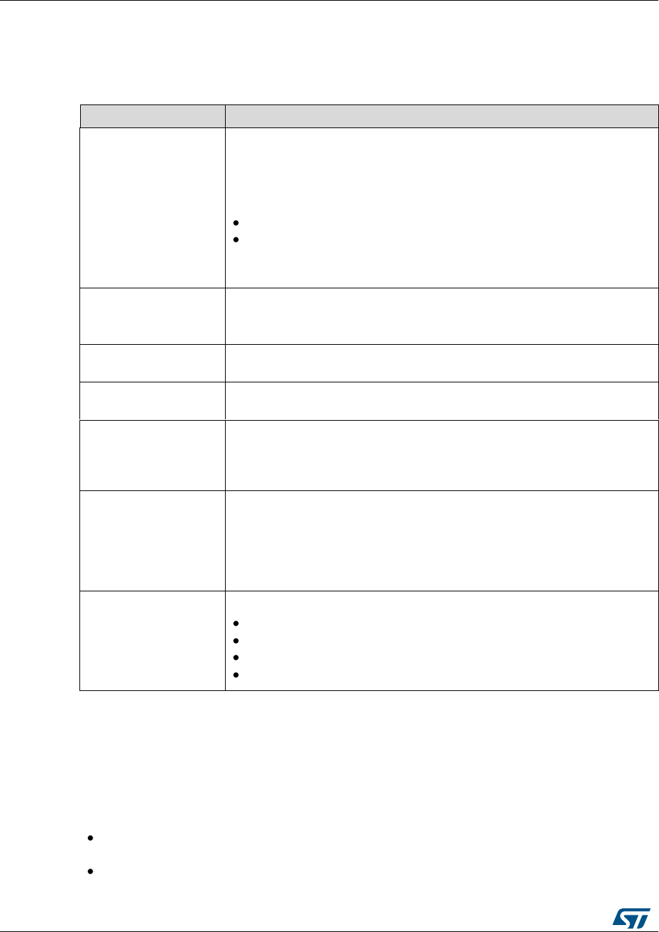
Overview of HAL drivers
UM1725
30/964
DocID025834 Rev 4
2.1.2 User-application files
The minimum files required to build an application using the HAL drivers are listed in the
table below:
Table 3: User-application files
File
Description
system_stm32f4xx.c
This file contains SystemInit() which is called at startup just after reset and
before branching to the main program. It does not configure the system
clock at startup (contrary to the standard library). This must be performed
using the HAL APIs in the user files.
It allows to :
relocate the vector table in internal SRAM.
configure FSMC/FMC peripheral (when available) to use as
data memory the external SRAM or SDRAM mounted on the
evaluation board.
startup_stm32f4xx.s
Toolchain specific file that contains reset handler and exception vectors.
For some toolchains, it allows adapting the stack/heap size to fit the
application requirements.
stm32f4xx_flash.icf
(optional)
Linker file for EWARM toolchain allowing mainly to adapt the stack/heap
size to fit the application requirements.
stm32f4xx_hal_msp.c
This file contains the MSP initialization and de-initialization (main routine
and callbacks) of the peripheral used in the user application.
stm32f4xx_hal_conf.h
This file allows the user to customize the HAL drivers for a specific
application.
It is not mandatory to modify this configuration. The application can use the
default configuration without any modification.
stm32f4xx_it.c/.h
This file contains the exceptions handler and peripherals interrupt service
routine, and calls HAL_IncTick() at regular time intervals to increment a
local variable (declared in stm32f4xx_hal.c) used as HAL timebase. By
default, this function is called each 1ms in Systick ISR. .
The PPP_IRQHandler() routine must call HAL_PPP_IRQHandler() if an
interrupt based process is used within the application.
main.c/.h
This file contains the main program routine, mainly:
the call to HAL_Init()
assert_failed() implementation
system clock configuration
peripheral HAL initialization and user application code.
The STM32Cube package comes with ready-to-use project templates, one for each
supported board. Each project contains the files listed above and a preconfigured project
for the supported toolchains.
Each project template provides empty main loop function and can be used as a starting
point to get familiar with project settings for STM32Cube. Their characteristics are the
following:
It contains sources of HAL, CMSIS and BSP drivers which are the minimal
components to develop a code on a given board.
It contains the include paths for all the firmware components.
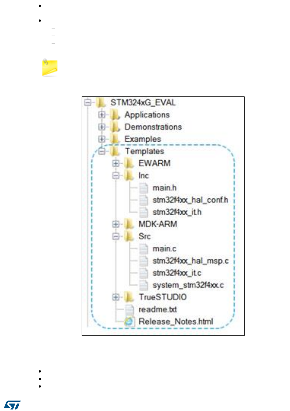
UM1725
Overview of HAL drivers
DocID025834 Rev 4
31/964
It defines the STM32 device supported, and allows to configure the CMSIS and HAL
drivers accordingly.
It provides ready to use user files preconfigured as defined below:
HAL is initialized
SysTick ISR implemented for HAL_Delay()
System clock configured with the maximum frequency of the device.
If an existing project is copied to another location, then include paths must be
updated.
Figure 1: Example of project template
2.2 HAL data structures
Each HAL driver can contain the following data structures:
Peripheral handle structures
Initialization and configuration structures
Specific process structures.

Overview of HAL drivers
UM1725
32/964
DocID025834 Rev 4
2.2.1 Peripheral handle structures
The APIs have a modular generic multi-instance architecture that allows working with
several IP instances simultaneous.
PPP_HandleTypeDef *handle is the main structure that is implemented in the HAL
drivers. It handles the peripheral/module configuration and registers and embeds all the
structures and variables needed to follow the peripheral device flow.
The peripheral handle is used for the following purposes:
Multi-instance support: each peripheral/module instance has its own handle. As a
result instance resources are independent.
Peripheral process intercommunication: the handle is used to manage shared data
resources between the process routines.
Example: global pointers, DMA handles, state machine.
Storage : this handle is used also to manage global variables within a given HAL
driver.
An example of peripheral structure is shown below:
typedef struct
{
USART_TypeDef *Instance; /* USART registers base address */
USART_InitTypeDef Init; /* Usart communication parameters */
uint8_t *pTxBuffPtr;/* Pointer to Usart Tx transfer Buffer */
uint16_t TxXferSize; /* Usart Tx Transfer size */
__IO uint16_t TxXferCount;/* Usart Tx Transfer Counter */
uint8_t *pRxBuffPtr;/* Pointer to Usart Rx transfer Buffer */
uint16_t RxXferSize; /* Usart Rx Transfer size */
__IO uint16_t RxXferCount; /* Usart Rx Transfer Counter */
DMA_HandleTypeDef *hdmatx; /* Usart Tx DMA Handle parameters */
DMA_HandleTypeDef *hdmarx; /* Usart Rx DMA Handle parameters */
HAL_LockTypeDef Lock; /* Locking object */
__IO HAL_USART_StateTypeDef State; /* Usart communication state */
__IO HAL_USART_ErrorTypeDef ErrorCode;/* USART Error code */
}USART_HandleTypeDef;
1) The multi-instance feature implies that all the APIs used in the application are
re-entrant and avoid using global variables because a subroutine can fail to be re-
entrant if they rely on a global variable to remain unchanged but that variable is
modified when the subroutine is recursively invoked. For this reason, the following
rules are respected:
Re-entrant code does not hold any static (or global) non-constant data: re-
entrant functions can work with global data. For example, a re-entrant
interrupt service routine can grab a piece of hardware status to work with
(e.g. serial port read buffer) which is not only global, but volatile. Still, typical
use of static variables and global data is not advised, in the sense that only
atomic read-modify-write instructions should be used in these variables. It
should not be possible for an interrupt or signal to occur during the execution
of such an instruction.
Reentrant code does not modify its own code.
2) When a peripheral can manage several processes simultaneously using the
DMA (full duplex case), the DMA interface handle for each process is added in the
PPP_HandleTypeDef.

UM1725
Overview of HAL drivers
DocID025834 Rev 4
33/964
3) For the shared and system peripherals, no handle or instance object is used.
The peripherals concerned by this exception are the following:
GPIO
SYSTICK
NVIC
PWR
RCC
FLASH.
2.2.2 Initialization and configuration structure
These structures are defined in the generic driver header file when it is common to all part
numbers. When they can change from one part number to another, the structures are
defined in the extension header file for each part number.
typedef struct
{
uint32_t BaudRate; /*!< This member configures the UART communication baudrate.*/
uint32_t WordLength; /*!< Specifies the number of data bits transmitted or received
in a frame.*/
uint32_t StopBits; /*!< Specifies the number of stop bits transmitted.*/
uint32_t Parity; /*!< Specifies the parity mode. */
uint32_t Mode; /*!< Specifies wether the Receive or Transmit mode is enabled or
disabled.*/
uint32_t HwFlowCtl; /*!< Specifies wether the hardware flow control mode is enabled
or disabled.*/
uint32_t OverSampling; /*!< Specifies wether the Over sampling 8 is enabled or
disabled,
to achieve higher speed (up to fPCLK/8).*/
}UART_InitTypeDef;
The config structure is used to initialize the sub-modules or sub-instances. See
below example:
HAL_ADC_ConfigChannel (ADC_HandleTypeDef* hadc, ADC_ChannelConfTypeDef*
sConfig)
2.2.3 Specific process structures
The specific process structures are used for specific process (common APIs). They are
defined in the generic driver header file.
Example:
HAL_PPP_Process (PPP_HandleTypeDef* hadc,PPP_ProcessConfig* sConfig)
2.3 API classification
The HAL APIs are classified into three categories:
Generic APIs: common generic APIs applying to all STM32 devices. These APIs are
consequently present in the generic HAL drivers files of all STM32 microcontrollers.
HAL_StatusTypeDef HAL_ADC_Init(ADC_HandleTypeDef* hadc); HAL_StatusTypeDef
HAL_ADC_DeInit(ADC_HandleTypeDef *hadc); HAL_StatusTypeDef
HAL_ADC_Start(ADC_HandleTypeDef* hadc); HAL_StatusTypeDef
HAL_ADC_Stop(ADC_HandleTypeDef* hadc); HAL_StatusTypeDef
HAL_ADC_Start_IT(ADC_HandleTypeDef* hadc); HAL_StatusTypeDef
HAL_ADC_Stop_IT(ADC_HandleTypeDef* hadc); void HAL_ADC_IRQHandler(ADC_HandleTypeDef*
hadc);
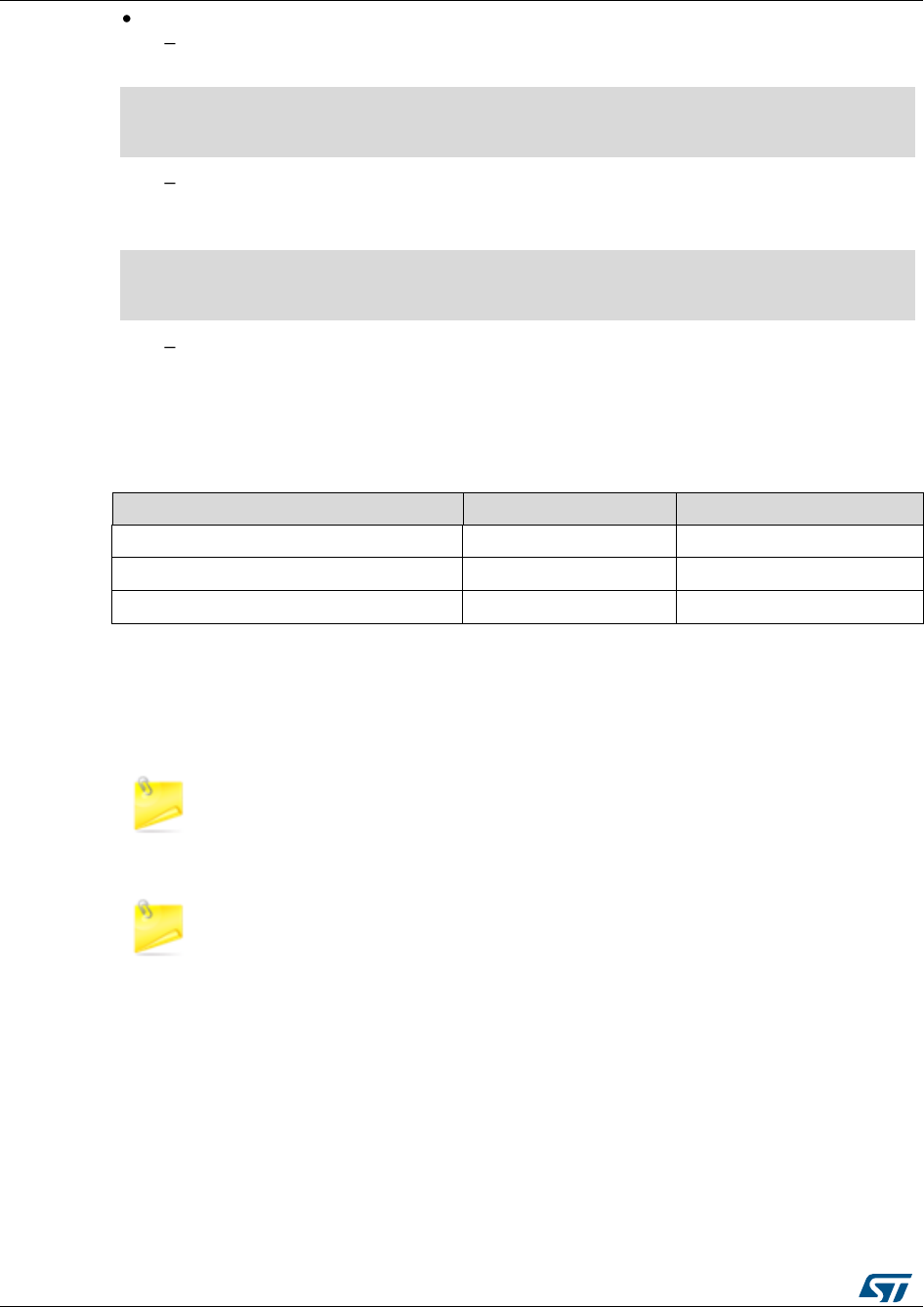
Overview of HAL drivers
UM1725
34/964
DocID025834 Rev 4
Extension APIs: This set of API is divided into two sub-categories :
Family specific APIs: APIs applying to a given family. They are located in the
extension HAL driver file (see example below related to the ADC).
HAL_StatusTypeDef HAL_ADCEx_InjectedStop(ADC_HandleTypeDef* hadc); HAL_StatusTypeDef
HAL_ADCEx_InjectedStop_IT(ADC_HandleTypeDef* hadc); HAL_StatusTypeDef
HAL_ADCEx_InjectedStart(ADC_HandleTypeDef* hadc); HAL_StatusTypeDef
HAL_ADCEx_InjectedStart_IT(ADC_HandleTypeDef* hadc);
Device part number specific APIs: These APIs are implemented in the
extension file and delimited by specific define statements relative to a given part
number.
#if defined(STM32F427xx) || defined(STM32F437xx) || defined(STM32F429xx) ||
defined(STM32F439xx) HAL_StatusTypeDef HAL_FLASHEx_OB_SelectPCROP(void);
HAL_StatusTypeDef HAL_FLASHEx_OB_DeSelectPCROP(void);
#endif /* STM32F427xx || STM32F437xx || STM32F429xx || STM32F439xx || */
The data structure related to the specific APIs is delimited by the device part
number define statement. It is located in the corresponding extension header C
file.
The following table summarizes the location of the different categories of HAL APIs in the
driver files.
Table 4: API classification
Generic file
Extension file
Common APIs
X
X (1)
Family specific APIs
X
Device specific APIs
X
Notes:
(1)In some cases, the implementation for a specific device part number may change . In this case the generic API
is declared as weak function in the extension file. The API is implemented again to overwrite the default function
Family specific APIs are only related to a given family. This means that if a
specific API is implemented in another family, and the arguments of this latter
family are different, additional structures and arguments might need to be added.
The IRQ handlers are used for common and family specific processes.

UM1725
Overview of HAL drivers
DocID025834 Rev 4
35/964
2.4 Devices supported by HAL drivers
Table 5: List of devices supported by HAL drivers
IP/Module
STM32F405xx
STM32F415xx
STM32F407xx
STM32F417xx
STM32F427xx
STM32F437xx
STM32F429xx
STM32F439xx
STM32F401xC
STM32F401xE
STM32F446xx
STM32F469xx
STM32F479xx
STM32F410xx
STM32F412xx
stm32f4xx_hal.c
Yes
Yes
Yes
Yes
Yes
Yes
Yes
Yes
Yes
Yes
Yes
Yes
Yes
Yes
Yes
stm32f4xx_hal_adc.c
Yes
Yes
Yes
Yes
Yes
Yes
Yes
Yes
Yes
Yes
Yes
Yes
Yes
Yes
Yes
stm32f4xx_hal_adc_ex.c
Yes
Yes
Yes
Yes
Yes
Yes
Yes
Yes
Yes
Yes
Yes
Yes
Yes
Yes
Yes
stm32f4xx_hal_can.c
Yes
Yes
Yes
Yes
Yes
Yes
Yes
Yes
No
No
Yes
Yes
Yes
Yes
Yes
stm32f4xx_hal_cec.c
No
No
No
No
No
No
No
No
No
No
Yes
No
No
No
No
stm32f4xx_hal_cortex.c
Yes
Yes
Yes
Yes
Yes
Yes
Yes
Yes
Yes
Yes
Yes
Yes
Yes
Yes
Yes
stm32f4xx_hal_crc.c
Yes
Yes
Yes
Yes
Yes
Yes
Yes
Yes
Yes
Yes
Yes
Yes
Yes
Yes
Yes
stm32f4xx_hal_cryp.c
No
Yes
No
Yes
No
Yes
No
Yes
No
No
No
No
Yes
No
No
stm32f4xx_hal_cryp_ex.
c
No
Yes
No
Yes
No
Yes
No
Yes
No
No
No
No
Yes
No
No
stm32f4xx_hal_dac.c
Yes
Yes
Yes
Yes
Yes
Yes
Yes
Yes
No
No
Yes
Yes
Yes
Yes
No
stm32f4xx_hal_dac_ex.c
Yes
Yes
Yes
Yes
Yes
Yes
Yes
Yes
No
No
Yes
Yes
Yes
Yes
No
stm32f4xx_hal_dcmi.c
No
No
Yes
Yes
Yes
Yes
Yes
Yes
No
No
Yes
Yes
Yes
No
No
stm32f4xx_hal_dcmi_ex.
c
No
No
Yes
Yes
Yes
Yes
Yes
Yes
No
No
Yes
Yes
Yes
No
No
stm32f4xx_hal_dfsdm.c
No
No
No
No
No
No
No
No
No
No
No
No
No
No
Yes
stm32f4xx_hal_dma.c
Yes
Yes
Yes
Yes
Yes
Yes
Yes
Yes
Yes
Yes
Yes
Yes
Yes
Yes
Yes
stm32f4xx_hal_dma2d.c
No
No
No
No
Yes
Yes
Yes
Yes
No
No
No
Yes
Yes
No
No
stm32f4xx_hal_dma_ex.
c
Yes
Yes
Yes
Yes
Yes
Yes
Yes
Yes
Yes
Yes
Yes
Yes
Yes
Yes
Yes
stm32f4xx_hal_dsi.c
No
No
No
No
No
No
No
No
No
No
No
Yes
Yes
No
No
stm32f4xx_hal_eth.c
No
No
Yes
Yes
Yes
Yes
Yes
Yes
No
No
No
Yes
Yes
No
No
stm32f4xx_hal_flash.c
Yes
Yes
Yes
Yes
Yes
Yes
Yes
Yes
Yes
Yes
Yes
Yes
Yes
Yes
Yes
stm32f4xx_hal_flash_ex.
c
No
No
No
No
Yes
Yes
Yes
Yes
Yes
Yes
Yes
Yes
Yes
Yes
Yes
stm32f4xx_hal_flash_
ramfunc.c
No
No
No
No
No
No
No
No
No
No
Yes
No
No
Yes
Yes
stm32f4xx_hal_fmpi2c.c
No
No
No
No
No
No
No
No
No
No
Yes
No
No
Yes
Yes
stm32f4xx_hal_fmpi2c_
ex.c
No
No
No
No
No
No
No
No
No
No
Yes
No
No
Yes
Yes
stm32f4xx_hal_gpio.c
Yes
Yes
Yes
Yes
Yes
Yes
Yes
Yes
Yes
Yes
Yes
Yes
Yes
Yes
Yes
stm32f4xx_hal_hash.c
No
Yes
No
Yes
No
Yes
No
Yes
No
No
No
No
Yes
No
No
stm32f4xx_hal_hash_ex.
c
No
No
No
No
No
Yes
No
Yes
No
No
No
No
Yes
No
No
stm32f4xx_hal_hcd.c
Yes
Yes
Yes
Yes
Yes
Yes
Yes
Yes
Yes
Yes
Yes
Yes
Yes
No
Yes
stm32f4xx_hal_i2c.c
Yes
Yes
Yes
Yes
Yes
Yes
Yes
Yes
Yes
Yes
Yes
Yes
Yes
Yes
Yes
stm32f4xx_hal_i2c_ex.c
No
No
No
No
Yes
Yes
Yes
Yes
Yes
Yes
Yes
Yes
Yes
Yes
Yes
stm32f4xx_hal_i2s.c
Yes
Yes
Yes
Yes
Yes
Yes
Yes
Yes
Yes
Yes
Yes
Yes
Yes
Yes
Yes

Overview of HAL drivers
UM1725
36/964
DocID025834 Rev 4
IP/Module
STM32F405xx
STM32F415xx
STM32F407xx
STM32F417xx
STM32F427xx
STM32F437xx
STM32F429xx
STM32F439xx
STM32F401xC
STM32F401xE
STM32F446xx
STM32F469xx
STM32F479xx
STM32F410xx
STM32F412xx
stm32f4xx_hal_i2s_ex.c
Yes
Yes
Yes
Yes
Yes
Yes
Yes
Yes
Yes
Yes
Yes
Yes
Yes
No
Yes
stm32f4xx_hal_irda.c
Yes
Yes
Yes
Yes
Yes
Yes
Yes
Yes
Yes
Yes
Yes
Yes
Yes
Yes
Yes
stm32f4xx_hal_iwdg.c
Yes
Yes
Yes
Yes
Yes
Yes
Yes
Yes
Yes
Yes
Yes
Yes
Yes
Yes
Yes
stm32f4xx_hal_lptim.c
No
No
No
No
No
No
No
No
No
No
No
No
No
Yes
No
stm32f4xx_hal_ltdc.c
No
No
No
No
No
No
Yes
Yes
No
No
No
Yes
Yes
No
No
stm32f4xx_hal_ltdc_ex.c
No
No
No
No
No
No
No
No
No
No
No
Yes
Yes
No
No
stm32f4xx_hal_msp_
template.c
NA
NA
NA
NA
NA
NA
NA
NA
NA
NA
NA
NA
NA
NA
NA
stm32f4xx_hal_nand.c
Yes
Yes
Yes
Yes
Yes
Yes
Yes
Yes
No
No
Yes
Yes
Yes
No
No
stm32f4xx_hal_nor.c
Yes
Yes
Yes
Yes
Yes
Yes
Yes
Yes
No
No
Yes
Yes
Yes
No
Yes
stm32f4xx_hal_pccard.c
Yes
Yes
Yes
Yes
Yes
Yes
Yes
Yes
No
No
No
No
No
No
No
stm32f4xx_hal_pcd.c
Yes
Yes
Yes
Yes
Yes
Yes
Yes
Yes
Yes
Yes
Yes
Yes
Yes
No
Yes
stm32f4xx_hal_pcd_ex.c
Yes
Yes
Yes
Yes
Yes
Yes
Yes
Yes
Yes
Yes
Yes
Yes
Yes
No
Yes
stm32f4xx_hal_pwr.c
Yes
Yes
Yes
Yes
Yes
Yes
Yes
Yes
Yes
Yes
Yes
Yes
Yes
Yes
Yes
stm32f4xx_hal_pwr_ex.c
No
No
No
No
Yes
Yes
Yes
Yes
No
No
Yes
Yes
Yes
Yes
Yes
stm32f4xx_hal_qspi.c
No
No
No
No
No
No
No
No
No
No
Yes
Yes
Yes
No
Yes
stm32f4xx_hal_rcc.c
Yes
Yes
Yes
Yes
Yes
Yes
Yes
Yes
Yes
Yes
Yes
Yes
Yes
Yes
Yes
stm32f4xx_hal_rcc_ex.c
Yes
Yes
Yes
Yes
Yes
Yes
Yes
Yes
Yes
Yes
Yes
Yes
Yes
Yes
Yes
stm32f4xx_hal_rng.c
Yes
Yes
Yes
Yes
Yes
Yes
Yes
Yes
Yes
Yes
No
Yes
Yes
Yes
Yes
stm32f4xx_hal_rtc.c
Yes
Yes
Yes
Yes
Yes
Yes
Yes
Yes
Yes
Yes
Yes
Yes
Yes
Yes
Yes
stm32f4xx_hal_rtc_ex.c
Yes
Yes
Yes
Yes
Yes
Yes
Yes
Yes
Yes
Yes
Yes
Yes
Yes
Yes
Yes
stm32f4xx_hal_sai.c
No
No
No
No
Yes
Yes
Yes
Yes
No
No
Yes
Yes
Yes
No
No
stm32f4xx_hal_sai_ex.c
No
No
No
No
Yes
Yes
Yes
Yes
No
No
Yes
Yes
Yes
No
No
stm32f4xx_hal_sd.c
Yes
Yes
Yes
Yes
Yes
Yes
Yes
Yes
Yes
Yes
Yes
Yes
Yes
No
Yes
stm32f4xx_hal_sdram.c
No
No
No
No
Yes
Yes
Yes
Yes
No
No
Yes
Yes
Yes
No
No
stm32f4xx_hal_smartcar
d.c
Yes
Yes
Yes
Yes
Yes
Yes
Yes
Yes
Yes
Yes
Yes
Yes
Yes
Yes
Yes
stm32f4xx_hal_spdifrx.c
No
No
No
No
No
No
No
No
No
No
Yes
No
No
No
No
stm32f4xx_hal_spi.c
Yes
Yes
Yes
Yes
Yes
Yes
Yes
Yes
Yes
Yes
Yes
Yes
Yes
Yes
Yes
stm32f4xx_hal_sram.c
Yes
Yes
Yes
Yes
Yes
Yes
Yes
Yes
No
No
Yes
Yes
Yes
No
Yes
stm32f4xx_hal_tim.c
Yes
Yes
Yes
Yes
Yes
Yes
Yes
Yes
Yes
Yes
Yes
Yes
Yes
Yes
Yes
stm32f4xx_hal_tim_ex.c
Yes
Yes
Yes
Yes
Yes
Yes
Yes
Yes
Yes
Yes
Yes
Yes
Yes
Yes
Yes
stm32f4xx_hal_uart.c
Yes
Yes
Yes
Yes
Yes
Yes
Yes
Yes
Yes
Yes
Yes
Yes
Yes
Yes
Yes
stm32f4xx_hal_usart.c
Yes
Yes
Yes
Yes
Yes
Yes
Yes
Yes
Yes
Yes
Yes
Yes
Yes
Yes
Yes
stm32f4xx_hal_wwdg.c
Yes
Yes
Yes
Yes
Yes
Yes
Yes
Yes
Yes
Yes
Yes
Yes
Yes
Yes
Yes
stm32f4xx_ll_fmc.c
No
No
No
No
Yes
Yes
Yes
Yes
No
No
Yes
Yes
Yes
No
No
stm32f4xx_ll_fsmc.c
Yes
Yes
Yes
Yes
No
No
No
No
No
No
No
No
No
No
Yes
stm32f4xx_ll_sdmmc.c
Yes
Yes
Yes
Yes
Yes
Yes
Yes
Yes
Yes
Yes
Yes
Yes
Yes
No
Yes
stm32f4xx_ll_usb.c
Yes
Yes
Yes
Yes
Yes
Yes
Yes
Yes
Yes
Yes
Yes
Yes
Yes
No
Yes

UM1725
Overview of HAL drivers
DocID025834 Rev 4
37/964
2.5 HAL driver rules
2.5.1 HAL API naming rules
The following naming rules are used in HAL drivers:
Table 6: HAL API naming rules
Generic
Family specific
Device specific
File
names
stm32f4xx_hal_ppp (c/h)
stm32f4xx_hal_ppp_ex (c/h)
stm32f4xx_ hal_ppp_ex (c/h)
Module
name
HAL_PPP_ MODULE
Functio
n name
HAL_PPP_Function
HAL_PPP_FeatureFunction_
MODE
HAL_PPPEx_Function
HAL_PPPEx_FeatureFunction_
MODE
HAL_PPPEx_Function
HAL_PPPEx_FeatureFunction_
MODE
Handle
name
PPP_HandleTypedef
NA
NA
Init
structu
re
name
PPP_InitTypeDef
NA
PPP_InitTypeDef
Enum
name
HAL_PPP_StructnameTypeD
ef
NA
NA
The PPP prefix refers to the peripheral functional mode and not to the peripheral itself.
For example, if the USART, PPP can be USART, IRDA, UART or SMARTCARD
depending on the peripheral mode.
The constants used in one file are defined within this file. A constant used in several
files is defined in a header file. All constants are written in uppercase, except for
peripheral driver function parameters.
typedef variable names should be suffixed with _TypeDef.
Registers are considered as constants. In most cases, their name is in uppercase and
uses the same acronyms as in the STM32F4xx reference manuals.
Peripheral registers are declared in the PPP_TypeDef structure (e.g. ADC_TypeDef)
in stm32f4xxx.h header file.stm32f4xxx.h corresponds to stm32f401xc.h,
stm32f401xe.h, stm32f405xx.h, stm32f415xx.h, stm32f407xx.h, stm32f417xx.h,
stm32f427xx.h, stm32f437xx.h, stm32f429xx.h, stm32f439xx.h, stm32f446xx.h,
stm32f469xx.h, stm32f479xx.h, stm32f410cx.h, stm32f410tx.h, stm32f410rx.h,
stm32f412cx.h, stm32f412rx.h, stm32f412vx.h or stm32f412zx.h.
Peripheral function names are prefixed by HAL_, then the corresponding peripheral
acronym in uppercase followed by an underscore. The first letter of each word is in
uppercase (e.g. HAL_UART_Transmit()). Only one underscore is allowed in a function
name to separate the peripheral acronym from the rest of the function name.
The structure containing the PPP peripheral initialization parameters are named
PPP_InitTypeDef (e.g. ADC_InitTypeDef).
The structure containing the Specific configuration parameters for the PPP peripheral
are named PPP_xxxxConfTypeDef (e.g. ADC_ChannelConfTypeDef).
Peripheral handle structures are named PPP_HandleTypedef (e.g
DMA_HandleTypeDef)
The functions used to initialize the PPP peripheral according to parameters specified
in PPP_InitTypeDef are named HAL_PPP_Init (e.g. HAL_TIM_Init()).
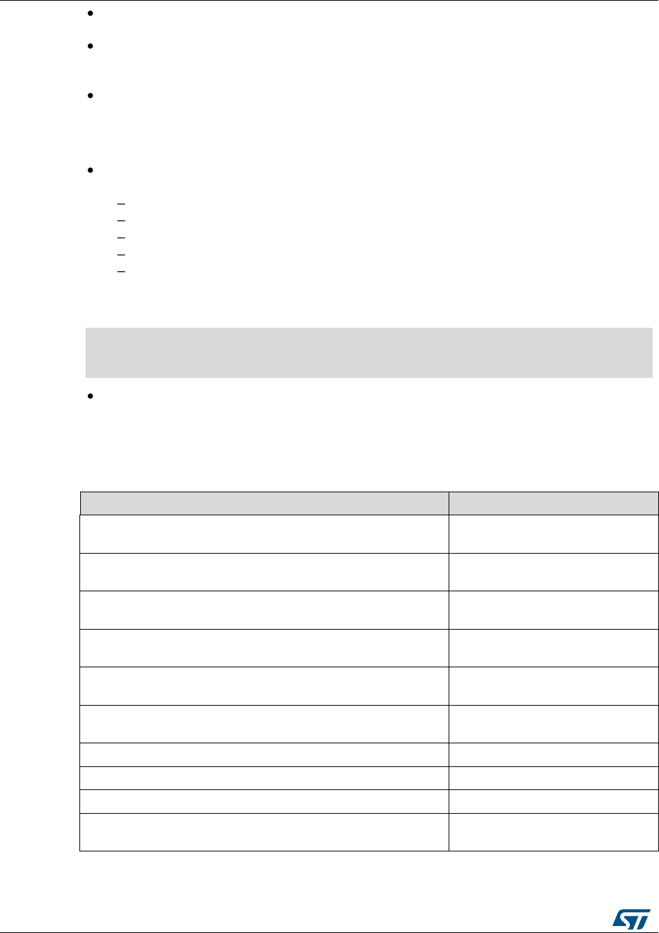
Overview of HAL drivers
UM1725
38/964
DocID025834 Rev 4
The functions used to reset the PPP peripheral registers to their default values are
named PPP_DeInit, e.g. TIM_DeInit.
The MODE suffix refers to the process mode, which can be polling, interrupt or DMA.
As an example, when the DMA is used in addition to the native resources, the function
should be called: HAL_PPP_Function_DMA ().
The Feature prefix should refer to the new feature.
Example: HAL_ADC_InjectionStart() refers to the injection mode
2.5.2 HAL general naming rules
For the shared and system peripherals, no handle or instance object is used. This rule
applies to the following peripherals:
GPIO
SYSTICK
NVIC
RCC
FLASH.
Example: The HAL_GPIO_Init() requires only the GPIO address and its configuration
parameters.
HAL_StatusTypeDef HAL_GPIO_Init (GPIO_TypeDef* GPIOx, GPIO_InitTypeDef *Init)
{
/*GPIO Initialization body */
}
The macros that handle interrupts and specific clock configurations are defined in
each peripheral/module driver. These macros are exported in the peripheral driver
header files so that they can be used by the extension file. The list of these macros is
defined below: This list is not exhaustive and other macros related to peripheral
features can be added, so that they can be used in the user application.
Table 7: Macros handling interrupts and specific clock configurations
Macros
Description
__HAL_PPP_ENABLE_IT(__HANDLE__, __INTERRUPT__)
Enables a specific peripheral
interrupt
__HAL_PPP_DISABLE_IT(__HANDLE__, __INTERRUPT__)
Disables a specific peripheral
interrupt
__HAL_PPP_GET_IT (__HANDLE__, __ INTERRUPT __)
Gets a specific peripheral interrupt
status
__HAL_PPP_CLEAR_IT (__HANDLE__, __ INTERRUPT __)
Clears a specific peripheral
interrupt status
__HAL_PPP_GET_FLAG (__HANDLE__, __FLAG__)
Gets a specific peripheral flag
status
__HAL_PPP_CLEAR_FLAG (__HANDLE__, __FLAG__)
Clears a specific peripheral flag
status
__HAL_PPP_ENABLE(__HANDLE__)
Enables a peripheral
__HAL_PPP_DISABLE(__HANDLE__)
Disables a peripheral
__HAL_PPP_XXXX (__HANDLE__, __PARAM__)
Specific PPP HAL driver macro
__HAL_PPP_GET_ IT_SOURCE (__HANDLE__, __
INTERRUPT __)
Checks the source of specified
interrupt

UM1725
Overview of HAL drivers
DocID025834 Rev 4
39/964
NVIC and SYSTICK are two ARM Cortex core features. The APIs related to these
features are located in the stm32f4xx_hal_cortex.c file.
When a status bit or a flag is read from registers, it is composed of shifted values
depending on the number of read values and of their size. In this case, the returned
status width is 32 bits. Example : STATUS = XX | (YY << 16) or STATUS=".
The PPP handles are valid before using the HAL_PPP_Init() API. The init function
performs a check before modifying the handle fields.
HAL_PPP_Init(PPP_HandleTypeDef) if(hppp == NULL) { return HAL_ERROR; }
The macros defined below are used:
Conditional macro:
#define ABS(x) (((x) > 0) ? (x) : -(x))
Pseudo-code macro (multiple instructions macro):
#define __HAL_LINKDMA(__HANDLE__, __PPP_DMA_FIELD_, __DMA_HANDLE_) \ do{ \
(__HANDLE__)->__PPP_DMA_FIELD_ = &(__DMA_HANDLE_); \ (__DMA_HANDLE_).Parent =
(__HANDLE__); \ } while(0)
2.5.3 HAL interrupt handler and callback functions
Besides the APIs, HAL peripheral drivers include:
HAL_PPP_IRQHandler() peripheral interrupt handler that should be called from
stm32f4xx_it.c
User callback functions.
The user callback functions are defined as empty functions with “weak” attribute. They
have to be defined in the user code.
There are three types of user callbacks functions:
Peripheral system level initialization/ de-Initialization callbacks: HAL_PPP_MspInit()
and HAL_PPP_MspDeInit
Process complete callbacks : HAL_PPP_ProcessCpltCallback
Error callback: HAL_PPP_ErrorCallback.
Table 8: Callback functions
Callback functions
Example
HAL_PPP_MspInit() / _DeInit()
Ex: HAL_USART_MspInit()
Called from HAL_PPP_Init() API function to perform peripheral
system level initialization (GPIOs, clock, DMA, interrupt)
HAL_PPP_ProcessCpltCallback
Ex: HAL_USART_TxCpltCallback
Called by peripheral or DMA interrupt handler when the process
completes
HAL_PPP_ErrorCallback
Ex: HAL_USART_ErrorCallback
Called by peripheral or DMA interrupt handler when an error
occurs

Overview of HAL drivers
UM1725
40/964
DocID025834 Rev 4
2.6 HAL generic APIs
The generic APIs provide common generic functions applying to all STM32 devices. They
are composed of four APIs groups:
Initialization and de-initialization functions:HAL_PPP_Init(), HAL_PPP_DeInit()
IO operation functions: HAL_PPP_Read(), HAL_PPP_Write(),HAL_PPP_Transmit(),
HAL_PPP_Receive()
Control functions:HAL_PPP_Set (), HAL_PPP_Get ().
State and Errors functions: HAL_PPP_GetState (), HAL_PPP_GetError ().
For some peripheral/module drivers, these groups are modified depending on the
peripheral/module implementation.
Example: in the timer driver, the API grouping is based on timer features (PWM, OC, IC...).
The initialization and de-initialization functions allow initializing a peripheral and configuring
the low-level resources, mainly clocks, GPIO, alternate functions (AF) and possibly DMA
and interrupts. The HAL_DeInit()function restores the peripheral default state, frees the
low-level resources and removes any direct dependency with the hardware.
The IO operation functions perform a row access to the peripheral payload data in write
and read modes.
The control functions are used to change dynamically the peripheral configuration and set
another operating mode.
The peripheral state and errors functions allow retrieving in runtime the peripheral and data
flow states, and identifying the type of errors that occurred. The example below is based on
the ADC peripheral. The list of generic APIs is not exhaustive. It is only given as an
example.
Table 9: HAL generic APIs
Function
Group
Common API Name
Description
Initialization
group
HAL_ADC_Init()
This function initializes the peripheral and
configures the low -level resources (clocks,
GPIO, AF..)
HAL_ADC_DeInit()
This function restores the peripheral default state,
frees the low-level resources and removes any
direct dependency with the hardware.
IO operation
group
HAL_ADC_Start ()
This function starts ADC conversions when the
polling method is used
HAL_ADC_Stop ()
This function stops ADC conversions when the
polling method is used
HAL_ADC_PollForConversion()
This function allows waiting for the end of
conversions when the polling method is used. In
this case, a timout value is specified by the user
according to the application.
HAL_ADC_Start_IT()
This function starts ADC conversions when the
interrupt method is used
HAL_ADC_Stop_IT()
This function stops ADC conversions when the
interrupt method is used
HAL_ADC_IRQHandler()
This function handles ADC interrupt requests

UM1725
Overview of HAL drivers
DocID025834 Rev 4
41/964
Function
Group
Common API Name
Description
HAL_ADC_ConvCpltCallback()
Callback function called in the IT subroutine to
indicate the end of the current process or when a
DMA transfer has completed
HAL_ADC_ErrorCallback()
Callback function called in the IT subroutine if a
peripheral error or a DMA transfer error occurred
Control group
HAL_ADC_ConfigChannel()
This function configures the selected ADC regular
channel, the corresponding rank in the sequencer
and the sample time
HAL_ADC_AnalogWDGConfig
This function configures the analog watchdog for
the selected ADC
State and
Errors group
HAL_ADC_GetState()
This function allows getting in runtime the
peripheral and the data flow states.
HAL_ADC_GetError()
This fuction allows getting in runtime the error
that occurred during IT routine
2.7 HAL extension APIs
2.7.1 HAL extension model overview
The extension APIs provide specific functions or overwrite modified APIs for a specific
family (series) or specific part number within the same family.
The extension model consists of an additional file, stm32f4xx_hal_ppp_ex.c, that includes
all the specific functions and define statements (stm32f4xx_hal_ppp_ex.h) for a given part
number.
Below an example based on the ADC peripheral:
Table 10: HAL extension APIs
Function Group
Common API Name
HAL_ADCEx_InjectedStart()
This function starts injected channel ADC conversions when
the polling method is used
HAL_ADCEx_InjectedStop()
This function stops injected channel ADC conversions when
the polling method is used
HAL_ADCEx_InjectedStart_IT()
This function starts injected channel ADC conversions when
the interrupt method is used
HAL_ADCEx_InjectedStop_IT()
This function stops injected channel ADC conversions when
the interrupt method is used
HAL_ADCEx_InjectedConfigChannel()
This function configures the selected ADC Injected channel
(corresponding rank in the sequencer and sample time)
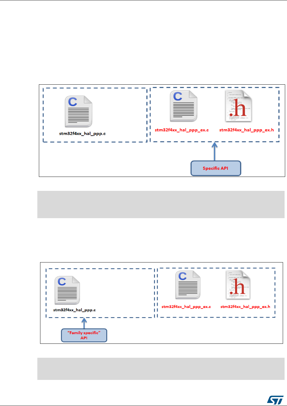
Overview of HAL drivers
UM1725
42/964
DocID025834 Rev 4
2.7.2 HAL extension model cases
The specific IP features can be handled by the HAL drivers in five different ways. They are
described below.
Case1: Adding a part number-specific function
When a new feature specific to a given device is required, the new APIs are added in the
stm32f4xx_hal_ppp_ex.c extension file. They are named HAL_PPPEx_Function().
Figure 2: Adding device-specific functions
Example: stm32f4xx_hal_flash_ex.c/h
#if defined(STM32F427xx) || defined(STM32F437xx) || defined(STM32F429xx)||
defined(STM32F439xx)
HAL_StatusTypeDef HAL_FLASHEx_OB_SelectPCROP(void);
HAL_StatusTypeDef HAL_FLASHEx_OB_DeSelectPCROP(void);
#endif /* STM32F427xx ||STM32F437xx || STM32F429xx || STM32F439xx */
Case2: Adding a family-specific function
In this case, the API is added in the extension driver C file and named
HAL_PPPEx_Function ().
Figure 3: Adding family-specific functions
Example: stm32f4xx_hal_adc_ex.c/h
HAL_StatusTypeDef HAL_ADCEx_InjectedStop(ADC_HandleTypeDef* hadc);
HAL_StatusTypeDef HAL_ADCEx_InjectedStop_IT(ADC_HandleTypeDef* hadc);
HAL_StatusTypeDef HAL_ADCEx_InjectedStart(ADC_HandleTypeDef* hadc);
HAL_StatusTypeDef HAL_ADCEx_InjectedStart_IT(ADC_HandleTypeDef* hadc);
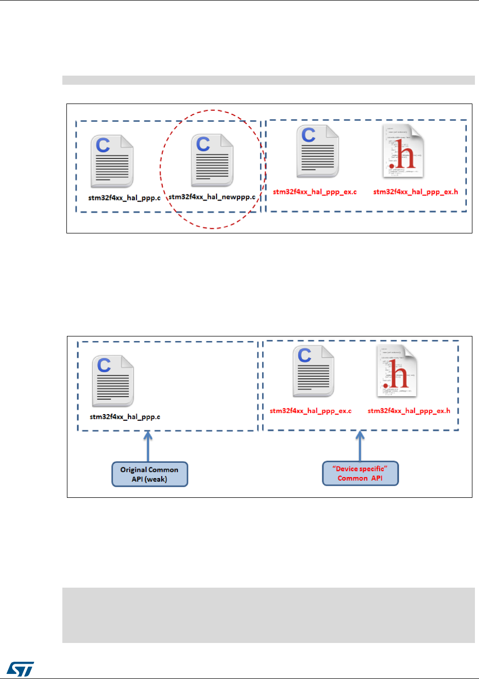
UM1725
Overview of HAL drivers
DocID025834 Rev 4
43/964
Case3 : Adding a new peripheral (specific to a device belonging to a given
family)
When a peripheral which is available only in a specific device is required, the APIs
corresponding to this new peripheral/module are added in stm32f4xx_hal_newppp.c.
However the inclusion of this file is selected in the stm32fxx_hal_conf.h using the macro:
#define HAL_NEWPPP_MODULE_ENABLED
Figure 4: Adding new peripherals
Example: stm32f4xx_hal_sai.c/h
Case4: Updating existing common APIs
In this case, the routines are defined with the same names in the stm32f4xx_hal_ppp_ex.c
extension file, while the generic API is defined as weak, so that the compiler will overwrite
the original routine by the new defined function.
Figure 5: Updating existing APIs
Case5 : Updating existing data structures
The data structure for a specific device part number (e.g. PPP_InitTypeDef) can have
different fields. In this case, the data structure is defined in the extension header file and
delimited by the specific part number define statement.
Example:
#if defined (STM32F401xx)
typedef struct
{
(…)
}PPP_InitTypeDef;
#endif /* STM32F401xx */
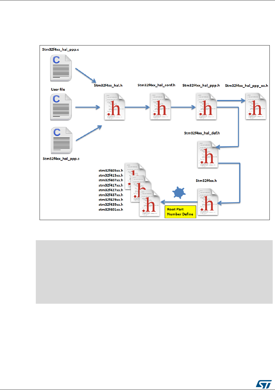
Overview of HAL drivers
UM1725
44/964
DocID025834 Rev 4
2.8 File inclusion model
The header of the common HAL driver file (stm32f4xx_hal.h) includes the common
configurations for the whole HAL library. It is the only header file that is included in the user
sources and the HAL C sources files to be able to use the HAL resources.
Figure 6: File inclusion model
A PPP driver is a standalone module which is used in a project. The user must enable the
corresponding USE_HAL_PPP_MODULE define statement in the configuration file.
/*********************************************************************
* @file stm32f4xx_hal_conf.h
* @author MCD Application Team
* @version VX.Y.Z * @date dd-mm-yyyy
* @brief This file contains the modules to be used
**********************************************************************
(…)
#define USE_HAL_USART_MODULE
#define USE_HAL_IRDA_MODULE
#define USE_HAL_DMA_MODULE
#define USE_HAL_RCC_MODULE
(…)

UM1725
Overview of HAL drivers
DocID025834 Rev 4
45/964
2.9 HAL common resources
The common HAL resources, such as common define enumerations, structures and
macros, are defined in stm32f4xx_hal_def.h.The main common define enumeration is
HAL_StatusTypeDef.
HAL Status: The HAL status is used by almost all HAL APIs, except for boolean
functions and IRQ handler. It returns the status of the current API operations. It has
four possible values as described below:
Typedef enum
{ HAL_OK = 0x00, HAL_ERROR = 0x01, HAL_BUSY = 0x02, HAL_TIMEOUT = 0x03
} HAL_StatusTypeDef;
HAL Locked: The HAL lock is used by all HAL APIs to prevent accessing by accident
shared resources.
typedef enum
{ HAL_UNLOCKED = 0x00, /*!<Resources unlocked */ HAL_LOCKED = 0x01 /*!< Resources
locked */
} HAL_LockTypeDef;
In addition to common resources, the stm32f4xx_hal_def.h file calls the stm32f4xx.h
file in CMSIS library to get the data structures and the address mapping for all
peripherals:
Declarations of peripheral registers and bits definition.
Macros to access peripheral registers hardware (Write register, Read
register…etc.).
Common macros
Macro defining HAL_MAX_DELAY
#define HAL_MAX_DELAY 0xFFFFFFFF
Macro linking a PPP peripheral to a DMA structure pointer: __HAL_LINKDMA();
#define __HAL_LINKDMA(__HANDLE__, __PPP_DMA_FIELD_, __DMA_HANDLE_) \
do{ \
(__HANDLE__)->__PPP_DMA_FIELD_ = &(__DMA_HANDLE_); \
(__DMA_HANDLE_).Parent = (__HANDLE__); \
} while(0)
2.10 HAL configuration
The configuration file, stm32f4xx_hal_conf.h, allows customizing the drivers for the user
application. Modifying this configuration is not mandatory: the application can use the
default configuration without any modification.
To configure these parameters, the user should enable, disable or modify some options by
uncommenting, commenting or modifying the values of the related define statements as
described in the table below:
Table 11: Define statements used for HAL configuration
Configuration item
Description
Default Value
HSE_VALUE
Defines the value of the external
oscillator (HSE) expressed in Hz.
The user must adjust this define
statement when using a different
crystal value.
25 000 000 (Hz)
HSE_STARTUP_TIMEOUT
Timeout for HSE start up,
expressed in ms
5000

Overview of HAL drivers
UM1725
46/964
DocID025834 Rev 4
Configuration item
Description
Default Value
HSI_VALUE
Defines the value of the internal
oscillator (HSI) expressed in Hz.
16 000 000 (Hz)
EXTERNAL_CLOCK_VALUE
This value is used by the
I2S/SAI HAL module to compute
the I2S/SAI clock source
frequency, this source is inserted
directly through I2S_CKIN pad.
12288000 (Hz)
VDD_VALUE
VDD value
3300 (mV)
USE_RTOS
Enables the use of RTOS
FALSE (for future use)
PREFETCH_ENABLE
Enables prefetch feature
TRUE
INSTRUCTION_CACHE_ENABLE
Enables instruction cache
TRUE
DATA_CACHE_ENABLE
Enables data cache
TRUE
USE HAL_PPP_MODULE
Enables module to be used in
the HAL driver
MAC_ADDRx
Ethernet peripheral
configuration : MAC address
ETH_RX_BUF_SIZE
Ethernet buffer size for receive
ETH_MAX_PACKET_SIZE
ETH_TX_BUF_SIZE
Ethernet buffer size for trasmit
ETH_MAX_PACKET_SIZE
ETH_RXBUFNB
The number of Rx buffers of
size ETH_RX_BUF_SIZE
4
ETH_TXBUFNB
The number of Tx buffers of size
ETH_RX_BUF_SIZE
4
DP83848_PHY_ADDRESS
DB83848 Ethernet PHY
Address
0x01
PHY_RESET_DELAY
PHY Reset delay these values
are based on a 1 ms Systick
interrupt
0x000000FF
PHY_CONFIG_DELAY
PHY Configuration delay
0x00000FFF
PHY_BCR PHY_BSR
Common PHY Registers
PHY_SR PHY_MICR PHY_MISR
Extended PHY registers
The stm32f4xx_hal_conf_template.h file is located in the HAL drivers Inc folder. It
should be copied to the user folder, renamed and modified as described above.
By default, the values defined in the stm32f4xx_hal_conf_template.h file are the
same as the ones used for the examples and demonstrations. All HAL include
files are enabled so that they can be used in the user code without modifications.

UM1725
Overview of HAL drivers
DocID025834 Rev 4
47/964
2.11 HAL system peripheral handling
This chapter gives an overview of how the system peripherals are handled by the HAL
drivers. The full API list is provided within each peripheral driver description section.
2.11.1 Clock
Two main functions can be used to configure the system clock:
HAL_RCC_OscConfig (RCC_OscInitTypeDef *RCC_OscInitStruct). This function
configures/enables multiple clock sources (HSE, HSI, LSE, LSI, PLL).
HAL_RCC_ClockConfig (RCC_ClkInitTypeDef *RCC_ClkInitStruct, uint32_t
FLatency). This function
Selects the system clock source
Configures AHB, APB1 and APB2 clock dividers
Configures the number od Flash memory wait states
Updates the SysTick configuration when HCLK clock changes.
Some peripheral clocks are not derived from the system clock (RTC, SDIO, I2S, SAI, Audio
PLL…). In this case, the clock configuration is performed by an extended API defined in
stm32f4xx_hal_ppp_ex.c: HAL_RCCEx_PeriphCLKConfig(RCC_PeriphCLKInitTypeDef
*PeriphClkInit).
Additional RCC HAL driver functions are available:
HAL_RCC_DeInit() Clock de-init function that return clock configuration to reset state
Get clock functions that allow retreiving various clock configurations (system clock,
HCLK, PCLK1, PCLK2, …)
MCO and CSS configuration functions
A set of macros are defined in stm32f4xx_hal_rcc.h. They allows executing elementary
operations on RCC block registers, such as peripherals clock gating/reset control:
__PPP_CLK_ENABLE/__PPP_CLK_DISABLE to enable/disable the peripheral clock
__PPP_FORCE_RESET/__PPP_RELEASE_RESET to force/release peripheral reset
__PPP_CLK_SLEEP_ENABLE/__PPP_CLK_SLEEP_DISABLE to enable/disable the
peripheral clock during low power (Sleep) mode.
2.11.2 GPIOs
GPIO HAL APIs are the following:
HAL_GPIO_Init() / HAL_GPIO_DeInit()
HAL_GPIO_ReadPin() / HAL_GPIO_WritePin()
HAL_GPIO_TogglePin ().
In addition to standard GPIO modes (input, output, analog), pin mode can be configured as
EXTI with interrupt or event generation.
When selecting EXTI mode with interrupt generation, the user must call
HAL_GPIO_EXTI_IRQHandler() from stm32f4xx_it.c and implement
HAL_GPIO_EXTI_Callback()
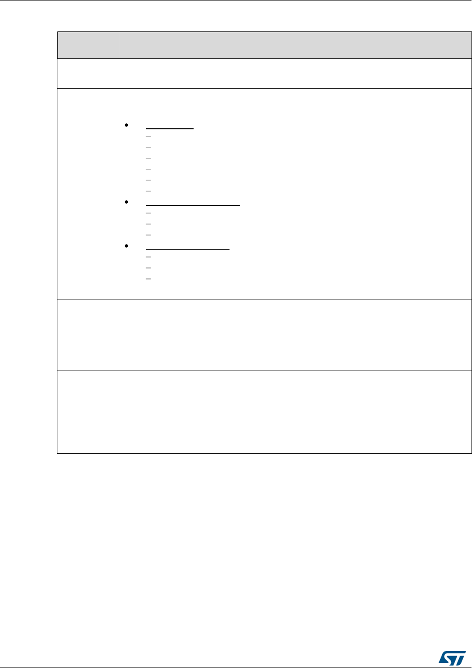
Overview of HAL drivers
UM1725
48/964
DocID025834 Rev 4
The table below describes the GPIO_InitTypeDef structure field.
Table 12: Description of GPIO_InitTypeDef structure
Structure
field
Description
Pin
Specifies the GPIO pins to be configured.
Possible values: GPIO_PIN_x or GPIO_PIN_All, where x[0..15]
Mode
Specifies the operating mode for the selected pins: GPIO mode or EXTI mode.
Possible values are:
GPIO mode
GPIO_MODE_INPUT : Input Floating
GPIO_MODE_OUTPUT_PP : Output Push Pull
GPIO_MODE_OUTPUT_OD : Output Open Drain
GPIO_MODE_AF_PP : Alternate Function Push Pull
GPIO_MODE_AF_OD : Alternate Function Open Drain
GPIO_MODE_ANALOG : Analog mode
External Interrupt Mode
GPIO_MODE_IT_RISING : Rising edge trigger detection
GPIO_MODE_IT_FALLING : Falling edge trigger detection
GPIO_MODE_IT_RISING_FALLING : Rising/Falling edge trigger detection
External Event Mode
GPIO_MODE_EVT_RISING : Rising edge trigger detection
GPIO_MODE_EVT_FALLING : Falling edge trigger detection
GPIO_MODE_EVT_RISING_FALLING: Rising/Falling edge trigger
detection
Pull
Specifies the Pull-up or Pull-down activation for the selected pins.
Possible values are:
GPIO_NOPULL
GPIO_PULLUP
GPIO_PULLDOWN
Speed
Specifies the speed for the selected pins
Possible values are:
GPIO_SPEED_LOW
GPIO_SPEED_MEDIUM
GPIO_SPEED_FAST
GPIO_SPEED_HIGH

UM1725
Overview of HAL drivers
DocID025834 Rev 4
49/964
Structure
field
Description
Alternate
Peripheral to be connected to the selected pins.
Possible values: GPIO_AFx_PPP, where
AFx: is the alternate function index
PPP: is the peripheral instance
Example: use GPIO_AF1_TIM1 to connect TIM1 IOs on AF1.
These values are defined in the GPIO extended driver, since the AF mapping may
change between product lines.
Refer to the “Alternate function mapping” table in the
datasheets for the detailed description of the system and
peripheral I/O alternate functions.
Please find below typical GPIO configuration examples:
Configuring GPIOs as output push-pull to drive external LEDs
GPIO_InitStruct.Pin = GPIO_PIN_12 | GPIO_PIN_13 | GPIO_PIN_14 | GPIO_PIN_15;
GPIO_InitStruct.Mode = GPIO_MODE_OUTPUT_PP;
GPIO_InitStruct.Pull = GPIO_PULLUP;
GPIO_InitStruct.Speed = GPIO_SPEED_FAST;
HAL_GPIO_Init(GPIOD, &GPIO_InitStruct);
Configuring PA0 as external interrupt with falling edge sensitivity:
GPIO_InitStructure.Mode = GPIO_MODE_IT_FALLING;
GPIO_InitStructure.Pull = GPIO_NOPULL;
GPIO_InitStructure.Pin = GPIO_PIN_0;
HAL_GPIO_Init(GPIOA, &GPIO_InitStructure);
Configuring USART3 Tx (PC10, mapped on AF7) as alternate function:
GPIO_InitStruct.Pin = GPIO_PIN_10;
GPIO_InitStruct.Mode = GPIO_MODE_AF_PP;
GPIO_InitStruct.Pull = GPIO_PULLUP;
GPIO_InitStruct.Speed = GPIO_SPEED_FAST;
GPIO_InitStruct.Alternate = GPIO_AF7_USART3;
HAL_GPIO_Init(GPIOC, &GPIO_InitStruct);
2.11.3 Cortex NVIC and SysTick timer
The Cortex HAL driver, stm32f4xx_hal_cortex.c, provides APIs to handle NVIC and
Systick. The supported APIs include:
HAL_NVIC_SetPriorityGrouping()
HAL_NVIC_SetPriority()
HAL_NVIC_EnableIRQ()/HAL_NVIC_DisableIRQ()
HAL_NVIC_SystemReset()
HAL_NVIC_GetPendingIRQ() / HAL_NVIC_SetPendingIRQ () /
HAL_NVIC_ClearPendingIRQ()
HAL_SYSTICK_Config()
HAL_SYSTICK_CLKSourceConfig()

Overview of HAL drivers
UM1725
50/964
DocID025834 Rev 4
2.11.4 PWR
The PWR HAL driver handles power management. The features shared between all
STM32 Series are listed below:
PVD configuration, enabling/disabling and interrupt handling
HAL_PWR_PVDConfig()
HAL_PWR_EnablePVD() / HAL_PWR_DisablePVD()
HAL_PWR_PVD_IRQHandler()
HAL_PWR_PVDCallback()
Wakeup pin configuration
HAL_PWR_EnableWakeUpPin() / HAL_PWR_DisableWakeUpPin()
Low power mode entry
HAL_PWR_EnterSLEEPMode()
HAL_PWR_EnterSTOPMode()
HAL_PWR_EnterSTANDBYMode()

UM1725
Overview of HAL drivers
DocID025834 Rev 4
51/964
Depending on the STM32 Series, extension functions are available in
stm32f4xx_hal_pwr_ex. Here are a few examples (the list is not exhaustive)
Backup domain registers enable/disable
HAL_PWREx_EnableBkUpReg() / HAL_PWREx_DisableBkUpReg()
Flash overdrive control and flash power-down, for STM32F429/F439xx only
HAL_PWREx_ActivateOverDrive()
HAL_PWREx_EnableFlashPowerDown().
2.11.5 EXTI
The EXTI is not considered as a standalone peripheral but rather as a service used by
other peripheral. As a result there are no EXTI APIs but each peripheral HAL driver
implements the associated EXTI configuration and EXTI function are implemented as
macros in its header file.
The first 16 EXTI lines connected to the GPIOs are managed within the GPIO driver. The
GPIO_InitTypeDef structure allows configuring an I/O as external interrupt or external
event.
The EXTI lines connected internally to the PVD, RTC, USB, and COMP are configured
within the HAL drivers of these peripheral through the macros given in the table below. The
EXTI internal connections depend on the targeted STM32 microcontroller (refer to the
product datasheet for more details):
Table 13: Description of EXTI configuration macros
Macros
Description
PPP_EXTI_LINE_FUNCTION
Defines the EXTI line connected to the internal peripheral.
Example:
#define PWR_EXTI_LINE_PVD ((uint32_t)0x00010000)
/*!<External interrupt line 16 Connected to the PVD EXTI
Line */
__HAL_PPP_EXTI_ENABLE_IT(__EXTI_LINE__)
Enables a given EXTI line
Example:
__HAL_PVD_EXTI_ENABLE_IT(PWR_EXTI_LINE_PVD)
__HAL_PPP_EXTI_DISABLE_IT(__EXTI_LINE__)
Disables a given EXTI line.
Example:
__HAL_PVD_EXTI_DISABLE_IT(PWR_EXTI_LINE_PVD)
__HAL_PPP_EXTI_GET_FLAG(__EXTI_LINE__)
Gets a given EXTI line interrupt flag pending bit status.
Example:
__HAL_PVD_EXTI_GET_FLAG(PWR_EXTI_LINE_PVD)
__HAL_PPP_EXTI_CLEAR_FLAG(__EXTI_LINE_
_)
Clears a given EXTI line interrupt flag pending bit.
Example;
__HAL_PVD_EXTI_CLEAR_FLAG(PWR_EXTI_LINE_PV
D)
__HAL_PPP_EXTI_GENERATE_SWIT
(__EXTI_LINE__)
Generates a software interrupt for a given EXTI line.
Example:
__HAL_PVD_EXTI_ GENERATE_SWIT
(PWR_EXTI_LINE_PVD)

Overview of HAL drivers
UM1725
52/964
DocID025834 Rev 4
If the EXTI interrupt mode is selected, the user application must call
HAL_PPP_FUNCTION_IRQHandler() (for example HAL_PWR_PVD_IRQHandler()), from
stm32f4xx_it.c file, and implement HAL_PPP_FUNCTIONCallback() callback function (for
example HAL_PWR_PVDCallback().
2.11.6 DMA
The DMA HAL driver allows enabling and configuring the peripheral to be connected to the
DMA Stream (except for internal SRAM/FLASH memory which do not require any
initialization). Refer to the product reference manual for details on the DMA request
corresponding to each peripheral.
For a given stream, HAL_DMA_Init() API allows programming the required configuration
through the following parameters:
Transfer Direction
Source and Destination data formats
Circular, Normal or peripheral flow control mode
Stream Priority level
Source and Destination Increment mode
FIFO mode and its Threshold (if needed)
Burst mode for Source and/or Destination (if needed).
Two operating modes are available:
Polling mode I/O operation
a. Use HAL_DMA_Start() to start DMA transfer when the source and destination
addresses and the Length of data to be transferred have been configured.
b. Use HAL_DMA_PollForTransfer() to poll for the end of current transfer. In this
case a fixed timeout can be configured depending on the user application.
Interrupt mode I/O operation
a. Configure the DMA interrupt priority using HAL_NVIC_SetPriority()
b. Enable the DMA IRQ handler using HAL_NVIC_EnableIRQ()
c. Use HAL_DMA_Start_IT() to start DMA transfer when the source and destination
addresses and the length of data to be transferred have been confgured. In this
case the DMA interrupt is configured.
d. Use HAL_DMA_IRQHandler() called under DMA_IRQHandler() Interrupt
subroutine
e. When data transfer is complete, HAL_DMA_IRQHandler() function is executed
and a user function can be called by customizing XferCpltCallback and
XferErrorCallback function pointer (i.e. a member of DMA handle structure).
Additional functions and macros are available to ensure efficient DMA management:
Use HAL_DMA_GetState() function to return the DMA state and
HAL_DMA_GetError() in case of error detection.
Use HAL_DMA_Abort() function to abort the current transfer
The most used DMA HAL driver macros are the following:
__HAL_DMA_ENABLE: enablse the specified DMA Stream.
__HAL_DMA_DISABLE: disables the specified DMA Stream.
__HAL_DMA_GET_FS: returns the current DMA Stream FIFO filled level.
__HAL_DMA_GET_FLAG: gets the DMA Stream pending flags.
__HAL_DMA_CLEAR_FLAG: clears the DMA Stream pending flags.
__HAL_DMA_ENABLE_IT: enables the specified DMA Stream interrupts.
__HAL_DMA_DISABLE_IT: disables the specified DMA Stream interrupts.

UM1725
Overview of HAL drivers
DocID025834 Rev 4
53/964
__HAL_DMA_GET_IT_SOURCE: checks whether the specified DMA stream interrupt
has occurred or not.
When a peripheral is used in DMA mode, the DMA initialization should be done in
the HAL_PPP_MspInit() callback. In addition, the user application should
associate the DMA handle to the PPP handle (refer to section “HAL IO operation
functions”).
DMA double-buffering feature is handled as an extension API.
DMA channel callbacks need to be initialized by the user application only in case
of memory-to-memory transfer. However when peripheral-to-memory transfers
are used, these callbacks are automatically initialized by calling a process API
function that uses the DMA.
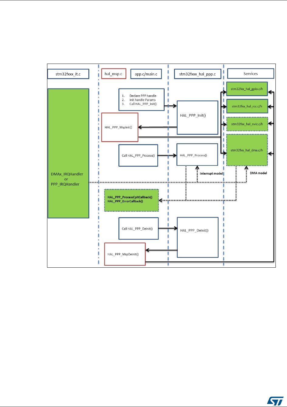
Overview of HAL drivers
UM1725
54/964
DocID025834 Rev 4
2.12 How to use HAL drivers
2.12.1 HAL usage models
The following figure shows the typical use of the HAL driver and the interaction between
the application user, the HAL driver and the interrupts.
Figure 7: HAL driver model
Basically, the HAL driver APIs are called from user files and optionally from interrupt
handlers file when the APIs based on the DMA or the PPP peripheral dedicated interrupts
are used.
When DMA or PPP peripheral interrupts are used, the PPP process complete callbacks are
called to inform the user about the process completion in real-time event mode (interrupts).
Note that the same process completion callbacks are used for DMA in interrupt mode.

UM1725
Overview of HAL drivers
DocID025834 Rev 4
55/964
2.12.2 HAL initialization
2.12.2.1 HAL global initialization
In addition to the peripheral initialization and de-initialization functions, a set of APIs are
provided to initialize the HAL core implemented in file stm32f4xx_hal.c.
HAL_Init(): this function must be called at application startup to
Initialize data/instruction cache and pre-fetch queue
Set Systick timer to generate an interrupt each 1ms (based on HSI clock) with the
lowest priority
Set priority grouping to 4 preemption bits
Call HAL_MspInit() user callback function to perform system level initializations
(Clock, GPIOs, DMA, interrupts). HAL_MspInit() is defined as “weak” empty
function in the HAL drivers.
HAL_DeInit()
Resets all peripherals
Calls function HAL_MspDeInit() which is a user callback function to do system
level De-Initalizations.
HAL_GetTick(): this function gets current SysTick counter value (incremented in
SysTick interrupt) used by peripherals drivers to handle timeouts.
HAL_Delay(). this function implements a delay (expressed in milliseconds) using the
SysTick timer.
Care must be taken when using HAL_Delay() since this function provides an accurate
delay (expressed in milliseconds) based on a variable incremented in SysTick ISR.
This means that if HAL_Delay() is called from a peripheral ISR, then the SysTick
interrupt must have highest priority (numerically lower) than the peripheral interrupt,
otherwise the caller ISR will be blocked.
In STM32Cube V1.0 implemented in STM32CubeF2 and STM32CubeF4 first
versions, the SysTick timer is used as default timebase. This has been modified to
allow implementing user-defined timebases (such as a general-purpose timer),
keeping in mind that the timebase duration must be kept at 1 ms since all
PPP_TIMEOUT_VALUEs are defined and handled in milliseconds. This
enhancement is implemented in STM32Cube V1.1 that is deployed starting from
STM32CubeL0/F0/F3 and later. This modification is backward compatible with
STM32Cube V1.0 implementation. Functions affecting timebase configurations
are declared as __Weak to allow different implementations in the user file.

Overview of HAL drivers
UM1725
56/964
DocID025834 Rev 4
2.12.2.2 System clock initialization
The clock configuration is done at the beginning of the user code. However the user can
change the configuration of the clock in his own code. Please find below the typical Clock
configuration sequence:
static void SystemClock_Config(void)
{
RCC_ClkInitTypeDef RCC_ClkInitStruct;
RCC_OscInitTypeDef RCC_OscInitStruct;
/* Enable HSE Oscillator and activate PLL with HSE as source */
RCC_OscInitStruct.OscillatorType = RCC_OSCILLATORTYPE_HSE;
RCC_OscInitStruct.HSEState = RCC_HSE_ON;
RCC_OscInitStruct.PLL.PLLState = RCC_PLL_ON;
RCC_OscInitStruct.PLL.PLLSource = RCC_PLLSOURCE_HSE;
RCC_OscInitStruct.PLL.PLLM = 25;
RCC_OscInitStruct.PLL.PLLN = 336;
RCC_OscInitStruct.PLL.PLLP = RCC_PLLP_DIV2;
RCC_OscInitStruct.PLL.PLLQ = 7;
HAL_RCC_OscConfig(&RCC_OscInitStruct);
/* Select PLL as system clock source and configure the HCLK, PCLK1 and PCLK2 clocks
dividers */
RCC_ClkInitStruct.ClockType = (RCC_CLOCKTYPE_SYSCLK | RCC_CLOCKTYPE_HCLK |
RCC_CLOCKTYPE_PCLK1 | RCC_CLOCKTYPE_PCLK2);
RCC_ClkInitStruct.SYSCLKSource = RCC_SYSCLKSOURCE_PLLCLK;
RCC_ClkInitStruct.AHBCLKDivider = RCC_SYSCLK_DIV1;
RCC_ClkInitStruct.APB1CLKDivider = RCC_HCLK_DIV4;
RCC_ClkInitStruct.APB2CLKDivider = RCC_HCLK_DIV2;
HAL_RCC_ClockConfig(&RCC_ClkInitStruct, FLASH_LATENCY_5); }
2.12.2.3 HAL MSP initialization process
The peripheral initialization is done through HAL_PPP_Init() while the hardware resources
initialization used by a peripheral (PPP) is performed during this initialization by calling
MSP callback function HAL_PPP_MspInit().
The MspInit callback performs the low level initialization related to the different additional
hardware resources: RCC, GPIO, NVIC and DMA.
All the HAL drivers with handles include two MSP callbacks for initialization and de-
initialization:
/**
* @brief Initializes the PPP MSP.
* @param hppp: PPP handle
* @retval None */
void __weak HAL_PPP_MspInit(PPP_HandleTypeDef *hppp) {
/* NOTE : This function Should not be modified, when the callback is needed,
the HAL_PPP_MspInit could be implemented in the user file */
}
/**
* @brief DeInitializes PPP MSP.
* @param hppp: PPP handle
* @retval None */
void __weak HAL_PPP_MspDeInit(PPP_HandleTypeDef *hppp) {
/* NOTE : This function Should not be modified, when the callback is needed,
the HAL_PPP_MspDeInit could be implemented in the user file */
}
The MSP callbacks are declared empty as weak functions in each peripheral driver. The
user can use them to set the low level initialization code or omit them and use his own
initialization routine.

UM1725
Overview of HAL drivers
DocID025834 Rev 4
57/964
The HAL MSP callback is implemented inside the stm32f4xx_hal_msp.c file in the user
folders. An stm32f4xx_hal_msp.c file template is located in the HAL folder and should be
copied to the user folder. It can be generated automatically by STM32CubeMX tool and
further modified. Note that all the routines are declared as weak functions and could be
overwritten or removed to use user low level initialization code.
Stm32f4xx_hal_msp.c file contains the following functions:
Table 14: MSP functions
Routine
Description
void HAL_MspInit()
Global MSP initialization routine
void HAL_MspDeInit()
Global MSP de-initialization routine
void HAL_PPP_MspInit()
PPP MSP initialization routine
void HAL_PPP_MspDeInit()
PPP MSP de-initialization routine
By default, if no peripheral needs to be de-initialized during the program execution, the
whole MSP initialization is done in Hal_MspInit() and MSP De-Initialization in the
Hal_MspDeInit(). In this case the HAL_PPP_MspInit() and HAL_PPP_MspDeInit() are not
implemented.
When one or more peripherals needs to be de-initialized in run time and the low level
resources of a given peripheral need to be released and used by another peripheral,
HAL_PPP_MspDeInit() and HAL_PPP_MspInit() are implemented for the concerned
peripheral and other peripherals initialization and de-Initialization are kept in the global
HAL_MspInit() and the HAL_MspDeInit().
If there is nothing to be initialized by the global HAL_MspInit() and HAL_MspDeInit(), the
two routines can simply be omitted.
2.12.3 HAL IO operation process
The HAL functions with internal data processing like Transmit, Receive, Write and Read
are generally provided with three data processing modes as follows:
Polling mode
Interrupt mode
DMA mode
2.12.3.1 Polling mode
In polling mode, the HAL functions return the process status when the data processing in
blocking mode is complete. The operation is considered complete when the function
returns the HAL_OK status, otherwise an error status is returned. The user can get more
information through the HAL_PPP_GetState() function. The data processing is handled
internally in a loop. A timeout (expressed in ms) is used to prevent process hanging.
The example below shows the typical polling mode processing sequence :
HAL_StatusTypeDef HAL_PPP_Transmit ( PPP_HandleTypeDef * phandle, uint8_t pData,
int16_tSize,uint32_tTimeout)
{
if((pData == NULL ) || (Size == 0))
{
return HAL_ERROR;
}
(…) while (data processing is running)
{
if( timeout reached )

Overview of HAL drivers
UM1725
58/964
DocID025834 Rev 4
{
return HAL_TIMEOUT;
}
}
(…)
return HELIAC; }
2.12.3.2 Interrupt mode
In Interrupt mode, the HAL function returns the process status after starting the data
processing and enabling the appropriate interruption. The end of the operation is indicated
by a callback declared as a weak function. It can be customized by the user to be informed
in real-time about the process completion. The user can also get the process status
through the HAL_PPP_GetState() function.
In interrupt mode, four functions are declared in the driver:
HAL_PPP_Process_IT(): launch the process
HAL_PPP_IRQHandler(): the global PPP peripheral interruption
__weak HAL_PPP_ProcessCpltCallback (): the callback relative to the process
completion.
__weak HAL_PPP_ProcessErrorCallback(): the callback relative to the process Error.
To use a process in interrupt mode, HAL_PPP_Process_IT() is called in the user file and
HAL_PPP_IRQHandler in stm32f4xx_it.c.
The HAL_PPP_ProcessCpltCallback() function is declared as weak function in the driver.
This means that the user can declare it again in the application. The function in the driver is
not modified.
An example of use is illustrated below:
main.c file:
UART_HandleTypeDef UartHandle;
int main(void)
{
/* Set User Parameters */
UartHandle.Init.BaudRate = 9600;
UartHandle.Init.WordLength = UART_DATABITS_8;
UartHandle.Init.StopBits = UART_STOPBITS_1;
UartHandle.Init.Parity = UART_PARITY_NONE;
UartHandle.Init.HwFlowCtl = UART_HWCONTROL_NONE;
UartHandle.Init.Mode = UART_MODE_TX_RX;
UartHandle.Init.Instance = USART3;
HAL_UART_Init(&UartHandle);
HAL_UART_SendIT(&UartHandle, TxBuffer, sizeof(TxBuffer));
while (1);
}
void HAL_UART_TxCpltCallback(UART_HandleTypeDef *huart)
{
}
void HAL_UART_ErrorCallback(UART_HandleTypeDef *huart)
{
}
stm32f4xx_it.cfile:
extern UART_HandleTypeDef UartHandle;
void USART3_IRQHandler(void)
{
HAL_UART_IRQHandler(&UartHandle);
}

UM1725
Overview of HAL drivers
DocID025834 Rev 4
59/964
2.12.3.3 DMA mode
In DMA mode, the HAL function returns the process status after starting the data
processing through the DMA and after enabling the appropriate DMA interruption. The end
of the operation is indicated by a callback declared as a weak function and can be
customized by the user to be informed in real-time about the process completion. The user
can also get the process status through the HAL_PPP_GetState() function. For the DMA
mode, three functions are declared in the driver:
HAL_PPP_Process_DMA(): launch the process
HAL_PPP_DMA_IRQHandler(): the DMA interruption used by the PPP peripheral
__weak HAL_PPP_ProcessCpltCallback(): the callback relative to the process
completion.
__weak HAL_PPP_ErrorCpltCallback(): the callback relative to the process Error.
To use a process in DMA mode, HAL_PPP_Process_DMA() is called in the user file and
the HAL_PPP_DMA_IRQHandler() is placed in the stm32f4xx_it.c. When DMA mode is
used, the DMA initialization is done in the HAL_PPP_MspInit() callback. The user should
also associate the DMA handle to the PPP handle. For this purpose, the handles of all the
peripheral drivers that use the DMA must be declared as follows:
typedef struct
{
PPP_TypeDef *Instance; /* Register base address */
PPP_InitTypeDef Init; /* PPP communication parameters */
HAL_StateTypeDef State; /* PPP communication state */
(…)
DMA_HandleTypeDef *hdma; /* associated DMA handle */
} PPP_HandleTypeDef;
The initialization is done as follows (UART example):
int main(void)
{
/* Set User Parameters */
UartHandle.Init.BaudRate = 9600;
UartHandle.Init.WordLength = UART_DATABITS_8;
UartHandle.Init.StopBits = UART_STOPBITS_1;
UartHandle.Init.Parity = UART_PARITY_NONE;
UartHandle.Init.HwFlowCtl = UART_HWCONTROL_NONE;
UartHandle.Init.Mode = UART_MODE_TX_RX;
UartHandle.Init.Instance = UART3;
HAL_UART_Init(&UartHandle);
(..)
}
void HAL_USART_MspInit (UART_HandleTypeDef * huart)
{
static DMA_HandleTypeDef hdma_tx;
static DMA_HandleTypeDef hdma_rx;
(…)
__HAL_LINKDMA(UartHandle, DMA_Handle_tx, hdma_tx);
__HAL_LINKDMA(UartHandle, DMA_Handle_rx, hdma_rx);
(…)
}
The HAL_PPP_ProcessCpltCallback() function is declared as weak function in the driver
that means, the user can declare it again in the application code. The function in the driver
should not be modified.
An example of use is illustrated below:
main.c file:
UART_HandleTypeDef UartHandle;
int main(void)
{
/* Set User Paramaters */

Overview of HAL drivers
UM1725
60/964
DocID025834 Rev 4
UartHandle.Init.BaudRate = 9600;
UartHandle.Init.WordLength = UART_DATABITS_8;
UartHandle.Init.StopBits = UART_STOPBITS_1;
UartHandle.Init.Parity = UART_PARITY_NONE;
UartHandle.Init.HwFlowCtl = UART_HWCONTROL_NONE;
UartHandle.Init.Mode = UART_MODE_TX_RX;
UartHandle.Init.Instance = USART3;
HAL_UART_Init(&UartHandle);
HAL_UART_Send_DMA(&UartHandle, TxBuffer, sizeof(TxBuffer));
while (1);
}
void HAL_UART_TxCpltCallback(UART_HandleTypeDef *phuart)
{
}
void HAL_UART_TxErrorCallback(UART_HandleTypeDef *phuart)
{
}
stm32f4xx_it.c file:
extern UART_HandleTypeDef UartHandle;
void DMAx_IRQHandler(void)
{
HAL_DMA_IRQHandler(&UartHandle.DMA_Handle_tx);
}
HAL_USART_TxCpltCallback() and HAL_USART_ErrorCallback() should be linked in the
HAL_PPP_Process_DMA() function to the DMA transfer complete callback and the DMA
transfer Error callback by using the following statement:
HAL_PPP_Process_DMA (PPP_HandleTypeDef *hppp, Params….)
{
(…)
hppp->DMA_Handle->XferCpltCallback = HAL_UART_TxCpltCallback ;
hppp->DMA_Handle->XferErrorCallback = HAL_UART_ErrorCallback ;
(…)
}
2.12.4 Timeout and error management
2.12.4.1 Timeout management
The timeout is often used for the APIs that operate in polling mode. It defines the delay
during which a blocking process should wait till an error is returned. An example is provided
below:
HAL_StatusTypeDef HAL_DMA_PollForTransfer(DMA_HandleTypeDef *hdma, uint32_t
CompleteLevel, uint32_t Timeout)
The timeout possible value are the following:
Table 15: Timeout values
Timeout value
Description
0
No poll : Immediate process check and exit
1 ... (HAL_MAX_DELAY -1)(1)
Timeout in ms
HAL_MAX_DELAY
Infinite poll till process is successful
Notes:
(1)HAL_MAX_DELAY is defined in the stm32fxxx_hal_def.h as 0xFFFFFFFF

UM1725
Overview of HAL drivers
DocID025834 Rev 4
61/964
However, in some cases, a fixed timeout is used for system peripherals or internal HAL
driver processes. In these cases, the timeout has the same meaning and is used in the
same way, except when it is defined locally in the drivers and cannot be modified or
introduced as an argument in the user application.
Example of fixed timeout:
#define LOCAL_PROCESS_TIMEOUT 100
HAL_StatusTypeDef HAL_PPP_Process(PPP_HandleTypeDef)
{
(…)
timeout = HAL_GetTick() + LOCAL_PROCESS_TIMEOUT;
(…)
while(ProcessOngoing)
{
(…)
if(HAL_GetTick() >= timeout)
{
/* Process unlocked */
__HAL_UNLOCK(hppp);
hppp->State= HAL_PPP_STATE_TIMEOUT;
return HAL_PPP_STATE_TIMEOUT;
}
}
(…)
}
The following example shows how to use the timeout inside the polling functions:
HAL_PPP_StateTypeDef HAL_PPP_Poll (PPP_HandleTypeDef *hppp, uint32_t Timeout)
{
(…)
timeout = HAL_GetTick() + Timeout;
(…)
while(ProcessOngoing)
{
(…)
if(Timeout != HAL_MAX_DELAY)
{
if(HAL_GetTick() >= timeout)
{
/* Process unlocked */
__HAL_UNLOCK(hppp);
hppp->State= HAL_PPP_STATE_TIMEOUT;
return hppp->State;
}
}
(…)
}
2.12.4.2 Error management
The HAL drivers implement a check for the following items:
Valid parameters: for some process the used parameters should be valid and already
defined, otherwise the system can crash or go into an undefined state. These critical
parameters are checked before they are used (see example below).
HAL_StatusTypeDef HAL_PPP_Process(PPP_HandleTypeDef* hppp, uint32_t *pdata, uint32
Size)
{ if ((pData == NULL ) || (Size == 0))
{ return HAL_ERROR;
}
}

Overview of HAL drivers
UM1725
62/964
DocID025834 Rev 4
Valid handle: the PPP peripheral handle is the most important argument since it keeps
the PPP driver vital parameters. It is always checked in the beginning of the
HAL_PPP_Init() function.
HAL_StatusTypeDef HAL_PPP_Init(PPP_HandleTypeDef* hppp)
{ if (hppp == NULL) //the handle should be already allocated
{ return HAL_ERROR;
}
}
Timeout error: the following statement is used when a timeout error occurs:
while (Process ongoing)
{
timeout = HAL_GetTick() + Timeout;
while (data processing is running)
{
if(timeout)
{ return HAL_TIMEOUT;
}
}
When an error occurs during a peripheral process, HAL_PPP_Process () returns with a
HAL_ERROR status. The HAL PPP driver implements the HAL_PPP_GetError () to allow
retrieving the origin of the error.
HAL_PPP_ErrorTypeDef HAL_PPP_GetError (PPP_HandleTypeDef *hppp);
In all peripheral handles, a HAL_PPP_ErrorTypeDef is defined and used to store the last
error code.
typedef struct
{
PPP_TypeDef * Instance; /* PPP registers base address */
PPP_InitTypeDef Init; /* PPP initialization parameters */
HAL_LockTypeDef Lock; /* PPP locking object */
__IO HAL_PPP_StateTypeDef State; /* PPP state */
__IO HAL_PPP_ErrorTypeDef ErrorCode; /* PPP Error code */
(…)
/* PPP specific parameters */
}
PPP_HandleTypeDef;
The error state and the peripheral global state are always updated before returning an
error:
PPP->State = HAL_PPP_READY; /* Set the peripheral ready */
PP->ErrorCode = HAL_ERRORCODE ; /* Set the error code */
_HAL_UNLOCK(PPP) ; /* Unlock the PPP resources */
return HAL_ERROR; /*return with HAL error */
HAL_PPP_GetError () must be used in interrupt mode in the error callback:
void HAL_PPP_ProcessCpltCallback(PPP_HandleTypeDef *hspi)
{
ErrorCode = HAL_PPP_GetError (hppp); /* retreive error code */
}

UM1725
Overview of HAL drivers
DocID025834 Rev 4
63/964
2.12.4.3 Run-time checking
The HAL implements run-time failure detection by checking the input values of all HAL
driver functions. The run-time checking is achieved by using an assert_param macro. This
macro is used in all the HAL drivers' functions which have an input parameter. It allows
verifying that the input value lies within the parameter allowed values.
To enable the run-time checking, use the assert_param macro, and leave the define
USE_FULL_ASSERT uncommented in stm32f34xx_hal_conf.h file.
void HAL_UART_Init(UART_HandleTypeDef *huart)
{
(..) /* Check the parameters */
assert_param(IS_UART_INSTANCE(huart->Instance));
assert_param(IS_UART_BAUDRATE(huart->Init.BaudRate));
assert_param(IS_UART_WORD_LENGTH(huart->Init.WordLength));
assert_param(IS_UART_STOPBITS(huart->Init.StopBits));
assert_param(IS_UART_PARITY(huart->Init.Parity));
assert_param(IS_UART_MODE(huart->Init.Mode));
assert_param(IS_UART_HARDWARE_FLOW_CONTROL(huart->Init.HwFlowCtl));
(..)
/** @defgroup UART_Word_Length *
@{
*/
#define UART_WORDLENGTH_8B ((uint32_t)0x00000000)
#define UART_WORDLENGTH_9B ((uint32_t)USART_CR1_M)
#define IS_UART_WORD_LENGTH(LENGTH) (((LENGTH) == UART_WORDLENGTH_8B) ||
\ ((LENGTH) == UART_WORDLENGTH_9B))
If the expression passed to the assert_param macro is false, theassert_failed function is
called and returns the name of the source file and the source line number of the call that
failed. If the expression is true, no value is returned.
The assert_param macro is implemented in stm32f4xx_hal_conf.h:
/* Exported macro ------------------------------------------------------------*/
#ifdef USE_FULL_ASSERT
/**
* @brief The assert_param macro is used for function's parameters check.
* @param expr: If expr is false, it calls assert_failed function
* which reports the name of the source file and the source
* line number of the call that failed.
* If expr is true, it returns no value.
* @retval None */
#define assert_param(expr) ((expr)?(void)0:assert_failed((uint8_t *)__FILE__,
__LINE__))
/* Exported functions --------------------------------------*/
void assert_failed(uint8_t* file, uint32_t line);
#else
#define assert_param(expr)((void)0)
#endif /* USE_FULL_ASSERT */

Overview of HAL drivers
UM1725
64/964
DocID025834 Rev 4
The assert_failed function is implemented in the main.c file or in any other user C file:
#ifdef USE_FULL_ASSERT /**
* @brief Reports the name of the source file and the source line number
* where the assert_param error has occurred.
* @param file: pointer to the source file name
* @param line: assert_param error line source number
* @retval None */
void assert_failed(uint8_t* file, uint32_t line)
{
/* User can add his own implementation to report the file name and line number,
ex: printf("Wrong parameters value: file %s on line %d\r\n", file, line) */
/* Infinite loop */
while (1)
{
}
}
Because of the overhead run-time checking introduces, it is recommended
to use it during application code development and debugging, and to
remove it from the final application to improve code size and speed.

UM1725
HAL System Driver
DocID025834 Rev 4
65/964
3 HAL System Driver
3.1 HAL Firmware driver API description
3.1.1 How to use this driver
The common HAL driver contains a set of generic and common APIs that can be used by
the PPP peripheral drivers and the user to start using the HAL.
The HAL contains two APIs' categories:
Common HAL APIs
Services HAL APIs
3.1.2 Initialization and de-initialization functions
This section provides functions allowing to:
Initializes the Flash interface the NVIC allocation and initial clock configuration. It
initializes the systick also when timeout is needed and the backup domain when
enabled.
de-Initializes common part of the HAL
Configure The time base source to have 1ms time base with a dedicated Tick
interrupt priority.
Systick timer is used by default as source of time base, but user can eventually
implement his proper time base source (a general purpose timer for example or
other time source), keeping in mind that Time base duration should be kept 1ms
since PPP_TIMEOUT_VALUEs are defined and handled in milliseconds basis.
Time base configuration function (HAL_InitTick ()) is called automatically at the
beginning of the program after reset by HAL_Init() or at any time when clock is
configured, by HAL_RCC_ClockConfig().
Source of time base is configured to generate interrupts at regular time intervals.
Care must be taken if HAL_Delay() is called from a peripheral ISR process, the
Tick interrupt line must have higher priority (numerically lower) than the
peripheral interrupt. Otherwise the caller ISR process will be blocked.
functions affecting time base configurations are declared as __weak to make
override possible in case of other implementations in user file.
This section contains the following APIs:
HAL_Init()
HAL_DeInit()
HAL_MspInit()
HAL_MspDeInit()
HAL_InitTick()
3.1.3 HAL Control functions
This section provides functions allowing to:
Provide a tick value in millisecond
Provide a blocking delay in millisecond
Suspend the time base source interrupt
Resume the time base source interrupt
Get the HAL API driver version
Get the device identifier

HAL System Driver
UM1725
66/964
DocID025834 Rev 4
Get the device revision identifier
Enable/Disable Debug module during SLEEP mode
Enable/Disable Debug module during STOP mode
Enable/Disable Debug module during STANDBY mode
This section contains the following APIs:
HAL_IncTick()
HAL_GetTick()
HAL_Delay()
HAL_SuspendTick()
HAL_ResumeTick()
HAL_GetHalVersion()
HAL_GetREVID()
HAL_GetDEVID()
HAL_DBGMCU_EnableDBGSleepMode()
HAL_DBGMCU_DisableDBGSleepMode()
HAL_DBGMCU_EnableDBGStopMode()
HAL_DBGMCU_DisableDBGStopMode()
HAL_DBGMCU_EnableDBGStandbyMode()
HAL_DBGMCU_DisableDBGStandbyMode()
HAL_EnableCompensationCell()
HAL_DisableCompensationCell()
HAL_EnableMemorySwappingBank()
HAL_DisableMemorySwappingBank()
3.1.4 Detailed description of functions
HAL_Init
Function Name
HAL_StatusTypeDef HAL_Init (void )
Function Description
This function is used to initialize the HAL Library; it must be the
first instruction to be executed in the main program (before to call
any other HAL function), it performs the following: Configure the
Flash prefetch, instruction and Data caches.
Return values
HAL: status
Notes
SysTick is used as time base for the HAL_Delay() function,
the application need to ensure that the SysTick time base is
always set to 1 millisecond to have correct HAL operation.
HAL_DeInit
Function Name
HAL_StatusTypeDef HAL_DeInit (void )
Function Description
This function de-Initializes common part of the HAL and stops the
systick.
Return values
HAL: status
HAL_MspInit
Function Name
void HAL_MspInit (void )
Function Description
Initializes the MSP.

UM1725
HAL System Driver
DocID025834 Rev 4
67/964
Return values
None
HAL_MspDeInit
Function Name
void HAL_MspDeInit (void )
Function Description
DeInitializes the MSP.
Return values
None
HAL_InitTick
Function Name
HAL_StatusTypeDef HAL_InitTick (uint32_t TickPriority)
Function Description
This function configures the source of the time base.
Parameters
TickPriority: Tick interrupt priority.
Return values
HAL: status
Notes
This function is called automatically at the beginning of
program after reset by HAL_Init() or at any time when clock is
reconfigured by HAL_RCC_ClockConfig().
In the default implementation, SysTick timer is the source of
time base. It is used to generate interrupts at regular time
intervals. Care must be taken if HAL_Delay() is called from a
peripheral ISR process, The the SysTick interrupt must have
higher priority (numerically lower) than the peripheral
interrupt. Otherwise the caller ISR process will be blocked.
The function is declared as __weak to be overwritten in case
of other implementation in user file.
HAL_IncTick
Function Name
void HAL_IncTick (void )
Function Description
This function is called to increment a global variable "uwTick" used
as application time base.
Return values
None
Notes
In the default implementation, this variable is incremented
each 1ms in Systick ISR.
This function is declared as __weak to be overwritten in case
of other implementations in user file.
HAL_Delay
Function Name
void HAL_Delay (__IO uint32_t Delay)
Function Description
This function provides accurate delay (in milliseconds) based on
variable incremented.
Parameters
Delay: specifies the delay time length, in milliseconds.
Return values
None
Notes
In the default implementation , SysTick timer is the source of
time base. It is used to generate interrupts at regular time
intervals where uwTick is incremented.

HAL System Driver
UM1725
68/964
DocID025834 Rev 4
This function is declared as __weak to be overwritten in case
of other implementations in user file.
HAL_GetTick
Function Name
uint32_t HAL_GetTick (void )
Function Description
Provides a tick value in millisecond.
Return values
tick: value
Notes
This function is declared as __weak to be overwritten in case
of other implementations in user file.
HAL_SuspendTick
Function Name
void HAL_SuspendTick (void )
Function Description
Suspend Tick increment.
Return values
None
Notes
In the default implementation , SysTick timer is the source of
time base. It is used to generate interrupts at regular time
intervals. Once HAL_SuspendTick() is called, the SysTick
interrupt will be disabled and so Tick increment is suspended.
This function is declared as __weak to be overwritten in case
of other implementations in user file.
HAL_ResumeTick
Function Name
void HAL_ResumeTick (void )
Function Description
Resume Tick increment.
Return values
None
Notes
In the default implementation , SysTick timer is the source of
time base. It is used to generate interrupts at regular time
intervals. Once HAL_ResumeTick() is called, the SysTick
interrupt will be enabled and so Tick increment is resumed.
This function is declared as __weak to be overwritten in case
of other implementations in user file.
HAL_GetHalVersion
Function Name
uint32_t HAL_GetHalVersion (void )
Function Description
Returns the HAL revision.
Return values
version: : 0xXYZR (8bits for each decimal, R for RC)
HAL_GetREVID
Function Name
uint32_t HAL_GetREVID (void )
Function Description
Returns the device revision identifier.
Return values
Device: revision identifier

UM1725
HAL System Driver
DocID025834 Rev 4
69/964
HAL_GetDEVID
Function Name
uint32_t HAL_GetDEVID (void )
Function Description
Returns the device identifier.
Return values
Device: identifier
HAL_DBGMCU_EnableDBGSleepMode
Function Name
void HAL_DBGMCU_EnableDBGSleepMode (void )
Function Description
Enable the Debug Module during SLEEP mode.
Return values
None
HAL_DBGMCU_DisableDBGSleepMode
Function Name
void HAL_DBGMCU_DisableDBGSleepMode (void )
Function Description
Disable the Debug Module during SLEEP mode.
Return values
None
HAL_DBGMCU_EnableDBGStopMode
Function Name
void HAL_DBGMCU_EnableDBGStopMode (void )
Function Description
Enable the Debug Module during STOP mode.
Return values
None
HAL_DBGMCU_DisableDBGStopMode
Function Name
void HAL_DBGMCU_DisableDBGStopMode (void )
Function Description
Disable the Debug Module during STOP mode.
Return values
None
HAL_DBGMCU_EnableDBGStandbyMode
Function Name
void HAL_DBGMCU_EnableDBGStandbyMode (void )
Function Description
Enable the Debug Module during STANDBY mode.
Return values
None
HAL_DBGMCU_DisableDBGStandbyMode
Function Name
void HAL_DBGMCU_DisableDBGStandbyMode (void )
Function Description
Disable the Debug Module during STANDBY mode.
Return values
None
HAL_EnableCompensationCell
Function Name
void HAL_EnableCompensationCell (void )
Function Description
Enables the I/O Compensation Cell.

HAL System Driver
UM1725
70/964
DocID025834 Rev 4
Return values
None
Notes
The I/O compensation cell can be used only when the device
supply voltage ranges from 2.4 to 3.6 V.
HAL_DisableCompensationCell
Function Name
void HAL_DisableCompensationCell (void )
Function Description
Power-down the I/O Compensation Cell.
Return values
None
Notes
The I/O compensation cell can be used only when the device
supply voltage ranges from 2.4 to 3.6 V.
HAL_EnableMemorySwappingBank
Function Name
void HAL_EnableMemorySwappingBank (void )
Function Description
Enables the Internal FLASH Bank Swapping.
Return values
None
Notes
This function can be used only for STM32F42xxx/43xxx
devices.
Flash Bank2 mapped at 0x08000000 (and aliased
@0x00000000) and Flash Bank1 mapped at 0x08100000
(and aliased at 0x00100000)
HAL_DisableMemorySwappingBank
Function Name
void HAL_DisableMemorySwappingBank (void )
Function Description
Disables the Internal FLASH Bank Swapping.
Return values
None
Notes
This function can be used only for STM32F42xxx/43xxx
devices.
The default state : Flash Bank1 mapped at 0x08000000 (and
aliased @0x00000000) and Flash Bank2 mapped at
0x08100000 (and aliased at 0x00100000)
3.2 HAL Firmware driver defines
3.2.1 HAL
HAL CAN Error Code
HAL_CAN_ERROR_NONE
No error
HAL_CAN_ERROR_EWG
EWG error
HAL_CAN_ERROR_EPV
EPV error
HAL_CAN_ERROR_BOF
BOF error
HAL_CAN_ERROR_STF
Stuff error
HAL_CAN_ERROR_FOR
Form error

UM1725
HAL System Driver
DocID025834 Rev 4
71/964
HAL_CAN_ERROR_ACK
Acknowledgment error
HAL_CAN_ERROR_BR
Bit recessive
HAL_CAN_ERROR_BD
LEC dominant
HAL_CAN_ERROR_CRC
LEC transfer error
HAL Exported Macros
__HAL_DBGMCU_FREEZE_TIM2
__HAL_DBGMCU_FREEZE_TIM3
__HAL_DBGMCU_FREEZE_TIM4
__HAL_DBGMCU_FREEZE_TIM5
__HAL_DBGMCU_FREEZE_TIM6
__HAL_DBGMCU_FREEZE_TIM7
__HAL_DBGMCU_FREEZE_TIM12
__HAL_DBGMCU_FREEZE_TIM13
__HAL_DBGMCU_FREEZE_TIM14
__HAL_DBGMCU_FREEZE_RTC
__HAL_DBGMCU_FREEZE_WWDG
__HAL_DBGMCU_FREEZE_IWDG
__HAL_DBGMCU_FREEZE_I2C1_TIMEOUT
__HAL_DBGMCU_FREEZE_I2C2_TIMEOUT
__HAL_DBGMCU_FREEZE_I2C3_TIMEOUT
__HAL_DBGMCU_FREEZE_CAN1
__HAL_DBGMCU_FREEZE_CAN2
__HAL_DBGMCU_FREEZE_TIM1
__HAL_DBGMCU_FREEZE_TIM8
__HAL_DBGMCU_FREEZE_TIM9
__HAL_DBGMCU_FREEZE_TIM10
__HAL_DBGMCU_FREEZE_TIM11
__HAL_DBGMCU_UNFREEZE_TIM2
__HAL_DBGMCU_UNFREEZE_TIM3
__HAL_DBGMCU_UNFREEZE_TIM4
__HAL_DBGMCU_UNFREEZE_TIM5
__HAL_DBGMCU_UNFREEZE_TIM6
__HAL_DBGMCU_UNFREEZE_TIM7
__HAL_DBGMCU_UNFREEZE_TIM12
__HAL_DBGMCU_UNFREEZE_TIM13
__HAL_DBGMCU_UNFREEZE_TIM14

HAL System Driver
UM1725
72/964
DocID025834 Rev 4
__HAL_DBGMCU_UNFREEZE_RTC
__HAL_DBGMCU_UNFREEZE_WWDG
__HAL_DBGMCU_UNFREEZE_IWDG
__HAL_DBGMCU_UNFREEZE_I2C1_TIMEOUT
__HAL_DBGMCU_UNFREEZE_I2C2_TIMEOUT
__HAL_DBGMCU_UNFREEZE_I2C3_TIMEOUT
__HAL_DBGMCU_UNFREEZE_CAN1
__HAL_DBGMCU_UNFREEZE_CAN2
__HAL_DBGMCU_UNFREEZE_TIM1
__HAL_DBGMCU_UNFREEZE_TIM8
__HAL_DBGMCU_UNFREEZE_TIM9
__HAL_DBGMCU_UNFREEZE_TIM10
__HAL_DBGMCU_UNFREEZE_TIM11
__HAL_SYSCFG_REMAPMEMORY_FLASH
__HAL_SYSCFG_REMAPMEMORY_SYSTEMFLASH
__HAL_SYSCFG_REMAPMEMORY_SRAM
__HAL_SYSCFG_REMAPMEMORY_FMC
__HAL_SYSCFG_REMAPMEMORY_FMC_SDRAM

UM1725
HAL ADC Generic Driver
DocID025834 Rev 4
73/964
4 HAL ADC Generic Driver
4.1 ADC Firmware driver registers structures
4.1.1 ADC_InitTypeDef
Data Fields
uint32_t ClockPrescaler
uint32_t Resolution
uint32_t DataAlign
uint32_t ScanConvMode
uint32_t EOCSelection
uint32_t ContinuousConvMode
uint32_t NbrOfConversion
uint32_t DiscontinuousConvMode
uint32_t NbrOfDiscConversion
uint32_t ExternalTrigConv
uint32_t ExternalTrigConvEdge
uint32_t DMAContinuousRequests
Field Documentation
uint32_t ADC_InitTypeDef::ClockPrescaler
Select ADC clock prescaler. The clock is common for all the ADCs. This parameter
can be a value of ADC_ClockPrescaler
uint32_t ADC_InitTypeDef::Resolution
Configures the ADC resolution. This parameter can be a value of ADC_Resolution
uint32_t ADC_InitTypeDef::DataAlign
Specifies ADC data alignment to right (MSB on register bit 11 and LSB on register bit
0) (default setting) or to left (if regular group: MSB on register bit 15 and LSB on
register bit 4, if injected group (MSB kept as signed value due to potential negative
value after offset application): MSB on register bit 14 and LSB on register bit 3). This
parameter can be a value of ADC_Data_align
uint32_t ADC_InitTypeDef::ScanConvMode
Configures the sequencer of regular and injected groups. This parameter can be
associated to parameter 'DiscontinuousConvMode' to have main sequence subdivided
in successive parts. If disabled: Conversion is performed in single mode (one channel
converted, the one defined in rank 1). Parameters 'NbrOfConversion' and
'InjectedNbrOfConversion' are discarded (equivalent to set to 1). If enabled:
Conversions are performed in sequence mode (multiple ranks defined by
'NbrOfConversion'/'InjectedNbrOfConversion' and each channel rank). Scan direction
is upward: from rank1 to rank 'n'. This parameter can be set to ENABLE or DISABLE
uint32_t ADC_InitTypeDef::EOCSelection
Specifies what EOC (End Of Conversion) flag is used for conversion by polling and
interruption: end of conversion of each rank or complete sequence. This parameter
can be a value of ADC_EOCSelection. Note: For injected group, end of conversion
(flag&IT) is raised only at the end of the sequence. Therefore, if end of conversion is
set to end of each conversion, injected group should not be used with interruption
(HAL_ADCEx_InjectedStart_IT) or polling (HAL_ADCEx_InjectedStart and

HAL ADC Generic Driver
UM1725
74/964
DocID025834 Rev 4
HAL_ADCEx_InjectedPollForConversion). By the way, polling is still possible since
driver will use an estimated timing for end of injected conversion. Note: If overrun
feature is intended to be used, use ADC in mode 'interruption' (function
HAL_ADC_Start_IT() ) with parameter EOCSelection set to end of each conversion
or in mode 'transfer by DMA' (function HAL_ADC_Start_DMA()). If overrun feature is
intended to be bypassed, use ADC in mode 'polling' or 'interruption' with parameter
EOCSelection must be set to end of sequence
uint32_t ADC_InitTypeDef::ContinuousConvMode
Specifies whether the conversion is performed in single mode (one conversion) or
continuous mode for regular group, after the selected trigger occurred (software start
or external trigger). This parameter can be set to ENABLE or DISABLE.
uint32_t ADC_InitTypeDef::NbrOfConversion
Specifies the number of ranks that will be converted within the regular group
sequencer. To use regular group sequencer and convert several ranks, parameter
'ScanConvMode' must be enabled. This parameter must be a number between
Min_Data = 1 and Max_Data = 16.
uint32_t ADC_InitTypeDef::DiscontinuousConvMode
Specifies whether the conversions sequence of regular group is performed in
Complete-sequence/Discontinuous-sequence (main sequence subdivided in
successive parts). Discontinuous mode is used only if sequencer is enabled
(parameter 'ScanConvMode'). If sequencer is disabled, this parameter is discarded.
Discontinuous mode can be enabled only if continuous mode is disabled. If continuous
mode is enabled, this parameter setting is discarded. This parameter can be set to
ENABLE or DISABLE.
uint32_t ADC_InitTypeDef::NbrOfDiscConversion
Specifies the number of discontinuous conversions in which the main sequence of
regular group (parameter NbrOfConversion) will be subdivided. If parameter
'DiscontinuousConvMode' is disabled, this parameter is discarded. This parameter
must be a number between Min_Data = 1 and Max_Data = 8.
uint32_t ADC_InitTypeDef::ExternalTrigConv
Selects the external event used to trigger the conversion start of regular group. If set
to ADC_SOFTWARE_START, external triggers are disabled. If set to external trigger
source, triggering is on event rising edge by default. This parameter can be a value of
ADC_External_trigger_Source_Regular
uint32_t ADC_InitTypeDef::ExternalTrigConvEdge
Selects the external trigger edge of regular group. If trigger is set to
ADC_SOFTWARE_START, this parameter is discarded. This parameter can be a
value of ADC_External_trigger_edge_Regular
uint32_t ADC_InitTypeDef::DMAContinuousRequests
Specifies whether the DMA requests are performed in one shot mode (DMA transfer
stop when number of conversions is reached) or in Continuous mode (DMA transfer
unlimited, whatever number of conversions). Note: In continuous mode, DMA must be
configured in circular mode. Otherwise an overrun will be triggered when DMA buffer
maximum pointer is reached. Note: This parameter must be modified when no
conversion is on going on both regular and injected groups (ADC disabled, or ADC
enabled without continuous mode or external trigger that could launch a conversion).
This parameter can be set to ENABLE or DISABLE.

UM1725
HAL ADC Generic Driver
DocID025834 Rev 4
75/964
4.1.2 ADC_ChannelConfTypeDef
Data Fields
uint32_t Channel
uint32_t Rank
uint32_t SamplingTime
uint32_t Offset
Field Documentation
uint32_t ADC_ChannelConfTypeDef::Channel
Specifies the channel to configure into ADC regular group. This parameter can be a
value of ADC_channels
uint32_t ADC_ChannelConfTypeDef::Rank
Specifies the rank in the regular group sequencer. This parameter must be a number
between Min_Data = 1 and Max_Data = 16
uint32_t ADC_ChannelConfTypeDef::SamplingTime
Sampling time value to be set for the selected channel. Unit: ADC clock cycles
Conversion time is the addition of sampling time and processing time (12 ADC clock
cycles at ADC resolution 12 bits, 11 cycles at 10 bits, 9 cycles at 8 bits, 7 cycles at 6
bits). This parameter can be a value of ADC_sampling_times Caution: This
parameter updates the parameter property of the channel, that can be used into
regular and/or injected groups. If this same channel has been previously configured in
the other group (regular/injected), it will be updated to last setting. Note: In case of
usage of internal measurement channels (VrefInt/Vbat/TempSensor), sampling time
constraints must be respected (sampling time can be adjusted in function of ADC
clock frequency and sampling time setting) Refer to device datasheet for timings
values, parameters TS_vrefint, TS_temp (values rough order: 4us min).
uint32_t ADC_ChannelConfTypeDef::Offset
Reserved for future use, can be set to 0
4.1.3 ADC_AnalogWDGConfTypeDef
Data Fields
uint32_t WatchdogMode
uint32_t HighThreshold
uint32_t LowThreshold
uint32_t Channel
uint32_t ITMode
uint32_t WatchdogNumber
Field Documentation
uint32_t ADC_AnalogWDGConfTypeDef::WatchdogMode
Configures the ADC analog watchdog mode. This parameter can be a value of
ADC_analog_watchdog_selection

HAL ADC Generic Driver
UM1725
76/964
DocID025834 Rev 4
uint32_t ADC_AnalogWDGConfTypeDef::HighThreshold
Configures the ADC analog watchdog High threshold value. This parameter must be
a 12-bit value.
uint32_t ADC_AnalogWDGConfTypeDef::LowThreshold
Configures the ADC analog watchdog High threshold value. This parameter must be
a 12-bit value.
uint32_t ADC_AnalogWDGConfTypeDef::Channel
Configures ADC channel for the analog watchdog. This parameter has an effect only
if watchdog mode is configured on single channel This parameter can be a value of
ADC_channels
uint32_t ADC_AnalogWDGConfTypeDef::ITMode
Specifies whether the analog watchdog is configured is interrupt mode or in polling
mode. This parameter can be set to ENABLE or DISABLE
uint32_t ADC_AnalogWDGConfTypeDef::WatchdogNumber
Reserved for future use, can be set to 0
4.1.4 ADC_HandleTypeDef
Data Fields
ADC_TypeDef * Instance
ADC_InitTypeDef Init
__IO uint32_t NbrOfCurrentConversionRank
DMA_HandleTypeDef * DMA_Handle
HAL_LockTypeDef Lock
__IO uint32_t State
__IO uint32_t ErrorCode
Field Documentation
ADC_TypeDef* ADC_HandleTypeDef::Instance
Register base address
ADC_InitTypeDef ADC_HandleTypeDef::Init
ADC required parameters
__IO uint32_t ADC_HandleTypeDef::NbrOfCurrentConversionRank
ADC number of current conversion rank
DMA_HandleTypeDef* ADC_HandleTypeDef::DMA_Handle
Pointer DMA Handler
HAL_LockTypeDef ADC_HandleTypeDef::Lock
ADC locking object
__IO uint32_t ADC_HandleTypeDef::State
ADC communication state
__IO uint32_t ADC_HandleTypeDef::ErrorCode
ADC Error code

UM1725
HAL ADC Generic Driver
DocID025834 Rev 4
77/964
4.2 ADC Firmware driver API description
4.2.1 ADC Peripheral features
1. 12-bit, 10-bit, 8-bit or 6-bit configurable resolution.
2. Interrupt generation at the end of conversion, end of injected conversion, and in case
of analog watchdog or overrun events
3. Single and continuous conversion modes.
4. Scan mode for automatic conversion of channel 0 to channel x.
5. Data alignment with in-built data coherency.
6. Channel-wise programmable sampling time.
7. External trigger option with configurable polarity for both regular and injected
conversion.
8. Dual/Triple mode (on devices with 2 ADCs or more).
9. Configurable DMA data storage in Dual/Triple ADC mode.
10. Configurable delay between conversions in Dual/Triple interleaved mode.
11. ADC conversion type (refer to the datasheets).
12. ADC supply requirements: 2.4 V to 3.6 V at full speed and down to 1.8 V at slower
speed.
13. ADC input range: VREF(minus) = VIN = VREF(plus).
14. DMA request generation during regular channel conversion.
4.2.2 How to use this driver
1. Initialize the ADC low level resources by implementing the HAL_ADC_MspInit():
a. Enable the ADC interface clock using __HAL_RCC_ADC_CLK_ENABLE()
b. ADC pins configuration
Enable the clock for the ADC GPIOs using the following function:
__HAL_RCC_GPIOx_CLK_ENABLE()
Configure these ADC pins in analog mode using HAL_GPIO_Init()
c. In case of using interrupts (e.g. HAL_ADC_Start_IT())
Configure the ADC interrupt priority using HAL_NVIC_SetPriority()
Enable the ADC IRQ handler using HAL_NVIC_EnableIRQ()
In ADC IRQ handler, call HAL_ADC_IRQHandler()
d. In case of using DMA to control data transfer (e.g. HAL_ADC_Start_DMA())
Enable the DMAx interface clock using
__HAL_RCC_DMAx_CLK_ENABLE()
Configure and enable two DMA streams stream for managing data transfer
from peripheral to memory (output stream)
Associate the initialized DMA handle to the CRYP DMA handle using
__HAL_LINKDMA()
Configure the priority and enable the NVIC for the transfer complete
interrupt on the two DMA Streams. The output stream should have higher
priority than the input stream.

HAL ADC Generic Driver
UM1725
78/964
DocID025834 Rev 4
Configuration of ADC, groups regular/injected, channels parameters
1. Configure the ADC parameters (resolution, data alignment, ...) and regular group
parameters (conversion trigger, sequencer, ...) using function HAL_ADC_Init().
2. Configure the channels for regular group parameters (channel number, channel rank
into sequencer, ..., into regular group) using function HAL_ADC_ConfigChannel().
3. Optionally, configure the injected group parameters (conversion trigger, sequencer,
..., of injected group) and the channels for injected group parameters (channel
number, channel rank into sequencer, ..., into injected group) using function
HAL_ADCEx_InjectedConfigChannel().
4. Optionally, configure the analog watchdog parameters (channels monitored,
thresholds, ...) using function HAL_ADC_AnalogWDGConfig().
5. Optionally, for devices with several ADC instances: configure the multimode
parameters using function HAL_ADCEx_MultiModeConfigChannel().
Execution of ADC conversions
1. ADC driver can be used among three modes: polling, interruption, transfer by DMA.
Polling mode IO operation
Start the ADC peripheral using HAL_ADC_Start()
Wait for end of conversion using HAL_ADC_PollForConversion(), at this stage user
can specify the value of timeout according to his end application
To read the ADC converted values, use the HAL_ADC_GetValue() function.
Stop the ADC peripheral using HAL_ADC_Stop()
Interrupt mode IO operation
Start the ADC peripheral using HAL_ADC_Start_IT()
Use HAL_ADC_IRQHandler() called under ADC_IRQHandler() Interrupt subroutine
At ADC end of conversion HAL_ADC_ConvCpltCallback() function is executed and
user can add his own code by customization of function pointer
HAL_ADC_ConvCpltCallback
In case of ADC Error, HAL_ADC_ErrorCallback() function is executed and user can
add his own code by customization of function pointer HAL_ADC_ErrorCallback
Stop the ADC peripheral using HAL_ADC_Stop_IT()
DMA mode IO operation
Start the ADC peripheral using HAL_ADC_Start_DMA(), at this stage the user specify
the length of data to be transferred at each end of conversion
At The end of data transfer by HAL_ADC_ConvCpltCallback() function is executed
and user can add his own code by customization of function pointer
HAL_ADC_ConvCpltCallback
In case of transfer Error, HAL_ADC_ErrorCallback() function is executed and user
can add his own code by customization of function pointer HAL_ADC_ErrorCallback
Stop the ADC peripheral using HAL_ADC_Stop_DMA()

UM1725
HAL ADC Generic Driver
DocID025834 Rev 4
79/964
ADC HAL driver macros list
Below the list of most used macros in ADC HAL driver.
__HAL_ADC_ENABLE : Enable the ADC peripheral
__HAL_ADC_DISABLE : Disable the ADC peripheral
__HAL_ADC_ENABLE_IT: Enable the ADC end of conversion interrupt
__HAL_ADC_DISABLE_IT: Disable the ADC end of conversion interrupt
__HAL_ADC_GET_IT_SOURCE: Check if the specified ADC interrupt source is
enabled or disabled
__HAL_ADC_CLEAR_FLAG: Clear the ADC's pending flags
__HAL_ADC_GET_FLAG: Get the selected ADC's flag status
ADC_GET_RESOLUTION: Return resolution bits in CR1 register
You can refer to the ADC HAL driver header file for more useful macros
Deinitialization of ADC
1. Disable the ADC interface
ADC clock can be hard reset and disabled at RCC top level.
Hard reset of ADC peripherals using macro
__HAL_RCC_ADC_FORCE_RESET(), __HAL_RCC_ADC_RELEASE_RESET().
ADC clock disable using the equivalent macro/functions as configuration step.
Example: Into HAL_ADC_MspDeInit() (recommended code location) or with
other device clock parameters configuration:
HAL_RCC_GetOscConfig(&RCC_OscInitStructure);
RCC_OscInitStructure.OscillatorType = RCC_OSCILLATORTYPE_HSI;
RCC_OscInitStructure.HSIState = RCC_HSI_OFF; (if not used for system
clock)
HAL_RCC_OscConfig(&RCC_OscInitStructure);
2. ADC pins configuration
Disable the clock for the ADC GPIOs using macro
__HAL_RCC_GPIOx_CLK_DISABLE()
3. Optionally, in case of usage of ADC with interruptions:
Disable the NVIC for ADC using function HAL_NVIC_DisableIRQ(ADCx_IRQn)
4. Optionally, in case of usage of DMA:
Deinitialize the DMA using function HAL_DMA_DeInit().
Disable the NVIC for DMA using function
HAL_NVIC_DisableIRQ(DMAx_Channelx_IRQn)

HAL ADC Generic Driver
UM1725
80/964
DocID025834 Rev 4
4.2.3 Initialization and de-initialization functions
This section provides functions allowing to:
Initialize and configure the ADC.
De-initialize the ADC.
This section contains the following APIs:
HAL_ADC_Init()
HAL_ADC_DeInit()
HAL_ADC_MspInit()
HAL_ADC_MspDeInit()
4.2.4 IO operation functions
This section provides functions allowing to:
Start conversion of regular channel.
Stop conversion of regular channel.
Start conversion of regular channel and enable interrupt.
Stop conversion of regular channel and disable interrupt.
Start conversion of regular channel and enable DMA transfer.
Stop conversion of regular channel and disable DMA transfer.
Handle ADC interrupt request.
This section contains the following APIs:
HAL_ADC_Start()
HAL_ADC_Stop()
HAL_ADC_PollForConversion()
HAL_ADC_PollForEvent()
HAL_ADC_Start_IT()
HAL_ADC_Stop_IT()
HAL_ADC_IRQHandler()
HAL_ADC_Start_DMA()
HAL_ADC_Stop_DMA()
HAL_ADC_GetValue()
HAL_ADC_ConvCpltCallback()
HAL_ADC_ConvHalfCpltCallback()
HAL_ADC_LevelOutOfWindowCallback()
HAL_ADC_ErrorCallback()
4.2.5 Peripheral Control functions
This section provides functions allowing to:
Configure regular channels.
Configure injected channels.
Configure multimode.
Configure the analog watch dog.
This section contains the following APIs:
HAL_ADC_ConfigChannel()
HAL_ADC_AnalogWDGConfig()

UM1725
HAL ADC Generic Driver
DocID025834 Rev 4
81/964
4.2.6 Peripheral State and errors functions
This subsection provides functions allowing to
Check the ADC state
Check the ADC Error
This section contains the following APIs:
HAL_ADC_GetState()
HAL_ADC_GetError()
4.2.7 Detailed description of functions
HAL_ADC_Init
Function Name
HAL_StatusTypeDef HAL_ADC_Init (ADC_HandleTypeDef *
hadc)
Function Description
Initializes the ADCx peripheral according to the specified
parameters in the ADC_InitStruct and initializes the ADC MSP.
Parameters
hadc: pointer to a ADC_HandleTypeDef structure that
contains the configuration information for the specified ADC.
Return values
HAL: status
Notes
This function is used to configure the global features of the
ADC ( ClockPrescaler, Resolution, Data Alignment and
number of conversion), however, the rest of the configuration
parameters are specific to the regular channels group (scan
mode activation, continuous mode activation, External trigger
source and edge, DMA continuous request after the last
transfer and End of conversion selection).
HAL_ADC_DeInit
Function Name
HAL_StatusTypeDef HAL_ADC_DeInit (ADC_HandleTypeDef *
hadc)
Function Description
Deinitializes the ADCx peripheral registers to their default reset
values.
Parameters
hadc: pointer to a ADC_HandleTypeDef structure that
contains the configuration information for the specified ADC.
Return values
HAL: status
HAL_ADC_MspInit
Function Name
void HAL_ADC_MspInit (ADC_HandleTypeDef * hadc)
Function Description
Initializes the ADC MSP.
Parameters
hadc: pointer to a ADC_HandleTypeDef structure that
contains the configuration information for the specified ADC.
Return values
None

HAL ADC Generic Driver
UM1725
82/964
DocID025834 Rev 4
HAL_ADC_MspDeInit
Function Name
void HAL_ADC_MspDeInit (ADC_HandleTypeDef * hadc)
Function Description
DeInitializes the ADC MSP.
Parameters
hadc: pointer to a ADC_HandleTypeDef structure that
contains the configuration information for the specified ADC.
Return values
None
HAL_ADC_Start
Function Name
HAL_StatusTypeDef HAL_ADC_Start (ADC_HandleTypeDef *
hadc)
Function Description
Enables ADC and starts conversion of the regular channels.
Parameters
hadc: pointer to a ADC_HandleTypeDef structure that
contains the configuration information for the specified ADC.
Return values
HAL: status
HAL_ADC_Stop
Function Name
HAL_StatusTypeDef HAL_ADC_Stop (ADC_HandleTypeDef *
hadc)
Function Description
Disables ADC and stop conversion of regular channels.
Parameters
hadc: pointer to a ADC_HandleTypeDef structure that
contains the configuration information for the specified ADC.
Return values
HAL: status.
Notes
Caution: This function will stop also injected channels.
HAL_ADC_PollForConversion
Function Name
HAL_StatusTypeDef HAL_ADC_PollForConversion
(ADC_HandleTypeDef * hadc, uint32_t Timeout)
Function Description
Poll for regular conversion complete.
Parameters
hadc: pointer to a ADC_HandleTypeDef structure that
contains the configuration information for the specified ADC.
Timeout: Timeout value in millisecond.
Return values
HAL: status
Notes
ADC conversion flags EOS (end of sequence) and EOC (end
of conversion) are cleared by this function.
This function cannot be used in a particular setup: ADC
configured in DMA mode and polling for end of each
conversion (ADC init parameter "EOCSelection" set to
ADC_EOC_SINGLE_CONV). In this case, DMA resets the
flag EOC and polling cannot be performed on each
conversion. Nevertheless, polling can still be performed on
the complete sequence.

UM1725
HAL ADC Generic Driver
DocID025834 Rev 4
83/964
HAL_ADC_PollForEvent
Function Name
HAL_StatusTypeDef HAL_ADC_PollForEvent
(ADC_HandleTypeDef * hadc, uint32_t EventType, uint32_t
Timeout)
Function Description
Poll for conversion event.
Parameters
hadc: pointer to a ADC_HandleTypeDef structure that
contains the configuration information for the specified ADC.
EventType: the ADC event type. This parameter can be one
of the following values:
ADC_AWD_EVENT: ADC Analog watch Dog event.
ADC_OVR_EVENT: ADC Overrun event.
Timeout: Timeout value in millisecond.
Return values
HAL: status
HAL_ADC_Start_IT
Function Name
HAL_StatusTypeDef HAL_ADC_Start_IT (ADC_HandleTypeDef
* hadc)
Function Description
Enables the interrupt and starts ADC conversion of regular
channels.
Parameters
hadc: pointer to a ADC_HandleTypeDef structure that
contains the configuration information for the specified ADC.
Return values
HAL: status.
HAL_ADC_Stop_IT
Function Name
HAL_StatusTypeDef HAL_ADC_Stop_IT (ADC_HandleTypeDef
* hadc)
Function Description
Disables the interrupt and stop ADC conversion of regular
channels.
Parameters
hadc: pointer to a ADC_HandleTypeDef structure that
contains the configuration information for the specified ADC.
Return values
HAL: status.
Notes
Caution: This function will stop also injected channels.
HAL_ADC_IRQHandler
Function Name
void HAL_ADC_IRQHandler (ADC_HandleTypeDef * hadc)
Function Description
Handles ADC interrupt request.
Parameters
hadc: pointer to a ADC_HandleTypeDef structure that
contains the configuration information for the specified ADC.
Return values
None

HAL ADC Generic Driver
UM1725
84/964
DocID025834 Rev 4
HAL_ADC_Start_DMA
Function Name
HAL_StatusTypeDef HAL_ADC_Start_DMA
(ADC_HandleTypeDef * hadc, uint32_t * pData, uint32_t
Length)
Function Description
Enables ADC DMA request after last transfer (Single-ADC mode)
and enables ADC peripheral.
Parameters
hadc: pointer to a ADC_HandleTypeDef structure that
contains the configuration information for the specified ADC.
pData: The destination Buffer address.
Length: The length of data to be transferred from ADC
peripheral to memory.
Return values
HAL: status
HAL_ADC_Stop_DMA
Function Name
HAL_StatusTypeDef HAL_ADC_Stop_DMA
(ADC_HandleTypeDef * hadc)
Function Description
Disables ADC DMA (Single-ADC mode) and disables ADC
peripheral.
Parameters
hadc: pointer to a ADC_HandleTypeDef structure that
contains the configuration information for the specified ADC.
Return values
HAL: status
HAL_ADC_GetValue
Function Name
uint32_t HAL_ADC_GetValue (ADC_HandleTypeDef * hadc)
Function Description
Gets the converted value from data register of regular channel.
Parameters
hadc: pointer to a ADC_HandleTypeDef structure that
contains the configuration information for the specified ADC.
Return values
Converted: value
HAL_ADC_ConvCpltCallback
Function Name
void HAL_ADC_ConvCpltCallback (ADC_HandleTypeDef *
hadc)
Function Description
Regular conversion complete callback in non blocking mode.
Parameters
hadc: pointer to a ADC_HandleTypeDef structure that
contains the configuration information for the specified ADC.
Return values
None
HAL_ADC_ConvHalfCpltCallback
Function Name
void HAL_ADC_ConvHalfCpltCallback (ADC_HandleTypeDef *
hadc)
Function Description
Regular conversion half DMA transfer callback in non blocking
mode.

UM1725
HAL ADC Generic Driver
DocID025834 Rev 4
85/964
Parameters
hadc: pointer to a ADC_HandleTypeDef structure that
contains the configuration information for the specified ADC.
Return values
None
HAL_ADC_LevelOutOfWindowCallback
Function Name
void HAL_ADC_LevelOutOfWindowCallback
(ADC_HandleTypeDef * hadc)
Function Description
Analog watchdog callback in non blocking mode.
Parameters
hadc: pointer to a ADC_HandleTypeDef structure that
contains the configuration information for the specified ADC.
Return values
None
HAL_ADC_ErrorCallback
Function Name
void HAL_ADC_ErrorCallback (ADC_HandleTypeDef * hadc)
Function Description
Error ADC callback.
Parameters
hadc: pointer to a ADC_HandleTypeDef structure that
contains the configuration information for the specified ADC.
Return values
None
Notes
In case of error due to overrun when using ADC with DMA
transfer (HAL ADC handle paramater "ErrorCode" to state
"HAL_ADC_ERROR_OVR"): Reinitialize the DMA using
function "HAL_ADC_Stop_DMA()".If needed, restart a new
ADC conversion using function "HAL_ADC_Start_DMA()"
(this function is also clearing overrun flag)
HAL_ADC_ConfigChannel
Function Name
HAL_StatusTypeDef HAL_ADC_ConfigChannel
(ADC_HandleTypeDef * hadc, ADC_ChannelConfTypeDef *
sConfig)
Function Description
Configures for the selected ADC regular channel its corresponding
rank in the sequencer and its sample time.
Parameters
hadc: pointer to a ADC_HandleTypeDef structure that
contains the configuration information for the specified ADC.
sConfig: ADC configuration structure.
Return values
HAL: status
HAL_ADC_AnalogWDGConfig
Function Name
HAL_StatusTypeDef HAL_ADC_AnalogWDGConfig
(ADC_HandleTypeDef * hadc, ADC_AnalogWDGConfTypeDef *
AnalogWDGConfig)
Function Description
Configures the analog watchdog.
Parameters
hadc: pointer to a ADC_HandleTypeDef structure that
contains the configuration information for the specified ADC.

HAL ADC Generic Driver
UM1725
86/964
DocID025834 Rev 4
AnalogWDGConfig: : pointer to an
ADC_AnalogWDGConfTypeDef structure that contains the
configuration information of ADC analog watchdog.
Return values
HAL: status
Notes
Analog watchdog thresholds can be modified while ADC
conversion is on going. In this case, some constraints must
be taken into account: The programmed threshold values are
effective from the next ADC EOC (end of unitary conversion).
Considering that registers write delay may happen due to bus
activity, this might cause an uncertainty on the effective timing
of the new programmed threshold values.
HAL_ADC_GetState
Function Name
uint32_t HAL_ADC_GetState (ADC_HandleTypeDef * hadc)
Function Description
return the ADC state
Parameters
hadc: pointer to a ADC_HandleTypeDef structure that
contains the configuration information for the specified ADC.
Return values
HAL: state
HAL_ADC_GetError
Function Name
uint32_t HAL_ADC_GetError (ADC_HandleTypeDef * hadc)
Function Description
Return the ADC error code.
Parameters
hadc: pointer to a ADC_HandleTypeDef structure that
contains the configuration information for the specified ADC.
Return values
ADC: Error Code
4.3 ADC Firmware driver defines
4.3.1 ADC
ADC Analog Watchdog Selection
ADC_ANALOGWATCHDOG_SINGLE_REG
ADC_ANALOGWATCHDOG_SINGLE_INJEC
ADC_ANALOGWATCHDOG_SINGLE_REGINJEC
ADC_ANALOGWATCHDOG_ALL_REG
ADC_ANALOGWATCHDOG_ALL_INJEC
ADC_ANALOGWATCHDOG_ALL_REGINJEC
ADC_ANALOGWATCHDOG_NONE
ADC Common Channels
ADC_CHANNEL_0
ADC_CHANNEL_1
ADC_CHANNEL_2

UM1725
HAL ADC Generic Driver
DocID025834 Rev 4
87/964
ADC_CHANNEL_3
ADC_CHANNEL_4
ADC_CHANNEL_5
ADC_CHANNEL_6
ADC_CHANNEL_7
ADC_CHANNEL_8
ADC_CHANNEL_9
ADC_CHANNEL_10
ADC_CHANNEL_11
ADC_CHANNEL_12
ADC_CHANNEL_13
ADC_CHANNEL_14
ADC_CHANNEL_15
ADC_CHANNEL_16
ADC_CHANNEL_17
ADC_CHANNEL_18
ADC_CHANNEL_VREFINT
ADC_CHANNEL_VBAT
ADC Channels Type
ADC_ALL_CHANNELS
ADC_REGULAR_CHANNELS
reserved for future use
ADC_INJECTED_CHANNELS
reserved for future use
ADC Clock Prescaler
ADC_CLOCK_SYNC_PCLK_DIV2
ADC_CLOCK_SYNC_PCLK_DIV4
ADC_CLOCK_SYNC_PCLK_DIV6
ADC_CLOCK_SYNC_PCLK_DIV8
ADC Data Align
ADC_DATAALIGN_RIGHT
ADC_DATAALIGN_LEFT
ADC Delay Between 2 Sampling Phases
ADC_TWOSAMPLINGDELAY_5CYCLES
ADC_TWOSAMPLINGDELAY_6CYCLES
ADC_TWOSAMPLINGDELAY_7CYCLES
ADC_TWOSAMPLINGDELAY_8CYCLES
ADC_TWOSAMPLINGDELAY_9CYCLES

HAL ADC Generic Driver
UM1725
88/964
DocID025834 Rev 4
ADC_TWOSAMPLINGDELAY_10CYCLES
ADC_TWOSAMPLINGDELAY_11CYCLES
ADC_TWOSAMPLINGDELAY_12CYCLES
ADC_TWOSAMPLINGDELAY_13CYCLES
ADC_TWOSAMPLINGDELAY_14CYCLES
ADC_TWOSAMPLINGDELAY_15CYCLES
ADC_TWOSAMPLINGDELAY_16CYCLES
ADC_TWOSAMPLINGDELAY_17CYCLES
ADC_TWOSAMPLINGDELAY_18CYCLES
ADC_TWOSAMPLINGDELAY_19CYCLES
ADC_TWOSAMPLINGDELAY_20CYCLES
ADC EOC Selection
ADC_EOC_SEQ_CONV
ADC_EOC_SINGLE_CONV
ADC_EOC_SINGLE_SEQ_CONV
reserved for future use
ADC Error Code
HAL_ADC_ERROR_NONE
No error
HAL_ADC_ERROR_INTERNAL
ADC IP internal error: if problem of clocking,
enable/disable, erroneous state
HAL_ADC_ERROR_OVR
Overrun error
HAL_ADC_ERROR_DMA
DMA transfer error
ADC Event Type
ADC_AWD_EVENT
ADC_OVR_EVENT
ADC Exported Macros
__HAL_ADC_RESET_HANDLE_STATE
Description:
Reset ADC handle state.
Parameters:
__HANDLE__: ADC handle
Return value:
None
__HAL_ADC_ENABLE
Description:
Enable the ADC peripheral.
Parameters:
__HANDLE__: ADC handle
Return value:

UM1725
HAL ADC Generic Driver
DocID025834 Rev 4
89/964
None
__HAL_ADC_DISABLE
Description:
Disable the ADC peripheral.
Parameters:
__HANDLE__: ADC handle
Return value:
None
__HAL_ADC_ENABLE_IT
Description:
Enable the ADC end of conversion
interrupt.
Parameters:
__HANDLE__: specifies the ADC Handle.
__INTERRUPT__: ADC Interrupt.
Return value:
None
__HAL_ADC_DISABLE_IT
Description:
Disable the ADC end of conversion
interrupt.
Parameters:
__HANDLE__: specifies the ADC Handle.
__INTERRUPT__: ADC interrupt.
Return value:
None
__HAL_ADC_GET_IT_SOURCE
Description:
Check if the specified ADC interrupt source
is enabled or disabled.
Parameters:
__HANDLE__: specifies the ADC Handle.
__INTERRUPT__: specifies the ADC
interrupt source to check.
Return value:
The: new state of __IT__ (TRUE or
FALSE).
__HAL_ADC_CLEAR_FLAG
Description:
Clear the ADC's pending flags.
Parameters:
__HANDLE__: specifies the ADC Handle.
__FLAG__: ADC flag.

HAL ADC Generic Driver
UM1725
90/964
DocID025834 Rev 4
Return value:
None
__HAL_ADC_GET_FLAG
Description:
Get the selected ADC's flag status.
Parameters:
__HANDLE__: specifies the ADC Handle.
__FLAG__: ADC flag.
Return value:
None
ADC Exported Types
HAL_ADC_STATE_RESET
ADC not yet initialized or disabled
HAL_ADC_STATE_READY
ADC peripheral ready for use
HAL_ADC_STATE_BUSY_INTERNAL
ADC is busy to internal process (initialization,
calibration)
HAL_ADC_STATE_TIMEOUT
TimeOut occurrence
HAL_ADC_STATE_ERROR_INTERNAL
Internal error occurrence
HAL_ADC_STATE_ERROR_CONFIG
Configuration error occurrence
HAL_ADC_STATE_ERROR_DMA
DMA error occurrence
HAL_ADC_STATE_REG_BUSY
A conversion on group regular is ongoing or
can occur (either by continuous mode,
external trigger, low power auto power-on (if
feature available), multimode ADC master
control (if feature available))
HAL_ADC_STATE_REG_EOC
Conversion data available on group regular
HAL_ADC_STATE_REG_OVR
Overrun occurrence
HAL_ADC_STATE_INJ_BUSY
A conversion on group injected is ongoing or
can occur (either by auto-injection mode,
external trigger, low power auto power-on (if
feature available), multimode ADC master
control (if feature available))
HAL_ADC_STATE_INJ_EOC
Conversion data available on group injected
HAL_ADC_STATE_AWD1
Out-of-window occurrence of analog
watchdog 1
HAL_ADC_STATE_AWD2
Not available on STM32F4 device: Out-of-
window occurrence of analog watchdog 2
HAL_ADC_STATE_AWD3
Not available on STM32F4 device: Out-of-
window occurrence of analog watchdog 3
HAL_ADC_STATE_MULTIMODE_SLAVE
Not available on STM32F4 device: ADC in
multimode slave state, controlled by another
ADC master (

UM1725
HAL ADC Generic Driver
DocID025834 Rev 4
91/964
ADC External Trigger Edge Regular
ADC_EXTERNALTRIGCONVEDGE_NONE
ADC_EXTERNALTRIGCONVEDGE_RISING
ADC_EXTERNALTRIGCONVEDGE_FALLING
ADC_EXTERNALTRIGCONVEDGE_RISINGFALLING
ADC External Trigger Source Regular
ADC_EXTERNALTRIGCONV_T1_CC1
ADC_EXTERNALTRIGCONV_T1_CC2
ADC_EXTERNALTRIGCONV_T1_CC3
ADC_EXTERNALTRIGCONV_T2_CC2
ADC_EXTERNALTRIGCONV_T2_CC3
ADC_EXTERNALTRIGCONV_T2_CC4
ADC_EXTERNALTRIGCONV_T2_TRGO
ADC_EXTERNALTRIGCONV_T3_CC1
ADC_EXTERNALTRIGCONV_T3_TRGO
ADC_EXTERNALTRIGCONV_T4_CC4
ADC_EXTERNALTRIGCONV_T5_CC1
ADC_EXTERNALTRIGCONV_T5_CC2
ADC_EXTERNALTRIGCONV_T5_CC3
ADC_EXTERNALTRIGCONV_T8_CC1
ADC_EXTERNALTRIGCONV_T8_TRGO
ADC_EXTERNALTRIGCONV_Ext_IT11
ADC_SOFTWARE_START
ADC Flags Definition
ADC_FLAG_AWD
ADC_FLAG_EOC
ADC_FLAG_JEOC
ADC_FLAG_JSTRT
ADC_FLAG_STRT
ADC_FLAG_OVR
ADC Interrupts Definition
ADC_IT_EOC
ADC_IT_AWD
ADC_IT_JEOC
ADC_IT_OVR

HAL ADC Generic Driver
UM1725
92/964
DocID025834 Rev 4
ADC Resolution
ADC_RESOLUTION_12B
ADC_RESOLUTION_10B
ADC_RESOLUTION_8B
ADC_RESOLUTION_6B
ADC Sampling Times
ADC_SAMPLETIME_3CYCLES
ADC_SAMPLETIME_15CYCLES
ADC_SAMPLETIME_28CYCLES
ADC_SAMPLETIME_56CYCLES
ADC_SAMPLETIME_84CYCLES
ADC_SAMPLETIME_112CYCLES
ADC_SAMPLETIME_144CYCLES
ADC_SAMPLETIME_480CYCLES

UM1725
HAL ADC Extension Driver
DocID025834 Rev 4
93/964
5 HAL ADC Extension Driver
5.1 ADCEx Firmware driver registers structures
5.1.1 ADC_InjectionConfTypeDef
Data Fields
uint32_t InjectedChannel
uint32_t InjectedRank
uint32_t InjectedSamplingTime
uint32_t InjectedOffset
uint32_t InjectedNbrOfConversion
uint32_t InjectedDiscontinuousConvMode
uint32_t AutoInjectedConv
uint32_t ExternalTrigInjecConv
uint32_t ExternalTrigInjecConvEdge
Field Documentation
uint32_t ADC_InjectionConfTypeDef::InjectedChannel
Selection of ADC channel to configure This parameter can be a value of
ADC_channels Note: Depending on devices, some channels may not be available on
package pins. Refer to device datasheet for channels availability.
uint32_t ADC_InjectionConfTypeDef::InjectedRank
Rank in the injected group sequencer This parameter must be a value of
ADCEx_injected_rank Note: In case of need to disable a channel or change order of
conversion sequencer, rank containing a previous channel setting can be overwritten
by the new channel setting (or parameter number of conversions can be adjusted)
uint32_t ADC_InjectionConfTypeDef::InjectedSamplingTime
Sampling time value to be set for the selected channel. Unit: ADC clock cycles
Conversion time is the addition of sampling time and processing time (12 ADC clock
cycles at ADC resolution 12 bits, 11 cycles at 10 bits, 9 cycles at 8 bits, 7 cycles at 6
bits). This parameter can be a value of ADC_sampling_times Caution: This
parameter updates the parameter property of the channel, that can be used into
regular and/or injected groups. If this same channel has been previously configured in
the other group (regular/injected), it will be updated to last setting. Note: In case of
usage of internal measurement channels (VrefInt/Vbat/TempSensor), sampling time
constraints must be respected (sampling time can be adjusted in function of ADC
clock frequency and sampling time setting) Refer to device datasheet for timings
values, parameters TS_vrefint, TS_temp (values rough order: 4us min).
uint32_t ADC_InjectionConfTypeDef::InjectedOffset
Defines the offset to be subtracted from the raw converted data (for channels set on
injected group only). Offset value must be a positive number. Depending of ADC
resolution selected (12, 10, 8 or 6 bits), this parameter must be a number between
Min_Data = 0x000 and Max_Data = 0xFFF, 0x3FF, 0xFF or 0x3F respectively.
uint32_t ADC_InjectionConfTypeDef::InjectedNbrOfConversion
Specifies the number of ranks that will be converted within the injected group
sequencer. To use the injected group sequencer and convert several ranks,
parameter 'ScanConvMode' must be enabled. This parameter must be a number

HAL ADC Extension Driver
UM1725
94/964
DocID025834 Rev 4
between Min_Data = 1 and Max_Data = 4. Caution: this setting impacts the entire
injected group. Therefore, call of HAL_ADCEx_InjectedConfigChannel() to configure
a channel on injected group can impact the configuration of other channels previously
set.
uint32_t ADC_InjectionConfTypeDef::InjectedDiscontinuousConvMode
Specifies whether the conversions sequence of injected group is performed in
Complete-sequence/Discontinuous-sequence (main sequence subdivided in
successive parts). Discontinuous mode is used only if sequencer is enabled
(parameter 'ScanConvMode'). If sequencer is disabled, this parameter is discarded.
Discontinuous mode can be enabled only if continuous mode is disabled. If continuous
mode is enabled, this parameter setting is discarded. This parameter can be set to
ENABLE or DISABLE. Note: For injected group, number of discontinuous ranks
increment is fixed to one-by-one. Caution: this setting impacts the entire injected
group. Therefore, call of HAL_ADCEx_InjectedConfigChannel() to configure a
channel on injected group can impact the configuration of other channels previously
set.
uint32_t ADC_InjectionConfTypeDef::AutoInjectedConv
Enables or disables the selected ADC automatic injected group conversion after
regular one This parameter can be set to ENABLE or DISABLE. Note: To use
Automatic injected conversion, discontinuous mode must be disabled
('DiscontinuousConvMode' and 'InjectedDiscontinuousConvMode' set to DISABLE)
Note: To use Automatic injected conversion, injected group external triggers must be
disabled ('ExternalTrigInjecConv' set to ADC_SOFTWARE_START) Note: In case of
DMA used with regular group: if DMA configured in normal mode (single shot) JAUTO
will be stopped upon DMA transfer complete. To maintain JAUTO always enabled,
DMA must be configured in circular mode. Caution: this setting impacts the entire
injected group. Therefore, call of HAL_ADCEx_InjectedConfigChannel() to configure
a channel on injected group can impact the configuration of other channels previously
set.
uint32_t ADC_InjectionConfTypeDef::ExternalTrigInjecConv
Selects the external event used to trigger the conversion start of injected group. If set
to ADC_INJECTED_SOFTWARE_START, external triggers are disabled. If set to
external trigger source, triggering is on event rising edge. This parameter can be a
value of ADCEx_External_trigger_Source_Injected Note: This parameter must be
modified when ADC is disabled (before ADC start conversion or after ADC stop
conversion). If ADC is enabled, this parameter setting is bypassed without error
reporting (as it can be the expected behaviour in case of another parameter update on
the fly) Caution: this setting impacts the entire injected group. Therefore, call of
HAL_ADCEx_InjectedConfigChannel() to configure a channel on injected group can
impact the configuration of other channels previously set.
uint32_t ADC_InjectionConfTypeDef::ExternalTrigInjecConvEdge
Selects the external trigger edge of injected group. This parameter can be a value of
ADCEx_External_trigger_edge_Injected. If trigger is set to
ADC_INJECTED_SOFTWARE_START, this parameter is discarded. Caution: this
setting impacts the entire injected group. Therefore, call of
HAL_ADCEx_InjectedConfigChannel() to configure a channel on injected group can
impact the configuration of other channels previously set.

UM1725
HAL ADC Extension Driver
DocID025834 Rev 4
95/964
5.1.2 ADC_MultiModeTypeDef
Data Fields
uint32_t Mode
uint32_t DMAAccessMode
uint32_t TwoSamplingDelay
Field Documentation
uint32_t ADC_MultiModeTypeDef::Mode
Configures the ADC to operate in independent or multi mode. This parameter can be
a value of ADCEx_Common_mode
uint32_t ADC_MultiModeTypeDef::DMAAccessMode
Configures the Direct memory access mode for multi ADC mode. This parameter can
be a value of ADCEx_Direct_memory_access_mode_for_multi_mode
uint32_t ADC_MultiModeTypeDef::TwoSamplingDelay
Configures the Delay between 2 sampling phases. This parameter can be a value of
ADC_delay_between_2_sampling_phases
5.2 ADCEx Firmware driver API description
5.2.1 How to use this driver
1. Initialize the ADC low level resources by implementing the HAL_ADC_MspInit():
a. Enable the ADC interface clock using __HAL_RCC_ADC_CLK_ENABLE()
b. ADC pins configuration
Enable the clock for the ADC GPIOs using the following function:
__HAL_RCC_GPIOx_CLK_ENABLE()
Configure these ADC pins in analog mode using HAL_GPIO_Init()
c. In case of using interrupts (e.g. HAL_ADC_Start_IT())
Configure the ADC interrupt priority using HAL_NVIC_SetPriority()
Enable the ADC IRQ handler using HAL_NVIC_EnableIRQ()
In ADC IRQ handler, call HAL_ADC_IRQHandler()
d. In case of using DMA to control data transfer (e.g. HAL_ADC_Start_DMA())
Enable the DMAx interface clock using
__HAL_RCC_DMAx_CLK_ENABLE()
Configure and enable two DMA streams stream for managing data transfer
from peripheral to memory (output stream)
Associate the initialized DMA handle to the ADC DMA handle using
__HAL_LINKDMA()
Configure the priority and enable the NVIC for the transfer complete
interrupt on the two DMA Streams. The output stream should have higher
priority than the input stream.
2. Configure the ADC Prescaler, conversion resolution and data alignment using the
HAL_ADC_Init() function.
3. Configure the ADC Injected channels group features, use HAL_ADC_Init() and
HAL_ADC_ConfigChannel() functions.

HAL ADC Extension Driver
UM1725
96/964
DocID025834 Rev 4
4. Three operation modes are available within this driver :
Polling mode IO operation
Start the ADC peripheral using HAL_ADCEx_InjectedStart()
Wait for end of conversion using HAL_ADC_PollForConversion(), at this stage user
can specify the value of timeout according to his end application
To read the ADC converted values, use the HAL_ADCEx_InjectedGetValue()
function.
Stop the ADC peripheral using HAL_ADCEx_InjectedStop()
Interrupt mode IO operation
Start the ADC peripheral using HAL_ADCEx_InjectedStart_IT()
Use HAL_ADC_IRQHandler() called under ADC_IRQHandler() Interrupt subroutine
At ADC end of conversion HAL_ADCEx_InjectedConvCpltCallback() function is
executed and user can add his own code by customization of function pointer
HAL_ADCEx_InjectedConvCpltCallback
In case of ADC Error, HAL_ADCEx_InjectedErrorCallback() function is executed and
user can add his own code by customization of function pointer
HAL_ADCEx_InjectedErrorCallback
Stop the ADC peripheral using HAL_ADCEx_InjectedStop_IT()
DMA mode IO operation
Start the ADC peripheral using HAL_ADCEx_InjectedStart_DMA(), at this stage the
user specify the length of data to be transferred at each end of conversion
At The end of data transfer ba HAL_ADCEx_InjectedConvCpltCallback() function is
executed and user can add his own code by customization of function pointer
HAL_ADCEx_InjectedConvCpltCallback
In case of transfer Error, HAL_ADCEx_InjectedErrorCallback() function is executed
and user can add his own code by customization of function pointer
HAL_ADCEx_InjectedErrorCallback
Stop the ADC peripheral using HAL_ADCEx_InjectedStop_DMA()
Multi mode ADCs Regular channels configuration
Select the Multi mode ADC regular channels features (dual or triple mode) and
configure the DMA mode using HAL_ADCEx_MultiModeConfigChannel() functions.
Start the ADC peripheral using HAL_ADCEx_MultiModeStart_DMA(), at this stage the
user specify the length of data to be transferred at each end of conversion
Read the ADCs converted values using the HAL_ADCEx_MultiModeGetValue()
function.

UM1725
HAL ADC Extension Driver
DocID025834 Rev 4
97/964
5.2.2 Extended features functions
This section provides functions allowing to:
Start conversion of injected channel.
Stop conversion of injected channel.
Start multimode and enable DMA transfer.
Stop multimode and disable DMA transfer.
Get result of injected channel conversion.
Get result of multimode conversion.
Configure injected channels.
Configure multimode.
This section contains the following APIs:
HAL_ADCEx_InjectedStart()
HAL_ADCEx_InjectedStart_IT()
HAL_ADCEx_InjectedStop()
HAL_ADCEx_InjectedPollForConversion()
HAL_ADCEx_InjectedStop_IT()
HAL_ADCEx_InjectedGetValue()
HAL_ADCEx_MultiModeStart_DMA()
HAL_ADCEx_MultiModeStop_DMA()
HAL_ADCEx_MultiModeGetValue()
HAL_ADCEx_InjectedConvCpltCallback()
HAL_ADCEx_InjectedConfigChannel()
HAL_ADCEx_MultiModeConfigChannel()
5.2.3 Detailed description of functions
HAL_ADCEx_InjectedStart
Function Name
HAL_StatusTypeDef HAL_ADCEx_InjectedStart
(ADC_HandleTypeDef * hadc)
Function Description
Enables the selected ADC software start conversion of the injected
channels.
Parameters
hadc: pointer to a ADC_HandleTypeDef structure that
contains the configuration information for the specified ADC.
Return values
HAL: status
HAL_ADCEx_InjectedStop
Function Name
HAL_StatusTypeDef HAL_ADCEx_InjectedStop
(ADC_HandleTypeDef * hadc)
Function Description
Stop conversion of injected channels.
Parameters
hadc: ADC handle
Return values
None
Notes
If ADC must be disabled and if conversion is on going on
regular group, function HAL_ADC_Stop must be used to stop
both injected and regular groups, and disable the ADC.

HAL ADC Extension Driver
UM1725
98/964
DocID025834 Rev 4
If injected group mode auto-injection is enabled, function
HAL_ADC_Stop must be used.
In case of auto-injection mode, HAL_ADC_Stop must be
used.
HAL_ADCEx_InjectedPollForConversion
Function Name
HAL_StatusTypeDef HAL_ADCEx_InjectedPollForConversion
(ADC_HandleTypeDef * hadc, uint32_t Timeout)
Function Description
Poll for injected conversion complete.
Parameters
hadc: pointer to a ADC_HandleTypeDef structure that
contains the configuration information for the specified ADC.
Timeout: Timeout value in millisecond.
Return values
HAL: status
HAL_ADCEx_InjectedStart_IT
Function Name
HAL_StatusTypeDef HAL_ADCEx_InjectedStart_IT
(ADC_HandleTypeDef * hadc)
Function Description
Enables the interrupt and starts ADC conversion of injected
channels.
Parameters
hadc: pointer to a ADC_HandleTypeDef structure that
contains the configuration information for the specified ADC.
Return values
HAL: status.
HAL_ADCEx_InjectedStop_IT
Function Name
HAL_StatusTypeDef HAL_ADCEx_InjectedStop_IT
(ADC_HandleTypeDef * hadc)
Function Description
Stop conversion of injected channels, disable interruption of end-
of-conversion.
Parameters
hadc: ADC handle
Return values
None
Notes
If ADC must be disabled and if conversion is on going on
regular group, function HAL_ADC_Stop must be used to stop
both injected and regular groups, and disable the ADC.
If injected group mode auto-injection is enabled, function
HAL_ADC_Stop must be used.
HAL_ADCEx_InjectedGetValue
Function Name
uint32_t HAL_ADCEx_InjectedGetValue (ADC_HandleTypeDef
* hadc, uint32_t InjectedRank)
Function Description
Gets the converted value from data register of injected channel.
Parameters
hadc: pointer to a ADC_HandleTypeDef structure that
contains the configuration information for the specified ADC.
InjectedRank: the ADC injected rank. This parameter can be
one of the following values:

UM1725
HAL ADC Extension Driver
DocID025834 Rev 4
99/964
ADC_INJECTED_RANK_1: Injected Channel1 selected
ADC_INJECTED_RANK_2: Injected Channel2 selected
ADC_INJECTED_RANK_3: Injected Channel3 selected
ADC_INJECTED_RANK_4: Injected Channel4 selected
Return values
None
HAL_ADCEx_MultiModeStart_DMA
Function Name
HAL_StatusTypeDef HAL_ADCEx_MultiModeStart_DMA
(ADC_HandleTypeDef * hadc, uint32_t * pData, uint32_t
Length)
Function Description
Enables ADC DMA request after last transfer (Multi-ADC mode)
and enables ADC peripheral.
Parameters
hadc: pointer to a ADC_HandleTypeDef structure that
contains the configuration information for the specified ADC.
pData: Pointer to buffer in which transferred from ADC
peripheral to memory will be stored.
Length: The length of data to be transferred from ADC
peripheral to memory.
Return values
HAL: status
Notes
Caution: This function must be used only with the ADC
master.
HAL_ADCEx_MultiModeStop_DMA
Function Name
HAL_StatusTypeDef HAL_ADCEx_MultiModeStop_DMA
(ADC_HandleTypeDef * hadc)
Function Description
Disables ADC DMA (multi-ADC mode) and disables ADC
peripheral.
Parameters
hadc: pointer to a ADC_HandleTypeDef structure that
contains the configuration information for the specified ADC.
Return values
HAL: status
HAL_ADCEx_MultiModeGetValue
Function Name
uint32_t HAL_ADCEx_MultiModeGetValue
(ADC_HandleTypeDef * hadc)
Function Description
Returns the last ADC1, ADC2 and ADC3 regular conversions
results data in the selected multi mode.
Parameters
hadc: pointer to a ADC_HandleTypeDef structure that
contains the configuration information for the specified ADC.
Return values
The: converted data value.

HAL ADC Extension Driver
UM1725
100/964
DocID025834 Rev 4
HAL_ADCEx_InjectedConvCpltCallback
Function Name
void HAL_ADCEx_InjectedConvCpltCallback
(ADC_HandleTypeDef * hadc)
Function Description
Injected conversion complete callback in non blocking mode.
Parameters
hadc: pointer to a ADC_HandleTypeDef structure that
contains the configuration information for the specified ADC.
Return values
None
HAL_ADCEx_InjectedConfigChannel
Function Name
HAL_StatusTypeDef HAL_ADCEx_InjectedConfigChannel
(ADC_HandleTypeDef * hadc, ADC_InjectionConfTypeDef *
sConfigInjected)
Function Description
Configures for the selected ADC injected channel its
corresponding rank in the sequencer and its sample time.
Parameters
hadc: pointer to a ADC_HandleTypeDef structure that
contains the configuration information for the specified ADC.
sConfigInjected: ADC configuration structure for injected
channel.
Return values
None
HAL_ADCEx_MultiModeConfigChannel
Function Name
HAL_StatusTypeDef HAL_ADCEx_MultiModeConfigChannel
(ADC_HandleTypeDef * hadc, ADC_MultiModeTypeDef *
multimode)
Function Description
Configures the ADC multi-mode.
Parameters
hadc: : pointer to a ADC_HandleTypeDef structure that
contains the configuration information for the specified ADC.
multimode: : pointer to an ADC_MultiModeTypeDef
structure that contains the configuration information for
multimode.
Return values
HAL: status
5.3 ADCEx Firmware driver defines
5.3.1 ADCEx
ADC Specific Channels
ADC_CHANNEL_DIFFERENCIATION_TEMPSENSOR_VBAT
ADC_CHANNEL_TEMPSENSOR
ADC Common Mode
ADC_MODE_INDEPENDENT
ADC_DUALMODE_REGSIMULT_INJECSIMULT
ADC_DUALMODE_REGSIMULT_ALTERTRIG

UM1725
HAL ADC Extension Driver
DocID025834 Rev 4
101/964
ADC_DUALMODE_INJECSIMULT
ADC_DUALMODE_REGSIMULT
ADC_DUALMODE_INTERL
ADC_DUALMODE_ALTERTRIG
ADC_TRIPLEMODE_REGSIMULT_INJECSIMULT
ADC_TRIPLEMODE_REGSIMULT_AlterTrig
ADC_TRIPLEMODE_INJECSIMULT
ADC_TRIPLEMODE_REGSIMULT
ADC_TRIPLEMODE_INTERL
ADC_TRIPLEMODE_ALTERTRIG
ADC Direct Memory Access Mode For Multi Mode
ADC_DMAACCESSMODE_DISABLED
DMA mode disabled
ADC_DMAACCESSMODE_1
DMA mode 1 enabled (2 / 3 half-words one by
one - 1 then 2 then 3)
ADC_DMAACCESSMODE_2
DMA mode 2 enabled (2 / 3 half-words by pairs -
2&1 then 1&3 then 3&2)
ADC_DMAACCESSMODE_3
DMA mode 3 enabled (2 / 3 bytes by pairs - 2&1
then 1&3 then 3&2)
ADC External Trigger Edge Injected
ADC_EXTERNALTRIGINJECCONVEDGE_NONE
ADC_EXTERNALTRIGINJECCONVEDGE_RISING
ADC_EXTERNALTRIGINJECCONVEDGE_FALLING
ADC_EXTERNALTRIGINJECCONVEDGE_RISINGFALLING
ADC External Trigger Source Injected
ADC_EXTERNALTRIGINJECCONV_T1_CC4
ADC_EXTERNALTRIGINJECCONV_T1_TRGO
ADC_EXTERNALTRIGINJECCONV_T2_CC1
ADC_EXTERNALTRIGINJECCONV_T2_TRGO
ADC_EXTERNALTRIGINJECCONV_T3_CC2
ADC_EXTERNALTRIGINJECCONV_T3_CC4
ADC_EXTERNALTRIGINJECCONV_T4_CC1
ADC_EXTERNALTRIGINJECCONV_T4_CC2
ADC_EXTERNALTRIGINJECCONV_T4_CC3
ADC_EXTERNALTRIGINJECCONV_T4_TRGO
ADC_EXTERNALTRIGINJECCONV_T5_CC4
ADC_EXTERNALTRIGINJECCONV_T5_TRGO
ADC_EXTERNALTRIGINJECCONV_T8_CC2

HAL ADC Extension Driver
UM1725
102/964
DocID025834 Rev 4
ADC_EXTERNALTRIGINJECCONV_T8_CC3
ADC_EXTERNALTRIGINJECCONV_T8_CC4
ADC_EXTERNALTRIGINJECCONV_EXT_IT15
ADC_INJECTED_SOFTWARE_START
ADC Injected Rank
ADC_INJECTED_RANK_1
ADC_INJECTED_RANK_2
ADC_INJECTED_RANK_3
ADC_INJECTED_RANK_4

UM1725
HAL CAN Generic Driver
DocID025834 Rev 4
103/964
6 HAL CAN Generic Driver
6.1 CAN Firmware driver registers structures
6.1.1 CAN_InitTypeDef
Data Fields
uint32_t Prescaler
uint32_t Mode
uint32_t SJW
uint32_t BS1
uint32_t BS2
uint32_t TTCM
uint32_t ABOM
uint32_t AWUM
uint32_t NART
uint32_t RFLM
uint32_t TXFP
Field Documentation
uint32_t CAN_InitTypeDef::Prescaler
Specifies the length of a time quantum. This parameter must be a number between
Min_Data = 1 and Max_Data = 1024
uint32_t CAN_InitTypeDef::Mode
Specifies the CAN operating mode. This parameter can be a value of
CAN_operating_mode
uint32_t CAN_InitTypeDef::SJW
Specifies the maximum number of time quanta the CAN hardware is allowed to
lengthen or shorten a bit to perform resynchronization. This parameter can be a value
of CAN_synchronisation_jump_width
uint32_t CAN_InitTypeDef::BS1
Specifies the number of time quanta in Bit Segment 1. This parameter can be a value
of CAN_time_quantum_in_bit_segment_1
uint32_t CAN_InitTypeDef::BS2
Specifies the number of time quanta in Bit Segment 2. This parameter can be a value
of CAN_time_quantum_in_bit_segment_2
uint32_t CAN_InitTypeDef::TTCM
Enable or disable the time triggered communication mode. This parameter can be set
to ENABLE or DISABLE.
uint32_t CAN_InitTypeDef::ABOM
Enable or disable the automatic bus-off management. This parameter can be set to
ENABLE or DISABLE
uint32_t CAN_InitTypeDef::AWUM
Enable or disable the automatic wake-up mode. This parameter can be set to
ENABLE or DISABLE
uint32_t CAN_InitTypeDef::NART
Enable or disable the non-automatic retransmission mode. This parameter can be set
to ENABLE or DISABLE

HAL CAN Generic Driver
UM1725
104/964
DocID025834 Rev 4
uint32_t CAN_InitTypeDef::RFLM
Enable or disable the receive FIFO Locked mode. This parameter can be set to
ENABLE or DISABLE
uint32_t CAN_InitTypeDef::TXFP
Enable or disable the transmit FIFO priority. This parameter can be set to ENABLE or
DISABLE
6.1.2 CAN_FilterConfTypeDef
Data Fields
uint32_t FilterIdHigh
uint32_t FilterIdLow
uint32_t FilterMaskIdHigh
uint32_t FilterMaskIdLow
uint32_t FilterFIFOAssignment
uint32_t FilterNumber
uint32_t FilterMode
uint32_t FilterScale
uint32_t FilterActivation
uint32_t BankNumber
Field Documentation
uint32_t CAN_FilterConfTypeDef::FilterIdHigh
Specifies the filter identification number (MSBs for a 32-bit configuration, first one for
a 16-bit configuration). This parameter must be a number between Min_Data =
0x0000U and Max_Data = 0xFFFFU
uint32_t CAN_FilterConfTypeDef::FilterIdLow
Specifies the filter identification number (LSBs for a 32-bit configuration, second one
for a 16-bit configuration). This parameter must be a number between Min_Data =
0x0000U and Max_Data = 0xFFFFU
uint32_t CAN_FilterConfTypeDef::FilterMaskIdHigh
Specifies the filter mask number or identification number, according to the mode
(MSBs for a 32-bit configuration, first one for a 16-bit configuration). This parameter
must be a number between Min_Data = 0x0000U and Max_Data = 0xFFFFU
uint32_t CAN_FilterConfTypeDef::FilterMaskIdLow
Specifies the filter mask number or identification number, according to the mode
(LSBs for a 32-bit configuration, second one for a 16-bit configuration). This parameter
must be a number between Min_Data = 0x0000U and Max_Data = 0xFFFFU
uint32_t CAN_FilterConfTypeDef::FilterFIFOAssignment
Specifies the FIFO (0 or 1) which will be assigned to the filter. This parameter can be
a value of CAN_filter_FIFO
uint32_t CAN_FilterConfTypeDef::FilterNumber
Specifies the filter which will be initialized. This parameter must be a number between
Min_Data = 0 and Max_Data = 27
uint32_t CAN_FilterConfTypeDef::FilterMode
Specifies the filter mode to be initialized. This parameter can be a value of
CAN_filter_mode
uint32_t CAN_FilterConfTypeDef::FilterScale
Specifies the filter scale. This parameter can be a value of CAN_filter_scale

UM1725
HAL CAN Generic Driver
DocID025834 Rev 4
105/964
uint32_t CAN_FilterConfTypeDef::FilterActivation
Enable or disable the filter. This parameter can be set to ENABLE or DISABLE.
uint32_t CAN_FilterConfTypeDef::BankNumber
Select the start slave bank filter. This parameter must be a number between
Min_Data = 0 and Max_Data = 28
6.1.3 CanTxMsgTypeDef
Data Fields
uint32_t StdId
uint32_t ExtId
uint32_t IDE
uint32_t RTR
uint32_t DLC
uint8_t Data
Field Documentation
uint32_t CanTxMsgTypeDef::StdId
Specifies the standard identifier. This parameter must be a number between
Min_Data = 0 and Max_Data = 0x7FF
uint32_t CanTxMsgTypeDef::ExtId
Specifies the extended identifier. This parameter must be a number between
Min_Data = 0 and Max_Data = 0x1FFFFFFFU
uint32_t CanTxMsgTypeDef::IDE
Specifies the type of identifier for the message that will be transmitted. This
parameter can be a value of CAN_Identifier_Type
uint32_t CanTxMsgTypeDef::RTR
Specifies the type of frame for the message that will be transmitted. This parameter
can be a value of CAN_remote_transmission_request
uint32_t CanTxMsgTypeDef::DLC
Specifies the length of the frame that will be transmitted. This parameter must be a
number between Min_Data = 0 and Max_Data = 8
uint8_t CanTxMsgTypeDef::Data[8]
Contains the data to be transmitted. This parameter must be a number between
Min_Data = 0 and Max_Data = 0xFF
6.1.4 CanRxMsgTypeDef
Data Fields
uint32_t StdId
uint32_t ExtId
uint32_t IDE
uint32_t RTR
uint32_t DLC
uint8_t Data
uint32_t FMI

HAL CAN Generic Driver
UM1725
106/964
DocID025834 Rev 4
uint32_t FIFONumber
Field Documentation
uint32_t CanRxMsgTypeDef::StdId
Specifies the standard identifier. This parameter must be a number between
Min_Data = 0 and Max_Data = 0x7FF
uint32_t CanRxMsgTypeDef::ExtId
Specifies the extended identifier. This parameter must be a number between
Min_Data = 0 and Max_Data = 0x1FFFFFFFU
uint32_t CanRxMsgTypeDef::IDE
Specifies the type of identifier for the message that will be received. This parameter
can be a value of CAN_Identifier_Type
uint32_t CanRxMsgTypeDef::RTR
Specifies the type of frame for the received message. This parameter can be a value
of CAN_remote_transmission_request
uint32_t CanRxMsgTypeDef::DLC
Specifies the length of the frame that will be received. This parameter must be a
number between Min_Data = 0 and Max_Data = 8
uint8_t CanRxMsgTypeDef::Data[8]
Contains the data to be received. This parameter must be a number between
Min_Data = 0 and Max_Data = 0xFF
uint32_t CanRxMsgTypeDef::FMI
Specifies the index of the filter the message stored in the mailbox passes through.
This parameter must be a number between Min_Data = 0 and Max_Data = 0xFF
uint32_t CanRxMsgTypeDef::FIFONumber
Specifies the receive FIFO number. This parameter can be CAN_FIFO0 or
CAN_FIFO1
6.1.5 CAN_HandleTypeDef
Data Fields
CAN_TypeDef * Instance
CAN_InitTypeDef Init
CanTxMsgTypeDef * pTxMsg
CanRxMsgTypeDef * pRxMsg
__IO HAL_CAN_StateTypeDef State
HAL_LockTypeDef Lock
__IO uint32_t ErrorCode
Field Documentation
CAN_TypeDef* CAN_HandleTypeDef::Instance
Register base address
CAN_InitTypeDef CAN_HandleTypeDef::Init
CAN required parameters
CanTxMsgTypeDef* CAN_HandleTypeDef::pTxMsg
Pointer to transmit structure
CanRxMsgTypeDef* CAN_HandleTypeDef::pRxMsg
Pointer to reception structure

UM1725
HAL CAN Generic Driver
DocID025834 Rev 4
107/964
__IO HAL_CAN_StateTypeDef CAN_HandleTypeDef::State
CAN communication state
HAL_LockTypeDef CAN_HandleTypeDef::Lock
CAN locking object
__IO uint32_t CAN_HandleTypeDef::ErrorCode
CAN Error code
6.2 CAN Firmware driver API description
6.2.1 How to use this driver
1. Enable the CAN controller interface clock using __HAL_RCC_CAN1_CLK_ENABLE()
for CAN1 and __HAL_RCC_CAN2_CLK_ENABLE() for CAN2 In case you are using
CAN2 only, you have to enable the CAN1 clock.
2. CAN pins configuration
Enable the clock for the CAN GPIOs using the following function:
__GPIOx_CLK_ENABLE()
Connect and configure the involved CAN pins to AF9 using the following function
HAL_GPIO_Init()
3. Initialize and configure the CAN using CAN_Init() function.
4. Transmit the desired CAN frame using HAL_CAN_Transmit() function.
5. Receive a CAN frame using HAL_CAN_Receive() function.
Polling mode IO operation
Start the CAN peripheral transmission and wait the end of this operation using
HAL_CAN_Transmit(), at this stage user can specify the value of timeout according to
his end application
Start the CAN peripheral reception and wait the end of this operation using
HAL_CAN_Receive(), at this stage user can specify the value of timeout according to
his end application
Interrupt mode IO operation
Start the CAN peripheral transmission using HAL_CAN_Transmit_IT()
Start the CAN peripheral reception using HAL_CAN_Receive_IT()
Use HAL_CAN_IRQHandler() called under the used CAN Interrupt subroutine
At CAN end of transmission HAL_CAN_TxCpltCallback() function is executed and
user can add his own code by customization of function pointer
HAL_CAN_TxCpltCallback
In case of CAN Error, HAL_CAN_ErrorCallback() function is executed and user can
add his own code by customization of function pointer HAL_CAN_ErrorCallback
CAN HAL driver macros list
Below the list of most used macros in CAN HAL driver.
__HAL_CAN_ENABLE_IT: Enable the specified CAN interrupts
__HAL_CAN_DISABLE_IT: Disable the specified CAN interrupts

HAL CAN Generic Driver
UM1725
108/964
DocID025834 Rev 4
__HAL_CAN_GET_IT_SOURCE: Check if the specified CAN interrupt source is
enabled or disabled
__HAL_CAN_CLEAR_FLAG: Clear the CAN's pending flags
__HAL_CAN_GET_FLAG: Get the selected CAN's flag status
You can refer to the CAN HAL driver header file for more useful macros
6.2.2 Initialization and de-initialization functions
This section provides functions allowing to:
Initialize and configure the CAN.
De-initialize the CAN.
This section contains the following APIs:
HAL_CAN_Init()
HAL_CAN_ConfigFilter()
HAL_CAN_DeInit()
HAL_CAN_MspInit()
HAL_CAN_MspDeInit()
6.2.3 IO operation functions
This section provides functions allowing to:
Transmit a CAN frame message.
Receive a CAN frame message.
Enter CAN peripheral in sleep mode.
Wake up the CAN peripheral from sleep mode.
This section contains the following APIs:
HAL_CAN_Transmit()
HAL_CAN_Transmit_IT()
HAL_CAN_Receive()
HAL_CAN_Receive_IT()
HAL_CAN_Sleep()
HAL_CAN_WakeUp()
HAL_CAN_IRQHandler()
HAL_CAN_TxCpltCallback()
HAL_CAN_RxCpltCallback()
HAL_CAN_ErrorCallback()
6.2.4 Peripheral State and Error functions
This subsection provides functions allowing to :
Check the CAN state.
Check CAN Errors detected during interrupt process
This section contains the following APIs:
HAL_CAN_GetState()
HAL_CAN_GetError()

UM1725
HAL CAN Generic Driver
DocID025834 Rev 4
109/964
6.2.5 Detailed description of functions
HAL_CAN_Init
Function Name
HAL_StatusTypeDef HAL_CAN_Init (CAN_HandleTypeDef *
hcan)
Function Description
Initializes the CAN peripheral according to the specified
parameters in the CAN_InitStruct.
Parameters
hcan: pointer to a CAN_HandleTypeDef structure that
contains the configuration information for the specified CAN.
Return values
HAL: status
HAL_CAN_ConfigFilter
Function Name
HAL_StatusTypeDef HAL_CAN_ConfigFilter
(CAN_HandleTypeDef * hcan, CAN_FilterConfTypeDef *
sFilterConfig)
Function Description
Configures the CAN reception filter according to the specified
parameters in the CAN_FilterInitStruct.
Parameters
hcan: pointer to a CAN_HandleTypeDef structure that
contains the configuration information for the specified CAN.
sFilterConfig: pointer to a CAN_FilterConfTypeDef structure
that contains the filter configuration information.
Return values
None
HAL_CAN_DeInit
Function Name
HAL_StatusTypeDef HAL_CAN_DeInit (CAN_HandleTypeDef *
hcan)
Function Description
Deinitializes the CANx peripheral registers to their default reset
values.
Parameters
hcan: pointer to a CAN_HandleTypeDef structure that
contains the configuration information for the specified CAN.
Return values
HAL: status
HAL_CAN_MspInit
Function Name
void HAL_CAN_MspInit (CAN_HandleTypeDef * hcan)
Function Description
Initializes the CAN MSP.
Parameters
hcan: pointer to a CAN_HandleTypeDef structure that
contains the configuration information for the specified CAN.
Return values
None
HAL_CAN_MspDeInit
Function Name
void HAL_CAN_MspDeInit (CAN_HandleTypeDef * hcan)
Function Description
DeInitializes the CAN MSP.

HAL CAN Generic Driver
UM1725
110/964
DocID025834 Rev 4
Parameters
hcan: pointer to a CAN_HandleTypeDef structure that
contains the configuration information for the specified CAN.
Return values
None
HAL_CAN_Transmit
Function Name
HAL_StatusTypeDef HAL_CAN_Transmit
(CAN_HandleTypeDef * hcan, uint32_t Timeout)
Function Description
Initiates and transmits a CAN frame message.
Parameters
hcan: pointer to a CAN_HandleTypeDef structure that
contains the configuration information for the specified CAN.
Timeout: Specify Timeout value
Return values
HAL: status
HAL_CAN_Transmit_IT
Function Name
HAL_StatusTypeDef HAL_CAN_Transmit_IT
(CAN_HandleTypeDef * hcan)
Function Description
Initiates and transmits a CAN frame message.
Parameters
hcan: pointer to a CAN_HandleTypeDef structure that
contains the configuration information for the specified CAN.
Return values
HAL: status
HAL_CAN_Receive
Function Name
HAL_StatusTypeDef HAL_CAN_Receive (CAN_HandleTypeDef
* hcan, uint8_t FIFONumber, uint32_t Timeout)
Function Description
Receives a correct CAN frame.
Parameters
hcan: pointer to a CAN_HandleTypeDef structure that
contains the configuration information for the specified CAN.
FIFONumber: FIFO Number value
Timeout: Specify Timeout value
Return values
HAL: status
HAL_CAN_Receive_IT
Function Name
HAL_StatusTypeDef HAL_CAN_Receive_IT
(CAN_HandleTypeDef * hcan, uint8_t FIFONumber)
Function Description
Receives a correct CAN frame.
Parameters
hcan: Pointer to a CAN_HandleTypeDef structure that
contains the configuration information for the specified CAN.
FIFONumber: Specify the FIFO number
Return values
HAL: status

UM1725
HAL CAN Generic Driver
DocID025834 Rev 4
111/964
HAL_CAN_Sleep
Function Name
HAL_StatusTypeDef HAL_CAN_Sleep (CAN_HandleTypeDef *
hcan)
Function Description
Enters the Sleep (low power) mode.
Parameters
hcan: pointer to a CAN_HandleTypeDef structure that
contains the configuration information for the specified CAN.
Return values
HAL: status.
HAL_CAN_WakeUp
Function Name
HAL_StatusTypeDef HAL_CAN_WakeUp
(CAN_HandleTypeDef * hcan)
Function Description
Wakes up the CAN peripheral from sleep mode, after that the CAN
peripheral is in the normal mode.
Parameters
hcan: pointer to a CAN_HandleTypeDef structure that
contains the configuration information for the specified CAN.
Return values
HAL: status.
HAL_CAN_IRQHandler
Function Name
void HAL_CAN_IRQHandler (CAN_HandleTypeDef * hcan)
Function Description
Handles CAN interrupt request.
Parameters
hcan: pointer to a CAN_HandleTypeDef structure that
contains the configuration information for the specified CAN.
Return values
None
HAL_CAN_TxCpltCallback
Function Name
void HAL_CAN_TxCpltCallback (CAN_HandleTypeDef * hcan)
Function Description
Transmission complete callback in non blocking mode.
Parameters
hcan: pointer to a CAN_HandleTypeDef structure that
contains the configuration information for the specified CAN.
Return values
None
HAL_CAN_RxCpltCallback
Function Name
void HAL_CAN_RxCpltCallback (CAN_HandleTypeDef * hcan)
Function Description
Transmission complete callback in non blocking mode.
Parameters
hcan: pointer to a CAN_HandleTypeDef structure that
contains the configuration information for the specified CAN.
Return values
None

HAL CAN Generic Driver
UM1725
112/964
DocID025834 Rev 4
HAL_CAN_ErrorCallback
Function Name
void HAL_CAN_ErrorCallback (CAN_HandleTypeDef * hcan)
Function Description
Error CAN callback.
Parameters
hcan: pointer to a CAN_HandleTypeDef structure that
contains the configuration information for the specified CAN.
Return values
None
HAL_CAN_GetError
Function Name
uint32_t HAL_CAN_GetError (CAN_HandleTypeDef * hcan)
Function Description
Return the CAN error code.
Parameters
hcan: pointer to a CAN_HandleTypeDef structure that
contains the configuration information for the specified CAN.
Return values
CAN: Error Code
HAL_CAN_GetState
Function Name
HAL_CAN_StateTypeDef HAL_CAN_GetState
(CAN_HandleTypeDef * hcan)
Function Description
return the CAN state
Parameters
hcan: pointer to a CAN_HandleTypeDef structure that
contains the configuration information for the specified CAN.
Return values
HAL: state
6.3 CAN Firmware driver defines
6.3.1 CAN
CAN Exported Macros
__HAL_CAN_RESET_HANDLE_STATE
Description:
Reset CAN handle state.
Parameters:
__HANDLE__: specifies the CAN Handle.
Return value:
None
__HAL_CAN_ENABLE_IT
Description:
Enable the specified CAN interrupts.
Parameters:
__HANDLE__: CAN handle
__INTERRUPT__: CAN Interrupt
Return value:
None

UM1725
HAL CAN Generic Driver
DocID025834 Rev 4
113/964
__HAL_CAN_DISABLE_IT
Description:
Disable the specified CAN interrupts.
Parameters:
__HANDLE__: CAN handle
__INTERRUPT__: CAN Interrupt
Return value:
None
__HAL_CAN_MSG_PENDING
Description:
Return the number of pending received
messages.
Parameters:
__HANDLE__: CAN handle
__FIFONUMBER__: Receive FIFO
number, CAN_FIFO0 or CAN_FIFO1.
Return value:
The: number of pending message.
__HAL_CAN_GET_FLAG
Description:
Check whether the specified CAN flag is
set or not.
Parameters:
__HANDLE__: CAN Handle
__FLAG__: specifies the flag to check.
This parameter can be one of the following
values:
CAN_TSR_RQCP0: Request
MailBox0 Flag
CAN_TSR_RQCP1: Request
MailBox1 Flag
CAN_TSR_RQCP2: Request
MailBox2 Flag
CAN_FLAG_TXOK0: Transmission
OK MailBox0 Flag
CAN_FLAG_TXOK1: Transmission
OK MailBox1 Flag
CAN_FLAG_TXOK2: Transmission
OK MailBox2 Flag
CAN_FLAG_TME0: Transmit mailbox
0 empty Flag
CAN_FLAG_TME1: Transmit mailbox
1 empty Flag
CAN_FLAG_TME2: Transmit mailbox
2 empty Flag
CAN_FLAG_FMP0: FIFO 0 Message
Pending Flag
CAN_FLAG_FF0: FIFO 0 Full Flag
CAN_FLAG_FOV0: FIFO 0 Overrun

HAL CAN Generic Driver
UM1725
114/964
DocID025834 Rev 4
Flag
CAN_FLAG_FMP1: FIFO 1 Message
Pending Flag
CAN_FLAG_FF1: FIFO 1 Full Flag
CAN_FLAG_FOV1: FIFO 1 Overrun
Flag
CAN_FLAG_WKU: Wake up Flag
CAN_FLAG_SLAK: Sleep
acknowledge Flag
CAN_FLAG_SLAKI: Sleep
acknowledge Flag
CAN_FLAG_EWG: Error Warning
Flag
CAN_FLAG_EPV: Error Passive Flag
CAN_FLAG_BOF: Bus-Off Flag
Return value:
The: new state of __FLAG__ (TRUE or
FALSE).
__HAL_CAN_CLEAR_FLAG
Description:
Clear the specified CAN pending flag.
Parameters:
__HANDLE__: CAN Handle.
__FLAG__: specifies the flag to check.
This parameter can be one of the following
values:
CAN_TSR_RQCP0: Request
MailBox0 Flag
CAN_TSR_RQCP1: Request
MailBox1 Flag
CAN_TSR_RQCP2: Request
MailBox2 Flag
CAN_FLAG_TXOK0: Transmission
OK MailBox0 Flag
CAN_FLAG_TXOK1: Transmission
OK MailBox1 Flag
CAN_FLAG_TXOK2: Transmission
OK MailBox2 Flag
CAN_FLAG_TME0: Transmit mailbox
0 empty Flag
CAN_FLAG_TME1: Transmit mailbox
1 empty Flag
CAN_FLAG_TME2: Transmit mailbox
2 empty Flag
CAN_FLAG_FMP0: FIFO 0 Message
Pending Flag
CAN_FLAG_FF0: FIFO 0 Full Flag
CAN_FLAG_FOV0: FIFO 0 Overrun
Flag
CAN_FLAG_FMP1: FIFO 1 Message
Pending Flag
CAN_FLAG_FF1: FIFO 1 Full Flag

UM1725
HAL CAN Generic Driver
DocID025834 Rev 4
115/964
CAN_FLAG_FOV1: FIFO 1 Overrun
Flag
CAN_FLAG_WKU: Wake up Flag
CAN_FLAG_SLAK: Sleep
acknowledge Flag
CAN_FLAG_SLAKI: Sleep
acknowledge Flag
Return value:
The: new state of __FLAG__ (TRUE or
FALSE).
__HAL_CAN_GET_IT_SOURCE
Description:
Check if the specified CAN interrupt source
is enabled or disabled.
Parameters:
__HANDLE__: CAN Handle
__INTERRUPT__: specifies the CAN
interrupt source to check. This parameter
can be one of the following values:
CAN_IT_TME: Transmit mailbox
empty interrupt enable
CAN_IT_FMP0: FIFO0 message
pending interrupt enable
CAN_IT_FMP1: FIFO1 message
pending interrupt enable
Return value:
The: new state of __IT__ (TRUE or
FALSE).
__HAL_CAN_TRANSMIT_STATUS
Description:
Check the transmission status of a CAN
Frame.
Parameters:
__HANDLE__: CAN Handle
__TRANSMITMAILBOX__: the number of
the mailbox that is used for transmission.
Return value:
The: new status of transmission (TRUE or
FALSE).
__HAL_CAN_FIFO_RELEASE
Description:
Release the specified receive FIFO.
Parameters:
__HANDLE__: CAN handle
__FIFONUMBER__: Receive FIFO
number, CAN_FIFO0 or CAN_FIFO1.

HAL CAN Generic Driver
UM1725
116/964
DocID025834 Rev 4
Return value:
None
__HAL_CAN_CANCEL_TRANSMIT
Description:
Cancel a transmit request.
Parameters:
__HANDLE__: CAN Handle
__TRANSMITMAILBOX__: the number of
the mailbox that is used for transmission.
Return value:
None
__HAL_CAN_DBG_FREEZE
Description:
Enable or disable the DBG Freeze for
CAN.
Parameters:
__HANDLE__: CAN Handle
__NEWSTATE__: new state of the CAN
peripheral. This parameter can be:
ENABLE (CAN reception/transmission is
frozen during debug. Reception FIFOs can
still be accessed/controlled normally) or
DISABLE (CAN is working during debug).
Return value:
None
CAN Filter FIFO
CAN_FILTER_FIFO0
Filter FIFO 0 assignment for filter x
CAN_FILTER_FIFO1
Filter FIFO 1 assignment for filter x
CAN Filter Mode
CAN_FILTERMODE_IDMASK
Identifier mask mode
CAN_FILTERMODE_IDLIST
Identifier list mode
CAN Filter Scale
CAN_FILTERSCALE_16BIT
Two 16-bit filters
CAN_FILTERSCALE_32BIT
One 32-bit filter
CAN Flags
CAN_FLAG_RQCP0
Request MailBox0 flag
CAN_FLAG_RQCP1
Request MailBox1 flag
CAN_FLAG_RQCP2
Request MailBox2 flag
CAN_FLAG_TXOK0
Transmission OK MailBox0 flag
CAN_FLAG_TXOK1
Transmission OK MailBox1 flag
CAN_FLAG_TXOK2
Transmission OK MailBox2 flag

UM1725
HAL CAN Generic Driver
DocID025834 Rev 4
117/964
CAN_FLAG_TME0
Transmit mailbox 0 empty flag
CAN_FLAG_TME1
Transmit mailbox 0 empty flag
CAN_FLAG_TME2
Transmit mailbox 0 empty flag
CAN_FLAG_FF0
FIFO 0 Full flag
CAN_FLAG_FOV0
FIFO 0 Overrun flag
CAN_FLAG_FF1
FIFO 1 Full flag
CAN_FLAG_FOV1
FIFO 1 Overrun flag
CAN_FLAG_INAK
Initialization acknowledge flag
CAN_FLAG_SLAK
Sleep acknowledge flag
CAN_FLAG_ERRI
Error flag
CAN_FLAG_WKU
Wake up flag
CAN_FLAG_SLAKI
Sleep acknowledge flag
CAN_FLAG_EWG
Error warning flag
CAN_FLAG_EPV
Error passive flag
CAN_FLAG_BOF
Bus-Off flag
CAN Identifier Type
CAN_ID_STD
Standard Id
CAN_ID_EXT
Extended Id
CAN InitStatus
CAN_INITSTATUS_FAILED
CAN initialization failed
CAN_INITSTATUS_SUCCESS
CAN initialization OK
CAN Interrupts
CAN_IT_TME
Transmit mailbox empty interrupt
CAN_IT_FMP0
FIFO 0 message pending interrupt
CAN_IT_FF0
FIFO 0 full interrupt
CAN_IT_FOV0
FIFO 0 overrun interrupt
CAN_IT_FMP1
FIFO 1 message pending interrupt
CAN_IT_FF1
FIFO 1 full interrupt
CAN_IT_FOV1
FIFO 1 overrun interrupt
CAN_IT_WKU
Wake-up interrupt
CAN_IT_SLK
Sleep acknowledge interrupt
CAN_IT_EWG
Error warning interrupt
CAN_IT_EPV
Error passive interrupt
CAN_IT_BOF
Bus-off interrupt
CAN_IT_LEC
Last error code interrupt
CAN_IT_ERR
Error Interrupt

HAL CAN Generic Driver
UM1725
118/964
DocID025834 Rev 4
CAN Mailboxes Definition
CAN_TXMAILBOX_0
CAN_TXMAILBOX_1
CAN_TXMAILBOX_2
CAN Operating Mode
CAN_MODE_NORMAL
Normal mode
CAN_MODE_LOOPBACK
Loopback mode
CAN_MODE_SILENT
Silent mode
CAN_MODE_SILENT_LOOPBACK
Loopback combined with silent mode
CAN Receive FIFO Number Constants
CAN_FIFO0
CAN FIFO 0 used to receive
CAN_FIFO1
CAN FIFO 1 used to receive
CAN Remote Transmission Request
CAN_RTR_DATA
Data frame
CAN_RTR_REMOTE
Remote frame
CAN Synchronisation Jump Width
CAN_SJW_1TQ
1 time quantum
CAN_SJW_2TQ
2 time quantum
CAN_SJW_3TQ
3 time quantum
CAN_SJW_4TQ
4 time quantum
CAN Time Quantum in bit segment 1
CAN_BS1_1TQ
1 time quantum
CAN_BS1_2TQ
2 time quantum
CAN_BS1_3TQ
3 time quantum
CAN_BS1_4TQ
4 time quantum
CAN_BS1_5TQ
5 time quantum
CAN_BS1_6TQ
6 time quantum
CAN_BS1_7TQ
7 time quantum
CAN_BS1_8TQ
8 time quantum
CAN_BS1_9TQ
9 time quantum
CAN_BS1_10TQ
10 time quantum
CAN_BS1_11TQ
11 time quantum
CAN_BS1_12TQ
12 time quantum
CAN_BS1_13TQ
13 time quantum
CAN_BS1_14TQ
14 time quantum
CAN_BS1_15TQ
15 time quantum

UM1725
HAL CAN Generic Driver
DocID025834 Rev 4
119/964
CAN_BS1_16TQ
16 time quantum
CAN Time Quantum in bit segment 2
CAN_BS2_1TQ
1 time quantum
CAN_BS2_2TQ
2 time quantum
CAN_BS2_3TQ
3 time quantum
CAN_BS2_4TQ
4 time quantum
CAN_BS2_5TQ
5 time quantum
CAN_BS2_6TQ
6 time quantum
CAN_BS2_7TQ
7 time quantum
CAN_BS2_8TQ
8 time quantum

HAL CEC Generic Driver
UM1725
120/964
DocID025834 Rev 4
7 HAL CEC Generic Driver
7.1 CEC Firmware driver registers structures
7.1.1 CEC_InitTypeDef
Data Fields
uint32_t SignalFreeTime
uint32_t Tolerance
uint32_t BRERxStop
uint32_t BREErrorBitGen
uint32_t LBPEErrorBitGen
uint32_t BroadcastMsgNoErrorBitGen
uint32_t SignalFreeTimeOption
uint32_t ListenMode
uint16_t OwnAddress
uint8_t * RxBuffer
Field Documentation
uint32_t CEC_InitTypeDef::SignalFreeTime
Set SFT field, specifies the Signal Free Time. It can be one of
CEC_Signal_Free_Time and belongs to the set {0,...,7} where 0x0 is the default
configuration else means 0.5 + (SignalFreeTime - 1) nominal data bit periods
uint32_t CEC_InitTypeDef::Tolerance
Set RXTOL bit, specifies the tolerance accepted on the received waveforms, it can be
a value of CEC_Tolerance : it is either CEC_STANDARD_TOLERANCE or
CEC_EXTENDED_TOLERANCE
uint32_t CEC_InitTypeDef::BRERxStop
Set BRESTP bit CEC_BRERxStop : specifies whether or not a Bit Rising Error stops
the reception. CEC_NO_RX_STOP_ON_BRE: reception is not stopped.
CEC_RX_STOP_ON_BRE: reception is stopped.
uint32_t CEC_InitTypeDef::BREErrorBitGen
Set BREGEN bit CEC_BREErrorBitGen : specifies whether or not an Error-Bit is
generated on the CEC line upon Bit Rising Error detection.
CEC_BRE_ERRORBIT_NO_GENERATION: no error-bit generation.
CEC_BRE_ERRORBIT_GENERATION: error-bit generation if BRESTP is set.
uint32_t CEC_InitTypeDef::LBPEErrorBitGen
Set LBPEGEN bit CEC_LBPEErrorBitGen : specifies whether or not an Error-Bit is
generated on the CEC line upon Long Bit Period Error detection.
CEC_LBPE_ERRORBIT_NO_GENERATION: no error-bit generation.
CEC_LBPE_ERRORBIT_GENERATION: error-bit generation.
uint32_t CEC_InitTypeDef::BroadcastMsgNoErrorBitGen
Set BRDNOGEN bit CEC_BroadCastMsgErrorBitGen : allows to avoid an Error-Bit
generation on the CEC line upon an error detected on a broadcast message.It
supersedes BREGEN and LBPEGEN bits for a broadcast message error handling. It
can take two values:1) CEC_BROADCASTERROR_ERRORBIT_GENERATION. a)
BRE detection: error-bit generation on the CEC line if
BRESTP=CEC_RX_STOP_ON_BRE and

UM1725
HAL CEC Generic Driver
DocID025834 Rev 4
121/964
BREGEN=CEC_BRE_ERRORBIT_NO_GENERATION. b) LBPE detection: error-bit
generation on the CEC line if
LBPGEN=CEC_LBPE_ERRORBIT_NO_GENERATION.2)
CEC_BROADCASTERROR_NO_ERRORBIT_GENERATION. no error-bit generation
in case neither a) nor b) are satisfied. Additionally, there is no error-bit generation in
case of Short Bit Period Error detection in a broadcast message while LSTN bit is set.
uint32_t CEC_InitTypeDef::SignalFreeTimeOption
Set SFTOP bit CEC_SFT_Option : specifies when SFT timer starts.
CEC_SFT_START_ON_TXSOM SFT: timer starts when TXSOM is set by software.
CEC_SFT_START_ON_TX_RX_END: SFT timer starts automatically at the end of
message transmission/reception.
uint32_t CEC_InitTypeDef::ListenMode
Set LSTN bit CEC_Listening_Mode : specifies device listening mode. It can take two
values:CEC_REDUCED_LISTENING_MODE: CEC peripheral receives only message
addressed to its own address (OAR). Messages addressed to different destination are
ignored. Broadcast messages are always received.CEC_FULL_LISTENING_MODE:
CEC peripheral receives messages addressed to its own address (OAR) with positive
acknowledge. Messages addressed to different destination are received, but without
interfering with the CEC bus: no acknowledge sent.
uint16_t CEC_InitTypeDef::OwnAddress
Own addresses configuration This parameter can be a value of
CEC_OWN_ADDRESS
uint8_t* CEC_InitTypeDef::RxBuffer
CEC Rx buffer pointeur
7.1.2 CEC_HandleTypeDef
Data Fields
CEC_TypeDef * Instance
CEC_InitTypeDef Init
uint8_t * pTxBuffPtr
uint16_t TxXferCount
uint16_t RxXferSize
HAL_LockTypeDef Lock
HAL_CEC_StateTypeDef gState
HAL_CEC_StateTypeDef RxState
uint32_t ErrorCode
Field Documentation
CEC_TypeDef* CEC_HandleTypeDef::Instance
CEC registers base address
CEC_InitTypeDef CEC_HandleTypeDef::Init
CEC communication parameters
uint8_t* CEC_HandleTypeDef::pTxBuffPtr
Pointer to CEC Tx transfer Buffer
uint16_t CEC_HandleTypeDef::TxXferCount
CEC Tx Transfer Counter
uint16_t CEC_HandleTypeDef::RxXferSize
CEC Rx Transfer size, 0: header received only

HAL CEC Generic Driver
UM1725
122/964
DocID025834 Rev 4
HAL_LockTypeDef CEC_HandleTypeDef::Lock
Locking object
HAL_CEC_StateTypeDef CEC_HandleTypeDef::gState
CEC state information related to global Handle management and also related to Tx
operations. This parameter can be a value of HAL_CEC_StateTypeDef
HAL_CEC_StateTypeDef CEC_HandleTypeDef::RxState
CEC state information related to Rx operations. This parameter can be a value of
HAL_CEC_StateTypeDef
uint32_t CEC_HandleTypeDef::ErrorCode
For errors handling purposes, copy of ISR register in case error is reported
7.2 CEC Firmware driver API description
7.2.1 How to use this driver
The CEC HAL driver can be used as follow:
1. Declare a CEC_HandleTypeDef handle structure.
2. Initialize the CEC low level resources by implementing the HAL_CEC_MspInit ()API:
a. Enable the CEC interface clock.
b. CEC pins configuration:
Enable the clock for the CEC GPIOs.
Configure these CEC pins as alternate function pull-up.
c. NVIC configuration if you need to use interrupt process
(HAL_CEC_Transmit_IT() and HAL_CEC_Receive_IT() APIs):
Configure the CEC interrupt priority.
Enable the NVIC CEC IRQ handle.
The specific CEC interrupts (Transmission complete interrupt, RXNE
interrupt and Error Interrupts) will be managed using the macros
__HAL_CEC_ENABLE_IT() and __HAL_CEC_DISABLE_IT() inside the
transmit and receive process.
3. Program the Signal Free Time (SFT) and SFT option, Tolerance, reception stop in in
case of Bit Rising Error, Error-Bit generation conditions, device logical address and
Listen mode in the hcec Init structure.
4. Initialize the CEC registers by calling the HAL_CEC_Init() API.
This API (HAL_CEC_Init()) configures also the low level Hardware GPIO,
CLOCK, CORTEX...etc) by calling the customed HAL_CEC_MspInit() API.
7.2.2 How to use this driver
The CEC HAL driver can be used as follow:
1. Declare a CEC_HandleTypeDef handle structure.
2. Initialize the CEC low level resources by implementing the HAL_CEC_MspInit ()API:
a. Enable the CEC interface clock.
b. CEC pins configuration:
Enable the clock for the CEC GPIOs.
Configure these CEC pins as alternate function pull-up.
c. NVIC configuration if you need to use interrupt process
(HAL_CEC_Transmit_IT() and HAL_CEC_Receive_IT() APIs):
Configure the CEC interrupt priority.

UM1725
HAL CEC Generic Driver
DocID025834 Rev 4
123/964
Enable the NVIC CEC IRQ handle.
The specific CEC interrupts (Transmission complete interrupt, RXNE
interrupt and Error Interrupts) will be managed using the macros
__HAL_CEC_ENABLE_IT() and __HAL_CEC_DISABLE_IT() inside the
transmit and receive process.
3. Program the Signal Free Time (SFT) and SFT option, Tolerance, reception stop in in
case of Bit Rising Error, Error-Bit generation conditions, device logical address and
Listen mode in the hcec Init structure.
4. Initialize the CEC registers by calling the HAL_CEC_Init() API.
This API (HAL_CEC_Init()) configures also the low level Hardware GPIO,
CLOCK, CORTEX...etc) by calling the customed HAL_CEC_MspInit() API.
7.2.3 Initialization and Configuration functions
This subsection provides a set of functions allowing to initialize the CEC
The following parameters need to be configured:
SignalFreeTime
Tolerance
BRERxStop (RX stopped or not upon Bit Rising Error)
BREErrorBitGen (Error-Bit generation in case of Bit Rising Error)
LBPEErrorBitGen (Error-Bit generation in case of Long Bit Period Error)
BroadcastMsgNoErrorBitGen (Error-bit generation in case of broadcast message
error)
SignalFreeTimeOption (SFT Timer start definition)
OwnAddress (CEC device address)
ListenMode
This section contains the following APIs:
HAL_CEC_Init()
HAL_CEC_DeInit()
HAL_CEC_SetDeviceAddress()
HAL_CEC_MspInit()
HAL_CEC_MspDeInit()
7.2.4 IO operation functions
This section contains the following APIs:
HAL_CEC_Transmit_IT()
HAL_CEC_GetLastReceivedFrameSize()
HAL_CEC_ChangeRxBuffer()
HAL_CEC_IRQHandler()
HAL_CEC_TxCpltCallback()
HAL_CEC_RxCpltCallback()
HAL_CEC_ErrorCallback()

HAL CEC Generic Driver
UM1725
124/964
DocID025834 Rev 4
7.2.5 Peripheral Control function
This subsection provides a set of functions allowing to control the CEC.
HAL_CEC_GetState() API can be helpful to check in run-time the state of the CEC
peripheral.
HAL_CEC_GetError() API can be helpful to check in run-time the error of the CEC
peripheral.
This section contains the following APIs:
HAL_CEC_GetState()
HAL_CEC_GetError()
7.2.6 Detailed description of functions
HAL_CEC_Init
Function Name
HAL_StatusTypeDef HAL_CEC_Init (CEC_HandleTypeDef *
hcec)
Function Description
Initializes the CEC mode according to the specified parameters in
the CEC_InitTypeDef and creates the associated handle .
Parameters
hcec: CEC handle
Return values
HAL: status
HAL_CEC_DeInit
Function Name
HAL_StatusTypeDef HAL_CEC_DeInit (CEC_HandleTypeDef *
hcec)
Function Description
DeInitializes the CEC peripheral.
Parameters
hcec: CEC handle
Return values
HAL: status
HAL_CEC_SetDeviceAddress
Function Name
HAL_StatusTypeDef HAL_CEC_SetDeviceAddress
(CEC_HandleTypeDef * hcec, uint16_t CEC_OwnAddress)
Function Description
Initializes the Own Address of the CEC device.
Parameters
hcec: CEC handle
CEC_OwnAddress: The CEC own address.
Return values
HAL: status
HAL_CEC_MspInit
Function Name
void HAL_CEC_MspInit (CEC_HandleTypeDef * hcec)
Function Description
CEC MSP Init.
Parameters
hcec: CEC handle
Return values
None

UM1725
HAL CEC Generic Driver
DocID025834 Rev 4
125/964
HAL_CEC_MspDeInit
Function Name
void HAL_CEC_MspDeInit (CEC_HandleTypeDef * hcec)
Function Description
CEC MSP DeInit.
Parameters
hcec: CEC handle
Return values
None
HAL_CEC_Transmit_IT
Function Name
HAL_StatusTypeDef HAL_CEC_Transmit_IT
(CEC_HandleTypeDef * hcec, uint8_t InitiatorAddress, uint8_t
DestinationAddress, uint8_t * pData, uint32_t Size)
Function Description
Send data in interrupt mode.
Parameters
hcec: CEC handle
InitiatorAddress: Initiator logical address
DestinationAddress: destination logical address
pData: pointer to input byte data buffer
Size: amount of data to be sent in bytes (without counting the
header). 0 means only the header is sent (ping operation).
Maximum TX size is 15 bytes (1 opcode and up to 14
operands).
Return values
HAL: status
HAL_CEC_GetLastReceivedFrameSize
Function Name
uint32_t HAL_CEC_GetLastReceivedFrameSize
(CEC_HandleTypeDef * hcec)
Function Description
Get size of the received frame.
Parameters
hcec: CEC handle
Return values
Frame: size
HAL_CEC_ChangeRxBuffer
Function Name
void HAL_CEC_ChangeRxBuffer (CEC_HandleTypeDef * hcec,
uint8_t * Rxbuffer)
Function Description
Change Rx Buffer.
Parameters
hcec: CEC handle
Rxbuffer: Rx Buffer
Return values
Frame: size
Notes
This function can be called only inside the
HAL_CEC_RxCpltCallback()
HAL_CEC_IRQHandler
Function Name
void HAL_CEC_IRQHandler (CEC_HandleTypeDef * hcec)
Function Description
This function handles CEC interrupt requests.

HAL CEC Generic Driver
UM1725
126/964
DocID025834 Rev 4
Parameters
hcec: CEC handle
Return values
None
HAL_CEC_TxCpltCallback
Function Name
void HAL_CEC_TxCpltCallback (CEC_HandleTypeDef * hcec)
Function Description
Tx Transfer completed callback.
Parameters
hcec: CEC handle
Return values
None
HAL_CEC_RxCpltCallback
Function Name
void HAL_CEC_RxCpltCallback (CEC_HandleTypeDef * hcec,
uint32_t RxFrameSize)
Function Description
Rx Transfer completed callback.
Parameters
hcec: CEC handle
RxFrameSize: Size of frame
Return values
None
HAL_CEC_ErrorCallback
Function Name
void HAL_CEC_ErrorCallback (CEC_HandleTypeDef * hcec)
Function Description
CEC error callbacks.
Parameters
hcec: CEC handle
Return values
None
HAL_CEC_GetState
Function Name
HAL_CEC_StateTypeDef HAL_CEC_GetState
(CEC_HandleTypeDef * hcec)
Function Description
return the CEC state
Parameters
hcec: pointer to a CEC_HandleTypeDef structure that
contains the configuration information for the specified CEC
module.
Return values
HAL: state
HAL_CEC_GetError
Function Name
uint32_t HAL_CEC_GetError (CEC_HandleTypeDef * hcec)
Function Description
Return the CEC error code.
Parameters
hcec: : pointer to a CEC_HandleTypeDef structure that
contains the configuration information for the specified CEC.
Return values
CEC: Error Code

UM1725
HAL CEC Generic Driver
DocID025834 Rev 4
127/964
7.3 CEC Firmware driver defines
7.3.1 CEC
CEC all RX or TX errors flags
CEC_ISR_ALL_ERROR
CEC Error Bit Generation if Bit Rise Error reported
CEC_BRE_ERRORBIT_NO_GENERATION
CEC_BRE_ERRORBIT_GENERATION
CEC Reception Stop on Error
CEC_NO_RX_STOP_ON_BRE
CEC_RX_STOP_ON_BRE
CEC Error Bit Generation on Broadcast message
CEC_BROADCASTERROR_ERRORBIT_GENERATION
CEC_BROADCASTERROR_NO_ERRORBIT_GENERATION
CEC Error Code
HAL_CEC_ERROR_NONE
no error
HAL_CEC_ERROR_RXOVR
CEC Rx-Overrun
HAL_CEC_ERROR_BRE
CEC Rx Bit Rising Error
HAL_CEC_ERROR_SBPE
CEC Rx Short Bit period Error
HAL_CEC_ERROR_LBPE
CEC Rx Long Bit period Error
HAL_CEC_ERROR_RXACKE
CEC Rx Missing Acknowledge
HAL_CEC_ERROR_ARBLST
CEC Arbitration Lost
HAL_CEC_ERROR_TXUDR
CEC Tx-Buffer Underrun
HAL_CEC_ERROR_TXERR
CEC Tx-Error
HAL_CEC_ERROR_TXACKE
CEC Tx Missing Acknowledge
CEC Exported Macros
__HAL_CEC_RESET_HANDLE_STATE
Description:
Reset CEC handle gstate &
RxState.
Parameters:
__HANDLE__: CEC handle.
Return value:
None
__HAL_CEC_GET_FLAG
Description:
Checks whether or not the
specified CEC interrupt flag is
set.

HAL CEC Generic Driver
UM1725
128/964
DocID025834 Rev 4
Parameters:
__HANDLE__: specifies the
CEC Handle.
__FLAG__: specifies the flag to
check.
CEC_FLAG_TXACKE: Tx
Missing acknowledge Error
CEC_FLAG_TXERR: Tx
Error.
CEC_FLAG_TXUDR: Tx-
Buffer Underrun.
CEC_FLAG_TXEND: End
of transmission (successful
transmission of the last
byte).
CEC_FLAG_TXBR: Tx-
Byte Request.
CEC_FLAG_ARBLST:
Arbitration Lost
CEC_FLAG_RXACKE:
Rx-Missing Acknowledge
CEC_FLAG_LBPE: Rx
Long period Error
CEC_FLAG_SBPE: Rx
Short period Error
CEC_FLAG_BRE: Rx Bit
Rising Error
CEC_FLAG_RXOVR: Rx
Overrun.
CEC_FLAG_RXEND: End
Of Reception.
CEC_FLAG_RXBR: Rx-
Byte Received.
Return value:
ITStatus
__HAL_CEC_CLEAR_FLAG
Description:
Clears the interrupt or status
flag when raised (write at 1)
Parameters:
__HANDLE__: specifies the
CEC Handle.
__FLAG__: specifies the
interrupt/status flag to clear.
This parameter can be one of
the following values:
CEC_FLAG_TXACKE: Tx
Missing acknowledge Error
CEC_FLAG_TXERR: Tx
Error.
CEC_FLAG_TXUDR: Tx-
Buffer Underrun.

UM1725
HAL CEC Generic Driver
DocID025834 Rev 4
129/964
CEC_FLAG_TXEND: End
of transmission (successful
transmission of the last
byte).
CEC_FLAG_TXBR: Tx-
Byte Request.
CEC_FLAG_ARBLST:
Arbitration Lost
CEC_FLAG_RXACKE:
Rx-Missing Acknowledge
CEC_FLAG_LBPE: Rx
Long period Error
CEC_FLAG_SBPE: Rx
Short period Error
CEC_FLAG_BRE: Rx Bit
Rising Error
CEC_FLAG_RXOVR: Rx
Overrun.
CEC_FLAG_RXEND: End
Of Reception.
CEC_FLAG_RXBR: Rx-
Byte Received.
Return value:
none
__HAL_CEC_ENABLE_IT
Description:
Enables the specified CEC
interrupt.
Parameters:
__HANDLE__: specifies the
CEC Handle.
__INTERRUPT__: specifies the
CEC interrupt to enable. This
parameter can be one of the
following values:
CEC_IT_TXACKE: Tx
Missing acknowledge Error
IT Enable
CEC_IT_TXERR: Tx Error
IT Enable
CEC_IT_TXUDR: Tx-
Buffer Underrun IT Enable
CEC_IT_TXEND: End of
transmission IT Enable
CEC_IT_TXBR: Tx-Byte
Request IT Enable
CEC_IT_ARBLST:
Arbitration Lost IT Enable
CEC_IT_RXACKE: Rx-
Missing Acknowledge IT
Enable
CEC_IT_LBPE: Rx Long

HAL CEC Generic Driver
UM1725
130/964
DocID025834 Rev 4
period Error IT Enable
CEC_IT_SBPE: Rx Short
period Error IT Enable
CEC_IT_BRE: Rx Bit
Rising Error IT Enable
CEC_IT_RXOVR: Rx
Overrun IT Enable
CEC_IT_RXEND: End Of
Reception IT Enable
CEC_IT_RXBR: Rx-Byte
Received IT Enable
Return value:
none
__HAL_CEC_DISABLE_IT
Description:
Disables the specified CEC
interrupt.
Parameters:
__HANDLE__: specifies the
CEC Handle.
__INTERRUPT__: specifies the
CEC interrupt to disable. This
parameter can be one of the
following values:
CEC_IT_TXACKE: Tx
Missing acknowledge Error
IT Enable
CEC_IT_TXERR: Tx Error
IT Enable
CEC_IT_TXUDR: Tx-
Buffer Underrun IT Enable
CEC_IT_TXEND: End of
transmission IT Enable
CEC_IT_TXBR: Tx-Byte
Request IT Enable
CEC_IT_ARBLST:
Arbitration Lost IT Enable
CEC_IT_RXACKE: Rx-
Missing Acknowledge IT
Enable
CEC_IT_LBPE: Rx Long
period Error IT Enable
CEC_IT_SBPE: Rx Short
period Error IT Enable
CEC_IT_BRE: Rx Bit
Rising Error IT Enable
CEC_IT_RXOVR: Rx
Overrun IT Enable
CEC_IT_RXEND: End Of
Reception IT Enable
CEC_IT_RXBR: Rx-Byte
Received IT Enable

UM1725
HAL CEC Generic Driver
DocID025834 Rev 4
131/964
Return value:
none
__HAL_CEC_GET_IT_SOURCE
Description:
Checks whether or not the
specified CEC interrupt is
enabled.
Parameters:
__HANDLE__: specifies the
CEC Handle.
__INTERRUPT__: specifies the
CEC interrupt to check. This
parameter can be one of the
following values:
CEC_IT_TXACKE: Tx
Missing acknowledge Error
IT Enable
CEC_IT_TXERR: Tx Error
IT Enable
CEC_IT_TXUDR: Tx-
Buffer Underrun IT Enable
CEC_IT_TXEND: End of
transmission IT Enable
CEC_IT_TXBR: Tx-Byte
Request IT Enable
CEC_IT_ARBLST:
Arbitration Lost IT Enable
CEC_IT_RXACKE: Rx-
Missing Acknowledge IT
Enable
CEC_IT_LBPE: Rx Long
period Error IT Enable
CEC_IT_SBPE: Rx Short
period Error IT Enable
CEC_IT_BRE: Rx Bit
Rising Error IT Enable
CEC_IT_RXOVR: Rx
Overrun IT Enable
CEC_IT_RXEND: End Of
Reception IT Enable
CEC_IT_RXBR: Rx-Byte
Received IT Enable
Return value:
FlagStatus
__HAL_CEC_ENABLE
Description:
Enables the CEC device.
Parameters:
__HANDLE__: specifies the
CEC Handle.

HAL CEC Generic Driver
UM1725
132/964
DocID025834 Rev 4
Return value:
none
__HAL_CEC_DISABLE
Description:
Disables the CEC device.
Parameters:
__HANDLE__: specifies the
CEC Handle.
Return value:
none
__HAL_CEC_FIRST_BYTE_TX_SET
Description:
Set Transmission Start flag.
Parameters:
__HANDLE__: specifies the
CEC Handle.
Return value:
none
__HAL_CEC_LAST_BYTE_TX_SET
Description:
Set Transmission End flag.
Parameters:
__HANDLE__: specifies the
CEC Handle.
Return value:
none: If the CEC message
consists of only one byte,
TXEOM must be set before of
TXSOM.
__HAL_CEC_GET_TRANSMISSION_START_FLA
G
Description:
Get Transmission Start flag.
Parameters:
__HANDLE__: specifies the
CEC Handle.
Return value:
FlagStatus
__HAL_CEC_GET_TRANSMISSION_END_FLAG
Description:
Get Transmission End flag.
Parameters:
__HANDLE__: specifies the
CEC Handle.

UM1725
HAL CEC Generic Driver
DocID025834 Rev 4
133/964
Return value:
FlagStatus
__HAL_CEC_CLEAR_OAR
Description:
Clear OAR register.
Parameters:
__HANDLE__: specifies the
CEC Handle.
Return value:
none
__HAL_CEC_SET_OAR
Description:
Set OAR register (without
resetting previously set address
in case of multi-address mode)
To reset OAR,
Parameters:
__HANDLE__: specifies the
CEC Handle.
__ADDRESS__: Own Address
value (CEC logical address is
identified by bit position)
Return value:
none
CEC Flags definition
CEC_FLAG_TXACKE
CEC_FLAG_TXERR
CEC_FLAG_TXUDR
CEC_FLAG_TXEND
CEC_FLAG_TXBR
CEC_FLAG_ARBLST
CEC_FLAG_RXACKE
CEC_FLAG_LBPE
CEC_FLAG_SBPE
CEC_FLAG_BRE
CEC_FLAG_RXOVR
CEC_FLAG_RXEND
CEC_FLAG_RXBR
CEC all RX errors interrupts enabling flag
CEC_IER_RX_ALL_ERR
CEC all TX errors interrupts enabling flag

HAL CEC Generic Driver
UM1725
134/964
DocID025834 Rev 4
CEC_IER_TX_ALL_ERR
CEC Initiator logical address position in message header
CEC_INITIATOR_LSB_POS
CEC Interrupts definition
CEC_IT_TXACKE
CEC_IT_TXERR
CEC_IT_TXUDR
CEC_IT_TXEND
CEC_IT_TXBR
CEC_IT_ARBLST
CEC_IT_RXACKE
CEC_IT_LBPE
CEC_IT_SBPE
CEC_IT_BRE
CEC_IT_RXOVR
CEC_IT_RXEND
CEC_IT_RXBR
CEC Error Bit Generation if Long Bit Period Error reported
CEC_LBPE_ERRORBIT_NO_GENERATION
CEC_LBPE_ERRORBIT_GENERATION
CEC Listening mode option
CEC_REDUCED_LISTENING_MODE
CEC_FULL_LISTENING_MODE
CEC Device Own Address position in CEC CFGR register
CEC_CFGR_OAR_LSB_POS
CEC Own Address
CEC_OWN_ADDRESS_NONE
CEC_OWN_ADDRESS_0
CEC_OWN_ADDRESS_1
CEC_OWN_ADDRESS_2
CEC_OWN_ADDRESS_3
CEC_OWN_ADDRESS_4
CEC_OWN_ADDRESS_5
CEC_OWN_ADDRESS_6
CEC_OWN_ADDRESS_7
CEC_OWN_ADDRESS_8

UM1725
HAL CEC Generic Driver
DocID025834 Rev 4
135/964
CEC_OWN_ADDRESS_9
CEC_OWN_ADDRESS_10
CEC_OWN_ADDRESS_11
CEC_OWN_ADDRESS_12
CEC_OWN_ADDRESS_13
CEC_OWN_ADDRESS_14
CEC Signal Free Time start option
CEC_SFT_START_ON_TXSOM
CEC_SFT_START_ON_TX_RX_END
CEC Signal Free Time setting parameter
CEC_DEFAULT_SFT
CEC_0_5_BITPERIOD_SFT
CEC_1_5_BITPERIOD_SFT
CEC_2_5_BITPERIOD_SFT
CEC_3_5_BITPERIOD_SFT
CEC_4_5_BITPERIOD_SFT
CEC_5_5_BITPERIOD_SFT
CEC_6_5_BITPERIOD_SFT
CEC Receiver Tolerance
CEC_STANDARD_TOLERANCE
CEC_EXTENDED_TOLERANCE

HAL CORTEX Generic Driver
UM1725
136/964
DocID025834 Rev 4
8 HAL CORTEX Generic Driver
8.1 CORTEX Firmware driver registers structures
8.1.1 MPU_Region_InitTypeDef
Data Fields
uint8_t Enable
uint8_t Number
uint32_t BaseAddress
uint8_t Size
uint8_t SubRegionDisable
uint8_t TypeExtField
uint8_t AccessPermission
uint8_t DisableExec
uint8_t IsShareable
uint8_t IsCacheable
uint8_t IsBufferable
Field Documentation
uint8_t MPU_Region_InitTypeDef::Enable
Specifies the status of the region. This parameter can be a value of
CORTEX_MPU_Region_Enable
uint8_t MPU_Region_InitTypeDef::Number
Specifies the number of the region to protect. This parameter can be a value of
CORTEX_MPU_Region_Number
uint32_t MPU_Region_InitTypeDef::BaseAddress
Specifies the base address of the region to protect.
uint8_t MPU_Region_InitTypeDef::Size
Specifies the size of the region to protect. This parameter can be a value of
CORTEX_MPU_Region_Size
uint8_t MPU_Region_InitTypeDef::SubRegionDisable
Specifies the number of the subregion protection to disable. This parameter must be
a number between Min_Data = 0x00 and Max_Data = 0xFF
uint8_t MPU_Region_InitTypeDef::TypeExtField
Specifies the TEX field level. This parameter can be a value of
CORTEX_MPU_TEX_Levels
uint8_t MPU_Region_InitTypeDef::AccessPermission
Specifies the region access permission type. This parameter can be a value of
CORTEX_MPU_Region_Permission_Attributes
uint8_t MPU_Region_InitTypeDef::DisableExec
Specifies the instruction access status. This parameter can be a value of
CORTEX_MPU_Instruction_Access
uint8_t MPU_Region_InitTypeDef::IsShareable
Specifies the shareability status of the protected region. This parameter can be a
value of CORTEX_MPU_Access_Shareable

UM1725
HAL CORTEX Generic Driver
DocID025834 Rev 4
137/964
uint8_t MPU_Region_InitTypeDef::IsCacheable
Specifies the cacheable status of the region protected. This parameter can be a value
of CORTEX_MPU_Access_Cacheable
uint8_t MPU_Region_InitTypeDef::IsBufferable
Specifies the bufferable status of the protected region. This parameter can be a value
of CORTEX_MPU_Access_Bufferable
8.2 CORTEX Firmware driver API description
8.2.1 How to use this driver
How to configure Interrupts using CORTEX HAL driver
This section provides functions allowing to configure the NVIC interrupts (IRQ). The
Cortex-M4 exceptions are managed by CMSIS functions.
1. Configure the NVIC Priority Grouping using HAL_NVIC_SetPriorityGrouping()
function according to the following table.
2. Configure the priority of the selected IRQ Channels using HAL_NVIC_SetPriority().
3. Enable the selected IRQ Channels using HAL_NVIC_EnableIRQ().
4. please refer to programing manual for details in how to configure priority. When the
NVIC_PRIORITYGROUP_0 is selected, IRQ preemption is no more possible. The
pending IRQ priority will be managed only by the sub priority. IRQ priority order
(sorted by highest to lowest priority): Lowest preemption priority Lowest sub priority
Lowest hardware priority (IRQ number)
How to configure Systick using CORTEX HAL driver
Setup SysTick Timer for time base.
The HAL_SYSTICK_Config() function calls the SysTick_Config() function which is a
CMSIS function that:
Configures the SysTick Reload register with value passed as function parameter.
Configures the SysTick IRQ priority to the lowest value (0x0FU).
Resets the SysTick Counter register.
Configures the SysTick Counter clock source to be Core Clock Source (HCLK).
Enables the SysTick Interrupt.
Starts the SysTick Counter.
You can change the SysTick Clock source to be HCLK_Div8 by calling the macro
__HAL_CORTEX_SYSTICKCLK_CONFIG(SYSTICK_CLKSOURCE_HCLK_DIV8)
just after the HAL_SYSTICK_Config() function call. The
__HAL_CORTEX_SYSTICKCLK_CONFIG() macro is defined inside the
stm32f4xx_hal_cortex.h file.
You can change the SysTick IRQ priority by calling the
HAL_NVIC_SetPriority(SysTick_IRQn,...) function just after the
HAL_SYSTICK_Config() function call. The HAL_NVIC_SetPriority() call the
NVIC_SetPriority() function which is a CMSIS function.
To adjust the SysTick time base, use the following formula: Reload Value = SysTick
Counter Clock (Hz) x Desired Time base (s)
Reload Value is the parameter to be passed for HAL_SYSTICK_Config()
function

HAL CORTEX Generic Driver
UM1725
138/964
DocID025834 Rev 4
Reload Value should not exceed 0xFFFFFF
8.2.2 Initialization and de-initialization functions
This section provides the CORTEX HAL driver functions allowing to configure Interrupts
Systick functionalities
This section contains the following APIs:
HAL_NVIC_SetPriorityGrouping()
HAL_NVIC_SetPriority()
HAL_NVIC_EnableIRQ()
HAL_NVIC_DisableIRQ()
HAL_NVIC_SystemReset()
HAL_SYSTICK_Config()
8.2.3 Peripheral Control functions
This subsection provides a set of functions allowing to control the CORTEX (NVIC,
SYSTICK, MPU) functionalities.
This section contains the following APIs:
HAL_MPU_ConfigRegion()
HAL_NVIC_GetPriorityGrouping()
HAL_NVIC_GetPriority()
HAL_NVIC_SetPendingIRQ()
HAL_NVIC_GetPendingIRQ()
HAL_NVIC_ClearPendingIRQ()
HAL_NVIC_GetActive()
HAL_SYSTICK_CLKSourceConfig()
HAL_SYSTICK_IRQHandler()
HAL_SYSTICK_Callback()
8.2.4 Detailed description of functions
HAL_NVIC_SetPriorityGrouping
Function Name
void HAL_NVIC_SetPriorityGrouping (uint32_t PriorityGroup)
Function Description
Sets the priority grouping field (preemption priority and subpriority)
using the required unlock sequence.
Parameters
PriorityGroup: The priority grouping bits length. This
parameter can be one of the following values:
NVIC_PRIORITYGROUP_0: 0 bits for preemption
priority 4 bits for subpriority
NVIC_PRIORITYGROUP_1: 1 bits for preemption
priority 3 bits for subpriority
NVIC_PRIORITYGROUP_2: 2 bits for preemption
priority 2 bits for subpriority
NVIC_PRIORITYGROUP_3: 3 bits for preemption
priority 1 bits for subpriority
NVIC_PRIORITYGROUP_4: 4 bits for preemption
priority 0 bits for subpriority
Return values
None

UM1725
HAL CORTEX Generic Driver
DocID025834 Rev 4
139/964
Notes
When the NVIC_PriorityGroup_0 is selected, IRQ preemption
is no more possible. The pending IRQ priority will be
managed only by the subpriority.
HAL_NVIC_SetPriority
Function Name
void HAL_NVIC_SetPriority (IRQn_Type IRQn, uint32_t
PreemptPriority, uint32_t SubPriority)
Function Description
Sets the priority of an interrupt.
Parameters
IRQn: External interrupt number. This parameter can be an
enumerator of IRQn_Type enumeration (For the complete
STM32 Devices IRQ Channels list, please refer to the
appropriate CMSIS device file (stm32f4xxxx.h))
PreemptPriority: The preemption priority for the IRQn
channel. This parameter can be a value between 0 and 15 A
lower priority value indicates a higher priority
SubPriority: the subpriority level for the IRQ channel. This
parameter can be a value between 0 and 15 A lower priority
value indicates a higher priority.
Return values
None
HAL_NVIC_EnableIRQ
Function Name
void HAL_NVIC_EnableIRQ (IRQn_Type IRQn)
Function Description
Enables a device specific interrupt in the NVIC interrupt controller.
Parameters
IRQn: External interrupt number. This parameter can be an
enumerator of IRQn_Type enumeration (For the complete
STM32 Devices IRQ Channels list, please refer to the
appropriate CMSIS device file (stm32f4xxxx.h))
Return values
None
Notes
To configure interrupts priority correctly, the
NVIC_PriorityGroupConfig() function should be called before.
HAL_NVIC_DisableIRQ
Function Name
void HAL_NVIC_DisableIRQ (IRQn_Type IRQn)
Function Description
Disables a device specific interrupt in the NVIC interrupt controller.
Parameters
IRQn: External interrupt number. This parameter can be an
enumerator of IRQn_Type enumeration (For the complete
STM32 Devices IRQ Channels list, please refer to the
appropriate CMSIS device file (stm32f4xxxx.h))
Return values
None

HAL CORTEX Generic Driver
UM1725
140/964
DocID025834 Rev 4
HAL_NVIC_SystemReset
Function Name
void HAL_NVIC_SystemReset (void )
Function Description
Initiates a system reset request to reset the MCU.
Return values
None
HAL_SYSTICK_Config
Function Name
uint32_t HAL_SYSTICK_Config (uint32_t TicksNumb)
Function Description
Initializes the System Timer and its interrupt, and starts the System
Tick Timer.
Parameters
TicksNumb: Specifies the ticks Number of ticks between two
interrupts.
Return values
status: - 0 Function succeeded.
1 Function failed.
HAL_MPU_ConfigRegion
Function Name
void HAL_MPU_ConfigRegion (MPU_Region_InitTypeDef *
MPU_Init)
Function Description
Initializes and configures the Region and the memory to be
protected.
Parameters
MPU_Init: Pointer to a MPU_Region_InitTypeDef structure
that contains the initialization and configuration information.
Return values
None
HAL_NVIC_GetPriorityGrouping
Function Name
uint32_t HAL_NVIC_GetPriorityGrouping (void )
Function Description
Gets the priority grouping field from the NVIC Interrupt Controller.
Return values
Priority: grouping field (SCB->AIRCR [10:8] PRIGROUP
field)
HAL_NVIC_GetPriority
Function Name
void HAL_NVIC_GetPriority (IRQn_Type IRQn, uint32_t
PriorityGroup, uint32_t * pPreemptPriority, uint32_t *
pSubPriority)
Function Description
Gets the priority of an interrupt.
Parameters
IRQn: External interrupt number. This parameter can be an
enumerator of IRQn_Type enumeration (For the complete
STM32 Devices IRQ Channels list, please refer to the
appropriate CMSIS device file (stm32f4xxxx.h))
PriorityGroup: the priority grouping bits length. This
parameter can be one of the following values:
NVIC_PRIORITYGROUP_0: 0 bits for preemption
priority 4 bits for subpriority
NVIC_PRIORITYGROUP_1: 1 bits for preemption

UM1725
HAL CORTEX Generic Driver
DocID025834 Rev 4
141/964
priority 3 bits for subpriority
NVIC_PRIORITYGROUP_2: 2 bits for preemption
priority 2 bits for subpriority
NVIC_PRIORITYGROUP_3: 3 bits for preemption
priority 1 bits for subpriority
NVIC_PRIORITYGROUP_4: 4 bits for preemption
priority 0 bits for subpriority
pPreemptPriority: Pointer on the Preemptive priority value
(starting from 0).
pSubPriority: Pointer on the Subpriority value (starting from
0).
Return values
None
HAL_NVIC_GetPendingIRQ
Function Name
uint32_t HAL_NVIC_GetPendingIRQ (IRQn_Type IRQn)
Function Description
Gets Pending Interrupt (reads the pending register in the NVIC
and returns the pending bit for the specified interrupt).
Parameters
IRQn: External interrupt number. This parameter can be an
enumerator of IRQn_Type enumeration (For the complete
STM32 Devices IRQ Channels list, please refer to the
appropriate CMSIS device file (stm32f4xxxx.h))
Return values
status: - 0 Interrupt status is not pending.
1 Interrupt status is pending.
HAL_NVIC_SetPendingIRQ
Function Name
void HAL_NVIC_SetPendingIRQ (IRQn_Type IRQn)
Function Description
Sets Pending bit of an external interrupt.
Parameters
IRQn: External interrupt number This parameter can be an
enumerator of IRQn_Type enumeration (For the complete
STM32 Devices IRQ Channels list, please refer to the
appropriate CMSIS device file (stm32f4xxxx.h))
Return values
None
HAL_NVIC_ClearPendingIRQ
Function Name
void HAL_NVIC_ClearPendingIRQ (IRQn_Type IRQn)
Function Description
Clears the pending bit of an external interrupt.
Parameters
IRQn: External interrupt number. This parameter can be an
enumerator of IRQn_Type enumeration (For the complete
STM32 Devices IRQ Channels list, please refer to the
appropriate CMSIS device file (stm32f4xxxx.h))
Return values
None

HAL CORTEX Generic Driver
UM1725
142/964
DocID025834 Rev 4
HAL_NVIC_GetActive
Function Name
uint32_t HAL_NVIC_GetActive (IRQn_Type IRQn)
Function Description
Gets active interrupt ( reads the active register in NVIC and returns
the active bit).
Parameters
IRQn: External interrupt number This parameter can be an
enumerator of IRQn_Type enumeration (For the complete
STM32 Devices IRQ Channels list, please refer to the
appropriate CMSIS device file (stm32f4xxxx.h))
Return values
status: - 0 Interrupt status is not pending.
1 Interrupt status is pending.
HAL_SYSTICK_CLKSourceConfig
Function Name
void HAL_SYSTICK_CLKSourceConfig (uint32_t CLKSource)
Function Description
Configures the SysTick clock source.
Parameters
CLKSource: specifies the SysTick clock source. This
parameter can be one of the following values:
SYSTICK_CLKSOURCE_HCLK_DIV8: AHB clock
divided by 8 selected as SysTick clock source.
SYSTICK_CLKSOURCE_HCLK: AHB clock selected as
SysTick clock source.
Return values
None
HAL_SYSTICK_IRQHandler
Function Name
void HAL_SYSTICK_IRQHandler (void )
Function Description
This function handles SYSTICK interrupt request.
Return values
None
HAL_SYSTICK_Callback
Function Name
void HAL_SYSTICK_Callback (void )
Function Description
SYSTICK callback.
Return values
None
HAL_MPU_Disable
Function Name
__STATIC_INLINE void HAL_MPU_Disable (void )
Function Description
Disables the MPU.
Return values
None

UM1725
HAL CORTEX Generic Driver
DocID025834 Rev 4
143/964
HAL_MPU_Enable
Function Name
__STATIC_INLINE void HAL_MPU_Enable (uint32_t
MPU_Control)
Function Description
Enables the MPU.
Parameters
MPU_Control: Specifies the control mode of the MPU during
hard fault, NMI, FAULTMASK and privileged access to the
default memory This parameter can be one of the following
values:
MPU_HFNMI_PRIVDEF_NONE
MPU_HARDFAULT_NMI
MPU_PRIVILEGED_DEFAULT
MPU_HFNMI_PRIVDEF
Return values
None
8.3 CORTEX Firmware driver defines
8.3.1 CORTEX
CORTEX MPU Instruction Access Bufferable
MPU_ACCESS_BUFFERABLE
MPU_ACCESS_NOT_BUFFERABLE
CORTEX MPU Instruction Access Cacheable
MPU_ACCESS_CACHEABLE
MPU_ACCESS_NOT_CACHEABLE
CORTEX MPU Instruction Access Shareable
MPU_ACCESS_SHAREABLE
MPU_ACCESS_NOT_SHAREABLE
MPU HFNMI and PRIVILEGED Access control
MPU_HFNMI_PRIVDEF_NONE
MPU_HARDFAULT_NMI
MPU_PRIVILEGED_DEFAULT
MPU_HFNMI_PRIVDEF
CORTEX MPU Instruction Access
MPU_INSTRUCTION_ACCESS_ENABLE
MPU_INSTRUCTION_ACCESS_DISABLE
CORTEX MPU Region Enable
MPU_REGION_ENABLE
MPU_REGION_DISABLE

HAL CORTEX Generic Driver
UM1725
144/964
DocID025834 Rev 4
CORTEX MPU Region Number
MPU_REGION_NUMBER0
MPU_REGION_NUMBER1
MPU_REGION_NUMBER2
MPU_REGION_NUMBER3
MPU_REGION_NUMBER4
MPU_REGION_NUMBER5
MPU_REGION_NUMBER6
MPU_REGION_NUMBER7
CORTEX MPU Region Permission Attributes
MPU_REGION_NO_ACCESS
MPU_REGION_PRIV_RW
MPU_REGION_PRIV_RW_URO
MPU_REGION_FULL_ACCESS
MPU_REGION_PRIV_RO
MPU_REGION_PRIV_RO_URO
CORTEX MPU Region Size
MPU_REGION_SIZE_32B
MPU_REGION_SIZE_64B
MPU_REGION_SIZE_128B
MPU_REGION_SIZE_256B
MPU_REGION_SIZE_512B
MPU_REGION_SIZE_1KB
MPU_REGION_SIZE_2KB
MPU_REGION_SIZE_4KB
MPU_REGION_SIZE_8KB
MPU_REGION_SIZE_16KB
MPU_REGION_SIZE_32KB
MPU_REGION_SIZE_64KB
MPU_REGION_SIZE_128KB
MPU_REGION_SIZE_256KB
MPU_REGION_SIZE_512KB
MPU_REGION_SIZE_1MB
MPU_REGION_SIZE_2MB
MPU_REGION_SIZE_4MB
MPU_REGION_SIZE_8MB

UM1725
HAL CORTEX Generic Driver
DocID025834 Rev 4
145/964
MPU_REGION_SIZE_16MB
MPU_REGION_SIZE_32MB
MPU_REGION_SIZE_64MB
MPU_REGION_SIZE_128MB
MPU_REGION_SIZE_256MB
MPU_REGION_SIZE_512MB
MPU_REGION_SIZE_1GB
MPU_REGION_SIZE_2GB
MPU_REGION_SIZE_4GB
MPU TEX Levels
MPU_TEX_LEVEL0
MPU_TEX_LEVEL1
MPU_TEX_LEVEL2
CORTEX Preemption Priority Group
NVIC_PRIORITYGROUP_0
0 bits for pre-emption priority 4 bits for subpriority
NVIC_PRIORITYGROUP_1
1 bits for pre-emption priority 3 bits for subpriority
NVIC_PRIORITYGROUP_2
2 bits for pre-emption priority 2 bits for subpriority
NVIC_PRIORITYGROUP_3
3 bits for pre-emption priority 1 bits for subpriority
NVIC_PRIORITYGROUP_4
4 bits for pre-emption priority 0 bits for subpriority
CORTEX _SysTick clock source
SYSTICK_CLKSOURCE_HCLK_DIV8
SYSTICK_CLKSOURCE_HCLK

HAL CRC Generic Driver
UM1725
146/964
DocID025834 Rev 4
9 HAL CRC Generic Driver
9.1 CRC Firmware driver registers structures
9.1.1 CRC_HandleTypeDef
Data Fields
CRC_TypeDef * Instance
HAL_LockTypeDef Lock
__IO HAL_CRC_StateTypeDef State
Field Documentation
CRC_TypeDef* CRC_HandleTypeDef::Instance
Register base address
HAL_LockTypeDef CRC_HandleTypeDef::Lock
CRC locking object
__IO HAL_CRC_StateTypeDef CRC_HandleTypeDef::State
CRC communication state
9.2 CRC Firmware driver API description
9.2.1 How to use this driver
The CRC HAL driver can be used as follows:
1. Enable CRC AHB clock using __HAL_RCC_CRC_CLK_ENABLE();
2. Use HAL_CRC_Accumulate() function to compute the CRC value of a 32-bit data
buffer using combination of the previous CRC value and the new one.
3. Use HAL_CRC_Calculate() function to compute the CRC Value of a new 32-bit data
buffer. This function resets the CRC computation unit before starting the computation
to avoid getting wrong CRC values.
9.2.2 Initialization and de-initialization functions
This section provides functions allowing to:
Initialize the CRC according to the specified parameters in the CRC_InitTypeDef and
create the associated handle
DeInitialize the CRC peripheral
Initialize the CRC MSP
DeInitialize CRC MSP
This section contains the following APIs:
HAL_CRC_Init()
HAL_CRC_DeInit()
HAL_CRC_MspInit()
HAL_CRC_MspDeInit()

UM1725
HAL CRC Generic Driver
DocID025834 Rev 4
147/964
9.2.3 Peripheral Control functions
This section provides functions allowing to:
Compute the 32-bit CRC value of 32-bit data buffer, using combination of the
previous CRC value and the new one.
Compute the 32-bit CRC value of 32-bit data buffer, independently of the previous
CRC value.
This section contains the following APIs:
HAL_CRC_Accumulate()
HAL_CRC_Calculate()
9.2.4 Peripheral State functions
This subsection permits to get in run-time the status of the peripheral and the data flow.
This section contains the following APIs:
HAL_CRC_GetState()
9.2.5 Detailed description of functions
HAL_CRC_Init
Function Name
HAL_StatusTypeDef HAL_CRC_Init (CRC_HandleTypeDef *
hcrc)
Function Description
Initializes the CRC according to the specified parameters in the
CRC_InitTypeDef and creates the associated handle.
Parameters
hcrc: pointer to a CRC_HandleTypeDef structure that
contains the configuration information for CRC
Return values
HAL: status
HAL_CRC_DeInit
Function Name
HAL_StatusTypeDef HAL_CRC_DeInit (CRC_HandleTypeDef *
hcrc)
Function Description
DeInitializes the CRC peripheral.
Parameters
hcrc: pointer to a CRC_HandleTypeDef structure that
contains the configuration information for CRC
Return values
HAL: status
HAL_CRC_MspInit
Function Name
void HAL_CRC_MspInit (CRC_HandleTypeDef * hcrc)
Function Description
Initializes the CRC MSP.
Parameters
hcrc: pointer to a CRC_HandleTypeDef structure that
contains the configuration information for CRC
Return values
None

HAL CRC Generic Driver
UM1725
148/964
DocID025834 Rev 4
HAL_CRC_MspDeInit
Function Name
void HAL_CRC_MspDeInit (CRC_HandleTypeDef * hcrc)
Function Description
DeInitializes the CRC MSP.
Parameters
hcrc: pointer to a CRC_HandleTypeDef structure that
contains the configuration information for CRC
Return values
None
HAL_CRC_Accumulate
Function Name
uint32_t HAL_CRC_Accumulate (CRC_HandleTypeDef * hcrc,
uint32_t pBuffer, uint32_t BufferLength)
Function Description
Computes the 32-bit CRC of 32-bit data buffer using combination
of the previous CRC value and the new one.
Parameters
hcrc: pointer to a CRC_HandleTypeDef structure that
contains the configuration information for CRC
pBuffer: pointer to the buffer containing the data to be
computed
BufferLength: length of the buffer to be computed
Return values
32-bit: CRC
HAL_CRC_Calculate
Function Name
uint32_t HAL_CRC_Calculate (CRC_HandleTypeDef * hcrc,
uint32_t pBuffer, uint32_t BufferLength)
Function Description
Computes the 32-bit CRC of 32-bit data buffer independently of
the previous CRC value.
Parameters
hcrc: pointer to a CRC_HandleTypeDef structure that
contains the configuration information for CRC
pBuffer: Pointer to the buffer containing the data to be
computed
BufferLength: Length of the buffer to be computed
Return values
32-bit: CRC
HAL_CRC_GetState
Function Name
HAL_CRC_StateTypeDef HAL_CRC_GetState
(CRC_HandleTypeDef * hcrc)
Function Description
Returns the CRC state.
Parameters
hcrc: pointer to a CRC_HandleTypeDef structure that
contains the configuration information for CRC
Return values
HAL: state
9.3 CRC Firmware driver defines
9.3.1 CRC
CRC Exported Macros

UM1725
HAL CRC Generic Driver
DocID025834 Rev 4
149/964
__HAL_CRC_RESET_HANDLE_STATE
Description:
Resets CRC handle state.
Parameters:
__HANDLE__: CRC handle
Return value:
None
__HAL_CRC_DR_RESET
Description:
Resets CRC Data Register.
Parameters:
__HANDLE__: CRC handle
Return value:
None
__HAL_CRC_SET_IDR
Description:
Stores a 8-bit data in the Independent
Data(ID) register.
Parameters:
__HANDLE__: CRC handle
__VALUE__: 8-bit value to be stored in the
ID register
Return value:
None
__HAL_CRC_GET_IDR
Description:
Returns the 8-bit data stored in the
Independent Data(ID) register.
Parameters:
__HANDLE__: CRC handle
Return value:
8-bit: value of the ID register

HAL CRYP Generic Driver
UM1725
150/964
DocID025834 Rev 4
10 HAL CRYP Generic Driver
10.1 CRYP Firmware driver registers structures
10.1.1 CRYP_InitTypeDef
Data Fields
uint32_t DataType
uint32_t KeySize
uint8_t * pKey
uint8_t * pInitVect
uint8_t IVSize
uint8_t TagSize
uint8_t * Header
uint32_t HeaderSize
uint8_t * pScratch
Field Documentation
uint32_t CRYP_InitTypeDef::DataType
32-bit data, 16-bit data, 8-bit data or 1-bit string. This parameter can be a value of
CRYP_Data_Type
uint32_t CRYP_InitTypeDef::KeySize
Used only in AES mode only : 128, 192 or 256 bit key length. This parameter can be
a value of CRYP_Key_Size
uint8_t* CRYP_InitTypeDef::pKey
The key used for encryption/decryption
uint8_t* CRYP_InitTypeDef::pInitVect
The initialization vector used also as initialization counter in CTR mode
uint8_t CRYP_InitTypeDef::IVSize
The size of initialization vector. This parameter (called nonce size in CCM) is used
only in AES-128/192/256 encryption/decryption CCM mode
uint8_t CRYP_InitTypeDef::TagSize
The size of returned authentication TAG. This parameter is used only in AES-
128/192/256 encryption/decryption CCM mode
uint8_t* CRYP_InitTypeDef::Header
The header used in GCM and CCM modes
uint32_t CRYP_InitTypeDef::HeaderSize
The size of header buffer in bytes
uint8_t* CRYP_InitTypeDef::pScratch
Scratch buffer used to append the header. It's size must be equal to header size + 21
bytes. This parameter is used only in AES-128/192/256 encryption/decryption CCM
mode

UM1725
HAL CRYP Generic Driver
DocID025834 Rev 4
151/964
10.1.2 CRYP_HandleTypeDef
Data Fields
CRYP_TypeDef * Instance
CRYP_InitTypeDef Init
uint8_t * pCrypInBuffPtr
uint8_t * pCrypOutBuffPtr
__IO uint16_t CrypInCount
__IO uint16_t CrypOutCount
HAL_StatusTypeDef Status
HAL_PhaseTypeDef Phase
DMA_HandleTypeDef * hdmain
DMA_HandleTypeDef * hdmaout
HAL_LockTypeDef Lock
__IO HAL_CRYP_STATETypeDef State
Field Documentation
CRYP_TypeDef* CRYP_HandleTypeDef::Instance
CRYP registers base address
CRYP_InitTypeDef CRYP_HandleTypeDef::Init
CRYP required parameters
uint8_t* CRYP_HandleTypeDef::pCrypInBuffPtr
Pointer to CRYP processing (encryption, decryption,...) buffer
uint8_t* CRYP_HandleTypeDef::pCrypOutBuffPtr
Pointer to CRYP processing (encryption, decryption,...) buffer
__IO uint16_t CRYP_HandleTypeDef::CrypInCount
Counter of inputed data
__IO uint16_t CRYP_HandleTypeDef::CrypOutCount
Counter of output data
HAL_StatusTypeDef CRYP_HandleTypeDef::Status
CRYP peripheral status
HAL_PhaseTypeDef CRYP_HandleTypeDef::Phase
CRYP peripheral phase
DMA_HandleTypeDef* CRYP_HandleTypeDef::hdmain
CRYP In DMA handle parameters
DMA_HandleTypeDef* CRYP_HandleTypeDef::hdmaout
CRYP Out DMA handle parameters
HAL_LockTypeDef CRYP_HandleTypeDef::Lock
CRYP locking object
__IO HAL_CRYP_STATETypeDef CRYP_HandleTypeDef::State
CRYP peripheral state

HAL CRYP Generic Driver
UM1725
152/964
DocID025834 Rev 4
10.2 CRYP Firmware driver API description
10.2.1 How to use this driver
The CRYP HAL driver can be used as follows:
1. Initialize the CRYP low level resources by implementing the HAL_CRYP_MspInit():
a. Enable the CRYP interface clock using __HAL_RCC_CRYP_CLK_ENABLE()
b. In case of using interrupts (e.g. HAL_CRYP_AESECB_Encrypt_IT())
Configure the CRYP interrupt priority using HAL_NVIC_SetPriority()
Enable the CRYP IRQ handler using HAL_NVIC_EnableIRQ()
In CRYP IRQ handler, call HAL_CRYP_IRQHandler()
c. In case of using DMA to control data transfer (e.g.
HAL_CRYP_AESECB_Encrypt_DMA())
Enable the DMAx interface clock using __DMAx_CLK_ENABLE()
Configure and enable two DMA streams one for managing data transfer
from memory to peripheral (input stream) and another stream for managing
data transfer from peripheral to memory (output stream)
Associate the initialized DMA handle to the CRYP DMA handle using
__HAL_LINKDMA()
Configure the priority and enable the NVIC for the transfer complete
interrupt on the two DMA Streams. The output stream should have higher
priority than the input stream HAL_NVIC_SetPriority() and
HAL_NVIC_EnableIRQ()
2. Initialize the CRYP HAL using HAL_CRYP_Init(). This function configures mainly:
a. The data type: 1-bit, 8-bit, 16-bit and 32-bit
b. The key size: 128, 192 and 256. This parameter is relevant only for AES
c. The encryption/decryption key. It's size depends on the algorithm used for
encryption/decryption
d. The initialization vector (counter). It is not used ECB mode.
3. Three processing (encryption/decryption) functions are available:
a. Polling mode: encryption and decryption APIs are blocking functions i.e. they
process the data and wait till the processing is finished, e.g.
HAL_CRYP_AESCBC_Encrypt()
b. Interrupt mode: encryption and decryption APIs are not blocking functions i.e.
they process the data under interrupt, e.g. HAL_CRYP_AESCBC_Encrypt_IT()
c. DMA mode: encryption and decryption APIs are not blocking functions i.e. the
data transfer is ensured by DMA, e.g. HAL_CRYP_AESCBC_Encrypt_DMA()
4. When the processing function is called at first time after HAL_CRYP_Init() the CRYP
peripheral is initialized and processes the buffer in input. At second call, the
processing function performs an append of the already processed buffer. When a new
data block is to be processed, call HAL_CRYP_Init() then the processing function.
5. Call HAL_CRYP_DeInit() to deinitialize the CRYP peripheral.
10.2.2 Initialization and de-initialization functions
This section provides functions allowing to:
Initialize the CRYP according to the specified parameters in the CRYP_InitTypeDef
and creates the associated handle
DeInitialize the CRYP peripheral
Initialize the CRYP MSP
DeInitialize CRYP MSP
This section contains the following APIs:

UM1725
HAL CRYP Generic Driver
DocID025834 Rev 4
153/964
HAL_CRYP_Init()
HAL_CRYP_DeInit()
HAL_CRYP_MspInit()
HAL_CRYP_MspDeInit()
10.2.3 AES processing functions
This section provides functions allowing to:
Encrypt plaintext using AES-128/192/256 using chaining modes
Decrypt cyphertext using AES-128/192/256 using chaining modes
Three processing functions are available:
Polling mode
Interrupt mode
DMA mode
This section contains the following APIs:
HAL_CRYP_AESECB_Encrypt()
HAL_CRYP_AESCBC_Encrypt()
HAL_CRYP_AESCTR_Encrypt()
HAL_CRYP_AESECB_Decrypt()
HAL_CRYP_AESCBC_Decrypt()
HAL_CRYP_AESCTR_Decrypt()
HAL_CRYP_AESECB_Encrypt_IT()
HAL_CRYP_AESCBC_Encrypt_IT()
HAL_CRYP_AESCTR_Encrypt_IT()
HAL_CRYP_AESECB_Decrypt_IT()
HAL_CRYP_AESCBC_Decrypt_IT()
HAL_CRYP_AESCTR_Decrypt_IT()
HAL_CRYP_AESECB_Encrypt_DMA()
HAL_CRYP_AESCBC_Encrypt_DMA()
HAL_CRYP_AESCTR_Encrypt_DMA()
HAL_CRYP_AESECB_Decrypt_DMA()
HAL_CRYP_AESCBC_Decrypt_DMA()
HAL_CRYP_AESCTR_Decrypt_DMA()
10.2.4 DES processing functions
This section provides functions allowing to:
Encrypt plaintext using DES using ECB or CBC chaining modes
Decrypt cyphertext using ECB or CBC chaining modes
Three processing functions are available:
Polling mode
Interrupt mode
DMA mode
This section contains the following APIs:
HAL_CRYP_DESECB_Encrypt()
HAL_CRYP_DESECB_Decrypt()
HAL_CRYP_DESCBC_Encrypt()
HAL_CRYP_DESCBC_Decrypt()
HAL_CRYP_DESECB_Encrypt_IT()

HAL CRYP Generic Driver
UM1725
154/964
DocID025834 Rev 4
HAL_CRYP_DESCBC_Encrypt_IT()
HAL_CRYP_DESECB_Decrypt_IT()
HAL_CRYP_DESCBC_Decrypt_IT()
HAL_CRYP_DESECB_Encrypt_DMA()
HAL_CRYP_DESCBC_Encrypt_DMA()
HAL_CRYP_DESECB_Decrypt_DMA()
HAL_CRYP_DESCBC_Decrypt_DMA()
10.2.5 TDES processing functions
This section provides functions allowing to:
Encrypt plaintext using TDES based on ECB or CBC chaining modes
Decrypt cyphertext using TDES based on ECB or CBC chaining modes
Three processing functions are available:
Polling mode
Interrupt mode
DMA mode
This section contains the following APIs:
HAL_CRYP_TDESECB_Encrypt()
HAL_CRYP_TDESECB_Decrypt()
HAL_CRYP_TDESCBC_Encrypt()
HAL_CRYP_TDESCBC_Decrypt()
HAL_CRYP_TDESECB_Encrypt_IT()
HAL_CRYP_TDESCBC_Encrypt_IT()
HAL_CRYP_TDESECB_Decrypt_IT()
HAL_CRYP_TDESCBC_Decrypt_IT()
HAL_CRYP_TDESECB_Encrypt_DMA()
HAL_CRYP_TDESCBC_Encrypt_DMA()
HAL_CRYP_TDESECB_Decrypt_DMA()
HAL_CRYP_TDESCBC_Decrypt_DMA()
10.2.6 DMA callback functions
This section provides DMA callback functions:
DMA Input data transfer complete
DMA Output data transfer complete
DMA error
This section contains the following APIs:
HAL_CRYP_InCpltCallback()
HAL_CRYP_OutCpltCallback()
HAL_CRYP_ErrorCallback()
10.2.7 CRYP IRQ handler management
This section provides CRYP IRQ handler function.
This section contains the following APIs:
HAL_CRYP_IRQHandler()

UM1725
HAL CRYP Generic Driver
DocID025834 Rev 4
155/964
10.2.8 Peripheral State functions
This subsection permits to get in run-time the status of the peripheral.
This section contains the following APIs:
HAL_CRYP_GetState()
10.2.9 Detailed description of functions
HAL_CRYP_Init
Function Name
HAL_StatusTypeDef HAL_CRYP_Init (CRYP_HandleTypeDef *
hcryp)
Function Description
Initializes the CRYP according to the specified parameters in the
CRYP_InitTypeDef and creates the associated handle.
Parameters
hcryp: pointer to a CRYP_HandleTypeDef structure that
contains the configuration information for CRYP module
Return values
HAL: status
HAL_CRYP_DeInit
Function Name
HAL_StatusTypeDef HAL_CRYP_DeInit
(CRYP_HandleTypeDef * hcryp)
Function Description
DeInitializes the CRYP peripheral.
Parameters
hcryp: pointer to a CRYP_HandleTypeDef structure that
contains the configuration information for CRYP module
Return values
HAL: status
HAL_CRYP_MspInit
Function Name
void HAL_CRYP_MspInit (CRYP_HandleTypeDef * hcryp)
Function Description
Initializes the CRYP MSP.
Parameters
hcryp: pointer to a CRYP_HandleTypeDef structure that
contains the configuration information for CRYP module
Return values
None
HAL_CRYP_MspDeInit
Function Name
void HAL_CRYP_MspDeInit (CRYP_HandleTypeDef * hcryp)
Function Description
DeInitializes CRYP MSP.
Parameters
hcryp: pointer to a CRYP_HandleTypeDef structure that
contains the configuration information for CRYP module
Return values
None

HAL CRYP Generic Driver
UM1725
156/964
DocID025834 Rev 4
HAL_CRYP_AESECB_Encrypt
Function Name
HAL_StatusTypeDef HAL_CRYP_AESECB_Encrypt
(CRYP_HandleTypeDef * hcryp, uint8_t * pPlainData, uint16_t
Size, uint8_t * pCypherData, uint32_t Timeout)
Function Description
Initializes the CRYP peripheral in AES ECB encryption mode then
encrypt pPlainData.
Parameters
hcryp: pointer to a CRYP_HandleTypeDef structure that
contains the configuration information for CRYP module
pPlainData: Pointer to the plaintext buffer
Size: Length of the plaintext buffer, must be a multiple of 16.
pCypherData: Pointer to the cyphertext buffer
Timeout: Specify Timeout value
Return values
HAL: status
HAL_CRYP_AESECB_Decrypt
Function Name
HAL_StatusTypeDef HAL_CRYP_AESECB_Decrypt
(CRYP_HandleTypeDef * hcryp, uint8_t * pCypherData,
uint16_t Size, uint8_t * pPlainData, uint32_t Timeout)
Function Description
Initializes the CRYP peripheral in AES ECB decryption mode then
decrypted pCypherData.
Parameters
hcryp: pointer to a CRYP_HandleTypeDef structure that
contains the configuration information for CRYP module
pCypherData: Pointer to the cyphertext buffer
Size: Length of the plaintext buffer, must be a multiple of 16.
pPlainData: Pointer to the plaintext buffer
Timeout: Specify Timeout value
Return values
HAL: status
HAL_CRYP_AESCBC_Encrypt
Function Name
HAL_StatusTypeDef HAL_CRYP_AESCBC_Encrypt
(CRYP_HandleTypeDef * hcryp, uint8_t * pPlainData, uint16_t
Size, uint8_t * pCypherData, uint32_t Timeout)
Function Description
Initializes the CRYP peripheral in AES CBC encryption mode then
encrypt pPlainData.
Parameters
hcryp: pointer to a CRYP_HandleTypeDef structure that
contains the configuration information for CRYP module
pPlainData: Pointer to the plaintext buffer
Size: Length of the plaintext buffer, must be a multiple of 16.
pCypherData: Pointer to the cyphertext buffer
Timeout: Specify Timeout value
Return values
HAL: status

UM1725
HAL CRYP Generic Driver
DocID025834 Rev 4
157/964
HAL_CRYP_AESCBC_Decrypt
Function Name
HAL_StatusTypeDef HAL_CRYP_AESCBC_Decrypt
(CRYP_HandleTypeDef * hcryp, uint8_t * pCypherData,
uint16_t Size, uint8_t * pPlainData, uint32_t Timeout)
Function Description
Initializes the CRYP peripheral in AES ECB decryption mode then
decrypted pCypherData.
Parameters
hcryp: pointer to a CRYP_HandleTypeDef structure that
contains the configuration information for CRYP module
pCypherData: Pointer to the cyphertext buffer
Size: Length of the plaintext buffer, must be a multiple of 16.
pPlainData: Pointer to the plaintext buffer
Timeout: Specify Timeout value
Return values
HAL: status
HAL_CRYP_AESCTR_Encrypt
Function Name
HAL_StatusTypeDef HAL_CRYP_AESCTR_Encrypt
(CRYP_HandleTypeDef * hcryp, uint8_t * pPlainData, uint16_t
Size, uint8_t * pCypherData, uint32_t Timeout)
Function Description
Initializes the CRYP peripheral in AES CTR encryption mode then
encrypt pPlainData.
Parameters
hcryp: pointer to a CRYP_HandleTypeDef structure that
contains the configuration information for CRYP module
pPlainData: Pointer to the plaintext buffer
Size: Length of the plaintext buffer, must be a multiple of 16.
pCypherData: Pointer to the cyphertext buffer
Timeout: Specify Timeout value
Return values
HAL: status
HAL_CRYP_AESCTR_Decrypt
Function Name
HAL_StatusTypeDef HAL_CRYP_AESCTR_Decrypt
(CRYP_HandleTypeDef * hcryp, uint8_t * pCypherData,
uint16_t Size, uint8_t * pPlainData, uint32_t Timeout)
Function Description
Initializes the CRYP peripheral in AES CTR decryption mode then
decrypted pCypherData.
Parameters
hcryp: pointer to a CRYP_HandleTypeDef structure that
contains the configuration information for CRYP module
pCypherData: Pointer to the cyphertext buffer
Size: Length of the plaintext buffer, must be a multiple of 16.
pPlainData: Pointer to the plaintext buffer
Timeout: Specify Timeout value
Return values
HAL: status

HAL CRYP Generic Driver
UM1725
158/964
DocID025834 Rev 4
HAL_CRYP_AESECB_Encrypt_IT
Function Name
HAL_StatusTypeDef HAL_CRYP_AESECB_Encrypt_IT
(CRYP_HandleTypeDef * hcryp, uint8_t * pPlainData, uint16_t
Size, uint8_t * pCypherData)
Function Description
Initializes the CRYP peripheral in AES ECB encryption mode using
Interrupt.
Parameters
hcryp: pointer to a CRYP_HandleTypeDef structure that
contains the configuration information for CRYP module
pPlainData: Pointer to the plaintext buffer
Size: Length of the plaintext buffer, must be a multiple of 16
bytes
pCypherData: Pointer to the cyphertext buffer
Return values
HAL: status
HAL_CRYP_AESCBC_Encrypt_IT
Function Name
HAL_StatusTypeDef HAL_CRYP_AESCBC_Encrypt_IT
(CRYP_HandleTypeDef * hcryp, uint8_t * pPlainData, uint16_t
Size, uint8_t * pCypherData)
Function Description
Initializes the CRYP peripheral in AES CBC encryption mode
using Interrupt.
Parameters
hcryp: pointer to a CRYP_HandleTypeDef structure that
contains the configuration information for CRYP module
pPlainData: Pointer to the plaintext buffer
Size: Length of the plaintext buffer, must be a multiple of 16
bytes
pCypherData: Pointer to the cyphertext buffer
Return values
HAL: status
HAL_CRYP_AESCTR_Encrypt_IT
Function Name
HAL_StatusTypeDef HAL_CRYP_AESCTR_Encrypt_IT
(CRYP_HandleTypeDef * hcryp, uint8_t * pPlainData, uint16_t
Size, uint8_t * pCypherData)
Function Description
Initializes the CRYP peripheral in AES CTR encryption mode using
Interrupt.
Parameters
hcryp: pointer to a CRYP_HandleTypeDef structure that
contains the configuration information for CRYP module
pPlainData: Pointer to the plaintext buffer
Size: Length of the plaintext buffer, must be a multiple of 16
bytes
pCypherData: Pointer to the cyphertext buffer
Return values
HAL: status

UM1725
HAL CRYP Generic Driver
DocID025834 Rev 4
159/964
HAL_CRYP_AESECB_Decrypt_IT
Function Name
HAL_StatusTypeDef HAL_CRYP_AESECB_Decrypt_IT
(CRYP_HandleTypeDef * hcryp, uint8_t * pCypherData,
uint16_t Size, uint8_t * pPlainData)
Function Description
Initializes the CRYP peripheral in AES ECB decryption mode using
Interrupt.
Parameters
hcryp: pointer to a CRYP_HandleTypeDef structure that
contains the configuration information for CRYP module
pCypherData: Pointer to the cyphertext buffer
Size: Length of the plaintext buffer, must be a multiple of 16.
pPlainData: Pointer to the plaintext buffer
Return values
HAL: status
HAL_CRYP_AESCTR_Decrypt_IT
Function Name
HAL_StatusTypeDef HAL_CRYP_AESCTR_Decrypt_IT
(CRYP_HandleTypeDef * hcryp, uint8_t * pCypherData,
uint16_t Size, uint8_t * pPlainData)
Function Description
Initializes the CRYP peripheral in AES CTR decryption mode using
Interrupt.
Parameters
hcryp: pointer to a CRYP_HandleTypeDef structure that
contains the configuration information for CRYP module
pCypherData: Pointer to the cyphertext buffer
Size: Length of the plaintext buffer, must be a multiple of 16
pPlainData: Pointer to the plaintext buffer
Return values
HAL: status
HAL_CRYP_AESCBC_Decrypt_IT
Function Name
HAL_StatusTypeDef HAL_CRYP_AESCBC_Decrypt_IT
(CRYP_HandleTypeDef * hcryp, uint8_t * pCypherData,
uint16_t Size, uint8_t * pPlainData)
Function Description
Initializes the CRYP peripheral in AES CBC decryption mode
using IT.
Parameters
hcryp: pointer to a CRYP_HandleTypeDef structure that
contains the configuration information for CRYP module
pCypherData: Pointer to the cyphertext buffer
Size: Length of the plaintext buffer, must be a multiple of 16
pPlainData: Pointer to the plaintext buffer
Return values
HAL: status
HAL_CRYP_AESECB_Encrypt_DMA
Function Name
HAL_StatusTypeDef HAL_CRYP_AESECB_Encrypt_DMA
(CRYP_HandleTypeDef * hcryp, uint8_t * pPlainData, uint16_t
Size, uint8_t * pCypherData)
Function Description
Initializes the CRYP peripheral in AES ECB encryption mode using
DMA.

HAL CRYP Generic Driver
UM1725
160/964
DocID025834 Rev 4
Parameters
hcryp: pointer to a CRYP_HandleTypeDef structure that
contains the configuration information for CRYP module
pPlainData: Pointer to the plaintext buffer
Size: Length of the plaintext buffer, must be a multiple of 16
bytes
pCypherData: Pointer to the cyphertext buffer
Return values
HAL: status
HAL_CRYP_AESECB_Decrypt_DMA
Function Name
HAL_StatusTypeDef HAL_CRYP_AESECB_Decrypt_DMA
(CRYP_HandleTypeDef * hcryp, uint8_t * pCypherData,
uint16_t Size, uint8_t * pPlainData)
Function Description
Initializes the CRYP peripheral in AES ECB decryption mode using
DMA.
Parameters
hcryp: pointer to a CRYP_HandleTypeDef structure that
contains the configuration information for CRYP module
pCypherData: Pointer to the cyphertext buffer
Size: Length of the plaintext buffer, must be a multiple of 16
bytes
pPlainData: Pointer to the plaintext buffer
Return values
HAL: status
HAL_CRYP_AESCBC_Encrypt_DMA
Function Name
HAL_StatusTypeDef HAL_CRYP_AESCBC_Encrypt_DMA
(CRYP_HandleTypeDef * hcryp, uint8_t * pPlainData, uint16_t
Size, uint8_t * pCypherData)
Function Description
Initializes the CRYP peripheral in AES CBC encryption mode
using DMA.
Parameters
hcryp: pointer to a CRYP_HandleTypeDef structure that
contains the configuration information for CRYP module
pPlainData: Pointer to the plaintext buffer
Size: Length of the plaintext buffer, must be a multiple of 16.
pCypherData: Pointer to the cyphertext buffer
Return values
HAL: status
HAL_CRYP_AESCBC_Decrypt_DMA
Function Name
HAL_StatusTypeDef HAL_CRYP_AESCBC_Decrypt_DMA
(CRYP_HandleTypeDef * hcryp, uint8_t * pCypherData,
uint16_t Size, uint8_t * pPlainData)
Function Description
Initializes the CRYP peripheral in AES CBC encryption mode
using DMA.
Parameters
hcryp: pointer to a CRYP_HandleTypeDef structure that
contains the configuration information for CRYP module
pCypherData: Pointer to the cyphertext buffer
Size: Length of the plaintext buffer, must be a multiple of 16
bytes

UM1725
HAL CRYP Generic Driver
DocID025834 Rev 4
161/964
pPlainData: Pointer to the plaintext buffer
Return values
HAL: status
HAL_CRYP_AESCTR_Encrypt_DMA
Function Name
HAL_StatusTypeDef HAL_CRYP_AESCTR_Encrypt_DMA
(CRYP_HandleTypeDef * hcryp, uint8_t * pPlainData, uint16_t
Size, uint8_t * pCypherData)
Function Description
Initializes the CRYP peripheral in AES CTR encryption mode using
DMA.
Parameters
hcryp: pointer to a CRYP_HandleTypeDef structure that
contains the configuration information for CRYP module
pPlainData: Pointer to the plaintext buffer
Size: Length of the plaintext buffer, must be a multiple of 16.
pCypherData: Pointer to the cyphertext buffer
Return values
HAL: status
HAL_CRYP_AESCTR_Decrypt_DMA
Function Name
HAL_StatusTypeDef HAL_CRYP_AESCTR_Decrypt_DMA
(CRYP_HandleTypeDef * hcryp, uint8_t * pCypherData,
uint16_t Size, uint8_t * pPlainData)
Function Description
Initializes the CRYP peripheral in AES CTR decryption mode using
DMA.
Parameters
hcryp: pointer to a CRYP_HandleTypeDef structure that
contains the configuration information for CRYP module
pCypherData: Pointer to the cyphertext buffer
Size: Length of the plaintext buffer, must be a multiple of 16
pPlainData: Pointer to the plaintext buffer
Return values
HAL: status
HAL_CRYP_DESECB_Encrypt
Function Name
HAL_StatusTypeDef HAL_CRYP_DESECB_Encrypt
(CRYP_HandleTypeDef * hcryp, uint8_t * pPlainData, uint16_t
Size, uint8_t * pCypherData, uint32_t Timeout)
Function Description
Initializes the CRYP peripheral in DES ECB encryption mode.
Parameters
hcryp: pointer to a CRYP_HandleTypeDef structure that
contains the configuration information for CRYP module
pPlainData: Pointer to the plaintext buffer
Size: Length of the plaintext buffer, must be a multiple of 8
pCypherData: Pointer to the cyphertext buffer
Timeout: Specify Timeout value
Return values
HAL: status

HAL CRYP Generic Driver
UM1725
162/964
DocID025834 Rev 4
HAL_CRYP_DESCBC_Encrypt
Function Name
HAL_StatusTypeDef HAL_CRYP_DESCBC_Encrypt
(CRYP_HandleTypeDef * hcryp, uint8_t * pPlainData, uint16_t
Size, uint8_t * pCypherData, uint32_t Timeout)
Function Description
Initializes the CRYP peripheral in DES CBC encryption mode.
Parameters
hcryp: pointer to a CRYP_HandleTypeDef structure that
contains the configuration information for CRYP module
pPlainData: Pointer to the plaintext buffer
Size: Length of the plaintext buffer, must be a multiple of 8
pCypherData: Pointer to the cyphertext buffer
Timeout: Specify Timeout value
Return values
HAL: status
HAL_CRYP_DESECB_Decrypt
Function Name
HAL_StatusTypeDef HAL_CRYP_DESECB_Decrypt
(CRYP_HandleTypeDef * hcryp, uint8_t * pCypherData,
uint16_t Size, uint8_t * pPlainData, uint32_t Timeout)
Function Description
Initializes the CRYP peripheral in DES ECB decryption mode.
Parameters
hcryp: pointer to a CRYP_HandleTypeDef structure that
contains the configuration information for CRYP module
pCypherData: Pointer to the cyphertext buffer
Size: Length of the plaintext buffer, must be a multiple of 8
pPlainData: Pointer to the plaintext buffer
Timeout: Specify Timeout value
Return values
HAL: status
HAL_CRYP_DESCBC_Decrypt
Function Name
HAL_StatusTypeDef HAL_CRYP_DESCBC_Decrypt
(CRYP_HandleTypeDef * hcryp, uint8_t * pCypherData,
uint16_t Size, uint8_t * pPlainData, uint32_t Timeout)
Function Description
Initializes the CRYP peripheral in DES ECB decryption mode.
Parameters
hcryp: pointer to a CRYP_HandleTypeDef structure that
contains the configuration information for CRYP module
pCypherData: Pointer to the cyphertext buffer
Size: Length of the plaintext buffer, must be a multiple of 8
pPlainData: Pointer to the plaintext buffer
Timeout: Specify Timeout value
Return values
HAL: status
HAL_CRYP_DESECB_Encrypt_IT
Function Name
HAL_StatusTypeDef HAL_CRYP_DESECB_Encrypt_IT
(CRYP_HandleTypeDef * hcryp, uint8_t * pPlainData, uint16_t
Size, uint8_t * pCypherData)
Function Description
Initializes the CRYP peripheral in DES ECB encryption mode
using IT.

UM1725
HAL CRYP Generic Driver
DocID025834 Rev 4
163/964
Parameters
hcryp: pointer to a CRYP_HandleTypeDef structure that
contains the configuration information for CRYP module
pPlainData: Pointer to the plaintext buffer
Size: Length of the plaintext buffer, must be a multiple of 8
pCypherData: Pointer to the cyphertext buffer
Return values
HAL: status
HAL_CRYP_DESECB_Decrypt_IT
Function Name
HAL_StatusTypeDef HAL_CRYP_DESECB_Decrypt_IT
(CRYP_HandleTypeDef * hcryp, uint8_t * pCypherData,
uint16_t Size, uint8_t * pPlainData)
Function Description
Initializes the CRYP peripheral in DES ECB decryption mode
using IT.
Parameters
hcryp: pointer to a CRYP_HandleTypeDef structure that
contains the configuration information for CRYP module
pPlainData: Pointer to the plaintext buffer
Size: Length of the plaintext buffer, must be a multiple of 8
pCypherData: Pointer to the cyphertext buffer
Return values
HAL: status
HAL_CRYP_DESCBC_Encrypt_IT
Function Name
HAL_StatusTypeDef HAL_CRYP_DESCBC_Encrypt_IT
(CRYP_HandleTypeDef * hcryp, uint8_t * pPlainData, uint16_t
Size, uint8_t * pCypherData)
Function Description
Initializes the CRYP peripheral in DES CBC encryption mode
using interrupt.
Parameters
hcryp: pointer to a CRYP_HandleTypeDef structure that
contains the configuration information for CRYP module
pPlainData: Pointer to the plaintext buffer
Size: Length of the plaintext buffer, must be a multiple of 8
pCypherData: Pointer to the cyphertext buffer
Return values
HAL: status
HAL_CRYP_DESCBC_Decrypt_IT
Function Name
HAL_StatusTypeDef HAL_CRYP_DESCBC_Decrypt_IT
(CRYP_HandleTypeDef * hcryp, uint8_t * pCypherData,
uint16_t Size, uint8_t * pPlainData)
Function Description
Initializes the CRYP peripheral in DES ECB decryption mode
using interrupt.
Parameters
hcryp: pointer to a CRYP_HandleTypeDef structure that
contains the configuration information for CRYP module
pPlainData: Pointer to the plaintext buffer
Size: Length of the plaintext buffer, must be a multiple of 8
pCypherData: Pointer to the cyphertext buffer
Return values
HAL: status

HAL CRYP Generic Driver
UM1725
164/964
DocID025834 Rev 4
HAL_CRYP_DESECB_Encrypt_DMA
Function Name
HAL_StatusTypeDef HAL_CRYP_DESECB_Encrypt_DMA
(CRYP_HandleTypeDef * hcryp, uint8_t * pPlainData, uint16_t
Size, uint8_t * pCypherData)
Function Description
Initializes the CRYP peripheral in DES ECB encryption mode
using DMA.
Parameters
hcryp: pointer to a CRYP_HandleTypeDef structure that
contains the configuration information for CRYP module
pPlainData: Pointer to the plaintext buffer
Size: Length of the plaintext buffer, must be a multiple of 8
pCypherData: Pointer to the cyphertext buffer
Return values
HAL: status
HAL_CRYP_DESECB_Decrypt_DMA
Function Name
HAL_StatusTypeDef HAL_CRYP_DESECB_Decrypt_DMA
(CRYP_HandleTypeDef * hcryp, uint8_t * pCypherData,
uint16_t Size, uint8_t * pPlainData)
Function Description
Initializes the CRYP peripheral in DES ECB decryption mode
using DMA.
Parameters
hcryp: pointer to a CRYP_HandleTypeDef structure that
contains the configuration information for CRYP module
pPlainData: Pointer to the plaintext buffer
Size: Length of the plaintext buffer, must be a multiple of 8
pCypherData: Pointer to the cyphertext buffer
Return values
HAL: status
HAL_CRYP_DESCBC_Encrypt_DMA
Function Name
HAL_StatusTypeDef HAL_CRYP_DESCBC_Encrypt_DMA
(CRYP_HandleTypeDef * hcryp, uint8_t * pPlainData, uint16_t
Size, uint8_t * pCypherData)
Function Description
Initializes the CRYP peripheral in DES CBC encryption mode
using DMA.
Parameters
hcryp: pointer to a CRYP_HandleTypeDef structure that
contains the configuration information for CRYP module
pPlainData: Pointer to the plaintext buffer
Size: Length of the plaintext buffer, must be a multiple of 8
pCypherData: Pointer to the cyphertext buffer
Return values
HAL: status
HAL_CRYP_DESCBC_Decrypt_DMA
Function Name
HAL_StatusTypeDef HAL_CRYP_DESCBC_Decrypt_DMA
(CRYP_HandleTypeDef * hcryp, uint8_t * pCypherData,
uint16_t Size, uint8_t * pPlainData)
Function Description
Initializes the CRYP peripheral in DES ECB decryption mode
using DMA.

UM1725
HAL CRYP Generic Driver
DocID025834 Rev 4
165/964
Parameters
hcryp: pointer to a CRYP_HandleTypeDef structure that
contains the configuration information for CRYP module
pPlainData: Pointer to the plaintext buffer
Size: Length of the plaintext buffer, must be a multiple of 8
pCypherData: Pointer to the cyphertext buffer
Return values
HAL: status
HAL_CRYP_TDESECB_Encrypt
Function Name
HAL_StatusTypeDef HAL_CRYP_TDESECB_Encrypt
(CRYP_HandleTypeDef * hcryp, uint8_t * pPlainData, uint16_t
Size, uint8_t * pCypherData, uint32_t Timeout)
Function Description
Initializes the CRYP peripheral in TDES ECB encryption mode
then encrypt pPlainData.
Parameters
hcryp: pointer to a CRYP_HandleTypeDef structure that
contains the configuration information for CRYP module
pPlainData: Pointer to the plaintext buffer
Size: Length of the plaintext buffer, must be a multiple of 8
pCypherData: Pointer to the cyphertext buffer
Timeout: Specify Timeout value
Return values
HAL: status
HAL_CRYP_TDESCBC_Encrypt
Function Name
HAL_StatusTypeDef HAL_CRYP_TDESCBC_Encrypt
(CRYP_HandleTypeDef * hcryp, uint8_t * pPlainData, uint16_t
Size, uint8_t * pCypherData, uint32_t Timeout)
Function Description
Initializes the CRYP peripheral in TDES CBC encryption mode
then encrypt pPlainData.
Parameters
hcryp: pointer to a CRYP_HandleTypeDef structure that
contains the configuration information for CRYP module
pPlainData: Pointer to the plaintext buffer
Size: Length of the plaintext buffer, must be a multiple of 8
pCypherData: Pointer to the cyphertext buffer
Timeout: Specify Timeout value
Return values
HAL: status
HAL_CRYP_TDESECB_Decrypt
Function Name
HAL_StatusTypeDef HAL_CRYP_TDESECB_Decrypt
(CRYP_HandleTypeDef * hcryp, uint8_t * pCypherData,
uint16_t Size, uint8_t * pPlainData, uint32_t Timeout)
Function Description
Initializes the CRYP peripheral in TDES ECB decryption mode
then decrypted pCypherData.
Parameters
hcryp: pointer to a CRYP_HandleTypeDef structure that
contains the configuration information for CRYP module
pPlainData: Pointer to the plaintext buffer
Size: Length of the plaintext buffer, must be a multiple of 8
pCypherData: Pointer to the cyphertext buffer

HAL CRYP Generic Driver
UM1725
166/964
DocID025834 Rev 4
Timeout: Specify Timeout value
Return values
HAL: status
HAL_CRYP_TDESCBC_Decrypt
Function Name
HAL_StatusTypeDef HAL_CRYP_TDESCBC_Decrypt
(CRYP_HandleTypeDef * hcryp, uint8_t * pCypherData,
uint16_t Size, uint8_t * pPlainData, uint32_t Timeout)
Function Description
Initializes the CRYP peripheral in TDES CBC decryption mode
then decrypted pCypherData.
Parameters
hcryp: pointer to a CRYP_HandleTypeDef structure that
contains the configuration information for CRYP module
pCypherData: Pointer to the cyphertext buffer
Size: Length of the plaintext buffer, must be a multiple of 8
pPlainData: Pointer to the plaintext buffer
Timeout: Specify Timeout value
Return values
HAL: status
HAL_CRYP_TDESECB_Encrypt_IT
Function Name
HAL_StatusTypeDef HAL_CRYP_TDESECB_Encrypt_IT
(CRYP_HandleTypeDef * hcryp, uint8_t * pPlainData, uint16_t
Size, uint8_t * pCypherData)
Function Description
Initializes the CRYP peripheral in TDES ECB encryption mode
using interrupt.
Parameters
hcryp: pointer to a CRYP_HandleTypeDef structure that
contains the configuration information for CRYP module
pPlainData: Pointer to the plaintext buffer
Size: Length of the plaintext buffer, must be a multiple of 8
pCypherData: Pointer to the cyphertext buffer
Return values
HAL: status
HAL_CRYP_TDESECB_Decrypt_IT
Function Name
HAL_StatusTypeDef HAL_CRYP_TDESECB_Decrypt_IT
(CRYP_HandleTypeDef * hcryp, uint8_t * pCypherData,
uint16_t Size, uint8_t * pPlainData)
Function Description
Initializes the CRYP peripheral in TDES ECB decryption mode.
Parameters
hcryp: pointer to a CRYP_HandleTypeDef structure that
contains the configuration information for CRYP module
pPlainData: Pointer to the plaintext buffer
Size: Length of the plaintext buffer, must be a multiple of 8
pCypherData: Pointer to the cyphertext buffer
Return values
HAL: status

UM1725
HAL CRYP Generic Driver
DocID025834 Rev 4
167/964
HAL_CRYP_TDESCBC_Encrypt_IT
Function Name
HAL_StatusTypeDef HAL_CRYP_TDESCBC_Encrypt_IT
(CRYP_HandleTypeDef * hcryp, uint8_t * pPlainData, uint16_t
Size, uint8_t * pCypherData)
Function Description
Initializes the CRYP peripheral in TDES CBC encryption mode.
Parameters
hcryp: pointer to a CRYP_HandleTypeDef structure that
contains the configuration information for CRYP module
pPlainData: Pointer to the plaintext buffer
Size: Length of the plaintext buffer, must be a multiple of 8
pCypherData: Pointer to the cyphertext buffer
Return values
HAL: status
HAL_CRYP_TDESCBC_Decrypt_IT
Function Name
HAL_StatusTypeDef HAL_CRYP_TDESCBC_Decrypt_IT
(CRYP_HandleTypeDef * hcryp, uint8_t * pCypherData,
uint16_t Size, uint8_t * pPlainData)
Function Description
Initializes the CRYP peripheral in TDES CBC decryption mode.
Parameters
hcryp: pointer to a CRYP_HandleTypeDef structure that
contains the configuration information for CRYP module
pCypherData: Pointer to the cyphertext buffer
Size: Length of the plaintext buffer, must be a multiple of 8
pPlainData: Pointer to the plaintext buffer
Return values
HAL: status
HAL_CRYP_TDESECB_Encrypt_DMA
Function Name
HAL_StatusTypeDef HAL_CRYP_TDESECB_Encrypt_DMA
(CRYP_HandleTypeDef * hcryp, uint8_t * pPlainData, uint16_t
Size, uint8_t * pCypherData)
Function Description
Initializes the CRYP peripheral in TDES ECB encryption mode
using DMA.
Parameters
hcryp: pointer to a CRYP_HandleTypeDef structure that
contains the configuration information for CRYP module
pPlainData: Pointer to the plaintext buffer
Size: Length of the plaintext buffer, must be a multiple of 8
pCypherData: Pointer to the cyphertext buffer
Return values
HAL: status
HAL_CRYP_TDESECB_Decrypt_DMA
Function Name
HAL_StatusTypeDef HAL_CRYP_TDESECB_Decrypt_DMA
(CRYP_HandleTypeDef * hcryp, uint8_t * pCypherData,
uint16_t Size, uint8_t * pPlainData)
Function Description
Initializes the CRYP peripheral in TDES ECB decryption mode
using DMA.
Parameters
hcryp: pointer to a CRYP_HandleTypeDef structure that
contains the configuration information for CRYP module

HAL CRYP Generic Driver
UM1725
168/964
DocID025834 Rev 4
pPlainData: Pointer to the plaintext buffer
Size: Length of the plaintext buffer, must be a multiple of 8
pCypherData: Pointer to the cyphertext buffer
Return values
HAL: status
HAL_CRYP_TDESCBC_Encrypt_DMA
Function Name
HAL_StatusTypeDef HAL_CRYP_TDESCBC_Encrypt_DMA
(CRYP_HandleTypeDef * hcryp, uint8_t * pPlainData, uint16_t
Size, uint8_t * pCypherData)
Function Description
Initializes the CRYP peripheral in TDES CBC encryption mode
using DMA.
Parameters
hcryp: pointer to a CRYP_HandleTypeDef structure that
contains the configuration information for CRYP module
pPlainData: Pointer to the plaintext buffer
Size: Length of the plaintext buffer, must be a multiple of 8
pCypherData: Pointer to the cyphertext buffer
Return values
HAL: status
HAL_CRYP_TDESCBC_Decrypt_DMA
Function Name
HAL_StatusTypeDef HAL_CRYP_TDESCBC_Decrypt_DMA
(CRYP_HandleTypeDef * hcryp, uint8_t * pCypherData,
uint16_t Size, uint8_t * pPlainData)
Function Description
Initializes the CRYP peripheral in TDES CBC decryption mode
using DMA.
Parameters
hcryp: pointer to a CRYP_HandleTypeDef structure that
contains the configuration information for CRYP module
pCypherData: Pointer to the cyphertext buffer
Size: Length of the plaintext buffer, must be a multiple of 8
pPlainData: Pointer to the plaintext buffer
Return values
HAL: status
HAL_CRYP_InCpltCallback
Function Name
void HAL_CRYP_InCpltCallback (CRYP_HandleTypeDef *
hcryp)
Function Description
Input FIFO transfer completed callbacks.
Parameters
hcryp: pointer to a CRYP_HandleTypeDef structure that
contains the configuration information for CRYP module
Return values
None
HAL_CRYP_OutCpltCallback
Function Name
void HAL_CRYP_OutCpltCallback (CRYP_HandleTypeDef *
hcryp)
Function Description
Output FIFO transfer completed callbacks.

UM1725
HAL CRYP Generic Driver
DocID025834 Rev 4
169/964
Parameters
hcryp: pointer to a CRYP_HandleTypeDef structure that
contains the configuration information for CRYP module
Return values
None
HAL_CRYP_ErrorCallback
Function Name
void HAL_CRYP_ErrorCallback (CRYP_HandleTypeDef *
hcryp)
Function Description
CRYP error callbacks.
Parameters
hcryp: pointer to a CRYP_HandleTypeDef structure that
contains the configuration information for CRYP module
Return values
None
HAL_CRYP_IRQHandler
Function Name
void HAL_CRYP_IRQHandler (CRYP_HandleTypeDef * hcryp)
Function Description
This function handles CRYP interrupt request.
Parameters
hcryp: pointer to a CRYP_HandleTypeDef structure that
contains the configuration information for CRYP module
Return values
None
HAL_CRYP_GetState
Function Name
HAL_CRYP_STATETypeDef HAL_CRYP_GetState
(CRYP_HandleTypeDef * hcryp)
Function Description
Returns the CRYP state.
Parameters
hcryp: pointer to a CRYP_HandleTypeDef structure that
contains the configuration information for CRYP module
Return values
HAL: state
10.3 CRYP Firmware driver defines
10.3.1 CRYP
CRYP Data Type
CRYP_DATATYPE_32B
CRYP_DATATYPE_16B
CRYP_DATATYPE_8B
CRYP_DATATYPE_1B
CRYP CRYP_AlgoModeDirection
CRYP_CR_ALGOMODE_DIRECTION
CRYP_CR_ALGOMODE_TDES_ECB_ENCRYPT
CRYP_CR_ALGOMODE_TDES_ECB_DECRYPT

HAL CRYP Generic Driver
UM1725
170/964
DocID025834 Rev 4
CRYP_CR_ALGOMODE_TDES_CBC_ENCRYPT
CRYP_CR_ALGOMODE_TDES_CBC_DECRYPT
CRYP_CR_ALGOMODE_DES_ECB_ENCRYPT
CRYP_CR_ALGOMODE_DES_ECB_DECRYPT
CRYP_CR_ALGOMODE_DES_CBC_ENCRYPT
CRYP_CR_ALGOMODE_DES_CBC_DECRYPT
CRYP_CR_ALGOMODE_AES_ECB_ENCRYPT
CRYP_CR_ALGOMODE_AES_ECB_DECRYPT
CRYP_CR_ALGOMODE_AES_CBC_ENCRYPT
CRYP_CR_ALGOMODE_AES_CBC_DECRYPT
CRYP_CR_ALGOMODE_AES_CTR_ENCRYPT
CRYP_CR_ALGOMODE_AES_CTR_DECRYPT
CRYP CRYP_Interrupt
CRYP_IT_INI
Input FIFO Interrupt
CRYP_IT_OUTI
Output FIFO Interrupt
CRYP CRYP_Flags
CRYP_FLAG_BUSY
The CRYP core is currently processing a block of data or a key
preparation (for AES decryption).
CRYP_FLAG_IFEM
Input FIFO is empty
CRYP_FLAG_IFNF
Input FIFO is not Full
CRYP_FLAG_OFNE
Output FIFO is not empty
CRYP_FLAG_OFFU
Output FIFO is Full
CRYP_FLAG_OUTRIS
Output FIFO service raw interrupt status
CRYP_FLAG_INRIS
Input FIFO service raw interrupt status
CRYP Exported Macros
__HAL_CRYP_RESET_HANDLE_STATE
Description:
Reset CRYP handle state.
Parameters:
__HANDLE__: specifies the CRYP
handle.
Return value:
None
__HAL_CRYP_ENABLE
Description:
Enable/Disable the CRYP peripheral.
Parameters:
__HANDLE__: specifies the CRYP
handle.

UM1725
HAL CRYP Generic Driver
DocID025834 Rev 4
171/964
Return value:
None
__HAL_CRYP_DISABLE
__HAL_CRYP_FIFO_FLUSH
Description:
Flush the data FIFO.
Parameters:
__HANDLE__: specifies the CRYP
handle.
Return value:
None
__HAL_CRYP_SET_MODE
Description:
Set the algorithm mode: AES-ECB, AES-
CBC, AES-CTR, DES-ECB, DES-CBC.
Parameters:
__HANDLE__: specifies the CRYP
handle.
MODE: The algorithm mode.
Return value:
None
__HAL_CRYP_GET_FLAG
Description:
Check whether the specified CRYP flag is
set or not.
Parameters:
__HANDLE__: specifies the CRYP
handle.
__FLAG__: specifies the flag to check.
This parameter can be one of the
following values:
CRYP_FLAG_BUSY: The CRYP
core is currently processing a block
of data or a key preparation (for AES
decryption).
CRYP_FLAG_IFEM: Input FIFO is
empty
CRYP_FLAG_IFNF: Input FIFO is
not full
CRYP_FLAG_INRIS: Input FIFO
service raw interrupt is pending
CRYP_FLAG_OFNE: Output FIFO
is not empty
CRYP_FLAG_OFFU: Output FIFO is
full
CRYP_FLAG_OUTRIS: Input FIFO
service raw interrupt is pending

HAL CRYP Generic Driver
UM1725
172/964
DocID025834 Rev 4
Return value:
The: new state of __FLAG__ (TRUE or
FALSE).
__HAL_CRYP_GET_IT
Description:
Check whether the specified CRYP
interrupt is set or not.
Parameters:
__HANDLE__: specifies the CRYP
handle.
__INTERRUPT__: specifies the interrupt
to check. This parameter can be one of
the following values:
CRYP_IT_INRIS: Input FIFO service
raw interrupt is pending
CRYP_IT_OUTRIS: Output FIFO
service raw interrupt is pending
Return value:
The: new state of __INTERRUPT__
(TRUE or FALSE).
__HAL_CRYP_ENABLE_IT
Description:
Enable the CRYP interrupt.
Parameters:
__HANDLE__: specifies the CRYP
handle.
__INTERRUPT__: CRYP Interrupt.
Return value:
None
__HAL_CRYP_DISABLE_IT
Description:
Disable the CRYP interrupt.
Parameters:
__HANDLE__: specifies the CRYP
handle.
__INTERRUPT__: CRYP interrupt.
Return value:
None
CRYP Key Size
CRYP_KEYSIZE_128B
CRYP_KEYSIZE_192B
CRYP_KEYSIZE_256B

UM1725
HAL CRYP Extension Driver
DocID025834 Rev 4
173/964
11 HAL CRYP Extension Driver
11.1 CRYPEx Firmware driver API description
11.1.1 How to use this driver
The CRYP Extension HAL driver can be used as follows:
1. Initialize the CRYP low level resources by implementing the HAL_CRYP_MspInit():
a. Enable the CRYP interface clock using __HAL_RCC_CRYP_CLK_ENABLE()
b. In case of using interrupts (e.g. HAL_CRYPEx_AESGCM_Encrypt_IT())
Configure the CRYP interrupt priority using HAL_NVIC_SetPriority()
Enable the CRYP IRQ handler using HAL_NVIC_EnableIRQ()
In CRYP IRQ handler, call HAL_CRYP_IRQHandler()
c. In case of using DMA to control data transfer (e.g.
HAL_AES_ECB_Encrypt_DMA())
Enable the DMAx interface clock using __DMAx_CLK_ENABLE()
Configure and enable two DMA streams one for managing data transfer
from memory to peripheral (input stream) and another stream for managing
data transfer from peripheral to memory (output stream)
Associate the initialized DMA handle to the CRYP DMA handle using
__HAL_LINKDMA()
Configure the priority and enable the NVIC for the transfer complete
interrupt on the two DMA Streams. The output stream should have higher
priority than the input stream HAL_NVIC_SetPriority() and
HAL_NVIC_EnableIRQ()
2. Initialize the CRYP HAL using HAL_CRYP_Init(). This function configures mainly:
a. The data type: 1-bit, 8-bit, 16-bit and 32-bit
b. The key size: 128, 192 and 256. This parameter is relevant only for AES
c. The encryption/decryption key. Its size depends on the algorithm used for
encryption/decryption
d. The initialization vector (counter). It is not used ECB mode.
3. Three processing (encryption/decryption) functions are available:
a. Polling mode: encryption and decryption APIs are blocking functions i.e. they
process the data and wait till the processing is finished e.g.
HAL_CRYPEx_AESGCM_Encrypt()
b. Interrupt mode: encryption and decryption APIs are not blocking functions i.e.
they process the data under interrupt e.g. HAL_CRYPEx_AESGCM_Encrypt_IT()
c. DMA mode: encryption and decryption APIs are not blocking functions i.e. the
data transfer is ensured by DMA e.g. HAL_CRYPEx_AESGCM_Encrypt_DMA()
4. When the processing function is called at first time after HAL_CRYP_Init() the CRYP
peripheral is initialized and processes the buffer in input. At second call, the
processing function performs an append of the already processed buffer. When a new
data block is to be processed, call HAL_CRYP_Init() then the processing function.
5. In AES-GCM and AES-CCM modes are an authenticated encryption algorithms which
provide authentication messages. HAL_AES_GCM_Finish() and
HAL_AES_CCM_Finish() are used to provide those authentication messages. Call
those functions after the processing ones (polling, interrupt or DMA). e.g. in AES-CCM
mode call HAL_CRYPEx_AESCCM_Encrypt() to encrypt the plain data then call
HAL_CRYPEx_AESCCM_Finish() to get the authentication message For CCM
Encrypt/Decrypt API's, only DataType = 8-bit is supported by this version. The
HAL_CRYPEx_AESGCM_xxxx() implementation is limited to 32bits inputs data length
(Plain/Cyphertext, Header) compared with GCM standards specifications (800-38D).

HAL CRYP Extension Driver
UM1725
174/964
DocID025834 Rev 4
6. Call HAL_CRYP_DeInit() to deinitialize the CRYP peripheral.
11.1.2 Extended AES processing functions
This section provides functions allowing to:
Encrypt plaintext using AES-128/192/256 using GCM and CCM chaining modes
Decrypt cyphertext using AES-128/192/256 using GCM and CCM chaining modes
Finish the processing. This function is available only for GCM and CCM
Three processing methods are available:
Polling mode
Interrupt mode
DMA mode
This section contains the following APIs:
HAL_CRYPEx_AESCCM_Encrypt()
HAL_CRYPEx_AESGCM_Encrypt()
HAL_CRYPEx_AESGCM_Decrypt()
HAL_CRYPEx_AESGCM_Finish()
HAL_CRYPEx_AESCCM_Finish()
HAL_CRYPEx_AESCCM_Decrypt()
HAL_CRYPEx_AESGCM_Encrypt_IT()
HAL_CRYPEx_AESCCM_Encrypt_IT()
HAL_CRYPEx_AESGCM_Decrypt_IT()
HAL_CRYPEx_AESCCM_Decrypt_IT()
HAL_CRYPEx_AESGCM_Encrypt_DMA()
HAL_CRYPEx_AESCCM_Encrypt_DMA()
HAL_CRYPEx_AESGCM_Decrypt_DMA()
HAL_CRYPEx_AESCCM_Decrypt_DMA()
11.1.3 CRYPEx IRQ handler management
This section provides CRYPEx IRQ handler function.
This section contains the following APIs:
HAL_CRYPEx_GCMCCM_IRQHandler()
11.1.4 Detailed description of functions
HAL_CRYPEx_AESGCM_Encrypt
Function Name
HAL_StatusTypeDef HAL_CRYPEx_AESGCM_Encrypt
(CRYP_HandleTypeDef * hcryp, uint8_t * pPlainData, uint16_t
Size, uint8_t * pCypherData, uint32_t Timeout)
Function Description
Initializes the CRYP peripheral in AES GCM encryption mode then
encrypt pPlainData.
Parameters
hcryp: pointer to a CRYP_HandleTypeDef structure that
contains the configuration information for CRYP module
pPlainData: Pointer to the plaintext buffer
Size: Length of the plaintext buffer, must be a multiple of 16
pCypherData: Pointer to the cyphertext buffer
Timeout: Timeout duration

UM1725
HAL CRYP Extension Driver
DocID025834 Rev 4
175/964
Return values
HAL: status
HAL_CRYPEx_AESGCM_Decrypt
Function Name
HAL_StatusTypeDef HAL_CRYPEx_AESGCM_Decrypt
(CRYP_HandleTypeDef * hcryp, uint8_t * pCypherData,
uint16_t Size, uint8_t * pPlainData, uint32_t Timeout)
Function Description
Initializes the CRYP peripheral in AES GCM decryption mode then
decrypted pCypherData.
Parameters
hcryp: pointer to a CRYP_HandleTypeDef structure that
contains the configuration information for CRYP module
pCypherData: Pointer to the cyphertext buffer
Size: Length of the cyphertext buffer, must be a multiple of
16
pPlainData: Pointer to the plaintext buffer
Timeout: Timeout duration
Return values
HAL: status
HAL_CRYPEx_AESGCM_Finish
Function Name
HAL_StatusTypeDef HAL_CRYPEx_AESGCM_Finish
(CRYP_HandleTypeDef * hcryp, uint32_t Size, uint8_t *
AuthTag, uint32_t Timeout)
Function Description
Computes the authentication TAG.
Parameters
hcryp: pointer to a CRYP_HandleTypeDef structure that
contains the configuration information for CRYP module
Size: Total length of the plain/cyphertext buffer
AuthTag: Pointer to the authentication buffer
Timeout: Timeout duration
Return values
HAL: status
HAL_CRYPEx_AESCCM_Encrypt
Function Name
HAL_StatusTypeDef HAL_CRYPEx_AESCCM_Encrypt
(CRYP_HandleTypeDef * hcryp, uint8_t * pPlainData, uint16_t
Size, uint8_t * pCypherData, uint32_t Timeout)
Function Description
Initializes the CRYP peripheral in AES CCM encryption mode then
encrypt pPlainData.
Parameters
hcryp: pointer to a CRYP_HandleTypeDef structure that
contains the configuration information for CRYP module
pPlainData: Pointer to the plaintext buffer
Size: Length of the plaintext buffer, must be a multiple of 16
pCypherData: Pointer to the cyphertext buffer
Timeout: Timeout duration
Return values
HAL: status

HAL CRYP Extension Driver
UM1725
176/964
DocID025834 Rev 4
HAL_CRYPEx_AESCCM_Decrypt
Function Name
HAL_StatusTypeDef HAL_CRYPEx_AESCCM_Decrypt
(CRYP_HandleTypeDef * hcryp, uint8_t * pCypherData,
uint16_t Size, uint8_t * pPlainData, uint32_t Timeout)
Function Description
Initializes the CRYP peripheral in AES CCM decryption mode then
decrypted pCypherData.
Parameters
hcryp: pointer to a CRYP_HandleTypeDef structure that
contains the configuration information for CRYP module
pPlainData: Pointer to the plaintext buffer
Size: Length of the plaintext buffer, must be a multiple of 16
pCypherData: Pointer to the cyphertext buffer
Timeout: Timeout duration
Return values
HAL: status
HAL_CRYPEx_AESCCM_Finish
Function Name
HAL_StatusTypeDef HAL_CRYPEx_AESCCM_Finish
(CRYP_HandleTypeDef * hcryp, uint8_t * AuthTag, uint32_t
Timeout)
Function Description
Computes the authentication TAG for AES CCM mode.
Parameters
hcryp: pointer to a CRYP_HandleTypeDef structure that
contains the configuration information for CRYP module
AuthTag: Pointer to the authentication buffer
Timeout: Timeout duration
Return values
HAL: status
Notes
This API is called after
HAL_AES_CCM_Encrypt()/HAL_AES_CCM_Decrypt()
HAL_CRYPEx_AESGCM_Encrypt_IT
Function Name
HAL_StatusTypeDef HAL_CRYPEx_AESGCM_Encrypt_IT
(CRYP_HandleTypeDef * hcryp, uint8_t * pPlainData, uint16_t
Size, uint8_t * pCypherData)
Function Description
Initializes the CRYP peripheral in AES GCM encryption mode
using IT.
Parameters
hcryp: pointer to a CRYP_HandleTypeDef structure that
contains the configuration information for CRYP module
pPlainData: Pointer to the plaintext buffer
Size: Length of the plaintext buffer, must be a multiple of 16
pCypherData: Pointer to the cyphertext buffer
Return values
HAL: status

UM1725
HAL CRYP Extension Driver
DocID025834 Rev 4
177/964
HAL_CRYPEx_AESGCM_Decrypt_IT
Function Name
HAL_StatusTypeDef HAL_CRYPEx_AESGCM_Decrypt_IT
(CRYP_HandleTypeDef * hcryp, uint8_t * pCypherData,
uint16_t Size, uint8_t * pPlainData)
Function Description
Initializes the CRYP peripheral in AES GCM decryption mode
using IT.
Parameters
hcryp: pointer to a CRYP_HandleTypeDef structure that
contains the configuration information for CRYP module
pCypherData: Pointer to the cyphertext buffer
Size: Length of the cyphertext buffer, must be a multiple of
16
pPlainData: Pointer to the plaintext buffer
Return values
HAL: status
HAL_CRYPEx_AESCCM_Encrypt_IT
Function Name
HAL_StatusTypeDef HAL_CRYPEx_AESCCM_Encrypt_IT
(CRYP_HandleTypeDef * hcryp, uint8_t * pPlainData, uint16_t
Size, uint8_t * pCypherData)
Function Description
Initializes the CRYP peripheral in AES CCM encryption mode
using interrupt.
Parameters
hcryp: pointer to a CRYP_HandleTypeDef structure that
contains the configuration information for CRYP module
pPlainData: Pointer to the plaintext buffer
Size: Length of the plaintext buffer, must be a multiple of 16
pCypherData: Pointer to the cyphertext buffer
Return values
HAL: status
HAL_CRYPEx_AESCCM_Decrypt_IT
Function Name
HAL_StatusTypeDef HAL_CRYPEx_AESCCM_Decrypt_IT
(CRYP_HandleTypeDef * hcryp, uint8_t * pCypherData,
uint16_t Size, uint8_t * pPlainData)
Function Description
Initializes the CRYP peripheral in AES CCM decryption mode
using interrupt then decrypted pCypherData.
Parameters
hcryp: pointer to a CRYP_HandleTypeDef structure that
contains the configuration information for CRYP module
pCypherData: Pointer to the cyphertext buffer
Size: Length of the plaintext buffer, must be a multiple of 16
pPlainData: Pointer to the plaintext buffer
Return values
HAL: status

HAL CRYP Extension Driver
UM1725
178/964
DocID025834 Rev 4
HAL_CRYPEx_AESGCM_Encrypt_DMA
Function Name
HAL_StatusTypeDef HAL_CRYPEx_AESGCM_Encrypt_DMA
(CRYP_HandleTypeDef * hcryp, uint8_t * pPlainData, uint16_t
Size, uint8_t * pCypherData)
Function Description
Initializes the CRYP peripheral in AES GCM encryption mode
using DMA.
Parameters
hcryp: pointer to a CRYP_HandleTypeDef structure that
contains the configuration information for CRYP module
pPlainData: Pointer to the plaintext buffer
Size: Length of the plaintext buffer, must be a multiple of 16
pCypherData: Pointer to the cyphertext buffer
Return values
HAL: status
HAL_CRYPEx_AESGCM_Decrypt_DMA
Function Name
HAL_StatusTypeDef HAL_CRYPEx_AESGCM_Decrypt_DMA
(CRYP_HandleTypeDef * hcryp, uint8_t * pCypherData,
uint16_t Size, uint8_t * pPlainData)
Function Description
Initializes the CRYP peripheral in AES GCM decryption mode
using DMA.
Parameters
hcryp: pointer to a CRYP_HandleTypeDef structure that
contains the configuration information for CRYP module
pCypherData: Pointer to the cyphertext buffer.
Size: Length of the cyphertext buffer, must be a multiple of
16
pPlainData: Pointer to the plaintext buffer
Return values
HAL: status
HAL_CRYPEx_AESCCM_Encrypt_DMA
Function Name
HAL_StatusTypeDef HAL_CRYPEx_AESCCM_Encrypt_DMA
(CRYP_HandleTypeDef * hcryp, uint8_t * pPlainData, uint16_t
Size, uint8_t * pCypherData)
Function Description
Initializes the CRYP peripheral in AES CCM encryption mode
using interrupt.
Parameters
hcryp: pointer to a CRYP_HandleTypeDef structure that
contains the configuration information for CRYP module
pPlainData: Pointer to the plaintext buffer
Size: Length of the plaintext buffer, must be a multiple of 16
pCypherData: Pointer to the cyphertext buffer
Return values
HAL: status
HAL_CRYPEx_AESCCM_Decrypt_DMA
Function Name
HAL_StatusTypeDef HAL_CRYPEx_AESCCM_Decrypt_DMA
(CRYP_HandleTypeDef * hcryp, uint8_t * pCypherData,
uint16_t Size, uint8_t * pPlainData)
Function Description
Initializes the CRYP peripheral in AES CCM decryption mode

UM1725
HAL CRYP Extension Driver
DocID025834 Rev 4
179/964
using DMA then decrypted pCypherData.
Parameters
hcryp: pointer to a CRYP_HandleTypeDef structure that
contains the configuration information for CRYP module
pCypherData: Pointer to the cyphertext buffer
Size: Length of the plaintext buffer, must be a multiple of 16
pPlainData: Pointer to the plaintext buffer
Return values
HAL: status
HAL_CRYPEx_GCMCCM_IRQHandler
Function Name
void HAL_CRYPEx_GCMCCM_IRQHandler
(CRYP_HandleTypeDef * hcryp)
Function Description
This function handles CRYPEx interrupt request.
Parameters
hcryp: pointer to a CRYPEx_HandleTypeDef structure that
contains the configuration information for CRYP module
Return values
None
11.2 CRYPEx Firmware driver defines
11.2.1 CRYPEx
CRYP AlgoModeDirection
CRYP_CR_ALGOMODE_AES_GCM_ENCRYPT
CRYP_CR_ALGOMODE_AES_GCM_DECRYPT
CRYP_CR_ALGOMODE_AES_CCM_ENCRYPT
CRYP_CR_ALGOMODE_AES_CCM_DECRYPT
CRYP PhaseConfig
CRYP_PHASE_INIT
CRYP_PHASE_HEADER
CRYP_PHASE_PAYLOAD
CRYP_PHASE_FINAL
CRYP Exported Macros
__HAL_CRYP_SET_PHASE
Description:
Set the phase: Init, header, payload, final.
Parameters:
__HANDLE__: specifies the CRYP handle.
__PHASE__: The phase.
Return value:
None

HAL DAC Generic Driver
UM1725
180/964
DocID025834 Rev 4
12 HAL DAC Generic Driver
12.1 DAC Firmware driver registers structures
12.1.1 DAC_HandleTypeDef
Data Fields
DAC_TypeDef * Instance
__IO HAL_DAC_StateTypeDef State
HAL_LockTypeDef Lock
DMA_HandleTypeDef * DMA_Handle1
DMA_HandleTypeDef * DMA_Handle2
__IO uint32_t ErrorCode
Field Documentation
DAC_TypeDef* DAC_HandleTypeDef::Instance
Register base address
__IO HAL_DAC_StateTypeDef DAC_HandleTypeDef::State
DAC communication state
HAL_LockTypeDef DAC_HandleTypeDef::Lock
DAC locking object
DMA_HandleTypeDef* DAC_HandleTypeDef::DMA_Handle1
Pointer DMA handler for channel 1
DMA_HandleTypeDef* DAC_HandleTypeDef::DMA_Handle2
Pointer DMA handler for channel 2
__IO uint32_t DAC_HandleTypeDef::ErrorCode
DAC Error code
12.1.2 DAC_ChannelConfTypeDef
Data Fields
uint32_t DAC_Trigger
uint32_t DAC_OutputBuffer
Field Documentation
uint32_t DAC_ChannelConfTypeDef::DAC_Trigger
Specifies the external trigger for the selected DAC channel. This parameter can be a
value of DAC_trigger_selection
uint32_t DAC_ChannelConfTypeDef::DAC_OutputBuffer
Specifies whether the DAC channel output buffer is enabled or disabled. This
parameter can be a value of DAC_output_buffer

UM1725
HAL DAC Generic Driver
DocID025834 Rev 4
181/964
12.2 DAC Firmware driver API description
12.2.1 DAC Peripheral features
DAC Channels
The device integrates two 12-bit Digital Analog Converters that can be used independently
or simultaneously (dual mode):
1. DAC channel1 with DAC_OUT1 (PA4) as output
2. DAC channel2 with DAC_OUT2 (PA5) as output
DAC Triggers
Digital to Analog conversion can be non-triggered using DAC_TRIGGER_NONE and
DAC_OUT1/DAC_OUT2 is available once writing to DHRx register.
Digital to Analog conversion can be triggered by:
1. External event: EXTI Line 9 (any GPIOx_Pin9) using DAC_TRIGGER_EXT_IT9. The
used pin (GPIOx_Pin9) must be configured in input mode.
2. Timers TRGO: TIM2, TIM4, TIM5, TIM6, TIM7 and TIM8
(DAC_TRIGGER_T2_TRGO, DAC_TRIGGER_T4_TRGO...)
3. Software using DAC_TRIGGER_SOFTWARE
DAC Buffer mode feature
Each DAC channel integrates an output buffer that can be used to reduce the output
impedance, and to drive external loads directly without having to add an external
operational amplifier. To enable, the output buffer use sConfig.DAC_OutputBuffer =
DAC_OUTPUTBUFFER_ENABLE;
Refer to the device datasheet for more details about output impedance value with
and without output buffer.
DAC wave generation feature
Both DAC channels can be used to generate
1. Noise wave
2. Triangle wave
DAC data format
The DAC data format can be:
1. 8-bit right alignment using DAC_ALIGN_8B_R
2. 12-bit left alignment using DAC_ALIGN_12B_L
3. 12-bit right alignment using DAC_ALIGN_12B_R

HAL DAC Generic Driver
UM1725
182/964
DocID025834 Rev 4
DAC data value to voltage correspondence
The analog output voltage on each DAC channel pin is determined by the following
equation: DAC_OUTx = VREF+ * DOR / 4095 with DOR is the Data Output Register VEF+
is the input voltage reference (refer to the device datasheet) e.g. To set DAC_OUT1 to
0.7V, use Assuming that VREF+ = 3.3V, DAC_OUT1 = (3.3 * 868) / 4095 = 0.7V
DMA requests
A DMA1 request can be generated when an external trigger (but not a software trigger)
occurs if DMA1 requests are enabled using HAL_DAC_Start_DMA()
DMA1 requests are mapped as following:
1. DAC channel1 : mapped on DMA1 Stream5 channel7 which must be already
configured
2. DAC channel2 : mapped on DMA1 Stream6 channel7 which must be already
configured For Dual mode and specific signal (Triangle and noise) generation please
refer to Extension Features Driver description
12.2.2 How to use this driver
DAC APB clock must be enabled to get write access to DAC registers using
HAL_DAC_Init()
Configure DAC_OUTx (DAC_OUT1: PA4, DAC_OUT2: PA5) in analog mode.
Configure the DAC channel using HAL_DAC_ConfigChannel() function.
Enable the DAC channel using HAL_DAC_Start() or HAL_DAC_Start_DMA functions
Polling mode IO operation
Start the DAC peripheral using HAL_DAC_Start()
To read the DAC last data output value, use the HAL_DAC_GetValue() function.
Stop the DAC peripheral using HAL_DAC_Stop()
DMA mode IO operation
Start the DAC peripheral using HAL_DAC_Start_DMA(), at this stage the user specify
the length of data to be transferred at each end of conversion
At The end of data transfer HAL_DAC_ConvCpltCallbackCh1()or
HAL_DAC_ConvCpltCallbackCh2() function is executed and user can add his own
code by customization of function pointer HAL_DAC_ConvCpltCallbackCh1 or
HAL_DAC_ConvCpltCallbackCh2
In case of transfer Error, HAL_DAC_ErrorCallbackCh1() function is executed and
user can add his own code by customization of function pointer
HAL_DAC_ErrorCallbackCh1
Stop the DAC peripheral using HAL_DAC_Stop_DMA()
DAC HAL driver macros list
Below the list of most used macros in DAC HAL driver.
__HAL_DAC_ENABLE : Enable the DAC peripheral
__HAL_DAC_DISABLE : Disable the DAC peripheral
__HAL_DAC_CLEAR_FLAG: Clear the DAC's pending flags

UM1725
HAL DAC Generic Driver
DocID025834 Rev 4
183/964
__HAL_DAC_GET_FLAG: Get the selected DAC's flag status
You can refer to the DAC HAL driver header file for more useful macros
12.2.3 Initialization and de-initialization functions
This section provides functions allowing to:
Initialize and configure the DAC.
De-initialize the DAC.
This section contains the following APIs:
HAL_DAC_Init()
HAL_DAC_DeInit()
HAL_DAC_MspInit()
HAL_DAC_MspDeInit()
12.2.4 IO operation functions
This section provides functions allowing to:
Start conversion.
Stop conversion.
Start conversion and enable DMA transfer.
Stop conversion and disable DMA transfer.
Get result of conversion.
This section contains the following APIs:
HAL_DAC_Start()
HAL_DAC_Stop()
HAL_DAC_Start_DMA()
HAL_DAC_Stop_DMA()
HAL_DAC_GetValue()
HAL_DAC_IRQHandler()
HAL_DAC_ConvCpltCallbackCh1()
HAL_DAC_ConvHalfCpltCallbackCh1()
HAL_DAC_ErrorCallbackCh1()
HAL_DAC_DMAUnderrunCallbackCh1()
12.2.5 Peripheral Control functions
This section provides functions allowing to:
Configure channels.
Set the specified data holding register value for DAC channel.
This section contains the following APIs:
HAL_DAC_ConfigChannel()
HAL_DAC_SetValue()

HAL DAC Generic Driver
UM1725
184/964
DocID025834 Rev 4
12.2.6 Peripheral State and Errors functions
This subsection provides functions allowing to
Check the DAC state.
Check the DAC Errors.
This section contains the following APIs:
HAL_DAC_GetState()
HAL_DAC_GetError()
HAL_DAC_IRQHandler()
HAL_DAC_ConvCpltCallbackCh1()
HAL_DAC_ConvHalfCpltCallbackCh1()
HAL_DAC_ErrorCallbackCh1()
HAL_DAC_DMAUnderrunCallbackCh1()
12.2.7 Detailed description of functions
HAL_DAC_Init
Function Name
HAL_StatusTypeDef HAL_DAC_Init (DAC_HandleTypeDef *
hdac)
Function Description
Initializes the DAC peripheral according to the specified
parameters in the DAC_InitStruct.
Parameters
hdac: pointer to a DAC_HandleTypeDef structure that
contains the configuration information for the specified DAC.
Return values
HAL: status
HAL_DAC_DeInit
Function Name
HAL_StatusTypeDef HAL_DAC_DeInit (DAC_HandleTypeDef *
hdac)
Function Description
Deinitializes the DAC peripheral registers to their default reset
values.
Parameters
hdac: pointer to a DAC_HandleTypeDef structure that
contains the configuration information for the specified DAC.
Return values
HAL: status
HAL_DAC_MspInit
Function Name
void HAL_DAC_MspInit (DAC_HandleTypeDef * hdac)
Function Description
Initializes the DAC MSP.
Parameters
hdac: pointer to a DAC_HandleTypeDef structure that
contains the configuration information for the specified DAC.
Return values
None

UM1725
HAL DAC Generic Driver
DocID025834 Rev 4
185/964
HAL_DAC_MspDeInit
Function Name
void HAL_DAC_MspDeInit (DAC_HandleTypeDef * hdac)
Function Description
DeInitializes the DAC MSP.
Parameters
hdac: pointer to a DAC_HandleTypeDef structure that
contains the configuration information for the specified DAC.
Return values
None
HAL_DAC_Start
Function Name
HAL_StatusTypeDef HAL_DAC_Start (DAC_HandleTypeDef *
hdac, uint32_t Channel)
Function Description
Enables DAC and starts conversion of channel.
Parameters
hdac: pointer to a DAC_HandleTypeDef structure that
contains the configuration information for the specified DAC.
Channel: The selected DAC channel. This parameter can be
one of the following values:
DAC_CHANNEL_1: DAC Channel1 selected
DAC_CHANNEL_2: DAC Channel2 selected
Return values
HAL: status
HAL_DAC_Stop
Function Name
HAL_StatusTypeDef HAL_DAC_Stop (DAC_HandleTypeDef *
hdac, uint32_t Channel)
Function Description
Disables DAC and stop conversion of channel.
Parameters
hdac: pointer to a DAC_HandleTypeDef structure that
contains the configuration information for the specified DAC.
Channel: The selected DAC channel. This parameter can be
one of the following values:
DAC_CHANNEL_1: DAC Channel1 selected
DAC_CHANNEL_2: DAC Channel2 selected
Return values
HAL: status
HAL_DAC_Start_DMA
Function Name
HAL_StatusTypeDef HAL_DAC_Start_DMA
(DAC_HandleTypeDef * hdac, uint32_t Channel, uint32_t *
pData, uint32_t Length, uint32_t Alignment)
Function Description
Enables DAC and starts conversion of channel.
Parameters
hdac: pointer to a DAC_HandleTypeDef structure that
contains the configuration information for the specified DAC.
Channel: The selected DAC channel. This parameter can be
one of the following values:
DAC_CHANNEL_1: DAC Channel1 selected
DAC_CHANNEL_2: DAC Channel2 selected
pData: The destination peripheral Buffer address.
Length: The length of data to be transferred from memory to
DAC peripheral

HAL DAC Generic Driver
UM1725
186/964
DocID025834 Rev 4
Alignment: Specifies the data alignment for DAC channel.
This parameter can be one of the following values:
DAC_ALIGN_8B_R: 8bit right data alignment selected
DAC_ALIGN_12B_L: 12bit left data alignment selected
DAC_ALIGN_12B_R: 12bit right data alignment selected
Return values
HAL: status
HAL_DAC_Stop_DMA
Function Name
HAL_StatusTypeDef HAL_DAC_Stop_DMA
(DAC_HandleTypeDef * hdac, uint32_t Channel)
Function Description
Disables DAC and stop conversion of channel.
Parameters
hdac: pointer to a DAC_HandleTypeDef structure that
contains the configuration information for the specified DAC.
Channel: The selected DAC channel. This parameter can be
one of the following values:
DAC_CHANNEL_1: DAC Channel1 selected
DAC_CHANNEL_2: DAC Channel2 selected
Return values
HAL: status
HAL_DAC_GetValue
Function Name
uint32_t HAL_DAC_GetValue (DAC_HandleTypeDef * hdac,
uint32_t Channel)
Function Description
Returns the last data output value of the selected DAC channel.
Parameters
hdac: pointer to a DAC_HandleTypeDef structure that
contains the configuration information for the specified DAC.
Channel: The selected DAC channel. This parameter can be
one of the following values:
DAC_CHANNEL_1: DAC Channel1 selected
DAC_CHANNEL_2: DAC Channel2 selected
Return values
The: selected DAC channel data output value.
HAL_DAC_ConfigChannel
Function Name
HAL_StatusTypeDef HAL_DAC_ConfigChannel
(DAC_HandleTypeDef * hdac, DAC_ChannelConfTypeDef *
sConfig, uint32_t Channel)
Function Description
Configures the selected DAC channel.
Parameters
hdac: pointer to a DAC_HandleTypeDef structure that
contains the configuration information for the specified DAC.
sConfig: DAC configuration structure.
Channel: The selected DAC channel. This parameter can be
one of the following values:
DAC_CHANNEL_1: DAC Channel1 selected
DAC_CHANNEL_2: DAC Channel2 selected
Return values
HAL: status

UM1725
HAL DAC Generic Driver
DocID025834 Rev 4
187/964
HAL_DAC_SetValue
Function Name
HAL_StatusTypeDef HAL_DAC_SetValue
(DAC_HandleTypeDef * hdac, uint32_t Channel, uint32_t
Alignment, uint32_t Data)
Function Description
Set the specified data holding register value for DAC channel.
Parameters
hdac: pointer to a DAC_HandleTypeDef structure that
contains the configuration information for the specified DAC.
Channel: The selected DAC channel. This parameter can be
one of the following values:
DAC_CHANNEL_1: DAC Channel1 selected
DAC_CHANNEL_2: DAC Channel2 selected
Alignment: Specifies the data alignment. This parameter
can be one of the following values:
DAC_ALIGN_8B_R: 8bit right data alignment selected
DAC_ALIGN_12B_L: 12bit left data alignment selected
DAC_ALIGN_12B_R: 12bit right data alignment selected
Data: Data to be loaded in the selected data holding register.
Return values
HAL: status
HAL_DAC_GetState
Function Name
HAL_DAC_StateTypeDef HAL_DAC_GetState
(DAC_HandleTypeDef * hdac)
Function Description
return the DAC state
Parameters
hdac: pointer to a DAC_HandleTypeDef structure that
contains the configuration information for the specified DAC.
Return values
HAL: state
HAL_DAC_IRQHandler
Function Name
void HAL_DAC_IRQHandler (DAC_HandleTypeDef * hdac)
Function Description
Handles DAC interrupt request.
Parameters
hdac: pointer to a DAC_HandleTypeDef structure that
contains the configuration information for the specified DAC.
Return values
None
HAL_DAC_GetError
Function Name
uint32_t HAL_DAC_GetError (DAC_HandleTypeDef * hdac)
Function Description
Return the DAC error code.
Parameters
hdac: pointer to a DAC_HandleTypeDef structure that
contains the configuration information for the specified DAC.
Return values
DAC: Error Code

HAL DAC Generic Driver
UM1725
188/964
DocID025834 Rev 4
HAL_DAC_ConvCpltCallbackCh1
Function Name
void HAL_DAC_ConvCpltCallbackCh1 (DAC_HandleTypeDef *
hdac)
Function Description
Conversion complete callback in non blocking mode for Channel1.
Parameters
hdac: pointer to a DAC_HandleTypeDef structure that
contains the configuration information for the specified DAC.
Return values
None
HAL_DAC_ConvHalfCpltCallbackCh1
Function Name
void HAL_DAC_ConvHalfCpltCallbackCh1
(DAC_HandleTypeDef * hdac)
Function Description
Conversion half DMA transfer callback in non blocking mode for
Channel1.
Parameters
hdac: pointer to a DAC_HandleTypeDef structure that
contains the configuration information for the specified DAC.
Return values
None
HAL_DAC_ErrorCallbackCh1
Function Name
void HAL_DAC_ErrorCallbackCh1 (DAC_HandleTypeDef *
hdac)
Function Description
Error DAC callback for Channel1.
Parameters
hdac: pointer to a DAC_HandleTypeDef structure that
contains the configuration information for the specified DAC.
Return values
None
HAL_DAC_DMAUnderrunCallbackCh1
Function Name
void HAL_DAC_DMAUnderrunCallbackCh1
(DAC_HandleTypeDef * hdac)
Function Description
DMA underrun DAC callback for channel1.
Parameters
hdac: pointer to a DAC_HandleTypeDef structure that
contains the configuration information for the specified DAC.
Return values
None
12.3 DAC Firmware driver defines
12.3.1 DAC
DAC Channel Selection
DAC_CHANNEL_1
DAC_CHANNEL_2

UM1725
HAL DAC Generic Driver
DocID025834 Rev 4
189/964
DAC Data Alignment
DAC_ALIGN_12B_R
DAC_ALIGN_12B_L
DAC_ALIGN_8B_R
DAC Error Code
HAL_DAC_ERROR_NONE
No error
HAL_DAC_ERROR_DMAUNDERRUNCH1
DAC channel1 DAM underrun error
HAL_DAC_ERROR_DMAUNDERRUNCH2
DAC channel2 DAM underrun error
HAL_DAC_ERROR_DMA
DMA error
DAC Exported Macros
__HAL_DAC_RESET_HANDLE_STATE
Description:
Reset DAC handle state.
Parameters:
__HANDLE__: specifies the DAC handle.
Return value:
None
__HAL_DAC_ENABLE
Description:
Enable the DAC channel.
Parameters:
__HANDLE__: specifies the DAC handle.
__DAC_Channel__: specifies the DAC
channel
Return value:
None
__HAL_DAC_DISABLE
Description:
Disable the DAC channel.
Parameters:
__HANDLE__: specifies the DAC handle
__DAC_Channel__: specifies the DAC
channel.
Return value:
None
__HAL_DAC_ENABLE_IT
Description:
Enable the DAC interrupt.
Parameters:
__HANDLE__: specifies the DAC handle
__INTERRUPT__: specifies the DAC

HAL DAC Generic Driver
UM1725
190/964
DocID025834 Rev 4
interrupt.
Return value:
None
__HAL_DAC_DISABLE_IT
Description:
Disable the DAC interrupt.
Parameters:
__HANDLE__: specifies the DAC handle
__INTERRUPT__: specifies the DAC
interrupt.
Return value:
None
__HAL_DAC_GET_IT_SOURCE
Description:
Checks if the specified DAC interrupt
source is enabled or disabled.
Parameters:
__HANDLE__: DAC handle
__INTERRUPT__: DAC interrupt source to
check This parameter can be any
combination of the following values:
DAC_IT_DMAUDR1: DAC channel 1
DMA underrun interrupt
DAC_IT_DMAUDR2: DAC channel 2
DMA underrun interrupt
Return value:
State: of interruption (SET or RESET)
__HAL_DAC_GET_FLAG
Description:
Get the selected DAC's flag status.
Parameters:
__HANDLE__: specifies the DAC handle.
__FLAG__: specifies the flag to clear. This
parameter can be any combination of the
following values:
DAC_FLAG_DMAUDR1: DMA
underrun 1 flag
DAC_FLAG_DMAUDR2: DMA
underrun 2 flag
Return value:
None
__HAL_DAC_CLEAR_FLAG
Description:
Clear the DAC's flag.
Parameters:
__HANDLE__: specifies the DAC handle.

UM1725
HAL DAC Generic Driver
DocID025834 Rev 4
191/964
__FLAG__: specifies the flag to clear. This
parameter can be any combination of the
following values:
DAC_FLAG_DMAUDR1: DMA
underrun 1 flag
DAC_FLAG_DMAUDR2: DMA
underrun 2 flag
Return value:
None
DAC Flags Definition
DAC_FLAG_DMAUDR1
DAC_FLAG_DMAUDR2
DAC IT Definition
DAC_IT_DMAUDR1
DAC_IT_DMAUDR2
DAC Output Buffer
DAC_OUTPUTBUFFER_ENABLE
DAC_OUTPUTBUFFER_DISABLE
DAC Trigger Selection
DAC_TRIGGER_NONE
Conversion is automatic once the DAC1_DHRxxxx
register has been loaded, and not by external trigger
DAC_TRIGGER_T2_TRGO
TIM2 TRGO selected as external conversion trigger for
DAC channel
DAC_TRIGGER_T4_TRGO
TIM4 TRGO selected as external conversion trigger for
DAC channel
DAC_TRIGGER_T5_TRGO
TIM5 TRGO selected as external conversion trigger for
DAC channel
DAC_TRIGGER_T6_TRGO
TIM6 TRGO selected as external conversion trigger for
DAC channel
DAC_TRIGGER_T7_TRGO
TIM7 TRGO selected as external conversion trigger for
DAC channel
DAC_TRIGGER_T8_TRGO
TIM8 TRGO selected as external conversion trigger for
DAC channel
DAC_TRIGGER_EXT_IT9
EXTI Line9 event selected as external conversion trigger
for DAC channel
DAC_TRIGGER_SOFTWARE
Conversion started by software trigger for DAC channel

HAL DAC Extension Driver
UM1725
192/964
DocID025834 Rev 4
13 HAL DAC Extension Driver
13.1 DACEx Firmware driver API description
13.1.1 How to use this driver
When Dual mode is enabled (i.e DAC Channel1 and Channel2 are used
simultaneously) : Use HAL_DACEx_DualGetValue() to get digital data to be converted
and use HAL_DACEx_DualSetValue() to set digital value to converted simultaneously
in Channel 1 and Channel 2.
Use HAL_DACEx_TriangleWaveGenerate() to generate Triangle signal.
Use HAL_DACEx_NoiseWaveGenerate() to generate Noise signal.
13.1.2 Extended features functions
This section provides functions allowing to:
Start conversion.
Stop conversion.
Start conversion and enable DMA transfer.
Stop conversion and disable DMA transfer.
Get result of conversion.
Get result of dual mode conversion.
This section contains the following APIs:
HAL_DACEx_DualGetValue()
HAL_DACEx_TriangleWaveGenerate()
HAL_DACEx_NoiseWaveGenerate()
HAL_DACEx_DualSetValue()
HAL_DACEx_ConvCpltCallbackCh2()
HAL_DACEx_ConvHalfCpltCallbackCh2()
HAL_DACEx_ErrorCallbackCh2()
HAL_DACEx_DMAUnderrunCallbackCh2()
13.1.3 Detailed description of functions
HAL_DACEx_DualGetValue
Function Name
uint32_t HAL_DACEx_DualGetValue (DAC_HandleTypeDef *
hdac)
Function Description
Returns the last data output value of the selected DAC channel.
Parameters
hdac: pointer to a DAC_HandleTypeDef structure that
contains the configuration information for the specified DAC.
Return values
The: selected DAC channel data output value.

UM1725
HAL DAC Extension Driver
DocID025834 Rev 4
193/964
HAL_DACEx_TriangleWaveGenerate
Function Name
HAL_StatusTypeDef HAL_DACEx_TriangleWaveGenerate
(DAC_HandleTypeDef * hdac, uint32_t Channel, uint32_t
Amplitude)
Function Description
Enables or disables the selected DAC channel wave generation.
Parameters
hdac: pointer to a DAC_HandleTypeDef structure that
contains the configuration information for the specified DAC.
Channel: The selected DAC channel. This parameter can be
one of the following values: DAC_CHANNEL_1 /
DAC_CHANNEL_2
Amplitude: Select max triangle amplitude. This parameter
can be one of the following values:
DAC_TRIANGLEAMPLITUDE_1: Select max triangle
amplitude of 1
DAC_TRIANGLEAMPLITUDE_3: Select max triangle
amplitude of 3
DAC_TRIANGLEAMPLITUDE_7: Select max triangle
amplitude of 7
DAC_TRIANGLEAMPLITUDE_15: Select max triangle
amplitude of 15
DAC_TRIANGLEAMPLITUDE_31: Select max triangle
amplitude of 31
DAC_TRIANGLEAMPLITUDE_63: Select max triangle
amplitude of 63
DAC_TRIANGLEAMPLITUDE_127: Select max triangle
amplitude of 127
DAC_TRIANGLEAMPLITUDE_255: Select max triangle
amplitude of 255
DAC_TRIANGLEAMPLITUDE_511: Select max triangle
amplitude of 511
DAC_TRIANGLEAMPLITUDE_1023: Select max triangle
amplitude of 1023
DAC_TRIANGLEAMPLITUDE_2047: Select max triangle
amplitude of 2047
DAC_TRIANGLEAMPLITUDE_4095: Select max triangle
amplitude of 4095
Return values
HAL: status
HAL_DACEx_NoiseWaveGenerate
Function Name
HAL_StatusTypeDef HAL_DACEx_NoiseWaveGenerate
(DAC_HandleTypeDef * hdac, uint32_t Channel, uint32_t
Amplitude)
Function Description
Enables or disables the selected DAC channel wave generation.
Parameters
hdac: pointer to a DAC_HandleTypeDef structure that
contains the configuration information for the specified DAC.
Channel: The selected DAC channel. This parameter can be
one of the following values: DAC_CHANNEL_1 /
DAC_CHANNEL_2
Amplitude: Unmask DAC channel LFSR for noise wave
generation. This parameter can be one of the following

HAL DAC Extension Driver
UM1725
194/964
DocID025834 Rev 4
values:
DAC_LFSRUNMASK_BIT0: Unmask DAC channel
LFSR bit0 for noise wave generation
DAC_LFSRUNMASK_BITS1_0: Unmask DAC channel
LFSR bit[1:0] for noise wave generation
DAC_LFSRUNMASK_BITS2_0: Unmask DAC channel
LFSR bit[2:0] for noise wave generation
DAC_LFSRUNMASK_BITS3_0: Unmask DAC channel
LFSR bit[3:0] for noise wave generation
DAC_LFSRUNMASK_BITS4_0: Unmask DAC channel
LFSR bit[4:0] for noise wave generation
DAC_LFSRUNMASK_BITS5_0: Unmask DAC channel
LFSR bit[5:0] for noise wave generation
DAC_LFSRUNMASK_BITS6_0: Unmask DAC channel
LFSR bit[6:0] for noise wave generation
DAC_LFSRUNMASK_BITS7_0: Unmask DAC channel
LFSR bit[7:0] for noise wave generation
DAC_LFSRUNMASK_BITS8_0: Unmask DAC channel
LFSR bit[8:0] for noise wave generation
DAC_LFSRUNMASK_BITS9_0: Unmask DAC channel
LFSR bit[9:0] for noise wave generation
DAC_LFSRUNMASK_BITS10_0: Unmask DAC channel
LFSR bit[10:0] for noise wave generation
DAC_LFSRUNMASK_BITS11_0: Unmask DAC channel
LFSR bit[11:0] for noise wave generation
Return values
HAL: status
HAL_DACEx_DualSetValue
Function Name
HAL_StatusTypeDef HAL_DACEx_DualSetValue
(DAC_HandleTypeDef * hdac, uint32_t Alignment, uint32_t
Data1, uint32_t Data2)
Function Description
Set the specified data holding register value for dual DAC channel.
Parameters
hdac: pointer to a DAC_HandleTypeDef structure that
contains the configuration information for the specified DAC.
Alignment: Specifies the data alignment for dual channel
DAC. This parameter can be one of the following values:
DAC_ALIGN_8B_R: 8bit right data alignment selected
DAC_ALIGN_12B_L: 12bit left data alignment selected
DAC_ALIGN_12B_R: 12bit right data alignment selected
Data1: Data for DAC Channel2 to be loaded in the selected
data holding register.
Data2: Data for DAC Channel1 to be loaded in the selected
data holding register.
Return values
HAL: status
Notes
In dual mode, a unique register access is required to write in
both DAC channels at the same time.

UM1725
HAL DAC Extension Driver
DocID025834 Rev 4
195/964
HAL_DACEx_ConvCpltCallbackCh2
Function Name
void HAL_DACEx_ConvCpltCallbackCh2
(DAC_HandleTypeDef * hdac)
Function Description
Conversion complete callback in non blocking mode for Channel2.
Parameters
hdac: pointer to a DAC_HandleTypeDef structure that
contains the configuration information for the specified DAC.
Return values
None
HAL_DACEx_ConvHalfCpltCallbackCh2
Function Name
void HAL_DACEx_ConvHalfCpltCallbackCh2
(DAC_HandleTypeDef * hdac)
Function Description
Conversion half DMA transfer callback in non blocking mode for
Channel2.
Parameters
hdac: pointer to a DAC_HandleTypeDef structure that
contains the configuration information for the specified DAC.
Return values
None
HAL_DACEx_ErrorCallbackCh2
Function Name
void HAL_DACEx_ErrorCallbackCh2 (DAC_HandleTypeDef *
hdac)
Function Description
Error DAC callback for Channel2.
Parameters
hdac: pointer to a DAC_HandleTypeDef structure that
contains the configuration information for the specified DAC.
Return values
None
HAL_DACEx_DMAUnderrunCallbackCh2
Function Name
void HAL_DACEx_DMAUnderrunCallbackCh2
(DAC_HandleTypeDef * hdac)
Function Description
DMA underrun DAC callback for channel2.
Parameters
hdac: pointer to a DAC_HandleTypeDef structure that
contains the configuration information for the specified DAC.
Return values
None
DAC_DMAConvCpltCh2
Function Name
void DAC_DMAConvCpltCh2 (DMA_HandleTypeDef * hdma)
Function Description
DMA conversion complete callback.
Parameters
hdma: pointer to a DMA_HandleTypeDef structure that
contains the configuration information for the specified DMA
module.
Return values
None

HAL DAC Extension Driver
UM1725
196/964
DocID025834 Rev 4
DAC_DMAErrorCh2
Function Name
void DAC_DMAErrorCh2 (DMA_HandleTypeDef * hdma)
Function Description
DMA error callback.
Parameters
hdma: pointer to a DMA_HandleTypeDef structure that
contains the configuration information for the specified DMA
module.
Return values
None
DAC_DMAHalfConvCpltCh2
Function Name
void DAC_DMAHalfConvCpltCh2 (DMA_HandleTypeDef *
hdma)
Function Description
DMA half transfer complete callback.
Parameters
hdma: pointer to a DMA_HandleTypeDef structure that
contains the configuration information for the specified DMA
module.
Return values
None
13.2 DACEx Firmware driver defines
13.2.1 DACEx
DAC LFS Run Mask Triangle Amplitude
DAC_LFSRUNMASK_BIT0
Unmask DAC channel LFSR bit0 for noise wave
generation
DAC_LFSRUNMASK_BITS1_0
Unmask DAC channel LFSR bit[1:0] for noise wave
generation
DAC_LFSRUNMASK_BITS2_0
Unmask DAC channel LFSR bit[2:0] for noise wave
generation
DAC_LFSRUNMASK_BITS3_0
Unmask DAC channel LFSR bit[3:0] for noise wave
generation
DAC_LFSRUNMASK_BITS4_0
Unmask DAC channel LFSR bit[4:0] for noise wave
generation
DAC_LFSRUNMASK_BITS5_0
Unmask DAC channel LFSR bit[5:0] for noise wave
generation
DAC_LFSRUNMASK_BITS6_0
Unmask DAC channel LFSR bit[6:0] for noise wave
generation
DAC_LFSRUNMASK_BITS7_0
Unmask DAC channel LFSR bit[7:0] for noise wave
generation
DAC_LFSRUNMASK_BITS8_0
Unmask DAC channel LFSR bit[8:0] for noise wave
generation
DAC_LFSRUNMASK_BITS9_0
Unmask DAC channel LFSR bit[9:0] for noise wave
generation
DAC_LFSRUNMASK_BITS10_0
Unmask DAC channel LFSR bit[10:0] for noise
wave generation

UM1725
HAL DAC Extension Driver
DocID025834 Rev 4
197/964
DAC_LFSRUNMASK_BITS11_0
Unmask DAC channel LFSR bit[11:0] for noise
wave generation
DAC_TRIANGLEAMPLITUDE_1
Select max triangle amplitude of 1
DAC_TRIANGLEAMPLITUDE_3
Select max triangle amplitude of 3
DAC_TRIANGLEAMPLITUDE_7
Select max triangle amplitude of 7
DAC_TRIANGLEAMPLITUDE_15
Select max triangle amplitude of 15
DAC_TRIANGLEAMPLITUDE_31
Select max triangle amplitude of 31
DAC_TRIANGLEAMPLITUDE_63
Select max triangle amplitude of 63
DAC_TRIANGLEAMPLITUDE_127
Select max triangle amplitude of 127
DAC_TRIANGLEAMPLITUDE_255
Select max triangle amplitude of 255
DAC_TRIANGLEAMPLITUDE_511
Select max triangle amplitude of 511
DAC_TRIANGLEAMPLITUDE_1023
Select max triangle amplitude of 1023
DAC_TRIANGLEAMPLITUDE_2047
Select max triangle amplitude of 2047
DAC_TRIANGLEAMPLITUDE_4095
Select max triangle amplitude of 4095

HAL DCMI Generic Driver
UM1725
198/964
DocID025834 Rev 4
14 HAL DCMI Generic Driver
14.1 DCMI Firmware driver registers structures
14.1.1 DCMI_HandleTypeDef
Data Fields
DCMI_TypeDef * Instance
DCMI_InitTypeDef Init
HAL_LockTypeDef Lock
__IO HAL_DCMI_StateTypeDef State
__IO uint32_t XferCount
__IO uint32_t XferSize
uint32_t XferTransferNumber
uint32_t pBuffPtr
DMA_HandleTypeDef * DMA_Handle
__IO uint32_t ErrorCode
Field Documentation
DCMI_TypeDef* DCMI_HandleTypeDef::Instance
DCMI Register base address
DCMI_InitTypeDef DCMI_HandleTypeDef::Init
DCMI parameters
HAL_LockTypeDef DCMI_HandleTypeDef::Lock
DCMI locking object
__IO HAL_DCMI_StateTypeDef DCMI_HandleTypeDef::State
DCMI state
__IO uint32_t DCMI_HandleTypeDef::XferCount
DMA transfer counter
__IO uint32_t DCMI_HandleTypeDef::XferSize
DMA transfer size
uint32_t DCMI_HandleTypeDef::XferTransferNumber
DMA transfer number
uint32_t DCMI_HandleTypeDef::pBuffPtr
Pointer to DMA output buffer
DMA_HandleTypeDef* DCMI_HandleTypeDef::DMA_Handle
Pointer to the DMA handler
__IO uint32_t DCMI_HandleTypeDef::ErrorCode
DCMI Error code

UM1725
HAL DCMI Generic Driver
DocID025834 Rev 4
199/964
14.2 DCMI Firmware driver API description
14.2.1 How to use this driver
The sequence below describes how to use this driver to capture image from a camera
module connected to the DCMI Interface. This sequence does not take into account the
configuration of the camera module, which should be made before to configure and enable
the DCMI to capture images.
1. Program the required configuration through following parameters: horizontal and
vertical polarity, pixel clock polarity, Capture Rate, Synchronization Mode, code of the
frame delimiter and data width using HAL_DCMI_Init() function.
2. Configure the DMA2_Stream1 channel1 to transfer Data from DCMI DR register to
the destination memory buffer.
3. Program the required configuration through following parameters: DCMI mode,
destination memory Buffer address and the data length and enable capture using
HAL_DCMI_Start_DMA() function.
4. Optionally, configure and Enable the CROP feature to select a rectangular window
from the received image using HAL_DCMI_ConfigCrop() and
HAL_DCMI_EnableCROP() functions
5. The capture can be stopped using HAL_DCMI_Stop() function.
6. To control DCMI state you can use the function HAL_DCMI_GetState().
DCMI HAL driver macros list
Below the list of most used macros in DCMI HAL driver.
__HAL_DCMI_ENABLE: Enable the DCMI peripheral.
__HAL_DCMI_DISABLE: Disable the DCMI peripheral.
__HAL_DCMI_GET_FLAG: Get the DCMI pending flags.
__HAL_DCMI_CLEAR_FLAG: Clear the DCMI pending flags.
__HAL_DCMI_ENABLE_IT: Enable the specified DCMI interrupts.
__HAL_DCMI_DISABLE_IT: Disable the specified DCMI interrupts.
__HAL_DCMI_GET_IT_SOURCE: Check whether the specified DCMI interrupt has
occurred or not.
You can refer to the DCMI HAL driver header file for more useful macros
14.2.2 Initialization and Configuration functions
This section provides functions allowing to:
Initialize and configure the DCMI
De-initialize the DCMI
This section contains the following APIs:
HAL_DCMI_Init()
HAL_DCMI_DeInit()
HAL_DCMI_MspInit()
HAL_DCMI_MspDeInit()

HAL DCMI Generic Driver
UM1725
200/964
DocID025834 Rev 4
14.2.3 IO operation functions
This section provides functions allowing to:
Configure destination address and data length and Enables DCMI DMA request and
enables DCMI capture
Stop the DCMI capture.
Handles DCMI interrupt request.
This section contains the following APIs:
HAL_DCMI_Start_DMA()
HAL_DCMI_Stop()
HAL_DCMI_Suspend()
HAL_DCMI_Resume()
HAL_DCMI_IRQHandler()
HAL_DCMI_ErrorCallback()
HAL_DCMI_LineEventCallback()
HAL_DCMI_VsyncEventCallback()
HAL_DCMI_FrameEventCallback()
HAL_DCMI_VsyncCallback()
HAL_DCMI_HsyncCallback()
14.2.4 Peripheral Control functions
This section provides functions allowing to:
Configure the CROP feature.
Enable/Disable the CROP feature.
This section contains the following APIs:
HAL_DCMI_ConfigCrop()
HAL_DCMI_DisableCrop()
HAL_DCMI_EnableCrop()
14.2.5 Peripheral State and Errors functions
This subsection provides functions allowing to
Check the DCMI state.
Get the specific DCMI error flag.
This section contains the following APIs:
HAL_DCMI_GetState()
HAL_DCMI_GetError()
14.2.6 Detailed description of functions
HAL_DCMI_Init
Function Name
HAL_StatusTypeDef HAL_DCMI_Init (DCMI_HandleTypeDef *
hdcmi)
Function Description
Initializes the DCMI according to the specified parameters in the
DCMI_InitTypeDef and create the associated handle.
Parameters
hdcmi: pointer to a DCMI_HandleTypeDef structure that
contains the configuration information for DCMI.

UM1725
HAL DCMI Generic Driver
DocID025834 Rev 4
201/964
Return values
HAL: status
HAL_DCMI_DeInit
Function Name
HAL_StatusTypeDef HAL_DCMI_DeInit (DCMI_HandleTypeDef
* hdcmi)
Function Description
Deinitializes the DCMI peripheral registers to their default reset
values.
Parameters
hdcmi: pointer to a DCMI_HandleTypeDef structure that
contains the configuration information for DCMI.
Return values
HAL: status
HAL_DCMI_MspInit
Function Name
void HAL_DCMI_MspInit (DCMI_HandleTypeDef * hdcmi)
Function Description
Initializes the DCMI MSP.
Parameters
hdcmi: pointer to a DCMI_HandleTypeDef structure that
contains the configuration information for DCMI.
Return values
None
HAL_DCMI_MspDeInit
Function Name
void HAL_DCMI_MspDeInit (DCMI_HandleTypeDef * hdcmi)
Function Description
DeInitializes the DCMI MSP.
Parameters
hdcmi: pointer to a DCMI_HandleTypeDef structure that
contains the configuration information for DCMI.
Return values
None
HAL_DCMI_Start_DMA
Function Name
HAL_StatusTypeDef HAL_DCMI_Start_DMA
(DCMI_HandleTypeDef * hdcmi, uint32_t DCMI_Mode, uint32_t
pData, uint32_t Length)
Function Description
Enables DCMI DMA request and enables DCMI capture.
Parameters
hdcmi: pointer to a DCMI_HandleTypeDef structure that
contains the configuration information for DCMI.
DCMI_Mode: DCMI capture mode snapshot or continuous
grab.
pData: The destination memory Buffer address (LCD Frame
buffer).
Length: The length of capture to be transferred.
Return values
HAL: status

HAL DCMI Generic Driver
UM1725
202/964
DocID025834 Rev 4
HAL_DCMI_Stop
Function Name
HAL_StatusTypeDef HAL_DCMI_Stop (DCMI_HandleTypeDef *
hdcmi)
Function Description
Disable DCMI DMA request and Disable DCMI capture.
Parameters
hdcmi: pointer to a DCMI_HandleTypeDef structure that
contains the configuration information for DCMI.
Return values
HAL: status
HAL_DCMI_Suspend
Function Name
HAL_StatusTypeDef HAL_DCMI_Suspend
(DCMI_HandleTypeDef * hdcmi)
Function Description
HAL_DCMI_Resume
Function Name
HAL_StatusTypeDef HAL_DCMI_Resume
(DCMI_HandleTypeDef * hdcmi)
Function Description
Resume DCMI capture.
Parameters
hdcmi: pointer to a DCMI_HandleTypeDef structure that
contains the configuration information for DCMI.
Return values
HAL: status
HAL_DCMI_ErrorCallback
Function Name
void HAL_DCMI_ErrorCallback (DCMI_HandleTypeDef *
hdcmi)
Function Description
Error DCMI callback.
Parameters
hdcmi: pointer to a DCMI_HandleTypeDef structure that
contains the configuration information for DCMI.
Return values
None
HAL_DCMI_LineEventCallback
Function Name
void HAL_DCMI_LineEventCallback (DCMI_HandleTypeDef *
hdcmi)
Function Description
Line Event callback.
Parameters
hdcmi: pointer to a DCMI_HandleTypeDef structure that
contains the configuration information for DCMI.
Return values
None
HAL_DCMI_FrameEventCallback
Function Name
void HAL_DCMI_FrameEventCallback (DCMI_HandleTypeDef *
hdcmi)
Function Description
Frame Event callback.

UM1725
HAL DCMI Generic Driver
DocID025834 Rev 4
203/964
Parameters
hdcmi: pointer to a DCMI_HandleTypeDef structure that
contains the configuration information for DCMI.
Return values
None
HAL_DCMI_VsyncEventCallback
Function Name
void HAL_DCMI_VsyncEventCallback (DCMI_HandleTypeDef *
hdcmi)
Function Description
VSYNC Event callback.
Parameters
hdcmi: pointer to a DCMI_HandleTypeDef structure that
contains the configuration information for DCMI.
Return values
None
HAL_DCMI_VsyncCallback
Function Name
void HAL_DCMI_VsyncCallback (DCMI_HandleTypeDef *
hdcmi)
Function Description
HAL_DCMI_HsyncCallback
Function Name
void HAL_DCMI_HsyncCallback (DCMI_HandleTypeDef *
hdcmi)
Function Description
HAL_DCMI_IRQHandler
Function Name
void HAL_DCMI_IRQHandler (DCMI_HandleTypeDef * hdcmi)
Function Description
Handles DCMI interrupt request.
Parameters
hdcmi: pointer to a DCMI_HandleTypeDef structure that
contains the configuration information for the DCMI.
Return values
None
HAL_DCMI_ConfigCrop
Function Name
HAL_StatusTypeDef HAL_DCMI_ConfigCrop
(DCMI_HandleTypeDef * hdcmi, uint32_t X0, uint32_t Y0,
uint32_t XSize, uint32_t YSize)
Function Description
Configure the DCMI CROP coordinate.
Parameters
hdcmi: pointer to a DCMI_HandleTypeDef structure that
contains the configuration information for DCMI.
X0: DCMI window X offset
Y0: DCMI window Y offset
XSize: DCMI Pixel per line
YSize: DCMI Line number
Return values
HAL: status

HAL DCMI Generic Driver
UM1725
204/964
DocID025834 Rev 4
HAL_DCMI_EnableCrop
Function Name
HAL_StatusTypeDef HAL_DCMI_EnableCrop
(DCMI_HandleTypeDef * hdcmi)
Function Description
Enable the Crop feature.
Parameters
hdcmi: pointer to a DCMI_HandleTypeDef structure that
contains the configuration information for DCMI.
Return values
HAL: status
HAL_DCMI_DisableCrop
Function Name
HAL_StatusTypeDef HAL_DCMI_DisableCrop
(DCMI_HandleTypeDef * hdcmi)
Function Description
Disable the Crop feature.
Parameters
hdcmi: pointer to a DCMI_HandleTypeDef structure that
contains the configuration information for DCMI.
Return values
HAL: status
HAL_DCMI_GetState
Function Name
HAL_DCMI_StateTypeDef HAL_DCMI_GetState
(DCMI_HandleTypeDef * hdcmi)
Function Description
Return the DCMI state.
Parameters
hdcmi: pointer to a DCMI_HandleTypeDef structure that
contains the configuration information for DCMI.
Return values
HAL: state
HAL_DCMI_GetError
Function Name
uint32_t HAL_DCMI_GetError (DCMI_HandleTypeDef * hdcmi)
Function Description
Return the DCMI error code.
Parameters
hdcmi: : pointer to a DCMI_HandleTypeDef structure that
contains the configuration information for DCMI.
Return values
DCMI: Error Code
14.3 DCMI Firmware driver defines
14.3.1 DCMI
DCMI Capture Mode
DCMI_MODE_CONTINUOUS
The received data are transferred continuously into the
destination memory through the DMA
DCMI_MODE_SNAPSHOT
Once activated, the interface waits for the start of frame
and then transfers a single frame through the DMA

UM1725
HAL DCMI Generic Driver
DocID025834 Rev 4
205/964
DCMI Capture Rate
DCMI_CR_ALL_FRAME
All frames are captured
DCMI_CR_ALTERNATE_2_FRAME
Every alternate frame captured
DCMI_CR_ALTERNATE_4_FRAME
One frame in 4 frames captured
DCMI Error Code
HAL_DCMI_ERROR_NONE
No error
HAL_DCMI_ERROR_OVR
Overrun error
HAL_DCMI_ERROR_SYNC
Synchronization error
HAL_DCMI_ERROR_TIMEOUT
Timeout error
HAL_DCMI_ERROR_DMA
DMA error
DCMI Exported Macros
__HAL_DCMI_RESET_HANDLE_STATE
Description:
Reset DCMI handle state.
Parameters:
__HANDLE__: specifies the DCMI
handle.
Return value:
None
__HAL_DCMI_ENABLE
Description:
Enable the DCMI.
Parameters:
__HANDLE__: DCMI handle
Return value:
None
__HAL_DCMI_DISABLE
Description:
Disable the DCMI.
Parameters:
__HANDLE__: DCMI handle
Return value:
None
__HAL_DCMI_GET_FLAG
Description:
Get the DCMI pending flag.
Parameters:
__HANDLE__: DCMI handle
__FLAG__: Get the specified flag. This
parameter can be one of the following
values (no combination allowed)
DCMI_FLAG_HSYNC: HSYNC pin

HAL DCMI Generic Driver
UM1725
206/964
DocID025834 Rev 4
state (active line / synchronization
between lines)
DCMI_FLAG_VSYNC: VSYNC pin
state (active frame / synchronization
between frames)
DCMI_FLAG_FNE: FIFO empty flag
DCMI_FLAG_FRAMERI: Frame
capture complete flag mask
DCMI_FLAG_OVRRI: Overrun flag
mask
DCMI_FLAG_ERRRI:
Synchronization error flag mask
DCMI_FLAG_VSYNCRI: VSYNC
flag mask
DCMI_FLAG_LINERI: Line flag mask
DCMI_FLAG_FRAMEMI: DCMI
Capture complete masked interrupt
status
DCMI_FLAG_OVRMI: DCMI Overrun
masked interrupt status
DCMI_FLAG_ERRMI: DCMI
Synchronization error masked
interrupt status
DCMI_FLAG_VSYNCMI: DCMI
VSYNC masked interrupt status
DCMI_FLAG_LINEMI: DCMI Line
masked interrupt status
Return value:
The: state of FLAG.
__HAL_DCMI_CLEAR_FLAG
Description:
Clear the DCMI pending flags.
Parameters:
__HANDLE__: DCMI handle
__FLAG__: specifies the flag to clear.
This parameter can be any combination of
the following values:
DCMI_FLAG_FRAMERI: Frame
capture complete flag mask
DCMI_FLAG_OVRRI: Overrun flag
mask
DCMI_FLAG_ERRRI:
Synchronization error flag mask
DCMI_FLAG_VSYNCRI: VSYNC
flag mask
DCMI_FLAG_LINERI: Line flag mask
Return value:
None

UM1725
HAL DCMI Generic Driver
DocID025834 Rev 4
207/964
__HAL_DCMI_ENABLE_IT
Description:
Enable the specified DCMI interrupts.
Parameters:
__HANDLE__: DCMI handle
__INTERRUPT__: specifies the DCMI
interrupt sources to be enabled. This
parameter can be any combination of the
following values:
DCMI_IT_FRAME: Frame capture
complete interrupt mask
DCMI_IT_OVR: Overrun interrupt
mask
DCMI_IT_ERR: Synchronization
error interrupt mask
DCMI_IT_VSYNC: VSYNC interrupt
mask
DCMI_IT_LINE: Line interrupt mask
Return value:
None
__HAL_DCMI_DISABLE_IT
Description:
Disable the specified DCMI interrupts.
Parameters:
__HANDLE__: DCMI handle
__INTERRUPT__: specifies the DCMI
interrupt sources to be enabled. This
parameter can be any combination of the
following values:
DCMI_IT_FRAME: Frame capture
complete interrupt mask
DCMI_IT_OVR: Overrun interrupt
mask
DCMI_IT_ERR: Synchronization
error interrupt mask
DCMI_IT_VSYNC: VSYNC interrupt
mask
DCMI_IT_LINE: Line interrupt mask
Return value:
None
__HAL_DCMI_GET_IT_SOURCE
Description:
Check whether the specified DCMI
interrupt has occurred or not.
Parameters:
__HANDLE__: DCMI handle
__INTERRUPT__: specifies the DCMI
interrupt source to check. This parameter
can be one of the following values:

HAL DCMI Generic Driver
UM1725
208/964
DocID025834 Rev 4
DCMI_IT_FRAME: Frame capture
complete interrupt mask
DCMI_IT_OVR: Overrun interrupt
mask
DCMI_IT_ERR: Synchronization
error interrupt mask
DCMI_IT_VSYNC: VSYNC interrupt
mask
DCMI_IT_LINE: Line interrupt mask
Return value:
The: state of INTERRUPT.
DCMI Extended Data Mode
DCMI_EXTEND_DATA_8B
Interface captures 8-bit data on every pixel clock
DCMI_EXTEND_DATA_10B
Interface captures 10-bit data on every pixel clock
DCMI_EXTEND_DATA_12B
Interface captures 12-bit data on every pixel clock
DCMI_EXTEND_DATA_14B
Interface captures 14-bit data on every pixel clock
DCMI Flags
DCMI_FLAG_HSYNC
HSYNC pin state (active line / synchronization between lines)
DCMI_FLAG_VSYNC
VSYNC pin state (active frame / synchronization between
frames)
DCMI_FLAG_FNE
FIFO not empty flag
DCMI_FLAG_FRAMERI
Frame capture complete interrupt flag
DCMI_FLAG_OVRRI
Overrun interrupt flag
DCMI_FLAG_ERRRI
Synchronization error interrupt flag
DCMI_FLAG_VSYNCRI
VSYNC interrupt flag
DCMI_FLAG_LINERI
Line interrupt flag
DCMI_FLAG_FRAMEMI
DCMI Frame capture complete masked interrupt status
DCMI_FLAG_OVRMI
DCMI Overrun masked interrupt status
DCMI_FLAG_ERRMI
DCMI Synchronization error masked interrupt status
DCMI_FLAG_VSYNCMI
DCMI VSYNC masked interrupt status
DCMI_FLAG_LINEMI
DCMI Line masked interrupt status
DCMI HSYNC Polarity
DCMI_HSPOLARITY_LOW
Horizontal synchronization active Low
DCMI_HSPOLARITY_HIGH
Horizontal synchronization active High
DCMI interrupt sources
DCMI_IT_FRAME
Capture complete interrupt
DCMI_IT_OVR
Overrun interrupt
DCMI_IT_ERR
Synchronization error interrupt
DCMI_IT_VSYNC
VSYNC interrupt

UM1725
HAL DCMI Generic Driver
DocID025834 Rev 4
209/964
DCMI_IT_LINE
Line interrupt
DCMI MODE JPEG
DCMI_JPEG_DISABLE
Mode JPEG Disabled
DCMI_JPEG_ENABLE
Mode JPEG Enabled
DCMI PIXCK Polarity
DCMI_PCKPOLARITY_FALLING
Pixel clock active on Falling edge
DCMI_PCKPOLARITY_RISING
Pixel clock active on Rising edge
DCMI Synchronization Mode
DCMI_SYNCHRO_HARDWARE
Hardware synchronization data capture (frame/line
start/stop) is synchronized with the HSYNC/VSYNC
signals
DCMI_SYNCHRO_EMBEDDED
Embedded synchronization data capture is
synchronized with synchronization codes embedded in
the data flow
DCMI VSYNC Polarity
DCMI_VSPOLARITY_LOW
Vertical synchronization active Low
DCMI_VSPOLARITY_HIGH
Vertical synchronization active High
DCMI Window Coordinate
DCMI_WINDOW_COORDINATE
Window coordinate
DCMI Window Height
DCMI_WINDOW_HEIGHT
Window Height
DCMI Window Vertical Line
DCMI_POSITION_CWSIZE_VLINE
Required left shift to set crop window vertical line
count
DCMI_POSITION_CWSTRT_VST
Required left shift to set crop window vertical start
line count

HAL DCMI Extension Driver
UM1725
210/964
DocID025834 Rev 4
15 HAL DCMI Extension Driver
15.1 DCMIEx Firmware driver registers structures
15.1.1 DCMI_CodesInitTypeDef
Data Fields
uint8_t FrameStartCode
uint8_t LineStartCode
uint8_t LineEndCode
uint8_t FrameEndCode
Field Documentation
uint8_t DCMI_CodesInitTypeDef::FrameStartCode
Specifies the code of the frame start delimiter.
uint8_t DCMI_CodesInitTypeDef::LineStartCode
Specifies the code of the line start delimiter.
uint8_t DCMI_CodesInitTypeDef::LineEndCode
Specifies the code of the line end delimiter.
uint8_t DCMI_CodesInitTypeDef::FrameEndCode
Specifies the code of the frame end delimiter.
15.1.2 DCMI_InitTypeDef
Data Fields
uint32_t SynchroMode
uint32_t PCKPolarity
uint32_t VSPolarity
uint32_t HSPolarity
uint32_t CaptureRate
uint32_t ExtendedDataMode
DCMI_CodesInitTypeDef SyncroCode
uint32_t JPEGMode
uint32_t ByteSelectMode
uint32_t ByteSelectStart
uint32_t LineSelectMode
uint32_t LineSelectStart
Field Documentation
uint32_t DCMI_InitTypeDef::SynchroMode
Specifies the Synchronization Mode: Hardware or Embedded. This parameter can be
a value of DCMI_Synchronization_Mode

UM1725
HAL DCMI Extension Driver
DocID025834 Rev 4
211/964
uint32_t DCMI_InitTypeDef::PCKPolarity
Specifies the Pixel clock polarity: Falling or Rising. This parameter can be a value of
DCMI_PIXCK_Polarity
uint32_t DCMI_InitTypeDef::VSPolarity
Specifies the Vertical synchronization polarity: High or Low. This parameter can be a
value of DCMI_VSYNC_Polarity
uint32_t DCMI_InitTypeDef::HSPolarity
Specifies the Horizontal synchronization polarity: High or Low. This parameter can be
a value of DCMI_HSYNC_Polarity
uint32_t DCMI_InitTypeDef::CaptureRate
Specifies the frequency of frame capture: All, 1/2 or 1/4. This parameter can be a
value of DCMI_Capture_Rate
uint32_t DCMI_InitTypeDef::ExtendedDataMode
Specifies the data width: 8-bit, 10-bit, 12-bit or 14-bit. This parameter can be a value
of DCMI_Extended_Data_Mode
DCMI_CodesInitTypeDef DCMI_InitTypeDef::SyncroCode
Specifies the code of the frame start delimiter.
uint32_t DCMI_InitTypeDef::JPEGMode
Enable or Disable the JPEG mode This parameter can be a value of
DCMI_MODE_JPEG
uint32_t DCMI_InitTypeDef::ByteSelectMode
Specifies the data to be captured by the interface This parameter can be a value of
DCMIEx_Byte_Select_Mode
uint32_t DCMI_InitTypeDef::ByteSelectStart
Specifies if the data to be captured by the interface is even or odd This parameter can
be a value of DCMIEx_Byte_Select_Start
uint32_t DCMI_InitTypeDef::LineSelectMode
Specifies the line of data to be captured by the interface This parameter can be a
value of DCMIEx_Line_Select_Mode
uint32_t DCMI_InitTypeDef::LineSelectStart
Specifies if the line of data to be captured by the interface is even or odd This
parameter can be a value of DCMIEx_Line_Select_Start
15.2 DCMIEx Firmware driver defines
15.2.1 DCMIEx
DCMI Byte Select Mode
DCMI_BSM_ALL
Interface captures all received data
DCMI_BSM_OTHER
Interface captures every other byte from the received data
DCMI_BSM_ALTERNATE_4
Interface captures one byte out of four
DCMI_BSM_ALTERNATE_2
Interface captures two bytes out of four
DCMI Byte Select Start
DCMI_OEBS_ODD
Interface captures first data from the frame/line start, second one
being dropped
DCMI_OEBS_EVEN
Interface captures second data from the frame/line start, first one
being dropped

HAL DCMI Extension Driver
UM1725
212/964
DocID025834 Rev 4
DCMI Line Select Mode
DCMI_LSM_ALL
Interface captures all received lines
DCMI_LSM_ALTERNATE_2
Interface captures one line out of two
DCMI Line Select Start
DCMI_OELS_ODD
Interface captures first line from the frame start, second one being
dropped
DCMI_OELS_EVEN
Interface captures second line from the frame start, first one being
dropped

UM1725
HAL DFSDM Generic Driver
DocID025834 Rev 4
213/964
16 HAL DFSDM Generic Driver
16.1 DFSDM Firmware driver registers structures
16.1.1 DFSDM_Channel_OutputClockTypeDef
Data Fields
FunctionalState Activation
uint32_t Selection
uint32_t Divider
Field Documentation
FunctionalState DFSDM_Channel_OutputClockTypeDef::Activation
Output clock enable/disable
uint32_t DFSDM_Channel_OutputClockTypeDef::Selection
Output clock is system clock or audio clock. This parameter can be a value of
DFSDM_Channel_OuputClock
uint32_t DFSDM_Channel_OutputClockTypeDef::Divider
Output clock divider. This parameter must be a number between Min_Data = 2 and
Max_Data = 256
16.1.2 DFSDM_Channel_InputTypeDef
Data Fields
uint32_t Multiplexer
uint32_t DataPacking
uint32_t Pins
Field Documentation
uint32_t DFSDM_Channel_InputTypeDef::Multiplexer
Input is external serial inputs or internal register. This parameter can be a value of
DFSDM_Channel_InputMultiplexer
uint32_t DFSDM_Channel_InputTypeDef::DataPacking
Standard, interleaved or dual mode for internal register. This parameter can be a
value of DFSDM_Channel_DataPacking
uint32_t DFSDM_Channel_InputTypeDef::Pins
Input pins are taken from same or following channel. This parameter can be a value
of DFSDM_Channel_InputPins

HAL DFSDM Generic Driver
UM1725
214/964
DocID025834 Rev 4
16.1.3 DFSDM_Channel_SerialInterfaceTypeDef
Data Fields
uint32_t Type
uint32_t SpiClock
Field Documentation
uint32_t DFSDM_Channel_SerialInterfaceTypeDef::Type
SPI or Manchester modes. This parameter can be a value of
DFSDM_Channel_SerialInterfaceType
uint32_t DFSDM_Channel_SerialInterfaceTypeDef::SpiClock
SPI clock select (external or internal with different sampling point). This parameter
can be a value of DFSDM_Channel_SpiClock
16.1.4 DFSDM_Channel_AwdTypeDef
Data Fields
uint32_t FilterOrder
uint32_t Oversampling
Field Documentation
uint32_t DFSDM_Channel_AwdTypeDef::FilterOrder
Analog watchdog Sinc filter order. This parameter can be a value of
DFSDM_Channel_AwdFilterOrder
uint32_t DFSDM_Channel_AwdTypeDef::Oversampling
Analog watchdog filter oversampling ratio. This parameter must be a number between
Min_Data = 1 and Max_Data = 32
16.1.5 DFSDM_Channel_InitTypeDef
Data Fields
DFSDM_Channel_OutputClockTypeDef OutputClock
DFSDM_Channel_InputTypeDef Input
DFSDM_Channel_SerialInterfaceTypeDef SerialInterface
DFSDM_Channel_AwdTypeDef Awd
int32_t Offset
uint32_t RightBitShift

UM1725
HAL DFSDM Generic Driver
DocID025834 Rev 4
215/964
Field Documentation
DFSDM_Channel_OutputClockTypeDef
DFSDM_Channel_InitTypeDef::OutputClock
DFSDM channel output clock parameters
DFSDM_Channel_InputTypeDef DFSDM_Channel_InitTypeDef::Input
DFSDM channel input parameters
DFSDM_Channel_SerialInterfaceTypeDef
DFSDM_Channel_InitTypeDef::SerialInterface
DFSDM channel serial interface parameters
DFSDM_Channel_AwdTypeDef DFSDM_Channel_InitTypeDef::Awd
DFSDM channel analog watchdog parameters
int32_t DFSDM_Channel_InitTypeDef::Offset
DFSDM channel offset. This parameter must be a number between Min_Data = -
8388608 and Max_Data = 8388607
uint32_t DFSDM_Channel_InitTypeDef::RightBitShift
DFSDM channel right bit shift. This parameter must be a number between Min_Data
= 0x00 and Max_Data = 0x1F
16.1.6 DFSDM_Channel_HandleTypeDef
Data Fields
DFSDM_Channel_TypeDef * Instance
DFSDM_Channel_InitTypeDef Init
HAL_DFSDM_Channel_StateTypeDef State
Field Documentation
DFSDM_Channel_TypeDef* DFSDM_Channel_HandleTypeDef::Instance
DFSDM channel instance
DFSDM_Channel_InitTypeDef DFSDM_Channel_HandleTypeDef::Init
DFSDM channel init parameters
HAL_DFSDM_Channel_StateTypeDef DFSDM_Channel_HandleTypeDef::State
DFSDM channel state
16.1.7 DFSDM_Filter_RegularParamTypeDef
Data Fields
uint32_t Trigger
FunctionalState FastMode
FunctionalState DmaMode

HAL DFSDM Generic Driver
UM1725
216/964
DocID025834 Rev 4
Field Documentation
uint32_t DFSDM_Filter_RegularParamTypeDef::Trigger
Trigger used to start regular conversion: software or synchronous. This parameter
can be a value of DFSDM_Filter_Trigger
FunctionalState DFSDM_Filter_RegularParamTypeDef::FastMode
Enable/disable fast mode for regular conversion
FunctionalState DFSDM_Filter_RegularParamTypeDef::DmaMode
Enable/disable DMA for regular conversion
16.1.8 DFSDM_Filter_InjectedParamTypeDef
Data Fields
uint32_t Trigger
FunctionalState ScanMode
FunctionalState DmaMode
uint32_t ExtTrigger
uint32_t ExtTriggerEdge
Field Documentation
uint32_t DFSDM_Filter_InjectedParamTypeDef::Trigger
Trigger used to start injected conversion: software, external or synchronous. This
parameter can be a value of DFSDM_Filter_Trigger
FunctionalState DFSDM_Filter_InjectedParamTypeDef::ScanMode
Enable/disable scanning mode for injected conversion
FunctionalState DFSDM_Filter_InjectedParamTypeDef::DmaMode
Enable/disable DMA for injected conversion
uint32_t DFSDM_Filter_InjectedParamTypeDef::ExtTrigger
External trigger. This parameter can be a value of DFSDM_Filter_ExtTrigger
uint32_t DFSDM_Filter_InjectedParamTypeDef::ExtTriggerEdge
External trigger edge: rising, falling or both. This parameter can be a value of
DFSDM_Filter_ExtTriggerEdge
16.1.9 DFSDM_Filter_FilterParamTypeDef
Data Fields
uint32_t SincOrder
uint32_t Oversampling
uint32_t IntOversampling

UM1725
HAL DFSDM Generic Driver
DocID025834 Rev 4
217/964
Field Documentation
uint32_t DFSDM_Filter_FilterParamTypeDef::SincOrder
Sinc filter order. This parameter can be a value of DFSDM_Filter_SincOrder
uint32_t DFSDM_Filter_FilterParamTypeDef::Oversampling
Filter oversampling ratio. This parameter must be a number between Min_Data = 1
and Max_Data = 1024
uint32_t DFSDM_Filter_FilterParamTypeDef::IntOversampling
Integrator oversampling ratio. This parameter must be a number between Min_Data =
1 and Max_Data = 256
16.1.10 DFSDM_Filter_InitTypeDef
Data Fields
DFSDM_Filter_RegularParamTypeDef RegularParam
DFSDM_Filter_InjectedParamTypeDef InjectedParam
DFSDM_Filter_FilterParamTypeDef FilterParam
Field Documentation
DFSDM_Filter_RegularParamTypeDef DFSDM_Filter_InitTypeDef::RegularParam
DFSDM regular conversion parameters
DFSDM_Filter_InjectedParamTypeDef DFSDM_Filter_InitTypeDef::InjectedParam
DFSDM injected conversion parameters
DFSDM_Filter_FilterParamTypeDef DFSDM_Filter_InitTypeDef::FilterParam
DFSDM filter parameters
16.1.11 DFSDM_Filter_HandleTypeDef
Data Fields
DFSDM_Filter_TypeDef * Instance
DFSDM_Filter_InitTypeDef Init
DMA_HandleTypeDef * hdmaReg
DMA_HandleTypeDef * hdmaInj
uint32_t RegularContMode
uint32_t RegularTrigger
uint32_t InjectedTrigger
uint32_t ExtTriggerEdge
FunctionalState InjectedScanMode
uint32_t InjectedChannelsNbr
uint32_t InjConvRemaining
HAL_DFSDM_Filter_StateTypeDef State
uint32_t ErrorCode

HAL DFSDM Generic Driver
UM1725
218/964
DocID025834 Rev 4
Field Documentation
DFSDM_Filter_TypeDef* DFSDM_Filter_HandleTypeDef::Instance
DFSDM filter instance
DFSDM_Filter_InitTypeDef DFSDM_Filter_HandleTypeDef::Init
DFSDM filter init parameters
DMA_HandleTypeDef* DFSDM_Filter_HandleTypeDef::hdmaReg
Pointer on DMA handler for regular conversions
DMA_HandleTypeDef* DFSDM_Filter_HandleTypeDef::hdmaInj
Pointer on DMA handler for injected conversions
uint32_t DFSDM_Filter_HandleTypeDef::RegularContMode
Regular conversion continuous mode
uint32_t DFSDM_Filter_HandleTypeDef::RegularTrigger
Trigger used for regular conversion
uint32_t DFSDM_Filter_HandleTypeDef::InjectedTrigger
Trigger used for injected conversion
uint32_t DFSDM_Filter_HandleTypeDef::ExtTriggerEdge
Rising, falling or both edges selected
FunctionalState DFSDM_Filter_HandleTypeDef::InjectedScanMode
Injected scanning mode
uint32_t DFSDM_Filter_HandleTypeDef::InjectedChannelsNbr
Number of channels in injected sequence
uint32_t DFSDM_Filter_HandleTypeDef::InjConvRemaining
Injected conversions remaining
HAL_DFSDM_Filter_StateTypeDef DFSDM_Filter_HandleTypeDef::State
DFSDM filter state
uint32_t DFSDM_Filter_HandleTypeDef::ErrorCode
DFSDM filter error code
16.1.12 DFSDM_Filter_AwdParamTypeDef
Data Fields
uint32_t DataSource
uint32_t Channel
int32_t HighThreshold
int32_t LowThreshold
uint32_t HighBreakSignal
uint32_t LowBreakSignal
Field Documentation
uint32_t DFSDM_Filter_AwdParamTypeDef::DataSource
Values from digital filter or from channel watchdog filter. This parameter can be a
value of DFSDM_Filter_AwdDataSource
uint32_t DFSDM_Filter_AwdParamTypeDef::Channel
Analog watchdog channel selection. This parameter can be a values combination of
DFSDM_Channel_Selection

UM1725
HAL DFSDM Generic Driver
DocID025834 Rev 4
219/964
int32_t DFSDM_Filter_AwdParamTypeDef::HighThreshold
High threshold for the analog watchdog. This parameter must be a number between
Min_Data = -8388608 and Max_Data = 8388607
int32_t DFSDM_Filter_AwdParamTypeDef::LowThreshold
Low threshold for the analog watchdog. This parameter must be a number between
Min_Data = -8388608 and Max_Data = 8388607
uint32_t DFSDM_Filter_AwdParamTypeDef::HighBreakSignal
Break signal assigned to analog watchdog high threshold event. This parameter can
be a values combination of DFSDM_BreakSignals
uint32_t DFSDM_Filter_AwdParamTypeDef::LowBreakSignal
Break signal assigned to analog watchdog low threshold event. This parameter can
be a values combination of DFSDM_BreakSignals
16.2 DFSDM Firmware driver API description
16.2.1 How to use this driver
Channel initialization
1. User has first to initialize channels (before filters initialization).
2. As prerequisite, fill in the HAL_DFSDM_ChannelMspInit() :
Enable DFSDMz clock interface with __HAL_RCC_DFSDMz_CLK_ENABLE().
Enable the clocks for the DFSDMz GPIOS with
__HAL_RCC_GPIOx_CLK_ENABLE().
Configure these DFSDMz pins in alternate mode using HAL_GPIO_Init().
If interrupt mode is used, enable and configure DFSDMz_FLT0 global interrupt
with HAL_NVIC_SetPriority() and HAL_NVIC_EnableIRQ().
3. Configure the output clock, input, serial interface, analog watchdog, offset and data
right bit shift parameters for this channel using the HAL_DFSDM_ChannelInit()
function.
Channel clock absence detector
1. Start clock absence detector using HAL_DFSDM_ChannelCkabStart() or
HAL_DFSDM_ChannelCkabStart_IT().
2. In polling mode, use HAL_DFSDM_ChannelPollForCkab() to detect the clock
absence.
3. In interrupt mode, HAL_DFSDM_ChannelCkabCallback() will be called if clock
absence is detected.
4. Stop clock absence detector using HAL_DFSDM_ChannelCkabStop() or
HAL_DFSDM_ChannelCkabStop_IT().
5. Please note that the same mode (polling or interrupt) has to be used for all channels
because the channels are sharing the same interrupt.
6. Please note also that in interrupt mode, if clock absence detector is stopped for one
channel, interrupt will be disabled for all channels.

HAL DFSDM Generic Driver
UM1725
220/964
DocID025834 Rev 4
Channel short circuit detector
1. Start short circuit detector using HAL_DFSDM_ChannelScdStart() or or
HAL_DFSDM_ChannelScdStart_IT().
2. In polling mode, use HAL_DFSDM_ChannelPollForScd() to detect short circuit.
3. In interrupt mode, HAL_DFSDM_ChannelScdCallback() will be called if short circuit is
detected.
4. Stop short circuit detector using HAL_DFSDM_ChannelScdStop() or or
HAL_DFSDM_ChannelScdStop_IT().
5. Please note that the same mode (polling or interrupt) has to be used for all channels
because the channels are sharing the same interrupt.
6. Please note also that in interrupt mode, if short circuit detector is stopped for one
channel, interrupt will be disabled for all channels.
Channel analog watchdog value
1. Get analog watchdog filter value of a channel using
HAL_DFSDM_ChannelGetAwdValue().
Channel offset value
1. Modify offset value of a channel using HAL_DFSDM_ChannelModifyOffset().
Filter initialization
1. After channel initialization, user has to init filters.
2. As prerequisite, fill in the HAL_DFSDM_FilterMspInit() :
If interrupt mode is used , enable and configure DFSDMz_FLTx global interrupt
with HAL_NVIC_SetPriority() and HAL_NVIC_EnableIRQ(). Please note that
DFSDMz_FLT0 global interrupt could be already enabled if interrupt is used for
channel.
If DMA mode is used, configure DMA with HAL_DMA_Init() and link it with
DFSDMz filter handle using __HAL_LINKDMA().
3. Configure the regular conversion, injected conversion and filter parameters for this
filter using the HAL_DFSDM_FilterInit() function.
Filter regular channel conversion
1. Select regular channel and enable/disable continuous mode using
HAL_DFSDM_FilterConfigRegChannel().
2. Start regular conversion using HAL_DFSDM_FilterRegularStart(),
HAL_DFSDM_FilterRegularStart_IT(), HAL_DFSDM_FilterRegularStart_DMA() or
HAL_DFSDM_FilterRegularMsbStart_DMA().
3. In polling mode, use HAL_DFSDM_FilterPollForRegConversion() to detect the end of
regular conversion.
4. In interrupt mode, HAL_DFSDM_FilterRegConvCpltCallback() will be called at the
end of regular conversion.

UM1725
HAL DFSDM Generic Driver
DocID025834 Rev 4
221/964
5. Get value of regular conversion and corresponding channel using
HAL_DFSDM_FilterGetRegularValue().
6. In DMA mode, HAL_DFSDM_FilterRegConvHalfCpltCallback() and
HAL_DFSDM_FilterRegConvCpltCallback() will be called respectively at the half
transfer and at the transfer complete. Please note that
HAL_DFSDM_FilterRegConvHalfCpltCallback() will be called only in DMA circular
mode.
7. Stop regular conversion using HAL_DFSDM_FilterRegularStop(),
HAL_DFSDM_FilterRegularStop_IT() or HAL_DFSDM_FilterRegularStop_DMA().
Filter injected channels conversion
1. Select injected channels using HAL_DFSDM_FilterConfigInjChannel().
2. Start injected conversion using HAL_DFSDM_FilterInjectedStart(),
HAL_DFSDM_FilterInjectedStart_IT(), HAL_DFSDM_FilterInjectedStart_DMA() or
HAL_DFSDM_FilterInjectedMsbStart_DMA().
3. In polling mode, use HAL_DFSDM_FilterPollForInjConversion() to detect the end of
injected conversion.
4. In interrupt mode, HAL_DFSDM_FilterInjConvCpltCallback() will be called at the end
of injected conversion.
5. Get value of injected conversion and corresponding channel using
HAL_DFSDM_FilterGetInjectedValue().
6. In DMA mode, HAL_DFSDM_FilterInjConvHalfCpltCallback() and
HAL_DFSDM_FilterInjConvCpltCallback() will be called respectively at the half
transfer and at the transfer complete. Please note that
HAL_DFSDM_FilterInjConvCpltCallback() will be called only in DMA circular mode.
7. Stop injected conversion using HAL_DFSDM_FilterInjectedStop(),
HAL_DFSDM_FilterInjectedStop_IT() or HAL_DFSDM_FilterInjectedStop_DMA().
Filter analog watchdog
1. Start filter analog watchdog using HAL_DFSDM_FilterAwdStart_IT().
2. HAL_DFSDM_FilterAwdCallback() will be called if analog watchdog occurs.
3. Stop filter analog watchdog using HAL_DFSDM_FilterAwdStop_IT().
Filter extreme detector
1. Start filter extreme detector using HAL_DFSDM_FilterExdStart().
2. Get extreme detector maximum value using HAL_DFSDM_FilterGetExdMaxValue().
3. Get extreme detector minimum value using HAL_DFSDM_FilterGetExdMinValue().
4. Start filter extreme detector using HAL_DFSDM_FilterExdStop().
Filter conversion time
1. Get conversion time value using HAL_DFSDM_FilterGetConvTimeValue().
16.2.2 Channel initialization and de-initialization functions
This section provides functions allowing to:
Initialize the DFSDM channel.
De-initialize the DFSDM channel.

HAL DFSDM Generic Driver
UM1725
222/964
DocID025834 Rev 4
This section contains the following APIs:
HAL_DFSDM_ChannelInit()
HAL_DFSDM_ChannelDeInit()
HAL_DFSDM_ChannelMspInit()
HAL_DFSDM_ChannelMspDeInit()
16.2.3 Channel operation functions
This section provides functions allowing to:
Manage clock absence detector feature.
Manage short circuit detector feature.
Get analog watchdog value.
Modify offset value.
This section contains the following APIs:
HAL_DFSDM_ChannelCkabStart()
HAL_DFSDM_ChannelPollForCkab()
HAL_DFSDM_ChannelCkabStop()
HAL_DFSDM_ChannelCkabStart_IT()
HAL_DFSDM_ChannelCkabCallback()
HAL_DFSDM_ChannelCkabStop_IT()
HAL_DFSDM_ChannelScdStart()
HAL_DFSDM_ChannelPollForScd()
HAL_DFSDM_ChannelScdStop()
HAL_DFSDM_ChannelScdStart_IT()
HAL_DFSDM_ChannelScdCallback()
HAL_DFSDM_ChannelScdStop_IT()
HAL_DFSDM_ChannelGetAwdValue()
HAL_DFSDM_ChannelModifyOffset()
16.2.4 Channel state function
This section provides function allowing to:
Get channel handle state.
This section contains the following APIs:
HAL_DFSDM_ChannelGetState()
16.2.5 Filter initialization and de-initialization functions
This section provides functions allowing to:
Initialize the DFSDM filter.
De-initialize the DFSDM filter.
This section contains the following APIs:
HAL_DFSDM_FilterInit()
HAL_DFSDM_FilterDeInit()
HAL_DFSDM_FilterMspInit()
HAL_DFSDM_FilterMspDeInit()

UM1725
HAL DFSDM Generic Driver
DocID025834 Rev 4
223/964
16.2.6 Filter control functions
This section provides functions allowing to:
Select channel and enable/disable continuous mode for regular conversion.
Select channels for injected conversion.
This section contains the following APIs:
HAL_DFSDM_FilterConfigRegChannel()
HAL_DFSDM_FilterConfigInjChannel()
16.2.7 Filter operation functions
This section provides functions allowing to:
Start conversion of regular/injected channel.
Poll for the end of regular/injected conversion.
Stop conversion of regular/injected channel.
Start conversion of regular/injected channel and enable interrupt.
Call the callback functions at the end of regular/injected conversions.
Stop conversion of regular/injected channel and disable interrupt.
Start conversion of regular/injected channel and enable DMA transfer.
Stop conversion of regular/injected channel and disable DMA transfer.
Start analog watchdog and enable interrupt.
Call the callback function when analog watchdog occurs.
Stop analog watchdog and disable interrupt.
Start extreme detector.
Stop extreme detector.
Get result of regular channel conversion.
Get result of injected channel conversion.
Get extreme detector maximum and minimum values.
Get conversion time.
Handle DFSDM interrupt request.
This section contains the following APIs:
HAL_DFSDM_FilterRegularStart()
HAL_DFSDM_FilterPollForRegConversion()
HAL_DFSDM_FilterRegularStop()
HAL_DFSDM_FilterRegularStart_IT()
HAL_DFSDM_FilterRegularStop_IT()
HAL_DFSDM_FilterRegularStart_DMA()
HAL_DFSDM_FilterRegularMsbStart_DMA()
HAL_DFSDM_FilterRegularStop_DMA()
HAL_DFSDM_FilterGetRegularValue()
HAL_DFSDM_FilterInjectedStart()
HAL_DFSDM_FilterPollForInjConversion()
HAL_DFSDM_FilterInjectedStop()
HAL_DFSDM_FilterInjectedStart_IT()
HAL_DFSDM_FilterInjectedStop_IT()
HAL_DFSDM_FilterInjectedStart_DMA()
HAL_DFSDM_FilterInjectedMsbStart_DMA()
HAL_DFSDM_FilterInjectedStop_DMA()
HAL_DFSDM_FilterGetInjectedValue()

HAL DFSDM Generic Driver
UM1725
224/964
DocID025834 Rev 4
HAL_DFSDM_FilterAwdStart_IT()
HAL_DFSDM_FilterAwdStop_IT()
HAL_DFSDM_FilterExdStart()
HAL_DFSDM_FilterExdStop()
HAL_DFSDM_FilterGetExdMaxValue()
HAL_DFSDM_FilterGetExdMinValue()
HAL_DFSDM_FilterGetConvTimeValue()
HAL_DFSDM_IRQHandler()
HAL_DFSDM_FilterRegConvCpltCallback()
HAL_DFSDM_FilterRegConvHalfCpltCallback()
HAL_DFSDM_FilterInjConvCpltCallback()
HAL_DFSDM_FilterInjConvHalfCpltCallback()
HAL_DFSDM_FilterAwdCallback()
HAL_DFSDM_FilterErrorCallback()
16.2.8 Filter state functions
This section provides functions allowing to:
Get the DFSDM filter state.
Get the DFSDM filter error.
This section contains the following APIs:
HAL_DFSDM_FilterGetState()
HAL_DFSDM_FilterGetError()
16.2.9 Detailed description of functions
HAL_DFSDM_ChannelInit
Function Name
HAL_StatusTypeDef HAL_DFSDM_ChannelInit
(DFSDM_Channel_HandleTypeDef * hdfsdm_channel)
Function Description
Initialize the DFSDM channel according to the specified
parameters in the DFSDM_ChannelInitTypeDef structure and
initialize the associated handle.
Parameters
hdfsdm_channel: : DFSDM channel handle.
Return values
HAL: status.
HAL_DFSDM_ChannelDeInit
Function Name
HAL_StatusTypeDef HAL_DFSDM_ChannelDeInit
(DFSDM_Channel_HandleTypeDef * hdfsdm_channel)
Function Description
De-initialize the DFSDM channel.
Parameters
hdfsdm_channel: : DFSDM channel handle.
Return values
HAL: status.
HAL_DFSDM_ChannelMspInit
Function Name
void HAL_DFSDM_ChannelMspInit
(DFSDM_Channel_HandleTypeDef * hdfsdm_channel)
Function Description
Initialize the DFSDM channel MSP.

UM1725
HAL DFSDM Generic Driver
DocID025834 Rev 4
225/964
Parameters
hdfsdm_channel: : DFSDM channel handle.
Return values
None
HAL_DFSDM_ChannelMspDeInit
Function Name
void HAL_DFSDM_ChannelMspDeInit
(DFSDM_Channel_HandleTypeDef * hdfsdm_channel)
Function Description
De-initialize the DFSDM channel MSP.
Parameters
hdfsdm_channel: : DFSDM channel handle.
Return values
None
HAL_DFSDM_ChannelCkabStart
Function Name
HAL_StatusTypeDef HAL_DFSDM_ChannelCkabStart
(DFSDM_Channel_HandleTypeDef * hdfsdm_channel)
Function Description
This function allows to start clock absence detection in polling
mode.
Parameters
hdfsdm_channel: : DFSDM channel handle.
Return values
HAL: status
Notes
Same mode has to be used for all channels.
If clock is not available on this channel during 5 seconds,
clock absence detection will not be activated and function will
return HAL_TIMEOUT error.
HAL_DFSDM_ChannelCkabStart_IT
Function Name
HAL_StatusTypeDef HAL_DFSDM_ChannelCkabStart_IT
(DFSDM_Channel_HandleTypeDef * hdfsdm_channel)
Function Description
This function allows to start clock absence detection in interrupt
mode.
Parameters
hdfsdm_channel: : DFSDM channel handle.
Return values
HAL: status
Notes
Same mode has to be used for all channels.
If clock is not available on this channel during 5 seconds,
clock absence detection will not be activated and function will
return HAL_TIMEOUT error.
HAL_DFSDM_ChannelCkabStop
Function Name
HAL_StatusTypeDef HAL_DFSDM_ChannelCkabStop
(DFSDM_Channel_HandleTypeDef * hdfsdm_channel)
Function Description
This function allows to stop clock absence detection in polling
mode.
Parameters
hdfsdm_channel: : DFSDM channel handle.
Return values
HAL: status

HAL DFSDM Generic Driver
UM1725
226/964
DocID025834 Rev 4
HAL_DFSDM_ChannelCkabStop_IT
Function Name
HAL_StatusTypeDef HAL_DFSDM_ChannelCkabStop_IT
(DFSDM_Channel_HandleTypeDef * hdfsdm_channel)
Function Description
This function allows to stop clock absence detection in interrupt
mode.
Parameters
hdfsdm_channel: : DFSDM channel handle.
Return values
HAL: status
Notes
Interrupt will be disabled for all channels
HAL_DFSDM_ChannelScdStart
Function Name
HAL_StatusTypeDef HAL_DFSDM_ChannelScdStart
(DFSDM_Channel_HandleTypeDef * hdfsdm_channel, uint32_t
Threshold, uint32_t BreakSignal)
Function Description
This function allows to start short circuit detection in polling mode.
Parameters
hdfsdm_channel: : DFSDM channel handle.
Threshold: : Short circuit detector threshold. This parameter
must be a number between Min_Data = 0 and Max_Data =
255.
BreakSignal: : Break signals assigned to short circuit event.
This parameter can be a values combination of DFSDM break
signals.
Return values
HAL: status
Notes
Same mode has to be used for all channels
HAL_DFSDM_ChannelScdStart_IT
Function Name
HAL_StatusTypeDef HAL_DFSDM_ChannelScdStart_IT
(DFSDM_Channel_HandleTypeDef * hdfsdm_channel, uint32_t
Threshold, uint32_t BreakSignal)
Function Description
This function allows to start short circuit detection in interrupt
mode.
Parameters
hdfsdm_channel: : DFSDM channel handle.
Threshold: : Short circuit detector threshold. This parameter
must be a number between Min_Data = 0 and Max_Data =
255.
BreakSignal: : Break signals assigned to short circuit event.
This parameter can be a values combination of DFSDM break
signals.
Return values
HAL: status
Notes
Same mode has to be used for all channels
HAL_DFSDM_ChannelScdStop
Function Name
HAL_StatusTypeDef HAL_DFSDM_ChannelScdStop
(DFSDM_Channel_HandleTypeDef * hdfsdm_channel)

UM1725
HAL DFSDM Generic Driver
DocID025834 Rev 4
227/964
Function Description
This function allows to stop short circuit detection in polling mode.
Parameters
hdfsdm_channel: : DFSDM channel handle.
Return values
HAL: status
HAL_DFSDM_ChannelScdStop_IT
Function Name
HAL_StatusTypeDef HAL_DFSDM_ChannelScdStop_IT
(DFSDM_Channel_HandleTypeDef * hdfsdm_channel)
Function Description
This function allows to stop short circuit detection in interrupt
mode.
Parameters
hdfsdm_channel: : DFSDM channel handle.
Return values
HAL: status
Notes
Interrupt will be disabled for all channels
HAL_DFSDM_ChannelGetAwdValue
Function Name
int16_t HAL_DFSDM_ChannelGetAwdValue
(DFSDM_Channel_HandleTypeDef * hdfsdm_channel)
Function Description
This function allows to get channel analog watchdog value.
Parameters
hdfsdm_channel: : DFSDM channel handle.
Return values
Channel: analog watchdog value.
HAL_DFSDM_ChannelModifyOffset
Function Name
HAL_StatusTypeDef HAL_DFSDM_ChannelModifyOffset
(DFSDM_Channel_HandleTypeDef * hdfsdm_channel, int32_t
Offset)
Function Description
This function allows to modify channel offset value.
Parameters
hdfsdm_channel: : DFSDM channel handle.
Offset: : DFSDM channel offset. This parameter must be a
number between Min_Data = -8388608 and Max_Data =
8388607.
Return values
HAL: status.
HAL_DFSDM_ChannelPollForCkab
Function Name
HAL_StatusTypeDef HAL_DFSDM_ChannelPollForCkab
(DFSDM_Channel_HandleTypeDef * hdfsdm_channel, uint32_t
Timeout)
Function Description
This function allows to poll for the clock absence detection.
Parameters
hdfsdm_channel: : DFSDM channel handle.
Timeout: : Timeout value in milliseconds.
Return values
HAL: status

HAL DFSDM Generic Driver
UM1725
228/964
DocID025834 Rev 4
HAL_DFSDM_ChannelPollForScd
Function Name
HAL_StatusTypeDef HAL_DFSDM_ChannelPollForScd
(DFSDM_Channel_HandleTypeDef * hdfsdm_channel, uint32_t
Timeout)
Function Description
This function allows to poll for the short circuit detection.
Parameters
hdfsdm_channel: : DFSDM channel handle.
Timeout: : Timeout value in milliseconds.
Return values
HAL: status
HAL_DFSDM_ChannelCkabCallback
Function Name
void HAL_DFSDM_ChannelCkabCallback
(DFSDM_Channel_HandleTypeDef * hdfsdm_channel)
Function Description
Clock absence detection callback.
Parameters
hdfsdm_channel: : DFSDM channel handle.
Return values
None
HAL_DFSDM_ChannelScdCallback
Function Name
void HAL_DFSDM_ChannelScdCallback
(DFSDM_Channel_HandleTypeDef * hdfsdm_channel)
Function Description
Short circuit detection callback.
Parameters
hdfsdm_channel: : DFSDM channel handle.
Return values
None
HAL_DFSDM_ChannelGetState
Function Name
HAL_DFSDM_Channel_StateTypeDef
HAL_DFSDM_ChannelGetState
(DFSDM_Channel_HandleTypeDef * hdfsdm_channel)
Function Description
This function allows to get the current DFSDM channel handle
state.
Parameters
hdfsdm_channel: : DFSDM channel handle.
Return values
DFSDM: channel state.
HAL_DFSDM_FilterInit
Function Name
HAL_StatusTypeDef HAL_DFSDM_FilterInit
(DFSDM_Filter_HandleTypeDef * hdfsdm_filter)
Function Description
Initialize the DFSDM filter according to the specified parameters in
the DFSDM_FilterInitTypeDef structure and initialize the
associated handle.
Parameters
hdfsdm_filter: : DFSDM filter handle.
Return values
HAL: status.

UM1725
HAL DFSDM Generic Driver
DocID025834 Rev 4
229/964
HAL_DFSDM_FilterDeInit
Function Name
HAL_StatusTypeDef HAL_DFSDM_FilterDeInit
(DFSDM_Filter_HandleTypeDef * hdfsdm_filter)
Function Description
De-initializes the DFSDM filter.
Parameters
hdfsdm_filter: : DFSDM filter handle.
Return values
HAL: status.
HAL_DFSDM_FilterMspInit
Function Name
void HAL_DFSDM_FilterMspInit
(DFSDM_Filter_HandleTypeDef * hdfsdm_filter)
Function Description
Initializes the DFSDM filter MSP.
Parameters
hdfsdm_filter: : DFSDM filter handle.
Return values
None
HAL_DFSDM_FilterMspDeInit
Function Name
void HAL_DFSDM_FilterMspDeInit
(DFSDM_Filter_HandleTypeDef * hdfsdm_filter)
Function Description
De-initializes the DFSDM filter MSP.
Parameters
hdfsdm_filter: : DFSDM filter handle.
Return values
None
HAL_DFSDM_FilterConfigRegChannel
Function Name
HAL_StatusTypeDef HAL_DFSDM_FilterConfigRegChannel
(DFSDM_Filter_HandleTypeDef * hdfsdm_filter, uint32_t
Channel, uint32_t ContinuousMode)
Function Description
This function allows to select channel and to enable/disable
continuous mode for regular conversion.
Parameters
hdfsdm_filter: : DFSDM filter handle.
Channel: : Channel for regular conversion. This parameter
can be a value of DFSDM Channel Selection.
ContinuousMode: : Enable/disable continuous mode for
regular conversion. This parameter can be a value of DFSDM
Continuous Mode.
Return values
HAL: status
HAL_DFSDM_FilterConfigInjChannel
Function Name
HAL_StatusTypeDef HAL_DFSDM_FilterConfigInjChannel
(DFSDM_Filter_HandleTypeDef * hdfsdm_filter, uint32_t
Channel)
Function Description
This function allows to select channels for injected conversion.
Parameters
hdfsdm_filter: : DFSDM filter handle.
Channel: : Channels for injected conversion. This parameter

HAL DFSDM Generic Driver
UM1725
230/964
DocID025834 Rev 4
can be a values combination of DFSDM Channel Selection.
Return values
HAL: status
HAL_DFSDM_FilterRegularStart
Function Name
HAL_StatusTypeDef HAL_DFSDM_FilterRegularStart
(DFSDM_Filter_HandleTypeDef * hdfsdm_filter)
Function Description
This function allows to start regular conversion in polling mode.
Parameters
hdfsdm_filter: : DFSDM filter handle.
Return values
HAL: status
Notes
This function should be called only when DFSDM filter
instance is in idle state or if injected conversion is ongoing.
HAL_DFSDM_FilterRegularStart_IT
Function Name
HAL_StatusTypeDef HAL_DFSDM_FilterRegularStart_IT
(DFSDM_Filter_HandleTypeDef * hdfsdm_filter)
Function Description
This function allows to start regular conversion in interrupt mode.
Parameters
hdfsdm_filter: : DFSDM filter handle.
Return values
HAL: status
Notes
This function should be called only when DFSDM filter
instance is in idle state or if injected conversion is ongoing.
HAL_DFSDM_FilterRegularStart_DMA
Function Name
HAL_StatusTypeDef HAL_DFSDM_FilterRegularStart_DMA
(DFSDM_Filter_HandleTypeDef * hdfsdm_filter, int32_t *
pData, uint32_t Length)
Function Description
This function allows to start regular conversion in DMA mode.
Parameters
hdfsdm_filter: : DFSDM filter handle.
pData: : The destination buffer address.
Length: : The length of data to be transferred from DFSDM
filter to memory.
Return values
HAL: status
Notes
This function should be called only when DFSDM filter
instance is in idle state or if injected conversion is ongoing.
Please note that data on buffer will contain signed regular
conversion value on 24 most significant bits and
corresponding channel on 3 least significant bits.
HAL_DFSDM_FilterRegularMsbStart_DMA
Function Name
HAL_StatusTypeDef
HAL_DFSDM_FilterRegularMsbStart_DMA
(DFSDM_Filter_HandleTypeDef * hdfsdm_filter, int16_t *
pData, uint32_t Length)

UM1725
HAL DFSDM Generic Driver
DocID025834 Rev 4
231/964
Function Description
This function allows to start regular conversion in DMA mode and
to get only the 16 most significant bits of conversion.
Parameters
hdfsdm_filter: : DFSDM filter handle.
pData: : The destination buffer address.
Length: : The length of data to be transferred from DFSDM
filter to memory.
Return values
HAL: status
Notes
This function should be called only when DFSDM filter
instance is in idle state or if injected conversion is ongoing.
Please note that data on buffer will contain signed 16 most
significant bits of regular conversion.
HAL_DFSDM_FilterRegularStop
Function Name
HAL_StatusTypeDef HAL_DFSDM_FilterRegularStop
(DFSDM_Filter_HandleTypeDef * hdfsdm_filter)
Function Description
This function allows to stop regular conversion in polling mode.
Parameters
hdfsdm_filter: : DFSDM filter handle.
Return values
HAL: status
Notes
This function should be called only if regular conversion is
ongoing.
HAL_DFSDM_FilterRegularStop_IT
Function Name
HAL_StatusTypeDef HAL_DFSDM_FilterRegularStop_IT
(DFSDM_Filter_HandleTypeDef * hdfsdm_filter)
Function Description
This function allows to stop regular conversion in interrupt mode.
Parameters
hdfsdm_filter: : DFSDM filter handle.
Return values
HAL: status
Notes
This function should be called only if regular conversion is
ongoing.
HAL_DFSDM_FilterRegularStop_DMA
Function Name
HAL_StatusTypeDef HAL_DFSDM_FilterRegularStop_DMA
(DFSDM_Filter_HandleTypeDef * hdfsdm_filter)
Function Description
This function allows to stop regular conversion in DMA mode.
Parameters
hdfsdm_filter: : DFSDM filter handle.
Return values
HAL: status
Notes
This function should be called only if regular conversion is
ongoing.
HAL_DFSDM_FilterInjectedStart
Function Name
HAL_StatusTypeDef HAL_DFSDM_FilterInjectedStart
(DFSDM_Filter_HandleTypeDef * hdfsdm_filter)

HAL DFSDM Generic Driver
UM1725
232/964
DocID025834 Rev 4
Function Description
This function allows to start injected conversion in polling mode.
Parameters
hdfsdm_filter: : DFSDM filter handle.
Return values
HAL: status
Notes
This function should be called only when DFSDM filter
instance is in idle state or if regular conversion is ongoing.
HAL_DFSDM_FilterInjectedStart_IT
Function Name
HAL_StatusTypeDef HAL_DFSDM_FilterInjectedStart_IT
(DFSDM_Filter_HandleTypeDef * hdfsdm_filter)
Function Description
This function allows to start injected conversion in interrupt mode.
Parameters
hdfsdm_filter: : DFSDM filter handle.
Return values
HAL: status
Notes
This function should be called only when DFSDM filter
instance is in idle state or if regular conversion is ongoing.
HAL_DFSDM_FilterInjectedStart_DMA
Function Name
HAL_StatusTypeDef HAL_DFSDM_FilterInjectedStart_DMA
(DFSDM_Filter_HandleTypeDef * hdfsdm_filter, int32_t *
pData, uint32_t Length)
Function Description
This function allows to start injected conversion in DMA mode.
Parameters
hdfsdm_filter: : DFSDM filter handle.
pData: : The destination buffer address.
Length: : The length of data to be transferred from DFSDM
filter to memory.
Return values
HAL: status
Notes
This function should be called only when DFSDM filter
instance is in idle state or if regular conversion is ongoing.
Please note that data on buffer will contain signed injected
conversion value on 24 most significant bits and
corresponding channel on 3 least significant bits.
HAL_DFSDM_FilterInjectedMsbStart_DMA
Function Name
HAL_StatusTypeDef
HAL_DFSDM_FilterInjectedMsbStart_DMA
(DFSDM_Filter_HandleTypeDef * hdfsdm_filter, int16_t *
pData, uint32_t Length)
Function Description
This function allows to start injected conversion in DMA mode and
to get only the 16 most significant bits of conversion.
Parameters
hdfsdm_filter: : DFSDM filter handle.
pData: : The destination buffer address.
Length: : The length of data to be transferred from DFSDM
filter to memory.
Return values
HAL: status

UM1725
HAL DFSDM Generic Driver
DocID025834 Rev 4
233/964
Notes
This function should be called only when DFSDM filter
instance is in idle state or if regular conversion is ongoing.
Please note that data on buffer will contain signed 16 most
significant bits of injected conversion.
HAL_DFSDM_FilterInjectedStop
Function Name
HAL_StatusTypeDef HAL_DFSDM_FilterInjectedStop
(DFSDM_Filter_HandleTypeDef * hdfsdm_filter)
Function Description
This function allows to stop injected conversion in polling mode.
Parameters
hdfsdm_filter: : DFSDM filter handle.
Return values
HAL: status
Notes
This function should be called only if injected conversion is
ongoing.
HAL_DFSDM_FilterInjectedStop_IT
Function Name
HAL_StatusTypeDef HAL_DFSDM_FilterInjectedStop_IT
(DFSDM_Filter_HandleTypeDef * hdfsdm_filter)
Function Description
This function allows to stop injected conversion in interrupt mode.
Parameters
hdfsdm_filter: : DFSDM filter handle.
Return values
HAL: status
Notes
This function should be called only if injected conversion is
ongoing.
HAL_DFSDM_FilterInjectedStop_DMA
Function Name
HAL_StatusTypeDef HAL_DFSDM_FilterInjectedStop_DMA
(DFSDM_Filter_HandleTypeDef * hdfsdm_filter)
Function Description
This function allows to stop injected conversion in DMA mode.
Parameters
hdfsdm_filter: : DFSDM filter handle.
Return values
HAL: status
Notes
This function should be called only if injected conversion is
ongoing.
HAL_DFSDM_FilterAwdStart_IT
Function Name
HAL_StatusTypeDef HAL_DFSDM_FilterAwdStart_IT
(DFSDM_Filter_HandleTypeDef * hdfsdm_filter,
DFSDM_Filter_AwdParamTypeDef * awdParam)
Function Description
This function allows to start filter analog watchdog in interrupt
mode.
Parameters
hdfsdm_filter: : DFSDM filter handle.
awdParam: : DFSDM filter analog watchdog parameters.
Return values
HAL: status

HAL DFSDM Generic Driver
UM1725
234/964
DocID025834 Rev 4
HAL_DFSDM_FilterAwdStop_IT
Function Name
HAL_StatusTypeDef HAL_DFSDM_FilterAwdStop_IT
(DFSDM_Filter_HandleTypeDef * hdfsdm_filter)
Function Description
This function allows to stop filter analog watchdog in interrupt
mode.
Parameters
hdfsdm_filter: : DFSDM filter handle.
Return values
HAL: status
HAL_DFSDM_FilterExdStart
Function Name
HAL_StatusTypeDef HAL_DFSDM_FilterExdStart
(DFSDM_Filter_HandleTypeDef * hdfsdm_filter, uint32_t
Channel)
Function Description
This function allows to start extreme detector feature.
Parameters
hdfsdm_filter: : DFSDM filter handle.
Channel: : Channels where extreme detector is enabled.
This parameter can be a values combination of DFSDM
Channel Selection.
Return values
HAL: status
HAL_DFSDM_FilterExdStop
Function Name
HAL_StatusTypeDef HAL_DFSDM_FilterExdStop
(DFSDM_Filter_HandleTypeDef * hdfsdm_filter)
Function Description
This function allows to stop extreme detector feature.
Parameters
hdfsdm_filter: : DFSDM filter handle.
Return values
HAL: status
HAL_DFSDM_FilterGetRegularValue
Function Name
int32_t HAL_DFSDM_FilterGetRegularValue
(DFSDM_Filter_HandleTypeDef * hdfsdm_filter, uint32_t *
Channel)
Function Description
This function allows to get regular conversion value.
Parameters
hdfsdm_filter: : DFSDM filter handle.
Channel: : Corresponding channel of regular conversion.
Return values
Regular: conversion value
HAL_DFSDM_FilterGetInjectedValue
Function Name
int32_t HAL_DFSDM_FilterGetInjectedValue
(DFSDM_Filter_HandleTypeDef * hdfsdm_filter, uint32_t *
Channel)
Function Description
This function allows to get injected conversion value.
Parameters
hdfsdm_filter: : DFSDM filter handle.
Channel: : Corresponding channel of injected conversion.

UM1725
HAL DFSDM Generic Driver
DocID025834 Rev 4
235/964
Return values
Injected: conversion value
HAL_DFSDM_FilterGetExdMaxValue
Function Name
int32_t HAL_DFSDM_FilterGetExdMaxValue
(DFSDM_Filter_HandleTypeDef * hdfsdm_filter, uint32_t *
Channel)
Function Description
This function allows to get extreme detector maximum value.
Parameters
hdfsdm_filter: : DFSDM filter handle.
Channel: : Corresponding channel.
Return values
Extreme: detector maximum value This value is between
Min_Data = -8388608 and Max_Data = 8388607.
HAL_DFSDM_FilterGetExdMinValue
Function Name
int32_t HAL_DFSDM_FilterGetExdMinValue
(DFSDM_Filter_HandleTypeDef * hdfsdm_filter, uint32_t *
Channel)
Function Description
This function allows to get extreme detector minimum value.
Parameters
hdfsdm_filter: : DFSDM filter handle.
Channel: : Corresponding channel.
Return values
Extreme: detector minimum value This value is between
Min_Data = -8388608 and Max_Data = 8388607.
HAL_DFSDM_FilterGetConvTimeValue
Function Name
uint32_t HAL_DFSDM_FilterGetConvTimeValue
(DFSDM_Filter_HandleTypeDef * hdfsdm_filter)
Function Description
This function allows to get conversion time value.
Parameters
hdfsdm_filter: : DFSDM filter handle.
Return values
Conversion: time value
Notes
To get time in second, this value has to be divided by DFSDM
clock frequency.
HAL_DFSDM_IRQHandler
Function Name
void HAL_DFSDM_IRQHandler (DFSDM_Filter_HandleTypeDef
* hdfsdm_filter)
Function Description
This function handles the DFSDM interrupts.
Parameters
hdfsdm_filter: : DFSDM filter handle.
Return values
None
HAL_DFSDM_FilterPollForRegConversion
Function Name
HAL_StatusTypeDef
HAL_DFSDM_FilterPollForRegConversion
(DFSDM_Filter_HandleTypeDef * hdfsdm_filter, uint32_t

HAL DFSDM Generic Driver
UM1725
236/964
DocID025834 Rev 4
Timeout)
Function Description
This function allows to poll for the end of regular conversion.
Parameters
hdfsdm_filter: : DFSDM filter handle.
Timeout: : Timeout value in milliseconds.
Return values
HAL: status
Notes
This function should be called only if regular conversion is
ongoing.
HAL_DFSDM_FilterPollForInjConversion
Function Name
HAL_StatusTypeDef HAL_DFSDM_FilterPollForInjConversion
(DFSDM_Filter_HandleTypeDef * hdfsdm_filter, uint32_t
Timeout)
Function Description
This function allows to poll for the end of injected conversion.
Parameters
hdfsdm_filter: : DFSDM filter handle.
Timeout: : Timeout value in milliseconds.
Return values
HAL: status
Notes
This function should be called only if injected conversion is
ongoing.
HAL_DFSDM_FilterRegConvCpltCallback
Function Name
void HAL_DFSDM_FilterRegConvCpltCallback
(DFSDM_Filter_HandleTypeDef * hdfsdm_filter)
Function Description
Regular conversion complete callback.
Parameters
hdfsdm_filter: : DFSDM filter handle.
Return values
None
Notes
In interrupt mode, user has to read conversion value in this
function using HAL_DFSDM_FilterGetRegularValue.
HAL_DFSDM_FilterRegConvHalfCpltCallback
Function Name
void HAL_DFSDM_FilterRegConvHalfCpltCallback
(DFSDM_Filter_HandleTypeDef * hdfsdm_filter)
Function Description
Half regular conversion complete callback.
Parameters
hdfsdm_filter: : DFSDM filter handle.
Return values
None
HAL_DFSDM_FilterInjConvCpltCallback
Function Name
void HAL_DFSDM_FilterInjConvCpltCallback
(DFSDM_Filter_HandleTypeDef * hdfsdm_filter)
Function Description
Injected conversion complete callback.
Parameters
hdfsdm_filter: : DFSDM filter handle.

UM1725
HAL DFSDM Generic Driver
DocID025834 Rev 4
237/964
Return values
None
Notes
In interrupt mode, user has to read conversion value in this
function using HAL_DFSDM_FilterGetInjectedValue.
HAL_DFSDM_FilterInjConvHalfCpltCallback
Function Name
void HAL_DFSDM_FilterInjConvHalfCpltCallback
(DFSDM_Filter_HandleTypeDef * hdfsdm_filter)
Function Description
Half injected conversion complete callback.
Parameters
hdfsdm_filter: : DFSDM filter handle.
Return values
None
HAL_DFSDM_FilterAwdCallback
Function Name
void HAL_DFSDM_FilterAwdCallback
(DFSDM_Filter_HandleTypeDef * hdfsdm_filter, uint32_t
Channel, uint32_t Threshold)
Function Description
Filter analog watchdog callback.
Parameters
hdfsdm_filter: : DFSDM filter handle.
Channel: : Corresponding channel.
Threshold: : Low or high threshold has been reached.
Return values
None
HAL_DFSDM_FilterErrorCallback
Function Name
void HAL_DFSDM_FilterErrorCallback
(DFSDM_Filter_HandleTypeDef * hdfsdm_filter)
Function Description
Error callback.
Parameters
hdfsdm_filter: : DFSDM filter handle.
Return values
None
HAL_DFSDM_FilterGetState
Function Name
HAL_DFSDM_Filter_StateTypeDef
HAL_DFSDM_FilterGetState (DFSDM_Filter_HandleTypeDef *
hdfsdm_filter)
Function Description
This function allows to get the current DFSDM filter handle state.
Parameters
hdfsdm_filter: : DFSDM filter handle.
Return values
DFSDM: filter state.
HAL_DFSDM_FilterGetError
Function Name
uint32_t HAL_DFSDM_FilterGetError
(DFSDM_Filter_HandleTypeDef * hdfsdm_filter)
Function Description
This function allows to get the current DFSDM filter error.

HAL DFSDM Generic Driver
UM1725
238/964
DocID025834 Rev 4
Parameters
hdfsdm_filter: : DFSDM filter handle.
Return values
DFSDM: filter error code.
16.3 DFSDM Firmware driver defines
16.3.1 DFSDM
DFSDM analog watchdog threshold
DFSDM_AWD_HIGH_THRESHOLD
Analog watchdog high threshold
DFSDM_AWD_LOW_THRESHOLD
Analog watchdog low threshold
DFSDM break signals
DFSDM_NO_BREAK_SIGNAL
No break signal
DFSDM_BREAK_SIGNAL_0
Break signal 0
DFSDM_BREAK_SIGNAL_1
Break signal 1
DFSDM_BREAK_SIGNAL_2
Break signal 2
DFSDM_BREAK_SIGNAL_3
Break signal 3
DFSDM channel analog watchdog filter order
DFSDM_CHANNEL_FASTSINC_ORDER
FastSinc filter type
DFSDM_CHANNEL_SINC1_ORDER
Sinc 1 filter type
DFSDM_CHANNEL_SINC2_ORDER
Sinc 2 filter type
DFSDM_CHANNEL_SINC3_ORDER
Sinc 3 filter type
DFSDM channel input data packing
DFSDM_CHANNEL_STANDARD_MODE
Standard data packing mode
DFSDM_CHANNEL_INTERLEAVED_MODE
Interleaved data packing mode
DFSDM_CHANNEL_DUAL_MODE
Dual data packing mode
DFSDM channel input multiplexer
DFSDM_CHANNEL_EXTERNAL_INPUTS
Data are taken from external inputs
DFSDM_CHANNEL_INTERNAL_REGISTER
Data are taken from internal register
DFSDM channel input pins
DFSDM_CHANNEL_SAME_CHANNEL_PINS
Input from pins on same channel
DFSDM_CHANNEL_FOLLOWING_CHANNEL_PINS
Input from pins on following
channel
DFSDM channel output clock selection
DFSDM_CHANNEL_OUTPUT_CLOCK_SYSTEM
Source for ouput clock is system clock
DFSDM_CHANNEL_OUTPUT_CLOCK_AUDIO
Source for ouput clock is audio clock
DFSDM Channel Selection
DFSDM_CHANNEL_0
DFSDM_CHANNEL_1

UM1725
HAL DFSDM Generic Driver
DocID025834 Rev 4
239/964
DFSDM_CHANNEL_2
DFSDM_CHANNEL_3
DFSDM channel serial interface type
DFSDM_CHANNEL_SPI_RISING
SPI with rising edge
DFSDM_CHANNEL_SPI_FALLING
SPI with falling edge
DFSDM_CHANNEL_MANCHESTER_RISING
Manchester with rising edge
DFSDM_CHANNEL_MANCHESTER_FALLING
Manchester with falling edge
DFSDM channel SPI clock selection
DFSDM_CHANNEL_SPI_CLOCK_EXTERNAL
External SPI clock
DFSDM_CHANNEL_SPI_CLOCK_INTERNAL
Internal SPI clock
DFSDM_CHANNEL_SPI_CLOCK_INTERNAL_DIV2_FALLING
Internal SPI clock divided
by 2, falling edge
DFSDM_CHANNEL_SPI_CLOCK_INTERNAL_DIV2_RISING
Internal SPI clock divided
by 2, rising edge
DFSDM Continuous Mode
DFSDM_CONTINUOUS_CONV_OFF
Conversion are not continuous
DFSDM_CONTINUOUS_CONV_ON
Conversion are continuous
DFSDM Exported Macros
__HAL_DFSDM_CHANNEL_RESET_HANDLE_STATE
Description:
Reset DFSDM channel
handle state.
Parameters:
__HANDLE__: DFSDM
channel handle.
Return value:
None
__HAL_DFSDM_FILTER_RESET_HANDLE_STATE
Description:
Reset DFSDM filter handle
state.
Parameters:
__HANDLE__: DFSDM
filter handle.
Return value:
None
DFSDM filter analog watchdog data source
DFSDM_FILTER_AWD_FILTER_DATA
From digital filter
DFSDM_FILTER_AWD_CHANNEL_DATA
From analog watchdog channel
DFSDM filter error code

HAL DFSDM Generic Driver
UM1725
240/964
DocID025834 Rev 4
DFSDM_FILTER_ERROR_NONE
No error
DFSDM_FILTER_ERROR_REGULAR_OVERRUN
Overrun occurs during regular
conversion
DFSDM_FILTER_ERROR_INJECTED_OVERRUN
Overrun occurs during injected
conversion
DFSDM_FILTER_ERROR_DMA
DMA error occurs
DFSDM filter external trigger
DFSDM_FILTER_EXT_TRIG_TIM1_TRGO
For DFSDM filter 0 and 1
DFSDM_FILTER_EXT_TRIG_TIM3_TRGO
For DFSDM filter 0 and 1
DFSDM_FILTER_EXT_TRIG_TIM8_TRGO
For DFSDM filter 0 and 1
DFSDM_FILTER_EXT_TRIG_TIM10_OC1
For DFSDM filter 0 and 1
DFSDM_FILTER_EXT_TRIG_TIM4_TRGO
For DFSDM filter 0 and 1
DFSDM_FILTER_EXT_TRIG_TIM6_TRGO
For DFSDM filter 0 and 1
DFSDM_FILTER_EXT_TRIG_EXTI11
For DFSDM filter 0 and 1
DFSDM_FILTER_EXT_TRIG_EXTI15
For DFSDM filter 0 and 1
DFSDM filter external trigger edge
DFSDM_FILTER_EXT_TRIG_RISING_EDGE
External rising edge
DFSDM_FILTER_EXT_TRIG_FALLING_EDGE
External falling edge
DFSDM_FILTER_EXT_TRIG_BOTH_EDGES
External rising and falling edges
DFSDM filter sinc order
DFSDM_FILTER_FASTSINC_ORDER
FastSinc filter type
DFSDM_FILTER_SINC1_ORDER
Sinc 1 filter type
DFSDM_FILTER_SINC2_ORDER
Sinc 2 filter type
DFSDM_FILTER_SINC3_ORDER
Sinc 3 filter type
DFSDM_FILTER_SINC4_ORDER
Sinc 4 filter type
DFSDM_FILTER_SINC5_ORDER
Sinc 5 filter type
DFSDM filter conversion trigger
DFSDM_FILTER_SW_TRIGGER
Software trigger
DFSDM_FILTER_SYNC_TRIGGER
Synchronous with DFSDM_FLT0
DFSDM_FILTER_EXT_TRIGGER
External trigger (only for injected conversion)

UM1725
HAL DMA2D Generic Driver
DocID025834 Rev 4
241/964
17 HAL DMA2D Generic Driver
17.1 DMA2D Firmware driver registers structures
17.1.1 DMA2D_ColorTypeDef
Data Fields
uint32_t Blue
uint32_t Green
uint32_t Red
Field Documentation
uint32_t DMA2D_ColorTypeDef::Blue
Configures the blue value. This parameter must be a number between Min_Data =
0x00 and Max_Data = 0xFF.
uint32_t DMA2D_ColorTypeDef::Green
Configures the green value. This parameter must be a number between Min_Data =
0x00 and Max_Data = 0xFF.
uint32_t DMA2D_ColorTypeDef::Red
Configures the red value. This parameter must be a number between Min_Data =
0x00 and Max_Data = 0xFF.
17.1.2 DMA2D_CLUTCfgTypeDef
Data Fields
uint32_t * pCLUT
uint32_t CLUTColorMode
uint32_t Size
Field Documentation
uint32_t* DMA2D_CLUTCfgTypeDef::pCLUT
Configures the DMA2D CLUT memory address.
uint32_t DMA2D_CLUTCfgTypeDef::CLUTColorMode
Configures the DMA2D CLUT color mode. This parameter can be one value of
DMA2D_CLUT_CM.
uint32_t DMA2D_CLUTCfgTypeDef::Size
Configures the DMA2D CLUT size. This parameter must be a number between
Min_Data = 0x00 and Max_Data = 0xFF.

HAL DMA2D Generic Driver
UM1725
242/964
DocID025834 Rev 4
17.1.3 DMA2D_InitTypeDef
Data Fields
uint32_t Mode
uint32_t ColorMode
uint32_t OutputOffset
Field Documentation
uint32_t DMA2D_InitTypeDef::Mode
Configures the DMA2D transfer mode. This parameter can be one value of
DMA2D_Mode.
uint32_t DMA2D_InitTypeDef::ColorMode
Configures the color format of the output image. This parameter can be one value of
DMA2D_Output_Color_Mode.
uint32_t DMA2D_InitTypeDef::OutputOffset
Specifies the Offset value. This parameter must be a number between Min_Data =
0x0000 and Max_Data = 0x3FFF.
17.1.4 DMA2D_LayerCfgTypeDef
Data Fields
uint32_t InputOffset
uint32_t InputColorMode
uint32_t AlphaMode
uint32_t InputAlpha
Field Documentation
uint32_t DMA2D_LayerCfgTypeDef::InputOffset
Configures the DMA2D foreground or background offset. This parameter must be a
number between Min_Data = 0x0000 and Max_Data = 0x3FFF.
uint32_t DMA2D_LayerCfgTypeDef::InputColorMode
Configures the DMA2D foreground or background color mode. This parameter can be
one value of DMA2D_Input_Color_Mode.
uint32_t DMA2D_LayerCfgTypeDef::AlphaMode
Configures the DMA2D foreground or background alpha mode. This parameter can
be one value of DMA2D_Alpha_Mode.
uint32_t DMA2D_LayerCfgTypeDef::InputAlpha
Specifies the DMA2D foreground or background alpha value and color value in case
of A8 or A4 color mode. This parameter must be a number between Min_Data = 0x00
and Max_Data = 0xFF except for the color modes detailed below.
Note:In case of A8 or A4 color mode (ARGB), this parameter must be a number
between Min_Data = 0x00000000 and Max_Data = 0xFFFFFFFF
whereInputAlpha[24:31] is the alpha value ALPHA[0:7]InputAlpha[16:23] is the red
value RED[0:7]InputAlpha[8:15] is the green value GREEN[0:7]InputAlpha[0:7] is the
blue value BLUE[0:7].

UM1725
HAL DMA2D Generic Driver
DocID025834 Rev 4
243/964
17.1.5 __DMA2D_HandleTypeDef
Data Fields
DMA2D_TypeDef * Instance
DMA2D_InitTypeDef Init
void(* XferCpltCallback
void(* XferErrorCallback
DMA2D_LayerCfgTypeDef LayerCfg
HAL_LockTypeDef Lock
__IO HAL_DMA2D_StateTypeDef State
__IO uint32_t ErrorCode
Field Documentation
DMA2D_TypeDef* __DMA2D_HandleTypeDef::Instance
DMA2D register base address.
DMA2D_InitTypeDef __DMA2D_HandleTypeDef::Init
DMA2D communication parameters.
void(* __DMA2D_HandleTypeDef::XferCpltCallback)(struct
__DMA2D_HandleTypeDef *hdma2d)
DMA2D transfer complete callback.
void(* __DMA2D_HandleTypeDef::XferErrorCallback)(struct
__DMA2D_HandleTypeDef *hdma2d)
DMA2D transfer error callback.
DMA2D_LayerCfgTypeDef
__DMA2D_HandleTypeDef::LayerCfg[MAX_DMA2D_LAYER]
DMA2D Layers parameters
HAL_LockTypeDef __DMA2D_HandleTypeDef::Lock
DMA2D lock.
__IO HAL_DMA2D_StateTypeDef __DMA2D_HandleTypeDef::State
DMA2D transfer state.
__IO uint32_t __DMA2D_HandleTypeDef::ErrorCode
DMA2D error code.
17.2 DMA2D Firmware driver API description
17.2.1 How to use this driver
1. Program the required configuration through the following parameters: the transfer
mode, the output color mode and the output offset using HAL_DMA2D_Init() function.
2. Program the required configuration through the following parameters: the input color
mode, the input color, the input alpha value, the alpha mode, and the input offset
using HAL_DMA2D_ConfigLayer() function for foreground or/and background layer.

HAL DMA2D Generic Driver
UM1725
244/964
DocID025834 Rev 4
Polling mode IO operation
1. Configure pdata parameter (explained hereafter), destination and data length and
enable the transfer using HAL_DMA2D_Start().
2. Wait for end of transfer using HAL_DMA2D_PollForTransfer(), at this stage user can
specify the value of timeout according to his end application.
Interrupt mode IO operation
1. Configure pdata parameter, destination and data length and enable the transfer using
HAL_DMA2D_Start_IT().
2. Use HAL_DMA2D_IRQHandler() called under DMA2D_IRQHandler() interrupt
subroutine
3. At the end of data transfer HAL_DMA2D_IRQHandler() function is executed and user
can add his own function by customization of function pointer XferCpltCallback
(member of DMA2D handle structure).
4. In case of error, the HAL_DMA2D_IRQHandler() function will call the callback
XferErrorCallback. In Register-to-Memory transfer mode, pdata parameter is the
register color, in Memory-to-memory or Memory-to-Memory with pixel format
conversion pdata is the source address. Configure the foreground source address,
the background source address, the destination and data length then Enable the
transfer using HAL_DMA2D_BlendingStart() in polling mode and
HAL_DMA2D_BlendingStart_IT() in interrupt mode HAL_DMA2D_BlendingStart() and
HAL_DMA2D_BlendingStart_IT() functions are used if the memory to memory with
blending transfer mode is selected.
5. Optionally, configure and enable the CLUT using HAL_DMA2D_CLUTLoad() in
polling mode or HAL_DMA2D_CLUTLoad_IT() in interrupt mode.
6. Optionally, configure the line watermark in using the API
HAL_DMA2D_ProgramLineEvent()
7. Optionally, configure the dead time value in the AHB clock cycle inserted between
two consecutive accesses on the AHB master port in using the API
HAL_DMA2D_ConfigDeadTime() and enable/disable the functionality with the APIs
HAL_DMA2D_EnableDeadTime() or HAL_DMA2D_DisableDeadTime().
8. The transfer can be suspended, resumed and aborted using the following functions:
HAL_DMA2D_Suspend(), HAL_DMA2D_Resume(), HAL_DMA2D_Abort().
9. The CLUT loading can be suspended, resumed and aborted using the following
functions: HAL_DMA2D_CLUTLoading_Suspend(),
HAL_DMA2D_CLUTLoading_Resume(), HAL_DMA2D_CLUTLoading_Abort().
10. To control the DMA2D state, use the following function: HAL_DMA2D_GetState().
11. To read the DMA2D error code, use the following function: HAL_DMA2D_GetError().
DMA2D HAL driver macros list
Below the list of most used macros in DMA2D HAL driver :
__HAL_DMA2D_ENABLE: Enable the DMA2D peripheral.
__HAL_DMA2D_GET_FLAG: Get the DMA2D pending flags.
__HAL_DMA2D_CLEAR_FLAG: Clear the DMA2D pending flags.
__HAL_DMA2D_ENABLE_IT: Enable the specified DMA2D interrupts.
__HAL_DMA2D_DISABLE_IT: Disable the specified DMA2D interrupts.
__HAL_DMA2D_GET_IT_SOURCE: Check whether the specified DMA2D interrupt is
enabled or not

UM1725
HAL DMA2D Generic Driver
DocID025834 Rev 4
245/964
You can refer to the DMA2D HAL driver header file for more useful macros
17.2.2 Initialization and Configuration functions
This section provides functions allowing to:
Initialize and configure the DMA2D
De-initialize the DMA2D
This section contains the following APIs:
HAL_DMA2D_Init()
HAL_DMA2D_DeInit()
HAL_DMA2D_MspInit()
HAL_DMA2D_MspDeInit()
17.2.3 IO operation functions
This section provides functions allowing to:
Configure the pdata, destination address and data size then start the DMA2D
transfer.
Configure the source for foreground and background, destination address and data
size then start a MultiBuffer DMA2D transfer.
Configure the pdata, destination address and data size then start the DMA2D transfer
with interrupt.
Configure the source for foreground and background, destination address and data
size then start a MultiBuffer DMA2D transfer with interrupt.
Abort DMA2D transfer.
Suspend DMA2D transfer.
Resume DMA2D transfer.
Enable CLUT transfer.
Configure CLUT loading then start transfer in polling mode.
Configure CLUT loading then start transfer in interrupt mode.
Abort DMA2D CLUT loading.
Suspend DMA2D CLUT loading.
Resume DMA2D CLUT loading.
Poll for transfer complete.
handle DMA2D interrupt request.
Transfer watermark callback.
CLUT Transfer Complete callback.
This section contains the following APIs:
HAL_DMA2D_Start()
HAL_DMA2D_Start_IT()
HAL_DMA2D_BlendingStart()
HAL_DMA2D_BlendingStart_IT()
HAL_DMA2D_Abort()
HAL_DMA2D_Suspend()
HAL_DMA2D_Resume()
HAL_DMA2D_EnableCLUT()
HAL_DMA2D_CLUTLoad()

HAL DMA2D Generic Driver
UM1725
246/964
DocID025834 Rev 4
HAL_DMA2D_CLUTLoad_IT()
HAL_DMA2D_CLUTLoading_Abort()
HAL_DMA2D_CLUTLoading_Suspend()
HAL_DMA2D_CLUTLoading_Resume()
HAL_DMA2D_PollForTransfer()
HAL_DMA2D_IRQHandler()
HAL_DMA2D_LineEventCallback()
HAL_DMA2D_CLUTLoadingCpltCallback()
17.2.4 Peripheral Control functions
This section provides functions allowing to:
Configure the DMA2D foreground or background layer parameters.
Configure the DMA2D CLUT transfer.
Configure the line watermark
Configure the dead time value.
Enable or disable the dead time value functionality.
This section contains the following APIs:
HAL_DMA2D_ConfigLayer()
HAL_DMA2D_ConfigCLUT()
HAL_DMA2D_ProgramLineEvent()
HAL_DMA2D_EnableDeadTime()
HAL_DMA2D_DisableDeadTime()
HAL_DMA2D_ConfigDeadTime()
17.2.5 Peripheral State and Errors functions
This subsection provides functions allowing to :
Get the DMA2D state
Get the DMA2D error code
This section contains the following APIs:
HAL_DMA2D_GetState()
HAL_DMA2D_GetError()
17.2.6 Detailed description of functions
HAL_DMA2D_Init
Function Name
HAL_StatusTypeDef HAL_DMA2D_Init
(DMA2D_HandleTypeDef * hdma2d)
Function Description
Initialize the DMA2D according to the specified parameters in the
DMA2D_InitTypeDef and create the associated handle.
Parameters
hdma2d: pointer to a DMA2D_HandleTypeDef structure that
contains the configuration information for the DMA2D.
Return values
HAL: status
HAL_DMA2D_DeInit
Function Name
HAL_StatusTypeDef HAL_DMA2D_DeInit
(DMA2D_HandleTypeDef * hdma2d)

UM1725
HAL DMA2D Generic Driver
DocID025834 Rev 4
247/964
Function Description
Deinitializes the DMA2D peripheral registers to their default reset
values.
Parameters
hdma2d: pointer to a DMA2D_HandleTypeDef structure that
contains the configuration information for the DMA2D.
Return values
None
HAL_DMA2D_MspInit
Function Name
void HAL_DMA2D_MspInit (DMA2D_HandleTypeDef *
hdma2d)
Function Description
Initializes the DMA2D MSP.
Parameters
hdma2d: pointer to a DMA2D_HandleTypeDef structure that
contains the configuration information for the DMA2D.
Return values
None
HAL_DMA2D_MspDeInit
Function Name
void HAL_DMA2D_MspDeInit (DMA2D_HandleTypeDef *
hdma2d)
Function Description
DeInitializes the DMA2D MSP.
Parameters
hdma2d: pointer to a DMA2D_HandleTypeDef structure that
contains the configuration information for the DMA2D.
Return values
None
HAL_DMA2D_Start
Function Name
HAL_StatusTypeDef HAL_DMA2D_Start
(DMA2D_HandleTypeDef * hdma2d, uint32_t pdata, uint32_t
DstAddress, uint32_t Width, uint32_t Height)
Function Description
Start the DMA2D Transfer.
Parameters
hdma2d: Pointer to a DMA2D_HandleTypeDef structure that
contains the configuration information for the DMA2D.
pdata: Configure the source memory Buffer address if
Memory-to-Memory or Memory-to-Memory with pixel format
conversion mode is selected, or configure the color value if
Register-to-Memory mode is selected.
DstAddress: The destination memory Buffer address.
Width: The width of data to be transferred from source to
destination (expressed in number of pixels per line).
Height: The height of data to be transferred from source to
destination (expressed in number of lines).
Return values
HAL: status

HAL DMA2D Generic Driver
UM1725
248/964
DocID025834 Rev 4
HAL_DMA2D_BlendingStart
Function Name
HAL_StatusTypeDef HAL_DMA2D_BlendingStart
(DMA2D_HandleTypeDef * hdma2d, uint32_t SrcAddress1,
uint32_t SrcAddress2, uint32_t DstAddress, uint32_t Width,
uint32_t Height)
Function Description
Start the multi-source DMA2D Transfer.
Parameters
hdma2d: Pointer to a DMA2D_HandleTypeDef structure that
contains the configuration information for the DMA2D.
SrcAddress1: The source memory Buffer address for the
foreground layer.
SrcAddress2: The source memory Buffer address for the
background layer.
DstAddress: The destination memory Buffer address.
Width: The width of data to be transferred from source to
destination (expressed in number of pixels per line).
Height: The height of data to be transferred from source to
destination (expressed in number of lines).
Return values
HAL: status
HAL_DMA2D_Start_IT
Function Name
HAL_StatusTypeDef HAL_DMA2D_Start_IT
(DMA2D_HandleTypeDef * hdma2d, uint32_t pdata, uint32_t
DstAddress, uint32_t Width, uint32_t Height)
Function Description
Start the DMA2D Transfer with interrupt enabled.
Parameters
hdma2d: Pointer to a DMA2D_HandleTypeDef structure that
contains the configuration information for the DMA2D.
pdata: Configure the source memory Buffer address if the
Memory-to-Memory or Memory-to-Memory with pixel format
conversion mode is selected, or configure the color value if
Register-to-Memory mode is selected.
DstAddress: The destination memory Buffer address.
Width: The width of data to be transferred from source to
destination (expressed in number of pixels per line).
Height: The height of data to be transferred from source to
destination (expressed in number of lines).
Return values
HAL: status
HAL_DMA2D_BlendingStart_IT
Function Name
HAL_StatusTypeDef HAL_DMA2D_BlendingStart_IT
(DMA2D_HandleTypeDef * hdma2d, uint32_t SrcAddress1,
uint32_t SrcAddress2, uint32_t DstAddress, uint32_t Width,
uint32_t Height)
Function Description
Start the multi-source DMA2D Transfer with interrupt enabled.
Parameters
hdma2d: Pointer to a DMA2D_HandleTypeDef structure that
contains the configuration information for the DMA2D.
SrcAddress1: The source memory Buffer address for the
foreground layer.

UM1725
HAL DMA2D Generic Driver
DocID025834 Rev 4
249/964
SrcAddress2: The source memory Buffer address for the
background layer.
DstAddress: The destination memory Buffer address.
Width: The width of data to be transferred from source to
destination (expressed in number of pixels per line).
Height: The height of data to be transferred from source to
destination (expressed in number of lines).
Return values
HAL: status
HAL_DMA2D_Suspend
Function Name
HAL_StatusTypeDef HAL_DMA2D_Suspend
(DMA2D_HandleTypeDef * hdma2d)
Function Description
Suspend the DMA2D Transfer.
Parameters
hdma2d: pointer to a DMA2D_HandleTypeDef structure that
contains the configuration information for the DMA2D.
Return values
HAL: status
HAL_DMA2D_Resume
Function Name
HAL_StatusTypeDef HAL_DMA2D_Resume
(DMA2D_HandleTypeDef * hdma2d)
Function Description
Resume the DMA2D Transfer.
Parameters
hdma2d: pointer to a DMA2D_HandleTypeDef structure that
contains the configuration information for the DMA2D.
Return values
HAL: status
HAL_DMA2D_Abort
Function Name
HAL_StatusTypeDef HAL_DMA2D_Abort
(DMA2D_HandleTypeDef * hdma2d)
Function Description
Abort the DMA2D Transfer.
Parameters
hdma2d: : pointer to a DMA2D_HandleTypeDef structure
that contains the configuration information for the DMA2D.
Return values
HAL: status
HAL_DMA2D_EnableCLUT
Function Name
HAL_StatusTypeDef HAL_DMA2D_EnableCLUT
(DMA2D_HandleTypeDef * hdma2d, uint32_t LayerIdx)
Function Description
Enable the DMA2D CLUT Transfer.
Parameters
hdma2d: Pointer to a DMA2D_HandleTypeDef structure that
contains the configuration information for the DMA2D.
LayerIdx: DMA2D Layer index. This parameter can be one
of the following values: 0(background) / 1(foreground)
Return values
HAL: status

HAL DMA2D Generic Driver
UM1725
250/964
DocID025834 Rev 4
HAL_DMA2D_CLUTLoad
Function Name
HAL_StatusTypeDef HAL_DMA2D_CLUTLoad
(DMA2D_HandleTypeDef * hdma2d, DMA2D_CLUTCfgTypeDef
CLUTCfg, uint32_t LayerIdx)
Function Description
Start DMA2D CLUT Loading.
Parameters
hdma2d: Pointer to a DMA2D_HandleTypeDef structure that
contains the configuration information for the DMA2D.
CLUTCfg: Pointer to a DMA2D_CLUTCfgTypeDef structure
that contains the configuration information for the color look
up table.
LayerIdx: DMA2D Layer index. This parameter can be one
of the following values: 0(background) / 1(foreground)
Return values
HAL: status
Notes
Invoking this API is similar to calling
HAL_DMA2D_ConfigCLUT() then
HAL_DMA2D_EnableCLUT().
HAL_DMA2D_CLUTLoad_IT
Function Name
HAL_StatusTypeDef HAL_DMA2D_CLUTLoad_IT
(DMA2D_HandleTypeDef * hdma2d, DMA2D_CLUTCfgTypeDef
CLUTCfg, uint32_t LayerIdx)
Function Description
Start DMA2D CLUT Loading with interrupt enabled.
Parameters
hdma2d: Pointer to a DMA2D_HandleTypeDef structure that
contains the configuration information for the DMA2D.
CLUTCfg: Pointer to a DMA2D_CLUTCfgTypeDef structure
that contains the configuration information for the color look
up table.
LayerIdx: DMA2D Layer index. This parameter can be one
of the following values: 0(background) / 1(foreground)
Return values
HAL: status
HAL_DMA2D_CLUTLoading_Abort
Function Name
HAL_StatusTypeDef HAL_DMA2D_CLUTLoading_Abort
(DMA2D_HandleTypeDef * hdma2d, uint32_t LayerIdx)
Function Description
Abort the DMA2D CLUT loading.
Parameters
hdma2d: : Pointer to a DMA2D_HandleTypeDef structure
that contains the configuration information for the DMA2D.
LayerIdx: DMA2D Layer index. This parameter can be one
of the following values: 0(background) / 1(foreground)
Return values
HAL: status
HAL_DMA2D_CLUTLoading_Suspend
Function Name
HAL_StatusTypeDef HAL_DMA2D_CLUTLoading_Suspend
(DMA2D_HandleTypeDef * hdma2d, uint32_t LayerIdx)

UM1725
HAL DMA2D Generic Driver
DocID025834 Rev 4
251/964
Function Description
Suspend the DMA2D CLUT loading.
Parameters
hdma2d: Pointer to a DMA2D_HandleTypeDef structure that
contains the configuration information for the DMA2D.
LayerIdx: DMA2D Layer index. This parameter can be one
of the following values: 0(background) / 1(foreground)
Return values
HAL: status
HAL_DMA2D_CLUTLoading_Resume
Function Name
HAL_StatusTypeDef HAL_DMA2D_CLUTLoading_Resume
(DMA2D_HandleTypeDef * hdma2d, uint32_t LayerIdx)
Function Description
Resume the DMA2D CLUT loading.
Parameters
hdma2d: pointer to a DMA2D_HandleTypeDef structure that
contains the configuration information for the DMA2D.
LayerIdx: DMA2D Layer index. This parameter can be one
of the following values: 0(background) / 1(foreground)
Return values
HAL: status
HAL_DMA2D_PollForTransfer
Function Name
HAL_StatusTypeDef HAL_DMA2D_PollForTransfer
(DMA2D_HandleTypeDef * hdma2d, uint32_t Timeout)
Function Description
Polling for transfer complete or CLUT loading.
Parameters
hdma2d: Pointer to a DMA2D_HandleTypeDef structure that
contains the configuration information for the DMA2D.
Timeout: Timeout duration
Return values
HAL: status
HAL_DMA2D_IRQHandler
Function Name
void HAL_DMA2D_IRQHandler (DMA2D_HandleTypeDef *
hdma2d)
Function Description
Handle DMA2D interrupt request.
Parameters
hdma2d: Pointer to a DMA2D_HandleTypeDef structure that
contains the configuration information for the DMA2D.
Return values
HAL: status
HAL_DMA2D_LineEventCallback
Function Name
void HAL_DMA2D_LineEventCallback
(DMA2D_HandleTypeDef * hdma2d)
Function Description
Transfer watermark callback.
Parameters
hdma2d: pointer to a DMA2D_HandleTypeDef structure that
contains the configuration information for the DMA2D.
Return values
None

HAL DMA2D Generic Driver
UM1725
252/964
DocID025834 Rev 4
HAL_DMA2D_CLUTLoadingCpltCallback
Function Name
void HAL_DMA2D_CLUTLoadingCpltCallback
(DMA2D_HandleTypeDef * hdma2d)
Function Description
CLUT Transfer Complete callback.
Parameters
hdma2d: pointer to a DMA2D_HandleTypeDef structure that
contains the configuration information for the DMA2D.
Return values
None
HAL_DMA2D_ConfigLayer
Function Name
HAL_StatusTypeDef HAL_DMA2D_ConfigLayer
(DMA2D_HandleTypeDef * hdma2d, uint32_t LayerIdx)
Function Description
Configure the DMA2D Layer according to the specified parameters
in the DMA2D_InitTypeDef and create the associated handle.
Parameters
hdma2d: pointer to a DMA2D_HandleTypeDef structure that
contains the configuration information for the DMA2D.
LayerIdx: DMA2D Layer index. This parameter can be one
of the following values: 0(background) / 1(foreground)
Return values
HAL: status
HAL_DMA2D_ConfigCLUT
Function Name
HAL_StatusTypeDef HAL_DMA2D_ConfigCLUT
(DMA2D_HandleTypeDef * hdma2d, DMA2D_CLUTCfgTypeDef
CLUTCfg, uint32_t LayerIdx)
Function Description
Configure the DMA2D CLUT Transfer.
Parameters
hdma2d: Pointer to a DMA2D_HandleTypeDef structure that
contains the configuration information for the DMA2D.
CLUTCfg: Pointer to a DMA2D_CLUTCfgTypeDef structure
that contains the configuration information for the color look
up table.
LayerIdx: DMA2D Layer index. This parameter can be one
of the following values: 0(background) / 1(foreground)
Return values
HAL: status
HAL_DMA2D_ProgramLineEvent
Function Name
HAL_StatusTypeDef HAL_DMA2D_ProgramLineEvent
(DMA2D_HandleTypeDef * hdma2d, uint32_t Line)
Function Description
Configure the line watermark.
Parameters
hdma2d: Pointer to a DMA2D_HandleTypeDef structure that
contains the configuration information for the DMA2D.
Line: Line Watermark configuration (maximum 16-bit long
value expected).
Return values
HAL: status
Notes
HAL_DMA2D_ProgramLineEvent() API enables the transfer
watermark interrupt.

UM1725
HAL DMA2D Generic Driver
DocID025834 Rev 4
253/964
The transfer watermark interrupt is disabled once it has
occurred.
HAL_DMA2D_EnableDeadTime
Function Name
HAL_StatusTypeDef HAL_DMA2D_EnableDeadTime
(DMA2D_HandleTypeDef * hdma2d)
Function Description
Enable DMA2D dead time feature.
Parameters
hdma2d: DMA2D handle.
Return values
HAL: status
HAL_DMA2D_DisableDeadTime
Function Name
HAL_StatusTypeDef HAL_DMA2D_DisableDeadTime
(DMA2D_HandleTypeDef * hdma2d)
Function Description
Disable DMA2D dead time feature.
Parameters
hdma2d: DMA2D handle.
Return values
HAL: status
HAL_DMA2D_ConfigDeadTime
Function Name
HAL_StatusTypeDef HAL_DMA2D_ConfigDeadTime
(DMA2D_HandleTypeDef * hdma2d, uint8_t DeadTime)
Function Description
Configure dead time.
Parameters
hdma2d: DMA2D handle.
DeadTime: dead time value.
Return values
HAL: status
Notes
The dead time value represents the guaranteed minimum
number of cycles between two consecutive transactions on
the AHB bus.
HAL_DMA2D_GetState
Function Name
HAL_DMA2D_StateTypeDef HAL_DMA2D_GetState
(DMA2D_HandleTypeDef * hdma2d)
Function Description
Return the DMA2D state.
Parameters
hdma2d: pointer to a DMA2D_HandleTypeDef structure that
contains the configuration information for the DMA2D.
Return values
HAL: state
HAL_DMA2D_GetError
Function Name
uint32_t HAL_DMA2D_GetError (DMA2D_HandleTypeDef *
hdma2d)
Function Description
Return the DMA2D error code.
Parameters
hdma2d: : pointer to a DMA2D_HandleTypeDef structure

HAL DMA2D Generic Driver
UM1725
254/964
DocID025834 Rev 4
that contains the configuration information for DMA2D.
Return values
DMA2D: Error Code
17.3 DMA2D Firmware driver defines
17.3.1 DMA2D
DMA2D API Aliases
HAL_DMA2D_DisableCLUT
Aliased to HAL_DMA2D_CLUTLoading_Abort for
compatibility with legacy code
DMA2D Alpha Mode
DMA2D_NO_MODIF_ALPHA
No modification of the alpha channel value
DMA2D_REPLACE_ALPHA
Replace original alpha channel value by programmed
alpha value
DMA2D_COMBINE_ALPHA
Replace original alpha channel value by programmed
alpha value with original alpha channel value
DMA2D CLUT Color Mode
DMA2D_CCM_ARGB8888
ARGB8888 DMA2D CLUT color mode
DMA2D_CCM_RGB888
RGB888 DMA2D CLUT color mode
DMA2D CLUT Size
DMA2D_CLUT_SIZE
DMA2D CLUT size
DMA2D Color Value
DMA2D_COLOR_VALUE
Color value mask
DMA2D Error Code
HAL_DMA2D_ERROR_NONE
No error
HAL_DMA2D_ERROR_TE
Transfer error
HAL_DMA2D_ERROR_CE
Configuration error
HAL_DMA2D_ERROR_CAE
CLUT access error
HAL_DMA2D_ERROR_TIMEOUT
Timeout error
DMA2D Exported Macros
__HAL_DMA2D_RESET_HANDLE_STATE
Description:
Reset DMA2D handle state.
Parameters:
__HANDLE__: specifies the DMA2D
handle.
Return value:
None
__HAL_DMA2D_ENABLE
Description:
Enable the DMA2D.

UM1725
HAL DMA2D Generic Driver
DocID025834 Rev 4
255/964
Parameters:
__HANDLE__: DMA2D handle
Return value:
None.
__HAL_DMA2D_GET_FLAG
Description:
Get the DMA2D pending flags.
Parameters:
__HANDLE__: DMA2D handle
__FLAG__: flag to check. This
parameter can be any combination of
the following values:
DMA2D_FLAG_CE: Configuration
error flag
DMA2D_FLAG_CTC: CLUT
transfer complete flag
DMA2D_FLAG_CAE: CLUT
access error flag
DMA2D_FLAG_TW: Transfer
Watermark flag
DMA2D_FLAG_TC: Transfer
complete flag
DMA2D_FLAG_TE: Transfer error
flag
Return value:
The: state of FLAG.
__HAL_DMA2D_CLEAR_FLAG
Description:
Clear the DMA2D pending flags.
Parameters:
__HANDLE__: DMA2D handle
__FLAG__: specifies the flag to clear.
This parameter can be any combination
of the following values:
DMA2D_FLAG_CE: Configuration
error flag
DMA2D_FLAG_CTC: CLUT
transfer complete flag
DMA2D_FLAG_CAE: CLUT
access error flag
DMA2D_FLAG_TW: Transfer
Watermark flag
DMA2D_FLAG_TC: Transfer
complete flag
DMA2D_FLAG_TE: Transfer error
flag
Return value:
None

HAL DMA2D Generic Driver
UM1725
256/964
DocID025834 Rev 4
__HAL_DMA2D_ENABLE_IT
Description:
Enable the specified DMA2D interrupts.
Parameters:
__HANDLE__: DMA2D handle
__INTERRUPT__: specifies the
DMA2D interrupt sources to be
enabled. This parameter can be any
combination of the following values:
DMA2D_IT_CE: Configuration
error interrupt mask
DMA2D_IT_CTC: CLUT transfer
complete interrupt mask
DMA2D_IT_CAE: CLUT access
error interrupt mask
DMA2D_IT_TW: Transfer
Watermark interrupt mask
DMA2D_IT_TC: Transfer complete
interrupt mask
DMA2D_IT_TE: Transfer error
interrupt mask
Return value:
None
__HAL_DMA2D_DISABLE_IT
Description:
Disable the specified DMA2D interrupts.
Parameters:
__HANDLE__: DMA2D handle
__INTERRUPT__: specifies the
DMA2D interrupt sources to be
disabled. This parameter can be any
combination of the following values:
DMA2D_IT_CE: Configuration
error interrupt mask
DMA2D_IT_CTC: CLUT transfer
complete interrupt mask
DMA2D_IT_CAE: CLUT access
error interrupt mask
DMA2D_IT_TW: Transfer
Watermark interrupt mask
DMA2D_IT_TC: Transfer complete
interrupt mask
DMA2D_IT_TE: Transfer error
interrupt mask
Return value:
None
__HAL_DMA2D_GET_IT_SOURCE
Description:
Check whether the specified DMA2D
interrupt source is enabled or not.

UM1725
HAL DMA2D Generic Driver
DocID025834 Rev 4
257/964
Parameters:
__HANDLE__: DMA2D handle
__INTERRUPT__: specifies the
DMA2D interrupt source to check. This
parameter can be one of the following
values:
DMA2D_IT_CE: Configuration
error interrupt mask
DMA2D_IT_CTC: CLUT transfer
complete interrupt mask
DMA2D_IT_CAE: CLUT access
error interrupt mask
DMA2D_IT_TW: Transfer
Watermark interrupt mask
DMA2D_IT_TC: Transfer complete
interrupt mask
DMA2D_IT_TE: Transfer error
interrupt mask
Return value:
The: state of INTERRUPT source.
DMA2D Exported Types
MAX_DMA2D_LAYER
DMA2D Flags
DMA2D_FLAG_CE
Configuration Error Interrupt Flag
DMA2D_FLAG_CTC
CLUT Transfer Complete Interrupt Flag
DMA2D_FLAG_CAE
CLUT Access Error Interrupt Flag
DMA2D_FLAG_TW
Transfer Watermark Interrupt Flag
DMA2D_FLAG_TC
Transfer Complete Interrupt Flag
DMA2D_FLAG_TE
Transfer Error Interrupt Flag
DMA2D Input Color Mode
DMA2D_INPUT_ARGB8888
ARGB8888 color mode
DMA2D_INPUT_RGB888
RGB888 color mode
DMA2D_INPUT_RGB565
RGB565 color mode
DMA2D_INPUT_ARGB1555
ARGB1555 color mode
DMA2D_INPUT_ARGB4444
ARGB4444 color mode
DMA2D_INPUT_L8
L8 color mode
DMA2D_INPUT_AL44
AL44 color mode
DMA2D_INPUT_AL88
AL88 color mode
DMA2D_INPUT_L4
L4 color mode
DMA2D_INPUT_A8
A8 color mode
DMA2D_INPUT_A4
A4 color mode

HAL DMA2D Generic Driver
UM1725
258/964
DocID025834 Rev 4
DMA2D Interrupts
DMA2D_IT_CE
Configuration Error Interrupt
DMA2D_IT_CTC
CLUT Transfer Complete Interrupt
DMA2D_IT_CAE
CLUT Access Error Interrupt
DMA2D_IT_TW
Transfer Watermark Interrupt
DMA2D_IT_TC
Transfer Complete Interrupt
DMA2D_IT_TE
Transfer Error Interrupt
DMA2D Maximum Line Watermark
DMA2D_LINE_WATERMARK_MAX
DMA2D maximum line watermark
DMA2D Maximum Number of Layers
DMA2D_MAX_LAYER
DMA2D maximum number of layers
DMA2D Mode
DMA2D_M2M
DMA2D memory to memory transfer mode
DMA2D_M2M_PFC
DMA2D memory to memory with pixel format conversion transfer
mode
DMA2D_M2M_BLEND
DMA2D memory to memory with blending transfer mode
DMA2D_R2M
DMA2D register to memory transfer mode
DMA2D Offset
DMA2D_OFFSET
Line Offset
DMA2D Output Color Mode
DMA2D_OUTPUT_ARGB8888
ARGB8888 DMA2D color mode
DMA2D_OUTPUT_RGB888
RGB888 DMA2D color mode
DMA2D_OUTPUT_RGB565
RGB565 DMA2D color mode
DMA2D_OUTPUT_ARGB1555
ARGB1555 DMA2D color mode
DMA2D_OUTPUT_ARGB4444
ARGB4444 DMA2D color mode
DMA2D Shifts
DMA2D_POSITION_FGPFCCR_CS
Required left shift to set foreground CLUT size
DMA2D_POSITION_BGPFCCR_CS
Required left shift to set background CLUT size
DMA2D_POSITION_FGPFCCR_CCM
Required left shift to set foreground CLUT color
mode
DMA2D_POSITION_BGPFCCR_CCM
Required left shift to set background CLUT
color mode
DMA2D_POSITION_AMTCR_DT
Required left shift to set deadtime value
DMA2D_POSITION_FGPFCCR_AM
Required left shift to set foreground alpha mode
DMA2D_POSITION_BGPFCCR_AM
Required left shift to set background alpha
mode
DMA2D_POSITION_FGPFCCR_ALPHA
Required left shift to set foreground alpha value
DMA2D_POSITION_BGPFCCR_ALPHA
Required left shift to set background alpha

UM1725
HAL DMA2D Generic Driver
DocID025834 Rev 4
259/964
value
DMA2D_POSITION_NLR_PL
Required left shift to set pixels per lines value
DMA2D Size
DMA2D_PIXEL
DMA2D number of pixels per line
DMA2D_LINE
DMA2D number of lines
DMA2D Time Out
DMA2D_TIMEOUT_ABORT
1s
DMA2D_TIMEOUT_SUSPEND
1s

HAL DMA Generic Driver
UM1725
260/964
DocID025834 Rev 4
18 HAL DMA Generic Driver
18.1 DMA Firmware driver registers structures
18.1.1 DMA_InitTypeDef
Data Fields
uint32_t Channel
uint32_t Direction
uint32_t PeriphInc
uint32_t MemInc
uint32_t PeriphDataAlignment
uint32_t MemDataAlignment
uint32_t Mode
uint32_t Priority
uint32_t FIFOMode
uint32_t FIFOThreshold
uint32_t MemBurst
uint32_t PeriphBurst
Field Documentation
uint32_t DMA_InitTypeDef::Channel
Specifies the channel used for the specified stream. This parameter can be a value of
DMA_Channel_selection
uint32_t DMA_InitTypeDef::Direction
Specifies if the data will be transferred from memory to peripheral, from memory to
memory or from peripheral to memory. This parameter can be a value of
DMA_Data_transfer_direction
uint32_t DMA_InitTypeDef::PeriphInc
Specifies whether the Peripheral address register should be incremented or not. This
parameter can be a value of DMA_Peripheral_incremented_mode
uint32_t DMA_InitTypeDef::MemInc
Specifies whether the memory address register should be incremented or not. This
parameter can be a value of DMA_Memory_incremented_mode
uint32_t DMA_InitTypeDef::PeriphDataAlignment
Specifies the Peripheral data width. This parameter can be a value of
DMA_Peripheral_data_size
uint32_t DMA_InitTypeDef::MemDataAlignment
Specifies the Memory data width. This parameter can be a value of
DMA_Memory_data_size
uint32_t DMA_InitTypeDef::Mode
Specifies the operation mode of the DMAy Streamx. This parameter can be a value of
DMA_mode
Note:The circular buffer mode cannot be used if the memory-to-memory data transfer
is configured on the selected Stream
uint32_t DMA_InitTypeDef::Priority
Specifies the software priority for the DMAy Streamx. This parameter can be a value
of DMA_Priority_level

UM1725
HAL DMA Generic Driver
DocID025834 Rev 4
261/964
uint32_t DMA_InitTypeDef::FIFOMode
Specifies if the FIFO mode or Direct mode will be used for the specified stream. This
parameter can be a value of DMA_FIFO_direct_mode
Note:The Direct mode (FIFO mode disabled) cannot be used if the memory-to-
memory data transfer is configured on the selected stream
uint32_t DMA_InitTypeDef::FIFOThreshold
Specifies the FIFO threshold level. This parameter can be a value of
DMA_FIFO_threshold_level
uint32_t DMA_InitTypeDef::MemBurst
Specifies the Burst transfer configuration for the memory transfers. It specifies the
amount of data to be transferred in a single non interruptible transaction. This
parameter can be a value of DMA_Memory_burst
Note:The burst mode is possible only if the address Increment mode is enabled.
uint32_t DMA_InitTypeDef::PeriphBurst
Specifies the Burst transfer configuration for the peripheral transfers. It specifies the
amount of data to be transferred in a single non interruptible transaction. This
parameter can be a value of DMA_Peripheral_burst
Note:The burst mode is possible only if the address Increment mode is enabled.
18.1.2 __DMA_HandleTypeDef
Data Fields
DMA_Stream_TypeDef * Instance
DMA_InitTypeDef Init
HAL_LockTypeDef Lock
__IO HAL_DMA_StateTypeDef State
void * Parent
void(* XferCpltCallback
void(* XferHalfCpltCallback
void(* XferM1CpltCallback
void(* XferM1HalfCpltCallback
void(* XferErrorCallback
void(* XferAbortCallback
__IO uint32_t ErrorCode
uint32_t StreamBaseAddress
uint32_t StreamIndex
Field Documentation
DMA_Stream_TypeDef* __DMA_HandleTypeDef::Instance
Register base address
DMA_InitTypeDef __DMA_HandleTypeDef::Init
DMA communication parameters
HAL_LockTypeDef __DMA_HandleTypeDef::Lock
DMA locking object
__IO HAL_DMA_StateTypeDef __DMA_HandleTypeDef::State
DMA transfer state
void* __DMA_HandleTypeDef::Parent
Parent object state

HAL DMA Generic Driver
UM1725
262/964
DocID025834 Rev 4
void(* __DMA_HandleTypeDef::XferCpltCallback)(struct __DMA_HandleTypeDef
*hdma)
DMA transfer complete callback
void(* __DMA_HandleTypeDef::XferHalfCpltCallback)(struct
__DMA_HandleTypeDef *hdma)
DMA Half transfer complete callback
void(* __DMA_HandleTypeDef::XferM1CpltCallback)(struct
__DMA_HandleTypeDef *hdma)
DMA transfer complete Memory1 callback
void(* __DMA_HandleTypeDef::XferM1HalfCpltCallback)(struct
__DMA_HandleTypeDef *hdma)
DMA transfer Half complete Memory1 callback
void(* __DMA_HandleTypeDef::XferErrorCallback)(struct
__DMA_HandleTypeDef *hdma)
DMA transfer error callback
void(* __DMA_HandleTypeDef::XferAbortCallback)(struct
__DMA_HandleTypeDef *hdma)
DMA transfer Abort callback
__IO uint32_t __DMA_HandleTypeDef::ErrorCode
DMA Error code
uint32_t __DMA_HandleTypeDef::StreamBaseAddress
DMA Stream Base Address
uint32_t __DMA_HandleTypeDef::StreamIndex
DMA Stream Index
18.2 DMA Firmware driver API description
18.2.1 How to use this driver
1. Enable and configure the peripheral to be connected to the DMA Stream (except for
internal SRAM/FLASH memories: no initialization is necessary) please refer to
Reference manual for connection between peripherals and DMA requests.
2. For a given Stream, program the required configuration through the following
parameters: Transfer Direction, Source and Destination data formats, Circular, Normal
or peripheral flow control mode, Stream Priority level, Source and Destination
Increment mode, FIFO mode and its Threshold (if needed), Burst mode for Source
and/or Destination (if needed) using HAL_DMA_Init() function. Prior to
HAL_DMA_Init() the clock must be enabled for DMA through the following macros:
__HAL_RCC_DMA1_CLK_ENABLE() or __HAL_RCC_DMA2_CLK_ENABLE().
Polling mode IO operation
Use HAL_DMA_Start() to start DMA transfer after the configuration of Source address
and destination address and the Length of data to be transferred.
Use HAL_DMA_PollForTransfer() to poll for the end of current transfer, in this case a
fixed Timeout can be configured by User depending from his application.
Use HAL_DMA_Abort() function to abort the current transfer.

UM1725
HAL DMA Generic Driver
DocID025834 Rev 4
263/964
Interrupt mode IO operation
Configure the DMA interrupt priority using HAL_NVIC_SetPriority()
Enable the DMA IRQ handler using HAL_NVIC_EnableIRQ()
Use HAL_DMA_Start_IT() to start DMA transfer after the configuration of Source
address and destination address and the Length of data to be transferred. In this case
the DMA interrupt is configured
Use HAL_DMA_IRQHandler() called under DMA_IRQHandler() Interrupt subroutine
At the end of data transfer HAL_DMA_IRQHandler() function is executed and user
can add his own function by customization of function pointer XferCpltCallback and
XferErrorCallback (i.e a member of DMA handle structure).
1. Use HAL_DMA_GetState() function to return the DMA state and
HAL_DMA_GetError() in case of error detection.
2. Use HAL_DMA_Abort_IT() function to abort the current transfer In Memory-to-
Memory transfer mode, Circular mode is not allowed. The FIFO is used mainly to
reduce bus usage and to allow data packing/unpacking: it is possible to set different
Data Sizes for the Peripheral and the Memory (ie. you can set Half-Word data size for
the peripheral to access its data register and set Word data size for the Memory to
gain in access time. Each two half words will be packed and written in a single access
to a Word in the Memory). When FIFO is disabled, it is not allowed to configure
different Data Sizes for Source and Destination. In this case the Peripheral Data Size
will be applied to both Source and Destination.
DMA HAL driver macros list
Below the list of most used macros in DMA HAL driver.
__HAL_DMA_ENABLE: Enable the specified DMA Stream.
__HAL_DMA_DISABLE: Disable the specified DMA Stream.
__HAL_DMA_GET_IT_SOURCE: Check whether the specified DMA Stream interrupt
has occurred or not.
You can refer to the DMA HAL driver header file for more useful macros
18.2.2 Initialization and de-initialization functions
This section provides functions allowing to initialize the DMA Stream source and
destination addresses, incrementation and data sizes, transfer direction, circular/normal
mode selection, memory-to-memory mode selection and Stream priority value.
The HAL_DMA_Init() function follows the DMA configuration procedures as described in
reference manual.
This section contains the following APIs:
HAL_DMA_Init()
HAL_DMA_DeInit()

HAL DMA Generic Driver
UM1725
264/964
DocID025834 Rev 4
18.2.3 IO operation functions
This section provides functions allowing to:
Configure the source, destination address and data length and Start DMA transfer
Configure the source, destination address and data length and Start DMA transfer
with interrupt
Abort DMA transfer
Poll for transfer complete
Handle DMA interrupt request
This section contains the following APIs:
HAL_DMA_Start()
HAL_DMA_Start_IT()
HAL_DMA_Abort()
HAL_DMA_Abort_IT()
HAL_DMA_PollForTransfer()
HAL_DMA_IRQHandler()
HAL_DMA_RegisterCallback()
HAL_DMA_UnRegisterCallback()
HAL_DMA_CleanCallbacks()
18.2.4 State and Errors functions
This subsection provides functions allowing to
Check the DMA state
Get error code
This section contains the following APIs:
HAL_DMA_GetState()
HAL_DMA_GetError()
18.2.5 Detailed description of functions
HAL_DMA_Init
Function Name
HAL_StatusTypeDef HAL_DMA_Init (DMA_HandleTypeDef *
hdma)
Function Description
Initializes the DMA according to the specified parameters in the
DMA_InitTypeDef and create the associated handle.
Parameters
hdma: Pointer to a DMA_HandleTypeDef structure that
contains the configuration information for the specified DMA
Stream.
Return values
HAL: status
HAL_DMA_DeInit
Function Name
HAL_StatusTypeDef HAL_DMA_DeInit (DMA_HandleTypeDef *
hdma)
Function Description
DeInitializes the DMA peripheral.
Parameters
hdma: pointer to a DMA_HandleTypeDef structure that
contains the configuration information for the specified DMA

UM1725
HAL DMA Generic Driver
DocID025834 Rev 4
265/964
Stream.
Return values
HAL: status
HAL_DMA_Start
Function Name
HAL_StatusTypeDef HAL_DMA_Start (DMA_HandleTypeDef *
hdma, uint32_t SrcAddress, uint32_t DstAddress, uint32_t
DataLength)
Function Description
Starts the DMA Transfer.
Parameters
hdma: : pointer to a DMA_HandleTypeDef structure that
contains the configuration information for the specified DMA
Stream.
SrcAddress: The source memory Buffer address
DstAddress: The destination memory Buffer address
DataLength: The length of data to be transferred from
source to destination
Return values
HAL: status
HAL_DMA_Start_IT
Function Name
HAL_StatusTypeDef HAL_DMA_Start_IT
(DMA_HandleTypeDef * hdma, uint32_t SrcAddress, uint32_t
DstAddress, uint32_t DataLength)
Function Description
Starts the DMA Transfer with interrupt enabled.
Parameters
hdma: pointer to a DMA_HandleTypeDef structure that
contains the configuration information for the specified DMA
Stream.
SrcAddress: The source memory Buffer address
DstAddress: The destination memory Buffer address
DataLength: The length of data to be transferred from
source to destination
Return values
HAL: status
HAL_DMA_Abort
Function Name
HAL_StatusTypeDef HAL_DMA_Abort (DMA_HandleTypeDef *
hdma)
Function Description
Aborts the DMA Transfer.
Parameters
hdma: : pointer to a DMA_HandleTypeDef structure that
contains the configuration information for the specified DMA
Stream.
Return values
HAL: status
Notes
After disabling a DMA Stream, a check for wait until the DMA
Stream is effectively disabled is added. If a Stream is disabled
while a data transfer is ongoing, the current data will be
transferred and the Stream will be effectively disabled only
after the transfer of this single data is finished.

HAL DMA Generic Driver
UM1725
266/964
DocID025834 Rev 4
HAL_DMA_Abort_IT
Function Name
HAL_StatusTypeDef HAL_DMA_Abort_IT
(DMA_HandleTypeDef * hdma)
Function Description
Aborts the DMA Transfer in Interrupt mode.
Parameters
hdma: : pointer to a DMA_HandleTypeDef structure that
contains the configuration information for the specified DMA
Stream.
Return values
HAL: status
HAL_DMA_PollForTransfer
Function Name
HAL_StatusTypeDef HAL_DMA_PollForTransfer
(DMA_HandleTypeDef * hdma,
HAL_DMA_LevelCompleteTypeDef CompleteLevel, uint32_t
Timeout)
Function Description
Polling for transfer complete.
Parameters
hdma: pointer to a DMA_HandleTypeDef structure that
contains the configuration information for the specified DMA
Stream.
CompleteLevel: Specifies the DMA level complete.
Timeout: Timeout duration.
Return values
HAL: status
Notes
The polling mode is kept in this version for legacy. it is
recommanded to use the IT model instead. This model could
be used for debug purpose.
The HAL_DMA_PollForTransfer API cannot be used in
circular and double buffering mode (automatic circular mode).
HAL_DMA_IRQHandler
Function Name
void HAL_DMA_IRQHandler (DMA_HandleTypeDef * hdma)
Function Description
Handles DMA interrupt request.
Parameters
hdma: pointer to a DMA_HandleTypeDef structure that
contains the configuration information for the specified DMA
Stream.
Return values
None
HAL_DMA_CleanCallbacks
Function Name
HAL_StatusTypeDef HAL_DMA_CleanCallbacks
(DMA_HandleTypeDef * hdma)
Function Description
HAL_DMA_RegisterCallback
Function Name
HAL_StatusTypeDef HAL_DMA_RegisterCallback
(DMA_HandleTypeDef * hdma, HAL_DMA_CallbackIDTypeDef

UM1725
HAL DMA Generic Driver
DocID025834 Rev 4
267/964
CallbackID, void(*)(DMA_HandleTypeDef *_hdma) pCallback)
Function Description
Register callbacks.
Parameters
hdma: pointer to a DMA_HandleTypeDef structure that
contains the configuration information for the specified DMA
Stream.
CallbackID: User Callback identifer a DMA_HandleTypeDef
structure as parameter.
pCallback: pointer to private callbacsk function which has
pointer to a DMA_HandleTypeDef structure as parameter.
Return values
HAL: status
HAL_DMA_UnRegisterCallback
Function Name
HAL_StatusTypeDef HAL_DMA_UnRegisterCallback
(DMA_HandleTypeDef * hdma, HAL_DMA_CallbackIDTypeDef
CallbackID)
Function Description
UnRegister callbacks.
Parameters
hdma: pointer to a DMA_HandleTypeDef structure that
contains the configuration information for the specified DMA
Stream.
CallbackID: User Callback identifer a
HAL_DMA_CallbackIDTypeDef ENUM as parameter.
Return values
HAL: status
HAL_DMA_GetState
Function Name
HAL_DMA_StateTypeDef HAL_DMA_GetState
(DMA_HandleTypeDef * hdma)
Function Description
Returns the DMA state.
Parameters
hdma: pointer to a DMA_HandleTypeDef structure that
contains the configuration information for the specified DMA
Stream.
Return values
HAL: state
HAL_DMA_GetError
Function Name
uint32_t HAL_DMA_GetError (DMA_HandleTypeDef * hdma)
Function Description
Return the DMA error code.
Parameters
hdma: : pointer to a DMA_HandleTypeDef structure that
contains the configuration information for the specified DMA
Stream.
Return values
DMA: Error Code

HAL DMA Generic Driver
UM1725
268/964
DocID025834 Rev 4
18.3 DMA Firmware driver defines
18.3.1 DMA
DMA Channel selection
DMA_CHANNEL_0
DMA Channel 0
DMA_CHANNEL_1
DMA Channel 1
DMA_CHANNEL_2
DMA Channel 2
DMA_CHANNEL_3
DMA Channel 3
DMA_CHANNEL_4
DMA Channel 4
DMA_CHANNEL_5
DMA Channel 5
DMA_CHANNEL_6
DMA Channel 6
DMA_CHANNEL_7
DMA Channel 7
DMA Data transfer direction
DMA_PERIPH_TO_MEMORY
Peripheral to memory direction
DMA_MEMORY_TO_PERIPH
Memory to peripheral direction
DMA_MEMORY_TO_MEMORY
Memory to memory direction
DMA Error Code
HAL_DMA_ERROR_NONE
No error
HAL_DMA_ERROR_TE
Transfer error
HAL_DMA_ERROR_FE
FIFO error
HAL_DMA_ERROR_DME
Direct Mode error
HAL_DMA_ERROR_TIMEOUT
Timeout error
HAL_DMA_ERROR_PARAM
Parameter error
HAL_DMA_ERROR_NO_XFER
Abort requested with no Xfer ongoing
HAL_DMA_ERROR_NOT_SUPPORTED
Not supported mode
DMA FIFO direct mode
DMA_FIFOMODE_DISABLE
FIFO mode disable
DMA_FIFOMODE_ENABLE
FIFO mode enable
DMA FIFO threshold level
DMA_FIFO_THRESHOLD_1QUARTERFULL
FIFO threshold 1 quart full configuration
DMA_FIFO_THRESHOLD_HALFFULL
FIFO threshold half full configuration
DMA_FIFO_THRESHOLD_3QUARTERSFULL
FIFO threshold 3 quarts full configuration
DMA_FIFO_THRESHOLD_FULL
FIFO threshold full configuration
DMA flag definitions
DMA_FLAG_FEIF0_4
DMA_FLAG_DMEIF0_4
DMA_FLAG_TEIF0_4

UM1725
HAL DMA Generic Driver
DocID025834 Rev 4
269/964
DMA_FLAG_HTIF0_4
DMA_FLAG_TCIF0_4
DMA_FLAG_FEIF1_5
DMA_FLAG_DMEIF1_5
DMA_FLAG_TEIF1_5
DMA_FLAG_HTIF1_5
DMA_FLAG_TCIF1_5
DMA_FLAG_FEIF2_6
DMA_FLAG_DMEIF2_6
DMA_FLAG_TEIF2_6
DMA_FLAG_HTIF2_6
DMA_FLAG_TCIF2_6
DMA_FLAG_FEIF3_7
DMA_FLAG_DMEIF3_7
DMA_FLAG_TEIF3_7
DMA_FLAG_HTIF3_7
DMA_FLAG_TCIF3_7
DMA Handle index
TIM_DMA_ID_UPDATE
Index of the DMA handle used for Update DMA requests
TIM_DMA_ID_CC1
Index of the DMA handle used for Capture/Compare 1
DMA requests
TIM_DMA_ID_CC2
Index of the DMA handle used for Capture/Compare 2
DMA requests
TIM_DMA_ID_CC3
Index of the DMA handle used for Capture/Compare 3
DMA requests
TIM_DMA_ID_CC4
Index of the DMA handle used for Capture/Compare 4
DMA requests
TIM_DMA_ID_COMMUTATION
Index of the DMA handle used for Commutation DMA
requests
TIM_DMA_ID_TRIGGER
Index of the DMA handle used for Trigger DMA requests
DMA interrupt enable definitions
DMA_IT_TC
DMA_IT_HT
DMA_IT_TE
DMA_IT_DME
DMA_IT_FE
DMA Memory burst
DMA_MBURST_SINGLE

HAL DMA Generic Driver
UM1725
270/964
DocID025834 Rev 4
DMA_MBURST_INC4
DMA_MBURST_INC8
DMA_MBURST_INC16
DMA Memory data size
DMA_MDATAALIGN_BYTE
Memory data alignment: Byte
DMA_MDATAALIGN_HALFWORD
Memory data alignment: HalfWord
DMA_MDATAALIGN_WORD
Memory data alignment: Word
DMA Memory incremented mode
DMA_MINC_ENABLE
Memory increment mode enable
DMA_MINC_DISABLE
Memory increment mode disable
DMA mode
DMA_NORMAL
Normal mode
DMA_CIRCULAR
Circular mode
DMA_PFCTRL
Peripheral flow control mode
DMA Peripheral burst
DMA_PBURST_SINGLE
DMA_PBURST_INC4
DMA_PBURST_INC8
DMA_PBURST_INC16
DMA Peripheral data size
DMA_PDATAALIGN_BYTE
Peripheral data alignment: Byte
DMA_PDATAALIGN_HALFWORD
Peripheral data alignment: HalfWord
DMA_PDATAALIGN_WORD
Peripheral data alignment: Word
DMA Peripheral incremented mode
DMA_PINC_ENABLE
Peripheral increment mode enable
DMA_PINC_DISABLE
Peripheral increment mode disable
DMA Priority level
DMA_PRIORITY_LOW
Priority level: Low
DMA_PRIORITY_MEDIUM
Priority level: Medium
DMA_PRIORITY_HIGH
Priority level: High
DMA_PRIORITY_VERY_HIGH
Priority level: Very High

UM1725
HAL DMA Extension Driver
DocID025834 Rev 4
271/964
19 HAL DMA Extension Driver
19.1 DMAEx Firmware driver API description
19.1.1 How to use this driver
The DMA Extension HAL driver can be used as follows:
1. Start a multi buffer transfer using the HAL_DMA_MultiBufferStart() function for polling
mode or HAL_DMA_MultiBufferStart_IT() for interrupt mode. In Memory-to-Memory
transfer mode, Multi (Double) Buffer mode is not allowed. When Multi (Double) Buffer
mode is enabled the, transfer is circular by default. In Multi (Double) buffer mode, it is
possible to update the base address for the AHB memory port on the fly
(DMA_SxM0AR or DMA_SxM1AR) when the stream is enabled.
19.1.2 Extended features functions
This section provides functions allowing to:
Configure the source, destination address and data length and Start MultiBuffer DMA
transfer
Configure the source, destination address and data length and Start MultiBuffer DMA
transfer with interrupt
Change on the fly the memory0 or memory1 address.
This section contains the following APIs:
HAL_DMAEx_MultiBufferStart()
HAL_DMAEx_MultiBufferStart_IT()
HAL_DMAEx_ChangeMemory()
19.1.3 Detailed description of functions
HAL_DMAEx_MultiBufferStart
Function Name
HAL_StatusTypeDef HAL_DMAEx_MultiBufferStart
(DMA_HandleTypeDef * hdma, uint32_t SrcAddress, uint32_t
DstAddress, uint32_t SecondMemAddress, uint32_t
DataLength)
Function Description
Starts the multi_buffer DMA Transfer.
Parameters
hdma: : pointer to a DMA_HandleTypeDef structure that
contains the configuration information for the specified DMA
Stream.
SrcAddress: The source memory Buffer address
DstAddress: The destination memory Buffer address
SecondMemAddress: The second memory Buffer address
in case of multi buffer Transfer
DataLength: The length of data to be transferred from
source to destination
Return values
HAL: status

HAL DMA Extension Driver
UM1725
272/964
DocID025834 Rev 4
HAL_DMAEx_MultiBufferStart_IT
Function Name
HAL_StatusTypeDef HAL_DMAEx_MultiBufferStart_IT
(DMA_HandleTypeDef * hdma, uint32_t SrcAddress, uint32_t
DstAddress, uint32_t SecondMemAddress, uint32_t
DataLength)
Function Description
Starts the multi_buffer DMA Transfer with interrupt enabled.
Parameters
hdma: pointer to a DMA_HandleTypeDef structure that
contains the configuration information for the specified DMA
Stream.
SrcAddress: The source memory Buffer address
DstAddress: The destination memory Buffer address
SecondMemAddress: The second memory Buffer address
in case of multi buffer Transfer
DataLength: The length of data to be transferred from
source to destination
Return values
HAL: status
HAL_DMAEx_ChangeMemory
Function Name
HAL_StatusTypeDef HAL_DMAEx_ChangeMemory
(DMA_HandleTypeDef * hdma, uint32_t Address,
HAL_DMA_MemoryTypeDef memory)
Function Description
Change the memory0 or memory1 address on the fly.
Parameters
hdma: pointer to a DMA_HandleTypeDef structure that
contains the configuration information for the specified DMA
Stream.
Address: The new address
memory: the memory to be changed, This parameter can be
one of the following values: MEMORY0 / MEMORY1
Return values
HAL: status
Notes
The MEMORY0 address can be changed only when the
current transfer use MEMORY1 and the MEMORY1 address
can be changed only when the current transfer use
MEMORY0.

UM1725
HAL DSI Generic Driver
DocID025834 Rev 4
273/964
20 HAL DSI Generic Driver
20.1 DSI Firmware driver registers structures
20.1.1 DSI_InitTypeDef
Data Fields
uint32_t AutomaticClockLaneControl
uint32_t TXEscapeCkdiv
uint32_t NumberOfLanes
Field Documentation
uint32_t DSI_InitTypeDef::AutomaticClockLaneControl
Automatic clock lane control This parameter can be any value of
DSI_Automatic_Clk_Lane_Control
uint32_t DSI_InitTypeDef::TXEscapeCkdiv
TX Escape clock division The values 0 and 1 stop the TX_ESC clock generation
uint32_t DSI_InitTypeDef::NumberOfLanes
Number of lanes This parameter can be any value of DSI_Number_Of_Lanes
20.1.2 DSI_PLLInitTypeDef
Data Fields
uint32_t PLLNDIV
uint32_t PLLIDF
uint32_t PLLODF
Field Documentation
uint32_t DSI_PLLInitTypeDef::PLLNDIV
PLL Loop Division Factor This parameter must be a value between 10 and 125
uint32_t DSI_PLLInitTypeDef::PLLIDF
PLL Input Division Factor This parameter can be any value of DSI_PLL_IDF
uint32_t DSI_PLLInitTypeDef::PLLODF
PLL Output Division Factor This parameter can be any value of DSI_PLL_ODF

HAL DSI Generic Driver
UM1725
274/964
DocID025834 Rev 4
20.1.3 DSI_VidCfgTypeDef
Data Fields
uint32_t VirtualChannelID
uint32_t ColorCoding
uint32_t LooselyPacked
uint32_t Mode
uint32_t PacketSize
uint32_t NumberOfChunks
uint32_t NullPacketSize
uint32_t HSPolarity
uint32_t VSPolarity
uint32_t DEPolarity
uint32_t HorizontalSyncActive
uint32_t HorizontalBackPorch
uint32_t HorizontalLine
uint32_t VerticalSyncActive
uint32_t VerticalBackPorch
uint32_t VerticalFrontPorch
uint32_t VerticalActive
uint32_t LPCommandEnable
uint32_t LPLargestPacketSize
uint32_t LPVACTLargestPacketSize
uint32_t LPHorizontalFrontPorchEnable
uint32_t LPHorizontalBackPorchEnable
uint32_t LPVerticalActiveEnable
uint32_t LPVerticalFrontPorchEnable
uint32_t LPVerticalBackPorchEnable
uint32_t LPVerticalSyncActiveEnable
uint32_t FrameBTAAcknowledgeEnable
Field Documentation
uint32_t DSI_VidCfgTypeDef::VirtualChannelID
Virtual channel ID
uint32_t DSI_VidCfgTypeDef::ColorCoding
Color coding for LTDC interface This parameter can be any value of
DSI_Color_Coding
uint32_t DSI_VidCfgTypeDef::LooselyPacked
Enable or disable loosely packed stream (needed only when using 18-bit
configuration). This parameter can be any value of DSI_LooselyPacked
uint32_t DSI_VidCfgTypeDef::Mode
Video mode type This parameter can be any value of DSI_Video_Mode_Type
uint32_t DSI_VidCfgTypeDef::PacketSize
Video packet size
uint32_t DSI_VidCfgTypeDef::NumberOfChunks
Number of chunks
uint32_t DSI_VidCfgTypeDef::NullPacketSize
Null packet size

UM1725
HAL DSI Generic Driver
DocID025834 Rev 4
275/964
uint32_t DSI_VidCfgTypeDef::HSPolarity
HSYNC pin polarity This parameter can be any value of DSI_HSYNC_Polarity
uint32_t DSI_VidCfgTypeDef::VSPolarity
VSYNC pin polarity This parameter can be any value of
DSI_VSYNC_Active_Polarity
uint32_t DSI_VidCfgTypeDef::DEPolarity
Data Enable pin polarity This parameter can be any value of
DSI_DATA_ENABLE_Polarity
uint32_t DSI_VidCfgTypeDef::HorizontalSyncActive
Horizontal synchronism active duration (in lane byte clock cycles)
uint32_t DSI_VidCfgTypeDef::HorizontalBackPorch
Horizontal back-porch duration (in lane byte clock cycles)
uint32_t DSI_VidCfgTypeDef::HorizontalLine
Horizontal line duration (in lane byte clock cycles)
uint32_t DSI_VidCfgTypeDef::VerticalSyncActive
Vertical synchronism active duration
uint32_t DSI_VidCfgTypeDef::VerticalBackPorch
Vertical back-porch duration
uint32_t DSI_VidCfgTypeDef::VerticalFrontPorch
Vertical front-porch duration
uint32_t DSI_VidCfgTypeDef::VerticalActive
Vertical active duration
uint32_t DSI_VidCfgTypeDef::LPCommandEnable
Low-power command enable This parameter can be any value of
DSI_LP_Command
uint32_t DSI_VidCfgTypeDef::LPLargestPacketSize
The size, in bytes, of the low power largest packet that can fit in a line during VSA,
VBP and VFP regions
uint32_t DSI_VidCfgTypeDef::LPVACTLargestPacketSize
The size, in bytes, of the low power largest packet that can fit in a line during VACT
region
uint32_t DSI_VidCfgTypeDef::LPHorizontalFrontPorchEnable
Low-power horizontal front-porch enable This parameter can be any value of
DSI_LP_HFP
uint32_t DSI_VidCfgTypeDef::LPHorizontalBackPorchEnable
Low-power horizontal back-porch enable This parameter can be any value of
DSI_LP_HBP
uint32_t DSI_VidCfgTypeDef::LPVerticalActiveEnable
Low-power vertical active enable This parameter can be any value of DSI_LP_VACT
uint32_t DSI_VidCfgTypeDef::LPVerticalFrontPorchEnable
Low-power vertical front-porch enable This parameter can be any value of
DSI_LP_VFP
uint32_t DSI_VidCfgTypeDef::LPVerticalBackPorchEnable
Low-power vertical back-porch enable This parameter can be any value of
DSI_LP_VBP
uint32_t DSI_VidCfgTypeDef::LPVerticalSyncActiveEnable
Low-power vertical sync active enable This parameter can be any value of
DSI_LP_VSYNC
uint32_t DSI_VidCfgTypeDef::FrameBTAAcknowledgeEnable
Frame bus-turn-around acknowledge enable This parameter can be any value of
DSI_FBTA_acknowledge

HAL DSI Generic Driver
UM1725
276/964
DocID025834 Rev 4
20.1.4 DSI_CmdCfgTypeDef
Data Fields
uint32_t VirtualChannelID
uint32_t ColorCoding
uint32_t CommandSize
uint32_t TearingEffectSource
uint32_t TearingEffectPolarity
uint32_t HSPolarity
uint32_t VSPolarity
uint32_t DEPolarity
uint32_t VSyncPol
uint32_t AutomaticRefresh
uint32_t TEAcknowledgeRequest
Field Documentation
uint32_t DSI_CmdCfgTypeDef::VirtualChannelID
Virtual channel ID
uint32_t DSI_CmdCfgTypeDef::ColorCoding
Color coding for LTDC interface This parameter can be any value of
DSI_Color_Coding
uint32_t DSI_CmdCfgTypeDef::CommandSize
Maximum allowed size for an LTDC write memory command, measured in pixels.
This parameter can be any value between 0x00 and 0xFFFFU
uint32_t DSI_CmdCfgTypeDef::TearingEffectSource
Tearing effect source This parameter can be any value of DSI_TearingEffectSource
uint32_t DSI_CmdCfgTypeDef::TearingEffectPolarity
Tearing effect pin polarity This parameter can be any value of
DSI_TearingEffectPolarity
uint32_t DSI_CmdCfgTypeDef::HSPolarity
HSYNC pin polarity This parameter can be any value of DSI_HSYNC_Polarity
uint32_t DSI_CmdCfgTypeDef::VSPolarity
VSYNC pin polarity This parameter can be any value of
DSI_VSYNC_Active_Polarity
uint32_t DSI_CmdCfgTypeDef::DEPolarity
Data Enable pin polarity This parameter can be any value of
DSI_DATA_ENABLE_Polarity
uint32_t DSI_CmdCfgTypeDef::VSyncPol
VSync edge on which the LTDC is halted This parameter can be any value of
DSI_Vsync_Polarity
uint32_t DSI_CmdCfgTypeDef::AutomaticRefresh
Automatic refresh mode This parameter can be any value of DSI_AutomaticRefresh
uint32_t DSI_CmdCfgTypeDef::TEAcknowledgeRequest
Tearing Effect Acknowledge Request Enable This parameter can be any value of
DSI_TE_AcknowledgeRequest

UM1725
HAL DSI Generic Driver
DocID025834 Rev 4
277/964
20.1.5 DSI_LPCmdTypeDef
Data Fields
uint32_t LPGenShortWriteNoP
uint32_t LPGenShortWriteOneP
uint32_t LPGenShortWriteTwoP
uint32_t LPGenShortReadNoP
uint32_t LPGenShortReadOneP
uint32_t LPGenShortReadTwoP
uint32_t LPGenLongWrite
uint32_t LPDcsShortWriteNoP
uint32_t LPDcsShortWriteOneP
uint32_t LPDcsShortReadNoP
uint32_t LPDcsLongWrite
uint32_t LPMaxReadPacket
uint32_t AcknowledgeRequest
Field Documentation
uint32_t DSI_LPCmdTypeDef::LPGenShortWriteNoP
Generic Short Write Zero parameters Transmission This parameter can be any value
of DSI_LP_LPGenShortWriteNoP
uint32_t DSI_LPCmdTypeDef::LPGenShortWriteOneP
Generic Short Write One parameter Transmission This parameter can be any value of
DSI_LP_LPGenShortWriteOneP
uint32_t DSI_LPCmdTypeDef::LPGenShortWriteTwoP
Generic Short Write Two parameters Transmission This parameter can be any value
of DSI_LP_LPGenShortWriteTwoP
uint32_t DSI_LPCmdTypeDef::LPGenShortReadNoP
Generic Short Read Zero parameters Transmission This parameter can be any value
of DSI_LP_LPGenShortReadNoP
uint32_t DSI_LPCmdTypeDef::LPGenShortReadOneP
Generic Short Read One parameter Transmission This parameter can be any value
of DSI_LP_LPGenShortReadOneP
uint32_t DSI_LPCmdTypeDef::LPGenShortReadTwoP
Generic Short Read Two parameters Transmission This parameter can be any value
of DSI_LP_LPGenShortReadTwoP
uint32_t DSI_LPCmdTypeDef::LPGenLongWrite
Generic Long Write Transmission This parameter can be any value of
DSI_LP_LPGenLongWrite
uint32_t DSI_LPCmdTypeDef::LPDcsShortWriteNoP
DCS Short Write Zero parameters Transmission This parameter can be any value of
DSI_LP_LPDcsShortWriteNoP
uint32_t DSI_LPCmdTypeDef::LPDcsShortWriteOneP
DCS Short Write One parameter Transmission This parameter can be any value of
DSI_LP_LPDcsShortWriteOneP
uint32_t DSI_LPCmdTypeDef::LPDcsShortReadNoP
DCS Short Read Zero parameters Transmission This parameter can be any value of
DSI_LP_LPDcsShortReadNoP

HAL DSI Generic Driver
UM1725
278/964
DocID025834 Rev 4
uint32_t DSI_LPCmdTypeDef::LPDcsLongWrite
DCS Long Write Transmission This parameter can be any value of
DSI_LP_LPDcsLongWrite
uint32_t DSI_LPCmdTypeDef::LPMaxReadPacket
Maximum Read Packet Size Transmission This parameter can be any value of
DSI_LP_LPMaxReadPacket
uint32_t DSI_LPCmdTypeDef::AcknowledgeRequest
Acknowledge Request Enable This parameter can be any value of
DSI_AcknowledgeRequest
20.1.6 DSI_PHY_TimerTypeDef
Data Fields
uint32_t ClockLaneHS2LPTime
uint32_t ClockLaneLP2HSTime
uint32_t DataLaneHS2LPTime
uint32_t DataLaneLP2HSTime
uint32_t DataLaneMaxReadTime
uint32_t StopWaitTime
Field Documentation
uint32_t DSI_PHY_TimerTypeDef::ClockLaneHS2LPTime
The maximum time that the D-PHY clock lane takes to go from high-speed to low-
power transmission
uint32_t DSI_PHY_TimerTypeDef::ClockLaneLP2HSTime
The maximum time that the D-PHY clock lane takes to go from low-power to high-
speed transmission
uint32_t DSI_PHY_TimerTypeDef::DataLaneHS2LPTime
The maximum time that the D-PHY data lanes takes to go from high-speed to low-
power transmission
uint32_t DSI_PHY_TimerTypeDef::DataLaneLP2HSTime
The maximum time that the D-PHY data lanes takes to go from low-power to high-
speed transmission
uint32_t DSI_PHY_TimerTypeDef::DataLaneMaxReadTime
The maximum time required to perform a read command
uint32_t DSI_PHY_TimerTypeDef::StopWaitTime
The minimum wait period to request a High-Speed transmission after the Stop state
20.1.7 DSI_HOST_TimeoutTypeDef
Data Fields
uint32_t TimeoutCkdiv
uint32_t HighSpeedTransmissionTimeout
uint32_t LowPowerReceptionTimeout
uint32_t HighSpeedReadTimeout
uint32_t LowPowerReadTimeout

UM1725
HAL DSI Generic Driver
DocID025834 Rev 4
279/964
uint32_t HighSpeedWriteTimeout
uint32_t HighSpeedWritePrespMode
uint32_t LowPowerWriteTimeout
uint32_t BTATimeout
Field Documentation
uint32_t DSI_HOST_TimeoutTypeDef::TimeoutCkdiv
Time-out clock division
uint32_t DSI_HOST_TimeoutTypeDef::HighSpeedTransmissionTimeout
High-speed transmission time-out
uint32_t DSI_HOST_TimeoutTypeDef::LowPowerReceptionTimeout
Low-power reception time-out
uint32_t DSI_HOST_TimeoutTypeDef::HighSpeedReadTimeout
High-speed read time-out
uint32_t DSI_HOST_TimeoutTypeDef::LowPowerReadTimeout
Low-power read time-out
uint32_t DSI_HOST_TimeoutTypeDef::HighSpeedWriteTimeout
High-speed write time-out
uint32_t DSI_HOST_TimeoutTypeDef::HighSpeedWritePrespMode
High-speed write presp mode This parameter can be any value of
DSI_HS_PrespMode
uint32_t DSI_HOST_TimeoutTypeDef::LowPowerWriteTimeout
Low-speed write time-out
uint32_t DSI_HOST_TimeoutTypeDef::BTATimeout
BTA time-out
20.1.8 DSI_HandleTypeDef
Data Fields
DSI_TypeDef * Instance
DSI_InitTypeDef Init
HAL_LockTypeDef Lock
__IO HAL_DSI_StateTypeDef State
__IO uint32_t ErrorCode
uint32_t ErrorMsk
Field Documentation
DSI_TypeDef* DSI_HandleTypeDef::Instance
Register base address
DSI_InitTypeDef DSI_HandleTypeDef::Init
DSI required parameters
HAL_LockTypeDef DSI_HandleTypeDef::Lock
DSI peripheral status
__IO HAL_DSI_StateTypeDef DSI_HandleTypeDef::State
DSI communication state
__IO uint32_t DSI_HandleTypeDef::ErrorCode
DSI Error code

HAL DSI Generic Driver
UM1725
280/964
DocID025834 Rev 4
uint32_t DSI_HandleTypeDef::ErrorMsk
DSI Error monitoring mask
20.2 DSI Firmware driver API description
20.2.1 Initialization and Configuration functions
This section provides functions allowing to:
Initialize and configure the DSI
De-initialize the DSI
This section contains the following APIs:
HAL_DSI_Init()
HAL_DSI_DeInit()
HAL_DSI_GetError()
HAL_DSI_ConfigErrorMonitor()
HAL_DSI_MspInit()
HAL_DSI_MspDeInit()
20.2.2 IO operation functions
This section provides function allowing to:
Handle DSI interrupt request
This section contains the following APIs:
HAL_DSI_IRQHandler()
HAL_DSI_TearingEffectCallback()
HAL_DSI_EndOfRefreshCallback()
HAL_DSI_ErrorCallback()
20.2.3 Peripheral Control functions
This section contains the following APIs:
HAL_DSI_SetGenericVCID()
HAL_DSI_ConfigVideoMode()
HAL_DSI_ConfigAdaptedCommandMode()
HAL_DSI_ConfigCommand()
HAL_DSI_ConfigFlowControl()
HAL_DSI_ConfigPhyTimer()
HAL_DSI_ConfigHostTimeouts()
HAL_DSI_Start()
HAL_DSI_Stop()
HAL_DSI_Refresh()
HAL_DSI_ColorMode()
HAL_DSI_Shutdown()
HAL_DSI_ShortWrite()
HAL_DSI_LongWrite()
HAL_DSI_Read()
HAL_DSI_EnterULPMData()
HAL_DSI_ExitULPMData()
HAL_DSI_EnterULPM()

UM1725
HAL DSI Generic Driver
DocID025834 Rev 4
281/964
HAL_DSI_ExitULPM()
HAL_DSI_PatternGeneratorStart()
HAL_DSI_PatternGeneratorStop()
HAL_DSI_SetSlewRateAndDelayTuning()
HAL_DSI_SetLowPowerRXFilter()
HAL_DSI_SetSDD()
HAL_DSI_SetLanePinsConfiguration()
HAL_DSI_SetPHYTimings()
HAL_DSI_ForceTXStopMode()
HAL_DSI_ForceRXLowPower()
HAL_DSI_ForceDataLanesInRX()
HAL_DSI_SetPullDown()
HAL_DSI_SetContentionDetectionOff()
20.2.4 Peripheral State and Errors functions
This subsection provides functions allowing to
Check the DSI state.
Get error code.
This section contains the following APIs:
HAL_DSI_GetState()
20.2.5 Detailed description of functions
HAL_DSI_Init
Function Name
HAL_StatusTypeDef HAL_DSI_Init (DSI_HandleTypeDef * hdsi,
DSI_PLLInitTypeDef * PLLInit)
Function Description
Initializes the DSI according to the specified parameters in the
DSI_InitTypeDef and create the associated handle.
Parameters
hdsi: pointer to a DSI_HandleTypeDef structure that
contains the configuration information for the DSI.
PLLInit: pointer to a DSI_PLLInitTypeDef structure that
contains the PLL Clock structure definition for the DSI.
Return values
HAL: status
HAL_DSI_DeInit
Function Name
HAL_StatusTypeDef HAL_DSI_DeInit (DSI_HandleTypeDef *
hdsi)
Function Description
De-initializes the DSI peripheral registers to their default reset
values.
Parameters
hdsi: pointer to a DSI_HandleTypeDef structure that
contains the configuration information for the DSI.
Return values
HAL: status
HAL_DSI_MspInit
Function Name
void HAL_DSI_MspInit (DSI_HandleTypeDef * hdsi)

HAL DSI Generic Driver
UM1725
282/964
DocID025834 Rev 4
Function Description
Initializes the DSI MSP.
Parameters
hdsi: pointer to a DSI_HandleTypeDef structure that
contains the configuration information for the DSI.
Return values
None
HAL_DSI_MspDeInit
Function Name
void HAL_DSI_MspDeInit (DSI_HandleTypeDef * hdsi)
Function Description
De-initializes the DSI MSP.
Parameters
hdsi: pointer to a DSI_HandleTypeDef structure that
contains the configuration information for the DSI.
Return values
None
HAL_DSI_IRQHandler
Function Name
void HAL_DSI_IRQHandler (DSI_HandleTypeDef * hdsi)
Function Description
Handles DSI interrupt request.
Parameters
hdsi: pointer to a DSI_HandleTypeDef structure that
contains the configuration information for the DSI.
Return values
HAL: status
HAL_DSI_TearingEffectCallback
Function Name
void HAL_DSI_TearingEffectCallback (DSI_HandleTypeDef *
hdsi)
Function Description
Tearing Effect DSI callback.
Parameters
hdsi: pointer to a DSI_HandleTypeDef structure that
contains the configuration information for the DSI.
Return values
None
HAL_DSI_EndOfRefreshCallback
Function Name
void HAL_DSI_EndOfRefreshCallback (DSI_HandleTypeDef *
hdsi)
Function Description
End of Refresh DSI callback.
Parameters
hdsi: pointer to a DSI_HandleTypeDef structure that
contains the configuration information for the DSI.
Return values
None
HAL_DSI_ErrorCallback
Function Name
void HAL_DSI_ErrorCallback (DSI_HandleTypeDef * hdsi)
Function Description
Operation Error DSI callback.
Parameters
hdsi: pointer to a DSI_HandleTypeDef structure that
contains the configuration information for the DSI.

UM1725
HAL DSI Generic Driver
DocID025834 Rev 4
283/964
Return values
None
HAL_DSI_SetGenericVCID
Function Name
HAL_StatusTypeDef HAL_DSI_SetGenericVCID
(DSI_HandleTypeDef * hdsi, uint32_t VirtualChannelID)
Function Description
Configure the Generic interface read-back Virtual Channel ID.
Parameters
hdsi: pointer to a DSI_HandleTypeDef structure that
contains the configuration information for the DSI.
VirtualChannelID: Virtual channel ID
Return values
HAL: status
HAL_DSI_ConfigVideoMode
Function Name
HAL_StatusTypeDef HAL_DSI_ConfigVideoMode
(DSI_HandleTypeDef * hdsi, DSI_VidCfgTypeDef * VidCfg)
Function Description
Select video mode and configure the corresponding parameters.
Parameters
hdsi: pointer to a DSI_HandleTypeDef structure that
contains the configuration information for the DSI.
VidCfg: pointer to a DSI_VidCfgTypeDef structure that
contains the DSI video mode configuration parameters
Return values
HAL: status
HAL_DSI_ConfigAdaptedCommandMode
Function Name
HAL_StatusTypeDef HAL_DSI_ConfigAdaptedCommandMode
(DSI_HandleTypeDef * hdsi, DSI_CmdCfgTypeDef * CmdCfg)
Function Description
Select adapted command mode and configure the corresponding
parameters.
Parameters
hdsi: pointer to a DSI_HandleTypeDef structure that
contains the configuration information for the DSI.
CmdCfg: pointer to a DSI_CmdCfgTypeDef structure that
contains the DSI command mode configuration parameters
Return values
HAL: status
HAL_DSI_ConfigCommand
Function Name
HAL_StatusTypeDef HAL_DSI_ConfigCommand
(DSI_HandleTypeDef * hdsi, DSI_LPCmdTypeDef * LPCmd)
Function Description
Configure command transmission mode: High-speed or Low-
power and enable/disable acknowledge request after packet
transmission.
Parameters
hdsi: pointer to a DSI_HandleTypeDef structure that
contains the configuration information for the DSI.
LPCmd: pointer to a DSI_LPCmdTypeDef structure that
contains the DSI command transmission mode configuration
parameters

HAL DSI Generic Driver
UM1725
284/964
DocID025834 Rev 4
Return values
HAL: status
HAL_DSI_ConfigFlowControl
Function Name
HAL_StatusTypeDef HAL_DSI_ConfigFlowControl
(DSI_HandleTypeDef * hdsi, uint32_t FlowControl)
Function Description
Configure the flow control parameters.
Parameters
hdsi: pointer to a DSI_HandleTypeDef structure that
contains the configuration information for the DSI.
FlowControl: flow control feature(s) to be enabled. This
parameter can be any combination of DSI Flow Control.
Return values
HAL: status
HAL_DSI_ConfigPhyTimer
Function Name
HAL_StatusTypeDef HAL_DSI_ConfigPhyTimer
(DSI_HandleTypeDef * hdsi, DSI_PHY_TimerTypeDef *
PhyTimers)
Function Description
Configure the DSI PHY timer parameters.
Parameters
hdsi: pointer to a DSI_HandleTypeDef structure that
contains the configuration information for the DSI.
PhyTimers: DSI_PHY_TimerTypeDef structure that contains
the DSI PHY timing parameters
Return values
HAL: status
HAL_DSI_ConfigHostTimeouts
Function Name
HAL_StatusTypeDef HAL_DSI_ConfigHostTimeouts
(DSI_HandleTypeDef * hdsi, DSI_HOST_TimeoutTypeDef *
HostTimeouts)
Function Description
Configure the DSI HOST timeout parameters.
Parameters
hdsi: pointer to a DSI_HandleTypeDef structure that
contains the configuration information for the DSI.
HostTimeouts: DSI_HOST_TimeoutTypeDef structure that
contains the DSI host timeout parameters
Return values
HAL: status
HAL_DSI_Start
Function Name
HAL_StatusTypeDef HAL_DSI_Start (DSI_HandleTypeDef *
hdsi)
Function Description
Start the DSI module.
Parameters
hdsi: pointer to a DSI_HandleTypeDef structure that
contains the configuration information for the DSI.
Return values
HAL: status

UM1725
HAL DSI Generic Driver
DocID025834 Rev 4
285/964
HAL_DSI_Stop
Function Name
HAL_StatusTypeDef HAL_DSI_Stop (DSI_HandleTypeDef *
hdsi)
Function Description
Stop the DSI module.
Parameters
hdsi: pointer to a DSI_HandleTypeDef structure that
contains the configuration information for the DSI.
Return values
HAL: status
HAL_DSI_Refresh
Function Name
HAL_StatusTypeDef HAL_DSI_Refresh (DSI_HandleTypeDef *
hdsi)
Function Description
Refresh the display in command mode.
Parameters
hdsi: pointer to a DSI_HandleTypeDef structure that
contains the configuration information for the DSI.
Return values
HAL: status
HAL_DSI_ColorMode
Function Name
HAL_StatusTypeDef HAL_DSI_ColorMode
(DSI_HandleTypeDef * hdsi, uint32_t ColorMode)
Function Description
Controls the display color mode in Video mode.
Parameters
hdsi: pointer to a DSI_HandleTypeDef structure that
contains the configuration information for the DSI.
ColorMode: Color mode (full or 8-colors). This parameter
can be any value of DSI Color Mode
Return values
HAL: status
HAL_DSI_Shutdown
Function Name
HAL_StatusTypeDef HAL_DSI_Shutdown
(DSI_HandleTypeDef * hdsi, uint32_t Shutdown)
Function Description
Control the display shutdown in Video mode.
Parameters
hdsi: pointer to a DSI_HandleTypeDef structure that
contains the configuration information for the DSI.
Shutdown: Shut-down (Display-ON or Display-OFF). This
parameter can be any value of DSI ShutDown
Return values
HAL: status
HAL_DSI_ShortWrite
Function Name
HAL_StatusTypeDef HAL_DSI_ShortWrite
(DSI_HandleTypeDef * hdsi, uint32_t ChannelID, uint32_t
Mode, uint32_t Param1, uint32_t Param2)
Function Description
DCS or Generic short write command.
Parameters
hdsi: pointer to a DSI_HandleTypeDef structure that

HAL DSI Generic Driver
UM1725
286/964
DocID025834 Rev 4
contains the configuration information for the DSI.
ChannelID: Virtual channel ID.
Mode: DSI short packet data type. This parameter can be
any value of DSI SHORT WRITE PKT Data Type.
Param1: DSC command or first generic parameter. This
parameter can be any value of DSI DCS Command or a
generic command code.
Param2: DSC parameter or second generic parameter.
Return values
HAL: status
HAL_DSI_LongWrite
Function Name
HAL_StatusTypeDef HAL_DSI_LongWrite
(DSI_HandleTypeDef * hdsi, uint32_t ChannelID, uint32_t
Mode, uint32_t NbParams, uint32_t Param1, uint8_t *
ParametersTable)
Function Description
DCS or Generic long write command.
Parameters
hdsi: pointer to a DSI_HandleTypeDef structure that
contains the configuration information for the DSI.
ChannelID: Virtual channel ID.
Mode: DSI long packet data type. This parameter can be any
value of DSI LONG WRITE PKT Data Type.
NbParams: Number of parameters.
Param1: DSC command or first generic parameter. This
parameter can be any value of DSI DCS Command or a
generic command code
ParametersTable: Pointer to parameter values table.
Return values
HAL: status
HAL_DSI_Read
Function Name
HAL_StatusTypeDef HAL_DSI_Read (DSI_HandleTypeDef *
hdsi, uint32_t ChannelNbr, uint8_t * Array, uint32_t Size,
uint32_t Mode, uint32_t DCSCmd, uint8_t * ParametersTable)
Function Description
Read command (DCS or generic)
Parameters
hdsi: pointer to a DSI_HandleTypeDef structure that
contains the configuration information for the DSI.
ChannelNbr: Virtual channel ID
Array: pointer to a buffer to store the payload of a read back
operation.
Size: Data size to be read (in byte).
Mode: DSI read packet data type. This parameter can be
any value of DSI SHORT READ PKT Data Type.
DCSCmd: DCS get/read command.
ParametersTable: Pointer to parameter values table.
Return values
HAL: status
HAL_DSI_EnterULPMData
Function Name
HAL_StatusTypeDef HAL_DSI_EnterULPMData

UM1725
HAL DSI Generic Driver
DocID025834 Rev 4
287/964
(DSI_HandleTypeDef * hdsi)
Function Description
Enter the ULPM (Ultra Low Power Mode) with the D-PHY PLL
running (only data lanes are in ULPM)
Parameters
hdsi: pointer to a DSI_HandleTypeDef structure that
contains the configuration information for the DSI.
Return values
HAL: status
HAL_DSI_ExitULPMData
Function Name
HAL_StatusTypeDef HAL_DSI_ExitULPMData
(DSI_HandleTypeDef * hdsi)
Function Description
Exit the ULPM (Ultra Low Power Mode) with the D-PHY PLL
running (only data lanes are in ULPM)
Parameters
hdsi: pointer to a DSI_HandleTypeDef structure that
contains the configuration information for the DSI.
Return values
HAL: status
HAL_DSI_EnterULPM
Function Name
HAL_StatusTypeDef HAL_DSI_EnterULPM
(DSI_HandleTypeDef * hdsi)
Function Description
Enter the ULPM (Ultra Low Power Mode) with the D-PHY PLL
turned off (both data and clock lanes are in ULPM)
Parameters
hdsi: pointer to a DSI_HandleTypeDef structure that
contains the configuration information for the DSI.
Return values
HAL: status
HAL_DSI_ExitULPM
Function Name
HAL_StatusTypeDef HAL_DSI_ExitULPM (DSI_HandleTypeDef
* hdsi)
Function Description
Exit the ULPM (Ultra Low Power Mode) with the D-PHY PLL
turned off (both data and clock lanes are in ULPM)
Parameters
hdsi: pointer to a DSI_HandleTypeDef structure that
contains the configuration information for the DSI.
Return values
HAL: status
HAL_DSI_PatternGeneratorStart
Function Name
HAL_StatusTypeDef HAL_DSI_PatternGeneratorStart
(DSI_HandleTypeDef * hdsi, uint32_t Mode, uint32_t
Orientation)
Function Description
Start test pattern generation.
Parameters
hdsi: pointer to a DSI_HandleTypeDef structure that
contains the configuration information for the DSI.
Mode: Pattern generator mode This parameter can be one of
the following values: 0 : Color bars (horizontal or vertical) 1 :

HAL DSI Generic Driver
UM1725
288/964
DocID025834 Rev 4
BER pattern (vertical only)
Orientation: Pattern generator orientation This parameter
can be one of the following values: 0 : Vertical color bars 1 :
Horizontal color bars
Return values
HAL: status
HAL_DSI_PatternGeneratorStop
Function Name
HAL_StatusTypeDef HAL_DSI_PatternGeneratorStop
(DSI_HandleTypeDef * hdsi)
Function Description
Stop test pattern generation.
Parameters
hdsi: pointer to a DSI_HandleTypeDef structure that
contains the configuration information for the DSI.
Return values
HAL: status
HAL_DSI_SetSlewRateAndDelayTuning
Function Name
HAL_StatusTypeDef HAL_DSI_SetSlewRateAndDelayTuning
(DSI_HandleTypeDef * hdsi, uint32_t CommDelay, uint32_t
Lane, uint32_t Value)
Function Description
Set Slew-Rate And Delay Tuning.
Parameters
hdsi: pointer to a DSI_HandleTypeDef structure that
contains the configuration information for the DSI.
CommDelay: Communication delay to be adjusted. This
parameter can be any value of DSI Communication Delay
Lane: select between clock or data lanes. This parameter
can be any value of DSI Lane Group
Value: Custom value of the slew-rate or delay
Return values
HAL: status
HAL_DSI_SetLowPowerRXFilter
Function Name
HAL_StatusTypeDef HAL_DSI_SetLowPowerRXFilter
(DSI_HandleTypeDef * hdsi, uint32_t Frequency)
Function Description
Low-Power Reception Filter Tuning.
Parameters
hdsi: pointer to a DSI_HandleTypeDef structure that
contains the configuration information for the DSI.
Frequency: cutoff frequency of low-pass filter at the input of
LPRX
Return values
HAL: status
HAL_DSI_SetSDD
Function Name
HAL_StatusTypeDef HAL_DSI_SetSDD (DSI_HandleTypeDef *
hdsi, FunctionalState State)
Function Description
Activate an additional current path on all lanes to meet the SDDTx
parameter defined in the MIPI D-PHY specification.

UM1725
HAL DSI Generic Driver
DocID025834 Rev 4
289/964
Parameters
hdsi: pointer to a DSI_HandleTypeDef structure that
contains the configuration information for the DSI.
State: ENABLE or DISABLE
Return values
HAL: status
HAL_DSI_SetLanePinsConfiguration
Function Name
HAL_StatusTypeDef HAL_DSI_SetLanePinsConfiguration
(DSI_HandleTypeDef * hdsi, uint32_t CustomLane, uint32_t
Lane, FunctionalState State)
Function Description
Custom lane pins configuration.
Parameters
hdsi: pointer to a DSI_HandleTypeDef structure that
contains the configuration information for the DSI.
CustomLane: Function to be applyed on selected lane. This
parameter can be any value of DSI CustomLane
Lane: select between clock or data lane 0 or data lane 1.
This parameter can be any value of DSI Lane Select
State: ENABLE or DISABLE
Return values
HAL: status
HAL_DSI_SetPHYTimings
Function Name
HAL_StatusTypeDef HAL_DSI_SetPHYTimings
(DSI_HandleTypeDef * hdsi, uint32_t Timing, FunctionalState
State, uint32_t Value)
Function Description
Set custom timing for the PHY.
Parameters
hdsi: pointer to a DSI_HandleTypeDef structure that
contains the configuration information for the DSI.
Timing: PHY timing to be adjusted. This parameter can be
any value of DSI PHY Timing
State: ENABLE or DISABLE
Value: Custom value of the timing
Return values
HAL: status
HAL_DSI_ForceTXStopMode
Function Name
HAL_StatusTypeDef HAL_DSI_ForceTXStopMode
(DSI_HandleTypeDef * hdsi, uint32_t Lane, FunctionalState
State)
Function Description
Force the Clock/Data Lane in TX Stop Mode.
Parameters
hdsi: pointer to a DSI_HandleTypeDef structure that
contains the configuration information for the DSI.
Lane: select between clock or data lanes. This parameter
can be any value of DSI Lane Group
State: ENABLE or DISABLE
Return values
HAL: status

HAL DSI Generic Driver
UM1725
290/964
DocID025834 Rev 4
HAL_DSI_ForceRXLowPower
Function Name
HAL_StatusTypeDef HAL_DSI_ForceRXLowPower
(DSI_HandleTypeDef * hdsi, FunctionalState State)
Function Description
Forces LP Receiver in Low-Power Mode.
Parameters
hdsi: pointer to a DSI_HandleTypeDef structure that
contains the configuration information for the DSI.
State: ENABLE or DISABLE
Return values
HAL: status
HAL_DSI_ForceDataLanesInRX
Function Name
HAL_StatusTypeDef HAL_DSI_ForceDataLanesInRX
(DSI_HandleTypeDef * hdsi, FunctionalState State)
Function Description
Force Data Lanes in RX Mode after a BTA.
Parameters
hdsi: pointer to a DSI_HandleTypeDef structure that
contains the configuration information for the DSI.
State: ENABLE or DISABLE
Return values
HAL: status
HAL_DSI_SetPullDown
Function Name
HAL_StatusTypeDef HAL_DSI_SetPullDown
(DSI_HandleTypeDef * hdsi, FunctionalState State)
Function Description
Enable a pull-down on the lanes to prevent from floating states
when unused.
Parameters
hdsi: pointer to a DSI_HandleTypeDef structure that
contains the configuration information for the DSI.
State: ENABLE or DISABLE
Return values
HAL: status
HAL_DSI_SetContentionDetectionOff
Function Name
HAL_StatusTypeDef HAL_DSI_SetContentionDetectionOff
(DSI_HandleTypeDef * hdsi, FunctionalState State)
Function Description
Switch off the contention detection on data lanes.
Parameters
hdsi: pointer to a DSI_HandleTypeDef structure that
contains the configuration information for the DSI.
State: ENABLE or DISABLE
Return values
HAL: status
HAL_DSI_GetError
Function Name
uint32_t HAL_DSI_GetError (DSI_HandleTypeDef * hdsi)
Function Description
Return the DSI error code.
Parameters
hdsi: pointer to a DSI_HandleTypeDef structure that
contains the configuration information for the DSI.

UM1725
HAL DSI Generic Driver
DocID025834 Rev 4
291/964
Return values
DSI: Error Code
HAL_DSI_ConfigErrorMonitor
Function Name
HAL_StatusTypeDef HAL_DSI_ConfigErrorMonitor
(DSI_HandleTypeDef * hdsi, uint32_t ActiveErrors)
Function Description
Enable the error monitor flags.
Parameters
hdsi: pointer to a DSI_HandleTypeDef structure that
contains the configuration information for the DSI.
ActiveErrors: indicates which error interrupts will be
enabled. This parameter can be any combination of DSI Error
Data Type.
Return values
HAL: status
HAL_DSI_GetState
Function Name
HAL_DSI_StateTypeDef HAL_DSI_GetState
(DSI_HandleTypeDef * hdsi)
Function Description
Return the DSI state.
Parameters
hdsi: pointer to a DSI_HandleTypeDef structure that
contains the configuration information for the DSI.
Return values
HAL: state
20.3 DSI Firmware driver defines
20.3.1 DSI
DSI Acknowledge Request
DSI_ACKNOWLEDGE_DISABLE
DSI_ACKNOWLEDGE_ENABLE
DSI Automatic Refresh
DSI_AR_DISABLE
DSI_AR_ENABLE
DSI Automatic Clk Lane Control
DSI_AUTO_CLK_LANE_CTRL_DISABLE
DSI_AUTO_CLK_LANE_CTRL_ENABLE
DSI Color Coding
DSI_RGB565
The values 0x00000001U and 0x00000002U can also be used for
the RGB565 color mode configuration
DSI_RGB666
The value 0x00000004U can also be used for the RGB666 color
mode configuration
DSI_RGB888
DSI Color Mode

HAL DSI Generic Driver
UM1725
292/964
DocID025834 Rev 4
DSI_COLOR_MODE_FULL
DSI_COLOR_MODE_EIGHT
DSI Communication Delay
DSI_SLEW_RATE_HSTX
DSI_SLEW_RATE_LPTX
DSI_HS_DELAY
DSI CustomLane
DSI_SWAP_LANE_PINS
DSI_INVERT_HS_SIGNAL
DSI DATA ENABLE Polarity
DSI_DATA_ENABLE_ACTIVE_HIGH
DSI_DATA_ENABLE_ACTIVE_LOW
DSI DCS Command
DSI_ENTER_IDLE_MODE
DSI_ENTER_INVERT_MODE
DSI_ENTER_NORMAL_MODE
DSI_ENTER_PARTIAL_MODE
DSI_ENTER_SLEEP_MODE
DSI_EXIT_IDLE_MODE
DSI_EXIT_INVERT_MODE
DSI_EXIT_SLEEP_MODE
DSI_GET_3D_CONTROL
DSI_GET_ADDRESS_MODE
DSI_GET_BLUE_CHANNEL
DSI_GET_DIAGNOSTIC_RESULT
DSI_GET_DISPLAY_MODE
DSI_GET_GREEN_CHANNEL
DSI_GET_PIXEL_FORMAT
DSI_GET_POWER_MODE
DSI_GET_RED_CHANNEL
DSI_GET_SCANLINE
DSI_GET_SIGNAL_MODE
DSI_NOP
DSI_READ_DDB_CONTINUE
DSI_READ_DDB_START
DSI_READ_MEMORY_CONTINUE

UM1725
HAL DSI Generic Driver
DocID025834 Rev 4
293/964
DSI_READ_MEMORY_START
DSI_SET_3D_CONTROL
DSI_SET_ADDRESS_MODE
DSI_SET_COLUMN_ADDRESS
DSI_SET_DISPLAY_OFF
DSI_SET_DISPLAY_ON
DSI_SET_GAMMA_CURVE
DSI_SET_PAGE_ADDRESS
DSI_SET_PARTIAL_COLUMNS
DSI_SET_PARTIAL_ROWS
DSI_SET_PIXEL_FORMAT
DSI_SET_SCROLL_AREA
DSI_SET_SCROLL_START
DSI_SET_TEAR_OFF
DSI_SET_TEAR_ON
DSI_SET_TEAR_SCANLINE
DSI_SET_VSYNC_TIMING
DSI_SOFT_RESET
DSI_WRITE_LUT
DSI_WRITE_MEMORY_CONTINUE
DSI_WRITE_MEMORY_START
DSI Error Data Type
HAL_DSI_ERROR_NONE
HAL_DSI_ERROR_ACK
acknowledge errors
HAL_DSI_ERROR_PHY
PHY related errors
HAL_DSI_ERROR_TX
transmission error
HAL_DSI_ERROR_RX
reception error
HAL_DSI_ERROR_ECC
ECC errors
HAL_DSI_ERROR_CRC
CRC error
HAL_DSI_ERROR_PSE
Packet Size error
HAL_DSI_ERROR_EOT
End Of Transmission error
HAL_DSI_ERROR_OVF
FIFO overflow error
HAL_DSI_ERROR_GEN
Generic FIFO related errors
DSI FBTA Acknowledge
DSI_FBTAA_DISABLE
DSI_FBTAA_ENABLE
DSI Flags

HAL DSI Generic Driver
UM1725
294/964
DocID025834 Rev 4
DSI_FLAG_TE
DSI_FLAG_ER
DSI_FLAG_BUSY
DSI_FLAG_PLLLS
DSI_FLAG_PLLL
DSI_FLAG_PLLU
DSI_FLAG_RRS
DSI_FLAG_RR
DSI Flow Control
DSI_FLOW_CONTROL_CRC_RX
DSI_FLOW_CONTROL_ECC_RX
DSI_FLOW_CONTROL_BTA
DSI_FLOW_CONTROL_EOTP_RX
DSI_FLOW_CONTROL_EOTP_TX
DSI_FLOW_CONTROL_ALL
DSI HSYNC Polarity
DSI_HSYNC_ACTIVE_HIGH
DSI_HSYNC_ACTIVE_LOW
DSI HS Presp Mode
DSI_HS_PM_DISABLE
DSI_HS_PM_ENABLE
DSI Interrupts
DSI_IT_TE
DSI_IT_ER
DSI_IT_PLLL
DSI_IT_PLLU
DSI_IT_RR
DSI Lane Group
DSI_CLOCK_LANE
DSI_CLOCK_LANE
DSI_DATA_LANES
DSI Lane Select
DSI_DATA_LANE0
DSI_DATA_LANE1
DSI LONG WRITE PKT Data Type
DSI_DCS_LONG_PKT_WRITE
DCS long write

UM1725
HAL DSI Generic Driver
DocID025834 Rev 4
295/964
DSI_GEN_LONG_PKT_WRITE
Generic long write
DSI Loosely Packed
DSI_LOOSELY_PACKED_ENABLE
DSI_LOOSELY_PACKED_DISABLE
DSI LP Command
DSI_LP_COMMAND_DISABLE
DSI_LP_COMMAND_ENABLE
DSI LP HBP
DSI_LP_HBP_DISABLE
DSI_LP_HBP_ENABLE
DSI LP HFP
DSI_LP_HFP_DISABLE
DSI_LP_HFP_ENABLE
DSI LP LPDcs Long Write
DSI_LP_DLW_DISABLE
DSI_LP_DLW_ENABLE
DSI LP LPDcs Short Read NoP
DSI_LP_DSR0P_DISABLE
DSI_LP_DSR0P_ENABLE
DSI LP LPDcs Short Write NoP
DSI_LP_DSW0P_DISABLE
DSI_LP_DSW0P_ENABLE
DSI LP LPDcs Short Write OneP
DSI_LP_DSW1P_DISABLE
DSI_LP_DSW1P_ENABLE
DSI LP LPGen LongWrite
DSI_LP_GLW_DISABLE
DSI_LP_GLW_ENABLE
DSI LP LPGen Short Read NoP
DSI_LP_GSR0P_DISABLE
DSI_LP_GSR0P_ENABLE
DSI LP LPGen Short Read OneP
DSI_LP_GSR1P_DISABLE
DSI_LP_GSR1P_ENABLE
DSI LP LPGen Short Read TwoP

HAL DSI Generic Driver
UM1725
296/964
DocID025834 Rev 4
DSI_LP_GSR2P_DISABLE
DSI_LP_GSR2P_ENABLE
DSI LP LPGen Short Write NoP
DSI_LP_GSW0P_DISABLE
DSI_LP_GSW0P_ENABLE
DSI LP LPGen Short Write OneP
DSI_LP_GSW1P_DISABLE
DSI_LP_GSW1P_ENABLE
DSI LP LPGen Short Write TwoP
DSI_LP_GSW2P_DISABLE
DSI_LP_GSW2P_ENABLE
DSI LP LPMax Read Packet
DSI_LP_MRDP_DISABLE
DSI_LP_MRDP_ENABLE
DSI LP VACT
DSI_LP_VACT_DISABLE
DSI_LP_VACT_ENABLE
DSI LP VBP
DSI_LP_VBP_DISABLE
DSI_LP_VBP_ENABLE
DSI LP VFP
DSI_LP_VFP_DISABLE
DSI_LP_VFP_ENABLE
DSI LP VSYNC
DSI_LP_VSYNC_DISABLE
DSI_LP_VSYNC_ENABLE
DSI Number Of Lanes
DSI_ONE_DATA_LANE
DSI_TWO_DATA_LANES
DSI PHY Timing
DSI_TCLK_POST
DSI_TLPX_CLK
DSI_THS_EXIT
DSI_TLPX_DATA
DSI_THS_ZERO
DSI_THS_TRAIL

UM1725
HAL DSI Generic Driver
DocID025834 Rev 4
297/964
DSI_THS_PREPARE
DSI_TCLK_ZERO
DSI_TCLK_PREPARE
DSI PLL IDF
DSI_PLL_IN_DIV1
DSI_PLL_IN_DIV2
DSI_PLL_IN_DIV3
DSI_PLL_IN_DIV4
DSI_PLL_IN_DIV5
DSI_PLL_IN_DIV6
DSI_PLL_IN_DIV7
DSI PLL ODF
DSI_PLL_OUT_DIV1
DSI_PLL_OUT_DIV2
DSI_PLL_OUT_DIV4
DSI_PLL_OUT_DIV8
DSI SHORT READ PKT Data Type
DSI_DCS_SHORT_PKT_READ
DCS short read
DSI_GEN_SHORT_PKT_READ_P0
Generic short read, no parameters
DSI_GEN_SHORT_PKT_READ_P1
Generic short read, one parameter
DSI_GEN_SHORT_PKT_READ_P2
Generic short read, two parameters
DSI SHORT WRITE PKT Data Type
DSI_DCS_SHORT_PKT_WRITE_P0
DCS short write, no parameters
DSI_DCS_SHORT_PKT_WRITE_P1
DCS short write, one parameter
DSI_GEN_SHORT_PKT_WRITE_P0
Generic short write, no parameters
DSI_GEN_SHORT_PKT_WRITE_P1
Generic short write, one parameter
DSI_GEN_SHORT_PKT_WRITE_P2
Generic short write, two parameters
DSI ShutDown
DSI_DISPLAY_ON
DSI_DISPLAY_OFF
DSI Tearing Effect Polarity
DSI_TE_RISING_EDGE
DSI_TE_FALLING_EDGE
DSI Tearing Effect Source
DSI_TE_DSILINK
DSI_TE_EXTERNAL
DSI TE Acknowledge Request

HAL DSI Generic Driver
UM1725
298/964
DocID025834 Rev 4
DSI_TE_ACKNOWLEDGE_DISABLE
DSI_TE_ACKNOWLEDGE_ENABLE
DSI Video Mode Type
DSI_VID_MODE_NB_PULSES
DSI_VID_MODE_NB_EVENTS
DSI_VID_MODE_BURST
DSI VSYNC Active Polarity
DSI_VSYNC_ACTIVE_HIGH
DSI_VSYNC_ACTIVE_LOW
DSI Vsync Polarity
DSI_VSYNC_FALLING
DSI_VSYNC_RISING

UM1725
HAL ETH Generic Driver
DocID025834 Rev 4
299/964
21 HAL ETH Generic Driver
21.1 ETH Firmware driver registers structures
21.1.1 ETH_InitTypeDef
Data Fields
uint32_t AutoNegotiation
uint32_t Speed
uint32_t DuplexMode
uint16_t PhyAddress
uint8_t * MACAddr
uint32_t RxMode
uint32_t ChecksumMode
uint32_t MediaInterface
Field Documentation
uint32_t ETH_InitTypeDef::AutoNegotiation
Selects or not the AutoNegotiation mode for the external PHY The AutoNegotiation
allows an automatic setting of the Speed (10/100Mbps) and the mode (half/full-
duplex). This parameter can be a value of ETH_AutoNegotiation
uint32_t ETH_InitTypeDef::Speed
Sets the Ethernet speed: 10/100 Mbps. This parameter can be a value of
ETH_Speed
uint32_t ETH_InitTypeDef::DuplexMode
Selects the MAC duplex mode: Half-Duplex or Full-Duplex mode This parameter can
be a value of ETH_Duplex_Mode
uint16_t ETH_InitTypeDef::PhyAddress
Ethernet PHY address. This parameter must be a number between Min_Data = 0 and
Max_Data = 32
uint8_t* ETH_InitTypeDef::MACAddr
MAC Address of used Hardware: must be pointer on an array of 6 bytes
uint32_t ETH_InitTypeDef::RxMode
Selects the Ethernet Rx mode: Polling mode, Interrupt mode. This parameter can be
a value of ETH_Rx_Mode
uint32_t ETH_InitTypeDef::ChecksumMode
Selects if the checksum is check by hardware or by software. This parameter can be
a value of ETH_Checksum_Mode
uint32_t ETH_InitTypeDef::MediaInterface
Selects the media-independent interface or the reduced media-independent interface.
This parameter can be a value of ETH_Media_Interface

HAL ETH Generic Driver
UM1725
300/964
DocID025834 Rev 4
21.1.2 ETH_MACInitTypeDef
Data Fields
uint32_t Watchdog
uint32_t Jabber
uint32_t InterFrameGap
uint32_t CarrierSense
uint32_t ReceiveOwn
uint32_t LoopbackMode
uint32_t ChecksumOffload
uint32_t RetryTransmission
uint32_t AutomaticPadCRCStrip
uint32_t BackOffLimit
uint32_t DeferralCheck
uint32_t ReceiveAll
uint32_t SourceAddrFilter
uint32_t PassControlFrames
uint32_t BroadcastFramesReception
uint32_t DestinationAddrFilter
uint32_t PromiscuousMode
uint32_t MulticastFramesFilter
uint32_t UnicastFramesFilter
uint32_t HashTableHigh
uint32_t HashTableLow
uint32_t PauseTime
uint32_t ZeroQuantaPause
uint32_t PauseLowThreshold
uint32_t UnicastPauseFrameDetect
uint32_t ReceiveFlowControl
uint32_t TransmitFlowControl
uint32_t VLANTagComparison
uint32_t VLANTagIdentifier
Field Documentation
uint32_t ETH_MACInitTypeDef::Watchdog
Selects or not the Watchdog timer When enabled, the MAC allows no more then 2048
bytes to be received. When disabled, the MAC can receive up to 16384 bytes. This
parameter can be a value of ETH_Watchdog
uint32_t ETH_MACInitTypeDef::Jabber
Selects or not Jabber timer When enabled, the MAC allows no more then 2048 bytes
to be sent. When disabled, the MAC can send up to 16384 bytes. This parameter can
be a value of ETH_Jabber
uint32_t ETH_MACInitTypeDef::InterFrameGap
Selects the minimum IFG between frames during transmission. This parameter can
be a value of ETH_Inter_Frame_Gap
uint32_t ETH_MACInitTypeDef::CarrierSense
Selects or not the Carrier Sense. This parameter can be a value of
ETH_Carrier_Sense

UM1725
HAL ETH Generic Driver
DocID025834 Rev 4
301/964
uint32_t ETH_MACInitTypeDef::ReceiveOwn
Selects or not the ReceiveOwn, ReceiveOwn allows the reception of frames when the
TX_EN signal is asserted in Half-Duplex mode. This parameter can be a value of
ETH_Receive_Own
uint32_t ETH_MACInitTypeDef::LoopbackMode
Selects or not the internal MAC MII Loopback mode. This parameter can be a value
of ETH_Loop_Back_Mode
uint32_t ETH_MACInitTypeDef::ChecksumOffload
Selects or not the IPv4 checksum checking for received frame payloads'
TCP/UDP/ICMP headers. This parameter can be a value of ETH_Checksum_Offload
uint32_t ETH_MACInitTypeDef::RetryTransmission
Selects or not the MAC attempt retries transmission, based on the settings of BL,
when a collision occurs (Half-Duplex mode). This parameter can be a value of
ETH_Retry_Transmission
uint32_t ETH_MACInitTypeDef::AutomaticPadCRCStrip
Selects or not the Automatic MAC Pad/CRC Stripping. This parameter can be a value
of ETH_Automatic_Pad_CRC_Strip
uint32_t ETH_MACInitTypeDef::BackOffLimit
Selects the BackOff limit value. This parameter can be a value of
ETH_Back_Off_Limit
uint32_t ETH_MACInitTypeDef::DeferralCheck
Selects or not the deferral check function (Half-Duplex mode). This parameter can be
a value of ETH_Deferral_Check
uint32_t ETH_MACInitTypeDef::ReceiveAll
Selects or not all frames reception by the MAC (No filtering). This parameter can be a
value of ETH_Receive_All
uint32_t ETH_MACInitTypeDef::SourceAddrFilter
Selects the Source Address Filter mode. This parameter can be a value of
ETH_Source_Addr_Filter
uint32_t ETH_MACInitTypeDef::PassControlFrames
Sets the forwarding mode of the control frames (including unicast and multicast
PAUSE frames) This parameter can be a value of ETH_Pass_Control_Frames
uint32_t ETH_MACInitTypeDef::BroadcastFramesReception
Selects or not the reception of Broadcast Frames. This parameter can be a value of
ETH_Broadcast_Frames_Reception
uint32_t ETH_MACInitTypeDef::DestinationAddrFilter
Sets the destination filter mode for both unicast and multicast frames. This parameter
can be a value of ETH_Destination_Addr_Filter
uint32_t ETH_MACInitTypeDef::PromiscuousMode
Selects or not the Promiscuous Mode This parameter can be a value of
ETH_Promiscuous_Mode
uint32_t ETH_MACInitTypeDef::MulticastFramesFilter
Selects the Multicast Frames filter mode:
None/HashTableFilter/PerfectFilter/PerfectHashTableFilter. This parameter can be a
value of ETH_Multicast_Frames_Filter
uint32_t ETH_MACInitTypeDef::UnicastFramesFilter
Selects the Unicast Frames filter mode:
HashTableFilter/PerfectFilter/PerfectHashTableFilter. This parameter can be a value
of ETH_Unicast_Frames_Filter
uint32_t ETH_MACInitTypeDef::HashTableHigh
This field holds the higher 32 bits of Hash table. This parameter must be a number
between Min_Data = 0x0 and Max_Data = 0xFFFFFFFFU

HAL ETH Generic Driver
UM1725
302/964
DocID025834 Rev 4
uint32_t ETH_MACInitTypeDef::HashTableLow
This field holds the lower 32 bits of Hash table. This parameter must be a number
between Min_Data = 0x0 and Max_Data = 0xFFFFFFFFU
uint32_t ETH_MACInitTypeDef::PauseTime
This field holds the value to be used in the Pause Time field in the transmit control
frame. This parameter must be a number between Min_Data = 0x0 and Max_Data =
0xFFFFU
uint32_t ETH_MACInitTypeDef::ZeroQuantaPause
Selects or not the automatic generation of Zero-Quanta Pause Control frames. This
parameter can be a value of ETH_Zero_Quanta_Pause
uint32_t ETH_MACInitTypeDef::PauseLowThreshold
This field configures the threshold of the PAUSE to be checked for automatic
retransmission of PAUSE Frame. This parameter can be a value of
ETH_Pause_Low_Threshold
uint32_t ETH_MACInitTypeDef::UnicastPauseFrameDetect
Selects or not the MAC detection of the Pause frames (with MAC Address0 unicast
address and unique multicast address). This parameter can be a value of
ETH_Unicast_Pause_Frame_Detect
uint32_t ETH_MACInitTypeDef::ReceiveFlowControl
Enables or disables the MAC to decode the received Pause frame and disable its
transmitter for a specified time (Pause Time) This parameter can be a value of
ETH_Receive_Flow_Control
uint32_t ETH_MACInitTypeDef::TransmitFlowControl
Enables or disables the MAC to transmit Pause frames (Full-Duplex mode) or the
MAC back-pressure operation (Half-Duplex mode) This parameter can be a value of
ETH_Transmit_Flow_Control
uint32_t ETH_MACInitTypeDef::VLANTagComparison
Selects the 12-bit VLAN identifier or the complete 16-bit VLAN tag for comparison
and filtering. This parameter can be a value of ETH_VLAN_Tag_Comparison
uint32_t ETH_MACInitTypeDef::VLANTagIdentifier
Holds the VLAN tag identifier for receive frames
21.1.3 ETH_DMAInitTypeDef
Data Fields
uint32_t DropTCPIPChecksumErrorFrame
uint32_t ReceiveStoreForward
uint32_t FlushReceivedFrame
uint32_t TransmitStoreForward
uint32_t TransmitThresholdControl
uint32_t ForwardErrorFrames
uint32_t ForwardUndersizedGoodFrames
uint32_t ReceiveThresholdControl
uint32_t SecondFrameOperate
uint32_t AddressAlignedBeats
uint32_t FixedBurst
uint32_t RxDMABurstLength
uint32_t TxDMABurstLength
uint32_t EnhancedDescriptorFormat
uint32_t DescriptorSkipLength
uint32_t DMAArbitration

UM1725
HAL ETH Generic Driver
DocID025834 Rev 4
303/964
Field Documentation
uint32_t ETH_DMAInitTypeDef::DropTCPIPChecksumErrorFrame
Selects or not the Dropping of TCP/IP Checksum Error Frames. This parameter can
be a value of ETH_Drop_TCP_IP_Checksum_Error_Frame
uint32_t ETH_DMAInitTypeDef::ReceiveStoreForward
Enables or disables the Receive store and forward mode. This parameter can be a
value of ETH_Receive_Store_Forward
uint32_t ETH_DMAInitTypeDef::FlushReceivedFrame
Enables or disables the flushing of received frames. This parameter can be a value of
ETH_Flush_Received_Frame
uint32_t ETH_DMAInitTypeDef::TransmitStoreForward
Enables or disables Transmit store and forward mode. This parameter can be a value
of ETH_Transmit_Store_Forward
uint32_t ETH_DMAInitTypeDef::TransmitThresholdControl
Selects or not the Transmit Threshold Control. This parameter can be a value of
ETH_Transmit_Threshold_Control
uint32_t ETH_DMAInitTypeDef::ForwardErrorFrames
Selects or not the forward to the DMA of erroneous frames. This parameter can be a
value of ETH_Forward_Error_Frames
uint32_t ETH_DMAInitTypeDef::ForwardUndersizedGoodFrames
Enables or disables the Rx FIFO to forward Undersized frames (frames with no Error
and length less than 64 bytes) including pad-bytes and CRC) This parameter can be a
value of ETH_Forward_Undersized_Good_Frames
uint32_t ETH_DMAInitTypeDef::ReceiveThresholdControl
Selects the threshold level of the Receive FIFO. This parameter can be a value of
ETH_Receive_Threshold_Control
uint32_t ETH_DMAInitTypeDef::SecondFrameOperate
Selects or not the Operate on second frame mode, which allows the DMA to process
a second frame of Transmit data even before obtaining the status for the first frame.
This parameter can be a value of ETH_Second_Frame_Operate
uint32_t ETH_DMAInitTypeDef::AddressAlignedBeats
Enables or disables the Address Aligned Beats. This parameter can be a value of
ETH_Address_Aligned_Beats
uint32_t ETH_DMAInitTypeDef::FixedBurst
Enables or disables the AHB Master interface fixed burst transfers. This parameter
can be a value of ETH_Fixed_Burst
uint32_t ETH_DMAInitTypeDef::RxDMABurstLength
Indicates the maximum number of beats to be transferred in one Rx DMA transaction.
This parameter can be a value of ETH_Rx_DMA_Burst_Length
uint32_t ETH_DMAInitTypeDef::TxDMABurstLength
Indicates the maximum number of beats to be transferred in one Tx DMA transaction.
This parameter can be a value of ETH_Tx_DMA_Burst_Length
uint32_t ETH_DMAInitTypeDef::EnhancedDescriptorFormat
Enables the enhanced descriptor format. This parameter can be a value of
ETH_DMA_Enhanced_descriptor_format
uint32_t ETH_DMAInitTypeDef::DescriptorSkipLength
Specifies the number of word to skip between two unchained descriptors (Ring mode)
This parameter must be a number between Min_Data = 0 and Max_Data = 32
uint32_t ETH_DMAInitTypeDef::DMAArbitration
Selects the DMA Tx/Rx arbitration. This parameter can be a value of
ETH_DMA_Arbitration

HAL ETH Generic Driver
UM1725
304/964
DocID025834 Rev 4
21.1.4 ETH_DMADescTypeDef
Data Fields
__IO uint32_t Status
uint32_t ControlBufferSize
uint32_t Buffer1Addr
uint32_t Buffer2NextDescAddr
uint32_t ExtendedStatus
uint32_t Reserved1
uint32_t TimeStampLow
uint32_t TimeStampHigh
Field Documentation
__IO uint32_t ETH_DMADescTypeDef::Status
Status
uint32_t ETH_DMADescTypeDef::ControlBufferSize
Control and Buffer1, Buffer2 lengths
uint32_t ETH_DMADescTypeDef::Buffer1Addr
Buffer1 address pointer
uint32_t ETH_DMADescTypeDef::Buffer2NextDescAddr
Buffer2 or next descriptor address pointer Enhanced ETHERNET DMA PTP
Descriptors
uint32_t ETH_DMADescTypeDef::ExtendedStatus
Extended status for PTP receive descriptor
uint32_t ETH_DMADescTypeDef::Reserved1
Reserved
uint32_t ETH_DMADescTypeDef::TimeStampLow
Time Stamp Low value for transmit and receive
uint32_t ETH_DMADescTypeDef::TimeStampHigh
Time Stamp High value for transmit and receive
21.1.5 ETH_DMARxFrameInfos
Data Fields
ETH_DMADescTypeDef * FSRxDesc
ETH_DMADescTypeDef * LSRxDesc
uint32_t SegCount
uint32_t length
uint32_t buffer
Field Documentation
ETH_DMADescTypeDef* ETH_DMARxFrameInfos::FSRxDesc
First Segment Rx Desc
ETH_DMADescTypeDef* ETH_DMARxFrameInfos::LSRxDesc
Last Segment Rx Desc

UM1725
HAL ETH Generic Driver
DocID025834 Rev 4
305/964
uint32_t ETH_DMARxFrameInfos::SegCount
Segment count
uint32_t ETH_DMARxFrameInfos::length
Frame length
uint32_t ETH_DMARxFrameInfos::buffer
Frame buffer
21.1.6 ETH_HandleTypeDef
Data Fields
ETH_TypeDef * Instance
ETH_InitTypeDef Init
uint32_t LinkStatus
ETH_DMADescTypeDef * RxDesc
ETH_DMADescTypeDef * TxDesc
ETH_DMARxFrameInfos RxFrameInfos
__IO HAL_ETH_StateTypeDef State
HAL_LockTypeDef Lock
Field Documentation
ETH_TypeDef* ETH_HandleTypeDef::Instance
Register base address
ETH_InitTypeDef ETH_HandleTypeDef::Init
Ethernet Init Configuration
uint32_t ETH_HandleTypeDef::LinkStatus
Ethernet link status
ETH_DMADescTypeDef* ETH_HandleTypeDef::RxDesc
Rx descriptor to Get
ETH_DMADescTypeDef* ETH_HandleTypeDef::TxDesc
Tx descriptor to Set
ETH_DMARxFrameInfos ETH_HandleTypeDef::RxFrameInfos
last Rx frame infos
__IO HAL_ETH_StateTypeDef ETH_HandleTypeDef::State
ETH communication state
HAL_LockTypeDef ETH_HandleTypeDef::Lock
ETH Lock
21.2 ETH Firmware driver API description
21.2.1 How to use this driver
1. Declare a ETH_HandleTypeDef handle structure, for example: ETH_HandleTypeDef
heth;
2. Fill parameters of Init structure in heth handle
3. Call HAL_ETH_Init() API to initialize the Ethernet peripheral (MAC, DMA, ...)
4. Initialize the ETH low level resources through the HAL_ETH_MspInit() API:
a. Enable the Ethernet interface clock using

HAL ETH Generic Driver
UM1725
306/964
DocID025834 Rev 4
__HAL_RCC_ETHMAC_CLK_ENABLE();
__HAL_RCC_ETHMACTX_CLK_ENABLE();
__HAL_RCC_ETHMACRX_CLK_ENABLE();
b. Initialize the related GPIO clocks
c. Configure Ethernet pin-out
d. Configure Ethernet NVIC interrupt (IT mode)
5. Initialize Ethernet DMA Descriptors in chain mode and point to allocated buffers:
a. HAL_ETH_DMATxDescListInit(); for Transmission process
b. HAL_ETH_DMARxDescListInit(); for Reception process
6. Enable MAC and DMA transmission and reception:
a. HAL_ETH_Start();
7. Prepare ETH DMA TX Descriptors and give the hand to ETH DMA to transfer the
frame to MAC TX FIFO:
a. HAL_ETH_TransmitFrame();
8. Poll for a received frame in ETH RX DMA Descriptors and get received frame
parameters
a. HAL_ETH_GetReceivedFrame(); (should be called into an infinite loop)
9. Get a received frame when an ETH RX interrupt occurs:
a. HAL_ETH_GetReceivedFrame_IT(); (called in IT mode only)
10. Communicate with external PHY device:
a. Read a specific register from the PHY HAL_ETH_ReadPHYRegister();
b. Write data to a specific RHY register: HAL_ETH_WritePHYRegister();
11. Configure the Ethernet MAC after ETH peripheral initialization
HAL_ETH_ConfigMAC(); all MAC parameters should be filled.
12. Configure the Ethernet DMA after ETH peripheral initialization
HAL_ETH_ConfigDMA(); all DMA parameters should be filled. The PTP protocol and
the DMA descriptors ring mode are not supported in this driver
21.2.2 Initialization and de-initialization functions
This section provides functions allowing to:
Initialize and configure the Ethernet peripheral
De-initialize the Ethernet peripheral
This section contains the following APIs:
HAL_ETH_Init()
HAL_ETH_DeInit()
HAL_ETH_DMATxDescListInit()
HAL_ETH_DMARxDescListInit()
HAL_ETH_MspInit()
HAL_ETH_MspDeInit()
21.2.3 IO operation functions
This section provides functions allowing to:
Transmit a frame HAL_ETH_TransmitFrame();
Receive a frame HAL_ETH_GetReceivedFrame();
HAL_ETH_GetReceivedFrame_IT();
Read from an External PHY register HAL_ETH_ReadPHYRegister();
Write to an External PHY register HAL_ETH_WritePHYRegister();
This section contains the following APIs:
HAL_ETH_TransmitFrame()
HAL_ETH_GetReceivedFrame()

UM1725
HAL ETH Generic Driver
DocID025834 Rev 4
307/964
HAL_ETH_GetReceivedFrame_IT()
HAL_ETH_IRQHandler()
HAL_ETH_TxCpltCallback()
HAL_ETH_RxCpltCallback()
HAL_ETH_ErrorCallback()
HAL_ETH_ReadPHYRegister()
HAL_ETH_WritePHYRegister()
21.2.4 Peripheral Control functions
This section provides functions allowing to:
Enable MAC and DMA transmission and reception. HAL_ETH_Start();
Disable MAC and DMA transmission and reception. HAL_ETH_Stop();
Set the MAC configuration in runtime mode HAL_ETH_ConfigMAC();
Set the DMA configuration in runtime mode HAL_ETH_ConfigDMA();
This section contains the following APIs:
HAL_ETH_Start()
HAL_ETH_Stop()
HAL_ETH_ConfigMAC()
HAL_ETH_ConfigDMA()
21.2.5 Peripheral State functions
This subsection permits to get in run-time the status of the peripheral and the data flow.
Get the ETH handle state: HAL_ETH_GetState();
This section contains the following APIs:
HAL_ETH_GetState()
21.2.6 Detailed description of functions
HAL_ETH_Init
Function Name
HAL_StatusTypeDef HAL_ETH_Init (ETH_HandleTypeDef *
heth)
Function Description
Initializes the Ethernet MAC and DMA according to default
parameters.
Parameters
heth: pointer to a ETH_HandleTypeDef structure that
contains the configuration information for ETHERNET module
Return values
HAL: status
HAL_ETH_DeInit
Function Name
HAL_StatusTypeDef HAL_ETH_DeInit (ETH_HandleTypeDef *
heth)
Function Description
De-Initializes the ETH peripheral.
Parameters
heth: pointer to a ETH_HandleTypeDef structure that
contains the configuration information for ETHERNET module
Return values
HAL: status

HAL ETH Generic Driver
UM1725
308/964
DocID025834 Rev 4
HAL_ETH_MspInit
Function Name
void HAL_ETH_MspInit (ETH_HandleTypeDef * heth)
Function Description
Initializes the ETH MSP.
Parameters
heth: pointer to a ETH_HandleTypeDef structure that
contains the configuration information for ETHERNET module
Return values
None
HAL_ETH_MspDeInit
Function Name
void HAL_ETH_MspDeInit (ETH_HandleTypeDef * heth)
Function Description
DeInitializes ETH MSP.
Parameters
heth: pointer to a ETH_HandleTypeDef structure that
contains the configuration information for ETHERNET module
Return values
None
HAL_ETH_DMATxDescListInit
Function Name
HAL_StatusTypeDef HAL_ETH_DMATxDescListInit
(ETH_HandleTypeDef * heth, ETH_DMADescTypeDef *
DMATxDescTab, uint8_t * TxBuff, uint32_t TxBuffCount)
Function Description
Initializes the DMA Tx descriptors in chain mode.
Parameters
heth: pointer to a ETH_HandleTypeDef structure that
contains the configuration information for ETHERNET module
DMATxDescTab: Pointer to the first Tx desc list
TxBuff: Pointer to the first TxBuffer list
TxBuffCount: Number of the used Tx desc in the list
Return values
HAL: status
HAL_ETH_DMARxDescListInit
Function Name
HAL_StatusTypeDef HAL_ETH_DMARxDescListInit
(ETH_HandleTypeDef * heth, ETH_DMADescTypeDef *
DMARxDescTab, uint8_t * RxBuff, uint32_t RxBuffCount)
Function Description
Initializes the DMA Rx descriptors in chain mode.
Parameters
heth: pointer to a ETH_HandleTypeDef structure that
contains the configuration information for ETHERNET module
DMARxDescTab: Pointer to the first Rx desc list
RxBuff: Pointer to the first RxBuffer list
RxBuffCount: Number of the used Rx desc in the list
Return values
HAL: status
HAL_ETH_TransmitFrame
Function Name
HAL_StatusTypeDef HAL_ETH_TransmitFrame
(ETH_HandleTypeDef * heth, uint32_t FrameLength)
Function Description
Sends an Ethernet frame.

UM1725
HAL ETH Generic Driver
DocID025834 Rev 4
309/964
Parameters
heth: pointer to a ETH_HandleTypeDef structure that
contains the configuration information for ETHERNET module
FrameLength: Amount of data to be sent
Return values
HAL: status
HAL_ETH_GetReceivedFrame
Function Name
HAL_StatusTypeDef HAL_ETH_GetReceivedFrame
(ETH_HandleTypeDef * heth)
Function Description
Checks for received frames.
Parameters
heth: pointer to a ETH_HandleTypeDef structure that
contains the configuration information for ETHERNET module
Return values
HAL: status
HAL_ETH_ReadPHYRegister
Function Name
HAL_StatusTypeDef HAL_ETH_ReadPHYRegister
(ETH_HandleTypeDef * heth, uint16_t PHYReg, uint32_t *
RegValue)
Function Description
Reads a PHY register.
Parameters
heth: pointer to a ETH_HandleTypeDef structure that
contains the configuration information for ETHERNET module
PHYReg: PHY register address, is the index of one of the 32
PHY register. This parameter can be one of the following
values: PHY_BCR: Transceiver Basic Control Register,
PHY_BSR: Transceiver Basic Status Register. More PHY
register could be read depending on the used PHY
RegValue: PHY register value
Return values
HAL: status
HAL_ETH_WritePHYRegister
Function Name
HAL_StatusTypeDef HAL_ETH_WritePHYRegister
(ETH_HandleTypeDef * heth, uint16_t PHYReg, uint32_t
RegValue)
Function Description
Writes to a PHY register.
Parameters
heth: pointer to a ETH_HandleTypeDef structure that
contains the configuration information for ETHERNET module
PHYReg: PHY register address, is the index of one of the 32
PHY register. This parameter can be one of the following
values: PHY_BCR: Transceiver Control Register. More PHY
register could be written depending on the used PHY
RegValue: the value to write
Return values
HAL: status
HAL_ETH_GetReceivedFrame_IT
Function Name
HAL_StatusTypeDef HAL_ETH_GetReceivedFrame_IT

HAL ETH Generic Driver
UM1725
310/964
DocID025834 Rev 4
(ETH_HandleTypeDef * heth)
Function Description
Gets the Received frame in interrupt mode.
Parameters
heth: pointer to a ETH_HandleTypeDef structure that
contains the configuration information for ETHERNET module
Return values
HAL: status
HAL_ETH_IRQHandler
Function Name
void HAL_ETH_IRQHandler (ETH_HandleTypeDef * heth)
Function Description
This function handles ETH interrupt request.
Parameters
heth: pointer to a ETH_HandleTypeDef structure that
contains the configuration information for ETHERNET module
Return values
HAL: status
HAL_ETH_TxCpltCallback
Function Name
void HAL_ETH_TxCpltCallback (ETH_HandleTypeDef * heth)
Function Description
Tx Transfer completed callbacks.
Parameters
heth: pointer to a ETH_HandleTypeDef structure that
contains the configuration information for ETHERNET module
Return values
None
HAL_ETH_RxCpltCallback
Function Name
void HAL_ETH_RxCpltCallback (ETH_HandleTypeDef * heth)
Function Description
Rx Transfer completed callbacks.
Parameters
heth: pointer to a ETH_HandleTypeDef structure that
contains the configuration information for ETHERNET module
Return values
None
HAL_ETH_ErrorCallback
Function Name
void HAL_ETH_ErrorCallback (ETH_HandleTypeDef * heth)
Function Description
Ethernet transfer error callbacks.
Parameters
heth: pointer to a ETH_HandleTypeDef structure that
contains the configuration information for ETHERNET module
Return values
None
HAL_ETH_Start
Function Name
HAL_StatusTypeDef HAL_ETH_Start (ETH_HandleTypeDef *
heth)
Function Description
Enables Ethernet MAC and DMA reception/transmission.
Parameters
heth: pointer to a ETH_HandleTypeDef structure that
contains the configuration information for ETHERNET module

UM1725
HAL ETH Generic Driver
DocID025834 Rev 4
311/964
Return values
HAL: status
HAL_ETH_Stop
Function Name
HAL_StatusTypeDef HAL_ETH_Stop (ETH_HandleTypeDef *
heth)
Function Description
Stop Ethernet MAC and DMA reception/transmission.
Parameters
heth: pointer to a ETH_HandleTypeDef structure that
contains the configuration information for ETHERNET module
Return values
HAL: status
HAL_ETH_ConfigMAC
Function Name
HAL_StatusTypeDef HAL_ETH_ConfigMAC
(ETH_HandleTypeDef * heth, ETH_MACInitTypeDef * macconf)
Function Description
Set ETH MAC Configuration.
Parameters
heth: pointer to a ETH_HandleTypeDef structure that
contains the configuration information for ETHERNET module
macconf: MAC Configuration structure
Return values
HAL: status
HAL_ETH_ConfigDMA
Function Name
HAL_StatusTypeDef HAL_ETH_ConfigDMA
(ETH_HandleTypeDef * heth, ETH_DMAInitTypeDef * dmaconf)
Function Description
Sets ETH DMA Configuration.
Parameters
heth: pointer to a ETH_HandleTypeDef structure that
contains the configuration information for ETHERNET module
dmaconf: DMA Configuration structure
Return values
HAL: status
HAL_ETH_GetState
Function Name
HAL_ETH_StateTypeDef HAL_ETH_GetState
(ETH_HandleTypeDef * heth)
Function Description
Return the ETH HAL state.
Parameters
heth: pointer to a ETH_HandleTypeDef structure that
contains the configuration information for ETHERNET module
Return values
HAL: state
21.3 ETH Firmware driver defines
21.3.1 ETH
ETH Address Aligned Beats
ETH_ADDRESSALIGNEDBEATS_ENABLE

HAL ETH Generic Driver
UM1725
312/964
DocID025834 Rev 4
ETH_ADDRESSALIGNEDBEATS_DISABLE
ETH Automatic Pad CRC Strip
ETH_AUTOMATICPADCRCSTRIP_ENABLE
ETH_AUTOMATICPADCRCSTRIP_DISABLE
ETH AutoNegotiation
ETH_AUTONEGOTIATION_ENABLE
ETH_AUTONEGOTIATION_DISABLE
ETH Back Off Limit
ETH_BACKOFFLIMIT_10
ETH_BACKOFFLIMIT_8
ETH_BACKOFFLIMIT_4
ETH_BACKOFFLIMIT_1
ETH Broadcast Frames Reception
ETH_BROADCASTFRAMESRECEPTION_ENABLE
ETH_BROADCASTFRAMESRECEPTION_DISABLE
ETH Buffers setting
ETH_MAX_PACKET_SIZE
ETH_HEADER + ETH_EXTRA + ETH_VLAN_TAG +
ETH_MAX_ETH_PAYLOAD + ETH_CRC
ETH_HEADER
6 byte Dest addr, 6 byte Src addr, 2 byte length/type
ETH_CRC
Ethernet CRC
ETH_EXTRA
Extra bytes in some cases
ETH_VLAN_TAG
optional 802.1q VLAN Tag
ETH_MIN_ETH_PAYLOAD
Minimum Ethernet payload size
ETH_MAX_ETH_PAYLOAD
Maximum Ethernet payload size
ETH_JUMBO_FRAME_PAYLOAD
Jumbo frame payload size
ETH_RX_BUF_SIZE
ETH_RXBUFNB
ETH_TX_BUF_SIZE
ETH_TXBUFNB
ETH Carrier Sense
ETH_CARRIERSENCE_ENABLE
ETH_CARRIERSENCE_DISABLE
ETH Checksum Mode
ETH_CHECKSUM_BY_HARDWARE
ETH_CHECKSUM_BY_SOFTWARE
ETH Checksum Offload
ETH_CHECKSUMOFFLAOD_ENABLE

UM1725
HAL ETH Generic Driver
DocID025834 Rev 4
313/964
ETH_CHECKSUMOFFLAOD_DISABLE
ETH Deferral Check
ETH_DEFFERRALCHECK_ENABLE
ETH_DEFFERRALCHECK_DISABLE
ETH Destination Addr Filter
ETH_DESTINATIONADDRFILTER_NORMAL
ETH_DESTINATIONADDRFILTER_INVERSE
ETH DMA Arbitration
ETH_DMAARBITRATION_ROUNDROBIN_RXTX_1_1
ETH_DMAARBITRATION_ROUNDROBIN_RXTX_2_1
ETH_DMAARBITRATION_ROUNDROBIN_RXTX_3_1
ETH_DMAARBITRATION_ROUNDROBIN_RXTX_4_1
ETH_DMAARBITRATION_RXPRIORTX
ETH DMA Enhanced descriptor format
ETH_DMAENHANCEDDESCRIPTOR_ENABLE
ETH_DMAENHANCEDDESCRIPTOR_DISABLE
ETH DMA Flags
ETH_DMA_FLAG_TST
Time-stamp trigger interrupt (on DMA)
ETH_DMA_FLAG_PMT
PMT interrupt (on DMA)
ETH_DMA_FLAG_MMC
MMC interrupt (on DMA)
ETH_DMA_FLAG_DATATRANSFERERROR
Error bits 0-Rx DMA, 1-Tx DMA
ETH_DMA_FLAG_READWRITEERROR
Error bits 0-write transfer, 1-read transfer
ETH_DMA_FLAG_ACCESSERROR
Error bits 0-data buffer, 1-desc. access
ETH_DMA_FLAG_NIS
Normal interrupt summary flag
ETH_DMA_FLAG_AIS
Abnormal interrupt summary flag
ETH_DMA_FLAG_ER
Early receive flag
ETH_DMA_FLAG_FBE
Fatal bus error flag
ETH_DMA_FLAG_ET
Early transmit flag
ETH_DMA_FLAG_RWT
Receive watchdog timeout flag
ETH_DMA_FLAG_RPS
Receive process stopped flag
ETH_DMA_FLAG_RBU
Receive buffer unavailable flag
ETH_DMA_FLAG_R
Receive flag
ETH_DMA_FLAG_TU
Underflow flag
ETH_DMA_FLAG_RO
Overflow flag
ETH_DMA_FLAG_TJT
Transmit jabber timeout flag
ETH_DMA_FLAG_TBU
Transmit buffer unavailable flag

HAL ETH Generic Driver
UM1725
314/964
DocID025834 Rev 4
ETH_DMA_FLAG_TPS
Transmit process stopped flag
ETH_DMA_FLAG_T
Transmit flag
ETH DMA Interrupts
ETH_DMA_IT_TST
Time-stamp trigger interrupt (on DMA)
ETH_DMA_IT_PMT
PMT interrupt (on DMA)
ETH_DMA_IT_MMC
MMC interrupt (on DMA)
ETH_DMA_IT_NIS
Normal interrupt summary
ETH_DMA_IT_AIS
Abnormal interrupt summary
ETH_DMA_IT_ER
Early receive interrupt
ETH_DMA_IT_FBE
Fatal bus error interrupt
ETH_DMA_IT_ET
Early transmit interrupt
ETH_DMA_IT_RWT
Receive watchdog timeout interrupt
ETH_DMA_IT_RPS
Receive process stopped interrupt
ETH_DMA_IT_RBU
Receive buffer unavailable interrupt
ETH_DMA_IT_R
Receive interrupt
ETH_DMA_IT_TU
Underflow interrupt
ETH_DMA_IT_RO
Overflow interrupt
ETH_DMA_IT_TJT
Transmit jabber timeout interrupt
ETH_DMA_IT_TBU
Transmit buffer unavailable interrupt
ETH_DMA_IT_TPS
Transmit process stopped interrupt
ETH_DMA_IT_T
Transmit interrupt
ETH DMA overflow
ETH_DMA_OVERFLOW_RXFIFOCOUNTER
Overflow bit for FIFO overflow
counter
ETH_DMA_OVERFLOW_MISSEDFRAMECOUNTER
Overflow bit for missed frame
counter
ETH DMA receive process state
ETH_DMA_RECEIVEPROCESS_STOPPED
Stopped - Reset or Stop Rx Command
issued
ETH_DMA_RECEIVEPROCESS_FETCHING
Running - fetching the Rx descriptor
ETH_DMA_RECEIVEPROCESS_WAITING
Running - waiting for packet
ETH_DMA_RECEIVEPROCESS_SUSPENDED
Suspended - Rx Descriptor unavailable
ETH_DMA_RECEIVEPROCESS_CLOSING
Running - closing descriptor
ETH_DMA_RECEIVEPROCESS_QUEUING
Running - queuing the receive frame
into host memory
ETH DMA RX Descriptor
ETH_DMARXDESC_OWN
OWN bit: descriptor is owned by
DMA engine

UM1725
HAL ETH Generic Driver
DocID025834 Rev 4
315/964
ETH_DMARXDESC_AFM
DA Filter Fail for the rx frame
ETH_DMARXDESC_FL
Receive descriptor frame length
ETH_DMARXDESC_ES
Error summary: OR of the following
bits: DE || OE || IPC || LC || RWT ||
RE || CE
ETH_DMARXDESC_DE
Descriptor error: no more
descriptors for receive frame
ETH_DMARXDESC_SAF
SA Filter Fail for the received frame
ETH_DMARXDESC_LE
Frame size not matching with length
field
ETH_DMARXDESC_OE
Overflow Error: Frame was
damaged due to buffer overflow
ETH_DMARXDESC_VLAN
VLAN Tag: received frame is a
VLAN frame
ETH_DMARXDESC_FS
First descriptor of the frame
ETH_DMARXDESC_LS
Last descriptor of the frame
ETH_DMARXDESC_IPV4HCE
IPC Checksum Error: Rx Ipv4
header checksum error
ETH_DMARXDESC_LC
Late collision occurred during
reception
ETH_DMARXDESC_FT
Frame type - Ethernet, otherwise
802.3
ETH_DMARXDESC_RWT
Receive Watchdog Timeout:
watchdog timer expired during
reception
ETH_DMARXDESC_RE
Receive error: error reported by MII
interface
ETH_DMARXDESC_DBE
Dribble bit error: frame contains non
int multiple of 8 bits
ETH_DMARXDESC_CE
CRC error
ETH_DMARXDESC_MAMPCE
Rx MAC Address/Payload
Checksum Error: Rx MAC address
matched/ Rx Payload Checksum
Error
ETH_DMARXDESC_DIC
Disable Interrupt on Completion
ETH_DMARXDESC_RBS2
Receive Buffer2 Size
ETH_DMARXDESC_RER
Receive End of Ring
ETH_DMARXDESC_RCH
Second Address Chained
ETH_DMARXDESC_RBS1
Receive Buffer1 Size
ETH_DMARXDESC_B1AP
Buffer1 Address Pointer
ETH_DMARXDESC_B2AP
Buffer2 Address Pointer
ETH_DMAPTPRXDESC_PTPV

HAL ETH Generic Driver
UM1725
316/964
DocID025834 Rev 4
ETH_DMAPTPRXDESC_PTPFT
ETH_DMAPTPRXDESC_PTPMT
ETH_DMAPTPRXDESC_PTPMT_SYNC
ETH_DMAPTPRXDESC_PTPMT_FOLLOWUP
ETH_DMAPTPRXDESC_PTPMT_DELAYREQ
ETH_DMAPTPRXDESC_PTPMT_DELAYRESP
ETH_DMAPTPRXDESC_PTPMT_PDELAYREQ_ANNOUNCE
ETH_DMAPTPRXDESC_PTPMT_PDELAYRESP_MANAG
ETH_DMAPTPRXDESC_PTPMT_PDELAYRESPFOLLOWUP_SIGNAL
ETH_DMAPTPRXDESC_IPV6PR
ETH_DMAPTPRXDESC_IPV4PR
ETH_DMAPTPRXDESC_IPCB
ETH_DMAPTPRXDESC_IPPE
ETH_DMAPTPRXDESC_IPHE
ETH_DMAPTPRXDESC_IPPT
ETH_DMAPTPRXDESC_IPPT_UDP
ETH_DMAPTPRXDESC_IPPT_TCP
ETH_DMAPTPRXDESC_IPPT_ICMP
ETH_DMAPTPRXDESC_RTSL
ETH_DMAPTPRXDESC_RTSH
ETH DMA Rx descriptor buffers
ETH_DMARXDESC_BUFFER1
DMA Rx Desc Buffer1
ETH_DMARXDESC_BUFFER2
DMA Rx Desc Buffer2
ETH DMA transmit process state
ETH_DMA_TRANSMITPROCESS_STOPPED
Stopped - Reset or Stop Tx Command
issued
ETH_DMA_TRANSMITPROCESS_FETCHING
Running - fetching the Tx descriptor
ETH_DMA_TRANSMITPROCESS_WAITING
Running - waiting for status
ETH_DMA_TRANSMITPROCESS_READING
Running - reading the data from host
memory
ETH_DMA_TRANSMITPROCESS_SUSPENDED
Suspended - Tx Descriptor
unavailable
ETH_DMA_TRANSMITPROCESS_CLOSING
Running - closing Rx descriptor
ETH DMA TX Descriptor
ETH_DMATXDESC_OWN
OWN bit: descriptor is owned by
DMA engine
ETH_DMATXDESC_IC
Interrupt on Completion
ETH_DMATXDESC_LS
Last Segment

UM1725
HAL ETH Generic Driver
DocID025834 Rev 4
317/964
ETH_DMATXDESC_FS
First Segment
ETH_DMATXDESC_DC
Disable CRC
ETH_DMATXDESC_DP
Disable Padding
ETH_DMATXDESC_TTSE
Transmit Time Stamp Enable
ETH_DMATXDESC_CIC
Checksum Insertion Control: 4
cases
ETH_DMATXDESC_CIC_BYPASS
Do Nothing: Checksum Engine is
bypassed
ETH_DMATXDESC_CIC_IPV4HEADER
IPV4 header Checksum Insertion
ETH_DMATXDESC_CIC_TCPUDPICMP_SEGMENT
TCP/UDP/ICMP Checksum
Insertion calculated over segment
only
ETH_DMATXDESC_CIC_TCPUDPICMP_FULL
TCP/UDP/ICMP Checksum
Insertion fully calculated
ETH_DMATXDESC_TER
Transmit End of Ring
ETH_DMATXDESC_TCH
Second Address Chained
ETH_DMATXDESC_TTSS
Tx Time Stamp Status
ETH_DMATXDESC_IHE
IP Header Error
ETH_DMATXDESC_ES
Error summary: OR of the
following bits: UE || ED || EC ||
LCO || NC || LCA || FF || JT
ETH_DMATXDESC_JT
Jabber Timeout
ETH_DMATXDESC_FF
Frame Flushed: DMA/MTL flushed
the frame due to SW flush
ETH_DMATXDESC_PCE
Payload Checksum Error
ETH_DMATXDESC_LCA
Loss of Carrier: carrier lost during
transmission
ETH_DMATXDESC_NC
No Carrier: no carrier signal from
the transceiver
ETH_DMATXDESC_LCO
Late Collision: transmission
aborted due to collision
ETH_DMATXDESC_EC
Excessive Collision: transmission
aborted after 16 collisions
ETH_DMATXDESC_VF
VLAN Frame
ETH_DMATXDESC_CC
Collision Count
ETH_DMATXDESC_ED
Excessive Deferral
ETH_DMATXDESC_UF
Underflow Error: late data arrival
from the memory
ETH_DMATXDESC_DB
Deferred Bit
ETH_DMATXDESC_TBS2
Transmit Buffer2 Size
ETH_DMATXDESC_TBS1
Transmit Buffer1 Size

HAL ETH Generic Driver
UM1725
318/964
DocID025834 Rev 4
ETH_DMATXDESC_B1AP
Buffer1 Address Pointer
ETH_DMATXDESC_B2AP
Buffer2 Address Pointer
ETH_DMAPTPTXDESC_TTSL
ETH_DMAPTPTXDESC_TTSH
ETH DMA Tx descriptor Checksum Insertion Control
ETH_DMATXDESC_CHECKSUMBYPASS
Checksum engine bypass
ETH_DMATXDESC_CHECKSUMIPV4HEADER
IPv4 header checksum
insertion
ETH_DMATXDESC_CHECKSUMTCPUDPICMPSEGMENT
TCP/UDP/ICMP checksum
insertion. Pseudo header
checksum is assumed to be
present
ETH_DMATXDESC_CHECKSUMTCPUDPICMPFULL
TCP/UDP/ICMP checksum
fully in hardware including
pseudo header
ETH DMA Tx descriptor segment
ETH_DMATXDESC_LASTSEGMENTS
Last Segment
ETH_DMATXDESC_FIRSTSEGMENT
First Segment
ETH Drop TCP IP Checksum Error Frame
ETH_DROPTCPIPCHECKSUMERRORFRAME_ENABLE
ETH_DROPTCPIPCHECKSUMERRORFRAME_DISABLE
ETH Duplex Mode
ETH_MODE_FULLDUPLEX
ETH_MODE_HALFDUPLEX
ETH Exported Macros
__HAL_ETH_RESET_HANDLE_STATE
Description:
Reset ETH handle state.
Parameters:
__HANDLE__: specifies the ETH
handle.
Return value:
None
__HAL_ETH_DMATXDESC_GET_FLAG
Description:
Checks whether the specified
ETHERNET DMA Tx Desc flag is set or
not.
Parameters:
__HANDLE__: ETH Handle
__FLAG__: specifies the flag of TDES0
to check.

UM1725
HAL ETH Generic Driver
DocID025834 Rev 4
319/964
Return value:
the: ETH_DMATxDescFlag (SET or
RESET).
__HAL_ETH_DMARXDESC_GET_FLAG
Description:
Checks whether the specified
ETHERNET DMA Rx Desc flag is set or
not.
Parameters:
__HANDLE__: ETH Handle
__FLAG__: specifies the flag of RDES0
to check.
Return value:
the: ETH_DMATxDescFlag (SET or
RESET).
__HAL_ETH_DMARXDESC_ENABLE_IT
Description:
Enables the specified DMA Rx Desc
receive interrupt.
Parameters:
__HANDLE__: ETH Handle
Return value:
None
__HAL_ETH_DMARXDESC_DISABLE_IT
Description:
Disables the specified DMA Rx Desc
receive interrupt.
Parameters:
__HANDLE__: ETH Handle
Return value:
None
__HAL_ETH_DMARXDESC_SET_OWN_
BIT
Description:
Set the specified DMA Rx Desc Own bit.
Parameters:
__HANDLE__: ETH Handle
Return value:
None
__HAL_ETH_DMATXDESC_GET_COLLI
SION_COUNT
Description:
Returns the specified ETHERNET DMA
Tx Desc collision count.
Parameters:
__HANDLE__: ETH Handle

HAL ETH Generic Driver
UM1725
320/964
DocID025834 Rev 4
Return value:
The: Transmit descriptor collision
counter value.
__HAL_ETH_DMATXDESC_SET_OWN_
BIT
Description:
Set the specified DMA Tx Desc Own bit.
Parameters:
__HANDLE__: ETH Handle
Return value:
None
__HAL_ETH_DMATXDESC_ENABLE_IT
Description:
Enables the specified DMA Tx Desc
Transmit interrupt.
Parameters:
__HANDLE__: ETH Handle
Return value:
None
__HAL_ETH_DMATXDESC_DISABLE_IT
Description:
Disables the specified DMA Tx Desc
Transmit interrupt.
Parameters:
__HANDLE__: ETH Handle
Return value:
None
__HAL_ETH_DMATXDESC_CHECKSUM
_INSERTION
Description:
Selects the specified ETHERNET DMA
Tx Desc Checksum Insertion.
Parameters:
__HANDLE__: ETH Handle
__CHECKSUM__: specifies is the DMA
Tx desc checksum insertion. This
parameter can be one of the following
values:
ETH_DMATXDESC_CHECKSUMB
YPASS : Checksum bypass
ETH_DMATXDESC_CHECKSUMI
PV4HEADER : IPv4 header
checksum
ETH_DMATXDESC_CHECKSUMT
CPUDPICMPSEGMENT :
TCP/UDP/ICMP checksum. Pseudo
header checksum is assumed to be
present

UM1725
HAL ETH Generic Driver
DocID025834 Rev 4
321/964
ETH_DMATXDESC_CHECKSUMT
CPUDPICMPFULL :
TCP/UDP/ICMP checksum fully in
hardware including pseudo header
Return value:
None
__HAL_ETH_DMATXDESC_CRC_ENABL
E
Description:
Enables the DMA Tx Desc CRC.
Parameters:
__HANDLE__: ETH Handle
Return value:
None
__HAL_ETH_DMATXDESC_CRC_DISAB
LE
Description:
Disables the DMA Tx Desc CRC.
Parameters:
__HANDLE__: ETH Handle
Return value:
None
__HAL_ETH_DMATXDESC_SHORT_FRA
ME_PADDING_ENABLE
Description:
Enables the DMA Tx Desc padding for
frame shorter than 64 bytes.
Parameters:
__HANDLE__: ETH Handle
Return value:
None
__HAL_ETH_DMATXDESC_SHORT_FRA
ME_PADDING_DISABLE
Description:
Disables the DMA Tx Desc padding for
frame shorter than 64 bytes.
Parameters:
__HANDLE__: ETH Handle
Return value:
None
__HAL_ETH_MAC_ENABLE_IT
Description:
Enables the specified ETHERNET MAC
interrupts.
Parameters:
__HANDLE__: : ETH Handle
__INTERRUPT__: specifies the
ETHERNET MAC interrupt sources to

HAL ETH Generic Driver
UM1725
322/964
DocID025834 Rev 4
be enabled or disabled. This parameter
can be any combination of the following
values:
ETH_MAC_IT_TST : Time stamp
trigger interrupt
ETH_MAC_IT_PMT : PMT interrupt
Return value:
None
__HAL_ETH_MAC_DISABLE_IT
Description:
Disables the specified ETHERNET MAC
interrupts.
Parameters:
__HANDLE__: : ETH Handle
__INTERRUPT__: specifies the
ETHERNET MAC interrupt sources to
be enabled or disabled. This parameter
can be any combination of the following
values:
ETH_MAC_IT_TST : Time stamp
trigger interrupt
ETH_MAC_IT_PMT : PMT interrupt
Return value:
None
__HAL_ETH_INITIATE_PAUSE_CONTRO
L_FRAME
Description:
Initiate a Pause Control Frame (Full-
duplex only).
Parameters:
__HANDLE__: ETH Handle
Return value:
None
__HAL_ETH_GET_FLOW_CONTROL_BU
SY_STATUS
Description:
Checks whether the ETHERNET flow
control busy bit is set or not.
Parameters:
__HANDLE__: ETH Handle
Return value:
The: new state of flow control busy
status bit (SET or RESET).
__HAL_ETH_BACK_PRESSURE_ACTIVA
TION_ENABLE
Description:
Enables the MAC Back Pressure
operation activation (Half-duplex only).
Parameters:

UM1725
HAL ETH Generic Driver
DocID025834 Rev 4
323/964
__HANDLE__: ETH Handle
Return value:
None
__HAL_ETH_BACK_PRESSURE_ACTIVA
TION_DISABLE
Description:
Disables the MAC BackPressure
operation activation (Half-duplex only).
Parameters:
__HANDLE__: ETH Handle
Return value:
None
__HAL_ETH_MAC_GET_FLAG
Description:
Checks whether the specified
ETHERNET MAC flag is set or not.
Parameters:
__HANDLE__: ETH Handle
__FLAG__: specifies the flag to check.
This parameter can be one of the
following values:
ETH_MAC_FLAG_TST : Time
stamp trigger flag
ETH_MAC_FLAG_MMCT : MMC
transmit flag
ETH_MAC_FLAG_MMCR : MMC
receive flag
ETH_MAC_FLAG_MMC : MMC
flag
ETH_MAC_FLAG_PMT : PMT flag
Return value:
The: state of ETHERNET MAC flag.
__HAL_ETH_DMA_ENABLE_IT
Description:
Enables the specified ETHERNET DMA
interrupts.
Parameters:
__HANDLE__: : ETH Handle
__INTERRUPT__: specifies the
ETHERNET DMA interrupt sources to
be enabled
Return value:
None
__HAL_ETH_DMA_DISABLE_IT
Description:
Disables the specified ETHERNET DMA
interrupts.

HAL ETH Generic Driver
UM1725
324/964
DocID025834 Rev 4
Parameters:
__HANDLE__: : ETH Handle
__INTERRUPT__: specifies the
ETHERNET DMA interrupt sources to
be disabled.
Return value:
None
__HAL_ETH_DMA_CLEAR_IT
Description:
Clears the ETHERNET DMA IT pending
bit.
Parameters:
__HANDLE__: : ETH Handle
__INTERRUPT__: specifies the interrupt
pending bit to clear.
Return value:
None
__HAL_ETH_DMA_GET_FLAG
Description:
Checks whether the specified
ETHERNET DMA flag is set or not.
Parameters:
__HANDLE__: ETH Handle
__FLAG__: specifies the flag to check.
Return value:
The: new state of ETH_DMA_FLAG
(SET or RESET).
__HAL_ETH_DMA_CLEAR_FLAG
Description:
Checks whether the specified
ETHERNET DMA flag is set or not.
Parameters:
__HANDLE__: ETH Handle
__FLAG__: specifies the flag to clear.
Return value:
The: new state of ETH_DMA_FLAG
(SET or RESET).
__HAL_ETH_GET_DMA_OVERFLOW_ST
ATUS
Description:
Checks whether the specified
ETHERNET DMA overflow flag is set or
not.
Parameters:
__HANDLE__: ETH Handle
__OVERFLOW__: specifies the DMA

UM1725
HAL ETH Generic Driver
DocID025834 Rev 4
325/964
overflow flag to check. This parameter
can be one of the following values:
ETH_DMA_OVERFLOW_RXFIFO
COUNTER : Overflow for FIFO
Overflows Counter
ETH_DMA_OVERFLOW_MISSED
FRAMECOUNTER : Overflow for
Buffer Unavailable Missed Frame
Counter
Return value:
The: state of ETHERNET DMA overflow
Flag (SET or RESET).
__HAL_ETH_SET_RECEIVE_WATCHDO
G_TIMER
Description:
Set the DMA Receive status watchdog
timer register value.
Parameters:
__HANDLE__: ETH Handle
__VALUE__: DMA Receive status
watchdog timer register value
Return value:
None
__HAL_ETH_GLOBAL_UNICAST_WAKE
UP_ENABLE
Description:
Enables any unicast packet filtered by
the MAC address recognition to be a
wake-up frame.
Parameters:
__HANDLE__: ETH Handle.
Return value:
None
__HAL_ETH_GLOBAL_UNICAST_WAKE
UP_DISABLE
Description:
Disables any unicast packet filtered by
the MAC address recognition to be a
wake-up frame.
Parameters:
__HANDLE__: ETH Handle.
Return value:
None
__HAL_ETH_WAKEUP_FRAME_DETECT
ION_ENABLE
Description:
Enables the MAC Wake-Up Frame
Detection.
Parameters:
__HANDLE__: ETH Handle.

HAL ETH Generic Driver
UM1725
326/964
DocID025834 Rev 4
Return value:
None
__HAL_ETH_WAKEUP_FRAME_DETECT
ION_DISABLE
Description:
Disables the MAC Wake-Up Frame
Detection.
Parameters:
__HANDLE__: ETH Handle.
Return value:
None
__HAL_ETH_MAGIC_PACKET_DETECTI
ON_ENABLE
Description:
Enables the MAC Magic Packet
Detection.
Parameters:
__HANDLE__: ETH Handle.
Return value:
None
__HAL_ETH_MAGIC_PACKET_DETECTI
ON_DISABLE
Description:
Disables the MAC Magic Packet
Detection.
Parameters:
__HANDLE__: ETH Handle.
Return value:
None
__HAL_ETH_POWER_DOWN_ENABLE
Description:
Enables the MAC Power Down.
Parameters:
__HANDLE__: ETH Handle
Return value:
None
__HAL_ETH_POWER_DOWN_DISABLE
Description:
Disables the MAC Power Down.
Parameters:
__HANDLE__: ETH Handle
Return value:
None
__HAL_ETH_GET_PMT_FLAG_STATUS
Description:
Checks whether the specified

UM1725
HAL ETH Generic Driver
DocID025834 Rev 4
327/964
ETHERNET PMT flag is set or not.
Parameters:
__HANDLE__: ETH Handle.
__FLAG__: specifies the flag to check.
This parameter can be one of the
following values:
ETH_PMT_FLAG_WUFFRPR :
Wake-Up Frame Filter Register
Pointer Reset
ETH_PMT_FLAG_WUFR : Wake-
Up Frame Received
ETH_PMT_FLAG_MPR : Magic
Packet Received
Return value:
The: new state of ETHERNET PMT Flag
(SET or RESET).
__HAL_ETH_MMC_COUNTER_FULL_PR
ESET
Description:
Preset and Initialize the MMC counters
to almost-full value: 0xFFFF_FFF0 (full -
16)
Parameters:
__HANDLE__: ETH Handle.
Return value:
None
__HAL_ETH_MMC_COUNTER_HALF_PR
ESET
Description:
Preset and Initialize the MMC counters
to almost-half value: 0x7FFF_FFF0 (half
- 16)
Parameters:
__HANDLE__: ETH Handle.
Return value:
None
__HAL_ETH_MMC_COUNTER_FREEZE_
ENABLE
Description:
Enables the MMC Counter Freeze.
Parameters:
__HANDLE__: ETH Handle.
Return value:
None
__HAL_ETH_MMC_COUNTER_FREEZE_
DISABLE
Description:
Disables the MMC Counter Freeze.
Parameters:

HAL ETH Generic Driver
UM1725
328/964
DocID025834 Rev 4
__HANDLE__: ETH Handle.
Return value:
None
__HAL_ETH_ETH_MMC_RESET_ONREA
D_ENABLE
Description:
Enables the MMC Reset On Read.
Parameters:
__HANDLE__: ETH Handle.
Return value:
None
__HAL_ETH_ETH_MMC_RESET_ONREA
D_DISABLE
Description:
Disables the MMC Reset On Read.
Parameters:
__HANDLE__: ETH Handle.
Return value:
None
__HAL_ETH_ETH_MMC_COUNTER_RO
LLOVER_ENABLE
Description:
Enables the MMC Counter Stop
Rollover.
Parameters:
__HANDLE__: ETH Handle.
Return value:
None
__HAL_ETH_ETH_MMC_COUNTER_RO
LLOVER_DISABLE
Description:
Disables the MMC Counter Stop
Rollover.
Parameters:
__HANDLE__: ETH Handle.
Return value:
None
__HAL_ETH_MMC_COUNTERS_RESET
Description:
Resets the MMC Counters.
Parameters:
__HANDLE__: ETH Handle.
Return value:
None
__HAL_ETH_MMC_RX_IT_ENABLE
Description:
Enables the specified ETHERNET MMC

UM1725
HAL ETH Generic Driver
DocID025834 Rev 4
329/964
Rx interrupts.
Parameters:
__HANDLE__: ETH Handle.
__INTERRUPT__: specifies the
ETHERNET MMC interrupt sources to
be enabled or disabled. This parameter
can be one of the following values:
ETH_MMC_IT_RGUF : When Rx
good unicast frames counter
reaches half the maximum value
ETH_MMC_IT_RFAE : When Rx
alignment error counter reaches
half the maximum value
ETH_MMC_IT_RFCE : When Rx
crc error counter reaches half the
maximum value
Return value:
None
__HAL_ETH_MMC_RX_IT_DISABLE
Description:
Disables the specified ETHERNET MMC
Rx interrupts.
Parameters:
__HANDLE__: ETH Handle.
__INTERRUPT__: specifies the
ETHERNET MMC interrupt sources to
be enabled or disabled. This parameter
can be one of the following values:
ETH_MMC_IT_RGUF : When Rx
good unicast frames counter
reaches half the maximum value
ETH_MMC_IT_RFAE : When Rx
alignment error counter reaches
half the maximum value
ETH_MMC_IT_RFCE : When Rx
crc error counter reaches half the
maximum value
Return value:
None
__HAL_ETH_MMC_TX_IT_ENABLE
Description:
Enables the specified ETHERNET MMC
Tx interrupts.
Parameters:
__HANDLE__: ETH Handle.
__INTERRUPT__: specifies the
ETHERNET MMC interrupt sources to
be enabled or disabled. This parameter
can be one of the following values:

HAL ETH Generic Driver
UM1725
330/964
DocID025834 Rev 4
ETH_MMC_IT_TGF : When Tx
good frame counter reaches half
the maximum value
ETH_MMC_IT_TGFMSC: When Tx
good multi col counter reaches half
the maximum value
ETH_MMC_IT_TGFSC : When Tx
good single col counter reaches
half the maximum value
Return value:
None
__HAL_ETH_MMC_TX_IT_DISABLE
Description:
Disables the specified ETHERNET MMC
Tx interrupts.
Parameters:
__HANDLE__: ETH Handle.
__INTERRUPT__: specifies the
ETHERNET MMC interrupt sources to
be enabled or disabled. This parameter
can be one of the following values:
ETH_MMC_IT_TGF : When Tx
good frame counter reaches half
the maximum value
ETH_MMC_IT_TGFMSC: When Tx
good multi col counter reaches half
the maximum value
ETH_MMC_IT_TGFSC : When Tx
good single col counter reaches
half the maximum value
Return value:
None
__HAL_ETH_WAKEUP_EXTI_ENABLE_I
T
Description:
Enables the ETH External interrupt line.
Return value:
None
__HAL_ETH_WAKEUP_EXTI_DISABLE_I
T
Description:
Disables the ETH External interrupt line.
Return value:
None
__HAL_ETH_WAKEUP_EXTI_ENABLE_E
VENT
Description:
Enable event on ETH External event
line.
Return value:
None.

UM1725
HAL ETH Generic Driver
DocID025834 Rev 4
331/964
__HAL_ETH_WAKEUP_EXTI_DISABLE_
EVENT
Description:
Disable event on ETH External event
line.
Return value:
None.
__HAL_ETH_WAKEUP_EXTI_GET_FLAG
Description:
Get flag of the ETH External interrupt
line.
Return value:
None
__HAL_ETH_WAKEUP_EXTI_CLEAR_FL
AG
Description:
Clear flag of the ETH External interrupt
line.
Return value:
None
__HAL_ETH_WAKEUP_EXTI_ENABLE_R
ISING_EDGE_TRIGGER
Description:
Enables rising edge trigger to the ETH
External interrupt line.
Return value:
None
__HAL_ETH_WAKEUP_EXTI_DISABLE_
RISING_EDGE_TRIGGER
Description:
Disables the rising edge trigger to the
ETH External interrupt line.
Return value:
None
__HAL_ETH_WAKEUP_EXTI_ENABLE_F
ALLING_EDGE_TRIGGER
Description:
Enables falling edge trigger to the ETH
External interrupt line.
Return value:
None
__HAL_ETH_WAKEUP_EXTI_DISABLE_
FALLING_EDGE_TRIGGER
Description:
Disables falling edge trigger to the ETH
External interrupt line.
Return value:
None
__HAL_ETH_WAKEUP_EXTI_ENABLE_F
ALLINGRISING_TRIGGER
Description:
Enables rising/falling edge trigger to the
ETH External interrupt line.

HAL ETH Generic Driver
UM1725
332/964
DocID025834 Rev 4
Return value:
None
__HAL_ETH_WAKEUP_EXTI_DISABLE_
FALLINGRISING_TRIGGER
Description:
Disables rising/falling edge trigger to the
ETH External interrupt line.
Return value:
None
__HAL_ETH_WAKEUP_EXTI_GENERAT
E_SWIT
Description:
Generate a Software interrupt on
selected EXTI line.
Return value:
None.
ETH EXTI LINE WAKEUP
ETH_EXTI_LINE_WAKEUP
External interrupt line 19 Connected to the ETH EXTI Line
ETH Fixed Burst
ETH_FIXEDBURST_ENABLE
ETH_FIXEDBURST_DISABLE
ETH Flush Received Frame
ETH_FLUSHRECEIVEDFRAME_ENABLE
ETH_FLUSHRECEIVEDFRAME_DISABLE
ETH Forward Error Frames
ETH_FORWARDERRORFRAMES_ENABLE
ETH_FORWARDERRORFRAMES_DISABLE
ETH Forward Undersized Good Frames
ETH_FORWARDUNDERSIZEDGOODFRAMES_ENABLE
ETH_FORWARDUNDERSIZEDGOODFRAMES_DISABLE
ETH Inter Frame Gap
ETH_INTERFRAMEGAP_96BIT
minimum IFG between frames during transmission is
96Bit
ETH_INTERFRAMEGAP_88BIT
minimum IFG between frames during transmission is
88Bit
ETH_INTERFRAMEGAP_80BIT
minimum IFG between frames during transmission is
80Bit
ETH_INTERFRAMEGAP_72BIT
minimum IFG between frames during transmission is
72Bit
ETH_INTERFRAMEGAP_64BIT
minimum IFG between frames during transmission is
64Bit
ETH_INTERFRAMEGAP_56BIT
minimum IFG between frames during transmission is
56Bit

UM1725
HAL ETH Generic Driver
DocID025834 Rev 4
333/964
ETH_INTERFRAMEGAP_48BIT
minimum IFG between frames during transmission is
48Bit
ETH_INTERFRAMEGAP_40BIT
minimum IFG between frames during transmission is
40Bit
ETH Jabber
ETH_JABBER_ENABLE
ETH_JABBER_DISABLE
ETH Loop Back Mode
ETH_LOOPBACKMODE_ENABLE
ETH_LOOPBACKMODE_DISABLE
ETH MAC addresses
ETH_MAC_ADDRESS0
ETH_MAC_ADDRESS1
ETH_MAC_ADDRESS2
ETH_MAC_ADDRESS3
ETH MAC addresses filter Mask bytes
ETH_MAC_ADDRESSMASK_BYTE6
Mask MAC Address high reg bits [15:8]
ETH_MAC_ADDRESSMASK_BYTE5
Mask MAC Address high reg bits [7:0]
ETH_MAC_ADDRESSMASK_BYTE4
Mask MAC Address low reg bits [31:24]
ETH_MAC_ADDRESSMASK_BYTE3
Mask MAC Address low reg bits [23:16]
ETH_MAC_ADDRESSMASK_BYTE2
Mask MAC Address low reg bits [15:8]
ETH_MAC_ADDRESSMASK_BYTE1
Mask MAC Address low reg bits [70]
ETH MAC addresses filter SA DA
ETH_MAC_ADDRESSFILTER_SA
ETH_MAC_ADDRESSFILTER_DA
ETH MAC Flags
ETH_MAC_FLAG_TST
Time stamp trigger flag (on MAC)
ETH_MAC_FLAG_MMCT
MMC transmit flag
ETH_MAC_FLAG_MMCR
MMC receive flag
ETH_MAC_FLAG_MMC
MMC flag (on MAC)
ETH_MAC_FLAG_PMT
PMT flag (on MAC)
ETH MAC Interrupts
ETH_MAC_IT_TST
Time stamp trigger interrupt (on MAC)
ETH_MAC_IT_MMCT
MMC transmit interrupt
ETH_MAC_IT_MMCR
MMC receive interrupt
ETH_MAC_IT_MMC
MMC interrupt (on MAC)
ETH_MAC_IT_PMT
PMT interrupt (on MAC)

HAL ETH Generic Driver
UM1725
334/964
DocID025834 Rev 4
ETH Media Interface
ETH_MEDIA_INTERFACE_MII
ETH_MEDIA_INTERFACE_RMII
ETH MMC Rx Interrupts
ETH_MMC_IT_RGUF
When Rx good unicast frames counter reaches half the maximum
value
ETH_MMC_IT_RFAE
When Rx alignment error counter reaches half the maximum value
ETH_MMC_IT_RFCE
When Rx crc error counter reaches half the maximum value
ETH MMC Tx Interrupts
ETH_MMC_IT_TGF
When Tx good frame counter reaches half the maximum value
ETH_MMC_IT_TGFMSC
When Tx good multi col counter reaches half the maximum
value
ETH_MMC_IT_TGFSC
When Tx good single col counter reaches half the maximum
value
ETH Multicast Frames Filter
ETH_MULTICASTFRAMESFILTER_PERFECTHASHTABLE
ETH_MULTICASTFRAMESFILTER_HASHTABLE
ETH_MULTICASTFRAMESFILTER_PERFECT
ETH_MULTICASTFRAMESFILTER_NONE
ETH Pass Control Frames
ETH_PASSCONTROLFRAMES_BLOCKALL
MAC filters all
control frames from
reaching the
application
ETH_PASSCONTROLFRAMES_FORWARDALL
MAC forwards all
control frames to
application even if
they fail the
Address Filter
ETH_PASSCONTROLFRAMES_FORWARDPASSEDADDRFILTER
MAC forwards
control frames that
pass the Address
Filter.
ETH Pause Low Threshold
ETH_PAUSELOWTHRESHOLD_MINUS4
Pause time minus 4 slot times
ETH_PAUSELOWTHRESHOLD_MINUS28
Pause time minus 28 slot times
ETH_PAUSELOWTHRESHOLD_MINUS144
Pause time minus 144 slot times
ETH_PAUSELOWTHRESHOLD_MINUS256
Pause time minus 256 slot times
ETH PMT Flags
ETH_PMT_FLAG_WUFFRPR
Wake-Up Frame Filter Register Pointer Reset
ETH_PMT_FLAG_WUFR
Wake-Up Frame Received

UM1725
HAL ETH Generic Driver
DocID025834 Rev 4
335/964
ETH_PMT_FLAG_MPR
Magic Packet Received
ETH Promiscuous Mode
ETH_PROMISCUOUS_MODE_ENABLE
ETH_PROMISCUOUS_MODE_DISABLE
ETH Receive All
ETH_RECEIVEALL_ENABLE
ETH_RECEIVEAll_DISABLE
ETH Receive Flow Control
ETH_RECEIVEFLOWCONTROL_ENABLE
ETH_RECEIVEFLOWCONTROL_DISABLE
ETH Receive Own
ETH_RECEIVEOWN_ENABLE
ETH_RECEIVEOWN_DISABLE
ETH Receive Store Forward
ETH_RECEIVESTOREFORWARD_ENABLE
ETH_RECEIVESTOREFORWARD_DISABLE
ETH Receive Threshold Control
ETH_RECEIVEDTHRESHOLDCONTROL_64BYTES
threshold level of the MTL
Receive FIFO is 64 Bytes
ETH_RECEIVEDTHRESHOLDCONTROL_32BYTES
threshold level of the MTL
Receive FIFO is 32 Bytes
ETH_RECEIVEDTHRESHOLDCONTROL_96BYTES
threshold level of the MTL
Receive FIFO is 96 Bytes
ETH_RECEIVEDTHRESHOLDCONTROL_128BYTES
threshold level of the MTL
Receive FIFO is 128 Bytes
ETH Retry Transmission
ETH_RETRYTRANSMISSION_ENABLE
ETH_RETRYTRANSMISSION_DISABLE
ETH Rx DMA Burst Length
ETH_RXDMABURSTLENGTH_1BEAT
maximum number of beats to be
transferred in one RxDMA transaction
is 1
ETH_RXDMABURSTLENGTH_2BEAT
maximum number of beats to be
transferred in one RxDMA transaction
is 2
ETH_RXDMABURSTLENGTH_4BEAT
maximum number of beats to be
transferred in one RxDMA transaction
is 4
ETH_RXDMABURSTLENGTH_8BEAT
maximum number of beats to be
transferred in one RxDMA transaction

HAL ETH Generic Driver
UM1725
336/964
DocID025834 Rev 4
is 8
ETH_RXDMABURSTLENGTH_16BEAT
maximum number of beats to be
transferred in one RxDMA transaction
is 16
ETH_RXDMABURSTLENGTH_32BEAT
maximum number of beats to be
transferred in one RxDMA transaction
is 32
ETH_RXDMABURSTLENGTH_4XPBL_4BEAT
maximum number of beats to be
transferred in one RxDMA transaction
is 4
ETH_RXDMABURSTLENGTH_4XPBL_8BEAT
maximum number of beats to be
transferred in one RxDMA transaction
is 8
ETH_RXDMABURSTLENGTH_4XPBL_16BEAT
maximum number of beats to be
transferred in one RxDMA transaction
is 16
ETH_RXDMABURSTLENGTH_4XPBL_32BEAT
maximum number of beats to be
transferred in one RxDMA transaction
is 32
ETH_RXDMABURSTLENGTH_4XPBL_64BEAT
maximum number of beats to be
transferred in one RxDMA transaction
is 64
ETH_RXDMABURSTLENGTH_4XPBL_128BEAT
maximum number of beats to be
transferred in one RxDMA transaction
is 128
ETH Rx Mode
ETH_RXPOLLING_MODE
ETH_RXINTERRUPT_MODE
ETH Second Frame Operate
ETH_SECONDFRAMEOPERARTE_ENABLE
ETH_SECONDFRAMEOPERARTE_DISABLE
ETH Source Addr Filter
ETH_SOURCEADDRFILTER_NORMAL_ENABLE
ETH_SOURCEADDRFILTER_INVERSE_ENABLE
ETH_SOURCEADDRFILTER_DISABLE
ETH Speed
ETH_SPEED_10M
ETH_SPEED_100M
ETH Transmit Flow Control
ETH_TRANSMITFLOWCONTROL_ENABLE
ETH_TRANSMITFLOWCONTROL_DISABLE

UM1725
HAL ETH Generic Driver
DocID025834 Rev 4
337/964
ETH Transmit Store Forward
ETH_TRANSMITSTOREFORWARD_ENABLE
ETH_TRANSMITSTOREFORWARD_DISABLE
ETH Transmit Threshold Control
ETH_TRANSMITTHRESHOLDCONTROL_64BYTES
threshold level of the MTL
Transmit FIFO is 64 Bytes
ETH_TRANSMITTHRESHOLDCONTROL_128BYTES
threshold level of the MTL
Transmit FIFO is 128 Bytes
ETH_TRANSMITTHRESHOLDCONTROL_192BYTES
threshold level of the MTL
Transmit FIFO is 192 Bytes
ETH_TRANSMITTHRESHOLDCONTROL_256BYTES
threshold level of the MTL
Transmit FIFO is 256 Bytes
ETH_TRANSMITTHRESHOLDCONTROL_40BYTES
threshold level of the MTL
Transmit FIFO is 40 Bytes
ETH_TRANSMITTHRESHOLDCONTROL_32BYTES
threshold level of the MTL
Transmit FIFO is 32 Bytes
ETH_TRANSMITTHRESHOLDCONTROL_24BYTES
threshold level of the MTL
Transmit FIFO is 24 Bytes
ETH_TRANSMITTHRESHOLDCONTROL_16BYTES
threshold level of the MTL
Transmit FIFO is 16 Bytes
ETH Tx DMA Burst Length
ETH_TXDMABURSTLENGTH_1BEAT
maximum number of beats to be
transferred in one TxDMA (or both)
transaction is 1
ETH_TXDMABURSTLENGTH_2BEAT
maximum number of beats to be
transferred in one TxDMA (or both)
transaction is 2
ETH_TXDMABURSTLENGTH_4BEAT
maximum number of beats to be
transferred in one TxDMA (or both)
transaction is 4
ETH_TXDMABURSTLENGTH_8BEAT
maximum number of beats to be
transferred in one TxDMA (or both)
transaction is 8
ETH_TXDMABURSTLENGTH_16BEAT
maximum number of beats to be
transferred in one TxDMA (or both)
transaction is 16
ETH_TXDMABURSTLENGTH_32BEAT
maximum number of beats to be
transferred in one TxDMA (or both)
transaction is 32
ETH_TXDMABURSTLENGTH_4XPBL_4BEAT
maximum number of beats to be
transferred in one TxDMA (or both)
transaction is 4
ETH_TXDMABURSTLENGTH_4XPBL_8BEAT
maximum number of beats to be
transferred in one TxDMA (or both)

HAL ETH Generic Driver
UM1725
338/964
DocID025834 Rev 4
transaction is 8
ETH_TXDMABURSTLENGTH_4XPBL_16BEAT
maximum number of beats to be
transferred in one TxDMA (or both)
transaction is 16
ETH_TXDMABURSTLENGTH_4XPBL_32BEAT
maximum number of beats to be
transferred in one TxDMA (or both)
transaction is 32
ETH_TXDMABURSTLENGTH_4XPBL_64BEAT
maximum number of beats to be
transferred in one TxDMA (or both)
transaction is 64
ETH_TXDMABURSTLENGTH_4XPBL_128BEAT
maximum number of beats to be
transferred in one TxDMA (or both)
transaction is 128
ETH Unicast Frames Filter
ETH_UNICASTFRAMESFILTER_PERFECTHASHTABLE
ETH_UNICASTFRAMESFILTER_HASHTABLE
ETH_UNICASTFRAMESFILTER_PERFECT
ETH Unicast Pause Frame Detect
ETH_UNICASTPAUSEFRAMEDETECT_ENABLE
ETH_UNICASTPAUSEFRAMEDETECT_DISABLE
ETH VLAN Tag Comparison
ETH_VLANTAGCOMPARISON_12BIT
ETH_VLANTAGCOMPARISON_16BIT
ETH Watchdog
ETH_WATCHDOG_ENABLE
ETH_WATCHDOG_DISABLE
ETH Zero Quanta Pause
ETH_ZEROQUANTAPAUSE_ENABLE
ETH_ZEROQUANTAPAUSE_DISABLE

UM1725
HAL FLASH Generic Driver
DocID025834 Rev 4
339/964
22 HAL FLASH Generic Driver
22.1 FLASH Firmware driver registers structures
22.1.1 FLASH_ProcessTypeDef
Data Fields
__IO FLASH_ProcedureTypeDef ProcedureOnGoing
__IO uint32_t NbSectorsToErase
__IO uint8_t VoltageForErase
__IO uint32_t Sector
__IO uint32_t Bank
__IO uint32_t Address
HAL_LockTypeDef Lock
__IO uint32_t ErrorCode
Field Documentation
__IO FLASH_ProcedureTypeDef FLASH_ProcessTypeDef::ProcedureOnGoing
__IO uint32_t FLASH_ProcessTypeDef::NbSectorsToErase
__IO uint8_t FLASH_ProcessTypeDef::VoltageForErase
__IO uint32_t FLASH_ProcessTypeDef::Sector
__IO uint32_t FLASH_ProcessTypeDef::Bank
__IO uint32_t FLASH_ProcessTypeDef::Address
HAL_LockTypeDef FLASH_ProcessTypeDef::Lock
__IO uint32_t FLASH_ProcessTypeDef::ErrorCode
22.2 FLASH Firmware driver API description
22.2.1 FLASH peripheral features
The Flash memory interface manages CPU AHB I-Code and D-Code accesses to the
Flash memory. It implements the erase and program Flash memory operations and the
read and write protection mechanisms.
The Flash memory interface accelerates code execution with a system of instruction
prefetch and cache lines.
The FLASH main features are:
Flash memory read operations
Flash memory program/erase operations
Read / write protections
Prefetch on I-Code
64 cache lines of 128 bits on I-Code
8 cache lines of 128 bits on D-Code

HAL FLASH Generic Driver
UM1725
340/964
DocID025834 Rev 4
22.2.2 How to use this driver
This driver provides functions and macros to configure and program the FLASH memory of
all STM32F4xx devices.
1. FLASH Memory IO Programming functions:
Lock and Unlock the FLASH interface using HAL_FLASH_Unlock() and
HAL_FLASH_Lock() functions
Program functions: byte, half word, word and double word
There Two modes of programming :
Polling mode using HAL_FLASH_Program() function
Interrupt mode using HAL_FLASH_Program_IT() function
2. Interrupts and flags management functions :
Handle FLASH interrupts by calling HAL_FLASH_IRQHandler()
Wait for last FLASH operation according to its status
Get error flag status by calling HAL_SetErrorCode()
In addition to these functions, this driver includes a set of macros allowing to handle the
following operations:
Set the latency
Enable/Disable the prefetch buffer
Enable/Disable the Instruction cache and the Data cache
Reset the Instruction cache and the Data cache
Enable/Disable the FLASH interrupts
Monitor the FLASH flags status
22.2.3 Programming operation functions
This subsection provides a set of functions allowing to manage the FLASH program
operations.
This section contains the following APIs:
HAL_FLASH_Program()
HAL_FLASH_Program_IT()
HAL_FLASH_IRQHandler()
HAL_FLASH_EndOfOperationCallback()
HAL_FLASH_OperationErrorCallback()
22.2.4 Peripheral Control functions
This subsection provides a set of functions allowing to control the FLASH memory
operations.
This section contains the following APIs:
HAL_FLASH_Unlock()
HAL_FLASH_Lock()
HAL_FLASH_OB_Unlock()
HAL_FLASH_OB_Lock()
HAL_FLASH_OB_Launch()
22.2.5 Peripheral Errors functions
This subsection permits to get in run-time Errors of the FLASH peripheral.
This section contains the following APIs:
HAL_FLASH_GetError()

UM1725
HAL FLASH Generic Driver
DocID025834 Rev 4
341/964
FLASH_WaitForLastOperation()
22.2.6 Detailed description of functions
HAL_FLASH_Program
Function Name
HAL_StatusTypeDef HAL_FLASH_Program (uint32_t
TypeProgram, uint32_t Address, uint64_t Data)
Function Description
Program byte, halfword, word or double word at a specified
address.
Parameters
TypeProgram: Indicate the way to program at a specified
address. This parameter can be a value of FLASH Type
Program
Address: specifies the address to be programmed.
Data: specifies the data to be programmed
Return values
HAL_StatusTypeDef: HAL Status
HAL_FLASH_Program_IT
Function Name
HAL_StatusTypeDef HAL_FLASH_Program_IT (uint32_t
TypeProgram, uint32_t Address, uint64_t Data)
Function Description
Program byte, halfword, word or double word at a specified
address with interrupt enabled.
Parameters
TypeProgram: Indicate the way to program at a specified
address. This parameter can be a value of FLASH Type
Program
Address: specifies the address to be programmed.
Data: specifies the data to be programmed
Return values
HAL: Status
HAL_FLASH_IRQHandler
Function Name
void HAL_FLASH_IRQHandler (void )
Function Description
This function handles FLASH interrupt request.
Return values
None
HAL_FLASH_EndOfOperationCallback
Function Name
void HAL_FLASH_EndOfOperationCallback (uint32_t
ReturnValue)
Function Description
FLASH end of operation interrupt callback.
Parameters
ReturnValue: The value saved in this parameter depends on
the ongoing procedure Mass Erase: Bank number which has
been requested to erase Sectors Erase: Sector which has
been erased (if 0xFFFFFFFFU, it means that all the selected
sectors have been erased) Program: Address which was
selected for data program
Return values
None

HAL FLASH Generic Driver
UM1725
342/964
DocID025834 Rev 4
HAL_FLASH_OperationErrorCallback
Function Name
void HAL_FLASH_OperationErrorCallback (uint32_t
ReturnValue)
Function Description
FLASH operation error interrupt callback.
Parameters
ReturnValue: The value saved in this parameter depends on
the ongoing procedure Mass Erase: Bank number which has
been requested to erase Sectors Erase: Sector number which
returned an error Program: Address which was selected for
data program
Return values
None
HAL_FLASH_Unlock
Function Name
HAL_StatusTypeDef HAL_FLASH_Unlock (void )
Function Description
Unlock the FLASH control register access.
Return values
HAL: Status
HAL_FLASH_Lock
Function Name
HAL_StatusTypeDef HAL_FLASH_Lock (void )
Function Description
Locks the FLASH control register access.
Return values
HAL: Status
HAL_FLASH_OB_Unlock
Function Name
HAL_StatusTypeDef HAL_FLASH_OB_Unlock (void )
Function Description
Unlock the FLASH Option Control Registers access.
Return values
HAL: Status
HAL_FLASH_OB_Lock
Function Name
HAL_StatusTypeDef HAL_FLASH_OB_Lock (void )
Function Description
Lock the FLASH Option Control Registers access.
Return values
HAL: Status
HAL_FLASH_OB_Launch
Function Name
HAL_StatusTypeDef HAL_FLASH_OB_Launch (void )
Function Description
Launch the option byte loading.
Return values
HAL: Status
HAL_FLASH_GetError
Function Name
uint32_t HAL_FLASH_GetError (void )
Function Description
Get the specific FLASH error flag.

UM1725
HAL FLASH Generic Driver
DocID025834 Rev 4
343/964
Return values
FLASH_ErrorCode: The returned value can be a
combination of:
HAL_FLASH_ERROR_RD: FLASH Read Protection
error flag (PCROP)
HAL_FLASH_ERROR_PGS: FLASH Programming
Sequence error flag
HAL_FLASH_ERROR_PGP: FLASH Programming
Parallelism error flag
HAL_FLASH_ERROR_PGA: FLASH Programming
Alignment error flag
HAL_FLASH_ERROR_WRP: FLASH Write protected
error flag
HAL_FLASH_ERROR_OPERATION: FLASH operation
Error flag
FLASH_WaitForLastOperation
Function Name
HAL_StatusTypeDef FLASH_WaitForLastOperation (uint32_t
Timeout)
Function Description
Wait for a FLASH operation to complete.
Parameters
Timeout: maximum flash operationtimeout
Return values
HAL: Status
22.3 FLASH Firmware driver defines
22.3.1 FLASH
FLASH Error Code
HAL_FLASH_ERROR_NONE
No error
HAL_FLASH_ERROR_RD
Read Protection error
HAL_FLASH_ERROR_PGS
Programming Sequence error
HAL_FLASH_ERROR_PGP
Programming Parallelism error
HAL_FLASH_ERROR_PGA
Programming Alignment error
HAL_FLASH_ERROR_WRP
Write protection error
HAL_FLASH_ERROR_OPERATION
Operation Error
FLASH Exported Macros
__HAL_FLASH_SET_LATENCY
Description:
Set the FLASH Latency.
Parameters:
__LATENCY__: FLASH Latency
The value of this parameter
depend on device used within the
same series
Return value:
none

HAL FLASH Generic Driver
UM1725
344/964
DocID025834 Rev 4
__HAL_FLASH_GET_LATENCY
Description:
Get the FLASH Latency.
Return value:
FLASH: Latency The value of this
parameter depend on device
used within the same series
__HAL_FLASH_PREFETCH_BUFFER_ENABLE
Description:
Enable the FLASH prefetch
buffer.
Return value:
none
__HAL_FLASH_PREFETCH_BUFFER_DISABL
E
Description:
Disable the FLASH prefetch
buffer.
Return value:
none
__HAL_FLASH_INSTRUCTION_CACHE_ENAB
LE
Description:
Enable the FLASH instruction
cache.
Return value:
none
__HAL_FLASH_INSTRUCTION_CACHE_DISAB
LE
Description:
Disable the FLASH instruction
cache.
Return value:
none
__HAL_FLASH_DATA_CACHE_ENABLE
Description:
Enable the FLASH data cache.
Return value:
none
__HAL_FLASH_DATA_CACHE_DISABLE
Description:
Disable the FLASH data cache.
Return value:
none
__HAL_FLASH_INSTRUCTION_CACHE_RESE
T
Description:
Resets the FLASH instruction
Cache.
Return value:

UM1725
HAL FLASH Generic Driver
DocID025834 Rev 4
345/964
None
Notes:
This function must be used only
when the Instruction Cache is
disabled.
__HAL_FLASH_DATA_CACHE_RESET
Description:
Resets the FLASH data Cache.
Return value:
None
Notes:
This function must be used only
when the data Cache is disabled.
__HAL_FLASH_ENABLE_IT
Description:
Enable the specified FLASH
interrupt.
Parameters:
__INTERRUPT__: : FLASH
interrupt This parameter can be
any combination of the following
values:
FLASH_IT_EOP: End of
FLASH Operation Interrupt
FLASH_IT_ERR: Error
Interrupt
Return value:
none
__HAL_FLASH_DISABLE_IT
Description:
Disable the specified FLASH
interrupt.
Parameters:
__INTERRUPT__: : FLASH
interrupt This parameter can be
any combination of the following
values:
FLASH_IT_EOP: End of
FLASH Operation Interrupt
FLASH_IT_ERR: Error
Interrupt
Return value:
none
__HAL_FLASH_GET_FLAG
Description:
Get the specified FLASH flag
status.

HAL FLASH Generic Driver
UM1725
346/964
DocID025834 Rev 4
Parameters:
__FLAG__: specifies the FLASH
flag to check. This parameter can
be one of the following values:
FLASH_FLAG_EOP :
FLASH End of Operation flag
FLASH_FLAG_OPERR :
FLASH operation Error flag
FLASH_FLAG_WRPERR:
FLASH Write protected error
flag
FLASH_FLAG_PGAERR:
FLASH Programming
Alignment error flag
FLASH_FLAG_PGPERR:
FLASH Programming
Parallelism error flag
FLASH_FLAG_PGSERR:
FLASH Programming
Sequence error flag
FLASH_FLAG_RDERR :
FLASH Read Protection
error flag (PCROP)
FLASH_FLAG_BSY : FLASH
Busy flag
Return value:
The: new state of __FLAG__
(SET or RESET).
__HAL_FLASH_CLEAR_FLAG
Description:
Clear the specified FLASH flag.
Parameters:
__FLAG__: specifies the FLASH
flags to clear. This parameter can
be any combination of the
following values:
FLASH_FLAG_EOP :
FLASH End of Operation flag
FLASH_FLAG_OPERR :
FLASH operation Error flag
FLASH_FLAG_WRPERR:
FLASH Write protected error
flag
FLASH_FLAG_PGAERR:
FLASH Programming
Alignment error flag
FLASH_FLAG_PGPERR:
FLASH Programming
Parallelism error flag
FLASH_FLAG_PGSERR:
FLASH Programming
Sequence error flag

UM1725
HAL FLASH Generic Driver
DocID025834 Rev 4
347/964
FLASH_FLAG_RDERR :
FLASH Read Protection
error flag (PCROP)
Return value:
none
FLASH Flag definition
FLASH_FLAG_EOP
FLASH End of Operation flag
FLASH_FLAG_OPERR
FLASH operation Error flag
FLASH_FLAG_WRPERR
FLASH Write protected error flag
FLASH_FLAG_PGAERR
FLASH Programming Alignment error flag
FLASH_FLAG_PGPERR
FLASH Programming Parallelism error flag
FLASH_FLAG_PGSERR
FLASH Programming Sequence error flag
FLASH_FLAG_RDERR
Read Protection error flag (PCROP)
FLASH_FLAG_BSY
FLASH Busy flag
FLASH Interrupt definition
FLASH_IT_EOP
End of FLASH Operation Interrupt source
FLASH_IT_ERR
Error Interrupt source
FLASH Private macros to check input parameters
IS_FLASH_TYPEPROGRAM
FLASH Keys
RDP_KEY
FLASH_KEY1
FLASH_KEY2
FLASH_OPT_KEY1
FLASH_OPT_KEY2
FLASH Latency
FLASH_LATENCY_0
FLASH Zero Latency cycle
FLASH_LATENCY_1
FLASH One Latency cycle
FLASH_LATENCY_2
FLASH Two Latency cycles
FLASH_LATENCY_3
FLASH Three Latency cycles
FLASH_LATENCY_4
FLASH Four Latency cycles
FLASH_LATENCY_5
FLASH Five Latency cycles
FLASH_LATENCY_6
FLASH Six Latency cycles
FLASH_LATENCY_7
FLASH Seven Latency cycles
FLASH_LATENCY_8
FLASH Eight Latency cycles
FLASH_LATENCY_9
FLASH Nine Latency cycles
FLASH_LATENCY_10
FLASH Ten Latency cycles

HAL FLASH Generic Driver
UM1725
348/964
DocID025834 Rev 4
FLASH_LATENCY_11
FLASH Eleven Latency cycles
FLASH_LATENCY_12
FLASH Twelve Latency cycles
FLASH_LATENCY_13
FLASH Thirteen Latency cycles
FLASH_LATENCY_14
FLASH Fourteen Latency cycles
FLASH_LATENCY_15
FLASH Fifteen Latency cycles
FLASH Program Parallelism
FLASH_PSIZE_BYTE
FLASH_PSIZE_HALF_WORD
FLASH_PSIZE_WORD
FLASH_PSIZE_DOUBLE_WORD
CR_PSIZE_MASK
FLASH Type Program
FLASH_TYPEPROGRAM_BYTE
Program byte (8-bit) at a specified address
FLASH_TYPEPROGRAM_HALFWORD
Program a half-word (16-bit) at a specified
address
FLASH_TYPEPROGRAM_WORD
Program a word (32-bit) at a specified
address
FLASH_TYPEPROGRAM_DOUBLEWORD
Program a double word (64-bit) at a
specified address

UM1725
HAL FLASH Extension Driver
DocID025834 Rev 4
349/964
23 HAL FLASH Extension Driver
23.1 FLASHEx Firmware driver registers structures
23.1.1 FLASH_EraseInitTypeDef
Data Fields
uint32_t TypeErase
uint32_t Banks
uint32_t Sector
uint32_t NbSectors
uint32_t VoltageRange
Field Documentation
uint32_t FLASH_EraseInitTypeDef::TypeErase
Mass erase or sector Erase. This parameter can be a value of
FLASHEx_Type_Erase
uint32_t FLASH_EraseInitTypeDef::Banks
Select banks to erase when Mass erase is enabled. This parameter must be a value
of FLASHEx_Banks
uint32_t FLASH_EraseInitTypeDef::Sector
Initial FLASH sector to erase when Mass erase is disabled This parameter must be a
value of FLASHEx_Sectors
uint32_t FLASH_EraseInitTypeDef::NbSectors
Number of sectors to be erased. This parameter must be a value between 1 and (max
number of sectors - value of Initial sector)
uint32_t FLASH_EraseInitTypeDef::VoltageRange
The device voltage range which defines the erase parallelism This parameter must be
a value of FLASHEx_Voltage_Range
23.1.2 FLASH_OBProgramInitTypeDef
Data Fields
uint32_t OptionType
uint32_t WRPState
uint32_t WRPSector
uint32_t Banks
uint32_t RDPLevel
uint32_t BORLevel
uint8_t USERConfig
Field Documentation

HAL FLASH Extension Driver
UM1725
350/964
DocID025834 Rev 4
uint32_t FLASH_OBProgramInitTypeDef::OptionType
Option byte to be configured. This parameter can be a value of
FLASHEx_Option_Type
uint32_t FLASH_OBProgramInitTypeDef::WRPState
Write protection activation or deactivation. This parameter can be a value of
FLASHEx_WRP_State
uint32_t FLASH_OBProgramInitTypeDef::WRPSector
Specifies the sector(s) to be write protected. The value of this parameter depend on
device used within the same series
uint32_t FLASH_OBProgramInitTypeDef::Banks
Select banks for WRP activation/deactivation of all sectors. This parameter must be a
value of FLASHEx_Banks
uint32_t FLASH_OBProgramInitTypeDef::RDPLevel
Set the read protection level. This parameter can be a value of
FLASHEx_Option_Bytes_Read_Protection
uint32_t FLASH_OBProgramInitTypeDef::BORLevel
Set the BOR Level. This parameter can be a value of FLASHEx_BOR_Reset_Level
uint8_t FLASH_OBProgramInitTypeDef::USERConfig
Program the FLASH User Option Byte: IWDG_SW / RST_STOP / RST_STDBY.
23.1.3 FLASH_AdvOBProgramInitTypeDef
Data Fields
uint32_t OptionType
uint32_t PCROPState
uint32_t Banks
uint16_t SectorsBank1
uint16_t SectorsBank2
uint8_t BootConfig
Field Documentation
uint32_t FLASH_AdvOBProgramInitTypeDef::OptionType
Option byte to be configured for extension. This parameter can be a value of
FLASHEx_Advanced_Option_Type
uint32_t FLASH_AdvOBProgramInitTypeDef::PCROPState
PCROP activation or deactivation. This parameter can be a value of
FLASHEx_PCROP_State
uint32_t FLASH_AdvOBProgramInitTypeDef::Banks
Select banks for PCROP activation/deactivation of all sectors. This parameter must
be a value of FLASHEx_Banks
uint16_t FLASH_AdvOBProgramInitTypeDef::SectorsBank1
Specifies the sector(s) set for PCROP for Bank1. This parameter can be a value of
FLASHEx_Option_Bytes_PC_ReadWrite_Protection
uint16_t FLASH_AdvOBProgramInitTypeDef::SectorsBank2
Specifies the sector(s) set for PCROP for Bank2. This parameter can be a value of
FLASHEx_Option_Bytes_PC_ReadWrite_Protection
uint8_t FLASH_AdvOBProgramInitTypeDef::BootConfig
Specifies Option bytes for boot config. This parameter can be a value of
FLASHEx_Dual_Boot

UM1725
HAL FLASH Extension Driver
DocID025834 Rev 4
351/964
23.2 FLASHEx Firmware driver API description
23.2.1 Flash Extension features
Comparing to other previous devices, the FLASH interface for STM32F427xx/437xx and
STM32F429xx/439xx devices contains the following additional features
Capacity up to 2 Mbyte with dual bank architecture supporting read-while-write
capability (RWW)
Dual bank memory organization
PCROP protection for all banks
23.2.2 How to use this driver
This driver provides functions to configure and program the FLASH memory of all
STM32F427xx/437xx, STM32F429xx/439xx, STM32F469xx/479xx and STM32F446xx
devices. It includes
1. FLASH Memory Erase functions:
Lock and Unlock the FLASH interface using HAL_FLASH_Unlock() and
HAL_FLASH_Lock() functions
Erase function: Erase sector, erase all sectors
There are two modes of erase :
Polling Mode using HAL_FLASHEx_Erase()
Interrupt Mode using HAL_FLASHEx_Erase_IT()
2. Option Bytes Programming functions: Use HAL_FLASHEx_OBProgram() to :
Set/Reset the write protection
Set the Read protection Level
Set the BOR level
Program the user Option Bytes
3. Advanced Option Bytes Programming functions: Use
HAL_FLASHEx_AdvOBProgram() to :
Extended space (bank 2) erase function
Full FLASH space (2 Mo) erase (bank 1 and bank 2)
Dual Boot activation
Write protection configuration for bank 2
PCROP protection configuration and control for both banks
23.2.3 Extended programming operation functions
This subsection provides a set of functions allowing to manage the Extension FLASH
programming operations.
This section contains the following APIs:
HAL_FLASHEx_Erase()
HAL_FLASHEx_Erase_IT()
HAL_FLASHEx_OBProgram()
HAL_FLASHEx_OBGetConfig()
HAL_FLASHEx_AdvOBProgram()
HAL_FLASHEx_AdvOBGetConfig()
HAL_FLASHEx_OB_SelectPCROP()
HAL_FLASHEx_OB_DeSelectPCROP()
HAL_FLASHEx_OB_GetBank2WRP()

HAL FLASH Extension Driver
UM1725
352/964
DocID025834 Rev 4
23.2.4 Detailed description of functions
HAL_FLASHEx_Erase
Function Name
HAL_StatusTypeDef HAL_FLASHEx_Erase
(FLASH_EraseInitTypeDef * pEraseInit, uint32_t * SectorError)
Function Description
Perform a mass erase or erase the specified FLASH memory
sectors.
Parameters
pEraseInit: pointer to an FLASH_EraseInitTypeDef structure
that contains the configuration information for the erasing.
SectorError: pointer to variable that contains the
configuration information on faulty sector in case of error
(0xFFFFFFFFU means that all the sectors have been
correctly erased)
Return values
HAL: Status
HAL_FLASHEx_Erase_IT
Function Name
HAL_StatusTypeDef HAL_FLASHEx_Erase_IT
(FLASH_EraseInitTypeDef * pEraseInit)
Function Description
Perform a mass erase or erase the specified FLASH memory
sectors with interrupt enabled.
Parameters
pEraseInit: pointer to an FLASH_EraseInitTypeDef structure
that contains the configuration information for the erasing.
Return values
HAL: Status
HAL_FLASHEx_OBProgram
Function Name
HAL_StatusTypeDef HAL_FLASHEx_OBProgram
(FLASH_OBProgramInitTypeDef * pOBInit)
Function Description
Program option bytes.
Parameters
pOBInit: pointer to an FLASH_OBInitStruct structure that
contains the configuration information for the programming.
Return values
HAL: Status
HAL_FLASHEx_OBGetConfig
Function Name
void HAL_FLASHEx_OBGetConfig
(FLASH_OBProgramInitTypeDef * pOBInit)
Function Description
Get the Option byte configuration.
Parameters
pOBInit: pointer to an FLASH_OBInitStruct structure that
contains the configuration information for the programming.
Return values
None

UM1725
HAL FLASH Extension Driver
DocID025834 Rev 4
353/964
HAL_FLASHEx_AdvOBProgram
Function Name
HAL_StatusTypeDef HAL_FLASHEx_AdvOBProgram
(FLASH_AdvOBProgramInitTypeDef * pAdvOBInit)
Function Description
Program option bytes.
Parameters
pAdvOBInit: pointer to an
FLASH_AdvOBProgramInitTypeDef structure that contains
the configuration information for the programming.
Return values
HAL: Status
HAL_FLASHEx_AdvOBGetConfig
Function Name
void HAL_FLASHEx_AdvOBGetConfig
(FLASH_AdvOBProgramInitTypeDef * pAdvOBInit)
Function Description
Get the OBEX byte configuration.
Parameters
pAdvOBInit: pointer to an
FLASH_AdvOBProgramInitTypeDef structure that contains
the configuration information for the programming.
Return values
None
HAL_FLASHEx_OB_SelectPCROP
Function
Name
HAL_StatusTypeDef HAL_FLASHEx_OB_SelectPCROP (void )
Function
Descripti
on
Select the Protection Mode.
Return
values
HAL: Status
Notes
After PCROP activated Option Byte modification NOT POSSIBLE!
excepted Global Read Out Protection modification (from level1 to level0)
Once SPRMOD bit is active unprotection of a protected sector is not
possible
Read a protected sector will set RDERR Flag and write a protected sector
will set WRPERR Flag
This function can be used only for
STM32F42xxx/STM32F43xxx/STM32F401xx/STM32F411xx/STM32F446
xx/
STM32F469xx/STM32F479xx/STM32F412Zx/STM32F412Vx/STM32F412
Rx/STM32F412Cx devices.
HAL_FLASHEx_OB_DeSelectPCROP
Function
Name
HAL_StatusTypeDef HAL_FLASHEx_OB_DeSelectPCROP (void )
Function
Descripti
on
Deselect the Protection Mode.
Return
HAL: Status

HAL FLASH Extension Driver
UM1725
354/964
DocID025834 Rev 4
values
Notes
After PCROP activated Option Byte modification NOT POSSIBLE!
excepted Global Read Out Protection modification (from level1 to level0)
Once SPRMOD bit is active unprotection of a protected sector is not
possible
Read a protected sector will set RDERR Flag and write a protected sector
will set WRPERR Flag
This function can be used only for
STM32F42xxx/STM32F43xxx/STM32F401xx/STM32F411xx/STM32F446
xx/
STM32F469xx/STM32F479xx/STM32F412Zx/STM32F412Vx/STM32F412
Rx/STM32F412Cx devices.
HAL_FLASHEx_OB_GetBank2WRP
Function Name
uint16_t HAL_FLASHEx_OB_GetBank2WRP (void )
Function Description
Returns the FLASH Write Protection Option Bytes value for Bank
2.
Return values
The: FLASH Write Protection Option Bytes value
Notes
This function can be used only for
STM32F42xxx/STM32F43xxx/STM32F469xx/STM32F479xx
devices.
FLASH_Erase_Sector
Function Name
void FLASH_Erase_Sector (uint32_t Sector, uint8_t
VoltageRange)
Function Description
Erase the specified FLASH memory sector.
Parameters
Sector: FLASH sector to erase The value of this parameter
depend on device used within the same series
VoltageRange: The device voltage range which defines the
erase parallelism. This parameter can be one of the following
values:
FLASH_VOLTAGE_RANGE_1: when the device voltage
range is 1.8V to 2.1V, the operation will be done by byte
(8-bit)
FLASH_VOLTAGE_RANGE_2: when the device voltage
range is 2.1V to 2.7V, the operation will be done by half
word (16-bit)
FLASH_VOLTAGE_RANGE_3: when the device voltage
range is 2.7V to 3.6V, the operation will be done by word
(32-bit)
FLASH_VOLTAGE_RANGE_4: when the device voltage
range is 2.7V to 3.6V + External Vpp, the operation will
be done by double word (64-bit)
Return values
None
FLASH_FlushCaches
Function Name
void FLASH_FlushCaches (void )

UM1725
HAL FLASH Extension Driver
DocID025834 Rev 4
355/964
Function Description
Flush the instruction and data caches.
Return values
None
23.3 FLASHEx Firmware driver defines
23.3.1 FLASHEx
FLASH Advanced Option Type
OPTIONBYTE_PCROP
PCROP option byte configuration
OPTIONBYTE_BOOTCONFIG
BOOTConfig option byte configuration
FLASH Banks
FLASH_BANK_1
Bank 1
FLASH_BANK_2
Bank 2
FLASH_BANK_BOTH
Bank1 and Bank2
FLASH BOR Reset Level
OB_BOR_LEVEL3
Supply voltage ranges from 2.70 to 3.60 V
OB_BOR_LEVEL2
Supply voltage ranges from 2.40 to 2.70 V
OB_BOR_LEVEL1
Supply voltage ranges from 2.10 to 2.40 V
OB_BOR_OFF
Supply voltage ranges from 1.62 to 2.10 V
FLASH Dual Boot
OB_DUAL_BOOT_ENABLE
Dual Bank Boot Enable
OB_DUAL_BOOT_DISABLE
Dual Bank Boot Disable, always boot on User Flash
FLASH Private macros to check input parameters
IS_FLASH_TYPEERASE
IS_VOLTAGERANGE
IS_WRPSTATE
IS_OPTIONBYTE
IS_OB_RDP_LEVEL
IS_OB_IWDG_SOURCE
IS_OB_STOP_SOURCE
IS_OB_STDBY_SOURCE
IS_OB_BOR_LEVEL
IS_PCROPSTATE
IS_OBEX
IS_FLASH_LATENCY
IS_FLASH_BANK
IS_FLASH_SECTOR
IS_FLASH_ADDRESS

HAL FLASH Extension Driver
UM1725
356/964
DocID025834 Rev 4
IS_FLASH_NBSECTORS
IS_OB_WRP_SECTOR
IS_OB_PCROP
IS_OB_BOOT
IS_OB_PCROP_SELECT
FLASH Mass Erase bit
FLASH_MER_BIT
2 MER bits here to clear
FLASH Option Bytes IWatchdog
OB_IWDG_SW
Software IWDG selected
OB_IWDG_HW
Hardware IWDG selected
FLASH Option Bytes nRST_STDBY
OB_STDBY_NO_RST
No reset generated when entering in STANDBY
OB_STDBY_RST
Reset generated when entering in STANDBY
FLASH Option Bytes nRST_STOP
OB_STOP_NO_RST
No reset generated when entering in STOP
OB_STOP_RST
Reset generated when entering in STOP
FLASH Option Bytes PC ReadWrite Protection
OB_PCROP_SECTOR_0
PC Read/Write protection of Sector0
OB_PCROP_SECTOR_1
PC Read/Write protection of Sector1
OB_PCROP_SECTOR_2
PC Read/Write protection of Sector2
OB_PCROP_SECTOR_3
PC Read/Write protection of Sector3
OB_PCROP_SECTOR_4
PC Read/Write protection of Sector4
OB_PCROP_SECTOR_5
PC Read/Write protection of Sector5
OB_PCROP_SECTOR_6
PC Read/Write protection of Sector6
OB_PCROP_SECTOR_7
PC Read/Write protection of Sector7
OB_PCROP_SECTOR_8
PC Read/Write protection of Sector8
OB_PCROP_SECTOR_9
PC Read/Write protection of Sector9
OB_PCROP_SECTOR_10
PC Read/Write protection of Sector10
OB_PCROP_SECTOR_11
PC Read/Write protection of Sector11
OB_PCROP_SECTOR_12
PC Read/Write protection of Sector12
OB_PCROP_SECTOR_13
PC Read/Write protection of Sector13
OB_PCROP_SECTOR_14
PC Read/Write protection of Sector14
OB_PCROP_SECTOR_15
PC Read/Write protection of Sector15
OB_PCROP_SECTOR_16
PC Read/Write protection of Sector16
OB_PCROP_SECTOR_17
PC Read/Write protection of Sector17
OB_PCROP_SECTOR_18
PC Read/Write protection of Sector18

UM1725
HAL FLASH Extension Driver
DocID025834 Rev 4
357/964
OB_PCROP_SECTOR_19
PC Read/Write protection of Sector19
OB_PCROP_SECTOR_20
PC Read/Write protection of Sector20
OB_PCROP_SECTOR_21
PC Read/Write protection of Sector21
OB_PCROP_SECTOR_22
PC Read/Write protection of Sector22
OB_PCROP_SECTOR_23
PC Read/Write protection of Sector23
OB_PCROP_SECTOR_All
PC Read/Write protection of all Sectors
FLASH Option Bytes Read Protection
OB_RDP_LEVEL_0
OB_RDP_LEVEL_1
OB_RDP_LEVEL_2
Warning: When enabling read protection level 2 it s no more
possible to go back to level 1 or 0
FLASH Option Bytes Write Protection
OB_WRP_SECTOR_0
Write protection of Sector0
OB_WRP_SECTOR_1
Write protection of Sector1
OB_WRP_SECTOR_2
Write protection of Sector2
OB_WRP_SECTOR_3
Write protection of Sector3
OB_WRP_SECTOR_4
Write protection of Sector4
OB_WRP_SECTOR_5
Write protection of Sector5
OB_WRP_SECTOR_6
Write protection of Sector6
OB_WRP_SECTOR_7
Write protection of Sector7
OB_WRP_SECTOR_8
Write protection of Sector8
OB_WRP_SECTOR_9
Write protection of Sector9
OB_WRP_SECTOR_10
Write protection of Sector10
OB_WRP_SECTOR_11
Write protection of Sector11
OB_WRP_SECTOR_12
Write protection of Sector12
OB_WRP_SECTOR_13
Write protection of Sector13
OB_WRP_SECTOR_14
Write protection of Sector14
OB_WRP_SECTOR_15
Write protection of Sector15
OB_WRP_SECTOR_16
Write protection of Sector16
OB_WRP_SECTOR_17
Write protection of Sector17
OB_WRP_SECTOR_18
Write protection of Sector18
OB_WRP_SECTOR_19
Write protection of Sector19
OB_WRP_SECTOR_20
Write protection of Sector20
OB_WRP_SECTOR_21
Write protection of Sector21
OB_WRP_SECTOR_22
Write protection of Sector22
OB_WRP_SECTOR_23
Write protection of Sector23
OB_WRP_SECTOR_All
Write protection of all Sectors

HAL FLASH Extension Driver
UM1725
358/964
DocID025834 Rev 4
FLASH Option Type
OPTIONBYTE_WRP
WRP option byte configuration
OPTIONBYTE_RDP
RDP option byte configuration
OPTIONBYTE_USER
USER option byte configuration
OPTIONBYTE_BOR
BOR option byte configuration
FLASH PCROP State
OB_PCROP_STATE_DISABLE
Disable PCROP
OB_PCROP_STATE_ENABLE
Enable PCROP
FLASH Sectors
FLASH_SECTOR_0
Sector Number 0
FLASH_SECTOR_1
Sector Number 1
FLASH_SECTOR_2
Sector Number 2
FLASH_SECTOR_3
Sector Number 3
FLASH_SECTOR_4
Sector Number 4
FLASH_SECTOR_5
Sector Number 5
FLASH_SECTOR_6
Sector Number 6
FLASH_SECTOR_7
Sector Number 7
FLASH_SECTOR_8
Sector Number 8
FLASH_SECTOR_9
Sector Number 9
FLASH_SECTOR_10
Sector Number 10
FLASH_SECTOR_11
Sector Number 11
FLASH_SECTOR_12
Sector Number 12
FLASH_SECTOR_13
Sector Number 13
FLASH_SECTOR_14
Sector Number 14
FLASH_SECTOR_15
Sector Number 15
FLASH_SECTOR_16
Sector Number 16
FLASH_SECTOR_17
Sector Number 17
FLASH_SECTOR_18
Sector Number 18
FLASH_SECTOR_19
Sector Number 19
FLASH_SECTOR_20
Sector Number 20
FLASH_SECTOR_21
Sector Number 21
FLASH_SECTOR_22
Sector Number 22
FLASH_SECTOR_23
Sector Number 23
FLASH Selection Protection Mode
OB_PCROP_DESELECTED
Disabled PcROP, nWPRi bits used for Write Protection on
sector i
OB_PCROP_SELECTED
Enable PcROP, nWPRi bits used for PCRoP Protection on

UM1725
HAL FLASH Extension Driver
DocID025834 Rev 4
359/964
sector i
FLASH Type Erase
FLASH_TYPEERASE_SECTORS
Sectors erase only
FLASH_TYPEERASE_MASSERASE
Flash Mass erase activation
FLASH Voltage Range
FLASH_VOLTAGE_RANGE_1
Device operating range: 1.8V to 2.1V
FLASH_VOLTAGE_RANGE_2
Device operating range: 2.1V to 2.7V
FLASH_VOLTAGE_RANGE_3
Device operating range: 2.7V to 3.6V
FLASH_VOLTAGE_RANGE_4
Device operating range: 2.7V to 3.6V + External Vpp
FLASH WRP State
OB_WRPSTATE_DISABLE
Disable the write protection of the desired bank 1 sectors
OB_WRPSTATE_ENABLE
Enable the write protection of the desired bank 1 sectors

HAL FLASH__RAMFUNC Generic Driver
UM1725
360/964
DocID025834 Rev 4
24 HAL FLASH__RAMFUNC Generic Driver
24.1 FLASH__RAMFUNC Firmware driver API description
24.1.1 APIs executed from Internal RAM
ARM Compiler
RAM functions are defined using the toolchain options. Functions that are be executed in
RAM should reside in a separate source module. Using the 'Options for File' dialog you can
simply change the 'Code / Const' area of a module to a memory space in physical RAM.
Available memory areas are declared in the 'Target' tab of the Options for Target' dialog.
ICCARM Compiler
RAM functions are defined using a specific toolchain keyword "__ramfunc".
GNU Compiler
RAM functions are defined using a specific toolchain attribute
"__attribute__((section(".RamFunc")))".
24.1.2 ramfunc functions
This subsection provides a set of functions that should be executed from RAM transfers.
This section contains the following APIs:
HAL_FLASHEx_StopFlashInterfaceClk()
HAL_FLASHEx_StartFlashInterfaceClk()
HAL_FLASHEx_EnableFlashSleepMode()
HAL_FLASHEx_DisableFlashSleepMode()
24.1.3 Detailed description of functions
HAL_FLASHEx_StopFlashInterfaceClk
Function Name
__RAM_FUNC HAL_FLASHEx_StopFlashInterfaceClk (void )
Function Description
Stop the flash interface while System Run.
Return values
None
Notes
This mode is only available for STM32F41xxx/STM32F446xx
devices.
This mode couldn't be set while executing with the flash itself.
It should be done with specific routine executed from RAM.
HAL_FLASHEx_StartFlashInterfaceClk
Function Name
__RAM_FUNC HAL_FLASHEx_StartFlashInterfaceClk (void )
Function Description
Start the flash interface while System Run.
Return values
None

UM1725
HAL FLASH__RAMFUNC Generic Driver
DocID025834 Rev 4
361/964
Notes
This mode is only available for STM32F411xx/STM32F446xx
devices.
This mode couldn't be set while executing with the flash itself.
It should be done with specific routine executed from RAM.
HAL_FLASHEx_EnableFlashSleepMode
Function Name
__RAM_FUNC HAL_FLASHEx_EnableFlashSleepMode (void )
Function Description
Enable the flash sleep while System Run.
Return values
None
Notes
This mode is only available for STM32F41xxx/STM32F446xx
devices.
This mode could n't be set while executing with the flash
itself. It should be done with specific routine executed from
RAM.
HAL_FLASHEx_DisableFlashSleepMode
Function Name
__RAM_FUNC HAL_FLASHEx_DisableFlashSleepMode (void )
Function Description
Disable the flash sleep while System Run.
Return values
None
Notes
This mode is only available for STM32F41xxx/STM32F446xx
devices.
This mode couldn't be set while executing with the flash itself.
It should be done with specific routine executed from RAM.

HAL FMPI2C Generic Driver
UM1725
362/964
DocID025834 Rev 4
25 HAL FMPI2C Generic Driver
25.1 FMPI2C Firmware driver registers structures
25.1.1 FMPI2C_InitTypeDef
Data Fields
uint32_t Timing
uint32_t OwnAddress1
uint32_t AddressingMode
uint32_t DualAddressMode
uint32_t OwnAddress2
uint32_t OwnAddress2Masks
uint32_t GeneralCallMode
uint32_t NoStretchMode
Field Documentation
uint32_t FMPI2C_InitTypeDef::Timing
Specifies the FMPI2C_TIMINGR_register value. This parameter calculated by
referring to FMPI2C initialization section in Reference manual
uint32_t FMPI2C_InitTypeDef::OwnAddress1
Specifies the first device own address. This parameter can be a 7-bit or 10-bit
address.
uint32_t FMPI2C_InitTypeDef::AddressingMode
Specifies if 7-bit or 10-bit addressing mode is selected. This parameter can be a
value of FMPI2C_ADDRESSING_MODE
uint32_t FMPI2C_InitTypeDef::DualAddressMode
Specifies if dual addressing mode is selected. This parameter can be a value of
FMPI2C_DUAL_ADDRESSING_MODE
uint32_t FMPI2C_InitTypeDef::OwnAddress2
Specifies the second device own address if dual addressing mode is selected This
parameter can be a 7-bit address.
uint32_t FMPI2C_InitTypeDef::OwnAddress2Masks
Specifies the acknowledge mask address second device own address if dual
addressing mode is selected This parameter can be a value of
FMPI2C_OWN_ADDRESS2_MASKS
uint32_t FMPI2C_InitTypeDef::GeneralCallMode
Specifies if general call mode is selected. This parameter can be a value of
FMPI2C_GENERAL_CALL_ADDRESSING_MODE
uint32_t FMPI2C_InitTypeDef::NoStretchMode
Specifies if nostretch mode is selected. This parameter can be a value of
FMPI2C_NOSTRETCH_MODE
25.1.2 __FMPI2C_HandleTypeDef
Data Fields

UM1725
HAL FMPI2C Generic Driver
DocID025834 Rev 4
363/964
FMPI2C_TypeDef * Instance
FMPI2C_InitTypeDef Init
uint8_t * pBuffPtr
uint16_t XferSize
__IO uint16_t XferCount
__IO uint32_t XferOptions
__IO uint32_t PreviousState
HAL_StatusTypeDef(* XferISR
DMA_HandleTypeDef * hdmatx
DMA_HandleTypeDef * hdmarx
HAL_LockTypeDef Lock
__IO HAL_FMPI2C_StateTypeDef State
__IO HAL_FMPI2C_ModeTypeDef Mode
__IO uint32_t ErrorCode
__IO uint32_t AddrEventCount
Field Documentation
FMPI2C_TypeDef* __FMPI2C_HandleTypeDef::Instance
FMPI2C registers base address
FMPI2C_InitTypeDef __FMPI2C_HandleTypeDef::Init
FMPI2C communication parameters
uint8_t* __FMPI2C_HandleTypeDef::pBuffPtr
Pointer to FMPI2C transfer buffer
uint16_t __FMPI2C_HandleTypeDef::XferSize
FMPI2C transfer size
__IO uint16_t __FMPI2C_HandleTypeDef::XferCount
FMPI2C transfer counter
__IO uint32_t __FMPI2C_HandleTypeDef::XferOptions
FMPI2C sequantial transfer options, this parameter can be a value of
FMPI2C_XFEROPTIONS
__IO uint32_t __FMPI2C_HandleTypeDef::PreviousState
FMPI2C communication Previous state
HAL_StatusTypeDef(* __FMPI2C_HandleTypeDef::XferISR)(struct
__FMPI2C_HandleTypeDef *hfmpi2c, uint32_t ITFlags, uint32_t ITSources)
FMPI2C transfer IRQ handler function pointer
DMA_HandleTypeDef* __FMPI2C_HandleTypeDef::hdmatx
FMPI2C Tx DMA handle parameters
DMA_HandleTypeDef* __FMPI2C_HandleTypeDef::hdmarx
FMPI2C Rx DMA handle parameters
HAL_LockTypeDef __FMPI2C_HandleTypeDef::Lock
FMPI2C locking object
__IO HAL_FMPI2C_StateTypeDef __FMPI2C_HandleTypeDef::State
FMPI2C communication state
__IO HAL_FMPI2C_ModeTypeDef __FMPI2C_HandleTypeDef::Mode
FMPI2C communication mode
__IO uint32_t __FMPI2C_HandleTypeDef::ErrorCode
FMPI2C Error code
__IO uint32_t __FMPI2C_HandleTypeDef::AddrEventCount
FMPI2C Address Event counter

HAL FMPI2C Generic Driver
UM1725
364/964
DocID025834 Rev 4
25.2 FMPI2C Firmware driver API description
25.2.1 How to use this driver
The FMPI2C HAL driver can be used as follows:
1. Declare a FMPI2C_HandleTypeDef handle structure, for example:
FMPI2C_HandleTypeDef hfmpi2c;
2. Initialize the FMPI2C low level resources by implementing the HAL_FMPI2C_MspInit()
API:
a. Enable the FMPI2Cx interface clock
b. FMPI2C pins configuration
Enable the clock for the FMPI2C GPIOs
Configure FMPI2C pins as alternate function open-drain
c. NVIC configuration if you need to use interrupt process
Configure the FMPI2Cx interrupt priority
Enable the NVIC FMPI2C IRQ Channel
d. DMA Configuration if you need to use DMA process
Declare a DMA_HandleTypeDef handle structure for the transmit or receive
channel
Enable the DMAx interface clock using
Configure the DMA handle parameters
Configure the DMA Tx or Rx channel
Associate the initialized DMA handle to the hfmpi2c DMA Tx or Rx handle
Configure the priority and enable the NVIC for the transfer complete
interrupt on the DMA Tx or Rx channel
3. Configure the Communication Clock Timing, Own Address1, Master Addressing
mode, Dual Addressing mode, Own Address2, Own Address2 Mask, General call and
Nostretch mode in the hfmpi2c Init structure.
4. Initialize the FMPI2C registers by calling the HAL_FMPI2C_Init(), configures also the
low level Hardware (GPIO, CLOCK, NVIC...etc) by calling the customized
HAL_FMPI2C_MspInit(&hfmpi2c) API.
5. To check if target device is ready for communication, use the function
HAL_FMPI2C_IsDeviceReady()
6. For FMPI2C IO and IO MEM operations, three operation modes are available within
this driver :
Polling mode IO operation
Transmit in master mode an amount of data in blocking mode using
HAL_FMPI2C_Master_Transmit()
Receive in master mode an amount of data in blocking mode using
HAL_FMPI2C_Master_Receive()
Transmit in slave mode an amount of data in blocking mode using
HAL_FMPI2C_Slave_Transmit()
Receive in slave mode an amount of data in blocking mode using
HAL_FMPI2C_Slave_Receive()
Polling mode IO MEM operation
Write an amount of data in blocking mode to a specific memory address using
HAL_FMPI2C_Mem_Write()

UM1725
HAL FMPI2C Generic Driver
DocID025834 Rev 4
365/964
Read an amount of data in blocking mode from a specific memory address using
HAL_FMPI2C_Mem_Read()
Interrupt mode IO operation
Transmit in master mode an amount of data in non-blocking mode using
HAL_FMPI2C_Master_Transmit_IT()
At transmission end of transfer, HAL_FMPI2C_MasterTxCpltCallback() is executed
and user can add his own code by customization of function pointer
HAL_FMPI2C_MasterTxCpltCallback()
Receive in master mode an amount of data in non-blocking mode using
HAL_FMPI2C_Master_Receive_IT()
At reception end of transfer, HAL_FMPI2C_MasterRxCpltCallback() is executed and
user can add his own code by customization of function pointer
HAL_FMPI2C_MasterRxCpltCallback()
Transmit in slave mode an amount of data in non-blocking mode using
HAL_FMPI2C_Slave_Transmit_IT()
At transmission end of transfer, HAL_FMPI2C_SlaveTxCpltCallback() is executed
and user can add his own code by customization of function pointer
HAL_FMPI2C_SlaveTxCpltCallback()
Receive in slave mode an amount of data in non-blocking mode using
HAL_FMPI2C_Slave_Receive_IT()
At reception end of transfer, HAL_FMPI2C_SlaveRxCpltCallback() is executed and
user can add his own code by customization of function pointer
HAL_FMPI2C_SlaveRxCpltCallback()
In case of transfer Error, HAL_FMPI2C_ErrorCallback() function is executed and user
can add his own code by customization of function pointer
HAL_FMPI2C_ErrorCallback()
Abort a master FMPI2C process communication with Interrupt using
HAL_FMPI2C_Master_Abort_IT()
End of abort process, HAL_FMPI2C_MasterRxCpltCallback() or
HAL_FMPI2C_MasterTxCpltCallback() is executed and user can add his own code by
customization of function pointer HAL_FMPI2C_MasterRxCpltCallback() or
HAL_FMPI2C_MasterTxCpltCallback()
Discard a slave FMPI2C process communication using
__HAL_FMPI2C_GENERATE_NACK() macro. This action will inform Master to
generate a Stop condition to discard the communication.
Interrupt mode IO sequential operation
These interfaces allow to manage a sequential transfer with a repeated start
condition when a direction change during transfer
A specific option field manage the different steps of a sequential transfer
Option field values are defined through FMPI2C_XFEROPTIONS and are listed
below:
FMPI2C_FIRST_AND_LAST_FRAME: No sequential usage, functionnal is same
as associated interfaces in no sequential mode
FMPI2C_FIRST_FRAME: Sequential usage, this option allow to manage a
sequence with start condition, address and data to transfer without a final stop
condition

HAL FMPI2C Generic Driver
UM1725
366/964
DocID025834 Rev 4
FMPI2C_NEXT_FRAME: Sequential usage, this option allow to manage a
sequence with a restart condition, address and with new data to transfer if the
direction change or manage only the new data to transfer if no direction change
and without a final stop condition in both cases
FMPI2C_LAST_FRAME: Sequential usage, this option allow to manage a
sequance with a restart condition, address and with new data to transfer if the
direction change or manage only the new data to transfer if no direction change
and with a final stop condition in both cases
Differents sequential FMPI2C interfaces are listed below:
Sequential transmit in master FMPI2C mode an amount of data in non-blocking
mode using HAL_FMPI2C_Master_Sequential_Transmit_IT()
At transmission end of current frame transfer,
HAL_FMPI2C_MasterTxCpltCallback() is executed and user can add his
own code by customization of function pointer
HAL_FMPI2C_MasterTxCpltCallback()
Sequential receive in master FMPI2C mode an amount of data in non-blocking
mode using HAL_FMPI2C_Master_Sequential_Receive_IT()
At reception end of current frame transfer,
HAL_FMPI2C_MasterRxCpltCallback() is executed and user can add his
own code by customization of function pointer
HAL_FMPI2C_MasterRxCpltCallback()
Abort a master FMPI2C process communication with Interrupt using
HAL_FMPI2C_Master_Abort_IT()
End of abort process, HAL_FMPI2C_AbortCpltCallback() is executed and
user can add his own code by customization of function pointer
HAL_FMPI2C_AbortCpltCallback()
mean HAL_FMPI2C_MasterTxCpltCallback() in case of previous state was
master transmit
mean HAL_FMPI2C_MasterRxCpltCallback() in case of previous state was
master receive
Enable/disable the Address listen mode in slave FMPI2C mode using
HAL_FMPI2C_EnableListen_IT() HAL_FMPI2C_DisableListen_IT()
When address slave FMPI2C match, HAL_FMPI2C_AddrCallback() is
executed and user can add his own code to check the Address Match Code
and the transmission direction request by master (Write/Read).
At Listen mode end HAL_FMPI2C_ListenCpltCallback() is executed and
user can add his own code by customization of function pointer
HAL_FMPI2C_ListenCpltCallback()
Sequential transmit in slave FMPI2C mode an amount of data in non-blocking
mode using HAL_FMPI2C_Slave_Sequential_Transmit_IT()
At transmission end of current frame transfer,
HAL_FMPI2C_SlaveTxCpltCallback() is executed and user can add his own
code by customization of function pointer
HAL_FMPI2C_SlaveTxCpltCallback()
Sequential receive in slave FMPI2C mode an amount of data in non-blocking
mode using HAL_FMPI2C_Slave_Sequential_Receive_IT()
At reception end of current frame transfer,
HAL_FMPI2C_SlaveRxCpltCallback() is executed and user can add his own
code by customization of function pointer
HAL_FMPI2C_SlaveRxCpltCallback()
In case of transfer Error, HAL_FMPI2C_ErrorCallback() function is executed and
user can add his own code by customization of function pointer
HAL_FMPI2C_ErrorCallback()

UM1725
HAL FMPI2C Generic Driver
DocID025834 Rev 4
367/964
Abort a master FMPI2C process communication with Interrupt using
HAL_FMPI2C_Master_Abort_IT()
End of abort process, HAL_FMPI2C_AbortCpltCallback() is executed and user
can add his own code by customization of function pointer
HAL_FMPI2C_AbortCpltCallback()
Discard a slave FMPI2C process communication using
__HAL_FMPI2C_GENERATE_NACK() macro. This action will inform Master to
generate a Stop condition to discard the communication.
Interrupt mode IO MEM operation
Write an amount of data in non-blocking mode with Interrupt to a specific memory
address using HAL_FMPI2C_Mem_Write_IT()
At Memory end of write transfer, HAL_FMPI2C_MemTxCpltCallback() is executed
and user can add his own code by customization of function pointer
HAL_FMPI2C_MemTxCpltCallback()
Read an amount of data in non-blocking mode with Interrupt from a specific memory
address using HAL_FMPI2C_Mem_Read_IT()
At Memory end of read transfer, HAL_FMPI2C_MemRxCpltCallback() is executed
and user can add his own code by customization of function pointer
HAL_FMPI2C_MemRxCpltCallback()
In case of transfer Error, HAL_FMPI2C_ErrorCallback() function is executed and user
can add his own code by customization of function pointer
HAL_FMPI2C_ErrorCallback()
DMA mode IO operation
Transmit in master mode an amount of data in non-blocking mode (DMA) using
HAL_FMPI2C_Master_Transmit_DMA()
At transmission end of transfer, HAL_FMPI2C_MasterTxCpltCallback() is executed
and user can add his own code by customization of function pointer
HAL_FMPI2C_MasterTxCpltCallback()
Receive in master mode an amount of data in non-blocking mode (DMA) using
HAL_FMPI2C_Master_Receive_DMA()
At reception end of transfer, HAL_FMPI2C_MasterRxCpltCallback() is executed and
user can add his own code by customization of function pointer
HAL_FMPI2C_MasterRxCpltCallback()
Transmit in slave mode an amount of data in non-blocking mode (DMA) using
HAL_FMPI2C_Slave_Transmit_DMA()
At transmission end of transfer, HAL_FMPI2C_SlaveTxCpltCallback() is executed
and user can add his own code by customization of function pointer
HAL_FMPI2C_SlaveTxCpltCallback()
Receive in slave mode an amount of data in non-blocking mode (DMA) using
HAL_FMPI2C_Slave_Receive_DMA()
At reception end of transfer, HAL_FMPI2C_SlaveRxCpltCallback() is executed and
user can add his own code by customization of function pointer
HAL_FMPI2C_SlaveRxCpltCallback()
In case of transfer Error, HAL_FMPI2C_ErrorCallback() function is executed and user
can add his own code by customization of function pointer
HAL_FMPI2C_ErrorCallback()
Abort a master FMPI2C process communication with Interrupt using
HAL_FMPI2C_Master_Abort_IT()

HAL FMPI2C Generic Driver
UM1725
368/964
DocID025834 Rev 4
End of abort process, HAL_FMPI2C_MasterRxCpltCallback() or
HAL_FMPI2C_MasterTxCpltCallback() is executed and user can add his own code by
customization of function pointer HAL_FMPI2C_MasterRxCpltCallback() or
HAL_FMPI2C_MasterTxCpltCallback()
Discard a slave FMPI2C process communication using
__HAL_FMPI2C_GENERATE_NACK() macro. This action will inform Master to
generate a Stop condition to discard the communication.
DMA mode IO MEM operation
Write an amount of data in non-blocking mode with DMA to a specific memory
address using HAL_FMPI2C_Mem_Write_DMA()
At Memory end of write transfer, HAL_FMPI2C_MemTxCpltCallback() is executed
and user can add his own code by customization of function pointer
HAL_FMPI2C_MemTxCpltCallback()
Read an amount of data in non-blocking mode with DMA from a specific memory
address using HAL_FMPI2C_Mem_Read_DMA()
At Memory end of read transfer, HAL_FMPI2C_MemRxCpltCallback() is executed
and user can add his own code by customization of function pointer
HAL_FMPI2C_MemRxCpltCallback()
In case of transfer Error, HAL_FMPI2C_ErrorCallback() function is executed and user
can add his own code by customization of function pointer
HAL_FMPI2C_ErrorCallback()
FMPI2C HAL driver macros list
Below the list of most used macros in FMPI2C HAL driver.
__HAL_FMPI2C_ENABLE: Enable the FMPI2C peripheral
__HAL_FMPI2C_DISABLE: Disable the FMPI2C peripheral
__HAL_FMPI2C_GENERATE_NACK: Generate a Non-Acknowledge FMPI2C
peripheral in Slave mode
__HAL_FMPI2C_GET_FLAG: Check whether the specified FMPI2C flag is set or not
__HAL_FMPI2C_CLEAR_FLAG: Clear the specified FMPI2C pending flag
__HAL_FMPI2C_ENABLE_IT: Enable the specified FMPI2C interrupt
__HAL_FMPI2C_DISABLE_IT: Disable the specified FMPI2C interrupt
You can refer to the FMPI2C HAL driver header file for more useful macros
25.2.2 Initialization and de-initialization functions
This subsection provides a set of functions allowing to initialize and deinitialize the
FMPI2Cx peripheral:
User must Implement HAL_FMPI2C_MspInit() function in which he configures all
related peripherals resources (CLOCK, GPIO, DMA, IT and NVIC ).
Call the function HAL_FMPI2C_Init() to configure the selected device with the
selected configuration:
Clock Timing
Own Address 1
Addressing mode (Master, Slave)

UM1725
HAL FMPI2C Generic Driver
DocID025834 Rev 4
369/964
Dual Addressing mode
Own Address 2
Own Address 2 Mask
General call mode
Nostretch mode
Call the function HAL_FMPI2C_DeInit() to restore the default configuration of the
selected FMPI2Cx peripheral.
This section contains the following APIs:
HAL_FMPI2C_Init()
HAL_FMPI2C_DeInit()
HAL_FMPI2C_MspInit()
HAL_FMPI2C_MspDeInit()
25.2.3 IO operation functions
This subsection provides a set of functions allowing to manage the FMPI2C data transfers.
1. There are two modes of transfer:
Blocking mode : The communication is performed in the polling mode. The
status of all data processing is returned by the same function after finishing
transfer.
No-Blocking mode : The communication is performed using Interrupts or DMA.
These functions return the status of the transfer startup. The end of the data
processing will be indicated through the dedicated FMPI2C IRQ when using
Interrupt mode or the DMA IRQ when using DMA mode.
2. Blocking mode functions are :
HAL_FMPI2C_Master_Transmit()
HAL_FMPI2C_Master_Receive()
HAL_FMPI2C_Slave_Transmit()
HAL_FMPI2C_Slave_Receive()
HAL_FMPI2C_Mem_Write()
HAL_FMPI2C_Mem_Read()
HAL_FMPI2C_IsDeviceReady()
3. No-Blocking mode functions with Interrupt are :
HAL_FMPI2C_Master_Transmit_IT()
HAL_FMPI2C_Master_Receive_IT()
HAL_FMPI2C_Slave_Transmit_IT()
HAL_FMPI2C_Slave_Receive_IT()
HAL_FMPI2C_Master_Sequential_Transmit_IT()
HAL_FMPI2C_Master_Sequential_Receive_IT()
HAL_FMPI2C_Slave_Sequential_Transmit_IT()
HAL_FMPI2C_Slave_Sequential_Receive_IT()
HAL_FMPI2C_Mem_Write_IT()
HAL_FMPI2C_Mem_Read_IT()
4. No-Blocking mode functions with DMA are :
HAL_FMPI2C_Master_Transmit_DMA()
HAL_FMPI2C_Master_Receive_DMA()
HAL_FMPI2C_Slave_Transmit_DMA()
HAL_FMPI2C_Slave_Receive_DMA()
HAL_FMPI2C_Mem_Write_DMA()
HAL_FMPI2C_Mem_Read_DMA()
5. A set of Transfer Complete Callbacks are provided in non Blocking mode:
HAL_FMPI2C_MemTxCpltCallback()

HAL FMPI2C Generic Driver
UM1725
370/964
DocID025834 Rev 4
HAL_FMPI2C_MemRxCpltCallback()
HAL_FMPI2C_MasterTxCpltCallback()
HAL_FMPI2C_MasterRxCpltCallback()
HAL_FMPI2C_SlaveTxCpltCallback()
HAL_FMPI2C_SlaveRxCpltCallback()
HAL_FMPI2C_ErrorCallback()
HAL_FMPI2C_AbortCpltCallback()
This section contains the following APIs:
HAL_FMPI2C_Master_Transmit()
HAL_FMPI2C_Master_Receive()
HAL_FMPI2C_Slave_Transmit()
HAL_FMPI2C_Slave_Receive()
HAL_FMPI2C_Master_Transmit_IT()
HAL_FMPI2C_Master_Receive_IT()
HAL_FMPI2C_Slave_Transmit_IT()
HAL_FMPI2C_Slave_Receive_IT()
HAL_FMPI2C_Master_Transmit_DMA()
HAL_FMPI2C_Master_Receive_DMA()
HAL_FMPI2C_Slave_Transmit_DMA()
HAL_FMPI2C_Slave_Receive_DMA()
HAL_FMPI2C_Mem_Write()
HAL_FMPI2C_Mem_Read()
HAL_FMPI2C_Mem_Write_IT()
HAL_FMPI2C_Mem_Read_IT()
HAL_FMPI2C_Mem_Write_DMA()
HAL_FMPI2C_Mem_Read_DMA()
HAL_FMPI2C_IsDeviceReady()
HAL_FMPI2C_Master_Sequential_Transmit_IT()
HAL_FMPI2C_Master_Sequential_Receive_IT()
HAL_FMPI2C_Slave_Sequential_Transmit_IT()
HAL_FMPI2C_Slave_Sequential_Receive_IT()
HAL_FMPI2C_EnableListen_IT()
HAL_FMPI2C_DisableListen_IT()
HAL_FMPI2C_Master_Abort_IT()
25.2.4 Peripheral State, Mode and Error functions
This subsection permit to get in run-time the status of the peripheral and the data flow.
This section contains the following APIs:
HAL_FMPI2C_GetState()
HAL_FMPI2C_GetMode()
HAL_FMPI2C_GetError()
25.2.5 Detailed description of functions
HAL_FMPI2C_Init
Function Name
HAL_StatusTypeDef HAL_FMPI2C_Init
(FMPI2C_HandleTypeDef * hfmpi2c)
Function Description
Initializes the FMPI2C according to the specified parameters in the
FMPI2C_InitTypeDef and initialize the associated handle.

UM1725
HAL FMPI2C Generic Driver
DocID025834 Rev 4
371/964
Parameters
hfmpi2c: Pointer to a FMPI2C_HandleTypeDef structure that
contains the configuration information for the specified
FMPI2C.
Return values
HAL: status
HAL_FMPI2C_DeInit
Function Name
HAL_StatusTypeDef HAL_FMPI2C_DeInit
(FMPI2C_HandleTypeDef * hfmpi2c)
Function Description
DeInitialize the FMPI2C peripheral.
Parameters
hfmpi2c: Pointer to a FMPI2C_HandleTypeDef structure that
contains the configuration information for the specified
FMPI2C.
Return values
HAL: status
HAL_FMPI2C_MspInit
Function Name
void HAL_FMPI2C_MspInit (FMPI2C_HandleTypeDef *
hfmpi2c)
Function Description
Initialize the FMPI2C MSP.
Parameters
hfmpi2c: Pointer to a FMPI2C_HandleTypeDef structure that
contains the configuration information for the specified
FMPI2C.
Return values
None
HAL_FMPI2C_MspDeInit
Function Name
void HAL_FMPI2C_MspDeInit (FMPI2C_HandleTypeDef *
hfmpi2c)
Function Description
DeInitialize the FMPI2C MSP.
Parameters
hfmpi2c: Pointer to a FMPI2C_HandleTypeDef structure that
contains the configuration information for the specified
FMPI2C.
Return values
None
HAL_FMPI2C_Master_Transmit
Function Name
HAL_StatusTypeDef HAL_FMPI2C_Master_Transmit
(FMPI2C_HandleTypeDef * hfmpi2c, uint16_t DevAddress,
uint8_t * pData, uint16_t Size, uint32_t Timeout)
Function Description
Transmits in master mode an amount of data in blocking mode.
Parameters
hfmpi2c: Pointer to a FMPI2C_HandleTypeDef structure that
contains the configuration information for the specified
FMPI2C.
DevAddress: Target device address: The device 7 bits
address value in datasheet must be shift at right before call
interface
pData: Pointer to data buffer

HAL FMPI2C Generic Driver
UM1725
372/964
DocID025834 Rev 4
Size: Amount of data to be sent
Timeout: Timeout duration
Return values
HAL: status
HAL_FMPI2C_Master_Receive
Function Name
HAL_StatusTypeDef HAL_FMPI2C_Master_Receive
(FMPI2C_HandleTypeDef * hfmpi2c, uint16_t DevAddress,
uint8_t * pData, uint16_t Size, uint32_t Timeout)
Function Description
Receives in master mode an amount of data in blocking mode.
Parameters
hfmpi2c: Pointer to a FMPI2C_HandleTypeDef structure that
contains the configuration information for the specified
FMPI2C.
DevAddress: Target device address: The device 7 bits
address value in datasheet must be shift at right before call
interface
pData: Pointer to data buffer
Size: Amount of data to be sent
Timeout: Timeout duration
Return values
HAL: status
HAL_FMPI2C_Slave_Transmit
Function Name
HAL_StatusTypeDef HAL_FMPI2C_Slave_Transmit
(FMPI2C_HandleTypeDef * hfmpi2c, uint8_t * pData, uint16_t
Size, uint32_t Timeout)
Function Description
Transmits in slave mode an amount of data in blocking mode.
Parameters
hfmpi2c: Pointer to a FMPI2C_HandleTypeDef structure that
contains the configuration information for the specified
FMPI2C.
pData: Pointer to data buffer
Size: Amount of data to be sent
Timeout: Timeout duration
Return values
HAL: status
HAL_FMPI2C_Slave_Receive
Function Name
HAL_StatusTypeDef HAL_FMPI2C_Slave_Receive
(FMPI2C_HandleTypeDef * hfmpi2c, uint8_t * pData, uint16_t
Size, uint32_t Timeout)
Function Description
Receive in slave mode an amount of data in blocking mode.
Parameters
hfmpi2c: Pointer to a FMPI2C_HandleTypeDef structure that
contains the configuration information for the specified
FMPI2C.
pData: Pointer to data buffer
Size: Amount of data to be sent
Timeout: Timeout duration
Return values
HAL: status

UM1725
HAL FMPI2C Generic Driver
DocID025834 Rev 4
373/964
HAL_FMPI2C_Mem_Write
Function Name
HAL_StatusTypeDef HAL_FMPI2C_Mem_Write
(FMPI2C_HandleTypeDef * hfmpi2c, uint16_t DevAddress,
uint16_t MemAddress, uint16_t MemAddSize, uint8_t * pData,
uint16_t Size, uint32_t Timeout)
Function Description
Write an amount of data in blocking mode to a specific memory
address.
Parameters
hfmpi2c: Pointer to a FMPI2C_HandleTypeDef structure that
contains the configuration information for the specified
FMPI2C.
DevAddress: Target device address
MemAddress: Internal memory address
MemAddSize: Size of internal memory address
pData: Pointer to data buffer
Size: Amount of data to be sent
Timeout: Timeout duration
Return values
HAL: status
HAL_FMPI2C_Mem_Read
Function Name
HAL_StatusTypeDef HAL_FMPI2C_Mem_Read
(FMPI2C_HandleTypeDef * hfmpi2c, uint16_t DevAddress,
uint16_t MemAddress, uint16_t MemAddSize, uint8_t * pData,
uint16_t Size, uint32_t Timeout)
Function Description
Read an amount of data in blocking mode from a specific memory
address.
Parameters
hfmpi2c: Pointer to a FMPI2C_HandleTypeDef structure that
contains the configuration information for the specified
FMPI2C.
DevAddress: Target device address
MemAddress: Internal memory address
MemAddSize: Size of internal memory address
pData: Pointer to data buffer
Size: Amount of data to be sent
Timeout: Timeout duration
Return values
HAL: status
HAL_FMPI2C_IsDeviceReady
Function Name
HAL_StatusTypeDef HAL_FMPI2C_IsDeviceReady
(FMPI2C_HandleTypeDef * hfmpi2c, uint16_t DevAddress,
uint32_t Trials, uint32_t Timeout)
Function Description
Checks if target device is ready for communication.
Parameters
hfmpi2c: Pointer to a FMPI2C_HandleTypeDef structure that
contains the configuration information for the specified
FMPI2C.
DevAddress: Target device address
Trials: Number of trials
Timeout: Timeout duration

HAL FMPI2C Generic Driver
UM1725
374/964
DocID025834 Rev 4
Return values
HAL: status
Notes
This function is used with Memory devices
HAL_FMPI2C_Master_Transmit_IT
Function Name
HAL_StatusTypeDef HAL_FMPI2C_Master_Transmit_IT
(FMPI2C_HandleTypeDef * hfmpi2c, uint16_t DevAddress,
uint8_t * pData, uint16_t Size)
Function Description
Transmit in master mode an amount of data in non-blocking mode
with Interrupt.
Parameters
hfmpi2c: Pointer to a FMPI2C_HandleTypeDef structure that
contains the configuration information for the specified
FMPI2C.
DevAddress: Target device address: The device 7 bits
address value in datasheet must be shift at right before call
interface
pData: Pointer to data buffer
Size: Amount of data to be sent
Return values
HAL: status
HAL_FMPI2C_Master_Receive_IT
Function Name
HAL_StatusTypeDef HAL_FMPI2C_Master_Receive_IT
(FMPI2C_HandleTypeDef * hfmpi2c, uint16_t DevAddress,
uint8_t * pData, uint16_t Size)
Function Description
Receive in master mode an amount of data in non-blocking mode
with Interrupt.
Parameters
hfmpi2c: Pointer to a FMPI2C_HandleTypeDef structure that
contains the configuration information for the specified
FMPI2C.
DevAddress: Target device address: The device 7 bits
address value in datasheet must be shift at right before call
interface
pData: Pointer to data buffer
Size: Amount of data to be sent
Return values
HAL: status
HAL_FMPI2C_Slave_Transmit_IT
Function Name
HAL_StatusTypeDef HAL_FMPI2C_Slave_Transmit_IT
(FMPI2C_HandleTypeDef * hfmpi2c, uint8_t * pData, uint16_t
Size)
Function Description
Transmit in slave mode an amount of data in non-blocking mode
with Interrupt.
Parameters
hfmpi2c: Pointer to a FMPI2C_HandleTypeDef structure that
contains the configuration information for the specified
FMPI2C.
pData: Pointer to data buffer
Size: Amount of data to be sent

UM1725
HAL FMPI2C Generic Driver
DocID025834 Rev 4
375/964
Return values
HAL: status
HAL_FMPI2C_Slave_Receive_IT
Function Name
HAL_StatusTypeDef HAL_FMPI2C_Slave_Receive_IT
(FMPI2C_HandleTypeDef * hfmpi2c, uint8_t * pData, uint16_t
Size)
Function Description
Receive in slave mode an amount of data in non-blocking mode
with Interrupt.
Parameters
hfmpi2c: Pointer to a FMPI2C_HandleTypeDef structure that
contains the configuration information for the specified
FMPI2C.
pData: Pointer to data buffer
Size: Amount of data to be sent
Return values
HAL: status
HAL_FMPI2C_Mem_Write_IT
Function Name
HAL_StatusTypeDef HAL_FMPI2C_Mem_Write_IT
(FMPI2C_HandleTypeDef * hfmpi2c, uint16_t DevAddress,
uint16_t MemAddress, uint16_t MemAddSize, uint8_t * pData,
uint16_t Size)
Function Description
Write an amount of data in non-blocking mode with Interrupt to a
specific memory address.
Parameters
hfmpi2c: Pointer to a FMPI2C_HandleTypeDef structure that
contains the configuration information for the specified
FMPI2C.
DevAddress: Target device address
MemAddress: Internal memory address
MemAddSize: Size of internal memory address
pData: Pointer to data buffer
Size: Amount of data to be sent
Return values
HAL: status
HAL_FMPI2C_Mem_Read_IT
Function Name
HAL_StatusTypeDef HAL_FMPI2C_Mem_Read_IT
(FMPI2C_HandleTypeDef * hfmpi2c, uint16_t DevAddress,
uint16_t MemAddress, uint16_t MemAddSize, uint8_t * pData,
uint16_t Size)
Function Description
Read an amount of data in non-blocking mode with Interrupt from
a specific memory address.
Parameters
hfmpi2c: Pointer to a FMPI2C_HandleTypeDef structure that
contains the configuration information for the specified
FMPI2C.
DevAddress: Target device address
MemAddress: Internal memory address
MemAddSize: Size of internal memory address
pData: Pointer to data buffer

HAL FMPI2C Generic Driver
UM1725
376/964
DocID025834 Rev 4
Size: Amount of data to be sent
Return values
HAL: status
HAL_FMPI2C_Master_Sequential_Transmit_IT
Function Name
HAL_StatusTypeDef
HAL_FMPI2C_Master_Sequential_Transmit_IT
(FMPI2C_HandleTypeDef * hfmpi2c, uint16_t DevAddress,
uint8_t * pData, uint16_t Size, uint32_t XferOptions)
Function Description
Sequential transmit in master FMPI2C mode an amount of data in
non-blocking mode with Interrupt.
Parameters
hfmpi2c: Pointer to a FMPI2C_HandleTypeDef structure that
contains the configuration information for the specified
FMPI2C.
DevAddress: Target device address: The device 7 bits
address value in datasheet must be shift at right before call
interface
pData: Pointer to data buffer
Size: Amount of data to be sent
XferOptions: Options of Transfer, value of FMPI2C
Sequential Transfer Options
Return values
HAL: status
Notes
This interface allow to manage repeated start condition when
a direction change during transfer
HAL_FMPI2C_Master_Sequential_Receive_IT
Function Name
HAL_StatusTypeDef
HAL_FMPI2C_Master_Sequential_Receive_IT
(FMPI2C_HandleTypeDef * hfmpi2c, uint16_t DevAddress,
uint8_t * pData, uint16_t Size, uint32_t XferOptions)
Function Description
Sequential receive in master FMPI2C mode an amount of data in
non-blocking mode with Interrupt.
Parameters
hfmpi2c: Pointer to a FMPI2C_HandleTypeDef structure that
contains the configuration information for the specified
FMPI2C.
DevAddress: Target device address: The device 7 bits
address value in datasheet must be shift at right before call
interface
pData: Pointer to data buffer
Size: Amount of data to be sent
XferOptions: Options of Transfer, value of FMPI2C
Sequential Transfer Options
Return values
HAL: status
Notes
This interface allow to manage repeated start condition when
a direction change during transfer

UM1725
HAL FMPI2C Generic Driver
DocID025834 Rev 4
377/964
HAL_FMPI2C_Slave_Sequential_Transmit_IT
Function Name
HAL_StatusTypeDef
HAL_FMPI2C_Slave_Sequential_Transmit_IT
(FMPI2C_HandleTypeDef * hfmpi2c, uint8_t * pData, uint16_t
Size, uint32_t XferOptions)
Function Description
Sequential transmit in slave/device FMPI2C mode an amount of
data in non-blocking mode with Interrupt.
Parameters
hfmpi2c: Pointer to a FMPI2C_HandleTypeDef structure that
contains the configuration information for the specified
FMPI2C.
pData: Pointer to data buffer
Size: Amount of data to be sent
XferOptions: Options of Transfer, value of FMPI2C
Sequential Transfer Options
Return values
HAL: status
Notes
This interface allow to manage repeated start condition when
a direction change during transfer
HAL_FMPI2C_Slave_Sequential_Receive_IT
Function Name
HAL_StatusTypeDef
HAL_FMPI2C_Slave_Sequential_Receive_IT
(FMPI2C_HandleTypeDef * hfmpi2c, uint8_t * pData, uint16_t
Size, uint32_t XferOptions)
Function Description
Sequential receive in slave/device FMPI2C mode an amount of
data in non-blocking mode with Interrupt.
Parameters
hfmpi2c: Pointer to a FMPI2C_HandleTypeDef structure that
contains the configuration information for the specified
FMPI2C.
pData: Pointer to data buffer
Size: Amount of data to be sent
XferOptions: Options of Transfer, value of FMPI2C
Sequential Transfer Options
Return values
HAL: status
Notes
This interface allow to manage repeated start condition when
a direction change during transfer
HAL_FMPI2C_EnableListen_IT
Function Name
HAL_StatusTypeDef HAL_FMPI2C_EnableListen_IT
(FMPI2C_HandleTypeDef * hfmpi2c)
Function Description
Enable the Address listen mode with Interrupt.
Parameters
hfmpi2c: Pointer to a FMPI2C_HandleTypeDef structure that
contains the configuration information for the specified
FMPI2C.
Return values
HAL: status

HAL FMPI2C Generic Driver
UM1725
378/964
DocID025834 Rev 4
HAL_FMPI2C_DisableListen_IT
Function Name
HAL_StatusTypeDef HAL_FMPI2C_DisableListen_IT
(FMPI2C_HandleTypeDef * hfmpi2c)
Function Description
Disable the Address listen mode with Interrupt.
Parameters
hfmpi2c: Pointer to a FMPI2C_HandleTypeDef structure that
contains the configuration information for the specified
FMPI2C
Return values
HAL: status
HAL_FMPI2C_Master_Abort_IT
Function Name
HAL_StatusTypeDef HAL_FMPI2C_Master_Abort_IT
(FMPI2C_HandleTypeDef * hfmpi2c, uint16_t DevAddress)
Function Description
Abort a master FMPI2C IT or DMA process communication with
Interrupt.
Parameters
hfmpi2c: Pointer to a FMPI2C_HandleTypeDef structure that
contains the configuration information for the specified
FMPI2C.
DevAddress: Target device address: The device 7 bits
address value in datasheet must be shift at right before call
interface
Return values
HAL: status
HAL_FMPI2C_Master_Transmit_DMA
Function Name
HAL_StatusTypeDef HAL_FMPI2C_Master_Transmit_DMA
(FMPI2C_HandleTypeDef * hfmpi2c, uint16_t DevAddress,
uint8_t * pData, uint16_t Size)
Function Description
Transmit in master mode an amount of data in non-blocking mode
with DMA.
Parameters
hfmpi2c: Pointer to a FMPI2C_HandleTypeDef structure that
contains the configuration information for the specified
FMPI2C.
DevAddress: Target device address: The device 7 bits
address value in datasheet must be shift at right before call
interface
pData: Pointer to data buffer
Size: Amount of data to be sent
Return values
HAL: status
HAL_FMPI2C_Master_Receive_DMA
Function Name
HAL_StatusTypeDef HAL_FMPI2C_Master_Receive_DMA
(FMPI2C_HandleTypeDef * hfmpi2c, uint16_t DevAddress,
uint8_t * pData, uint16_t Size)
Function Description
Receive in master mode an amount of data in non-blocking mode
with DMA.

UM1725
HAL FMPI2C Generic Driver
DocID025834 Rev 4
379/964
Parameters
hfmpi2c: Pointer to a FMPI2C_HandleTypeDef structure that
contains the configuration information for the specified
FMPI2C.
DevAddress: Target device address: The device 7 bits
address value in datasheet must be shift at right before call
interface
pData: Pointer to data buffer
Size: Amount of data to be sent
Return values
HAL: status
HAL_FMPI2C_Slave_Transmit_DMA
Function Name
HAL_StatusTypeDef HAL_FMPI2C_Slave_Transmit_DMA
(FMPI2C_HandleTypeDef * hfmpi2c, uint8_t * pData, uint16_t
Size)
Function Description
Transmit in slave mode an amount of data in non-blocking mode
with DMA.
Parameters
hfmpi2c: Pointer to a FMPI2C_HandleTypeDef structure that
contains the configuration information for the specified
FMPI2C.
pData: Pointer to data buffer
Size: Amount of data to be sent
Return values
HAL: status
HAL_FMPI2C_Slave_Receive_DMA
Function Name
HAL_StatusTypeDef HAL_FMPI2C_Slave_Receive_DMA
(FMPI2C_HandleTypeDef * hfmpi2c, uint8_t * pData, uint16_t
Size)
Function Description
Receive in slave mode an amount of data in non-blocking mode
with DMA.
Parameters
hfmpi2c: Pointer to a FMPI2C_HandleTypeDef structure that
contains the configuration information for the specified
FMPI2C.
pData: Pointer to data buffer
Size: Amount of data to be sent
Return values
HAL: status
HAL_FMPI2C_Mem_Write_DMA
Function Name
HAL_StatusTypeDef HAL_FMPI2C_Mem_Write_DMA
(FMPI2C_HandleTypeDef * hfmpi2c, uint16_t DevAddress,
uint16_t MemAddress, uint16_t MemAddSize, uint8_t * pData,
uint16_t Size)
Function Description
Write an amount of data in non-blocking mode with DMA to a
specific memory address.
Parameters
hfmpi2c: Pointer to a FMPI2C_HandleTypeDef structure that
contains the configuration information for the specified
FMPI2C.

HAL FMPI2C Generic Driver
UM1725
380/964
DocID025834 Rev 4
DevAddress: Target device address
MemAddress: Internal memory address
MemAddSize: Size of internal memory address
pData: Pointer to data buffer
Size: Amount of data to be sent
Return values
HAL: status
HAL_FMPI2C_Mem_Read_DMA
Function Name
HAL_StatusTypeDef HAL_FMPI2C_Mem_Read_DMA
(FMPI2C_HandleTypeDef * hfmpi2c, uint16_t DevAddress,
uint16_t MemAddress, uint16_t MemAddSize, uint8_t * pData,
uint16_t Size)
Function Description
Reads an amount of data in non-blocking mode with DMA from a
specific memory address.
Parameters
hfmpi2c: Pointer to a FMPI2C_HandleTypeDef structure that
contains the configuration information for the specified
FMPI2C.
DevAddress: Target device address
MemAddress: Internal memory address
MemAddSize: Size of internal memory address
pData: Pointer to data buffer
Size: Amount of data to be read
Return values
HAL: status
HAL_FMPI2C_EV_IRQHandler
Function Name
void HAL_FMPI2C_EV_IRQHandler (FMPI2C_HandleTypeDef *
hfmpi2c)
Function Description
This function handles FMPI2C event interrupt request.
Parameters
hfmpi2c: Pointer to a FMPI2C_HandleTypeDef structure that
contains the configuration information for the specified
FMPI2C.
Return values
None
HAL_FMPI2C_ER_IRQHandler
Function Name
void HAL_FMPI2C_ER_IRQHandler (FMPI2C_HandleTypeDef *
hfmpi2c)
Function Description
This function handles FMPI2C error interrupt request.
Parameters
hfmpi2c: Pointer to a FMPI2C_HandleTypeDef structure that
contains the configuration information for the specified
FMPI2C.
Return values
None

UM1725
HAL FMPI2C Generic Driver
DocID025834 Rev 4
381/964
HAL_FMPI2C_MasterTxCpltCallback
Function Name
void HAL_FMPI2C_MasterTxCpltCallback
(FMPI2C_HandleTypeDef * hfmpi2c)
Function Description
Master Tx Transfer completed callback.
Parameters
hfmpi2c: Pointer to a FMPI2C_HandleTypeDef structure that
contains the configuration information for the specified
FMPI2C.
Return values
None
HAL_FMPI2C_MasterRxCpltCallback
Function Name
void HAL_FMPI2C_MasterRxCpltCallback
(FMPI2C_HandleTypeDef * hfmpi2c)
Function Description
Master Rx Transfer completed callback.
Parameters
hfmpi2c: Pointer to a FMPI2C_HandleTypeDef structure that
contains the configuration information for the specified
FMPI2C.
Return values
None
HAL_FMPI2C_SlaveTxCpltCallback
Function Name
void HAL_FMPI2C_SlaveTxCpltCallback
(FMPI2C_HandleTypeDef * hfmpi2c)
Function Description
Slave Tx Transfer completed callback.
Parameters
hfmpi2c: Pointer to a FMPI2C_HandleTypeDef structure that
contains the configuration information for the specified
FMPI2C.
Return values
None
HAL_FMPI2C_SlaveRxCpltCallback
Function Name
void HAL_FMPI2C_SlaveRxCpltCallback
(FMPI2C_HandleTypeDef * hfmpi2c)
Function Description
Slave Rx Transfer completed callback.
Parameters
hfmpi2c: Pointer to a FMPI2C_HandleTypeDef structure that
contains the configuration information for the specified
FMPI2C.
Return values
None
HAL_FMPI2C_AddrCallback
Function Name
void HAL_FMPI2C_AddrCallback (FMPI2C_HandleTypeDef *
hfmpi2c, uint8_t TransferDirection, uint16_t AddrMatchCode)
Function Description
Slave Address Match callback.
Parameters
hfmpi2c: Pointer to a FMPI2C_HandleTypeDef structure that
contains the configuration information for the specified

HAL FMPI2C Generic Driver
UM1725
382/964
DocID025834 Rev 4
FMPI2C.
TransferDirection: Master request Transfer Direction
(Write/Read), value of FMPI2C Sequential Transfer Options
AddrMatchCode: Address Match Code
Return values
None
HAL_FMPI2C_ListenCpltCallback
Function Name
void HAL_FMPI2C_ListenCpltCallback
(FMPI2C_HandleTypeDef * hfmpi2c)
Function Description
Listen Complete callback.
Parameters
hfmpi2c: Pointer to a FMPI2C_HandleTypeDef structure that
contains the configuration information for the specified
FMPI2C.
Return values
None
HAL_FMPI2C_MemTxCpltCallback
Function Name
void HAL_FMPI2C_MemTxCpltCallback
(FMPI2C_HandleTypeDef * hfmpi2c)
Function Description
Memory Tx Transfer completed callback.
Parameters
hfmpi2c: Pointer to a FMPI2C_HandleTypeDef structure that
contains the configuration information for the specified
FMPI2C.
Return values
None
HAL_FMPI2C_MemRxCpltCallback
Function Name
void HAL_FMPI2C_MemRxCpltCallback
(FMPI2C_HandleTypeDef * hfmpi2c)
Function Description
Memory Rx Transfer completed callback.
Parameters
hfmpi2c: Pointer to a FMPI2C_HandleTypeDef structure that
contains the configuration information for the specified
FMPI2C.
Return values
None
HAL_FMPI2C_ErrorCallback
Function Name
void HAL_FMPI2C_ErrorCallback (FMPI2C_HandleTypeDef *
hfmpi2c)
Function Description
FMPI2C error callback.
Parameters
hfmpi2c: Pointer to a FMPI2C_HandleTypeDef structure that
contains the configuration information for the specified
FMPI2C.
Return values
None

UM1725
HAL FMPI2C Generic Driver
DocID025834 Rev 4
383/964
HAL_FMPI2C_AbortCpltCallback
Function Name
void HAL_FMPI2C_AbortCpltCallback
(FMPI2C_HandleTypeDef * hfmpi2c)
Function Description
FMPI2C abort callback.
Parameters
hfmpi2c: Pointer to a FMPI2C_HandleTypeDef structure that
contains the configuration information for the specified
FMPI2C.
Return values
None
HAL_FMPI2C_GetState
Function Name
HAL_FMPI2C_StateTypeDef HAL_FMPI2C_GetState
(FMPI2C_HandleTypeDef * hfmpi2c)
Function Description
Return the FMPI2C handle state.
Parameters
hfmpi2c: Pointer to a FMPI2C_HandleTypeDef structure that
contains the configuration information for the specified
FMPI2C.
Return values
HAL: state
HAL_FMPI2C_GetMode
Function Name
HAL_FMPI2C_ModeTypeDef HAL_FMPI2C_GetMode
(FMPI2C_HandleTypeDef * hfmpi2c)
Function Description
Returns the FMPI2C Master, Slave, Memory or no mode.
Parameters
hfmpi2c: Pointer to a FMPI2C_HandleTypeDef structure that
contains the configuration information for FMPI2C module
Return values
HAL: mode
HAL_FMPI2C_GetError
Function Name
uint32_t HAL_FMPI2C_GetError (FMPI2C_HandleTypeDef *
hfmpi2c)
Function Description
Return the FMPI2C error code.
Parameters
hfmpi2c: Pointer to a FMPI2C_HandleTypeDef structure that
contains the configuration information for the specified
FMPI2C.
Return values
FMPI2C: Error Code
25.3 FMPI2C Firmware driver defines
25.3.1 FMPI2C
FMPI2C Addressing Mode
FMPI2C_ADDRESSINGMODE_7BIT
FMPI2C_ADDRESSINGMODE_10BIT

HAL FMPI2C Generic Driver
UM1725
384/964
DocID025834 Rev 4
FMPI2C Dual Addressing Mode
FMPI2C_DUALADDRESS_DISABLE
FMPI2C_DUALADDRESS_ENABLE
FMPI2C Error Code definition
HAL_FMPI2C_ERROR_NONE
No error
HAL_FMPI2C_ERROR_BERR
BERR error
HAL_FMPI2C_ERROR_ARLO
ARLO error
HAL_FMPI2C_ERROR_AF
ACKF error
HAL_FMPI2C_ERROR_OVR
OVR error
HAL_FMPI2C_ERROR_DMA
DMA transfer error
HAL_FMPI2C_ERROR_TIMEOUT
Timeout error
HAL_FMPI2C_ERROR_SIZE
Size Management error
FMPI2C Exported Macros
__HAL_FMPI2C_RESET_HANDLE_STATE
Description:
Reset FMPI2C handle state.
Parameters:
__HANDLE__: specifies the FMPI2C
Handle.
Return value:
None
__HAL_FMPI2C_ENABLE_IT
Description:
Enable the specified FMPI2C interrupt.
Parameters:
__HANDLE__: specifies the FMPI2C
Handle.
__INTERRUPT__: specifies the
interrupt source to enable. This
parameter can be one of the following
values:
FMPI2C_IT_ERRI Errors interrupt
enable
FMPI2C_IT_TCI Transfer
complete interrupt enable
FMPI2C_IT_STOPI STOP
detection interrupt enable
FMPI2C_IT_NACKI NACK
received interrupt enable
FMPI2C_IT_ADDRI Address
match interrupt enable
FMPI2C_IT_RXI RX interrupt
enable
FMPI2C_IT_TXI TX interrupt
enable

UM1725
HAL FMPI2C Generic Driver
DocID025834 Rev 4
385/964
Return value:
None
__HAL_FMPI2C_DISABLE_IT
Description:
Disable the specified FMPI2C interrupt.
Parameters:
__HANDLE__: specifies the FMPI2C
Handle.
__INTERRUPT__: specifies the
interrupt source to disable. This
parameter can be one of the following
values:
FMPI2C_IT_ERRI Errors interrupt
enable
FMPI2C_IT_TCI Transfer
complete interrupt enable
FMPI2C_IT_STOPI STOP
detection interrupt enable
FMPI2C_IT_NACKI NACK
received interrupt enable
FMPI2C_IT_ADDRI Address
match interrupt enable
FMPI2C_IT_RXI RX interrupt
enable
FMPI2C_IT_TXI TX interrupt
enable
Return value:
None
__HAL_FMPI2C_GET_IT_SOURCE
Description:
Check whether the specified FMPI2C
interrupt source is enabled or not.
Parameters:
__HANDLE__: specifies the FMPI2C
Handle.
__INTERRUPT__: specifies the
FMPI2C interrupt source to check. This
parameter can be one of the following
values:
FMPI2C_IT_ERRI Errors interrupt
enable
FMPI2C_IT_TCI Transfer
complete interrupt enable
FMPI2C_IT_STOPI STOP
detection interrupt enable
FMPI2C_IT_NACKI NACK
received interrupt enable
FMPI2C_IT_ADDRI Address
match interrupt enable
FMPI2C_IT_RXI RX interrupt

HAL FMPI2C Generic Driver
UM1725
386/964
DocID025834 Rev 4
enable
FMPI2C_IT_TXI TX interrupt
enable
Return value:
The: new state of __INTERRUPT__
(SET or RESET).
__HAL_FMPI2C_GET_FLAG
Description:
Check whether the specified FMPI2C
flag is set or not.
Parameters:
__HANDLE__: specifies the FMPI2C
Handle.
__FLAG__: specifies the flag to check.
This parameter can be one of the
following values:
FMPI2C_FLAG_TXE Transmit
data register empty
FMPI2C_FLAG_TXIS Transmit
interrupt status
FMPI2C_FLAG_RXNE Receive
data register not empty
FMPI2C_FLAG_ADDR Address
matched (slave mode)
FMPI2C_FLAG_AF Acknowledge
failure received flag
FMPI2C_FLAG_STOPF STOP
detection flag
FMPI2C_FLAG_TC Transfer
complete (master mode)
FMPI2C_FLAG_TCR Transfer
complete reload
FMPI2C_FLAG_BERR Bus error
FMPI2C_FLAG_ARLO Arbitration
lost
FMPI2C_FLAG_OVR
Overrun/Underrun
FMPI2C_FLAG_PECERR PEC
error in reception
FMPI2C_FLAG_TIMEOUT
Timeout or Tlow detection flag
FMPI2C_FLAG_ALERT SMBus
alert
FMPI2C_FLAG_BUSY Bus busy
FMPI2C_FLAG_DIR Transfer
direction (slave mode)
Return value:
The: new state of __FLAG__ (SET or
RESET).
__HAL_FMPI2C_CLEAR_FLAG
Description:

UM1725
HAL FMPI2C Generic Driver
DocID025834 Rev 4
387/964
Clear the FMPI2C pending flags which
are cleared by writing 1 in a specific bit.
Parameters:
__HANDLE__: specifies the FMPI2C
Handle.
__FLAG__: specifies the flag to clear.
This parameter can be any combination
of the following values:
FMPI2C_FLAG_TXE Transmit
data register empty
FMPI2C_FLAG_ADDR Address
matched (slave mode)
FMPI2C_FLAG_AF Acknowledge
failure received flag
FMPI2C_FLAG_STOPF STOP
detection flag
FMPI2C_FLAG_BERR Bus error
FMPI2C_FLAG_ARLO Arbitration
lost
FMPI2C_FLAG_OVR
Overrun/Underrun
FMPI2C_FLAG_PECERR PEC
error in reception
FMPI2C_FLAG_TIMEOUT
Timeout or Tlow detection flag
FMPI2C_FLAG_ALERT SMBus
alert
Return value:
None
__HAL_FMPI2C_ENABLE
Description:
Enable the specified FMPI2C
peripheral.
Parameters:
__HANDLE__: specifies the FMPI2C
Handle.
Return value:
None
__HAL_FMPI2C_DISABLE
Description:
Disable the specified FMPI2C
peripheral.
Parameters:
__HANDLE__: specifies the FMPI2C
Handle.
Return value:
None

HAL FMPI2C Generic Driver
UM1725
388/964
DocID025834 Rev 4
__HAL_FMPI2C_GENERATE_NACK
Description:
Generate a Non-Acknowledge FMPI2C
peripheral in Slave mode.
Parameters:
__HANDLE__: specifies the FMPI2C
Handle.
Return value:
None
FMPI2C Flag definition
FMPI2C_FLAG_TXE
FMPI2C_FLAG_TXIS
FMPI2C_FLAG_RXNE
FMPI2C_FLAG_ADDR
FMPI2C_FLAG_AF
FMPI2C_FLAG_STOPF
FMPI2C_FLAG_TC
FMPI2C_FLAG_TCR
FMPI2C_FLAG_BERR
FMPI2C_FLAG_ARLO
FMPI2C_FLAG_OVR
FMPI2C_FLAG_PECERR
FMPI2C_FLAG_TIMEOUT
FMPI2C_FLAG_ALERT
FMPI2C_FLAG_BUSY
FMPI2C_FLAG_DIR
FMPI2C General Call Addressing Mode
FMPI2C_GENERALCALL_DISABLE
FMPI2C_GENERALCALL_ENABLE
FMPI2C Interrupt configuration definition
FMPI2C_IT_ERRI
FMPI2C_IT_TCI
FMPI2C_IT_STOPI
FMPI2C_IT_NACKI
FMPI2C_IT_ADDRI
FMPI2C_IT_RXI
FMPI2C_IT_TXI

UM1725
HAL FMPI2C Generic Driver
DocID025834 Rev 4
389/964
FMPI2C Memory Address Size
FMPI2C_MEMADD_SIZE_8BIT
FMPI2C_MEMADD_SIZE_16BIT
FMPI2C No-Stretch Mode
FMPI2C_NOSTRETCH_DISABLE
FMPI2C_NOSTRETCH_ENABLE
FMPI2C Own Address2 Masks
FMPI2C_OA2_NOMASK
FMPI2C_OA2_MASK01
FMPI2C_OA2_MASK02
FMPI2C_OA2_MASK03
FMPI2C_OA2_MASK04
FMPI2C_OA2_MASK05
FMPI2C_OA2_MASK06
FMPI2C_OA2_MASK07
FMPI2C Reload End Mode
FMPI2C_RELOAD_MODE
FMPI2C_AUTOEND_MODE
FMPI2C_SOFTEND_MODE
FMPI2C Start or Stop Mode
FMPI2C_NO_STARTSTOP
FMPI2C_GENERATE_STOP
FMPI2C_GENERATE_START_READ
FMPI2C_GENERATE_START_WRITE
FMPI2C Transfer Direction
FMPI2C_DIRECTION_RECEIVE
FMPI2C_DIRECTION_TRANSMIT
FMPI2C Sequential Transfer Options
FMPI2C_NO_OPTION_FRAME
FMPI2C_FIRST_FRAME
FMPI2C_NEXT_FRAME
FMPI2C_FIRST_AND_LAST_FRAME
FMPI2C_LAST_FRAME

HAL FMPI2C Extension Driver
UM1725
390/964
DocID025834 Rev 4
26 HAL FMPI2C Extension Driver
26.1 FMPI2CEx Firmware driver API description
26.1.1 FMPI2C peripheral Extended features
Comparing to other previous devices, the FMPI2C interface for STM32F4xx devices
contains the following additional features
Possibility to disable or enable Analog Noise Filter
Use of a configured Digital Noise Filter
Disable or enable wakeup from Stop mode
26.1.2 How to use this driver
This driver provides functions to configure Noise Filter and Wake Up Feature
1. Configure FMPI2C Analog noise filter using the function
HAL_FMPI2CEx_ConfigAnalogFilter()
2. Configure FMPI2C Digital noise filter using the function
HAL_FMPI2CEx_ConfigDigitalFilter()
3. Configure the enable or disable of FMPI2C Wake Up Mode using the functions :
HAL_FMPI2CEx_EnableWakeUp()
HAL_FMPI2CEx_DisableWakeUp()
4. Configure the enable or disable of fast mode plus driving capability using the
functions :
HAL_FMPI2CEx_EnableFastModePlus()
HAL_FMPI2CEx_DisbleFastModePlus()
26.1.3 Extended features functions
This section provides functions allowing to:
Configure Noise Filters
Configure Wake Up Feature
This section contains the following APIs:
HAL_FMPI2CEx_ConfigAnalogFilter()
HAL_FMPI2CEx_ConfigDigitalFilter()
HAL_FMPI2CEx_EnableFastModePlus()
HAL_FMPI2CEx_DisableFastModePlus()
26.1.4 Detailed description of functions
HAL_FMPI2CEx_ConfigAnalogFilter
Function Name
HAL_StatusTypeDef HAL_FMPI2CEx_ConfigAnalogFilter
(FMPI2C_HandleTypeDef * hfmpi2c, uint32_t AnalogFilter)
Function Description
Configure FMPI2C Analog noise filter.
Parameters
hfmpi2c: Pointer to a FMPI2C_HandleTypeDef structure that
contains the configuration information for the specified
FMPI2Cx peripheral.
AnalogFilter: New state of the Analog filter.

UM1725
HAL FMPI2C Extension Driver
DocID025834 Rev 4
391/964
Return values
HAL: status
HAL_FMPI2CEx_ConfigDigitalFilter
Function Name
HAL_StatusTypeDef HAL_FMPI2CEx_ConfigDigitalFilter
(FMPI2C_HandleTypeDef * hfmpi2c, uint32_t DigitalFilter)
Function Description
Configure FMPI2C Digital noise filter.
Parameters
hfmpi2c: Pointer to a FMPI2C_HandleTypeDef structure that
contains the configuration information for the specified
FMPI2Cx peripheral.
DigitalFilter: Coefficient of digital noise filter between 0x00
and 0x0F.
Return values
HAL: status
HAL_FMPI2CEx_EnableFastModePlus
Function Name
void HAL_FMPI2CEx_EnableFastModePlus (uint32_t
ConfigFastModePlus)
Function Description
Enable the FMPI2C fast mode plus driving capability.
Parameters
ConfigFastModePlus: Selects the pin. This parameter can
be one of the FMPI2C Extended Fast Mode Plus values
Return values
None
HAL_FMPI2CEx_DisableFastModePlus
Function Name
void HAL_FMPI2CEx_DisableFastModePlus (uint32_t
ConfigFastModePlus)
Function Description
Disable the FMPI2C fast mode plus driving capability.
Parameters
ConfigFastModePlus: Selects the pin. This parameter can
be one of the FMPI2C Extended Fast Mode Plus values
Return values
None
26.2 FMPI2CEx Firmware driver defines
26.2.1 FMPI2CEx
FMPI2C Extended Analog Filter
FMPI2C_ANALOGFILTER_ENABLE
FMPI2C_ANALOGFILTER_DISABLE
FMPI2C Extended Fast Mode Plus
FMPI2C_FASTMODEPLUS_SCL
Enable Fast Mode Plus on FMPI2C1 SCL pins
FMPI2C_FASTMODEPLUS_SDA
Enable Fast Mode Plus on FMPI2C1 SDA pins

HAL GPIO Generic Driver
UM1725
392/964
DocID025834 Rev 4
27 HAL GPIO Generic Driver
27.1 GPIO Firmware driver registers structures
27.1.1 GPIO_InitTypeDef
Data Fields
uint32_t Pin
uint32_t Mode
uint32_t Pull
uint32_t Speed
uint32_t Alternate
Field Documentation
uint32_t GPIO_InitTypeDef::Pin
Specifies the GPIO pins to be configured. This parameter can be any value of
GPIO_pins_define
uint32_t GPIO_InitTypeDef::Mode
Specifies the operating mode for the selected pins. This parameter can be a value of
GPIO_mode_define
uint32_t GPIO_InitTypeDef::Pull
Specifies the Pull-up or Pull-Down activation for the selected pins. This parameter
can be a value of GPIO_pull_define
uint32_t GPIO_InitTypeDef::Speed
Specifies the speed for the selected pins. This parameter can be a value of
GPIO_speed_define
uint32_t GPIO_InitTypeDef::Alternate
Peripheral to be connected to the selected pins. This parameter can be a value of
GPIO_Alternate_function_selection
27.2 GPIO Firmware driver API description
27.2.1 GPIO Peripheral features
Subject to the specific hardware characteristics of each I/O port listed in the datasheet,
each port bit of the General Purpose IO (GPIO) Ports, can be individually configured by
software in several modes:
Input mode
Analog mode
Output mode
Alternate function mode
External interrupt/event lines
During and just after reset, the alternate functions and external interrupt lines are not
active and the I/O ports are configured in input floating mode.

UM1725
HAL GPIO Generic Driver
DocID025834 Rev 4
393/964
All GPIO pins have weak internal pull-up and pull-down resistors, which can be activated
or not.
In Output or Alternate mode, each IO can be configured on open-drain or push-pull type
and the IO speed can be selected depending on the VDD value.
All ports have external interrupt/event capability. To use external interrupt lines, the port
must be configured in input mode. All available GPIO pins are connected to the 16 external
interrupt/event lines from EXTI0 to EXTI15.
The external interrupt/event controller consists of up to 23 edge detectors (16 lines are
connected to GPIO) for generating event/interrupt requests (each input line can be
independently configured to select the type (interrupt or event) and the corresponding
trigger event (rising or falling or both). Each line can also be masked independently.
27.2.2 How to use this driver
1. Enable the GPIO AHB clock using the following function:
__HAL_RCC_GPIOx_CLK_ENABLE().
2. Configure the GPIO pin(s) using HAL_GPIO_Init().
Configure the IO mode using "Mode" member from GPIO_InitTypeDef structure
Activate Pull-up, Pull-down resistor using "Pull" member from GPIO_InitTypeDef
structure.
In case of Output or alternate function mode selection: the speed is configured
through "Speed" member from GPIO_InitTypeDef structure.
In alternate mode is selection, the alternate function connected to the IO is
configured through "Alternate" member from GPIO_InitTypeDef structure.
Analog mode is required when a pin is to be used as ADC channel or DAC
output.
In case of external interrupt/event selection the "Mode" member from
GPIO_InitTypeDef structure select the type (interrupt or event) and the
corresponding trigger event (rising or falling or both).
3. In case of external interrupt/event mode selection, configure NVIC IRQ priority
mapped to the EXTI line using HAL_NVIC_SetPriority() and enable it using
HAL_NVIC_EnableIRQ().
4. To get the level of a pin configured in input mode use HAL_GPIO_ReadPin().
5. To set/reset the level of a pin configured in output mode use
HAL_GPIO_WritePin()/HAL_GPIO_TogglePin().
6. To lock pin configuration until next reset use HAL_GPIO_LockPin().
7. During and just after reset, the alternate functions are not active and the GPIO pins
are configured in input floating mode (except JTAG pins).
8. The LSE oscillator pins OSC32_IN and OSC32_OUT can be used as general
purpose (PC14 and PC15, respectively) when the LSE oscillator is off. The LSE has
priority over the GPIO function.
9. The HSE oscillator pins OSC_IN/OSC_OUT can be used as general purpose PH0
and PH1, respectively, when the HSE oscillator is off. The HSE has priority over the
GPIO function.
27.2.3 Initialization and de-initialization functions
This section provides functions allowing to initialize and de-initialize the GPIOs to be ready
for use.
This section contains the following APIs:
HAL_GPIO_Init()
HAL_GPIO_DeInit()

HAL GPIO Generic Driver
UM1725
394/964
DocID025834 Rev 4
27.2.4 IO operation functions
This section contains the following APIs:
HAL_GPIO_ReadPin()
HAL_GPIO_WritePin()
HAL_GPIO_TogglePin()
HAL_GPIO_LockPin()
HAL_GPIO_EXTI_IRQHandler()
HAL_GPIO_EXTI_Callback()
27.2.5 Detailed description of functions
HAL_GPIO_Init
Function Name
void HAL_GPIO_Init (GPIO_TypeDef * GPIOx,
GPIO_InitTypeDef * GPIO_Init)
Function Description
Initializes the GPIOx peripheral according to the specified
parameters in the GPIO_Init.
Parameters
GPIOx: where x can be (A..K) to select the GPIO peripheral
for STM32F429X device or x can be (A..I) to select the GPIO
peripheral for STM32F40XX and STM32F427X devices.
GPIO_Init: pointer to a GPIO_InitTypeDef structure that
contains the configuration information for the specified GPIO
peripheral.
Return values
None
HAL_GPIO_DeInit
Function Name
void HAL_GPIO_DeInit (GPIO_TypeDef * GPIOx, uint32_t
GPIO_Pin)
Function Description
De-initializes the GPIOx peripheral registers to their default reset
values.
Parameters
GPIOx: where x can be (A..K) to select the GPIO peripheral
for STM32F429X device or x can be (A..I) to select the GPIO
peripheral for STM32F40XX and STM32F427X devices.
GPIO_Pin: specifies the port bit to be written. This parameter
can be one of GPIO_PIN_x where x can be (0..15).
Return values
None
HAL_GPIO_ReadPin
Function Name
GPIO_PinState HAL_GPIO_ReadPin (GPIO_TypeDef * GPIOx,
uint16_t GPIO_Pin)
Function Description
Reads the specified input port pin.
Parameters
GPIOx: where x can be (A..K) to select the GPIO peripheral
for STM32F429X device or x can be (A..I) to select the GPIO
peripheral for STM32F40XX and STM32F427X devices.
GPIO_Pin: specifies the port bit to read. This parameter can
be GPIO_PIN_x where x can be (0..15).

UM1725
HAL GPIO Generic Driver
DocID025834 Rev 4
395/964
Return values
The: input port pin value.
HAL_GPIO_WritePin
Function Name
void HAL_GPIO_WritePin (GPIO_TypeDef * GPIOx, uint16_t
GPIO_Pin, GPIO_PinState PinState)
Function Description
Sets or clears the selected data port bit.
Parameters
GPIOx: where x can be (A..K) to select the GPIO peripheral
for STM32F429X device or x can be (A..I) to select the GPIO
peripheral for STM32F40XX and STM32F427X devices.
GPIO_Pin: specifies the port bit to be written. This parameter
can be one of GPIO_PIN_x where x can be (0..15).
PinState: specifies the value to be written to the selected bit.
This parameter can be one of the GPIO_PinState enum
values:
GPIO_PIN_RESET: to clear the port pin
GPIO_PIN_SET: to set the port pin
Return values
None
Notes
This function uses GPIOx_BSRR register to allow atomic
read/modify accesses. In this way, there is no risk of an IRQ
occurring between the read and the modify access.
HAL_GPIO_TogglePin
Function Name
void HAL_GPIO_TogglePin (GPIO_TypeDef * GPIOx, uint16_t
GPIO_Pin)
Function Description
Toggles the specified GPIO pins.
Parameters
GPIOx: Where x can be (A..K) to select the GPIO peripheral
for STM32F429X device or x can be (A..I) to select the GPIO
peripheral for STM32F40XX and STM32F427X devices.
GPIO_Pin: Specifies the pins to be toggled.
Return values
None
HAL_GPIO_LockPin
Function Name
HAL_StatusTypeDef HAL_GPIO_LockPin (GPIO_TypeDef *
GPIOx, uint16_t GPIO_Pin)
Function Description
Locks GPIO Pins configuration registers.
Parameters
GPIOx: where x can be (A..F) to select the GPIO peripheral
for STM32F4 family
GPIO_Pin: specifies the port bit to be locked. This parameter
can be any combination of GPIO_PIN_x where x can be
(0..15).
Return values
None
Notes
The locked registers are GPIOx_MODER, GPIOx_OTYPER,
GPIOx_OSPEEDR, GPIOx_PUPDR, GPIOx_AFRL and
GPIOx_AFRH.
The configuration of the locked GPIO pins can no longer be

HAL GPIO Generic Driver
UM1725
396/964
DocID025834 Rev 4
modified until the next reset.
HAL_GPIO_EXTI_IRQHandler
Function Name
void HAL_GPIO_EXTI_IRQHandler (uint16_t GPIO_Pin)
Function Description
This function handles EXTI interrupt request.
Parameters
GPIO_Pin: Specifies the pins connected EXTI line
Return values
None
HAL_GPIO_EXTI_Callback
Function Name
void HAL_GPIO_EXTI_Callback (uint16_t GPIO_Pin)
Function Description
EXTI line detection callbacks.
Parameters
GPIO_Pin: Specifies the pins connected EXTI line
Return values
None
27.3 GPIO Firmware driver defines
27.3.1 GPIO
GPIO Alternate Function Selection
GPIO_AF0_RTC_50Hz
GPIO_AF0_MCO
GPIO_AF0_TAMPER
GPIO_AF0_SWJ
GPIO_AF0_TRACE
GPIO_AF1_TIM1
GPIO_AF1_TIM2
GPIO_AF2_TIM3
GPIO_AF2_TIM4
GPIO_AF2_TIM5
GPIO_AF3_TIM8
GPIO_AF3_TIM9
GPIO_AF3_TIM10
GPIO_AF3_TIM11
GPIO_AF4_I2C1
GPIO_AF4_I2C2
GPIO_AF4_I2C3
GPIO_AF5_SPI1
GPIO_AF5_SPI2

UM1725
HAL GPIO Generic Driver
DocID025834 Rev 4
397/964
GPIO_AF5_SPI3
GPIO_AF5_SPI4
GPIO_AF5_SPI5
GPIO_AF5_SPI6
GPIO_AF5_I2S3ext
GPIO_AF6_SPI3
GPIO_AF6_I2S2ext
GPIO_AF6_SAI1
GPIO_AF7_USART1
GPIO_AF7_USART2
GPIO_AF7_USART3
GPIO_AF7_I2S3ext
GPIO_AF8_UART4
GPIO_AF8_UART5
GPIO_AF8_USART6
GPIO_AF8_UART7
GPIO_AF8_UART8
GPIO_AF9_CAN1
GPIO_AF9_CAN2
GPIO_AF9_TIM12
GPIO_AF9_TIM13
GPIO_AF9_TIM14
GPIO_AF9_LTDC
GPIO_AF9_QSPI
GPIO_AF10_OTG_FS
GPIO_AF10_OTG_HS
GPIO_AF10_QSPI
GPIO_AF11_ETH
GPIO_AF12_FMC
GPIO_AF12_OTG_HS_FS
GPIO_AF12_SDIO
GPIO_AF13_DCMI
GPIO_AF13_DSI
GPIO_AF14_LTDC
GPIO_AF15_EVENTOUT

HAL GPIO Generic Driver
UM1725
398/964
DocID025834 Rev 4
GPIO Exported Macros
__HAL_GPIO_EXTI_GET_FLAG
Description:
Checks whether the specified EXTI line
flag is set or not.
Parameters:
__EXTI_LINE__: specifies the EXTI line
flag to check. This parameter can be
GPIO_PIN_x where x can be(0..15)
Return value:
The: new state of __EXTI_LINE__ (SET or
RESET).
__HAL_GPIO_EXTI_CLEAR_FLAG
Description:
Clears the EXTI's line pending flags.
Parameters:
__EXTI_LINE__: specifies the EXTI lines
flags to clear. This parameter can be any
combination of GPIO_PIN_x where x can
be (0..15)
Return value:
None
__HAL_GPIO_EXTI_GET_IT
Description:
Checks whether the specified EXTI line is
asserted or not.
Parameters:
__EXTI_LINE__: specifies the EXTI line to
check. This parameter can be
GPIO_PIN_x where x can be(0..15)
Return value:
The: new state of __EXTI_LINE__ (SET or
RESET).
__HAL_GPIO_EXTI_CLEAR_IT
Description:
Clears the EXTI's line pending bits.
Parameters:
__EXTI_LINE__: specifies the EXTI lines
to clear. This parameter can be any
combination of GPIO_PIN_x where x can
be (0..15)
Return value:
None
__HAL_GPIO_EXTI_GENERATE_SWIT
Description:
Generates a Software interrupt on selected

UM1725
HAL GPIO Generic Driver
DocID025834 Rev 4
399/964
EXTI line.
Parameters:
__EXTI_LINE__: specifies the EXTI line to
check. This parameter can be
GPIO_PIN_x where x can be(0..15)
Return value:
None
GPIO mode define
GPIO_MODE_INPUT
Input Floating Mode
GPIO_MODE_OUTPUT_PP
Output Push Pull Mode
GPIO_MODE_OUTPUT_OD
Output Open Drain Mode
GPIO_MODE_AF_PP
Alternate Function Push Pull Mode
GPIO_MODE_AF_OD
Alternate Function Open Drain Mode
GPIO_MODE_ANALOG
Analog Mode
GPIO_MODE_IT_RISING
External Interrupt Mode with Rising edge trigger
detection
GPIO_MODE_IT_FALLING
External Interrupt Mode with Falling edge trigger
detection
GPIO_MODE_IT_RISING_FALLING
External Interrupt Mode with Rising/Falling edge
trigger detection
GPIO_MODE_EVT_RISING
External Event Mode with Rising edge trigger
detection
GPIO_MODE_EVT_FALLING
External Event Mode with Falling edge trigger
detection
GPIO_MODE_EVT_RISING_FALLING
External Event Mode with Rising/Falling edge
trigger detection
GPIO pins define
GPIO_PIN_0
GPIO_PIN_1
GPIO_PIN_2
GPIO_PIN_3
GPIO_PIN_4
GPIO_PIN_5
GPIO_PIN_6
GPIO_PIN_7
GPIO_PIN_8
GPIO_PIN_9
GPIO_PIN_10
GPIO_PIN_11

HAL GPIO Generic Driver
UM1725
400/964
DocID025834 Rev 4
GPIO_PIN_12
GPIO_PIN_13
GPIO_PIN_14
GPIO_PIN_15
GPIO_PIN_All
GPIO_PIN_MASK
GPIO pull define
GPIO_NOPULL
No Pull-up or Pull-down activation
GPIO_PULLUP
Pull-up activation
GPIO_PULLDOWN
Pull-down activation
GPIO speed define
GPIO_SPEED_FREQ_LOW
IO works at 2 MHz, please refer to the product
datasheet
GPIO_SPEED_FREQ_MEDIUM
range 12,5 MHz to 50 MHz, please refer to the
product datasheet
GPIO_SPEED_FREQ_HIGH
range 25 MHz to 100 MHz, please refer to the
product datasheet
GPIO_SPEED_FREQ_VERY_HIGH
range 50 MHz to 200 MHz, please refer to the
product datasheet

UM1725
HAL GPIO Extension Driver
DocID025834 Rev 4
401/964
28 HAL GPIO Extension Driver
28.1 GPIOEx Firmware driver defines
28.1.1 GPIOEx
GPIO Get Port Index
GPIO_GET_INDEX
GPIO Check Alternate Function
IS_GPIO_AF

HAL HASH Generic Driver
UM1725
402/964
DocID025834 Rev 4
29 HAL HASH Generic Driver
29.1 HASH Firmware driver registers structures
29.1.1 HASH_InitTypeDef
Data Fields
uint32_t DataType
uint32_t KeySize
uint8_t * pKey
Field Documentation
uint32_t HASH_InitTypeDef::DataType
32-bit data, 16-bit data, 8-bit data or 1-bit string. This parameter can be a value of
HASH_Data_Type
uint32_t HASH_InitTypeDef::KeySize
The key size is used only in HMAC operation
uint8_t* HASH_InitTypeDef::pKey
The key is used only in HMAC operation
29.1.2 HASH_HandleTypeDef
Data Fields
HASH_InitTypeDef Init
uint8_t * pHashInBuffPtr
uint8_t * pHashOutBuffPtr
__IO uint32_t HashBuffSize
__IO uint32_t HashInCount
__IO uint32_t HashITCounter
HAL_StatusTypeDef Status
HAL_HASH_PhaseTypeDef Phase
DMA_HandleTypeDef * hdmain
HAL_LockTypeDef Lock
__IO HAL_HASH_StateTypeDef State
Field Documentation
HASH_InitTypeDef HASH_HandleTypeDef::Init
HASH required parameters
uint8_t* HASH_HandleTypeDef::pHashInBuffPtr
Pointer to input buffer
uint8_t* HASH_HandleTypeDef::pHashOutBuffPtr
Pointer to input buffer

UM1725
HAL HASH Generic Driver
DocID025834 Rev 4
403/964
__IO uint32_t HASH_HandleTypeDef::HashBuffSize
Size of buffer to be processed
__IO uint32_t HASH_HandleTypeDef::HashInCount
Counter of inputed data
__IO uint32_t HASH_HandleTypeDef::HashITCounter
Counter of issued interrupts
HAL_StatusTypeDef HASH_HandleTypeDef::Status
HASH peripheral status
HAL_HASH_PhaseTypeDef HASH_HandleTypeDef::Phase
HASH peripheral phase
DMA_HandleTypeDef* HASH_HandleTypeDef::hdmain
HASH In DMA handle parameters
HAL_LockTypeDef HASH_HandleTypeDef::Lock
HASH locking object
__IO HAL_HASH_StateTypeDef HASH_HandleTypeDef::State
HASH peripheral state
29.2 HASH Firmware driver API description
29.2.1 How to use this driver
The HASH HAL driver can be used as follows:
1. Initialize the HASH low level resources by implementing the HAL_HASH_MspInit():
a. Enable the HASH interface clock using __HAL_RCC_HASH_CLK_ENABLE()
b. In case of using processing APIs based on interrupts (e.g.
HAL_HMAC_SHA1_Start_IT())
Configure the HASH interrupt priority using HAL_NVIC_SetPriority()
Enable the HASH IRQ handler using HAL_NVIC_EnableIRQ()
In HASH IRQ handler, call HAL_HASH_IRQHandler()
c. In case of using DMA to control data transfer (e.g.
HAL_HMAC_SHA1_Start_DMA())
Enable the DMAx interface clock using __DMAx_CLK_ENABLE()
Configure and enable one DMA stream one for managing data transfer from
memory to peripheral (input stream). Managing data transfer from peripheral
to memory can be performed only using CPU
Associate the initialized DMA handle to the HASH DMA handle using
__HAL_LINKDMA()
Configure the priority and enable the NVIC for the transfer complete
interrupt on the DMA Stream using HAL_NVIC_SetPriority() and
HAL_NVIC_EnableIRQ()
2. Initialize the HASH HAL using HAL_HASH_Init(). This function configures mainly:
a. The data type: 1-bit, 8-bit, 16-bit and 32-bit.
b. For HMAC, the encryption key.
c. For HMAC, the key size used for encryption.
3. Three processing functions are available:
a. Polling mode: processing APIs are blocking functions i.e. they process the data
and wait till the digest computation is finished e.g. HAL_HASH_SHA1_Start()
b. Interrupt mode: encryption and decryption APIs are not blocking functions i.e.
they process the data under interrupt e.g. HAL_HASH_SHA1_Start_IT()
c. DMA mode: processing APIs are not blocking functions and the CPU is not used
for data transfer i.e. the data transfer is ensured by DMA e.g.
HAL_HASH_SHA1_Start_DMA()

HAL HASH Generic Driver
UM1725
404/964
DocID025834 Rev 4
4. When the processing function is called at first time after HAL_HASH_Init() the HASH
peripheral is initialized and processes the buffer in input. After that, the digest
computation is started. When processing multi-buffer use the accumulate function to
write the data in the peripheral without starting the digest computation. In last buffer
use the start function to input the last buffer ans start the digest computation.
a. e.g. HAL_HASH_SHA1_Accumulate() : write 1st data buffer in the peripheral
without starting the digest computation
b. write (n-1)th data buffer in the peripheral without starting the digest computation
c. HAL_HASH_SHA1_Start() : write (n)th data buffer in the peripheral and start the
digest computation
5. In HMAC mode, there is no Accumulate API. Only Start API is available.
6. In case of using DMA, call the DMA start processing e.g.
HAL_HASH_SHA1_Start_DMA(). After that, call the finish function in order to get the
digest value e.g. HAL_HASH_SHA1_Finish()
7. Call HAL_HASH_DeInit() to deinitialize the HASH peripheral.
29.2.2 HASH processing using polling mode functions
This section provides functions allowing to calculate in polling mode the hash value using
one of the following algorithms:
MD5
SHA1
This section contains the following APIs:
HAL_HASH_MD5_Start()
HAL_HASH_MD5_Accumulate()
HAL_HASH_SHA1_Start()
HAL_HASH_SHA1_Accumulate()
29.2.3 HASH processing using interrupt mode functions
This section provides functions allowing to calculate in interrupt mode the hash value using
one of the following algorithms:
MD5
SHA1
This section contains the following APIs:
HAL_HASH_MD5_Start_IT()
HAL_HASH_SHA1_Start_IT()
HAL_HASH_IRQHandler()
HAL_HMAC_SHA1_Start()
HAL_HMAC_MD5_Start()
29.2.4 HASH processing using DMA mode functions
This section provides functions allowing to calculate in DMA mode the hash value using
one of the following algorithms:
MD5
SHA1
This section contains the following APIs:
HAL_HASH_MD5_Start_DMA()
HAL_HASH_MD5_Finish()
HAL_HASH_SHA1_Start_DMA()

UM1725
HAL HASH Generic Driver
DocID025834 Rev 4
405/964
HAL_HASH_SHA1_Finish()
HAL_HASH_SHA1_Start_IT()
HAL_HASH_MD5_Start_IT()
29.2.5 HMAC processing using polling mode functions
This section provides functions allowing to calculate in polling mode the HMAC value using
one of the following algorithms:
MD5
SHA1
This section contains the following APIs:
HAL_HMAC_MD5_Start()
HAL_HMAC_SHA1_Start()
HAL_HASH_SHA1_Start_DMA()
HAL_HASH_SHA1_Finish()
HAL_HASH_MD5_Start_DMA()
HAL_HASH_MD5_Finish()
29.2.6 HMAC processing using DMA mode functions
This section provides functions allowing to calculate in DMA mode the HMAC value using
one of the following algorithms:
MD5
SHA1
This section contains the following APIs:
HAL_HMAC_MD5_Start_DMA()
HAL_HMAC_SHA1_Start_DMA()
29.2.7 Peripheral State functions
This subsection permits to get in run-time the status of the peripheral.
This section contains the following APIs:
HAL_HASH_GetState()
HAL_HASH_IRQHandler()
29.2.8 Initialization and de-initialization functions
This section provides functions allowing to:
Initialize the HASH according to the specified parameters in the HASH_InitTypeDef
and creates the associated handle.
DeInitialize the HASH peripheral.
Initialize the HASH MSP.
DeInitialize HASH MSP.
This section contains the following APIs:
HAL_HASH_Init()
HAL_HASH_DeInit()
HAL_HASH_MspInit()
HAL_HASH_MspDeInit()
HAL_HASH_InCpltCallback()
HAL_HASH_ErrorCallback()

HAL HASH Generic Driver
UM1725
406/964
DocID025834 Rev 4
HAL_HASH_DgstCpltCallback()
29.2.9 Detailed description of functions
HAL_HASH_Init
Function Name
HAL_StatusTypeDef HAL_HASH_Init (HASH_HandleTypeDef *
hhash)
Function Description
Initializes the HASH according to the specified parameters in the
HASH_HandleTypeDef and creates the associated handle.
Parameters
hhash: pointer to a HASH_HandleTypeDef structure that
contains the configuration information for HASH module
Return values
HAL: status
HAL_HASH_DeInit
Function Name
HAL_StatusTypeDef HAL_HASH_DeInit
(HASH_HandleTypeDef * hhash)
Function Description
DeInitializes the HASH peripheral.
Parameters
hhash: pointer to a HASH_HandleTypeDef structure that
contains the configuration information for HASH module
Return values
HAL: status
Notes
This API must be called before starting a new processing.
HAL_HASH_SHA1_Start
Function Name
HAL_StatusTypeDef HAL_HASH_SHA1_Start
(HASH_HandleTypeDef * hhash, uint8_t * pInBuffer, uint32_t
Size, uint8_t * pOutBuffer, uint32_t Timeout)
Function Description
Initializes the HASH peripheral in SHA1 mode then processes
pInBuffer.
Parameters
hhash: pointer to a HASH_HandleTypeDef structure that
contains the configuration information for HASH module
pInBuffer: Pointer to the input buffer (buffer to be hashed).
Size: Length of the input buffer in bytes. If the Size is not
multiple of 64 bytes, the padding is managed by hardware.
pOutBuffer: Pointer to the computed digest. Its size must be
20 bytes.
Timeout: Timeout value
Return values
HAL: status
HAL_HASH_MD5_Start
Function Name
HAL_StatusTypeDef HAL_HASH_MD5_Start
(HASH_HandleTypeDef * hhash, uint8_t * pInBuffer, uint32_t
Size, uint8_t * pOutBuffer, uint32_t Timeout)
Function Description
Initializes the HASH peripheral in MD5 mode then processes
pInBuffer.

UM1725
HAL HASH Generic Driver
DocID025834 Rev 4
407/964
Parameters
hhash: pointer to a HASH_HandleTypeDef structure that
contains the configuration information for HASH module
pInBuffer: Pointer to the input buffer (buffer to be hashed).
Size: Length of the input buffer in bytes. If the Size is multiple
of 64 bytes, appending the input buffer is possible. If the Size
is not multiple of 64 bytes, the padding is managed by
hardware and appending the input buffer is no more possible.
pOutBuffer: Pointer to the computed digest. Its size must be
16 bytes.
Timeout: Timeout value
Return values
HAL: status
HAL_HASH_MD5_Accumulate
Function Name
HAL_StatusTypeDef HAL_HASH_MD5_Accumulate
(HASH_HandleTypeDef * hhash, uint8_t * pInBuffer, uint32_t
Size)
Function Description
Initializes the HASH peripheral in MD5 mode then writes the
pInBuffer.
Parameters
hhash: pointer to a HASH_HandleTypeDef structure that
contains the configuration information for HASH module
pInBuffer: Pointer to the input buffer (buffer to be hashed).
Size: Length of the input buffer in bytes. If the Size is multiple
of 64 bytes, appending the input buffer is possible. If the Size
is not multiple of 64 bytes, the padding is managed by
hardware and appending the input buffer is no more possible.
Return values
HAL: status
HAL_HASH_SHA1_Accumulate
Function Name
HAL_StatusTypeDef HAL_HASH_SHA1_Accumulate
(HASH_HandleTypeDef * hhash, uint8_t * pInBuffer, uint32_t
Size)
Function Description
Initializes the HASH peripheral in SHA1 mode then processes
pInBuffer.
Parameters
hhash: pointer to a HASH_HandleTypeDef structure that
contains the configuration information for HASH module
pInBuffer: Pointer to the input buffer (buffer to be hashed).
Size: Length of the input buffer in bytes. If the Size is not
multiple of 64 bytes, the padding is managed by hardware.
Return values
HAL: status
Notes
Input buffer size in bytes must be a multiple of 4 otherwise the
digest computation is corrupted.
HAL_HMAC_SHA1_Start
Function Name
HAL_StatusTypeDef HAL_HMAC_SHA1_Start
(HASH_HandleTypeDef * hhash, uint8_t * pInBuffer, uint32_t
Size, uint8_t * pOutBuffer, uint32_t Timeout)

HAL HASH Generic Driver
UM1725
408/964
DocID025834 Rev 4
Function Description
Initializes the HASH peripheral in HMAC SHA1 mode then
processes pInBuffer.
Parameters
hhash: pointer to a HASH_HandleTypeDef structure that
contains the configuration information for HASH module
pInBuffer: Pointer to the input buffer (buffer to be hashed).
Size: Length of the input buffer in bytes. If the Size is not
multiple of 64 bytes, the padding is managed by hardware.
pOutBuffer: Pointer to the computed digest. Its size must be
20 bytes.
Timeout: Timeout value
Return values
HAL: status
HAL_HMAC_MD5_Start
Function Name
HAL_StatusTypeDef HAL_HMAC_MD5_Start
(HASH_HandleTypeDef * hhash, uint8_t * pInBuffer, uint32_t
Size, uint8_t * pOutBuffer, uint32_t Timeout)
Function Description
Initializes the HASH peripheral in HMAC MD5 mode then
processes pInBuffer.
Parameters
hhash: pointer to a HASH_HandleTypeDef structure that
contains the configuration information for HASH module
pInBuffer: Pointer to the input buffer (buffer to be hashed).
Size: Length of the input buffer in bytes. If the Size is not
multiple of 64 bytes, the padding is managed by hardware.
pOutBuffer: Pointer to the computed digest. Its size must be
20 bytes.
Timeout: Timeout value
Return values
HAL: status
HAL_HASH_SHA1_Start_IT
Function Name
HAL_StatusTypeDef HAL_HASH_SHA1_Start_IT
(HASH_HandleTypeDef * hhash, uint8_t * pInBuffer, uint32_t
Size, uint8_t * pOutBuffer)
Function Description
Initializes the HASH peripheral in SHA1 mode then processes
pInBuffer.
Parameters
hhash: pointer to a HASH_HandleTypeDef structure that
contains the configuration information for HASH module
pInBuffer: Pointer to the input buffer (buffer to be hashed).
Size: Length of the input buffer in bytes. If the Size is not
multiple of 64 bytes, the padding is managed by hardware.
pOutBuffer: Pointer to the computed digest. Its size must be
20 bytes.
Return values
HAL: status
HAL_HASH_MD5_Start_IT
Function Name
HAL_StatusTypeDef HAL_HASH_MD5_Start_IT
(HASH_HandleTypeDef * hhash, uint8_t * pInBuffer, uint32_t

UM1725
HAL HASH Generic Driver
DocID025834 Rev 4
409/964
Size, uint8_t * pOutBuffer)
Function Description
Initializes the HASH peripheral in MD5 mode then processes
pInBuffer.
Parameters
hhash: pointer to a HASH_HandleTypeDef structure that
contains the configuration information for HASH module
pInBuffer: Pointer to the input buffer (buffer to be hashed).
Size: Length of the input buffer in bytes. If the Size is not
multiple of 64 bytes, the padding is managed by hardware.
pOutBuffer: Pointer to the computed digest. Its size must be
16 bytes.
Return values
HAL: status
HAL_HASH_SHA1_Start_DMA
Function Name
HAL_StatusTypeDef HAL_HASH_SHA1_Start_DMA
(HASH_HandleTypeDef * hhash, uint8_t * pInBuffer, uint32_t
Size)
Function Description
Initializes the HASH peripheral in SHA1 mode then enables DMA
to control data transfer.
Parameters
hhash: pointer to a HASH_HandleTypeDef structure that
contains the configuration information for HASH module
pInBuffer: Pointer to the input buffer (buffer to be hashed).
Size: Length of the input buffer in bytes. If the Size is not
multiple of 64 bytes, the padding is managed by hardware.
Return values
HAL: status
HAL_HASH_SHA1_Finish
Function Name
HAL_StatusTypeDef HAL_HASH_SHA1_Finish
(HASH_HandleTypeDef * hhash, uint8_t * pOutBuffer, uint32_t
Timeout)
Function Description
Returns the computed digest in SHA1 mode.
Parameters
hhash: pointer to a HASH_HandleTypeDef structure that
contains the configuration information for HASH module
pOutBuffer: Pointer to the computed digest. Its size must be
20 bytes.
Timeout: Timeout value
Return values
HAL: status
HAL_HASH_MD5_Start_DMA
Function Name
HAL_StatusTypeDef HAL_HASH_MD5_Start_DMA
(HASH_HandleTypeDef * hhash, uint8_t * pInBuffer, uint32_t
Size)
Function Description
Initializes the HASH peripheral in MD5 mode then enables DMA to
control data transfer.
Parameters
hhash: pointer to a HASH_HandleTypeDef structure that
contains the configuration information for HASH module

HAL HASH Generic Driver
UM1725
410/964
DocID025834 Rev 4
pInBuffer: Pointer to the input buffer (buffer to be hashed).
Size: Length of the input buffer in bytes. If the Size is not
multiple of 64 bytes, the padding is managed by hardware.
Return values
HAL: status
HAL_HASH_MD5_Finish
Function Name
HAL_StatusTypeDef HAL_HASH_MD5_Finish
(HASH_HandleTypeDef * hhash, uint8_t * pOutBuffer, uint32_t
Timeout)
Function Description
Returns the computed digest in MD5 mode.
Parameters
hhash: pointer to a HASH_HandleTypeDef structure that
contains the configuration information for HASH module
pOutBuffer: Pointer to the computed digest. Its size must be
16 bytes.
Timeout: Timeout value
Return values
HAL: status
HAL_HMAC_SHA1_Start_DMA
Function Name
HAL_StatusTypeDef HAL_HMAC_SHA1_Start_DMA
(HASH_HandleTypeDef * hhash, uint8_t * pInBuffer, uint32_t
Size)
Function Description
Initializes the HASH peripheral in HMAC SHA1 mode then enables
DMA to control data transfer.
Parameters
hhash: pointer to a HASH_HandleTypeDef structure that
contains the configuration information for HASH module
pInBuffer: Pointer to the input buffer (buffer to be hashed).
Size: Length of the input buffer in bytes. If the Size is not
multiple of 64 bytes, the padding is managed by hardware.
Return values
HAL: status
HAL_HMAC_MD5_Start_DMA
Function Name
HAL_StatusTypeDef HAL_HMAC_MD5_Start_DMA
(HASH_HandleTypeDef * hhash, uint8_t * pInBuffer, uint32_t
Size)
Function Description
Initializes the HASH peripheral in HMAC MD5 mode then enables
DMA to control data transfer.
Parameters
hhash: pointer to a HASH_HandleTypeDef structure that
contains the configuration information for HASH module
pInBuffer: Pointer to the input buffer (buffer to be hashed).
Size: Length of the input buffer in bytes. If the Size is not
multiple of 64 bytes, the padding is managed by hardware.
Return values
HAL: status

UM1725
HAL HASH Generic Driver
DocID025834 Rev 4
411/964
HAL_HASH_IRQHandler
Function Name
void HAL_HASH_IRQHandler (HASH_HandleTypeDef * hhash)
Function Description
This function handles HASH interrupt request.
Parameters
hhash: pointer to a HASH_HandleTypeDef structure that
contains the configuration information for HASH module
Return values
None
HAL_HASH_GetState
Function Name
HAL_HASH_StateTypeDef HAL_HASH_GetState
(HASH_HandleTypeDef * hhash)
Function Description
return the HASH state
Parameters
hhash: pointer to a HASH_HandleTypeDef structure that
contains the configuration information for HASH module
Return values
HAL: state
HAL_HASH_MspInit
Function Name
void HAL_HASH_MspInit (HASH_HandleTypeDef * hhash)
Function Description
Initializes the HASH MSP.
Parameters
hhash: pointer to a HASH_HandleTypeDef structure that
contains the configuration information for HASH module
Return values
None
HAL_HASH_MspDeInit
Function Name
void HAL_HASH_MspDeInit (HASH_HandleTypeDef * hhash)
Function Description
DeInitializes HASH MSP.
Parameters
hhash: pointer to a HASH_HandleTypeDef structure that
contains the configuration information for HASH module
Return values
None
HAL_HASH_InCpltCallback
Function Name
void HAL_HASH_InCpltCallback (HASH_HandleTypeDef *
hhash)
Function Description
Input data transfer complete callback.
Parameters
hhash: pointer to a HASH_HandleTypeDef structure that
contains the configuration information for HASH module
Return values
None

HAL HASH Generic Driver
UM1725
412/964
DocID025834 Rev 4
HAL_HASH_DgstCpltCallback
Function Name
void HAL_HASH_DgstCpltCallback (HASH_HandleTypeDef *
hhash)
Function Description
Digest computation complete callback.
Parameters
hhash: pointer to a HASH_HandleTypeDef structure that
contains the configuration information for HASH module
Return values
None
Notes
This callback is not relevant with DMA.
HAL_HASH_ErrorCallback
Function Name
void HAL_HASH_ErrorCallback (HASH_HandleTypeDef *
hhash)
Function Description
Data transfer Error callback.
Parameters
hhash: pointer to a HASH_HandleTypeDef structure that
contains the configuration information for HASH module
Return values
None
29.3 HASH Firmware driver defines
29.3.1 HASH
HASH Data Type
HASH_DATATYPE_32B
32-bit data. No swapping
HASH_DATATYPE_16B
16-bit data. Each half word is swapped
HASH_DATATYPE_8B
8-bit data. All bytes are swapped
HASH_DATATYPE_1B
1-bit data. In the word all bits are swapped
HASH Algorithm Selection
HASH_ALGOSELECTION_SHA1
HASH function is SHA1
HASH_ALGOSELECTION_SHA224
HASH function is SHA224
HASH_ALGOSELECTION_SHA256
HASH function is SHA256
HASH_ALGOSELECTION_MD5
HASH function is MD5
HASH Algorithm Mode
HASH_ALGOMODE_HASH
Algorithm is HASH
HASH_ALGOMODE_HMAC
Algorithm is HMAC
HASH HMAC Long key
HASH_HMAC_KEYTYPE_SHORTKEY
HMAC Key is <= 64 bytes
HASH_HMAC_KEYTYPE_LONGKEY
HMAC Key is> 64 bytes

UM1725
HAL HASH Generic Driver
DocID025834 Rev 4
413/964
HASH Flags definition
HASH_FLAG_DINIS
16 locations are free in the DIN : A new block can be entered into
the input buffer
HASH_FLAG_DCIS
Digest calculation complete
HASH_FLAG_DMAS
DMA interface is enabled (DMAE=1) or a transfer is ongoing
HASH_FLAG_BUSY
The hash core is Busy : processing a block of data
HASH_FLAG_DINNE
DIN not empty : The input buffer contains at least one word of data
HASH Interrupts definition
HASH_IT_DINI
A new block can be entered into the input buffer (DIN)
HASH_IT_DCI
Digest calculation complete
HASH Exported Macros
__HAL_HASH_RESET_HANDLE_STATE
Description:
Reset HASH handle state.
Parameters:
__HANDLE__: specifies the HASH
handle.
Return value:
None
__HAL_HASH_GET_FLAG
Description:
Check whether the specified HASH flag is
set or not.
Parameters:
__FLAG__: specifies the flag to check.
This parameter can be one of the
following values:
HASH_FLAG_DINIS: A new block
can be entered into the input buffer.
HASH_FLAG_DCIS: Digest
calculation complete
HASH_FLAG_DMAS: DMA interface
is enabled (DMAE=1) or a transfer is
ongoing
HASH_FLAG_BUSY: The hash core
is Busy : processing a block of data
HASH_FLAG_DINNE: DIN not
empty : The input buffer contains at
least one word of data
Return value:
The: new state of __FLAG__ (TRUE or
FALSE).
__HAL_HASH_SET_MDMAT
Description:
Enable the multiple DMA mode.

HAL HASH Generic Driver
UM1725
414/964
DocID025834 Rev 4
Return value:
None
__HAL_HASH_RESET_MDMAT
Description:
Disable the multiple DMA mode.
Return value:
None
__HAL_HASH_START_DIGEST
Description:
Start the digest computation.
Return value:
None
__HAL_HASH_SET_NBVALIDBITS
Description:
Set the number of valid bits in last word
written in Data register.
Parameters:
SIZE: size in byte of last data written in
Data register.
Return value:
None

UM1725
HAL HASH Extension Driver
DocID025834 Rev 4
415/964
30 HAL HASH Extension Driver
30.1 HASHEx Firmware driver API description
30.1.1 How to use this driver
The HASH HAL driver can be used as follows:
1. Initialize the HASH low level resources by implementing the HAL_HASH_MspInit():
a. Enable the HASH interface clock using __HAL_RCC_HASH_CLK_ENABLE()
b. In case of using processing APIs based on interrupts (e.g.
HAL_HMACEx_SHA224_Start())
Configure the HASH interrupt priority using HAL_NVIC_SetPriority()
Enable the HASH IRQ handler using HAL_NVIC_EnableIRQ()
In HASH IRQ handler, call HAL_HASH_IRQHandler()
c. In case of using DMA to control data transfer (e.g.
HAL_HMACEx_SH224_Start_DMA())
Enable the DMAx interface clock using __DMAx_CLK_ENABLE()
Configure and enable one DMA stream one for managing data transfer from
memory to peripheral (input stream). Managing data transfer from peripheral
to memory can be performed only using CPU
Associate the initialized DMA handle to the HASH DMA handle using
__HAL_LINKDMA()
Configure the priority and enable the NVIC for the transfer complete
interrupt on the DMA Stream: HAL_NVIC_SetPriority() and
HAL_NVIC_EnableIRQ()
2. Initialize the HASH HAL using HAL_HASH_Init(). This function configures mainly:
a. The data type: 1-bit, 8-bit, 16-bit and 32-bit.
b. For HMAC, the encryption key.
c. For HMAC, the key size used for encryption.
3. Three processing functions are available:
a. Polling mode: processing APIs are blocking functions i.e. they process the data
and wait till the digest computation is finished e.g.
HAL_HASHEx_SHA224_Start()
b. Interrupt mode: encryption and decryption APIs are not blocking functions i.e.
they process the data under interrupt e.g. HAL_HASHEx_SHA224_Start_IT()
c. DMA mode: processing APIs are not blocking functions and the CPU is not used
for data transfer i.e. the data transfer is ensured by DMA e.g.
HAL_HASHEx_SHA224_Start_DMA()
4. When the processing function is called at first time after HAL_HASH_Init() the HASH
peripheral is initialized and processes the buffer in input. After that, the digest
computation is started. When processing multi-buffer use the accumulate function to
write the data in the peripheral without starting the digest computation. In last buffer
use the start function to input the last buffer ans start the digest computation.
a. e.g. HAL_HASHEx_SHA224_Accumulate() : write 1st data buffer in the
peripheral without starting the digest computation
b. write (n-1)th data buffer in the peripheral without starting the digest computation
c. HAL_HASHEx_SHA224_Start() : write (n)th data buffer in the peripheral and
start the digest computation
5. In HMAC mode, there is no Accumulate API. Only Start API is available.
6. In case of using DMA, call the DMA start processing e.g.
HAL_HASHEx_SHA224_Start_DMA(). After that, call the finish function in order to get
the digest value e.g. HAL_HASHEx_SHA224_Finish()

HAL HASH Extension Driver
UM1725
416/964
DocID025834 Rev 4
7. Call HAL_HASH_DeInit() to deinitialize the HASH peripheral.
30.1.2 HASH processing using polling mode functions
This section provides functions allowing to calculate in polling mode the hash value using
one of the following algorithms:
SHA224
SHA256
This section contains the following APIs:
HAL_HASHEx_SHA224_Start()
HAL_HASHEx_SHA256_Start()
HAL_HASHEx_SHA224_Accumulate()
HAL_HASHEx_SHA256_Accumulate()
30.1.3 HMAC processing using polling mode functions
This section provides functions allowing to calculate in polling mode the HMAC value using
one of the following algorithms:
SHA224
SHA256
This section contains the following APIs:
HAL_HMACEx_SHA224_Start()
HAL_HMACEx_SHA256_Start()
30.1.4 HASH processing using interrupt functions
This section provides functions allowing to calculate in interrupt mode the hash value using
one of the following algorithms:
SHA224
SHA256
This section contains the following APIs:
HAL_HASHEx_SHA224_Start_IT()
HAL_HASHEx_SHA256_Start_IT()
HAL_HASHEx_IRQHandler()
30.1.5 HASH processing using DMA functions
This section provides functions allowing to calculate in DMA mode the hash value using
one of the following algorithms:
SHA224
SHA256
This section contains the following APIs:
HAL_HASHEx_SHA224_Start_DMA()
HAL_HASHEx_SHA224_Finish()
HAL_HASHEx_SHA256_Start_DMA()
HAL_HASHEx_SHA256_Finish()

UM1725
HAL HASH Extension Driver
DocID025834 Rev 4
417/964
30.1.6 HMAC processing using DMA functions
This section provides functions allowing to calculate in DMA mode the HMAC value using
one of the following algorithms:
SHA224
SHA256
This section contains the following APIs:
HAL_HMACEx_SHA224_Start_DMA()
HAL_HMACEx_SHA256_Start_DMA()
30.1.7 Detailed description of functions
HAL_HASHEx_SHA224_Start
Function Name
HAL_StatusTypeDef HAL_HASHEx_SHA224_Start
(HASH_HandleTypeDef * hhash, uint8_t * pInBuffer, uint32_t
Size, uint8_t * pOutBuffer, uint32_t Timeout)
Function Description
Initializes the HASH peripheral in SHA224 mode then processes
pInBuffer.
Parameters
hhash: pointer to a HASH_HandleTypeDef structure that
contains the configuration information for HASH module
pInBuffer: Pointer to the input buffer (buffer to be hashed).
Size: Length of the input buffer in bytes. If the Size is not
multiple of 64 bytes, the padding is managed by hardware.
pOutBuffer: Pointer to the computed digest. Its size must be
28 bytes.
Timeout: Specify Timeout value
Return values
HAL: status
HAL_HASHEx_SHA256_Start
Function Name
HAL_StatusTypeDef HAL_HASHEx_SHA256_Start
(HASH_HandleTypeDef * hhash, uint8_t * pInBuffer, uint32_t
Size, uint8_t * pOutBuffer, uint32_t Timeout)
Function Description
Initializes the HASH peripheral in SHA256 mode then processes
pInBuffer.
Parameters
hhash: pointer to a HASH_HandleTypeDef structure that
contains the configuration information for HASH module
pInBuffer: Pointer to the input buffer (buffer to be hashed).
Size: Length of the input buffer in bytes. If the Size is not
multiple of 64 bytes, the padding is managed by hardware.
pOutBuffer: Pointer to the computed digest. Its size must be
32 bytes.
Timeout: Specify Timeout value
Return values
HAL: status

HAL HASH Extension Driver
UM1725
418/964
DocID025834 Rev 4
HAL_HASHEx_SHA224_Accumulate
Function Name
HAL_StatusTypeDef HAL_HASHEx_SHA224_Accumulate
(HASH_HandleTypeDef * hhash, uint8_t * pInBuffer, uint32_t
Size)
Function Description
Initializes the HASH peripheral in SHA224 mode then processes
pInBuffer.
Parameters
hhash: pointer to a HASH_HandleTypeDef structure that
contains the configuration information for HASH module
pInBuffer: Pointer to the input buffer (buffer to be hashed).
Size: Length of the input buffer in bytes. If the Size is not
multiple of 64 bytes, the padding is managed by hardware.
Return values
HAL: status
HAL_HASHEx_SHA256_Accumulate
Function Name
HAL_StatusTypeDef HAL_HASHEx_SHA256_Accumulate
(HASH_HandleTypeDef * hhash, uint8_t * pInBuffer, uint32_t
Size)
Function Description
Initializes the HASH peripheral in SHA256 mode then processes
pInBuffer.
Parameters
hhash: pointer to a HASH_HandleTypeDef structure that
contains the configuration information for HASH module
pInBuffer: Pointer to the input buffer (buffer to be hashed).
Size: Length of the input buffer in bytes. If the Size is not
multiple of 64 bytes, the padding is managed by hardware.
Return values
HAL: status
HAL_HMACEx_SHA224_Start
Function Name
HAL_StatusTypeDef HAL_HMACEx_SHA224_Start
(HASH_HandleTypeDef * hhash, uint8_t * pInBuffer, uint32_t
Size, uint8_t * pOutBuffer, uint32_t Timeout)
Function Description
Initializes the HASH peripheral in HMAC SHA224 mode then
processes pInBuffer.
Parameters
hhash: pointer to a HASH_HandleTypeDef structure that
contains the configuration information for HASH module
pInBuffer: Pointer to the input buffer (buffer to be hashed).
Size: Length of the input buffer in bytes. If the Size is not
multiple of 64 bytes, the padding is managed by hardware.
pOutBuffer: Pointer to the computed digest. Its size must be
20 bytes.
Timeout: Timeout value
Return values
HAL: status

UM1725
HAL HASH Extension Driver
DocID025834 Rev 4
419/964
HAL_HMACEx_SHA256_Start
Function Name
HAL_StatusTypeDef HAL_HMACEx_SHA256_Start
(HASH_HandleTypeDef * hhash, uint8_t * pInBuffer, uint32_t
Size, uint8_t * pOutBuffer, uint32_t Timeout)
Function Description
Initializes the HASH peripheral in HMAC SHA256 mode then
processes pInBuffer.
Parameters
hhash: pointer to a HASH_HandleTypeDef structure that
contains the configuration information for HASH module
pInBuffer: Pointer to the input buffer (buffer to be hashed).
Size: Length of the input buffer in bytes. If the Size is not
multiple of 64 bytes, the padding is managed by hardware.
pOutBuffer: Pointer to the computed digest. Its size must be
20 bytes.
Timeout: Timeout value
Return values
HAL: status
HAL_HASHEx_SHA224_Start_IT
Function Name
HAL_StatusTypeDef HAL_HASHEx_SHA224_Start_IT
(HASH_HandleTypeDef * hhash, uint8_t * pInBuffer, uint32_t
Size, uint8_t * pOutBuffer)
Function Description
Initializes the HASH peripheral in SHA224 mode then processes
pInBuffer.
Parameters
hhash: pointer to a HASH_HandleTypeDef structure that
contains the configuration information for HASH module
pInBuffer: Pointer to the input buffer (buffer to be hashed).
Size: Length of the input buffer in bytes. If the Size is not
multiple of 64 bytes, the padding is managed by hardware.
pOutBuffer: Pointer to the computed digest. Its size must be
20 bytes.
Return values
HAL: status
HAL_HASHEx_SHA256_Start_IT
Function Name
HAL_StatusTypeDef HAL_HASHEx_SHA256_Start_IT
(HASH_HandleTypeDef * hhash, uint8_t * pInBuffer, uint32_t
Size, uint8_t * pOutBuffer)
Function Description
Initializes the HASH peripheral in SHA256 mode then processes
pInBuffer.
Parameters
hhash: pointer to a HASH_HandleTypeDef structure that
contains the configuration information for HASH module
pInBuffer: Pointer to the input buffer (buffer to be hashed).
Size: Length of the input buffer in bytes. If the Size is not
multiple of 64 bytes, the padding is managed by hardware.
pOutBuffer: Pointer to the computed digest. Its size must be
20 bytes.
Return values
HAL: status

HAL HASH Extension Driver
UM1725
420/964
DocID025834 Rev 4
HAL_HASHEx_SHA224_Start_DMA
Function Name
HAL_StatusTypeDef HAL_HASHEx_SHA224_Start_DMA
(HASH_HandleTypeDef * hhash, uint8_t * pInBuffer, uint32_t
Size)
Function Description
Initializes the HASH peripheral in SHA224 mode then enables
DMA to control data transfer.
Parameters
hhash: pointer to a HASH_HandleTypeDef structure that
contains the configuration information for HASH module
pInBuffer: Pointer to the input buffer (buffer to be hashed).
Size: Length of the input buffer in bytes. If the Size is not
multiple of 64 bytes, the padding is managed by hardware.
Return values
HAL: status
HAL_HASHEx_SHA224_Finish
Function Name
HAL_StatusTypeDef HAL_HASHEx_SHA224_Finish
(HASH_HandleTypeDef * hhash, uint8_t * pOutBuffer, uint32_t
Timeout)
Function Description
Returns the computed digest in SHA224.
Parameters
hhash: pointer to a HASH_HandleTypeDef structure that
contains the configuration information for HASH module
pOutBuffer: Pointer to the computed digest. Its size must be
28 bytes.
Timeout: Timeout value
Return values
HAL: status
HAL_HASHEx_SHA256_Start_DMA
Function Name
HAL_StatusTypeDef HAL_HASHEx_SHA256_Start_DMA
(HASH_HandleTypeDef * hhash, uint8_t * pInBuffer, uint32_t
Size)
Function Description
Initializes the HASH peripheral in SHA256 mode then enables
DMA to control data transfer.
Parameters
hhash: pointer to a HASH_HandleTypeDef structure that
contains the configuration information for HASH module
pInBuffer: Pointer to the input buffer (buffer to be hashed).
Size: Length of the input buffer in bytes. If the Size is not
multiple of 64 bytes, the padding is managed by hardware.
Return values
HAL: status
HAL_HASHEx_SHA256_Finish
Function Name
HAL_StatusTypeDef HAL_HASHEx_SHA256_Finish
(HASH_HandleTypeDef * hhash, uint8_t * pOutBuffer, uint32_t
Timeout)
Function Description
Returns the computed digest in SHA256.
Parameters
hhash: pointer to a HASH_HandleTypeDef structure that
contains the configuration information for HASH module

UM1725
HAL HASH Extension Driver
DocID025834 Rev 4
421/964
pOutBuffer: Pointer to the computed digest. Its size must be
32 bytes.
Timeout: Timeout value
Return values
HAL: status
HAL_HMACEx_SHA224_Start_DMA
Function Name
HAL_StatusTypeDef HAL_HMACEx_SHA224_Start_DMA
(HASH_HandleTypeDef * hhash, uint8_t * pInBuffer, uint32_t
Size)
Function Description
Initializes the HASH peripheral in HMAC SHA224 mode then
enables DMA to control data transfer.
Parameters
hhash: pointer to a HASH_HandleTypeDef structure that
contains the configuration information for HASH module
pInBuffer: Pointer to the input buffer (buffer to be hashed).
Size: Length of the input buffer in bytes. If the Size is not
multiple of 64 bytes, the padding is managed by hardware.
Return values
HAL: status
HAL_HMACEx_SHA256_Start_DMA
Function Name
HAL_StatusTypeDef HAL_HMACEx_SHA256_Start_DMA
(HASH_HandleTypeDef * hhash, uint8_t * pInBuffer, uint32_t
Size)
Function Description
Initializes the HASH peripheral in HMAC SHA256 mode then
enables DMA to control data transfer.
Parameters
hhash: pointer to a HASH_HandleTypeDef structure that
contains the configuration information for HASH module
pInBuffer: Pointer to the input buffer (buffer to be hashed).
Size: Length of the input buffer in bytes. If the Size is not
multiple of 64 bytes, the padding is managed by hardware.
Return values
HAL: status
HAL_HASHEx_IRQHandler
Function Name
void HAL_HASHEx_IRQHandler (HASH_HandleTypeDef *
hhash)
Function Description
This function handles HASH interrupt request.
Parameters
hhash: pointer to a HASH_HandleTypeDef structure that
contains the configuration information for HASH module
Return values
None

HAL HCD Generic Driver
UM1725
422/964
DocID025834 Rev 4
31 HAL HCD Generic Driver
31.1 HCD Firmware driver registers structures
31.1.1 HCD_HandleTypeDef
Data Fields
HCD_TypeDef * Instance
HCD_InitTypeDef Init
HCD_HCTypeDef hc
HAL_LockTypeDef Lock
__IO HCD_StateTypeDef State
void * pData
Field Documentation
HCD_TypeDef* HCD_HandleTypeDef::Instance
Register base address
HCD_InitTypeDef HCD_HandleTypeDef::Init
HCD required parameters
HCD_HCTypeDef HCD_HandleTypeDef::hc[15]
Host channels parameters
HAL_LockTypeDef HCD_HandleTypeDef::Lock
HCD peripheral status
__IO HCD_StateTypeDef HCD_HandleTypeDef::State
HCD communication state
void* HCD_HandleTypeDef::pData
Pointer Stack Handler
31.2 HCD Firmware driver API description
31.2.1 How to use this driver
1. Declare a HCD_HandleTypeDef handle structure, for example: HCD_HandleTypeDef
hhcd;
2. Fill parameters of Init structure in HCD handle
3. Call HAL_HCD_Init() API to initialize the HCD peripheral (Core, Host core, ...)
4. Initialize the HCD low level resources through the HAL_HCD_MspInit() API:
a. Enable the HCD/USB Low Level interface clock using the following macros
__HAL_RCC_USB_OTG_FS_CLK_ENABLE();
__HAL_RCC_USB_OTG_HS_CLK_ENABLE(); (For High Speed Mode)
__HAL_RCC_USB_OTG_HS_ULPI_CLK_ENABLE(); (For High Speed
Mode)
b. Initialize the related GPIO clocks
c. Configure HCD pin-out
d. Configure HCD NVIC interrupt

UM1725
HAL HCD Generic Driver
DocID025834 Rev 4
423/964
5. Associate the Upper USB Host stack to the HAL HCD Driver:
a. hhcd.pData = phost;
6. Enable HCD transmission and reception:
a. HAL_HCD_Start();
31.2.2 Initialization and de-initialization functions
This section provides functions allowing to:
This section contains the following APIs:
HAL_HCD_Init()
HAL_HCD_HC_Init()
HAL_HCD_HC_Halt()
HAL_HCD_DeInit()
HAL_HCD_MspInit()
HAL_HCD_MspDeInit()
31.2.3 IO operation functions
This subsection provides a set of functions allowing to manage the USB Host Data
Transfer
This section contains the following APIs:
HAL_HCD_HC_SubmitRequest()
HAL_HCD_IRQHandler()
HAL_HCD_SOF_Callback()
HAL_HCD_Connect_Callback()
HAL_HCD_Disconnect_Callback()
HAL_HCD_HC_NotifyURBChange_Callback()
31.2.4 Peripheral Control functions
This subsection provides a set of functions allowing to control the HCD data transfers.
This section contains the following APIs:
HAL_HCD_Start()
HAL_HCD_Stop()
HAL_HCD_ResetPort()
31.2.5 Peripheral State functions
This subsection permits to get in run-time the status of the peripheral and the data flow.
This section contains the following APIs:
HAL_HCD_GetState()
HAL_HCD_HC_GetURBState()
HAL_HCD_HC_GetXferCount()
HAL_HCD_HC_GetState()
HAL_HCD_GetCurrentFrame()
HAL_HCD_GetCurrentSpeed()

HAL HCD Generic Driver
UM1725
424/964
DocID025834 Rev 4
31.2.6 Detailed description of functions
HAL_HCD_Init
Function Name
HAL_StatusTypeDef HAL_HCD_Init (HCD_HandleTypeDef *
hhcd)
Function Description
Initialize the host driver.
Parameters
hhcd: HCD handle
Return values
HAL: status
HAL_HCD_DeInit
Function Name
HAL_StatusTypeDef HAL_HCD_DeInit (HCD_HandleTypeDef *
hhcd)
Function Description
DeInitialize the host driver.
Parameters
hhcd: HCD handle
Return values
HAL: status
HAL_HCD_HC_Init
Function Name
HAL_StatusTypeDef HAL_HCD_HC_Init (HCD_HandleTypeDef
* hhcd, uint8_t ch_num, uint8_t epnum, uint8_t dev_address,
uint8_t speed, uint8_t ep_type, uint16_t mps)
Function Description
Initialize a host channel.
Parameters
hhcd: HCD handle
ch_num: Channel number. This parameter can be a value
from 1 to 15
epnum: Endpoint number. This parameter can be a value
from 1 to 15
dev_address: : Current device address This parameter can
be a value from 0 to 255
speed: Current device speed. This parameter can be one of
these values: HCD_SPEED_HIGH: High speed mode,
HCD_SPEED_FULL: Full speed mode, HCD_SPEED_LOW:
Low speed mode
ep_type: Endpoint Type. This parameter can be one of these
values: EP_TYPE_CTRL: Control type, EP_TYPE_ISOC:
Isochronous type, EP_TYPE_BULK: Bulk type,
EP_TYPE_INTR: Interrupt type
mps: Max Packet Size. This parameter can be a value from
0 to32K
Return values
HAL: status
HAL_HCD_HC_Halt
Function Name
HAL_StatusTypeDef HAL_HCD_HC_Halt
(HCD_HandleTypeDef * hhcd, uint8_t ch_num)
Function Description
Halt a host channel.

UM1725
HAL HCD Generic Driver
DocID025834 Rev 4
425/964
Parameters
hhcd: HCD handle
ch_num: Channel number. This parameter can be a value
from 1 to 15
Return values
HAL: status
HAL_HCD_MspInit
Function Name
void HAL_HCD_MspInit (HCD_HandleTypeDef * hhcd)
Function Description
Initialize the HCD MSP.
Parameters
hhcd: HCD handle
Return values
None
HAL_HCD_MspDeInit
Function Name
void HAL_HCD_MspDeInit (HCD_HandleTypeDef * hhcd)
Function Description
DeInitialize the HCD MSP.
Parameters
hhcd: HCD handle
Return values
None
HAL_HCD_HC_SubmitRequest
Function Name
HAL_StatusTypeDef HAL_HCD_HC_SubmitRequest
(HCD_HandleTypeDef * hhcd, uint8_t ch_num, uint8_t
direction, uint8_t ep_type, uint8_t token, uint8_t * pbuff,
uint16_t length, uint8_t do_ping)
Function Description
Submit a new URB for processing.
Parameters
hhcd: HCD handle
ch_num: Channel number. This parameter can be a value
from 1 to 15
direction: Channel number. This parameter can be one of
these values: 0 : Output / 1 : Input
ep_type: Endpoint Type. This parameter can be one of these
values: EP_TYPE_CTRL: Control type/ EP_TYPE_ISOC:
Isochronous type/ EP_TYPE_BULK: Bulk type/
EP_TYPE_INTR: Interrupt type/
token: Endpoint Type. This parameter can be one of these
values: 0: HC_PID_SETUP / 1: HC_PID_DATA1
pbuff: pointer to URB data
length: Length of URB data
do_ping: activate do ping protocol (for high speed only). This
parameter can be one of these values: 0 : do ping inactive / 1
: do ping active
Return values
HAL: status
HAL_HCD_IRQHandler
Function Name
void HAL_HCD_IRQHandler (HCD_HandleTypeDef * hhcd)
Function Description
Handle HCD interrupt request.

HAL HCD Generic Driver
UM1725
426/964
DocID025834 Rev 4
Parameters
hhcd: HCD handle
Return values
None
HAL_HCD_SOF_Callback
Function Name
void HAL_HCD_SOF_Callback (HCD_HandleTypeDef * hhcd)
Function Description
SOF callback.
Parameters
hhcd: HCD handle
Return values
None
HAL_HCD_Connect_Callback
Function Name
void HAL_HCD_Connect_Callback (HCD_HandleTypeDef *
hhcd)
Function Description
Connection Event callback.
Parameters
hhcd: HCD handle
Return values
None
HAL_HCD_Disconnect_Callback
Function Name
void HAL_HCD_Disconnect_Callback (HCD_HandleTypeDef *
hhcd)
Function Description
Disconnection Event callback.
Parameters
hhcd: HCD handle
Return values
None
HAL_HCD_HC_NotifyURBChange_Callback
Function Name
void HAL_HCD_HC_NotifyURBChange_Callback
(HCD_HandleTypeDef * hhcd, uint8_t chnum,
HCD_URBStateTypeDef urb_state)
Function Description
Notify URB state change callback.
Parameters
hhcd: HCD handle
chnum: Channel number. This parameter can be a value
from 1 to 15
urb_state: This parameter can be one of these values:
URB_IDLE/ URB_DONE/ URB_NOTREADY/ URB_NYET/
URB_ERROR/ URB_STALL/
Return values
None
HAL_HCD_ResetPort
Function Name
HAL_StatusTypeDef HAL_HCD_ResetPort
(HCD_HandleTypeDef * hhcd)
Function Description
Reset the host port.

UM1725
HAL HCD Generic Driver
DocID025834 Rev 4
427/964
Parameters
hhcd: HCD handle
Return values
HAL: status
HAL_HCD_Start
Function Name
HAL_StatusTypeDef HAL_HCD_Start (HCD_HandleTypeDef *
hhcd)
Function Description
Start the host driver.
Parameters
hhcd: HCD handle
Return values
HAL: status
HAL_HCD_Stop
Function Name
HAL_StatusTypeDef HAL_HCD_Stop (HCD_HandleTypeDef *
hhcd)
Function Description
Stop the host driver.
Parameters
hhcd: HCD handle
Return values
HAL: status
HAL_HCD_GetState
Function Name
HCD_StateTypeDef HAL_HCD_GetState (HCD_HandleTypeDef
* hhcd)
Function Description
Return the HCD handle state.
Parameters
hhcd: HCD handle
Return values
HAL: state
HAL_HCD_HC_GetURBState
Function Name
HCD_URBStateTypeDef HAL_HCD_HC_GetURBState
(HCD_HandleTypeDef * hhcd, uint8_t chnum)
Function Description
Return URB state for a channel.
Parameters
hhcd: HCD handle
chnum: Channel number. This parameter can be a value
from 1 to 15
Return values
URB: state. This parameter can be one of these values:
URB_IDLE/ URB_DONE/ URB_NOTREADY/ URB_NYET/
URB_ERROR/ URB_STALL
HAL_HCD_HC_GetXferCount
Function Name
uint32_t HAL_HCD_HC_GetXferCount (HCD_HandleTypeDef *
hhcd, uint8_t chnum)
Function Description
Return the last host transfer size.
Parameters
hhcd: HCD handle
chnum: Channel number. This parameter can be a value

HAL HCD Generic Driver
UM1725
428/964
DocID025834 Rev 4
from 1 to 15
Return values
last: transfer size in byte
HAL_HCD_HC_GetState
Function Name
HCD_HCStateTypeDef HAL_HCD_HC_GetState
(HCD_HandleTypeDef * hhcd, uint8_t chnum)
Function Description
Return the Host Channel state.
Parameters
hhcd: HCD handle
chnum: Channel number. This parameter can be a value
from 1 to 15
Return values
Host: channel state This parameter can be one of these
values: HC_IDLE/ HC_XFRC/ HC_HALTED/ HC_NYET/
HC_NAK/ HC_STALL/ HC_XACTERR/ HC_BBLERR/
HC_DATATGLERR
HAL_HCD_GetCurrentFrame
Function Name
uint32_t HAL_HCD_GetCurrentFrame (HCD_HandleTypeDef *
hhcd)
Function Description
Return the current Host frame number.
Parameters
hhcd: HCD handle
Return values
Current: Host frame number
HAL_HCD_GetCurrentSpeed
Function Name
uint32_t HAL_HCD_GetCurrentSpeed (HCD_HandleTypeDef *
hhcd)
Function Description
Return the Host enumeration speed.
Parameters
hhcd: HCD handle
Return values
Enumeration: speed
31.3 HCD Firmware driver defines
31.3.1 HCD
HCD Exported Macros
__HAL_HCD_ENABLE
__HAL_HCD_DISABLE
__HAL_HCD_GET_FLAG
__HAL_HCD_CLEAR_FLAG
__HAL_HCD_IS_INVALID_INTERRUPT
__HAL_HCD_CLEAR_HC_INT
__HAL_HCD_MASK_HALT_HC_INT

UM1725
HAL HCD Generic Driver
DocID025834 Rev 4
429/964
__HAL_HCD_UNMASK_HALT_HC_INT
__HAL_HCD_MASK_ACK_HC_INT
__HAL_HCD_UNMASK_ACK_HC_INT
HCD PHY Module
HCD_PHY_ULPI
HCD_PHY_EMBEDDED
HCD Speed
HCD_SPEED_HIGH
HCD_SPEED_LOW
HCD_SPEED_FULL

HAL I2C Generic Driver
UM1725
430/964
DocID025834 Rev 4
32 HAL I2C Generic Driver
32.1 I2C Firmware driver registers structures
32.1.1 I2C_InitTypeDef
Data Fields
uint32_t ClockSpeed
uint32_t DutyCycle
uint32_t OwnAddress1
uint32_t AddressingMode
uint32_t DualAddressMode
uint32_t OwnAddress2
uint32_t GeneralCallMode
uint32_t NoStretchMode
Field Documentation
uint32_t I2C_InitTypeDef::ClockSpeed
Specifies the clock frequency. This parameter must be set to a value lower than
400kHz
uint32_t I2C_InitTypeDef::DutyCycle
Specifies the I2C fast mode duty cycle. This parameter can be a value of
I2C_duty_cycle_in_fast_mode
uint32_t I2C_InitTypeDef::OwnAddress1
Specifies the first device own address. This parameter can be a 7-bit or 10-bit
address.
uint32_t I2C_InitTypeDef::AddressingMode
Specifies if 7-bit or 10-bit addressing mode is selected. This parameter can be a
value of I2C_addressing_mode
uint32_t I2C_InitTypeDef::DualAddressMode
Specifies if dual addressing mode is selected. This parameter can be a value of
I2C_dual_addressing_mode
uint32_t I2C_InitTypeDef::OwnAddress2
Specifies the second device own address if dual addressing mode is selected This
parameter can be a 7-bit address.
uint32_t I2C_InitTypeDef::GeneralCallMode
Specifies if general call mode is selected. This parameter can be a value of
I2C_general_call_addressing_mode
uint32_t I2C_InitTypeDef::NoStretchMode
Specifies if nostretch mode is selected. This parameter can be a value of
I2C_nostretch_mode

UM1725
HAL I2C Generic Driver
DocID025834 Rev 4
431/964
32.1.2 I2C_HandleTypeDef
Data Fields
I2C_TypeDef * Instance
I2C_InitTypeDef Init
uint8_t * pBuffPtr
uint16_t XferSize
__IO uint16_t XferCount
__IO uint32_t XferOptions
__IO uint32_t PreviousState
DMA_HandleTypeDef * hdmatx
DMA_HandleTypeDef * hdmarx
HAL_LockTypeDef Lock
__IO HAL_I2C_StateTypeDef State
__IO HAL_I2C_ModeTypeDef Mode
__IO uint32_t ErrorCode
__IO uint32_t Devaddress
__IO uint32_t Memaddress
__IO uint32_t MemaddSize
__IO uint32_t EventCount
Field Documentation
I2C_TypeDef* I2C_HandleTypeDef::Instance
I2C registers base address
I2C_InitTypeDef I2C_HandleTypeDef::Init
I2C communication parameters
uint8_t* I2C_HandleTypeDef::pBuffPtr
Pointer to I2C transfer buffer
uint16_t I2C_HandleTypeDef::XferSize
I2C transfer size
__IO uint16_t I2C_HandleTypeDef::XferCount
I2C transfer counter
__IO uint32_t I2C_HandleTypeDef::XferOptions
I2C transfer options
__IO uint32_t I2C_HandleTypeDef::PreviousState
I2C communication Previous state and mode context for internal usage
DMA_HandleTypeDef* I2C_HandleTypeDef::hdmatx
I2C Tx DMA handle parameters
DMA_HandleTypeDef* I2C_HandleTypeDef::hdmarx
I2C Rx DMA handle parameters
HAL_LockTypeDef I2C_HandleTypeDef::Lock
I2C locking object
__IO HAL_I2C_StateTypeDef I2C_HandleTypeDef::State
I2C communication state
__IO HAL_I2C_ModeTypeDef I2C_HandleTypeDef::Mode
I2C communication mode
__IO uint32_t I2C_HandleTypeDef::ErrorCode
I2C Error code

HAL I2C Generic Driver
UM1725
432/964
DocID025834 Rev 4
__IO uint32_t I2C_HandleTypeDef::Devaddress
I2C Target device address
__IO uint32_t I2C_HandleTypeDef::Memaddress
I2C Target memory address
__IO uint32_t I2C_HandleTypeDef::MemaddSize
I2C Target memory address size
__IO uint32_t I2C_HandleTypeDef::EventCount
I2C Event counter
32.2 I2C Firmware driver API description
32.2.1 How to use this driver
The I2C HAL driver can be used as follows:
1. Declare a I2C_HandleTypeDef handle structure, for example: I2C_HandleTypeDef
hi2c;
2. Initialize the I2C low level resources by implement the HAL_I2C_MspInit() API:
a. Enable the I2Cx interface clock
b. I2C pins configuration
Enable the clock for the I2C GPIOs
Configure I2C pins as alternate function open-drain
c. NVIC configuration if you need to use interrupt process
Configure the I2Cx interrupt priority
Enable the NVIC I2C IRQ Channel
d. DMA Configuration if you need to use DMA process
Declare a DMA_HandleTypeDef handle structure for the transmit or receive
stream
Enable the DMAx interface clock using
Configure the DMA handle parameters
Configure the DMA Tx or Rx Stream
Associate the initialized DMA handle to the hi2c DMA Tx or Rx handle
Configure the priority and enable the NVIC for the transfer complete
interrupt on the DMA Tx or Rx Stream
3. Configure the Communication Speed, Duty cycle, Addressing mode, Own Address1,
Dual Addressing mode, Own Address2, General call and Nostretch mode in the hi2c
Init structure.
4. Initialize the I2C registers by calling the HAL_I2C_Init(), configures also the low level
Hardware (GPIO, CLOCK, NVIC...etc) by calling the customized
HAL_I2C_MspInit(&hi2c) API.
5. To check if target device is ready for communication, use the function
HAL_I2C_IsDeviceReady()
6. For I2C IO and IO MEM operations, three operation modes are available within this
driver :
Polling mode IO operation
Transmit in master mode an amount of data in blocking mode using
HAL_I2C_Master_Transmit()
Receive in master mode an amount of data in blocking mode using
HAL_I2C_Master_Receive()
Transmit in slave mode an amount of data in blocking mode using
HAL_I2C_Slave_Transmit()

UM1725
HAL I2C Generic Driver
DocID025834 Rev 4
433/964
Receive in slave mode an amount of data in blocking mode using
HAL_I2C_Slave_Receive()
Polling mode IO MEM operation
Write an amount of data in blocking mode to a specific memory address using
HAL_I2C_Mem_Write()
Read an amount of data in blocking mode from a specific memory address using
HAL_I2C_Mem_Read()
Interrupt mode IO operation
Transmit in master mode an amount of data in non blocking mode using
HAL_I2C_Master_Transmit_IT()
At transmission end of transfer HAL_I2C_MasterTxCpltCallback is executed and user
can add his own code by customization of function pointer
HAL_I2C_MasterTxCpltCallback
Receive in master mode an amount of data in non blocking mode using
HAL_I2C_Master_Receive_IT()
At reception end of transfer HAL_I2C_MasterRxCpltCallback is executed and user
can add his own code by customization of function pointer
HAL_I2C_MasterRxCpltCallback
Transmit in slave mode an amount of data in non blocking mode using
HAL_I2C_Slave_Transmit_IT()
At transmission end of transfer HAL_I2C_SlaveTxCpltCallback is executed and user
can add his own code by customization of function pointer
HAL_I2C_SlaveTxCpltCallback
Receive in slave mode an amount of data in non blocking mode using
HAL_I2C_Slave_Receive_IT()
At reception end of transfer HAL_I2C_SlaveRxCpltCallback is executed and user can
add his own code by customization of function pointer HAL_I2C_SlaveRxCpltCallback
In case of transfer Error, HAL_I2C_ErrorCallback() function is executed and user can
add his own code by customization of function pointer HAL_I2C_ErrorCallback
Interrupt mode IO sequential operation
These interfaces allow to manage a sequential transfer with a repeated start condition
when a direction change during transfer
A specific option manage the different steps of a sequential transfer
Differents steps option I2C_XferOptions_definition are listed below :
I2C_FIRST_AND_LAST_FRAME: No sequential usage, functionnal is same as
associated interfaces in no sequential mode
I2C_FIRST_FRAME: Sequential usage, this option allow to manage a start
condition with data to transfer without a final stop condition
I2C_NEXT_FRAME: Sequential usage, this option allow to manage a restart
condition with new data to transfer if the direction change or manage only the
new data to transfer if no direction change and without a final stop condition in
both cases
I2C_LAST_FRAME: Sequential usage, this option allow to manage a restart
condition with new data to transfer if the direction change or manage only the
new data to transfer if no direction change and with a final stop condition in both
cases

HAL I2C Generic Driver
UM1725
434/964
DocID025834 Rev 4
Sequential transmit in master I2C mode an amount of data in non-blocking mode
using HAL_I2C_Master_Sequential_Transmit_IT()
At transmission end of current frame transfer, HAL_I2C_MasterTxCpltCallback()
is executed and user can add his own code by customization of function pointer
HAL_I2C_MasterTxCpltCallback()
Sequential receive in master I2C mode an amount of data in non-blocking mode
using HAL_I2C_Master_Sequential_Receive_IT()
At reception end of current frame transfer, HAL_I2C_MasterRxCpltCallback() is
executed and user can add his own code by customization of function pointer
HAL_I2C_MasterRxCpltCallback()
Abort a master I2C process communication with Interrupt using
HAL_I2C_Master_Abort_IT()
The associated previous transfer callback is called at the end of abort process
mean HAL_I2C_MasterTxCpltCallback() in case of previous state was master
transmit
mean HAL_I2c_MasterRxCpltCallback() in case of previous state was master
receive
Enable/disable the Address listen mode in slave I2C mode using
HAL_I2C_EnableListen_IT() HAL_I2C_DisableListen_IT()
When address slave I2C match, HAL_I2C_AddrCallback() is executed and user
can add his own code to check the Address Match Code and the transmission
direction request by master (Write/Read).
At Listen mode end HAL_I2C_ListenCpltCallback() is executed and user can add
his own code by customization of function pointer HAL_I2C_ListenCpltCallback()
Sequential transmit in slave I2C mode an amount of data in non-blocking mode using
HAL_I2C_Slave_Sequential_Transmit_IT()
At transmission end of current frame transfer, HAL_I2C_SlaveTxCpltCallback()
is executed and user can add his own code by customization of function pointer
HAL_I2C_SlaveTxCpltCallback()
Sequential receive in slave I2C mode an amount of data in non-blocking mode using
HAL_I2C_Slave_Sequential_Receive_IT()
At reception end of current frame transfer, HAL_I2C_SlaveRxCpltCallback() is
executed and user can add his own code by customization of function pointer
HAL_I2C_SlaveRxCpltCallback()
Interrupt mode IO MEM operation
Write an amount of data in no-blocking mode with Interrupt to a specific memory
address using HAL_I2C_Mem_Write_IT()
At MEM end of write transfer HAL_I2C_MemTxCpltCallback is executed and user can
add his own code by customization of function pointer HAL_I2C_MemTxCpltCallback
Read an amount of data in no-blocking mode with Interrupt from a specific memory
address using HAL_I2C_Mem_Read_IT()
At MEM end of read transfer HAL_I2C_MemRxCpltCallback is executed and user can
add his own code by customization of function pointer HAL_I2C_MemRxCpltCallback
In case of transfer Error, HAL_I2C_ErrorCallback() function is executed and user can
add his own code by customization of function pointer HAL_I2C_ErrorCallback
DMA mode IO operation
Transmit in master mode an amount of data in non blocking mode (DMA) using
HAL_I2C_Master_Transmit_DMA()
At transmission end of transfer HAL_I2C_MasterTxCpltCallback is executed and user
can add his own code by customization of function pointer
HAL_I2C_MasterTxCpltCallback

UM1725
HAL I2C Generic Driver
DocID025834 Rev 4
435/964
Receive in master mode an amount of data in non blocking mode (DMA) using
HAL_I2C_Master_Receive_DMA()
At reception end of transfer HAL_I2C_MasterRxCpltCallback is executed and user
can add his own code by customization of function pointer
HAL_I2C_MasterRxCpltCallback
Transmit in slave mode an amount of data in non blocking mode (DMA) using
HAL_I2C_Slave_Transmit_DMA()
At transmission end of transfer HAL_I2C_SlaveTxCpltCallback is executed and user
can add his own code by customization of function pointer
HAL_I2C_SlaveTxCpltCallback
Receive in slave mode an amount of data in non blocking mode (DMA) using
HAL_I2C_Slave_Receive_DMA()
At reception end of transfer HAL_I2C_SlaveRxCpltCallback is executed and user can
add his own code by customization of function pointer HAL_I2C_SlaveRxCpltCallback
In case of transfer Error, HAL_I2C_ErrorCallback() function is executed and user can
add his own code by customization of function pointer HAL_I2C_ErrorCallback
DMA mode IO MEM operation
Write an amount of data in no-blocking mode with DMA to a specific memory address
using HAL_I2C_Mem_Write_DMA()
At MEM end of write transfer HAL_I2C_MemTxCpltCallback is executed and user can
add his own code by customization of function pointer HAL_I2C_MemTxCpltCallback
Read an amount of data in no-blocking mode with DMA from a specific memory
address using HAL_I2C_Mem_Read_DMA()
At MEM end of read transfer HAL_I2C_MemRxCpltCallback is executed and user can
add his own code by customization of function pointer HAL_I2C_MemRxCpltCallback
In case of transfer Error, HAL_I2C_ErrorCallback() function is executed and user can
add his own code by customization of function pointer HAL_I2C_ErrorCallback
I2C HAL driver macros list
Below the list of most used macros in I2C HAL driver.
__HAL_I2C_ENABLE: Enable the I2C peripheral
__HAL_I2C_DISABLE: Disable the I2C peripheral
__HAL_I2C_GET_FLAG: Checks whether the specified I2C flag is set or not
__HAL_I2C_CLEAR_FLAG: Clear the specified I2C pending flag
__HAL_I2C_ENABLE_IT: Enable the specified I2C interrupt
__HAL_I2C_DISABLE_IT: Disable the specified I2C interrupt
You can refer to the I2C HAL driver header file for more useful macros
32.2.2 Initialization and de-initialization functions
This subsection provides a set of functions allowing to initialize and de-initialize the I2Cx
peripheral:
User must Implement HAL_I2C_MspInit() function in which he configures all related
peripherals resources (CLOCK, GPIO, DMA, IT and NVIC).

HAL I2C Generic Driver
UM1725
436/964
DocID025834 Rev 4
Call the function HAL_I2C_Init() to configure the selected device with the selected
configuration:
Communication Speed
Duty cycle
Addressing mode
Own Address 1
Dual Addressing mode
Own Address 2
General call mode
Nostretch mode
Call the function HAL_I2C_DeInit() to restore the default configuration of the selected
I2Cx peripheral.
This section contains the following APIs:
HAL_I2C_Init()
HAL_I2C_DeInit()
HAL_I2C_MspInit()
HAL_I2C_MspDeInit()
32.2.3 IO operation functions
This subsection provides a set of functions allowing to manage the I2C data transfers.
1. There are two modes of transfer:
Blocking mode : The communication is performed in the polling mode. The
status of all data processing is returned by the same function after finishing
transfer.
No-Blocking mode : The communication is performed using Interrupts or DMA.
These functions return the status of the transfer startup. The end of the data
processing will be indicated through the dedicated I2C IRQ when using Interrupt
mode or the DMA IRQ when using DMA mode.
2. Blocking mode functions are :
HAL_I2C_Master_Transmit()
HAL_I2C_Master_Receive()
HAL_I2C_Slave_Transmit()
HAL_I2C_Slave_Receive()
HAL_I2C_Mem_Write()
HAL_I2C_Mem_Read()
HAL_I2C_IsDeviceReady()
3. No-Blocking mode functions with Interrupt are :
HAL_I2C_Master_Transmit_IT()
HAL_I2C_Master_Receive_IT()
HAL_I2C_Slave_Transmit_IT()
HAL_I2C_Slave_Receive_IT()
HAL_I2C_Master_Sequential_Transmit_IT()
HAL_I2C_Master_Sequential_Receive_IT()
HAL_I2C_Slave_Sequential_Transmit_IT()
HAL_I2C_Slave_Sequential_Receive_IT()
HAL_I2C_Mem_Write_IT()
HAL_I2C_Mem_Read_IT()
4. No-Blocking mode functions with DMA are :
HAL_I2C_Master_Transmit_DMA()
HAL_I2C_Master_Receive_DMA()
HAL_I2C_Slave_Transmit_DMA()

UM1725
HAL I2C Generic Driver
DocID025834 Rev 4
437/964
HAL_I2C_Slave_Receive_DMA()
HAL_I2C_Mem_Write_DMA()
HAL_I2C_Mem_Read_DMA()
5. A set of Transfer Complete Callbacks are provided in non Blocking mode:
HAL_I2C_MemTxCpltCallback()
HAL_I2C_MemRxCpltCallback()
HAL_I2C_MasterTxCpltCallback()
HAL_I2C_MasterRxCpltCallback()
HAL_I2C_SlaveTxCpltCallback()
HAL_I2C_SlaveRxCpltCallback()
HAL_I2C_ErrorCallback()
HAL_I2C_AbortCpltCallback()
This section contains the following APIs:
HAL_I2C_Master_Transmit()
HAL_I2C_Master_Receive()
HAL_I2C_Slave_Transmit()
HAL_I2C_Slave_Receive()
HAL_I2C_Master_Transmit_IT()
HAL_I2C_Master_Receive_IT()
HAL_I2C_Master_Sequential_Transmit_IT()
HAL_I2C_Master_Sequential_Receive_IT()
HAL_I2C_Slave_Transmit_IT()
HAL_I2C_Slave_Receive_IT()
HAL_I2C_Slave_Sequential_Transmit_IT()
HAL_I2C_Slave_Sequential_Receive_IT()
HAL_I2C_EnableListen_IT()
HAL_I2C_DisableListen_IT()
HAL_I2C_Master_Transmit_DMA()
HAL_I2C_Master_Receive_DMA()
HAL_I2C_Master_Abort_IT()
HAL_I2C_Slave_Transmit_DMA()
HAL_I2C_Slave_Receive_DMA()
HAL_I2C_Mem_Write()
HAL_I2C_Mem_Read()
HAL_I2C_Mem_Write_IT()
HAL_I2C_Mem_Read_IT()
HAL_I2C_Mem_Write_DMA()
HAL_I2C_Mem_Read_DMA()
HAL_I2C_IsDeviceReady()
HAL_I2C_EV_IRQHandler()
HAL_I2C_ER_IRQHandler()
HAL_I2C_MasterTxCpltCallback()
HAL_I2C_MasterRxCpltCallback()
HAL_I2C_SlaveTxCpltCallback()
HAL_I2C_SlaveRxCpltCallback()
HAL_I2C_AddrCallback()
HAL_I2C_ListenCpltCallback()
HAL_I2C_MemTxCpltCallback()
HAL_I2C_MemRxCpltCallback()
HAL_I2C_ErrorCallback()
HAL_I2C_AbortCpltCallback()

HAL I2C Generic Driver
UM1725
438/964
DocID025834 Rev 4
32.2.4 Peripheral State, Mode and Errors functions
This subsection permits to get in run-time the status of the peripheral and the data flow.
This section contains the following APIs:
HAL_I2C_GetState()
HAL_I2C_GetMode()
HAL_I2C_GetError()
32.2.5 Detailed description of functions
HAL_I2C_Init
Function Name
HAL_StatusTypeDef HAL_I2C_Init (I2C_HandleTypeDef * hi2c)
Function Description
Initializes the I2C according to the specified parameters in the
I2C_InitTypeDef and create the associated handle.
Parameters
hi2c: Pointer to a I2C_HandleTypeDef structure that contains
the configuration information for I2C module
Return values
HAL: status
HAL_I2C_DeInit
Function Name
HAL_StatusTypeDef HAL_I2C_DeInit (I2C_HandleTypeDef *
hi2c)
Function Description
DeInitializes the I2C peripheral.
Parameters
hi2c: Pointer to a I2C_HandleTypeDef structure that contains
the configuration information for I2C module
Return values
HAL: status
HAL_I2C_MspInit
Function Name
void HAL_I2C_MspInit (I2C_HandleTypeDef * hi2c)
Function Description
I2C MSP Init.
Parameters
hi2c: Pointer to a I2C_HandleTypeDef structure that contains
the configuration information for I2C module
Return values
None
HAL_I2C_MspDeInit
Function Name
void HAL_I2C_MspDeInit (I2C_HandleTypeDef * hi2c)
Function Description
I2C MSP DeInit.
Parameters
hi2c: Pointer to a I2C_HandleTypeDef structure that contains
the configuration information for I2C module
Return values
None

UM1725
HAL I2C Generic Driver
DocID025834 Rev 4
439/964
HAL_I2C_Master_Transmit
Function Name
HAL_StatusTypeDef HAL_I2C_Master_Transmit
(I2C_HandleTypeDef * hi2c, uint16_t DevAddress, uint8_t *
pData, uint16_t Size, uint32_t Timeout)
Function Description
Transmits in master mode an amount of data in blocking mode.
Parameters
hi2c: Pointer to a I2C_HandleTypeDef structure that contains
the configuration information for I2C module
DevAddress: Target device address: The device 7 bits
address value in datasheet must be shift at right before call
interface
pData: Pointer to data buffer
Size: Amount of data to be sent
Timeout: Timeout duration
Return values
HAL: status
HAL_I2C_Master_Receive
Function Name
HAL_StatusTypeDef HAL_I2C_Master_Receive
(I2C_HandleTypeDef * hi2c, uint16_t DevAddress, uint8_t *
pData, uint16_t Size, uint32_t Timeout)
Function Description
Receives in master mode an amount of data in blocking mode.
Parameters
hi2c: Pointer to a I2C_HandleTypeDef structure that contains
the configuration information for I2C module
DevAddress: Target device address: The device 7 bits
address value in datasheet must be shift at right before call
interface
pData: Pointer to data buffer
Size: Amount of data to be sent
Timeout: Timeout duration
Return values
HAL: status
HAL_I2C_Slave_Transmit
Function Name
HAL_StatusTypeDef HAL_I2C_Slave_Transmit
(I2C_HandleTypeDef * hi2c, uint8_t * pData, uint16_t Size,
uint32_t Timeout)
Function Description
Transmits in slave mode an amount of data in blocking mode.
Parameters
hi2c: Pointer to a I2C_HandleTypeDef structure that contains
the configuration information for I2C module
pData: Pointer to data buffer
Size: Amount of data to be sent
Timeout: Timeout duration
Return values
HAL: status

HAL I2C Generic Driver
UM1725
440/964
DocID025834 Rev 4
HAL_I2C_Slave_Receive
Function Name
HAL_StatusTypeDef HAL_I2C_Slave_Receive
(I2C_HandleTypeDef * hi2c, uint8_t * pData, uint16_t Size,
uint32_t Timeout)
Function Description
Receive in slave mode an amount of data in blocking mode.
Parameters
hi2c: Pointer to a I2C_HandleTypeDef structure that contains
the configuration information for I2C module
pData: Pointer to data buffer
Size: Amount of data to be sent
Timeout: Timeout duration
Return values
HAL: status
HAL_I2C_Mem_Write
Function Name
HAL_StatusTypeDef HAL_I2C_Mem_Write
(I2C_HandleTypeDef * hi2c, uint16_t DevAddress, uint16_t
MemAddress, uint16_t MemAddSize, uint8_t * pData, uint16_t
Size, uint32_t Timeout)
Function Description
Write an amount of data in blocking mode to a specific memory
address.
Parameters
hi2c: Pointer to a I2C_HandleTypeDef structure that contains
the configuration information for I2C module
DevAddress: Target device address
MemAddress: Internal memory address
MemAddSize: Size of internal memory address
pData: Pointer to data buffer
Size: Amount of data to be sent
Timeout: Timeout duration
Return values
HAL: status
HAL_I2C_Mem_Read
Function Name
HAL_StatusTypeDef HAL_I2C_Mem_Read
(I2C_HandleTypeDef * hi2c, uint16_t DevAddress, uint16_t
MemAddress, uint16_t MemAddSize, uint8_t * pData, uint16_t
Size, uint32_t Timeout)
Function Description
Read an amount of data in blocking mode from a specific memory
address.
Parameters
hi2c: Pointer to a I2C_HandleTypeDef structure that contains
the configuration information for I2C module
DevAddress: Target device address
MemAddress: Internal memory address
MemAddSize: Size of internal memory address
pData: Pointer to data buffer
Size: Amount of data to be sent
Timeout: Timeout duration
Return values
HAL: status

UM1725
HAL I2C Generic Driver
DocID025834 Rev 4
441/964
HAL_I2C_IsDeviceReady
Function Name
HAL_StatusTypeDef HAL_I2C_IsDeviceReady
(I2C_HandleTypeDef * hi2c, uint16_t DevAddress, uint32_t
Trials, uint32_t Timeout)
Function Description
Checks if target device is ready for communication.
Parameters
hi2c: Pointer to a I2C_HandleTypeDef structure that contains
the configuration information for I2C module
DevAddress: Target device address
Trials: Number of trials
Timeout: Timeout duration
Return values
HAL: status
Notes
This function is used with Memory devices
HAL_I2C_Master_Transmit_IT
Function Name
HAL_StatusTypeDef HAL_I2C_Master_Transmit_IT
(I2C_HandleTypeDef * hi2c, uint16_t DevAddress, uint8_t *
pData, uint16_t Size)
Function Description
Transmit in master mode an amount of data in no-blocking mode
with Interrupt.
Parameters
hi2c: Pointer to a I2C_HandleTypeDef structure that contains
the configuration information for I2C module
DevAddress: Target device address: The device 7 bits
address value in datasheet must be shift at right before call
interface
pData: Pointer to data buffer
Size: Amount of data to be sent
Return values
HAL: status
HAL_I2C_Master_Receive_IT
Function Name
HAL_StatusTypeDef HAL_I2C_Master_Receive_IT
(I2C_HandleTypeDef * hi2c, uint16_t DevAddress, uint8_t *
pData, uint16_t Size)
Function Description
Receive in master mode an amount of data in no-blocking mode
with Interrupt.
Parameters
hi2c: Pointer to a I2C_HandleTypeDef structure that contains
the configuration information for I2C module
DevAddress: Target device address: The device 7 bits
address value in datasheet must be shift at right before call
interface
pData: Pointer to data buffer
Size: Amount of data to be sent
Return values
HAL: status

HAL I2C Generic Driver
UM1725
442/964
DocID025834 Rev 4
HAL_I2C_Slave_Transmit_IT
Function Name
HAL_StatusTypeDef HAL_I2C_Slave_Transmit_IT
(I2C_HandleTypeDef * hi2c, uint8_t * pData, uint16_t Size)
Function Description
Transmit in slave mode an amount of data in no-blocking mode
with Interrupt.
Parameters
hi2c: Pointer to a I2C_HandleTypeDef structure that contains
the configuration information for I2C module
pData: Pointer to data buffer
Size: Amount of data to be sent
Return values
HAL: status
HAL_I2C_Slave_Receive_IT
Function Name
HAL_StatusTypeDef HAL_I2C_Slave_Receive_IT
(I2C_HandleTypeDef * hi2c, uint8_t * pData, uint16_t Size)
Function Description
Receive in slave mode an amount of data in no-blocking mode
with Interrupt.
Parameters
hi2c: Pointer to a I2C_HandleTypeDef structure that contains
the configuration information for I2C module
pData: Pointer to data buffer
Size: Amount of data to be sent
Return values
HAL: status
HAL_I2C_Mem_Write_IT
Function Name
HAL_StatusTypeDef HAL_I2C_Mem_Write_IT
(I2C_HandleTypeDef * hi2c, uint16_t DevAddress, uint16_t
MemAddress, uint16_t MemAddSize, uint8_t * pData, uint16_t
Size)
Function Description
Write an amount of data in no-blocking mode with Interrupt to a
specific memory address.
Parameters
hi2c: Pointer to a I2C_HandleTypeDef structure that contains
the configuration information for I2C module
DevAddress: Target device address
MemAddress: Internal memory address
MemAddSize: Size of internal memory address
pData: Pointer to data buffer
Size: Amount of data to be sent
Return values
HAL: status
HAL_I2C_Mem_Read_IT
Function Name
HAL_StatusTypeDef HAL_I2C_Mem_Read_IT
(I2C_HandleTypeDef * hi2c, uint16_t DevAddress, uint16_t
MemAddress, uint16_t MemAddSize, uint8_t * pData, uint16_t
Size)
Function Description
Read an amount of data in no-blocking mode with Interrupt from a
specific memory address.

UM1725
HAL I2C Generic Driver
DocID025834 Rev 4
443/964
Parameters
hi2c: Pointer to a I2C_HandleTypeDef structure that contains
the configuration information for I2C module
DevAddress: Target device address
MemAddress: Internal memory address
MemAddSize: Size of internal memory address
pData: Pointer to data buffer
Size: Amount of data to be sent
Return values
HAL: status
HAL_I2C_Master_Sequential_Transmit_IT
Function Name
HAL_StatusTypeDef
HAL_I2C_Master_Sequential_Transmit_IT
(I2C_HandleTypeDef * hi2c, uint16_t DevAddress, uint8_t *
pData, uint16_t Size, uint32_t XferOptions)
Function Description
Sequential transmit in master mode an amount of data in no-
blocking mode with Interrupt.
Parameters
hi2c: Pointer to a I2C_HandleTypeDef structure that contains
the configuration information for I2C module
DevAddress: Target device address: The device 7 bits
address value in datasheet must be shift at right before call
interface
pData: Pointer to data buffer
Size: Amount of data to be sent
XferOptions: Options of Transfer, value of I2C XferOptions
definition
Return values
HAL: status
Notes
This interface allow to manage repeated start condition when
a direction change during transfer
HAL_I2C_Master_Sequential_Receive_IT
Function Name
HAL_StatusTypeDef HAL_I2C_Master_Sequential_Receive_IT
(I2C_HandleTypeDef * hi2c, uint16_t DevAddress, uint8_t *
pData, uint16_t Size, uint32_t XferOptions)
Function Description
Sequential receive in master mode an amount of data in no-
blocking mode with Interrupt.
Parameters
hi2c: Pointer to a I2C_HandleTypeDef structure that contains
the configuration information for I2C module
DevAddress: Target device address: The device 7 bits
address value in datasheet must be shift at right before call
interface
pData: Pointer to data buffer
Size: Amount of data to be sent
XferOptions: Options of Transfer, value of I2C XferOptions
definition
Return values
HAL: status
Notes
This interface allow to manage repeated start condition when
a direction change during transfer

HAL I2C Generic Driver
UM1725
444/964
DocID025834 Rev 4
HAL_I2C_Slave_Sequential_Transmit_IT
Function Name
HAL_StatusTypeDef HAL_I2C_Slave_Sequential_Transmit_IT
(I2C_HandleTypeDef * hi2c, uint8_t * pData, uint16_t Size,
uint32_t XferOptions)
Function Description
Sequential transmit in slave mode an amount of data in no-
blocking mode with Interrupt.
Parameters
hi2c: Pointer to a I2C_HandleTypeDef structure that contains
the configuration information for I2C module
pData: Pointer to data buffer
Size: Amount of data to be sent
XferOptions: Options of Transfer, value of I2C XferOptions
definition
Return values
HAL: status
Notes
This interface allow to manage repeated start condition when
a direction change during transfer
HAL_I2C_Slave_Sequential_Receive_IT
Function Name
HAL_StatusTypeDef HAL_I2C_Slave_Sequential_Receive_IT
(I2C_HandleTypeDef * hi2c, uint8_t * pData, uint16_t Size,
uint32_t XferOptions)
Function Description
Sequential receive in slave mode an amount of data in no-blocking
mode with Interrupt.
Parameters
hi2c: Pointer to a I2C_HandleTypeDef structure that contains
the configuration information for I2C module
pData: Pointer to data buffer
Size: Amount of data to be sent
XferOptions: Options of Transfer, value of I2C XferOptions
definition
Return values
HAL: status
Notes
This interface allow to manage repeated start condition when
a direction change during transfer
HAL_I2C_Master_Abort_IT
Function Name
HAL_StatusTypeDef HAL_I2C_Master_Abort_IT
(I2C_HandleTypeDef * hi2c, uint16_t DevAddress)
Function Description
Abort a master I2C process communication with Interrupt.
Parameters
hi2c: Pointer to a I2C_HandleTypeDef structure that contains
the configuration information for the specified I2C.
DevAddress: Target device address: The device 7 bits
address value in datasheet must be shift at right before call
interface
Return values
HAL: status
Notes
This abort can be called only if state is ready

UM1725
HAL I2C Generic Driver
DocID025834 Rev 4
445/964
HAL_I2C_EnableListen_IT
Function Name
HAL_StatusTypeDef HAL_I2C_EnableListen_IT
(I2C_HandleTypeDef * hi2c)
Function Description
Enable the Address listen mode with Interrupt.
Parameters
hi2c: Pointer to a I2C_HandleTypeDef structure that contains
the configuration information for the specified I2C.
Return values
HAL: status
HAL_I2C_DisableListen_IT
Function Name
HAL_StatusTypeDef HAL_I2C_DisableListen_IT
(I2C_HandleTypeDef * hi2c)
Function Description
Disable the Address listen mode with Interrupt.
Parameters
hi2c: Pointer to a I2C_HandleTypeDef structure that contains
the configuration information for the specified I2C.
Return values
HAL: status
HAL_I2C_Master_Transmit_DMA
Function Name
HAL_StatusTypeDef HAL_I2C_Master_Transmit_DMA
(I2C_HandleTypeDef * hi2c, uint16_t DevAddress, uint8_t *
pData, uint16_t Size)
Function Description
Transmit in master mode an amount of data in no-blocking mode
with DMA.
Parameters
hi2c: Pointer to a I2C_HandleTypeDef structure that contains
the configuration information for I2C module
DevAddress: Target device address: The device 7 bits
address value in datasheet must be shift at right before call
interface
pData: Pointer to data buffer
Size: Amount of data to be sent
Return values
HAL: status
HAL_I2C_Master_Receive_DMA
Function Name
HAL_StatusTypeDef HAL_I2C_Master_Receive_DMA
(I2C_HandleTypeDef * hi2c, uint16_t DevAddress, uint8_t *
pData, uint16_t Size)
Function Description
Receive in master mode an amount of data in no-blocking mode
with DMA.
Parameters
hi2c: Pointer to a I2C_HandleTypeDef structure that contains
the configuration information for I2C module
DevAddress: Target device address: The device 7 bits
address value in datasheet must be shift at right before call
interface
pData: Pointer to data buffer
Size: Amount of data to be sent

HAL I2C Generic Driver
UM1725
446/964
DocID025834 Rev 4
Return values
HAL: status
HAL_I2C_Slave_Transmit_DMA
Function Name
HAL_StatusTypeDef HAL_I2C_Slave_Transmit_DMA
(I2C_HandleTypeDef * hi2c, uint8_t * pData, uint16_t Size)
Function Description
Transmit in slave mode an amount of data in no-blocking mode
with DMA.
Parameters
hi2c: Pointer to a I2C_HandleTypeDef structure that contains
the configuration information for I2C module
pData: Pointer to data buffer
Size: Amount of data to be sent
Return values
HAL: status
HAL_I2C_Slave_Receive_DMA
Function Name
HAL_StatusTypeDef HAL_I2C_Slave_Receive_DMA
(I2C_HandleTypeDef * hi2c, uint8_t * pData, uint16_t Size)
Function Description
Receive in slave mode an amount of data in no-blocking mode
with DMA.
Parameters
hi2c: Pointer to a I2C_HandleTypeDef structure that contains
the configuration information for I2C module
pData: Pointer to data buffer
Size: Amount of data to be sent
Return values
HAL: status
HAL_I2C_Mem_Write_DMA
Function Name
HAL_StatusTypeDef HAL_I2C_Mem_Write_DMA
(I2C_HandleTypeDef * hi2c, uint16_t DevAddress, uint16_t
MemAddress, uint16_t MemAddSize, uint8_t * pData, uint16_t
Size)
Function Description
Write an amount of data in no-blocking mode with DMA to a
specific memory address.
Parameters
hi2c: Pointer to a I2C_HandleTypeDef structure that contains
the configuration information for I2C module
DevAddress: Target device address
MemAddress: Internal memory address
MemAddSize: Size of internal memory address
pData: Pointer to data buffer
Size: Amount of data to be sent
Return values
HAL: status
HAL_I2C_Mem_Read_DMA
Function Name
HAL_StatusTypeDef HAL_I2C_Mem_Read_DMA
(I2C_HandleTypeDef * hi2c, uint16_t DevAddress, uint16_t
MemAddress, uint16_t MemAddSize, uint8_t * pData, uint16_t
Size)

UM1725
HAL I2C Generic Driver
DocID025834 Rev 4
447/964
Function Description
Reads an amount of data in no-blocking mode with DMA from a
specific memory address.
Parameters
hi2c: Pointer to a I2C_HandleTypeDef structure that contains
the configuration information for I2C module
DevAddress: Target device address
MemAddress: Internal memory address
MemAddSize: Size of internal memory address
pData: Pointer to data buffer
Size: Amount of data to be read
Return values
HAL: status
HAL_I2C_EV_IRQHandler
Function Name
void HAL_I2C_EV_IRQHandler (I2C_HandleTypeDef * hi2c)
Function Description
This function handles I2C event interrupt request.
Parameters
hi2c: Pointer to a I2C_HandleTypeDef structure that contains
the configuration information for I2C module
Return values
HAL: status
HAL_I2C_ER_IRQHandler
Function Name
void HAL_I2C_ER_IRQHandler (I2C_HandleTypeDef * hi2c)
Function Description
This function handles I2C error interrupt request.
Parameters
hi2c: Pointer to a I2C_HandleTypeDef structure that contains
the configuration information for I2C module
Return values
HAL: status
HAL_I2C_MasterTxCpltCallback
Function Name
void HAL_I2C_MasterTxCpltCallback (I2C_HandleTypeDef *
hi2c)
Function Description
Master Tx Transfer completed callbacks.
Parameters
hi2c: Pointer to a I2C_HandleTypeDef structure that contains
the configuration information for I2C module
Return values
None
HAL_I2C_MasterRxCpltCallback
Function Name
void HAL_I2C_MasterRxCpltCallback (I2C_HandleTypeDef *
hi2c)
Function Description
Master Rx Transfer completed callbacks.
Parameters
hi2c: Pointer to a I2C_HandleTypeDef structure that contains
the configuration information for I2C module
Return values
None

HAL I2C Generic Driver
UM1725
448/964
DocID025834 Rev 4
HAL_I2C_SlaveTxCpltCallback
Function Name
void HAL_I2C_SlaveTxCpltCallback (I2C_HandleTypeDef *
hi2c)
Function Description
Slave Tx Transfer completed callbacks.
Parameters
hi2c: Pointer to a I2C_HandleTypeDef structure that contains
the configuration information for I2C module
Return values
None
HAL_I2C_SlaveRxCpltCallback
Function Name
void HAL_I2C_SlaveRxCpltCallback (I2C_HandleTypeDef *
hi2c)
Function Description
Slave Rx Transfer completed callbacks.
Parameters
hi2c: Pointer to a I2C_HandleTypeDef structure that contains
the configuration information for I2C module
Return values
None
HAL_I2C_AddrCallback
Function Name
void HAL_I2C_AddrCallback (I2C_HandleTypeDef * hi2c,
uint8_t TransferDirection, uint16_t AddrMatchCode)
Function Description
Slave Address Match callback.
Parameters
hi2c: Pointer to a I2C_HandleTypeDef structure that contains
the configuration information for the specified I2C.
TransferDirection: Master request Transfer Direction
(Write/Read), value of I2C XferOptions definition
AddrMatchCode: Address Match Code
Return values
None
HAL_I2C_ListenCpltCallback
Function Name
void HAL_I2C_ListenCpltCallback (I2C_HandleTypeDef * hi2c)
Function Description
Listen Complete callback.
Parameters
hi2c: Pointer to a I2C_HandleTypeDef structure that contains
the configuration information for the specified I2C.
Return values
None
HAL_I2C_MemTxCpltCallback
Function Name
void HAL_I2C_MemTxCpltCallback (I2C_HandleTypeDef *
hi2c)
Function Description
Memory Tx Transfer completed callbacks.
Parameters
hi2c: Pointer to a I2C_HandleTypeDef structure that contains
the configuration information for I2C module
Return values
None

UM1725
HAL I2C Generic Driver
DocID025834 Rev 4
449/964
HAL_I2C_MemRxCpltCallback
Function Name
void HAL_I2C_MemRxCpltCallback (I2C_HandleTypeDef *
hi2c)
Function Description
Memory Rx Transfer completed callbacks.
Parameters
hi2c: Pointer to a I2C_HandleTypeDef structure that contains
the configuration information for I2C module
Return values
None
HAL_I2C_ErrorCallback
Function Name
void HAL_I2C_ErrorCallback (I2C_HandleTypeDef * hi2c)
Function Description
I2C error callbacks.
Parameters
hi2c: Pointer to a I2C_HandleTypeDef structure that contains
the configuration information for I2C module
Return values
None
HAL_I2C_AbortCpltCallback
Function Name
void HAL_I2C_AbortCpltCallback (I2C_HandleTypeDef * hi2c)
Function Description
I2C abort callback.
Parameters
hi2c: Pointer to a I2C_HandleTypeDef structure that contains
the configuration information for the specified I2C.
Return values
None
HAL_I2C_GetState
Function Name
HAL_I2C_StateTypeDef HAL_I2C_GetState
(I2C_HandleTypeDef * hi2c)
Function Description
Returns the I2C state.
Parameters
hi2c: Pointer to a I2C_HandleTypeDef structure that contains
the configuration information for I2C module
Return values
HAL: state
HAL_I2C_GetMode
Function Name
HAL_I2C_ModeTypeDef HAL_I2C_GetMode
(I2C_HandleTypeDef * hi2c)
Function Description
Returns the I2C Master, Slave, Memory or no mode.
Parameters
hi2c: Pointer to a I2C_HandleTypeDef structure that contains
the configuration information for I2C module
Return values
HAL: mode

HAL I2C Generic Driver
UM1725
450/964
DocID025834 Rev 4
HAL_I2C_GetError
Function Name
uint32_t HAL_I2C_GetError (I2C_HandleTypeDef * hi2c)
Function Description
Return the I2C error code.
Parameters
hi2c: Pointer to a I2C_HandleTypeDef structure that contains
the configuration information for the specified I2C.
Return values
I2C: Error Code
32.3 I2C Firmware driver defines
32.3.1 I2C
I2C addressing mode
I2C_ADDRESSINGMODE_7BIT
I2C_ADDRESSINGMODE_10BIT
I2C dual addressing mode
I2C_DUALADDRESS_DISABLE
I2C_DUALADDRESS_ENABLE
I2C duty cycle in fast mode
I2C_DUTYCYCLE_2
I2C_DUTYCYCLE_16_9
I2C Error Code
HAL_I2C_ERROR_NONE
No error
HAL_I2C_ERROR_BERR
BERR error
HAL_I2C_ERROR_ARLO
ARLO error
HAL_I2C_ERROR_AF
AF error
HAL_I2C_ERROR_OVR
OVR error
HAL_I2C_ERROR_DMA
DMA transfer error
HAL_I2C_ERROR_TIMEOUT
Timeout Error
I2C Exported Macros
__HAL_I2C_RESET_HANDLE_STATE
Description:
Reset I2C handle state.
Parameters:
__HANDLE__: specifies the I2C Handle.
This parameter can be I2C where x: 1, 2, or
3 to select the I2C peripheral.
Return value:
None
__HAL_I2C_ENABLE_IT
Description:
Enable or disable the specified I2C

UM1725
HAL I2C Generic Driver
DocID025834 Rev 4
451/964
interrupts.
Parameters:
__HANDLE__: specifies the I2C Handle.
This parameter can be I2C where x: 1, 2, or
3 to select the I2C peripheral.
__INTERRUPT__: specifies the interrupt
source to enable or disable. This parameter
can be one of the following values:
I2C_IT_BUF: Buffer interrupt enable
I2C_IT_EVT: Event interrupt enable
I2C_IT_ERR: Error interrupt enable
Return value:
None
__HAL_I2C_DISABLE_IT
__HAL_I2C_GET_IT_SOURCE
Description:
Checks if the specified I2C interrupt source
is enabled or disabled.
Parameters:
__HANDLE__: specifies the I2C Handle.
This parameter can be I2C where x: 1, 2, or
3 to select the I2C peripheral.
__INTERRUPT__: specifies the I2C
interrupt source to check. This parameter
can be one of the following values:
I2C_IT_BUF: Buffer interrupt enable
I2C_IT_EVT: Event interrupt enable
I2C_IT_ERR: Error interrupt enable
Return value:
The: new state of __INTERRUPT__ (TRUE
or FALSE).
__HAL_I2C_GET_FLAG
Description:
Checks whether the specified I2C flag is set
or not.
Parameters:
__HANDLE__: specifies the I2C Handle.
This parameter can be I2C where x: 1, 2, or
3 to select the I2C peripheral.
__FLAG__: specifies the flag to check. This
parameter can be one of the following
values:
I2C_FLAG_SMBALERT: SMBus Alert
flag
I2C_FLAG_TIMEOUT: Timeout or Tlow
error flag
I2C_FLAG_PECERR: PEC error in
reception flag

HAL I2C Generic Driver
UM1725
452/964
DocID025834 Rev 4
I2C_FLAG_OVR: Overrun/Underrun
flag
I2C_FLAG_AF: Acknowledge failure
flag
I2C_FLAG_ARLO: Arbitration lost flag
I2C_FLAG_BERR: Bus error flag
I2C_FLAG_TXE: Data register empty
flag
I2C_FLAG_RXNE: Data register not
empty flag
I2C_FLAG_STOPF: Stop detection flag
I2C_FLAG_ADD10: 10-bit header sent
flag
I2C_FLAG_BTF: Byte transfer finished
flag
I2C_FLAG_ADDR: Address sent flag
Address matched flag
I2C_FLAG_SB: Start bit flag
I2C_FLAG_DUALF: Dual flag
I2C_FLAG_SMBHOST: SMBus host
header
I2C_FLAG_SMBDEFAULT: SMBus
default header
I2C_FLAG_GENCALL: General call
header flag
I2C_FLAG_TRA: Transmitter/Receiver
flag
I2C_FLAG_BUSY: Bus busy flag
I2C_FLAG_MSL: Master/Slave flag
Return value:
The: new state of __FLAG__ (TRUE or
FALSE).
__HAL_I2C_CLEAR_FLAG
Description:
Clears the I2C pending flags which are
cleared by writing 0 in a specific bit.
Parameters:
__HANDLE__: specifies the I2C Handle.
This parameter can be I2C where x: 1, 2, or
3 to select the I2C peripheral.
__FLAG__: specifies the flag to clear. This
parameter can be any combination of the
following values:
I2C_FLAG_SMBALERT: SMBus Alert
flag
I2C_FLAG_TIMEOUT: Timeout or Tlow
error flag
I2C_FLAG_PECERR: PEC error in
reception flag
I2C_FLAG_OVR: Overrun/Underrun
flag (Slave mode)
I2C_FLAG_AF: Acknowledge failure

UM1725
HAL I2C Generic Driver
DocID025834 Rev 4
453/964
flag
I2C_FLAG_ARLO: Arbitration lost flag
(Master mode)
I2C_FLAG_BERR: Bus error flag
Return value:
None
__HAL_I2C_CLEAR_ADDRFLAG
Description:
Clears the I2C ADDR pending flag.
Parameters:
__HANDLE__: specifies the I2C Handle.
This parameter can be I2C where x: 1, 2, or
3 to select the I2C peripheral.
Return value:
None
__HAL_I2C_CLEAR_STOPFLAG
Description:
Clears the I2C STOPF pending flag.
Parameters:
__HANDLE__: specifies the I2C Handle.
This parameter can be I2C where x: 1, 2, or
3 to select the I2C peripheral.
Return value:
None
__HAL_I2C_ENABLE
Description:
Enable the I2C peripheral.
Parameters:
__HANDLE__: specifies the I2C Handle.
This parameter can be I2Cx where x: 1 or 2
to select the I2C peripheral.
Return value:
None
__HAL_I2C_DISABLE
Description:
Disable the I2C peripheral.
Parameters:
__HANDLE__: specifies the I2C Handle.
This parameter can be I2Cx where x: 1 or 2
to select the I2C peripheral.
Return value:
None
I2C Flag definition

HAL I2C Generic Driver
UM1725
454/964
DocID025834 Rev 4
I2C_FLAG_SMBALERT
I2C_FLAG_TIMEOUT
I2C_FLAG_PECERR
I2C_FLAG_OVR
I2C_FLAG_AF
I2C_FLAG_ARLO
I2C_FLAG_BERR
I2C_FLAG_TXE
I2C_FLAG_RXNE
I2C_FLAG_STOPF
I2C_FLAG_ADD10
I2C_FLAG_BTF
I2C_FLAG_ADDR
I2C_FLAG_SB
I2C_FLAG_DUALF
I2C_FLAG_SMBHOST
I2C_FLAG_SMBDEFAULT
I2C_FLAG_GENCALL
I2C_FLAG_TRA
I2C_FLAG_BUSY
I2C_FLAG_MSL
I2C general call addressing mode
I2C_GENERALCALL_DISABLE
I2C_GENERALCALL_ENABLE
I2C Interrupt configuration definition
I2C_IT_BUF
I2C_IT_EVT
I2C_IT_ERR
I2C Private macros to check input parameters
IS_I2C_DUTY_CYCLE
IS_I2C_ADDRESSING_MODE
IS_I2C_DUAL_ADDRESS
IS_I2C_GENERAL_CALL
IS_I2C_NO_STRETCH
IS_I2C_MEMADD_SIZE
IS_I2C_CLOCK_SPEED

UM1725
HAL I2C Generic Driver
DocID025834 Rev 4
455/964
IS_I2C_OWN_ADDRESS1
IS_I2C_OWN_ADDRESS2
IS_I2C_TRANSFER_OPTIONS_REQUEST
I2C Memory Address Size
I2C_MEMADD_SIZE_8BIT
I2C_MEMADD_SIZE_16BIT
I2C nostretch mode
I2C_NOSTRETCH_DISABLE
I2C_NOSTRETCH_ENABLE
I2C XferDirection definition
I2C_DIRECTION_RECEIVE
I2C_DIRECTION_TRANSMIT
I2C XferOptions definition
I2C_FIRST_FRAME
I2C_NEXT_FRAME
I2C_FIRST_AND_LAST_FRAME
I2C_LAST_FRAME

HAL I2C Extension Driver
UM1725
456/964
DocID025834 Rev 4
33 HAL I2C Extension Driver
33.1 I2CEx Firmware driver API description
33.1.1 I2C peripheral extension features
Comparing to other previous devices, the I2C interface for STM32F427xx/437xx/
429xx/439xx devices contains the following additional features :
Possibility to disable or enable Analog Noise Filter
Use of a configured Digital Noise Filter
33.1.2 How to use this driver
This driver provides functions to configure Noise Filter
1. Configure I2C Analog noise filter using the function HAL_I2C_AnalogFilter_Config()
2. Configure I2C Digital noise filter using the function HAL_I2C_DigitalFilter_Config()
33.1.3 Extension features functions
This section provides functions allowing to:
Configure Noise Filters
This section contains the following APIs:
HAL_I2CEx_ConfigAnalogFilter()
HAL_I2CEx_ConfigDigitalFilter()
33.1.4 Detailed description of functions
HAL_I2CEx_ConfigAnalogFilter
Function Name
HAL_StatusTypeDef HAL_I2CEx_ConfigAnalogFilter
(I2C_HandleTypeDef * hi2c, uint32_t AnalogFilter)
Function Description
Configures I2C Analog noise filter.
Parameters
hi2c: pointer to a I2C_HandleTypeDef structure that contains
the configuration information for the specified I2Cx peripheral.
AnalogFilter: new state of the Analog filter.
Return values
HAL: status
HAL_I2CEx_ConfigDigitalFilter
Function Name
HAL_StatusTypeDef HAL_I2CEx_ConfigDigitalFilter
(I2C_HandleTypeDef * hi2c, uint32_t DigitalFilter)
Function Description
Configures I2C Digital noise filter.
Parameters
hi2c: pointer to a I2C_HandleTypeDef structure that contains
the configuration information for the specified I2Cx peripheral.
DigitalFilter: Coefficient of digital noise filter between 0x00
and 0x0F.
Return values
HAL: status

UM1725
HAL I2C Extension Driver
DocID025834 Rev 4
457/964
33.2 I2CEx Firmware driver defines
33.2.1 I2CEx
I2C Analog Filter
I2C_ANALOGFILTER_ENABLE
I2C_ANALOGFILTER_DISABLE

HAL I2S Generic Driver
UM1725
458/964
DocID025834 Rev 4
34 HAL I2S Generic Driver
34.1 I2S Firmware driver registers structures
34.1.1 I2S_InitTypeDef
Data Fields
uint32_t Mode
uint32_t Standard
uint32_t DataFormat
uint32_t MCLKOutput
uint32_t AudioFreq
uint32_t CPOL
uint32_t ClockSource
uint32_t FullDuplexMode
Field Documentation
uint32_t I2S_InitTypeDef::Mode
Specifies the I2S operating mode. This parameter can be a value of I2S_Mode
uint32_t I2S_InitTypeDef::Standard
Specifies the standard used for the I2S communication. This parameter can be a
value of I2S_Standard
uint32_t I2S_InitTypeDef::DataFormat
Specifies the data format for the I2S communication. This parameter can be a value
of I2S_Data_Format
uint32_t I2S_InitTypeDef::MCLKOutput
Specifies whether the I2S MCLK output is enabled or not. This parameter can be a
value of I2S_MCLK_Output
uint32_t I2S_InitTypeDef::AudioFreq
Specifies the frequency selected for the I2S communication. This parameter can be a
value of I2S_Audio_Frequency
uint32_t I2S_InitTypeDef::CPOL
Specifies the idle state of the I2S clock. This parameter can be a value of
I2S_Clock_Polarity
uint32_t I2S_InitTypeDef::ClockSource
Specifies the I2S Clock Source. This parameter can be a value of I2S_Clock_Source
uint32_t I2S_InitTypeDef::FullDuplexMode
Specifies the I2S FullDuplex mode. This parameter can be a value of
I2S_FullDuplex_Mode
34.1.2 I2S_HandleTypeDef
Data Fields
SPI_TypeDef * Instance
I2S_InitTypeDef Init

UM1725
HAL I2S Generic Driver
DocID025834 Rev 4
459/964
uint16_t * pTxBuffPtr
__IO uint16_t TxXferSize
__IO uint16_t TxXferCount
uint16_t * pRxBuffPtr
__IO uint16_t RxXferSize
__IO uint16_t RxXferCount
DMA_HandleTypeDef * hdmatx
DMA_HandleTypeDef * hdmarx
__IO HAL_LockTypeDef Lock
__IO HAL_I2S_StateTypeDef State
__IO uint32_t ErrorCode
Field Documentation
SPI_TypeDef* I2S_HandleTypeDef::Instance
I2S_InitTypeDef I2S_HandleTypeDef::Init
uint16_t* I2S_HandleTypeDef::pTxBuffPtr
__IO uint16_t I2S_HandleTypeDef::TxXferSize
__IO uint16_t I2S_HandleTypeDef::TxXferCount
uint16_t* I2S_HandleTypeDef::pRxBuffPtr
__IO uint16_t I2S_HandleTypeDef::RxXferSize
__IO uint16_t I2S_HandleTypeDef::RxXferCount
DMA_HandleTypeDef* I2S_HandleTypeDef::hdmatx
DMA_HandleTypeDef* I2S_HandleTypeDef::hdmarx
__IO HAL_LockTypeDef I2S_HandleTypeDef::Lock
__IO HAL_I2S_StateTypeDef I2S_HandleTypeDef::State
__IO uint32_t I2S_HandleTypeDef::ErrorCode
34.2 I2S Firmware driver API description
34.2.1 How to use this driver
The I2S HAL driver can be used as follow:
1. Declare a I2S_HandleTypeDef handle structure.
2. Initialize the I2S low level resources by implement the HAL_I2S_MspInit() API:
a. Enable the SPIx interface clock.
b. I2S pins configuration:
Enable the clock for the I2S GPIOs.
Configure these I2S pins as alternate function pull-up.
c. NVIC configuration if you need to use interrupt process (HAL_I2S_Transmit_IT()
and HAL_I2S_Receive_IT() APIs).
Configure the I2Sx interrupt priority.
Enable the NVIC I2S IRQ handle.
d. DMA Configuration if you need to use DMA process (HAL_I2S_Transmit_DMA()
and HAL_I2S_Receive_DMA() APIs:
Declare a DMA handle structure for the Tx/Rx stream.
Enable the DMAx interface clock.
Configure the declared DMA handle structure with the required Tx/Rx
parameters.
Configure the DMA Tx/Rx Stream.
Associate the initialized DMA handle to the I2S DMA Tx/Rx handle.

HAL I2S Generic Driver
UM1725
460/964
DocID025834 Rev 4
Configure the priority and enable the NVIC for the transfer complete
interrupt on the DMA Tx/Rx Stream.
3. Program the Mode, Standard, Data Format, MCLK Output, Audio frequency and
Polarity using HAL_I2S_Init() function. The specific I2S interrupts (Transmission
complete interrupt, RXNE interrupt and Error Interrupts) will be managed using the
macros __I2S_ENABLE_IT() and __I2S_DISABLE_IT() inside the transmit and
receive process. Make sure that either: I2S PLL is configured or External clock
source is configured after setting correctly the define constant
EXTERNAL_CLOCK_VALUE in the stm32f4xx_hal_conf.h file.
4. Three operation modes are available within this driver :
Polling mode IO operation
Send an amount of data in blocking mode using HAL_I2S_Transmit()
Receive an amount of data in blocking mode using HAL_I2S_Receive()
Interrupt mode IO operation
Send an amount of data in non blocking mode using HAL_I2S_Transmit_IT()
At transmission end of half transfer HAL_I2S_TxHalfCpltCallback is executed and
user can add his own code by customization of function pointer
HAL_I2S_TxHalfCpltCallback
At transmission end of transfer HAL_I2S_TxCpltCallback is executed and user can
add his own code by customization of function pointer HAL_I2S_TxCpltCallback
Receive an amount of data in non blocking mode using HAL_I2S_Receive_IT()
At reception end of half transfer HAL_I2S_RxHalfCpltCallback is executed and user
can add his own code by customization of function pointer
HAL_I2S_RxHalfCpltCallback
At reception end of transfer HAL_I2S_RxCpltCallback is executed and user can add
his own code by customization of function pointer HAL_I2S_RxCpltCallback
In case of transfer Error, HAL_I2S_ErrorCallback() function is executed and user can
add his own code by customization of function pointer HAL_I2S_ErrorCallback
DMA mode IO operation
Send an amount of data in non blocking mode (DMA) using
HAL_I2S_Transmit_DMA()
At transmission end of half transfer HAL_I2S_TxHalfCpltCallback is executed and
user can add his own code by customization of function pointer
HAL_I2S_TxHalfCpltCallback
At transmission end of transfer HAL_I2S_TxCpltCallback is executed and user can
add his own code by customization of function pointer HAL_I2S_TxCpltCallback
Receive an amount of data in non blocking mode (DMA) using
HAL_I2S_Receive_DMA()
At reception end of half transfer HAL_I2S_RxHalfCpltCallback is executed and user
can add his own code by customization of function pointer
HAL_I2S_RxHalfCpltCallback
At reception end of transfer HAL_I2S_RxCpltCallback is executed and user can add
his own code by customization of function pointer HAL_I2S_RxCpltCallback
In case of transfer Error, HAL_I2S_ErrorCallback() function is executed and user can
add his own code by customization of function pointer HAL_I2S_ErrorCallback

UM1725
HAL I2S Generic Driver
DocID025834 Rev 4
461/964
Pause the DMA Transfer using HAL_I2S_DMAPause()
Resume the DMA Transfer using HAL_I2S_DMAResume()
Stop the DMA Transfer using HAL_I2S_DMAStop()
I2S HAL driver macros list
Below the list of most used macros in USART HAL driver.
__HAL_I2S_ENABLE: Enable the specified SPI peripheral (in I2S mode)
__HAL_I2S_DISABLE: Disable the specified SPI peripheral (in I2S mode)
__HAL_I2S_ENABLE_IT : Enable the specified I2S interrupts
__HAL_I2S_DISABLE_IT : Disable the specified I2S interrupts
__HAL_I2S_GET_FLAG: Check whether the specified I2S flag is set or not
You can refer to the I2S HAL driver header file for more useful macros
34.2.2 Initialization and de-initialization functions
This subsection provides a set of functions allowing to initialize and de-initialize the I2Sx
peripheral in simplex mode:
User must Implement HAL_I2S_MspInit() function in which he configures all related
peripherals resources (CLOCK, GPIO, DMA, IT and NVIC ).
Call the function HAL_I2S_Init() to configure the selected device with the selected
configuration:
Mode
Standard
Data Format
MCLK Output
Audio frequency
Polarity
Call the function HAL_I2S_DeInit() to restore the default configuration of the selected
I2Sx peripheral.
This section contains the following APIs:
HAL_I2S_Init()
HAL_I2S_DeInit()
HAL_I2S_MspInit()
HAL_I2S_MspDeInit()
34.2.3 IO operation functions
This subsection provides a set of functions allowing to manage the I2S data transfers.
1. There are two modes of transfer:
Blocking mode : The communication is performed in the polling mode. The
status of all data processing is returned by the same function after finishing
transfer.
No-Blocking mode : The communication is performed using Interrupts or DMA.
These functions return the status of the transfer startup. The end of the data
processing will be indicated through the dedicated I2S IRQ when using Interrupt
mode or the DMA IRQ when using DMA mode.
2. Blocking mode functions are :

HAL I2S Generic Driver
UM1725
462/964
DocID025834 Rev 4
HAL_I2S_Transmit()
HAL_I2S_Receive()
3. No-Blocking mode functions with Interrupt are :
HAL_I2S_Transmit_IT()
HAL_I2S_Receive_IT()
4. No-Blocking mode functions with DMA are :
HAL_I2S_Transmit_DMA()
HAL_I2S_Receive_DMA()
5. A set of Transfer Complete Callbacks are provided in non Blocking mode:
HAL_I2S_TxCpltCallback()
HAL_I2S_RxCpltCallback()
HAL_I2S_ErrorCallback()
This section contains the following APIs:
HAL_I2S_Transmit()
HAL_I2S_Receive()
HAL_I2S_Transmit_IT()
HAL_I2S_Receive_IT()
HAL_I2S_Transmit_DMA()
HAL_I2S_Receive_DMA()
HAL_I2S_DMAPause()
HAL_I2S_DMAResume()
HAL_I2S_DMAStop()
HAL_I2S_IRQHandler()
HAL_I2S_TxHalfCpltCallback()
HAL_I2S_TxCpltCallback()
HAL_I2S_RxHalfCpltCallback()
HAL_I2S_RxCpltCallback()
HAL_I2S_ErrorCallback()
HAL_I2S_GetState()
HAL_I2S_GetError()
34.2.4 Peripheral State and Errors functions
This subsection permits to get in run-time the status of the peripheral and the data flow.
This section contains the following APIs:
HAL_I2S_GetState()
HAL_I2S_GetError()
34.2.5 Detailed description of functions
HAL_I2S_Init
Function Name
HAL_StatusTypeDef HAL_I2S_Init (I2S_HandleTypeDef * hi2s)
Function Description
Initializes the I2S according to the specified parameters in the
I2S_InitTypeDef and create the associated handle.
Parameters
hi2s: pointer to a I2S_HandleTypeDef structure that contains
the configuration information for I2S module
Return values
HAL: status

UM1725
HAL I2S Generic Driver
DocID025834 Rev 4
463/964
HAL_I2S_DeInit
Function Name
HAL_StatusTypeDef HAL_I2S_DeInit (I2S_HandleTypeDef *
hi2s)
Function Description
DeInitializes the I2S peripheral.
Parameters
hi2s: pointer to a I2S_HandleTypeDef structure that contains
the configuration information for I2S module
Return values
HAL: status
HAL_I2S_MspInit
Function Name
void HAL_I2S_MspInit (I2S_HandleTypeDef * hi2s)
Function Description
I2S MSP Init.
Parameters
hi2s: pointer to a I2S_HandleTypeDef structure that contains
the configuration information for I2S module
Return values
None
HAL_I2S_MspDeInit
Function Name
void HAL_I2S_MspDeInit (I2S_HandleTypeDef * hi2s)
Function Description
I2S MSP DeInit.
Parameters
hi2s: pointer to a I2S_HandleTypeDef structure that contains
the configuration information for I2S module
Return values
None
HAL_I2S_Transmit
Function Name
HAL_StatusTypeDef HAL_I2S_Transmit (I2S_HandleTypeDef *
hi2s, uint16_t * pData, uint16_t Size, uint32_t Timeout)
Function Description
Transmit an amount of data in blocking mode.
Parameters
hi2s: pointer to a I2S_HandleTypeDef structure that contains
the configuration information for I2S module
pData: a 16-bit pointer to data buffer.
Size: number of data sample to be sent:
Timeout: Timeout duration
Return values
HAL: status
Notes
When a 16-bit data frame or a 16-bit data frame extended is
selected during the I2S configuration phase, the Size
parameter means the number of 16-bit data length in the
transaction and when a 24-bit data frame or a 32-bit data
frame is selected the Size parameter means the number of
16-bit data length.
The I2S is kept enabled at the end of transaction to avoid the
clock de-synchronization between Master and Slave(example:
audio streaming).

HAL I2S Generic Driver
UM1725
464/964
DocID025834 Rev 4
HAL_I2S_Receive
Function Name
HAL_StatusTypeDef HAL_I2S_Receive (I2S_HandleTypeDef *
hi2s, uint16_t * pData, uint16_t Size, uint32_t Timeout)
Function Description
Receive an amount of data in blocking mode.
Parameters
hi2s: pointer to a I2S_HandleTypeDef structure that contains
the configuration information for I2S module
pData: a 16-bit pointer to data buffer.
Size: number of data sample to be sent:
Timeout: Timeout duration
Return values
HAL: status
Notes
When a 16-bit data frame or a 16-bit data frame extended is
selected during the I2S configuration phase, the Size
parameter means the number of 16-bit data length in the
transaction and when a 24-bit data frame or a 32-bit data
frame is selected the Size parameter means the number of
16-bit data length.
The I2S is kept enabled at the end of transaction to avoid the
clock de-synchronization between Master and Slave(example:
audio streaming).
In I2S Master Receiver mode, just after enabling the
peripheral the clock will be generate in continuous way and as
the I2S is not disabled at the end of the I2S transaction.
HAL_I2S_Transmit_IT
Function Name
HAL_StatusTypeDef HAL_I2S_Transmit_IT
(I2S_HandleTypeDef * hi2s, uint16_t * pData, uint16_t Size)
Function Description
Transmit an amount of data in non-blocking mode with Interrupt.
Parameters
hi2s: pointer to a I2S_HandleTypeDef structure that contains
the configuration information for I2S module
pData: a 16-bit pointer to data buffer.
Size: number of data sample to be sent:
Return values
HAL: status
Notes
When a 16-bit data frame or a 16-bit data frame extended is
selected during the I2S configuration phase, the Size
parameter means the number of 16-bit data length in the
transaction and when a 24-bit data frame or a 32-bit data
frame is selected the Size parameter means the number of
16-bit data length.
The I2S is kept enabled at the end of transaction to avoid the
clock de-synchronization between Master and Slave(example:
audio streaming).
HAL_I2S_Receive_IT
Function Name
HAL_StatusTypeDef HAL_I2S_Receive_IT
(I2S_HandleTypeDef * hi2s, uint16_t * pData, uint16_t Size)
Function Description
Receive an amount of data in non-blocking mode with Interrupt.

UM1725
HAL I2S Generic Driver
DocID025834 Rev 4
465/964
Parameters
hi2s: pointer to a I2S_HandleTypeDef structure that contains
the configuration information for I2S module
pData: a 16-bit pointer to the Receive data buffer.
Size: number of data sample to be sent:
Return values
HAL: status
Notes
When a 16-bit data frame or a 16-bit data frame extended is
selected during the I2S configuration phase, the Size
parameter means the number of 16-bit data length in the
transaction and when a 24-bit data frame or a 32-bit data
frame is selected the Size parameter means the number of
16-bit data length.
The I2S is kept enabled at the end of transaction to avoid the
clock de-synchronization between Master and Slave(example:
audio streaming).
It is recommended to use DMA for the I2S receiver to avoid
de-synchronisation between Master and Slave otherwise the
I2S interrupt should be optimized.
HAL_I2S_IRQHandler
Function Name
void HAL_I2S_IRQHandler (I2S_HandleTypeDef * hi2s)
Function Description
This function handles I2S interrupt request.
Parameters
hi2s: pointer to a I2S_HandleTypeDef structure that contains
the configuration information for I2S module
Return values
None
HAL_I2S_Transmit_DMA
Function Name
HAL_StatusTypeDef HAL_I2S_Transmit_DMA
(I2S_HandleTypeDef * hi2s, uint16_t * pData, uint16_t Size)
Function Description
Transmit an amount of data in non-blocking mode with DMA.
Parameters
hi2s: pointer to a I2S_HandleTypeDef structure that contains
the configuration information for I2S module
pData: a 16-bit pointer to the Transmit data buffer.
Size: number of data sample to be sent:
Return values
HAL: status
Notes
When a 16-bit data frame or a 16-bit data frame extended is
selected during the I2S configuration phase, the Size
parameter means the number of 16-bit data length in the
transaction and when a 24-bit data frame or a 32-bit data
frame is selected the Size parameter means the number of
16-bit data length.
The I2S is kept enabled at the end of transaction to avoid the
clock de-synchronization between Master and Slave(example:
audio streaming).

HAL I2S Generic Driver
UM1725
466/964
DocID025834 Rev 4
HAL_I2S_Receive_DMA
Function Name
HAL_StatusTypeDef HAL_I2S_Receive_DMA
(I2S_HandleTypeDef * hi2s, uint16_t * pData, uint16_t Size)
Function Description
Receive an amount of data in non-blocking mode with DMA.
Parameters
hi2s: pointer to a I2S_HandleTypeDef structure that contains
the configuration information for I2S module
pData: a 16-bit pointer to the Receive data buffer.
Size: number of data sample to be sent:
Return values
HAL: status
Notes
When a 16-bit data frame or a 16-bit data frame extended is
selected during the I2S configuration phase, the Size
parameter means the number of 16-bit data length in the
transaction and when a 24-bit data frame or a 32-bit data
frame is selected the Size parameter means the number of
16-bit data length.
The I2S is kept enabled at the end of transaction to avoid the
clock de-synchronization between Master and Slave(example:
audio streaming).
HAL_I2S_DMAPause
Function Name
HAL_StatusTypeDef HAL_I2S_DMAPause
(I2S_HandleTypeDef * hi2s)
Function Description
Pauses the audio stream playing from the Media.
Parameters
hi2s: pointer to a I2S_HandleTypeDef structure that contains
the configuration information for I2S module
Return values
HAL: status
HAL_I2S_DMAResume
Function Name
HAL_StatusTypeDef HAL_I2S_DMAResume
(I2S_HandleTypeDef * hi2s)
Function Description
Resumes the audio stream playing from the Media.
Parameters
hi2s: pointer to a I2S_HandleTypeDef structure that contains
the configuration information for I2S module
Return values
HAL: status
HAL_I2S_DMAStop
Function Name
HAL_StatusTypeDef HAL_I2S_DMAStop (I2S_HandleTypeDef
* hi2s)
Function Description
Resumes the audio stream playing from the Media.
Parameters
hi2s: pointer to a I2S_HandleTypeDef structure that contains
the configuration information for I2S module
Return values
HAL: status

UM1725
HAL I2S Generic Driver
DocID025834 Rev 4
467/964
HAL_I2S_GetState
Function Name
HAL_I2S_StateTypeDef HAL_I2S_GetState
(I2S_HandleTypeDef * hi2s)
Function Description
Return the I2S state.
Parameters
hi2s: pointer to a I2S_HandleTypeDef structure that contains
the configuration information for I2S module
Return values
HAL: state
HAL_I2S_GetError
Function Name
uint32_t HAL_I2S_GetError (I2S_HandleTypeDef * hi2s)
Function Description
Return the I2S error code.
Parameters
hi2s: pointer to a I2S_HandleTypeDef structure that contains
the configuration information for I2S module
Return values
I2S: Error Code
HAL_I2S_TxHalfCpltCallback
Function Name
void HAL_I2S_TxHalfCpltCallback (I2S_HandleTypeDef * hi2s)
Function Description
Tx Transfer Half completed callbacks.
Parameters
hi2s: pointer to a I2S_HandleTypeDef structure that contains
the configuration information for I2S module
Return values
None
HAL_I2S_TxCpltCallback
Function Name
void HAL_I2S_TxCpltCallback (I2S_HandleTypeDef * hi2s)
Function Description
Tx Transfer completed callbacks.
Parameters
hi2s: pointer to a I2S_HandleTypeDef structure that contains
the configuration information for I2S module
Return values
None
HAL_I2S_RxHalfCpltCallback
Function Name
void HAL_I2S_RxHalfCpltCallback (I2S_HandleTypeDef * hi2s)
Function Description
Rx Transfer half completed callbacks.
Parameters
hi2s: pointer to a I2S_HandleTypeDef structure that contains
the configuration information for I2S module
Return values
None
HAL_I2S_RxCpltCallback
Function Name
void HAL_I2S_RxCpltCallback (I2S_HandleTypeDef * hi2s)
Function Description
Rx Transfer completed callbacks.

HAL I2S Generic Driver
UM1725
468/964
DocID025834 Rev 4
Parameters
hi2s: pointer to a I2S_HandleTypeDef structure that contains
the configuration information for I2S module
Return values
None
HAL_I2S_ErrorCallback
Function Name
void HAL_I2S_ErrorCallback (I2S_HandleTypeDef * hi2s)
Function Description
I2S error callbacks.
Parameters
hi2s: pointer to a I2S_HandleTypeDef structure that contains
the configuration information for I2S module
Return values
None
I2S_DMATxCplt
Function Name
void I2S_DMATxCplt (DMA_HandleTypeDef * hdma)
Function Description
DMA I2S transmit process complete callback.
Parameters
hdma: pointer to a DMA_HandleTypeDef structure that
contains the configuration information for the specified DMA
module.
Return values
None
I2S_DMATxHalfCplt
Function Name
void I2S_DMATxHalfCplt (DMA_HandleTypeDef * hdma)
Function Description
DMA I2S transmit process half complete callback.
Parameters
hdma: pointer to a DMA_HandleTypeDef structure that
contains the configuration information for the specified DMA
module.
Return values
None
I2S_DMARxCplt
Function Name
void I2S_DMARxCplt (DMA_HandleTypeDef * hdma)
Function Description
DMA I2S receive process complete callback.
Parameters
hdma: pointer to a DMA_HandleTypeDef structure that
contains the configuration information for the specified DMA
module.
Return values
None
I2S_DMARxHalfCplt
Function Name
void I2S_DMARxHalfCplt (DMA_HandleTypeDef * hdma)
Function Description
DMA I2S receive process half complete callback.
Parameters
hdma: pointer to a DMA_HandleTypeDef structure that
contains the configuration information for the specified DMA
module.

UM1725
HAL I2S Generic Driver
DocID025834 Rev 4
469/964
Return values
None
I2S_DMAError
Function Name
void I2S_DMAError (DMA_HandleTypeDef * hdma)
Function Description
DMA I2S communication error callback.
Parameters
hdma: pointer to a DMA_HandleTypeDef structure that
contains the configuration information for the specified DMA
module.
Return values
None
I2S_WaitFlagStateUntilTimeout
Function Name
HAL_StatusTypeDef I2S_WaitFlagStateUntilTimeout
(I2S_HandleTypeDef * hi2s, uint32_t Flag, uint32_t Status,
uint32_t Timeout)
Function Description
This function handles I2S Communication Timeout.
Parameters
hi2s: pointer to a I2S_HandleTypeDef structure that contains
the configuration information for I2S module
Flag: Flag checked
Status: Value of the flag expected
Timeout: Duration of the timeout
Return values
HAL: status
I2S_Transmit_IT
Function Name
HAL_StatusTypeDef I2S_Transmit_IT (I2S_HandleTypeDef *
hi2s)
Function Description
Transmit an amount of data in non-blocking mode with Interrupt.
Parameters
hi2s: pointer to a I2S_HandleTypeDef structure that contains
the configuration information for I2S module
Return values
HAL: status
I2S_Receive_IT
Function Name
HAL_StatusTypeDef I2S_Receive_IT (I2S_HandleTypeDef *
hi2s)
Function Description
Receive an amount of data in non-blocking mode with Interrupt.
Parameters
hi2s: pointer to a I2S_HandleTypeDef structure that contains
the configuration information for I2S module
Return values
HAL: status
34.3 I2S Firmware driver defines
34.3.1 I2S
I2S Audio Frequency

HAL I2S Generic Driver
UM1725
470/964
DocID025834 Rev 4
I2S_AUDIOFREQ_192K
I2S_AUDIOFREQ_96K
I2S_AUDIOFREQ_48K
I2S_AUDIOFREQ_44K
I2S_AUDIOFREQ_32K
I2S_AUDIOFREQ_22K
I2S_AUDIOFREQ_16K
I2S_AUDIOFREQ_11K
I2S_AUDIOFREQ_8K
I2S_AUDIOFREQ_DEFAULT
I2S Clock Polarity
I2S_CPOL_LOW
I2S_CPOL_HIGH
I2S Clock Source
I2S_CLOCK_PLL
I2S_CLOCK_EXTERNAL
I2S Data Format
I2S_DATAFORMAT_16B
I2S_DATAFORMAT_16B_EXTENDED
I2S_DATAFORMAT_24B
I2S_DATAFORMAT_32B
I2S Error Code
HAL_I2S_ERROR_NONE
No error
HAL_I2S_ERROR_UDR
I2S Underrun error
HAL_I2S_ERROR_OVR
I2S Overrun error
HAL_I2SEX_ERROR_UDR
I2S extended Underrun error
HAL_I2SEX_ERROR_OVR
I2S extended Overrun error
HAL_I2S_ERROR_FRE
I2S Frame format error
HAL_I2S_ERROR_DMA
DMA transfer error
I2S Exported Macros
__HAL_I2S_RESET_HANDLE_STATE
Description:
Reset I2S handle state.
Parameters:
__HANDLE__: specifies the I2S Handle.
Return value:
None

UM1725
HAL I2S Generic Driver
DocID025834 Rev 4
471/964
__HAL_I2S_ENABLE
Description:
Enable or disable the specified SPI
peripheral (in I2S mode).
Parameters:
__HANDLE__: specifies the I2S Handle.
Return value:
None
__HAL_I2S_DISABLE
__HAL_I2S_ENABLE_IT
Description:
Enable or disable the specified I2S
interrupts.
Parameters:
__HANDLE__: specifies the I2S Handle.
__INTERRUPT__: specifies the interrupt
source to enable or disable. This parameter
can be one of the following values:
I2S_IT_TXE: Tx buffer empty interrupt
enable
I2S_IT_RXNE: RX buffer not empty
interrupt enable
I2S_IT_ERR: Error interrupt enable
Return value:
None
__HAL_I2S_DISABLE_IT
__HAL_I2S_GET_IT_SOURCE
Description:
Checks if the specified I2S interrupt source
is enabled or disabled.
Parameters:
__HANDLE__: specifies the I2S Handle.
This parameter can be I2S where x: 1, 2, or
3 to select the I2S peripheral.
__INTERRUPT__: specifies the I2S
interrupt source to check. This parameter
can be one of the following values:
I2S_IT_TXE: Tx buffer empty interrupt
enable
I2S_IT_RXNE: RX buffer not empty
interrupt enable
I2S_IT_ERR: Error interrupt enable
Return value:
The: new state of __IT__ (TRUE or FALSE).
__HAL_I2S_GET_FLAG
Description:
Checks whether the specified I2S flag is set

HAL I2S Generic Driver
UM1725
472/964
DocID025834 Rev 4
or not.
Parameters:
__HANDLE__: specifies the I2S Handle.
__FLAG__: specifies the flag to check. This
parameter can be one of the following
values:
I2S_FLAG_RXNE: Receive buffer not
empty flag
I2S_FLAG_TXE: Transmit buffer empty
flag
I2S_FLAG_UDR: Underrun flag
I2S_FLAG_OVR: Overrun flag
I2S_FLAG_FRE: Frame error flag
I2S_FLAG_CHSIDE: Channel Side flag
I2S_FLAG_BSY: Busy flag
Return value:
The: new state of __FLAG__ (TRUE or
FALSE).
__HAL_I2S_CLEAR_OVRFLAG
Description:
Clears the I2S OVR pending flag.
Parameters:
__HANDLE__: specifies the I2S Handle.
Return value:
None
__HAL_I2S_CLEAR_UDRFLAG
Description:
Clears the I2S UDR pending flag.
Parameters:
__HANDLE__: specifies the I2S Handle.
Return value:
None
I2S Flags Definition
I2S_FLAG_TXE
I2S_FLAG_RXNE
I2S_FLAG_UDR
I2S_FLAG_OVR
I2S_FLAG_FRE
I2S_FLAG_CHSIDE
I2S_FLAG_BSY
I2S FullDuplex Mode
I2S_FULLDUPLEXMODE_DISABLE

UM1725
HAL I2S Generic Driver
DocID025834 Rev 4
473/964
I2S_FULLDUPLEXMODE_ENABLE
I2S Interrupts Definition
I2S_IT_TXE
I2S_IT_RXNE
I2S_IT_ERR
I2S Mclk Output
I2S_MCLKOUTPUT_ENABLE
I2S_MCLKOUTPUT_DISABLE
I2S Mode
I2S_MODE_SLAVE_TX
I2S_MODE_SLAVE_RX
I2S_MODE_MASTER_TX
I2S_MODE_MASTER_RX
I2S Standard
I2S_STANDARD_PHILIPS
I2S_STANDARD_MSB
I2S_STANDARD_LSB
I2S_STANDARD_PCM_SHORT
I2S_STANDARD_PCM_LONG

HAL I2S Extension Driver
UM1725
474/964
DocID025834 Rev 4
35 HAL I2S Extension Driver
35.1 I2SEx Firmware driver API description
35.1.1 I2S Extension features
1. In I2S full duplex mode, each SPI peripheral is able to manage sending and receiving
data simultaneously using two data lines. Each SPI peripheral has an extended block
called I2Sxext (i.e I2S2ext for SPI2 and I2S3ext for SPI3).
2. The extension block is not a full SPI IP, it is used only as I2S slave to implement full
duplex mode. The extension block uses the same clock sources as its master.
3. Both I2Sx and I2Sx_ext can be configured as transmitters or receivers.
Only I2Sx can deliver SCK and WS to I2Sx_ext in full duplex mode, where I2Sx
can be I2S2 or I2S3.
35.1.2 How to use this driver
Three operation modes are available within this driver :
Polling mode IO operation
Send and receive in the same time an amount of data in blocking mode using
HAL_I2S_TransmitReceive()
Interrupt mode IO operation
Send and receive in the same time an amount of data in non blocking mode using
HAL_I2S_TransmitReceive_IT()
At transmission end of half transfer HAL_I2S_TxHalfCpltCallback is executed and
user can add his own code by customization of function pointer
HAL_I2S_TxHalfCpltCallback
At transmission end of transfer HAL_I2S_TxCpltCallback is executed and user can
add his own code by customization of function pointer HAL_I2S_TxCpltCallback
At reception end of half transfer HAL_I2S_RxHalfCpltCallback is executed and user
can add his own code by customization of function pointer
HAL_I2S_RxHalfCpltCallback
At reception end of transfer HAL_I2S_RxCpltCallback is executed and user can add
his own code by customization of function pointer HAL_I2S_RxCpltCallback
In case of transfer Error, HAL_I2S_ErrorCallback() function is executed and user can
add his own code by customization of function pointer HAL_I2S_ErrorCallback

UM1725
HAL I2S Extension Driver
DocID025834 Rev 4
475/964
DMA mode IO operation
Send and receive an amount of data in non blocking mode (DMA) using
HAL_I2S_TransmitReceive_DMA()
At transmission end of half transfer HAL_I2S_TxHalfCpltCallback is executed and
user can add his own code by customization of function pointer
HAL_I2S_TxHalfCpltCallback
At transmission end of transfer HAL_I2S_TxCpltCallback is executed and user can
add his own code by customization of function pointer HAL_I2S_TxCpltCallback
At reception end of half transfer HAL_I2S_RxHalfCpltCallback is executed and user
can add his own code by customization of function pointer
HAL_I2S_RxHalfCpltCallback
At reception end of transfer HAL_I2S_RxCpltCallback is executed and user can add
his own code by customization of function pointer HAL_I2S_RxCpltCallback
In case of transfer Error, HAL_I2S_ErrorCallback() function is executed and user can
add his own code by customization of function pointer HAL_I2S_ErrorCallback
Pause the DMA Transfer using HAL_I2S_DMAPause()
Resume the DMA Transfer using HAL_I2S_DMAResume()
Stop the DMA Transfer using HAL_I2S_DMAStop()
35.1.3 Extension features Functions
This subsection provides a set of functions allowing to manage the I2S data transfers.
1. There are two modes of transfer:
Blocking mode : The communication is performed in the polling mode. The
status of all data processing is returned by the same function after finishing
transfer.
No-Blocking mode : The communication is performed using Interrupts or DMA.
These functions return the status of the transfer startup. The end of the data
processing will be indicated through the dedicated I2S IRQ when using Interrupt
mode or the DMA IRQ when using DMA mode.
2. Blocking mode functions are :
HAL_I2S_TransmitReceive()
3. No-Blocking mode functions with Interrupt are :
HAL_I2S_TransmitReceive_IT()
4. No-Blocking mode functions with DMA are :
HAL_I2S_TransmitReceive_DMA()
5. A set of Transfer Complete Callbacks are provided in non Blocking mode:
HAL_I2S_TxCpltCallback()
HAL_I2S_RxCpltCallback()
HAL_I2S_ErrorCallback()
This section contains the following APIs:
HAL_I2S_Init()
HAL_I2SEx_TransmitReceive()
HAL_I2SEx_TransmitReceive_IT()
HAL_I2SEx_TransmitReceive_DMA()
HAL_I2S_DMAPause()
HAL_I2S_DMAResume()
HAL_I2S_DMAStop()
HAL_I2S_IRQHandler()

HAL I2S Extension Driver
UM1725
476/964
DocID025834 Rev 4
35.1.4 Detailed description of functions
HAL_I2SEx_TransmitReceive
Function Name
HAL_StatusTypeDef HAL_I2SEx_TransmitReceive
(I2S_HandleTypeDef * hi2s, uint16_t * pTxData, uint16_t *
pRxData, uint16_t Size, uint32_t Timeout)
Function Description
Full-Duplex Transmit/Receive data in blocking mode.
Parameters
hi2s: pointer to a I2S_HandleTypeDef structure that contains
the configuration information for I2S module
pTxData: a 16-bit pointer to the Transmit data buffer.
pRxData: a 16-bit pointer to the Receive data buffer.
Size: number of data sample to be sent:
Timeout: Timeout duration
Return values
HAL: status
Notes
When a 16-bit data frame or a 16-bit data frame extended is
selected during the I2S configuration phase, the Size
parameter means the number of 16-bit data length in the
transaction and when a 24-bit data frame or a 32-bit data
frame is selected the Size parameter means the number of
16-bit data length.
The I2S is kept enabled at the end of transaction to avoid the
clock de-synchronization between Master and Slave(example:
audio streaming).
HAL_I2SEx_TransmitReceive_IT
Function Name
HAL_StatusTypeDef HAL_I2SEx_TransmitReceive_IT
(I2S_HandleTypeDef * hi2s, uint16_t * pTxData, uint16_t *
pRxData, uint16_t Size)
Function Description
Full-Duplex Transmit/Receive data in non-blocking mode using
Interrupt.
Parameters
hi2s: pointer to a I2S_HandleTypeDef structure that contains
the configuration information for I2S module
pTxData: a 16-bit pointer to the Transmit data buffer.
pRxData: a 16-bit pointer to the Receive data buffer.
Size: number of data sample to be sent:
Return values
HAL: status
Notes
When a 16-bit data frame or a 16-bit data frame extended is
selected during the I2S configuration phase, the Size
parameter means the number of 16-bit data length in the
transaction and when a 24-bit data frame or a 32-bit data
frame is selected the Size parameter means the number of
16-bit data length.
The I2S is kept enabled at the end of transaction to avoid the
clock de-synchronization between Master and Slave(example:
audio streaming).

UM1725
HAL I2S Extension Driver
DocID025834 Rev 4
477/964
HAL_I2SEx_TransmitReceive_DMA
Function Name
HAL_StatusTypeDef HAL_I2SEx_TransmitReceive_DMA
(I2S_HandleTypeDef * hi2s, uint16_t * pTxData, uint16_t *
pRxData, uint16_t Size)
Function Description
Full-Duplex Transmit/Receive data in non-blocking mode using
DMA.
Parameters
hi2s: pointer to a I2S_HandleTypeDef structure that contains
the configuration information for I2S module
pTxData: a 16-bit pointer to the Transmit data buffer.
pRxData: a 16-bit pointer to the Receive data buffer.
Size: number of data sample to be sent:
Return values
HAL: status
Notes
When a 16-bit data frame or a 16-bit data frame extended is
selected during the I2S configuration phase, the Size
parameter means the number of 16-bit data length in the
transaction and when a 24-bit data frame or a 32-bit data
frame is selected the Size parameter means the number of
16-bit data length.
The I2S is kept enabled at the end of transaction to avoid the
clock de-synchronization between Master and Slave(example:
audio streaming).
I2SEx_TransmitReceive_IT
Function Name
HAL_StatusTypeDef I2SEx_TransmitReceive_IT
(I2S_HandleTypeDef * hi2s)
Function Description
Full-Duplex Transmit/Receive data in non-blocking mode using
Interrupt.
Parameters
hi2s: pointer to a I2S_HandleTypeDef structure that contains
the configuration information for I2S module
Return values
HAL: status
I2S_GetInputClock
Function Name
uint32_t I2S_GetInputClock (I2S_HandleTypeDef * hi2s)
Function Description
Get I2S clock Input based on Source clock selection in RCC.
Parameters
hi2s: pointer to a I2S_HandleTypeDef structure that contains
the configuration information for I2S module
Return values
I2S: Clock Input

HAL IRDA Generic Driver
UM1725
478/964
DocID025834 Rev 4
36 HAL IRDA Generic Driver
36.1 IRDA Firmware driver registers structures
36.1.1 IRDA_InitTypeDef
Data Fields
uint32_t BaudRate
uint32_t WordLength
uint32_t Parity
uint32_t Mode
uint8_t Prescaler
uint32_t IrDAMode
Field Documentation
uint32_t IRDA_InitTypeDef::BaudRate
This member configures the IRDA communication baud rate. The baud rate is
computed using the following formula:IntegerDivider = ((PCLKx) / (8 * (hirda-
>Init.BaudRate)))FractionalDivider = ((IntegerDivider - ((uint32_t) IntegerDivider)) * 8)
+ 0.5
uint32_t IRDA_InitTypeDef::WordLength
Specifies the number of data bits transmitted or received in a frame. This parameter
can be a value of IRDA_Word_Length
uint32_t IRDA_InitTypeDef::Parity
Specifies the parity mode. This parameter can be a value of IRDA_Parity
Note:When parity is enabled, the computed parity is inserted at the MSB position of
the transmitted data (9th bit when the word length is set to 9 data bits; 8th bit when the
word length is set to 8 data bits).
uint32_t IRDA_InitTypeDef::Mode
Specifies wether the Receive or Transmit mode is enabled or disabled. This
parameter can be a value of IRDA_Mode
uint8_t IRDA_InitTypeDef::Prescaler
Specifies the Prescaler
uint32_t IRDA_InitTypeDef::IrDAMode
Specifies the IrDA mode This parameter can be a value of IRDA_Low_Power
36.1.2 IRDA_HandleTypeDef
Data Fields
USART_TypeDef * Instance
IRDA_InitTypeDef Init
uint8_t * pTxBuffPtr
uint16_t TxXferSize
uint16_t TxXferCount
uint8_t * pRxBuffPtr
uint16_t RxXferSize

UM1725
HAL IRDA Generic Driver
DocID025834 Rev 4
479/964
uint16_t RxXferCount
DMA_HandleTypeDef * hdmatx
DMA_HandleTypeDef * hdmarx
HAL_LockTypeDef Lock
__IO HAL_IRDA_StateTypeDef gState
__IO HAL_IRDA_StateTypeDef RxState
__IO uint32_t ErrorCode
Field Documentation
USART_TypeDef* IRDA_HandleTypeDef::Instance
IRDA_InitTypeDef IRDA_HandleTypeDef::Init
uint8_t* IRDA_HandleTypeDef::pTxBuffPtr
uint16_t IRDA_HandleTypeDef::TxXferSize
uint16_t IRDA_HandleTypeDef::TxXferCount
uint8_t* IRDA_HandleTypeDef::pRxBuffPtr
uint16_t IRDA_HandleTypeDef::RxXferSize
uint16_t IRDA_HandleTypeDef::RxXferCount
DMA_HandleTypeDef* IRDA_HandleTypeDef::hdmatx
DMA_HandleTypeDef* IRDA_HandleTypeDef::hdmarx
HAL_LockTypeDef IRDA_HandleTypeDef::Lock
__IO HAL_IRDA_StateTypeDef IRDA_HandleTypeDef::gState
__IO HAL_IRDA_StateTypeDef IRDA_HandleTypeDef::RxState
__IO uint32_t IRDA_HandleTypeDef::ErrorCode
36.2 IRDA Firmware driver API description
36.2.1 How to use this driver
The IRDA HAL driver can be used as follows:
1. Declare a IRDA_HandleTypeDef handle structure.
2. Initialize the IRDA low level resources by implementing the HAL_IRDA_MspInit() API:
a. Enable the USARTx interface clock.
b. IRDA pins configuration:
Enable the clock for the IRDA GPIOs.
Configure these IRDA pins as alternate function pull-up.
c. NVIC configuration if you need to use interrupt process
(HAL_IRDA_Transmit_IT() and HAL_IRDA_Receive_IT() APIs):
Configure the USARTx interrupt priority.
Enable the NVIC USART IRQ handle.
d. DMA Configuration if you need to use DMA process
(HAL_IRDA_Transmit_DMA() and HAL_IRDA_Receive_DMA() APIs):
Declare a DMA handle structure for the Tx/Rx stream.
Enable the DMAx interface clock.
Configure the declared DMA handle structure with the required Tx/Rx
parameters.
Configure the DMA Tx/Rx Stream.
Associate the initialized DMA handle to the IRDA DMA Tx/Rx handle.
Configure the priority and enable the NVIC for the transfer complete
interrupt on the DMA Tx/Rx Stream.

HAL IRDA Generic Driver
UM1725
480/964
DocID025834 Rev 4
3. Program the Baud Rate, Word Length, Parity, IrDA Mode, Prescaler and
Mode(Receiver/Transmitter) in the hirda Init structure.
4. Initialize the IRDA registers by calling the HAL_IRDA_Init() API:
This API configures also the low level Hardware GPIO, CLOCK, CORTEX...etc)
by calling the customized HAL_IRDA_MspInit() API. The specific IRDA interrupts
(Transmission complete interrupt, RXNE interrupt and Error Interrupts) will be
managed using the macros __HAL_IRDA_ENABLE_IT() and
__HAL_IRDA_DISABLE_IT() inside the transmit and receive process.
5. Three operation modes are available within this driver :
Polling mode IO operation
Send an amount of data in blocking mode using HAL_IRDA_Transmit()
Receive an amount of data in blocking mode using HAL_IRDA_Receive()
Interrupt mode IO operation
Send an amount of data in non blocking mode using HAL_IRDA_Transmit_IT()
At transmission end of transfer HAL_IRDA_TxCpltCallback is executed and user can
add his own code by customization of function pointer HAL_IRDA_TxCpltCallback
Receive an amount of data in non blocking mode using HAL_IRDA_Receive_IT()
At reception end of transfer HAL_IRDA_RxCpltCallback is executed and user can add
his own code by customization of function pointer HAL_IRDA_RxCpltCallback
In case of transfer Error, HAL_IRDA_ErrorCallback() function is executed and user
can add his own code by customization of function pointer HAL_IRDA_ErrorCallback
DMA mode IO operation
Send an amount of data in non blocking mode (DMA) using
HAL_IRDA_Transmit_DMA()
At transmission end of transfer HAL_IRDA_TxCpltCallback is executed and user can
add his own code by customization of function pointer HAL_IRDA_TxCpltCallback
Receive an amount of data in non blocking mode (DMA) using
HAL_IRDA_Receive_DMA()
At reception end of transfer HAL_IRDA_RxCpltCallback is executed and user can add
his own code by customization of function pointer HAL_IRDA_RxCpltCallback
In case of transfer Error, HAL_IRDA_ErrorCallback() function is executed and user
can add his own code by customization of function pointer HAL_IRDA_ErrorCallback
IRDA HAL driver macros list
You can refer to the IRDA HAL driver header file for more useful macros

UM1725
HAL IRDA Generic Driver
DocID025834 Rev 4
481/964
36.2.2 Initialization and Configuration functions
This subsection provides a set of functions allowing to initialize the USARTx or the UARTy
in IrDA mode.
For the asynchronous mode only these parameters can be configured:
BaudRate
WordLength
Parity: If the parity is enabled, then the MSB bit of the data written in the data
register is transmitted but is changed by the parity bit. Depending on the frame
length defined by the M bit (8-bits or 9-bits), please refer to Reference manual for
possible IRDA frame formats.
Prescaler: A pulse of width less than two and greater than one PSC period(s)
may or may not be rejected. The receiver set up time should be managed by
software. The IrDA physical layer specification specifies a minimum of 10 ms
delay between transmission and reception (IrDA is a half duplex protocol).
Mode: Receiver/transmitter modes
IrDAMode: the IrDA can operate in the Normal mode or in the Low power mode.
The HAL_IRDA_Init() API follows IRDA configuration procedures (details for the
procedures are available in reference manual).
This section contains the following APIs:
HAL_IRDA_Init()
HAL_IRDA_DeInit()
HAL_IRDA_MspInit()
HAL_IRDA_MspDeInit()
36.2.3 IO operation functions
IrDA is a half duplex communication protocol. If the Transmitter is busy, any data on the
IrDA receive line will be ignored by the IrDA decoder and if the Receiver is busy, data on
the TX from the USART to IrDA will not be encoded by IrDA. While receiving data,
transmission should be avoided as the data to be transmitted could be corrupted.
1. There are two modes of transfer:
Blocking mode: The communication is performed in polling mode. The HAL
status of all data processing is returned by the same function after finishing
transfer.
No-Blocking mode: The communication is performed using Interrupts or DMA,
These APIs return the HAL status. The end of the data processing will be
indicated through the dedicated IRDA IRQ when using Interrupt mode or the
DMA IRQ when using DMA mode. The HAL_IRDA_TxCpltCallback(),
HAL_IRDA_RxCpltCallback() user callbacks will be executed respectively at the
end of the transmit or Receive process The HAL_IRDA_ErrorCallback() user
callback will be executed when a communication error is detected
2. Blocking mode API's are :
HAL_IRDA_Transmit()
HAL_IRDA_Receive()
3. Non Blocking mode APIs with Interrupt are :
HAL_IRDA_Transmit_IT()
HAL_IRDA_Receive_IT()
HAL_IRDA_IRQHandler()
4. Non Blocking mode functions with DMA are :
HAL_IRDA_Transmit_DMA()

HAL IRDA Generic Driver
UM1725
482/964
DocID025834 Rev 4
HAL_IRDA_Receive_DMA()
5. A set of Transfer Complete Callbacks are provided in non Blocking mode:
HAL_IRDA_TxCpltCallback()
HAL_IRDA_RxCpltCallback()
HAL_IRDA_ErrorCallback()
This section contains the following APIs:
HAL_IRDA_Transmit()
HAL_IRDA_Receive()
HAL_IRDA_Transmit_IT()
HAL_IRDA_Receive_IT()
HAL_IRDA_Transmit_DMA()
HAL_IRDA_Receive_DMA()
HAL_IRDA_DMAPause()
HAL_IRDA_DMAResume()
HAL_IRDA_DMAStop()
HAL_IRDA_IRQHandler()
HAL_IRDA_TxCpltCallback()
HAL_IRDA_TxHalfCpltCallback()
HAL_IRDA_RxCpltCallback()
HAL_IRDA_RxHalfCpltCallback()
HAL_IRDA_ErrorCallback()
36.2.4 Peripheral State and Errors functions
This subsection provides a set of functions allowing to return the State of IrDA
communication process and also return Peripheral Errors occurred during communication
process
HAL_IRDA_GetState() API can be helpful to check in run-time the state of the IrDA
peripheral.
HAL_IRDA_GetError() check in run-time errors that could be occurred during
communication.
This section contains the following APIs:
HAL_IRDA_GetState()
HAL_IRDA_GetError()
36.2.5 Detailed description of functions
HAL_IRDA_Init
Function Name
HAL_StatusTypeDef HAL_IRDA_Init (IRDA_HandleTypeDef *
hirda)
Function Description
Initializes the IRDA mode according to the specified parameters in
the IRDA_InitTypeDef and create the associated handle.
Parameters
hirda: pointer to a IRDA_HandleTypeDef structure that
contains the configuration information for the specified IRDA
module.
Return values
HAL: status

UM1725
HAL IRDA Generic Driver
DocID025834 Rev 4
483/964
HAL_IRDA_DeInit
Function Name
HAL_StatusTypeDef HAL_IRDA_DeInit (IRDA_HandleTypeDef
* hirda)
Function Description
DeInitializes the IRDA peripheral.
Parameters
hirda: pointer to a IRDA_HandleTypeDef structure that
contains the configuration information for the specified IRDA
module.
Return values
HAL: status
HAL_IRDA_MspInit
Function Name
void HAL_IRDA_MspInit (IRDA_HandleTypeDef * hirda)
Function Description
IRDA MSP Init.
Parameters
hirda: pointer to a IRDA_HandleTypeDef structure that
contains the configuration information for the specified IRDA
module.
Return values
None
HAL_IRDA_MspDeInit
Function Name
void HAL_IRDA_MspDeInit (IRDA_HandleTypeDef * hirda)
Function Description
IRDA MSP DeInit.
Parameters
hirda: pointer to a IRDA_HandleTypeDef structure that
contains the configuration information for the specified IRDA
module.
Return values
None
HAL_IRDA_Transmit
Function Name
HAL_StatusTypeDef HAL_IRDA_Transmit
(IRDA_HandleTypeDef * hirda, uint8_t * pData, uint16_t Size,
uint32_t Timeout)
Function Description
Sends an amount of data in blocking mode.
Parameters
hirda: pointer to a IRDA_HandleTypeDef structure that
contains the configuration information for the specified IRDA
module.
pData: Pointer to data buffer
Size: Amount of data to be sent
Timeout: Specify timeout value
Return values
HAL: status
HAL_IRDA_Receive
Function Name
HAL_StatusTypeDef HAL_IRDA_Receive
(IRDA_HandleTypeDef * hirda, uint8_t * pData, uint16_t Size,
uint32_t Timeout)

HAL IRDA Generic Driver
UM1725
484/964
DocID025834 Rev 4
Function Description
Receive an amount of data in blocking mode.
Parameters
hirda: pointer to a IRDA_HandleTypeDef structure that
contains the configuration information for the specified IRDA
module.
pData: Pointer to data buffer
Size: Amount of data to be received
Timeout: Specify timeout value
Return values
HAL: status
HAL_IRDA_Transmit_IT
Function Name
HAL_StatusTypeDef HAL_IRDA_Transmit_IT
(IRDA_HandleTypeDef * hirda, uint8_t * pData, uint16_t Size)
Function Description
Send an amount of data in non blocking mode.
Parameters
hirda: pointer to a IRDA_HandleTypeDef structure that
contains the configuration information for the specified IRDA
module.
pData: Pointer to data buffer
Size: Amount of data to be sent
Return values
HAL: status
HAL_IRDA_Receive_IT
Function Name
HAL_StatusTypeDef HAL_IRDA_Receive_IT
(IRDA_HandleTypeDef * hirda, uint8_t * pData, uint16_t Size)
Function Description
Receives an amount of data in non blocking mode.
Parameters
hirda: pointer to a IRDA_HandleTypeDef structure that
contains the configuration information for the specified IRDA
module.
pData: Pointer to data buffer
Size: Amount of data to be received
Return values
HAL: status
HAL_IRDA_Transmit_DMA
Function Name
HAL_StatusTypeDef HAL_IRDA_Transmit_DMA
(IRDA_HandleTypeDef * hirda, uint8_t * pData, uint16_t Size)
Function Description
Sends an amount of data in non blocking mode.
Parameters
hirda: pointer to a IRDA_HandleTypeDef structure that
contains the configuration information for the specified IRDA
module.
pData: Pointer to data buffer
Size: Amount of data to be sent
Return values
HAL: status

UM1725
HAL IRDA Generic Driver
DocID025834 Rev 4
485/964
HAL_IRDA_Receive_DMA
Function Name
HAL_StatusTypeDef HAL_IRDA_Receive_DMA
(IRDA_HandleTypeDef * hirda, uint8_t * pData, uint16_t Size)
Function Description
Receives an amount of data in non blocking mode.
Parameters
hirda: pointer to a IRDA_HandleTypeDef structure that
contains the configuration information for the specified IRDA
module.
pData: Pointer to data buffer
Size: Amount of data to be received
Return values
HAL: status
Notes
When the IRDA parity is enabled (PCE = 1) the data received
contain the parity bit.
HAL_IRDA_DMAPause
Function Name
HAL_StatusTypeDef HAL_IRDA_DMAPause
(IRDA_HandleTypeDef * hirda)
Function Description
Pauses the DMA Transfer.
Parameters
hirda: pointer to a IRDA_HandleTypeDef structure that
contains the configuration information for the specified IRDA
module.
Return values
HAL: status
HAL_IRDA_DMAResume
Function Name
HAL_StatusTypeDef HAL_IRDA_DMAResume
(IRDA_HandleTypeDef * hirda)
Function Description
Resumes the DMA Transfer.
Parameters
hirda: pointer to a IRDA_HandleTypeDef structure that
contains the configuration information for the specified IRDA
module.
Return values
HAL: status
HAL_IRDA_DMAStop
Function Name
HAL_StatusTypeDef HAL_IRDA_DMAStop
(IRDA_HandleTypeDef * hirda)
Function Description
Stops the DMA Transfer.
Parameters
hirda: pointer to a IRDA_HandleTypeDef structure that
contains the configuration information for the specified IRDA
module.
Return values
HAL: status

HAL IRDA Generic Driver
UM1725
486/964
DocID025834 Rev 4
HAL_IRDA_IRQHandler
Function Name
void HAL_IRDA_IRQHandler (IRDA_HandleTypeDef * hirda)
Function Description
This function handles IRDA interrupt request.
Parameters
hirda: pointer to a IRDA_HandleTypeDef structure that
contains the configuration information for the specified IRDA
module.
Return values
None
HAL_IRDA_TxCpltCallback
Function Name
void HAL_IRDA_TxCpltCallback (IRDA_HandleTypeDef *
hirda)
Function Description
Tx Transfer complete callbacks.
Parameters
hirda: pointer to a IRDA_HandleTypeDef structure that
contains the configuration information for the specified IRDA
module.
Return values
None
HAL_IRDA_RxCpltCallback
Function Name
void HAL_IRDA_RxCpltCallback (IRDA_HandleTypeDef *
hirda)
Function Description
Rx Transfer complete callbacks.
Parameters
hirda: pointer to a IRDA_HandleTypeDef structure that
contains the configuration information for the specified IRDA
module.
Return values
None
HAL_IRDA_TxHalfCpltCallback
Function Name
void HAL_IRDA_TxHalfCpltCallback (IRDA_HandleTypeDef *
hirda)
Function Description
Tx Half Transfer completed callbacks.
Parameters
hirda: pointer to a IRDA_HandleTypeDef structure that
contains the configuration information for the specified
USART module.
Return values
None
HAL_IRDA_RxHalfCpltCallback
Function Name
void HAL_IRDA_RxHalfCpltCallback (IRDA_HandleTypeDef *
hirda)
Function Description
Rx Half Transfer complete callbacks.
Parameters
hirda: pointer to a IRDA_HandleTypeDef structure that
contains the configuration information for the specified IRDA
module.

UM1725
HAL IRDA Generic Driver
DocID025834 Rev 4
487/964
Return values
None
HAL_IRDA_ErrorCallback
Function Name
void HAL_IRDA_ErrorCallback (IRDA_HandleTypeDef * hirda)
Function Description
IRDA error callbacks.
Parameters
hirda: pointer to a IRDA_HandleTypeDef structure that
contains the configuration information for the specified IRDA
module.
Return values
None
HAL_IRDA_GetState
Function Name
HAL_IRDA_StateTypeDef HAL_IRDA_GetState
(IRDA_HandleTypeDef * hirda)
Function Description
Returns the IRDA state.
Parameters
hirda: pointer to a IRDA_HandleTypeDef structure that
contains the configuration information for the specified IRDA
module.
Return values
HAL: state
HAL_IRDA_GetError
Function Name
uint32_t HAL_IRDA_GetError (IRDA_HandleTypeDef * hirda)
Function Description
Return the IARDA error code.
Parameters
hirda: : pointer to a IRDA_HandleTypeDef structure that
contains the configuration information for the specified IRDA.
Return values
IRDA: Error Code
36.3 IRDA Firmware driver defines
36.3.1 IRDA
IRDA Error Code
HAL_IRDA_ERROR_NONE
No error
HAL_IRDA_ERROR_PE
Parity error
HAL_IRDA_ERROR_NE
Noise error
HAL_IRDA_ERROR_FE
Frame error
HAL_IRDA_ERROR_ORE
Overrun error
HAL_IRDA_ERROR_DMA
DMA transfer error

HAL IRDA Generic Driver
UM1725
488/964
DocID025834 Rev 4
IRDA Exported Macros
__HAL_IRDA_RESET_HANDLE_STATE
Description:
Reset IRDA handle gstate & RxState.
Parameters:
__HANDLE__: specifies the USART
Handle. This parameter can be
USARTx where x: 1, 2, 3, 4, 5, 6, 7 or
8 to select the USART or UART
peripheral.
Return value:
None
__HAL_IRDA_FLUSH_DRREGISTER
Description:
Flushs the IRDA DR register.
Parameters:
__HANDLE__: specifies the USART
Handle. This parameter can be
USARTx where x: 1, 2, 3, 4, 5, 6, 7 or
8 to select the USART or UART
peripheral.
__HAL_IRDA_GET_FLAG
Description:
Checks whether the specified IRDA
flag is set or not.
Parameters:
__HANDLE__: specifies the USART
Handle. This parameter can be
USARTx where x: 1, 2, 3, 4, 5, 6, 7 or
8 to select the USART or UART
peripheral.
__FLAG__: specifies the flag to
check. This parameter can be one of
the following values:
IRDA_FLAG_TXE: Transmit data
register empty flag
IRDA_FLAG_TC: Transmission
Complete flag
IRDA_FLAG_RXNE: Receive
data register not empty flag
IRDA_FLAG_IDLE: Idle Line
detection flag
IRDA_FLAG_ORE: OverRun
Error flag
IRDA_FLAG_NE: Noise Error
flag
IRDA_FLAG_FE: Framing Error
flag
IRDA_FLAG_PE: Parity Error
flag

UM1725
HAL IRDA Generic Driver
DocID025834 Rev 4
489/964
Return value:
The: new state of __FLAG__ (TRUE
or FALSE).
__HAL_IRDA_CLEAR_FLAG
Description:
Clears the specified IRDA pending
flag.
Parameters:
__HANDLE__: specifies the USART
Handle. This parameter can be
USARTx where x: 1, 2, 3, 4, 5, 6, 7 or
8 to select the USART or UART
peripheral.
__FLAG__: specifies the flag to
check. This parameter can be any
combination of the following values:
IRDA_FLAG_TC: Transmission
Complete flag.
IRDA_FLAG_RXNE: Receive
data register not empty flag.
Return value:
None
Notes:
PE (Parity error), FE (Framing error),
NE (Noise error), ORE (OverRun
error) and IDLE (Idle line detected)
flags are cleared by software
sequence: a read operation to
USART_SR register followed by a
read operation to USART_DR
register. RXNE flag can be also
cleared by a read to the USART_DR
register. TC flag can be also cleared
by software sequence: a read
operation to USART_SR register
followed by a write operation to
USART_DR register. TXE flag is
cleared only by a write to the
USART_DR register.
__HAL_IRDA_CLEAR_PEFLAG
Description:
Clear the IRDA PE pending flag.
Parameters:
__HANDLE__: specifies the USART
Handle. This parameter can be
USARTx where x: 1, 2, 3, 4, 5, 6, 7 or
8 to select the USART or UART
peripheral.
Return value:

HAL IRDA Generic Driver
UM1725
490/964
DocID025834 Rev 4
None
__HAL_IRDA_CLEAR_FEFLAG
Description:
Clear the IRDA FE pending flag.
Parameters:
__HANDLE__: specifies the USART
Handle. This parameter can be
USARTx where x: 1, 2, 3, 4, 5, 6, 7 or
8 to select the USART or UART
peripheral.
Return value:
None
__HAL_IRDA_CLEAR_NEFLAG
Description:
Clear the IRDA NE pending flag.
Parameters:
__HANDLE__: specifies the USART
Handle. This parameter can be
USARTx where x: 1, 2, 3, 4, 5, 6, 7 or
8 to select the USART or UART
peripheral.
Return value:
None
__HAL_IRDA_CLEAR_OREFLAG
Description:
Clear the IRDA ORE pending flag.
Parameters:
__HANDLE__: specifies the USART
Handle. This parameter can be
USARTx where x: 1, 2, 3, 4, 5, 6, 7 or
8 to select the USART or UART
peripheral.
Return value:
None
__HAL_IRDA_CLEAR_IDLEFLAG
Description:
Clear the IRDA IDLE pending flag.
Parameters:
__HANDLE__: specifies the USART
Handle. This parameter can be
USARTx where x: 1, 2, 3, 4, 5, 6, 7 or
8 to select the USART or UART
peripheral.
Return value:
None

UM1725
HAL IRDA Generic Driver
DocID025834 Rev 4
491/964
__HAL_IRDA_ENABLE_IT
Description:
Enables or disables the specified
IRDA interrupt.
Parameters:
__HANDLE__: specifies the USART
Handle. This parameter can be
USARTx where x: 1, 2, 3, 4, 5, 6, 7 or
8 to select the USART or UART
peripheral.
__INTERRUPT__: specifies the IRDA
interrupt source to check. This
parameter can be one of the following
values:
IRDA_IT_TXE: Transmit Data
Register empty interrupt
IRDA_IT_TC: Transmission
complete interrupt
IRDA_IT_RXNE: Receive Data
register not empty interrupt
IRDA_IT_IDLE: Idle line
detection interrupt
IRDA_IT_PE: Parity Error
interrupt
IRDA_IT_ERR: Error
interrupt(Frame error, noise
error, overrun error)
Return value:
None
__HAL_IRDA_DISABLE_IT
__HAL_IRDA_GET_IT_SOURCE
Description:
Checks whether the specified IRDA
interrupt has occurred or not.
Parameters:
__HANDLE__: specifies the USART
Handle. This parameter can be
USARTx where x: 1, 2, 3, 4, 5, 6, 7 or
8 to select the USART or UART
peripheral.
__IT__: specifies the IRDA interrupt
source to check. This parameter can
be one of the following values:
IRDA_IT_TXE: Transmit Data
Register empty interrupt
IRDA_IT_TC: Transmission
complete interrupt
IRDA_IT_RXNE: Receive Data
register not empty interrupt
IRDA_IT_IDLE: Idle line
detection interrupt

HAL IRDA Generic Driver
UM1725
492/964
DocID025834 Rev 4
USART_IT_ERR: Error interrupt
IRDA_IT_PE: Parity Error
interrupt
Return value:
The: new state of __IT__ (TRUE or
FALSE).
__HAL_IRDA_ONE_BIT_SAMPLE_ENABLE
Description:
Macro to enable the IRDA's one bit
sample method.
Parameters:
__HANDLE__: specifies the IRDA
Handle.
Return value:
None
__HAL_IRDA_ONE_BIT_SAMPLE_DISABLE
Description:
Macro to disable the IRDA's one bit
sample method.
Parameters:
__HANDLE__: specifies the IRDA
Handle.
Return value:
None
__HAL_IRDA_ENABLE
Description:
Enable UART/USART associated to
IRDA Handle.
Parameters:
__HANDLE__: specifies the IRDA
Handle. IRDA Handle selects the
USARTx or UARTy peripheral
(USART,UART availability and x,y
values depending on device).
Return value:
None
__HAL_IRDA_DISABLE
Description:
Disable UART/USART associated to
IRDA Handle.
Parameters:
__HANDLE__: specifies the IRDA
Handle. IRDA Handle selects the
USARTx or UARTy peripheral
(USART,UART availability and x,y
values depending on device).

UM1725
HAL IRDA Generic Driver
DocID025834 Rev 4
493/964
Return value:
None
IRDA Flags
IRDA_FLAG_TXE
IRDA_FLAG_TC
IRDA_FLAG_RXNE
IRDA_FLAG_IDLE
IRDA_FLAG_ORE
IRDA_FLAG_NE
IRDA_FLAG_FE
IRDA_FLAG_PE
IRDA Interrupt Definitions
IRDA_IT_PE
IRDA_IT_TXE
IRDA_IT_TC
IRDA_IT_RXNE
IRDA_IT_IDLE
IRDA_IT_LBD
IRDA_IT_CTS
IRDA_IT_ERR
IRDA Low Power
IRDA_POWERMODE_LOWPOWER
IRDA_POWERMODE_NORMAL
IRDA Transfer Mode
IRDA_MODE_RX
IRDA_MODE_TX
IRDA_MODE_TX_RX
IRDA Parity
IRDA_PARITY_NONE
IRDA_PARITY_EVEN
IRDA_PARITY_ODD
IRDA Word Length
IRDA_WORDLENGTH_8B
IRDA_WORDLENGTH_9B

HAL IWDG Generic Driver
UM1725
494/964
DocID025834 Rev 4
37 HAL IWDG Generic Driver
37.1 IWDG Firmware driver registers structures
37.1.1 IWDG_InitTypeDef
Data Fields
uint32_t Prescaler
uint32_t Reload
Field Documentation
uint32_t IWDG_InitTypeDef::Prescaler
Select the prescaler of the IWDG. This parameter can be a value of IWDG_Prescaler
uint32_t IWDG_InitTypeDef::Reload
Specifies the IWDG down-counter reload value. This parameter must be a number
between Min_Data = 0 and Max_Data = 0x0FFF
37.1.2 IWDG_HandleTypeDef
Data Fields
IWDG_TypeDef * Instance
IWDG_InitTypeDef Init
Field Documentation
IWDG_TypeDef* IWDG_HandleTypeDef::Instance
Register base address
IWDG_InitTypeDef IWDG_HandleTypeDef::Init
IWDG required parameters
37.2 IWDG Firmware driver API description
37.2.1 IWDG Generic features
The IWDG can be started by either software or hardware (configurable through option
byte).
The IWDG is clocked by Low-Speed clock (LSI) and thus stays active even if the
main clock fails.
Once the IWDG is started, the LSI is forced ON and both can not be disabled. The
counter starts counting down from the reset value (0xFFF). When it reaches the end of
count value (0x000) a reset signal is generated (IWDG reset).

UM1725
HAL IWDG Generic Driver
DocID025834 Rev 4
495/964
Whenever the key value 0x0000 AAAA is written in the IWDG_KR register, the
IWDG_RLR value is reloaded in the counter and the watchdog reset is prevented.
The IWDG is implemented in the VDD voltage domain that is still functional in STOP
and STANDBY mode (IWDG reset can wake-up from STANDBY). IWDGRST flag in
RCC_CSR register can be used to inform when an IWDG reset occurs.
Debug mode : When the microcontroller enters debug mode (core halted), the IWDG
counter either continues to work normally or stops, depending on DBG_IWDG_STOP
configuration bit in DBG module, accessible through
__HAL_DBGMCU_FREEZE_IWDG() and __HAL_DBGMCU_UNFREEZE_IWDG()
macros
Min-max timeout value @32KHz (LSI): ~125us / ~32.7s The IWDG timeout may vary due
to LSI frequency dispersion. STM32F4xx devices provide the capability to measure the LSI
frequency (LSI clock connected internally to TIM5 CH4 input capture). The measured value
can be used to have an IWDG timeout with an acceptable accuracy.
37.2.2 How to use this driver
1. Use IWDG using HAL_IWDG_Init() function to :
Enable instance by writing Start keyword in IWDG_KEY register. LSI clock is
forced ON and IWDG counter starts downcounting.
Enable write access to configuration register: IWDG_PR & IWDG_RLR.
Configure the IWDG prescaler and counter reload value. This reload value will
be loaded in the IWDG counter each time the watchdog is reloaded, then the
IWDG will start counting down from this value.
wait for status flags to be reset"
2. Then the application program must refresh the IWDG counter at regular intervals
during normal operation to prevent an MCU reset, using HAL_IWDG_Refresh()
function.
IWDG HAL driver macros list
Below the list of most used macros in IWDG HAL driver:
__HAL_IWDG_START: Enable the IWDG peripheral
__HAL_IWDG_RELOAD_COUNTER: Reloads IWDG counter with value defined in
the reload register
37.2.3 Initialization and Start functions
This section provides functions allowing to:
Initialize the IWDG according to the specified parameters in the IWDG_InitTypeDef of
associated handle.
Once initialization is performed in HAL_IWDG_Init function, Watchdog is reloaded in
order to exit function with correct time base.
This section contains the following APIs:
HAL_IWDG_Init()
37.2.4 IO operation functions
This section provides functions allowing to:
Refresh the IWDG.
This section contains the following APIs:

HAL IWDG Generic Driver
UM1725
496/964
DocID025834 Rev 4
HAL_IWDG_Refresh()
37.2.5 Detailed description of functions
HAL_IWDG_Init
Function Name
HAL_StatusTypeDef HAL_IWDG_Init (IWDG_HandleTypeDef *
hiwdg)
Function Description
Initialize the IWDG according to the specified parameters in the
IWDG_InitTypeDef and start watchdog.
Parameters
hiwdg: pointer to a IWDG_HandleTypeDef structure that
contains the configuration information for the specified IWDG
module.
Return values
HAL: status
HAL_IWDG_Refresh
Function Name
HAL_StatusTypeDef HAL_IWDG_Refresh
(IWDG_HandleTypeDef * hiwdg)
Function Description
Refresh the IWDG.
Parameters
hiwdg: pointer to a IWDG_HandleTypeDef structure that
contains the configuration information for the specified IWDG
module.
Return values
HAL: status
37.3 IWDG Firmware driver defines
37.3.1 IWDG
IWDG Exported Macros
__HAL_IWDG_START
Description:
Enable the IWDG peripheral.
Parameters:
__HANDLE__: IWDG handle
Return value:
None
__HAL_IWDG_RELOAD_COUNTER
Description:
Reload IWDG counter with value defined in
the reload register (write access to IWDG_PR
& IWDG_RLR registers disabled).
Parameters:
__HANDLE__: IWDG handle
Return value:
None

UM1725
HAL IWDG Generic Driver
DocID025834 Rev 4
497/964
IWDG Prescaler
IWDG_PRESCALER_4
IWDG prescaler set to 4
IWDG_PRESCALER_8
IWDG prescaler set to 8
IWDG_PRESCALER_16
IWDG prescaler set to 16
IWDG_PRESCALER_32
IWDG prescaler set to 32
IWDG_PRESCALER_64
IWDG prescaler set to 64
IWDG_PRESCALER_128
IWDG prescaler set to 128
IWDG_PRESCALER_256
IWDG prescaler set to 256

HAL LPTIM Generic Driver
UM1725
498/964
DocID025834 Rev 4
38 HAL LPTIM Generic Driver
38.1 LPTIM Firmware driver registers structures
38.1.1 LPTIM_ClockConfigTypeDef
Data Fields
uint32_t Source
uint32_t Prescaler
Field Documentation
uint32_t LPTIM_ClockConfigTypeDef::Source
Selects the clock source. This parameter can be a value of LPTIM_Clock_Source
uint32_t LPTIM_ClockConfigTypeDef::Prescaler
Specifies the counter clock Prescaler. This parameter can be a value of
LPTIM_Clock_Prescaler
38.1.2 LPTIM_ULPClockConfigTypeDef
Data Fields
uint32_t Polarity
uint32_t SampleTime
Field Documentation
uint32_t LPTIM_ULPClockConfigTypeDef::Polarity
Selects the polarity of the active edge for the counter unit if the ULPTIM input is
selected. Note: This parameter is used only when Ultra low power clock source is
used. Note: If the polarity is configured on 'both edges', an auxiliary clock (one of the
Low power oscillator) must be active. This parameter can be a value of
LPTIM_Clock_Polarity
uint32_t LPTIM_ULPClockConfigTypeDef::SampleTime
Selects the clock sampling time to configure the clock glitch filter. Note: This
parameter is used only when Ultra low power clock source is used. This parameter
can be a value of LPTIM_Clock_Sample_Time
38.1.3 LPTIM_TriggerConfigTypeDef
Data Fields
uint32_t Source
uint32_t ActiveEdge
uint32_t SampleTime

UM1725
HAL LPTIM Generic Driver
DocID025834 Rev 4
499/964
Field Documentation
uint32_t LPTIM_TriggerConfigTypeDef::Source
Selects the Trigger source. This parameter can be a value of
LPTIM_Trigger_Source
uint32_t LPTIM_TriggerConfigTypeDef::ActiveEdge
Selects the Trigger active edge. Note: This parameter is used only when an external
trigger is used. This parameter can be a value of LPTIM_External_Trigger_Polarity
uint32_t LPTIM_TriggerConfigTypeDef::SampleTime
Selects the trigger sampling time to configure the clock glitch filter. Note: This
parameter is used only when an external trigger is used. This parameter can be a
value of LPTIM_Trigger_Sample_Time
38.1.4 LPTIM_InitTypeDef
Data Fields
LPTIM_ClockConfigTypeDef Clock
LPTIM_ULPClockConfigTypeDef UltraLowPowerClock
LPTIM_TriggerConfigTypeDef Trigger
uint32_t OutputPolarity
uint32_t UpdateMode
uint32_t CounterSource
Field Documentation
LPTIM_ClockConfigTypeDef LPTIM_InitTypeDef::Clock
Specifies the clock parameters
LPTIM_ULPClockConfigTypeDef LPTIM_InitTypeDef::UltraLowPowerClock
Specifies the Ultra Low Power clock parameters
LPTIM_TriggerConfigTypeDef LPTIM_InitTypeDef::Trigger
Specifies the Trigger parameters
uint32_t LPTIM_InitTypeDef::OutputPolarity
Specifies the Output polarity. This parameter can be a value of
LPTIM_Output_Polarity
uint32_t LPTIM_InitTypeDef::UpdateMode
Specifies whether the update of the autorelaod and the compare values is done
immediately or after the end of current period. This parameter can be a value of
LPTIM_Updating_Mode
uint32_t LPTIM_InitTypeDef::CounterSource
Specifies whether the counter is incremented each internal event or each external
event. This parameter can be a value of LPTIM_Counter_Source
38.1.5 LPTIM_HandleTypeDef
Data Fields
LPTIM_TypeDef * Instance
LPTIM_InitTypeDef Init

HAL LPTIM Generic Driver
UM1725
500/964
DocID025834 Rev 4
HAL_StatusTypeDef Status
HAL_LockTypeDef Lock
__IO HAL_LPTIM_StateTypeDef State
Field Documentation
LPTIM_TypeDef* LPTIM_HandleTypeDef::Instance
Register base address
LPTIM_InitTypeDef LPTIM_HandleTypeDef::Init
LPTIM required parameters
HAL_StatusTypeDef LPTIM_HandleTypeDef::Status
LPTIM peripheral status
HAL_LockTypeDef LPTIM_HandleTypeDef::Lock
LPTIM locking object
__IO HAL_LPTIM_StateTypeDef LPTIM_HandleTypeDef::State
LPTIM peripheral state
38.2 LPTIM Firmware driver API description
38.2.1 How to use this driver
The LPTIM HAL driver can be used as follows:
1. Initialize the LPTIM low level resources by implementing the HAL_LPTIM_MspInit():
a. Enable the LPTIM interface clock using __LPTIMx_CLK_ENABLE().
b. In case of using interrupts (e.g. HAL_LPTIM_PWM_Start_IT()):
Configure the LPTIM interrupt priority using HAL_NVIC_SetPriority().
Enable the LPTIM IRQ handler using HAL_NVIC_EnableIRQ().
In LPTIM IRQ handler, call HAL_LPTIM_IRQHandler().
2. Initialize the LPTIM HAL using HAL_LPTIM_Init(). This function configures mainly:
a. The instance: LPTIM1.
b. Clock: the counter clock.
Source : it can be either the ULPTIM input (IN1) or one of the internal clock;
(APB, LSE or LSI).
Prescaler: select the clock divider.
c. UltraLowPowerClock : To be used only if the ULPTIM is selected as counter
clock source.
Polarity: polarity of the active edge for the counter unit if the ULPTIM input
is selected.
SampleTime: clock sampling time to configure the clock glitch filter.
d. Trigger: How the counter start.
Source: trigger can be software or one of the hardware triggers.
ActiveEdge : only for hardware trigger.
SampleTime : trigger sampling time to configure the trigger glitch filter.
e. OutputPolarity : 2 opposite polarities are possibles.
f. UpdateMode: specifies whether the update of the autoreload and the compare
values is done immediately or after the end of current period.
3. Six modes are available:
a. PWM Mode: To generate a PWM signal with specified period and pulse, call
HAL_LPTIM_PWM_Start() or HAL_LPTIM_PWM_Start_IT() for interruption
mode.

UM1725
HAL LPTIM Generic Driver
DocID025834 Rev 4
501/964
b. One Pulse Mode: To generate pulse with specified width in response to a
stimulus, call HAL_LPTIM_OnePulse_Start() or
HAL_LPTIM_OnePulse_Start_IT() for interruption mode.
c. Set once Mode: In this mode, the output changes the level (from low level to high
level if the output polarity is configured high, else the opposite) when a compare
match occurs. To start this mode, call HAL_LPTIM_SetOnce_Start() or
HAL_LPTIM_SetOnce_Start_IT() for interruption mode.
d. Encoder Mode: To use the encoder interface call HAL_LPTIM_Encoder_Start()
or HAL_LPTIM_Encoder_Start_IT() for interruption mode.
e. Time out Mode: an active edge on one selected trigger input rests the counter.
The first trigger event will start the timer, any successive trigger event will reset
the counter and the timer will restart. To start this mode call
HAL_LPTIM_TimeOut_Start_IT() or HAL_LPTIM_TimeOut_Start_IT() for
interruption mode.
f. Counter Mode: counter can be used to count external events on the LPTIM
Input1 or it can be used to count internal clock cycles. To start this mode, call
HAL_LPTIM_Counter_Start() or HAL_LPTIM_Counter_Start_IT() for interruption
mode.
4. User can stop any process by calling the corresponding API: HAL_LPTIM_Xxx_Stop()
or HAL_LPTIM_Xxx_Stop_IT() if the process is already started in interruption mode.
5. Call HAL_LPTIM_DeInit() to deinitialize the LPTIM peripheral.
38.2.2 Initialization and de-initialization functions
This section provides functions allowing to:
Initialize the LPTIM according to the specified parameters in the LPTIM_InitTypeDef
and creates the associated handle.
DeInitialize the LPTIM peripheral.
Initialize the LPTIM MSP.
DeInitialize LPTIM MSP.
This section contains the following APIs:
HAL_LPTIM_Init()
HAL_LPTIM_DeInit()
HAL_LPTIM_MspInit()
HAL_LPTIM_MspDeInit()
38.2.3 LPTIM Start Stop operation functions
This section provides functions allowing to:
Start the PWM mode.
Stop the PWM mode.
Start the One pulse mode.
Stop the One pulse mode.
Start the Set once mode.
Stop the Set once mode.
Start the Encoder mode.
Stop the Encoder mode.
Start the Timeout mode.
Stop the Timeout mode.
Start the Counter mode.
Stop the Counter mode.
This section contains the following APIs:

HAL LPTIM Generic Driver
UM1725
502/964
DocID025834 Rev 4
HAL_LPTIM_PWM_Start()
HAL_LPTIM_PWM_Stop()
HAL_LPTIM_PWM_Start_IT()
HAL_LPTIM_PWM_Stop_IT()
HAL_LPTIM_OnePulse_Start()
HAL_LPTIM_OnePulse_Stop()
HAL_LPTIM_OnePulse_Start_IT()
HAL_LPTIM_OnePulse_Stop_IT()
HAL_LPTIM_SetOnce_Start()
HAL_LPTIM_SetOnce_Stop()
HAL_LPTIM_SetOnce_Start_IT()
HAL_LPTIM_SetOnce_Stop_IT()
HAL_LPTIM_Encoder_Start()
HAL_LPTIM_Encoder_Stop()
HAL_LPTIM_Encoder_Start_IT()
HAL_LPTIM_Encoder_Stop_IT()
HAL_LPTIM_TimeOut_Start()
HAL_LPTIM_TimeOut_Stop()
HAL_LPTIM_TimeOut_Start_IT()
HAL_LPTIM_TimeOut_Stop_IT()
HAL_LPTIM_Counter_Start()
HAL_LPTIM_Counter_Stop()
HAL_LPTIM_Counter_Start_IT()
HAL_LPTIM_Counter_Stop_IT()
38.2.4 LPTIM Read operation functions
This section provides LPTIM Reading functions.
Read the counter value.
Read the period (Auto-reload) value.
Read the pulse (Compare)value.
This section contains the following APIs:
HAL_LPTIM_ReadCounter()
HAL_LPTIM_ReadAutoReload()
HAL_LPTIM_ReadCompare()
38.2.5 LPTIM IRQ handler
This section provides LPTIM IRQ handler function.
This section contains the following APIs:
HAL_LPTIM_IRQHandler()
HAL_LPTIM_CompareMatchCallback()
HAL_LPTIM_AutoReloadMatchCallback()
HAL_LPTIM_TriggerCallback()
HAL_LPTIM_CompareWriteCallback()
HAL_LPTIM_AutoReloadWriteCallback()
HAL_LPTIM_DirectionUpCallback()
HAL_LPTIM_DirectionDownCallback()

UM1725
HAL LPTIM Generic Driver
DocID025834 Rev 4
503/964
38.2.6 Peripheral State functions
This subsection permits to get in run-time the status of the peripheral.
This section contains the following APIs:
HAL_LPTIM_GetState()
38.2.7 Detailed description of functions
HAL_LPTIM_Init
Function Name
HAL_StatusTypeDef HAL_LPTIM_Init (LPTIM_HandleTypeDef
* hlptim)
Function Description
Initializes the LPTIM according to the specified parameters in the
LPTIM_InitTypeDef and creates the associated handle.
Parameters
hlptim: LPTIM handle
Return values
HAL: status
HAL_LPTIM_DeInit
Function Name
HAL_StatusTypeDef HAL_LPTIM_DeInit
(LPTIM_HandleTypeDef * hlptim)
Function Description
DeInitializes the LPTIM peripheral.
Parameters
hlptim: LPTIM handle
Return values
HAL: status
HAL_LPTIM_MspInit
Function Name
void HAL_LPTIM_MspInit (LPTIM_HandleTypeDef * hlptim)
Function Description
Initializes the LPTIM MSP.
Parameters
hlptim: LPTIM handle
Return values
None
HAL_LPTIM_MspDeInit
Function Name
void HAL_LPTIM_MspDeInit (LPTIM_HandleTypeDef * hlptim)
Function Description
DeInitializes LPTIM MSP.
Parameters
hlptim: LPTIM handle
Return values
None
HAL_LPTIM_PWM_Start
Function Name
HAL_StatusTypeDef HAL_LPTIM_PWM_Start
(LPTIM_HandleTypeDef * hlptim, uint32_t Period, uint32_t
Pulse)
Function Description
Starts the LPTIM PWM generation.

HAL LPTIM Generic Driver
UM1725
504/964
DocID025834 Rev 4
Parameters
hlptim: : LPTIM handle
Period: : Specifies the Autoreload value. This parameter
must be a value between 0x0000 and 0xFFFF.
Pulse: : Specifies the compare value. This parameter must
be a value between 0x0000 and 0xFFFF.
Return values
HAL: status
HAL_LPTIM_PWM_Stop
Function Name
HAL_StatusTypeDef HAL_LPTIM_PWM_Stop
(LPTIM_HandleTypeDef * hlptim)
Function Description
Stops the LPTIM PWM generation.
Parameters
hlptim: : LPTIM handle
Return values
HAL: status
HAL_LPTIM_PWM_Start_IT
Function Name
HAL_StatusTypeDef HAL_LPTIM_PWM_Start_IT
(LPTIM_HandleTypeDef * hlptim, uint32_t Period, uint32_t
Pulse)
Function Description
Starts the LPTIM PWM generation in interrupt mode.
Parameters
hlptim: : LPTIM handle
Period: : Specifies the Autoreload value. This parameter
must be a value between 0x0000 and 0xFFFF
Pulse: : Specifies the compare value. This parameter must
be a value between 0x0000 and 0xFFFF
Return values
HAL: status
HAL_LPTIM_PWM_Stop_IT
Function Name
HAL_StatusTypeDef HAL_LPTIM_PWM_Stop_IT
(LPTIM_HandleTypeDef * hlptim)
Function Description
Stops the LPTIM PWM generation in interrupt mode.
Parameters
hlptim: : LPTIM handle
Return values
HAL: status
HAL_LPTIM_OnePulse_Start
Function Name
HAL_StatusTypeDef HAL_LPTIM_OnePulse_Start
(LPTIM_HandleTypeDef * hlptim, uint32_t Period, uint32_t
Pulse)
Function Description
Starts the LPTIM One pulse generation.
Parameters
hlptim: : LPTIM handle
Period: : Specifies the Autoreload value. This parameter
must be a value between 0x0000 and 0xFFFF.
Pulse: : Specifies the compare value. This parameter must
be a value between 0x0000 and 0xFFFF.

UM1725
HAL LPTIM Generic Driver
DocID025834 Rev 4
505/964
Return values
HAL: status
HAL_LPTIM_OnePulse_Stop
Function Name
HAL_StatusTypeDef HAL_LPTIM_OnePulse_Stop
(LPTIM_HandleTypeDef * hlptim)
Function Description
Stops the LPTIM One pulse generation.
Parameters
hlptim: : LPTIM handle
Return values
HAL: status
HAL_LPTIM_OnePulse_Start_IT
Function Name
HAL_StatusTypeDef HAL_LPTIM_OnePulse_Start_IT
(LPTIM_HandleTypeDef * hlptim, uint32_t Period, uint32_t
Pulse)
Function Description
Starts the LPTIM One pulse generation in interrupt mode.
Parameters
hlptim: : LPTIM handle
Period: : Specifies the Autoreload value. This parameter
must be a value between 0x0000 and 0xFFFF.
Pulse: : Specifies the compare value. This parameter must
be a value between 0x0000 and 0xFFFF.
Return values
HAL: status
HAL_LPTIM_OnePulse_Stop_IT
Function Name
HAL_StatusTypeDef HAL_LPTIM_OnePulse_Stop_IT
(LPTIM_HandleTypeDef * hlptim)
Function Description
Stops the LPTIM One pulse generation in interrupt mode.
Parameters
hlptim: : LPTIM handle
Return values
HAL: status
HAL_LPTIM_SetOnce_Start
Function Name
HAL_StatusTypeDef HAL_LPTIM_SetOnce_Start
(LPTIM_HandleTypeDef * hlptim, uint32_t Period, uint32_t
Pulse)
Function Description
Starts the LPTIM in Set once mode.
Parameters
hlptim: : LPTIM handle
Period: : Specifies the Autoreload value. This parameter
must be a value between 0x0000 and 0xFFFF.
Pulse: : Specifies the compare value. This parameter must
be a value between 0x0000 and 0xFFFF.
Return values
HAL: status

HAL LPTIM Generic Driver
UM1725
506/964
DocID025834 Rev 4
HAL_LPTIM_SetOnce_Stop
Function Name
HAL_StatusTypeDef HAL_LPTIM_SetOnce_Stop
(LPTIM_HandleTypeDef * hlptim)
Function Description
Stops the LPTIM Set once mode.
Parameters
hlptim: : LPTIM handle
Return values
HAL: status
HAL_LPTIM_SetOnce_Start_IT
Function Name
HAL_StatusTypeDef HAL_LPTIM_SetOnce_Start_IT
(LPTIM_HandleTypeDef * hlptim, uint32_t Period, uint32_t
Pulse)
Function Description
Starts the LPTIM Set once mode in interrupt mode.
Parameters
hlptim: : LPTIM handle
Period: : Specifies the Autoreload value. This parameter
must be a value between 0x0000 and 0xFFFF.
Pulse: : Specifies the compare value. This parameter must
be a value between 0x0000 and 0xFFFF.
Return values
HAL: status
HAL_LPTIM_SetOnce_Stop_IT
Function Name
HAL_StatusTypeDef HAL_LPTIM_SetOnce_Stop_IT
(LPTIM_HandleTypeDef * hlptim)
Function Description
Stops the LPTIM Set once mode in interrupt mode.
Parameters
hlptim: : LPTIM handle
Return values
HAL: status
HAL_LPTIM_Encoder_Start
Function Name
HAL_StatusTypeDef HAL_LPTIM_Encoder_Start
(LPTIM_HandleTypeDef * hlptim, uint32_t Period)
Function Description
Starts the Encoder interface.
Parameters
hlptim: : LPTIM handle
Period: : Specifies the Autoreload value. This parameter
must be a value between 0x0000 and 0xFFFF.
Return values
HAL: status
HAL_LPTIM_Encoder_Stop
Function Name
HAL_StatusTypeDef HAL_LPTIM_Encoder_Stop
(LPTIM_HandleTypeDef * hlptim)
Function Description
Stops the Encoder interface.
Parameters
hlptim: : LPTIM handle
Return values
HAL: status

UM1725
HAL LPTIM Generic Driver
DocID025834 Rev 4
507/964
HAL_LPTIM_Encoder_Start_IT
Function Name
HAL_StatusTypeDef HAL_LPTIM_Encoder_Start_IT
(LPTIM_HandleTypeDef * hlptim, uint32_t Period)
Function Description
Starts the Encoder interface in interrupt mode.
Parameters
hlptim: : LPTIM handle
Period: : Specifies the Autoreload value. This parameter
must be a value between 0x0000 and 0xFFFF.
Return values
HAL: status
HAL_LPTIM_Encoder_Stop_IT
Function Name
HAL_StatusTypeDef HAL_LPTIM_Encoder_Stop_IT
(LPTIM_HandleTypeDef * hlptim)
Function Description
Stops the Encoder interface in interrupt mode.
Parameters
hlptim: : LPTIM handle
Return values
HAL: status
HAL_LPTIM_TimeOut_Start
Function Name
HAL_StatusTypeDef HAL_LPTIM_TimeOut_Start
(LPTIM_HandleTypeDef * hlptim, uint32_t Period, uint32_t
Timeout)
Function Description
Starts the Timeout function.
Parameters
hlptim: : LPTIM handle
Period: : Specifies the Autoreload value. This parameter
must be a value between 0x0000 and 0xFFFF.
Timeout: : Specifies the TimeOut value to rest the counter.
This parameter must be a value between 0x0000 and
0xFFFF.
Return values
HAL: status
HAL_LPTIM_TimeOut_Stop
Function Name
HAL_StatusTypeDef HAL_LPTIM_TimeOut_Stop
(LPTIM_HandleTypeDef * hlptim)
Function Description
Stops the Timeout function.
Parameters
hlptim: : LPTIM handle
Return values
HAL: status
HAL_LPTIM_TimeOut_Start_IT
Function Name
HAL_StatusTypeDef HAL_LPTIM_TimeOut_Start_IT
(LPTIM_HandleTypeDef * hlptim, uint32_t Period, uint32_t
Timeout)
Function Description
Starts the Timeout function in interrupt mode.
Parameters
hlptim: : LPTIM handle

HAL LPTIM Generic Driver
UM1725
508/964
DocID025834 Rev 4
Period: : Specifies the Autoreload value. This parameter
must be a value between 0x0000 and 0xFFFF.
Timeout: : Specifies the TimeOut value to rest the counter.
This parameter must be a value between 0x0000 and
0xFFFF.
Return values
HAL: status
HAL_LPTIM_TimeOut_Stop_IT
Function Name
HAL_StatusTypeDef HAL_LPTIM_TimeOut_Stop_IT
(LPTIM_HandleTypeDef * hlptim)
Function Description
Stops the Timeout function in interrupt mode.
Parameters
hlptim: : LPTIM handle
Return values
HAL: status
HAL_LPTIM_Counter_Start
Function Name
HAL_StatusTypeDef HAL_LPTIM_Counter_Start
(LPTIM_HandleTypeDef * hlptim, uint32_t Period)
Function Description
Starts the Counter mode.
Parameters
hlptim: : LPTIM handle
Period: : Specifies the Autoreload value. This parameter
must be a value between 0x0000 and 0xFFFF.
Return values
HAL: status
HAL_LPTIM_Counter_Stop
Function Name
HAL_StatusTypeDef HAL_LPTIM_Counter_Stop
(LPTIM_HandleTypeDef * hlptim)
Function Description
Stops the Counter mode.
Parameters
hlptim: : LPTIM handle
Return values
HAL: status
HAL_LPTIM_Counter_Start_IT
Function Name
HAL_StatusTypeDef HAL_LPTIM_Counter_Start_IT
(LPTIM_HandleTypeDef * hlptim, uint32_t Period)
Function Description
Starts the Counter mode in interrupt mode.
Parameters
hlptim: : LPTIM handle
Period: : Specifies the Autoreload value. This parameter
must be a value between 0x0000 and 0xFFFF.
Return values
HAL: status

UM1725
HAL LPTIM Generic Driver
DocID025834 Rev 4
509/964
HAL_LPTIM_Counter_Stop_IT
Function Name
HAL_StatusTypeDef HAL_LPTIM_Counter_Stop_IT
(LPTIM_HandleTypeDef * hlptim)
Function Description
Stops the Counter mode in interrupt mode.
Parameters
hlptim: : LPTIM handle
Return values
HAL: status
HAL_LPTIM_ReadCounter
Function Name
uint32_t HAL_LPTIM_ReadCounter (LPTIM_HandleTypeDef *
hlptim)
Function Description
This function returns the current counter value.
Parameters
hlptim: LPTIM handle
Return values
Counter: value.
HAL_LPTIM_ReadAutoReload
Function Name
uint32_t HAL_LPTIM_ReadAutoReload
(LPTIM_HandleTypeDef * hlptim)
Function Description
This function return the current Autoreload (Period) value.
Parameters
hlptim: LPTIM handle
Return values
Autoreload: value.
HAL_LPTIM_ReadCompare
Function Name
uint32_t HAL_LPTIM_ReadCompare (LPTIM_HandleTypeDef *
hlptim)
Function Description
This function return the current Compare (Pulse) value.
Parameters
hlptim: LPTIM handle
Return values
Compare: value.
HAL_LPTIM_IRQHandler
Function Name
void HAL_LPTIM_IRQHandler (LPTIM_HandleTypeDef *
hlptim)
Function Description
This function handles LPTIM interrupt request.
Parameters
hlptim: LPTIM handle
Return values
None
HAL_LPTIM_CompareMatchCallback
Function Name
void HAL_LPTIM_CompareMatchCallback
(LPTIM_HandleTypeDef * hlptim)
Function Description
Compare match callback in non blocking mode.

HAL LPTIM Generic Driver
UM1725
510/964
DocID025834 Rev 4
Parameters
hlptim: : LPTIM handle
Return values
None
HAL_LPTIM_AutoReloadMatchCallback
Function Name
void HAL_LPTIM_AutoReloadMatchCallback
(LPTIM_HandleTypeDef * hlptim)
Function Description
Autoreload match callback in non blocking mode.
Parameters
hlptim: : LPTIM handle
Return values
None
HAL_LPTIM_TriggerCallback
Function Name
void HAL_LPTIM_TriggerCallback (LPTIM_HandleTypeDef *
hlptim)
Function Description
Trigger detected callback in non blocking mode.
Parameters
hlptim: : LPTIM handle
Return values
None
HAL_LPTIM_CompareWriteCallback
Function Name
void HAL_LPTIM_CompareWriteCallback
(LPTIM_HandleTypeDef * hlptim)
Function Description
Compare write callback in non blocking mode.
Parameters
hlptim: : LPTIM handle
Return values
None
HAL_LPTIM_AutoReloadWriteCallback
Function Name
void HAL_LPTIM_AutoReloadWriteCallback
(LPTIM_HandleTypeDef * hlptim)
Function Description
Autoreload write callback in non blocking mode.
Parameters
hlptim: : LPTIM handle
Return values
None
HAL_LPTIM_DirectionUpCallback
Function Name
void HAL_LPTIM_DirectionUpCallback
(LPTIM_HandleTypeDef * hlptim)
Function Description
Direction counter changed from Down to Up callback in non
blocking mode.
Parameters
hlptim: : LPTIM handle
Return values
None

UM1725
HAL LPTIM Generic Driver
DocID025834 Rev 4
511/964
HAL_LPTIM_DirectionDownCallback
Function Name
void HAL_LPTIM_DirectionDownCallback
(LPTIM_HandleTypeDef * hlptim)
Function Description
Direction counter changed from Up to Down callback in non
blocking mode.
Parameters
hlptim: : LPTIM handle
Return values
None
HAL_LPTIM_GetState
Function Name
HAL_LPTIM_StateTypeDef HAL_LPTIM_GetState
(LPTIM_HandleTypeDef * hlptim)
Function Description
Returns the LPTIM state.
Parameters
hlptim: LPTIM handle
Return values
HAL: state
38.3 LPTIM Firmware driver defines
38.3.1 LPTIM
LPTIM Clock Polarity
LPTIM_CLOCKPOLARITY_RISING
LPTIM_CLOCKPOLARITY_FALLING
LPTIM_CLOCKPOLARITY_RISING_FALLING
LPTIM Clock Prescaler
LPTIM_PRESCALER_DIV1
LPTIM_PRESCALER_DIV2
LPTIM_PRESCALER_DIV4
LPTIM_PRESCALER_DIV8
LPTIM_PRESCALER_DIV16
LPTIM_PRESCALER_DIV32
LPTIM_PRESCALER_DIV64
LPTIM_PRESCALER_DIV128
LPTIM Clock Sample Time
LPTIM_CLOCKSAMPLETIME_DIRECTTRANSITION
LPTIM_CLOCKSAMPLETIME_2TRANSITIONS
LPTIM_CLOCKSAMPLETIME_4TRANSITIONS
LPTIM_CLOCKSAMPLETIME_8TRANSITIONS

HAL LPTIM Generic Driver
UM1725
512/964
DocID025834 Rev 4
LPTIM Clock Source
LPTIM_CLOCKSOURCE_APBCLOCK_LPOSC
LPTIM_CLOCKSOURCE_ULPTIM
LPTIM Counter Source
LPTIM_COUNTERSOURCE_INTERNAL
LPTIM_COUNTERSOURCE_EXTERNAL
LPTIM Exported Macros
__HAL_LPTIM_RESET_HANDLE_STATE
Description:
Reset LPTIM handle
state.
Parameters:
__HANDLE__: LPTIM
handle
Return value:
None
__HAL_LPTIM_ENABLE
Description:
Enable/Disable the
LPTIM peripheral.
Parameters:
__HANDLE__: LPTIM
handle
Return value:
None
__HAL_LPTIM_DISABLE
__HAL_LPTIM_START_CONTINUOUS
Description:
Starts the LPTIM
peripheral in Continuous
or in single mode.
Parameters:
__HANDLE__: DMA
handle
Return value:
None
__HAL_LPTIM_START_SINGLE
__HAL_LPTIM_AUTORELOAD_SET
Description:
Writes the passed
parameter in the
Autoreload register.
Parameters:

UM1725
HAL LPTIM Generic Driver
DocID025834 Rev 4
513/964
__HANDLE__: LPTIM
handle
__VALUE__: :
Autoreload value
Return value:
None
__HAL_LPTIM_COMPARE_SET
Description:
Writes the passed
parameter in the
Compare register.
Parameters:
__HANDLE__: LPTIM
handle
__VALUE__: : Compare
value
Return value:
None
__HAL_LPTIM_GET_FLAG
Description:
Checks whether the
specified LPTIM flag is
set or not.
Parameters:
__HANDLE__: LPTIM
handle
__FLAG__: : LPTIM flag
to check This parameter
can be a value of:
LPTIM_FLAG_DO
WN : Counter
direction change up
Flag.
LPTIM_FLAG_UP :
Counter direction
change down to up
Flag.
LPTIM_FLAG_ARR
OK : Autoreload
register update OK
Flag.
LPTIM_FLAG_CMP
OK : Compare
register update OK
Flag.
LPTIM_FLAG_EXT
TRIG : External
trigger edge event
Flag.
LPTIM_FLAG_ARR

HAL LPTIM Generic Driver
UM1725
514/964
DocID025834 Rev 4
M : Autoreload
match Flag.
LPTIM_FLAG_CMP
M : Compare match
Flag.
Return value:
The: state of the
specified flag (SET or
RESET).
__HAL_LPTIM_CLEAR_FLAG
Description:
Clears the specified
LPTIM flag.
Parameters:
__HANDLE__: LPTIM
handle.
__FLAG__: : LPTIM flag
to clear. This parameter
can be a value of:
LPTIM_FLAG_DO
WN : Counter
direction change up
Flag.
LPTIM_FLAG_UP :
Counter direction
change down to up
Flag.
LPTIM_FLAG_ARR
OK : Autoreload
register update OK
Flag.
LPTIM_FLAG_CMP
OK : Compare
register update OK
Flag.
LPTIM_FLAG_EXT
TRIG : External
trigger edge event
Flag.
LPTIM_FLAG_ARR
M : Autoreload
match Flag.
LPTIM_FLAG_CMP
M : Compare match
Flag.
Return value:
None.
__HAL_LPTIM_ENABLE_IT
Description:
Enable the specified
LPTIM interrupt.

UM1725
HAL LPTIM Generic Driver
DocID025834 Rev 4
515/964
Parameters:
__HANDLE__: : LPTIM
handle.
__INTERRUPT__: :
LPTIM interrupt to set.
This parameter can be a
value of:
LPTIM_IT_DOWN :
Counter direction
change up Interrupt.
LPTIM_IT_UP :
Counter direction
change down to up
Interrupt.
LPTIM_IT_ARROK
: Autoreload
register update OK
Interrupt.
LPTIM_IT_CMPOK
: Compare register
update OK
Interrupt.
LPTIM_IT_EXTTRI
G : External trigger
edge event
Interrupt.
LPTIM_IT_ARRM :
Autoreload match
Interrupt.
LPTIM_IT_CMPM :
Compare match
Interrupt.
Return value:
None.
__HAL_LPTIM_DISABLE_IT
Description:
Disable the specified
LPTIM interrupt.
Parameters:
__HANDLE__: : LPTIM
handle.
__INTERRUPT__: :
LPTIM interrupt to set.
This parameter can be a
value of:
LPTIM_IT_DOWN :
Counter direction
change up Interrupt.
LPTIM_IT_UP :
Counter direction
change down to up
Interrupt.

HAL LPTIM Generic Driver
UM1725
516/964
DocID025834 Rev 4
LPTIM_IT_ARROK
: Autoreload
register update OK
Interrupt.
LPTIM_IT_CMPOK
: Compare register
update OK
Interrupt.
LPTIM_IT_EXTTRI
G : External trigger
edge event
Interrupt.
LPTIM_IT_ARRM :
Autoreload match
Interrupt.
LPTIM_IT_CMPM :
Compare match
Interrupt.
Return value:
None.
__HAL_LPTIM_GET_IT_SOURCE
Description:
Checks whether the
specified LPTIM interrupt
is set or not.
Parameters:
__HANDLE__: : LPTIM
handle.
__INTERRUPT__: :
LPTIM interrupt to
check. This parameter
can be a value of:
LPTIM_IT_DOWN :
Counter direction
change up Interrupt.
LPTIM_IT_UP :
Counter direction
change down to up
Interrupt.
LPTIM_IT_ARROK
: Autoreload
register update OK
Interrupt.
LPTIM_IT_CMPOK
: Compare register
update OK
Interrupt.
LPTIM_IT_EXTTRI
G : External trigger
edge event
Interrupt.
LPTIM_IT_ARRM :

UM1725
HAL LPTIM Generic Driver
DocID025834 Rev 4
517/964
Autoreload match
Interrupt.
LPTIM_IT_CMPM :
Compare match
Interrupt.
Return value:
Interrupt: status.
__HAL_LPTIM_OPTR_CONFIG
Description:
LPTIM Option Register.
Parameters:
__HANDLE__: LPTIM
handle
__VALUE__: This
parameter can be a
value of :
LPTIM_OP_PAD_A
F
LPTIM_OP_PAD_P
A4
LPTIM_OP_PAD_P
B9
LPTIM_OP_TIM_D
AC
Return value:
None
__HAL_LPTIM_WAKEUPTIMER_EXTI_ENABLE_IT
Description:
Enable interrupt on the
LPTIM Wake-up Timer
associated Exti line.
Return value:
None
__HAL_LPTIM_WAKEUPTIMER_EXTI_DISABLE_IT
Description:
Disable interrupt on the
LPTIM Wake-up Timer
associated Exti line.
Return value:
None
__HAL_LPTIM_WAKEUPTIMER_EXTI_ENABLE_EVENT
Description:
Enable event on the
LPTIM Wake-up Timer
associated Exti line.
Return value:
None.

HAL LPTIM Generic Driver
UM1725
518/964
DocID025834 Rev 4
__HAL_LPTIM_WAKEUPTIMER_EXTI_DISABLE_EVENT
Description:
Disable event on the
LPTIM Wake-up Timer
associated Exti line.
Return value:
None.
__HAL_LPTIM_WAKEUPTIMER_EXTI_ENABLE_FALLIN
G_EDGE
Description:
Enable falling edge
trigger on the LPTIM
Wake-up Timer
associated Exti line.
Return value:
None.
__HAL_LPTIM_WAKEUPTIMER_EXTI_DISABLE_FALLI
NG_EDGE
Description:
Disable falling edge
trigger on the LPTIM
Wake-up Timer
associated Exti line.
Return value:
None.
__HAL_LPTIM_WAKEUPTIMER_EXTI_ENABLE_RISING
_EDGE
Description:
Enable rising edge
trigger on the LPTIM
Wake-up Timer
associated Exti line.
Return value:
None.
__HAL_LPTIM_WAKEUPTIMER_EXTI_DISABLE_RISIN
G_EDGE
Description:
Disable rising edge
trigger on the LPTIM
Wake-up Timer
associated Exti line.
Return value:
None.
__HAL_LPTIM_WAKEUPTIMER_EXTI_ENABLE_RISING
_FALLING_EDGE
Description:
Enable rising & falling
edge trigger on the
LPTIM Wake-up Timer
associated Exti line.
Return value:
None.
__HAL_LPTIM_WAKEUPTIMER_EXTI_DISABLE_RISIN
Description:

UM1725
HAL LPTIM Generic Driver
DocID025834 Rev 4
519/964
G_FALLING_EDGE
Disable rising & falling
edge trigger on the
LPTIM Wake-up Timer
associated Exti line.
Return value:
None.
__HAL_LPTIM_WAKEUPTIMER_EXTI_GET_FLAG
Description:
Check whether the
LPTIM Wake-up Timer
associated Exti line
interrupt flag is set or
not.
Return value:
Line: Status.
__HAL_LPTIM_WAKEUPTIMER_EXTI_CLEAR_FLAG
Description:
Clear the LPTIM Wake-
up Timer associated Exti
line flag.
Return value:
None.
__HAL_LPTIM_WAKEUPTIMER_EXTI_GENERATE_SWI
T
Description:
Generate a Software
interrupt on the LPTIM
Wake-up Timer
associated Exti line.
Return value:
None.
LPTIM External Trigger Polarity
LPTIM_ACTIVEEDGE_RISING
LPTIM_ACTIVEEDGE_FALLING
LPTIM_ACTIVEEDGE_RISING_FALLING
LPTIM Flag Definition
LPTIM_FLAG_DOWN
LPTIM_FLAG_UP
LPTIM_FLAG_ARROK
LPTIM_FLAG_CMPOK
LPTIM_FLAG_EXTTRIG
LPTIM_FLAG_ARRM
LPTIM_FLAG_CMPM
LPTIM Interrupts Definition

HAL LPTIM Generic Driver
UM1725
520/964
DocID025834 Rev 4
LPTIM_IT_DOWN
LPTIM_IT_UP
LPTIM_IT_ARROK
LPTIM_IT_CMPOK
LPTIM_IT_EXTTRIG
LPTIM_IT_ARRM
LPTIM_IT_CMPM
Register Definition
LPTIM_OP_PAD_AF
LPTIM_OP_PAD_PA4
LPTIM_OP_PAD_PB9
LPTIM_OP_TIM_DAC
LPTIM Output Polarity
LPTIM_OUTPUTPOLARITY_HIGH
LPTIM_OUTPUTPOLARITY_LOW
LPTIM Trigger Sample Time
LPTIM_TRIGSAMPLETIME_DIRECTTRANSITION
LPTIM_TRIGSAMPLETIME_2TRANSITIONS
LPTIM_TRIGSAMPLETIME_4TRANSITIONS
LPTIM_TRIGSAMPLETIME_8TRANSITIONS
LPTIM Trigger Source
LPTIM_TRIGSOURCE_SOFTWARE
LPTIM_TRIGSOURCE_0
LPTIM_TRIGSOURCE_1
LPTIM_TRIGSOURCE_2
LPTIM_TRIGSOURCE_3
LPTIM_TRIGSOURCE_4
LPTIM_TRIGSOURCE_5
LPTIM Updating Mode
LPTIM_UPDATE_IMMEDIATE
LPTIM_UPDATE_ENDOFPERIOD
LPTIM WAKEUP Timer EXTI Line
LPTIM_EXTI_LINE_WAKEUPTIMER_EVENT
External interrupt line 23 Connected to the
LPTIM EXTI Line

UM1725
HAL LTDC Generic Driver
DocID025834 Rev 4
521/964
39 HAL LTDC Generic Driver
39.1 LTDC Firmware driver registers structures
39.1.1 LTDC_ColorTypeDef
Data Fields
uint8_t Blue
uint8_t Green
uint8_t Red
uint8_t Reserved
Field Documentation
uint8_t LTDC_ColorTypeDef::Blue
Configures the blue value. This parameter must be a number between Min_Data =
0x00 and Max_Data = 0xFF.
uint8_t LTDC_ColorTypeDef::Green
Configures the green value. This parameter must be a number between Min_Data =
0x00 and Max_Data = 0xFF.
uint8_t LTDC_ColorTypeDef::Red
Configures the red value. This parameter must be a number between Min_Data =
0x00 and Max_Data = 0xFF.
uint8_t LTDC_ColorTypeDef::Reserved
Reserved 0xFF
39.1.2 LTDC_InitTypeDef
Data Fields
uint32_t HSPolarity
uint32_t VSPolarity
uint32_t DEPolarity
uint32_t PCPolarity
uint32_t HorizontalSync
uint32_t VerticalSync
uint32_t AccumulatedHBP
uint32_t AccumulatedVBP
uint32_t AccumulatedActiveW
uint32_t AccumulatedActiveH
uint32_t TotalWidth
uint32_t TotalHeigh
LTDC_ColorTypeDef Backcolor

HAL LTDC Generic Driver
UM1725
522/964
DocID025834 Rev 4
Field Documentation
uint32_t LTDC_InitTypeDef::HSPolarity
configures the horizontal synchronization polarity. This parameter can be one value of
LTDC_HS_POLARITY
uint32_t LTDC_InitTypeDef::VSPolarity
configures the vertical synchronization polarity. This parameter can be one value of
LTDC_VS_POLARITY
uint32_t LTDC_InitTypeDef::DEPolarity
configures the data enable polarity. This parameter can be one of value of
LTDC_DE_POLARITY
uint32_t LTDC_InitTypeDef::PCPolarity
configures the pixel clock polarity. This parameter can be one of value of
LTDC_PC_POLARITY
uint32_t LTDC_InitTypeDef::HorizontalSync
configures the number of Horizontal synchronization width. This parameter must be a
number between Min_Data = 0x000 and Max_Data = 0xFFF.
uint32_t LTDC_InitTypeDef::VerticalSync
configures the number of Vertical synchronization height. This parameter must be a
number between Min_Data = 0x000 and Max_Data = 0x7FF.
uint32_t LTDC_InitTypeDef::AccumulatedHBP
configures the accumulated horizontal back porch width. This parameter must be a
number between Min_Data = LTDC_HorizontalSync and Max_Data = 0xFFF.
uint32_t LTDC_InitTypeDef::AccumulatedVBP
configures the accumulated vertical back porch height. This parameter must be a
number between Min_Data = LTDC_VerticalSync and Max_Data = 0x7FF.
uint32_t LTDC_InitTypeDef::AccumulatedActiveW
configures the accumulated active width. This parameter must be a number between
Min_Data = LTDC_AccumulatedHBP and Max_Data = 0xFFF.
uint32_t LTDC_InitTypeDef::AccumulatedActiveH
configures the accumulated active height. This parameter must be a number between
Min_Data = LTDC_AccumulatedVBP and Max_Data = 0x7FF.
uint32_t LTDC_InitTypeDef::TotalWidth
configures the total width. This parameter must be a number between Min_Data =
LTDC_AccumulatedActiveW and Max_Data = 0xFFF.
uint32_t LTDC_InitTypeDef::TotalHeigh
configures the total height. This parameter must be a number between Min_Data =
LTDC_AccumulatedActiveH and Max_Data = 0x7FF.
LTDC_ColorTypeDef LTDC_InitTypeDef::Backcolor
Configures the background color.
39.1.3 LTDC_LayerCfgTypeDef
Data Fields
uint32_t WindowX0
uint32_t WindowX1
uint32_t WindowY0
uint32_t WindowY1
uint32_t PixelFormat
uint32_t Alpha

UM1725
HAL LTDC Generic Driver
DocID025834 Rev 4
523/964
uint32_t Alpha0
uint32_t BlendingFactor1
uint32_t BlendingFactor2
uint32_t FBStartAdress
uint32_t ImageWidth
uint32_t ImageHeight
LTDC_ColorTypeDef Backcolor
Field Documentation
uint32_t LTDC_LayerCfgTypeDef::WindowX0
Configures the Window Horizontal Start Position. This parameter must be a number
between Min_Data = 0x000 and Max_Data = 0xFFF.
uint32_t LTDC_LayerCfgTypeDef::WindowX1
Configures the Window Horizontal Stop Position. This parameter must be a number
between Min_Data = 0x000 and Max_Data = 0xFFF.
uint32_t LTDC_LayerCfgTypeDef::WindowY0
Configures the Window vertical Start Position. This parameter must be a number
between Min_Data = 0x000 and Max_Data = 0x7FF.
uint32_t LTDC_LayerCfgTypeDef::WindowY1
Configures the Window vertical Stop Position. This parameter must be a number
between Min_Data = 0x0000 and Max_Data = 0x7FF.
uint32_t LTDC_LayerCfgTypeDef::PixelFormat
Specifies the pixel format. This parameter can be one of value of LTDC_Pixelformat
uint32_t LTDC_LayerCfgTypeDef::Alpha
Specifies the constant alpha used for blending. This parameter must be a number
between Min_Data = 0x00 and Max_Data = 0xFF.
uint32_t LTDC_LayerCfgTypeDef::Alpha0
Configures the default alpha value. This parameter must be a number between
Min_Data = 0x00 and Max_Data = 0xFF.
uint32_t LTDC_LayerCfgTypeDef::BlendingFactor1
Select the blending factor 1. This parameter can be one of value of
LTDC_BlendingFactor1
uint32_t LTDC_LayerCfgTypeDef::BlendingFactor2
Select the blending factor 2. This parameter can be one of value of
LTDC_BlendingFactor2
uint32_t LTDC_LayerCfgTypeDef::FBStartAdress
Configures the color frame buffer address
uint32_t LTDC_LayerCfgTypeDef::ImageWidth
Configures the color frame buffer line length. This parameter must be a number
between Min_Data = 0x0000U and Max_Data = 0x1FFF.
uint32_t LTDC_LayerCfgTypeDef::ImageHeight
Specifies the number of line in frame buffer. This parameter must be a number
between Min_Data = 0x000 and Max_Data = 0x7FF.
LTDC_ColorTypeDef LTDC_LayerCfgTypeDef::Backcolor
Configures the layer background color.

HAL LTDC Generic Driver
UM1725
524/964
DocID025834 Rev 4
39.1.4 LTDC_HandleTypeDef
Data Fields
LTDC_TypeDef * Instance
LTDC_InitTypeDef Init
LTDC_LayerCfgTypeDef LayerCfg
HAL_LockTypeDef Lock
__IO HAL_LTDC_StateTypeDef State
__IO uint32_t ErrorCode
Field Documentation
LTDC_TypeDef* LTDC_HandleTypeDef::Instance
LTDC Register base address
LTDC_InitTypeDef LTDC_HandleTypeDef::Init
LTDC parameters
LTDC_LayerCfgTypeDef LTDC_HandleTypeDef::LayerCfg[MAX_LAYER]
LTDC Layers parameters
HAL_LockTypeDef LTDC_HandleTypeDef::Lock
LTDC Lock
__IO HAL_LTDC_StateTypeDef LTDC_HandleTypeDef::State
LTDC state
__IO uint32_t LTDC_HandleTypeDef::ErrorCode
LTDC Error code
39.2 LTDC Firmware driver API description
39.2.1 How to use this driver
1. Program the required configuration through the following parameters: the LTDC
timing, the horizontal and vertical polarity, the pixel clock polarity, Data Enable polarity
and the LTDC background color value using HAL_LTDC_Init() function
2. Program the required configuration through the following parameters: the pixel format,
the blending factors, input alpha value, the window size and the image size using
HAL_LTDC_ConfigLayer() function for foreground or/and background layer.
3. Optionally, configure and enable the CLUT using HAL_LTDC_ConfigCLUT() and
HAL_LTDC_EnableCLUT functions.
4. Optionally, enable the Dither using HAL_LTDC_EnableDither().
5. Optionally, configure and enable the Color keying using
HAL_LTDC_ConfigColorKeying() and HAL_LTDC_EnableColorKeying functions.
6. Optionally, configure LineInterrupt using HAL_LTDC_ProgramLineEvent() function
7. If needed, reconfigure and change the pixel format value, the alpha value value, the
window size, the window position and the layer start address for foreground or/and
background layer using respectively the following functions:
HAL_LTDC_SetPixelFormat(), HAL_LTDC_SetAlpha(),
HAL_LTDC_SetWindowSize(), HAL_LTDC_SetWindowPosition(),
HAL_LTDC_SetAddress.

UM1725
HAL LTDC Generic Driver
DocID025834 Rev 4
525/964
8. Variant functions with "_NoReload" post fix allows to set the LTDC
configuration/settings without immediate reload. This is useful in case when the
program requires to modify serval LTDC settings (on one or both layers) then
applying(reload) these settings in one shot by calling the function
"HAL_LTDC_Relaod" After calling the "_NoReload" functions to set different
color/format/layer settings, the program can call the function "HAL_LTDC_Relaod" To
apply(Reload) these settings. Function "HAL_LTDC_Relaod" can be called with the
parameter "ReloadType" set to LTDC_RELOAD_IMMEDIATE if an immediate reload
is required. Function "HAL_LTDC_Relaod" can be called with the parameter
"ReloadType" set to LTDC_RELOAD_VERTICAL_BLANKING if the reload should be
done in the next vertical blanking period, this option allows to avoid display flicker by
applying the new settings during the vertical blanking period.
9. To control LTDC state you can use the following function: HAL_LTDC_GetState()
LTDC HAL driver macros list
Below the list of most used macros in LTDC HAL driver.
__HAL_LTDC_ENABLE: Enable the LTDC.
__HAL_LTDC_DISABLE: Disable the LTDC.
__HAL_LTDC_LAYER_ENABLE: Enable the LTDC Layer.
__HAL_LTDC_LAYER_DISABLE: Disable the LTDC Layer.
__HAL_LTDC_RELOAD_CONFIG: Reload Layer Configuration.
__HAL_LTDC_GET_FLAG: Get the LTDC pending flags.
__HAL_LTDC_CLEAR_FLAG: Clear the LTDC pending flags.
__HAL_LTDC_ENABLE_IT: Enable the specified LTDC interrupts.
__HAL_LTDC_DISABLE_IT: Disable the specified LTDC interrupts.
__HAL_LTDC_GET_IT_SOURCE: Check whether the specified LTDC interrupt has
occurred or not.
You can refer to the LTDC HAL driver header file for more useful macros
39.2.2 Initialization and Configuration functions
This section provides functions allowing to:
Initialize and configure the LTDC
De-initialize the LTDC
This section contains the following APIs:
HAL_LTDC_Init()
HAL_LTDC_DeInit()
HAL_LTDC_MspInit()
HAL_LTDC_MspDeInit()
HAL_LTDC_ErrorCallback()
HAL_LTDC_LineEventCallback()
HAL_LTDC_ReloadEventCallback()
39.2.3 IO operation functions
This section provides function allowing to:
Handle LTDC interrupt request

HAL LTDC Generic Driver
UM1725
526/964
DocID025834 Rev 4
This section contains the following APIs:
HAL_LTDC_IRQHandler()
HAL_LTDC_ErrorCallback()
HAL_LTDC_LineEventCallback()
HAL_LTDC_ReloadEventCallback()
39.2.4 Peripheral Control functions
This section provides functions allowing to:
Configure the LTDC foreground or/and background parameters.
Set the active layer.
Configure the color keying.
Configure the C-LUT.
Enable / Disable the color keying.
Enable / Disable the C-LUT.
Update the layer position.
Update the layer size.
Update pixel format on the fly.
Update transparency on the fly.
Update address on the fly.
This section contains the following APIs:
HAL_LTDC_ConfigLayer()
HAL_LTDC_ConfigColorKeying()
HAL_LTDC_ConfigCLUT()
HAL_LTDC_EnableColorKeying()
HAL_LTDC_DisableColorKeying()
HAL_LTDC_EnableCLUT()
HAL_LTDC_DisableCLUT()
HAL_LTDC_EnableDither()
HAL_LTDC_DisableDither()
HAL_LTDC_SetWindowSize()
HAL_LTDC_SetWindowPosition()
HAL_LTDC_SetPixelFormat()
HAL_LTDC_SetAlpha()
HAL_LTDC_SetAddress()
HAL_LTDC_SetPitch()
HAL_LTDC_ProgramLineEvent()
HAL_LTDC_Relaod()
HAL_LTDC_ConfigLayer_NoReload()
HAL_LTDC_SetWindowSize_NoReload()
HAL_LTDC_SetWindowPosition_NoReload()
HAL_LTDC_SetPixelFormat_NoReload()
HAL_LTDC_SetAlpha_NoReload()
HAL_LTDC_SetAddress_NoReload()
HAL_LTDC_SetPitch_NoReload()
HAL_LTDC_ConfigColorKeying_NoReload()
HAL_LTDC_EnableColorKeying_NoReload()
HAL_LTDC_DisableColorKeying_NoReload()
HAL_LTDC_EnableCLUT_NoReload()
HAL_LTDC_DisableCLUT_NoReload()

UM1725
HAL LTDC Generic Driver
DocID025834 Rev 4
527/964
39.2.5 Peripheral State and Errors functions
This subsection provides functions allowing to
Check the LTDC state.
Get error code.
This section contains the following APIs:
HAL_LTDC_GetState()
HAL_LTDC_GetError()
39.2.6 Detailed description of functions
HAL_LTDC_Init
Function Name
HAL_StatusTypeDef HAL_LTDC_Init (LTDC_HandleTypeDef *
hltdc)
Function Description
Initializes the LTDC according to the specified parameters in the
LTDC_InitTypeDef and create the associated handle.
Parameters
hltdc: pointer to a LTDC_HandleTypeDef structure that
contains the configuration information for the LTDC.
Return values
HAL: status
HAL_LTDC_DeInit
Function Name
HAL_StatusTypeDef HAL_LTDC_DeInit (LTDC_HandleTypeDef
* hltdc)
Function Description
Deinitializes the LTDC peripheral registers to their default reset
values.
Parameters
hltdc: pointer to a LTDC_HandleTypeDef structure that
contains the configuration information for the LTDC.
Return values
None
HAL_LTDC_MspInit
Function Name
void HAL_LTDC_MspInit (LTDC_HandleTypeDef * hltdc)
Function Description
Initializes the LTDC MSP.
Parameters
hltdc: : pointer to a LTDC_HandleTypeDef structure that
contains the configuration information for the LTDC.
Return values
None
HAL_LTDC_MspDeInit
Function Name
void HAL_LTDC_MspDeInit (LTDC_HandleTypeDef * hltdc)
Function Description
DeInitializes the LTDC MSP.
Parameters
hltdc: : pointer to a LTDC_HandleTypeDef structure that
contains the configuration information for the LTDC.
Return values
None

HAL LTDC Generic Driver
UM1725
528/964
DocID025834 Rev 4
HAL_LTDC_ErrorCallback
Function Name
void HAL_LTDC_ErrorCallback (LTDC_HandleTypeDef * hltdc)
Function Description
Error LTDC callback.
Parameters
hltdc: pointer to a LTDC_HandleTypeDef structure that
contains the configuration information for the LTDC.
Return values
None
HAL_LTDC_LineEventCallback
Function Name
void HAL_LTDC_LineEventCallback (LTDC_HandleTypeDef *
hltdc)
Function Description
Line Event callback.
Parameters
hltdc: pointer to a LTDC_HandleTypeDef structure that
contains the configuration information for the LTDC.
Return values
None
HAL_LTDC_ReloadEventCallback
Function Name
void HAL_LTDC_ReloadEventCallback (LTDC_HandleTypeDef
* hltdc)
Function Description
Reload Event callback.
Parameters
hltdc: pointer to a LTDC_HandleTypeDef structure that
contains the configuration information for the LTDC.
Return values
None
HAL_LTDC_IRQHandler
Function Name
void HAL_LTDC_IRQHandler (LTDC_HandleTypeDef * hltdc)
Function Description
Handles LTDC interrupt request.
Parameters
hltdc: pointer to a LTDC_HandleTypeDef structure that
contains the configuration information for the LTDC.
Return values
HAL: status
HAL_LTDC_ConfigLayer
Function Name
HAL_StatusTypeDef HAL_LTDC_ConfigLayer
(LTDC_HandleTypeDef * hltdc, LTDC_LayerCfgTypeDef *
pLayerCfg, uint32_t LayerIdx)
Function Description
Configure the LTDC Layer according to the specified parameters
in the LTDC_InitTypeDef and create the associated handle.
Parameters
hltdc: pointer to a LTDC_HandleTypeDef structure that
contains the configuration information for the LTDC.
pLayerCfg: pointer to a LTDC_LayerCfgTypeDef structure
that contains the configuration information for the Layer.
LayerIdx: LTDC Layer index. This parameter can be one of
the following values: 0 or 1

UM1725
HAL LTDC Generic Driver
DocID025834 Rev 4
529/964
Return values
HAL: status
HAL_LTDC_SetWindowSize
Function Name
HAL_StatusTypeDef HAL_LTDC_SetWindowSize
(LTDC_HandleTypeDef * hltdc, uint32_t XSize, uint32_t YSize,
uint32_t LayerIdx)
Function Description
Set the LTDC window size.
Parameters
hltdc: pointer to a LTDC_HandleTypeDef structure that
contains the configuration information for the LTDC.
XSize: LTDC Pixel per line
YSize: LTDC Line number
LayerIdx: LTDC Layer index. This parameter can be one of
the following values: 0 or 1
Return values
HAL: status
HAL_LTDC_SetWindowPosition
Function Name
HAL_StatusTypeDef HAL_LTDC_SetWindowPosition
(LTDC_HandleTypeDef * hltdc, uint32_t X0, uint32_t Y0,
uint32_t LayerIdx)
Function Description
Set the LTDC window position.
Parameters
hltdc: pointer to a LTDC_HandleTypeDef structure that
contains the configuration information for the LTDC.
X0: LTDC window X offset
Y0: LTDC window Y offset
LayerIdx: LTDC Layer index. This parameter can be one of
the following values: 0 or 1
Return values
HAL: status
HAL_LTDC_SetPixelFormat
Function Name
HAL_StatusTypeDef HAL_LTDC_SetPixelFormat
(LTDC_HandleTypeDef * hltdc, uint32_t Pixelformat, uint32_t
LayerIdx)
Function Description
Reconfigure the pixel format.
Parameters
hltdc: pointer to a LTDC_HandleTypeDef structure that
contains the configuration information for the LTDC.
Pixelformat: new pixel format value.
LayerIdx: LTDC Layer index. This parameter can be one of
the following values: 0 or 1.
Return values
HAL: status
HAL_LTDC_SetAlpha
Function Name
HAL_StatusTypeDef HAL_LTDC_SetAlpha
(LTDC_HandleTypeDef * hltdc, uint32_t Alpha, uint32_t
LayerIdx)

HAL LTDC Generic Driver
UM1725
530/964
DocID025834 Rev 4
Function Description
Reconfigure the layer alpha value.
Parameters
hltdc: pointer to a LTDC_HandleTypeDef structure that
contains the configuration information for the LTDC.
Alpha: new alpha value.
LayerIdx: LTDC Layer index. This parameter can be one of
the following values: 0 or 1
Return values
HAL: status
HAL_LTDC_SetAddress
Function Name
HAL_StatusTypeDef HAL_LTDC_SetAddress
(LTDC_HandleTypeDef * hltdc, uint32_t Address, uint32_t
LayerIdx)
Function Description
Reconfigure the frame buffer Address.
Parameters
hltdc: pointer to a LTDC_HandleTypeDef structure that
contains the configuration information for the LTDC.
Address: new address value.
LayerIdx: LTDC Layer index. This parameter can be one of
the following values: 0 or 1.
Return values
HAL: status
HAL_LTDC_SetPitch
Function Name
HAL_StatusTypeDef HAL_LTDC_SetPitch
(LTDC_HandleTypeDef * hltdc, uint32_t LinePitchInPixels,
uint32_t LayerIdx)
Function Description
Function used to reconfigure the pitch for specific cases where the
attached LayerIdx buffer have a width that is larger than the one
intended to be displayed on screen.
Parameters
hltdc: pointer to a LTDC_HandleTypeDef structure that
contains the configuration information for the LTDC.
LinePitchInPixels: New line pitch in pixels to configure for
LTDC layer 'LayerIdx'.
LayerIdx: LTDC layer index concerned by the modification of
line pitch.
Return values
HAL: status
HAL_LTDC_ConfigColorKeying
Function Name
HAL_StatusTypeDef HAL_LTDC_ConfigColorKeying
(LTDC_HandleTypeDef * hltdc, uint32_t RGBValue, uint32_t
LayerIdx)
Function Description
Configure the color keying.
Parameters
hltdc: pointer to a LTDC_HandleTypeDef structure that
contains the configuration information for the LTDC.
RGBValue: the color key value
LayerIdx: LTDC Layer index. This parameter can be one of
the following values: 0 or 1

UM1725
HAL LTDC Generic Driver
DocID025834 Rev 4
531/964
Return values
HAL: status
HAL_LTDC_ConfigCLUT
Function Name
HAL_StatusTypeDef HAL_LTDC_ConfigCLUT
(LTDC_HandleTypeDef * hltdc, uint32_t * pCLUT, uint32_t
CLUTSize, uint32_t LayerIdx)
Function Description
Load the color lookup table.
Parameters
hltdc: pointer to a LTDC_HandleTypeDef structure that
contains the configuration information for the LTDC.
pCLUT: pointer to the color lookup table address.
CLUTSize: the color lookup table size.
LayerIdx: LTDC Layer index. This parameter can be one of
the following values: 0 or 1
Return values
HAL: status
HAL_LTDC_EnableColorKeying
Function Name
HAL_StatusTypeDef HAL_LTDC_EnableColorKeying
(LTDC_HandleTypeDef * hltdc, uint32_t LayerIdx)
Function Description
Enable the color keying.
Parameters
hltdc: pointer to a LTDC_HandleTypeDef structure that
contains the configuration information for the LTDC.
LayerIdx: LTDC Layer index. This parameter can be one of
the following values: 0 or 1
Return values
HAL: status
HAL_LTDC_DisableColorKeying
Function Name
HAL_StatusTypeDef HAL_LTDC_DisableColorKeying
(LTDC_HandleTypeDef * hltdc, uint32_t LayerIdx)
Function Description
Disable the color keying.
Parameters
hltdc: pointer to a LTDC_HandleTypeDef structure that
contains the configuration information for the LTDC.
LayerIdx: LTDC Layer index. This parameter can be one of
the following values: 0 or 1
Return values
HAL: status
HAL_LTDC_EnableCLUT
Function Name
HAL_StatusTypeDef HAL_LTDC_EnableCLUT
(LTDC_HandleTypeDef * hltdc, uint32_t LayerIdx)
Function Description
Enable the color lookup table.
Parameters
hltdc: pointer to a LTDC_HandleTypeDef structure that
contains the configuration information for the LTDC.
LayerIdx: LTDC Layer index. This parameter can be one of
the following values: 0 or 1

HAL LTDC Generic Driver
UM1725
532/964
DocID025834 Rev 4
Return values
HAL: status
HAL_LTDC_DisableCLUT
Function Name
HAL_StatusTypeDef HAL_LTDC_DisableCLUT
(LTDC_HandleTypeDef * hltdc, uint32_t LayerIdx)
Function Description
Disable the color lookup table.
Parameters
hltdc: pointer to a LTDC_HandleTypeDef structure that
contains the configuration information for the LTDC.
LayerIdx: LTDC Layer index. This parameter can be one of
the following values: 0 or 1
Return values
HAL: status
HAL_LTDC_ProgramLineEvent
Function Name
HAL_StatusTypeDef HAL_LTDC_ProgramLineEvent
(LTDC_HandleTypeDef * hltdc, uint32_t Line)
Function Description
Define the position of the line interrupt .
Parameters
hltdc: pointer to a LTDC_HandleTypeDef structure that
contains the configuration information for the LTDC.
Line: Line Interrupt Position.
Return values
HAL: status
HAL_LTDC_EnableDither
Function Name
HAL_StatusTypeDef HAL_LTDC_EnableDither
(LTDC_HandleTypeDef * hltdc)
Function Description
Enables Dither.
Parameters
hltdc: pointer to a LTDC_HandleTypeDef structure that
contains the configuration information for the LTDC.
Return values
HAL: status
HAL_LTDC_DisableDither
Function Name
HAL_StatusTypeDef HAL_LTDC_DisableDither
(LTDC_HandleTypeDef * hltdc)
Function Description
Disables Dither.
Parameters
hltdc: pointer to a LTDC_HandleTypeDef structure that
contains the configuration information for the LTDC.
Return values
HAL: status
HAL_LTDC_Relaod
Function Name
HAL_StatusTypeDef HAL_LTDC_Relaod
(LTDC_HandleTypeDef * hltdc, uint32_t ReloadType)
Function Description
LTDC configuration relaod .

UM1725
HAL LTDC Generic Driver
DocID025834 Rev 4
533/964
Parameters
hltdc: pointer to a LTDC_HandleTypeDef structure that
contains the configuration information for the LTDC.
ReloadType: This parameter can be one of the following
values : LTDC_RELOAD_IMMEDIATE : Immediate Reload
LTDC_SRCR_VBR : Reload in the next Vertical Blanking
Return values
HAL: status
HAL_LTDC_ConfigLayer_NoReload
Function Name
HAL_StatusTypeDef HAL_LTDC_ConfigLayer_NoReload
(LTDC_HandleTypeDef * hltdc, LTDC_LayerCfgTypeDef *
pLayerCfg, uint32_t LayerIdx)
Function Description
Configure the LTDC Layer according to the specified without
reloading parameters in the LTDC_InitTypeDef and create the
associated handle.
Parameters
hltdc: pointer to a LTDC_HandleTypeDef structure that
contains the configuration information for the LTDC.
pLayerCfg: pointer to a LTDC_LayerCfgTypeDef structure
that contains the configuration information for the Layer.
LayerIdx: LTDC Layer index. This parameter can be one of
the following values: 0 or 1
Return values
HAL: status
HAL_LTDC_SetWindowSize_NoReload
Function Name
HAL_StatusTypeDef HAL_LTDC_SetWindowSize_NoReload
(LTDC_HandleTypeDef * hltdc, uint32_t XSize, uint32_t YSize,
uint32_t LayerIdx)
Function Description
Set the LTDC window size without reloading.
Parameters
hltdc: pointer to a LTDC_HandleTypeDef structure that
contains the configuration information for the LTDC.
XSize: LTDC Pixel per line
YSize: LTDC Line number
LayerIdx: LTDC Layer index. This parameter can be one of
the following values: 0 or 1
Return values
HAL: status
HAL_LTDC_SetWindowPosition_NoReload
Function Name
HAL_StatusTypeDef
HAL_LTDC_SetWindowPosition_NoReload
(LTDC_HandleTypeDef * hltdc, uint32_t X0, uint32_t Y0,
uint32_t LayerIdx)
Function Description
Set the LTDC window position without reloading.
Parameters
hltdc: pointer to a LTDC_HandleTypeDef structure that
contains the configuration information for the LTDC.
X0: LTDC window X offset
Y0: LTDC window Y offset
LayerIdx: LTDC Layer index. This parameter can be one of

HAL LTDC Generic Driver
UM1725
534/964
DocID025834 Rev 4
the following values: 0 or 1
Return values
HAL: status
HAL_LTDC_SetPixelFormat_NoReload
Function Name
HAL_StatusTypeDef HAL_LTDC_SetPixelFormat_NoReload
(LTDC_HandleTypeDef * hltdc, uint32_t Pixelformat, uint32_t
LayerIdx)
Function Description
Reconfigure the pixel format without reloading.
Parameters
hltdc: pointer to a LTDC_HandleTypeDfef structure that
contains the configuration information for the LTDC.
Pixelformat: new pixel format value.
LayerIdx: LTDC Layer index. This parameter can be one of
the following values: 0 or 1.
Return values
HAL: status
HAL_LTDC_SetAlpha_NoReload
Function Name
HAL_StatusTypeDef HAL_LTDC_SetAlpha_NoReload
(LTDC_HandleTypeDef * hltdc, uint32_t Alpha, uint32_t
LayerIdx)
Function Description
Reconfigure the layer alpha value without reloading.
Parameters
hltdc: pointer to a LTDC_HandleTypeDef structure that
contains the configuration information for the LTDC.
Alpha: new alpha value.
LayerIdx: LTDC Layer index. This parameter can be one of
the following values: 0 or 1
Return values
HAL: status
HAL_LTDC_SetAddress_NoReload
Function Name
HAL_StatusTypeDef HAL_LTDC_SetAddress_NoReload
(LTDC_HandleTypeDef * hltdc, uint32_t Address, uint32_t
LayerIdx)
Function Description
Reconfigure the frame buffer Address without reloading.
Parameters
hltdc: pointer to a LTDC_HandleTypeDef structure that
contains the configuration information for the LTDC.
Address: new address value.
LayerIdx: LTDC Layer index. This parameter can be one of
the following values: 0 or 1.
Return values
HAL: status
HAL_LTDC_SetPitch_NoReload
Function Name
HAL_StatusTypeDef HAL_LTDC_SetPitch_NoReload
(LTDC_HandleTypeDef * hltdc, uint32_t LinePitchInPixels,
uint32_t LayerIdx)
Function Description
Function used to reconfigure the pitch for specific cases where the

UM1725
HAL LTDC Generic Driver
DocID025834 Rev 4
535/964
attached LayerIdx buffer have a width that is larger than the one
intended to be displayed on screen.
Parameters
hltdc: pointer to a LTDC_HandleTypeDef structure that
contains the configuration information for the LTDC.
LinePitchInPixels: New line pitch in pixels to configure for
LTDC layer 'LayerIdx'.
LayerIdx: LTDC layer index concerned by the modification of
line pitch.
Return values
HAL: status
HAL_LTDC_ConfigColorKeying_NoReload
Function Name
HAL_StatusTypeDef
HAL_LTDC_ConfigColorKeying_NoReload
(LTDC_HandleTypeDef * hltdc, uint32_t RGBValue, uint32_t
LayerIdx)
Function Description
Configure the color keying without reloading.
Parameters
hltdc: pointer to a LTDC_HandleTypeDef structure that
contains the configuration information for the LTDC.
RGBValue: the color key value
LayerIdx: LTDC Layer index. This parameter can be one of
the following values: 0 or 1
Return values
HAL: status
HAL_LTDC_EnableColorKeying_NoReload
Function Name
HAL_StatusTypeDef
HAL_LTDC_EnableColorKeying_NoReload
(LTDC_HandleTypeDef * hltdc, uint32_t LayerIdx)
Function Description
Enable the color keying without reloading.
Parameters
hltdc: pointer to a LTDC_HandleTypeDef structure that
contains the configuration information for the LTDC.
LayerIdx: LTDC Layer index. This parameter can be one of
the following values: 0 or 1
Return values
HAL: status
HAL_LTDC_DisableColorKeying_NoReload
Function Name
HAL_StatusTypeDef
HAL_LTDC_DisableColorKeying_NoReload
(LTDC_HandleTypeDef * hltdc, uint32_t LayerIdx)
Function Description
Disable the color keying without reloading.
Parameters
hltdc: pointer to a LTDC_HandleTypeDef structure that
contains the configuration information for the LTDC.
LayerIdx: LTDC Layer index. This parameter can be one of
the following values: 0 or 1
Return values
HAL: status

HAL LTDC Generic Driver
UM1725
536/964
DocID025834 Rev 4
HAL_LTDC_EnableCLUT_NoReload
Function Name
HAL_StatusTypeDef HAL_LTDC_EnableCLUT_NoReload
(LTDC_HandleTypeDef * hltdc, uint32_t LayerIdx)
Function Description
Enable the color lookup table without reloading.
Parameters
hltdc: pointer to a LTDC_HandleTypeDef structure that
contains the configuration information for the LTDC.
LayerIdx: LTDC Layer index. This parameter can be one of
the following values: 0 or 1
Return values
HAL: status
HAL_LTDC_DisableCLUT_NoReload
Function Name
HAL_StatusTypeDef HAL_LTDC_DisableCLUT_NoReload
(LTDC_HandleTypeDef * hltdc, uint32_t LayerIdx)
Function Description
Disable the color lookup table without reloading.
Parameters
hltdc: pointer to a LTDC_HandleTypeDef structure that
contains the configuration information for the LTDC.
LayerIdx: LTDC Layer index. This parameter can be one of
the following values: 0 or 1
Return values
HAL: status
HAL_LTDC_GetState
Function Name
HAL_LTDC_StateTypeDef HAL_LTDC_GetState
(LTDC_HandleTypeDef * hltdc)
Function Description
Return the LTDC state.
Parameters
hltdc: pointer to a LTDC_HandleTypeDef structure that
contains the configuration information for the LTDC.
Return values
HAL: state
HAL_LTDC_GetError
Function Name
uint32_t HAL_LTDC_GetError (LTDC_HandleTypeDef * hltdc)
Function Description
Return the LTDC error code.
Parameters
hltdc: : pointer to a LTDC_HandleTypeDef structure that
contains the configuration information for the LTDC.
Return values
LTDC: Error Code

UM1725
HAL LTDC Generic Driver
DocID025834 Rev 4
537/964
39.3 LTDC Firmware driver defines
39.3.1 LTDC
LTDC Alpha
LTDC_ALPHA
LTDC Cte Alpha mask
LTDC BACK COLOR
LTDC_COLOR
Color mask
LTDC Blending Factor1
LTDC_BLENDING_FACTOR1_CA
Blending factor : Cte Alpha
LTDC_BLENDING_FACTOR1_PAxCA
Blending factor : Cte Alpha x Pixel Alpha
LTDC Blending Factor2
LTDC_BLENDING_FACTOR2_CA
Blending factor : Cte Alpha
LTDC_BLENDING_FACTOR2_PAxCA
Blending factor : Cte Alpha x Pixel Alpha
LTDC DE POLARITY
LTDC_DEPOLARITY_AL
Data Enable, is active low.
LTDC_DEPOLARITY_AH
Data Enable, is active high.
LTDC Error Code
HAL_LTDC_ERROR_NONE
LTDC No error
HAL_LTDC_ERROR_TE
LTDC Transfer error
HAL_LTDC_ERROR_FU
LTDC FIFO Underrun
HAL_LTDC_ERROR_TIMEOUT
LTDC Timeout error
LTDC Exported Macros
__HAL_LTDC_RESET_HANDLE_STATE
Description:
Reset LTDC handle state.
Parameters:
__HANDLE__: specifies the LTDC
handle.
Return value:
None
__HAL_LTDC_ENABLE
Description:
Enable the LTDC.
Parameters:
__HANDLE__: LTDC handle
Return value:
None.
__HAL_LTDC_DISABLE
Description:
Disable the LTDC.

HAL LTDC Generic Driver
UM1725
538/964
DocID025834 Rev 4
Parameters:
__HANDLE__: LTDC handle
Return value:
None.
__HAL_LTDC_LAYER_ENABLE
Description:
Enable the LTDC Layer.
Parameters:
__HANDLE__: LTDC handle
__LAYER__: Specify the layer to be
enabled This parameter can be 0 or 1
Return value:
None.
__HAL_LTDC_LAYER_DISABLE
Description:
Disable the LTDC Layer.
Parameters:
__HANDLE__: LTDC handle
__LAYER__: Specify the layer to be
disabled This parameter can be 0 or 1
Return value:
None.
__HAL_LTDC_RELOAD_CONFIG
Description:
Reload Layer Configuration.
Parameters:
__HANDLE__: LTDC handle
Return value:
None.
__HAL_LTDC_GET_FLAG
Description:
Get the LTDC pending flags.
Parameters:
__HANDLE__: LTDC handle
__FLAG__: Get the specified flag. This
parameter can be any combination of the
following values:
LTDC_FLAG_LI: Line Interrupt flag
LTDC_FLAG_FU: FIFO Underrun
Interrupt flag
LTDC_FLAG_TE: Transfer Error
interrupt flag
LTDC_FLAG_RR: Register Reload
Interrupt Flag

UM1725
HAL LTDC Generic Driver
DocID025834 Rev 4
539/964
Return value:
The: state of FLAG (SET or RESET).
__HAL_LTDC_CLEAR_FLAG
Description:
Clears the LTDC pending flags.
Parameters:
__HANDLE__: LTDC handle
__FLAG__: specifies the flag to clear.
This parameter can be any combination
of the following values:
LTDC_FLAG_LI: Line Interrupt flag
LTDC_FLAG_FU: FIFO Underrun
Interrupt flag
LTDC_FLAG_TE: Transfer Error
interrupt flag
LTDC_FLAG_RR: Register Reload
Interrupt Flag
Return value:
None
__HAL_LTDC_ENABLE_IT
Description:
Enables the specified LTDC interrupts.
Parameters:
__HANDLE__: LTDC handle
__INTERRUPT__: specifies the LTDC
interrupt sources to be enabled. This
parameter can be any combination of the
following values:
LTDC_IT_LI: Line Interrupt flag
LTDC_IT_FU: FIFO Underrun
Interrupt flag
LTDC_IT_TE: Transfer Error
interrupt flag
LTDC_IT_RR: Register Reload
Interrupt Flag
Return value:
None
__HAL_LTDC_DISABLE_IT
Description:
Disables the specified LTDC interrupts.
Parameters:
__HANDLE__: LTDC handle
__INTERRUPT__: specifies the LTDC
interrupt sources to be disabled. This
parameter can be any combination of the
following values:
LTDC_IT_LI: Line Interrupt flag
LTDC_IT_FU: FIFO Underrun

HAL LTDC Generic Driver
UM1725
540/964
DocID025834 Rev 4
Interrupt flag
LTDC_IT_TE: Transfer Error
interrupt flag
LTDC_IT_RR: Register Reload
Interrupt Flag
Return value:
None
__HAL_LTDC_GET_IT_SOURCE
Description:
Checks whether the specified LTDC
interrupt has occurred or not.
Parameters:
__HANDLE__: LTDC handle
__INTERRUPT__: specifies the LTDC
interrupt source to check. This parameter
can be one of the following values:
LTDC_IT_LI: Line Interrupt flag
LTDC_IT_FU: FIFO Underrun
Interrupt flag
LTDC_IT_TE: Transfer Error
interrupt flag
LTDC_IT_RR: Register Reload
Interrupt Flag
Return value:
The: state of INTERRUPT (SET or
RESET).
LTDC Exported Types
MAX_LAYER
LTDC Flag
LTDC_FLAG_LI
LTDC_FLAG_FU
LTDC_FLAG_TE
LTDC_FLAG_RR
LTDC HS POLARITY
LTDC_HSPOLARITY_AL
Horizontal Synchronization is active low.
LTDC_HSPOLARITY_AH
Horizontal Synchronization is active high.
LTDC Interrupts
LTDC_IT_LI
LTDC_IT_FU
LTDC_IT_TE
LTDC_IT_RR
LTDC LAYER Config

UM1725
HAL LTDC Generic Driver
DocID025834 Rev 4
541/964
LTDC_STOPPOSITION
LTDC Layer stop position
LTDC_STARTPOSITION
LTDC Layer start position
LTDC_COLOR_FRAME_BUFFER
LTDC Layer Line length
LTDC_LINE_NUMBER
LTDC Layer Line number
LTDC PC POLARITY
LTDC_PCPOLARITY_IPC
input pixel clock.
LTDC_PCPOLARITY_IIPC
inverted input pixel clock.
LTDC Pixel format
LTDC_PIXEL_FORMAT_ARGB8888
ARGB8888 LTDC pixel format
LTDC_PIXEL_FORMAT_RGB888
RGB888 LTDC pixel format
LTDC_PIXEL_FORMAT_RGB565
RGB565 LTDC pixel format
LTDC_PIXEL_FORMAT_ARGB1555
ARGB1555 LTDC pixel format
LTDC_PIXEL_FORMAT_ARGB4444
ARGB4444 LTDC pixel format
LTDC_PIXEL_FORMAT_L8
L8 LTDC pixel format
LTDC_PIXEL_FORMAT_AL44
AL44 LTDC pixel format
LTDC_PIXEL_FORMAT_AL88
AL88 LTDC pixel format
LTDC Reload Type
LTDC_RELOAD_IMMEDIATE
Immediate Reload
LTDC_RELOAD_VERTICAL_BLANKING
Vertical Blanking Reload
LTDC SYNC
LTDC_HORIZONTALSYNC
Horizontal synchronization width.
LTDC_VERTICALSYNC
Vertical synchronization height.
LTDC VS POLARITY
LTDC_VSPOLARITY_AL
Vertical Synchronization is active low.
LTDC_VSPOLARITY_AH
Vertical Synchronization is active high.

HAL LTDC Extension Driver
UM1725
542/964
DocID025834 Rev 4
40 HAL LTDC Extension Driver
40.1 LTDCEx Firmware driver API description
40.1.1 Initialization and Configuration functions
This section provides functions allowing to:
Initialize and configure the LTDC
This section contains the following APIs:
HAL_LTDC_StructInitFromVideoConfig()
HAL_LTDC_StructInitFromAdaptedCommandConfig()
40.1.2 Detailed description of functions
HAL_LTDC_StructInitFromVideoConfig
Function Name
HAL_StatusTypeDef HAL_LTDC_StructInitFromVideoConfig
(LTDC_HandleTypeDef * hltdc, DSI_VidCfgTypeDef * VidCfg)
Function Description
Retrieve common parameters from DSI Video mode configuration
structure.
Parameters
hltdc: pointer to a LTDC_HandleTypeDef structure that
contains the configuration information for the LTDC.
VidCfg: pointer to a DSI_VidCfgTypeDef structure that
contains the DSI video mode configuration parameters
Return values
HAL: status
Notes
The implementation of this function is taking into account the
LTDC polarities inversion as described in the current LTDC
specification
HAL_LTDC_StructInitFromAdaptedCommandConfig
Function Name
HAL_StatusTypeDef
HAL_LTDC_StructInitFromAdaptedCommandConfig
(LTDC_HandleTypeDef * hltdc, DSI_CmdCfgTypeDef *
CmdCfg)
Function Description
Retrieve common parameters from DSI Adapted command mode
configuration structure.
Parameters
hltdc: pointer to a LTDC_HandleTypeDef structure that
contains the configuration information for the LTDC.
CmdCfg: pointer to a DSI_CmdCfgTypeDef structure that
contains the DSI command mode configuration parameters
Return values
HAL: status
Notes
The implementation of this function is taking into account the
LTDC polarities inversion as described in the current LTDC
specification

UM1725
HAL NAND Generic Driver
DocID025834 Rev 4
543/964
41 HAL NAND Generic Driver
41.1 NAND Firmware driver registers structures
41.1.1 NAND_IDTypeDef
Data Fields
uint8_t Maker_Id
uint8_t Device_Id
uint8_t Third_Id
uint8_t Fourth_Id
Field Documentation
uint8_t NAND_IDTypeDef::Maker_Id
uint8_t NAND_IDTypeDef::Device_Id
uint8_t NAND_IDTypeDef::Third_Id
uint8_t NAND_IDTypeDef::Fourth_Id
41.1.2 NAND_AddressTypeDef
Data Fields
uint16_t Page
uint16_t Zone
uint16_t Block
Field Documentation
uint16_t NAND_AddressTypeDef::Page
NAND memory Page address
uint16_t NAND_AddressTypeDef::Zone
NAND memory Zone address
uint16_t NAND_AddressTypeDef::Block
NAND memory Block address
41.1.3 NAND_InfoTypeDef
Data Fields
uint32_t PageSize
uint32_t SpareAreaSize
uint32_t BlockSize
uint32_t BlockNbr

HAL NAND Generic Driver
UM1725
544/964
DocID025834 Rev 4
uint32_t ZoneSize
Field Documentation
uint32_t NAND_InfoTypeDef::PageSize
NAND memory page (without spare area) size measured in K. bytes
uint32_t NAND_InfoTypeDef::SpareAreaSize
NAND memory spare area size measured in K. bytes
uint32_t NAND_InfoTypeDef::BlockSize
NAND memory block size number of pages
uint32_t NAND_InfoTypeDef::BlockNbr
NAND memory number of blocks
uint32_t NAND_InfoTypeDef::ZoneSize
NAND memory zone size measured in number of blocks
41.1.4 NAND_HandleTypeDef
Data Fields
FMC_NAND_TypeDef * Instance
FMC_NAND_InitTypeDef Init
HAL_LockTypeDef Lock
__IO HAL_NAND_StateTypeDef State
NAND_InfoTypeDef Info
Field Documentation
FMC_NAND_TypeDef* NAND_HandleTypeDef::Instance
Register base address
FMC_NAND_InitTypeDef NAND_HandleTypeDef::Init
NAND device control configuration parameters
HAL_LockTypeDef NAND_HandleTypeDef::Lock
NAND locking object
__IO HAL_NAND_StateTypeDef NAND_HandleTypeDef::State
NAND device access state
NAND_InfoTypeDef NAND_HandleTypeDef::Info
NAND characteristic information structure
41.2 NAND Firmware driver API description
41.2.1 How to use this driver
This driver is a generic layered driver which contains a set of APIs used to control NAND
flash memories. It uses the FMC/FSMC layer functions to interface with NAND devices.
This driver is used as follows:
NAND flash memory configuration sequence using the function HAL_NAND_Init()
with control and timing parameters for both common and attribute spaces.

UM1725
HAL NAND Generic Driver
DocID025834 Rev 4
545/964
Read NAND flash memory maker and device IDs using the function
HAL_NAND_Read_ID(). The read information is stored in the NAND_ID_TypeDef
structure declared by the function caller.
Access NAND flash memory by read/write operations using the functions
HAL_NAND_Read_Page()/HAL_NAND_Read_SpareArea(),
HAL_NAND_Write_Page()/HAL_NAND_Write_SpareArea() to read/write
page(s)/spare area(s). These functions use specific device information (Block, page
size..) predefined by the user in the HAL_NAND_Info_TypeDef structure. The
read/write address information is contained by the Nand_Address_Typedef structure
passed as parameter.
Perform NAND flash Reset chip operation using the function HAL_NAND_Reset().
Perform NAND flash erase block operation using the function
HAL_NAND_Erase_Block(). The erase block address information is contained in the
Nand_Address_Typedef structure passed as parameter.
Read the NAND flash status operation using the function HAL_NAND_Read_Status().
You can also control the NAND device by calling the control APIs
HAL_NAND_ECC_Enable()/ HAL_NAND_ECC_Disable() to respectively
enable/disable the ECC code correction feature or the function HAL_NAND_GetECC()
to get the ECC correction code.
You can monitor the NAND device HAL state by calling the function
HAL_NAND_GetState()
This driver is a set of generic APIs which handle standard NAND flash
operations. If a NAND flash device contains different operations and/or
implementations, it should be implemented separately.
41.2.2 NAND Initialization and de-initialization functions
This section provides functions allowing to initialize/de-initialize the NAND memory
This section contains the following APIs:
HAL_NAND_Init()
HAL_NAND_DeInit()
HAL_NAND_MspInit()
HAL_NAND_MspDeInit()
HAL_NAND_IRQHandler()
HAL_NAND_ITCallback()
41.2.3 NAND Input and Output functions
This section provides functions allowing to use and control the NAND memory
This section contains the following APIs:
HAL_NAND_Read_ID()
HAL_NAND_Reset()
HAL_NAND_Read_Page()
HAL_NAND_Write_Page()
HAL_NAND_Read_SpareArea()
HAL_NAND_Write_SpareArea()
HAL_NAND_Erase_Block()
HAL_NAND_Read_Status()
HAL_NAND_Address_Inc()

HAL NAND Generic Driver
UM1725
546/964
DocID025834 Rev 4
41.2.4 NAND Control functions
This subsection provides a set of functions allowing to control dynamically the NAND
interface.
This section contains the following APIs:
HAL_NAND_ECC_Enable()
HAL_NAND_ECC_Disable()
HAL_NAND_GetECC()
41.2.5 NAND State functions
This subsection permits to get in run-time the status of the NAND controller and the data
flow.
This section contains the following APIs:
HAL_NAND_GetState()
HAL_NAND_Read_Status()
41.2.6 Detailed description of functions
HAL_NAND_Init
Function Name
HAL_StatusTypeDef HAL_NAND_Init (NAND_HandleTypeDef *
hnand, FMC_NAND_PCC_TimingTypeDef *
ComSpace_Timing, FMC_NAND_PCC_TimingTypeDef *
AttSpace_Timing)
Function Description
Perform NAND memory Initialization sequence.
Parameters
hnand: pointer to a NAND_HandleTypeDef structure that
contains the configuration information for NAND module.
ComSpace_Timing: pointer to Common space timing
structure
AttSpace_Timing: pointer to Attribute space timing structure
Return values
HAL: status
HAL_NAND_DeInit
Function Name
HAL_StatusTypeDef HAL_NAND_DeInit
(NAND_HandleTypeDef * hnand)
Function Description
Perform NAND memory De-Initialization sequence.
Parameters
hnand: pointer to a NAND_HandleTypeDef structure that
contains the configuration information for NAND module.
Return values
HAL: status
HAL_NAND_MspInit
Function Name
void HAL_NAND_MspInit (NAND_HandleTypeDef * hnand)
Function Description
NAND MSP Init.
Parameters
hnand: pointer to a NAND_HandleTypeDef structure that
contains the configuration information for NAND module.

UM1725
HAL NAND Generic Driver
DocID025834 Rev 4
547/964
Return values
None
HAL_NAND_MspDeInit
Function Name
void HAL_NAND_MspDeInit (NAND_HandleTypeDef * hnand)
Function Description
NAND MSP DeInit.
Parameters
hnand: pointer to a NAND_HandleTypeDef structure that
contains the configuration information for NAND module.
Return values
None
HAL_NAND_IRQHandler
Function Name
void HAL_NAND_IRQHandler (NAND_HandleTypeDef * hnand)
Function Description
This function handles NAND device interrupt request.
Parameters
hnand: pointer to a NAND_HandleTypeDef structure that
contains the configuration information for NAND module.
Return values
HAL: status
HAL_NAND_ITCallback
Function Name
void HAL_NAND_ITCallback (NAND_HandleTypeDef * hnand)
Function Description
NAND interrupt feature callback.
Parameters
hnand: pointer to a NAND_HandleTypeDef structure that
contains the configuration information for NAND module.
Return values
None
HAL_NAND_Read_ID
Function Name
HAL_StatusTypeDef HAL_NAND_Read_ID
(NAND_HandleTypeDef * hnand, NAND_IDTypeDef *
pNAND_ID)
Function Description
Read the NAND memory electronic signature.
Parameters
hnand: pointer to a NAND_HandleTypeDef structure that
contains the configuration information for NAND module.
pNAND_ID: NAND ID structure
Return values
HAL: status
HAL_NAND_Reset
Function Name
HAL_StatusTypeDef HAL_NAND_Reset
(NAND_HandleTypeDef * hnand)
Function Description
NAND memory reset.
Parameters
hnand: pointer to a NAND_HandleTypeDef structure that
contains the configuration information for NAND module.
Return values
HAL: status

HAL NAND Generic Driver
UM1725
548/964
DocID025834 Rev 4
HAL_NAND_Read_Page
Function Name
HAL_StatusTypeDef HAL_NAND_Read_Page
(NAND_HandleTypeDef * hnand, NAND_AddressTypeDef *
pAddress, uint8_t * pBuffer, uint32_t NumPageToRead)
Function Description
Read Page(s) from NAND memory block.
Parameters
hnand: pointer to a NAND_HandleTypeDef structure that
contains the configuration information for NAND module.
pAddress: : pointer to NAND address structure
pBuffer: : pointer to destination read buffer
NumPageToRead: : number of pages to read from block
Return values
HAL: status
HAL_NAND_Write_Page
Function Name
HAL_StatusTypeDef HAL_NAND_Write_Page
(NAND_HandleTypeDef * hnand, NAND_AddressTypeDef *
pAddress, uint8_t * pBuffer, uint32_t NumPageToWrite)
Function Description
Write Page(s) to NAND memory block.
Parameters
hnand: pointer to a NAND_HandleTypeDef structure that
contains the configuration information for NAND module.
pAddress: : pointer to NAND address structure
pBuffer: : pointer to source buffer to write
NumPageToWrite: : number of pages to write to block
Return values
HAL: status
HAL_NAND_Read_SpareArea
Function Name
HAL_StatusTypeDef HAL_NAND_Read_SpareArea
(NAND_HandleTypeDef * hnand, NAND_AddressTypeDef *
pAddress, uint8_t * pBuffer, uint32_t NumSpareAreaToRead)
Function Description
Read Spare area(s) from NAND memory.
Parameters
hnand: pointer to a NAND_HandleTypeDef structure that
contains the configuration information for NAND module.
pAddress: : pointer to NAND address structure
pBuffer: pointer to source buffer to write
NumSpareAreaToRead: Number of spare area to read
Return values
HAL: status
HAL_NAND_Write_SpareArea
Function Name
HAL_StatusTypeDef HAL_NAND_Write_SpareArea
(NAND_HandleTypeDef * hnand, NAND_AddressTypeDef *
pAddress, uint8_t * pBuffer, uint32_t NumSpareAreaTowrite)
Function Description
Write Spare area(s) to NAND memory.
Parameters
hnand: pointer to a NAND_HandleTypeDef structure that
contains the configuration information for NAND module.
pAddress: : pointer to NAND address structure
pBuffer: : pointer to source buffer to write

UM1725
HAL NAND Generic Driver
DocID025834 Rev 4
549/964
NumSpareAreaTowrite: : number of spare areas to write to
block
Return values
HAL: status
HAL_NAND_Erase_Block
Function Name
HAL_StatusTypeDef HAL_NAND_Erase_Block
(NAND_HandleTypeDef * hnand, NAND_AddressTypeDef *
pAddress)
Function Description
NAND memory Block erase.
Parameters
hnand: pointer to a NAND_HandleTypeDef structure that
contains the configuration information for NAND module.
pAddress: : pointer to NAND address structure
Return values
HAL: status
HAL_NAND_Read_Status
Function Name
uint32_t HAL_NAND_Read_Status (NAND_HandleTypeDef *
hnand)
Function Description
NAND memory read status.
Parameters
hnand: pointer to a NAND_HandleTypeDef structure that
contains the configuration information for NAND module.
Return values
NAND: status
HAL_NAND_Address_Inc
Function Name
uint32_t HAL_NAND_Address_Inc (NAND_HandleTypeDef *
hnand, NAND_AddressTypeDef * pAddress)
Function Description
Increment the NAND memory address.
Parameters
hnand: pointer to a NAND_HandleTypeDef structure that
contains the configuration information for NAND module.
pAddress: pointer to NAND address structure
Return values
The: new status of the increment address operation. It can
be:
NAND_VALID_ADDRESS: When the new address is
valid address
NAND_INVALID_ADDRESS: When the new address is
invalid address
HAL_NAND_ECC_Enable
Function Name
HAL_StatusTypeDef HAL_NAND_ECC_Enable
(NAND_HandleTypeDef * hnand)
Function Description
Enables dynamically NAND ECC feature.
Parameters
hnand: pointer to a NAND_HandleTypeDef structure that
contains the configuration information for NAND module.
Return values
HAL: status

HAL NAND Generic Driver
UM1725
550/964
DocID025834 Rev 4
HAL_NAND_ECC_Disable
Function Name
HAL_StatusTypeDef HAL_NAND_ECC_Disable
(NAND_HandleTypeDef * hnand)
Function Description
Disables dynamically FMC_NAND ECC feature.
Parameters
hnand: pointer to a NAND_HandleTypeDef structure that
contains the configuration information for NAND module.
Return values
HAL: status
HAL_NAND_GetECC
Function Name
HAL_StatusTypeDef HAL_NAND_GetECC
(NAND_HandleTypeDef * hnand, uint32_t * ECCval, uint32_t
Timeout)
Function Description
Disables dynamically NAND ECC feature.
Parameters
hnand: pointer to a NAND_HandleTypeDef structure that
contains the configuration information for NAND module.
ECCval: pointer to ECC value
Timeout: maximum timeout to wait
Return values
HAL: status
HAL_NAND_GetState
Function Name
HAL_NAND_StateTypeDef HAL_NAND_GetState
(NAND_HandleTypeDef * hnand)
Function Description
return the NAND state
Parameters
hnand: pointer to a NAND_HandleTypeDef structure that
contains the configuration information for NAND module.
Return values
HAL: state
HAL_NAND_Read_Status
Function Name
uint32_t HAL_NAND_Read_Status (NAND_HandleTypeDef *
hnand)
Function Description
NAND memory read status.
Parameters
hnand: pointer to a NAND_HandleTypeDef structure that
contains the configuration information for NAND module.
Return values
NAND: status
41.3 NAND Firmware driver defines
41.3.1 NAND
NAND Exported Macros
__HAL_NAND_RESET_HANDLE_STATE
Description:
Reset NAND handle state.

UM1725
HAL NAND Generic Driver
DocID025834 Rev 4
551/964
Parameters:
__HANDLE__: specifies the NAND
handle.
Return value:
None

HAL NOR Generic Driver
UM1725
552/964
DocID025834 Rev 4
42 HAL NOR Generic Driver
42.1 NOR Firmware driver registers structures
42.1.1 NOR_IDTypeDef
Data Fields
uint16_t Manufacturer_Code
uint16_t Device_Code1
uint16_t Device_Code2
uint16_t Device_Code3
Field Documentation
uint16_t NOR_IDTypeDef::Manufacturer_Code
Defines the device's manufacturer code used to identify the memory
uint16_t NOR_IDTypeDef::Device_Code1
uint16_t NOR_IDTypeDef::Device_Code2
uint16_t NOR_IDTypeDef::Device_Code3
Defines the device's codes used to identify the memory. These codes can be
accessed by performing read operations with specific control signals and addresses
set.They can also be accessed by issuing an Auto Select command
42.1.2 NOR_CFITypeDef
Data Fields
uint16_t CFI_1
uint16_t CFI_2
uint16_t CFI_3
uint16_t CFI_4
Field Documentation
uint16_t NOR_CFITypeDef::CFI_1
< Defines the information stored in the memory's Common flash interface which
contains a description of various electrical and timing parameters, density information
and functions supported by the memory
uint16_t NOR_CFITypeDef::CFI_2
uint16_t NOR_CFITypeDef::CFI_3
uint16_t NOR_CFITypeDef::CFI_4

UM1725
HAL NOR Generic Driver
DocID025834 Rev 4
553/964
42.1.3 NOR_HandleTypeDef
Data Fields
FMC_NORSRAM_TypeDef * Instance
FMC_NORSRAM_EXTENDED_TypeDef * Extended
FMC_NORSRAM_InitTypeDef Init
HAL_LockTypeDef Lock
__IO HAL_NOR_StateTypeDef State
Field Documentation
FMC_NORSRAM_TypeDef* NOR_HandleTypeDef::Instance
Register base address
FMC_NORSRAM_EXTENDED_TypeDef* NOR_HandleTypeDef::Extended
Extended mode register base address
FMC_NORSRAM_InitTypeDef NOR_HandleTypeDef::Init
NOR device control configuration parameters
HAL_LockTypeDef NOR_HandleTypeDef::Lock
NOR locking object
__IO HAL_NOR_StateTypeDef NOR_HandleTypeDef::State
NOR device access state
42.2 NOR Firmware driver API description
42.2.1 How to use this driver
This driver is a generic layered driver which contains a set of APIs used to control NOR
flash memories. It uses the FMC/FSMC layer functions to interface with NOR devices. This
driver is used as follows:
NOR flash memory configuration sequence using the function HAL_NOR_Init() with
control and timing parameters for both normal and extended mode.
Read NOR flash memory manufacturer code and device IDs using the function
HAL_NOR_Read_ID(). The read information is stored in the NOR_ID_TypeDef
structure declared by the function caller.
Access NOR flash memory by read/write data unit operations using the functions
HAL_NOR_Read(), HAL_NOR_Program().
Perform NOR flash erase block/chip operations using the functions
HAL_NOR_Erase_Block() and HAL_NOR_Erase_Chip().
Read the NOR flash CFI (common flash interface) IDs using the function
HAL_NOR_Read_CFI(). The read information is stored in the NOR_CFI_TypeDef
structure declared by the function caller.
You can also control the NOR device by calling the control APIs
HAL_NOR_WriteOperation_Enable()/ HAL_NOR_WriteOperation_Disable() to
respectively enable/disable the NOR write operation
You can monitor the NOR device HAL state by calling the function
HAL_NOR_GetState()

HAL NOR Generic Driver
UM1725
554/964
DocID025834 Rev 4
This driver is a set of generic APIs which handle standard NOR flash operations.
If a NOR flash device contains different operations and/or implementations, it
should be implemented separately.
NOR HAL driver macros list
Below the list of most used macros in NOR HAL driver.
NOR_WRITE : NOR memory write data to specified address
42.2.2 NOR Initialization and de_initialization functions
This section provides functions allowing to initialize/de-initialize the NOR memory
This section contains the following APIs:
HAL_NOR_Init()
HAL_NOR_DeInit()
HAL_NOR_MspInit()
HAL_NOR_MspDeInit()
HAL_NOR_MspWait()
42.2.3 NOR Input and Output functions
This section provides functions allowing to use and control the NOR memory
This section contains the following APIs:
HAL_NOR_Read_ID()
HAL_NOR_ReturnToReadMode()
HAL_NOR_Read()
HAL_NOR_Program()
HAL_NOR_ReadBuffer()
HAL_NOR_ProgramBuffer()
HAL_NOR_Erase_Block()
HAL_NOR_Erase_Chip()
HAL_NOR_Read_CFI()
42.2.4 NOR Control functions
This subsection provides a set of functions allowing to control dynamically the NOR
interface.
This section contains the following APIs:
HAL_NOR_WriteOperation_Enable()
HAL_NOR_WriteOperation_Disable()
42.2.5 NOR State functions
This subsection permits to get in run-time the status of the NOR controller and the data
flow.
This section contains the following APIs:
HAL_NOR_GetState()
HAL_NOR_GetStatus()

UM1725
HAL NOR Generic Driver
DocID025834 Rev 4
555/964
42.2.6 Detailed description of functions
HAL_NOR_Init
Function Name
HAL_StatusTypeDef HAL_NOR_Init (NOR_HandleTypeDef *
hnor, FMC_NORSRAM_TimingTypeDef * Timing,
FMC_NORSRAM_TimingTypeDef * ExtTiming)
Function Description
Perform the NOR memory Initialization sequence.
Parameters
hnor: pointer to the NOR handle
Timing: pointer to NOR control timing structure
ExtTiming: pointer to NOR extended mode timing structure
Return values
HAL: status
HAL_NOR_DeInit
Function Name
HAL_StatusTypeDef HAL_NOR_DeInit (NOR_HandleTypeDef *
hnor)
Function Description
Perform NOR memory De-Initialization sequence.
Parameters
hnor: pointer to a NOR_HandleTypeDef structure that
contains the configuration information for NOR module.
Return values
HAL: status
HAL_NOR_MspInit
Function Name
void HAL_NOR_MspInit (NOR_HandleTypeDef * hnor)
Function Description
NOR MSP Init.
Parameters
hnor: pointer to a NOR_HandleTypeDef structure that
contains the configuration information for NOR module.
Return values
None
HAL_NOR_MspDeInit
Function Name
void HAL_NOR_MspDeInit (NOR_HandleTypeDef * hnor)
Function Description
NOR MSP DeInit.
Parameters
hnor: pointer to a NOR_HandleTypeDef structure that
contains the configuration information for NOR module.
Return values
None
HAL_NOR_MspWait
Function Name
void HAL_NOR_MspWait (NOR_HandleTypeDef * hnor,
uint32_t Timeout)
Function Description
NOR BSP Wait for Ready/Busy signal.
Parameters
hnor: pointer to a NOR_HandleTypeDef structure that
contains the configuration information for NOR module.
Timeout: Maximum timeout value

HAL NOR Generic Driver
UM1725
556/964
DocID025834 Rev 4
Return values
None
HAL_NOR_Read_ID
Function Name
HAL_StatusTypeDef HAL_NOR_Read_ID
(NOR_HandleTypeDef * hnor, NOR_IDTypeDef * pNOR_ID)
Function Description
Read NOR flash IDs.
Parameters
hnor: pointer to the NOR handle
pNOR_ID: : pointer to NOR ID structure
Return values
HAL: status
HAL_NOR_ReturnToReadMode
Function Name
HAL_StatusTypeDef HAL_NOR_ReturnToReadMode
(NOR_HandleTypeDef * hnor)
Function Description
Returns the NOR memory to Read mode.
Parameters
hnor: pointer to the NOR handle
Return values
HAL: status
HAL_NOR_Read
Function Name
HAL_StatusTypeDef HAL_NOR_Read (NOR_HandleTypeDef *
hnor, uint32_t * pAddress, uint16_t * pData)
Function Description
Read data from NOR memory.
Parameters
hnor: pointer to the NOR handle
pAddress: pointer to Device address
pData: : pointer to read data
Return values
HAL: status
HAL_NOR_Program
Function Name
HAL_StatusTypeDef HAL_NOR_Program
(NOR_HandleTypeDef * hnor, uint32_t * pAddress, uint16_t *
pData)
Function Description
Program data to NOR memory.
Parameters
hnor: pointer to the NOR handle
pAddress: Device address
pData: : pointer to the data to write
Return values
HAL: status
HAL_NOR_ReadBuffer
Function Name
HAL_StatusTypeDef HAL_NOR_ReadBuffer
(NOR_HandleTypeDef * hnor, uint32_t uwAddress, uint16_t *
pData, uint32_t uwBufferSize)
Function Description
Reads a half-word buffer from the NOR memory.

UM1725
HAL NOR Generic Driver
DocID025834 Rev 4
557/964
Parameters
hnor: pointer to the NOR handle
uwAddress: NOR memory internal address to read from.
pData: pointer to the buffer that receives the data read from
the NOR memory.
uwBufferSize: : number of Half word to read.
Return values
HAL: status
HAL_NOR_ProgramBuffer
Function Name
HAL_StatusTypeDef HAL_NOR_ProgramBuffer
(NOR_HandleTypeDef * hnor, uint32_t uwAddress, uint16_t *
pData, uint32_t uwBufferSize)
Function Description
Writes a half-word buffer to the NOR memory.
Parameters
hnor: pointer to the NOR handle
uwAddress: NOR memory internal start write address
pData: pointer to source data buffer.
uwBufferSize: Size of the buffer to write
Return values
HAL: status
HAL_NOR_Erase_Block
Function Name
HAL_StatusTypeDef HAL_NOR_Erase_Block
(NOR_HandleTypeDef * hnor, uint32_t BlockAddress, uint32_t
Address)
Function Description
Erase the specified block of the NOR memory.
Parameters
hnor: pointer to the NOR handle
BlockAddress: : Block to erase address
Address: Device address
Return values
HAL: status
HAL_NOR_Erase_Chip
Function Name
HAL_StatusTypeDef HAL_NOR_Erase_Chip
(NOR_HandleTypeDef * hnor, uint32_t Address)
Function Description
Erase the entire NOR chip.
Parameters
hnor: pointer to the NOR handle
Address: : Device address
Return values
HAL: status
HAL_NOR_Read_CFI
Function Name
HAL_StatusTypeDef HAL_NOR_Read_CFI
(NOR_HandleTypeDef * hnor, NOR_CFITypeDef * pNOR_CFI)
Function Description
Read NOR flash CFI IDs.
Parameters
hnor: pointer to the NOR handle
pNOR_CFI: : pointer to NOR CFI IDs structure

HAL NOR Generic Driver
UM1725
558/964
DocID025834 Rev 4
Return values
HAL: status
HAL_NOR_WriteOperation_Enable
Function Name
HAL_StatusTypeDef HAL_NOR_WriteOperation_Enable
(NOR_HandleTypeDef * hnor)
Function Description
Enables dynamically NOR write operation.
Parameters
hnor: pointer to the NOR handle
Return values
HAL: status
HAL_NOR_WriteOperation_Disable
Function Name
HAL_StatusTypeDef HAL_NOR_WriteOperation_Disable
(NOR_HandleTypeDef * hnor)
Function Description
Disables dynamically NOR write operation.
Parameters
hnor: pointer to the NOR handle
Return values
HAL: status
HAL_NOR_GetState
Function Name
HAL_NOR_StateTypeDef HAL_NOR_GetState
(NOR_HandleTypeDef * hnor)
Function Description
return the NOR controller state
Parameters
hnor: pointer to the NOR handle
Return values
NOR: controller state
HAL_NOR_GetStatus
Function Name
HAL_NOR_StatusTypeDef HAL_NOR_GetStatus
(NOR_HandleTypeDef * hnor, uint32_t Address, uint32_t
Timeout)
Function Description
Returns the NOR operation status.
Parameters
hnor: pointer to the NOR handle
Address: Device address
Timeout: NOR programming Timeout

UM1725
HAL NOR Generic Driver
DocID025834 Rev 4
559/964
Return values
NOR_Status: The returned value can be:
HAL_NOR_STATUS_SUCCESS,
HAL_NOR_STATUS_ERROR or
HAL_NOR_STATUS_TIMEOUT
42.3 NOR Firmware driver defines
42.3.1 NOR
NOR Exported Macros
__HAL_NOR_RESET_HANDLE_STATE
Description:
Reset NOR handle state.
Parameters:
__HANDLE__: specifies the NOR handle.
Return value:
None

HAL PCCARD Generic Driver
UM1725
560/964
DocID025834 Rev 4
43 HAL PCCARD Generic Driver
43.1 PCCARD Firmware driver registers structures
43.1.1 PCCARD_HandleTypeDef
Data Fields
FMC_PCCARD_TypeDef * Instance
FMC_PCCARD_InitTypeDef Init
__IO HAL_PCCARD_StateTypeDef State
HAL_LockTypeDef Lock
Field Documentation
FMC_PCCARD_TypeDef* PCCARD_HandleTypeDef::Instance
Register base address for PCCARD device
FMC_PCCARD_InitTypeDef PCCARD_HandleTypeDef::Init
PCCARD device control configuration parameters
__IO HAL_PCCARD_StateTypeDef PCCARD_HandleTypeDef::State
PCCARD device access state
HAL_LockTypeDef PCCARD_HandleTypeDef::Lock
PCCARD Lock
43.2 PCCARD Firmware driver API description
43.2.1 How to use this driver
This driver is a generic layered driver which contains a set of APIs used to control
PCCARD/compact flash memories. It uses the FMC/FSMC layer functions to interface with
PCCARD devices. This driver is used for:
PCCARD/Compact Flash memory configuration sequence using the function
HAL_PCCARD_Init()/HAL_CF_Init() with control and timing parameters for both
common and attribute spaces.
Read PCCARD/Compact Flash memory maker and device IDs using the function
HAL_PCCARD_Read_ID()/HAL_CF_Read_ID(). The read information is stored in the
CompactFlash_ID structure declared by the function caller.
Access PCCARD/Compact Flash memory by read/write operations using the
functions HAL_PCCARD_Read_Sector()/ HAL_PCCARD_Write_Sector() -
HAL_CF_Read_Sector()/HAL_CF_Write_Sector(), to read/write sector.
Perform PCCARD/Compact Flash Reset chip operation using the function
HAL_PCCARD_Reset()/HAL_CF_Reset.
Perform PCCARD/Compact Flash erase sector operation using the function
HAL_PCCARD_Erase_Sector()/HAL_CF_Erase_Sector.
Read the PCCARD/Compact Flash status operation using the function
HAL_PCCARD_ReadStatus()/HAL_CF_ReadStatus().
You can monitor the PCCARD/Compact Flash device HAL state by calling the
function HAL_PCCARD_GetState()/HAL_CF_GetState()

UM1725
HAL PCCARD Generic Driver
DocID025834 Rev 4
561/964
This driver is a set of generic APIs which handle standard PCCARD/compact
flash operations. If a PCCARD/Compact Flash device contains different
operations and/or implementations, it should be implemented separately.
43.2.2 PCCARD Initialization and de-initialization functions
This section provides functions allowing to initialize/de-initialize the PCCARD memory
This section contains the following APIs:
HAL_PCCARD_Init()
HAL_PCCARD_DeInit()
HAL_PCCARD_MspInit()
HAL_PCCARD_MspDeInit()
43.2.3 PCCARD Input and Output functions
This section provides functions allowing to use and control the PCCARD memory
This section contains the following APIs:
HAL_PCCARD_Read_ID()
HAL_PCCARD_Read_Sector()
HAL_PCCARD_Write_Sector()
HAL_PCCARD_Erase_Sector()
HAL_PCCARD_Reset()
HAL_PCCARD_IRQHandler()
HAL_PCCARD_ITCallback()
43.2.4 PCCARD State functions
This subsection permits to get in run-time the status of the PCCARD controller and the
data flow.
This section contains the following APIs:
HAL_PCCARD_GetState()
HAL_PCCARD_GetStatus()
HAL_PCCARD_ReadStatus()
43.2.5 Detailed description of functions
HAL_PCCARD_Init
Function Name
HAL_StatusTypeDef HAL_PCCARD_Init
(PCCARD_HandleTypeDef * hpccard,
FMC_NAND_PCC_TimingTypeDef * ComSpaceTiming,
FMC_NAND_PCC_TimingTypeDef * AttSpaceTiming,
FMC_NAND_PCC_TimingTypeDef * IOSpaceTiming)
Function Description
Perform the PCCARD memory Initialization sequence.
Parameters
hpccard: pointer to a PCCARD_HandleTypeDef structure
that contains the configuration information for PCCARD
module.
ComSpaceTiming: Common space timing structure
AttSpaceTiming: Attribute space timing structure

HAL PCCARD Generic Driver
UM1725
562/964
DocID025834 Rev 4
IOSpaceTiming: IO space timing structure
Return values
HAL: status
HAL_PCCARD_DeInit
Function Name
HAL_StatusTypeDef HAL_PCCARD_DeInit
(PCCARD_HandleTypeDef * hpccard)
Function Description
Perform the PCCARD memory De-initialization sequence.
Parameters
hpccard: pointer to a PCCARD_HandleTypeDef structure
that contains the configuration information for PCCARD
module.
Return values
HAL: status
HAL_PCCARD_MspInit
Function Name
void HAL_PCCARD_MspInit (PCCARD_HandleTypeDef *
hpccard)
Function Description
PCCARD MSP Init.
Parameters
hpccard: pointer to a PCCARD_HandleTypeDef structure
that contains the configuration information for PCCARD
module.
Return values
None
HAL_PCCARD_MspDeInit
Function Name
void HAL_PCCARD_MspDeInit (PCCARD_HandleTypeDef *
hpccard)
Function Description
PCCARD MSP DeInit.
Parameters
hpccard: pointer to a PCCARD_HandleTypeDef structure
that contains the configuration information for PCCARD
module.
Return values
None
HAL_PCCARD_Read_ID
Function Name
HAL_StatusTypeDef HAL_PCCARD_Read_ID
(PCCARD_HandleTypeDef * hpccard, uint8_t
CompactFlash_ID, uint8_t * pStatus)
Function Description
Read Compact Flash's ID.
Parameters
hpccard: pointer to a PCCARD_HandleTypeDef structure
that contains the configuration information for PCCARD
module.
CompactFlash_ID: Compact flash ID structure.
pStatus: pointer to compact flash status
Return values
HAL: status

UM1725
HAL PCCARD Generic Driver
DocID025834 Rev 4
563/964
HAL_PCCARD_Write_Sector
Function Name
HAL_StatusTypeDef HAL_PCCARD_Write_Sector
(PCCARD_HandleTypeDef * hpccard, uint16_t * pBuffer,
uint16_t SectorAddress, uint8_t * pStatus)
Function Description
Write sector to PCCARD memory.
Parameters
hpccard: pointer to a PCCARD_HandleTypeDef structure
that contains the configuration information for PCCARD
module.
pBuffer: pointer to source write buffer
SectorAddress: Sector address to write
pStatus: pointer to PCCARD status
Return values
HAL: status
HAL_PCCARD_Read_Sector
Function Name
HAL_StatusTypeDef HAL_PCCARD_Read_Sector
(PCCARD_HandleTypeDef * hpccard, uint16_t * pBuffer,
uint16_t SectorAddress, uint8_t * pStatus)
Function Description
Read sector from PCCARD memory.
Parameters
hpccard: pointer to a PCCARD_HandleTypeDef structure
that contains the configuration information for PCCARD
module.
pBuffer: pointer to destination read buffer
SectorAddress: Sector address to read
pStatus: pointer to PCCARD status
Return values
HAL: status
HAL_PCCARD_Erase_Sector
Function Name
HAL_StatusTypeDef HAL_PCCARD_Erase_Sector
(PCCARD_HandleTypeDef * hpccard, uint16_t SectorAddress,
uint8_t * pStatus)
Function Description
Erase sector from PCCARD memory.
Parameters
hpccard: pointer to a PCCARD_HandleTypeDef structure
that contains the configuration information for PCCARD
module.
SectorAddress: Sector address to erase
pStatus: pointer to PCCARD status
Return values
HAL: status
HAL_PCCARD_Reset
Function Name
HAL_StatusTypeDef HAL_PCCARD_Reset
(PCCARD_HandleTypeDef * hpccard)
Function Description
Reset the PCCARD memory.
Parameters
hpccard: pointer to a PCCARD_HandleTypeDef structure
that contains the configuration information for PCCARD

HAL PCCARD Generic Driver
UM1725
564/964
DocID025834 Rev 4
module.
Return values
HAL: status
HAL_PCCARD_IRQHandler
Function Name
void HAL_PCCARD_IRQHandler (PCCARD_HandleTypeDef *
hpccard)
Function Description
This function handles PCCARD device interrupt request.
Parameters
hpccard: pointer to a PCCARD_HandleTypeDef structure
that contains the configuration information for PCCARD
module.
Return values
HAL: status
HAL_PCCARD_ITCallback
Function Name
void HAL_PCCARD_ITCallback (PCCARD_HandleTypeDef *
hpccard)
Function Description
PCCARD interrupt feature callback.
Parameters
hpccard: pointer to a PCCARD_HandleTypeDef structure
that contains the configuration information for PCCARD
module.
Return values
None
HAL_PCCARD_GetState
Function Name
HAL_PCCARD_StateTypeDef HAL_PCCARD_GetState
(PCCARD_HandleTypeDef * hpccard)
Function Description
return the PCCARD controller state
Parameters
hpccard: pointer to a PCCARD_HandleTypeDef structure
that contains the configuration information for PCCARD
module.
Return values
HAL: state
HAL_PCCARD_GetStatus
Function Name
HAL_PCCARD_StatusTypeDef HAL_PCCARD_GetStatus
(PCCARD_HandleTypeDef * hpccard)
Function Description
Get the compact flash memory status.
Parameters
hpccard: pointer to a PCCARD_HandleTypeDef structure
that contains the configuration information for PCCARD
module.
Return values
New: status of the PCCARD operation. This parameter can
be:
CompactFlash_TIMEOUT_ERROR: when the previous
operation generate a Timeout error
CompactFlash_READY: when memory is ready for the
next operation

UM1725
HAL PCCARD Generic Driver
DocID025834 Rev 4
565/964
HAL_PCCARD_ReadStatus
Function Name
HAL_PCCARD_StatusTypeDef HAL_PCCARD_ReadStatus
(PCCARD_HandleTypeDef * hpccard)
Function Description
Reads the Compact Flash memory status using the Read status
command.
Parameters
hpccard: pointer to a PCCARD_HandleTypeDef structure
that contains the configuration information for PCCARD
module.
Return values
The: status of the Compact Flash memory. This parameter
can be:
CompactFlash_BUSY: when memory is busy
CompactFlash_READY: when memory is ready for the
next operation
CompactFlash_ERROR: when the previous operation
generates error
43.3 PCCARD Firmware driver defines
43.3.1 PCCARD
PCCARD Exported Macros
__HAL_PCCARD_RESET_HANDLE_STATE
Description:
Reset PCCARD handle state.
Parameters:
__HANDLE__: specifies the PCCARD
handle.
Return value:
None

HAL PCD Generic Driver
UM1725
566/964
DocID025834 Rev 4
44 HAL PCD Generic Driver
44.1 PCD Firmware driver registers structures
44.1.1 PCD_HandleTypeDef
Data Fields
PCD_TypeDef * Instance
PCD_InitTypeDef Init
PCD_EPTypeDef IN_ep
PCD_EPTypeDef OUT_ep
HAL_LockTypeDef Lock
__IO PCD_StateTypeDef State
uint32_t Setup
PCD_LPM_StateTypeDef LPM_State
uint32_t BESL
uint32_t lpm_active
void * pData
Field Documentation
PCD_TypeDef* PCD_HandleTypeDef::Instance
Register base address
PCD_InitTypeDef PCD_HandleTypeDef::Init
PCD required parameters
PCD_EPTypeDef PCD_HandleTypeDef::IN_ep[15]
IN endpoint parameters
PCD_EPTypeDef PCD_HandleTypeDef::OUT_ep[15]
OUT endpoint parameters
HAL_LockTypeDef PCD_HandleTypeDef::Lock
PCD peripheral status
__IO PCD_StateTypeDef PCD_HandleTypeDef::State
PCD communication state
uint32_t PCD_HandleTypeDef::Setup[12]
Setup packet buffer
PCD_LPM_StateTypeDef PCD_HandleTypeDef::LPM_State
LPM State
uint32_t PCD_HandleTypeDef::BESL
uint32_t PCD_HandleTypeDef::lpm_active
Enable or disable the Link Power Management . This parameter can be set to
ENABLE or DISABLE
void* PCD_HandleTypeDef::pData
Pointer to upper stack Handler

UM1725
HAL PCD Generic Driver
DocID025834 Rev 4
567/964
44.2 PCD Firmware driver API description
44.2.1 How to use this driver
The PCD HAL driver can be used as follows:
1. Declare a PCD_HandleTypeDef handle structure, for example: PCD_HandleTypeDef
hpcd;
2. Fill parameters of Init structure in HCD handle
3. Call HAL_PCD_Init() API to initialize the PCD peripheral (Core, Device core, ...)
4. Initialize the PCD low level resources through the HAL_PCD_MspInit() API:
a. Enable the PCD/USB Low Level interface clock using
__HAL_RCC_USB_OTG_FS_CLK_ENABLE();
__HAL_RCC_USB_OTG_HS_CLK_ENABLE(); (For High Speed Mode)
b. Initialize the related GPIO clocks
c. Configure PCD pin-out
d. Configure PCD NVIC interrupt
5. Associate the Upper USB device stack to the HAL PCD Driver:
a. hpcd.pData = pdev;
6. Enable PCD transmission and reception:
a. HAL_PCD_Start();
44.2.2 Initialization and de-initialization functions
This section provides functions allowing to:
This section contains the following APIs:
HAL_PCD_Init()
HAL_PCD_DeInit()
HAL_PCD_MspInit()
HAL_PCD_MspDeInit()
44.2.3 IO operation functions
This subsection provides a set of functions allowing to manage the PCD data transfers.
This section contains the following APIs:
HAL_PCD_Start()
HAL_PCD_Stop()
HAL_PCD_IRQHandler()
HAL_PCD_DataOutStageCallback()
HAL_PCD_DataInStageCallback()
HAL_PCD_SetupStageCallback()
HAL_PCD_SOFCallback()
HAL_PCD_ResetCallback()
HAL_PCD_SuspendCallback()
HAL_PCD_ResumeCallback()
HAL_PCD_ISOOUTIncompleteCallback()
HAL_PCD_ISOINIncompleteCallback()
HAL_PCD_ConnectCallback()
HAL_PCD_DisconnectCallback()

HAL PCD Generic Driver
UM1725
568/964
DocID025834 Rev 4
44.2.4 Peripheral Control functions
This subsection provides a set of functions allowing to control the PCD data transfers.
This section contains the following APIs:
HAL_PCD_DevConnect()
HAL_PCD_DevDisconnect()
HAL_PCD_SetAddress()
HAL_PCD_EP_Open()
HAL_PCD_EP_Close()
HAL_PCD_EP_Receive()
HAL_PCD_EP_GetRxCount()
HAL_PCD_EP_Transmit()
HAL_PCD_EP_SetStall()
HAL_PCD_EP_ClrStall()
HAL_PCD_EP_Flush()
HAL_PCD_ActivateRemoteWakeup()
HAL_PCD_DeActivateRemoteWakeup()
44.2.5 Peripheral State functions
This subsection permits to get in run-time the status of the peripheral and the data flow.
This section contains the following APIs:
HAL_PCD_GetState()
44.2.6 Detailed description of functions
HAL_PCD_Init
Function Name
HAL_StatusTypeDef HAL_PCD_Init (PCD_HandleTypeDef *
hpcd)
Function Description
Initializes the PCD according to the specified parameters in the
PCD_InitTypeDef and initialize the associated handle.
Parameters
hpcd: PCD handle
Return values
HAL: status
HAL_PCD_DeInit
Function Name
HAL_StatusTypeDef HAL_PCD_DeInit (PCD_HandleTypeDef *
hpcd)
Function Description
DeInitializes the PCD peripheral.
Parameters
hpcd: PCD handle
Return values
HAL: status

UM1725
HAL PCD Generic Driver
DocID025834 Rev 4
569/964
HAL_PCD_MspInit
Function Name
void HAL_PCD_MspInit (PCD_HandleTypeDef * hpcd)
Function Description
Initializes the PCD MSP.
Parameters
hpcd: PCD handle
Return values
None
HAL_PCD_MspDeInit
Function Name
void HAL_PCD_MspDeInit (PCD_HandleTypeDef * hpcd)
Function Description
DeInitializes PCD MSP.
Parameters
hpcd: PCD handle
Return values
None
HAL_PCD_Start
Function Name
HAL_StatusTypeDef HAL_PCD_Start (PCD_HandleTypeDef *
hpcd)
Function Description
Start The USB OTG Device.
Parameters
hpcd: PCD handle
Return values
HAL: status
HAL_PCD_Stop
Function Name
HAL_StatusTypeDef HAL_PCD_Stop (PCD_HandleTypeDef *
hpcd)
Function Description
Stop The USB OTG Device.
Parameters
hpcd: PCD handle
Return values
HAL: status
HAL_PCD_IRQHandler
Function Name
void HAL_PCD_IRQHandler (PCD_HandleTypeDef * hpcd)
Function Description
Handles PCD interrupt request.
Parameters
hpcd: PCD handle
Return values
HAL: status
HAL_PCD_DataOutStageCallback
Function Name
void HAL_PCD_DataOutStageCallback (PCD_HandleTypeDef *
hpcd, uint8_t epnum)
Function Description
Data OUT stage callback.
Parameters
hpcd: PCD handle
epnum: endpoint number

HAL PCD Generic Driver
UM1725
570/964
DocID025834 Rev 4
Return values
None
HAL_PCD_DataInStageCallback
Function Name
void HAL_PCD_DataInStageCallback (PCD_HandleTypeDef *
hpcd, uint8_t epnum)
Function Description
Data IN stage callback.
Parameters
hpcd: PCD handle
epnum: endpoint number
Return values
None
HAL_PCD_SetupStageCallback
Function Name
void HAL_PCD_SetupStageCallback (PCD_HandleTypeDef *
hpcd)
Function Description
Setup stage callback.
Parameters
hpcd: PCD handle
Return values
None
HAL_PCD_SOFCallback
Function Name
void HAL_PCD_SOFCallback (PCD_HandleTypeDef * hpcd)
Function Description
USB Start Of Frame callback.
Parameters
hpcd: PCD handle
Return values
None
HAL_PCD_ResetCallback
Function Name
void HAL_PCD_ResetCallback (PCD_HandleTypeDef * hpcd)
Function Description
USB Reset callback.
Parameters
hpcd: PCD handle
Return values
None
HAL_PCD_SuspendCallback
Function Name
void HAL_PCD_SuspendCallback (PCD_HandleTypeDef *
hpcd)
Function Description
Suspend event callback.
Parameters
hpcd: PCD handle
Return values
None

UM1725
HAL PCD Generic Driver
DocID025834 Rev 4
571/964
HAL_PCD_ResumeCallback
Function Name
void HAL_PCD_ResumeCallback (PCD_HandleTypeDef *
hpcd)
Function Description
Resume event callback.
Parameters
hpcd: PCD handle
Return values
None
HAL_PCD_ISOOUTIncompleteCallback
Function Name
void HAL_PCD_ISOOUTIncompleteCallback
(PCD_HandleTypeDef * hpcd, uint8_t epnum)
Function Description
Incomplete ISO OUT callback.
Parameters
hpcd: PCD handle
epnum: endpoint number
Return values
None
HAL_PCD_ISOINIncompleteCallback
Function Name
void HAL_PCD_ISOINIncompleteCallback
(PCD_HandleTypeDef * hpcd, uint8_t epnum)
Function Description
Incomplete ISO IN callback.
Parameters
hpcd: PCD handle
epnum: endpoint number
Return values
None
HAL_PCD_ConnectCallback
Function Name
void HAL_PCD_ConnectCallback (PCD_HandleTypeDef *
hpcd)
Function Description
Connection event callback.
Parameters
hpcd: PCD handle
Return values
None
HAL_PCD_DisconnectCallback
Function Name
void HAL_PCD_DisconnectCallback (PCD_HandleTypeDef *
hpcd)
Function Description
Disconnection event callback.
Parameters
hpcd: PCD handle
Return values
None

HAL PCD Generic Driver
UM1725
572/964
DocID025834 Rev 4
HAL_PCD_DevConnect
Function Name
HAL_StatusTypeDef HAL_PCD_DevConnect
(PCD_HandleTypeDef * hpcd)
Function Description
Connect the USB device.
Parameters
hpcd: PCD handle
Return values
HAL: status
HAL_PCD_DevDisconnect
Function Name
HAL_StatusTypeDef HAL_PCD_DevDisconnect
(PCD_HandleTypeDef * hpcd)
Function Description
Disconnect the USB device.
Parameters
hpcd: PCD handle
Return values
HAL: status
HAL_PCD_SetAddress
Function Name
HAL_StatusTypeDef HAL_PCD_SetAddress
(PCD_HandleTypeDef * hpcd, uint8_t address)
Function Description
Set the USB Device address.
Parameters
hpcd: PCD handle
address: new device address
Return values
HAL: status
HAL_PCD_EP_Open
Function Name
HAL_StatusTypeDef HAL_PCD_EP_Open
(PCD_HandleTypeDef * hpcd, uint8_t ep_addr, uint16_t
ep_mps, uint8_t ep_type)
Function Description
Open and configure an endpoint.
Parameters
hpcd: PCD handle
ep_addr: endpoint address
ep_mps: endpoint max packet size
ep_type: endpoint type
Return values
HAL: status
HAL_PCD_EP_Close
Function Name
HAL_StatusTypeDef HAL_PCD_EP_Close
(PCD_HandleTypeDef * hpcd, uint8_t ep_addr)
Function Description
Deactivate an endpoint.
Parameters
hpcd: PCD handle
ep_addr: endpoint address
Return values
HAL: status

UM1725
HAL PCD Generic Driver
DocID025834 Rev 4
573/964
HAL_PCD_EP_Receive
Function Name
HAL_StatusTypeDef HAL_PCD_EP_Receive
(PCD_HandleTypeDef * hpcd, uint8_t ep_addr, uint8_t * pBuf,
uint32_t len)
Function Description
Receive an amount of data.
Parameters
hpcd: PCD handle
ep_addr: endpoint address
pBuf: pointer to the reception buffer
len: amount of data to be received
Return values
HAL: status
HAL_PCD_EP_Transmit
Function Name
HAL_StatusTypeDef HAL_PCD_EP_Transmit
(PCD_HandleTypeDef * hpcd, uint8_t ep_addr, uint8_t * pBuf,
uint32_t len)
Function Description
Send an amount of data.
Parameters
hpcd: PCD handle
ep_addr: endpoint address
pBuf: pointer to the transmission buffer
len: amount of data to be sent
Return values
HAL: status
HAL_PCD_EP_GetRxCount
Function Name
uint16_t HAL_PCD_EP_GetRxCount (PCD_HandleTypeDef *
hpcd, uint8_t ep_addr)
Function Description
Get Received Data Size.
Parameters
hpcd: PCD handle
ep_addr: endpoint address
Return values
Data: Size
HAL_PCD_EP_SetStall
Function Name
HAL_StatusTypeDef HAL_PCD_EP_SetStall
(PCD_HandleTypeDef * hpcd, uint8_t ep_addr)
Function Description
Set a STALL condition over an endpoint.
Parameters
hpcd: PCD handle
ep_addr: endpoint address
Return values
HAL: status
HAL_PCD_EP_ClrStall
Function Name
HAL_StatusTypeDef HAL_PCD_EP_ClrStall
(PCD_HandleTypeDef * hpcd, uint8_t ep_addr)
Function Description
Clear a STALL condition over in an endpoint.

HAL PCD Generic Driver
UM1725
574/964
DocID025834 Rev 4
Parameters
hpcd: PCD handle
ep_addr: endpoint address
Return values
HAL: status
HAL_PCD_EP_Flush
Function Name
HAL_StatusTypeDef HAL_PCD_EP_Flush
(PCD_HandleTypeDef * hpcd, uint8_t ep_addr)
Function Description
Flush an endpoint.
Parameters
hpcd: PCD handle
ep_addr: endpoint address
Return values
HAL: status
HAL_PCD_ActivateRemoteWakeup
Function Name
HAL_StatusTypeDef HAL_PCD_ActivateRemoteWakeup
(PCD_HandleTypeDef * hpcd)
Function Description
Activate remote wakeup signalling.
Parameters
hpcd: PCD handle
Return values
HAL: status
HAL_PCD_DeActivateRemoteWakeup
Function Name
HAL_StatusTypeDef HAL_PCD_DeActivateRemoteWakeup
(PCD_HandleTypeDef * hpcd)
Function Description
De-activate remote wakeup signalling.
Parameters
hpcd: PCD handle
Return values
HAL: status
HAL_PCD_GetState
Function Name
PCD_StateTypeDef HAL_PCD_GetState (PCD_HandleTypeDef
* hpcd)
Function Description
Return the PCD handle state.
Parameters
hpcd: PCD handle
Return values
HAL: state
44.3 PCD Firmware driver defines
44.3.1 PCD
PCD Exported Macros
__HAL_PCD_ENABLE
__HAL_PCD_DISABLE
__HAL_PCD_GET_FLAG

UM1725
HAL PCD Generic Driver
DocID025834 Rev 4
575/964
__HAL_PCD_CLEAR_FLAG
__HAL_PCD_IS_INVALID_INTERRUPT
__HAL_PCD_UNGATE_PHYCLOCK
__HAL_PCD_GATE_PHYCLOCK
__HAL_PCD_IS_PHY_SUSPENDED
USB_OTG_FS_WAKEUP_EXTI_RISING_EDGE
USB_OTG_FS_WAKEUP_EXTI_FALLING_EDGE
USB_OTG_FS_WAKEUP_EXTI_RISING_FALLING_EDGE
USB_OTG_HS_WAKEUP_EXTI_RISING_EDGE
USB_OTG_HS_WAKEUP_EXTI_FALLING_EDGE
USB_OTG_HS_WAKEUP_EXTI_RISING_FALLING_EDGE
USB_OTG_HS_WAKEUP_EXTI_LINE
External
interrupt
line 20
Connecte
d to the
USB HS
EXTI Line
USB_OTG_FS_WAKEUP_EXTI_LINE
External
interrupt
line 18
Connecte
d to the
USB FS
EXTI Line
__HAL_USB_OTG_HS_WAKEUP_EXTI_ENABLE_IT
__HAL_USB_OTG_HS_WAKEUP_EXTI_DISABLE_IT
__HAL_USB_OTG_HS_WAKEUP_EXTI_GET_FLAG
__HAL_USB_OTG_HS_WAKEUP_EXTI_CLEAR_FLAG
__HAL_USB_OTG_HS_WAKEUP_EXTI_ENABLE_RISING_EDGE
__HAL_USB_OTG_HS_WAKEUP_EXTI_ENABLE_FALLING_EDGE
__HAL_USB_OTG_HS_WAKEUP_EXTI_ENABLE_RISING_FALLING_EDG
E
__HAL_USB_OTG_HS_WAKEUP_EXTI_GENERATE_SWIT
__HAL_USB_OTG_FS_WAKEUP_EXTI_ENABLE_IT
__HAL_USB_OTG_FS_WAKEUP_EXTI_DISABLE_IT
__HAL_USB_OTG_FS_WAKEUP_EXTI_GET_FLAG
__HAL_USB_OTG_FS_WAKEUP_EXTI_CLEAR_FLAG
__HAL_USB_OTG_FS_WAKEUP_EXTI_ENABLE_RISING_EDGE
__HAL_USB_OTG_FS_WAKEUP_EXTI_ENABLE_FALLING_EDGE
__HAL_USB_OTG_FS_WAKEUP_EXTI_ENABLE_RISING_FALLING_EDGE

HAL PCD Generic Driver
UM1725
576/964
DocID025834 Rev 4
__HAL_USB_OTG_FS_WAKEUP_EXTI_GENERATE_SWIT
PCD PHY Module
PCD_PHY_ULPI
PCD_PHY_EMBEDDED
PCD Speed
PCD_SPEED_HIGH
PCD_SPEED_HIGH_IN_FULL
PCD_SPEED_FULL
Turnaround Timeout Value
USBD_HS_TRDT_VALUE
USBD_FS_TRDT_VALUE

UM1725
HAL PCD Extension Driver
DocID025834 Rev 4
577/964
45 HAL PCD Extension Driver
45.1 PCDEx Firmware driver API description
45.1.1 Extended features functions
This section provides functions allowing to:
Update FIFO configuration
This section contains the following APIs:
HAL_PCDEx_SetTxFiFo()
HAL_PCDEx_SetRxFiFo()
HAL_PCDEx_ActivateLPM()
HAL_PCDEx_DeActivateLPM()
HAL_PCDEx_LPM_Callback()
45.1.2 Detailed description of functions
HAL_PCDEx_SetTxFiFo
Function Name
HAL_StatusTypeDef HAL_PCDEx_SetTxFiFo
(PCD_HandleTypeDef * hpcd, uint8_t fifo, uint16_t size)
Function Description
Set Tx FIFO.
Parameters
hpcd: PCD handle
fifo: The number of Tx fifo
size: Fifo size
Return values
HAL: status
HAL_PCDEx_SetRxFiFo
Function Name
HAL_StatusTypeDef HAL_PCDEx_SetRxFiFo
(PCD_HandleTypeDef * hpcd, uint16_t size)
Function Description
Set Rx FIFO.
Parameters
hpcd: PCD handle
size: Size of Rx fifo
Return values
HAL: status
HAL_PCDEx_ActivateLPM
Function Name
HAL_StatusTypeDef HAL_PCDEx_ActivateLPM
(PCD_HandleTypeDef * hpcd)
Function Description
Activate LPM feature.
Parameters
hpcd: PCD handle
Return values
HAL: status

HAL PCD Extension Driver
UM1725
578/964
DocID025834 Rev 4
HAL_PCDEx_DeActivateLPM
Function Name
HAL_StatusTypeDef HAL_PCDEx_DeActivateLPM
(PCD_HandleTypeDef * hpcd)
Function Description
Deactivate LPM feature.
Parameters
hpcd: PCD handle
Return values
HAL: status
HAL_PCDEx_LPM_Callback
Function Name
void HAL_PCDEx_LPM_Callback (PCD_HandleTypeDef *
hpcd, PCD_LPM_MsgTypeDef msg)
Function Description
Send LPM message to user layer callback.
Parameters
hpcd: PCD handle
msg: LPM message
Return values
HAL: status

UM1725
HAL PWR Generic Driver
DocID025834 Rev 4
579/964
46 HAL PWR Generic Driver
46.1 PWR Firmware driver registers structures
46.1.1 PWR_PVDTypeDef
Data Fields
uint32_t PVDLevel
uint32_t Mode
Field Documentation
uint32_t PWR_PVDTypeDef::PVDLevel
PVDLevel: Specifies the PVD detection level. This parameter can be a value of
PWR_PVD_detection_level
uint32_t PWR_PVDTypeDef::Mode
Mode: Specifies the operating mode for the selected pins. This parameter can be a
value of PWR_PVD_Mode
46.2 PWR Firmware driver API description
46.2.1 Initialization and de-initialization functions
After reset, the backup domain (RTC registers, RTC backup data registers and backup
SRAM) is protected against possible unwanted write accesses. To enable access to the
RTC Domain and RTC registers, proceed as follows:
Enable the Power Controller (PWR) APB1 interface clock using the
__HAL_RCC_PWR_CLK_ENABLE() macro.
Enable access to RTC domain using the HAL_PWR_EnableBkUpAccess() function.
This section contains the following APIs:
HAL_PWR_DeInit()
HAL_PWR_EnableBkUpAccess()
HAL_PWR_DisableBkUpAccess()
46.2.2 Peripheral Control functions
PVD configuration
The PVD is used to monitor the VDD power supply by comparing it to a threshold
selected by the PVD Level (PLS[2:0] bits in the PWR_CR).
A PVDO flag is available to indicate if VDD/VDDA is higher or lower than the PVD
threshold. This event is internally connected to the EXTI line16 and can generate an
interrupt if enabled. This is done through __HAL_PWR_PVD_EXTI_ENABLE_IT()
macro.
The PVD is stopped in Standby mode.

HAL PWR Generic Driver
UM1725
580/964
DocID025834 Rev 4
Wake-up pin configuration
Wake-up pin is used to wake up the system from Standby mode. This pin is forced in
input pull-down configuration and is active on rising edges.
There is one Wake-up pin: Wake-up Pin 1 on PA.00.
For STM32F446xx there are two Wake-Up pins: Pin1 on PA.00 and Pin2 on
PC.13
For
STM32F410xx/STM32F412Zx/STM32F412Rx/STM32F412Vx/STM32F412Cx
there are three Wake-Up pins: Pin1 on PA.00, Pin2 on PC.00 and Pin3 on PC.01
Low Power modes configuration
The devices feature 3 low-power modes:
Sleep mode: Cortex-M4 core stopped, peripherals kept running.
Stop mode: all clocks are stopped, regulator running, regulator in low power mode
Standby mode: 1.2V domain powered off.
Sleep mode
Entry: The Sleep mode is entered by using the
HAL_PWR_EnterSLEEPMode(PWR_MAINREGULATOR_ON,
PWR_SLEEPENTRY_WFI) functions with
PWR_SLEEPENTRY_WFI: enter SLEEP mode with WFI instruction
PWR_SLEEPENTRY_WFE: enter SLEEP mode with WFE instruction The
Regulator parameter is not used for the STM32F4 family and is kept as
parameter just to maintain compatibility with the lower power families (STM32L).
Exit: Any peripheral interrupt acknowledged by the nested vectored interrupt
controller (NVIC) can wake up the device from Sleep mode.
Stop mode
In Stop mode, all clocks in the 1.2V domain are stopped, the PLL, the HSI, and the HSE
RC oscillators are disabled. Internal SRAM and register contents are preserved. The
voltage regulator can be configured either in normal or low-power mode. To minimize the
consumption In Stop mode, FLASH can be powered off before entering the Stop mode
using the HAL_PWREx_EnableFlashPowerDown() function. It can be switched on again by
software after exiting the Stop mode using the HAL_PWREx_DisableFlashPowerDown()
function.
Entry: The Stop mode is entered using the
HAL_PWR_EnterSTOPMode(PWR_MAINREGULATOR_ON) function with:
Main regulator ON.
Low Power regulator ON.
Exit: Any EXTI Line (Internal or External) configured in Interrupt/Event mode.
Standby mode
The Standby mode allows to achieve the lowest power consumption. It is based on
the Cortex-M4 deep sleep mode, with the voltage regulator disabled. The 1.2V domain
is consequently powered off. The PLL, the HSI oscillator and the HSE oscillator are
also switched off. SRAM and register contents are lost except for the RTC registers,

UM1725
HAL PWR Generic Driver
DocID025834 Rev 4
581/964
RTC backup registers, backup SRAM and Standby circuitry. The voltage regulator is
OFF.
Entry:
The Standby mode is entered using the HAL_PWR_EnterSTANDBYMode()
function.
Exit:
WKUP pin rising edge, RTC alarm (Alarm A and Alarm B), RTC wake-up,
tamper event, time-stamp event, external reset in NRST pin, IWDG reset.
Auto-wake-up (AWU) from low-power mode
The MCU can be woken up from low-power mode by an RTC Alarm event, an RTC
Wake-up event, a tamper event or a time-stamp event, without depending on an
external interrupt (Auto-wake-up mode).
RTC auto-wake-up (AWU) from the Stop and Standby modes
To wake up from the Stop mode with an RTC alarm event, it is necessary to
configure the RTC to generate the RTC alarm using the
HAL_RTC_SetAlarm_IT() function.
To wake up from the Stop mode with an RTC Tamper or time stamp event, it is
necessary to configure the RTC to detect the tamper or time stamp event using
the HAL_RTCEx_SetTimeStamp_IT() or HAL_RTCEx_SetTamper_IT() functions.
To wake up from the Stop mode with an RTC Wake-up event, it is necessary to
configure the RTC to generate the RTC Wake-up event using the
HAL_RTCEx_SetWakeUpTimer_IT() function.
This section contains the following APIs:
HAL_PWR_ConfigPVD()
HAL_PWR_EnablePVD()
HAL_PWR_DisablePVD()
HAL_PWR_EnableWakeUpPin()
HAL_PWR_DisableWakeUpPin()
HAL_PWR_EnterSLEEPMode()
HAL_PWR_EnterSTOPMode()
HAL_PWR_EnterSTANDBYMode()
HAL_PWR_PVD_IRQHandler()
HAL_PWR_PVDCallback()
HAL_PWR_EnableSleepOnExit()
HAL_PWR_DisableSleepOnExit()
HAL_PWR_EnableSEVOnPend()
HAL_PWR_DisableSEVOnPend()
46.2.3 Detailed description of functions
HAL_PWR_DeInit
Function Name
void HAL_PWR_DeInit (void )
Function Description
Deinitializes the HAL PWR peripheral registers to their default
reset values.
Return values
None

HAL PWR Generic Driver
UM1725
582/964
DocID025834 Rev 4
HAL_PWR_EnableBkUpAccess
Function Name
void HAL_PWR_EnableBkUpAccess (void )
Function Description
Enables access to the backup domain (RTC registers, RTC
backup data registers and backup SRAM).
Return values
None
Notes
If the HSE divided by 2, 3, ..31 is used as the RTC clock, the
Backup Domain Access should be kept enabled.
HAL_PWR_DisableBkUpAccess
Function Name
void HAL_PWR_DisableBkUpAccess (void )
Function Description
Disables access to the backup domain (RTC registers, RTC
backup data registers and backup SRAM).
Return values
None
Notes
If the HSE divided by 2, 3, ..31 is used as the RTC clock, the
Backup Domain Access should be kept enabled.
HAL_PWR_ConfigPVD
Function Name
void HAL_PWR_ConfigPVD (PWR_PVDTypeDef * sConfigPVD)
Function Description
Configures the voltage threshold detected by the Power Voltage
Detector(PVD).
Parameters
sConfigPVD: pointer to an PWR_PVDTypeDef structure that
contains the configuration information for the PVD.
Return values
None
Notes
Refer to the electrical characteristics of your device datasheet
for more details about the voltage threshold corresponding to
each detection level.
HAL_PWR_EnablePVD
Function Name
void HAL_PWR_EnablePVD (void )
Function Description
Enables the Power Voltage Detector(PVD).
Return values
None
HAL_PWR_DisablePVD
Function Name
void HAL_PWR_DisablePVD (void )
Function Description
Disables the Power Voltage Detector(PVD).
Return values
None

UM1725
HAL PWR Generic Driver
DocID025834 Rev 4
583/964
HAL_PWR_EnableWakeUpPin
Function
Name
void HAL_PWR_EnableWakeUpPin (uint32_t WakeUpPinx)
Function
Descripti
on
Enables the Wake-up PINx functionality.
Paramet
ers
WakeUpPinx: Specifies the Power Wake-Up pin to enable. This
parameter can be one of the following values:
PWR_WAKEUP_PIN1
PWR_WAKEUP_PIN2 available only on
STM32F410xx/STM32F446xx/STM32F412Zx/STM32F412Rx/STM32
F412Vx/STM32F412Cx devices
PWR_WAKEUP_PIN3 available only on
STM32F410xx/STM32F412xx devices
Return
values
None
HAL_PWR_DisableWakeUpPin
Function
Name
void HAL_PWR_DisableWakeUpPin (uint32_t WakeUpPinx)
Function
Descripti
on
Disables the Wake-up PINx functionality.
Paramet
ers
WakeUpPinx: Specifies the Power Wake-Up pin to disable. This
parameter can be one of the following values:
PWR_WAKEUP_PIN1
PWR_WAKEUP_PIN2 available only on
STM32F410xx/STM32F446xx/STM32F412Zx/STM32F412Rx/STM32
F412Vx/STM32F412Cx devices
PWR_WAKEUP_PIN3 available only on
STM32F410xx/STM32F412Zx/STM32F412Rx/STM32F412Vx/STM3
2F412Cx devices
Return
values
None
HAL_PWR_EnterSTOPMode
Function Name
void HAL_PWR_EnterSTOPMode (uint32_t Regulator, uint8_t
STOPEntry)
Function Description
Enters Stop mode.
Parameters
Regulator: Specifies the regulator state in Stop mode. This
parameter can be one of the following values:
PWR_MAINREGULATOR_ON: Stop mode with
regulator ON
PWR_LOWPOWERREGULATOR_ON: Stop mode with
low power regulator ON
STOPEntry: Specifies if Stop mode in entered with WFI or
WFE instruction. This parameter can be one of the following
values:

HAL PWR Generic Driver
UM1725
584/964
DocID025834 Rev 4
PWR_STOPENTRY_WFI: Enter Stop mode with WFI
instruction
PWR_STOPENTRY_WFE: Enter Stop mode with WFE
instruction
Return values
None
Notes
In Stop mode, all I/O pins keep the same state as in Run
mode.
When exiting Stop mode by issuing an interrupt or a wake-up
event, the HSI RC oscillator is selected as system clock.
When the voltage regulator operates in low power mode, an
additional startup delay is incurred when waking up from Stop
mode. By keeping the internal regulator ON during Stop
mode, the consumption is higher although the startup time is
reduced.
HAL_PWR_EnterSLEEPMode
Function Name
void HAL_PWR_EnterSLEEPMode (uint32_t Regulator, uint8_t
SLEEPEntry)
Function Description
Enters Sleep mode.
Parameters
Regulator: Specifies the regulator state in SLEEP mode.
This parameter can be one of the following values:
PWR_MAINREGULATOR_ON: SLEEP mode with
regulator ON
PWR_LOWPOWERREGULATOR_ON: SLEEP mode
with low power regulator ON
SLEEPEntry: Specifies if SLEEP mode in entered with WFI
or WFE instruction. This parameter can be one of the
following values:
PWR_SLEEPENTRY_WFI: enter SLEEP mode with WFI
instruction
PWR_SLEEPENTRY_WFE: enter SLEEP mode with
WFE instruction
Return values
None
Notes
In Sleep mode, all I/O pins keep the same state as in Run
mode.
In Sleep mode, the systick is stopped to avoid exit from this
mode with systick interrupt when used as time base for
Timeout
This parameter is not used for the STM32F4 family and is
kept as parameter just to maintain compatibility with the lower
power families.
HAL_PWR_EnterSTANDBYMode
Function Name
void HAL_PWR_EnterSTANDBYMode (void )
Function Description
Enters Standby mode.
Return values
None
Notes
In Standby mode, all I/O pins are high impedance except for:

UM1725
HAL PWR Generic Driver
DocID025834 Rev 4
585/964
Reset pad (still available)RTC_AF1 pin (PC13) if configured
for tamper, time-stamp, RTC Alarm out, or RTC clock
calibration out.RTC_AF2 pin (PI8) if configured for tamper or
time-stamp.WKUP pin 1 (PA0) if enabled.
HAL_PWR_PVD_IRQHandler
Function Name
void HAL_PWR_PVD_IRQHandler (void )
Function Description
This function handles the PWR PVD interrupt request.
Return values
None
Notes
This API should be called under the PVD_IRQHandler().
HAL_PWR_PVDCallback
Function Name
void HAL_PWR_PVDCallback (void )
Function Description
PWR PVD interrupt callback.
Return values
None
HAL_PWR_EnableSleepOnExit
Function Name
void HAL_PWR_EnableSleepOnExit (void )
Function Description
Indicates Sleep-On-Exit when returning from Handler mode to
Thread mode.
Return values
None
Notes
Set SLEEPONEXIT bit of SCR register. When this bit is set,
the processor re-enters SLEEP mode when an interruption
handling is over. Setting this bit is useful when the processor
is expected to run only on interruptions handling.
HAL_PWR_DisableSleepOnExit
Function Name
void HAL_PWR_DisableSleepOnExit (void )
Function Description
Disables Sleep-On-Exit feature when returning from Handler mode
to Thread mode.
Return values
None
Notes
Clears SLEEPONEXIT bit of SCR register. When this bit is
set, the processor re-enters SLEEP mode when an
interruption handling is over.
HAL_PWR_EnableSEVOnPend
Function Name
void HAL_PWR_EnableSEVOnPend (void )
Function Description
Enables CORTEX M4 SEVONPEND bit.
Return values
None
Notes
Sets SEVONPEND bit of SCR register. When this bit is set,
this causes WFE to wake up when an interrupt moves from

HAL PWR Generic Driver
UM1725
586/964
DocID025834 Rev 4
inactive to pended.
HAL_PWR_DisableSEVOnPend
Function Name
void HAL_PWR_DisableSEVOnPend (void )
Function Description
Disables CORTEX M4 SEVONPEND bit.
Return values
None
Notes
Clears SEVONPEND bit of SCR register. When this bit is set,
this causes WFE to wake up when an interrupt moves from
inactive to pended.
46.3 PWR Firmware driver defines
46.3.1 PWR
PWR CR Register alias address
DBP_BIT_NUMBER
CR_DBP_BB
PVDE_BIT_NUMBER
CR_PVDE_BB
PMODE_BIT_NUMBER
CR_PMODE_BB
PWR CSR Register alias address
EWUP_BIT_NUMBER
CSR_EWUP_BB
PWR Exported Macro
__HAL_PWR_GET_FLAG
Description:
Check PWR flag is set or
not.
Parameters:
__FLAG__: specifies the
flag to check. This
parameter can be one of the
following values:
PWR_FLAG_WU:
Wake Up flag. This flag
indicates that a wakeup
event was received
from the WKUP pin or
from the RTC alarm
(Alarm A or Alarm B),
RTC Tamper event,
RTC TimeStamp event
or RTC Wakeup. An
additional wakeup
event is detected if the

UM1725
HAL PWR Generic Driver
DocID025834 Rev 4
587/964
WKUP pin is enabled
(by setting the EWUP
bit) when the WKUP
pin level is already
high.
PWR_FLAG_SB:
StandBy flag. This flag
indicates that the
system was resumed
from StandBy mode.
PWR_FLAG_PVDO:
PVD Output. This flag
is valid only if PVD is
enabled by the
HAL_PWR_EnablePV
D() function. The PVD
is stopped by Standby
mode For this reason,
this bit is equal to 0
after Standby or reset
until the PVDE bit is
set.
PWR_FLAG_BRR:
Backup regulator ready
flag. This bit is not
reset when the device
wakes up from Standby
mode or by a system
reset or power reset.
PWR_FLAG_VOSRDY
: This flag indicates
that the Regulator
voltage scaling output
selection is ready.
Return value:
The: new state of
__FLAG__ (TRUE or
FALSE).
__HAL_PWR_CLEAR_FLAG
Description:
Clear the PWR's pending
flags.
Parameters:
__FLAG__: specifies the
flag to clear. This parameter
can be one of the following
values:
PWR_FLAG_WU:
Wake Up flag
PWR_FLAG_SB:
StandBy flag
__HAL_PWR_PVD_EXTI_ENABLE_IT
Description:

HAL PWR Generic Driver
UM1725
588/964
DocID025834 Rev 4
Enable the PVD Exti Line
16.
Return value:
None.
__HAL_PWR_PVD_EXTI_DISABLE_IT
Description:
Disable the PVD EXTI Line
16.
Return value:
None.
__HAL_PWR_PVD_EXTI_ENABLE_EVENT
Description:
Enable event on PVD Exti
Line 16.
Return value:
None.
__HAL_PWR_PVD_EXTI_DISABLE_EVENT
Description:
Disable event on PVD Exti
Line 16.
Return value:
None.
__HAL_PWR_PVD_EXTI_ENABLE_RISING_EDGE
Description:
Enable the PVD Extended
Interrupt Rising Trigger.
Return value:
None.
__HAL_PWR_PVD_EXTI_DISABLE_RISING_EDGE
Description:
Disable the PVD Extended
Interrupt Rising Trigger.
Return value:
None.
__HAL_PWR_PVD_EXTI_ENABLE_FALLING_EDGE
Description:
Enable the PVD Extended
Interrupt Falling Trigger.
Return value:
None.
__HAL_PWR_PVD_EXTI_DISABLE_FALLING_EDGE
Description:
Disable the PVD Extended
Interrupt Falling Trigger.
Return value:

UM1725
HAL PWR Generic Driver
DocID025834 Rev 4
589/964
None.
__HAL_PWR_PVD_EXTI_ENABLE_RISING_FALLIN
G_EDGE
Description:
PVD EXTI line
configuration: set rising &
falling edge trigger.
Return value:
None.
__HAL_PWR_PVD_EXTI_DISABLE_RISING_FALLIN
G_EDGE
Description:
Disable the PVD Extended
Interrupt Rising & Falling
Trigger.
Return value:
None.
__HAL_PWR_PVD_EXTI_GET_FLAG
Description:
checks whether the
specified PVD Exti interrupt
flag is set or not.
Return value:
EXTI: PVD Line Status.
__HAL_PWR_PVD_EXTI_CLEAR_FLAG
Description:
Clear the PVD Exti flag.
Return value:
None.
__HAL_PWR_PVD_EXTI_GENERATE_SWIT
Description:
Generates a Software
interrupt on PVD EXTI line.
Return value:
None
PWR Flag
PWR_FLAG_WU
PWR_FLAG_SB
PWR_FLAG_PVDO
PWR_FLAG_BRR
PWR_FLAG_VOSRDY
PWR Private macros to check input parameters
IS_PWR_PVD_LEVEL
IS_PWR_PVD_MODE
IS_PWR_REGULATOR

HAL PWR Generic Driver
UM1725
590/964
DocID025834 Rev 4
IS_PWR_SLEEP_ENTRY
IS_PWR_STOP_ENTRY
PWR PVD detection level
PWR_PVDLEVEL_0
PWR_PVDLEVEL_1
PWR_PVDLEVEL_2
PWR_PVDLEVEL_3
PWR_PVDLEVEL_4
PWR_PVDLEVEL_5
PWR_PVDLEVEL_6
PWR_PVDLEVEL_7
PWR PVD EXTI Line
PWR_EXTI_LINE_PVD
External interrupt line 16 Connected to the PVD EXTI Line
PWR PVD Mode
PWR_PVD_MODE_NORMAL
basic mode is used
PWR_PVD_MODE_IT_RISING
External Interrupt Mode with Rising edge
trigger detection
PWR_PVD_MODE_IT_FALLING
External Interrupt Mode with Falling
edge trigger detection
PWR_PVD_MODE_IT_RISING_FALLING
External Interrupt Mode with
Rising/Falling edge trigger detection
PWR_PVD_MODE_EVENT_RISING
Event Mode with Rising edge trigger
detection
PWR_PVD_MODE_EVENT_FALLING
Event Mode with Falling edge trigger
detection
PWR_PVD_MODE_EVENT_RISING_FALLING
Event Mode with Rising/Falling edge
trigger detection
PWR PVD Mode Mask
PVD_MODE_IT
PVD_MODE_EVT
PVD_RISING_EDGE
PVD_FALLING_EDGE
PWR Register alias address
PWR_OFFSET
PWR_CR_OFFSET
PWR_CSR_OFFSET
PWR_CR_OFFSET_BB
PWR_CSR_OFFSET_BB

UM1725
HAL PWR Generic Driver
DocID025834 Rev 4
591/964
PWR Regulator state in SLEEP/STOP mode
PWR_MAINREGULATOR_ON
PWR_LOWPOWERREGULATOR_ON
PWR SLEEP mode entry
PWR_SLEEPENTRY_WFI
PWR_SLEEPENTRY_WFE
PWR STOP mode entry
PWR_STOPENTRY_WFI
PWR_STOPENTRY_WFE
PWR WakeUp Pins
PWR_WAKEUP_PIN1

HAL PWR Extension Driver
UM1725
592/964
DocID025834 Rev 4
47 HAL PWR Extension Driver
47.1 PWREx Firmware driver API description
47.1.1 Peripheral extended features functions
Main and Backup Regulators configuration
The backup domain includes 4 Kbytes of backup SRAM accessible only from the
CPU, and address in 32-bit, 16-bit or 8-bit mode. Its content is retained even in
Standby or VBAT mode when the low power backup regulator is enabled. It can be
considered as an internal EEPROM when VBAT is always present. You can use the
HAL_PWREx_EnableBkUpReg() function to enable the low power backup regulator.
When the backup domain is supplied by VDD (analog switch connected to VDD) the
backup SRAM is powered from VDD which replaces the VBAT power supply to save
battery life.
The backup SRAM is not mass erased by a tamper event. It is read protected to
prevent confidential data, such as cryptographic private key, from being accessed.
The backup SRAM can be erased only through the Flash interface when a protection
level change from level 1 to level 0 is requested. Refer to the description of Read
protection (RDP) in the Flash programming manual.
The main internal regulator can be configured to have a tradeoff between
performance and power consumption when the device does not operate at the
maximum frequency. This is done through
__HAL_PWR_MAINREGULATORMODE_CONFIG() macro which configure VOS bit
in PWR_CR register Refer to the product datasheets for more details.
FLASH Power Down configuration
By setting the FPDS bit in the PWR_CR register by using the
HAL_PWREx_EnableFlashPowerDown() function, the Flash memory also enters
power down mode when the device enters Stop mode. When the Flash memory is in
power down mode, an additional startup delay is incurred when waking up from Stop
mode.
For STM32F42xxx/43xxx/446xx/469xx/479xx Devices, the scale can be modified only
when the PLL is OFF and the HSI or HSE clock source is selected as system clock.
The new value programmed is active only when the PLL is ON. When the PLL is OFF,
the voltage scale 3 is automatically selected. Refer to the datasheets for more details.
Over-Drive and Under-Drive configuration
For STM32F42xxx/43xxx/446xx/469xx/479xx Devices, in Run mode: the main
regulator has 2 operating modes available:
Normal mode: The CPU and core logic operate at maximum frequency at a
given voltage scaling (scale 1, scale 2 or scale 3)
Over-drive mode: This mode allows the CPU and the core logic to operate at a
higher frequency than the normal mode for a given voltage scaling (scale 1, scale
2 or scale 3). This mode is enabled through HAL_PWREx_EnableOverDrive()

UM1725
HAL PWR Extension Driver
DocID025834 Rev 4
593/964
function and disabled by HAL_PWREx_DisableOverDrive() function, to enter or
exit from Over-drive mode please follow the sequence described in Reference
manual.
For STM32F42xxx/43xxx/446xx/469xx/479xx Devices, in Stop mode: the main
regulator or low power regulator supplies a low power voltage to the 1.2V domain,
thus preserving the content of registers and internal SRAM. 2 operating modes are
available:
Normal mode: the 1.2V domain is preserved in nominal leakage mode. This
mode is only available when the main regulator or the low power regulator is
used in Scale 3 or low voltage mode.
Under-drive mode: the 1.2V domain is preserved in reduced leakage mode. This
mode is only available when the main regulator or the low power regulator is in
low voltage mode.
This section contains the following APIs:
HAL_PWREx_EnableBkUpReg()
HAL_PWREx_DisableBkUpReg()
HAL_PWREx_EnableFlashPowerDown()
HAL_PWREx_DisableFlashPowerDown()
HAL_PWREx_GetVoltageRange()
HAL_PWREx_ControlVoltageScaling()
HAL_PWREx_EnableWakeUpPinPolarityRisingEdge()
HAL_PWREx_EnableWakeUpPinPolarityFallingEdge()
HAL_PWREx_EnableOverDrive()
HAL_PWREx_DisableOverDrive()
HAL_PWREx_EnterUnderDriveSTOPMode()
47.1.2 Detailed description of functions
HAL_PWREx_EnableFlashPowerDown
Function Name
void HAL_PWREx_EnableFlashPowerDown (void )
Function Description
Enables the Flash Power Down in Stop mode.
Return values
None
HAL_PWREx_DisableFlashPowerDown
Function Name
void HAL_PWREx_DisableFlashPowerDown (void )
Function Description
Disables the Flash Power Down in Stop mode.
Return values
None
HAL_PWREx_EnableBkUpReg
Function Name
HAL_StatusTypeDef HAL_PWREx_EnableBkUpReg (void )
Function Description
Enables the Backup Regulator.
Return values
HAL: status
HAL_PWREx_DisableBkUpReg
Function Name
HAL_StatusTypeDef HAL_PWREx_DisableBkUpReg (void )

HAL PWR Extension Driver
UM1725
594/964
DocID025834 Rev 4
Function Description
Disables the Backup Regulator.
Return values
HAL: status
HAL_PWREx_GetVoltageRange
Function Name
uint32_t HAL_PWREx_GetVoltageRange (void )
Function Description
Return Voltage Scaling Range.
Return values
The: configured scale for the regulator voltage(VOS bit field).
The returned value can be one of the following:
PWR_REGULATOR_VOLTAGE_SCALE1:
Regulator voltage output Scale 1 mode
PWR_REGULATOR_VOLTAGE_SCALE2:
Regulator voltage output Scale 2 mode
PWR_REGULATOR_VOLTAGE_SCALE3:
Regulator voltage output Scale 3 mode
HAL_PWREx_ControlVoltageScaling
Function Name
HAL_StatusTypeDef HAL_PWREx_ControlVoltageScaling
(uint32_t VoltageScaling)
Function Description
Configures the main internal regulator output voltage.
Parameters
VoltageScaling: specifies the regulator output voltage to
achieve a tradeoff between performance and power
consumption. This parameter can be one of the following
values:
PWR_REGULATOR_VOLTAGE_SCALE1: Regulator
voltage output range 1 mode, the maximum value of
fHCLK is 168 MHz. It can be extended to 180 MHz by
activating the over-drive mode.
PWR_REGULATOR_VOLTAGE_SCALE2: Regulator
voltage output range 2 mode, the maximum value of
fHCLK is 144 MHz. It can be extended to, 168 MHz by
activating the over-drive mode.
PWR_REGULATOR_VOLTAGE_SCALE3: Regulator
voltage output range 3 mode, the maximum value of
fHCLK is 120 MHz.
Return values
HAL: Status
Notes
To update the system clock frequency(SYSCLK): Set the HSI
or HSE as system clock frequency using the
HAL_RCC_ClockConfig().Call the HAL_RCC_OscConfig() to
configure the PLL.Call HAL_PWREx_ConfigVoltageScaling()
API to adjust the voltage scale.Set the new system clock
frequency using the HAL_RCC_ClockConfig().
The scale can be modified only when the HSI or HSE clock
source is selected as system clock source, otherwise the API
returns HAL_ERROR.
When the PLL is OFF, the voltage scale 3 is automatically
selected and the VOS bits value in the PWR_CR1 register are
not taken in account.
This API forces the PLL state ON to allow the possibility to
configure the voltage scale 1 or 2.

UM1725
HAL PWR Extension Driver
DocID025834 Rev 4
595/964
The new voltage scale is active only when the PLL is ON.
HAL_PWREx_EnableWakeUpPinPolarityRisingEdge
Function Name
void HAL_PWREx_EnableWakeUpPinPolarityRisingEdge
(void )
Function Description
Enables Wakeup Pin Detection on high level (rising edge).
Return values
None
HAL_PWREx_EnableWakeUpPinPolarityFallingEdge
Function Name
void HAL_PWREx_EnableWakeUpPinPolarityFallingEdge
(void )
Function Description
Enables Wakeup Pin Detection on low level (falling edge).
Return values
None
HAL_PWREx_EnableOverDrive
Function Name
HAL_StatusTypeDef HAL_PWREx_EnableOverDrive (void )
Function
Description
Activates the Over-Drive mode.
Return values
HAL: status
Notes
This function can be used only for
STM32F42xx/STM32F43xx/STM32F446xx/STM32F469xx/STM32F
479xx devices. This mode allows the CPU and the core logic to
operate at a higher frequency than the normal mode for a given
voltage scaling (scale 1, scale 2 or scale 3).
It is recommended to enter or exit Over-drive mode when the
application is not running critical tasks and when the system clock
source is either HSI or HSE. During the Over-drive switch activation,
no peripheral clocks should be enabled. The peripheral clocks must
be enabled once the Over-drive mode is activated.
HAL_PWREx_DisableOverDrive
Function Name
HAL_StatusTypeDef HAL_PWREx_DisableOverDrive (void )
Function
Description
Deactivates the Over-Drive mode.
Return values
HAL: status
Notes
This function can be used only for
STM32F42xx/STM32F43xx/STM32F446xx/STM32F469xx/STM32F
479xx devices. This mode allows the CPU and the core logic to
operate at a higher frequency than the normal mode for a given
voltage scaling (scale 1, scale 2 or scale 3).
It is recommended to enter or exit Over-drive mode when the
application is not running critical tasks and when the system clock
source is either HSI or HSE. During the Over-drive switch activation,
no peripheral clocks should be enabled. The peripheral clocks must
be enabled once the Over-drive mode is activated.

HAL PWR Extension Driver
UM1725
596/964
DocID025834 Rev 4
HAL_PWREx_EnterUnderDriveSTOPMode
Function
Name
HAL_StatusTypeDef HAL_PWREx_EnterUnderDriveSTOPMode
(uint32_t Regulator, uint8_t STOPEntry)
Function
Description
Enters in Under-Drive STOP mode.
Parameters
Regulator: specifies the regulator state in STOP mode. This
parameter can be one of the following values:
PWR_MAINREGULATOR_UNDERDRIVE_ON: Main Regulator
in under-drive mode and Flash memory in power-down when the
device is in Stop under-drive mode
PWR_LOWPOWERREGULATOR_UNDERDRIVE_ON: Low
Power Regulator in under-drive mode and Flash memory in
power-down when the device is in Stop under-drive mode
STOPEntry: specifies if STOP mode in entered with WFI or WFE
instruction. This parameter can be one of the following values:
PWR_SLEEPENTRY_WFI: enter STOP mode with WFI
instruction
PWR_SLEEPENTRY_WFE: enter STOP mode with WFE
instruction
Return
values
None
Notes
This mode is only available for
STM32F42xxx/STM324F3xxx/STM32F446xx/STM32F469xx/STM32F
479xx devices.
This mode can be selected only when the Under-Drive is already
active
This mode is enabled only with STOP low power mode. In this mode,
the 1.2V domain is preserved in reduced leakage mode. This mode is
only available when the main regulator or the low power regulator is in
low voltage mode
If the Under-drive mode was enabled, it is automatically disabled after
exiting Stop mode. When the voltage regulator operates in Under-drive
mode, an additional startup delay is induced when waking up from
Stop mode.
In Stop mode, all I/O pins keep the same state as in Run mode.
When exiting Stop mode by issuing an interrupt or a wake-up event,
the HSI RC oscillator is selected as system clock.
When the voltage regulator operates in low power mode, an additional
startup delay is incurred when waking up from Stop mode. By keeping
the internal regulator ON during Stop mode, the consumption is higher
although the startup time is reduced.
47.2 PWREx Firmware driver defines
47.2.1 PWREx
PWRx CSR Register alias address
BRE_BIT_NUMBER
CSR_BRE_BB

UM1725
HAL PWR Extension Driver
DocID025834 Rev 4
597/964
WUPP_BIT_NUMBER
CSR_WUPP_BB
PWREx Exported Constants
__HAL_PWR_VOLTAGESCALING_CON
FIG
Description:
macros configure the main internal
regulator output voltage.
Parameters:
__REGULATOR__: specifies the
regulator output voltage to achieve a
tradeoff between performance and power
consumption when the device does not
operate at the maximum frequency (refer
to the datasheets for more details). This
parameter can be one of the following
values:
PWR_REGULATOR_VOLTAGE_SC
ALE1: Regulator voltage output
Scale 1 mode
PWR_REGULATOR_VOLTAGE_SC
ALE2: Regulator voltage output
Scale 2 mode
PWR_REGULATOR_VOLTAGE_SC
ALE3: Regulator voltage output
Scale 3 mode
Return value:
None
__HAL_PWR_OVERDRIVE_ENABLE
Notes:
These macros can be used only for
STM32F42xx/STM3243xx devices.
__HAL_PWR_OVERDRIVE_DISABLE
__HAL_PWR_OVERDRIVESWITCHING
_ENABLE
Notes:
These macros can be used only for
STM32F42xx/STM3243xx devices.
__HAL_PWR_OVERDRIVESWITCHING
_DISABLE
__HAL_PWR_UNDERDRIVE_ENABLE
Notes:
This mode is enabled only with STOP low
power mode. In this mode, the 1.2V
domain is preserved in reduced leakage
mode. This mode is only available when
the main regulator or the low power
regulator is in low voltage mode. If the
Under-drive mode was enabled, it is
automatically disabled after exiting Stop
mode. When the voltage regulator
operates in Under-drive mode, an
additional startup delay is induced when

HAL PWR Extension Driver
UM1725
598/964
DocID025834 Rev 4
waking up from Stop mode.
__HAL_PWR_UNDERDRIVE_DISABLE
__HAL_PWR_GET_ODRUDR_FLAG
Description:
Check PWR flag is set or not.
Parameters:
__FLAG__: specifies the flag to check.
This parameter can be one of the
following values:
PWR_FLAG_ODRDY: This flag
indicates that the Over-drive mode is
ready
PWR_FLAG_ODSWRDY: This flag
indicates that the Over-drive mode
switching is ready
PWR_FLAG_UDRDY: This flag
indicates that the Under-drive mode
is enabled in Stop mode
Return value:
The: new state of __FLAG__ (TRUE or
FALSE).
Notes:
These macros can be used only for
STM32F42xx/STM3243xx devices.
__HAL_PWR_CLEAR_ODRUDR_FLAG
Notes:
These macros can be used only for
STM32F42xx/STM3243xx devices.
PWREx Private macros to check input parameters
IS_PWR_REGULATOR_UNDERDRIVE
IS_PWR_VOLTAGE_SCALING_RANGE
IS_PWR_WAKEUP_PIN
PWREx Over Under Drive Flag
PWR_FLAG_ODRDY
PWR_FLAG_ODSWRDY
PWR_FLAG_UDRDY
PWREx Register alias address
FPDS_BIT_NUMBER
CR_FPDS_BB
ODEN_BIT_NUMBER
CR_ODEN_BB
ODSWEN_BIT_NUMBER
CR_ODSWEN_BB

UM1725
HAL PWR Extension Driver
DocID025834 Rev 4
599/964
MRLVDS_BIT_NUMBER
CR_MRLVDS_BB
LPLVDS_BIT_NUMBER
CR_LPLVDS_BB
PWREx Regulator state in UnderDrive mode
PWR_MAINREGULATOR_UNDERDRIVE_ON
PWR_LOWPOWERREGULATOR_UNDERDRIVE_ON
PWREx Regulator Voltage Scale
PWR_REGULATOR_VOLTAGE_SCALE1
PWR_REGULATOR_VOLTAGE_SCALE2
PWR_REGULATOR_VOLTAGE_SCALE3

HAL QSPI Generic Driver
UM1725
600/964
DocID025834 Rev 4
48 HAL QSPI Generic Driver
48.1 QSPI Firmware driver registers structures
48.1.1 QSPI_InitTypeDef
Data Fields
uint32_t ClockPrescaler
uint32_t FifoThreshold
uint32_t SampleShifting
uint32_t FlashSize
uint32_t ChipSelectHighTime
uint32_t ClockMode
uint32_t FlashID
uint32_t DualFlash
Field Documentation
uint32_t QSPI_InitTypeDef::ClockPrescaler
uint32_t QSPI_InitTypeDef::FifoThreshold
uint32_t QSPI_InitTypeDef::SampleShifting
uint32_t QSPI_InitTypeDef::FlashSize
uint32_t QSPI_InitTypeDef::ChipSelectHighTime
uint32_t QSPI_InitTypeDef::ClockMode
uint32_t QSPI_InitTypeDef::FlashID
uint32_t QSPI_InitTypeDef::DualFlash
48.1.2 QSPI_HandleTypeDef
Data Fields
QUADSPI_TypeDef * Instance
QSPI_InitTypeDef Init
uint8_t * pTxBuffPtr
__IO uint16_t TxXferSize
__IO uint16_t TxXferCount
uint8_t * pRxBuffPtr
__IO uint16_t RxXferSize
__IO uint16_t RxXferCount
DMA_HandleTypeDef * hdma
__IO HAL_LockTypeDef Lock
__IO HAL_QSPI_StateTypeDef State
__IO uint32_t ErrorCode
uint32_t Timeout

UM1725
HAL QSPI Generic Driver
DocID025834 Rev 4
601/964
Field Documentation
QUADSPI_TypeDef* QSPI_HandleTypeDef::Instance
QSPI_InitTypeDef QSPI_HandleTypeDef::Init
uint8_t* QSPI_HandleTypeDef::pTxBuffPtr
__IO uint16_t QSPI_HandleTypeDef::TxXferSize
__IO uint16_t QSPI_HandleTypeDef::TxXferCount
uint8_t* QSPI_HandleTypeDef::pRxBuffPtr
__IO uint16_t QSPI_HandleTypeDef::RxXferSize
__IO uint16_t QSPI_HandleTypeDef::RxXferCount
DMA_HandleTypeDef* QSPI_HandleTypeDef::hdma
__IO HAL_LockTypeDef QSPI_HandleTypeDef::Lock
__IO HAL_QSPI_StateTypeDef QSPI_HandleTypeDef::State
__IO uint32_t QSPI_HandleTypeDef::ErrorCode
uint32_t QSPI_HandleTypeDef::Timeout
48.1.3 QSPI_CommandTypeDef
Data Fields
uint32_t Instruction
uint32_t Address
uint32_t AlternateBytes
uint32_t AddressSize
uint32_t AlternateBytesSize
uint32_t DummyCycles
uint32_t InstructionMode
uint32_t AddressMode
uint32_t AlternateByteMode
uint32_t DataMode
uint32_t NbData
uint32_t DdrMode
uint32_t DdrHoldHalfCycle
uint32_t SIOOMode
Field Documentation
uint32_t QSPI_CommandTypeDef::Instruction
uint32_t QSPI_CommandTypeDef::Address
uint32_t QSPI_CommandTypeDef::AlternateBytes
uint32_t QSPI_CommandTypeDef::AddressSize
uint32_t QSPI_CommandTypeDef::AlternateBytesSize
uint32_t QSPI_CommandTypeDef::DummyCycles
uint32_t QSPI_CommandTypeDef::InstructionMode
uint32_t QSPI_CommandTypeDef::AddressMode
uint32_t QSPI_CommandTypeDef::AlternateByteMode
uint32_t QSPI_CommandTypeDef::DataMode
uint32_t QSPI_CommandTypeDef::NbData
uint32_t QSPI_CommandTypeDef::DdrMode
uint32_t QSPI_CommandTypeDef::DdrHoldHalfCycle
uint32_t QSPI_CommandTypeDef::SIOOMode

HAL QSPI Generic Driver
UM1725
602/964
DocID025834 Rev 4
48.1.4 QSPI_AutoPollingTypeDef
Data Fields
uint32_t Match
uint32_t Mask
uint32_t Interval
uint32_t StatusBytesSize
uint32_t MatchMode
uint32_t AutomaticStop
Field Documentation
uint32_t QSPI_AutoPollingTypeDef::Match
uint32_t QSPI_AutoPollingTypeDef::Mask
uint32_t QSPI_AutoPollingTypeDef::Interval
uint32_t QSPI_AutoPollingTypeDef::StatusBytesSize
uint32_t QSPI_AutoPollingTypeDef::MatchMode
uint32_t QSPI_AutoPollingTypeDef::AutomaticStop
48.1.5 QSPI_MemoryMappedTypeDef
Data Fields
uint32_t TimeOutPeriod
uint32_t TimeOutActivation
Field Documentation
uint32_t QSPI_MemoryMappedTypeDef::TimeOutPeriod
uint32_t QSPI_MemoryMappedTypeDef::TimeOutActivation
48.2 QSPI Firmware driver API description
48.2.1 How to use this driver
Initialization
1. As prerequisite, fill in the HAL_QSPI_MspInit() :
Enable QuadSPI clock interface with __HAL_RCC_QSPI_CLK_ENABLE().
Reset QuadSPI IP with __HAL_RCC_QSPI_FORCE_RESET() and
__HAL_RCC_QSPI_RELEASE_RESET().
Enable the clocks for the QuadSPI GPIOS with
__HAL_RCC_GPIOx_CLK_ENABLE().

UM1725
HAL QSPI Generic Driver
DocID025834 Rev 4
603/964
Configure these QuadSPI pins in alternate mode using HAL_GPIO_Init().
If interrupt mode is used, enable and configure QuadSPI global interrupt with
HAL_NVIC_SetPriority() and HAL_NVIC_EnableIRQ().
If DMA mode is used, enable the clocks for the QuadSPI DMA channel with
__HAL_RCC_DMAx_CLK_ENABLE(), configure DMA with HAL_DMA_Init(), link
it with QuadSPI handle using __HAL_LINKDMA(), enable and configure DMA
channel global interrupt with HAL_NVIC_SetPriority() and
HAL_NVIC_EnableIRQ().
2. Configure the flash size, the clock prescaler, the fifo threshold, the clock mode, the
sample shifting and the CS high time using the HAL_QSPI_Init() function.
Indirect functional mode
1. Configure the command sequence using the HAL_QSPI_Command() or
HAL_QSPI_Command_IT() functions :
Instruction phase : the mode used and if present the instruction opcode.
Address phase : the mode used and if present the size and the address value.
Alternate-bytes phase : the mode used and if present the size and the alternate
bytes values.
Dummy-cycles phase : the number of dummy cycles (mode used is same as
data phase).
Data phase : the mode used and if present the number of bytes.
Double Data Rate (DDR) mode : the activation (or not) of this mode and the
delay if activated.
Sending Instruction Only Once (SIOO) mode : the activation (or not) of this
mode.
2. If no data is required for the command, it is sent directly to the memory :
In polling mode, the output of the function is done when the transfer is complete.
In interrupt mode, HAL_QSPI_CmdCpltCallback() will be called when the
transfer is complete.
3. For the indirect write mode, use HAL_QSPI_Transmit(), HAL_QSPI_Transmit_DMA()
or HAL_QSPI_Transmit_IT() after the command configuration :
In polling mode, the output of the function is done when the transfer is complete.
In interrupt mode, HAL_QSPI_FifoThresholdCallback() will be called when the
fifo threshold is reached and HAL_QSPI_TxCpltCallback() will be called when the
transfer is complete.
In DMA mode, HAL_QSPI_TxHalfCpltCallback() will be called at the half transfer
and HAL_QSPI_TxCpltCallback() will be called when the transfer is complete.
4. For the indirect read mode, use HAL_QSPI_Receive(), HAL_QSPI_Receive_DMA()
or HAL_QSPI_Receive_IT() after the command configuration :
In polling mode, the output of the function is done when the transfer is complete.
In interrupt mode, HAL_QSPI_FifoThresholdCallback() will be called when the
fifo threshold is reached and HAL_QSPI_RxCpltCallback() will be called when the
transfer is complete.
In DMA mode, HAL_QSPI_RxHalfCpltCallback() will be called at the half transfer
and HAL_QSPI_RxCpltCallback() will be called when the transfer is complete.
Auto-polling functional mode
1. Configure the command sequence and the auto-polling functional mode using the
HAL_QSPI_AutoPolling() or HAL_QSPI_AutoPolling_IT() functions :
Instruction phase : the mode used and if present the instruction opcode.

HAL QSPI Generic Driver
UM1725
604/964
DocID025834 Rev 4
Address phase : the mode used and if present the size and the address value.
Alternate-bytes phase : the mode used and if present the size and the alternate
bytes values.
Dummy-cycles phase : the number of dummy cycles (mode used is same as
data phase).
Data phase : the mode used.
Double Data Rate (DDR) mode : the activation (or not) of this mode and the
delay if activated.
Sending Instruction Only Once (SIOO) mode : the activation (or not) of this
mode.
The size of the status bytes, the match value, the mask used, the match mode
(OR/AND), the polling interval and the automatic stop activation.
2. After the configuration :
In polling mode, the output of the function is done when the status match is
reached. The automatic stop is activated to avoid an infinite loop.
In interrupt mode, HAL_QSPI_StatusMatchCallback() will be called each time
the status match is reached.
Memory-mapped functional mode
1. Configure the command sequence and the memory-mapped functional mode using
the HAL_QSPI_MemoryMapped() functions :
Instruction phase : the mode used and if present the instruction opcode.
Address phase : the mode used and the size.
Alternate-bytes phase : the mode used and if present the size and the alternate
bytes values.
Dummy-cycles phase : the number of dummy cycles (mode used is same as
data phase).
Data phase : the mode used.
Double Data Rate (DDR) mode : the activation (or not) of this mode and the
delay if activated.
Sending Instruction Only Once (SIOO) mode : the activation (or not) of this
mode.
The timeout activation and the timeout period.
2. After the configuration, the QuadSPI will be used as soon as an access on the AHB is
done on the address range. HAL_QSPI_TimeOutCallback() will be called when the
timeout expires.
Errors management and abort functionality
1. HAL_QSPI_GetError() function gives the error raised during the last operation.
2. HAL_QSPI_Abort() and HAL_QSPI_AbortIT() functions aborts any on-going operation
and flushes the fifo :
In polling mode, the output of the function is done when the transfer complete bit
is set and the busy bit cleared.
In interrupt mode, HAL_QSPI_AbortCpltCallback() will be called when the
transfer complete bi is set.

UM1725
HAL QSPI Generic Driver
DocID025834 Rev 4
605/964
Control functions
1. HAL_QSPI_GetState() function gives the current state of the HAL QuadSPI driver.
2. HAL_QSPI_SetTimeout() function configures the timeout value used in the driver.
3. HAL_QSPI_SetFifoThreshold() function configures the threshold on the Fifo of the
QSPI IP.
4. HAL_QSPI_GetFifoThreshold() function gives the current of the Fifo's threshold
Workarounds linked to Silicon Limitation
1. Workarounds Implemented inside HAL Driver
Extra data written in the FIFO at the end of a read transfer
48.2.2 Initialization and Configuration functions
This subsection provides a set of functions allowing to :
Initialize the QuadSPI.
De-initialize the QuadSPI.
This section contains the following APIs:
HAL_QSPI_Init()
HAL_QSPI_DeInit()
HAL_QSPI_MspInit()
HAL_QSPI_MspDeInit()
48.2.3 IO operation functions
This subsection provides a set of functions allowing to :
Handle the interrupts.
Handle the command sequence.
Transmit data in blocking, interrupt or DMA mode.
Receive data in blocking, interrupt or DMA mode.
Manage the auto-polling functional mode.
Manage the memory-mapped functional mode.
This section contains the following APIs:
HAL_QSPI_IRQHandler()
HAL_QSPI_Command()
HAL_QSPI_Command_IT()
HAL_QSPI_Transmit()
HAL_QSPI_Receive()
HAL_QSPI_Transmit_IT()
HAL_QSPI_Receive_IT()
HAL_QSPI_Transmit_DMA()
HAL_QSPI_Receive_DMA()
HAL_QSPI_AutoPolling()
HAL_QSPI_AutoPolling_IT()
HAL_QSPI_MemoryMapped()
HAL_QSPI_ErrorCallback()

HAL QSPI Generic Driver
UM1725
606/964
DocID025834 Rev 4
HAL_QSPI_AbortCpltCallback()
HAL_QSPI_CmdCpltCallback()
HAL_QSPI_RxCpltCallback()
HAL_QSPI_TxCpltCallback()
HAL_QSPI_RxHalfCpltCallback()
HAL_QSPI_TxHalfCpltCallback()
HAL_QSPI_FifoThresholdCallback()
HAL_QSPI_StatusMatchCallback()
HAL_QSPI_TimeOutCallback()
48.2.4 Peripheral Control and State functions
This subsection provides a set of functions allowing to :
Check in run-time the state of the driver.
Check the error code set during last operation.
Abort any operation.
This section contains the following APIs:
HAL_QSPI_GetState()
HAL_QSPI_GetError()
HAL_QSPI_Abort()
HAL_QSPI_Abort_IT()
HAL_QSPI_SetTimeout()
HAL_QSPI_SetFifoThreshold()
HAL_QSPI_GetFifoThreshold()
HAL_QSPI_ErrorCallback()
HAL_QSPI_AbortCpltCallback()
HAL_QSPI_FifoThresholdCallback()
HAL_QSPI_CmdCpltCallback()
HAL_QSPI_RxCpltCallback()
HAL_QSPI_TxCpltCallback()
HAL_QSPI_RxHalfCpltCallback()
HAL_QSPI_TxHalfCpltCallback()
HAL_QSPI_StatusMatchCallback()
HAL_QSPI_TimeOutCallback()
48.2.5 Detailed description of functions
HAL_QSPI_Init
Function Name
HAL_StatusTypeDef HAL_QSPI_Init (QSPI_HandleTypeDef *
hqspi)
Function Description
Initializes the QSPI mode according to the specified parameters in
the QSPI_InitTypeDef and creates the associated handle.
Parameters
hqspi: qspi handle
Return values
HAL: status

UM1725
HAL QSPI Generic Driver
DocID025834 Rev 4
607/964
HAL_QSPI_DeInit
Function Name
HAL_StatusTypeDef HAL_QSPI_DeInit (QSPI_HandleTypeDef
* hqspi)
Function Description
DeInitializes the QSPI peripheral.
Parameters
hqspi: qspi handle
Return values
HAL: status
HAL_QSPI_MspInit
Function Name
void HAL_QSPI_MspInit (QSPI_HandleTypeDef * hqspi)
Function Description
QSPI MSP Init.
Parameters
hqspi: QSPI handle
Return values
None
HAL_QSPI_MspDeInit
Function Name
void HAL_QSPI_MspDeInit (QSPI_HandleTypeDef * hqspi)
Function Description
QSPI MSP DeInit.
Parameters
hqspi: QSPI handle
Return values
None
HAL_QSPI_IRQHandler
Function Name
void HAL_QSPI_IRQHandler (QSPI_HandleTypeDef * hqspi)
Function Description
This function handles QSPI interrupt request.
Parameters
hqspi: QSPI handle
Return values
None.:
HAL_QSPI_Command
Function Name
HAL_StatusTypeDef HAL_QSPI_Command
(QSPI_HandleTypeDef * hqspi, QSPI_CommandTypeDef *
cmd, uint32_t Timeout)
Function Description
Sets the command configuration.
Parameters
hqspi: QSPI handle
cmd: : structure that contains the command configuration
information
Timeout: : Time out duration
Return values
HAL: status
Notes
This function is used only in Indirect Read or Write Modes

HAL QSPI Generic Driver
UM1725
608/964
DocID025834 Rev 4
HAL_QSPI_Transmit
Function Name
HAL_StatusTypeDef HAL_QSPI_Transmit
(QSPI_HandleTypeDef * hqspi, uint8_t * pData, uint32_t
Timeout)
Function Description
Transmit an amount of data in blocking mode.
Parameters
hqspi: QSPI handle
pData: pointer to data buffer
Timeout: : Time out duration
Return values
HAL: status
Notes
This function is used only in Indirect Write Mode
HAL_QSPI_Receive
Function Name
HAL_StatusTypeDef HAL_QSPI_Receive
(QSPI_HandleTypeDef * hqspi, uint8_t * pData, uint32_t
Timeout)
Function Description
Receive an amount of data in blocking mode.
Parameters
hqspi: QSPI handle
pData: pointer to data buffer
Timeout: : Time out duration
Return values
HAL: status
Notes
This function is used only in Indirect Read Mode
HAL_QSPI_Command_IT
Function Name
HAL_StatusTypeDef HAL_QSPI_Command_IT
(QSPI_HandleTypeDef * hqspi, QSPI_CommandTypeDef *
cmd)
Function Description
Sets the command configuration in interrupt mode.
Parameters
hqspi: QSPI handle
cmd: : structure that contains the command configuration
information
Return values
HAL: status
Notes
This function is used only in Indirect Read or Write Modes
HAL_QSPI_Transmit_IT
Function Name
HAL_StatusTypeDef HAL_QSPI_Transmit_IT
(QSPI_HandleTypeDef * hqspi, uint8_t * pData)
Function Description
Send an amount of data in interrupt mode.
Parameters
hqspi: QSPI handle
pData: pointer to data buffer
Return values
HAL: status
Notes
This function is used only in Indirect Write Mode

UM1725
HAL QSPI Generic Driver
DocID025834 Rev 4
609/964
HAL_QSPI_Receive_IT
Function Name
HAL_StatusTypeDef HAL_QSPI_Receive_IT
(QSPI_HandleTypeDef * hqspi, uint8_t * pData)
Function Description
Receive an amount of data in no-blocking mode with Interrupt.
Parameters
hqspi: QSPI handle
pData: pointer to data buffer
Return values
HAL: status
Notes
This function is used only in Indirect Read Mode
HAL_QSPI_Transmit_DMA
Function Name
HAL_StatusTypeDef HAL_QSPI_Transmit_DMA
(QSPI_HandleTypeDef * hqspi, uint8_t * pData)
Function Description
Sends an amount of data in non blocking mode with DMA.
Parameters
hqspi: QSPI handle
pData: pointer to data buffer
Return values
HAL: status
Notes
This function is used only in Indirect Write Mode
If DMA peripheral access is configured as halfword, the
number of data and the fifo threshold should be aligned on
halfword
If DMA peripheral access is configured as word, the number
of data and the fifo threshold should be aligned on word
HAL_QSPI_Receive_DMA
Function Name
HAL_StatusTypeDef HAL_QSPI_Receive_DMA
(QSPI_HandleTypeDef * hqspi, uint8_t * pData)
Function Description
Receives an amount of data in non blocking mode with DMA.
Parameters
hqspi: QSPI handle
pData: pointer to data buffer.
Return values
HAL: status
Notes
This function is used only in Indirect Read Mode
If DMA peripheral access is configured as halfword, the
number of data and the fifo threshold should be aligned on
halfword
If DMA peripheral access is configured as word, the number
of data and the fifo threshold should be aligned on word
HAL_QSPI_AutoPolling
Function Name
HAL_StatusTypeDef HAL_QSPI_AutoPolling
(QSPI_HandleTypeDef * hqspi, QSPI_CommandTypeDef *
cmd, QSPI_AutoPollingTypeDef * cfg, uint32_t Timeout)
Function Description
Configure the QSPI Automatic Polling Mode in blocking mode.
Parameters
hqspi: QSPI handle

HAL QSPI Generic Driver
UM1725
610/964
DocID025834 Rev 4
cmd: structure that contains the command configuration
information.
cfg: structure that contains the polling configuration
information.
Timeout: : Time out duration
Return values
HAL: status
Notes
This function is used only in Automatic Polling Mode
HAL_QSPI_AutoPolling_IT
Function Name
HAL_StatusTypeDef HAL_QSPI_AutoPolling_IT
(QSPI_HandleTypeDef * hqspi, QSPI_CommandTypeDef *
cmd, QSPI_AutoPollingTypeDef * cfg)
Function Description
Configure the QSPI Automatic Polling Mode in non-blocking mode.
Parameters
hqspi: QSPI handle
cmd: structure that contains the command configuration
information.
cfg: structure that contains the polling configuration
information.
Return values
HAL: status
Notes
This function is used only in Automatic Polling Mode
HAL_QSPI_MemoryMapped
Function Name
HAL_StatusTypeDef HAL_QSPI_MemoryMapped
(QSPI_HandleTypeDef * hqspi, QSPI_CommandTypeDef *
cmd, QSPI_MemoryMappedTypeDef * cfg)
Function Description
Configure the Memory Mapped mode.
Parameters
hqspi: QSPI handle
cmd: structure that contains the command configuration
information.
cfg: structure that contains the memory mapped
configuration information.
Return values
HAL: status
Notes
This function is used only in Memory mapped Mode
HAL_QSPI_ErrorCallback
Function Name
void HAL_QSPI_ErrorCallback (QSPI_HandleTypeDef * hqspi)
Function Description
Transfer Error callbacks.
Parameters
hqspi: QSPI handle
Return values
None

UM1725
HAL QSPI Generic Driver
DocID025834 Rev 4
611/964
HAL_QSPI_AbortCpltCallback
Function Name
void HAL_QSPI_AbortCpltCallback (QSPI_HandleTypeDef *
hqspi)
Function Description
Abort completed callback.
Parameters
hqspi: QSPI handle
Return values
None
HAL_QSPI_FifoThresholdCallback
Function Name
void HAL_QSPI_FifoThresholdCallback (QSPI_HandleTypeDef
* hqspi)
Function Description
FIFO Threshold callbacks.
Parameters
hqspi: QSPI handle
Return values
None
HAL_QSPI_CmdCpltCallback
Function Name
void HAL_QSPI_CmdCpltCallback (QSPI_HandleTypeDef *
hqspi)
Function Description
Command completed callback.
Parameters
hqspi: QSPI handle
Return values
None
HAL_QSPI_RxCpltCallback
Function Name
void HAL_QSPI_RxCpltCallback (QSPI_HandleTypeDef *
hqspi)
Function Description
Rx Transfer completed callbacks.
Parameters
hqspi: QSPI handle
Return values
None
HAL_QSPI_TxCpltCallback
Function Name
void HAL_QSPI_TxCpltCallback (QSPI_HandleTypeDef *
hqspi)
Function Description
Tx Transfer completed callbacks.
Parameters
hqspi: QSPI handle
Return values
None
HAL_QSPI_RxHalfCpltCallback
Function Name
void HAL_QSPI_RxHalfCpltCallback (QSPI_HandleTypeDef *
hqspi)
Function Description
Rx Half Transfer completed callbacks.

HAL QSPI Generic Driver
UM1725
612/964
DocID025834 Rev 4
Parameters
hqspi: QSPI handle
Return values
None
HAL_QSPI_TxHalfCpltCallback
Function Name
void HAL_QSPI_TxHalfCpltCallback (QSPI_HandleTypeDef *
hqspi)
Function Description
Tx Half Transfer completed callbacks.
Parameters
hqspi: QSPI handle
Return values
None
HAL_QSPI_StatusMatchCallback
Function Name
void HAL_QSPI_StatusMatchCallback (QSPI_HandleTypeDef *
hqspi)
Function Description
Status Match callbacks.
Parameters
hqspi: QSPI handle
Return values
None
HAL_QSPI_TimeOutCallback
Function Name
void HAL_QSPI_TimeOutCallback (QSPI_HandleTypeDef *
hqspi)
Function Description
Timeout callbacks.
Parameters
hqspi: QSPI handle
Return values
None
HAL_QSPI_GetState
Function Name
HAL_QSPI_StateTypeDef HAL_QSPI_GetState
(QSPI_HandleTypeDef * hqspi)
Function Description
Return the QSPI handle state.
Parameters
hqspi: QSPI handle
Return values
HAL: state
HAL_QSPI_GetError
Function Name
uint32_t HAL_QSPI_GetError (QSPI_HandleTypeDef * hqspi)
Function Description
Return the QSPI error code.
Parameters
hqspi: QSPI handle
Return values
QSPI: Error Code

UM1725
HAL QSPI Generic Driver
DocID025834 Rev 4
613/964
HAL_QSPI_Abort
Function Name
HAL_StatusTypeDef HAL_QSPI_Abort (QSPI_HandleTypeDef *
hqspi)
Function Description
Abort the current transmission.
Parameters
hqspi: QSPI handle
Return values
HAL: status
HAL_QSPI_Abort_IT
Function Name
HAL_StatusTypeDef HAL_QSPI_Abort_IT
(QSPI_HandleTypeDef * hqspi)
Function Description
Abort the current transmission (non-blocking function)
Parameters
hqspi: QSPI handle
Return values
HAL: status
HAL_QSPI_SetTimeout
Function Name
void HAL_QSPI_SetTimeout (QSPI_HandleTypeDef * hqspi,
uint32_t Timeout)
Function Description
Set QSPI timeout.
Parameters
hqspi: QSPI handle.
Timeout: Timeout for the QSPI memory access.
Return values
None
HAL_QSPI_SetFifoThreshold
Function Name
HAL_StatusTypeDef HAL_QSPI_SetFifoThreshold
(QSPI_HandleTypeDef * hqspi, uint32_t Threshold)
Function Description
Set QSPI Fifo threshold.
Parameters
hqspi: QSPI handle.
Threshold: Threshold of the Fifo (value between 1 and 16).
Return values
HAL: status
HAL_QSPI_GetFifoThreshold
Function Name
uint32_t HAL_QSPI_GetFifoThreshold (QSPI_HandleTypeDef *
hqspi)
Function Description
Get QSPI Fifo threshold.
Parameters
hqspi: QSPI handle.
Return values
Fifo: threshold (value between 1 and 16)

HAL QSPI Generic Driver
UM1725
614/964
DocID025834 Rev 4
48.3 QSPI Firmware driver defines
48.3.1 QSPI
QSPI Address Mode
QSPI_ADDRESS_NONE
No address
QSPI_ADDRESS_1_LINE
Address on a single line
QSPI_ADDRESS_2_LINES
Address on two lines
QSPI_ADDRESS_4_LINES
Address on four lines
QSPI Address Size
QSPI_ADDRESS_8_BITS
8-bit address
QSPI_ADDRESS_16_BITS
16-bit address
QSPI_ADDRESS_24_BITS
24-bit address
QSPI_ADDRESS_32_BITS
32-bit address
QSPI Alternate Bytes Mode
QSPI_ALTERNATE_BYTES_NONE
No alternate bytes
QSPI_ALTERNATE_BYTES_1_LINE
Alternate bytes on a single line
QSPI_ALTERNATE_BYTES_2_LINES
Alternate bytes on two lines
QSPI_ALTERNATE_BYTES_4_LINES
Alternate bytes on four lines
QSPI Alternate Bytes Size
QSPI_ALTERNATE_BYTES_8_BITS
8-bit alternate bytes
QSPI_ALTERNATE_BYTES_16_BITS
16-bit alternate bytes
QSPI_ALTERNATE_BYTES_24_BITS
24-bit alternate bytes
QSPI_ALTERNATE_BYTES_32_BITS
32-bit alternate bytes
QSPI Automatic Stop
QSPI_AUTOMATIC_STOP_DISABLE
AutoPolling stops only with abort or QSPI
disabling
QSPI_AUTOMATIC_STOP_ENABLE
AutoPolling stops as soon as there is a match
QSPI Chip Select High Time
QSPI_CS_HIGH_TIME_1_CYCLE
nCS stay high for at least 1 clock cycle between
commands
QSPI_CS_HIGH_TIME_2_CYCLE
nCS stay high for at least 2 clock cycles between
commands
QSPI_CS_HIGH_TIME_3_CYCLE
nCS stay high for at least 3 clock cycles between
commands
QSPI_CS_HIGH_TIME_4_CYCLE
nCS stay high for at least 4 clock cycles between
commands
QSPI_CS_HIGH_TIME_5_CYCLE
nCS stay high for at least 5 clock cycles between
commands
QSPI_CS_HIGH_TIME_6_CYCLE
nCS stay high for at least 6 clock cycles between

UM1725
HAL QSPI Generic Driver
DocID025834 Rev 4
615/964
commands
QSPI_CS_HIGH_TIME_7_CYCLE
nCS stay high for at least 7 clock cycles between
commands
QSPI_CS_HIGH_TIME_8_CYCLE
nCS stay high for at least 8 clock cycles between
commands
QSPI Clock Mode
QSPI_CLOCK_MODE_0
Clk stays low while nCS is released
QSPI_CLOCK_MODE_3
Clk goes high while nCS is released
QSPI Clock Prescaler
IS_QSPI_CLOCK_PRESCALER
QSPI Data Mode
QSPI_DATA_NONE
No data
QSPI_DATA_1_LINE
Data on a single line
QSPI_DATA_2_LINES
Data on two lines
QSPI_DATA_4_LINES
Data on four lines
QSPI Ddr HoldHalfCycle
QSPI_DDR_HHC_ANALOG_DELAY
Delay the data output using analog delay in DDR
mode
QSPI_DDR_HHC_HALF_CLK_DELAY
Delay the data output by 1/2 clock cycle in DDR
mode
QSPI Ddr Mode
QSPI_DDR_MODE_DISABLE
Double data rate mode disabled
QSPI_DDR_MODE_ENABLE
Double data rate mode enabled
QSPI Dual Flash Mode
QSPI_DUALFLASH_ENABLE
QSPI_DUALFLASH_DISABLE
QSPI Dummy Cycles
IS_QSPI_DUMMY_CYCLES
QSPI Error Code
HAL_QSPI_ERROR_NONE
No error
HAL_QSPI_ERROR_TIMEOUT
Timeout error
HAL_QSPI_ERROR_TRANSFER
Transfer error
HAL_QSPI_ERROR_DMA
DMA transfer error
HAL_QSPI_ERROR_INVALID_PARAM
Invalid parameters error
QSPI Exported Macros
__HAL_QSPI_RESET_HANDLE_STATE
Description:
Reset QSPI handle state.
Parameters:

HAL QSPI Generic Driver
UM1725
616/964
DocID025834 Rev 4
__HANDLE__: QSPI handle.
Return value:
None
__HAL_QSPI_ENABLE
Description:
Enable QSPI.
Parameters:
__HANDLE__: specifies the QSPI Handle.
Return value:
None
__HAL_QSPI_DISABLE
Description:
Disable QSPI.
Parameters:
__HANDLE__: specifies the QSPI Handle.
Return value:
None
__HAL_QSPI_ENABLE_IT
Description:
Enables the specified QSPI interrupt.
Parameters:
__HANDLE__: specifies the QSPI Handle.
__INTERRUPT__: specifies the QSPI
interrupt source to enable. This parameter
can be one of the following values:
QSPI_IT_TO: QSPI Time out
interrupt
QSPI_IT_SM: QSPI Status match
interrupt
QSPI_IT_FT: QSPI FIFO threshold
interrupt
QSPI_IT_TC: QSPI Transfer
complete interrupt
QSPI_IT_TE: QSPI Transfer error
interrupt
Return value:
None
__HAL_QSPI_DISABLE_IT
Description:
Disables the specified QSPI interrupt.
Parameters:
__HANDLE__: specifies the QSPI Handle.
__INTERRUPT__: specifies the QSPI
interrupt source to disable. This parameter
can be one of the following values:
QSPI_IT_TO: QSPI Timeout interrupt

UM1725
HAL QSPI Generic Driver
DocID025834 Rev 4
617/964
QSPI_IT_SM: QSPI Status match
interrupt
QSPI_IT_FT: QSPI FIFO threshold
interrupt
QSPI_IT_TC: QSPI Transfer
complete interrupt
QSPI_IT_TE: QSPI Transfer error
interrupt
Return value:
None
__HAL_QSPI_GET_IT_SOURCE
Description:
Checks whether the specified QSPI
interrupt source is enabled.
Parameters:
__HANDLE__: specifies the QSPI Handle.
__INTERRUPT__: specifies the QSPI
interrupt source to check. This parameter
can be one of the following values:
QSPI_IT_TO: QSPI Time out
interrupt
QSPI_IT_SM: QSPI Status match
interrupt
QSPI_IT_FT: QSPI FIFO threshold
interrupt
QSPI_IT_TC: QSPI Transfer
complete interrupt
QSPI_IT_TE: QSPI Transfer error
interrupt
Return value:
The: new state of __INTERRUPT__
(TRUE or FALSE).
__HAL_QSPI_GET_FLAG
Description:
Get the selected QSPI's flag status.
Parameters:
__HANDLE__: specifies the QSPI Handle.
__FLAG__: specifies the QSPI flag to
check. This parameter can be one of the
following values:
QSPI_FLAG_BUSY: QSPI Busy flag
QSPI_FLAG_TO: QSPI Time out flag
QSPI_FLAG_SM: QSPI Status match
flag
QSPI_FLAG_FT: QSPI FIFO
threshold flag
QSPI_FLAG_TC: QSPI Transfer
complete flag
QSPI_FLAG_TE: QSPI Transfer error

HAL QSPI Generic Driver
UM1725
618/964
DocID025834 Rev 4
flag
Return value:
None
__HAL_QSPI_CLEAR_FLAG
Description:
Clears the specified QSPI's flag status.
Parameters:
__HANDLE__: specifies the QSPI Handle.
__FLAG__: specifies the QSPI clear
register flag that needs to be set This
parameter can be one of the following
values:
QSPI_FLAG_TO: QSPI Time out flag
QSPI_FLAG_SM: QSPI Status match
flag
QSPI_FLAG_TC: QSPI Transfer
complete flag
QSPI_FLAG_TE: QSPI Transfer error
flag
Return value:
None
QSPI Fifo Threshold
IS_QSPI_FIFO_THRESHOLD
QSPI Flags
QSPI_FLAG_BUSY
Busy flag: operation is ongoing
QSPI_FLAG_TO
Timeout flag: timeout occurs in memory-mapped mode
QSPI_FLAG_SM
Status match flag: received data matches in autopolling mode
QSPI_FLAG_FT
Fifo threshold flag: Fifo threshold reached or data left after read
from memory is complete
QSPI_FLAG_TC
Transfer complete flag: programmed number of data have been
transferred or the transfer has been aborted
QSPI_FLAG_TE
Transfer error flag: invalid address is being accessed
QSPI Flash Size
IS_QSPI_FLASH_SIZE
QSPI Flash Select
QSPI_FLASH_ID_1
QSPI_FLASH_ID_2
QSPI Instruction
IS_QSPI_INSTRUCTION
QSPI Instruction Mode
QSPI_INSTRUCTION_NONE
No instruction

UM1725
HAL QSPI Generic Driver
DocID025834 Rev 4
619/964
QSPI_INSTRUCTION_1_LINE
Instruction on a single line
QSPI_INSTRUCTION_2_LINES
Instruction on two lines
QSPI_INSTRUCTION_4_LINES
Instruction on four lines
QSPI Interrupts
QSPI_IT_TO
Interrupt on the timeout flag
QSPI_IT_SM
Interrupt on the status match flag
QSPI_IT_FT
Interrupt on the fifo threshold flag
QSPI_IT_TC
Interrupt on the transfer complete flag
QSPI_IT_TE
Interrupt on the transfer error flag
QSPI Interval
IS_QSPI_INTERVAL
QSPI Match Mode
QSPI_MATCH_MODE_AND
AND match mode between unmasked bits
QSPI_MATCH_MODE_OR
OR match mode between unmasked bits
QSPI Sample Shifting
QSPI_SAMPLE_SHIFTING_NONE
No clock cycle shift to sample data
QSPI_SAMPLE_SHIFTING_HALFCYCLE
1/2 clock cycle shift to sample data
QSPI SIOO Mode
QSPI_SIOO_INST_EVERY_CMD
Send instruction on every transaction
QSPI_SIOO_INST_ONLY_FIRST_CMD
Send instruction only for the first command
QSPI Status Bytes Size
IS_QSPI_STATUS_BYTES_SIZE
QSPI TimeOut Activation
QSPI_TIMEOUT_COUNTER_DISABLE
Timeout counter disabled, nCS remains active
QSPI_TIMEOUT_COUNTER_ENABLE
Timeout counter enabled, nCS released when
timeout expires
QSPI TimeOut Period
IS_QSPI_TIMEOUT_PERIOD
QSPI Timeout definition
HAL_QPSI_TIMEOUT_DEFAULT_VALUE

HAL RCC Generic Driver
UM1725
620/964
DocID025834 Rev 4
49 HAL RCC Generic Driver
49.1 RCC Firmware driver registers structures
49.1.1 RCC_OscInitTypeDef
Data Fields
uint32_t OscillatorType
uint32_t HSEState
uint32_t LSEState
uint32_t HSIState
uint32_t HSICalibrationValue
uint32_t LSIState
RCC_PLLInitTypeDef PLL
Field Documentation
uint32_t RCC_OscInitTypeDef::OscillatorType
The oscillators to be configured. This parameter can be a value of
RCC_Oscillator_Type
uint32_t RCC_OscInitTypeDef::HSEState
The new state of the HSE. This parameter can be a value of RCC_HSE_Config
uint32_t RCC_OscInitTypeDef::LSEState
The new state of the LSE. This parameter can be a value of RCC_LSE_Config
uint32_t RCC_OscInitTypeDef::HSIState
The new state of the HSI. This parameter can be a value of RCC_HSI_Config
uint32_t RCC_OscInitTypeDef::HSICalibrationValue
The HSI calibration trimming value (default is RCC_HSICALIBRATION_DEFAULT).
This parameter must be a number between Min_Data = 0x00 and Max_Data = 0x1F
uint32_t RCC_OscInitTypeDef::LSIState
The new state of the LSI. This parameter can be a value of RCC_LSI_Config
RCC_PLLInitTypeDef RCC_OscInitTypeDef::PLL
PLL structure parameters
49.1.2 RCC_ClkInitTypeDef
Data Fields
uint32_t ClockType
uint32_t SYSCLKSource
uint32_t AHBCLKDivider
uint32_t APB1CLKDivider
uint32_t APB2CLKDivider
Field Documentation

UM1725
HAL RCC Generic Driver
DocID025834 Rev 4
621/964
uint32_t RCC_ClkInitTypeDef::ClockType
The clock to be configured. This parameter can be a value of
RCC_System_Clock_Type
uint32_t RCC_ClkInitTypeDef::SYSCLKSource
The clock source (SYSCLKS) used as system clock. This parameter can be a value
of RCC_System_Clock_Source
uint32_t RCC_ClkInitTypeDef::AHBCLKDivider
The AHB clock (HCLK) divider. This clock is derived from the system clock
(SYSCLK). This parameter can be a value of RCC_AHB_Clock_Source
uint32_t RCC_ClkInitTypeDef::APB1CLKDivider
The APB1 clock (PCLK1) divider. This clock is derived from the AHB clock (HCLK).
This parameter can be a value of RCC_APB1_APB2_Clock_Source
uint32_t RCC_ClkInitTypeDef::APB2CLKDivider
The APB2 clock (PCLK2) divider. This clock is derived from the AHB clock (HCLK).
This parameter can be a value of RCC_APB1_APB2_Clock_Source
49.2 RCC Firmware driver API description
49.2.1 RCC specific features
After reset the device is running from Internal High Speed oscillator (HSI 16MHz) with
Flash 0 wait state, Flash prefetch buffer, D-Cache and I-Cache are disabled, and all
peripherals are off except internal SRAM, Flash and JTAG.
There is no prescaler on High speed (AHB) and Low speed (APB) busses; all
peripherals mapped on these busses are running at HSI speed.
The clock for all peripherals is switched off, except the SRAM and FLASH.
All GPIOs are in input floating state, except the JTAG pins which are assigned to be
used for debug purpose.
Once the device started from reset, the user application has to:
Configure the clock source to be used to drive the System clock (if the application
needs higher frequency/performance)
Configure the System clock frequency and Flash settings
Configure the AHB and APB busses prescalers
Enable the clock for the peripheral(s) to be used
Configure the clock source(s) for peripherals which clocks are not derived from the
System clock (I2S, RTC, ADC, USB OTG FS/SDIO/RNG)
49.2.2 RCC Limitations
A delay between an RCC peripheral clock enable and the effective peripheral enabling
should be taken into account in order to manage the peripheral read/write from/to registers.
This delay depends on the peripheral mapping.
If peripheral is mapped on AHB: the delay is 2 AHB clock cycle after the clock enable
bit is set on the hardware register
If peripheral is mapped on APB: the delay is 2 APB clock cycle after the clock enable
bit is set on the hardware register
Implemented Workaround:
For AHB & APB peripherals, a dummy read to the peripheral register has been
inserted in each __HAL_RCC_PPP_CLK_ENABLE() macro.

HAL RCC Generic Driver
UM1725
622/964
DocID025834 Rev 4
49.2.3 Initialization and de-initialization functions
This section provides functions allowing to configure the internal/external oscillators (HSE,
HSI, LSE, LSI, PLL, CSS and MCO) and the System busses clocks (SYSCLK, AHB, APB1
and APB2).
Internal/external clock and PLL configuration
1. HSI (high-speed internal), 16 MHz factory-trimmed RC used directly or through the
PLL as System clock source.
2. LSI (low-speed internal), 32 KHz low consumption RC used as IWDG and/or RTC
clock source.
3. HSE (high-speed external), 4 to 26 MHz crystal oscillator used directly or through the
PLL as System clock source. Can be used also as RTC clock source.
4. LSE (low-speed external), 32 KHz oscillator used as RTC clock source.
5. PLL (clocked by HSI or HSE), featuring two different output clocks:
The first output is used to generate the high speed system clock (up to 168 MHz)
The second output is used to generate the clock for the USB OTG FS (48 MHz),
the random analog generator (<=48 MHz) and the SDIO (<= 48 MHz).
6. CSS (Clock security system), once enable using the macro
__HAL_RCC_CSS_ENABLE() and if a HSE clock failure occurs(HSE used directly or
through PLL as System clock source), the System clocks automatically switched to
HSI and an interrupt is generated if enabled. The interrupt is linked to the Cortex-M4
NMI (Non-Maskable Interrupt) exception vector.
7. MCO1 (microcontroller clock output), used to output HSI, LSE, HSE or PLL clock
(through a configurable prescaler) on PA8 pin.
8. MCO2 (microcontroller clock output), used to output HSE, PLL, SYSCLK or PLLI2S
clock (through a configurable prescaler) on PC9 pin.
System, AHB and APB busses clocks configuration
1. Several clock sources can be used to drive the System clock (SYSCLK): HSI, HSE
and PLL. The AHB clock (HCLK) is derived from System clock through configurable
prescaler and used to clock the CPU, memory and peripherals mapped on AHB bus
(DMA, GPIO...). APB1 (PCLK1) and APB2 (PCLK2) clocks are derived from AHB
clock through configurable prescalers and used to clock the peripherals mapped on
these busses. You can use "HAL_RCC_GetSysClockFreq()" function to retrieve the
frequencies of these clocks.
2. For the STM32F405xx/07xx and STM32F415xx/17xx devices, the maximum
frequency of the SYSCLK and HCLK is 168 MHz, PCLK2 84 MHz and PCLK1 42
MHz. Depending on the device voltage range, the maximum frequency should be
adapted accordingly (refer to the product datasheets for more details).
3. For the STM32F42xxx, STM32F43xxx, STM32F446xx, STM32F469xx and
STM32F479xx devices, the maximum frequency of the SYSCLK and HCLK is 180
MHz, PCLK2 90 MHz and PCLK1 45 MHz. Depending on the device voltage range,
the maximum frequency should be adapted accordingly (refer to the product
datasheets for more details).
4. For the STM32F401xx, the maximum frequency of the SYSCLK and HCLK is 84
MHz, PCLK2 84 MHz and PCLK1 42 MHz. Depending on the device voltage range,
the maximum frequency should be adapted accordingly (refer to the product
datasheets for more details).
5. For the STM32F41xxx, the maximum frequency of the SYSCLK and HCLK is 100
MHz, PCLK2 100 MHz and PCLK1 50 MHz. Depending on the device voltage range,
the maximum frequency should be adapted accordingly (refer to the product
datasheets for more details).

UM1725
HAL RCC Generic Driver
DocID025834 Rev 4
623/964
This section contains the following APIs:
HAL_RCC_DeInit()
HAL_RCC_OscConfig()
HAL_RCC_ClockConfig()
49.2.4 Peripheral Control functions
This subsection provides a set of functions allowing to control the RCC Clocks
frequencies.
This section contains the following APIs:
HAL_RCC_MCOConfig()
HAL_RCC_EnableCSS()
HAL_RCC_DisableCSS()
HAL_RCC_GetSysClockFreq()
HAL_RCC_GetHCLKFreq()
HAL_RCC_GetPCLK1Freq()
HAL_RCC_GetPCLK2Freq()
HAL_RCC_GetOscConfig()
HAL_RCC_GetClockConfig()
HAL_RCC_NMI_IRQHandler()
HAL_RCC_CSSCallback()
49.2.5 Detailed description of functions
HAL_RCC_DeInit
Function Name
void HAL_RCC_DeInit (void )
Function Description
Resets the RCC clock configuration to the default reset state.
Return values
None
Notes
The default reset state of the clock configuration is given
below: HSI ON and used as system clock sourceHSE and
PLL OFFAHB, APB1 and APB2 prescaler set to 1.CSS,
MCO1 and MCO2 OFFAll interrupts disabled
This function doesn't modify the configuration of the
Peripheral clocksLSI, LSE and RTC clocks
HAL_RCC_OscConfig
Function Name
HAL_StatusTypeDef HAL_RCC_OscConfig
(RCC_OscInitTypeDef * RCC_OscInitStruct)
Function Description
Initializes the RCC Oscillators according to the specified
parameters in the RCC_OscInitTypeDef.
Parameters
RCC_OscInitStruct: pointer to an RCC_OscInitTypeDef
structure that contains the configuration information for the
RCC Oscillators.
Return values
HAL: status
Notes
The PLL is not disabled when used as system clock.
Transitions LSE Bypass to LSE On and LSE On to LSE
Bypass are not supported by this API. User should request a
transition to LSE Off first and then LSE On or LSE Bypass.

HAL RCC Generic Driver
UM1725
624/964
DocID025834 Rev 4
Transition HSE Bypass to HSE On and HSE On to HSE
Bypass are not supported by this API. User should request a
transition to HSE Off first and then HSE On or HSE Bypass.
HAL_RCC_ClockConfig
Function Name
HAL_StatusTypeDef HAL_RCC_ClockConfig
(RCC_ClkInitTypeDef * RCC_ClkInitStruct, uint32_t FLatency)
Function Description
Initializes the CPU, AHB and APB busses clocks according to the
specified parameters in the RCC_ClkInitStruct.
Parameters
RCC_ClkInitStruct: pointer to an RCC_OscInitTypeDef
structure that contains the configuration information for the
RCC peripheral.
FLatency: FLASH Latency, this parameter depend on device
selected
Return values
None
Notes
The SystemCoreClock CMSIS variable is used to store
System Clock Frequency and updated by
HAL_RCC_GetHCLKFreq() function called within this function
The HSI is used (enabled by hardware) as system clock
source after startup from Reset, wake-up from STOP and
STANDBY mode, or in case of failure of the HSE used
directly or indirectly as system clock (if the Clock Security
System CSS is enabled).
A switch from one clock source to another occurs only if the
target clock source is ready (clock stable after startup delay or
PLL locked). If a clock source which is not yet ready is
selected, the switch will occur when the clock source will be
ready.
Depending on the device voltage range, the software has to
set correctly HPRE[3:0] bits to ensure that HCLK not exceed
the maximum allowed frequency (for more details refer to
section above "Initialization/de-initialization functions")
HAL_RCC_MCOConfig
Function Name
void HAL_RCC_MCOConfig (uint32_t RCC_MCOx, uint32_t
RCC_MCOSource, uint32_t RCC_MCODiv)
Function Description
Selects the clock source to output on MCO1 pin(PA8) or on MCO2
pin(PC9).
Parameters
RCC_MCOx: specifies the output direction for the clock
source. This parameter can be one of the following values:
RCC_MCO1: Clock source to output on MCO1 pin(PA8).
RCC_MCO2: Clock source to output on MCO2 pin(PC9).
RCC_MCOSource: specifies the clock source to output. This
parameter can be one of the following values:
RCC_MCO1SOURCE_HSI: HSI clock selected as
MCO1 source
RCC_MCO1SOURCE_LSE: LSE clock selected as
MCO1 source
RCC_MCO1SOURCE_HSE: HSE clock selected as

UM1725
HAL RCC Generic Driver
DocID025834 Rev 4
625/964
MCO1 source
RCC_MCO1SOURCE_PLLCLK: main PLL clock
selected as MCO1 source
RCC_MCO2SOURCE_SYSCLK: System clock
(SYSCLK) selected as MCO2 source
RCC_MCO2SOURCE_PLLI2SCLK: PLLI2S clock
selected as MCO2 source, available for all STM32F4
devices except STM32F410xx
RCC_MCO2SOURCE_I2SCLK: I2SCLK clock selected
as MCO2 source, available only for STM32F410Rx
devices
RCC_MCO2SOURCE_HSE: HSE clock selected as
MCO2 source
RCC_MCO2SOURCE_PLLCLK: main PLL clock
selected as MCO2 source
RCC_MCODiv: specifies the MCOx prescaler. This
parameter can be one of the following values:
RCC_MCODIV_1: no division applied to MCOx clock
RCC_MCODIV_2: division by 2 applied to MCOx clock
RCC_MCODIV_3: division by 3 applied to MCOx clock
RCC_MCODIV_4: division by 4 applied to MCOx clock
RCC_MCODIV_5: division by 5 applied to MCOx clock
Return values
None
Notes
PA8/PC9 should be configured in alternate function mode.
For STM32F410Rx devices to output I2SCLK clock on MCO2
you should have at last one of the SPI clocks enabled (SPI1,
SPI2 or SPI5).
HAL_RCC_EnableCSS
Function Name
void HAL_RCC_EnableCSS (void )
Function Description
Enables the Clock Security System.
Return values
None
Notes
If a failure is detected on the HSE oscillator clock, this
oscillator is automatically disabled and an interrupt is
generated to inform the software about the failure (Clock
Security System Interrupt, CSSI), allowing the MCU to
perform rescue operations. The CSSI is linked to the Cortex-
M4 NMI (Non-Maskable Interrupt) exception vector.
HAL_RCC_DisableCSS
Function Name
void HAL_RCC_DisableCSS (void )
Function Description
Disables the Clock Security System.
Return values
None

HAL RCC Generic Driver
UM1725
626/964
DocID025834 Rev 4
HAL_RCC_GetSysClockFreq
Function Name
uint32_t HAL_RCC_GetSysClockFreq (void )
Function Description
Returns the SYSCLK frequency.
Return values
SYSCLK: frequency
Notes
The system frequency computed by this function is not the
real frequency in the chip. It is calculated based on the
predefined constant and the selected clock source:
If SYSCLK source is HSI, function returns values based on
HSI_VALUE(*)
If SYSCLK source is HSE, function returns values based on
HSE_VALUE(**)
If SYSCLK source is PLL, function returns values based on
HSE_VALUE(**) or HSI_VALUE(*) multiplied/divided by the
PLL factors.
(*) HSI_VALUE is a constant defined in stm32f4xx_hal_conf.h
file (default value 16 MHz) but the real value may vary
depending on the variations in voltage and temperature.
(**) HSE_VALUE is a constant defined in
stm32f4xx_hal_conf.h file (default value 25 MHz), user has to
ensure that HSE_VALUE is same as the real frequency of the
crystal used. Otherwise, this function may have wrong result.
The result of this function could be not correct when using
fractional value for HSE crystal.
This function can be used by the user application to compute
the baudrate for the communication peripherals or configure
other parameters.
Each time SYSCLK changes, this function must be called to
update the right SYSCLK value. Otherwise, any configuration
based on this function will be incorrect.
HAL_RCC_GetHCLKFreq
Function Name
uint32_t HAL_RCC_GetHCLKFreq (void )
Function Description
Returns the HCLK frequency.
Return values
HCLK: frequency
Notes
Each time HCLK changes, this function must be called to
update the right HCLK value. Otherwise, any configuration
based on this function will be incorrect.
The SystemCoreClock CMSIS variable is used to store
System Clock Frequency and updated within this function
HAL_RCC_GetPCLK1Freq
Function Name
uint32_t HAL_RCC_GetPCLK1Freq (void )
Function Description
Returns the PCLK1 frequency.
Return values
PCLK1: frequency
Notes
Each time PCLK1 changes, this function must be called to
update the right PCLK1 value. Otherwise, any configuration

UM1725
HAL RCC Generic Driver
DocID025834 Rev 4
627/964
based on this function will be incorrect.
HAL_RCC_GetPCLK2Freq
Function Name
uint32_t HAL_RCC_GetPCLK2Freq (void )
Function Description
Returns the PCLK2 frequency.
Return values
PCLK2: frequency
Notes
Each time PCLK2 changes, this function must be called to
update the right PCLK2 value. Otherwise, any configuration
based on this function will be incorrect.
HAL_RCC_GetOscConfig
Function Name
void HAL_RCC_GetOscConfig (RCC_OscInitTypeDef *
RCC_OscInitStruct)
Function Description
Configures the RCC_OscInitStruct according to the internal RCC
configuration registers.
Parameters
RCC_OscInitStruct: pointer to an RCC_OscInitTypeDef
structure that will be configured.
Return values
None
HAL_RCC_GetClockConfig
Function Name
void HAL_RCC_GetClockConfig (RCC_ClkInitTypeDef *
RCC_ClkInitStruct, uint32_t * pFLatency)
Function Description
Configures the RCC_ClkInitStruct according to the internal RCC
configuration registers.
Parameters
RCC_ClkInitStruct: pointer to an RCC_ClkInitTypeDef
structure that will be configured.
pFLatency: Pointer on the Flash Latency.
Return values
None
HAL_RCC_NMI_IRQHandler
Function Name
void HAL_RCC_NMI_IRQHandler (void )
Function Description
This function handles the RCC CSS interrupt request.
Return values
None
Notes
This API should be called under the NMI_Handler().
HAL_RCC_CSSCallback
Function Name
void HAL_RCC_CSSCallback (void )
Function Description
RCC Clock Security System interrupt callback.
Return values
None

HAL RCC Generic Driver
UM1725
628/964
DocID025834 Rev 4
49.3 RCC Firmware driver defines
49.3.1 RCC
AHB1 Peripheral Clock Enable Disable
__HAL_RCC_GPIOA_CLK_ENABLE
__HAL_RCC_GPIOB_CLK_ENABLE
__HAL_RCC_GPIOC_CLK_ENABLE
__HAL_RCC_GPIOH_CLK_ENABLE
__HAL_RCC_DMA1_CLK_ENABLE
__HAL_RCC_DMA2_CLK_ENABLE
__HAL_RCC_GPIOA_CLK_DISABLE
__HAL_RCC_GPIOB_CLK_DISABLE
__HAL_RCC_GPIOC_CLK_DISABLE
__HAL_RCC_GPIOH_CLK_DISABLE
__HAL_RCC_DMA1_CLK_DISABLE
__HAL_RCC_DMA2_CLK_DISABLE
AHB1 Force Release Reset
__HAL_RCC_AHB1_FORCE_RESET
__HAL_RCC_GPIOA_FORCE_RESET
__HAL_RCC_GPIOB_FORCE_RESET
__HAL_RCC_GPIOC_FORCE_RESET
__HAL_RCC_GPIOH_FORCE_RESET
__HAL_RCC_DMA1_FORCE_RESET
__HAL_RCC_DMA2_FORCE_RESET
__HAL_RCC_AHB1_RELEASE_RESET
__HAL_RCC_GPIOA_RELEASE_RESET
__HAL_RCC_GPIOB_RELEASE_RESET
__HAL_RCC_GPIOC_RELEASE_RESET
__HAL_RCC_GPIOH_RELEASE_RESET
__HAL_RCC_DMA1_RELEASE_RESET
__HAL_RCC_DMA2_RELEASE_RESET
AHB1 Peripheral Low Power Enable Disable
__HAL_RCC_GPIOA_CLK_SLEEP_ENABLE
__HAL_RCC_GPIOB_CLK_SLEEP_ENABLE
__HAL_RCC_GPIOC_CLK_SLEEP_ENABLE
__HAL_RCC_GPIOH_CLK_SLEEP_ENABLE
__HAL_RCC_DMA1_CLK_SLEEP_ENABLE

UM1725
HAL RCC Generic Driver
DocID025834 Rev 4
629/964
__HAL_RCC_DMA2_CLK_SLEEP_ENABLE
__HAL_RCC_GPIOA_CLK_SLEEP_DISABLE
__HAL_RCC_GPIOB_CLK_SLEEP_DISABLE
__HAL_RCC_GPIOC_CLK_SLEEP_DISABLE
__HAL_RCC_GPIOH_CLK_SLEEP_DISABLE
__HAL_RCC_DMA1_CLK_SLEEP_DISABLE
__HAL_RCC_DMA2_CLK_SLEEP_DISABLE
AHB1 Peripheral Clock Enable Disable Status
__HAL_RCC_GPIOA_IS_CLK_ENABLED
__HAL_RCC_GPIOB_IS_CLK_ENABLED
__HAL_RCC_GPIOC_IS_CLK_ENABLED
__HAL_RCC_GPIOH_IS_CLK_ENABLED
__HAL_RCC_DMA1_IS_CLK_ENABLED
__HAL_RCC_DMA2_IS_CLK_ENABLED
__HAL_RCC_GPIOA_IS_CLK_DISABLED
__HAL_RCC_GPIOB_IS_CLK_DISABLED
__HAL_RCC_GPIOC_IS_CLK_DISABLED
__HAL_RCC_GPIOH_IS_CLK_DISABLED
__HAL_RCC_DMA1_IS_CLK_DISABLED
__HAL_RCC_DMA2_IS_CLK_DISABLED
AHB Clock Source
RCC_SYSCLK_DIV1
RCC_SYSCLK_DIV2
RCC_SYSCLK_DIV4
RCC_SYSCLK_DIV8
RCC_SYSCLK_DIV16
RCC_SYSCLK_DIV64
RCC_SYSCLK_DIV128
RCC_SYSCLK_DIV256
RCC_SYSCLK_DIV512
APB1/APB2 Clock Source
RCC_HCLK_DIV1
RCC_HCLK_DIV2
RCC_HCLK_DIV4
RCC_HCLK_DIV8
RCC_HCLK_DIV16

HAL RCC Generic Driver
UM1725
630/964
DocID025834 Rev 4
APB1 Peripheral Clock Enable Disable
__HAL_RCC_TIM5_CLK_ENABLE
__HAL_RCC_WWDG_CLK_ENABLE
__HAL_RCC_SPI2_CLK_ENABLE
__HAL_RCC_USART2_CLK_ENABLE
__HAL_RCC_I2C1_CLK_ENABLE
__HAL_RCC_I2C2_CLK_ENABLE
__HAL_RCC_PWR_CLK_ENABLE
__HAL_RCC_TIM5_CLK_DISABLE
__HAL_RCC_WWDG_CLK_DISABLE
__HAL_RCC_SPI2_CLK_DISABLE
__HAL_RCC_USART2_CLK_DISABLE
__HAL_RCC_I2C1_CLK_DISABLE
__HAL_RCC_I2C2_CLK_DISABLE
__HAL_RCC_PWR_CLK_DISABLE
APB1 Force Release Reset
__HAL_RCC_APB1_FORCE_RESET
__HAL_RCC_TIM5_FORCE_RESET
__HAL_RCC_WWDG_FORCE_RESET
__HAL_RCC_SPI2_FORCE_RESET
__HAL_RCC_USART2_FORCE_RESET
__HAL_RCC_I2C1_FORCE_RESET
__HAL_RCC_I2C2_FORCE_RESET
__HAL_RCC_PWR_FORCE_RESET
__HAL_RCC_APB1_RELEASE_RESET
__HAL_RCC_TIM5_RELEASE_RESET
__HAL_RCC_WWDG_RELEASE_RESET
__HAL_RCC_SPI2_RELEASE_RESET
__HAL_RCC_USART2_RELEASE_RESET
__HAL_RCC_I2C1_RELEASE_RESET
__HAL_RCC_I2C2_RELEASE_RESET
__HAL_RCC_PWR_RELEASE_RESET
APB1 Peripheral Low Power Enable Disable
__HAL_RCC_TIM5_CLK_SLEEP_ENABLE
__HAL_RCC_WWDG_CLK_SLEEP_ENABLE
__HAL_RCC_SPI2_CLK_SLEEP_ENABLE

UM1725
HAL RCC Generic Driver
DocID025834 Rev 4
631/964
__HAL_RCC_USART2_CLK_SLEEP_ENABLE
__HAL_RCC_I2C1_CLK_SLEEP_ENABLE
__HAL_RCC_I2C2_CLK_SLEEP_ENABLE
__HAL_RCC_PWR_CLK_SLEEP_ENABLE
__HAL_RCC_TIM5_CLK_SLEEP_DISABLE
__HAL_RCC_WWDG_CLK_SLEEP_DISABLE
__HAL_RCC_SPI2_CLK_SLEEP_DISABLE
__HAL_RCC_USART2_CLK_SLEEP_DISABLE
__HAL_RCC_I2C1_CLK_SLEEP_DISABLE
__HAL_RCC_I2C2_CLK_SLEEP_DISABLE
__HAL_RCC_PWR_CLK_SLEEP_DISABLE
APB1 Peripheral Clock Enable Disable Status
__HAL_RCC_TIM5_IS_CLK_ENABLED
__HAL_RCC_WWDG_IS_CLK_ENABLED
__HAL_RCC_SPI2_IS_CLK_ENABLED
__HAL_RCC_USART2_IS_CLK_ENABLED
__HAL_RCC_I2C1_IS_CLK_ENABLED
__HAL_RCC_I2C2_IS_CLK_ENABLED
__HAL_RCC_PWR_IS_CLK_ENABLED
__HAL_RCC_TIM5_IS_CLK_DISABLED
__HAL_RCC_WWDG_IS_CLK_DISABLED
__HAL_RCC_SPI2_IS_CLK_DISABLED
__HAL_RCC_USART2_IS_CLK_DISABLED
__HAL_RCC_I2C1_IS_CLK_DISABLED
__HAL_RCC_I2C2_IS_CLK_DISABLED
__HAL_RCC_PWR_IS_CLK_DISABLED
APB2 Peripheral Clock Enable Disable
__HAL_RCC_TIM1_CLK_ENABLE
__HAL_RCC_USART1_CLK_ENABLE
__HAL_RCC_USART6_CLK_ENABLE
__HAL_RCC_ADC1_CLK_ENABLE
__HAL_RCC_SPI1_CLK_ENABLE
__HAL_RCC_SYSCFG_CLK_ENABLE
__HAL_RCC_TIM9_CLK_ENABLE
__HAL_RCC_TIM11_CLK_ENABLE
__HAL_RCC_TIM1_CLK_DISABLE

HAL RCC Generic Driver
UM1725
632/964
DocID025834 Rev 4
__HAL_RCC_USART1_CLK_DISABLE
__HAL_RCC_USART6_CLK_DISABLE
__HAL_RCC_ADC1_CLK_DISABLE
__HAL_RCC_SPI1_CLK_DISABLE
__HAL_RCC_SYSCFG_CLK_DISABLE
__HAL_RCC_TIM9_CLK_DISABLE
__HAL_RCC_TIM11_CLK_DISABLE
APB2 Force Release Reset
__HAL_RCC_APB2_FORCE_RESET
__HAL_RCC_TIM1_FORCE_RESET
__HAL_RCC_USART1_FORCE_RESET
__HAL_RCC_USART6_FORCE_RESET
__HAL_RCC_ADC_FORCE_RESET
__HAL_RCC_SPI1_FORCE_RESET
__HAL_RCC_SYSCFG_FORCE_RESET
__HAL_RCC_TIM9_FORCE_RESET
__HAL_RCC_TIM11_FORCE_RESET
__HAL_RCC_APB2_RELEASE_RESET
__HAL_RCC_TIM1_RELEASE_RESET
__HAL_RCC_USART1_RELEASE_RESET
__HAL_RCC_USART6_RELEASE_RESET
__HAL_RCC_ADC_RELEASE_RESET
__HAL_RCC_SPI1_RELEASE_RESET
__HAL_RCC_SYSCFG_RELEASE_RESET
__HAL_RCC_TIM9_RELEASE_RESET
__HAL_RCC_TIM11_RELEASE_RESET
APB2 Peripheral Low Power Enable Disable
__HAL_RCC_TIM1_CLK_SLEEP_ENABLE
__HAL_RCC_USART1_CLK_SLEEP_ENABLE
__HAL_RCC_USART6_CLK_SLEEP_ENABLE
__HAL_RCC_ADC1_CLK_SLEEP_ENABLE
__HAL_RCC_SPI1_CLK_SLEEP_ENABLE
__HAL_RCC_SYSCFG_CLK_SLEEP_ENABLE
__HAL_RCC_TIM9_CLK_SLEEP_ENABLE
__HAL_RCC_TIM11_CLK_SLEEP_ENABLE
__HAL_RCC_TIM1_CLK_SLEEP_DISABLE

UM1725
HAL RCC Generic Driver
DocID025834 Rev 4
633/964
__HAL_RCC_USART1_CLK_SLEEP_DISABLE
__HAL_RCC_USART6_CLK_SLEEP_DISABLE
__HAL_RCC_ADC1_CLK_SLEEP_DISABLE
__HAL_RCC_SPI1_CLK_SLEEP_DISABLE
__HAL_RCC_SYSCFG_CLK_SLEEP_DISABLE
__HAL_RCC_TIM9_CLK_SLEEP_DISABLE
__HAL_RCC_TIM11_CLK_SLEEP_DISABLE
APB2 Peripheral Clock Enable Disable Status
__HAL_RCC_TIM1_IS_CLK_ENABLED
__HAL_RCC_USART1_IS_CLK_ENABLED
__HAL_RCC_USART6_IS_CLK_ENABLED
__HAL_RCC_ADC1_IS_CLK_ENABLED
__HAL_RCC_SPI1_IS_CLK_ENABLED
__HAL_RCC_SYSCFG_IS_CLK_ENABLED
__HAL_RCC_TIM9_IS_CLK_ENABLED
__HAL_RCC_TIM11_IS_CLK_ENABLED
__HAL_RCC_TIM1_IS_CLK_DISABLED
__HAL_RCC_USART1_IS_CLK_DISABLED
__HAL_RCC_USART6_IS_CLK_DISABLED
__HAL_RCC_ADC1_IS_CLK_DISABLED
__HAL_RCC_SPI1_IS_CLK_DISABLED
__HAL_RCC_SYSCFG_IS_CLK_DISABLED
__HAL_RCC_TIM9_IS_CLK_DISABLED
__HAL_RCC_TIM11_IS_CLK_DISABLED
RCC BitAddress AliasRegion
RCC_OFFSET
RCC_CR_OFFSET
RCC_HSION_BIT_NUMBER
RCC_CR_HSION_BB
RCC_CSSON_BIT_NUMBER
RCC_CR_CSSON_BB
RCC_PLLON_BIT_NUMBER
RCC_CR_PLLON_BB
RCC_BDCR_OFFSET
RCC_RTCEN_BIT_NUMBER
RCC_BDCR_RTCEN_BB

HAL RCC Generic Driver
UM1725
634/964
DocID025834 Rev 4
RCC_BDRST_BIT_NUMBER
RCC_BDCR_BDRST_BB
RCC_CSR_OFFSET
RCC_LSION_BIT_NUMBER
RCC_CSR_LSION_BB
RCC_CR_BYTE2_ADDRESS
RCC_CIR_BYTE1_ADDRESS
RCC_CIR_BYTE2_ADDRESS
RCC_BDCR_BYTE0_ADDRESS
RCC_DBP_TIMEOUT_VALUE
RCC_LSE_TIMEOUT_VALUE
HSE_TIMEOUT_VALUE
HSI_TIMEOUT_VALUE
LSI_TIMEOUT_VALUE
Flags
RCC_FLAG_HSIRDY
RCC_FLAG_HSERDY
RCC_FLAG_PLLRDY
RCC_FLAG_PLLI2SRDY
RCC_FLAG_LSERDY
RCC_FLAG_LSIRDY
RCC_FLAG_BORRST
RCC_FLAG_PINRST
RCC_FLAG_PORRST
RCC_FLAG_SFTRST
RCC_FLAG_IWDGRST
RCC_FLAG_WWDGRST
RCC_FLAG_LPWRRST
Flags Interrupts Management
__HAL_RCC_ENABLE_IT
Description:
Enable RCC interrupt (Perform Byte access
to RCC_CIR[14:8] bits to enable the
selected interrupts).
Parameters:
__INTERRUPT__: specifies the RCC
interrupt sources to be enabled. This
parameter can be any combination of the
following values:
RCC_IT_LSIRDY: LSI ready interrupt.

UM1725
HAL RCC Generic Driver
DocID025834 Rev 4
635/964
RCC_IT_LSERDY: LSE ready interrupt.
RCC_IT_HSIRDY: HSI ready interrupt.
RCC_IT_HSERDY: HSE ready
interrupt.
RCC_IT_PLLRDY: Main PLL ready
interrupt.
RCC_IT_PLLI2SRDY: PLLI2S ready
interrupt.
__HAL_RCC_DISABLE_IT
Description:
Disable RCC interrupt (Perform Byte access
to RCC_CIR[14:8] bits to disable the
selected interrupts).
Parameters:
__INTERRUPT__: specifies the RCC
interrupt sources to be disabled. This
parameter can be any combination of the
following values:
RCC_IT_LSIRDY: LSI ready interrupt.
RCC_IT_LSERDY: LSE ready interrupt.
RCC_IT_HSIRDY: HSI ready interrupt.
RCC_IT_HSERDY: HSE ready
interrupt.
RCC_IT_PLLRDY: Main PLL ready
interrupt.
RCC_IT_PLLI2SRDY: PLLI2S ready
interrupt.
__HAL_RCC_CLEAR_IT
Description:
Clear the RCC's interrupt pending bits
(Perform Byte access to RCC_CIR[23:16]
bits to clear the selected interrupt pending
bits.
Parameters:
__INTERRUPT__: specifies the interrupt
pending bit to clear. This parameter can be
any combination of the following values:
RCC_IT_LSIRDY: LSI ready interrupt.
RCC_IT_LSERDY: LSE ready interrupt.
RCC_IT_HSIRDY: HSI ready interrupt.
RCC_IT_HSERDY: HSE ready
interrupt.
RCC_IT_PLLRDY: Main PLL ready
interrupt.
RCC_IT_PLLI2SRDY: PLLI2S ready
interrupt.
RCC_IT_CSS: Clock Security System
interrupt
__HAL_RCC_GET_IT
Description:
Check the RCC's interrupt has occurred or

HAL RCC Generic Driver
UM1725
636/964
DocID025834 Rev 4
not.
Parameters:
__INTERRUPT__: specifies the RCC
interrupt source to check. This parameter
can be one of the following values:
RCC_IT_LSIRDY: LSI ready interrupt.
RCC_IT_LSERDY: LSE ready interrupt.
RCC_IT_HSIRDY: HSI ready interrupt.
RCC_IT_HSERDY: HSE ready
interrupt.
RCC_IT_PLLRDY: Main PLL ready
interrupt.
RCC_IT_PLLI2SRDY: PLLI2S ready
interrupt.
RCC_IT_CSS: Clock Security System
interrupt
Return value:
The: new state of __INTERRUPT__ (TRUE
or FALSE).
__HAL_RCC_CLEAR_RESET_FLAGS
RCC_FLAG_MASK
Description:
Check RCC flag is set or not.
Parameters:
__FLAG__: specifies the flag to check. This
parameter can be one of the following
values:
RCC_FLAG_HSIRDY: HSI oscillator
clock ready.
RCC_FLAG_HSERDY: HSE oscillator
clock ready.
RCC_FLAG_PLLRDY: Main PLL clock
ready.
RCC_FLAG_PLLI2SRDY: PLLI2S
clock ready.
RCC_FLAG_LSERDY: LSE oscillator
clock ready.
RCC_FLAG_LSIRDY: LSI oscillator
clock ready.
RCC_FLAG_BORRST: POR/PDR or
BOR reset.
RCC_FLAG_PINRST: Pin reset.
RCC_FLAG_PORRST: POR/PDR
reset.
RCC_FLAG_SFTRST: Software reset.
RCC_FLAG_IWDGRST: Independent
Watchdog reset.
RCC_FLAG_WWDGRST: Window
Watchdog reset.
RCC_FLAG_LPWRRST: Low Power

UM1725
HAL RCC Generic Driver
DocID025834 Rev 4
637/964
reset.
Return value:
The: new state of __FLAG__ (TRUE or
FALSE).
__HAL_RCC_GET_FLAG
Get Clock source
__HAL_RCC_SYSCLK_CONFIG
Description:
Macro to configure the system clock source.
Parameters:
__RCC_SYSCLKSOURCE__: specifies the
system clock source. This parameter can be one
of the following values:
RCC_SYSCLKSOURCE_HSI: HSI
oscillator is used as system clock source.
RCC_SYSCLKSOURCE_HSE: HSE
oscillator is used as system clock source.
RCC_SYSCLKSOURCE_PLLCLK: PLL
output is used as system clock source.
RCC_SYSCLKSOURCE_PLLRCLK: PLLR
output is used as system clock source.
__HAL_RCC_GET_SYSCLK_SO
URCE
Description:
Macro to get the clock source used as system
clock.
Return value:
The: clock source used as system clock. The
returned value can be one of the following:
RCC_SYSCLKSOURCE_STATUS_HSI:
HSI used as system clock.
RCC_SYSCLKSOURCE_STATUS_HSE:
HSE used as system clock.
RCC_SYSCLKSOURCE_STATUS_PLLCL
K: PLL used as system clock.
RCC_SYSCLKSOURCE_STATUS_PLLRC
LK: PLLR used as system clock.
__HAL_RCC_GET_PLL_OSCSO
URCE
Description:
Macro to get the oscillator used as PLL clock
source.
Return value:
The: oscillator used as PLL clock source. The
returned value can be one of the following:
RCC_PLLSOURCE_HSI: HSI oscillator is
used as PLL clock source.
RCC_PLLSOURCE_HSE: HSE oscillator is
used as PLL clock source.
HSE Config

HAL RCC Generic Driver
UM1725
638/964
DocID025834 Rev 4
RCC_HSE_OFF
RCC_HSE_ON
RCC_HSE_BYPASS
HSE Configuration
__HAL_RCC_HSE_CONFIG
Description:
Macro to configure the External High Speed oscillator
(HSE).
Parameters:
__STATE__: specifies the new state of the HSE. This
parameter can be one of the following values:
RCC_HSE_OFF: turn OFF the HSE oscillator,
HSERDY flag goes low after 6 HSE oscillator
clock cycles.
RCC_HSE_ON: turn ON the HSE oscillator.
RCC_HSE_BYPASS: HSE oscillator bypassed
with external clock.
Notes:
Transition HSE Bypass to HSE On and HSE On to
HSE Bypass are not supported by this macro. User
should request a transition to HSE Off first and then
HSE On or HSE Bypass. After enabling the HSE
(RCC_HSE_ON or RCC_HSE_Bypass), the
application software should wait on HSERDY flag to
be set indicating that HSE clock is stable and can be
used to clock the PLL and/or system clock. HSE state
can not be changed if it is used directly or through the
PLL as system clock. In this case, you have to select
another source of the system clock then change the
HSE state (ex. disable it). The HSE is stopped by
hardware when entering STOP and STANDBY modes.
This function reset the CSSON bit, so if the clock
security system(CSS) was previously enabled you
have to enable it again after calling this function.
HSI Config
RCC_HSI_OFF
RCC_HSI_ON
RCC_HSICALIBRATION_DEFAULT
HSI Configuration
__HAL_RCC_HSI_ENABLE
Notes:
The HSI is stopped by hardware
when entering STOP and
STANDBY modes. It is used
(enabled by hardware) as
system clock source after
startup from Reset, wake-up
from STOP and STANDBY
mode, or in case of failure of the

UM1725
HAL RCC Generic Driver
DocID025834 Rev 4
639/964
HSE used directly or indirectly
as system clock (if the Clock
Security System CSS is
enabled). HSI can not be
stopped if it is used as system
clock source. In this case, you
have to select another source of
the system clock then stop the
HSI. After enabling the HSI, the
application software should wait
on HSIRDY flag to be set
indicating that HSI clock is
stable and can be used as
system clock source. This
parameter can be: ENABLE or
DISABLE. When the HSI is
stopped, HSIRDY flag goes low
after 6 HSI oscillator clock
cycles.
__HAL_RCC_HSI_DISABLE
__HAL_RCC_HSI_CALIBRATIONVALUE_ADJUS
T
Description:
Macro to adjust the Internal High
Speed oscillator (HSI)
calibration value.
Parameters:
__HSICalibrationValue__:
specifies the calibration
trimming value. (default is
RCC_HSICALIBRATION_DEFA
ULT). This parameter must be a
number between 0 and 0x1F.
Notes:
The calibration is used to
compensate for the variations in
voltage and temperature that
influence the frequency of the
internal HSI RC.
RTC Clock Configuration
__HAL_RCC_RTC_ENABLE
Notes:
These macros must be used only after the
RTC clock source was selected.
__HAL_RCC_RTC_DISABLE
__HAL_RCC_RTC_CLKPRESCALER
Description:
Macros to configure the RTC clock
(RTCCLK).
Parameters:
__RTCCLKSource__: specifies the RTC

HAL RCC Generic Driver
UM1725
640/964
DocID025834 Rev 4
clock source. This parameter can be one of
the following values:
RCC_RTCCLKSOURCE_LSE: LSE
selected as RTC clock.
RCC_RTCCLKSOURCE_LSI: LSI
selected as RTC clock.
RCC_RTCCLKSOURCE_HSE_DIVx:
HSE clock divided by x selected as
RTC clock, where x:[2,31]
Notes:
As the RTC clock configuration bits are in
the Backup domain and write access is
denied to this domain after reset, you have
to enable write access using the Power
Backup Access macro before to configure
the RTC clock source (to be done once
after reset). Once the RTC clock is
configured it can't be changed unless the
Backup domain is reset using
__HAL_RCC_BackupReset_RELEASE()
macro, or by a Power On Reset (POR).
If the LSE or LSI is used as RTC clock
source, the RTC continues to work in STOP
and STANDBY modes, and can be used as
wake-up source. However, when the HSE
clock is used as RTC clock source, the
RTC cannot be used in STOP and
STANDBY modes. The maximum input
clock frequency for RTC is 1MHz (when
using HSE as RTC clock source).
__HAL_RCC_RTC_CONFIG
__HAL_RCC_BACKUPRESET_FORC
E
Notes:
This function resets the RTC peripheral
(including the backup registers) and the
RTC clock source selection in RCC_CSR
register. The BKPSRAM is not affected by
this reset.
__HAL_RCC_BACKUPRESET_RELEA
SE
Interrupts
RCC_IT_LSIRDY
RCC_IT_LSERDY
RCC_IT_HSIRDY
RCC_IT_HSERDY
RCC_IT_PLLRDY
RCC_IT_PLLI2SRDY
RCC_IT_CSS

UM1725
HAL RCC Generic Driver
DocID025834 Rev 4
641/964
RCC Private macros to check input parameters
IS_RCC_OSCILLATORTYPE
IS_RCC_HSE
IS_RCC_LSE
IS_RCC_HSI
IS_RCC_LSI
IS_RCC_PLL
IS_RCC_PLLSOURCE
IS_RCC_SYSCLKSOURCE
IS_RCC_RTCCLKSOURCE
IS_RCC_PLLM_VALUE
IS_RCC_PLLP_VALUE
IS_RCC_PLLQ_VALUE
IS_RCC_HCLK
IS_RCC_CLOCKTYPE
IS_RCC_PCLK
IS_RCC_MCO
IS_RCC_MCO1SOURCE
IS_RCC_MCODIV
IS_RCC_CALIBRATION_VALUE
LSE Config
RCC_LSE_OFF
RCC_LSE_ON
RCC_LSE_BYPASS
LSE Configuration
__HAL_RCC_LSE_CONFIG
Description:
Macro to configure the External Low Speed oscillator
(LSE).
Parameters:
__STATE__: specifies the new state of the LSE. This
parameter can be one of the following values:
RCC_LSE_OFF: turn OFF the LSE oscillator,
LSERDY flag goes low after 6 LSE oscillator clock
cycles.
RCC_LSE_ON: turn ON the LSE oscillator.
RCC_LSE_BYPASS: LSE oscillator bypassed
with external clock.
Notes:
Transition LSE Bypass to LSE On and LSE On to LSE
Bypass are not supported by this macro. User should

HAL RCC Generic Driver
UM1725
642/964
DocID025834 Rev 4
request a transition to LSE Off first and then LSE On or
LSE Bypass. As the LSE is in the Backup domain and
write access is denied to this domain after reset, you
have to enable write access using
HAL_PWR_EnableBkUpAccess() function before to
configure the LSE (to be done once after reset). After
enabling the LSE (RCC_LSE_ON or
RCC_LSE_BYPASS), the application software should
wait on LSERDY flag to be set indicating that LSE
clock is stable and can be used to clock the RTC.
LSI Config
RCC_LSI_OFF
RCC_LSI_ON
LSI Configuration
__HAL_RCC_LSI_ENABLE
Notes:
After enabling the LSI, the application software should
wait on LSIRDY flag to be set indicating that LSI clock
is stable and can be used to clock the IWDG and/or the
RTC. LSI can not be disabled if the IWDG is running.
When the LSI is stopped, LSIRDY flag goes low after 6
LSI oscillator clock cycles.
__HAL_RCC_LSI_DISABLE
MCO1 Clock Source
RCC_MCO1SOURCE_HSI
RCC_MCO1SOURCE_LSE
RCC_MCO1SOURCE_HSE
RCC_MCO1SOURCE_PLLCLK
MCO2 Clock Source
RCC_MCO2SOURCE_SYSCLK
RCC_MCO2SOURCE_PLLI2SCLK
RCC_MCO2SOURCE_HSE
RCC_MCO2SOURCE_PLLCLK
MCOx Clock Prescaler
RCC_MCODIV_1
RCC_MCODIV_2
RCC_MCODIV_3
RCC_MCODIV_4
RCC_MCODIV_5
MCO Index
RCC_MCO1
RCC_MCO2

UM1725
HAL RCC Generic Driver
DocID025834 Rev 4
643/964
Oscillator Type
RCC_OSCILLATORTYPE_NONE
RCC_OSCILLATORTYPE_HSE
RCC_OSCILLATORTYPE_HSI
RCC_OSCILLATORTYPE_LSE
RCC_OSCILLATORTYPE_LSI
PLLP Clock Divider
RCC_PLLP_DIV2
RCC_PLLP_DIV4
RCC_PLLP_DIV6
RCC_PLLP_DIV8
PLL Clock Source
RCC_PLLSOURCE_HSI
RCC_PLLSOURCE_HSE
PLL Config
RCC_PLL_NONE
RCC_PLL_OFF
RCC_PLL_ON
PLL Configuration
__HAL_RCC_PLL_ENABLE
Notes:
After enabling the main PLL, the
application software should wait on
PLLRDY flag to be set indicating that
PLL clock is stable and can be used as
system clock source. The main PLL can
not be disabled if it is used as system
clock source The main PLL is disabled
by hardware when entering STOP and
STANDBY modes.
__HAL_RCC_PLL_DISABLE
__HAL_RCC_PLL_PLLSOURCE_CONFIG
Description:
Macro to configure the PLL clock
source.
Parameters:
__PLLSOURCE__: specifies the PLL
entry clock source. This parameter can
be one of the following values:
RCC_PLLSOURCE_HSI: HSI
oscillator clock selected as PLL
clock entry
RCC_PLLSOURCE_HSE: HSE
oscillator clock selected as PLL

HAL RCC Generic Driver
UM1725
644/964
DocID025834 Rev 4
clock entry
Notes:
This function must be used only when
the main PLL is disabled.
__HAL_RCC_PLL_PLLM_CONFIG
Description:
Macro to configure the PLL
multiplication factor.
Parameters:
__PLLM__: specifies the division factor
for PLL VCO input clock This parameter
must be a number between Min_Data =
2 and Max_Data = 63.
Notes:
This function must be used only when
the main PLL is disabled.
You have to set the PLLM parameter
correctly to ensure that the VCO input
frequency ranges from 1 to 2 MHz. It is
recommended to select a frequency of 2
MHz to limit PLL jitter.
RTC Clock Source
RCC_RTCCLKSOURCE_LSE
RCC_RTCCLKSOURCE_LSI
RCC_RTCCLKSOURCE_HSE_DIV2
RCC_RTCCLKSOURCE_HSE_DIV3
RCC_RTCCLKSOURCE_HSE_DIV4
RCC_RTCCLKSOURCE_HSE_DIV5
RCC_RTCCLKSOURCE_HSE_DIV6
RCC_RTCCLKSOURCE_HSE_DIV7
RCC_RTCCLKSOURCE_HSE_DIV8
RCC_RTCCLKSOURCE_HSE_DIV9
RCC_RTCCLKSOURCE_HSE_DIV10
RCC_RTCCLKSOURCE_HSE_DIV11
RCC_RTCCLKSOURCE_HSE_DIV12
RCC_RTCCLKSOURCE_HSE_DIV13
RCC_RTCCLKSOURCE_HSE_DIV14
RCC_RTCCLKSOURCE_HSE_DIV15
RCC_RTCCLKSOURCE_HSE_DIV16
RCC_RTCCLKSOURCE_HSE_DIV17
RCC_RTCCLKSOURCE_HSE_DIV18

UM1725
HAL RCC Generic Driver
DocID025834 Rev 4
645/964
RCC_RTCCLKSOURCE_HSE_DIV19
RCC_RTCCLKSOURCE_HSE_DIV20
RCC_RTCCLKSOURCE_HSE_DIV21
RCC_RTCCLKSOURCE_HSE_DIV22
RCC_RTCCLKSOURCE_HSE_DIV23
RCC_RTCCLKSOURCE_HSE_DIV24
RCC_RTCCLKSOURCE_HSE_DIV25
RCC_RTCCLKSOURCE_HSE_DIV26
RCC_RTCCLKSOURCE_HSE_DIV27
RCC_RTCCLKSOURCE_HSE_DIV28
RCC_RTCCLKSOURCE_HSE_DIV29
RCC_RTCCLKSOURCE_HSE_DIV30
RCC_RTCCLKSOURCE_HSE_DIV31
System Clock Source
RCC_SYSCLKSOURCE_HSI
RCC_SYSCLKSOURCE_HSE
RCC_SYSCLKSOURCE_PLLCLK
RCC_SYSCLKSOURCE_PLLRCLK
System Clock Source Status
RCC_SYSCLKSOURCE_STATUS_HSI
HSI used as system clock
RCC_SYSCLKSOURCE_STATUS_HSE
HSE used as system clock
RCC_SYSCLKSOURCE_STATUS_PLLCLK
PLL used as system clock
RCC_SYSCLKSOURCE_STATUS_PLLRCLK
PLLR used as system clock
System Clock Type
RCC_CLOCKTYPE_SYSCLK
RCC_CLOCKTYPE_HCLK
RCC_CLOCKTYPE_PCLK1
RCC_CLOCKTYPE_PCLK2

HAL RCC Extension Driver
UM1725
646/964
DocID025834 Rev 4
50 HAL RCC Extension Driver
50.1 RCCEx Firmware driver registers structures
50.1.1 RCC_PLLInitTypeDef
Data Fields
uint32_t PLLState
uint32_t PLLSource
uint32_t PLLM
uint32_t PLLN
uint32_t PLLP
uint32_t PLLQ
uint32_t PLLR
Field Documentation
uint32_t RCC_PLLInitTypeDef::PLLState
The new state of the PLL. This parameter can be a value of RCC_PLL_Config
uint32_t RCC_PLLInitTypeDef::PLLSource
RCC_PLLSource: PLL entry clock source. This parameter must be a value of
RCC_PLL_Clock_Source
uint32_t RCC_PLLInitTypeDef::PLLM
PLLM: Division factor for PLL VCO input clock. This parameter must be a number
between Min_Data = 0 and Max_Data = 63
uint32_t RCC_PLLInitTypeDef::PLLN
PLLN: Multiplication factor for PLL VCO output clock. This parameter must be a
number between Min_Data = 50 and Max_Data = 432 except for STM32F411xE
devices where the Min_Data = 192
uint32_t RCC_PLLInitTypeDef::PLLP
PLLP: Division factor for main system clock (SYSCLK). This parameter must be a
value of RCC_PLLP_Clock_Divider
uint32_t RCC_PLLInitTypeDef::PLLQ
PLLQ: Division factor for OTG FS, SDIO and RNG clocks. This parameter must be a
number between Min_Data = 4 and Max_Data = 15
uint32_t RCC_PLLInitTypeDef::PLLR
PLLR: PLL division factor for I2S, SAI, SYSTEM, SPDIFRX clocks. This parameter is
only available in STM32F410xx/STM32F446xx/STM32F469xx/STM32F479xx and
STM32F412Zx/STM32F412Vx/STM32F412Rx/STM32F412Cx devices. This
parameter must be a number between Min_Data = 2 and Max_Data = 7
50.1.2 RCC_PLLI2SInitTypeDef
Data Fields
uint32_t PLLI2SN
uint32_t PLLI2SR

UM1725
HAL RCC Extension Driver
DocID025834 Rev 4
647/964
uint32_t PLLI2SQ
Field Documentation
uint32_t RCC_PLLI2SInitTypeDef::PLLI2SN
Specifies the multiplication factor for PLLI2S VCO output clock. This parameter must
be a number between Min_Data = 50 and Max_Data = 432. This parameter will be
used only when PLLI2S is selected as Clock Source I2S or SAI
uint32_t RCC_PLLI2SInitTypeDef::PLLI2SR
Specifies the division factor for I2S clock. This parameter must be a number between
Min_Data = 2 and Max_Data = 7. This parameter will be used only when PLLI2S is
selected as Clock Source I2S or SAI
uint32_t RCC_PLLI2SInitTypeDef::PLLI2SQ
Specifies the division factor for SAI1 clock. This parameter must be a number
between Min_Data = 2 and Max_Data = 15. This parameter will be used only when
PLLI2S is selected as Clock Source SAI
50.1.3 RCC_PLLSAIInitTypeDef
Data Fields
uint32_t PLLSAIN
uint32_t PLLSAIP
uint32_t PLLSAIQ
uint32_t PLLSAIR
Field Documentation
uint32_t RCC_PLLSAIInitTypeDef::PLLSAIN
Specifies the multiplication factor for PLLI2S VCO output clock. This parameter must
be a number between Min_Data = 50 and Max_Data = 432. This parameter will be
used only when PLLSAI is selected as Clock Source SAI or LTDC
uint32_t RCC_PLLSAIInitTypeDef::PLLSAIP
Specifies division factor for OTG FS and SDIO clocks. This parameter is only
available in STM32F469xx/STM32F479xx devices. This parameter must be a value of
RCCEx_PLLSAIP_Clock_Divider
uint32_t RCC_PLLSAIInitTypeDef::PLLSAIQ
Specifies the division factor for SAI1 clock. This parameter must be a number
between Min_Data = 2 and Max_Data = 15. This parameter will be used only when
PLLSAI is selected as Clock Source SAI or LTDC
uint32_t RCC_PLLSAIInitTypeDef::PLLSAIR
specifies the division factor for LTDC clock This parameter must be a number
between Min_Data = 2 and Max_Data = 7. This parameter will be used only when
PLLSAI is selected as Clock Source LTDC

HAL RCC Extension Driver
UM1725
648/964
DocID025834 Rev 4
50.1.4 RCC_PeriphCLKInitTypeDef
Data Fields
uint32_t PeriphClockSelection
RCC_PLLI2SInitTypeDef PLLI2S
RCC_PLLSAIInitTypeDef PLLSAI
uint32_t PLLI2SDivQ
uint32_t PLLSAIDivQ
uint32_t PLLSAIDivR
uint32_t RTCClockSelection
uint8_t TIMPresSelection
uint32_t Clk48ClockSelection
uint32_t SdioClockSelection
Field Documentation
uint32_t RCC_PeriphCLKInitTypeDef::PeriphClockSelection
The Extended Clock to be configured. This parameter can be a value of
RCCEx_Periph_Clock_Selection
RCC_PLLI2SInitTypeDef RCC_PeriphCLKInitTypeDef::PLLI2S
PLL I2S structure parameters. This parameter will be used only when PLLI2S is
selected as Clock Source I2S or SAI
RCC_PLLSAIInitTypeDef RCC_PeriphCLKInitTypeDef::PLLSAI
PLL SAI structure parameters. This parameter will be used only when PLLI2S is
selected as Clock Source SAI or LTDC
uint32_t RCC_PeriphCLKInitTypeDef::PLLI2SDivQ
Specifies the PLLI2S division factor for SAI1 clock. This parameter must be a number
between Min_Data = 1 and Max_Data = 32 This parameter will be used only when
PLLI2S is selected as Clock Source SAI
uint32_t RCC_PeriphCLKInitTypeDef::PLLSAIDivQ
Specifies the PLLI2S division factor for SAI1 clock. This parameter must be a number
between Min_Data = 1 and Max_Data = 32 This parameter will be used only when
PLLSAI is selected as Clock Source SAI
uint32_t RCC_PeriphCLKInitTypeDef::PLLSAIDivR
Specifies the PLLSAI division factor for LTDC clock. This parameter must be one
value of RCCEx_PLLSAI_DIVR
uint32_t RCC_PeriphCLKInitTypeDef::RTCClockSelection
Specifies RTC Clock Prescalers Selection. This parameter can be a value of
RCC_RTC_Clock_Source
uint8_t RCC_PeriphCLKInitTypeDef::TIMPresSelection
Specifies TIM Clock Prescalers Selection. This parameter can be a value of
RCCEx_TIM_PRescaler_Selection
uint32_t RCC_PeriphCLKInitTypeDef::Clk48ClockSelection
Specifies CLK48 Clock Selection this clock used OTG FS, SDIO and RNG clocks.
This parameter can be a value of RCCEx_CLK48_Clock_Source
uint32_t RCC_PeriphCLKInitTypeDef::SdioClockSelection
Specifies SDIO Clock Source Selection. This parameter can be a value of
RCCEx_SDIO_Clock_Source

UM1725
HAL RCC Extension Driver
DocID025834 Rev 4
649/964
50.2 RCCEx Firmware driver API description
50.2.1 Extended Peripheral Control functions
This subsection provides a set of functions allowing to control the RCC Clocks
frequencies.
Important note: Care must be taken when HAL_RCCEx_PeriphCLKConfig() is
used to select the RTC clock source; in this case the Backup domain will be reset
in order to modify the RTC Clock source, as consequence RTC registers
(including the backup registers) and RCC_BDCR register are set to their reset
values.
This section contains the following APIs:
HAL_RCC_DeInit()
HAL_RCCEx_PeriphCLKConfig()
HAL_RCCEx_GetPeriphCLKConfig()
HAL_RCC_OscConfig()
HAL_RCC_GetOscConfig()
HAL_RCCEx_SelectLSEMode()
50.2.2 Detailed description of functions
HAL_RCCEx_PeriphCLKConfig
Function Name
HAL_StatusTypeDef HAL_RCCEx_PeriphCLKConfig
(RCC_PeriphCLKInitTypeDef * PeriphClkInit)
Function Description
Initializes the RCC extended peripherals clocks according to the
specified parameters in the RCC_PeriphCLKInitTypeDef.
Parameters
PeriphClkInit: pointer to an RCC_PeriphCLKInitTypeDef
structure that contains the configuration information for the
Extended Peripherals clocks(I2S, SAI, LTDC, RTC and TIM).
Return values
HAL: status
Notes
Care must be taken when HAL_RCCEx_PeriphCLKConfig() is
used to select the RTC clock source; in this case the Backup
domain will be reset in order to modify the RTC Clock source,
as consequence RTC registers (including the backup
registers) and RCC_BDCR register are set to their reset
values.
HAL_RCCEx_GetPeriphCLKConfig
Function Name
void HAL_RCCEx_GetPeriphCLKConfig
(RCC_PeriphCLKInitTypeDef * PeriphClkInit)
Function Description
Configures the RCC_PeriphCLKInitTypeDef according to the
internal RCC configuration registers.
Parameters
PeriphClkInit: pointer to an RCC_PeriphCLKInitTypeDef
structure that will be configured.
Return values
None

HAL RCC Extension Driver
UM1725
650/964
DocID025834 Rev 4
HAL_RCCEx_SelectLSEMode
Functi
on
Name
void HAL_RCCEx_SelectLSEMode (uint8_t Mode)
Functi
on
Descri
ption
Select LSE mode.
Param
eters
Mode: specifies the LSE mode. This parameter can be one of the following
values:
RCC_LSE_LOWPOWER_MODE: LSE oscillator in low power mode
selection
RCC_LSE_HIGHDRIVE_MODE: LSE oscillator in High Drive mode
selection
Return
values
None
Notes
This mode is only available for
STM32F410xx/STM32F411xx/STM32F446xx/STM32F469xx/STM32F479xx/
STM32F412Zx/STM32F412Vx/STM32F412Rx/STM32F412Cx devices.
50.3 RCCEx Firmware driver defines
50.3.1 RCCEx
AHB1 Peripheral Clock Enable Disable
__HAL_RCC_BKPSRAM_CLK_ENABLE
__HAL_RCC_CCMDATARAMEN_CLK_ENABLE
__HAL_RCC_CRC_CLK_ENABLE
__HAL_RCC_GPIOD_CLK_ENABLE
__HAL_RCC_GPIOE_CLK_ENABLE
__HAL_RCC_GPIOI_CLK_ENABLE
__HAL_RCC_GPIOF_CLK_ENABLE
__HAL_RCC_GPIOG_CLK_ENABLE
__HAL_RCC_GPIOJ_CLK_ENABLE
__HAL_RCC_GPIOK_CLK_ENABLE
__HAL_RCC_DMA2D_CLK_ENABLE
__HAL_RCC_ETHMAC_CLK_ENABLE
__HAL_RCC_ETHMACTX_CLK_ENABLE
__HAL_RCC_ETHMACRX_CLK_ENABLE
__HAL_RCC_ETHMACPTP_CLK_ENABLE
__HAL_RCC_USB_OTG_HS_CLK_ENABLE
__HAL_RCC_USB_OTG_HS_ULPI_CLK_ENABLE

UM1725
HAL RCC Extension Driver
DocID025834 Rev 4
651/964
__HAL_RCC_GPIOD_CLK_DISABLE
__HAL_RCC_GPIOE_CLK_DISABLE
__HAL_RCC_GPIOF_CLK_DISABLE
__HAL_RCC_GPIOG_CLK_DISABLE
__HAL_RCC_GPIOI_CLK_DISABLE
__HAL_RCC_GPIOJ_CLK_DISABLE
__HAL_RCC_GPIOK_CLK_DISABLE
__HAL_RCC_DMA2D_CLK_DISABLE
__HAL_RCC_ETHMAC_CLK_DISABLE
__HAL_RCC_ETHMACTX_CLK_DISABLE
__HAL_RCC_ETHMACRX_CLK_DISABLE
__HAL_RCC_ETHMACPTP_CLK_DISABLE
__HAL_RCC_USB_OTG_HS_CLK_DISABLE
__HAL_RCC_USB_OTG_HS_ULPI_CLK_DISABLE
__HAL_RCC_BKPSRAM_CLK_DISABLE
__HAL_RCC_CCMDATARAMEN_CLK_DISABLE
__HAL_RCC_CRC_CLK_DISABLE
__HAL_RCC_ETH_CLK_ENABLE
__HAL_RCC_ETH_CLK_DISABLE
AHB1 Force Release Reset
__HAL_RCC_GPIOD_FORCE_RESET
__HAL_RCC_GPIOE_FORCE_RESET
__HAL_RCC_GPIOF_FORCE_RESET
__HAL_RCC_GPIOG_FORCE_RESET
__HAL_RCC_GPIOI_FORCE_RESET
__HAL_RCC_ETHMAC_FORCE_RESET
__HAL_RCC_USB_OTG_HS_FORCE_RESET
__HAL_RCC_GPIOJ_FORCE_RESET
__HAL_RCC_GPIOK_FORCE_RESET
__HAL_RCC_DMA2D_FORCE_RESET
__HAL_RCC_CRC_FORCE_RESET
__HAL_RCC_GPIOD_RELEASE_RESET
__HAL_RCC_GPIOE_RELEASE_RESET
__HAL_RCC_GPIOF_RELEASE_RESET
__HAL_RCC_GPIOG_RELEASE_RESET
__HAL_RCC_GPIOI_RELEASE_RESET

HAL RCC Extension Driver
UM1725
652/964
DocID025834 Rev 4
__HAL_RCC_ETHMAC_RELEASE_RESET
__HAL_RCC_USB_OTG_HS_RELEASE_RESET
__HAL_RCC_GPIOJ_RELEASE_RESET
__HAL_RCC_GPIOK_RELEASE_RESET
__HAL_RCC_DMA2D_RELEASE_RESET
__HAL_RCC_CRC_RELEASE_RESET
AHB1 Peripheral Low Power Enable Disable
__HAL_RCC_GPIOD_CLK_SLEEP_ENABLE
__HAL_RCC_GPIOE_CLK_SLEEP_ENABLE
__HAL_RCC_GPIOF_CLK_SLEEP_ENABLE
__HAL_RCC_GPIOG_CLK_SLEEP_ENABLE
__HAL_RCC_GPIOI_CLK_SLEEP_ENABLE
__HAL_RCC_SRAM2_CLK_SLEEP_ENABLE
__HAL_RCC_ETHMAC_CLK_SLEEP_ENABLE
__HAL_RCC_ETHMACTX_CLK_SLEEP_ENABLE
__HAL_RCC_ETHMACRX_CLK_SLEEP_ENABLE
__HAL_RCC_ETHMACPTP_CLK_SLEEP_ENABLE
__HAL_RCC_USB_OTG_HS_CLK_SLEEP_ENABLE
__HAL_RCC_USB_OTG_HS_ULPI_CLK_SLEEP_ENABLE
__HAL_RCC_GPIOJ_CLK_SLEEP_ENABLE
__HAL_RCC_GPIOK_CLK_SLEEP_ENABLE
__HAL_RCC_SRAM3_CLK_SLEEP_ENABLE
__HAL_RCC_DMA2D_CLK_SLEEP_ENABLE
__HAL_RCC_CRC_CLK_SLEEP_ENABLE
__HAL_RCC_FLITF_CLK_SLEEP_ENABLE
__HAL_RCC_SRAM1_CLK_SLEEP_ENABLE
__HAL_RCC_BKPSRAM_CLK_SLEEP_ENABLE
__HAL_RCC_GPIOD_CLK_SLEEP_DISABLE
__HAL_RCC_GPIOE_CLK_SLEEP_DISABLE
__HAL_RCC_GPIOF_CLK_SLEEP_DISABLE
__HAL_RCC_GPIOG_CLK_SLEEP_DISABLE
__HAL_RCC_GPIOI_CLK_SLEEP_DISABLE
__HAL_RCC_SRAM2_CLK_SLEEP_DISABLE
__HAL_RCC_ETHMAC_CLK_SLEEP_DISABLE
__HAL_RCC_ETHMACTX_CLK_SLEEP_DISABLE
__HAL_RCC_ETHMACRX_CLK_SLEEP_DISABLE

UM1725
HAL RCC Extension Driver
DocID025834 Rev 4
653/964
__HAL_RCC_ETHMACPTP_CLK_SLEEP_DISABLE
__HAL_RCC_USB_OTG_HS_CLK_SLEEP_DISABLE
__HAL_RCC_USB_OTG_HS_ULPI_CLK_SLEEP_DISABLE
__HAL_RCC_GPIOJ_CLK_SLEEP_DISABLE
__HAL_RCC_GPIOK_CLK_SLEEP_DISABLE
__HAL_RCC_DMA2D_CLK_SLEEP_DISABLE
__HAL_RCC_CRC_CLK_SLEEP_DISABLE
__HAL_RCC_FLITF_CLK_SLEEP_DISABLE
__HAL_RCC_SRAM1_CLK_SLEEP_DISABLE
__HAL_RCC_BKPSRAM_CLK_SLEEP_DISABLE
AHB1 Peripheral Clock Enable Disable Status
__HAL_RCC_GPIOD_IS_CLK_ENABLED
__HAL_RCC_GPIOE_IS_CLK_ENABLED
__HAL_RCC_GPIOF_IS_CLK_ENABLED
__HAL_RCC_GPIOG_IS_CLK_ENABLED
__HAL_RCC_GPIOI_IS_CLK_ENABLED
__HAL_RCC_GPIOJ_IS_CLK_ENABLED
__HAL_RCC_GPIOK_IS_CLK_ENABLED
__HAL_RCC_DMA2D_IS_CLK_ENABLED
__HAL_RCC_ETHMAC_IS_CLK_ENABLED
__HAL_RCC_ETHMACTX_IS_CLK_ENABLED
__HAL_RCC_ETHMACRX_IS_CLK_ENABLED
__HAL_RCC_ETHMACPTP_IS_CLK_ENABLED
__HAL_RCC_USB_OTG_HS_IS_CLK_ENABLED
__HAL_RCC_USB_OTG_HS_ULPI_IS_CLK_ENABLED
__HAL_RCC_BKPSRAM_IS_CLK_ENABLED
__HAL_RCC_CCMDATARAMEN_IS_CLK_ENABLED
__HAL_RCC_CRC_IS_CLK_ENABLED
__HAL_RCC_ETH_IS_CLK_ENABLED
__HAL_RCC_GPIOD_IS_CLK_DISABLED
__HAL_RCC_GPIOE_IS_CLK_DISABLED
__HAL_RCC_GPIOF_IS_CLK_DISABLED
__HAL_RCC_GPIOG_IS_CLK_DISABLED
__HAL_RCC_GPIOI_IS_CLK_DISABLED
__HAL_RCC_GPIOJ_IS_CLK_DISABLED
__HAL_RCC_GPIOK_IS_CLK_DISABLED

HAL RCC Extension Driver
UM1725
654/964
DocID025834 Rev 4
__HAL_RCC_DMA2D_IS_CLK_DISABLED
__HAL_RCC_ETHMAC_IS_CLK_DISABLED
__HAL_RCC_ETHMACTX_IS_CLK_DISABLED
__HAL_RCC_ETHMACRX_IS_CLK_DISABLED
__HAL_RCC_ETHMACPTP_IS_CLK_DISABLED
__HAL_RCC_USB_OTG_HS_IS_CLK_DISABLED
__HAL_RCC_USB_OTG_HS_ULPI_IS_CLK_DISABLED
__HAL_RCC_BKPSRAM_IS_CLK_DISABLED
__HAL_RCC_CCMDATARAMEN_IS_CLK_DISABLED
__HAL_RCC_CRC_IS_CLK_DISABLED
__HAL_RCC_ETH_IS_CLK_DISABLED
AHB2 Peripheral Clock Enable Disable
__HAL_RCC_DCMI_CLK_ENABLE
__HAL_RCC_DCMI_CLK_DISABLE
__HAL_RCC_CRYP_CLK_ENABLE
__HAL_RCC_HASH_CLK_ENABLE
__HAL_RCC_CRYP_CLK_DISABLE
__HAL_RCC_HASH_CLK_DISABLE
__HAL_RCC_USB_OTG_FS_CLK_ENABLE
__HAL_RCC_USB_OTG_FS_CLK_DISABLE
__HAL_RCC_RNG_CLK_ENABLE
__HAL_RCC_RNG_CLK_DISABLE
AHB2 Force Release Reset
__HAL_RCC_AHB2_FORCE_RESET
__HAL_RCC_USB_OTG_FS_FORCE_RESET
__HAL_RCC_RNG_FORCE_RESET
__HAL_RCC_DCMI_FORCE_RESET
__HAL_RCC_AHB2_RELEASE_RESET
__HAL_RCC_USB_OTG_FS_RELEASE_RESET
__HAL_RCC_RNG_RELEASE_RESET
__HAL_RCC_DCMI_RELEASE_RESET
__HAL_RCC_CRYP_FORCE_RESET
__HAL_RCC_HASH_FORCE_RESET
__HAL_RCC_CRYP_RELEASE_RESET
__HAL_RCC_HASH_RELEASE_RESET
AHB2 Peripheral Low Power Enable Disable

UM1725
HAL RCC Extension Driver
DocID025834 Rev 4
655/964
__HAL_RCC_USB_OTG_FS_CLK_SLEEP_ENABLE
__HAL_RCC_USB_OTG_FS_CLK_SLEEP_DISABLE
__HAL_RCC_RNG_CLK_SLEEP_ENABLE
__HAL_RCC_RNG_CLK_SLEEP_DISABLE
__HAL_RCC_DCMI_CLK_SLEEP_ENABLE
__HAL_RCC_DCMI_CLK_SLEEP_DISABLE
__HAL_RCC_CRYP_CLK_SLEEP_ENABLE
__HAL_RCC_HASH_CLK_SLEEP_ENABLE
__HAL_RCC_CRYP_CLK_SLEEP_DISABLE
__HAL_RCC_HASH_CLK_SLEEP_DISABLE
AHB2 Peripheral Clock Enable Disable Status
__HAL_RCC_DCMI_IS_CLK_ENABLED
__HAL_RCC_DCMI_IS_CLK_DISABLED
__HAL_RCC_CRYP_IS_CLK_ENABLED
__HAL_RCC_CRYP_IS_CLK_DISABLED
__HAL_RCC_HASH_IS_CLK_ENABLED
__HAL_RCC_HASH_IS_CLK_DISABLED
__HAL_RCC_USB_OTG_FS_IS_CLK_ENABLED
__HAL_RCC_USB_OTG_FS_IS_CLK_DISABLED
__HAL_RCC_RNG_IS_CLK_ENABLED
__HAL_RCC_RNG_IS_CLK_DISABLED
AHB3 Peripheral Clock Enable Disable
__HAL_RCC_FMC_CLK_ENABLE
__HAL_RCC_FMC_CLK_DISABLE
__HAL_RCC_QSPI_CLK_ENABLE
__HAL_RCC_QSPI_CLK_DISABLE
AHB3 Force Release Reset
__HAL_RCC_AHB3_FORCE_RESET
__HAL_RCC_AHB3_RELEASE_RESET
__HAL_RCC_FMC_FORCE_RESET
__HAL_RCC_FMC_RELEASE_RESET
__HAL_RCC_QSPI_FORCE_RESET
__HAL_RCC_QSPI_RELEASE_RESET
AHB3 Peripheral Low Power Enable Disable
__HAL_RCC_FMC_CLK_SLEEP_ENABLE
__HAL_RCC_FMC_CLK_SLEEP_DISABLE

HAL RCC Extension Driver
UM1725
656/964
DocID025834 Rev 4
__HAL_RCC_QSPI_CLK_SLEEP_ENABLE
__HAL_RCC_QSPI_CLK_SLEEP_DISABLE
AHB3 Peripheral Clock Enable Disable Status
__HAL_RCC_FMC_IS_CLK_ENABLED
__HAL_RCC_FMC_IS_CLK_DISABLED
__HAL_RCC_QSPI_IS_CLK_ENABLED
__HAL_RCC_QSPI_IS_CLK_DISABLED
APB1 Peripheral Clock Enable Disable
__HAL_RCC_TIM6_CLK_ENABLE
__HAL_RCC_TIM7_CLK_ENABLE
__HAL_RCC_TIM12_CLK_ENABLE
__HAL_RCC_TIM13_CLK_ENABLE
__HAL_RCC_TIM14_CLK_ENABLE
__HAL_RCC_TIM14_CLK_ENABLE
__HAL_RCC_USART3_CLK_ENABLE
__HAL_RCC_UART4_CLK_ENABLE
__HAL_RCC_UART5_CLK_ENABLE
__HAL_RCC_CAN1_CLK_ENABLE
__HAL_RCC_CAN2_CLK_ENABLE
__HAL_RCC_DAC_CLK_ENABLE
__HAL_RCC_UART7_CLK_ENABLE
__HAL_RCC_UART8_CLK_ENABLE
__HAL_RCC_TIM2_CLK_ENABLE
__HAL_RCC_TIM3_CLK_ENABLE
__HAL_RCC_TIM4_CLK_ENABLE
__HAL_RCC_SPI3_CLK_ENABLE
__HAL_RCC_I2C3_CLK_ENABLE
__HAL_RCC_TIM2_CLK_DISABLE
__HAL_RCC_TIM3_CLK_DISABLE
__HAL_RCC_TIM4_CLK_DISABLE
__HAL_RCC_SPI3_CLK_DISABLE
__HAL_RCC_I2C3_CLK_DISABLE
__HAL_RCC_TIM6_CLK_DISABLE
__HAL_RCC_TIM7_CLK_DISABLE
__HAL_RCC_TIM12_CLK_DISABLE
__HAL_RCC_TIM13_CLK_DISABLE

UM1725
HAL RCC Extension Driver
DocID025834 Rev 4
657/964
__HAL_RCC_TIM14_CLK_DISABLE
__HAL_RCC_USART3_CLK_DISABLE
__HAL_RCC_UART4_CLK_DISABLE
__HAL_RCC_UART5_CLK_DISABLE
__HAL_RCC_CAN1_CLK_DISABLE
__HAL_RCC_CAN2_CLK_DISABLE
__HAL_RCC_DAC_CLK_DISABLE
__HAL_RCC_UART7_CLK_DISABLE
__HAL_RCC_UART8_CLK_DISABLE
APB1 Force Release Reset
__HAL_RCC_TIM6_FORCE_RESET
__HAL_RCC_TIM7_FORCE_RESET
__HAL_RCC_TIM12_FORCE_RESET
__HAL_RCC_TIM13_FORCE_RESET
__HAL_RCC_TIM14_FORCE_RESET
__HAL_RCC_USART3_FORCE_RESET
__HAL_RCC_UART4_FORCE_RESET
__HAL_RCC_UART5_FORCE_RESET
__HAL_RCC_CAN1_FORCE_RESET
__HAL_RCC_CAN2_FORCE_RESET
__HAL_RCC_DAC_FORCE_RESET
__HAL_RCC_UART7_FORCE_RESET
__HAL_RCC_UART8_FORCE_RESET
__HAL_RCC_TIM2_FORCE_RESET
__HAL_RCC_TIM3_FORCE_RESET
__HAL_RCC_TIM4_FORCE_RESET
__HAL_RCC_SPI3_FORCE_RESET
__HAL_RCC_I2C3_FORCE_RESET
__HAL_RCC_TIM2_RELEASE_RESET
__HAL_RCC_TIM3_RELEASE_RESET
__HAL_RCC_TIM4_RELEASE_RESET
__HAL_RCC_SPI3_RELEASE_RESET
__HAL_RCC_I2C3_RELEASE_RESET
__HAL_RCC_TIM6_RELEASE_RESET
__HAL_RCC_TIM7_RELEASE_RESET
__HAL_RCC_TIM12_RELEASE_RESET

HAL RCC Extension Driver
UM1725
658/964
DocID025834 Rev 4
__HAL_RCC_TIM13_RELEASE_RESET
__HAL_RCC_TIM14_RELEASE_RESET
__HAL_RCC_USART3_RELEASE_RESET
__HAL_RCC_UART4_RELEASE_RESET
__HAL_RCC_UART5_RELEASE_RESET
__HAL_RCC_CAN1_RELEASE_RESET
__HAL_RCC_CAN2_RELEASE_RESET
__HAL_RCC_DAC_RELEASE_RESET
__HAL_RCC_UART7_RELEASE_RESET
__HAL_RCC_UART8_RELEASE_RESET
APB1 Peripheral Low Power Enable Disable
__HAL_RCC_TIM6_CLK_SLEEP_ENABLE
__HAL_RCC_TIM7_CLK_SLEEP_ENABLE
__HAL_RCC_TIM12_CLK_SLEEP_ENABLE
__HAL_RCC_TIM13_CLK_SLEEP_ENABLE
__HAL_RCC_TIM14_CLK_SLEEP_ENABLE
__HAL_RCC_USART3_CLK_SLEEP_ENABLE
__HAL_RCC_UART4_CLK_SLEEP_ENABLE
__HAL_RCC_UART5_CLK_SLEEP_ENABLE
__HAL_RCC_CAN1_CLK_SLEEP_ENABLE
__HAL_RCC_CAN2_CLK_SLEEP_ENABLE
__HAL_RCC_DAC_CLK_SLEEP_ENABLE
__HAL_RCC_UART7_CLK_SLEEP_ENABLE
__HAL_RCC_UART8_CLK_SLEEP_ENABLE
__HAL_RCC_TIM2_CLK_SLEEP_ENABLE
__HAL_RCC_TIM3_CLK_SLEEP_ENABLE
__HAL_RCC_TIM4_CLK_SLEEP_ENABLE
__HAL_RCC_SPI3_CLK_SLEEP_ENABLE
__HAL_RCC_I2C3_CLK_SLEEP_ENABLE
__HAL_RCC_TIM2_CLK_SLEEP_DISABLE
__HAL_RCC_TIM3_CLK_SLEEP_DISABLE
__HAL_RCC_TIM4_CLK_SLEEP_DISABLE
__HAL_RCC_SPI3_CLK_SLEEP_DISABLE
__HAL_RCC_I2C3_CLK_SLEEP_DISABLE
__HAL_RCC_TIM6_CLK_SLEEP_DISABLE
__HAL_RCC_TIM7_CLK_SLEEP_DISABLE

UM1725
HAL RCC Extension Driver
DocID025834 Rev 4
659/964
__HAL_RCC_TIM12_CLK_SLEEP_DISABLE
__HAL_RCC_TIM13_CLK_SLEEP_DISABLE
__HAL_RCC_TIM14_CLK_SLEEP_DISABLE
__HAL_RCC_USART3_CLK_SLEEP_DISABLE
__HAL_RCC_UART4_CLK_SLEEP_DISABLE
__HAL_RCC_UART5_CLK_SLEEP_DISABLE
__HAL_RCC_CAN1_CLK_SLEEP_DISABLE
__HAL_RCC_CAN2_CLK_SLEEP_DISABLE
__HAL_RCC_DAC_CLK_SLEEP_DISABLE
__HAL_RCC_UART7_CLK_SLEEP_DISABLE
__HAL_RCC_UART8_CLK_SLEEP_DISABLE
APB1 Peripheral Clock Enable Disable Status
__HAL_RCC_TIM2_IS_CLK_ENABLED
__HAL_RCC_TIM3_IS_CLK_ENABLED
__HAL_RCC_TIM4_IS_CLK_ENABLED
__HAL_RCC_SPI3_IS_CLK_ENABLED
__HAL_RCC_I2C3_IS_CLK_ENABLED
__HAL_RCC_TIM6_IS_CLK_ENABLED
__HAL_RCC_TIM7_IS_CLK_ENABLED
__HAL_RCC_TIM12_IS_CLK_ENABLED
__HAL_RCC_TIM13_IS_CLK_ENABLED
__HAL_RCC_TIM14_IS_CLK_ENABLED
__HAL_RCC_USART3_IS_CLK_ENABLED
__HAL_RCC_UART4_IS_CLK_ENABLED
__HAL_RCC_UART5_IS_CLK_ENABLED
__HAL_RCC_CAN1_IS_CLK_ENABLED
__HAL_RCC_CAN2_IS_CLK_ENABLED
__HAL_RCC_DAC_IS_CLK_ENABLED
__HAL_RCC_UART7_IS_CLK_ENABLED
__HAL_RCC_UART8_IS_CLK_ENABLED
__HAL_RCC_TIM2_IS_CLK_DISABLED
__HAL_RCC_TIM3_IS_CLK_DISABLED
__HAL_RCC_TIM4_IS_CLK_DISABLED
__HAL_RCC_SPI3_IS_CLK_DISABLED
__HAL_RCC_I2C3_IS_CLK_DISABLED
__HAL_RCC_TIM6_IS_CLK_DISABLED

HAL RCC Extension Driver
UM1725
660/964
DocID025834 Rev 4
__HAL_RCC_TIM7_IS_CLK_DISABLED
__HAL_RCC_TIM12_IS_CLK_DISABLED
__HAL_RCC_TIM13_IS_CLK_DISABLED
__HAL_RCC_TIM14_IS_CLK_DISABLED
__HAL_RCC_USART3_IS_CLK_DISABLED
__HAL_RCC_UART4_IS_CLK_DISABLED
__HAL_RCC_UART5_IS_CLK_DISABLED
__HAL_RCC_CAN1_IS_CLK_DISABLED
__HAL_RCC_CAN2_IS_CLK_DISABLED
__HAL_RCC_DAC_IS_CLK_DISABLED
__HAL_RCC_UART7_IS_CLK_DISABLED
__HAL_RCC_UART8_IS_CLK_DISABLED
APB2 Peripheral Clock Enable Disable
__HAL_RCC_TIM8_CLK_ENABLE
__HAL_RCC_ADC2_CLK_ENABLE
__HAL_RCC_ADC3_CLK_ENABLE
__HAL_RCC_SPI5_CLK_ENABLE
__HAL_RCC_SPI6_CLK_ENABLE
__HAL_RCC_SAI1_CLK_ENABLE
__HAL_RCC_SDIO_CLK_ENABLE
__HAL_RCC_SPI4_CLK_ENABLE
__HAL_RCC_TIM10_CLK_ENABLE
__HAL_RCC_SDIO_CLK_DISABLE
__HAL_RCC_SPI4_CLK_DISABLE
__HAL_RCC_TIM10_CLK_DISABLE
__HAL_RCC_TIM8_CLK_DISABLE
__HAL_RCC_ADC2_CLK_DISABLE
__HAL_RCC_ADC3_CLK_DISABLE
__HAL_RCC_SPI5_CLK_DISABLE
__HAL_RCC_SPI6_CLK_DISABLE
__HAL_RCC_SAI1_CLK_DISABLE
__HAL_RCC_LTDC_CLK_ENABLE
__HAL_RCC_LTDC_CLK_DISABLE
__HAL_RCC_DSI_CLK_ENABLE
__HAL_RCC_DSI_CLK_DISABLE

UM1725
HAL RCC Extension Driver
DocID025834 Rev 4
661/964
APB2 Force Release Reset
__HAL_RCC_TIM8_FORCE_RESET
__HAL_RCC_SPI5_FORCE_RESET
__HAL_RCC_SPI6_FORCE_RESET
__HAL_RCC_SAI1_FORCE_RESET
__HAL_RCC_SDIO_FORCE_RESET
__HAL_RCC_SPI4_FORCE_RESET
__HAL_RCC_TIM10_FORCE_RESET
__HAL_RCC_SDIO_RELEASE_RESET
__HAL_RCC_SPI4_RELEASE_RESET
__HAL_RCC_TIM10_RELEASE_RESET
__HAL_RCC_TIM8_RELEASE_RESET
__HAL_RCC_SPI5_RELEASE_RESET
__HAL_RCC_SPI6_RELEASE_RESET
__HAL_RCC_SAI1_RELEASE_RESET
__HAL_RCC_LTDC_FORCE_RESET
__HAL_RCC_LTDC_RELEASE_RESET
__HAL_RCC_DSI_FORCE_RESET
__HAL_RCC_DSI_RELEASE_RESET
APB2 Peripheral Low Power Enable Disable
__HAL_RCC_TIM8_CLK_SLEEP_ENABLE
__HAL_RCC_ADC2_CLK_SLEEP_ENABLE
__HAL_RCC_ADC3_CLK_SLEEP_ENABLE
__HAL_RCC_SPI5_CLK_SLEEP_ENABLE
__HAL_RCC_SPI6_CLK_SLEEP_ENABLE
__HAL_RCC_SAI1_CLK_SLEEP_ENABLE
__HAL_RCC_SDIO_CLK_SLEEP_ENABLE
__HAL_RCC_SPI4_CLK_SLEEP_ENABLE
__HAL_RCC_TIM10_CLK_SLEEP_ENABLE
__HAL_RCC_SDIO_CLK_SLEEP_DISABLE
__HAL_RCC_SPI4_CLK_SLEEP_DISABLE
__HAL_RCC_TIM10_CLK_SLEEP_DISABLE
__HAL_RCC_TIM8_CLK_SLEEP_DISABLE
__HAL_RCC_ADC2_CLK_SLEEP_DISABLE
__HAL_RCC_ADC3_CLK_SLEEP_DISABLE
__HAL_RCC_SPI5_CLK_SLEEP_DISABLE

HAL RCC Extension Driver
UM1725
662/964
DocID025834 Rev 4
__HAL_RCC_SPI6_CLK_SLEEP_DISABLE
__HAL_RCC_SAI1_CLK_SLEEP_DISABLE
__HAL_RCC_LTDC_CLK_SLEEP_ENABLE
__HAL_RCC_LTDC_CLK_SLEEP_DISABLE
__HAL_RCC_DSI_CLK_SLEEP_ENABLE
__HAL_RCC_DSI_CLK_SLEEP_DISABLE
APB2 Peripheral Clock Enable Disable Status
__HAL_RCC_TIM8_IS_CLK_ENABLED
__HAL_RCC_ADC2_IS_CLK_ENABLED
__HAL_RCC_ADC3_IS_CLK_ENABLED
__HAL_RCC_SPI5_IS_CLK_ENABLED
__HAL_RCC_SPI6_IS_CLK_ENABLED
__HAL_RCC_SAI1_IS_CLK_ENABLED
__HAL_RCC_SDIO_IS_CLK_ENABLED
__HAL_RCC_SPI4_IS_CLK_ENABLED
__HAL_RCC_TIM10_IS_CLK_ENABLED
__HAL_RCC_SDIO_IS_CLK_DISABLED
__HAL_RCC_SPI4_IS_CLK_DISABLED
__HAL_RCC_TIM10_IS_CLK_DISABLED
__HAL_RCC_TIM8_IS_CLK_DISABLED
__HAL_RCC_ADC2_IS_CLK_DISABLED
__HAL_RCC_ADC3_IS_CLK_DISABLED
__HAL_RCC_SPI5_IS_CLK_DISABLED
__HAL_RCC_SPI6_IS_CLK_DISABLED
__HAL_RCC_SAI1_IS_CLK_DISABLED
__HAL_RCC_LTDC_IS_CLK_ENABLED
__HAL_RCC_LTDC_IS_CLK_DISABLED
__HAL_RCC_DSI_IS_CLK_ENABLED
__HAL_RCC_DSI_IS_CLK_DISABLED
RCC BitAddress AliasRegion
RCC_PLLSAION_BIT_NUMBER
RCC_CR_PLLSAION_BB
PLLSAI_TIMEOUT_VALUE
RCC_PLLI2SON_BIT_NUMBER
RCC_CR_PLLI2SON_BB
RCC_DCKCFGR_OFFSET

UM1725
HAL RCC Extension Driver
DocID025834 Rev 4
663/964
RCC_TIMPRE_BIT_NUMBER
RCC_DCKCFGR_TIMPRE_BB
RCC_CFGR_OFFSET
RCC_I2SSRC_BIT_NUMBER
RCC_CFGR_I2SSRC_BB
PLLI2S_TIMEOUT_VALUE
PLL_TIMEOUT_VALUE
RCC CLK48 Clock Source
RCC_CLK48CLKSOURCE_PLLQ
RCC_CLK48CLKSOURCE_PLLSAIP
RCC DSI Clock Source
RCC_DSICLKSOURCE_DSIPHY
RCC_DSICLKSOURCE_PLLR
RCCEx Exported Macros
__HAL_RCC_PLL_CONFIG
Description:
Macro to configure the main PLL clock
source, multiplication and division factors.
Parameters:
__RCC_PLLSource__: specifies the PLL
entry clock source. This parameter can be
one of the following values:
RCC_PLLSOURCE_HSI: HSI
oscillator clock selected as PLL clock
entry
RCC_PLLSOURCE_HSE: HSE
oscillator clock selected as PLL clock
entry
__PLLM__: specifies the division factor for
PLL VCO input clock This parameter must
be a number between Min_Data = 2 and
Max_Data = 63.
__PLLN__: specifies the multiplication
factor for PLL VCO output clock This
parameter must be a number between
Min_Data = 50 and Max_Data = 432.
__PLLP__: specifies the division factor for
main system clock (SYSCLK) This
parameter must be a number in the range
{2, 4, 6, or 8}.
__PLLQ__: specifies the division factor for
OTG FS, SDIO and RNG clocks This
parameter must be a number between
Min_Data = 2 and Max_Data = 15.
__PLLR__: PLL division factor for I2S, SAI,
SYSTEM, SPDIFRX clocks. This
parameter must be a number between

HAL RCC Extension Driver
UM1725
664/964
DocID025834 Rev 4
Min_Data = 2 and Max_Data = 7.
Notes:
This function must be used only when the
main PLL is disabled.
This clock source (RCC_PLLSource) is
common for the main PLL and PLLI2S.
You have to set the PLLM parameter
correctly to ensure that the VCO input
frequency ranges from 1 to 2 MHz. It is
recommended to select a frequency of 2
MHz to limit PLL jitter.
You have to set the PLLN parameter
correctly to ensure that the VCO output
frequency is between 100 and 432 MHz.
If the USB OTG FS is used in your
application, you have to set the PLLQ
parameter correctly to have 48 MHz clock
for the USB. However, the SDIO and RNG
need a frequency lower than or equal to 48
MHz to work correctly.
This parameter is only available in
STM32F446xx/STM32F469xx/STM32F479
xx/
STM32F412Zx/STM32F412Vx/STM32F41
2Rx/STM32F412Cx devices.
__HAL_RCC_PLLI2S_ENABLE
Notes:
The PLLI2S is disabled by hardware when
entering STOP and STANDBY modes.
__HAL_RCC_PLLI2S_DISABLE
__HAL_RCC_PLLI2S_CONFIG
Description:
Macro to configure the PLLI2S clock
multiplication and division factors .
Parameters:
__PLLI2SN__: specifies the multiplication
factor for PLLI2S VCO output clock This
parameter must be a number between
Min_Data = 50 and Max_Data = 432.
__PLLI2SR__: specifies the division factor
for I2S clock This parameter must be a
number between Min_Data = 2 and
Max_Data = 7.
Notes:
This macro must be used only when the
PLLI2S is disabled. PLLI2S clock source is
common with the main PLL (configured in
HAL_RCC_ClockConfig() API).
You have to set the PLLI2SN parameter
correctly to ensure that the VCO output
frequency is between Min_Data = 100 and

UM1725
HAL RCC Extension Driver
DocID025834 Rev 4
665/964
Max_Data = 432 MHz.
You have to set the PLLI2SR parameter
correctly to not exceed 192 MHz on the I2S
clock frequency.
__HAL_RCC_PLLI2S_SAICLK_CONFI
G
Description:
Macro used by the SAI HAL driver to
configure the PLLI2S clock multiplication
and division factors.
Parameters:
__PLLI2SN__: specifies the multiplication
factor for PLLI2S VCO output clock. This
parameter must be a number between
Min_Data = 50 and Max_Data = 432.
__PLLI2SQ__: specifies the division factor
for SAI1 clock. This parameter must be a
number between Min_Data = 2 and
Max_Data = 15.
__PLLI2SR__: specifies the division factor
for I2S clock This parameter must be a
number between Min_Data = 2 and
Max_Data = 7.
Notes:
This macro must be used only when the
PLLI2S is disabled. PLLI2S clock source is
common with the main PLL (configured in
HAL_RCC_ClockConfig() API)
You have to set the PLLI2SN parameter
correctly to ensure that the VCO output
frequency is between Min_Data = 100 and
Max_Data = 432 MHz.
the PLLI2SQ parameter is only available
with
STM32F427xx/437xx/429xx/439xx/469xx/4
79xx Devices and can be configured using
the
__HAL_RCC_PLLI2S_PLLSAICLK_CONFI
G() macro
You have to set the PLLI2SR parameter
correctly to not exceed 192 MHz on the I2S
clock frequency.
__HAL_RCC_PLLSAI_ENABLE
Notes:
The PLLSAI is only available with
STM32F429x/439x Devices. The PLLSAI
is disabled by hardware when entering
STOP and STANDBY modes.
__HAL_RCC_PLLSAI_DISABLE
__HAL_RCC_PLLSAI_CONFIG
Description:
Macro to configure the PLLSAI clock
multiplication and division factors.

HAL RCC Extension Driver
UM1725
666/964
DocID025834 Rev 4
Parameters:
__PLLSAIN__: specifies the multiplication
factor for PLLSAI VCO output clock. This
parameter must be a number between
Min_Data = 50 and Max_Data = 432.
__PLLSAIP__: specifies division factor for
SDIO and CLK48 clocks. This parameter
must be a number in the range {2, 4, 6, or
8}.
__PLLSAIQ__: specifies the division factor
for SAI clock This parameter must be a
number between Min_Data = 2 and
Max_Data = 15.
__PLLSAIR__: specifies the division factor
for LTDC clock This parameter must be a
number between Min_Data = 2 and
Max_Data = 7.
Notes:
You have to set the PLLSAIN parameter
correctly to ensure that the VCO output
frequency is between Min_Data = 100 and
Max_Data = 432 MHz.
__HAL_RCC_PLLI2S_PLLSAICLKDIVQ
_CONFIG
Description:
Macro to configure the SAI clock Divider
coming from PLLI2S.
Parameters:
__PLLI2SDivQ__: specifies the PLLI2S
division factor for SAI1 clock. This
parameter must be a number between 1
and 32. SAI1 clock frequency = f(PLLI2SQ)
/ __PLLI2SDivQ__
Notes:
This function must be called before
enabling the PLLI2S.
__HAL_RCC_PLLSAI_PLLSAICLKDIV
Q_CONFIG
Description:
Macro to configure the SAI clock Divider
coming from PLLSAI.
Parameters:
__PLLSAIDivQ__: specifies the PLLSAI
division factor for SAI1 clock . This
parameter must be a number between
Min_Data = 1 and Max_Data = 32. SAI1
clock frequency = f(PLLSAIQ) /
__PLLSAIDivQ__
Notes:
This function must be called before
enabling the PLLSAI.

UM1725
HAL RCC Extension Driver
DocID025834 Rev 4
667/964
__HAL_RCC_PLLSAI_PLLSAICLKDIV
R_CONFIG
Description:
Macro to configure the LTDC clock Divider
coming from PLLSAI.
Parameters:
__PLLSAIDivR__: specifies the PLLSAI
division factor for LTDC clock . This
parameter must be a number between
Min_Data = 2 and Max_Data = 16. LTDC
clock frequency = f(PLLSAIR) /
__PLLSAIDivR__
Notes:
The LTDC peripheral is only available with
STM32F427/437/429/439/469/479xx
Devices. This function must be called
before enabling the PLLSAI.
__HAL_RCC_I2S_CONFIG
Description:
Macro to configure the I2S clock source
(I2SCLK).
Parameters:
__SOURCE__: specifies the I2S clock
source. This parameter can be one of the
following values:
RCC_I2SCLKSOURCE_PLLI2S:
PLLI2S clock used as I2S clock
source.
RCC_I2SCLKSOURCE_EXT:
External clock mapped on the
I2S_CKIN pin used as I2S clock
source.
Notes:
This function must be called before
enabling the I2S APB clock.
__HAL_RCC_SAI_BLOCKACLKSOUR
CE_CONFIG
Description:
Macro to configure SAI1BlockA clock
source selection.
Parameters:
__SOURCE__: specifies the SAI Block A
clock source. This parameter can be one of
the following values:
RCC_SAIACLKSOURCE_PLLI2S:
PLLI2S_Q clock divided by
PLLI2SDIVQ used as SAI1 Block A
clock.
RCC_SAIACLKSOURCE_PLLSAI:
PLLISAI_Q clock divided by
PLLSAIDIVQ used as SAI1 Block A
clock.

HAL RCC Extension Driver
UM1725
668/964
DocID025834 Rev 4
RCC_SAIACLKSOURCE_Ext:
External clock mapped on the
I2S_CKIN pin used as SAI1 Block A
clock.
Notes:
The SAI peripheral is only available with
STM32F427/437/429/439/469/479xx
Devices. This function must be called
before enabling PLLSAI, PLLI2S and the
SAI clock.
__HAL_RCC_SAI_BLOCKBCLKSOUR
CE_CONFIG
Description:
Macro to configure SAI1BlockB clock
source selection.
Parameters:
__SOURCE__: specifies the SAI Block B
clock source. This parameter can be one of
the following values:
RCC_SAIBCLKSOURCE_PLLI2S:
PLLI2S_Q clock divided by
PLLI2SDIVQ used as SAI1 Block B
clock.
RCC_SAIBCLKSOURCE_PLLSAI:
PLLISAI_Q clock divided by
PLLSAIDIVQ used as SAI1 Block B
clock.
RCC_SAIBCLKSOURCE_Ext:
External clock mapped on the
I2S_CKIN pin used as SAI1 Block B
clock.
Notes:
The SAI peripheral is only available with
STM32F427/437/429/439/469/479xx
Devices. This function must be called
before enabling PLLSAI, PLLI2S and the
SAI clock.
__HAL_RCC_CLK48_CONFIG
Description:
Macro to configure the CLK48 clock.
Parameters:
__SOURCE__: specifies the CLK48 clock
source. This parameter can be one of the
following values:
RCC_CLK48CLKSOURCE_PLLQ:
PLL VCO Output divided by PLLQ
used as CLK48 clock.
RCC_CLK48CLKSOURCE_PLLSAIP:
PLLSAI VCO Output divided by
PLLSAIP used as CLK48 clock.

UM1725
HAL RCC Extension Driver
DocID025834 Rev 4
669/964
__HAL_RCC_GET_CLK48_SOURCE
Description:
Macro to Get the CLK48 clock.
Return value:
The: clock source can be one of the
following values:
RCC_CLK48CLKSOURCE_PLLQ:
PLL VCO Output divided by PLLQ
used as CLK48 clock.
RCC_CLK48CLKSOURCE_PLLSAIP:
PLLSAI VCO Output divided by
PLLSAIP used as CLK48 clock.
__HAL_RCC_SDIO_CONFIG
Description:
Macro to configure the SDIO clock.
Parameters:
__SOURCE__: specifies the SDIO clock
source. This parameter can be one of the
following values:
RCC_SDIOCLKSOURCE_CLK48:
CLK48 output used as SDIO clock.
RCC_SDIOCLKSOURCE_SYSCLK:
System clock output used as SDIO
clock.
__HAL_RCC_GET_SDIO_SOURCE
Description:
Macro to Get the SDIO clock.
Return value:
The: clock source can be one of the
following values:
RCC_SDIOCLKSOURCE_CLK48:
CLK48 output used as SDIO clock.
RCC_SDIOCLKSOURCE_SYSCLK:
System clock output used as SDIO
clock.
__HAL_RCC_DSI_CONFIG
Description:
Macro to configure the DSI clock.
Parameters:
__SOURCE__: specifies the DSI clock
source. This parameter can be one of the
following values:
RCC_DSICLKSOURCE_PLLR: PLLR
output used as DSI clock.
RCC_DSICLKSOURCE_DSIPHY:
DSI-PHY output used as DSI clock.

HAL RCC Extension Driver
UM1725
670/964
DocID025834 Rev 4
__HAL_RCC_GET_DSI_SOURCE
Description:
Macro to Get the DSI clock.
Return value:
The: clock source can be one of the
following values:
RCC_DSICLKSOURCE_PLLR: PLLR
output used as DSI clock.
RCC_DSICLKSOURCE_DSIPHY: DSI-
PHY output used as DSI clock.
__HAL_RCC_TIMCLKPRESCALER
Description:
Macro to configure the Timers clocks
prescalers.
Parameters:
__PRESC__: : specifies the Timers clocks
prescalers selection This parameter can be
one of the following values:
RCC_TIMPRES_DESACTIVATED: The
Timers kernels clocks prescaler is equal
to HPRE if PPREx is corresponding to
division by 1 or 2, else it is equal to
[(HPRE * PPREx) / 2] if PPREx is
corresponding to division by 4 or more.
RCC_TIMPRES_ACTIVATED: The
Timers kernels clocks prescaler is equal
to HPRE if PPREx is corresponding to
division by 1, 2 or 4, else it is equal to
[(HPRE * PPREx) / 4] if PPREx is
corresponding to division by 8 or more.
Notes:
This feature is only available with
STM32F429x/439x Devices.
__HAL_RCC_PLLSAI_ENABLE_IT
__HAL_RCC_PLLSAI_DISABLE_IT
__HAL_RCC_PLLSAI_CLEAR_IT
__HAL_RCC_PLLSAI_GET_IT
Description:
Check the PLLSAI RDY interrupt has
occurred or not.
Return value:
The: new state (TRUE or FALSE).
__HAL_RCC_PLLSAI_GET_FLAG
Description:
Check PLLSAI RDY flag is set or not.
Return value:
The: new state (TRUE or FALSE).

UM1725
HAL RCC Extension Driver
DocID025834 Rev 4
671/964
I2S Clock Source
RCC_I2SCLKSOURCE_PLLI2S
RCC_I2SCLKSOURCE_EXT
RCC Private macros to check input parameters
IS_RCC_PLLN_VALUE
IS_RCC_PLLI2SN_VALUE
IS_RCC_PERIPHCLOCK
IS_RCC_PLLI2SR_VALUE
IS_RCC_PLLI2SQ_VALUE
IS_RCC_PLLSAIN_VALUE
IS_RCC_PLLSAIQ_VALUE
IS_RCC_PLLSAIR_VALUE
IS_RCC_PLLSAI_DIVQ_VALUE
IS_RCC_PLLI2S_DIVQ_VALUE
IS_RCC_PLLSAI_DIVR_VALUE
IS_RCC_PLLR_VALUE
IS_RCC_PLLSAIP_VALUE
IS_RCC_CLK48CLKSOURCE
IS_RCC_SDIOCLKSOURCE
IS_RCC_DSIBYTELANECLKSOURCE
IS_RCC_LSE_MODE
IS_RCC_MCO2SOURCE
RCC LSE Dual Mode Selection
RCC_LSE_LOWPOWER_MODE
RCC_LSE_HIGHDRIVE_MODE
RCC Extended MCOx Clock Config
__HAL_RCC_MCO1_CONFIG
Description:
Macro to configure the MCO1 clock.
Parameters:
__MCOCLKSOURCE__: specifies the MCO clock
source. This parameter can be one of the following
values:
RCC_MCO1SOURCE_HSI: HSI clock selected
as MCO1 source
RCC_MCO1SOURCE_LSE: LSE clock selected
as MCO1 source
RCC_MCO1SOURCE_HSE: HSE clock
selected as MCO1 source
RCC_MCO1SOURCE_PLLCLK: main PLL
clock selected as MCO1 source

HAL RCC Extension Driver
UM1725
672/964
DocID025834 Rev 4
__MCODIV__: specifies the MCO clock prescaler.
This parameter can be one of the following values:
RCC_MCODIV_1: no division applied to MCOx
clock
RCC_MCODIV_2: division by 2 applied to
MCOx clock
RCC_MCODIV_3: division by 3 applied to
MCOx clock
RCC_MCODIV_4: division by 4 applied to
MCOx clock
RCC_MCODIV_5: division by 5 applied to
MCOx clock
__HAL_RCC_MCO2_CONFIG
Description:
Macro to configure the MCO2 clock.
Parameters:
__MCOCLKSOURCE__: specifies the MCO clock
source. This parameter can be one of the following
values:
RCC_MCO2SOURCE_SYSCLK: System clock
(SYSCLK) selected as MCO2 source
RCC_MCO2SOURCE_PLLI2SCLK: PLLI2S
clock selected as MCO2 source, available for all
STM32F4 devices except STM32F410xx
RCC_MCO2SOURCE_I2SCLK: I2SCLK clock
selected as MCO2 source, available only for
STM32F410Rx devices
RCC_MCO2SOURCE_HSE: HSE clock
selected as MCO2 source
RCC_MCO2SOURCE_PLLCLK: main PLL
clock selected as MCO2 source
__MCODIV__: specifies the MCO clock prescaler.
This parameter can be one of the following values:
RCC_MCODIV_1: no division applied to MCOx
clock
RCC_MCODIV_2: division by 2 applied to
MCOx clock
RCC_MCODIV_3: division by 3 applied to
MCOx clock
RCC_MCODIV_4: division by 4 applied to
MCOx clock
RCC_MCODIV_5: division by 5 applied to
MCOx clock
Notes:
For STM32F410Rx devices, to output I2SCLK clock
on MCO2, you should have at least one of the SPI
clocks enabled (SPI1, SPI2 or SPI5).

UM1725
HAL RCC Extension Driver
DocID025834 Rev 4
673/964
RCC Periph Clock Selection
RCC_PERIPHCLK_I2S
RCC_PERIPHCLK_SAI_PLLI2S
RCC_PERIPHCLK_SAI_PLLSAI
RCC_PERIPHCLK_LTDC
RCC_PERIPHCLK_TIM
RCC_PERIPHCLK_RTC
RCC_PERIPHCLK_PLLI2S
RCC_PERIPHCLK_CLK48
RCC_PERIPHCLK_SDIO
RCC PLLSAIP Clock Divider
RCC_PLLSAIP_DIV2
RCC_PLLSAIP_DIV4
RCC_PLLSAIP_DIV6
RCC_PLLSAIP_DIV8
RCC PLLSAI DIVR
RCC_PLLSAIDIVR_2
RCC_PLLSAIDIVR_4
RCC_PLLSAIDIVR_8
RCC_PLLSAIDIVR_16
RCC SAI BlockA Clock Source
RCC_SAIACLKSOURCE_PLLSAI
RCC_SAIACLKSOURCE_PLLI2S
RCC_SAIACLKSOURCE_EXT
RCC SAI BlockB Clock Source
RCC_SAIBCLKSOURCE_PLLSAI
RCC_SAIBCLKSOURCE_PLLI2S
RCC_SAIBCLKSOURCE_EXT
RCC SDIO Clock Source
RCC_SDIOCLKSOURCE_CLK48
RCC_SDIOCLKSOURCE_SYSCLK
RCC TIM PRescaler Selection
RCC_TIMPRES_DESACTIVATED
RCC_TIMPRES_ACTIVATED

HAL RNG Generic Driver
UM1725
674/964
DocID025834 Rev 4
51 HAL RNG Generic Driver
51.1 RNG Firmware driver registers structures
51.1.1 RNG_HandleTypeDef
Data Fields
RNG_TypeDef * Instance
HAL_LockTypeDef Lock
__IO HAL_RNG_StateTypeDef State
uint32_t RandomNumber
Field Documentation
RNG_TypeDef* RNG_HandleTypeDef::Instance
Register base address
HAL_LockTypeDef RNG_HandleTypeDef::Lock
RNG locking object
__IO HAL_RNG_StateTypeDef RNG_HandleTypeDef::State
RNG communication state
uint32_t RNG_HandleTypeDef::RandomNumber
Last Generated RNG Data
51.2 RNG Firmware driver API description
51.2.1 How to use this driver
The RNG HAL driver can be used as follows:
1. Enable the RNG controller clock using __HAL_RCC_RNG_CLK_ENABLE() macro in
HAL_RNG_MspInit().
2. Activate the RNG peripheral using HAL_RNG_Init() function.
3. Wait until the 32 bit Random Number Generator contains a valid random data using
(polling/interrupt) mode.
4. Get the 32 bit random number using HAL_RNG_GenerateRandomNumber() function.
51.2.2 Initialization and de-initialization functions
This section provides functions allowing to:
Initialize the RNG according to the specified parameters in the RNG_InitTypeDef and
create the associated handle
DeInitialize the RNG peripheral
Initialize the RNG MSP
DeInitialize RNG MSP
This section contains the following APIs:
HAL_RNG_Init()
HAL_RNG_DeInit()

UM1725
HAL RNG Generic Driver
DocID025834 Rev 4
675/964
HAL_RNG_MspInit()
HAL_RNG_MspDeInit()
51.2.3 Peripheral Control functions
This section provides functions allowing to:
Get the 32 bit Random number
Get the 32 bit Random number with interrupt enabled
Handle RNG interrupt request
This section contains the following APIs:
HAL_RNG_GenerateRandomNumber()
HAL_RNG_GenerateRandomNumber_IT()
HAL_RNG_IRQHandler()
HAL_RNG_GetRandomNumber()
HAL_RNG_GetRandomNumber_IT()
HAL_RNG_ReadLastRandomNumber()
HAL_RNG_ReadyDataCallback()
HAL_RNG_ErrorCallback()
51.2.4 Peripheral State functions
This subsection permits to get in run-time the status of the peripheral and the data flow.
This section contains the following APIs:
HAL_RNG_GetState()
51.2.5 Detailed description of functions
HAL_RNG_Init
Function Name
HAL_StatusTypeDef HAL_RNG_Init (RNG_HandleTypeDef *
hrng)
Function Description
Initializes the RNG peripheral and creates the associated handle.
Parameters
hrng: pointer to a RNG_HandleTypeDef structure that
contains the configuration information for RNG.
Return values
HAL: status
HAL_RNG_DeInit
Function Name
HAL_StatusTypeDef HAL_RNG_DeInit (RNG_HandleTypeDef *
hrng)
Function Description
DeInitializes the RNG peripheral.
Parameters
hrng: pointer to a RNG_HandleTypeDef structure that
contains the configuration information for RNG.
Return values
HAL: status
HAL_RNG_MspInit
Function Name
void HAL_RNG_MspInit (RNG_HandleTypeDef * hrng)

HAL RNG Generic Driver
UM1725
676/964
DocID025834 Rev 4
Function Description
Initializes the RNG MSP.
Parameters
hrng: pointer to a RNG_HandleTypeDef structure that
contains the configuration information for RNG.
Return values
None
HAL_RNG_MspDeInit
Function Name
void HAL_RNG_MspDeInit (RNG_HandleTypeDef * hrng)
Function Description
DeInitializes the RNG MSP.
Parameters
hrng: pointer to a RNG_HandleTypeDef structure that
contains the configuration information for RNG.
Return values
None
HAL_RNG_GetRandomNumber
Function Name
uint32_t HAL_RNG_GetRandomNumber (RNG_HandleTypeDef
* hrng)
Function Description
Returns generated random number in polling mode (Obsolete)
Use HAL_RNG_GenerateRandomNumber() API instead.
Parameters
hrng: pointer to a RNG_HandleTypeDef structure that
contains the configuration information for RNG.
Return values
Random: value
HAL_RNG_GetRandomNumber_IT
Function Name
uint32_t HAL_RNG_GetRandomNumber_IT
(RNG_HandleTypeDef * hrng)
Function Description
Returns a 32-bit random number with interrupt enabled (Obsolete),
Use HAL_RNG_GenerateRandomNumber_IT() API instead.
Parameters
hrng: pointer to a RNG_HandleTypeDef structure that
contains the configuration information for RNG.
Return values
32-bit: random number
HAL_RNG_GenerateRandomNumber
Function Name
HAL_StatusTypeDef HAL_RNG_GenerateRandomNumber
(RNG_HandleTypeDef * hrng, uint32_t * random32bit)
Function Description
Generates a 32-bit random number.
Parameters
hrng: pointer to a RNG_HandleTypeDef structure that
contains the configuration information for RNG.
random32bit: pointer to generated random number variable
if successful.
Return values
HAL: status
Notes
Each time the random number data is read the
RNG_FLAG_DRDY flag is automatically cleared.

UM1725
HAL RNG Generic Driver
DocID025834 Rev 4
677/964
HAL_RNG_GenerateRandomNumber_IT
Function Name
HAL_StatusTypeDef HAL_RNG_GenerateRandomNumber_IT
(RNG_HandleTypeDef * hrng)
Function Description
Generates a 32-bit random number in interrupt mode.
Parameters
hrng: pointer to a RNG_HandleTypeDef structure that
contains the configuration information for RNG.
Return values
HAL: status
HAL_RNG_ReadLastRandomNumber
Function Name
uint32_t HAL_RNG_ReadLastRandomNumber
(RNG_HandleTypeDef * hrng)
Function Description
Read latest generated random number.
Parameters
hrng: pointer to a RNG_HandleTypeDef structure that
contains the configuration information for RNG.
Return values
random: value
HAL_RNG_IRQHandler
Function Name
void HAL_RNG_IRQHandler (RNG_HandleTypeDef * hrng)
Function Description
Handles RNG interrupt request.
Parameters
hrng: pointer to a RNG_HandleTypeDef structure that
contains the configuration information for RNG.
Return values
None
Notes
In the case of a clock error, the RNG is no more able to
generate random numbers because the PLL48CLK clock is
not correct. User has to check that the clock controller is
correctly configured to provide the RNG clock and clear the
CEIS bit using __HAL_RNG_CLEAR_IT(). The clock error
has no impact on the previously generated random numbers,
and the RNG_DR register contents can be used.
In the case of a seed error, the generation of random
numbers is interrupted as long as the SECS bit is '1'. If a
number is available in the RNG_DR register, it must not be
used because it may not have enough entropy. In this case, it
is recommended to clear the SEIS bit using
__HAL_RNG_CLEAR_IT(), then disable and enable the RNG
peripheral to reinitialize and restart the RNG.
User-written HAL_RNG_ErrorCallback() API is called once
whether SEIS or CEIS are set.
HAL_RNG_ErrorCallback
Function Name
void HAL_RNG_ErrorCallback (RNG_HandleTypeDef * hrng)
Function Description
RNG error callbacks.
Parameters
hrng: pointer to a RNG_HandleTypeDef structure that
contains the configuration information for RNG.

HAL RNG Generic Driver
UM1725
678/964
DocID025834 Rev 4
Return values
None
HAL_RNG_ReadyDataCallback
Function Name
void HAL_RNG_ReadyDataCallback (RNG_HandleTypeDef *
hrng, uint32_t random32bit)
Function Description
Data Ready callback in non-blocking mode.
Parameters
hrng: pointer to a RNG_HandleTypeDef structure that
contains the configuration information for RNG.
random32bit: generated random number.
Return values
None
HAL_RNG_GetState
Function Name
HAL_RNG_StateTypeDef HAL_RNG_GetState
(RNG_HandleTypeDef * hrng)
Function Description
Returns the RNG state.
Parameters
hrng: pointer to a RNG_HandleTypeDef structure that
contains the configuration information for RNG.
Return values
HAL: state
51.3 RNG Firmware driver defines
51.3.1 RNG
RNG Interrupt definition
RNG_IT_DRDY
Data Ready interrupt
RNG_IT_CEI
Clock error interrupt
RNG_IT_SEI
Seed error interrupt
RNG Flag definition
RNG_FLAG_DRDY
Data ready
RNG_FLAG_CECS
Clock error current status
RNG_FLAG_SECS
Seed error current status
RNG Exported Macros
__HAL_RNG_RESET_HANDLE_STATE
Description:
Reset RNG handle state.
Parameters:
__HANDLE__: RNG Handle
Return value:
None
__HAL_RNG_ENABLE
Description:
Enables the RNG peripheral.

UM1725
HAL RNG Generic Driver
DocID025834 Rev 4
679/964
Parameters:
__HANDLE__: RNG Handle
Return value:
None
__HAL_RNG_DISABLE
Description:
Disables the RNG peripheral.
Parameters:
__HANDLE__: RNG Handle
Return value:
None
__HAL_RNG_GET_FLAG
Description:
Check the selected RNG flag status.
Parameters:
__HANDLE__: RNG Handle
__FLAG__: RNG flag This parameter can
be one of the following values:
RNG_FLAG_DRDY: Data ready
RNG_FLAG_CECS: Clock error
current status
RNG_FLAG_SECS: Seed error
current status
Return value:
The: new state of __FLAG__ (SET or
RESET).
__HAL_RNG_CLEAR_FLAG
Description:
Clears the selected RNG flag status.
Parameters:
__HANDLE__: RNG handle
__FLAG__: RNG flag to clear
Return value:
None
Notes:
WARNING: This is a dummy macro for
HAL code alignment, flags
RNG_FLAG_DRDY, RNG_FLAG_CECS
and RNG_FLAG_SECS are read-only.
__HAL_RNG_ENABLE_IT
Description:
Enables the RNG interrupts.
Parameters:
__HANDLE__: RNG Handle

HAL RNG Generic Driver
UM1725
680/964
DocID025834 Rev 4
Return value:
None
__HAL_RNG_DISABLE_IT
Description:
Disables the RNG interrupts.
Parameters:
__HANDLE__: RNG Handle
Return value:
None
__HAL_RNG_GET_IT
Description:
Checks whether the specified RNG
interrupt has occurred or not.
Parameters:
__HANDLE__: RNG Handle
__INTERRUPT__: specifies the RNG
interrupt status flag to check. This
parameter can be one of the following
values:
RNG_IT_DRDY: Data ready interrupt
RNG_IT_CEI: Clock error interrupt
RNG_IT_SEI: Seed error interrupt
Return value:
The: new state of __INTERRUPT__ (SET
or RESET).
__HAL_RNG_CLEAR_IT
Description:
Clear the RNG interrupt status flags.
Parameters:
__HANDLE__: RNG Handle
__INTERRUPT__: specifies the RNG
interrupt status flag to clear. This
parameter can be one of the following
values:
RNG_IT_CEI: Clock error interrupt
RNG_IT_SEI: Seed error interrupt
Return value:
None
Notes:
RNG_IT_DRDY flag is read-only, reading
RNG_DR register automatically clears
RNG_IT_DRDY.

UM1725
HAL RTC Generic Driver
DocID025834 Rev 4
681/964
52 HAL RTC Generic Driver
52.1 RTC Firmware driver registers structures
52.1.1 RTC_InitTypeDef
Data Fields
uint32_t HourFormat
uint32_t AsynchPrediv
uint32_t SynchPrediv
uint32_t OutPut
uint32_t OutPutPolarity
uint32_t OutPutType
Field Documentation
uint32_t RTC_InitTypeDef::HourFormat
Specifies the RTC Hour Format. This parameter can be a value of
RTC_Hour_Formats
uint32_t RTC_InitTypeDef::AsynchPrediv
Specifies the RTC Asynchronous Predivider value. This parameter must be a number
between Min_Data = 0x00 and Max_Data = 0x7F
uint32_t RTC_InitTypeDef::SynchPrediv
Specifies the RTC Synchronous Predivider value. This parameter must be a number
between Min_Data = 0x00 and Max_Data = 0x7FFFU
uint32_t RTC_InitTypeDef::OutPut
Specifies which signal will be routed to the RTC output. This parameter can be a
value of RTC_Output_selection_Definitions
uint32_t RTC_InitTypeDef::OutPutPolarity
Specifies the polarity of the output signal. This parameter can be a value of
RTC_Output_Polarity_Definitions
uint32_t RTC_InitTypeDef::OutPutType
Specifies the RTC Output Pin mode. This parameter can be a value of
RTC_Output_Type_ALARM_OUT
52.1.2 RTC_TimeTypeDef
Data Fields
uint8_t Hours
uint8_t Minutes
uint8_t Seconds
uint8_t TimeFormat
uint32_t SubSeconds
uint32_t SecondFraction
uint32_t DayLightSaving
uint32_t StoreOperation

HAL RTC Generic Driver
UM1725
682/964
DocID025834 Rev 4
Field Documentation
uint8_t RTC_TimeTypeDef::Hours
Specifies the RTC Time Hour. This parameter must be a number between Min_Data
= 0 and Max_Data = 12 if the RTC_HourFormat_12 is selected. This parameter must
be a number between Min_Data = 0 and Max_Data = 23 if the RTC_HourFormat_24
is selected
uint8_t RTC_TimeTypeDef::Minutes
Specifies the RTC Time Minutes. This parameter must be a number between
Min_Data = 0 and Max_Data = 59
uint8_t RTC_TimeTypeDef::Seconds
Specifies the RTC Time Seconds. This parameter must be a number between
Min_Data = 0 and Max_Data = 59
uint8_t RTC_TimeTypeDef::TimeFormat
Specifies the RTC AM/PM Time. This parameter can be a value of
RTC_AM_PM_Definitions
uint32_t RTC_TimeTypeDef::SubSeconds
Specifies the RTC_SSR RTC Sub Second register content. This parameter
corresponds to a time unit range between [0-1] Second with [1 Sec / SecondFraction
+1] granularity
uint32_t RTC_TimeTypeDef::SecondFraction
Specifies the range or granularity of Sub Second register content corresponding to
Synchronous pre-scaler factor value (PREDIV_S) This parameter corresponds to a
time unit range between [0-1] Second with [1 Sec / SecondFraction +1] granularity.
This field will be used only by HAL_RTC_GetTime function
uint32_t RTC_TimeTypeDef::DayLightSaving
Specifies DayLight Save Operation. This parameter can be a value of
RTC_DayLightSaving_Definitions
uint32_t RTC_TimeTypeDef::StoreOperation
Specifies RTC_StoreOperation value to be written in the BCK bit in CR register to
store the operation. This parameter can be a value of
RTC_StoreOperation_Definitions
52.1.3 RTC_DateTypeDef
Data Fields
uint8_t WeekDay
uint8_t Month
uint8_t Date
uint8_t Year
Field Documentation
uint8_t RTC_DateTypeDef::WeekDay
Specifies the RTC Date WeekDay. This parameter can be a value of
RTC_WeekDay_Definitions
uint8_t RTC_DateTypeDef::Month
Specifies the RTC Date Month (in BCD format). This parameter can be a value of
RTC_Month_Date_Definitions

UM1725
HAL RTC Generic Driver
DocID025834 Rev 4
683/964
uint8_t RTC_DateTypeDef::Date
Specifies the RTC Date. This parameter must be a number between Min_Data = 1
and Max_Data = 31
uint8_t RTC_DateTypeDef::Year
Specifies the RTC Date Year. This parameter must be a number between Min_Data =
0 and Max_Data = 99
52.1.4 RTC_AlarmTypeDef
Data Fields
RTC_TimeTypeDef AlarmTime
uint32_t AlarmMask
uint32_t AlarmSubSecondMask
uint32_t AlarmDateWeekDaySel
uint8_t AlarmDateWeekDay
uint32_t Alarm
Field Documentation
RTC_TimeTypeDef RTC_AlarmTypeDef::AlarmTime
Specifies the RTC Alarm Time members
uint32_t RTC_AlarmTypeDef::AlarmMask
Specifies the RTC Alarm Masks. This parameter can be a value of
RTC_AlarmMask_Definitions
uint32_t RTC_AlarmTypeDef::AlarmSubSecondMask
Specifies the RTC Alarm SubSeconds Masks. This parameter can be a value of
RTC_Alarm_Sub_Seconds_Masks_Definitions
uint32_t RTC_AlarmTypeDef::AlarmDateWeekDaySel
Specifies the RTC Alarm is on Date or WeekDay. This parameter can be a value of
RTC_AlarmDateWeekDay_Definitions
uint8_t RTC_AlarmTypeDef::AlarmDateWeekDay
Specifies the RTC Alarm Date/WeekDay. If the Alarm Date is selected, this parameter
must be set to a value in the 1-31 range. If the Alarm WeekDay is selected, this
parameter can be a value of RTC_WeekDay_Definitions
uint32_t RTC_AlarmTypeDef::Alarm
Specifies the alarm . This parameter can be a value of RTC_Alarms_Definitions
52.1.5 RTC_HandleTypeDef
Data Fields
RTC_TypeDef * Instance
RTC_InitTypeDef Init
HAL_LockTypeDef Lock
__IO HAL_RTCStateTypeDef State

HAL RTC Generic Driver
UM1725
684/964
DocID025834 Rev 4
Field Documentation
RTC_TypeDef* RTC_HandleTypeDef::Instance
Register base address
RTC_InitTypeDef RTC_HandleTypeDef::Init
RTC required parameters
HAL_LockTypeDef RTC_HandleTypeDef::Lock
RTC locking object
__IO HAL_RTCStateTypeDef RTC_HandleTypeDef::State
Time communication state
52.2 RTC Firmware driver API description
52.2.1 Backup Domain Operating Condition
The real-time clock (RTC), the RTC backup registers, and the backup SRAM (BKP SRAM)
can be powered from the VBAT voltage when the main VDD supply is powered off. To
retain the content of the RTC backup registers, backup SRAM, and supply the RTC when
VDD is turned off, VBAT pin can be connected to an optional standby voltage supplied by a
battery or by another source.
To allow the RTC operating even when the main digital supply (VDD) is turned off, the
VBAT pin powers the following blocks:
1. The RTC
2. The LSE oscillator
3. The backup SRAM when the low power backup regulator is enabled
4. PC13 to PC15 I/Os, plus PI8 I/O (when available)
When the backup domain is supplied by VDD (analog switch connected to VDD), the
following pins are available:
1. PC14 and PC15 can be used as either GPIO or LSE pins
2. PC13 can be used as a GPIO or as the RTC_AF1 pin
3. PI8 can be used as a GPIO or as the RTC_AF2 pin
When the backup domain is supplied by VBAT (analog switch connected to VBAT
because VDD is not present), the following pins are available:
1. PC14 and PC15 can be used as LSE pins only
2. PC13 can be used as the RTC_AF1 pin
3. PI8 can be used as the RTC_AF2 pin
52.2.2 Backup Domain Reset
The backup domain reset sets all RTC registers and the RCC_BDCR register to their reset
values. The BKPSRAM is not affected by this reset. The only way to reset the BKPSRAM is
through the Flash interface by requesting a protection level change from 1 to 0.
A backup domain reset is generated when one of the following events occurs:
1. Software reset, triggered by setting the BDRST bit in the RCC Backup domain control
register (RCC_BDCR).
2. VDD or VBAT power on, if both supplies have previously been powered off.

UM1725
HAL RTC Generic Driver
DocID025834 Rev 4
685/964
52.2.3 Backup Domain Access
After reset, the backup domain (RTC registers, RTC backup data registers and backup
SRAM) is protected against possible unwanted write accesses.
To enable access to the RTC Domain and RTC registers, proceed as follows:
Enable the Power Controller (PWR) APB1 interface clock using the
__HAL_RCC_PWR_CLK_ENABLE() function.
Enable access to RTC domain using the HAL_PWR_EnableBkUpAccess() function.
Select the RTC clock source using the __HAL_RCC_RTC_CONFIG() function.
Enable RTC Clock using the __HAL_RCC_RTC_ENABLE() function.
52.2.4 How to use this driver
Enable the RTC domain access (see description in the section above).
Configure the RTC Prescaler (Asynchronous and Synchronous) and RTC hour format
using the HAL_RTC_Init() function.
Time and Date configuration
To configure the RTC Calendar (Time and Date) use the HAL_RTC_SetTime() and
HAL_RTC_SetDate() functions.
To read the RTC Calendar, use the HAL_RTC_GetTime() and HAL_RTC_GetDate()
functions.
Alarm configuration
To configure the RTC Alarm use the HAL_RTC_SetAlarm() function. You can also
configure the RTC Alarm with interrupt mode using the HAL_RTC_SetAlarm_IT()
function.
To read the RTC Alarm, use the HAL_RTC_GetAlarm() function.
52.2.5 RTC and low power modes
The MCU can be woken up from a low power mode by an RTC alternate function.
The RTC alternate functions are the RTC alarms (Alarm A and Alarm B), RTC wake-up,
RTC tamper event detection and RTC time stamp event detection. These RTC alternate
functions can wake up the system from the Stop and Standby low power modes.
The system can also wake up from low power modes without depending on an external
interrupt (Auto-wake-up mode), by using the RTC alarm or the RTC wake-up events.
The RTC provides a programmable time base for waking up from the Stop or Standby
mode at regular intervals. Wake-up from STOP and STANDBY modes is possible only
when the RTC clock source is LSE or LSI.
52.2.6 Initialization and de-initialization functions
This section provides functions allowing to initialize and configure the RTC Prescaler
(Synchronous and Asynchronous), RTC Hour format, disable RTC registers Write
protection, enter and exit the RTC initialization mode, RTC registers synchronization check
and reference clock detection enable.

HAL RTC Generic Driver
UM1725
686/964
DocID025834 Rev 4
1. The RTC Prescaler is programmed to generate the RTC 1Hz time base. It is split into
2 programmable prescalers to minimize power consumption.
A 7-bit asynchronous prescaler and a 13-bit synchronous prescaler.
When both prescalers are used, it is recommended to configure the
asynchronous prescaler to a high value to minimize power consumption.
2. All RTC registers are Write protected. Writing to the RTC registers is enabled by
writing a key into the Write Protection register, RTC_WPR.
3. To configure the RTC Calendar, user application should enter initialization mode. In
this mode, the calendar counter is stopped and its value can be updated. When the
initialization sequence is complete, the calendar restarts counting after 4 RTCCLK
cycles.
4. To read the calendar through the shadow registers after Calendar initialization,
calendar update or after wake-up from low power modes the software must first clear
the RSF flag. The software must then wait until it is set again before reading the
calendar, which means that the calendar registers have been correctly copied into the
RTC_TR and RTC_DR shadow registers.The HAL_RTC_WaitForSynchro() function
implements the above software sequence (RSF clear and RSF check).
This section contains the following APIs:
HAL_RTC_Init()
HAL_RTC_DeInit()
HAL_RTC_MspInit()
HAL_RTC_MspDeInit()
52.2.7 RTC Time and Date functions
This section provides functions allowing to configure Time and Date features
This section contains the following APIs:
HAL_RTC_SetTime()
HAL_RTC_GetTime()
HAL_RTC_SetDate()
HAL_RTC_GetDate()
52.2.8 RTC Alarm functions
This section provides functions allowing to configure Alarm feature
This section contains the following APIs:
HAL_RTC_SetAlarm()
HAL_RTC_SetAlarm_IT()
HAL_RTC_DeactivateAlarm()
HAL_RTC_GetAlarm()
HAL_RTC_AlarmIRQHandler()
HAL_RTC_AlarmAEventCallback()
HAL_RTC_PollForAlarmAEvent()
52.2.9 Peripheral Control functions
This subsection provides functions allowing to
Wait for RTC Time and Date Synchronization
This section contains the following APIs:
HAL_RTC_WaitForSynchro()

UM1725
HAL RTC Generic Driver
DocID025834 Rev 4
687/964
52.2.10 Peripheral State functions
This subsection provides functions allowing to
Get RTC state
This section contains the following APIs:
HAL_RTC_GetState()
52.2.11 Detailed description of functions
HAL_RTC_Init
Function Name
HAL_StatusTypeDef HAL_RTC_Init (RTC_HandleTypeDef *
hrtc)
Function Description
Initializes the RTC peripheral.
Parameters
hrtc: pointer to a RTC_HandleTypeDef structure that
contains the configuration information for RTC.
Return values
HAL: status
HAL_RTC_DeInit
Function Name
HAL_StatusTypeDef HAL_RTC_DeInit (RTC_HandleTypeDef *
hrtc)
Function Description
DeInitializes the RTC peripheral.
Parameters
hrtc: pointer to a RTC_HandleTypeDef structure that
contains the configuration information for RTC.
Return values
HAL: status
Notes
This function doesn't reset the RTC Backup Data registers.
HAL_RTC_MspInit
Function Name
void HAL_RTC_MspInit (RTC_HandleTypeDef * hrtc)
Function Description
Initializes the RTC MSP.
Parameters
hrtc: pointer to a RTC_HandleTypeDef structure that
contains the configuration information for RTC.
Return values
None
HAL_RTC_MspDeInit
Function Name
void HAL_RTC_MspDeInit (RTC_HandleTypeDef * hrtc)
Function Description
DeInitializes the RTC MSP.
Parameters
hrtc: pointer to a RTC_HandleTypeDef structure that
contains the configuration information for RTC.
Return values
None

HAL RTC Generic Driver
UM1725
688/964
DocID025834 Rev 4
HAL_RTC_SetTime
Function Name
HAL_StatusTypeDef HAL_RTC_SetTime (RTC_HandleTypeDef
* hrtc, RTC_TimeTypeDef * sTime, uint32_t Format)
Function Description
Sets RTC current time.
Parameters
hrtc: pointer to a RTC_HandleTypeDef structure that
contains the configuration information for RTC.
sTime: Pointer to Time structure
Format: Specifies the format of the entered parameters. This
parameter can be one of the following values:
RTC_FORMAT_BIN: Binary data format
RTC_FORMAT_BCD: BCD data format
Return values
HAL: status
HAL_RTC_GetTime
Function Name
HAL_StatusTypeDef HAL_RTC_GetTime (RTC_HandleTypeDef
* hrtc, RTC_TimeTypeDef * sTime, uint32_t Format)
Function Description
Gets RTC current time.
Parameters
hrtc: pointer to a RTC_HandleTypeDef structure that
contains the configuration information for RTC.
sTime: Pointer to Time structure
Format: Specifies the format of the entered parameters. This
parameter can be one of the following values:
RTC_FORMAT_BIN: Binary data format
RTC_FORMAT_BCD: BCD data format
Return values
HAL: status
Notes
You can use SubSeconds and SecondFraction (sTime
structure fields returned) to convert SubSeconds value in
second fraction ratio with time unit following generic formula:
Second fraction ratio * time_unit= [(SecondFraction-
SubSeconds)/(SecondFraction+1)] * time_unit This
conversion can be performed only if no shift operation is
pending (ie. SHFP=0) when PREDIV_S >= SS
You must call HAL_RTC_GetDate() after
HAL_RTC_GetTime() to unlock the values in the higher-order
calendar shadow registers to ensure consistency between the
time and date values. Reading RTC current time locks the
values in calendar shadow registers until current date is read.
HAL_RTC_SetDate
Function Name
HAL_StatusTypeDef HAL_RTC_SetDate (RTC_HandleTypeDef
* hrtc, RTC_DateTypeDef * sDate, uint32_t Format)
Function Description
Sets RTC current date.
Parameters
hrtc: pointer to a RTC_HandleTypeDef structure that
contains the configuration information for RTC.
sDate: Pointer to date structure
Format: specifies the format of the entered parameters. This
parameter can be one of the following values:

UM1725
HAL RTC Generic Driver
DocID025834 Rev 4
689/964
RTC_FORMAT_BIN: Binary data format
RTC_FORMAT_BCD: BCD data format
Return values
HAL: status
HAL_RTC_GetDate
Function Name
HAL_StatusTypeDef HAL_RTC_GetDate (RTC_HandleTypeDef
* hrtc, RTC_DateTypeDef * sDate, uint32_t Format)
Function Description
Gets RTC current date.
Parameters
hrtc: pointer to a RTC_HandleTypeDef structure that
contains the configuration information for RTC.
sDate: Pointer to Date structure
Format: Specifies the format of the entered parameters. This
parameter can be one of the following values:
RTC_FORMAT_BIN: Binary data format
RTC_FORMAT_BCD: BCD data format
Return values
HAL: status
Notes
You must call HAL_RTC_GetDate() after
HAL_RTC_GetTime() to unlock the values in the higher-order
calendar shadow registers to ensure consistency between the
time and date values. Reading RTC current time locks the
values in calendar shadow registers until Current date is read.
HAL_RTC_SetAlarm
Function Name
HAL_StatusTypeDef HAL_RTC_SetAlarm
(RTC_HandleTypeDef * hrtc, RTC_AlarmTypeDef * sAlarm,
uint32_t Format)
Function Description
Sets the specified RTC Alarm.
Parameters
hrtc: pointer to a RTC_HandleTypeDef structure that
contains the configuration information for RTC.
sAlarm: Pointer to Alarm structure
Format: Specifies the format of the entered parameters. This
parameter can be one of the following values:
RTC_FORMAT_BIN: Binary data format
RTC_FORMAT_BCD: BCD data format
Return values
HAL: status
HAL_RTC_SetAlarm_IT
Function Name
HAL_StatusTypeDef HAL_RTC_SetAlarm_IT
(RTC_HandleTypeDef * hrtc, RTC_AlarmTypeDef * sAlarm,
uint32_t Format)
Function Description
Sets the specified RTC Alarm with Interrupt.
Parameters
hrtc: pointer to a RTC_HandleTypeDef structure that
contains the configuration information for RTC.
sAlarm: Pointer to Alarm structure
Format: Specifies the format of the entered parameters. This
parameter can be one of the following values:

HAL RTC Generic Driver
UM1725
690/964
DocID025834 Rev 4
RTC_FORMAT_BIN: Binary data format
RTC_FORMAT_BCD: BCD data format
Return values
HAL: status
HAL_RTC_DeactivateAlarm
Function Name
HAL_StatusTypeDef HAL_RTC_DeactivateAlarm
(RTC_HandleTypeDef * hrtc, uint32_t Alarm)
Function Description
Deactivate the specified RTC Alarm.
Parameters
hrtc: pointer to a RTC_HandleTypeDef structure that
contains the configuration information for RTC.
Alarm: Specifies the Alarm. This parameter can be one of
the following values:
RTC_ALARM_A: AlarmA
RTC_ALARM_B: AlarmB
Return values
HAL: status
HAL_RTC_GetAlarm
Function Name
HAL_StatusTypeDef HAL_RTC_GetAlarm
(RTC_HandleTypeDef * hrtc, RTC_AlarmTypeDef * sAlarm,
uint32_t Alarm, uint32_t Format)
Function Description
Gets the RTC Alarm value and masks.
Parameters
hrtc: pointer to a RTC_HandleTypeDef structure that
contains the configuration information for RTC.
sAlarm: Pointer to Date structure
Alarm: Specifies the Alarm. This parameter can be one of
the following values:
RTC_ALARM_A: AlarmA
RTC_ALARM_B: AlarmB
Format: Specifies the format of the entered parameters. This
parameter can be one of the following values:
RTC_FORMAT_BIN: Binary data format
RTC_FORMAT_BCD: BCD data format
Return values
HAL: status
HAL_RTC_AlarmIRQHandler
Function Name
void HAL_RTC_AlarmIRQHandler (RTC_HandleTypeDef * hrtc)
Function Description
This function handles Alarm interrupt request.
Parameters
hrtc: pointer to a RTC_HandleTypeDef structure that
contains the configuration information for RTC.
Return values
None
HAL_RTC_PollForAlarmAEvent
Function Name
HAL_StatusTypeDef HAL_RTC_PollForAlarmAEvent
(RTC_HandleTypeDef * hrtc, uint32_t Timeout)

UM1725
HAL RTC Generic Driver
DocID025834 Rev 4
691/964
Function Description
This function handles AlarmA Polling request.
Parameters
hrtc: pointer to a RTC_HandleTypeDef structure that
contains the configuration information for RTC.
Timeout: Timeout duration
Return values
HAL: status
HAL_RTC_AlarmAEventCallback
Function Name
void HAL_RTC_AlarmAEventCallback (RTC_HandleTypeDef *
hrtc)
Function Description
Alarm A callback.
Parameters
hrtc: pointer to a RTC_HandleTypeDef structure that
contains the configuration information for RTC.
Return values
None
HAL_RTC_WaitForSynchro
Function Name
HAL_StatusTypeDef HAL_RTC_WaitForSynchro
(RTC_HandleTypeDef * hrtc)
Function Description
Waits until the RTC Time and Date registers (RTC_TR and
RTC_DR) are synchronized with RTC APB clock.
Parameters
hrtc: pointer to a RTC_HandleTypeDef structure that
contains the configuration information for RTC.
Return values
HAL: status
Notes
The RTC Resynchronization mode is write protected, use the
__HAL_RTC_WRITEPROTECTION_DISABLE() before
calling this function.
To read the calendar through the shadow registers after
Calendar initialization, calendar update or after wake-up from
low power modes the software must first clear the RSF flag.
The software must then wait until it is set again before reading
the calendar, which means that the calendar registers have
been correctly copied into the RTC_TR and RTC_DR shadow
registers.
HAL_RTC_GetState
Function Name
HAL_RTCStateTypeDef HAL_RTC_GetState
(RTC_HandleTypeDef * hrtc)
Function Description
Returns the RTC state.
Parameters
hrtc: pointer to a RTC_HandleTypeDef structure that
contains the configuration information for RTC.
Return values
HAL: state

HAL RTC Generic Driver
UM1725
692/964
DocID025834 Rev 4
RTC_EnterInitMode
Function Name
HAL_StatusTypeDef RTC_EnterInitMode
(RTC_HandleTypeDef * hrtc)
Function Description
Enters the RTC Initialization mode.
Parameters
hrtc: pointer to a RTC_HandleTypeDef structure that
contains the configuration information for RTC.
Return values
HAL: status
Notes
The RTC Initialization mode is write protected, use the
__HAL_RTC_WRITEPROTECTION_DISABLE() before
calling this function.
RTC_ByteToBcd2
Function Name
uint8_t RTC_ByteToBcd2 (uint8_t Value)
Function Description
Converts a 2 digit decimal to BCD format.
Parameters
Value: Byte to be converted
Return values
Converted: byte
RTC_Bcd2ToByte
Function Name
uint8_t RTC_Bcd2ToByte (uint8_t Value)
Function Description
Converts from 2 digit BCD to Binary.
Parameters
Value: BCD value to be converted
Return values
Converted: word
52.3 RTC Firmware driver defines
52.3.1 RTC
RTC Alarm Date WeekDay Definitions
RTC_ALARMDATEWEEKDAYSEL_DATE
RTC_ALARMDATEWEEKDAYSEL_WEEKDAY
RTC Alarm Mask Definitions
RTC_ALARMMASK_NONE
RTC_ALARMMASK_DATEWEEKDAY
RTC_ALARMMASK_HOURS
RTC_ALARMMASK_MINUTES
RTC_ALARMMASK_SECONDS
RTC_ALARMMASK_ALL
RTC Alarms Definitions
RTC_ALARM_A
RTC_ALARM_B

UM1725
HAL RTC Generic Driver
DocID025834 Rev 4
693/964
RTC Alarm Sub Seconds Masks Definitions
RTC_ALARMSUBSECONDMASK_ALL
All Alarm SS fields are masked. There is no
comparison on sub seconds for Alarm
RTC_ALARMSUBSECONDMASK_SS14_1
SS[14:1] are don't care in Alarm
comparison. Only SS[0] is compared.
RTC_ALARMSUBSECONDMASK_SS14_2
SS[14:2] are don't care in Alarm
comparison. Only SS[1:0] are compared
RTC_ALARMSUBSECONDMASK_SS14_3
SS[14:3] are don't care in Alarm
comparison. Only SS[2:0] are compared
RTC_ALARMSUBSECONDMASK_SS14_4
SS[14:4] are don't care in Alarm
comparison. Only SS[3:0] are compared
RTC_ALARMSUBSECONDMASK_SS14_5
SS[14:5] are don't care in Alarm
comparison. Only SS[4:0] are compared
RTC_ALARMSUBSECONDMASK_SS14_6
SS[14:6] are don't care in Alarm
comparison. Only SS[5:0] are compared
RTC_ALARMSUBSECONDMASK_SS14_7
SS[14:7] are don't care in Alarm
comparison. Only SS[6:0] are compared
RTC_ALARMSUBSECONDMASK_SS14_8
SS[14:8] are don't care in Alarm
comparison. Only SS[7:0] are compared
RTC_ALARMSUBSECONDMASK_SS14_9
SS[14:9] are don't care in Alarm
comparison. Only SS[8:0] are compared
RTC_ALARMSUBSECONDMASK_SS14_10
SS[14:10] are don't care in Alarm
comparison. Only SS[9:0] are compared
RTC_ALARMSUBSECONDMASK_SS14_11
SS[14:11] are don't care in Alarm
comparison. Only SS[10:0] are compared
RTC_ALARMSUBSECONDMASK_SS14_12
SS[14:12] are don't care in Alarm
comparison.Only SS[11:0] are compared
RTC_ALARMSUBSECONDMASK_SS14_13
SS[14:13] are don't care in Alarm
comparison. Only SS[12:0] are compared
RTC_ALARMSUBSECONDMASK_SS14
SS[14] is don't care in Alarm
comparison.Only SS[13:0] are compared
RTC_ALARMSUBSECONDMASK_NONE
SS[14:0] are compared and must match to
activate alarm.
RTC AM PM Definitions
RTC_HOURFORMAT12_AM
RTC_HOURFORMAT12_PM
RTC DayLight Saving Definitions
RTC_DAYLIGHTSAVING_SUB1H
RTC_DAYLIGHTSAVING_ADD1H
RTC_DAYLIGHTSAVING_NONE

HAL RTC Generic Driver
UM1725
694/964
DocID025834 Rev 4
RTC Exported Macros
__HAL_RTC_RESET_HANDLE_STATE
Description:
Reset RTC handle state.
Parameters:
__HANDLE__: specifies
the RTC handle.
Return value:
None
__HAL_RTC_WRITEPROTECTION_DISABLE
Description:
Disable the write
protection for RTC
registers.
Parameters:
__HANDLE__: specifies
the RTC handle.
Return value:
None
__HAL_RTC_WRITEPROTECTION_ENABLE
Description:
Enable the write protection
for RTC registers.
Parameters:
__HANDLE__: specifies
the RTC handle.
Return value:
None
__HAL_RTC_ALARMA_ENABLE
Description:
Enable the RTC ALARMA
peripheral.
Parameters:
__HANDLE__: specifies
the RTC handle.
Return value:
None
__HAL_RTC_ALARMA_DISABLE
Description:
Disable the RTC ALARMA
peripheral.
Parameters:
__HANDLE__: specifies
the RTC handle.

UM1725
HAL RTC Generic Driver
DocID025834 Rev 4
695/964
Return value:
None
__HAL_RTC_ALARMB_ENABLE
Description:
Enable the RTC ALARMB
peripheral.
Parameters:
__HANDLE__: specifies
the RTC handle.
Return value:
None
__HAL_RTC_ALARMB_DISABLE
Description:
Disable the RTC ALARMB
peripheral.
Parameters:
__HANDLE__: specifies
the RTC handle.
Return value:
None
__HAL_RTC_ALARM_ENABLE_IT
Description:
Enable the RTC Alarm
interrupt.
Parameters:
__HANDLE__: specifies
the RTC handle.
__INTERRUPT__:
specifies the RTC Alarm
interrupt sources to be
enabled or disabled. This
parameter can be any
combination of the
following values:
RTC_IT_ALRA:
Alarm A interrupt
RTC_IT_ALRB:
Alarm B interrupt
Return value:
None
__HAL_RTC_ALARM_DISABLE_IT
Description:
Disable the RTC Alarm
interrupt.
Parameters:
__HANDLE__: specifies
the RTC handle.

HAL RTC Generic Driver
UM1725
696/964
DocID025834 Rev 4
__INTERRUPT__:
specifies the RTC Alarm
interrupt sources to be
enabled or disabled. This
parameter can be any
combination of the
following values:
RTC_IT_ALRA:
Alarm A interrupt
RTC_IT_ALRB:
Alarm B interrupt
Return value:
None
__HAL_RTC_ALARM_GET_IT
Description:
Check whether the
specified RTC Alarm
interrupt has occurred or
not.
Parameters:
__HANDLE__: specifies
the RTC handle.
__INTERRUPT__:
specifies the RTC Alarm
interrupt to check. This
parameter can be:
RTC_IT_ALRA:
Alarm A interrupt
RTC_IT_ALRB:
Alarm B interrupt
Return value:
None
__HAL_RTC_ALARM_GET_FLAG
Description:
Get the selected RTC
Alarm's flag status.
Parameters:
__HANDLE__: specifies
the RTC handle.
__FLAG__: specifies the
RTC Alarm Flag to check.
This parameter can be:
RTC_FLAG_ALRAF
RTC_FLAG_ALRBF
RTC_FLAG_ALRAW
F
RTC_FLAG_ALRBW
F
Return value:

UM1725
HAL RTC Generic Driver
DocID025834 Rev 4
697/964
None
__HAL_RTC_ALARM_CLEAR_FLAG
Description:
Clear the RTC Alarm's
pending flags.
Parameters:
__HANDLE__: specifies
the RTC handle.
__FLAG__: specifies the
RTC Alarm Flag sources
to be enabled or disabled.
This parameter can be:
RTC_FLAG_ALRAF
RTC_FLAG_ALRBF
Return value:
None
__HAL_RTC_ALARM_GET_IT_SOURCE
Description:
Check whether the
specified RTC Alarm
interrupt has been enabled
or not.
Parameters:
__HANDLE__: specifies
the RTC handle.
__INTERRUPT__:
specifies the RTC Alarm
interrupt sources to check.
This parameter can be:
RTC_IT_ALRA:
Alarm A interrupt
RTC_IT_ALRB:
Alarm B interrupt
Return value:
None
__HAL_RTC_ALARM_EXTI_ENABLE_IT
Description:
Enable interrupt on the
RTC Alarm associated Exti
line.
Return value:
None
__HAL_RTC_ALARM_EXTI_DISABLE_IT
Description:
Disable interrupt on the
RTC Alarm associated Exti
line.

HAL RTC Generic Driver
UM1725
698/964
DocID025834 Rev 4
Return value:
None
__HAL_RTC_ALARM_EXTI_ENABLE_EVENT
Description:
Enable event on the RTC
Alarm associated Exti line.
Return value:
None.
__HAL_RTC_ALARM_EXTI_DISABLE_EVENT
Description:
Disable event on the RTC
Alarm associated Exti line.
Return value:
None.
__HAL_RTC_ALARM_EXTI_ENABLE_FALLING_EDGE
Description:
Enable falling edge trigger
on the RTC Alarm
associated Exti line.
Return value:
None.
__HAL_RTC_ALARM_EXTI_DISABLE_FALLING_EDG
E
Description:
Disable falling edge trigger
on the RTC Alarm
associated Exti line.
Return value:
None.
__HAL_RTC_ALARM_EXTI_ENABLE_RISING_EDGE
Description:
Enable rising edge trigger
on the RTC Alarm
associated Exti line.
Return value:
None.
__HAL_RTC_ALARM_EXTI_DISABLE_RISING_EDGE
Description:
Disable rising edge trigger
on the RTC Alarm
associated Exti line.
Return value:
None.
__HAL_RTC_ALARM_EXTI_ENABLE_RISING_FALLIN
G_EDGE
Description:
Enable rising & falling
edge trigger on the RTC
Alarm associated Exti line.

UM1725
HAL RTC Generic Driver
DocID025834 Rev 4
699/964
Return value:
None.
__HAL_RTC_ALARM_EXTI_DISABLE_RISING_FALLIN
G_EDGE
Description:
Disable rising & falling
edge trigger on the RTC
Alarm associated Exti line.
Return value:
None.
__HAL_RTC_ALARM_EXTI_GET_FLAG
Description:
Check whether the RTC
Alarm associated Exti line
interrupt flag is set or not.
Return value:
Line: Status.
__HAL_RTC_ALARM_EXTI_CLEAR_FLAG
Description:
Clear the RTC Alarm
associated Exti line flag.
Return value:
None.
__HAL_RTC_ALARM_EXTI_GENERATE_SWIT
Description:
Generate a Software
interrupt on RTC Alarm
associated Exti line.
Return value:
None.
RTC Flags Definitions
RTC_FLAG_RECALPF
RTC_FLAG_TAMP2F
RTC_FLAG_TAMP1F
RTC_FLAG_TSOVF
RTC_FLAG_TSF
RTC_FLAG_WUTF
RTC_FLAG_ALRBF
RTC_FLAG_ALRAF
RTC_FLAG_INITF
RTC_FLAG_RSF
RTC_FLAG_INITS
RTC_FLAG_SHPF

HAL RTC Generic Driver
UM1725
700/964
DocID025834 Rev 4
RTC_FLAG_WUTWF
RTC_FLAG_ALRBWF
RTC_FLAG_ALRAWF
RTC Hour Formats
RTC_HOURFORMAT_24
RTC_HOURFORMAT_12
RTC Input Parameter Format Definitions
RTC_FORMAT_BIN
RTC_FORMAT_BCD
RTC Interrupts Definitions
RTC_IT_TS
RTC_IT_WUT
RTC_IT_ALRB
RTC_IT_ALRA
RTC_IT_TAMP
RTC_IT_TAMP1
RTC_IT_TAMP2
RTC Private macros to check input parameters
IS_RTC_HOUR_FORMAT
IS_RTC_OUTPUT
IS_RTC_OUTPUT_POL
IS_RTC_OUTPUT_TYPE
IS_RTC_HOUR12
IS_RTC_HOUR24
IS_RTC_ASYNCH_PREDIV
IS_RTC_SYNCH_PREDIV
IS_RTC_MINUTES
IS_RTC_SECONDS
IS_RTC_HOURFORMAT12
IS_RTC_DAYLIGHT_SAVING
IS_RTC_STORE_OPERATION
IS_RTC_FORMAT
IS_RTC_YEAR
IS_RTC_MONTH
IS_RTC_DATE
IS_RTC_WEEKDAY

UM1725
HAL RTC Generic Driver
DocID025834 Rev 4
701/964
IS_RTC_ALARM_DATE_WEEKDAY_DATE
IS_RTC_ALARM_DATE_WEEKDAY_WEEKDAY
IS_RTC_ALARM_DATE_WEEKDAY_SEL
IS_RTC_ALARM_MASK
IS_RTC_ALARM
IS_RTC_ALARM_SUB_SECOND_VALUE
IS_RTC_ALARM_SUB_SECOND_MASK
RTC Month Date Definitions
RTC_MONTH_JANUARY
RTC_MONTH_FEBRUARY
RTC_MONTH_MARCH
RTC_MONTH_APRIL
RTC_MONTH_MAY
RTC_MONTH_JUNE
RTC_MONTH_JULY
RTC_MONTH_AUGUST
RTC_MONTH_SEPTEMBER
RTC_MONTH_OCTOBER
RTC_MONTH_NOVEMBER
RTC_MONTH_DECEMBER
RTC Output Polarity Definitions
RTC_OUTPUT_POLARITY_HIGH
RTC_OUTPUT_POLARITY_LOW
RTC Output Selection Definitions
RTC_OUTPUT_DISABLE
RTC_OUTPUT_ALARMA
RTC_OUTPUT_ALARMB
RTC_OUTPUT_WAKEUP
RTC Output Type ALARM OUT
RTC_OUTPUT_TYPE_OPENDRAIN
RTC_OUTPUT_TYPE_PUSHPULL
RTC Store Operation Definitions
RTC_STOREOPERATION_RESET
RTC_STOREOPERATION_SET
RTC WeekDay Definitions
RTC_WEEKDAY_MONDAY

HAL RTC Generic Driver
UM1725
702/964
DocID025834 Rev 4
RTC_WEEKDAY_TUESDAY
RTC_WEEKDAY_WEDNESDAY
RTC_WEEKDAY_THURSDAY
RTC_WEEKDAY_FRIDAY
RTC_WEEKDAY_SATURDAY
RTC_WEEKDAY_SUNDAY

UM1725
HAL RTC Extension Driver
DocID025834 Rev 4
703/964
53 HAL RTC Extension Driver
53.1 RTCEx Firmware driver registers structures
53.1.1 RTC_TamperTypeDef
Data Fields
uint32_t Tamper
uint32_t PinSelection
uint32_t Trigger
uint32_t Filter
uint32_t SamplingFrequency
uint32_t PrechargeDuration
uint32_t TamperPullUp
uint32_t TimeStampOnTamperDetection
Field Documentation
uint32_t RTC_TamperTypeDef::Tamper
Specifies the Tamper Pin. This parameter can be a value of
RTCEx_Tamper_Pins_Definitions
uint32_t RTC_TamperTypeDef::PinSelection
Specifies the Tamper Pin. This parameter can be a value of
RTCEx_Tamper_Pins_Selection
uint32_t RTC_TamperTypeDef::Trigger
Specifies the Tamper Trigger. This parameter can be a value of
RTCEx_Tamper_Trigger_Definitions
uint32_t RTC_TamperTypeDef::Filter
Specifies the RTC Filter Tamper. This parameter can be a value of
RTCEx_Tamper_Filter_Definitions
uint32_t RTC_TamperTypeDef::SamplingFrequency
Specifies the sampling frequency. This parameter can be a value of
RTCEx_Tamper_Sampling_Frequencies_Definitions
uint32_t RTC_TamperTypeDef::PrechargeDuration
Specifies the Precharge Duration . This parameter can be a value of
RTCEx_Tamper_Pin_Precharge_Duration_Definitions
uint32_t RTC_TamperTypeDef::TamperPullUp
Specifies the Tamper PullUp . This parameter can be a value of
RTCEx_Tamper_Pull_UP_Definitions
uint32_t RTC_TamperTypeDef::TimeStampOnTamperDetection
Specifies the TimeStampOnTamperDetection. This parameter can be a value of
RTCEx_Tamper_TimeStampOnTamperDetection_Definitions

HAL RTC Extension Driver
UM1725
704/964
DocID025834 Rev 4
53.2 RTCEx Firmware driver API description
53.2.1 How to use this driver
Enable the RTC domain access.
Configure the RTC Prescaler (Asynchronous and Synchronous) and RTC hour format
using the HAL_RTC_Init() function.
RTC Wake-up configuration
To configure the RTC Wake-up Clock source and Counter use the
HAL_RTC_SetWakeUpTimer() function. You can also configure the RTC Wake-up
timer in interrupt mode using the HAL_RTC_SetWakeUpTimer_IT() function.
To read the RTC Wake-up Counter register, use the HAL_RTC_GetWakeUpTimer()
function.
TimeStamp configuration
Configure the RTC_AFx trigger and enable the RTC TimeStamp using the
HAL_RTC_SetTimeStamp() function. You can also configure the RTC TimeStamp
with interrupt mode using the HAL_RTC_SetTimeStamp_IT() function.
To read the RTC TimeStamp Time and Date register, use the
HAL_RTC_GetTimeStamp() function.
The TIMESTAMP alternate function can be mapped either to RTC_AF1 (PC13) or
RTC_AF2 (PI8 or PA0 only for STM32F446xx devices) depending on the value of
TSINSEL bit in RTC_TAFCR register. The corresponding pin is also selected by
HAL_RTC_SetTimeStamp() or HAL_RTC_SetTimeStamp_IT() function.
Tamper configuration
Enable the RTC Tamper and configure the Tamper filter count, trigger Edge or Level
according to the Tamper filter (if equal to 0 Edge else Level) value, sampling
frequency, precharge or discharge and Pull-UP using the HAL_RTC_SetTamper()
function. You can configure RTC Tamper in interrupt mode using
HAL_RTC_SetTamper_IT() function.
The TAMPER1 alternate function can be mapped either to RTC_AF1 (PC13) or
RTC_AF2 (PI8 or PA0 only for STM32F446xx devices) depending on the value of
TAMP1INSEL bit in RTC_TAFCR register. The corresponding pin is also selected by
HAL_RTC_SetTamper() or HAL_RTC_SetTamper_IT() function.
Backup Data Registers configuration
To write to the RTC Backup Data registers, use the HAL_RTC_BKUPWrite() function.
To read the RTC Backup Data registers, use the HAL_RTC_BKUPRead() function.

UM1725
HAL RTC Extension Driver
DocID025834 Rev 4
705/964
53.2.2 RTC TimeStamp and Tamper functions
This section provides functions allowing to configure TimeStamp feature
This section contains the following APIs:
HAL_RTCEx_SetTimeStamp()
HAL_RTCEx_SetTimeStamp_IT()
HAL_RTCEx_DeactivateTimeStamp()
HAL_RTCEx_GetTimeStamp()
HAL_RTCEx_SetTamper()
HAL_RTCEx_SetTamper_IT()
HAL_RTCEx_DeactivateTamper()
HAL_RTCEx_TamperTimeStampIRQHandler()
HAL_RTCEx_TimeStampEventCallback()
HAL_RTCEx_Tamper1EventCallback()
HAL_RTCEx_Tamper2EventCallback()
HAL_RTCEx_PollForTimeStampEvent()
HAL_RTCEx_PollForTamper1Event()
HAL_RTCEx_PollForTamper2Event()
53.2.3 RTC Wake-up functions
This section provides functions allowing to configure Wake-up feature
This section contains the following APIs:
HAL_RTCEx_SetWakeUpTimer()
HAL_RTCEx_SetWakeUpTimer_IT()
HAL_RTCEx_DeactivateWakeUpTimer()
HAL_RTCEx_GetWakeUpTimer()
HAL_RTCEx_WakeUpTimerIRQHandler()
HAL_RTCEx_WakeUpTimerEventCallback()
HAL_RTCEx_PollForWakeUpTimerEvent()
53.2.4 Extension Peripheral Control functions
This subsection provides functions allowing to
Write a data in a specified RTC Backup data register
Read a data in a specified RTC Backup data register
Set the Coarse calibration parameters.
Deactivate the Coarse calibration parameters
Set the Smooth calibration parameters.
Configure the Synchronization Shift Control Settings.
Configure the Calibration Pinout (RTC_CALIB) Selection (1Hz or 512Hz).
Deactivate the Calibration Pinout (RTC_CALIB) Selection (1Hz or 512Hz).
Enable the RTC reference clock detection.
Disable the RTC reference clock detection.
Enable the Bypass Shadow feature.
Disable the Bypass Shadow feature.
This section contains the following APIs:
HAL_RTCEx_BKUPWrite()
HAL_RTCEx_BKUPRead()
HAL_RTCEx_SetCoarseCalib()
HAL_RTCEx_DeactivateCoarseCalib()

HAL RTC Extension Driver
UM1725
706/964
DocID025834 Rev 4
HAL_RTCEx_SetSmoothCalib()
HAL_RTCEx_SetSynchroShift()
HAL_RTCEx_SetCalibrationOutPut()
HAL_RTCEx_DeactivateCalibrationOutPut()
HAL_RTCEx_SetRefClock()
HAL_RTCEx_DeactivateRefClock()
HAL_RTCEx_EnableBypassShadow()
HAL_RTCEx_DisableBypassShadow()
53.2.5 Extended features functions
This section provides functions allowing to:
RTC Alarm B callback
RTC Poll for Alarm B request
This section contains the following APIs:
HAL_RTCEx_AlarmBEventCallback()
HAL_RTCEx_PollForAlarmBEvent()
53.2.6 Detailed description of functions
HAL_RTCEx_SetTimeStamp
Function Name
HAL_StatusTypeDef HAL_RTCEx_SetTimeStamp
(RTC_HandleTypeDef * hrtc, uint32_t TimeStampEdge,
uint32_t RTC_TimeStampPin)
Function Description
Sets TimeStamp.
Parameters
hrtc: pointer to a RTC_HandleTypeDef structure that
contains the configuration information for RTC.
TimeStampEdge: Specifies the pin edge on which the
TimeStamp is activated. This parameter can be one of the
following values:
RTC_TIMESTAMPEDGE_RISING: the Time stamp
event occurs on the rising edge of the related pin.
RTC_TIMESTAMPEDGE_FALLING: the Time stamp
event occurs on the falling edge of the related pin.
RTC_TimeStampPin: specifies the RTC TimeStamp Pin.
This parameter can be one of the following values:
RTC_TIMESTAMPPIN_DEFAULT: PC13 is selected as
RTC TimeStamp Pin.
RTC_TIMESTAMPPIN_POS1: PI8/PA0 is selected as
RTC TimeStamp Pin. (PI8 for all STM32 devices except
for STM32F446xx devices the PA0 is used)
RTC_TIMESTAMPPIN_PA0: PA0 is selected as RTC
TimeStamp Pin only for STM32F446xx devices
Return values
HAL: status
Notes
This API must be called before enabling the TimeStamp
feature.

UM1725
HAL RTC Extension Driver
DocID025834 Rev 4
707/964
HAL_RTCEx_SetTimeStamp_IT
Function Name
HAL_StatusTypeDef HAL_RTCEx_SetTimeStamp_IT
(RTC_HandleTypeDef * hrtc, uint32_t TimeStampEdge,
uint32_t RTC_TimeStampPin)
Function Description
Sets TimeStamp with Interrupt.
Parameters
hrtc: pointer to a RTC_HandleTypeDef structure that
contains the configuration information for RTC.
TimeStampEdge: Specifies the pin edge on which the
TimeStamp is activated. This parameter can be one of the
following values:
RTC_TIMESTAMPEDGE_RISING: the Time stamp
event occurs on the rising edge of the related pin.
RTC_TIMESTAMPEDGE_FALLING: the Time stamp
event occurs on the falling edge of the related pin.
RTC_TimeStampPin: Specifies the RTC TimeStamp Pin.
This parameter can be one of the following values:
RTC_TIMESTAMPPIN_DEFAULT: PC13 is selected as
RTC TimeStamp Pin.
RTC_TIMESTAMPPIN_PI8: PI8 is selected as RTC
TimeStamp Pin. (not applicable in the case of
STM32F446xx devices)
RTC_TIMESTAMPPIN_PA0: PA0 is selected as RTC
TimeStamp Pin only for STM32F446xx devices
Return values
HAL: status
Notes
This API must be called before enabling the TimeStamp
feature.
HAL_RTCEx_DeactivateTimeStamp
Function Name
HAL_StatusTypeDef HAL_RTCEx_DeactivateTimeStamp
(RTC_HandleTypeDef * hrtc)
Function Description
Deactivates TimeStamp.
Parameters
hrtc: pointer to a RTC_HandleTypeDef structure that
contains the configuration information for RTC.
Return values
HAL: status
HAL_RTCEx_GetTimeStamp
Function Name
HAL_StatusTypeDef HAL_RTCEx_GetTimeStamp
(RTC_HandleTypeDef * hrtc, RTC_TimeTypeDef *
sTimeStamp, RTC_DateTypeDef * sTimeStampDate, uint32_t
Format)
Function Description
Gets the RTC TimeStamp value.
Parameters
hrtc: pointer to a RTC_HandleTypeDef structure that
contains the configuration information for RTC.
sTimeStamp: Pointer to Time structure
sTimeStampDate: Pointer to Date structure
Format: specifies the format of the entered parameters. This
parameter can be one of the following values:

HAL RTC Extension Driver
UM1725
708/964
DocID025834 Rev 4
RTC_FORMAT_BIN: Binary data format
RTC_FORMAT_BCD: BCD data format
Return values
HAL: status
HAL_RTCEx_SetTamper
Function Name
HAL_StatusTypeDef HAL_RTCEx_SetTamper
(RTC_HandleTypeDef * hrtc, RTC_TamperTypeDef * sTamper)
Function Description
Sets Tamper.
Parameters
hrtc: pointer to a RTC_HandleTypeDef structure that
contains the configuration information for RTC.
sTamper: Pointer to Tamper Structure.
Return values
HAL: status
Notes
By calling this API we disable the tamper interrupt for all
tampers.
HAL_RTCEx_SetTamper_IT
Function Name
HAL_StatusTypeDef HAL_RTCEx_SetTamper_IT
(RTC_HandleTypeDef * hrtc, RTC_TamperTypeDef * sTamper)
Function Description
Sets Tamper with interrupt.
Parameters
hrtc: pointer to a RTC_HandleTypeDef structure that
contains the configuration information for RTC.
sTamper: Pointer to RTC Tamper.
Return values
HAL: status
Notes
By calling this API we force the tamper interrupt for all
tampers.
HAL_RTCEx_DeactivateTamper
Function Name
HAL_StatusTypeDef HAL_RTCEx_DeactivateTamper
(RTC_HandleTypeDef * hrtc, uint32_t Tamper)
Function Description
Deactivates Tamper.
Parameters
hrtc: pointer to a RTC_HandleTypeDef structure that
contains the configuration information for RTC.
Tamper: Selected tamper pin. This parameter can be
RTC_Tamper_1 and/or RTC_TAMPER_2.
Return values
HAL: status
HAL_RTCEx_TamperTimeStampIRQHandler
Function Name
void HAL_RTCEx_TamperTimeStampIRQHandler
(RTC_HandleTypeDef * hrtc)
Function Description
This function handles TimeStamp interrupt request.
Parameters
hrtc: pointer to a RTC_HandleTypeDef structure that
contains the configuration information for RTC.

UM1725
HAL RTC Extension Driver
DocID025834 Rev 4
709/964
Return values
None
HAL_RTCEx_Tamper1EventCallback
Function Name
void HAL_RTCEx_Tamper1EventCallback
(RTC_HandleTypeDef * hrtc)
Function Description
Tamper 1 callback.
Parameters
hrtc: pointer to a RTC_HandleTypeDef structure that
contains the configuration information for RTC.
Return values
None
HAL_RTCEx_Tamper2EventCallback
Function Name
void HAL_RTCEx_Tamper2EventCallback
(RTC_HandleTypeDef * hrtc)
Function Description
Tamper 2 callback.
Parameters
hrtc: pointer to a RTC_HandleTypeDef structure that
contains the configuration information for RTC.
Return values
None
HAL_RTCEx_TimeStampEventCallback
Function Name
void HAL_RTCEx_TimeStampEventCallback
(RTC_HandleTypeDef * hrtc)
Function Description
TimeStamp callback.
Parameters
hrtc: pointer to a RTC_HandleTypeDef structure that
contains the configuration information for RTC.
Return values
None
HAL_RTCEx_PollForTimeStampEvent
Function Name
HAL_StatusTypeDef HAL_RTCEx_PollForTimeStampEvent
(RTC_HandleTypeDef * hrtc, uint32_t Timeout)
Function Description
This function handles TimeStamp polling request.
Parameters
hrtc: pointer to a RTC_HandleTypeDef structure that
contains the configuration information for RTC.
Timeout: Timeout duration
Return values
HAL: status
HAL_RTCEx_PollForTamper1Event
Function Name
HAL_StatusTypeDef HAL_RTCEx_PollForTamper1Event
(RTC_HandleTypeDef * hrtc, uint32_t Timeout)
Function Description
This function handles Tamper1 Polling.
Parameters
hrtc: pointer to a RTC_HandleTypeDef structure that
contains the configuration information for RTC.

HAL RTC Extension Driver
UM1725
710/964
DocID025834 Rev 4
Timeout: Timeout duration
Return values
HAL: status
HAL_RTCEx_PollForTamper2Event
Function Name
HAL_StatusTypeDef HAL_RTCEx_PollForTamper2Event
(RTC_HandleTypeDef * hrtc, uint32_t Timeout)
Function Description
This function handles Tamper2 Polling.
Parameters
hrtc: pointer to a RTC_HandleTypeDef structure that
contains the configuration information for RTC.
Timeout: Timeout duration
Return values
HAL: status
HAL_RTCEx_SetWakeUpTimer
Function Name
HAL_StatusTypeDef HAL_RTCEx_SetWakeUpTimer
(RTC_HandleTypeDef * hrtc, uint32_t WakeUpCounter,
uint32_t WakeUpClock)
Function Description
Sets wake up timer.
Parameters
hrtc: pointer to a RTC_HandleTypeDef structure that
contains the configuration information for RTC.
WakeUpCounter: Wake up counter
WakeUpClock: Wake up clock
Return values
HAL: status
HAL_RTCEx_SetWakeUpTimer_IT
Function Name
HAL_StatusTypeDef HAL_RTCEx_SetWakeUpTimer_IT
(RTC_HandleTypeDef * hrtc, uint32_t WakeUpCounter,
uint32_t WakeUpClock)
Function Description
Sets wake up timer with interrupt.
Parameters
hrtc: pointer to a RTC_HandleTypeDef structure that
contains the configuration information for RTC.
WakeUpCounter: Wake up counter
WakeUpClock: Wake up clock
Return values
HAL: status
HAL_RTCEx_DeactivateWakeUpTimer
Function Name
uint32_t HAL_RTCEx_DeactivateWakeUpTimer
(RTC_HandleTypeDef * hrtc)
Function Description
Deactivates wake up timer counter.
Parameters
hrtc: pointer to a RTC_HandleTypeDef structure that
contains the configuration information for RTC.
Return values
HAL: status

UM1725
HAL RTC Extension Driver
DocID025834 Rev 4
711/964
HAL_RTCEx_GetWakeUpTimer
Function Name
uint32_t HAL_RTCEx_GetWakeUpTimer (RTC_HandleTypeDef
* hrtc)
Function Description
Gets wake up timer counter.
Parameters
hrtc: pointer to a RTC_HandleTypeDef structure that
contains the configuration information for RTC.
Return values
Counter: value
HAL_RTCEx_WakeUpTimerIRQHandler
Function Name
void HAL_RTCEx_WakeUpTimerIRQHandler
(RTC_HandleTypeDef * hrtc)
Function Description
This function handles Wake Up Timer interrupt request.
Parameters
hrtc: pointer to a RTC_HandleTypeDef structure that
contains the configuration information for RTC.
Return values
None
HAL_RTCEx_WakeUpTimerEventCallback
Function Name
void HAL_RTCEx_WakeUpTimerEventCallback
(RTC_HandleTypeDef * hrtc)
Function Description
Wake Up Timer callback.
Parameters
hrtc: pointer to a RTC_HandleTypeDef structure that
contains the configuration information for RTC.
Return values
None
HAL_RTCEx_PollForWakeUpTimerEvent
Function Name
HAL_StatusTypeDef HAL_RTCEx_PollForWakeUpTimerEvent
(RTC_HandleTypeDef * hrtc, uint32_t Timeout)
Function Description
This function handles Wake Up Timer Polling.
Parameters
hrtc: pointer to a RTC_HandleTypeDef structure that
contains the configuration information for RTC.
Timeout: Timeout duration
Return values
HAL: status
HAL_RTCEx_BKUPWrite
Function Name
void HAL_RTCEx_BKUPWrite (RTC_HandleTypeDef * hrtc,
uint32_t BackupRegister, uint32_t Data)
Function Description
Writes a data in a specified RTC Backup data register.
Parameters
hrtc: pointer to a RTC_HandleTypeDef structure that
contains the configuration information for RTC.
BackupRegister: RTC Backup data Register number. This
parameter can be: RTC_BKP_DRx where x can be from 0 to
19 to specify the register.

HAL RTC Extension Driver
UM1725
712/964
DocID025834 Rev 4
Data: Data to be written in the specified RTC Backup data
register.
Return values
None
HAL_RTCEx_BKUPRead
Function Name
uint32_t HAL_RTCEx_BKUPRead (RTC_HandleTypeDef * hrtc,
uint32_t BackupRegister)
Function Description
Reads data from the specified RTC Backup data Register.
Parameters
hrtc: pointer to a RTC_HandleTypeDef structure that
contains the configuration information for RTC.
BackupRegister: RTC Backup data Register number. This
parameter can be: RTC_BKP_DRx where x can be from 0 to
19 to specify the register.
Return values
Read: value
HAL_RTCEx_SetCoarseCalib
Function Name
HAL_StatusTypeDef HAL_RTCEx_SetCoarseCalib
(RTC_HandleTypeDef * hrtc, uint32_t CalibSign, uint32_t
Value)
Function Description
Sets the Coarse calibration parameters.
Parameters
hrtc: pointer to a RTC_HandleTypeDef structure that
contains the configuration information for RTC.
CalibSign: Specifies the sign of the coarse calibration value.
This parameter can be one of the following values :
RTC_CALIBSIGN_POSITIVE: The value sign is positive
RTC_CALIBSIGN_NEGATIVE: The value sign is
negative
Value: value of coarse calibration expressed in ppm (coded
on 5 bits).
Return values
HAL: status
Notes
This Calibration value should be between 0 and 63 when
using negative sign with a 2-ppm step.
This Calibration value should be between 0 and 126 when
using positive sign with a 4-ppm step.
HAL_RTCEx_DeactivateCoarseCalib
Function Name
HAL_StatusTypeDef HAL_RTCEx_DeactivateCoarseCalib
(RTC_HandleTypeDef * hrtc)
Function Description
Deactivates the Coarse calibration parameters.
Parameters
hrtc: pointer to a RTC_HandleTypeDef structure that
contains the configuration information for RTC.
Return values
HAL: status

UM1725
HAL RTC Extension Driver
DocID025834 Rev 4
713/964
HAL_RTCEx_SetSmoothCalib
Function Name
HAL_StatusTypeDef HAL_RTCEx_SetSmoothCalib
(RTC_HandleTypeDef * hrtc, uint32_t SmoothCalibPeriod,
uint32_t SmoothCalibPlusPulses, uint32_t
SmouthCalibMinusPulsesValue)
Function Description
Sets the Smooth calibration parameters.
Parameters
hrtc: pointer to a RTC_HandleTypeDef structure that
contains the configuration information for RTC.
SmoothCalibPeriod: Select the Smooth Calibration Period.
This parameter can be can be one of the following values :
RTC_SMOOTHCALIB_PERIOD_32SEC: The smooth
calibration period is 32s.
RTC_SMOOTHCALIB_PERIOD_16SEC: The smooth
calibration period is 16s.
RTC_SMOOTHCALIB_PERIOD_8SEC: The smooth
calibration period is 8s.
SmoothCalibPlusPulses: Select to Set or reset the CALP
bit. This parameter can be one of the following values:
RTC_SMOOTHCALIB_PLUSPULSES_SET: Add one
RTCCLK pulse every 2*11 pulses.
RTC_SMOOTHCALIB_PLUSPULSES_RESET: No
RTCCLK pulses are added.
SmouthCalibMinusPulsesValue: Select the value of
CALM[8:0] bits. This parameter can be one any value from 0
to 0x000001FF.
Return values
HAL: status
Notes
To deactivate the smooth calibration, the field
SmoothCalibPlusPulses must be equal to
SMOOTHCALIB_PLUSPULSES_RESET and the field
SmouthCalibMinusPulsesValue must be equal to 0.
HAL_RTCEx_SetSynchroShift
Function Name
HAL_StatusTypeDef HAL_RTCEx_SetSynchroShift
(RTC_HandleTypeDef * hrtc, uint32_t ShiftAdd1S, uint32_t
ShiftSubFS)
Function Description
Configures the Synchronization Shift Control Settings.
Parameters
hrtc: pointer to a RTC_HandleTypeDef structure that
contains the configuration information for RTC.
ShiftAdd1S: Select to add or not 1 second to the time
calendar. This parameter can be one of the following values :
RTC_SHIFTADD1S_SET: Add one second to the clock
calendar.
RTC_SHIFTADD1S_RESET: No effect.
ShiftSubFS: Select the number of Second Fractions to
substitute. This parameter can be one any value from 0 to
0x7FFF.
Return values
HAL: status
Notes
When REFCKON is set, firmware must not write to Shift

HAL RTC Extension Driver
UM1725
714/964
DocID025834 Rev 4
control register.
HAL_RTCEx_SetCalibrationOutPut
Function Name
HAL_StatusTypeDef HAL_RTCEx_SetCalibrationOutPut
(RTC_HandleTypeDef * hrtc, uint32_t CalibOutput)
Function Description
Configures the Calibration Pinout (RTC_CALIB) Selection (1Hz or
512Hz).
Parameters
hrtc: pointer to a RTC_HandleTypeDef structure that
contains the configuration information for RTC.
CalibOutput: Select the Calibration output Selection . This
parameter can be one of the following values:
RTC_CALIBOUTPUT_512HZ: A signal has a regular
waveform at 512Hz.
RTC_CALIBOUTPUT_1HZ: A signal has a regular
waveform at 1Hz.
Return values
HAL: status
HAL_RTCEx_DeactivateCalibrationOutPut
Function Name
HAL_StatusTypeDef
HAL_RTCEx_DeactivateCalibrationOutPut
(RTC_HandleTypeDef * hrtc)
Function Description
Deactivates the Calibration Pinout (RTC_CALIB) Selection (1Hz or
512Hz).
Parameters
hrtc: pointer to a RTC_HandleTypeDef structure that
contains the configuration information for RTC.
Return values
HAL: status
HAL_RTCEx_SetRefClock
Function Name
HAL_StatusTypeDef HAL_RTCEx_SetRefClock
(RTC_HandleTypeDef * hrtc)
Function Description
Enables the RTC reference clock detection.
Parameters
hrtc: pointer to a RTC_HandleTypeDef structure that
contains the configuration information for RTC.
Return values
HAL: status
HAL_RTCEx_DeactivateRefClock
Function Name
HAL_StatusTypeDef HAL_RTCEx_DeactivateRefClock
(RTC_HandleTypeDef * hrtc)
Function Description
Disable the RTC reference clock detection.
Parameters
hrtc: pointer to a RTC_HandleTypeDef structure that
contains the configuration information for RTC.
Return values
HAL: status

UM1725
HAL RTC Extension Driver
DocID025834 Rev 4
715/964
HAL_RTCEx_EnableBypassShadow
Function Name
HAL_StatusTypeDef HAL_RTCEx_EnableBypassShadow
(RTC_HandleTypeDef * hrtc)
Function Description
Enables the Bypass Shadow feature.
Parameters
hrtc: pointer to a RTC_HandleTypeDef structure that
contains the configuration information for RTC.
Return values
HAL: status
Notes
When the Bypass Shadow is enabled the calendar value are
taken directly from the Calendar counter.
HAL_RTCEx_DisableBypassShadow
Function Name
HAL_StatusTypeDef HAL_RTCEx_DisableBypassShadow
(RTC_HandleTypeDef * hrtc)
Function Description
Disables the Bypass Shadow feature.
Parameters
hrtc: pointer to a RTC_HandleTypeDef structure that
contains the configuration information for RTC.
Return values
HAL: status
Notes
When the Bypass Shadow is enabled the calendar value are
taken directly from the Calendar counter.
HAL_RTCEx_AlarmBEventCallback
Function Name
void HAL_RTCEx_AlarmBEventCallback
(RTC_HandleTypeDef * hrtc)
Function Description
Alarm B callback.
Parameters
hrtc: pointer to a RTC_HandleTypeDef structure that
contains the configuration information for RTC.
Return values
None
HAL_RTCEx_PollForAlarmBEvent
Function Name
HAL_StatusTypeDef HAL_RTCEx_PollForAlarmBEvent
(RTC_HandleTypeDef * hrtc, uint32_t Timeout)
Function Description
This function handles AlarmB Polling request.
Parameters
hrtc: pointer to a RTC_HandleTypeDef structure that
contains the configuration information for RTC.
Timeout: Timeout duration
Return values
HAL: status

HAL RTC Extension Driver
UM1725
716/964
DocID025834 Rev 4
53.3 RTCEx Firmware driver defines
53.3.1 RTCEx
RTC Add 1 Second Parameter Definitions
RTC_SHIFTADD1S_RESET
RTC_SHIFTADD1S_SET
RTC Backup Registers Definitions
RTC_BKP_DR0
RTC_BKP_DR1
RTC_BKP_DR2
RTC_BKP_DR3
RTC_BKP_DR4
RTC_BKP_DR5
RTC_BKP_DR6
RTC_BKP_DR7
RTC_BKP_DR8
RTC_BKP_DR9
RTC_BKP_DR10
RTC_BKP_DR11
RTC_BKP_DR12
RTC_BKP_DR13
RTC_BKP_DR14
RTC_BKP_DR15
RTC_BKP_DR16
RTC_BKP_DR17
RTC_BKP_DR18
RTC_BKP_DR19
RTC Calibration
__HAL_RTC_COARSE_CALIB_ENABLE
Description:
Enable the Coarse calibration
process.
Parameters:
__HANDLE__: specifies the
RTC handle.
Return value:
None
__HAL_RTC_COARSE_CALIB_DISABLE
Description:
Disable the Coarse calibration

UM1725
HAL RTC Extension Driver
DocID025834 Rev 4
717/964
process.
Parameters:
__HANDLE__: specifies the
RTC handle.
Return value:
None
__HAL_RTC_CALIBRATION_OUTPUT_ENABLE
Description:
Enable the RTC calibration
output.
Parameters:
__HANDLE__: specifies the
RTC handle.
Return value:
None
__HAL_RTC_CALIBRATION_OUTPUT_DISABLE
Description:
Disable the calibration output.
Parameters:
__HANDLE__: specifies the
RTC handle.
Return value:
None
__HAL_RTC_CLOCKREF_DETECTION_ENABLE
Description:
Enable the clock reference
detection.
Parameters:
__HANDLE__: specifies the
RTC handle.
Return value:
None
__HAL_RTC_CLOCKREF_DETECTION_DISABLE
Description:
Disable the clock reference
detection.
Parameters:
__HANDLE__: specifies the
RTC handle.
Return value:
None
__HAL_RTC_SHIFT_GET_FLAG
Description:
Get the selected RTC shift

HAL RTC Extension Driver
UM1725
718/964
DocID025834 Rev 4
operation's flag status.
Parameters:
__HANDLE__: specifies the
RTC handle.
__FLAG__: specifies the RTC
shift operation Flag is pending
or not. This parameter can be:
RTC_FLAG_SHPF
Return value:
None
RTC Calib Output Selection Definitions
RTC_CALIBOUTPUT_512HZ
RTC_CALIBOUTPUT_1HZ
RTC Digital Calib Definitions
RTC_CALIBSIGN_POSITIVE
RTC_CALIBSIGN_NEGATIVE
Private macros to check input parameters
IS_RTC_BKP
IS_TIMESTAMP_EDGE
IS_RTC_TAMPER
IS_RTC_TAMPER_PIN
IS_RTC_TIMESTAMP_PIN
IS_RTC_TAMPER_TRIGGER
IS_RTC_TAMPER_FILTER
IS_RTC_TAMPER_SAMPLING_FREQ
IS_RTC_TAMPER_PRECHARGE_DURATION
IS_RTC_TAMPER_TIMESTAMPONTAMPER_DETECTION
IS_RTC_TAMPER_PULLUP_STATE
IS_RTC_WAKEUP_CLOCK
IS_RTC_WAKEUP_COUNTER
IS_RTC_CALIB_SIGN
IS_RTC_CALIB_VALUE
IS_RTC_SMOOTH_CALIB_PERIOD
IS_RTC_SMOOTH_CALIB_PLUS
IS_RTC_SMOOTH_CALIB_MINUS
IS_RTC_SHIFT_ADD1S
IS_RTC_SHIFT_SUBFS
IS_RTC_CALIB_OUTPUT

UM1725
HAL RTC Extension Driver
DocID025834 Rev 4
719/964
RTC Smooth Calib Period Definitions
RTC_SMOOTHCALIB_PERIOD_32SEC
If RTCCLK = 32768 Hz, Smooth calibration
period is 32s, else 2exp20 RTCCLK seconds
RTC_SMOOTHCALIB_PERIOD_16SEC
If RTCCLK = 32768 Hz, Smooth calibration
period is 16s, else 2exp19 RTCCLK seconds
RTC_SMOOTHCALIB_PERIOD_8SEC
If RTCCLK = 32768 Hz, Smooth calibration
period is 8s, else 2exp18 RTCCLK seconds
RTC Smooth Calib Plus Pulses Definitions
RTC_SMOOTHCALIB_PLUSPULSES_SET
The number of RTCCLK pulses added
during a X -second window = Y -
CALM[8:0] with Y = 512, 256, 128 when
X = 32, 16, 8
RTC_SMOOTHCALIB_PLUSPULSES_RESET
The number of RTCCLK pulses
subbstited during a 32-second window =
CALM[8:0]
RTC Tamper
__HAL_RTC_TAMPER1_ENABLE
Description:
Enable the RTC Tamper1 input
detection.
Parameters:
__HANDLE__: specifies the RTC
handle.
Return value:
None
__HAL_RTC_TAMPER1_DISABLE
Description:
Disable the RTC Tamper1 input
detection.
Parameters:
__HANDLE__: specifies the RTC
handle.
Return value:
None
__HAL_RTC_TAMPER2_ENABLE
Description:
Enable the RTC Tamper2 input
detection.
Parameters:
__HANDLE__: specifies the RTC
handle.
Return value:
None
__HAL_RTC_TAMPER2_DISABLE
Description:

HAL RTC Extension Driver
UM1725
720/964
DocID025834 Rev 4
Disable the RTC Tamper2 input
detection.
Parameters:
__HANDLE__: specifies the RTC
handle.
Return value:
None
__HAL_RTC_TAMPER_GET_IT
Description:
Check whether the specified RTC
Tamper interrupt has occurred or not.
Parameters:
__HANDLE__: specifies the RTC
handle.
__INTERRUPT__: specifies the RTC
Tamper interrupt to check. This
parameter can be:
RTC_IT_TAMP1
RTC_IT_TAMP2
Return value:
None
__HAL_RTC_TAMPER_GET_IT_SOURCE
Description:
Check whether the specified RTC
Tamper interrupt has been enabled or
not.
Parameters:
__HANDLE__: specifies the RTC
handle.
__INTERRUPT__: specifies the RTC
Tamper interrupt source to check. This
parameter can be:
RTC_IT_TAMP: Tamper interrupt
Return value:
None
__HAL_RTC_TAMPER_GET_FLAG
Description:
Get the selected RTC Tamper's flag
status.
Parameters:
__HANDLE__: specifies the RTC
handle.
__FLAG__: specifies the RTC Tamper
Flag sources to be enabled or disabled.
This parameter can be:
RTC_FLAG_TAMP1F

UM1725
HAL RTC Extension Driver
DocID025834 Rev 4
721/964
RTC_FLAG_TAMP2F
Return value:
None
__HAL_RTC_TAMPER_CLEAR_FLAG
Description:
Clear the RTC Tamper's pending flags.
Parameters:
__HANDLE__: specifies the RTC
handle.
__FLAG__: specifies the RTC Tamper
Flag to clear. This parameter can be:
RTC_FLAG_TAMP1F
RTC_FLAG_TAMP2F
Return value:
None
RTC Tamper Filter Definitions
RTC_TAMPERFILTER_DISABLE
Tamper filter is disabled
RTC_TAMPERFILTER_2SAMPLE
Tamper is activated after 2 consecutive samples at
the active level
RTC_TAMPERFILTER_4SAMPLE
Tamper is activated after 4 consecutive samples at
the active level
RTC_TAMPERFILTER_8SAMPLE
Tamper is activated after 8 consecutive samples at
the active level.
RTC Tamper Pins Definitions
RTC_TAMPER_1
RTC_TAMPER_2
RTC tamper Pins Selection
RTC_TAMPERPIN_DEFAULT
RTC_TAMPERPIN_POS1
RTC Tamper Pin Precharge Duration Definitions
RTC_TAMPERPRECHARGEDURATION_1RTCCLK
Tamper pins are pre-charged
before sampling during 1 RTCCLK
cycle
RTC_TAMPERPRECHARGEDURATION_2RTCCLK
Tamper pins are pre-charged
before sampling during 2 RTCCLK
cycles
RTC_TAMPERPRECHARGEDURATION_4RTCCLK
Tamper pins are pre-charged
before sampling during 4 RTCCLK
cycles
RTC_TAMPERPRECHARGEDURATION_8RTCCLK
Tamper pins are pre-charged
before sampling during 8 RTCCLK
cycles

HAL RTC Extension Driver
UM1725
722/964
DocID025834 Rev 4
RTC Tamper Pull Up Definitions
RTC_TAMPER_PULLUP_ENABLE
TimeStamp on Tamper Detection event saved
RTC_TAMPER_PULLUP_DISABLE
TimeStamp on Tamper Detection event is not saved
RTC Tamper Sampling Frequencies Definitions
RTC_TAMPERSAMPLINGFREQ_RTCCLK_DIV32768
Each of the tamper inputs are
sampled with a frequency =
RTCCLK / 32768
RTC_TAMPERSAMPLINGFREQ_RTCCLK_DIV16384
Each of the tamper inputs are
sampled with a frequency =
RTCCLK / 16384
RTC_TAMPERSAMPLINGFREQ_RTCCLK_DIV8192
Each of the tamper inputs are
sampled with a frequency =
RTCCLK / 8192
RTC_TAMPERSAMPLINGFREQ_RTCCLK_DIV4096
Each of the tamper inputs are
sampled with a frequency =
RTCCLK / 4096
RTC_TAMPERSAMPLINGFREQ_RTCCLK_DIV2048
Each of the tamper inputs are
sampled with a frequency =
RTCCLK / 2048
RTC_TAMPERSAMPLINGFREQ_RTCCLK_DIV1024
Each of the tamper inputs are
sampled with a frequency =
RTCCLK / 1024
RTC_TAMPERSAMPLINGFREQ_RTCCLK_DIV512
Each of the tamper inputs are
sampled with a frequency =
RTCCLK / 512
RTC_TAMPERSAMPLINGFREQ_RTCCLK_DIV256
Each of the tamper inputs are
sampled with a frequency =
RTCCLK / 256
EXTI RTC Tamper Timestamp EXTI
__HAL_RTC_TAMPER_TIMESTAMP_EXTI_ENABLE_I
T
Description:
Enable interrupt on the
RTC Tamper and
Timestamp associated Exti
line.
Return value:
None
__HAL_RTC_TAMPER_TIMESTAMP_EXTI_DISABLE_
IT
Description:
Disable interrupt on the
RTC Tamper and
Timestamp associated Exti
line.
Return value:
None
__HAL_RTC_TAMPER_TIMESTAMP_EXTI_ENABLE_
Description:

UM1725
HAL RTC Extension Driver
DocID025834 Rev 4
723/964
EVENT
Enable event on the RTC
Tamper and Timestamp
associated Exti line.
Return value:
None.
__HAL_RTC_TAMPER_TIMESTAMP_EXTI_DISABLE_
EVENT
Description:
Disable event on the RTC
Tamper and Timestamp
associated Exti line.
Return value:
None.
__HAL_RTC_TAMPER_TIMESTAMP_EXTI_ENABLE_
FALLING_EDGE
Description:
Enable falling edge trigger
on the RTC Tamper and
Timestamp associated Exti
line.
Return value:
None.
__HAL_RTC_TAMPER_TIMESTAMP_EXTI_DISABLE_
FALLING_EDGE
Description:
Disable falling edge trigger
on the RTC Tamper and
Timestamp associated Exti
line.
Return value:
None.
__HAL_RTC_TAMPER_TIMESTAMP_EXTI_ENABLE_
RISING_EDGE
Description:
Enable rising edge trigger
on the RTC Tamper and
Timestamp associated Exti
line.
Return value:
None.
__HAL_RTC_TAMPER_TIMESTAMP_EXTI_DISABLE_
RISING_EDGE
Description:
Disable rising edge trigger
on the RTC Tamper and
Timestamp associated Exti
line.
Return value:
None.
__HAL_RTC_TAMPER_TIMESTAMP_EXTI_ENABLE_
RISING_FALLING_EDGE
Description:
Enable rising & falling
edge trigger on the RTC

HAL RTC Extension Driver
UM1725
724/964
DocID025834 Rev 4
Tamper and Timestamp
associated Exti line.
Return value:
None.
__HAL_RTC_TAMPER_TIMESTAMP_EXTI_DISABLE_
RISING_FALLING_EDGE
Description:
Disable rising & falling
edge trigger on the RTC
Tamper and Timestamp
associated Exti line.
Return value:
None.
__HAL_RTC_TAMPER_TIMESTAMP_EXTI_GET_FLA
G
Description:
Check whether the RTC
Tamper and Timestamp
associated Exti line
interrupt flag is set or not.
Return value:
Line: Status.
__HAL_RTC_TAMPER_TIMESTAMP_EXTI_CLEAR_F
LAG
Description:
Clear the RTC Tamper and
Timestamp associated Exti
line flag.
Return value:
None.
__HAL_RTC_TAMPER_TIMESTAMP_EXTI_GENERAT
E_SWIT
Description:
Generate a Software
interrupt on the RTC
Tamper and Timestamp
associated Exti line.
Return value:
None.
RTC Tamper TimeStamp On Tamper Detection Definitions
RTC_TIMESTAMPONTAMPERDETECTION_ENABLE
TimeStamp on Tamper
Detection event saved
RTC_TIMESTAMPONTAMPERDETECTION_DISABLE
TimeStamp on Tamper
Detection event is not saved
RTC Tamper Triggers Definitions
RTC_TAMPERTRIGGER_RISINGEDGE
RTC_TAMPERTRIGGER_FALLINGEDGE
RTC_TAMPERTRIGGER_LOWLEVEL
RTC_TAMPERTRIGGER_HIGHLEVEL

UM1725
HAL RTC Extension Driver
DocID025834 Rev 4
725/964
RTC Timestamp
__HAL_RTC_TIMESTAMP_ENABLE
Description:
Enable the RTC TimeStamp
peripheral.
Parameters:
__HANDLE__: specifies the RTC
handle.
Return value:
None
__HAL_RTC_TIMESTAMP_DISABLE
Description:
Disable the RTC TimeStamp
peripheral.
Parameters:
__HANDLE__: specifies the RTC
handle.
Return value:
None
__HAL_RTC_TIMESTAMP_ENABLE_IT
Description:
Enable the RTC TimeStamp
interrupt.
Parameters:
__HANDLE__: specifies the RTC
handle.
__INTERRUPT__: specifies the
RTC TimeStamp interrupt sources
to be enabled or disabled. This
parameter can be:
RTC_IT_TS: TimeStamp
interrupt
Return value:
None
__HAL_RTC_TIMESTAMP_DISABLE_IT
Description:
Disable the RTC TimeStamp
interrupt.
Parameters:
__HANDLE__: specifies the RTC
handle.
__INTERRUPT__: specifies the
RTC TimeStamp interrupt sources
to be enabled or disabled. This
parameter can be:
RTC_IT_TS: TimeStamp
interrupt

HAL RTC Extension Driver
UM1725
726/964
DocID025834 Rev 4
Return value:
None
__HAL_RTC_TIMESTAMP_GET_IT
Description:
Check whether the specified RTC
TimeStamp interrupt has occurred
or not.
Parameters:
__HANDLE__: specifies the RTC
handle.
__INTERRUPT__: specifies the
RTC TimeStamp interrupt to check.
This parameter can be:
RTC_IT_TS: TimeStamp
interrupt
Return value:
None
__HAL_RTC_TIMESTAMP_GET_IT_SOURCE
Description:
Check whether the specified RTC
Time Stamp interrupt has been
enabled or not.
Parameters:
__HANDLE__: specifies the RTC
handle.
__INTERRUPT__: specifies the
RTC Time Stamp interrupt source to
check. This parameter can be:
RTC_IT_TS: TimeStamp
interrupt
Return value:
None
__HAL_RTC_TIMESTAMP_GET_FLAG
Description:
Get the selected RTC TimeStamp's
flag status.
Parameters:
__HANDLE__: specifies the RTC
handle.
__FLAG__: specifies the RTC
TimeStamp flag to check. This
parameter can be:
RTC_FLAG_TSF
RTC_FLAG_TSOVF
Return value:
None

UM1725
HAL RTC Extension Driver
DocID025834 Rev 4
727/964
__HAL_RTC_TIMESTAMP_CLEAR_FLAG
Description:
Clear the RTC Time Stamp's
pending flags.
Parameters:
__HANDLE__: specifies the RTC
handle.
__FLAG__: specifies the RTC Alarm
Flag sources to be enabled or
disabled. This parameter can be:
RTC_FLAG_TSF
Return value:
None
RTC TimeStamp Pins Selection
RTC_TIMESTAMPPIN_DEFAULT
RTC_TIMESTAMPPIN_POS1
RTC TimeStamp Edges Definitions
RTC_TIMESTAMPEDGE_RISING
RTC_TIMESTAMPEDGE_FALLING
RTC WakeUp Timer
__HAL_RTC_WAKEUPTIMER_ENABLE
Description:
Enable the RTC WakeUp Timer
peripheral.
Parameters:
__HANDLE__: specifies the RTC
handle.
Return value:
None
__HAL_RTC_WAKEUPTIMER_DISABLE
Description:
Disable the RTC Wake-up Timer
peripheral.
Parameters:
__HANDLE__: specifies the RTC
handle.
Return value:
None
__HAL_RTC_WAKEUPTIMER_ENABLE_IT
Description:
Enable the RTC WakeUpTimer
interrupt.
Parameters:
__HANDLE__: specifies the RTC

HAL RTC Extension Driver
UM1725
728/964
DocID025834 Rev 4
handle.
__INTERRUPT__: specifies the
RTC WakeUpTimer interrupt
sources to be enabled or disabled.
This parameter can be:
RTC_IT_WUT: WakeUpTimer
A interrupt
Return value:
None
__HAL_RTC_WAKEUPTIMER_DISABLE_IT
Description:
Disable the RTC WakeUpTimer
interrupt.
Parameters:
__HANDLE__: specifies the RTC
handle.
__INTERRUPT__: specifies the
RTC WakeUpTimer interrupt
sources to be enabled or disabled.
This parameter can be:
RTC_IT_WUT: WakeUpTimer
A interrupt
Return value:
None
__HAL_RTC_WAKEUPTIMER_GET_IT
Description:
Check whether the specified RTC
WakeUpTimer interrupt has
occurred or not.
Parameters:
__HANDLE__: specifies the RTC
handle.
__INTERRUPT__: specifies the
RTC WakeUpTimer interrupt to
check. This parameter can be:
RTC_IT_WUT: WakeUpTimer
A interrupt
Return value:
None
__HAL_RTC_WAKEUPTIMER_GET_IT_SOUR
CE
Description:
Check whether the specified RTC
Wake Up timer interrupt has been
enabled or not.
Parameters:
__HANDLE__: specifies the RTC
handle.
__INTERRUPT__: specifies the

UM1725
HAL RTC Extension Driver
DocID025834 Rev 4
729/964
RTC Wake Up timer interrupt
sources to check. This parameter
can be:
RTC_IT_WUT: WakeUpTimer
interrupt
Return value:
None
__HAL_RTC_WAKEUPTIMER_GET_FLAG
Description:
Get the selected RTC
WakeUpTimer's flag status.
Parameters:
__HANDLE__: specifies the RTC
handle.
__FLAG__: specifies the RTC
WakeUpTimer Flag to check. This
parameter can be:
RTC_FLAG_WUTF
RTC_FLAG_WUTWF
Return value:
None
__HAL_RTC_WAKEUPTIMER_CLEAR_FLAG
Description:
Clear the RTC Wake Up timer's
pending flags.
Parameters:
__HANDLE__: specifies the RTC
handle.
__FLAG__: specifies the RTC
Tamper Flag sources to be enabled
or disabled. This parameter can be:
RTC_FLAG_WUTF
Return value:
None
__HAL_RTC_WAKEUPTIMER_EXTI_ENABLE
_IT
Description:
Enable interrupt on the RTC Wake-
up Timer associated Exti line.
Return value:
None
__HAL_RTC_WAKEUPTIMER_EXTI_DISABLE
_IT
Description:
Disable interrupt on the RTC Wake-
up Timer associated Exti line.
Return value:
None

HAL RTC Extension Driver
UM1725
730/964
DocID025834 Rev 4
__HAL_RTC_WAKEUPTIMER_EXTI_ENABLE
_EVENT
Description:
Enable event on the RTC Wake-up
Timer associated Exti line.
Return value:
None.
__HAL_RTC_WAKEUPTIMER_EXTI_DISABLE
_EVENT
Description:
Disable event on the RTC Wake-up
Timer associated Exti line.
Return value:
None.
__HAL_RTC_WAKEUPTIMER_EXTI_ENABLE
_FALLING_EDGE
Description:
Enable falling edge trigger on the
RTC Wake-up Timer associated
Exti line.
Return value:
None.
__HAL_RTC_WAKEUPTIMER_EXTI_DISABLE
_FALLING_EDGE
Description:
Disable falling edge trigger on the
RTC Wake-up Timer associated
Exti line.
Return value:
None.
__HAL_RTC_WAKEUPTIMER_EXTI_ENABLE
_RISING_EDGE
Description:
Enable rising edge trigger on the
RTC Wake-up Timer associated
Exti line.
Return value:
None.
__HAL_RTC_WAKEUPTIMER_EXTI_DISABLE
_RISING_EDGE
Description:
Disable rising edge trigger on the
RTC Wake-up Timer associated
Exti line.
Return value:
None.
__HAL_RTC_WAKEUPTIMER_EXTI_ENABLE
_RISING_FALLING_EDGE
Description:
Enable rising & falling edge trigger
on the RTC Wake-up Timer
associated Exti line.
Return value:
None.

UM1725
HAL RTC Extension Driver
DocID025834 Rev 4
731/964
__HAL_RTC_WAKEUPTIMER_EXTI_DISABLE
_RISING_FALLING_EDGE
Description:
Disable rising & falling edge trigger
on the RTC Wake-up Timer
associated Exti line.
Return value:
None.
__HAL_RTC_WAKEUPTIMER_EXTI_GET_FL
AG
Description:
Check whether the RTC Wake-up
Timer associated Exti line interrupt
flag is set or not.
Return value:
Line: Status.
__HAL_RTC_WAKEUPTIMER_EXTI_CLEAR_
FLAG
Description:
Clear the RTC Wake-up Timer
associated Exti line flag.
Return value:
None.
__HAL_RTC_WAKEUPTIMER_EXTI_GENERA
TE_SWIT
Description:
Generate a Software interrupt on
the RTC Wake-up Timer
associated Exti line.
Return value:
None.
RTC Wake-up Timer Definitions
RTC_WAKEUPCLOCK_RTCCLK_DIV16
RTC_WAKEUPCLOCK_RTCCLK_DIV8
RTC_WAKEUPCLOCK_RTCCLK_DIV4
RTC_WAKEUPCLOCK_RTCCLK_DIV2
RTC_WAKEUPCLOCK_CK_SPRE_16BITS
RTC_WAKEUPCLOCK_CK_SPRE_17BITS

HAL SAI Generic Driver
UM1725
732/964
DocID025834 Rev 4
54 HAL SAI Generic Driver
54.1 SAI Firmware driver registers structures
54.1.1 SAI_InitTypeDef
Data Fields
uint32_t AudioMode
uint32_t Synchro
uint32_t SynchroExt
uint32_t OutputDrive
uint32_t NoDivider
uint32_t FIFOThreshold
uint32_t ClockSource
uint32_t AudioFrequency
uint32_t Mckdiv
uint32_t MonoStereoMode
uint32_t CompandingMode
uint32_t TriState
uint32_t Protocol
uint32_t DataSize
uint32_t FirstBit
uint32_t ClockStrobing
Field Documentation
uint32_t SAI_InitTypeDef::AudioMode
Specifies the SAI Block audio Mode. This parameter can be a value of
SAI_Block_Mode
uint32_t SAI_InitTypeDef::Synchro
Specifies SAI Block synchronization This parameter can be a value of
SAI_Block_Synchronization
uint32_t SAI_InitTypeDef::SynchroExt
Specifies SAI external output synchronization, this setup is common for BlockA and
BlockB This parameter can be a value of SAI_Block_SyncExt
Note:: If both audio blocks of same SAI are used, this parameter has to be set to the
same value for each audio block
uint32_t SAI_InitTypeDef::OutputDrive
Specifies when SAI Block outputs are driven. This parameter can be a value of
SAI_Block_Output_Drive
Note:this value has to be set before enabling the audio block but after the audio block
configuration.
uint32_t SAI_InitTypeDef::NoDivider
Specifies whether master clock will be divided or not. This parameter can be a value
of SAI_Block_NoDivider
Note:If bit NODIV in the SAI_xCR1 register is cleared, the frame length should be
aligned to a number equal to a power of 2, from 8 to 256. If bit NODIV in the
SAI_xCR1 register is set, the frame length can take any of the values without

UM1725
HAL SAI Generic Driver
DocID025834 Rev 4
733/964
constraint since the input clock of the audio block should be equal to the bit clock.
There is no MCLK_x clock which can be output.
uint32_t SAI_InitTypeDef::FIFOThreshold
Specifies SAI Block FIFO threshold. This parameter can be a value of
SAI_Block_Fifo_Threshold
uint32_t SAI_InitTypeDef::ClockSource
Specifies the SAI Block x Clock source. This parameter is not used for STM32F446xx
devices.
uint32_t SAI_InitTypeDef::AudioFrequency
Specifies the audio frequency sampling. This parameter can be a value of
SAI_Audio_Frequency
uint32_t SAI_InitTypeDef::Mckdiv
Specifies the master clock divider, the parameter will be used if for AudioFrequency
the user choice This parameter must be a number between Min_Data = 0 and
Max_Data = 15
uint32_t SAI_InitTypeDef::MonoStereoMode
Specifies if the mono or stereo mode is selected. This parameter can be a value of
SAI_Mono_Stereo_Mode
uint32_t SAI_InitTypeDef::CompandingMode
Specifies the companding mode type. This parameter can be a value of
SAI_Block_Companding_Mode
uint32_t SAI_InitTypeDef::TriState
Specifies the companding mode type. This parameter can be a value of
SAI_TRIState_Management
uint32_t SAI_InitTypeDef::Protocol
Specifies the SAI Block protocol. This parameter can be a value of
SAI_Block_Protocol
uint32_t SAI_InitTypeDef::DataSize
Specifies the SAI Block data size. This parameter can be a value of
SAI_Block_Data_Size
uint32_t SAI_InitTypeDef::FirstBit
Specifies whether data transfers start from MSB or LSB bit. This parameter can be a
value of SAI_Block_MSB_LSB_transmission
uint32_t SAI_InitTypeDef::ClockStrobing
Specifies the SAI Block clock strobing edge sensitivity. This parameter can be a value
of SAI_Block_Clock_Strobing
54.1.2 SAI_FrameInitTypeDef
Data Fields
uint32_t FrameLength
uint32_t ActiveFrameLength
uint32_t FSDefinition
uint32_t FSPolarity
uint32_t FSOffset
Field Documentation
uint32_t SAI_FrameInitTypeDef::FrameLength
Specifies the Frame length, the number of SCK clocks for each audio frame. This
parameter must be a number between Min_Data = 8 and Max_Data = 256.

HAL SAI Generic Driver
UM1725
734/964
DocID025834 Rev 4
Note:If master clock MCLK_x pin is declared as an output, the frame length should be
aligned to a number equal to power of 2 in order to keep in an audio frame, an integer
number of MCLK pulses by bit Clock.
uint32_t SAI_FrameInitTypeDef::ActiveFrameLength
Specifies the Frame synchronization active level length. This Parameter specifies the
length in number of bit clock (SCK + 1) of the active level of FS signal in audio frame.
This parameter must be a number between Min_Data = 1 and Max_Data = 128
uint32_t SAI_FrameInitTypeDef::FSDefinition
Specifies the Frame synchronization definition. This parameter can be a value of
SAI_Block_FS_Definition
uint32_t SAI_FrameInitTypeDef::FSPolarity
Specifies the Frame synchronization Polarity. This parameter can be a value of
SAI_Block_FS_Polarity
uint32_t SAI_FrameInitTypeDef::FSOffset
Specifies the Frame synchronization Offset. This parameter can be a value of
SAI_Block_FS_Offset
54.1.3 SAI_SlotInitTypeDef
Data Fields
uint32_t FirstBitOffset
uint32_t SlotSize
uint32_t SlotNumber
uint32_t SlotActive
Field Documentation
uint32_t SAI_SlotInitTypeDef::FirstBitOffset
Specifies the position of first data transfer bit in the slot. This parameter must be a
number between Min_Data = 0 and Max_Data = 24
uint32_t SAI_SlotInitTypeDef::SlotSize
Specifies the Slot Size. This parameter can be a value of SAI_Block_Slot_Size
uint32_t SAI_SlotInitTypeDef::SlotNumber
Specifies the number of slot in the audio frame. This parameter must be a number
between Min_Data = 1 and Max_Data = 16
uint32_t SAI_SlotInitTypeDef::SlotActive
Specifies the slots in audio frame that will be activated. This parameter can be a
value of SAI_Block_Slot_Active
54.1.4 __SAI_HandleTypeDef
Data Fields
SAI_Block_TypeDef * Instance
SAI_InitTypeDef Init
SAI_FrameInitTypeDef FrameInit
SAI_SlotInitTypeDef SlotInit
uint8_t * pBuffPtr
uint16_t XferSize

UM1725
HAL SAI Generic Driver
DocID025834 Rev 4
735/964
uint16_t XferCount
DMA_HandleTypeDef * hdmatx
DMA_HandleTypeDef * hdmarx
SAIcallback mutecallback
void(* InterruptServiceRoutine
HAL_LockTypeDef Lock
__IO HAL_SAI_StateTypeDef State
__IO uint32_t ErrorCode
Field Documentation
SAI_Block_TypeDef* __SAI_HandleTypeDef::Instance
SAI Blockx registers base address
SAI_InitTypeDef __SAI_HandleTypeDef::Init
SAI communication parameters
SAI_FrameInitTypeDef __SAI_HandleTypeDef::FrameInit
SAI Frame configuration parameters
SAI_SlotInitTypeDef __SAI_HandleTypeDef::SlotInit
SAI Slot configuration parameters
uint8_t* __SAI_HandleTypeDef::pBuffPtr
Pointer to SAI transfer Buffer
uint16_t __SAI_HandleTypeDef::XferSize
SAI transfer size
uint16_t __SAI_HandleTypeDef::XferCount
SAI transfer counter
DMA_HandleTypeDef* __SAI_HandleTypeDef::hdmatx
SAI Tx DMA handle parameters
DMA_HandleTypeDef* __SAI_HandleTypeDef::hdmarx
SAI Rx DMA handle parameters
SAIcallback __SAI_HandleTypeDef::mutecallback
SAI mute callback
void(* __SAI_HandleTypeDef::InterruptServiceRoutine)(struct
__SAI_HandleTypeDef *hsai)
HAL_LockTypeDef __SAI_HandleTypeDef::Lock
SAI locking object
__IO HAL_SAI_StateTypeDef __SAI_HandleTypeDef::State
SAI communication state
__IO uint32_t __SAI_HandleTypeDef::ErrorCode
SAI Error code
54.2 SAI Firmware driver API description
54.2.1 How to use this driver
The SAI HAL driver can be used as follows:
1. Declare a SAI_HandleTypeDef handle structure (eg. SAI_HandleTypeDef hsai).
2. Initialize the SAI low level resources by implementing the HAL_SAI_MspInit() API:
a. Enable the SAI interface clock.
b. SAI pins configuration:
Enable the clock for the SAI GPIOs.
Configure these SAI pins as alternate function pull-up.

HAL SAI Generic Driver
UM1725
736/964
DocID025834 Rev 4
c. NVIC configuration if you need to use interrupt process (HAL_SAI_Transmit_IT()
and HAL_SAI_Receive_IT() APIs):
Configure the SAI interrupt priority.
Enable the NVIC SAI IRQ handle.
d. DMA Configuration if you need to use DMA process (HAL_SAI_Transmit_DMA()
and HAL_SAI_Receive_DMA() APIs):
Declare a DMA handle structure for the Tx/Rx stream.
Enable the DMAx interface clock.
Configure the declared DMA handle structure with the required Tx/Rx
parameters.
Configure the DMA Tx/Rx Stream.
Associate the initialized DMA handle to the SAI DMA Tx/Rx handle.
Configure the priority and enable the NVIC for the transfer complete
interrupt on the DMA Tx/Rx Stream.
3. The initialization can be done by two ways
a. Expert mode : Initialize the structures Init, FrameInit and SlotInit and call
HAL_SAI_Init().
b. Simplified mode : Initialize the high part of Init Structure and call
HAL_SAI_InitProtocol().
The specific SAI interrupts (FIFO request and Overrun underrun interrupt) will be
managed using the macros __HAL_SAI_ENABLE_IT() and
__HAL_SAI_DISABLE_IT() inside the transmit and receive process.
SAI Clock Source configuration is managed differently depending on the selected
STM32F4 devices :
For STM32F446xx devices, the configuration is managed through
RCCEx_PeriphCLKConfig() function in the HAL RCC drivers
For STM32F439xx/STM32F437xx/STM32F429xx/STM32F427xx devices,
the configuration is managed within HAL SAI drivers through HAL_SAI_Init()
function using ClockSource field of SAI_InitTypeDef structure.
Make sure that either:
I2S PLL is configured or
SAI PLL is configured or
External clock source is configured after setting correctly the define constant
EXTERNAL_CLOCK_VALUE in the stm32f4xx_hal_conf.h file.
In master Tx mode: enabling the audio block immediately generates the bit clock
for the external slaves even if there is no data in the FIFO, However FS signal
generation is conditioned by the presence of data in the FIFO.
In master Rx mode: enabling the audio block immediately generates the bit clock
and FS signal for the external slaves.

UM1725
HAL SAI Generic Driver
DocID025834 Rev 4
737/964
It is mandatory to respect the following conditions in order to avoid bad SAI
behavior:
First bit Offset <= (SLOT size - Data size)
Data size <= SLOT size
Number of SLOT x SLOT size = Frame length
The number of slots should be even when
SAI_FS_CHANNEL_IDENTIFICATION is selected.
Three operation modes are available within this driver :
Polling mode IO operation
Send an amount of data in blocking mode using HAL_SAI_Transmit()
Receive an amount of data in blocking mode using HAL_SAI_Receive()
Interrupt mode IO operation
Send an amount of data in non-blocking mode using HAL_SAI_Transmit_IT()
At transmission end of transfer HAL_SAI_TxCpltCallback() is executed and user can
add his own code by customization of function pointer HAL_SAI_TxCpltCallback()
Receive an amount of data in non-blocking mode using HAL_SAI_Receive_IT()
At reception end of transfer HAL_SAI_RxCpltCallback() is executed and user can add
his own code by customization of function pointer HAL_SAI_RxCpltCallback()
In case of flag error, HAL_SAI_ErrorCallback() function is executed and user can add
his own code by customization of function pointer HAL_SAI_ErrorCallback()
DMA mode IO operation
Send an amount of data in non-blocking mode (DMA) using
HAL_SAI_Transmit_DMA()
At transmission end of transfer HAL_SAI_TxCpltCallback() is executed and user can
add his own code by customization of function pointer HAL_SAI_TxCpltCallback()
Receive an amount of data in non-blocking mode (DMA) using
HAL_SAI_Receive_DMA()
At reception end of transfer HAL_SAI_RxCpltCallback() is executed and user can add
his own code by customization of function pointer HAL_SAI_RxCpltCallback()
In case of flag error, HAL_SAI_ErrorCallback() function is executed and user can add
his own code by customization of function pointer HAL_SAI_ErrorCallback()
Pause the DMA Transfer using HAL_SAI_DMAPause()
Resume the DMA Transfer using HAL_SAI_DMAResume()
Stop the DMA Transfer using HAL_SAI_DMAStop()
SAI HAL driver additional function list
Below the list the others API available SAI HAL driver :
HAL_SAI_EnableTxMuteMode(): Enable the mute in tx mode
HAL_SAI_DisableTxMuteMode(): Disable the mute in tx mode
HAL_SAI_EnableRxMuteMode(): Enable the mute in Rx mode
HAL_SAI_DisableRxMuteMode(): Disable the mute in Rx mode

HAL SAI Generic Driver
UM1725
738/964
DocID025834 Rev 4
HAL_SAI_FlushRxFifo(): Flush the rx fifo.
HAL_SAI_Abort(): Abort the current transfer
SAI HAL driver macros list
Below the list of most used macros in SAI HAL driver :
__HAL_SAI_ENABLE(): Enable the SAI peripheral
__HAL_SAI_DISABLE(): Disable the SAI peripheral
__HAL_SAI_ENABLE_IT(): Enable the specified SAI interrupts
__HAL_SAI_DISABLE_IT(): Disable the specified SAI interrupts
__HAL_SAI_GET_IT_SOURCE(): Check if the specified SAI interrupt source is
enabled or disabled
__HAL_SAI_GET_FLAG(): Check whether the specified SAI flag is set or not
54.2.2 Initialization and de-initialization functions
This subsection provides a set of functions allowing to initialize and de-initialize the SAIx
peripheral:
User must implement HAL_SAI_MspInit() function in which he configures all related
peripherals resources (CLOCK, GPIO, DMA, IT and NVIC ).
Call the function HAL_SAI_Init() to configure the selected device with the selected
configuration:
Mode (Master/slave TX/RX)
Protocol
Data Size
MCLK Output
Audio frequency
FIFO Threshold
Frame Config
Slot Config
Call the function HAL_SAI_DeInit() to restore the default configuration of the selected
SAI peripheral.
This section contains the following APIs:
HAL_SAI_InitProtocol()
HAL_SAI_Init()
HAL_SAI_DeInit()
HAL_SAI_MspInit()
HAL_SAI_MspDeInit()
54.2.3 IO operation functions
This subsection provides a set of functions allowing to manage the SAI data transfers.
There are two modes of transfer:
Blocking mode : The communication is performed in the polling mode. The
status of all data processing is returned by the same function after finishing
transfer.
No-Blocking mode : The communication is performed using Interrupts or DMA.
These functions return the status of the transfer startup. The end of the data
processing will be indicated through the dedicated SAI IRQ when using Interrupt
mode or the DMA IRQ when using DMA mode.
Blocking mode functions are :
HAL_SAI_Transmit()

UM1725
HAL SAI Generic Driver
DocID025834 Rev 4
739/964
HAL_SAI_Receive()
HAL_SAI_TransmitReceive()
Non Blocking mode functions with Interrupt are :
HAL_SAI_Transmit_IT()
HAL_SAI_Receive_IT()
HAL_SAI_TransmitReceive_IT()
Non Blocking mode functions with DMA are :
HAL_SAI_Transmit_DMA()
HAL_SAI_Receive_DMA()
HAL_SAI_TransmitReceive_DMA()
A set of Transfer Complete Callbacks are provided in non Blocking mode:
HAL_SAI_TxCpltCallback()
HAL_SAI_RxCpltCallback()
HAL_SAI_ErrorCallback()
This section contains the following APIs:
HAL_SAI_Transmit()
HAL_SAI_Receive()
HAL_SAI_Transmit_IT()
HAL_SAI_Receive_IT()
HAL_SAI_DMAPause()
HAL_SAI_DMAResume()
HAL_SAI_DMAStop()
HAL_SAI_Abort()
HAL_SAI_Transmit_DMA()
HAL_SAI_Receive_DMA()
HAL_SAI_EnableTxMuteMode()
HAL_SAI_DisableTxMuteMode()
HAL_SAI_EnableRxMuteMode()
HAL_SAI_DisableRxMuteMode()
HAL_SAI_IRQHandler()
HAL_SAI_TxCpltCallback()
HAL_SAI_TxHalfCpltCallback()
HAL_SAI_RxCpltCallback()
HAL_SAI_RxHalfCpltCallback()
HAL_SAI_ErrorCallback()
54.2.4 Peripheral State and Errors functions
This subsection permits to get in run-time the status of the peripheral and the data flow.
This section contains the following APIs:
HAL_SAI_GetState()
HAL_SAI_GetError()
54.2.5 Detailed description of functions
HAL_SAI_InitProtocol
Function Name
HAL_StatusTypeDef HAL_SAI_InitProtocol
(SAI_HandleTypeDef * hsai, uint32_t protocol, uint32_t
datasize, uint32_t nbslot)
Function Description
Initialize the structure FrameInit, SlotInit and the low part of Init

HAL SAI Generic Driver
UM1725
740/964
DocID025834 Rev 4
according to the specified parameters and call the function
HAL_SAI_Init to initialize the SAI block.
Parameters
hsai: pointer to a SAI_HandleTypeDef structure that contains
the configuration information for SAI module.
protocol: one of the supported protocol SAI Supported
protocol
datasize: one of the supported datasize SAI protocol data
size the configuration information for SAI module.
nbslot: Number of slot.
Return values
HAL: status
HAL_SAI_Init
Function Name
HAL_StatusTypeDef HAL_SAI_Init (SAI_HandleTypeDef * hsai)
Function Description
Initialize the SAI according to the specified parameters.
Parameters
hsai: pointer to a SAI_HandleTypeDef structure that contains
the configuration information for SAI module.
Return values
HAL: status
HAL_SAI_DeInit
Function Name
HAL_StatusTypeDef HAL_SAI_DeInit (SAI_HandleTypeDef *
hsai)
Function Description
DeInitialize the SAI peripheral.
Parameters
hsai: pointer to a SAI_HandleTypeDef structure that contains
the configuration information for SAI module.
Return values
HAL: status
HAL_SAI_MspInit
Function Name
void HAL_SAI_MspInit (SAI_HandleTypeDef * hsai)
Function Description
Initialize the SAI MSP.
Parameters
hsai: pointer to a SAI_HandleTypeDef structure that contains
the configuration information for SAI module.
Return values
None
HAL_SAI_MspDeInit
Function Name
void HAL_SAI_MspDeInit (SAI_HandleTypeDef * hsai)
Function Description
DeInitialize the SAI MSP.
Parameters
hsai: pointer to a SAI_HandleTypeDef structure that contains
the configuration information for SAI module.
Return values
None

UM1725
HAL SAI Generic Driver
DocID025834 Rev 4
741/964
HAL_SAI_Transmit
Function Name
HAL_StatusTypeDef HAL_SAI_Transmit (SAI_HandleTypeDef
* hsai, uint8_t * pData, uint16_t Size, uint32_t Timeout)
Function Description
Transmit an amount of data in blocking mode.
Parameters
hsai: pointer to a SAI_HandleTypeDef structure that contains
the configuration information for SAI module.
pData: Pointer to data buffer
Size: Amount of data to be sent
Timeout: Timeout duration
Return values
HAL: status
HAL_SAI_Receive
Function Name
HAL_StatusTypeDef HAL_SAI_Receive (SAI_HandleTypeDef *
hsai, uint8_t * pData, uint16_t Size, uint32_t Timeout)
Function Description
Receive an amount of data in blocking mode.
Parameters
hsai: pointer to a SAI_HandleTypeDef structure that contains
the configuration information for SAI module.
pData: Pointer to data buffer
Size: Amount of data to be received
Timeout: Timeout duration
Return values
HAL: status
HAL_SAI_Transmit_IT
Function Name
HAL_StatusTypeDef HAL_SAI_Transmit_IT
(SAI_HandleTypeDef * hsai, uint8_t * pData, uint16_t Size)
Function Description
Transmit an amount of data in non-blocking mode with Interrupt.
Parameters
hsai: pointer to a SAI_HandleTypeDef structure that contains
the configuration information for SAI module.
pData: Pointer to data buffer
Size: Amount of data to be sent
Return values
HAL: status
HAL_SAI_Receive_IT
Function Name
HAL_StatusTypeDef HAL_SAI_Receive_IT
(SAI_HandleTypeDef * hsai, uint8_t * pData, uint16_t Size)
Function Description
Receive an amount of data in non-blocking mode with Interrupt.
Parameters
hsai: pointer to a SAI_HandleTypeDef structure that contains
the configuration information for SAI module.
pData: Pointer to data buffer
Size: Amount of data to be received
Return values
HAL: status

HAL SAI Generic Driver
UM1725
742/964
DocID025834 Rev 4
HAL_SAI_Transmit_DMA
Function Name
HAL_StatusTypeDef HAL_SAI_Transmit_DMA
(SAI_HandleTypeDef * hsai, uint8_t * pData, uint16_t Size)
Function Description
Transmit an amount of data in non-blocking mode with DMA.
Parameters
hsai: pointer to a SAI_HandleTypeDef structure that contains
the configuration information for SAI module.
pData: Pointer to data buffer
Size: Amount of data to be sent
Return values
HAL: status
HAL_SAI_Receive_DMA
Function Name
HAL_StatusTypeDef HAL_SAI_Receive_DMA
(SAI_HandleTypeDef * hsai, uint8_t * pData, uint16_t Size)
Function Description
Receive an amount of data in non-blocking mode with DMA.
Parameters
hsai: pointer to a SAI_HandleTypeDef structure that contains
the configuration information for SAI module.
pData: Pointer to data buffer
Size: Amount of data to be received
Return values
HAL: status
HAL_SAI_DMAPause
Function Name
HAL_StatusTypeDef HAL_SAI_DMAPause
(SAI_HandleTypeDef * hsai)
Function Description
Pause the audio stream playing from the Media.
Parameters
hsai: pointer to a SAI_HandleTypeDef structure that contains
the configuration information for SAI module.
Return values
HAL: status
HAL_SAI_DMAResume
Function Name
HAL_StatusTypeDef HAL_SAI_DMAResume
(SAI_HandleTypeDef * hsai)
Function Description
Resume the audio stream playing from the Media.
Parameters
hsai: pointer to a SAI_HandleTypeDef structure that contains
the configuration information for SAI module.
Return values
HAL: status
HAL_SAI_DMAStop
Function Name
HAL_StatusTypeDef HAL_SAI_DMAStop (SAI_HandleTypeDef
* hsai)
Function Description
Stop the audio stream playing from the Media.
Parameters
hsai: pointer to a SAI_HandleTypeDef structure that contains
the configuration information for SAI module.

UM1725
HAL SAI Generic Driver
DocID025834 Rev 4
743/964
Return values
HAL: status
HAL_SAI_Abort
Function Name
HAL_StatusTypeDef HAL_SAI_Abort (SAI_HandleTypeDef *
hsai)
Function Description
Abort the current transfer and disable the SAI.
Parameters
hsai: pointer to a SAI_HandleTypeDef structure that contains
the configuration information for SAI module.
Return values
HAL: status
HAL_SAI_EnableTxMuteMode
Function Name
HAL_StatusTypeDef HAL_SAI_EnableTxMuteMode
(SAI_HandleTypeDef * hsai, uint16_t val)
Function Description
Enable the Tx mute mode.
Parameters
hsai: pointer to a SAI_HandleTypeDef structure that contains
the configuration information for SAI module.
val: value sent during the mute SAI Block Mute Value
Return values
HAL: status
HAL_SAI_DisableTxMuteMode
Function Name
HAL_StatusTypeDef HAL_SAI_DisableTxMuteMode
(SAI_HandleTypeDef * hsai)
Function Description
Disable the Tx mute mode.
Parameters
hsai: pointer to a SAI_HandleTypeDef structure that contains
the configuration information for SAI module.
Return values
HAL: status
HAL_SAI_EnableRxMuteMode
Function Name
HAL_StatusTypeDef HAL_SAI_EnableRxMuteMode
(SAI_HandleTypeDef * hsai, SAIcallback callback, uint16_t
counter)
Function Description
Enable the Rx mute detection.
Parameters
hsai: pointer to a SAI_HandleTypeDef structure that contains
the configuration information for SAI module.
callback: function called when the mute is detected.
counter: number a data before mute detection max 63.
Return values
HAL: status
HAL_SAI_DisableRxMuteMode
Function Name
HAL_StatusTypeDef HAL_SAI_DisableRxMuteMode
(SAI_HandleTypeDef * hsai)
Function Description
Disable the Rx mute detection.

HAL SAI Generic Driver
UM1725
744/964
DocID025834 Rev 4
Parameters
hsai: pointer to a SAI_HandleTypeDef structure that contains
the configuration information for SAI module.
Return values
HAL: status
HAL_SAI_IRQHandler
Function Name
void HAL_SAI_IRQHandler (SAI_HandleTypeDef * hsai)
Function Description
Handle SAI interrupt request.
Parameters
hsai: pointer to a SAI_HandleTypeDef structure that contains
the configuration information for SAI module.
Return values
None
HAL_SAI_TxHalfCpltCallback
Function Name
void HAL_SAI_TxHalfCpltCallback (SAI_HandleTypeDef *
hsai)
Function Description
Tx Transfer Half completed callback.
Parameters
hsai: pointer to a SAI_HandleTypeDef structure that contains
the configuration information for SAI module.
Return values
None
HAL_SAI_TxCpltCallback
Function Name
void HAL_SAI_TxCpltCallback (SAI_HandleTypeDef * hsai)
Function Description
Tx Transfer completed callback.
Parameters
hsai: pointer to a SAI_HandleTypeDef structure that contains
the configuration information for SAI module.
Return values
None
HAL_SAI_RxHalfCpltCallback
Function Name
void HAL_SAI_RxHalfCpltCallback (SAI_HandleTypeDef *
hsai)
Function Description
Rx Transfer half completed callback.
Parameters
hsai: pointer to a SAI_HandleTypeDef structure that contains
the configuration information for SAI module.
Return values
None
HAL_SAI_RxCpltCallback
Function Name
void HAL_SAI_RxCpltCallback (SAI_HandleTypeDef * hsai)
Function Description
Rx Transfer completed callback.
Parameters
hsai: pointer to a SAI_HandleTypeDef structure that contains
the configuration information for SAI module.
Return values
None

UM1725
HAL SAI Generic Driver
DocID025834 Rev 4
745/964
HAL_SAI_ErrorCallback
Function Name
void HAL_SAI_ErrorCallback (SAI_HandleTypeDef * hsai)
Function Description
SAI error callback.
Parameters
hsai: pointer to a SAI_HandleTypeDef structure that contains
the configuration information for SAI module.
Return values
None
HAL_SAI_GetState
Function Name
HAL_SAI_StateTypeDef HAL_SAI_GetState
(SAI_HandleTypeDef * hsai)
Function Description
Return the SAI handle state.
Parameters
hsai: pointer to a SAI_HandleTypeDef structure that contains
the configuration information for SAI module.
Return values
HAL: state
HAL_SAI_GetError
Function Name
uint32_t HAL_SAI_GetError (SAI_HandleTypeDef * hsai)
Function Description
Return the SAI error code.
Parameters
hsai: pointer to a SAI_HandleTypeDef structure that contains
the configuration information for the specified SAI Block.
Return values
SAI: Error Code
54.3 SAI Firmware driver defines
54.3.1 SAI
SAI Audio Frequency
SAI_AUDIO_FREQUENCY_192K
SAI_AUDIO_FREQUENCY_96K
SAI_AUDIO_FREQUENCY_48K
SAI_AUDIO_FREQUENCY_44K
SAI_AUDIO_FREQUENCY_32K
SAI_AUDIO_FREQUENCY_22K
SAI_AUDIO_FREQUENCY_16K
SAI_AUDIO_FREQUENCY_11K
SAI_AUDIO_FREQUENCY_8K
SAI_AUDIO_FREQUENCY_MCKDIV
SAI Block Clock Strobing
SAI_CLOCKSTROBING_FALLINGEDGE
SAI_CLOCKSTROBING_RISINGEDGE

HAL SAI Generic Driver
UM1725
746/964
DocID025834 Rev 4
SAI Block Companding Mode
SAI_NOCOMPANDING
SAI_ULAW_1CPL_COMPANDING
SAI_ALAW_1CPL_COMPANDING
SAI_ULAW_2CPL_COMPANDING
SAI_ALAW_2CPL_COMPANDING
SAI Block Data Size
SAI_DATASIZE_8
SAI_DATASIZE_10
SAI_DATASIZE_16
SAI_DATASIZE_20
SAI_DATASIZE_24
SAI_DATASIZE_32
SAI Block Fifo Status Level
SAI_FIFOSTATUS_EMPTY
SAI_FIFOSTATUS_LESS1QUARTERFULL
SAI_FIFOSTATUS_1QUARTERFULL
SAI_FIFOSTATUS_HALFFULL
SAI_FIFOSTATUS_3QUARTERFULL
SAI_FIFOSTATUS_FULL
SAI Block Fifo Threshold
SAI_FIFOTHRESHOLD_EMPTY
SAI_FIFOTHRESHOLD_1QF
SAI_FIFOTHRESHOLD_HF
SAI_FIFOTHRESHOLD_3QF
SAI_FIFOTHRESHOLD_FULL
SAI Block Flags Definition
SAI_FLAG_OVRUDR
SAI_FLAG_MUTEDET
SAI_FLAG_WCKCFG
SAI_FLAG_FREQ
SAI_FLAG_CNRDY
SAI_FLAG_AFSDET
SAI_FLAG_LFSDET
SAI Block FS Definition
SAI_FS_STARTFRAME

UM1725
HAL SAI Generic Driver
DocID025834 Rev 4
747/964
SAI_FS_CHANNEL_IDENTIFICATION
SAI Block FS Offset
SAI_FS_FIRSTBIT
SAI_FS_BEFOREFIRSTBIT
SAI Block FS Polarity
SAI_FS_ACTIVE_LOW
SAI_FS_ACTIVE_HIGH
SAI Block Interrupts Definition
SAI_IT_OVRUDR
SAI_IT_MUTEDET
SAI_IT_WCKCFG
SAI_IT_FREQ
SAI_IT_CNRDY
SAI_IT_AFSDET
SAI_IT_LFSDET
SAI Block Mode
SAI_MODEMASTER_TX
SAI_MODEMASTER_RX
SAI_MODESLAVE_TX
SAI_MODESLAVE_RX
SAI Block MSB LSB transmission
SAI_FIRSTBIT_MSB
SAI_FIRSTBIT_LSB
SAI Block Mute Value
SAI_ZERO_VALUE
SAI_LAST_SENT_VALUE
SAI Block NoDivider
SAI_MASTERDIVIDER_ENABLE
SAI_MASTERDIVIDER_DISABLE
SAI Block Output Drive
SAI_OUTPUTDRIVE_DISABLE
SAI_OUTPUTDRIVE_ENABLE
SAI Block Protocol
SAI_FREE_PROTOCOL
SAI_SPDIF_PROTOCOL
SAI_AC97_PROTOCOL
SAI Block Slot Active

HAL SAI Generic Driver
UM1725
748/964
DocID025834 Rev 4
SAI_SLOT_NOTACTIVE
SAI_SLOTACTIVE_0
SAI_SLOTACTIVE_1
SAI_SLOTACTIVE_2
SAI_SLOTACTIVE_3
SAI_SLOTACTIVE_4
SAI_SLOTACTIVE_5
SAI_SLOTACTIVE_6
SAI_SLOTACTIVE_7
SAI_SLOTACTIVE_8
SAI_SLOTACTIVE_9
SAI_SLOTACTIVE_10
SAI_SLOTACTIVE_11
SAI_SLOTACTIVE_12
SAI_SLOTACTIVE_13
SAI_SLOTACTIVE_14
SAI_SLOTACTIVE_15
SAI_SLOTACTIVE_ALL
SAI Block Slot Size
SAI_SLOTSIZE_DATASIZE
SAI_SLOTSIZE_16B
SAI_SLOTSIZE_32B
SAI External synchronisation
SAI_SYNCEXT_DISABLE
SAI_SYNCEXT_OUTBLOCKA_ENABLE
SAI_SYNCEXT_OUTBLOCKB_ENABLE
SAI Block Synchronization
SAI_ASYNCHRONOUS
Asynchronous
SAI_SYNCHRONOUS
Synchronous with other block of same SAI
SAI_SYNCHRONOUS_EXT_SAI1
Synchronous with other SAI, SAI1
SAI_SYNCHRONOUS_EXT_SAI2
Synchronous with other SAI, SAI2
SAI Clock Source
SAI_CLKSOURCE_PLLSAI
SAI_CLKSOURCE_PLLI2S
SAI_CLKSOURCE_EXT
SAI_CLKSOURCE_NA
No applicable for STM32F446xx

UM1725
HAL SAI Generic Driver
DocID025834 Rev 4
749/964
SAI Error Code
HAL_SAI_ERROR_NONE
No error
HAL_SAI_ERROR_OVR
Overrun Error
HAL_SAI_ERROR_UDR
Underrun error
HAL_SAI_ERROR_AFSDET
Anticipated Frame synchronisation detection
HAL_SAI_ERROR_LFSDET
Late Frame synchronisation detection
HAL_SAI_ERROR_CNREADY
codec not ready
HAL_SAI_ERROR_WCKCFG
Wrong clock configuration
HAL_SAI_ERROR_TIMEOUT
Timeout error
HAL_SAI_ERROR_DMA
DMA error
SAI Exported Macros
__HAL_SAI_RESET_HANDLE_STATE
Description:
Reset SAI handle state.
Parameters:
__HANDLE__: specifies the SAI Handle.
Return value:
NoneS
__HAL_SAI_ENABLE_IT
Description:
Enable or disable the specified SAI
interrupts.
Parameters:
__HANDLE__: specifies the SAI Handle.
__INTERRUPT__: specifies the interrupt
source to enable or disable. This parameter
can be one of the following values:
SAI_IT_OVRUDR: Overrun underrun
interrupt enable
SAI_IT_MUTEDET: Mute detection
interrupt enable
SAI_IT_WCKCFG: Wrong Clock
Configuration interrupt enable
SAI_IT_FREQ: FIFO request interrupt
enable
SAI_IT_CNRDY: Codec not ready
interrupt enable
SAI_IT_AFSDET: Anticipated frame
synchronization detection interrupt
enable
SAI_IT_LFSDET: Late frame
synchronization detection interrupt
enable
Return value:
None

HAL SAI Generic Driver
UM1725
750/964
DocID025834 Rev 4
__HAL_SAI_DISABLE_IT
__HAL_SAI_GET_IT_SOURCE
Description:
Check if the specified SAI interrupt source is
enabled or disabled.
Parameters:
__HANDLE__: specifies the SAI Handle.
This parameter can be SAI where x: 1, 2, or
3 to select the SAI peripheral.
__INTERRUPT__: specifies the SAI
interrupt source to check. This parameter
can be one of the following values:
SAI_IT_OVRUDR: Overrun underrun
interrupt enable
SAI_IT_MUTEDET: Mute detection
interrupt enable
SAI_IT_WCKCFG: Wrong Clock
Configuration interrupt enable
SAI_IT_FREQ: FIFO request interrupt
enable
SAI_IT_CNRDY: Codec not ready
interrupt enable
SAI_IT_AFSDET: Anticipated frame
synchronization detection interrupt
enable
SAI_IT_LFSDET: Late frame
synchronization detection interrupt
enable
Return value:
The: new state of __INTERRUPT__ (TRUE
or FALSE).
__HAL_SAI_GET_FLAG
Description:
Check whether the specified SAI flag is set
or not.
Parameters:
__HANDLE__: specifies the SAI Handle.
__FLAG__: specifies the flag to check. This
parameter can be one of the following
values:
SAI_FLAG_OVRUDR: Overrun
underrun flag.
SAI_FLAG_MUTEDET: Mute detection
flag.
SAI_FLAG_WCKCFG: Wrong Clock
Configuration flag.
SAI_FLAG_FREQ: FIFO request flag.
SAI_FLAG_CNRDY: Codec not ready
flag.
SAI_FLAG_AFSDET: Anticipated
frame synchronization detection flag.

UM1725
HAL SAI Generic Driver
DocID025834 Rev 4
751/964
SAI_FLAG_LFSDET: Late frame
synchronization detection flag.
Return value:
The: new state of __FLAG__ (TRUE or
FALSE).
__HAL_SAI_CLEAR_FLAG
Description:
Clear the specified SAI pending flag.
Parameters:
__HANDLE__: specifies the SAI Handle.
__FLAG__: specifies the flag to check. This
parameter can be any combination of the
following values:
SAI_FLAG_OVRUDR: Clear Overrun
underrun
SAI_FLAG_MUTEDET: Clear Mute
detection
SAI_FLAG_WCKCFG: Clear Wrong
Clock Configuration
SAI_FLAG_FREQ: Clear FIFO request
SAI_FLAG_CNRDY: Clear Codec not
ready
SAI_FLAG_AFSDET: Clear Anticipated
frame synchronization detection
SAI_FLAG_LFSDET: Clear Late frame
synchronization detection
Return value:
None
__HAL_SAI_ENABLE
Description:
Enable SAI.
Parameters:
__HANDLE__: specifies the SAI Handle.
Return value:
None
__HAL_SAI_DISABLE
Description:
Disable SAI.
Parameters:
__HANDLE__: specifies the SAI Handle.
Return value:
None
SAI Mono Stereo Mode
SAI_STEREOMODE
SAI_MONOMODE

HAL SAI Generic Driver
UM1725
752/964
DocID025834 Rev 4
SAI Supported protocol
SAI_I2S_STANDARD
SAI_I2S_MSBJUSTIFIED
SAI_I2S_LSBJUSTIFIED
SAI_PCM_LONG
SAI_PCM_SHORT
SAI protocol data size
SAI_PROTOCOL_DATASIZE_16BIT
SAI_PROTOCOL_DATASIZE_16BITEXTENDED
SAI_PROTOCOL_DATASIZE_24BIT
SAI_PROTOCOL_DATASIZE_32BIT
SAI TRIState Management
SAI_OUTPUT_NOTRELEASED
SAI_OUTPUT_RELEASED

UM1725
HAL SAI Extension Driver
DocID025834 Rev 4
753/964
55 HAL SAI Extension Driver
55.1 SAIEx Firmware driver API description
55.1.1 SAI peripheral extension features
Comparing to other previous devices, the SAI interface for STM32F446xx devices contains
the following additional features :
Possibility to be clocked from PLLR
55.1.2 How to use this driver
This driver provides functions to manage several sources to clock SAI
55.1.3 Extension features Functions
This subsection provides a set of functions allowing to manage the possible SAI clock
sources.
This section contains the following APIs:
SAI_BlockSynchroConfig()
SAI_GetInputClock()
55.1.4 Detailed description of functions
SAI_BlockSynchroConfig
Function Name
void SAI_BlockSynchroConfig (SAI_HandleTypeDef * hsai)
Function Description
Configure SAI Block synchronization mode.
Parameters
hsai: pointer to a SAI_HandleTypeDef structure that contains
the configuration information for SAI module.
Return values
SAI: Clock Input
SAI_GetInputClock
Function Name
uint32_t SAI_GetInputClock (SAI_HandleTypeDef * hsai)
Function Description
Get SAI Input Clock based on SAI source clock selection.
Parameters
hsai: pointer to a SAI_HandleTypeDef structure that contains
the configuration information for SAI module.
Return values
SAI: Clock Input

HAL SDRAM Generic Driver
UM1725
754/964
DocID025834 Rev 4
56 HAL SDRAM Generic Driver
56.1 SDRAM Firmware driver registers structures
56.1.1 SDRAM_HandleTypeDef
Data Fields
FMC_SDRAM_TypeDef * Instance
FMC_SDRAM_InitTypeDef Init
__IO HAL_SDRAM_StateTypeDef State
HAL_LockTypeDef Lock
DMA_HandleTypeDef * hdma
Field Documentation
FMC_SDRAM_TypeDef* SDRAM_HandleTypeDef::Instance
Register base address
FMC_SDRAM_InitTypeDef SDRAM_HandleTypeDef::Init
SDRAM device configuration parameters
__IO HAL_SDRAM_StateTypeDef SDRAM_HandleTypeDef::State
SDRAM access state
HAL_LockTypeDef SDRAM_HandleTypeDef::Lock
SDRAM locking object
DMA_HandleTypeDef* SDRAM_HandleTypeDef::hdma
Pointer DMA handler
56.2 SDRAM Firmware driver API description
56.2.1 How to use this driver
This driver is a generic layered driver which contains a set of APIs used to control SDRAM
memories. It uses the FMC layer functions to interface with SDRAM devices. The following
sequence should be followed to configure the FMC to interface with SDRAM memories:
1. Declare a SDRAM_HandleTypeDef handle structure, for example:
SDRAM_HandleTypeDef hdsram
Fill the SDRAM_HandleTypeDef handle "Init" field with the allowed values of the
structure member.
Fill the SDRAM_HandleTypeDef handle "Instance" field with a predefined base
register instance for NOR or SDRAM device
2. Declare a FMC_SDRAM_TimingTypeDef structure; for example:
FMC_SDRAM_TimingTypeDef Timing; and fill its fields with the allowed values of the
structure member.
3. Initialize the SDRAM Controller by calling the function HAL_SDRAM_Init(). This
function performs the following sequence:
a. MSP hardware layer configuration using the function HAL_SDRAM_MspInit()
b. Control register configuration using the FMC SDRAM interface function
FMC_SDRAM_Init()

UM1725
HAL SDRAM Generic Driver
DocID025834 Rev 4
755/964
c. Timing register configuration using the FMC SDRAM interface function
FMC_SDRAM_Timing_Init()
d. Program the SDRAM external device by applying its initialization sequence
according to the device plugged in your hardware. This step is mandatory for
accessing the SDRAM device.
4. At this stage you can perform read/write accesses from/to the memory connected to
the SDRAM Bank. You can perform either polling or DMA transfer using the following
APIs:
HAL_SDRAM_Read()/HAL_SDRAM_Write() for polling read/write access
HAL_SDRAM_Read_DMA()/HAL_SDRAM_Write_DMA() for DMA read/write
transfer
5. You can also control the SDRAM device by calling the control APIs
HAL_SDRAM_WriteOperation_Enable()/ HAL_SDRAM_WriteOperation_Disable() to
respectively enable/disable the SDRAM write operation or the function
HAL_SDRAM_SendCommand() to send a specified command to the SDRAM device.
The command to be sent must be configured with the
FMC_SDRAM_CommandTypeDef structure.
6. You can continuously monitor the SDRAM device HAL state by calling the function
HAL_SDRAM_GetState()
56.2.2 SDRAM Initialization and de_initialization functions
This section provides functions allowing to initialize/de-initialize the SDRAM memory
This section contains the following APIs:
HAL_SDRAM_Init()
HAL_SDRAM_DeInit()
HAL_SDRAM_MspInit()
HAL_SDRAM_MspDeInit()
HAL_SDRAM_IRQHandler()
HAL_SDRAM_RefreshErrorCallback()
HAL_SDRAM_DMA_XferCpltCallback()
HAL_SDRAM_DMA_XferErrorCallback()
56.2.3 SDRAM Input and Output functions
This section provides functions allowing to use and control the SDRAM memory
This section contains the following APIs:
HAL_SDRAM_Read_8b()
HAL_SDRAM_Write_8b()
HAL_SDRAM_Read_16b()
HAL_SDRAM_Write_16b()
HAL_SDRAM_Read_32b()
HAL_SDRAM_Write_32b()
HAL_SDRAM_Read_DMA()
HAL_SDRAM_Write_DMA()
56.2.4 SDRAM Control functions
This subsection provides a set of functions allowing to control dynamically the SDRAM
interface.
This section contains the following APIs:
HAL_SDRAM_WriteProtection_Enable()

HAL SDRAM Generic Driver
UM1725
756/964
DocID025834 Rev 4
HAL_SDRAM_WriteProtection_Disable()
HAL_SDRAM_SendCommand()
HAL_SDRAM_ProgramRefreshRate()
HAL_SDRAM_SetAutoRefreshNumber()
HAL_SDRAM_GetModeStatus()
56.2.5 SDRAM State functions
This subsection permits to get in run-time the status of the SDRAM controller and the data
flow.
This section contains the following APIs:
HAL_SDRAM_GetState()
56.2.6 Detailed description of functions
HAL_SDRAM_Init
Function Name
HAL_StatusTypeDef HAL_SDRAM_Init
(SDRAM_HandleTypeDef * hsdram,
FMC_SDRAM_TimingTypeDef * Timing)
Function Description
Performs the SDRAM device initialization sequence.
Parameters
hsdram: pointer to a SDRAM_HandleTypeDef structure that
contains the configuration information for SDRAM module.
Timing: Pointer to SDRAM control timing structure
Return values
HAL: status
HAL_SDRAM_DeInit
Function Name
HAL_StatusTypeDef HAL_SDRAM_DeInit
(SDRAM_HandleTypeDef * hsdram)
Function Description
Perform the SDRAM device initialization sequence.
Parameters
hsdram: pointer to a SDRAM_HandleTypeDef structure that
contains the configuration information for SDRAM module.
Return values
HAL: status
HAL_SDRAM_MspInit
Function Name
void HAL_SDRAM_MspInit (SDRAM_HandleTypeDef *
hsdram)
Function Description
SDRAM MSP Init.
Parameters
hsdram: pointer to a SDRAM_HandleTypeDef structure that
contains the configuration information for SDRAM module.
Return values
None
HAL_SDRAM_MspDeInit
Function Name
void HAL_SDRAM_MspDeInit (SDRAM_HandleTypeDef *
hsdram)

UM1725
HAL SDRAM Generic Driver
DocID025834 Rev 4
757/964
Function Description
SDRAM MSP DeInit.
Parameters
hsdram: pointer to a SDRAM_HandleTypeDef structure that
contains the configuration information for SDRAM module.
Return values
None
HAL_SDRAM_IRQHandler
Function Name
void HAL_SDRAM_IRQHandler (SDRAM_HandleTypeDef *
hsdram)
Function Description
This function handles SDRAM refresh error interrupt request.
Parameters
hsdram: pointer to a SDRAM_HandleTypeDef structure that
contains the configuration information for SDRAM module.
Return values
HAL: status
HAL_SDRAM_RefreshErrorCallback
Function Name
void HAL_SDRAM_RefreshErrorCallback
(SDRAM_HandleTypeDef * hsdram)
Function Description
SDRAM Refresh error callback.
Parameters
hsdram: pointer to a SDRAM_HandleTypeDef structure that
contains the configuration information for SDRAM module.
Return values
None
HAL_SDRAM_DMA_XferCpltCallback
Function Name
void HAL_SDRAM_DMA_XferCpltCallback
(DMA_HandleTypeDef * hdma)
Function Description
DMA transfer complete callback.
Parameters
hdma: pointer to a DMA_HandleTypeDef structure that
contains the configuration information for the specified DMA
module.
Return values
None
HAL_SDRAM_DMA_XferErrorCallback
Function Name
void HAL_SDRAM_DMA_XferErrorCallback
(DMA_HandleTypeDef * hdma)
Function Description
DMA transfer complete error callback.
Parameters
hdma: DMA handle
Return values
None
HAL_SDRAM_Read_8b
Function Name
HAL_StatusTypeDef HAL_SDRAM_Read_8b
(SDRAM_HandleTypeDef * hsdram, uint32_t * pAddress,
uint8_t * pDstBuffer, uint32_t BufferSize)

HAL SDRAM Generic Driver
UM1725
758/964
DocID025834 Rev 4
Function Description
Reads 8-bit data buffer from the SDRAM memory.
Parameters
hsdram: pointer to a SDRAM_HandleTypeDef structure that
contains the configuration information for SDRAM module.
pAddress: Pointer to read start address
pDstBuffer: Pointer to destination buffer
BufferSize: Size of the buffer to read from memory
Return values
HAL: status
HAL_SDRAM_Write_8b
Function Name
HAL_StatusTypeDef HAL_SDRAM_Write_8b
(SDRAM_HandleTypeDef * hsdram, uint32_t * pAddress,
uint8_t * pSrcBuffer, uint32_t BufferSize)
Function Description
Writes 8-bit data buffer to SDRAM memory.
Parameters
hsdram: pointer to a SDRAM_HandleTypeDef structure that
contains the configuration information for SDRAM module.
pAddress: Pointer to write start address
pSrcBuffer: Pointer to source buffer to write
BufferSize: Size of the buffer to write to memory
Return values
HAL: status
HAL_SDRAM_Read_16b
Function Name
HAL_StatusTypeDef HAL_SDRAM_Read_16b
(SDRAM_HandleTypeDef * hsdram, uint32_t * pAddress,
uint16_t * pDstBuffer, uint32_t BufferSize)
Function Description
Reads 16-bit data buffer from the SDRAM memory.
Parameters
hsdram: pointer to a SDRAM_HandleTypeDef structure that
contains the configuration information for SDRAM module.
pAddress: Pointer to read start address
pDstBuffer: Pointer to destination buffer
BufferSize: Size of the buffer to read from memory
Return values
HAL: status
HAL_SDRAM_Write_16b
Function Name
HAL_StatusTypeDef HAL_SDRAM_Write_16b
(SDRAM_HandleTypeDef * hsdram, uint32_t * pAddress,
uint16_t * pSrcBuffer, uint32_t BufferSize)
Function Description
Writes 16-bit data buffer to SDRAM memory.
Parameters
hsdram: pointer to a SDRAM_HandleTypeDef structure that
contains the configuration information for SDRAM module.
pAddress: Pointer to write start address
pSrcBuffer: Pointer to source buffer to write
BufferSize: Size of the buffer to write to memory
Return values
HAL: status

UM1725
HAL SDRAM Generic Driver
DocID025834 Rev 4
759/964
HAL_SDRAM_Read_32b
Function Name
HAL_StatusTypeDef HAL_SDRAM_Read_32b
(SDRAM_HandleTypeDef * hsdram, uint32_t * pAddress,
uint32_t * pDstBuffer, uint32_t BufferSize)
Function Description
Reads 32-bit data buffer from the SDRAM memory.
Parameters
hsdram: pointer to a SDRAM_HandleTypeDef structure that
contains the configuration information for SDRAM module.
pAddress: Pointer to read start address
pDstBuffer: Pointer to destination buffer
BufferSize: Size of the buffer to read from memory
Return values
HAL: status
HAL_SDRAM_Write_32b
Function Name
HAL_StatusTypeDef HAL_SDRAM_Write_32b
(SDRAM_HandleTypeDef * hsdram, uint32_t * pAddress,
uint32_t * pSrcBuffer, uint32_t BufferSize)
Function Description
Writes 32-bit data buffer to SDRAM memory.
Parameters
hsdram: pointer to a SDRAM_HandleTypeDef structure that
contains the configuration information for SDRAM module.
pAddress: Pointer to write start address
pSrcBuffer: Pointer to source buffer to write
BufferSize: Size of the buffer to write to memory
Return values
HAL: status
HAL_SDRAM_Read_DMA
Function Name
HAL_StatusTypeDef HAL_SDRAM_Read_DMA
(SDRAM_HandleTypeDef * hsdram, uint32_t * pAddress,
uint32_t * pDstBuffer, uint32_t BufferSize)
Function Description
Reads a Words data from the SDRAM memory using DMA
transfer.
Parameters
hsdram: pointer to a SDRAM_HandleTypeDef structure that
contains the configuration information for SDRAM module.
pAddress: Pointer to read start address
pDstBuffer: Pointer to destination buffer
BufferSize: Size of the buffer to read from memory
Return values
HAL: status
HAL_SDRAM_Write_DMA
Function Name
HAL_StatusTypeDef HAL_SDRAM_Write_DMA
(SDRAM_HandleTypeDef * hsdram, uint32_t * pAddress,
uint32_t * pSrcBuffer, uint32_t BufferSize)
Function Description
Writes a Words data buffer to SDRAM memory using DMA
transfer.
Parameters
hsdram: pointer to a SDRAM_HandleTypeDef structure that
contains the configuration information for SDRAM module.

HAL SDRAM Generic Driver
UM1725
760/964
DocID025834 Rev 4
pAddress: Pointer to write start address
pSrcBuffer: Pointer to source buffer to write
BufferSize: Size of the buffer to write to memory
Return values
HAL: status
HAL_SDRAM_WriteProtection_Enable
Function Name
HAL_StatusTypeDef HAL_SDRAM_WriteProtection_Enable
(SDRAM_HandleTypeDef * hsdram)
Function Description
Enables dynamically SDRAM write protection.
Parameters
hsdram: pointer to a SDRAM_HandleTypeDef structure that
contains the configuration information for SDRAM module.
Return values
HAL: status
HAL_SDRAM_WriteProtection_Disable
Function Name
HAL_StatusTypeDef HAL_SDRAM_WriteProtection_Disable
(SDRAM_HandleTypeDef * hsdram)
Function Description
Disables dynamically SDRAM write protection.
Parameters
hsdram: pointer to a SDRAM_HandleTypeDef structure that
contains the configuration information for SDRAM module.
Return values
HAL: status
HAL_SDRAM_SendCommand
Function Name
HAL_StatusTypeDef HAL_SDRAM_SendCommand
(SDRAM_HandleTypeDef * hsdram,
FMC_SDRAM_CommandTypeDef * Command, uint32_t
Timeout)
Function Description
Sends Command to the SDRAM bank.
Parameters
hsdram: pointer to a SDRAM_HandleTypeDef structure that
contains the configuration information for SDRAM module.
Command: SDRAM command structure
Timeout: Timeout duration
Return values
HAL: status
HAL_SDRAM_ProgramRefreshRate
Function Name
HAL_StatusTypeDef HAL_SDRAM_ProgramRefreshRate
(SDRAM_HandleTypeDef * hsdram, uint32_t RefreshRate)
Function Description
Programs the SDRAM Memory Refresh rate.
Parameters
hsdram: pointer to a SDRAM_HandleTypeDef structure that
contains the configuration information for SDRAM module.
RefreshRate: The SDRAM refresh rate value
Return values
HAL: status

UM1725
HAL SDRAM Generic Driver
DocID025834 Rev 4
761/964
HAL_SDRAM_SetAutoRefreshNumber
Function Name
HAL_StatusTypeDef HAL_SDRAM_SetAutoRefreshNumber
(SDRAM_HandleTypeDef * hsdram, uint32_t
AutoRefreshNumber)
Function Description
Sets the Number of consecutive SDRAM Memory auto Refresh
commands.
Parameters
hsdram: pointer to a SDRAM_HandleTypeDef structure that
contains the configuration information for SDRAM module.
AutoRefreshNumber: The SDRAM auto Refresh number
Return values
HAL: status
HAL_SDRAM_GetModeStatus
Function Name
uint32_t HAL_SDRAM_GetModeStatus
(SDRAM_HandleTypeDef * hsdram)
Function Description
Returns the SDRAM memory current mode.
Parameters
hsdram: pointer to a SDRAM_HandleTypeDef structure that
contains the configuration information for SDRAM module.
Return values
The: SDRAM memory mode.
HAL_SDRAM_GetState
Function Name
HAL_SDRAM_StateTypeDef HAL_SDRAM_GetState
(SDRAM_HandleTypeDef * hsdram)
Function Description
Returns the SDRAM state.
Parameters
hsdram: pointer to a SDRAM_HandleTypeDef structure that
contains the configuration information for SDRAM module.
Return values
HAL: state
56.3 SDRAM Firmware driver defines
56.3.1 SDRAM
SDRAM Exported Macros
__HAL_SDRAM_RESET_HANDLE_STATE
Description:
Reset SDRAM handle state.
Parameters:
__HANDLE__: specifies the SDRAM
handle.
Return value:
None

HAL SD Generic Driver
UM1725
762/964
DocID025834 Rev 4
57 HAL SD Generic Driver
57.1 SD Firmware driver registers structures
57.1.1 SD_HandleTypeDef
Data Fields
SD_TypeDef * Instance
SD_InitTypeDef Init
HAL_LockTypeDef Lock
uint32_t CardType
uint32_t RCA
uint32_t CSD
uint32_t CID
__IO uint32_t SdTransferCplt
__IO uint32_t SdTransferErr
__IO uint32_t DmaTransferCplt
__IO uint32_t SdOperation
DMA_HandleTypeDef * hdmarx
DMA_HandleTypeDef * hdmatx
Field Documentation
SD_TypeDef* SD_HandleTypeDef::Instance
SDIO register base address
SD_InitTypeDef SD_HandleTypeDef::Init
SD required parameters
HAL_LockTypeDef SD_HandleTypeDef::Lock
SD locking object
uint32_t SD_HandleTypeDef::CardType
SD card type
uint32_t SD_HandleTypeDef::RCA
SD relative card address
uint32_t SD_HandleTypeDef::CSD[4]
SD card specific data table
uint32_t SD_HandleTypeDef::CID[4]
SD card identification number table
__IO uint32_t SD_HandleTypeDef::SdTransferCplt
SD transfer complete flag in non blocking mode
__IO uint32_t SD_HandleTypeDef::SdTransferErr
SD transfer error flag in non blocking mode
__IO uint32_t SD_HandleTypeDef::DmaTransferCplt
SD DMA transfer complete flag
__IO uint32_t SD_HandleTypeDef::SdOperation
SD transfer operation (read/write)
DMA_HandleTypeDef* SD_HandleTypeDef::hdmarx
SD Rx DMA handle parameters
DMA_HandleTypeDef* SD_HandleTypeDef::hdmatx
SD Tx DMA handle parameters

UM1725
HAL SD Generic Driver
DocID025834 Rev 4
763/964
57.1.2 HAL_SD_CSDTypedef
Data Fields
__IO uint8_t CSDStruct
__IO uint8_t SysSpecVersion
__IO uint8_t Reserved1
__IO uint8_t TAAC
__IO uint8_t NSAC
__IO uint8_t MaxBusClkFrec
__IO uint16_t CardComdClasses
__IO uint8_t RdBlockLen
__IO uint8_t PartBlockRead
__IO uint8_t WrBlockMisalign
__IO uint8_t RdBlockMisalign
__IO uint8_t DSRImpl
__IO uint8_t Reserved2
__IO uint32_t DeviceSize
__IO uint8_t MaxRdCurrentVDDMin
__IO uint8_t MaxRdCurrentVDDMax
__IO uint8_t MaxWrCurrentVDDMin
__IO uint8_t MaxWrCurrentVDDMax
__IO uint8_t DeviceSizeMul
__IO uint8_t EraseGrSize
__IO uint8_t EraseGrMul
__IO uint8_t WrProtectGrSize
__IO uint8_t WrProtectGrEnable
__IO uint8_t ManDeflECC
__IO uint8_t WrSpeedFact
__IO uint8_t MaxWrBlockLen
__IO uint8_t WriteBlockPaPartial
__IO uint8_t Reserved3
__IO uint8_t ContentProtectAppli
__IO uint8_t FileFormatGrouop
__IO uint8_t CopyFlag
__IO uint8_t PermWrProtect
__IO uint8_t TempWrProtect
__IO uint8_t FileFormat
__IO uint8_t ECC
__IO uint8_t CSD_CRC
__IO uint8_t Reserved4
Field Documentation
__IO uint8_t HAL_SD_CSDTypedef::CSDStruct
CSD structure
__IO uint8_t HAL_SD_CSDTypedef::SysSpecVersion
System specification version
__IO uint8_t HAL_SD_CSDTypedef::Reserved1
Reserved

HAL SD Generic Driver
UM1725
764/964
DocID025834 Rev 4
__IO uint8_t HAL_SD_CSDTypedef::TAAC
Data read access time 1
__IO uint8_t HAL_SD_CSDTypedef::NSAC
Data read access time 2 in CLK cycles
__IO uint8_t HAL_SD_CSDTypedef::MaxBusClkFrec
Max. bus clock frequency
__IO uint16_t HAL_SD_CSDTypedef::CardComdClasses
Card command classes
__IO uint8_t HAL_SD_CSDTypedef::RdBlockLen
Max. read data block length
__IO uint8_t HAL_SD_CSDTypedef::PartBlockRead
Partial blocks for read allowed
__IO uint8_t HAL_SD_CSDTypedef::WrBlockMisalign
Write block misalignment
__IO uint8_t HAL_SD_CSDTypedef::RdBlockMisalign
Read block misalignment
__IO uint8_t HAL_SD_CSDTypedef::DSRImpl
DSR implemented
__IO uint8_t HAL_SD_CSDTypedef::Reserved2
Reserved
__IO uint32_t HAL_SD_CSDTypedef::DeviceSize
Device Size
__IO uint8_t HAL_SD_CSDTypedef::MaxRdCurrentVDDMin
Max. read current @ VDD min
__IO uint8_t HAL_SD_CSDTypedef::MaxRdCurrentVDDMax
Max. read current @ VDD max
__IO uint8_t HAL_SD_CSDTypedef::MaxWrCurrentVDDMin
Max. write current @ VDD min
__IO uint8_t HAL_SD_CSDTypedef::MaxWrCurrentVDDMax
Max. write current @ VDD max
__IO uint8_t HAL_SD_CSDTypedef::DeviceSizeMul
Device size multiplier
__IO uint8_t HAL_SD_CSDTypedef::EraseGrSize
Erase group size
__IO uint8_t HAL_SD_CSDTypedef::EraseGrMul
Erase group size multiplier
__IO uint8_t HAL_SD_CSDTypedef::WrProtectGrSize
Write protect group size
__IO uint8_t HAL_SD_CSDTypedef::WrProtectGrEnable
Write protect group enable
__IO uint8_t HAL_SD_CSDTypedef::ManDeflECC
Manufacturer default ECC
__IO uint8_t HAL_SD_CSDTypedef::WrSpeedFact
Write speed factor
__IO uint8_t HAL_SD_CSDTypedef::MaxWrBlockLen
Max. write data block length
__IO uint8_t HAL_SD_CSDTypedef::WriteBlockPaPartial
Partial blocks for write allowed
__IO uint8_t HAL_SD_CSDTypedef::Reserved3
Reserved
__IO uint8_t HAL_SD_CSDTypedef::ContentProtectAppli
Content protection application
__IO uint8_t HAL_SD_CSDTypedef::FileFormatGrouop
File format group

UM1725
HAL SD Generic Driver
DocID025834 Rev 4
765/964
__IO uint8_t HAL_SD_CSDTypedef::CopyFlag
Copy flag (OTP)
__IO uint8_t HAL_SD_CSDTypedef::PermWrProtect
Permanent write protection
__IO uint8_t HAL_SD_CSDTypedef::TempWrProtect
Temporary write protection
__IO uint8_t HAL_SD_CSDTypedef::FileFormat
File format
__IO uint8_t HAL_SD_CSDTypedef::ECC
ECC code
__IO uint8_t HAL_SD_CSDTypedef::CSD_CRC
CSD CRC
__IO uint8_t HAL_SD_CSDTypedef::Reserved4
Always 1
57.1.3 HAL_SD_CIDTypedef
Data Fields
__IO uint8_t ManufacturerID
__IO uint16_t OEM_AppliID
__IO uint32_t ProdName1
__IO uint8_t ProdName2
__IO uint8_t ProdRev
__IO uint32_t ProdSN
__IO uint8_t Reserved1
__IO uint16_t ManufactDate
__IO uint8_t CID_CRC
__IO uint8_t Reserved2
Field Documentation
__IO uint8_t HAL_SD_CIDTypedef::ManufacturerID
Manufacturer ID
__IO uint16_t HAL_SD_CIDTypedef::OEM_AppliID
OEM/Application ID
__IO uint32_t HAL_SD_CIDTypedef::ProdName1
Product Name part1
__IO uint8_t HAL_SD_CIDTypedef::ProdName2
Product Name part2
__IO uint8_t HAL_SD_CIDTypedef::ProdRev
Product Revision
__IO uint32_t HAL_SD_CIDTypedef::ProdSN
Product Serial Number
__IO uint8_t HAL_SD_CIDTypedef::Reserved1
Reserved1
__IO uint16_t HAL_SD_CIDTypedef::ManufactDate
Manufacturing Date
__IO uint8_t HAL_SD_CIDTypedef::CID_CRC
CID CRC

HAL SD Generic Driver
UM1725
766/964
DocID025834 Rev 4
__IO uint8_t HAL_SD_CIDTypedef::Reserved2
Always 1
57.1.4 HAL_SD_CardStatusTypedef
Data Fields
__IO uint8_t DAT_BUS_WIDTH
__IO uint8_t SECURED_MODE
__IO uint16_t SD_CARD_TYPE
__IO uint32_t SIZE_OF_PROTECTED_AREA
__IO uint8_t SPEED_CLASS
__IO uint8_t PERFORMANCE_MOVE
__IO uint8_t AU_SIZE
__IO uint16_t ERASE_SIZE
__IO uint8_t ERASE_TIMEOUT
__IO uint8_t ERASE_OFFSET
Field Documentation
__IO uint8_t HAL_SD_CardStatusTypedef::DAT_BUS_WIDTH
Shows the currently defined data bus width
__IO uint8_t HAL_SD_CardStatusTypedef::SECURED_MODE
Card is in secured mode of operation
__IO uint16_t HAL_SD_CardStatusTypedef::SD_CARD_TYPE
Carries information about card type
__IO uint32_t HAL_SD_CardStatusTypedef::SIZE_OF_PROTECTED_AREA
Carries information about the capacity of protected area
__IO uint8_t HAL_SD_CardStatusTypedef::SPEED_CLASS
Carries information about the speed class of the card
__IO uint8_t HAL_SD_CardStatusTypedef::PERFORMANCE_MOVE
Carries information about the card's performance move
__IO uint8_t HAL_SD_CardStatusTypedef::AU_SIZE
Carries information about the card's allocation unit size
__IO uint16_t HAL_SD_CardStatusTypedef::ERASE_SIZE
Determines the number of AUs to be erased in one operation
__IO uint8_t HAL_SD_CardStatusTypedef::ERASE_TIMEOUT
Determines the timeout for any number of AU erase
__IO uint8_t HAL_SD_CardStatusTypedef::ERASE_OFFSET
Carries information about the erase offset
57.1.5 HAL_SD_CardInfoTypedef
Data Fields
HAL_SD_CSDTypedef SD_csd
HAL_SD_CIDTypedef SD_cid
uint64_t CardCapacity
uint32_t CardBlockSize

UM1725
HAL SD Generic Driver
DocID025834 Rev 4
767/964
uint16_t RCA
uint8_t CardType
Field Documentation
HAL_SD_CSDTypedef HAL_SD_CardInfoTypedef::SD_csd
SD card specific data register
HAL_SD_CIDTypedef HAL_SD_CardInfoTypedef::SD_cid
SD card identification number register
uint64_t HAL_SD_CardInfoTypedef::CardCapacity
Card capacity
uint32_t HAL_SD_CardInfoTypedef::CardBlockSize
Card block size
uint16_t HAL_SD_CardInfoTypedef::RCA
SD relative card address
uint8_t HAL_SD_CardInfoTypedef::CardType
SD card type
57.2 SD Firmware driver API description
57.2.1 How to use this driver
This driver implements a high level communication layer for read and write from/to this
memory. The needed STM32 hardware resources (SDIO and GPIO) are performed by the
user in HAL_SD_MspInit() function (MSP layer). Basically, the MSP layer configuration
should be the same as we provide in the examples. You can easily tailor this configuration
according to hardware resources.
This driver is a generic layered driver for SDIO memories which uses the HAL SDIO driver
functions to interface with SD and uSD cards devices. It is used as follows:
1. Initialize the SDIO low level resources by implement the HAL_SD_MspInit() API:
a. Enable the SDIO interface clock using __HAL_RCC_SDIO_CLK_ENABLE();
b. SDIO pins configuration for SD card
Enable the clock for the SDIO GPIOs using the functions
__HAL_RCC_GPIOx_CLK_ENABLE();
Configure these SDIO pins as alternate function pull-up using
HAL_GPIO_Init() and according to your pin assignment;
c. DMA Configuration if you need to use DMA process
(HAL_SD_ReadBlocks_DMA() and HAL_SD_WriteBlocks_DMA() APIs).
Enable the DMAx interface clock using
__HAL_RCC_DMAx_CLK_ENABLE();
Configure the DMA using the function HAL_DMA_Init() with predeclared
and filled.
d. NVIC configuration if you need to use interrupt process when using DMA
transfer.
Configure the SDIO and DMA interrupt priorities using functions
HAL_NVIC_SetPriority(); DMA priority is superior to SDIO's priority
Enable the NVIC DMA and SDIO IRQs using function
HAL_NVIC_EnableIRQ()
SDIO interrupts are managed using the macros
__HAL_SD_SDIO_ENABLE_IT() and __HAL_SD_SDIO_DISABLE_IT()
inside the communication process.

HAL SD Generic Driver
UM1725
768/964
DocID025834 Rev 4
SDIO interrupts pending bits are managed using the macros
__HAL_SD_SDIO_GET_IT() and __HAL_SD_SDIO_CLEAR_IT()
2. At this stage, you can perform SD read/write/erase operations after SD card
initialization
SD Card Initialization and configuration
To initialize the SD Card, use the HAL_SD_Init() function. It Initializes the SD Card and put
it into Standby State (Ready for data transfer). This function provide the following
operations:
1. Apply the SD Card initialization process at 400KHz and check the SD Card type
(Standard Capacity or High Capacity). You can change or adapt this frequency by
adjusting the "ClockDiv" field. The SD Card frequency (SDIO_CK) is computed as
follows: SDIO_CK = SDIOCLK / (ClockDiv + 2) In initialization mode and according to
the SD Card standard, make sure that the SDIO_CK frequency doesn't exceed
400KHz.
2. Get the SD CID and CSD data. All these information are managed by the SDCardInfo
structure. This structure provide also ready computed SD Card capacity and Block
size. These information are stored in SD handle structure in case of future use.
3. Configure the SD Card Data transfer frequency. By Default, the card transfer
frequency is set to 24MHz. You can change or adapt this frequency by adjusting the
"ClockDiv" field. In transfer mode and according to the SD Card standard, make sure
that the SDIO_CK frequency doesn't exceed 25MHz and 50MHz in High-speed mode
switch. To be able to use a frequency higher than 24MHz, you should use the SDIO
peripheral in bypass mode. Refer to the corresponding reference manual for more
details.
4. Select the corresponding SD Card according to the address read with the step 2.
5. Configure the SD Card in wide bus mode: 4-bits data.
SD Card Read operation
You can read from SD card in polling mode by using function HAL_SD_ReadBlocks().
This function support only 512-bytes block length (the block size should be chosen as
512 bytes). You can choose either one block read operation or multiple block read
operation by adjusting the "NumberOfBlocks" parameter.
You can read from SD card in DMA mode by using function
HAL_SD_ReadBlocks_DMA(). This function support only 512-bytes block length (the
block size should be chosen as 512 bytes). You can choose either one block read
operation or multiple block read operation by adjusting the "NumberOfBlocks"
parameter. After this, you have to call the function HAL_SD_CheckReadOperation(),
to insure that the read transfer is done correctly in both DMA and SD sides.
SD Card Write operation
You can write to SD card in polling mode by using function HAL_SD_WriteBlocks().
This function support only 512-bytes block length (the block size should be chosen as
512 bytes). You can choose either one block read operation or multiple block read
operation by adjusting the "NumberOfBlocks" parameter.
You can write to SD card in DMA mode by using function
HAL_SD_WriteBlocks_DMA(). This function support only 512-bytes block length (the
block size should be chosen as 512 byte). You can choose either one block read
operation or multiple block read operation by adjusting the "NumberOfBlocks"

UM1725
HAL SD Generic Driver
DocID025834 Rev 4
769/964
parameter. After this, you have to call the function HAL_SD_CheckWriteOperation(),
to insure that the write transfer is done correctly in both DMA and SD sides.
SD card status
At any time, you can check the SD Card status and get the SD card state by using the
HAL_SD_GetStatus() function. This function checks first if the SD card is still
connected and then get the internal SD Card transfer state.
You can also get the SD card SD Status register by using the
HAL_SD_SendSDStatus() function.
SD HAL driver macros list
You can refer to the SD HAL driver header file for more useful macros
57.2.2 Initialization and de-initialization functions
This section provides functions allowing to initialize/de-initialize the SD card device to be
ready for use.
This section contains the following APIs:
HAL_SD_Init()
HAL_SD_DeInit()
HAL_SD_MspInit()
HAL_SD_MspDeInit()
57.2.3 IO operation functions
This subsection provides a set of functions allowing to manage the data transfer from/to
SD card.
This section contains the following APIs:
HAL_SD_ReadBlocks()
HAL_SD_WriteBlocks()
HAL_SD_ReadBlocks_DMA()
HAL_SD_WriteBlocks_DMA()
HAL_SD_CheckReadOperation()
HAL_SD_CheckWriteOperation()
HAL_SD_Erase()
HAL_SD_IRQHandler()
HAL_SD_XferCpltCallback()
HAL_SD_XferErrorCallback()
HAL_SD_DMA_RxCpltCallback()
HAL_SD_DMA_RxErrorCallback()
HAL_SD_DMA_TxCpltCallback()
HAL_SD_DMA_TxErrorCallback()

HAL SD Generic Driver
UM1725
770/964
DocID025834 Rev 4
57.2.4 Peripheral Control functions
This subsection provides a set of functions allowing to control the SD card operations.
This section contains the following APIs:
HAL_SD_Get_CardInfo()
HAL_SD_WideBusOperation_Config()
HAL_SD_StopTransfer()
HAL_SD_HighSpeed()
57.2.5 Peripheral State functions
This subsection permits to get in runtime the status of the peripheral and the data flow.
This section contains the following APIs:
HAL_SD_SendSDStatus()
HAL_SD_GetStatus()
HAL_SD_GetCardStatus()
57.2.6 Detailed description of functions
HAL_SD_Init
Function Name
HAL_SD_ErrorTypedef HAL_SD_Init (SD_HandleTypeDef *
hsd, HAL_SD_CardInfoTypedef * SDCardInfo)
Function Description
Initializes the SD card according to the specified parameters in the
SD_HandleTypeDef and create the associated handle.
Parameters
hsd: SD handle
SDCardInfo: HAL_SD_CardInfoTypedef structure for SD
card information
Return values
HAL: SD error state
HAL_SD_DeInit
Function Name
HAL_StatusTypeDef HAL_SD_DeInit (SD_HandleTypeDef *
hsd)
Function Description
De-Initializes the SD card.
Parameters
hsd: SD handle
Return values
HAL: status
HAL_SD_MspInit
Function Name
void HAL_SD_MspInit (SD_HandleTypeDef * hsd)
Function Description
Initializes the SD MSP.
Parameters
hsd: SD handle
Return values
None

UM1725
HAL SD Generic Driver
DocID025834 Rev 4
771/964
HAL_SD_MspDeInit
Function Name
void HAL_SD_MspDeInit (SD_HandleTypeDef * hsd)
Function Description
De-Initialize SD MSP.
Parameters
hsd: SD handle
Return values
None
HAL_SD_ReadBlocks
Function Name
HAL_SD_ErrorTypedef HAL_SD_ReadBlocks
(SD_HandleTypeDef * hsd, uint32_t * pReadBuffer, uint64_t
ReadAddr, uint32_t BlockSize, uint32_t NumberOfBlocks)
Function Description
Reads block(s) from a specified address in a card.
Parameters
hsd: SD handle
pReadBuffer: pointer to the buffer that will contain the
received data
ReadAddr: Address from where data is to be read
BlockSize: SD card Data block size
NumberOfBlocks: Number of SD blocks to read
Return values
SD: Card error state
Notes
BlockSize must be 512 bytes.
HAL_SD_WriteBlocks
Function Name
HAL_SD_ErrorTypedef HAL_SD_WriteBlocks
(SD_HandleTypeDef * hsd, uint32_t * pWriteBuffer, uint64_t
WriteAddr, uint32_t BlockSize, uint32_t NumberOfBlocks)
Function Description
Allows to write block(s) to a specified address in a card.
Parameters
hsd: SD handle
pWriteBuffer: pointer to the buffer that will contain the data
to transmit
WriteAddr: Address from where data is to be written
BlockSize: SD card Data block size
NumberOfBlocks: Number of SD blocks to write
Return values
SD: Card error state
Notes
BlockSize must be 512 bytes.
HAL_SD_Erase
Function Name
HAL_SD_ErrorTypedef HAL_SD_Erase (SD_HandleTypeDef *
hsd, uint64_t startaddr, uint64_t endaddr)
Function Description
Erases the specified memory area of the given SD card.
Parameters
hsd: SD handle
startaddr: Start byte address
endaddr: End byte address
Return values
SD: Card error state

HAL SD Generic Driver
UM1725
772/964
DocID025834 Rev 4
HAL_SD_IRQHandler
Function Name
void HAL_SD_IRQHandler (SD_HandleTypeDef * hsd)
Function Description
This function handles SD card interrupt request.
Parameters
hsd: SD handle
Return values
None
HAL_SD_DMA_RxCpltCallback
Function Name
void HAL_SD_DMA_RxCpltCallback (DMA_HandleTypeDef *
hdma)
Function Description
SD Transfer complete Rx callback in non blocking mode.
Parameters
hdma: pointer to a DMA_HandleTypeDef structure that
contains the configuration information for the specified DMA
module.
Return values
None
HAL_SD_DMA_RxErrorCallback
Function Name
void HAL_SD_DMA_RxErrorCallback (DMA_HandleTypeDef *
hdma)
Function Description
SD DMA transfer complete Rx error callback.
Parameters
hdma: pointer to a DMA_HandleTypeDef structure that
contains the configuration information for the specified DMA
module.
Return values
None
HAL_SD_DMA_TxCpltCallback
Function Name
void HAL_SD_DMA_TxCpltCallback (DMA_HandleTypeDef *
hdma)
Function Description
SD Transfer complete Tx callback in non blocking mode.
Parameters
hdma: pointer to a DMA_HandleTypeDef structure that
contains the configuration information for the specified DMA
module.
Return values
None
HAL_SD_DMA_TxErrorCallback
Function Name
void HAL_SD_DMA_TxErrorCallback (DMA_HandleTypeDef *
hdma)
Function Description
SD DMA transfer complete error Tx callback.
Parameters
hdma: pointer to a DMA_HandleTypeDef structure that
contains the configuration information for the specified DMA
module.
Return values
None

UM1725
HAL SD Generic Driver
DocID025834 Rev 4
773/964
HAL_SD_XferCpltCallback
Function Name
void HAL_SD_XferCpltCallback (SD_HandleTypeDef * hsd)
Function Description
SD end of transfer callback.
Parameters
hsd: SD handle
Return values
None
HAL_SD_XferErrorCallback
Function Name
void HAL_SD_XferErrorCallback (SD_HandleTypeDef * hsd)
Function Description
SD Transfer Error callback.
Parameters
hsd: SD handle
Return values
None
HAL_SD_ReadBlocks_DMA
Function Name
HAL_SD_ErrorTypedef HAL_SD_ReadBlocks_DMA
(SD_HandleTypeDef * hsd, uint32_t * pReadBuffer, uint64_t
ReadAddr, uint32_t BlockSize, uint32_t NumberOfBlocks)
Function Description
Reads block(s) from a specified address in a card.
Parameters
hsd: SD handle
pReadBuffer: Pointer to the buffer that will contain the
received data
ReadAddr: Address from where data is to be read
BlockSize: SD card Data block size
NumberOfBlocks: Number of blocks to read.
Return values
SD: Card error state
Notes
This API should be followed by the function
HAL_SD_CheckReadOperation() to check the completion of
the read process
BlockSize must be 512 bytes.
HAL_SD_WriteBlocks_DMA
Function Name
HAL_SD_ErrorTypedef HAL_SD_WriteBlocks_DMA
(SD_HandleTypeDef * hsd, uint32_t * pWriteBuffer, uint64_t
WriteAddr, uint32_t BlockSize, uint32_t NumberOfBlocks)
Function Description
Writes block(s) to a specified address in a card.
Parameters
hsd: SD handle
pWriteBuffer: pointer to the buffer that will contain the data
to transmit
WriteAddr: Address from where data is to be read
BlockSize: the SD card Data block size
NumberOfBlocks: Number of blocks to write
Return values
SD: Card error state
Notes
This API should be followed by the function
HAL_SD_CheckWriteOperation() to check the completion of

HAL SD Generic Driver
UM1725
774/964
DocID025834 Rev 4
the write process (by SD current status polling).
BlockSize must be 512 bytes.
HAL_SD_CheckWriteOperation
Function Name
HAL_SD_ErrorTypedef HAL_SD_CheckWriteOperation
(SD_HandleTypeDef * hsd, uint32_t Timeout)
Function Description
This function waits until the SD DMA data write transfer is finished.
Parameters
hsd: SD handle
Timeout: Timeout duration
Return values
SD: Card error state
HAL_SD_CheckReadOperation
Function Name
HAL_SD_ErrorTypedef HAL_SD_CheckReadOperation
(SD_HandleTypeDef * hsd, uint32_t Timeout)
Function Description
This function waits until the SD DMA data read transfer is finished.
Parameters
hsd: SD handle
Timeout: Timeout duration
Return values
SD: Card error state
HAL_SD_Get_CardInfo
Function Name
HAL_SD_ErrorTypedef HAL_SD_Get_CardInfo
(SD_HandleTypeDef * hsd, HAL_SD_CardInfoTypedef *
pCardInfo)
Function Description
Returns information about specific card.
Parameters
hsd: SD handle
pCardInfo: Pointer to a HAL_SD_CardInfoTypedef structure
that contains all SD cardinformation
Return values
SD: Card error state
HAL_SD_WideBusOperation_Config
Function Name
HAL_SD_ErrorTypedef HAL_SD_WideBusOperation_Config
(SD_HandleTypeDef * hsd, uint32_t WideMode)
Function Description
Enables wide bus operation for the requested card if supported by
card.
Parameters
hsd: SD handle
WideMode: Specifies the SD card wide bus mode This
parameter can be one of the following values:
SDIO_BUS_WIDE_8B: 8-bit data transfer (Only for
MMC)
SDIO_BUS_WIDE_4B: 4-bit data transfer
SDIO_BUS_WIDE_1B: 1-bit data transfer
Return values
SD: Card error state

UM1725
HAL SD Generic Driver
DocID025834 Rev 4
775/964
HAL_SD_StopTransfer
Function Name
HAL_SD_ErrorTypedef HAL_SD_StopTransfer
(SD_HandleTypeDef * hsd)
Function Description
Aborts an ongoing data transfer.
Parameters
hsd: SD handle
Return values
SD: Card error state
HAL_SD_HighSpeed
Function Name
HAL_SD_ErrorTypedef HAL_SD_HighSpeed
(SD_HandleTypeDef * hsd)
Function Description
Switches the SD card to High Speed mode.
Parameters
hsd: SD handle
Return values
SD: Card error state
Notes
This operation should be followed by the configuration of PLL
to have SDIOCK clock between 67 and 75 MHz
HAL_SD_SendSDStatus
Function Name
HAL_SD_ErrorTypedef HAL_SD_SendSDStatus
(SD_HandleTypeDef * hsd, uint32_t * pSDstatus)
Function Description
Returns the current SD card's status.
Parameters
hsd: SD handle
pSDstatus: Pointer to the buffer that will contain the SD card
status SD Status register)
Return values
SD: Card error state
HAL_SD_GetCardStatus
Function Name
HAL_SD_ErrorTypedef HAL_SD_GetCardStatus
(SD_HandleTypeDef * hsd, HAL_SD_CardStatusTypedef *
pCardStatus)
Function Description
Gets the SD card status.
Parameters
hsd: SD handle
pCardStatus: Pointer to the HAL_SD_CardStatusTypedef
structure that will contain the SD card status information
Return values
SD: Card error state
HAL_SD_GetStatus
Function Name
HAL_SD_TransferStateTypedef HAL_SD_GetStatus
(SD_HandleTypeDef * hsd)
Function Description
Gets the current sd card data status.
Parameters
hsd: SD handle

HAL SD Generic Driver
UM1725
776/964
DocID025834 Rev 4
Return values
Data: Transfer state
57.3 SD Firmware driver defines
57.3.1 SD
SD Exported Constants
SD_CMD_GO_IDLE_STATE
Resets the SD memory
card.
SD_CMD_SEND_OP_COND
Sends host capacity support
information and activates
the card's initialization
process.
SD_CMD_ALL_SEND_CID
Asks any card connected to
the host to send the CID
numbers on the CMD line.
SD_CMD_SET_REL_ADDR
Asks the card to publish a
new relative address (RCA).
SD_CMD_SET_DSR
Programs the DSR of all
cards.
SD_CMD_SDIO_SEN_OP_COND
Sends host capacity support
information (HCS) and asks
the accessed card to send
its operating condition
register (OCR) content in
the response on the CMD
line.
SD_CMD_HS_SWITCH
Checks switchable function
(mode 0) and switch card
function (mode 1).
SD_CMD_SEL_DESEL_CARD
Selects the card by its own
relative address and gets
deselected by any other
address
SD_CMD_HS_SEND_EXT_CSD
Sends SD Memory Card
interface condition, which
includes host supply voltage
information and asks the
card whether card supports
voltage.
SD_CMD_SEND_CSD
Addressed card sends its
card specific data (CSD) on
the CMD line.
SD_CMD_SEND_CID
Addressed card sends its
card identification (CID) on
the CMD line.
SD_CMD_READ_DAT_UNTIL_STOP
SD card doesn't support it.
SD_CMD_STOP_TRANSMISSION
Forces the card to stop

UM1725
HAL SD Generic Driver
DocID025834 Rev 4
777/964
transmission.
SD_CMD_SEND_STATUS
Addressed card sends its
status register.
SD_CMD_HS_BUSTEST_READ
SD_CMD_GO_INACTIVE_STATE
Sends an addressed card
into the inactive state.
SD_CMD_SET_BLOCKLEN
Sets the block length (in
bytes for SDSC) for all
following block commands
(read, write, lock). Default
block length is fixed to 512
Bytes. Not effective for
SDHS and SDXC.
SD_CMD_READ_SINGLE_BLOCK
Reads single block of size
selected by
SET_BLOCKLEN in case of
SDSC, and a block of fixed
512 bytes in case of SDHC
and SDXC.
SD_CMD_READ_MULT_BLOCK
Continuously transfers data
blocks from card to host
until interrupted by
STOP_TRANSMISSION
command.
SD_CMD_HS_BUSTEST_WRITE
64 bytes tuning pattern is
sent for SDR50 and
SDR104.
SD_CMD_WRITE_DAT_UNTIL_STOP
Speed class control
command.
SD_CMD_SET_BLOCK_COUNT
Specify block count for
CMD18 and CMD25.
SD_CMD_WRITE_SINGLE_BLOCK
Writes single block of size
selected by
SET_BLOCKLEN in case of
SDSC, and a block of fixed
512 bytes in case of SDHC
and SDXC.
SD_CMD_WRITE_MULT_BLOCK
Continuously writes blocks
of data until a
STOP_TRANSMISSION
follows.
SD_CMD_PROG_CID
Reserved for manufacturers.
SD_CMD_PROG_CSD
Programming of the
programmable bits of the
CSD.
SD_CMD_SET_WRITE_PROT
Sets the write protection bit
of the addressed group.

HAL SD Generic Driver
UM1725
778/964
DocID025834 Rev 4
SD_CMD_CLR_WRITE_PROT
Clears the write protection
bit of the addressed group.
SD_CMD_SEND_WRITE_PROT
Asks the card to send the
status of the write protection
bits.
SD_CMD_SD_ERASE_GRP_START
Sets the address of the first
write block to be erased.
(For SD card only).
SD_CMD_SD_ERASE_GRP_END
Sets the address of the last
write block of the continuous
range to be erased.
SD_CMD_ERASE_GRP_START
Sets the address of the first
write block to be erased.
Reserved for each
command system set by
switch function command
(CMD6).
SD_CMD_ERASE_GRP_END
Sets the address of the last
write block of the continuous
range to be erased.
Reserved for each
command system set by
switch function command
(CMD6).
SD_CMD_ERASE
Reserved for SD security
applications.
SD_CMD_FAST_IO
SD card doesn't support it
(Reserved).
SD_CMD_GO_IRQ_STATE
SD card doesn't support it
(Reserved).
SD_CMD_LOCK_UNLOCK
Sets/resets the password or
lock/unlock the card. The
size of the data block is set
by the SET_BLOCK_LEN
command.
SD_CMD_APP_CMD
Indicates to the card that the
next command is an
application specific
command rather than a
standard command.
SD_CMD_GEN_CMD
Used either to transfer a
data block to the card or to
get a data block from the
card for general
purpose/application specific
commands.
SD_CMD_NO_CMD
SD_CMD_APP_SD_SET_BUSWIDTH
SDIO_APP_CMD should be
sent before sending these

UM1725
HAL SD Generic Driver
DocID025834 Rev 4
779/964
commands. (ACMD6)
Defines the data bus width
to be used for data transfer.
The allowed data bus widths
are given in SCR register.
SD_CMD_SD_APP_STATUS
(ACMD13) Sends the SD
status.
SD_CMD_SD_APP_SEND_NUM_WRITE_BLOCKS
(ACMD22) Sends the
number of the written
(without errors) write blocks.
Responds with 32bit+CRC
data block.
SD_CMD_SD_APP_OP_COND
(ACMD41) Sends host
capacity support information
(HCS) and asks the
accessed card to send its
operating condition register
(OCR) content in the
response on the CMD line.
SD_CMD_SD_APP_SET_CLR_CARD_DETECT
(ACMD42)
Connects/Disconnects the
50 KOhm pull-up resistor on
CD/DAT3 (pin 1) of the card.
SD_CMD_SD_APP_SEND_SCR
Reads the SD Configuration
Register (SCR).
SD_CMD_SDIO_RW_DIRECT
For SD I/O card only,
reserved for security
specification.
SD_CMD_SDIO_RW_EXTENDED
For SD I/O card only,
reserved for security
specification.
SD_CMD_SD_APP_GET_MKB
SD_CMD_APP_CMD
should be sent before
sending these commands.
For SD card only
SD_CMD_SD_APP_GET_MID
For SD card only
SD_CMD_SD_APP_SET_CER_RN1
For SD card only
SD_CMD_SD_APP_GET_CER_RN2
For SD card only
SD_CMD_SD_APP_SET_CER_RES2
For SD card only
SD_CMD_SD_APP_GET_CER_RES1
For SD card only
SD_CMD_SD_APP_SECURE_READ_MULTIPLE_BLOCK
For SD card only
SD_CMD_SD_APP_SECURE_WRITE_MULTIPLE_BLOCK
For SD card only
SD_CMD_SD_APP_SECURE_ERASE
For SD card only
SD_CMD_SD_APP_CHANGE_SECURE_AREA
For SD card only
SD_CMD_SD_APP_SECURE_WRITE_MKB
For SD card only

HAL SD Generic Driver
UM1725
780/964
DocID025834 Rev 4
STD_CAPACITY_SD_CARD_V1_1
STD_CAPACITY_SD_CARD_V2_0
HIGH_CAPACITY_SD_CARD
MULTIMEDIA_CARD
SECURE_DIGITAL_IO_CARD
HIGH_SPEED_MULTIMEDIA_CARD
SECURE_DIGITAL_IO_COMBO_CARD
HIGH_CAPACITY_MMC_CARD
SD Exported Macros
__HAL_SD_SDIO_ENABLE
Description:
Enable the SD device.
Return value:
None
__HAL_SD_SDIO_DISABLE
Description:
Disable the SD device.
Return value:
None
__HAL_SD_SDIO_DMA_ENABLE
Description:
Enable the SDIO DMA transfer.
Return value:
None
__HAL_SD_SDIO_DMA_DISABLE
Description:
Disable the SDIO DMA transfer.
Return value:
None
__HAL_SD_SDIO_ENABLE_IT
Description:
Enable the SD device interrupt.
Parameters:
__HANDLE__: SD Handle
__INTERRUPT__: specifies the SDIO interrupt
sources to be enabled. This parameter can be
one or a combination of the following values:
SDIO_IT_CCRCFAIL: Command response
received (CRC check failed) interrupt
SDIO_IT_DCRCFAIL: Data block
sent/received (CRC check failed) interrupt
SDIO_IT_CTIMEOUT: Command response
timeout interrupt
SDIO_IT_DTIMEOUT: Data timeout
interrupt

UM1725
HAL SD Generic Driver
DocID025834 Rev 4
781/964
SDIO_IT_TXUNDERR: Transmit FIFO
underrun error interrupt
SDIO_IT_RXOVERR: Received FIFO
overrun error interrupt
SDIO_IT_CMDREND: Command response
received (CRC check passed) interrupt
SDIO_IT_CMDSENT: Command sent (no
response required) interrupt
SDIO_IT_DATAEND: Data end (data
counter, SDIDCOUNT, is zero) interrupt
SDIO_IT_STBITERR: Start bit not detected
on all data signals in wide bus mode
interrupt
SDIO_IT_DBCKEND: Data block
sent/received (CRC check passed) interrupt
SDIO_IT_CMDACT: Command transfer in
progress interrupt
SDIO_IT_TXACT: Data transmit in progress
interrupt
SDIO_IT_RXACT: Data receive in progress
interrupt
SDIO_IT_TXFIFOHE: Transmit FIFO Half
Empty interrupt
SDIO_IT_RXFIFOHF: Receive FIFO Half
Full interrupt
SDIO_IT_TXFIFOF: Transmit FIFO full
interrupt
SDIO_IT_RXFIFOF: Receive FIFO full
interrupt
SDIO_IT_TXFIFOE: Transmit FIFO empty
interrupt
SDIO_IT_RXFIFOE: Receive FIFO empty
interrupt
SDIO_IT_TXDAVL: Data available in
transmit FIFO interrupt
SDIO_IT_RXDAVL: Data available in
receive FIFO interrupt
SDIO_IT_SDIOIT: SD I/O interrupt received
interrupt
SDIO_IT_CEATAEND: CE-ATA command
completion signal received for CMD61
interrupt
Return value:
None
__HAL_SD_SDIO_DISABLE_IT
Description:
Disable the SD device interrupt.
Parameters:
__HANDLE__: SD Handle
__INTERRUPT__: specifies the SDIO interrupt
sources to be disabled. This parameter can be
one or a combination of the following values:

HAL SD Generic Driver
UM1725
782/964
DocID025834 Rev 4
SDIO_IT_CCRCFAIL: Command response
received (CRC check failed) interrupt
SDIO_IT_DCRCFAIL: Data block
sent/received (CRC check failed) interrupt
SDIO_IT_CTIMEOUT: Command response
timeout interrupt
SDIO_IT_DTIMEOUT: Data timeout
interrupt
SDIO_IT_TXUNDERR: Transmit FIFO
underrun error interrupt
SDIO_IT_RXOVERR: Received FIFO
overrun error interrupt
SDIO_IT_CMDREND: Command response
received (CRC check passed) interrupt
SDIO_IT_CMDSENT: Command sent (no
response required) interrupt
SDIO_IT_DATAEND: Data end (data
counter, SDIDCOUNT, is zero) interrupt
SDIO_IT_STBITERR: Start bit not detected
on all data signals in wide bus mode
interrupt
SDIO_IT_DBCKEND: Data block
sent/received (CRC check passed) interrupt
SDIO_IT_CMDACT: Command transfer in
progress interrupt
SDIO_IT_TXACT: Data transmit in progress
interrupt
SDIO_IT_RXACT: Data receive in progress
interrupt
SDIO_IT_TXFIFOHE: Transmit FIFO Half
Empty interrupt
SDIO_IT_RXFIFOHF: Receive FIFO Half
Full interrupt
SDIO_IT_TXFIFOF: Transmit FIFO full
interrupt
SDIO_IT_RXFIFOF: Receive FIFO full
interrupt
SDIO_IT_TXFIFOE: Transmit FIFO empty
interrupt
SDIO_IT_RXFIFOE: Receive FIFO empty
interrupt
SDIO_IT_TXDAVL: Data available in
transmit FIFO interrupt
SDIO_IT_RXDAVL: Data available in
receive FIFO interrupt
SDIO_IT_SDIOIT: SD I/O interrupt received
interrupt
SDIO_IT_CEATAEND: CE-ATA command
completion signal received for CMD61
interrupt
Return value:
None

UM1725
HAL SD Generic Driver
DocID025834 Rev 4
783/964
__HAL_SD_SDIO_GET_FLAG
Description:
Check whether the specified SD flag is set or
not.
Parameters:
__HANDLE__: SD Handle
__FLAG__: specifies the flag to check. This
parameter can be one of the following values:
SDIO_FLAG_CCRCFAIL: Command
response received (CRC check failed)
SDIO_FLAG_DCRCFAIL: Data block
sent/received (CRC check failed)
SDIO_FLAG_CTIMEOUT: Command
response timeout
SDIO_FLAG_DTIMEOUT: Data timeout
SDIO_FLAG_TXUNDERR: Transmit FIFO
underrun error
SDIO_FLAG_RXOVERR: Received FIFO
overrun error
SDIO_FLAG_CMDREND: Command
response received (CRC check passed)
SDIO_FLAG_CMDSENT: Command sent
(no response required)
SDIO_FLAG_DATAEND: Data end (data
counter, SDIDCOUNT, is zero)
SDIO_FLAG_STBITERR: Start bit not
detected on all data signals in wide bus
mode.
SDIO_FLAG_DBCKEND: Data block
sent/received (CRC check passed)
SDIO_FLAG_CMDACT: Command transfer
in progress
SDIO_FLAG_TXACT: Data transmit in
progress
SDIO_FLAG_RXACT: Data receive in
progress
SDIO_FLAG_TXFIFOHE: Transmit FIFO
Half Empty
SDIO_FLAG_RXFIFOHF: Receive FIFO
Half Full
SDIO_FLAG_TXFIFOF: Transmit FIFO full
SDIO_FLAG_RXFIFOF: Receive FIFO full
SDIO_FLAG_TXFIFOE: Transmit FIFO
empty
SDIO_FLAG_RXFIFOE: Receive FIFO
empty
SDIO_FLAG_TXDAVL: Data available in
transmit FIFO
SDIO_FLAG_RXDAVL: Data available in
receive FIFO
SDIO_FLAG_SDIOIT: SD I/O interrupt
received
SDIO_FLAG_CEATAEND: CE-ATA

HAL SD Generic Driver
UM1725
784/964
DocID025834 Rev 4
command completion signal received for
CMD61
Return value:
The: new state of SD FLAG (SET or RESET).
__HAL_SD_SDIO_CLEAR_FLAG
Description:
Clear the SD's pending flags.
Parameters:
__HANDLE__: SD Handle
__FLAG__: specifies the flag to clear. This
parameter can be one or a combination of the
following values:
SDIO_FLAG_CCRCFAIL: Command
response received (CRC check failed)
SDIO_FLAG_DCRCFAIL: Data block
sent/received (CRC check failed)
SDIO_FLAG_CTIMEOUT: Command
response timeout
SDIO_FLAG_DTIMEOUT: Data timeout
SDIO_FLAG_TXUNDERR: Transmit FIFO
underrun error
SDIO_FLAG_RXOVERR: Received FIFO
overrun error
SDIO_FLAG_CMDREND: Command
response received (CRC check passed)
SDIO_FLAG_CMDSENT: Command sent
(no response required)
SDIO_FLAG_DATAEND: Data end (data
counter, SDIDCOUNT, is zero)
SDIO_FLAG_STBITERR: Start bit not
detected on all data signals in wide bus
mode
SDIO_FLAG_DBCKEND: Data block
sent/received (CRC check passed)
SDIO_FLAG_SDIOIT: SD I/O interrupt
received
SDIO_FLAG_CEATAEND: CE-ATA
command completion signal received for
CMD61
Return value:
None
__HAL_SD_SDIO_GET_IT
Description:
Check whether the specified SD interrupt has
occurred or not.
Parameters:
__HANDLE__: SD Handle
__INTERRUPT__: specifies the SDIO interrupt
source to check. This parameter can be one of
the following values:

UM1725
HAL SD Generic Driver
DocID025834 Rev 4
785/964
SDIO_IT_CCRCFAIL: Command response
received (CRC check failed) interrupt
SDIO_IT_DCRCFAIL: Data block
sent/received (CRC check failed) interrupt
SDIO_IT_CTIMEOUT: Command response
timeout interrupt
SDIO_IT_DTIMEOUT: Data timeout
interrupt
SDIO_IT_TXUNDERR: Transmit FIFO
underrun error interrupt
SDIO_IT_RXOVERR: Received FIFO
overrun error interrupt
SDIO_IT_CMDREND: Command response
received (CRC check passed) interrupt
SDIO_IT_CMDSENT: Command sent (no
response required) interrupt
SDIO_IT_DATAEND: Data end (data
counter, SDIDCOUNT, is zero) interrupt
SDIO_IT_STBITERR: Start bit not detected
on all data signals in wide bus mode
interrupt
SDIO_IT_DBCKEND: Data block
sent/received (CRC check passed) interrupt
SDIO_IT_CMDACT: Command transfer in
progress interrupt
SDIO_IT_TXACT: Data transmit in progress
interrupt
SDIO_IT_RXACT: Data receive in progress
interrupt
SDIO_IT_TXFIFOHE: Transmit FIFO Half
Empty interrupt
SDIO_IT_RXFIFOHF: Receive FIFO Half
Full interrupt
SDIO_IT_TXFIFOF: Transmit FIFO full
interrupt
SDIO_IT_RXFIFOF: Receive FIFO full
interrupt
SDIO_IT_TXFIFOE: Transmit FIFO empty
interrupt
SDIO_IT_RXFIFOE: Receive FIFO empty
interrupt
SDIO_IT_TXDAVL: Data available in
transmit FIFO interrupt
SDIO_IT_RXDAVL: Data available in
receive FIFO interrupt
SDIO_IT_SDIOIT: SD I/O interrupt received
interrupt
SDIO_IT_CEATAEND: CE-ATA command
completion signal received for CMD61
interrupt
Return value:
The: new state of SD IT (SET or RESET).

HAL SD Generic Driver
UM1725
786/964
DocID025834 Rev 4
__HAL_SD_SDIO_CLEAR_IT
Description:
Clear the SD's interrupt pending bits.
Parameters:
__HANDLE__: SD Handle
__INTERRUPT__: specifies the interrupt
pending bit to clear. This parameter can be one
or a combination of the following values:
SDIO_IT_CCRCFAIL: Command response
received (CRC check failed) interrupt
SDIO_IT_DCRCFAIL: Data block
sent/received (CRC check failed) interrupt
SDIO_IT_CTIMEOUT: Command response
timeout interrupt
SDIO_IT_DTIMEOUT: Data timeout
interrupt
SDIO_IT_TXUNDERR: Transmit FIFO
underrun error interrupt
SDIO_IT_RXOVERR: Received FIFO
overrun error interrupt
SDIO_IT_CMDREND: Command response
received (CRC check passed) interrupt
SDIO_IT_CMDSENT: Command sent (no
response required) interrupt
SDIO_IT_DATAEND: Data end (data
counter, SDIO_DCOUNT, is zero) interrupt
SDIO_IT_STBITERR: Start bit not detected
on all data signals in wide bus mode
interrupt
SDIO_IT_SDIOIT: SD I/O interrupt received
interrupt
SDIO_IT_CEATAEND: CE-ATA command
completion signal received for CMD61
Return value:
None
SD Handle Structure definition
SD_InitTypeDef
SD_TypeDef

UM1725
HAL SMARTCARD Generic Driver
DocID025834 Rev 4
787/964
58 HAL SMARTCARD Generic Driver
58.1 SMARTCARD Firmware driver registers structures
58.1.1 SMARTCARD_InitTypeDef
Data Fields
uint32_t BaudRate
uint32_t WordLength
uint32_t StopBits
uint32_t Parity
uint32_t Mode
uint32_t CLKPolarity
uint32_t CLKPhase
uint32_t CLKLastBit
uint32_t Prescaler
uint32_t GuardTime
uint32_t NACKState
Field Documentation
uint32_t SMARTCARD_InitTypeDef::BaudRate
This member configures the SmartCard communication baud rate. The baud rate is
computed using the following formula:IntegerDivider = ((PCLKx) / (8 * (hirda-
>Init.BaudRate)))FractionalDivider = ((IntegerDivider - ((uint32_t) IntegerDivider)) * 8)
+ 0.5
uint32_t SMARTCARD_InitTypeDef::WordLength
Specifies the number of data bits transmitted or received in a frame. This parameter
can be a value of SMARTCARD_Word_Length
uint32_t SMARTCARD_InitTypeDef::StopBits
Specifies the number of stop bits transmitted. This parameter can be a value of
SMARTCARD_Stop_Bits
uint32_t SMARTCARD_InitTypeDef::Parity
Specifies the parity mode. This parameter can be a value of SMARTCARD_Parity
Note:When parity is enabled, the computed parity is inserted at the MSB position of
the transmitted data (9th bit when the word length is set to 9 data bits; 8th bit when the
word length is set to 8 data bits).
uint32_t SMARTCARD_InitTypeDef::Mode
Specifies whether the Receive or Transmit mode is enabled or disabled. This
parameter can be a value of SMARTCARD_Mode
uint32_t SMARTCARD_InitTypeDef::CLKPolarity
Specifies the steady state of the serial clock. This parameter can be a value of
SMARTCARD_Clock_Polarity
uint32_t SMARTCARD_InitTypeDef::CLKPhase
Specifies the clock transition on which the bit capture is made. This parameter can be
a value of SMARTCARD_Clock_Phase
uint32_t SMARTCARD_InitTypeDef::CLKLastBit
Specifies whether the clock pulse corresponding to the last transmitted data bit (MSB)

HAL SMARTCARD Generic Driver
UM1725
788/964
DocID025834 Rev 4
has to be output on the SCLK pin in synchronous mode. This parameter can be a
value of SMARTCARD_Last_Bit
uint32_t SMARTCARD_InitTypeDef::Prescaler
Specifies the SmartCard Prescaler value used for dividing the system clock to provide
the smartcard clock. The value given in the register (5 significant bits) is multiplied by
2 to give the division factor of the source clock frequency. This parameter can be a
value of SMARTCARD_Prescaler
uint32_t SMARTCARD_InitTypeDef::GuardTime
Specifies the SmartCard Guard Time value in terms of number of baud clocks
uint32_t SMARTCARD_InitTypeDef::NACKState
Specifies the SmartCard NACK Transmission state. This parameter can be a value of
SMARTCARD_NACK_State
58.1.2 SMARTCARD_HandleTypeDef
Data Fields
USART_TypeDef * Instance
SMARTCARD_InitTypeDef Init
uint8_t * pTxBuffPtr
uint16_t TxXferSize
uint16_t TxXferCount
uint8_t * pRxBuffPtr
uint16_t RxXferSize
uint16_t RxXferCount
DMA_HandleTypeDef * hdmatx
DMA_HandleTypeDef * hdmarx
HAL_LockTypeDef Lock
__IO HAL_SMARTCARD_StateTypeDef gState
__IO HAL_SMARTCARD_StateTypeDef RxState
__IO uint32_t ErrorCode
Field Documentation
USART_TypeDef* SMARTCARD_HandleTypeDef::Instance
SMARTCARD_InitTypeDef SMARTCARD_HandleTypeDef::Init
uint8_t* SMARTCARD_HandleTypeDef::pTxBuffPtr
uint16_t SMARTCARD_HandleTypeDef::TxXferSize
uint16_t SMARTCARD_HandleTypeDef::TxXferCount
uint8_t* SMARTCARD_HandleTypeDef::pRxBuffPtr
uint16_t SMARTCARD_HandleTypeDef::RxXferSize
uint16_t SMARTCARD_HandleTypeDef::RxXferCount
DMA_HandleTypeDef* SMARTCARD_HandleTypeDef::hdmatx
DMA_HandleTypeDef* SMARTCARD_HandleTypeDef::hdmarx
HAL_LockTypeDef SMARTCARD_HandleTypeDef::Lock
__IO HAL_SMARTCARD_StateTypeDef SMARTCARD_HandleTypeDef::gState
__IO HAL_SMARTCARD_StateTypeDef SMARTCARD_HandleTypeDef::RxState
__IO uint32_t SMARTCARD_HandleTypeDef::ErrorCode

UM1725
HAL SMARTCARD Generic Driver
DocID025834 Rev 4
789/964
58.2 SMARTCARD Firmware driver API description
58.2.1 How to use this driver
The SMARTCARD HAL driver can be used as follows:
1. Declare a SMARTCARD_HandleTypeDef handle structure.
2. Initialize the SMARTCARD low level resources by implementing the
HAL_SMARTCARD_MspInit() API:
a. Enable the USARTx interface clock.
b. SMARTCARD pins configuration:
Enable the clock for the SMARTCARD GPIOs.
Configure these SMARTCARD pins as alternate function pull-up.
c. NVIC configuration if you need to use interrupt process
(HAL_SMARTCARD_Transmit_IT() and HAL_SMARTCARD_Receive_IT() APIs):
Configure the USARTx interrupt priority.
Enable the NVIC USART IRQ handle.
d. DMA Configuration if you need to use DMA process
(HAL_SMARTCARD_Transmit_DMA() and HAL_SMARTCARD_Receive_DMA()
APIs):
Declare a DMA handle structure for the Tx/Rx stream.
Enable the DMAx interface clock.
Configure the declared DMA handle structure with the required Tx/Rx
parameters.
Configure the DMA Tx/Rx Stream.
Associate the initialized DMA handle to the SMARTCARD DMA Tx/Rx
handle.
Configure the priority and enable the NVIC for the transfer complete
interrupt on the DMA Tx/Rx Stream.
3. Program the Baud Rate, Word Length , Stop Bit, Parity, Hardware flow control and
Mode(Receiver/Transmitter) in the SMARTCARD Init structure.
4. Initialize the SMARTCARD registers by calling the HAL_SMARTCARD_Init() API:
These APIs configure also the low level Hardware GPIO, CLOCK,
CORTEX...etc) by calling the customized HAL_SMARTCARD_MspInit() API.
The specific SMARTCARD interrupts (Transmission complete interrupt, RXNE
interrupt and Error Interrupts) will be managed using the macros
__HAL_SMARTCARD_ENABLE_IT() and __HAL_SMARTCARD_DISABLE_IT()
inside the transmit and receive process.
Three operation modes are available within this driver :
Polling mode IO operation
Send an amount of data in blocking mode using HAL_SMARTCARD_Transmit()
Receive an amount of data in blocking mode using HAL_SMARTCARD_Receive()
Interrupt mode IO operation
Send an amount of data in non blocking mode using
HAL_SMARTCARD_Transmit_IT()

HAL SMARTCARD Generic Driver
UM1725
790/964
DocID025834 Rev 4
At transmission end of transfer HAL_SMARTCARD_TxCpltCallback is executed and
user can add his own code by customization of function pointer
HAL_SMARTCARD_TxCpltCallback
Receive an amount of data in non blocking mode using
HAL_SMARTCARD_Receive_IT()
At reception end of transfer HAL_SMARTCARD_RxCpltCallback is executed and
user can add his own code by customization of function pointer
HAL_SMARTCARD_RxCpltCallback
In case of transfer Error, HAL_SMARTCARD_ErrorCallback() function is executed
and user can add his own code by customization of function pointer
HAL_SMARTCARD_ErrorCallback
DMA mode IO operation
Send an amount of data in non blocking mode (DMA) using
HAL_SMARTCARD_Transmit_DMA()
At transmission end of transfer HAL_SMARTCARD_TxCpltCallback is executed and
user can add his own code by customization of function pointer
HAL_SMARTCARD_TxCpltCallback
Receive an amount of data in non blocking mode (DMA) using
HAL_SMARTCARD_Receive_DMA()
At reception end of transfer HAL_SMARTCARD_RxCpltCallback is executed and
user can add his own code by customization of function pointer
HAL_SMARTCARD_RxCpltCallback
In case of transfer Error, HAL_SMARTCARD_ErrorCallback() function is executed
and user can add his own code by customization of function pointer
HAL_SMARTCARD_ErrorCallback
SMARTCARD HAL driver macros list
Below the list of most used macros in SMARTCARD HAL driver.
__HAL_SMARTCARD_ENABLE: Enable the SMARTCARD peripheral
__HAL_SMARTCARD_DISABLE: Disable the SMARTCARD peripheral
__HAL_SMARTCARD_GET_FLAG : Check whether the specified SMARTCARD flag
is set or not
__HAL_SMARTCARD_CLEAR_FLAG : Clear the specified SMARTCARD pending
flag
__HAL_SMARTCARD_ENABLE_IT: Enable the specified SMARTCARD interrupt
__HAL_SMARTCARD_DISABLE_IT: Disable the specified SMARTCARD interrupt
You can refer to the SMARTCARD HAL driver header file for more useful macros
58.2.2 Initialization and Configuration functions
This subsection provides a set of functions allowing to initialize the USART in Smartcard
mode.
The Smartcard interface is designed to support asynchronous protocol Smartcards as
defined in the ISO 7816-3 standard.

UM1725
HAL SMARTCARD Generic Driver
DocID025834 Rev 4
791/964
The USART can provide a clock to the smartcard through the SCLK output. In smartcard
mode, SCLK is not associated to the communication but is simply derived from the internal
peripheral input clock through a 5-bit prescaler.
For the Smartcard mode only these parameters can be configured:
Baud Rate
Word Length => Should be 9 bits (8 bits + parity)
Stop Bit
Parity: => Should be enabled
USART polarity
USART phase
USART LastBit
Receiver/transmitter modes
Prescaler
GuardTime
NACKState: The Smartcard NACK state
Recommended SmartCard interface configuration to get the Answer to Reset from
the Card:
Word Length = 9 Bits
1.5 Stop Bit
Even parity
BaudRate = 12096 baud
Tx and Rx enabled
Please refer to the ISO 7816-3 specification for more details.
It is also possible to choose 0.5 stop bit for receiving but it is recommended to
use 1.5 stop bits for both transmitting and receiving to avoid switching between
the two configurations.
The HAL_SMARTCARD_Init() function follows the USART SmartCard configuration
procedure (details for the procedure are available in reference manual (RM0329)).
This section contains the following APIs:
HAL_SMARTCARD_Init()
HAL_SMARTCARD_DeInit()
HAL_SMARTCARD_MspInit()
HAL_SMARTCARD_MspDeInit()
HAL_SMARTCARD_ReInit()
58.2.3 IO operation functions
This subsection provides a set of functions allowing to manage the SMARTCARD data
transfers. Smartcard is a single wire half duplex communication protocol. The Smartcard
interface is designed to support asynchronous protocol Smartcards as defined in the ISO
7816-3 standard. The USART should be configured as: (+) 8 bits plus parity: where M=1
and PCE=1 in the USART_CR1 register (+) 1.5 stop bits when transmitting and receiving:
where STOP=11 in the USART_CR2 register.
1. There are two modes of transfer:
Blocking mode: The communication is performed in polling mode. The HAL
status of all data processing is returned by the same function after finishing
transfer.

HAL SMARTCARD Generic Driver
UM1725
792/964
DocID025834 Rev 4
Non Blocking mode: The communication is performed using Interrupts or DMA,
These APIs return the HAL status. The end of the data processing will be
indicated through the dedicated SMARTCARD IRQ when using Interrupt mode or
the DMA IRQ when using DMA mode. The
HAL_SMARTCARD_TxCpltCallback(), HAL_SMARTCARD_RxCpltCallback()
user callbacks will be executed respectively at the end of the Transmit or Receive
process The HAL_SMARTCARD_ErrorCallback() user callback will be executed
when a communication error is detected
2. Blocking mode APIs are :
HAL_SMARTCARD_Transmit()
HAL_SMARTCARD_Receive()
3. Non Blocking mode APIs with Interrupt are :
HAL_SMARTCARD_Transmit_IT()
HAL_SMARTCARD_Receive_IT()
HAL_SMARTCARD_IRQHandler()
4. Non Blocking mode functions with DMA are :
HAL_SMARTCARD_Transmit_DMA()
HAL_SMARTCARD_Receive_DMA()
5. A set of Transfer Complete Callbacks are provided in non Blocking mode:
HAL_SMARTCARD_TxCpltCallback()
HAL_SMARTCARD_RxCpltCallback()
HAL_SMARTCARD_ErrorCallback()
This subsection provides a set of functions allowing to manage the SMARTCARD data
transfers. Smartcard is a single wire half duplex communication protocol. The Smartcard
interface is designed to support asynchronous protocol Smartcards as defined in the ISO
7816-3 standard. The USART should be configured as:
8 bits plus parity: where M=1 and PCE=1 in the USART_CR1 register
1.5 stop bits when transmitting and receiving: where STOP=11 in the USART_CR2
register. (#) There are two modes of transfer:
Blocking mode: The communication is performed in polling mode. The HAL
status of all data processing is returned by the same function after finishing
transfer.
Non Blocking mode: The communication is performed using Interrupts or DMA,
These APIs return the HAL status. The end of the data processing will be
indicated through the dedicated SMARTCARD IRQ when using Interrupt mode or
the DMA IRQ when using DMA mode. The
HAL_SMARTCARD_TxCpltCallback(), HAL_SMARTCARD_RxCpltCallback()
user callbacks will be executed respectively at the end of the Transmit or Receive
process The HAL_SMARTCARD_ErrorCallback() user callback will be executed
when a communication error is detected (#) Blocking mode APIs are :
HAL_SMARTCARD_Transmit()
HAL_SMARTCARD_Receive() (#) Non Blocking mode APIs with Interrupt are :
HAL_SMARTCARD_Transmit_IT()
HAL_SMARTCARD_Receive_IT()
HAL_SMARTCARD_IRQHandler() (#) Non Blocking mode functions with DMA
are :
HAL_SMARTCARD_Transmit_DMA()
HAL_SMARTCARD_Receive_DMA() (#) A set of Transfer Complete Callbacks
are provided in non Blocking mode:
HAL_SMARTCARD_TxCpltCallback()
HAL_SMARTCARD_RxCpltCallback()
HAL_SMARTCARD_ErrorCallback()

UM1725
HAL SMARTCARD Generic Driver
DocID025834 Rev 4
793/964
This section contains the following APIs:
HAL_SMARTCARD_Transmit()
HAL_SMARTCARD_Receive()
HAL_SMARTCARD_Transmit_IT()
HAL_SMARTCARD_Receive_IT()
HAL_SMARTCARD_Transmit_DMA()
HAL_SMARTCARD_Receive_DMA()
HAL_SMARTCARD_IRQHandler()
HAL_SMARTCARD_TxCpltCallback()
HAL_SMARTCARD_RxCpltCallback()
HAL_SMARTCARD_ErrorCallback()
58.2.4 Peripheral State and Errors functions
This subsection provides a set of functions allowing to control the SmartCard.
HAL_SMARTCARD_GetState() API can be helpful to check in run-time the state of
the SmartCard peripheral.
HAL_SMARTCARD_GetError() check in run-time errors that could be occurred during
communication.
This section contains the following APIs:
HAL_SMARTCARD_GetState()
HAL_SMARTCARD_GetError()
58.2.5 Detailed description of functions
HAL_SMARTCARD_Init
Function Name
HAL_StatusTypeDef HAL_SMARTCARD_Init
(SMARTCARD_HandleTypeDef * hsc)
Function Description
Initializes the SmartCard mode according to the specified
parameters in the SMARTCARD_InitTypeDef and create the
associated handle .
Parameters
hsc: pointer to a SMARTCARD_HandleTypeDef structure
that contains the configuration information for SMARTCARD
module.
Return values
HAL: status
HAL_SMARTCARD_ReInit
Function Name
HAL_StatusTypeDef HAL_SMARTCARD_ReInit
(SMARTCARD_HandleTypeDef * hsc)
Function Description
HAL_SMARTCARD_DeInit
Function Name
HAL_StatusTypeDef HAL_SMARTCARD_DeInit
(SMARTCARD_HandleTypeDef * hsc)
Function Description
DeInitializes the USART SmartCard peripheral.
Parameters
hsc: pointer to a SMARTCARD_HandleTypeDef structure
that contains the configuration information for SMARTCARD

HAL SMARTCARD Generic Driver
UM1725
794/964
DocID025834 Rev 4
module.
Return values
HAL: status
HAL_SMARTCARD_MspInit
Function Name
void HAL_SMARTCARD_MspInit
(SMARTCARD_HandleTypeDef * hsc)
Function Description
SMARTCARD MSP Init.
Parameters
hsc: pointer to a SMARTCARD_HandleTypeDef structure
that contains the configuration information for SMARTCARD
module.
Return values
None
HAL_SMARTCARD_MspDeInit
Function Name
void HAL_SMARTCARD_MspDeInit
(SMARTCARD_HandleTypeDef * hsc)
Function Description
SMARTCARD MSP DeInit.
Parameters
hsc: pointer to a SMARTCARD_HandleTypeDef structure
that contains the configuration information for SMARTCARD
module.
Return values
None
HAL_SMARTCARD_Transmit
Function Name
HAL_StatusTypeDef HAL_SMARTCARD_Transmit
(SMARTCARD_HandleTypeDef * hsc, uint8_t * pData, uint16_t
Size, uint32_t Timeout)
Function Description
Send an amount of data in blocking mode.
Parameters
hsc: pointer to a SMARTCARD_HandleTypeDef structure
that contains the configuration information for SMARTCARD
module.
pData: pointer to data buffer
Size: amount of data to be sent
Timeout: Timeout duration
Return values
HAL: status
HAL_SMARTCARD_Receive
Function Name
HAL_StatusTypeDef HAL_SMARTCARD_Receive
(SMARTCARD_HandleTypeDef * hsc, uint8_t * pData, uint16_t
Size, uint32_t Timeout)
Function Description
Receive an amount of data in blocking mode.
Parameters
hsc: pointer to a SMARTCARD_HandleTypeDef structure
that contains the configuration information for SMARTCARD
module.
pData: pointer to data buffer
Size: amount of data to be received

UM1725
HAL SMARTCARD Generic Driver
DocID025834 Rev 4
795/964
Timeout: Timeout duration
Return values
HAL: status
HAL_SMARTCARD_Transmit_IT
Function Name
HAL_StatusTypeDef HAL_SMARTCARD_Transmit_IT
(SMARTCARD_HandleTypeDef * hsc, uint8_t * pData, uint16_t
Size)
Function Description
Send an amount of data in non blocking mode.
Parameters
hsc: pointer to a SMARTCARD_HandleTypeDef structure
that contains the configuration information for SMARTCARD
module.
pData: pointer to data buffer
Size: amount of data to be sent
Return values
HAL: status
HAL_SMARTCARD_Receive_IT
Function Name
HAL_StatusTypeDef HAL_SMARTCARD_Receive_IT
(SMARTCARD_HandleTypeDef * hsc, uint8_t * pData, uint16_t
Size)
Function Description
Receive an amount of data in non blocking mode.
Parameters
hsc: pointer to a SMARTCARD_HandleTypeDef structure
that contains the configuration information for SMARTCARD
module.
pData: pointer to data buffer
Size: amount of data to be received
Return values
HAL: status
HAL_SMARTCARD_Transmit_DMA
Function Name
HAL_StatusTypeDef HAL_SMARTCARD_Transmit_DMA
(SMARTCARD_HandleTypeDef * hsc, uint8_t * pData, uint16_t
Size)
Function Description
Send an amount of data in non blocking mode.
Parameters
hsc: pointer to a SMARTCARD_HandleTypeDef structure
that contains the configuration information for SMARTCARD
module.
pData: pointer to data buffer
Size: amount of data to be sent
Return values
HAL: status
HAL_SMARTCARD_Receive_DMA
Function Name
HAL_StatusTypeDef HAL_SMARTCARD_Receive_DMA
(SMARTCARD_HandleTypeDef * hsc, uint8_t * pData, uint16_t
Size)
Function Description
Receive an amount of data in non blocking mode.

HAL SMARTCARD Generic Driver
UM1725
796/964
DocID025834 Rev 4
Parameters
hsc: pointer to a SMARTCARD_HandleTypeDef structure
that contains the configuration information for SMARTCARD
module.
pData: pointer to data buffer
Size: amount of data to be received
Return values
HAL: status
Notes
When the SMARTCARD parity is enabled (PCE = 1) the data
received contain the parity bit.s
HAL_SMARTCARD_IRQHandler
Function Name
void HAL_SMARTCARD_IRQHandler
(SMARTCARD_HandleTypeDef * hsc)
Function Description
This function handles SMARTCARD interrupt request.
Parameters
hsc: pointer to a SMARTCARD_HandleTypeDef structure
that contains the configuration information for SMARTCARD
module.
Return values
None
HAL_SMARTCARD_TxCpltCallback
Function Name
void HAL_SMARTCARD_TxCpltCallback
(SMARTCARD_HandleTypeDef * hsc)
Function Description
Tx Transfer completed callbacks.
Parameters
hsc: pointer to a SMARTCARD_HandleTypeDef structure
that contains the configuration information for SMARTCARD
module.
Return values
None
HAL_SMARTCARD_RxCpltCallback
Function Name
void HAL_SMARTCARD_RxCpltCallback
(SMARTCARD_HandleTypeDef * hsc)
Function Description
Rx Transfer completed callbacks.
Parameters
hsc: pointer to a SMARTCARD_HandleTypeDef structure
that contains the configuration information for SMARTCARD
module.
Return values
None
HAL_SMARTCARD_ErrorCallback
Function Name
void HAL_SMARTCARD_ErrorCallback
(SMARTCARD_HandleTypeDef * hsc)
Function Description
SMARTCARD error callbacks.
Parameters
hsc: pointer to a SMARTCARD_HandleTypeDef structure
that contains the configuration information for SMARTCARD
module.

UM1725
HAL SMARTCARD Generic Driver
DocID025834 Rev 4
797/964
Return values
None
HAL_SMARTCARD_GetState
Function Name
HAL_SMARTCARD_StateTypeDef
HAL_SMARTCARD_GetState (SMARTCARD_HandleTypeDef *
hsc)
Function Description
return the SMARTCARD state
Parameters
hsc: pointer to a SMARTCARD_HandleTypeDef structure
that contains the configuration information for SMARTCARD
module.
Return values
HAL: state
HAL_SMARTCARD_GetError
Function Name
uint32_t HAL_SMARTCARD_GetError
(SMARTCARD_HandleTypeDef * hsc)
Function Description
Return the SMARTCARD error code.
Parameters
hsc: : pointer to a SMARTCARD_HandleTypeDef structure
that contains the configuration information for the specified
SMARTCARD.
Return values
SMARTCARD: Error Code
58.3 SMARTCARD Firmware driver defines
58.3.1 SMARTCARD
SMARTCARD Clock Phase
SMARTCARD_PHASE_1EDGE
SMARTCARD_PHASE_2EDGE
SMARTCARD Clock Polarity
SMARTCARD_POLARITY_LOW
SMARTCARD_POLARITY_HIGH
SMARTCARD DMA requests
SMARTCARD_DMAREQ_TX
SMARTCARD_DMAREQ_RX
SMARTCARD Error Code
HAL_SMARTCARD_ERROR_NONE
No error
HAL_SMARTCARD_ERROR_PE
Parity error
HAL_SMARTCARD_ERROR_NE
Noise error
HAL_SMARTCARD_ERROR_FE
Frame error
HAL_SMARTCARD_ERROR_ORE
Overrun error

HAL SMARTCARD Generic Driver
UM1725
798/964
DocID025834 Rev 4
HAL_SMARTCARD_ERROR_DMA
DMA transfer error
SMARTCARD Exported Macros
__HAL_SMARTCARD_RESET_HANDLE_STA
TE
Description:
Reset SMARTCARD handle gstate
& RxState.
Parameters:
__HANDLE__: specifies the
SMARTCARD Handle.
Return value:
None
__HAL_SMARTCARD_FLUSH_DRREGISTER
Description:
Flushs the Smartcard DR register.
Parameters:
__HANDLE__: specifies the
SMARTCARD Handle.
__HAL_SMARTCARD_GET_FLAG
Description:
Checks whether the specified
Smartcard flag is set or not.
Parameters:
__HANDLE__: specifies the
SMARTCARD Handle.
__FLAG__: specifies the flag to
check. This parameter can be one
of the following values:
SMARTCARD_FLAG_TXE:
Transmit data register empty
flag
SMARTCARD_FLAG_TC:
Transmission Complete flag
SMARTCARD_FLAG_RXNE:
Receive data register not
empty flag
SMARTCARD_FLAG_IDLE:
Idle Line detection flag
SMARTCARD_FLAG_ORE:
Overrun Error flag
SMARTCARD_FLAG_NE:
Noise Error flag
SMARTCARD_FLAG_FE:
Framing Error flag
SMARTCARD_FLAG_PE:
Parity Error flag
Return value:
The: new state of __FLAG__
(TRUE or FALSE).

UM1725
HAL SMARTCARD Generic Driver
DocID025834 Rev 4
799/964
__HAL_SMARTCARD_CLEAR_FLAG
Description:
Clears the specified Smartcard
pending flags.
Parameters:
__HANDLE__: specifies the
SMARTCARD Handle.
__FLAG__: specifies the flag to
check. This parameter can be any
combination of the following
values:
SMARTCARD_FLAG_TC:
Transmission Complete flag.
SMARTCARD_FLAG_RXNE:
Receive data register not
empty flag.
Notes:
PE (Parity error), FE (Framing
error), NE (Noise error) and ORE
(Overrun error) flags are cleared
by software sequence: a read
operation to USART_SR register
followed by a read operation to
USART_DR register. RXNE flag
can be also cleared by a read to
the USART_DR register. TC flag
can be also cleared by software
sequence: a read operation to
USART_SR register followed by a
write operation to USART_DR
register. TXE flag is cleared only
by a write to the USART_DR
register.
__HAL_SMARTCARD_CLEAR_PEFLAG
Description:
Clear the SMARTCARD PE
pending flag.
Parameters:
__HANDLE__: specifies the
USART Handle. This parameter
can be USARTx where x: 1, 2, 3,
4, 5, 6, 7 or 8 to select the USART
or SMARTCARD peripheral.
Return value:
None
__HAL_SMARTCARD_CLEAR_FEFLAG
Description:
Clear the SMARTCARD FE
pending flag.
Parameters:

HAL SMARTCARD Generic Driver
UM1725
800/964
DocID025834 Rev 4
__HANDLE__: specifies the
USART Handle. This parameter
can be USARTx where x: 1, 2, 3,
4, 5, 6, 7 or 8 to select the USART
or SMARTCARD peripheral.
Return value:
None
__HAL_SMARTCARD_CLEAR_NEFLAG
Description:
Clear the SMARTCARD NE
pending flag.
Parameters:
__HANDLE__: specifies the
USART Handle. This parameter
can be USARTx where x: 1, 2, 3,
4, 5, 6, 7 or 8 to select the USART
or SMARTCARD peripheral.
Return value:
None
__HAL_SMARTCARD_CLEAR_OREFLAG
Description:
Clear the SMARTCARD ORE
pending flag.
Parameters:
__HANDLE__: specifies the
USART Handle. This parameter
can be USARTx where x: 1, 2, 3,
4, 5, 6, 7 or 8 to select the USART
or SMARTCARD peripheral.
Return value:
None
__HAL_SMARTCARD_CLEAR_IDLEFLAG
Description:
Clear the SMARTCARD IDLE
pending flag.
Parameters:
__HANDLE__: specifies the
USART Handle. This parameter
can be USARTx where x: 1, 2, 3,
4, 5, 6, 7 or 8 to select the USART
or SMARTCARD peripheral.
Return value:
None
__HAL_SMARTCARD_ENABLE_IT
Description:
Enables or disables the specified
SmartCard interrupts.

UM1725
HAL SMARTCARD Generic Driver
DocID025834 Rev 4
801/964
Parameters:
__HANDLE__: specifies the
SMARTCARD Handle.
__INTERRUPT__: specifies the
SMARTCARD interrupt source to
check. This parameter can be one
of the following values:
SMARTCARD_IT_TXE:
Transmit Data Register empty
interrupt
SMARTCARD_IT_TC:
Transmission complete
interrupt
SMARTCARD_IT_RXNE:
Receive Data register not
empty interrupt
SMARTCARD_IT_IDLE: Idle
line detection interrupt
SMARTCARD_IT_PE: Parity
Error interrupt
SMARTCARD_IT_ERR: Error
interrupt(Frame error, noise
error, overrun error)
__HAL_SMARTCARD_DISABLE_IT
__HAL_SMARTCARD_GET_IT_SOURCE
Description:
Checks whether the specified
SmartCard interrupt has occurred
or not.
Parameters:
__HANDLE__: specifies the
SmartCard Handle.
__IT__: specifies the
SMARTCARD interrupt source to
check. This parameter can be one
of the following values:
SMARTCARD_IT_TXE:
Transmit Data Register empty
interrupt
SMARTCARD_IT_TC:
Transmission complete
interrupt
SMARTCARD_IT_RXNE:
Receive Data register not
empty interrupt
SMARTCARD_IT_IDLE: Idle
line detection interrupt
SMARTCARD_IT_ERR: Error
interrupt
SMARTCARD_IT_PE: Parity
Error interrupt

HAL SMARTCARD Generic Driver
UM1725
802/964
DocID025834 Rev 4
Return value:
The: new state of __IT__ (TRUE or
FALSE).
__HAL_SMARTCARD_ONE_BIT_SAMPLE_EN
ABLE
Description:
Macro to enable the
SMARTCARD's one bit sample
method.
Parameters:
__HANDLE__: specifies the
SMARTCARD Handle.
Return value:
None
__HAL_SMARTCARD_ONE_BIT_SAMPLE_DI
SABLE
Description:
Macro to disable the
SMARTCARD's one bit sample
method.
Parameters:
__HANDLE__: specifies the
SMARTCARD Handle.
Return value:
None
__HAL_SMARTCARD_ENABLE
Description:
Enable the USART associated to
the SMARTCARD Handle.
Parameters:
__HANDLE__: specifies the
SMARTCARD Handle.
SMARTCARD Handle selects the
USARTx peripheral (USART
availability and x value depending
on device).
Return value:
None
__HAL_SMARTCARD_DISABLE
Description:
Disable the USART associated to
the SMARTCARD Handle.
Parameters:
__HANDLE__: specifies the
SMARTCARD Handle.
SMARTCARD Handle selects the
USARTx peripheral (USART
availability and x value depending

UM1725
HAL SMARTCARD Generic Driver
DocID025834 Rev 4
803/964
on device).
Return value:
None
__HAL_SMARTCARD_DMA_REQUEST_ENAB
LE
Description:
Macros to enable or disable the
SmartCard DMA request.
Parameters:
__HANDLE__: specifies the
SmartCard Handle.
__REQUEST__: specifies the
SmartCard DMA request. This
parameter can be one of the
following values:
SMARTCARD_DMAREQ_TX:
SmartCard DMA transmit
request
SMARTCARD_DMAREQ_RX
: SmartCard DMA receive
request
__HAL_SMARTCARD_DMA_REQUEST_DISA
BLE
SMARTCARD Last Bit
SMARTCARD_LASTBIT_DISABLE
SMARTCARD_LASTBIT_ENABLE
SMARTCARD Mode
SMARTCARD_MODE_RX
SMARTCARD_MODE_TX
SMARTCARD_MODE_TX_RX
SMARTCARD NACK State
SMARTCARD_NACK_ENABLE
SMARTCARD_NACK_DISABLE
SMARTCARD Parity
SMARTCARD_PARITY_EVEN
SMARTCARD_PARITY_ODD
SMARTCARD Prescaler
SMARTCARD_PRESCALER_SYSCLK_DIV2
SYSCLK divided by 2
SMARTCARD_PRESCALER_SYSCLK_DIV4
SYSCLK divided by 4
SMARTCARD_PRESCALER_SYSCLK_DIV6
SYSCLK divided by 6
SMARTCARD_PRESCALER_SYSCLK_DIV8
SYSCLK divided by 8
SMARTCARD_PRESCALER_SYSCLK_DIV10
SYSCLK divided by 10
SMARTCARD_PRESCALER_SYSCLK_DIV12
SYSCLK divided by 12

HAL SMARTCARD Generic Driver
UM1725
804/964
DocID025834 Rev 4
SMARTCARD_PRESCALER_SYSCLK_DIV14
SYSCLK divided by 14
SMARTCARD_PRESCALER_SYSCLK_DIV16
SYSCLK divided by 16
SMARTCARD_PRESCALER_SYSCLK_DIV18
SYSCLK divided by 18
SMARTCARD_PRESCALER_SYSCLK_DIV20
SYSCLK divided by 20
SMARTCARD_PRESCALER_SYSCLK_DIV22
SYSCLK divided by 22
SMARTCARD_PRESCALER_SYSCLK_DIV24
SYSCLK divided by 24
SMARTCARD_PRESCALER_SYSCLK_DIV26
SYSCLK divided by 26
SMARTCARD_PRESCALER_SYSCLK_DIV28
SYSCLK divided by 28
SMARTCARD_PRESCALER_SYSCLK_DIV30
SYSCLK divided by 30
SMARTCARD_PRESCALER_SYSCLK_DIV32
SYSCLK divided by 32
SMARTCARD_PRESCALER_SYSCLK_DIV34
SYSCLK divided by 34
SMARTCARD_PRESCALER_SYSCLK_DIV36
SYSCLK divided by 36
SMARTCARD_PRESCALER_SYSCLK_DIV38
SYSCLK divided by 38
SMARTCARD_PRESCALER_SYSCLK_DIV40
SYSCLK divided by 40
SMARTCARD_PRESCALER_SYSCLK_DIV42
SYSCLK divided by 42
SMARTCARD_PRESCALER_SYSCLK_DIV44
SYSCLK divided by 44
SMARTCARD_PRESCALER_SYSCLK_DIV46
SYSCLK divided by 46
SMARTCARD_PRESCALER_SYSCLK_DIV48
SYSCLK divided by 48
SMARTCARD_PRESCALER_SYSCLK_DIV50
SYSCLK divided by 50
SMARTCARD_PRESCALER_SYSCLK_DIV52
SYSCLK divided by 52
SMARTCARD_PRESCALER_SYSCLK_DIV54
SYSCLK divided by 54
SMARTCARD_PRESCALER_SYSCLK_DIV56
SYSCLK divided by 56
SMARTCARD_PRESCALER_SYSCLK_DIV58
SYSCLK divided by 58
SMARTCARD_PRESCALER_SYSCLK_DIV60
SYSCLK divided by 60
SMARTCARD_PRESCALER_SYSCLK_DIV62
SYSCLK divided by 62
SMARTCARD Number of Stop Bits
SMARTCARD_STOPBITS_0_5
SMARTCARD_STOPBITS_1_5
SMARTCARD Word Length
SMARTCARD_WORDLENGTH_9B

UM1725
HAL SPDIFRX Generic Driver
DocID025834 Rev 4
805/964
59 HAL SPDIFRX Generic Driver
59.1 SPDIFRX Firmware driver registers structures
59.1.1 SPDIFRX_InitTypeDef
Data Fields
uint32_t InputSelection
uint32_t Retries
uint32_t WaitForActivity
uint32_t ChannelSelection
uint32_t DataFormat
uint32_t StereoMode
uint32_t PreambleTypeMask
uint32_t ChannelStatusMask
uint32_t ValidityBitMask
uint32_t ParityErrorMask
Field Documentation
uint32_t SPDIFRX_InitTypeDef::InputSelection
Specifies the SPDIF input selection. This parameter can be a value of
SPDIFRX_Input_Selection
uint32_t SPDIFRX_InitTypeDef::Retries
Specifies the Maximum allowed re-tries during synchronization phase. This parameter
can be a value of SPDIFRX_Max_Retries
uint32_t SPDIFRX_InitTypeDef::WaitForActivity
Specifies the wait for activity on SPDIF selected input. This parameter can be a value
of SPDIFRX_Wait_For_Activity.
uint32_t SPDIFRX_InitTypeDef::ChannelSelection
Specifies whether the control flow will take the channel status from channel A or B.
This parameter can be a value of SPDIFRX_Channel_Selection
uint32_t SPDIFRX_InitTypeDef::DataFormat
Specifies the Data samples format (LSB, MSB, ...). This parameter can be a value of
SPDIFRX_Data_Format
uint32_t SPDIFRX_InitTypeDef::StereoMode
Specifies whether the peripheral is in stereo or mono mode. This parameter can be a
value of SPDIFRX_Stereo_Mode
uint32_t SPDIFRX_InitTypeDef::PreambleTypeMask
Specifies whether The preamble type bits are copied or not into the received frame.
This parameter can be a value of SPDIFRX_PT_Mask
uint32_t SPDIFRX_InitTypeDef::ChannelStatusMask
Specifies whether the channel status and user bits are copied or not into the received
frame. This parameter can be a value of SPDIFRX_ChannelStatus_Mask
uint32_t SPDIFRX_InitTypeDef::ValidityBitMask
Specifies whether the validity bit is copied or not into the received frame. This
parameter can be a value of SPDIFRX_V_Mask

HAL SPDIFRX Generic Driver
UM1725
806/964
DocID025834 Rev 4
uint32_t SPDIFRX_InitTypeDef::ParityErrorMask
Specifies whether the parity error bit is copied or not into the received frame. This
parameter can be a value of SPDIFRX_PE_Mask
59.1.2 SPDIFRX_SetDataFormatTypeDef
Data Fields
uint32_t DataFormat
uint32_t StereoMode
uint32_t PreambleTypeMask
uint32_t ChannelStatusMask
uint32_t ValidityBitMask
uint32_t ParityErrorMask
Field Documentation
uint32_t SPDIFRX_SetDataFormatTypeDef::DataFormat
Specifies the Data samples format (LSB, MSB, ...). This parameter can be a value of
SPDIFRX_Data_Format
uint32_t SPDIFRX_SetDataFormatTypeDef::StereoMode
Specifies whether the peripheral is in stereo or mono mode. This parameter can be a
value of SPDIFRX_Stereo_Mode
uint32_t SPDIFRX_SetDataFormatTypeDef::PreambleTypeMask
Specifies whether The preamble type bits are copied or not into the received frame.
This parameter can be a value of SPDIFRX_PT_Mask
uint32_t SPDIFRX_SetDataFormatTypeDef::ChannelStatusMask
Specifies whether the channel status and user bits are copied or not into the received
frame. This parameter can be a value of SPDIFRX_ChannelStatus_Mask
uint32_t SPDIFRX_SetDataFormatTypeDef::ValidityBitMask
Specifies whether the validity bit is copied or not into the received frame. This
parameter can be a value of SPDIFRX_V_Mask
uint32_t SPDIFRX_SetDataFormatTypeDef::ParityErrorMask
Specifies whether the parity error bit is copied or not into the received frame. This
parameter can be a value of SPDIFRX_PE_Mask
59.1.3 SPDIFRX_HandleTypeDef
Data Fields
SPDIFRX_TypeDef * Instance
SPDIFRX_InitTypeDef Init
uint32_t * pRxBuffPtr
uint32_t * pCsBuffPtr
__IO uint16_t RxXferSize
__IO uint16_t RxXferCount
__IO uint16_t CsXferSize
__IO uint16_t CsXferCount
DMA_HandleTypeDef * hdmaCsRx

UM1725
HAL SPDIFRX Generic Driver
DocID025834 Rev 4
807/964
DMA_HandleTypeDef * hdmaDrRx
__IO HAL_LockTypeDef Lock
__IO HAL_SPDIFRX_StateTypeDef State
__IO uint32_t ErrorCode
Field Documentation
SPDIFRX_TypeDef* SPDIFRX_HandleTypeDef::Instance
SPDIFRX_InitTypeDef SPDIFRX_HandleTypeDef::Init
uint32_t* SPDIFRX_HandleTypeDef::pRxBuffPtr
uint32_t* SPDIFRX_HandleTypeDef::pCsBuffPtr
__IO uint16_t SPDIFRX_HandleTypeDef::RxXferSize
__IO uint16_t SPDIFRX_HandleTypeDef::RxXferCount
__IO uint16_t SPDIFRX_HandleTypeDef::CsXferSize
__IO uint16_t SPDIFRX_HandleTypeDef::CsXferCount
DMA_HandleTypeDef* SPDIFRX_HandleTypeDef::hdmaCsRx
DMA_HandleTypeDef* SPDIFRX_HandleTypeDef::hdmaDrRx
__IO HAL_LockTypeDef SPDIFRX_HandleTypeDef::Lock
__IO HAL_SPDIFRX_StateTypeDef SPDIFRX_HandleTypeDef::State
__IO uint32_t SPDIFRX_HandleTypeDef::ErrorCode
59.2 SPDIFRX Firmware driver API description
59.2.1 How to use this driver
The SPDIFRX HAL driver can be used as follow:
1. Declare SPDIFRX_HandleTypeDef handle structure.
2. Initialize the SPDIFRX low level resources by implement the
HAL_SPDIFRX_MspInit() API:
a. Enable the SPDIFRX interface clock.
b. SPDIFRX pins configuration:
Enable the clock for the SPDIFRX GPIOs.
Configure these SPDIFRX pins as alternate function pull-up.
c. NVIC configuration if you need to use interrupt process
(HAL_SPDIFRX_ReceiveControlFlow_IT() and
HAL_SPDIFRX_ReceiveDataFlow_IT() API's).
Configure the SPDIFRX interrupt priority.
Enable the NVIC SPDIFRX IRQ handle.
d. DMA Configuration if you need to use DMA process
(HAL_SPDIFRX_ReceiveDataFlow_DMA() and
HAL_SPDIFRX_ReceiveControlFlow_DMA() API's).
Declare a DMA handle structure for the reception of the Data Flow channel.
Declare a DMA handle structure for the reception of the Control Flow
channel.
Enable the DMAx interface clock.
Configure the declared DMA handle structure CtrlRx/DataRx with the
required parameters.
Configure the DMA Channel.
Associate the initialized DMA handle to the SPDIFRX DMA CtrlRx/DataRx
handle.

HAL SPDIFRX Generic Driver
UM1725
808/964
DocID025834 Rev 4
Configure the priority and enable the NVIC for the transfer complete
interrupt on the DMA CtrlRx/DataRx channel.
3. Program the input selection, re-tries number, wait for activity, channel status
selection, data format, stereo mode and masking of user bits using
HAL_SPDIFRX_Init() function. The specific SPDIFRX interrupts (RXNE/CSRNE and
Error Interrupts) will be managed using the macros __SPDIFRX_ENABLE_IT() and
__SPDIFRX_DISABLE_IT() inside the receive process. Make sure that ck_spdif clock
is configured.
4. Three operation modes are available within this driver :
Polling mode for reception operation (for debug purpose)
Receive data flow in blocking mode using HAL_SPDIFRX_ReceiveDataFlow()
Receive control flow of data in blocking mode using
HAL_SPDIFRX_ReceiveControlFlow()
Interrupt mode for reception operation
Receive an amount of data (Data Flow) in non blocking mode using
HAL_SPDIFRX_ReceiveDataFlow_IT()
Receive an amount of data (Control Flow) in non blocking mode using
HAL_SPDIFRX_ReceiveControlFlow_IT()
At reception end of half transfer HAL_SPDIFRX_RxHalfCpltCallback is executed and
user can add his own code by customization of function pointer
HAL_SPDIFRX_RxHalfCpltCallback
At reception end of transfer HAL_SPDIFRX_RxCpltCallback is executed and user can
add his own code by customization of function pointer HAL_SPDIFRX_RxCpltCallback
In case of transfer Error, HAL_SPDIFRX_ErrorCallback() function is executed and
user can add his own code by customization of function pointer
HAL_SPDIFRX_ErrorCallback
DMA mode for reception operation
Receive an amount of data (Data Flow) in non blocking mode (DMA) using
HAL_SPDIFRX_ReceiveDataFlow_DMA()
Receive an amount of data (Control Flow) in non blocking mode (DMA) using
HAL_SPDIFRX_ReceiveControlFlow_DMA()
At reception end of half transfer HAL_SPDIFRX_RxHalfCpltCallback is executed and
user can add his own code by customization of function pointer
HAL_SPDIFRX_RxHalfCpltCallback
At reception end of transfer HAL_SPDIFRX_RxCpltCallback is executed and user can
add his own code by customization of function pointer HAL_SPDIFRX_RxCpltCallback
In case of transfer Error, HAL_SPDIFRX_ErrorCallback() function is executed and
user can add his own code by customization of function pointer
HAL_SPDIFRX_ErrorCallback
Stop the DMA Transfer using HAL_SPDIFRX_DMAStop()
SPDIFRX HAL driver macros list
Below the list of most used macros in SPDIFRX HAL driver.
__HAL_SPDIFRX_IDLE: Disable the specified SPDIFRX peripheral (IDEL State)

UM1725
HAL SPDIFRX Generic Driver
DocID025834 Rev 4
809/964
__HAL_SPDIFRX_SYNC: Enable the synchronization state of the specified SPDIFRX
peripheral (SYNC State)
__HAL_SPDIFRX_RCV: Enable the receive state of the specified SPDIFRX
peripheral (RCV State)
__HAL_SPDIFRX_ENABLE_IT : Enable the specified SPDIFRX interrupts
__HAL_SPDIFRX_DISABLE_IT : Disable the specified SPDIFRX interrupts
__HAL_SPDIFRX_GET_FLAG: Check whether the specified SPDIFRX flag is set or
not.
You can refer to the SPDIFRX HAL driver header file for more useful macros
59.2.2 Initialization and de-initialization functions
This subsection provides a set of functions allowing to initialize and de-initialize the
SPDIFRX peripheral:
User must Implement HAL_SPDIFRX_MspInit() function in which he configures all
related peripherals resources (CLOCK, GPIO, DMA, IT and NVIC ).
Call the function HAL_SPDIFRX_Init() to configure the SPDIFRX peripheral with the
selected configuration:
Input Selection (IN0, IN1,...)
Maximum allowed re-tries during synchronization phase
Wait for activity on SPDIF selected input
Channel status selection (from channel A or B)
Data format (LSB, MSB, ...)
Stereo mode
User bits masking (PT,C,U,V,...)
Call the function HAL_SPDIFRX_DeInit() to restore the default configuration of the
selected SPDIFRXx peripheral.
This section contains the following APIs:
HAL_SPDIFRX_Init()
HAL_SPDIFRX_DeInit()
HAL_SPDIFRX_MspInit()
HAL_SPDIFRX_MspDeInit()
HAL_SPDIFRX_SetDataFormat()
59.2.3 IO operation functions
This subsection provides a set of functions allowing to manage the SPDIFRX data
transfers.
1. There is two mode of transfer:
Blocking mode : The communication is performed in the polling mode. The
status of all data processing is returned by the same function after finishing
transfer.
No-Blocking mode : The communication is performed using Interrupts or DMA.
These functions return the status of the transfer start-up. The end of the data
processing will be indicated through the dedicated SPDIFRX IRQ when using
Interrupt mode or the DMA IRQ when using DMA mode.
2. Blocking mode functions are :
HAL_SPDIFRX_ReceiveDataFlow()

HAL SPDIFRX Generic Driver
UM1725
810/964
DocID025834 Rev 4
HAL_SPDIFRX_ReceiveControlFlow() (+@) Do not use blocking mode to
receive both control and data flow at the same time.
3. No-Blocking mode functions with Interrupt are :
HAL_SPDIFRX_ReceiveControlFlow_IT()
HAL_SPDIFRX_ReceiveDataFlow_IT()
4. No-Blocking mode functions with DMA are :
HAL_SPDIFRX_ReceiveControlFlow_DMA()
HAL_SPDIFRX_ReceiveDataFlow_DMA()
5. A set of Transfer Complete Callbacks are provided in No_Blocking mode:
HAL_SPDIFRX_RxCpltCallback()
HAL_SPDIFRX_ErrorCallback()
This section contains the following APIs:
HAL_SPDIFRX_ReceiveDataFlow()
HAL_SPDIFRX_ReceiveControlFlow()
HAL_SPDIFRX_ReceiveDataFlow_IT()
HAL_SPDIFRX_ReceiveControlFlow_IT()
HAL_SPDIFRX_ReceiveDataFlow_DMA()
HAL_SPDIFRX_ReceiveControlFlow_DMA()
HAL_SPDIFRX_DMAStop()
HAL_SPDIFRX_IRQHandler()
HAL_SPDIFRX_RxHalfCpltCallback()
HAL_SPDIFRX_RxCpltCallback()
HAL_SPDIFRX_CxHalfCpltCallback()
HAL_SPDIFRX_CxCpltCallback()
HAL_SPDIFRX_ErrorCallback()
59.2.4 Peripheral State and Errors functions
This subsection permit to get in run-time the status of the peripheral and the data flow.
This section contains the following APIs:
HAL_SPDIFRX_GetState()
HAL_SPDIFRX_GetError()
59.2.5 Detailed description of functions
HAL_SPDIFRX_Init
Function Name
HAL_StatusTypeDef HAL_SPDIFRX_Init
(SPDIFRX_HandleTypeDef * hspdif)
Function Description
Initializes the SPDIFRX according to the specified parameters in
the SPDIFRX_InitTypeDef and create the associated handle.
Parameters
hspdif: SPDIFRX handle
Return values
HAL: status
HAL_SPDIFRX_DeInit
Function Name
HAL_StatusTypeDef HAL_SPDIFRX_DeInit
(SPDIFRX_HandleTypeDef * hspdif)
Function Description
DeInitializes the SPDIFRX peripheral.

UM1725
HAL SPDIFRX Generic Driver
DocID025834 Rev 4
811/964
Parameters
hspdif: SPDIFRX handle
Return values
HAL: status
HAL_SPDIFRX_MspInit
Function Name
void HAL_SPDIFRX_MspInit (SPDIFRX_HandleTypeDef *
hspdif)
Function Description
SPDIFRX MSP Init.
Parameters
hspdif: SPDIFRX handle
Return values
None
HAL_SPDIFRX_MspDeInit
Function Name
void HAL_SPDIFRX_MspDeInit (SPDIFRX_HandleTypeDef *
hspdif)
Function Description
SPDIFRX MSP DeInit.
Parameters
hspdif: SPDIFRX handle
Return values
None
HAL_SPDIFRX_SetDataFormat
Function Name
HAL_StatusTypeDef HAL_SPDIFRX_SetDataFormat
(SPDIFRX_HandleTypeDef * hspdif,
SPDIFRX_SetDataFormatTypeDef sDataFormat)
Function Description
Sets the SPDIFRX dtat format according to the specified
parameters in the SPDIFRX_InitTypeDef.
Parameters
hspdif: SPDIFRX handle
sDataFormat: SPDIFRX data format
Return values
HAL: status
HAL_SPDIFRX_ReceiveDataFlow
Function Name
HAL_StatusTypeDef HAL_SPDIFRX_ReceiveDataFlow
(SPDIFRX_HandleTypeDef * hspdif, uint32_t * pData, uint16_t
Size, uint32_t Timeout)
Function Description
Receives an amount of data (Data Flow) in blocking mode.
Parameters
hspdif: pointer to SPDIFRX_HandleTypeDef structure that
contains the configuration information for SPDIFRX module.
pData: Pointer to data buffer
Size: Amount of data to be received
Timeout: Timeout duration
Return values
HAL: status
HAL_SPDIFRX_ReceiveControlFlow
Function Name
HAL_StatusTypeDef HAL_SPDIFRX_ReceiveControlFlow
(SPDIFRX_HandleTypeDef * hspdif, uint32_t * pData, uint16_t

HAL SPDIFRX Generic Driver
UM1725
812/964
DocID025834 Rev 4
Size, uint32_t Timeout)
Function Description
Receives an amount of data (Control Flow) in blocking mode.
Parameters
hspdif: pointer to a SPDIFRX_HandleTypeDef structure that
contains the configuration information for SPDIFRX module.
pData: Pointer to data buffer
Size: Amount of data to be received
Timeout: Timeout duration
Return values
HAL: status
HAL_SPDIFRX_ReceiveControlFlow_IT
Function Name
HAL_StatusTypeDef HAL_SPDIFRX_ReceiveControlFlow_IT
(SPDIFRX_HandleTypeDef * hspdif, uint32_t * pData, uint16_t
Size)
Function Description
Receive an amount of data (Control Flow) with Interrupt.
Parameters
hspdif: SPDIFRX handle
pData: a 32-bit pointer to the Receive data buffer.
Size: number of data sample (Control Flow) to be received :
Return values
HAL: status
HAL_SPDIFRX_ReceiveDataFlow_IT
Function Name
HAL_StatusTypeDef HAL_SPDIFRX_ReceiveDataFlow_IT
(SPDIFRX_HandleTypeDef * hspdif, uint32_t * pData, uint16_t
Size)
Function Description
Receive an amount of data (Data Flow) in non-blocking mode with
Interrupt.
Parameters
hspdif: SPDIFRX handle
pData: a 32-bit pointer to the Receive data buffer.
Size: number of data sample to be received .
Return values
HAL: status
HAL_SPDIFRX_IRQHandler
Function Name
void HAL_SPDIFRX_IRQHandler (SPDIFRX_HandleTypeDef *
hspdif)
Function Description
This function handles SPDIFRX interrupt request.
Parameters
hspdif: SPDIFRX handle
Return values
HAL: status
HAL_SPDIFRX_ReceiveControlFlow_DMA
Function Name
HAL_StatusTypeDef
HAL_SPDIFRX_ReceiveControlFlow_DMA
(SPDIFRX_HandleTypeDef * hspdif, uint32_t * pData, uint16_t
Size)
Function Description
Receive an amount of data (Control Flow) with DMA.

UM1725
HAL SPDIFRX Generic Driver
DocID025834 Rev 4
813/964
Parameters
hspdif: SPDIFRX handle
pData: a 32-bit pointer to the Receive data buffer.
Size: number of data (Control Flow) sample to be received :
Return values
HAL: status
HAL_SPDIFRX_ReceiveDataFlow_DMA
Function Name
HAL_StatusTypeDef HAL_SPDIFRX_ReceiveDataFlow_DMA
(SPDIFRX_HandleTypeDef * hspdif, uint32_t * pData, uint16_t
Size)
Function Description
Receive an amount of data (Data Flow) mode with DMA.
Parameters
hspdif: SPDIFRX handle
pData: a 32-bit pointer to the Receive data buffer.
Size: number of data sample to be received :
Return values
HAL: status
HAL_SPDIFRX_DMAStop
Function Name
HAL_StatusTypeDef HAL_SPDIFRX_DMAStop
(SPDIFRX_HandleTypeDef * hspdif)
Function Description
stop the audio stream receive from the Media.
Parameters
hspdif: SPDIFRX handle
Return values
None
HAL_SPDIFRX_RxHalfCpltCallback
Function Name
void HAL_SPDIFRX_RxHalfCpltCallback
(SPDIFRX_HandleTypeDef * hspdif)
Function Description
Rx Transfer (Data flow) half completed callbacks.
Parameters
hspdif: SPDIFRX handle
Return values
None
HAL_SPDIFRX_RxCpltCallback
Function Name
void HAL_SPDIFRX_RxCpltCallback
(SPDIFRX_HandleTypeDef * hspdif)
Function Description
Rx Transfer (Data flow) completed callbacks.
Parameters
hspdif: SPDIFRX handle
Return values
None
HAL_SPDIFRX_ErrorCallback
Function Name
void HAL_SPDIFRX_ErrorCallback (SPDIFRX_HandleTypeDef
* hspdif)
Function Description
SPDIFRX error callbacks.

HAL SPDIFRX Generic Driver
UM1725
814/964
DocID025834 Rev 4
Parameters
hspdif: SPDIFRX handle
Return values
None
HAL_SPDIFRX_CxHalfCpltCallback
Function Name
void HAL_SPDIFRX_CxHalfCpltCallback
(SPDIFRX_HandleTypeDef * hspdif)
Function Description
Rx (Control flow) Transfer half completed callbacks.
Parameters
hspdif: SPDIFRX handle
Return values
None
HAL_SPDIFRX_CxCpltCallback
Function Name
void HAL_SPDIFRX_CxCpltCallback
(SPDIFRX_HandleTypeDef * hspdif)
Function Description
Rx Transfer (Control flow) completed callbacks.
Parameters
hspdif: SPDIFRX handle
Return values
None
HAL_SPDIFRX_GetState
Function Name
HAL_SPDIFRX_StateTypeDef HAL_SPDIFRX_GetState
(SPDIFRX_HandleTypeDef * hspdif)
Function Description
Return the SPDIFRX state.
Parameters
hspdif: : SPDIFRX handle
Return values
HAL: state
HAL_SPDIFRX_GetError
Function Name
uint32_t HAL_SPDIFRX_GetError (SPDIFRX_HandleTypeDef *
hspdif)
Function Description
Return the SPDIFRX error code.
Parameters
hspdif: : SPDIFRX handle
Return values
SPDIFRX: Error Code
59.3 SPDIFRX Firmware driver defines
59.3.1 SPDIFRX
SPDIFRX Channel Status Mask
SPDIFRX_CHANNELSTATUS_OFF
SPDIFRX_CHANNELSTATUS_ON
SPDIFRX Channel Selection
SPDIFRX_CHANNEL_A

UM1725
HAL SPDIFRX Generic Driver
DocID025834 Rev 4
815/964
SPDIFRX_CHANNEL_B
SPDIFRX Data Format
SPDIFRX_DATAFORMAT_LSB
SPDIFRX_DATAFORMAT_MSB
SPDIFRX_DATAFORMAT_32BITS
SPDIFRX Error Code
HAL_SPDIFRX_ERROR_NONE
No error
HAL_SPDIFRX_ERROR_TIMEOUT
Timeout error
HAL_SPDIFRX_ERROR_OVR
OVR error
HAL_SPDIFRX_ERROR_PE
Parity error
HAL_SPDIFRX_ERROR_DMA
DMA transfer error
HAL_SPDIFRX_ERROR_UNKNOWN
Unknown Error error
SPDIFRX Exported Macros
__HAL_SPDIFRX_RESET_HANDLE_STATE
Description:
Reset SPDIFRX handle state.
Parameters:
__HANDLE__: SPDIFRX handle.
Return value:
None
__HAL_SPDIFRX_IDLE
Description:
Disable the specified SPDIFRX
peripheral (IDLE State).
Parameters:
__HANDLE__: specifies the
SPDIFRX Handle.
Return value:
None
__HAL_SPDIFRX_SYNC
Description:
Enable the specified SPDIFRX
peripheral (SYNC State).
Parameters:
__HANDLE__: specifies the
SPDIFRX Handle.
Return value:
None
__HAL_SPDIFRX_RCV
Description:
Enable the specified SPDIFRX
peripheral (RCV State).

HAL SPDIFRX Generic Driver
UM1725
816/964
DocID025834 Rev 4
Parameters:
__HANDLE__: specifies the
SPDIFRX Handle.
Return value:
None
__HAL_SPDIFRX_ENABLE_IT
Description:
Enable or disable the specified
SPDIFRX interrupts.
Parameters:
__HANDLE__: specifies the
SPDIFRX Handle.
__INTERRUPT__: specifies the
interrupt source to enable or disable.
This parameter can be one of the
following values:
SPDIFRX_IT_RXNE
SPDIFRX_IT_CSRNE
SPDIFRX_IT_PERRIE
SPDIFRX_IT_OVRIE
SPDIFRX_IT_SBLKIE
SPDIFRX_IT_SYNCDIE
SPDIFRX_IT_IFEIE
Return value:
None
__HAL_SPDIFRX_DISABLE_IT
__HAL_SPDIFRX_GET_IT_SOURCE
Description:
Checks if the specified SPDIFRX
interrupt source is enabled or
disabled.
Parameters:
__HANDLE__: specifies the
SPDIFRX Handle.
__INTERRUPT__: specifies the
SPDIFRX interrupt source to check.
This parameter can be one of the
following values:
SPDIFRX_IT_RXNE
SPDIFRX_IT_CSRNE
SPDIFRX_IT_PERRIE
SPDIFRX_IT_OVRIE
SPDIFRX_IT_SBLKIE
SPDIFRX_IT_SYNCDIE
SPDIFRX_IT_IFEIE
Return value:
The: new state of __IT__ (TRUE or

UM1725
HAL SPDIFRX Generic Driver
DocID025834 Rev 4
817/964
FALSE).
__HAL_SPDIFRX_GET_FLAG
Description:
Checks whether the specified
SPDIFRX flag is set or not.
Parameters:
__HANDLE__: specifies the
SPDIFRX Handle.
__FLAG__: specifies the flag to
check. This parameter can be one of
the following values:
SPDIFRX_FLAG_RXNE
SPDIFRX_FLAG_CSRNE
SPDIFRX_FLAG_PERR
SPDIFRX_FLAG_OVR
SPDIFRX_FLAG_SBD
SPDIFRX_FLAG_SYNCD
SPDIFRX_FLAG_FERR
SPDIFRX_FLAG_SERR
SPDIFRX_FLAG_TERR
Return value:
The: new state of __FLAG__ (TRUE
or FALSE).
__HAL_SPDIFRX_CLEAR_IT
Description:
Clears the specified SPDIFRX SR
flag, in setting the proper IFCR
register bit.
Parameters:
__HANDLE__: specifies the USART
Handle.
__IT_CLEAR__: specifies the
interrupt clear register flag that needs
to be set to clear the corresponding
interrupt This parameter can be one
of the following values:
SPDIFRX_FLAG_PERR
SPDIFRX_FLAG_OVR
SPDIFRX_SR_SBD
SPDIFRX_SR_SYNCD
Return value:
None
SPDIFRX Flags Definition
SPDIFRX_FLAG_RXNE
SPDIFRX_FLAG_CSRNE
SPDIFRX_FLAG_PERR
SPDIFRX_FLAG_OVR

HAL SPDIFRX Generic Driver
UM1725
818/964
DocID025834 Rev 4
SPDIFRX_FLAG_SBD
SPDIFRX_FLAG_SYNCD
SPDIFRX_FLAG_FERR
SPDIFRX_FLAG_SERR
SPDIFRX_FLAG_TERR
SPDIFRX Input Selection
SPDIFRX_INPUT_IN0
SPDIFRX_INPUT_IN1
SPDIFRX_INPUT_IN2
SPDIFRX_INPUT_IN3
SPDIFRX Interrupts Definition
SPDIFRX_IT_RXNE
SPDIFRX_IT_CSRNE
SPDIFRX_IT_PERRIE
SPDIFRX_IT_OVRIE
SPDIFRX_IT_SBLKIE
SPDIFRX_IT_SYNCDIE
SPDIFRX_IT_IFEIE
SPDIFRX Maximum Retries
SPDIFRX_MAXRETRIES_NONE
SPDIFRX_MAXRETRIES_3
SPDIFRX_MAXRETRIES_15
SPDIFRX_MAXRETRIES_63
SPDIFRX Parity Error Mask
SPDIFRX_PARITYERRORMASK_OFF
SPDIFRX_PARITYERRORMASK_ON
SPDIFRX Preamble Type Mask
SPDIFRX_PREAMBLETYPEMASK_OFF
SPDIFRX_PREAMBLETYPEMASK_ON
SPDIFRX State
SPDIFRX_STATE_IDLE
SPDIFRX_STATE_SYNC
SPDIFRX_STATE_RCV
SPDIFRX Stereo Mode
SPDIFRX_STEREOMODE_DISABLE
SPDIFRX_STEREOMODE_ENABLE
SPDIFRX Validity Mask

UM1725
HAL SPDIFRX Generic Driver
DocID025834 Rev 4
819/964
SPDIFRX_VALIDITYMASK_OFF
SPDIFRX_VALIDITYMASK_ON
SPDIFRX Wait For Activity
SPDIFRX_WAITFORACTIVITY_OFF
SPDIFRX_WAITFORACTIVITY_ON

HAL SPI Generic Driver
UM1725
820/964
DocID025834 Rev 4
60 HAL SPI Generic Driver
60.1 SPI Firmware driver registers structures
60.1.1 SPI_InitTypeDef
Data Fields
uint32_t Mode
uint32_t Direction
uint32_t DataSize
uint32_t CLKPolarity
uint32_t CLKPhase
uint32_t NSS
uint32_t BaudRatePrescaler
uint32_t FirstBit
uint32_t TIMode
uint32_t CRCCalculation
uint32_t CRCPolynomial
Field Documentation
uint32_t SPI_InitTypeDef::Mode
Specifies the SPI operating mode. This parameter can be a value of SPI_Mode
uint32_t SPI_InitTypeDef::Direction
Specifies the SPI bidirectional mode state. This parameter can be a value of
SPI_Direction
uint32_t SPI_InitTypeDef::DataSize
Specifies the SPI data size. This parameter can be a value of SPI_Data_Size
uint32_t SPI_InitTypeDef::CLKPolarity
Specifies the serial clock steady state. This parameter can be a value of
SPI_Clock_Polarity
uint32_t SPI_InitTypeDef::CLKPhase
Specifies the clock active edge for the bit capture. This parameter can be a value of
SPI_Clock_Phase
uint32_t SPI_InitTypeDef::NSS
Specifies whether the NSS signal is managed by hardware (NSS pin) or by software
using the SSI bit. This parameter can be a value of SPI_Slave_Select_management
uint32_t SPI_InitTypeDef::BaudRatePrescaler
Specifies the Baud Rate prescaler value which will be used to configure the transmit
and receive SCK clock. This parameter can be a value of SPI_BaudRate_Prescaler
Note:The communication clock is derived from the master clock. The slave clock does
not need to be set.
uint32_t SPI_InitTypeDef::FirstBit
Specifies whether data transfers start from MSB or LSB bit. This parameter can be a
value of SPI_MSB_LSB_transmission
uint32_t SPI_InitTypeDef::TIMode
Specifies if the TI mode is enabled or not. This parameter can be a value of
SPI_TI_mode

UM1725
HAL SPI Generic Driver
DocID025834 Rev 4
821/964
uint32_t SPI_InitTypeDef::CRCCalculation
Specifies if the CRC calculation is enabled or not. This parameter can be a value of
SPI_CRC_Calculation
uint32_t SPI_InitTypeDef::CRCPolynomial
Specifies the polynomial used for the CRC calculation. This parameter must be a
number between Min_Data = 0 and Max_Data = 65535
60.1.2 __SPI_HandleTypeDef
Data Fields
SPI_TypeDef * Instance
SPI_InitTypeDef Init
uint8_t * pTxBuffPtr
uint16_t TxXferSize
__IO uint16_t TxXferCount
uint8_t * pRxBuffPtr
uint16_t RxXferSize
__IO uint16_t RxXferCount
void(* RxISR
void(* TxISR
DMA_HandleTypeDef * hdmatx
DMA_HandleTypeDef * hdmarx
HAL_LockTypeDef Lock
__IO HAL_SPI_StateTypeDef State
__IO uint32_t ErrorCode
Field Documentation
SPI_TypeDef* __SPI_HandleTypeDef::Instance
SPI_InitTypeDef __SPI_HandleTypeDef::Init
uint8_t* __SPI_HandleTypeDef::pTxBuffPtr
uint16_t __SPI_HandleTypeDef::TxXferSize
__IO uint16_t __SPI_HandleTypeDef::TxXferCount
uint8_t* __SPI_HandleTypeDef::pRxBuffPtr
uint16_t __SPI_HandleTypeDef::RxXferSize
__IO uint16_t __SPI_HandleTypeDef::RxXferCount
void(* __SPI_HandleTypeDef::RxISR)(struct __SPI_HandleTypeDef *hspi)
void(* __SPI_HandleTypeDef::TxISR)(struct __SPI_HandleTypeDef *hspi)
DMA_HandleTypeDef* __SPI_HandleTypeDef::hdmatx
DMA_HandleTypeDef* __SPI_HandleTypeDef::hdmarx
HAL_LockTypeDef __SPI_HandleTypeDef::Lock
__IO HAL_SPI_StateTypeDef __SPI_HandleTypeDef::State
__IO uint32_t __SPI_HandleTypeDef::ErrorCode

HAL SPI Generic Driver
UM1725
822/964
DocID025834 Rev 4
60.2 SPI Firmware driver API description
60.2.1 How to use this driver
The SPI HAL driver can be used as follows:
1. Declare a SPI_HandleTypeDef handle structure, for example: SPI_HandleTypeDef
hspi;
2. Initialize the SPI low level resources by implementing the HAL_SPI_MspInit() API:
a. Enable the SPIx interface clock
b. SPI pins configuration
Enable the clock for the SPI GPIOs
Configure these SPI pins as alternate function push-pull
c. NVIC configuration if you need to use interrupt process
Configure the SPIx interrupt priority
Enable the NVIC SPI IRQ handle
d. DMA Configuration if you need to use DMA process
Declare a DMA_HandleTypeDef handle structure for the transmit or receive
stream
Enable the DMAx clock
Configure the DMA handle parameters
Configure the DMA Tx or Rx stream
Associate the initialized hdma_tx handle to the hspi DMA Tx or Rx handle
Configure the priority and enable the NVIC for the transfer complete
interrupt on the DMA Tx or Rx stream
3. Program the Mode, BidirectionalMode , Data size, Baudrate Prescaler, NSS
management, Clock polarity and phase, FirstBit and CRC configuration in the hspi Init
structure.
4. Initialize the SPI registers by calling the HAL_SPI_Init() API:
This API configures also the low level Hardware GPIO, CLOCK, CORTEX...etc)
by calling the customized HAL_SPI_MspInit() API.
Circular mode restriction:
1. The DMA circular mode cannot be used when the SPI is configured in these modes:
a. Master 2Lines RxOnly
b. Master 1Line Rx
2. The CRC feature is not managed when the DMA circular mode is enabled
3. When the SPI DMA Pause/Stop features are used, we must use the following APIs
the HAL_SPI_DMAPause()/ HAL_SPI_DMAStop() only under the SPI callbacks
Master Receive mode restriction:
1. In Master unidirectional receive-only mode (MSTR =1, BIDIMODE=0, RXONLY=0) or
bidirectional receive mode (MSTR=1, BIDIMODE=1, BIDIOE=0), to ensure that the
SPI does not initiate a new transfer the following procedure has to be respected:
a. HAL_SPI_DeInit()
b. HAL_SPI_Init()
The max SPI frequency depend on SPI data size (8bits, 16bits), SPI mode(2
Lines fullduplex, 2 lines RxOnly, 1 line TX/RX) and Process mode (Polling, IT,
DMA).

UM1725
HAL SPI Generic Driver
DocID025834 Rev 4
823/964
TX/RX processes are HAL_SPI_TransmitReceive(),
HAL_SPI_TransmitReceive_IT() and HAL_SPI_TransmitReceive_DMA()
RX processes are HAL_SPI_Receive(), HAL_SPI_Receive_IT() and
HAL_SPI_Receive_DMA()
TX processes are HAL_SPI_Transmit(), HAL_SPI_Transmit_IT() and
HAL_SPI_Transmit_DMA()
60.2.2 Initialization and de-initialization functions
This subsection provides a set of functions allowing to initialize and de-initialize the SPIx
peripheral:
User must implement HAL_SPI_MspInit() function in which he configures all related
peripherals resources (CLOCK, GPIO, DMA, IT and NVIC ).
Call the function HAL_SPI_Init() to configure the selected device with the selected
configuration:
Mode
Direction
Data Size
Clock Polarity and Phase
NSS Management
BaudRate Prescaler
FirstBit
TIMode
CRC Calculation
CRC Polynomial if CRC enabled
Call the function HAL_SPI_DeInit() to restore the default configuration of the selected
SPIx peripheral.
This section contains the following APIs:
HAL_SPI_Init()
HAL_SPI_DeInit()
HAL_SPI_MspInit()
HAL_SPI_MspDeInit()
60.2.3 IO operation functions
This subsection provides a set of functions allowing to manage the SPI data transfers.
The SPI supports master and slave mode :
1. There are two modes of transfer:
Blocking mode: The communication is performed in polling mode. The HAL
status of all data processing is returned by the same function after finishing
transfer.
No-Blocking mode: The communication is performed using Interrupts or DMA,
These APIs return the HAL status. The end of the data processing will be
indicated through the dedicated SPI IRQ when using Interrupt mode or the DMA
IRQ when using DMA mode. The HAL_SPI_TxCpltCallback(),
HAL_SPI_RxCpltCallback() and HAL_SPI_TxRxCpltCallback() user callbacks will
be executed respectively at the end of the transmit or Receive process The
HAL_SPI_ErrorCallback()user callback will be executed when a communication
error is detected
2. APIs provided for these 2 transfer modes (Blocking mode or Non blocking mode
using either Interrupt or DMA) exist for 1Line (simplex) and 2Lines (full duplex) modes.

HAL SPI Generic Driver
UM1725
824/964
DocID025834 Rev 4
This section contains the following APIs:
HAL_SPI_Transmit()
HAL_SPI_Receive()
HAL_SPI_TransmitReceive()
HAL_SPI_Transmit_IT()
HAL_SPI_Receive_IT()
HAL_SPI_TransmitReceive_IT()
HAL_SPI_Transmit_DMA()
HAL_SPI_Receive_DMA()
HAL_SPI_TransmitReceive_DMA()
HAL_SPI_DMAPause()
HAL_SPI_DMAResume()
HAL_SPI_DMAStop()
HAL_SPI_IRQHandler()
HAL_SPI_TxCpltCallback()
HAL_SPI_RxCpltCallback()
HAL_SPI_TxRxCpltCallback()
HAL_SPI_TxHalfCpltCallback()
HAL_SPI_RxHalfCpltCallback()
HAL_SPI_TxRxHalfCpltCallback()
HAL_SPI_ErrorCallback()
60.2.4 Peripheral State and Errors functions
This subsection provides a set of functions allowing to control the SPI.
HAL_SPI_GetState() API can be helpful to check in run-time the state of the SPI
peripheral
HAL_SPI_GetError() check in run-time Errors occurring during communication
This section contains the following APIs:
HAL_SPI_GetState()
HAL_SPI_GetError()
60.2.5 Detailed description of functions
HAL_SPI_Init
Function Name
HAL_StatusTypeDef HAL_SPI_Init (SPI_HandleTypeDef * hspi)
Function Description
Initialize the SPI according to the specified parameters in the
SPI_InitTypeDef and initialize the associated handle.
Parameters
hspi: pointer to a SPI_HandleTypeDef structure that contains
the configuration information for SPI module.
Return values
HAL: status
HAL_SPI_DeInit
Function Name
HAL_StatusTypeDef HAL_SPI_DeInit (SPI_HandleTypeDef *
hspi)
Function Description
De Initialize the SPI peripheral.
Parameters
hspi: pointer to a SPI_HandleTypeDef structure that contains

UM1725
HAL SPI Generic Driver
DocID025834 Rev 4
825/964
the configuration information for SPI module.
Return values
HAL: status
HAL_SPI_MspInit
Function Name
void HAL_SPI_MspInit (SPI_HandleTypeDef * hspi)
Function Description
Initialize the SPI MSP.
Parameters
hspi: pointer to a SPI_HandleTypeDef structure that contains
the configuration information for SPI module.
Return values
None
HAL_SPI_MspDeInit
Function Name
void HAL_SPI_MspDeInit (SPI_HandleTypeDef * hspi)
Function Description
De-Initialize the SPI MSP.
Parameters
hspi: pointer to a SPI_HandleTypeDef structure that contains
the configuration information for SPI module.
Return values
None
HAL_SPI_Transmit
Function Name
HAL_StatusTypeDef HAL_SPI_Transmit (SPI_HandleTypeDef *
hspi, uint8_t * pData, uint16_t Size, uint32_t Timeout)
Function Description
Transmit an amount of data in blocking mode.
Parameters
hspi: pointer to a SPI_HandleTypeDef structure that contains
the configuration information for SPI module.
pData: pointer to data buffer
Size: amount of data to be sent
Timeout: Timeout duration
Return values
HAL: status
HAL_SPI_Receive
Function Name
HAL_StatusTypeDef HAL_SPI_Receive (SPI_HandleTypeDef *
hspi, uint8_t * pData, uint16_t Size, uint32_t Timeout)
Function Description
Receive an amount of data in blocking mode.
Parameters
hspi: pointer to a SPI_HandleTypeDef structure that contains
the configuration information for SPI module.
pData: pointer to data buffer
Size: amount of data to be received
Timeout: Timeout duration
Return values
HAL: status

HAL SPI Generic Driver
UM1725
826/964
DocID025834 Rev 4
HAL_SPI_TransmitReceive
Function Name
HAL_StatusTypeDef HAL_SPI_TransmitReceive
(SPI_HandleTypeDef * hspi, uint8_t * pTxData, uint8_t *
pRxData, uint16_t Size, uint32_t Timeout)
Function Description
Transmit and Receive an amount of data in blocking mode.
Parameters
hspi: pointer to a SPI_HandleTypeDef structure that contains
the configuration information for SPI module.
pTxData: pointer to transmission data buffer
pRxData: pointer to reception data buffer
Size: amount of data to be sent and received
Timeout: Timeout duration
Return values
HAL: status
HAL_SPI_Transmit_IT
Function Name
HAL_StatusTypeDef HAL_SPI_Transmit_IT
(SPI_HandleTypeDef * hspi, uint8_t * pData, uint16_t Size)
Function Description
Transmit an amount of data in non-blocking mode with Interrupt.
Parameters
hspi: pointer to a SPI_HandleTypeDef structure that contains
the configuration information for SPI module.
pData: pointer to data buffer
Size: amount of data to be sent
Return values
HAL: status
HAL_SPI_Receive_IT
Function Name
HAL_StatusTypeDef HAL_SPI_Receive_IT
(SPI_HandleTypeDef * hspi, uint8_t * pData, uint16_t Size)
Function Description
Receive an amount of data in non-blocking mode with Interrupt.
Parameters
hspi: pointer to a SPI_HandleTypeDef structure that contains
the configuration information for SPI module.
pData: pointer to data buffer
Size: amount of data to be sent
Return values
HAL: status
HAL_SPI_TransmitReceive_IT
Function Name
HAL_StatusTypeDef HAL_SPI_TransmitReceive_IT
(SPI_HandleTypeDef * hspi, uint8_t * pTxData, uint8_t *
pRxData, uint16_t Size)
Function Description
Transmit and Receive an amount of data in non-blocking mode
with Interrupt.
Parameters
hspi: pointer to a SPI_HandleTypeDef structure that contains
the configuration information for SPI module.
pTxData: pointer to transmission data buffer
pRxData: pointer to reception data buffer
Size: amount of data to be sent and received

UM1725
HAL SPI Generic Driver
DocID025834 Rev 4
827/964
Return values
HAL: status
HAL_SPI_Transmit_DMA
Function Name
HAL_StatusTypeDef HAL_SPI_Transmit_DMA
(SPI_HandleTypeDef * hspi, uint8_t * pData, uint16_t Size)
Function Description
Transmit an amount of data in non-blocking mode with DMA.
Parameters
hspi: pointer to a SPI_HandleTypeDef structure that contains
the configuration information for SPI module.
pData: pointer to data buffer
Size: amount of data to be sent
Return values
HAL: status
HAL_SPI_Receive_DMA
Function Name
HAL_StatusTypeDef HAL_SPI_Receive_DMA
(SPI_HandleTypeDef * hspi, uint8_t * pData, uint16_t Size)
Function Description
Receive an amount of data in non-blocking mode with DMA.
Parameters
hspi: pointer to a SPI_HandleTypeDef structure that contains
the configuration information for SPI module.
pData: pointer to data buffer
Size: amount of data to be sent
Return values
HAL: status
Notes
When the CRC feature is enabled the pData Length must be
Size + 1.
HAL_SPI_TransmitReceive_DMA
Function Name
HAL_StatusTypeDef HAL_SPI_TransmitReceive_DMA
(SPI_HandleTypeDef * hspi, uint8_t * pTxData, uint8_t *
pRxData, uint16_t Size)
Function Description
Transmit and Receive an amount of data in non-blocking mode
with DMA.
Parameters
hspi: pointer to a SPI_HandleTypeDef structure that contains
the configuration information for SPI module.
pTxData: pointer to transmission data buffer
pRxData: pointer to reception data buffer
Size: amount of data to be sent
Return values
HAL: status
Notes
When the CRC feature is enabled the pRxData Length must
be Size + 1
HAL_SPI_DMAPause
Function Name
HAL_StatusTypeDef HAL_SPI_DMAPause
(SPI_HandleTypeDef * hspi)
Function Description
Pause the DMA Transfer.

HAL SPI Generic Driver
UM1725
828/964
DocID025834 Rev 4
Parameters
hspi: pointer to a SPI_HandleTypeDef structure that contains
the configuration information for the specified SPI module.
Return values
HAL: status
HAL_SPI_DMAResume
Function Name
HAL_StatusTypeDef HAL_SPI_DMAResume
(SPI_HandleTypeDef * hspi)
Function Description
Resume the DMA Transfer.
Parameters
hspi: pointer to a SPI_HandleTypeDef structure that contains
the configuration information for the specified SPI module.
Return values
HAL: status
HAL_SPI_DMAStop
Function Name
HAL_StatusTypeDef HAL_SPI_DMAStop (SPI_HandleTypeDef
* hspi)
Function Description
Stop the DMA Transfer.
Parameters
hspi: pointer to a SPI_HandleTypeDef structure that contains
the configuration information for the specified SPI module.
Return values
HAL: status
HAL_SPI_IRQHandler
Function Name
void HAL_SPI_IRQHandler (SPI_HandleTypeDef * hspi)
Function Description
Handle SPI interrupt request.
Parameters
hspi: pointer to a SPI_HandleTypeDef structure that contains
the configuration information for the specified SPI module.
Return values
None
HAL_SPI_TxCpltCallback
Function Name
void HAL_SPI_TxCpltCallback (SPI_HandleTypeDef * hspi)
Function Description
Tx Transfer completed callback.
Parameters
hspi: pointer to a SPI_HandleTypeDef structure that contains
the configuration information for SPI module.
Return values
None
HAL_SPI_RxCpltCallback
Function Name
void HAL_SPI_RxCpltCallback (SPI_HandleTypeDef * hspi)
Function Description
Rx Transfer completed callback.
Parameters
hspi: pointer to a SPI_HandleTypeDef structure that contains
the configuration information for SPI module.
Return values
None

UM1725
HAL SPI Generic Driver
DocID025834 Rev 4
829/964
HAL_SPI_TxRxCpltCallback
Function Name
void HAL_SPI_TxRxCpltCallback (SPI_HandleTypeDef * hspi)
Function Description
Tx and Rx Transfer completed callback.
Parameters
hspi: pointer to a SPI_HandleTypeDef structure that contains
the configuration information for SPI module.
Return values
None
HAL_SPI_TxHalfCpltCallback
Function Name
void HAL_SPI_TxHalfCpltCallback (SPI_HandleTypeDef * hspi)
Function Description
Tx Half Transfer completed callback.
Parameters
hspi: pointer to a SPI_HandleTypeDef structure that contains
the configuration information for SPI module.
Return values
None
HAL_SPI_RxHalfCpltCallback
Function Name
void HAL_SPI_RxHalfCpltCallback (SPI_HandleTypeDef *
hspi)
Function Description
Rx Half Transfer completed callback.
Parameters
hspi: pointer to a SPI_HandleTypeDef structure that contains
the configuration information for SPI module.
Return values
None
HAL_SPI_TxRxHalfCpltCallback
Function Name
void HAL_SPI_TxRxHalfCpltCallback (SPI_HandleTypeDef *
hspi)
Function Description
Tx and Rx Half Transfer callback.
Parameters
hspi: pointer to a SPI_HandleTypeDef structure that contains
the configuration information for SPI module.
Return values
None
HAL_SPI_ErrorCallback
Function Name
void HAL_SPI_ErrorCallback (SPI_HandleTypeDef * hspi)
Function Description
SPI error callback.
Parameters
hspi: pointer to a SPI_HandleTypeDef structure that contains
the configuration information for SPI module.
Return values
None
HAL_SPI_GetState
Function Name
HAL_SPI_StateTypeDef HAL_SPI_GetState
(SPI_HandleTypeDef * hspi)

HAL SPI Generic Driver
UM1725
830/964
DocID025834 Rev 4
Function Description
Return the SPI handle state.
Parameters
hspi: pointer to a SPI_HandleTypeDef structure that contains
the configuration information for SPI module.
Return values
SPI: state
HAL_SPI_GetError
Function Name
uint32_t HAL_SPI_GetError (SPI_HandleTypeDef * hspi)
Function Description
Return the SPI error code.
Parameters
hspi: pointer to a SPI_HandleTypeDef structure that contains
the configuration information for SPI module.
Return values
SPI: error code in bitmap format
60.3 SPI Firmware driver defines
60.3.1 SPI
SPI BaudRate Prescaler
SPI_BAUDRATEPRESCALER_2
SPI_BAUDRATEPRESCALER_4
SPI_BAUDRATEPRESCALER_8
SPI_BAUDRATEPRESCALER_16
SPI_BAUDRATEPRESCALER_32
SPI_BAUDRATEPRESCALER_64
SPI_BAUDRATEPRESCALER_128
SPI_BAUDRATEPRESCALER_256
SPI Clock Phase
SPI_PHASE_1EDGE
SPI_PHASE_2EDGE
SPI Clock Polarity
SPI_POLARITY_LOW
SPI_POLARITY_HIGH
SPI CRC Calculation
SPI_CRCCALCULATION_DISABLE
SPI_CRCCALCULATION_ENABLE
SPI Data Size
SPI_DATASIZE_8BIT
SPI_DATASIZE_16BIT
SPI Direction Mode
SPI_DIRECTION_2LINES

UM1725
HAL SPI Generic Driver
DocID025834 Rev 4
831/964
SPI_DIRECTION_2LINES_RXONLY
SPI_DIRECTION_1LINE
SPI Error Code
HAL_SPI_ERROR_NONE
No error
HAL_SPI_ERROR_MODF
MODF error
HAL_SPI_ERROR_CRC
CRC error
HAL_SPI_ERROR_OVR
OVR error
HAL_SPI_ERROR_FRE
FRE error
HAL_SPI_ERROR_DMA
DMA transfer error
HAL_SPI_ERROR_FLAG
Flag: RXNE,TXE, BSY
SPI Exported Macros
__HAL_SPI_RESET_HANDLE_STATE
Description:
Reset SPI handle state.
Parameters:
__HANDLE__: specifies the SPI Handle.
This parameter can be SPI where x: 1, 2, or
3 to select the SPI peripheral.
Return value:
None
__HAL_SPI_ENABLE_IT
Description:
Enable or disable the specified SPI
interrupts.
Parameters:
__HANDLE__: specifies the SPI Handle.
This parameter can be SPI where x: 1, 2, or
3 to select the SPI peripheral.
__INTERRUPT__: specifies the interrupt
source to enable or disable. This parameter
can be one of the following values:
SPI_IT_TXE: Tx buffer empty interrupt
enable
SPI_IT_RXNE: RX buffer not empty
interrupt enable
SPI_IT_ERR: Error interrupt enable
Return value:
None
__HAL_SPI_DISABLE_IT
__HAL_SPI_GET_IT_SOURCE
Description:
Check whether the specified SPI interrupt
source is enabled or not.
Parameters:

HAL SPI Generic Driver
UM1725
832/964
DocID025834 Rev 4
__HANDLE__: specifies the SPI Handle.
This parameter can be SPI where x: 1, 2, or
3 to select the SPI peripheral.
__INTERRUPT__: specifies the SPI
interrupt source to check. This parameter
can be one of the following values:
SPI_IT_TXE: Tx buffer empty interrupt
enable
SPI_IT_RXNE: RX buffer not empty
interrupt enable
SPI_IT_ERR: Error interrupt enable
Return value:
The: new state of __IT__ (TRUE or FALSE).
__HAL_SPI_GET_FLAG
Description:
Check whether the specified SPI flag is set
or not.
Parameters:
__HANDLE__: specifies the SPI Handle.
This parameter can be SPI where x: 1, 2, or
3 to select the SPI peripheral.
__FLAG__: specifies the flag to check. This
parameter can be one of the following
values:
SPI_FLAG_RXNE: Receive buffer not
empty flag
SPI_FLAG_TXE: Transmit buffer
empty flag
SPI_FLAG_CRCERR: CRC error flag
SPI_FLAG_MODF: Mode fault flag
SPI_FLAG_OVR: Overrun flag
SPI_FLAG_BSY: Busy flag
SPI_FLAG_FRE: Frame format error
flag
Return value:
The: new state of __FLAG__ (TRUE or
FALSE).
__HAL_SPI_CLEAR_CRCERRFLAG
Description:
Clear the SPI CRCERR pending flag.
Parameters:
__HANDLE__: specifies the SPI Handle.
This parameter can be SPI where x: 1, 2, or
3 to select the SPI peripheral.
Return value:
None

UM1725
HAL SPI Generic Driver
DocID025834 Rev 4
833/964
__HAL_SPI_CLEAR_MODFFLAG
Description:
Clear the SPI MODF pending flag.
Parameters:
__HANDLE__: specifies the SPI Handle.
This parameter can be SPI where x: 1, 2, or
3 to select the SPI peripheral.
Return value:
None
__HAL_SPI_CLEAR_OVRFLAG
Description:
Clear the SPI OVR pending flag.
Parameters:
__HANDLE__: specifies the SPI Handle.
This parameter can be SPI where x: 1, 2, or
3 to select the SPI peripheral.
Return value:
None
__HAL_SPI_CLEAR_FREFLAG
Description:
Clear the SPI FRE pending flag.
Parameters:
__HANDLE__: specifies the SPI Handle.
This parameter can be SPI where x: 1, 2, or
3 to select the SPI peripheral.
Return value:
None
__HAL_SPI_ENABLE
Description:
Enable the SPI peripheral.
Parameters:
__HANDLE__: specifies the SPI Handle.
This parameter can be SPI where x: 1, 2, or
3 to select the SPI peripheral.
Return value:
None
__HAL_SPI_DISABLE
Description:
Disable the SPI peripheral.
Parameters:
__HANDLE__: specifies the SPI Handle.
This parameter can be SPI where x: 1, 2, or
3 to select the SPI peripheral.

HAL SPI Generic Driver
UM1725
834/964
DocID025834 Rev 4
Return value:
None
SPI Flags Definition
SPI_FLAG_RXNE
SPI_FLAG_TXE
SPI_FLAG_BSY
SPI_FLAG_CRCERR
SPI_FLAG_MODF
SPI_FLAG_OVR
SPI_FLAG_FRE
SPI Interrupt Definition
SPI_IT_TXE
SPI_IT_RXNE
SPI_IT_ERR
SPI Mode
SPI_MODE_SLAVE
SPI_MODE_MASTER
SPI MSB LSB Transmission
SPI_FIRSTBIT_MSB
SPI_FIRSTBIT_LSB
SPI Slave Select Management
SPI_NSS_SOFT
SPI_NSS_HARD_INPUT
SPI_NSS_HARD_OUTPUT
SPI TI Mode
SPI_TIMODE_DISABLE
SPI_TIMODE_ENABLE

UM1725
HAL SRAM Generic Driver
DocID025834 Rev 4
835/964
61 HAL SRAM Generic Driver
61.1 SRAM Firmware driver registers structures
61.1.1 SRAM_HandleTypeDef
Data Fields
FMC_NORSRAM_TypeDef * Instance
FMC_NORSRAM_EXTENDED_TypeDef * Extended
FMC_NORSRAM_InitTypeDef Init
HAL_LockTypeDef Lock
__IO HAL_SRAM_StateTypeDef State
DMA_HandleTypeDef * hdma
Field Documentation
FMC_NORSRAM_TypeDef* SRAM_HandleTypeDef::Instance
Register base address
FMC_NORSRAM_EXTENDED_TypeDef* SRAM_HandleTypeDef::Extended
Extended mode register base address
FMC_NORSRAM_InitTypeDef SRAM_HandleTypeDef::Init
SRAM device control configuration parameters
HAL_LockTypeDef SRAM_HandleTypeDef::Lock
SRAM locking object
__IO HAL_SRAM_StateTypeDef SRAM_HandleTypeDef::State
SRAM device access state
DMA_HandleTypeDef* SRAM_HandleTypeDef::hdma
Pointer DMA handler
61.2 SRAM Firmware driver API description
61.2.1 How to use this driver
This driver is a generic layered driver which contains a set of APIs used to control SRAM
memories. It uses the FMC layer functions to interface with SRAM devices. The following
sequence should be followed to configure the FMC/FSMC to interface with SRAM/PSRAM
memories:
1. Declare a SRAM_HandleTypeDef handle structure, for example:
SRAM_HandleTypeDef hsram; and:
Fill the SRAM_HandleTypeDef handle "Init" field with the allowed values of the
structure member.
Fill the SRAM_HandleTypeDef handle "Instance" field with a predefined base
register instance for NOR or SRAM device
Fill the SRAM_HandleTypeDef handle "Extended" field with a predefined base
register instance for NOR or SRAM extended mode
2. Declare two FMC_NORSRAM_TimingTypeDef structures, for both normal and
extended mode timings; for example: FMC_NORSRAM_TimingTypeDef Timing and

HAL SRAM Generic Driver
UM1725
836/964
DocID025834 Rev 4
FMC_NORSRAM_TimingTypeDef ExTiming; and fill its fields with the allowed values
of the structure member.
3. Initialize the SRAM Controller by calling the function HAL_SRAM_Init(). This function
performs the following sequence:
a. MSP hardware layer configuration using the function HAL_SRAM_MspInit()
b. Control register configuration using the FMC NORSRAM interface function
FMC_NORSRAM_Init()
c. Timing register configuration using the FMC NORSRAM interface function
FMC_NORSRAM_Timing_Init()
d. Extended mode Timing register configuration using the FMC NORSRAM
interface function FMC_NORSRAM_Extended_Timing_Init()
e. Enable the SRAM device using the macro __FMC_NORSRAM_ENABLE()
4. At this stage you can perform read/write accesses from/to the memory connected to
the NOR/SRAM Bank. You can perform either polling or DMA transfer using the
following APIs:
HAL_SRAM_Read()/HAL_SRAM_Write() for polling read/write access
HAL_SRAM_Read_DMA()/HAL_SRAM_Write_DMA() for DMA read/write
transfer
5. You can also control the SRAM device by calling the control APIs
HAL_SRAM_WriteOperation_Enable()/ HAL_SRAM_WriteOperation_Disable() to
respectively enable/disable the SRAM write operation
6. You can continuously monitor the SRAM device HAL state by calling the function
HAL_SRAM_GetState()
61.2.2 SRAM Initialization and de_initialization functions
This section provides functions allowing to initialize/de-initialize the SRAM memory
This section contains the following APIs:
HAL_SRAM_Init()
HAL_SRAM_DeInit()
HAL_SRAM_MspInit()
HAL_SRAM_MspDeInit()
HAL_SRAM_DMA_XferCpltCallback()
HAL_SRAM_DMA_XferErrorCallback()
61.2.3 SRAM Input and Output functions
This section provides functions allowing to use and control the SRAM memory
This section contains the following APIs:
HAL_SRAM_Read_8b()
HAL_SRAM_Write_8b()
HAL_SRAM_Read_16b()
HAL_SRAM_Write_16b()
HAL_SRAM_Read_32b()
HAL_SRAM_Write_32b()
HAL_SRAM_Read_DMA()
HAL_SRAM_Write_DMA()
61.2.4 SRAM Control functions
This subsection provides a set of functions allowing to control dynamically the SRAM
interface.
This section contains the following APIs:

UM1725
HAL SRAM Generic Driver
DocID025834 Rev 4
837/964
HAL_SRAM_WriteOperation_Enable()
HAL_SRAM_WriteOperation_Disable()
61.2.5 SRAM State functions
This subsection permits to get in run-time the status of the SRAM controller and the data
flow.
This section contains the following APIs:
HAL_SRAM_GetState()
61.2.6 Detailed description of functions
HAL_SRAM_Init
Function Name
HAL_StatusTypeDef HAL_SRAM_Init (SRAM_HandleTypeDef *
hsram, FMC_NORSRAM_TimingTypeDef * Timing,
FMC_NORSRAM_TimingTypeDef * ExtTiming)
Function Description
Performs the SRAM device initialization sequence.
Parameters
hsram: pointer to a SRAM_HandleTypeDef structure that
contains the configuration information for SRAM module.
Timing: Pointer to SRAM control timing structure
ExtTiming: Pointer to SRAM extended mode timing structure
Return values
HAL: status
HAL_SRAM_DeInit
Function Name
HAL_StatusTypeDef HAL_SRAM_DeInit
(SRAM_HandleTypeDef * hsram)
Function Description
Performs the SRAM device De-initialization sequence.
Parameters
hsram: pointer to a SRAM_HandleTypeDef structure that
contains the configuration information for SRAM module.
Return values
HAL: status
HAL_SRAM_MspInit
Function Name
void HAL_SRAM_MspInit (SRAM_HandleTypeDef * hsram)
Function Description
SRAM MSP Init.
Parameters
hsram: pointer to a SRAM_HandleTypeDef structure that
contains the configuration information for SRAM module.
Return values
None
HAL_SRAM_MspDeInit
Function Name
void HAL_SRAM_MspDeInit (SRAM_HandleTypeDef * hsram)
Function Description
SRAM MSP DeInit.
Parameters
hsram: pointer to a SRAM_HandleTypeDef structure that
contains the configuration information for SRAM module.

HAL SRAM Generic Driver
UM1725
838/964
DocID025834 Rev 4
Return values
None
HAL_SRAM_DMA_XferCpltCallback
Function Name
void HAL_SRAM_DMA_XferCpltCallback
(DMA_HandleTypeDef * hdma)
Function Description
DMA transfer complete callback.
Parameters
hdma: pointer to a SRAM_HandleTypeDef structure that
contains the configuration information for SRAM module.
Return values
None
HAL_SRAM_DMA_XferErrorCallback
Function Name
void HAL_SRAM_DMA_XferErrorCallback
(DMA_HandleTypeDef * hdma)
Function Description
DMA transfer complete error callback.
Parameters
hdma: pointer to a SRAM_HandleTypeDef structure that
contains the configuration information for SRAM module.
Return values
None
HAL_SRAM_Read_8b
Function Name
HAL_StatusTypeDef HAL_SRAM_Read_8b
(SRAM_HandleTypeDef * hsram, uint32_t * pAddress, uint8_t *
pDstBuffer, uint32_t BufferSize)
Function Description
Reads 8-bit buffer from SRAM memory.
Parameters
hsram: pointer to a SRAM_HandleTypeDef structure that
contains the configuration information for SRAM module.
pAddress: Pointer to read start address
pDstBuffer: Pointer to destination buffer
BufferSize: Size of the buffer to read from memory
Return values
HAL: status
HAL_SRAM_Write_8b
Function Name
HAL_StatusTypeDef HAL_SRAM_Write_8b
(SRAM_HandleTypeDef * hsram, uint32_t * pAddress, uint8_t *
pSrcBuffer, uint32_t BufferSize)
Function Description
Writes 8-bit buffer to SRAM memory.
Parameters
hsram: pointer to a SRAM_HandleTypeDef structure that
contains the configuration information for SRAM module.
pAddress: Pointer to write start address
pSrcBuffer: Pointer to source buffer to write
BufferSize: Size of the buffer to write to memory
Return values
HAL: status

UM1725
HAL SRAM Generic Driver
DocID025834 Rev 4
839/964
HAL_SRAM_Read_16b
Function Name
HAL_StatusTypeDef HAL_SRAM_Read_16b
(SRAM_HandleTypeDef * hsram, uint32_t * pAddress, uint16_t
* pDstBuffer, uint32_t BufferSize)
Function Description
Reads 16-bit buffer from SRAM memory.
Parameters
hsram: pointer to a SRAM_HandleTypeDef structure that
contains the configuration information for SRAM module.
pAddress: Pointer to read start address
pDstBuffer: Pointer to destination buffer
BufferSize: Size of the buffer to read from memory
Return values
HAL: status
HAL_SRAM_Write_16b
Function Name
HAL_StatusTypeDef HAL_SRAM_Write_16b
(SRAM_HandleTypeDef * hsram, uint32_t * pAddress, uint16_t
* pSrcBuffer, uint32_t BufferSize)
Function Description
Writes 16-bit buffer to SRAM memory.
Parameters
hsram: pointer to a SRAM_HandleTypeDef structure that
contains the configuration information for SRAM module.
pAddress: Pointer to write start address
pSrcBuffer: Pointer to source buffer to write
BufferSize: Size of the buffer to write to memory
Return values
HAL: status
HAL_SRAM_Read_32b
Function Name
HAL_StatusTypeDef HAL_SRAM_Read_32b
(SRAM_HandleTypeDef * hsram, uint32_t * pAddress, uint32_t
* pDstBuffer, uint32_t BufferSize)
Function Description
Reads 32-bit buffer from SRAM memory.
Parameters
hsram: pointer to a SRAM_HandleTypeDef structure that
contains the configuration information for SRAM module.
pAddress: Pointer to read start address
pDstBuffer: Pointer to destination buffer
BufferSize: Size of the buffer to read from memory
Return values
HAL: status
HAL_SRAM_Write_32b
Function Name
HAL_StatusTypeDef HAL_SRAM_Write_32b
(SRAM_HandleTypeDef * hsram, uint32_t * pAddress, uint32_t
* pSrcBuffer, uint32_t BufferSize)
Function Description
Writes 32-bit buffer to SRAM memory.
Parameters
hsram: pointer to a SRAM_HandleTypeDef structure that
contains the configuration information for SRAM module.
pAddress: Pointer to write start address
pSrcBuffer: Pointer to source buffer to write

HAL SRAM Generic Driver
UM1725
840/964
DocID025834 Rev 4
BufferSize: Size of the buffer to write to memory
Return values
HAL: status
HAL_SRAM_Read_DMA
Function Name
HAL_StatusTypeDef HAL_SRAM_Read_DMA
(SRAM_HandleTypeDef * hsram, uint32_t * pAddress, uint32_t
* pDstBuffer, uint32_t BufferSize)
Function Description
Reads a Words data from the SRAM memory using DMA transfer.
Parameters
hsram: pointer to a SRAM_HandleTypeDef structure that
contains the configuration information for SRAM module.
pAddress: Pointer to read start address
pDstBuffer: Pointer to destination buffer
BufferSize: Size of the buffer to read from memory
Return values
HAL: status
HAL_SRAM_Write_DMA
Function Name
HAL_StatusTypeDef HAL_SRAM_Write_DMA
(SRAM_HandleTypeDef * hsram, uint32_t * pAddress, uint32_t
* pSrcBuffer, uint32_t BufferSize)
Function Description
Writes a Words data buffer to SRAM memory using DMA transfer.
Parameters
hsram: pointer to a SRAM_HandleTypeDef structure that
contains the configuration information for SRAM module.
pAddress: Pointer to write start address
pSrcBuffer: Pointer to source buffer to write
BufferSize: Size of the buffer to write to memory
Return values
HAL: status
HAL_SRAM_WriteOperation_Enable
Function Name
HAL_StatusTypeDef HAL_SRAM_WriteOperation_Enable
(SRAM_HandleTypeDef * hsram)
Function Description
Enables dynamically SRAM write operation.
Parameters
hsram: pointer to a SRAM_HandleTypeDef structure that
contains the configuration information for SRAM module.
Return values
HAL: status
HAL_SRAM_WriteOperation_Disable
Function Name
HAL_StatusTypeDef HAL_SRAM_WriteOperation_Disable
(SRAM_HandleTypeDef * hsram)
Function Description
Disables dynamically SRAM write operation.
Parameters
hsram: pointer to a SRAM_HandleTypeDef structure that
contains the configuration information for SRAM module.
Return values
HAL: status

UM1725
HAL SRAM Generic Driver
DocID025834 Rev 4
841/964
HAL_SRAM_GetState
Function Name
HAL_SRAM_StateTypeDef HAL_SRAM_GetState
(SRAM_HandleTypeDef * hsram)
Function Description
Returns the SRAM controller state.
Parameters
hsram: pointer to a SRAM_HandleTypeDef structure that
contains the configuration information for SRAM module.
Return values
HAL: state
61.3 SRAM Firmware driver defines
61.3.1 SRAM
SRAM Exported Macros
__HAL_SRAM_RESET_HANDLE_STATE
Description:
Reset SRAM handle state.
Parameters:
__HANDLE__: SRAM handle
Return value:
None

HAL TIM Generic Driver
UM1725
842/964
DocID025834 Rev 4
62 HAL TIM Generic Driver
62.1 TIM Firmware driver registers structures
62.1.1 TIM_Base_InitTypeDef
Data Fields
uint32_t Prescaler
uint32_t CounterMode
uint32_t Period
uint32_t ClockDivision
uint32_t RepetitionCounter
Field Documentation
uint32_t TIM_Base_InitTypeDef::Prescaler
Specifies the prescaler value used to divide the TIM clock. This parameter can be a
number between Min_Data = 0x0000U and Max_Data = 0xFFFFU
uint32_t TIM_Base_InitTypeDef::CounterMode
Specifies the counter mode. This parameter can be a value of TIM_Counter_Mode
uint32_t TIM_Base_InitTypeDef::Period
Specifies the period value to be loaded into the active Auto-Reload Register at the
next update event. This parameter can be a number between Min_Data = 0x0000U
and Max_Data = 0xFFFF.
uint32_t TIM_Base_InitTypeDef::ClockDivision
Specifies the clock division. This parameter can be a value of TIM_ClockDivision
uint32_t TIM_Base_InitTypeDef::RepetitionCounter
Specifies the repetition counter value. Each time the RCR downcounter reaches zero,
an update event is generated and counting restarts from the RCR value (N). This
means in PWM mode that (N+1) corresponds to:the number of PWM periods in edge-
aligned modethe number of half PWM period in center-aligned mode This parameter
must be a number between Min_Data = 0x00 and Max_Data = 0xFF.
Note:This parameter is valid only for TIM1 and TIM8.
62.1.2 TIM_OC_InitTypeDef
Data Fields
uint32_t OCMode
uint32_t Pulse
uint32_t OCPolarity
uint32_t OCNPolarity
uint32_t OCFastMode
uint32_t OCIdleState
uint32_t OCNIdleState

UM1725
HAL TIM Generic Driver
DocID025834 Rev 4
843/964
Field Documentation
uint32_t TIM_OC_InitTypeDef::OCMode
Specifies the TIM mode. This parameter can be a value of
TIM_Output_Compare_and_PWM_modes
uint32_t TIM_OC_InitTypeDef::Pulse
Specifies the pulse value to be loaded into the Capture Compare Register. This
parameter can be a number between Min_Data = 0x0000U and Max_Data = 0xFFFFU
uint32_t TIM_OC_InitTypeDef::OCPolarity
Specifies the output polarity. This parameter can be a value of
TIM_Output_Compare_Polarity
uint32_t TIM_OC_InitTypeDef::OCNPolarity
Specifies the complementary output polarity. This parameter can be a value of
TIM_Output_Compare_N_Polarity
Note:This parameter is valid only for TIM1 and TIM8.
uint32_t TIM_OC_InitTypeDef::OCFastMode
Specifies the Fast mode state. This parameter can be a value of
TIM_Output_Fast_State
Note:This parameter is valid only in PWM1 and PWM2 mode.
uint32_t TIM_OC_InitTypeDef::OCIdleState
Specifies the TIM Output Compare pin state during Idle state. This parameter can be
a value of TIM_Output_Compare_Idle_State
Note:This parameter is valid only for TIM1 and TIM8.
uint32_t TIM_OC_InitTypeDef::OCNIdleState
Specifies the TIM Output Compare pin state during Idle state. This parameter can be
a value of TIM_Output_Compare_N_Idle_State
Note:This parameter is valid only for TIM1 and TIM8.
62.1.3 TIM_OnePulse_InitTypeDef
Data Fields
uint32_t OCMode
uint32_t Pulse
uint32_t OCPolarity
uint32_t OCNPolarity
uint32_t OCIdleState
uint32_t OCNIdleState
uint32_t ICPolarity
uint32_t ICSelection
uint32_t ICFilter
Field Documentation
uint32_t TIM_OnePulse_InitTypeDef::OCMode
Specifies the TIM mode. This parameter can be a value of
TIM_Output_Compare_and_PWM_modes
uint32_t TIM_OnePulse_InitTypeDef::Pulse
Specifies the pulse value to be loaded into the Capture Compare Register. This
parameter can be a number between Min_Data = 0x0000U and Max_Data = 0xFFFFU

HAL TIM Generic Driver
UM1725
844/964
DocID025834 Rev 4
uint32_t TIM_OnePulse_InitTypeDef::OCPolarity
Specifies the output polarity. This parameter can be a value of
TIM_Output_Compare_Polarity
uint32_t TIM_OnePulse_InitTypeDef::OCNPolarity
Specifies the complementary output polarity. This parameter can be a value of
TIM_Output_Compare_N_Polarity
Note:This parameter is valid only for TIM1 and TIM8.
uint32_t TIM_OnePulse_InitTypeDef::OCIdleState
Specifies the TIM Output Compare pin state during Idle state. This parameter can be
a value of TIM_Output_Compare_Idle_State
Note:This parameter is valid only for TIM1 and TIM8.
uint32_t TIM_OnePulse_InitTypeDef::OCNIdleState
Specifies the TIM Output Compare pin state during Idle state. This parameter can be
a value of TIM_Output_Compare_N_Idle_State
Note:This parameter is valid only for TIM1 and TIM8.
uint32_t TIM_OnePulse_InitTypeDef::ICPolarity
Specifies the active edge of the input signal. This parameter can be a value of
TIM_Input_Capture_Polarity
uint32_t TIM_OnePulse_InitTypeDef::ICSelection
Specifies the input. This parameter can be a value of TIM_Input_Capture_Selection
uint32_t TIM_OnePulse_InitTypeDef::ICFilter
Specifies the input capture filter. This parameter can be a number between Min_Data
= 0x0 and Max_Data = 0xF
62.1.4 TIM_IC_InitTypeDef
Data Fields
uint32_t ICPolarity
uint32_t ICSelection
uint32_t ICPrescaler
uint32_t ICFilter
Field Documentation
uint32_t TIM_IC_InitTypeDef::ICPolarity
Specifies the active edge of the input signal. This parameter can be a value of
TIM_Input_Capture_Polarity
uint32_t TIM_IC_InitTypeDef::ICSelection
Specifies the input. This parameter can be a value of TIM_Input_Capture_Selection
uint32_t TIM_IC_InitTypeDef::ICPrescaler
Specifies the Input Capture Prescaler. This parameter can be a value of
TIM_Input_Capture_Prescaler
uint32_t TIM_IC_InitTypeDef::ICFilter
Specifies the input capture filter. This parameter can be a number between Min_Data
= 0x0 and Max_Data = 0xF

UM1725
HAL TIM Generic Driver
DocID025834 Rev 4
845/964
62.1.5 TIM_Encoder_InitTypeDef
Data Fields
uint32_t EncoderMode
uint32_t IC1Polarity
uint32_t IC1Selection
uint32_t IC1Prescaler
uint32_t IC1Filter
uint32_t IC2Polarity
uint32_t IC2Selection
uint32_t IC2Prescaler
uint32_t IC2Filter
Field Documentation
uint32_t TIM_Encoder_InitTypeDef::EncoderMode
Specifies the active edge of the input signal. This parameter can be a value of
TIM_Encoder_Mode
uint32_t TIM_Encoder_InitTypeDef::IC1Polarity
Specifies the active edge of the input signal. This parameter can be a value of
TIM_Input_Capture_Polarity
uint32_t TIM_Encoder_InitTypeDef::IC1Selection
Specifies the input. This parameter can be a value of TIM_Input_Capture_Selection
uint32_t TIM_Encoder_InitTypeDef::IC1Prescaler
Specifies the Input Capture Prescaler. This parameter can be a value of
TIM_Input_Capture_Prescaler
uint32_t TIM_Encoder_InitTypeDef::IC1Filter
Specifies the input capture filter. This parameter can be a number between Min_Data
= 0x0 and Max_Data = 0xF
uint32_t TIM_Encoder_InitTypeDef::IC2Polarity
Specifies the active edge of the input signal. This parameter can be a value of
TIM_Input_Capture_Polarity
uint32_t TIM_Encoder_InitTypeDef::IC2Selection
Specifies the input. This parameter can be a value of TIM_Input_Capture_Selection
uint32_t TIM_Encoder_InitTypeDef::IC2Prescaler
Specifies the Input Capture Prescaler. This parameter can be a value of
TIM_Input_Capture_Prescaler
uint32_t TIM_Encoder_InitTypeDef::IC2Filter
Specifies the input capture filter. This parameter can be a number between Min_Data
= 0x0 and Max_Data = 0xF
62.1.6 TIM_ClockConfigTypeDef
Data Fields
uint32_t ClockSource
uint32_t ClockPolarity
uint32_t ClockPrescaler

HAL TIM Generic Driver
UM1725
846/964
DocID025834 Rev 4
uint32_t ClockFilter
Field Documentation
uint32_t TIM_ClockConfigTypeDef::ClockSource
TIM clock sources. This parameter can be a value of TIM_Clock_Source
uint32_t TIM_ClockConfigTypeDef::ClockPolarity
TIM clock polarity. This parameter can be a value of TIM_Clock_Polarity
uint32_t TIM_ClockConfigTypeDef::ClockPrescaler
TIM clock prescaler. This parameter can be a value of TIM_Clock_Prescaler
uint32_t TIM_ClockConfigTypeDef::ClockFilter
TIM clock filter. This parameter can be a number between Min_Data = 0x0 and
Max_Data = 0xF
62.1.7 TIM_ClearInputConfigTypeDef
Data Fields
uint32_t ClearInputState
uint32_t ClearInputSource
uint32_t ClearInputPolarity
uint32_t ClearInputPrescaler
uint32_t ClearInputFilter
Field Documentation
uint32_t TIM_ClearInputConfigTypeDef::ClearInputState
TIM clear Input state. This parameter can be ENABLE or DISABLE
uint32_t TIM_ClearInputConfigTypeDef::ClearInputSource
TIM clear Input sources. This parameter can be a value of TIM_ClearInput_Source
uint32_t TIM_ClearInputConfigTypeDef::ClearInputPolarity
TIM Clear Input polarity. This parameter can be a value of TIM_ClearInput_Polarity
uint32_t TIM_ClearInputConfigTypeDef::ClearInputPrescaler
TIM Clear Input prescaler. This parameter can be a value of
TIM_ClearInput_Prescaler
uint32_t TIM_ClearInputConfigTypeDef::ClearInputFilter
TIM Clear Input filter. This parameter can be a number between Min_Data = 0x0 and
Max_Data = 0xF
62.1.8 TIM_SlaveConfigTypeDef
Data Fields
uint32_t SlaveMode
uint32_t InputTrigger
uint32_t TriggerPolarity
uint32_t TriggerPrescaler
uint32_t TriggerFilter

UM1725
HAL TIM Generic Driver
DocID025834 Rev 4
847/964
Field Documentation
uint32_t TIM_SlaveConfigTypeDef::SlaveMode
Slave mode selection This parameter can be a value of TIM_Slave_Mode
uint32_t TIM_SlaveConfigTypeDef::InputTrigger
Input Trigger source This parameter can be a value of TIM_Trigger_Selection
uint32_t TIM_SlaveConfigTypeDef::TriggerPolarity
Input Trigger polarity This parameter can be a value of TIM_Trigger_Polarity
uint32_t TIM_SlaveConfigTypeDef::TriggerPrescaler
Input trigger prescaler This parameter can be a value of TIM_Trigger_Prescaler
uint32_t TIM_SlaveConfigTypeDef::TriggerFilter
Input trigger filter This parameter can be a number between Min_Data = 0x0 and
Max_Data = 0xF
62.1.9 TIM_HandleTypeDef
Data Fields
TIM_TypeDef * Instance
TIM_Base_InitTypeDef Init
HAL_TIM_ActiveChannel Channel
DMA_HandleTypeDef * hdma
HAL_LockTypeDef Lock
__IO HAL_TIM_StateTypeDef State
Field Documentation
TIM_TypeDef* TIM_HandleTypeDef::Instance
Register base address
TIM_Base_InitTypeDef TIM_HandleTypeDef::Init
TIM Time Base required parameters
HAL_TIM_ActiveChannel TIM_HandleTypeDef::Channel
Active channel
DMA_HandleTypeDef* TIM_HandleTypeDef::hdma[7]
DMA Handlers array This array is accessed by a DMA_Handle_index
HAL_LockTypeDef TIM_HandleTypeDef::Lock
Locking object
__IO HAL_TIM_StateTypeDef TIM_HandleTypeDef::State
TIM operation state
62.2 TIM Firmware driver API description
62.2.1 TIMER Generic features
The Timer features include:
1. 16-bit up, down, up/down auto-reload counter.
2. 16-bit programmable prescaler allowing dividing (also on the fly) the counter clock
frequency either by any factor between 1 and 65536.
3. Up to 4 independent channels for:

HAL TIM Generic Driver
UM1725
848/964
DocID025834 Rev 4
Input Capture
Output Compare
PWM generation (Edge and Center-aligned Mode)
One-pulse mode output
62.2.2 How to use this driver
1. Initialize the TIM low level resources by implementing the following functions
depending from feature used :
Time Base : HAL_TIM_Base_MspInit()
Input Capture : HAL_TIM_IC_MspInit()
Output Compare : HAL_TIM_OC_MspInit()
PWM generation : HAL_TIM_PWM_MspInit()
One-pulse mode output : HAL_TIM_OnePulse_MspInit()
Encoder mode output : HAL_TIM_Encoder_MspInit()
2. Initialize the TIM low level resources :
a. Enable the TIM interface clock using __TIMx_CLK_ENABLE();
b. TIM pins configuration
Enable the clock for the TIM GPIOs using the following function:
__GPIOx_CLK_ENABLE();
Configure these TIM pins in Alternate function mode using
HAL_GPIO_Init();
3. The external Clock can be configured, if needed (the default clock is the internal clock
from the APBx), using the following function: HAL_TIM_ConfigClockSource, the clock
configuration should be done before any start function.
4. Configure the TIM in the desired functioning mode using one of the initialization
function of this driver:
HAL_TIM_Base_Init: to use the Timer to generate a simple time base
HAL_TIM_OC_Init and HAL_TIM_OC_ConfigChannel: to use the Timer to
generate an Output Compare signal.
HAL_TIM_PWM_Init and HAL_TIM_PWM_ConfigChannel: to use the Timer to
generate a PWM signal.
HAL_TIM_IC_Init and HAL_TIM_IC_ConfigChannel: to use the Timer to
measure an external signal.
HAL_TIM_OnePulse_Init and HAL_TIM_OnePulse_ConfigChannel: to use the
Timer in One Pulse Mode.
HAL_TIM_Encoder_Init: to use the Timer Encoder Interface.
5. Activate the TIM peripheral using one of the start functions depending from the
feature used:
Time Base : HAL_TIM_Base_Start(), HAL_TIM_Base_Start_DMA(),
HAL_TIM_Base_Start_IT()
Input Capture : HAL_TIM_IC_Start(), HAL_TIM_IC_Start_DMA(),
HAL_TIM_IC_Start_IT()
Output Compare : HAL_TIM_OC_Start(), HAL_TIM_OC_Start_DMA(),
HAL_TIM_OC_Start_IT()
PWM generation : HAL_TIM_PWM_Start(), HAL_TIM_PWM_Start_DMA(),
HAL_TIM_PWM_Start_IT()
One-pulse mode output : HAL_TIM_OnePulse_Start(),
HAL_TIM_OnePulse_Start_IT()
Encoder mode output : HAL_TIM_Encoder_Start(),
HAL_TIM_Encoder_Start_DMA(), HAL_TIM_Encoder_Start_IT().
6. The DMA Burst is managed with the two following functions:
HAL_TIM_DMABurst_WriteStart() HAL_TIM_DMABurst_ReadStart()

UM1725
HAL TIM Generic Driver
DocID025834 Rev 4
849/964
62.2.3 Time Base functions
This section provides functions allowing to:
Initialize and configure the TIM base.
De-initialize the TIM base.
Start the Time Base.
Stop the Time Base.
Start the Time Base and enable interrupt.
Stop the Time Base and disable interrupt.
Start the Time Base and enable DMA transfer.
Stop the Time Base and disable DMA transfer.
This section contains the following APIs:
HAL_TIM_Base_Init()
HAL_TIM_Base_DeInit()
HAL_TIM_Base_MspInit()
HAL_TIM_Base_MspDeInit()
HAL_TIM_Base_Start()
HAL_TIM_Base_Stop()
HAL_TIM_Base_Start_IT()
HAL_TIM_Base_Stop_IT()
HAL_TIM_Base_Start_DMA()
HAL_TIM_Base_Stop_DMA()
62.2.4 Time Output Compare functions
This section provides functions allowing to:
Initialize and configure the TIM Output Compare.
De-initialize the TIM Output Compare.
Start the Time Output Compare.
Stop the Time Output Compare.
Start the Time Output Compare and enable interrupt.
Stop the Time Output Compare and disable interrupt.
Start the Time Output Compare and enable DMA transfer.
Stop the Time Output Compare and disable DMA transfer.
This section contains the following APIs:
HAL_TIM_OC_Init()
HAL_TIM_OC_DeInit()
HAL_TIM_OC_MspInit()
HAL_TIM_OC_MspDeInit()
HAL_TIM_OC_Start()
HAL_TIM_OC_Stop()
HAL_TIM_OC_Start_IT()
HAL_TIM_OC_Stop_IT()
HAL_TIM_OC_Start_DMA()
HAL_TIM_OC_Stop_DMA()
62.2.5 Time PWM functions
This section provides functions allowing to:
Initialize and configure the TIM OPWM.
De-initialize the TIM PWM.

HAL TIM Generic Driver
UM1725
850/964
DocID025834 Rev 4
Start the Time PWM.
Stop the Time PWM.
Start the Time PWM and enable interrupt.
Stop the Time PWM and disable interrupt.
Start the Time PWM and enable DMA transfer.
Stop the Time PWM and disable DMA transfer.
This section contains the following APIs:
HAL_TIM_PWM_Init()
HAL_TIM_PWM_DeInit()
HAL_TIM_PWM_MspInit()
HAL_TIM_PWM_MspDeInit()
HAL_TIM_PWM_Start()
HAL_TIM_PWM_Stop()
HAL_TIM_PWM_Start_IT()
HAL_TIM_PWM_Stop_IT()
HAL_TIM_PWM_Start_DMA()
HAL_TIM_PWM_Stop_DMA()
62.2.6 Time Input Capture functions
This section provides functions allowing to:
Initialize and configure the TIM Input Capture.
De-initialize the TIM Input Capture.
Start the Time Input Capture.
Stop the Time Input Capture.
Start the Time Input Capture and enable interrupt.
Stop the Time Input Capture and disable interrupt.
Start the Time Input Capture and enable DMA transfer.
Stop the Time Input Capture and disable DMA transfer.
This section contains the following APIs:
HAL_TIM_IC_Init()
HAL_TIM_IC_DeInit()
HAL_TIM_IC_MspInit()
HAL_TIM_IC_MspDeInit()
HAL_TIM_IC_Start()
HAL_TIM_IC_Stop()
HAL_TIM_IC_Start_IT()
HAL_TIM_IC_Stop_IT()
HAL_TIM_IC_Start_DMA()
HAL_TIM_IC_Stop_DMA()
62.2.7 Time One Pulse functions
This section provides functions allowing to:
Initialize and configure the TIM One Pulse.
De-initialize the TIM One Pulse.
Start the Time One Pulse.
Stop the Time One Pulse.
Start the Time One Pulse and enable interrupt.
Stop the Time One Pulse and disable interrupt.
Start the Time One Pulse and enable DMA transfer.

UM1725
HAL TIM Generic Driver
DocID025834 Rev 4
851/964
Stop the Time One Pulse and disable DMA transfer.
This section contains the following APIs:
HAL_TIM_OnePulse_Init()
HAL_TIM_OnePulse_DeInit()
HAL_TIM_OnePulse_MspInit()
HAL_TIM_OnePulse_MspDeInit()
HAL_TIM_OnePulse_Start()
HAL_TIM_OnePulse_Stop()
HAL_TIM_OnePulse_Start_IT()
HAL_TIM_OnePulse_Stop_IT()
62.2.8 Time Encoder functions
This section provides functions allowing to:
Initialize and configure the TIM Encoder.
De-initialize the TIM Encoder.
Start the Time Encoder.
Stop the Time Encoder.
Start the Time Encoder and enable interrupt.
Stop the Time Encoder and disable interrupt.
Start the Time Encoder and enable DMA transfer.
Stop the Time Encoder and disable DMA transfer.
This section contains the following APIs:
HAL_TIM_Encoder_Init()
HAL_TIM_Encoder_DeInit()
HAL_TIM_Encoder_MspInit()
HAL_TIM_Encoder_MspDeInit()
HAL_TIM_Encoder_Start()
HAL_TIM_Encoder_Stop()
HAL_TIM_Encoder_Start_IT()
HAL_TIM_Encoder_Stop_IT()
HAL_TIM_Encoder_Start_DMA()
HAL_TIM_Encoder_Stop_DMA()
62.2.9 IRQ handler management
This section provides Timer IRQ handler function.
This section contains the following APIs:
HAL_TIM_IRQHandler()
62.2.10 Peripheral Control functions
This section provides functions allowing to:
Configure The Input Output channels for OC, PWM, IC or One Pulse mode.
Configure External Clock source.
Configure Complementary channels, break features and dead time.
Configure Master and the Slave synchronization.
Configure the DMA Burst Mode.
This section contains the following APIs:

HAL TIM Generic Driver
UM1725
852/964
DocID025834 Rev 4
HAL_TIM_OC_ConfigChannel()
HAL_TIM_IC_ConfigChannel()
HAL_TIM_PWM_ConfigChannel()
HAL_TIM_OnePulse_ConfigChannel()
HAL_TIM_DMABurst_WriteStart()
HAL_TIM_DMABurst_WriteStop()
HAL_TIM_DMABurst_ReadStart()
HAL_TIM_DMABurst_ReadStop()
HAL_TIM_GenerateEvent()
HAL_TIM_ConfigOCrefClear()
HAL_TIM_ConfigClockSource()
HAL_TIM_ConfigTI1Input()
HAL_TIM_SlaveConfigSynchronization()
HAL_TIM_SlaveConfigSynchronization_IT()
HAL_TIM_ReadCapturedValue()
62.2.11 TIM Callbacks functions
This section provides TIM callback functions:
Timer Period elapsed callback
Timer Output Compare callback
Timer Input capture callback
Timer Trigger callback
Timer Error callback
This section contains the following APIs:
HAL_TIM_PeriodElapsedCallback()
HAL_TIM_OC_DelayElapsedCallback()
HAL_TIM_IC_CaptureCallback()
HAL_TIM_PWM_PulseFinishedCallback()
HAL_TIM_TriggerCallback()
HAL_TIM_ErrorCallback()
62.2.12 Peripheral State functions
This subsection permits to get in run-time the status of the peripheral and the data flow.
This section contains the following APIs:
HAL_TIM_Base_GetState()
HAL_TIM_OC_GetState()
HAL_TIM_PWM_GetState()
HAL_TIM_IC_GetState()
HAL_TIM_OnePulse_GetState()
HAL_TIM_Encoder_GetState()
62.2.13 Detailed description of functions
HAL_TIM_Base_Init
Function Name
HAL_StatusTypeDef HAL_TIM_Base_Init (TIM_HandleTypeDef
* htim)
Function Description
Initializes the TIM Time base Unit according to the specified
parameters in the TIM_HandleTypeDef and create the associated

UM1725
HAL TIM Generic Driver
DocID025834 Rev 4
853/964
handle.
Parameters
htim: pointer to a TIM_HandleTypeDef structure that
contains the configuration information for TIM module.
Return values
HAL: status
HAL_TIM_Base_DeInit
Function Name
HAL_StatusTypeDef HAL_TIM_Base_DeInit
(TIM_HandleTypeDef * htim)
Function Description
DeInitializes the TIM Base peripheral.
Parameters
htim: pointer to a TIM_HandleTypeDef structure that
contains the configuration information for TIM module.
Return values
HAL: status
HAL_TIM_Base_MspInit
Function Name
void HAL_TIM_Base_MspInit (TIM_HandleTypeDef * htim)
Function Description
Initializes the TIM Base MSP.
Parameters
htim: pointer to a TIM_HandleTypeDef structure that
contains the configuration information for TIM module.
Return values
None
HAL_TIM_Base_MspDeInit
Function Name
void HAL_TIM_Base_MspDeInit (TIM_HandleTypeDef * htim)
Function Description
DeInitializes TIM Base MSP.
Parameters
htim: pointer to a TIM_HandleTypeDef structure that
contains the configuration information for TIM module.
Return values
None
HAL_TIM_Base_Start
Function Name
HAL_StatusTypeDef HAL_TIM_Base_Start
(TIM_HandleTypeDef * htim)
Function Description
Starts the TIM Base generation.
Parameters
htim: pointer to a TIM_HandleTypeDef structure that
contains the configuration information for TIM module.
Return values
HAL: status
HAL_TIM_Base_Stop
Function Name
HAL_StatusTypeDef HAL_TIM_Base_Stop
(TIM_HandleTypeDef * htim)
Function Description
Stops the TIM Base generation.
Parameters
htim: pointer to a TIM_HandleTypeDef structure that

HAL TIM Generic Driver
UM1725
854/964
DocID025834 Rev 4
contains the configuration information for TIM module.
Return values
HAL: status
HAL_TIM_Base_Start_IT
Function Name
HAL_StatusTypeDef HAL_TIM_Base_Start_IT
(TIM_HandleTypeDef * htim)
Function Description
Starts the TIM Base generation in interrupt mode.
Parameters
htim: pointer to a TIM_HandleTypeDef structure that
contains the configuration information for TIM module.
Return values
HAL: status
HAL_TIM_Base_Stop_IT
Function Name
HAL_StatusTypeDef HAL_TIM_Base_Stop_IT
(TIM_HandleTypeDef * htim)
Function Description
Stops the TIM Base generation in interrupt mode.
Parameters
htim: pointer to a TIM_HandleTypeDef structure that
contains the configuration information for TIM module.
Return values
HAL: status
HAL_TIM_Base_Start_DMA
Function Name
HAL_StatusTypeDef HAL_TIM_Base_Start_DMA
(TIM_HandleTypeDef * htim, uint32_t * pData, uint16_t Length)
Function Description
Starts the TIM Base generation in DMA mode.
Parameters
htim: pointer to a TIM_HandleTypeDef structure that
contains the configuration information for TIM module.
pData: The source Buffer address.
Length: The length of data to be transferred from memory to
peripheral.
Return values
HAL: status
HAL_TIM_Base_Stop_DMA
Function Name
HAL_StatusTypeDef HAL_TIM_Base_Stop_DMA
(TIM_HandleTypeDef * htim)
Function Description
Stops the TIM Base generation in DMA mode.
Parameters
htim: pointer to a TIM_HandleTypeDef structure that
contains the configuration information for TIM module.
Return values
HAL: status
HAL_TIM_OC_Init
Function Name
HAL_StatusTypeDef HAL_TIM_OC_Init (TIM_HandleTypeDef *
htim)

UM1725
HAL TIM Generic Driver
DocID025834 Rev 4
855/964
Function Description
Initializes the TIM Output Compare according to the specified
parameters in the TIM_HandleTypeDef and create the associated
handle.
Parameters
htim: pointer to a TIM_HandleTypeDef structure that
contains the configuration information for TIM module.
Return values
HAL: status
HAL_TIM_OC_DeInit
Function Name
HAL_StatusTypeDef HAL_TIM_OC_DeInit
(TIM_HandleTypeDef * htim)
Function Description
DeInitializes the TIM peripheral.
Parameters
htim: pointer to a TIM_HandleTypeDef structure that
contains the configuration information for TIM module.
Return values
HAL: status
HAL_TIM_OC_MspInit
Function Name
void HAL_TIM_OC_MspInit (TIM_HandleTypeDef * htim)
Function Description
Initializes the TIM Output Compare MSP.
Parameters
htim: pointer to a TIM_HandleTypeDef structure that
contains the configuration information for TIM module.
Return values
None
HAL_TIM_OC_MspDeInit
Function Name
void HAL_TIM_OC_MspDeInit (TIM_HandleTypeDef * htim)
Function Description
DeInitializes TIM Output Compare MSP.
Parameters
htim: pointer to a TIM_HandleTypeDef structure that
contains the configuration information for TIM module.
Return values
None
HAL_TIM_OC_Start
Function Name
HAL_StatusTypeDef HAL_TIM_OC_Start (TIM_HandleTypeDef
* htim, uint32_t Channel)
Function Description
Starts the TIM Output Compare signal generation.
Parameters
htim: pointer to a TIM_HandleTypeDef structure that
contains the configuration information for TIM module.
Channel: TIM Channel to be enabled. This parameter can be
one of the following values:
TIM_CHANNEL_1: TIM Channel 1 selected
TIM_CHANNEL_2: TIM Channel 2 selected
TIM_CHANNEL_3: TIM Channel 3 selected
TIM_CHANNEL_4: TIM Channel 4 selected
Return values
HAL: status

HAL TIM Generic Driver
UM1725
856/964
DocID025834 Rev 4
HAL_TIM_OC_Stop
Function Name
HAL_StatusTypeDef HAL_TIM_OC_Stop (TIM_HandleTypeDef
* htim, uint32_t Channel)
Function Description
Stops the TIM Output Compare signal generation.
Parameters
htim: pointer to a TIM_HandleTypeDef structure that
contains the configuration information for TIM module.
Channel: TIM Channel to be disabled. This parameter can
be one of the following values:
TIM_CHANNEL_1: TIM Channel 1 selected
TIM_CHANNEL_2: TIM Channel 2 selected
TIM_CHANNEL_3: TIM Channel 3 selected
TIM_CHANNEL_4: TIM Channel 4 selected
Return values
HAL: status
HAL_TIM_OC_Start_IT
Function Name
HAL_StatusTypeDef HAL_TIM_OC_Start_IT
(TIM_HandleTypeDef * htim, uint32_t Channel)
Function Description
Starts the TIM Output Compare signal generation in interrupt
mode.
Parameters
htim: pointer to a TIM_HandleTypeDef structure that
contains the configuration information for TIM module.
Channel: TIM Channel to be enabled. This parameter can be
one of the following values:
TIM_CHANNEL_1: TIM Channel 1 selected
TIM_CHANNEL_2: TIM Channel 2 selected
TIM_CHANNEL_3: TIM Channel 3 selected
TIM_CHANNEL_4: TIM Channel 4 selected
Return values
HAL: status
HAL_TIM_OC_Stop_IT
Function Name
HAL_StatusTypeDef HAL_TIM_OC_Stop_IT
(TIM_HandleTypeDef * htim, uint32_t Channel)
Function Description
Stops the TIM Output Compare signal generation in interrupt
mode.
Parameters
htim: pointer to a TIM_HandleTypeDef structure that
contains the configuration information for TIM module.
Channel: TIM Channel to be disabled. This parameter can
be one of the following values:
TIM_CHANNEL_1: TIM Channel 1 selected
TIM_CHANNEL_2: TIM Channel 2 selected
TIM_CHANNEL_3: TIM Channel 3 selected
TIM_CHANNEL_4: TIM Channel 4 selected
Return values
HAL: status

UM1725
HAL TIM Generic Driver
DocID025834 Rev 4
857/964
HAL_TIM_OC_Start_DMA
Function Name
HAL_StatusTypeDef HAL_TIM_OC_Start_DMA
(TIM_HandleTypeDef * htim, uint32_t Channel, uint32_t *
pData, uint16_t Length)
Function Description
Starts the TIM Output Compare signal generation in DMA mode.
Parameters
htim: pointer to a TIM_HandleTypeDef structure that
contains the configuration information for TIM module.
Channel: TIM Channel to be enabled. This parameter can be
one of the following values:
TIM_CHANNEL_1: TIM Channel 1 selected
TIM_CHANNEL_2: TIM Channel 2 selected
TIM_CHANNEL_3: TIM Channel 3 selected
TIM_CHANNEL_4: TIM Channel 4 selected
pData: The source Buffer address.
Length: The length of data to be transferred from memory to
TIM peripheral
Return values
HAL: status
HAL_TIM_OC_Stop_DMA
Function Name
HAL_StatusTypeDef HAL_TIM_OC_Stop_DMA
(TIM_HandleTypeDef * htim, uint32_t Channel)
Function Description
Stops the TIM Output Compare signal generation in DMA mode.
Parameters
htim: pointer to a TIM_HandleTypeDef structure that
contains the configuration information for TIM module.
Channel: TIM Channel to be disabled. This parameter can
be one of the following values:
TIM_CHANNEL_1: TIM Channel 1 selected
TIM_CHANNEL_2: TIM Channel 2 selected
TIM_CHANNEL_3: TIM Channel 3 selected
TIM_CHANNEL_4: TIM Channel 4 selected
Return values
HAL: status
HAL_TIM_PWM_Init
Function Name
HAL_StatusTypeDef HAL_TIM_PWM_Init (TIM_HandleTypeDef
* htim)
Function Description
Initializes the TIM PWM Time Base according to the specified
parameters in the TIM_HandleTypeDef and create the associated
handle.
Parameters
htim: pointer to a TIM_HandleTypeDef structure that
contains the configuration information for TIM module.
Return values
HAL: status
HAL_TIM_PWM_DeInit
Function Name
HAL_StatusTypeDef HAL_TIM_PWM_DeInit
(TIM_HandleTypeDef * htim)

HAL TIM Generic Driver
UM1725
858/964
DocID025834 Rev 4
Function Description
DeInitializes the TIM peripheral.
Parameters
htim: pointer to a TIM_HandleTypeDef structure that
contains the configuration information for TIM module.
Return values
HAL: status
HAL_TIM_PWM_MspInit
Function Name
void HAL_TIM_PWM_MspInit (TIM_HandleTypeDef * htim)
Function Description
Initializes the TIM PWM MSP.
Parameters
htim: pointer to a TIM_HandleTypeDef structure that
contains the configuration information for TIM module.
Return values
None
HAL_TIM_PWM_MspDeInit
Function Name
void HAL_TIM_PWM_MspDeInit (TIM_HandleTypeDef * htim)
Function Description
DeInitializes TIM PWM MSP.
Parameters
htim: pointer to a TIM_HandleTypeDef structure that
contains the configuration information for TIM module.
Return values
None
HAL_TIM_PWM_Start
Function Name
HAL_StatusTypeDef HAL_TIM_PWM_Start
(TIM_HandleTypeDef * htim, uint32_t Channel)
Function Description
Starts the PWM signal generation.
Parameters
htim: pointer to a TIM_HandleTypeDef structure that
contains the configuration information for TIM module.
Channel: TIM Channels to be enabled. This parameter can
be one of the following values:
TIM_CHANNEL_1: TIM Channel 1 selected
TIM_CHANNEL_2: TIM Channel 2 selected
TIM_CHANNEL_3: TIM Channel 3 selected
TIM_CHANNEL_4: TIM Channel 4 selected
Return values
HAL: status
HAL_TIM_PWM_Stop
Function Name
HAL_StatusTypeDef HAL_TIM_PWM_Stop
(TIM_HandleTypeDef * htim, uint32_t Channel)
Function Description
Stops the PWM signal generation.
Parameters
htim: pointer to a TIM_HandleTypeDef structure that
contains the configuration information for TIM module.
Channel: TIM Channels to be disabled. This parameter can
be one of the following values:
TIM_CHANNEL_1: TIM Channel 1 selected
TIM_CHANNEL_2: TIM Channel 2 selected

UM1725
HAL TIM Generic Driver
DocID025834 Rev 4
859/964
TIM_CHANNEL_3: TIM Channel 3 selected
TIM_CHANNEL_4: TIM Channel 4 selected
Return values
HAL: status
HAL_TIM_PWM_Start_IT
Function Name
HAL_StatusTypeDef HAL_TIM_PWM_Start_IT
(TIM_HandleTypeDef * htim, uint32_t Channel)
Function Description
Starts the PWM signal generation in interrupt mode.
Parameters
htim: pointer to a TIM_HandleTypeDef structure that
contains the configuration information for TIM module.
Channel: TIM Channel to be disabled. This parameter can
be one of the following values:
TIM_CHANNEL_1: TIM Channel 1 selected
TIM_CHANNEL_2: TIM Channel 2 selected
TIM_CHANNEL_3: TIM Channel 3 selected
TIM_CHANNEL_4: TIM Channel 4 selected
Return values
HAL: status
HAL_TIM_PWM_Stop_IT
Function Name
HAL_StatusTypeDef HAL_TIM_PWM_Stop_IT
(TIM_HandleTypeDef * htim, uint32_t Channel)
Function Description
Stops the PWM signal generation in interrupt mode.
Parameters
htim: pointer to a TIM_HandleTypeDef structure that
contains the configuration information for TIM module.
Channel: TIM Channels to be disabled. This parameter can
be one of the following values:
TIM_CHANNEL_1: TIM Channel 1 selected
TIM_CHANNEL_2: TIM Channel 2 selected
TIM_CHANNEL_3: TIM Channel 3 selected
TIM_CHANNEL_4: TIM Channel 4 selected
Return values
HAL: status
HAL_TIM_PWM_Start_DMA
Function Name
HAL_StatusTypeDef HAL_TIM_PWM_Start_DMA
(TIM_HandleTypeDef * htim, uint32_t Channel, uint32_t *
pData, uint16_t Length)
Function Description
Starts the TIM PWM signal generation in DMA mode.
Parameters
htim: pointer to a TIM_HandleTypeDef structure that
contains the configuration information for TIM module.
Channel: TIM Channels to be enabled. This parameter can
be one of the following values:
TIM_CHANNEL_1: TIM Channel 1 selected
TIM_CHANNEL_2: TIM Channel 2 selected
TIM_CHANNEL_3: TIM Channel 3 selected
TIM_CHANNEL_4: TIM Channel 4 selected
pData: The source Buffer address.

HAL TIM Generic Driver
UM1725
860/964
DocID025834 Rev 4
Length: The length of data to be transferred from memory to
TIM peripheral
Return values
HAL: status
HAL_TIM_PWM_Stop_DMA
Function Name
HAL_StatusTypeDef HAL_TIM_PWM_Stop_DMA
(TIM_HandleTypeDef * htim, uint32_t Channel)
Function Description
Stops the TIM PWM signal generation in DMA mode.
Parameters
htim: pointer to a TIM_HandleTypeDef structure that
contains the configuration information for TIM module.
Channel: TIM Channels to be disabled. This parameter can
be one of the following values:
TIM_CHANNEL_1: TIM Channel 1 selected
TIM_CHANNEL_2: TIM Channel 2 selected
TIM_CHANNEL_3: TIM Channel 3 selected
TIM_CHANNEL_4: TIM Channel 4 selected
Return values
HAL: status
HAL_TIM_IC_Init
Function Name
HAL_StatusTypeDef HAL_TIM_IC_Init (TIM_HandleTypeDef *
htim)
Function Description
Initializes the TIM Input Capture Time base according to the
specified parameters in the TIM_HandleTypeDef and create the
associated handle.
Parameters
htim: pointer to a TIM_HandleTypeDef structure that
contains the configuration information for TIM module.
Return values
HAL: status
HAL_TIM_IC_DeInit
Function Name
HAL_StatusTypeDef HAL_TIM_IC_DeInit (TIM_HandleTypeDef
* htim)
Function Description
DeInitializes the TIM peripheral.
Parameters
htim: pointer to a TIM_HandleTypeDef structure that
contains the configuration information for TIM module.
Return values
HAL: status
HAL_TIM_IC_MspInit
Function Name
void HAL_TIM_IC_MspInit (TIM_HandleTypeDef * htim)
Function Description
Initializes the TIM INput Capture MSP.
Parameters
htim: pointer to a TIM_HandleTypeDef structure that
contains the configuration information for TIM module.
Return values
None

UM1725
HAL TIM Generic Driver
DocID025834 Rev 4
861/964
HAL_TIM_IC_MspDeInit
Function Name
void HAL_TIM_IC_MspDeInit (TIM_HandleTypeDef * htim)
Function Description
DeInitializes TIM Input Capture MSP.
Parameters
htim: pointer to a TIM_HandleTypeDef structure that
contains the configuration information for TIM module.
Return values
None
HAL_TIM_IC_Start
Function Name
HAL_StatusTypeDef HAL_TIM_IC_Start (TIM_HandleTypeDef *
htim, uint32_t Channel)
Function Description
Starts the TIM Input Capture measurement.
Parameters
htim: pointer to a TIM_HandleTypeDef structure that
contains the configuration information for TIM module.
Channel: TIM Channels to be enabled. This parameter can
be one of the following values:
TIM_CHANNEL_1: TIM Channel 1 selected
TIM_CHANNEL_2: TIM Channel 2 selected
TIM_CHANNEL_3: TIM Channel 3 selected
TIM_CHANNEL_4: TIM Channel 4 selected
Return values
HAL: status
HAL_TIM_IC_Stop
Function Name
HAL_StatusTypeDef HAL_TIM_IC_Stop (TIM_HandleTypeDef *
htim, uint32_t Channel)
Function Description
Stops the TIM Input Capture measurement.
Parameters
htim: pointer to a TIM_HandleTypeDef structure that
contains the configuration information for TIM module.
Channel: TIM Channels to be disabled. This parameter can
be one of the following values:
TIM_CHANNEL_1: TIM Channel 1 selected
TIM_CHANNEL_2: TIM Channel 2 selected
TIM_CHANNEL_3: TIM Channel 3 selected
TIM_CHANNEL_4: TIM Channel 4 selected
Return values
HAL: status
HAL_TIM_IC_Start_IT
Function Name
HAL_StatusTypeDef HAL_TIM_IC_Start_IT
(TIM_HandleTypeDef * htim, uint32_t Channel)
Function Description
Starts the TIM Input Capture measurement in interrupt mode.
Parameters
htim: pointer to a TIM_HandleTypeDef structure that
contains the configuration information for TIM module.
Channel: TIM Channels to be enabled. This parameter can
be one of the following values:
TIM_CHANNEL_1: TIM Channel 1 selected

HAL TIM Generic Driver
UM1725
862/964
DocID025834 Rev 4
TIM_CHANNEL_2: TIM Channel 2 selected
TIM_CHANNEL_3: TIM Channel 3 selected
TIM_CHANNEL_4: TIM Channel 4 selected
Return values
HAL: status
HAL_TIM_IC_Stop_IT
Function Name
HAL_StatusTypeDef HAL_TIM_IC_Stop_IT
(TIM_HandleTypeDef * htim, uint32_t Channel)
Function Description
Stops the TIM Input Capture measurement in interrupt mode.
Parameters
htim: pointer to a TIM_HandleTypeDef structure that
contains the configuration information for TIM module.
Channel: TIM Channels to be disabled. This parameter can
be one of the following values:
TIM_CHANNEL_1: TIM Channel 1 selected
TIM_CHANNEL_2: TIM Channel 2 selected
TIM_CHANNEL_3: TIM Channel 3 selected
TIM_CHANNEL_4: TIM Channel 4 selected
Return values
HAL: status
HAL_TIM_IC_Start_DMA
Function Name
HAL_StatusTypeDef HAL_TIM_IC_Start_DMA
(TIM_HandleTypeDef * htim, uint32_t Channel, uint32_t *
pData, uint16_t Length)
Function Description
Starts the TIM Input Capture measurement on in DMA mode.
Parameters
htim: pointer to a TIM_HandleTypeDef structure that
contains the configuration information for TIM module.
Channel: TIM Channels to be enabled. This parameter can
be one of the following values:
TIM_CHANNEL_1: TIM Channel 1 selected
TIM_CHANNEL_2: TIM Channel 2 selected
TIM_CHANNEL_3: TIM Channel 3 selected
TIM_CHANNEL_4: TIM Channel 4 selected
pData: The destination Buffer address.
Length: The length of data to be transferred from TIM
peripheral to memory.
Return values
HAL: status
HAL_TIM_IC_Stop_DMA
Function Name
HAL_StatusTypeDef HAL_TIM_IC_Stop_DMA
(TIM_HandleTypeDef * htim, uint32_t Channel)
Function Description
Stops the TIM Input Capture measurement on in DMA mode.
Parameters
htim: pointer to a TIM_HandleTypeDef structure that
contains the configuration information for TIM module.
Channel: TIM Channels to be disabled. This parameter can
be one of the following values:
TIM_CHANNEL_1: TIM Channel 1 selected

UM1725
HAL TIM Generic Driver
DocID025834 Rev 4
863/964
TIM_CHANNEL_2: TIM Channel 2 selected
TIM_CHANNEL_3: TIM Channel 3 selected
TIM_CHANNEL_4: TIM Channel 4 selected
Return values
HAL: status
HAL_TIM_OnePulse_Init
Function Name
HAL_StatusTypeDef HAL_TIM_OnePulse_Init
(TIM_HandleTypeDef * htim, uint32_t OnePulseMode)
Function Description
Initializes the TIM One Pulse Time Base according to the specified
parameters in the TIM_HandleTypeDef and create the associated
handle.
Parameters
htim: pointer to a TIM_HandleTypeDef structure that
contains the configuration information for TIM module.
OnePulseMode: Select the One pulse mode. This parameter
can be one of the following values:
TIM_OPMODE_SINGLE: Only one pulse will be
generated.
TIM_OPMODE_REPETITIVE: Repetitive pulses will be
generated.
Return values
HAL: status
HAL_TIM_OnePulse_DeInit
Function Name
HAL_StatusTypeDef HAL_TIM_OnePulse_DeInit
(TIM_HandleTypeDef * htim)
Function Description
DeInitializes the TIM One Pulse.
Parameters
htim: pointer to a TIM_HandleTypeDef structure that
contains the configuration information for TIM module.
Return values
HAL: status
HAL_TIM_OnePulse_MspInit
Function Name
void HAL_TIM_OnePulse_MspInit (TIM_HandleTypeDef * htim)
Function Description
Initializes the TIM One Pulse MSP.
Parameters
htim: pointer to a TIM_HandleTypeDef structure that
contains the configuration information for TIM module.
Return values
None
HAL_TIM_OnePulse_MspDeInit
Function Name
void HAL_TIM_OnePulse_MspDeInit (TIM_HandleTypeDef *
htim)
Function Description
DeInitializes TIM One Pulse MSP.
Parameters
htim: pointer to a TIM_HandleTypeDef structure that
contains the configuration information for TIM module.
Return values
None

HAL TIM Generic Driver
UM1725
864/964
DocID025834 Rev 4
HAL_TIM_OnePulse_Start
Function Name
HAL_StatusTypeDef HAL_TIM_OnePulse_Start
(TIM_HandleTypeDef * htim, uint32_t OutputChannel)
Function Description
Starts the TIM One Pulse signal generation.
Parameters
htim: pointer to a TIM_HandleTypeDef structure that
contains the configuration information for TIM module.
OutputChannel: : TIM Channels to be enabled. This
parameter can be one of the following values:
TIM_CHANNEL_1: TIM Channel 1 selected
TIM_CHANNEL_2: TIM Channel 2 selected
Return values
HAL: status
HAL_TIM_OnePulse_Stop
Function Name
HAL_StatusTypeDef HAL_TIM_OnePulse_Stop
(TIM_HandleTypeDef * htim, uint32_t OutputChannel)
Function Description
Stops the TIM One Pulse signal generation.
Parameters
htim: pointer to a TIM_HandleTypeDef structure that
contains the configuration information for TIM module.
OutputChannel: : TIM Channels to be disable. This
parameter can be one of the following values:
TIM_CHANNEL_1: TIM Channel 1 selected
TIM_CHANNEL_2: TIM Channel 2 selected
Return values
HAL: status
HAL_TIM_OnePulse_Start_IT
Function Name
HAL_StatusTypeDef HAL_TIM_OnePulse_Start_IT
(TIM_HandleTypeDef * htim, uint32_t OutputChannel)
Function Description
Starts the TIM One Pulse signal generation in interrupt mode.
Parameters
htim: pointer to a TIM_HandleTypeDef structure that
contains the configuration information for TIM module.
OutputChannel: : TIM Channels to be enabled. This
parameter can be one of the following values:
TIM_CHANNEL_1: TIM Channel 1 selected
TIM_CHANNEL_2: TIM Channel 2 selected
Return values
HAL: status
HAL_TIM_OnePulse_Stop_IT
Function Name
HAL_StatusTypeDef HAL_TIM_OnePulse_Stop_IT
(TIM_HandleTypeDef * htim, uint32_t OutputChannel)
Function Description
Stops the TIM One Pulse signal generation in interrupt mode.
Parameters
htim: pointer to a TIM_HandleTypeDef structure that
contains the configuration information for TIM module.
OutputChannel: : TIM Channels to be enabled. This
parameter can be one of the following values:
TIM_CHANNEL_1: TIM Channel 1 selected

UM1725
HAL TIM Generic Driver
DocID025834 Rev 4
865/964
TIM_CHANNEL_2: TIM Channel 2 selected
Return values
HAL: status
HAL_TIM_Encoder_Init
Function Name
HAL_StatusTypeDef HAL_TIM_Encoder_Init
(TIM_HandleTypeDef * htim, TIM_Encoder_InitTypeDef *
sConfig)
Function Description
Initializes the TIM Encoder Interface and create the associated
handle.
Parameters
htim: pointer to a TIM_HandleTypeDef structure that
contains the configuration information for TIM module.
sConfig: TIM Encoder Interface configuration structure
Return values
HAL: status
HAL_TIM_Encoder_DeInit
Function Name
HAL_StatusTypeDef HAL_TIM_Encoder_DeInit
(TIM_HandleTypeDef * htim)
Function Description
DeInitializes the TIM Encoder interface.
Parameters
htim: pointer to a TIM_HandleTypeDef structure that
contains the configuration information for TIM module.
Return values
HAL: status
HAL_TIM_Encoder_MspInit
Function Name
void HAL_TIM_Encoder_MspInit (TIM_HandleTypeDef * htim)
Function Description
Initializes the TIM Encoder Interface MSP.
Parameters
htim: pointer to a TIM_HandleTypeDef structure that
contains the configuration information for TIM module.
Return values
None
HAL_TIM_Encoder_MspDeInit
Function Name
void HAL_TIM_Encoder_MspDeInit (TIM_HandleTypeDef *
htim)
Function Description
DeInitializes TIM Encoder Interface MSP.
Parameters
htim: pointer to a TIM_HandleTypeDef structure that
contains the configuration information for TIM module.
Return values
None
HAL_TIM_Encoder_Start
Function Name
HAL_StatusTypeDef HAL_TIM_Encoder_Start
(TIM_HandleTypeDef * htim, uint32_t Channel)
Function Description
Starts the TIM Encoder Interface.

HAL TIM Generic Driver
UM1725
866/964
DocID025834 Rev 4
Parameters
htim: pointer to a TIM_HandleTypeDef structure that
contains the configuration information for TIM module.
Channel: TIM Channels to be enabled. This parameter can
be one of the following values:
TIM_CHANNEL_1: TIM Channel 1 selected
TIM_CHANNEL_2: TIM Channel 2 selected
TIM_CHANNEL_ALL: TIM Channel 1 and TIM Channel 2
are selected
Return values
HAL: status
HAL_TIM_Encoder_Stop
Function Name
HAL_StatusTypeDef HAL_TIM_Encoder_Stop
(TIM_HandleTypeDef * htim, uint32_t Channel)
Function Description
Stops the TIM Encoder Interface.
Parameters
htim: pointer to a TIM_HandleTypeDef structure that
contains the configuration information for TIM module.
Channel: TIM Channels to be disabled. This parameter can
be one of the following values:
TIM_CHANNEL_1: TIM Channel 1 selected
TIM_CHANNEL_2: TIM Channel 2 selected
TIM_CHANNEL_ALL: TIM Channel 1 and TIM Channel 2
are selected
Return values
HAL: status
HAL_TIM_Encoder_Start_IT
Function Name
HAL_StatusTypeDef HAL_TIM_Encoder_Start_IT
(TIM_HandleTypeDef * htim, uint32_t Channel)
Function Description
Starts the TIM Encoder Interface in interrupt mode.
Parameters
htim: pointer to a TIM_HandleTypeDef structure that
contains the configuration information for TIM module.
Channel: TIM Channels to be enabled. This parameter can
be one of the following values:
TIM_CHANNEL_1: TIM Channel 1 selected
TIM_CHANNEL_2: TIM Channel 2 selected
TIM_CHANNEL_ALL: TIM Channel 1 and TIM Channel 2
are selected
Return values
HAL: status
HAL_TIM_Encoder_Stop_IT
Function Name
HAL_StatusTypeDef HAL_TIM_Encoder_Stop_IT
(TIM_HandleTypeDef * htim, uint32_t Channel)
Function Description
Stops the TIM Encoder Interface in interrupt mode.
Parameters
htim: pointer to a TIM_HandleTypeDef structure that
contains the configuration information for TIM module.
Channel: TIM Channels to be disabled. This parameter can
be one of the following values:

UM1725
HAL TIM Generic Driver
DocID025834 Rev 4
867/964
TIM_CHANNEL_1: TIM Channel 1 selected
TIM_CHANNEL_2: TIM Channel 2 selected
TIM_CHANNEL_ALL: TIM Channel 1 and TIM Channel 2
are selected
Return values
HAL: status
HAL_TIM_Encoder_Start_DMA
Function Name
HAL_StatusTypeDef HAL_TIM_Encoder_Start_DMA
(TIM_HandleTypeDef * htim, uint32_t Channel, uint32_t *
pData1, uint32_t * pData2, uint16_t Length)
Function Description
Starts the TIM Encoder Interface in DMA mode.
Parameters
htim: pointer to a TIM_HandleTypeDef structure that
contains the configuration information for TIM module.
Channel: TIM Channels to be enabled. This parameter can
be one of the following values:
TIM_CHANNEL_1: TIM Channel 1 selected
TIM_CHANNEL_2: TIM Channel 2 selected
TIM_CHANNEL_ALL: TIM Channel 1 and TIM Channel 2
are selected
pData1: The destination Buffer address for IC1.
pData2: The destination Buffer address for IC2.
Length: The length of data to be transferred from TIM
peripheral to memory.
Return values
HAL: status
HAL_TIM_Encoder_Stop_DMA
Function Name
HAL_StatusTypeDef HAL_TIM_Encoder_Stop_DMA
(TIM_HandleTypeDef * htim, uint32_t Channel)
Function Description
Stops the TIM Encoder Interface in DMA mode.
Parameters
htim: pointer to a TIM_HandleTypeDef structure that
contains the configuration information for TIM module.
Channel: TIM Channels to be enabled. This parameter can
be one of the following values:
TIM_CHANNEL_1: TIM Channel 1 selected
TIM_CHANNEL_2: TIM Channel 2 selected
TIM_CHANNEL_ALL: TIM Channel 1 and TIM Channel 2
are selected
Return values
HAL: status
HAL_TIM_IRQHandler
Function Name
void HAL_TIM_IRQHandler (TIM_HandleTypeDef * htim)
Function Description
This function handles TIM interrupts requests.
Parameters
htim: pointer to a TIM_HandleTypeDef structure that
contains the configuration information for TIM module.
Return values
None

HAL TIM Generic Driver
UM1725
868/964
DocID025834 Rev 4
HAL_TIM_OC_ConfigChannel
Function Name
HAL_StatusTypeDef HAL_TIM_OC_ConfigChannel
(TIM_HandleTypeDef * htim, TIM_OC_InitTypeDef * sConfig,
uint32_t Channel)
Function Description
Initializes the TIM Output Compare Channels according to the
specified parameters in the TIM_OC_InitTypeDef.
Parameters
htim: pointer to a TIM_HandleTypeDef structure that
contains the configuration information for TIM module.
sConfig: TIM Output Compare configuration structure
Channel: TIM Channels to be enabled. This parameter can
be one of the following values:
TIM_CHANNEL_1: TIM Channel 1 selected
TIM_CHANNEL_2: TIM Channel 2 selected
TIM_CHANNEL_3: TIM Channel 3 selected
TIM_CHANNEL_4: TIM Channel 4 selected
Return values
HAL: status
HAL_TIM_PWM_ConfigChannel
Function Name
HAL_StatusTypeDef HAL_TIM_PWM_ConfigChannel
(TIM_HandleTypeDef * htim, TIM_OC_InitTypeDef * sConfig,
uint32_t Channel)
Function Description
Initializes the TIM PWM channels according to the specified
parameters in the TIM_OC_InitTypeDef.
Parameters
htim: pointer to a TIM_HandleTypeDef structure that
contains the configuration information for TIM module.
sConfig: TIM PWM configuration structure
Channel: TIM Channels to be enabled. This parameter can
be one of the following values:
TIM_CHANNEL_1: TIM Channel 1 selected
TIM_CHANNEL_2: TIM Channel 2 selected
TIM_CHANNEL_3: TIM Channel 3 selected
TIM_CHANNEL_4: TIM Channel 4 selected
Return values
HAL: status
HAL_TIM_IC_ConfigChannel
Function Name
HAL_StatusTypeDef HAL_TIM_IC_ConfigChannel
(TIM_HandleTypeDef * htim, TIM_IC_InitTypeDef * sConfig,
uint32_t Channel)
Function Description
Initializes the TIM Input Capture Channels according to the
specified parameters in the TIM_IC_InitTypeDef.
Parameters
htim: pointer to a TIM_HandleTypeDef structure that
contains the configuration information for TIM module.
sConfig: TIM Input Capture configuration structure
Channel: TIM Channels to be enabled. This parameter can
be one of the following values:
TIM_CHANNEL_1: TIM Channel 1 selected
TIM_CHANNEL_2: TIM Channel 2 selected

UM1725
HAL TIM Generic Driver
DocID025834 Rev 4
869/964
TIM_CHANNEL_3: TIM Channel 3 selected
TIM_CHANNEL_4: TIM Channel 4 selected
Return values
HAL: status
HAL_TIM_OnePulse_ConfigChannel
Function Name
HAL_StatusTypeDef HAL_TIM_OnePulse_ConfigChannel
(TIM_HandleTypeDef * htim, TIM_OnePulse_InitTypeDef *
sConfig, uint32_t OutputChannel, uint32_t InputChannel)
Function Description
Initializes the TIM One Pulse Channels according to the specified
parameters in the TIM_OnePulse_InitTypeDef.
Parameters
htim: pointer to a TIM_HandleTypeDef structure that
contains the configuration information for TIM module.
sConfig: TIM One Pulse configuration structure
OutputChannel: TIM Channels to be enabled. This
parameter can be one of the following values:
TIM_CHANNEL_1: TIM Channel 1 selected
TIM_CHANNEL_2: TIM Channel 2 selected
InputChannel: TIM Channels to be enabled. This parameter
can be one of the following values:
TIM_CHANNEL_1: TIM Channel 1 selected
TIM_CHANNEL_2: TIM Channel 2 selected
Return values
HAL: status
HAL_TIM_ConfigOCrefClear
Function Name
HAL_StatusTypeDef HAL_TIM_ConfigOCrefClear
(TIM_HandleTypeDef * htim, TIM_ClearInputConfigTypeDef *
sClearInputConfig, uint32_t Channel)
Function Description
Configures the OCRef clear feature.
Parameters
htim: pointer to a TIM_HandleTypeDef structure that
contains the configuration information for TIM module.
sClearInputConfig: pointer to a
TIM_ClearInputConfigTypeDef structure that contains the
OCREF clear feature and parameters for the TIM peripheral.
Channel: specifies the TIM Channel. This parameter can be
one of the following values:
TIM_CHANNEL_1: TIM Channel 1 selected
TIM_CHANNEL_2: TIM Channel 2 selected
TIM_CHANNEL_3: TIM Channel 3 selected
TIM_CHANNEL_4: TIM Channel 4 selected
Return values
HAL: status
HAL_TIM_ConfigClockSource
Function Name
HAL_StatusTypeDef HAL_TIM_ConfigClockSource
(TIM_HandleTypeDef * htim, TIM_ClockConfigTypeDef *
sClockSourceConfig)
Function Description
Configures the clock source to be used.

HAL TIM Generic Driver
UM1725
870/964
DocID025834 Rev 4
Parameters
htim: pointer to a TIM_HandleTypeDef structure that
contains the configuration information for TIM module.
sClockSourceConfig: pointer to a TIM_ClockConfigTypeDef
structure that contains the clock source information for the
TIM peripheral.
Return values
HAL: status
HAL_TIM_ConfigTI1Input
Function Name
HAL_StatusTypeDef HAL_TIM_ConfigTI1Input
(TIM_HandleTypeDef * htim, uint32_t TI1_Selection)
Function Description
Selects the signal connected to the TI1 input: direct from
CH1_input or a XOR combination between CH1_input, CH2_input
& CH3_input.
Parameters
htim: pointer to a TIM_HandleTypeDef structure that
contains the configuration information for TIM module.
TI1_Selection: Indicate whether or not channel 1 is
connected to the output of a XOR gate. This parameter can
be one of the following values:
TIM_TI1SELECTION_CH1: The TIMx_CH1 pin is
connected to TI1 input
TIM_TI1SELECTION_XORCOMBINATION: The
TIMx_CH1, CH2 and CH3 pins are connected to the TI1
input (XOR combination)
Return values
HAL: status
HAL_TIM_SlaveConfigSynchronization
Function Name
HAL_StatusTypeDef HAL_TIM_SlaveConfigSynchronization
(TIM_HandleTypeDef * htim, TIM_SlaveConfigTypeDef *
sSlaveConfig)
Function Description
Configures the TIM in Slave mode.
Parameters
htim: pointer to a TIM_HandleTypeDef structure that
contains the configuration information for TIM module.
sSlaveConfig: pointer to a TIM_SlaveConfigTypeDef
structure that contains the selected trigger (internal trigger
input, filtered timer input or external trigger input) and the )
and the Slave mode (Disable, Reset, Gated, Trigger, External
clock mode 1).
Return values
HAL: status
HAL_TIM_SlaveConfigSynchronization_IT
Function Name
HAL_StatusTypeDef
HAL_TIM_SlaveConfigSynchronization_IT
(TIM_HandleTypeDef * htim, TIM_SlaveConfigTypeDef *
sSlaveConfig)
Function Description
Configures the TIM in Slave mode in interrupt mode.
Parameters
htim: TIM handle.

UM1725
HAL TIM Generic Driver
DocID025834 Rev 4
871/964
sSlaveConfig: pointer to a TIM_SlaveConfigTypeDef
structure that contains the selected trigger (internal trigger
input, filtered timer input or external trigger input) and the )
and the Slave mode (Disable, Reset, Gated, Trigger, External
clock mode 1).
Return values
HAL: status
HAL_TIM_DMABurst_WriteStart
Function Name
HAL_StatusTypeDef HAL_TIM_DMABurst_WriteStart
(TIM_HandleTypeDef * htim, uint32_t BurstBaseAddress,
uint32_t BurstRequestSrc, uint32_t * BurstBuffer, uint32_t
BurstLength)
Function Description
Configure the DMA Burst to transfer Data from the memory to the
TIM peripheral.
Parameters
htim: pointer to a TIM_HandleTypeDef structure that
contains the configuration information for TIM module.
BurstBaseAddress: TIM Base address from when the DMA
will starts the Data write. This parameters can be on of the
following values:
TIM_DMABASE_CR1
TIM_DMABASE_CR2
TIM_DMABASE_SMCR
TIM_DMABASE_DIER
TIM_DMABASE_SR
TIM_DMABASE_EGR
TIM_DMABASE_CCMR1
TIM_DMABASE_CCMR2
TIM_DMABASE_CCER
TIM_DMABASE_CNT
TIM_DMABASE_PSC
TIM_DMABASE_ARR
TIM_DMABASE_RCR
TIM_DMABASE_CCR1
TIM_DMABASE_CCR2
TIM_DMABASE_CCR3
TIM_DMABASE_CCR4
TIM_DMABASE_BDTR
TIM_DMABASE_DCR
BurstRequestSrc: TIM DMA Request sources. This
parameters can be on of the following values:
TIM_DMA_UPDATE: TIM update Interrupt source
TIM_DMA_CC1: TIM Capture Compare 1 DMA source
TIM_DMA_CC2: TIM Capture Compare 2 DMA source
TIM_DMA_CC3: TIM Capture Compare 3 DMA source
TIM_DMA_CC4: TIM Capture Compare 4 DMA source
TIM_DMA_COM: TIM Commutation DMA source
TIM_DMA_TRIGGER: TIM Trigger DMA source
BurstBuffer: The Buffer address.
BurstLength: DMA Burst length. This parameter can be one
value between TIM_DMABURSTLENGTH_1TRANSFER and

HAL TIM Generic Driver
UM1725
872/964
DocID025834 Rev 4
TIM_DMABURSTLENGTH_18TRANSFERS.
Return values
HAL: status
HAL_TIM_DMABurst_WriteStop
Function Name
HAL_StatusTypeDef HAL_TIM_DMABurst_WriteStop
(TIM_HandleTypeDef * htim, uint32_t BurstRequestSrc)
Function Description
Stops the TIM DMA Burst mode.
Parameters
htim: pointer to a TIM_HandleTypeDef structure that
contains the configuration information for TIM module.
BurstRequestSrc: TIM DMA Request sources to disable
Return values
HAL: status
HAL_TIM_DMABurst_ReadStart
Function Name
HAL_StatusTypeDef HAL_TIM_DMABurst_ReadStart
(TIM_HandleTypeDef * htim, uint32_t BurstBaseAddress,
uint32_t BurstRequestSrc, uint32_t * BurstBuffer, uint32_t
BurstLength)
Function Description
Configure the DMA Burst to transfer Data from the TIM peripheral
to the memory.
Parameters
htim: pointer to a TIM_HandleTypeDef structure that
contains the configuration information for TIM module.
BurstBaseAddress: TIM Base address from when the DMA
will starts the Data read. This parameters can be on of the
following values:
TIM_DMABASE_CR1
TIM_DMABASE_CR2
TIM_DMABASE_SMCR
TIM_DMABASE_DIER
TIM_DMABASE_SR
TIM_DMABASE_EGR
TIM_DMABASE_CCMR1
TIM_DMABASE_CCMR2
TIM_DMABASE_CCER
TIM_DMABASE_CNT
TIM_DMABASE_PSC
TIM_DMABASE_ARR
TIM_DMABASE_RCR
TIM_DMABASE_CCR1
TIM_DMABASE_CCR2
TIM_DMABASE_CCR3
TIM_DMABASE_CCR4
TIM_DMABASE_BDTR
TIM_DMABASE_DCR
BurstRequestSrc: TIM DMA Request sources. This
parameters can be on of the following values:
TIM_DMA_UPDATE: TIM update Interrupt source
TIM_DMA_CC1: TIM Capture Compare 1 DMA source
TIM_DMA_CC2: TIM Capture Compare 2 DMA source

UM1725
HAL TIM Generic Driver
DocID025834 Rev 4
873/964
TIM_DMA_CC3: TIM Capture Compare 3 DMA source
TIM_DMA_CC4: TIM Capture Compare 4 DMA source
TIM_DMA_COM: TIM Commutation DMA source
TIM_DMA_TRIGGER: TIM Trigger DMA source
BurstBuffer: The Buffer address.
BurstLength: DMA Burst length. This parameter can be one
value between TIM_DMABURSTLENGTH_1TRANSFER and
TIM_DMABURSTLENGTH_18TRANSFERS.
Return values
HAL: status
HAL_TIM_DMABurst_ReadStop
Function Name
HAL_StatusTypeDef HAL_TIM_DMABurst_ReadStop
(TIM_HandleTypeDef * htim, uint32_t BurstRequestSrc)
Function Description
Stop the DMA burst reading.
Parameters
htim: pointer to a TIM_HandleTypeDef structure that
contains the configuration information for TIM module.
BurstRequestSrc: TIM DMA Request sources to disable.
Return values
HAL: status
HAL_TIM_GenerateEvent
Function Name
HAL_StatusTypeDef HAL_TIM_GenerateEvent
(TIM_HandleTypeDef * htim, uint32_t EventSource)
Function Description
Generate a software event.
Parameters
htim: pointer to a TIM_HandleTypeDef structure that
contains the configuration information for TIM module.
EventSource: specifies the event source. This parameter
can be one of the following values:
TIM_EVENTSOURCE_UPDATE: Timer update Event
source
TIM_EVENTSOURCE_CC1: Timer Capture Compare 1
Event source
TIM_EVENTSOURCE_CC2: Timer Capture Compare 2
Event source
TIM_EVENTSOURCE_CC3: Timer Capture Compare 3
Event source
TIM_EVENTSOURCE_CC4: Timer Capture Compare 4
Event source
TIM_EVENTSOURCE_COM: Timer COM event source
TIM_EVENTSOURCE_TRIGGER: Timer Trigger Event
source
TIM_EVENTSOURCE_BREAK: Timer Break event
source
Return values
HAL: status
Notes
TIM6 and TIM7 can only generate an update event.
TIM_EVENTSOURCE_COM and
TIM_EVENTSOURCE_BREAK are used only with TIM1 and
TIM8.

HAL TIM Generic Driver
UM1725
874/964
DocID025834 Rev 4
HAL_TIM_ReadCapturedValue
Function Name
uint32_t HAL_TIM_ReadCapturedValue (TIM_HandleTypeDef *
htim, uint32_t Channel)
Function Description
Read the captured value from Capture Compare unit.
Parameters
htim: pointer to a TIM_HandleTypeDef structure that
contains the configuration information for TIM module.
Channel: TIM Channels to be enabled. This parameter can
be one of the following values:
TIM_CHANNEL_1: TIM Channel 1 selected
TIM_CHANNEL_2: TIM Channel 2 selected
TIM_CHANNEL_3: TIM Channel 3 selected
TIM_CHANNEL_4: TIM Channel 4 selected
Return values
Captured: value
HAL_TIM_PeriodElapsedCallback
Function Name
void HAL_TIM_PeriodElapsedCallback (TIM_HandleTypeDef *
htim)
Function Description
Period elapsed callback in non blocking mode.
Parameters
htim: pointer to a TIM_HandleTypeDef structure that
contains the configuration information for TIM module.
Return values
None
HAL_TIM_OC_DelayElapsedCallback
Function Name
void HAL_TIM_OC_DelayElapsedCallback
(TIM_HandleTypeDef * htim)
Function Description
Output Compare callback in non blocking mode.
Parameters
htim: pointer to a TIM_HandleTypeDef structure that
contains the configuration information for TIM module.
Return values
None
HAL_TIM_IC_CaptureCallback
Function Name
void HAL_TIM_IC_CaptureCallback (TIM_HandleTypeDef *
htim)
Function Description
Input Capture callback in non blocking mode.
Parameters
htim: pointer to a TIM_HandleTypeDef structure that
contains the configuration information for TIM module.
Return values
None
HAL_TIM_PWM_PulseFinishedCallback
Function Name
void HAL_TIM_PWM_PulseFinishedCallback
(TIM_HandleTypeDef * htim)
Function Description
PWM Pulse finished callback in non blocking mode.

UM1725
HAL TIM Generic Driver
DocID025834 Rev 4
875/964
Parameters
htim: pointer to a TIM_HandleTypeDef structure that
contains the configuration information for TIM module.
Return values
None
HAL_TIM_TriggerCallback
Function Name
void HAL_TIM_TriggerCallback (TIM_HandleTypeDef * htim)
Function Description
Hall Trigger detection callback in non blocking mode.
Parameters
htim: pointer to a TIM_HandleTypeDef structure that
contains the configuration information for TIM module.
Return values
None
HAL_TIM_ErrorCallback
Function Name
void HAL_TIM_ErrorCallback (TIM_HandleTypeDef * htim)
Function Description
Timer error callback in non blocking mode.
Parameters
htim: pointer to a TIM_HandleTypeDef structure that
contains the configuration information for TIM module.
Return values
None
HAL_TIM_Base_GetState
Function Name
HAL_TIM_StateTypeDef HAL_TIM_Base_GetState
(TIM_HandleTypeDef * htim)
Function Description
Return the TIM Base state.
Parameters
htim: pointer to a TIM_HandleTypeDef structure that
contains the configuration information for TIM module.
Return values
HAL: state
HAL_TIM_OC_GetState
Function Name
HAL_TIM_StateTypeDef HAL_TIM_OC_GetState
(TIM_HandleTypeDef * htim)
Function Description
Return the TIM OC state.
Parameters
htim: pointer to a TIM_HandleTypeDef structure that
contains the configuration information for TIM module.
Return values
HAL: state
HAL_TIM_PWM_GetState
Function Name
HAL_TIM_StateTypeDef HAL_TIM_PWM_GetState
(TIM_HandleTypeDef * htim)
Function Description
Return the TIM PWM state.
Parameters
htim: pointer to a TIM_HandleTypeDef structure that
contains the configuration information for TIM module.

HAL TIM Generic Driver
UM1725
876/964
DocID025834 Rev 4
Return values
HAL: state
HAL_TIM_IC_GetState
Function Name
HAL_TIM_StateTypeDef HAL_TIM_IC_GetState
(TIM_HandleTypeDef * htim)
Function Description
Return the TIM Input Capture state.
Parameters
htim: pointer to a TIM_HandleTypeDef structure that
contains the configuration information for TIM module.
Return values
HAL: state
HAL_TIM_OnePulse_GetState
Function Name
HAL_TIM_StateTypeDef HAL_TIM_OnePulse_GetState
(TIM_HandleTypeDef * htim)
Function Description
Return the TIM One Pulse Mode state.
Parameters
htim: pointer to a TIM_HandleTypeDef structure that
contains the configuration information for TIM module.
Return values
HAL: state
HAL_TIM_Encoder_GetState
Function Name
HAL_TIM_StateTypeDef HAL_TIM_Encoder_GetState
(TIM_HandleTypeDef * htim)
Function Description
Return the TIM Encoder Mode state.
Parameters
htim: pointer to a TIM_HandleTypeDef structure that
contains the configuration information for TIM module.
Return values
HAL: state
TIM_Base_SetConfig
Function Name
void TIM_Base_SetConfig (TIM_TypeDef * TIMx,
TIM_Base_InitTypeDef * Structure)
Function Description
Time Base configuration.
Parameters
TIMx: TIM peripheral
Structure: pointer on TIM Time Base required parameters
Return values
None
TIM_TI1_SetConfig
Function Name
void TIM_TI1_SetConfig (TIM_TypeDef * TIMx, uint32_t
TIM_ICPolarity, uint32_t TIM_ICSelection, uint32_t
TIM_ICFilter)
Function Description
Configure the TI1 as Input.
Parameters
TIMx: to select the TIM peripheral.
TIM_ICPolarity: : The Input Polarity. This parameter can be
one of the following values:

UM1725
HAL TIM Generic Driver
DocID025834 Rev 4
877/964
TIM_ICPolarity_Rising
TIM_ICPolarity_Falling
TIM_ICPolarity_BothEdge
TIM_ICSelection: specifies the input to be used. This
parameter can be one of the following values:
TIM_ICSelection_DirectTI: TIM Input 1 is selected to be
connected to IC1.
TIM_ICSelection_IndirectTI: TIM Input 1 is selected to be
connected to IC2.
TIM_ICSelection_TRC: TIM Input 1 is selected to be
connected to TRC.
TIM_ICFilter: Specifies the Input Capture Filter. This
parameter must be a value between 0x00 and 0x0F.
Return values
None
Notes
TIM_ICFilter and TIM_ICPolarity are not used in INDIRECT
mode as TI2FP1 (on channel2 path) is used as the input
signal. Therefore CCMR1 must be protected against un-
initialized filter and polarity values.
TIM_OC2_SetConfig
Function Name
void TIM_OC2_SetConfig (TIM_TypeDef * TIMx,
TIM_OC_InitTypeDef * OC_Config)
Function Description
Time Output Compare 2 configuration.
Parameters
TIMx: to select the TIM peripheral
OC_Config: The output configuration structure
Return values
None
TIM_DMADelayPulseCplt
Function Name
void TIM_DMADelayPulseCplt (DMA_HandleTypeDef * hdma)
Function Description
TIM DMA Delay Pulse complete callback.
Parameters
hdma: pointer to a DMA_HandleTypeDef structure that
contains the configuration information for the specified DMA
module.
Return values
None
TIM_DMAError
Function Name
void TIM_DMAError (DMA_HandleTypeDef * hdma)
Function Description
TIM DMA error callback.
Parameters
hdma: pointer to a DMA_HandleTypeDef structure that
contains the configuration information for the specified DMA
module.
Return values
None

HAL TIM Generic Driver
UM1725
878/964
DocID025834 Rev 4
TIM_DMACaptureCplt
Function Name
void TIM_DMACaptureCplt (DMA_HandleTypeDef * hdma)
Function Description
TIM DMA Capture complete callback.
Parameters
hdma: pointer to a DMA_HandleTypeDef structure that
contains the configuration information for the specified DMA
module.
Return values
None
TIM_CCxChannelCmd
Function Name
void TIM_CCxChannelCmd (TIM_TypeDef * TIMx, uint32_t
Channel, uint32_t ChannelState)
Function Description
Enables or disables the TIM Capture Compare Channel x.
Parameters
TIMx: to select the TIM peripheral
Channel: specifies the TIM Channel This parameter can be
one of the following values:
TIM_Channel_1: TIM Channel 1
TIM_Channel_2: TIM Channel 2
TIM_Channel_3: TIM Channel 3
TIM_Channel_4: TIM Channel 4
ChannelState: specifies the TIM Channel CCxE bit new
state. This parameter can be: TIM_CCx_ENABLE or
TIM_CCx_Disable.
Return values
None
62.3 TIM Firmware driver defines
62.3.1 TIM
TIM AOE Bit State
TIM_AUTOMATICOUTPUT_ENABLE
TIM_AUTOMATICOUTPUT_DISABLE
TIM Break Input State
TIM_BREAK_ENABLE
TIM_BREAK_DISABLE
TIM Break Polarity
TIM_BREAKPOLARITY_LOW
TIM_BREAKPOLARITY_HIGH
TIM Channel
TIM_CHANNEL_1
TIM_CHANNEL_2
TIM_CHANNEL_3
TIM_CHANNEL_4

UM1725
HAL TIM Generic Driver
DocID025834 Rev 4
879/964
TIM_CHANNEL_ALL
TIM Clear Input Polarity
TIM_CLEARINPUTPOLARITY_INVERTED
Polarity for ETRx pin
TIM_CLEARINPUTPOLARITY_NONINVERTED
Polarity for ETRx pin
TIM Clear Input Prescaler
TIM_CLEARINPUTPRESCALER_DIV1
No prescaler is used
TIM_CLEARINPUTPRESCALER_DIV2
Prescaler for External ETR pin: Capture
performed once every 2 events.
TIM_CLEARINPUTPRESCALER_DIV4
Prescaler for External ETR pin: Capture
performed once every 4 events.
TIM_CLEARINPUTPRESCALER_DIV8
Prescaler for External ETR pin: Capture
performed once every 8 events.
TIM Clear Input Source
TIM_CLEARINPUTSOURCE_ETR
TIM_CLEARINPUTSOURCE_NONE
TIM Clock Division
TIM_CLOCKDIVISION_DIV1
TIM_CLOCKDIVISION_DIV2
TIM_CLOCKDIVISION_DIV4
TIM Clock Polarity
TIM_CLOCKPOLARITY_INVERTED
Polarity for ETRx clock sources
TIM_CLOCKPOLARITY_NONINVERTED
Polarity for ETRx clock sources
TIM_CLOCKPOLARITY_RISING
Polarity for TIx clock sources
TIM_CLOCKPOLARITY_FALLING
Polarity for TIx clock sources
TIM_CLOCKPOLARITY_BOTHEDGE
Polarity for TIx clock sources
TIM Clock Prescaler
TIM_CLOCKPRESCALER_DIV1
No prescaler is used
TIM_CLOCKPRESCALER_DIV2
Prescaler for External ETR Clock: Capture performed
once every 2 events.
TIM_CLOCKPRESCALER_DIV4
Prescaler for External ETR Clock: Capture performed
once every 4 events.
TIM_CLOCKPRESCALER_DIV8
Prescaler for External ETR Clock: Capture performed
once every 8 events.
TIM Clock Source
TIM_CLOCKSOURCE_ETRMODE2
TIM_CLOCKSOURCE_INTERNAL
TIM_CLOCKSOURCE_ITR0
TIM_CLOCKSOURCE_ITR1

HAL TIM Generic Driver
UM1725
880/964
DocID025834 Rev 4
TIM_CLOCKSOURCE_ITR2
TIM_CLOCKSOURCE_ITR3
TIM_CLOCKSOURCE_TI1ED
TIM_CLOCKSOURCE_TI1
TIM_CLOCKSOURCE_TI2
TIM_CLOCKSOURCE_ETRMODE1
TIM Commutation Source
TIM_COMMUTATION_TRGI
TIM_COMMUTATION_SOFTWARE
TIM Counter Mode
TIM_COUNTERMODE_UP
TIM_COUNTERMODE_DOWN
TIM_COUNTERMODE_CENTERALIGNED1
TIM_COUNTERMODE_CENTERALIGNED2
TIM_COUNTERMODE_CENTERALIGNED3
TIM DMA Base address
TIM_DMABASE_CR1
TIM_DMABASE_CR2
TIM_DMABASE_SMCR
TIM_DMABASE_DIER
TIM_DMABASE_SR
TIM_DMABASE_EGR
TIM_DMABASE_CCMR1
TIM_DMABASE_CCMR2
TIM_DMABASE_CCER
TIM_DMABASE_CNT
TIM_DMABASE_PSC
TIM_DMABASE_ARR
TIM_DMABASE_RCR
TIM_DMABASE_CCR1
TIM_DMABASE_CCR2
TIM_DMABASE_CCR3
TIM_DMABASE_CCR4
TIM_DMABASE_BDTR
TIM_DMABASE_DCR
TIM_DMABASE_OR

UM1725
HAL TIM Generic Driver
DocID025834 Rev 4
881/964
TIM DMA Burst Length
TIM_DMABURSTLENGTH_1TRANSFER
TIM_DMABURSTLENGTH_2TRANSFERS
TIM_DMABURSTLENGTH_3TRANSFERS
TIM_DMABURSTLENGTH_4TRANSFERS
TIM_DMABURSTLENGTH_5TRANSFERS
TIM_DMABURSTLENGTH_6TRANSFERS
TIM_DMABURSTLENGTH_7TRANSFERS
TIM_DMABURSTLENGTH_8TRANSFERS
TIM_DMABURSTLENGTH_9TRANSFERS
TIM_DMABURSTLENGTH_10TRANSFERS
TIM_DMABURSTLENGTH_11TRANSFERS
TIM_DMABURSTLENGTH_12TRANSFERS
TIM_DMABURSTLENGTH_13TRANSFERS
TIM_DMABURSTLENGTH_14TRANSFERS
TIM_DMABURSTLENGTH_15TRANSFERS
TIM_DMABURSTLENGTH_16TRANSFERS
TIM_DMABURSTLENGTH_17TRANSFERS
TIM_DMABURSTLENGTH_18TRANSFERS
TIM DMA sources
TIM_DMA_UPDATE
TIM_DMA_CC1
TIM_DMA_CC2
TIM_DMA_CC3
TIM_DMA_CC4
TIM_DMA_COM
TIM_DMA_TRIGGER
TIM Encoder Mode
TIM_ENCODERMODE_TI1
TIM_ENCODERMODE_TI2
TIM_ENCODERMODE_TI12
TIM ETR Polarity
TIM_ETRPOLARITY_INVERTED
Polarity for ETR source
TIM_ETRPOLARITY_NONINVERTED
Polarity for ETR source
TIM ETR Prescaler
TIM_ETRPRESCALER_DIV1
No prescaler is used

HAL TIM Generic Driver
UM1725
882/964
DocID025834 Rev 4
TIM_ETRPRESCALER_DIV2
ETR input source is divided by 2
TIM_ETRPRESCALER_DIV4
ETR input source is divided by 4
TIM_ETRPRESCALER_DIV8
ETR input source is divided by 8
TIM Event Source
TIM_EVENTSOURCE_UPDATE
TIM_EVENTSOURCE_CC1
TIM_EVENTSOURCE_CC2
TIM_EVENTSOURCE_CC3
TIM_EVENTSOURCE_CC4
TIM_EVENTSOURCE_COM
TIM_EVENTSOURCE_TRIGGER
TIM_EVENTSOURCE_BREAK
TIM Exported Macros
__HAL_TIM_RESET_HANDLE_ST
ATE
Description:
Reset TIM handle state.
Parameters:
__HANDLE__: TIM handle
Return value:
None
__HAL_TIM_ENABLE
Description:
Enable the TIM peripheral.
Parameters:
__HANDLE__: TIM handle
Return value:
None
__HAL_TIM_MOE_ENABLE
Description:
Enable the TIM main Output.
Parameters:
__HANDLE__: TIM handle
Return value:
None
__HAL_TIM_DISABLE
Description:
Disable the TIM peripheral.
Parameters:
__HANDLE__: TIM handle

UM1725
HAL TIM Generic Driver
DocID025834 Rev 4
883/964
Return value:
None
__HAL_TIM_MOE_DISABLE
Description:
Disable the TIM main Output.
Parameters:
__HANDLE__: TIM handle
Return value:
None
__HAL_TIM_ENABLE_IT
__HAL_TIM_ENABLE_DMA
__HAL_TIM_DISABLE_IT
__HAL_TIM_DISABLE_DMA
__HAL_TIM_GET_FLAG
__HAL_TIM_CLEAR_FLAG
__HAL_TIM_GET_IT_SOURCE
__HAL_TIM_CLEAR_IT
__HAL_TIM_IS_TIM_COUNTING_
DOWN
__HAL_TIM_SET_PRESCALER
TIM_SET_ICPRESCALERVALUE
TIM_RESET_ICPRESCALERVAL
UE
TIM_SET_CAPTUREPOLARITY
TIM_RESET_CAPTUREPOLARIT
Y
__HAL_TIM_SET_COMPARE
Description:
Sets the TIM Capture Compare Register value
on runtime without calling another time
ConfigChannel function.
Parameters:
__HANDLE__: TIM handle.
__CHANNEL__: : TIM Channels to be
configured. This parameter can be one of the
following values:
TIM_CHANNEL_1: TIM Channel 1
selected
TIM_CHANNEL_2: TIM Channel 2
selected
TIM_CHANNEL_3: TIM Channel 3
selected
TIM_CHANNEL_4: TIM Channel 4
selected

HAL TIM Generic Driver
UM1725
884/964
DocID025834 Rev 4
__COMPARE__: specifies the Capture
Compare register new value.
Return value:
None
__HAL_TIM_GET_COMPARE
Description:
Gets the TIM Capture Compare Register value
on runtime.
Parameters:
__HANDLE__: TIM handle.
__CHANNEL__: : TIM Channel associated with
the capture compare register This parameter
can be one of the following values:
TIM_CHANNEL_1: get capture/compare 1
register value
TIM_CHANNEL_2: get capture/compare 2
register value
TIM_CHANNEL_3: get capture/compare 3
register value
TIM_CHANNEL_4: get capture/compare 4
register value
Return value:
None
__HAL_TIM_SET_COUNTER
Description:
Sets the TIM Counter Register value on
runtime.
Parameters:
__HANDLE__: TIM handle.
__COUNTER__: specifies the Counter register
new value.
Return value:
None
__HAL_TIM_GET_COUNTER
Description:
Gets the TIM Counter Register value on
runtime.
Parameters:
__HANDLE__: TIM handle.
Return value:
None
__HAL_TIM_SET_AUTORELOAD
Description:
Sets the TIM Autoreload Register value on
runtime without calling another time any Init
function.

UM1725
HAL TIM Generic Driver
DocID025834 Rev 4
885/964
Parameters:
__HANDLE__: TIM handle.
__AUTORELOAD__: specifies the Counter
register new value.
Return value:
None
__HAL_TIM_GET_AUTORELOAD
Description:
Gets the TIM Autoreload Register value on
runtime.
Parameters:
__HANDLE__: TIM handle.
Return value:
None
__HAL_TIM_SET_CLOCK
DIVISION
Description:
Sets the TIM Clock Division value on runtime
without calling another time any Init function.
Parameters:
__HANDLE__: TIM handle.
__CKD__: specifies the clock division value.
This parameter can be one of the following
value:
TIM_CLOCKDIVISION_DIV1
TIM_CLOCKDIVISION_DIV2
TIM_CLOCKDIVISION_DIV4
Return value:
None
__HAL_TIM_GET_CLOCK
DIVISION
Description:
Gets the TIM Clock Division value on runtime.
Parameters:
__HANDLE__: TIM handle.
Return value:
None
__HAL_TIM_SET_ICPRESCALER
Description:
Sets the TIM Input Capture prescaler on
runtime without calling another time
Parameters:
__HANDLE__: TIM handle.
__CHANNEL__: : TIM Channels to be
configured. This parameter can be one of the
following values:
TIM_CHANNEL_1: TIM Channel 1

HAL TIM Generic Driver
UM1725
886/964
DocID025834 Rev 4
selected
TIM_CHANNEL_2: TIM Channel 2
selected
TIM_CHANNEL_3: TIM Channel 3
selected
TIM_CHANNEL_4: TIM Channel 4
selected
__ICPSC__: specifies the Input Capture4
prescaler new value. This parameter can be
one of the following values:
TIM_ICPSC_DIV1: no prescaler
TIM_ICPSC_DIV2: capture is done once
every 2 events
TIM_ICPSC_DIV4: capture is done once
every 4 events
TIM_ICPSC_DIV8: capture is done once
every 8 events
Return value:
None
__HAL_TIM_GET_ICPRESCALER
Description:
Gets the TIM Input Capture prescaler on
runtime.
Parameters:
__HANDLE__: TIM handle.
__CHANNEL__: : TIM Channels to be
configured. This parameter can be one of the
following values:
TIM_CHANNEL_1: get input capture 1
prescaler value
TIM_CHANNEL_2: get input capture 2
prescaler value
TIM_CHANNEL_3: get input capture 3
prescaler value
TIM_CHANNEL_4: get input capture 4
prescaler value
Return value:
None
__HAL_TIM_URS_ENABLE
Description:
Set the Update Request Source (URS) bit of the
TIMx_CR1 register.
Parameters:
__HANDLE__: TIM handle.
Return value:
None
Notes:
When the USR bit of the TIMx_CR1 register is

UM1725
HAL TIM Generic Driver
DocID025834 Rev 4
887/964
set, only counter overflow/underflow generates
an update interrupt or DMA request (if enabled)
__HAL_TIM_URS_DISABLE
Description:
Reset the Update Request Source (URS) bit of
the TIMx_CR1 register.
Parameters:
__HANDLE__: TIM handle.
Return value:
None
Notes:
When the USR bit of the TIMx_CR1 register is
reset, any of the following events generate an
update interrupt or DMA request (if enabled): _
Counter overflow/underflow _ Setting the UG bit
_ Update generation through the slave mode
controller
__HAL_TIM_SET_CAPTURE
POLARITY
Description:
Sets the TIM Capture x input polarity on
runtime.
Parameters:
__HANDLE__: TIM handle.
__CHANNEL__: TIM Channels to be
configured. This parameter can be one of the
following values:
TIM_CHANNEL_1: TIM Channel 1
selected
TIM_CHANNEL_2: TIM Channel 2
selected
TIM_CHANNEL_3: TIM Channel 3
selected
TIM_CHANNEL_4: TIM Channel 4
selected
__POLARITY__: Polarity for TIx source
TIM_INPUTCHANNELPOLARITY_RISING
: Rising Edge
TIM_INPUTCHANNELPOLARITY_FALLIN
G: Falling Edge
TIM_INPUTCHANNELPOLARITY_BOTHE
DGE: Rising and Falling Edge
Return value:
None
Notes:
The polarity
TIM_INPUTCHANNELPOLARITY_BOTHEDGE
is not authorized for TIM Channel 4.

HAL TIM Generic Driver
UM1725
888/964
DocID025834 Rev 4
TIM Flag definition
TIM_FLAG_UPDATE
TIM_FLAG_CC1
TIM_FLAG_CC2
TIM_FLAG_CC3
TIM_FLAG_CC4
TIM_FLAG_COM
TIM_FLAG_TRIGGER
TIM_FLAG_BREAK
TIM_FLAG_CC1OF
TIM_FLAG_CC2OF
TIM_FLAG_CC3OF
TIM_FLAG_CC4OF
TIM Input Capture Polarity
TIM_ICPOLARITY_RISING
TIM_ICPOLARITY_FALLING
TIM_ICPOLARITY_BOTHEDGE
TIM Input Capture Prescaler
TIM_ICPSC_DIV1
Capture performed each time an edge is detected on the capture
input
TIM_ICPSC_DIV2
Capture performed once every 2 events
TIM_ICPSC_DIV4
Capture performed once every 4 events
TIM_ICPSC_DIV8
Capture performed once every 8 events
TIM Input Capture Selection
TIM_ICSELECTION_DIRECTTI
TIM Input 1, 2, 3 or 4 is selected to be connected to
IC1, IC2, IC3 or IC4, respectively
TIM_ICSELECTION_INDIRECTTI
TIM Input 1, 2, 3 or 4 is selected to be connected to
IC2, IC1, IC4 or IC3, respectively
TIM_ICSELECTION_TRC
TIM Input 1, 2, 3 or 4 is selected to be connected to
TRC
TIM Input Channel Polarity
TIM_INPUTCHANNELPOLARITY_RISING
Polarity for TIx source
TIM_INPUTCHANNELPOLARITY_FALLING
Polarity for TIx source
TIM_INPUTCHANNELPOLARITY_BOTHEDGE
Polarity for TIx source
TIM Interrupt definition
TIM_IT_UPDATE
TIM_IT_CC1
TIM_IT_CC2

UM1725
HAL TIM Generic Driver
DocID025834 Rev 4
889/964
TIM_IT_CC3
TIM_IT_CC4
TIM_IT_COM
TIM_IT_TRIGGER
TIM_IT_BREAK
TIM Private macros to check input parameters
IS_TIM_COUNTER_MODE
IS_TIM_CLOCKDIVISION_DIV
IS_TIM_PWM_MODE
IS_TIM_OC_MODE
IS_TIM_FAST_STATE
IS_TIM_OC_POLARITY
IS_TIM_OCN_POLARITY
IS_TIM_OCIDLE_STATE
IS_TIM_OCNIDLE_STATE
IS_TIM_CHANNELS
IS_TIM_OPM_CHANNELS
IS_TIM_COMPLEMENTARY_CHANNELS
IS_TIM_IC_POLARITY
IS_TIM_IC_SELECTION
IS_TIM_IC_PRESCALER
IS_TIM_OPM_MODE
IS_TIM_DMA_SOURCE
IS_TIM_ENCODER_MODE
IS_TIM_EVENT_SOURCE
IS_TIM_CLOCKSOURCE
IS_TIM_CLOCKPOLARITY
IS_TIM_CLOCKPRESCALER
IS_TIM_CLOCKFILTER
IS_TIM_CLEARINPUT_SOURCE
IS_TIM_CLEARINPUT_POLARITY
IS_TIM_CLEARINPUT_PRESCALER
IS_TIM_CLEARINPUT_FILTER
IS_TIM_OSSR_STATE
IS_TIM_OSSI_STATE
IS_TIM_LOCK_LEVEL

HAL TIM Generic Driver
UM1725
890/964
DocID025834 Rev 4
IS_TIM_BREAK_STATE
IS_TIM_BREAK_POLARITY
IS_TIM_AUTOMATIC_OUTPUT_STATE
IS_TIM_TRGO_SOURCE
IS_TIM_SLAVE_MODE
IS_TIM_MSM_STATE
IS_TIM_TRIGGER_SELECTION
IS_TIM_INTERNAL_TRIGGEREVENT_SELECTION
IS_TIM_TRIGGERPOLARITY
IS_TIM_TRIGGERPRESCALER
IS_TIM_TRIGGERFILTER
IS_TIM_TI1SELECTION
IS_TIM_DMA_BASE
IS_TIM_DMA_LENGTH
IS_TIM_IC_FILTER
TIM Lock level
TIM_LOCKLEVEL_OFF
TIM_LOCKLEVEL_1
TIM_LOCKLEVEL_2
TIM_LOCKLEVEL_3
TIM Mask Definition
TIM_CCER_CCxE_MASK
TIM_CCER_CCxNE_MASK
TIM Master Mode Selection
TIM_TRGO_RESET
TIM_TRGO_ENABLE
TIM_TRGO_UPDATE
TIM_TRGO_OC1
TIM_TRGO_OC1REF
TIM_TRGO_OC2REF
TIM_TRGO_OC3REF
TIM_TRGO_OC4REF
TIM Master Slave Mode
TIM_MASTERSLAVEMODE_ENABLE
TIM_MASTERSLAVEMODE_DISABLE

UM1725
HAL TIM Generic Driver
DocID025834 Rev 4
891/964
TIM One Pulse Mode
TIM_OPMODE_SINGLE
TIM_OPMODE_REPETITIVE
TIM OSSI OffState Selection for Idle mode state
TIM_OSSI_ENABLE
TIM_OSSI_DISABLE
TIM OSSR OffState Selection for Run mode state
TIM_OSSR_ENABLE
TIM_OSSR_DISABLE
TIM Output Compare and PWM modes
TIM_OCMODE_TIMING
TIM_OCMODE_ACTIVE
TIM_OCMODE_INACTIVE
TIM_OCMODE_TOGGLE
TIM_OCMODE_PWM1
TIM_OCMODE_PWM2
TIM_OCMODE_FORCED_ACTIVE
TIM_OCMODE_FORCED_INACTIVE
TIM Output Compare Idle State
TIM_OCIDLESTATE_SET
TIM_OCIDLESTATE_RESET
TIM Output Compare N Idle State
TIM_OCNIDLESTATE_SET
TIM_OCNIDLESTATE_RESET
TIM Output CompareN Polarity
TIM_OCNPOLARITY_HIGH
TIM_OCNPOLARITY_LOW
TIM Output Compare Polarity
TIM_OCPOLARITY_HIGH
TIM_OCPOLARITY_LOW
TIM Output Fast State
TIM_OCFAST_DISABLE
TIM_OCFAST_ENABLE
TIM Slave Mode
TIM_SLAVEMODE_DISABLE
TIM_SLAVEMODE_RESET

HAL TIM Generic Driver
UM1725
892/964
DocID025834 Rev 4
TIM_SLAVEMODE_GATED
TIM_SLAVEMODE_TRIGGER
TIM_SLAVEMODE_EXTERNAL1
TIM TI1 Selection
TIM_TI1SELECTION_CH1
TIM_TI1SELECTION_XORCOMBINATION
TIM Trigger Polarity
TIM_TRIGGERPOLARITY_INVERTED
Polarity for ETRx trigger sources
TIM_TRIGGERPOLARITY_NONINVERTED
Polarity for ETRx trigger sources
TIM_TRIGGERPOLARITY_RISING
Polarity for TIxFPx or TI1_ED trigger
sources
TIM_TRIGGERPOLARITY_FALLING
Polarity for TIxFPx or TI1_ED trigger
sources
TIM_TRIGGERPOLARITY_BOTHEDGE
Polarity for TIxFPx or TI1_ED trigger
sources
TIM Trigger Prescaler
TIM_TRIGGERPRESCALER_DIV1
No prescaler is used
TIM_TRIGGERPRESCALER_DIV2
Prescaler for External ETR Trigger: Capture
performed once every 2 events.
TIM_TRIGGERPRESCALER_DIV4
Prescaler for External ETR Trigger: Capture
performed once every 4 events.
TIM_TRIGGERPRESCALER_DIV8
Prescaler for External ETR Trigger: Capture
performed once every 8 events.
TIM Trigger Selection
TIM_TS_ITR0
TIM_TS_ITR1
TIM_TS_ITR2
TIM_TS_ITR3
TIM_TS_TI1F_ED
TIM_TS_TI1FP1
TIM_TS_TI2FP2
TIM_TS_ETRF
TIM_TS_NONE

UM1725
HAL TIM Extension Driver
DocID025834 Rev 4
893/964
63 HAL TIM Extension Driver
63.1 TIMEx Firmware driver registers structures
63.1.1 TIM_HallSensor_InitTypeDef
Data Fields
uint32_t IC1Polarity
uint32_t IC1Prescaler
uint32_t IC1Filter
uint32_t Commutation_Delay
Field Documentation
uint32_t TIM_HallSensor_InitTypeDef::IC1Polarity
Specifies the active edge of the input signal. This parameter can be a value of
TIM_Input_Capture_Polarity
uint32_t TIM_HallSensor_InitTypeDef::IC1Prescaler
Specifies the Input Capture Prescaler. This parameter can be a value of
TIM_Input_Capture_Prescaler
uint32_t TIM_HallSensor_InitTypeDef::IC1Filter
Specifies the input capture filter. This parameter can be a number between Min_Data
= 0x0 and Max_Data = 0xF
uint32_t TIM_HallSensor_InitTypeDef::Commutation_Delay
Specifies the pulse value to be loaded into the Capture Compare Register. This
parameter can be a number between Min_Data = 0x0000U and Max_Data = 0xFFFFU
63.1.2 TIM_MasterConfigTypeDef
Data Fields
uint32_t MasterOutputTrigger
uint32_t MasterSlaveMode
Field Documentation
uint32_t TIM_MasterConfigTypeDef::MasterOutputTrigger
Trigger output (TRGO) selection. This parameter can be a value of
TIM_Master_Mode_Selection
uint32_t TIM_MasterConfigTypeDef::MasterSlaveMode
Master/slave mode selection. This parameter can be a value of
TIM_Master_Slave_Mode

HAL TIM Extension Driver
UM1725
894/964
DocID025834 Rev 4
63.1.3 TIM_BreakDeadTimeConfigTypeDef
Data Fields
uint32_t OffStateRunMode
uint32_t OffStateIDLEMode
uint32_t LockLevel
uint32_t DeadTime
uint32_t BreakState
uint32_t BreakPolarity
uint32_t AutomaticOutput
Field Documentation
uint32_t TIM_BreakDeadTimeConfigTypeDef::OffStateRunMode
TIM off state in run mode. This parameter can be a value of
TIM_OSSR_Off_State_Selection_for_Run_mode_state
uint32_t TIM_BreakDeadTimeConfigTypeDef::OffStateIDLEMode
TIM off state in IDLE mode. This parameter can be a value of
TIM_OSSI_Off_State_Selection_for_Idle_mode_state
uint32_t TIM_BreakDeadTimeConfigTypeDef::LockLevel
TIM Lock level. This parameter can be a value of TIM_Lock_level
uint32_t TIM_BreakDeadTimeConfigTypeDef::DeadTime
TIM dead Time. This parameter can be a number between Min_Data = 0x00 and
Max_Data = 0xFF
uint32_t TIM_BreakDeadTimeConfigTypeDef::BreakState
TIM Break State. This parameter can be a value of
TIM_Break_Input_enable_disable
uint32_t TIM_BreakDeadTimeConfigTypeDef::BreakPolarity
TIM Break input polarity. This parameter can be a value of TIM_Break_Polarity
uint32_t TIM_BreakDeadTimeConfigTypeDef::AutomaticOutput
TIM Automatic Output Enable state. This parameter can be a value of
TIM_AOE_Bit_Set_Reset
63.2 TIMEx Firmware driver API description
63.2.1 TIMER Extended features
The Timer Extension features include:
1. Complementary outputs with programmable dead-time for :
Input Capture
Output Compare
PWM generation (Edge and Center-aligned Mode)
One-pulse mode output
2. Synchronization circuit to control the timer with external signals and to interconnect
several timers together.
3. Break input to put the timer output signals in reset state or in a known state.
4. Supports incremental (quadrature) encoder and hall-sensor circuitry for positioning
purposes

UM1725
HAL TIM Extension Driver
DocID025834 Rev 4
895/964
63.2.2 How to use this driver
1. Initialize the TIM low level resources by implementing the following functions
depending from feature used :
Complementary Output Compare : HAL_TIM_OC_MspInit()
Complementary PWM generation : HAL_TIM_PWM_MspInit()
Complementary One-pulse mode output : HAL_TIM_OnePulse_MspInit()
Hall Sensor output : HAL_TIM_HallSensor_MspInit()
2. Initialize the TIM low level resources :
a. Enable the TIM interface clock using __TIMx_CLK_ENABLE();
b. TIM pins configuration
Enable the clock for the TIM GPIOs using the following function:
__GPIOx_CLK_ENABLE();
Configure these TIM pins in Alternate function mode using
HAL_GPIO_Init();
3. The external Clock can be configured, if needed (the default clock is the internal clock
from the APBx), using the following function: HAL_TIM_ConfigClockSource, the clock
configuration should be done before any start function.
4. Configure the TIM in the desired functioning mode using one of the initialization
function of this driver:
HAL_TIMEx_HallSensor_Init and HAL_TIMEx_ConfigCommutationEvent: to use
the Timer Hall Sensor Interface and the commutation event with the
corresponding Interrupt and DMA request if needed (Note that One Timer is used
to interface with the Hall sensor Interface and another Timer should be used to
use the commutation event).
5. Activate the TIM peripheral using one of the start functions:
Complementary Output Compare : HAL_TIMEx_OCN_Start(),
HAL_TIMEx_OCN_Start_DMA(), HAL_TIMEx_OC_Start_IT()
Complementary PWM generation : HAL_TIMEx_PWMN_Start(),
HAL_TIMEx_PWMN_Start_DMA(), HAL_TIMEx_PWMN_Start_IT()
Complementary One-pulse mode output : HAL_TIMEx_OnePulseN_Start(),
HAL_TIMEx_OnePulseN_Start_IT()
Hall Sensor output : HAL_TIMEx_HallSensor_Start(),
HAL_TIMEx_HallSensor_Start_DMA(), HAL_TIMEx_HallSensor_Start_IT().
63.2.3 Timer Hall Sensor functions
This section provides functions allowing to:
Initialize and configure TIM HAL Sensor.
De-initialize TIM HAL Sensor.
Start the Hall Sensor Interface.
Stop the Hall Sensor Interface.
Start the Hall Sensor Interface and enable interrupts.
Stop the Hall Sensor Interface and disable interrupts.
Start the Hall Sensor Interface and enable DMA transfers.
Stop the Hall Sensor Interface and disable DMA transfers.
This section contains the following APIs:
HAL_TIMEx_HallSensor_Init()
HAL_TIMEx_HallSensor_DeInit()
HAL_TIMEx_HallSensor_MspInit()
HAL_TIMEx_HallSensor_MspDeInit()
HAL_TIMEx_HallSensor_Start()

HAL TIM Extension Driver
UM1725
896/964
DocID025834 Rev 4
HAL_TIMEx_HallSensor_Stop()
HAL_TIMEx_HallSensor_Start_IT()
HAL_TIMEx_HallSensor_Stop_IT()
HAL_TIMEx_HallSensor_Start_DMA()
HAL_TIMEx_HallSensor_Stop_DMA()
63.2.4 Timer Complementary Output Compare functions
This section provides functions allowing to:
Start the Complementary Output Compare/PWM.
Stop the Complementary Output Compare/PWM.
Start the Complementary Output Compare/PWM and enable interrupts.
Stop the Complementary Output Compare/PWM and disable interrupts.
Start the Complementary Output Compare/PWM and enable DMA transfers.
Stop the Complementary Output Compare/PWM and disable DMA transfers.
This section contains the following APIs:
HAL_TIMEx_OCN_Start()
HAL_TIMEx_OCN_Stop()
HAL_TIMEx_OCN_Start_IT()
HAL_TIMEx_OCN_Stop_IT()
HAL_TIMEx_OCN_Start_DMA()
HAL_TIMEx_OCN_Stop_DMA()
63.2.5 Timer Complementary PWM functions
This section provides functions allowing to:
Start the Complementary PWM.
Stop the Complementary PWM.
Start the Complementary PWM and enable interrupts.
Stop the Complementary PWM and disable interrupts.
Start the Complementary PWM and enable DMA transfers.
Stop the Complementary PWM and disable DMA transfers.
Start the Complementary Input Capture measurement.
Stop the Complementary Input Capture.
Start the Complementary Input Capture and enable interrupts.
Stop the Complementary Input Capture and disable interrupts.
Start the Complementary Input Capture and enable DMA transfers.
Stop the Complementary Input Capture and disable DMA transfers.
Start the Complementary One Pulse generation.
Stop the Complementary One Pulse.
Start the Complementary One Pulse and enable interrupts.
Stop the Complementary One Pulse and disable interrupts.
This section contains the following APIs:
HAL_TIMEx_PWMN_Start()
HAL_TIMEx_PWMN_Stop()
HAL_TIMEx_PWMN_Start_IT()
HAL_TIMEx_PWMN_Stop_IT()
HAL_TIMEx_PWMN_Start_DMA()
HAL_TIMEx_PWMN_Stop_DMA()

UM1725
HAL TIM Extension Driver
DocID025834 Rev 4
897/964
63.2.6 Timer Complementary One Pulse functions
This section provides functions allowing to:
Start the Complementary One Pulse generation.
Stop the Complementary One Pulse.
Start the Complementary One Pulse and enable interrupts.
Stop the Complementary One Pulse and disable interrupts.
This section contains the following APIs:
HAL_TIMEx_OnePulseN_Start()
HAL_TIMEx_OnePulseN_Stop()
HAL_TIMEx_OnePulseN_Start_IT()
HAL_TIMEx_OnePulseN_Stop_IT()
63.2.7 Peripheral Control functions
This section provides functions allowing to:
Configure The Input Output channels for OC, PWM, IC or One Pulse mode.
Configure External Clock source.
Configure Complementary channels, break features and dead time.
Configure Master and the Slave synchronization.
Configure the commutation event in case of use of the Hall sensor interface.
Configure the DMA Burst Mode.
This section contains the following APIs:
HAL_TIMEx_ConfigCommutationEvent()
HAL_TIMEx_ConfigCommutationEvent_IT()
HAL_TIMEx_ConfigCommutationEvent_DMA()
HAL_TIMEx_MasterConfigSynchronization()
HAL_TIMEx_ConfigBreakDeadTime()
HAL_TIMEx_RemapConfig()
63.2.8 Extension Callbacks functions
This section provides Extension TIM callback functions:
Timer Commutation callback
Timer Break callback
This section contains the following APIs:
HAL_TIMEx_CommutationCallback()
HAL_TIMEx_BreakCallback()
TIMEx_DMACommutationCplt()
63.2.9 Extension Peripheral State functions
This subsection permits to get in run-time the status of the peripheral and the data flow.
This section contains the following APIs:
HAL_TIMEx_HallSensor_GetState()

HAL TIM Extension Driver
UM1725
898/964
DocID025834 Rev 4
63.2.10 Detailed description of functions
HAL_TIMEx_HallSensor_Init
Function Name
HAL_StatusTypeDef HAL_TIMEx_HallSensor_Init
(TIM_HandleTypeDef * htim, TIM_HallSensor_InitTypeDef *
sConfig)
Function Description
Initializes the TIM Hall Sensor Interface and create the associated
handle.
Parameters
htim: pointer to a TIM_HandleTypeDef structure that
contains the configuration information for TIM module.
sConfig: TIM Hall Sensor configuration structure
Return values
HAL: status
HAL_TIMEx_HallSensor_DeInit
Function Name
HAL_StatusTypeDef HAL_TIMEx_HallSensor_DeInit
(TIM_HandleTypeDef * htim)
Function Description
DeInitializes the TIM Hall Sensor interface.
Parameters
htim: pointer to a TIM_HandleTypeDef structure that
contains the configuration information for TIM module.
Return values
HAL: status
HAL_TIMEx_HallSensor_MspInit
Function Name
void HAL_TIMEx_HallSensor_MspInit (TIM_HandleTypeDef *
htim)
Function Description
Initializes the TIM Hall Sensor MSP.
Parameters
htim: pointer to a TIM_HandleTypeDef structure that
contains the configuration information for TIM module.
Return values
None
HAL_TIMEx_HallSensor_MspDeInit
Function Name
void HAL_TIMEx_HallSensor_MspDeInit (TIM_HandleTypeDef
* htim)
Function Description
DeInitializes TIM Hall Sensor MSP.
Parameters
htim: pointer to a TIM_HandleTypeDef structure that
contains the configuration information for TIM module.
Return values
None
HAL_TIMEx_HallSensor_Start
Function Name
HAL_StatusTypeDef HAL_TIMEx_HallSensor_Start
(TIM_HandleTypeDef * htim)
Function Description
Starts the TIM Hall Sensor Interface.
Parameters
htim: pointer to a TIM_HandleTypeDef structure that

UM1725
HAL TIM Extension Driver
DocID025834 Rev 4
899/964
contains the configuration information for TIM module.
Return values
HAL: status
HAL_TIMEx_HallSensor_Stop
Function Name
HAL_StatusTypeDef HAL_TIMEx_HallSensor_Stop
(TIM_HandleTypeDef * htim)
Function Description
Stops the TIM Hall sensor Interface.
Parameters
htim: pointer to a TIM_HandleTypeDef structure that
contains the configuration information for TIM module.
Return values
HAL: status
HAL_TIMEx_HallSensor_Start_IT
Function Name
HAL_StatusTypeDef HAL_TIMEx_HallSensor_Start_IT
(TIM_HandleTypeDef * htim)
Function Description
Starts the TIM Hall Sensor Interface in interrupt mode.
Parameters
htim: pointer to a TIM_HandleTypeDef structure that
contains the configuration information for TIM module.
Return values
HAL: status
HAL_TIMEx_HallSensor_Stop_IT
Function Name
HAL_StatusTypeDef HAL_TIMEx_HallSensor_Stop_IT
(TIM_HandleTypeDef * htim)
Function Description
Stops the TIM Hall Sensor Interface in interrupt mode.
Parameters
htim: pointer to a TIM_HandleTypeDef structure that
contains the configuration information for TIM module.
Return values
HAL: status
HAL_TIMEx_HallSensor_Start_DMA
Function Name
HAL_StatusTypeDef HAL_TIMEx_HallSensor_Start_DMA
(TIM_HandleTypeDef * htim, uint32_t * pData, uint16_t Length)
Function Description
Starts the TIM Hall Sensor Interface in DMA mode.
Parameters
htim: pointer to a TIM_HandleTypeDef structure that
contains the configuration information for TIM module.
pData: The destination Buffer address.
Length: The length of data to be transferred from TIM
peripheral to memory.
Return values
HAL: status
HAL_TIMEx_HallSensor_Stop_DMA
Function Name
HAL_StatusTypeDef HAL_TIMEx_HallSensor_Stop_DMA
(TIM_HandleTypeDef * htim)

HAL TIM Extension Driver
UM1725
900/964
DocID025834 Rev 4
Function Description
Stops the TIM Hall Sensor Interface in DMA mode.
Parameters
htim: pointer to a TIM_HandleTypeDef structure that
contains the configuration information for TIM module.
Return values
HAL: status
HAL_TIMEx_OCN_Start
Function Name
HAL_StatusTypeDef HAL_TIMEx_OCN_Start
(TIM_HandleTypeDef * htim, uint32_t Channel)
Function Description
Starts the TIM Output Compare signal generation on the
complementary output.
Parameters
htim: pointer to a TIM_HandleTypeDef structure that
contains the configuration information for TIM module.
Channel: TIM Channel to be enabled. This parameter can be
one of the following values:
TIM_CHANNEL_1: TIM Channel 1 selected
TIM_CHANNEL_2: TIM Channel 2 selected
TIM_CHANNEL_3: TIM Channel 3 selected
TIM_CHANNEL_4: TIM Channel 4 selected
Return values
HAL: status
HAL_TIMEx_OCN_Stop
Function Name
HAL_StatusTypeDef HAL_TIMEx_OCN_Stop
(TIM_HandleTypeDef * htim, uint32_t Channel)
Function Description
Stops the TIM Output Compare signal generation on the
complementary output.
Parameters
htim: pointer to a TIM_HandleTypeDef structure that
contains the configuration information for TIM module.
Channel: TIM Channel to be disabled. This parameter can
be one of the following values:
TIM_CHANNEL_1: TIM Channel 1 selected
TIM_CHANNEL_2: TIM Channel 2 selected
TIM_CHANNEL_3: TIM Channel 3 selected
TIM_CHANNEL_4: TIM Channel 4 selected
Return values
HAL: status
HAL_TIMEx_OCN_Start_IT
Function Name
HAL_StatusTypeDef HAL_TIMEx_OCN_Start_IT
(TIM_HandleTypeDef * htim, uint32_t Channel)
Function Description
Starts the TIM Output Compare signal generation in interrupt
mode on the complementary output.
Parameters
htim: pointer to a TIM_HandleTypeDef structure that
contains the configuration information for TIM module.
Channel: TIM Channel to be enabled. This parameter can be
one of the following values:
TIM_CHANNEL_1: TIM Channel 1 selected
TIM_CHANNEL_2: TIM Channel 2 selected

UM1725
HAL TIM Extension Driver
DocID025834 Rev 4
901/964
TIM_CHANNEL_3: TIM Channel 3 selected
TIM_CHANNEL_4: TIM Channel 4 selected
Return values
HAL: status
HAL_TIMEx_OCN_Stop_IT
Function Name
HAL_StatusTypeDef HAL_TIMEx_OCN_Stop_IT
(TIM_HandleTypeDef * htim, uint32_t Channel)
Function Description
Stops the TIM Output Compare signal generation in interrupt mode
on the complementary output.
Parameters
htim: pointer to a TIM_HandleTypeDef structure that
contains the configuration information for TIM module.
Channel: TIM Channel to be disabled. This parameter can
be one of the following values:
TIM_CHANNEL_1: TIM Channel 1 selected
TIM_CHANNEL_2: TIM Channel 2 selected
TIM_CHANNEL_3: TIM Channel 3 selected
TIM_CHANNEL_4: TIM Channel 4 selected
Return values
HAL: status
HAL_TIMEx_OCN_Start_DMA
Function Name
HAL_StatusTypeDef HAL_TIMEx_OCN_Start_DMA
(TIM_HandleTypeDef * htim, uint32_t Channel, uint32_t *
pData, uint16_t Length)
Function Description
Starts the TIM Output Compare signal generation in DMA mode on
the complementary output.
Parameters
htim: pointer to a TIM_HandleTypeDef structure that
contains the configuration information for TIM module.
Channel: TIM Channel to be enabled. This parameter can be
one of the following values:
TIM_CHANNEL_1: TIM Channel 1 selected
TIM_CHANNEL_2: TIM Channel 2 selected
TIM_CHANNEL_3: TIM Channel 3 selected
TIM_CHANNEL_4: TIM Channel 4 selected
pData: The source Buffer address.
Length: The length of data to be transferred from memory to
TIM peripheral
Return values
HAL: status
HAL_TIMEx_OCN_Stop_DMA
Function Name
HAL_StatusTypeDef HAL_TIMEx_OCN_Stop_DMA
(TIM_HandleTypeDef * htim, uint32_t Channel)
Function Description
Stops the TIM Output Compare signal generation in DMA mode on
the complementary output.
Parameters
htim: pointer to a TIM_HandleTypeDef structure that
contains the configuration information for TIM module.
Channel: TIM Channel to be disabled. This parameter can

HAL TIM Extension Driver
UM1725
902/964
DocID025834 Rev 4
be one of the following values:
TIM_CHANNEL_1: TIM Channel 1 selected
TIM_CHANNEL_2: TIM Channel 2 selected
TIM_CHANNEL_3: TIM Channel 3 selected
TIM_CHANNEL_4: TIM Channel 4 selected
Return values
HAL: status
HAL_TIMEx_PWMN_Start
Function Name
HAL_StatusTypeDef HAL_TIMEx_PWMN_Start
(TIM_HandleTypeDef * htim, uint32_t Channel)
Function Description
Starts the PWM signal generation on the complementary output.
Parameters
htim: pointer to a TIM_HandleTypeDef structure that
contains the configuration information for TIM module.
Channel: TIM Channel to be enabled. This parameter can be
one of the following values:
TIM_CHANNEL_1: TIM Channel 1 selected
TIM_CHANNEL_2: TIM Channel 2 selected
TIM_CHANNEL_3: TIM Channel 3 selected
TIM_CHANNEL_4: TIM Channel 4 selected
Return values
HAL: status
HAL_TIMEx_PWMN_Stop
Function Name
HAL_StatusTypeDef HAL_TIMEx_PWMN_Stop
(TIM_HandleTypeDef * htim, uint32_t Channel)
Function Description
Stops the PWM signal generation on the complementary output.
Parameters
htim: pointer to a TIM_HandleTypeDef structure that
contains the configuration information for TIM module.
Channel: TIM Channel to be disabled. This parameter can
be one of the following values:
TIM_CHANNEL_1: TIM Channel 1 selected
TIM_CHANNEL_2: TIM Channel 2 selected
TIM_CHANNEL_3: TIM Channel 3 selected
TIM_CHANNEL_4: TIM Channel 4 selected
Return values
HAL: status
HAL_TIMEx_PWMN_Start_IT
Function Name
HAL_StatusTypeDef HAL_TIMEx_PWMN_Start_IT
(TIM_HandleTypeDef * htim, uint32_t Channel)
Function Description
Starts the PWM signal generation in interrupt mode on the
complementary output.
Parameters
htim: pointer to a TIM_HandleTypeDef structure that
contains the configuration information for TIM module.
Channel: TIM Channel to be disabled. This parameter can
be one of the following values:
TIM_CHANNEL_1: TIM Channel 1 selected
TIM_CHANNEL_2: TIM Channel 2 selected

UM1725
HAL TIM Extension Driver
DocID025834 Rev 4
903/964
TIM_CHANNEL_3: TIM Channel 3 selected
TIM_CHANNEL_4: TIM Channel 4 selected
Return values
HAL: status
HAL_TIMEx_PWMN_Stop_IT
Function Name
HAL_StatusTypeDef HAL_TIMEx_PWMN_Stop_IT
(TIM_HandleTypeDef * htim, uint32_t Channel)
Function Description
Stops the PWM signal generation in interrupt mode on the
complementary output.
Parameters
htim: pointer to a TIM_HandleTypeDef structure that
contains the configuration information for TIM module.
Channel: TIM Channel to be disabled. This parameter can
be one of the following values:
TIM_CHANNEL_1: TIM Channel 1 selected
TIM_CHANNEL_2: TIM Channel 2 selected
TIM_CHANNEL_3: TIM Channel 3 selected
TIM_CHANNEL_4: TIM Channel 4 selected
Return values
HAL: status
HAL_TIMEx_PWMN_Start_DMA
Function Name
HAL_StatusTypeDef HAL_TIMEx_PWMN_Start_DMA
(TIM_HandleTypeDef * htim, uint32_t Channel, uint32_t *
pData, uint16_t Length)
Function Description
Starts the TIM PWM signal generation in DMA mode on the
complementary output.
Parameters
htim: pointer to a TIM_HandleTypeDef structure that
contains the configuration information for TIM module.
Channel: TIM Channel to be enabled. This parameter can be
one of the following values:
TIM_CHANNEL_1: TIM Channel 1 selected
TIM_CHANNEL_2: TIM Channel 2 selected
TIM_CHANNEL_3: TIM Channel 3 selected
TIM_CHANNEL_4: TIM Channel 4 selected
pData: The source Buffer address.
Length: The length of data to be transferred from memory to
TIM peripheral
Return values
HAL: status
HAL_TIMEx_PWMN_Stop_DMA
Function Name
HAL_StatusTypeDef HAL_TIMEx_PWMN_Stop_DMA
(TIM_HandleTypeDef * htim, uint32_t Channel)
Function Description
Stops the TIM PWM signal generation in DMA mode on the
complementary output.
Parameters
htim: pointer to a TIM_HandleTypeDef structure that
contains the configuration information for TIM module.
Channel: TIM Channel to be disabled. This parameter can

HAL TIM Extension Driver
UM1725
904/964
DocID025834 Rev 4
be one of the following values:
TIM_CHANNEL_1: TIM Channel 1 selected
TIM_CHANNEL_2: TIM Channel 2 selected
TIM_CHANNEL_3: TIM Channel 3 selected
TIM_CHANNEL_4: TIM Channel 4 selected
Return values
HAL: status
HAL_TIMEx_OnePulseN_Start
Function Name
HAL_StatusTypeDef HAL_TIMEx_OnePulseN_Start
(TIM_HandleTypeDef * htim, uint32_t OutputChannel)
Function Description
Starts the TIM One Pulse signal generation on the complementary
output.
Parameters
htim: pointer to a TIM_HandleTypeDef structure that
contains the configuration information for TIM module.
OutputChannel: TIM Channel to be enabled. This parameter
can be one of the following values:
TIM_CHANNEL_1: TIM Channel 1 selected
TIM_CHANNEL_2: TIM Channel 2 selected
Return values
HAL: status
HAL_TIMEx_OnePulseN_Stop
Function Name
HAL_StatusTypeDef HAL_TIMEx_OnePulseN_Stop
(TIM_HandleTypeDef * htim, uint32_t OutputChannel)
Function Description
Stops the TIM One Pulse signal generation on the complementary
output.
Parameters
htim: pointer to a TIM_HandleTypeDef structure that
contains the configuration information for TIM module.
OutputChannel: TIM Channel to be disabled. This
parameter can be one of the following values:
TIM_CHANNEL_1: TIM Channel 1 selected
TIM_CHANNEL_2: TIM Channel 2 selected
Return values
HAL: status
HAL_TIMEx_OnePulseN_Start_IT
Function Name
HAL_StatusTypeDef HAL_TIMEx_OnePulseN_Start_IT
(TIM_HandleTypeDef * htim, uint32_t OutputChannel)
Function Description
Starts the TIM One Pulse signal generation in interrupt mode on
the complementary channel.
Parameters
htim: pointer to a TIM_HandleTypeDef structure that
contains the configuration information for TIM module.
OutputChannel: TIM Channel to be enabled. This parameter
can be one of the following values:
TIM_CHANNEL_1: TIM Channel 1 selected
TIM_CHANNEL_2: TIM Channel 2 selected
Return values
HAL: status

UM1725
HAL TIM Extension Driver
DocID025834 Rev 4
905/964
HAL_TIMEx_OnePulseN_Stop_IT
Function Name
HAL_StatusTypeDef HAL_TIMEx_OnePulseN_Stop_IT
(TIM_HandleTypeDef * htim, uint32_t OutputChannel)
Function Description
Stops the TIM One Pulse signal generation in interrupt mode on
the complementary channel.
Parameters
htim: pointer to a TIM_HandleTypeDef structure that
contains the configuration information for TIM module.
OutputChannel: TIM Channel to be disabled. This
parameter can be one of the following values:
TIM_CHANNEL_1: TIM Channel 1 selected
TIM_CHANNEL_2: TIM Channel 2 selected
Return values
HAL: status
HAL_TIMEx_ConfigCommutationEvent
Function Name
HAL_StatusTypeDef HAL_TIMEx_ConfigCommutationEvent
(TIM_HandleTypeDef * htim, uint32_t InputTrigger, uint32_t
CommutationSource)
Function Description
Configure the TIM commutation event sequence.
Parameters
htim: pointer to a TIM_HandleTypeDef structure that
contains the configuration information for TIM module.
InputTrigger: the Internal trigger corresponding to the Timer
Interfacing with the Hall sensor. This parameter can be one of
the following values:
TIM_TS_ITR0: Internal trigger 0 selected
TIM_TS_ITR1: Internal trigger 1 selected
TIM_TS_ITR2: Internal trigger 2 selected
TIM_TS_ITR3: Internal trigger 3 selected
TIM_TS_NONE: No trigger is needed
CommutationSource: the Commutation Event source. This
parameter can be one of the following values:
TIM_COMMUTATION_TRGI: Commutation source is the
TRGI of the Interface Timer
TIM_COMMUTATION_SOFTWARE: Commutation
source is set by software using the COMG bit
Return values
HAL: status
Notes
This function is mandatory to use the commutation event in
order to update the configuration at each commutation
detection on the TRGI input of the Timer, the typical use of
this feature is with the use of another Timer(interface Timer)
configured in Hall sensor interface, this interface Timer will
generate the commutation at its TRGO output (connected to
Timer used in this function) each time the TI1 of the Interface
Timer detect a commutation at its input TI1.
HAL_TIMEx_ConfigCommutationEvent_IT
Function Name
HAL_StatusTypeDef
HAL_TIMEx_ConfigCommutationEvent_IT
(TIM_HandleTypeDef * htim, uint32_t InputTrigger, uint32_t

HAL TIM Extension Driver
UM1725
906/964
DocID025834 Rev 4
CommutationSource)
Function Description
Configure the TIM commutation event sequence with interrupt.
Parameters
htim: pointer to a TIM_HandleTypeDef structure that
contains the configuration information for TIM module.
InputTrigger: the Internal trigger corresponding to the Timer
Interfacing with the Hall sensor. This parameter can be one of
the following values:
TIM_TS_ITR0: Internal trigger 0 selected
TIM_TS_ITR1: Internal trigger 1 selected
TIM_TS_ITR2: Internal trigger 2 selected
TIM_TS_ITR3: Internal trigger 3 selected
TIM_TS_NONE: No trigger is needed
CommutationSource: the Commutation Event source. This
parameter can be one of the following values:
TIM_COMMUTATION_TRGI: Commutation source is the
TRGI of the Interface Timer
TIM_COMMUTATION_SOFTWARE: Commutation
source is set by software using the COMG bit
Return values
HAL: status
Notes
This function is mandatory to use the commutation event in
order to update the configuration at each commutation
detection on the TRGI input of the Timer, the typical use of
this feature is with the use of another Timer(interface Timer)
configured in Hall sensor interface, this interface Timer will
generate the commutation at its TRGO output (connected to
Timer used in this function) each time the TI1 of the Interface
Timer detect a commutation at its input TI1.
HAL_TIMEx_ConfigCommutationEvent_DMA
Function Name
HAL_StatusTypeDef
HAL_TIMEx_ConfigCommutationEvent_DMA
(TIM_HandleTypeDef * htim, uint32_t InputTrigger, uint32_t
CommutationSource)
Function Description
Configure the TIM commutation event sequence with DMA.
Parameters
htim: pointer to a TIM_HandleTypeDef structure that
contains the configuration information for TIM module.
InputTrigger: the Internal trigger corresponding to the Timer
Interfacing with the Hall sensor. This parameter can be one of
the following values:
TIM_TS_ITR0: Internal trigger 0 selected
TIM_TS_ITR1: Internal trigger 1 selected
TIM_TS_ITR2: Internal trigger 2 selected
TIM_TS_ITR3: Internal trigger 3 selected
TIM_TS_NONE: No trigger is needed
CommutationSource: the Commutation Event source. This
parameter can be one of the following values:
TIM_COMMUTATION_TRGI: Commutation source is the
TRGI of the Interface Timer
TIM_COMMUTATION_SOFTWARE: Commutation

UM1725
HAL TIM Extension Driver
DocID025834 Rev 4
907/964
source is set by software using the COMG bit
Return values
HAL: status
Notes
This function is mandatory to use the commutation event in
order to update the configuration at each commutation
detection on the TRGI input of the Timer, the typical use of
this feature is with the use of another Timer(interface Timer)
configured in Hall sensor interface, this interface Timer will
generate the commutation at its TRGO output (connected to
Timer used in this function) each time the TI1 of the Interface
Timer detect a commutation at its input TI1.
: The user should configure the DMA in his own software, in
This function only the COMDE bit is set
HAL_TIMEx_MasterConfigSynchronization
Function Name
HAL_StatusTypeDef
HAL_TIMEx_MasterConfigSynchronization
(TIM_HandleTypeDef * htim, TIM_MasterConfigTypeDef *
sMasterConfig)
Function Description
Configures the TIM in master mode.
Parameters
htim: pointer to a TIM_HandleTypeDef structure that
contains the configuration information for TIM module.
sMasterConfig: pointer to a TIM_MasterConfigTypeDef
structure that contains the selected trigger output (TRGO) and
the Master/Slave mode.
Return values
HAL: status
HAL_TIMEx_ConfigBreakDeadTime
Function Name
HAL_StatusTypeDef HAL_TIMEx_ConfigBreakDeadTime
(TIM_HandleTypeDef * htim,
TIM_BreakDeadTimeConfigTypeDef * sBreakDeadTimeConfig)
Function Description
Configures the Break feature, dead time, Lock level, OSSI/OSSR
State and the AOE(automatic output enable).
Parameters
htim: pointer to a TIM_HandleTypeDef structure that
contains the configuration information for TIM module.
sBreakDeadTimeConfig: pointer to a
TIM_ConfigBreakDeadConfig_TypeDef structure that
contains the BDTR Register configuration information for the
TIM peripheral.
Return values
HAL: status
HAL_TIMEx_RemapConfig
Function Name
HAL_StatusTypeDef HAL_TIMEx_RemapConfig
(TIM_HandleTypeDef * htim, uint32_t Remap)
Function Description
Configures the TIM2, TIM5 and TIM11 Remapping input
capabilities.
Parameters
htim: pointer to a TIM_HandleTypeDef structure that

HAL TIM Extension Driver
UM1725
908/964
DocID025834 Rev 4
contains the configuration information for TIM module.
Remap: specifies the TIM input remapping source. This
parameter can be one of the following values:
TIM_TIM2_TIM8_TRGO: TIM2 ITR1 input is connected
to TIM8 Trigger output(default)
TIM_TIM2_ETH_PTP: TIM2 ITR1 input is connected to
ETH PTP trigger output.
TIM_TIM2_USBFS_SOF: TIM2 ITR1 input is connected
to USB FS SOF.
TIM_TIM2_USBHS_SOF: TIM2 ITR1 input is connected
to USB HS SOF.
TIM_TIM5_GPIO: TIM5 CH4 input is connected to
dedicated Timer pin(default)
TIM_TIM5_LSI: TIM5 CH4 input is connected to LSI
clock.
TIM_TIM5_LSE: TIM5 CH4 input is connected to LSE
clock.
TIM_TIM5_RTC: TIM5 CH4 input is connected to RTC
Output event.
TIM_TIM11_GPIO: TIM11 CH4 input is connected to
dedicated Timer pin(default)
TIM_TIM11_HSE: TIM11 CH4 input is connected to
HSE_RTC clock (HSE divided by a programmable
prescaler)
Return values
HAL: status
HAL_TIMEx_CommutationCallback
Function Name
void HAL_TIMEx_CommutationCallback (TIM_HandleTypeDef
* htim)
Function Description
Hall commutation changed callback in non blocking mode.
Parameters
htim: pointer to a TIM_HandleTypeDef structure that
contains the configuration information for TIM module.
Return values
None
HAL_TIMEx_BreakCallback
Function Name
void HAL_TIMEx_BreakCallback (TIM_HandleTypeDef * htim)
Function Description
Hall Break detection callback in non blocking mode.
Parameters
htim: pointer to a TIM_HandleTypeDef structure that
contains the configuration information for TIM module.
Return values
None
TIMEx_DMACommutationCplt
Function Name
void TIMEx_DMACommutationCplt (DMA_HandleTypeDef *
hdma)
Function Description
TIM DMA Commutation callback.
Parameters
hdma: pointer to a DMA_HandleTypeDef structure that

UM1725
HAL TIM Extension Driver
DocID025834 Rev 4
909/964
contains the configuration information for the specified DMA
module.
Return values
None
HAL_TIMEx_HallSensor_GetState
Function Name
HAL_TIM_StateTypeDef HAL_TIMEx_HallSensor_GetState
(TIM_HandleTypeDef * htim)
Function Description
Return the TIM Hall Sensor interface state.
Parameters
htim: pointer to a TIM_HandleTypeDef structure that
contains the configuration information for TIM module.
Return values
HAL: state
63.3 TIMEx Firmware driver defines
63.3.1 TIMEx
TIM Remap
TIM_TIM2_TIM8_TRGO
TIM_TIM2_ETH_PTP
TIM_TIM2_USBFS_SOF
TIM_TIM2_USBHS_SOF
TIM_TIM5_GPIO
TIM_TIM5_LSI
TIM_TIM5_LSE
TIM_TIM5_RTC
TIM_TIM11_GPIO
TIM_TIM11_HSE

HAL UART Generic Driver
UM1725
910/964
DocID025834 Rev 4
64 HAL UART Generic Driver
64.1 UART Firmware driver registers structures
64.1.1 UART_InitTypeDef
Data Fields
uint32_t BaudRate
uint32_t WordLength
uint32_t StopBits
uint32_t Parity
uint32_t Mode
uint32_t HwFlowCtl
uint32_t OverSampling
Field Documentation
uint32_t UART_InitTypeDef::BaudRate
This member configures the UART communication baud rate. The baud rate is
computed using the following formula:IntegerDivider = ((PCLKx) / (8 * (OVR8+1) *
(huart->Init.BaudRate)))FractionalDivider = ((IntegerDivider - ((uint32_t)
IntegerDivider)) * 8 * (OVR8+1)) + 0.5 Where OVR8 is the "oversampling by 8 mode"
configuration bit in the CR1 register.
uint32_t UART_InitTypeDef::WordLength
Specifies the number of data bits transmitted or received in a frame. This parameter
can be a value of UART_Word_Length
uint32_t UART_InitTypeDef::StopBits
Specifies the number of stop bits transmitted. This parameter can be a value of
UART_Stop_Bits
uint32_t UART_InitTypeDef::Parity
Specifies the parity mode. This parameter can be a value of UART_Parity
Note:When parity is enabled, the computed parity is inserted at the MSB position of
the transmitted data (9th bit when the word length is set to 9 data bits; 8th bit when the
word length is set to 8 data bits).
uint32_t UART_InitTypeDef::Mode
Specifies whether the Receive or Transmit mode is enabled or disabled. This
parameter can be a value of UART_Mode
uint32_t UART_InitTypeDef::HwFlowCtl
Specifies whether the hardware flow control mode is enabled or disabled. This
parameter can be a value of UART_Hardware_Flow_Control
uint32_t UART_InitTypeDef::OverSampling
Specifies whether the Over sampling 8 is enabled or disabled, to achieve higher
speed (up to fPCLK/8). This parameter can be a value of UART_Over_Sampling

UM1725
HAL UART Generic Driver
DocID025834 Rev 4
911/964
64.1.2 UART_HandleTypeDef
Data Fields
USART_TypeDef * Instance
UART_InitTypeDef Init
uint8_t * pTxBuffPtr
uint16_t TxXferSize
uint16_t TxXferCount
uint8_t * pRxBuffPtr
uint16_t RxXferSize
uint16_t RxXferCount
DMA_HandleTypeDef * hdmatx
DMA_HandleTypeDef * hdmarx
HAL_LockTypeDef Lock
__IO HAL_UART_StateTypeDef gState
__IO HAL_UART_StateTypeDef RxState
__IO uint32_t ErrorCode
Field Documentation
USART_TypeDef* UART_HandleTypeDef::Instance
UART registers base address
UART_InitTypeDef UART_HandleTypeDef::Init
UART communication parameters
uint8_t* UART_HandleTypeDef::pTxBuffPtr
Pointer to UART Tx transfer Buffer
uint16_t UART_HandleTypeDef::TxXferSize
UART Tx Transfer size
uint16_t UART_HandleTypeDef::TxXferCount
UART Tx Transfer Counter
uint8_t* UART_HandleTypeDef::pRxBuffPtr
Pointer to UART Rx transfer Buffer
uint16_t UART_HandleTypeDef::RxXferSize
UART Rx Transfer size
uint16_t UART_HandleTypeDef::RxXferCount
UART Rx Transfer Counter
DMA_HandleTypeDef* UART_HandleTypeDef::hdmatx
UART Tx DMA Handle parameters
DMA_HandleTypeDef* UART_HandleTypeDef::hdmarx
UART Rx DMA Handle parameters
HAL_LockTypeDef UART_HandleTypeDef::Lock
Locking object
__IO HAL_UART_StateTypeDef UART_HandleTypeDef::gState
UART state information related to global Handle management and also related to Tx
operations. This parameter can be a value of HAL_UART_StateTypeDef
__IO HAL_UART_StateTypeDef UART_HandleTypeDef::RxState
UART state information related to Rx operations. This parameter can be a value of
HAL_UART_StateTypeDef
__IO uint32_t UART_HandleTypeDef::ErrorCode
UART Error code

HAL UART Generic Driver
UM1725
912/964
DocID025834 Rev 4
64.2 UART Firmware driver API description
64.2.1 How to use this driver
The UART HAL driver can be used as follows:
1. Declare a UART_HandleTypeDef handle structure.
2. Initialize the UART low level resources by implementing the HAL_UART_MspInit()
API:
a. Enable the USARTx interface clock.
b. UART pins configuration:
Enable the clock for the UART GPIOs.
Configure these UART pins as alternate function pull-up.
c. NVIC configuration if you need to use interrupt process
(HAL_UART_Transmit_IT() and HAL_UART_Receive_IT() APIs):
Configure the USARTx interrupt priority.
Enable the NVIC USART IRQ handle.
d. DMA Configuration if you need to use DMA process
(HAL_UART_Transmit_DMA() and HAL_UART_Receive_DMA() APIs):
Declare a DMA handle structure for the Tx/Rx stream.
Enable the DMAx interface clock.
Configure the declared DMA handle structure with the required Tx/Rx
parameters.
Configure the DMA Tx/Rx Stream.
Associate the initialized DMA handle to the UART DMA Tx/Rx handle.
Configure the priority and enable the NVIC for the transfer complete
interrupt on the DMA Tx/Rx Stream.
3. Program the Baud Rate, Word Length, Stop Bit, Parity, Hardware flow control and
Mode(Receiver/Transmitter) in the Init structure.
4. For the UART asynchronous mode, initialize the UART registers by calling the
HAL_UART_Init() API.
5. For the UART Half duplex mode, initialize the UART registers by calling the
HAL_HalfDuplex_Init() API.
6. For the LIN mode, initialize the UART registers by calling the HAL_LIN_Init() API.
7. For the Multi-Processor mode, initialize the UART registers by calling the
HAL_MultiProcessor_Init() API.
The specific UART interrupts (Transmission complete interrupt, RXNE interrupt
and Error Interrupts) will be managed using the macros
__HAL_UART_ENABLE_IT() and __HAL_UART_DISABLE_IT() inside the
transmit and receive process.
These APIs (HAL_UART_Init() and HAL_HalfDuplex_Init()) configure also the low
level Hardware GPIO, CLOCK, CORTEX...etc) by calling the customized
HAL_UART_MspInit() API.

UM1725
HAL UART Generic Driver
DocID025834 Rev 4
913/964
Three operation modes are available within this driver :
Polling mode IO operation
Send an amount of data in blocking mode using HAL_UART_Transmit()
Receive an amount of data in blocking mode using HAL_UART_Receive()
Interrupt mode IO operation
Send an amount of data in non blocking mode using HAL_UART_Transmit_IT()
At transmission end of transfer HAL_UART_TxCpltCallback is executed and user can
add his own code by customization of function pointer HAL_UART_TxCpltCallback
Receive an amount of data in non blocking mode using HAL_UART_Receive_IT()
At reception end of transfer HAL_UART_RxCpltCallback is executed and user can
add his own code by customization of function pointer HAL_UART_RxCpltCallback
In case of transfer Error, HAL_UART_ErrorCallback() function is executed and user
can add his own code by customization of function pointer HAL_UART_ErrorCallback
DMA mode IO operation
Send an amount of data in non blocking mode (DMA) using
HAL_UART_Transmit_DMA()
At transmission end of half transfer HAL_UART_TxHalfCpltCallback is executed and
user can add his own code by customization of function pointer
HAL_UART_TxHalfCpltCallback
At transmission end of transfer HAL_UART_TxCpltCallback is executed and user can
add his own code by customization of function pointer HAL_UART_TxCpltCallback
Receive an amount of data in non blocking mode (DMA) using
HAL_UART_Receive_DMA()
At reception end of half transfer HAL_UART_RxHalfCpltCallback is executed and
user can add his own code by customization of function pointer
HAL_UART_RxHalfCpltCallback
At reception end of transfer HAL_UART_RxCpltCallback is executed and user can
add his own code by customization of function pointer HAL_UART_RxCpltCallback
In case of transfer Error, HAL_UART_ErrorCallback() function is executed and user
can add his own code by customization of function pointer HAL_UART_ErrorCallback
Pause the DMA Transfer using HAL_UART_DMAPause()
Resume the DMA Transfer using HAL_UART_DMAResume()
Stop the DMA Transfer using HAL_UART_DMAStop()
UART HAL driver macros list
Below the list of most used macros in UART HAL driver.
__HAL_UART_ENABLE: Enable the UART peripheral
__HAL_UART_DISABLE: Disable the UART peripheral
__HAL_UART_GET_FLAG : Check whether the specified UART flag is set or not
__HAL_UART_CLEAR_FLAG : Clear the specified UART pending flag
__HAL_UART_ENABLE_IT: Enable the specified UART interrupt
__HAL_UART_DISABLE_IT: Disable the specified UART interrupt

HAL UART Generic Driver
UM1725
914/964
DocID025834 Rev 4
__HAL_UART_GET_IT_SOURCE: Check whether the specified UART interrupt has
occurred or not
You can refer to the UART HAL driver header file for more useful macros
64.2.2 Initialization and Configuration functions
This subsection provides a set of functions allowing to initialize the USARTx or the UARTy
in asynchronous mode.
For the asynchronous mode only these parameters can be configured:
Baud Rate
Word Length
Stop Bit
Parity: If the parity is enabled, then the MSB bit of the data written in the data
register is transmitted but is changed by the parity bit. Depending on the frame
length defined by the M bit (8-bits or 9-bits), please refer to Reference manual for
possible UART frame formats.
Hardware flow control
Receiver/transmitter modes
Over Sampling Method
The HAL_UART_Init(), HAL_HalfDuplex_Init(), HAL_LIN_Init() and
HAL_MultiProcessor_Init() APIs follow respectively the UART asynchronous, UART Half
duplex, LIN and Multi-Processor configuration procedures (details for the procedures are
available in reference manual (RM0329)).
This section contains the following APIs:
HAL_UART_Init()
HAL_HalfDuplex_Init()
HAL_LIN_Init()
HAL_MultiProcessor_Init()
HAL_UART_DeInit()
HAL_UART_MspInit()
HAL_UART_MspDeInit()
64.2.3 IO operation functions
This subsection provides a set of functions allowing to manage the UART asynchronous
and Half duplex data transfers.
1. There are two modes of transfer:
Blocking mode: The communication is performed in polling mode. The HAL
status of all data processing is returned by the same function after finishing
transfer.
Non blocking mode: The communication is performed using Interrupts or DMA,
these APIs return the HAL status. The end of the data processing will be
indicated through the dedicated UART IRQ when using Interrupt mode or the
DMA IRQ when using DMA mode. The HAL_UART_TxCpltCallback(),
HAL_UART_RxCpltCallback() user callbacks will be executed respectively at the
end of the transmit or receive process. The HAL_UART_ErrorCallback() user
callback will be executed when a communication error is detected.
2. Blocking mode APIs are:

UM1725
HAL UART Generic Driver
DocID025834 Rev 4
915/964
HAL_UART_Transmit()
HAL_UART_Receive()
3. Non Blocking mode APIs with Interrupt are:
HAL_UART_Transmit_IT()
HAL_UART_Receive_IT()
HAL_UART_IRQHandler()
4. Non Blocking mode functions with DMA are:
HAL_UART_Transmit_DMA()
HAL_UART_Receive_DMA()
5. A set of Transfer Complete Callbacks are provided in non blocking mode:
HAL_UART_TxCpltCallback()
HAL_UART_RxCpltCallback()
HAL_UART_ErrorCallback()
In the Half duplex communication, it is forbidden to run the transmit and receive
process in parallel, the UART state HAL_UART_STATE_BUSY_TX_RX can't be
useful.
This section contains the following APIs:
HAL_UART_Transmit()
HAL_UART_Receive()
HAL_UART_Transmit_IT()
HAL_UART_Receive_IT()
HAL_UART_Transmit_DMA()
HAL_UART_Receive_DMA()
HAL_UART_DMAPause()
HAL_UART_DMAResume()
HAL_UART_DMAStop()
HAL_UART_IRQHandler()
HAL_UART_TxCpltCallback()
HAL_UART_TxHalfCpltCallback()
HAL_UART_RxCpltCallback()
HAL_UART_RxHalfCpltCallback()
HAL_UART_ErrorCallback()
64.2.4 Peripheral Control functions
This subsection provides a set of functions allowing to control the UART:
HAL_LIN_SendBreak() API can be helpful to transmit the break character.
HAL_MultiProcessor_EnterMuteMode() API can be helpful to enter the UART in mute
mode.
HAL_MultiProcessor_ExitMuteMode() API can be helpful to exit the UART mute
mode by software.
This section contains the following APIs:
HAL_LIN_SendBreak()
HAL_MultiProcessor_EnterMuteMode()
HAL_MultiProcessor_ExitMuteMode()
HAL_HalfDuplex_EnableTransmitter()
HAL_HalfDuplex_EnableReceiver()

HAL UART Generic Driver
UM1725
916/964
DocID025834 Rev 4
64.2.5 Peripheral State and Errors functions
This subsection provides a set of functions allowing to return the State of UART
communication process, return Peripheral Errors occurred during communication process
HAL_UART_GetState() API can be helpful to check in run-time the state of the UART
peripheral.
HAL_UART_GetError() check in run-time errors that could be occurred during
communication.
This section contains the following APIs:
HAL_UART_GetState()
HAL_UART_GetError()
64.2.6 Detailed description of functions
HAL_UART_Init
Function Name
HAL_StatusTypeDef HAL_UART_Init (UART_HandleTypeDef *
huart)
Function Description
Initializes the UART mode according to the specified parameters in
the UART_InitTypeDef and create the associated handle.
Parameters
huart: pointer to a UART_HandleTypeDef structure that
contains the configuration information for the specified UART
module.
Return values
HAL: status
HAL_HalfDuplex_Init
Function Name
HAL_StatusTypeDef HAL_HalfDuplex_Init
(UART_HandleTypeDef * huart)
Function Description
Initializes the half-duplex mode according to the specified
parameters in the UART_InitTypeDef and create the associated
handle.
Parameters
huart: pointer to a UART_HandleTypeDef structure that
contains the configuration information for the specified UART
module.
Return values
HAL: status
HAL_LIN_Init
Function Name
HAL_StatusTypeDef HAL_LIN_Init (UART_HandleTypeDef *
huart, uint32_t BreakDetectLength)
Function Description
Initializes the LIN mode according to the specified parameters in
the UART_InitTypeDef and create the associated handle.
Parameters
huart: pointer to a UART_HandleTypeDef structure that
contains the configuration information for the specified UART
module.
BreakDetectLength: Specifies the LIN break detection
length. This parameter can be one of the following values:
UART_LINBREAKDETECTLENGTH_10B: 10-bit break

UM1725
HAL UART Generic Driver
DocID025834 Rev 4
917/964
detection
UART_LINBREAKDETECTLENGTH_11B: 11-bit break
detection
Return values
HAL: status
HAL_MultiProcessor_Init
Function Name
HAL_StatusTypeDef HAL_MultiProcessor_Init
(UART_HandleTypeDef * huart, uint8_t Address, uint32_t
WakeUpMethod)
Function Description
Initializes the Multi-Processor mode according to the specified
parameters in the UART_InitTypeDef and create the associated
handle.
Parameters
huart: pointer to a UART_HandleTypeDef structure that
contains the configuration information for the specified UART
module.
Address: USART address
WakeUpMethod: specifies the USART wake-up method.
This parameter can be one of the following values:
UART_WAKEUPMETHOD_IDLELINE: Wake-up by an
idle line detection
UART_WAKEUPMETHOD_ADDRESSMARK: Wake-up
by an address mark
Return values
HAL: status
HAL_UART_DeInit
Function Name
HAL_StatusTypeDef HAL_UART_DeInit
(UART_HandleTypeDef * huart)
Function Description
DeInitializes the UART peripheral.
Parameters
huart: pointer to a UART_HandleTypeDef structure that
contains the configuration information for the specified UART
module.
Return values
HAL: status
HAL_UART_MspInit
Function Name
void HAL_UART_MspInit (UART_HandleTypeDef * huart)
Function Description
UART MSP Init.
Parameters
huart: pointer to a UART_HandleTypeDef structure that
contains the configuration information for the specified UART
module.
Return values
None
HAL_UART_MspDeInit
Function Name
void HAL_UART_MspDeInit (UART_HandleTypeDef * huart)
Function Description
UART MSP DeInit.

HAL UART Generic Driver
UM1725
918/964
DocID025834 Rev 4
Parameters
huart: pointer to a UART_HandleTypeDef structure that
contains the configuration information for the specified UART
module.
Return values
None
HAL_UART_Transmit
Function Name
HAL_StatusTypeDef HAL_UART_Transmit
(UART_HandleTypeDef * huart, uint8_t * pData, uint16_t Size,
uint32_t Timeout)
Function Description
Sends an amount of data in blocking mode.
Parameters
huart: pointer to a UART_HandleTypeDef structure that
contains the configuration information for the specified UART
module.
pData: Pointer to data buffer
Size: Amount of data to be sent
Timeout: Timeout duration
Return values
HAL: status
HAL_UART_Receive
Function Name
HAL_StatusTypeDef HAL_UART_Receive
(UART_HandleTypeDef * huart, uint8_t * pData, uint16_t Size,
uint32_t Timeout)
Function Description
Receives an amount of data in blocking mode.
Parameters
huart: pointer to a UART_HandleTypeDef structure that
contains the configuration information for the specified UART
module.
pData: Pointer to data buffer
Size: Amount of data to be received
Timeout: Timeout duration
Return values
HAL: status
HAL_UART_Transmit_IT
Function Name
HAL_StatusTypeDef HAL_UART_Transmit_IT
(UART_HandleTypeDef * huart, uint8_t * pData, uint16_t Size)
Function Description
Sends an amount of data in non blocking mode.
Parameters
huart: pointer to a UART_HandleTypeDef structure that
contains the configuration information for the specified UART
module.
pData: Pointer to data buffer
Size: Amount of data to be sent
Return values
HAL: status
HAL_UART_Receive_IT
Function Name
HAL_StatusTypeDef HAL_UART_Receive_IT

UM1725
HAL UART Generic Driver
DocID025834 Rev 4
919/964
(UART_HandleTypeDef * huart, uint8_t * pData, uint16_t Size)
Function Description
Receives an amount of data in non blocking mode.
Parameters
huart: pointer to a UART_HandleTypeDef structure that
contains the configuration information for the specified UART
module.
pData: Pointer to data buffer
Size: Amount of data to be received
Return values
HAL: status
HAL_UART_Transmit_DMA
Function Name
HAL_StatusTypeDef HAL_UART_Transmit_DMA
(UART_HandleTypeDef * huart, uint8_t * pData, uint16_t Size)
Function Description
Sends an amount of data in non blocking mode.
Parameters
huart: pointer to a UART_HandleTypeDef structure that
contains the configuration information for the specified UART
module.
pData: Pointer to data buffer
Size: Amount of data to be sent
Return values
HAL: status
HAL_UART_Receive_DMA
Function Name
HAL_StatusTypeDef HAL_UART_Receive_DMA
(UART_HandleTypeDef * huart, uint8_t * pData, uint16_t Size)
Function Description
Receives an amount of data in non blocking mode.
Parameters
huart: pointer to a UART_HandleTypeDef structure that
contains the configuration information for the specified UART
module.
pData: Pointer to data buffer
Size: Amount of data to be received
Return values
HAL: status
Notes
When the UART parity is enabled (PCE = 1) the data
received contain the parity bit.
HAL_UART_DMAPause
Function Name
HAL_StatusTypeDef HAL_UART_DMAPause
(UART_HandleTypeDef * huart)
Function Description
Pauses the DMA Transfer.
Parameters
huart: pointer to a UART_HandleTypeDef structure that
contains the configuration information for the specified UART
module.
Return values
HAL: status

HAL UART Generic Driver
UM1725
920/964
DocID025834 Rev 4
HAL_UART_DMAResume
Function Name
HAL_StatusTypeDef HAL_UART_DMAResume
(UART_HandleTypeDef * huart)
Function Description
Resumes the DMA Transfer.
Parameters
huart: pointer to a UART_HandleTypeDef structure that
contains the configuration information for the specified UART
module.
Return values
HAL: status
HAL_UART_DMAStop
Function Name
HAL_StatusTypeDef HAL_UART_DMAStop
(UART_HandleTypeDef * huart)
Function Description
Stops the DMA Transfer.
Parameters
huart: pointer to a UART_HandleTypeDef structure that
contains the configuration information for the specified UART
module.
Return values
HAL: status
HAL_UART_IRQHandler
Function Name
void HAL_UART_IRQHandler (UART_HandleTypeDef * huart)
Function Description
This function handles UART interrupt request.
Parameters
huart: pointer to a UART_HandleTypeDef structure that
contains the configuration information for the specified UART
module.
Return values
None
HAL_UART_TxCpltCallback
Function Name
void HAL_UART_TxCpltCallback (UART_HandleTypeDef *
huart)
Function Description
Tx Transfer completed callbacks.
Parameters
huart: pointer to a UART_HandleTypeDef structure that
contains the configuration information for the specified UART
module.
Return values
None
HAL_UART_TxHalfCpltCallback
Function Name
void HAL_UART_TxHalfCpltCallback (UART_HandleTypeDef *
huart)
Function Description
Tx Half Transfer completed callbacks.
Parameters
huart: pointer to a UART_HandleTypeDef structure that
contains the configuration information for the specified UART
module.

UM1725
HAL UART Generic Driver
DocID025834 Rev 4
921/964
Return values
None
HAL_UART_RxCpltCallback
Function Name
void HAL_UART_RxCpltCallback (UART_HandleTypeDef *
huart)
Function Description
Rx Transfer completed callbacks.
Parameters
huart: pointer to a UART_HandleTypeDef structure that
contains the configuration information for the specified UART
module.
Return values
None
HAL_UART_RxHalfCpltCallback
Function Name
void HAL_UART_RxHalfCpltCallback (UART_HandleTypeDef *
huart)
Function Description
Rx Half Transfer completed callbacks.
Parameters
huart: pointer to a UART_HandleTypeDef structure that
contains the configuration information for the specified UART
module.
Return values
None
HAL_UART_ErrorCallback
Function Name
void HAL_UART_ErrorCallback (UART_HandleTypeDef *
huart)
Function Description
UART error callbacks.
Parameters
huart: pointer to a UART_HandleTypeDef structure that
contains the configuration information for the specified UART
module.
Return values
None
HAL_LIN_SendBreak
Function Name
HAL_StatusTypeDef HAL_LIN_SendBreak
(UART_HandleTypeDef * huart)
Function Description
Transmits break characters.
Parameters
huart: pointer to a UART_HandleTypeDef structure that
contains the configuration information for the specified UART
module.
Return values
HAL: status
HAL_MultiProcessor_EnterMuteMode
Function Name
HAL_StatusTypeDef HAL_MultiProcessor_EnterMuteMode
(UART_HandleTypeDef * huart)
Function Description
Enters the UART in mute mode.

HAL UART Generic Driver
UM1725
922/964
DocID025834 Rev 4
Parameters
huart: pointer to a UART_HandleTypeDef structure that
contains the configuration information for the specified UART
module.
Return values
HAL: status
HAL_MultiProcessor_ExitMuteMode
Function Name
HAL_StatusTypeDef HAL_MultiProcessor_ExitMuteMode
(UART_HandleTypeDef * huart)
Function Description
Exits the UART mute mode: wake up software.
Parameters
huart: pointer to a UART_HandleTypeDef structure that
contains the configuration information for the specified UART
module.
Return values
HAL: status
HAL_HalfDuplex_EnableTransmitter
Function Name
HAL_StatusTypeDef HAL_HalfDuplex_EnableTransmitter
(UART_HandleTypeDef * huart)
Function Description
Enables the UART transmitter and disables the UART receiver.
Parameters
huart: pointer to a UART_HandleTypeDef structure that
contains the configuration information for the specified UART
module.
Return values
HAL: status
HAL_HalfDuplex_EnableReceiver
Function Name
HAL_StatusTypeDef HAL_HalfDuplex_EnableReceiver
(UART_HandleTypeDef * huart)
Function Description
Enables the UART receiver and disables the UART transmitter.
Parameters
huart: pointer to a UART_HandleTypeDef structure that
contains the configuration information for the specified UART
module.
Return values
HAL: status
HAL_UART_GetState
Function Name
HAL_UART_StateTypeDef HAL_UART_GetState
(UART_HandleTypeDef * huart)
Function Description
Returns the UART state.
Parameters
huart: pointer to a UART_HandleTypeDef structure that
contains the configuration information for the specified UART
module.
Return values
HAL: state

UM1725
HAL UART Generic Driver
DocID025834 Rev 4
923/964
HAL_UART_GetError
Function Name
uint32_t HAL_UART_GetError (UART_HandleTypeDef * huart)
Function Description
Return the UART error code.
Parameters
huart: : pointer to a UART_HandleTypeDef structure that
contains the configuration information for the specified UART.
Return values
UART: Error Code
64.3 UART Firmware driver defines
64.3.1 UART
UART Error Code
HAL_UART_ERROR_NONE
No error
HAL_UART_ERROR_PE
Parity error
HAL_UART_ERROR_NE
Noise error
HAL_UART_ERROR_FE
Frame error
HAL_UART_ERROR_ORE
Overrun error
HAL_UART_ERROR_DMA
DMA transfer error
UART Exported Macros
__HAL_UART_RESET_HANDLE_STATE
Description:
Reset UART handle gstate &
RxState.
Parameters:
__HANDLE__: specifies the UART
Handle. This parameter can be
UARTx where x: 1, 2, 3, 4, 5, 6, 7 or
8 to select the USART or UART
peripheral.
Return value:
None
__HAL_UART_FLUSH_DRREGISTER
Description:
Flushes the UART DR register.
Parameters:
__HANDLE__: specifies the UART
Handle.
__HAL_UART_GET_FLAG
Description:
Checks whether the specified UART
flag is set or not.
Parameters:
__HANDLE__: specifies the UART
Handle. This parameter can be

HAL UART Generic Driver
UM1725
924/964
DocID025834 Rev 4
UARTx where x: 1, 2, 3, 4, 5, 6, 7 or
8 to select the USART or UART
peripheral.
__FLAG__: specifies the flag to
check. This parameter can be one of
the following values:
UART_FLAG_CTS: CTS
Change flag (not available for
UART4 and UART5)
UART_FLAG_LBD: LIN Break
detection flag
UART_FLAG_TXE: Transmit
data register empty flag
UART_FLAG_TC:
Transmission Complete flag
UART_FLAG_RXNE: Receive
data register not empty flag
UART_FLAG_IDLE: Idle Line
detection flag
UART_FLAG_ORE: Overrun
Error flag
UART_FLAG_NE: Noise Error
flag
UART_FLAG_FE: Framing
Error flag
UART_FLAG_PE: Parity Error
flag
Return value:
The: new state of __FLAG__ (TRUE
or FALSE).
__HAL_UART_CLEAR_FLAG
Description:
Clears the specified UART pending
flag.
Parameters:
__HANDLE__: specifies the UART
Handle. This parameter can be
UARTx where x: 1, 2, 3, 4, 5, 6, 7 or
8 to select the USART or UART
peripheral.
__FLAG__: specifies the flag to
check. This parameter can be any
combination of the following values:
UART_FLAG_CTS: CTS
Change flag (not available for
UART4 and UART5).
UART_FLAG_LBD: LIN Break
detection flag.
UART_FLAG_TC:
Transmission Complete flag.
UART_FLAG_RXNE: Receive
data register not empty flag.

UM1725
HAL UART Generic Driver
DocID025834 Rev 4
925/964
Return value:
None
Notes:
PE (Parity error), FE (Framing error),
NE (Noise error), ORE (Overrun
error) and IDLE (Idle line detected)
flags are cleared by software
sequence: a read operation to
USART_SR register followed by a
read operation to USART_DR
register. RXNE flag can be also
cleared by a read to the USART_DR
register. TC flag can be also cleared
by software sequence: a read
operation to USART_SR register
followed by a write operation to
USART_DR register. TXE flag is
cleared only by a write to the
USART_DR register.
__HAL_UART_CLEAR_PEFLAG
Description:
Clear the UART PE pending flag.
Parameters:
__HANDLE__: specifies the UART
Handle. This parameter can be
UARTx where x: 1, 2, 3, 4, 5, 6, 7 or
8 to select the USART or UART
peripheral.
Return value:
None
__HAL_UART_CLEAR_FEFLAG
Description:
Clear the UART FE pending flag.
Parameters:
__HANDLE__: specifies the UART
Handle. This parameter can be
UARTx where x: 1, 2, 3, 4, 5, 6, 7 or
8 to select the USART or UART
peripheral.
Return value:
None
__HAL_UART_CLEAR_NEFLAG
Description:
Clear the UART NE pending flag.
Parameters:
__HANDLE__: specifies the UART
Handle. This parameter can be
UARTx where x: 1, 2, 3, 4, 5, 6, 7 or

HAL UART Generic Driver
UM1725
926/964
DocID025834 Rev 4
8 to select the USART or UART
peripheral.
Return value:
None
__HAL_UART_CLEAR_OREFLAG
Description:
Clear the UART ORE pending flag.
Parameters:
__HANDLE__: specifies the UART
Handle. This parameter can be
UARTx where x: 1, 2, 3, 4, 5, 6, 7 or
8 to select the USART or UART
peripheral.
Return value:
None
__HAL_UART_CLEAR_IDLEFLAG
Description:
Clear the UART IDLE pending flag.
Parameters:
__HANDLE__: specifies the UART
Handle. This parameter can be
UARTx where x: 1, 2, 3, 4, 5, 6, 7 or
8 to select the USART or UART
peripheral.
Return value:
None
UART_IT_MASK
Description:
Enable the specified UART interrupt.
Parameters:
__HANDLE__: specifies the UART
Handle. This parameter can be
UARTx where x: 1, 2, 3, 4, 5, 6, 7 or
8 to select the USART or UART
peripheral.
__INTERRUPT__: specifies the
UART interrupt source to enable.
This parameter can be one of the
following values:
UART_IT_CTS: CTS change
interrupt
UART_IT_LBD: LIN Break
detection interrupt
UART_IT_TXE: Transmit Data
Register empty interrupt
UART_IT_TC: Transmission
complete interrupt
UART_IT_RXNE: Receive Data

UM1725
HAL UART Generic Driver
DocID025834 Rev 4
927/964
register not empty interrupt
UART_IT_IDLE: Idle line
detection interrupt
UART_IT_PE: Parity Error
interrupt
UART_IT_ERR: Error
interrupt(Frame error, noise
error, overrun error)
Return value:
None
__HAL_UART_ENABLE_IT
__HAL_UART_DISABLE_IT
Description:
Disable the specified UART
interrupt.
Parameters:
__HANDLE__: specifies the UART
Handle. This parameter can be
UARTx where x: 1, 2, 3, 4, 5, 6, 7 or
8 to select the USART or UART
peripheral.
__INTERRUPT__: specifies the
UART interrupt source to disable.
This parameter can be one of the
following values:
UART_IT_CTS: CTS change
interrupt
UART_IT_LBD: LIN Break
detection interrupt
UART_IT_TXE: Transmit Data
Register empty interrupt
UART_IT_TC: Transmission
complete interrupt
UART_IT_RXNE: Receive Data
register not empty interrupt
UART_IT_IDLE: Idle line
detection interrupt
UART_IT_PE: Parity Error
interrupt
UART_IT_ERR: Error
interrupt(Frame error, noise
error, overrun error)
Return value:
None
__HAL_UART_GET_IT_SOURCE
Description:
Checks whether the specified UART
interrupt has occurred or not.
Parameters:
__HANDLE__: specifies the UART

HAL UART Generic Driver
UM1725
928/964
DocID025834 Rev 4
Handle. This parameter can be
UARTx where x: 1, 2, 3, 4, 5, 6, 7 or
8 to select the USART or UART
peripheral.
__IT__: specifies the UART interrupt
source to check. This parameter can
be one of the following values:
UART_IT_CTS: CTS change
interrupt (not available for
UART4 and UART5)
UART_IT_LBD: LIN Break
detection interrupt
UART_IT_TXE: Transmit Data
Register empty interrupt
UART_IT_TC: Transmission
complete interrupt
UART_IT_RXNE: Receive Data
register not empty interrupt
UART_IT_IDLE: Idle line
detection interrupt
USART_IT_ERR: Error interrupt
Return value:
The: new state of __IT__ (TRUE or
FALSE).
__HAL_UART_HWCONTROL_CTS_ENABLE
Description:
Enable CTS flow control This macro
allows to enable CTS hardware flow
control for a given UART instance,
without need to call
Parameters:
__HANDLE__: specifies the UART
Handle. The Handle Instance can be
USART1, USART2 or LPUART.
Return value:
None
Notes:
As macro is expected to be used for
modifying CTS Hw flow control
feature activation, without need for
USART instance Deinit/Init, following
conditions for macro call should be
fulfilled : UART instance should have
already been initialised (through call
of HAL_UART_Init() )macro could
only be called when corresponding
UART instance is disabled (i.e
__HAL_UART_DISABLE(__HANDL
E__)) and should be followed by an
Enable macro (i.e
__HAL_UART_ENABLE(__HANDLE

UM1725
HAL UART Generic Driver
DocID025834 Rev 4
929/964
__)).
__HAL_UART_HWCONTROL_CTS_DISABLE
Description:
Disable CTS flow control This macro
allows to disable CTS hardware flow
control for a given UART instance,
without need to call
Parameters:
__HANDLE__: specifies the UART
Handle. The Handle Instance can be
USART1, USART2 or LPUART.
Return value:
None
Notes:
As macro is expected to be used for
modifying CTS Hw flow control
feature activation, without need for
USART instance Deinit/Init, following
conditions for macro call should be
fulfilled : UART instance should have
already been initialised (through call
of HAL_UART_Init() )macro could
only be called when corresponding
UART instance is disabled (i.e
__HAL_UART_DISABLE(__HANDL
E__)) and should be followed by an
Enable macro (i.e
__HAL_UART_ENABLE(__HANDLE
__)).
__HAL_UART_HWCONTROL_RTS_ENABLE
Description:
Enable RTS flow control This macro
allows to enable RTS hardware flow
control for a given UART instance,
without need to call
Parameters:
__HANDLE__: specifies the UART
Handle. The Handle Instance can be
USART1, USART2 or LPUART.
Return value:
None
Notes:
As macro is expected to be used for
modifying RTS Hw flow control
feature activation, without need for
USART instance Deinit/Init, following
conditions for macro call should be
fulfilled : UART instance should have
already been initialised (through call

HAL UART Generic Driver
UM1725
930/964
DocID025834 Rev 4
of HAL_UART_Init() )macro could
only be called when corresponding
UART instance is disabled (i.e
__HAL_UART_DISABLE(__HANDL
E__)) and should be followed by an
Enable macro (i.e
__HAL_UART_ENABLE(__HANDLE
__)).
__HAL_UART_HWCONTROL_RTS_DISABLE
Description:
Disable RTS flow control This macro
allows to disable RTS hardware flow
control for a given UART instance,
without need to call
Parameters:
__HANDLE__: specifies the UART
Handle. The Handle Instance can be
USART1, USART2 or LPUART.
Return value:
None
Notes:
As macro is expected to be used for
modifying RTS Hw flow control
feature activation, without need for
USART instance Deinit/Init, following
conditions for macro call should be
fulfilled : UART instance should have
already been initialised (through call
of HAL_UART_Init() )macro could
only be called when corresponding
UART instance is disabled (i.e
__HAL_UART_DISABLE(__HANDL
E__)) and should be followed by an
Enable macro (i.e
__HAL_UART_ENABLE(__HANDLE
__)).
__HAL_UART_ONE_BIT_SAMPLE_ENABLE
Description:
macros to enables the UART's one
bit sample method
Parameters:
__HANDLE__: specifies the UART
Handle.
Return value:
None
__HAL_UART_ONE_BIT_SAMPLE_DISABLE
Description:
macros to disables the UART's one
bit sample method

UM1725
HAL UART Generic Driver
DocID025834 Rev 4
931/964
Parameters:
__HANDLE__: specifies the UART
Handle.
Return value:
None
__HAL_UART_ENABLE
Description:
Enable UART.
Parameters:
__HANDLE__: specifies the UART
Handle.
Return value:
None
__HAL_UART_DISABLE
Description:
Disable UART.
Parameters:
__HANDLE__: specifies the UART
Handle.
Return value:
None
UART FLags
UART_FLAG_CTS
UART_FLAG_LBD
UART_FLAG_TXE
UART_FLAG_TC
UART_FLAG_RXNE
UART_FLAG_IDLE
UART_FLAG_ORE
UART_FLAG_NE
UART_FLAG_FE
UART_FLAG_PE
UART Hardware Flow Control
UART_HWCONTROL_NONE
UART_HWCONTROL_RTS
UART_HWCONTROL_CTS
UART_HWCONTROL_RTS_CTS
UART Interrupt Definitions
UART_IT_PE

HAL UART Generic Driver
UM1725
932/964
DocID025834 Rev 4
UART_IT_TXE
UART_IT_TC
UART_IT_RXNE
UART_IT_IDLE
UART_IT_LBD
UART_IT_CTS
UART_IT_ERR
UART LIN Break Detection Length
UART_LINBREAKDETECTLENGTH_10B
UART_LINBREAKDETECTLENGTH_11B
UART Transfer Mode
UART_MODE_RX
UART_MODE_TX
UART_MODE_TX_RX
UART Over Sampling
UART_OVERSAMPLING_16
UART_OVERSAMPLING_8
UART Parity
UART_PARITY_NONE
UART_PARITY_EVEN
UART_PARITY_ODD
UART State
UART_STATE_DISABLE
UART_STATE_ENABLE
UART Number of Stop Bits
UART_STOPBITS_1
UART_STOPBITS_2
UART Wakeup Functions
UART_WAKEUPMETHOD_IDLELINE
UART_WAKEUPMETHOD_ADDRESSMARK
UART Word Length
UART_WORDLENGTH_8B
UART_WORDLENGTH_9B

UM1725
HAL USART Generic Driver
DocID025834 Rev 4
933/964
65 HAL USART Generic Driver
65.1 USART Firmware driver registers structures
65.1.1 USART_InitTypeDef
Data Fields
uint32_t BaudRate
uint32_t WordLength
uint32_t StopBits
uint32_t Parity
uint32_t Mode
uint32_t CLKPolarity
uint32_t CLKPhase
uint32_t CLKLastBit
Field Documentation
uint32_t USART_InitTypeDef::BaudRate
This member configures the Usart communication baud rate. The baud rate is
computed using the following formula:IntegerDivider = ((PCLKx) / (8 * (husart-
>Init.BaudRate)))FractionalDivider = ((IntegerDivider - ((uint32_t) IntegerDivider)) * 8)
+ 0.5
uint32_t USART_InitTypeDef::WordLength
Specifies the number of data bits transmitted or received in a frame. This parameter
can be a value of USART_Word_Length
uint32_t USART_InitTypeDef::StopBits
Specifies the number of stop bits transmitted. This parameter can be a value of
USART_Stop_Bits
uint32_t USART_InitTypeDef::Parity
Specifies the parity mode. This parameter can be a value of USART_Parity
Note:When parity is enabled, the computed parity is inserted at the MSB position of
the transmitted data (9th bit when the word length is set to 9 data bits; 8th bit when the
word length is set to 8 data bits).
uint32_t USART_InitTypeDef::Mode
Specifies whether the Receive or Transmit mode is enabled or disabled. This
parameter can be a value of USART_Mode
uint32_t USART_InitTypeDef::CLKPolarity
Specifies the steady state of the serial clock. This parameter can be a value of
USART_Clock_Polarity
uint32_t USART_InitTypeDef::CLKPhase
Specifies the clock transition on which the bit capture is made. This parameter can be
a value of USART_Clock_Phase
uint32_t USART_InitTypeDef::CLKLastBit
Specifies whether the clock pulse corresponding to the last transmitted data bit (MSB)
has to be output on the SCLK pin in synchronous mode. This parameter can be a
value of USART_Last_Bit

HAL USART Generic Driver
UM1725
934/964
DocID025834 Rev 4
65.1.2 USART_HandleTypeDef
Data Fields
USART_TypeDef * Instance
USART_InitTypeDef Init
uint8_t * pTxBuffPtr
uint16_t TxXferSize
__IO uint16_t TxXferCount
uint8_t * pRxBuffPtr
uint16_t RxXferSize
__IO uint16_t RxXferCount
DMA_HandleTypeDef * hdmatx
DMA_HandleTypeDef * hdmarx
HAL_LockTypeDef Lock
__IO HAL_USART_StateTypeDef State
__IO uint32_t ErrorCode
Field Documentation
USART_TypeDef* USART_HandleTypeDef::Instance
USART_InitTypeDef USART_HandleTypeDef::Init
uint8_t* USART_HandleTypeDef::pTxBuffPtr
uint16_t USART_HandleTypeDef::TxXferSize
__IO uint16_t USART_HandleTypeDef::TxXferCount
uint8_t* USART_HandleTypeDef::pRxBuffPtr
uint16_t USART_HandleTypeDef::RxXferSize
__IO uint16_t USART_HandleTypeDef::RxXferCount
DMA_HandleTypeDef* USART_HandleTypeDef::hdmatx
DMA_HandleTypeDef* USART_HandleTypeDef::hdmarx
HAL_LockTypeDef USART_HandleTypeDef::Lock
__IO HAL_USART_StateTypeDef USART_HandleTypeDef::State
__IO uint32_t USART_HandleTypeDef::ErrorCode
65.2 USART Firmware driver API description
65.2.1 How to use this driver
The USART HAL driver can be used as follows:
1. Declare a USART_HandleTypeDef handle structure.
2. Initialize the USART low level resources by implementing the HAL_USART_MspInit ()
API:
a. Enable the USARTx interface clock.
b. USART pins configuration:
Enable the clock for the USART GPIOs.
Configure these USART pins as alternate function pull-up.
c. NVIC configuration if you need to use interrupt process
(HAL_USART_Transmit_IT(), HAL_USART_Receive_IT() and
HAL_USART_TransmitReceive_IT() APIs):
Configure the USARTx interrupt priority.

UM1725
HAL USART Generic Driver
DocID025834 Rev 4
935/964
Enable the NVIC USART IRQ handle.
d. DMA Configuration if you need to use DMA process
(HAL_USART_Transmit_DMA() HAL_USART_Receive_IT() and
HAL_USART_TransmitReceive_IT() APIs):
Declare a DMA handle structure for the Tx/Rx stream.
Enable the DMAx interface clock.
Configure the declared DMA handle structure with the required Tx/Rx
parameters.
Configure the DMA Tx/Rx Stream.
Associate the initialized DMA handle to the USART DMA Tx/Rx handle.
Configure the priority and enable the NVIC for the transfer complete
interrupt on the DMA Tx/Rx Stream.
3. Program the Baud Rate, Word Length, Stop Bit, Parity, Hardware flow control and
Mode(Receiver/Transmitter) in the husart Init structure.
4. Initialize the USART registers by calling the HAL_USART_Init() API:
These APIs configures also the low level Hardware GPIO, CLOCK,
CORTEX...etc) by calling the customized HAL_USART_MspInit(&husart) API.
The specific USART interrupts (Transmission complete interrupt, RXNE interrupt
and Error Interrupts) will be managed using the macros
__HAL_USART_ENABLE_IT() and __HAL_USART_DISABLE_IT() inside the
transmit and receive process.
5. Three operation modes are available within this driver :
Polling mode IO operation
Send an amount of data in blocking mode using HAL_USART_Transmit()
Receive an amount of data in blocking mode using HAL_USART_Receive()
Interrupt mode IO operation
Send an amount of data in non blocking mode using HAL_USART_Transmit_IT()
At transmission end of transfer HAL_USART_TxHalfCpltCallback is executed and
user can add his own code by customization of function pointer
HAL_USART_TxCpltCallback
Receive an amount of data in non blocking mode using HAL_USART_Receive_IT()
At reception end of transfer HAL_USART_RxCpltCallback is executed and user can
add his own code by customization of function pointer HAL_USART_RxCpltCallback
In case of transfer Error, HAL_USART_ErrorCallback() function is executed and user
can add his own code by customization of function pointer
HAL_USART_ErrorCallback
DMA mode IO operation
Send an amount of data in non blocking mode (DMA) using
HAL_USART_Transmit_DMA()
At transmission end of half transfer HAL_USART_TxHalfCpltCallback is executed and
user can add his own code by customization of function pointer
HAL_USART_TxHalfCpltCallback
At transmission end of transfer HAL_USART_TxCpltCallback is executed and user
can add his own code by customization of function pointer
HAL_USART_TxCpltCallback

HAL USART Generic Driver
UM1725
936/964
DocID025834 Rev 4
Receive an amount of data in non blocking mode (DMA) using
HAL_USART_Receive_DMA()
At reception end of half transfer HAL_USART_RxHalfCpltCallback is executed and
user can add his own code by customization of function pointer
HAL_USART_RxHalfCpltCallback
At reception end of transfer HAL_USART_RxCpltCallback is executed and user can
add his own code by customization of function pointer HAL_USART_RxCpltCallback
In case of transfer Error, HAL_USART_ErrorCallback() function is executed and user
can add his own code by customization of function pointer
HAL_USART_ErrorCallback
Pause the DMA Transfer using HAL_USART_DMAPause()
Resume the DMA Transfer using HAL_USART_DMAResume()
Stop the DMA Transfer using HAL_USART_DMAStop()
USART HAL driver macros list
Below the list of most used macros in USART HAL driver.
__HAL_USART_ENABLE: Enable the USART peripheral
__HAL_USART_DISABLE: Disable the USART peripheral
__HAL_USART_GET_FLAG : Check whether the specified USART flag is set or not
__HAL_USART_CLEAR_FLAG : Clear the specified USART pending flag
__HAL_USART_ENABLE_IT: Enable the specified USART interrupt
__HAL_USART_DISABLE_IT: Disable the specified USART interrupt
You can refer to the USART HAL driver header file for more useful macros
65.2.2 Initialization and Configuration functions
This subsection provides a set of functions allowing to initialize the USART in
asynchronous and in synchronous modes.
For the asynchronous mode only these parameters can be configured:
Baud Rate
Word Length
Stop Bit
Parity: If the parity is enabled, then the MSB bit of the data written in the data
register is transmitted but is changed by the parity bit. Depending on the frame
length defined by the M bit (8-bits or 9-bits), please refer to Reference manual for
possible USART frame formats.
USART polarity
USART phase
USART LastBit
Receiver/transmitter modes
The HAL_USART_Init() function follows the USART synchronous configuration procedure
(details for the procedure are available in reference manual (RM0329)).
This section contains the following APIs:
HAL_USART_Init()
HAL_USART_DeInit()
HAL_USART_MspInit()
HAL_USART_MspDeInit()

UM1725
HAL USART Generic Driver
DocID025834 Rev 4
937/964
65.2.3 IO operation functions
This subsection provides a set of functions allowing to manage the USART synchronous
data transfers.
The USART supports master mode only: it cannot receive or send data related to an input
clock (SCLK is always an output).
1. There are two modes of transfer:
Blocking mode: The communication is performed in polling mode. The HAL
status of all data processing is returned by the same function after finishing
transfer.
No-Blocking mode: The communication is performed using Interrupts or DMA,
These API's return the HAL status. The end of the data processing will be
indicated through the dedicated USART IRQ when using Interrupt mode or the
DMA IRQ when using DMA mode. The HAL_USART_TxCpltCallback(),
HAL_USART_RxCpltCallback() and HAL_USART_TxRxCpltCallback() user
callbacks will be executed respectively at the end of the transmit or Receive
process The HAL_USART_ErrorCallback() user callback will be executed when a
communication error is detected
2. Blocking mode APIs are :
HAL_USART_Transmit() in simplex mode
HAL_USART_Receive() in full duplex receive only
HAL_USART_TransmitReceive() in full duplex mode
3. Non Blocking mode APIs with Interrupt are :
HAL_USART_Transmit_IT()in simplex mode
HAL_USART_Receive_IT() in full duplex receive only
HAL_USART_TransmitReceive_IT() in full duplex mode
HAL_USART_IRQHandler()
4. Non Blocking mode functions with DMA are :
HAL_USART_Transmit_DMA()in simplex mode
HAL_USART_Receive_DMA() in full duplex receive only
HAL_USART_TransmitReceie_DMA() in full duplex mode
HAL_USART_DMAPause()
HAL_USART_DMAResume()
HAL_USART_DMAStop()
5. A set of Transfer Complete Callbacks are provided in non Blocking mode:
HAL_USART_TxHalfCpltCallback()
HAL_USART_TxCpltCallback()
HAL_USART_RxHalfCpltCallback()
HAL_USART_RxCpltCallback()
HAL_USART_ErrorCallback()
HAL_USART_TxRxCpltCallback()
This section contains the following APIs:
HAL_USART_Transmit()
HAL_USART_Receive()
HAL_USART_TransmitReceive()
HAL_USART_Transmit_IT()
HAL_USART_Receive_IT()
HAL_USART_TransmitReceive_IT()
HAL_USART_Transmit_DMA()
HAL_USART_Receive_DMA()
HAL_USART_TransmitReceive_DMA()
HAL_USART_DMAPause()

HAL USART Generic Driver
UM1725
938/964
DocID025834 Rev 4
HAL_USART_DMAResume()
HAL_USART_DMAStop()
HAL_USART_IRQHandler()
HAL_USART_TxCpltCallback()
HAL_USART_TxHalfCpltCallback()
HAL_USART_RxCpltCallback()
HAL_USART_RxHalfCpltCallback()
HAL_USART_TxRxCpltCallback()
HAL_USART_ErrorCallback()
65.2.4 Peripheral State and Errors functions
This subsection provides a set of functions allowing to return the State of USART
communication process, return Peripheral Errors occurred during communication process
HAL_USART_GetState() API can be helpful to check in run-time the state of the
USART peripheral.
HAL_USART_GetError() check in run-time errors that could be occurred during
communication.
This section contains the following APIs:
HAL_USART_GetState()
HAL_USART_GetError()
65.2.5 Detailed description of functions
HAL_USART_Init
Function Name
HAL_StatusTypeDef HAL_USART_Init
(USART_HandleTypeDef * husart)
Function Description
Initializes the USART mode according to the specified parameters
in the USART_InitTypeDef and create the associated handle.
Parameters
husart: pointer to a USART_HandleTypeDef structure that
contains the configuration information for the specified
USART module.
Return values
HAL: status
HAL_USART_DeInit
Function Name
HAL_StatusTypeDef HAL_USART_DeInit
(USART_HandleTypeDef * husart)
Function Description
DeInitializes the USART peripheral.
Parameters
husart: pointer to a USART_HandleTypeDef structure that
contains the configuration information for the specified
USART module.
Return values
HAL: status
HAL_USART_MspInit
Function Name
void HAL_USART_MspInit (USART_HandleTypeDef * husart)
Function Description
USART MSP Init.

UM1725
HAL USART Generic Driver
DocID025834 Rev 4
939/964
Parameters
husart: pointer to a USART_HandleTypeDef structure that
contains the configuration information for the specified
USART module.
Return values
None
HAL_USART_MspDeInit
Function Name
void HAL_USART_MspDeInit (USART_HandleTypeDef *
husart)
Function Description
USART MSP DeInit.
Parameters
husart: pointer to a USART_HandleTypeDef structure that
contains the configuration information for the specified
USART module.
Return values
None
HAL_USART_Transmit
Function Name
HAL_StatusTypeDef HAL_USART_Transmit
(USART_HandleTypeDef * husart, uint8_t * pTxData, uint16_t
Size, uint32_t Timeout)
Function Description
Simplex Send an amount of data in blocking mode.
Parameters
husart: pointer to a USART_HandleTypeDef structure that
contains the configuration information for the specified
USART module.
pTxData: Pointer to data buffer
Size: Amount of data to be sent
Timeout: Timeout duration
Return values
HAL: status
HAL_USART_Receive
Function Name
HAL_StatusTypeDef HAL_USART_Receive
(USART_HandleTypeDef * husart, uint8_t * pRxData, uint16_t
Size, uint32_t Timeout)
Function Description
Full-Duplex Receive an amount of data in blocking mode.
Parameters
husart: pointer to a USART_HandleTypeDef structure that
contains the configuration information for the specified
USART module.
pRxData: Pointer to data buffer
Size: Amount of data to be received
Timeout: Timeout duration
Return values
HAL: status
HAL_USART_TransmitReceive
Function Name
HAL_StatusTypeDef HAL_USART_TransmitReceive
(USART_HandleTypeDef * husart, uint8_t * pTxData, uint8_t *
pRxData, uint16_t Size, uint32_t Timeout)

HAL USART Generic Driver
UM1725
940/964
DocID025834 Rev 4
Function Description
Full-Duplex Send receive an amount of data in full-duplex mode
(blocking mode).
Parameters
husart: pointer to a USART_HandleTypeDef structure that
contains the configuration information for the specified
USART module.
pTxData: Pointer to data transmitted buffer
pRxData: Pointer to data received buffer
Size: Amount of data to be sent
Timeout: Timeout duration
Return values
HAL: status
HAL_USART_Transmit_IT
Function Name
HAL_StatusTypeDef HAL_USART_Transmit_IT
(USART_HandleTypeDef * husart, uint8_t * pTxData, uint16_t
Size)
Function Description
Simplex Send an amount of data in non-blocking mode.
Parameters
husart: pointer to a USART_HandleTypeDef structure that
contains the configuration information for the specified
USART module.
pTxData: Pointer to data buffer
Size: Amount of data to be sent
Return values
HAL: status
Notes
The USART errors are not managed to avoid the overrun
error.
HAL_USART_Receive_IT
Function Name
HAL_StatusTypeDef HAL_USART_Receive_IT
(USART_HandleTypeDef * husart, uint8_t * pRxData, uint16_t
Size)
Function Description
Simplex Receive an amount of data in non-blocking mode.
Parameters
husart: pointer to a USART_HandleTypeDef structure that
contains the configuration information for the specified
USART module.
pRxData: Pointer to data buffer
Size: Amount of data to be received
Return values
HAL: status
HAL_USART_TransmitReceive_IT
Function Name
HAL_StatusTypeDef HAL_USART_TransmitReceive_IT
(USART_HandleTypeDef * husart, uint8_t * pTxData, uint8_t *
pRxData, uint16_t Size)
Function Description
Full-Duplex Send receive an amount of data in full-duplex mode
(non-blocking).
Parameters
husart: pointer to a USART_HandleTypeDef structure that
contains the configuration information for the specified

UM1725
HAL USART Generic Driver
DocID025834 Rev 4
941/964
USART module.
pTxData: Pointer to data transmitted buffer
pRxData: Pointer to data received buffer
Size: Amount of data to be received
Return values
HAL: status
HAL_USART_Transmit_DMA
Function Name
HAL_StatusTypeDef HAL_USART_Transmit_DMA
(USART_HandleTypeDef * husart, uint8_t * pTxData, uint16_t
Size)
Function Description
Simplex Send an amount of data in non-blocking mode.
Parameters
husart: pointer to a USART_HandleTypeDef structure that
contains the configuration information for the specified
USART module.
pTxData: Pointer to data buffer
Size: Amount of data to be sent
Return values
HAL: status
HAL_USART_Receive_DMA
Function Name
HAL_StatusTypeDef HAL_USART_Receive_DMA
(USART_HandleTypeDef * husart, uint8_t * pRxData, uint16_t
Size)
Function Description
Full-Duplex Receive an amount of data in non-blocking mode.
Parameters
husart: pointer to a USART_HandleTypeDef structure that
contains the configuration information for the specified
USART module.
pRxData: Pointer to data buffer
Size: Amount of data to be received
Return values
HAL: status
Notes
The USART DMA transmit stream must be configured in
order to generate the clock for the slave.
When the USART parity is enabled (PCE = 1) the data
received contain the parity bit.
HAL_USART_TransmitReceive_DMA
Function Name
HAL_StatusTypeDef HAL_USART_TransmitReceive_DMA
(USART_HandleTypeDef * husart, uint8_t * pTxData, uint8_t *
pRxData, uint16_t Size)
Function Description
Full-Duplex Transmit Receive an amount of data in non-blocking
mode.
Parameters
husart: pointer to a USART_HandleTypeDef structure that
contains the configuration information for the specified
USART module.
pTxData: Pointer to data transmitted buffer
pRxData: Pointer to data received buffer

HAL USART Generic Driver
UM1725
942/964
DocID025834 Rev 4
Size: Amount of data to be received
Return values
HAL: status
Notes
When the USART parity is enabled (PCE = 1) the data
received contain the parity bit.
HAL_USART_DMAPause
Function Name
HAL_StatusTypeDef HAL_USART_DMAPause
(USART_HandleTypeDef * husart)
Function Description
Pauses the DMA Transfer.
Parameters
husart: pointer to a USART_HandleTypeDef structure that
contains the configuration information for the specified
USART module.
Return values
HAL: status
HAL_USART_DMAResume
Function Name
HAL_StatusTypeDef HAL_USART_DMAResume
(USART_HandleTypeDef * husart)
Function Description
Resumes the DMA Transfer.
Parameters
husart: pointer to a USART_HandleTypeDef structure that
contains the configuration information for the specified
USART module.
Return values
HAL: status
HAL_USART_DMAStop
Function Name
HAL_StatusTypeDef HAL_USART_DMAStop
(USART_HandleTypeDef * husart)
Function Description
Stops the DMA Transfer.
Parameters
husart: pointer to a USART_HandleTypeDef structure that
contains the configuration information for the specified
USART module.
Return values
HAL: status
HAL_USART_IRQHandler
Function Name
void HAL_USART_IRQHandler (USART_HandleTypeDef *
husart)
Function Description
This function handles USART interrupt request.
Parameters
husart: pointer to a USART_HandleTypeDef structure that
contains the configuration information for the specified
USART module.
Return values
None

UM1725
HAL USART Generic Driver
DocID025834 Rev 4
943/964
HAL_USART_TxCpltCallback
Function Name
void HAL_USART_TxCpltCallback (USART_HandleTypeDef *
husart)
Function Description
Tx Transfer completed callbacks.
Parameters
husart: pointer to a USART_HandleTypeDef structure that
contains the configuration information for the specified
USART module.
Return values
None
HAL_USART_TxHalfCpltCallback
Function Name
void HAL_USART_TxHalfCpltCallback
(USART_HandleTypeDef * husart)
Function Description
Tx Half Transfer completed callbacks.
Parameters
husart: pointer to a USART_HandleTypeDef structure that
contains the configuration information for the specified
USART module.
Return values
None
HAL_USART_RxCpltCallback
Function Name
void HAL_USART_RxCpltCallback (USART_HandleTypeDef *
husart)
Function Description
Rx Transfer completed callbacks.
Parameters
husart: pointer to a USART_HandleTypeDef structure that
contains the configuration information for the specified
USART module.
Return values
None
HAL_USART_RxHalfCpltCallback
Function Name
void HAL_USART_RxHalfCpltCallback
(USART_HandleTypeDef * husart)
Function Description
Rx Half Transfer completed callbacks.
Parameters
husart: pointer to a USART_HandleTypeDef structure that
contains the configuration information for the specified
USART module.
Return values
None
HAL_USART_TxRxCpltCallback
Function Name
void HAL_USART_TxRxCpltCallback (USART_HandleTypeDef
* husart)
Function Description
Tx/Rx Transfers completed callback for the non-blocking process.
Parameters
husart: pointer to a USART_HandleTypeDef structure that
contains the configuration information for the specified

HAL USART Generic Driver
UM1725
944/964
DocID025834 Rev 4
USART module.
Return values
None
HAL_USART_ErrorCallback
Function Name
void HAL_USART_ErrorCallback (USART_HandleTypeDef *
husart)
Function Description
USART error callbacks.
Parameters
husart: pointer to a USART_HandleTypeDef structure that
contains the configuration information for the specified
USART module.
Return values
None
HAL_USART_GetState
Function Name
HAL_USART_StateTypeDef HAL_USART_GetState
(USART_HandleTypeDef * husart)
Function Description
Returns the USART state.
Parameters
husart: pointer to a USART_HandleTypeDef structure that
contains the configuration information for the specified
USART module.
Return values
HAL: state
HAL_USART_GetError
Function Name
uint32_t HAL_USART_GetError (USART_HandleTypeDef *
husart)
Function Description
Return the USART error code.
Parameters
husart: : pointer to a USART_HandleTypeDef structure that
contains the configuration information for the specified
USART.
Return values
USART: Error Code
65.3 USART Firmware driver defines
65.3.1 USART
USART Clock
USART_CLOCK_DISABLE
USART_CLOCK_ENABLE
USART Clock Phase
USART_PHASE_1EDGE
USART_PHASE_2EDGE
USART Clock Polarity
USART_POLARITY_LOW

UM1725
HAL USART Generic Driver
DocID025834 Rev 4
945/964
USART_POLARITY_HIGH
USART Error Code
HAL_USART_ERROR_NONE
No error
HAL_USART_ERROR_PE
Parity error
HAL_USART_ERROR_NE
Noise error
HAL_USART_ERROR_FE
Frame error
HAL_USART_ERROR_ORE
Overrun error
HAL_USART_ERROR_DMA
DMA transfer error
USART Exported Macros
__HAL_USART_RESET_HANDLE_STATE
Description:
Reset USART handle state.
Parameters:
__HANDLE__: specifies the
USART Handle. This parameter
can be USARTx where x: 1, 2, 3 or
6 to select the USART peripheral.
Return value:
None
__HAL_USART_GET_FLAG
Description:
Checks whether the specified
Smartcard flag is set or not.
Parameters:
__HANDLE__: specifies the
USART Handle. This parameter
can be USARTx where x: 1, 2, 3 or
6 to select the USART peripheral.
__FLAG__: specifies the flag to
check. This parameter can be one
of the following values:
USART_FLAG_TXE: Transmit
data register empty flag
USART_FLAG_TC:
Transmission Complete flag
USART_FLAG_RXNE:
Receive data register not
empty flag
USART_FLAG_IDLE: Idle Line
detection flag
USART_FLAG_ORE: Overrun
Error flag
USART_FLAG_NE: Noise
Error flag
USART_FLAG_FE: Framing
Error flag
USART_FLAG_PE: Parity

HAL USART Generic Driver
UM1725
946/964
DocID025834 Rev 4
Error flag
Return value:
The: new state of __FLAG__
(TRUE or FALSE).
__HAL_USART_CLEAR_FLAG
Description:
Clears the specified Smartcard
pending flags.
Parameters:
__HANDLE__: specifies the
USART Handle. This parameter
can be USARTx where x: 1, 2, 3 or
6 to select the USART peripheral.
__FLAG__: specifies the flag to
check. This parameter can be any
combination of the following values:
USART_FLAG_TC:
Transmission Complete flag.
USART_FLAG_RXNE:
Receive data register not
empty flag.
Return value:
None
Notes:
PE (Parity error), FE (Framing
error), NE (Noise error), ORE
(Overrun error) and IDLE (Idle line
detected) flags are cleared by
software sequence: a read
operation to USART_SR register
followed by a read operation to
USART_DR register. RXNE flag
can be also cleared by a read to the
USART_DR register. TC flag can
be also cleared by software
sequence: a read operation to
USART_SR register followed by a
write operation to USART_DR
register. TXE flag is cleared only by
a write to the USART_DR register.
__HAL_USART_CLEAR_PEFLAG
Description:
Clear the USART PE pending flag.
Parameters:
__HANDLE__: specifies the
USART Handle. This parameter
can be USARTx where x: 1, 2, 3 or
6 to select the USART peripheral.
Return value:

UM1725
HAL USART Generic Driver
DocID025834 Rev 4
947/964
None
__HAL_USART_CLEAR_FEFLAG
Description:
Clear the USART FE pending flag.
Parameters:
__HANDLE__: specifies the
USART Handle. This parameter
can be USARTx where x: 1, 2, 3 or
6 to select the USART peripheral.
Return value:
None
__HAL_USART_CLEAR_NEFLAG
Description:
Clear the USART NE pending flag.
Parameters:
__HANDLE__: specifies the
USART Handle. This parameter
can be USARTx where x: 1, 2, 3 or
6 to select the USART peripheral.
Return value:
None
__HAL_USART_CLEAR_OREFLAG
Description:
Clear the UART ORE pending flag.
Parameters:
__HANDLE__: specifies the
USART Handle. This parameter
can be USARTx where x: 1, 2, 3 or
6 to select the USART peripheral.
Return value:
None
__HAL_USART_CLEAR_IDLEFLAG
Description:
Clear the USART IDLE pending
flag.
Parameters:
__HANDLE__: specifies the
USART Handle. This parameter
can be USARTx where x: 1, 2, 3 or
6 to select the USART peripheral.
Return value:
None
__HAL_USART_ENABLE_IT
Description:
Enables or disables the specified
USART interrupts.

HAL USART Generic Driver
UM1725
948/964
DocID025834 Rev 4
Parameters:
__HANDLE__: specifies the
USART Handle. This parameter
can be USARTx where x: 1, 2, 3 or
6 to select the USART peripheral.
__INTERRUPT__: specifies the
USART interrupt source to check.
This parameter can be one of the
following values:
USART_IT_TXE: Transmit
Data Register empty interrupt
USART_IT_TC: Transmission
complete interrupt
USART_IT_RXNE: Receive
Data register not empty
interrupt
USART_IT_IDLE: Idle line
detection interrupt
USART_IT_PE: Parity Error
interrupt
USART_IT_ERR: Error
interrupt(Frame error, noise
error, overrun error) This
parameter can be: ENABLE or
DISABLE.
Return value:
None
__HAL_USART_DISABLE_IT
__HAL_USART_GET_IT_SOURCE
Description:
Checks whether the specified
USART interrupt has occurred or
not.
Parameters:
__HANDLE__: specifies the
USART Handle. This parameter
can be USARTx where x: 1, 2, 3 or
6 to select the USART peripheral.
__IT__: specifies the USART
interrupt source to check. This
parameter can be one of the
following values:
USART_IT_TXE: Transmit
Data Register empty interrupt
USART_IT_TC: Transmission
complete interrupt
USART_IT_RXNE: Receive
Data register not empty
interrupt
USART_IT_IDLE: Idle line
detection interrupt

UM1725
HAL USART Generic Driver
DocID025834 Rev 4
949/964
USART_IT_ERR: Error
interrupt
USART_IT_PE: Parity Error
interrupt
Return value:
The: new state of __IT__ (TRUE or
FALSE).
__HAL_USART_ONE_BIT_SAMPLE_ENABLE
Description:
Macro to enable the USART's one
bit sample method.
Parameters:
__HANDLE__: specifies the
USART Handle.
Return value:
None
__HAL_USART_ONE_BIT_SAMPLE_DISABLE
Description:
Macro to disable the USART's one
bit sample method.
Parameters:
__HANDLE__: specifies the
USART Handle.
Return value:
None
__HAL_USART_ENABLE
Description:
Enable USART.
Parameters:
__HANDLE__: specifies the
USART Handle. USART Handle
selects the USARTx peripheral
(USART availability and x value
depending on device).
Return value:
None
__HAL_USART_DISABLE
Description:
Disable USART.
Parameters:
__HANDLE__: specifies the
USART Handle. USART Handle
selects the USARTx peripheral
(USART availability and x value
depending on device).

HAL USART Generic Driver
UM1725
950/964
DocID025834 Rev 4
Return value:
None
USART Flags
USART_FLAG_TXE
USART_FLAG_TC
USART_FLAG_RXNE
USART_FLAG_IDLE
USART_FLAG_ORE
USART_FLAG_NE
USART_FLAG_FE
USART_FLAG_PE
USART Interrupts Definition
USART_IT_PE
USART_IT_TXE
USART_IT_TC
USART_IT_RXNE
USART_IT_IDLE
USART_IT_LBD
USART_IT_CTS
USART_IT_ERR
USART Last Bit
USART_LASTBIT_DISABLE
USART_LASTBIT_ENABLE
USART Mode
USART_MODE_RX
USART_MODE_TX
USART_MODE_TX_RX
USART NACK State
USART_NACK_ENABLE
USART_NACK_DISABLE
USART Parity
USART_PARITY_NONE
USART_PARITY_EVEN
USART_PARITY_ODD
USART Number of Stop Bits
USART_STOPBITS_1

UM1725
HAL USART Generic Driver
DocID025834 Rev 4
951/964
USART_STOPBITS_0_5
USART_STOPBITS_2
USART_STOPBITS_1_5
USART Word Length
USART_WORDLENGTH_8B
USART_WORDLENGTH_9B

HAL WWDG Generic Driver
UM1725
952/964
DocID025834 Rev 4
66 HAL WWDG Generic Driver
66.1 WWDG Firmware driver registers structures
66.1.1 WWDG_InitTypeDef
Data Fields
uint32_t Prescaler
uint32_t Window
uint32_t Counter
uint32_t EWIMode
Field Documentation
uint32_t WWDG_InitTypeDef::Prescaler
Specifies the prescaler value of the WWDG. This parameter can be a value of
WWDG_Prescaler
uint32_t WWDG_InitTypeDef::Window
Specifies the WWDG window value to be compared to the downcounter. This
parameter must be a number Min_Data = 0x40 and Max_Data = 0x7F
uint32_t WWDG_InitTypeDef::Counter
Specifies the WWDG free-running downcounter value. This parameter must be a
number between Min_Data = 0x40 and Max_Data = 0x7F
uint32_t WWDG_InitTypeDef::EWIMode
Specifies if WWDG Early Wakeup Interupt is enable or not. This parameter can be a
value of WWDG_EWI_Mode
66.1.2 WWDG_HandleTypeDef
Data Fields
WWDG_TypeDef * Instance
WWDG_InitTypeDef Init
Field Documentation
WWDG_TypeDef* WWDG_HandleTypeDef::Instance
Register base address
WWDG_InitTypeDef WWDG_HandleTypeDef::Init
WWDG required parameters

UM1725
HAL WWDG Generic Driver
DocID025834 Rev 4
953/964
66.2 WWDG Firmware driver API description
66.2.1 WWDG specific features
Once enabled the WWDG generates a system reset on expiry of a programmed time
period, unless the program refreshes the counter (downcounter) before reaching 0x3F
value (i.e. a reset is generated when the counter value rolls over from 0x40 to 0x3F).
An MCU reset is also generated if the counter value is refreshed before the counter
has reached the refresh window value. This implies that the counter must be refreshed
in a limited window.
Once enabled the WWDG cannot be disabled except by a system reset.
WWDGRST flag in RCC_CSR register can be used to inform when a WWDG reset
occurs.
The WWDG counter input clock is derived from the APB clock divided by a
programmable prescaler.
WWDG clock (Hz) = PCLK1 / (4096 * Prescaler)
WWDG timeout (mS) = 1000 * Counter / WWDG clock
WWDG Counter refresh is allowed between the following limits :
min time (mS) = 1000 * (Counter _ Window) / WWDG clock
max time (mS) = 1000 * (Counter _ 0x40) / WWDG clock
Min-max timeout value at 50 MHz(PCLK1): 81.9 us / 41.9 ms
The Early Wakeup Interrupt (EWI) can be used if specific safety operations or data
logging must be performed before the actual reset is generated. When the
downcounter reaches the value 0x40, an EWI interrupt is generated and the
corresponding interrupt service routine (ISR) can be used to trigger specific actions
(such as communications or data logging), before resetting the device. In some
applications, the EWI interrupt can be used to manage a software system check
and/or system recovery/graceful degradation, without generating a WWDG reset. In
this case, the corresponding interrupt service routine (ISR) should reload the WWDG
counter to avoid the WWDG reset, then trigger the required actions. Note:When the
EWI interrupt cannot be served, e.g. due to a system lock in a higher priority task, the
WWDG reset will eventually be generated.
Debug mode : When the microcontroller enters debug mode (core halted), the
WWDG counter either continues to work normally or stops, depending on
DBG_WWDG_STOP configuration bit in DBG module, accessible through
__HAL_DBGMCU_FREEZE_WWDG() and __HAL_DBGMCU_UNFREEZE_WWDG()
macros
66.2.2 How to use this driver
Enable WWDG APB1 clock using __HAL_RCC_WWDG_CLK_ENABLE().
Set the WWDG prescaler, refresh window, counter value and Early Wakeup Interrupt
mode using using HAL_WWDG_Init() function. This enables WWDG peripheral and
the downcounter starts downcounting from given counter value. Init function can be
called again to modify all watchdog parameters, however if EWI mode has been set
once, it can't be clear until next reset.
The application program must refresh the WWDG counter at regular intervals during
normal operation to prevent an MCU reset using HAL_WWDG_Refresh() function.
This operation must occur only when the counter is lower than the window value
already programmed.
if Early Wakeup Interrupt mode is enable an interrupt is generated when the counter
reaches 0x40. User can add his own code in weak function
HAL_WWDG_EarlyWakeupCallback().

HAL WWDG Generic Driver
UM1725
954/964
DocID025834 Rev 4
WWDG HAL driver macros list
Below the list of most used macros in WWDG HAL driver.
__HAL_WWDG_GET_IT_SOURCE: Check the selected WWDG's interrupt source.
__HAL_WWDG_GET_FLAG: Get the selected WWDG's flag status.
__HAL_WWDG_CLEAR_FLAG: Clear the WWDG's pending flags.
66.2.3 Initialization and Configuration functions
This section provides functions allowing to:
Initialize and start the WWDG according to the specified parameters in the
WWDG_InitTypeDef of associated handle.
Initialize the WWDG MSP.
This section contains the following APIs:
HAL_WWDG_Init()
HAL_WWDG_MspInit()
66.2.4 IO operation functions
This section provides functions allowing to:
Refresh the WWDG.
Handle WWDG interrupt request and associated function callback.
This section contains the following APIs:
HAL_WWDG_Refresh()
HAL_WWDG_IRQHandler()
HAL_WWDG_EarlyWakeupCallback()
66.2.5 Detailed description of functions
HAL_WWDG_Init
Function Name
HAL_StatusTypeDef HAL_WWDG_Init
(WWDG_HandleTypeDef * hwwdg)
Function Description
Initialize the WWDG according to the specified.
Parameters
hwwdg: pointer to a WWDG_HandleTypeDef structure that
contains the configuration information for the specified
WWDG module.
Return values
HAL: status
HAL_WWDG_MspInit
Function Name
void HAL_WWDG_MspInit (WWDG_HandleTypeDef * hwwdg)
Function Description
Initialize the WWDG MSP.
Parameters
hwwdg: pointer to a WWDG_HandleTypeDef structure that
contains the configuration information for the specified
WWDG module.
Return values
None
Notes
When rewriting this function in user file, mechanism may be

UM1725
HAL WWDG Generic Driver
DocID025834 Rev 4
955/964
added to avoid multiple initialize when HAL_WWDG_Init
function is called again to change parameters.
HAL_WWDG_Refresh
Function Name
HAL_StatusTypeDef HAL_WWDG_Refresh
(WWDG_HandleTypeDef * hwwdg)
Function Description
Refresh the WWDG.
Parameters
hwwdg: pointer to a WWDG_HandleTypeDef structure that
contains the configuration information for the specified
WWDG module.
Return values
HAL: status
HAL_WWDG_IRQHandler
Function Name
void HAL_WWDG_IRQHandler (WWDG_HandleTypeDef *
hwwdg)
Function Description
Handle WWDG interrupt request.
Parameters
hwwdg: pointer to a WWDG_HandleTypeDef structure that
contains the configuration information for the specified
WWDG module.
Return values
None
Notes
The Early Wakeup Interrupt (EWI) can be used if specific
safety operations or data logging must be performed before
the actual reset is generated. The EWI interrupt is enabled by
calling HAL_WWDG_Init function with EWIMode set to
WWDG_EWI_ENABLE. When the downcounter reaches the
value 0x40, and EWI interrupt is generated and the
corresponding Interrupt Service Routine (ISR) can be used to
trigger specific actions (such as communications or data
logging), before resetting the device.
HAL_WWDG_EarlyWakeupCallback
Function Name
void HAL_WWDG_EarlyWakeupCallback
(WWDG_HandleTypeDef * hwwdg)
Function Description
WWDG Early Wakeup callback.
Parameters
hwwdg: : pointer to a WWDG_HandleTypeDef structure that
contains the configuration information for the specified
WWDG module.
Return values
None
66.3 WWDG Firmware driver defines
66.3.1 WWDG
WWDG Early Wakeup Interrupt Mode
WWDG_EWI_DISABLE
EWI Disable

HAL WWDG Generic Driver
UM1725
956/964
DocID025834 Rev 4
WWDG_EWI_ENABLE
EWI Enable
WWDG Exported Macros
__HAL_WWDG_ENABLE
Description:
Enables the WWDG peripheral.
Parameters:
__HANDLE__: WWDG handle
Return value:
None
__HAL_WWDG_ENABLE_IT
Description:
Enables the WWDG early wakeup interrupt.
Parameters:
__HANDLE__: WWDG handle
__INTERRUPT__: specifies the interrupt to
enable. This parameter can be one of the
following values:
WWDG_IT_EWI: Early wakeup interrupt
Return value:
None
Notes:
Once enabled this interrupt cannot be disabled
except by a system reset.
__HAL_WWDG_GET_IT
Description:
Checks whether the selected WWDG interrupt
has occurred or not.
Parameters:
__HANDLE__: WWDG handle
__INTERRUPT__: specifies the it to check. This
parameter can be one of the following values:
WWDG_FLAG_EWIF: Early wakeup
interrupt IT
Return value:
The: new state of WWDG_FLAG (SET or
RESET).
__HAL_WWDG_CLEAR_IT
Description:
Clear the WWDG's interrupt pending bits bits to
clear the selected interrupt pending bits.
Parameters:
__HANDLE__: WWDG handle
__INTERRUPT__: specifies the interrupt
pending bit to clear. This parameter can be one
of the following values:

UM1725
HAL WWDG Generic Driver
DocID025834 Rev 4
957/964
WWDG_FLAG_EWIF: Early wakeup
interrupt flag
__HAL_WWDG_GET_FLAG
Description:
Check whether the specified WWDG flag is set
or not.
Parameters:
__HANDLE__: WWDG handle
__FLAG__: specifies the flag to check. This
parameter can be one of the following values:
WWDG_FLAG_EWIF: Early wakeup
interrupt flag
Return value:
The: new state of WWDG_FLAG (SET or
RESET).
__HAL_WWDG_CLEAR_FLAG
Description:
Clears the WWDG's pending flags.
Parameters:
__HANDLE__: WWDG handle
__FLAG__: specifies the flag to clear. This
parameter can be one of the following values:
WWDG_FLAG_EWIF: Early wakeup
interrupt flag
Return value:
None
__HAL_WWDG_GET_IT_SOURCE
Description:
Checks if the specified WWDG interrupt source
is enabled or disabled.
Parameters:
__HANDLE__: WWDG Handle.
__INTERRUPT__: specifies the WWDG
interrupt source to check. This parameter can
be one of the following values:
WWDG_IT_EWI: Early Wakeup Interrupt
Return value:
state: of __INTERRUPT__ (TRUE or FALSE).
WWDG Flag definition
WWDG_FLAG_EWIF
Early wakeup interrupt flag
WWDG Interrupt definition
WWDG_IT_EWI
Early wakeup interrupt
WWDG Prescaler
WWDG_PRESCALER_1
WWDG counter clock = (PCLK1/4096)/1

HAL WWDG Generic Driver
UM1725
958/964
DocID025834 Rev 4
WWDG_PRESCALER_2
WWDG counter clock = (PCLK1/4096)/2
WWDG_PRESCALER_4
WWDG counter clock = (PCLK1/4096)/4
WWDG_PRESCALER_8
WWDG counter clock = (PCLK1/4096)/8

UM1725
FAQs
DocID025834 Rev 4
959/964
67 FAQs
General subjects
Why should I use the HAL drivers?
There are many advantages in using the HAL drivers:
Ease of use: you can use the HAL drivers to configure and control any peripheral
embedded within your STM32 MCU without prior in-depth knowledge of the product.
HAL drivers provide intuitive and ready-to-use APIs to configure the peripherals and
support polling, interrupt and DMA programming model to accommodate all
application requirements, thus allowing the end-user to build a complete application by
calling a few APIs.
Higher level of abstraction than a standard peripheral library allowing to transparently
manage:
Data transfers and processing using blocking mode (polling) or non-blocking
mode (interrupt or DMA)
Error management through peripheral error detection and timeout mechanism.
Generic architecture speeding up initialization and porting, thus allowing customers to
focus on innovation.
Generic set of APIs with full compatibility across the STM32 series/lines, to ease the
porting task between STM32 MCUs.
The APIs provided within the HAL drivers are feature-oriented and do not required in-
depth knowledge of peripheral operation.
The APIs provided are modular. They include initialization, IO operation and control
functions. The end-user has to call init function, then start the process by calling one
IO operation functions (write, read, transmit, receive, …). Most of the peripherals have
the same architecture.
The number of functions required to build a complete and useful application is very
reduced. As an example, to build a UART communication process, the user only has
to call HAL_UART_Init() then HAL_UART_Transmit() or HAL_UART_Receive().
Which STM32F4 devices are supported by the HAL drivers?
The HAL drivers are developed to support all STM32F4 devices. To ensure compatibility
between all devices and portability with others series and lines, the API is split into the
generic and the extension APIs . For more details, please refer to Section 4.4: "Devices
supported by HAL drivers".
What is the cost of using HAL drivers in term of code size and performance?
Like generic architecture drivers, the HAL drivers may induce firmware overhead.
This is due to the high abstraction level and ready-to-use APIs which allow data transfers,
errors management and offloads the user application from implementation details.
Architecture
How many files should I modify to configure the HAL drivers?
Only one file needs to be modified: stm32f4xx_hal_conf.h. You can modify this file by
disabling unused modules, or adjusting some parameters (i.e. HSE value, System
configuration, Ethernet parameters configuration…)

FAQs
UM1725
960/964
DocID025834 Rev 4
A template is provided in the HAL drivers folders (stm32f4xx_hal_conf_template.c).
Which header files should I include in my application to use the HAL
drivers?
Only stm32f4xx_hal.h file has to be included.
What is the difference between stm32f4xx_hal_ppp.c/.h and
stm32f4xx_hal_ppp_ex.c/.h?
The HAL driver architecture supports common features across STM32 series/lines. To
support specific features, the drivers are split into two groups.
The generic APIs (stm32f4xx_hal_ppp.c): It includes the common set of APIs across
all the STM32 product lines
The extension APIs (stm32f4xx_hal_ppp_ex.c): It includes the specific APIs for
specific device part number or family.
Is it possible to use the APIs available in stm32f4xx_ll_ppp.c?
These APIs cannot be used directly because they are internal and offer services to upper
layer drivers. As an example stm32f4xx_ll_fmc.c/h driver is used by stm32f4xx_hal_sram.c,
stm32f4xx_hal_nor.c, stm32f4xx_hal_nand.c and stm32f4xx_hal_sdram.c drivers.
Initialization and I/O operation functions
How do I configure the system clock?
Unlike the standard library, the system clock configuration is not performed in CMSIS
drivers file (system_stm32f4xx.c) but in the main user application by calling the two main
functions, HAL_RCC_OscConfig() and HAL_RCC_ClockConfig(). It can be modified in any
user application section.
What is the purpose of the PPP_HandleTypeDef *pHandle structure located
in each driver in addition to the Initialization structure
PPP_HandleTypeDef *pHandle is the main structure implemented in the HAL drivers. It
handles the peripheral configuration and registers, and embeds all the structures and
variables required to follow the peripheral device flow (pointer to buffer, Error code,
State,...)
However, this structure is not required to service peripherals such as GPIO, SYSTICK,
PWR, and RCC.
What is the purpose of HAL_PPP_MspInit() and HAL_PPP_MspDeInit()
functions?
These function are called within HAL_PPP_Init() and HAL_PPP_DeInit(), respectively.
They are used to perform the low level Initialization/de-initialization related to the additional
hardware resources (RCC, GPIO, NVIC and DMA).
These functions are declared in stm32f4xx_hal_msp.c. A template is provided in the HAL
driver folders (stm32f4xx_hal_msp_template.c).

UM1725
FAQs
DocID025834 Rev 4
961/964
When and how should I use callbacks functions (functions declared with the
attribute __weak)?
Use callback functions for the I/O operations used in DMA or interrupt mode. The PPP
process complete callbacks are called to inform the user about process completion in real-
time event mode (interrupts).
The Errors callbacks are called when a processing error occurs in DMA or interrupt mode.
These callbacks are customized by the user to add user proprietary code. They can be
declared in the application. Note that the same process completion callbacks are used for
DMA and interrupt mode.
Is it mandatory to use HAL_Init() function at the beginning of the user
application?
It is mandatory to use HAL_Init() function to enable the system configuration (Prefetch,
Data instruction cache,…), configure the systTick and the NVIC priority grouping and the
hardware low level initialization.
The sysTick configuration shall be adjusted by calling HAL_RCC_ClockConfig() function,
to obtain 1 ms whatever the system clock.
Why do I need to configure the SysTick timer to use the HAL drivers?
The SysTick timer is configured to be used to generate variable increments by calling
HAL_IncTick() function in Systick ISR and retrieve the value of this variable by calling
HAL_GetTick() function.
The call HAL_GetTick() function is mandatory when using HAL drivers with Polling
Process or when using HAL_Delay().
Why is the SysTick timer configured to have 1 ms?
This is mandatory to ensure correct IO operation in particular for polling mode operation
where the 1 ms is required as timebase.
Could HAL_Delay() function block my application under certain conditions?
Care must be taken when using HAL_Delay() since this function provides accurate delay
based on a variable incremented in SysTick ISR. This implies that if HAL_Delay() is called
from a peripheral ISR process, then the SysTick interrupt must have higher priority
(numerically lower) than the peripheral interrupt, otherwise the caller ISR process will be
blocked. Use HAL_NVIC_SetPriority() function to change the SysTick interrupt priority.
What programming model sequence should I follow to use HAL drivers ?
Follow the sequence below to use the APIs provided in the HAL drivers:
1. Call HAL_Init() function to initialize the system (data cache, NVIC priority,…).
2. Initialize the system clock by calling HAL_RCC_OscConfig() followed by
HAL_RCC_ClockConfig().
3. Add HAL_IncTick() function under SysTick_Handler() ISR function to enable polling
process when using HAL_Delay() function
4. Start initializing your peripheral by calling HAL_PPP_Init().
5. Implement the hardware low level initialization (Peripheral clock, GPIO, DMA,..) by
calling HAL_PPP_MspInit() in stm32f4xx_hal_msp.c
6. Start your process operation by calling IO operation functions.

FAQs
UM1725
962/964
DocID025834 Rev 4
What is the purpose of HAL_PPP_IRQHandler() function and when should I
use it?
HAL_PPP_IRQHandler() is used to handle interrupt process. It is called under
PPP_IRQHandler() function in stm32f4xx_it.c. In this case, the end-user has to implement
only the callbacks functions (prefixed by __weak) to perform the appropriate action when
an interrupt is detected. Advanced users can implement their own code in
PPP_IRQHandler() without calling HAL_PPP_IRQHandler().
Can I use directly the macros defined in stm32f4xx_hal_ppp.h ?
Yes, you can: a set of macros is provided with the APIs. They allow accessing directly
some specific features using peripheral flags.
Where must PPP_HandleTypedef structure peripheral handler be declared?
PPP_HandleTypedef structure peripheral handler must be declared as a global variable, so
that all the structure fields are set to 0 by default. In this way, the peripheral handler default
state are set to HAL_PPP_STATE_RESET, which is the default state for each peripheral
after a system reset.

UM1725
Revision history
DocID025834 Rev 4
963/964
68 Revision history
Table 16: Document revision history
Date
Revision
Changes
05-May-2014
1
Initial release.
03-Apr-2015
2
Added CEC, FMPI2C, QSPI and SPDIFRX in Table 1: "Acronyms
and definitions".
Added STM32F446xx, cec, dcmi, fmpi2c, fmpi2c_ex, spdifrx and
qspi in Table 5: "List of devices supported by HAL drivers".
Updated Common macros section in Section 4.9: "HAL common
resources".
Added Section 9: "HAL CEC Generic Driver", Section 26: "HAL
FLASH__RAMFUNC Generic Driver"Section 27: "HAL FMPI2C
Generic Driver", Section 28: "HAL FMPI2C Extension Driver",
Section 50: "HAL QSPI Generic Driver" and Section 61: "HAL
SPDIFRX Generic Driver".
15-Sep-2015
3
Added DSI and LPTIM and removed msp_template in Table 1:
"Acronyms and definitions".
Added STM32F469xx, STM32F479xx, STM32F410xx, dsi, ltdc_ex
and lptim in Table 5: "List of devices supported by HAL drivers".
Added Section 22: "HAL DSI Generic Driver", Section 40: "HAL
LPTIM Generic Driver" and Section 41: "HAL LTDC Generic
Driver".
08-Sep-2016
4
Added DFSDM in Table 1: "Acronyms and definitions".
Added STM32F412Cx, STM32F412Rx, STM32F412Vx,
STM32F412Zx and DFSDM in Table 5: "List of devices supported
by HAL drivers".
Added Section 16: "HAL DFSDM Generic Driver".

UM1725
964/964
DocID025834 Rev 4
IMPORTANT NOTICE – PLEASE READ CAREFULLY
STMicroelectronics NV and its subsidiaries (“ST”) reserve the right to make changes, corrections, enhancements,
modifications, and improvements to ST products and/or to this document at any time without notice. Purchasers should obtain
the latest relevant information on ST products before placing orders. ST products are sold pursuant to ST’s terms and
conditions of sale in place at the time of order acknowledgement.
Purchasers are solely responsible for the choice, selection, and use of ST products and ST assumes no liability for application
assistance or the design of Purchasers’ products.
No license, express or implied, to any intellectual property right is granted by ST herein.
Resale of ST products with provisions different from the information set forth herein shall void any warranty granted by ST for
such product.
ST and the ST logo are trademarks of ST. All other product or service names are the property of their respective owners.
Information in this document supersedes and replaces information previously supplied in any prior versions of this document.
© 2016 STMicroelectronics – All rights reserved
