Hammond Rectifier Design Guide
Hammond_Rectifier_Design_Guide
User Manual:
Open the PDF directly: View PDF ![]() .
.
Page Count: 1
11
EUROPE
Basingstoke, UK 01256 812812
AUSTRALIA
Queenstown, Australia 61-8-8240-2244
CANADA
Guelph, Ontario (519) 822-2960
St. Laurent, Quebec (514) 343-9010
USA
Cheektowaga, NY (716) 630-7030 ©
www.hammondmfg.com
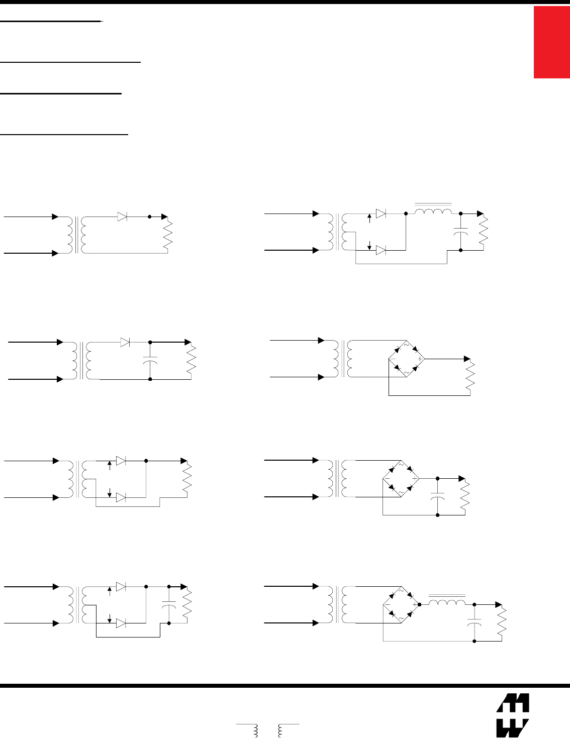
FULL WAVE BRIDGE Choke Input Load
Pri
V A.C.
Sec
V A.C.
+
I D.C.
+
V D.C.
-
V (Peak) D.C. = 0.90 X Sec. V A.C.
V (Avg) D.C. = 0.90 X Sec. V A.C.
I D.C. = 0.94 X Sec. I A.C.
Design Guide for Rectier Use
Pri
V A.C.
Sec
V A.C.
+
-
V D.C.
HALF WAVE Resistive Load
V D.C. = 0.45 X Sec. V A.C.
I D.C. = 0.64 X Sec. I A.C.
I D.C.
Pri
V A.C.
Sec
V A.C.
HALF WAVE Capacitor Input Load
V (Peak) D.C. = 1.41 X Sec. V A.C.
V (Avg) D.C. = 0.90 X Sec. V A.C.
I D.C. = 0.28 X Sec. I A.C.
I D.C.
+
V D.C.
+
-
FULL WAVE Resistive Load
Pri
V A.C.
Sec
V A.C.
I D.C.
V D.C.
+
-
V D.C. = 0.45 X Sec. V A.C.
I D.C. = 1.27 X Sec. I A.C.
Pri
V A.C.
Sec
V A.C.
FULL WAVE Capacitor Input Load
V (Peak) D.C. = 0.71 X Sec. V A.C.
V (Avg) D.C. = 0.45 X Sec. V A.C.
I D.C. = 1.00 X Sec. I A.C.
+
+
-
V D.C.
I D.C.
FULL WAVE Choke Input Load
I D.C.
V D.C.
+
-
Pri
V A.C.
Sec
V A.C.
+
V (Peak) D.C. = 0.45 X Sec. V A.C.
V (Avg) D.C. = 0.45 X Sec. V A.C.
I D.C. = 1.54 X Sec. I A.C.
Pri
V A.C.
Sec
V A.C.
FULL WAVE BRIDGE Resistive Load
I D.C.
+
V D.C.
-
V D.C. = 0.90 X Sec. V A.C.
I D.C. = 0.90 X Sec. I A.C.
FULL WAVE BRIDGE Capacitor Input Load
V (Peak) D.C. = 1.41 X Sec. V A.C.
V (Avg) D.C. = 0.90 X Sec. V A.C.
I D.C. = 0.62 X Sec. I A.C.
+
+
-
V D.C.
Pri
V A.C.
Sec
V A.C.
I D.C.
Transformer Voltage: A transformer's required secondary A.C. voltage varies greatly with the type of rectier chosen and lter arrangement.
Use the formulas below as a guide based on the D.C. voltage you require and the rectier/lter chosen. All A.C. voltage references are R.M.S. Don't
forget to take into account losses (not included in this guide), especially diode voltage drop. Leave an adequate safety margin for D.C. regulator volt-
age requirements and minimum operating line voltage.
Transformer Current Ratings: A transformer's A.C. current rating needs to be recalculated from the D.C. load current. The required current
varies with type of rectier chosen and lter type. Use the formulas below as a guide, shown for common D.C. supplies. Included in the formulas
higher peak to peak capacitor charging current in the lter.
Rectier Selection Notes: When selecting rectiers remember, average current in a full wave circuit is .5 x I D.C. per diode. In a half wave
circuit, average current is equal to I D.C. per diode. A rating at least twice the output current is recommended to cover turn on surge. In full wave
circuits, the reverse voltage rating should be in excess of 1.4 x V A.C. In half wave circuits, the reverse voltage rating should be in excess of
2.8 x V A.C.
Capacitor Selection Notes: When choosing capacitor voltage, allowances should be made for D.C. voltage rise due to transformer
regulation. Remember, R.M.S. ripple current in a lter capacitor can be 2 to 3 times D.C. load current. Capacitor life is greatly increased by reducing
it's temperature via less R.M.S. current or reduced ambient temperature.
Power
