Hardware Integration Manual
Hardware-Integration-Manual
User Manual:
Open the PDF directly: View PDF ![]() .
.
Page Count: 21
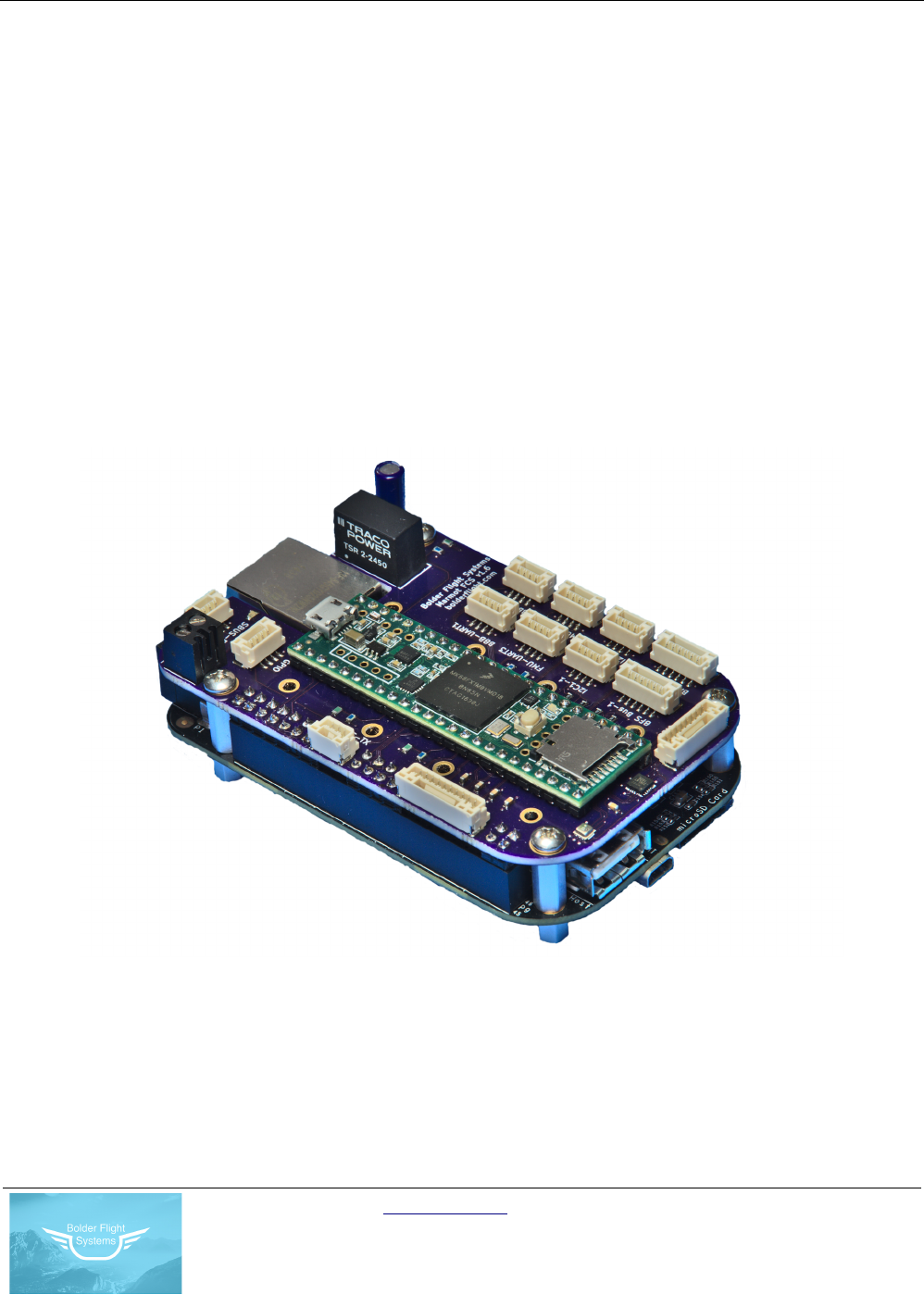

Table of Contents
Revision History........................................................................................................................................3
Flight Control System Overview..............................................................................................................4
Purpose......................................................................................................................................................6
Marmot Flight Management Unit.............................................................................................................7
Overview..............................................................................................................................................7
Specifications.......................................................................................................................................8
Mounting..............................................................................................................................................8
Location................................................................................................................................................8
Orientation............................................................................................................................................8
Power....................................................................................................................................................9
Connections..........................................................................................................................................9
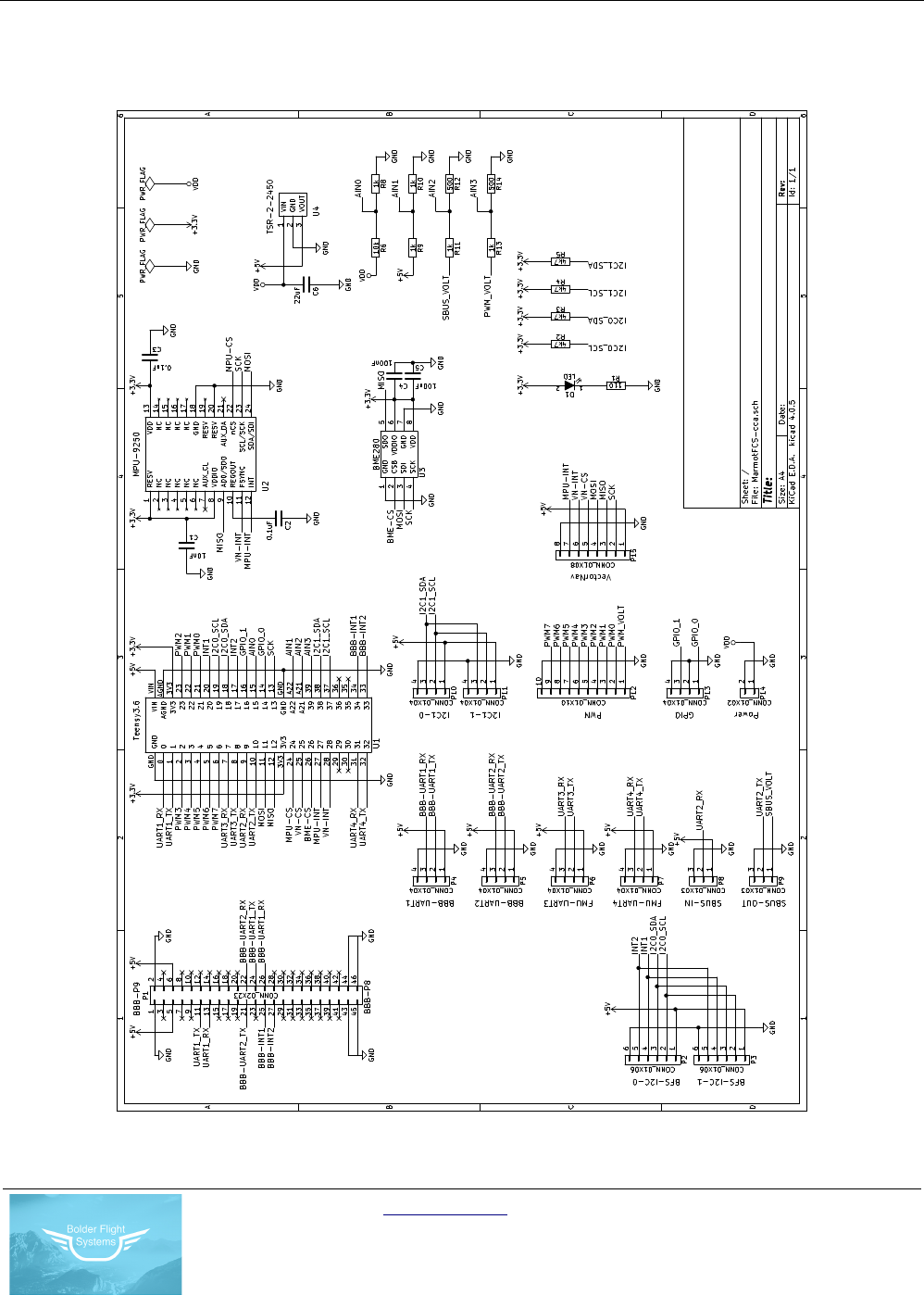
Schematic...........................................................................................................................................10
Raven Sensor and Actuator Node............................................................................................................11
Overview............................................................................................................................................11
Specifications......................................................................................................................................11
Mounting............................................................................................................................................11
Location..............................................................................................................................................12
Power..................................................................................................................................................12
Connections........................................................................................................................................12
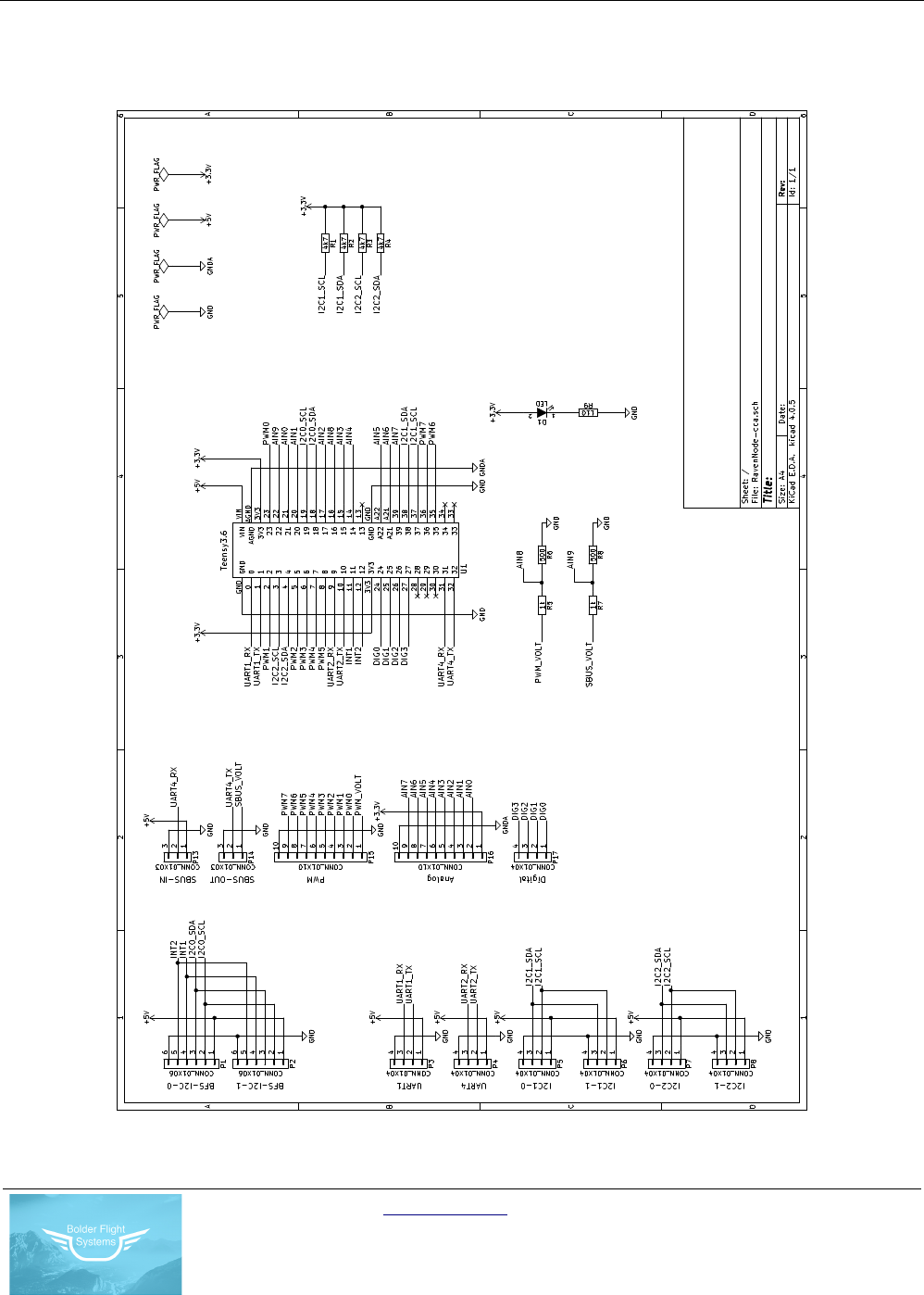
Schematic...........................................................................................................................................13
Swift Air Data.........................................................................................................................................14
Overview............................................................................................................................................14
Specifications.....................................................................................................................................14
Mounting............................................................................................................................................14
Location..............................................................................................................................................14
Orientation..........................................................................................................................................15
Power..................................................................................................................................................15
Connections........................................................................................................................................15
PWM, SBUS, and Analog Breakout Boards...........................................................................................16
Overview............................................................................................................................................16
Mounting............................................................................................................................................16
Connections........................................................................................................................................16
VectorNav Breakout Boards....................................................................................................................17
Overview............................................................................................................................................17
Mounting............................................................................................................................................17
Power..................................................................................................................................................17
Connections........................................................................................................................................17
Connectors...............................................................................................................................................18
Overview............................................................................................................................................18
Specifications.....................................................................................................................................18
Bolder Flight Systems | bolderflight.com | Designed and Assembled in the United States 2


Flight Control System Overview
Our flight control system is designed to be extremely low-latency, deterministic, and highly scalable.
At the core of the flight control system is the Marmot Flight Management Unit (FMU). From a
hardware standpoint, the Marmot FMU consists of:
•A Teensy 3.6 Cortex M4 microcontroller capable of a 240 MHz CPU frequency with a single
precision hardware floating point unit.
•Voltage regulation with a +6.5V to +36V input range providing clean 5V output up to 2A
capacity.
•MPU-9250 nine axis inertial measurement unit.
•BME-280 pressure, temperature, and humidity sensor.
•SBUS input for sensing up to 16 channels of pilot input from an SBUS capable receiver.
•SBUS output for actuating up to 16 SBUS capable servos.
•PWM output for actuating up to 8 PWM capable servos.
•One I2C and one SPI bus for connecting external sensors, such as the Swift Air Data sensor or
VectorNav inertial measurement units and systems.
•Four UARTS, two from the Teensy 3.6 microcontroller and two from the BeagleBone Black,
for connecting external sensors such as GNSS receivers or radio modems.
•Two GPIO’s, which can be configured for PWM output, digital I/O, or analog input up to
+3.3V.
•Bolder Flight Systems expansion bus.
•Measurement of input, regulated, SBUS, and PWM voltages.
The FMU is intended to integrate with a BeagleBone Black using a high speed UART port capable of
transferring data at rates up to 1.5 Mbaud. The FMU provides regulated 5V power to the BeagleBone
Black. Two digital pins are shared between FMU and BeagleBone Black for triggering interrupts.
Additional sensing and actuation can be added by integrating Raven Sensor and Actuator Nodes
(Nodes) over the Bolder Flight Systems expansion bus (BFS Bus). An unlimited number of Nodes can
be added; the BFS Bus provides regulated power, high bandwidth data transfer up to 245 kB/s, and
two digital lines for synchronization. Pulses on the digital lines can be used to synchronize data
collection, actuator commands, and keep a synchronized clock across the network of FMU and Nodes.
We consider this capability critical for research and development environments where sensing and
actuation requirements often change dramatically from one research program to the next.
Bolder Flight Systems | bolderflight.com | Designed and Assembled in the United States 4
Each node consists of:
•A Teensy 3.6 Cortex M4 microcontroller capable of a 240 MHz CPU frequency with a single
precision hardware floating point unit.
•SBUS input for sensing up to 16 channels of pilot input from an SBUS capable receiver.
•SBUS output for actuating up to 16 SBUS capable servos.
•PWM output for actuating up to 8 PWM capable servos.
•Two I2C buses for connecting external sensors, such as the Swift Air Data sensor.
•Two UARTS, for connecting external sensors such as GNSS receivers or radio modems.
•Eight analog inputs up to +3.3V.
•Four digital I/O.
•Measurement of SBUS, and PWM voltages.
PWM, SBUS, and Analog boards breakout the PWM, SBUS, and Analog pins from JST-GH
connectors to convenient 0.1” (2.54 mm) spaced headers. A VectorNav VN-100 / VN-200 breakout
enables easy integration of VectorNav VN-100 or VN-200 inertial measurement units and systems to
the FMU.
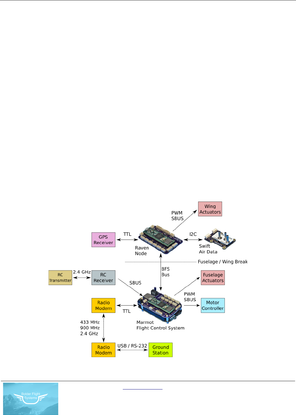
Functional block diagrams of a couple example layouts are given below.
Bolder Flight Systems | bolderflight.com | Designed and Assembled in the United States 5
Figure 1: A simple aircraft integration
Purpose
The purpose of this manual is to provide:
•Hardware technical specifications for flight control system components.
•Guidance on mounting, orientation, and location of flight control system components.
•Power input requirements.
•Technical specifications for all buses.
Bolder Flight Systems | bolderflight.com | Designed and Assembled in the United States 6
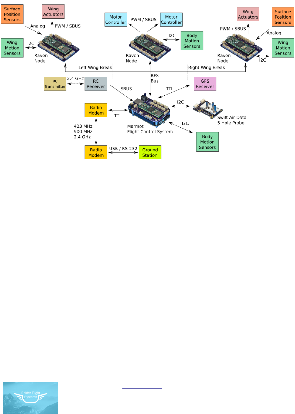
Figure 2: A complex aircraft integration

Marmot Flight Management Unit
Overview
At the core of the flight control system is the Marmot Flight Management Unit (FMU). From a
hardware standpoint, the Marmot FMU consists of:
•A Teensy 3.6 Cortex M4 microcontroller capable of a 240
MHz CPU frequency with a single precision hardware
floating point unit.
•Voltage regulation with a +6.5V to +36V input range
providing clean 5V output up to 2A capacity.
•MPU-9250 nine axis inertial measurement unit.
•BME-280 pressure, temperature, and humidity sensor.
•SBUS input for sensing up to 16 channels of pilot input from an SBUS capable receiver.
•SBUS output for actuating up to 16 SBUS capable servos.
•PWM output for actuating up to 8 PWM capable servos.
•One I2C and one SPI bus for connecting external sensors, such as the Swift Air Data sensor or
VectorNav inertial measurement units and systems.
•Four UARTS, two from the Teensy 3.6 microcontroller and two from the BeagleBone Black,
for connecting external sensors such as GNSS receivers or radio modems.
•Two GPIO’s, which can be configured for PWM output, digital I/O, or analog input up to
+3.3V.
•Bolder Flight Systems expansion bus.
•Measurement of input, regulated, SBUS, and PWM voltages.
The FMU is intended to integrate with a BeagleBone Black using a high speed UART port capable of
transferring data at rates up to 1.5 Mbaud. The FMU provides regulated 5V power to the BeagleBone
Black. Two digital pins are shared between FMU and BeagleBone Black for triggering interrupts.
Bolder Flight Systems | bolderflight.com | Designed and Assembled in the United States 7
Specifications
•Voltage Input: +6.5V to +36V
•Current Draw (with BeagleBone Black): 350 mA
•Size (with BeagleBone Black): 55 mm x 89 mm x 30.5 mm
•Weight (with BeagleBone Black): 75 g
Mounting
Four 4-40 mounting holes are provided and aligned with the BeagleBone Black mounting holes. We
recommend a 7/16 inch length standoff between the BeagleBone Black and FMU and a 3/16 inch
length standoff between the BeagleBone Black and the aircraft structure.
Location
The FMU should be mounted near the aircraft center of gravity.
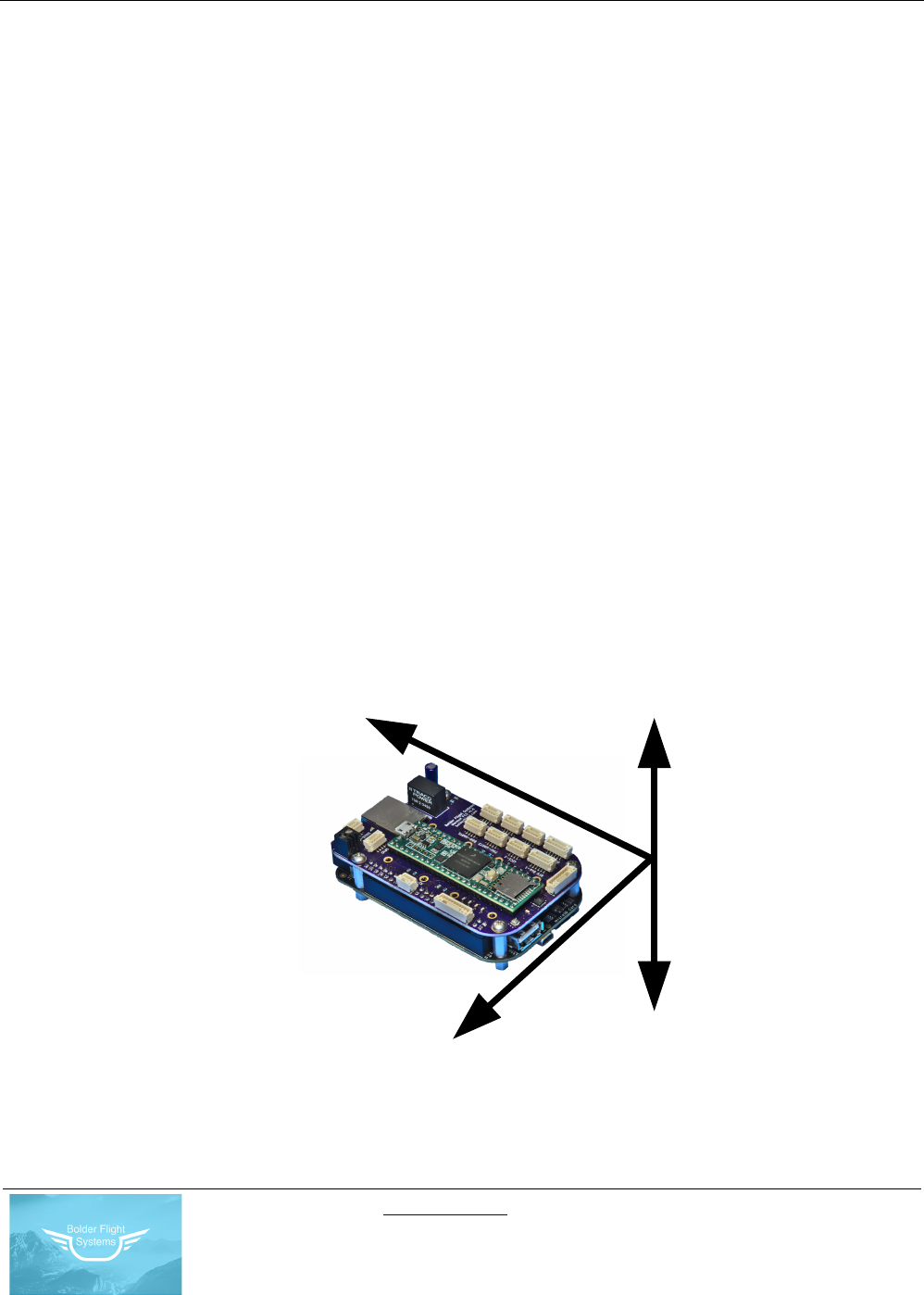
Orientation
Relative to the FMU, the MPU-9250 orientation is depicted below. If you use the Bolder Flight
Systems MPU-9250 library, the accelerometer and gyroscope are transformed to align with the
magnetometer axis system.
Bolder Flight Systems | bolderflight.com | Designed and Assembled in the United States 8
+Accel Y
+Gyro Y
+Mag X
+Accel X
+Gyro X
+ Mag Y
+Mag Z
+Accel Z
+Gyro Z

Power
Power input is provided via a screw terminal, labeled PWR, capable of accepting 16-28 AWG wire.
+6.5V to +36V input voltage is acceptable; typically this would be provided by the UAS motor battery
if it is between a 2S and 6S battery pack, otherwise, this power would need to be provided by a
regulator or separate avionics battery.
Regulated 5V power, up to 2A, is provided by the FMU to the BeagleBone Black, BFS Bus Nodes,
and integrated sensors. Regulated power from the FMU is not intended to be used by SBUS or PWM
servos and this must be provided separately.
Input, regulated, PWM, and SBUS voltages are brought to analog inputs for monitoring and recording
these voltage levels. Voltage dividers are used to scale the voltages to acceptable analog input ranges,
please see the schematic for details.
Connections
The following connections are available on the FMU:
•SBUS input for sensing up to 16 channels of pilot input from an SBUS capable receiver.
•SBUS output for actuating up to 16 SBUS capable servos.
•PWM output for actuating up to 8 PWM capable servos.
•One I2C and one SPI bus for connecting external sensors, such as the Swift Air Data sensor or
VectorNav inertial measurement units and systems.
•Four UARTS, two from the Teensy 3.6 microcontroller and two from the BeagleBone Black,
for connecting external sensors such as GNSS receivers or radio modems.
•Two GPIO’s, which can be configured for PWM output, digital I/O, or analog input up to
+3.3V.
•Bolder Flight Systems expansion bus (BFS Bus).
Reference the Connectors section for details.
Bolder Flight Systems | bolderflight.com | Designed and Assembled in the United States 9
Raven Sensor and Actuator Node
Overview
Additional sensing and actuation can be added by integrating
Raven Sensor and Actuator Nodes (Nodes) over the Bolder
Flight Systems expansion bus (BFS Bus). An unlimited number
of Nodes can be added; the BFS Bus provides regulated power,
high bandwidth data transfer up to 245 kB/s, and two digital
lines for synchronization. Each node consists of:
•A Teensy 3.6 Cortex M4 microcontroller capable of a
240 MHz CPU frequency with a single precision
hardware floating point unit.
•SBUS input for sensing up to 16 channels of pilot input from an SBUS capable receiver.
•SBUS output for actuating up to 16 SBUS capable servos.
•PWM output for actuating up to 8 PWM capable servos.
•Two I2C buses for connecting external sensors, such as the Swift Air Data sensor.
•Two UARTS, for connecting external sensors such as GNSS receivers or radio modems.
•Eight analog inputs up to +3.3V.
•Four digital I/O.
•Bolder Flight Systems expansion bus.
•Measurement of SBUS, and PWM voltages.
Specifications
•Voltage Input: +3.6V to +6V
•Current Draw: 125 mA
•Size: 45 mm x 70 mm x 8.5 mm
•Weight: 20 g
Mounting
Eight 2-56 mounting holes are provided and there is no minimum standoff length.
Bolder Flight Systems | bolderflight.com | Designed and Assembled in the United States 11

Location
Nodes should be located conveniently for sensing and actuation while minimizing BFS Bus lengths.
On UAS with removable wings, this is typically in the wing root to minimize the wiring crossing the
wing break, which can often be resolved to only the BFS Bus and actuator power and ground.
Power
Power is provided by the BFS Bus from the FMU. For situations where the Node is not powered by
the FMU, the BFS Bus may be used to power the Node using a voltage input from +3.6V to +6V.
Connections
The following connections are available on the Node:
•SBUS input for sensing up to 16 channels of pilot input from an SBUS capable receiver.
•SBUS output for actuating up to 16 SBUS capable servos.
•PWM output for actuating up to 8 PWM capable servos.
•Two I2C buses for connecting external sensors, such as the Swift Air Data sensor.
•Two UARTS, for connecting external sensors such as GNSS receivers or radio modems.
•Eight analog inputs up to +3.3V.
•Four digital I/O.
•Bolder Flight Systems expansion bus (BFS Bus).
Reference the Connectors section for details.
Bolder Flight Systems | bolderflight.com | Designed and Assembled in the United States 12

Swift Air Data
Overview
The Swift Air Data sensor provides high accuracy measurements of static
and differential pressure in a convenient package that integrates easily
with Bolder Flight Systems components.
•Calibrated and temperature compensated static and differential
pressure with digital output over I2C.
•Small overall error within a temperature range of -25C to +85C.
•14 bit resolution.
•Libraries available to initialize the sensor and collect pressure data at rates of up to 2 kHz.
Specifications
•Voltage Input: +3.32V to +6V
•Current Draw: 20 mA
•Size: 28 mm x 40 mm x 18.5 mm
•Weight: 10 g
Mounting
Four 2-56 mounting holes are provided and there is no minimum standoff length.
Location
The Swift Air Data sensor should be located near the UAS air data boom to minimize pneumatic delay.
Air data booms should be located far outside of the propeller diameter to minimize motor influence
and the boom length should be at least 1.5 times the wing chord to reduce upwash. If the air data boom
is located off center-line, the data should be corrected back to the aircraft center of gravity.
Bolder Flight Systems | bolderflight.com | Designed and Assembled in the United States 14
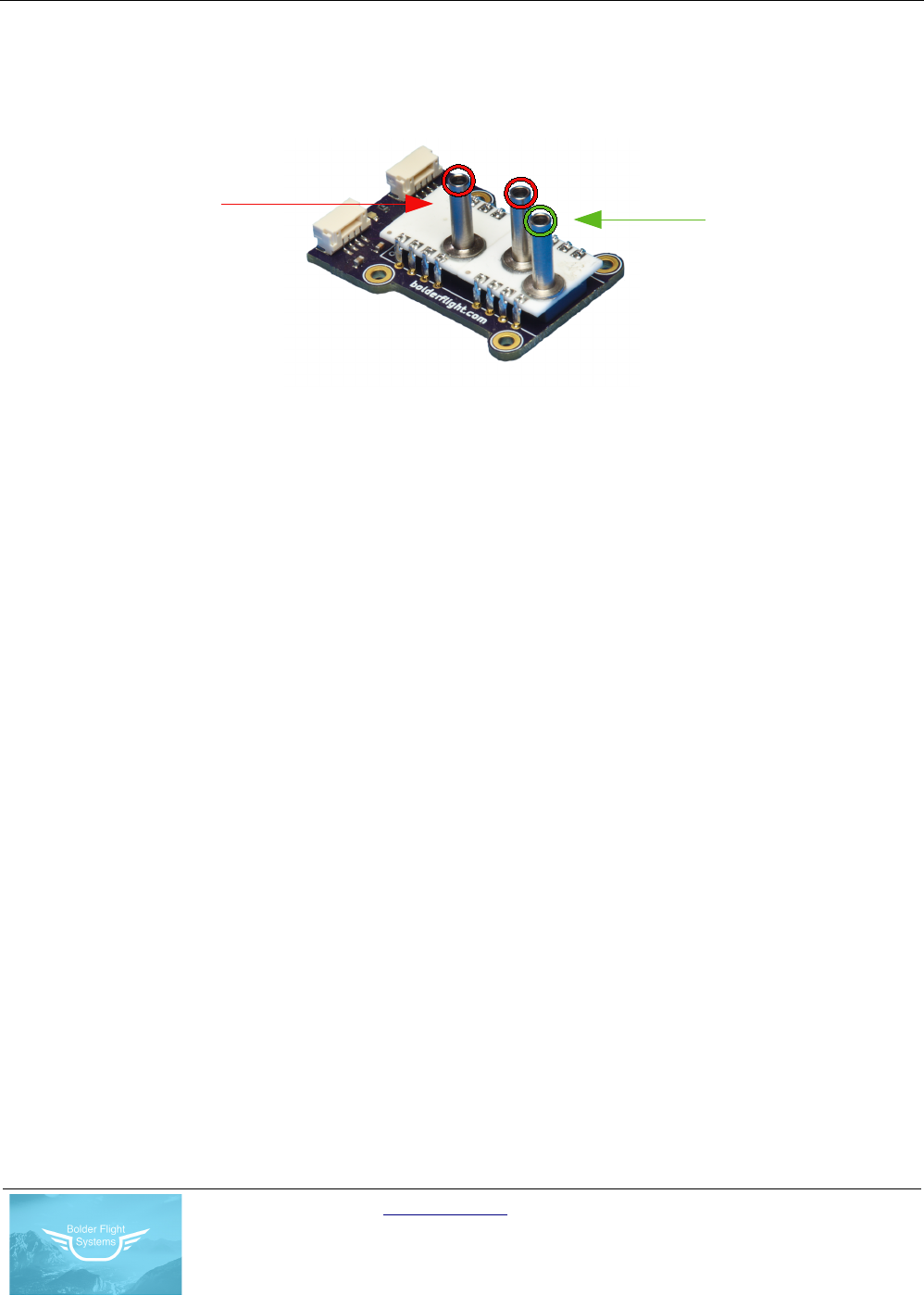
Orientation
The Swift Air Data sensor contains both static and differential sensors, pneumatic connections are
depicted below.
Custom I2C addresses can be selected for the pressure transducers when ordering; typically the static
pressure sensor is given the lower numbered address. The default I2C address for the static pressure
sensor is 0x10 with a range of 70000 Pa – 120000 Pa. The default I2C address for the differential
pressure transducer is 0x11 with a range of 0 Pa – 2000 Pa; however, transducers with ranges of 0 Pa –
500 Pa and 0 Pa – 1000 Pa are available on request.
Power
Power is supplied via the I2C interface from the FMU or Node. Nominally, +5V is the input voltage
level; however, a range of +3.32V to +6V is acceptable.
Connections
I2C interfaces are used and two I2C connectors are present to enable daisy chaining devices connected
to the bus. Please refer to the Connectors section for a detailed pinout.
Bolder Flight Systems | bolderflight.com | Designed and Assembled in the United States 15
Static Pressure
Ports
Differential
Pressure
Port

PWM, SBUS, and Analog Breakout Boards
Overview
PWM, SBUS, and Analog breakout boards breakout the JST-GH connectors to convenient 0.1” (2.54
mm) spaced headers. These boards fit eight channels of signals and provide bused power and ground
as well. Connector orientation is labeled on the board and matches RC servo wire ordering, enabling
standard servo connectors to be used. Two of the SBUS breakout boards can be daisy chained to
enable up to 16 channels of SBUS output.
For the PWM and SBUS breakout boards, power must be provided for the servos, either via one of the
actuator channels or via the provided screw terminals. Actuator voltage is measured, up to +9.9V.
Breakout boards are designed to handle 12A of current draw from the servos.
For the analog breakout board, +3.3V is supplied to enable the easy integration of potentiometers.
Mounting
Four 2-56 mounting holes are provided on each board in a pattern matching mounting holes on the
FMU and Node. If mounting the breakout board to an FMU or Node, a minimum standoff length of
5/16” is recommended.
Connections
Please refer to the Connectors section for a detailed pinout of the PWM, SBUS, and analog connectors.
Bolder Flight Systems | bolderflight.com | Designed and Assembled in the United States 16
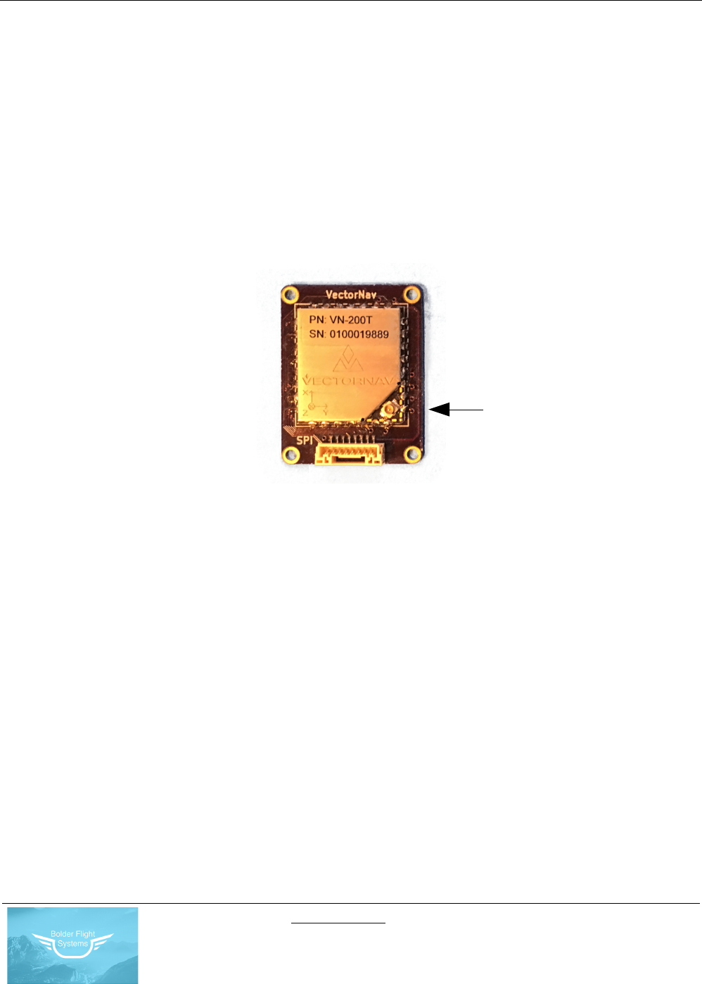
VectorNav Breakout Boards
Overview
A breakout board is available to enable integration of VectorNav VN-100 or VN-200 inertial
measurement units and systems. These breakout boards work with the VectorNav surface mounted
units and interface the VectorNav with the FMU over SPI.
Mounting
If you are soldering the VectorNav unit to the breakout board, the orientation is shown below.
Four 2-56 mounting holes are provided to mount the VectorNav breakout board to the FMU. 5/16”
length standoffs are recommended between the VectorNav breakout board and the FMU.
Power
Power is supplied via the SPI interface from the FMU. Nominally, +5V is the input voltage level;
however, a range of +3.2V to +5.5V is acceptable.
Connections
An SPI interface is used, please refer to the Connectors section for a detailed pinout. Note the
Interrupt Out pin brings the VectorNav generated interrupt to the FMU microcontroller and the MPU-
9250 FSYNC pin. The Interrupt In pin brings the MPU-9250 generated interrupt to the VectorNav
SYNC_IN pin. This setup enables either IMU to drive interrupts on the FMU and data synchronization
between the inertial measurement units.
Bolder Flight Systems | bolderflight.com | Designed and Assembled in the United States 17
VectorNav
Pin 1
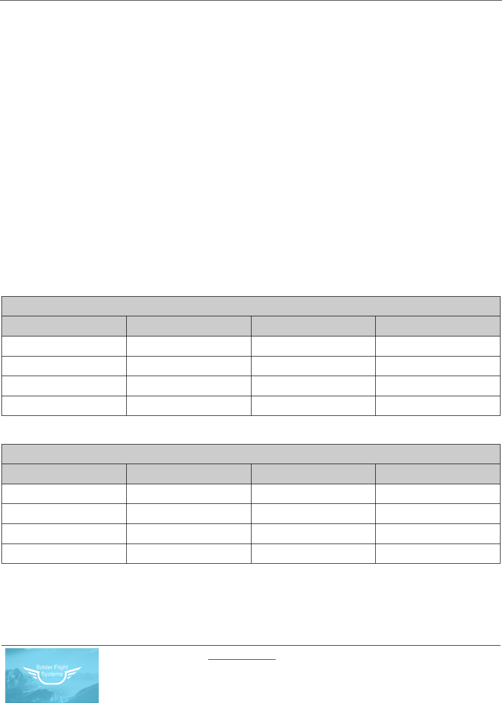
Connectors
Overview
JST-GH connectors are used for all Bolder Flight Systems components, incorporating signals as well
as regulated voltage. Connector requirements are below:
•Connector type: JST-GH
•Cable: 26 AWG, insulation outer diameter 0.76 to 1.0 mm. We recommend EcoWire 6711 by
Alpha Wire.
•Power voltage: +5V
•Signal voltage: +3.3V (typical, see specifications)
Specifications
Details for each connector is below, please use caution and ensure specified voltage levels are met,
higher voltage levels may damage components:
UART Specification
Pin Color Signal Voltage
1 Red VCC +5V
2 White TX +3.3V
3 Blue RX +3.3V
4 Black GND GND
I2C Specification
Pin Color Signal Voltage
1 Red VCC +5V
2 Slate SCL +3.3V
3 Violet SDA +3.3V
4 Black GND GND
Bolder Flight Systems | bolderflight.com | Designed and Assembled in the United States 18

CAN Specification
Pin Color Signal Voltage
1 Red VCC +5V
2 Orange CAN H +3.3V
3 Brown CAN L +3.3V
4 Black GND GND
SPI Specification
Pin Color Signal Voltage
1 Red VCC +5V
2 Slate SCK +3.3V
3 Blue MISO +3.3V
4 Violet MOSI +3.3V
5 White CS +3.3V
6 Orange Interrupt Out +3.3V
7 Brown Interrupt In +3.3V
8 Black GND GND
SBUS RX Specification
Pin Color Signal Voltage
1 Red VCC +5V
2 White RX +3.3V
3 Black GND GND
SBUS TX Specification
Pin Color Signal Voltage
1 Red Vmeas Measure up to +9.9V
2 Orange TX +3.3V
3 Black GND GND
Bolder Flight Systems | bolderflight.com | Designed and Assembled in the United States 19

PWM Specification
Pin Color Signal Voltage
1 Red Vmeas Measure up to +9.9V
2 White Actuator 0 +3.3V
3 Blue Actuator 1 +3.3V
4 Slate Actuator 2 +3.3V
5 Violet Actuator 3 +3.3V
6 Orange Actuator 4 +3.3V
7 Brown Actuator 5 +3.3V
8 White Actuator 6 +3.3V
9 Violet Actuator 7 +3.3V
10 Black GND GND
Analog Specification
Pin Color Signal Voltage
1 Red VCC +3.3V
2 Slate Analog 0 +3.3V
3 Blue Analog 1 +3.3V
4 Violet Analog 2 +3.3V
5 White Analog 3 +3.3V
6 Brown Analog 4 +3.3V
7 Orange Analog 5 +3.3V
8 Blue Analog 6 +3.3V
9 Slate Analog 7 +3.3V
10 Black GND GND
Bolder Flight Systems | bolderflight.com | Designed and Assembled in the United States 20

GPIO Specification
Pin Color Signal Voltage
1 White GPIO 0 +3.3V
2 Black GND GND
3 Violet GPIO 1 +3.3V
4 Black GND GND
Digital Specification
Pin Color Signal Voltage
1 White Digital 0 +3.3V
2 Orange Digital 1 +3.3V
3 Blue Digital 2 +3.3V
4 Brown Digital 3 +3.3V
BFS Bus Specification
Pin Color Signal Voltage
1 Red VCC +5V
2 Slate SCL +3.3V
3 Violet SDA +3.3V
4 Blue Interrupt 1 +3.3V
5 White Interrupt 2 +3.3V
6 Black GND GND
Bolder Flight Systems | bolderflight.com | Designed and Assembled in the United States 21
