Hattersley Technical Product Guide
User Manual: Hattersley Technical Product Guide
Open the PDF directly: View PDF ![]() .
.
Page Count: 228 [warning: Documents this large are best viewed by clicking the View PDF Link!]
WATER
HEATING
VENTILATION
AIR CON
GAS FUTURE VALVE TECHNOLOGY
Te c h n i c a l
P ro d u c t
G u i d e
www.cranebsu.com
Balancing Valves
Public Health Range
Traditional Valves
PO BOX 719, IPSWICH IP1 9DU
HOME SALES: +44 (0)1744 458670
EXPORT SALES: +44 (0)1744 458671
TECHNICAL HELPLINE: 0845 604 1790
FAX: +44 (0)1744 26912
EMAIL: uksales@hattersley.com
EMAIL: export@hattersley.com
EMAIL: tech-enquiries@hattersley.com
www.hattersley.com
• Designed and manufactured under quality management
systems in accordance with BS EN 9001:2008.
• For full terms and conditions, please visit our website.
•
We hope our communications have an impact on you - but not
the environment - we have taken steps to ensure this brochure
is printed on Forestry Stewardship Council material and the
paper is made by an elemental chlorine free process.
Every effort has been made to ensure that the information contained in this publication is accurate at the time of
publishing. Hattersley Ltd assumes no responsibility or liability for typographical errors or omissions or for any
misinterpretation of the information within the publication and reserves the right to change without notice.
ISSUE 2
Visit www.flowoffluids.com to order your
copy of the New Technical Paper 410.
www.flowoffluids.com
FM311
ISO 9001
T E C H N I C A L P R O D U C T G U I D E I SS U E 2
New
Now includes
Hook-Up II
IVMMXI
Distributor details
Technical Helpline: 0845 604 1790
E: tech-enquiries@hattersley.com W: www.hattersley.com
2
INTRODUCTION
About Hattersley
The origins of Hattersley date
to 1897, when 20 year-old
Richard Hattersley started a
small tool-making business
in Halifax. In the early 1900s
he relocated to Ormskirk,
and in 1910 he joined with
three other engineering companies, including
Newman Hender & Co. of Woodchester, to
form United Brassfounders & Engineers.
By 1937 Hattersley & Newman Hender both
enjoyed worldwide sales, with Hattersley
exporting to some 73 countries. During the
second world war, both companies entered
war production, making fuses for armaments,
brass rods for munitions factories and, of
course, special valves for military purposes.
In 2004, Crane Limited purchased the
Hattersley valve brand and business from
Hattersley Newman Hender Limited, a
subsidiary of Tomkins plc.
Quality Assurance
Rigid quality control and inspection at all
stages of manufacture ensure that Hattersley
products are suitable for their intended
application and will give reliable service.
Every valve is individually tested in
accordance with the relevant product
standard.
Hattersley is an approved manufacturer
under various quality schemes, including
the British Standard Institution (BSI)
Kitemark, and is ISO9001:2008 accredited.
In addition, the company has been approved
and/or listed by third party organisations
including the United Kingdom Water
Regulations Advisory Scheme.
Future
Today, the Hattersley brand is synonymous
with quality, reliability and service to the very
highest standards, and has industry
experience in many market sectors including
heating and ventilation, chemicals, textiles,
drugs, waste treatment and power
generation. Hattersley can supply a skilfully
engineered solution for every application.
Flagship products include a full range of
commissioning valves suitable for constant
and variable flow systems.
Technical Helpline: 0845 604 1790
E: tech-enquiries@hattersley.com W: www.hattersley.com
227
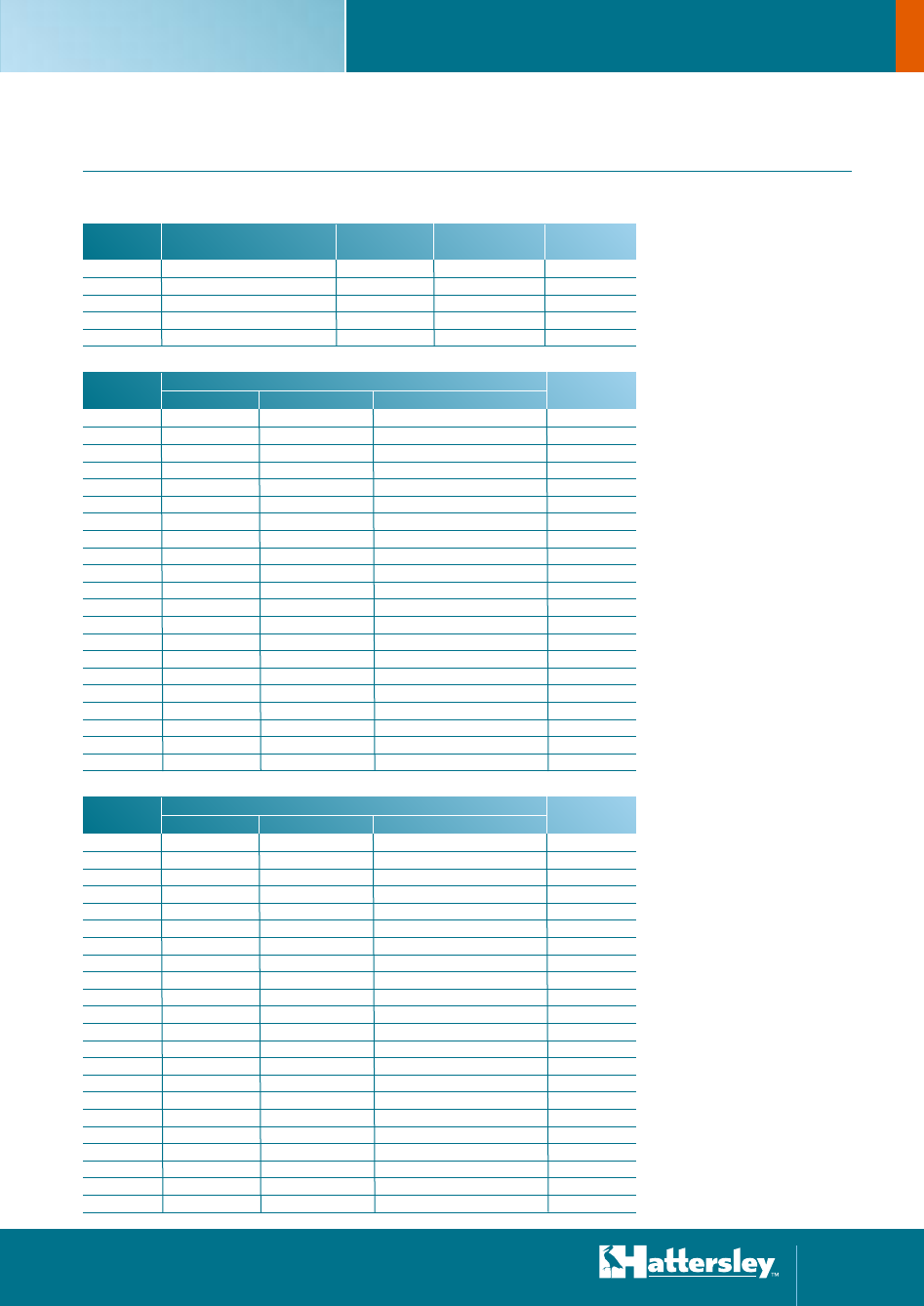
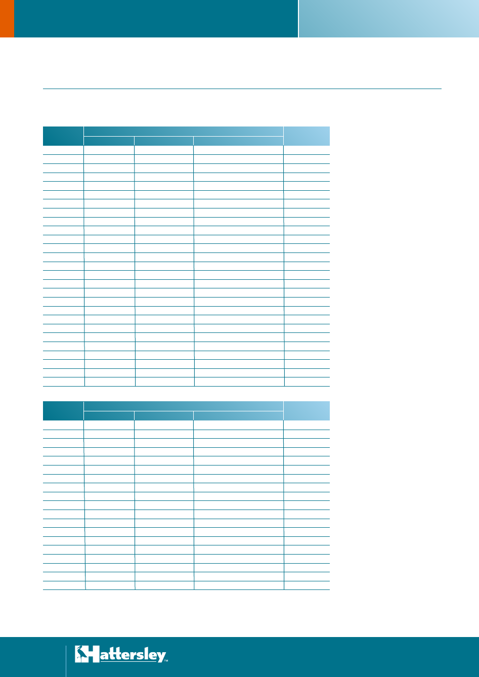
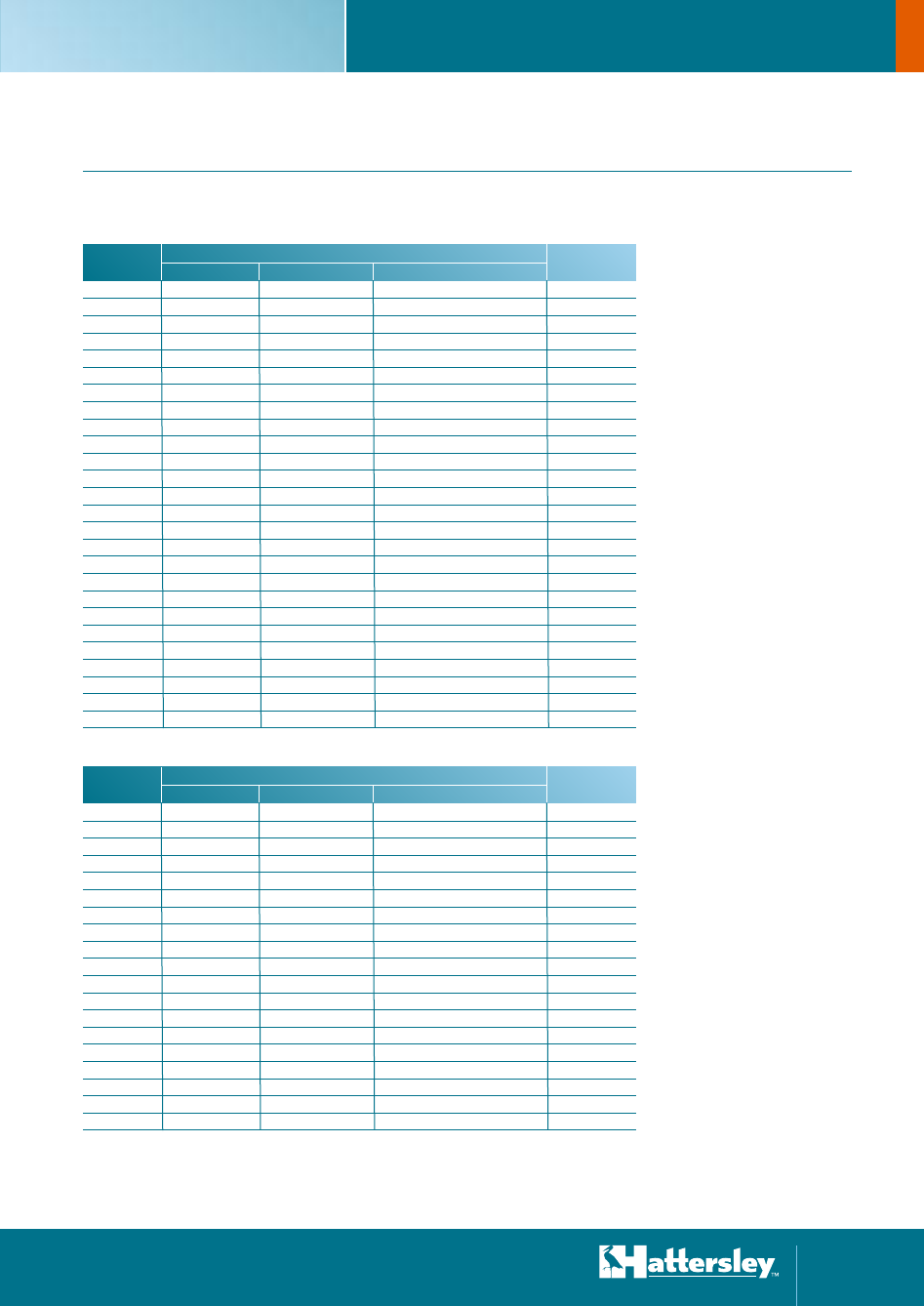
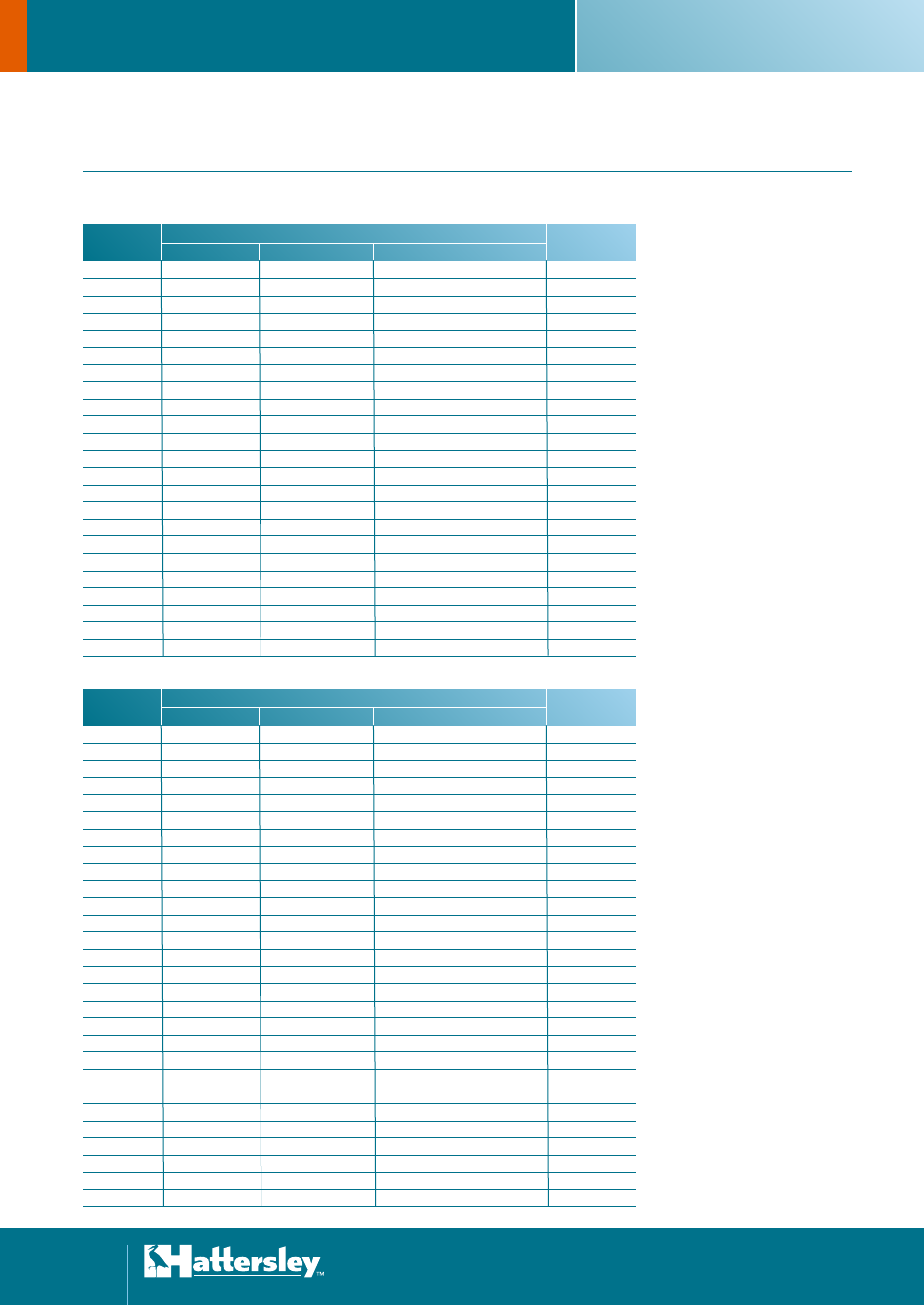
FIGURE NUMBER INDEX
Fig. No. Index
C4 .....................................148
5........................................149
5N .....................................150
5NLS.................................150
13......................................151
17......................................153
23......................................152
28......................................131
30......................................125
30C ...................................126
30CLS...............................127
30LS .................................125
C31 ...................................128
33......................................129
33X....................................124
33XLS ...............................124
35......................................132
42......................................110
47......................................111
48......................................112
49......................................113
70/RT ................................173
75/RS................................173
77......................................185
78......................................186
81HU.................................145
100......................................78
100TH .................................79
100C ...................................80
100CEXT.............................80
100CLS...............................81
100CTH ..............................81
100CYL ...............................83
100EXT ...............................78
100LS .................................79
100MHU .............................87
100YL..................................82
107MHU .............................88
108C ............................84/191
110......................................85
113......................................86
170M.................................157
171M.................................157
200L..................................160
200M.................................158
200R .................................159
200T..................................160
201M.................................158
201R .................................159
201T..................................160
201TG...............................160
221T..................................160
249.............................114/189
249C ..........................114/189
C262 ...................................66
H262 ...................................66
C264 ...................................67
H264 ...................................67
C266 ...................................62
H266 ...................................62
C267 ...................................64
H267 ...................................64
C268 ...................................63
H268 ...................................63
C269 ...................................65
H269 ...................................65
C270 ...................................71
F300....................................54
R300 ...................................54
305......................................71
370....................................144
371....................................144
401M.................................161
430....................................187
440....................................188
501....................................141
504....................................142
M511.................................137
M540.................................140
M541.................................138
M544.................................139
M544E ..............................139
M549.................................135
M552.................................136
M552E ..............................136
609....................................133
C618 .................................134
631......................................22
M650.................................118
M651.................................119
M653.................................120
669....................................130
731....................................154
M733DR.........................34-35
M737..............................36-37
750......................................23
775......................................76
761.............................115/190
807....................................177
810....................................180
811....................................181
817....................................176
850.............................121-122
907....................................177
910....................................180
911....................................181
950......................................92
C950 ...................................93
950W ..................................95
950G ...................................92
950WG................................95
951......................................97
951G ...................................97
953......................................38
953G ...................................38
970......................................94
970G ...................................94
970W ..................................96
971......................................98
971G ...................................98
973......................................39
973G ...................................39
980......................................99
1000....................................24
1000L..................................25
1000M.................................25
1013..................................116
1050....................................18
1051....................................19
1052....................................18
1053....................................19
1200DR...............................29
1432....................................26
1432C .................................26
1432L..................................26
1432LC ...............................26
M1541...............................138
M1552...............................136
DP1732...............................56
DP1732L.............................56
DP1732M............................56
1732....................................27
1732C .................................27
1732L..................................27
1732LC ...............................27
1732M.................................27
1732MC ..............................27
1807.............................89/178
1807C ..........................90/179
1832....................................28
1832L..................................28
1832M.................................28
1900..................................184
M2000............................30-31
2050....................................20
2761...........................115/190
M3000.................................32
3047..................................117
3150..................................167
3180..................................171
3250..................................168
3280..................................172
3300LS .............................169
3400LS .............................170
M4000.................................33
4970..................................100
4970G ...............................100
4983G .................................40
4990..................................101
4990G........................102-107
4993G............................43-46
5953....................................41
5953G .................................41
5973....................................42
5973G .................................42
MultiComm....................69-70
ProComm ......................73-74
Fig. Number Page Fig. Number Page Fig. Number Page Fig. Number Page
Technical Helpline: 0845 604 1790
E: tech-enquiries@hattersley.com W: www.hattersley.com
3
CONTENTS
Contents
Balancing – Automatic 11
Balancing – Static 21
Differential Pressure Control Valves 51
Hook-Up II 57
MultiComm 69
Pressure Independent Control Valves 71
ProComm 73
Balancing Valves
Air Vents/De-Aerators 75
Ball Valves 77
Butterfly Valves 91
Check Valves 109
Gate Valves 123
Gland Cocks/Drain Taps 143
Globe Valves 147
Lubricated Plug Valves 155
Radiator Valves 165
Strainers 175
Traditional Valves
Introduction 183
Thermal Balancing Valves 184
Thermostatic Mixing Valves 185
Pressure Reducing Valves 187
Check Valves 189
Non-Return Valves 190
Ball Valves 191
Public Health Range
NABIC
Brownall
Flange Tables 213
Typical Kv Values 223
Quality Assurance 226
Miscellaneous
Fig. No. Index 227
Figure Number Index
About Hattersley 2
Introduction to Sister Brands 4-5
Valve Selection Guide 8-10
Introduction
NABIC Safety & Control Valves 195
Brownall Plant Room Valves 207
Technical Helpline: 0845 604 1790
E: tech-enquiries@hattersley.com W: www.hattersley.com
4
SISTER BRANDS
Sister Brands
Today, Hattersley is a
leading brand of Crane
Building Services & Utilities,
and is joined by an array of
complementary building
services brands which
include NABIC, Brownall,
Wade, Rhodes and IAT.
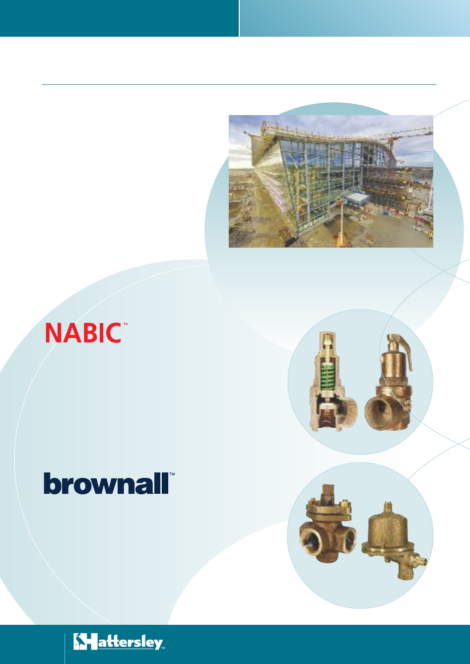
One of the UK's leading suppliers of gunmetal safety valves,
NABIC has long been recognised as the industry standard
for commercial and industrial hot water applications. With
the introduction of new products, this leadership has been
extended to cover other building service fluids such as
steam and air.
The Brownall range of automatic air eliminators cover low,
medium and high pressure applications and are suitable for
use with water, aviation fuel, diesel and light oils. The range
is completed by three-way vent valves, offering efficient
performance and reliable service combined with potential
savings in time and cost by simplifying the venting system
for single/multiboiler or calorifier installations.
Heathrow Terminal 5 is equipped with a range of
Hattersley products.
www.baa.com/photolibrary
Technical Helpline: 0845 604 1790
E: tech-enquiries@hattersley.com W: www.hattersley.com
5
SISTER BRANDS
The importance of safe and reliable potable water systems
has never been greater, and a range of I.A.T. products
complements the existing Hattersley range.
Rhodes is a market leader in the design and
manufacture of sight flow indicator equipment,
having produced indicators since 1951.
Rhodes sight flow indicators can be found in
process, petrochemical and pharmaceutical
plants all over the world.
An extensive range of low and medium pressure brass
compression fittings, valves and accessories. The range
also covers SISTEM-P and compact push in fittings,
nickel plated BSP fittings, quick release couplings,
air guns, recoil hoses and tubing.
TM
Technical Helpline: 0845 604 1790
E: tech-enquiries@hattersley.com W: www.hattersley.com
6
Technical Helpline: 0845 604 1790
E: tech-enquiries@hattersley.com W: www.hattersley.com
7
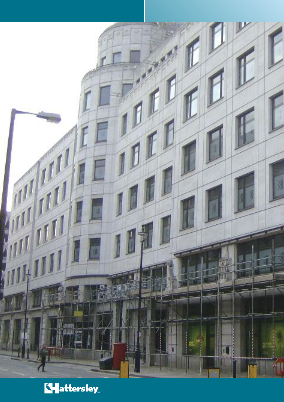
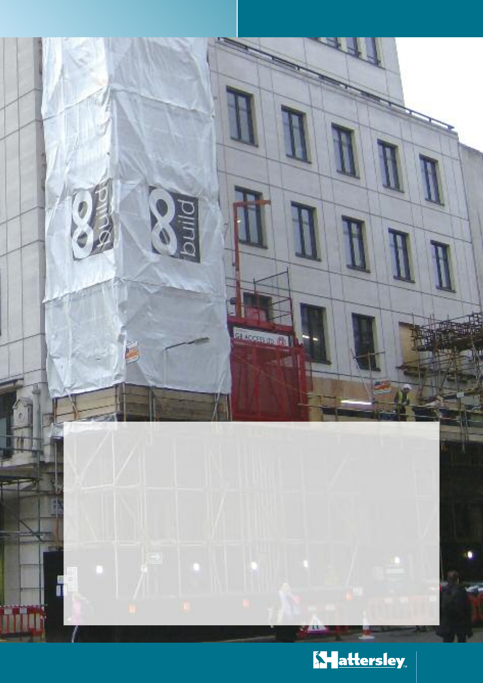
Project: Henrietta House, London
Client: CB Richard Ellis of London
Contractor: Silverline Engineering
Distributor: T G Lynes
Specification: Range of Hattersley isolation valves
A range of isolating valves has been specified for installation within the fancoils of Henrietta
House, a prestigious office development in London’s West End. The building is undergoing
refurbishment before CB Richard Ellis of London relocates its headquarters to the office in
May 2011.
The building is 7 floors tall and will provide 9000m² of luxurious office space. The Hattersley
valves, including the newly designed Fig. 100 ball valve range, will control the heating and
cooling of each floor. Hattersley was selected because its valves are light, compact and
easy to install and operate. For Silverline Engineering, the fact that design features include
improved leak protection, and resistance to damage onsite, will ensure a long and
maintenance-free life expectancy.
Technical Helpline: 0845 604 1790
E: tech-enquiries@hattersley.com W: www.hattersley.com
8
VALVE SELECTION GUIDE
Valve Selection Guide
Application Size LTHW - MTHW - CHW HTHW -
Range Max 100°C Max 110°C Above 120°C(1)
Isolation 15mm - 50mm 100 100 100EXT
65mm - 300mm 950 or 4970 950 or 4970 950 or 4970 4990-PN25(6)
Check 15mm - 50mm 47 47 47 4872
65mm - 300mm 850 850 850 M650-PN25
Double Check 15mm - 50mm
65mm - 300mm
Regulating(3) 15mm - 50mm 1432/1432L 1432/1432L 1432/1432L 1200DR-PN40
65mm - 300mm 973G 973G 973G 4993-PN25(6)
M733DR M733DR M733DR M733DR
Flow 15mm - 50mm 1000(3) 1000(3) 1000(3) M4000-PN40
Measurement(3) 65mm - 300mm M2000-PN16 M2000-PN16 M2000-PN16 M3000-PN40
Commissioning(3) 15mm - 50mm 1732(3) 1732(3) 1732(3) 5200-PN40
65mm - 300mm 5973G 5973G 5973G M3000/4993(6)
65mm - 300mm M737 M737 M737
Motorflow 15mm - 20mm 1832(3) 1832(3) 1832(3)
(Control)(3)
Automatic Flow 15mm - 50mm 1051 1051 1051
Balancing 65mm - 300mm 2050 2050 2050
Strainers 15mm - 50mm 817 817 817 808-PN25
65mm - 300mm 810-PN16 810-PN16 810-PN16 810-PN16
15mm Conventional Conventional
Fan Coils(3) 20mm
25mm 266(2) 266(2)
Drains Plant 81HU 81HU 81HU
General 371 371 371
Thermostatic 15mm - 20mm
Mixing Valves
Combined Vent 25mm - 50mm 110 110
& Drain 65mm - 150mm 201T-PN16 201T
Radiator Wheel Angle Pattern 3150 Straight Pattern 3250
Valves Lockshield 3300LS 3400LS
Thermostatic Standard Angle Pattern 3180 Straight Pattern 3280
Radiator Valves Remote 3075/2RS 3275/RS
(1) HTHW - Pressure/temp refer to catalogue on individual products
(2) See page 8
(3) Low/Med/Standard flows available (see catalogue)
(4) Fig 249C 15mm - 28mm size range
(4A) Fig 249 32mm - 50mm size range
(5) 549-PN6 available
(6) For temp up to 125°C - 65mm+ (Isol 976) (Reg 979) (CS 5979)
(7) Available with isolating valves - Fig. 78. De-Aerators - Fig. 770 (20mm-50mm) Fig. 771 (50-150mm)
Technical Helpline: 0845 604 1790
E: tech-enquiries@hattersley.com W: www.hattersley.com
9
VALVE SELECTION GUIDE
Application Size Mains Hot & Cold Steam (Sat) Condensate Air Gas
Range Cold Water Water Services to 10 bar (Isolation)
Isolation 15mm - 50mm 13 30 113
65mm - 300mm 950W 950W 17-PN16 M541-PN16 951W
Check 15mm - 50mm 47 47 1013 47
65mm - 300mm 5870 5870 M651-PN16
Double Check 15mm - 28mm 249(4A) 249C(4)
65mm - 300mm 2761-PN16
Regulating(3) 15mm - 50mm 1432/1432L
65mm - 300mm 953W
Flow 15mm - 50mm 1000(3)
Measurement(3) 65mm - 300mm M2000
Commissioning(3) 15mm - 50mm 1732(3)
65mm - 300mm 5953W
Motorflow 15mm - 20mm
(Control)(3)
Automatic Flow 15mm - 50mm 1051
Balancing 65mm - 300mm
Strainers 15mm - 50mm 807
65mm - 300mm 810 810
15mm
Fan Coils(3) 20mm
25mm
Drains Plant/Rm 81HU 113
General 371
Thermostatic 15mm - 20mm 77(7)
Mixing Valves
Combined Vent 25mm - 50mm 110
& Drain 65mm - 150mm
Radiator Wheel
Valves Lockshield
Thermostatic Standard
Radiator Valves Remote
(1) HTHW - Pressure/temp refer to catalogue on individual products
(2) See page 8
(3) Low/Med/Standard flows available (see catalogue)
(4) Fig 249C 15mm - 28mm size range
(4A) Fig 249 32mm - 50mm size range
(5) 549-PN6 available
(6) For temp up to 125°C - 65mm+ (Isol 976) (Reg 979) (CS 5979)
(7) Available with isolating valves - Fig. 78. De-Aerators - Fig. 770 (20mm-50mm) Fig. 771 (50-150mm)
Main incoming
gas to building
65 - 300mm
971YL
(FL Butterfly)
Inside building
15-50mm
100YL (Ball)
65-200mm
201M-PN16
(Plug)
(to 80mm)
Technical Helpline: 0845 604 1790
E: tech-enquiries@hattersley.com W: www.hattersley.com
10
VALVE SELECTION GUIDE
Application Size LTHW MTHW CHW
Range
Isolation 15mm - 50mm 30 30 30
65mm - 300mm M541-PN16(5) M541-PN16(5) M541-PN16(5)
Check 15mm - 50mm 47 47 47
65mm - 300mm 651-PN16 651-PN16 651-PN16
Regulating 15mm - 50mm 1432/1432L 1432/1432L 1432/1432L
65mm - 300mm M733DR-PN16 M733DR-PN16 M733DR-PN16
Flow 15mm - 50mm 1000 1000 1000
Measurement 65mm - 300mm M2000-PN16 M2000-PN16 M2000-PN16
Commissioning 15mm - 50mm 1732(3) 1732(3) 1732(3)
65mm - 300mm M2733-PN16 M2733-PN16 M2733-PN16
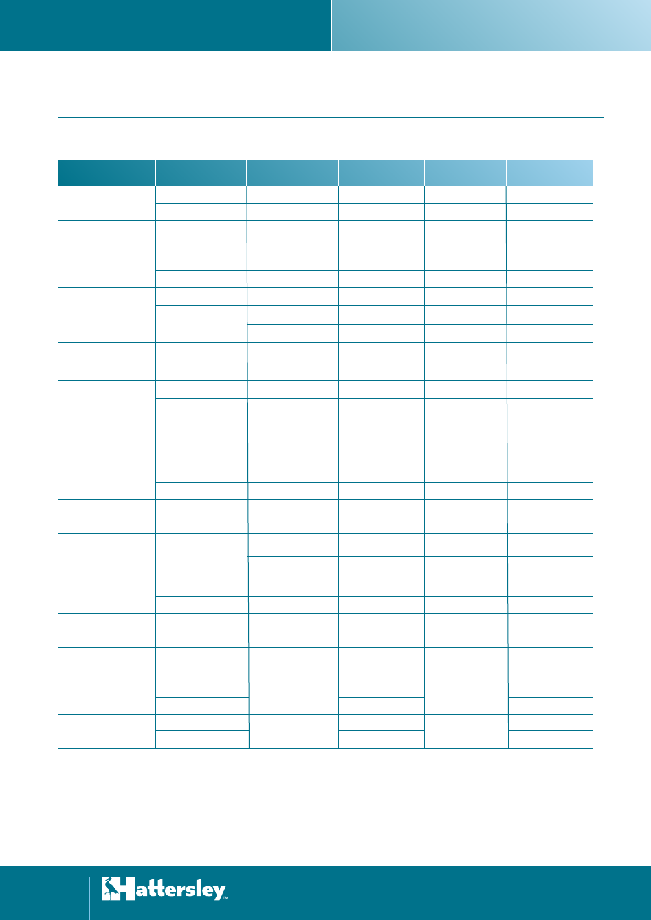
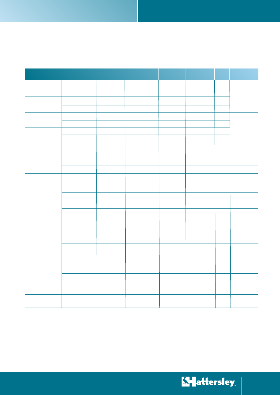
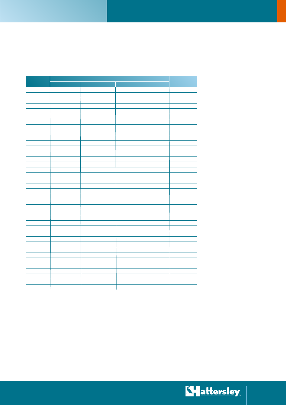
Type Size at 1.0 kPa Signal at 4.7 kPa Signal
1000L 1/2" 0.014 l/s 0.03 l/s
1000M 1/2" 0.028 l/s 0.06 l/s
1000 1/2" 0.054 l/s 0.117 l/s
1000 3/4" 0.116 l/s 0.251 l/s
1000 1" 0.207 l/s 0.449 l/s
1000 11/4" 0.425 l/s 0.923 l/s
1000 11/2" 0.640 l/s 1.388 l/s
1000 2" 1.325 l/s 2.875 l/s
M2000 65mm 2.75 l/s 5.93 l/s
M2000 80mm 3.82 l/s 8.27 l/s
M2000 100mm 6.25 l/s 13.54 l/s
M2000 125mm 9.48 l/s 20.52 l/s
M2000 150mm 13.7 l/s 29.5 l/s
M2000 200mm 23.2 l/s 50.3 l/s
M2000 250mm 34.8 l/s 75.3 l/s
M2000 300mm 50.5 l/s 109.4 l/s
COMMISSIONING VALVE SIZING CHART
Fig. No. Description
266H Hook-Up with 1732 DRV, strainer and
blow down valve for LTHW and MTHW
applications.
266C Hook-Up with 1732 DRV, strainer,
blow down valve and extension stem on
lever operated ball valve for chilled water
applications.
267H Hook-Up with 1832 motorised FODRV,
strainer and blow down valve for
LTHW and MTHW applications.
267C Hook-Up with 1832 motorised
FODRV strainer, blow down valve and
extension stem on lever operated ball valve
for chilled water applications.
268H Hook-Up with 1732 DRV for
LTHW and MTHW applications.
268C Hook-Up with 1732 DRV for chilled water
applications and extension
stem on lever operated ball valve.
262H Hook-Up with 1050 Autoflow for
LTHW and MTHW applications.
262C Hook-Up with 1050 Autoflow for chilled
water applications and extension
stem on lever operated ball valve.
COMPACT HOOK-UP
Based on medium grade pipe and water with an SG of 1.
Valve Selection Guide
Technical Helpline: 0845 604 1790
E: tech-enquiries@hattersley.com W: www.hattersley.com
11
BALANCING VALVES - AUTOMATIC
Balancing Valves - Automatic
Hattersley Autoflow (automatic balancing) valves give users and specifiers
a major alternative to traditional commissioning products.
Autoflow offers a radical, cost-effective method of regulating hot and chilled
water systems. It is available in DZR copper alloy in sizes 1/2" to 2" with
threaded ends and ductile iron in sizes from 21/2" to 14" (65 to 350mm).
• Ensures constant volume irrespective of
pressure fluctuations caused by pump speed or
overflows from operation of remote control valve
• Design changes can be easily made by
selection of the appropriate cartridge,
eliminating the need for recommissioning
• Easy to insulate
• Can be installed in any pipework configuration -
does not require straight lengths of pipe
• Dynamic flow-limiting characteristics permit
variable volume systems to function correctly
• DZR Y-Pattern and universal pattern can
optionally be used as strainers (Figures 1052
and 1053)
• Automatically maintains flow at the specified
rate regardless of fluctuations in pressure
• Factory selection of the appropriate
cartridge provides desired flow rate
• Tamperproof
• Self adjusting universal DZR assembly
with multi-purpose functions
• Compact size
• Energy efficient, preventing overflows
or excess flow rates
FEATURES
BENEFITS
Technical Helpline: 0845 604 1790
E: tech-enquiries@hattersley.com W: www.hattersley.com
12
BALANCING VALVES - AUTOMATIC
Every effort has been made to ensure that the information contained in this publication is accurate at the time of publishing.
Hattersley Ltd assumes no responsibility or liability for typographical errors or omissions or for any misinterpretation of the
information within the publication and reserves the right to change without notice.
For Commissioning Valve Coefficients please refer to pages 47-49.
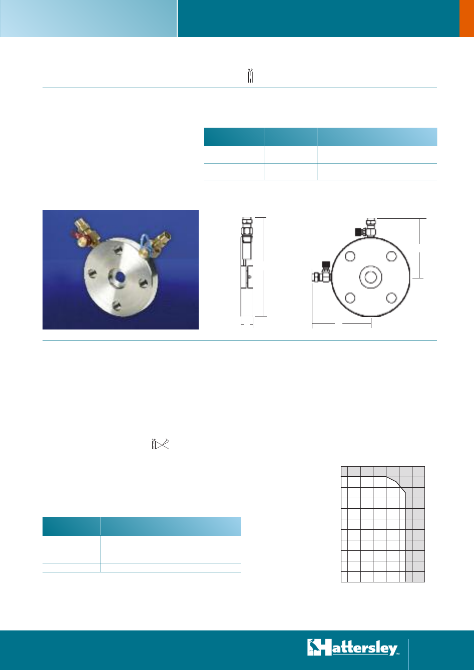
Fig. 1050, 1051, 1052 and 1053
DZR Autoflow
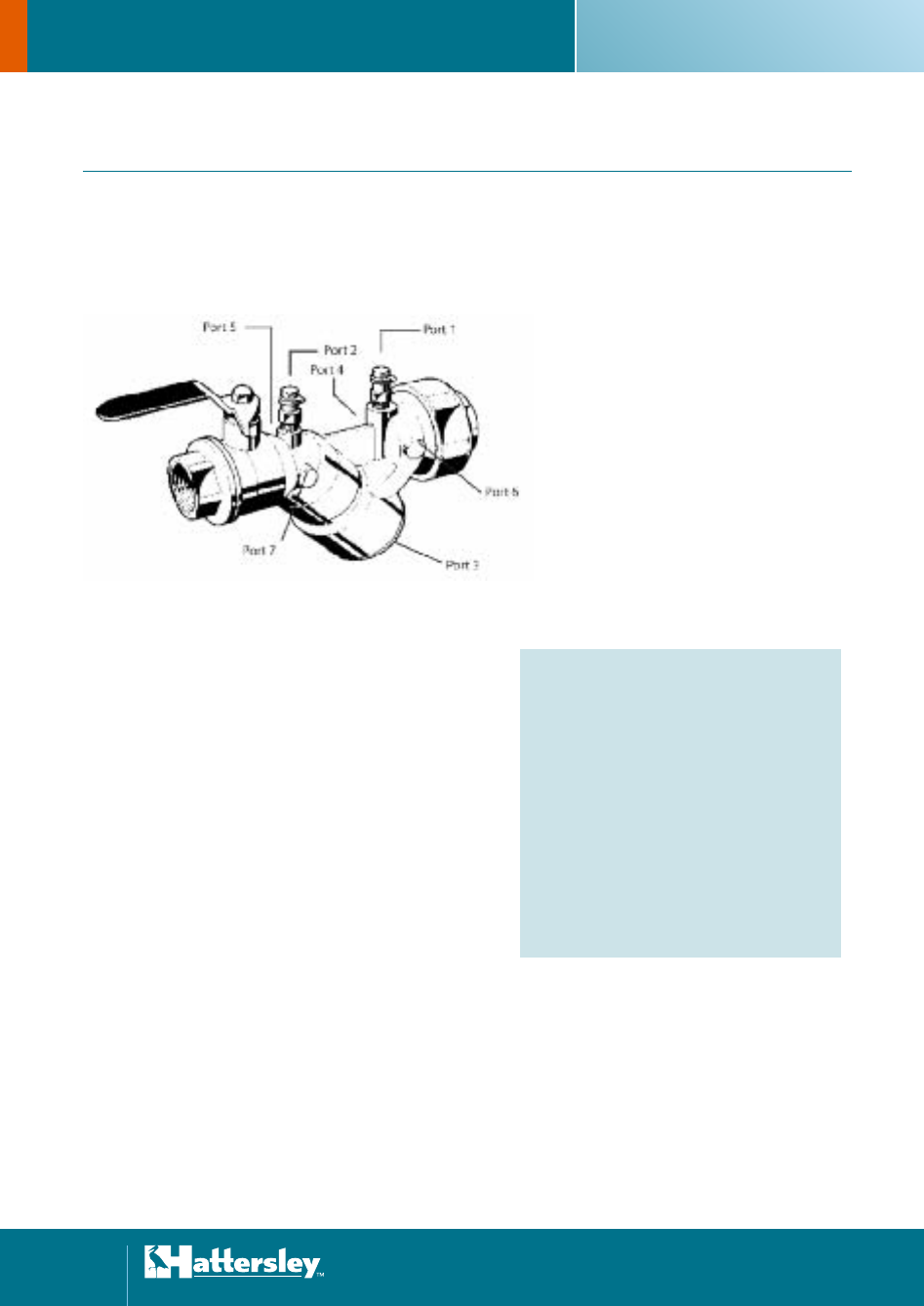
PORT IDENTIFICATION, THREADS AND SPECIFYING INFORMATION
Fig. 1051 shown
Port Identification and Connection Size - Figs. 1050, 1051, 1052 and 1053
•Ports 1 and 2 are threaded 1/4" BSP (Pl) and
fitted with figure 631 test points
•Port 1 can be supplied optionally threaded
1/2" BSP (Pl)
•Port 3 is threaded 1/4 BSP (Pl) in sizes 1/2 to 3/4"
and 1/2" BSP (Pl) in sizes 1 to 2" and fitted with
blank plug
•All other ports can be supplied threaded
1/4" BSP (Pl) to order
•For all figure numbers, ports are identified with
‘Y’ part of body in same orientation
•Ports 4, 5, 6 and 7 apply only to figures 1051/
1053
•Figures 1050/1052 have ports 1, 2 and 3 only
How to Specify Hattersley Autoflow Valves
Automatic balancing valves have replaceable cartridges with flow
rates determined at the factory. The flow cartridges are stainless steel
or nickel finish. Deep drawn metal cartridges are not acceptable.
Each cartridge is coded to indicate specific flow rate duty. The flow
cartridge is 17 to 200 kPa rated as standard. Rating 34 to 400 kPa
available as option.
1/2 to 2" sizes are available with two body types, standard
Y-Pattern and universal Y-Pattern with integral isolating ball valve and
union connection. Bodies are DZR copper alloy with pressure tapping
ports and are fitted with colour coded test points. Optional extended
stems are available with universal type to allow for insulation.
End connections are threaded as standard. 1/2 to 2" sizes have
optional strainer facility in lieu of flow cartridge.
Maximum pressure: 25 bar
Maximum temperature: 120°C
Hattersley Autoflow Ref:
1/2 to 2" DZR Y-Pattern: Fig.1050
1/2 to 2" DZR Universal Pattern: Fig. 1051
65 to 350mm Ductile Iron: Fig. 2050
NES Ref: Y11.2230
Technical Helpline: 0845 604 1790
E: tech-enquiries@hattersley.com W: www.hattersley.com
13
Fig. 1050, 1051 DZR Autoflow
Fig. 2050 Ductile Iron Autoflow
FLOW RATES
Every effort has been made to
ensure that the information
contained in this publication is
accurate at the time of publishing.
Hattersley Ltd assumes no
responsibility or liability for
typographical errors or omissions
or for any misinterpretation of the
information within the publication
and reserves the right to change
without notice.
For Commissioning Valve
Coefficients please refer to
pages 47-49.
Valve Recommended Velocity Maximum Velocity
Size Minimum Flow (l/s) (m/s) Flow (l/s)
6 4.7 0.25 34 1.79
8 8.5 0.25 60 1.79
10 12.6 0.24 94 1.76
12 17.7 0.23 128 1.70
14 22.7 0.25 162 1.82
Flow Rates for Valves 6" (150mm) and above
Flow Cartridge Pipe Velocity
(l/s) Code Size (inch) Adaptor (inch to inch) (m/s)
0.021 T 0.50 No Adaptor 0.10
0.032 Y 0.50 No Adaptor 0.16
0.042 U 0.50 No Adaptor 0.21
0.047 Z 0.50 No Adaptor 0.23
0.056 V 0.50 No Adaptor 0.28
0.063 A 0.50 No Adaptor 0.31
0.079 AX 0.50 No Adaptor 0.39
0.095 AY 0.50 No Adaptor 0.47
0.110 AZ 0.50 No Adaptor 0.54
0.126 B 0.50 No Adaptor 0.62
0.142 BX 0.50 No Adaptor 0.70
0.158 BY 0.50 No Adaptor 0.78
0.166 BU 0.50 No Adaptor 0.82
0.174 BZ 0.50 No Adaptor 0.85
0.189 C 0.50 No Adaptor 0.93
0.221 CY 0.50 No Adaptor 1.09
0.253 D 0.50 No Adaptor 1.24
0.284 DY 0.50 No Adaptor 1.40
0.316 E 0.75 No Adaptor 1.55
0.379 F 0.75 No Adaptor 1.86
0.442 G 0.75 No Adaptor 2.17
1/2" Body
Flow Cartridge Pipe Velocity
(l/s) Code Size (inch) Adaptor (inch to inch) (m/s)
0.021 T 0.50 No Adaptor 0.06
0.032 Y 0.50 No Adaptor 0.09
0.042 U 0.50 No Adaptor 0.12
0.047 Z 0.50 No Adaptor 0.13
0.056 V 0.50 No Adaptor 0.15
0.063 A 0.50 No Adaptor 0.17
0.079 AX 0.50 No Adaptor 0.22
0.095 AY 0.50 No Adaptor 0.26
0.110 AZ 0.50 No Adaptor 0.30
0.126 B 0.50 No Adaptor 0.34
0.142 BX 0.50 No Adaptor 0.39
0.158 BY 0.50 No Adaptor 0.43
0.166 BU 0.50 No Adaptor 0.45
0.174 BZ 0.50 No Adaptor 0.47
0.189 C 0.50 No Adaptor 0.52
0.221 CY 0.50 No Adaptor 0.60
0.253 D 0.50 No Adaptor 0.69
0.284 DY 0.50 No Adaptor 0.78
0.316 E 0.75 No adaptor 0.86
0.379 F 0.75 No adaptor 1.03
0.442 G 0.75 No adaptor 1.21
0.505 H 0.75 No adaptor 1.38
3/4" Body
The following tables list the
flow rates attainable using the
standard range of cartridges
and adaptors for valves up to
100mm (4") size.
Above this size a multi-
cartridge permutation is used
to obtain the desired flow rate.
These tables indicate the
minimum and maximum flow
rates for each size from 150 to
350mm (6 to 14"). Flow rates
increase in increments of
approximately 0.32l/s.
BALANCING VALVES - AUTOMATIC
Technical Helpline: 0845 604 1790
E: tech-enquiries@hattersley.com W: www.hattersley.com
14
BALANCING VALVES - AUTOMATIC
Every effort has been made to ensure that the information contained in this publication is accurate at the time of publishing.
Hattersley Ltd assumes no responsibility or liability for typographical errors or omissions or for any misinterpretation of the
information within the publication and reserves the right to change without notice.
For Commissioning Valve Coefficients please refer to pages 47-49.
Fig. 1050, 1051 DZR Autoflow
Fig. 2050 Ductile Iron Autoflow
Flow Cartridge Pipe Velocity
(l/s) Code Size (inch) Adaptor (inch to inch) (m/s)
0.042 U 0.50 1.25 to 0.75 0.07
0.047 Z 0.50 1.25 to 0.75 0.08
0.064 A 0.50 1.25 to 0.75 0.11
0.079 AX 0.50 1.25 to 0.75 0.13
0.095 AY 0.50 1.25 to 0.75 0.16
0.110 AZ 0.50 1.25 to 0.75 0.19
0.126 B 0.50 1.25 to 0.75 0.22
0.158 BY 0.50 1.25 to 0.75 0.27
0.169 BU 0.50 1.25 to 0.75 0.29
0.189 C 0.50 1.25 to 0.75 0.32
0.221 CY 0.50 1.25 to 0.75 0.38
0.253 D 0.50 1.25 to 0.75 0.43
0.284 DY 0.50 1.25 to 0.75 0.49
0.316 E 0.75 1.25 to 0.75 0.54
0.379 F 0.75 1.25 to 0.75 0.65
0.442 G 0.75 1.25 to 0.75 0.75
0.505 H 0.75 1.25 to 0.75 0.86
0.568 I 1.25 No adaptor 0.97
0.631 AO 1.25 No adaptor 1.08
0.694 AA 1.25 No adaptor 1.19
0.758 AB 1.25 No adaptor 1.29
0.821 AC 1.25 No adaptor 1.40
0.884 AD 1.25 No adaptor 1.51
0.947 AE 1.25 No adaptor 1.62
1.010 AF 1.25 No adaptor 1.73
1.073 AG 1.25 No adaptor 1.83
1.136 AH 1.25 No adaptor 1.94
1" Body
Flow Cartridge Pipe Velocity
(l/s) Code Size (inch) Adaptor (inch to inch) (m/s)
0.189 C 0.50 1.25 to 0.75 0.19
0.221 CY 0.50 1.25 to 0.75 0.22
0.253 D 0.50 1.25 to 0.75 0.25
0.284 DY 0.50 1.25 to 0.75 0.28
0.316 E 0.75 1.25 to 0.75 0.31
0.375 F 0.75 1.25 to 0.75 0.37
0.442 G 0.75 1.25 to 0.75 0.43
0.505 H 0.75 1.25 to 0.75 0.50
0.568 I 1.25 No adaptor 0.56
0.631 AO 1.25 No adaptor 0.62
0.694 AA 1.25 No adaptor 0.68
0.758 AB 1.25 No adaptor 0.74
0.821 AC 1.25 No adaptor 0.81
0.884 AD 1.25 No adaptor 0.87
0.947 AE 1.25 No adaptor 0.93
1.010 AF 1.25 No adaptor 0.99
1.073 AG 1.25 No adaptor 1.05
1.136 AH 1.25 No adaptor 1.12
1.199 AI 1.25 No adaptor 1.18
11/4" Body
FLOW RATES
Technical Helpline: 0845 604 1790
E: tech-enquiries@hattersley.com W: www.hattersley.com
15
Every effort has been made to ensure that the information contained in this publication is accurate at the time of publishing.
Hattersley Ltd assumes no responsibility or liability for typographical errors or omissions or for any misinterpretation of the
information within the publication and reserves the right to change without notice.
For Commissioning Valve Coefficients please refer to pages 47-49.
Fig. 1050, 1051 DZR Autoflow
Fig. 2050 Ductile Iron Autoflow
Flow Cartridge Pipe Velocity
(l/s) Code Size (inch) Adaptor (inch to inch) (m/s)
0.442 G 0.75 2 to 0.75 0.32
0.505 H 0.75 2 to 0.75 0.37
0.568 I 1.25 2 to 1.25 0.41
0.631 AO 1.25 2 to 1.25 0.46
0.694 AA 1.25 2 to 1.25 0.50
0.758 AB 1.25 2 to 1.25 0.55
0.821 AC 1.25 2 to 1.25 0.60
0.884 AD 1.25 2 to 1.25 0.64
0.947 AE 1.25 2 to 1.25 0.69
1.010 AF 1.25 2 to 1.25 0.73
1.073 AG 1.25 2 to 1.25 0.78
1.136 AH 1.25 2 to 1.25 0.82
1.199 AI 1.25 2 to 1.25 0.87
1.263 BO 2 No adaptor 0.92
1.389 BB 2 No adaptor 1.01
1.515 BD 2 No adaptor 1.10
1.641 BF 2 No adaptor 1.19
1.768 BH 2 No adaptor 1.28
1.894 CO 2 No adaptor 1.37
2.020 CB 2 No adaptor 1.46
2.146 CD 2 No adaptor 1.56
2.273 CF 2 No adaptor 1.65
2.399 CH 2 No adaptor 1.74
2.525 DO 2 No adaptor 1.83
2.651 DB 2 No adaptor 1.92
2.778 DD 2 No adaptor 2.01
11/2" Body
Flow Cartridge Pipe Velocity
(l/s) Code Size (inch) Adaptor (inch to inch) (m/s)
0.821 AC 1.25 2 to 1.25 0.37
0.884 AD 1.25 2 to 1.25 0.40
0.947 AE 1.25 2 to 1.25 0.43
1.263 BO 2 No adaptor 0.57
1.389 BB 2 No adaptor 0.63
1.515 BD 2 No adaptor 0.69
1.641 BF 2 No adaptor 0.74
1.768 BH 2 No adaptor 0.80
1.894 CO 2 No adaptor 0.86
2.020 CB 2 No adaptor 0.92
2.146 CD 2 No adaptor 0.97
2.273 CF 2 No adaptor 1.03
2.399 CH 2 No adaptor 1.09
2.525 DO 2 No adaptor 1.14
2.651 DB 2 No adaptor 1.20
2.778 DD 2 No adaptor 1.26
2.904 DF 2 No adaptor 1.32
3.030 DH 2 No adaptor 1.37
3.157 EO 2 No adaptor 1.43
2" Body
FLOW RATES
BALANCING VALVES - AUTOMATIC
Technical Helpline: 0845 604 1790
E: tech-enquiries@hattersley.com W: www.hattersley.com
16
BALANCING VALVES - AUTOMATIC
Fig. 1050, 1051 DZR Autoflow
Fig. 2050 Ductile Iron Autoflow
Every effort has been made to
ensure that the information
contained in this publication is
accurate at the time of publishing.
Hattersley Ltd assumes no
responsibility or liability for
typographical errors or omissions
or for any misinterpretation of the
information within the publication
and reserves the right to change
without notice.
For Commissioning Valve
Coefficients please refer to
pages 47-49.
Flow Cartridge Pipe Velocity
(l/s) Code Size (inch) Adaptor (inch to inch) (m/s)
1.199 AI 1.25 2.5 to 1.25 0.32
1.263 BO 2 2.5 to 2 0.34
1.389 BB 2 2.5 to 2 0.37
1.515 BD 2 2.5 to 2 0.41
1.641 BF 2 2.5 to 2 0.44
1.768 BH 2 2.5 to 2 0.48
1.894 CO 2 2.5 to 2 0.51
2.020 CB 2 2.5 to 2 0.54
2.146 CD 2 2.5 to 2 0.58
2.273 CF 2 2.5 to 2 0.61
2.399 CH 2 2.5 to 2 0.65
2.525 DO 2 2.5 to 2 0.68
2.651 DB 2 2.5 to 2 0.72
2.778 DD 2 2.5 to 2 0.75
2.904 DF 2 2.5 to 2 0.78
3.030 DH 2 2.5 to 2 0.82
3.157 EO 2 2.5 to 2 0.85
3.283 EB 2.5 No adaptor 0.89
3.535 EF 2.5 No adaptor 0.95
3.788 FO 2.5 No adaptor 1.02
4.040 FD 2.5 No adaptor 1.09
4.293 FH 2.5 No adaptor 1.16
4.545 GB 2.5 No adaptor 1.23
21/2" Body
Flow Cartridge Pipe Velocity
(l/s) Code Size (inch) Adaptor (inch to inch) (m/s)
2.146 CD 2 3 to 2 0.42
2.273 CF 2 3 to 2 0.44
2.399 CH 2 3 to 2 0.47
2.525 DO 2 3 to 2 0.49
2.651 DB 2 3 to 2 0.52
2.778 DD 2 3 to 2 0.54
2.904 DF 2 3 to 2 0.57
3.030 DH 2 3 to 2 0.59
3.157 EO 2 3 to 2 0.62
3.283 EB 3 No adaptor 0.64
3.535 EF 3 No adaptor 0.69
3.788 FO 3 No adaptor 0.74
4.040 FD 3 No adaptor 0.79
4.293 FH 3 No adaptor 0.84
4.545 GB 3 No adaptor 0.89
4.735 GE 3 No adaptor 0.93
5.050 HO 3 No adaptor 0.99
5.366 HE 3 No adaptor 1.05
5.682 IO 3 No adaptor 1.11
5.997 IE 3 No adaptor 1.17
6.313 AOO 3 No adaptor 1.23
6.629 AOE 3 No adaptor 1.30
6.944 AAO 3 No adaptor 1.36
7.260 AAE 3 No adaptor 1.42
7.576 ABO 3 No adaptor 1.48
7.891 ABE 3 No adaptor 1.54
8.207 ACO 3 No adaptor 1.60
8.523 ACE 3 No adaptor 1.67
3" Body ANSI
FLOW RATES
Technical Helpline: 0845 604 1790
E: tech-enquiries@hattersley.com W: www.hattersley.com
17
BALANCING VALVES - AUTOMATIC
Every effort has been made to ensure that the information contained in this publication is accurate at the time of publishing.
Hattersley Ltd assumes no responsibility or liability for typographical errors or omissions or for any misinterpretation of the
information within the publication and reserves the right to change without notice.
For Commissioning Valve Coefficients please refer to pages 47-49.
Fig. 1050, 1051 DZR Autoflow
Fig. 2050 Ductile Iron Autoflow
Flow Cartridge Pipe Velocity
(l/s) Code Size (inch) Adaptor (inch to inch) (m/s)
5.366 HE 3/B No adaptor 0.62
5.682 IO 3/B No adaptor 0.65
5.997 IE 3/B No adaptor 0.69
6.313 AOO 3/B No adaptor 0.73
6.629 AOE 3/B No adaptor 0.77
6.944 AAO 3/B No adaptor 0.81
7.260 AAE 3/B No adaptor 0.84
7.576 ABO 3/B No adaptor 0.87
7.891 ABE 3/B No adaptor 0.91
8.207 ACO 3/B No adaptor 0.95
8.523 ACE 3/B No adaptor 0.98
8.838 ADO 3/2 No adaptor/3 to 2 1.02
9.154 ADE 3/2 No adaptor/3 to 2 1.06
9.470 AEO 3/3 No adaptor 1.09
9.785 AEE 3/3 No adaptor 1.13
10.101 AFO 3/3 No adaptor 1.16
10.416 AFE 3/3 No adaptor 1.20
10.732 AGO 3/3 No adaptor 1.24
11.048 AGE 3/3 No adaptor 1.27
11.363 AHO 3/3 No adaptor 1.31
11.679 AHE 3/3 No adaptor 1.35
11.995 AIO 3/3 No adaptor 1.38
12.310 AIE 3/3 No adaptor 1.42
12.626 BOO 3/3 No adaptor 1.46
12.942 BOE 3/3 No adaptor 1.49
13.257 BAO 3/3 No adaptor 1.53
13.573 BAE 3/3 No adaptor 1.56
13.889 BBO 3/3 No adaptor 1.60
14.204 BBE 3/3 No adaptor 1.64
14.520 BCO 3/3 No adaptor 1.67
14.836 BCE 3/3 No adaptor 1.71
15.151 BDO 3/3 No adaptor 1.75
15.467 BDE 3/3 No adaptor 1.78
15.783 BEO 3/3 No adaptor 1.82
16.098 BEE 3/3 No adaptor 1.86
16.414 BFO 3/3 No adaptor 1.89
16.729 BFE 3/3 No adaptor 1.93
17.045 GO 3/3 No adaptor 1.96
4" Body ANSI (fittings provided for installation in PN16 rated systems)
FLOW RATES
Technical Helpline: 0845 604 1790
E: tech-enquiries@hattersley.com W: www.hattersley.com
18
BALANCING VALVES - AUTOMATIC
25 BAR
Every effort has been made to ensure that the information contained in this publication is accurate at the time of publishing.
Hattersley Ltd assumes no responsibility or liability for typographical errors or omissions or for any misinterpretation of the
information within the publication and reserves the right to change without notice.
For Commissioning Valve Coefficients please refer to pages 47-49.
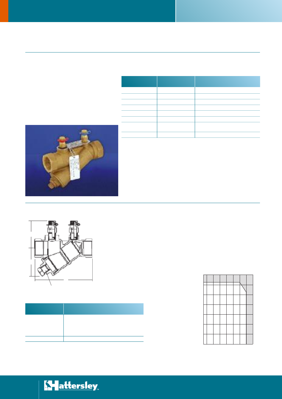
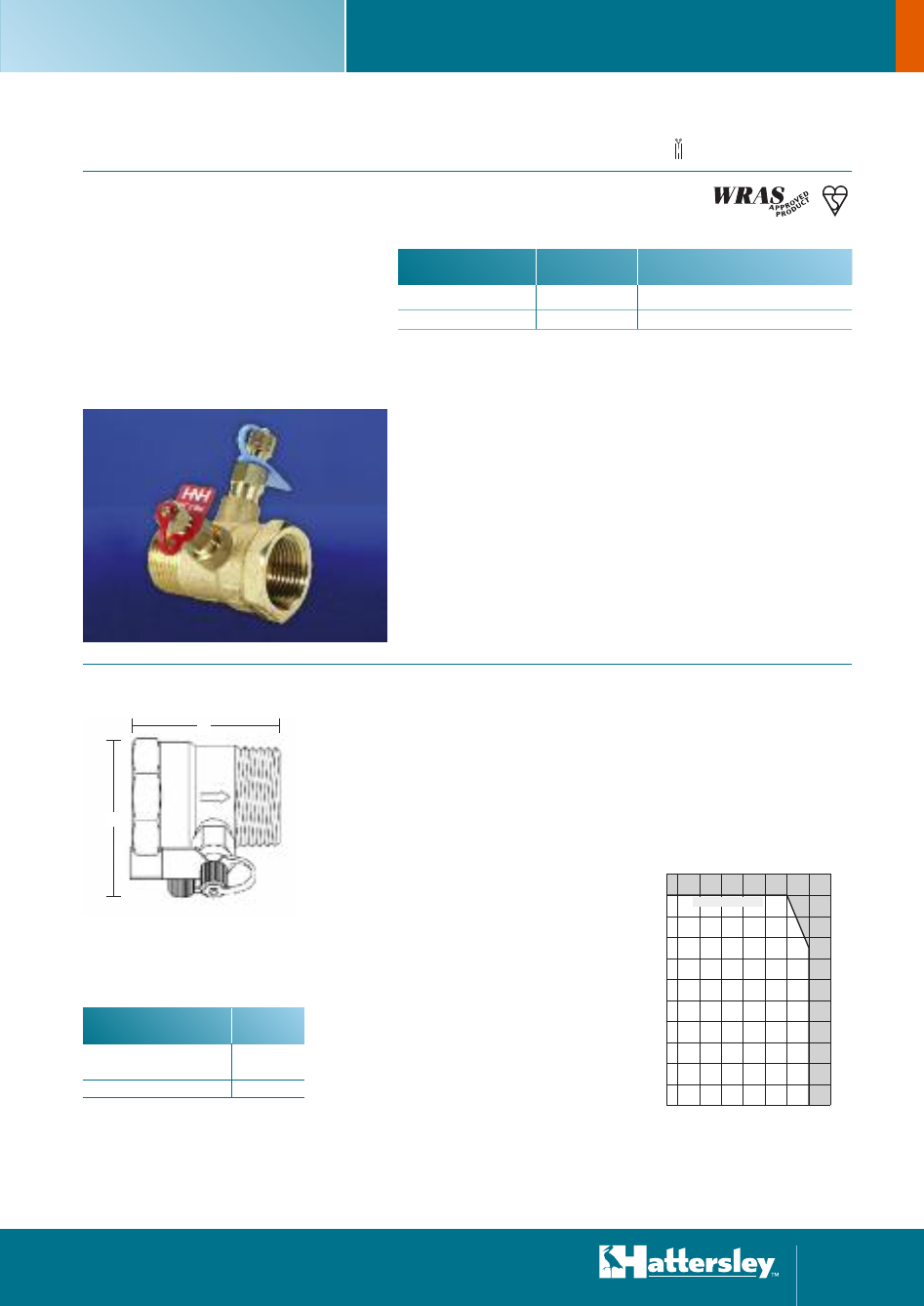
Fig. 1050 (Flow Control) Fig. 1052 (Strainer)
DZR Y-Pattern Autoflow
DIMENSIONAL DRAWINGS PRESSURE/
TEMPERATURE RATING
21 bar at 120ºC
25 bar up to 100ºC
TEST PRESSURES
(HYDRAULIC)
Shell: 37.5 bar
SPECIFICATION
Taper threaded BS EN 10266 (ISO 7-1)
formerly BS 21.
Autoflow regulator is factory set for
correct flow.
Cartridge removable from body to provide
access for change, inspection and cleaning
without removing body from pipeline.
Supplied with two figure 631 test points in
port positions 1 and 2 - see page 10.
Other ports can be supplied threaded,
see page 10 for details.
Drain valve optional.
Test points can be supplied with extension
pieces to clear insulation.
Tagged with flow rate.
Figure 1052 fitted with 20 mesh stainless
steel filter in lieu of flow cartridge.
FEATURES AND BENEFITS
• Ensures constant volume irrespective
of changing conditions
• Energy efficient, preventing overflows
or excess flow rates
• Tamperproof
MATERIAL SPECIFICATION
Body DZR Copper Alloy 12164 CW602N
Cover DZR Copper Alloy 12164 CW602N
Seals EPDM
Drain Plug Brass 12164 CW614N
Test Point Fig. 631
Flow Cartridge Stainless Steel 10270 X10CrNr18-8 A276-304
Flow Cartridge
Adaptor Brass 12164 CW619N
Strainer Element Stainless Steel 10270 X10CrNr18-8 A276-304
Component Material Specification
BS EN ASTM
0 20 40 60 80 100 120 140
Temperature ˚C
28
24
20
16
12
4
0
Pressure bar
8
E
B
C
A
Nom
Size in 1/2 3/4 1 11/4 11/2 2
A mm 101 106 141 148 177 179
B mm 51 51 68 68 104 104
C (Approx) mm 56 56 60 60 65 65
E (BS21 Pl) 1/4 1/4 1/2 1/2 1/2 1/2
Weight kg 0.52 0.55 0.98 1.1 2.2 2.4
DIMENSIONS AND WEIGHTS
Technical Helpline: 0845 604 1790
E: tech-enquiries@hattersley.com W: www.hattersley.com
19
BALANCING VALVES - AUTOMATIC
Every effort has been made to ensure that the information contained in this publication is accurate at the time of publishing.
Hattersley Ltd assumes no responsibility or liability for typographical errors or omissions or for any misinterpretation of the
information within the publication and reserves the right to change without notice.
For Commissioning Valve Coefficients please refer to pages 47-49.
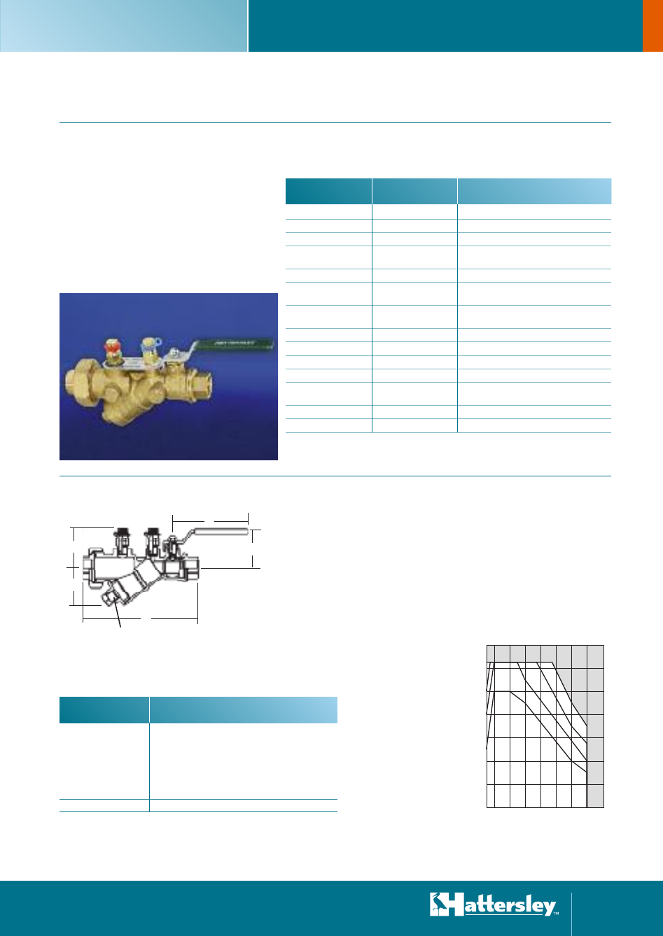
Fig. 1051 (Flow Control) Fig. 1053 (Strainer)
DZR Universal Autoflow
DIMENSIONAL DRAWINGS PRESSURE/
TEMPERATURE RATING
See pressure/temperature chart
TEST PRESSURES
(HYDRAULIC)
Shell: 37.5 bar
SPECIFICATION
Taper threaded BS EN 10266 (ISO 7-1)
formerly BS 21.
Autoflow regulator factory set to automatically
ensure correct flow.
Cartridge removable from body to provide
access for change, inspection and cleaning
without removing body from pipeline.
Supplied with two figure 631 test points in
port positions 1 and 2 - see page 10.
Other ports can be supplied drilled and tapped,
see page 10 for details.
Drain valve optional.
Extension stem for ball valve available.
Test points can be supplied with extension
pieces to clear insulation.
Tagged with flow rate.
Figure 1053 fitted with 20 mesh stainless steel
filter in lieu of flow cartridge.
Alternative end connections available on request.
FEATURES AND BENEFITS
• Ensures constant volume irrespective
of changing conditions
• Energy efficient, preventing overflows
or excess flow rates
• Tamperproof
MATERIAL SPECIFICATION
Body DZR Copper Alloy 12164 CW602N
Tail Pipe DZR Copper Alloy 12164 CW602N
Union Nut Brass 12164 CW614N
Ball (hard
chrome plated) Brass 12164 CW614N
Stem Brass 12164 CW614N
Stem Seals PTFE or PTFE/
Neoprene
Seats PTFE or PTFE/
Neoprene
Cover DZR Copper Alloy 12164 CW602N
Drain Plug Brass 12164 CW614N
Test Point Fig. 631
Flow Cartridge Stainless Steel 10270 X10CrNr18-8 A276-304
Flow Cartridge
Adaptor Brass 12164 CW614N
Seals EPDM
Strainer Element Stainless Steel 10270 X10CrNr18-8 A276-304
Component Material Specification
BS EN ASTM
Nom
Size in 1/2 3/4 1 11/4 11/2 2
A mm 157 160 219 221 253 253
B mm 51 51 68 68 103 103
C (Approx) mm 56 56 60 60 65 65
D mm 51 51 66 66 87 87
E (BS21 Pl) 1/4 1/4 1/2 1/2 1/2 1/2
F mm 100 100 120 120 140 140
Weight kg 1.1 1.1 2.3 2.3 4.6 4.6
DIMENSIONS AND WEIGHTS
0
20
40
60
80
100
140 120
T emperature ˚ C
28
24
20
16
12
4
0
Pressure bar
8
1
/
2
to
3
/
4
in
1in
1
1
/
4
to 1
1
/
2
in
2in
A
D
C
B
E
F
Technical Helpline: 0845 604 1790
E: tech-enquiries@hattersley.com W: www.hattersley.com
20
BALANCING VALVES - AUTOMATIC
PN16
Every effort has been made to ensure that the information contained in this publication is accurate at the time of publishing.
Hattersley Ltd assumes no responsibility or liability for typographical errors or omissions or for any misinterpretation of the
information within the publication and reserves the right to change without notice.
For Commissioning Valve Coefficients please refer to pages 47-49.
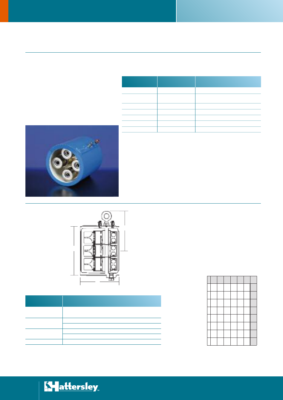
Fig. 2050
Ductile Iron Autoflow
PRESSURE/
TEMPERATURE RATING
16 bar from -10 to 120ºC
TEST PRESSURES
(HYDRAULIC)
Shell: 24 bar
SPECIFICATION
Ductile iron body designed to fit between
ANSI 150 flanges. A pair of ANSI 150
slip-on flanges will be supplied with the
assembly where required for installation
into BS1387 tube
Supplied with lifting eye bolt to assist
with installation.
Autoflow regulator factory set to
automatically ensure correct flow.
Changes to flow specification can be
accommodated by changing the
relevant flow regulators.
Supplied complete with two figure 631
test points and drain plug.
Optional bolts and gaskets available.
Suitable for PN40 pressure rating.
FEATURES AND BENEFITS
• Ensures constant volume irrespective
of changing conditions
• Energy efficient, preventing overflows
or excess flow rates
• Tamperproof
MATERIAL SPECIFICATION
Body Ductile Iron 1563 EN GJS 500/7 A536 60-40-18
Flow Cartridge Brass 12164 CW614N
Adaptor
Test Points Fig. 631
Flow Cartridge Nickel Plated Brass
Seals EPDM
Drain Plug Brass 12164 CW614N
Eye Bolt Steel
Component Material Specification
BS EN ASTM
A
B
D
0 20 40 60 80 100 120 140
Temperature ˚C
14
12
10
8
6
2
0
Pressure bar
4
16
18
Nom mm 65 80 100 150 200 250 300 350
Size in 21/2 3 4 6 8 10 12 14
A mm 148 223 244 258 279 279 279 279
in 5.82 8.78 8.78 8.78 8.78 8.78 8.78 8.78
B (Approx) mm - - 155 175 205 235 250 300
in - - 6 7 8 9 10 12
D mm 108 127 173 216 280 340 406 450
in 4.25 5.00 6.82 8.50 11.00 13.35 16.00 17.72
*Weight (max) kg 6.1 10 12 19 30 35 53 69
DIMENSIONS AND WEIGHTS
DIMENSIONAL DRAWINGS
Technical Helpline: 0845 604 1790
E: tech-enquiries@hattersley.com W: www.hattersley.com
21
BALANCING VALVES - STATIC
Balancing Valves - Static
Hattersley’s range of static balancing valves
includes Double Regulating Valves and Fixed
Orifice Double Regulating Valves. The integral
fixed orifice design offers greater accuracy,
makes set-up easier and involves fewer
connections resulting in lower installation costs.
Available in medium and low flow versions,
Hattersley’s static balancing valves offer positive
flow control at all handwheel settings.
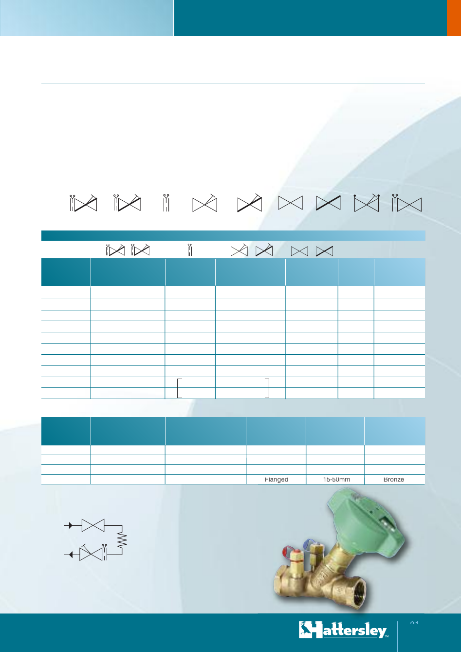
Service Commissioning Metering Double Regulating End Size Body
Set (CS) Station (MS) Valve (DRV) Connections Range Material
Fig. No. Fig. No. Fig. No.
Chilled Water 2432 1000 1432 Screwed
1/2
- 2" Bronze/DZR
LTHW, MTHW 2432C 1000 1432C Compression 15mm Bronze/DZR
- 1732 + 1832 -----
- 1732C + 1832C -----
- 1732L + 1832L --Screwed
1/2
" Bronze/DZR
- 1732LC + 1832LC --Compression 15mm Bronze/DZR
- 1732M + 1832M --Screwed
1/2
" Bronze/DZR
- 1732MC + 1832MC --Compression 15mm Bronze/DZR
HTHW 5200 - 1200DR Flanged 15-50mm Bronze
--4000 ---Stainless Steel
ONE VALVE SYSTEM (MEASUREMENT AND REGULATION AT ONE POINT)
Commissioning Set Components
Service FODRV/ Isolating Valve End Size Range Body
VODRV Fig. No. Connections Material
Fig. No.
Chilled Water 1732 30 Screwed
1/2
- 2" DZR
- 1832 ----
LTHW MTHW M737 M541 Flanged 50-300mm Cast Iron
HTHW 1200DRZ 1200 Flanged 15-50mm Bronze
Commissioning
Set (Globe)
Commissioning
Set (Butterfly)
Metering
Station
Double Regulating
Valve (Globe)
Double Regulating
Valve (Butterfly)
Isolating Valve
(Gate)
Isolating Valve
(Butterfly)
Pressure Tapped
Valve (Globe)
Pressure Tapped
Valve (MS + IV)
IV
CS
Preferred Arrangement
VARIABLE ORIFICE DOUBLE REGULATING VALVES (VODRV’S)
1732 FODRV replaces Bronze VODRV
Technical Helpline: 0845 604 1790
E: tech-enquiries@hattersley.com W: www.hattersley.com
22
BALANCING VALVES - STATIC
Every effort has been made to ensure that the information contained in this publication is accurate at the time of publishing.
Hattersley Ltd assumes no responsibility or liability for typographical errors or omissions or for any misinterpretation of the
information within the publication and reserves the right to change without notice.
For Commissioning Valve Coefficients please refer to pages 47-49.
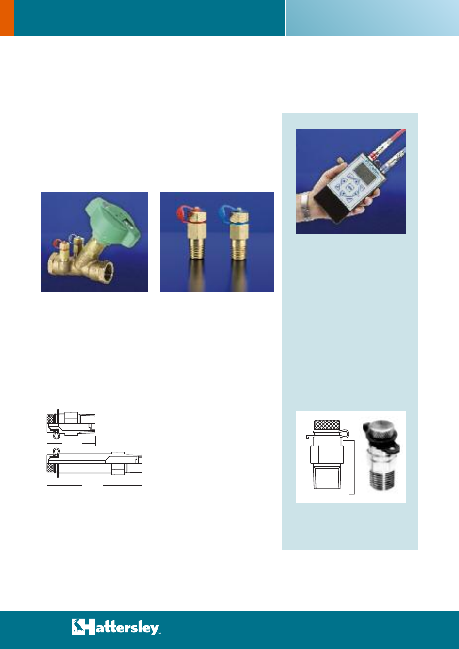
36mm
68mm
Strategically placed test points allow
access to live fluid systems for
pressure and temperature
measurements. Maximum
temperature is 120°C and maximum
pressure is 3450kPa. Suitable for
Chilled Water, LTHW and MTHW.
The single piece DZR copper alloy
body houses a uniquely designed
elastomeric core, providing excellent
sealing performance and wear
resistance.
Double sealing on the cap is
provided by precision metal to metal
jointing backed up by a resilient
O-Ring, allowing convenient, positive
finger tightening.
Elastomer Seal
Fig. 631
for Pressure and Temperature Measurement Hattersley Test Points
BS 7350
When fitted to measuring devices
and strainers, test points are
supplied with cap retainers in red
and blue for upstream and
downstream port identification.This
meets the requirements of BS 7350.
Test Probes
The application of a silicone lubricant
to the probe shaft prior
to insertion is recommended.
Test points are available in either
standard length, figure 631, or
extended length, figure 633, both
threaded 1/4" BSP (Tr). The extended
length test point requires special test
probe available from Hattersley.
Hattersley figure 631 test points are
WRAS Approved products and are
listed in the water fittings and
materials directory.
Test points are fitted with green cap
retainers.
Figure 631 - 10 test points per pack
Figure 633 - 5 test points per pack
Technical Helpline: 0845 604 1790
E: tech-enquiries@hattersley.com W: www.hattersley.com
23
BALANCING VALVES - STATIC
Every effort has been made to ensure that the information contained in this publication is accurate at the time of publishing.
Hattersley Ltd assumes no responsibility or liability for typographical errors or omissions or for any misinterpretation of the
information within the publication and reserves the right to change without notice.
For Commissioning Valve Coefficients please refer to pages 47-49.
DIMENSIONAL DRAWINGS
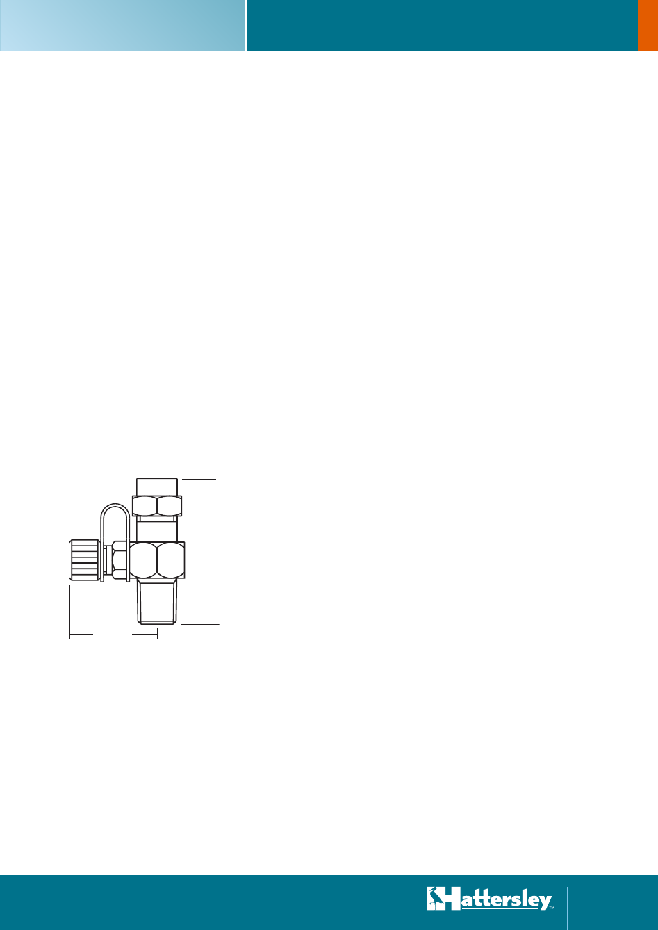
Fig. 750
Hattersley Valve Controlled Test Points
FEATURES AND BENEFITS
• Double isolating
• Uses standard air vent key
• Fitted with cap retainers in red
and blue for upstream and
downstream port identification.
When used in pairs on measuring
devices this meets the
requirements of BS 7350
• Recommended by Hattersley and
fitted as standard to Hattersley
M3000 and 4000 metering stations
• Copper alloy construction
• Accepts commercially available probes
• Threaded 1/4 ISO 7 (Tr)
30mm
50mm
Suitable for 40 bar pressure up to 180°C
including HTHW service.
Technical Helpline: 0845 604 1790
E: tech-enquiries@hattersley.com W: www.hattersley.com
24
BALANCING VALVES - STATIC
PN20 - SERIES B (THREADED)
Every effort has been made to ensure that the information contained in this publication is accurate at the time of publishing.
Hattersley Ltd assumes no responsibility or liability for typographical errors or omissions or for any misinterpretation of the
information within the publication and reserves the right to change without notice.
For Commissioning Valve Coefficients please refer to pages 47-49.
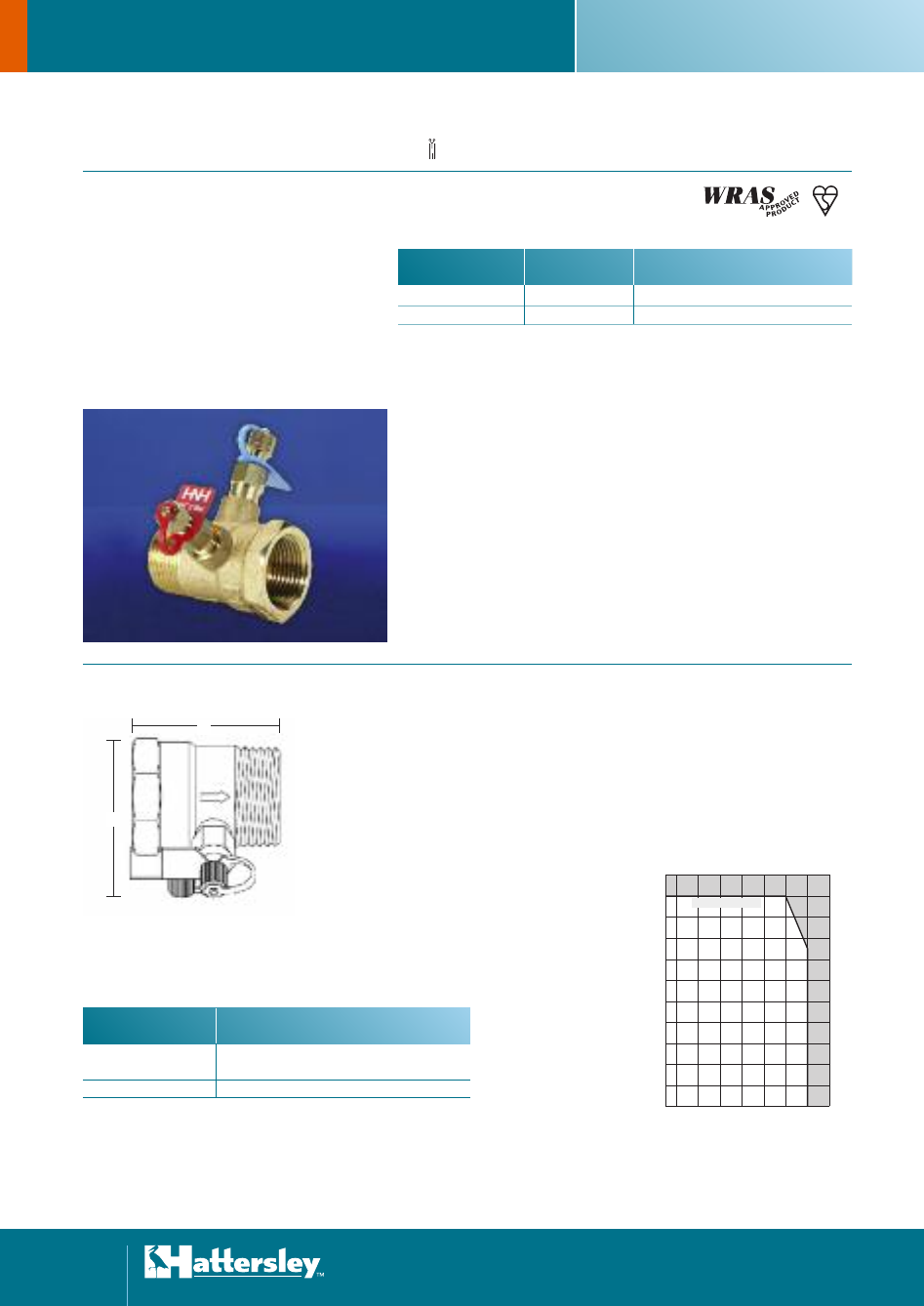
Fig. 1000
DZR Brass Metering Stations
DIMENSIONAL DRAWINGS PRESSURE/
TEMPERATURE RATING
Threaded Ends
PN20 Series B
15 bar at 120ºC
20 bar from -10 to 100ºC
TEST PRESSURES
(HYDRAULIC)
Shell: 30 bar
SPECIFICATION
Kitemarked to BS 7350:1990.
WRAS Approved Product.
Supplied fitted with two figure 631 test points
Figure 1000 end connections threaded to
BS EN 10266 (ISO 7-1) formerly BS 21.
Taper female with the exception of the 1/2" inlet
which is parallel.
FEATURES AND BENEFITS
• Precise and accurate measurement,
conforming to BS 7350:1990
• Dezincification resistant material preventing
corrosion cracking and fungal growth
• WRAS approved for use with potable water
• Supplied with red and blue test points for
upstream and downstream port identification
MATERIAL SPECIFICATION
Metering Station DZR Brass 12165 CW602N
Test Point Fig. 631
Component Material Specification
BS EN
Threaded Ends
0 20 40 60 80 100 120 140
Temperature ˚C
20
16
12
4
0
Pressure bar
8
B
A
Nom mm 15 22 28 32 40 50
Size in 1/2 3/4 1 11/4 11/2 2
A (threaded) mm 57 58 66 72 72 82
B mm 55 61 65 71 73 79
Weight kg 0.29 0.30 0.40 0.50 0.54 0.77
DIMENSIONS AND WEIGHTS
Technical Helpline: 0845 604 1790
E: tech-enquiries@hattersley.com W: www.hattersley.com
25
BALANCING VALVES - STATIC
PN20 - SERIES B (THREADED)
Every effort has been made to ensure that the information contained in this publication is accurate at the time of publishing.
Hattersley Ltd assumes no responsibility or liability for typographical errors or omissions or for any misinterpretation of the
information within the publication and reserves the right to change without notice.
For Commissioning Valve Coefficients please refer to pages 47-49.
Fig. 1000L, 1000M
DZR Brass Low & Medium Flow Metering Stations
DIMENSIONAL DRAWINGS PRESSURE/
TEMPERATURE RATING
Threaded Ends
PN20 Series B
15 bar at 120ºC
20 bar from -10 to 100ºC
TEST PRESSURES
(HYDRAULIC)
Shell: 30 bar
SPECIFICATION
Generally in accordance with BS 7350:1990.
WRAS Approved Product.
Supplied fitted with two figure 631 test points.
Outlet connection taper threaded BS EN 10266
(ISO 7-1) formerly BS 21.
Inlet connection screwed BS 2779 (ISO 228)
parallel.
Suitable for use with flow rates down to 0.01l/s.
FEATURES AND BENEFITS
• Precise and accurate measurement,
conforming to BS 7350:1990
• Dezincification resistant material preventing
corrosion cracking and fungal growth
• WRAS approved for use with potable water
• Supplied with red and blue test points for
upstream and downstream port identification
MATERIAL SPECIFICATION
Metering Station DZR Brass 12165 CW602N
Test Point Fig. 631
Component Material Specification
BS EN
Threaded Ends
0 20 40 60 80 100 120 140
Temperature ˚C
20
16
12
4
0
Pressure bar
8
Nom mm 15
Size in 1/2
A (threaded) mm 57
B mm 55
Weight kg 0.29
DIMENSIONS AND WEIGHTS
B
A
Technical Helpline: 0845 604 1790
E: tech-enquiries@hattersley.com W: www.hattersley.com
26
BALANCING VALVES - STATIC
PN20 (THREADED) PN16 (COMPRESSION)
Every effort has been made to ensure that the information contained in this publication is accurate at the time of publishing.
Hattersley Ltd assumes no responsibility or liability for typographical errors or omissions or for any misinterpretation of the
information within the publication and reserves the right to change without notice.
For Commissioning Valve Coefficients please refer to pages 47-49.
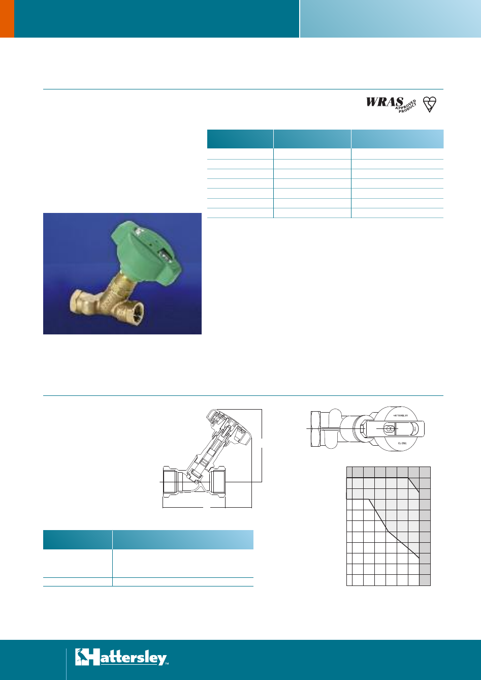
Fig. 1432, 1432L, 1432C, 1432LC
Bronze Double Regulating Valve
SPECIFICATION
Kitemarked to BS 7350:1990.
Handwheel operated.
Numerical indicator.
Inside screw non-rising handwheel.
Characterised regulating disc.
Flow charts available.
End connections threaded.
Sizes 1 to 2" taper threaded BS EN 10266 (ISO 7-1)
formerly BS 21.
Sizes 1/2 & 3/4" to ISO 228 parallel.
Sizes DN15 & DN20 when used with compression.
adaptors suitable for copper pipe to BS EN 1057 R250
(half hard).
WRAS Approved Product.
APPLICATION
Figure 1432 can be used with Hattersley metering
stations for commissioning.
FEATURES AND BENEFITS
• Provides precise and accurate flow regulation
• Easy to operate with handwheel and
numerical indicator
• Robust bronze body for long service life
• WRAS approved for use with potable water
• Positive flow control at all handwheel settings
MATERIAL SPECIFICATION
Handwheel Plastic -
Stem DZR copper alloy 12165 CW602N
Stem Seals EPDM -
Disc DZR copper alloy 12165 CW602N
Disc Seal (1-2") PTFE -
Bonnet DZR copper alloy 12165 CW602N
Body Bronze 1982 CC491K
Component Material Specification
BS EN
Compre
s
s
i
o
n
E
nd
s
Threaded Ends
0 20 40 60 80 100 120 140
Temperature ˚C
20
16
12
4
0
Pressure bar
8
A
PRESSURE/
TEMPERATURE
RATING
Threaded Ends
BS 7350 PN20
17.2 bar at 120ºC
20 bar at -10 to 100ºC
Compressions Ends
5 bar at 120ºC
6 bar at 110ºC
10 bar at 65ºC
16 bar from -10 to 30ºC
TEST PRESSURES
(HYDRAULIC)
Body: 30 bar
Seat: 22 bar
Nom
Size in 1/2L 1/2 3/4 1 1
1/4 11/2 2
A mm 87 87 96 100 114 125 146
A (compression) mm 105 105 118 - - - -
B mm 110 110 111 132 133 148 149
Weight kg 0.54 0.54 0.58 0.88 1.05 1.43 1.88
DIMENSIONS AND WEIGHTS
B
DIMENSIONAL DRAWINGS
Technical Helpline: 0845 604 1790
E: tech-enquiries@hattersley.com W: www.hattersley.com
27
BALANCING VALVES - STATIC
PN20 (THREADED) PN16 (COMPRESSION)
Every effort has been made to ensure that the information contained in this publication is accurate at the time of publishing.
Hattersley Ltd assumes no responsibility or liability for typographical errors or omissions or for any misinterpretation of the
information within the publication and reserves the right to change without notice.
For Commissioning Valve Coefficients please refer to pages 47-49.
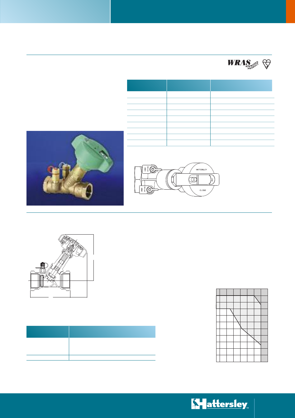
Fig. 1732, 1732M, 1732L , 1732C, 1732MC, 1732LC
Bronze Fixed Orifice Double Regulating Valve (FODRV)
DIMENSIONAL DRAWINGS SPECIFICATION
Kitemarked to BS 7350:1990.
Handwheel operated.
Numerical indicator.
Inside screw non-rising
handwheel.
Characterised regulating disc.
Integral fixed orifice.
Supplied with two figure 631
test points.
Flow charts available.
End connections threaded.
Sizes 1 to 2" taper threaded
BS EN 10266 (ISO 7-1)
formerly BS 21.
Sizes 1/2 & 3/4" to ISO 228
parallel.
Sizes DN15 & DN20 when
used with compression
adaptors suitable for copper
pipe to BS EN 1057 R250
(half hard).
WRAS Approved Product.
FEATURES AND BENEFITS
• Provides precise and accurate flow regulation
• Easy to operate with handwheel and
numerical indicator
• Integral orifice and test points – no need for
separate DRV and metering station
• WRAS approved for use with potable water
• Positive flow control at all handwheel settings
MATERIAL SPECIFICATION
Handwheel Plastic
Stem DZR copper alloy 12165 CW602N
Stem Seals EPDM
Disc DZR copper alloy 12165 CW602N
Disc Seal (1-2") PTFE
Bonnet DZR copper alloy 12165 CW602N
Body Bronze 1982 CC491K
Orifice Insert DZR copper alloy 12165 CW602N
Fig. 631 Test Valve DZR copper alloy 12165 CW602N
Component Material Specification
BS EN
Compre
s
s
i
o
n
E
nd
s
Threaded Ends
0 20 40 60 80 100 120 140
Temperature ˚C
20
16
12
4
0
Pressure bar
8
A
B
PRESSURE/
TEMPERATURE RATING
Threaded Ends
BS 7350 PN20
17.2 bar at 120ºC
20 bar at -10 to 100ºC
Compressions Ends
5 bar at 120ºC
6 bar at 110ºC
10 bar at 65ºC
16 bar from -10 to 30ºC
TEST PRESSURES
(HYDRAULIC)
Body: 30 bar
Seat: 22 bar
Nom
Size in 1/2L 1/2M 1/2 3/4 1 1
1/4 11/2 2
A mm 87 87 87 96 100 114 125 146
A (compression) mm 105 105 105 118 - - - -
B mm 110 110 110 111 132 133 148 149
Weight kg 0.61 0.61 0.61 0.65 0.95 1.13 1.52 1.98
DIMENSIONS AND WEIGHTS
Technical Helpline: 0845 604 1790
E: tech-enquiries@hattersley.com W: www.hattersley.com
28
BALANCING VALVES - STATIC
PN25 (THREADED) PN16 (COMPRESSION)
Every effort has been made to ensure that the information contained in this publication is accurate at the time of publishing.
Hattersley Ltd assumes no responsibility or liability for typographical errors or omissions or for any misinterpretation of the
information within the publication and reserves the right to change without notice.
For Commissioning Valve Coefficients please refer to pages 47-49.
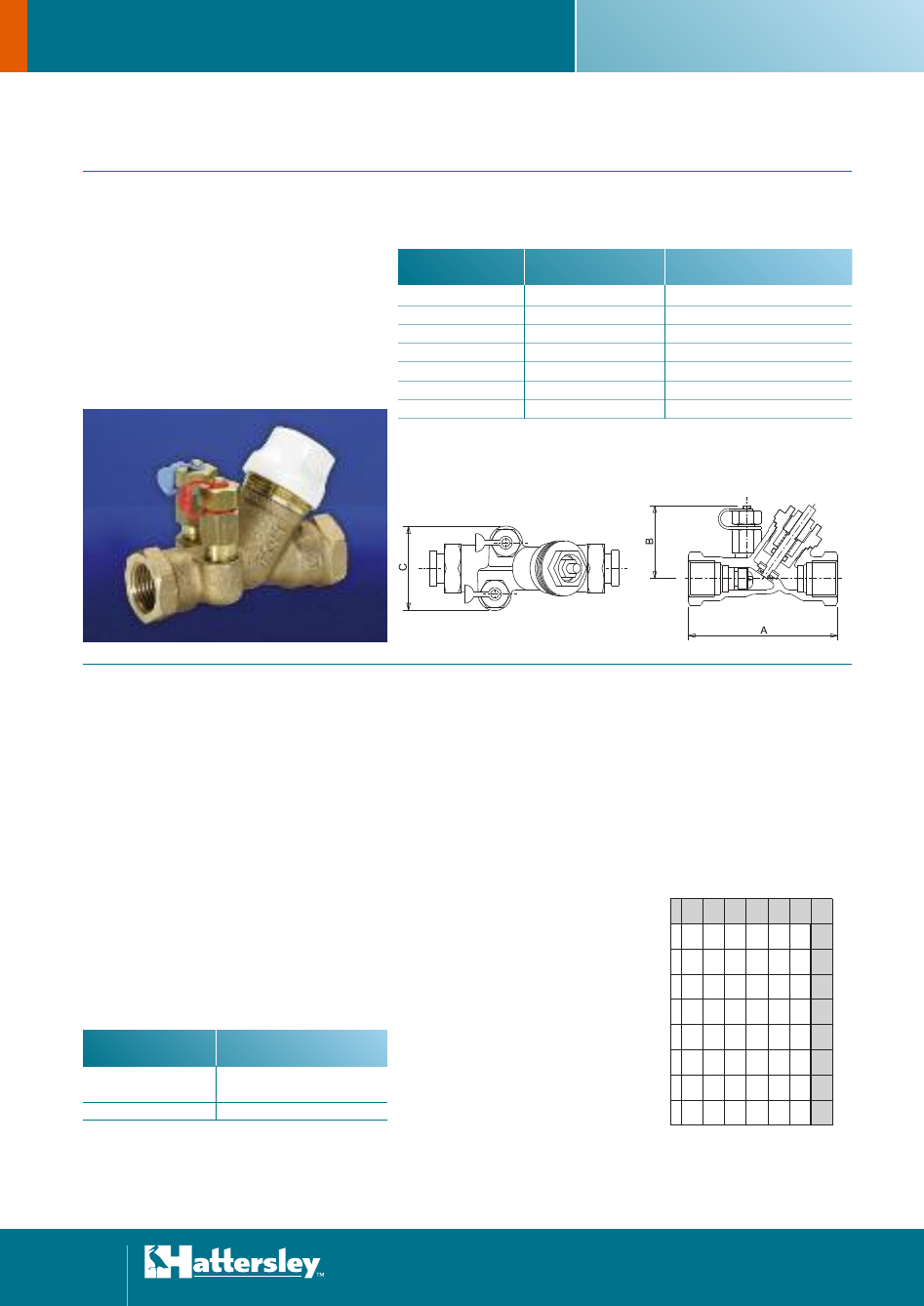
Fig. 1832, 1832M, 1832L
Bronze Motorised Fixed Orifice Double Regulating Valve
PRESSURE/
TEMPERATURE
RATING
Threaded Ends
BS 7350 PN20
16 bar at 120ºC
25 bar at -10 to 100ºC
TEST PRESSURES
(HYDRAULIC)
Body: 30 bar
Seat: 1.4 bar DP
Note: Max DP = 1.2 bar
SPECIFICATION
Actuator operated for on/off or
modulating control.
Double regulating device allows
flow to be balanced.
Integral fixed orifice.
Supplied with 2 Figure 631 test points.
Flow charts available.
End connections threaded
Sizes 1/2 & 3/4" to ISO 228 parallel.
The 1832 Motorised FODRV is
designed for installations in circuits
where combined functions of actuated
regulation and flow measurement are
required.
Accuracy of flow measurement is
+5% across all driving settings.
1832: 1/2" has a flow range of
0.061 to 0.132l/s
3/4" has a flow range of
0.131 to 0.289l/s
1832M: 1/2" medium flow version
is suitable for flow
applications in the range
of 0.03 to 0.07l/s
1832L: 1/2" low flow version is
suitable for flow
applications in the range
of 0.01 to 0.03l/s
FEATURES AND BENEFITS
• Provides precise and accurate flow regulation
• Designed for circuits where combined
functions of actuated regulation and flow
measurement are required
• Operated by motorised actuator
• Integral fixed orifice commissioning valve and
two port control panel – faster commissioning
MATERIAL SPECIFICATION
Stem DZR copper alloy 12165 CW602N
Stem Seals EPDM
Disc EPDM
Bonnet DZR copper alloy 12165 CW602N
Body Bronze 1982 CC491K
Orifice Insert DZR copper alloy 12165 CW602N
Fig. 631 Test Valve DZR copper alloy 12165 CW602N
Component Material Specification
BS EN
Nom
Size in 1/2L 1/2M 1/2 3/4
A mm 87 87 87 96
B mm 50 50 50 51
Weight kg 0.41 0.41 0.41 0.45
DIMENSIONS AND WEIGHTS
0 20 40 60 80 100 120 140
Temperature ˚C
18
16
12
4
0
Pressure bar
8
Threaded Ends
2
6
10
14
DIMENSIONAL DRAWINGS
(Motorised FODRV)
Technical Helpline: 0845 604 1790
E: tech-enquiries@hattersley.com W: www.hattersley.com
29
BALANCING VALVES - STATIC
PN40
Every effort has been made to ensure that the information contained in this publication is accurate at the time of publishing.
Hattersley Ltd assumes no responsibility or liability for typographical errors or omissions or for any misinterpretation of the
information within the publication and reserves the right to change without notice.
For Commissioning Valve Coefficients please refer to pages 47-49.
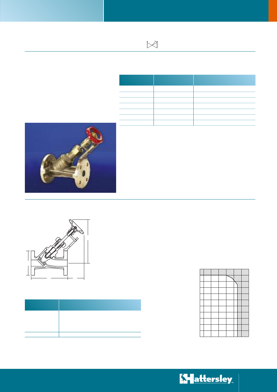
Fig. 1200DR
Bronze Double Regulating Valves
DIMENSIONAL DRAWINGS PRESSURE/
TEMPERATURE RATING
BS 5154 PN40 Series A
34 bar at 180ºC
40 bar from -10 to 120ºC
TEST PRESSURES
(HYDRAULIC)
Shell: 60 bar
Seat: 44 bar
SPECIFICATION
Conforms to BS 7350:1990.
Rising stem.
Screwed bonnet.
Flanged to BS EN 1092-3 PN40.
Fitted with parabolic regulating disc
in Stainless Steel, double regulating
device and indicator.
Flow charts available.
FEATURES AND BENEFITS
• Provides precise and accurate flow regulation
• Easy to operate with handwheel
• Robust bronze body for long service life
• Suitable for high pressure applications
MATERIAL SPECIFICATION
Stem Manganese Bronze 12164 CW721R
Gland Packing Asbestos Free
Bonnet Bronze 1982 CC491K B62
Swivel Nut Manganese Bronze 12164 CW721R
Disc Stainless Steel
Seat Stainless Steel
Body Bronze 1982 CC491K B62
Component Material Specification
BS EN ASTM
0 40 80 120 160 200 240
36
32
28
24
20
16
12
8
4
0
Pressure bar
40
44
T empe r ature ˚ C
A E
B
D
Nom
Size mm 15 20 25 32 40 50
A mm 133 146 162 184 200 238
B (open) mm 168 187 213 238 267 306
D mm 95 105 115 140 150 165
E (open) mm 64 79 92 98 117 121
Weight kg 2.5 3.5 4.9 7.5 10 14
DIMENSIONS AND WEIGHTS
Technical Helpline: 0845 604 1790
E: tech-enquiries@hattersley.com W: www.hattersley.com
30
BALANCING VALVES - STATIC
PN16 - SIZES 50-300mm
Every effort has been made to ensure that the information contained in this publication is accurate at the time of publishing.
Hattersley Ltd assumes no responsibility or liability for typographical errors or omissions or for any misinterpretation of the
information within the publication and reserves the right to change without notice.
For Commissioning Valve Coefficients please refer to pages 47-49.
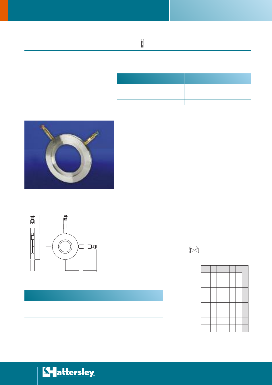
Fig. M2000
Stainless Steel Metering Stations
DIMENSIONAL DRAWINGS PRESSURE/
TEMPERATURE RATING
16 bar from -10 to 120ºC
Note: The Test Point figure 631 has a
maximum working temperature of 120ºC.
For higher temperature requirements
contact Hattersley Sales Office.
SPECIFICATION
Kitemarked to BS 7350:1990.
Outside diameter locates metering station
centrally on the relevant BS EN 1092-2
PN16 flange bolting.
Compatibility with other flanges available.
Supplied complete with extensions and
figure 631 test points.
Flow charts available.
FEATURES AND BENEFITS
• Compact, wafer design for fitting in tight spaces
• Accurate flow measurement
• Supplied with red and blue test points for
upstream and downstream port identification
MATERIAL SPECIFICATION
Body Stainless Steel 10088-1 X2 CrNiNo17-12-2
A276-316L
Extension Sleeve Stainless Steel
Test Points Fig. 631
Component Material Specification
BS EN ASTM
B
A
C
B
0 20 40 60 80 100 120 14 0
Temperature ˚C
14
12
10
8
6
2
0
Pressure bar
4
16
18
Nom
Size mm 50 65 80 100 125 150 200 250 300
A mm 20 20 20 20 20 20 20 20 20
B mm 150 160 170 180 195 205 235 260 260
C mm 205 225 240 260 290 315 370 426 481
Weight kg 1.3 1.6 1.9 2.1 2.8 3.3 5.0 6.0 7.0
Note: Weight shown above includes extensions, test points, gaskets and box.
DIMENSIONS AND WEIGHTS
Use with figure M733DR to make
Commissioning Set M2733.
Technical Helpline: 0845 604 1790
E: tech-enquiries@hattersley.com W: www.hattersley.com
31
BALANCING VALVES - STATIC
PN16 - SIZES 350-600mm
Every effort has been made to ensure that the information contained in this publication is accurate at the time of publishing.
Hattersley Ltd assumes no responsibility or liability for typographical errors or omissions or for any misinterpretation of the
information within the publication and reserves the right to change without notice.
For Commissioning Valve Coefficients please refer to pages 47-49.
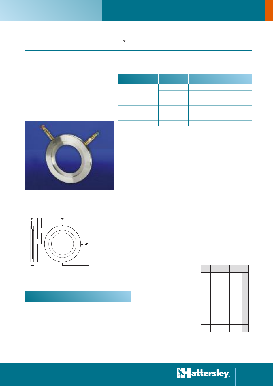
Fig. M2000
Cast Iron Metering Stations
DIMENSIONAL DRAWINGS PRESSURE/
TEMPERATURE RATING
PN16
16 bar from -10 to 120ºC
Note: The Test Point figure 631 has a
maximum working temperature of 120ºC
If other test points are fitted the maximum
operating temperature should be obtained
from the test point manufacturer.
TEST PRESSURES
(HYDRAULIC)
Shell: 24 bar
SPECIFICATION
Outside diameter locates metering station
centrally on BS EN 1092-2 PN16 flange
bolting.
Adaptations to suit other flanges available.
Supplied complete with extensions and
figure 631 test points.
Flow charts available.
Note: When used with a butterfly valve a
minimum of 5 diameters of straight length
of same diameter pipe as the valve must be
fitted on both sides of the metering station.
FEATURES AND BENEFITS
• Compact, wafer design for fitting in tight spaces
• Accurate flow measurement
• Supplied with red and blue test points for
upstream and downstream port identification
MATERIAL SPECIFICATION
Body (350 to 450mm) Cast Iron 1561 EN-JL1030 A126 ClB
(500 to 700mm) Carbon Steel
Orifice Plate Stainless Steel 10088-1 X2 CrNiNo17-12-2
AISI 316
Retaining Ring 18/8 Stainless
Steel
Extension Sleeve Stainless Steel
Test Points Fig. 631
Component Material Specification
BS EN ASTM
Nom
Size mm 350 400 450 500 600
A mm 38 38 38 38 38
B mm 320 345 375 397 456
C mm 545 595 655 707 825
Weight kg 32 39 50 30 40
DIMENSIONS AND WEIGHTS
0 20 40 60 80 100 120 14 0
Temperature ˚C
14
12
10
8
6
2
0
Pressure bar
4
16
18
C
B
Note: Weight shown above includes extensions, test points, gaskets
lifting hook and box. Larger sizes available on request.
Technical Helpline: 0845 604 1790
E: tech-enquiries@hattersley.com W: www.hattersley.com
32
BALANCING VALVES - STATIC
PN25
Every effort has been made to ensure that the information contained in this publication is accurate at the time of publishing.
Hattersley Ltd assumes no responsibility or liability for typographical errors or omissions or for any misinterpretation of the
information within the publication and reserves the right to change without notice.
For Commissioning Valve Coefficients please refer to pages 47-49.
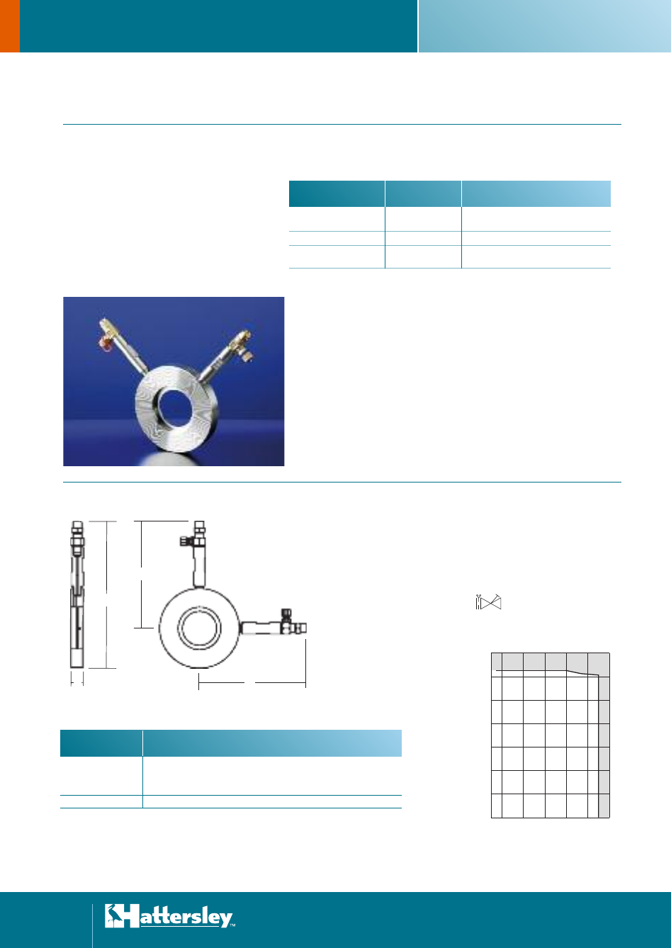
Fig. M3000
Stainless Steel Metering Stations
DIMENSIONAL DRAWINGS SPECIFICATION
Outside diameter locates metering station
centrally on the relevant BS EN 1092-2
flange bolting.
Compatibility with other flanges available.
Supplied complete with extensions and
figure 750 test points.
Flow charts available.
FEATURES AND BENEFITS
• Compact, wafer design for fitting in tight spaces
• Accurate flow measurement
• Supplied with red and blue test points for
upstream and downstream port identification
MATERIAL SPECIFICATION
Body Stainless Steel 10088-1 X2CrNiMo 17-12-2
AISI 316
Extension Sleeve Stainless Steel
Valve Controlled Fig. 750
Test Points
Component Material Specification
BS EN ASTM
0 40 80 120 160 200
Temperature ˚C
28
24
20
16
12
4
0
Pressure bar
8
B
B
C
A
PRESSURE/
TEMPERATURE RATING
24.2 bar at 180ºC
25 bar from -10 to 120ºC
Note: The Valve Controlled Test Point
figure 750 has a maximum working
temperature of 180ºC. If other test
points are fitted the maximum operating
temperature should be obtained from
the test point manufacturer. Use with double regulating valve to
make Commissioning Set
Nom
Size mm 50 65 80 100 125 150 200 250 300
A mm 20 20 20 20 20 20 20 20 20
B mm 165 175 185 195 208 223 253 282 312
C mm 220 240 255 280 306 336 396 453 513
Weight kg 1.3 1.6 1.9 2.1 2.8 3.3 5.0 6.0 7.0
Note: Weight shown above includes extensions, test points, gaskets and box.
DIMENSIONS AND WEIGHTS
Technical Helpline: 0845 604 1790
E: tech-enquiries@hattersley.com W: www.hattersley.com
33
BALANCING VALVES - STATIC
PN40
Every effort has been made to ensure that the information contained in this publication is accurate at the time of publishing.
Hattersley Ltd assumes no responsibility or liability for typographical errors or omissions or for any misinterpretation of the
information within the publication and reserves the right to change without notice.
For Commissioning Valve Coefficients please refer to pages 47-49.
Fig. M4000
Stainless Steel Metering Stations
DIMENSIONAL DRAWINGS
PRESSURE/
TEMPERATURE RATING
PN40 Series A
34 bar at 180ºC
40 bar from -10 to 120ºC
Note: The Valve Controlled Test Point
figure 750 has a maximum working
temperature of 180ºC. If other test
points are fitted the maximum operating
temperature should be obtained from
the test point manufacturer.
TEST PRESSURES
(HYDRAULIC)
Shell: 60 bar
SPECIFICATION
Conforms to BS 7350.
One piece full flange diameter.
Integral orifice plate.
Flange dimensions to BS EN 1092-2 PN40.
Supplied complete with flange bolts, nuts and
figure 750 test points.
Flow charts available.
Can also be used with figure 1200 PN40
isolating valve to form an orifice valve (PTV).
FEATURES AND BENEFITS
• Suitable for high pressure applications
• Compact, flanged design for fitting in
tight spaces
• Accurate flow measurement
• Supplied with red and blue test points for
upstream and downstream port identification
MATERIAL SPECIFICATION
Metering Station Stainless Steel 10088-1 X2CrNiMo 17-12-2
AISI 316 17
Valve Controlled
Test Point Fig. 750
Component Material Specification
BS EN ASTM
Nom
Size mm 15 20 25 32 40 50
A mm 18 18 18 18 18 18
B mm 95 100 105 115 120 130
C mm 140 150 160 185 195 210
Weight kg 1.4 1.6 1.8 2.5 2.9 3.5
Weights shown above include test points and gaskets.
DIMENSIONS AND WEIGHTS
0 40 80 120 160 200 240
36
32
28
24
20
16
12
8
4
0
Pressure bar
40
44
T empe r ature ˚ C
Use with figure 1200DR to make
Commissioning Set 5200
B
B
C
A
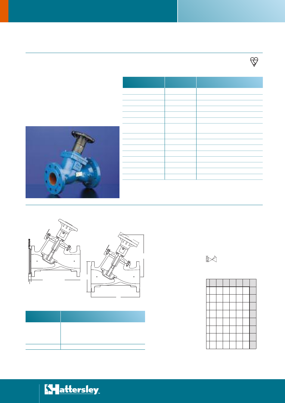
Technical Helpline: 0845 604 1790
E: tech-enquiries@hattersley.com W: www.hattersley.com
34
BALANCING VALVES - STATIC
PN16 - SIZES 50-200mm
Every effort has been made to ensure that the information contained in this publication is accurate at the time of publishing.
Hattersley Ltd assumes no responsibility or liability for typographical errors or omissions or for any misinterpretation of the
information within the publication and reserves the right to change without notice.
For Commissioning Valve Coefficients please refer to pages 47-49.
Fig. M733DR
Cast Iron Globe Valves with Double Regulating Feature
DIMENSIONAL DRAWINGS SPECIFICATION
Kitemarked to BS 7350:1990.
Inside screw, non-rising stem.
EPDM coated disc.
Flanged to BS EN 1092-2 PN16.
Fitted with regulating disc, double
regulating device and indicator.
FEATURES AND BENEFITS
• Robust iron body materials for long service life
• Precise flow regulation
• Flanged with handwheel – easy to install
and operate
• Positive flow control at all handwheel settings
MATERIAL SPECIFICATION
Indicator Ring Polymer
Indicator Polymer
Gland H T Brass 12164 CW721R B138 C67500
Gland Packing Graphite
Stuffing Box H T Brass 12164 CW721R B138 C67500
Stem (50 to 100mm) H T Brass 12164 CW721R B138 C67500
Stem (125 to 200mm) Stainless Steel 10088-1 X2 CrNiNo17-12-2
A276-316L
Indicator Sleeve Polymer
Bonnet Ductile Iron 1563 EN JS 1050 A536 80 55 06
Bonnet Gasket Asbestos Free
Disc Stem Nut H T Brass 12164 CW721R B138 C67500
Disc Cast Iron 1561 EN JLI030 A126 CI B
Disc Coating EPDM
Body Cast Iron 1561 EN JLI030 A126 CI B
Seat Ring Bronze 1982 CC491K
Component Material Specification
BS EN ASTM
0 20 40 60 80 100 120 14 0
Temperature ˚C
14
12
10
8
6
2
0
Pressure bar
4
16
18
A
B
D
C
Fig. M733
2000
Use with M2000 PN16 to make
Commissioning Set M2733
Nom
Size mm 50 65 80 100 125 150 200
A mm 230 290 310 350 400 480 600
B mm 250 278 292 310 350 385 450
C mm 166 166 166 166 250 250 250
D mm 165 185 200 220 250 285 340
Weight kg 15 21 26 37 65 82 139
DIMENSIONS AND WEIGHTS
PRESSURE/
TEMPERATURE
RATING
16 bar from -10 to 120ºC
Note: The maximum temperature
is determined by the EPDM
elastomer coated disc.
TEST PRESSURES
(HYDRAULIC)
Shell: 24 bar
Seat: 17.6 bar

Technical Helpline: 0845 604 1790
E: tech-enquiries@hattersley.com W: www.hattersley.com
35
BALANCING VALVES - STATIC
PN16 - SIZES 250-300mm
Every effort has been made to ensure that the information contained in this publication is accurate at the time of publishing.
Hattersley Ltd assumes no responsibility or liability for typographical errors or omissions or for any misinterpretation of the
information within the publication and reserves the right to change without notice.
For Commissioning Valve Coefficients please refer to pages 47-49.
Fig. M733DR
Ductile Iron Globe Valves with Double
Regulating Feature
DIMENSIONAL DRAWINGS SPECIFICATION
Conforms to BS 7350: 1990.
Inside screw, non-rising stem.
Copper alloy trim.
Flanged to BS EN 1092-2 PN16.
Fitted with regulating disc, double
regulating device and indicator.
FEATURES AND BENEFITS
• Robust iron body materials for long service life
• Precise flow regulation
• Flanged with handwheel – easy to install
and operate
• Positive flow control at all handwheel settings
MATERIAL SPECIFICATION
Stem 316 SS 10088 X5CrNiMo17-12-2
A276 316
Gland (200 to 300mm) Cast Iron 1561 GRADE 250
Gland Nut Mild Steel
Bonnet Ductile Iron 536 65-45-12
Bonnet Gasket Asbestos Free
Disc Cast Iron 1561 GRADE 250
Disc Insert PTFE
Disc Coating EPDM
Seat Ring Bronze 1982 CC491K
Body Ductile Iron 536 65-45-12
Packing Asbestos Free
Component Material Specification
BS EN ASTM
0 20 40 60 80 100 120 14 0
Temperature ˚C
14
12
10
8
6
2
0
Pressure bar
4
16
18
A
B
C
M733
M2000
Use with figure M2000 to make
Commissioning Set M2733
Nom
Size mm 250 300
A mm 730 850
B mm 575 645
C mm 420 420
Weight kg 192 251
DIMENSIONS AND WEIGHTS
PRESSURE/
TEMPERATURE
RATING
16 bar from -10 to 120°C
TEST PRESSURES
(HYDRAULIC)
Shell: 24 bar
Seat: 17.6 bar
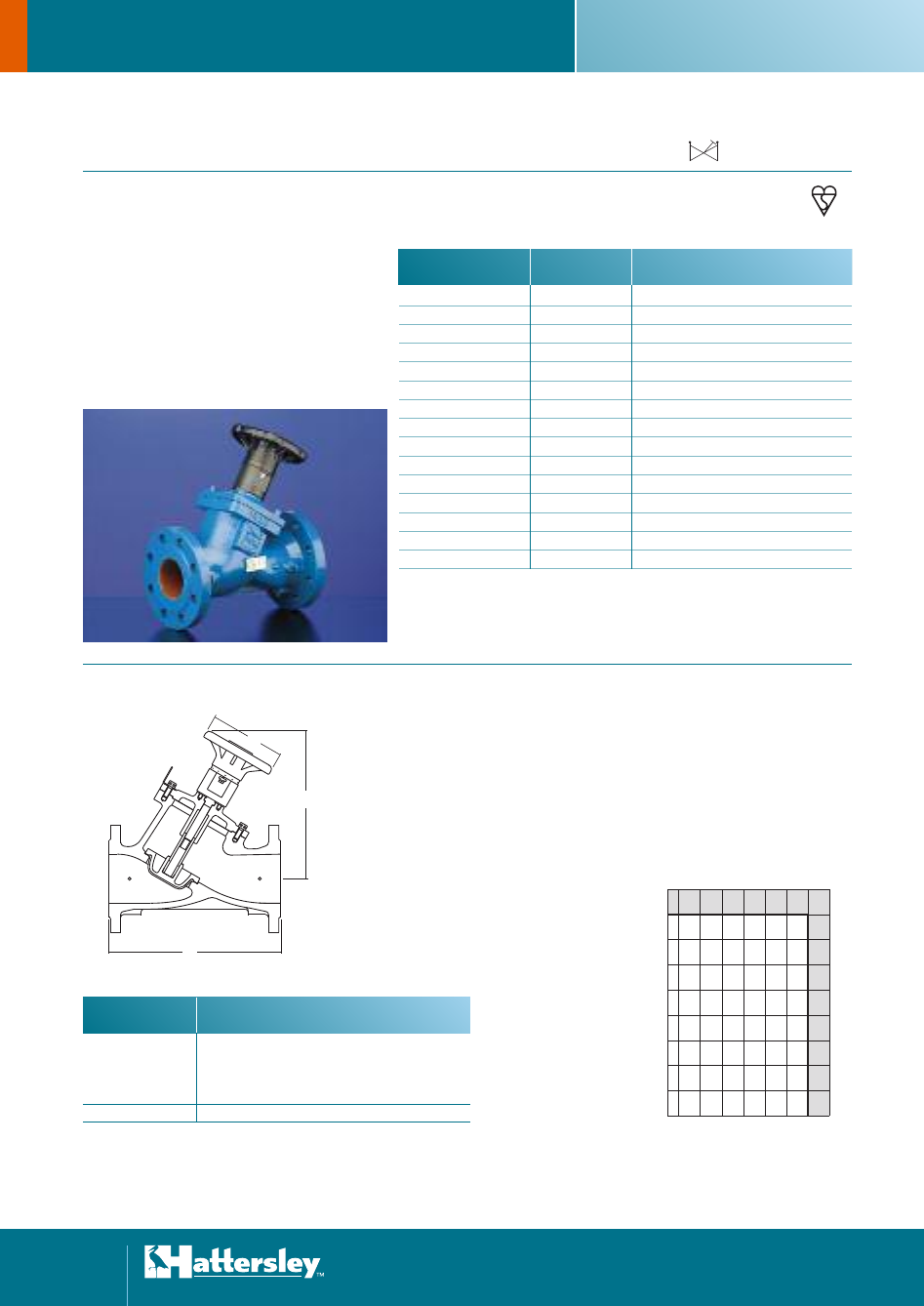
Technical Helpline: 0845 604 1790
E: tech-enquiries@hattersley.com W: www.hattersley.com
36
BALANCING VALVES - STATIC
PN16 - SIZES 50-200mm
Every effort has been made to ensure that the information contained in this publication is accurate at the time of publishing.
Hattersley Ltd assumes no responsibility or liability for typographical errors or omissions or for any misinterpretation of the
information within the publication and reserves the right to change without notice.
For Commissioning Valve Coefficients please refer to pages 47-49.
Fig. M737
Cast Iron Variable Orifice Double Regulating Valves
DIMENSIONAL DRAWINGS PRESSURE/
TEMPERATURE RATING
16 bar from -10 to 120ºC
Note: The maximum temperature is
determined by the EPDM elastomer
coated disc.
TEST PRESSURES
(HYDRAULIC)
Shell: 24 bar
Seat: 17.6 bar
SPECIFICATION
Kitemarked to BS 7350:1990.
Inside screw, non-rising stem.
EPDM coated disc.
Flanged to BS EN 1092-2 PN16
Fitted with regulating disc, double
regulating device and indicator, figure 631
test points and extensions.
Valves can be supplied with vapour seal.
Optional insulation boxes.
Flow charts available.
FEATURES AND BENEFITS
• Robust iron body materials for long service life
• Precise flow regulation
• Flanged with handwheel – easy to install
and operate
• Positive flow control at all handwheel settings
MATERIAL SPECIFICATION
Indicator Ring Polymer
Indicator Polymer
Gland H T Brass 1561 EN JSI040
Gland Flange Graphite
Stuffing Box H T Brass 1561 EN JSI040
Stem (50 to 100mm) H T Brass 1561 EN JSI040
Stem (125 to 200mm) Stainless Steel 10270 X10CrNr18-8 A276-304
Indicator Sleeve Polymer
Bonnet Ductile Iron 1561 EN JS1050
Bonnet Gasket Asbestos Free
Disc Stem Nut H T Brass 1561 EN JSI040
Disc Cast Iron 1541 EN JLI040 A126 CI B
Disc Coating EPDM
Body Cast Iron 1561 EN-JLI030 A126 CI B
Extension Sleeve Bronze 1982 CC491K B505 C83600
Component Material Specification
BS EN ASTM
A
B
C
0 20 40 60 80 100 120 14 0
Temperature ˚C
14
12
10
8
6
2
0
Pressure bar
4
16
18
Nom
Size mm 50 65 80 100 125 150 200
A mm 230 290 310 350 400 480 600
B mm 250 278 292 310 350 385 450
C mm 166 166 166 166 250 250 250
D mm 165 185 200 220 250 285 340
Weight kg 15 21 26 37 65 82 139
DIMENSIONS AND WEIGHTS
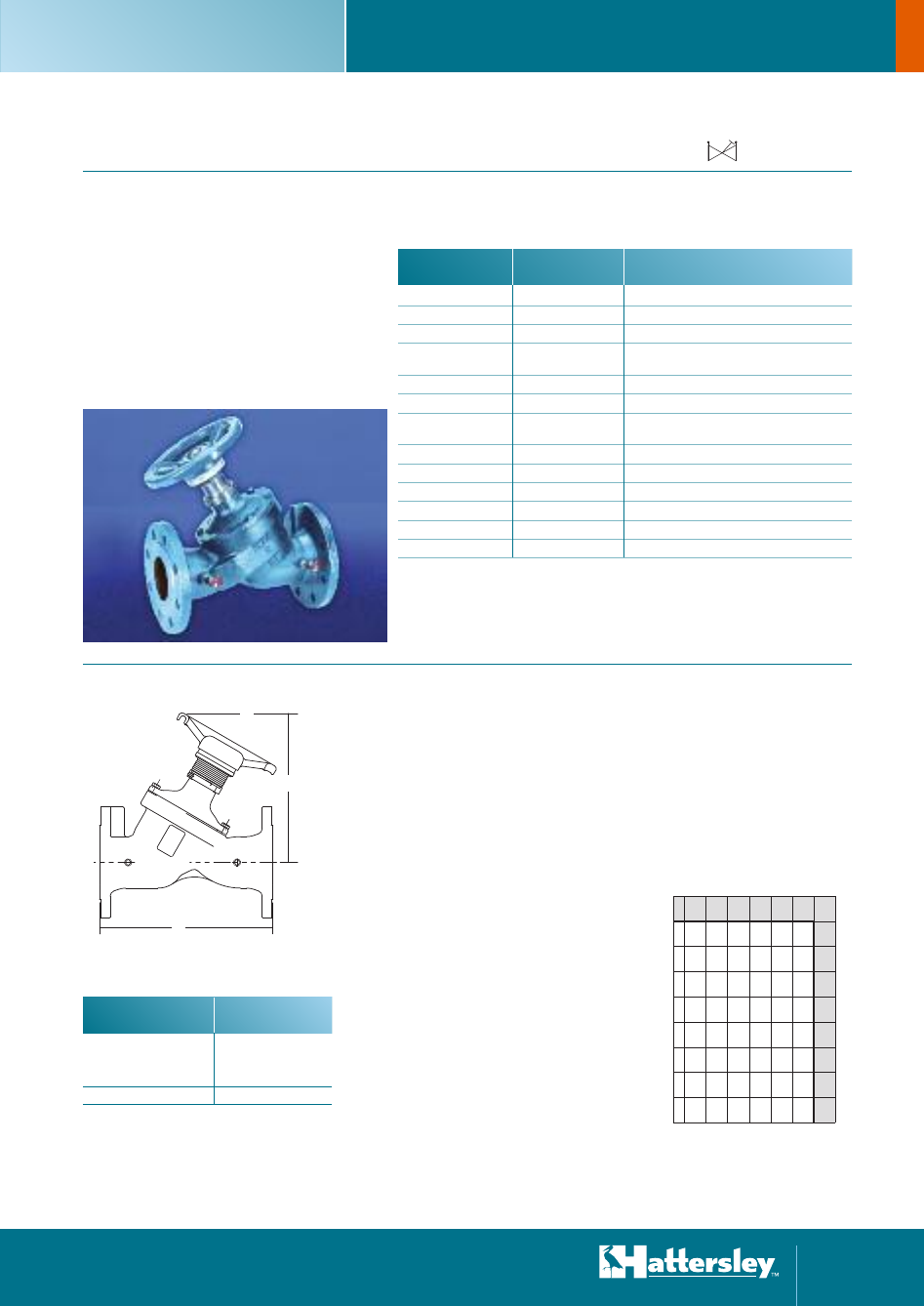
Technical Helpline: 0845 604 1790
E: tech-enquiries@hattersley.com W: www.hattersley.com
37
BALANCING VALVES - STATIC
PN16 - SIZES 250-300mm
Every effort has been made to ensure that the information contained in this publication is accurate at the time of publishing.
Hattersley Ltd assumes no responsibility or liability for typographical errors or omissions or for any misinterpretation of the
information within the publication and reserves the right to change without notice.
For Commissioning Valve Coefficients please refer to pages 47-49.
Fig. M737
Ductile Iron Variable Orifice Double Regulating Valves
DIMENSIONAL DRAWINGS PRESSURE/
TEMPERATURE RATING
BS EN 1092-2 PN16
16 bar from -10 to 120ºC
TEST PRESSURES
(HYDRAULIC)
Shell: 24 bar
Seat: 17.6 bar
SPECIFICATION
BS 7350:1990.
Face to face dimensions to BS EN 558-1
basic series 1.
Ductile iron body.
Inside screw.
Non-rising stem.
Bronze body seat.
Flanged to BS EN 1092-2 PN16.
Flow charts available.
FEATURES AND BENEFITS
• Robust iron body materials for long service life
• Precise flow regulation
• Flanged with handwheel – easy to install
and operate
• Positive flow control at all handwheel settings
MATERIAL SPECIFICATION
Handwheel Ductile Iron 1563 EN-JSI030 A536-65-45-12
Gland Cast Iron 1561 EN-JLI030 A126 CI B
Gland Packing Asbestos Free
Stem Stainless Steel 10088-1 X2 CrNiNo17-12-2
A276-316L
Seat Retainer Bronze
Disc Cast Iron 1561 EN-JLI030 A126 CI B
Disc Insert PTFE or
PTFE/Neoprene
Disc Coating EPDM
Regulating Cone Bronze
Bonnet Ductile Iron 1563 EN-JSI030 A536-65-45-12
Bonnet Gasket Asbestos Free
Body Seat Ring Bronze 1982 CC491K
Body Ductile Iron 1563 EN-JSI030 A536-65-45-12m
Component Material Specification
BS EN ASTM
0 20 40 60 80 100 120 14 0
Temperature ˚C
14
12
10
8
6
2
0
Pressure bar
4
16
18
Nom
Size mm 250 300
A mm 730 850
B (open) mm 575 645
C mm 420 420
Weight kg 192 251
DIMENSIONS AND WEIGHTS
A
B
C
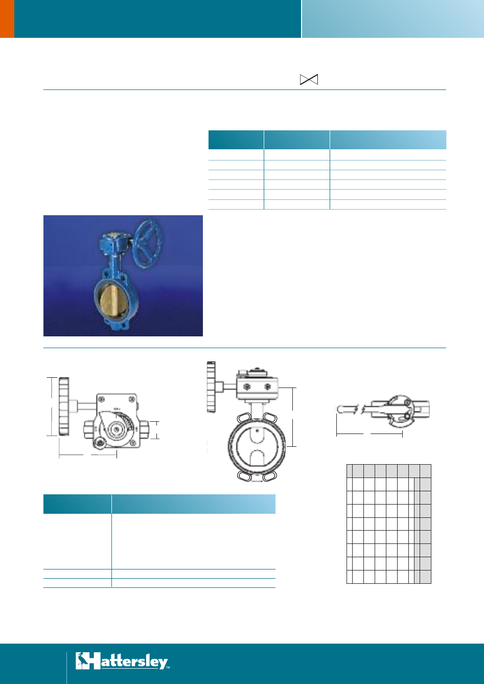
Technical Helpline: 0845 604 1790
E: tech-enquiries@hattersley.com W: www.hattersley.com
38
BALANCING VALVES - STATIC
PN16
Every effort has been made to ensure that the information contained in this publication is accurate at the time of publishing.
Hattersley Ltd assumes no responsibility or liability for typographical errors or omissions or for any misinterpretation of the
information within the publication and reserves the right to change without notice.
For Commissioning Valve Coefficients please refer to pages 47-49.
Fig. 953, 953G
Cast Iron with Double Regulating Feature
DIMENSIONAL DRAWINGS
PRESSURE/
TEMPERATURE RATING
EPDM Seat
16 bar from -10 up to 120ºC
SERVICE RATING
Suitable for Chilled Water, LTHW and MTHW
TEST PRESSURES
Shell: 24 bar
Seat: 17.6 bar
SPECIFICATION
Valves up to and including 200mm can
be supplied lever operated or fully
enclosed gear operated.
All operators fitted with double
regulating feature.
Flow charts available.
Note: Butterfly valves should not be
less than 30° open when used for
regulation duties.
FEATURES AND BENEFITS
• Robust iron body materials for long service life
• Precise flow regulation
• Flanged with handwheel – easy to install
and operate
• Positive flow control at all handwheel settings
MATERIAL SPECIFICATION
Body Ductile Iron
Shaft Stainless Steel 10088-1 X17CrNi16-2 AISI 431
Disc Aluminium Bronze 1982 CC333G B148 C95800
Disc Stainless Steel 10270 X10CrNr18-8 A276 304
Liner EPDM
Bearings PTFE Coated Steel
Component Material Specification
BS EN ASTM
0 20 40 60 80 100 120 140
T emperature ˚ C
14
12
10
8
6
2
0
Pressure bar
4
16
18
G
H
K
J
A
Nom
Size mm 50 65 80 100 125 150 200 250 300
A mm 43 46 46 52 56 56 60 68 78
F* mm 264 272 279 301 314 345 369 - -
G mm 250 250 250 250 250 315 315 - -
H mm 182 190 197 219 232 254 278 281 306
J mm 123 123 123 123 123 123 123 228 228
K dia mm 125 125 125 125 125 125 125 300 300
Weight (953W) kg 4.1 4.9 5.2 6.5 8.5 11.4 16 - -
Weight (953WG) kg 4.9 5.7 6.0 7.3 9.3 12 16 29 41
*F dimension is centre of valve to maximum lift of lever
DIMENSIONS AND WEIGHTS
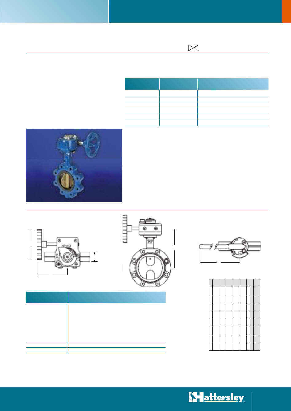
Technical Helpline: 0845 604 1790
E: tech-enquiries@hattersley.com W: www.hattersley.com
39
BALANCING VALVES - STATIC
PN16
Every effort has been made to ensure that the information contained in this publication is accurate at the time of publishing.
Hattersley Ltd assumes no responsibility or liability for typographical errors or omissions or for any misinterpretation of the
information within the publication and reserves the right to change without notice.
For Commissioning Valve Coefficients please refer to pages 47-49.
Fig. 973, 973G
Ductile Iron with Double Regulating Feature
DIMENSIONAL DRAWINGS
PRESSURE/
TEMPERATURE RATING
EPDM Seat
16 bar from -10 up to 120ºC
SERVICE RATING
Suitable for Chilled Water, LTHW and MTHW
TEST PRESSURES
Shell: 24 bar
Seat: 17.6 bar
SPECIFICATION
Generally conforms to BS EN 593: 2009.
Valves up to and including 200mm can
be supplied lever operated or fully
enclosed gear operated.
All operators fitted with double regulating
feature.
Flow charts available.
Note: Butterfly valves should not be less
than 30° open when used for regulation
duties.
Stainless Steel disc option 4973 - 4973G.
FEATURES AND BENEFITS
• Robust iron body materials for long service life
• Precise flow regulation
• Flanged with handwheel – easy to install
and operate
• Positive flow control at all handwheel settings
MATERIAL SPECIFICATION
Body Ductile Iron 1561 EN-JLI030 A126 CI B
Shaft Stainless Steel 10088-1 X17CrNi16-2 AISI 431
Disc Aluminium Bronze 1982 CC333G B148 C95800
Disc Stainless Steel 10270 X10CrNr18-8 A276 304
Liner EPDM
Bearings PTFE Coated Steel
Component Material Specification
BS EN ASTM
Nom
Size mm 50 65 80 100 125 150 200 250 300
A mm 43 46 46 52 56 56 60 68 78
D mm 165 185 200 220 250 285 340 405 460
F* mm 264 272 279 301 314 345 369 - -
G mm 250 250 250 250 250 315 315 - -
H mm 182 190 197 219 232 254 278 281 306
J mm 123 123 123 123 123 123 123 228 228
K dia mm 125 125 125 125 125 125 125 300 300
Weight (973W) kg 4.6 5.4 7.2 8.8 12 14 20 - -
Weight (973WG) kg 5.4 6.2 8.0 9.6 12 15 21 33 45
*F dimension is centre of valve to maximum lift of lever
DIMENSIONS AND WEIGHTS
J
A
K
H
0 20 40 60 80 100 120 140
T emperature ˚ C
14
12
10
8
6
2
0
Pressure bar
4
16
18
G
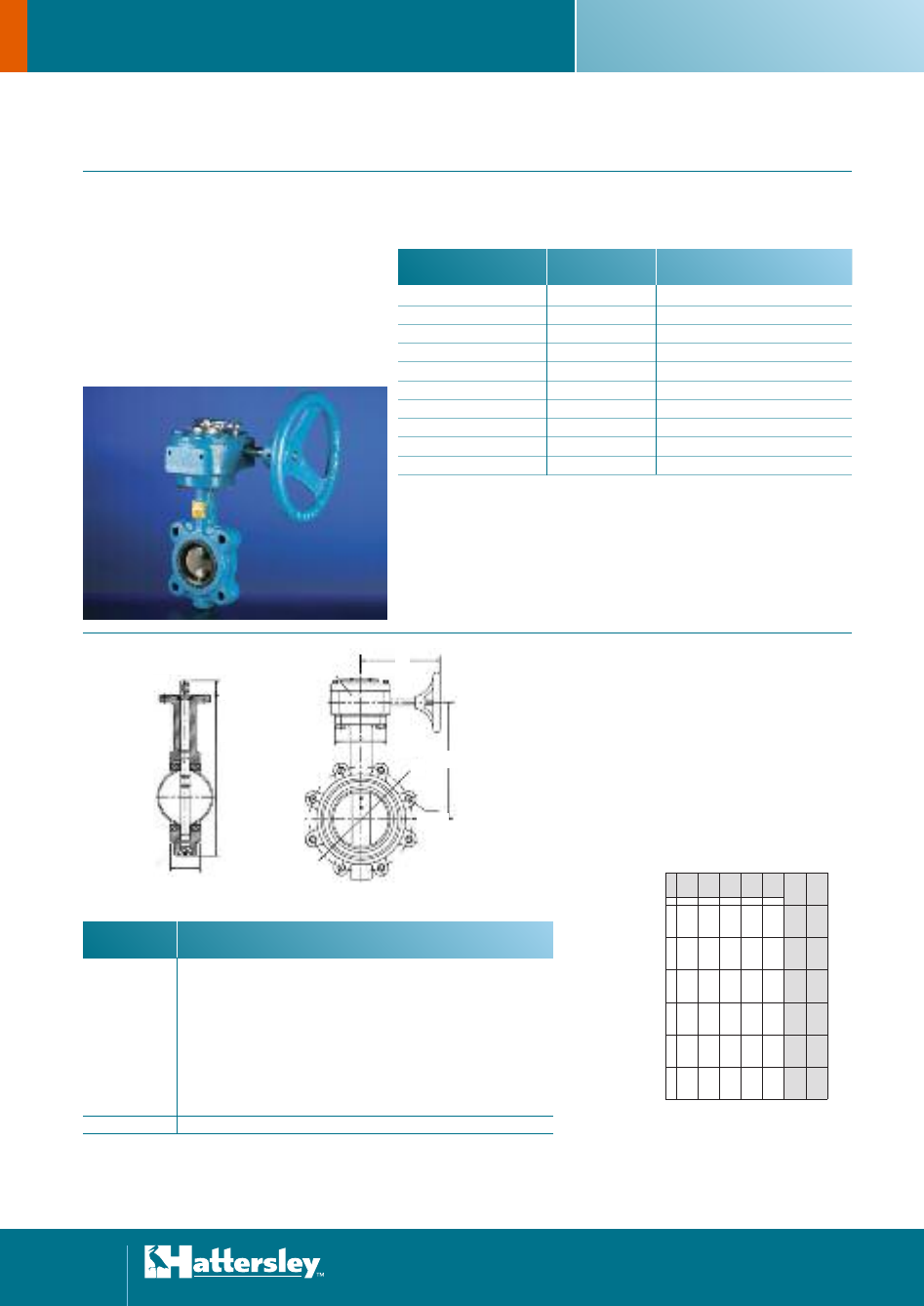
Technical Helpline: 0845 604 1790
E: tech-enquiries@hattersley.com W: www.hattersley.com
40
BALANCING VALVES - STATIC
PN25 - DN50-300
Every effort has been made to ensure that the information contained in this publication is accurate at the time of publishing.
Hattersley Ltd assumes no responsibility or liability for typographical errors or omissions or for any misinterpretation of the
information within the publication and reserves the right to change without notice.
For Commissioning Valve Coefficients please refer to pages 47-49.
Fig. 4983G
Ductile Iron Fully-lugged Double Regulating Valve
SPECIFICATION
A fully lugged butterfly valve for use
with PN25 flanges.
High temperature EPDM liner for
applications up to 120ºC.
A double regulating gearbox as standard.
Can be used in conjunction with a flow
measurement device, figure M3000 to
regulate and measure flow.
FEATURES AND BENEFITS
• Robust iron body materials for long service life
• Precise flow regulation
• Flanged with handwheel – easy to install
and operate
• Positive flow control at all handwheel settings
MATERIAL SPECIFICATION
Body Ductile Iron 1563 EN GJS 56017
Plug Carbon Steel
Liner EPDM
Shaft (lower) Steel AISI 431
Disc Stainless Steel SS304
Shaft (upper) Steel AISI 431
O-Ring EPDM
Lock Plate Brass ASTM B16 C36000
Snap Ring Carbon Steel
Gearbox -
Component Material Specification
BS EN
0 20 40 60 80 100 120 140
Temperature ˚C
28
24
20
16
12
4
0
Pressure bar
8
L
K
N-M
A
B
E
H
H1
Nom
Size mm 50 65 80 100 125 150 200 250 300
A mm 140 152 160 180 191 202 241 274 315
B mm 68 76 85 100 120 132 160 200 230
H mm 35 35 35 35 35 35 45 45 45
D mm 90 90 90 90 90 90 125 125 125
E mm 43 45 46 51.5 56 56.5 60 68.5 79.5
L mm 160 160 160 160 160 160 238 238 238
K mm 125 145 160 190 220 250 310 370 430
N-M mm 4-M16 8-M16 8-M16 8-M20 8-M24 8-M24 8-M24 12-M27 16-M27
H-I mm 172.5 184.5 192.5 212.5 223.5 234.5 278.0 311.0 366.0
Weight kg 10.0 10.8 11.0 13.0 16.0 18.5 29.8 40.0 53.0
DIMENSIONS AND WEIGHTS
DIMENSIONAL DRAWINGS PRESSURE/
TEMPERATURE
RATING
25 bar from -10 to 120ºC
TEST PRESSURES
(HYDRAULIC)
Shell: 37.5 bar
Seat: 27.5 bar
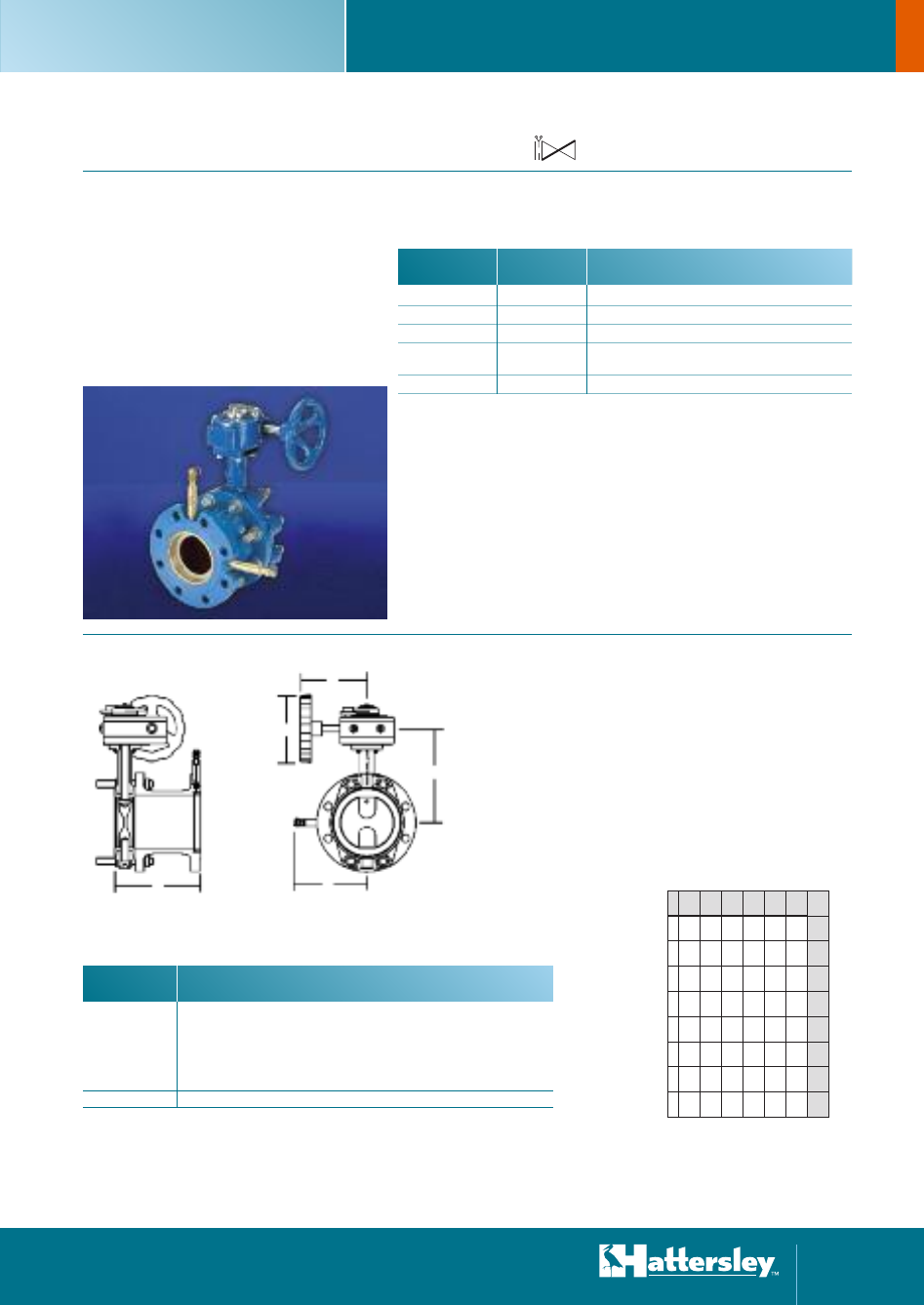
Technical Helpline: 0845 604 1790
E: tech-enquiries@hattersley.com W: www.hattersley.com
41
BALANCING VALVES - STATIC
PN16
Every effort has been made to ensure that the information contained in this publication is accurate at the time of publishing.
Hattersley Ltd assumes no responsibility or liability for typographical errors or omissions or for any misinterpretation of the
information within the publication and reserves the right to change without notice.
For Commissioning Valve Coefficients please refer to pages 47-49.
DIMENSIONAL DRAWINGS PRESSURE/
TEMPERATURE
RATING
EPDM Seat
16 bar from -10°C to 120°C
TEST PRESSURES
Shell: 24 bar
Seat: 17.6 bar
SPECIFICATION
Gear operation provides infinitely variable
settings between fully open and closed
positions.
Comprehensive flow charts available.
Metering station kitemarked to BS 7350.
Lever operated version available in sizes
50 to 200mm.
NOTES
The valve should not be less than 30°
open for regulation duties.
FEATURES AND BENEFITS
• Robust iron body materials for long service life
• Precise flow regulation and accurate
measurement
• Flanged with handwheel – easy to install
and operate
• Positive flow control at all handwheel settings
MATERIAL SPECIFICATION
Valve Fig. 953G
Test Points Fig. 631
Extension Sleeve Gunmetal 1400LG2 B62 1705 G-CuSn5ZnPb
Housing Cast Iron 1452 Gr220 A126 CI B 1691 GG22
(Nickel Plated)
Orifice Plate Stainless Steel 970 316S31 AISI 316 17440 X5CrNiMo1812
Component Material Specification
BS EN ASTM DIN
0 20 40 60 80 100 120 14 0
Temperature ˚C
14
12
10
8
6
2
0
Pressure bar
4
16
18
AB
H
J
K
Nom
Size mm 50 65 80 100 125 150 200 250 300
A mm 133 151 166 192 221 246 300 358 418
B mm 135 145 160 165 180 190 225 255 275
H mm 182 190 197 219 232 254 278 281 306
J mm 123 123 123 123 123 123 123 228 228
K dia 125 125 125 125 125 125 125 300 300
Weight kg 10.0 10.8 11.0 13.0 16.0 18.5 29.8 40.0 53.0
DIMENSIONS AND WEIGHTS
Fig. 5953, 5953G
Cast Iron Metrex Commissioning Sets
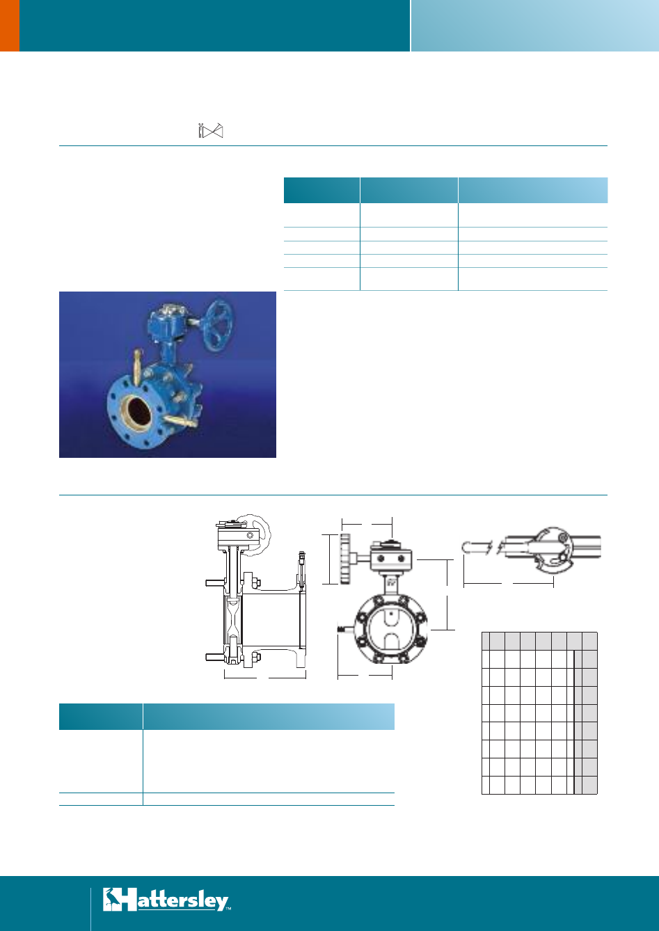
Technical Helpline: 0845 604 1790
E: tech-enquiries@hattersley.com W: www.hattersley.com
42
BALANCING VALVES - STATIC
PN16
Every effort has been made to ensure that the information contained in this publication is accurate at the time of publishing.
Hattersley Ltd assumes no responsibility or liability for typographical errors or omissions or for any misinterpretation of the
information within the publication and reserves the right to change without notice.
For Commissioning Valve Coefficients please refer to pages 47-49.
Fig. 5973, 5973G
Cast Iron Metrex Commissioning Sets Chilled Water,
LTHW & MTHW
SPECIFICATION
A close coupled
commissioning set
comprising a lugged butterfly
valve and metering station to
offer all the advantages of the
close coupled concept
together with an accuracy
of ±5% of flow rate.
Gear operation provides
infinitely variable settings
between fully open and
closed positions.
The commissioning set is
supplied as a single unit.
Supplied complete with
figure 631 test points and
necessary bolting for
connection of the valve end
to the system.
Comprehensive flow charts
available.
Note: The valve should be
not less than 30° open for
regulation duties.
Wrench operated version
available in sizes 50 to
200mm.
Figure 9973G available,
stainless steel disc.
FEATURES AND BENEFITS
• Robust iron body materials for long service life
• Precise flow regulation and accurate
measurement
• Flanged with handwheel – easy to install
and operate
• Positive flow control at all handwheel settings
MATERIAL SPECIFICATION
Valve Fig. 973 (see
page 41 for materials)
Test Points Fig. 631
Extension Sleeve Bronze 1982 CC491K B62
Housing Cast Iron 1561 EN-JLI040 A126 Cl B
Orifice Plate Stainless Steel 10088-1 XSCrNiMo 17-12-2
AISI 316
Component Material Specification
BS EN ASTM
0 20 40 60 80 100 120 140
T emperature ˚ C
14
12
10
8
6
2
0
Pressure bar
4
16
18
G
AB
H
J
PRESSURE/
TEMPERATURE
RATING
EPDM Seat
16 bar from -10 to 120ºC
SERVICE RATING
Suitable for Chilled Water,
LTHW and MTHW
TEST PRESSURES
(HYDRAULIC)
Shell: 24 bar
Seat: 17.6 bar
Nom
Size mm 50 65 80 100 125 150 200 250 300
A mm 133 151 166 192 221 246 300 358 418
B mm 135 145 160 165 180 190 225 255 275
H mm 182 190 197 219 232 254 278 281 306
J mm 123 123 123 123 123 123 123 228 228
K dia mm 125 125 125 125 125 125 125 300 300
Weight (geared)kg 13 15 21 26 33 45 69 94 131
DIMENSIONS AND WEIGHTS
DIMENSIONAL DRAWINGS
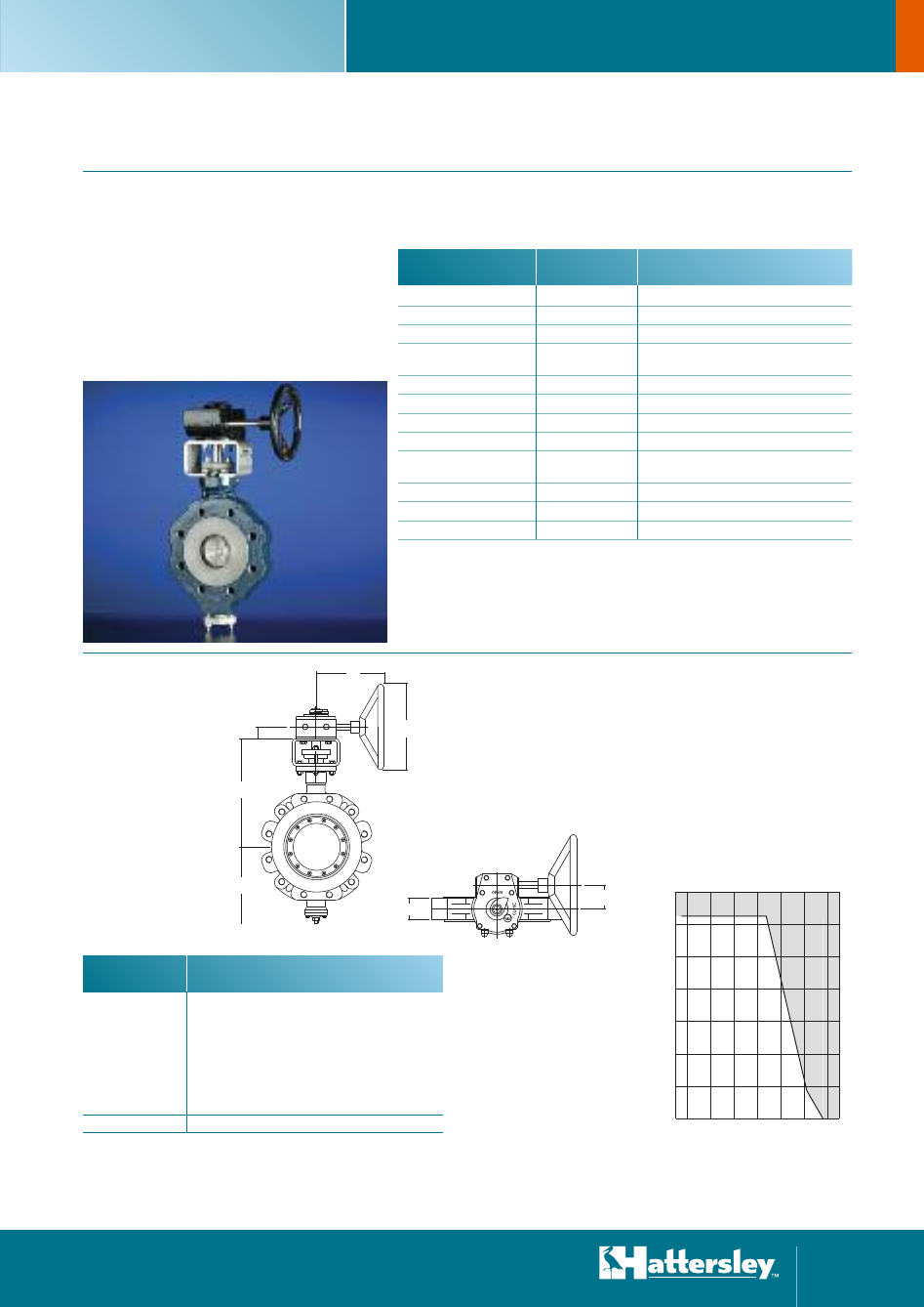
Technical Helpline: 0845 604 1790
E: tech-enquiries@hattersley.com W: www.hattersley.com
43
BALANCING VALVES - STATIC
PN25 DN50-150
Every effort has been made to ensure that the information contained in this publication is accurate at the time of publishing.
Hattersley Ltd assumes no responsibility or liability for typographical errors or omissions or for any misinterpretation of the
information within the publication and reserves the right to change without notice.
For Commissioning Valve Coefficients please refer to pages 47-49.
F
B
H
D
C
E
A
Fig. 4993G
Steel Fully-lugged Double Regulating Valve
PRESSURE/
TEMPERATURE RATING
25 bar from -10 to 135ºC
20.7 bar at 149ºC
3.4 bar at 204ºC
TEST PRESSURES
(HYDRAULIC)
Body: 37.5 bar
Seat: 27.5 bar
SPECIFICATION
Designed to BS EN 593: 2009.
Face to face dimensions to BS EN 558-1
basic series 16.
Reinforced PTFE disc seal.
Stainless steel body seat.
Double eccentric disc.
Bi-directional isolation.
Valves fitted with double regulating feature.
Actuator flange ISO 5211/1.
To suit flange connections BS EN 1092-2
PN25, alternative flanges available.
FEATURES AND BENEFITS
• Precise flow regulation
• Flanged with handwheel – easy to install
and operate
• Positive flow control at all handwheel settings
• Bi-directional isolation
• Double eccentric disc
MATERIAL SPECIFICATION
Body Steel 10213-2 GP240GH A216 WCB
Body Seat Stainless Steel 10270 X10CrNr18-8 A276-304
Disc Stainless Steel 10270 X10CrNr18-8 A276-304
Disc Seal Ring PTFE or
PTFE/Neoprene
Retaining Ring Stainless Steel 10270 X10CrNr18-8 A276-304
Stem Stainless Steel 10270 X10CrNr18-8 A276-304
Disc Pin Stainless Steel 10270 X10CrNr18-8 A276-304
Bottom Cap Steel 10213-2 GP240GH A216 WCB
Gland Packing PTFE or
PTFE/Neoprene
Bearings Bronze-PTFE
Gearbox Cast Iron 1561 EN-JLI030 A126 CI B
Handwheel Stainless Steel 10270 X10CrNr18-8 A276-304
Component Material Specification
BS EN ASTM
0 40 80 120 160 200 240
Temperature ˚C
28
24
20
16
12
4
0
Pressure bar
8
Nom
Size mm 50 65 80 100 125 150
A mm 43 46 64 64 70 76
B mm 123 131 150 175 187 218
H mm 215 215 220 281 294 317
C mm 27 27 27 35 35 42
D dia mm 125 200 200 250 300 300
E mm 39 39 39 52 52 67
F mm 152 159 159 184 197 223
Weight kg 10 12 17 24 33 47
DIMENSIONAL DRAWINGS
DIMENSIONS AND WEIGHTS
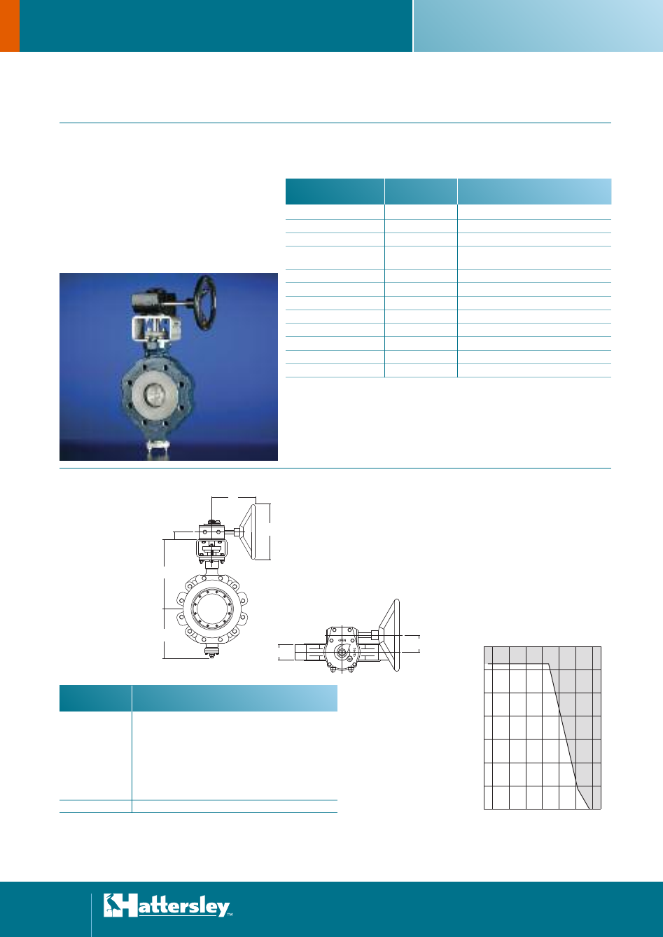
Technical Helpline: 0845 604 1790
E: tech-enquiries@hattersley.com W: www.hattersley.com
44
BALANCING VALVES - STATIC
PN25 DN200-500
Every effort has been made to ensure that the information contained in this publication is accurate at the time of publishing.
Hattersley Ltd assumes no responsibility or liability for typographical errors or omissions or for any misinterpretation of the
information within the publication and reserves the right to change without notice.
For Commissioning Valve Coefficients please refer to pages 47-49.
Fig. 4993G
Steel Fully-lugged Double Regulating Valve
SPECIFICATION
Designed to BS EN 593:2009.
Face to face dimensions to BS EN 558-1
basic series 16.
Reinforced PTFE disc seal.
Stainless steel body seat.
Double eccentric disc.
Bi-directional isolation.
Valves fitted with double regulating feature
Actuator flange ISO 5211/1.
To suit flange connections BS EN 1092-2
PN25, alternative flanges available.
FEATURES AND BENEFITS
• Precise flow regulation
• Flanged with handwheel – easy to install
and operate
• Positive flow control at all handwheel settings
• Bi-directional isolation
• Double eccentric disc
MATERIAL SPECIFICATION
Body Steel 10213-2 GP240GH A216 WCB
Body Seat Stainless Steel 10270 X10CrNr18-8 A276-304
Disc Stainless Steel 10270 X10CrNr18-8 A276-304
Disc Seal Ring PTFE or
PTFE/Neoprene
Retaining Ring Stainless Steel 10270 X10CrNr18-8 A276-304
Stem Stainless Steel 10270 X10CrNr18-8 A276-304
Disc Pin Stainless Steel 10270 X10CrNr18-8 A276-304
Bottom Cap Steel
Gland Packing PTFE Graphite
Bearings Bronze-PTFE
Gearbox Cast Iron 1561 EN-JLI030 A126 CI B
Handwheel Stainless Steel
Component Material Specification
BS EN ASTM
Nom
Size mm 200 250 300 350 400 450 500
A mm 89 114 114 127 140 152 152
B mm 294 333 382 398 448 473 555
H mm 369 396 461 477 557 583 643
C mm 42 50 50 50 66 66 66
D dia mm 300 457 457 457 610 610 610
E mm 67 90 123 154 138 138 138
F mm 223 279 331 356 477 477 477
Weight kg 73 126 167 243 340 454 493
E
A
0 40 80 120 160 200 240
Temperature ˚C
28
24
20
16
12
4
0
Pressure bar
8
PRESSURE/
TEMPERATURE RATING
25 bar from -10 to 135ºC
20.7 bar at 149ºC
3.4 bar at 204ºC
TEST PRESSURES
(HYDRAULIC)
Body: 37.5 bar
Seat: 27.5 bar
F
B
H
D
C
DIMENSIONAL DRAWINGS
DIMENSIONS AND WEIGHTS
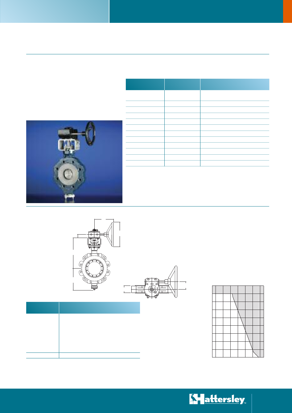
Technical Helpline: 0845 604 1790
E: tech-enquiries@hattersley.com W: www.hattersley.com
45
BALANCING VALVES - STATIC
PN40 DN65-150
Every effort has been made to ensure that the information contained in this publication is accurate at the time of publishing.
Hattersley Ltd assumes no responsibility or liability for typographical errors or omissions or for any misinterpretation of the
information within the publication and reserves the right to change without notice.
For Commissioning Valve Coefficients please refer to pages 47-49.
Fig. 4993G
Steel Fully-lugged Double Regulating Valve
SPECIFICATION
Designed to BS EN 593:2009.
Face to face dimensions to BS EN 558-1
basic series 16.
Reinforced PTFE disc seal.
Stainless steel body seat.
Double eccentric disc.
Bi-directional isolation.
Valves fitted with double regulating feature.
Actuator flange ISO 5211/1.
To suit flange connections BS EN 1092-2
PN40, alternative flanges available.
FEATURES AND BENEFITS
• Precise flow regulation
• Flanged with handwheel – easy to install
and operate
• Positive flow control at all handwheel settings
• Bi-directional isolation
• Double eccentric disc
MATERIAL SPECIFICATION
Disc Seal Ring PTFE or PTFE/
Neoprene
Retaining Ring Stainless Steel 10270 X10CrNr18-8 A276-304
Stem Stainless Steel 10270 X10CrNr18-8 A276-304
Disc Pin Stainless Steel 10270 X10CrNr18-8 A276-304
Bottom Cap Steel
Gland Packing PTFE Graphite
Bearings Bronze-PTFE
Gearbox Cast Iron 1561 EN-JLI030 A126 CI B
Handwheel Steel
Body Steel 10213-2 GP240GH A216 WCB
Body Seat Stainless Steel 10270 X10CrNr18-8 A276-304
Disc Stainless Steel 10270 X10CrNr18-8 A276-304
Component Material Specification
BS EN ASTM
0 40 80 120 160 200 240
Temperature ˚C
45
40
35
30
25
20
15
10
5
0
Pressure bar
F
B
H
D
C
E
A
Nom
Size mm 50 65 80 100 125 150
A mm 43 46 64 64 70 76
B mm 123 131 150 175 187 218
H mm 215 215 220 281 294 317
C mm 27 27 27 35 35 42
D dia mm 125 200 200 250 300 300
E mm 39 39 39 52 52 67
F mm 152 159 159 184 197 223
Weight kg 10 12 17 24 33 47
PRESSURE/
TEMPERATURE RATING
40 bar from -10 to 90ºC
20.7 bar at 149ºC
3.4 bar at 204ºC
TEST PRESSURES
(HYDRAULIC)
Body: 60 bar
Seat: 44 bar
DIMENSIONS AND WEIGHTS
DIMENSIONAL DRAWINGS
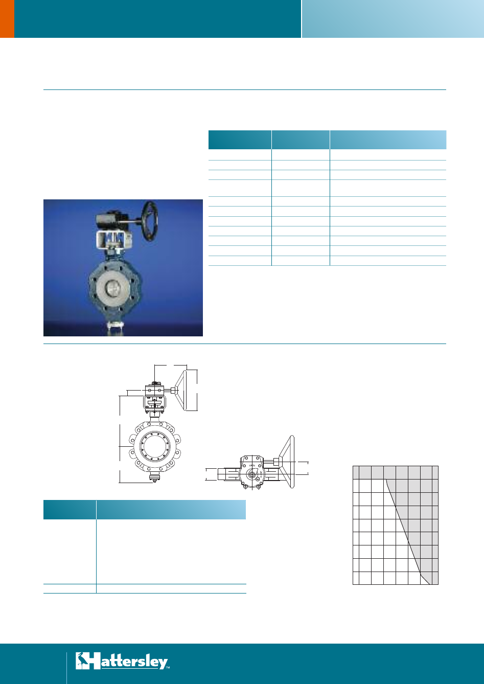
Technical Helpline: 0845 604 1790
E: tech-enquiries@hattersley.com W: www.hattersley.com
46
BALANCING VALVES - STATIC
PN40 DN200-500
Every effort has been made to ensure that the information contained in this publication is accurate at the time of publishing.
Hattersley Ltd assumes no responsibility or liability for typographical errors or omissions or for any misinterpretation of the
information within the publication and reserves the right to change without notice.
For Commissioning Valve Coefficients please refer to pages 47-49.
Fig. 4993G
Steel Fully-lugged Double Regulating Valve
SPECIFICATION
Designed to BS EN 593:2009.
Face to face dimensions to BS EN 558-1
basic series 16.
Reinforced PTFE disc seal.
Stainless steel body seat.
Double eccentric disc.
Bi-directional isolation.
Valves fitted with double regulating feature.
Actuator flange ISO 5211/1.
To suit flange connections BS EN 1092-2
PN40, alternative flanges available.
FEATURES AND BENEFITS
• Precise flow regulation
• Flanged with handwheel – easy to install
and operate
• Positive flow control at all handwheel settings
• Bi-directional isolation
• Double eccentric disc
MATERIAL SPECIFICATION
Body Steel 10213-2 GP240GH A216 WCB
Body Seat Stainless Steel 10270 X10CrNr18-8 A276-304
Disc Stainless Steel 10270 X10CrNr18-8 A276-304
Disc Seal Ring PTFE or PTFE/
Neoprene
Retaining Ring Stainless Steel 10270 X10CrNr18-8 A276-304
Stem Stainless Steel 10270 X10CrNr18-8 A276-304
Disc Pin Stainless Steel 10270 X10CrNr18-8 A276-304
Gland Packing PTFE Graphite
Bearings Bronze-PTFE
Gearbox Cast Iron 1561 EN-JLI030 A126 CI B
Handwheel Steel
Component Material Specification
BS EN ASTM
E
A
0 40 80 120 160 200 240
Temperature ˚C
45
40
35
30
25
20
15
10
5
0
Pressure bar
Nom
Size mm 200 250 300 350 400 450 500
A mm 89 114 114 127 140 152 152
B mm 294 333 382 398 448 473 555
H mm 369 396 461 477 557 583 643
C mm 42 50 50 50 66 66 66
D dia mm 300 457 457 457 610 610 610
E mm 67 90 123 154 138 138 138
F mm 223 279 331 356 477 477 477
Weight kg 79 143 203 288 415 469 589
DIMENSIONAL DRAWINGS
DIMENSIONS AND WEIGHTS
PRESSURE/
TEMPERATURE RATING
40 bar from -10 to 90ºC
20.7 bar at 149ºC
3.4 bar at 204ºC
TEST PRESSURES
(HYDRAULIC)
Body: 60 bar
Seat: 44 bar
F
B
H
D
C
Technical Helpline: 0845 604 1790
E: tech-enquiries@hattersley.com W: www.hattersley.com
47
BALANCING VALVES - STATIC
Every effort has been made to ensure that the information contained in this publication is accurate at the time of publishing.
Hattersley Ltd assumes no responsibility or liability for typographical errors or omissions or for any misinterpretation of the
information within the publication and reserves the right to change without notice.
Cast Iron and Steel Commissioning Valves Coefficients
Nom
Size mm 50 65 80 100 125 150 200
Flow Kv 71.91 155.9 217.3 380.2 576.6 830.8 1412
Headloss Factor 0.45 0.4 0.4 0.35 0.35 0.35 0.35
Kvs 48.24 98.58 137.4 224.9 341.1 491.5 835.4
Fig. M2000
Nom
Size mm 250 300 350 400 450 500 600
Flow Kv 2116 3073 3810 4968 6087 7958 11621
Headloss Factor 0.35 0.35 0.35 0.35 0.35 0.35 0.35
Kvs 1252 1818 2254 2939 3601 4708 6875
Nom
Size mm 50 65 80 100 125 150 200 250 300
Flow Kv - 155.9 217.3 380.2 576.6 830.8 1412 2116 3073
Headloss Factor - 0.4 0.4 0.35 0.35 0.35 0.35 0.35 0.35
Kvs - 98.58 137.4 224.9 341.1 491.5 835.4 1252 1818
Fig. M3000
Nom
Size mm 50 65 80 100 125 150 200 250 300
Flow Kv (fully open) 48.39 78.16 114.1 198.3 312.8 438.2 833.3 1185 1450
Fig. M733DR
Nom
Size mm 50 65 80 100 125 150 200 250 300
Flow Kv (fully open) 48.39 78.16 114.1 198.3 312.8 438.2 833.3 1185 1450
Kvs 49.47 81.79 128.1 223.9 349.4 445.9 889.5 1185 1450
Fig. M737
Nom
Size mm 50 65 80 100 125 150 200 250 300
Headloss Factor 0.45 0.4 0.4 0.35 0.35 0.35 0.35 0.35 0.35
Kvs 48.24 98.58 137.4 224.9 341.1 491.5 835.4 1252 1818
Fig. 5953G
Nom
Size mm 50 65 80 100 125 150 200 250 300
Headloss Factor 0.45 0.4 0.4 0.35 0.35 0.35 0.35 0.35 0.35
Kvs 48.24 98.58 137.4 224.9 341.1 491.5 835.4 1252 1818
Fig. 5973G
Nom
Size mm 50 65 80 100 125 150 200 250 300
Headloss Factor 1.86 0.95 0.50 0.29 0.37 0.43 0.31 0.56 0.33
Kvs 85 204 370 820 982 1353 2923 3374 6350
Fig. 4983G PN25
Technical Helpline: 0845 604 1790
E: tech-enquiries@hattersley.com W: www.hattersley.com
48
BALANCING VALVES - STATIC
Every effort has been made to ensure that the information contained in this publication is accurate at the time of publishing.
Hattersley Ltd assumes no responsibility or liability for typographical errors or omissions or for any misinterpretation of the
information within the publication and reserves the right to change without notice.
Nom
Size mm 15 22 28 32 40 50
Flow Kv 2.244 5.4 9.63 21.68 34.38 71.1
Headloss Factor 0.75 0.6 0.6 0.5 0.45 0.45
Kvs 1.943 4.181 7.46 15.33 23.06 47.7
Fig. 1000
Nom
Size mm 15
Flow Kv 2.354
Headloss Factor 0.75
Kvs 2.039
Fig. 1000C
Nom
Size mm 15
Flow Kv 1.101
Headloss Factor 0.83
Kvs 1.003
Fig. 1000M
Nom
Size mm 15
Flow Kv 0.533
Headloss Factor 0.9
Kvs 0.506
Fig. 1000L
Nom
Size mm 15
Flow Kv 0.539
Headloss Factor 0.9
Kvs 0.511
Fig. 1000LC
Nom
Size mm 15
Flow Kv 1.129
Headloss Factor 0.83
Kvs 1.029
Fig. 1000MC
Bronze Commissioning Valves Coefficients
Nom
Size in
1/2
L
1/2
3/4
1 1
1/4
1
1/2
2
1432 Flow Kv (fully open) 2.26 2.14 3.6 6.37 12.3 21.3 31.3
1432L Flow Kv - 2.26 - - - - -
1432C Flow Kv - 2.14 3.6 - - - -
1432LC Flow Kv - 2.26 - - - - -
Fig. 1432, 1432L, 1432C, 1432LC
Nom
Size in
1/2
3/4
1 1
1/4
1
1/2
2
2432 Flow Kv 1.549 2.995 5.31 10.7 18.11 28.65
2432LM Flow Kv 0.99 - - - - -
2432LL Flow Kv 0.519 - - - - -
Fig. 2432, 2432LM, 2432LL
Headloss Factor %
The headloss across a metering station is less than the
differential pressure (¢P) signal indicated at the pressure
tappings as shown on the metering station flow charts.
The value of headloss for the metering station is shown
as a percentage of the signal in the tables below.
The headloss of the DRV is obtained from the graph at the fully
open position at the particular design flow rate. The total
headloss of the metering station and DRV (commissioning set),
when directly coupled or independently located, is the
summation of the two separate values.
Technical Helpline: 0845 604 1790
E: tech-enquiries@hattersley.com W: www.hattersley.com
49
BALANCING VALVES - STATIC
Every effort has been made to ensure that the information contained in this publication is accurate at the time of publishing.
Hattersley Ltd assumes no responsibility or liability for typographical errors or omissions or for any misinterpretation of the
information within the publication and reserves the right to change without notice.
Nom
Size in
1/2
L
1/2
M
1/2 3/4
1 1
1/4
1
1/2
2
1732 Flow Kv - - 1.87 3.14 5.59 10.8 18.1 29.1
1732 Kvs - - 1.943 4.181 7.46 15.33 23.06 47.7
1732M Flow Kv - - 1.06 - - - - -
1732M Kvs - - 1.003 - - - - -
1732L Flow Kv - - 0.57 - - - - -
1732L Kvs - - 0.506 - - - - -
1732C Flow Kv - - 1.87 3.14 - - - -
1732C Kvs - - 2.037 4.457 - - - -
1732MC Flow Kv - - 1.06 - - - - -
1732MC Kvs - - 1.029 - - - - -
1732LC Flow Kv - - 0.57 - - - - -
1732LC Kvs - - 0.511 - - - - -
Fig. 1732, 1732M, 1732L, 1732C, 1732MC, 1732LC
Nom
Size in
1/2 3/4
1832 Flow Kv 1.703 2.973
1832 Kvs 1.943 4.181
1832M Flow Kv 1.056 -
1832M Kvs 1.003 -
1832L Flow Kv 0.532 -
1832L Kvs 0.506 -
Fig. 1832, 1832M, 1832L
Nom
Size mm 15 20 25 35 40 50
Flow Kv 4.74 9.96 18.46 26.71 42.15 70.95
Fig. 1200DR
Nom
Size mm 15 20 25 35 40 50
Flow Kv 2.293 5.331 9.506 22.15 36.36 70.91
Headloss Factor 0.75 0.6 0.6 0.5 0.45 0.45
Kvs 1.986 4.129 7.363 15.66 24.39 47.57
Fig. 4000
Bronze Commissioning Valves Coefficients
Technical Helpline: 0845 604 1790
E: tech-enquiries@hattersley.com W: www.hattersley.com
50
The Baltic Arts Centre, Gateshead, Tyne & Wear
Specification: Range of Hattersley Commissioning and Traditional Valves
Technical Helpline: 0845 604 1790
E: tech-enquiries@hattersley.com W: www.hattersley.com
51
DIFFERENTIAL PRESSURE CONTROL VALVES
Differential Pressure Control Valves
Extremely efficient, the DPCV is set to a maximum
differential pressure limit, under dynamic
balancing conditions, which ensures flow cannot
exceed a desired rate. It therefore helps reduce
energy consumption and the risk of noise, and
simplifies the commissioning process.
The EPM diaphragm, which separates the upper
and lower chamber of the valve, in combination
with the balanced piston, is key to stabilising
differential pressure within the system.
The rubber-seated piston, controlled by the
diaphragm, closes the valve on rising differential
pressure and opens it on falling differential
pressure. The valve will continue to move in this
way until equilibrium of pressure is achieved.
This ensures the maximum desired flow rates or
differential pressures are not exceeded.
Installing a DPCV in a system to control
differential pressure can also help to minimise
the risk of noise.
Installing a DPCV in a circuit ensures the system
remains balanced, independent from any
changes in other areas of the circuit, which
greatly simplifies the balancing and
commissioning procedure. It also maintains the
control authority of the 2 port control valve.
Available in sizes from DN15 to DN50, in flow and
return configurations, the DPCV operates at a
temperature range of -10˚C to 100˚C and is
PN16 rated. The pressure differential is set on
installation, across a 20 to 80 kPa range, and can
be easily adjusted on commissioning as required
by the changing conditions.
Hattersley offers other accessories which are
highly recommended in order to achieve an
optimum performance. See page 57 for details.
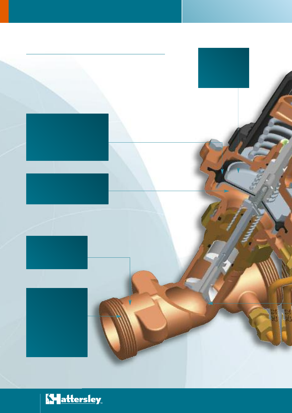
Technical Helpline: 0845 604 1790
E: tech-enquiries@hattersley.com W: www.hattersley.com
52
DIFFERENTIAL PRESSURE CONTROL VALVES
Lower Chamber*
The lower pressure, after the load, is
transmitted to the lower chamber.
Diaphragm
Separates and balances the upper
and lower chambers and therefore
the differential pressure. The
Diaphragm reacts quickly to
fluctuation in pressure.
Upper Chamber*
The higher pressure,
before the load, is
transmitted to the
upper chamber.
Body
PN16 rated. Compact
design allows for installation
in limited spaces.
Differential Pressure Control Valves
Features and Benefits
Male Threaded Ends
Male and female adapters
are available so that the
DPCV can be placed in any
standard pipework. See
page 55 for details. The
valve is easily replaceable
without disturbing the
surrounding pipework.
*Please see page 55 for typical installation layouts.
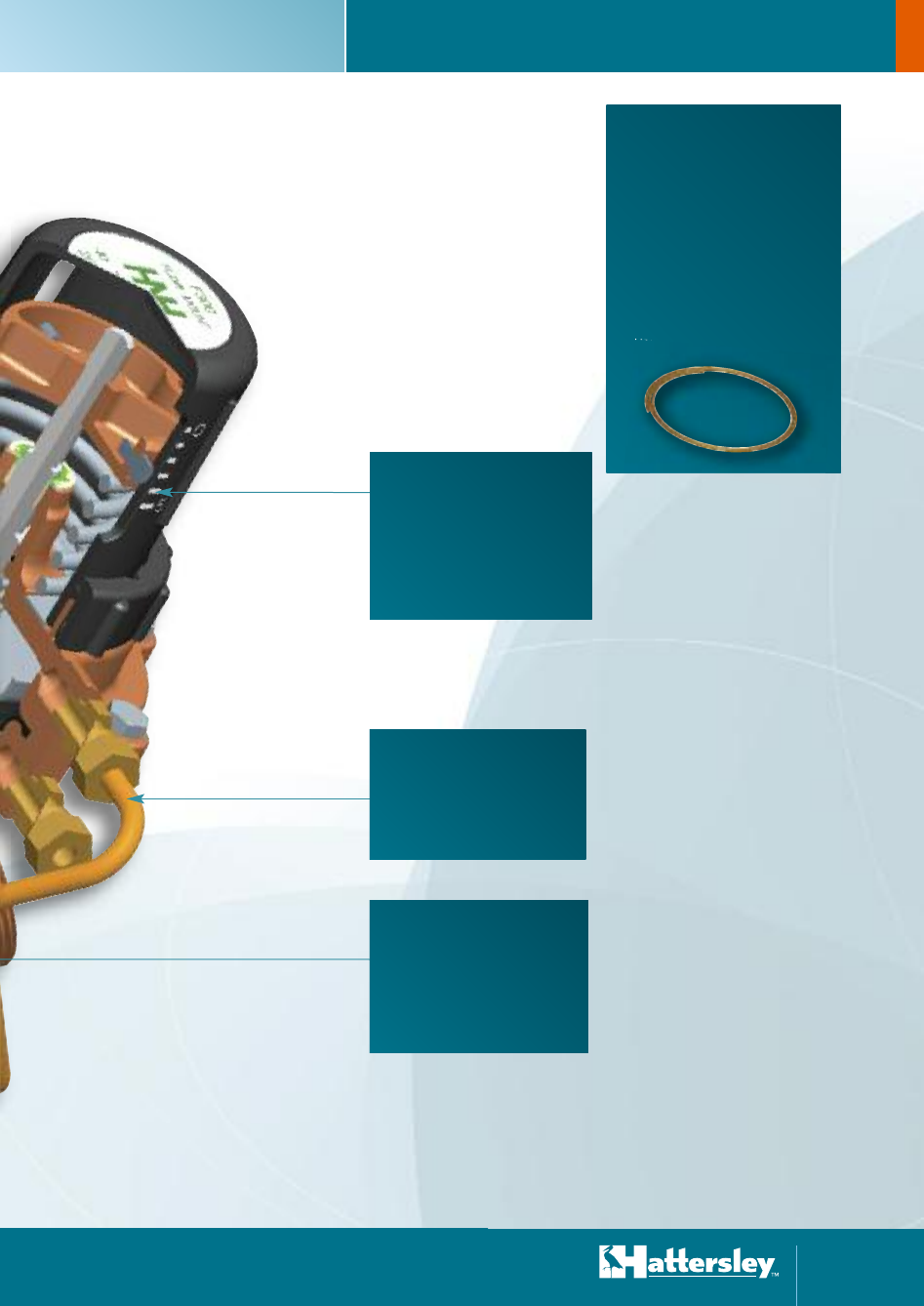
Technical Helpline: 0845 604 1790
E: tech-enquiries@hattersley.com W: www.hattersley.com
53
DIFFERENTIAL PRESSURE CONTROL VALVES
Adjuster
Easily sets differential pressure
across a 20-80 kPa range, and
can be adjusted to maintain
desired flow rates or differential
pressure, matching circuit
conditions.
Integral Impulse Tube*
Pressure from before the load
is linked to the upper
chamber (flow mounted
configuration only).
Rubber Seated Piston
Closes on rising differential
pressure and opens on falling
differential pressure.
Maintains the desired system
flow rate.
Impulse Tube
Alongside the DPCV, an
impulse tube is supplied
as standard. It is essential
to the valve’s performance
as it taps pressure from
the other side of the circuit
and links it to the valve’s
chambers.
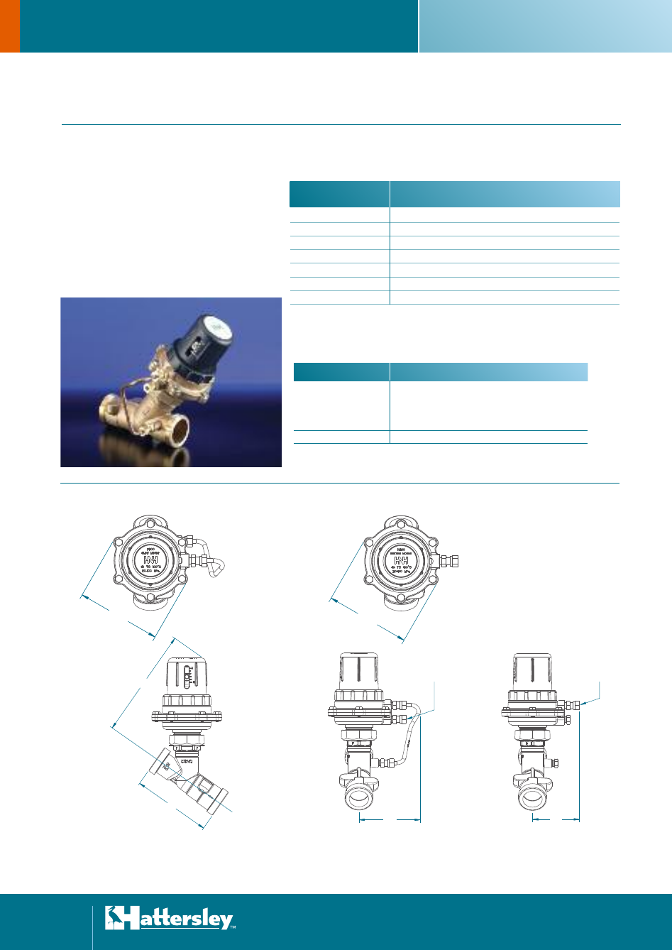
Technical Helpline: 0845 604 1790
E: tech-enquiries@hattersley.com W: www.hattersley.com
54
DIFFERENTIAL PRESSURE CONTROL VALVES
PN16
Every effort has been made to ensure that the information contained in this publication is accurate at the time of publishing.
Hattersley Ltd assumes no responsibility or liability for typographical errors or omissions or for any misinterpretation of the
information within the publication and reserves the right to change without notice.
Fig. F300 Flow
Fig. R300 Return
DIMENSIONAL DRAWINGS
FEATURES AND BENEFITS
• Maintains a consistent performance
• Use with variable speed pumps within
HVAC systems
• Enhances efficiency
• Reduces energy consumption
• Simplifies the commissioning process
• Easily adjusted to meet future conditions
MATERIAL SPECIFICATION
Body Bronze BS EN 1982 (CC491K)
Bonnet Bronze BS EN 1982 (CC491K)
Chamber Bronze BS EN 1982 (CC491K)
Adjuster Nylon Grade PA6
Stem / Piston Stainless Steel BS EN 10088 - 1:2005
Diaphragm Rubber EPM
O-Ring Seals Rubber EPDM
Component Material
105 80
Impulse Tube
Connection
Impulse Tube
Connection
A
B
Flow Configuration
Top View Return Configuration
Top View
119
119
Size DN15 DN20 DN25 DN32 DN40 DN50
A mm 90 96 114 132.5 150.5 184
B mm 175 175 185 190 195 205
End Connection in 3/4" 1" 11/4" 1
1/2" 13/4" 23/8"
BSP Parallel Male
Weight kg 2.34 2.39 2.62 2.76 3.07 3.57
DIMENSIONS AND WEIGHTS
Flow Configuration
Front View
Flow & Return
Configuration
Side View
Return Configuration
Front View
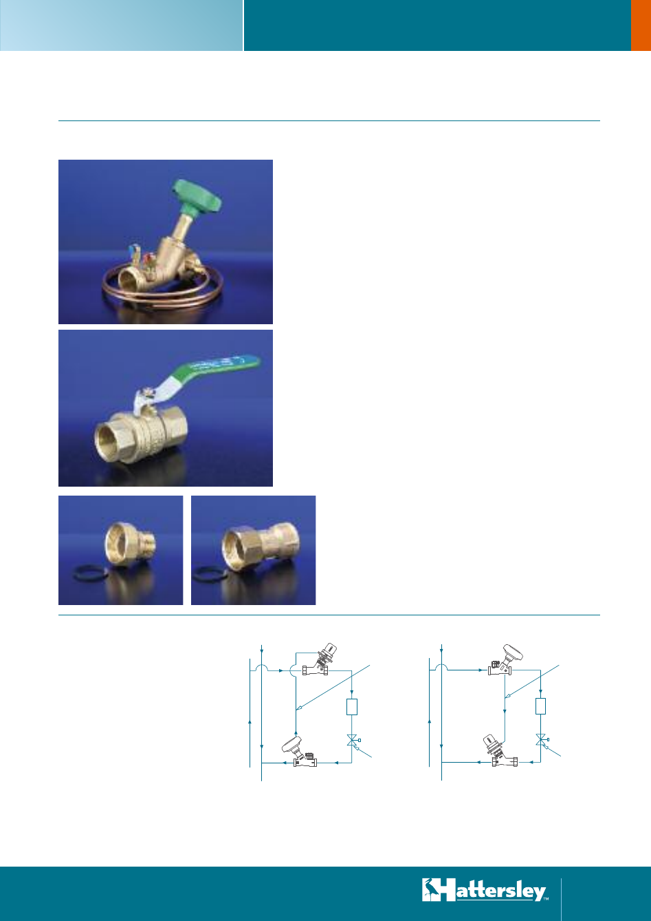
Technical Helpline: 0845 604 1790
E: tech-enquiries@hattersley.com W: www.hattersley.com
55
DIFFERENTIAL PRESSURE CONTROL VALVES
ACCESSORIES
Every effort has been made to ensure that the information contained in this publication is accurate at the time of publishing.
Hattersley Ltd assumes no responsibility or liability for typographical errors or omissions or for any misinterpretation of the
information within the publication and reserves the right to change without notice.
DPCV Accessories
ISOLATING BALL VALVE
Installing a ball valve in the impulse tube allows isolation of
the tube during flushing. This helps to ensure that the tube
is kept free from debris.
COMPANION VALVE
Hattersley highly recommends the use of a companion valve as a
part of the circuit. As well as providing standard flow measuring
and regulating features, the companion valve has an integral
tapping point for an impulse tube to link the valve and the DPCV.
Additional impulse tubes are available on request.
MALE AND FEMALE TAILPIECES
Hattersley offers additional male and female BSP taper
threaded couplings, giving the contractors a variety of
options on installation and enabling a fast and easy
connection to the pipework.
Companion
Valve
Load
DPCV
Impulse
Tube
2 Port
Control
Valve
DPCV
P2
P1
Companion
Valve
Load
Impulse
Tube
2 Port
Control
Valve
Example Flow Configuration (F300) Example RETURN Configuration (R300)
TYPICAL INSTALLATION LAYOUTS
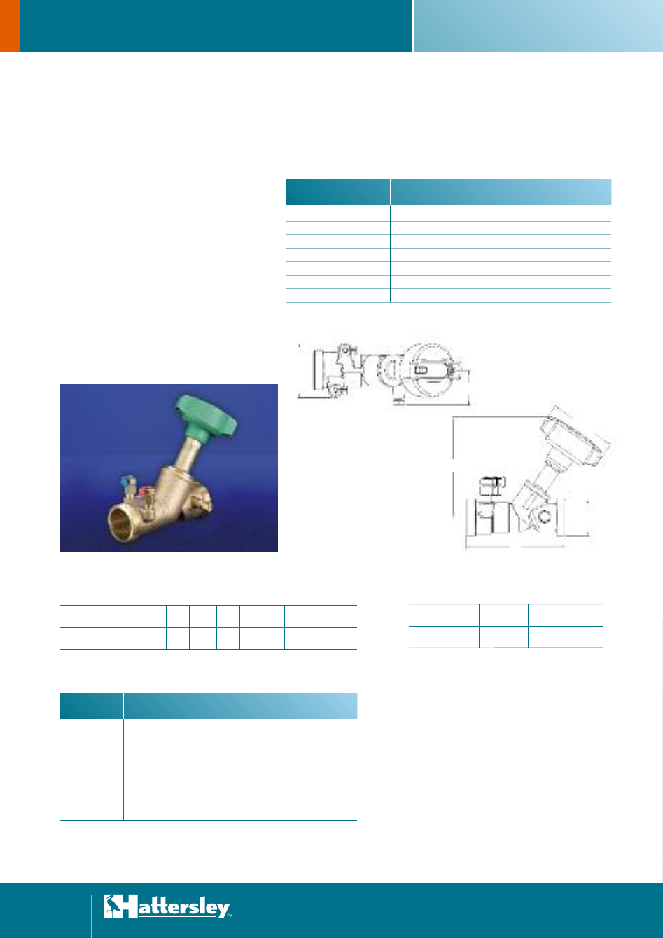
Technical Helpline: 0845 604 1790
E: tech-enquiries@hattersley.com W: www.hattersley.com
56
DIFFERENTIAL PRESSURE CONTROL VALVES
PN16
Every effort has been made to ensure that the information contained in this publication is accurate at the time of publishing.
Hattersley Ltd assumes no responsibility or liability for typographical errors or omissions or for any misinterpretation of the
information within the publication and reserves the right to change without notice.
Companion Valve – DP1732 - Standard Flow, DP1732M - Medium
Flow, DP1732L - Low Flow
END CONNECTIONS
Male parallel threads to ISO 228
SPECIFICATION
Inside screw non-rising stem.
Characterised regulating disc.
Integral fixed orifice.
Supplied with 2 Fig. 631 test points fitted.
FEATURES AND BENEFITS
• Has an integral tapping point for the impulse
tube to link with the Hattersley DPCV
• Integral orifice and test points provide precise
and accurate flow measurement
• Easy to operate with Double Regulating
handwheel and numerical position indicator
• Positive flow control at all handwheel settings
• Manufactured using WRAS Approved materials
• Can be used plugged, as supplied, for PN25
applications or with an impulse tube for PN16
applications
• Characterised regulating disc tends towards
equal percentage performance
• Male threaded ends for easy connection to all
pipework systems
MATERIAL SPECIFICATION
FIg DP DP DP DP DP DP DP DP
No. 1732 1732M 1732L 1732 1732 1732 1732 1732
A mm 90 90 90 96 114 132.5 150.5 184
B mm 105 105 105 106 127 128 143 144
C mm 50 50 50 54 62 66 70 78
D mm 34 34 34 36 39 43 46 48
E mm G3/4" G
3/4" G3/4" G1" G11/4" G11/2" G13/4" G23/8"
Kv 1.87 1.06 0.57 3.14 5.59 10.80 18.10 29.10
Kvs 1.943 1.003 0.506 4.181 7.46 15.33 23.06 47.7
Weight kg 0.60 0.60 0.60 0.65 0.99 1.12 1.48 2.13
D
C
DIMENSIONS AND WEIGHTS
Body Bronze - BS EN 1982: CC491K
Bonnet DN15 to DN32 DZR Brass - BS EN 12164: CW602N
Bonnet DN40 & DN50 Bronze - BS EN 1982: CC491K
Stem/Disc DZR Brass - BS EN 12164: CW602N
'O' Ring Seal EPDM Rubber WRAS Approved
Plug R1/8 Inch DZR Brass - BS EN 12164: CW602N
Fig. 631 Test Points DZR Brass - BS EN 12164: CW602N
Component Material
DIMENSIONAL DRAWINGS
Temperature ˚C -10 - 30 40 50 65 80 90 100 110 120
Pressure bar 16 14.3 12.6 10 8.7 7.8 6.9 6 5
Temperature ˚C -10 - 30 110 120
Pressure bar 25 23.4 21.8
PRESSURE/TEMPERATURE RATING
WHEN IMPULSE TUBE IS INSERTED WHEN PLUGGED
E
Ø 90
B
A
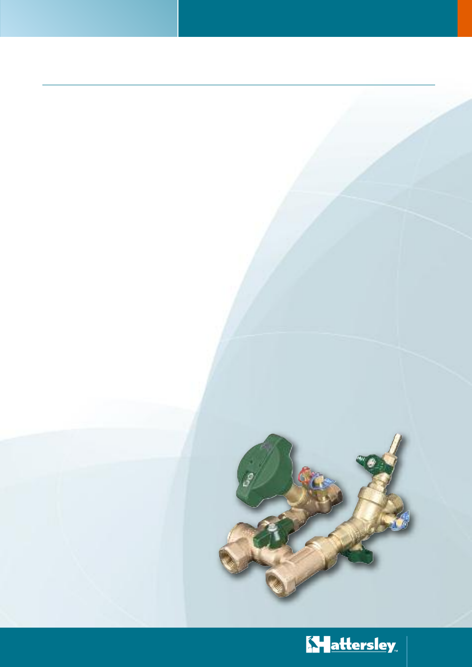
Technical Helpline: 0845 604 1790
E: tech-enquiries@hattersley.com W: www.hattersley.com
57
HOOK-UP II
Hook-Up II
Hook-Up II provides flow control, measurement,
flushing and isolation, using bronze and DZR
brass components. It is PN16 rated with versions
suitable for chilled, low and medium temperature
hot water, ranging from -10°C to a maximum of
120°C. Available in 1/2", 3/4" and 1" sizes.
The Hook-Up II is pre-fabricated using proven,
stringently tested Hattersley products. The fully
assembled unit is tested to BS EN 12266-1:2003
prior to delivery. For a complete list of
components see the specification for
each figure number on the following pages.
The newly designed Hook-Up II features a
number of design improvements. A single cast
H-Body reduces the number of joints, the weight
and the size of the module. A combination of
components can be selected to attach to the
H-Body, depending on the site specifications.
BENEFITS
For the design engineer there are many
advantages. With all the components supplied as
one pre-tested unit, minimal design involvement
is needed and the performance of the entire unit
is known in advance.
For the contractor the need for only four
connections offers significant reductions in costs.
The fully tested, guaranteed and standardised
components are pressure tested before leaving
Hattersley. Apart from the cleaning of the strainer,
the Hook-Up II is designed to be maintenance
free.
This brochure outlines our standard range but
other configurations can be made by special
arrangement. Our technical team will assist
with valve sizing etc.
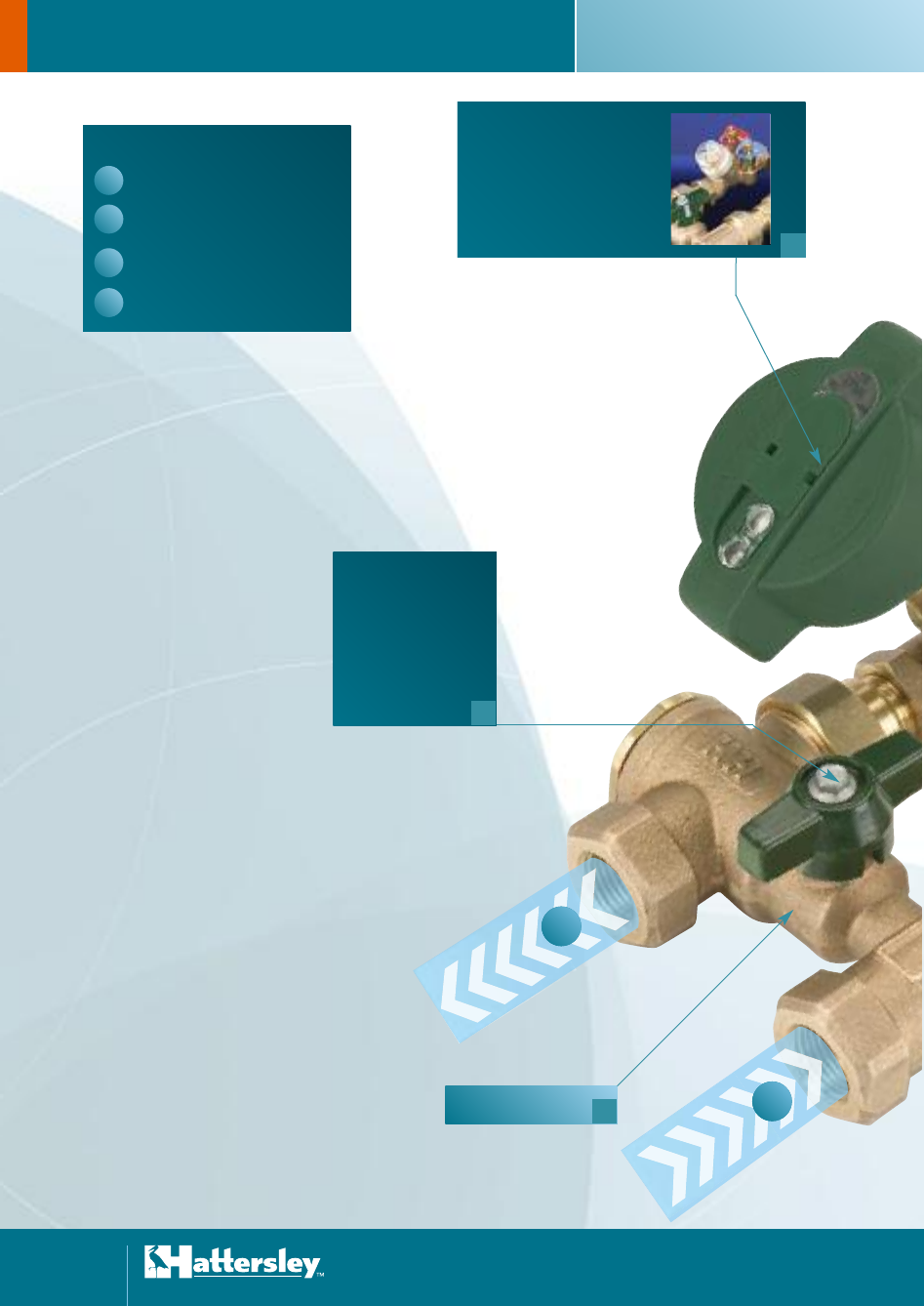
Technical Helpline: 0845 604 1790
E: tech-enquiries@hattersley.com W: www.hattersley.com
58
HOOK-UP II
Flow Connection from Pipework
Flow Connection to the
Terminal Unit
Return Connection from the
Terminal Unit
Return Connection to Pipework
A
B
C
D
Flow and Return Connections:
Centralised
Isolation Valve
Allows easy back
flushing, forward
flushing and isolation.
An extension stem is
added for chilled
water services
Flushing bypass
2
1
11 A
D
Figure 266 for heated water is shown here.
Commissioning Set
Adjusts and sets the flow rate
with proven high accuracy.
Customers can opt for
manually set FODRV valve
or a motorised
FODRV valve (left).
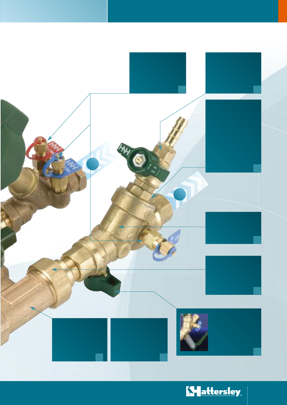
Technical Helpline: 0845 604 1790
E: tech-enquiries@hattersley.com W: www.hattersley.com
59
HOOK-UP II
Reference Tags
Each unit is tagged with
individual fan coil reference
numbers and relevant
customer information as
requested.
Pressure Test Points
On commissioning valves
for flow measurement.
On strainer to check
pressure drop across
load.
Extension Stems
For chilled water services,
extension stems are fitted
as standard to the
isolation ball valve to
enable lagging.
Union Connector
Allows custom alignment
and features an integral
O-Ring to ensure joints
are pressure tight.
End Connectors
Simple connection to
system. BSP female
threads allow
connections to any
possible pipes using
adaptors. Installed
directly on flow and
return connections of
heating and cooling
terminal units ie. fan coils
and chilled beams.
New H-Body
is factory tested before
and after final assembly.
Consists of one compact
casting; reducing weight
and size.
Strainer (optional)
Keeps system clean.
Filters flow before it
reaches terminal unit.
Draincock
For routine maintenance,
allows flushing of
strainer without need to
remove basket.
34
5
6
7
8
9
10
C
B

Technical Helpline: 0845 604 1790
E: tech-enquiries@hattersley.com W: www.hattersley.com
60

Technical Helpline: 0845 604 1790
E: tech-enquiries@hattersley.com W: www.hattersley.com
61
Project: Wembley WO5 development, London
Client: Quintain
Architect: PRP/The Manser Practice
Project Manager: Stace LLP
Mechanical Contractor: FCS Services
Specification: Hattersley Hook-Up II
Hattersley Hook-Up II flow management modules have been specified for the HVAC
system of Quintain’s new mixed-use development in the Wembley WO5 district, which
surrounds the Wembley Arena. The project will have 3 phases; the student
accommodation will be constructed first, followed by apartments and then a 4* Hilton
Hotel. Hattersley valves will be installed in all stages of the development to provide
heating, ventilation and air conditioning.
The Hook-Up II is ideal for this project as it provides easy flow control and accurate flow
measurement, along with flushing and isolating capabilities from a single, pre-fabricated
unit. Only four connections need to be made on-site, speeding up installation time and
reducing costs. All modules are tested in advance so design engineers know the exact
performance of the entire unit prior to installation.
The construction of student halls of residence has just started and will comprise
656 bedrooms, communal kitchens and car parking over 11 floors.
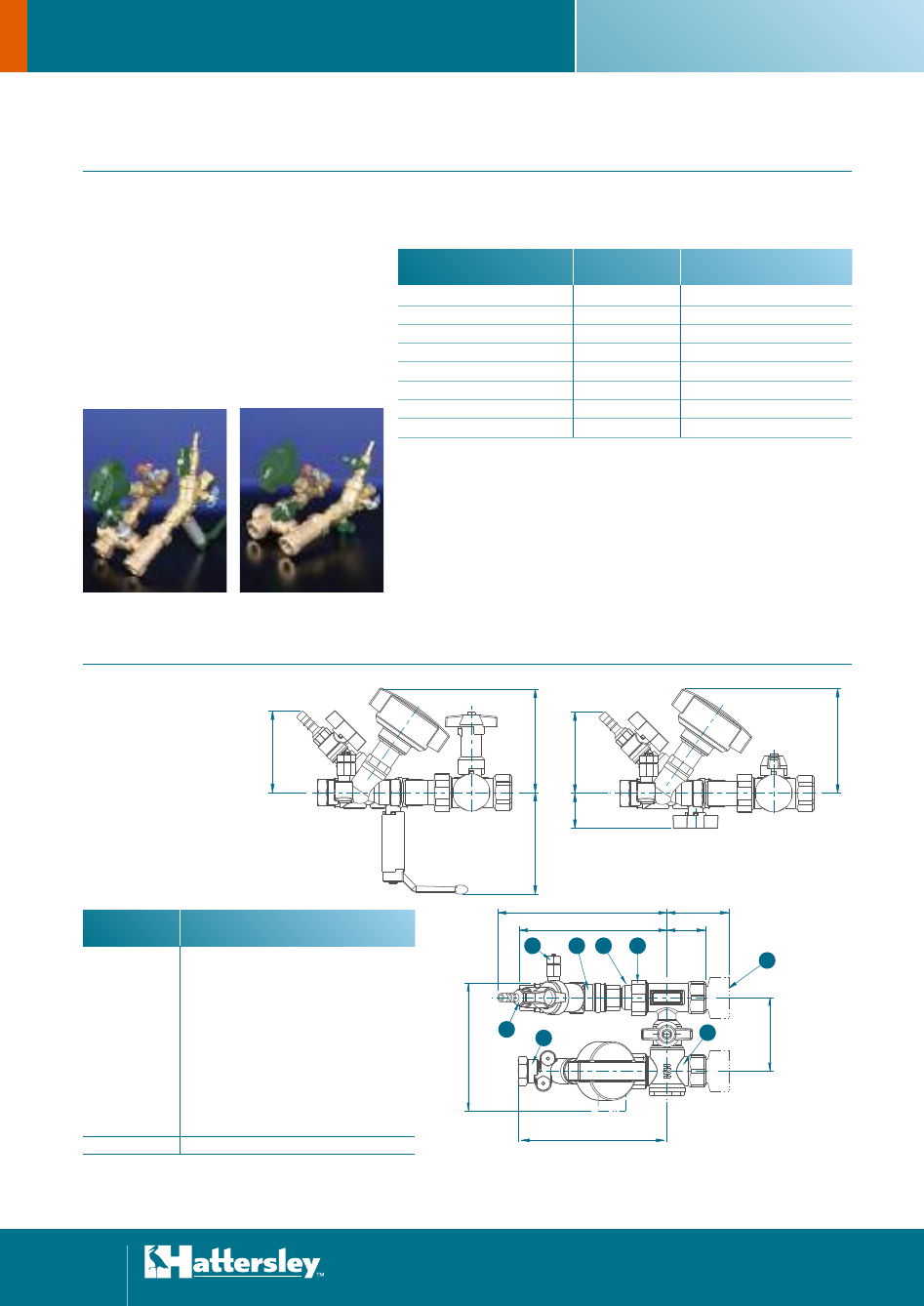
Technical Helpline: 0845 604 1790
E: tech-enquiries@hattersley.com W: www.hattersley.com
62
HOOK-UP II
PN16
Every effort has been made to ensure that the information contained in this publication is accurate at the time of publishing.
Hattersley Ltd assumes no responsibility or liability for typographical errors or omissions or for any misinterpretation of the
information within the publication and reserves the right to change without notice.
Fig. C266, H266
Manual (with Drain and Strainer)
PRESSURE/
TEMPERATURE RATING
PN16 -10 to 120°C
TEST PRESSURES
Tested to BS EN 12266-1:2003
SPECIFICATION
Both modules can adopt a left or
right-handed configuration.
SERVICE RATING
Figure C266 is suitable for chilled
water applications.
Figure H266 is suitable for LTHW
and MTHW applications.
MATERIAL SPECIFICATION
1. H-Body Bronze 1982 CC491K
2. Fig. 1732/M/L FODRV Bronze 1982 CC491K
3. Fig. 1807 Strainer Ball DZR Brass 12165 CW602N
4. Union Connector DZR Brass 12164 CW602N
5. Fig. 103 Blow Down Valve DZR Brass 12165 CW602N
6. Fig. 631 Test Point DZR Brass 12164 CW602N
7. Adaptors for 1" only* DZR Brass 12164 CW602N
8. Union Nut Brass 12164 CW614N
Component Material Specification
BS EN
Fig. C266 for
chilled water
Fig. H266 for
heated water
J
1
7
A
H
C
B
OVER HANDWHEEL LUGS
F
J
J1
2
3 46
5
634
4
8
7
1
5
22
E
GD1
ED
G
Fig. C266 Fig. H266
*For 1" system pipework, adaptors can be fitted to our standard units.
DIMENSIONAL DRAWINGS
Nom
Size mm 1/2 female 3/4 female 1 female
A mm 143 143 150
B mm 170 185 221
C mm 205 215 251
D mm 38 47 50
D1 mm 105 119 123
E mm 110 120 120
F mm 168 175 190
G mm 110 111 132
H mm 80 80 80
J mm 42 42 42
J1 mm - - 70
Weight kg 2.35 2.70 3.40
DIMENSIONS AND WEIGHTS
(right-hand
configuration
shown)
FEATURES AND BENEFITS
• Ultra compact, prefabricated unit
• Provides flow control, measurement, flushing
and isolation
• Can be tailored to customer’s specifications
• For use with Chilled Water, LTHW and MTHW
• Reduces time, costs and specification risks

Technical Helpline: 0845 604 1790
E: tech-enquiries@hattersley.com W: www.hattersley.com
63
HOOK-UP II
PN16
Every effort has been made to ensure that the information contained in this publication is accurate at the time of publishing.
Hattersley Ltd assumes no responsibility or liability for typographical errors or omissions or for any misinterpretation of the
information within the publication and reserves the right to change without notice.
Fig. C268, H268
Manual (with Drain and Strainer)
DIMENSIONAL DRAWINGS
MATERIAL SPECIFICATION
1. H-Body (DN15 - DN20) Bronze 1982 CC491K
2. Fig. 1732/M/L DRV Bronze 1982 CC491K
3. Fig. 100 Ball Valve DZR Brass 12165 CW602N
4. Union Connector DZR Brass 12165 CW602N
5. Adaptors for 1" only* DZR Brass 12165 CW602N
6. Union Nut Brass 12164 CW614N
Component Material Specification
BS EN
Fig. C268 for
chilled water
Fig. H268 for
heated water
PRESSURE/
TEMPERATURE RATING
PN16 -10 to 120°C
TEST PRESSURES
Tested to BS EN 12266-1:2003
SPECIFICATION
Both modules can adopt a left or
right-handed configuration.
SERVICE RATING
Figure C268 is suitable for chilled
water applications.
Figure H268 is suitable for LTHW
and MTHW applications.
F
J
H
B J1
A
OVER HANDWHEEL LUGS
3
1
2
34
5
344
6
5
1
2
D1
G
D
G
Fig. C268 Fig. H268
*For 1" system pipework, adaptors can be fitted to our standard units.
Nom
Size mm 1/2 female 3/4 female 1 female
A mm 143 143 150
B mm 120 125 149
D mm 45 54 57
D1 mm 110 119 123
F mm 168 175 190
G mm 110 111 132
H mm 80 80 80
J mm 42 42 42
J1 mm - - 70
Weight kg 1.90 2.20 2.75
DIMENSIONS AND WEIGHTS
(right-hand
configuration
shown)
FEATURES AND BENEFITS
• Ultra compact, prefabricated unit
• Provides flow control, measurement, flushing
and isolation
• Can be tailored to customer’s specifications
• For use with Chilled Water, LTHW and MTHW
• Reduces time, costs and specification risks
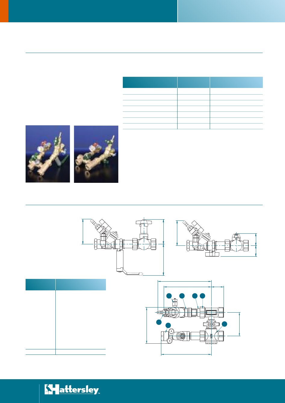
Technical Helpline: 0845 604 1790
E: tech-enquiries@hattersley.com W: www.hattersley.com
64
HOOK-UP II
PN16
Every effort has been made to ensure that the information contained in this publication is accurate at the time of publishing.
Hattersley Ltd assumes no responsibility or liability for typographical errors or omissions or for any misinterpretation of the
information within the publication and reserves the right to change without notice.
Fig. C267 H267
MotoBalance (with Drain and Strainer)
MATERIAL SPECIFICATION
1. H-Body Bronze 1982 CC491K
2. Fig. 1832/M/L FODRV Bronze 1982 CC491K
3. Fig. 1807 Strainer Ball DZR Brass 12165 CW602N
4. Union Connector DZR Brass 12164 CW602N
5. Fig. 103 Blow Down Valve DZR Brass 12165 CW602N
6. Fig. 631 Test Point DZR Brass 12164 CW602N
7. Union Nut Brass 12164 CW614N
Component Material Specification
BS EN
PRESSURE/
TEMPERATURE RATING
PN16 -10 to 120°C
TEST PRESSURES
Tested to BS EN 12266-1: 2003
SPECIFICATION
Both modules can adopt a left or
right-handed configuration.
SERVICE RATING
Figure C267 is suitable for chilled
water applications.
Figure H267 is suitable for LTHW
and MTHW applications.
Fig. C267 for
chilled water
Fig. H267 for
heated water
A
H
J
C
B
F
1
2
34
5
6
63
5
21
44
7
E
G1D1
G
E
D
Fig. C267 Fig. H267
Nom
Size mm 1/2 female 3/4 female
A mm 125 125
B mm 170 185
C mm 205 215
D mm 38 47
D1 mm 105 119
E mm 110 120
F mm 168 175
G mm 43 43
G1 mm 85 85
H mm 80 80
J mm 42 42
Weight kg 2.20 2.54
DIMENSIONS AND WEIGHTS
DIMENSIONAL DRAWINGS
(right-hand
configuration
shown)
FEATURES AND BENEFITS
• Ultra compact, prefabricated unit
• Provides flow control, measurement, flushing
and isolation
• Can be tailored to customer’s specifications
• For use with Chilled Water, LTHW and MTHW
• Reduces time, costs and specification risks
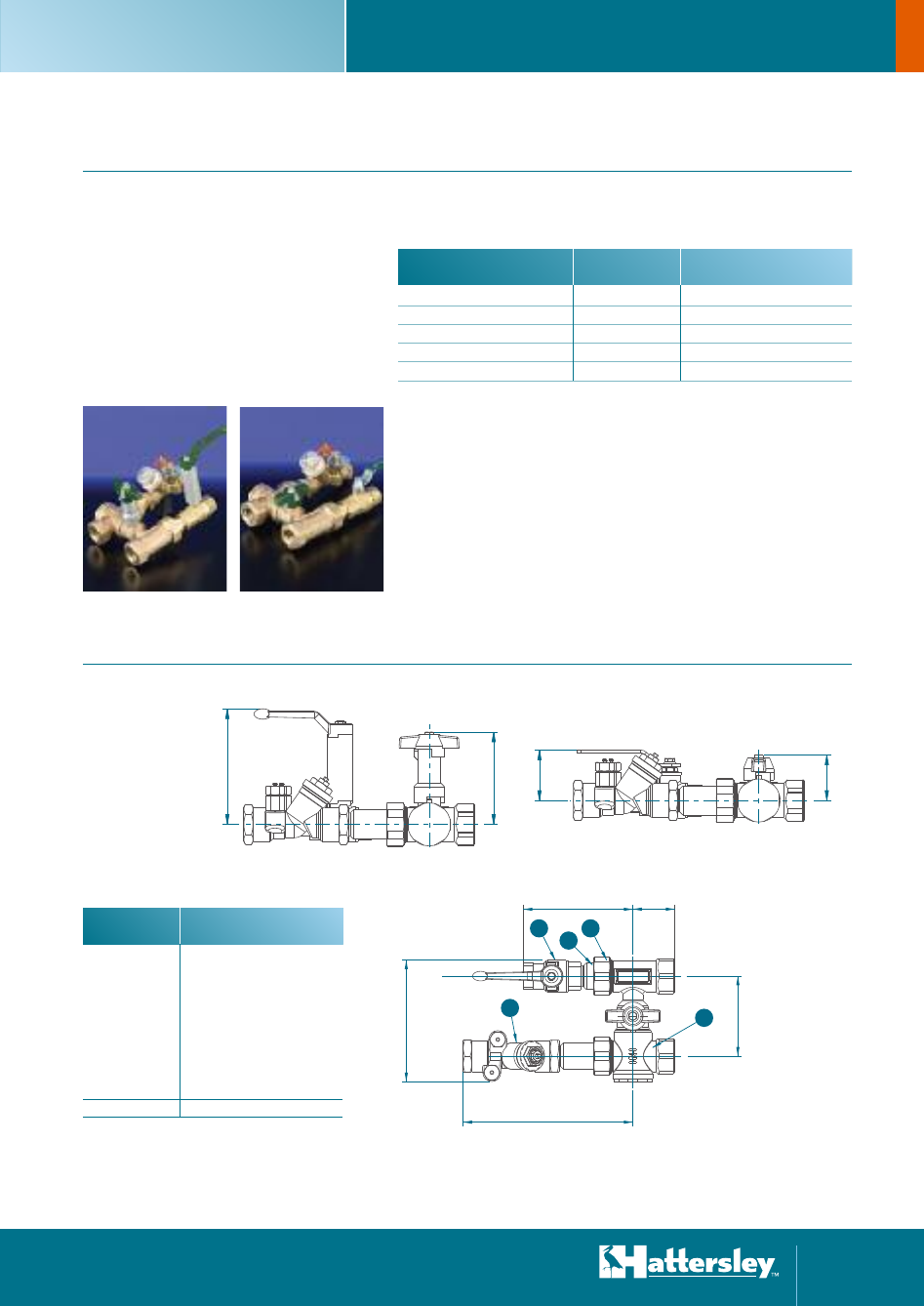
Technical Helpline: 0845 604 1790
E: tech-enquiries@hattersley.com W: www.hattersley.com
65
HOOK-UP II
PN16
Every effort has been made to ensure that the information contained in this publication is accurate at the time of publishing.
Hattersley Ltd assumes no responsibility or liability for typographical errors or omissions or for any misinterpretation of the
information within the publication and reserves the right to change without notice.
Fig. C269, H269
MotoBalance (with Drain and Strainer)
FEATURES AND BENEFITS
• Ultra compact, prefabricated unit
• Provides flow control, measurement, flushing
and isolation
• Can be tailored to customer’s specifications
• For use with Chilled Water, LTHW and MTHW
• Reduces time, costs and specification risks
MATERIAL SPECIFICATION
1. H-Body (DN15 - DN20) Bronze 1982 CC491K
2. Fig. 1832/M/L DRV Bronze 1982 CC491K
3. Fig. 100 Ball Valve DZR Brass 12165 CW602N
4. Union Connector DZR Brass 12165 CW602N
5. Union Nut Brass 12164 CW614N
Component Material Specification
BS EN
Fig. C269 for
chilled water
Fig. H269 for
heated water
PRESSURE/
TEMPERATURE RATING
PN16 -10 to 120°C
TEST PRESSURES
(HYDRAULIC)
Tested to BS EN 12266-1
SPECIFICATION
Both modules can adopt a left or
right-handed configuration.
SERVICE RATING
Figure C269 is suitable for chilled
water applications.
Figure H269 is suitable for LTHW
and MTHW applications.
BJ
H
F
A
1
2
3
4
3 5
4
2
1
D1
G1
D
G
(right-hand
configuration
shown)
Fig. H269Fig. C269
Nom
Size mm 1/2 female 3/4 female
A mm 125 125
B mm 120 125
D mm 45 54
D1 mm 110 119
F mm 168 175
G mm 43 43
G1 mm 85 85
H mm 80 80
J mm 42 42
Weight kg 1.75 2.04
DIMENSIONS AND WEIGHTS
DIMENSIONAL DRAWINGS
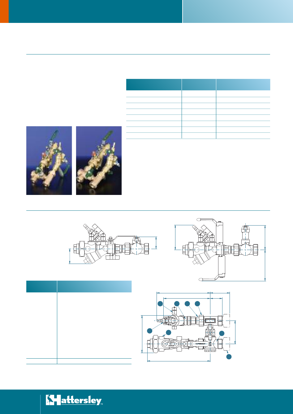
Technical Helpline: 0845 604 1790
E: tech-enquiries@hattersley.com W: www.hattersley.com
66
HOOK-UP II
PN16
Every effort has been made to ensure that the information contained in this publication is accurate at the time of publishing.
Hattersley Ltd assumes no responsibility or liability for typographical errors or omissions or for any misinterpretation of the
information within the publication and reserves the right to change without notice.
Fig. C262, H262
Autoflow (with Drain and Strainer)
PRESSURE/
TEMPERATURE RATING
PN16 -10 to 120°C
TEST PRESSURES
Tested to BS EN 12266-1:2003
SPECIFICATION
Both modules can adopt a left or
right-handed configuration.
SERVICE RATING
Figure C262 is suitable for chilled
water applications.
Figure H262 is suitable for LTHW
and MTHW applications.
FEATURES AND BENEFITS
• Ultra compact, prefabricated unit
• Provides flow control, measurement, flushing
and isolation
• Can be tailored to customer’s specifications
• For use with Chilled Water, LTHW and MTHW
• Reduces time, costs and specification risks
MATERIAL SPECIFICATION
1. H-Body Bronze 1982 CC491K
2. Fig. 1051 Autoflow DZR Brass 12165 CW602N
3. Fig. 1807 Strainer Ball DZR Brass 12165 CW602N
4. Union Connector DZR Brass 12164 CW602N
5. Fig. 103 Blow Down Valve DZR Brass 12165 CW602N
6. Fig. 631 Test Point DZR Brass 12164 CW602N
7. Adaptors for 1" only* DZR Brass 12164 CW602N
8. Union Nut Brass 12164 CW614N
Component Material Specification
BS EN
Fig. C262 for
chilled water
Fig. H262 for
heated water
D1 G1
E
G
D
Fig. C262Fig. H262
Nom
Size mm 1/2 female 3/4 female 1 female
A mm 130 135 140
B mm 170 185 221
C mm 205 215 251
D mm 51 51 68
D1 mm 105 119 123
E mm 110 120 120
F mm 220 225 295
G mm 43 43 43
G1 mm 85 85 85
H mm 80 80 80
J mm 42 42 42
J1 mm - - 70
Weight kg 2.78 3.09 4.67
DIMENSIONS AND WEIGHTS
DIMENSIONAL DRAWINGS
*For 1" system pipework, adaptors can be fitted to our standard units.
BJ
C J1
F
7
1
52
6 3 4 8
A
H
(right-hand
configuration
shown)
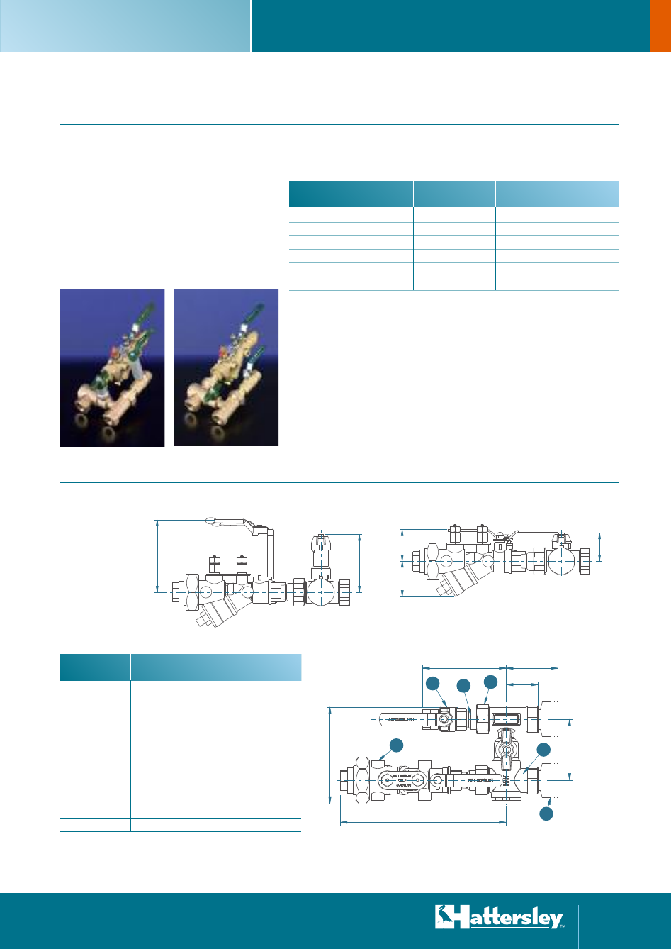
Technical Helpline: 0845 604 1790
E: tech-enquiries@hattersley.com W: www.hattersley.com
67
HOOK-UP II
PN16
Every effort has been made to ensure that the information contained in this publication is accurate at the time of publishing.
Hattersley Ltd assumes no responsibility or liability for typographical errors or omissions or for any misinterpretation of the
information within the publication and reserves the right to change without notice.
(right-hand
configuration
shown)
Fig. C264, H264
Autoflow (with Drain and Strainer)
FEATURES AND BENEFITS
• Ultra compact, prefabricated unit
• Provides flow control, measurement, flushing
and isolation
• Can be tailored to customer’s specifications
• For use with Chilled Water, LTHW and MTHW
• Reduces time, costs and specification risks
MATERIAL SPECIFICATION
1. H-Body (DN15 - DN20) Bronze 1982 CC491K
2. Fig. 1051 Autoflow DZR Brass 12165 CW602N
3. Fig. 100 Ball Valve DZR Brass 12165 CW602N
4. Union Connector DZR Brass 12165 CW602N
5. Adaptors for 1" only* DZR Brass 12164 CW602N
6. Union Nut Brass 12164 CW614N
Component Material Specification
BS EN
PRESSURE/
TEMPERATURE RATING
PN16 -10 to 120°C
TEST PRESSURES
Tested to BS EN 12266-1: 2003
SPECIFICATION
Both modules can adopt a left or
right-handed configuration.
SERVICE RATING
Figure C264 is suitable for chilled
water applications.
Figure H264 is suitable for LTHW
and MTHW applications.
Fig. C264 for
chilled water
Fig. H264 for
heated water
H
F
A
J
3
21
5
46
J1B
D1
G1
DK
G
Fig. C264 Fig. H264
*For 1" system pipework, adaptors can be fitted to our standard units.
Nom
Size mm 1/2 female 3/4 female 1 female
A mm 130 135 140
B mm 120 125 149
D mm 45 54 57
D1 mm 110 119 123
F mm 220 225 295
G mm 43 43 43
G1 mm 85 85 85
H mm 80 80 80
J mm 42 42 42
J1 mm - - 70
K mm 51 51 68
Weight kg 2.33 2.59 4.07
DIMENSIONS AND WEIGHTS
DIMENSIONAL DRAWINGS
Technical Helpline: 0845 604 1790
E: tech-enquiries@hattersley.com W: www.hattersley.com
68
Gulf Hotel, Bahrain
Specification: Hattersley Globe and Butterfly Valves
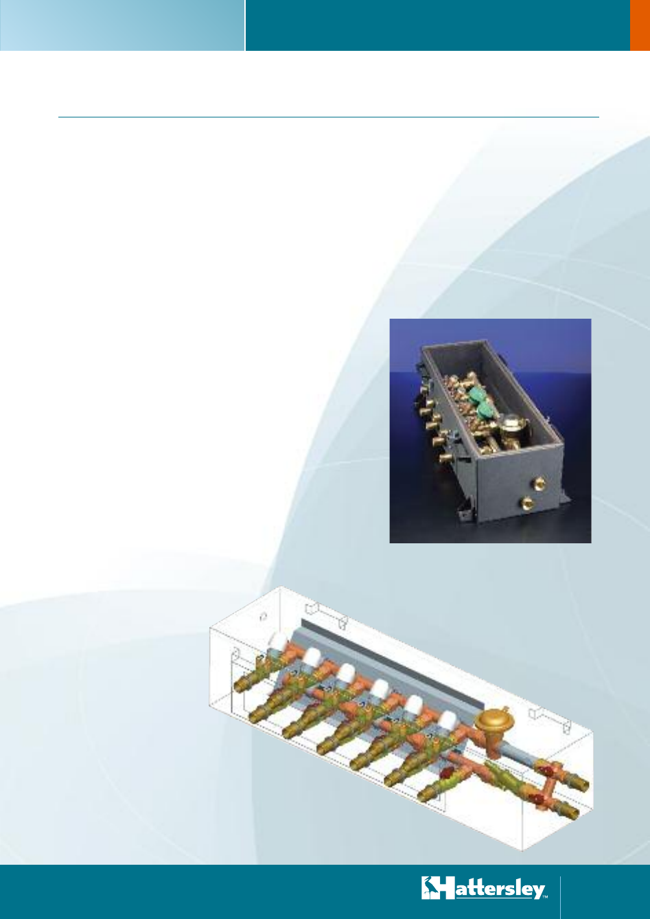
Technical Helpline: 0845 604 1790
E: tech-enquiries@hattersley.com W: www.hattersley.com
69
MULTICOMM
MultiComm
On large projects, significant time and cost can be
eliminated by enabling commissioning at convenient
locations. Ends of corridors, or accessible cupboards
can be used, which would also eliminate disruption to
occupiers during maintenance works.
The MultiComm is an exceptionally efficient,
practical and versatile system:
• Depending on flow rates, up to six terminals can be
served from a single MultiComm unit.
• All units are custom built to suit site specification.
• All site connections can be made without the need to
access the internal components.
• MultiComm is suitable for variable flow or constant
flow systems.
• All connections are BSPT Female, enabling standard
pipe or specialist adaptors to be used.
• Fan coil units can be flushed, vented and balanced
without the time-consuming 'looping out' procedure.
This can be carried out by one commissioning
engineer instead of a team.
• A single strainer serves all circuits, eliminating the
need for individual strainers.
• All systems can be flushed through the unique
Hook-Up H-Body.
• The single DPCV
maintains constant
differential pressure
between manifolds.
Hattersley MultiComm provides one
easy access point for commissioning
and maintenance of multiple
heating/chilled water terminal units.
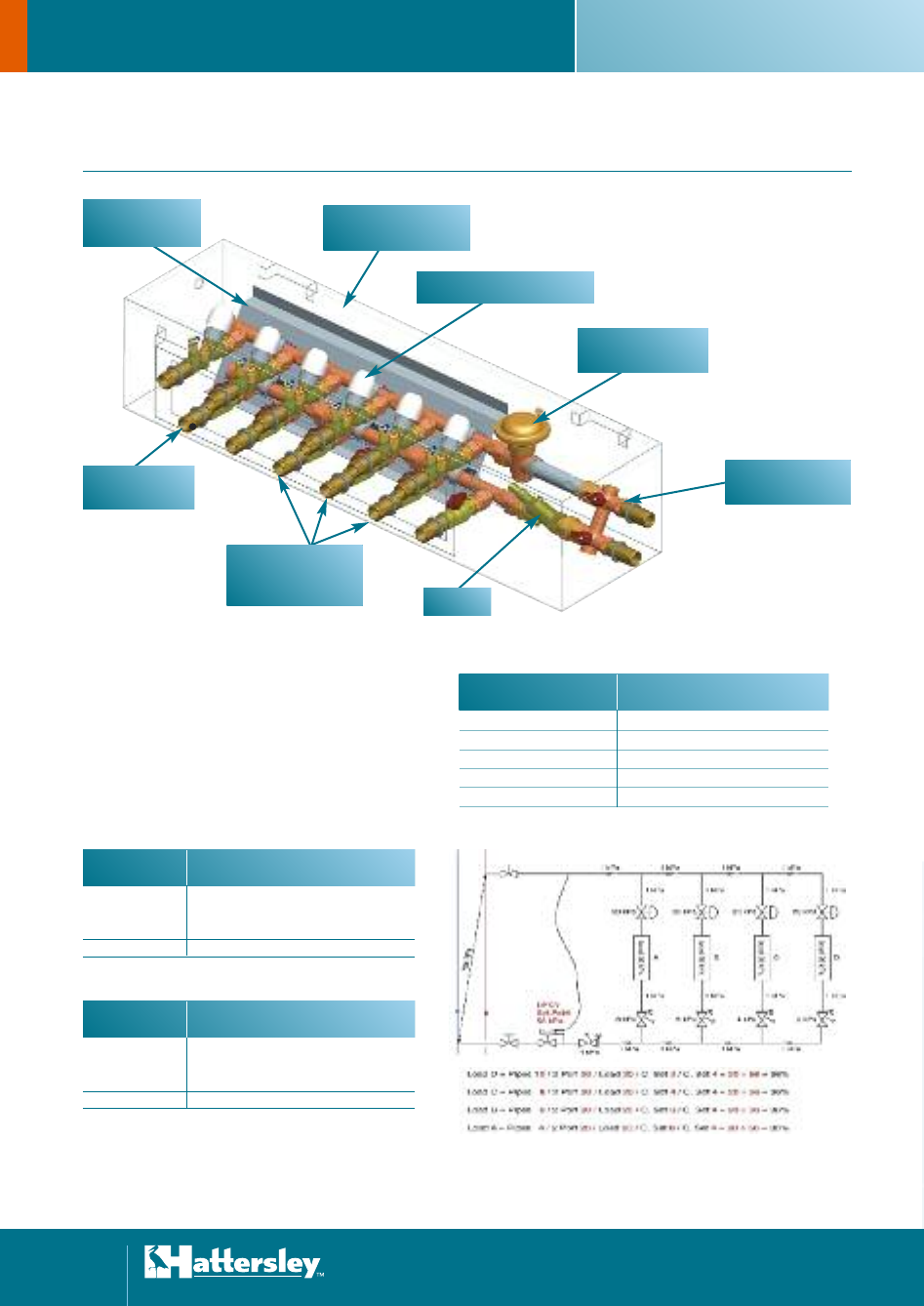
Technical Helpline: 0845 604 1790
E: tech-enquiries@hattersley.com W: www.hattersley.com
70
MULTICOMM
Every effort has been made to ensure that the information contained in this publication is accurate at the time of publishing.
Hattersley Ltd assumes no responsibility or liability for typographical errors or omissions or for any misinterpretation of the
information within the publication and reserves the right to change without notice.
MultiComm
Outlets &
Inlets 6x6 5x5 4x4 3x3 2x2
Length mm 1120 1120 880 880 640
Height mm 250 250 250 250 250
Width mm 290 290 290 290 290
Weight kg 40 38 36 34 30
DIMENSIONS AND WEIGHTS
Flow Isolation
Valves
All connections
accessible without
entering box Strainer
Unique H-Body
for flushing
DPCV for Variable
flow systems
Return Balancing Valves
Insulated box for
Heating or Chilling
Mounting plate
for manifolds
TYPICAL SCHEMATIC
PRESSURE/
TEMPERATURE RATING
Maximum pressure: 16 bar
Temperature rating: -10 to 100°C
MATERIAL SPECIFICATION
H-Body Bronze
Strainer Bronze (Fig. 817)
Manifolds Bronze
Isolation Valves DZR Brass (Fig. 100)
Regulation Valves Bronze (1732 or 1832)
Component Material
Units with outlets and inlets on same side
Outlets &
Inlets 6x6 5x5 4x4 3x3 2x2
Length mm 1120 1120 880 880 640
Height mm 200 200 200 200 200
Width mm 400 400 400 400 400
Weight kg 40 38 36 34 30
Units with outlets and inlets on opposite side
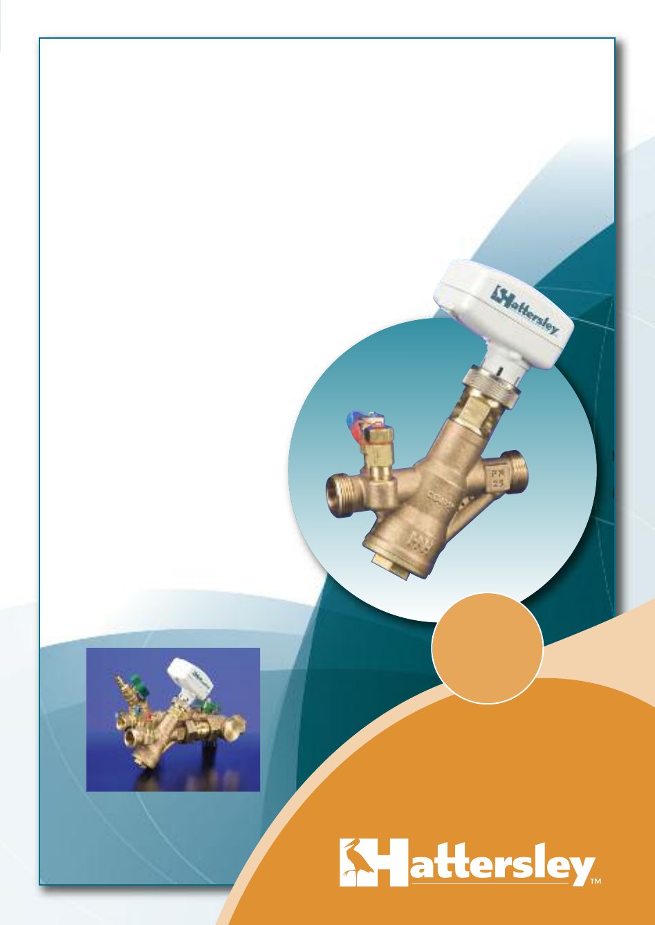
Pressure
Independent
Control Valves
FEATURES AND BENEFITS
• Unique flow measurement for
accurate commissioning and
troubleshooting
• Pre-set flow rates
• Reacts to system changes
to maintain stable flow rates
• Equal percentage control
characteristic ensures
improved system control
• Removable cartridge for
flushing, complies with
CIBSE and BSRIA
recommendation
• Also available as part of
Hook-Up II flow management
system
Call us on
0845 604 1790
or visit us online
www.hattersley.com
Details
available on
request
Figure 305*
Figure C270 series - Hook-Up with PICV*
* Please note PICV and
actuator are sold separately.

Technical Helpline: 0845 604 1790
E: tech-enquiries@hattersley.com W: www.hattersley.com
72
One Reading Central, Reading, Berkshire
Specification: Hattersley Fixed Orifice Double Regulating Valves
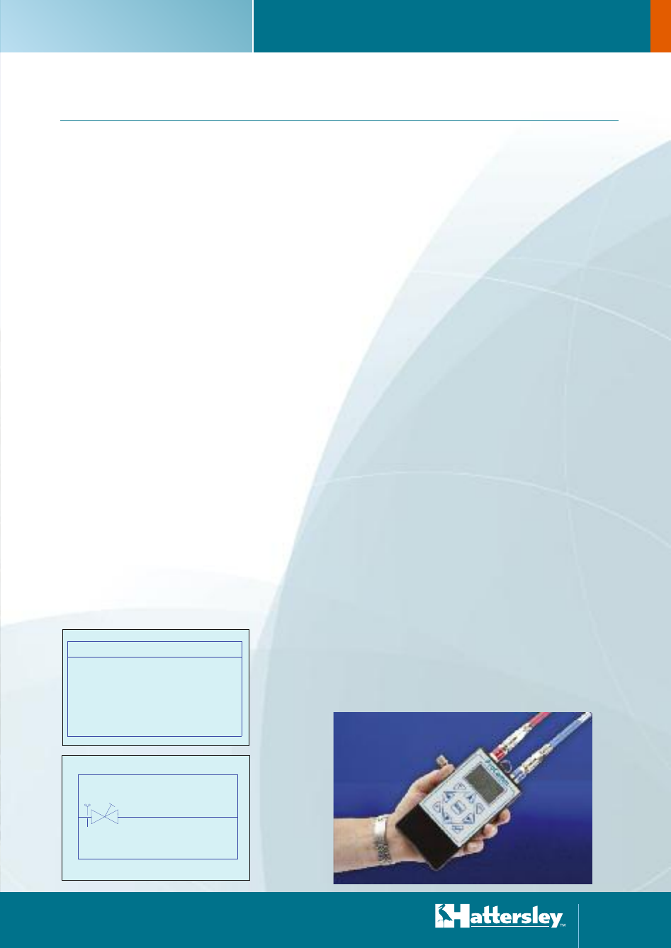
Technical Helpline: 0845 604 1790
E: tech-enquiries@hattersley.com W: www.hattersley.com
73
PROCOMM
ProComm
State of the-art electronics, microprocessor and hydraulics in one compact unit.
The ProComm makes the on-site
measurement of differential pressure and flow
rates of water in HVAC systems an extremely
simple operation.
With a range of sophisticated features
providing extremely accurate measurement,
coupled with a database of over 1300 valves
from 34 manufacturers worldwide, the
ProComm is the ultimate instrument for
commissioning engineers.
Ease of use
The nine button keypad allows simple
navigation through the menu system that
provides the option to select the most
appropriate screen for the work being carried
out. This can show the full parameter of data
available or simply a screen showing just the
differential pressure - useful for those wishing
to use the ProComm as a simple manometer.
Unlike any other commissioning unit, the most
commonly used functions – Flow and
Pressure – are shown as the default screen
from the Display menu. This means that for
most general commissioning purposes the
most valuable data is shown at the touch of
a button – in large text.
FLOW/PRESSURE
MULTI DISPLAY
PRESSURE
FLOW
PRESSURE SCOPE
ABOUT
DISPLAY
19° C
2.2 Kv s
5.3 kPa
0.26 L/S
HATTERSLEY FIXED 1732 15mm
ZERO DP
Sophistication
Accuracy of measurement is one of the most
important elements of the function of commissioning
units. The ProComm gives differential pressure
readings with accuracy better than 1% or 100
Pascals, plus, an integral damping system further
improves reading confidence on unstable systems.
This level of accuracy is achieved with the use of the
latest wet/wet sensor technology. ProComm
incorporates a unique crossover valve arrangement
designed to protect the sensor, if exposed to high
differential pressures.
More sophistication is available as Bluetooth can be
fitted as an option to enable direct communication
with a laptop, PDA or another ProComm (peer to
peer).
Convenience
Designed to be as portable as possible, the compact
and lightweight unit is easily operated in the hand
or may be clipped to a lanyard.
The complete ProComm unit includes:
• 1 x Carry case
• 1 x Handheld transducer and display unit
• 2 x Connector tubes with isolating valves (2 metres)
• 2 x Straight Mechseal style adaptors
• 2 x Angled binder style adaptors
• 1 x PP3 battery
• 1 x Lanyard
• 1 x Set of operating instructions
• 1 x Calibration certificate
• 1 x Quick start guide

Technical Helpline: 0845 604 1790
E: tech-enquiries@hattersley.com W: www.hattersley.com
74
PROCOMM
Every effort has been made to ensure that the information contained in this publication is accurate at the time of publishing.
Hattersley Ltd assumes no responsibility or liability for typographical errors or omissions or for any misinterpretation of the
information within the publication and reserves the right to change without notice.
ProComm
TECHNICAL SPECIFICATION
Calibrated Range: 0.3 kPa to 250 kPa
Accuracy: +/- 0.03 kPa 0.3 to 1kPa
+/- 0.05 kPa 1.0 to 10 kPa
+/- 5% 10kPa to 250kPa
Maximum Static Pressure: 10 bar
Resolution: 0.01 kPa < 100kPa
0.1 kPa >100kPa
ENVIRONMENT
Media Temperature: Max 95°C
Storage Temperature: Ambient (Avoid low temperature to protect unit/sensor)
Power Supply: PP3 9v battery.
Effective Operating Time: 20 hours with standard alkaline PP3 battery
(Dependent on use of backlight).
Calibration: Annual calibration is recommended.
Valve Database: 1300 valves stored including all major European manufacturers.
Language English French Design Flow 0 l/sec
Italian
Spanish Target Flow 0%
Pressure kPa Pa
psi Flow Alerts ON
bar
feet H2O Light Timer 10 minutes
Inches H2O
metres H2O Auto off Timer 10 minutes
mm H2O
cm H2O DP Cut Off 30 kPa
Flow l/sec l/min
l/hr Update time 1 second
galls/m (imp)
galls/m (US) Sample time 3 seconds
m3/hr
Temperature Celsius Fahrenheit Specific Gravity 01:00
Set Menu The following settings
Default Option can be changed
by the user
Pre-set Defaults
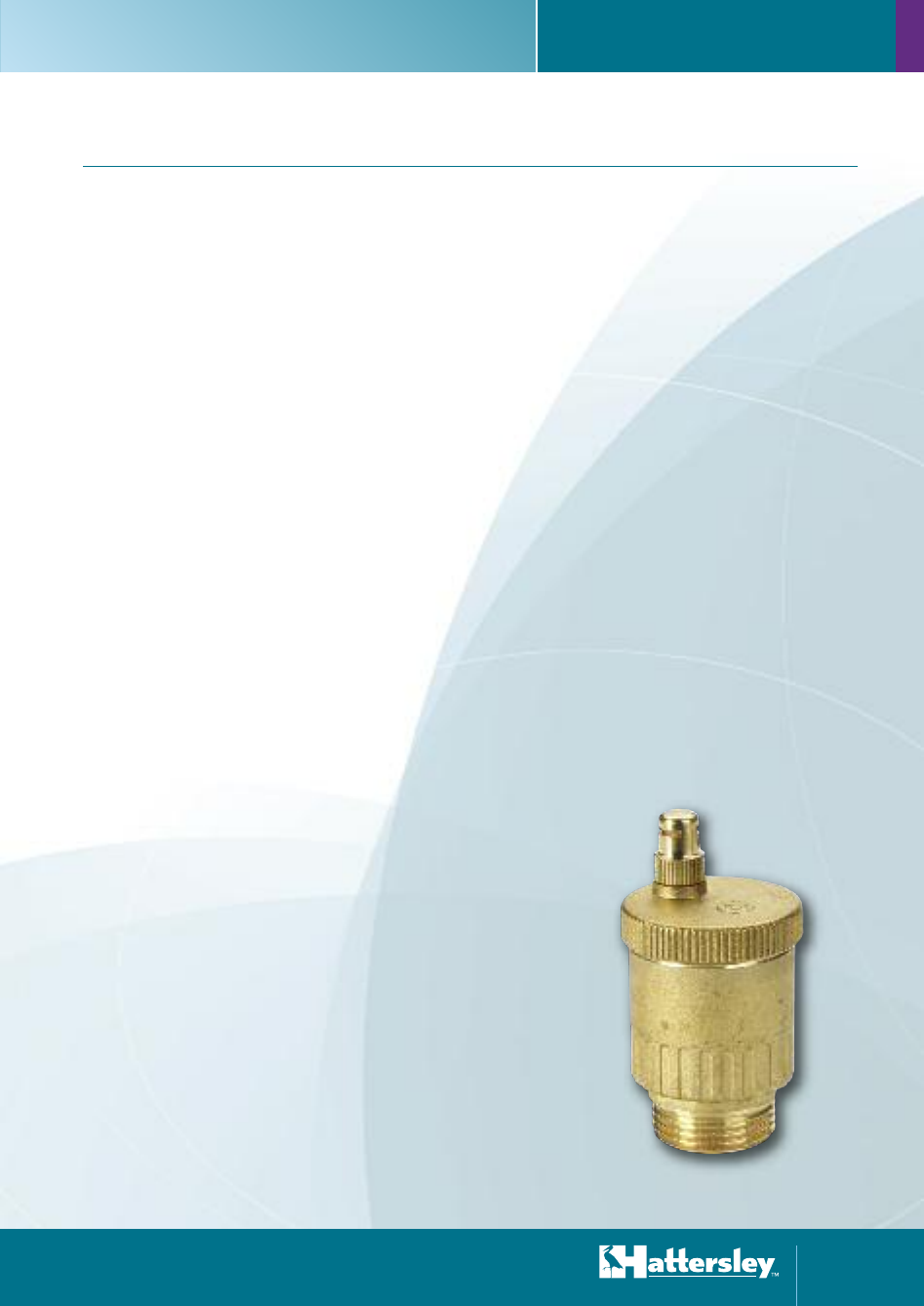
Technical Helpline: 0845 604 1790
E: tech-enquiries@hattersley.com W: www.hattersley.com
75
AIR VENTS/DE-AERATORS
Air Vents/De-Aerators
Offering an efficient performance, the Hattersley Air Vents remove
inevitable and potentially dangerous air trapped in the system.
Designed to simplify the venting process, for single or multi-boiler
and calorifier installations, the range offers savings in time and costs.
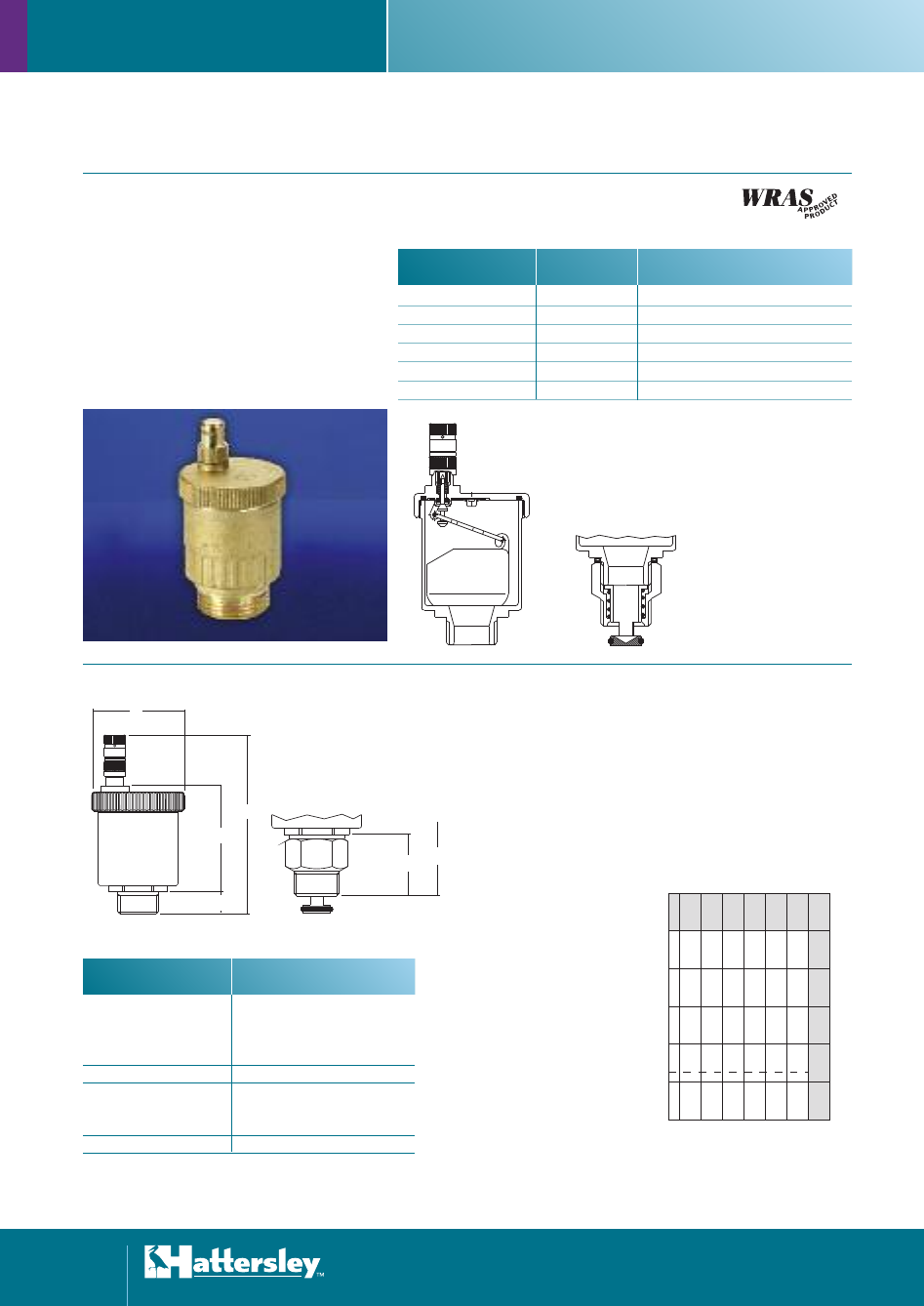
Technical Helpline: 0845 604 1790
E: tech-enquiries@hattersley.com W: www.hattersley.com
76
AIR VENT
PN10
Every effort has been made to ensure that the information contained in this publication is accurate at the time of publishing.
Hattersley Ltd assumes no responsibility or liability for typographical errors or omissions or for any misinterpretation of the
information within the publication and reserves the right to change without notice.
Fig. 775
Automatic
PRESSURE/
TEMPERATURE RATING
10 bar at 120ºC
MAXIMUM DISCHARGE
PRESSURE
2.5 bar
SPECIFICATION
Brass body and cover.
Polypropylene float.
EPDM seals.
WRAS approved product.
Anti vacuum cap.
BSP parallel thread.
Non return valve option available in
sizes 3/8" and 1/2".
Isolation valve option available
in sizes 3/4" and 1".
NOTE
The non-return valve base allows
the automatic air vent to be removed
without draining the system.
MATERIAL SPECIFICATION
Body Brass 12165 CW617N B455 C38000
Cover Brass 12165 CW617N B455 C38000
Float Polypropylene
Seals EPDM
Anti Vacuum Cap Brass 12165 CW617N B455 C38000
Non Return Valve Brass 12165 CW617N B455 C38000
Component Material Specification
BS EN ASTM
FEATURES AND BENEFITS
• Removes inevitable potentially dangerous
air trapped in system
• Simplifies the venting process
• Saves time and costs
0 20 40 60 80 100 120 140
Temperature ˚C
12
10
8
6
2
0
Pressure bar
4
Max Discharge Pressure
A
D
C
B
D
C
Nom
Size in 3/8 1/2 3/4 1
A mm 48 48 48 48
B mm 54.5 54.5 56 56
C mm 11.5 11.5 12.5 12.5
D mm 89.5 89.5 92 92
Weight kg 0.18 0.18 0.25 0.25
With Non Return Valve
C mm 28 28 - -
D mm 106 106 - -
Weight kg 0.23 0.23 - -
DIMENSIONS AND WEIGHTS
DIMENSIONAL DRAWINGS
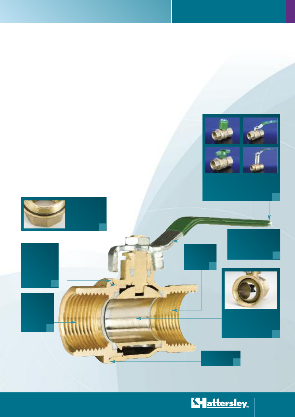
Technical Helpline: 0845 604 1790
E: tech-enquiries@hattersley.com W: www.hattersley.com
77
BALL VALVES
Ball Valves
The Hattersley Series of ball valves consists of compact,
lightweight units which are easy to install and operate, yet
their ability to withstand robust construction ensures long,
trouble-free service life. They offer full flow with minimum
turbulence in the open position and bubble tight closure in
the closed position. Only a quarter-turn is required to fully
open or close the valve.
The New Figure 100 Series. See website for Next Generation DZR Ball Valves video.
Available
in different
taper thread
options -
BS EN 10226-2
or ANSI
B1.20.1
Loctite 648 is
used on the
main joint
threads to give
more strength
and resistance to
installation
damage
Secondary O-Ring
seal, for additional
leakage protection,
aids resistance to
site installation
damage
Ball is DZR brass chrome
plated, designed for a
long life. Temperature
range is -10° to 120˚C.
Ball is full bore
Quarter turn operation
provides positive isolation
in conjunction with PTFE,
WRAS approved seats
and stem seals
Hattersley pipe
threads meet
full gauge
length
Multiple operating handle options
(Clockwise from top right), quarter
turn lever, extended stem lever,
T-Handle & lockshield
Primary metal
to metal seal
8
7
5
4
1
2
3
6
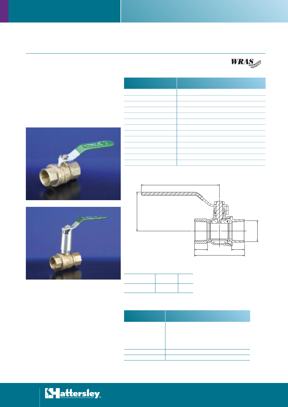
Technical Helpline: 0845 604 1790
E: tech-enquiries@hattersley.com W: www.hattersley.com
78
BALL VALVES
PN25
Every effort has been made to ensure that the information contained in this publication is accurate at the time of publishing.
Hattersley Ltd assumes no responsibility or liability for typographical errors or omissions or for any misinterpretation of the
information within the publication and reserves the right to change without notice.
Fig. 100, 100EXT
Threaded DZR - Lever Operated
MATERIAL SPECIFICATION
Hex-Nut Steel Plated
Lever Steel Dacromet Plated
Sleeve Green PVC
Packing Nut Brass CW617N
Packing Gland PTFE WRAS Approved
Body DZR Brass CW602N
Seats PTFE WRAS Approved
Ball DZR Brass CW602N Chrome Plated
O-Ring Rubber EPDM WRAS Approved
Bonnet DZR Brass CW602N
Stem DZR Brass CW602N
Extension Stem Outer Aluminium
Extension Stem Inner Brass Nickel Plated
Component Material
FEATURES AND BENEFITS
• Dezincification resistant
• Light, compact and easy to install and operate
• Improved leak protection
• More resistant to damage during installation
• Sizes from 1/4" to 2"
• WRAS Approved
L2
H
SIZE
L1 L1
L
Nom
Size Fig in 1/4 3/8 1/2 3/4 1 1
1/4 11/2 2
L 100 mm 46 46 58.5 67 80.5 94 102 124
L1 mm 12 12 15.5 17 21 23 23 26.5
L2 100 mm 89 89 98.5 98.5 125 140 140 165
H 100 mm 41 41 48 51 62 77.5 83 95.5
H 100EXT mm - - 103 107 116 129 135 150
Weight 100 g 152 136 205 302 511 890 1292 2238
Weight 100EXT g - - 270 366 589 1009 1410 2283
DIMENSIONS AND WEIGHTS
PRESSURE/TEMPERATURE
RATINGS THREADED
Fig. 100
Fig. 100EXT Temperature ˚C -10 to 100 120
Pressure bar 25 21.8
DIMENSIONAL DRAWINGS
SPECIFICATION
UK End Connection: BS EN 10226-2:2005
formerly BS21 Taper.
US End Connection: ANSI B1.20.1:1983.
Operator: Lever.
Quarter turn.
PTFE seats and stem seal.
WRAS listed.
Intermediate pressure ratings shall be determined by interpolation.
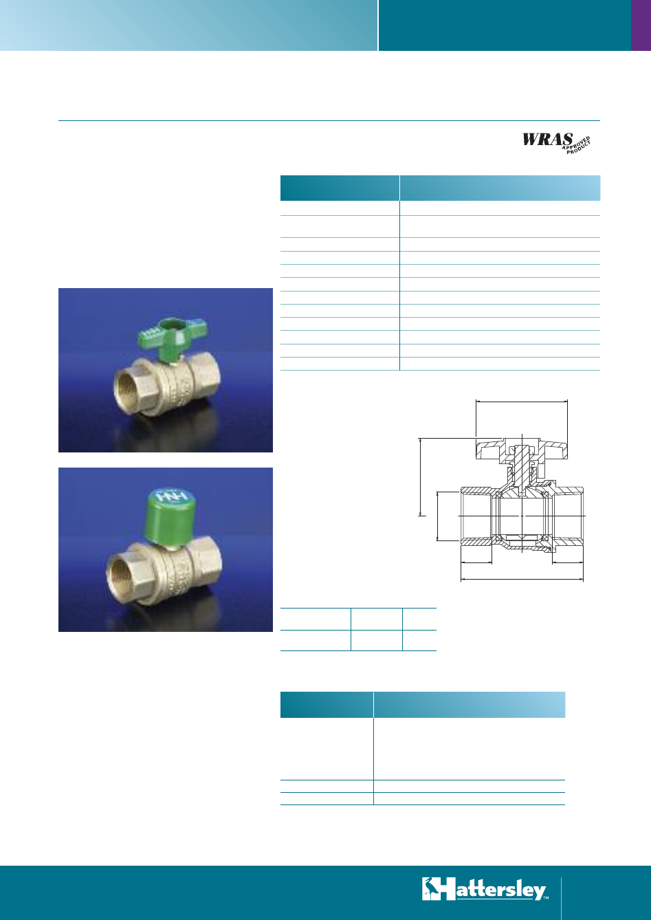
Technical Helpline: 0845 604 1790
E: tech-enquiries@hattersley.com W: www.hattersley.com
79
BALL VALVES
PN25
Every effort has been made to ensure that the information contained in this publication is accurate at the time of publishing.
Hattersley Ltd assumes no responsibility or liability for typographical errors or omissions or for any misinterpretation of the
information within the publication and reserves the right to change without notice.
Fig. 100TH, 100LS
Threaded DZR - T-Handle or Lockshield
MATERIAL SPECIFICATIONFEATURES AND BENEFITS
• Dezincification resistant
• Light, compact and easy to install and operate
• Improved leak protection
• More resistant to damage during installation
• Sizes from 1/4" to 2"
• WRAS Approved
Hex-Nut Steel Plated
T-Handle Aluminium
AL-46100 Green
Packing Nut Brass CW617N
Packing Gland PTFE WRAS Approved
Body DZR Brass CW602N
Seats PTFE WRAS Approved
Ball DZR Brass CW602N Chrome Plated
O-Ring Rubber EPDM WRAS Approved
Bonnet DZR Brass CW602N
Stem DZR Brass CW602N
Lockshield Brass CW617N
Lockshield Cover Polypropylene Green
Component Material
Nom
Size Fig in 1/2 3/4 1 11/4 11/2 2
L mm 59 67 80.5 94 102 124
L1 mm 15.5 17 21 23 23 26.5
L2 100TH mm 50 50 55 82 82 110
H 100TH mm 40 43 54 61 67 80.5
H 100LS mm 42 45 58 67 73.5 86.5
Weight 100TH g 183 277 470 809 1210 2106
Weight 100LS g 207 302 506 867 1269 2166
DIMENSIONS AND WEIGHTS
Fig. 100TH
Fig. 100LS
SPECIFICATION
UK End Connection: BS EN 10226-2:2005
formerly BS21 Taper.
US End Connection: ANSI B1.20.1:1983.
Operator: T-Handle/Spanner/Socket.
Quarter turn.
PTFE seats and stem seal.
WRAS listed.
L2
H
SIZE
L1 L1
L
PRESSURE/TEMPERATURE
RATINGS THREADED
Temperature ˚C -10 to 100 120
Pressure bar 25 21.8
Intermediate pressure ratings shall be determined by interpolation.
DIMENSIONAL DRAWINGS
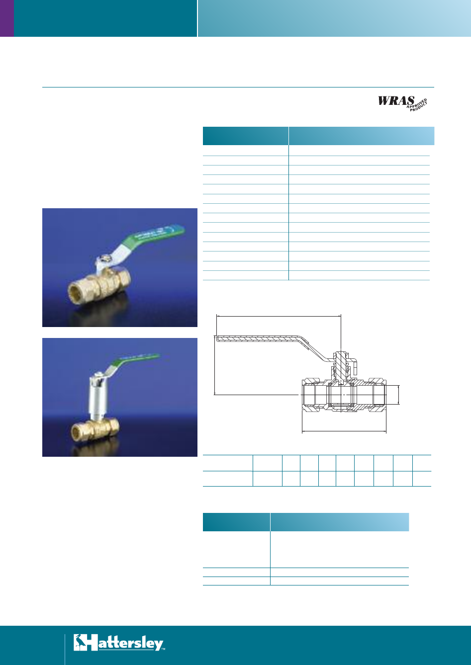
Technical Helpline: 0845 604 1790
E: tech-enquiries@hattersley.com W: www.hattersley.com
80
BALL VALVES
PN16
Every effort has been made to ensure that the information contained in this publication is accurate at the time of publishing.
Hattersley Ltd assumes no responsibility or liability for typographical errors or omissions or for any misinterpretation of the
information within the publication and reserves the right to change without notice.
Fig. 100C, 100CEXT
Compression Ended DZR - Lever Operated
MATERIAL SPECIFICATION
Hex-Nut Steel Plated
Lever Steel Dacromet Plated
Handle Sleeve Green PVC
Packing Nut Brass CW617N
Packing Gland PTFE WRAS Approved
Body DZR Brass CW602N
Seats PTFE WRAS Approved
Ball DZR Brass CW602N Chrome Plated
Bonnet DZR Brass CW602N
Compression Olive Brass CW507L
Compression Nut DZR Brass CW602N
Stem DZR Brass CW602N
Extension Stem Outer Aluminium
Extension Stem Inner Brass Nickel Plated
Component Material
FEATURES AND BENEFITS
• Dezincification resistant
• Light, compact and easy to install and operate
• Improved leak protection
• More resistant to damage during installation
• Sizes from 15 to 54mm
• WRAS Approved
L2
H
SIZE
L
Fig. 100C
Fig. 100CEXT
Nom
Size Fig mm 15 22 28 35 42 54
L C mm 66.5 80 92.5 104.5 122 141
L2 C mm 98.5 98.5 125 140 140 165
H C mm 47 51 62 77.5 83 97.5
H CEXT mm 103 107 116 129 135 150
Weight C g 212 368 608 1007 1549 2538
Weight CEXT g 275 429 682 1125 1667 2683
DIMENSIONS AND WEIGHTS
SPECIFICATION
UK End Connection: Compression
Ends to BS EN 1254-2:1998.
Operator: Lever.
Quarter turn.
PTFE seats and stem seal.
WRAS listed.
PRESSURE/TEMPERATURE RATINGS COMPRESSION
Temperature ˚C -10 to 30 40 50 65 80 90 100 110 120
Pressure bar 16 14.3 12.6 10 8.7 7.8 6.9 6 5
Intermediate pressure ratings shall be determined by interpolation
DIMENSIONAL DRAWINGS
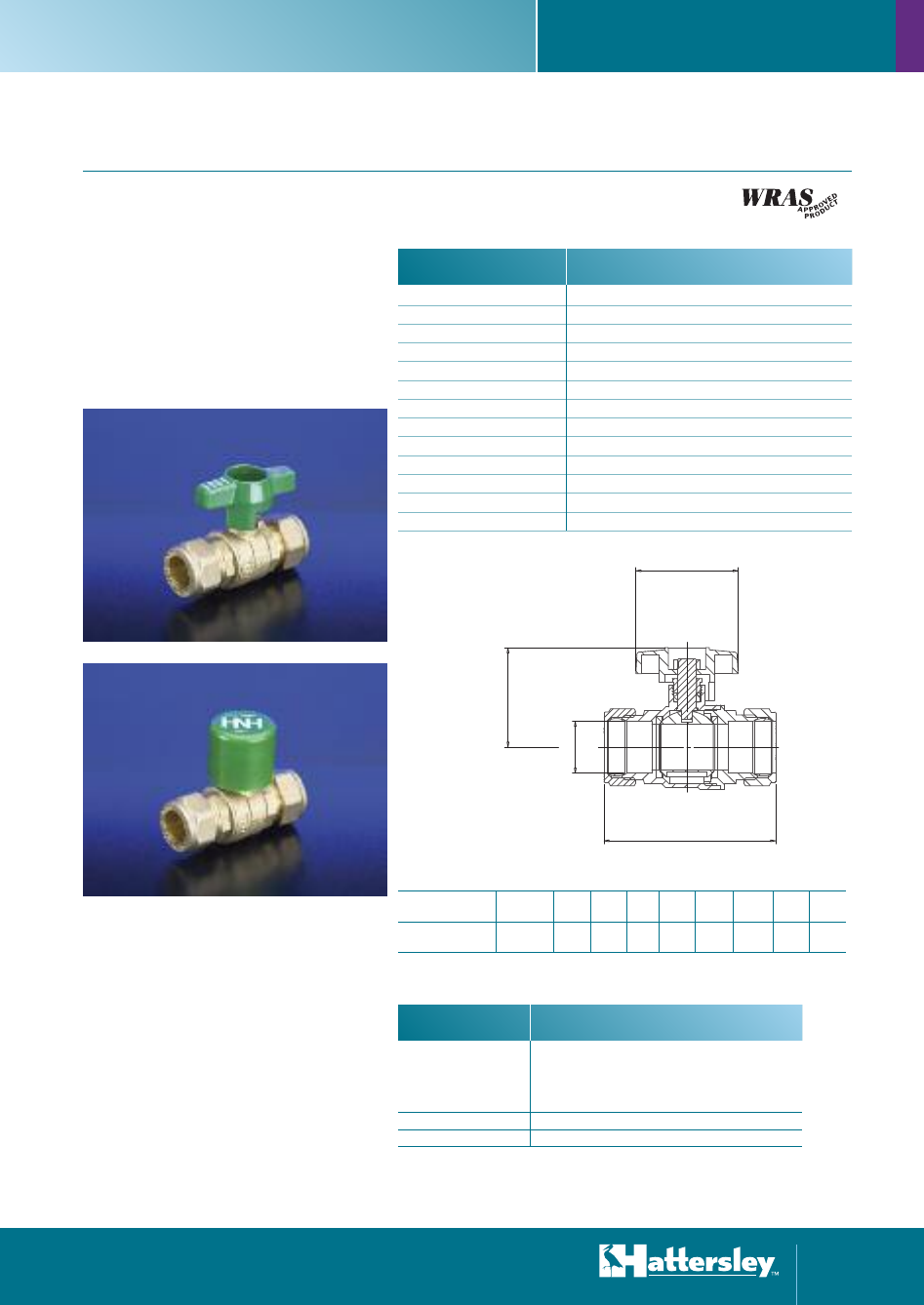
Technical Helpline: 0845 604 1790
E: tech-enquiries@hattersley.com W: www.hattersley.com
81
BALL VALVES
PN16
Every effort has been made to ensure that the information contained in this publication is accurate at the time of publishing.
Hattersley Ltd assumes no responsibility or liability for typographical errors or omissions or for any misinterpretation of the
information within the publication and reserves the right to change without notice.
Fig. 100CTH, 100CLS
Compression Ended DZR - T-Handle or Lockshield
MATERIAL SPECIFICATIONFEATURES AND BENEFITS
• Dezincification resistant
• Light, compact and easy to install and operate
• Improved leak protection
• More resistant to damage during installation
• Sizes from 15 to 54mm
• WRAS Approved
Hex-Nut Steel Plated
T-Handle Aluminium AL-46100 Green
Packing Nut Brass CW617N
Packing Gland PTFE WRAS Approved
Body DZR Brass CW602N
Seats PTFE WRAS Approved
Ball DZR Brass CW602N Chrome Plated
Bonnet DZR Brass CW602N
Compression Olive Brass CW507L
Compression Nut DZR Brass CW602N
Stem DZR Brass CW602N
Lockshield Brass CW617N
Lockshield Cover Polypropylene Green
Component Material
Fig. 100CTH
Fig. 100CLS
Nom
Size Fig mm 15 22 28 35 42 54
L mm 66.5 80 92.5 104.5 122 141
L2 mm 50 50 55 82 82 110
H CTH mm 40 43 54 61 67 80.5
H CLS mm 42 45 59.5 67 73.5 86.5
Weight CTH kg 187 343 567 977 1487 2634
Weight CLS kg 220 376 614 1039 1549 2437
DIMENSIONS AND WEIGHTS
SPECIFICATION
UK End Connection: Compression ends
to BS EN 1254-2:1998.
Operator: T-Handle/Spanner/Socket.
Quarter turn.
PTFE seats and stem seal.
WRAS listed.
L2
H
SIZE
L
PRESSURE/TEMPERATURE RATINGS COMPRESSION
Temperature ˚C -10 to 30 40 50 65 80 90 100 110 120
Pressure bar 16 14.3 12.6 10 8.7 7.8 6.9 6 5
Intermediate pressure ratings shall be determined by interpolation
DIMENSIONAL DRAWINGS
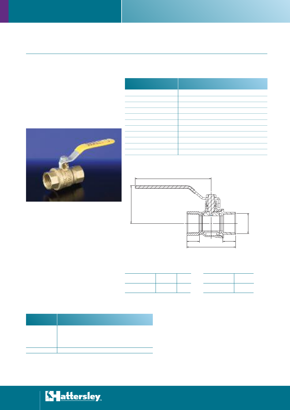
Technical Helpline: 0845 604 1790
E: tech-enquiries@hattersley.com W: www.hattersley.com
82
BALL VALVES
PN25
Every effort has been made to ensure that the information contained in this publication is accurate at the time of publishing.
Hattersley Ltd assumes no responsibility or liability for typographical errors or omissions or for any misinterpretation of the
information within the publication and reserves the right to change without notice.
Fig. 100YL
Gas Threaded DZR - Lever Operated
MATERIAL SPECIFICATIONFEATURES AND BENEFITS
• Dezincification resistant
• Light, compact and easy to install and operate
• More resistant to damage during installation
• Sizes from 1/4" to 2"
• Tested to BS EN 331:1998
Hex-Nut Dacromet Plated Steel
Handle Sleeve PVC Yellow
Handle Dacromet Plated Steel
Packing Nut Brass CW617N
Packing Gland PTFE
Body DZR Brass CW602N
Ball DZR Brass CW602N
Seats PTFE
O-Ring NBR BS EN549 approval
Bonnet DZR Brass CW602N
Stem DZR Brass CW602N
Component Material
L2
H
SIZE
L1 L1
L
Nom
Size in 1/4 3/8 1/2 3/4 1 1
1/4 11/2 2
L mm 46 46 59 67 80.5 94 102 124
L1 in 12 12 15.5 17 21 23 23 26.5
L2 in 89 89 98.5 98.5 125 140 140 165
H mm 41 41 48 51 63 78 83.5 97.5
Weight kg 152 136 205 302 511 890 1292 2238
DIMENSIONS AND WEIGHTS
PRESSURE/TEMPERATURE RATINGS COMPRESSION
NON-GAS APPLICATION GAS APPLICATION
Intermediate pressure ratings shall be determined by interpolation
Temperature ˚C -10 to 100 110
Pressure bar 25 23.5
Temperature ˚C -20 to 60
Pressure bar 5
SPECIFICATION
UK End Connection: BS EN 10226-2:2005
formerly BS21 Taper.
US End Connection ANSI B1.20.1:1983.
Operator: Lever.
Specification: Quarter turn.
PTFE seats and stem seal.
Tested by GL Industrial Services and
complies with the essential requirements
of BS EN 331:1998.
DIMENSIONAL DRAWINGS
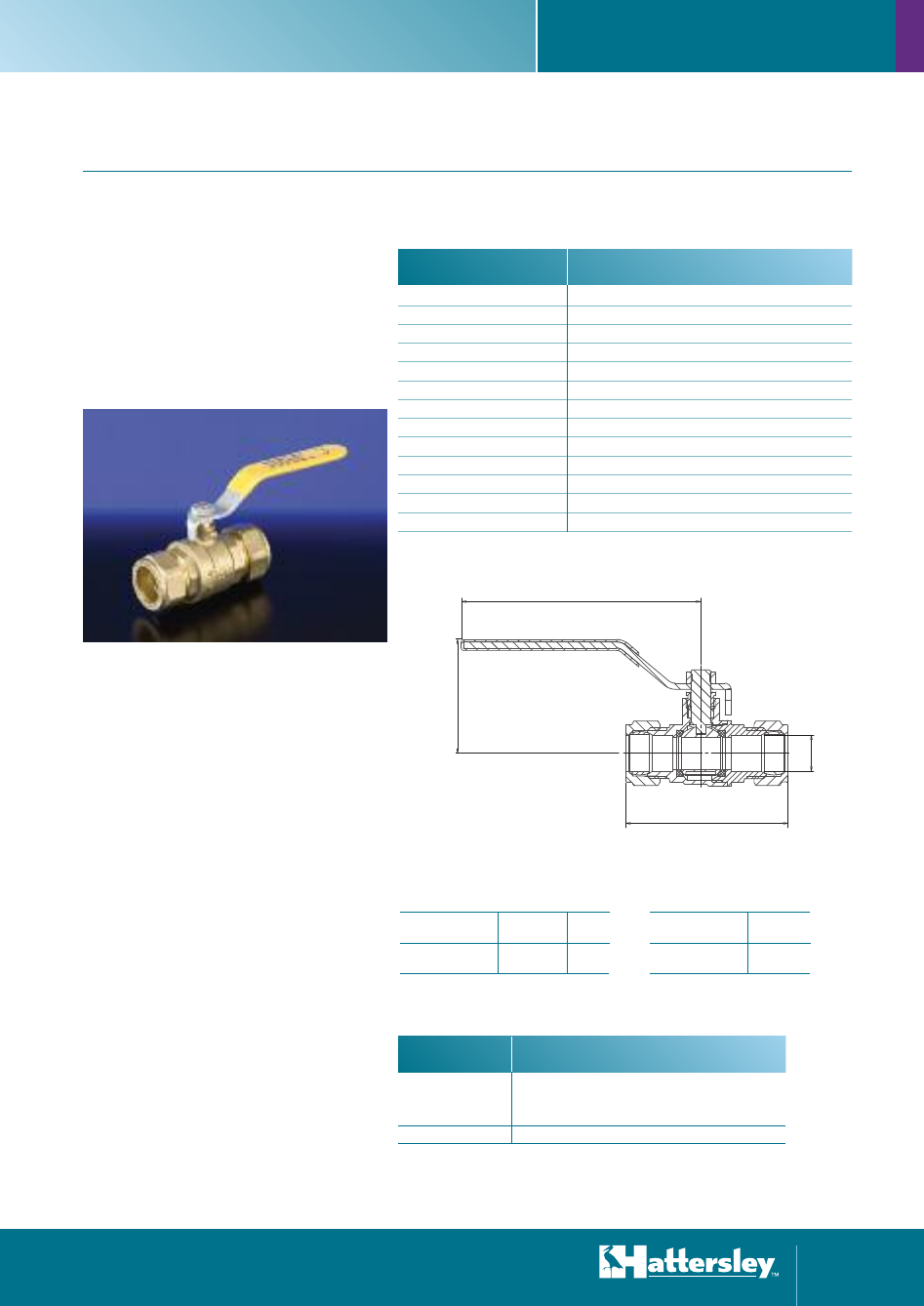
Technical Helpline: 0845 604 1790
E: tech-enquiries@hattersley.com W: www.hattersley.com
83
BALL VALVES
PN16
Every effort has been made to ensure that the information contained in this publication is accurate at the time of publishing.
Hattersley Ltd assumes no responsibility or liability for typographical errors or omissions or for any misinterpretation of the
information within the publication and reserves the right to change without notice.
Fig. 100CYL
Gas Compression DZR - Lever Operated
MATERIAL SPECIFICATION
Handle Sleeve PVC Yellow
Hex-Nut Dacromet Plated Steel
Handle Dacromet Plated Steel
Packing Nut Brass CW617N
Packing Gland PTFE
Body DZR Brass CW602N
Seats PTFE
Ball CW602N
O-Ring NBR BS EN549 approval
Bonnet DZR Bras CW602N
Sleeve CW507L
Sleeve Nut CW602N
Stem DZR Brass CW602N
Component Material
FEATURES AND BENEFITS
• Dezincification resistant
• Light, compact and easy to install and operate
• More resistant to damage during installation
• Sizes from 15 to 54mm
• Tested to BS EN 331:1998
L2
__
H
SIZE
L
Nom
Size mm 15 22 28 35 42 54
L mm 66.5 80 92.5 104.5 122 141
L2 mm 98.5 98.5 125 140 140 165
H mm 47 51 63 78 83.5 97.5
Weight g 212 368 608 1007 1545 2538
DIMENSIONS AND WEIGHTS
SPECIFICATION
UK End Connection: Compression ends
to BS EN 1254-2:1998.
Operator: Lever.
Specification: Quarter turn.
PTFE seats and stem seal.
Tested by GL Industrial Services and
complies with the essential requirements
of BS EN 331:1998.
DIMENSIONAL DRAWINGS
PRESSURE/TEMPERATURE RATINGS COMPRESSION
NON-GAS APPLICATION GAS APPLICATION
Intermediate pressure ratings shall be determined by interpolation
Temperature ˚C -10 to 30 110
Pressure bar 16 5
Temperature ˚C -10 to 60
Pressure bar 5
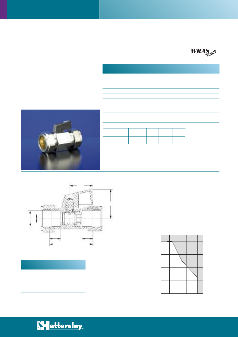
Technical Helpline: 0845 604 1790
E: tech-enquiries@hattersley.com W: www.hattersley.com
84
BALL VALVES
PN16
Every effort has been made to ensure that the information contained in this publication is accurate at the time of publishing.
Hattersley Ltd assumes no responsibility or liability for typographical errors or omissions or for any misinterpretation of the
information within the publication and reserves the right to change without notice.
Fig. 108C
Service Ball Valve
DIMENSIONAL DRAWINGS PRESSURE/
TEMPERATURE RATING
PN16
OPERATOR
Handle (The handle can be removed to
allow for screwdriver operation).
SPECIFICATION
Compression ends to BS EN 1254-2 for use
with BS EN 1057 R250 (half-hard) copper tube.
WRAS Approved product.
MATERIAL SPECIFICATIONFEATURES AND BENEFITS
• Light, compact and easy to install and operate
• WRAS Approved for use on wholesome
(potable) water
• Compression ends to BS EN 1254-2 for use
with BS EN 1057 R250 (half-hard) copper tube
• Part of Hattersley’s extensive public health range
• Chrome plated finish
• Handle can be removed to allow for
screwdriver operation
0 20 40 60 80 100 120 14 0
Temperature ˚C
14
12
10
8
6
2
0
Pressure bar
4
16
18
L
SIZE
BORE
H
L1 L1
L2
DIMENSIONS AND WEIGHTS
Screw Steel Dacromet Plated
Handle Nylon (Ral 9017)
Stem DZR Brass Chromium Plated
O-Ring EPDM WRAS Approved
Nut DZR Brass CW602N Chromium Plated
Olive Brass CW507L
Body DZR Brass CW602N Chromium Plated
PTFE Seat PTFE WRAS Approved
Ball DZR Brass CW602N Chromium Plated
Seat Retainer DZR Brass CW602N Chromium Plated
Component Material
Nom
Size mm DN15 DN22
Bore mm Ø8 Ø14
L mm 42 53
L1 mm 11 13
L2 mm 23 23
H mm 29 34
Weight g 123 260
Temperature ˚C -10 to 30 65 110 120
Pressure bar 16 10 6 5
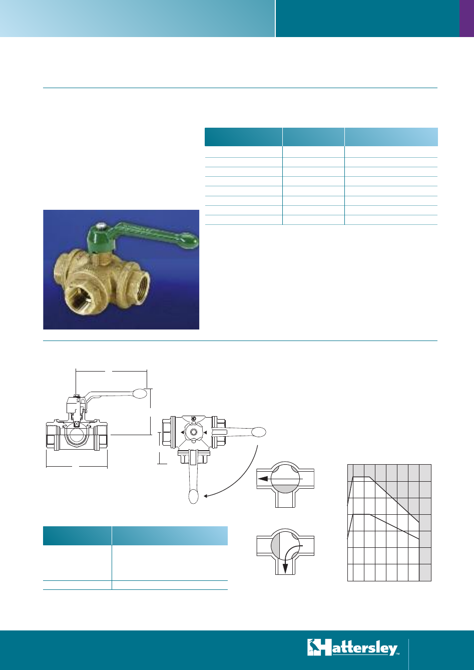
Technical Helpline: 0845 604 1790
E: tech-enquiries@hattersley.com W: www.hattersley.com
85
BALL VALVES
PN25
Every effort has been made to ensure that the information contained in this publication is accurate at the time of publishing.
Hattersley Ltd assumes no responsibility or liability for typographical errors or omissions or for any misinterpretation of the
information within the publication and reserves the right to change without notice.
Fig. 110
DZR - 3-way (T-Port) Vent Valve
DIMENSIONAL DRAWINGS SPECIFICATION
90º operation.
Hard chrome plated DZR ball.
Valve ports permanently marked.
Fixed lever.
Internally threaded ends to
BS EN 10266 (ISO 7).
Blow-out proof stem.
PTFE seats and stem seals.
MATERIAL SPECIFICATION
Lever Aluminium
Stem DZR Copper Alloy 12164 CW602N
Stem Seal PTFE
Body Seal EPDM
Ball (hard chrome plated) DZR Copper Alloy 12164 CW602N
Seat Rings PTFE
Body Ends DZR Copper Alloy 12165 CW602N
Body DZR Copper Alloy 12165 CW602N
Component Material Specification
BS EN
FEATURES AND BENEFITS
• Dezincification resistant copper alloy 3-way
(T-port) vent valve
• PTFE seats and seals. Blow-out proof stem
• Ends threaded to BS EN 10266 (ISO 7)
• Wrench operated. Ports permanently marked
• Sizes 1" to 2"
0
20
40
60
80
100
140 120
T emperature ˚ C
28
24
20
16
12
4
0
Pressure bar
8
1in
1
1
/
4
& 1
1
/
2
in
FLOW
DRAIN
FLOW
A
C
B
Position 1
Position 2
E
Nom
Size in 1 11/4 11/2 2
A mm 113 130 147 169
B mm 82 99 103 116
C mm 120 150 150 175
E (=A/2) mm 57 65 74 85
Weight (approx) kg 1.7 2.5 3.6 5.7
DIMENSIONS AND WEIGHTS
Position 1
Position 1
PRESSURE/
TEMPERATURE RATING
As shown in pressure/ temperature graph.
TEST PRESSURES (HYDRAULIC)
25 bar pneumatic

Technical Helpline: 0845 604 1790
E: tech-enquiries@hattersley.com W: www.hattersley.com
86
BALL VALVES
PN40
Every effort has been made to ensure that the information contained in this publication is accurate at the time of publishing.
Hattersley Ltd assumes no responsibility or liability for typographical errors or omissions or for any misinterpretation of the
information within the publication and reserves the right to change without notice.
Fig. 113
Full Bore Bronze
DIMENSIONAL DRAWINGS PRESSURE/
TEMPERATURE RATING
1/2" to 2" sizes
40 bar from -10 to 100ºC
18 bar at 140ºC
25 bar from -10 to 100ºC
21/2" and 3" sizes
18 bar at 140ºC
SPECIFICATION
Blow-out proof stem.
Full bore hard chrome plated ball.
Virgin PTFE seats and stem seals.
Taper threaded BS EN 10 (ISO 7-1)
formerly BS 21.
MATERIAL SPECIFICATIONFEATURES AND BENEFITS
• Light, compact and easy to install and operate
• Robust construction for long life
0 40 80 120 160
36
32
28
24
20
16
12
8
4
0
Pressure bar
40
44
Temperature C
21/2" & 3"
1/2" to 2"
A
B
C
Nom
Size in 1/2 3/4 1 11/4 11/2 2 21/2
A mm 55 62 73 83 92 107 144
B mm 46 55 62 70 75 82 82
C mm 82 103 106 106 150 160 162
Weight kg 0.25 0.45 0.70 1.15 1.70 2.95 -
DIMENSIONS AND WEIGHTS
Lever Steel
Stem Copper Alloy B16-C36000
Stem Seals PTFE or PTFE/
Neoprene
Ball (hard chrome Copper Alloy B16-C36000
plated)
Seat Rings PTFE or PTFE/
Neoprene
Seat Retainer Bronze BS84-C84400
Body Bronze BS84-C84400
Component Material Specification
ASTM
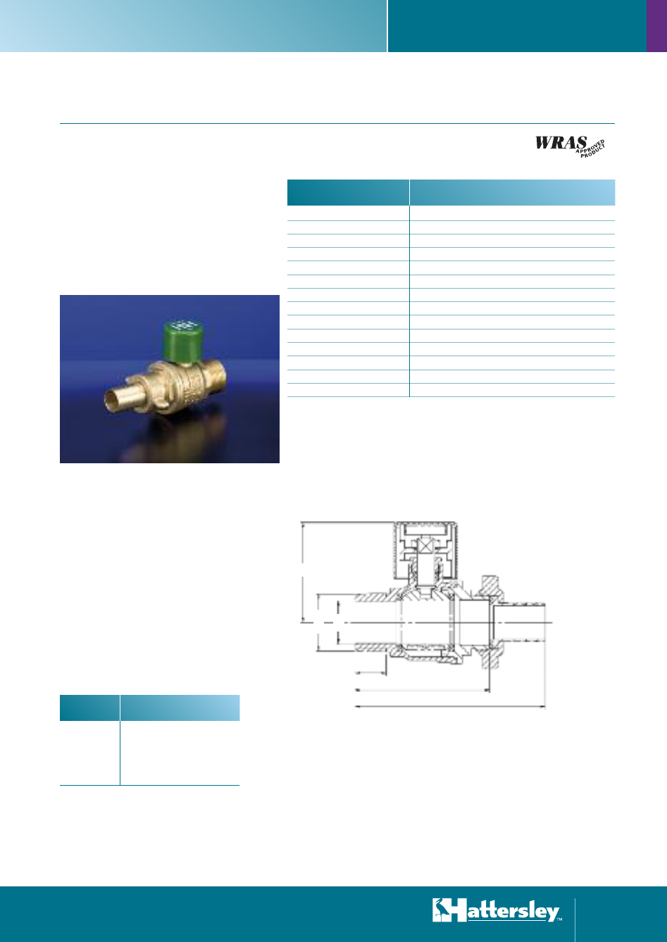
Technical Helpline: 0845 604 1790
E: tech-enquiries@hattersley.com W: www.hattersley.com
87
BALL VALVES
PN25
Every effort has been made to ensure that the information contained in this publication is accurate at the time of publishing.
Hattersley Ltd assumes no responsibility or liability for typographical errors or omissions or for any misinterpretation of the
information within the publication and reserves the right to change without notice.
Fig. 100MHU
Male Hose Union
DIMENSIONAL DRAWINGS
MATERIAL SPECIFICATION
Shield Cover Green PP (RAL6002)
Hex-Nut Q235 Dacromet Plated
Lockshield CW617N
Packing Nut CW617N
Packing Gland PTFE(701-N) WRAS approval
Body CW602N
Ball CW602N
PTFE PTFE(701-N) WRAS approval
O-Ring EPDM WRAS approval
Bonnet CW602N
Washer PTFE(701-N) WRAS approval
Tailpiece CW602N
Union Ring CW602N
Stem CW602N
Component Material
FEATURES AND BENEFITS
• Worldwide availability
• High quality range
• Long and trouble-free service life
• Full bore
Nom
Size in G 1/2 G 3/4 G 1
DN mm 15 20 25
L mm 84 98 109
L1 mm 14 15.5 18
L2 mm 58 66 77
H mm 41.8 45.3 57.7
DIMENSIONS AND WEIGHTS
PRESSURE/
TEMPERATURE RATING
-10°C to 100°C
TEST PRESSURES
(HYDRAULIC)
25 bar
SPECIFICATION
Quarter turn.
PTFE seats and stem seal.
WRAS listed.
H
L1
L2
DN
SIZE
L2
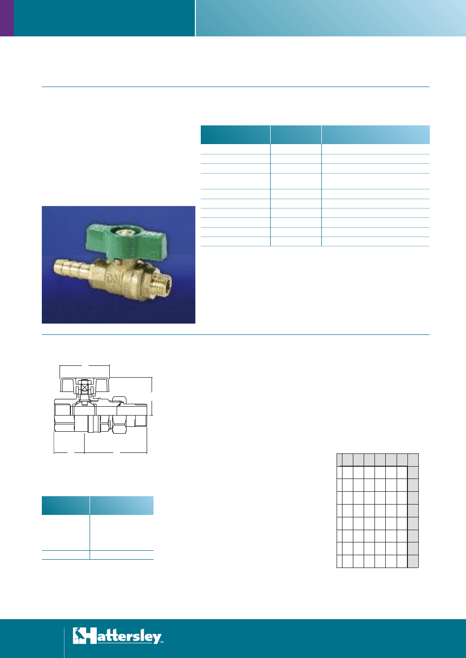
Technical Helpline: 0845 604 1790
E: tech-enquiries@hattersley.com W: www.hattersley.com
88
BALL VALVES
PN25
Every effort has been made to ensure that the information contained in this publication is accurate at the time of publishing.
Hattersley Ltd assumes no responsibility or liability for typographical errors or omissions or for any misinterpretation of the
information within the publication and reserves the right to change without notice.
Fig. 107MHU
Brass with Male Union
DIMENSIONAL DRAWINGS PRESSURE/
TEMPERATURE RATING
32 bar from -10 to 120ºC
TEST PRESSURES
(HYDRAULIC)
25 bar pneumatic
SPECIFICATION
Nickel plated body.
Blow-out proof stem.
Full bore hard chrome plated ball.
Virgin PTFE seats and stem seal T-Handle.
Union nut with male tail threaded BS EN
10266 (ISO 7).
Internal threaded end to BS EN 2779
(ISO 228/1).
MATERIAL SPECIFICATION
FEATURES AND BENEFITS
• Dezincification resistant copper alloy ball valve
• PTFE seats and seals
• Blow-out proof stem
• Fitted with hose union and captive cap
• Lockshield operation
• Ends threaded to BS EN 10266 (ISO 7)
• Sizes 1/2" - 1"
T-Handle Aluminium
Stem Brass 12164 CW617N B124 Alloy 2
Stem Seals PTFE
Ball Brass 12164 CW617N B124 Alloy 2
(hard chrome plated)
Seat Rings Virgin PTFE
Tail Brass 12165 CW617N B124 Alloy 2
Tail O-Ring Nitrile
Union Nut Brass 12165 CW617N B124 Alloy 2
Body End Brass 12165 CW617N B124 Alloy 2
Body Brass 12165 CW617N B124 Alloy 2
Component Material Specification
BS EN ASTM
0 20 40 60 80 100 120 14 0
Temperature ˚C
28
24
20
16
12
4
0
Pressure bar
8
32
36
BA
D
C
Nom
Size in 1/2 3/4
A mm 25 29
B mm 59 68
C mm 33 43
D mm 47 56
Weight kg 0.28 0.48
DIMENSIONS AND WEIGHTS
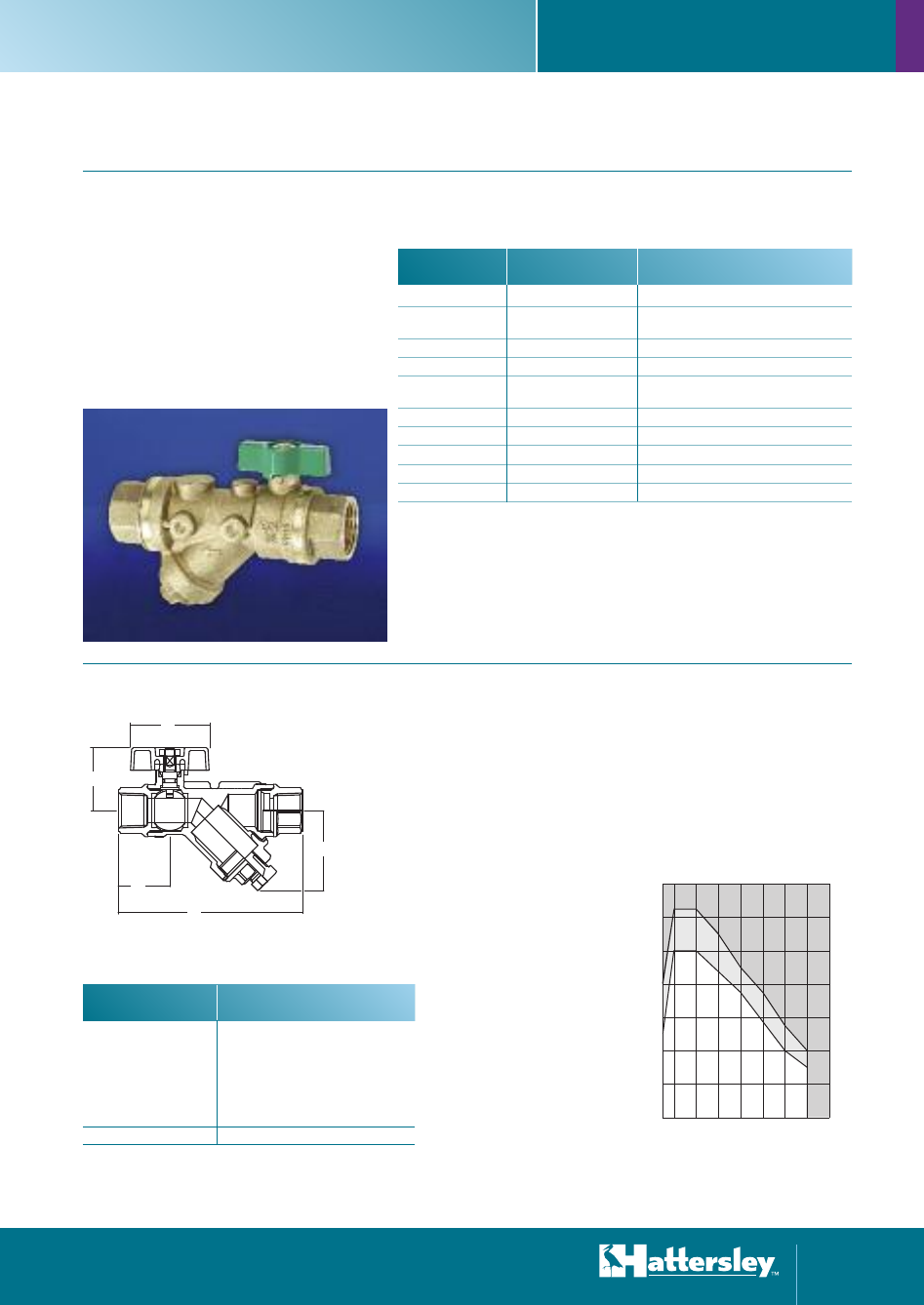
Technical Helpline: 0845 604 1790
E: tech-enquiries@hattersley.com W: www.hattersley.com
89
BALL VALVES
PN25
Every effort has been made to ensure that the information contained in this publication is accurate at the time of publishing.
Hattersley Ltd assumes no responsibility or liability for typographical errors or omissions or for any misinterpretation of the
information within the publication and reserves the right to change without notice.
Fig. 1807
DZR Strainer Ball Valve
DIMENSIONAL DRAWINGS PRESSURE/
TEMPERATURE RATING
PN25 - 1/2 to 11/2" sizes
25 bar 0° to 20ºC
7 bar at 120ºC
PN20 - 2" size
20 bar 0° to 20ºC
6 bar at 120ºC
TEST PRESSURES
25 bar pneumatic
SPECIFICATION
DZR body.
Blow-out proof stem.
Hard chrome plated ball.
Virgin PTFE seats.
T-Handle operated.
0.8mm diameter perforated 304
stainless steel screen.
Drain plug.
Taper threaded BS EN 10 (ISO 7-1)
formerly BS 21.
OPTIONAL FEATURES
Lever.
Extension stem.
Figure 103 hose outlet blowdown valve.
MATERIAL SPECIFICATION
Handle Aluminium
Stem DZR Copper
Alloy 12164 CW602N
Stem Seal EPDM
Gland Seals Virgin PTFE
Ball DZR Copper Alloy 12164 CW602N
Hard chrome plated
Seat Rings Virgin PTFE
Body DZR Copper Alloy 12165 CW602N
Screen Stainless Steel AISI 304
Cap Gasket Asbestos Free
Cap DZR Copper Alloy 12165 CW602N
Component Material Specification
BS EN ASTM
FEATURES AND BENEFITS
• Light, compact and easy to install and operate
• Robust construction for long life
1
/2" to
1
1
/
2
" S
i
z
e
s
2"
S
i
z
e
0 20 40 60 80 100 120 140
Temperature ˚C
28
24
20
16
12
4
0
Pressure bar
8
A
B
C
D
E
Nom
Size in 1/2 3/4 1
A mm 110 129 151
B mm 31 35 42
C mm 48 60 59
D mm 38 46 50
E mm 47 56 56
Drain plug BSP 1/4 1/4 1/4
Weight kg 0.54 0.80 1.23
DIMENSIONS AND WEIGHTS
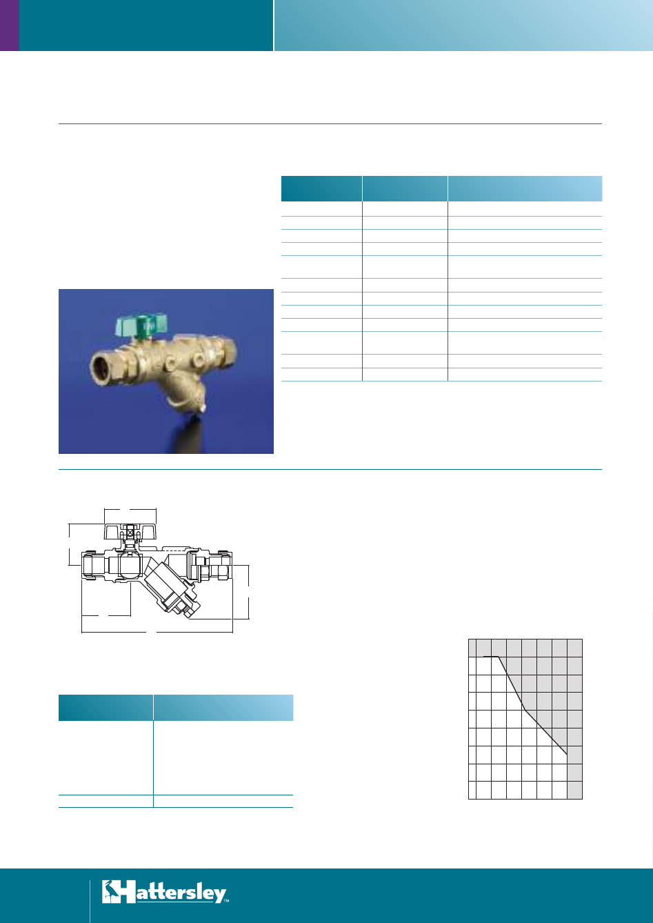
Technical Helpline: 0845 604 1790
E: tech-enquiries@hattersley.com W: www.hattersley.com
90
BALL VALVES
PN16
Every effort has been made to ensure that the information contained in this publication is accurate at the time of publishing.
Hattersley Ltd assumes no responsibility or liability for typographical errors or omissions or for any misinterpretation of the
information within the publication and reserves the right to change without notice.
Fig. 1807C
DZR Strainer Ball Valve
DIMENSIONAL DRAWINGS PRESSURE/
TEMPERATURE RATING
PN16
5 bar at 120ºC
6 bar at 110ºC
10 bar at 65ºC
16 bar at -10 to 30ºC
TEST PRESSURES
25 bar pneumatic
SPECIFICATION
DZR body.
Blow-out proof stem.
Hard chrome plated ball.
Virgin PTFE seats.
T-Handle operated.
0.8mm diameter perforated 304 stainless
steel screen.
Drain plug.
Compression ends to BS EN 1254-2.
Use with R250 (half hard) copper tube.
MATERIAL SPECIFICATIONFEATURES AND BENEFITS
• Light, compact and easy to install and operate
• Robust construction for long life
Nom
Size mm 15 22 28
A mm 137 159 175
B mm 45 50 53
C mm 48 60 59
D mm 38 46 50
E mm 47 56 56
Drain plug BSP 1/4 1/4 1/4
Weight kg 0.6 0.9 1.3
DIMENSIONS AND WEIGHTS
0 20 40 60 80 100 120 14 0
Temperature ˚C
14
12
10
8
6
2
0
Pressure bar
4
16
18
A
B
C
D
E
Cap Gasket Asbestos Free
Screen Stainless Steel 10270 X10CrNr18-8 A276-304
Compression Ring Brass B16 C36000
Cap DZR Copper Alloy 12164 CW602N
Compression Nut Brass 12164 CW614N B16-C36000 /
B124-C37700
Handle Aluminium
Stem DZR Copper Alloy 12164 CW602N
Stem Seals EPDM
Gland Seals Virgin PTFE
Ball (hard chrome
plated) DZR Copper Alloy 12164 CW602N
Seat Rings Virgin PTFE
Body DZR Copper Alloy 12164 CW602N
Component Material Specification
BS EN ASTM
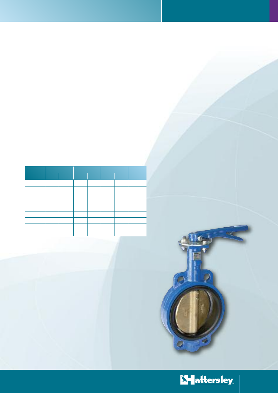
Technical Helpline: 0845 604 1790
E: tech-enquiries@hattersley.com W: www.hattersley.com
91
BUTTERFLY VALVES
Butterfly Valves
Hattersley butterfly valves are compact quarter
turn valves.
The body is elastomer lined providing a resilient
bubble tight shut off. The valves are supplied in
wafer or lugged variants and may be lever or
gearbox operated. Linings are EPDM or Nitrile
rubber depending on the intended service
conditions. Primarily recommended for on off
service, they may also be used for non-critical
throttling applications. Only a quarter turn is
needed to fully open or close the valve.
Hattersley also offer a range of high performance
butterfly valves, developed for high integrity
shut-off and regulation duties. This range is ideal
where increased pressure and elevated
temperature specifications are outside the
normal operating parameters of concentric disc
valves. The Hattersley high performance valves
have enhanced features to provide impeccable
performance and reliability.
Fig. No. Body Liner Disc/Pins Shaft
CI DI ENASS SS
950 •• • •
951 ••••
970 •• • •
971 ••• •
4941 ••••
4950 •• •• •
4951 ••••
4970 •• •• •
4971 ••••
Valve Figure Number Guide
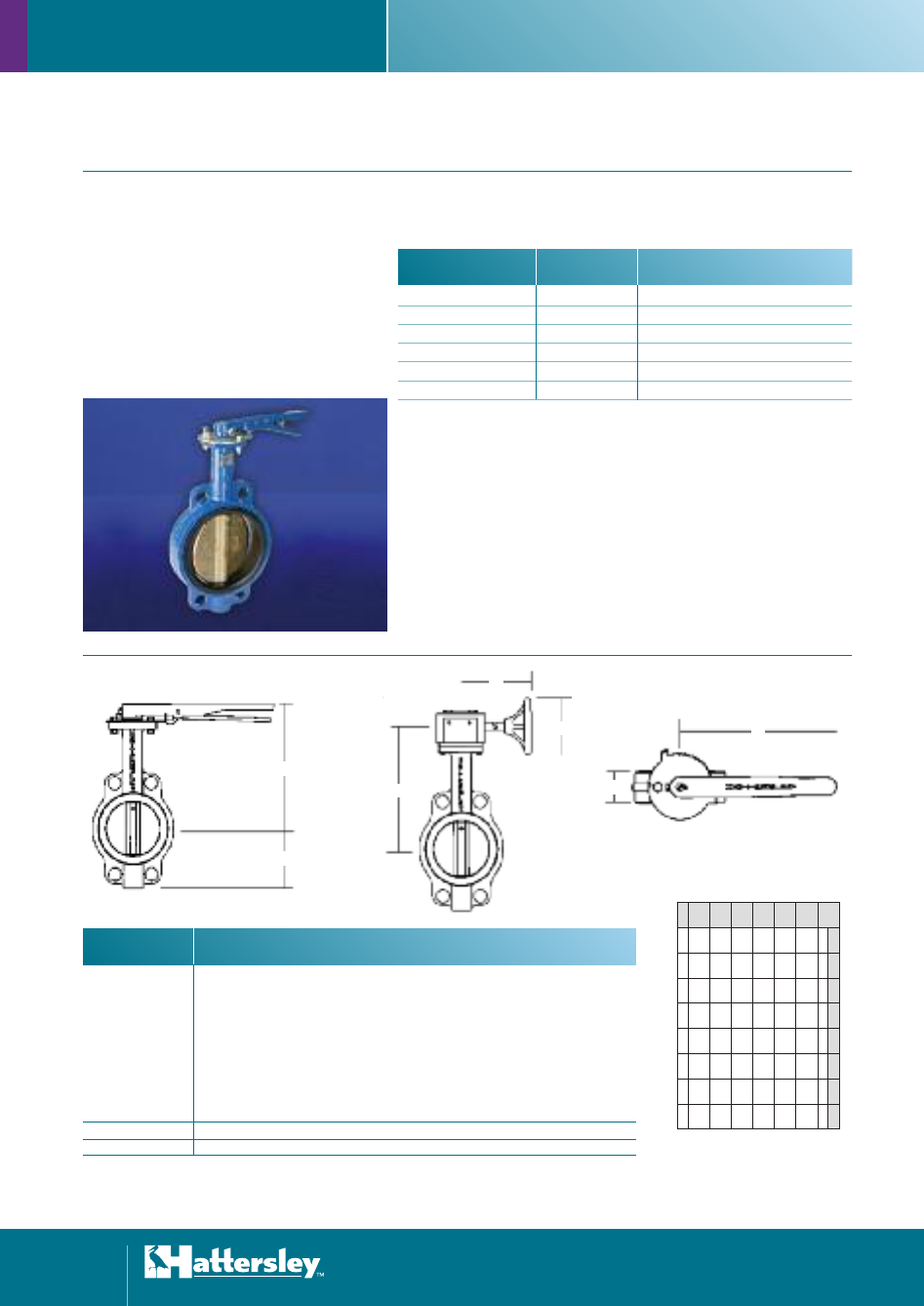
Technical Helpline: 0845 604 1790
E: tech-enquiries@hattersley.com W: www.hattersley.com
92
BUTTERFLY VALVES
PN16
Every effort has been made to ensure that the information contained in this publication is accurate at the time of publishing.
Hattersley Ltd assumes no responsibility or liability for typographical errors or omissions or for any misinterpretation of the
information within the publication and reserves the right to change without notice.
Fig. 950
Semi-lugged Wafer Pattern
DIMENSIONAL DRAWINGS
MATERIAL SPECIFICATION
Body Ductile Iron 1563 EN-JS1030 A536-65-45-12
Shaft Stainless Steel 10088-1 X12Cr13 A276 410
Disc Al Bronze 1982 CC333G B148 C95300
Bushes PTFE
O-Ring Buna N
Liner EPDM
Component Material Specification
BS EN ASTM
FEATURES AND BENEFITS
• Rubber liner bonded to backing ring
• Two high strength, low friction bearings for
upper and lower shafts, restrain shaft
deflection, ensuring effective stem sealing
• Long neck for insulation
• Maintenance free
• Good control characteristics
0 20 40 60 80 100 120 140
T emperature ˚ C
14
12
10
8
6
2
0
Pressure bar
4
16
18
H
J
K
F
E
G
A
PRESSURE/
TEMPERATURE RATING
16 bar from -10 to 120ºC
15.7 bar at 130ºC
TEST PRESSURES
Hydrostatic
Body: 24 bar
Seat: 17.6 bar
SPECIFICATION
Generally conforms to BS EN 593:2009.
Ductile Iron body epoxy coated.
Centring holes.
Aluminium bronze disc.
EPDM liner.
Trigger lever.
Valves DN250 and larger supplied as standard
with fully enclosed gear operator.
To suit flange connections BS EN 1092-2 PN16.
Valves may be used for flow regulation.
950, 950G
Nom
Size mm 50 65 80 100 125 150 200 250 300 350 400 450 500 600
A mm 44 48 48 54 57 57 63 70 79 79 89 108 133 156
B mm 83 95 102 124 136 150 197 210 248 280 305 381 381 458
C mm 195 207 213 232 245 257 305 - - 369 400 422 480 562
D mm 162 175 181 200 213 255 260 292 337 442 492 553 480 562
E mm 260 260 260 260 260 260 356 - - 38 54 105 105 110
F mm 204 217 223 242 255 267 300 332 377 300 450 450 450 450
G mm 150 150 150 150 300 300 300 300 300 230 230 340 230 360
H mm 240 240 240 240 240 230 230 230 230 80 120 185 120 185
J mm 60 60 60 60 60 60 80 80 80 - - - - -
Weight lever kg 3 4 5 7 8 9 15 80 80 - - - - -
Weight geared kg 8 9 10 11 13 14 19 32 47 60 100 145 190 290
DIMENSIONS AND WEIGHTS
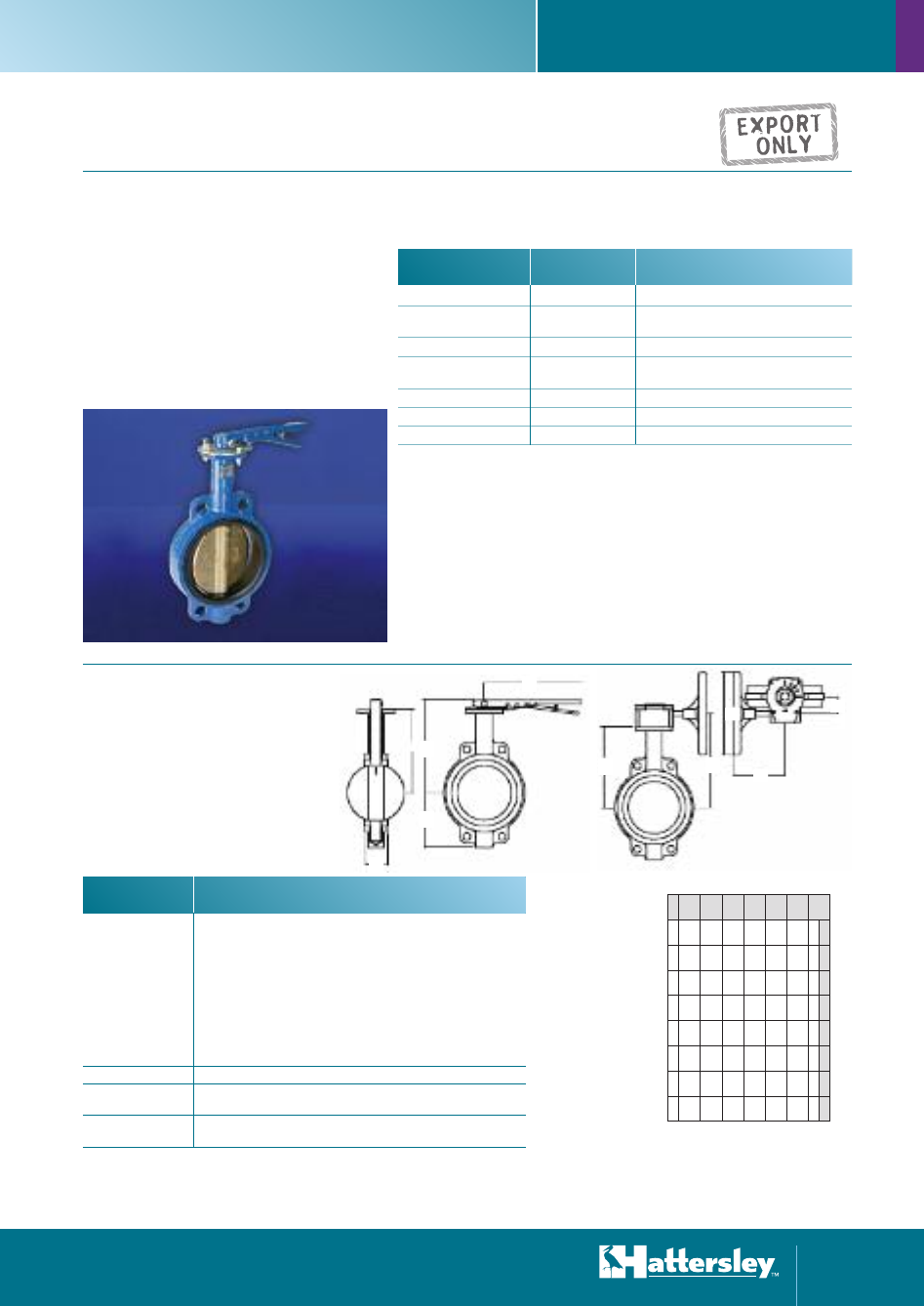
Technical Helpline: 0845 604 1790
E: tech-enquiries@hattersley.com W: www.hattersley.com
93
BUTTERFLY VALVES
PN16
Every effort has been made to ensure that the information contained in this publication is accurate at the time of publishing.
Hattersley Ltd assumes no responsibility or liability for typographical errors or omissions or for any misinterpretation of the
information within the publication and reserves the right to change without notice.
0 20 40 60 80 100 120 140
T emperature ˚ C
14
12
10
8
6
2
0
Pressure bar
4
16
18
Fig. C950
Wafer Type Butterfly Valve
DIMENSIONAL DRAWINGS
MATERIAL SPECIFICATIONFEATURES AND BENEFITS
• Rubber liner bonded to backing ring
• Two high strength, low friction bearings for
upper and lower shafts, restrain shaft
deflection, ensuring effective stem sealing
• Long neck for insulation
• Maintenance free
• Good control characteristics
Body Ductile Iron 1563 EN-JS1030 A536 65-45-12
Operating Shaft Stainless Steel 10088-1 A276 410 Shaft
X12Cr13
Disc Al Bronze 1982 CC333G B148 C95300
Taper Pins Stainless Steel 10088-1 A276 316
X5CrNiMo17-12-2
Bushes PTFE
O-Ring Buna N
Liner EPDM
Component Material Specification
BS EN ASTM
PRESSURE/
TEMPERATURE RATING
16 bar from -10 to 120°C
15.7 bar at 130°C
TEST PRESSURES
(HYDRAULIC)
Body: 24 bar
Seat: 17.6 bar
SPECIFICATION
Generally conforms to BS EN 593:2009.
Ductile Iron body epoxy coated.
Centring holes.
Aluminium bronze disc.
EPDM liner.
Trigger lever.
Valves DN250 and larger supplied as standard
with fully enclosed gear operator.
To suit flange connections BS EN 1092-2 PN16.
Valves may be used for flow regulation.
Nom
Size mm 50 65 80 100 125 150 200 250 300
A mm 44 48 48 54 57 57 63 70 79
B mm 83 95 102 124 136 150 197 210 248
C mm 195 207 213 232 245 257 305
D mm 162 175 181 200 213 225 260 292 337
E mm 260 260 260 260 260 260 356
F mm 204 217 223 242 255 267 300 332 377
G mm 150 150 150 150 300 300 300 300 300
H mm 240 240 240 240 240 230 230 230 230
J mm 60 60 60 60 60 60 80 80 80
Weight kg 3 4 5 7 8 9 15 31 40
PED Categorisation
Valve size 50 65 80 100 125 150 200 250 300
Group 2 Liquids
Cat. SEP SEP SEP SEP SEP SEP SEP SEP SEP
DIMENSIONS AND WEIGHTS
B
A
D
C
E
FH
J
G
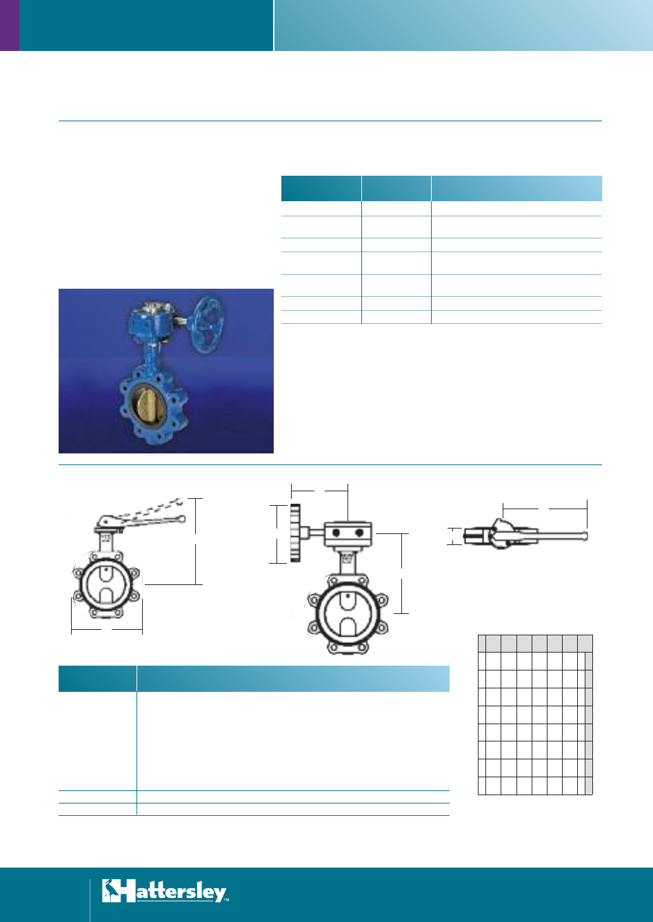
Technical Helpline: 0845 604 1790
E: tech-enquiries@hattersley.com W: www.hattersley.com
94
BUTTERFLY VALVES
PN16
Every effort has been made to ensure that the information contained in this publication is accurate at the time of publishing.
Hattersley Ltd assumes no responsibility or liability for typographical errors or omissions or for any misinterpretation of the
information within the publication and reserves the right to change without notice.
Fig. 970
Fully-lugged Wafer Pattern
DIMENSIONAL DRAWINGS
MATERIAL SPECIFICATIONFEATURES AND BENEFITS
• Available up to DN600
• Valve body fully-lugged
• Long neck for insulation
• Maintenance free
• Good control characteristics
970, 970G
0 20 40 60 80 100 120 140
T emperature ˚ C
14
12
10
8
6
2
0
Pressure bar
4
16
18
H
J
K
F
D
A
G
PRESSURE/
TEMPERATURE RATING
PN16 from -10 up to 130ºC
TEST PRESSURES
Hydrostatic
Body: 24 bar
Seat: 17.6 bar
SPECIFICATION
Conforms to BS EN 593:2009.
Fully-lugged.
Lever or gearbox.
Valves DN250 and larger supplied as
standard with fully enclosed gear operator.
Valves may be used for flow regulation.
Body Ductile Iron 1563 EN-JS 1030 A536 65-45-12
Shaft Stainless Steel 10088-1 X5CrNiMo17-12-2
A532 Gr316
Disc Bronze 1982 CC333G B148-C95300
Bushes
(up to 100mm) PTFE
125mm and above Bronze
(lubricated)
O-Ring Buna N
Liner EPDM
Component Material Specification
BS EN ASTM
Nom
Size mm 50 65 80 100 125 150 200 250 300 350 400 450 500 600
A mm 43 46 46 52 56 56 60 68 78 78 102 114 127 154
D mm 165 185 200 220 250 285 340 405 460 520 580 640 715 840
F mm 264 272 279 301 314 345 369 - - - - - - -
G mm 250 250 250 250 250 315 315 - - - - - - -
H mm 182 190 197 219 232 254 278 281 306 354 408 433 458 557
J mm 123 123 123 123 123 123 123 228 228 228 305 305 305 305
K mm 125 125 125 125 125 125 125 300 300 300 400 400 400 400
Shaft size A/F mm 10 10 10 12 12 16 16 24 24 24 30 30 30 30
Weight lever kg 4.6 5.4 7.2 8.8 12 14 20 - - - - - - -
Weight geared kg 5.4 6.2 8.0 9.6 12 15 21 33 45 55 91 111 136 225
DIMENSIONS AND WEIGHTS
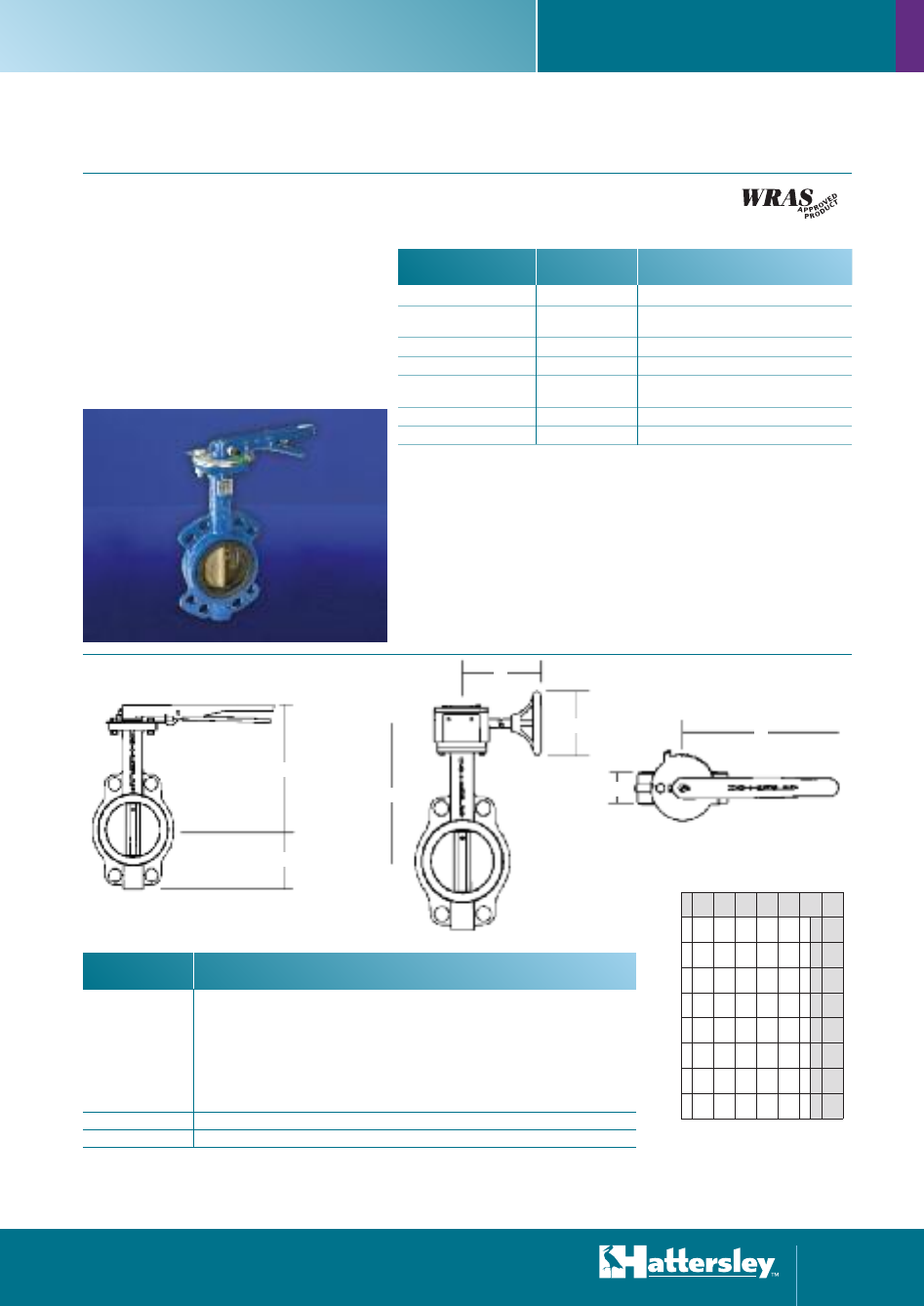
Technical Helpline: 0845 604 1790
E: tech-enquiries@hattersley.com W: www.hattersley.com
95
BUTTERFLY VALVES
PN16
Every effort has been made to ensure that the information contained in this publication is accurate at the time of publishing.
Hattersley Ltd assumes no responsibility or liability for typographical errors or omissions or for any misinterpretation of the
information within the publication and reserves the right to change without notice.
Fig. 950W
Semi-lugged Wafer Pattern
DIMENSIONAL DRAWINGS
MATERIAL SPECIFICATION
Body Ductile Iron 1563 EN-JS 1030 A536 65-45-12
Shaft Stainless Steel 10088-1 X5CrNiMo17-12-2
A532 Gr316
Disc Bronze 1982 CC333G B148-C95300
Bushes (up to 100mm) PTFE
125mm and above Bronze
(lubricated)
O-Ring Buna N
Liner EPDM
Component Material Specification
BS EN ASTM
FEATURES AND BENEFITS
• Rubber liner bonded to steel backing ring
• Two high strength, low friction bearings for
upper and lower shafts, restrain shaft
deflection, ensuring effective stem sealing
• Long neck for insulation
• Maintenance free
• Good control characteristics
950W, 950WG
0 20 40 60 80 100 120 140
T emperature ˚ C
14
12
10
8
6
2
0
Pressure bar
4
16
18
PRESSURE/
TEMPERATURE RATING
PN16 from -10 up to 110ºC
TEST PRESSURES
Each valve is individually hydrostatically
tested to BS EN 12266-1 at the following
test pressures.
Shell: 24 bar
Seat: 17.6 bar
Nom
Size mm 50 65 80 100 125 150 200 250 300 350 400 450 500 600
A mm 42 45 45 52 54 56 61 66 77 77 87 106 132 152
E mm 80 89 95 114 127 139 175 203 242 267 301 327 361 459
F mm 183 197 203 222 235 248 282 - - - - - - -
G mm 270 270 270 270 270 270 270 - - - - - - -
H mm 279 302 314 352 378 403 478 537 622 678 764 812 918 1098
J mm 154 154 154 154 154 154 238 238 222 222 300 300 350 350
K mm 152 152 152 152 152 152 300 300 300 300 300 300 300 300
Weight lever kg 4 5 5 6 9 10 15 - - - - - - -
Weight geared kg 8 9 10 11 13 14 19 32 47 59 93 117 - -
DIMENSIONS AND WEIGHTS
H
J
K
F
E
G
A
SPECIFICATION
Conforms to BS EN 593:2009.
Semi-lugged.
Aluminium bronze or stainless steel disc.
WRAS approved.
Lever or gearbox.
Valves DN250 and larger supplied as
standard with fully enclosed gear operator.
Valves may be used for flow regulation.
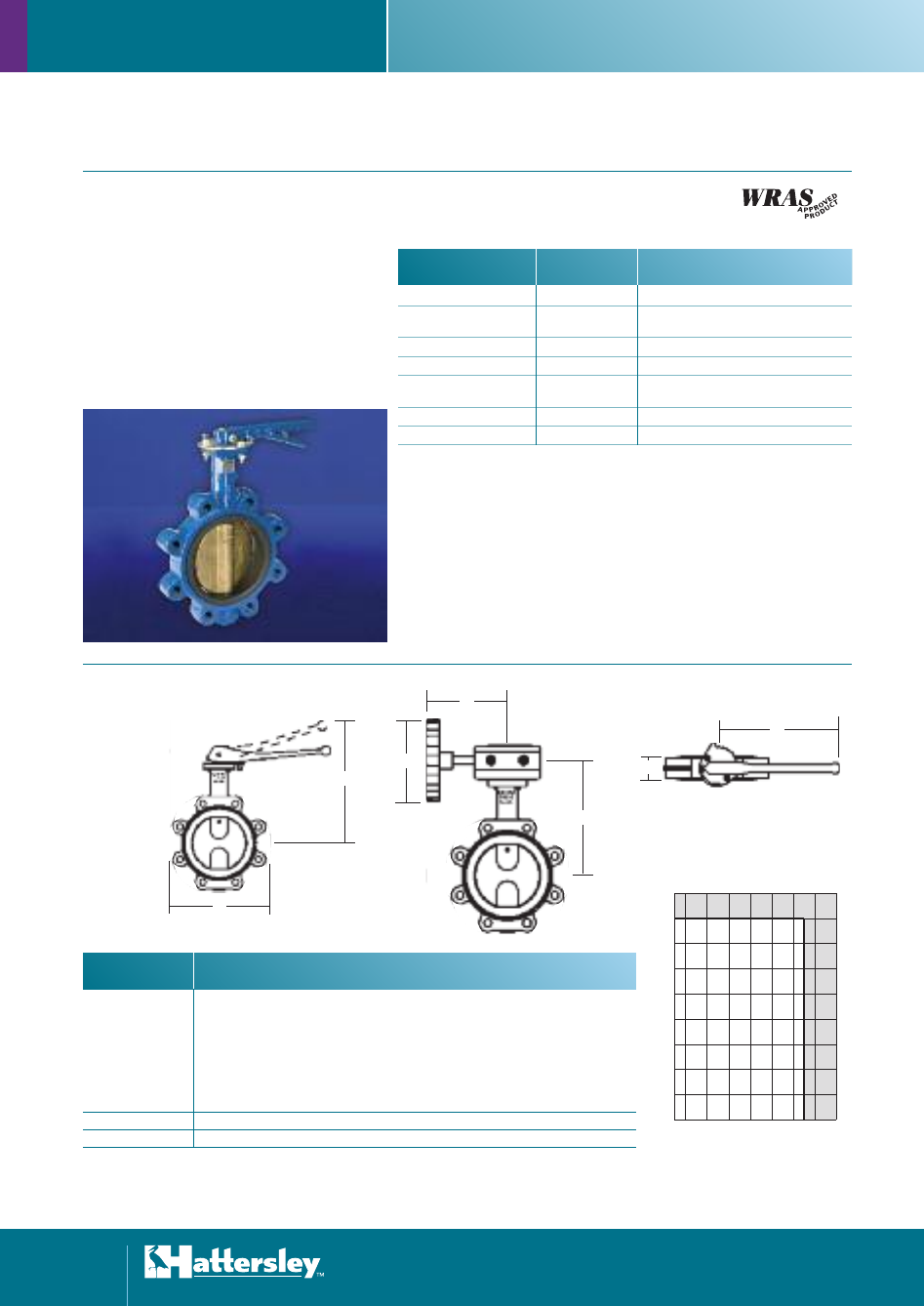
Technical Helpline: 0845 604 1790
E: tech-enquiries@hattersley.com W: www.hattersley.com
96
BUTTERFLY VALVES
PN16
Every effort has been made to ensure that the information contained in this publication is accurate at the time of publishing.
Hattersley Ltd assumes no responsibility or liability for typographical errors or omissions or for any misinterpretation of the
information within the publication and reserves the right to change without notice.
Fig. 970W
Fully-lugged Wafer Pattern
DIMENSIONAL DRAWINGS
MATERIAL SPECIFICATIONFEATURES AND BENEFITS
• Available up to DN600
• Valve body fully lugged
• Suitable for end of line duty up to 10 bar
• Long neck for insulation
• Maintenance free
• Good control characteristics
Body Ductile Iron 1563 EN-JS 1030 A536 65-45-12
Shaft Stainless Steel 10088-1 X5CrNiMo17-12-2
A532 Gr316
Disc Bronze 1982 CC333G B148-C95300
Bushes (up to 100mm) PTFE
125mm and above Bronze
(lubricated)
O-Ring Buna N
Liner EPDM
Component Material Specification
BS EN ASTM
0 20 40 60 80 100 120 140
T emperature ˚ C
14
12
10
8
6
2
0
Pressure bar
4
16
18
H
J
K
F
D
A
G
PRESSURE/
TEMPERATURE RATING
PN16 from -10 up to 120ºC
TEST PRESSURES
Each valve is individually hydrostatically
tested to BS EN 12266-1 at the following
test pressures.
Shell: 24 bar
Seat: 17.6 bar
SPECIFICATION
Conforms to BS EN 593:2009.
Fully-lugged.
Aluminium bronze disc.
WRAS approved.
Lever or gearbox.
Valves DN250 and larger supplied as
standard with fully enclosed gear operator.
Valves may be used for flow regulation.
Nom
Size mm 50 65 80 100 125 150 200 250 300 350 400 450 500 600
A mm 42 45 45 52 54 56 61 66 77 77 87 106 132 152
E mm 80 89 95 114 127 139 175 203 242 267 301 327 361 459
F mm 183 197 203 222 235 248 282 - - - - - - -
G mm 270 270 270 270 270 270 270 - - - - - - -
H mm 279 302 314 352 378 403 478 537 622 678 764 812 918 1098
J mm 154 154 154 154 154 154 238 238 222 222 300 300 350 350
K mm 152 152 152 152 152 152 300 300 300 300 300 300 300 300
Weight lever kg 4 5 5 6 9 10 15 - - - - - - -
Weight geared kg 8 9 10 11 13 14 19 32 47 59 93 117 - -
DIMENSIONS AND WEIGHTS
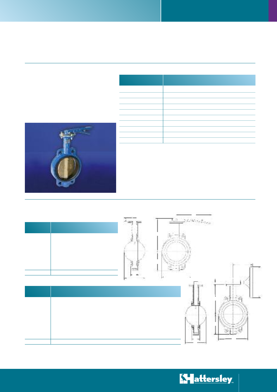
Technical Helpline: 0845 604 1790
E: tech-enquiries@hattersley.com W: www.hattersley.com
97
BUTTERFLY VALVES
PN16
Every effort has been made to ensure that the information contained in this publication is accurate at the time of publishing.
Hattersley Ltd assumes no responsibility or liability for typographical errors or omissions or for any misinterpretation of the
information within the publication and reserves the right to change without notice.
Fig. 951 and 951G
Semi-lugged, Lever/Gearbox Operated Wafer Pattern
to BS EN 593:2009
MATERIAL SPECIFICATION
Body Ductile Iron ASTM A536 (Epoxy Paint)
Disc Aluminium Bronze
Liner Nitrile Temp. -10 to 90°C
Shaft Stainless Steel Type 410
Taper Pin Stainless Steel Type 316
Key Carbon Steel
O-Ring Buna-N
Bushing PTFE
Lever & Screw Carbon Steel (Epoxy Paint)
Stop Plate Carbon Steel (Zn Plated)
Component Material
FEATURES AND BENEFITS
• Aluminium Bronze disc
• Stainless Steel shaft
• 951 - Trigger lever, 951G - Gearbox operated
• Sizes 350 to 600mm PN16 only
• Valves are suitable for use with flanges
conforming to BS EN 1092-2 PN10
or PN16 and ANSI B16.1 Class 125
(sizes 2" to 12")
Nom
Size mm 50 65 80 100 125 150 200
A mm 195 207 213 232 245 257 305
B mm 83 95 102 124 136 150 197
C mm 44 48 48 54 57 57 63
D mm 32 32 32 32 32 32 44
E mm 102 121 130 171 197 219 268
F mm 260 260 260 260 260 260 356
G mm 32 46 64 90 111 145 193
Weight kg 3.5 4 5.4 6.7 9 9.9 16.4
DIMENSIONS AND WEIGHTS
Fig 951
Nom
Size mm 50 65 80 100 125 150 200 250 300 350 400 450 500 600
A mm 162 175 181 200 213 225 260 292 337 368 400 422 479 562
B mm 83 95 102 124 136 150 197 210 248 279 305 381 381 457
C mm 44 48 48 54 57 57 63 70 79 79 89 108 133 156
D mm 42 42 42 42 42 42 40 40 40 40 - - - -
E mm 102 121 130 171 197 219 268 332 410 435 508 543 592 708
F mm 150 150 150 150 300 300 300 300 300 300 450 450 450 450
G mm 32 46 64 90 111 145 193 241 290 325 380 427 474 574
K mm 240 240 240 240 240 240 230 230 230 230 277 277 321 335
Weight kg 15 15.5 16.9 18.2 20.5 21.4 29 33.5 45.8 56.2 88.4 110.2 160.5 260
Fig 951G
B
G
G
C
C
E
E
F
F
K
A
A
D
D
B
PRESSURE/
TEMPERATURE RATING
PN16 from -10 up to 90˚C
TEST PRESSURES
Each valve is individually hydrostatically
tested to BS EN 12266-1:2003 at the
following test pressures:
Shell: 24 bar
Seat: 17.6 bar
SPECIFICATION
Semi-lugged.
Lever or gearbox.
Valves DN250 and larger supplied as standard with
a fully enclosed gear operator.
Valves may be used for flow regulation.
Suitable for gas applications.
Figures 951 and 951G are suitable for Group 1 and
2 gases and Group 1 and 2 liquids as defined by
the Pressure Equipment Directive 97/23/EC.
DIMENSIONAL DRAWINGS
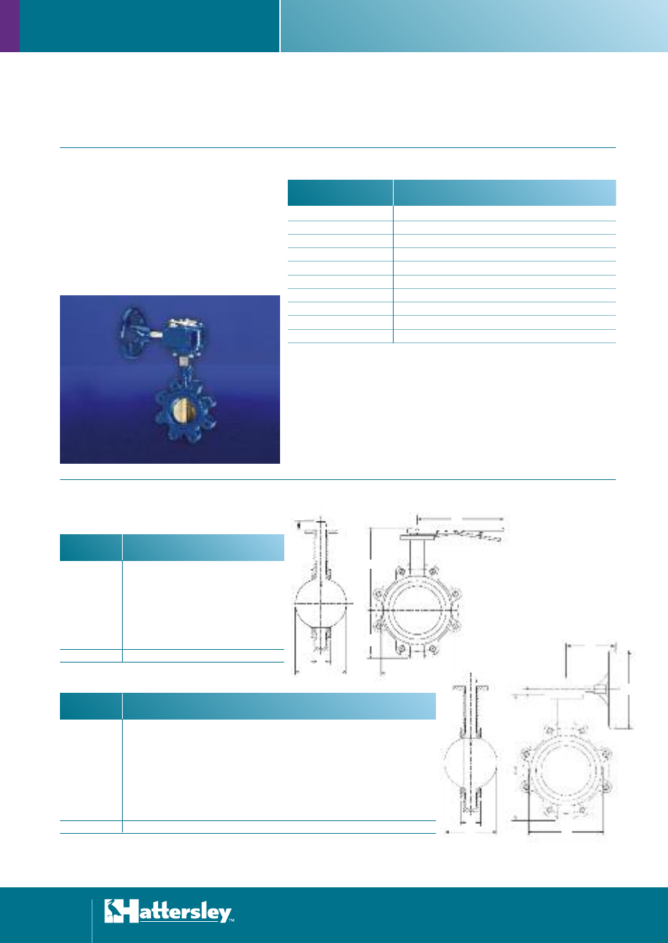
Technical Helpline: 0845 604 1790
E: tech-enquiries@hattersley.com W: www.hattersley.com
98
BUTTERFLY VALVES
PN16
Every effort has been made to ensure that the information contained in this publication is accurate at the time of publishing.
Hattersley Ltd assumes no responsibility or liability for typographical errors or omissions or for any misinterpretation of the
information within the publication and reserves the right to change without notice.
MATERIAL SPECIFICATIONFEATURES AND BENEFITS
• Aluminium Bronze disc
• Stainless Steel shaft
• 971 - Trigger lever, 971G - Gearbox operated
• Valves are suitable for use with flanges
conforming to BS EN 1092-2 PN10
or PN16 - Sizes 65-150mm
• Sizes 200-600mm PN16 only
Fig. 971 and 971G
Fully-lugged, Lever/Gearbox Operated Wafer Pattern
to BS EN 593: 2009
Nom
Size mm 50 65 80 100 125 150 200
A mm 195 207 213 232 245 257 305
B mm 83 95 102 124 136 150 197
C mm 44 48 48 54 57 57 63
D mm 32 32 32 32 32 32 44
E mm 102 121 130 171 197 219 268
F mm 260 260 260 260 260 260 356
G mm 32 46 64 90 111 145 193
Weight kg 4 4.5 7.2 12.6 13.5 14.9 24.1
DIMENSIONS AND WEIGHTS
Fig. 971
Nom
Size mm 50 65 80 100 125 150 200 250 300 350 400 450 500 600
A mm 162 175 181 200 213 225 260 292 337 368 400 422 479 562
B mm 83 95 102 124 136 150 197 210 248 279 305 381 381 457
C mm 44 48 48 54 57 57 63 70 79 79 89 108 133 156
D mm 42 42 42 42 42 42 40 40 40 40 - - - -
E mm 102 121 130 171 197 219 268 332 410 435 508 543 592 708
F mm 150 150 150 150 300 300 300 300 300 300 450 450 450 450
G mm 32 46 64 90 111 145 193 241 290 325 380 427 474 574
K mm 240 240 240 240 240 240 230 230 230 230 277 277 321 335
Weight kg 15.5 16 18.7 24.1 25 26.4 36.7 47.1 62.1 84.9 123.8 139.7 215.5 337.3
Fig. 971G
B
B
G
C
E
E
F
F
K
A
A
D
D
Body Ductile Iron ASTM A536 (Epoxy Paint)
Disc Aluminium Bronze
Liner Nitrile Temp. -10 to 90˚C
Shaft Stainless Steel Type 410
Taper Pin Stainless Steel Type 316
Key Carbon Steel
O-Ring Buna-N
Bushing PTFE
Lever & Screw Carbon Steel (Epoxy Paint)
Stop Plate Carbon Steel (Zn Plated)
Component Material
PRESSURE/
TEMPERATURE RATING
PN16 from -10 up to 90˚C
TEST PRESSURES
Each valve is individually hydrostatically
tested to BS EN 12266-1:2003 at the
following test pressures:
Shell: 24 bar
Seat: 17.6 bar
SPECIFICATION
Fully-lugged.
Lever or gearbox.
Valves DN250 and larger supplied as standard
with a fully enclosed gear operator.
Valves may be used for flow regulation.
Suitable for gas applications.
Fig. 971 and 971G are suitable for Group 1 and
2 gases and Group 1 and 2 liquids as defined
by the Pressure Equipment Directive 97/23/EC.
DIMENSIONAL DRAWINGS
G
C
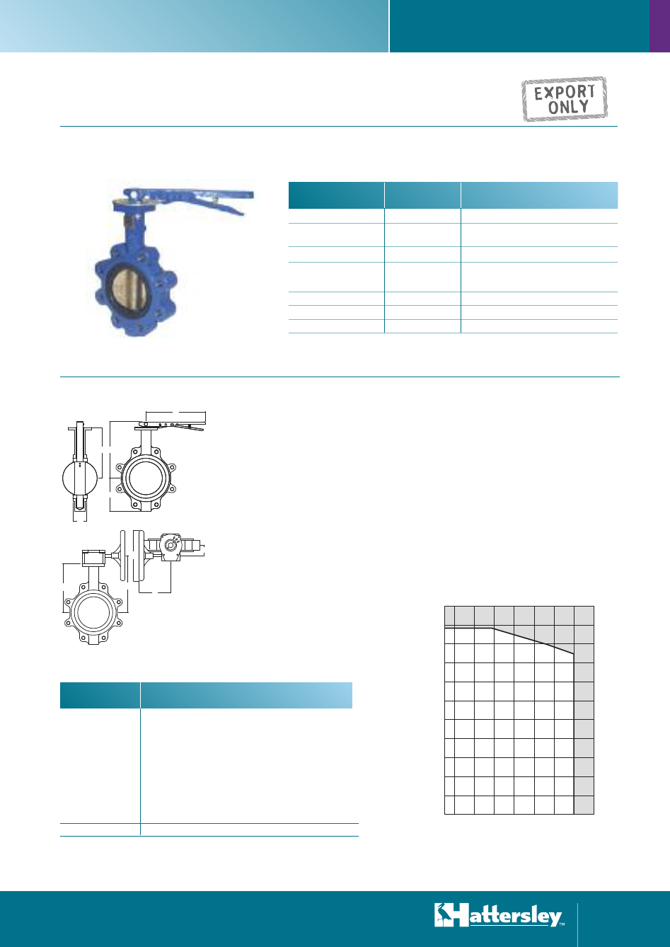
Technical Helpline: 0845 604 1790
E: tech-enquiries@hattersley.com W: www.hattersley.com
99
BUTTERFLY VALVES
PN16
Every effort has been made to ensure that the information contained in this publication is accurate at the time of publishing.
Hattersley Ltd assumes no responsibility or liability for typographical errors or omissions or for any misinterpretation of the
information within the publication and reserves the right to change without notice.
Nom
Size mm 50 65 80 100 125 150 200 250 300
A mm 44 48 48 54 57 57 63 70 79
B mm 83 95 102 124 136 150 197 210 248
C mm 195 207 213 232 245 257 - - -
D mm 162 175 181 200 213 225 260 292 337
E mm 260 260 260 260 260 260 - - -
F mm 204 217 223 242 255 267 300 332 377
G mm 150 150 150 150 300 300 300 300 300
H mm 240 240 240 240 240 230 230 230 230
J mm 60 60 60 60 60 60 80 80 80
Weight kg 10 11 12 13 16 19 30 40 53
DIMENSIONS AND WEIGHTS
Fig. 980ANSI
Ductile Iron Fully Lugged Butterfly Valve Class 150
DIMENSIONAL DRAWINGS
MATERIAL SPECIFICATION
Body Ductile Iron 1563 EN-JS1030 A536 65-45-12
Operating Shaft Stainless Steel 10088-1 A276 410
X12Cr13
Disc Al Bronze 12165 CW307G B150 C63000
Taper pins Stainless Steel 10088-1 A276 316
X5CrNiMo17-12-2
Bushes EDPM
O-Ring Buna N
Liner EPDM
Component Material Specification
BS EN ASTM
PRESSURE/
TEMPERATURE RATING
19.65 bar from -10 to 37.8°C
16.93 bar at 120°C
TEST PRESSURES
(HYDRAULIC)
Body: 29.5 bar
Seat: 21.6 bar
SPECIFICATION
Generally conforms to BS EN 593.
Ductile Iron body epoxy coated.
Fully lugged.
Aluminium bronze disk.
EPDM liner phenolic backed.
Trigger Lever.
Valves DN200 and larger supplied as standard
with fully enclosed gear operator.
Suitable for fitting between flanges to ANSI B16.1
Class 125 and 150.
Valves may be used for flow regulation.
020406080100 120 140
Tem per ature ˚C
14
12
10
8
6
2
0
Pressure bar
4
16
18
20
22
50:1
CLOSED
OPEN
F
H
D
J
G
A
B
CD
E
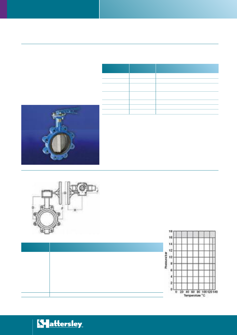
Technical Helpline: 0845 604 1790
E: tech-enquiries@hattersley.com W: www.hattersley.com
100
BUTTERFLY VALVES
PN16
Every effort has been made to ensure that the information contained in this publication is accurate at the time of publishing.
Hattersley Ltd assumes no responsibility or liability for typographical errors or omissions or for any misinterpretation of the
information within the publication and reserves the right to change without notice.
Fig. 4970/4970G
Ductile Iron Fully-lugged
PRESSURE/
TEMPERATURE RATING
16 bar from -10 to 120°C
15.7 bar at 130°C
TEST PRESSURES
Body: 24 bar
Seat: 17.6 bar
SPECIFICATION
Generally conforms to BS EN 593:2009.
Ductile Iron body epoxy coated.
Fully-lugged.
Stainless steel disc.
EPDM liner.
To suit flange connections BS EN 1092-2 PN16.
Valves may be used for flow regulation.
Valves DN250 and larger supplied as standard
with fully enclosed gear operator.
Valves DN450 and larger supplied with spur gear
unit as part of gear operator.
MATERIAL SPECIFICATION
Body Ductile Iron 1563 EN-JS1030 A536-65-45-12
Operating Shaft Stainless Steel 10088-1 X12Cr13 A276 410
Disc Stainless Steel 110213-4 GX5CrNiMo19-11-2
A351 CF8M
Taper Pins Stainless Steel 10088-1X5CrNiMo17-12-2
A276 316
Bushes PTFE
O-Ring Buna N
Liner EPDM
Component Material Specification
BS EN ASTM
FEATURES AND BENEFITS
• Available up to DN600
• Valve body fully-lugged
• Long neck for insulation
• Maintenance free
• Good control characteristics
Nom
Size mm 50 65 80 100 125 150 200 250 300 350 400 450 500 600
A mm 44 48 48 54 57 57 63 70 79 79 89 108 133 156
B mm 83 95 102 124 136 150 197 210 248 280 305 381 381 458
C mm 195 207 213 232 245 257 305 - - 369 400 422 480 562
D mm 162 175 181 200 213 225 260 292 337 520 580 640 715 840
E mm 260 260 260 260 260 260 356 - - 38 54 105 105 110
F mm 204 217 223 242 255 267 300 332 377 300 450 450 450 450
G mm 150 150 150 150 300 300 300 300 300 230 230 340 340 360
H mm 240 240 240 240 240 230 230 230 230 80 120 185 185 185
J mm 60 60 60 60 60 60 80 80 80 - - - - -
Weight kg 3 4 6 12 13 14 22 43 57 65 104 150 198 300
DIMENSIONS AND WEIGHTS
DIMENSIONAL DRAWINGS
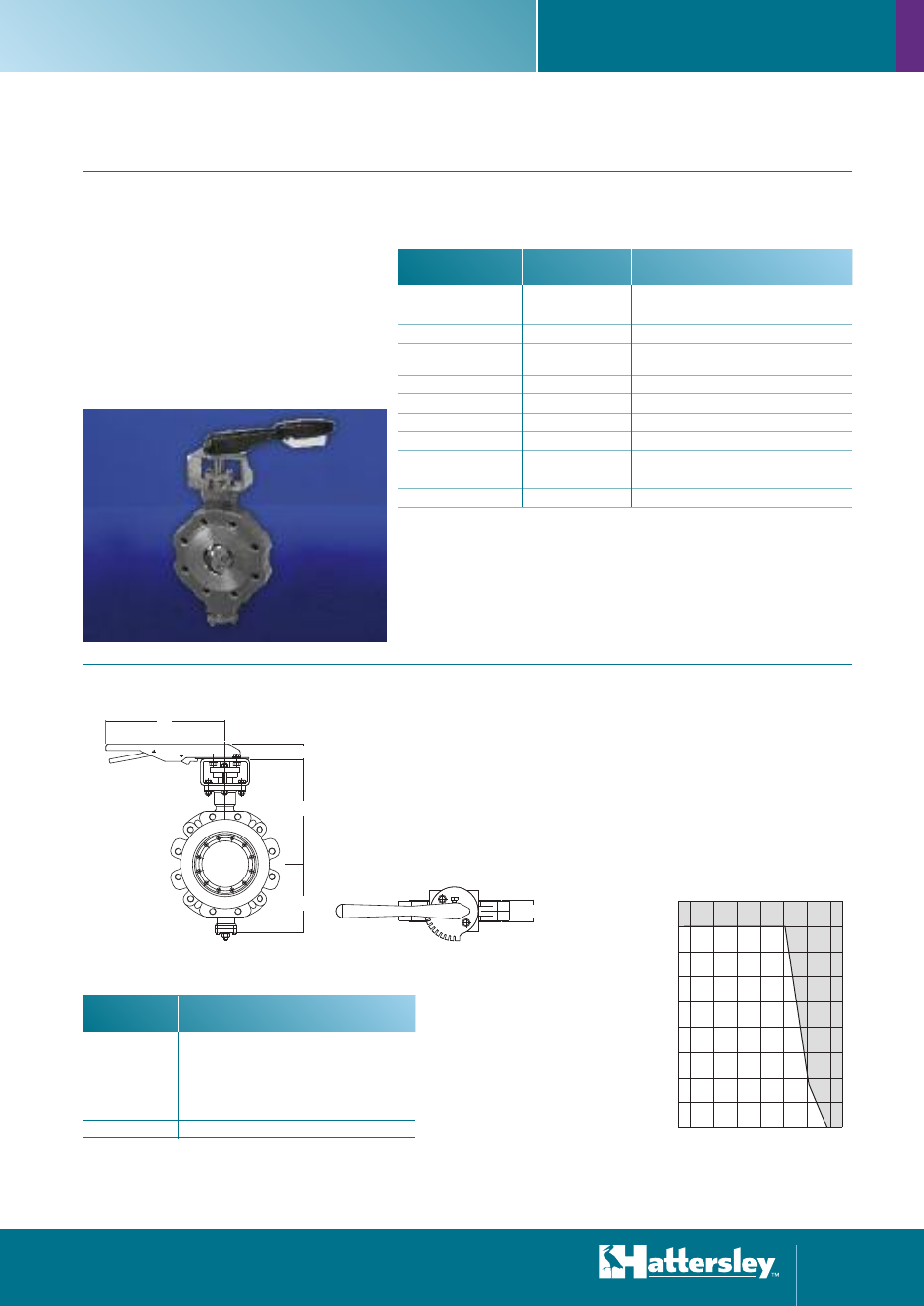
Technical Helpline: 0845 604 1790
E: tech-enquiries@hattersley.com W: www.hattersley.com
101
BUTTERFLY VALVES
PN16 DN50-150
Every effort has been made to ensure that the information contained in this publication is accurate at the time of publishing.
Hattersley Ltd assumes no responsibility or liability for typographical errors or omissions or for any misinterpretation of the
information within the publication and reserves the right to change without notice.
Fig. 4990
Steel Fully-lugged
PRESSURE/
TEMPERATURE RATING
16 bar from -10 to 163ºC
3.4 bar at 204ºC
TEST PRESSURES
(HYDRAULIC)
Body: 24 bar
Seat: 17.6 bar
SPECIFICATION
Designed to BS EN 593:2009.
Face to face dimensions to BS EN 558-1 basic series 20.
Reinforced PTFE disc seal.
Stainless steel body seat.
Double eccentric disc.
Bi-directional isolation.
Valves are supplied lever operated.
Actuator flange ISO 5211/1.
To suit flange connections BS EN 1092-2 PN16,
alternative flanges available.
Wafer pattern available figure 4985 PN16.
MATERIAL SPECIFICATIONFEATURES AND BENEFITS
• Carbon steel body with stainless steel seat
• Stainless steel stem and double offset disc
• Reinforced PTFE seat
• End of line servicing up to full rating
• High Kv values
Body Steel 10213-2 GP240GH A216 WCB
Body Seat Stainless Steel 12073 XCrNiMn23-12-2
Disc Stainless Steel 10088-1 X17CrNi16-2 AISI 431
Disc Seal Ring PTFE or PTFE/
Neoprene
Retaining Ring Stainless Steel 10088-1 X17CrNi16-2 AISI 431
Stem Stainless Steel 10088-1 X17CrNi16-2 AISI 431
Disc Pin Stainless Steel 10088-1 X17CrNi16-2 AISI 431
Bottom Cap Steel
Gland Packing PTFE Graphite
Bearings Bronze-PTFE
Lever
Component Material Specification
BS EN ASTM
B
H
C
L
A
0 40 80 120 160 200 240
Temperature ˚C
18
16
14
12
10
8
6
4
2
0
Pressure bar
Nom
Size mm 50 65 80 100 125 150
A mm 43 46 46 52 56 56
B mm 123 131 150 175 187 218
H mm 215 215 225 244 260 270
C mm 27 27 27 35 35 42
L mm 265 265 265 265 265 265
Weight kg - - - - - -
DIMENSIONS AND WEIGHTS
DIMENSIONAL DRAWINGS

Fig. 4990G
Steel Fully-lugged
SPECIFICATION
Designed to BS EN 593:2009.
Face to face dimensions to BS EN 558-1 basic series 20.
Reinforced PTFE disc seal.
Stainless steel body seat.
Double eccentric disc.
Bi-directional isolation.
Valves are supplied gear operated.
Actuator flange ISO 5211/1.
To suit flange connections BS EN 1092-2 PN16,
alternative flanges available.
Wafer pattern available figure 4985G PN16.
MATERIAL SPECIFICATION
Body Steel 10213-2 GP240GH A216 WCB
Body Seat Stainless Steel 12073 XCrNiMn23-12-2
Disc Stainless Steel 10088-1 X17CrNi16-2 AISI 431
Disc Seal Ring PTFE or PTFE
Neoprene
Retaining Ring Stainless Steel 10088-1 X17CrNi16-2 AISI 431
Stem Stainless Steel 10088-1 X17CrNi16-2 AISI 431
Disc Pin Stainless Steel 10088-1 X17CrNi16-2 AISI 431
Bottom Cap Steel
Gland Packing PTFE Graphite
Gearbox Cast Iron 1561 EN-JLI030 A126 CI B
Handwheel Steel
Component Material Specification
BS EN ASTM
FEATURES AND BENEFITS
• Carbon steel body with stainless steel seat
• Stainless steel stem and double offset disc
• Reinforced PTFE seat
• End of line servicing up to full rating
• High Kv values
0 40 80 120 160 200 240
Temperature ˚C
18
16
14
12
10
8
6
4
2
0
Pressure bar
F
B
H
D
C
DIMENSIONAL DRAWINGS
E
A
PRESSURE/
TEMPERATURE
RATING
16bar from -10 to 163ºC
3.4bar at 204ºC
TEST PRESSURES
(HYDRAULIC)
Body: 24 bar
Seat: 17.6 bar
Nom
Size mm 50 65 80 100 125 150
A mm 43 46 46 52 56 56
B mm 123 131 150 175 187 218
H mm 215 215 225 244 260 270
C mm 27 27 27 27 27 27
D dia mm 125 200 200 200 200 200
E mm 39 39 39 39 39 39
F mm 152 159 159 159 159 159
Weight kg - - - - - -
DIMENSIONS AND WEIGHTS
Technical Helpline: 0845 604 1790
E: tech-enquiries@hattersley.com W: www.hattersley.com
102
BUTTERFLY VALVES
PN16 DN50-150
Every effort has been made to ensure that the information contained in this publication is accurate at the time of publishing.
Hattersley Ltd assumes no responsibility or liability for typographical errors or omissions or for any misinterpretation of the
information within the publication and reserves the right to change without notice.
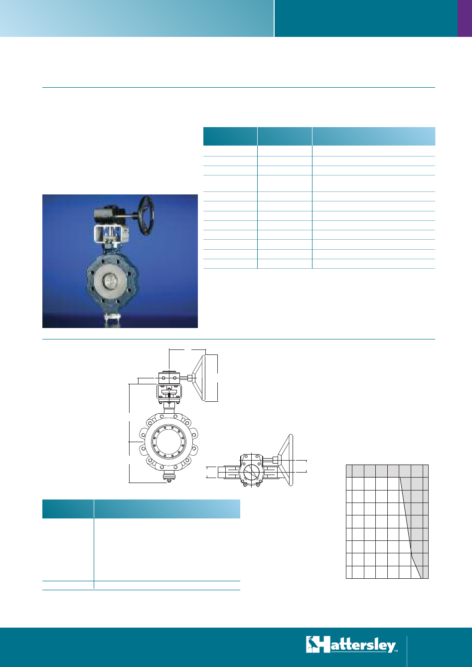
Technical Helpline: 0845 604 1790
E: tech-enquiries@hattersley.com W: www.hattersley.com
103
BUTTERFLY VALVES
PN16 DN200-500
Every effort has been made to ensure that the information contained in this publication is accurate at the time of publishing.
Hattersley Ltd assumes no responsibility or liability for typographical errors or omissions or for any misinterpretation of the
information within the publication and reserves the right to change without notice.
Fig. 4990G
Steel Fully-lugged
SPECIFICATION
Designed to BS EN 593:2009.
Face to face dimensions to BS EN 558-1
basic series 20.
Reinforced PTFE disc seal.
Stainless steel body seat.
Double eccentric disc.
Bi-directional isolation.
Valves are supplied gear operated.
Actuator flange ISO 5211/1.
To suit flange connections BS EN 1092-2
PN16, alternative flanges available.
Wafer pattern available figure 4985G PN16.
MATERIAL SPECIFICATIONFEATURES AND BENEFITS
• Carbon steel body with stainless steel seat
• Stainless steel stem and double offset disc
• Reinforced PTFE seat
• End of line servicing up to full rating
• High Kv values
Body Steel 10213-2 GP240GH A216 WCB
Body Seat Stainless Steel 12073 XCrNiMn23-12-2
Disc Stainless Steel 10088-1 X17CrNi16-2 AISI 431
Disc Seal Ring PTFE or PTFE/
Neoprene
Retaining Ring Stainless Steel 10088-1 X17CrNi16-2 AISI 431
Stem Stainless Steel 10088-1 X2 CrNiNo17-12-2 A276-316L
Disc Pin Stainless Steel 10088-1 X17CrNi16-2 AISI 431
Bottom Cap Steel
Gland Packing PTFE Graphite
Bearings Bronze-PTFE
Gearbox Cast Iron 1561 EN-JLI030 A126 CI B
Handwheel Steel
Component Material Specification
BS EN ASTM
F
B
H
D
C
E
A
0 40 80 120 160 200 240
Temperature ˚C
18
16
14
12
10
8
6
4
2
0
Pressure bar
Nom
Size mm 200 250 300 350 400 450 500
A mm 60 68 78 78 102 - 127
B mm 294 333 382 398 448 - 555
H mm 320 366 390 425 440 - 510
C mm 35 42 42 50 50 - 50
D dia mm 300 300 300 457 457 - 457
E mm 52 67 67 90 90 - 123
F mm 197 223 223 279 279 - 331
Weight kg - - - - - - -
PRESSURE/
TEMPERATURE
RATING
16 bar from -10 to 163ºC
3.4 bar at 204ºC
TEST PRESSURES
(HYDRAULIC)
Body: 24 bar
Seat: 17.6 bar
DIMENSIONAL DRAWINGS
DIMENSIONS AND WEIGHTS
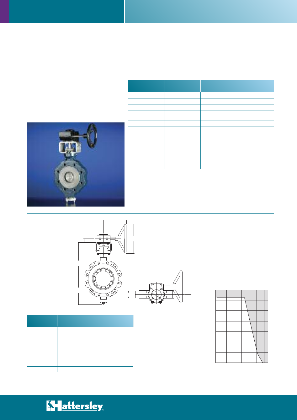
Fig. 4990G
Steel Fully-lugged
SPECIFICATION
Designed to BS EN 593:2009.
Face to face dimensions to BS EN 558-1
basic series 16.
Reinforced PTFE disc seal.
Stainless steel body seat.
Double eccentric disc.
Bi-directional isolation.
Valves are supplied gear operated.
Actuator flange ISO 5211/1.
To suit flange connections BS EN 1092-2
PN25, alternative flanges available.
MATERIAL SPECIFICATION
Body Steel 10213-2 GP240GH A216 WCB
Body Seat Stainless Steel 12073 XCrNiMn23-12-2
Disc Stainless Steel 10088-1 X17CrNi16-2 AISI 431
Disc Seal Ring PTFE or PTFE/
Neoprene
Retaining Ring Stainless Steel 10088-1 X17CrNi16-2 AISI 431
Stem Stainless Steel 10088-1 X17CrNi16-2 AISI 431
Disc Pin Stainless Steel 10088-1 X17CrNi16-2 AISI 431
Bottom Cap Steel
Gland Packing PTFE Graphite
Bearings Bronze-PTFE
Gearbox Cast Iron 1561 EN-JLI030 A126 CI B
Handwheel Steel
Component Material Specification
BS EN ASTM
FEATURES AND BENEFITS
• Carbon steel body with stainless steel seat
• Stainless steel stem and double offset disc
• Reinforced PTFE seat
• End of line servicing up to full rating
• High Kv values
0 40 80 120 160 200 240
Temperature ˚C
28
24
20
16
12
4
0
Pressure bar
8
F
B
H
D
C
Nom
Size mm 50 65 80 100 125 150
A mm 43 46 65 65 70 76
B mm 123 131 150 175 187 218
H mm 215 215 220 281 294 317
C mm 27 27 27 35 35 42
D dia mm 125 200 200 250 300 300
E mm 39 39 39 52 52 67
F mm 152 159 159 184 197 223
Weight kg 10 12 17 24 32 47
DIMENSIONS AND WEIGHTS
DIMENSIONAL DRAWINGS
E
A
PRESSURE/
TEMPERATURE RATING
25 bar from -10 to 135ºC
20.7 bar at 149ºC
3.4 bar at 204ºC
TEST PRESSURES
(HYDRAULIC)
Body: 37.5 bar
Seat: 27.5 bar
Technical Helpline: 0845 604 1790
E: tech-enquiries@hattersley.com W: www.hattersley.com
104
BUTTERFLY VALVES
PN25 DN50-150
Every effort has been made to ensure that the information contained in this publication is accurate at the time of publishing.
Hattersley Ltd assumes no responsibility or liability for typographical errors or omissions or for any misinterpretation of the
information within the publication and reserves the right to change without notice.

Technical Helpline: 0845 604 1790
E: tech-enquiries@hattersley.com W: www.hattersley.com
105
BUTTERFLY VALVES
PN25 DN200-500
Every effort has been made to ensure that the information contained in this publication is accurate at the time of publishing.
Hattersley Ltd assumes no responsibility or liability for typographical errors or omissions or for any misinterpretation of the
information within the publication and reserves the right to change without notice.
Fig. 4990G
Steel Fully-lugged
SPECIFICATION
Designed to BS EN 593:2009.
Face to face dimensions to BS EN 558-1
basic series 16.
Reinforced PTFE disc seal.
Stainless steel body seat.
Double eccentric disc.
Bi-directional isolation.
Valves are supplied gear operated.
Actuator flange ISO 5211/1.
To suit flange connections BS EN 1092-2
PN25, alternative flanges available.
MATERIAL SPECIFICATIONFEATURES AND BENEFITS
• Carbon steel body with stainless steel seat
• Stainless steel stem and double offset disc
• Reinforced PTFE seat
• End of line servicing up to full rating
• High Kv values
Body Steel 10213-2 GP240GH A216 WCB
Body Seat Stainless Steel 12073 XCrNiMn23-12-2
Disc Stainless Steel 10088-1 X17CrNi16-2 AISI 431
Disc Seal Ring PTFE or PTFE/
Neoprene
Retaining ring Stainless Steel 10088-1 X17CrNi16-2 AISI 431
Stem Stainless Steel 10088-1 X17CrNi16-2 AISI 431
Disc Pin Stainless Steel 10088-1 X17CrNi16-2 AISI 431
Bottom Cap Steel
Gland Packing PTFE Graphite
Bearings Bronze-PTFE
Gearbox Cast Iron 1561 EN-JLI030 A126 CI B
Handwheel Steel
Component Material Specification
BS EN ASTM
F
B
H
D
C
0 40 80 120 160 200 240
Temperature ˚C
28
24
20
16
12
4
0
Pressure bar
8
Nom
Size mm 200 250 300 350 400 450 500
A mm 89 114 114 127 140 152 152
B mm 294 333 382 398 448 473 555
H mm 369 396 461 477 557 583 643
C mm 42 50 50 50 66 66 66
D dia mm 300 457 457 457 610 610 610
E mm 67 90 123 154 138 138 138
F mm 223 229 331 356 477 477 477
Weight kg 73 126 167 243 340 454 493
DIMENSIONS AND WEIGHTS
DIMENSIONAL DRAWINGS
E
A
PRESSURE/
TEMPERATURE
RATING
25 bar from -10 to 135ºC
20.7 bar at 149ºC
3.4 bar at 204ºC
TEST PRESSURES
(HYDRAULIC)
Body: 37.5 bar
Seat: 27.5 bar

F
B
H
D
C
E
A
Fig. 4990G
Steel Fully-lugged
DIMENSIONAL DRAWINGS SPECIFICATION
Designed to BS EN 593:2009.
Face to face dimensions to BS EN 558-1
basic series 16.
Reinforced PTFE disc seal.
Stainless steel body seat.
Double eccentric disc.
Bi-directional isolation.
Valves are supplied gear operated.
Actuator flange ISO 5211/1.
To suit flange connections BS EN 1092-2
PN40, alternative flanges available.
MATERIAL SPECIFICATION
Body Steel 10213-2 GP240GH A216 WCB
Body Seat Stainless Steel 12073 XCrNiMn23-12-2
Disc Stainless Steel 10088-1 X17CrNi16-2 AISI 431
Disc Seal Ring PTFE or PTFE/
Neoprene
Retaining Ring Stainless Steel 10088-1 X2 CrNiNo17-12-2
A276-316L
Stem Stainless Steel 10088-1 X17CrNi16-2 AISI 431
Disc Pin Stainless Steel 10088-1 X17CrNi16-2 AISI 431
Bottom Cap Steel
Gland Packing PTFE Graphite
Gearbox Cast Iron 1561 EN-JLI030 A126 CI B
Handwheel Steel
Component Material Specification
BS EN ASTM
FEATURES AND BENEFITS
• Carbon steel body with stainless steel seat
• Stainless steel stem and double offset disc
• Reinforced PTFE seat
• End of line servicing up to full rating
• High Kv values
0 40 80 120 160 200 240
Temperature ˚C
45
40
35
30
25
20
15
10
5
0
Pressure bar
Nom
Size mm 50 65 80 100 125 150
A mm 43 46 64 64 70 76
B mm 123 131 150 175 187 218
H mm 215 215 220 281 294 317
C mm 27 27 27 35 35 42
D dia mm 125 200 200 250 300 300
E mm 39 39 39 52 52 67
F mm 152 159 159 184 197 223
Weight kg 10 12 17 24 32 47
DIMENSIONS AND WEIGHTS
PRESSURE/
TEMPERATURE
RATING
40 bar from -10 to 90ºC
20.7 bar at 149ºC
3.4 bar at 204ºC
TEST PRESSURES
(HYDRAULIC)
Body: 60 bar
Seat: 44 bar
Technical Helpline: 0845 604 1790
E: tech-enquiries@hattersley.com W: www.hattersley.com
106
BUTTERFLY VALVES
PN40 DN65-150
Every effort has been made to ensure that the information contained in this publication is accurate at the time of publishing.
Hattersley Ltd assumes no responsibility or liability for typographical errors or omissions or for any misinterpretation of the
information within the publication and reserves the right to change without notice.
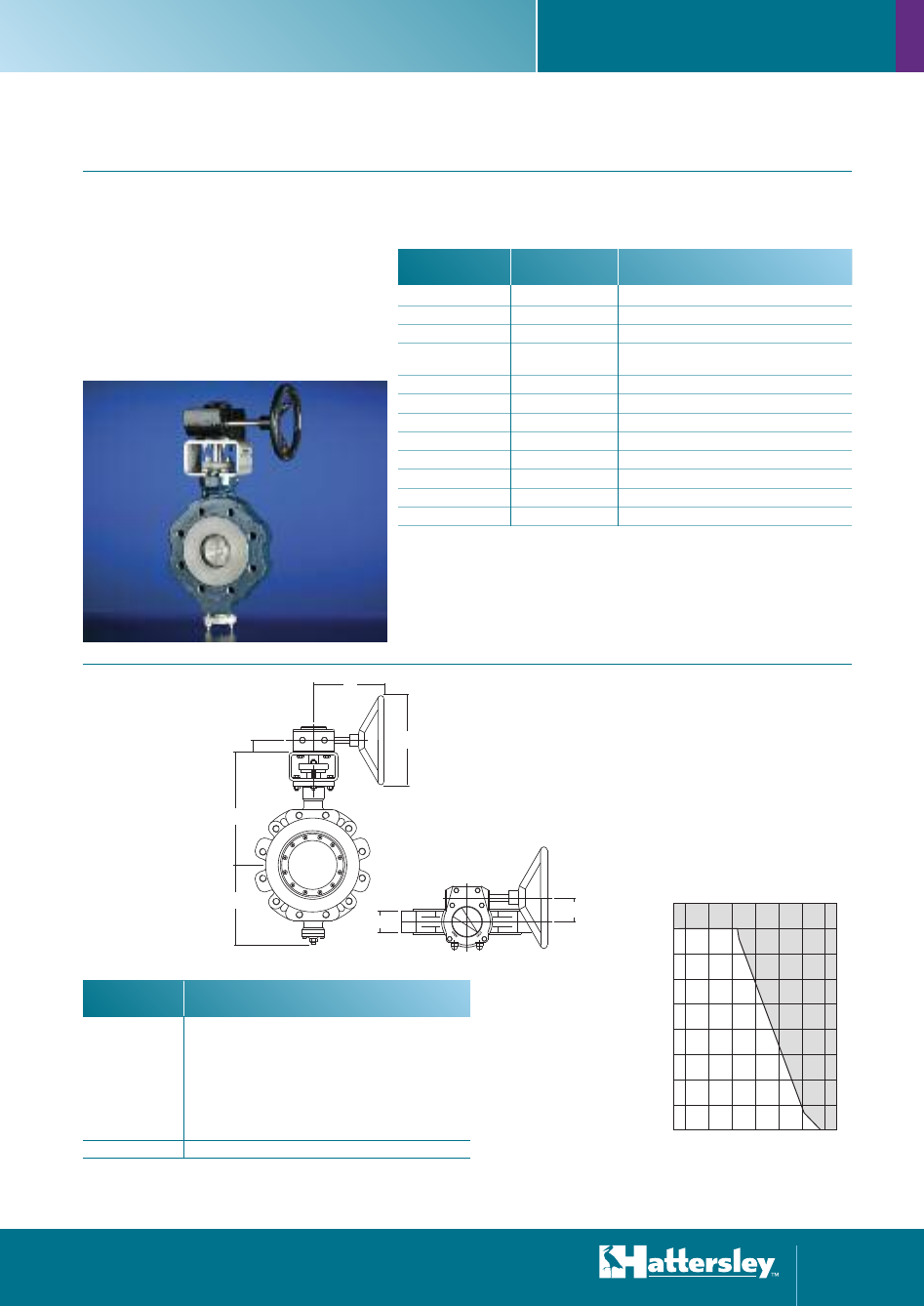
Technical Helpline: 0845 604 1790
E: tech-enquiries@hattersley.com W: www.hattersley.com
107
BUTTERFLY VALVES
PN40 DN200-500
Every effort has been made to ensure that the information contained in this publication is accurate at the time of publishing.
Hattersley Ltd assumes no responsibility or liability for typographical errors or omissions or for any misinterpretation of the
information within the publication and reserves the right to change without notice.
F
B
H
D
C
E
A
Fig. 4990G
Steel Fully-lugged
DIMENSIONAL DRAWINGS SPECIFICATION
Designed to BS EN 593:2009.
Face to face dimensions to BS EN 558-1
basic series 16.
Reinforced PTFE disc seal.
Stainless steel body seat.
Double eccentric disc.
Bi-directional isolation.
Valves are supplied gear operated
Actuator flange ISO 5211/1.
To suit flange connections BS EN 1092-2
PN40, alternative flanges available.
MATERIAL SPECIFICATIONFEATURES AND BENEFITS
• Carbon steel body with stainless steel seat
• Stainless steel stem and double offset disc
• Reinforced PTFE seat
• End of line servicing up to full rating
• High Kv values
Body Steel 10213-2 GP240GH A216 WCB
Body Seat Stainless Steel 12073 XCrNiMn23-12-2
Disc Stainless Steel 10088-33 X8CrNiS 18-9 AISI 420
Disc Seal Ring PTFE or PTFE/
Neoprene
Retaining Ring Stainless Steel 10088-1 X17CrNi16-2 AISI 431
Stem Stainless Steel 10088-1 X17CrNi16-2 AISI 431
Disc Pin Stainless Steel 10088-1 X17CrNi16-2 AISI 431
Bottom Cap Steel
Gland Packing PTFE Graphite
Bearings Bronze-PTFE
Gearbox Cast Iron 1561 EN-JLI030 A126 CI B
Handwheel Steel
Component Material Specification
BS EN ASTM
0 40 80 120 160 200 240
Temperature ˚C
45
40
35
30
25
20
15
10
5
0
Pressure bar
Nom
Size mm 200 250 300 350 400 450 500
A mm 89 114 114 127 140 152 152
B mm 294 333 382 398 448 473 555
H mm 369 396 461 477 557 583 643
C mm 42 50 50 50 66 66 66
D dia mm 300 457 457 457 610 610 610
E mm 67 90 123 154 138 138 138
F mm 223 279 331 356 477 477 477
Weight kg 79 143 203 288 415 469 589
DIMENSIONS AND WEIGHTS
PRESSURE/
TEMPERATURE RATING
40 bar from -10 to 90ºC
20.7 bar at 149ºC
3.4 bar at 204ºC
TEST PRESSURES
(HYDRAULIC)
Body: 60 bar
Seat: 44 bar
Technical Helpline: 0845 604 1790
E: tech-enquiries@hattersley.com W: www.hattersley.com
108
The Cube, Birmingham
Specification: Hattersley Hook-Ups
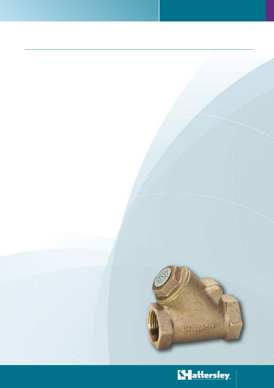
Technical Helpline: 0845 604 1790
E: tech-enquiries@hattersley.com W: www.hattersley.com
109
CHECK VALVES
Check Valves
Check valves permit flow in one direction only,
and close automatically if flow reverses. They are
entirely automatic in action, depending upon
pressure and velocity of flow within the line to
perform their functions of opening and closing.
Most Hattersley swing check valves can be
installed in horizontal or vertical upward flow
piping. Lift check valves must be used in
horizontal lines only.
Hattersley offers four basic types of bronze
check valves, namely:
• Horizontal lift check
• Vertical lift check
• Swing check
• Double check
Swing check valves, having 6 diameters of
straight lengths of pipe upstream and 3 diameters
downstream, are suitable for velocities up to
3 metres/second. If the valve is situated such that
turbulent flow enters the valve, the velocity should
not exceed 2 metres/second.
Horizontal lift check valves are primarily used for
air, gas and steam services whilst swing check
valves are most suitable for water and other
liquids.
For air, gas and low pressure applications,
especially where bubble tight closure is required,
a valve with rubber faced disc is necessary.
Compressed air service requires a horizontal lift
check valve with a nitrile rubber facing on the
disc and fitted with a recoil spring. The valve
should always be installed as far away from the
compressor as possible.
When selecting valves, reference to codes of
practice and other mandatory specifications
should be made which may preclude certain
types for specific applications.
Double check valves are designed to prevent
contamination of water caused by back
syphonage, back flow and cross connection in
supplies such as those to hose taps, cisterns,
stand pipes, showers and basins.
Valves, where designated, are WRAS Approved
Products and listed in the Water Fittings and
Materials Directory.
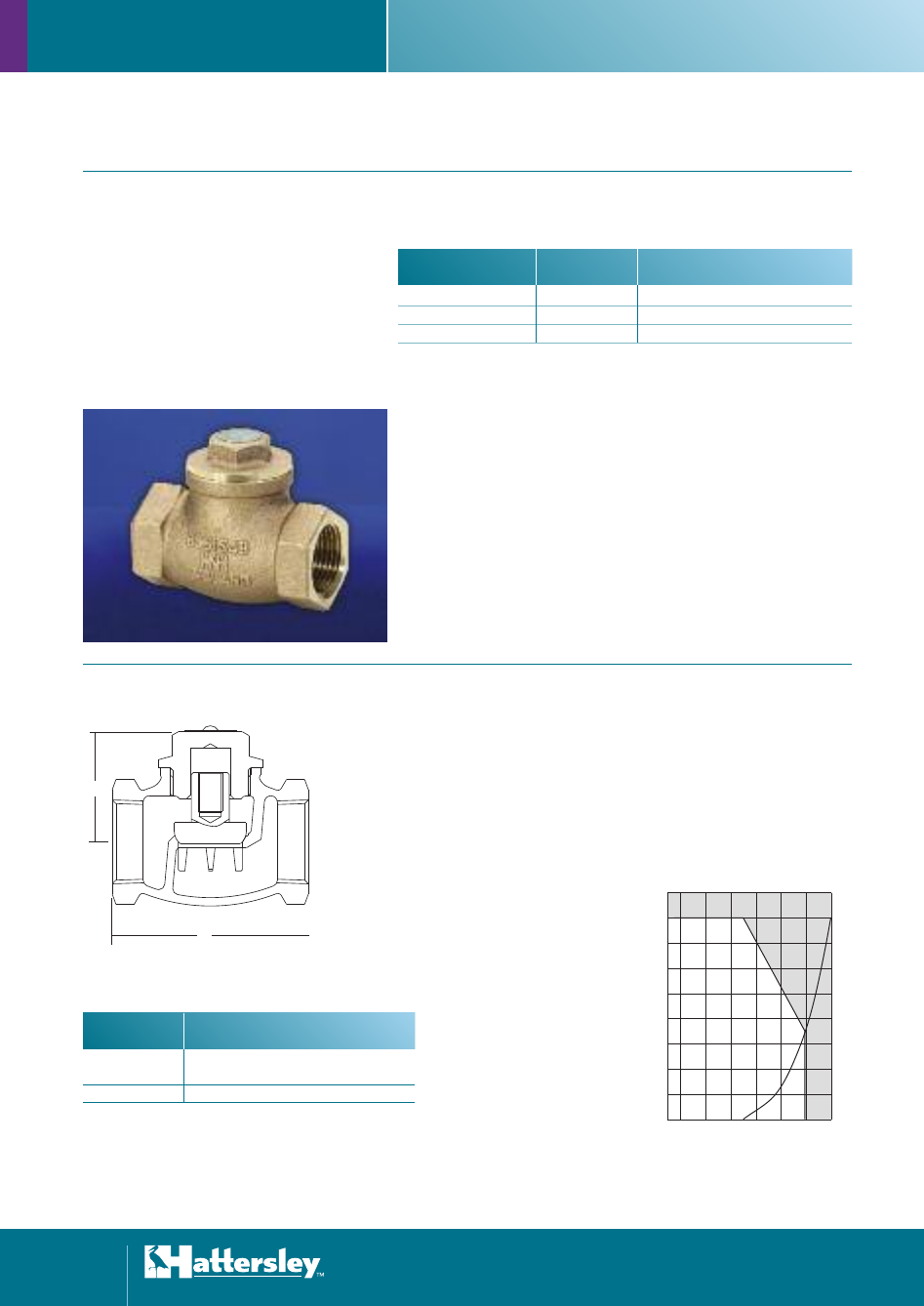
Technical Helpline: 0845 604 1790
E: tech-enquiries@hattersley.com W: www.hattersley.com
110
CHECK VALVES
PN32
Every effort has been made to ensure that the information contained in this publication is accurate at the time of publishing.
Hattersley Ltd assumes no responsibility or liability for typographical errors or omissions or for any misinterpretation of the
information within the publication and reserves the right to change without notice.
Fig. 42
Bronze - Horizontal Lift
DIMENSIONAL DRAWINGS PRESSURE/
TEMPERATURE RATING
BS 5154 PN32 Series B
14 bar at 198ºC
32 bar from -10 to 100ºC
TEST PRESSURES
Shell: 6 bar (pneumatic)
Seat: 35.2 bar (hydraulic)
SPECIFICATION
BS 5154:1991.
Bronze body.
Horizontal lift pattern.
Metal to metal seat.
Guilded disc.
Threaded cap.
Taper threaded to BS EN 10226 ISO 7-1
(BS 21).
Available taper threaded NPT to ASTM
B1.20.1 (42AT).
MATERIAL SPECIFICATION
Body Bronze 1982 CC491K B62 C83600
Cap Bronze 1982 CC491K B62 C83600
Disc (1/4" - 1") Bronze 1982 CC491K B62 C83600
Component Material Specification
BS EN ASTM
FEATURES AND BENEFITS
• Robust and high quality bronze body
• Horizontal lift pattern
• Metal to metal seat for enhance sealing
• Taper threaded to BS EN 10226 ISO 7-1
(BS 21)
B
A
S
a
t
u
r
a
t
e
d
S
t
e
a
m
0 40 80 120 160 200 240
T emperature ˚ C
28
24
20
16
12
4
0
Pressure bar
8
32
36
Nom
Size in 1/2 3/4 1 11/4 11/2 2
A mm 60 74 86 99 109 130
B mm 39 43 51 58 64 70
Weight kg 0.5 0.7 1.6 1.7 2.5 3.5
DIMENSIONS AND WEIGHTS
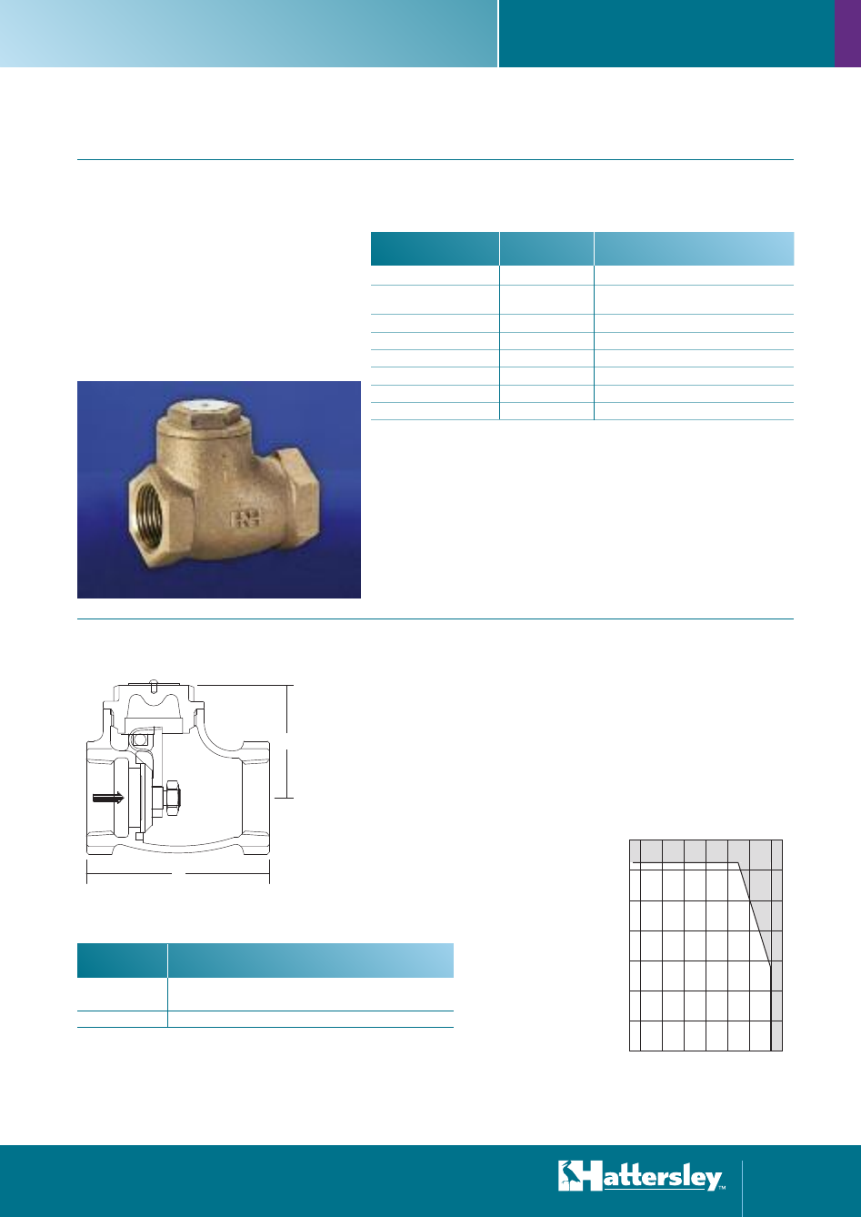
Technical Helpline: 0845 604 1790
E: tech-enquiries@hattersley.com W: www.hattersley.com
111
Every effort has been made to ensure that the information contained in this publication is accurate at the time of publishing.
Hattersley Ltd assumes no responsibility or liability for typographical errors or omissions or for any misinterpretation of the
information within the publication and reserves the right to change without notice.
Fig. 47
Bronze - Swing Pattern
DIMENSIONAL DRAWINGS PRESSURE/
TEMPERATURE RATING
BS 5154
25 bar -10 to 100ºC
10.5 bar at 186ºC
TEST PRESSURES
Shell: 6 bar (pneumatic)
Seat: 27.5 bar (hydraulic)
SPECIFICATION
BS 5154:1991.
Bronze body.
Horizontal swing pattern.
Threaded cover.
Taper threaded to BS EN 10226 ISO 7-1
(BS 21).
MATERIAL SPECIFICATIONFEATURES AND BENEFITS
• Horizontal swing pattern
• Robust and high quality bronze body
• Metal to metal seat for enhance sealing
• Taper threaded to BS EN 10226 ISO 7-1
(BS 21)
Nom
Size in 1/4 3/8 1/2 3/4 1 11/4 11/2 2 21/2 3
A mm 48 48 58 66 80 89 95 108 155 190
B mm 33 33 38 42 49 56 65 76 98 99
Weight kg 0.20 0.19 0.32 0.43 0.61 1.01 1.34 2.12 4.08 5.76
DIMENSIONS AND WEIGHTS
A
B
0 30 60 90 120 150 180
Temperature ˚C
28
24
20
16
12
4
0
Pressure bar
8
Cap Bronze 1982 CC491K B62 C83600
Hinge Pin Stainless Steel 10088-1 X2 A276-316L
CrNiNo17-12-2
Hinge Stainless Steel 970 GR316S11
Disc Nut Brass 12164 CW614N B455 C38500
Body Bronze 1982 CC491K B62 C83600
Hinge Bronze 1982 CC491K B62 C83600
Disc Brass 12164 CW614N B455 C38500
Disc (11/4" - 3") Bronze 1982 CC491K B62 C83600
Component Material Specification
BS EN ASTM
CHECK VALVES
PN25
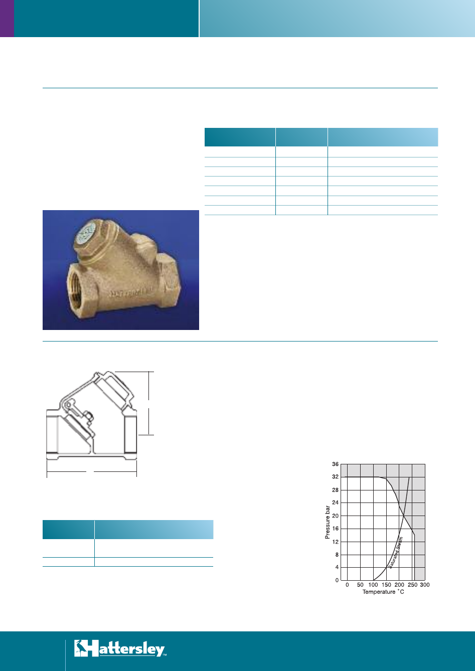
Technical Helpline: 0845 604 1790
E: tech-enquiries@hattersley.com W: www.hattersley.com
112
CHECK VALVES
PN32 SERIES A
Every effort has been made to ensure that the information contained in this publication is accurate at the time of publishing.
Hattersley Ltd assumes no responsibility or liability for typographical errors or omissions or for any misinterpretation of the
information within the publication and reserves the right to change without notice.
Fig. 48
Bronze - Oblique Swing Pattern
DIMENSIONAL DRAWINGS PRESSURE/
TEMPERATURE RATING
BS5154 PN32 Series A
14 bar at 260ºC
32 bar from -10 to 120ºC
TEST PRESSURES
(HYDRAULIC)
Shell: 48 bar
Seat: 35.2 bar
SPECIFICATION
Oblique swing pattern.
Threaded cover.
Metal to metal seat.
Ends threaded internal
BS EN 10266 (ISO 7).
Suitable for mounting in horizontal
and vertical pipe (with vertical
flow upwards).
MATERIAL SPECIFICATION
Cap Bronze 1982 CC491K B62 C83600
Hinge Pin Brass 12164 CW603N B16-C36000
Hinge Bronze 1982 CC491K B62 C83600
Hinge Pin Plug Brass 12164 CW617N B124 Alloy 2
Disc Bronze 1982 CC491K B62 C83600
Disc Nut Brass 12164 CW603N B16-C36000
Body Bronze 1982 CC491K B62 C83600
Component Material Specification
BS EN
FEATURES AND BENEFITS
• Oblique swing pattern
• Robust and high quality bronze body
• Metal to metal seat for enhance sealing
B
A
Nom
Size in 1/2 3/4 1 11/4 11/2 2
A mm 60 70 86.4 96 116 136
B mm 45 50 58 68 75 94
Weight kg 0.28 0.42 0.62 1.0 1.4 2.1
DIMENSIONS AND WEIGHTS
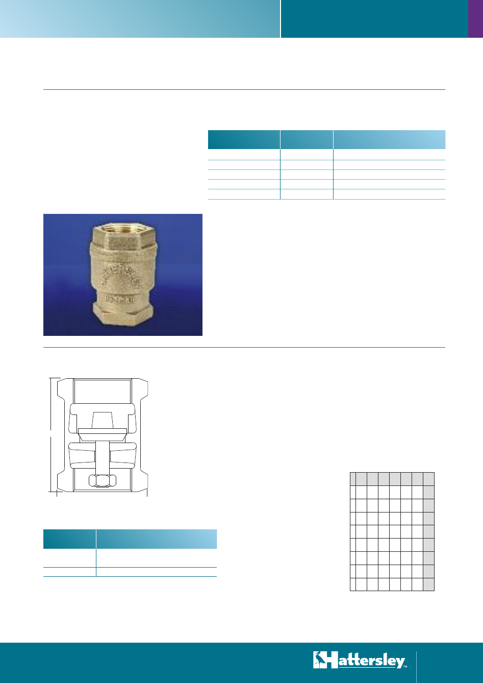
Technical Helpline: 0845 604 1790
E: tech-enquiries@hattersley.com W: www.hattersley.com
113
CHECK VALVES
PN32 SERIES B
Every effort has been made to ensure that the information contained in this publication is accurate at the time of publishing.
Hattersley Ltd assumes no responsibility or liability for typographical errors or omissions or for any misinterpretation of the
information within the publication and reserves the right to change without notice.
Fig. 49
Bronze - Vertical Lift Pattern
DIMENSIONAL DRAWINGS PRESSURE/
TEMPERATURE RATING
BS 5154 PN32 Series B
32 bar from -10 to 120ºC
TEST PRESSURES
(PNEUMATIC)
Body: 6 bar
Seat: 6 bar
SPECIFICATION
Bronze body.
Stainless steel spring.
Taper threaded BS EN 10266
(ISO 7-1) formerly BS 21.
Available with NPT threads to ASTM
B1.20.1.
Suitable for mounting horizontally or
vertically (flow upwards).
Resilient seat.
MATERIAL SPECIFICATIONFEATURES AND BENEFITS
• Robust and high quality bronze body
• Suitable for mounting horizontally or vertically
• Resilient seat
Nom
Size in 1/2 3/4 1 11/4 11/2 2
A mm 53 59 67 79 84 96
B mm 33 40 50 60 66 80
Weight kg 0.18 0.27 0.44 0.63 0.93 1.4
DIMENSIONS AND WEIGHTS
0 20 40 60 80 100 120 14 0
Temperature ˚C
28
24
20
16
12
4
0
Pressure bar
8
32
36
A
B
Body Bronze 1982 CC491K B62 C83600
Disc Bronze 1982 CC491K B62 C83600
Spring Stainless Steel 10270 X10CrNr18-8 A276-304
End Cap Bronze 1982 CC491K B62 C83600
Seat EPDM
Component Material Specification
BS EN
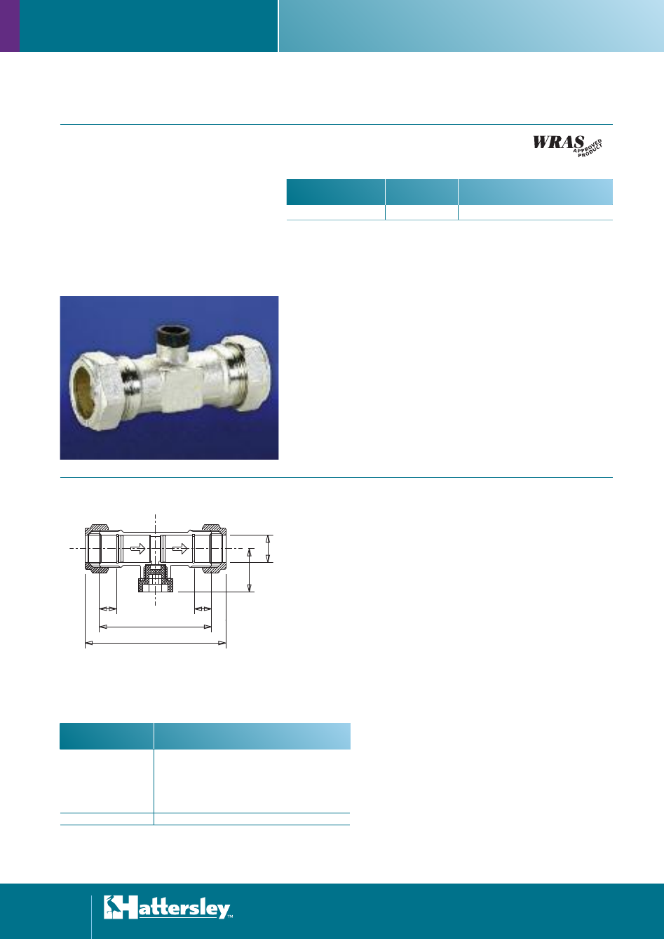
Technical Helpline: 0845 604 1790
E: tech-enquiries@hattersley.com W: www.hattersley.com
114
CHECK VALVES
PN16
Every effort has been made to ensure that the information contained in this publication is accurate at the time of publishing.
Hattersley Ltd assumes no responsibility or liability for typographical errors or omissions or for any misinterpretation of the
information within the publication and reserves the right to change without notice.
Fig. 249 & 249C Brass - Single & Double Check
(Fig. 249C Chromium Plated) Check Valves
DIMENSIONAL DRAWINGS SPECIFICATION
Fig. No. 249
Double Check - 15mm, 22mm, 28mm
Fig. No. 249C
Double Check chromium plated - 15mm
Manufactured to BS 6282.
WRAS approved PN16 85ºC.
Application: Water.
End Connection: Compression.
Back Flow Prevention Device category:
Single check - Class 2 as per Water Supply.
Contamination Risks (water fittings)
Regulations 1999.
Double check - Class 3 as per Water Supply.
Contamination Risks (water fittings)
Regulations 1999.
MATERIAL SPECIFICATION
Body DZR Brass 12165 CW602N
Component Material Specification
BS EN
FEATURES AND BENEFITS
• WRAS approved for use with potable water
• Compression ends for use with half hard
R250 copper pipe
• Single, double and chromium plated
options available
D
B B
A
C
E
Fig. 249 & 249C
Nom mm 15 22 28 15
Size Fig. 249 Fig. 249 Fig. 249 Fig. 249C
A mm 61.4 74.6 88.6 61.4
B mm 9.5 10.5 12.5 9.5
C mm 15.2 22.2 28.25 15.2
D mm 78.5 91.4 106.3 78.5
E mm 24.5 27.5 30.5 24.5
Weight (approx) kg 0.116 0.212 0.360 0.116
DIMENSIONS AND WEIGHTS
PRESSURE/
TEMPERATURE RATING
16 bar from -10 to 85ºC
TEST PRESSURES
(HYDRAULIC)
Body: 24 bar
Seat: 17.6 bar
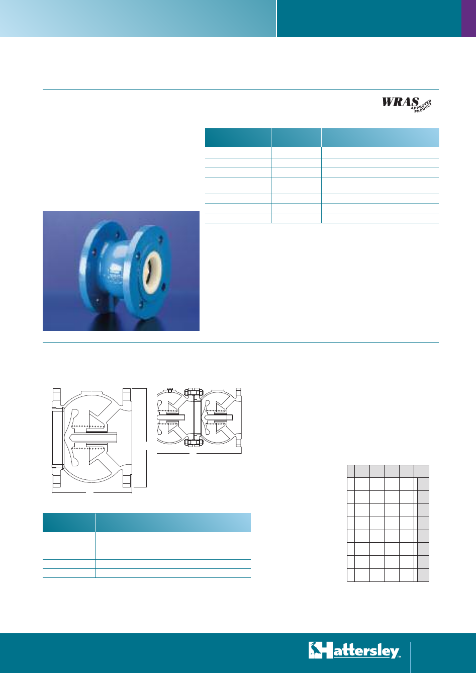
Technical Helpline: 0845 604 1790
E: tech-enquiries@hattersley.com W: www.hattersley.com
115
CHECK VALVES
PN16
Every effort has been made to ensure that the information contained in this publication is accurate at the time of publishing.
Hattersley Ltd assumes no responsibility or liability for typographical errors or omissions or for any misinterpretation of the
information within the publication and reserves the right to change without notice.
Note: These valves are not intended to be used as backflow prevention devices
conforming to Schedule 2 Section 6 of the WRAS Water Regulations Guide.
Fig. 761 and 2761
Aquacheck®Non Return Valve
DIMENSIONAL DRAWINGS SPECIFICATION
Spring Loaded axially guided disc.
Resilient Seat located in body.
Flanged to BS EN 1092-2 PN16.
Alternative pressure ratings to PN25.
Alternative flange details including BS EN 1092-2
PN25 and PN40 and ANSI B16.1 Class 125.
NOTES
Sizes:
50mm to 250mm WRAS Approved.
300mm is not WRAS Approved.
MATERIAL SPECIFICATION
Body Ductile Iron 1563 EN-JS1030 A536-65-45-12
Plunger DN50-150 Bronze
Plunger DN200-400 Cast Iron 1561 EN-JLI030 A126 CI B
Seat Retaining Ring Steel -
Xylan Coated
Seat Nitrile
Guide Bronze
Spring Stainless Steel 10270 X10CrNr18-8 A276-304
Component Material Specification
BS EN ASTM
FEATURES AND BENEFITS
• Spring loaded axially guided disc
• Positive non-slam shut-off
• Flanged to BS EN 1092-2
• Resilient seat located in body
0 20 40 60 80 100
T emperature ˚ C
14
12
10
8
6
2
0
Pressure bar
4
16
18
B
Double Check Valve
configuration Fig. 2761
D
A
Single Check Valve
Fig. 761
PRESSURE/
TEMPERATURE
RATING
16 bar from -10 to 85ºC
TEST
PRESSURES
(HYDRAULIC)
Body: 24 bar
Seat: 17.6 bar
Nom
Size mm 50 65 80 100 125 150 200 250 300
A mm 120 119 130 155 200 230 280 344 385
B mm 240 241 260 310 403 460 560 688 770
D mm 165 185 200 220 250 285 340 405 460
Weight 761 kg 5 7 9 13 21 28 47 83 123
Weight 2761 kg 11 15 20 27 44 58 97 168 249
DIMENSIONS AND WEIGHTS
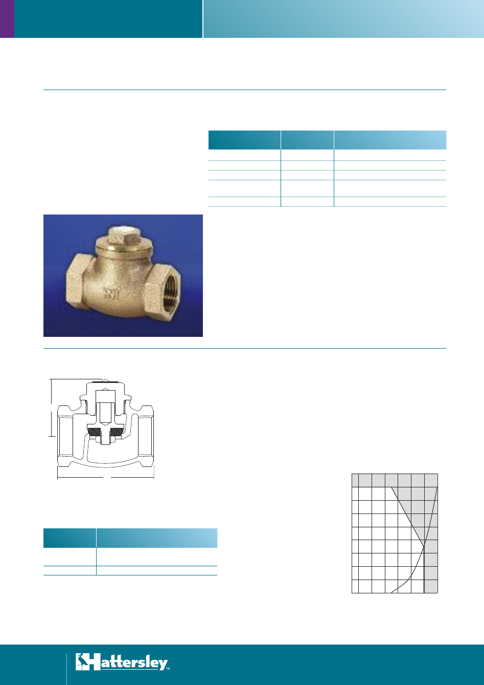
Technical Helpline: 0845 604 1790
E: tech-enquiries@hattersley.com W: www.hattersley.com
116
CHECK VALVES
PN32 SERIES B
Every effort has been made to ensure that the information contained in this publication is accurate at the time of publishing.
Hattersley Ltd assumes no responsibility or liability for typographical errors or omissions or for any misinterpretation of the
information within the publication and reserves the right to change without notice.
Fig. 1013
Bronze - Horizontal Lift Pattern
DIMENSIONAL DRAWINGS PRESSURE/
TEMPERATURE RATING
BS 5154 PN32 Series B
14 bar at 198ºC
32 bar from -10 to 100ºC
TEST PRESSURES
Body: 6 bar - pneumatic
Seat: 35.2 bar - hydraulic
SPECIFICATION
BS 5154:1991.
Bronze body.
Horizontal lift pattern.
Replaceable PTFE - glass filled disc.
Guilded disc.
Threaded cap.
Taper threaded BS EN 10266
(ISO 7-1) formerly BS 21.
MATERIAL SPECIFICATIONFEATURES AND BENEFITS
• Robust and high quality bronze body
• Horizontal lift pattern
• Replaceable PFTE, glass filled disc
• Taper threaded to BS EN 10226 ISO 7-1
(BS 21)
S
a
t
u
r
a
t
e
d
S
t
e
a
m
0 40 80 120 160 200 240
Temperature ˚C
28
24
20
16
12
4
0
Pressure bar
8
32
36
A
B
Nom
Size in 1/2 3/4 1 11/4 11/2 2
A mm 60 74 86 99 109 130
B mm 39 43 51 58 64 70
Weight kg 0.4 0.6 1.1 1.3 2.1 3.4
DIMENSIONS AND WEIGHTS
Cap (11/4" to 2") Bronze 1982 CC491K B62 C83600
Cap (1/2" to 1") Brass 12164 CW603N B16 C36000
Disc Holder Bronze 1982 CC491K B62 C83600
Disc PTFE -
Glass Filled
Body Bronze 1982 CC491K B62 C83600
Component Material Specification
BS EN
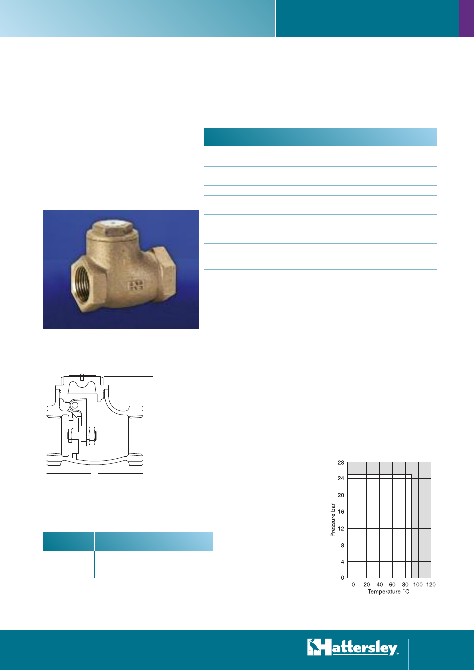
Technical Helpline: 0845 604 1790
E: tech-enquiries@hattersley.com W: www.hattersley.com
117
CHECK VALVES
PN25
Every effort has been made to ensure that the information contained in this publication is accurate at the time of publishing.
Hattersley Ltd assumes no responsibility or liability for typographical errors or omissions or for any misinterpretation of the
information within the publication and reserves the right to change without notice.
Fig. 3047
Bronze - Swing Pattern
DIMENSIONAL DRAWINGS PRESSURE/
TEMPERATURE RATING
BS 5154:1991 PN25
25 bar from -10 to restricted 90ºC
TEST PRESSURES
Body: 6 bar - pneumatic
Seat: 27.5 bar - hydraulic
SPECIFICATION
Horizontal swing pattern.
Threaded cover.
Alternative disc materials available.
Ends threaded internal BS EN 10266
(ISO 7).
Suitable for mounting in horizontal
and vertical pipe (with vertical
flow upwards).
MATERIAL SPECIFICATION
Body Bronze 1982 CC491K
Cap Bronze 1982 CC491K
Disc Holder (1/2" to 1") Brass 12164 CW614N
Disc Holder (11/4" to 2") Bronze 1982 CC491K
Disc Nitrile 2751 BA80
Disc Nut Brass 12164 CW614N
Disc Retaining Washer Brass 12164 CW614N
Hinge Bronze 1982 CC491K
Hinge Pin Stainless Steel 970 GR316S11
Hinge Nut Brass 12164 CW614N
Identification Plate Aluminium
Drive Screw Steel
Electro Brassed
Component Material Specification
BS EN
FEATURES AND BENEFITS
• Horizontal swing pattern
• Robust and high quality bronze body
• Various disc materials available
• Taper threaded to BS EN 10226 ISO 7-1
(BS 21)
A
B
Nom
Size in 1/2 3/4 1 11/4 11/2 2
A mm 58 66 80 89 95 108
B mm 38 42 49 56 65 76
Weight kg 0.33 0.43 0.63 1.01 1.34 2.12
DIMENSIONS AND WEIGHTS

Technical Helpline: 0845 604 1790
E: tech-enquiries@hattersley.com W: www.hattersley.com
118
CHECK VALVES
PN25
Every effort has been made to ensure that the information contained in this publication is accurate at the time of publishing.
Hattersley Ltd assumes no responsibility or liability for typographical errors or omissions or for any misinterpretation of the
information within the publication and reserves the right to change without notice.
Fig. M650
Ductile Iron - Swing Pattern
DIMENSIONAL DRAWINGS PRESSURE/
TEMPERATURE RATING
BS EN 12334 PN25
25 bar from -10 to 120ºC
21.5 bar at 220ºC
TEST PRESSURES
(HYDRAULIC)
PN25
Shell: 37.5 bar
Seat: 27.5 bar
SPECIFICATION
BS EN 12334:2001 PN25.
Horizontal swing pattern.
Bolted cover.
Flanged to BS EN 1092-2 PN25.
Copper alloy trim.
Suitable for mounting in horizontal
and vertical pipelines (with vertical
flow upwards).
MATERIAL SPECIFICATIONFEATURES AND BENEFITS
• Suitable for velocities of up to 3 metres/second
• Ideal for water or other liquids
• Bolted cover
• Suitable for mounting in horizontal and
vertical pipelines
0 40 80 120 160 200 240
Temperature ˚C
28
24
20
16
12
4
0
Pressure bar
8
S
a
t
u
r
a
t
e
d
S
t
e
a
m
A
B
Nom
Size mm 50 65 80 100 125 150 200 250 300
A mm 203 216 241 292 330 356 495 622 699
B mm 121 135 141 168 182 215 267 305 343
Weight kg 16 22 28 40 62 82 144 232 310
DIMENSIONS AND WEIGHTS
Cover Ductile Iron 1563 EN-JS 1050
Cover Gasket Asbestos Free
Hinge Pin Stainless Steel 970 420537
Hinge Ductile Iron 1563 EN-JS 1050
Disc Ductile Iron 1563 EN-JS 1050
Disc Face Ring Bronze 1982 CC491K
Body Ring Bronze 1982 CC491K
Body Ductile Iron 1563 EN-JS 1050
Component Material Specification
BS EN
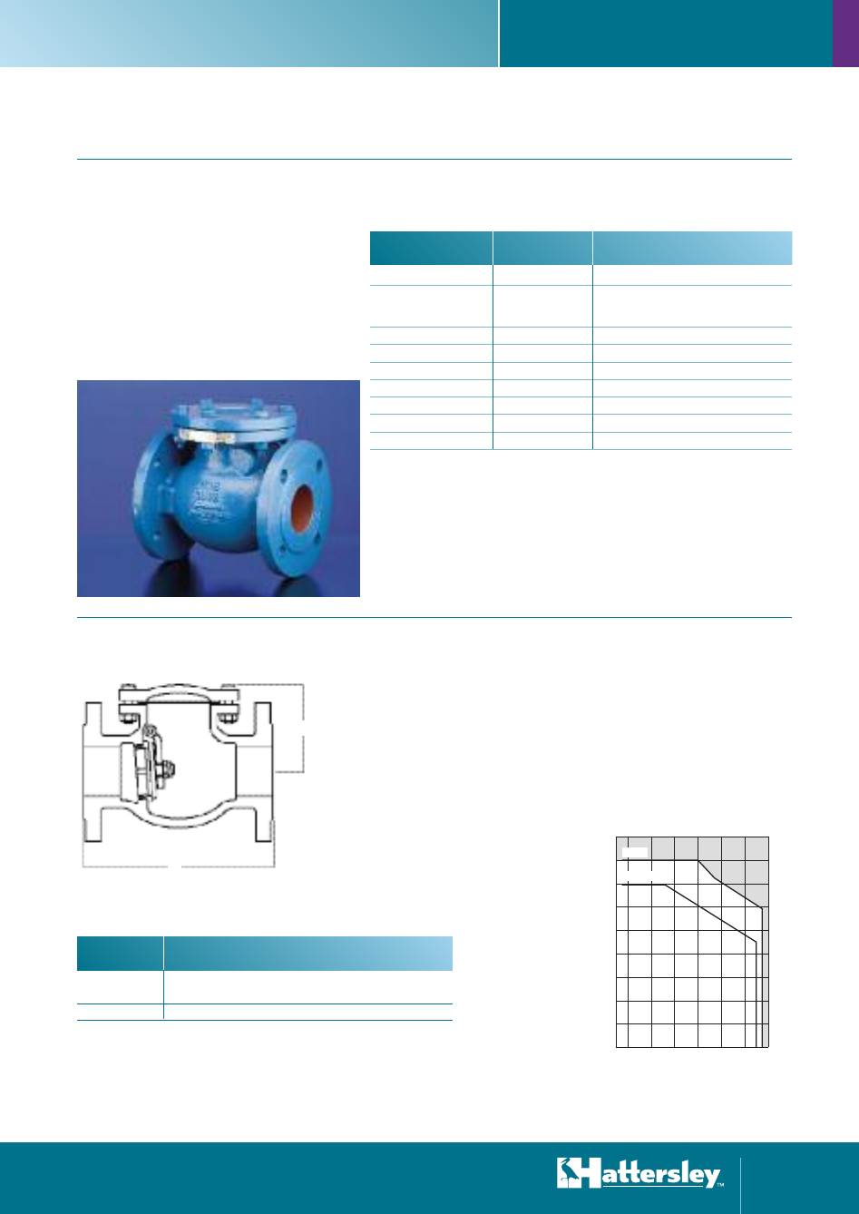
Technical Helpline: 0845 604 1790
E: tech-enquiries@hattersley.com W: www.hattersley.com
119
CHECK VALVES
PN16
Every effort has been made to ensure that the information contained in this publication is accurate at the time of publishing.
Hattersley Ltd assumes no responsibility or liability for typographical errors or omissions or for any misinterpretation of the
information within the publication and reserves the right to change without notice.
Fig. M651
Cast Iron - Swing Pattern
DIMENSIONAL DRAWINGS PRESSURE/
TEMPERATURE RATING
BS EN 1092-2 PN16
16 bar from -10 to 120ºC
11.8 bar at 230ºC
TEST PRESSURES
Seat: 17.6 bar (hydraulic)
Body: 24 bar (hydraulic)
SPECIFICATION
BS EN 12334:2001.
Face to Face dimensions to BS EN 558-1
basic series 10.
Cast iron body.
Bolted cover.
Bronze trim.
Suitable for mounting in horizontal and vertical
pipes (with the flow upwards).
Flanged to BS EN 1092-2 PN16.
Flanges drilled to BS 10 available.
MATERIAL SPECIFICATION
Cover Cast Iron 1561 EN JLI040 A126 CI B
Cover Gasket Reinforced
Compressed
Graphite
Hinge Pin Brass 12164 CW603N B16-C36000
Hinge Pin Plug Brass 12164 CW603N B16-C36000
Hinge Ductile Iron 1563 EN-JS1040 A536 70-50-05
Disc Cast Iron 1561 EN JLI040 A126 CI B
Disc Face Ring Bronze 1982 CC491K B62-C83600
Body Seat Ring Bronze 1982 CC491K B62-C83600
Body Cast Iron 1561 EN JLI040 A126 CI B
Component Material Specification
BS EN ASTM
FEATURES AND BENEFITS
• Suitable for velocities of up to 3 metres/second
• Ideal for water or other liquids
• Bolted cover
• Suitable for mounting in horizontal
and vertical pipelines
PN16
ANSI 125
0 40 80 120 160 200 240
Temperature ˚C
18
16
14
12
10
8
6
4
2
0
Pressure bar
A
B
Nom
Size mm 50 65 80 100 125 150 200 250 300
A mm 203 216 241 292 330 356 495 622 699
B mm 113 133 143 163 197 212 257 298 330
Weight kg 13 18 21 35 48 68 113 218 282
DIMENSIONS AND WEIGHTS
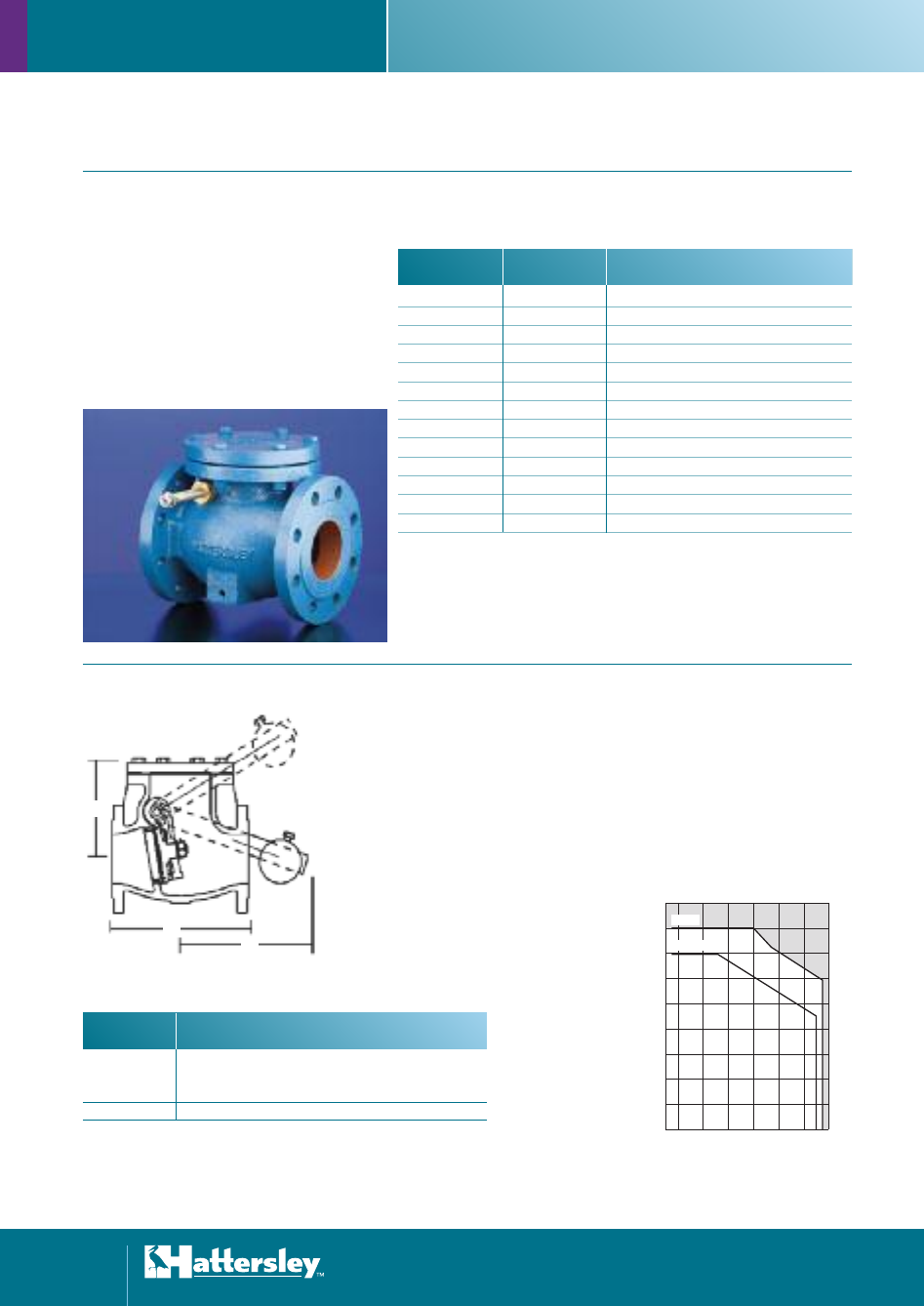
Technical Helpline: 0845 604 1790
E: tech-enquiries@hattersley.com W: www.hattersley.com
120
CHECK VALVES
PN16 ANSI 125
Every effort has been made to ensure that the information contained in this publication is accurate at the time of publishing.
Hattersley Ltd assumes no responsibility or liability for typographical errors or omissions or for any misinterpretation of the
information within the publication and reserves the right to change without notice.
Fig. M653
Cast Iron with Lever and Weight
DIMENSIONAL DRAWINGS PRESSURE/
TEMPERATURE RATING
BS EN 12334:2001 PN16
16 bar from -10 to 120ºC
BS 5153 ANSI
11.8 bar at 230ºC
9 bar at 218ºC
13.8 bar from -10 to 66ºC
TEST PRESSURES
PN16
Shell: 24 bar
Seat: 17.6 bar
Class 125
Shell: 24.1 bar
Seat: 13.8 bar
SPECIFICATION
Flanged to BS EN 1092-2 PN16 and bolted cover
Outside lever and adjustable weight.
If valve fig number M653 is to be used in a vertical
pipeline this must meet ANSI B16.1 Class 125.
Copper alloy trim.
Suitable for mounting in horizontal and vertical
pipelines (with vertical flow upwards).
BS EN 12334:2001 PN16.
be stated on order so that the lever and weight
assembly can be positioned accordingly.
MATERIAL SPECIFICATIONFEATURES AND BENEFITS
• Lever and weight offers the ability to alter
the flow resistance
• Bolted cover
• Suitable for mounting in horizontal and
vertical pipelines
• Flanged to BS EN 1092-2
Cover Cast Iron 1561 EN-JLI030 A126 CI B
Cover Gasket Asbestos Free
Hinge Pin Plug Stainless Steel 10270 X10CrNr18-8 A276-304
Hinge Ductile Iron 1561 EN JS1050
Gland Packing Asbestos Free
Disc Cast Iron 1561 EN-JLI030 A126 CI B
Disc Face Ring Bronze
Body Ring Bronze
Body Cast Iron 1561 EN-JLI030 A126 CI B
Counter Weight Cast Iron 1561 EN-JLI030 A126 CI B
Operating Shaft Stainless Steel 10088-1 X2 CrNiNo17-12-2 A276-316L
Operating Lever Stainless Steel 10270 X10CrNr18-8 A276-304
Spring Stainless Steel 10270 X10CrNr18-8 A276-304
Component Material Specification
BS EN ASTM
Nom
Size mm 50 65 80 100 125 150 200 250 300
A mm 203 216 241 292 330 356 495 622 699
B mm 121 135 141 168 182 215 267 305 343
C mm 200 200 215 250 300 290 580 730 720
Weight kg 21 27 33 45 66 86 152 244 320
DIMENSIONS AND WEIGHTS
PN16
ANSI 125
0 40 80 120 160 200 240
Temperature ˚C
18
16
14
12
10
8
6
4
2
0
Pressure bar
A
B
C
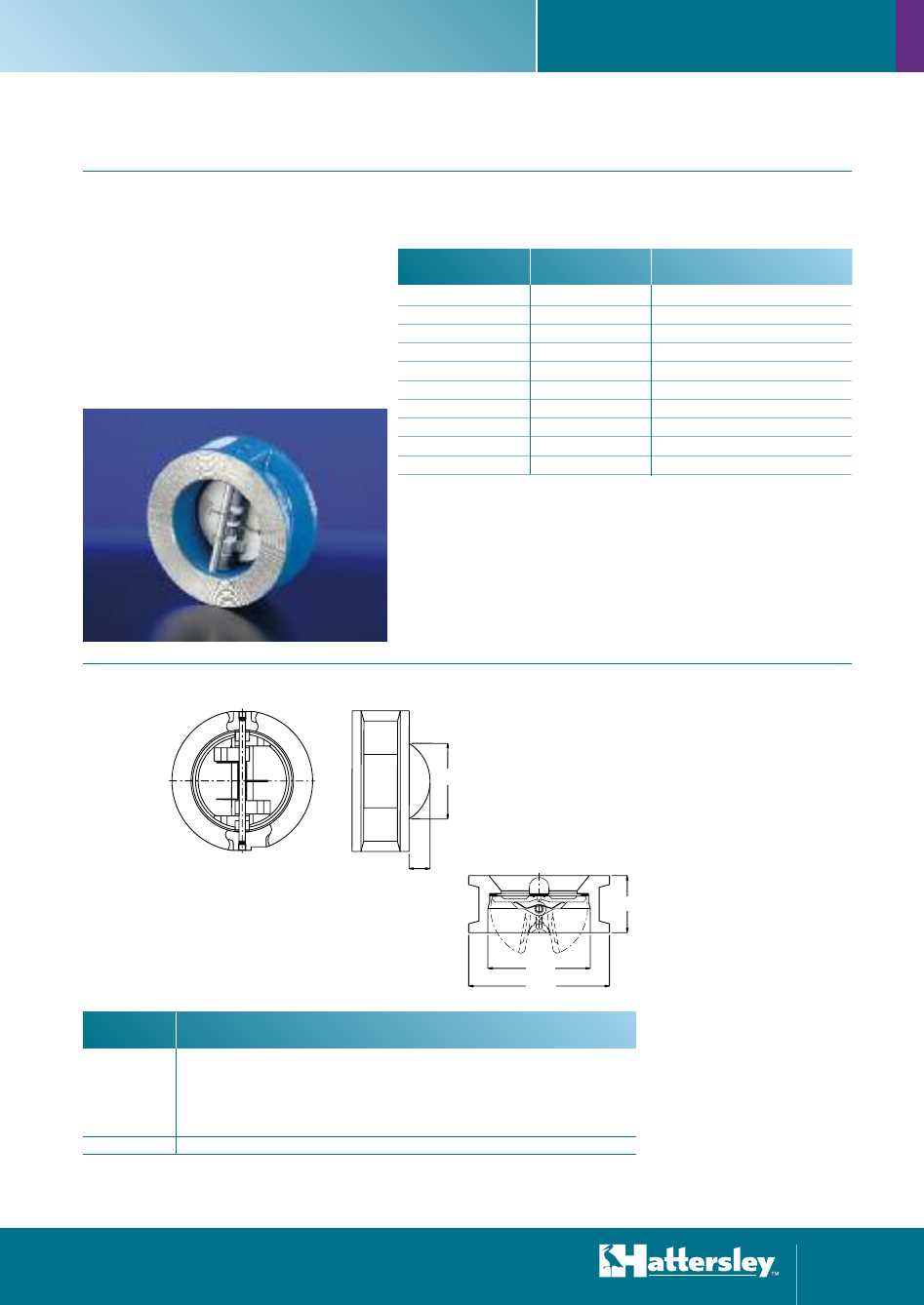
Technical Helpline: 0845 604 1790
E: tech-enquiries@hattersley.com W: www.hattersley.com
121
CHECK VALVES
PN16
Every effort has been made to ensure that the information contained in this publication is accurate at the time of publishing.
Hattersley Ltd assumes no responsibility or liability for typographical errors or omissions or for any misinterpretation of the
information within the publication and reserves the right to change without notice.
Fig. 850
Cast Iron - Wafer Pattern
DIMENSIONAL DRAWINGS PRESSURE/
TEMPERATURE
RATING
16 bar up to 120°C
TEST PRESSURES
(HYDRAULIC)
Shell: 24 bar
Seat: 17.6 bar
SPECIFICATION
Face-to-face in accordance with
BS 5155 (long pattern) ISO 5752
(long pattern).
Suitable for fitting between flanges
to BS 4504 PN10/16. ANSI B16.1
Class 125 and BS 10 Table D/E.
Sizes 250mm and above are fitted
with an eyebolt.
MATERIAL SPECIFICATIONFEATURES AND BENEFITS
• Double door wafer pattern with spring
assisted closure
• Elastomer seat vulcanised to the body
casting to ensure extended seal life
• Suitable for mounting in horizontal and
vertical pipelines
• Ideal for fitting between flanges to
BS EN 1092-2
Body Cast Iron BS1452 GR220
Seat EPDM
Disc Gunmetal BS1400 LG2
Shaft Stainless Steel BS970 BS970 304 S12
Spring Stainless Steel BS970 BS970 304 S12
Washer Stainless Steel
Seal EPDM
Setscrew Stainless Steel
Stop Pin Stainless Steel BS970 304 S12
Bushing Teflon
Component Material Specification
BS EN
Ø/C
E
Ø/D
Ø/A
B
Nom
Size mm 65 80 100 125 150 200 250 300 350 400 450 500 600
A mm 118 140 158 188 212 268 325 375 430 475 528 580 690
B mm 45 64 64 70 76 89 114 114 127 140 150 152 178
C mm 59 69 90 110 136 185 225 278 331 381 430 475 575
D mm 84 100 115 135 160 210 256 306 356 406 460 510 610
E mm 13.7 15.7 25.2 33.7 43.2 61.2 71.7 96.7 121.7 146.7 155 175 195
Weight kg 3 4 5 6 9 13 23 31 48 62 86 104 181
DIMENSIONS AND WEIGHTS
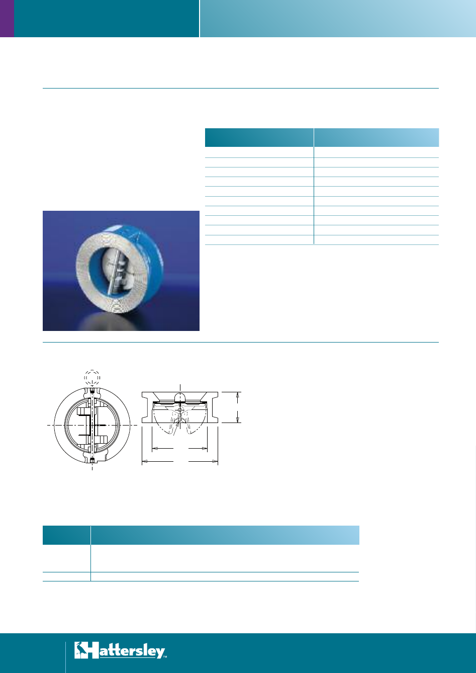
Technical Helpline: 0845 604 1790
E: tech-enquiries@hattersley.com W: www.hattersley.com
122
CHECK VALVES
PN25
Every effort has been made to ensure that the information contained in this publication is accurate at the time of publishing.
Hattersley Ltd assumes no responsibility or liability for typographical errors or omissions or for any misinterpretation of the
information within the publication and reserves the right to change without notice.
Fig. 850
Cast Iron - Wafer Pattern
DIMENSIONAL DRAWINGS PRESSURE/
TEMPERATURE
RATING
25 bar up to 120°C
TEST PRESSURES
(HYDRAULIC)
Shell: 37.5 bar
Seat: 27.5 bar
SPECIFICATION
Face-to-face in accordance with
BS 5155 (long pattern) ISO 5752
(long pattern).
Suitable for fitting between flanges
to BS 4504 PN10/16. ANSI B16.1
Class 125 and BS 10 Table D/E.
Sizes 150mm and above are fitted
with an eyebolt.
MATERIAL SPECIFICATIONFEATURES AND BENEFITS
• Double door wafer pattern with spring
assisted closure
• Elastomer seat vulcanised to the body
casting to ensure extended seal life
• Suitable for mounting in horizontal and
vertical pipelines
• Ideal for fitting between flanges to
BS EN 1092-2
Body A536 65-45-12
Plate B584 C83600
Spring SUS 316
Hinge Pin SUS 304
Stop Pin SUS 304
Retainer A105
Body Bearing SUS 304
Plate Bearing SUS 304
Eye Bolt A105
Seat EPDM
Component Specification
BS EN
C
Ø/B
Ø/A
Nom
Size DN 40 50 65 80 100 125 150 200 250 300 350 400 450 500 600
A mm 86 105 124 137 168 194 222 276 340 400 457 507 565 625 731
B mm 60 60 73 89 114 141 168 219 273 324 356 406 457 508 610
C mm 43 54 54 57 64 70 76 95 108 143 184 191 203 213 222
Weight kg 1.8 2.5 3.5 4.5 8 10 13 28 45 68 95 132 147 202 265
DIMENSIONS AND WEIGHTS
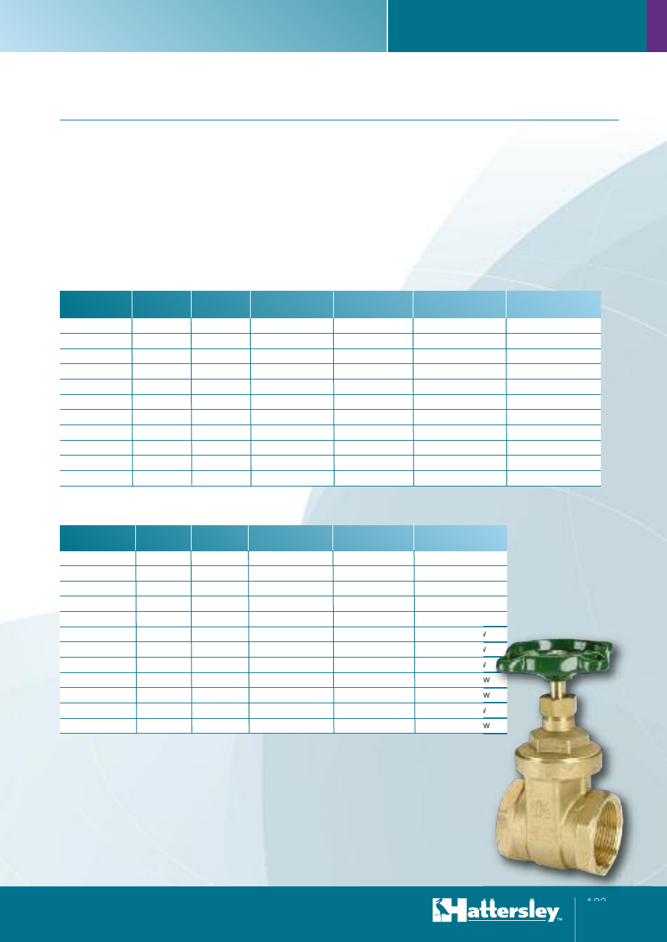
Technical Helpline: 0845 604 1790
E: tech-enquiries@hattersley.com W: www.hattersley.com
123
GATE VALVES
Gate Valves
Hattersley gate valves offer the ultimate in
dependable service wherever minimum pressure
drop is important.
They serve as efficient stop valves with fluid flow in
either direction. The straight through design offers
little resistance to flow and reduces pressure drop
to a minimum. A gate-like disc - actuated by a
stem screw and handwheel - moves up and down
at right angles to the path of flow, and seats
against two seat faces to shut off the flow. Gate
valves are not recommended for throttling since
the control characteristic is not appropriate and
subsequent damage, due to erosion, may prevent
the valve providing an effective shut off.
Fig. No. PN Series End Size Bonnet Wedge
Rating Connections Range Pattern Material
35 PN16† 16 B Flanged 15 - 100mm Threaded Bronze
30C† 16 B Compression 15 - 54mm Threaded Bronze
30CLS† 16 B Compression 15 - 54mm Threaded Bronze
30*† 20 B Threaded 1/4 - 3" Threaded DZR Alloy
30LS*† 20 B Threaded 1/4 - 3" Threaded DZR Alloy
33X*† 20 B Threaded 1/4 - 4" Threaded Bronze
33XLS*† 20 B Threaded 1/4 - 4" Threaded Bronze
33* 32 B Threaded 1/4 - 3" Threaded Bronze
669 32 B Threaded 1/4 - 2" Union Bronze
28 - - Threaded 1/2 - 3" Threaded Bronze
609 32 A Threaded 1/4 - 3" Threaded Bronze
Fig. No. PN Class End Size Pattern
Rating Rating Connections Range
M549 PN6 6 - Flanged 50 - 300mm Inside Screw
M549E - 100 Flanged 2 - 12" Inside Screw
M552 PN6 6 - Flanged 50 - 300mm Outside Screw
M552E - 100 Flanged 2 - 12" Inside Screw
1552 PN6 6 - Flanged 50 - 300mm Outside Screw
M511 PN10 10 - Flanged 50 - 150mm Inside Screw
M541 PN16 16 - Flanged 50 - 400mm Inside Screw
1541 PN16 16 - Flanged 50 - 400mm Inside Screw
M544 PN16 16 - Flanged 50 - 300mm Outside Screw
M540 PN25 25 - Flanged 50 - 150mm Outside Screw
501 ANSI - 125 Flanged 2 - 12" Inside Screw
504 ANSI - 125 Flanged 2 - 12" Outside Screw
Alternative Trim Materials
Prefix 1: All Iron Prefix 4: Stainless Steel Prefix 5: Aluminium Bronze
† WRAS Approved Product
* Kitemarked to the relevant British Standard
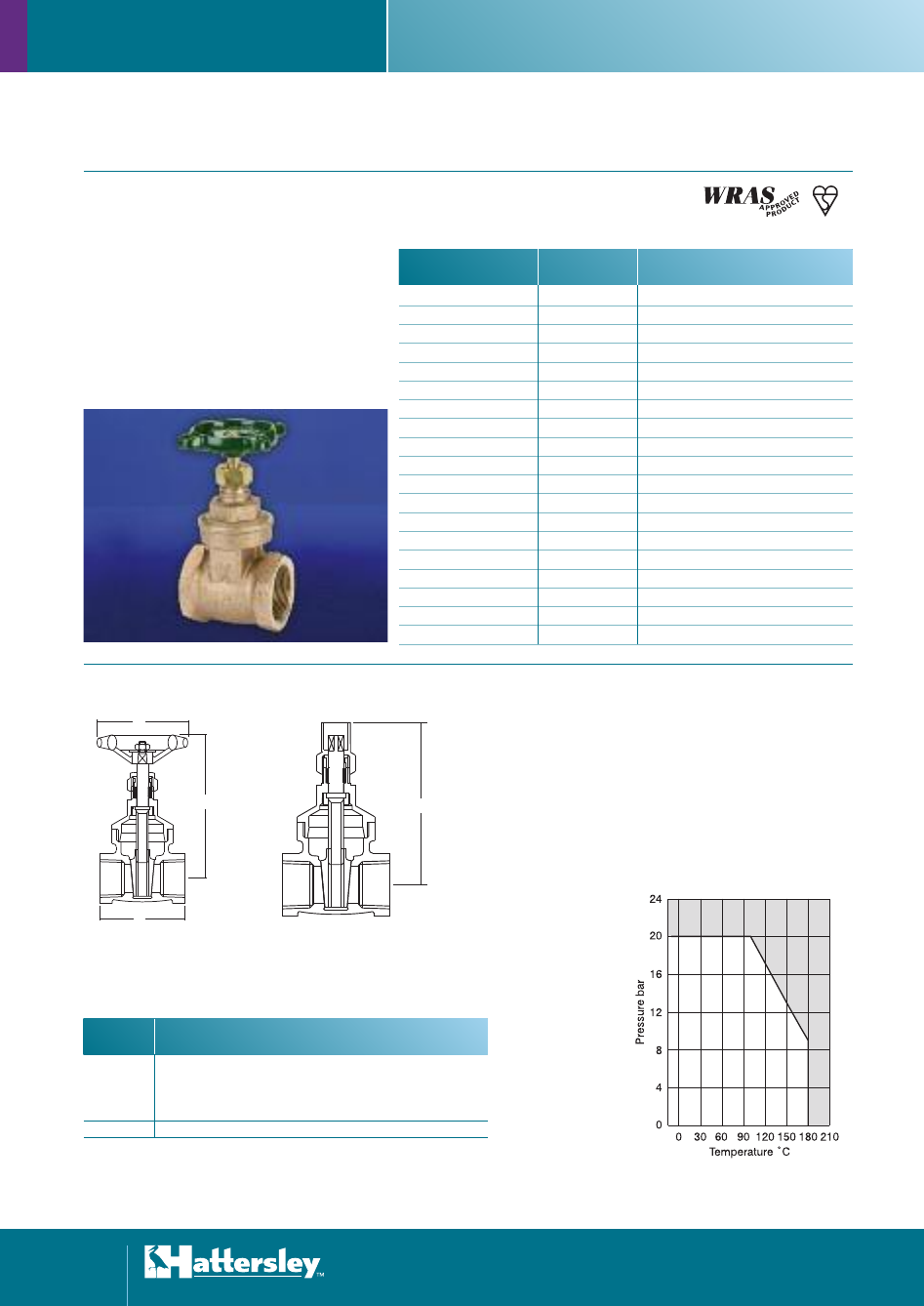
Technical Helpline: 0845 604 1790
E: tech-enquiries@hattersley.com W: www.hattersley.com
124
GATE VALVES
PN20 SERIES B
Every effort has been made to ensure that the information contained in this publication is accurate at the time of publishing.
Hattersley Ltd assumes no responsibility or liability for typographical errors or omissions or for any misinterpretation of the
information within the publication and reserves the right to change without notice.
Fig. 33X - 33XLS
Bronze
DIMENSIONAL DRAWINGS SPECIFICATION
Kitemarked to BS EN 12288:2010.
WRAS Approved Product.
Non-rising stem.
Threaded bonnet.
One piece wedge.
Taper threaded BS EN 10266 (ISO 7-1)
formerly BS 21.
Available with NPT thread (33XAT) 1/2 to 4".
Available with lockshield (33XLS) up to 2".
MATERIAL SPECIFICATION
Body Bronze 1982 CC491K B505 C83600
Bonnet Bronze 1982 CC491K B62 C83600
Stem (1/4" to 2") DZR Brass 12164 CW602N
Stem (21/2" & 3") Brass 12164 CW614N
Stem (4") Al Bronze 12163 CW301G B150 C64200
Disc Bronze 1982 CC491K B505 C83600
Stuffing Box (1/4" to 2") DZR Brass 12164 CW602N
Stuffing Box (21/2" & 3") Brass 12165 CW617N B124 C37700
Stuffing Box 4" Bronze 1982 CC491K B505 C83600
Packing Ring Asbestos Free
Gland (1/2" to 3") Brass 12164 CW614N
Gland (4") Bronze 1982 CC491K B62 C83600
Lockshield Cap Brass 12164 CW614N
Packing Nut (1/2" to 3") Brass 12164 CW614N
Packing Nut (4") Bronze 1982 CC491K B62-C83600
Handwheel Aluminium
Identification Plate Aluminium
Gasket Fibre
Handwheel Nut Brass 12164 CW614N
Component Material Specification
BS EN ASTM
FEATURES AND BENEFITS
• Robust and high quality bronze body with
integral seating surfaces
• Kitemarked to BS EN 12288
• WRAS approved for use with potable water
• Inside screw pattern with non-rising stem
Nom
Size in 1/4 3/8 1/2 3/4 1 11/4 11/2 2 21/2 3 4
A mm 46 46 51 55 63 71 73 83 96 105 162
B mm 75 75 82 95 118 144 166 190 219 259 366
C mm 57 57 5 69 69 76 81 94 140 150 232
D mm 87 87 86 112 124 149 175 196 - - -
Weight kg 0.27 0.26 0.35 0.55 0.84 1.18 1.66 2.55 4.30 6.4 18.37
A
B
C
D
33X 33XLS
DIMENSIONS AND WEIGHTS
PRESSURE/
TEMPERATURE
RATING
BS EN 12288 PN20 Series B
9 bar at 180ºC
20 bar from -10 to 100ºC
TEST PRESSURES
(HYDRAULIC)
Air Seat: 6 bar
Shell: 6 bar
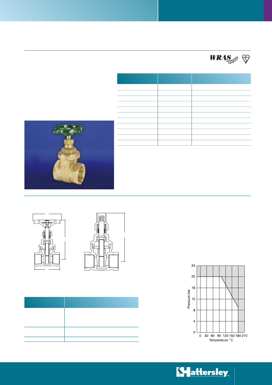
Technical Helpline: 0845 604 1790
E: tech-enquiries@hattersley.com W: www.hattersley.com
125
GATE VALVES
PN20 SERIES B
Every effort has been made to ensure that the information contained in this publication is accurate at the time of publishing.
Hattersley Ltd assumes no responsibility or liability for typographical errors or omissions or for any misinterpretation of the
information within the publication and reserves the right to change without notice.
Fig. 30 - 30LS
DZR
DIMENSIONAL DRAWINGS SPECIFICATION
Kitemarked to BS EN 12288:2010.
WRAS Approved Product.
Non-rising stem.
Threaded bonnet.
One piece wedge.
Taper threaded BS EN 10266 (ISO 7-1)
formerly BS 21.
Available with lockshield (30LS).
Available with NPT thread (30AT).
MATERIAL SPECIFICATION
DIMENSIONS AND WEIGHTS
FEATURES AND BENEFITS
• Dezincification Resistant Brass prevents
corrosion and fungal growth
• Kitemarked to BS EN 12288
• WRAS approved for use with potable water
• Inside screw pattern with non-rising stem
Nom
Size in 1/2 3/4 1 11/4 11/2 2
A mm 51.6 56 64 72 75 91
B mm 90 100 120 125 145 170
C mm 56.8 56.8 69.2 69.2 75.5 81.5
D mm 80 85 105 110 130 155
Lockshield key Fig. 391 391 391 391 391 391
Ref A A 2 2 2A 3
Weight kg 0.32 0.45 0.7 1.22 1.55 2.45
A
B
C
E
30LS
30
Handwheel Nut Brass 12164 CW614N
Identification Plate Aluminium
Handwheel Aluminium
Stem DZR Brass 12164 CW602N
Packing Nut Brass 12164 CW614N
Gland Brass 12164 CW614N
Packing Ring Asbestos Free
Body DZR Brass 12164 CW602N
Disc DZR Brass 12164 CW602N
Stuffing Box DZR Brass 12164 CW602N
Bonnet DZR Brass 12164 CW602N
Component Material Specification
BS EN
PRESSURE/
TEMPERATURE
RATING
BS EN 12288 PN20 Series B
9 bar at 180ºC
20 bar from -10 to 100ºC
TEST PRESSURES
(HYDRAULIC)
Air Seat: 6 bar
Shell: 6 bar
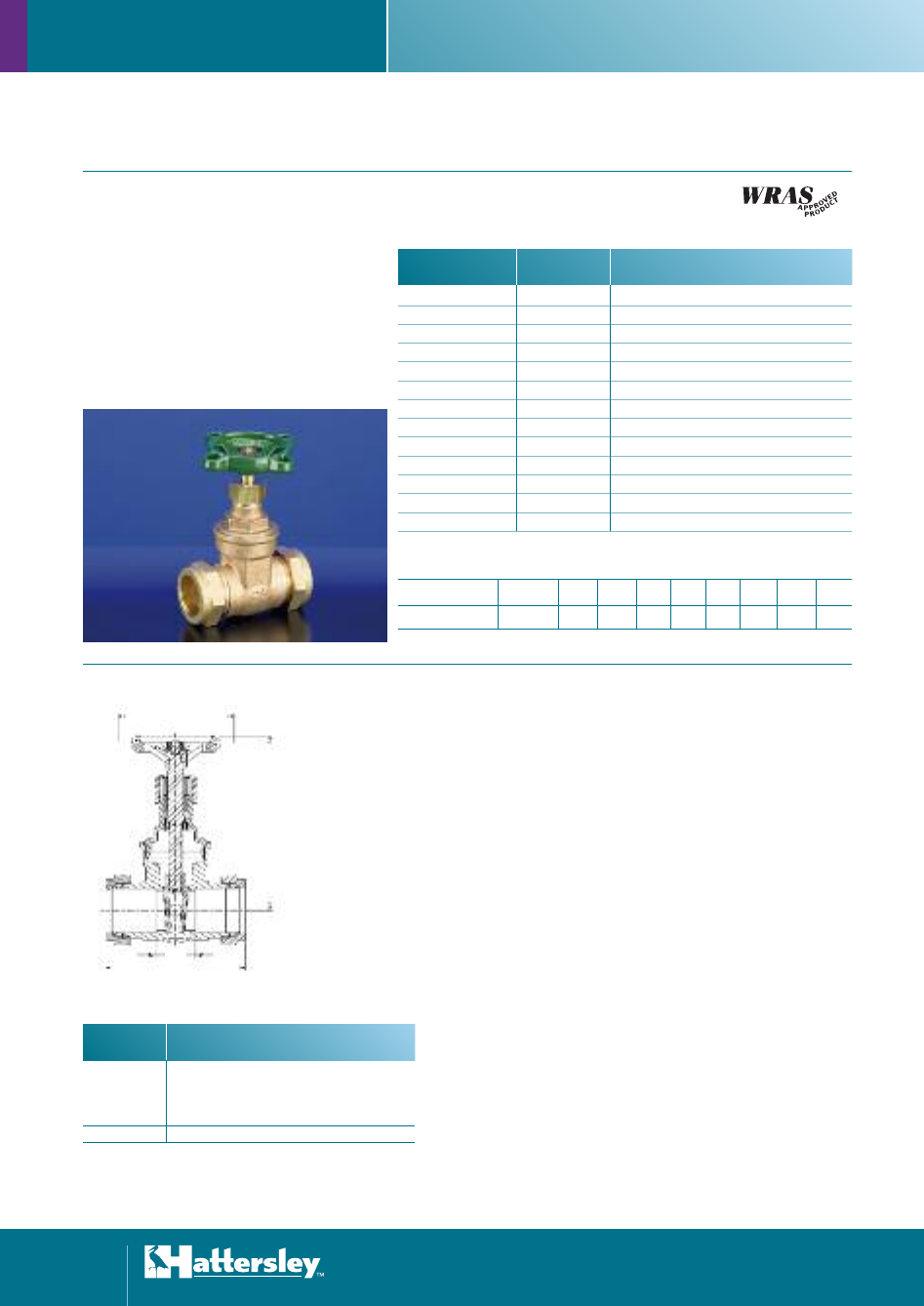
Technical Helpline: 0845 604 1790
E: tech-enquiries@hattersley.com W: www.hattersley.com
126
GATE VALVES
PN16
Every effort has been made to ensure that the information contained in this publication is accurate at the time of publishing.
Hattersley Ltd assumes no responsibility or liability for typographical errors or omissions or for any misinterpretation of the
information within the publication and reserves the right to change without notice.
Fig. 30C
Bronze
A
D
B
C
Across Protrusions
PRESSURE/TEMPERATURE RATINGS COMPRESSION
Temperature ˚C -10 to 30 40 50 65 80 90 100 110 120
Pressure bar 16 14.3 12.6 10 8.7 7.8 6.9 6 5
Intermediate pressure ratings shall be determined by interpolation.
DIMENSIONAL DRAWINGS
MATERIAL SPECIFICATION
PRESSURE/
TEMPERATURE RATING
PN16
TEST PRESSURES
(PNEUMATIC)
Seat: 6 bar
Shell: 6 bar
SPECIFICATION
UK End Connection: Compression ends to
BS EN 1057:2006: Half hard R250.
Operator: Handwheel.
Gate valves are best for services that require
infrequent valve operation and where the disc
is kept either fully open or closed. They are not
practical for throttling.
Valves are manufactured in accordance with
BS EN 12288: 2010 (formerly BS 5154) PN20
for Series B ratings, but are limited to the
pressure/temperature ratings detailed in
BS EN 1057:2006 for compression end
fittings.
This valve is to be used on Group 2 liquids
only, as defined by the Pressure Equipment
Directive 97/23/EC.
FEATURES AND BENEFITS
• Robust and high quality bronze body with
integral seating surfaces
• Offers the ultimate in dependable service
wherever minimum pressure drop is important
• WRAS Approved for use with potable water
• Inside screw pattern with non-rising stem
Nom
Size mm 15 22 28 35 42 54
A mm 69 75 86 100 111 133
B mm 74 86 105 110 130 152
C mm 48 69 76 81 94 100
D mm 26.5 23.5 25.5 30.5 34.5 37
Weight kg 0.34 0.50 0.70 0.95 1.45 2.50
DIMENSIONS AND WEIGHTS
Body Bronze BS EN 1982 (CC491K)
Bonnet Bronze BS EN 1982 (CC491K)
Stem DZR Brass BS EN 12164 CW602N
Disc Bronze BS EN 1982 (CC491K)
Stem Retainer DZR Brass BS EN 12164 CW602N
Packing Ring Asbestos Free
Gland (28-54 only) Brass BS EN 12164 CW614N
Packing Nut Brass BS EN 12164 CW614N
Handwheel Aluminium
Identification Plate Aluminium
Handwheel Nut Brass BS EN 12164 CW614N
Compression Olive Brass BS EN 12449:1999 CW505L OR CW507L
Compression Nut Brass BS EN 12165 CW617N
Component Material Specification
BS EN
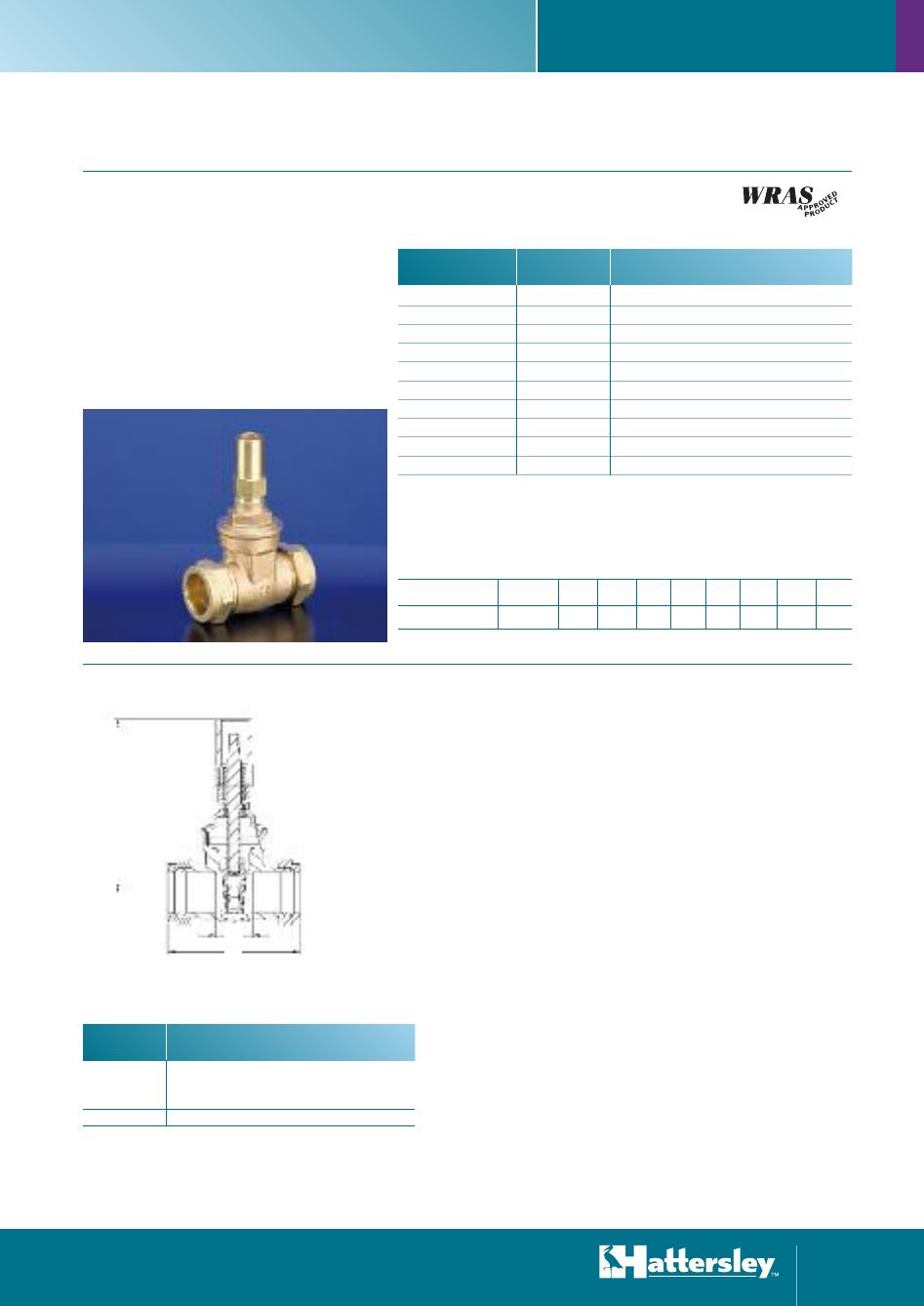
Technical Helpline: 0845 604 1790
E: tech-enquiries@hattersley.com W: www.hattersley.com
127
GATE VALVES
PN16
Every effort has been made to ensure that the information contained in this publication is accurate at the time of publishing.
Hattersley Ltd assumes no responsibility or liability for typographical errors or omissions or for any misinterpretation of the
information within the publication and reserves the right to change without notice.
Fig. 30CLS
Bronze
B
PRESSURE/TEMPERATURE RATINGS COMPRESSION
Temperature ˚C -10 to 30 40 50 65 80 90 100 110 120
Pressure bar 16 14.3 12.6 10 8.7 7.8 6.9 6 5
Intermediate pressure ratings shall be determined by interpolation.
DIMENSIONAL DRAWINGS PRESSURE/
TEMPERATURE RATING
PN16
TEST PRESSURES
(HYDRAULIC)
Seat: 6 bar
Shell: 6 bar
SPECIFICATION
UK End Connection: Compression ends to
BS EN 1057: 2006: Half hard R250.
Operator: Handwheel.
Gate valves are best for services that require
infrequent valve operation and where the disc
is kept either fully open or closed. They are
not practical for throttling.
Valves are manufactured in accordance with
BS EN 12288:2010 (formerly BS 5154)
PN20 for Series B ratings, but are limited to
the pressure/temperature ratings detailed in
BS EN 1057:2006 for compression end
fittings.
This valve is to be used on Group 2 liquids
only, as defined by the Pressure Equipment
Directive 97/23/EC.
FEATURES AND BENEFITS
• Robust and high quality bronze body with
integral seating surfaces
• Offers the ultimate in dependable service
wherever minimum pressure drop is important
• WRAS Approved for use with potable water
• Inside screw pattern with non-rising stem
Nom
Size mm 15 22 28 35 42 54
A mm 69 75 86 100 111 133
B mm 78 90 110 115 136 160
D mm 26.5 23.5 25.5 30.5 34.5 37
Weight kg 0.34 0.50 0.70 0.95 1.45 2.50
DIMENSIONS AND WEIGHTS
MATERIAL SPECIFICATION
Body Bronze BS EN 1982 (CC491K)
Bonnet Bronze BS EN 1982 (CC491K)
Stem DZR Brass BS EN 12164 CW602N
Disc Bronze BS EN 1982 (CC491K)
Stem Retainer DZR Brass BS EN 12164 CW602N
Packing Ring Asbestos Free
Gland (28-54 only) Brass BS EN 12164 CW614N
Lockshield Brass BS EN 12164 CW614N
Compression Olive Brass BS EN 12449:1999 CW505L OR CW507L
Compression Nut Brass BS EN 12165 CW617N
Component Material Specification
BS EN
A
D
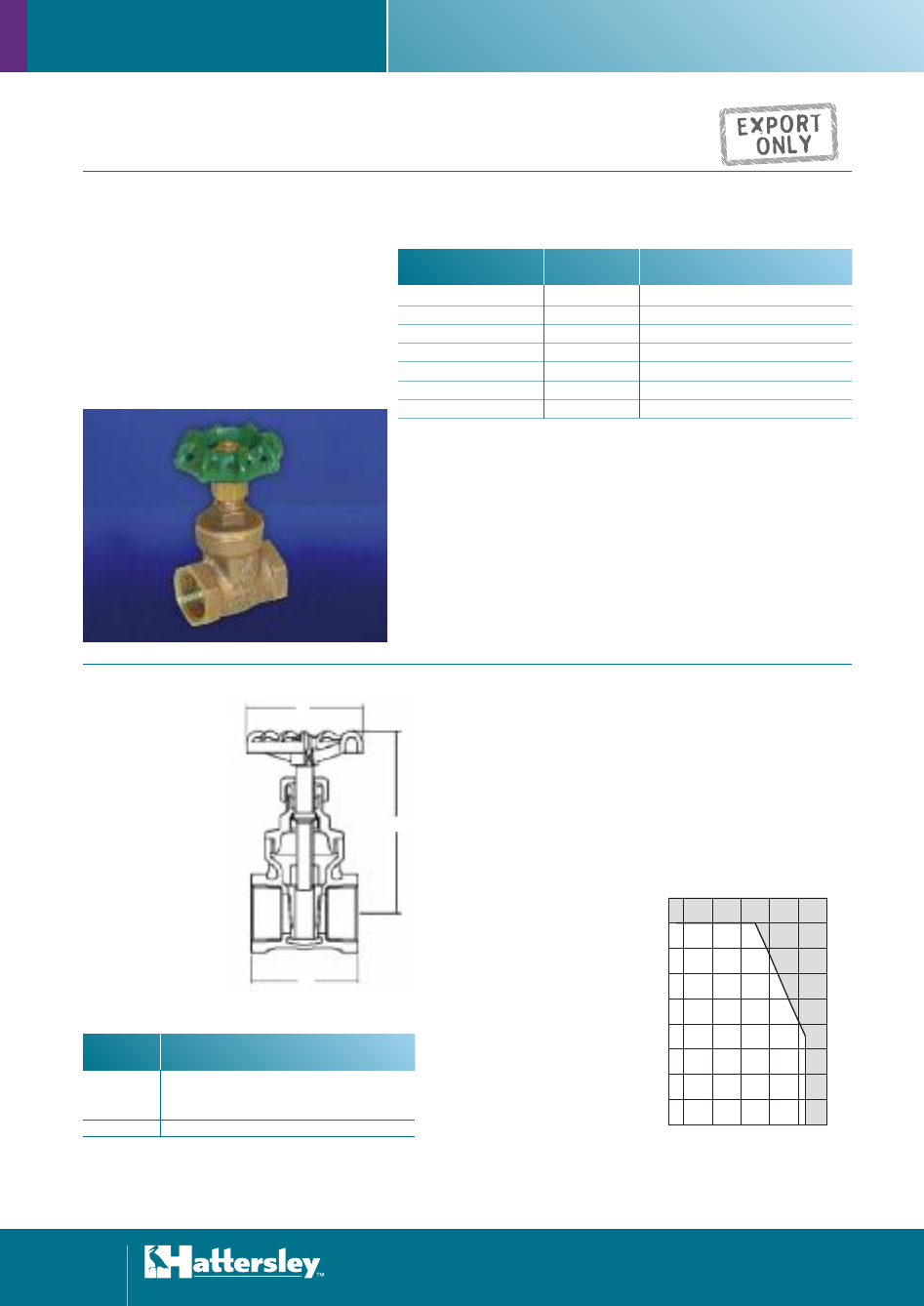
Technical Helpline: 0845 604 1790
E: tech-enquiries@hattersley.com W: www.hattersley.com
128
GATE VALVES
PN16 SERIES B
Every effort has been made to ensure that the information contained in this publication is accurate at the time of publishing.
Hattersley Ltd assumes no responsibility or liability for typographical errors or omissions or for any misinterpretation of the
information within the publication and reserves the right to change without notice.
Fig. C31
Bronze
DIMENSIONAL DRAWINGS PRESSURE/
TEMPERATURE RATING
7 bar at 170°C
16 bar from -10 to 100°C
TEST PRESSURES
(HYDRAULIC)
Each valve is individually hydrostatically
tested to BS EN 12266 at the following test.
Shell: 24 bar
Seat: 17.6 bar
SPECIFICATION
Bronze body and bonnet.
Non-rising stem.
Threaded bonnet.
One piece wedge.
Taper threaded BS EN 10226 (ISO 7-1)
formerly BS 21.
Available with NPT thread (C31AT)
subject to minimum quantities.
Generally in accordance with
BS EN 12266.
MATERIAL SPECIFICATIONFEATURES AND BENEFITS
• Robust and high quality bronze body with
integral seating surfaces
• Inside screw pattern with rising stem
• Suitable for high pressures up to 16 bar
Handwheel Cast Iron 1561 EN-JL1030 A126 CI B
Stem Brass 12164 CW603N B16 C36000
Gland Packing PTFE
Stem Ring Brass 12164 CW603N B16 C36000
Bonnet Bronze 1982 CC490K B584 C84400
Wedge Bronze 1982 CC490K B584 C84400
Body Bronze 1982 CC490K B584 C84400
Component Material Specification
BS EN ASTM
Nom
Size in 1/2 3/4 1 11/4 11/2 2
A mm 53 57 64 70 74 85
B mm 75 84 95 116 127 151
C mm 54 58 64 70 74 85
Weight kg 0.3 0.4 0.6 0.8 0.9 1.5
DIMENSIONS AND WEIGHTS
0 40 80 120 160 200
T empe r ature ˚ C
18
16
14
12
10
8
6
4
2
0
Pressure bar
A
B
C

Technical Helpline: 0845 604 1790
E: tech-enquiries@hattersley.com W: www.hattersley.com
129
GATE VALVES
PN32 SERIES B
Every effort has been made to ensure that the information contained in this publication is accurate at the time of publishing.
Hattersley Ltd assumes no responsibility or liability for typographical errors or omissions or for any misinterpretation of the
information within the publication and reserves the right to change without notice.
Fig. 33
Bronze
DIMENSIONAL DRAWINGS PRESSURE/
TEMPERATURE RATING
BS EN 12288 PN32 Series B
14 bar at 198ºC
32 bar from -10 to 100ºC
TEST PRESSURES
(HYDRAULIC)
Shell: 48 bar
Seat: 35.2 bar
SPECIFICATION
Kitemarked to BS EN 12288:2010.
Non-rising stem.
Threaded bonnet.
One piece wedge.
Taper threaded BS EN 10226 (ISO 7-1)
formerly BS 21.
Available with NPT thread (33AT)
1/2 to 3".
MATERIAL SPECIFICATIONFEATURES AND BENEFITS
• Robust and high quality bronze body with
integral seating surfaces
• Kitemarked to BS EN 12288
• Inside screw pattern with non-rising stem
• Suitable for high pressures up to 32 bar
0 40 80 120 160 200 240
T emperature ˚ C
28
24
20
16
12
4
0
Pressure bar
8
32
36
A
B
C
Nom
Size in 1/4 3/8 1/2 3/4 1 11/4 11/2 2 21/2 3
A mm 46 46 51 55 63 71 73 83 108 117
B mm 78 78 86 98 120 148 172 196 241 256
C mm 60 60 70 80 85 95 102 120 140 150
Weight kg 0.36 0.35 0.47 0.6 0.92 1.41 1.92 2.72 5.62 7.89
DIMENSIONS AND WEIGHTS
Disc Bronze 1982 CC491K B62 C83600
Packing Ring Asbestos Free
Handwheel Aluminium
Gland Brass 12164 CW614N B455 C38500
Stuffing Box DZR Brass 12164 CW602N
Stem DZR Brass 12164 CW602N
Stem (21/2" & 3") Al Bronze 12163 CW301G B150 C64200
Bonnet Bronze 1982 CC491K B62 C83600
Body Bronze 1982 CC491K B62 C83600
Packing Nut Brass 12164 CW614N
Identification Plate Aluminium
Handwheel Nut Brass 12164 CW614N
Component Material Specification
BS EN ASTM
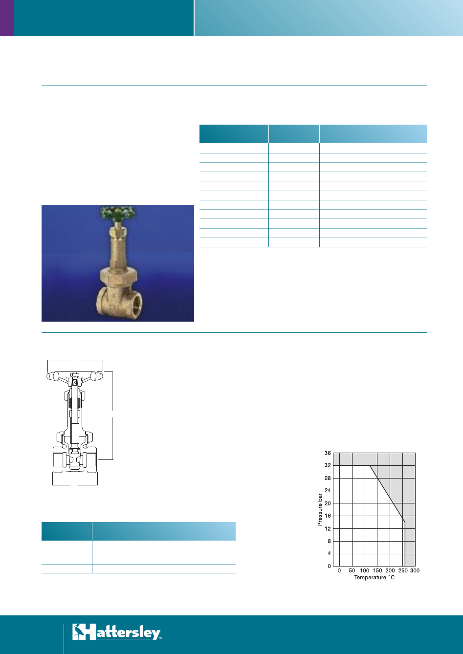
Technical Helpline: 0845 604 1790
E: tech-enquiries@hattersley.com W: www.hattersley.com
130
GATE VALVES
PN32 SERIES B
Every effort has been made to ensure that the information contained in this publication is accurate at the time of publishing.
Hattersley Ltd assumes no responsibility or liability for typographical errors or omissions or for any misinterpretation of the
information within the publication and reserves the right to change without notice.
Fig. 669
Bronze
DIMENSIONAL DRAWINGS PRESSURE/
TEMPERATURE RATING
BS EN 12288 PN32 Series A
14 bar at 260ºC
32 bar from -10 to 120ºC
TEST PRESSURES
(HYDRAULIC)
Shell: 48 bar
Seat: 35.2 bar
SPECIFICATION
BS EN 12288:2010.
Rising stem.
Union bonnet.
One piece wedge.
Taper threaded BS EN 10226 (ISO 7-1)
formerly BS 21.
Available with NPT thread (669AT).
MATERIAL SPECIFICATION
Body Bronze 1982 CC491K B62 C83600
Packing Ring Asbestos Free
Bonnet Bronze 1982 CC491K B62 C83600
Stem Bronze 1982 CC491K B62 C83600
Disc Bronze 1982 CC491K B62 C83600
Gland Brass 12164 CW614N
Packing Nut Brass 12164 CW614N
Handwheel Aluminium
Handwheel Nut Brass 12164 CW614N
Union Ring Bronze 1982 CC491K B62 C83600
Identification Plate Aluminium
Component Material Specification
BS EN ASTM
FEATURES AND BENEFITS
• Robust and high quality bronze body with
integral seating surfaces
• Inside screw pattern with rising stem
• Suitable for high pressures up to 32 bar
C
B
Nom
Size in 1/4 3/8 1/2 3/4 1 11/4 11/2 2
A mm 46 46 51 55 63 71 73 83
B mm 134 134 137 169 194 232 266 321
C mm 69 69 76 81 94 100 120 140
Weight kg 0.32 0.31 0.46 0.72 1.10 1.50 2.25 3.20
DIMENSIONS AND WEIGHTS
A
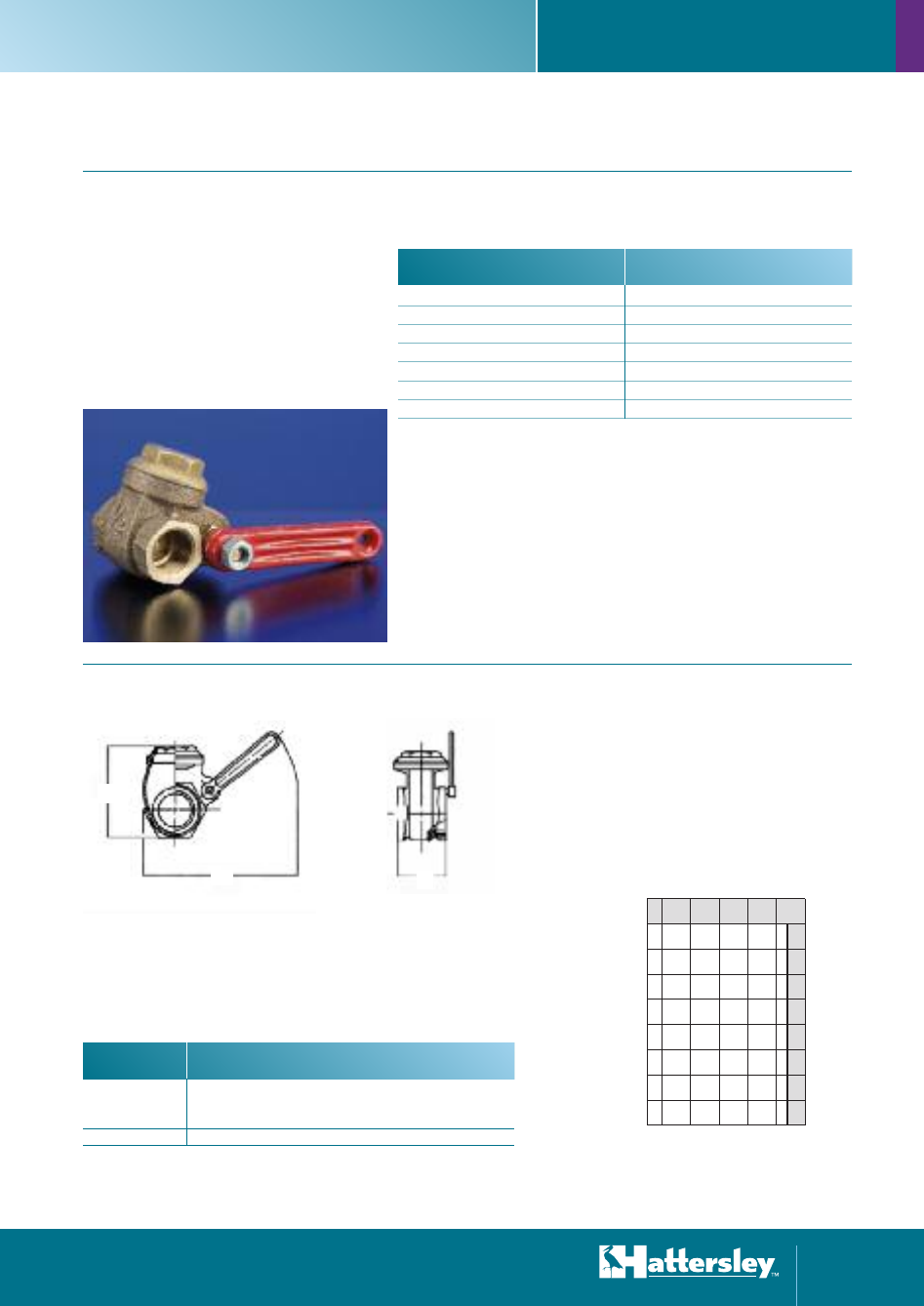
Technical Helpline: 0845 604 1790
E: tech-enquiries@hattersley.com W: www.hattersley.com
131
GATE VALVES
PN16
Every effort has been made to ensure that the information contained in this publication is accurate at the time of publishing.
Hattersley Ltd assumes no responsibility or liability for typographical errors or omissions or for any misinterpretation of the
information within the publication and reserves the right to change without notice.
Fig. 28
Bronze - Lever operated
DIMENSIONAL DRAWINGS PRESSURE/
TEMPERATURE RATING
16 bar
-20°C to +90°C
SPECIFICATION
Screwed BSP.
Lever Operated.
Bronze Body up to 11/2".
Brass Body 2" to 4".
MATERIAL SPECIFICATIONFEATURES AND BENEFITS
• Robust and high quality bronze body with
integral seating surfaces
• Lever operated for ease of use
• Fitted with asbestos-free gland packing as
standard
Body Bronze / Brass
Wedge Brass
Lever Brass
Washer Brass
Plug Brass
O-Ring NBR
Gasket Fibre
Component Material
0 20 40 60 80 100
T emperature ˚ C
14
12
10
8
6
2
0
Pressure bar
4
16
18
H
L
Nom DN 15 20 25 32 40 50 65 80 100
Size in 1/2 3/4 1 11/4 11/2 2 21/2 3 4
L mm 46 51 57 61 67 75 80 86 92
H mm 57 66 76 88 96 115 150 170 210
D mm 130 147 155 184 215 230 355 370 400
Weight kg 0.39 0.56 0.78 1.10 1.42 1.62 2.85 3.80 5.80
DIMENSIONS AND WEIGHTS
D
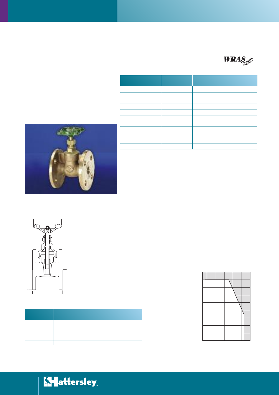
Technical Helpline: 0845 604 1790
E: tech-enquiries@hattersley.com W: www.hattersley.com
132
GATE VALVES
PN16 SERIES B
Every effort has been made to ensure that the information contained in this publication is accurate at the time of publishing.
Hattersley Ltd assumes no responsibility or liability for typographical errors or omissions or for any misinterpretation of the
information within the publication and reserves the right to change without notice.
Fig. 35
Bronze
DIMENSIONAL DRAWINGS PRESSURE/
TEMPERATURE RATING
BS 5154 PN16 Series
7 bar at 170ºC
16 bar from -10 to 100ºC
TEST PRESSURES
(HYDRAULIC)
Shell: 24 bar
Seat: 17.6 bar
SPECIFICATION
Non-rising stem.
Threaded bonnet.
One piece wedge.
Flanged to BS EN 1092-3 PN16.
MATERIAL SPECIFICATION
Gland Brass 12164 CW614N
Body Bronze 1982 CC491K B62 C83600
Bonnet Bronze 1982 CC491K B62 C83600
Stem Brass 12164 CW614N
Disc Bronze 1982 CC491K B62 C83600
Stuffing Box Brass 12165 CW617N B124 C37700
Packing Ring Graphite
Packing Nut Brass 12164 CW614N
Handwheel Aluminium
Identification Plate Aluminium
Handwheel Nut Brass 12164 CW614N
Component Material Specification
BS EN ASTM
FEATURES AND BENEFITS
• Robust and high quality bronze body with
integral seating surfaces
• Flanges ends require no pipe threading
• Inside screw pattern with non-rising stem
0 40 80 120 160 200
T empe r ature ˚ C
18
16
14
12
10
8
6
4
2
0
Pressure bar
A
C
B
D
Nom
Size mm 20 25 32 40 50 65 80 100
A mm 90 100 110 120 135 165 185 190
B mm 110 130 145 165 200 240 280 365
C mm 80 85 95 120 120 155 180 230
D mm 105 115 140 150 165 185 200 220
Weight kg 2.1 2.7 4.0 4.4 6.3 9.1 15.4 22.2
DIMENSIONS AND WEIGHTS
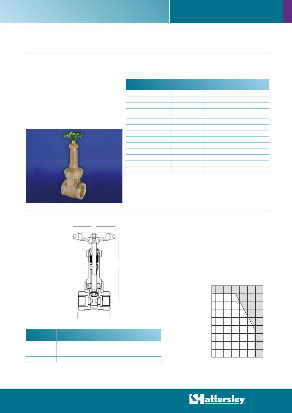
Technical Helpline: 0845 604 1790
E: tech-enquiries@hattersley.com W: www.hattersley.com
133
GATE VALVES
PN32 SERIES B
Every effort has been made to ensure that the information contained in this publication is accurate at the time of publishing.
Hattersley Ltd assumes no responsibility or liability for typographical errors or omissions or for any misinterpretation of the
information within the publication and reserves the right to change without notice.
Fig. 609
Bronze
PRESSURE/
TEMPERATURE RATING
14 bar at 198ºC
32 bar from -10 to 100ºC
TEST PRESSURES
(HYDRAULIC)
Each valve is individually hydrostatically
tested to BS EN 12266 at the following
test pressures.
Shell: 48 bar
Seat: 35.2 bar
SPECIFICATION
Rising stem.
Threaded bonnet.
One piece wedge.
Bronze trim.
Taper threaded BS EN 10226 (ISO 7-1)
formerly BS 21.
Complies with BS EN 12288:2010.
MATERIAL SPECIFICATIONFEATURES AND BENEFITS
• Robust and high quality bronze body with
integral seating surfaces
• Inside screw pattern with rising stem
• Suitable for high pressures up to 32 bar
Body Bronze 1982 CC491K B62 C83600
Bonnet Bronze 1982 CC491K B62 C83600
Stem (1/4" to 2") Bronze 1982 CC491K B62 C83600
Stem (21/2") AL. Brass
(CA 12) 12163 CW301G
Stem (3") Bronze 1982 CC491K B62 C83600
Disc Bronze 1982 CC491K B62 C83600
Packing Ring Asbestos Free
Gland Brass 12164 CW614N
Packing Nut (21/2" & 3") Brass 12164 CW721R
Packing Nut (1/4" to 2") Brass 12164 CW614N
Handwheel Aluminium
Identification Plate Aluminium
Handwheel Nut Brass 12164 CW614N
Component Material Specification
BS EN ASTM
Nom
Size in 1/4 3/8 1/2 3/4 1 11/4 11/2 2 21/2 3
A mm 46 46 51 55 63 71 73 83 108 117
B (open) mm 129 129 133 162 191 223 253 307 374 436
C mm 60 70 70 80 85 95 105 120 140 180
Weight kg 0.35 0.40 0.50 0.75 1.30 1.70 2.60 3.50 6.00 8.80
DIMENSIONS AND WEIGHTS
0 40 80 120 160 200 240
T emperature ˚ C
28
24
20
16
12
4
0
Pressure bar
8
32
36
A
B
C
DIMENSIONAL DRAWINGS
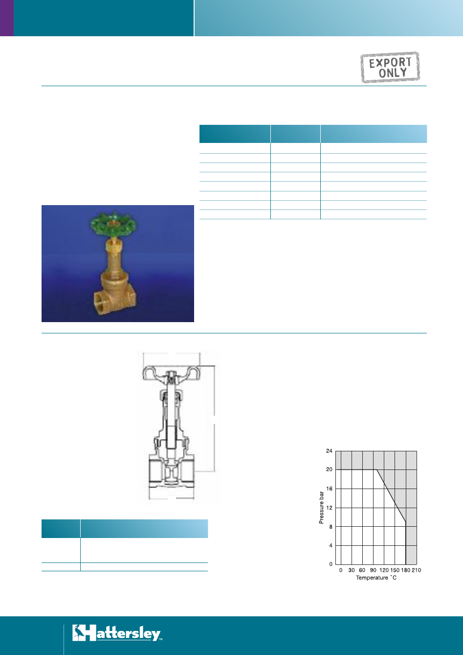
Technical Helpline: 0845 604 1790
E: tech-enquiries@hattersley.com W: www.hattersley.com
134
GATE VALVES
PN20 SERIES B
Every effort has been made to ensure that the information contained in this publication is accurate at the time of publishing.
Hattersley Ltd assumes no responsibility or liability for typographical errors or omissions or for any misinterpretation of the
information within the publication and reserves the right to change without notice.
Fig. C618
Bronze
DIMENSIONAL DRAWINGS PRESSURE/
TEMPERATURE RATING
9 bar at 180°C
20 bar from -10 to 100˚C
TEST PRESSURES
(HYDRAULIC)
Each valve is individually hydrostatically
tested to BS EN 12266 at the following
test pressures.
Shell: 30 bar
Seat: 22 bar
SPECIFICATION
Rising stem.
Threaded bonnet.
One piece wedge.
Bronze trim.
Taper threaded BS EN 10226 (ISO 7-1)
formerly BS 21.
Complies with BS EN 12288:2010.
Available with NPT thread (C618AT).
Complies with MSS SP-80 Class 150.
MATERIAL SPECIFICATION
Handwheel Cast Iron 1561 EN-JL1030 A126 CI B
Stem Copper Alloy 12164 CW714R B21-C48200
Gland Nut Copper Alloy 12164 CW603N B16-C36000
Gland Copper Alloy 12164 CW603N B16-C36000
Gland Packing PTFE
Bonnet Bronze 1982 CC491K B62-C83600
Body Bronze 1982 CC491K B62-C83600
Wedge Bronze 1982 CC491K B62-C83600
Component Material Specification
BS EN ASTM
FEATURES AND BENEFITS
• Robust and high quality bronze body with
integral seating surfaces
• Inside screw pattern with rising stem
• Suitable for high pressures up to 20 bar
Nom
Size in 1/2 3/4 1 11/4 11/2 2
A mm 48 52 59 64 68 75
B mm 117 140 167 195 222 264
C mm 53 64 73 80 90 102
Weight kg 0.35 0.53 0.75 1.05 1.41 2.03
DIMENSIONS AND WEIGHTS
A
C
B
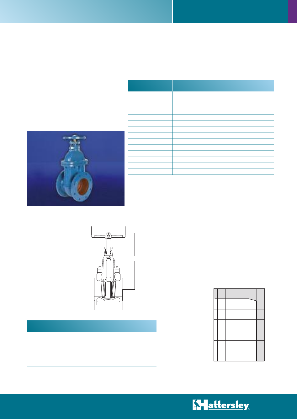
Technical Helpline: 0845 604 1790
E: tech-enquiries@hattersley.com W: www.hattersley.com
135
GATE VALVES
PN6
Every effort has been made to ensure that the information contained in this publication is accurate at the time of publishing.
Hattersley Ltd assumes no responsibility or liability for typographical errors or omissions or for any misinterpretation of the
information within the publication and reserves the right to change without notice.
Fig. M549
Cast Iron
PRESSURE/
TEMPERATURE RATING
BS EN 1171 PN6
6 bar at -10 to 120ºC
5.4 bar at 150ºC
TEST PRESSURES
(HYDRAULIC)
Shell: 9 bar
Seat: 6.6 bar
SPECIFICATION
Inside screw.
Non-rising stem.
Bronze trim.
Flanged to BS EN 1092-2 PN6.
Also available flanged to BS10
Table E Fig. 549E.
MATERIAL SPECIFICATION
Handwheel Cast Iron 1561 EN-JLI030 A126 CI B
Gland Cast Iron 1561 EN-JLI030 A126 CI B
Gland Packing Expanded
Graphite
Stuffing Box Cast Iron 1561 EN-JLI030 A126 CI B
Stuffing Box Gasket Asbestos Free
Stem Brass 12164 CW614N
Bonnet Cast Iron 1561 EN-JL1040
Bonnet Gasket Asbestos Free
Wedge Nut Brass 12164 CW614N
Wedge Brass 12164 CW614N
Wedge Facing Ring Bronze 1982 CC491K
Body Seat Ring Bronze 1982 CC491K
Body Cast Iron 1561 EN-JL1040
Component Material Specification
BS EN ASTM
FEATURES AND BENEFITS
• Cast Iron with integral flanges
• Inside screw pattern with non-rising stem
• Ideal for use for non-corrosive and reasonably
clean services
• Seat rings are threaded and securely fixed into
the body
0 30 60 90 120 150 180
T emperature ˚ C
7
6
5
4
3
2
1
0
Pressure bar
Nom mm 50 65 80 100 125 150 200 250 300
Size in 2 21/2 3 4 5 6 8 10 12
A PN6 mm 150 170 180 190 200 210 230 250 270
A Table E in 53/4 61/4 61/2 63/4 71/2 81/4 91/2 103/4 12
B mm 202 222 250 303 351 411 498 579 680
C mm 130 130 150 185 185 195 225 245 185
D PN6 mm 140 160 190 210 240 265 320 375 440
D Table E in 6 61/2 71/4 81/2 10 11 131/4 16 18
Weight kg 13 16 22 29 40 51 88 150 205
A
C
B
DIMENSIONS AND WEIGHTS
DIMENSIONAL DRAWINGS
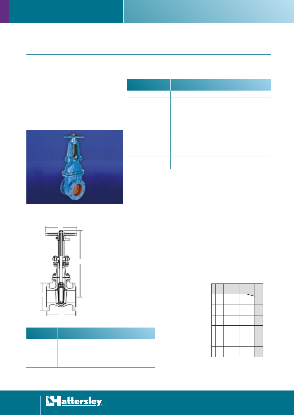
Technical Helpline: 0845 604 1790
E: tech-enquiries@hattersley.com W: www.hattersley.com
136
GATE VALVES
PN6
Every effort has been made to ensure that the information contained in this publication is accurate at the time of publishing.
Hattersley Ltd assumes no responsibility or liability for typographical errors or omissions or for any misinterpretation of the
information within the publication and reserves the right to change without notice.
Fig. M552, M552E, M1552
Cast Iron
DIMENSIONAL DRAWINGS PRESSURE/
TEMPERATURE RATING
BS EN 1171: 2002 PN6
6 bar at -10 to 120ºC
5.4 bar at 150ºC
TEST PRESSURES
(HYDRAULIC)
Shell: 9 bar
Seat: 6.6 bar
SPECIFICATION
Outside screw.
Rising stem.
Bronze trim.
Flanged to BS EN1092-2 PN6.
Also available flanged to BS10
Table E figure 552E.
Available with all iron trim
figure 1552 PN6.
MATERIAL SPECIFICATIONFEATURES AND BENEFITS
• Cast Iron with integral flanges
• Outside screw pattern with rising stem
• Ideal for use on more active media where fluid
might have an adverse affect on thread
• Flanges ends require no pipe threading
Nom mm 50 65 80 100 125 150 200 250 300
Size in 2 21/2 3 4 5 6 8 10 12
A PN6 mm 146 159 165 171 191 210 241 273 305
A Table E in 53/4 61/4 61/2 63/4 71/2 81/4 91/2 103/4 12
B (open) mm 405 415 486 632 710 842 1100 1228 1373
C mm 190 190 190 305 305 305 305 405 405
Weight kg 14 18 25 34 48 59 91 157 210
DIMENSIONS AND WEIGHTS
0 30 60 90 120 150 180
T emperature ˚ C
7
6
5
4
3
2
1
0
Pressure bar
A
C
B
D
Body Cast Iron 1561 EN-JLI040 A126 CI B
Wedge Cast Iron 1561 EN-JLI040 A126 CI B
Bonnet Cast Iron 1561 EN-JLI040 A126 CI B
Yoke Joint Cast Iron 1561 EN-JLI040 A126 CI B
Yoke Sleeve Cast Bronze 1982 CC491K B62 C83600
Bonnet Gasket Asbestos Free
Wedge Nut Brass 12164 CW614N
Stem Steel 10087 11sMn30 A105
Stuffing Box Cast Iron 1561 EN-JLI030 A126 CI B
Stuffing Box Gasket Asbestos Free
Gland Follower Ductile Iron 1563 EN-JSI040
Packing Gland Brass
Handwheel Cast Iron 1561 EN-JLI030 A126 CI B
Component Material Specification
BS EN ASTM
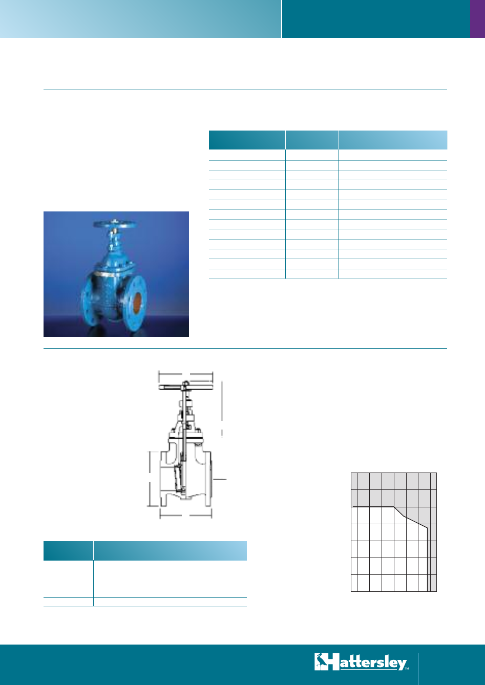
Technical Helpline: 0845 604 1790
E: tech-enquiries@hattersley.com W: www.hattersley.com
137
GATE VALVES
PN10
Every effort has been made to ensure that the information contained in this publication is accurate at the time of publishing.
Hattersley Ltd assumes no responsibility or liability for typographical errors or omissions or for any misinterpretation of the
information within the publication and reserves the right to change without notice.
Fig. M511
Cast Iron
PRESSURE/
TEMPERATURE
RATING
BS EN 1171:2002 PN10
10 bar at -10 to 120ºC
7.4 bar at 230ºC
TEST PRESSURES
Each valve is individually
hydrostatically tested to
BS EN 12266:Part 1 at the
following test pressures;
Shell: 15 bar
Seat: 11 bar
SPECIFICATION
Complies with BS EN 1171: 2002.
Face to face dimension to BS EN 558-1
series 14.
Inside screw.
Non-rising stem.
Bronze trim.
Flanged to BS EN 1092-2 PN10.
MATERIAL SPECIFICATION
Handwheel Cast Iron 1561 EN-JL1040 A126 CI B
Gland Cast Iron 1561 EN-JL1040 A126 CI B
Gland Packing Graphite
Stuffing Box Cast Iron 1561 EN-JL1040 A126 CI B
Stuffing Box Gasket Graphite
Stem Copper Alloy 12164 CW603N B16-C36000
Bonnet Cast Iron 1561 EN-JL1040 A126 CI B
Bonnet Gasket Graphite
Wedge Nut Bronze
Wedge Cast Iron 1561 EN-JL1040 A126 CI B
Wedge Facing Ring Bronze
Body Seat Ring Bronze
Body Cast Iron 1561 EN-JL1040 A126 CI B
Component Material Specification
BS EN ASTM
FEATURES AND BENEFITS
• Cast Iron with integral flanges
• Inside screw pattern with non-rising stem
• Ideal for use for non-corrosive and reasonably
clean services
• Seat rings are threaded and securely fixed
into the body
A
B
C
D
0 40 80 120 160 200 240
T emperature ˚ C
14
12
10
8
6
2
0
Pressure bar
4
Nom
Size mm 50 65 80 100 125 150
A mm 150 170 180 190 200 210
B mm 292 324 360 380 454 490
C mm 160 160 200 200 250 250
D mm 160 185 200 220 250 285
Weight kg 17 20 28 34 51 62
DIMENSIONS AND WEIGHTS
DIMENSIONAL DRAWINGS
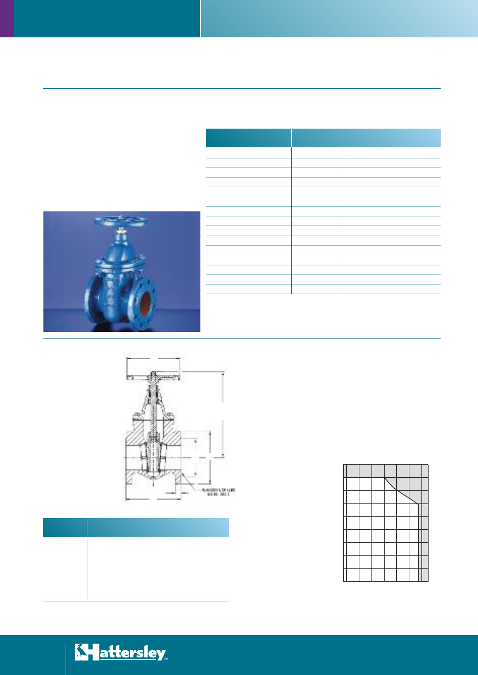
Technical Helpline: 0845 604 1790
E: tech-enquiries@hattersley.com W: www.hattersley.com
138
GATE VALVES
PN16
Every effort has been made to ensure that the information contained in this publication is accurate at the time of publishing.
Hattersley Ltd assumes no responsibility or liability for typographical errors or omissions or for any misinterpretation of the
information within the publication and reserves the right to change without notice.
Fig. M541, M1541
Cast Iron
PRESSURE/
TEMPERATURE RATING
-10 to 120° C at 16 bar
200°C at 12.8 bar
TEST PRESSURES
(HYDRAULIC)
Shell: 24 bar
Seat: 17.6 bar
SPECIFICATION
Wedge disc.
Non-rising stem.
Inside screw.
Handwheel operated.
OPTIONAL
FEATURES
Flanges undrilled.
MATERIAL SPECIFICATIONFEATURES AND BENEFITS
• Cast Iron with integral flanges
• Flanged ends require no pipe threading
Nom
Size mm 65 80 100 125 150 200
A mm 190 203 229 254 267 292
B mm 20 22 24 26 28 30
C mm 185 200 220 250 285 340
D mm 262 286 356 426 463 578
E mm 190 190 220 300 300 350
F mm 118 132 156 184 211 266
Weight kg 18.7 23.9 37.6 50.7 63.8 104.3
10
8
6
4
2
0
Pressure bar
0 40 80 120 160 200 240
T empe r ature ˚ C
12
14
16
18
AB
C
D
Approx.
F
E
Body Grey Iron 1561 EN-JL1040
Bonnet Grey Iron 1561 EN-JL1040
Disc Grey Iron 1561 EN-JL1040
Body Seat Ring Bronze 1982 (CC491K)
Disc Seat Ring Bronze 1982 (CC491K)
Stem Stainless Steel 970: 410S21
Gasket Graphite Graphite (Asbestos Free)
Gland Packing Nut Stainless Steel 970: 304S31
Handwheel Grey Iron 1561 EN-JL1040
Stem Retaining Ring Stainless Steel 970: 304S31
Disc Stem Nut Bronze 1982 (CC491K)
Packing Ring Graphite Graphite (Asbestos Free)
Handwheel Retaining Nut Steel 4190 GR4
Handwheel Washer Steel 4320
Body ID Plate (Not Shown) Aluminium
Component Material Specification
BS EN
All dimensions are nominal.
Please note sizes 50, 250 and
300mm are also available,
please refer to the website.
DIMENSIONS AND WEIGHTS
DIMENSIONAL DRAWINGS
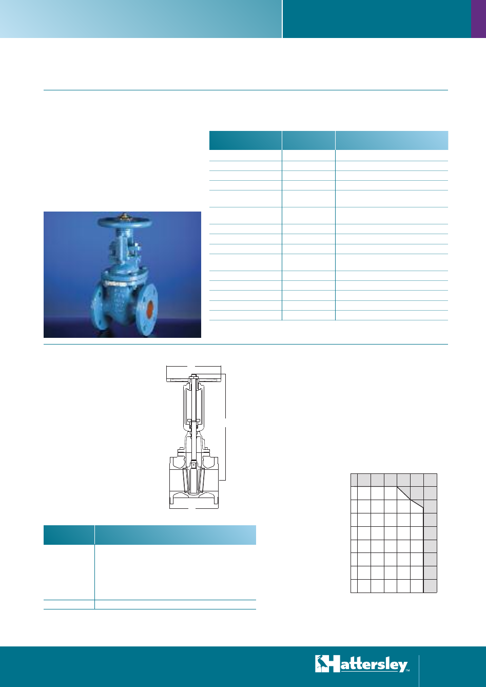
Technical Helpline: 0845 604 1790
E: tech-enquiries@hattersley.com W: www.hattersley.com
139
GATE VALVES
PN16
Every effort has been made to ensure that the information contained in this publication is accurate at the time of publishing.
Hattersley Ltd assumes no responsibility or liability for typographical errors or omissions or for any misinterpretation of the
information within the publication and reserves the right to change without notice.
Fig. M544 - M544E
Cast Iron
PRESSURE/
TEMPERATURE RATING
BS EN 1171 PN16
16 bar at -10 to 120ºC
11.8 bar at 230ºC
TEST PRESSURES
(HYDRAULIC)
Shell: 24 bar
Seat: 17.6 bar
SPECIFICATION
BS 5150 and BS EN 1171.
Outside screw.
Rising stem.
Flanged to BS EN 1092-2 PN16.
Bronze trim.
Flanges drilled to BS10 available
figure 544E.
Face to face dimensions at
BS EN 558-1 basic series 3.
MATERIAL SPECIFICATION
Handwheel Cast Iron 1561 EN-JLI030 A126 CI B
Yoke Sleeve Bronze
Yoke (100 to 300mm) Cast Iron 1561 EN-JLI030 A126 CI B
Gland Cast Iron 1561 EN-JLI030 A126 CI B
Gland Packing Expanded
Graphite
Yoke Joint Asbestos Free
(100 & 300mm)
Stem Steel EN10087 11sMn30
Bonnet Cast Iron 1561 EN-JLI040 A126 CI B
Bonnet Gasket Asbestos Free
Stem Cone Bush Brass 12164 CW614N B16-C36000 /
B124-C37700
Wedge Nut Bronze
Wedge Cast Iron 1561 EN-JLI040 A126 CI B
Wedge Facing Ring Bronze
Body Seat Ring Cast Iron 1561 EN-JLI040 A126 CI B
Body Cast Iron 1561 EN-JLI040 A126 CI B
Component Material Specification
BS EN ASTM
FEATURES AND BENEFITS
• Cast Iron with integral flanges
• Outside screw pattern with rising stem
• Ideal for use on more active media where fluid
might have an adverse effect on thread
• Flanges ends require no pipe threading
0 40 80 120 160 200 240
Temperature ˚C
18
16
14
12
10
8
6
4
2
0
Pressure bar
499 (SHUT)499 (SHUT)
A
C
B
Nom mm 50 65 80 100 125 150 200 250 300
Size in 2 21/2 3 4 5 6 8 10 12
A PN6 mm 178 190 203 229 254 267 292 330 356
B (open) mm 343 345 443 520 572 668 884 955 1054
C mm 190 190 190 305 305 305 305 405 405
D PN16 mm 165 185 200 220 250 285 340 405 460
D Table E in 6 61/2 71/4 81/2 10 11 131/4 16 18
D Table F in 61/2 71/4 8 9 11 12 141/2 17 191/4
Weight kg 17 20 28 40 56 69 125 227 265
DIMENSIONS AND WEIGHTS
DIMENSIONAL DRAWINGS
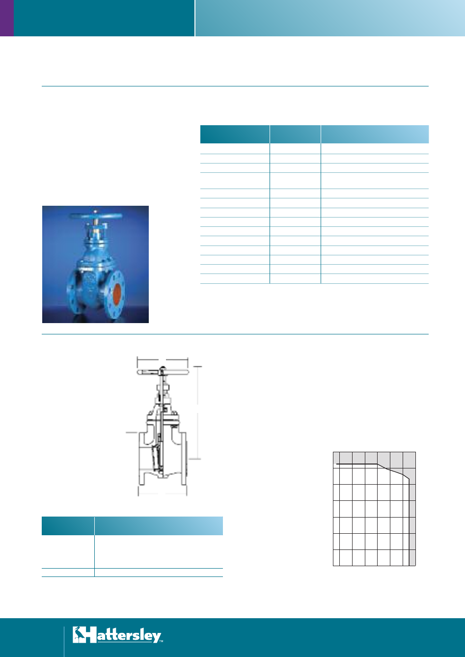
Technical Helpline: 0845 604 1790
E: tech-enquiries@hattersley.com W: www.hattersley.com
140
GATE VALVES
PN25
Every effort has been made to ensure that the information contained in this publication is accurate at the time of publishing.
Hattersley Ltd assumes no responsibility or liability for typographical errors or omissions or for any misinterpretation of the
information within the publication and reserves the right to change without notice.
Fig. M540
Ductile Iron
PRESSURE/
TEMPERATURE RATING
BS EN 1171:2002 PN25
25 bar at -10 to 120ºC
21.5 bar at 220ºC
TEST PRESSURES
(HYDRAULIC)
PN25
Shell: 37.5 bar
Seat: 27.5 bar
SPECIFICATION
Inside screw.
Non-rising stem.
Flanged to BS EN 1092-2 PN25.
Bronze trim.
MATERIAL SPECIFICATIONFEATURES AND BENEFITS
• Ductile Iron with integral flanges
• Inside screw pattern with non-rising stem
• Ideal for use for non-corrosive and
reasonably clean services
• Seat rings are threaded and securely fixed
into the body
0 40 80 120 160 200 240
Temperature ˚C
28
24
20
16
12
4
0
Pressure bar
8
Nom
Size mm 50 65 80 100 125 150
A mm 178 190 203 229 254 267
B mm 322 322 340 420 477 542
C mm 190 190 190 305 305 305
D mm 165 185 200 235 270 300
Weight kg 16 19 24 35 45 62
DIMENSIONS AND WEIGHTS
A
C
B
D
Handwheel Cast Iron 1561 EN JL1030
Gland Flange Ductile Iron 1561 EN JS1050
Gland H T Brass 1561 EN JS1040
Gland Packing Expanded
Graphite
Stuffing Box Ductile Iron 1561 EN JS1050
Stuffing Box Gasket Asbestos Free
Stem Al Bronze 12163 CW301G B150 C64200
Bonnet Ductile Iron 1563 EN JS1050
Bonnet Gasket Asbestos Free
Wedge Nut Al Bronze 12163 CW301G B150 C64200
Wedge Ductile Iron 1563 EN JS1050
Wedge Facing Ring Bronze
Body Seat Ring Bronze
Body Ductile Iron 1563 EN JS1050
Component Material Specification
BS EN ASTM
DIMENSIONAL DRAWINGS
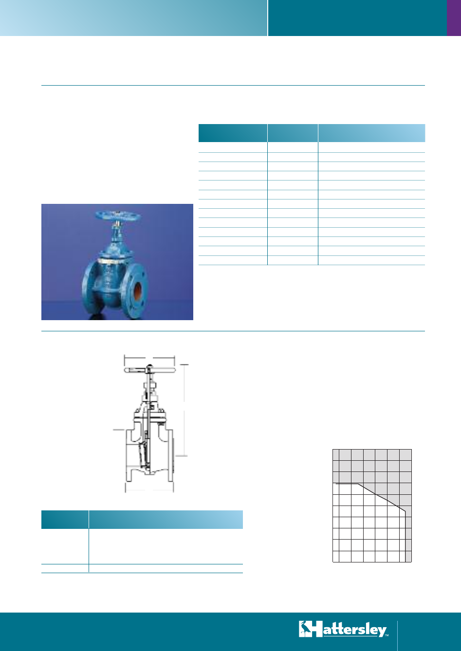
Technical Helpline: 0845 604 1790
E: tech-enquiries@hattersley.com W: www.hattersley.com
141
GATE VALVES
CLASS 125
Every effort has been made to ensure that the information contained in this publication is accurate at the time of publishing.
Hattersley Ltd assumes no responsibility or liability for typographical errors or omissions or for any misinterpretation of the
information within the publication and reserves the right to change without notice.
Fig. 501
Cast Iron
DIMENSIONAL DRAWINGS PRESSURE/
TEMPERATURE RATING
13.8 bar at -10 to 65ºC
8.6 bar at 232ºC
TEST PRESSURES
Each valve is individually hydrostatically
tested to MSS SP-70 at the following test
pressures.
Shell: 24.1 bar
Seat: 15.2 bar
SPECIFICATION
Face to face dimensions.
ANSI B16.10 & basic BS EN 558-2
Series 3.
Inside screw.
Flanged to ANSI B16.1 Class 125
and BS 1560 3.2.
Bronze trim.
Complies with MSS SP-70 Class 125
and BS5150 ANSI 125.
MATERIAL SPECIFICATION
Handwheel Cast Iron 1561 EN-JLI030 A126 CI B
Gland Cast Iron 1561 EN-JLI030 A126 CI B
Gland Packing Graphite
Stuffing Box Cast Iron 1561 EN-JLI030 A126 CI B
Stuffing Box Gasket Graphite
Stem Copper Alloy 12164 CW603N B16 C36000
Bonnet Cast Iron 1561 EN-JLI040 A126 CI B
Bonnet Gasket Graphite
Wedge Nut Bronze 1982 CC491K B62 C83600
Wedge Cast Iron 1561 EN-JLI040 A126 CI B
Wedge Facing Ring Bronze 1982 CC491K B62 C83600
Body Seat Ring Bronze 1982 CC491K B62 C83600
Body Cast Iron 1561 EN-JLI040 A126 CI B
Component Material Specification
BS EN ASTM
FEATURES AND BENEFITS
• Cast Iron with integral flanges
• Inside screw pattern with non-rising stem
• Ideal for use for non-corrosive and reasonably
clean services
• Seat rings are threaded and securely fixed into
the body
0 40 80 120 160 200 240
Temperature ˚C
18
16
14
12
6
4
2
0
Pressure bar
8
10
20
A
C
B
D
Nom
Size in 2 21/2 3 4 5 6 8 10 12
A in 7 71/2 8 9 10 101/2 111/2 13 14
B in 11 121/2 131/2 151/4 18 20 25 29 35
C in 7 7 8 10 12 12 14 16 18
D in 6 7 71/2 9 10 11 131/2 16 19
Weight kg 20 25 29 48 65 80 126 179 205
DIMENSIONS AND WEIGHTS
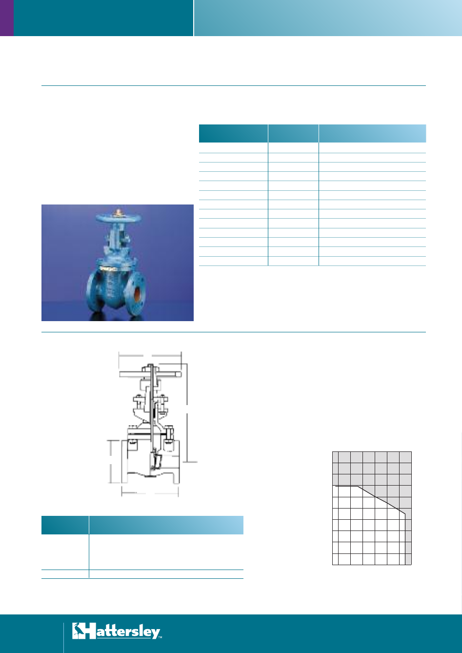
Technical Helpline: 0845 604 1790
E: tech-enquiries@hattersley.com W: www.hattersley.com
142
GATE VALVES
CLASS 125
Every effort has been made to ensure that the information contained in this publication is accurate at the time of publishing.
Hattersley Ltd assumes no responsibility or liability for typographical errors or omissions or for any misinterpretation of the
information within the publication and reserves the right to change without notice.
Fig. 504
Cast Iron
PRESSURE/
TEMPERATURE RATING
BS EN 1092-2 Class 125
13.8 bar from -10 to 65ºC
8.6 bar at 232ºC
TEST PRESSURES
Each valve is individually hydrostatically
tested to MSS SP-70 at the following test
pressures.
Shell: 24.1 bar
Seat: 15.2 bar
SPECIFICATION
BS 5150:1990 ANSI 125.
Face to face dimensions ANSI B16.10.
Outside screw.
Rising stem.
Bronze trim.
Flanged to ANSI B16.1 Class 125.
Complies with MSS SP-70 Class 125.
MATERIAL SPECIFICATIONFEATURES AND BENEFITS
• Cast Iron with integral flanges
• Outside screw pattern with rising stem
• Ideal for use on more active media where fluid
might have an adverse affect on thread
• Flanges ends require no pipe threading
Nom
Size in 2 21/2 3 4 5 6 8 10 12
A in 7 71/2 8 9 10 101/2 111/2 13 14
B in 133/4 151/2 18 221/4 26 31 37 47 55
C in 7 7 8 10 12 12 14 16 18
D in 6 7 71/2 9 10 11 131/2 16 19
Weight kg 24 26 29 50 71 88 136 198 268
0 40 80 120 160 200 240
Temperature ˚C
18
16
14
12
6
4
2
0
Pressure bar
8
10
20
A
B
C
D
Handwheel Cast Iron 1561 EN-JLI030 A126 CI B
Gland Cast Iron 1561 EN-JLI030 A126 CI B
Gland Packing Graphite
Stuffing Box Cast Iron 1561 EN-JLI030 A126 CI B
Stuffing Box Gasket Graphite
Stem Copper Alloy 12164 CW603N B16 C36000
Bonnet Cast Iron 1561 EN-JLI030 A126 CI B
Bonnet Gasket Graphite
Wedge Nut Bronze 1982 CC491K B62 C83600
Wedge Cast Iron 1561 EN-JLI030 A126 CI B
Wedge Facing Ring Bronze 1982 CC491K B62 C83600
Body Seat Ring Bronze 1982 CC491K B62 C83600
Body Cast Iron 1561 EN-JLI030 A126 CI B
Component Material Specification
BS EN ASTM
DIMENSIONS AND WEIGHTS
DIMENSIONAL DRAWINGS
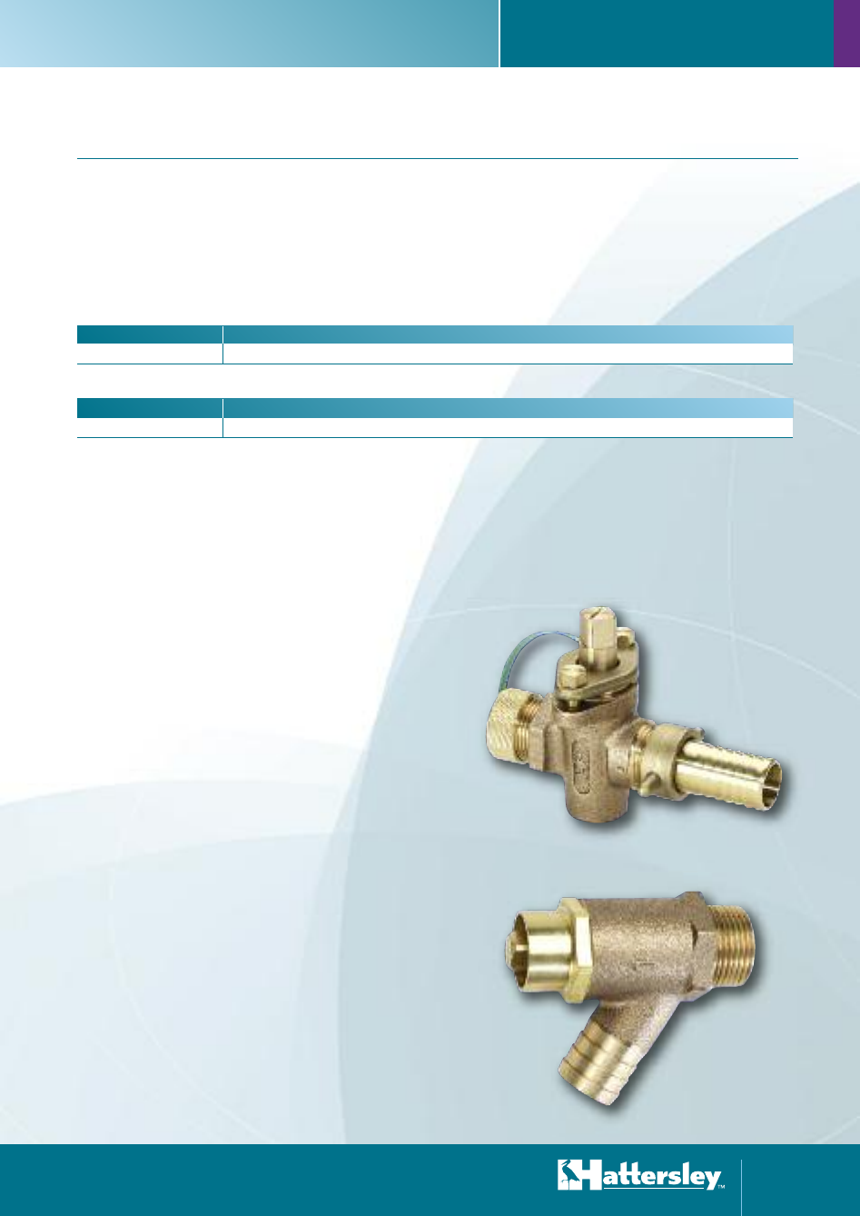
Technical Helpline: 0845 604 1790
E: tech-enquiries@hattersley.com W: www.hattersley.com
143
GLAND COCKS/DRAINTAPS
Gland Cocks/Drain Taps
Fitting Hattersley’s Drain Taps and Gland Cocks enable systems to be
drained without removing pipework. They prevent the build up of sediment
that flows through the pipework thus extending its life expectancy.
Malleable Iron Levers
MI Lever No. Y1 Y2 Y3 Y4 Y5 Y6 Y7 Y8 Y9
Square Size mm 8.7 9.5 10.3 12.7 14.3 15.9 19.1 22.2 25.4
MI Lever No. D1 D2 D3 D31/2 D41/2 D5 D6 D7 D71/2 D8
Square Size mm 7.9 10.3 11.1 13.5 15.9 17.5 19.1 23.8 26.2 31.8
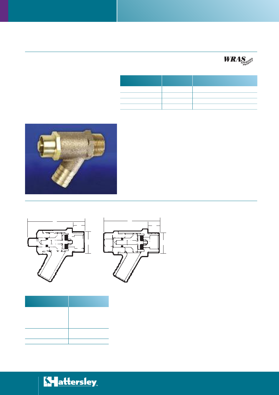
Technical Helpline: 0845 604 1790
E: tech-enquiries@hattersley.com W: www.hattersley.com
144
DRAINING TAPS
Every effort has been made to ensure that the information contained in this publication is accurate at the time of publishing.
Hattersley Ltd assumes no responsibility or liability for typographical errors or omissions or for any misinterpretation of the
information within the publication and reserves the right to change without notice.
Fig. 370-371
Bronze
DIMENSIONAL DRAWINGS PRESSURE/
TEMPERATURE RATING
Suitable for pressures of 13 bar up to a
maximum temperature of 120°C.
FEATURES AND BENEFITS
• Enables system to be drained without
removing pipework
• Prevents build-up of sediment
• Extends life expectancy of pipework
A
C
Fig. 370
B
Fig. 371
A
C
B
DIMENSIONS AND WEIGHTS
Nom
Size in 1/2 3/4 1
A (370) mm 57 73 79
A (371) mm 59 75 83
B mm 13 16 19
C mm 10 10 11
Lockshield key Fig. 391 391 393
Ref 2 3 6
Weight kg 0.22 0.36 0.68
MATERIAL SPECIFICATION
Body Bronze 1982 CC491K
Stem Brass 12164 CW603N
Bonnet Brass 12164 CW603N
Disc Holder Brass 12164 CW603N
Component Material Specification
BS EN
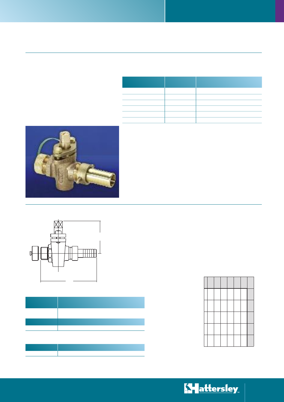
Technical Helpline: 0845 604 1790
E: tech-enquiries@hattersley.com W: www.hattersley.com
145
GLAND COCKS
Every effort has been made to ensure that the information contained in this publication is accurate at the time of publishing.
Hattersley Ltd assumes no responsibility or liability for typographical errors or omissions or for any misinterpretation of the
information within the publication and reserves the right to change without notice.
Fig. 81HU
Bronze Hose Union
DIMENSIONAL DRAWINGS PRESSURE/
TEMPERATURE
RATING
10 bar 0 to 120ºC
TEST PRESSURES
(HYDRAULIC)
Body: 20 bar
SPECIFICATION
90º operation.
Sizes 1/2" to 1" supplied complete with cap and strap.
Other sizes available with cap and chain on request.
Plugs have square heads with a slot to indicate plug
position.
Malleable iron levers available on request.
Malleable iron lever can be pinned to the plug head at
extra charge.
Taper threaded BS EN 10226 (ISO 7-1) formerly BS 21.
Figure 81HU Gland Cocks are not suitable for gas
service.
MATERIAL SPECIFICATIONFEATURES AND BENEFITS
• Enables system to be drained without
removing pipework
• Prevents build-up of sediment
• Extends life expectancy of pipework
A
B
0 20 40 60 80 100 120 140
Temperature ˚C
12
10
8
6
2
0
Pressure bar
4
Nom
Size in 1/4 3/8 1/2 3/4 1 11/4 11/2
A mm 95 102 93 117 145 184 203
B mm 47 54 54 64 79 90 100
MI Lever No. Y1 Y2 D2 D31/2 D41/2 Y6 Y7
Weight kg 0.32 0.35 0.38 0.67 1.2 1.5 2.5
DIMENSIONS AND WEIGHTS
MI Lever No. Y1 Y2 D2 D31/2 D41/2 Y6 Y7
Square size mm 8.7 9.5 10.3 13.5 15.9 15.9 19.1
MALLEABLE IRON LEVERS
Gland (1/2" to 1") Brass 12165 CW617N B124 Alloy 2
Gland (11/4" to 2") Bronze 1982 CC491K B62
Gland Packing Asbestos Free
Plug Bronze 1982 CC491K B62
Cap and Tail Brass 12164 CW614N B455-385
Body Bronze 1982 CC491K B62
Component Material Specification
BS EN ASTM
Technical Helpline: 0845 604 1790
E: tech-enquiries@hattersley.com W: www.hattersley.com
146
Terminal 5, Heathrow Airport, London
Specification: Hattersley Automatic and Static Balancing Valves
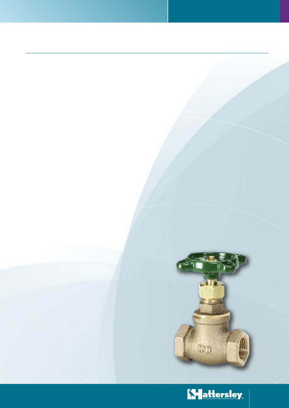
Technical Helpline: 0845 604 1790
E: tech-enquiries@hattersley.com W: www.hattersley.com
147
GLOBE VALVES
Globe Valves
Hattersley globe valves are highly efficient for throttling
service because seat and disc designs provide flow
characteristics with proportionate relationships between
valve lift and flow rate. This assures accurate flow
control/regulation. Globe valve bodies are normally of
spherical shape, ensuring maximum strength against
line pressures and pipeline strains. Wide faced hexagon
ends on threaded valves provide a firm wrench grip
which prevents damage to the valve.
The majority of Hattersley globe valves are inside screw
pattern, having either a screwed bonnet or union bonnet
configuration. A wide choice of disc and seat materials
is offered in this range to enable the user to select a
valve most suited for the intended service.
There are five basic seat and disc arrangements
available:
1. Metal to metal: the seat being integral with the body.
2. Renewable alloy or stainless steel disc and seat.
3. Renewable composition or elastomeric disc.
4. Renewable composition elastomeric disc alloy seat.
5. Vee-Reg pattern stainless steel disc and seat giving
protection against wire drawing on steam service.
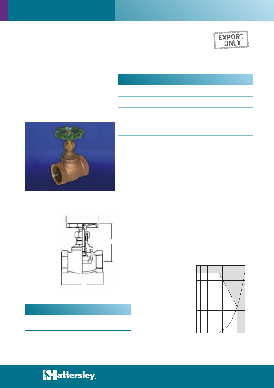
Technical Helpline: 0845 604 1790
E: tech-enquiries@hattersley.com W: www.hattersley.com
148
GLOBE VALVES
PN16 SERIES B
Every effort has been made to ensure that the information contained in this publication is accurate at the time of publishing.
Hattersley Ltd assumes no responsibility or liability for typographical errors or omissions or for any misinterpretation of the
information within the publication and reserves the right to change without notice.
S
a
t
u
r
a
t
e
d
S
t
e
a
m
0 40 80 120 160 200 240
Temperature ˚C
28
24
20
16
12
4
0
Pressure bar
8
32
36
Fig. C4
Bronze
DIMENSIONAL DRAWINGS PRESSURE/
TEMPERATURE RATING
7 bar at 170°C
16 bar from -10 to 100°C
TEST PRESSURES
(PNEUMATIC)
Each valve is individually hydrostatically tested
to BS 5154 at the following test pressures.
Shell: 24 bar
Seat: 17.6 bar
SPECIFICATION
Rising stem.
Threaded bonnet.
Metal disc.
Taper thread BS EN 12288
(BS 21-IS0 7).
Available with NPT thread (C4AT)
subject to minimum quantities.
MATERIAL SPECIFICATION
Handwheel Cast Iron A126 CI B
Stem Brass B16 C36000
Gland Nut Brass B16 C36000
Gland Follower Brass B16 C36000
Gland Packing PTFE
Bonnet Bronze B584 C84400
Disc 1/2" to 1" Bronze B16 C36000
Disc 11/4" to 2" Bronze B584 C84400
Body Bronze B584 C84400
Component Material Specification
ASTM
FEATURES AND BENEFITS
• High quality bronze body with robust
spherical shape
• Rising stem and screwed bonnet
• Assures accurate flow regulation/control
• Suitable for high pressures up to 16 bar
Nom
Size in 1/2 3/4 1 11/4 11/2 2
A mm 49 56 65 75 84 99
B mm 70 70 87 94 104 124
C mm 53 58 64 74 74 87
Weight kg 0.26 0.35 0.55 0.72 1.01 1.54
DIMENSIONS AND WEIGHTS
A
C
B
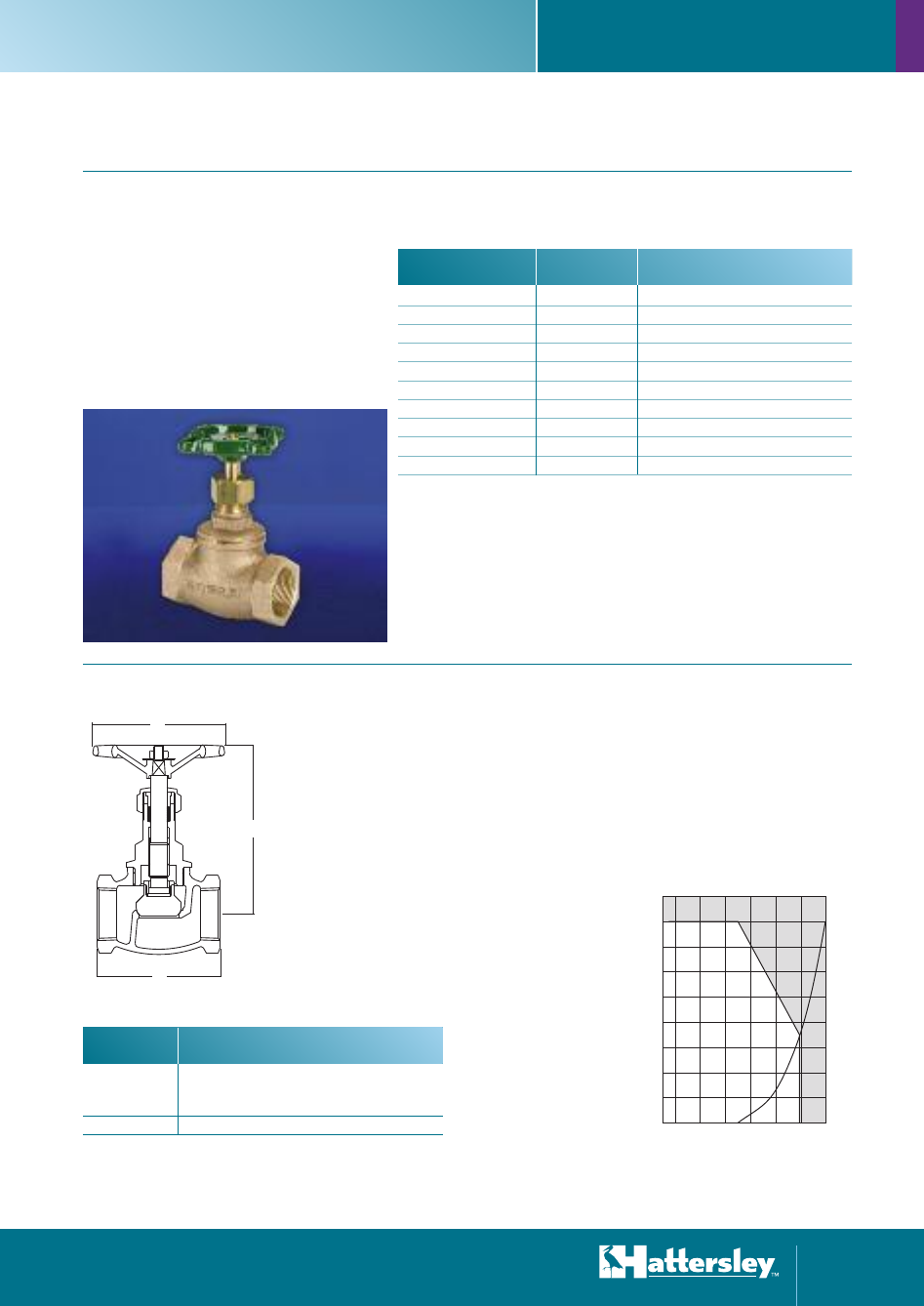
Technical Helpline: 0845 604 1790
E: tech-enquiries@hattersley.com W: www.hattersley.com
149
GLOBE VALVES
PN32 SERIES B
Every effort has been made to ensure that the information contained in this publication is accurate at the time of publishing.
Hattersley Ltd assumes no responsibility or liability for typographical errors or omissions or for any misinterpretation of the
information within the publication and reserves the right to change without notice.
Fig. 5
Bronze
DIMENSIONAL DRAWINGS PRESSURE/
TEMPERATURE RATING
BS 5154 PN32 Series B
14 bar at 198ºC
32 bar from -10 to 100ºC
TEST PRESSURES
(PNEUMATIC)
Body: 6 bar
Seat: 6 bar
SPECIFICATION
Rising stem.
Screwed bonnet.
Available with NPT threads to
ASTM B1.20.1.
Taper threaded BS EN 10226
(ISO 7-1) formerly BS 21.
BS 5154.
Bronze Body.
MATERIAL SPECIFICATION
Body Cast Bronze 1982 CC491K B62 C83600
Disc (1/2" to 1") Brass 12165 CW617N B124 C37700
Disc (11/4" to 2") Bronze 1982 CC491K B62 C83600
Stem Brass 12164 CW617N B455 C38000
Bonnet Bronze 1982 CC491K B62 C83600
Stem Packing Teflon PTFE
Packing PTFE
Handwheel Aluminium
Gland Nut Brass 12164 CW614N B455 C38500
Lock Nut Brass 12164 CW614N B455 C38500
Component Material Specification
BS EN ASTM
FEATURES AND BENEFITS
• High quality bronze body with robust
spherical shape
• Rising stem and screwed bonnet
• Assures accurate flow regulation/control
• Suitable for high pressures up to 32 bar
S
a
t
u
r
a
t
e
d
S
t
e
a
m
0 40 80 120 160 200 240
Temperature ˚C
28
24
20
16
12
4
0
Pressure bar
8
32
36
A
C
B
Nom
Size in 1/2 3/4 1 11/4 11/2 2
A mm 60 74 86 99 109 130
B (open) mm 92 108 118 137 162 166
C mm 70 76 82 94 101 119
Weight kg 0.4 0.5 0.9 1.4 1.7 2.7
DIMENSIONS AND WEIGHTS
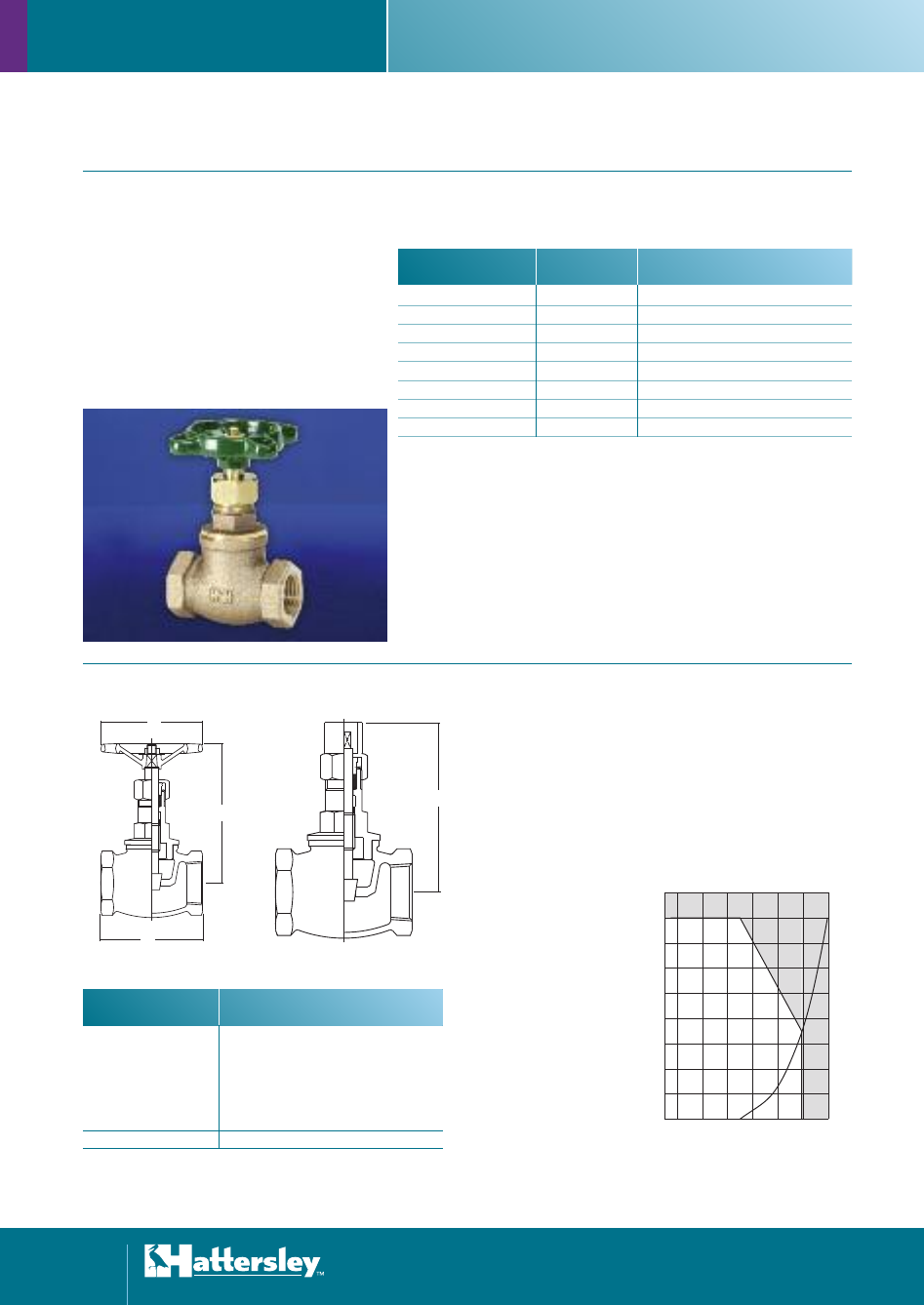
Technical Helpline: 0845 604 1790
E: tech-enquiries@hattersley.com W: www.hattersley.com
150
GLOBE VALVES
PN32 SERIES B
Every effort has been made to ensure that the information contained in this publication is accurate at the time of publishing.
Hattersley Ltd assumes no responsibility or liability for typographical errors or omissions or for any misinterpretation of the
information within the publication and reserves the right to change without notice.
Fig. 5N - 5NLS
Bronze Needle
DIMENSIONAL DRAWINGS SPECIFICATION
Rising stem.
Screwed bonnet.
Taper threaded BS EN 10226
(ISO 7-1) formerly BS 21.
MATERIAL SPECIFICATIONFEATURES AND BENEFITS
• High quality bronze body with robust
spherical shape
• Rising stem and screwed bonnet
• Assures accurate flow regulation/control
• Suitable for high pressures up to 32 bar
S
a
t
u
r
a
t
e
d
S
t
e
a
m
0 40 80 120 160 200 240
Temperature ˚C
28
24
20
16
12
4
0
Pressure bar
8
32
36
A
C
B
E
5N 5NLS
DIMENSIONS AND WEIGHTS
Nom
Size in 1/4 3/8 1/2 3/4 1
A mm 51 51 60 74 86
B (open) mm 72 72 92 108 118
C mm 57 57 68 75 82
E mm 75 75 95 111 121
Lockshield key Fig. 391 391 391 391 391
Ref IP IP IP IP IP
Weight kg 0.2 0.2 0.4 0.6 0.9
Body Cast Bronze 1982 CC491K B62 C83600
Stem Brass 12164 CW617N B124 Alloy 2
Stem Packing Teflon PTFE
Bonnet Cast Bronze 1982 CC491K B62 C83600
Packing Nut Brass 12164 CW614N B455 C38500
Handwheel Aluminium
Identification Plate Aluminium
Handwheel Nut Brass 12164 CW614N B455 C38500
Component Material Specification
BS EN ASTM
PRESSURE/
TEMPERATURE RATING
BS 5154: 1991 PN32 Series B
14 bar at 198ºC
32 bar from -10 to 100ºC
TEST PRESSURES
(PNEUMATIC)
Body: 6 bar
Seat: 6 bar
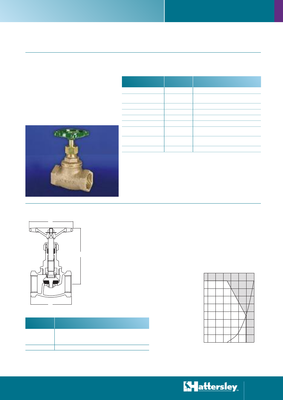
Technical Helpline: 0845 604 1790
E: tech-enquiries@hattersley.com W: www.hattersley.com
151
GLOBE VALVES
PN32 SERIES B
Every effort has been made to ensure that the information contained in this publication is accurate at the time of publishing.
Hattersley Ltd assumes no responsibility or liability for typographical errors or omissions or for any misinterpretation of the
information within the publication and reserves the right to change without notice.
Fig. 13
Bronze
DIMENSIONAL DRAWINGS PRESSURE/
TEMPERATURE RATING
BS 5154:1991 PN32 Series B
14 bar at 198ºC
32 bar from -10 to 100ºC
TEST PRESSURES
(PNEUMATIC)
Shell: 6 bar
Seat: 6 bar
SPECIFICATION
BS 5154:1991.
Bronze body.
PTFE replacement disc.
Rising stem.
Screwed bonnet.
Taper threaded BS EN 10226
(ISO 7-1) formerly BS 21.
Available with NPT threads to
ASTM B1.20.1
MATERIAL SPECIFICATION
Handwheel Nut Aluminium
Gland Nut Brass 12164 CW614N B16 C36000
B124 C37700
Packing PTFE
Bonnet Bronze 1982 CC491K B62 C83600
Stem Brass 12165 CW617N B455 C38000
Disc Stem Nut Brass 12164 CW603N B16 C36000
Disc Holder Brass 12164 CW614N B16 C36000
B124 C37700
Disc Retaining Washer Brass 12164 CW614N B16 C36000
B124 C37700
Body Bronze 1982 CC491K B62 C83600
Component Material Specification
BS EN ASTM
FEATURES AND BENEFITS
• High quality bronze body with robust
spherical shape
• Rising stem and screwed bonnet
• Assures accurate flow regulation/control
• Suitable for high pressures up to 32 bar
S
a
t
u
r
a
t
e
d
S
t
e
a
m
0 40 80 120 160 200 240
Temperature ˚C
28
24
20
16
12
4
0
Pressure bar
8
32
36
Nom
Size in 1/4 3/8 1/2 3/4 1 11/4 11/2 2
A mm 51 51 60 74 86 99 109 130
B (open) mm 72 72 92 108 118 137 162 166
C mm 56.5 56.5 68.3 75.1 82 94 100 119
Weight kg 0.3 0.3 0.5 0.6 1.1 1.6 2.2 3.7
DIMENSIONS AND WEIGHTS
A
C
B
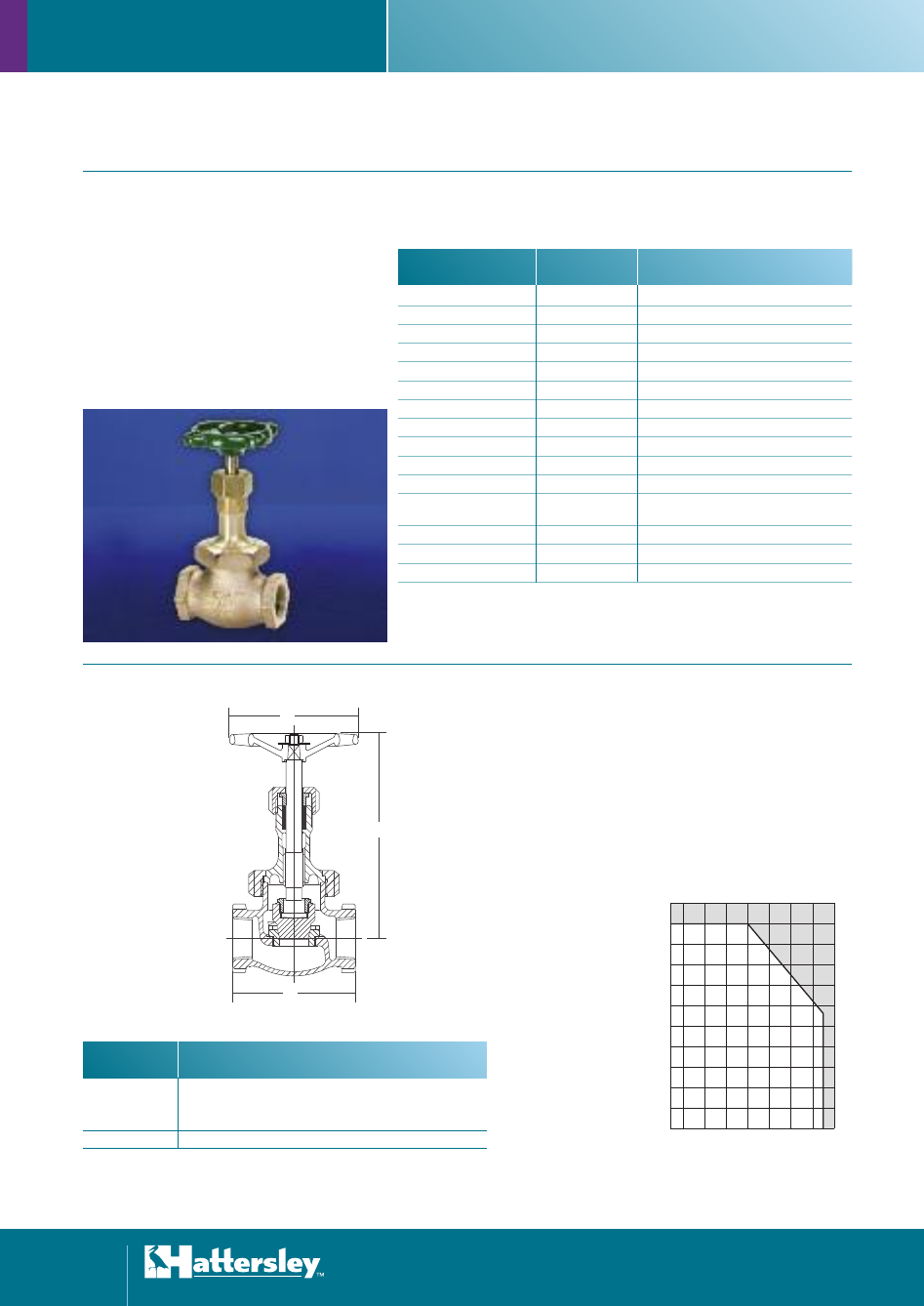
Technical Helpline: 0845 604 1790
E: tech-enquiries@hattersley.com W: www.hattersley.com
152
GLOBE VALVES
PN40
Every effort has been made to ensure that the information contained in this publication is accurate at the time of publishing.
Hattersley Ltd assumes no responsibility or liability for typographical errors or omissions or for any misinterpretation of the
information within the publication and reserves the right to change without notice.
Fig. 23
Bronze
DIMENSIONAL DRAWINGS PRESSURE/
TEMPERATURE RATING
PN40
17.5 bar at 260ºF
40 bar from -10 to 120ºC
TEST PRESSURES
(HYDRAULIC)
Shell: 60 bar
Seat: 44 bar
SPECIFICATION
BS 5154:1991.
Bronze body.
316 stainless steel disc.
Rising stem.
Union bonnet.
Taper threaded BS EN 10226
(ISO 7-1) formerly BS 21.
Available with NPT threads to
ASTM B1.20.1.
MATERIAL SPECIFICATIONFEATURES AND BENEFITS
• High quality bronze body with robust
spherical shape
• Rising stem and union bonnet
• Assures accurate flow regulation/control
• Suitable for high pressures up to 40 bar
Nom
Size in 1/4 3/8 1/2 3/4 1 11/4 11/2 2
A mm 59 59 68 81 95 108 121 146
B mm 126 126 142 154 173 201 225 255
C mm 76 76 81 94 100 119 139 150
Weight kg 0.56 0.55 0.8 1.24 1.82 2.73 3.78 6.03
DIMENSIONS AND WEIGHTS
0 40 80 120 160 200 240 280
36
32
28
24
20
16
12
8
4
0
Pressure bar
40
44
T empe r ature ˚ C
B
A
C
Handwheel Aluminium
Gland Brass 12164 CW614N
Packing Non Asbestos
Bonnet Bronze 1982 CC491K B62 C83600
Union Ring Bronze 1982 CC491K B62 C83600
Disc 316 St. Steel
Stem Man Bronze 12164 CW721R B138C67500
Disc Stem Ring Man Bronze 12164 CW721R B138C67500
Body Seat Ring 13% Cr St 10088 X12Cr13 A276 410
Body Bronze 1982 CC491K B62 C83600
Lock Washer Brass 2870 CZ 123
Packing Nut Brass 12164 CW721R
(1/4" to 11/2")
Packing Nut 2" Bronze 1982 CC491K
Handwheel Nut Brass 12164 CW614N
Identification Plate Aluminium
Component Material Specification
BS EN ASTM

Technical Helpline: 0845 604 1790
E: tech-enquiries@hattersley.com W: www.hattersley.com
153
GLOBE VALVES
PN16 SERIES B
Every effort has been made to ensure that the information contained in this publication is accurate at the time of publishing.
Hattersley Ltd assumes no responsibility or liability for typographical errors or omissions or for any misinterpretation of the
information within the publication and reserves the right to change without notice.
Fig.17
Bronze
DIMENSIONAL DRAWINGS PRESSURE/
TEMPERATURE RATING
BS 5154: 1991 PN16 Series B
7 bar at 170ºC
16 bar from -10 to 100ºC
TEST PRESSURES
(HYDRAULIC)
Shell: 24 bar
Seat: 17.6 bar
SPECIFICATION
Rising stem.
Screwed bonnet.
Renewable glass filled PTFE disc.
Conical seat disc (15 to 50mm).
Flanged to BS EN 1092-3.
Also available with flanges drilled to BS10
Table E and F and ANSI from PN16 flanges.
Face to face dimensions of all valves are to
PN16 detail.
MATERIAL SPECIFICATION
Body Bronze 1982 CC491K B62 C83600
Disc Stem Ring Man Bronze 12164 CW721R B138 C67500
Packing Asbestos Free
Gland Brass 12164 CW614N
Packing Nut Brass 12164 CW614N
Washer Brass 12164 CW614N
Disc Retaining Nut Brass 12164 CW614N
Handwheel Aluminium
Handwheel Nut Brass 12164 CW614N
Identification Plate Aluminium
Bonnet Bronze 1982 CC491K B62 C83600
Stem Brass 12164 CW721R
Disc PTFE
Disc Holder Bronze 1982 CC491K B62 C83600
Component Material Specification
BS EN ASTM
FEATURES AND BENEFITS
• High quality bronze body with robust
spherical shape
• Rising stem and screwed bonnet
• Assures accurate flow regulation/control
• Integral flanges require no pipe threading
0 40 80 120 160 200
Temperature ˚C
18
16
14
12
10
8
6
4
2
0
Pressure bar
S
a
t
u
r
a
t
e
d
S
t
e
a
m
B
A
C
Nom
Size mm 15 20 25 32 40 50
A mm 80 90 100 110 120 135
B mm 101 119 130 155 172 196
C mm 70 80 95 95 105 120
D mm 95 105 115 140 150 165
E mm 6.0 6.0 8.0 8.0 9.0 11.0
Weight kg 1.24 1.76 2.30 2.82 5.22 5.71
DIMENSIONS AND WEIGHTS
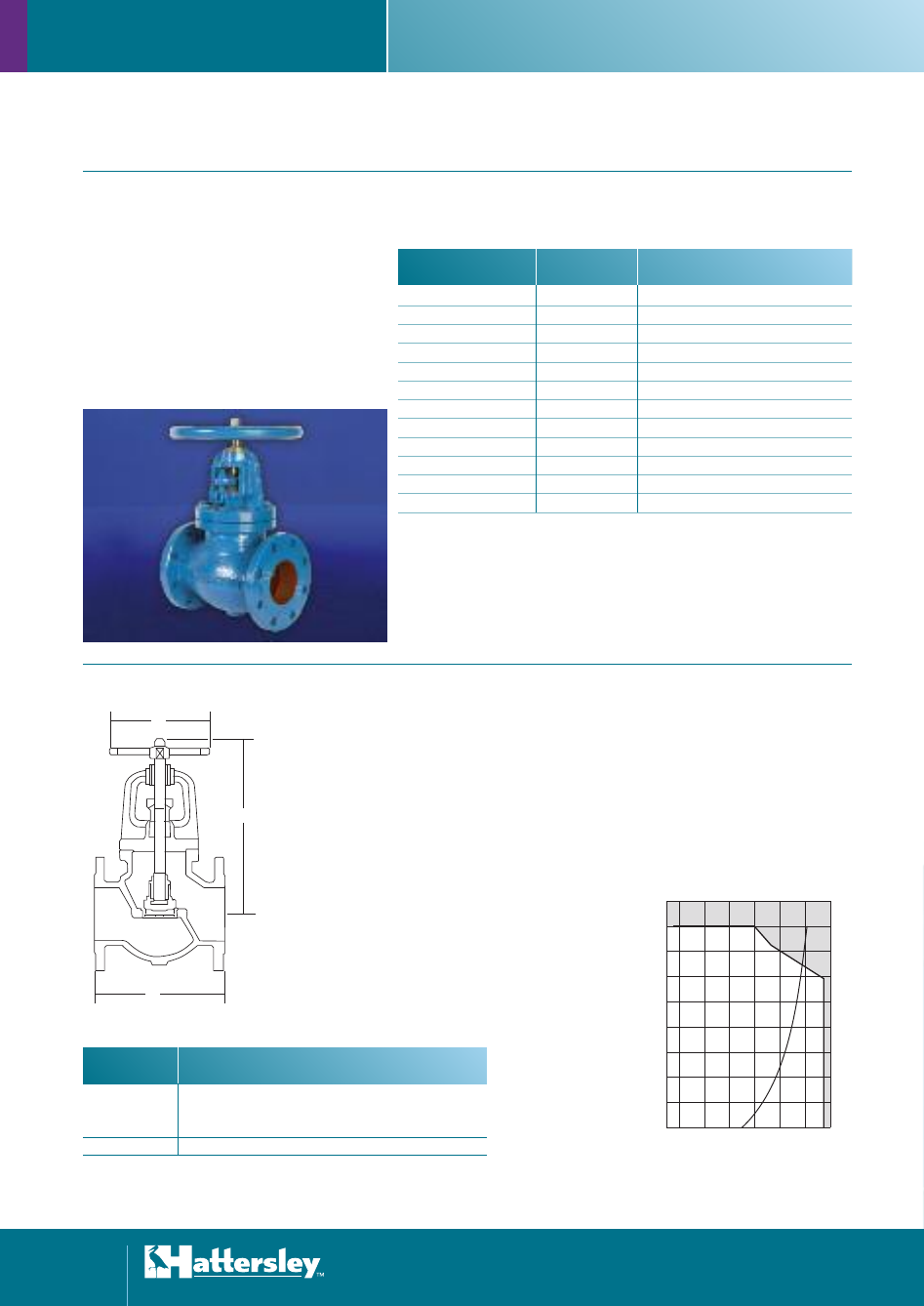
Technical Helpline: 0845 604 1790
E: tech-enquiries@hattersley.com W: www.hattersley.com
154
GLOBE VALVES
PN16
Every effort has been made to ensure that the information contained in this publication is accurate at the time of publishing.
Hattersley Ltd assumes no responsibility or liability for typographical errors or omissions or for any misinterpretation of the
information within the publication and reserves the right to change without notice.
Fig. 731
Cast Iron
DIMENSIONAL DRAWINGS PRESSURE/
TEMPERATURE
RATING
16 bar from -10 to 120ºC
11.8 bar at 230ºC
TEST PRESSURES
(HYDRAULIC)
Body: 24 bar
Seat: 17.6 bar
SPECIFICATION
BS EN 13789:2010.
Face to face dimensions BS EN 588-1 basic series 10.
Cast iron body and bonnet.
Outside screw, rising stem.
Bronze trim.
Sizes DN125 to DN300 have a centre guided disc.
Handwheel operated.
Flanged to BS EN 1092-2 PN16.
Also available flanged BS 5152 ANSI 125 figure 731
ANSI.
MATERIAL SPECIFICATIONFEATURES AND BENEFITS
• Valve body is made of high grade cast iron
and has integral flanges
• Supplied with asbestos free gland packing
and gaskets
• Outside screw pattern with rising stem
• Ideal for use on more active media where fluid
might have an adverse effect on thread
Nom
Size mm 50 65 80 100 125 150 200 250 300
A mm 203 216 241 292 330 356 495 622 698
B (open) mm 259 300 318 402 419 479 537 640 733
C mm 178 178 200 254 300 300 348 400 457
Weight kg 16 21 26 44 62 83 141 221 295
DIMENSIONS AND WEIGHTS
0 40 80 120 160 200 240
T emperature ˚ C
18
16
14
12
10
8
6
4
2
0
Pressure bar
S a t u r
a
t e d
S t
e
a m
B
A
C
Handwheel Cast Iron 1561 EN-JL1030 A126 CIB
Yoke Bush Bronze 1982 CC491K B62 C83600
Stem Brass 12164 CW603R B16 C36000
Gland Flange Ductile Iron 1563 EN-JS1030 A536 65-45-12
Gland Follower Bronze 1982 CC491K B62 C83600
Gland Packing Graphite
Bonnet Cast Iron 1561 EN-JL1040 A126 ClB
Bonnet Gasket Graphite
Disc Stem Nut Bronze 1982 CC491K B62 C83600
Disc Bronze 1982 CC491K B584 C83600
Body Seat Ring Bronze 1982 CC491K B584 C83600
Body Cast Iron 1561 EN-JL1040 A126 ClB
Component Material Specification
BS EN ASTM

Technical Helpline: 0845 604 1790
E: tech-enquiries@hattersley.com W: www.hattersley.com
155
LUBRICATED PLUG VALVES
Lubricated Plug Valves
The principle of the HNH-Milliken plug valve is as
simple as its design. The plug, which is the only
moving part of the valve, when open, presents a
straight through passage in line with the pipeline,
and when turned through 90° to the closed
position stops the flow.
A special sealing compound is used to effect a
completely leak tight seal. When line pressure is
applied to the valve in the closed position, the
parallel plug is forced to the downstream side of
the valve. The plug is then in contact with the
body in the area surrounding the outlet port.
The sealing compound, which surrounds the
outlet port by means of special grooves in the
plug, forms a barrier to line pressure. It is also
spread over the sealing surfaces of the plug and
body so that a very thin film of compound is
established between the plug and body surfaces
on the downstream side.
The metal to metal contact of plug and body
together with the barrier of sealing compound
ensures a completely leak tight valve. The sealing
compound to some extent preserves the body
and plug surfaces from corrosion, and provides
lubrication for ease of operation. Providing the
valve is correctly maintained, which in general
simply means injecting a small amount of sealing
compound from time to time and moving the
plug, a valve giving positive shut-off will result in
and provide many years of satisfactory service.
Specification
Screwed end valve are supplied screwed internal
to BS EN 10266 (ISO 7) or API Line Pipe Thread
as required.
PN16 flanged end valves are drilled to
BS EN 1092 2PN16 and class 125 conform
to ANSI B16.1 Class 125.
PN25 flanged end valves are drilled to
BS EN 1092 2PN25 and Class 250 conform
to ANSI B16.1 Class 250.
Steam Jacketing
Steam jacketed bottom covers can be fitted to the HNH-Milliken valves shown in the table.
Steam jacketing is used on viscous services where heat is required to keep the media in a liquid state.
Health and Safety
HNH-Milliken plug valves contain sealing
compound and grease which, for their intended
use, do not present a significant hazard to health.
If skin contact occurs when recharging the valve
with compound wash hands thoroughly with
soap and water and maintain good standards of
hygiene.
Health and safety data sheets are available for
each compound and give guidance on safe
handling and remedial action if misused.
Flanges
This catalogue provides information for screwed
end valves and valves fitted with flanges to
BS EN 1092-2 and ANSI B16.1. Valves with
BS10 flanges can be supplied, details on
application.
Gearing
In this catalogue the dimensional tables indicate
where, in our opinion, valves should be fitted with
gearing.
Steam Jacket Availability
Nom Size mm 25 32 40 50 65 80 100 125 150 200 250
in 11
1/4 11/2 22
1/2 345 6810
200S -- -•••••--
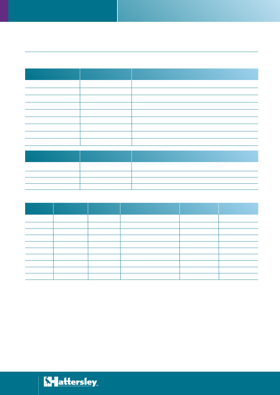
Technical Helpline: 0845 604 1790
E: tech-enquiries@hattersley.com W: www.hattersley.com
156
LUBRICATED PLUG VALVES
Every effort has been made to ensure that the information contained in this publication is accurate at the time of publishing.
Hattersley Ltd assumes no responsibility or liability for typographical errors or omissions or for any misinterpretation of the
information within the publication and reserves the right to change without notice.
VALVE PRESSURE/
TEMPERATURE RATING
The pressure/temperature ratings given apply
to the valve only.
The maximum temperature at which a valve
may operate depends upon the sealing
compound with which the valve is filled.
However, should the sealing compound have
an operating temperature different to that of
the valve the lower temperature must apply.
Cast Iron HNH-Milliken Plug Valves Operating and Test Pressures
Flanged Sizes Pressure/Temperature Rating
Hot Cold
BS EN 1092-2 PN16 All 11.2 bar at 250°C 16 bar from -10 to 120°C
ANSI B16.1 Class 125
1/2
to 12" 125lbf/in2at 450°F 200lbf/in2from -20 to 150°F
ANSI B16.1 Class 125 14 to 24" 100lbf/in2at 353°F 150lbf/in2from -20 to 150°F
BS1560 Class 125 15 to 300mm 8.6 bar at 230°C 13.8 bar from -10 to 65°C
BS1560 Class 125 350 to 600mm 6.9 bar at 180°C 10.3 bar from -10 to 65°C
ANSI B16.1 Class 250
1/2
to 12" 250Ibf/in2at 450°F 500lbf/in2from -20 to 150°F
ANSI B16.1 Class 250 14 to 24" 200lbf/in2at 406°F 300lbf/in2from -20 to 150°F
BS1560 Class 250 15 to 300mm 17.2 bar at 230°C 34.5 bar from -10 to 65°C
BS1560 Class 250 350 to 600mm 14.1 bar at 200°C 20.7 bar from -10 to 65°C
Screwed Sizes Pressure/Temperature Rating
Hot Cold
PN16 All 10.8 bar at 260
°
C 16 bar from -10 to 120
°
C
(157lbf/in
2
at 500
°
F) (232lbf/in
2
from -23 to 248
°
F)
Class 250All 17.5 bar at 260
°
C 34.5 bar from -10 to 120
°
C
(253lbf/in
2
at 500
°
F) (500lbf/in
2
from -23 to 248
°
F)
Fig. No End Pressure Nominal Body Test Seat Test
Connection Rating Size bar lbf/in2 bar lbf/in2
200M DN15 (1/2") to DN80 (3")
200R Screwed PN16 DN25 (1") to DN50 (2") 24.0 348 17.6 255
200L/T DN15 (1/2") to DN50 (2")
171MG Flanged PN16 DN150 (6") to DN600 (24")
201M Flanged PN16 DN25 (1") to DN200 (8") 24.0 348 17.6 255
201R Flanged ANSI 125 DN32 (11/4") to DN100 (4") 24.1 350 13.8 200
201T Flanged ANSI 125 DN50 (2") to DN150 (6") 18.3 265 12.1 175
221T DN80 (3")
205M
401M Flanged ANSI 250 DN50 (2”) to DN150 (6”) 51.7 750 34.5 500
}
}
Hydrostatic Test Pressures
Note 1: All valves 1/2" to 11/2" inclusive
are pneumatically tested to:
Body: 6 to 7 bar
Seat: 6 to 7 bar
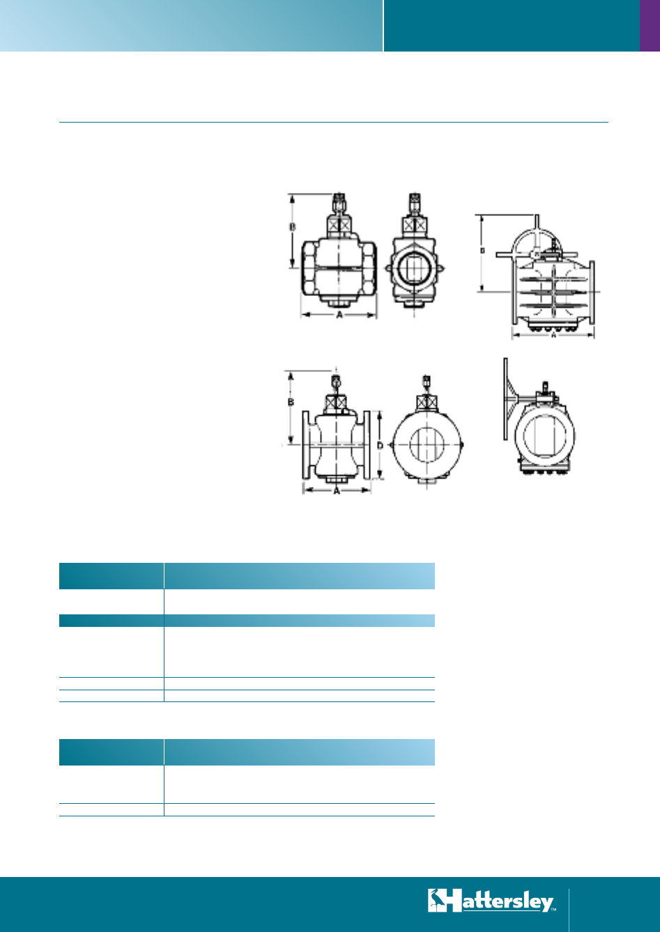
Technical Helpline: 0845 604 1790
E: tech-enquiries@hattersley.com W: www.hattersley.com
157
LUBRICATED PLUG VALVES
CLASS 125
Every effort has been made to ensure that the information contained in this publication is accurate at the time of publishing.
Hattersley Ltd assumes no responsibility or liability for typographical errors or omissions or for any misinterpretation of the
information within the publication and reserves the right to change without notice.
Fig. 170M (Screwed), 171M (Flanged)
Cast Iron HNH-Milliken - Short Pattern, Reduced Bore
DETAILS OF
TAPPED HOLES
The close proximity of the flange to
the body does not allow room for all
bolt holes to be drilled through.
These holes are drilled and tapped
as follows:
Valve size Tapped
125mm M16
150 to 200mm M20
250 to 300mm M24
FEATURES AND BENEFITS
• Sealing compound effects a completely
leak tight seal.
• When open - presents a straight through
passage in line with pipeline
• Stops flow after 90° turn
170M - Sizes 1" to 4"
171M - Sizes 1" to 8"
171MG* - Sizes 6" to 24"
supplied with fully
enclosed gearing
DIMENSIONAL DRAWINGS
Nom mm 25 32 40 50 65 80 100 125 150 200
Size in 1 11/4 11/2 2 21/2 3 4 5 6 8
A (170M) mm 92 102 111 152 165 187 225 - - -
A (171M) mm 102 111 118 178 190 203 225 254 267 292
in 4 43/8 45/8 7 71/2 8 9 10 101/2 111/2
B mm 103 108 119 127 197 206 254 270 298 327
D Flanged ANSI 125 in 41/4 45/8 5 6 7 71/2 9 10 11 131/2
Wrench (screwed) G G J J L L O - - -
Wrench (flanged) G/C G/C J/C J L L O P P Q
Weight (screwed) kg 1.7 1.9 2.4 4.3 6.6 10 21 - - -
Weight (flanged) kg 2.9 4.2 5.0 8.2 11 17 24 44 57 77
DIMENSIONS AND WEIGHTS
Dimensions 170M and 171M
Nom mm 150 200 250 300 400 450 500 600
Size in 6 8 10 12 16 18 20 24
A mm 267 292 330 356 762 864 914 1067
B mm 380 473 532 576 738 802 843 914
D Flanged ANSI 125 in 11 131/2 16 19 231/2 25 271/2 32
Weight kg 71 95 163 224 558 625 1190 1610
Dimensions 171MG (with gear unit)
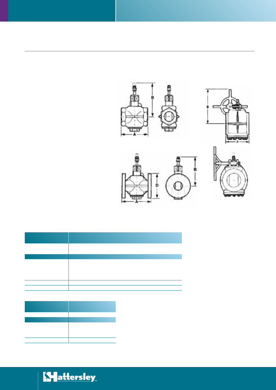
Technical Helpline: 0845 604 1790
E: tech-enquiries@hattersley.com W: www.hattersley.com
158
LUBRICATED PLUG VALVES
CLASS 125
Every effort has been made to ensure that the information contained in this publication is accurate at the time of publishing.
Hattersley Ltd assumes no responsibility or liability for typographical errors or omissions or for any misinterpretation of the
information within the publication and reserves the right to change without notice.
Fig. 200M (Screwed), 201M (Flanged)
Cast Iron HNH-Milliken - Short Pattern, Full Bore
FEATURES AND BENEFITS
• Sealing compound effects a completely
leak tight seal.
• When open - presents a straight through
passage in line with pipeline
• Stops flow after 90° turn
DETAILS OF
TAPPED HOLES
The close proximity of the flange to
the body does not allow room for all
bolt holes to be drilled through.
These holes are drilled and tapped
as follows:
Valve size Tapped
100 and 125mm M16
150 to 200mm M20
200M - Sizes 1/2" to 3"
201M - Sizes 1" to 8"
Sizes 5", 6" and 8" have bolted
bottom cover
201M - Sizes 5" to 8"
Nom mm 15 20 25 32 40 50 65 80 100 125 150
Size in 1/2 3/4 1 11/4 11/2 2 21/2 3 4 5 6
A (200M) mm 81 88 106 111 117 152 165 187 - - -
A (201M) mm - - 121 111 117 178 190 203 229 254 267
in - - 43/4 43/8 45/8 7 71/2 8 9 10 101/2
B mm - - 108 124 127 197 206 254 270 299 327
D Flanged PN16 mm - - 115 140 150 165 185 200 220 250 285
D Flanged ANSI 125 in - - 41/4 45/8 5 6 7 71/2 9 10 11
Wrench G G G J J L L O P P Q
Weight (200M) kg 0.8 1.2 2.1 2.6 3.1 6.0 8.8 14 31 - -
Weight (201M) kg 2.7 2.7 3.9 4.6 5.7 10 13 19 39 58 77
DIMENSIONS AND WEIGHTS
Dimensions 200M and 201M
Nom mm 125 150 200
Size in 5 6 8
A mm 254 267 292
in 10 101/2 111/2
B mm 381 473 533
D Flanged PN16 mm 250 285 340
D Flanged ANSI 125 in 10 11 131/4
Weight kg 72 95 167
Dimensions 201MG (with gear unit)
DIMENSIONAL DRAWINGS
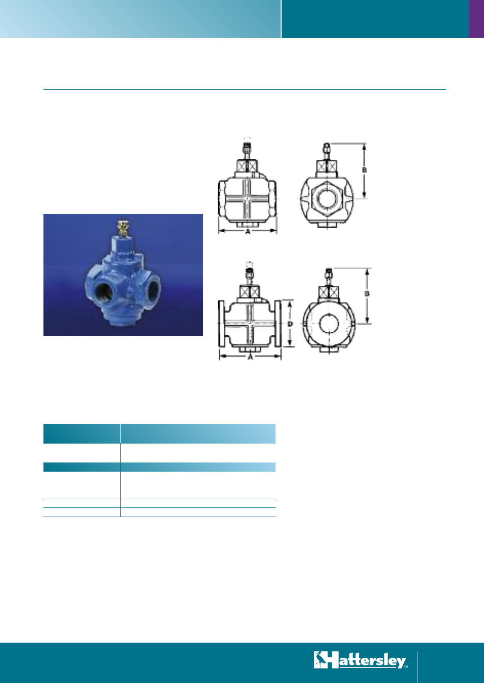
Technical Helpline: 0845 604 1790
E: tech-enquiries@hattersley.com W: www.hattersley.com
159
LUBRICATED PLUG VALVES
PN16 & CLASS 125
Every effort has been made to ensure that the information contained in this publication is accurate at the time of publishing.
Hattersley Ltd assumes no responsibility or liability for typographical errors or omissions or for any misinterpretation of the
information within the publication and reserves the right to change without notice.
Fig. 200R (Screwed), 201R (Flanged)
Cast Iron HNH-Milliken Plug Valves - Round Port, Full Bore
FEATURES AND BENEFITS
• Sealing compound effects a completely
leak tight seal.
• When open - presents a straight through
passage in line with pipeline
• Stops flow after 90° turn
Nom mm 25 32 40 50 65 80 100
Size in 1 11/4 11/2 2 21/2 3 4
A (200R) mm 106 - 140 190 - - -
A (201R) mm - 127 133 190 222 244 324
in 5 51/4 71/2 83/4 95/8 123/4 -
B mm 114 124 140 206 216 245 286
D Flanged ANSI 125 in 41/4 45/8 5 6 7 71/2 9
Wrench J J L O O P Q
Weight (200R) kg 1.9 3.6 4.9 12 19 25 60
Weight (201R) kg 3.8 5.8 7.5 17 23 30 61
DIMENSIONS AND WEIGHTS
Dimensions 200R and 201R
DIMENSIONAL DRAWINGS
200R - Sizes 1", 11/2" and 2" only
201R - Sizes 11/4" to 4"
4" size has bolted bottom cover
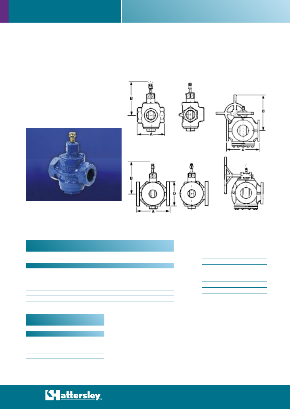
Technical Helpline: 0845 604 1790
E: tech-enquiries@hattersley.com W: www.hattersley.com
160
LUBRICATED PLUG VALVES
PN16 & CLASS 125
Every effort has been made to ensure that the information contained in this publication is accurate at the time of publishing.
Hattersley Ltd assumes no responsibility or liability for typographical errors or omissions or for any misinterpretation of the
information within the publication and reserves the right to change without notice.
Fig. 200L/T, 201T, 201TG Fig. 221T
Cast Iron HNH-Milliken Plug Valves - 3 Way Pattern L-Port & T-Port
FEATURES AND BENEFITS
• Sealing compound effects a completely
leak tight seal.
• When open - presents a straight through
passage in line with pipeline
• Stops flow after 90° turn
VALVE IDENTIFICATION
Ends Operation Fig No
Non-transflow
Screwed Wrench 200L
Screwed Wrench 200T
Flanged Wrench 201T
Flanged Geared 201TG
Transflow
Flanged Wrench 221T
Transflow pattern valves allow reduced
flow through the ports during rotation of
the plug from one position to another.
Nom mm 15 20 25 32 40 50 65 80 100
Size in 1/2 3/4 1 11/4 11/2 2 21/2 3 4
A (200L/T) mm 99 99 108 127 140 162 - - -
A (201T/221T) mm - - - - - 216 248 267 324
in - - - - - 81/2 93/4 101/2 123/4
B mm 108 108 118 133 133 206 222 257 302
Flanged PN16 mm - - - - - 165 185 200 220
D Flanged ANSI 125 in - - - - - 6 7 71/2 9
Wrench G G J J L L O P Q
Weight (screwed) kg 1.7 1.6 2.5 3.8 5.2 8.4 15 29 51
Weight (flanged) kg - - - - - 13 24 39 82
DIMENSIONS AND WEIGHTS
Dimensions (wrench operated)
Nom mm 125 150
Size in 5 6
A mm 387 406
in 151/4 16
B mm 476 521
D Flanged PN16 mm 250 285
D Flanged ANSI 125 in 10 11
Weight kg 125 151
Dimensions (with gear unit)
DIMENSIONAL DRAWINGS
200L, 200T - Sizes 1/2" to 2"
>4" size has bolted cover
201T - Sizes 2" to 4", 221T - 80mm only
>4" size has bolted cover
201TG - Sizes 5" to 6"
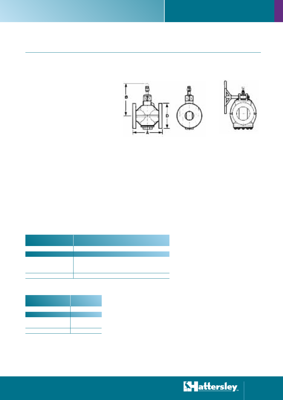
Technical Helpline: 0845 604 1790
E: tech-enquiries@hattersley.com W: www.hattersley.com
161
LUBRICATED PLUG VALVES
CLASS 250
Every effort has been made to ensure that the information contained in this publication is accurate at the time of publishing.
Hattersley Ltd assumes no responsibility or liability for typographical errors or omissions or for any misinterpretation of the
information within the publication and reserves the right to change without notice.
Fig. 401M (Flanged)
Cast Iron HNH-Milliken Plug Valves - Regular Pattern, Full Bore
FEATURES AND BENEFITS
• Sealing compound effects a completely
leak tight seal.
• When open - presents a straight through
passage in line with pipeline
• Stops flow after 90° turn
Nom mm 15 20 25 32 40 50 65 80 100
Size in 1/2 3/4 1 11/4 11/2 2 21/2 3 4
A (401M) mm - - - - - 216 241 283 305
in - - - - - 81/2 91/2 111/8 12
B mm 102 105 108 124 127 187 206 254 270
D Flanged ANSI 250 in - - 47/8 51/4 61/8 61/2 71/2 81/4 10
Wrench G G G J J L L O P
Weight (401M) kg 3.0 3.7 5.0 5.6 7.0 15 17 28 51
DIMENSIONS AND WEIGHTS
Dimensions 401M
Nom mm 125 150
Size in 5 6
A mm 381 403
in 15 157/8
B mm 381 473
D Flanged ANSI 250 in 11 121/2
Weight kg 92 120
Dimensions 401MG (with gear unit)
DIMENSIONAL DRAWINGS
401M - Sizes 2" to 4" 401MG
- Sizes 5
"
to 6
"
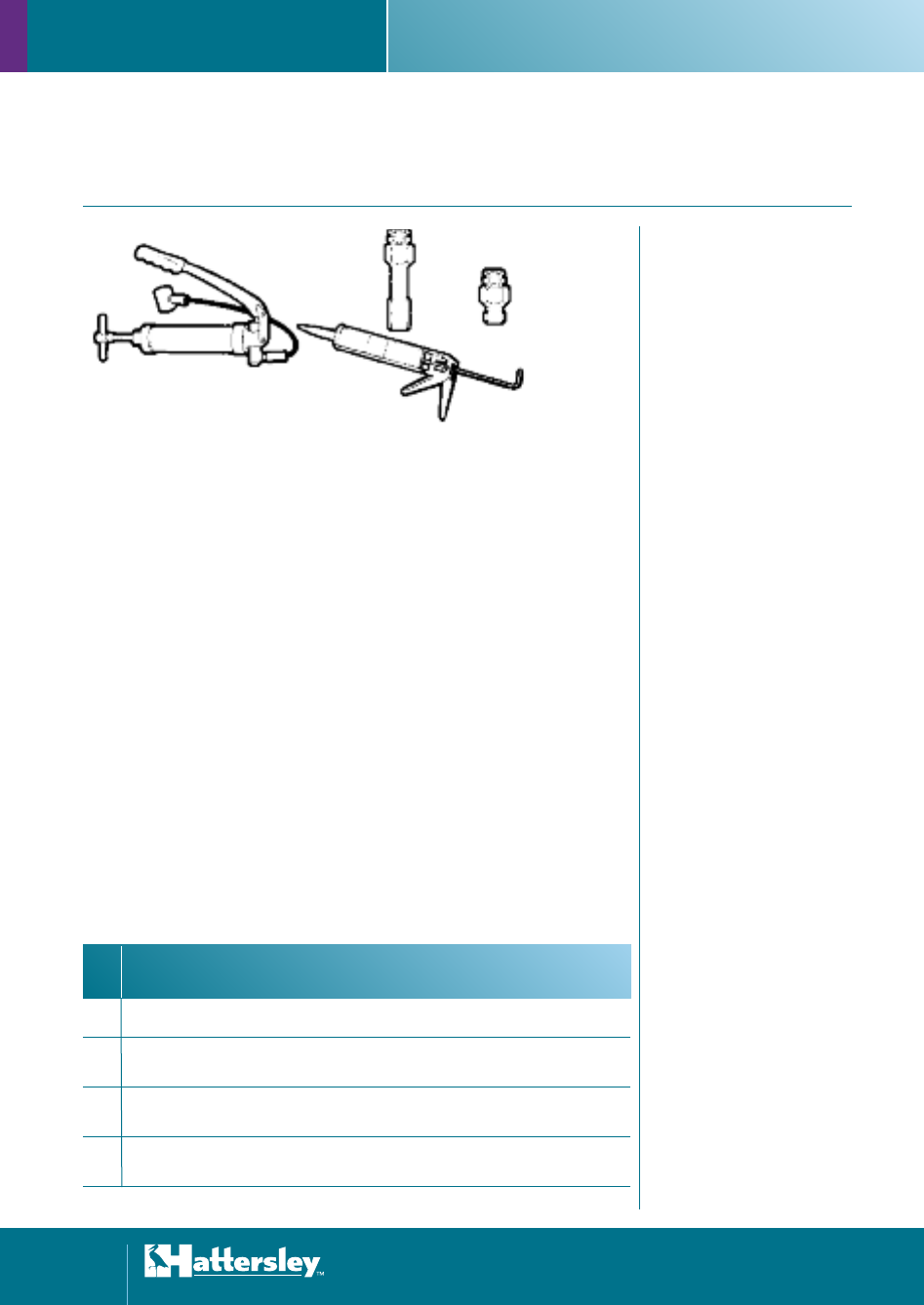
Technical Helpline: 0845 604 1790
E: tech-enquiries@hattersley.com W: www.hattersley.com
162
LUBRICATED PLUG VALVES
CLASS 250
Servicing Instructions
HNH-Milliken Parallel Plug Valves
Positive isolation with minimum maintenance
Sealing compound injection gun type NMG 40 for use
with pre-packed sealing compound cartridges.
For use with valves fitted with button head nipples and
combination sealing screws.
Combination
Sealing Screw
(for gun injection)
Button Head Nipple (for
gun injection)
Lightweight
compound gun
SEALING
In service sealing compound should be
used for each individual medium to
affect good isolation. Our
recommendations for sealing
compounds are the result of
considerable research. If there is any
doubt as to the suitability of a particular
compound for a given service, test
should be carried out in a new clean
valve. This is the only way to conduct
such tests. Laboratory tests using a
beaker of line fluid and immersing a stick
of compound have proved misleading.
Where samples of fluid can be supplied,
together with details of temperature and
pressure, and if known frequency of
operation, we will carry out specific
tests and give our recommendations
based upon the results.
CONSTRUCTION
Only five major parts are involved when
dismantling ie. body, parallel plug, PTFE
thrust ring, bottom cover and plug
support spring.
OPERATION
Care must be taken particularly with
geared valves that the plug is eased off
the body stop after operation to ensure
the plug is free to float.
ROUTINE
MAINTENANCE
Valves are despatched by Hattersley
charged with sealing compound. A
compound identification tag states
clearly that the valve has been
assembled and tested with a universal
compound. The user is advised to follow
the chart overleaf for specific
applications. When injecting additional
sealing compound, care should be taken
to ensure that it is of the correct type.
Where the service permits, the valve
should be partially or fully operated once
to ensure free operation and to
determine the effort required.
For infrequently operated valves
maintenance merely consists of two or
three turns of the combination screw or,
if gun injection, several strokes of the
lever, and opening and closing the valve
a minimum of three times to distribute
the compound evenly around the plug at
three monthly intervals. It is difficult to
be specific how often the valve should
be recharged with sealing compound,
since this is determined by the frequency
of operation, type of service, pressure
and temperature.
No. Temperature Colour of Colour Availability Do NOT Cleaning
Range Compound of Box use for Solvent
Label
18* 32° to 450°F Black Buff Bulk Water or Strong Water
0° to 230°C Chemicals Trichloroethane
44 -40° to 284°F Black Green Tubes, Bulk Strong Chemicals Trichloroethane
-40° to 140°C Prepacked and Strong Trichloroethane
Cartridges Chemicals
74 -31° to 500°F Grey Apple Green Bulk and Nitrating Acids Paraffin
-34° to 260°C Prepacked Steam, HTHW Hot Water
Cartridges
90** -20° to 375°F White White Bulk and Solvents Acetone
-30° to 190°C Prepacked
Cartridges
* Not suitable for gun injection ** UK WFBS Listed
Injection of Compound
When the combination screw has reached its
limit (screwed fully down) this indicates that
the valve needs recharging with sealing
compound.
When using the lightweight compound gun,
remove the combination screw, partially fill the
compound reservoir in the plug, replace the
combination screw, and screw down.
This operation may need repeating several
times. When using the NMG 40 high pressure
gun, attach the nozzle to the injection nipple
and give several steady stokes of the lever.
VALVES MUST EITHER BE FULLY OPEN OR
FULLY CLOSED WHILST THEY ARE BEING
CHARGED.
Indication of Full Charging
The first indication of the valve becoming fully
charged is an increase in the effort required to
rotate the combination screw, or with the high
pressure gun injection an increase in the effort
required on the lever.
The effort required to operate the valve should
have increased from the initial operation prior
to injection of sealing compound.
Method of injection
Where the number of valves to be charged is
small, ie. 12-15 valves, especially if they are in
the smaller sizes, lightweight gun injection
can be successfully used. For larger
quantities use of the NMG40 high pressure
gun is recommended.
Valve Leakage
Leakage through the valve indicates that the
valve requires injection of sealing compound
or that it needs opening and closing a
minimum of three times to distribute the
compound evenly.
Operating Torque
Should a valve become jammed or unusually
stiff to operate, this can generally be cured by
the injection of sealing compound. If this is
ineffective, it will be necessary to dismantle
the valve, clean the components and
recharge with sealing compound.
Servicing
Advice is available from the Hattersley Service
Department in connection with all aspects of
operation, lubrication and maintenance.

Technical Helpline: 0845 604 1790
E: tech-enquiries@hattersley.com W: www.hattersley.com
163
LUBRICATED PLUG VALVES
Sealing Compound Recommendations
Acetone/Acetate 74
Acetone 74
Air 90,74
Alcohols 74
Alkaline Solutions 74
Ammonia Anhydrous 74
Ammonia (Gas) 74
Ammonia (Liquid) 74
Ammoniacal Copper Hydroxide 74
Ammonium Hydroxide 74
Amyl Alcohol (Pure) 74
Anline Dyes 74
Anthracine Oil 74
Aromatic Hydrocarbons 44
Aromatic Solvents 44
Asphalt 18,74
Asphalt Emulsions 18,74
Barium Hydroxide 74
Beet Sugar Liquors 90
Benzene 44
Benzyl Alcohol 74
Bocarbonate of Soda 74
Bitumen 18,74
Blast Furnace Gas 90,74
Boiler Blow Down 90
Borax 90
Brake Fluid 74
Bunker Fuel 161
Butadiene 44
Butane (Gas or Liquid) 44
Butanol 74
Butyl Alcohol 74
Calcium Chloride Solution 90,74
Calcium Hydroxide (Lime Water) 90,74
Calcium Sulphate 90,74
Cane Sugar Liquors 90
Carbolic Acid (Phenol Sol.) 74
Carbonate of Soda 74
Carbon Bisulphide 44
Carbon Dioxide 90,74
Carbon Monoxide Gas 90,74
Carburetted Water Gas 44,74
Caster Oil 74
Caustic Potash 74
Caustic Soda 74
Cellulose Acetate Solutions 74
Cellulose Nitrate 74
Cement (Dry) 90,74
Cement Slurries 90,74
Chloride of Lime 90,74
Chocolate No
compound
Chrome Alum 90,74
Chrome Tanning Liquor 90,74
Coal Gas 44
Coal Gas Condensate 90,44
Coal/Petroleum Mixed Gas
Condensate 90,44
Coal Tar 18
Coal Tar Oils 74
Coal Tar Solvents 44
Coal Washers 90,74
Coconut Oil 90,74
Coke Oven Gas 90,74
Condensate 90
Corn Oil 90,74
Corn Syrup (Glucose) 90
Cotton Seed Oil 90,74
Creosote 44,18
Cumene 44
Cutting Oil 44
Cyanide Solutions 90,74
Denatured Alcohol 74
Dextrine 90
Diesel Fuel 44
Distillate Petroleum 44
Disinfectant Solution 90
Enamel (see Paint)
Epsom Salts 90
Ethane Gas 44
Ethanalamine 74,44
Ether, Petroleum 44
Ethers 44
Ethyl Acetate 44
Ethyl Alcohol (Ethanol) 74
Ethyl Benzine 44
Ethyl Chloride Gas or Liquid 44
Ethylene 44,18
Ethylene Dichloride (Dry) 44,74
Ethyline Gas 44,18
Ethylene Glyco/Water Sol.
(50% Antifreeze) 90,74
Ethylene Glycol 74
Ferrous Chloride (Pure) 90,74
Fish Oil 44
Fuel JP4 44
Fuel Oil 44
Furlural 44
Gases *
Gas (Manufactured) 90,44
Gas (Natural) 90,44
Gas Oil 44
Gasoline 44
Glucose 90
Glycerine (Glycerol) 90,74
Grain Alcohols (Ethyl Alcohol) 74
Grease 44,74
Gypsum (Calcium Sulphate) 90
Helium Gas 90,44
Heptane 44
Heavy Oil (Coke Plant) 44
Hexane 44
Hydraulic Fluid (Haughtosafe 271) 44
Hydraulic Oil 44
Hydrocarbons (Aromatic) 44
Hydrogen Gas 90,44
Kerosene 44
Ketones (Not Acetone) 44,74
Lard 90
Latex *
Light Naphthas 44
Light Oil 44,74
Linseed Oil 90,74
Liquid Petroleum Gas (LPG) 44
Lubricating Oil 44
Lye Solutions (Alkalies) 74
Magnesium Hydroxide 90
Maltose (Malt Syrup) 90
Manufactured Gas 90,44
Methane Gas 90,44
Methyl Alcohol (Methanol) 74
Methyl Bromide 74
Methyl Chloride, Gas or Liquid 44
Methylated Spirits 74
Milk of Lime 90,74
Mineral Oil 44
Mineral Spirits 44
Molasses 90
Monoethanolomine 74,44
Service Sealing
Compound
Service Sealing
Compound
Service Sealing
Compound
* Refer to Technical Department

Technical Helpline: 0845 604 1790
E: tech-enquiries@hattersley.com W: www.hattersley.com
164
LUBRICATED PLUG VALVES
Sealing Compound Recommendations
Naptha 44
Naptha Vapours 44
Naphthalene 44,74
Natural Gas 90,44
Nitrobenzene 44
Nitrogen Gas 90,44
Oil Gas Mixture 44
Oil (Petroleum) 44
Oil Tar 18,74
Oil Water Mixtures 90,44
Paints
- Alcohol Solvent Base 74
- Hydrocarbon Solvent Base 44
- Varnish 44
- Water Based 90
- White Spirit Based 44
Paraffin 44
Paraffin Wax 90,44
Pentane 44
Petrolatum (Petroleum Jelly) 44,74
Petroleum Gas 90,44
Petroleum Ether 44
Phthalic Anhydride 74
Pine Resin 90,74
Pitch 18,74
Polyester Resin Solvent *
Polyisobutylene 44
Polyvinyl Acetate Emulsion *
Potash (Potassium Carbonate) 90,74
Potassium Cyanide Liquor 90,74
Potassium Sulphate 90
Producer Gas 90,44
Propane (Gas or Liquid) 90,44
Propylene 44
Pyridine *
Quenching Oil 44,18
Rapeseed Oil 90,44,74
Road Tars 18,74
Rosin (Fine Resin) *
Rubber Latex *
Rubber Solvent *
Sewage 90,44
Sewage Gas 90,44
Shell Cornea 44
Shell Garia “A” 44
Shell Turbine Oil 44
Shellac in Alcohol 74
Shock Absorber Oil (Mineral) *
Sludge and Sewage 90,44
Soap Solutions 90,74
Soda Liquor (Paper Industry) 74
Sodium Carbonate (Soda Ash) 74
Sodium Cyanide Solution 90,74
Sodium Hydroxide
(up to 50% Conc.) 74
Sodium Metasilicate 74
Sodium Nitrate 90
Sodium Phosphate (Tri-basic) 90,74
Sodium Silicate 74
Sodium Sulphate 90,74
Soluble Oil 90,74
Solvent Naphtha 17,44
Starch Solutions 90
Sugar Solutions 90
Sulphur (Liquid) 44,18,74
Sulphur Dioxide 74
Sulphur Trioxide 74
Synthetic Resins *
Synthetic Tannins *
Tanning Liquors 90,74
Tar 18,74
Tar Oil (Creosote) 44,18
Teepol 90
Tempering Oil 44,18
Tetraethyl Lead 44
Toluene (Toluol) 44
Triethanolamine 74
Trimethylamine 44,74
Trisodium Phosphate 90,74
Turpentine 44
Tallow 90
Vacuum Service 90,44
Varnish (See Paints)
Vegetable Oils 90,74
Vegetable Oils and Water 90,74
Vegetable Tannins 90,74
Vinyl Chloride Monomer 74
Water (Cold) 90
Water (Cold, Domestic) 90
Water (Hot, Heating) 90
Water/Gas 90,74
Water Softener Salts 90,74
Wax Emulsions 90,74
Waxes 44,74
White Spirit 44
Wood Alcohol (Methyl Alcohol) 74
Wort, Beer 90
Xylol (Xylene) 44
* Refer to Technical Department
Service Sealing
Compound
Service Sealing
Compound
Service Sealing
Compound
Technical Helpline: 0845 604 1790
E: tech-enquiries@hattersley.com W: www.hattersley.com
165
RADIATOR VALVES
Radiator Valves
Series 3000 radiator valves from Hattersley are
recognised as the industry standard for high
quality and dependable performance. The range
incorporates Thermostatic, Wheelhead and
Lockshield valves; and also a Universal valve
body to accommodate TRV and Wheel heads.
All valves are available in 1/2" and 3/4" BSP sizes,
each supplied complete with complementary
compression end adaptors.
The chrome plated brass valves are
complemented by a range of accessories
including Remote Sensors and Transmitters,
and Tamperproof TRV locks.
The Hattersley Series 3000 radiator valves enable
isolation, regulation and give thermostatic
control.
Universal Valve Body for TRV and Wheel Head
The range offers interchangeability of the TRV
head and the Wheelhead. The revolutionary
body design enables both the TRV head and
the Wheelhead to be connected directly to a
common valve body without the need for
adaptors. This design breakthrough therefore
reduces the cost of stock holding and increases
the versatility of the range.
Function
Thermostatic valves are typically used for
regulating the fluid flow to the radiators of central
heating systems. They are provided with a
regulating element which automatically controls
the opening of the valve to keep the ambient
temperature of the room, where they are
installed, constant at the set value. This prevents
unwanted temperature rises and achieves
considerable energy savings.
The Series 3000 Radiator valve range is
eminently suitable for building services
installations where durability and rugged
construction are predominant, while satisfying
the aesthetic requirements demanded for modern
commercial and domestic interiors.
Maximum working pressure: 10 bar operating
between 5 to 100°C.
The Hattersley range of valves and TRV controls
are approved to standards UNI EN 215.
Additional information available on request.
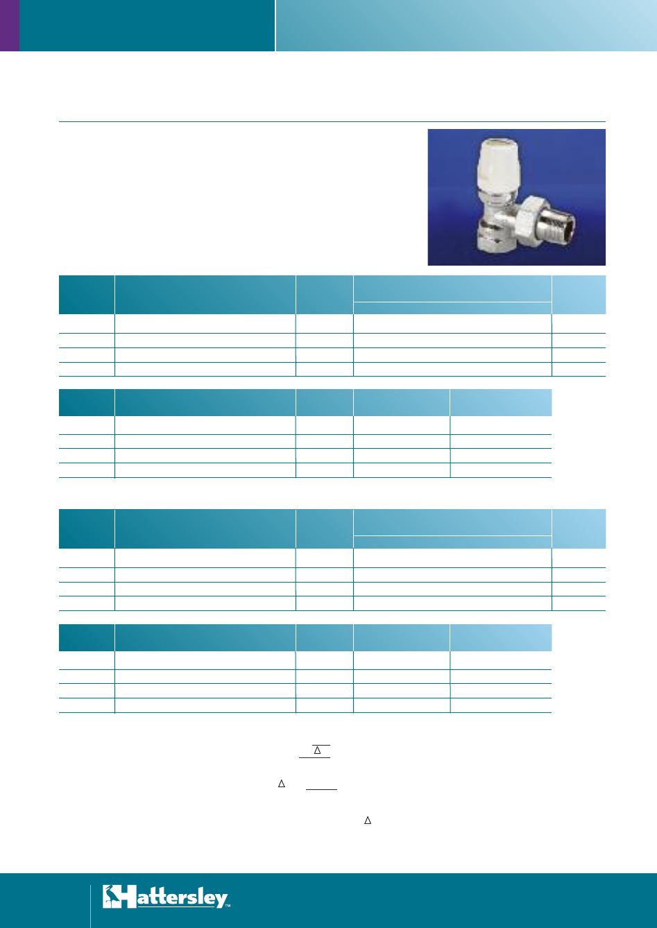
Technical Helpline: 0845 604 1790
E: tech-enquiries@hattersley.com W: www.hattersley.com
166
RADIATOR VALVES
Every effort has been made to ensure that the information contained in this publication is accurate at the time of publishing.
Hattersley Ltd assumes no responsibility or liability for typographical errors or omissions or for any misinterpretation of the
information within the publication and reserves the right to change without notice.
Series 3000
Hydraulic Characteristics
Kv (m3/h)
Fig. Description Size Proportional Band (K) Kvs
1 1.5 2 3
3100 Universal TRV/Wheel Valve Body 1/2" 0.34 0.52 0.64 0.90 2.39
3100 Universal TRV/Wheel Valve Body 3/4" 0.40 0.63 0.81 1.09 3.19
3300 Lockshield Valve 1/2" 0.34 0.52 0.64 0.90 2.39
3300 Lockshield Valve 3/4" 0.40 0.63 0.81 1.09 3.19
Valve with Angle Connections
Fig. Description Size Nominal Flow Max. Diff Pres.
(l/h) (bar)
3100 Universal TRV/Wheel Valve Body 1/2" 180 1
3100 Universal TRV/Wheel Valve Body 3/4" 240 1
3300 Lockshield Valve 1/2" 180 1
3300 Lockshield Valve 3/4" 240 1
Kv (m3/h)
Fig. Description Size Proportional Band (K) Kvs
1 1.5 2 3
3200 Universal TRV/Wheel Valve Body 1/2" 0.32 0.50 0.67 0.86 1.52
3200 Universal TRV/Wheel Valve Body 3/4" 0.43 0.63 0.82 1.05 2.20
3400 Lockshield Valve 1/2" 0.32 0.50 0.67 0.86 1.52
3400 Lockshield Valve 3/4" 0.43 0.63 0.82 1.05 2.20
Valve with Straight Connections
Fig. Description Size Nominal Flow Max. Diff Pres.
(l/h) (bar)
3200 Universal TRV/Wheel Valve Body 1/2" 180 1
3200 Universal TRV/Wheel Valve Body 3/4" 240 1
3400 Lockshield Valve 1/2" 180 1
3400 Lockshield Valve 3/4" 240 1
Kv = is flow rate in m3/h at 1 bar Dp at 20°C
Kvs = Kv with valve fully open
Flow and Headloss Calculation Formulae
Q = Kv√ p
36
p = Q x 36
Kv
where Q is in 1/s and p is in kPa
( )2
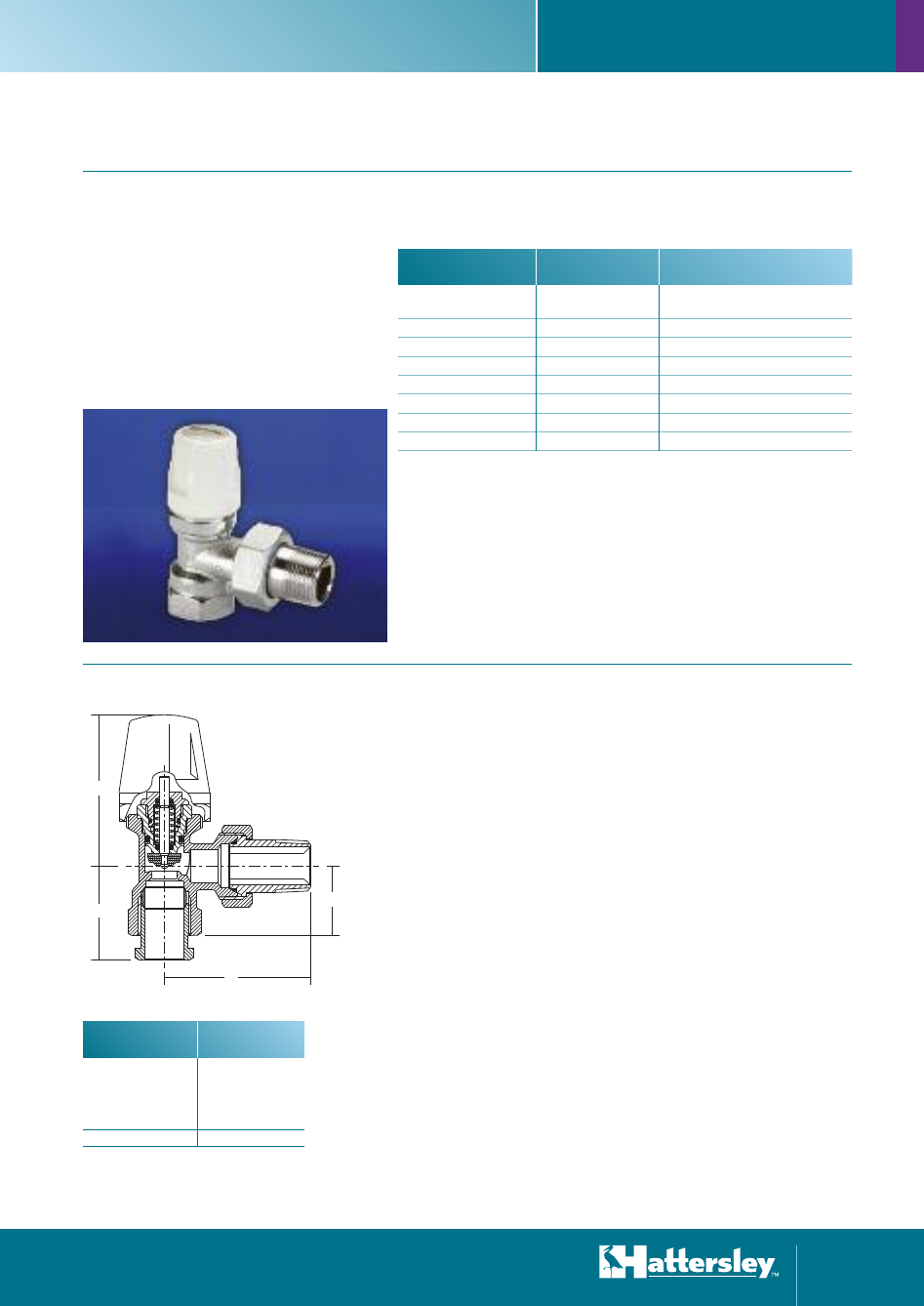
Technical Helpline: 0845 604 1790
E: tech-enquiries@hattersley.com W: www.hattersley.com
167
RADIATOR VALVES
Every effort has been made to ensure that the information contained in this publication is accurate at the time of publishing.
Hattersley Ltd assumes no responsibility or liability for typographical errors or omissions or for any misinterpretation of the
information within the publication and reserves the right to change without notice.
Fig. 3150
Angle Wheel Head
DIMENSIONAL DRAWINGS
MATERIAL SPECIFICATIONFEATURES AND BENEFITS
• Regulates the fluid flow to radiators of the
central heating system
• Prevents unwanted temperature rises
and achieves considerable energy savings
• Suitable for installations where durability
and rugged construction are predominant
Body Brass
(Chrome Plated) BS EN 12164 CW617N
Valve Insert Assembly EPDM Valve Disc
T80 Std Wheel Head Thermoplastic ABS
Tailpiece Ring Brass BS EN 12164 CW617N
Tailpiece Brass BS EN 12164 CW617N
Compression Olive Brass BS EN 12164 CW602N
Compression Adaptor Brass BS EN 12164 CW614N
Hydraulic Seals Rubber EPDM
Component Material Specification
BS EN
D
C
B
A
Nom
Size mm 15 22
A mm 60 61
B mm 37 42
C mm 27.5 30.5
D mm 58 66
Body Weight kg 0.350 0.519
DIMENSIONS AND WEIGHTS
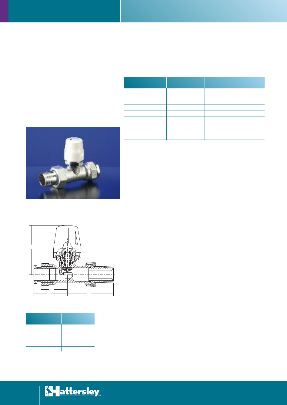
Technical Helpline: 0845 604 1790
E: tech-enquiries@hattersley.com W: www.hattersley.com
168
RADIATOR VALVES
Every effort has been made to ensure that the information contained in this publication is accurate at the time of publishing.
Hattersley Ltd assumes no responsibility or liability for typographical errors or omissions or for any misinterpretation of the
information within the publication and reserves the right to change without notice.
Fig. 3250
Straight Wheel Head
DIMENSIONAL DRAWINGS
FEATURES AND BENEFITS
• Regulates the fluid flow to radiators of the
central heating system
• Prevents unwanted temperature rises
and achieves considerable energy savings
• Suitable for installations where durability
and rugged construction are predominant
MATERIAL SPECIFICATION
Body Brass
(Chrome Plated) BS EN 12164 CW617N
Valve Insert Assembly EPDM Valve Disc
T80 Std Wheel Head Thermoplastic ABS
Tailpiece Ring Brass BS EN 12164 CW617N
Tailpiece Brass BS EN 12164 CW617N
Compression Olive Brass BS EN 12164 CW602N
Compression Adaptor Brass BS EN 12164 CW614N
Hydraulic Seals Rubber EPDM
Component Material Specification
BS EN
Nom
Size mm 15 22
A mm 64 64
B mm 34 40
C mm 44 51
D mm 60 65
Body Weight kg 0.391 0.580
DIMENSIONS AND WEIGHTS
A
B
D
C
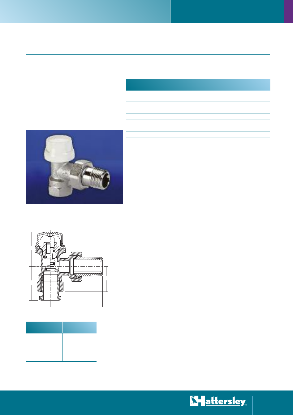
Technical Helpline: 0845 604 1790
E: tech-enquiries@hattersley.com W: www.hattersley.com
169
RADIATOR VALVES
Every effort has been made to ensure that the information contained in this publication is accurate at the time of publishing.
Hattersley Ltd assumes no responsibility or liability for typographical errors or omissions or for any misinterpretation of the
information within the publication and reserves the right to change without notice.
Fig. 3300LS
Angle Lockshield
DIMENSIONAL DRAWINGS
FEATURES AND BENEFITS
• Regulates the fluid flow to radiators of the
central heating system
• Prevents unwanted temperature rises
and achieves considerable energy savings
• Suitable for installations where durability
and rugged construction are predominant
MATERIAL SPECIFICATION
Body Brass
(Chrome Plated) BS EN 12164 CW617N
Lockshield Assembly Brass BS EN 12164 CW614N
Lockshield Cap Thermoplastic ABS
Tailpiece Ring Brass BS EN 12164 CW617N
Tailpiece Brass BS EN 12164 CW617N
Compression Olive Brass BS EN 12164 CW602N
Compression Adaptor Brass BS EN 12164 CW614N
Hydraulic Seals Rubber EPDM
Component Material Specification
BS EN
Nom
Size mm 15 22
A mm 36.5 40.5
B mm 38.5 39.5
C mm 27.5 30.5
D mm 58 66
Body Weight kg 0.232 0.387
DIMENSIONS AND WEIGHTS
A
B
D
C
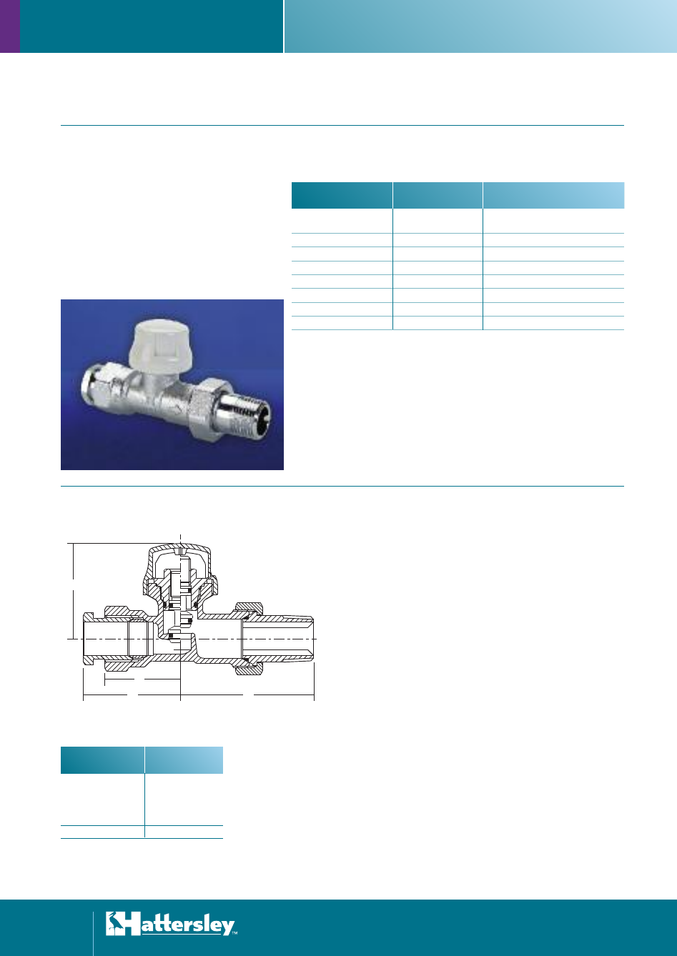
Technical Helpline: 0845 604 1790
E: tech-enquiries@hattersley.com W: www.hattersley.com
170
RADIATOR VALVES
Every effort has been made to ensure that the information contained in this publication is accurate at the time of publishing.
Hattersley Ltd assumes no responsibility or liability for typographical errors or omissions or for any misinterpretation of the
information within the publication and reserves the right to change without notice.
Fig. 3400LS
Straight Lockshield
DIMENSIONAL DRAWINGS
FEATURES AND BENEFITS
• Regulates the fluid flow to radiators of the
central heating system
• Prevents unwanted temperature rises
and achieves considerable energy savings
• Suitable for installations where durability
and rugged construction are predominant
A
B
D
C
MATERIAL SPECIFICATION
Body Brass
(Chrome Plated) BS EN 12164 CW617N
Lockshield Assembly Brass BS EN 12164 CW614N
Lockshield Cap Thermoplastic ABS
Tailpiece Ring Brass BS EN 12164 CW617N
Tailpiece Brass BS EN 12164 CW617N
Compression Olive Brass BS EN 12164 CW602N
Compression Adaptor Brass BS EN 12164 CW614N
Hydraulic Seals Rubber EPDM
Component Material Specification
BS EN
Nom
Size mm 15 22
A mm 43 44
B mm 34 40
C mm 44 51
D mm 60 65
Body Weight kg 0.232 0.387
DIMENSIONS AND WEIGHTS
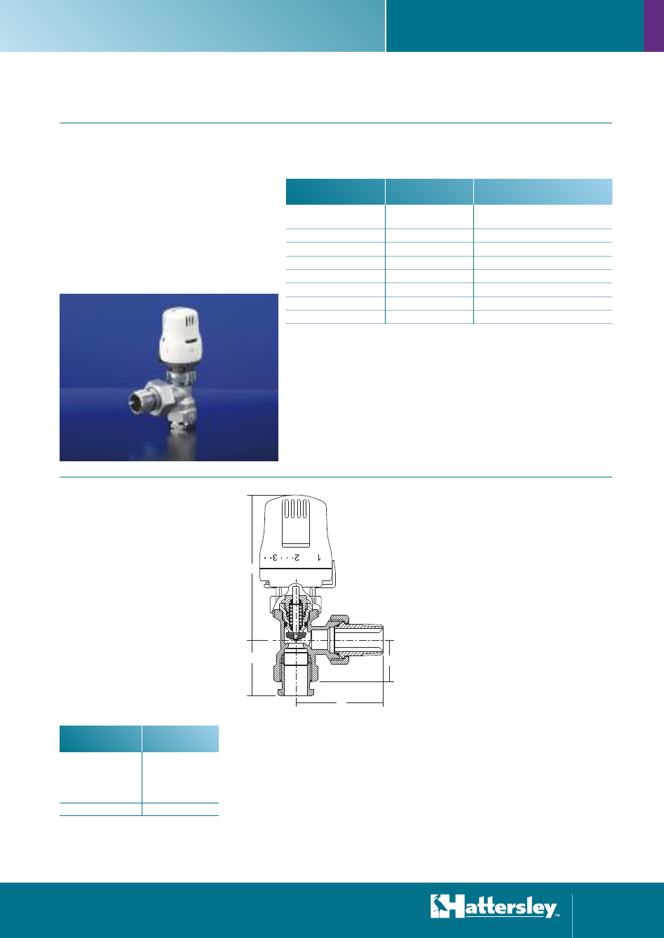
Technical Helpline: 0845 604 1790
E: tech-enquiries@hattersley.com W: www.hattersley.com
171
RADIATOR VALVES
Every effort has been made to ensure that the information contained in this publication is accurate at the time of publishing.
Hattersley Ltd assumes no responsibility or liability for typographical errors or omissions or for any misinterpretation of the
information within the publication and reserves the right to change without notice.
Fig. 3180
Angle TRV
DIMENSIONAL DRAWINGS
FEATURES AND BENEFITS
• Regulates the fluid flow to radiators of the
central heating system
• Prevents unwanted temperature rises
and achieves considerable energy savings
• Suitable for installations where durability
and rugged construction are predominant
Nom
Size mm 15 22
A mm 37 42
B mm 96 98
C mm 27.5 30.5
D mm 58 66
Body Weight kg 0.350 0.519
DIMENSIONS AND WEIGHTS
A
B
D
C
MATERIAL SPECIFICATION
Body Brass
(Chrome Plated) BS EN12164 CW617N
Valve Insert Assembly EPDM Valve Disc
T80 Std Wheel Head Thermoplastic ABS
Tailpiece Ring Brass BS EN12164 CW617N
Tailpiece Brass BS EN12164 CW617N
Compression Olive Brass BS EN12164 CW602N
Compression Adaptor Brass BS EN12164 CW614N
Hydraulic Seals Rubber EPDM
Component Material Specification
BS EN
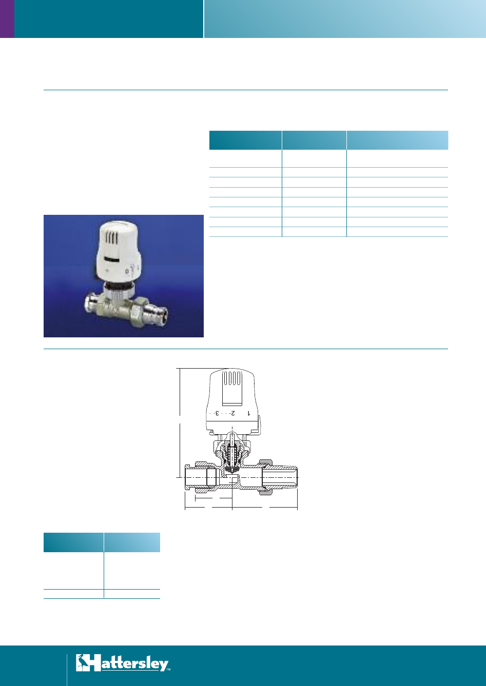
Technical Helpline: 0845 604 1790
E: tech-enquiries@hattersley.com W: www.hattersley.com
172
RADIATOR VALVES
Every effort has been made to ensure that the information contained in this publication is accurate at the time of publishing.
Hattersley Ltd assumes no responsibility or liability for typographical errors or omissions or for any misinterpretation of the
information within the publication and reserves the right to change without notice.
Fig. 3280
Straight TRV
DIMENSIONAL DRAWINGS
FEATURES AND BENEFITS
• Regulates the fluid flow to radiators of the
central heating system
• Prevents unwanted temperature rises
and achieves considerable energy savings
• Suitable for installations where durability
and rugged construction are predominant
A
B
DC
Nom
Size mm 15 22
A mm 100 100
B mm 34 40
C mm 44 51
D mm 60 65
Body Weight kg 0.391 0.580
DIMENSIONS AND WEIGHTS
MATERIAL SPECIFICATION
Body Brass
(Chrome Plated) BS EN 12164 CW617N
Valve Insert Assembly EPDM Valve Disc
T80 Std Wheel Head Thermoplastic ABS
Tailpiece Ring Brass BS EN 12164 CW617N
Tailpiece Brass BS EN 12164 CW617N
Compression Olive Brass BS EN 12164 CW602N
Compression Adaptor Brass BS EN 12164 CW614N
Hydraulic Seals Rubber EPDM
Component Material Specification
BS EN
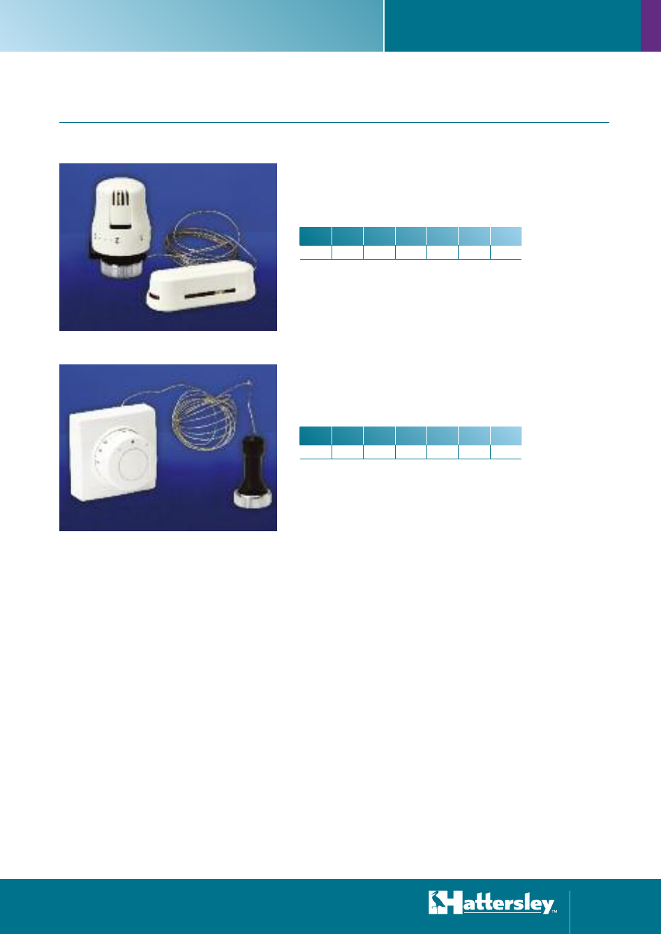
Technical Helpline: 0845 604 1790
E: tech-enquiries@hattersley.com W: www.hattersley.com
173
RADIATOR VALVES
Every effort has been made to ensure that the information contained in this publication is accurate at the time of publishing.
Hattersley Ltd assumes no responsibility or liability for typographical errors or omissions or for any misinterpretation of the
information within the publication and reserves the right to change without notice.
Fig. 75/RS and 70/RT
Accessories
TRV HEAD WITH REMOTE SENSOR FIG. 75/RS
Max isolating differential pressure 1 bar
Temperature adjustment range 0° to 28°C
Frost protection cut in 7° C
Max ambient temperature 50°C
Fig. 75/RS
Fig. 70/RT
0
*
1 2 3 4 5
0°C 7°C 12°C 16°C 20°C 24°C 28°C
TRV TRANSMITTER FIG. 70/RT
Max isolating differential pressure 1 bar
Temperature adjustment range 6° to 28°C
Frost protection cut in 6°C
Max ambient temperature 50°C
0
*
1 2 3 4 5
0°C 6°C 12°C 16°C 20°C 24°C 28°C
Technical Helpline: 0845 604 1790
E: tech-enquiries@hattersley.com W: www.hattersley.com
174
Wheelock Square Tower, Shanghai
Specification: Range of Hattersley Traditional Valves
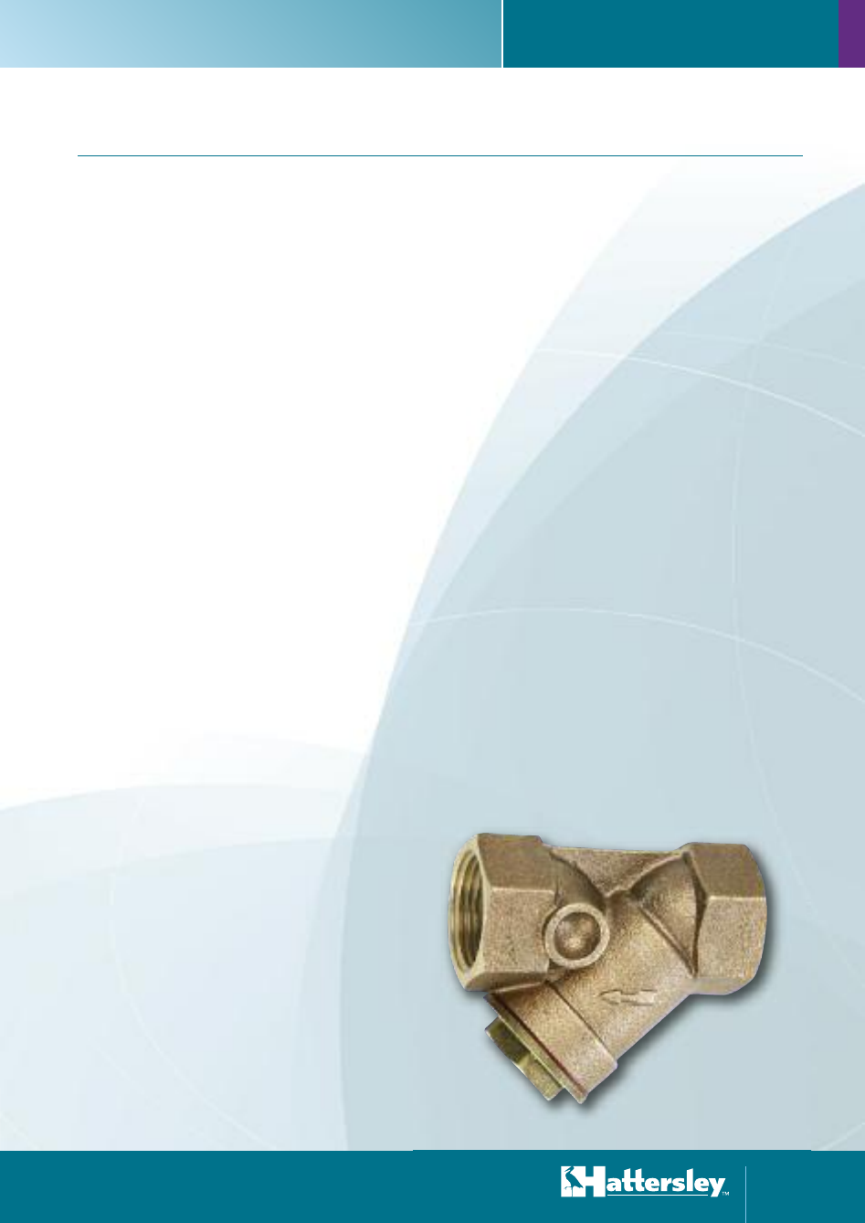
Technical Helpline: 0845 604 1790
E: tech-enquiries@hattersley.com W: www.hattersley.com
175
STRAINERS
Strainers
Scale and dirt in piping systems can cause endless trouble
and serious damage to pipeline equipment. Installation of
Hattersley strainers will help eliminate the problems caused
by foreign matter within piping systems. Generous
proportions of Hattersley strainers allow the units to collect
significant quantities of foreign matter before pressure
losses necessitate cleaning of the basket.

Technical Helpline: 0845 604 1790
E: tech-enquiries@hattersley.com W: www.hattersley.com
176
STRAINERS
PN16
Every effort has been made to ensure that the information contained in this publication is accurate at the time of publishing.
Hattersley Ltd assumes no responsibility or liability for typographical errors or omissions or for any misinterpretation of the
information within the publication and reserves the right to change without notice.
Fig. 817
Bronze Y-Type
DIMENSIONAL DRAWINGS
PRESSURE/
TEMPERATURE RATING
PN16
16 bar -10º to 100ºC
7 bar at 170ºC
TEST PRESSURES
(HYDRAULIC)
6 bar air
SPECIFICATION
Bronze body.
304 stainless steel.
End connections threaded to BS EN 10266
(BS21 Taper ISO R7) & B1.20.1 ANSI.
MATERIAL SPECIFICATION
Cap Bronze
Screen Stainless Steel 304
Body Bronze 1982 CC491K
Component Material Specification
BS EN
FEATURES AND BENEFITS
• Robust and high quality bronze body
• Streamlined flow contours minimise
pressure drop
• Compact design with short face to face
• Perforated stainless steel screen
• Captive asbestos-free non-stick gasket
• Comprehensive flow characteristics available
Nom
Size in 1/2 3/4 1 11/4 11/2 2
A mm 58 70 88 96 107 126
B mm 33 42 48 55 61 79
C mm 15 18 20 26 31 36
D mm 62 80 93 108 118 153
kv 4.8 8.8 16.1 25.5 36 38
Weight kg 0.2 0.3 0.4 0.7 1.0 1.5
DIMENSIONS AND WEIGHTS
A
B
D
C
D
=withdrawal distance for the screen
0 40 80 120 160 200
Temperature ˚C
18
16
14
12
10
8
6
4
2
0
Pressure bar
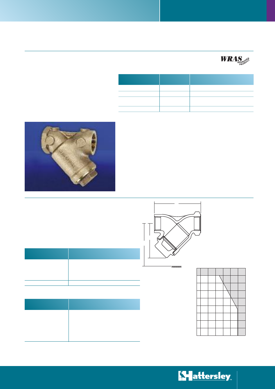
Technical Helpline: 0845 604 1790
E: tech-enquiries@hattersley.com W: www.hattersley.com
177
STRAINERS
PN32
Every effort has been made to ensure that the information contained in this publication is accurate at the time of publishing.
Hattersley Ltd assumes no responsibility or liability for typographical errors or omissions or for any misinterpretation of the
information within the publication and reserves the right to change without notice.
B
A
C
C
=withdrawal
distance for
strainer element
Fig. 807/907
Bronze Y-Type
MATERIAL SPECIFICATIONFEATURES AND BENEFITS
• Robust and high quality bronze body
• Streamlined flow contours minimise
pressure drop
• Compact design with short face to face
• Perforated stainless steel screen
• Captive asbestos-free non-stick gasket
• Comprehensive flow characteristics available
Body Bronze 1982 CC491K B62
Screen Stainless Steel 10088-1 X10CrNi18-10 AISI 304
Gasket Asbestos Free
(non-stick)
Cap Bronze 1982 CC491K B62
Component Material Specification
BS EN ASTM
Nom
Size in 1/2 3/4 1 11/4 11/2 2
Holes Dia mm 0.75 0.75 0.75 0.75 0.75 0.75
Holes cm2 50 50 50 50 50 50
Free Flow Area cm2 22.6 22.6 22.6 22.6 22.6 22.6
Element Area cm2 24.6 36 68.5 107.1 143.1 255
Free Flow Area cm2 5.5 8.1 15.5 24.2 32.3 57.6
% Nominal Bore 434 284 305 305 283 284
SCREEN DATA
0 40 80 120 160 200 240
T emperature ˚ C
28
24
20
16
12
4
0
Pressure bar
8
32
36
PRESSURE/
TEMPERATURE RATING
PN32
14 bar at 198°C
32 bar from -10 to 100°C
Note: Fig. 907 restricted to 135°C
TEST PRESSURES
(HYDRAULIC)
Shell: 6 bar air
SPECIFICATION
Standard screen has 0.75mm diameter
holes.
Screwed cap.
Ends threaded to BS EN 10266
(BS21 ISO R7).
Figure 907 supplied complete with two
Figure 631 test points and plugs.
DIMENSIONAL DRAWINGS
Nom
Size in 1/2 3/4 1 11/4 11/2 2
A mm 68 80 95 115 130 153
B mm 49 64 89 97 116 159
C mm 65 90 115 135 165 235
k Factor 3.3 4.2 3.6 3.2 3.3 3.5
Weight kg 0.4 0.5 0.9 1.5 1.8 3.3
DIMENSIONS AND WEIGHTS
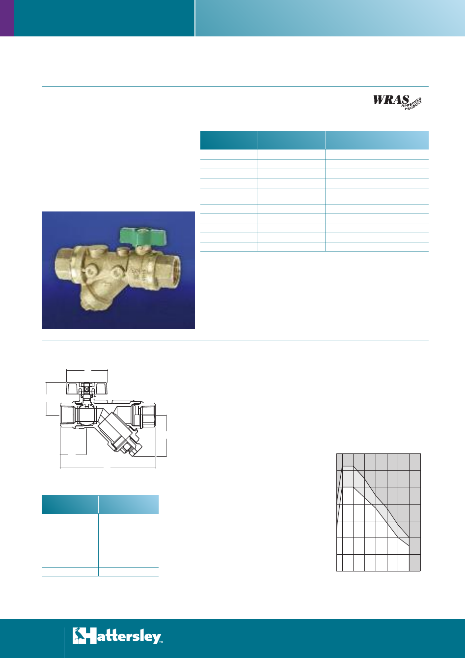
Technical Helpline: 0845 604 1790
E: tech-enquiries@hattersley.com W: www.hattersley.com
178
STRAINERS
PN25
Every effort has been made to ensure that the information contained in this publication is accurate at the time of publishing.
Hattersley Ltd assumes no responsibility or liability for typographical errors or omissions or for any misinterpretation of the
information within the publication and reserves the right to change without notice.
Fig. 1807
DZR Strainer Ball Valve
DIMENSIONAL DRAWINGS PRESSURE/
TEMPERATURE RATING
PN25 - 1/2 to 11/2" sizes
25 bar 0ºC to 20ºC, 7 bar at 120ºC
PN20 - 2" size
20 bar 0 to 20ºC, 6 bar at 120ºC
TEST PRESSURES
(PNEUMATIC)
6 bar
OPTIONAL FEATURES
Lever
Extension stem
Figure 103 hose outlet blowdown valve
SPECIFICATION
DZR body.
Blow-out proof stem.
Hard chrome plated ball.
Virgin PTFE seats.
T-Handle operated.
0.8mm diameter perforated 304
stainless steel screen.
Drain plug.
BS EN 10266 Taper threaded (ISO R7).
WRAS Approved Product.
MATERIAL SPECIFICATION
Handle Aluminium
Stem DZR Copper Alloy 12164 CW602N
Stem Seal EPDM
Gland Seals Virgin PTFE
Ball DZR Copper Alloy 12164 CW602N
Hard chrome plated
Seat Rings Virgin PTFE
Body DZR Copper Alloy 12165 CW602N
Screen Stainless Steel AISI 304
Cap Gasket Asbestos Free
Cap DZR Copper Alloy 12165 CW602N
Component Material Specification
BS EN ASTM
FEATURES AND BENEFITS
• Integral ball valve for quick and easy isolation
• Dezincification resistant body material prevents
corrosion and fungal growth
• Streamlined flow contours minimise
pressure drop
• Perforated stainless steel screen
1
/2" to
1
1
/
2
" S
i
z
e
s
2"
S
i
z
e
0 20 40 60 80 100 120 140
Temperature ˚C
28
24
20
16
12
4
0
Pressure bar
8
A
B
C
D
E
Nom
Size in 1/2 3/4 1
A mm 110 129 151
B mm 31 35 42
C mm 48 60 59
D mm 38 46 50
E mm 47 56 56
Drain Plug BSP 1/4 1/4 1/4
Weight kg 0.54 0.80 1.23
DIMENSIONS AND WEIGHTS
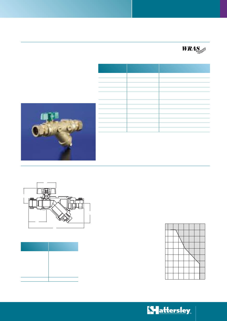
Technical Helpline: 0845 604 1790
E: tech-enquiries@hattersley.com W: www.hattersley.com
179
STRAINERS
PN16
Every effort has been made to ensure that the information contained in this publication is accurate at the time of publishing.
Hattersley Ltd assumes no responsibility or liability for typographical errors or omissions or for any misinterpretation of the
information within the publication and reserves the right to change without notice.
Fig. 1807C
DZR Strainer Ball Valve
DIMENSIONAL DRAWINGS PRESSURE/
TEMPERATURE RATING
PN16
5 bar at 120ºC
6 bar at 110ºC
10 bar at 65ºC
16 bar at -10 to 30ºC
TEST PRESSURES
(PNEUMATIC)
25 bar
OPTIONAL FEATURES
Lever
Extension stem
Figure 103 hose outlet blowdown valve
SPECIFICATION
DZR body.
Blow-out proof stem.
Hard chrome plated ball.
Virgin PTFE seats.
T-Handle operated.
0.8mm diameter perforated 304
stainless steel screen.
Drain plug.
Compression ends to BS EN 1254-2.
Use with R250 (half hard) copper tube.
WRAS Approved Product.
MATERIAL SPECIFICATIONFEATURES AND BENEFITS
• Integral ball valve for quick and easy isolation
• Dezincification resistant body material prevents
corrosion and fungal growth
• Streamlined flow contours minimise
pressure drop
• Perforated stainless steel screen
Handle Aluminium
Stem DZR Copper Alloy 12164 CW602N
Stem Seal EPDM
Gland Seals Virgin PTFE
Ball DZR Copper Alloy 12164 CW602N
Hard chrome plated
Seat Rings Virgin PTFE
Body DZR Copper Alloy 12165 CW602N
Screen Stainless Steel AISI 304
Cap Gasket Asbestos Free
Cap DZR Copper Alloy 12165 CW602N
Compression Ring Brass
Compression Nut Brass 12165 CW617N B124 C37700
Component Material Specification
BS EN ASTM
Nom
Size mm 15 22 28
A mm 137 159 175
B mm 45 50 53
C mm 48 60 59
D mm 38 46 50
E mm 47 56 56
Drain Plug BSP 1/4 1/4 1/4
Weight kg 0.6 0.9 1.3
DIMENSIONS AND WEIGHTS
0 20 40 60 80 100 120 14 0
Temperature ˚C
14
12
10
8
6
2
0
Pressure bar
4
16
18
A
B
C
D
E
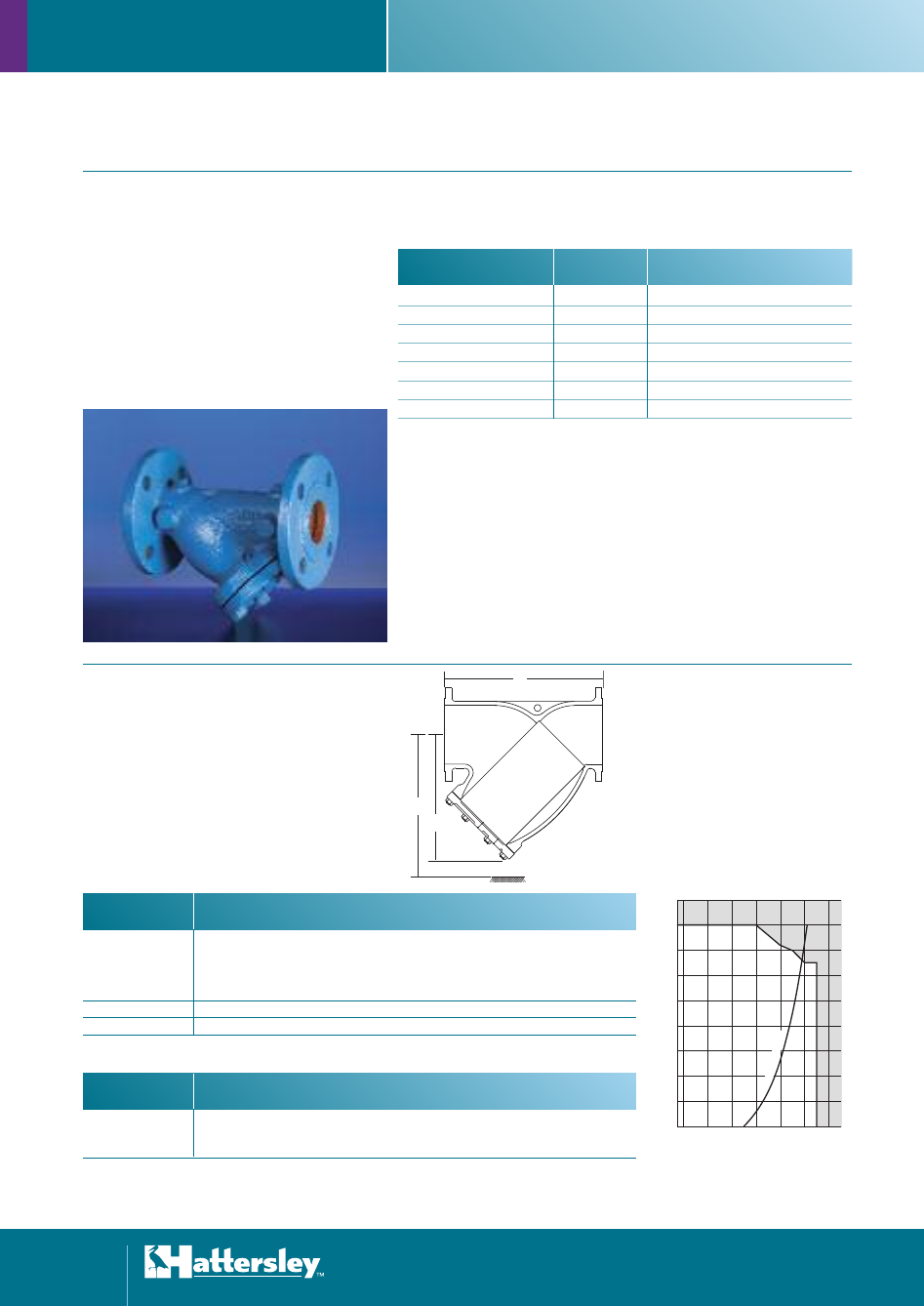
Technical Helpline: 0845 604 1790
E: tech-enquiries@hattersley.com W: www.hattersley.com
180
STRAINERS
PN16
Every effort has been made to ensure that the information contained in this publication is accurate at the time of publishing.
Hattersley Ltd assumes no responsibility or liability for typographical errors or omissions or for any misinterpretation of the
information within the publication and reserves the right to change without notice.
Fig. 810/910
Cast Iron Y-Type
DIMENSIONAL DRAWINGS
SPECIFICATION
Bolted cover.
Figure 910 supplied complete with
two figure 631 test points and plugs.
Flanges to BS EN 1092-2 PN16.
MATERIAL SPECIFICATION
Body sizes DN50 to 400 Cast Iron 1561 EN-JL1040 A126 Class B
DN450 to 600 Ductile Iron 1563 EN-JS1050 A536 80-55-06
Cover sizes DN50 to 400 Cast Iron 1561 EN-JL1040 A126 Class B
DN450 to 600 Ductile Iron 1563 EN-JS1050 A536 80-55-06
Screen Stainless Steel 1449 304S315 AISI 304
Gasket Teflon/Graphite
Plug Cast Iron EN-JL1040 A126 Class B
Component Material Specification
BS EN ASTM
FEATURES AND BENEFITS
• High strength cast iron construction
• Streamlined flow contours minimise
pressure drop
• Asbestos-free non-stick gasket
• Suitable for saturated steam service
• Comprehensive flow characteristics available
10
8
6
4
2
0
Pressure bar
0 40 80 120 160 200 240
Temperature ˚C
12
14
16
18
S
a
t
u
r
a
t
e
d
S
t
e
a
m
A
BC
=withdrawal
distance for
strainer element
C
Nom
Size mm 50 65 80 100 125 150 200 250 300 350 400 450 500 600
Hole Dia mm 1.6 1.6 1.6 1.6 1.6 1.6 1.6 1.6 1.6 3 3 3 3 3
Free Flow % 33 33 33 40 40 40 40 40 40 40 40 40 40 40
Area/cm2
SCREEN DATA
PRESSURE/
TEMPERATURE RATING
13 bar at 220ºC
16 bar from -10 to 120ºC
Note: 910 restricted to 135°C
TEST PRESSURES
(HYDRAULIC)
Shell: 24 bar
Nom
Size mm 50 65 80 100 125 150 200 250 300 350 400 450 500 600
A mm 230 273 295 352 416 470 573 660 770 960 1079 1168 1275 1450
B mm 146 174 198 232 285 305 401 473 554 740 840 910 968 1160
C mm 178 216 248 300 373 450 621 703 834 740 840 910 968 1160
Cover Plug mm 1/2 1 1 1 11/4 11/2 11/2 2 2 - - - - -
Weight kg 10.5 14.9 19.2 32.4 48 64.5 106 175 251 458 556 628 780 1080
Flow kv 59 93 136 229 363 499 817 1361 1928 - - - - -
DIMENSIONS AND WEIGHTS
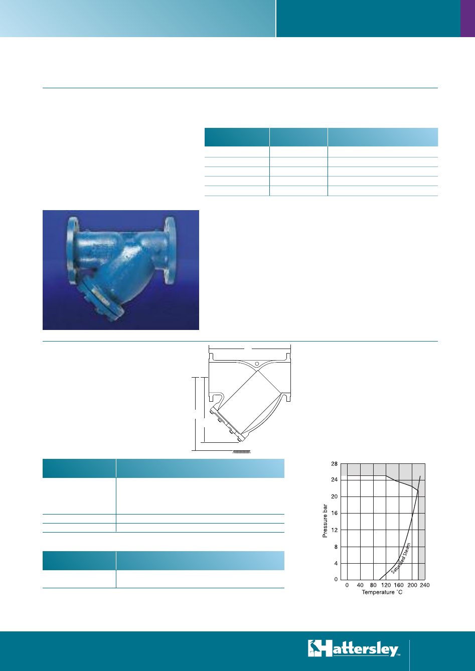
Technical Helpline: 0845 604 1790
E: tech-enquiries@hattersley.com W: www.hattersley.com
181
STRAINERS
PN25
Every effort has been made to ensure that the information contained in this publication is accurate at the time of publishing.
Hattersley Ltd assumes no responsibility or liability for typographical errors or omissions or for any misinterpretation of the
information within the publication and reserves the right to change without notice.
Fig. 811/911
Ductile Iron Y-Type
DIMENSIONAL DRAWINGS
PRESSURE/
TEMPERATURE RATING
PN25
21.5 bar at 220ºC
25 bar from -10 to 120ºC
Note: 911 restricted to 180ºC
TEST PRESSURES
(HYDRAULIC)
Shell: 37.5 bar
SPECIFICATION
Bolted cover.
Figure 911 supplied complete with two
figure 631 valve controlled test points.
All other sizes flanged to BS EN 1092-2
PN25.
MATERIAL SPECIFICATIONFEATURES AND BENEFITS
• High strength ductile iron construction
• Streamlined flow contours minimise
pressure drop
• Asbestos-free non-stick gasket
• Suitable for saturated steam service
• Comprehensive flow characteristics available
Body Ductile Iron 1561 EN JS1050
Cover Ductile Iron 1561 EN JS1050
Screen Stainless Steel SS 304 AISI 304
Gasket Teflon/Graphite
Plug Ductile Iron 1561 EN JS1050
Component Material Specification
BS EN ASTM
A
BC
=withdrawal
distance for
strainer element
C
Nom
Size mm 50 65 80 100 125 150 200 250 300
Hole Dia mm 1.6 1.6 1.6 1.6 1.6 1.6 1.6 1.6 1.6
Free Flow Area/cm2 % 33 33 33 40 40 40 40 40 40
SCREEN DATA
Nom
Size mm 50 65 80 100 125 150 200 250 300
A mm 230 273 295 352 416 470 573 660 770
B mm 146 174 198 232 285 305 401 473 554
C mm 178 216 248 300 373 450 621 703 834
Cover Plug mm 1/2 1 1 1 11/4 11/2 11/2 2 2
Weight kg 10.5 14.9 19.2 32.4 48 64.5 106 175 251
Flow kv 59 93 136 229 363 499 817 1361 1928
DIMENSIONS AND WEIGHTS
Technical Helpline: 0845 604 1790
E: tech-enquiries@hattersley.com W: www.hattersley.com
182
Queen Elizabeth Hospital, Birmingham
Specification: Hattersley Thermal Balancing Valves
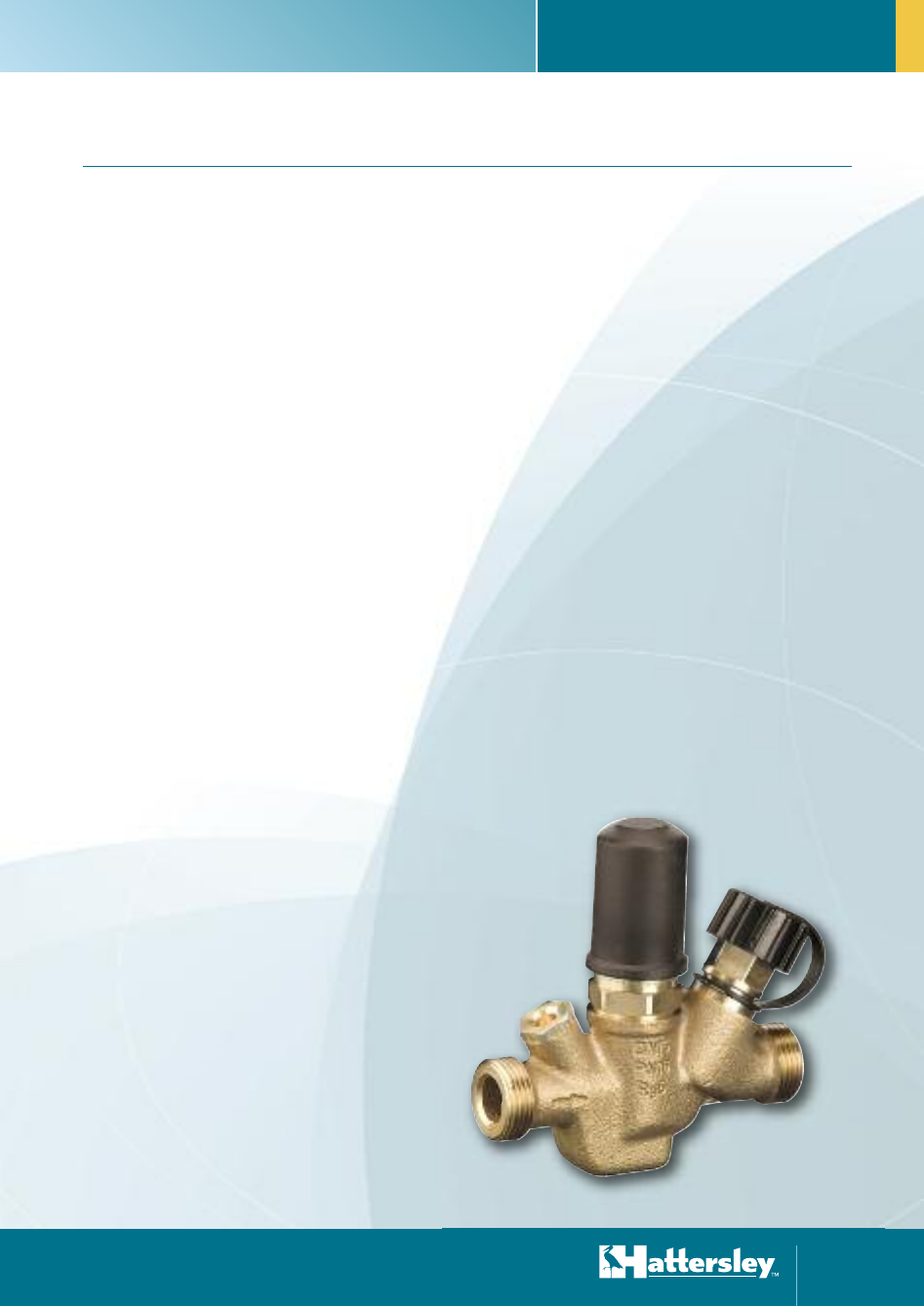
Technical Helpline: 0845 604 1790
E: tech-enquiries@hattersley.com W: www.hattersley.com
183
PUBLIC HEALTH RANGE
Public Health Range
The Hattersley Public Health range consists of a
number of WRAS approved valves specifically
designed for the control of hot water systems.
Thermal disinfection raises water temperatures to a
level at which Legionella will not survive. This can be
carried out by raising the temperature of the whole
contents of the calorifier to 70°C then circulating the
water throughout the system for at least an hour.
To be effective, the temperature at the calorifier should
be high enough to ensure that the temperature at the
taps and appliances does not fall below 60°C.
The range consists of valves which offer self-balancing,
thermostatically controlled regulation of flow and
thermal disinfection assisting with protection against
Legionella. These systems are complemented by
Thermostatic Mixing Valves which blend hot water
(stored at temperatures high enough to kill bacteria)
with cold, to ensure constant and safe outlet
temperatures to prevent scalding.
These systems are ideal for a range of projects
including healthcare, schools, workplace and
domestic environments.
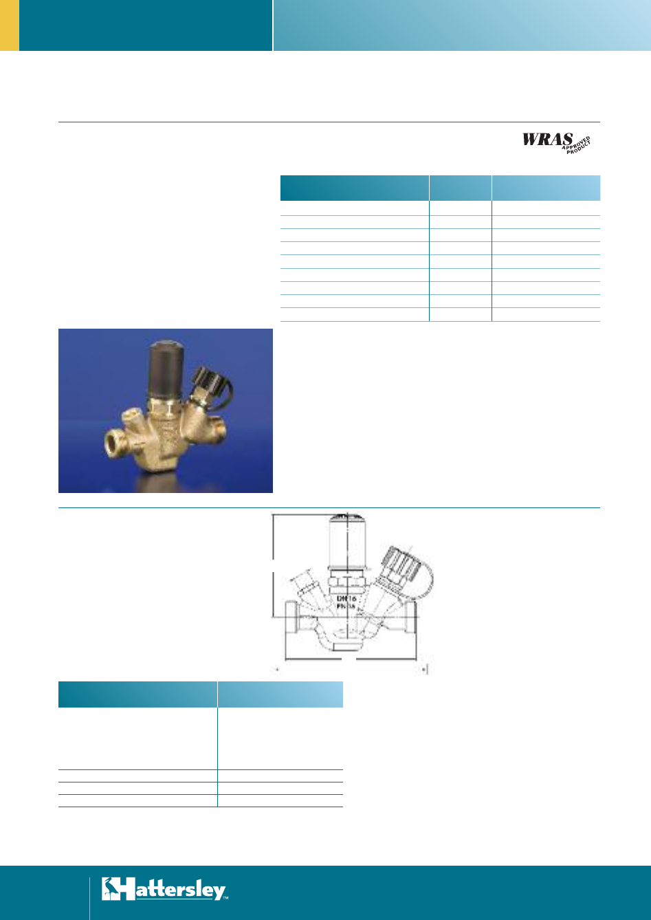
Technical Helpline: 0845 604 1790
E: tech-enquiries@hattersley.com W: www.hattersley.com
184
PUBLIC HEALTH RANGE
PN16
Every effort has been made to ensure that the information contained in this publication is accurate at the time of publishing.
Hattersley Ltd assumes no responsibility or liability for typographical errors or omissions or for any misinterpretation of the
information within the publication and reserves the right to change without notice.
Fig. 1900
Thermal Balancing Valves
DIMENSIONAL DRAWINGS PRESSURE/
TEMPERATURE RATING
Max Temperature 90ºC
Nominal Pressure PN16
OPERATION
When the set point is preset to 57°C, the
valve remains completely open up to a
valve temperature of 52°C.
Between 52°C and the preset set point of
57°C, the valve starts to close. When the
set point temperature has been reached,
a minimum volume flow is continuously
flowing through the circulation system.
If the storage temperature is further
increased to temperatures greater than
70°C to effect disinfection, the valve
increases the flow.
FEATURES AND BENEFITS
• Ideal for domestic hot water systems to assist
with protection against Legionella
• Provides self-balancing, thermostatically
controlled regulation of flow and disinfection
• Suitable for circuits greater than 10 metres
in length
• Thermostatically controlled regulation of the
volume flow – self-balancing
• Assists with disinfection at temperatures above
70°C by increasing the flow automatically
• Has an accuracy of +/- 1°C
Nom
Inside Dia mm 15 20 25
Height (H1) mm 85 85 95
Length (L1) mm 110 123 133
Length (L2) Copper Tails mm 176 186 200
Length (L2) Mapress Copper mm 172 174 182
Length (L2) Mepla mm 174 178 186
Weight kg 0.7 0.9 1.2
Flow Kv cmb/h 0.92 1.70 2.71
Drain Valve (G) BSP 1/4 1/4 1/4
DIMENSIONS AND WEIGHTS
MATERIAL SPECIFICATION
Body Bronze BS EN 1982 CC491K
Upper part Bronze BS EN 1982 CC491K
Valve stem Bronze BS EN 1982 CC491K
Valve cone Bronze BS EN 1982 CC491K
Upper part seal, valve stem seal EPDM 70 EPDM
Closing upper part valve cone seal PTFE Teflon
Drain plug Bronze BS EN 1982 CC491K
Closing handle Plastic Polyacetal (PA)
Plate / clamping band Plastic Polyacetal (PA)
Component Material Specification
BS EN
H1
L1
L2
G
1/4
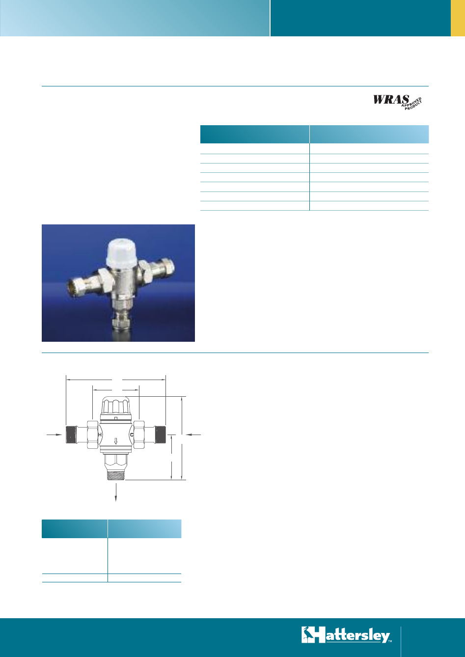
Technical Helpline: 0845 604 1790
E: tech-enquiries@hattersley.com W: www.hattersley.com
185
PUBLIC HEALTH RANGE
PN10
Every effort has been made to ensure that the information contained in this publication is accurate at the time of publishing.
Hattersley Ltd assumes no responsibility or liability for typographical errors or omissions or for any misinterpretation of the
information within the publication and reserves the right to change without notice.
Fig. 77
Thermostatic Mixing Valves
DIMENSIONAL DRAWINGS FACTORY SETTING
38°C
TEMPERATURE
SETTING RANGE
35-46°C
MINIMUM HOT TO MIX
TEMPERATURE
10°C
TEMPERATURE
STABILITY
±2°C
MAXIMUM WORKING
PRESSURE
10 bar
Kv
1.26
MINIMUM FLOW
PRESSURE
0.2 bar
SPECIFICATION
Pressure Rating: PN10.
Operator: Lockshield.
Figure 77 has been independently tested
and certified as meeting the requirements
of the D08 specification under the TMV 3
scheme.
Hattersley products are designed for
installation and use within suitably
designed systems reflecting CIBSE,
BSRIA and HVAC guidelines.
MATERIAL SPECIFICATION
O-Ring EPDM Rubber
1.5 Strainer Stainless Steel 304
Reduction Union DZR Brass CW602N
Element Vernet 0304
Spring Stainless Steel 304
Top DZR Brass CW602N
Valve Body DZR Brass CW602N
Component Material
FEATURES AND BENEFITS
• Blends hot and cold water to ensure constant,
controlled safe outlet temperature
• Fulfils the ‘duty of care’ requirements
against scalding
• Ideal for healthcare, schools, workplace
and domestic environments
• Flat face union ensures easy removal for
maintenance
• Integral strainers and check valves
• Tamper proof adjustment
HOT
MIXED OUTLET
A
C
D
B
COLD
A
B
C
D
Nom
Size mm 15 22
A mm 122 145
B mm 58 58
C mm 55 70
D mm 102 117
Weight kg 0.6 0.8
DIMENSIONS AND WEIGHTS
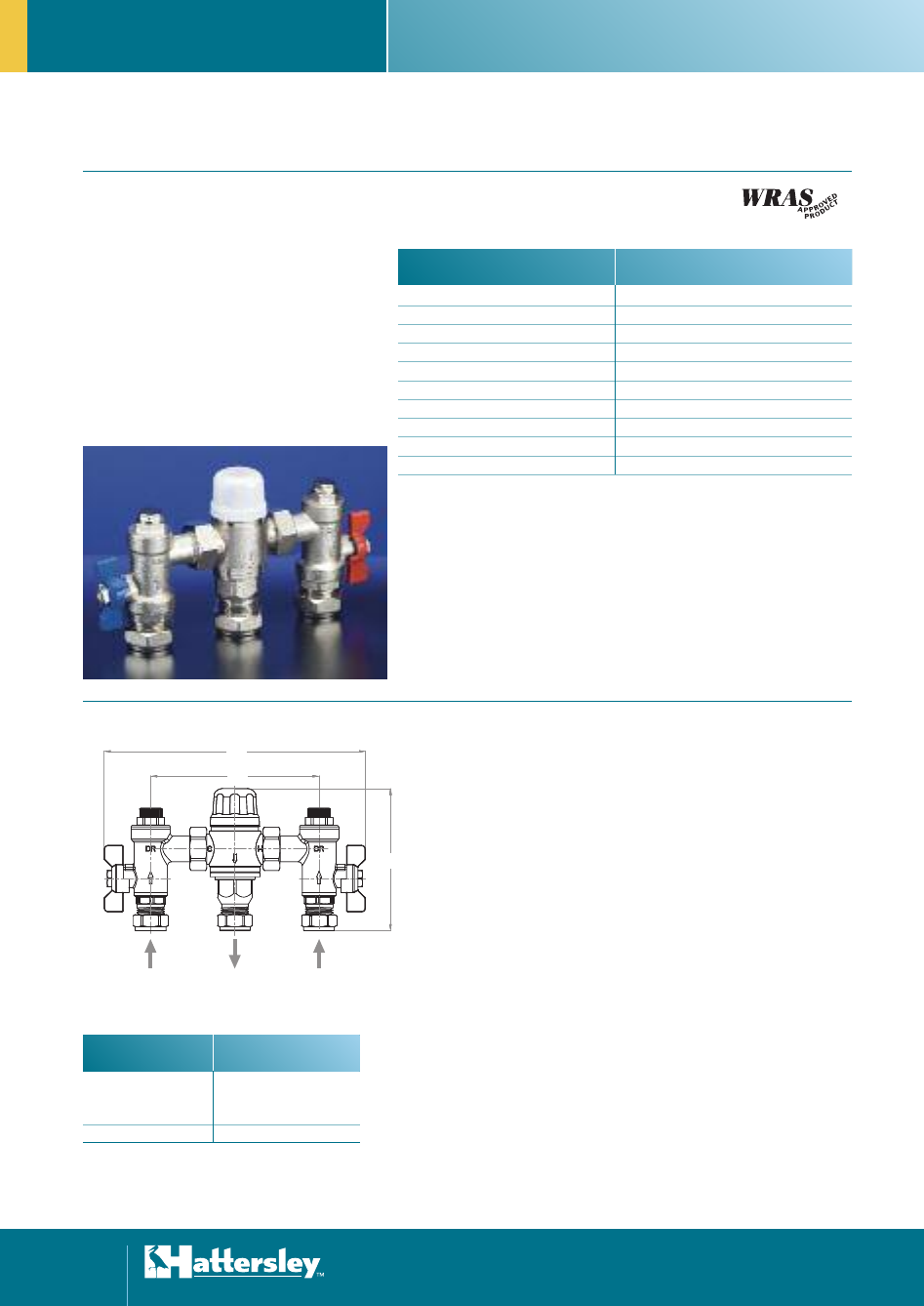
Technical Helpline: 0845 604 1790
E: tech-enquiries@hattersley.com W: www.hattersley.com
186
PUBLIC HEALTH RANGE
PN10
Every effort has been made to ensure that the information contained in this publication is accurate at the time of publishing.
Hattersley Ltd assumes no responsibility or liability for typographical errors or omissions or for any misinterpretation of the
information within the publication and reserves the right to change without notice.
Fig. 78
Thermostatic Mixing Valves
DIMENSIONAL DRAWINGS FACTORY SETTING
38°C
TEMPERATURE
SETTING RANGE
35-46°C
MINIMUM HOT TO MIX
TEMPERATURE
10°C
TEMPERATURE
STABILITY
±2°C
MAXIMUM WORKING
PRESSURE
10 bar
Kv
1.26
MINIMUM FLOW
PRESSURE
0.2 bar
SPECIFICATION
Pressure Rating: PN10.
Operator: Lockshield.
Figure 78 has been independently tested
and certified as meeting the requirements
of the D08 specification under the TMV 3
scheme.
Hattersley products are designed for
installation and use within suitably
designed systems reflecting CIBSE,
BSRIA and HVAC guidelines.
FEATURES AND BENEFITS
• Blends hot and cold water to ensure constant,
controlled safe outlet temperature
• Fulfils the ‘duty of care’ requirements
against scalding
• Ideal for healthcare, schools, workplace
and domestic environments
• Flat face union ensures easy removal for
maintenance
• Integral strainers and check valves
• Tamper proof adjustment
• Includes ball valves for isolation
MATERIAL SPECIFICATION
O-Ring EPDM Rubber
1.5 Strainer Stainless Steel 304
Reduction Union DZR Brass CW602N
Element Vernet 0304
Spring Stainless Steel 304
Top DZR Brass CW602N
Valve Body DZR Brass CW602N
Ball DZR Brass CW602N
T-Handle Al Alloy
Ball Seal PTFE
Component Material
A
B
C
COLD HOTOUTLET
A
B
C
Nom
Size mm 15 22
A mm 200 200
B mm 128 128
C mm 110 110
Weight kg 1.1 1.3
DIMENSIONS AND WEIGHTS
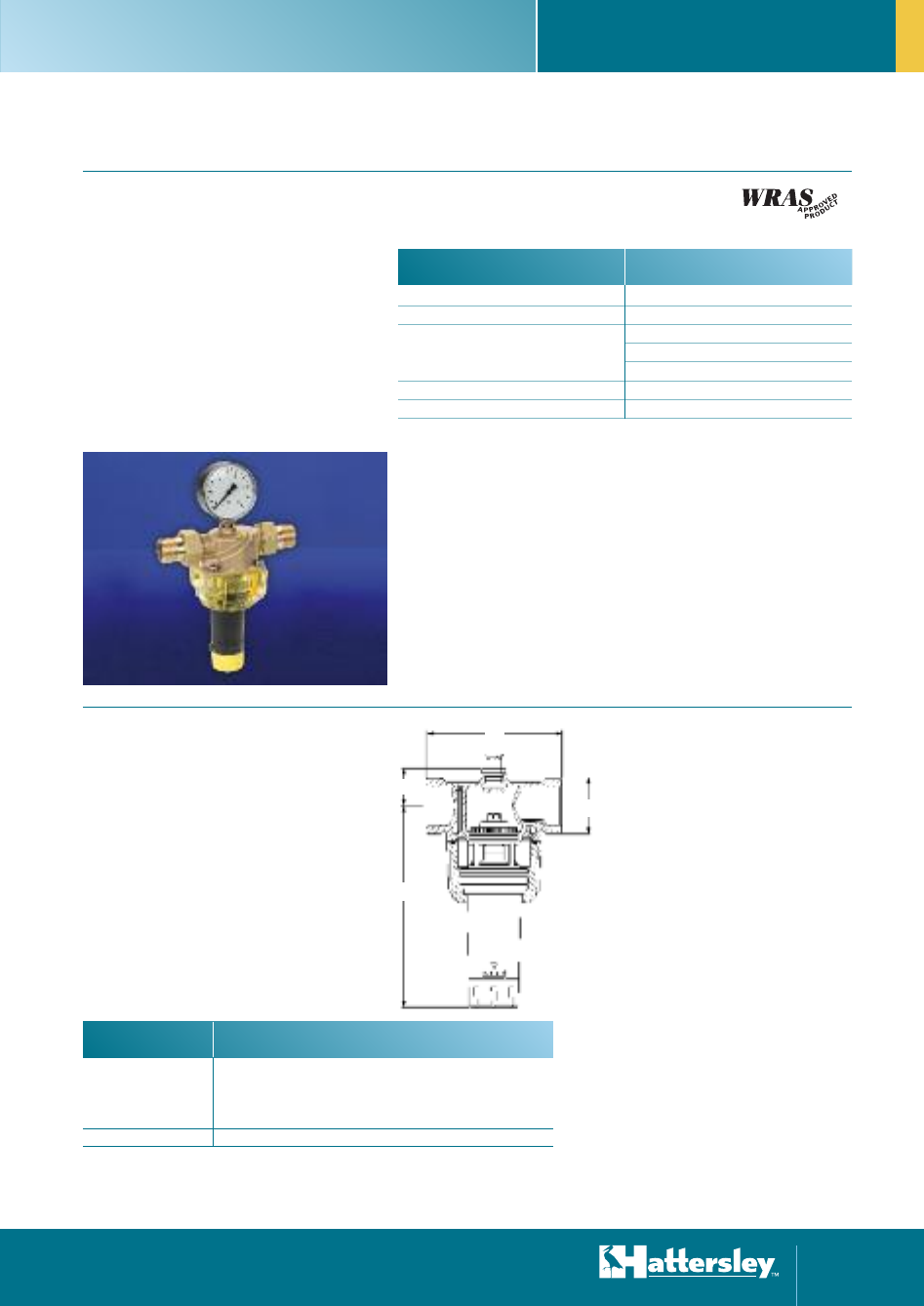
Technical Helpline: 0845 604 1790
E: tech-enquiries@hattersley.com W: www.hattersley.com
187
PUBLIC HEALTH RANGE
PN16
Every effort has been made to ensure that the information contained in this publication is accurate at the time of publishing.
Hattersley Ltd assumes no responsibility or liability for typographical errors or omissions or for any misinterpretation of the
information within the publication and reserves the right to change without notice.
Fig. 430
Pressure Reducing Valves
DIMENSIONAL DRAWINGS PRESSURE/
TEMPERATURE RATING
Pressure Rating: 16 bar
Maximum Fluid Temperature: 60ºC
Maximum Inlet Pressure: 16 bar
Outlet Pressure: 1.5 bar - 6.0 bar
SPECIFICATION
Suitable for:
• Water
• Compressed Air
MATERIAL SPECIFICATION
Body Bronze
Disc Bronze
Cartridge Stainless Steel
Bronze
Nitrile
Filter Stainless Steel
Gaskets Nitrile
Component Material
FEATURES AND BENEFITS
• PRVs enable control of pressure from boosted
cold water supplies to match site requirements
• Simple to install
• Recommend that isolation valves are fitted
upstream and downstream of the valve to
enable isolation for cleaning of filter
• WRAS approved
• Manufactured in accordance with BS EN 1567
• Figure 430 must be fitted with adjustable
cartridge element pointing downwards
L1
A1
H2
H1
G1/4
Nom mm 15 20 25 32 40 50 Gauge
Size Fig 430 430 430 430 430 430 435
L1 mm 90 90 100 105 130 140
H1 mm 150 150 150 225 225 225
H2 mm 25 25 25 38 38 38
A1 mm G3/4 G1 G11/4 G11/2 G13/4 G23/8
Weight kg 0.90 0.93 1.00 2.20 2.30 2.50 0.25
DIMENSIONS AND WEIGHTS
Fits all
sizes
*Pressure gauge is required for each
installed valve and is ordered separately.
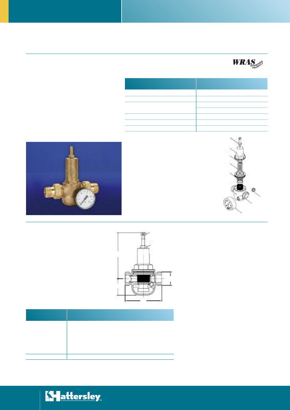
Technical Helpline: 0845 604 1790
E: tech-enquiries@hattersley.com W: www.hattersley.com
188
PUBLIC HEALTH RANGE
PN25
Every effort has been made to ensure that the information contained in this publication is accurate at the time of publishing.
Hattersley Ltd assumes no responsibility or liability for typographical errors or omissions or for any misinterpretation of the
information within the publication and reserves the right to change without notice.
8
7
6
5
4
1
Fig. 440
Pressure Reducing Valves
DIMENSIONAL DRAWINGS PRESSURE/
TEMPERATURE RATING
Pressure Rating: 25 bar
Maximum Fluid Temperature: 90ºC
Maximum Inlet Pressure: 25 bar
Outlet Pressure: 1.0 bar - 7.0 bar
SPECIFICATION
Suitable for:
• Water
• Compressed Air
FEATURES AND BENEFITS
• PRVs enable control of pressure from boosted
cold water supplies to match site requirements
• Simple to install
• Recommend that isolation valves are fitted
upstream and downstream of the valve to
enable isolation for cleaning of filter
• WRAS approved
• Manufactured in accordance with BS EN 1567
• Figure 440 can be installed horizontally or
vertically
MATERIAL SPECIFICATION
Body Bronze
Cover Bronze
Insert Stainless Steel
Bronze
Filter Stainless Steel
Spring Stainless Steel
Disc Brass
Component Material
L1
A1
H2
H1
S1
S2
DIMENSIONS AND WEIGHTS
Nom mm 15 20 25 32 40 50 Gauge
Size Fig 440 440 440 440 440 440 445
L1 mm 75 92 98 98 128 148
H1 mm 110 110 150 160 190 265
H2 mm 30 42 46 46 52 75
S1 mm 10 10 12 12 12 13
S2 mm 13 13 17 17 17 19
A1 mm G3/4 G1 G11/4 G11/2 G13/4 G23/8
Weight kg 0.80 1.30 1.70 1.90 3.60 6.70 0.25
DIMENSIONS AND WEIGHTS
Fits all
sizes
2
3
1. Pressure
Gauge
2. Valve Body
3. Blanking Plug
4. Insert
5. Spring
6. Spring Plate
7. Spring Cover
8. Adjustment
Spindle
*Pressure gauge is required for each
installed valve and is ordered separately.
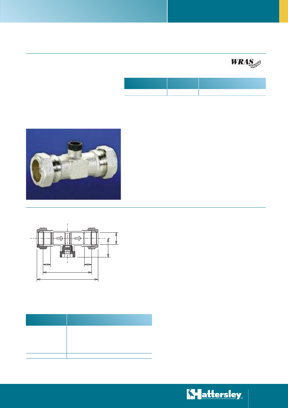
Technical Helpline: 0845 604 1790
E: tech-enquiries@hattersley.com W: www.hattersley.com
189
PUBLIC HEALTH RANGE
PN16
Every effort has been made to ensure that the information contained in this publication is accurate at the time of publishing.
Hattersley Ltd assumes no responsibility or liability for typographical errors or omissions or for any misinterpretation of the
information within the publication and reserves the right to change without notice.
Fig. 249 & 249C Brass - Single & Double Check
(Fig. 249C Chromium Plated) Check Valves
DIMENSIONAL DRAWINGS SPECIFICATION
Fig. No. 249
Double Check - 15mm, 22mm, 28mm
Fig. No. 249C
Double Check chromium plated - 15mm
Manufactured to BS 6282.
WRAS approved PN16 85°C.
Application: Water.
End Connection: Compression.
Back Flow Prevention Device category:
Single check - Class 2 as per Water Supply.
Contamination Risks (water fittings)
Regulations 1999.
Double check - Class 3 as per Water Supply.
Contamination Risks (water fittings)
Regulations 1999.
MATERIAL SPECIFICATION
Body DZR Brass 12165 CW602N
Component Material Specification
BS EN
FEATURES AND BENEFITS
• WRAS approved for use with potable water
• Compression ends for use with half hard
R250 copper pipe
• Single, double and chromium plated options
available
D
B B
A
C
E
Fig. 249 & 249C
Nom mm 15 22 28 15
Size Fig. 249 Fig. 249 Fig. 249 Fig. 249C
A mm 61.4 74.6 88.6 61.4
B mm 9.5 10.5 12.5 9.5
C mm 15.2 22.2 28.25 15.2
D mm 78.5 91.4 106.3 78.5
E mm 24.5 27.5 30.5 24.5
Weight (approx) kg 0.116 0.212 0.360 0.116
DIMENSIONS AND WEIGHTS
PRESSURE/
TEMPERATURE RATING
16 bar from -10 to 85ºC
TEST PRESSURES
(HYDRAULIC)
Body: 24 bar
Seat: 17.6 bar
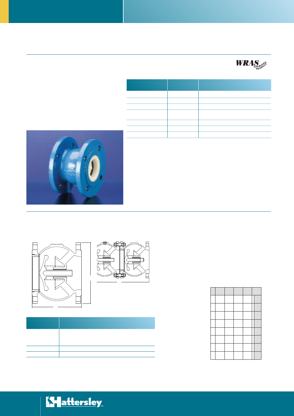
Technical Helpline: 0845 604 1790
E: tech-enquiries@hattersley.com W: www.hattersley.com
190
PUBLIC HEALTH RANGE
PN16
Every effort has been made to ensure that the information contained in this publication is accurate at the time of publishing.
Hattersley Ltd assumes no responsibility or liability for typographical errors or omissions or for any misinterpretation of the
information within the publication and reserves the right to change without notice.
Fig. 761 and 2761
Aquacheck®Non-Return Valve
DIMENSIONAL DRAWINGS SPECIFICATION
Spring Loaded axially guided disc.
Resilient Seat located in body.
Flanged to BS EN 1092-2 PN16.
Alternative pressure ratings to PN25.
Alternative flange details including BS EN 1092-2
PN25 and PN40 and ANSI B16.1 Class 125.
NOTES
Sizes:
50mm to 250mm WRAS Approved.
300mm is not WRAS Approved.
MATERIAL SPECIFICATION
Body Ductile Iron 1563 EN-JS1030 A536-65-45-12
Plunger DN50-150 Bronze
Plunger DN200-400 Cast Iron 1561 EN-JLI030 A126 CI B
Seat Retaining Ring Steel -
Xylan Coated
Seat Nitrile
Guide Bronze
Spring Stainless Steel 10270 X10CrNr18-8 A276-304
Component Material Specification
BS EN ASTM
FEATURES AND BENEFITS
• Spring loaded axially guided disc
• Positive non-slam shut-off
• Flanged to BS EN 1092-2
• Resilient seat located in body
0 20 40 60 80 100
T emperature ˚ C
14
12
10
8
6
2
0
Pressure bar
4
16
18
B
Double Check Valve
configuration Fig. 2761
D
A
Single Check Valve
Fig. 761
PRESSURE/
TEMPERATURE
RATING
16 bar from -10 to 85ºC
TEST
PRESSURES
(HYDRAULIC)
Body: 24 bar
Seat: 17.6 bar
Nom
Size mm 50 65 80 100 125 150 200 250 300
A mm 120 119 130 155 200 230 280 344 385
B mm 240 241 260 310 403 460 560 688 770
D mm 165 185 200 220 250 285 340 405 460
Weight 761 kg 5 7 9 13 21 28 47 83 123
Weight 2761 kg 11 15 20 27 44 58 97 168 249
DIMENSIONS AND WEIGHTS
Note: These valves are not intended to be used as backflow prevention devices
conforming to Schedule 2 Section 6 of the WRAS Water Regulations Guide.
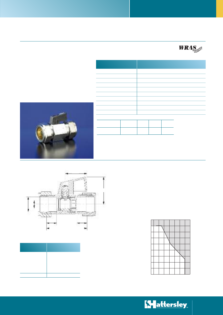
Technical Helpline: 0845 604 1790
E: tech-enquiries@hattersley.com W: www.hattersley.com
191
PUBLIC HEALTH RANGE
PN16
Every effort has been made to ensure that the information contained in this publication is accurate at the time of publishing.
Hattersley Ltd assumes no responsibility or liability for typographical errors or omissions or for any misinterpretation of the
information within the publication and reserves the right to change without notice.
Fig. 108C
Service Ball Valve
DIMENSIONAL DRAWINGS PRESSURE/
TEMPERATURE RATING
PN16
OPERATOR
Handle (The handle can be removed to
allow for screwdriver operation).
SPECIFICATION
Compression ends to BS EN 1254-2 for use
with BS EN 1057 R250 (half-hard) copper tube.
WRAS Approved product.
MATERIAL SPECIFICATIONFEATURES AND BENEFITS
• Light, compact and easy to install and operate
• WRAS Approved for use on wholesome
(potable) water
• Compression ends to BS EN 1254-2 for use
with BS EN 1057 R250 (half-hard) copper tube
• Part of Hattersley’s extensive public health range
• Chrome plated finish
• Handle can be removed to allow for
screwdriver operation
0 20 40 60 80 100 120 14 0
Temperature ˚C
14
12
10
8
6
2
0
Pressure bar
4
16
18
L
SIZE
BORE
H
L1 L1
L2
DIMENSIONS AND WEIGHTS
Screw Steel Dacromet Plated
Handle Nylon (Ral 9017)
Stem DZR Brass Chromium Plated
O-Ring EPDM WRAS Approved
Nut DZR Brass CW602N Chromium Plated
Olive Brass CW507L
Body DZR Brass CW602N Chromium Plated
PTFE Seat PTFE WRAS Approved
Ball DZR Brass CW602N Chromium Plated
Seat Retainer DZR Brass CW602N Chromium Plated
Component Material
Nom
Size mm DN15 DN22
Bore mm Ø8 Ø14
L mm 42 53
L1 mm 11 13
L2 mm 23 23
H mm 29 34
Weight g 123 260
Temperature ˚C -10 to 30 65 110 120
Pressure bar 16 10 6 5
Technical Helpline: 0845 604 1790
E: tech-enquiries@hattersley.com W: www.hattersley.com
192

Technical Helpline: 0845 604 1790
E: tech-enquiries@hattersley.com W: www.hattersley.com
193
Project: Ricoh Arena
Client: Coventry Football Club
Contractor: Haden Young
Specification: Hattersley Hook-Up and commissioning valves
For the past six years, Hattersley Hook-Up units and commissioning valves have been
heating and cooling the 32,000 seat Ricoh Arena that is home to Coventry City FC. The site
also comprises an exhibition hall, a hotel, a leisure club, a casino, and one of the UK’s
largest Tesco Extra supermarkets.
Throughout the stadium Hook-Up flow management modules, part of Hattersley’s
extensive range of commissioning valves, are providing heating and air-conditioning.
The units provide precise flow control, flow measurement, system and coil flushing and
isolation capabilities from a single compact and lightweight unit. Built from bronze and DZR
brass they can be used for chilled and heating water systems from -10 °C to 120°C.

Technical Helpline: 0845 604 1790
E: tech-enquiries@hattersley.com W: www.hattersley.com
194
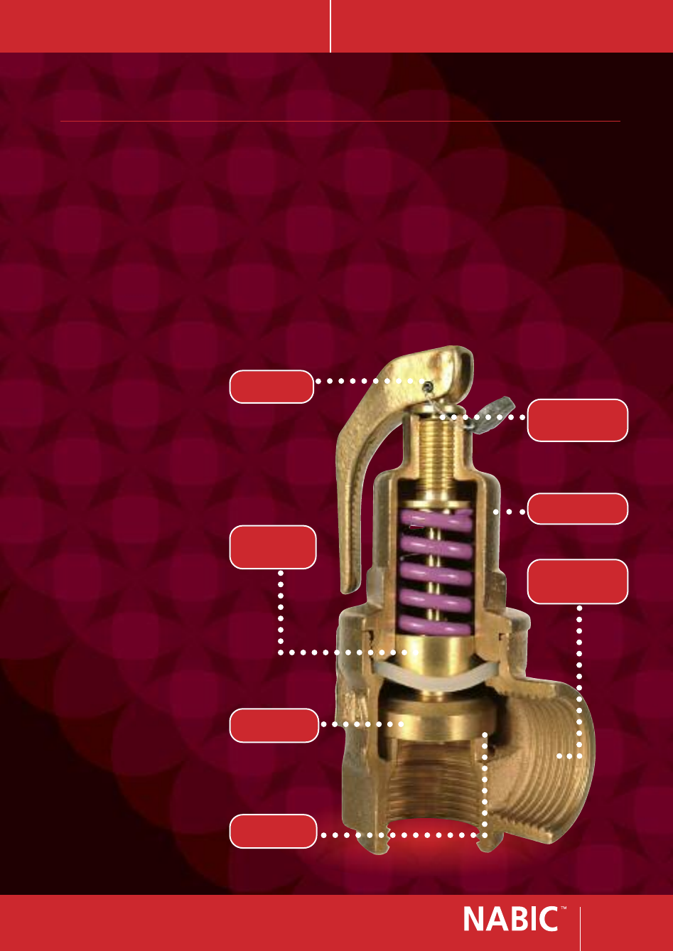
Technical Helpline: 01744 458 615
www.nabic.co.uk
195
SAFETY & CONTROL VALVES
Safety & Control Valves
1. Safe Manual
Testing
7. Diaphragm
protected
working parts
3. Easy inspection &
cleaning
2. Pressure setting
locked and
sealed at factory
4. High discharge
capacities certified
by AOTC
6. High degree of
seat tightness
5. Resilient PFTE
seating design
One of the UK's leading suppliers of gunmetal
safety valves, NABIC has long been recognised
as the industry standard for commercial and
industrial hot water applications. In fact, our
valves are ideal for hot water supply, heating,
pump relief, bypass relief, outside installation
and for use with difficult gases and liquids.
Designed and tested to the latest British Standards
with third party certified discharge capacities,
NABIC valves are manufactured under an
ISO 9001 quality assurance system. Every valve is
tested after assembly and again before despatch
to ensure high product quality is maintained.
For Air, Steam and Water
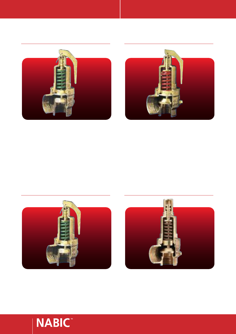
Technical Helpline: 01744 458 615
www.nabic.co.uk
196
SAFETY & CONTROL VALVES
COPPER ALLOY
Fig. 500
High Lift Safety Valve
Fig. 542
Safety Relief Valve
Figure 542 Safety Valve is an extremely versatile valve,
suitable for use on hot water, steam or air. Although
designed primarily for the protection of hot water boilers,
its wide range of applications make it an ideal valve for
stocking as a general purpose safety valve.
Body Material |Gunmetal
Maximum Pressure |10.5 bar
Maximum Temperature |195°C
Figure 500 High Lift Safety Valve has been designed
primarily for use on unvented hot water heating systems,
where a high-capacity emergency steam relief capability
is required. High capacity and resilient PTFE seating, also
make it ideal for steam, air and inert gas applications.
A PTFE to Viton seating design is also available where
greater seal tightness is required.
Body Material |Gunmetal
Maximum Pressure |12.5 bar
Maximum Temperature |195°C
Fig. 500L
Pressure Relief Valve
Fig. 542L
Pressure Relief Valve
Body Material |Gunmetal
Maximum Pressure |10.5 bar
Maximum Temperature |195°C
Body Material |Gunmetal
Maximum Pressure |12.5 bar
Maximum Temperature |195°C
NABIC Pressure Relief Valves are intended for use where pressure tightness is required on the discharge side of the valve. They are
ideal for pump relief, bypass relief, outside installations, and on cold water mains to protect from PRV failure.
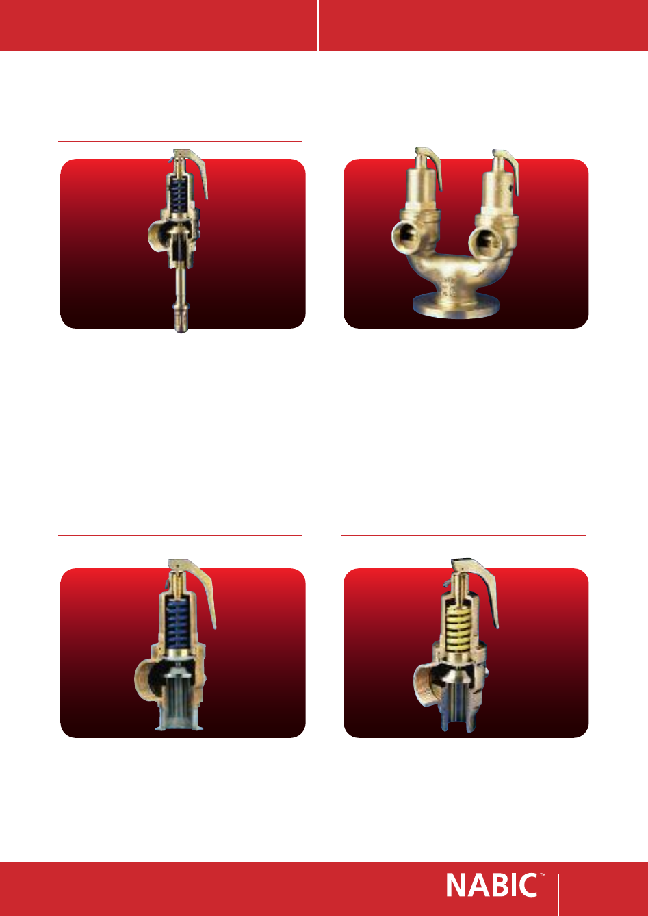
Technical Helpline: 01744 458615
www.nabic.co.uk
197
SAFETY & CONTROL VALVES
COPPER ALLOY
Fig. 520
Double Spring Safety Valve
Fig. 500T
Combined Pressure and
Temperature Relief Valve
Figure 500T Combined Pressure & Temperature Relief Valve
has been designed for use on unvented hot water supply
systems, where protection against excess temperature is
required in addition to pressure protection. Pressure and
temperature elements of the valve operate independently,
thereby providing dual safety protection in the one valve.
Body Material |Gunmetal
Maximum Working Temperature |75°C
Maximum Pressure |12.5 bar
Maximum Temperature |95°C
Figure 520 High Lift Safety Valve has been designed
and tested to BS 6759. Based on the proven design of
the figure 500 Safety Value, the high capacity and
resilient PTFE seating make figure 520 ideal for steam,
hot water, air and inert gas applications.
Body Material |Gunmetal
Maximum Pressure |12.5 bar
Maximum Temperature |195°C
Fig. 500ST
High Lift Safety Valve
Fig. 500SS
Pressure Relief Valve
Wetted Parts |Stainless Steel
Body Material |Gunmetal
Maximum Set Pressure |12.5 bar
Maximum Temperature |195°C
Wetted Parts |Stainless Steel
Body Material |Gunmetal
Maximum Set Pressure |12.5 bar
Maximum Temperature |195°C
This version of the Figure 500 has been produced for applications where the properties of stainless steel are required for the service
fluid being used but the working environment does not necessitate a full stainless steel valve. It can be supplied with a test lever or as a
sealed dome version to suit customer requirements.
with Stainless Steel Wetted Parts with Stainless Steel Wetted Parts
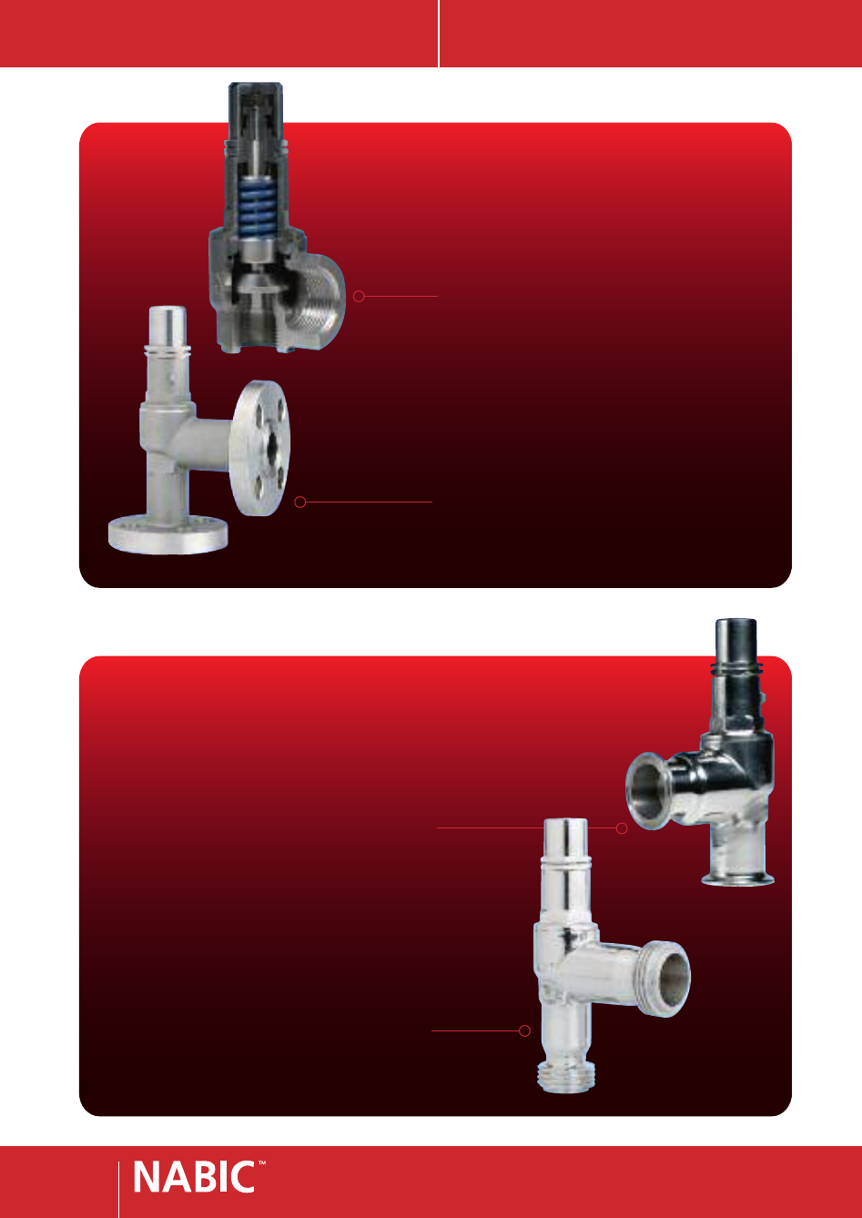
Technical Helpline: 01744 458 615
www.nabic.co.uk
198
SAFETY & CONTROL VALVES
STAINLESS STEEL
The Stainless Steel version of the figure 500 High Lift Safety
Valve has been specifically developed for use where difficult
fluids or gases are encountered. Its anti-corrosion properties,
high discharge capacities and excellent seat tightness make
it an ideal valve for these applications. For other specific
technical requirements please consult the NABIC technical
department.
Fig. 500FN High Lift Safety Valve
Body Material |Stainless Steel
Maximum Pressure |11 bar
Maximum Temperature |195°C
Fig. 500FS High Lift Safety Valve
Body Material |Stainless Steel
Maximum Pressure |11 bar
Maximum Temperature |195°C
Fig. 500FF High Lift Safety Valve
Body Material |Stainless Steel
Maximum Pressure |11 bar
Maximum Temperature |195°C
Connection options are:
FN-Screwed x Screwed
FS-Flanged x Screwed
FF-Flanged x Flanged
Designed for hygienic applications, these full stainless steel
constructed valves have connections to BS 4285. Figure 500AA has
clamp type couplings which conform to part 3 and the figure 500DF
has threaded (IDF type) couplings to part 4. Both ranges of valves
are highly polished, with inlet bore finish of 0.4 µm. For other specific
requirements please consult the NABIC technical department.
Fig. 500AA High Lift Safety Valve
Body Material |Stainless steel
Maximum Set Pressure |11 bar
Maximum Temperature |195°C
Fig. 500AS High Lift Safety Valve
Body Material |Stainless steel
Maximum Set Pressure |11 bar
Maximum Temperature |195°C
Fig. 500DF High Lift Safety Valve
Body Material |Stainless steel
Maximum Set Pressure |11 bar
Maximum Temperature |195°C
Connection options are:
AA-Hygenic Clamp x Hygenic Clamp
AS-Hygenic Clamp x Screwed
DF-IDF Thread x IDF Thread
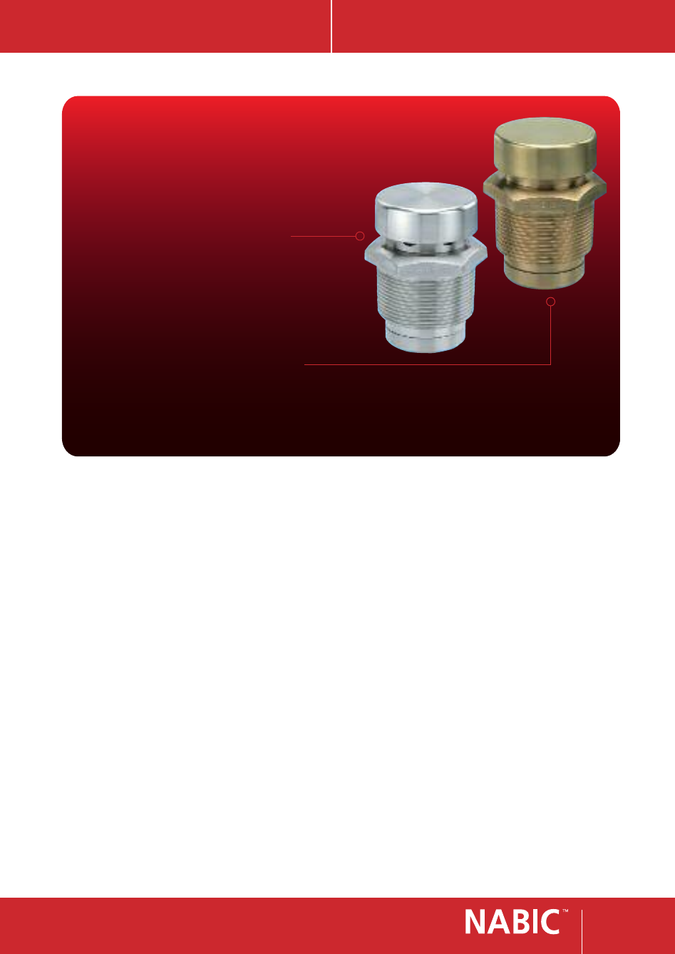
Technical Helpline: 01744 458615
www.nabic.co.uk
199
ANTI-VACUUM VALVES
Figure 568 Anti-Vacuum Valves are used to protect drying cylinders, calorifiers and
tankers from collapse due to internal vacuum. They are also used on steam systems,
to assist condensate drainage and to prevent suction of contents from vats.
Vacuum valves are normally fitted vertically, at the top of the vessel or pipeline being
protected. Horizontal revolving cylinders however, should have a
figure 568 fitted at each end, diametrically opposite one another.
Fig. 568SS Stainless Steel
Anti-Vacuum Valve
Body Material |Stainless Steel
Maximum Set Pressure |13.5 bar
Maximum Temperature |195°C
Fig. 568 Anti-Vacuum Valve
Body Material |Gunmetal
Maximum Set Pressure |13.5 bar
Maximum Temperature |195°C
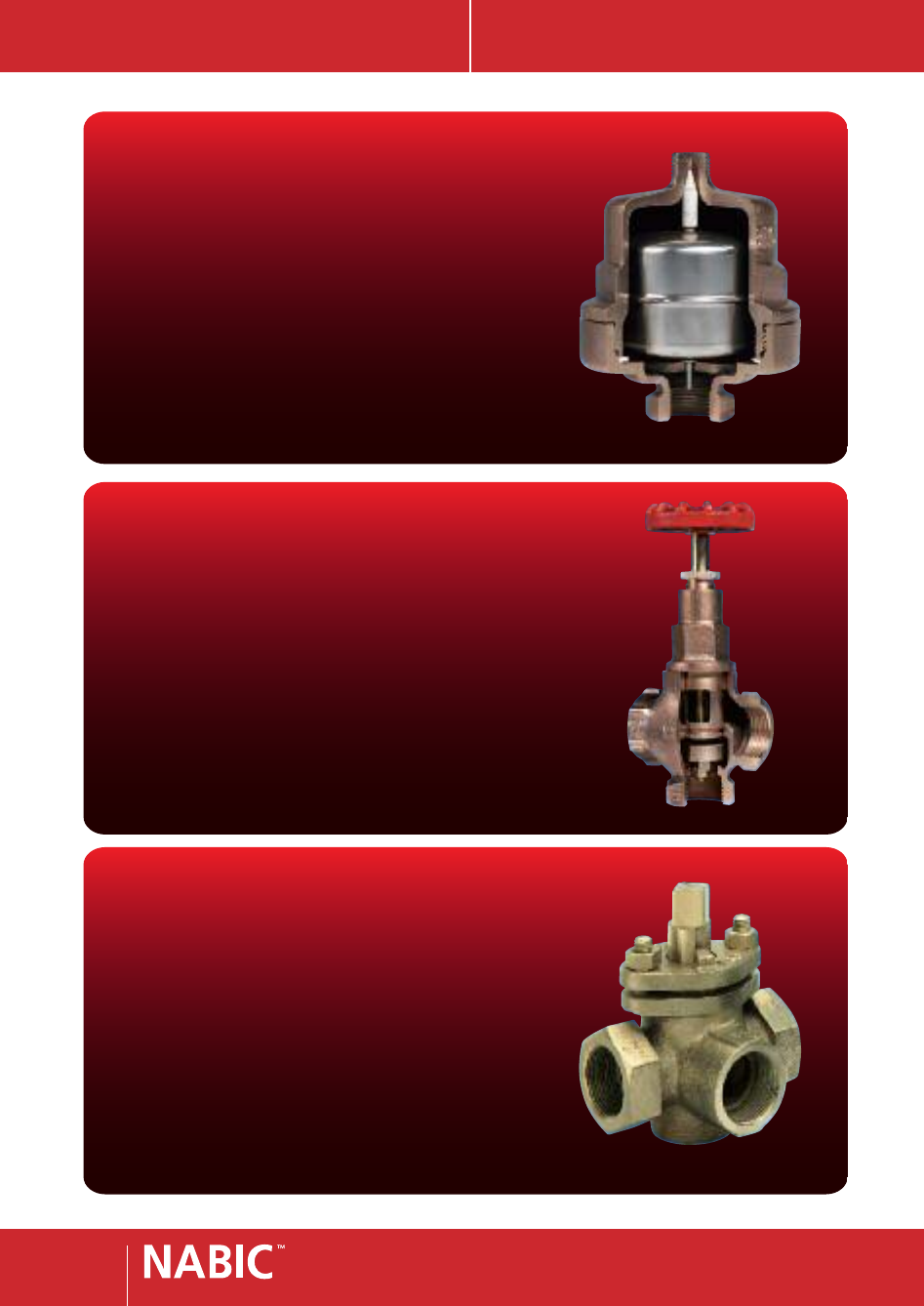
Technical Helpline: 01744 458 615
www.nabic.co.uk
200
BOILER SYSTEM VALVES
Fig. 100 Automatic Air-Vent
Body Material |Gunmetal
Float |Stainless Steel
Maximum Pressure |10 bar
Minimum Pressure |0.15 bar
Maximum Temperature |93°C
Figure 100 Automatic Air Vent is an extremely efficient valve designed
for use on central heating installations where the removal of large air
bubbles trapped in the system helps to reduce noise levels, maintain
circulation and improve heat output. They can also be fitted to other
fluid systems where air inclusion causes problems.
Fig. 175 Three Way Vent Cock
Body Material |Gunmetal
Maximum Working Pressure |7 bar
Maximum Working Temperature |100°C
Figure 175 Three Way Vent Cock has been designed for use on vented
hot water systems, to ensure there is a permanent connection from the
boiler or calorifier to atmosphere. Fitting a figure 175 allows the use of
a single common vent pipe, and permits continued operation of the
system whilst maintenance is carried out on an individual unit.
Fig. 503 Three Way Vent Valve
Body Material |Gunmetal
Maximum Working Pressure |7 bar
Maximum Working Temperature |93°C
Figure 503 Three Way Valve has been designed for use on vented hot
water systems, to ensure there is a permanent connection from the
boiler or calorifier to atmosphere. Fitting a figure 503 allows the use of
a single common vent pipe, and permits continued operation of the
system whilst maintenance is carried out on an individual unit.
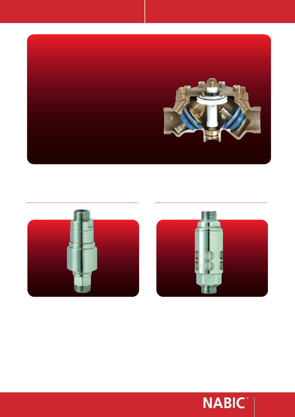
Technical Helpline: 01744 458615
www.nabic.co.uk
201
ANTI-POLLUTION VALVES
Fig. 255 Reduced Pressure Zone
Anti-Pollution Valve
Body Material |Gunmetal
Check Valves |Plastic
Seals |EPDM
Maximum Working Pressure |10 bar
Maximum Working Temperature |60°C
The RPZ Anti-Pollution valve is a type BA safety device used to prevent
contamination of drinking water through syphoning or backflow up to
class 4 fluid category. They are particularly suitable for industrial and
commercial applications and can also be used for supplies to buildings
within the scope of the water regulations.
Fig. 256A
Pipe Interrupter
Figure 256A is classified as a DC type suitable for protecting
up to fluid category 5. Incorporating ventilation ports that are
totally unrestricted and permanent, water is guided past
these air vents using a venturi type nozzle. Since they are
constantly open to atmosphere, this stops syphonage and
allows the escape of water in the event of backflow.
Body Material |Brass
Internals |Plastic
O-Rings |EPDM
Maximum Set Pressure |10 bar
Maximum Temperature |60°C
Fig. 256B
Pipe Interrupter
Figure 256B is classified as a DB type suitable for protecting
up to fluid category 4. This device has a moving element
which seals the ventilation gaps during normal flow
conditions. When negative pressures occur on the inlet side
which could cause syphonage, the membrane retracts seals
the flow ports and simultaneously vents the outlet side of the
pipe interrupter.
Body Material |Brass
Internals |Plastic
O-Rings |EPDM
Maximum Set Pressure |10 bar
Maximum Temperature |60°C
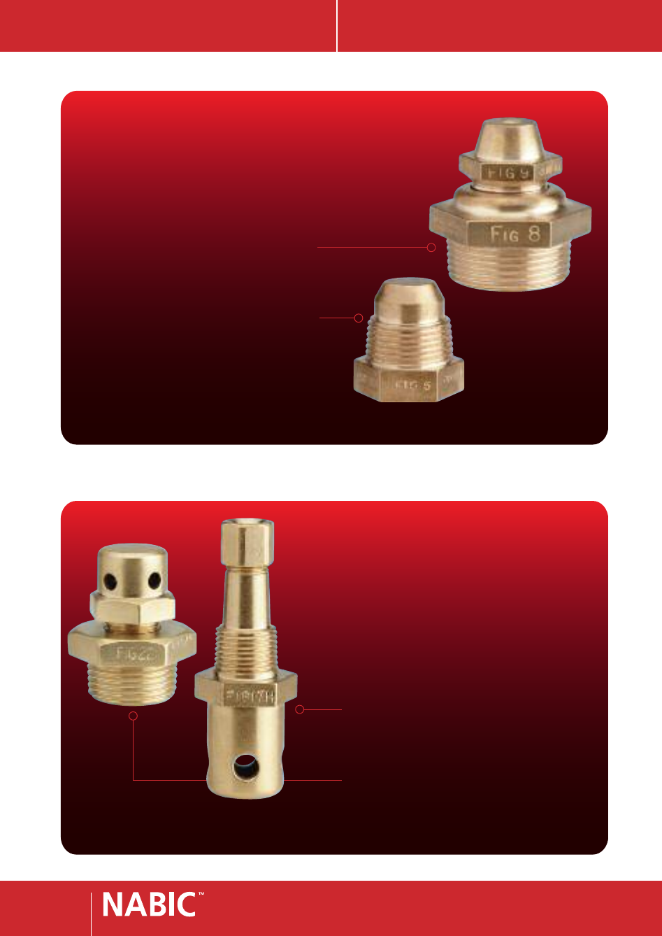
Technical Helpline: 01744 458 615
www.nabic.co.uk
202
FUSIBLE PLUGS
Figure 5 and figure 8 Fusible Plugs are used to protect
internally fired steam boilers. If overheating occurs due to low
water conditions, the plugs are designed to operate and allow
pressure to reduce, thereby preventing collapse of the boiler.
Fig. 8 Fusible Plugs For Steam
Body Material |Gunmetal
Maximum Pressure |24 bar
Fig. 5 Fusible Plugs For Steam
Body Material |Gunmetal
Maximum Pressure |24 bar
Fig. 17H Fusible Plugs For Air
Body Material |Brass
Maximum Pressure |20 bar
Fig. 22 Fusible Plugs For Air
Body Material |Brass
Maximum Pressure |20 bar
Figure 17H Fusible plugs are used to protect compressed air
systems from the risk of an explosion occurring due to
ignition of oil vapour. Figure 22 Fusible Plugs are used to
protect air receivers from the risk of an explosion occurring
due to external fire. Both plugs are designed to operate
when high temperatures occur, thereby reducing pressure
and providing audible warning of dangerous conditions.
Higher Pressure versions available upon request.
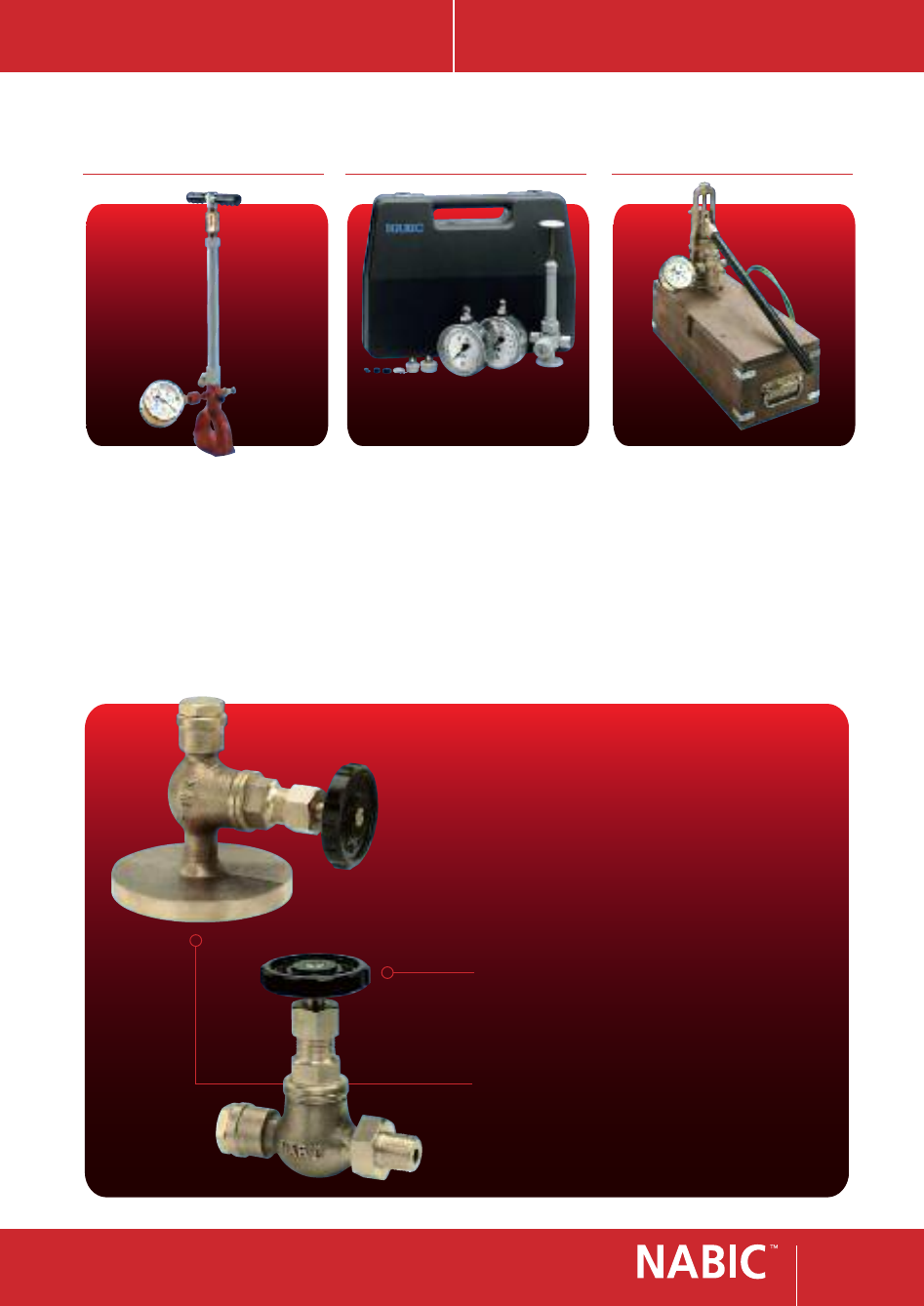
Technical Helpline: 01744 458615
www.nabic.co.uk
203
TEST VALVES & EQUIPMENT
Fig. 55N Test Valve
Body Material |Gunmetal
Maximum Pressure |17.5 bar
Maximum Temperature |260°C
Fig. 174 Text Valve
Body Material |Gunmetal
Maximum Pressure |17.5 bar
Maximum Temperature |260°C
Figure 55N is a robust gunmetal stop valve, with a
stainless steel needle type valve and seat. A dust cap
protects the test gauge connection, which is tapped 3/8"
BSP. The boiler connector is threaded 1/2" BSP male.
Figure 174 is a flanged version of figure 55N. The Test
Valves are used on steam boilers, to provide a means for
attaching a test pressure gauge. This enables the
calibration of the boiler gauge to be checked under
working conditions. It also serves a useful purpose as an
air vent, to facilitate draining and filling of the boiler.
Fig. 300
Test Pump
Fig. 362
Pressure Gauge Tester
Fig. 122
Test Pump
Figure 300 is a portable, stirrup type,
hydraulic test pump of brass construction.
Its dual pressure range facility provides
increased capacity per stroke at low
pressures, with quick and easy
changeover to the high pressure range.
Body Material |Brass
Low Pressure Range |0-16 bar
High Pressure Range |0-70 bar
Figure 362 Pressure Gauge Tester is a
compact portable unit, used for checking
pressure gauges on site. The tester is
comprised of a small hand-operated air
pump with fine adjustment facility.
Suitable fittings are supplied to enable
most gauges in common use to be
tested throughout their range.
Figure 122 is a hydraulic test pump of
robust construction. A precision built pump
in high pressure bronze, with steel lever,
supplied with a screw base which can be
fitted to the lid of the carrying case.
Alternately, the pump can be fitted with a
tripod kit at extra cost.
Body Material |Gunmetal
Maximum Pressure |700 bar
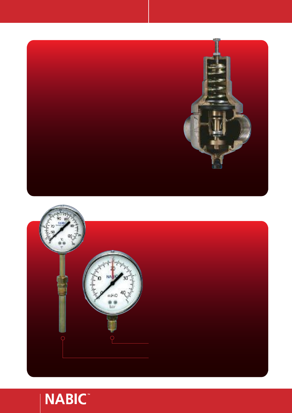
Technical Helpline: 01744 458 615
www.nabic.co.uk
204
PRESSURE REDUCING VALVES
Figure 850 Pressure Reducing Valve is designed for general and
commercial use, and is used where there is a requirement to lower
the pressure of a fluid from one level to another. It also maintains the
reduced pressure at a constant value, irrespective of fluctuations in
the inlet pressure or changes in the flow demand.
Fig. 850 Pressure Reducing Valve
Body Material |Brass Nickel Plated
Maximum Inlet Pressure |25 bar
Maximum Outlet Pressure |7 bar
Minimum Outlet Pressure |0.5 bar
Minimum Working Temperature |85°C
Fig. 210 Altitude Gauge
Fig. 345 Vapour Pressure
Thermometer
Figure 345 complies with BS 5235 and has a range of 20°C
to 120°C. It has a 100mm diameter dial and an immersion
depth of 100mm. Supplied complete with pocket, which is
screwed 1/2" BSP. We are happy to provide other
temperature gauges and connections on request.
Figure 210 is manufactured to BS 1780 and has a 100mm
diameter dial, 3/8" BSP bottom connection and full size
Bourdon tube.
Also available straight from stock are figure 219 DN10 Scroll
Syphon Kit and figure 215 DN10 Pressure Gauge Cock.
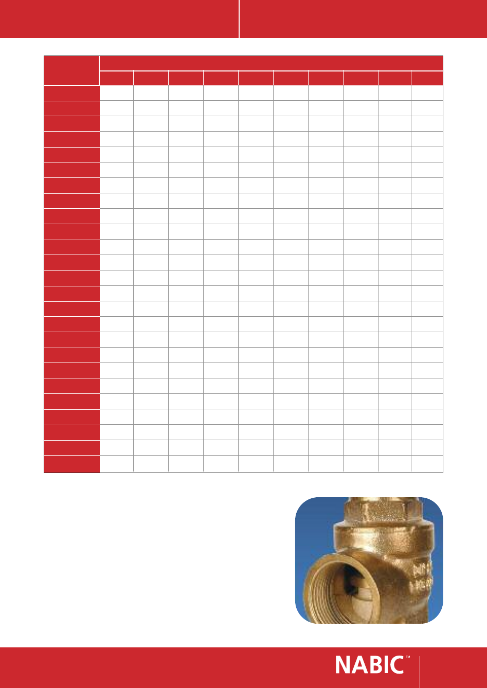
Technical Helpline: 01744 458615
www.nabic.co.uk
205
SIZE AVAILABILITY MATRIX
Quality Guarantee
Constructed from high performance materials, NABIC products are
produced using the latest technology and manufacturing techniques within
a quality system to ISO 9001. Inspection of components throughout all
stages of manufacture and individual testing of completed products prior
to despatch ensures quality and reliability is maintained.
Designed to relevant standards the majority of NABIC products are third
party certified and UK WFBS listed.
Valve Size DN
10 15 20 25 32 40 50 65 80 100
Fig. 500 ••••••• •
Fig. 500L ••••••• •
Fig. 500 FLG ••••• •
Fig. 500SS •••••••
Fig. 500FN •••
Fig. 500FF •••
Fig. 500AA •••
Fig. 500AS •••
Fig. 500DF •••
Fig. 500T* ••••••
Fig. 520 •••
Fig. 542 ••••••••
Fig. 542 FLG •••••
Fig. 542L ••••••••
Fig. 542L FLG •••••
Fig. 800 •••
Fig. 175 ••• •• •
Fig. 503 ••••• •
Fig. 568 ••••••
Fig. 850 •••••••••
Fig. 100 •
Fig. 55N •
Fig. 255 •••••••
Fig. 256A ••••
Fig. 256B •••

Technical Helpline: 01744 458 615
www.nabic.co.uk
206
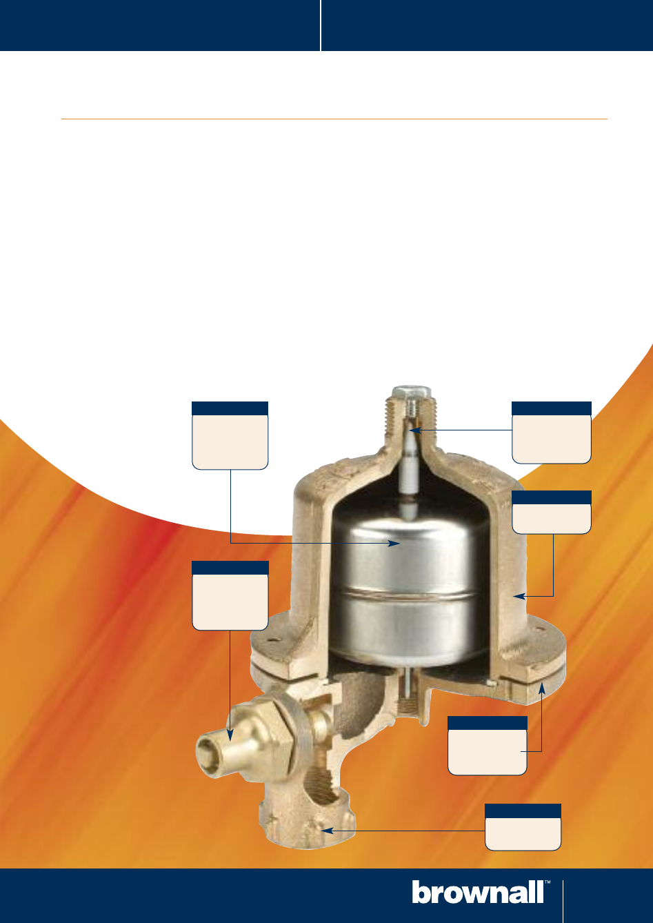
Technical Helpline: 01744 458 615
www.brownall.co.uk
207
PLANT ROOM VALVES
"4*6<#775'*4>.;
=<75*<2,2:42526*<7:;*6-724.:'.6<'*4>.;
With a proven track record for high quality,
Brownall offers an exclusive range of Automatic Air
Eliminators (AAE) covering low, medium and high
pressure applications, complemented by the
Three-way Vent Valves and Vent Cocks for boilers.
Offering efficient performance, the Brownall range
removes inevitable and potentially dangerous air
trapped in the system. Air Eliminators are suitable
for use with water, glycol, aviation fuel, diesel and
light oils.
Installed at the highest point of the fluid carrying
system, the trapped air will enter the float chamber
of the air eliminator. This reduces the float
buoyancy and allows air to escape
through the outlet orifice.
To complement the AAE, the Univent and Vent
Cocks are installed to provide a direct connection
from the boiler to the atmosphere. Designed to
simplify the venting process, for single or multi
point boiler and calorifier installations, the range
offers savings in time and costs. Bronze body parts
enable the range to operate in high-turbulence
aerated hot water, which can be a very corrosive
environment.
All the above make Brownall the number one
choice with professional building services,
consulting engineers and specifying authorities.
7;<=62<;*:.;=8842.-
,7584.<.?2<1*6
2;74*<260>*4>.?12,1
?244.*;24A2;74*<.<1.
<7.6*+4.:*82-
26;2<=;.:>2,260
2.
$1.44,75876.6<;
5*6=/*,<=:.-/:75
5*<.:2*4:.;2;<*6<<7
;<:.;;,7::7;276,:*,3260
*6-/=60*40:7?<1
4.
:*60.7/,766.,<276;
26,4=-260$";,:.?.-
*6-J*60.-
3.
#7+=;<,76;<:=,<276*6-
:.42*+4.78.:*<276/7:
26-=;<:2*4.6>2:765.6<;
5.
*:0.J7*<,76;<:=,<276
<78:7>2-.5*@25=5
:.;.*<260/7:,.?12,1
:.-=,.;<1.:2;37/
4.*3*0.*6-;.*4;*<*
52625=57/+*:
1.
#.;242.6<"%;.*<
76.46..-4.-.;206
?12,13..8;2<;;1*8.
*6-/7:5<75*26<*26*
4.*3<201<;.*<
6.
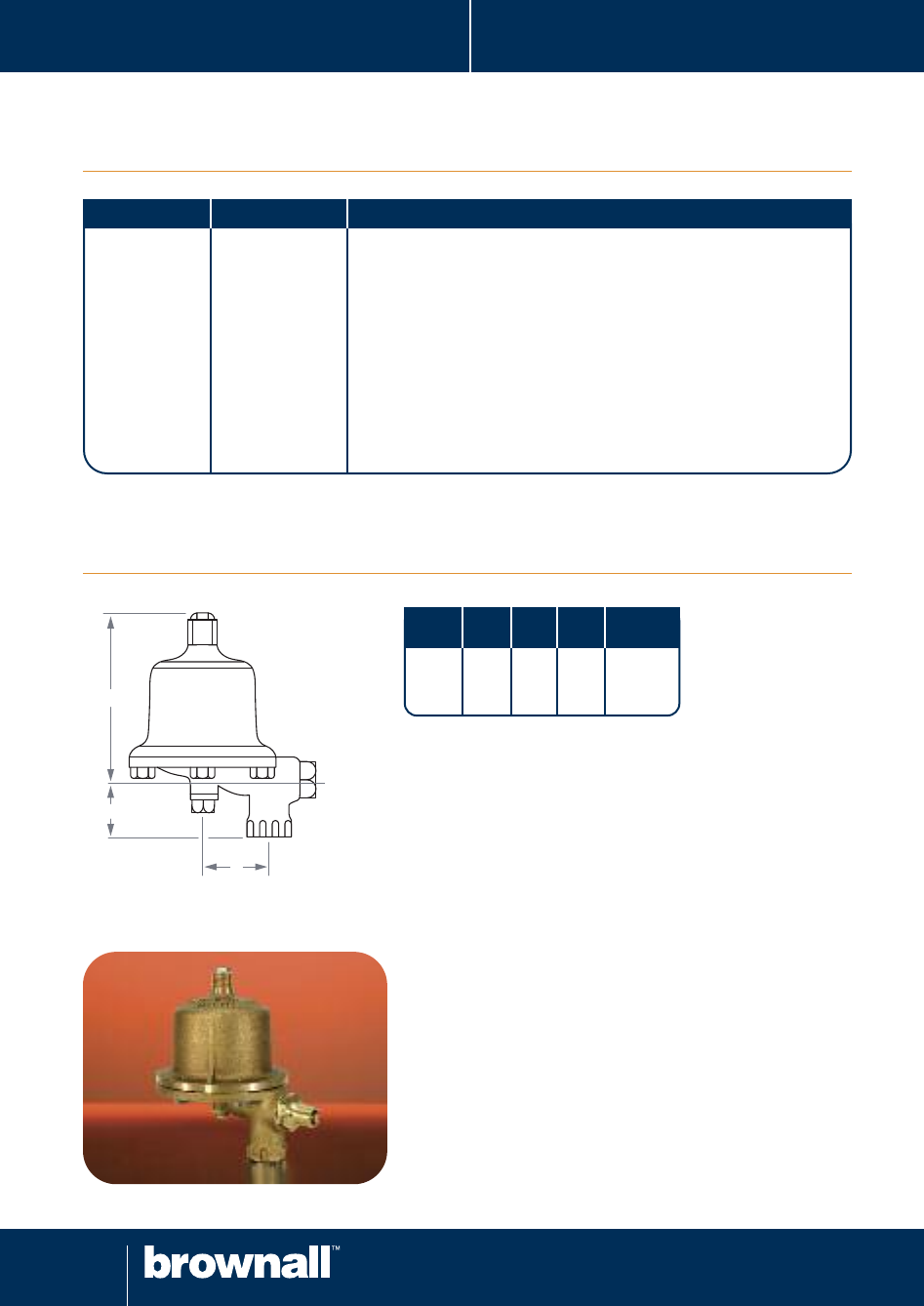
Technical Helpline: 01744 458 615
www.brownall.co.uk
208
PLANT ROOM VALVES
$<*6-*:-":.;;=:.8842,*<276;%A8.*6-
=<75*<2,2:42526*<7:;
A
B
C
%)""#% !%$
%A8. '.:<2,*464.<>*24*+4.$8.,2*4!:-.:
%A8. '.:<2,*464.<?2<16<.0:*47,3;12.4-;74*<260'*4>.
%A8. '.:<2,*464.<?2<16<.0:*47,3;12.4-;74*<260'*4>.1.,3'*4>.
%A8.$2-.64.<>*24*+4.$8.,2*4!:-.:
%A8."( "('.:<2,*464.<?2<16<.0:*47,3;12.4-;74*<260'*4>.
%A8."("($%'.:<2,*464.<?2<16<.0:*47,3;12.4-;74*<260'*4>.
%A8."("( $%'.:<2,*464.<?2<16<.0:*47,3;12.4-;74*<260'*4>.
%A8."("(" '.:<2,*464.<?2<16<.0:*47,3;12.4-;74*<260'*4>.
%A8."("( 4*;;>.:<2,*4264.<?2<16<.0:*47,3;12.4-;74*<260'*4>.
Materials of Construction
Body and Dome :76B.=65.<*4
Spindle and Seating $<*264.;;$<..4
Valve "% ..-4.
Float$<*264.;;$<..4
Technical Data
Connections64.<$ E#8 .5*4.
!=<4.<$ $!E *4.
Pressure Rating&8<7+*:+/26
76$17,3
Temp Rating&8<7CC
Recommended Min.
Working Pressure+*:/<.H.,<2>.1.*-)
Type A B C Weight
kg
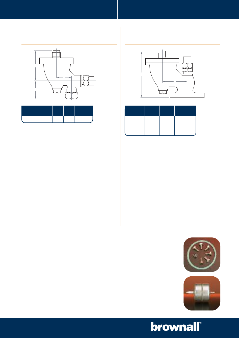
Technical Helpline: 01744 458 615
www.brownall.co.uk
209
PLANT ROOM VALVES
.-2=5":.;;=:.7<(*<.:
8842,*<276;"(
201":.;;=:.7<(*<.:
8842,*<276;"(
$.:>2,.2<;47*<;;.5+4A
%A8.;$"$"
%A8.;*6-=<75*<2,2:42526*<7:;*:.5*6=/*,<=:.-?2<126+=24<2;74*<260
>*4>.;?12,1?1.6,47;.-*447?<1.-75.<7+.:.57>.-*6-<1.J7*<*;;.5+4A
:.84*,.-*447?260:*82-26;2<=;.:>2,260
%A8.*6-:.9=2:.*6*--2<276*42;74*<260>*4>.76<1.264.<<72;74*<.2</:75<1.
;A;<.58:27:<7:.57>260<1.J7*<*;;.5+4A
$"2;74*<7:32<*>*24*+4./7:<A8.;*2:.42526*<7:;$""($.:>2,.
32<2;*>*24*+4./7:<A8.;"(*6-"(*2:.42526*<7:;
$.:>2,.32<;,758:2;.7/*J7*<*;;.5+4A26,6..-4.*6-;826-4.;.*<?*;1.:*6-
:.<*26260;,:.?;
A
B
C
A
B
Materials of Construction
Body and Dome:76B.=65.<*4
Spindle and Seating$<*264.;;$<..4
Valve76.4
Float 2,3.4447A$24>.::*B.-
Technical Data
Connections 64.<$ E
#8 .5*4.
!=<4.<$ $!E
*4.
Pressure Rating &8<7+*:+/26
Temp Rating &8<7CC
Recommended Min.
Working Pressure +*:/<.H.,<2>.1.*-
Materials of Construction
Body and Dome :76B.=65.<*4
Spindle and Seating $<*264.;;$<..4
Valve 76.4
Float 2,3.4447A$24>.::*B.-
Technical Data
Connections64.<$%*+4.7: 4*60.-
*6+.;=8842.--:244.-<7" 7:
6;24*;;
!=<4.<$ $!E *4.
Pressure Rating "(+*:2+/26
"(+*:2+/26
Temp Rating "(CC
"(CC
Recommended Min.
Working Pressure +*:/<.H.,<2>.1.*-)
Type A B Weight
kg
$%FG
$%FG
"
4*;;
Type A B C Weight
kg
"(
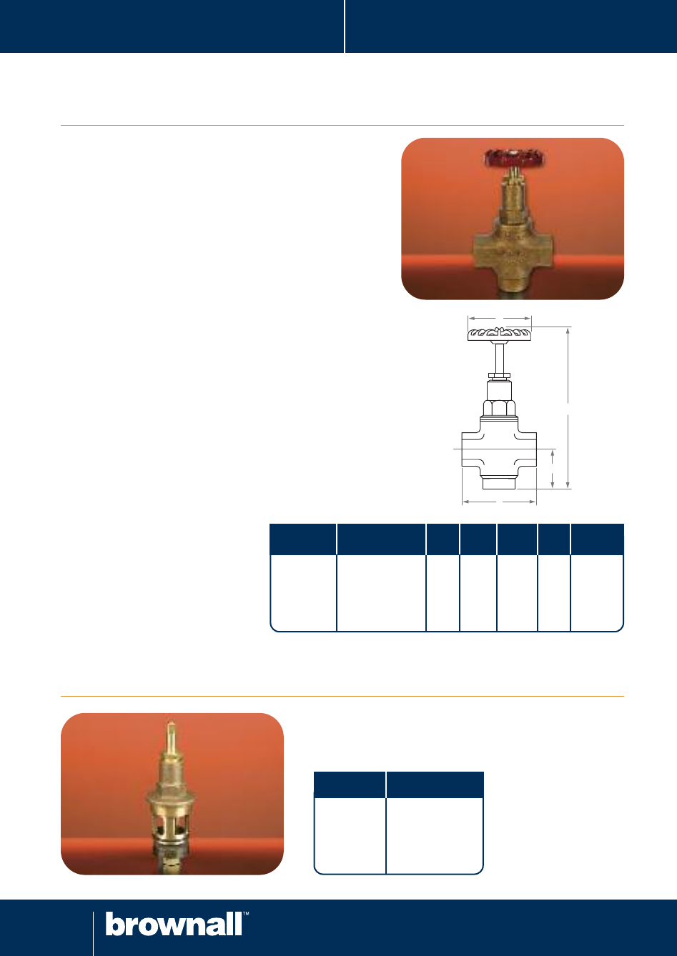
Technical Helpline: 01744 458 615
www.brownall.co.uk
210
PLANT ROOM VALVES
A
D
B
C (max)
&62>.6<#.84*,.5.6<*:<:2-0.20764A
20
%1:..?*A&62>.6<
55 K&'$"
55
/
K&'$"
55
/
K&'$"
55 K&'$"
55
/
K&'$"
Size Product code
#.84*,.5.6<,*:<:2-0.;/7:<1.%1:..?*A&62>.6<>*4>.
*447?:*82-26;2<=;.:>2,260
Technical Data
Max pressure: +*:
Max temperature: D
Connections: $ E#8.5*4.
Materials:
Body: :76B.=65.<*4
Head: :76B.=65.<*4
Trim: :*;;
Spindle: :*;;+*:
Renewable Seat: "
20=:.%1:..?*A&62>.6<2;-.;206.-/7:=;.76
>.6<.-17<?*<.:;A;<.5;<7.6;=:.<1*<<1.:.2;
*4?*A;*-2:.,<,766.,<276/:75<1.+724.:,*47:2I.:
<7<1.*<57;81.:.*-./:75+7-A5*<.:2*4;
:.;2;<*6<<7;<:.;;,7::7;276,:*,32602<,*6+.=;.-
/7:;2604.7:5=4<2+724.:26;<*44*<276;
6426.;.:>2,260=;260&62>.6<:.84*,.5.6<
,*:<:2-0.;*447?;>*4>.5*26<.6*6,.<7+.,*::2.-7=<
?2<17=<-2;<=:+260<1.828.?7:3
%1.&62>.6<,*6+.78.6.-*6-,47;.-=;260<1.
26<.0:*41*6-?1..4%7,47;.<1.-:*2687:<*6-78.6
<1.>.6<<=:6<1.1*6-?1..4,47,3?2;.<72<;/=44
<:*>.4%=:6<1.1*6-?1..4*6<2,47,3?2;.<778.6<1.
-:*26*6-,47;.<1.>.6<
55K &'
55
/
K &'
55
/
K&'
55K&'
55
/
K&'
Nominal Product AB CDWeight
Size code (max) kg
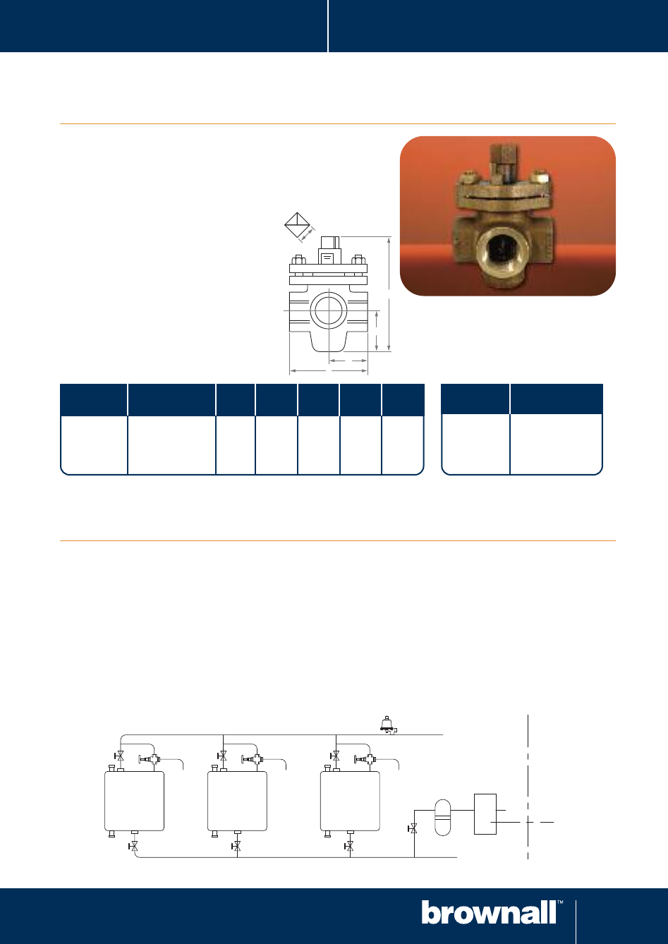
Technical Helpline: 01744 458 615
www.brownall.co.uk
211
PLANT ROOM VALVES
%A82,*4=4<2724.:$A;<.5
26,7:87:*<260:7?6*44&62>.6<;'.6<7,3;20
ISOLATOR VALVE UNIVENT VALVE
DRAIN
BOILER
UNIVENT VALVE
DRAIN
BOILER
UNIVENT VALVE
EXPANSION
VESSEL
PRESSURISATION
UNIT
AUTO AIR VENT
MCW
DRAIN
BOILER
Please note: %1:..?*A&62>.6<;*6-%1:..?*A'.6<7,3;*:.26<.:,1*60.*+4.
%1.=;.7/;,:.?-7?6>*4>.;/7:5=4<2+724.:17<
?*<.:26;<*44*<276;,*6*447?<1.=;.7/*;2604.>.6<
828.<7;.:>.*6A6=5+.:7/+724.:; 7+724.:26<1.
;A;<.5,*6+.4./<26*6=6>.6<.-,76-2<276
2::.;8.,<2>.7/<1.;.4.,<.-;.<<260;7/<1.>*4>.;
<*44<25.;<1.>.6<>*4>..6;=:.;*/=44+7:..@2<
/:75<1.+724.:<7*<57;81.:.
678.:*<276,47,3?2;.<=:62607/<1.1*6-?1..4
,47;.;<1.-:*26*6-78.6;<1.>.6<6<2,47,3?2;.
:7<*<2767/<1.1*6-?1..478.6;<1.-:*26*6-
,47;.;<1.>.6<
Note: %1.-2*0:*5;17?62;;,1.5*<2,*6-2;67<
26<.6-.-*;*0=2-.<7<1.26;<*44*<2767/<1.>.6<
>*4>.;<2;.;;.6<2*4<1*<>.6<>*4>.;*:.I<<.-26
*,,7:-*6,.?2<1<1.5*6=/*,<=:.:;
:.,755.6-*<276;*6-,7584A?2<1.*4<1*6-
$*/.<A:.0=4*<276;.<,
D
B
C
E
A
20
%1:..?*A'.6<7,3;
20=:.2;:.;2;<*6<<7;<:.;;,7::7;276,:*,3260*6-=;.-
76;2604.5=4<2+724.:7:,*47:2I.:26;<*44*<276;2<<260*
%1:..?*A'.6<7,3.6;=:.;*,76;<*6<,766.,<276/:75<1.
+724.:7:,*47:2I.:<7<1.*<57;81.:.
.>.:;*:.*>*24*+4.*;*678<276*4.@<:*
Technical Data
Max pressure: +*:
Max temperature: D
Connections: $ E#8.5*4.
Materials
Body: :76B.=65.<*4
Plug: :76B.=65.<*4
Gland: :76B.=65.<*4 Valve Levers
55K'
55
/
K'
55
/
K'
55K'
Normal
size
Product
code
A B C D E
55 K'
55
/
K'
55
/
K'
55 K'
Size Product code
Technical Helpline: 0845 604 1790
E: tech-enquiries@hattersley.com W: www.hattersley.com
212
The Sage, Gateshead, Tyne & Wear
Specification: Hattersley Commissioning Valves
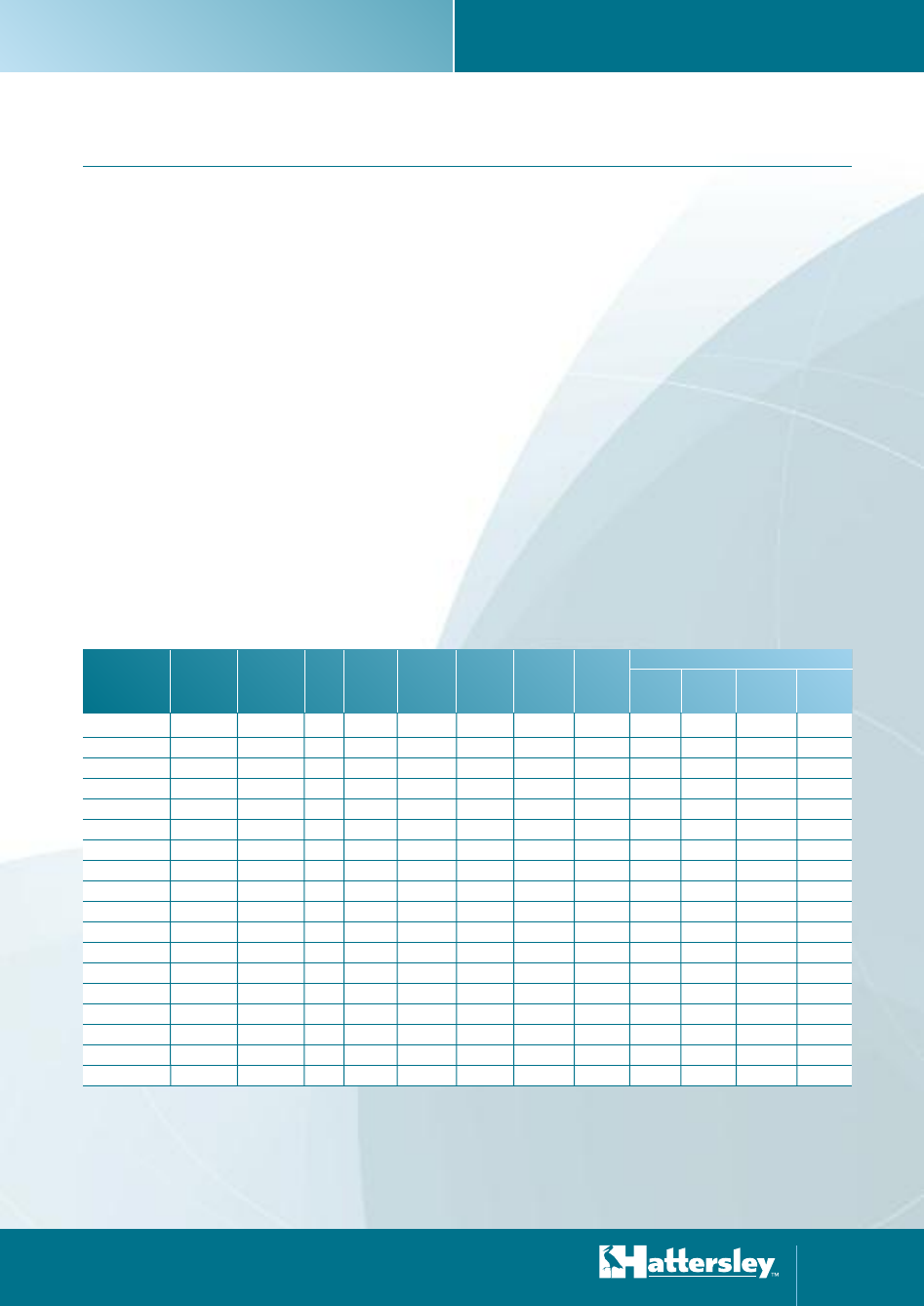
Technical Helpline: 0845 604 1790
E: tech-enquiries@hattersley.com W: www.hattersley.com
213
FLANGE TABLES
Flange Tables
PN6 80 55 4 M10 11 38 40 2 12 (1) - 12 -
PN10 95 65 4 M12 14 46 45 2 14 (1) - 16 14
PN16 95 65 4 M12 14 46 45 2 14 (1) 6 (2) 16 14
PN25 95 65 4 M12 14 46 45 2 16 (1) 8 (2) 16 14
PN40 95 65 4 M12 14 46 45 2 - 9 (2) 16 16
PN64 105 75 4 M12 14 - 45 2 - - 20 -
ANSI
Class 125/150 31/2 (89) 23/8 (60) 4 1/2 (13) 5/8 (16) - 13/8 (35) 1/16 (2) - 5/16 (8) 7/16 (11) -
Class 300 33/4 (95) 25/8 (67) 4 1/2 (13) 5/8 (16) - 13/8 (35) 1/16 (2) - 1/2 (13) 1/2 (13) -
Class 600 33/4 (95) 25/8 (67) 4 1/2 (13) 5/8 (16) - 13/8 (35) 1/4 (6) - - 9/16 (14) -
Class 900 43/4 (121) 31/4 (83) 4 3/4 (19) 7/8 (22) - 13/8 (35) 1/4 (6) - - 7/8 (22) -
Class 1500 43/4 (121) 31/4 (83) 4 3/4 (19) 7/8 (22) - 13/8 (35) 1/4 (6) - - 7/8 (22) -
BS 10
Table A 33/4 (95) 25/8 (67) 4 1/2 (13) 9/16 (14) - - - 1/2 (13) 1/4 (6) - -
Table D 33/4 (95) 25/8 (67) 4 1/2 (13) 9/16 (14) - - - 1/2 (13) 1/4 (6) 3/8 (10) -
Table E 33/4 (95) 25/8 (67) 4 1/2 (13) 9/16 (14) - - - 1/2 (13) 1/4 (6) 3/8 (10) -
Table F 33/4 (95) 25/8 (67) 4 1/2 (13) 9/16 (14) - - - 1/2 (13) 5/16 (8) 3/8 (10) -
Table H 41/2 (114) 31/4 (83) 4 5/8 (16) 11/16 (17) - 21/4 (57) 1/16 (2) 5/8 (16) 3/8 (10) 1/2 (13) -
Nominal Size 15mm (1/2")
Dia. Bolt No. Dia. Dia. Dia. Dia. Height Thickness of flange
BS EN 1092 of circle of of of of raised of raised of Grey Copper Cast and Ductile
flange diameter bolts bolts holes face(3) face(3) raised Cast Alloy Forged Cast
Iron Steel face(3) Iron Steel Iron
(1) These flange thicknesses are also valid for ductile iron flanges type 21-2 (2) Flange thicknesses for copper alloy are from BS 4504
(3) Copper alloy flanges are always flat-faced
This information is extracted from the following
European, British and American standards:
• BS EN 1092 Circular flanges for pipes, valves,
fittings and accessories, PN designated Part 1
Steel flanges.
• Part 2 Cast iron flanges.
• BS 4504 Flanges and bolting for pipes, valves,
and fittings metric series (for copper alloy
flanges only).
• ANSI B16.1 Cast Iron pipe flanges and
flanged fittings.
• ANSI B16.5 Steel pipe flanges and flanged
fittings.
• ANSI B16.24 Bronze flanges and flanged
fittings BS10 Flanges and bolting for pipes,
valves and fittings.
Notes:
1. Raised joint faces are applicable to
BS EN 1092-1, BS EN 1092-2, BS10 ANSI
table H steel, and classes 150
to 1500 inclusive.
2. ANSI Class 125 refers to cast iron only.
3. ANSI 600, 900, 1500 flange thickness does
not include raised face.
4. Dimensions for flanges to BS EN 1092 are
given in millimetres only. Dimensions for
ANSI and BS 10 flanges are shown in inches
with the metric equivalent (to nearest whole
millimetre) in brackets.

Technical Helpline: 0845 604 1790
E: tech-enquiries@hattersley.com W: www.hattersley.com
214
FLANGE TABLES
PN6 90 65 4 M10 11 48 50 2 14 (1) - 14 -
PN10 105 75 4 M12 14 56 58 2 16 (1) - 18 16
PN16 105 75 4 M12 14 56 58 2 16 (1) 6 (2) 18 16
PN25 105 75 4 M12 14 56 58 2 18 (1) 8 (2) 18 16
PN40 105 75 4 M12 14 56 58 2 - 9 (2) 18 18
PN64 130 90 4 M16 18 - 58 2 - - 22 -
PN100 130 90 4 M16 18 - 58 2 - - 22 -
ANSI
Class 125/150 37/8 (98) 23/4 (70) 4 1/2 (13) 5/8 (16) - 111/16 (43) 1/16 (2) - 11/32 (9) 9/16 (14) -
Class 300 45/8 (117) 31/4 (83) 4 5/8 (16) 3/4 (19) - 111/16 (43) 1/16 (2) - 17/32 (13) 5/8 (16) -
Class 600 45/8 (117) 31/4 (83) 4 5/8 (16) 3/4 (19) - 111/16 (43) 1/4 (6) - - 5/8 (16) -
Class 900 51/8 (130) 31/2 (89) 4 3/4 (19) 7/8 (22) - 111/16 (43) 1/4 (6) - - 1 (25) -
Class 1500 51/8 (130) 31/2 (89) 4 3/4 (19) 7/8 (22) - 111/16 (43) 1/4 (6) - - 1 (25) -
BS 10
Table A 4 (102) 27/8 (73) 4 1/2 (13) 9/16 (14) - - - 1/2 (13) 1/4 (6) - -
Table D 4 (102) 27/8 (73) 4 1/2 (13) 9/16 (14) - - - 1/2 (13) 1/4 (6) 3/8 (10) -
Table E 4 (102) 27/8 (73) 4 1/2 (13) 9/16 (14) - - - 1/2 (13) 1/4 (6) 3/8 (10) -
Table F 4 (102) 27/8 (73) 4 1/2 (13) 9/16 (14) - - - 1/2 (13) 5/16 (8) 3/8 (10) -
Table H 41/2 (114) 31/4 (83) 4 5/8 (16) 11/16 (17) - 21/4 (57) 1/16 (2) 5/8 (16) 3/8 (10) 1/2 (13) -
Nominal Size 20mm (3/4")
Dia. Bolt No. Dia. Dia. Dia. Dia. Height Thickness of flange
BS EN 1092 of circle of of of of raised of raised of Grey Copper Cast and Ductile
flange diameter bolts bolts holes face(3) face(3) raised Cast Alloy Forged Cast
Iron Steel face(3) Iron Steel Iron
(1) These flange thicknesses are also valid for ductile iron flanges type 21-2 (2) Flange thicknesses for copper alloy are from BS 4504
(3) Copper alloy flanges are always flat-faced
PN 6 100 75 4 M10 11 58 60 3 2 14 (1) - 14 -
PN10 115 85 4 M12 14 65 68 3 2 16 (1) - 18 16
PN16 115 85 4 M12 14 65 68 3 2 16 (1) 8 (2) 18 16
PN25 115 85 4 M12 14 65 68 3 2 18 (1) 9 (2) 18 16
PN40 115 85 4 M12 14 65 68 3 2 - 11 (2) 18 18
PN64 140 100 4 M16 18 - 68 - 2 - - 24 -
PN100 140 100 4 M16 18 - 68 - 2 - - 24 -
ANSI
Class 125/150 41/4 (114) 31/8 (79) 4 1/2 (13) 5/8 (16) - 2 (51) - 1/16 (2) 7/16 (11) 3/8 (10) 7/16 (11) 9/10 (14)
Class 300 47/8 (124) 31/2 (89) 4 5/8 (16) 3/4 (19) - 2 (51) - 1/16 (2) - 19/32 (15) 11/16 (17) -
Class 600 47/8 (124) 31/2 (89) 4 5/8 (16) 3/4 (19) - 2 (51) - 1/4 (6) - - 11/16 (17)
Class 900 57/8 (149) 4 (102) 4 7/8 (22) 1 (25) - 2 (51) - 1/4 (6) - - 11/8 (29) -
Class 1500 57/8 (149) 4 (102) 4 7/8 (22) 1 (25) - 2 (51) - 1/4 (6) - - 11/8 (29) -
BS 10
Table A 41/2 (114) 31/4 (83) 4 1/2 (13) 9/16 (14) - - - - 1/2 (13) 5/16 (8) - -
Table D 41/2 (114) 31/4 (83) 4 1/2 (13) 9/16 (14) - - - - 1/2 (13) 5/16 (8) 3/8 (10) -
Table E 41/2 (114) 31/4 (83) 4 1/2 (13) 9/16 (14) - - - - 1/2 (13) 5/16 (8) 3/8 (10) -
Table F 43/4 (121) 37/16 (87) 4 5/8 (16) 11/16 (17) - - - - 1/2 (13) 3/8 (10) 3/8 (10) -
Table H 43/4 (121) 37/16 (87) 4 5/8 (16) 11/16 (17) - 21/2 (64) - 1/16 (2) 3/4 (19) 7/16 (11) 9/16 (14) -
Nominal Size 25mm (1")
Dia. Bolt No. Dia. Dia. Dia. Dia. Height Height Thickness of flange
BS EN 1092 of circle of of of of raised of raised of raised of raised Grey Copper Cast and Ductile
flange diameter bolts bolts holes face(3) face(3) face(3) face(3) Cast Alloy Forged Cast
Iron Steel Iron Steel Iron Steel Iron
(1) These flange thicknesses are also valid for ductile iron flanges type 21-2 (2) Flange thicknesses for copper alloy are from BS 4504
(3) Copper alloy flanges are always flat-faced

Technical Helpline: 0845 604 1790
E: tech-enquiries@hattersley.com W: www.hattersley.com
215
FLANGE TABLES
PN 6 120 90 4 M12 14 14 69 70 3 2 16 (1) - 14 -
PN10 140 100 4 M16 19 18 76 78 3 2 18 (1) - 18 18
PN16 140 100 4 M16 19 18 76 78 3 2 18 (1) 8 (2) 18 18
PN25 140 100 4 M16 19 18 76 78 3 2 20 (1) 9 (2) 18 18
PN40 140 100 4 M16 19 18 76 78 3 2 - 11 (2) 18 20
PN64 155 110 4 M20 - 22 - 78 - 2 - - 26 -
PN100 155 110 4 M20 - 22 - 78 - 2 - - 26 -
ANSI
Class 125/150 4
5/8
(117) 3
1/2
(89) 4
1/2
(13)
5/8
(16)
5/8
(16) - 2
1/2
(64) -
1/16
(2)
1/2
(13)
13/32
(10)
1/2
(13)
5/8
(16)
Class 300 5
1/4
(133) 3
7/8
(98) 4
5/8
(16) -
3/4
(19) - 2
1/2
(64) -
1/16
(2) -
5/8
(16)
3/4
(19) -
Class 600 5
1/4
(133) 3
7/8
(98) 4
5/8
(16) -
3/4
(19) - 2
1/2
(64) -
1/4
(6) - -
13/16
(21) -
Class 900 6
1/4
(159) 4
3/8
(111) 4
7/8
(22) - 1 (25) - 2
1/2
(64) -
1/4
(6) - - 1
1/8
(29) -
Class 1500 6
1/4
(159) 4
3/8
(111) 4
7/8
(22) - 1 (25) - 2
1/2
(64) -
1/4
(6) - - 1
1/8
(29) -
BS 10
Table A 4
3/4
(121) 3
7/16
(87) 4
1/2
(13)
9/16
(14)
9/16
(14) - - - -
5/8
(16)
5/16
(8) - -
Table D 4
3/4
(121) 3
7/16
(87) 4
1/2
(13)
9/16
(14)
9/16
(14) - - - -
5/8
(16)
5/16
(8)
1/2
(13) -
Table E 4
3/4
(121) 3
7/16
(87) 4
1/2
(13)
9/16
(14)
9/16
(14) - - - -
5/8
(16)
5/16
(8)
1/2
(13) -
Table F 5
1/4
(133) 3
7/8
(98) 4
5/8
(16)
11/16
(17)
11/16
(17) - - - -
5/8
(16)
3/8
(10)
1/2
(13) -
Table H 5
1/4
(133) 3
7/8
(98) 4
5/8
(16)
11/16
(17)
11/16
(17) - 3 (76) -
1/16
(2)
7/8
(22)
7/16
(11)
11/16
(17) -
Nominal Size 32mm (11/4")
Dia. Bolt No. Dia. Dia. Dia. Dia. Dia. Height Height Thickness of flange
BS EN 1092 of circle of of of of of raised of raised of raised of raised Grey Copper Cast and Ductile
flange diameter bolts bolts holes holes face(3) face(3) face(3) face(3) Cast Alloy Forged Cast
Iron Steel Iron Steel Iron Steel Iron Steel Iron
PN6 130 100 4 M12 14 14 78 80 3 2 16 (1) - 14 -
PN10 150 110 4 M16 19 18 84 88 3 2 18 (1) - 18 19
PN16 150 110 4 M16 19 18 84 88 3 2 18 (1) 9 (2) 18 19
PN25 150 110 4 M16 19 18 84 88 3 2 20 (1) 11 (2) 18 19
PN40 150 110 4 M16 19 18 84 88 3 2 - 13 (2) 18 19
PN64 170 125 4 M20 - 22 - 88 - 2 - - 28 -
PN100 170 125 4 M20 - 22 - 88 - 2 - - 28 -
ANSI
Class 125/150 5 (127) 3
7/8
(98) 4
1/2
(13)
5/8
(16)
5/8
(16) - 2
7/8
(73) -
1/16
(2)
9/16
(14)
7/16
(11)
9/16
(14)
11/16
(17)
Class 300 6
1/8
(156) 4
1/2
(114) 4
3/4
(19) -
7/8
(22) - 2
7/8
(73) -
1/16
(2) -
11/16
(17)
13/16
(21) -
Class 600 6
1/8
(156) 4
1/2
(114) 4
3/4
(19) -
7/8
(22) - 2
7/8
(73) -
1/4
(6) - -
7/8
(22) -
Class 900 7 (178) 4
7/8
(124) 4 1 (25) - 1
1/8
(29) - 2
7/8
(73) -
1/4
(6) - - 1
1/4
(32) -
Class 1500 7 (178) 4
7/8
(124) 4 1 (25) - 1
1/8
(29) - 2
7/8
(73) -
1/4
(6) - - 1
1/4
(32) -
BS 10
Table A 5
1/4
(133) 3
7/8
(98) 4
1/2
(13)
9/16
(14)
9/16
(14) - - - -
5/8
(16)
3/8
(10) - -
Table D 5
1/4
(133) 3
7/8
(98) 4
1/2
(13)
9/16
(14)
9/16
(14) - - - -
5/8
(16)
3/8
(10)
1/2
(13) -
Table E 5
1/4
(133) 3
7/8
(98) 4
1/2
(13)
9/16
(14)
9/16
(14) - - - -
5/8
(16)
3/8
(10)
1/2
(13) -
Table F 5
1/2
(140) 4
1/8
(105) 4
5/8
(16)
11/16
(17)
11/16
(17) - - - -
5/8
(16)
7/16
(11)
1/2
(13) -
Table H 5
1/2
(140) 4
1/8
(105) 4
5/8
(16)
11/16
(17)
11/16
(17) - 3
1/4
(83) -
1/16
(2)
7/8
(22)
1/2
(13)
11/16
(17) -
Nominal Size 40mm (11/2")
Dia. Bolt No. Dia. Dia. Dia. Dia. Dia. Height Height Thickness of flange
BS EN 1092 of circle of of of of of raised of raised of raised of raised Grey Copper Cast and Ductile
flange diameter bolts bolts holes holes face(3) face(3) face(3) face(3) Cast Alloy Forged Cast
Iron Steel Iron Steel Iron Steel Iron Steel Iron
(1) These flange thicknesses are also valid for ductile iron flanges type 21-2 (2) Flange thicknesses for copper alloy are from BS 4504
(3) Copper alloy flanges are always flat-faced
(1) These flange thicknesses are also valid for ductile iron flanges type 21-2 (2) Flange thicknesses for copper alloy are from BS 4504
(3) Copper alloy flanges are always flat-faced

Technical Helpline: 0845 604 1790
E: tech-enquiries@hattersley.com W: www.hattersley.com
216
FLANGE TABLES
PN 6 140 110 4 M12 14 14 88 90 3 2 16 (1) - 14 -
PN10 165 125 4 M16 19 18 99 102 3 2 20 (1) - 18 19
PN16 165 125 4 M16 19 18 99 102 3 2 20 (1) 11 (2) 18 19
PN25 165 125 4 M16 19 18 99 102 3 2 22 (1) 11 (2) 20 19
PN40 165 125 4 M16 19 18 99 102 3 2 - 13 (2) 20 19
PN64 180 135 4 M20 - 22 - 102 - 2 - - 26 -
PN100 195 145 4 M24 - 26 - 102 - 2 - - 30 -
ANSI
Class 125/150 6 (152) 4
3/4
(121) 4
5/8
(16)
3/4
(19)
3/4
(19) - 3
5/8
(92) -
1/16
(2)
5/8
(16)
1/2
(13)
5/8
(16) -
Class 300 6
1/2
(165) 5 (127) 8
5/8
(16) -
3/4
(19) - 3
5/8
(92) -
1/16
(2) -
3/4
(19)
7/8
(22) -
Class 600 6
1/2
(165) 5 (127) 8
5/8
(16) -
3/4
(19) - 3
5/8
(92) -
1/4
(6) - - 1 (25) -
Class 900 8
1/2
(216) 6
1/2
(165) 8
7/8
(22) - 1 (25) - 3
5/8
(92) -
1/4
(6) - - 1
1/2
(38) -
Class 1500 8
1/2
(216) 6
1/2
(165) 8
7/8
(22) - 1 (25) - 3
5/8
(92) -
1/4
(6) - - 1
1/2
(38) -
BS 10
Table A 6 (152) 4
1/2
(114) 4
5/8
(16)
11/16
(17)
11/16
(17) - - - -
5/8
(16)
3/8
(10) - -
Table D 6 (152) 4
1/2
(114) 4
5/8
(16)
11/16
(17)
11/16
(17) - - - -
11/16
(17)
3/8
(10)
9/16
(14) -
Table E 6 (152) 4
1/2
(114) 4
5/8
(16)
11/16
(17)
11/16
(17) - - - -
3/4
(19)
3/8
(10)
9/16
(14) -
Table F 6
1/2
(165) 5 (127) 4
5/8
(16)
11/16
(17)
11/16
(17) - - - -
3/4
(19)
7/16
(11)
5/8
(16) -
Table H 6
1/2
(165) 5 (127) 4
5/8
(16)
11/16
(17)
11/16
(17) - 4 (102) -
1/16
(2) 1 (25)
1/2
(13)
3/4
(19) -
Nominal Size 50mm (2")
Dia. Bolt No. Dia. Dia. Dia. Dia. Dia. Height Height Thickness of flange
BS EN 1092 of circle of of of of of raised of raised of raised of raised Grey Copper Cast and Ductile
flange diameter bolts bolts holes holes face(3) face(3) face(3) face(3) Cast Alloy Forged Cast
Iron Steel Iron Steel Iron Steel Iron Steel Iron
PN 6 160 130 4 M12 14 14 108 110 2 3 16 (1) - 14 -
PN 10 185 145 4 (2) M16 19 18 118 122 2 3 20 (1) - 18 19
PN 16 185 145 4 (2) M16 19 18 118 122 2 3 20 (1) 13 18 19
PN 25 185 145 8 M16 19 18 118 122 2 3 24 (1) 13 22 19
PN 40 185 145 8 M16 19 18 118 122 2 3 - 14 22 19
PN 64 205 160 8 M20 - 22 - 122 2 - - - 26 -
PN 100 220 170 8 M24 - 26 - 122 2 - - - 34 -
ANSI
Class 125/150 7 (178) 5
1/2
(140) 4
5/8
(16)
3/4
(19)
3/4
(19) - 4
1/8
(105) -
1/16
(2)
11/16
(17)
9/16
(14)
11/16
(17) -
Class 300 7
1/2
(191) 5
7/8
(149) 8
3/4
(19) -
7/8
(22) - 4
1/8
(105) -
1/16
(2) -
13/16
(21) 1 (25) -
Class 600 7
1/2
(191) 5
7/8
(149) 8
3/4
(19) -
7/8
(22) - 4
1/8
(105) -
1/4
(6) - - 1
1/8
(29) -
Class 900 9
5/8
(244) 7
1/2
(191) 8 1 (25) - 1
1/8
(29) - 4
1/8
(105) -
1/4
(6) - - 1
5/8
(41) -
Class 1500 9
5/8
(244) 7
1/2
(191) 8 1 (25) - 1
1/8
(29) - 4
1/8
(105) -
1/4
(6) - - 1
5/8
(41) -
BS 10
Table A 6
1/2
(165) 5 (127) 4
5/8
(16)
11/16
(17)
11/16
(17) - - - -
11/16
(17)
7/16
(11) - -
Table D 6
1/2
(165) 5 (127) 4
5/8
(16)
11/16
(17)
11/16
(17) - - - -
11/16
(17)
7/16
(11)
9/16
(14) -
Table E 6
1/2
(165) 5 (127) 4
5/8
(16)
11/16
(17)
11/16
(17) - - - -
3/4
(19)
7/16
(11)
9/16
(14) -
Table F 7
1/4
(184) 5
3/4
(146) 8
5/8
(16)
11/16
(17)
11/16
(17) - - - -
3/4
(19)
1/2
(13)
5/8
(16) -
Table H 7
1/4
(184) 5
3/4
(146) 8
5/8
(16)
11/16
(17)
11/16
(17) - 4
1/2
(114) -
1/16
(2) 1 (25)
9/16
(14)
3/4
(19) -
Nominal Size 65mm (21/2")
Dia. Bolt No. Dia. Dia. Dia. Dia. Dia. Height Height Thickness of flange
BS EN 1092 of circle of of of of of raised of raised of raised of raised Grey Copper Cast and Ductile
flange diameter bolts bolts holes holes face(3) face(3) face(3) face(3) Cast Alloy Forged Cast
Iron Steel Iron Steel Iron Steel Iron Steel Iron
(1) These flange thicknesses are also valid for ductile iron flanges type 21-2 (2) Flange thicknesses for copper alloy are from BS 4504
(3) Copper alloy flanges are always flat-faced
(1) These flange thicknesses are also valid for ductile iron flanges type 21-2
(2) Steel flanges in this DN and PN may be supplied with 8 holes. For compliance with these, equivalent cast iron flanges may be
supplied with 8 holes as special order and after agreement between manufacturer and customer
(3) Flange thicknesses for copper alloy are from BS 4504 (4) Copper alloy flanges are always flat-faced
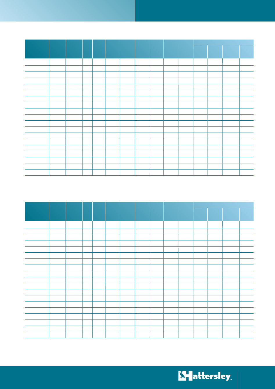
Technical Helpline: 0845 604 1790
E: tech-enquiries@hattersley.com W: www.hattersley.com
217
FLANGE TABLES
PN 6 190 150 4 M16 19 18 124 128 3 2 18 (1) - 16 -
PN10 200 160 8 M16 19 18 132 138 3 2 22 (1) - 20 19
PN16 200 160 8 M16 19 18 132 138 3 2 22 (1) 13 (2) 20 19
PN25 200 160 8 M16 19 18 132 138 3 2 26 (1) 14 (2) 24 19
PN40 200 160 8 M16 19 18 132 138 3 2 - 16 (2) 24 19
PN64 215 170 8 M20 - 22 - 138 - 2 - - 28 -
PN100 230 180 8 M24 - 26 - 138 - 2 - - 36 -
ANSI
Class 125/150 7
1/2
(191) 6 (152) 4
5/8
(16)
3/4
(19)
3/4
(19) - 5 (127) -
1/16
(2)
3/4
(19)
5/8
(16)
3/4
(19) -
Class 300 8
1/4
(210) 6
5/8
(168) 8
3/4
(19) -
7/8
(22) - 5 (127) -
1/16
(2) -
29/32
(23) 1
1/8
(29) -
Class 600 8
1/4
(210) 6
5/8
(168) 8
3/4
(19) -
7/8
(22) - 5 (127) -
1/4
(6) - - 1
1/4
(32) -
Class 900 9
1/2
(241) 7
1/2
(192) 8
7/8
(22) - 1 (25) - 5 (127) -
1/4
(6) - - 1
1/2
(38) -
Class 1500 10
1/2
(267) 8 (203) 8 1
1/8
(29) - 1
1/4
(32) - 5 (127) -
1/4
(6) - - 1
7/8
(48) -
BS 10
Table A 7
1/4
(184) 5
3/4
(146) 4
5/8
(16)
11/16
(17)
11/16
(17) - - - -
11/16
(17)
1/2
(13) - -
Table D 7
1/4
(184) 5
3/4
(146) 4
5/8
(16)
11/16
(17)
11/16
(17) - - - -
3/4
(19)
1/2
(13)
9/16
(14) -
Table E 7
1/4
(184) 5
3/4
(146) 4
5/8
(16)
11/16
(17)
11/16
(17) - - - -
3/4
(19)
1/2
(13)
9/16
(14) -
Table F 8 (203) 6
1/2
(165) 8
5/8
(16)
11/16
(17)
11/16
(17) - - - -
3/4
(19)
9/16
(14)
5/8
(16) -
Table H 8 (203) 6
1/2
(165) 8
5/8
(16)
11/16
(17)
11/16
(17) - 5 (127) -
1/16
(2) 1
1/8
(29)
5/8
(16)
7/8
(22) -
Nominal Size 80mm (3")
Dia. Bolt No. Dia. Dia. Dia. Dia. Dia. Height Height Thickness of flange
BS EN 1092 of circle of of of of of raised of raised of raised of raised Grey Copper Cast and Ductile
flange diameter bolts bolts holes holes face(3) face(3) face(3) face(3) Cast Alloy Forged Cast
Iron Steel Iron Steel Iron Steel Iron Steel Iron
PN 6 210 170 4 M16 19 18 144 148 3 2 18 (1) - 16 -
PN10 220 180 8 M16 19 18 156 158 3 2 24 (1) - 20 19
PN16 220 180 8 M16 19 18 156 158 3 2 24 (1) 16 (2) 20 19
PN25 235 190 8 M20 23 22 156 162 3 2 28 (1) 17 (2) 24 19
PN40 235 190 8 M20 23 22 156 162 3 2 - 19 (2) 24 19
PN64 250 200 8 M24 - 26 - 162 - 2 - - 30 -
PN100 265 210 8 M27 - 30 - 162 - 2 - - 40 -
ANSI
Class 125/150 9 (229) 7
1/2
(191) 8
5/8
(16)
3/4
(19)
3/4
(19) - 6
3/16
(157) -
1/16
(2)
15/16
(24)
11/16
(17)
15/16
(24) -
Class 300 10 (254) 7
7/8
(200) 8
3/4
(19) -
7/8
(22) - 6
3/16
(157) -
1/16
(2) -
11/16
(27) 1
1/4
(32) -
Class 600 10
3/4
(273) 8
1/2
(216) 8
7/8
(22) - 1 (25) - 6
3/16
(157) -
1/4
(6) - - 1
1/2
(38) -
Class 900 11
1/2
(292) 9
1/4
(235) 8 1
1/8
(29) - 1
1/4
(32) - 6
3/16
(157) -
1/4
(6) - - 1
3/4
(44) -
Class 1500 12
1/4
(311) 9
1/2
(241) 8 1
1/4
(32) - 1
3/8
(35) - 6
3/16
(157) -
1/4
(6) - - 2
1/8
(54) -
BS 10
Table A 8
1/2
(216) 7 (178) 4
5/8
(16)
11/16
(17)
11/16
(17) - - - -
3/4
(19)
5/8
(16) - -
Table D 8
1/2
(216) 7 (178) 4
5/8
(16)
11/16
(17)
11/16
(17) - - - -
3/4
(19)
5/8
(16)
11/16
(17) -
Table E 8
1/2
(216) 7 (178) 8
5/8
(16)
11/16
(17)
11/16
(17) - - - -
7/8
(22)
5/8
(16)
11/16
(17) -
Table F 9 (229) 7
1/2
(191) 8
5/8
(16)
11/16
(17)
11/16
(17) - - - -
7/8
(22)
11/16
(17)
3/4
(19) -
Table H 9 (229) 7
1/2
(191) 8
5/8
(16)
11/16
(17)
11/16
(17) - 6 (152) -
1/16
(2) 1
1/4
(32)
3/4
(19) 1 (25) -
Nominal Size 100mm (4")
Dia. Bolt No. Dia. Dia. Dia. Dia. Dia. Height Height Thickness of flange
BS EN 1092 of circle of of of of of raised of raised of raised of raised Grey Copper Cast and Ductile
flange diameter bolts bolts holes holes face(3) face(3) face(3) face(3) Cast Alloy Forged Cast
Iron Steel Iron Steel Iron Steel Iron Steel Iron
(1) These flange thicknesses are also valid for ductile iron flanges type 21-2 (2) Flange thicknesses for copper alloy are from BS 4504
(3) Copper alloy flanges are always flat-faced
(1) These flange thicknesses are also valid for ductile iron flanges type 21-2 (2) Flange thicknesses for copper alloy are from BS 4504
(3) Copper alloy flanges are always flat-faced
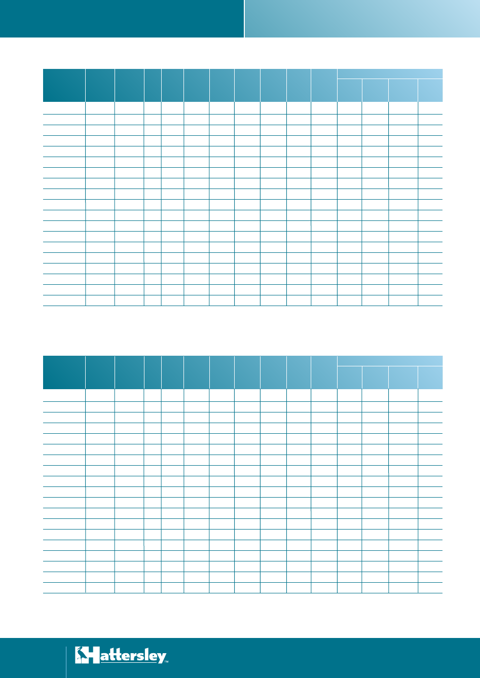
Technical Helpline: 0845 604 1790
E: tech-enquiries@hattersley.com W: www.hattersley.com
218
FLANGE TABLES
PN 6 240 200 8 M16 19 18 174 178 3 2 20 (1) - 18 -
PN10 250 210 8 M16 19 18 184 188 3 2 26 (1) - 22 19
PN16 250 210 8 M16 19 18 184 188 3 2 26 (1) - 22 19
PN25 270 220 8 M24 28 26 184 188 3 2 30 (1) - 26 19
PN40 270 220 8 M24 28 26 184 188 3 2 - - 26 23.5
PN64 295 240 8 M27 - 30 - 188 - 2 - - 34 -
PN100 315 250 8 M30 - 33 - 188 - 2 - - 40 -
ANSI
Class 125/150 10 (254) 8
1/2
(216) 8
3/4
(19)
7/8
(22)
7/8
(22) - 7
5/16
(186) -
1/16
(2)
5/16
(24)
3/4
(19)
5/16
(24) -
Class 300 11 (279) 9
1/4
(235) 8
3/4
(19) -
7/8
(22) - 7
5/16
(186) -
1/16
(2) - 1
1/8
(29) 1
3/8
(35) -
Class 600 13 (330) 10
1/2
(267) 8 1 (25) - 1
1/8
(29) - 7
5/16
(186) -
1/4
(6) - - 1
3/4
(44) -
Class 900 13
3/4
(349) 11 (279) 8 1
1/4
(32) - 1
3/8
(35) - 7
5/16
(186) -
1/4
(6) - - 2 (51) -
Class 1500 14
3/4
(375) 11
1/2
(292) 8 1
1/2
(38) - 1
5/8
(41) - 7
5/16
(186) -
1/4
(6) - - 2
7/8
(73) -
BS 10
Table A 10 (254) 8
1/4
(210) 4
5/8
(16)
11/16
(17)
11/16
(17) - - - -
3/4
(19)
11/16
(17) - -
Table D 10 (254) 8
1/4
(210) 8
5/8
(16)
11/16
(17)
11/16
(17) - - - -
13/16
(21)
11/16
(17)
11/16
(17) -
Table E 10 (254) 8
1/4
(210) 8
5/8
(16)
11/16
(17)
11/16
(17) - - - -
7/8
(22)
11/16
(17)
11/16
(17) -
Table F 11 (279) 9
1/4
(235) 8
3/4
(19)
7/8
(22)
7/8
(22) - - - - 1 (25)
3/4
(19)
7/8
(22) -
Table H 11 (279) 9
1/4
(235) 8
3/4
(19)
7/8
(22)
7/8
(22) - 7 (178) -
1/16
(2) 1
3/8
(35)
7/8
(22) 1
1/8
(29) -
Nominal Size 125mm (5")
Dia. Bolt No. Dia. Dia. Dia. Dia. Dia. Height Height Thickness of flange
BS EN 1092 of circle of of of of of raised of raised of raised of raised Grey Copper Cast and Ductile
flange diameter bolts bolts holes holes face(3) face(3) face(3) face(3) Cast Alloy Forged Cast
Iron Steel Iron Steel Iron Steel Iron Steel Iron
PN6 265 225 8 M16 19 18 199 202 3 2 20 (1) - 18 -
PN10 285 240 8 M20 23 22 211 212 3 2 26 (1) - 22 19
PN16 285 240 8 M20 23 22 211 212 3 2 26 (1) - 22 19
PN25 300 250 8 M24 28 26 211 218 3 2 34 (1) - 28 20
PN40 300 250 8 M24 28 26 211 218 3 2 - - 28 26
PN64 345 280 8 M30 - 33 - 218 - 2 - - 36 -
PN100 355 290 12 M30 - 33 - 218 - 2 - - 44 -
ANSI
Class 125/150 11 (279) 9
1/2
(241) 8
3/4
(19)
7/8
(22)
7/8
(22) - 8
1/2
(216) -
1/16
(2) 1 (25)
13/16
(21) 1 (25) -
Class 300 12
1/2
(318) 10
5/8
(270) 12
3/4
(19) -
7/8
(22) - 8
1/2
(216) -
1/16
(2) -
13/16
(30) 1
7/16
(37) -
Class 600 14 (356) 11
1/2
(292) 12 1 (25) - 1
1/8
(29) - 8
1/2
(216) -
1/4
(6) - - 1
7/8
(48) -
Class 900 15 (381) 12
1/2
(318) 12 1
1/8
(29) - 1
1/4
(32) - 8
1/2
(216) -
1/4
(6) - - 2
3/16
(56) -
Class 1500 15
1/2
(394) 12
1/2
(318) 12 1
3/8
(35) - 1
1/2
(38) - 8
1/2
(216) -
1/4
(6) - - 3
1/4
(83) -
BS 10
Table A 11 (279) 9
1/4
(235) 4
5/8
(16)
11/16
(17)
11/16
(17) - - - -
13/16
(21)
11/16
(17) - -
Table D 11 (279) 9
1/4
(235) 8
5/8
(16)
11/16
(17)
11/16
(17) - - - -
13/16
(21)
11/16
(17)
11/16
(17) -
Table E 11 (279) 9
1/4
(235) 8
3/4
(19)
7/8
(22)
7/8
(22) - - - -
7/8
(22)
11/16
(17)
11/16
(17) -
Table F 12 (305) 10
1/4
(260) 12
3/4
(19)
7/8
(22)
7/8
(22) - - - - 1 (25)
7/8
(22)
7/8
(22) -
Table H 12 (305) 10
1/4
(260) 12
3/4
(19)
7/8
(22)
7/8
(22) - 8
1/4
(210) -
1/16
(2) 1
3/8
(35) 1 (25) 1
1/8
(29) -
Nominal Size 150mm (6")
Dia. Bolt No. Dia. Dia. Dia. Dia. Dia. Height Height Thickness of flange
BS EN 1092 of circle of of of of of raised of raised of raised of raised Grey Copper Cast and Ductile
flange diameter bolts bolts holes holes face(3) face(3) face(3) face(3) Cast Alloy Forged Cast
Iron Steel Iron Steel Iron Steel Iron Steel Iron
(1) These flange thicknesses are also valid for ductile iron flanges type 21-2
(2) Copper alloy flanges are always flat-faced
(1) These flange thicknesses are also valid for ductile iron flanges type 21-2
(2) Copper alloy flanges are always flat-faced
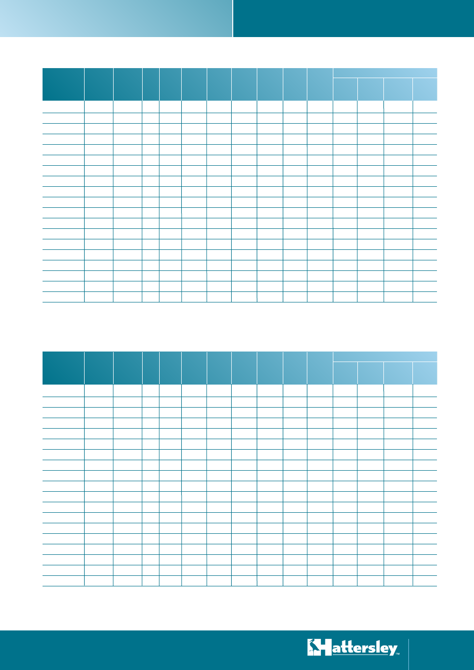
Technical Helpline: 0845 604 1790
E: tech-enquiries@hattersley.com W: www.hattersley.com
219
FLANGE TABLES
PN 6 320 280 8 M16 19 18 254 258 3 2 22 (1) - 20 -
PN10 340 295 8 M20 23 22 266 268 3 2 26 (1) - 24 20
PN16 340 295 12 M20 23 22 266 268 3 2 30 (1) - 24 20
PN25 360 310 12 M24 28 26 274 278 3 2 34 (1) - 30 22
PN40 375 320 12 M27 31 30 284 285 3 2 - - 34 30
PN64 415 345 12 M33 - 36 - 285 - 2 - - 42 -
PN100 430 360 12 M33 - 36 - 285 - 2 - - 52 -
ANSI
Class 125/150 13
1/2
(343) 11
3/4
(298) 8
3/4
(19)
7/8
(22)
7/8
(22) - 10
5/8
(270) -
1/16
(2) 1
1/8
(29)
15/16
(24) 1
1/8
(29) -
Class 300 15 (381) 13 (330) 12
7/8
(22) - 1 (25) - 10
5/8
(270) -
1/16
(2) - 1
3/8
(35) 1
5/8
(41) -
Class 600 16
1/2
(419) 13
3/4
(349) 12 1
1/8
(29) - 1
1/4
(32) - 10
5/8
(270) -
1/4
(6) - - 2
3/16
(56) -
Class 900 18
1/2
(470) 15
1/2
(394) 12 1
3/8
(35) - 1
1/2
(38) - 10
5/8
(270) -
1/4
(6) - - 2
1/2
(64) -
Class 1500 19 (438) 15
1/2
(394) 12 1
5/8
(41) - 1
3/4
(44) - 10
5/8
(270) -
1/4
(6) - - 3
5/8
(92) -
BS 10
Table A 13
1/4
(337) 11
1/2
(292) 8
5/8
(16)
11/16
(17)
11/16
(17) - - - -
7/8
(22)
3/4
(19)
1/2
(13) -
Table D 13
1/4
(337) 11
1/2
(292) 8
5/8
(16)
11/16
(17)
11/16
(17) - - - -
7/8
(22)
3/4
(19)
3/4
(19) -
Table E 13
1/4
(337) 11
1/2
(292) 8
3/4
(19)
7/8
(22)
7/8
(22) - - - - 1 (25)
3/4
(19)
3/4
(19) -
Table F 14
1/2
(368) 12
3/4
(324) 12
3/4
(19)
7/8
(22)
7/8
(22) - - - - 1
1/8
(29) 1 (25) 1 (25) -
Table H 14
1/2
(368) 12
3/4
(324) 12
3/4
(19)
7/8
(22)
7/8
(22) - 10
1/4
(260) -
1/16
(2) 1
1/2
(38) 1
1/4
(32) 1
1/4
(32) -
Nominal Size 200mm (8")
Dia. Bolt No. Dia. Dia. Dia. Dia. Dia. Height Height Thickness of flange
BS EN 1092 of circle of of of of of raised of raised of raised of raised Grey Copper Cast and Ductile
flange diameter bolts bolts holes holes face(3) face(3) face(3) face(3) Cast Alloy Forged Cast
Iron Steel Iron Steel Iron Steel Iron Steel Iron
PN6 375 335 12 M16 19 18 309 312 3 2 24 (1) - 22 -
PN10 395 (2) 350 12 M20 23 22 319 320 3 2 28 (1) - 26 22
PN16 405 (2) 355 12 M24 28 26 319 320 3 2 32 (1) - 26 22
PN25 425 370 12 M27 31 30 330 335 3 2 - - 32 24.5
PN40 450 385 12 M30 34 33 345 345 3 2 - - 38 34.5
PN64 470 400 12 M33 - 36 - 345 - 2 - - 46 -
PN100 505 430 12 M36 - 39 - 345 - 2 - - 60 -
ANSI
Class 125/150 16 (406) 14
1/4
(362) 12
7/8
(22) 1 (25) 1 (25) - 12
3/4
(324) -
1/16
(2) 1
3/16
(30) 1 (25) 1
3/16
(30) -
Class 300 17
1/2
(445) 15
1/4
(387) 16 1 (25) - 1
1/8
(29) - 12
3/4
(324) -
1/16
(2) - - 1
7/8
(41) -
Class 600 20 (508) 17 (432) 16 1
1/4
(32) - 1
3/8
(35) - 12
3/4
(324) -
1/4
(6) - - 2
1/2
(64) -
Class 900 21
1/2
(546) 18
1/2
(470) 16 1
3/8
(35) - 1
1/2
(38) - 12
3/4
(324) -
1/4
(6) - - 2
3/4
(70) -
Class 1500 23 (584) 19 (483) 12 1
7/8
(41) - 2 (51) - 12
3/4
(324) -
1/4
(6) - - 4
1/4
(108) -
BS 10
Table A 16 (406) 14 (356) 8
3/4
(19)
7/8
(22)
7/8
(22) - - - -
15/16
(24)
3/4
(19) - -
Table D 16 (406) 14 (356) 8
3/4
(19)
7/8
(22)
7/8
(22) - - - - 1 (25)
3/4
(19)
3/4
(19) -
Table E 16 (406) 14 (356) 12
3/4
(19)
7/8
(22)
7/8
(22) - - - - 1 (25)
7/8
(22)
7/8
(22) -
Table F 17 (432) 15 (381) 12
7/8
(22) 1 (25) 1 (25) - - - - 1
1/8
(29) 1 (25) 1 (25) -
Table H 17 (432) 15 (381) 12
7/8
(22) 1 (25) 1 (25) - 12
1/4
(311) -
1/16
(2) 1
5/8
(41) 1
3/8
(35) 1
3/8
(35) -
Nominal Size 250mm (10")
Dia. Bolt No. Dia. Dia. Dia. Dia. Dia. Height Height Thickness of flange
BS EN 1092 of circle of of of of of raised of raised of raised of raised Grey Copper Cast and Ductile
flange diameter bolts bolts holes holes face(3) face(3) face(3) face(3) Cast Alloy Forged Cast
Iron Steel Iron Steel Iron Steel Iron Steel Iron
(1) These flange thicknesses are also valid for ductile iron flanges type 21-2
(2) Copper alloy flanges are always flat-faced
(1) These flange thicknesses are also valid for ductile iron flanges type 21-2
(2) For ductile iron pipes and fittings the outside diameters shall be: for PN10, D = 400mm, for PN16, D = 400mm
(3) Copper alloy flanges are always flat-faced

Technical Helpline: 0845 604 1790
E: tech-enquiries@hattersley.com W: www.hattersley.com
220
FLANGE TABLES
PN6 440 395 12 M20 23 22 363 365 4 2 24 (1) - 22 -
PN10 445 (2) 400 12 M20 23 22 370 370 4 2 28 (1) - 26 24.5
PN16 460 (2) 410 12 M24 28 26 370 378 4 2 32 (1) - 28 24.5
PN25 485 430 16 M27 31 30 389 395 4 2 40 (1) - 34 27.5
PN40 515 450 16 M30 34 33 409 410 4 2 - - 42 39.5
PN64 530 460 16 M33 - 36 - 410 - 2 - - 52 -
PN100 585 500 16 M39 - 42 - 410 - 2 - - 68 -
ANSI
Class 125/150 19 (483) 17 (432) 12
7/8
(22) 1 (25) 1 (25) - 15 (381) -
1/16
(2) 1
1/4
(32) 1
1/16
(27) 1
1/4
(32) -
Class 300 20
1/2
(521) 17
3/4
(451) 16 1
1/8
(29) - 1
1/4
(32) - 15 (381) -
1/16
(2) - - 2 (51) -
Class 600 22 (559) 19
1/4
(489) 20 1
1/4
(32) - 1
3/8
(35) - 15 (381) -
1/4
(6) - - 2
5/8
(67) -
Class 900 24 (610) 21 (533) 20 1
3/8
(35) - 1
1/2
(38) - 15 (381) -
1/4
(6) - - 3
1/8
(80) -
Class 1500 26
1/2
(673) 22
1/2
(571) 16 2 (51) - 2
1/8
(54) - 15 (381) -
1/4
(6) - - 4
7/8
(124) -
BS 10
Table A 18 (457) 16 (406) 8
3/4
(19)
7/8
(22)
7/8
(22) - - - -
15/16
(24)
7/8
(22) - -
Table D 18 (457) 16 (406) 12
3/4
(19)
7/8
(22)
7/8
(22) - - - - 1 (25)
7/8
(22)
7/8
(22) -
Table E 18 (457) 16 (406) 12
7/8
(22) 1 (25) 1 (25) - - - - 1
1/8
(29) 1 (25) 1 (25) -
Table F 19
1/4
(489) 17
1/4
(438) 16
7/8
(22) 1 (25) 1 (25) - - - - 1
1/4
(32) 1
1/8
(29) 1
1/8
(29) -
Table H 19
1/4
(489) 17
1/4
(438) 16
7/8
(22) 1 (25) 1 (25) - 14
1/4
(362) -
1/16
(2) 1
3/4
(44) 1
1/2
(38) 1
1/2
(38) -
Nominal Size 300mm (12")
Dia. Bolt No. Dia. Dia. Dia. Dia. Dia. Height Height Thickness of flange
BS EN 1092 of circle of of of of of raised of raised of raised of raised Grey Copper Cast and Ductile
flange diameter bolts bolts holes holes face(3) face(3) face(3) face(3) Cast Alloy Forged Cast
Iron Steel Iron Steel Iron Steel Iron Steel Iron
(1) These flange thicknesses are also valid for ductile iron flanges type 21-2
(2) For ductile iron pipes and fittings the outside diameter shall be: for PN10, D = 455mm; for PN16, D = 455 mm
(3) Copper alloy flanges are always flat-faced
PN6 490 445 12 M20 23 22 413 415 4 2 26 (1) - 22 -
PN10 505 460 16 M20 23 22 429 430 4 2 30 (1) - 26 24.5
PN16 520 470 16 M24 28 26 429 438 4 2 36 (1) - 30 26.5
PN25 555 490 16 M30 34 33 448 450 4 2 44 (1) - 38 30
PN40 580 510 16 M33 37 36 465 465 4 2 - - 46 44
PN64 600 525 16 M36 - 39 - 465 - 2 - - 56 -
PN100 655 560 16 M45 - 48 - 465 - 2 - - 74 -
ANSI
Class 125/150 21 (533) 18
3/4
(476) 12 1 (25) 1
1/8
(29) 1
1/8
(29) - 16
1/4
(413) -
1/16
(2) 1
3/8
(35) - 1
3/8
(35) -
Class 300 23 (584) 20
1/4
(514) 20 1
1/8
(29) - 1
1/4
(32) - 16
1/4
(413) -
1/16
(2) - - 2
1/8
(54) -
Class 600 23
3/4
(603) 20
3/4
(527) 20 1
3/8
(35) - 1
1/2
(38) - 16
1/4
(413) -
1/4
(6) - - 2
3/4
(70) -
Class 900 25
1/4
(641) 22 (559) 20 1
1/2
(38) - 1
5/8
(41) - 16
1/4
(413) -
1/4
(6) - -
3/8
(86) -
Class 1500 29
1/2
(749) 25 (635) 16 2
1/4
(57) - 2
3/8
(60) - 16
1/4
(413) -
1/4
(6) - - 5
1/4
(133) -
BS 10
Table A 20
3/4
(527) 18
1/2
(470) 8
7/8
(22) 1 (25) 1 (25) - - - - 1 (25) 1 (25) - -
Table D 20
3/4
(527) 18
1/2
(470) 12
7/8
(22) 1 (25) 1 (25) - - - - 1
1/8
(29) 1 (25) 1 (25) -
Table E 20
3/4
(527) 18
1/2
(470) 12
7/8
(22) 1 (25) 1 (25) - - - - 1
1/4
(32) 1 (25) 1 (25) -
Table F 21
3/4
(552) 19
1/2
(495) 16 1 (25) 1
1/8
(29) 1
1/8
(29) - - - - 1
3/8
(35) 1
1/4
(32) 1
1/4
(32) -
Table H 21
3/4
(552) 19
1/2
(495) 16 1 (25) 1
1/8
(29) 1
1/8
(29) - 16
1/2
(419) -
1/16
(2) 1
7/8
(48) 1
5/8
(41) 1
5/8
(41) -
Nominal Size 350mm (14")
Dia. Bolt No. Dia. Dia. Dia. Dia. Dia. Height Height Thickness of flange
BS EN 1092 of circle of of of of of raised of raised of raised of raised Grey Copper Cast and Ductile
flange diameter bolts bolts holes holes face(3) face(3) face(3) face(3) Cast Alloy Forged Cast
Iron Steel Iron Steel Iron Steel Iron Steel Iron
(1) These flange thicknesses are also valid for ductile iron flanges type 21-2
(2) Copper alloy flanges are always flat-faced

Technical Helpline: 0845 604 1790
E: tech-enquiries@hattersley.com W: www.hattersley.com
221
FLANGE TABLES
PN6 540 495 16 M20 23 22 463 465 4 2 28 (1) - 22 -
PN10 565 515 16 M24 28 26 480 482 4 2 32 (1) - 26 24.5
PN16 580 525 16 M27 31 30 480 490 4 2 38 (1) - 32 28
PN25 620 550 16 M33 37 36 503 505 4 2 48 (1) - 40 32
PN40 660 585 16 M36 41 39 535 535 4 2 - - 50 48
PN64 670 585 16 M39 - 42 - 535 - 2 - - 60 -
PN100 715 620 16 M45 - 48 - 535 - 2 - - 78 -
ANSI
Class 125/150 23
1/2
(597) 21
1/4
(540) 16 1 (25) 1
1/8
(29) 1
1/8
(29) - 18
1/2
(470) -
1/16
(2) 1
7/16
(37) - 1
7/16
(37) -
Class 300 25
1/2
(648) 22
1/2
(572) 20 1
1/4
(32) - 1
3/8
(35) - 18
1/2
(470) -
1/16
(2) - - 2
1/4
(57) -
Class 600 27 (686) 23
3/4
(603) 20 1
1/2
(38) - 1
5/8
(41) - 18
1/2
(470) -
1/4
(6) - - 3 (76) -
Class 900 27
3/4
(705) 24
1/4
(616) 20 1
5/8
(41) - 1
3/4
(44) - 18
1/2
(470) -
1/4
(6) - - 3
1/2
(89) -
Class 1500 32
1/2
(826) 27
3/4
(705) 16 2
1/2
(64) - 2
5/8
(67) - 18
1/2
(470) -
1/4
(6) - - 5
3/4
(146) -
BS 10
Table A 22
3/4
(578) 20
1/2
(521) 12
7/8
(22) 1 (25) 1 (25) - - - - 1
1/16
(27) 1 (25) - -
Table D 22
3/4
(578) 20
1/2
(521) 12
7/8
(22) 1 (25) 1 (25) - - - - 1
1/8
(29) 1 (25) 1 (25) -
Table E 22
3/4
(578) 20
1/2
(521) 12
7/8
(22) 1 (25) 1 (25) - - - - 1
1/4
(32) 1 (25) 1 (25) -
Table F 24 (610) 21
3/4
(552) 20 1 (25) 1
1/8
(29) 1
1/8
(29) - - - - 1
3/8
(35) 1
1/4
(32) 1
1/4
(32) -
Table H 24 (610) 21
3/4
(552) 20 1 (25) 1
1/8
(29) 1
1/8
(29) - 19 (483) -
1/16
(2) 2 (51) 1
3/4
(44) 1
3/4
(44) -
Nominal Size 400mm (16")
Dia. Bolt No. Dia. Dia. Dia. Dia. Dia. Height Height Thickness of flange
BS EN 1092 of circle of of of of of raised of raised of raised of raised Grey Copper Cast and Ductile
flange diameter bolts bolts holes holes face(3) face(3) face(3) face(3) Cast Alloy Forged Cast
Iron Steel Iron Steel Iron Steel Iron Steel Iron
PN6 595 550 16 M20 23 22 518 520 4 2 28 (1) - 22 -
PN10 615 565 20 M24 28 26 530 532 4 2 32 (1) - 28 25.5
PN16 640 585 20 M27 31 30 548 550 4 2 40 (1) - 40 30
PN25 670 600 20 M33 37 36 548 555 4 2 50 (1) - 46 34.5
PN40 685 610 20 M36 41 39 560 560 4 2 - - 57 49
PN64 - - - - - - - - - - - - - -
PN100 - - - - - - - - - - - - - -
ANSI
Class 125/150 25 (635) 22
3/4
(578) 16 1
1/8
(29) 1
1/4
(32) 1
1/4
(32) - 21 (533) -
1/16
(2) 1
9/16
(40) - 1
9/16
(40) -
Class 300 28 (711) 24
3/4
(629) 24 1
1/4
(32) - 1
3/8
(35) - 21 (533) -
1/16
(2) - - 2
3/8
(60) -
Class 600 29
1/4
(743) 25
3/4
(654) 20 1
5/8
(41) - 1
3/4
(44) - 21 (533) -
1/4
(6) - - 3
1/4
(83) -
Class 900 31 (787) 27 (686) 20 1
7/8
(48) - 2 (51) - 21 (533) -
1/4
(6) - - 4 (102) -
Class 1500 36 (914) 30
1/2
(775) 16 2
3/4
(70) - 2
7/8
(73) - 21 (533) -
1/4
(6) - - 6
3/8
(162) -
BS 10
Table A 25
1/4
(641) 23 (584) 12
7/8
(22) - 1 (25) - - - - 1
1/16
(27) 1
1/16
(27) - -
Table D 25
1/4
(641) 23 (584) 12
7/8
(22) - 1 (25) - - - - 1
1/4
(32) 1
1/8
(29) 1
1/8
(29) -
Table E 25
1/4
(641) 23 (584) 16
7/8
(22) - 1 (25) - - - - 1
3/8
(35) 1
1/8
(29) 1
1/8
(29) -
Table F 26
1/2
(673) 24 (610) 20
11/8
(29) - 1
1/4
(32) - - - - 1
1/2
(38) 1
3/8
(35) 1
3/8
(35) -
Table H 26
1/2
(673) 24 (610) 20
11/8
(29) - 1
1/4
(32) - 21 (533) -
1/16
(2) 2
1/8
(54) 1
7/8
(48) 1
7/8
(48) -
Nominal Size 450mm (18")
Dia. Bolt No. Dia. Dia. Dia. Dia. Dia. Height Height Thickness of flange
BS EN 1092 of circle of of of of of raised of raised of raised of raised Grey Copper Cast and Ductile
flange diameter bolts bolts holes holes face(3) face(3) face(3) face(3) Cast Alloy Forged Cast
Iron Steel Iron Steel Iron Steel Iron Steel Iron
(1) These flange thicknesses are also valid for ductile iron flanges type 21-2
(2) Copper alloy flanges are always flat-faced
(1) These flange thicknesses are also valid for ductile iron flanges type 21-2
(2) Copper alloy flanges are always flat-faced

Technical Helpline: 0845 604 1790
E: tech-enquiries@hattersley.com W: www.hattersley.com
222
FLANGE TABLES
PN6 645 600 20 M20 23 22 568 570 4 2 30 (1) - 24 (2) -
PN10 670 620 20 M24 28 26 582 585 4 2 34 (1) - 28 (2) 26.5
PN16 715 650 20 M30 34 33 609 610 4 2 42 (1) - 44 (2) 31.5
PN25 730 660 20 M33 37 36 609 615 4 2 52 (1) - 48 (2) 36.5
PN40 755 670 20 M39 44 42 615 615 4 2 - - 57 (2) 52
PN64 800 705 20 M45 - 48 - 615 - 2 - - 68 (2) -
PN100 870 760 20 M52 - 56 - 615 - 2 - - 94 (2) -
ANSI
Class 125/150 27
1/2
(699) 25 (635) 20 1
1/8
(29) 1
1/4
(32) 1
1/4
(32) - 23 (584) -
1/16
(2) 1
11/16
(43) - 1
11/16
(43) -
Class 300 30
1/2
(775) 27 (686) 24 1
1/4
(32) - 1
3/8
(35) - 23 (584) -
1/16
(2) - - 2
1/2
(64) -
Class 600 32 (813) 28
1/2
(724) 24 1
5/8
(41) - 1
3/4
(44) - 23 (584) -
1/4
(6) - - 3
1/2
(89) -
Class 900 33
3/4
(857) 29
1/2
(749) 20 2 (51) - 2
1/8
(54) - 23 (584) -
1/4
(6) - - 4
1/4
(108) -
Class 1500 38
3/4
(984) 32
3/4
(832) 16 3 (76) - 3
1/8
(79) - 23 (584) -
1/4
(6) - - 7 (178) -
BS 10
Table A 27
3/4
(705) 25
1/4
(641) 12
7/8
(22) 1 (25) 1 (25) - - - - 1
1/8
(29) 1
1/8
(29) - -
Table D 27
3/4
(705) 25
1/4
(641) 16
7/8
(22) 1 (25) 1 (25) - - - - 1
1/4
(32) 1
1/4
(32) - -
Table E 27
3/4
(705) 25
1/4
(641) 16
7/8
(22) 1 (25) 1 (25) - - - - 1
1/2
(38) 1
1/4
(32) 1
1/4
(32) -
Table F 29 (737) 26
1/2
(673) 24 1
1/8
(29) 1
1/4
(32) 1
1/4
(32) - - - - 1
5/8
(41) 1
1/2
(38) 1
1/2
(38) -
Table H 29 (737) 26
1/2
(673) 24 1
1/8
(29) 1
1/4
(32) 1
1/4
(32) - 23
1/2
(597) -
1/16
(2) 2
1/4
(57) 2 (51) 2 (51) -
Nominal Size 500mm (20")
Dia. Bolt No. Dia. Dia. Dia. Dia. Dia. Height Height Thickness of flange
BS EN 1092 of circle of of of of of raised of raised of raised of raised Grey Copper Cast and Ductile
flange diameter bolts bolts holes holes face(3) face(3) face(3) face(3) Cast Alloy Forged Cast
Iron Steel Iron Steel Iron Steel Iron Steel Iron
(1) These flange thicknesses are also valid for ductile iron flanges type 21-2
(2) These flange thicknesses are changed substantially as a result of the flange calculation method used in BS EN 1092-1
(3) Copper alloy flanges are always flat-faced
PN6 755 705 20 M24 28 26 667 670 5 2 30 (1) - 30 -
PN10 780 725 20 M27 31 30 682 685 5 2 36 (1) - 34 30
PN16 840 770 20 M33 37 36 720 725 5 2 48 (1) - 54 36
PN25 845 770 20 M36 41 39 720 720 5 2 - - 58 42
PN40 890 795 20 M45 50 48 735 735 5 2 - - 72 58
PN64 930 820 20 M52 - 56 - 735 - 2 - - 76 -
ANSI
Class 125/150 32 (813) 29
1/2
(749) 20 1
1/4
(32) 1
3/8
(35) 1
3/8
(35) - 27
1/4
(692) -
1/16
(2) 1
7/8
(48) - 1
7/8
(48) -
Class 300 36 (914) 32 (813) 24 1
1/2
(38) - 1
5/8
(41) - 27
1/4
(692) -
1/16
(2) - - 2
3/4
(70) -
Class 600 37 (940) 33 (838) 24 1
7/8
(48) - 2 (51) - 27
1/4
(692) -
1/4
(6) - - 4 (102) -
Class 900 41 (1041) 35
1/2
(902) 20 2
1/2
(64) - 2
5/8
(67) - 27
1/4
(692) -
1/4
(6) - - 5
1/2
(140) -
Class 1500 46 (1168) 39 (991) 16 3
1/2
(89) - 3
5/8
(92) - 27
1/4
(692) -
1/4
(6) - - 8 (203) -
BS 10
Table A 32
1/2
(826) 29
3/4
(756) 12 1 (25) 1
1/8
(29) 1
1/8
(29) - - - - 1
3/16
(30) 1
3/16
(30) - -
Table D 32
1/2
(826) 29
3/4
(756) 16 1 (25) 1
1/8
(29) 1
1/8
(29) - - - - 1
3/8
(35) 1
3/8
(35) 1
3/8
(35) -
Table E 32
1/2
(826) 29
3/4
(756) 16 1
1/8
(29) 1
1/4
(32) 1
1/4
(32) - - - - 1
5/8
(41) 1
1/2
(38) 1
1/2
(38) -
Table F 33
1/2
(851) 30
3/4
(781) 24 1
1/4
(32) 1
1/4
(32) 1
3/8
(35) - - - - 1
3/4
(44) 1
5/8
(41) 1
5/8
(41) -
Table H 33
1/2
(851) 30
3/4
(781) 24 1
1/4
(32) 1
3/8
(35) 1
3/8
(35) - 27
1/2
(699) -
1/16
(2) 2
1/2
(64) 2
1/4
(57) 2
1/4
(57) -
Nominal Size 600mm (24")
Dia. Bolt No. Dia. Dia. Dia. Dia. Dia. Height Height Thickness of flange
BS EN 1092 of circle of of of of of raised of raised of raised of raised Grey Copper Cast and Ductile
flange diameter bolts bolts holes holes face(3) face(3) face(3) face(3) Cast Alloy Forged Cast
Iron Steel Iron Steel Iron Steel Iron Steel Iron
(1) These flange thicknesses are also valid for ductile iron flanges type 21-2
(2) These flange thicknesses are changed substantially as a result of the flange calculation method used in BS EN 1092-1
(3) Copper alloy flanges are always flat-faced
Technical Helpline: 0845 604 1790
E: tech-enquiries@hattersley.com W: www.hattersley.com
223
TYPICAL KV VALUES
Typical Kv Values
Size Kv
15 31
20 45
25 63
32 102
40 375
50 420
BALL VALVE
ie. Fig. 100
Size Kv
65 227
80 350
100 696
125 1186
150 1832
200 3638
250 6194
300 9570
350 8163
400 12083
450 14169
500 18512
600 24208
BUTTERFLY VALVE
ie. Fig. 970
Size Kv
15 6.61
20 17.75
25 29.35
32 37.82
40 62.1
50 114
CHECK VALVE
ie. Fig. 47
Size Kv
65 187
80 496
100 599
125 799
150 1428
200 2129
250 2725
300 3850
CHECK VALVE
ie. Fig. M651
Size Kv
15 3.05
20 5.71
25 10
32 14.22
40 18.79
50 34.23
GLOBE VALVE
ie. Fig. 5
Size Kv
65 71
80 109
100 168
125 264
150 380
200 676
250 1065
300 1515
GLOBE VALVE
ie. Fig. 731
Size Kv
15 1.87
20 3.14
25 5.59
32 10.8
40 18.1
50 29.1
COMISSIONING VALVE
ie. Fig. 1732
Size Kv
65 69.4
80 101
100 175.8
125 274.9
150 387.6
200 717.7
250 1108
300 1593
COMISSIONING VALVE
ie. Fig. M733
Size Kv
15 14
20 32
25 57
32 90
40 129
50 230
GATE VALVE
ie. Fig. 30
Size Kv
65 360
80 519
100 923
125 1443
150 2077
200 3693
250 5771
300 8310
GATE VALVE
ie. Fig. M541
Size Kv
15 5.6
20 8.5
25 15.1
32 26.4
40 31.9
50 52.5
STRAINER
ie. Fig. 807
Size Kv
65 94
80 135
100 225
125 327
150 481
200 793
250 1353
300 1897
STRAINER
ie. Fig. 810
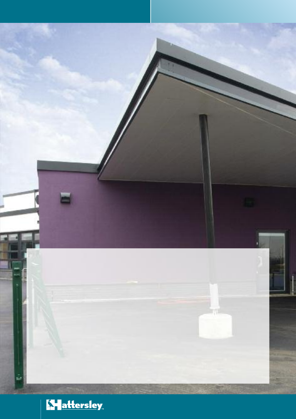
Technical Helpline: 0845 604 1790
E: tech-enquiries@hattersley.com W: www.hattersley.com
224
Project: Sir Charles Parsons School, Newcastle
Client: Newcastle City Council
Civil Engineer: Sir Robert McAlpine
HVAC Contractor: Integral
Distributor: BSS (Newcastle) Ltd.
Specification: A range of Hattersley isolating and commissioning valves
A wide range of Hattersley valves, including Fig. 1732 commissioning valves, have been installed
in Charles Parsons School, Walker. The secondary school was regenerated as part of the
Government’s Building Schools for the Future (BSF) programme and was one of 16 schools
being redeveloped in the Newcastle-Upon-Tyne area. Valves were installed in the new purpose-
built accommodation to provide heating, ventilation and air conditioning throughout the building.
Sir Charles Parsons School is a large school for students with special educational needs and so
along with classrooms, the building also houses sensory rooms and state-of-the-art swimming
and therapy pools. The Hattersley valves are preferred because of their weight and space saving.
The Hattersley technical team and regional manager liaised closely with contractors and
specifiers to ensure this project ran smoothly.
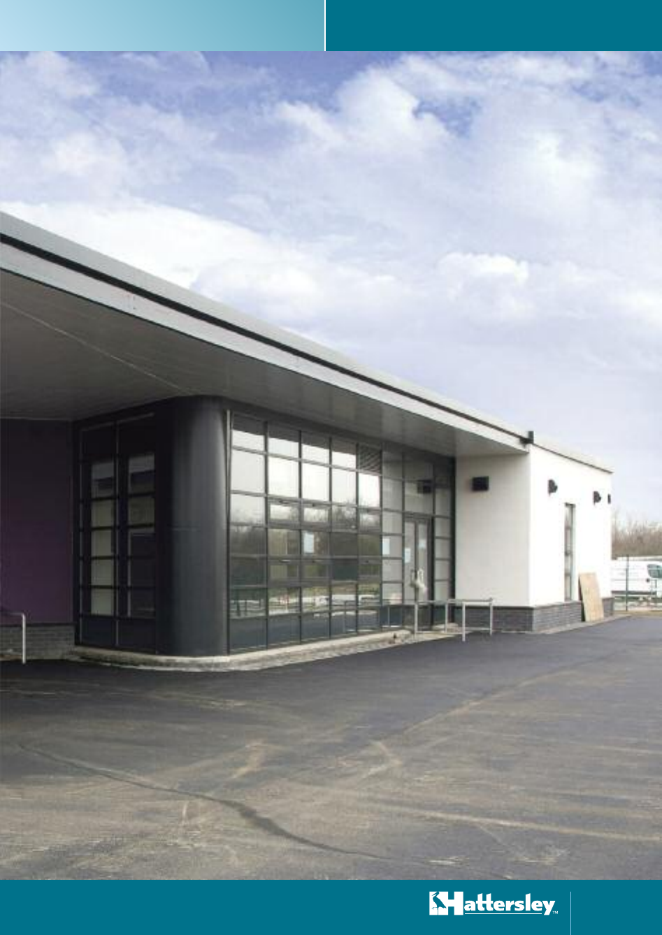
Technical Helpline: 0845 604 1790
E: tech-enquiries@hattersley.com W: www.hattersley.com
225
Technical Helpline: 0845 604 1790
E: tech-enquiries@hattersley.com W: www.hattersley.com
226
QUALITY ASSURANCE
Quality Assurance
Firm of Assessed Capability
BS EN/ISO 9000 is the reference Standard for Quality Systems.
WRc Evaluation and Testing Centre
The WRc Evaluation and Testing Centre is
responsible for the Water Regulations Advisory
Scheme, with testing and approval of water fittings
meeting the requirements of the United Kingdom
Water Regulations/Bylaws (Scotland).
Valves for use in public water supply systems and
domestic situations must not contravene the United
Kingdom Water Regulations. Valves which are
designated WRAS Approved Product and listed in
the Water Fittings and Materials Directory will not
contravene those bylaws.
Many Hattersley valves have been tested and
certified as being WRAS Approved Products and are
listed in the Water Fittings and Materials Directory.
CE Mark
The symbol shown is the European mark for product certification.
The Kitemark
The Kitemark is a registered trademark owned by
British Standards Institution and may only be used
by manufacturers who are approved licensees and
whose products fully comply with the individual
product standards.
Annual product audits and regular surveillance
visits by BSI ensure continuing compliance with
specification requirements and confirm acceptable
Quality Systems to BS EN ISO 9000.

Technical Helpline: 0845 604 1790
E: tech-enquiries@hattersley.com W: www.hattersley.com
2
INTRODUCTION
About Hattersley
The origins of Hattersley date
to 1897, when 20 year-old
Richard Hattersley started a
small tool-making business
in Halifax. In the early 1900s
he relocated to Ormskirk,
and in 1910 he joined with
three other engineering companies, including
Newman Hender & Co. of Woodchester, to
form United Brassfounders & Engineers.
By 1937 Hattersley & Newman Hender both
enjoyed worldwide sales, with Hattersley
exporting to some 73 countries. During the
second world war, both companies entered
war production, making fuses for armaments,
brass rods for munitions factories and, of
course, special valves for military purposes.
In 2004, Crane Limited purchased the
Hattersley valve brand and business from
Hattersley Newman Hender Limited, a
subsidiary of Tomkins plc.
Quality Assurance
Rigid quality control and inspection at all
stages of manufacture ensure that Hattersley
products are suitable for their intended
application and will give reliable service.
Every valve is individually tested in
accordance with the relevant product
standard.
Hattersley is an approved manufacturer
under various quality schemes, including
the British Standard Institution (BSI)
Kitemark, and is ISO9001:2008 accredited.
In addition, the company has been approved
and/or listed by third party organisations
including the United Kingdom Water
Regulations Advisory Scheme.
Future
Today, the Hattersley brand is synonymous
with quality, reliability and service to the very
highest standards, and has industry
experience in many market sectors including
heating and ventilation, chemicals, textiles,
drugs, waste treatment and power
generation. Hattersley can supply a skilfully
engineered solution for every application.
Flagship products include a full range of
commissioning valves suitable for constant
and variable flow systems.
Technical Helpline: 0845 604 1790
E: tech-enquiries@hattersley.com W: www.hattersley.com
227
FIGURE NUMBER INDEX
Fig. No. Index
C4 .....................................148
5........................................149
5N .....................................150
5NLS.................................150
13......................................151
17......................................153
23......................................152
28......................................131
30......................................125
30C ...................................126
30CLS...............................127
30LS .................................125
C31 ...................................128
33......................................129
33X....................................124
33XLS ...............................124
35......................................132
42......................................110
47......................................111
48......................................112
49......................................113
70/RT ................................173
75/RS................................173
77......................................185
78......................................186
81HU.................................145
100......................................78
100TH .................................79
100C ...................................80
100CEXT.............................80
100CLS...............................81
100CTH ..............................81
100CYL ...............................83
100EXT ...............................78
100LS .................................79
100MHU .............................87
100YL..................................82
107MHU .............................88
108C ............................84/191
110......................................85
113......................................86
170M.................................157
171M.................................157
200L..................................160
200M.................................158
200R .................................159
200T..................................160
201M.................................158
201R .................................159
201T..................................160
201TG...............................160
221T..................................160
249.............................114/189
249C ..........................114/189
C262 ...................................66
H262 ...................................66
C264 ...................................67
H264 ...................................67
C266 ...................................62
H266 ...................................62
C267 ...................................64
H267 ...................................64
C268 ...................................63
H268 ...................................63
C269 ...................................65
H269 ...................................65
C270 ...................................71
F300....................................54
R300 ...................................54
305......................................71
370....................................144
371....................................144
401M.................................161
430....................................187
440....................................188
501....................................141
504....................................142
M511.................................137
M540.................................140
M541.................................138
M544.................................139
M544E ..............................139
M549.................................135
M552.................................136
M552E ..............................136
609....................................133
C618 .................................134
631......................................22
M650.................................118
M651.................................119
M653.................................120
669....................................130
731....................................154
M733DR.........................34-35
M737..............................36-37
750......................................23
775......................................76
761.............................115/190
807....................................177
810....................................180
811....................................181
817....................................176
850.............................121-122
907....................................177
910....................................180
911....................................181
950......................................92
C950 ...................................93
950W ..................................95
950G ...................................92
950WG................................95
951......................................97
951G ...................................97
953......................................38
953G ...................................38
970......................................94
970G ...................................94
970W ..................................96
971......................................98
971G ...................................98
973......................................39
973G ...................................39
980......................................99
1000....................................24
1000L..................................25
1000M.................................25
1013..................................116
1050....................................18
1051....................................19
1052....................................18
1053....................................19
1200DR...............................29
1432....................................26
1432C .................................26
1432L..................................26
1432LC ...............................26
M1541...............................138
M1552...............................136
DP1732...............................56
DP1732L.............................56
DP1732M............................56
1732....................................27
1732C .................................27
1732L..................................27
1732LC ...............................27
1732M.................................27
1732MC ..............................27
1807.............................89/178
1807C ..........................90/179
1832....................................28
1832L..................................28
1832M.................................28
1900..................................184
M2000............................30-31
2050....................................20
2761...........................115/190
M3000.................................32
3047..................................117
3150..................................167
3180..................................171
3250..................................168
3280..................................172
3300LS .............................169
3400LS .............................170
M4000.................................33
4970..................................100
4970G ...............................100
4983G .................................40
4990..................................101
4990G........................102-107
4993G............................43-46
5953....................................41
5953G .................................41
5973....................................42
5973G .................................42
MultiComm....................69-70
ProComm ......................73-74
Fig. Number Page Fig. Number Page Fig. Number Page Fig. Number Page
WATER
HEATING
VENTILATION
AIR CON
GAS FUTURE VALVE TECHNOLOGY
Te c h n i c a l
P ro d u c t
G u i d e
www.cranebsu.com
Balancing Valves
Public Health Range
Traditional Valves
PO BOX 719, IPSWICH IP1 9DU
HOME SALES: +44 (0)1744 458670
EXPORT SALES: +44 (0)1744 458671
TECHNICAL HELPLINE: 0845 604 1790
FAX: +44 (0)1744 26912
EMAIL: uksales@hattersley.com
EMAIL: export@hattersley.com
EMAIL: tech-enquiries@hattersley.com
www.hattersley.com
• Designed and manufactured under quality management
systems in accordance with BS EN 9001:2008.
• For full terms and conditions, please visit our website.
•
We hope our communications have an impact on you - but not
the environment - we have taken steps to ensure this brochure
is printed on Forestry Stewardship Council material and the
paper is made by an elemental chlorine free process.
Every effort has been made to ensure that the information contained in this publication is accurate at the time of
publishing. Hattersley Ltd assumes no responsibility or liability for typographical errors or omissions or for any
misinterpretation of the information within the publication and reserves the right to change without notice.
IS S UE 2
Visit www.flowoffluids.com to order your
copy of the New Technical Paper 410.
www.flowoffluids.com
FM311
ISO 9001
T E C H N I C A L P R O D U C T G U I D E I SS U E 2
New
Now includes
Hook-Up II
IVMMXI
Distributor details
