Heathkit A Guide To The Amateur Radio Products AGuide
User Manual: Heathkit-AGuideToTheAmateurRadioProducts
Open the PDF directly: View PDF ![]() .
.
Page Count: 254 [warning: Documents this large are best viewed by clicking the View PDF Link!]
A Guide
to
the
Amateur
Radio
Products
I
II
I l
I
...

~fUW?H&fi
A Guide
to
the
Amateur
Radio
Products
By
Chuck
Penson
WA7ZZE
Electric
Radio
Press,
Inc.
DURANGO,
COLORADO
Copyright©
1995
by
Chuck
Penson,
WA7ZZE, P.O.
Box
2414,
St
.
Paul,
Minnesota
55102.
Product
photos
by
Chuck
Penson
or
from
the
Heath
catalogs,
except
where
noted.
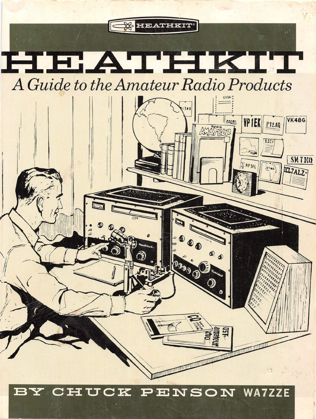
Cover
art
is
from
a
the
cover
of
a
1961
Heathkit
log
book.
Back
cover
art
is
from
a
Heathkit
SB-llO
assembly
manual.
Author
photo
by
Jim
Yunker,
Minneapolis,
Minnesota.
Editorial
assistance
provided
by
Kathryn
Bevacqua,
Minneapolis,
Minnesota.
Book
design
by
David
Steinlicht,
St.
Paul,
Minnesota.
Book
was
assembled
using
Quark
XPress.
Photos
retouched
using
Adobe
Photoshop.
Book
text
is
Adobe
New
Century
Schoolbook.
Captions
are
Monotype
Grotesque
Bold
Condensed.
Headlines
are
Monotype
Grotesque
Bold
Extended.
Display
type
is
based
on
the
typeface
Hellenic.
First
Printing:
October
1995.
For
Dad
For
Kathryn

IT§
~f
UiSf
UHi*l
CONTENTS
(
./
)
Foreward
....................................
7
(
.I
) A
History
of
the
Heath
Company
................
9
(
./
)
Buying
and
Collecting
Heathkits
.............
.
37
(
.I
) A
Guide
to
the
Arna
teur
Radio
Products
.........
41
(
./
)
Heath
Master
Product
Index
by
Model
.......
.
227
(
./
)
Heath
Master
Product
Index
by
Type
........
.
233
(
./
)
Product
References
.......................
.
239
(
./
)
Product
Timelines
........................
.
246
A
Guid
e
to
the
Amat
e
ur
Radio
Products 5

Foreward
~
esearching
the
Heath
Company's
past
~
has
not
been
an
easy
task.
Very
few
peo
-
ple
with
firsthand
information
from
the
earliest
years
,
prior
to
1955
or
so,
remain
to
tell
the
tale.
To
further
complicate
matters
virtually
all
the
records
documenting
Heath's
past
were
thrown
out
in
the
mid
'80s,
when
Heath
began
its
unfor-
tunate
and
unceremonious
departure
from
the
kit
business
.
Those
records
included
everything
from
engineering
notes,
advertising
photos,
and
sales
records,
to
product
manuals
and
catalogs.
Almost
nothing
survived.
A few
precious
arti-
facts
were
quite
literally
rescued
from
the
dumpster
by
employees
looking
for
items
of
either
cash
or
sentimental
value,
but
most
of
the
Heath's
recorded
history
is
now
entombed
some
-
where
in
a
landfill.
This
is
a
tragic
loss
indeed
.
That
th
e
recorded
history
of
a
company
playing
such
an
important
role
in
the
development
of
both
electronics
and
amateur
radio
could
be
tossed
away
without
a
thought
is
beyond
com-
prehension.
Yet
people
who
know
the
story
of
Heath,
or
at
least
who
know
their
part
of
it
,
are
out
there
,
and
many
of
them
have
contributed
in
signifi-
cant
ways
to
this
book.
Those
who
were
kind
enough
to
spend
time
talking
with
me
about
the
Heath
story
include
many
curr
en
t
and
form
er
Heath
managers
,
engineers,
and
technicians.
Among
them
,
Chas
Gilmore
;
Al
Robertson
,
K
SBLL;
Dar
Evans,
KSADS;
Gen
e
Fiebich
,
Ron
Oxley
, WMSZ; Tom Woods, WA0RBW;
Chuck
Bab-
bit,
Terry
Perdue,
KSTP;
Ray
Nelson,
Bill
Denk,
WSLUH;
Norm
Harvey,
WSRTY;
Randy
Kaeding
,
K
STMK;
Jerry
Tol
s
ma
,
W9GPB;
Bob
Knapp
,
WA2CKY;
Mike
Elliot
, WSKRR;
and
Bob
Groh.
My
thanks
to
all
of
these
folks
for
their
time,
pati
e
nce
,
and
memories.
A
number
of
friend
s
were
in
st
rumental
in
the
proc
ess
of
writing
this
book
.
They
include
Bill
Schmitt
,
KE0XE,
for
all
those
back
issues
of
El
ec-
tronics
magazine,
Courtney
Anne
Nieman
and
Morgan
L'Argent
,
KB0QEJ,
who
helped
sift
through
all
the
old
ham
radio
magazines
;
and
Paul
March
,
KB0MAN
,
owner
of
the
Amateur
Radio
Consignment
Center,
in
St.
Pau
l,
Min-
A Guide to the
Amateur
Radio
Products
nesota,
who
let
me
take
photos
of
a
number
of
pieces
at
his
store.
Also
of
assistance
were
Kathryn
Bevacqua;
David
Steinlicht
;
Jim
Yunker;
Anne
Welsbacher;
John
Desmond,
K0TG
;
Gene
Kaari
,
W0UZS;
Art
Edhlund
,
KA0ZHZ;
and
Steve
Raymer
of
the
Pavek
Museum
of
Broadcasting.
Additionally,
fellow
collectors
Nick
England
,
KD4CPL;
Dave
Ishamael,
WAGVVL;
Jim
Lockwood
,
KMGNK;
Mike
Sewell,
K0CRX;
and
Chuck
Maas
,
W0IUH
,
provided
a
lot
of
detail
that
I
never
would
have
found
without
their
assistance.
Of
course
Electric
Radio
editor
Barry
Wiseman,
NGCSW, who
provided
a
great
deal
of
support
and
encouragement
,
can
not
go
unacknowledged.
And
lastly,
a
very
special
thanks
to
former
Heath
engineer
Joe
Shafer
, KSDCE;
former
Heath
production
schedule
manager
Helen
Holland;
all
of
the
members
of
the
Heath
Golden
Oldies
club;
and
of
course
to
the
Heath
Company,
without
whose
cooperation
this
book
would
not
have
been
possible.
This
book
is
intended
to
be
a
kind
of
field
guide,
or
spotter's
guide
if
you
prefer.
It
is
a
book
to
keep
in
your
backpack
while
roaming
flea
markets
, a
book
to
keep
in
your
shack
for ha
ndy
reference
when
you
work
someone
running
an
HW-12A,
and
a
book
to
help
you
interpret
the
Yellow
Sheets
or
classified
section
in
El
ectric
Radio.
Additionally,
this
book
will
serve
to
familiari
ze
the
collector
with
the
160
or
so
prin-
cipal
amateur
radio
products
the
Heath
compa-
ny
produced
from
1952
to
1991.
The
book
does
not
go
into
great
technical
depth,
but
should
pro-
vide
sufficient
detail
about
the
piece
of
equip-
ment
you
are
looking
at
and
what
you
may
be
getting
into
should
you
decide
to
buy
it.
For
those
who
own
or
who
once
owned
Heath-
kit
equipment
(that's
just
about
everyone,
isn't
it?
)
and
for
those
who
remember
Heath
fondly
and
mourn
its
passing
,
this
book
will
provide
an
opportunity
to
browse,
as
you
once
did
for
hours,
through
the
Heathkit
catalog
.
Finally,
I
hope
this
book
will
ensure
that
history
records
the
accomplishments
of
a
remarkable
company
on
the
shores
of
Lake
Michigan
and
the
equally
remarkable
people
who
worked
there.
7

r@
~
f dif
ii'Hiil
A
History
of
the
Heath
Company
lVL
y
earliest
recollection
of
the
Heath
company
dates
from
about
age
6
(
1958
),
when
my
father
bought
and
assembled
an
AR-3
shortwave
receiver.
I
don't
recall
the
construction
of
the
radio,
but
I do
remember
with
great
clarity
when
he
brought
it
down
into
the
living
room,
set
it
up
on
an
end
table,
threw
a s
hort
length
of
wire
out
the
window,
and
tuned
in
WWV. I
remember
being
thorough
ly
aston-
ished.
It
was
at
that
mom
ent
that
my
interest
in
radio
and
in
the
Heath
company
began.
I
spent
hours
listening,
spellbound,
to
WWV
and
all
the
other
strange
beeps
and
buzzes
ema
nating
from
that
AR-3.
Sometime
later
my
dad
gave
my
brother
and
me
a
CR
-1
crystal
radio
which,
from
the
perspective
of
my
yout
h ,
appeared
to
defy
the
laws
of
physic
s.
Wh
en
I
was
about
10,
I
received
a
pair
of
GW-21 lOOmw
walkie
-
talkies.
Although
they
worked
very
well
and
provided
end
le
ss
hours
of
enjoyment,
I
was,
by
that
tim
e,
old
enough
to
attempt
to
"make
them
work
bet-
ter."
It
is
a
miracle
any
of
those
early
kits
sur-
vived
my
efforts.
The
AR-3
made
it
to
the
pre-
sent.
The
crystal
radio
and
walkie
-
ta
lki
es
weren't
so lucky.
It
is
likely
that
most
people
familiar
with
the
Heath
Company
have
similar
stor
ies
to
tell-
growing
up
with
the
sme
ll
of
solder
smoke,
the
howl
of
a
heterodyne,
and
the
occasional
electric
s
hock
or
exploding
electrolytic.
(
V'°
) HEATHKIT'S
EARLY
YEARS
Most
hams
are
at
l
east
vaguely
famil-
®
_IJ!Ji,
iar
with
the
hi
story
of
the
Heath
com-
~
pany.
H
eat
h
recounted
the
story
of
its
humble
beginnings
in
severa
l
product
catalogs,
and
one
of
the
best
"t
humbnail
"
ver-
sions
is
on
the
back
cover
of
the
1968
general
catalog
number
610.
Around
the
turn
of
the
cen
-
tury
Edward
Heath
founded
the
Heath
Aero-
plane
Company.
Busin
ess
was
brisk
and
in
1926,
Heath
offered
an
airplane
in
kit
form.
Heath
A Guide to the
Amateur
Radio
Products
was
killed
in
1931
when
the
plane
he
was
flying
crashed
during
a
test
flight.
After
Heath's
death
the
company
floundered
and
eventually
went
bankrupt.
In
1935
a
young
engineer
named
Howard
Anthony
purcha
sed
th
e
Heath
company
at
auction.
After
World
War
II
Anthony
got
the
idea
that
there
might
be
some
money
to
be
made
in
the
war
surplus
electronics
market
and
pur-
chased
a
large
quantity
of
material.
Exactly
how
much
surplus
he
bou
ght
is
the
subject
of
some
disagreement-anywhere
from
a
single
boxcar
to
several
entire
warehouses
full
depending
on
which
account
you
read
-
but
there
is
no
doubt
that
it
was
a
very
lar
ge
quantity.
These
surplus
parts
were
the
building
blocks
Anthony
would
use
to
assemble
an
entirely
new
Heath
company.
Anthony'
s
original
idea
was
sim
ply
to
sell
hi
s
s
urplus
parts
outright.
Early
advertisements
and
flyers
listed
everything
from
military
trans-
mitters
and
receivers
to
meters,
chok
es,
dynamotors,
and
condensers.
Often
mixed
in
with
the
ads
were
diagr
ams
and
schematics
sug
-
gesting
alternative
us
es
or
modifications
for
the
items
being
sold.
On
occasion,
these
schematics
showed
devices
for
which
H
eath
didn't
even
sell
parts!
The
idea
to
offer
electronic
products
in
kit
form
had
occurred
to
Howard
almost
10
years
earlier,
but
now
,
armed
with
a
vast
stock
of
raw
material,
he
found
himself
in
a
position
to
test
the
kit
market.
In
194
7
the
Heath
Company
offered
its
first
kit
product
-a
five-inch
oscillo-
scope.
The
idea
to
offer
a
scope
was
a
logical
one
-
among
the
items
acquired
in
Anthony's
surplus
buy
were
several
thousand
five-inch
CRTs.
On
the
strength
of
a
sing
le
ad
in
Electron-
ics
magazine
orders
poured
in
by
the
hundred
s,
and
the
rest
,
as
they
say,
is
hi
story
.
Th
en
in
1954
,
as
though
history
were
repeating
it
se
lf
,
Howard
Anthony
was
killed
in
a
plane
crash
.
Anthony's
wife
continued
to
run
the
compan
y
until
1958
when
she
sold
it
to
Daystrom,
a
lar
ge
holding
company.
9
.A
HISTORY
OF
THE
HEATH
CO:l'.11.CP.ANY
~
~
'if
d§!U&Ei
'i)
S EA
RCH
LI
G HT
SECT
IO
N
iq)
ft) S EA RC
HLIGH
T S
EC
TION
@
O
SC
ILLOSCOPE KIT
omplece kir
of
parts
for 5"
scope.
Io·
d udes
punch
ed
and
formed chassis
and
case, l
ettered
pane
l, aJl tubes, (5
BPl
ind.),
oil tilled filters, cased
transformer,
freq.
compensated
amp
lifiers,
15
to
30M
sweep
gcneraror,
every
part
supp
li
ed, diagr
am
and
in
structions.
. . . . . . . . . . . . . . . . 39.50
3B7 / 1
291
U.H.F.
Tw
in
Triode
....
.
l.50
30
6/1299
U.
H
.F.
Tetrode
. . .
..
..
.
..
!.50
Tub
es,
new
bulk
6
J7,
6SL7, 6A6,
6YtS
,
6]5,
IG6GT
, I
UI4
, 12C8. ea .
...
.
..
.49
ircuir
Breaker, 50
Amp.
220V 2 pole .95
Circuit
Breaker,
l
Amp.
110
Volt
....
.95
K it
Power
Rheostats.
25
and
0 \ '
arr
· 6 for 2.95
Kit
As
sorted
Cerlmic
C
on
densers
20
for
1.00
Kir
Assorted
5;1ver &
Mica
Condensers.
a
ll
.
marked
.....
...
.
.. .. ..
12
fo
r 1.00
Kh
Pmentiom
erers.
long
shafcs, 600
ohms
to
200M
ohms
.
.............
10 for 1.95
Ocral
Sockets m
ade
by Cinch
..
20
for
J.00
Dynamotors.
\\'
I.E.,
24
V .
input
220V .080
A.
output
..
......
..........
..
...
1.50
Dynamotors.
6
Volt
input.
550V
at
.350A
o
ut
put
.
....
..
..
.....
.
...........
6.95
Dynamotors
W.E.
12
V.
i
nput
220 V .
. 0 OA
OUIDUt
.....•.••
. . .
..•
••..
• 1.95
BRAND
NEW
BC455B
\'Vestern
Elect
ric 6
tube
superbetcrodyne
receivers, 3
ganir
cond.
R .F.
Srnge--
21F
sta.!ZeS,
in
original
canon
, ·with
rubes
..............
..
...........
4.95
DUAL
TUNI
NG
UN
IT
BC746.
contains
mo
un
ted
transm
itrer
c
ry
st:i l freo. 3735, receiver crysrnl 455
ab
ove
.
transmirrcr
r
ank
co
i
l,
receiver.
ant.
coiJ
and
tuni11g
condense
r,
all
for
.....
...
.. ..
..
..
.
..
.
....
.
....
1.00
RG
S/ U
Coaxial
Cable,
Pe
r foot . .05
WrHe
for
Complete
Llsflngs
No
order
un d
er
$2.0
0
We
will ship
C.
O .D.
. . . .
HEATH
caM1AHY
~
~
BENTON
HARIOR,
MICHIGAN
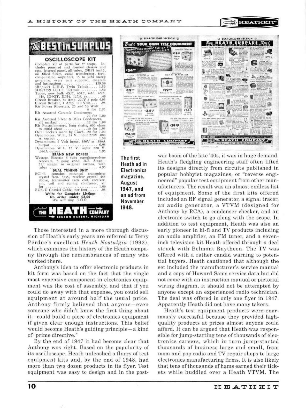
The
first
Heath
ad
in
Electronics
magazine,
August
1947,and
an ad
from
November
1948 .
Tho
se
interested
in
a
more
thoroug
h
discu
s-
s
ion
of
Heath's
ear
ly
yea
rs
are
referre
d
to
Terry
Perdue
's
exce
ll
ent
H e
ath
Nostalg
ia
(1992)
,
which
exam
i
nes
the
history
of
th
e
Heat
h
compa
-
ny
through
t h e
remembrances
of
m
any
who
worked
there.
Anthony's
idea
to
offer
electronic
products
in
kit
form
was
based
on
the
fact
that
the
single
most
expe
n
sive
component
in
el
ectron
ics
equip-
ment
was
t he
cost
of
assembly
,
and
that
if
you
could
do
away
wi
th
that
expense
,
you
could
sell
equipment
at
around
half
the
u
sua
l
price.
Anthony
firm
ly
beli
eve
d
that
anyone-even
someone
who
didn't
know
the
first
th
i
ng
about
it
-
could
bu
ild
a
piece
of
el
ectronics
equipment
if
given
clear
enough
in
s
tructions.
Th
is
belief
wou
ld
become
Heath's
guiding
princip
l
e-a
kind
of
"
prime
di
rective."
By
the
en
d
of
1
94
7
it
had
become
clear
that
Anthony
was
rig
h
t.
Based
on
the
po
pul
arity
of
its
oscilloscope
, H
eath
unleas
h
ed
a
fl
urry
of
test
e
quipment
kits
and
,
by
the
end
of
1
948,
had
more
t h
an
two
dozen
products
in
its
flyer.
Test
eq
u
ipment
was
easy
to
design
and
in
the
post
-
10
war
boom
of
the l
ate
'40s
,
it
was
in
hu
ge
demand
.
H
ea
th's
fled
gling
engineering
staff
often
li
fted
it
s
desig
n s di
rectly
from
circuits
publis
h
ed
in
popu
l
ar
hobbyist
maga
z
ines,
or
"reverse
engi
-
ne
ere
d"
popu
l
ar
test
equipment
from
ot
h
er
man
-
ufacturers.
Th
e
result
was
an
al
most
end
l
ess
list
of
equipme
nt
.
Some
of
the
firs
t
kits
offered
included
an
RF
signa
l
generator,
a
signa
l
tracer,
an
audio
generator,
a
VTVM
(designed
for
Anthony
by
RCA
),
a
condenser
checker,
and
an
el
ectr
onic
switch
to
go
along
wit
h t h e scope.
In
addition
to
test
equipment
,
Heat
h
was
also
an
early
pioneer
in
hi
-
fi
and
TV
prod
u
cts
in
clud
i
ng
an
a
udio
amp
li
fier
,
an
FM
tuner,
and
a
seven-
inch
telev
i
sion
kit
Heath
offered
th
r
oug
h a
dea
l
struck
wit
h B
elmont
Rayth
e
on
. T
he
TV
w
as
off
ere
d
with
a
rather
candid
warning
to
poten-
tial
buyers.
Heath
cautioned
that
alt h ou
gh
the
set
included
the
manufacturer
's
service
manua
l
and
a copy
of
Howard
Sams
service
data
but
did
not
come
wit
h
an
in
s
truction
manua
l
or
pi
ctoria
l
wiring
diagram
,
it
should
not
be
attempted
by
anyone
except
an
experienced
rad
io
technician
.
Th
e
dea
l
was
offered
in
on
ly
one
flyer
in
1947.
Apparent
ly
Heath
did
not
have
many
takers.
Heath
's
test
equipment
products
were
enor
-
mously
successful
because
they
provide
d
high
-
quality
products
at
pric
es
al
most
anyone
could
afford.
It
can
be
argued
that
Heat
h
was
respon
-
sible
for
jump
-
starting
tens
of
tho
u
san
ds
of
elec-
tronics
careers
,
which
in
turn
jump
-
started
thousands
of
bu
s
iness
l
arge
an
d
sma
ll
,
from
mom
and
pop
radio
and
TV
repair
shops
to
l
arge
electronics
manufacturing
firms.
It
is
also
li
kely
that
tens
of
t hou
sands
of
hams
ear
ned th
eir
tick
-
ets
wh
il
e h
udd
l
ed
over
a
Heat
h VT
VM
.
The
HE
.AT
HK
IT
IE=
~
f
§f
#f
iU&f
*l
.A
HISTORY
OF'
THE
HEATH
COlll.IP.ANY
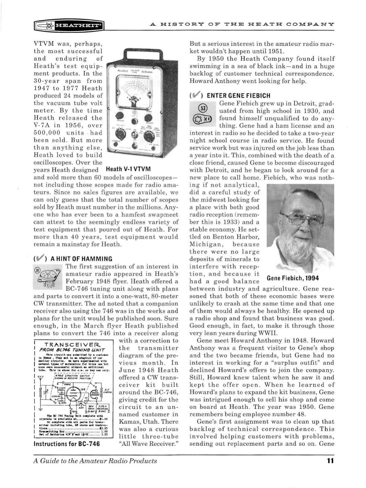
VTVM
was,
perhaps
,
the
most
s
ucce
ssf
ul
and
enduring
of
Heath's
test
equip-
ment
products.
In
the
30-year
span
from
1947
to
1977
Heath
produced
24
model
s
of
the
vacuum
tube
volt
met
er.
By
the
time
Heath
released
the
V-7
A
in
1956
,
over
500,000
units
·.
had
been
so
ld.
But
more
than
anything
else,
Heath
lov
ed
to
build
oscilloscopes.
Over
the
years
H
eat
h
design
ed
Heath
V-1
VTVM
and
so
ld
more
than
60
models
of
oscilloscopes
-
not
including
thos
e
scopes
m
ade
for
radio
ama
-
teurs
.
Since
no
sales
figures
are
available,
we
can
only
guess
that
the
total
number
of
scopes
sold
by
Heath
mu
st
number
in
the
millions.
Any-
one
who
has
ever
been
to
a h
amfest
swapmeet
can
attest
to
th
e
seemi
ngly
endless
variety
of
test
equipment
th
at
poured
out
of
Heath.
For
more
than
40
years,
test
equipment
would
remain
a
mainstay
for
Heath
.
( V ) A HINT
OF
HAMMING
The
first
suggestion
of
an
inter
est
in
amateur
radio
appeared
in
Heath
's
February
1948
flyer
. H
eat
h
offered
a
BC-746
tuning
unit
along
with
plan
s
and
parts
to
convert
it
into
a
one-watt,
80-meter
CW
transmitter.
The
ad
noted
that
a
companion
receiver
also
using
the
746
was
in
the
works
and
plan
s for
the
unit
would
be
publi
s
hed
soon.
Sure
enough,
in
the
March
flyer
H
eath
publi
she
d
plans
to
convert
th
e
746
into
a
receiver
along
1
with
a
correction
to
TRANSCEIVER
:
rR.OM
6C746
Tl/NINO
UNIT
the
transmitter
1 "'
~·:.;::•:.:-::::"!!~.!!
:::.,.'°-'
di
agram
of
the
pre-
1
::!!:
~
:!;:
1
!~·llO~~~:a·;:r::!.du:
1
:=t
via
us
month
.
In
I
:~:.~1
:
11
~
·::!::!
;!~~!
.
~ra:!!t!:•!G1,.
June
1948
Heath
r-------------·
I /
iH':;!
,;
';;;r;,~~
;:;,~~~
/
I
.'
~-·
'
I I
I I
I
I
I
I
I
I
RF
CHOKE
!~~~~~~~~~~----'
Instructions
for
BC-
746
offered
a
CW
trans
-
ceiver
kit
built
around
the
BC-746,
giving
credit
for
the
circuit
to
an
un-
named
customer
in
Kamas,
Utah.
There
was
also
a
curious
littl
e
three-tube
"A
ll
Wave Receiver."
A Guide
to
the
Amateur
Radio
Products
But
a
serious
inter
est
in
the
amateur
radio
mar-
ket
wouldn't
happen
until
1951.
By
1950
the
Heath
Company
found
itself
swimming
in
a
sea
of
black
ink-and
in
a
huge
backlog
of
customer
technical
correspondence.
Howard
Anthony
went
looking
for
help
.
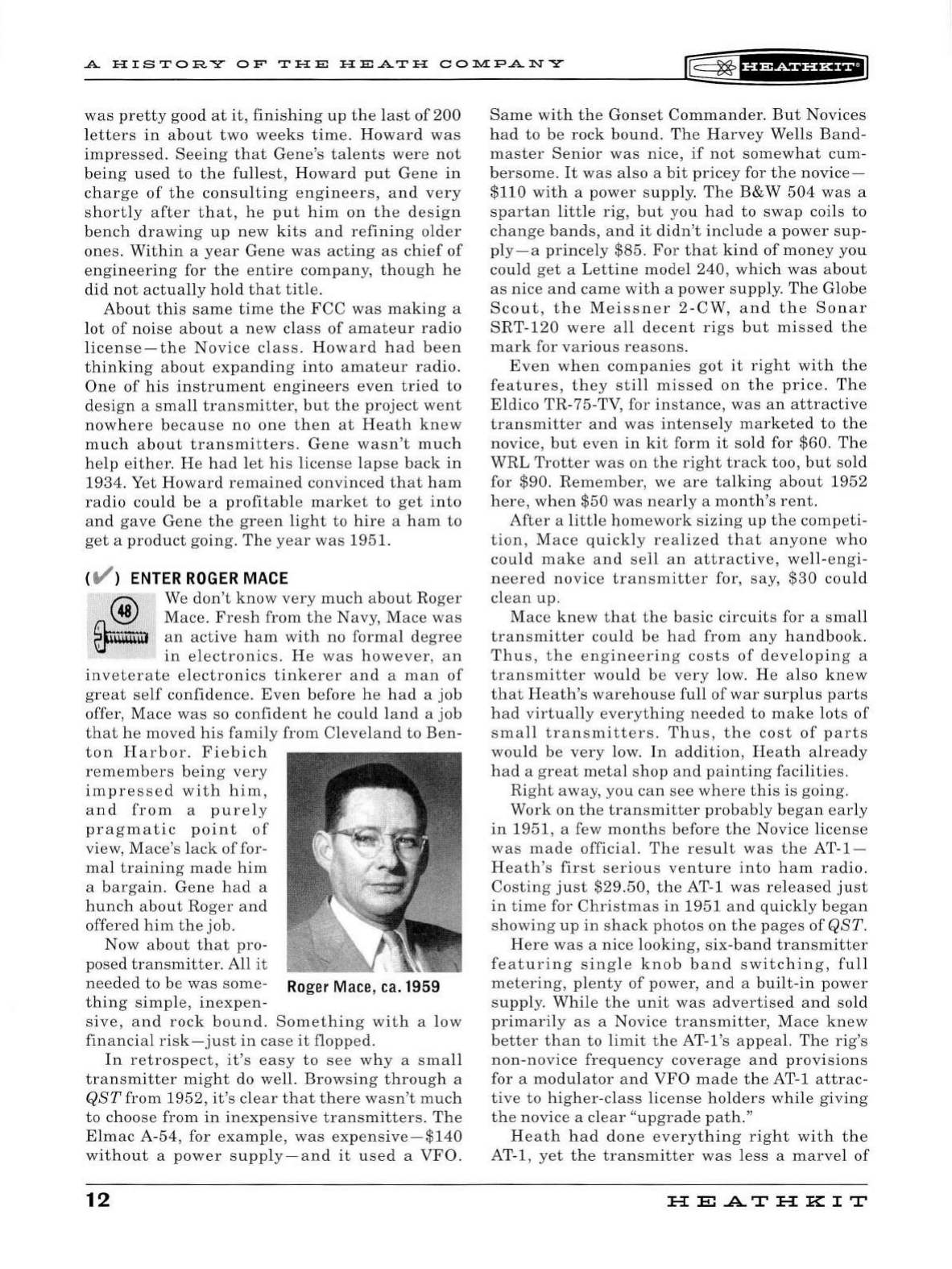
( V )
ENTER
GENE
FIEBICH
®
@ill
Gene
Fiebich
grew
up
in
Detroit,
grad
-
uated
from
high
school
in
1930,
an
d
found
himself
unqualified
to
do
any-
thing.
Gene
had
a
ham
license
and
an
int
erest
in
radio
so he
decid
ed
to
take
a
two-
yea
r
night
sc
hool
course
in
radio
service.
He
found
service
work
but
was
injured
on
th
e
job
less
than
a
year
into
it.
This,
combined
with
the
death
of
a
close
friend,
cau
sed
Gene
to
b
ecome
discour
age
d
with
D
etro
it
,
and
he
began
to
look
around
for a
new
place
to
call
home.
Fi
ebic
h ,
who
was
noth-
ing
if
not
analyti
cal
,
did
a
care
ful
stu
dy
of
the
mid
west
l
ooking
for
a
place
with
both
good
radio
reception
(
remem
-
ber
this
is
1933
)
an
d a
stable
economy.
He
set
-
tled
on
Benton
H
arbor,
Michigan,
because
ther
e
were
no
large
deposits
of
minerals
to
interf
ere
with
recep-
tion,
and
becau
se
it
had
a
good
balance
Gene
Fiebich,
1994
between
industry
and
agriculture.
Gene
rea-
soned
that
both
of
these
economic
base
s
were
unlikely
to
crash
at
the
same
time
and
that
one
of
them
wou
ld
always
be
healthy.
He
opened
up
a
radio
shop
and
found
that
business
was
good.
Good
enough,
in
fact,
to
make
it
through
tho
se
very
le
an
years
during
WWII.
Gene
meet
Howard
Anthony
in
1948.
Howard
Anthony
was
a
frequent
visitor
to
Gene's
shop
and
the
two
became
friend
s,
but
Gene
had
no
interest
in
working
for
a "s
urplus
outfit
"
and
declined
Howard
's
offers
to
join
the
company.
Still,
Howard
knew
talent
when
he
saw
it
and
kept
the
offer
open.
When
he
learn
ed
of
Howard
's
plans
to
ex
pand
the
kit
business,
Gene
was
intrigued
enough
to
sell
his
shop
and
come
on
board
at
Heath.
The
year
wa
s
1950.
Gene
remembers
being
em
ployee
number
48.
Gene's
first
assignment
was
to
clean
up
that
backlog
of
technical
corr
es
pondence.
This
involv
ed
helping
customers
with
probl
e
ms
,
sending
out
replacement
parts
and
so
on
.
Gene
11
A
HISTORY
OF
THE
HEATH
00]).l.[F'ANY
[E;=
~
IH&&f
HHfiJ
was
pretty
good
at
it,
finishing
up
the
l
ast
of
200
letters
in
about
two
weeks
time.
Howard
was
impressed.
Seeing
that
Gene
's
talents
were
not
being
used
to
the
fullest,
H
oward
put
Gene
in
charge
of
the
consulting
engineers,
and
very
shortly
after
that,
he
put
him
on
the
design
bench
drawing
up
new
kits
and
refining
older
ones.
Within
a
year
Gene
was
acting
as
chief
of
engineering
for
the
entire
company,
th
ough
he
did
not
actually
hold
that
tit
le.
About
this
same
time
the
FCC
was
making
a
lot
of
noise
about
a
new
class
of
amateur
radio
license
-
the
Novice
class.
Howard
had
been
thinking
about
expanding
into
amateur
radio.
One
of
his
instrument
engineers
even
tried
to
design
a
sma
ll
transmitter,
but
the
project
went
nowhere
because
no
one
then
at
Heath
knew
much
about
transmitters.
Gene
wasn
't
much
help
either.
He
had
let
his
license
lapse
back
in
1934. Yet
Howard
remained
convinced
that
ham
radio
could
be a
profitable
market
to
get
into
and
gave
Gene
the
green
light
to
hire
a
ham
to
get
a
product
going.
The
year
was
1951.
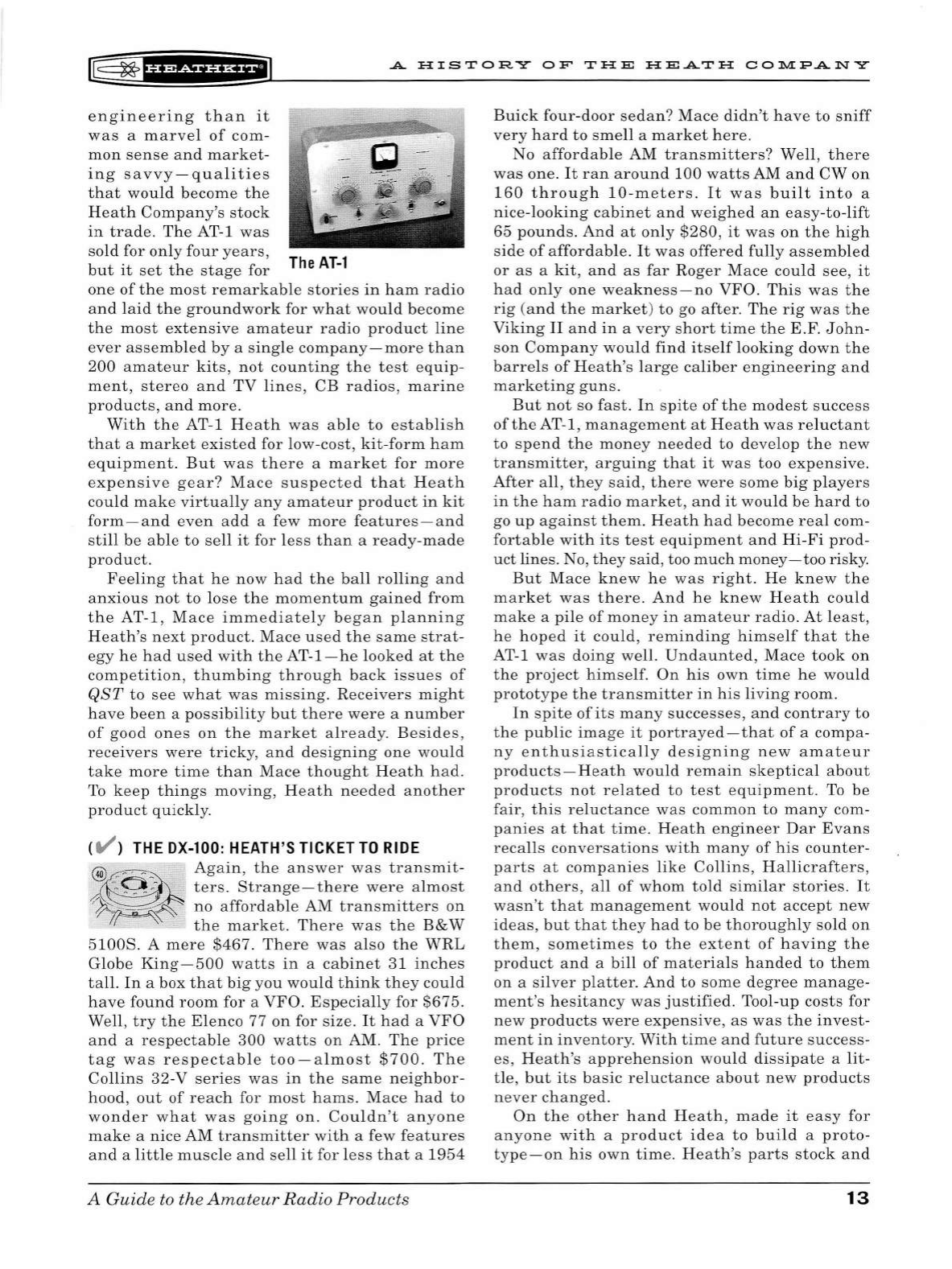
(
t/'
)
ENTER
ROGER
MACE
® We
don't
know
very
much
about
Roger
Ck
Mace.
Fresh
from
the
Navy,
Mace
was
li'..f"iillm
an
active
ham
with
no
forma
l
degree
'
in
el
ectronics.
He
was
however
,
an
inveterate
electronics
tinkerer
and
a
man
of
great
self
confidence.
Even
before
he
h
ad
a
job
offer,
Mace
was
so
confident
he
could
l
and
a
job
that
he
moved
hi
s
family
from
Cleveland
to
Ben-
ton
Harbor.
Fiebich
remembers
being
very
impressed
with
him
,
and
from
a
purely
pragmatic
point
of
view,
Mace
's l
ack
of
for-
mal
training
made
him
a
bargain.
Gene
had
a
hunch
about
Roger
and
offered
him
the
job.
Now
about
that
pro-
posed
transmitter.
All
it
needed
to
be
was
some-
Ro
g
er
Mace
, ca. 1959
thing
simp
le,
inexpen-
sive,
and
rock
bound.
Something
wi
th
a
low
financial
risk
-
just
in
case
it
flopped
.
In
retrospect
,
it
's
easy
to
see
why
a
small
transmitter
might
do well.
Browsing
through
a
QST
from
1952,
it's
clear
that
there
wasn
't
much
to
choose
from
in
inexpensive
transmitters.
The
El
mac
A-
54,
for
example,
was
expensive-$140
without
a
power
supp
l
y-and
it
use
d a
VFO.
12
Same
with
the
Gonset
Commander
.
But
Novices
had
to
be
rock
bound
.
The
Harvey
Wells
Band-
master
Senior
was
nice,
if
not
somewhat
cum-
bersome.
It
was
also
a
bit
pricey
for
the
novice
-
$110
with
a
power
supp
ly.
The
B&W
504
was
a
spartan
litt
le
rig,
but
you
had
to
swap
coils
to
ch
ange
bands,
and
it
didn't
include
a
power
sup
-
ply - a
princely
$85.
For
that
kind
of
money
you
could
get
a
Lettine
model
240,
which
was
about
as
nice
and
came
with
a
power
supply
.
The
Globe
Scout
,
the
Meissner
2 -
CW,
and
the
Sonar
SRT-120
were
all
decent
rigs
but
missed
the
mark
for
various
reasons
.
Even
when
companies
got
it
right
with
the
features,
they
still
missed
on
the
price.
The
Eldico
TR-75
-TV, for
instance,
was
an
attractive
transmitter
and
was
intensely
marketed
to
the
novice,
but
even
in
kit
form
it
sold for
$60.
The
WRL
Trotter
was
on
the
right
track
too
,
but
sold
for $90.
Remember,
we
are
talking
about
1952
here
,
when
$50
was
nearly
a
month's
rent.
After
a
little
homework
sizing
up
the
competi
-
tion
,
Mace
quickly
rea
l
ized
that
anyone
who
could
make
and
sell
an
attractive,
well
-
engi-
neer
ed
novice
transmitter
for,
say,
$30
could
clean
up.
Mace
knew
that
the
basic
circuits
for a
small
transmitter
could
be
had
from
any
handbook.
Thus,
the
engineering
costs
of
developing
a
transmitter
would
be
very
low.
He
also
knew
that
Heath's
warehouse
full
of
war
surplus
parts
had
virtually
everything
needed
to
make
lots
of
small
transmitters.
Thus,
the
cost
of
parts
would
be
very
low.
In
addition,
Heath
already
had
a
great
metal
shop
and
painting
facilities.
Right
away
,
you
can
see
where
this
is
going.
Work
on
the
transmitter
probably
began
early
in
1951
, a few
months
before
the
Novice
license
was
made
official.
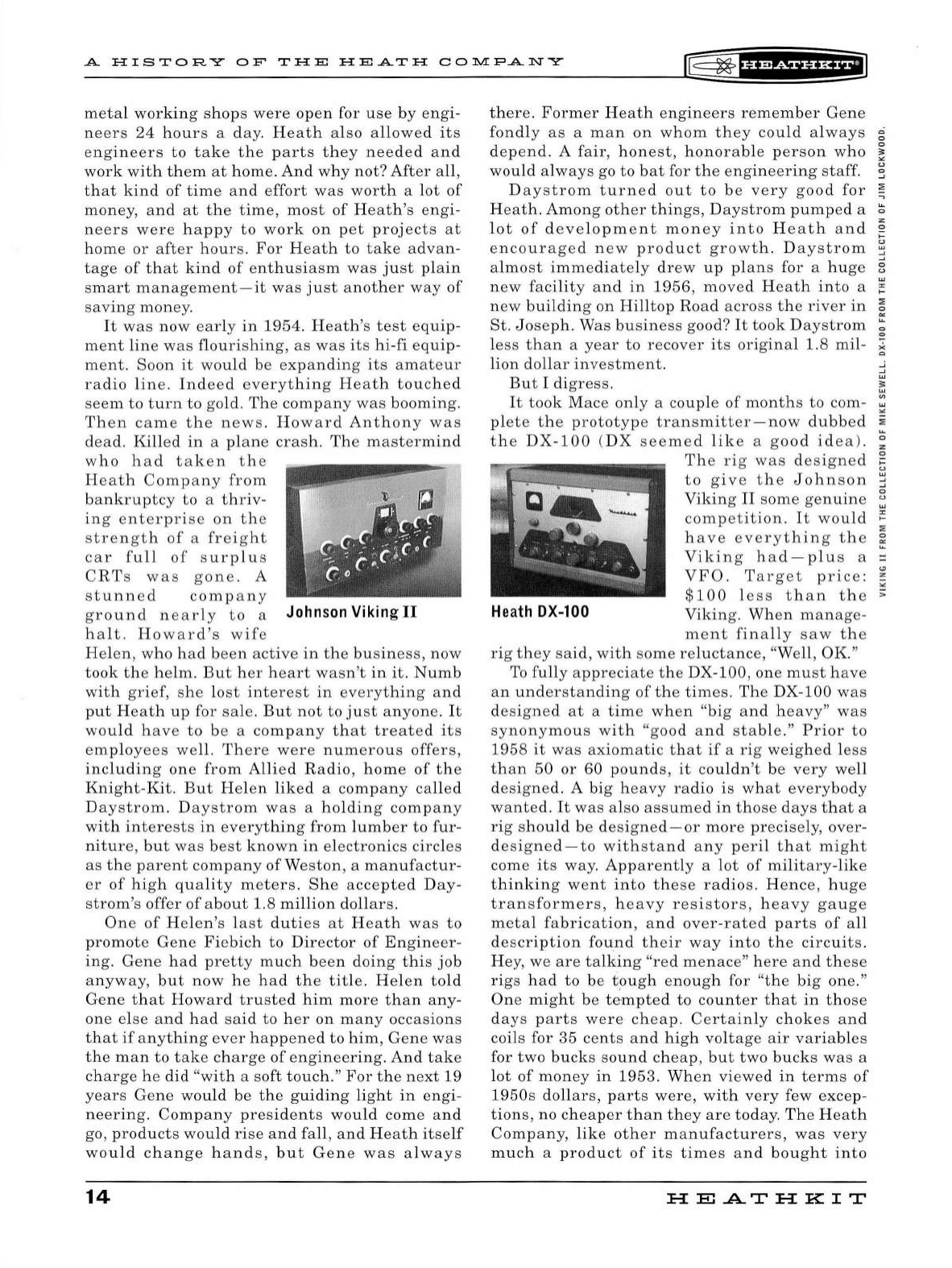
The
result
was
the
AT-1-
Heath
's
first
serious
venture
into
ham
radio.
Costing
just
$29.50,
the
AT-1
was
re
l
eased
just
in
time
for
Christmas
in
1951
and
quickly
began
showing
up
in
shack
photos
on
the
pages
of
QST.
Here
was
a
nice
looking,
six-band
transmitter
featuring
single
knob
band
switching,
full
metering
, pl
enty
of
power,
and
a
bui
l
t-in
power
supply.
While
the
unit
was
advertised
and
sold
primarily
as
a
Novice
transmitter,
Mace
knew
better
than
to
limit
the
AT-l
's
appeal.
The
rig
's
non-novice
frequency
coverage
and
provisions
for a
modu
l
ator
and
VFO
made
the
AT-1
attrac-
tive
to
higher
-
class
license
holders
while
giving
the
novice
a
clear
"upgrade
path."
Heath
had
done
everything
right
with
the
AT-1,
yet
the
transmitter
was
less
a
marvel
of
HE.A.TH
KIT
r@
~
f¥'*5¥HHE@
.A
H I
ST
ORY
O F
THE
HEATH
CO:D.'.'.IP.ANY
engineering
than
it
was
a
marvel
of
com-
mon
sense
and
market-
ing
savvy
-
qualities
that
would
become
the
Heath
Company's
stock
in
trade.
The
AT-1
was
sold
for
only
four
years,
but
it
set
the
stage
for
The
AT
-l
one
of
the
most
remarkable
stories
in
ham
radio
and
laid
the
groundwork
for
what
would
become
the
most
extensive
amateur
radio
product
line
ever
assemb
l
ed
by
a
single
company-more
than
200
amateur
kits,
not
counting
the
test
equip-
ment,
stereo
and
TV
lines,
CB
radios,
marine
products,
and
more.
With
the
AT-1
Heath
was
able
to
establish
that
a
market
existed
for
low-cost,
kit-form
ham
equipment.
But
was
there
a
market
for
more
expensive
gear?
Mace
suspected
that
Heath
could
make
virtually
any
amateur
product
in
kit
form-and
even
add
a few
more
features-and
still
be
able
to
sell
it
for
less
than
a
ready
-
made
product
.
Feeling
that
he
now
had
the
ball
rolling
and
anxious
not
to
lose
the
momentum
gained
from
the
AT-1,
Mace
immediately
began
planning
Heath's
next
product.
Mace
used
the
same
strat-
egy
he
had
used
with
the
AT-1-he
looked
at
the
competition,
thumbing
through
back
issues
of
QST
to
see
what
was
missing
.
Receivers
might
have
been
a
possibility
but
there
were
a
number
of
good
ones
on
the
market
already.
Besides,
receivers
were
tricky,
and
designing
one
would
take
more
time
than
Mace
thought
Heath
had.
To
keep
things
moving,
Heath
needed
another
product
quickly.
( V )
THE
DX-100
:
HEATH
'S
TICKET
TO
RIDE
@~
Again,
the
answer
was
transmit-
A.@~
ters.
Strange-there
were
al
most
'
~~
~
no
affordable
AM
transmitters
on
'/
1
~
the
market.
There
was
the
B&W
51008.
A
mere
$467.
There
was
also
the
WRL
Globe
King-500
watts
in
a
cabinet
31
inches
tall.
In
a box
that
big
you
would
think
they
could
have
found
room
for a
VFO
.
Especially
for
$675.
Well,
try
the
Elenco
77
on
for size.
It
had
a
VFO
and
a
respectable
300
watts
on
AM.
The
price
tag
was
respectable
too-almost
$700.
The
Collins
32-V
series
was
in
the
same
neighbor-
hood,
out
of
reach
for
most
hams.
Mace
had
to
wonder
what
was
going
on.
Couldn
't
anyone
make
a
nice
AM
transmitter
with
a few
features
and
a
little
muscle
and
sell
it
for
less
that
a
1954
A Guide
to
the
Amateur
Radio
Products
Buick
four-door
sedan?
Mace
didn't
have
to
sniff
very
hard
to
smell
a
market
here.
No
affordable
AM
transmitters?
Well,
there
was
one
.
It
ran
around
100
watts
AM
and
CW
on
160
thro
u gh
10
-
meters.
It
was
built
into
a
nice-looking
cabinet
and
weighed
an
easy-to-lift
65
pounds.
And
at
only
$280,
it
was
on
the
high
side
of
affor
d
able.
It
was
offered
fully
assembled
or
as
a
kit
,
and
as
far
Roger
Mace
could
see,
it
had
only
one
weakness-no
VFO.
This
was
the
rig
(and
th e
market)
to
go
after.
The
rig
was
the
Viking
II
and
in
a
very
short
time
the
E.F.
John-
son
Company
would
find
itself
looking
down
the
barrels
of
Heath's
l
arge
caliber
engineering
and
marketing
guns.
But
not
so
fast.
In
spite
of
the
modest
success
of
the
AT-1,
management
at
Heath
was
re
l
uctant
to
spend
the
money
needed
to
develop
the
new
transmitter,
arguing
that
it
was
too
expensive.
After
all,
they
said,
there
were
some
big
pl
ayers
in
the
ham
radio
market
,
and
it
would
be
hard
to
go
up
against
them.
Heath
had
become
real
com-
fortable
with
its
test
equipment
and
Hi
-
Fi
prod
-
uct
lines. No,
they
said
, too
much
money-too
risky.
But
Mace
knew
he
was
right.
He
knew
the
market
was
there.
And
he
knew
Heath
could
make
a
pile
of
money
in
amateur
radio
.
At
least,
he
hoped
it
could,
reminding
himself
that
the
AT-1
was
doing
well.
Undaunted,
Mace
took
on
the
project
himself.
On
his
own
time
he
would
prototype
the
transmitter
in
his
living
room.
In
spite
of
its
many
successes
,
and
contrary
to
the
public
image
it
portrayed-that
of
a
compa
-
ny
enthusiastically
designing
new
amateur
products
- H
eath
would
remain
skeptical
about
products
not
related
to
test
equipment
.
To
be
fair,
this
re
l
uctance
was
common
to
many
com-
panies
at
that
time.
Heath
engineer
Dar
Evans
recalls
conversations
with
many
of
his
counter-
parts
at
companies
like
Collins,
Hallicrafters,
and
others,
a
ll
of
whom
told
similar
stories.
It
wasn
't
that
management
would
not
accept
new
ideas,
but
that
they
had
to
be
thoroughly
sold
on
them,
sometimes
to
the
extent
of
having
the
product
and
a
bill
of
materials
handed
to
them
on
a
silver
pl
atter.
And
to
some
degree
manage-
ment's
hesitancy
was
justified.
Tool-
up
costs
for
new
products
were
expensive,
as
was
the
invest-
ment
in
inventory.
With
time
and
future
success-
es,
Heath
's
apprehension
would
dissipate
a
lit-
tle,
but
its
basic
reluctance
about
new
products
never
changed.
On
the
other
hand
Heath,
made
it
easy
for
anyone
with
a
product
idea
to
bui
ld a
proto-
type-on
his
own
time.
Heath's
parts
stock
and
13
A
HISTORY
OF
THE
HEATH
CO~PANY
~
~
fHMiHHil
metal
working
shops
were
open
for
use
by
engi-
neers
24
hours
a d a
y.
Heath
also
allowed
its
engineers
to
take
the
parts
they
needed
and
work
with
them
at
home.
And
why
not?
After
all,
that
kind
of
time
and
effort
was
worth
a
lot
of
money,
and
at
the
time,
most
of
Heath's
engi
-
neers
were
happy
to
work
on
pet
projects
at
home
or
after
hours.
For
Heath
to
take
advan-
tage
of
that
kind
of
enthusiasm
was
just
plain
smart
management-it
was
just
another
way
of
saving
money.
It
was
now
early
in
1954.
Heath
's
test
equip-
ment
line
was
flourishing,
as
was
its
hi-fi
equip-
ment.
Soon
it
would
be
expanding
its
amateur
radio
line
.
Indeed
everything
Heat
h
touched
seem
to
turn
to
gold.
The
company
was
booming.
Then
came
the
news
.
Howard
Anthony
was
dead.
Killed
in
a
plane
crash
.
The
mastermind
who
h a d
taken
th
e
Heath
Company
from
bankruptcy
to
a
thriv
-
ing
enterprise
on
the
strength
of
a
freight
car
full
of
surplus
CRTs
was
gon
e . A
stunned
company
ground
nearly
to
a Johnson
Vikin
g
II
ha
lt .
Howard
's
wife
Helen,
who
had
been
active
in
the
business
,
now
took
the
helm
.
But
her
heart
wasn't
in
it.
Numb
wi
th
grief,
she
l
ost
interest
in
everything
and
put
Heath
up
for
sale.
But
not
to
just
an
yone.
It
would
have
to
be
a
company
that
treated
its
emp
l
oyees
well.
There
were
numerous
offers,
including
one
from
Allied
Radio,
home
of
the
Knight
-
Kit.
But
Helen
liked
a
company
called
Daystrom
.
Daystrom
was
a
holding
company
with
interests
in
everything
from
lumber
to
fur
-
niture,
but
was
best
known
in
electronics
circles
as
the
parent
company
of
Weston,
a
manufactur-
er
of
high
quality
meters.
She
accep
t
ed
Day
-
strom's
offer
of
about
1.8
million
dollars.
One
of
Helen's
last
duties
at
Heath
was
to
promote
Gene
Fiebich
to
Director
of
E
ngineer-
ing
.
Gene
had
pretty
much
been
doing
this
job
anyway,
but
now
he
had
the
title.
He
l
en
told
Gene
that
Howard
trusted
him
more
than
any
-
one
else
and
had
said
to
her
on
many
occasions
that
if
anything
ever
happened
to
him,
Gene
was
the
man
to
take
charge
of
engineering.
And
take
charge
he
did
"with
a
soft
touch."
For
the
next
19
years
Gene
would
be
the
guiding
light
in
engi
-
neering.
Company
presidents
wou
ld
come
and
go,
products
would
rise
and
fall,
and
Heath
itself
wou
ld
change
hands,
but
Gene
was
always
14
there.
Former
Heath
engineers
remember
Gene
fondly
as
a
man
on
whom
they
could
always
g
depend.
A fair,
honest,
honorable
person
who
~
would
always
go to
bat
for
the
engineering
staff.
~
Daystrom
turned
out
to
be
very
good
for
:;;
H
eath.
Among
other
things,
Daystrom
pumped
a
~
z
l
ot
of
deve
l
opment
money
into
Heath
and
~
encouraged
new
product
growth
.
Daystrom
~
almost
immediately
drew
up
plans
for
a
huge
;;
new
facility
and
in
1956,
moved
Heath
into
a
~
new
building
on
Hilltop
Road
across
the
river
in
~
St.
Joseph.
Was
business
good?
It
took
Daystrom
;;:
less
than
a
year
to
recover
its
original
1.8
mil
-
~
li
on
dollar
investment.
3
But
I
digress.
~
It
took
Mace
only
a
couple
of
months
to
com- ;
pl
et
e
the
prototype
transmitter
-
now
dubbed
;::
the
DX-100
(DX
seemed
like
a
good
idea)
.
~
The
rig
was
designed
~
to
give
the
Johnson
j
Viking
II
some
genuine
~
competition.
It
would
~
:;;
have
everything
the
~
Viking
had
-
pl
us
a =
VFO.
Ta
rget
price:
~
"'
$100
less
than
the
>
Heath
DX-100
Viking.
When
manage-
ment
finally
saw
the
rig
they
said,
with
some
reluctance,
"Well,
OK
"
To
fully
appreciate
the
DX-
100,
one
must
have
an
understanding
of
the
times.
The
DX-
100
was
designed
at
a
time
when
"big
and
heavy"
was
synonymous
with
"good
and
stable."
Prior
to
1958
it
was
axiomatic
that
if
a
rig
weighed
less
than
50
or
60
pounds,
it
couldn
't
be
very
well
designed
. A
big
heavy
radio
is
what
everybody
wanted.
It
was
also
assumed
in
those
days
that
a
rig
should
be
designed
-
or
more
precisely
,
over-
designed
-
to
withstand
any
peril
that
might
come
its
way.
Apparently
a
lot
of
military
-
like
thinking
went
into
these
radios.
Hence,
huge
transformers,
heavy
resistors
,
heavy
gauge
metal
fabrication
,
and
over
-
rated
parts
of
all
description
found
their
way
into
the
circuits
.
Hey,
we
are
talking
"red
menace"
here
and
these
rigs
had
to
be
tough
enough
for
"the
big
one."
One
might
be
tempted
to
counter
that
in
those
days
parts
were
cheap.
Certainly
chokes
and
coils for
35
cents
and
high
voltage
air
variables
for
two
bucks
sound
cheap,
but
two
bu
cks
was
a
l
ot
of
money
in
1953
.
When
viewed
in
terms
of
1
950s
dollars,
parts
were,
with
very
few
excep-
tions
,
no
cheaper
than
they
are
today.
The
Heath
Company
,
like
other
manufacturers,
was
very
much
a
product
of
its
times
and
bought
into
H
El
A.TH
KIT
K§
~
'H?df
HHEiJ
A
HIS
TOR
Y
OF'
THE
HE
ATH
CO:Jl.l.[P
A N Y
much
of
the
over-design
theory
of
construction.
Over
-
designed
or
not,
Heath
had
to
come
in
on
budget
.
In
addition
to
its
well-oiled
manufactur-
ing
facilities
and
its remaining
stockpile
of
so-
cheap-as-to
-
be-free
surplus
parts,
Heath
had
another
trick
for
saving
money.
Can
you
say
"reverse
engineering?"
This
was
a
simple
strategy
Heath
had
discov-
ered
years
earlier.
Here's
how
it
works.
Find
a
successful
product,
buy
a few,
take
them
apart
to
see
how
they
work
,
then
design
your
own
version
with
a few
improvements
and
added
features.
All
you
need
are
a few
veteran
home
-
brewer
types
-
graduate
engineers
need
not
apply. You
save
big
money.
Swe
ll
idea
,
eh?
Reverse
engineering
had
been
extreme
ly
effective
wh
en
Heath
applied
it
to
test
equipment
products.
Did
Heath
do
it
with
the
Viking?
Only
God
and
Roger
Mace
know
for
sure
,
but
it
seems
a
likely
scenario
given
the
similarities
in
design
and
layout
of
the
Viking
II
and
the
DX-100.
When
all
the
dust
had
settled,
the
two
-
tone
gray
DX-100
weighed
in
at
an
even
100
pounds
and
had
"stable"
written
all
over
it
.
The
rig
ran
125
watts
AM
and
140
on
CW,
used
15
tubes
and,
and
yes,
it
had
a
VFO.
Sticker
price:
$189.50
- a
full
$100
less
than
the
Viking.
Even
before
it
went
out
the
door,
Heath
felt
like
it
had
a
winner
but
was
quick
to
realize
it
didn
't
matter
how
good
the
DX-
100
was
if
no
one
cou
ld
put
it
together.
To
win
at
this
game
would
take
a
crys-
tal
clear,
understandable
assembly
manual.
While
engineers
like
Mace
were
still
writing
the
basic
step-by-step
instructions,
Heath
hired
a
few
graphic
art
i
sts
to
help
with
the
illustrations
and
a few
editors
to
help
make
sense
of
the
engi
-
neer's
often
over-technical
style.
In
fact,
there
was
now
an
entire
"manuals
department."
The
quality
of
its
products
notwithstanding,
it
was
Heath's
manua
ls
that
would
eventually
make
it
the
only
serious
player
in
the
kit
market.
And
did
the
DX-100
sell?
While
the
records
of
these
early
years
are
gone,
we
can
deduce
by
looking
at
Heath's
advertisingthat
it
was
a
phe
-
nomenally
popular
product.
Prior
to
the
DX-100,
Heath
bought
only
small
ads
in
QST
focused
pri-
marily
on
test
equipment
.
But
by
1956,
less
than
a
year
after
the
release
of
the
100,
Heath
began
buying
three
fu
ll
pages
of
advertising
in
se
l
ected
issues
of
the
popular
hobby
magazine.
By
1958
the
company
was
buying
five
full
pages
every
month
.
That
kind
of
advertising
takes
money-
l
ots
of
money-and
there
can
be
little
doubt
about
where
that
money
came
from.
It
came
from
the
DX-
100.
A Guide
to
the
Amateur
Radio
Pr
oducts
The
DX-100
was
more
than
just
a
wildly
suc-
cessful
transmitter.
It
was
a
pivotal
product
in
Heath
's
development
.
Indeed,
it
was
Heath's
ticket
to
ride.
The
revenue
generated
by
the
100
bought
more
than
just
advertising.
It
bought
"know
how"
-
it
bought
engineers.
Graduate
engineers.
Al
Roberston,
Joe
Shafer,
Dar
Evans,
and
nine
others
with
the
power
to
move
Heath
out
of
the
reverse
engineering
mode
and
into
a
series
of
innovative
products
of
its
own
design
.
In
the
years
that
followed,
as
we
shall
see
,
Heath
would
have
many
successful
products
,
many
even
more
successful
than
the
100.
But
because
of
what
it
was,
when
it
happened,
and
what
it
did
for
Heath,
few
Heathkits
will
be
remembered
more
fondly
-
or
by
so
many-as
the
DX-
100.
( V )
FULL
SPEED
AHEAD
On
the
strength
of
just
two
pr~ducts
,
@
the
AT-1
and
DX-100
transmitters
,
the
Heath
company
had
established
itself
as
a
major
player
in
the
amateur
radio
marketp
l
ace,
and
one
to
be
taken
serious
-
ly.
Again
not
wanting
to
lose
any
momentum
and
now
embo
l
dened
by
the
huge
financial
gains
made
with
the
DX-
100,
Heath
's
engineers
quickly
began
planning
their
next
amateur
products.
While
the
AT
-1
and
the
DX-100
were
well-
designed
products
from
an
electrical
point
of
view
,
they
weren't
much
to
look
at
because
they
had
been
deve
l
oped
primarily
to
see
what
kind
of
market
existed
for
kit
form
amateur
radio
products.
Nevertheless
,
the
DX-100
was
selling
better
than
anyone
ever
could
have
imagined
. So
rather
than
replace
it
with
a
new
r ig,
Heath
decided
that
a
refinement
of
the
100
offered
as
a
"high
end"
product
would
give
customers
a
choice
of
rigs
while
giving
Heath
a
greater
share
of
the
overall
market.
This
low-end
versus
high-end
strategy
proved
so
exceptionally
effec-
tive
that
Heat
h
would
go
on
to
use
it
again
and
again
with
future
products.
Additionally,
Heath
knew
that
if
it
were
to
comp
e
te
aggressively,
it
would
need
a
decent
receiver
in
its
product
line
.
Heath
also
reasoned
that
designing
the
new
products
as
a
matched
pair
would
not
only
be
attractive
from
a
consumer
marketing
perspec-
tive,
it
would
enable
the
company
to
use
many
of
the
same
parts
for
both
units
,
thus
saving
money.
The
"
economics
of
scale"
was
a
concept
on
which
Heath
had
a
firm
gra
sp.
Heath
turned
its
attention
first
to
developing
a
receiver
,
since
the
receiver
would
be
far
more
complex
to
design
than
the
transmitter
and
15
A.
HISTORY
OF
THE
HEATH
COl'.11.[FA.NY
~
~
f
§f
idiHHEiJ
would
take
much
long
er
to
get
to
a
prototype
stage.
Th
ere
were,
by
the
late
'50s,
l
ots
of
companies
cranking
out
tran
s
mitt
ers,
but
there
wasn't
much
in
the
way
of
competition
with
respect
to
affordable
ham-band-only
receivers.
Prior
to
1958-the
year
Heath
released
the
receiver-
the
vast
majority
of
commercially
avai
l
able
rece
ivers
were
general
coverage
units
with
a
band
s
pread
added
for
the
ham
bands.
High
quality
h a
m-band-onl
y
receivers
were
prett
y
scarce,
and
the
few
that
were
on
the
mark
et
were
pr
et
ty
expensive.
In
d
es
igning
the
RX-1 ,
Heath
looked
carefully
at
five
or
s
ix
of
the
better
receivers
of
the
d
ay
to
get
a feel for
what
fea
-
tures
a
decen
t
communi
catio
ns
receiver
might
includ
e-an
d
ho
w
much
it
might
cost.
Th
e
Hallicrafters
SX-101
was
a
completely
average
rece
i
ver
that
ran
abo
ut
$400
.
The
Ham-
merlund
HQ-110
was
a
thoroughly
unremark-
ab
le
ra
dio for
$230
(
the
somew
hat
more
remark-
ab
le
HQ-170
didn
't
arrive
until
1958
).
National
had
a
coup
le
of
very
pro
fessiona
l
receivers
pric
ed
accor
dingly
:
the
HR0-60
cost
ju
st
under
$500
and
the
NC-300
went
for
about
$350.
Then
of course
there
was
the
Collins
75A4
which,
at
$650,
was
affor
dabl
e
only
by
the
military
and
a few
of
the
more
af
flu
en
t h
ams
.
These
rece
ive
rs,
H
eath
fig-
ured,
would
be
the
ones
to
compete
wit
h .
A
quick
a
naly
sis
found
that
most
of
the
bette
r
re
ceivers
on
the
mark
et
h
ad
a few
things
in
com-
mon.
Virtua
ll
y a
ll
were
dual
conversion
s
up
er
-
h
et
d
es
i
gns
and
mo
st
had
s
lide
rule
dials
,
which
were
regarded
as
a
sign
of
quality.
Ad
d
itionally
most
had
ad
ju
sta
bl
e
se
l
ectiv
it
y,
some
kind
of
notch
filter,
a
cry
sta
l
calibrator,
an
d a
tunable
front
en
d. So
with
a
laundr
y
list
of
feature
s
and
specifications
in
hand,
H
eath
turned,
as
it
had
for
it
s
previous
amateur
products
,
to
chief
eng
i-
neer
Roger
Mace.
The
challenge
was
to
combine
a
ll
the
features
of
the
best
receivers
in
a
sty
lish
cab
in
et
an
d
se
ll
it
for say,
und
er
$300.
(
ti°
) HEATHKIT'S
GREEN
MACHINES
@
,,
The
phy
sical
design
of
the
new
receiv
-
er,
dubbed
the
RX-1 "
Mohawk,"
was
realized
by
H
eath's
in
-h
ouse
indu
s
tri-
al
desi
gner,
Stu
Sizer,
hired
after
H
eat
h d
ecide
d
to
get
serious
about
cosmetics
.
Th
e RX-1 wo
uld
be
abo
ut
the
same
physical
size
as
the
DX-100
but
would
be
finished
in
a
glossy
two-tone
gree
n p
aint,
fitted
with
attractive
esc
utch
eons,
and
garnished
wit
h s
hiny
die-ca
st
a
luminum
knob
s. We
will
never
know
with
cer-
tainty
why
Heath
sett
led
on
green,
but
we do
know
there
was
great
interest
in
an
attempt
to
16
di
st
inguish
H
eat
h
products
from
the
ubiquitous
gray
and
wr
inkl
e
black
box
es
of
it
s
competitors.
Whil
e
there
may
hav
e
been
so
me
industrial
psy-
chology
involved,
it
is
more
lik
ely
that
giv
en
the
alternatives
of
red,
blu
e, a
nd
ye
llow,
green
may
simply
have
b
een
vi
ewe
d
as
the
on
ly
real
choice.
In
any
case
it
wasn
't
long
before
the
color
green
became
sy
non
ymous
with
He
at
hkits.
Ind
eed,
the
color sc
heme
proved
so
popul
ar
H
ea
th
would
go
on
to
u
se
it
in
virtually
every
a
mateur
product
it
made
until
the
early
'8
0s.
Building
a d
evice
as
complex
as
a
communica-
tions
receiver
is
a da
unting
task
under
the
b
est
of
circumstances.
The
assem
bly
of
the
RX-l
's
dial
drive
mechanism,
for
example,
was
eno
u
gh
to
intimida
te
a
watch
maker
,
and
the
point-to-
point
wiring
required
a
much
sma
ll
er
i
ron
and
a
much
s
teadier
hand
than
man
y
ops
were
accus-
tomed
to.
Heath
deve
l
oped
a
number
of
strate
-
gies
to
help
the
build
er
cope
with
the
intric
ac
i
es
of
the
work
,
includin
g
improved
instructions
,
detai
led
gra
phic
s,
and
diagram
s
in
the
manual
;
the
u
se
of
color
-
coded
wiring
h
arness
es;
and
that
s
imple
but
in
genious
tool,
the
plastic
nut
starter.
But
it
was
the
pre
-
assem
bled
and
tuned
front-end
sub
-ch
assis
that
really
made
the
RX-1
possib
le
in
ki
t
form.
Heath
's e
ngineers
recog-
nized
the
complexities
of
a
li
g
ning
s
uch
a
unit
a
nd
wise
ly
decided
that
providing
the
front-
en
d
al
ready
assembled
and
tuned
would
avoid
a
lot
of
h
ea
d
ac
hes
l
ater
on
-
both
for
the
ms
elves
and
for
the
cons
um
er.
Without
a
pre-assemb
led
and
tuned
front
-
end,
the
alignment
of
the
receiver
wou
ld
have
be
en
a
painful
and
time
-c
ons
u
ming
task,
beyo
nd
the
capabilities
of
many
ops
and/or
their
test
eq
ui
pment
. H
eath
knew
that
to
se
ll
receivers
it
would
h
ave
to
make
the
construction
both
practica
l a
nd
po
ssib
le. H
eat
h
contract
ed
with
Sherwood
El
ectronics
in
Chicago
to
build
the
front
-
end
assembly
.
Whether
Roger
Mace
designed
the
unit
him
se
lf
or
farmed
it
out
to
Sherwood
is
n
ot
known
,
but
the
ent
ire
front-end
modu
le
was,
at
the
very
l
east,
asse
mbled
a
nd
a
li
gned
by
Sherwood
and
included
the
RF
and
HF
oscillators,
the
mixer
stages,
and
the
band
switc
h
unit.
All
the
kit
build
er
had
to
do
was
attac
h
it
to
the
main
ch
assis
with
a few
screws
and
plug
in
a
couple
of
cables.
With
the
IF
fre-
quencies
established,
the
tune-up
proc
edure
co
uld
be
don
e
usin
g
nothing
more
th
at
the
RX-l
's
built
-in
crystal
ca
libr
ator
an
d S
-m
eter.
In
d
esig
ning
product
s
this
way
H
eath
was
esta
bli
s
hing
for
itse
lf a
kind
of
go
ld
en
rul
e:
To
be
s
uccessfu
l
in
the
kit
market,
a
product
must
be
d
es
igned
so
that
it
can
be
assem
bl
ed
by
a
person
HE
.AT
HK
IT
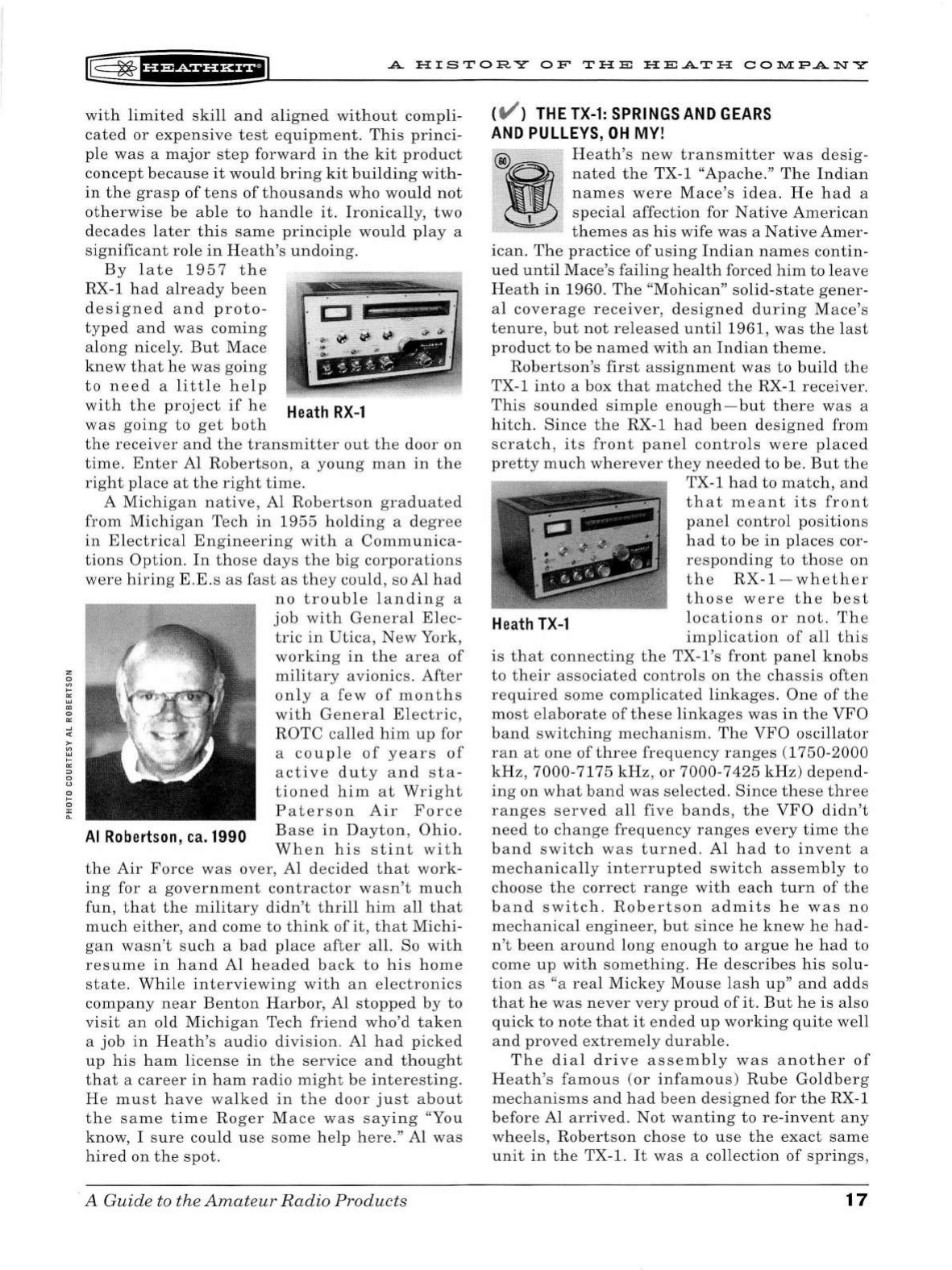
r@
~
f
i'Mf
HH+i
A
HISTORY
OF
TH
E
HEATH
CO:r.l.l:PANY
with
limited
skill
and
a
ligned
without
compli-
cated
or
expensive
t
est
eq
uipment.
This
princi-
pl
e
was
a
major
step
forward
in
the
kit
product
concept
because
it
would
brin
g
kit
building
with-
in
the
grasp
of
tens
of
thousands
who
would
not
ot
h
er
wi
se
be
able
to
ha
ndl
e
it.
Ironica
ll
y,
two
d
eca
d
es
later
thi
s
same
principl
e
would
play
a
si
gnifica
nt
role
in
H
ea
th'
s
undoing.
By l
ate
1
957
the
RX-1
had
al
read
y b
ee
n
d
esig
n e d
and
proto-
.
CJ
typed
a
nd
was
coming
a
lon
g nicely.
But
Mac
e
knew
that
he
was
going
t o n
ee
d a
little
help
with
the
project
if
h e
Heath
RX-l
was
g
oing
to
get
both
the
receiver
and
th
e
transmitter
out
the
door
on
time
.
Enter
Al
Robert
son , a yo
ung
man
in
the
right
pl
ace
at
the
right
time.
A
Mi
c
hi
ga
n
nativ
e, Al R
oberts
on
graduated
from
Michigan
Tech
in
19
55
holdin
g a
de
gree
in
Electrica
l
Engin
eer
in
g
wit
h a
Communica-
ti
ons
Option
.
In
those
days
the
big
corporations
were
hiring
E .
E.
s
as
fas
t
as
th
ey
could,
so Al h a d
no
trouble
landin
g a
job
wit
h
Gen
era
l
El
ec-
tr
ic
in
Utica
,
New
York,
work
in
g
in
the
ar
ea
of
military
avionics.
After
only
a
few
of
month
s
with
General
El
ectric,
ROT
C
ca
ll
ed
him
up
for
a
co
upl
e
of
years
of
active
duty
and
sta
-
tioned
him
a t
Wri
g
ht
P
aterso
n
Air
For
ce
Al
Robertson
, ca. 1990
Base
in
Da
yt
on
,
Ohio
.
Wh
en
hi
s
st
int
wi t h
the
Air
Forc
e
was
over
, Al dec
id
ed
that
work
-
in
g
for
a
government
co
nt
ractor
wasn't
mu
ch
fun
,
that
the
milita
ry
didn
't
thrill
him
all
that
much
e
ither
,
and
come
to
t
hi
nk
of
it
,
that
Michi
-
gan
wasn't
such
a bad
place
after
all. So
with
resume
in
hand
Al
h
ea
ded b
ac
k
to
his
hom
e
sta
te.
While
interviewin
g w
ith
an
electronics
com
pany
near
Benton
H
ar
bor, Al
stopped
by
to
visit
an
old
Michigan
Tech
friend
who'd
tak
en
a
job
in
Heath
's
audio
di
vision.
Al
had
pick
ed
up
hi
s
ham
license
in
the
service
a
nd
thou
ght
th
at
a
ca
reer
in
ham
radio
might
be
interestin
g.
He
mu
st
have
walked
in
the
door
ju
st
about
the
sa
m e
tim
e Ro
ger
M
ace
was
say
ing
"You
know, I s
ure
could
u
se
some h e
lp
he
re.
" Al
was
hired
on
the
spot.
A
Guid
e
to
the
Amat
eur
Radio
Products
( V )
THE
TX-1
:
SPRINGS
AND
GEARS
AND
PULLEYS
,
OH
MY!
@)
Heath
's n
ew
transmitter
was
de
sig-
nated
th
e TX-1 "A
pache.
"
The
Indian
names
wer e Ma
ce's
idea.
He
had
a
special
affection
for
Native
Americ
an
them
es
as
his
wife
was
a
Native
Am
e
r-
i
can.
Th
e
practice
of
u s
in
g
Indi
an
names
contin-
ued
until
Mace's
failing
h
ea
lth
forced
him
to
l
eave
H
ea
th
in
1960.
Th
e "
Mohican
" s
olid-state
gener-
al
cove
rage
receiv
er,
d
esig
n ed
during
Mace's
tenure,
but
not
released
until
1961
,
was
the
l
ast
pro
duct
to
be
named
with
an
Indian
theme.
Robe
rtson
's
first
assignment
was
to
build
th
e
TX-1
into
a box
that
matched
the
RX-1
receiv
er.
Thi
s so
unded
simple
e
nou
gh -
but
there
w
as
a
hitch
.
Since
the
RX-1 h a d b
ee
n
designed
from
scratc
h ,
its
front
p
ane
l
controls
were
plac
ed
p
re
tt
y
much
wh
erever
they
nee
ded
to
be.
But
the
Heath
TX-1
TX-1 ha d
to
match
, a
nd
that
m
ea
nt
it
s
front
panel
control
pos
ition
s
h ad
to
be
in
place
s cor-
r
es
ponding
to
tho
se
on
the
RX
-
1-wh
e
th
er
tho
se
were
the
b
es
t
loc
a
ti
ons
or
not.
Th
e
implication
of
all
thi
s
is
t hat
connecting
the
TX-l
's
front
panel
kn
obs
to
their
asso
ciat
ed
controls
on
the
chassis
of
te
n
req
uir
ed so
me
complicated
link
ages.
One
of
the
most
e
laborate
of
th
ese
link
ages
was
in
the
VFO
band
switc
hin
g mech a
ni
sm .
The
VFO
osc
illator
ran
at
one
of
th
ree
frequency
ranges
(
1750-2000
kHz
,
7000
-7175
kHz,
or
7000-7
4
25
kHz)
depend-
ing
on
what
band
was
sel
ecte
d.
Since
these
thr
ee
ranges
served
all
five
bands,
the
VFO
didn
't
need
to
change
frequency
ra
n
ges
every
time
the
band
sw
itch
was
turned.
Al
h a d
to
invent
a
m e
chanica
ll
y
int
e
rrupt
ed
sw
itch
assembly
to
choo
se
the
corr
ect
range
w
ith
eac
h
turn
of
th
e
b a
nd
sw
itch
.
Rob
ertso
n a
dmits
he
was
no
mec
hanical
engineer,
but
si
nce h e
knew
he
h
ad
-
n
't
b
een
around
lon
g e
nou
gh
to
argue
he
had
to
come
up
with
something.
He d
escr
ibes
his
solu
-
tion
as
"a
real
Mick
ey
Mou
se
l
as
h
up"
and
adds
th
at
he
w
as
never
very
pro
ud
of
it
.
But
he
is
also
quick
to
note
that
it
ende
d
up
working
quite
we
ll
an
d
pro
ve
d
extremely
dur
a
bl
e.
Th
e
dial
driv
e
assembly
was
anoth
er
of
H
ea
th
's
famou
s (
or
in
fa
mou
s)
Rube
Gol
db
erg
mechanisms
and
ha d
been
d
es
ig
ned
for
the
RX-1
b
efore
Al
arrived.
Not
wa
nting
to
re
-
invent
any
wheels
,
Robert
s
on
chose
to
u
se
the
exact
same
unit
in
the
TX-1.
It
was
a
collection
of
springs,
17
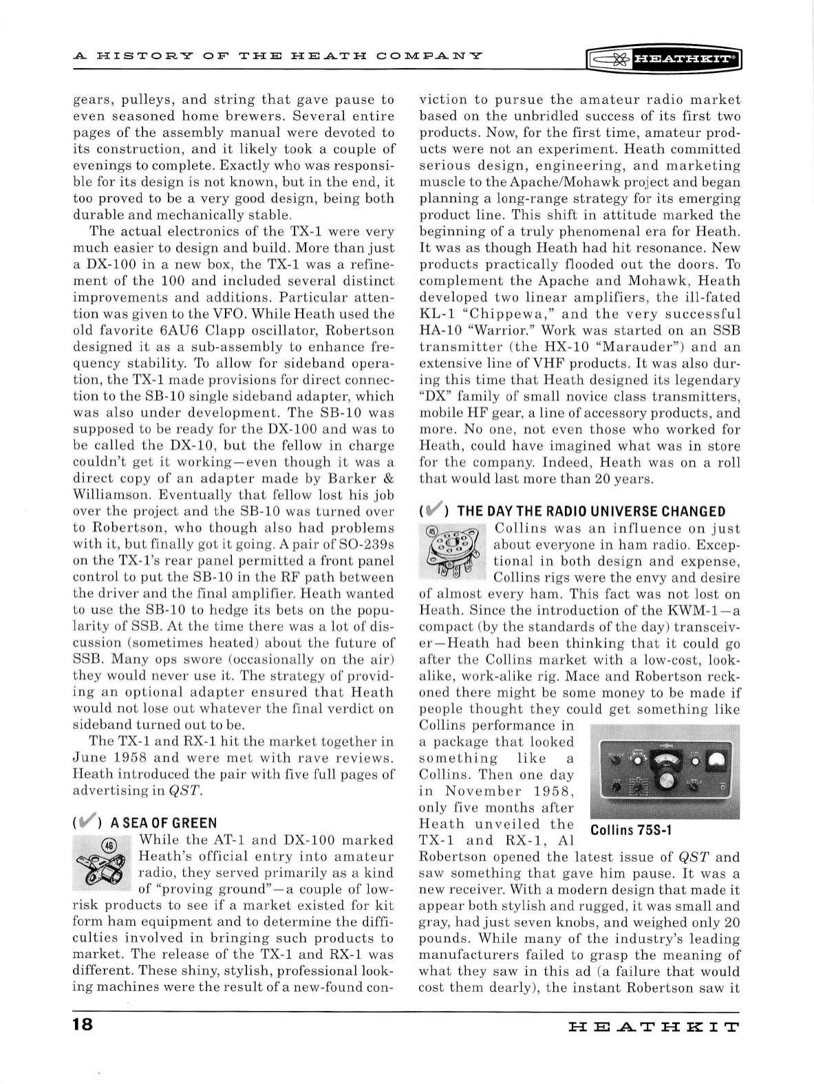
A
HISTORY
OF
THE
HEATH
COlll.[FANY
r@=
~
f
UMih&f
iJ
gears,
pulleys,
and
string
that
gave
pause
to
even
seasoned
home
brewers.
Several
entire
pages
of
the
assembly
manual
were
devoted
to
its
construction,
and
it
likely
took
a
couple
of
evenings
to
complete.
Exactly
who
was
responsi-
ble
for
its
design
is
not
known,
but
in
the
e
nd,
it
too
proved
to
be
a
very
good
design,
being
both
durable
and
mechanically
stable.
The
actual
electronics
of
the
TX-1
were
very
much
easier
to
design
and
build.
More
than
just
a
DX-100
in
a
new
box,
the
TX-1
was
a
refine-
ment
of
the
100
and
included
several
distinct
improvements
and
additions.
Particular
atten-
tion
was
given
to
the
VFO.
While
Heath
used
the
old
favorite
6AU6
Clapp
oscillator,
Robertson
designed
it
as
a
sub-assembly
to
enhance
fre-
quency
stability.
To
allow
for
sideband
opera-
tion
,
the
TX-1
made
provisions
for
direct
connec
-
tion
to
the
SB-10
single
sideband
adapter,
which
was
also
under
development.
The
SB-10
was
supposed
to
be
ready
for
the
DX-100
and
was
to
be
called
the
DX-10,
but
the
fellow
in
charge
couldn't
get
it
working
-
even
though
it
was
a
direct
copy
of
an
adapter
made
by
Barker
&
Williamson.
Eventually
that
fellow
lost
his
job
over
the
project
and
the
SB-10
was
turned
over
to
Robertson,
who
though
also
had
problems
with
it,
but
finally
got
it
going.
A
pair
of
S0-239s
on
the
TX-l's
rear
panel
permitted
a
front
panel
control
to
put
the
SB-10
in
the
RF
path
between
the
driver
and
the
final
amplifier.
Heath
wanted
to
use
the
SB-10
to
h e
dge
its
bets
on
the
popu-
l
arity
of
SSB
.
At
the
time
there
was
a
lot
of
di
s-
cussion
(sometimes
he
a
ted)
about
the
future
of
SSB
.
Many
ops
swore
(
occasionally
on
the
air)
they
would
never
use
it.
The
strategy
of
provid-
ing
an
optional
adapter
ensured
that
Heath
would
not
lose
out
whatever
the
final
verdict
on
sideband
turned
out
to
be
.
The
TX-1
and
RX-1
hit
th
e
mark
et
together
in
Jun
e
1958
and
were
met
with
rave
r
ev
iews
.
Heath
introduced
the
pair
with
five
full
p
ag
es
of
advertising
in
QST.
( V ) A
SEA
OF
GREEN
@
While
the
AT-1
and
DX-100
marked
~
Heath
's
official
entry
into
amateur
(§fail!)
radio
,
they
se
rved
primarily
as
a
kind
of
"proving
ground"
- a
couple
of
low-
risk
products
to
see
if
a
market
existed
for
kit
form
ham
equipme
nt
and
to
determine
the
diffi-
culties
involved
in
bringing
such
products
to
market.
The
release
of
the
TX-1
and
RX-1
was
different
.
These
shiny,
stylish,
professional
look-
ing
machines
were
the
resu
lt
of
a
new-found
con-
18
viction
to
pursue
the
amateur
radio
market
based
on
the
unbridled
success
of
its
first
two
products.
Now,
for
the
first
time,
amateur
prod-
ucts
were
not
an
experiment.
Heath
committed
serious
design,
engineering,
and
marketing
muscle
to
the
Apache
/
Mohawk
project
and
began
planning
a
long-range
strategy
for
its
emerging
product
lin
e.
This
sh
ift
in
attitude
marked
the
beginning
of
a
truly
phenomenal
era
for
Heath.
It
was
as
though
H
eath
had
hit
resonance.
New
products
practically
flooded
out
the
doors.
To
complement
the
Apache
and
Mohawk,
Heath
developed
two
linear
amplifiers,
the
ill-fated
KL-1
"C
hippewa
,"
and
the
very
successfu
l
HA-10
"Warrior
."
Work
was
started
on
an
SSB
transmitter
(the
HX-10
"Marauder")
and
an
extensive
line
of
VHF
products.
It
was
also
dur-
ing
this
time
that
Heath
designed
its
legendary
"DX"
family
of
small
novice
class
transmitters,
mobi
le
HF
gear,
a
line
of
accessory
products
,
and
more
. No
one,
not
even
those
who
worked
for
Heath,
could
have
imagined
what
was
in
store
for
the
company.
Indeed
,
Heath
was
on
a
roll
that
would
last
more
than
20
years.
(
t/
)
THE
DAY
THE
RADIO
UNIVERSE
CHANGED
Collins
was
an
influence
on
just
about
everyone
in
ham
radio.
Excep-
tional
in
both
design
and
expense,
Collins
rigs
were
the
envy
and
desire
of
almost
every
ham.
This
fact
was
not
lo
st
on
Heath
.
Since
the
introduction
of
the
KWM-1-a
compact
(
by
the
standards
of
th
e
day
)
transc
eiv-
er-Heath
h a d
been
thinking
that
it
could
go
after
the
Collins
market
with
a lo
w-cost,
look-
alike,
work
-
alike
rig
.
Mace
and
Robertson
reck
-
oned
there
might
be
some
mon
ey
to
be
made
if
peopl
e
thought
th
ey
could
get
something
like
Collins
performance
in
a
pack
age
that
looked
something
like
a
Collins
.
Then
one
day
in
No
ve
mb
e r 1
958,
only
five
months
after
Heath
unveiled
the
Collins 75S-l
TX-1
and
RX-1
,
Al
Robertson
opened
the
latest
issue
of
QST
and
saw
something
that
gave
him
pause.
It
was
a
new
receiver.
With
a
modern
design
that
made
it
appear
both
stylish
and
rugged
,
it
was
small
and
gray,
had
just
seven
knobs,
and
we
igh
ed
only
20
pounds.
While
many
of
the
industry's
leading
manufacturers
failed
to
grasp
the
meaning
of
what
they
saw
in
this
ad
(a
failure
that
would
cost
them
dearly)
,
the
instant
Robertson
saw
it
HE
AT
HK
IT
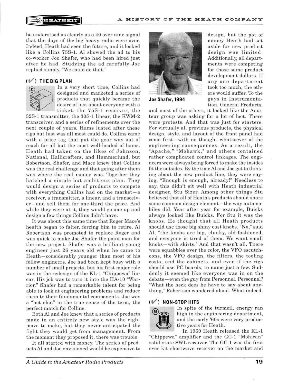
~
~
f
Hi&f
H&fil
A H I
STOR
Y O F
TH
E
HEATH
CO~PANY
he
understood
as
clearly
as
a
40
over
nine
signal
that
the
days
of
the
big
heavy
radio
were
over.
Indeed,
Heath
had
seen
the
future
,
and
it
looked
like
a
Collins
75S-l.
Al
showed
the
ad
to
his
co
-
worker
Joe
Shafer,
who
had
been
hired
just
after
he
had.
Studying
the
ad
carefully
Joe
replied
simply,
"We
could
do
that
."
(
t/
)
THE
BIG
PLAN
@
In
a
very
short
time,
Collins
had
designed
and
marketed
a
series
of
~
products
that
quickly
became
the
~
.
desire
of
just
about
everyone
with
a
ticket:
the
75S-1
receiver
,
the
32S-1
transmitter,
the
30S
-1
linear,
t he KWM-2
transceiver,
and
a
series
of
refinements
over
the
n
ex
t
couple
of
years.
Hams
lusted
after
these
rigs
but
lust
was
all
most
could
do.
Collins
came
with
a
price
tag
that
put
the
gear
way
out
of
reach
for
all
but
the
most
well-hea
l
ed
of
hams.
Heath
had
taken
on
the
likes
of
Johnson
,
National,
Hallicrafters,
and
Hammerlund,
but
Robertson
,
Shafer,
and
Mace
knew
that
Collins
was
the
real
challenge
and
that
going
after
them
was
where
th e
real
money
was.
Together
they
hatched
a
simple
but
ambitious
pl
an.
They
would
design
a
series
of
products
to
compete
with
everything
Collins
had
on
the
market-a
receiver
, a
transmitter
, a
linear,
and
a
transceiv
-
er
-
and
sell
them
for
one-third
the
price.
And
while
they
were
at
it,
they
would
go
one
up
and
design
a few
things
Collins
didn
't
have.
It
was
about
this
same
time
that
Roger
Mace
's
health
began
to
falter,
forcing
him
to
retire.
Al
Robertson
was
promoted
to
replace
Roger
and
was
quick
to
make
Joe
Shafer
the
point
man
for
the
new
pro
j
ect.
Shafer
was
a
brilliant
young
engineer
just
26
years
old
when
he
came
to
Heath
-
considerably
younger
than
most
of
his
fellow
engineers.
Joe
had
been
kept
busy
with
a
number
of
sma
ll
projects,
but
his
first
major
ro
le
was
in
the
redesign
of
the
KL
-1
"Chippewa"
lin-
ear.
His
job
was
to
turn
it
into
the
HA
-10 "War-
rior."
Shafer
had
a
remarkable
talent
for
being
able
to
look
at
engineering
problems
and
reduce
them
to
their
fundamental
components.
Joe
was
a
"hot
shot"
in
the
true
sense
of
the
term,
the
perfect
match
for
Collins
.
Both
Al
and
Joe
knew
that
a
series
of
products
made
in
an
entirely
new
style
was
the
right
move
to
make
,
but
they
never
anticipated
the
fight
they
would
get
from
management.
From
the
moment
they
proposed
it,
there
was
trouble.
It
all
started
with
money.
The
series
of
prod-
ucts
Al
and
Joe
envisioned
would
be
expensive
to
A Guide
to
the
Amateur
Radio
Products
design,
but
the
pot
of
money
Heath
had
set
aside
for
new
product
design
was
limited.
Additionally,
all
depart-
ments
were
competing
for
those
same
product
development
dollars.
If
any
one
department
took
too
much,
the
oth-
ers
would
suffer.
To
the
Joe
Sh
afer, 1994
guys
in
I
nstrumenta
-
tion,
General
Products,
and
most
of
the
others,
it
looked
like
the
Ama
-
teur
group
was
asking
for a
lot
of
loot.
There
were
protests
.
And
that
was
just
for
starters
.
For
virtually
all
previous
products,
the
physical
design
,
sty
le,
and
l
ayout
of
the
front
panel
had
come
first-with
no
thought
whatsoever
of
the
engineering
consequences
.
As
a
result
,
the
"Apache,"
"Mohawk,"
and
others
contained
rather
complicated
control
linkages.
The
engi
-
neers
were
always
being
forced to
make
the
insides
fit
the
outsides
. By
the
time
Al
and
Joe
got
to
think-
ing
about
the
new
product
line,
they
were
say-
ing,
"Enough
is
enough,
already!"
Needless
to
say,
this
didn't
sit
well
with
Heath
industrial
designer,
Stu
Sizer
.
Among
other
things
Stu
believed
that
all
of
Heath's
products
should
share
some
common
design
element-the
way
automo-
biles
did.
Year
after
year
for
example,
Buicks
always
l
ooked
like
Buicks
.
For
Stu
it
was
the
knobs.
He
thought
that
all
Heath
products
should
use
those
big
shiny
cast
knobs.
"No,"
said
Al,
"the
knobs
are
big,
clunky,
old
-
fashioned,
and
everyone
is
tired
of
them.
We
want
small
knobs
-
with
skirts."
And
that
wasn't
all.
There
were
squabbles
over
the
color,
the
VFO
escutch-
eons,
the
VFO
design,
the
filters,
the
tooling
costs,
and
the
cabinets,
and
even
if
the
rigs
should
use
PC
boards
,
to
name
just
a few.
Sud-
denly
it
seemed
like
everyone
was
in
on
the
debate-even
the
guy
from
Personnel.
Personnel?
"What
the
heck
does
he
have
to
say
about
any-
thing,
"
Robertson
wondered
aloud.
What
indeed.
(
t/
) NON-STOP
HITS
In
spite
of
the
turmoil,
energy
ran
high
in
the
engineering
department,
and
the
early
'60s
were
very
produc-
tive
years
for
Heath.
In
1960
Heath
released
the
KL-1
"Chippewa"
amplifier
and
the
GC-1
"Mohican"
solid-state
SWL
receiver.
The
GC-1
was
the
first
ever
kit
shortwave
receiver
on
the
market
and
19
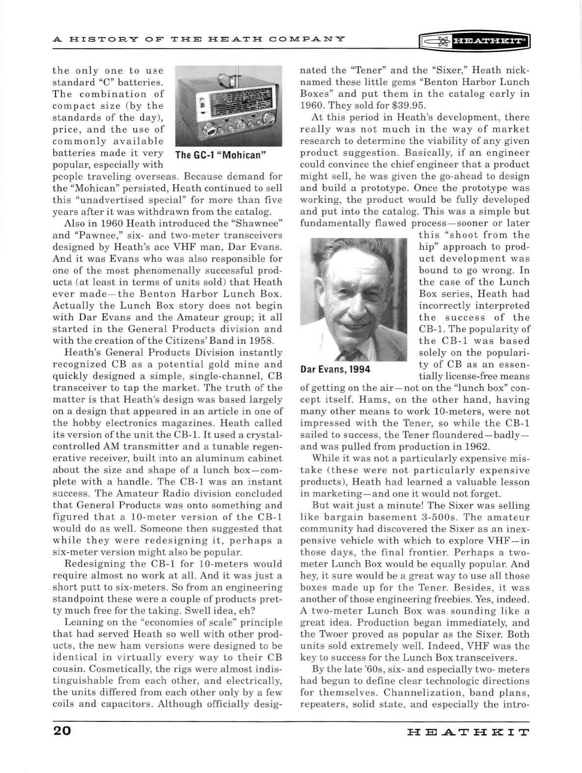
A
HISTOR
Y
OF
THE
H
EA
T H
CO:r-.1.IFANY
~
~
fH?f!Hi*PI
the
only
one
to
use
standard
"C"
batteries.
The
combination
of
compact
size
(by
the
standards
of
the
day
),
price,
and
the
use
of
commonly
available
batteries
made
it
very
Th
e G
C-1
"
Moh
ican"
popular,
especially
with
people
traveling
overseas.
Because
demand
for
the
"Mohican"
persisted,
Heath
continued
to
sell
this
"
unadvertised
special"
for
more
than
five
years
after
it
was
withdrawn
from
the
catalog.
Also
in
1960
Heath
introduced
the
"Shawnee"
and
"Pawnee,"
six-
and
two-meter
transceivers
designed
by
Heath's
ace
VHF
man,
Dar
Evans.
And
it
was
Evans
who
was
also
responsible
for
one
of
the
most
phenomenally
s
uccessful
prod-
ucts
(
at
least
in
terms
of
units
sold)
that
Heath
ever
made-the
Benton
Harbor
Lunch
Box.
Actually
the
Lunch
Box
story
does
not
begin
with
Dar
Evans
and
the
Amateur
group;
it
all
started
in
the
General
Products
division
and
with
the
creation
of
the
Citizens'
Band
in
1958.
Heath's
General
Products
Division
instantly
recognized
CB
as
a
potential
gold
mine
and
quickly
designed
a
simple,
single-channel,
CB
transceiver
to
tap
the
market.
The
truth
of
the
matter
is
that
Heath's
design
was
based
largely
on
a
design
that
appeared
in
an
article
in
one
of
the
hobby
electronics
magazines.
Heath
called
its
version
of
the
unit
the
CB-1.
It
used
a
crystal-
controlled
AM
transmitter
and
a
tunable
regen
-
erative
receiver,
built
into
an
aluminum
cabinet
about
the
size
and
shape
of
a
lunch
box
-com-
pl
ete
with
a
handle.
The
CB-1
was
an
instant
success.
The
Amateur
Radio
division
concluded
that
General
Products
was
onto
something
and
figured
that
a
10-meter
version
of
the
CB-1
would
do
as
well.
Someone
then
suggested
that
while
they
were
redesigning
it,
perhaps
a
six
-
meter
version
might
also
be
popular
.
Redesigning
the
CB-1
for
10-meters
would
require
almost
no
work
at
all.
And
it
was
just
a
short
putt
to
six-meters.
So
from
an
engineering
standpoint
these
were
a
couple
of
products
pret-
ty
much
free
for
the
taking.
Swell
idea,
eh?
Leaning
on
the
"
economies
of
s
cale"
principl
e
that
had
served
Heath
so
well
with
other
prod-
ucts
,
the
new
ham
version
s
were
designed
to
be
identical
in
virtually
ever
y
way
to
their
CB
cousin
.
Cosmetically,
the
rigs
were
almost
indis-
tinguishable
from
each
other
,
and
electrically
,
the
units
differed
from
each
other
only
by
a few
coils
and
capacitors.
Although
officially
desig-
20
nated
the
"Tener
"
and
the
"Sixer
,"
Heath
nick
-
named
these
little
gems
"Benton
Harbor
Lunch
Boxes"
and
put
them
in
the
cata
l
og
early
in
1960.
They
sold
for
$39.95.
At
this
period
in
Heath's
development,
there
really
was
not
much
in
the
way
of
market
research
to
determine
the
viability
of
any
given
product
suggestion.
Basically,
if
an
engineer
could
convince
the
chief
engineer
that
a
product
might
sell,
he
was
given
the
go-ahead
to
design
and
build
a
prototype.
Once
the
prototype
was
working
,
the
product
would
be
fully
developed
and
put
into
the
catalog.
This
was
a
simple
but
fundamentally
flawed
process-sooner
or
l
ater
Dar
Evans
, 1994
this
"shoot
from
the
hip"
approach
to
prod-
uct
deve
l
opment
was
bound
to
go
wrong
.
In
the
case
of
the
Lunch
Box
series,
H
eath
had
incorrectly
interpreted
the
success
of
the
CB-1.
The
popularity
of
the
CB
-1
was
based
solely
on
the
populari-
ty
of
CB
as
an
essen-
tially
license
-free
means
of
getting
on
the
air
-
not
on
the
"lunc
h box" con-
cept
itse
l
f.
Hams,
on
the
other
hand,
having
many
other
means
to
work
10-meters,
were
not
impressed
with
the
Tener,
so
while
the
CB-1
sailed
to
success,
the
Tener
floundered-badly
-
and
was
pulled
from
production
in
1962.
While
it
was
not
a
particular
ly
expensive
mis-
take
(these
were
not
particularly
expensive
products),
Heath
had
learned
a
va
l
uable
lesson
in
marketing-and
one
it
would
not
forget.
But
wait
just
a
minute!
The
Sixer
was
selling
like
bargain
basement
3-500s.
The
amateur
community
had
discovered
the
Sixer
as
an
inex-
pe
nsive
vehicle
with
which
to
explore
VHF-in
those
days,
the
final
frontier.
Perhaps
a
two
-
meter
Lunch
Box
would
be
equally
popular.
And
hey,
it
sure
would
be
a
great
way
to
use
all
thos
e
boxes
made
up
for
the
Tener.
Besides,
it
was
a
nother
of
those
engineering
freebies
. Yes,
indeed.
A
two-meter
Lunch
Box
was
sounding
like
a
gre
at
idea.
Production
began
immediately,
and
the
Twoer
proved
as
popular
as
the
Sixer.
Both
units
sold
extr
e
mely
well.
Indeed,
VHF
was
the
ke
y
to
s
uccess
for
the
Lunch
Box
transceivers.
By
the
late
'
60s
, six-
and
especially
two-
meters
had
begun
to
define
cle
ar
technologic
directions
for
themselves
.
Channelization
,
band
plans,
repeaters,
solid
stat
e,
and
especially
the
intro
-
HE
.AT
HK
IT
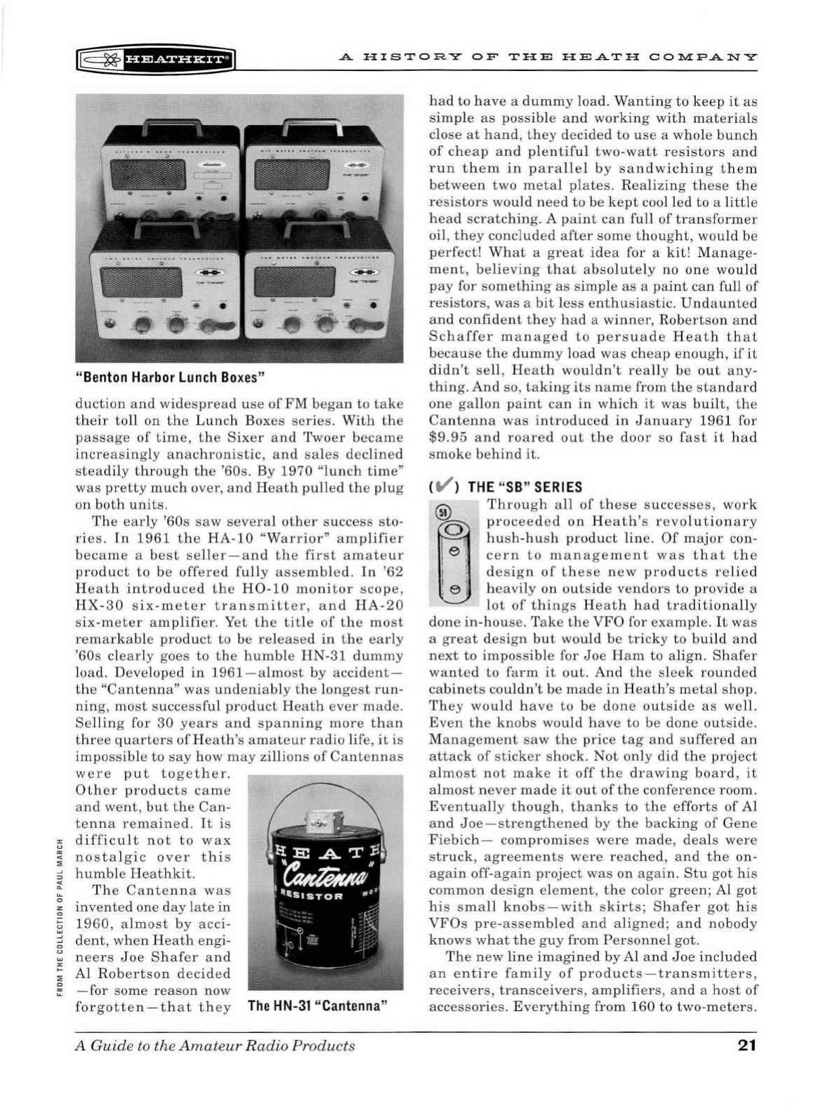
l@:
~
fi'
*Sf
UH+@
A
HISTORY
OF
TH
E
HEATH
COlv.[PANY
"
Benton
Harbor
Lunch
Boxes
"
duction
a
nd
widespread
u
se
of
FM
began
to
take
their
toll
on
the
Lunch
Boxes
series.
With
the
passag
e
of
time,
th
e
Sixer
and
Twoer
became
increa
s
in
g
ly
anachronistic,
and
sa
le
s
declin
ed
steadily
through
the
'60s.
By
1970
"
lunch
tim
e"
was
pretty
much
over, a
nd
Heath
pulled
the
plug
on
both
units.
The
ear
ly '
60s
saw
se
veral
other
success
sto
-
ries.
In
1961
th
e
HA-10
"Warrior"
amplifier
becam
e a
best
seller-
and
the
fir
st
amateur
product
to
be
off
ere
d
fully
assembled.
In
'62
Heath
introduced
the
H0
-
10
monitor
scope,
HX
-
30
s
ix-met
er
transmitter,
and
HA
-
20
six-meter
amplifier.
Yet
the
title
of
the
most
remarkable
product
to
be
relea
se
d
in
the
ea
rly
'
60s
clearly
goes
to
the
humbl
e
HN-31
dumm
y
load
.
Developed
in
1961-almo
st
by
accident-
the
"Cantenna"
was
undeniably
the
longest
run
-
ning,
most
successful
product
H
eat
h
ever
made.
Selling
for
30
years
and
spanning
more
than
three
quarters
of
H
eat
h's
amateur
radio
life
,
it
is
impossible
to
say
how
may
zillions
of
Cantennas
were
put
together.
Other
products
came
a
nd
went
,
but
the
Can-
te
nna
remai
ned
.
It
is
"'
difficult
not
to
wax
u
"'
"'
:E
nostalgic
ove
r
this
:::
humbl
e
Heathkit.
-:.
Th
e
Cantenna
was
~
i
invent
ed
one
da
y
lat
e
in
§
1960,
a
lmo
st
by
acc
i-
g
dent
,
when
Heath
engi
-
~
neers
Joe
Shafer
a
nd
"'
; Al
Rob
ertso
n d
eci
d
ed
0
"'
-for
some
reason
now
forgott
e
n-that
they
The
HN-
31 "
Cantenna
"
A
Guid
e
to
the
Amateur
Radio
Products
had
to
have
a
dummy
load.
Wanting
to
keep
it
as
simple
as
possible
and
working
with
mat
eria
ls
clo
se
at
hand
,
th
ey
dec
ided
to
u
se
a
whole
bunch
of
cheap
and
pl
ent
iful
two
-
watt
r
es
istors
a
nd
run
them
in
parallel
by
sandwiching
them
betw
een
two
metal
plate
s. R
ealizing
th
ese
the
re
si
stors
would
n
eed
to
be
kept
cool
led
to
a
littl
e
head
scratching.
A
paint
can
full
of
transform
er
oil,
they
concluded
after
some
thought,
would
be
perfect!
What
a
great
idea
for
a
kit!
Man
age
-
ment
,
believing
that
absolutely
no
one
would
pa
y for so
mething
as
s
imple
as
a
paint
can
full
of
re
s
istors
,
was
a
bit
l
ess
enthusiastic.
Undaunted
and
confident
th
ey
had
a
winner,
Robertson
a
nd
Schaffer
managed
to
persuade
Heath
that
because
the
dumm
y
load
was
cheap
enough,
if
it
didn't
sell,
Heath
wouldn't
really
be
out
any
-
thing.
And
so,
taking
its
name
from
the
standard
one
gallon
paint
can
in
which
it
was
built
,
the
Cantenna
was
introduced
in
January
1961
for
$9.95
and
roared
out
the
door
so
fast
it
had
smoke
behind
it.
CV )
THE
"
SB
"
SERIES
e I
i i
I I
; e ·
Through
all
of
these
successes,
work
proceed
e d
on
Heath's
revo
l
utionary
hush
-
hu
sh
product
lin
e.
Of
major
con-
cern
to
management
was
that
the
design
of
these
new
products
relied
heavily
on
outside
vendors
to
provide
a
lot
of
things
Heath
had
traditionally
don
e
in
-
house.
Tak
e
the
VFO
for
exa
mple.
It
was
a
great
design
but
wou
ld
be
tricky
to
build
and
next
to
impossible
for
Joe
Ham
to
align
.
Shafer
want
ed
to
farm
it
out.
And
the
sleek
round
ed
cabinets
couldn't
be
made
in
Heath's
metal
shop.
The
y
would
hav
e
to
be
done
outside
as
well.
Even
the
knobs
would
have
to
be
done
out
si
de.
Man
ageme
nt
saw
the
price
tag
and
suffered
an
attack
of
st
icker
shock.
Not
only
did
the
project
almost
not
mak
e
it
off
the
dr
aw
ing
board,
it
almost
n
eve
r
made
it
out
of
th
e
conference
room.
Eventuall
y
thou
gh ,
thanks
to
the
efforts
of
Al
and
Joe
- s
trength
ene
d
by
the
backing
of
Gene
Fiebich
-
compromises
were
made,
deal
s
were
struck,
agre
ements
were
reached,
and
the
on-
again
off-again
project
was
on
aga
in
.
Stu
got
hi
s
common
design
el
ement,
the
color
green;
Al
got
h
is
sma
ll
knob
s -
with
skirts
;
Shafer
got
hi
s
VFOs
pre-assembled
and
aligned;
and
nobody
know
s
what
the
g
uy
from
Personnel
got.
Th
e
new
line
imagined
by
Al
and
Joe
includ
ed
an
entire
family
of
products
-
transmitters
,
receiv
ers
,
transc
eiv
ers,
amplifiers
,
and
a
host
of
accessories.
Everything
from
160
to
two-m
eters.
21
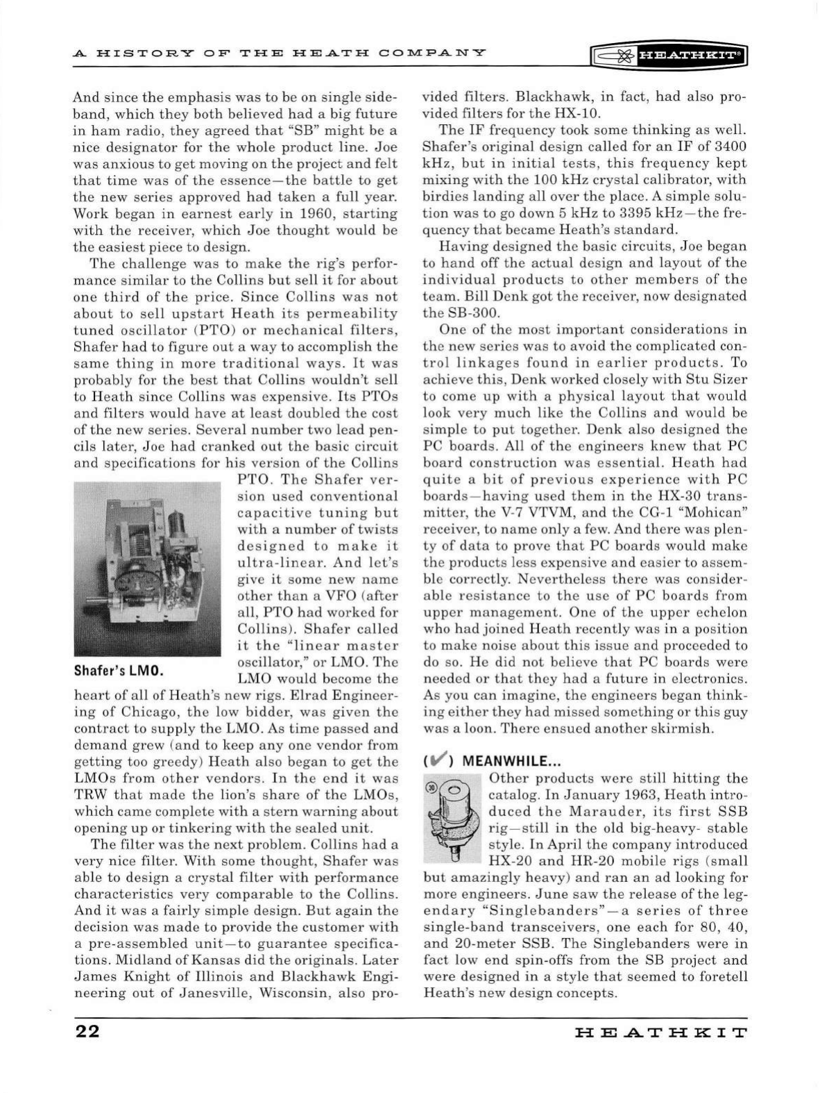
A
HISTORY
OF'
THE
HE.A.TH
COlY.!P.A.NY
l®
~f
U&riii'H+i
And
since
the
emphasis
was
to
be
on
single
side
-
band,
which
they
both
believed
had
a
big
future
in
ham
radio
,
they
agreed
that
"SB"
might
be
a
nice
designator
for
the
whole
product
lin
e.
Joe
was
anxious
to
get
moving
on
the
project
and
felt
that
time
was
of
the
essence-the
battle
to
get
the
new
series
approved
had
taken
a
full
year.
Work
began
in
earnest
early
in
1960,
starting
with
the
receiver,
which
Joe
thought
would
be
the
easiest
piece
to
design.
The
challenge
was
to
make
the
rig
's
perfor-
mance
simi
l
ar
to
the
Collins
but
sell
it
for
about
one
third
of
the
price.
Since
Collins
was
not
about
to
se
ll
upstart
Heath
it
s
permeability
tuned
oscillator
(
PTO
)
or
mechanical
filters,
Shafer
had
to
figure
out
a
way
to
accomplish
the
same
thing
in
more
traditional
ways.
It
was
probably
for
the
best
that
Co
llin
s
wouldn't
se
ll
to
Heath
since
Collins
was
expensive.
It
s
PTOs
and
filters
would
have
at
least
doubled
the
cost
of
the
new
series.
Several
number
two
lead
pen-
cils
lat
er,
Joe
had
cranked
out
the
basic
circuit
and
specifications
for
his
version
of
the
Collins
Shafer's
LMO.
PTO.
The
Shafer
ver-
sion
used
conventional
capacitive
tuning
but
with
a
number
of
twists
designed
to
make
it
ultra-linear.
And
let
's
give
it
some
new
name
other
than
a
VFO
(a
fter
all,
PTO
had
worked
for
Collins).
Shafer
calle
d
it
the
"linear
master
oscillator,
"
or
LMO.
The
LMO
would
become
the
heart
of
all
of
Heath's
new
rigs.
Elrad
Engineer-
ing
of
Chicago,
the
low
bidder
,
was
given
the
contract
to
supp
ly
the
LMO.
As
time
passed
an
d
demand
grew
(and
to
keep
any
one
vendor
from
getting
too
greedy)
Heath
also
began
to
get
the
LMOs
from
other
vendors.
In
the
end
it
was
TRW
that
made
the
lion's
share
of
the
LMOs,
whic
h
came
complete
with
a
stern
warning
about
opening
up
or
tinkering
with
the
sea
l
ed
unit
.
The
filter
was
the
next
problem.
Co
llin
s
had
a
very
nice
filter.
With
some
thought,
Shafer
was
able
to
design
a
crystal
filter
with
performance
characteristics
very
comparable
to
the
Collins.
And
it
was
a
fairly
simple
design.
But
again
the
decision
was
made
to
provide
the
customer
with
a
pre-a
sse
mbled
unit
-
to
guarantee
specifica-
tions.
Midland
of
Kansas
did
the
originals.
Later
James
Knight
of
Illinois
and
Blackhawk
Engi-
neering
out
of
Janesville
,
Wisconsin
,
also
pro-
22
vided
filters.
Blackhawk,
in
fact,
had
also pro-
vided
filters
for
the
HX-10.
The
IF
frequency
took
some
thinking
as
wel
l.
Shafer's
original
design
called
for
an
IF
of
3400
kHz,
but
in
initial
tests,
this
frequency
kept
mixing
with
the
100
kHz
crysta
l
calibrator,
w
ith
birdies
l
anding
a
ll
over
the
place
. A
simple
so
lu-
tion
was
to
go
down
5
kHz
to
3395
kHz-the
fre-
quency
that
became
H
eath's
standard.
Having
designed
the
basic
circuits,
Joe
began
to
hand
off
the
actual
design
and
layout
of
the
individual
products
to
other
members
of
the
team.
Bill
Denk
got
the
receiver,
now
designated
the
SB-300.
One
of
the
most
important
considerations
in
the
new
series
was
to
avoid
the
complicat
ed con-
tro
l
linkages
found
in
earl
i
er
products.
To
achieve
this,
Denk
worked
closely
wit
h
Stu
Sizer
to
come
up
with
a
physical
la
yout
that
would
look
very
much
like
the
Co
llin
s
and
would
be
simp
le
to
put
together.
Denk
also
designed
the
PC
boards.
All
of
the
engineers
knew
that
PC
board
construction
was
essential.
Heath
had
quite
a
bit
of
previous
experience
with
PC
boards
-
having
used
them
in
the
HX-30
trans-
mitter
,
the
V-7
VTVM,
and
the
CG-1
"Mohican"
receiver
,
to
name
only
a few.
And
there
was
plen-
ty
of
data
to
prove
that
PC
boards
would
make
the
products
less
expensive
and
easier
to
assem-
ble
correctly
.
Nevertheless
there
was
consider-
able
resistance
to
the
u
se
of
PC
boards
from
upper
management.
One
of
the
upper
echelon
who
had
joined
Heath
recently
was
in
a
position
to
make
noise
about
this
issue
and
proceeded
to
do so.
He
did
not
believe
that
PC
boards
were
needed
or
that
they
had
a
future
in
electronics.
As
you
can
imagine,
the
engineers
began
think-
ing
either
t
he
y
had
missed
something
or
this
guy
was
a loon.
There
ensued
another
skirmish.
( V ) MEANWHILE ...
Other
products
were
still
hitting
the
catalog.
In
January
196
3,
Heath
intro-
duced
the
Marauder,
its
first
SSB
rig-still
in
the
old
big-heavy-
s
table
sty
le.
In
April
the
company
introduced
HX-20
and
HR-20
mobile
rigs
(small
but
amazingly
heavy)
and
ran
an
ad
lookin
g for
more
engineers.
June
saw
the
release
of
the
l
eg
-
endary
"Singleban
d
ers"-a
series
of
three
sing
le-b
and
transceivers,
one
each
for
80
,
40
,
and
20-meter
SSB
.
The
Singlebanders
were
in
fact
low
en
d
spin-offs
from
the
SB
project
a
nd
were
designed
in
a
style
that
seemed
to
foretell
Heath
's
new
design
concepts.
HE.A.TH
KIT
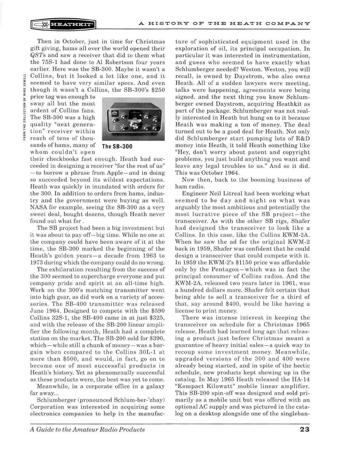
[-=
~
1
H?&iHHfiJ
A
HISTORY
OF
THE
HEATH
CO~FANY
Then
in
October,
just
in
time
for
Christmas
gift
giving,
hams
all
over
the
world
opened
their
QSTs
and
saw
a
receiver
that
did
to
them
what
the
75S-1
had
done
to
Al
Robertson
four
years
earlier.
Here
was
the
SB-300.
Maybe
it
wasn't
a
~
Collins,
but
it
looked
a
lot
like
one,
and
it
~
seemed
to
have
very
similar
specs.
And
even
~
though
it
wasn't
a
Collins,
the
SB-300's
$250
~
price
tag
was
enough
to
0
;:;
sway
all
but
the
most
§
ardent
of
Collins
fans.
~
The
SB-300
was
a
high
~
quality
"next
genera-
;
tion"
receiver
within
~
reach
of
tens
of
thou-
sands
of
hams,
many
of
The
SB-300
whom
couldn't
open
their
checkbooks
fast
enough.
Heath
had
suc
-
ceeded
in
designing
a
receiver
"for
the
rest
of
us
"
-to
borrow
a
phrase
from
Apple-and
in
doing
so
succeeded
beyond
its
wildest
expectations.
Heath
was
quickly
in
inundated
with
orders
for
the
300.
In
addition
to
orders
from
hams,
indus-
try
and
the
government
were
buying
as
well.
NASA
for
examp
le,
seeing
the
SB-300
as
a
very
sweet
deal,
bought
dozens,
though
Heath
never
found
out
what
for .
The
SB
project
had
been
a
big
investment
but
it
was
about
to
pa
y
off-big
time.
While
no
one
at
the
company
could
have
been
aware
of
it
at
the
time,
the
SB-300
marked
the
beginning
of
the
Heath's
golden
years-a
decade
from
1963
to
1973
during
which
the
company
could do no w
rong
.
The
ex
hilaration
resu
ltin
g
from
the
success
of
the
300
seemed
to
supercharge
everyone
and
put
company
pride
and
spirit
at
an
all-time
high.
Work
on
the
300
's
matching
transmitter
went
int
o
high
gear,
as
did
work
on
a
variety
of
acces-
sories.
The
SB-400
transmitter
was
rel
ease
d
June
1964.
Designed
to
compete
with
the
$590
Collins
32S-l,
the
SB-400
came
in
at
just
$325,
and
with
the
release
of
the
SB-200
linear
ampli
-
fier
the
following
month,
Heath
had
a
compl
ete
station
on
the
market.
The
SB-200
sold
for
$39
0,
which
-
while
sti
ll
a
chunk
of
money-was
a
bar-
gain
when
compared
to
the
Collins
30L-1
at
more
than
$500,
and
would,
in
fact,
go
on
to
become
one
of
most
successfu
l
products
in
H
eath's
hi
s
tory
. Yet
as
phenomenally
successful
as
these
products
were,
the
best
was
yet
to
come.
Meanwhile,
in
a
corporate
office
in
a
galaxy
far
away
.
..
Schlumberger
(
pronounced
Schlum-ber-'zhay
)
Corporation
was
interested
in
acquiring
some
electronics
companies
to
help
in
the
manufac-
A Guide
to
the
Amateur
Radio
Products
ture
of
sophisticated
equipment
used
in
the
exploration
of
oil,
its
principal
occupation.
In
particular
it
was
interested
in
instrumentation
,
and
guess
who
seemed
to
have
exact
ly
what
Schlumb
erger
needed?
Weston.
Weston,
you
will
r
ecall,
is
owned
by
Daystrom,
who
also
owns
Heath.
All
of
a
sudden
la
wyers
were
meeting
,
talks
were
h
appening,
agreements
were
being
signed,
and
the
next
thing
you
know
Schlum-
ber
ger
owne
d D
aystrom,
acquiring
Heathkit
as
part
of
the
package
.
Schlumberger
was
not
real-
ly
interested
in
Heath
but
hun
g
on
to
it
because
H
eat
h
was
making
a
ton
of
money.
The
deal
turned
out
to
be
a good
deal
for
Heath.
Not
only
did
Schlumberger
start
pumping
lots
of
R&D
money
into
Heath,
it
tol
d
Heath
somet
hin
g
like
"Hey,
don
't
worry
about
patent
and
copyright
problems
,
you
just
build
anything
you
want
and
le
ave
any
legal
troubles
to
us.
"
And
so
it
did.
Thi
s
was
October
1964.
Now
then,
back
to
the
booming
business
of
ham
radio.
Engineer
Neil
Litreal
h
ad
been
working
what
seemed
to
be
day
and
night
on
what
was
arguab
ly
the
most
ambitious
and
potentially
the
most
lucrative
piece
of
the
SB
project-the
transceiver.
As
with
the
other
SB
rigs,
Shafer
h
ad
de
sig
ned
the
transceiver
to
look
like
a
Collins.
In
this
case,
like
the
Collins
KWM-2A.
When
he
saw
the
ad
for
the
original
KWM-2
back
in
1959,
Shafer
was
confident
that
he
could
design
a
transceiver
that
could
compete
with
it.
In
1959
the
KWM-2's
$1150
price
was
affordable
only
by
the
Pentagon-which
was
in
fact
the
principal
consumer
of
Collins
radios.
And
the
KWM-2A,
released
two
years
later
in
1961
,
was
a
hundred
dollars
more
.
Shafer
felt
certain
that
being
able
to
sell
a
transceiver
for
a
third
of
that,
say
around
$400,
would
be
like
havin
g a
lice
ns
e
to
print
money.
There
was
intense
inter
es
t
in
keeping
the
transceiv
er
on
schedule
for
a
Christmas
1965
relea
se.
Heath
had
learned
long
ago
that
releas-
ing
a
product
just
before
Christmas
meant
a
guarantee
of
heav
y
initial
sales
- a
quick
way
to
recoup
some
inv
estme
nt
money.
Meanwhile,
up
graded
versions
of
the
300
and
400
were
al
ready
being
started,
and
in
spite
of
the
hectic
sch
edu
le,
new
products
kept
showing
up
in
the
catalog.
In
May
1965
Heath
released
the
HA-14
"Kompact
Kilowatt
"
mobile
linear
amplifier.
Thi
s
SB-200
spin-off
was
designed
and
sold
pri-
marily
as
a
mobile
unit
but
was
offered
with
an
optional
AC s
uppl
y
and
was
pictured
in
the
cata
-
log
on
a
desktop
al
ongside
one
of
the
sing
le
ban-
23
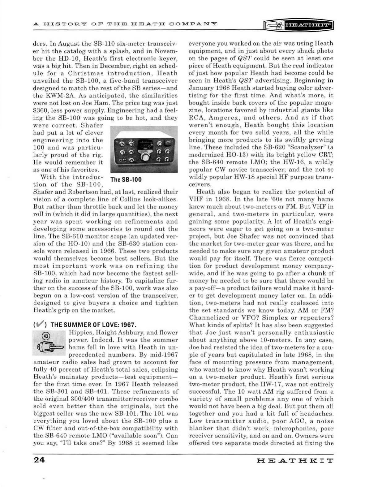
A
HISTORY
OF
THE
HEATH
COlY.l:PA
NY
IT5
~
f
UMi§fHEI
ders.
In
August
the
SB-110
six-meter
transceiv-
er
hit
the
catalog
with
a
splash,
and
in
Novem-
ber
the
HD-10,
Heath
's
first
electronic
keyer,
was
a
big
hit.
Then
in
December,
right
on
sched-
ule
for
a
Christmas
introduction,
Heath
unveiled
the
SB
-
100,
a
five-band
transceiver
designed
to
match
the
rest
of
the
SB
series
-
and
the
KWM-2A.
As
anticipated
,
the
similarities
were
not
lost
on
Joe
Ham
.
The
price
tag
was
just
$360,
less
power
supply.
Engineering
had
a feel-
ing
the
SB
-
100
was
going
to
be
hot,
and
they
were
correct.
Shafer
had
put
a l
ot
of
clever
engineering
into
the
100
and
was
particu
-
larly
proud
of
the
rig.
He
would
remember
it
as
one
of
his
favorites.
With
the
introduc-
The
SB-lOO
tion
of
the
SB-100,
Shafer
and
Robertson
had,
at
last
,
realized
their
vision
of
a
complete
line
of
Collins
look-alikes
.
But
rather
than
throttle
back
and
let
the
money
roll
in
(
which
it
did
in
l
arge
quantities),
the
next
year
was
spent
working
on
refinements
and
developing
some
accessories
to
round
out
the
line.
The
SB-610
monitor
scope
(
an
updated
ver
-
sion
of
the
H0-10
)
and
the
SB-630
station
con-
sole
were
released
in
1966.
These
two
products
would
themse
l
ves
become
best
sellers.
But
th
e
most
important
work
was
on
r e
fining
the
SB-100,
which
had
now
become
the
fastest
sell
-
ing
radio
in
amateur
history.
To
capitalize
fur
-
ther
on
the
success
of
the
SB-100,
work
wa
s
also
begun
on
a low-
cost
version
of
the
transceiver,
designed
to
give
buyers
a
choice
and
tighten
Heath's
grip
on
the
market
.
CV )
THE
SUMMER
OF
LOVE:
1967.
@
3
Hippies
,
Haight
Ashbury
,
and
flower
.
power.
Indeed
.
It
was
the
summer
~
hams
fell
in
love
with
Heath
in
un-
precedented
number
s.
By
mid
-
1967
amateur
radio
sales
had
grown
to
account
for
fully
40
percent
of
Heath
's
total
sales,
eclipsing
Heath'
s
mainstay
products-test
equipment-
for
the
first
time
ever.
In
1967
Heat
h
released
the
SB
-
301
and
SB-401.
The
se
refinement
s
of
the
original
300
/
400
transmitter
/re
ceiver
combo
sold
even
better
than
the
originals
,
but
the
biggest
s
eller
was
the
new
SB
-
101.
The
101
was
everything
you
loved
about
the
SB-100
plus
a
CW
filter
and
out-of
-
the
-
box
compatibility
with
the
SB
-
640
remote
LMO
("
available
soon
")
.
Can
you
say,
"I'll
take
one?"
By
1968
it
seemed
like
24
everyone
you
worked
on
the
air
was
using
Heath
equipment,
and
in
just
about
every
shack
photo
on
the
pages
of
QST
cou
ld
be
seen
at
least
one
piece
of
Heath
equipment.
But
the
rea
l
indicator
of
just
how
popular
Heath
had
become
could
be
seen
in
Heath's
QST
advertising.
Beginning
in
January
1968
Heath
started
buying
color
adver-
tising
for
the
first
time.
And
what
's
more,
it
bought
inside
back
covers
of
the
popu
l
ar
maga-
zine,
locations
favored
by
industria
l
giants
like
RCA,
Amperex,
and
others
.
And
as
if
that
weren't
enough,
Heath
bought
this
location
every
month
for
two
solid
years
,
all
the
while
bringing
more
products
to
its
swiftly
growing
li
ne.
These
included
the
SB-620
"Scanalyzer"
(a
modernized
H0
-13)
with
its
bright
yellow
CRT;
the
SB-640
remote
LMO;
the
HW
-1 6, a
wildly
popular
CW
novice
transceiver;
and
the
not
so
wildly
popular
HW-18
special
HF
purpose
trans
-
ceivers.
Heath
also
began
to
realize
the
potential
of
VHF
in
1968.
In
the
late
'
60s
not
many
ham
s
knew
much
about
two-meters
or
FM.
But
VHF
in
general
,
and
two
-
meters
in
particu
l
ar
,
were
gaining
some
popularity.
A
lot
of
Heath's
engi
-
neers
were
eager
to
get
going
on
a
two-meter
project
,
but
Joe
Shafer
was
not
convinced
that
the
market
for
two-meter
gear
was
there
,
and
he
needed
to
make
sure
any
given
amateur
product
would
pay
for
its
elf.
There
was
fierce
competi
-
tion
for
product
development
money
company-
wide,
and
if
he
was
going
to
go
after
a
chunk
of
money
he
needed
to
be
sure
that
there
would
be
a
pay
-
off-a
product
failure
would
make
it
hard-
er
to
get
development
money
later
on.
In
addi-
tion,
two
-
meters
had
not
really
coalesced
into
the
set
standards
we
know
today.
AM
or
FM?
Channelized
or
VFO?
Simplex
or
repeaters?
What
kinds
of
splits?
It
has
also
been
suggested
that
Joe
just
wasn't
personally
enthusiastic
about
anything
above
10-
meters
.
In
any
case,
Joe
had
resisted
the
idea
of
two
-
meters
for a cou-
ple
of
years
but
capitulated
in
late
1968,
in
the
face
of
mounting
press
u
re
from
ma
n
agement,
who
wanted
to
know
why
Heath
wasn't
working
on
a
two-meter
product.
Heath's
first
serious
two-meter
product,
the
HW-17,
was
not
entirely
successful.
The
10
watt
AM
rig
s
uffered
from
a
variety
of
small
problems
any
one
of
which
would
not
have
been
a
big
deal.
But
put
them
all
together
and
you
had
a
kit
full
of
headaches.
L
ow
transmitter
audio,
poor
AGC,
a
noise
blanker
that
didn
't
work,
microphonics,
poor
rec
e
iver
sensitivity
,
and
on
and
on.
Owners
were
offered
two
separate
mods
directed
at
fixing
the
HE
..A..T
HK
IT
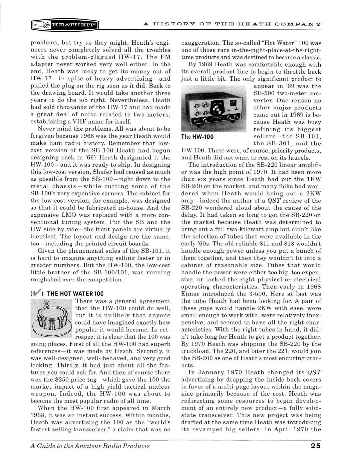
r@
~fi'Si#'H+il
A
HISTORY
OF
THE
HEATH
COlll.l:PANY
problems,
but
try
as
they
might,
Heath's
engi-
neers
never
completely
solved
all
the
troubl
es
with
the
problem-plagued
HW-17.
Th
e
FM
adapter
never
worked
very
well
either.
In
the
end,
Heath
was
lucky
to
get
its
money
out
of
HW-17-in
spite
of
heavy
advertis
ing-and
pulled
the
plug
on
the
rig
soon
as
it
did.
Back
to
the
drawing
board.
It
would
take
another
three
years
to
do
the
job
right
.
Nevertheless,
He
ath
h
ad
so
ld
thousands
of
the
HW-17
and
had
made
a
great
deal
of
noise
related
to
two-meters,
establishing
a
VHF
name
for
itself.
Never
mind
the
problems
.
All
was
about
to
be
forgiven
because
1968
was
the
year
Heath
would
make
ham
radio
history.
Remember
that
low-
cost
version
of
the
SB-100
Heath
had
begun
designing
back
in
'66?
Heath
designated
it
the
HW-100-and
it
was
ready
to
ship.
In
designing
this
low-cost
version,
Shafer
had
reused
as
much
as
possible
from
the
SB-100-right
down
to
the
metal
chassis-while
cutting
some
of
the
SB-lOO's
very
expensive
corners
.
The
cabinet
for
the
low-co
st
version,
for
examp
le,
was
desi
gned
so
that
it
could
be
fabricated
in-house.
And
the
expensive
LMO
was
replaced
with
a
more
con-
ventional
tuning
system.
Put
the
SB
and
the
HW
side
by
side-the
front
panels
are
virtually
identical.
The
layout
and
design
are
the
same,
too-includi
ng
the
printed
circuit
boards.
Given
the
phenomenal
sa
l
es
of
the
SB-101,
it
is
hard
to
imagine
anything
selling
faster
or
in
greater
numbers.
But
the
HW-100,
the
low-
cost
little
brother
of
the
SB-100
/
101,
was
running
roughshod
over
the
competition.
CV )
THE
HOT
WATER
100
=-
There
was
a
general
agreement
that
th
e
HW-100
could
do
well
,
but
it
is
unlikely
that
anyone
.
could
have
imagined
exac
tl
y
how
popular
it
wou
ld
become.
In
ret-
rospect
it
is
clear
that
the
100
was
going
places.
Fir
st
of
all
the
HW-100
had
superb
references-
it
was
made
by
Heath.
Secondly,
it
was
well
-d
esigned,
well-
behaved,
and
very
good
looking.
Thirdly,
it
had
just
about
all
the
fea
-
tures
you
could
ask
for.
And
then
of
course
there
was
the
$250
price
tag-which
gave
the
100
the
market
impact
of
a
high
yield
tactical
nucle
ar
weapon.
Indeed,
the
HW-100
was
about
to
bec
ome
the
most
popular
radio
of
all
time
.
When
the
HW-100
first
appeared
in
March
1968,
it
was
an
in
stant
success.
Within
months,
Heath
was
advertising
the
100
as
the
"world's
fastest
se
ll
ing
transceiver
,'' a
claim
that
was
no
A
Guide
to
the
Amateur
Radio
Products
exaggeratio
n.
The
so-called
"Hot
Water"
100
was
one
of
those
rare
in-the-right-place-at-the-right-
time
products
and
was
destined
to become a classic.
By
1969
Heath
was
comfortable
enough
with
its
overall
product
lin
e to
begin
to
throttle
back
just
a
little
bit.
The
only
significan
t
product
to
appear
in
'69
was
the
SB-500
two-meter
con-
verter.
One
reason
no
other
major
product
s
came
out
in
1969
is
be-
cause
Heath
was
busy
refining
its
biggest
The
HW-100
sellers-the
SB-101,
the
SB-301,
and
the
HW-100.
These
were,
of
course,
priority
products,
and
Heath
did
not
want
to
rest
on
its
laurel
s.
The
introduction
of
the
SB-220
linear
amplifi-
er
was
the
high
point
of
1970.
It
had
been
more
than
six
years
since
Heath
had
put
the
lKW
SB-200
on
the
market
,
and
many
folks
had
won-
dered
when
H
eath
would
bring
out
a
2KW
amp
-indeed
the
author
of
a
QST
review
of
the
SB-220
wondered
aloud
about
the
cause
of
the
delay.
It
had
taken
so
long
to
get
the
SB-220
on
the
market
because
Heath
was
determined
to
bring
out
a
full
two-kilowatt
amp
but
didn
't
like
the
selection
of
tubes
that
were
available
in
the
early
'60s.
The
old
reliable
811
and
813
wouldn't
handle
eno
ugh
power
unless
you
put
a
bunch
of
them
together,
and
then
they
wouldn't
fit
into
a
cabinet
of
reasonable
s
ize.
Tubes
that
would
handle
the
power
were
either
too
big,
too
expen-
sive,
or
lacked
the
right
physical
or
electrical
operating
characteristics.
Then
early
in
1968
Eimac
introduced
the
3-500.
Here
at
last
was
the
tube
Heath
had
been
looking
for. A
pair
of
these
guys
would
handle
2KW
with
ease,
were
small
enoug
h
to
work
with,
were
relatively
inex-
pensive,
and
seemed
to
have
a
ll
the
right
char-
acteristics.
With
the
right
tubes
in
hand
,
it
did-
n't
take
long
for
Heath
to
get
a
product
together
.
By
1970
Heath
was
shipping
the
SB-220
by
the
truckload.
The
220,
and
later
the
221,
would
join
the
SB-200
as
one
of
Heath's
most
end
urin
g
prod-
ucts.
In
January
1970
Heath
changed
its
QST
advertising
by
dropping
the
inside
back
covers
in
favor
of
a
multi-page
la
y
out
within
the
maga-
zine
primarily
because
of
the
cost.
Heath
was
redirecting
some
resources
to
begin
dev
e
lop-
me
nt
of
an
entirely
new
product-a
full
y solid-
state
transceiver
.
This
new
project
was
being
drafted
at
t
he
same
time
Heath
was
introducing
its
revamped
big
sellers
.
In
April
1970
the
25
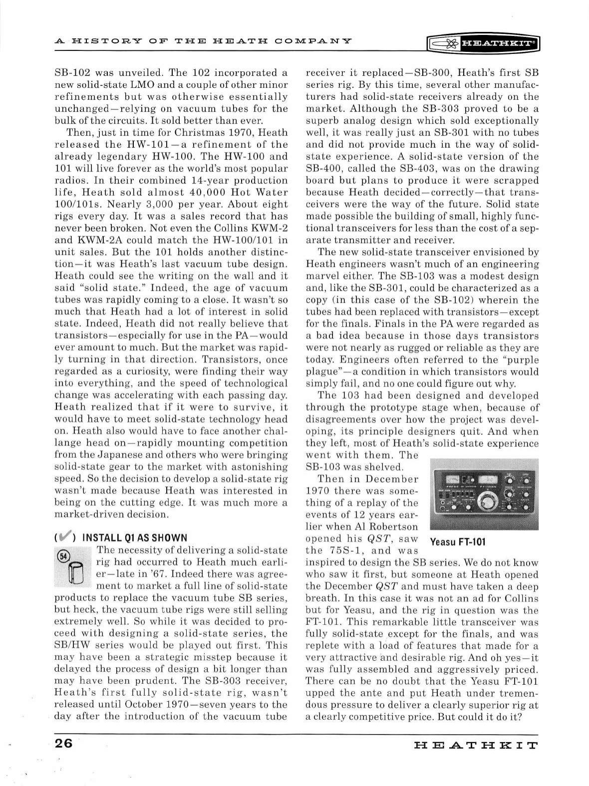
A ·
HISTORY
OF
THE
HEATH
CO])l.[PANY
~
~f
U?tSiUHfi
SB-102
was
unveiled.
The
102
incorporated
a
new
solid-state
LMO
and
a
couple
of
other
minor
refinements
but
was
otherwise
essentially
unchanged-relying
on
vacuum
tubes
for
the
bulk
of
the
circuits.
It
sold
better
than
ever
.
Then,
just
in
time
for
Christmas
1970,
Heath
released
the
HW-101-a
refinement
of
the
already
legendary
HW-100.
The
HW-100
and
101
will
live
forever
as
the
world's
most
popular
radios.
In
their
combined
14-year
production
life,
Heath
sold
almost
40,000
Hot
Water
100/lOls.
Nearly
3,000
per
year.
About
eight
rigs
every
day.
It
was
a
sales
record
that
h
as
never
been
broken.
Not
even
the
Collins
KWM-2
and
KWM-2A
could
match
the
HW-100
/
101
in
unit
sales.
But
the
101
holds
another
distinc-
tion-it
was
Heath's
last
vacuum
tube
design
.
Heath
cou
ld
see
the
writi
ng
on
the
wall
and
it
said
"solid
state."
Indeed,
the
age
of
vacuum
tubes
was
rapidly
coming
to
a close.
It
wasn't
so
much
that
H
eath
had
a
lot
of
interest
in
solid
state.
Indeed,
Heath
did
not
really
believe
that
transistors-especially
for
use
in
the
PA-
would
ever
amount
to
much
.
But
the
market
was
rapid-
ly
turning
in
that
di
re
ction.
Transistors,
once
regarded
as
a
curiosity,
were
finding
their
way
into
everything
,
and
the
speed
of
technological
change
was
accelerating
with
each
passing
day.
Heath
realized
that
if
it
were
to
survive,
it
would
have
to
meet
solid-state
technology
head
on
.
Heath
also
wou
ld
have
to
face
another
chal-
lange
head
on
-
rapidly
mounting
competition
from
the
Japanese
and
others
who
were
bringing
solid-state
gear
to
the
market
with
astonishing
speed.
So
the
decision
to
develop
a
solid-state
rig
wasn't
made
be
cause
Heath
was
interested
in
being
on
the
cutting
edge.
It
was
much
more
a
market
-d
riven
decision
.
(
t/'
) INSTALL
Ql
AS
SHOWN
®OCJ
The
necessity
of
delivering
a
solid
-
state
rig
had
occurred
to
Heath
much
earli
-
er
-l
ate
in
'67.
Indeed
there
was
agree
-
ment
to
market
a
full
line
of
solid
-st
ate
products
to
repl
ace
the
vacuum
tube
SB
series,
but
heck
,
the
vacuum
tub
e
rig
s
were
still
selling
extremely
well. So
while
it
was
decid
ed
to
pro-
cee
d
with
desi
g
ning
a
solid-state
series,
the
SB/HW
series
would
be
played
out
fir
st .
Thi
s
may
ha
ve
been
a
strategic
mi
sste
p
becaus
e
it
delayed
the
proc
es
s
of
design
a
bit
long
er
than
may
have
been
prudent.
The
SB-303
receiver,
Heath
's
first
fully
so
lid-
state
rig
,
wasn
't
re
l
eased
until
October
1970-s
eve
n
years
to
the
day
after
the
introduction
of
the
vacuum
tube
26
receiver
it
replaced-SB-300,
Heath's
first
SB
series
rig.
By
this
time,
severa
l
other
manufac-
turers
had
solid-state
receivers
already
on
the
market.
Although
the
SB-303
proved
to
be
a
superb
analog
design
which
sold
exceptionally
well,
it
was
really
just
an
SB-301
with
no
tube
s
and
did
not
provide
much
in
the
way
of
solid-
state
experience.
A so
lid-state
version
of
the
SB-400
,
called
the
SB-403,
was
on
the
drawing
board
but
plans
to
produce
it
were
scrapped
because
Heath
decided-correctly-that
trans-
ceivers
were
the
way
of
the
future.
Solid
state
made
possible
the
building
of
small,
highly
func-
tional
transceivers
for
less
than
the
cost
of
a
sep-
arate
transmitter
and
receiver.
The
new
solid
-
state
transceiver
envisioned
by
Heath
engineers
wasn't
much
of
an
engineering
marvel
either.
The
SB-103
was
a
modest
design
and,
like
the
SB-301,
could
be
characterized
as
a
copy
(in
this
case
of
the
SB-102)
wherein
the
tubes
had
been
replaced
with
transistors
-e
xcept
for
the
finals.
Finals
in
the
PA
were
regarded
as
a
bad
ide
a
because
in
those
days
transistors
were
not
near
ly
as
rugged
or
reliable
as
they
are
today.
Engineers
often
referred
to
the
"
purple
plague"
-a
condition
in
which
transistors
would
simp
ly
fail
,
and
no
one
could
figure
out
why.
The
10
3
had
been
designed
and
developed
through
the
prototype
stage
when,
because
of
disagreements
over
how
the
project
was
devel-
oping
,
its
principle
designers
quit.
And
when
th
ey
left,
most
of
Heath
's so
lid-
state
experience
went
with
them.
The
SB-103
was
shelved.
Then
in
December
1970
there
was
some
-
thing
of
a
replay
of
the
events
of
12
years
ear-
lier
when
Al
Rob
e
rtson
opened
his
QST
,
saw
Yeasu
FT-101
th
e
75S-1,
and
was
inspired
to
design
the
SB
series.
We do
not
know
who
saw
it
first
,
but
someone
at
Heath
opened
the
December
QST
and
must
hav
e
taken
a
deep
breath.
In
this
case
it
was
not
an
ad
for
Collins
but
for Yeasu,
and
the
rig
in
que
s
tion
was
the
FT-101.
This
remarkable
little
transceiv
er
was
fully
solid-state
except
for
the
finals,
and
was
replete
with
a
load
of
features
that
mad
e for a
very
attractive
and
desirable
rig.
And
oh
yes-it
w
as
fu
ll
y
ass
embled
and
aggressively
priced.
Th
ere
can
be
no
doubt
that
th
e
Yeasu
FT-101
upp
ed
the
ante
and
put
Heath
under
tremen-
dous
pressure
to
deliver
a
clearly
superior
rig
at
a cl
ea
rl
y
competitive
pric
e.
But
could
it
do
it?
HE
.AT
HK
IT
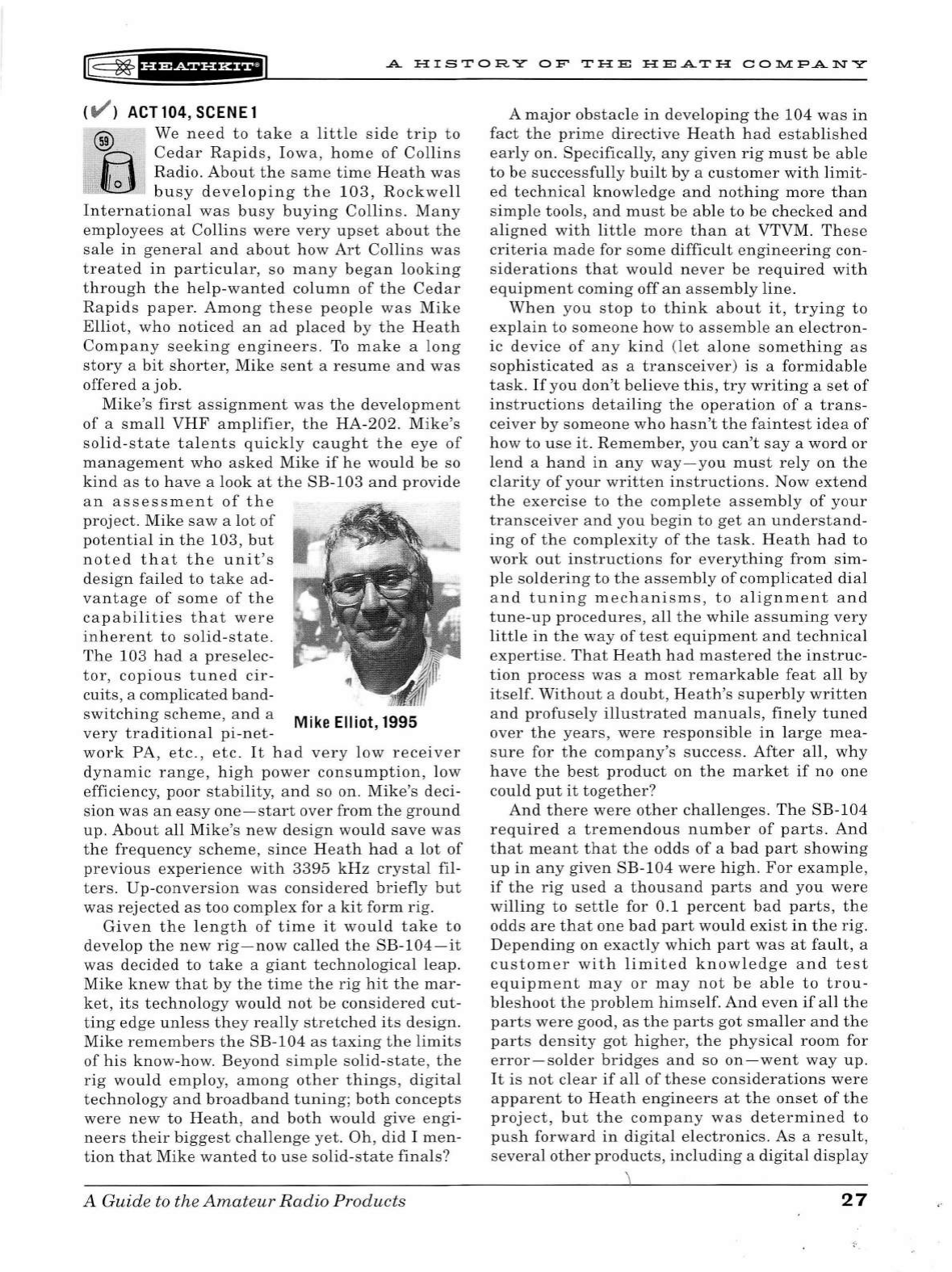
[#
~
f
b?df
¥'Hiil
.A.
HISTORY
OF
THE
HE.A.TH
COl'.11.l:P.A.NY
CV )
ACT
104,
SCENE
1
We
need
to
take
a
little
side
trip
to
Cedar
Rapids,
Iowa,
home
of
Collins
Radio.
About
the
same
time
Heath
was
busy
developing
the
103,
Rockwell
International
was
busy
buying
Collins.
Many
employees
at
Collins
were
very
upset
about
the
sale
in
genera
l
and
about
how
Art
Collins
was
treated
in
particular,
so
many
began
looking
through
the
help-wanted
column
of
the
Cedar
Rapids
paper.
Among
these
people
was
Mike
Elliot,
who
noticed
an
ad
placed
by
the
Heath
Company
seeking
engineers.
To
make
a
long
story
a
bit
shorter,
Mike
sent
a
resume
and
was
offered
a job.
Mike's
first
assignment
was
the
development
of
a
small
VHF
amplifier,
the
HA-202.
Mike's
solid-state
talents
quickly
caught
the
eye
of
management
who
asked
Mike
if
he
would
be
so
kind
as
to
have
a
look
at
the
SB-103
and
provide
an
assessment
of
the
project.
Mike
saw
a
lot
of
potential
in
the
103,
but
noted
that
the
unit's
design
failed
to
take
ad-
vantage
of
some
of
the
capabilities
that
were
inherent
to
solid
-
state.
The
103
had
a
preselec-
tor,
copious
tuned
cir-
cuits
, a complicated
band-
switching
scheme,
and
a
Mike
Elliot, 1995
very
traditional
pi-net-
work
PA,
etc.,
etc.
It
had
very
low
receiver
dynamic
range,
high
power
consumption,
low
efficiency,
poor
stability,
and
so on.
Mike's
deci-
sion
was
an
easy
one-start
over
from
the
ground
up
.
About
all
Mike's
new
design
would
save
was
the
frequency
scheme,
since
Heath
had
a
lot
of
previous
experience
with
3395
kHz
crystal
fil-
ters.
Up-conversion
was
considered
briefly
but
was
rejected
as
too
complex
for a
kit
form
rig.
Given
the
length
of
time
it
would
take
to
develop
the
new
rig
-
now
called
the
SB-104-it
was
decided
to
take
a
giant
technological
leap.
Mike
knew
that
by
the
time
the
rig
hit
the
mar-
ket,
its
techno
lo
gy
would
not
be
considered
cut-
ting
edge
unless
they
really
stretched
its
design.
Mike
remembers
the
SB-104
as
taxing
the
limi
ts
of
his
know-how.
Beyond
simple
solid
-
state
,
the
rig
would
emp
lo
y,
among
other
things,
digital
technology
and
broadband
tuning;
both
concepts
were
new
to
Heath,
and
both
would
give
engi-
neers
their
biggest
challenge
yet.
Oh,
did
I
men-
tion
that
Mike
wanted
to
use
solid-state
finals?
A Guide to the
Amateur
Radio
Products
A
major
obstacle
in
developing
the
104
was
in
fact
the
prime
directive
Heath
had
established
early
on. Specifically,
any
given
rig
must
be
able
to
be
successfully
built
by
a
customer
with
limit-
ed
technical
knowledge
and
nothing
more
than
simple
tools,
and
must
be
able
to
be
checked
and
aligned
with
little
more
than
at
VTVM.
These
criteria
made
for
some
difficult
engineering
con-
siderations
that
would
never
be
required
with
equipment
coming
off
an
assembly
line.
When
you
stop
to
think
about
it,
trying
to
explain
to
someone
how
to
assemble
an
electron-
ic
device
of
any
kind
(let
alone
something
as
sophisticated
as
a
transceiver)
is
a
formidable
task.
If
you
don't
believe
this,
try
writing
a
set
of
instructions
detailing
the
operation
of
a
trans-
ceiver
by
someone
who
hasn't
the
faintest
idea
of
how
to
use
it.
Remember,
you
can't
say
a
word
or
lend
a
hand
in
any
way
-
you
must
rely
on
the
clarity
of
your
written
instructions.
Now
extend
the
exercise
to
the
complete
assembly
of
your
transceiver
and
you
begin
to
get
an
understand-
ing
of
the
complexity
of
the
task.
Heath
had
to
work
out
i
nstructions
for
everything
from
sim
-
ple
soldering
to
the
assembly
of
complicated
dial
and
tuning
mechanisms,
to
alignment
and
tune-up
procedures,
all
the
while
assuming
very
little
in
the
way
of
test
equipment
and
technical
expertise.
That
Heath
had
mastered
the
instruc-
tion
process
was
a
most
remarkab
le
feat
all
by
itself.
Without
a
doubt
,
Heath's
superbly
written
and
profusely
illustrated
manuals,
finely
tuned
over
the
years,
were
responsible
in
lar
ge
mea-
sure
for
the
company's
success.
After
all,
why
have
the
best
product
on
the
market
if
no
one
could
put
it
together?
And
there
were
other
challenges
.
The
SB-104
required
a
tremendous
number
of
parts.
And
that
meant
that
the
odds
of
a
bad
part
showing
up
in
any
given
SB-104
were
high.
For
example,
if
the
rig
used
a
thousand
parts
and
you
were
willing
to
settle
for 0
.1
percent
bad
parts,
the
odds
are
that
one
bad
part
would
exist
in
the
rig.
Depending
on
exactly
which
part
was
at
fault,
a
customer
with
limited
knowledge
and
test
equipment
may
or
may
not
be
able
to
trou-
bleshoot
the
problem
himself.
And
even
if
all
the
parts
were
good,
as
the
parts
got
smaller
and
the
parts
density
got
higher,
the
physical
room
for
error-solder
bridges
and
so
on-went
way
up.
It
is
not
clear
if
all
of
these
considerations
were
apparent
to
Heath
engineers
at
the
onset
of
the
project,
but
the
company
was
determined
to
push
forward
in
digital
electronics
.
As
a
result,
several
other
products,
including
a
digital
display
27
A
HISTORY
OF
THE
HEATH
CO]).l.[PANY
II5
~
f¥
1
%i§fHil
for
the
SB-102
and
a
sy
nth
esize
d
two
-
meter
transceiver,
were
initiated.
What
is
cle
ar,
at
least
in
hindsight
,
is
that
solid-state
technolog
y
substantia
ll
y
raised
the
stakes
for
the
kit
engi
-
neer
as
well
as
for
the
kit
build
er
.
<V >
GROWING
PAINS
@
And
as
if
that
were
not
eno
ugh
, th
ere
~
was
another
more
s
ubtl
e
problem.
.
~
Heath
had
become
a
big
company
and
was
beginnin
g
to
experience
the
kinds
of
probl
ems
big
companies
hav
e.
The
mo
st
sig-
nificant
of
these
was
higher
employee
turnov
er.
It
was
increasingly
difficu
lt
to
keep
the
same
peopl
e
on
a
project
from
start
to
finish
.
The
result
was
a l
ack
of
continuity
th
at
hampered
product
developm
ent;
added
to
a
growing
overa
ll
l
eve
l
of
emp
l
oyee
frustration,
and
started
a slow
but
perva
sive
corrosion
of
morale.
Ind
eed,
the
"fami
ly"
atmosphere
that
Howard
Anthon
y
had
worked
so h
ar
d
to
foster
was
beginning
to
eva
porat
e.
Th
e
year
1971
was
unique
in
H
eat
h's
hi
story
-no
significant
amateur
product
s
were
re
l
eased
th
at
year.
A
reflection
,
perhap
s,
of
the
probl
ems
H
eath
was
havin
g
with
products
a
lready
und
er
de
velopment.
In
April
1972
,
while
sti
ll
wrestling
with
the
SB-104,
Heath
released
its
first
digita
l
produ
ct,
the
SB
-
650-a
digital
frequency
display
for
the
SB-102.
The
$200
SB
-
650
worked
we
ll
,
cr
eated
a
sensation
within
the
ham
community,
and
was
warmly
received
by
reviewers.
But
compared
to
the
SB-104,
the
650
was
child's
play.
The
unit
was
based
on
a couple dozen
TTL
chips
, a
double-sided
PC
board,
and
Nixie
neon
readout
tubes.
Two
other
significant
prod
ucts
a
lso
hit
the
mark
et
in
1972.
The
first
was
the
HW-7
QRP
transceiver.
It
h
as
been
sa
id
that
the
HW-7
was
the
result
of
casual
lunch-tim
e
exper
iment
s
with
low
pow
er.
Thi
s
may
be
true,
but
it
is
lik
ely
that
th
ere
was
much
more
motivation
than
simp
le
tink
er
in
g.
The
HW-7
was
prob
ab
ly
inspired
by
th
e
Power
Mite
PM
-1, a
sma
ll
, solid-
sta
te
80
and
40
meter
QRP
transceiver
introduced
by
Ten-T
ee.
By
the
time
Heath
released
the
HW-7,
Ten-T
ee
had
dev
elop
ed
the
$50
PM
-1
into
severa
l
other
more
sophisticated
produ
cts
s
uffici
ent
ly
more
expens
iv
e
to
allow
Heath
to
price
the
HW
-7
at
$79.95
an
d
sti
ll be
compet
iti
ve.
Th
e
two-watt,
thr
ee
-b
and
HW-7
proved
very
popu
l
ar
a
nd
quickl
y
became
a
best
seller.
Th
e
other
significant
product
re
l
ease
d
in
1972
didn
't
come
out
of
t h e
amateur
division.
The
General
Products
group
h ad
been
tinkering
wit
h
digital
circuits
themselves
and
h
ad
discovered
a
28
clock
chip
manufactured
by
Mostek.
Th
e
result
was
the
GC-10
05-a
six
-digit
digita
l clock
in
a
stylish
wood-grained
plastic
cabinet
.
It
was
the
first
commercial
digital
clock
kit,
and
one
of
the
very
first
digital
clocks
to
app
ear
on
the
market.
At
$55
the
clock
was
not
cheap,
but
was
s
ubst
an-
tiall
y l
ess
expensive
than
any
other
digital
clock
on
the
ma
rket
.
Sometimes
a
littl
e
product
like
thi
s
takes
everyone
by
s
urpri
se-eve
n
those
who
design
ed
it
.
The
1005
practically
ex
ploded
out
of
the
catalog
.
It
may
be
hard
to
be
lieve
but
H
eat
h
so
ld
more
than
50,000
unit
s p
er
year-a
lmost
140
a
day
...
seve
n
days
a
week.
Because
it
di
s-
play
ed
secon
ds
and
cou
ld
be
set
accurately,
it
was
very
popular
with
hams
as
a
shack
accesso
-
ry.
To
say
that
He
at
h
made
a
killing
with
the
GC-1005
wou
ld
under
sta
te
it
s
profits
.
As
if
trying
to
go "
one
up
"
on
the
Genera
l
Product
s
gro
up
,
the
Amateur
group
fir
ed
back
with
a
killer
of
its
own
.
In
April
1973
it
rel
ease
d
th
e
HW-202
two-m
eter
transceiver.
Heath
want-
ed
b a
dl
y
to
tap the
soon
-to-b
e
-boomin
g
two
-
m
eter
market
but
didn
't
want
anot
her
HW-17
on
it
s
hands.
It
had
been
t
hr
ee
years
s
in
ce H
eat
h
took
the
ill-fated
HW-17
off
the
market.
This
tim
e,
Heath
had
done
its
hom
ewor
k.
Th
e
eng
i-
ne
ers
knew
what
it
wou
ld
take
to
crack
the
mar-
k
et
and
they
knew
how
to
do
it.
The
HW-202
was
a
straightforward,
crysta
l-
controlled,
solid-
state
rig-a
s
uperb
piece
of
eng
ine
ering
in
tho
se
ea
rly
d
ays
of
two
-m
eters.
The
un
it
sold so we
ll
that
H
eath
had
trouble
keeping
up
with
orders.
H
eat
h
was
su
ccessfully
in
to
VHF
at
la
st-big
time
.
In
spite
of
t h
ese
achievements,
ho
wever,
H
eath
wou
ld
never
venture
higher
in
frequency
than
two-meters.
P
erhaps
the
most
sig
nific
ant
eve
nt
of
1973
wa
s
the
retirement
of
Gene
Fiebich
.
Gene
had
manag
ed e
ngin
eering
wit
h a
gentle
hand
a
lmo
st
from
day
one.
He
was
a
vision
ary
a
nd
a
tireless
champion
of
the
Amateur
divi
s
ion
,
and
fought
h
ard
for
many
impo
rtant
proj
ects.
It
was
he,
for
example,
who
p
ersuade
d
senior
management
to
OK
the
SB
ser
ie
s
project
back
in
19
58.
Gene
sai
d
he
decided
to
retire
because
he "co
uld
see
the
handwriting
on
the
wall
." H e
could
see
the
off-
s
hor
e
competit
ion
in
the
wings,
he
co
uld
see
the
di
rection
the
industry
was
taking
,
and
he co
uld
see
the
way
H
eat
h h
ad
changed
over
the
years.
So
after
23
year
s
at
Heath,
Gene
decided
it
was
time
to
go.
Hi
s
departure
was,
in
a way,
symbo
lic
of
what
was
h
appening
to
H
eat
h-the
founda
-
tion
wa
s
beginning
to
crumble
.
Gene
Fiebich
pa
sse
d
away
early
in
1995.
Meanwhile
work
on
the
SB
-1 04
drag
ged
on.
HE...A.THKIT
rE=
~
'HiiiHH+iJ
A
HIS
T
OR
Y
OF
THE
HEATH
COlll.l:FANY
As a
prototype,
the
rig
was
unstable,
quirky,
and
erratic.
The
biggest
problem
with
the
SB
-
104
can
be
summed
up
in
two
words
-
"cutting
edge."
The
SB-
104
was
a
rig
pus
h
ing
every
edge
of
the
envelope.
A
very
complex
rig
involving
lots
of
new
technologies,
it
was
the
expression
of
Heath's
desire
to
recapture
its
steadily
eroding
market
share
with
a
product
that
would
be
regarded
not
just
as
"state
of
the
art"
but
as
"ahead
of
its
time."
The
reliability
of
parts
was
a
major
source
of
frustration.
For
example,
it
was
discovered
that
depending
on
the
batch
of
diodes
used
in
the
bal-
anced
modulator,
you
may
or
may
not
be
able
to
get
it
to
balance.
The
104
used
more
than
275
solid-state
devices
including
31
ICs.
There
were,
of
course,
hundreds
of
capacitors,
resistors
,
coils,
crystals,
and
so
on
,
and
parts
tolerances
were
turning
out
to
be
more
critical
than
had
been
imagined
.
Further,
there
was
no
easy
or
inexpensive
way
to
ensure
that
any
given
part
was
within
tolerance.
Again
, for
rigs
coming
off
an
assembly
line
,
parts
could
have
a
wider
toler-
ance.
But
for
kit
building,
engineers
needed
to
ensure
that
the
rig
would
land
on
its
feet
with
a
minimum
of
tweaking
.
Remember
the
prime
directive-the
customer
has
limited
knowledge
and
doesn
't
have
sophisticated
test
or
alignment
equipm
e
nt.
Random
sampling
of
parts
wasn
't
good
enough
for
the
104
.
As
a
result,
the
cost
of
quality
assurance
rose
substantially,
which
in
turn
added
to
the
cost
of
the
rig
.
( V )
SCENE
104
ACT
2
®
~
·
At
last,
just
in
time
for
Christmas
1974,
Heath
rolled
out
the
SB-104
with
a
full
-
co
l
or
fold-out
ad
in
QST.
The
ad
fea-
tured
the
comp
l
ete
104
series
product
·
line
including
the
SB-230
linear
amplifi-
er,
the
SB-634
station
console
,
the
SB-644
remote
LMO,
the
SB-
614
station
monitor
scope,
and
the
SB-604
station
speaker.
There
were
also
extensive
product
notes
written
by
Joe
Shafer,
extolling
the
many
virtues
of
the
104.
A
2KW
lin
ea
r
amplifi
er,
the
SB
-
240
(using
a
pair
of
3-500s)
had
also
been
developed
through
The
SB-104
the
proof-built
stage,
but
at
the
last
moment
the
unit
was
canceled
because
of
safety
concerns.
There
were
fears
that
because
of
the
rig's
layout
the
customer
would
be
threatened
by
high
voltage.
About
14
A Guide
to
the
Amateur
Radio
Products
units
were
actually
built.
Several
were
destroyed
and
the
rest
ended
up
with
employees.
Sales
of
the
SB-104
were
good,
but
almost
immediately,
customers
began
calling
with
prob-
lems.
Most
of
the
problems
turned
out
to
be
related
to
mistakes
in
assembly
and
tune
up.
There
can
be
little
doubt
the
104
was
a
good
solid
rig
,
but
it
quickly
became
clear
that
align-
ment
of
the
104
was
critical
to
the
success
of
the
rig
and
l
eft
almost
no
margin
for
error.
Addition-
ally,
the
sheer
complexity
of
the
assembly
process
was
testing
the
limits
of
even
experi-
enced
kit
bui
l
ders.
Unknowingly,
Heath
had
stepped
over
the
line
,
violating
the
prime
direc-
tive.
But
it
was
also
clear
that
there
were
some
design
problems
as
well
.
The
CW
wave
form
was
much
too
abrupt,
the
TR
switching
was
not
very
clean
,
and
the
digital
disp
l
ay
had
the
jitters
,
to
name
only
a few
of
the
104's
troubles.
Heath's
initial
strategy
was
to
handle
these
one
at
a
time,
but
in
a
short
while,
it
became
clear
that
a
bigger
fix
was
in
order.
One
solution
was
to
begin
to
pre-assemble
some
of
the
more
complex
boards,
including
some
of
the
RF
boards.
That
solved
some
of
the
problems
but,
of
course,
it
ate
substantially
into
the
profits
.
The
SB-104
wasn't
Heath's
only
headache.
Late
in
'75
the
company
had
released
its
replace
-
ment
for
the
venerable
HW-202
two-meter
transceiver-the
HW-2026
.
The
2026
was
a
syn-
thesized
unit
on
which
the
frequency
was
set
with
thumbwheel
switches.
The
2026
had
given
its
designers
about
as
much
trouble
as
the
104
had
provided
for
its
crew.
Almost
as
soon
as
the
first
units
went
out
the
door,
customers
began
calling
with
complaints
that
they
were
bringing
up
repeaters
other
than
the
one
intended
as
well
as
putting
in
good
signals
on
law
enforcement
frequencies
,
whenever
the
2026
was
put
on
the
air.
Some
quick
checking
revealed
that
the
transmitter
had
some
significant
spurs.
The
problem
was
not
really
a
design
flaw.
In
design-
ing
th
e
2026
Heath
had
looked
at
the
Clegg
FM-27
.
The
engineers
had
noticed
some
signifi-
cant
spurs
on
the
27's
signal
but
concluded
that
if
the
spurs
weren
't a
problem
for
Clegg
they
shouldn't
be
a
problem
for
Heath.
Unfortunately
for
Heath
,
the
spurs
from
the
2026
landed
in
all
the
wrong
places
.
Heath
had
designed
the
2026
to
conform
to
CCIR
specifications,
and
in
fact,
the
2026
actually
performed
better
than
the
CCIR
specs
by
a good
10
db.
The
problem
was
that
the
CCIR
specs
were
flawed.
And
to
make
matter
worse,
a
quick
fix
was
not
in
the
cards.
For
the
first
and
only
time
in
its
history
,
Heath
29
A
HISTORY
OF
THE
HEATH
CO:r-1.l:FANY
nr=
~
f
H?diUHilJ
issued
a
product
recall.
Customers
were
offered
their
money
back
or
a
trade-in
for
one
of
Heath's
other
new
products
that
year
,
the
HW-2021
walkie-
talkie.
Unfortunately
for
customers
who
chose
the
walkie-talkie,
satisfaction
proved
somewhat
e
lusiv
e.
While
the
2021
was
a
good
basic
design,
it
s
shear
compactness
reduced
the
odds
of
assemb
lin
g
the
unit
without
errors.
Th
ere
was
at
l
east
one
success
in
197
5-the
HD-1410
el
ectronic
keyer.
Th
e
physical
d
esign
of
the
HD-1410
was
patterned
after
the
T
en-Tee
KR-20
and
a
keyer
sold
by
Palomar
Engin
eers,
both
of
which
first
appeared
lat
e
in
1969.
The
1410
rep
l
aced
the
very
s
ucc
essful
HD-10
(
the
first
kit
keyer
on
the
market),
which
Heath
had
released
10
years
earlier
.
The
1410
was
more
compact
and
more
easily
adjustable
that
its
pre-
decessor,
and
employe
d a
vastly
improv
ed
switching
scheme.
It
so
ld
extremely
well.
H
eath
also
had
some
luck
with
the
HW-104
,
the
low-
end
version
of
the
SB-104.
The
HW
ver-
sion
replaced
most
of
the
complicated
digital
cir
-
cuits
with
analog
designs.
For
examp
l
e,
the
HW-104
used
a
traditional
tuning
sc
heme
with
a
dial
readout
more
akin
to
the
SB-102.
The
HW-104
worked
quite
well
because
of
these
changes,
but
still
suffere
d
in
sa
l
es
as
a
result
of
guilt
by
association
.
It
was
also
being
torn
to
s
hred
s
by
the
competition.
The
rig
would
last
only
two
years
.
( V )
ENTERING
THE
COMPUTER
AGE
@
Still
reeling
from
the
HW-2026
recall
an
d
still
pulling
out
its
h
air
over
the
SB-104,
Heath
pressed
on,
working
on
an
improved
version
on
the
104
and
beginning
work
on
an
entire
ly
new
transceiver
,
the
SS-SOOO.
At
the
same
time,
development
also
began
on
an
entire
ly
new
product-the
personal
computer.
Heath
can
be
credited
with
some
real
vision
in
this
area.
It
was
still
a
year
or
so
before
the
first
Apple
and
the
Radio
Shack
computers
would
appear
.
Heath
recognized
the
value
an
d
potential
of
the
com-
puter
very
early
on.
For
most
people,
computers
were
still
very
much
a
curiosity.
Heath
under-
stood
that
personal
com
put
ers
were
not
some
passing
fad,
and
that
they
were,
in
fact,
the
next
major
growth
industry
.
Heath
quickly
tooled
up
for
a
major
effort,
enth
usi
astica
ll
y
beginnin
g
work
on
a
pair
of
compu
ter
products-the
HS
and
the
Hll.
Ironically,
by
starting
development
of
the
computers,
Heath
was
unleashing
the
very
products
that
would
le
ad
to
its
demise.
In
November
1976,
exac
tl
y
one
year
after
the
30
rel
ease
of
the
ill-fat
ed
HW-2026
,
Heath
re
l
eased
its
rep
lac
ement,
the
HW-2036-an
entirely
redesigned
two-meter
transceiver.
To
help
e
limi-
nat
e
any
lingerin
g
suspic
ion
s
about
the
new
rig,
the
ad
in
the
catalog
was
complete
with
charts
det
ailing
its
spectral
purity.
This
time
Heath
had
gotten
it
right
and
the
rig
was
a
hit.
Sales
took
off
and
never
slowed
down
.
You
could
almost
hear
He
ath's
collective
sigh
of
relief.
It
had
been
a long,
hot,
frustrating,
and
expensive
summer
for e
ngin
eering.
Getting
the
bugs
out
had
not
been
easy.
The
first
of
two
significant
releases
in
1977
was
the
HS
personal
computer.
The
HS
did
not
in
any
way
resemble
personal
computers
as
we
hav
e
come
to
know
them.
The
HS
was
a
nerd
s
-only
SOSOA-based
product
wit
h a conve-
ni
ent
front
panel
keypad
for
programming.
As
luck
would
have
it
,
there
were
plenty
of
nerds
who
had
been
waiting
their
whole
liv
es
for
a
product
like
this.
They
wasted
no
time
putting
in
their
orders-heck
,
only
$300
,
less
any
kind
of
I/O.
The
Hll,
Heath
's
other
com
put
er,
was
somew
h
at
more
imposing-it
was
a
plain
white
box
with
no
front
panel
controls
at
all.
The
Hll
was
based
on
the
DEC
PDP-11103
and
was
avai
l-
able
with
an
optional
eight
or
16-bit
bu
s.
This
machine
was
a
bit
more pricey
t
han
the
HS-
$1200
in
kit
form,
$2000
wired,
less
I/O.
Never-
theless
,
the
two
computers
proved
both
popular
and
lucrative.
Sales
of
the
HS,
Hll,
and
their
periph
era
l
product
s
quickly
infused
a
great
deal
of
cash
into
the
company.
While
Heath's
gross
sa
l
es
were
rapidly
approaching
$
100
million
annually,
the
bulk
of
the
money
wasn't
coming
from
amate
ur
products.
Heath
was
pullin
g
in
money
from
television
and
stereo
products,
and
from
test
equipment
as
well
as
from
computers.
Amateur
products
,
which
10
years
earlier
had
accounted
for
40
percent
of
Heath
's
sales,
had
shrunk
to
less
than
25
p
ercent
.
And
to
make
matters
more
uncomfortable
,
engineer
in
g
costs
in
the
amateur
division
were
very
high.
The
secon
d
significant
release
in
1977
was
the
improved
SB-104.
It
had
taken
a
lot
of
re-engi-
ne
ering,
but
in
Jul
y
1977,
Heath
re-released
the
SB-104
as
the
104A.
Most
of
the
problems
had
been
solved
but
the
rig
remained
touchy.
True
to
it
s
customers
,
Heath
worked
diligently
to
keep
everyone
happ
y
and
,
for
the
most
part,
cus-
tomers
were
happ
y.
But
the
word
was
out
that
the
104
was
"iffy"
and
that
getting
it
to
work
could
be
a
problem
.
Sales
flattened
out,
then
slowly
started
down.
But
Heath
wasn't
standing
st
ill.
Development
of
the
104
's
replacement,
des-
HE..A..THKIT
~
~fH&iU&f@
A
HISTORY
OF
THE
HEATH
CO?ll.J:PANY
ignated
the
SS-8000
,
was
moving
slow
ly
for
-
ward.
Among
other
thing
s, H
ea
th
had
develop
ed
an
ambitious
plan
to
provide
for
computer
con-
trol
of
the
new
transc
eiver.
There
was
nothing
e
ls
e
like
it
on
the
mark
e
t.
A
computer-controlled
HF
station
was
somethin
g
that
only
a
handful
of
h
ams
had
even
dreamt
about.
In
1978
Heath
released
the
HW-8
, a
repl
ace
-
me
nt
for
the
HW-7
QRP
rig.
The
HW-7
had
been
very
popular
but
had
b
ee
n
cr
itici
ze
d for a
num-
b
er
of
minor
probl
em s a
nd
limitation
s.
Th
e
HW-8
addressed
all
of
tho
se
problems
and
added
a f
ew
nice
touche
s.
Th
e
HW-8
would
turn
out
to
be
one
of
the
most
popul
ar
of
th
e
three
version
s
H
ea
th
made-attaining
a
kind
of
cult
status-
a
nd
one
of
the
most
popul
ar
QRP
rigs
ever
mar
-
keted.
In
that
same
year,
H
eat
h
replaced
th
e
very
s
ucc
ess
ful
HW-20
36
two
-
meter
box
with
the
new
digital
readout
VF-7401.
The
7401
was
nice
and
had
lot
s
of
power
an
d f
ea
tures
,
but
th
e
unit
had
cost
a
bundl
e
to
d
esign,
and
sales
were
n
ever
as
high
as
H
eat
h h
ad
hop
ed for.
It
i
sn'
t
that
anyo
ne
thou
g
ht
poorl
y
of
th
e
7401
,
but
by
this
time,
the
off-shor
e
competitors
were
turnin
g
up
th
e
heat
on
H
ea
th-
and
it
hurt.
It
is
lik
ely
th
at H
ea
th
lost
money
on
th
e 7401.
The
VF-7401
is a sig
nificant
product
in
H
ea
th
's
history
, how-
ever,
as
it
was
th
e l
ast
kit-
type
two-meter
prod-
u
ct
H
ea
th
ev
er
made. By
this
time
off-shore
com
-
petition
in
the
exp
l
oding
two
-
meter
mark
et
was
so
feroc
iou
s
it
was
cl
ear
that
H
eat
h
could
not
compete.
Heath
wa
lk
ed
away
from
VHF
a
nd
n
ever
came
back-
at
l
east
not
with
its
own
eq
uipm
en
t.
(V )
1978-THE
BEGINNING
OF
THE
END
@
In
1978
Schlu
mberge
r (
rememb
er
Schlumberger?
it
owned
He
ath?)
decided
that
it
would
be
nice
to
h
ave
an
"
in-h
ouse
"
source
of
se
miconduc-
tors
an
d b
ega
n
lookin
g
aro
und
for a
nice
se
mi-
conductor
manu
fact
u
rer
to
swa
ll
ow
.
It
didn
't
have
to
look
ve
ry
far. H
eath
was
buying
lit
era
ll
y
mi
llion
s
of
se
miconduct
ors
every
yea
r
from
a
compa
ny
called
F
airc
hild
.
Heath
was,
in
fact,
Fairchild's
singl
e l
argest
consumer
of
b
oth
discrete
a
nd
int
egra
t
ed
devices.
Additionally,
Sc
hlu
mb
erger
owned
a l
ot
of
other
companies
that
used
se
mi
con
du
ctors,
an
d
it
u
sed
a lot
it
se
l
f.
This,
it
r
easone
d,
cou
ld
be
sweet
d
ea
l.
By
acq
uirin
g
Fair
c
hild
,
Sch
lumb
erge
r
wo
uld
contro
l
not
only
th e so
ur
ce
an
d th e
devic
es,
but
al
so
the
product
s
in
w
hi
ch
they
were
u
se
d.
Funny
..
.
that
is
exac
tl
y
ho
w
the
Federal
Tr
ade
Commission
saw
it.
Who
co
uld
hav
e
im
agi
n ed
A
Guid
e
to
the
Amat
eur
Radio
Products
th
at
we
wou
ld
ever
h
ea
r
the
words
"
Heath
"
an
d
"a
ntitrust
"
in
the
sa
me
se
ntence?
The
Federal
Trad
e
Commission
exp
lain
ed
to
Schlumberger
its
ac
tions
mi
g
ht-at
the
risk
of
putting
too
fine
a
point
on
it-
be
construed
as,
well,
illegal.
The
Commis
sion
told
Schlumberger
that
if
it
wanted
Fairchild
it
would
have
to
se
ll
H
ea
th.
Sorry.
If
ther
e
was
any
doubt
abo
ut
Schlum-
b
erger's
loyalty
to
H
ea
th
,
it
didn't
last
ver
y
long
.
Schlumberger
had
purch
ase
d
Heath
for a song
a
nd
now
,
whi
le
it
wasn
't
exa
ctl
y
what
it
had
plann
ed,
had
the
opportunity
to
se
ll
it
for s
ome-
thing
much
more
lik
e a
sym
phony.
It
saw
th
e
chance
to
make
a
great
d
ea
l
of
mon
ey
very
quickl
y
a
nd
it
took
it.
By
D
ecem
ber
1978,
Heath
was
up
for
sale.
It
is
hard
to
say
what
kind
of
effect
this
news
h ad
on
e
mployee
s at H
eat
h
or
on
the
admini
s-
tration.
But
ther
e
can
be
no
doubt
that
a s
hock
wave
swe
pt
through
th
e
pl
a
nt
. A
clue
about
the
int
en s
it
y
of
this
s
hock
wave
can
be
found
in
the
pages
of
QST.
H
eat
h h ad
no
ad
in
the
Febru
ary
1979
is
s
ue
of
QST.
Thi
s sma
ll
eve
nt
wa
s s
pok
e
volumes:
it
was
the
first
i
ss
ue
He
at
h
had
mi
sse
d
in
more
than
20
years
or
a
dv
er
tisin
g.
By
January
1979
He
at
h
had
com
pleted
devel-
opment
of
its
third
computer
product-the
H89
"a
ll-in-one"
comput
er.
Th
e
H89
used
not
ju
st
one
bu
t a pair
of
the
n
ew
Mo
ste
k Z80
microproces-
sors
and
was
a
mo
st
remarkab
le
product.
It
was
not
some
inscrutabl
e box w
ith
a k
ey
pad;
it
h ad a
k
ey
bo
ar
d, a
di
s
pl
ay
screen,
a
nd
a
flopp
y di
sk
drive
built
into
one
very
attract
ive
cabinet.
It
was
how
ever,
onl
y p
art
ly a
kit.
The
main
CPU
and
t
erm
inal
int
erface
boar
ds
were
fully
assem-
bl
ed
an
d
teste
d,
as
was
th e
keyboard
and
th
e
di
sk
dri
ve
.
Durin
g d
eve
lopm
e
nt
of
the
H89
,
H
eat
h
qui
c
kly
r
ea
li
zed
th
at
a
lmo
st
no
one
could
successfu
lly
as
semb
le
and
-if
necessary-trou-
bleshoot
one
of
these
t
hin
gs
.
Assembly
then
,
was
limit
ed
to
cons
truction
of
t h e
power
s
uppl
y a
nd
the
putting
together
of
all
the
s
ub-ass
e
mbli
es.
The
H
89
first
appeared
in
Heath's
Summer
1979
cata
log
an
d li
sted
for ab
ou
t
$20
00, d
epe
ndin
g
on
what
options
y
ou
a
dd
ed.
Th
e
89
was
e
normou
sly
successfu
l.
Heath
so
ld
zi
ll
ions
of
them.
At
about
thi
s
same
time,
the
idea
that
person-
al
comp
ut
e
rs
could
be
worth
a
lot
of
money
was
beginning
to
occur
to
a
number
of
l
arge
corpora-
tions,
many
of
w
hi
ch
began
to
explore
th
e
id
ea
of
designing
their
own
computer
products.
Among
these
was
the
Ze
nith
Corporatio
n .
Zenith
ha d
the
idea
t
hat
it
might
be
pos
s
ibl
e
to
by
pa
ss
much
of
the
expe
n si
ve
a
nd
time-consuming
d
esign
phase
an
d
get
a h
ead
start
on
the
competition
by
buying
a
company
a
lr
ea
dy
making
comput
ers.
31
A
HISTORY
OF
THE
HEATH
CO~FANY
rE¥
~
f
H¥Sf
¥f
i*+il
Zenith
began
l
ooking
around
for
some
small
computer
company
it
could
easil
y
acquire
and
it
didn't
take
lon
g
for
its
corporate
gaze
to
fall
upon
Heath.
From
Zenith's
perspective
Heath
was
very
attractive.
It
was
reasonably
priced
and
had
an
excellent
computer
product
line
on
the
market
and
more
in
development
.
Negotia-
tions
began
early
in
1979
,
and
th
e
deal
was
com-
pleted
by
fall.
Zenith
was
now
in
the
computer
business
-
and
Heath
was
now
in
trouble.
<V >
THE
END
IN
SIGHT
The
Zenith
buyout
was
a
nasty
piece
of
busin
e
ss
by
a
ll
accounts.
Many
peo-
ple
at
Heath
thought
Zenith
would
be
good
for
business.
After
all,
Zenith
was
a
consumer
electronics
company.
It
was
logical
to
assume
that
Zenith
might
bring
with
it
a
lot
of
marketing
muscle
and
know-how
that
would
be
very
beneficial
to
Heath.
Zenith,
however,
had
other
ideas.
Zenith
was
interested
only
in
Heath's
computer
line.
Nothing
else
mat-
tered
.
Nothing.
In
fact
emp
l
oyees
began
to
feel
that
Zenith
regarded
them
and
Heath's
products
with
contempt
.
They
were
probably
right
.
Bud-
get
cuts
and
layoffs
were
quick
to
follow.
Zenith
cut
the
budgets
of
all
of
Heath's
departments
by
15
percent
every
year
beginning
in
1980.
All
departments
except
computers,
that
is.
Addi
-
tionally,
Zenith
began
siphoning
huge
amounts
of
cash
and
resources
from
Heath.
Al
Rob
e
rtson
wasn't
having
much
fun
.
For
him
,
the
Zenith
buyout
was
only
part
of
it
.
He
had
been
transferred
to
mark
e
ting
a
couple
of
years
earlier,
and
he
wasn
't
doing
the
things
he
really
loved.
He
looked
around
one
day
and
couldn
't
see
the
Heath
company
he
had
originally
come
to
work
for.
Time
to
go. Al
called
it
a
day
-
and
retired
.
His
departure,
like
Gene
Fiebich
'
s,
was
a
harbinger
of
things
to
come.
Needl
e
ss
to say,
the
takeover,
the
budget
cut
s,
the
lay-offs,
and
all
the
rest,
were
very
disrup-
tive
and
very
distracting.
And
none
of
these
cor-
porate
high
jink
s he
lped
th
e
Amateur
group
,
who
had
been
having
plenty
of
troub
le
with
the
SS-8000
even
before
the
Zenith
problems.
Nev-
erthele
s
s,
work
had
progressed
well
into
the
proof-built
stage
by
this
time,
giving
Heath
enough
confidence
to
run
a t e
aser
ad
in
the
Spring
1980
catalog.
The
ad
displayed
th
e
SS-8000
,
major
portions
of
which
were
hidden
by
a la
rge
banner
reading
"space
reserved
for
revolutionary
new
SS-8000.
"
Text
in
an
inset
stated
"
see
it
here-in
your
next
Heathkit
cata-
log."
In
another
inset
was
a
picture
of
the
new
32
H19
smart
terminal
(not
the
H89),
implying
that
the
SS-8000
could
be
computer
controlled.
It
had
become
increasing
clear
over
the
course
of
its
development
that
given
the
complexity
and
parts
density
of
the
SS-8000,
it
would
be
very
difficult,
perhaps
impossible,
for
the
average
builder
to
successfully
assemble
and
a
lign
the
rig.
Heath
found
itself
in
a
bind
.
It
had
two
choices-
both
bad.
To
proceed
with
the
rig
in
kit
form
meant
endless
problems
for
the
customer
and
lot
s
of
bad
PR.
To
offer
the
rig
fully
assembled
meant
a
working
rig
and
a
happy
customer
,
but
would
double
the
cost
,
making
it
unaffordable
.
No
matter
what
it
decided,
Heath
was
in
trouble.
Still
smarting
from
its
experiences
with
the
SB-104,
Heath
made
the
decision
to
offer
the
SS-8000
as
a
fully
assembled
product
and
not
as
a
kit.
Of
course
by
the
time
this
determination
was
made,
a
fully
operational
model-no
longer
a
prototype-had
been
completed.
It
is
impor-
tant
to
remember
here
that
it
had
taken
most
of
five
years
to
develop
the
8000
to
this
point
. Now
it
would
take
another
three
years
to
redesign
the
rig
for
sale
as
a
pre-assembled
unit.
This
would
prove
to
be
the
single
most
costly
decision
ever
made
at
Heath
because
the
SS-8000/9000
was
the
sing
le
most
expensive
product
Heath
had
ever
designed.
Most
estimates
put
th
e
development
cost
s
of
the
8000
/
9000
project
at
around
3
million
dollars,
and
probably
more.
The
SS-9000
hit
the
market
for
almost
$2800
in
the
face
of
competition
costing
half
of
that.
Bells
,
whistle
s,
and
computer
-
control
notwithstand-
in
g,
it
never
really
had
a
chance.
Only
a
couple
of
thousand
units
were
ever
sold.
The
project
was
an
immense
financial
loss
from
which
the
company
never
fully
recovered.
The
HW-5400,
Heath
's
last
hope
of
success
in
the
kit
market,
did
little
better
.
It
sold
for
only
a
year
and
a
half,
and
while
it
wa
s
less
expensive
to
develop,
Heath
lost
a
bundle
on
it
as
well
.
It
originally
had
sold
for
$750.
The
power
supply
was
another
$175;
the
frequency
entry
ke
ypad
was
another
$60;
and
so
was
the
"
deluxe
"
SSB
crystal
filter.
The
whole
package
was
just
over
a
$1000,
and
for
almost
everybody,
it
just
didn't
add
up.
Not
when
compared
to
rigs
from
Ken-
wood,
Yeasu,
and
others
.
And
comparing
was
what
e
veryone
wa
s
doing.
By
th
e
time
the
SS
-9000
hit
the
catalog
in
19
82
it
was
crystal
clear
to
everyone
Heath
could
no
longer
st
a
nd
up
to
off-shore
competi
-
tion
.
There
was
some
talk
of
having
the
SS-9000
and
HW-5400
built
overseas.
Engineers
made
severa
l
trips
to
Korea
to
meet
with
manufactur-
HE
A.TH
KIT
~
~t§f@Siifi*F@
A
HISTORY
OF
THE
HEATH
COJ:\l.l:PANY
ers
and
exp
lore
this
idea,
but
nothing
came
of
it.
Meanwhile
Icom
,
Kenwood,
and
Yeasu
were
putting
new
products
on
the
market
at
the
rate
of
almost
one
a
month,
and
by
the
middle
of
1982,
Heath's
Amateur
group
essent
ially
caved
in
und
er
the
und
er
the
now
crushing
weight
of
foreign
competition.
The
SS-9000
and
the
HW-5400
were
to
be
the
la
st
big
products.
Another
factor
contributing
to
the
demise
of
the
Amat
eur
gro
up
was
the
layoffs
of
1982.
Until
that
time,
the
Amat
eur
group
had
really
been
trying
to
hold
things
together.
The
layoffs
were
the
la
st
straw
for
Joe
Shafer.
Drake
had
been
courting
Joe
for
several
years
and
this
seemed
like
a good
time
to
make
a
run
for
it.
He
did.
At
the
same
time,
man
ageme
nt
was
deciding
that
it
had
had
enough
of
ham
radio
and
that
it
was
time
to
go QRT.
For
all
inte
nts
and
purposes,
the
Amateur
grou
p
was
out
of
business.
The
effects
on
the
Amateur
group
of
these
lay-
offs
are
clearly
visible
in
the
products
that
came
out
of
the
department
after
'82
.
These
products
were
either
extensions
or
refinements
of
existing
products
or
were
r el
ative
ly
simp
le
in
nature
.
Concentration
on
these
"dow
nsiz
ed"
products
was
a
reflection
of
the
increasingly
limited
resourc
es
available
to
the
Amateur
group
and
Heath
's
inability
to
compete
in
other
product
areas.
Th
e "
little
brown
box"
ser
i
es,
which
began
to
appear
in
1985,
provides
the
best
exa
mpl
e
of
a
company
struggling
to
maintain
a
presence
in
amateur
radio.
The
little
brown
box
series
was
a
group
of
accessory
products
that
did
not
require
any
sop
hi
sticated
or
innovative
engineering
and
which
could
be
marketed
very
inexpensively.
The
group
encompasses
mo
st
of
the
hi
gh
four-digit
"H
D"
series
of
products
and
includ
es
the
HD-1418
Active
Audio
Filt
er,
the
HD-1
420
VLF
Receiving
Converter
,
the
HD-1422
Antenna
Noise
Bridge,
the
HD-1424
Active
Antenna
,
and
several
others.
There
was
at
l
east
one
gem
in
this
otherwise
unr
emarkab
le
series
of
products:
the
extraord
inar
y
HD-8999
"UltraPro"
CW
key-
board
.
This
microprocessor-based
keyboard
fea-
tured
memories,
practice
sessions,
a
type-ahead
buff
er,
built-in
side-tone,
complete
control
of
all
operating
parameters,
and
the
ability
to
key
any
transmitter
ever
made
.
But
products
like
these
are
not
enough
to
make
a
living
on.
Especially
when
yo
ur
par
e
nt
company
couldn't
care
less
about
them.
The
end
did
not
come
quickly.
No
one
came
in
one
day
and
said
"That's
it
. No
more
ham
products
."
In
stead,
the
Amateur
group
sl
owly
withered
away.
As
budget
cuts
continued,
people
once
A Guide to the
Amateur
Radio
Products
working
for
the
Amateur
group
were
transferred
to
other
areas,
laid
off,
or
replaced
by
mark
eting
types.
By
1984
only
a
handful
of
people
were
left
in
the
Amateur
group
and
they
were
not
design-
ing
amateur
products.
They
worked
on
products
like
electronic
Christmas
ornaments,
light
dim-
mer
s,
and
motor
speed
controls.
By
1985
all
new
amateur
product
d
eve
lop-
ment
had
ceased.
Only
a
few
products
were
relea
sed
after
'85
and
all
of
them
had
been
developed
earlier.
The
budg
et
cuts,
transfers,
and
layoffs
continued,
and
although
a
numb
er
of
ham
products
lingered
in
the
catalog,
by
1986
the
Heath
company
we
once
knew
and
loved
was
gone.
During
the
lat
e
80s
and
early
90s
Heath
made
a few
more
attempts
in
amateur
radio
by
strik-
ing
deals
with
other
companies
to
make
equip
-
ment
using
the
Heath
nam
e.
Heath
went
to
Ameritron
and
came
back
with
the
SB-1000
lin-
ear
amplifier
.
It
went
to
Standard
for
HTs,
to
Yeasu
(ironic,
isn
't
it?)
for
a
transceiver
(the
SB-1400),
and
to
Telex
for a
rotator.
With
the
exception
of
the
SB-1000
,
Heath
made
very
little
money
with
this
strategy,
and
the
concept
was
abandonedinshortorde~
Ultimately,
the
splitting
up
of
Zenith
itself,
and
its
s
ubsequent
sale
to
Group
Bull,
a
French
conglomerate,
left
Heath
directionles
s
and
in
disarray.
Bull
had
no
interest
at
a
ll
in
Heath
and
immediately
put
the
company
on
the
block.
Heath
experimented
with
the
home
security
market
for a
while,
acting
as
a
reseller
for
prod-
ucts
designed
and
built
off-shore.
It
was
a
short-lived
exercise.
It
a
lso
began
to
experiment
with
home-study
products,
selling
educational
videos
and
workbooks
on
subjects
related
to
electronics
and
computers.
This
market
proved
more
profitable
and
Heath
continues
to
expand
into
the
home
study
market.
Group
Bull
was
finally
successful
in
selling
Heath
in
February
1995. As
of
this
writing
little
is
known
about
the
buyers-said
to
be
a
group
of
investors
from
Florida-or
their
intentions
for
the
company.
It
appears
as
though
as
le
ast
one
more
chapter
of
Heath's
history
awaits
writing.
( V )
WHAT
HAPPENED
TO
HEATH?
People
often
attribute
Heath's
diffi-
culties
to
off-shore
competition
in
the
early
'80s.
To
be
sure,
that
was
a
major
factor.
Peopl
e
also
point
to
the
Zenith
buyout
and
subse
quent
bud-
get
cuts.
It
is
true
that
Zenith
did
not
h e
lp
mat-
ters.
But
the
off-shore
competition
and
Zenith
were
not
the
causes
of
Heath
's
demise.
They
33
A
HISTOR-Y
OF
THE
HEATH
CO:D.1.IPAN"Y
IE:=
~
'Ui&f
#f
HEI
served
only
to
hasten
the
in
evitab
le.
It
is
clear
that
Heath's
problems
really
began
much
earlier,
in
the
late
'
60s
.
After
20
years
of
rock
solid
products
,
things
began
to
unravel.
This
difficulty
is
seen
first
in
the
SB-104
and
is
evident
in
many
s
ubsequent
products.
What
is
l
ess
clear
is
why
things
began
to
unravel.
I h
ave
talked
to
many
former
Heath
employees
and
I
ha
ve
heard
their
technical
explanations
of
what
happ
ened,
for
example,
to
the
SB-104,
HW-20
21,
SS-9000
,
and
others
.
They
cite,
amo
ng
other
things
,
the
cutting-edge
nature
of
technologies
being
used
and
the
complexity
of
the
projects
undertaken
.
But
these
exp
l
anations
do
not
fully
account
for
the
problems
,
and
the
turn
of
events
that
must
have
begun
about
1969-about
the
time
d
eve
lopment
of
the
SB-104
began.
Gene
Fiebich
may
not
h
ave
been
able
to
put
it
into
words
,
but
it
is
cl
ear
that
he
felt
things
chang-
ing,
and
that
by
1973
the
atmosphere
h
ad,
for
him
, b
ecome
intolerable.
I
submit
that
H
ea
th
ha d
difficulty
coping
with
the
dramatic
growth
it
experienced
through
th
e
'
60s
.
This
high-speed
growth
resu
lted
in
its
crossing
a
kind
of
threshold
around
1969
,
at
which
point
Heath
began
to
suffer
from
the
same
things
that
plague
many
large
companies-poor
internal
communication,
high
em
ployee
turn
over
,
corrosion
of
morale,
and
especia
ll
y
the
lo
ss
the
"fa
mily
"
feeling
that
had
serve
d
Heath
so
well
in
its
earlier
years.
The
family
feeling
is
, I
think
,
what
Gene
missed
most.
Thi
s
kind
of
sce
-
nario
is
not
unique.
It
is
experienced
by
lots
of
companies
in
their
formative
years.
The
differ-
ence
for H
ea
th
is
that
it
had
to
contend
not
only
with
its
own
growth,
but
with
the
growth
of
a
rapidly
changing
market
and
the
growth
of
a
rapidl
y
changing
technology.
Th
e
combination
of
the
se
forces,
combined
with
th
e
ravaging
effects
of
a
corporate
takeover,
would
h a
ve
driv
en a
les
ser
company
to
spontaneous
combustion.
To
its
credit
,
Heath
was
a
ble
to
cope,
at
l
eas
t
to
some
extent
,
with
all
of
these
changes.
The
inabi
li
ty
to
adapt
to
change
is
a
major
probl
em
plaguing
many
big
companies.
As
com-
pani
es
grow,
there
is a
tendency
to
bec
ome
mired
in
bur
ea
ucrac
y
an
d
its
attendant
problem
s.
Deci
sion
making
beco
mes
diffic
ult
becaus
e
too
many
s
ignature
s
are
required
and
/
or
there
is
too
much
fear
of
making
important
decision
s -
no
one
wants
to
take
responsibility.
By
the
early
'
60s
, e
lectronics
technology
was
changing
at
a
rate
that
began
to
outpaced
He
at
h's
ability
to
adapt.
The
cycle
time
for
bringin
g a
kit
to
mar-
ket
had
lengthen
ed
from
two
or
three
years
to
34
more
than
five
years
because
of
the
growing
complexity
and
speed
of
techno
logic
change
.
The
cycle
time
was
l
engthen
in
g
at
a
time
when
the
ability
to
adapt
quickly
was
becoming
more
crit
-
ical
with
each
passing
day.
At
some
point
tech-
nology
began
to
cycle
with
an
interval
shorter
than
the
cycle
time
for
completing
a
kit.
The
result
was
that
half
way
through
development
of
a
given
kit
,
Heath
could
find
itself
working
on
an
outmoded
product.
Th
e
density
of
parts
was
also
playing
a roll.
As
kits
became
more
sophisticated,
greater
skill
wa
s
required
by
the
builder.
With
the
SS-9000,
H
eath
fina
ll
y
exceeded
the
average
kit
builder's
ability
to
successfully
assemble
a
kit.
Parts
quality
was
a
problem
as
well
.
Greater
numbers
of
parts
increas
ed
the
chanc
es
of
a
bad
part
app
ear
ing
in
a
product
too
sophisticated
for
the
average
builder
to
troubleshoot.
Additionally,
as
manufacturing
proc
esses
b
ecame
increasingly
automated,
the
cost
of
assembly-Heath
's
very
reason
for
b e
ing
-
beg
an
to
approach
zero,
and
the
savings
once
poss
ible
in
kit
form
vanis
h
ed.
By
the
lat
e
'60s
it
was
possible
to
buy
a
fully
assembled
and
tested
produ
ct
for
the
same
or
l
ess
than
the
cost
of
a
kit
.
And
in
the
e
nd,
it
must
be
recognized
that
people
began
to
change.
Heath's
original
cus-
tomer
base
was
getting
older
and
the
younger
generation
seemed
to
have
neither
the
time
nor
the
interest
required
to
assemb
le a
kit.
In
stant
gratification
had
come
of
age.
Wh
at
happened
to
Heath?
Th
e
re
is
no
one
simple
answer.
It
is
clear
that
a
conste
ll
ation
of
event
s a
nd
circum
sta
nces
converged
on
Heath
and
that
their
combined
weight
simply
crushed
the
company
.
( V )
CAN
IT
HAPPEN
AGAIN?
Thomas
Wolfe
said
it
be
s
t.
"You
can't
go
home
again."
The
Heathkit
ph
e-
nomenon
was
a
result
of
the
right
per-
son,
in
th
e
right
place
,
at
the
right
time
in
history,
with
the
right
idea,
for
the
right
price.
The
Heathkit
phenom
e
non
happ
ene
d
at
a
tim
e
in
history
when
the
leisurely
pac
e
of
technologic
change
permitted
the
tim
e-inte
nsive
process
of
kit
desi
gn ,
and
when
the
eco
nomics
of
el
ectronics
manufacturing
pro-
vided
a
cost-effective
alternative
process
for
th
e
acqui
s
ition
of
electronic
technology.
The
H
eat
h-
kit
phenomenon
happened
at
a
time
in
history
when
electronics
was
a
great
d
ea
l
simpler
than
it
is
today,
when
it
was
realistic
a
lly
possible
for
Joe
H am
and
hi
s
50-watt,
half-inch
chisel
tip
HE
.AT
HK
IT
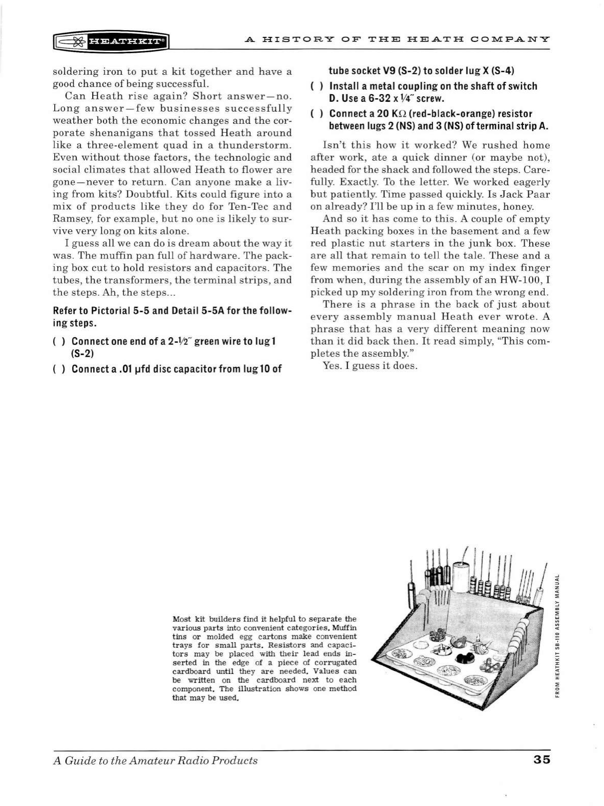
l8
~
f
b&&f
HH+il
A
HISTORY
OF
THE
HEATH
CO?>.l.l:PANY
soldering
iron
to
put
a
kit
together
and
h
ave
a
good
chance
of
being
successful.
Can
Heath
rise
again?
Short
answer-no.
Long
answer-few
businesses
successfully
weather
both
the
economic
changes
and
the
cor-
porate
shenanigans
that
tossed
Heath
around
like
a
three-element
quad
in
a
thunderstorm.
Even
without
those
factors,
the
technologic
and
social
climates
that
allowed
Heath
to
flower
are
gone-never
to
return
.
Can
anyone
make
a liv-
ing
from
kits?
Doubtful.
Kits
could
figure
into
a
mix
of
products
lik
e
they
do
for
Ten-Tee
and
Ramsey,
for
example,
but
no
one
is
likely
to
sur
-
vive
very
long
on
kits
alone.
I
guess
all
we
can
do
is
dream
abo
ut
the
way
it
was.
The
muffin
pan
full
of
hardware.
The
pack-
ing
box
cut
to
hold
resistors
and
capacitors.
The
tubes,
the
transformers,
the
terminal
strips,
and
the
steps.
Ah,
the
steps
...
Refer
to
Pictorial
5-5
and Detail
5-5A
for
the
follow-
ing
steps.
( ) Connect
one
end
of
a
2-W
' green wire to
lug
1
(S-2)
( ) Connect a
.01
µfd disc capacitor from
lug
10
of
tube socket V9 (S-2)
to
solder
lug
X (S-4)
( )
Install
a metal coupling
on
the shaft
of
switch
D.
Use
a
6-32
x
V4"
screw.
( ) Connect a 20 KQ (red-black-orange) resistor
between
lugs 2
(NS)
and
3
(NS)
of
terminal strip
A.
Isn't
this
how
it
worked?
We
rushed
home
after
work,
ate
a
quick
dinner
(or
maybe
not),
headed
for
the
shack
and
followed
the
steps.
Care-
fully
.
Exactly.
To
the
letter
. We
worked
eagerly
but
patiently.
Time
passed
quickly.
Is
Jack
Paar
on
already?
I'll
be
up
in
a few
minutes,
honey.
And
so
it
has
come
to
this
. A
couple
of
empty
Heath
packing
boxes
in
the
basement
and
a few
red
plastic
nut
starters
in
the
junk
box.
These
are
all
that
remain
to
tell
the
tale.
These
and
a
few
memories
and
the
scar
on
my
index
finger
from
when,
during
the
assembly
of
an
HW-100
, I
picked
up
my
soldering
iron
from
the
wrong
end.
There
is
a
phrase
in
the
back
of
just
about
every
assembly
manual
Heath
ever
wrote.
A
phrase
that
has
a
very
different
meaning
now
than
it
did
back
then.
It
read
simply,
"This
com-
pletes
the
assembly."
Yes. I
guess
it
does.
Most
kit
builders
find
it
helpful
to
separate
the
various
parts
into
convenient
categories.
Muffin
tins
or
molded egg
car
t
ons
make
convenient
trays
for
small
parts.
Resistors
and
capaci
-
tors
may
be
placed
with
their
lead
ends
in-
serted
in
the
edge of a
piece
of
corrugated
cardboard
until
they
are
needed.
Values
can
be
written
on
the
cardboard
next
to
each
component.
The
illustration
shows
one
method
that
may
be
used.
A Guide
to
the
Amateur
Radio
Products
35

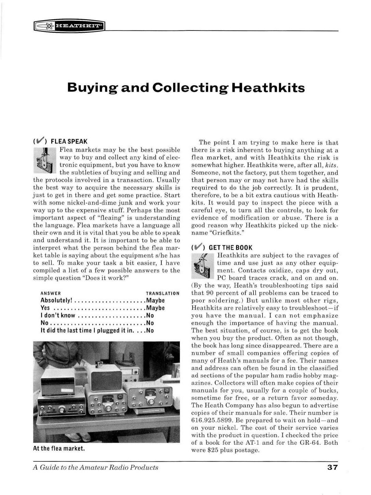
lB
~
u•&tUHE;i]
Buying
and
Collecting
Heathkits
CV >
FLEA
SPEAK
Flea
markets
may
be
the
best
possible
way
to
b
uy
and
co
ll
ect
any
kind
of
elec-
tronic
equipment,
but
you
have
to
know
the
subt
l
eties
of
buying
and
se
ll
ing
and
the
protoco
ls
involved
in
a
transaction
.
Usually
the
best
way
to
acquire
th
e
necessary
skills
is
just
to
get
in
there
and
get
some
prac
ti
ce.
Start
wit
h
some
nickel
-
and
-
dime
j
unk
and
work
your
way
up
to
the
expensive
st
uff.
Perhaps
the
most
important
aspect
of
"fleai
ng"
is
understanding
the
language
. Fl
ea
markets
have
a l
anguage
all
th
eir
own
an
d
it
is
vital
th
at
you
be
able
to
speak
and
understan
d
it.
It
is
important
to
be
able
to
interpret
what
the
person
behind
the
flea
mar-
ket
table
is
saying
about
t he
equipments
/
he
has
to
sell.
To
ma
ke
your
task
a
bit
easier,
I
have
compiled
a
lis
t
of
a few
possib
le
answers
to
the
simple
questio
n
"Does
it
work?"
ANSWER TRANSLATION
Absolutely!
.
..
..................
Maybe
Yes
. .
........................
.
Maybe
I
don
't
know
...
.
...............
.
No
No
.......
.
....
..
.....
.
........
No
It
did
the
last
time I
plugged
it
in
.
..
.
No
At
the
flea market.
A Guide
to
the
Amateur
Radio
Products
T
he
point
I
am
trying
to
make
h
ere
is
that
there
is
a
risk
inherent
to
buying
anyt
h
ing
at
a
fl
ea
market,
and
with
Heathkits
the
risk
is
somewhat
h igh er.
Heathkits
were,
after
a
ll
,
kits.
Someone,
not
t he
factory
,
put
them
toget
her,
and
that
person
may
or
may
n
ot
have
had
the
skills
req
u
ired
to
do
the
job
c
orrectly.
It
is
prudent,
therefore,
to
be
a
bit
extra
cautious
with
Heath-
kits.
It
wou
ld
pay
to
inspect
the
piece
with
a
carefu
l
eye,
to
turn
all
th e
controls,
to
l
ook
for
evidence
of
modification
or
abuse.
Th
ere
is
a
good
reason
why
Heat
hk i
ts
picked
up
th e
nick
-
name
"Griefkits."
CV >
GET
THE
BOOK
.4
!QI
Heathkits
are
su
bject
to
the
ravages
of
time
and
use
ju
st
as
any
ot
h
er
equip-
ment
.
Contacts
oxidize,
caps
d
ry
out,
PC
board
traces
crack,
and
on
and
on.
(
By
the
way, H
eath
's
tro
ubl
eshooting
tips
said
that
90
percent
of
all
pro
bl
ems
can
be
traced
to
poor
solderi
n
g.)
But
u
nli
ke
most
other
rigs,
H
eathkits
are
relatively
easy
to
troub
l
es
h
oot
-
if
you
have
the
manua
l. I
can
not
em
phasize
en
ough
the
importance
of
having
t h e
manual.
The
best
situation,
of
co
u
rse
,
is
to
get
the
book
when
you
buy
the
product.
Often
as
not
though
,
the
book
has
l
ong
since
di
sapp
ea
red.
Th
ere
are
a
number
of
small
companies
offering
copies
of
man
y
of
Heath's
manua
ls for a fee.
Their
names
and
address
can
often
be
found
in
the
classified
ad
sections
of
the
popular
ham
radio
hobby
mag
-
azines.
Collectors
will
often
make
copies
of
their
manuals
for
you
,
usually
for a
couple
of
bucks,
sometime
for
free,
or
a
return
favor
someday.
The
Heath
Company
has
also
begun
to
advertise
copies
of
their
manuals
for
sale
.
Their
nu
mber
is
616.925.5899.
Be
prepared
to
wait
on
hold-and
on
your
nicke
l.
The
cost
of
their
service
varies
with
the
product
in
quest
ion. I
checked
the
price
of
a
book
for
the
AT-1 and for
the
GR
-64.
Both
were
$25
pl
us
postage.
37
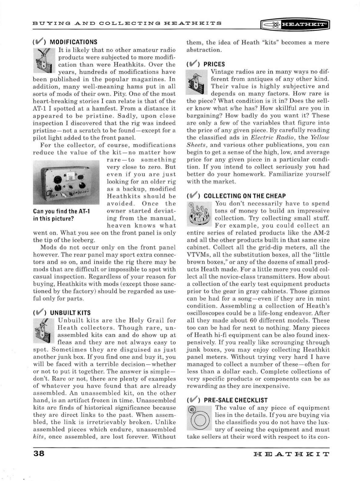
BU
Y
ING
AND
COLLECTING
HEATH
K
ITS
IE=
~
fUfSiHHEI
{V ) MODIFICATIONS
It
is
likely
that
no
other
amateur
radio
products
were
subjected
to
more
modifi-
cation
than
were
Heathkits.
Over
the
years,
hundreds
of
modifications
have
been
published
in
the
popular
magazines.
In
addition,
many
well
-
meaning
hams
put
in
all
sorts
of
mods
of
their
own
.
Pity
.
One
of
the
most
heart-breaking
stories
I
can
relate
is
that
of
the
AT-1 I
spotted
at
a
hamfest
.
From
a
distance
it
appeared
to
be
pristine.
Sad
ly,
upon
close
inspection
I
discovered
that
the
rig
was
indeed
pristine-not
a
scratch
to
be
found-except
for a
pilot
light
added
to
the
front
panel.
For
the
co
ll
ector,
of
cou
rse,
modifications
reduce
the
value
of
the
kit
-
no
matter
how
Can
you
find
the
AT-1
in
this
picture?
rare-to
something
very
close
to
zero.
But
even
if
you
are
just
looking
for
an
older
rig
as
a
backup,
modified
Heathkits
should
be
a
voided
.
Once
the
owner
started
deviat-
ing
from
the
manual,
heaven
knows
what
went
on.
What
you
see
on
the
front
panel
is
only
the
tip
of
the
iceberg.
Mods
do
not
occur
on
ly
on
the
fro
nt
panel
however.
The
rear
panel
may
sport
extra
connec-
tors
and
so on,
and
inside
th e
rig
there
may
be
mods
that
are
difficult
or
impossible
to
spot
with
casual
inspection.
Regardless
of
your
reason
for
bu
ying,
Heathkits
with
mods
(except
t h
ose
sanc
-
tioned
by
the
factory)
sho
u
ld
be
regarded
as
use
-
ful
only
for
parts.
{V )
UNBUILT
KITS
Unbui
lt
kits
are
the
Ho
ly
Grail
for
Heath
collectors.
Though
rare,
un
-
assembled
kits
ca
n
and
do sh ow
up
at
fleas
and
they
are
not
always
easy
to
spot
.
Sometimes
they
are
disguised
as
just
another
junk
box.
If
you
find
one
and
buy
it,
you
wi
ll
be
faced
with
a
terrible
decision-whether
or
not
to
put
it
together
.
The
answer
is
simple-
don't
.
Rare
or
not
,
there
are
plenty
of
examples
of
whatever
you
have
found
that
are
already
assembled.
An
unassembled
kit,
on
the
other
hand,
is
an
artifact
frozen
in
time.
Unassembled
kits
are
finds
of
historica
l
significance
because
they
are
direct
links
to
the
past.
When
assem
-
bl
ed
,
the
link
is
irretrievably
broke
n .
Unlike
assembled
pieces
which
endure
,
unassembled
kits,
once
assembled,
are
l
ost
forever.
Without
38
them,
the
idea
of
Heath
"kits"
becomes
a
mere
abstraction.
{V )
PRICES
Vintage
radios
are
in
many
ways
no
dif-
ferent
from
ant
i
ques
of
any
other
kind.
Their
value
is
h
ighly
subjective
and
depends
on
many
factors.
How
rare
is
the
piece?
Wh
at
condition
is
it
in?
Does
the
sell-
er
know
wh
at
s/he
has?
How
skillfu
l
are
you
in
bargaining?
How
bad
ly do
you
want
it?
These
are
only
a few
of
the
variables
that
figure
into
the
price
of
any
given
piece
.
By
carefu
lly
reading
the
classified
ads
in
Electric
Radio,
th e Yellow
Sheets,
and
various
other
publications,
you
can
begin
to
get
a
sense
of
the
h
igh,
l
ow,
and
average
price
for
any
given
piece
in
a
particu
l
ar
condi-
tion.
If
you
intend
to
co
ll
ect
serious
ly
you
had
better
do
your
homework.
Familiarize
yourself
with
the
market.
{V )
COLLECTING
ON
THE
CHEAP
-
~
, You
don't
necessarily
have
to
spend
~~§~
tons
o~
money
to
build
an
impressive
~
collection.
Try
collectmg
small
stuff.
For
example,
you
could
collect
an
entire
series
of
re
l
ated
products
like
the
AM-2
and
all
the
other
products
bu
ilt
in
that
same
size
cabinet.
Coll
ect
all
the
grid-dip
meters,
all
the
VTVMs,
all
the
substitution
boxes,
all
the
"
little
br
own
boxes,"
or
any
of
th e
dozens
of
small
prod-
ucts
Heath
made
.
For
a l
ittle
more
you
could
col-
l
ect
all
the
nov
i
ce-class
transmitters.
How
about
a
collection
of
the
ear
ly
test
equipment
products
prior
to
the
gear
in
gray
cabinets.
Those
gizmos
can
be
had
for a
song-even
if
they
are
in
mint
condition.
Assembling
a
collection
of
Heath's
osci
ll
oscopes
could
be
a life-
long
endeavor.
After
a
ll
they
made
about
60 di
fferent
mode
ls.
These
too
can
be
had
for
next
to
nothing.
Many
pieces
of
Heath
hi
-
fi
equipment
can
be
also
found
inex
-
pensively.
If
you
really
like
scrounging
through
junk
boxes,
you
may
enjoy
collecting
Heathkit
panel
meters.
Without
trying
very
hard
I
have
managed
to
co
ll
ect
a
number
of
these-often
for
l
ess
than
a
dollar
each.
Complete
collections
of
very
specific
products
or
components
can
be
as
rewarding
as
they
are
inexpensive
.
{V )
PRE-SALE
CHECKLIST
'@
The
value
of
any
piece
of
equipment
~
lies
in
the
details.
If
you
are
buying
via
~
the
classifieds
you
do
not
have
the
lux-
ury
of
seeing
the
equipment
and
must
take
sellers
at
their
word
with
respect
to
its
con-
HE
..A...T
HK
IT
(@
~
fU&iHHiiJ
B
UY
ING
A
ND
COLLECT
IN
G
HEATH
K
ITS
di
tion.
It
is
very
rare
to
be
intentionally
deceived,
but
for a
variety
of
reasons
sellers
may
not
themselves
know
if
what
they
have
is
in
good
working
order
and
fitted
with
original
parts.
Bu
ying
at
flea
markets,
however,
is
a
different
matter.
It
is
very
important
to
carefully
inspect
the
unit
in
question
before
you
hand
over
your
hard-earned
money.
In
the
excitement
of
finding
a
Heathkit
you
want
(
especially
a
rare
one)
it
is
easy
to
overlook
a
problem.
When
you
spot,
for
example,
a VX-1
and
your
heart
rate
doubles,
it
is
possible
not
to
see
that
extra
toggle
switch
on
the
front
panel
,
or
that
the
mic
connector
has
been
replaced
with
a
non
-
original.
I
once
discov-
ered
a
beautiful
Mohawk
at
a
flea
market
.
The
unit
appeared
to
be
perfect
and
was
priced
accordingly.
Upon
careful
inspection
however,
I
observed
that
the
main
tuning
knob
was
not
original.
It
had
been
replaced
by
something
sim-
il
ar
.
Finding
an
original
knob
is
not
impossible
but
could
be
both
difficult
and
expensive.
Once
you
have
your
hand
on
a
piece
of
equip-
ment
you
have
the
right
of
first
offer.
No
one
is
going
to
take
it
away
from
you.
Relax.
Take
your
time.
Here
is
a
check
list
you
can
use
to
make
sure
you
are
buying
a good
piece
of
gear,
Heath
or
otherwise.
CH
EC
K
FOR
:
( ) Rust
( ) Dents
( ) Scratches
( ) Or
ig
inal knobs
( ) Ex
tra
holes in
top
/sides /back
of
cabinet
( ) Ex
tra
front
panel controls/connectors
( ) Extra rear panel controls/connectors
( )
All
connectors are original t
ype
( ) Feet are present and original
( )
All
pa
int
is
original
( )
All
painted surfaces
intact
(no worn spots)
A Guide to the
Amateur
Radio
Products
( ) Dial and
front
panel legends orig
inal
and
intact
( ) Dial window g
lass/plastic
in
ta
ct
( ) Meters orig
inal
and not stuck
( ) Controls operate
smoothly
throu
gh ran g
es
( ) Slide rule
dial
pointers operate
smoothly
over entire
length
( ) Dial drums
not
cracked
( ) Fuses present and not burned
out
( ) Wiring
is
neat
{ ) Soldering is expert
{ )
All
tubes present and
intact
( ) Evidence
of
internal
modifications
{ ) Chassis corrosion
{ ) Battery corrosion {where applicable)
( ) Evidence
of
overheated/burned components
( ) Assembly and /or operating manual present
These
steps
represent
that
fabled
"ounce
of
prevention."
And
given
the
weight
of
the
average
"boat
anchor
,"
they
may
be
worth
much
more
than
the
fabled
"pound
of
cure.
"
There
is
a
great
deal
more
that
could
be
said
about
collecting,
restoring,
and
using
vintage
radio
equipment-most
of
it
well
beyond
the
scope
of
this
book.
The
potential
collector
has
a
great
deal
to
learn
and
there
are
many
good
sources
to
learn
from.
Hamfests
offer
an
oppor
-
tunity
not
only
to
collect,
but
also
to
connect
with
collectors,
most
of
whom
are
only
too
happy
to
share
their
knowledge
and
experiences.
Users
of
the
Internet
have
access
to
a
wea
l
th
of
infor-
mation
about
vintage
radios.
In
addition
to
the
Usenet
newsgroups
such
as
REC.RADIO.SWAP
there
is
a
listserve
dedicated
to
the
discussion
of
vintage
radios.
To
subscribe
send
a
post
to
"boatanchors
@
gnu.ai
.
mit.edu".
Owning
and
using
vintages
radios
is
a
great
joy
I
hope
many
people
will
experience,
and
the
fraternity
of
collecting
has
many
rewards.
39

~
~
1
i'¥Si§'HfiJ
A
Guide
to
the
Amateur
Radio
Products
A
Guide
to the
Amateur
Radio
Products 41

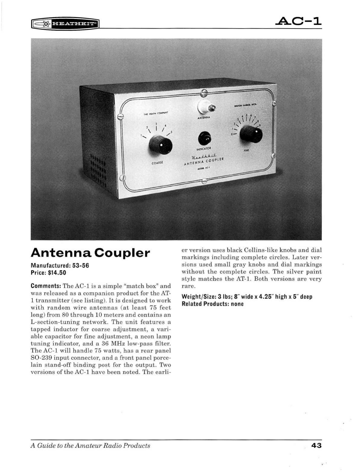
r@
~'if
i&iHH+iJ
Antenna
Coupler
Manufactured:
53-56
Price:
$14.50
Comments:
The
AC-1
is
a
simp
le
"
match
box
"
an
d
was
re
l
eased
as
a
companion
product
for
th
e
AT-
1
transmitter
(see
listing).
It
is
designed
to
work
with
random
wire
antennas
(at
least
75
feet
long
)
from
80
through
10
meters
and
contains
an
L-section-tuning
network.
The
unit
features
a
tapped
inductor
for
coarse
adjustment,
a
vari
-
able
capacitor
for
fine
adjustment,
a
neon
l
amp
tuning
indicator,
and
a
36
MHz
low-pass
filter.
The
AC-1 will h
andle
75
watts,
h
as
a
rear
panel
S0
-
239
input
connector,
and
a
front
panel
porce-
l
ain
stand
-
off
binding
post
for
the
out
pu
t. Two
versions
of
the
AC-1
have
been
not
ed.
The
earli
-
A
Guide
to
the
Amateur
Radio
Products
it<P1CAIOR
~LER
Atner-HlA
~J.,C,.1
.A.C-1
er
version
uses
black
Collins-like
knobs
and
dial
markings
including
complete
circles.
Later
ver-
sions
used
small
gray
knobs
and
dial
markings
without
the
complete
circles.
The
si
lv
er
paint
style
matches
the
AT-1.
Both
versions
are
very
rare
.
Weight/Size: 3
lbs;
8"
wide
x 4.25"
high
x 5"
deep
Related
Products:
none
43
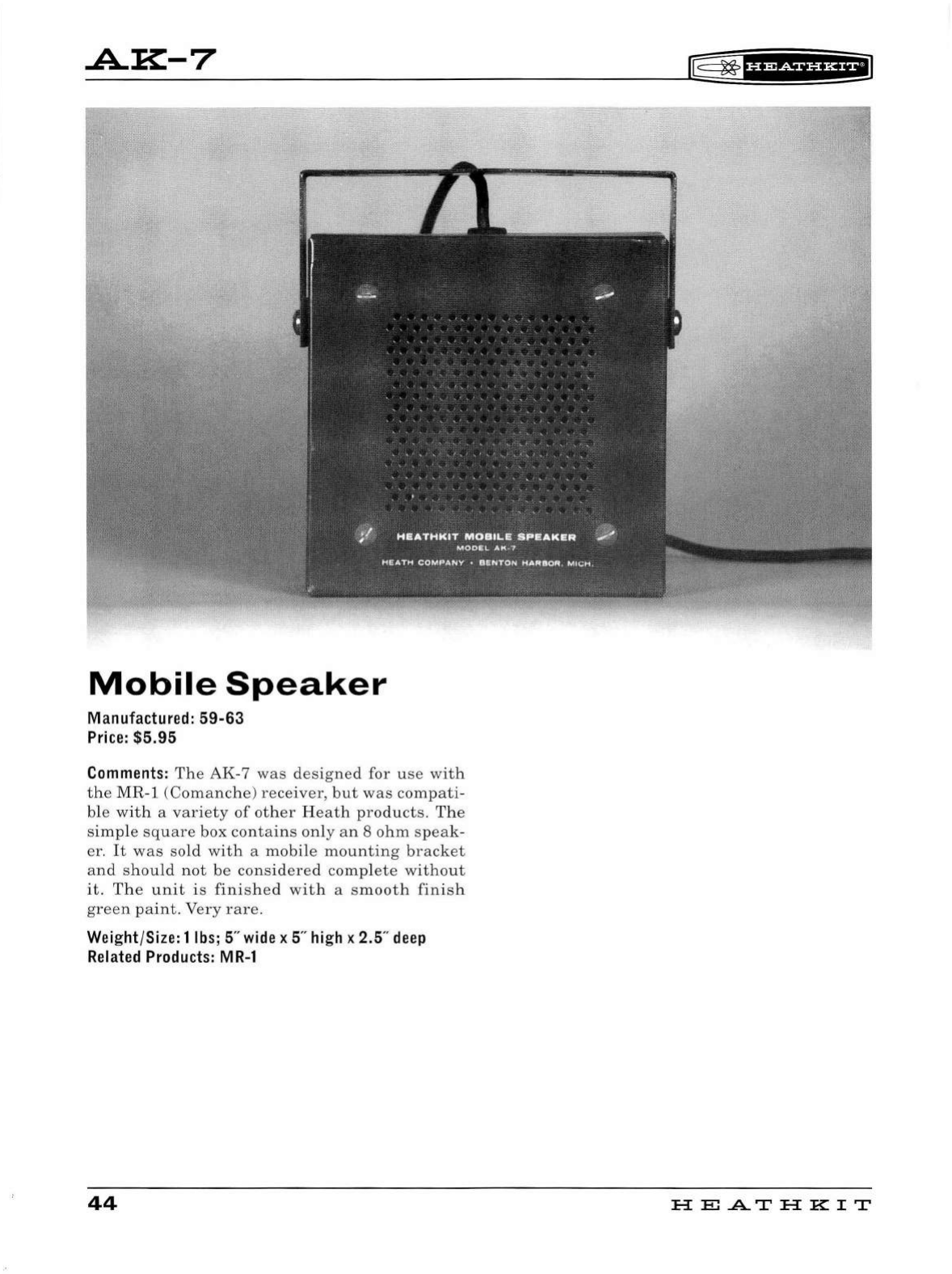
.A.K:-7
Mobile
Speaker
Manufactured: 59-63
Price
: $5.95
Comments:
The
AK
-7
was
designed
for
use
with
the
MR-1
(Comanche)
receiver,
but
was
compat
i-
ble
wi
th
a
variety
of
other
Heath
products.
The
simp
le
square
box
contains
on
ly
an
8
ohm
speak
-
er.
It
was
sold
with
a
mobi
le
mounting
bracket
and
sh
ould
not
be
considered
comp
l
ete
without
it.
The
unit
is
finis
h
ed
wit
h a
smooth
finis
h
green
paint.
Very
rare
.
Weight/Size: 1
lbs
; 5"
wide
x 5"
high
x 2.5"
deep
Related
Products:
MR-1
44
r®
~f
H@Sf
UHEI
HE
.A..T
HK
IT
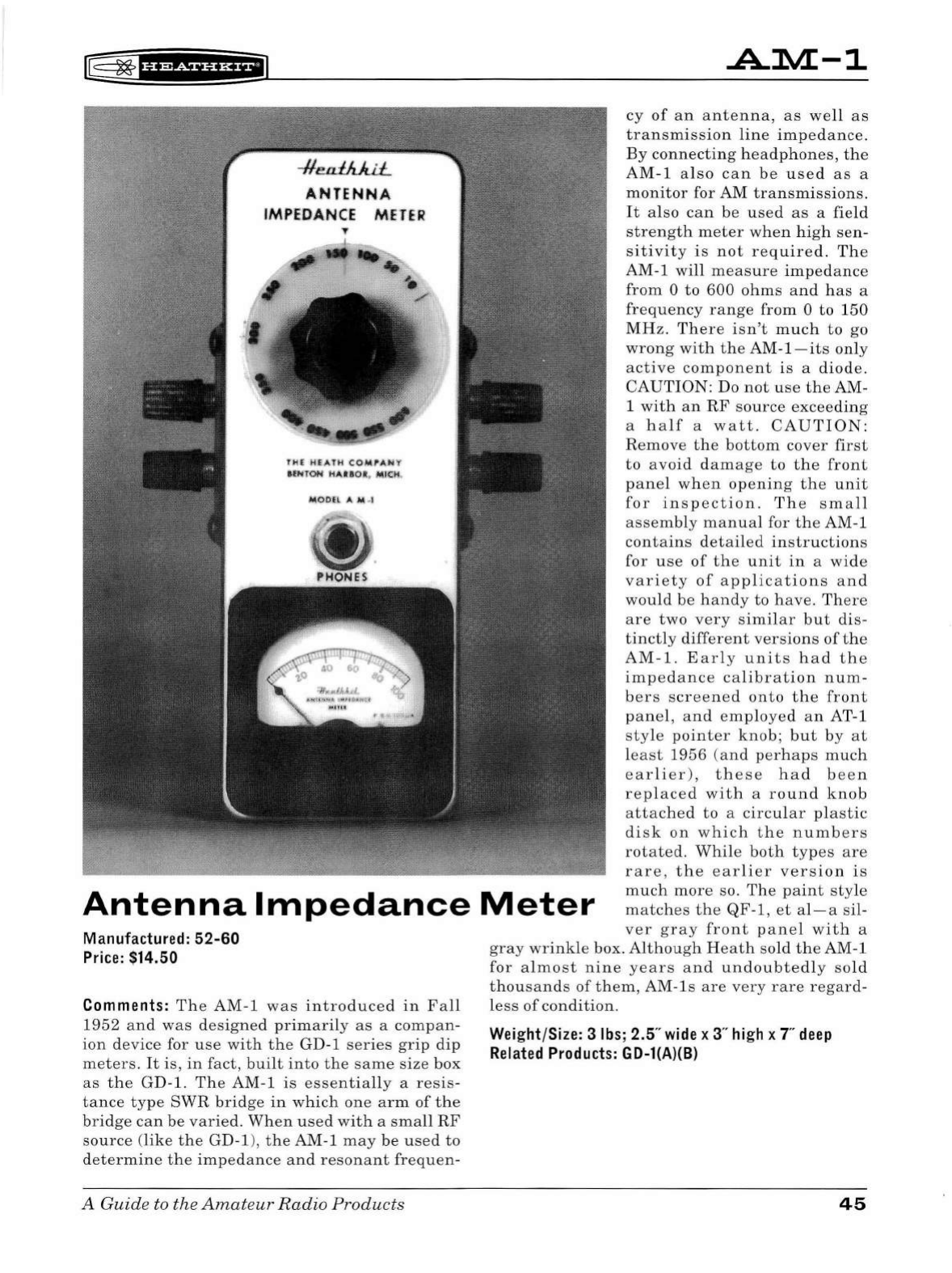
[§
~
thiSii'HiiiJ
ANTE
N.NA
IMPEDANCE METER
T
T.Hl
m:
,A'l H
COl(fAH
'I'
tfJUON
tl
AUOll,
,
Ml~
@
PHONES
.A.1VL-1
cy
of
an
antenna,
as
well
as
transmission
line
impedance
.
By
connecting
headp
h
ones,
the
AM-1
a l
so
can
be
u
sed
as
a
monitor
for AM
tra
n
smissions
.
It
also
can
be
used as
a field
strengt
h
meter
when
h
igh
sen-
si
ti
vi
ty
is
not
req
u
ired.
The
AM
-1
wi
ll
measure
impedance
from
0
to
600
ohms
and
has
a
freq
u e
nc
y
range
from
0
to
150
MHz
. Th
ere
isn't
m u
ch
to
go
wrong
wi
th
the
AM-
1-
its
only
active
component
is
a
diode
.
CAUTION
: Do
not
u
se
the
AM-
1
with
an
RF
source
exceeding
a
half
a
watt.
CAUTION:
Antenna
Impedance
Meter
Remove
th e
bottom
cover
first
to
avoid
damage
to
the
front
pane
l wh
en
opening
the
unit
for
inspection.
The
small
assembly
manual
for
the
AM-1
contains
detailed
instructions
for
use
of
the
unit
in
a
wide
variety
of
applications
and
would
be
handy
to
have.
Th
e
re
are
two
very
simi
l
ar
but
dis-
tinctly
di
fferent
vers
i
ons
of
the
AM-1.
Earl
y
units
had
th
e
imp
e
dance
calibration
num
-
bers
screened
onto
the
front
panel
,
and
employe
d
an
AT-1
style
pointer
knob;
but
by
at
lea
st
1956
(an
d
perhap
s
much
earlier),
these
had
b
ee
n
replaced
with
a
ro
u
nd
knob
attached
to
a
circu
l
ar
pla
s
tic
disk
on
which
the
numb
ers
rotated.
Whil
e
both
type
s
are
rare,
t h e
earlier
version
is
much
more
so.
The
paint
style
matches
the
QF-1,
et
al-a
sil-
ver
gray
front
panel
wi
th
a
Manufactured:
52-60
Price:
$14.50
Comments:
The
AM
-1
was
i
ntroduced
in
Fall
1952
and
was
designed
primarily
as
a
compan-
ion
device
for
use
with
the
GD
-1
series
grip
dip
meters.
It
is
,
in
fact,
built
into
the
same
size
box
as
the
GD-1. Th e AM-1
is
essentia
ll
y a
resis-
tance
type
SWR
bridge
in
wh
ich
one
a
rm
of
the
bridge
can
be
varied.
When
used
with
a
small
RF
source
(like
the
GD-1),
the
AM-1
may
be
used
to
d
etermine
the
impedance
an d
resonant
frequen
-
A Guide to the
Amateur
Radio
Products
gray
wrink
le box.
Although
Heath
sold the AM-1
for
almost
nine
years
and
undoubted
ly
so
ld
th
ousands
of
them,
AM-ls
are
very
rare
regard-
l
ess
of
condition
.
Weight/Size: 3
lbs;
2.5"
wide
x 3"
high
x T
deep
Related
Products:
GD-l(A)(B)
45
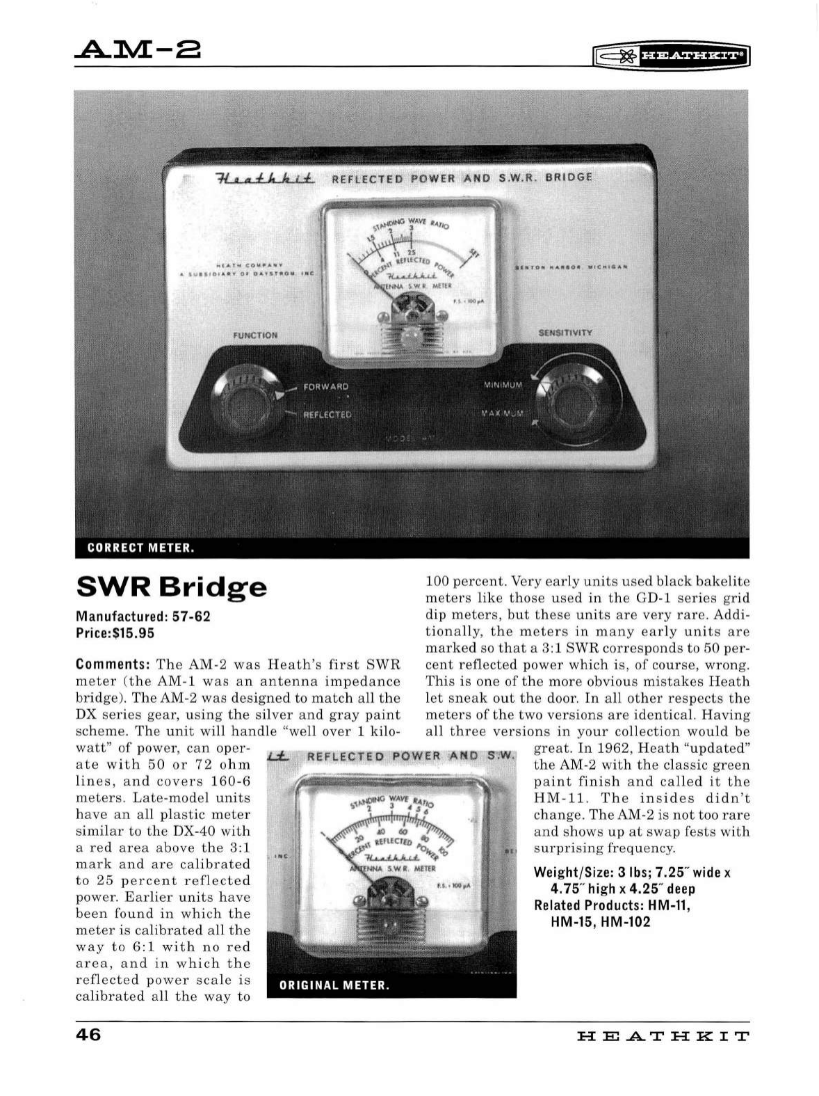
.A.lVL-a
ot.t
•t"'4
,
cowp_,..,.-.,
A
$Vllf0)A
<llf'
0'
O-.YfT"O"'
• • C
SWR
Bridge
Manufactured: 57-62
Price:$15.95
Comments:
The
AM-2
was
He
at
h's
first
SWR
meter
(
the
AM-1
was
an
antenna
impedanc
e
bridge
).
The
AM-2
was
designed
to
match
all
th
e
DX
series
gear,
u
sing
the
silver
and
gray
paint
sc
hem
e.
Th
e
un
it
will
handl
e "we
ll
over
1
kilo
-
watt
"
of
power,
can
oper
-
ate
with
50
or
72
ohm
lines
,
an
d
covers
160-6
met
ers.
L
ate
-m
od
el
units
hav
e
an
a
ll
pla
stic
meter
similar
to
the
DX-40
with
a
red
ar
ea
above
the
3:1
mark
and
are
calibrated
to
25
percent
reflected
power.
Earli
er
unit
s
have
been
found
in
which
the
meter
is
calibrated
a
ll
the
way
to
6:1
with
no
re
d
area,
and
in
which
the
refl
ected
power
sca
le is
calibr
ate
d a
ll
the
way
to
46
[;
~fifidiiflffiJ
100
percent.
Very
early
unit
s
used
black
bakelite
meter
s
lik
e
those
used
in
the
GD-1
series
gri
d
dip
meters,
but
these
unit
s
are
very
rare.
Addi-
tion
a
ll
y,
the
meter
s
in
man
y
ea
rl
y
unit
s
are
marked
so
that
a 3:1
SWR
corresponds
to
50
per-
cent
reflected
pow
er
which
is,
of
course,
wrong.
Thi
s is
one
of
the
more
obvious
mistakes
He
a
th
l
et
sneak
out
the
door
.
In
all
other
respect
s
the
met
ers
of
the
two
versions
are
identical.
Havin
g
a
ll
three
ve
r
sio
n s
in
yo
ur
co
ll
ection
would
be
JN.
great.
In
1962
, H
eat
h "
updat
ed"
the
AM-2
with
the
classic
green
paint
finish
and
called
it
the
HM-11.
Th
e
in
s
ide
s
didn
't
ch ange.
The
AM-2 is
not
too
rare
and
s
hows
up
at
swa
p
fests
with
surpr
is
ing
frequency
.
Weight/Size: 3
lbs;
7.25"
wide
x
4.75"
high
x 4.25"
deep
Related
Products:
HM-11,
HM-15, HM-102
H
El
.A..T
HK
IT
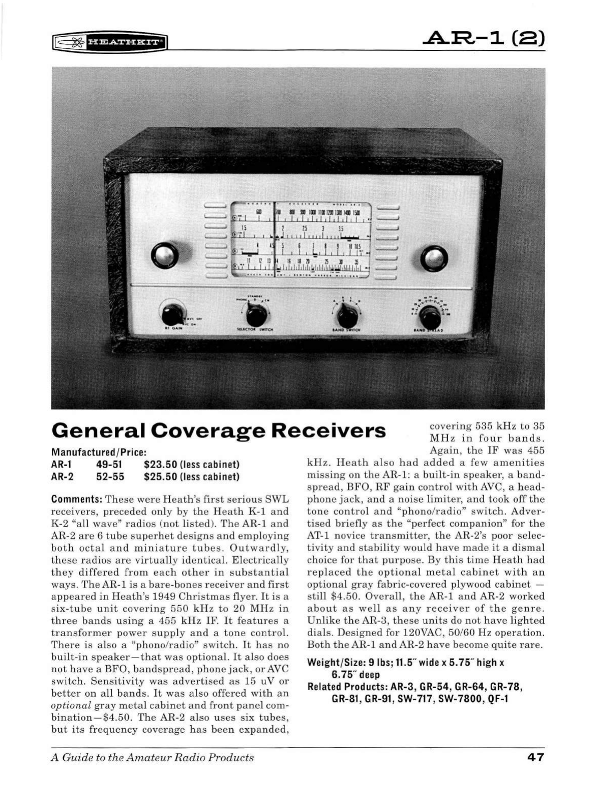
r8
~
1
Ui&f
Hi*fiJ
.A.:R-1
caJ
General
Coverage
Receivers
covering
535
kHz
to
35
MHz
in
fo u r
bands.
Again,
the
IF
was
455
Manufactured/Price:
AR-1
49-51 $23.50
(less
cab
i
net)
AR-2
52-55 $25.50
(less
cabinet)
Comments:
These
were
Heat
h's
first
serious
SW
L
receivers,
preceded
only
by
the
Heath
K-1
and
K-2
"a
ll
wave"
radios
(
not
listed)
.
The
AR-1
and
AR-2
are
6
tube
superhet
designs
and
employing
both
octal
and
miniature
tubes.
Outwardly,
th
ese
radios
are
virtually
id
entical.
Electrically
they
differed
from
each
ot
h
er
in
su
bstantial
ways.
The
AR-1
is
a
bare-bo
n
es
receiver
and
first
appeared
in
Heath's
1949
Christmas
flyer.
It
is
a
six-tube
unit
covering
550
kHz
to
20
MHz
in
three
bands
using
a
455
k
Hz
IF.
It
features
a
transformer
power
supply
and
a
tone
contro
l.
Th
ere
is
also
a
"phono/rad
i
o"
switch.
It
has
no
built-in
speaker-that
was
optional.
It
also
does
not
h
ave
a
BFO,
bandspread,
phone
jack,
or
AVC
switch.
Sensitiv
i
ty
was
ad
vertised
as
15
uV
or
better
on
all
bands
. It
was
also
offered
with
an
optional
gray
metal
cabinet
and
front
panel
com-
bi
nation
-
$4.50.
Th e AR-2 also
uses
six
tubes
,
but
its
frequency
coverage
has
been
expanded,
A Guide to the
Amateur
Ra
dio Products
kHz.
H
eat
h a l
so
had
added
a
few
amenities
missing
on
the
AR
-
1:
a buil
t-in
speaker,
a
band-
spread,
BFO,
RF
gain
control
with
AVC, a
head
-
ph
one
jack,
an d a
noise
limiter,
and
took
off
the
tone
control
and
"phono/radio"
switch
.
Adver-
tised
briefly
as
the
"
perfect
companion"
for
the
AT-1
novice
transmitter
,
the
AR-2's
poor
se
lec-
tivity
and
stability
would
have
made
it
a
disma
l
choice for
that
purpose
. By
this
time
Heath
had
replaced
the
optional
metal
cabinet
with
an
optional
gray
fabric-covered
pl
ywood
cabinet
-
st
i
ll
$4
.50.
Overall
,
the
AR-1
and
AR
-2
worked
about
as
we
ll
as
any
receiver
of
t h e
genre.
Unlike
the
AR
-3,
these
un
i
ts
do
not
have
lighted
dia
ls.
Designe
d for 120VAC,
50/60
Hz
operation
.
Both
theAR-
1
andAR-2
have
become
quite
rare.
Weight/Size: 9
lbs
;
11.5
"
wide
x 5. 75"
high
x
6.75"
deep
Related
Products:
AR-3 , GR-54, GR-64, GR-78,
GR-81
,
GR-91
,
SW-717
, SW-7800,
QF-1
47
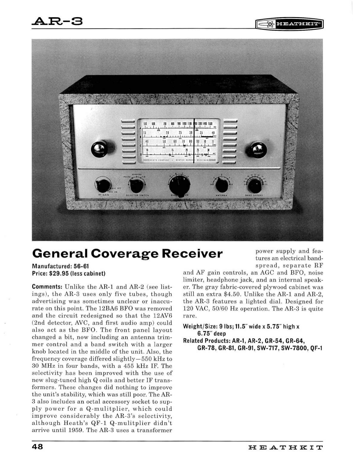
.A.::R-3
I&
~
fH&iHHEI
General
Coverage
Receiver
p
ower
supp
ly
and
fea
-
tu
res
an
electrical
band
-
Manufactured: 56-61
Price:
$29.95
(less
cabinet)
Comments:
Unlike
the
AR
-1
and
AR
-2
(see
list-
in
gs
),
the
AR
-3
uses
on
ly
five
tubes,
though
advertising
was
sometimes
unclear
or
inaccu
-
rate
on
this
point.
The
12BA6
BFO
was
removed
and
the
circuit
redesigned
so
that
t h e 12AV6
(
2nd
detector,
AVC
,
and
first
audio
amp
)
could
also
act
as
the
BFO.
The
front
panel
l
ayout
changed
a
bit,
now
incl
u
ding
an
ante
n
na
trim
-
mer
contro
l
and
a
band
switch
with
a
larger
knob
located
in
the
midd
le
of
the
unit.
Also, th e
frequenc
y
coverage
differed
slightly-550
kHz
to
30
MHz
in
four
bands,
wit h a
455
kHz
IF.
The
selectivity
has
been
improved
with
t h e
use
of
new
slug
-
tuned
high
Q coils
and
better
IF
trans
-
formers
.
These
changes
did
nothing
to
improve
the
unit
's
stability,
which
was
sti
ll poor.
The
AR
-
3
also
includes
an
octal
accessory
socket
to
sup
-
pl
y
power
for
a Q-
mulitp
li
er,
wh
ich
could
im
prov
e
considerably
t h e
AR-3
's
se
l
ectivity,
a l
though
Heat
h
's
QF-
1
Q-mu
l
itp
li
er
didn
't
arrive
until
1959
.
The
AR
-3
uses
a
transformer
48
spread,
separate
RF
and
AF
gain
contro
l
s,
an
AGC
an
d B
FO,
noise
li
miter,
hea
dph
one
jack
,
and
an
interna
l
speak
-
er.
The
gray
fabric
-
covered
· plywood
cabinet
was
sti
ll
an
extra
$4.50
.
Unli
ke
the
AR-1
and
AR-2,
the
AR-3
feature
s a
lig
h
ted
dial.
Designed
for
120 VAC,
50
/60
Hz
operation.
The AR-3
is
quite
rare.
Weight/Size: 9lbs;11.5"
wide
x 5.75"
high
x
6.75"
deep
Related
Products:
AR-1,
AR-2, GR-54, GR-64,
GR-78,
GR-81
,
GR-91
,
SW-717
, SW-7800,
QF-1
HE
A.TH
KIT
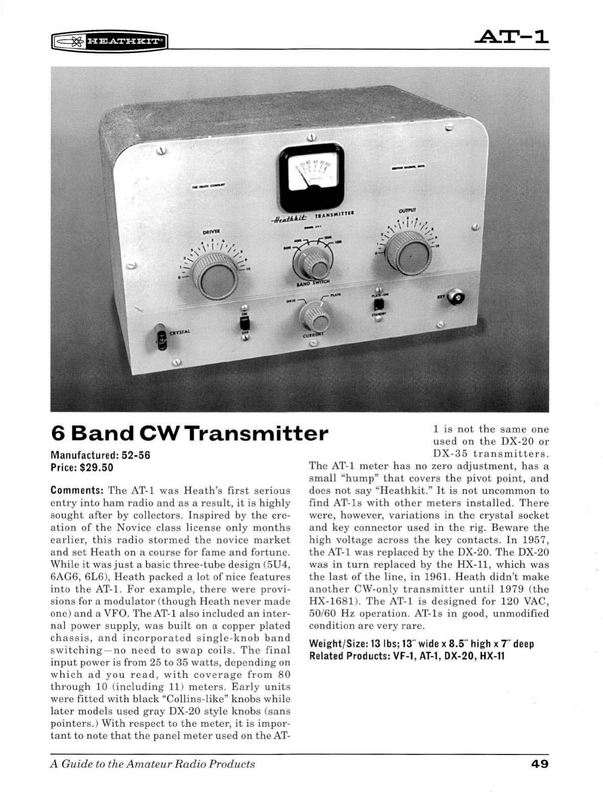
IT§
~
f#'ifiUHEil
.A..T-1
6
Band
CW
Transmitter
1
is
not
the
same
one
used
on
the
DX
-
20
or
Manufactured: 52-56
Price:
$29.50
Comments:
The
AT-1
was
H
eath's
first
serious
entry
into
ham
radio
and
as
a
result,
it
is
highly
sought
after
by
co
ll
ectors.
Inspired
by
the
cre
-
ation
of
the
Novice
class
li
cense
only
months
earlier,
this
radio
stormed
the
novice
market
and
set
Heath
on
a
course
for
fame
and
fortune.
Whi
le
it
was
just
a
basic
th
r
ee-tube
design
(5U4,
6AG6,
6L6
),
Heath
packed
a
lot
of
nice
features
into
the
AT-1.
For
examp
le,
there
were
provi
-
sions
for a
modu
l
ator
(though
Heath
never
made
one)
and
a
VFO.
The
AT-1 also
included
an
inter
-
nal
power
supp
l
y,
was
bui
lt
on
a
copper
plated
chassis,
and
i
ncorporate
d
single-knob
band
switching-no
need
to
swap
coils
.
The
fina
l
input
power
is
from
25
to
35
watts,
depending
on
which
ad
you
read,
with
cov
erage
from
80
through
10 (
including
11)
meters.
Ear
ly
units
were
fitted
with
black
"Co
lli
ns-like"
knobs
whi
le
l
ater
models
used
gray
DX-
20
style
knobs
(sans
pointers.
)
With
respect
to
t he
meter,
it
is
impor
-
tant
to
note
that
the
pane
l
meter
used
on
the
AT-
A Guide
to
the
Amateur
Radio
Products
DX-35
transmitters.
The
AT-1
meter
has
no
zero
adjustment,
has
a
small
"
hump"
that
covers
the
pivot
point
,
and
does
not
say
"Heathkit
."
It
is
not
uncommon
to
find
AT-
ls
wi
th
other
meters
installe
d.
There
were,
however,
variations
in
the
crystal
socket
and
key
connector
used
in
the
rig.
Beware
the
high
voltage
across
the
key
contacts
.
In
1957,
the
AT-1
was
replaced
by
the
DX-20. The DX-
20
was
in
turn
replaced
by
the
HX
-11,
which
was
th e l
ast
of
the
line,
in
1961.
Heath
didn't
make
another
CW
-
only
transmitter
until
1979
(t
he
HX-1681).
The
AT-1
is
designed
for
1
20
VAC,
50
/60
Hz
operation.
AT-ls
in
good,
unmodified
condition
are
very
rare.
Weight/
Size:
13
lbs;
13
"
wide
x 8.5"
high
x
7"
deep
Related
Products
:
VF-1
,
AT-1
, DX-20,
HX-11
49
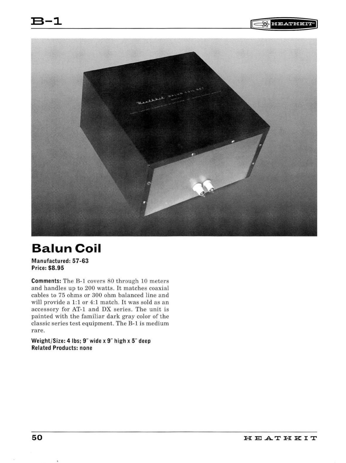
B-1
Balun
Coil
Manufactured:
57-63
Price:
$8.95
Comments:
The
B-1
covers
80
through
10
meters
a
nd
handles
up
to
200
wat
t s.
It
matches
coaxia
l
cab
l
es
to
75
ohms
or
300
ohm
balance
d
line
and
w
ill
provide
a 1:1
or
4:1
match
.
It
was
sold
as
an
accessory
for
AT-1
and
DX
series.
The
unit
is
pa
i
nted
with
th e
familiar
d
ark
gray
col
or of
the
cl
assic
series
test
equipme
nt.
The
B-1
is
medium
rare.
Weight/Size: 4
lbs
; 9"
wide
x 9"
high
x 5"
deep
Related
Products:
none
50
~
~
'if
fif
Hi*il
HE
..AT
HK
IT
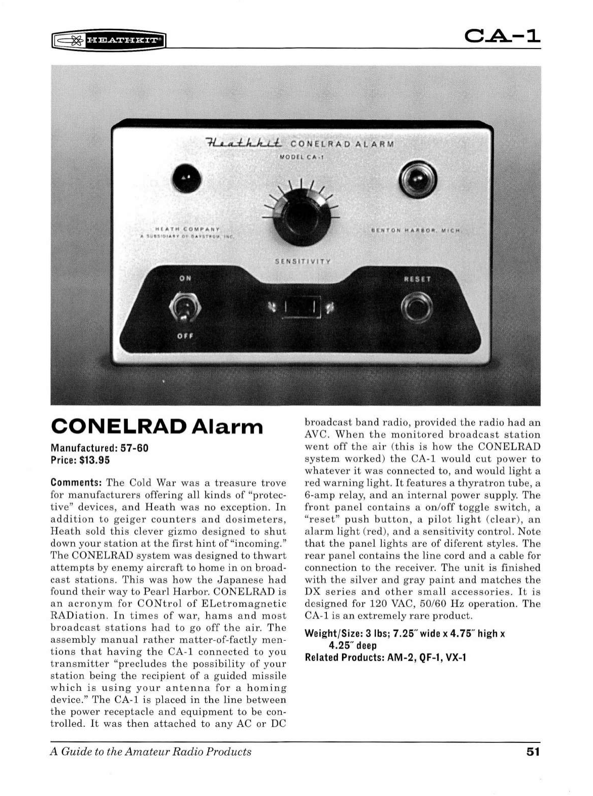
~fHMi§fHf;i]
C.A.-1
~
C·O
ELR
AO
Al)
AR
l1
(0CHL
C A •l
HfATH
CCJMPllll
A-
t\l
li
SIDI
Alli
'1
IH
£jl
~
V
8't
A D
~
.
Pt
t\.
CONELRAD
Alarm
Manufactured: 57-60
Price:
$13.95
Comments:
The
Cold
War
was
a
treasure
trove
for
manufacturers
offering
a
ll
kin
ds
of
"protec
-
tive"
devic
es,
and
Heath
was
no
exce
ption.
In
addition
to
geiger
counters
and
dosimeters,
Heath
sold
this
clever
gizmo
d
esigne
d
to
sh
ut
down
your
stat
ion
at
the
fir
st
hint
of
"
incoming."
The
CONELRAD
syste
m
was
d
esigne
d
to
thwart
atte
mpts
by e
nem
y
aircraft
to
hom
e
in
on
b
roa
d-
cast
stations.
Thi
s
was
how
the
J
apa
nes
e
had
found
their
way
to
Pearl
Harbor.
CONELRAD
is
an
acronym
for
CONtro
l
of
EL
etro
ma
gnet
ic
RADiation.
In
times
of
war,
h a
ms
and
most
broadcast
sta
tion
s
had
to
go
off
the
air.
The
assembly
manua
l
rather
matter-of-factly
men
-
tions
th
at
having
the
CA
-1
conn
ecte
d
to
you
transmitter
"precludes
the
pos
sibi
lity
of
yo
ur
stat
ion
b
eing
the
recipient
of
a g
uided
missile
which
is
using
your
antenna
for
a
homing
d
evi
ce."
Th
e CA-1
is
placed
in
th
e
line
betw
ee
n
the
pow
er
receptacl
e
and
eq
uipm
e
nt
to
be
con-
trolled.
It
was
then
attached
to
any
AC
or
DC
A Guide
to
the
Amateur
Radio
Products
broadcast
band
radio,
provided
the
radio
had
an
AVC.
When
th
e
monitored
bro
a
dcast
sta
tion
went
off
the
air
(
this
is
how
the
CONELRAD
system
worked)
the
CA-1
would
cut
power
to
whatever
it
was
co
nnec
te
d
to,
and
would
li
g
ht
a
red
warning
light
.
It
features
a
thyratron
tube,
a
6-amp
relay,
and
an
internal
power
supply.
The
front
p
ane
l
cont
a
ins
a
on
/
off
to
gg
le
switch,
a
"res
et
"
push
button
, a
pilot
li
g
ht
(
clear
),
an
ala
rm
li
g
ht
(red
),
an
d a
sens
itivit
y
control.
Note
that
the
panel
li
g
ht
s
are
of
difer
en
t
styles
.
The
rear
pan
el
contains
the
lin
e
cord
and
a
cabl
e for
connection
to
th
e
receiver.
The
unit
is
fini
s
hed
with
th
e
si
lver
and
gray
paint
and
match
es
the
DX
series
and
other
sm a
ll
accessories.
It
is
d
esig
ned
for
120
VAC,
50
/
60
Hz
operation.
The
CA-1
is
an
ex
trem
e
ly
rar
e
product
.
Weight/Size: 3
lbs;
7.25"wide x 4.75"
high
x
4.25"
deep
Related
Products:
AM-2,
QF-1,
VX-1
51
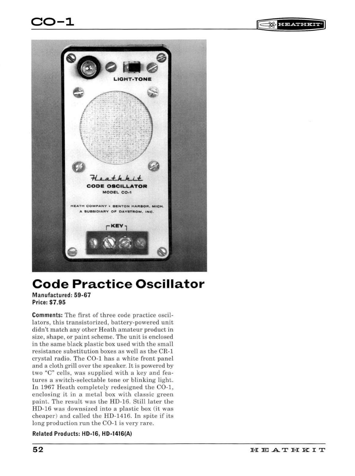
C0-1
•
~
COD&
OSCILLATOR
MODEL
C0-1
HEATH
COMPANY
•
eeNTON
HARBOR.
MICt"t.
A
SVBSIOIARV
OF
DAYSTROM.
INC.
rKEYl
Code
Practice
Oscillator
Manufactured:
59-67
Price: $7.
95
Comments:
The
first
of
three
code
practice
oscil-
lators,
this
transistorized,
battery
-
powered
unit
didn
't
match
any
other
Heath
amateur
product
in
size, sh
ape,
or
paint
sch
eme.
The
unit
is
enclosed
in
the
same
bl
ack
plastic
box
used
with
the
small
resistance
substitution
boxes
as
well
as
the
CR-1
crysta
l
radio.
The
C0-
1
has
a
white
front
pane
l
and
a
cloth
gri
ll
over
the
speaker.
It
is
power
ed
by
two
"C"
cells,
was
supplied
with
a
key
and
fea-
tures
a
switch
-
selectab
le
tone
or
blinking
light.
In
1967
Heath
completely
redesigned
the
C0-1,
enclosing
it
in
a
metal
box
with
classic
green
paint
.
The
result
was
the
HD
-16.
Still
later
the
HD-16
was
downsized
into
a pl
astic
box
(it
was
cheaper
)
and
called
the
HD-1416.
In
spite
if
its
l
ong
production
run
the
C0
-1
is
very
rare.
Related Products: HD-16, HD-1416(A)
52
®=
~
1
U@SiHH+I
HE.A.TH
KIT
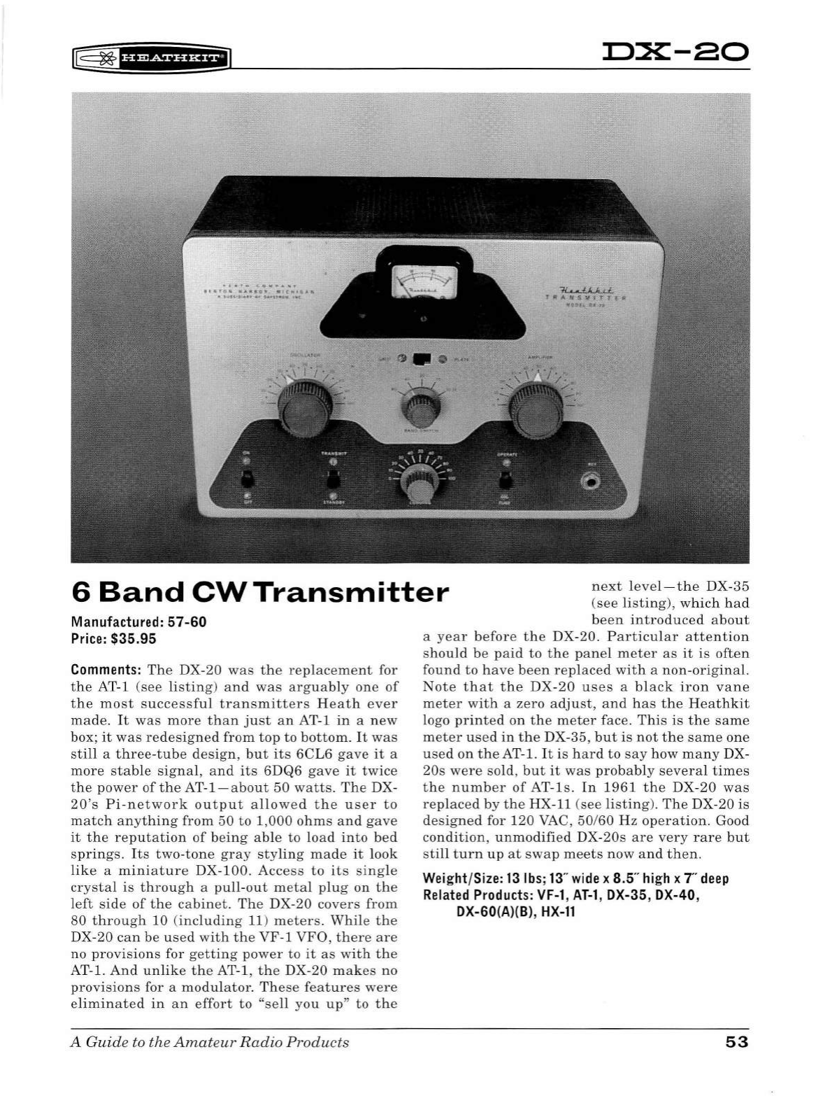
n:x:-ao
6
Band
CW
Transmitter
next
level-the
DX-35
(see
listing),
which
had
Manufa
ct
ured:
57-60
Price:
$35.95
Comments:
The
DX-20
was
the
replacement
for
the
AT-1
(see
listing
)
and
was
arguab
ly
one
of
the
most
successful
transmitters
Heath
ever
made.
It
was
more
than
just
an
AT-1
in
a
new
box;
it
was
redesigned
from
top
to
bottom.
It
was
still
a
three
-
tube
design,
but
its
6CL6
gave
it
a
more
stable
signal,
and
its
6DQ6
gave
it
twice
the
power
of
the
AT-1 -
about
50
watts.
The
DX-
20's
Pi-ne
tw
ork
output
allow
ed
the
user
to
match
anything
from
50
to
1,000
ohms
and
gave
it
the
reputation
of
being
able
to
load
into
bed
springs.
Its
two-tone
gray
styling
made
it
look
like
a
miniature
DX-100.
Acce
ss
to
its
single
crystal
is
through
a
pull
-
out
m
eta
l
plug
on
the
left
side
of
the
cabinet.
The
DX-20
covers
from
80
through
10 (
including
11) m
eters.
While
the
DX-20
can
be
used
with
the
VF-1
VFO,
there
are
no
provisions
for
getting
power
to
it
as
with
the
AT-1.
And
unlike
the
AT-1 ,
the
DX-20
makes
no
provisions
for a
modulator.
These
features
were
eliminated
in
an
effort
to
"sell
you
up
"
to
the
A Guide
to
the
Amat
e
ur
Radio
Products
been
introduced
about
a
year
before
the
DX-20.
Particular
attention
should
be
paid
to
the
panel
meter
as
it
is
often
found
to
have
been
replaced
with
a
non-original.
Note
that
the
DX-20
uses
a
black
iron
vane
meter
with
a
zero
adjust,
and
h
as
the
Heathkit
logo
printed
on
the
meter
face.
This
is
the
same
meter
used
in
the
DX-35,
but
is
not
the
same
one
used
on
the
AT-1.
It
is
hard
to
say
how
many
DX-
20s
were
sold,
but
it
was
probably
several
times
the
number
of
AT-ls.
In
1961
the
DX-20
was
replaced
by
the
HX-11 (s
ee
listing
).
The
DX-20
is
designed
for
120
VAC
,
50/60
Hz
operation.
Good
condition,
unmodified
DX-20s
are
very
rare
but
still
turn
up
at
swap
meets
now
and
then
.
Wei
g
ht
/
Size:
13
lbs
;
13
"
wide
x
8.5
"
hi
gh x T
deep
Rel
a
ted
Product
s:
VF-1
,
AT-1
, DX-35, DX-40,
DX-60(A)(B),
HX-11
53
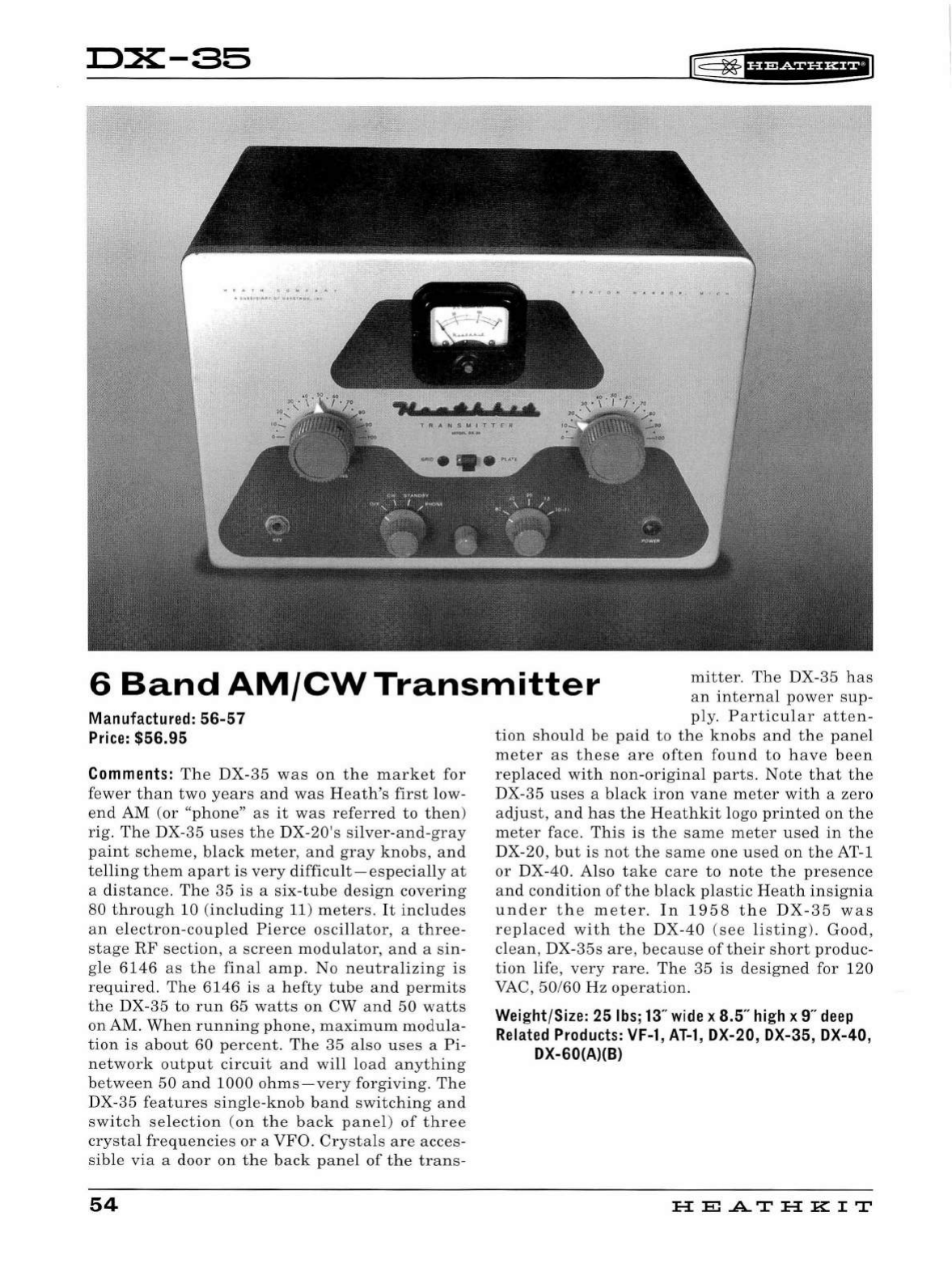
D:X:-85
~
~
1
H@f§fi*EI
..........
TRA
N
SM
ITT
ER
6
Band
AM/CW
Transmitter
mitter.
The
DX-35
has
an
internal
power
sup-
Manufactured:
56-57
Price:
$56.95
Comments:
The
DX
-
35
was
on
the
market
for
fewer
than
two
years
an
d
was
Heath's
first
low-
end
AM
(or
"phone"
as
it
was
referred
to
then)
rig
.
The
DX-35
uses
the
D
X-20's
silver-and
-
gray
paint
scheme,
bl
ack
meter,
and
gray
knobs,
and
te
ll
ing
them
apart
is
very
d
ifficult-especially
at
a
distance.
The
35
is
a
si
x-
tube
desig
n
covering
80
through
10
(including
11)
meters.
It
includes
an
electron-coup
l
ed
Pierce
oscillator,
a
three-
stage
RF
section,
a
screen
modu
l
ator,
and
a
sin-
gle
6146
as
the
final
amp.
No
neutralizing
is
required.
The
6146
is
a h
efty
tube
a
nd
permits
the
DX-
35
to
run
65
watts
on
CW
and
50
watts
on
AM
.
When
running
phone,
maximum
modula-
tion
is
about
60
percent.
T
he
35
also u
ses
a
Pi-
network
output
circuit
and
will
load
anything
between
50
and
1000
ohms-very
forgiving.
The
DX-
35
features
single-knob
band
switching
and
switch
se
l
ect
i
on
(on
t h e
back
pane
l)
of
three
crysta
l
frequencies
or
a
VFO.
Crysta
ls
are
acces-
sib
le
via
a
door
on
t he
back
panel
of
t he
trans-
54
ply.
Particular
a
tten-
tion
should
be
paid
to
the
knobs
and
the
panel
meter
as
these
are
often
found
to
have
been
replaced
with
non
-
original
parts.
Note
that
the
DX-35
uses
a
black
iron
vane
meter
with
a
zero
adjust,
and
h
as
the
Heathkit
logo
printed
on
the
meter
face.
This
is
the
same
meter
used
in
the
DX-20,
but
is
not
the
same
one
used
on
the
AT-1
or
DX-40. Also
take
care
to
note
t he
presence
and
condition
of
the
black
plastic
Heath
insignia
under
the
meter.
I n 1
958
the
DX
-
35
was
replaced
with
the
DX
-
40
(
see
listing).
Good
,
clean,
DX-35s
are,
because
of
their
short
produc-
tion
life,
very
rare.
The
35
is
designed
for
120
VAC,
50/60
Hz
operation.
Weight/Size: 25
lbs
;
13
"
wide
x
8.5
"
high
x 9"
deep
Related
Products:
VF-1
,
AT-1
, DX-20, DX-35, DX-40,
DX-60(A)(B)
H
El.A.TH
KIT
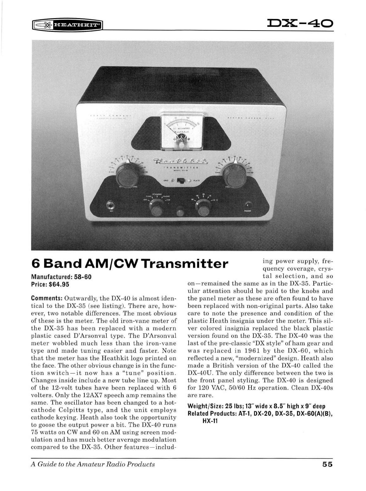
~
~
fbidf§fHf'J
D:X:-40
6
Band
AM/CW
Transmitter
ing
power
supply,
fre
-
quency
coverage,
crys-
Manufactured: 58-60
Price:
$64.95
Comments:
Outwardly,
the
DX-40
is
almost
iden-
tical
to
the
DX-
35
(see
listing).
There
are,
how-
ever,
two
notab
le
differences.
The
most
obvious
of
these
is
the
meter.
The
old
iron-vane
meter
of
the
DX-35
has
been
replaced
with
a
modern
pl
astic
cased
D'Arsonva
l
type.
The
D'Arsonva
l
meter
wobbled
much
l
ess
than
the
iron
-
vane
type
and
made
tuning
easier
and
faster.
Note
that
t he
meter
has
the
Heathkit
logo
printed
on
the
face.
The
other
obviou s
change
is
in
th e
func
-
tion
switch-it
now
h
as
a
"tune"
position.
Changes
inside
include
a
new
t u
be
line
up
.
Most
of
the
12-volt
tubes
have
been
replaced
with
6
volters.
Only
the
12AX7
speech
amp
remains
the
same.
The
osci
ll
ator
has
been
changed
to
a
hot-
cathode
Colpitts
type,
and
t h e
unit
employs
cathode
keying.
Heath
also
took
the
opportunity
to
goose
the
output
power
a
bit
.
The
DX-
40
runs
75
watts
on
CW
and
60
on
AM
using
screen
mod
-
ulation
and
has
much
better
average
modulation
compared
to
the
DX-35.
Other
features-includ-
A
Guide
to
the
Amateur
Radio
Products
tal
selection,
and
so
on-remained
the
same
as
in
the
DX-35.
Partic-
ular
attention
should
be
paid
to
the
knobs
and
the
panel
meter
as
these
are
often
found
to
have
been
replaced
with
non-origina
l
parts.
Also
take
care
to
note
the
presence
and
condition
of
the
plastic
Heat
h
insignia
under
the
meter
.
This
si
l-
ver
colored
insignia
replaced
the
black
plastic
version
found
on
the
DX-
35
. Th e DX-
40
was
the
last
of
the
pre-classic
"DX
sty
le"
of
ham
gear
and
was
replaced
in
196
1
by
t h e
DX-60,
which
reflected
a new,
"modernized"
d
esign
.
Heath
also
made
a
British
version
of
the
DX-
40
called
the
DX-40U.
The
on
ly
difference
between
the
two
is
the
front
panel
styli
ng.
The
DX-40
is
designed
for
120
VAC,
50/60
Hz
operation.
Clean
DX-
40s
are
rare.
Weight/Size: 25
lbs
;
13"
wide
x 8.5"
high
x 9"
deep
Related
Products:
AT-1
, DX-20, DX-35, DX-60(A)(B),
HX-11
55
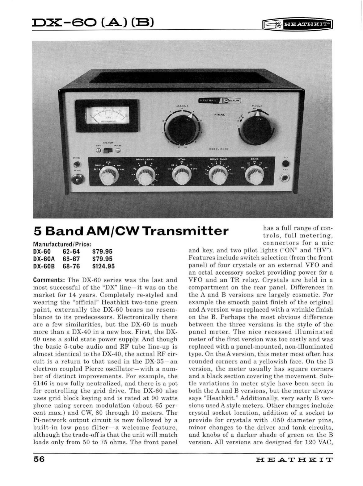
D:X:-60
(.A)
CB)
l®
~
tif
P&i¥'HEI
1..0AOING
FINAL
ORIVE
LEVEL
)(TAL
ORIVE:
TUNE
BAND
.::·ft)·
. "':· .
".:'~
··-··
: : '
.:~·.
~·
. ·:...
.:,,··
: : :
:~
--·:
·: ;·
•'"
::i•
...
,.
• }
,. ,
5
Band
AM/CW
Transmitter
has
a
full
range
of
con-
trols
,
full
metering,
Manufactured
/Price:
DX-60
62-64
$79.95
DX-GOA
65-67
$79.95
DX-608
68-
76 $124.95
Comments:
The
DX
-60
series
was
the
l
ast
and
most
successful
of
the
"DX"
line
-
it
was
on
the
market
for
14
years.
Completely
re
-
sty
l
ed
and
wearing
the
"official"
Heathkit
two-tone
green
paint,
externa
ll
y
the
DX
-
60
bears
no
resem-
blance
to
its
predecessors.
El
ectronica
ll
y
there
are
a few
simi
l
arities,
but
the
DX-
60
is
much
more
than
a DX-
40
in
a
new
box.
First,
the
DX-
60
uses
a
solid
state
power
supply.
And
though
the
basic
5-t u
be
audio
and
RF
tube
line
-
up
is
almost
identical
to
the
DX-40,
the
actual
RF
cir
-
cuit
is
a
return
to
that
used
in
the
DX-35-an
electron
coupled
Pierce
oscillator-with
a
num-
ber
of
distinct
improvements
.
For
example
,
the
6146
is
now
fully
neutralized,
and
there
is
a
pot
for
controlling
the
grid
drive.
The
DX
-60
also
uses
grid
block
keying
and
is
rated
at
90 wa
tts
phone
using
screen
modulation
(about
65
per-
cent
max.
)
and
CW
,
80
through
10
meters
.
The
Pi
-
network
output
circuit
is
now
followed
by
a
bui
lt -
in
low
pass
fil
ter
- a
welcome
feature,
although
the
trade-off
is
that
t he
unit
wi
ll
match
loads
only
from
50
to
75
ohms
.
The
front
pane
l
56
connectors
for
a
mic
and
key,
and
two
pilot
lights
("ON"
and
"HV").
Features
include
switch
selection
(
from
the
front
panel)
of
four
crysta
ls
or
an
external
VFO
and
an
octal
accessory
socket
providing
power
for a
VFO
and
an
TR
relay.
Crystals
are
held
in
a
compartment
on
the
rear
panel.
Differences
in
the
A
and
B
versions
are
largely
cosmetic
.
For
example
the
smooth
paint
finish
of
the
original
and
A
version
was
replaced
with
a
wri
n
kle
finish
on
the
B.
Perhaps
the
most
obvious
difference
between
the
three
versions
is
the
style
of
the
panel
meter.
The
nice
recessed
i
ll
uminated
meter
of
the
first
version
was
too
costly
and
was
rep
l
aced
with
a
panel
-
mounted,
non-i
ll
uminated
type
.
On
the
A
version,
this
meter
most
often
has
rounded
corners
and
a
yellowish
face.
On
the
B
version
,
the
meter
usually
has
square
corners
and
a bl
ack
section
covering
the
movement
.
Sub
-
tle
variations
in
meter
style
have
been
seen
in
both
the
A
and
B
versions
,
but
the
meter
always
says
"Heathkit
."
Additionally,
very
early
B
ver-
sions
used
A
sty
le
meters.
Other
changes
inclu
de
crysta
l
socket
l
ocation,
addition
of
a
socket
to
provide
for
crystals
with
.050
diameter
pins,
minor
changes
to
the
driver
and
tank
circuits,
and
knobs
of
a
darker
shade
of
green
on
the
B
version.
A
ll
versions
are
designed
for
120
VAC,
HE.A.TH
KIT
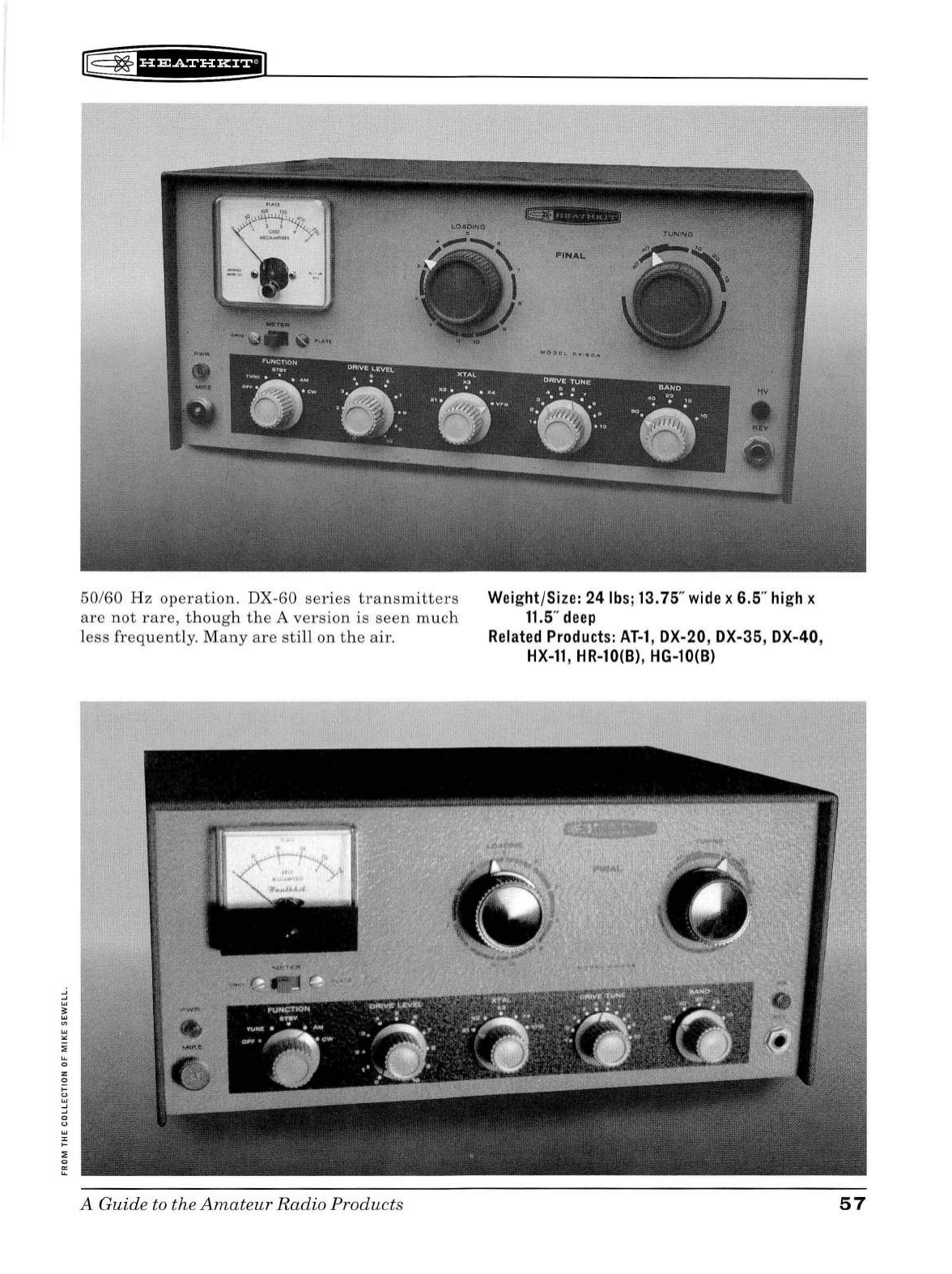
lE
~
f
H&ii'Hf
iil
50/60
Hz
operation.
DX-60
series
transmitters
are
not
rare
,
though
the
A
version
is
seen
much
less
frequently.
Many
are
still
on
the
air.
A
Guide
to the
Amateur
Radio
Products
Wei
ght/Size: 24
lbs;
13.
75"
wide
x 6.5"
high
x
11.5
"
deep
Related
Products:
AT-1
, DX-20 , DX-35, DX-40,
HX-11
, HR-10(8), HG-10(8)
57
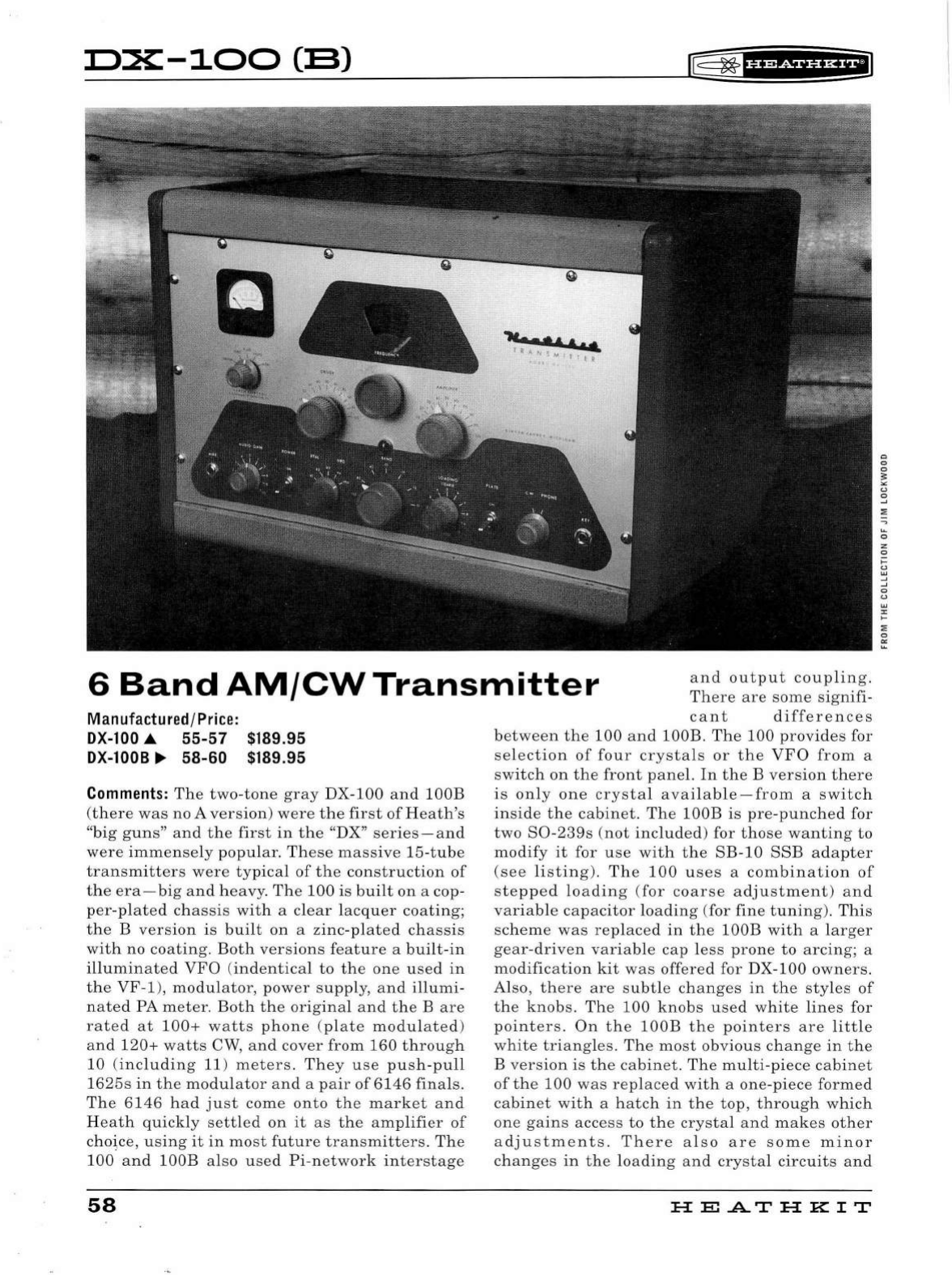
D:X:-100
(B)
r®
~
'§f
ff&ii'HiiJ
••••••
1
it
ANS,
..&
"'
M I l J { !l
6
Band
AM/CW
Transmitter
and
output
coupling.
There
are
some
sign
ifi-
Manufactured
/
Price:
DX-100
.A
55-57
DX-1008
...
58-60
$189.95
$189.95
Comments:
The
two-tone
gray
DX-
100
and
lOOB
(
there
was
no A
version)
were
the
fir
st
of
H
eat
h's
"
bi
g
guns
"
and
the
first
in
the
"DX"
se
rie
s
-and
were
imm
ense
ly
popular
.
These
massive
15-
tube
transmitt
ers
wer
e
typical
of
the
construction
of
the
era-
big
and
heavy.
Th
e
100
is
built
on
a cop-
per-plated
chassis
with
a cl
ea
r
lacquer
coating;
the
B
version
is
built
on
a
zinc-plated
chassis
with
no
coating.
Both
versions
feature
a
built-in
illumin
ate
d
VFO
(
indentical
to
the
one
u
se
d
in
the
VF
-1
),
modulator,
pow
er
supply,
and
illumi
-
n
ate
d PA m
eter.
Both
the
original
an
d
th
e B
are
rated
at
100+
watts
phone
(
pl
ate
modul
a
ted
)
an
d
120+
watts
CW
,
and
cover
from
160
through
10
(
including
11 )
meters.
They
u
se
pu
s
h-pull
1625s
in
the
modulator
and
a
pair
of6146
finals.
The
6146
had
ju
st
come
onto
the
market
a
nd
H
eat
h
quickly
settled
on
it
as
th
e a
mplifie
r
of
choice,
using
it
in
most
future
tr
ansm
itter
s.
The
100
and
lOOB
also
used
Pi-network
int
erstag
e
58
ca
nt
differences
be
twe
en
the
100
an
d lOOB .
The
100
provid
es
for
se
lection
of
four
crysta
ls
or
the
VFO
from
a
sw
itch
on
th
e
front
pan
el.
In
the
B
version
there
is
onl
y
one
crystal
available-from
a
switch
inside
the
cabinet.
Th
e lOOB is
pre-punched
for
two
S0-239s
(
not
includ
ed) for
those
wanting
to
modify
it
for u
se
with
th
e
SB-10
SSB
adapter
(see
listing).
Th
e
100
u
ses
a
combination
of
ste
pp
ed
loadin
g (
for
coarse
adjustment)
and
variable
capacitor
loadin
g (for
fin
e
tuning
).
This
sc
hem
e
was
replaced
in
the
lOOB
with
a
larger
gear
-dri
ven
variable
cap
l
ess
pron
e
to
arcing;
a
modification
kit
was
offered
for DX-100
owners.
Also,
there
are
subt
le
changes
in
the
sty
l
es
of
the
knob
s.
Th
e
100
knob
s u
sed
white
lines
for
pointer
s.
On
the
lOOB
the
point
ers
are
little
white
triangles.
The
most
obvious
change
in
the
B ve
rsion
is
th
e
cabinet
.
Th
e
multi-piece
cabinet
of
the
100
was
rep
l
ace
d
with
a
one-piece
formed
cabinet
wit
h a
hatch
in
the
top,
through
which
one
gains
access
to
th
e
crystal
and
mak
es
other
a
dju
stme
nt
s.
There
a l
so
are
some
minor
changes
in
the
lo
ad
in
g
an
d
crystal
circuits
and
HE
A.TH
KIT
Q
0
0
~
"
"
0
~
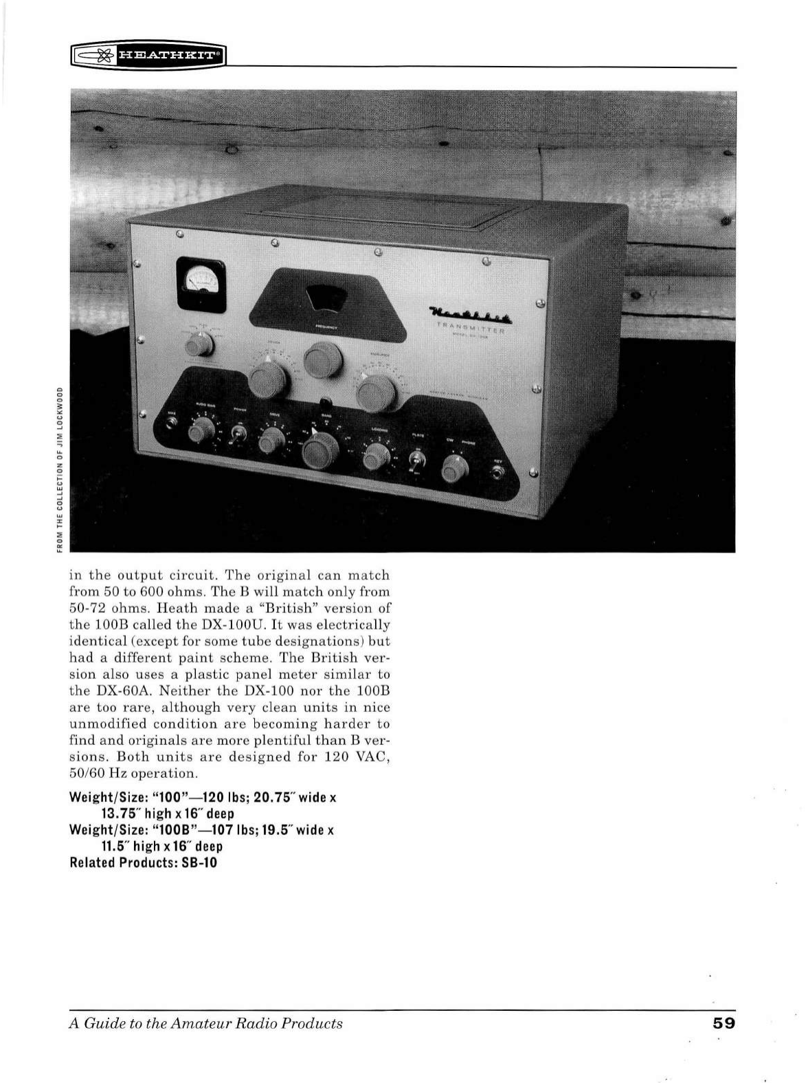
0
0
0
~
u
0
~
u.
0
z
0
,_
u
w
~
~
0
u
w
"
,_
:;;;
0
"'
u.
rE
~f#
1
¥f
Hi*f#l
in
the
output
circuit.
The
original
can
match
from
50
to
600
ohm
s.
The
B
will
ma
tch
only
from
50
-72
ohm
s.
Heath
made
a
"British"
ver
s
ion
of
the
lOOB
called
th
e DX-lOOU.
It
wa
s
electrically
identical
(exce
pt
for s
ome
tube
de
s
ignation
s)
but
had
a
different
pa
int
scheme.
Th
e
Briti
sh
ver-
s
ion
also
uses
a
plastic
p
ane
l m
eter
similar
to
the
DX-60A
N
eit
h
er
th
e DX-100
nor
th
e lOOB
are
too
rare,
although
very
clean
units
in
nice
unmodifi
ed
condition
ar
e
becomin
g
hard
er
to
find
and
ori
g
inal
s
are
mor
e
plentiful
than
B
ver
-
s
ion
s.
Both
unit
s
are
d
esig
ned
for
120
VAC ,
50/
60
Hz
op
era
tion
.
Weight/Size:
"100"-120
lbs;
20.
75"
wide
x
13.75"
high
x
16"
deep
Weight/Size:
"1008"-107
lbs;
19.5"
wide
x
11.5"
high
x
16
"
deep
Related
Products:
SB-10
A Guide to the
Amateur
Radio
Products
.......
I
A.IL
·~A
I
...
~&MI
T'Te'1:.
' .
59
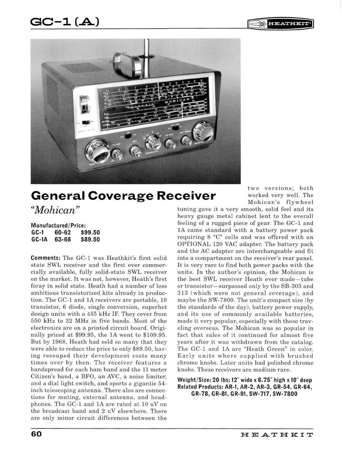
GC-1
(.A.)
f:
~
f
Uiiiiii*fl
General
Coverage
Receiver
two
versions;
both
worked
very
well
.
The
Mohican's
flywheel
"
Mohican
"
Manufactured/Price:
GC-1
60-62 $99.50
GC-lA 63-68 $89.50
Comments:
The
GC-1
was
Heathkit
's
first
soli
d
state
SWL
receiver
and
the
first
ever
commer
-
cia
ll
y
avai
l
ab
le,
fully
solid-state
SWL
receiver
on
the
market.
It
was
not,
however
,
Heath's
first
foray
in
solid
state.
Heath
had
a
number
of
l
ess
ambitious
transistor
i
zed
kits
al
ready
in
produc
-
tion.
The
GC-1
and
lA
receivers
are
portable,
10
trans
i
stor,
6
diode,
single
conversion,
superhet
desig
n
units
with
a
455
kHz
I
F.
They
cover
from
550
kHz
to
32
MHz
in
five
bands.
Most
of
the
electronics
are
on
a
printed
circuit
board.
Origi
-
nally
priced
at
$99.95,
the
lA
went
to
$109.95.
But
by
1968,
Heath
had
sold
so
many
that
they
were
able
to
reduce
the
price
to
only
$89.50
,
hav
-
ing
recouped
their
development
costs
many
times
over
by
then.
The
receiver
features
a
bandspread
for
each
ham
band
and
the
11
meter
Citizen's
band,
a
BFO,
an
AVC, a
noise
limiter,
and
a d
ia
l
lig
ht
switch,
and
sports
a
gigantic
54
-
inch
telescoping
antenna.
There
also
are
connec
-
tions
for
muting
,
external
antenna,
and
head
-
phones.
The
GC-1
and
lA
are
rated
at
10
uV
on
the
broadcast
band
and
2
uV
el
sewhere
.
There
are
on
ly
minor
circuit
differences
between
the
60
tuning
gave
it
a
very
smooth,
solid
feel
and
its
heavy
gauge
metal
cabinet
l
ent
to
the
overa
ll
feeling
of
a
rugged
piece
of
gear.
The
GC-1
and
lA
came
standard
with
a
battery
power
pack
requiring
8 "C"
cells
and
was
offered
with
an
OPTIONAL
120 VAC
adapter.
The
battery
pack
and
the
AC
adapter
are
interchangeable
and
fit
into
a
compartment
on
the
receiver's
rear
panel.
It
is
very
rare
to
find
both
power
packs
with
the
units
.
In
the
author's
opin
i
on,
the
Mohican
is
the
best
SW
L
receiver
Heath
ever
made-tube
or
transistor
-
surpassed
only
by
the
SB-303
and
313
(
which
were
not
genera
l
coverage
),
and
maybe
the
SW-7800.
The
unit's
compact
size
(
by
the
standards
of
the
day),
battery
power
supp
l
y,
and
its
use
of
commonly
available
batteries,
made
it
very
popular,
especia
ll
y
with
those
trav
-
eling
overseas.
The
Mohican
was
so
popular
in
fact
that
sa
l
es
of
it
continued
for
almost
five
years
after
it
was
withdrawn
from
the
catalog.
The
GC-1
and
lA
are
"
Heath
Green
"
in
color.
Early
units
where
supplied
with
brushed
chrome
knobs
.
Later
units
had
polished
chrome
knobs.
These
receivers
are
medium
rare.
Wei
ght/Size: 20
lbs;
12
"
wide
x
6.
75"
high
x
10
"
deep
Related
Products:
AR-1
,
AR-2
,
AR-3
, GR-54, GR-64,
GR-
78, G
R-81
, G
R-91
,
SW-
717
,
SW-
7800
HE.A.TH
KIT
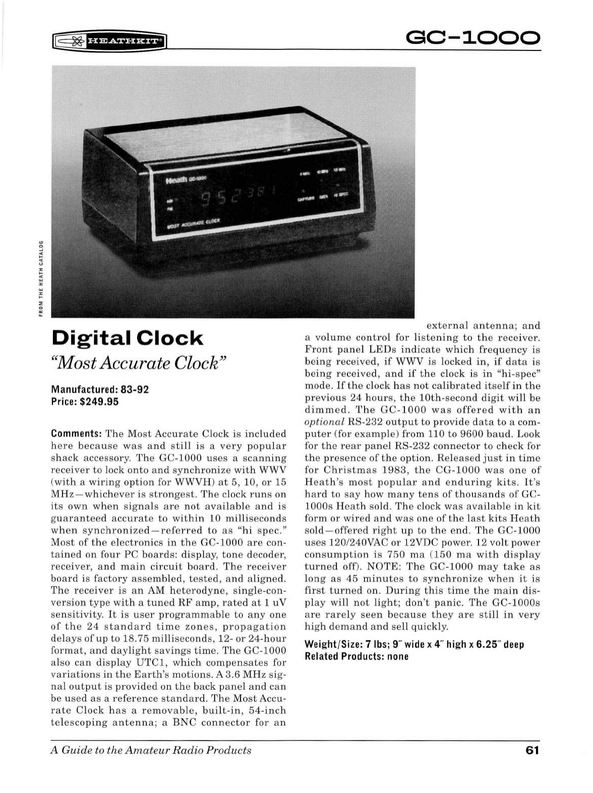
lE
~
'HM¥HH+ii1
Digital
Clock
"Most
Accurate
Clock''
Manufactured:
83-92
Price:
$249.95
Comments:
The
Most
Accurate
Clock
is
included
here
because
was
and
still
is
a
very
popular
shack
accessory.
The
GC-1000
uses
a
scanning
receiver
to
lock
onto
and
synchronize
with
WWV
(
with
a
wiring
option
for WWVH)
at
5,
10,
or
15
MHz-whichever
is
strongest.
The
clock
runs
on
its
own
when
signals
are
not
available
and
is
guaranteed
accurate
to
within
10
milliseconds
when
synchronized-referred
to
as
"hi
spec
."
Most
of
the
electronics
in
the
GC-1000
are
con-
tained
on
four
PC
boards
:
display
,
tone
decoder
,
receiver,
and
main
circuit
board.
The
receiver
board
is
factory
assembled,
tested,
and
aligned.
The
receiver
is
an
AM
heterodyne,
single-con-
version
type
with
a
tuned
RF
amp,
rated
at
1
uV
sensitivity
.
It
is
user
programmable
to
any
one
of
the
24
standard
time
zones,
propagation
delays
of
up
to
18.75
milliseconds
, 12-
or
24-hour
format,
and
daylight
savings
time.
The
GC-1000
also
can
display
UTCl,
which
compensates
for
variations
in
the
Earth's
motions.
A
3.6
MHz
sig-
nal
output
is
provided
on
the
back
panel
and
can
be
used
as
a
reference
standard.
The
Most
Accu-
rate
Clock
has
a r e
movable,
built-in,
54
-i
nch
telescoping
antenna;
a
BNC
connector
for
an
A Guide to the
Amateur
Radio
Products
GC-1000
external
antenna
;
and
a vo
lum
e
control
for
listening
to
the
receiver.
Front
panel
LEDs
indicate
which
frequency
is
being
received,
if
WWV
is
locked
in,
if
data
is
being
received,
and
if
the
clock
is
in
"hi-spec"
mode.
If
the
clock
has
not
calibrated
itself
in
the
previous
24
hours
,
the
10th-second
digit
will
be
dimmed.
The
GC-1000
was
offered
with
an
optional
RS-232
output
to
provide
data
to
a com-
puter
(for
example
)
from
110
to
9600
baud.
Look
for
the
rear
panel
RS-232
connector
to
check
for
the
presence
of
the
option.
Released
just
in
time
for
Christmas
1983,
the
CG-1000
was
one
of
Heath's
most
popular
and
enduring
kits.
It's
hard
to
say
how
many
tens
of
thousands
of
GC-
lOOOs
Heath
sold.
The
clock
was
available
in
kit
form
or
wired
and
was
one
of
the
last
kits
Heath
sold-offered
right
up
to
the
end.
The
GC-1000
uses
120/240VAC
or
12VDC
power.
12
volt
power
consumption
is
750
ma
(150
ma
with
display
turned
off).
NOTE:
The
GC
-1000
may
take
as
long
as
45
minutes
to
synchronize
when
it
is
first
turned
on.
During
this
time
the
main
dis-
play
will
not
light;
don
't
panic
.
The
GC-lOOOs
are
rarely
seen
because
they
are
still
in
very
high
demand
and
sell
quickly.
Weight/Size: 7
lbs;
9"
wide
x 4"
high
x 6.25"
deep
Related
Products:
none
61
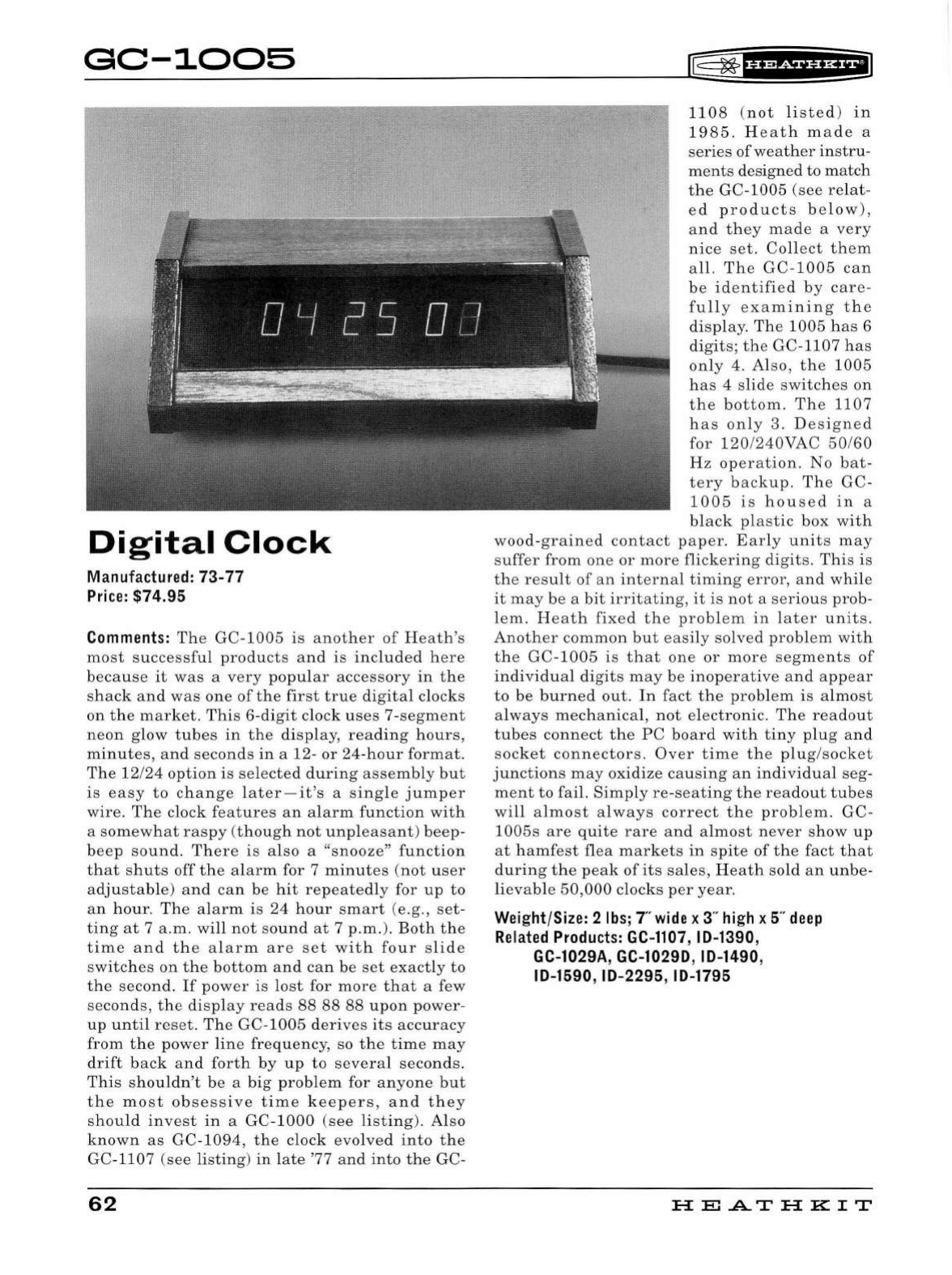
GC-1005
Di
g i
ta
l
Clock
Ma
nu
fac
tu
red:
73
-77
Price:
$7
4.
95
Comments:
The
GC-1005
is
another
of
Heath's
most
successful
products
and
is
included
here
because
it
was
a
very
popular
accessory
in
the
shack
and
was
one
of
the
first
true
digital
clocks
on
the
market
.
This
6-digit
clock
uses
7-segment
neon
glow
tubes
in
the
disp
lay,
reading
hours,
minutes,
and
seconds
in
a 12-
or
24-hour
format
.
The
12/
24
option
is
selected
during
assembly
but
is
easy
to
change
later-it
's a
single
jumper
wire.
The
clock
features
an
alarm
function
with
a
somewhat
raspy
(
though
not
unpleasant)
beep
-
beep
sound.
There
is
also
a
"snooze"
function
that
shuts
off
the
alarm
for 7
minutes
(not
user
adjustable)
and
can
be
hit
repeatedly
for
up
to
an
hour.
The
alarm
is
24
hour
smart
(e.g
.,
set
-
ting
at
7 a .m.
will
not
sound
at
7
p.m.).
Both
the
time
and
the
alarm
are
set
with
four
slide
switches
on
the
bottom
and
can
be
set
exactly
to
the
second.
If
power
is
lost
for
more
that
a few
seconds,
the
display
reads
88 88
88
upon
power-
up
until
reset.
The
GC-1005
derives
its
accuracy
from
the
power
line
frequency,
so
the
time
may
drift
back
and
forth
by
up
to
severa
l
seconds
.
This
shouldn't
be
a
big
problem
for
anyone
but
the
most
obsessive
time
keepers
,
and
they
should
invest
in
a
GC-1000
(see
listing)
.
Also
known
as
GC-
1094
,
the
clock
evolved
into
the
GC-1107 (see
listing
)
in
late
'77
and
into
the
GC-
62
IE=
~
f
h&Sf
if
HEI
1108
(
not
listed
)
in
1985
.
Heath
made
a
series
of
weather
instru-
ments
designed
to
match
the
GC-
1005
(see
relat-
ed
products
b e
low),
and
they
made
a
very
nice
set.
Collect
them
all.
Th
e
GC-1005
can
be
identified
by
care
-
fully
examining
the
display
.
The
1005
has
6
digits;
th
e GC-
1107
has
only
4.
Also,
the
1005
has
4
slide
switches
on
the
bottom.
Th
e
1107
has
only
3. D
esigne
d
for
120
/
240VAC
50
/
60
Hz
operation.
No
bat
-
tery
backup.
The
GC-
1005
is
housed
in
a
black
plastic
box
with
wood-grained
contact
paper.
Early
units
may
suffer
from
one
or
more
flickering
digits
.
This
is
the
result
of
an
internal
timing
error,
and
while
it
may
be
a
bit
irritatin
g,
it
is
not
a
serious
prob-
lem.
He
at
h
fixed
the
problem
in
later
units.
Another
common
but
easily
solved
problem
with
the
GC
-
1005
is
that
one
or
more
segments
of
individual
digits
may
be
inoperative
and
appear
to
be
burned
out
.
In
fact
the
problem
is
almost
always
mechanical,
not
electronic.
The
readout
tubes
connect
the
PC
board
with
tiny
plug
and
socket
connectors.
Over
time
the
pl
ug
/
socket
junctions
may
oxidize
cau
si
ng
an
individual
seg-
ment
to
fail.
Simply
re
-
seating
the
readout
tubes
will
almost
always
correct
the
problem
. GC-
1005s
are
quite
rare
and
almost
never
show
up
at
hamfest
flea
markets
in
spite
of
the
fact
that
dur
i
ng
the
peak
of
its
sales,
Heath
sold
an
unbe
-
lievable
50,000
clocks
per
year.
Weight/Size: 2
lbs
; r
wide
x 3"
high
x 5"
deep
Related
Products:
GC-1107
, ID-1390,
GC-1029A, GC-10290, ID-1490,
ID-1590, ID-2295, ID-1795
H
El
.AT
HK
IT
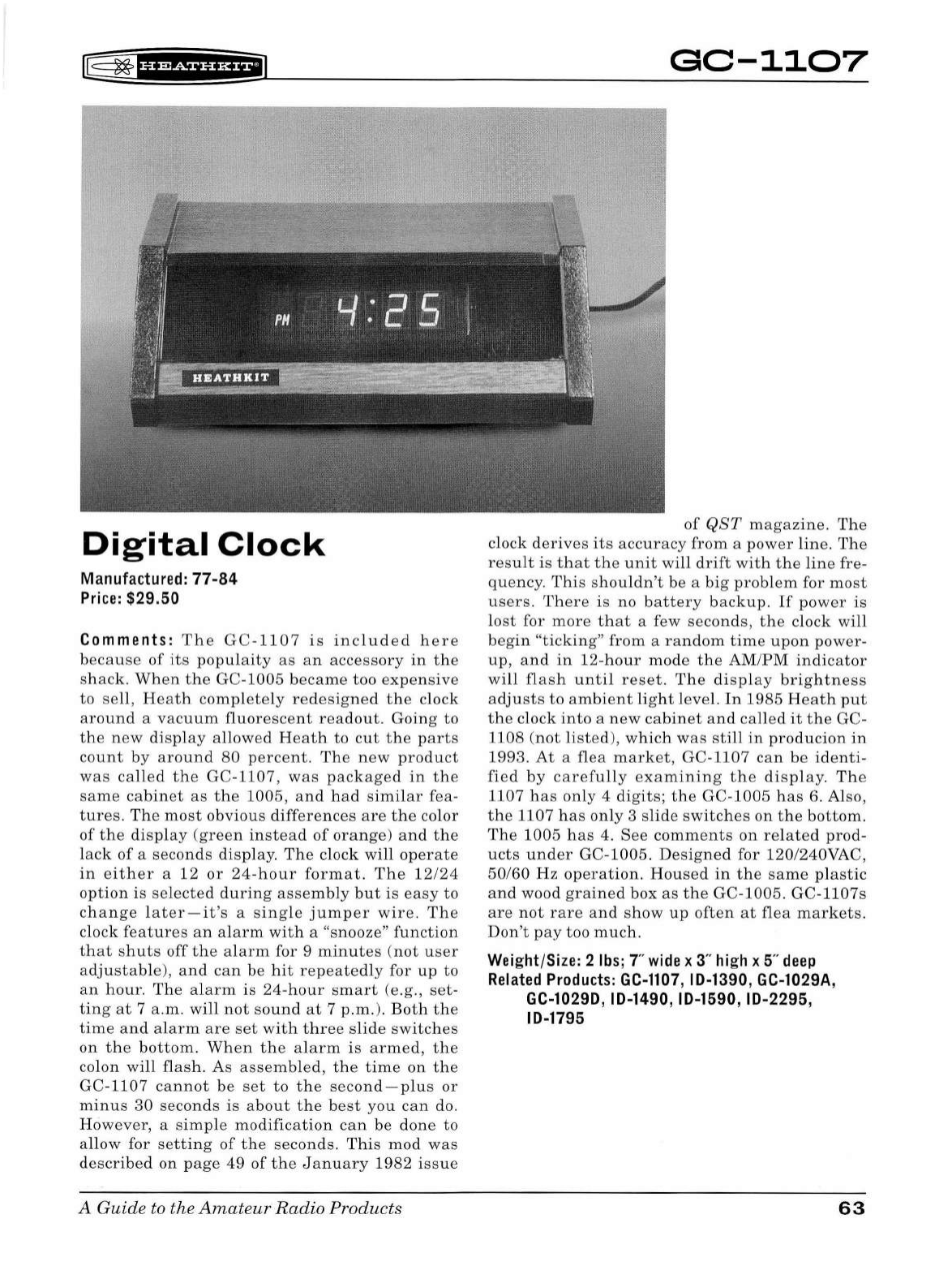
r@
~
'#f
friiU&fiJ
Digital
Clock
Manufactu r
ed
:
77-84
Pr
ice:
$29.
50
Comments:
The
GC-1107
is
included
here
because
of
its
populaity
as
an
accessory
in
the
shack.
When
the
GC-
1005
became
too
expensive
to
sell,
Heath
completely
redesigned
the
clock
around
a
vacuum
fluorescent
readout.
Going
to
the
new
display
allowed
Heath
to
cut
the
parts
count
by
around
80
percent.
The
new
product
was
called
the
GC-1107,
was
packaged
in
the
same
cabinet
as
the
1005
,
and
had
similar
fea
-
tures.
The
most
obvious
differences
are
the
color
of
the
display
(green
instead
of
orange)
and
the
lack
of
a
seconds
display.
The
clock
will
operate
in
either
a
12
or
24-hour
format.
The
12/24
option
is
se
lected
during
assembly
but
is
easy
to
change
later
-
it
's a
single
jumper
wire.
The
clock
features
an
alarm
with
a "snooze"
function
that
shuts
off
the
alarm
for 9
minutes
(
not
user
adjustable),
and
can
be
hit
repeatedly
for
up
to
an
hour.
The
alarm
is
24-hour
smart
(e.g.,
set
-
ting
at
7
a.m.
will
not
sound
at
7
p.m.).
Both
the
time
and
alarm
are
set
with
three
slide
switches
on
the
bottom.
When
the
alarm
is
armed,
the
colon
will
flash.
As
assembled,
the
time
on
the
GC-1107
cannot
be
set
to
the
second-plus
or
minus
30
seconds
is
about
the
best
you
can
do.
However,
a
simple
modification
can
be
done
to
allow
for
setting
of
the
seconds.
This
mod
was
described
on
page
49
of
the
January
1982
issue
A Guide to the
Amateur
Radio
Pr
oducts
GC-1107
of
QST
magazine
.
The
clock
derives
its
accuracy
from
a
power
line
.
The
resu
lt
is
that
the
unit
will
drift
with
the
line
fre-
quency.
This
shouldn't
be
a
big
problem
for
most
users.
There
is
no
battery
backup.
If
power
is
lost
for
more
that
a few
seconds,
the
clock
wi
ll
begin
"ticking"
from
a
random
time
upon
power
-
up,
and
in
12-
hour
mode
the
AM
/
PM
indicator
will
flash
until
reset
.
The
displ
ay
brightness
adjusts
to
ambient
lig
ht
level.
In
1985
Heath
put
the
clock
into
a
new
cabinet
and
called
it
the
GC-
1108
(not
listed)
,
which
was
still
in
producion
in
1993.
At
a
flea
market,
GC-1107
can
be
identi-
fied
by
carefully
examining
th
e
display.
The
1107
has
only
4
digits;
the
GC-
1005
has
6. Also,
the
1107
has
only
3
slide
switches
on
the
bottom.
The
1
005
has
4.
See
comments
on
related
prod
-
ucts
under
GC-
1005.
D
esigned
for 120/240VAC,
50/60
Hz
operation.
Housed
in
the
same
pl
astic
and
wood
grained
box
as
the
GC-1005.
GC-1107s
are
not
rare
and
show
up
often
at
flea
markets
.
Don't
pay
too
much.
Weight/Size: 2
lbs
; T
wide
x 3"
high
x 5"
deep
Related
Products:
GC-1107
, 10-1390, GC-1029A,
GC-10290, 10-1490, 10-1590, 10-2295,
10-1795
63
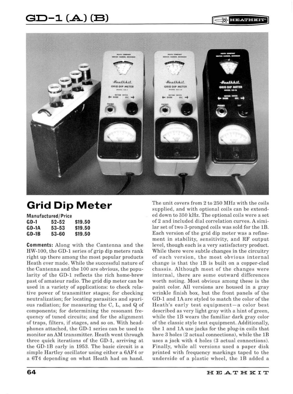
GD-1
(.A.)
CB)
...
;.~
/
.
..
.;
.,,._
.,
•
""""~·
-ll
e.a:l:
IJ..
i:L
GRID 011' M E
TER
Grid
Dip
Meter
Manufactured
/
Price
GD-1
52-52
GD-lA
53-53
GD-18
53-60
$19.50
$19.50
$19.50
Comments:
Along
with
the
Cantenna
and
the
HW-100,
the
GD-1
series
of
grip
dip
meters
rank
right
up
there
among
the
most
popular
products
Heath
ever
made.
While
the
successful
nature
of
the
Cantenna
and
the
100
are
obvious,
the
popu
-
larity
of
the
GD-1
reflects
the
rich
home-brew
past
of
amateur
radio.
The
grid
dip
meter
can
be
used
in
a
variety
of
applications
:
to
check
rela-
tive
power
of
transmitter
stages
; for
checking
neutralization;
for
locating
parasitics
and
spuri-
ous
radiation;
for
measuring
the
C, L,
and
Q
of
components;
for
determining
the
resonant
fre-
quency
of
tuned
circuits;
and
for
the
alignment
of
traps
,
filters,
if
stages,
and
so on.
With
head-
phones
attached,
the
GD-1
ser
i
es
can
be
used
to
monitor
an
AM
transmitter.
Heath
went
through
three
quick
iterations
of
the
GD-1,
arriving
at
the
GD-lB
early
in
1953.
The
basic
circuit
is
a
simple
Hartley
oscillator
using
either
a
6AF4
or
a
6T4
depending
on
what
Heath
had
on
hand
.
64
¢11'.j!'~
....
~
-
..
._
\-
-1
/
,,,.,.f}t.lt.i.J::..
GRID
OI
P M
ETER
lf5
~
'f'P&f
UHEI
The
unit
covers
from
2
to
250
MHz
with
the
coils
supplied
,
and
with
optional
coils
can
be
extend-
ed
down
to
350
kHz.
The
optional
coils
were
a
set
of
2
and
included
dia
l
correlation
curves
. A
simi-
lar
set
of
two
3-
pronged
coils
was
sold
for
the
lB.
Each
version
of
the
grid
dip
meter
was
a
refine-
ment
in
stability
,
sensitivity,
and
RF
output
level,
though
each
is
a
very
satisfactory
product.
While
there
were
subtle
changes
in
the
circuitry
of
each
version
,
the
mo
st
obvious
internal
change
is
that
the
lB
is
bui
lt
on
a
copper
-
clad
chassis.
Although
most
of
the
changes
were
internal
,
there
are
some
outward
differences
worth
noting.
Most
obvious
among
these
is
the
paint
color.
All
versions
are
housed
in
a
gray
wrinkle
finish
box,
but
the
front
panels
of
the
GD-1
and
lA
are
sty
l
ed
to
match
the
color
of
the
Heath's
early
test
equipment-a
color
best
described
as
very
light
gray
with
a
hint
of
green,
while
the
lB
wears
the
familiar
dark
gray
color
of
the
classic
style
test
equipment.
Additiona
ll
y,
the
1
and
lA
use
jacks
for
the
plug
-
in
coils
that
have
3
ho
l
es
(2
actual
connections)
, wh
ile
the
lB
uses
a
jack
with
4
ho
les (3
actual
connections
).
Finally,
whi
le
all
versions
used
a
paper
disk
printed
with
frequency
markings
taped
to
the
underside
of
a
plastic
wheel,
the
l B
added
a
HE
...A..T
HK
IT
r@
~
f#
1
Wf
UHEI
plastic
window
with
a
hairline
reticule
for
improved
accuracy.
If
the
tape
has
dried
out
and
the
paper
dial
markings
have
fallen
away
from
the
plastic
disk
it
is
a
simple
matter
to
reattach
them,
assuming
the
paper
disk
is
still
in
good
condition.
With
the
aid
of
a
computer
and
the
appropriate
software,
it
even
would
be
possible
to
make
a
new
paper
disk.
The
units
were
origi-
nally
supplied
with
spare
blank
dial
scales
for
custom
use,
though
few
of
these
have
survived.
CAUTION
:
Remove
the
bottom
cover
first
to
avoid
damage
to
the
front
panel
when
opening
the
unit
for
inspection
.
The
GD-1
series
features
a
solid
state
power
supply,
a
sensitivity
control,
and
a
rear
panel
switch
to
de-energize
the
oscil-
lator
and
permit
operation
as
an
absorption
wave
meter
(500
uV
required
for
full
scale
read-
ing).
The
GD-1
was
supplied
with
6
plug-in
coils,
while
the
lA
and
lB
were
supplied
with
only
5.
These
coils
are
stored
in
a
nice
maroon-colored
cardboard
box
and
the
meter
should
not
be
con-
sidered
complete
without
both
the
coils
and
the
A Guide to the
Amateur
Radio
Products
box.
Perhaps
the
most
remarkable
thing
about
the
GD-1,
lA,
and
lB
is
the
sheer
number
of
them
Heath
sold.
In
the
first
two
years
on
the
market,
Heath
sold
more
than
15,000
grid
dip
meters.
Based
on
the
number
of
them
that
show
up
at
swap
meets
it
is
likely
that
the
total
num-
ber
sold
in
the
ensuing
six
years
may
have
been
several
times
that
.
The
most
common
version
seen
these
days
is
the
lB.
lAs
are
much
more
scarce,
and
the
original
GD-1
is
very
rarely
seen.
All
three
in
your
collection
make
a
fine
set.
Look
for
the
matching
AM-1
(see
listing)
to
complete
the
line.
Weight/Size: 4
lbs;
2.5"
wide
x
3"
high
x T
deep
Related
Products:
AM-1
65
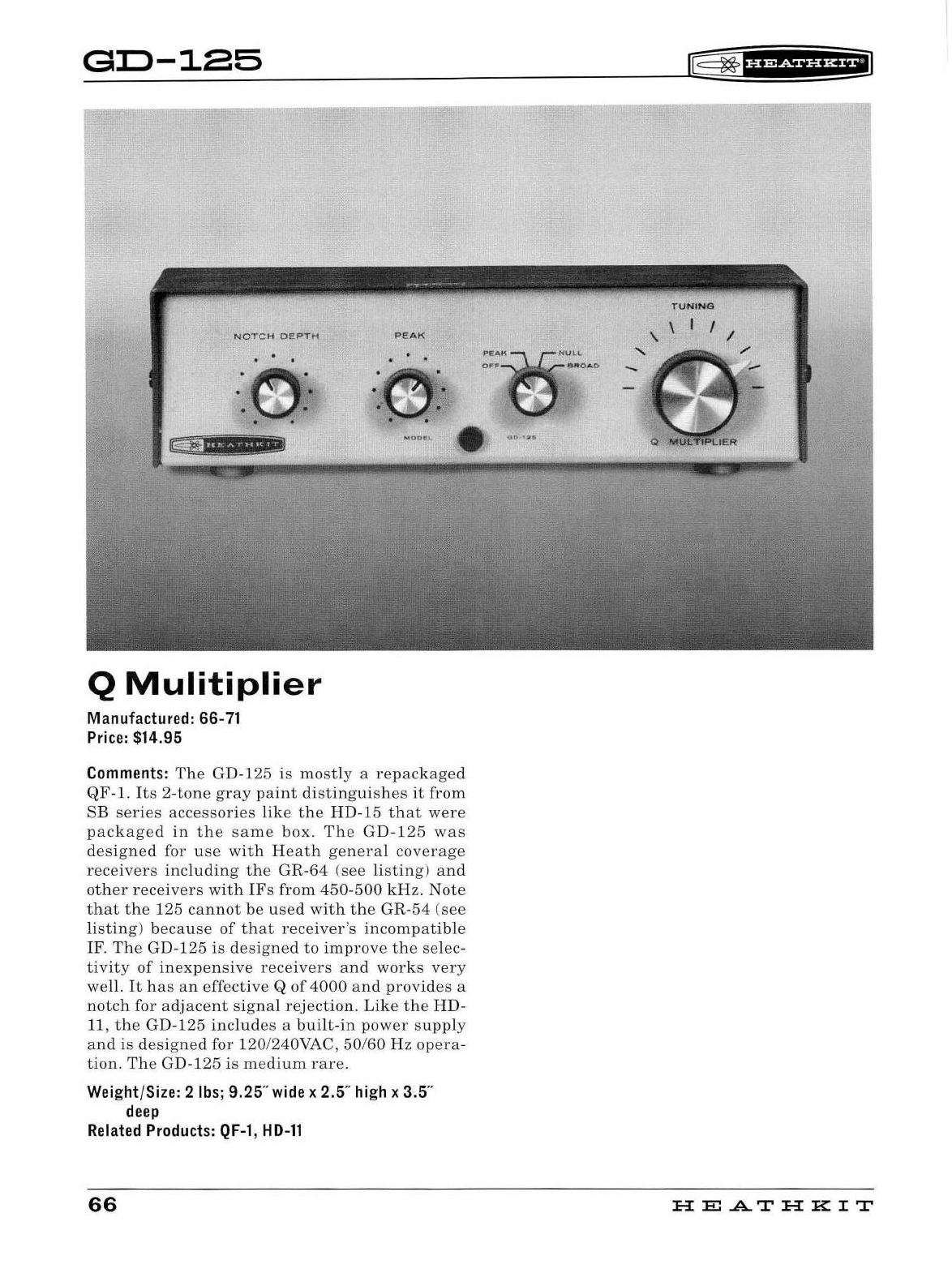
GD-125
NOTCH
DEPT
H
lAAh'Mit!fiMI
Q
Mulitiplier
Manufactured: 66-
71
Price:
$14.95
PEAK
Comments:
The GD-125
is
most
ly a
repackaged
QF-1.
It
s 2-
tone
gray
paint
disti
n
guishes
it
fr
om
SB
series
accessories
like
the
HD
-15 th
at
were
packaged
in
the
same
box.
The
GD
-1
25
was
designed
for u
se
with
Heath
genera
l
coverage
receivers
including
the
GR-64
(see
listing)
and
ot
h
er
receivers
with
IFs
from
45
0-
500
kHz.
Note
th
at
th e 125
cannot
be
used
wit
h
the
GR-54
(see
li
sting)
because
of
that
receiver
's
incompatib
le
IF.
The
GD-1 25
is
designe
d
to
im
p
rove
the
se
lec-
tivity
of
inex
p
ensive
receivers
and
works
very
well.
It
has
an
effective
Q
of
4000
and
provides
a
notch
for
adjacent
signa
l
re
j
ectio
n.
Like
the
HD-
11
,
the
GD-1
25
incl
u
des
a
built
-in
power
supp
ly
and
is
designed
for 120/240VAC,
50/60
Hz
opera
-
tion.
Th e GD-
125
is
medium
rare.
Weight/Size: 2
lbs;
9.25"
wide
x 2.5
..
high
x 3.5"
deep
Related
Products:
QF-1
,
HD-11
66
lE=
~
1
H&rii§f
&fi
HE
..A..T
HK
IT
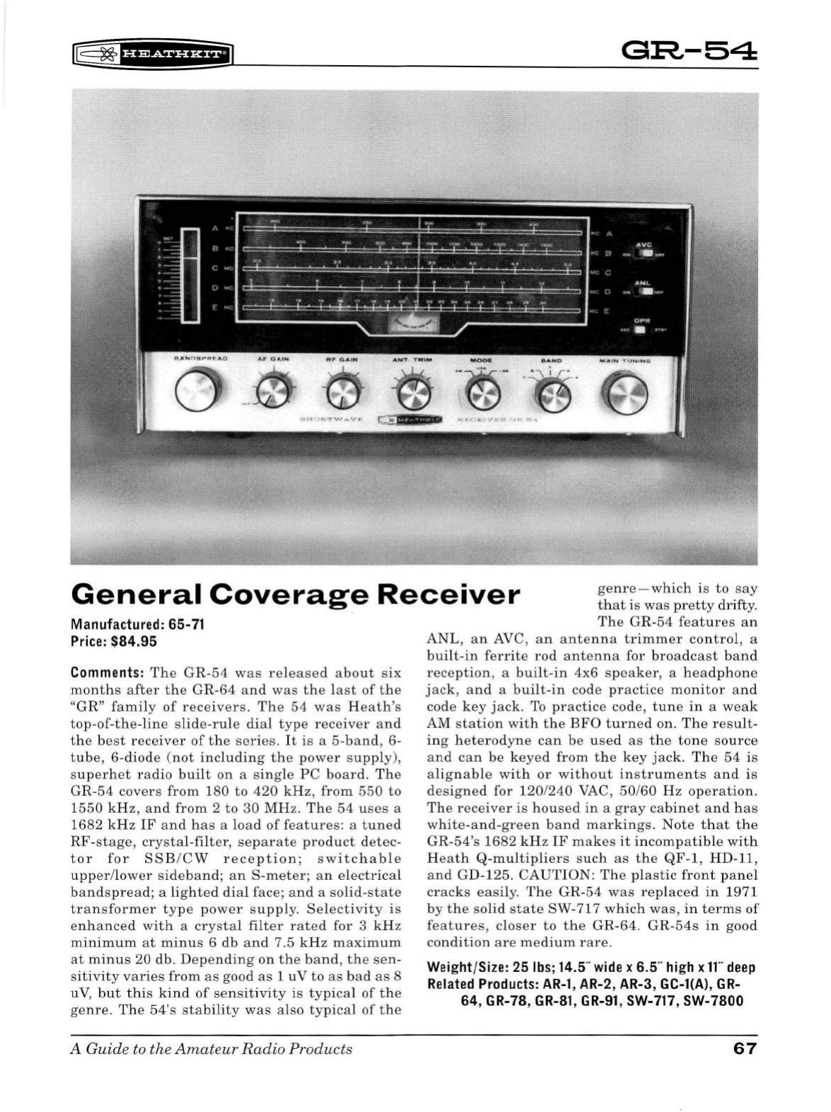
[
~
fi'idf
Hi*fiJ
G:R-54
General
Coverage
Receiver
genre
-which
is
to
say
that
is
was
pretty
dr
ifty.
Manufactured: 65-
71
Price:
$84.95
Comments:
The
GR-54
was
released
about
six
months
after
the
GR
-
64
an d
was
the
l
ast
of
t he
"GR"
family
of
receivers
.
The
54
was
Heath's
top
-
of
-
the
-
line
slide-ru
le
dia
l
type
receiver
an d
the
best
receiver
of
t he
ser
ies.
It
is
a 5-
band,
6-
tube
,
6-diode
(not
including
the
power
supp
ly),
superhet
radio
built
on
a
sing
le
PC
board.
Th e
GR-54
covers
from
1
80
to
420
kHz,
from
550
to
1550
kHz
,
and
from
2
to
30
MHz.
The
54
uses
a
1682
kH z
IF
and
has
a l
oa
d
of
features
: a
tuned
RF
-
stage,
crystal-fi
l
ter,
separate
prod
u
ct
detec
-
tor
fo r
SSE
/
CW
reception;
switc
h
ab
l e
upper
/l
ower
si
deband;
an
S
-meter;
an
el
ectrica
l
bandspread;
a
lighted
dia
l face;
and
a sol
id
-
state
transformer
type
power
su
pply
.
Se
l
ectivity
is
en
h
anced
wit
h a
crysta
l fil
ter
rated
for 3 kHz
minimum
at
minus
6
db
an d 7 .5
kHz
maxim
u m
at
minus
20
db
.
Depending
on
the
band,
the
sen
-
sitivity
varies
from
as
good
as
1 u V
to
as
bad
as
8
u
V,
but
th
is
kind
of
sensit
i
vity
is
typica
l
of
th e
genre.
T
he
54's
stab
i
lity
was
also
typical
of
t he
A Guide
to
the
Amateur
Radio
Products
The
GR-54
features
an
AN
L,
an
AVC,
an
antenna
trimmer
contro
l, a
built
-in
ferr
i
te
rod
anten
n a for b
road
c
ast
band
reception,
a
built
-
in
4x6
speaker,
a
headp
hone
jack,
and
a
built-in
code
practice
monitor
and
code
key
jack
.
To
practice
code,
tune
in
a
weak
AM
station
with
the
BFO
turne
d
on
.
The
result
-
ing
he
t
erodyne
can
be
used
as
t he
tone
sou
rce
and
ca
n
be
keyed
from
t he
key
jack
.
The
54
is
al
ignable
with
or
without
instrume
n
ts
an
d
is
designed
for 1
20
/
240
VAC,
50
/
60
Hz
operation.
The
receiver
is
housed
in
a
gray
cabinet
and
has
white
-an
d-green
band
markings.
Note
that
the
GR-54's
1682
kHz
IF
makes
it
incompatible
with
H
eath
Q-m
ul
tipliers
such
as
the
QF
-1, HD-11,
and
GD-125.
CAU
TI
ON
: T
he
pl
astic
front
pa
n el
cracks
easi
l
y.
The
GR-54
was
replaced
in
1971
by
the
solid
state
SW
-717
which
was,
in
terms
of
features,
closer
to
the
GR
-64.
GR
-
54s
in
good
condition
are
medi
um
rare.
Weight/Size: 25
lbs
; 14.5"
wide
x 6.5"
high
x
11"
deep
Related
Products:
AR-1
, AR-2, AR-3 , GC-l(A),
GR-
64, GR-78,
GR-81
,
GR-91,
SW-717, SW-7800
67
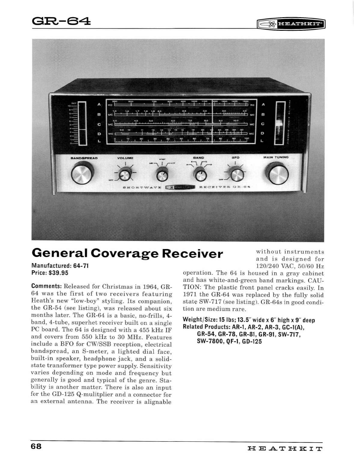
G:R-64
IE
~
'H&tSi§f
Hil
General
Coverage
Receiver
without
instruments
and
is
designed
for
Manufactured: 64-71
Price:
$39.95
Comments:
Released
for
Christmas
in
1964,
GR-
64
was
the
first
of
two
receivers
featuring
Heath's
new
"low-boy"
styling
.
Its
companion,
the
GR-54
(see
li
sting),
was
released
about
six
months
l
ater.
The
GR-64
is
a
basic,
no-frills
, 4-
band
,
4-tube
,
superhet
rec
eiver
built
on
a
sing
le
PC
board.
The
64
is
design
ed
with
a
455
kHz
IF
and
covers
from
550
kHz
to
30
MHz.
Features
include
a
BFO
for
CW
/
SSE
reception,
electrical
bandspread,
an
S-meter
, a
lighted
dial
face,
built
-
in
speaker,
headphone
jack,
and
a
solid
-
state
transformer
type
power
supp
ly.
Sensitivity
varies
depending
on
mode
and
frequency
but
generally
is
good
and
typical
of
the
genre.
Sta-
bility
is
another
matter.
There
is
also
an
input
for
the
GD-125
Q-mulitplier
and
a
connector
for
an
externa
l
antenna.
The
receiver
is
alignable
68
120
/
240
VAC
,
50
/
60
Hz
operation.
The
64
is
housed
in
a
gray
cabinet
and
has
white-and-green
band
markings
. CAU-
TION:
The
plastic
front
panel
crac
ks
easily.
In
1971
the
GR
-64
was
replaced
by
the
fully
solid
state
SW-717
(see
listing)
.
GR-64s
in
good condi-
tion
are
medium
rare.
Weight
/
Size:
15
lbs
; 13.5"
wide
x 6"
high
x 9"
deep
Related
Products:
AR-1
,
AR-2
,
AR-3
, GC-l(A),
GR-54, GR-78,
GR-81
,
GR-91
, SW-717,
SW-7800,
QF-1,
GD-125
HE
A..T
HK
IT
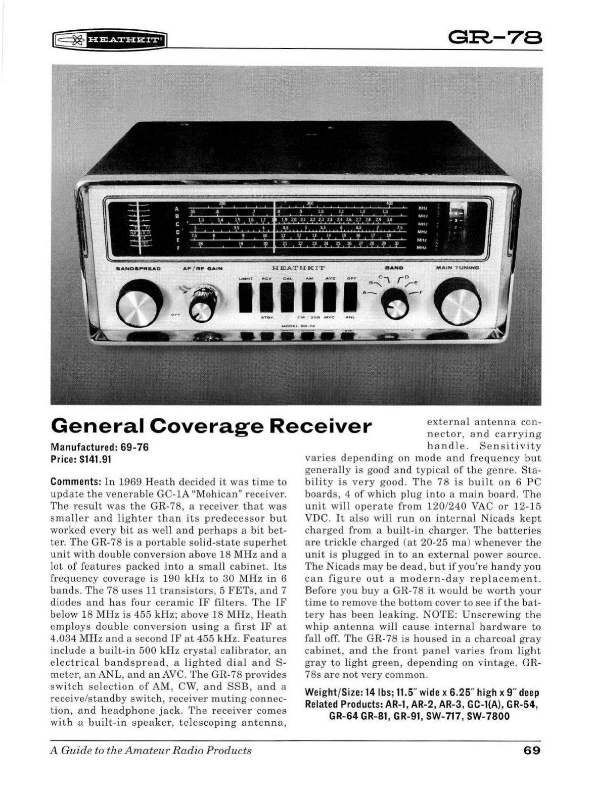
[[
~fUMiUH+il
G:R-78
General
Coverage
Receiver
exter
nal
antenna
con-
nector,
and
carrying
handle.
Sensitivity
Manufactured:
69-76
Price:
$141.91
Comments:
In
1969
Heath
decided
it
was
time
to
update
the
venerable
GC-
lA
"Mohican"
receiver.
The
result
was
the
GR-78, a
receiver
that
was
sma
ller
and
light
er
than
its
predecessor
but
worked
every
bit
as
well
and
perhaps
a
bit
bet
-
ter.
The
GR-78
is
a
portable
solid-
state
superhet
unit
with
double
conversion
above 18
MHz
and
a
lot
of
features
packed
into
a
small
cabinet.
Its
frequency
coverage
is
190
kHz
to
30
MHz
in
6
bands.
Th
e 78
uses
11
transistors,
5
FETs,
and
7
diodes
and
ha
s
four
ceramic
IF
filters.
Th
e
IF
below
18
MHz
is
455
kHz;
above
18
MHz,
Heath
emp
loys
double
conve
rsion
usin
g a
first
IF
at
4.034
MH
z a
nd
a seco
nd
IF
at
455
kHz.
Featu
res
include
a
built-in
500
kH
z
crystal
calibrator,
an
el
ec
trical
bandspread,
a
lighted
dial
and
S-
meter,
anANL,
and
an
AVC .
The
GR
-78
pro
vides
switc
h
se
l
ection
of
AM, CW,
and
SSB,
and
a
rece
ive
/stan
dby
switch,
receiver
muting
connec-
tion,
and
headphone
jack.
The
receiver
comes
with
a
built-in
spea
ker
,
telescoping
antenna,
A Guide to the
Amateur
Radio
Products
varies
d
epe
ndin
g
on
mode
and
frequency
but
genera
ll
y is good
an
d
typical
of
the
genre
.
Sta-
bility
is
very
good
.
Th
e
78
is
built
on
6
PC
boards,
4
of
which
plug
into
a
main
boa
rd
.
The
unit
will
operate
from
120/240
VAC
or
12-15
VDC.
It
also
will
r
un
on
internal
Nicads
kept
charged
from a
built
-
in
c
harger.
The
batteries
are
trickle
charged
(at
20-25
ma
)
whenever
the
unit
is
plu
gge
d
in
to
an
exter
nal
power
source
.
The
Nicads
may
be
d
ea
d,
but
if
you
'
re
hand
y
you
can
figure
out
a
modern-day
replacement
.
Before
you
buy
a GR-78
it
would
be
worth
yo
ur
time
to
remove
the
bottom
cover
to
see
ifthe
bat-
tery
ha
s
been
l
eaki
ng
.
NOTE:
Unscrewing
the
whip
antenna
will
cause
intern
al
hardw
are
to
fall
off.
The
GR-78
is
hou
se
d
in
a
charcoal
gray
cabinet,
an
d
the
front
panel
varies
from
light
gray
to
li
gh
t
gr
een,
depending
on
vintage.
GR
-
78s
are
not
very
common.
Weight/Size: 14lbs;11.5"
wide
x 6.25"
high
x
9"
deep
Related
Products:
AR-1
, AR-2, AR-3, GC-l(A), GR-54,
GR-64
GR-81,
GR-91
, SW-717, SW-7800
69
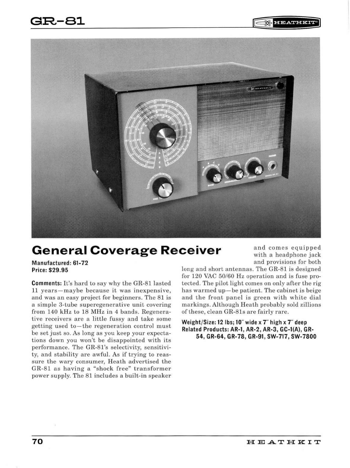
GIR,-81
rG=
~
1
H?&iif
Hil
General
Coverage
Receiver
and
comes
equipped
with
a
headphone
jack
and
provisions
for
both
Manufactured: 61-72
Price:
$29.95
Comments:
It's
hard
to
say
why
the
GR
-
81
lasted
11
years
-
maybe
because
it
was
inexpensive,
and
was
an
easy
project
for
beginners.
The
81
is
a
simple
3-tube
superegenerative
unit
covering
from
140
kHz
to
18
MHz
in
4
bands.
Regen
e
ra-
tive
receivers
are
a
li
tt
le
fussy
and
take
some
getting
used
to-the
regeneration
control
must
be
set
just
so. As
long
as
you
keep
your
expecta-
tions
down
you
won't
be
disappointed
with
its
performance.
The
GR
-
81's
selectivity,
sensitivi
-
ty,
and
stabi
li
ty
are
awful.
As
if
trying
to
reas
-
sure
the
wary
consumer
,
Heath
advertised
the
GR
-
81
as
having
a
"shock
free"
tra
n
sformer
power
supp
l
y.
T
he
81
i
ncludes
a
bui
l
t-in
speaker
70
long
and
short
antennas
.
The
GR-81
is
designed
for
120
VAC 50/60
Hz
operation
and
is
fuse
pro-
tected.
The
pilot
light
comes
on
only
after
the
rig
has
warmed
up -
be
patient
.
The
cabinet
is
beige
and
the
front
pane
l
is
green
with
white
dia
l
markings
. Al
though
H
eath
probably
sold
zillions
of
th
ese,
clean
GR-81s
are
fair
ly
rare.
Weight/Size:
12
lbs;
10
"
wide
x
Thigh
x T
deep
Related
Products:
AR-1
,
AR-2
,
AR-3
, GC-l(A),
GR-
54, GR-64, GR-78,
GR-91,
SW-717, SW-7800
HE
.AT
HK
IT
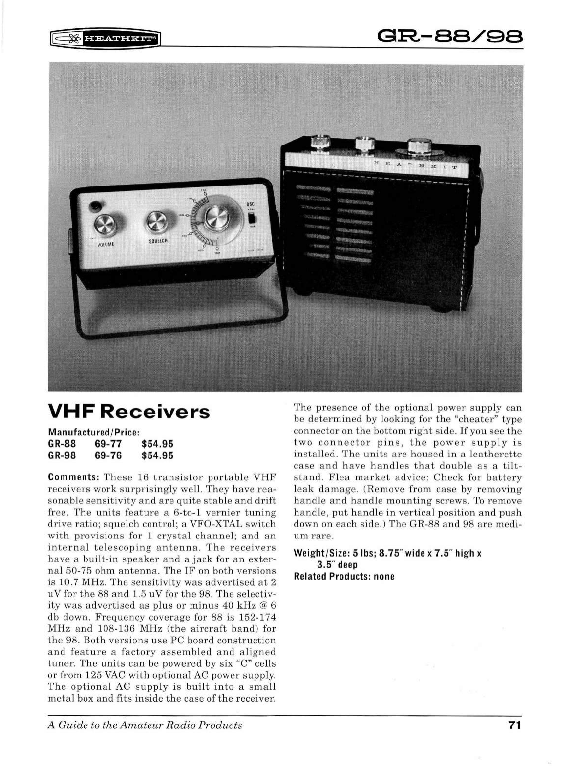
[
~
'§f
i§f
H&f
iiJ
VHF
Receivers
Manufact
ured
/
Pri
ce:
GR-88
69
-77 $54.95
GR
-98 69-76 $54.95
Comments:
These
16
transistor
portable
VHF
receivers
work
surprisingly
well.
Th
ey
have
rea
-
sona
ble
sensitivity
and
are
quite
stable
and
drift
free.
Th
e
units
feature
a 6-
to
-1
vernier
tuning
drive
ratio;
squelch
control;
a VFO-XTAL
switch
with
provi
s
ion
s
for
1
cr
ysta
l
channel;
and
an
internal
telescoping
antenna.
Th
e
receivers
h
ave
a
built
-
in
speaker
and
a
jack
for
an
exter
-
nal
50
-75
ohm
antenna.
Th
e
IF
on
both
versions
is
10
. 7
MHz.
The
se
nsitivit
y
was
advertised
at
2
uV
for
the
88
and
1.5
uV
for
the
98.
The
selectiv
-
ity
was
advertised
as
plus
or
minus
40
kHz
@ 6
db
down.
Frequ
e
nc
y
coverage
for
88
is
152-174
MHz
and
108-136
MHz
(t
h e
aircraft
band
) for
the
98.
Both
versions
use
PC
board
construction
and
feature
a
factory
assembled
a
nd
aligned
tun
er.
Th
e
units
can
be
pow
ere
d by s
ix
"C"
cells
or
from
125
VAC
with
optional
AC
power
supply.
The
optional
AC s
upply
is
built
into
a
small
m
eta
l
box
and
fit
s
inside
the
case
of
the
rec
e
iver
.
A Guide to the
Amateur
Radio
Products
G:R-88/98
The
pre
se
nce
of
the
optional
pow
er
supply
can
be
determined
by
looking
for
the
"
cheater"
type
connector
on
the
bottom
right
side.
If
you
see
the
two
connector
pins,
the
power
supply
is
installed.
The
unit
s
are
housed
in
a
leatherette
case
and
have
handles
that
double
as
a
tilt-
stand
.
Fl
ea
market
advice:
Check
for
battery
leak
damage.
(R
emove
from
cas
e
by
removing
handle
and
hand
le
mounting
screws.
To
remove
hand
le,
put
handl
e
in
vertical
position
and
push
down
on
each
side
.)
The
GR
-
88
and
98
ar
e
medi
-
um
rare.
Weight
/
Size:
5
lbs
; 8.75"
wide
x 7.5
..
hi
gh x
3.5"
deep
Related
Products:
none
71
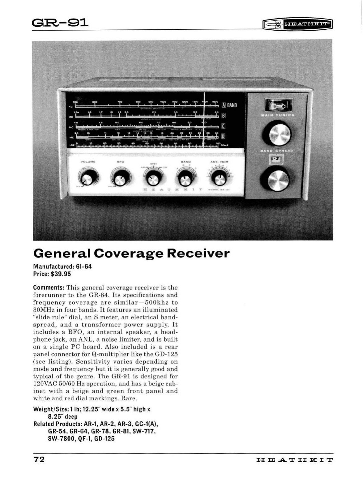
G:R-91
General
Coverage
Receiver
Manufactured: 61-64
Price:
$39.95
Comments:
This
general
coverage
receiver
is
the
forerunner
to
the
GR
-64.
Its
specifications
and
frequency
coverage
are
sim
ilar-500khz
to
30MHz
in
four
b
ands
.
It
features
an
illuminated
"s
lide
rule"
dial
,
an
S
meter
,
an
electrical
band-
spread,
a
nd
a
transformer
power
supply
.
It
includes
a
BFO
,
an
int
erna
l
speaker,
a h
ead
-
phone
j
ack,
an
ANL
, a
noi
se
limit
er,
and
is
bui
lt
on
a
single
PC
board.
Also
included
is
a
rear
panel
connector
for
Q-multiplier
like
the
GD-125
(see
listing
). S
ensitiv
it
y
varies
depending
on
mode
and
frequency
but
it
is
generally
good a
nd
typical
of
the
genre.
Th
e GR-91
is
designed
for
120VAC
50/60
Hz
operation,
and
h
as
a
beig
e
cab-
inet
with
a
bei
ge
and
gree
n
front
pan
el
and
white
and
red
di
al
markings.
Rar
e.
Weight/Size: 1lb;12.25"
wide
x 5.5
..
high
x
8.25"
deep
Related
Products:
AR-1,
AR-2
,
AR-3
, GC-l(A),
GR-54, GR-64, GR-78,
GR-81,
SW-717,
SW-7800,
QF-1,
GD-125
72
lE=
~
fi
1
?t5f
UH+i1
HE
.A..T
HK
IT
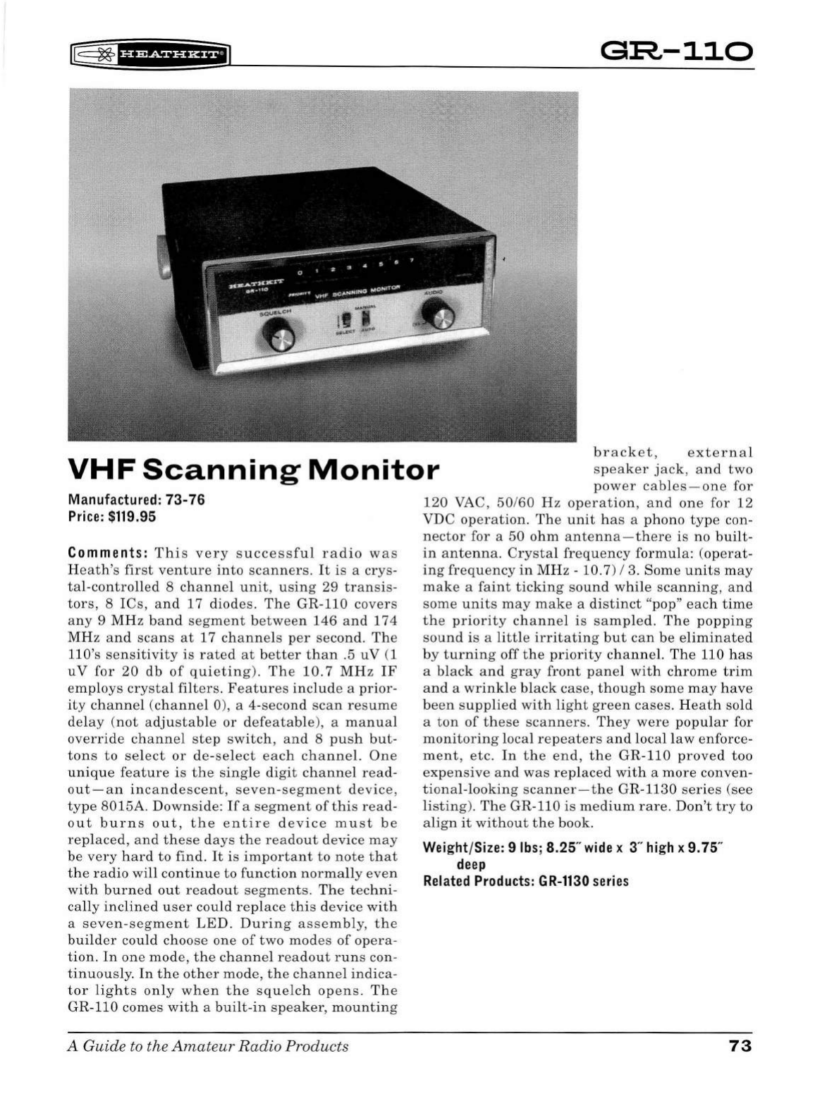
r@
~'#
1
Sii'HfiJ
G:R-110
VHF
Scanning
Monitor
bracket,
external
speaker
jack,
and
two
power
cables-one
for
Manufactured:
73-76
Price:
$119.95
Comments:
This
very
successf
ul
radio
was
Heath's
first
venture
into
scanners.
It
is
a
crys
-
tal-controlled
8
channel
unit
,
using
29
transis
-
tors,
8
IC
s,
and
17 di
odes
.
The
GR-110
covers
any
9
MHz
band
segment
between
146
and
174
MHz
an
d
scans
at
17
channels
per
second.
The
llO
's
sensitivity
is
rated
at
better
than
.5
uV
(1
uV
for
20
db
of
q
ui
eting).
The
10
.7
MHz
IF
e
mpl
oys
crystal
filters.
Features
include
a
prior-
it
y
channel
(channel
0), a
4-second
scan
resume
del
ay
(not
adjustab
le
or
defeatable),
a
manual
override
channel
ste
p
switch,
and
8
push
but-
tons
to
se
l
ect
or
de-select
eac
h ch
anne
l.
One
unique
feature
is
the
sing
le
digit
channel
read-
o
ut-
an
in
ca
nd
esce
nt
,
seven
-
segment
device,
type
8015A.
Downside:
Ifa
segment
of
t
hi
s
read-
o
ut
burns
out,
the
entire
device
must
be
rep
l
aced,
and
these
days
the
readout
device
may
be
very
h
ard
to
find.
It
is
important
to
note
that
the
radio
will
continue
to
function
normally
even
with
burned
out
rea
dou
t
segments
.
The
techni-
cally
inclined
user
could
replace
this
device
with
a
seven
-
segment
LED.
During
assembly,
t h e
builder
could
choose
one
of
two
modes
of
opera
-
tion.
In
one
mode,
the
chan
nel
readout
r
un
s
co
n-
tinuously.
In
t he
other
mode,
the
channel
indica-
tor
lights
only
when
the
squelch
ope
ns.
The
GR-110
comes
with
a
built-in
speaker,
mounting
A
Guide
to
the
Amateur
Radio
Products
1
20
VAC,
50
/
60
Hz
operation,
and
one
for
12
VDC
operation.
The
unit
h
as
a
ph
ono
type
con-
nector
for a 50
ohm
antenna-t
h
ere
is
no
bu
ilt-
in
antenna
.
Crystal
frequency
formula:
(operat-
ing
frequency
in
MHz
-10. 7) I 3.
Some
unit
s m
ay
make
a
faint
ticking
sound
whi
le
scanning,
and
some
units
may
ma
ke a
distinct
"pop"
each
time
the
priority
channel
is
sampled
.
The
popping
sound
is a
little
irritating
but
can
be
e
li
minated
by
turning
off
the
priority
channel.
The
110
has
a
black
and
gray
front
panel
w
ith
chrome
trim
and
a
wrinkle
black
case,
though
some
may
have
been
supplied
with
li
ght
green
cases.
Heath
so
ld
a
ton
of
these
scanners.
They
were
popular
for
moni
to
rin
g
local
repeaters
and
local
l
aw
enforce
-
ment,
etc.
In
the
end,
the
GR-
110
proved
too
expensive
an
d
was
replaced
wit
h a
more
conven-
tional-looking
scan
n
er-t
h e
GR
-11
30
series
(see
li
sting).
The
GR-110
is
medium
rare.
Don
't
try
to
align
it
without
the
book.
Weight/Size: 9
lbs;
8.25"
wide
x 3"
high
x 9.75"
deep
Related
Products:
GR-1130
series
73
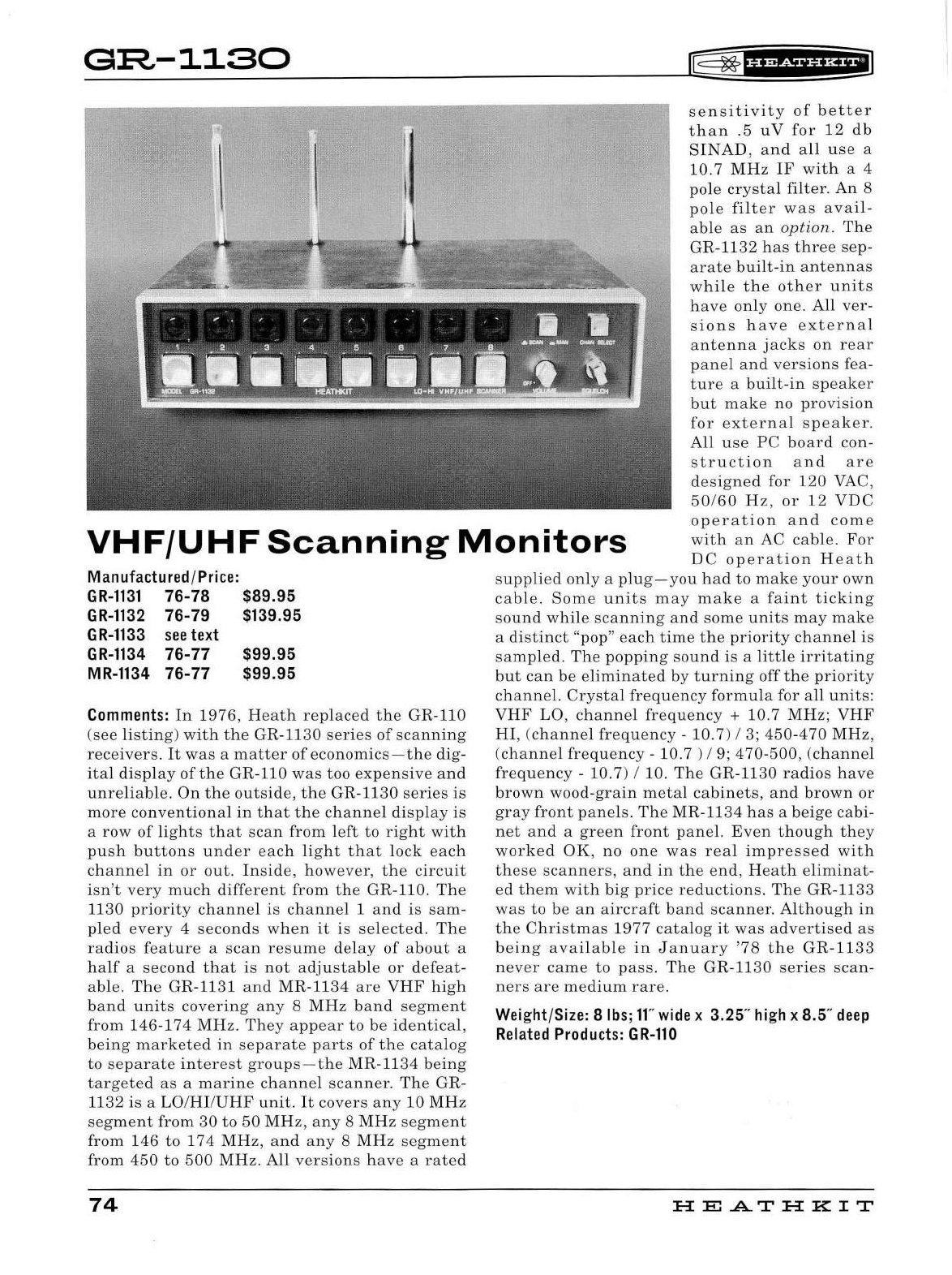
G:R-1130
~fHWiHHilJ
sensitivity
of
better
than
.5
uV
for
12
db
SINAD
,
an
d
all
us
e a
10.7
MHz
IF
with
a 4
pole
crystal
filt
er.
An
8
pol
e
filter
was
avail-
able
as
an
option.
Th
e
GR
-11
32
has
three
sep
-
arate
built
-
in
anten
n
as
while
the
other
unit
s
h
ave
only
one.
All
ver-
sions
h
ave
external
antenna
jacks
on
rear
panel
and
versions
fea
-
ture
a
built-in
speaker
but
make
no
provision
for
externa
l
speaker.
All
use
PC
board
con-
struct
ion
and
are
designed
for
120
VAC,
50/60
Hz,
or
12
VDC
operation
and
come
with
an
AC
cable
.
For
VHF/UHF
Scanning
Monitors
D C
operation
Heath
supp
li
ed
on
ly a
plug-you
had
to
make
your
own
cable
.
Some
units
may
make
a
fa
in
t
ticking
sound
while
scann
in
g
and
some
units
may
make
a
distinct
"pop"
eac
h
time
the
priority
channel
is
samp
l
ed.
The
popping
so
und
is
a
little
ir
ritating
but
can
be
e
liminat
ed
by
turning
off
the
priority
channel.
Crystal
frequency
formula
for
all
units:
Manufactured /
Pr
i
ce:
GR-1131
76-78 $89.95
GR-1132
76-79 $139.95
GR-1133
see
text
GR-1134
76-77
MR-1134
76-77
$99.95
$99.95
Comments:
In
1976,
Heath
replaced
the
GR
-110
(see
listing)
with
the
GR-1130
series
of
scanning
receivers.
It
was
a
matter
of
economics-the
di
g-
ital
display
of
the
GR-110
was
too
expensive
and
unr
e
liabl
e.
On
the
outside,
the
GR
-
1130
series
is
more
conventional
in
that
the
channel
display
is
a
row
of
lights
that
scan
from
left
to
right
with
push
buttons
under
each
light
that
lock
each
channe
l
in
or
out.
Inside,
however
,
the
circuit
isn't
very
much
different
from
the
GR
-110.
The
1130
priority
channe
l
is
channel
1
and
is
sam
-
pled
every
4
secon
ds w
hen
it
is
se
l
ected.
The
radios
feature
a
scan
res
um
e
delay
of
about
a
half
a
second
that
is
not
adjustable
or
defeat-
able.
The
GR
-1131
and
MR-1134
are
VHF
high
band
units
covering
any
8
MHz
band
segment
from
146
-
174
MHz.
They
appear
to
be
identical,
being
marketed
in
separate
parts
of
the
catalog
to
separate
interest
groups
-
the
MR-1134
being
targeted
as
a
marine
cha
nn
el
scanner.
The
GR
-
1132
is
a
LO/HI/UHF
unit.
It
covers
any
10
MHz
segment
from
30
to
50
MHz,
any
8
MHz
segment
from
146
to
174
MHz,
an
d
any
8
MHz
segment
from
450
to
500
MHz.
All
versions
have
a
rated
74
VHF
LO
, c
hann
el
frequency
+ 10.7
MHz;
VHF
HI
, (ch
anne
l
frequency
-
10.7
) I 3;
450-470
MHz
,
(channel
frequency
-10. 7 ) I 9; 4 70-500,
(cha
nn
el
frequency
-
10.7)
I 10.
The
GR-1130
radios
hav
e
brown
wood-grain
m
eta
l
cabinets,
a
nd
brown
or
gray
front
pan
els.
Th
e
MR-1134
ha
s a
bei
ge
cabi-
net
and
a
green
front
panel.
Even
though
they
worked
OK,
no
one
was
real
impres
sed
with
these
scanners
,
and
in
the
end
,
Heath
eliminat
-
ed
them
with
big
price
reductions.
The
GR
-11
33
was
to
be
an
aircraft
band
scanner
.
Although
in
the
Christmas
1977
catalog
it
was
ad
vertise
d
as
b
eing
ava
ilabl
e
in
J a
nu
ary
'78
the
GR-1133
never
came
to
pass.
The
GR-1130
series
scan-
ners
are
medium
rare
.
Weight/Size: 8
lbs;
ff'
wide
x 3.25"
high
x 8.5"
deep
Related
Products:
GR-110
HE
A..T
HK
IT
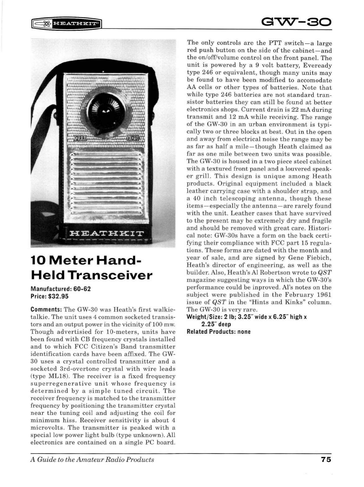
rB
~f
HMf#ii*E'1
10
Meter
Hand-
Held
Transceiver
Manufactured: 60-62
Price:
$32.95
Comments:
The
GW-30
was
Heath's
first
walkie-
talkie.
The
unit
uses
4
common
socketed
transis-
tors
and
an
output
power
in
the
vicinity
of 100 mw.
Though
advertisied
for
10-meters,
units
have
been
found
with
CB
frequency
crystals
installed
a
nd
to
which
FCC
Citizen's
Band
transmitter
identification
cards
h
ave
been
affixed.
The
GW-
30
uses
a
crystal
controlled
transmitter
and
a
socketed
3rd-overtone
crystal
with
wire
l
eads
(type
ML18).
The
receiver
is
a
fixed
frequency
superregenerative
unit
whose
frequency
is
determined
by
a
simp
le
tuned
circuit.
The
receiver
frequency
is
matched
to
the
transmitter
frequency
by
positioning
the
transmitter
crysta
l
near
the
tuning
coil
and
adjusting
the
coil for
minimum
hiss.
Receiver
sensitivity
is
about
4
microvolts.
The
transmitter
is
peaked
with
a
special
low
power
light
bulb
(
type
unknown).
All
elec
tron
ics
are
contained
on
a
single
PC
board.
A Guide to the
Amateur
Radio
Products
GVV--80
The
only
contro
ls
are
the
PTT
switch-a
larg
e
red
push
button
on
the
side
of
the
cabinet-and
the
on/off/volume
control
on
the
front
pan
el.
Th
e
unit
is
powered
by
a 9
volt
battery,
Eveready
type
246
or
equivalent,
though
many
unit
s
may
be
found
to
ha
ve
been
modified
to
accomodate
AA
cells
or
other
types
of
batteries.
Note
that
while
type
246
batteries
are
not
standard
tran-
sistor
batteries
they
can
sti
ll
be
found
at
better
electronics
s
hop
s.
Current
drain
is
22
mA
during
transmit
an
d 12
mA
while
receiving.
Th
e
range
of
the
GW-30
in
an
urban
environment
is
typi-
cally
two
or
three
blocks
at
best.
Out
in
the
open
and
away
from
electrical
noise
the
range
may
be
as
far
as
half
a
mile-though
Heath
claimed
as
far
as
one
mile
between
two
units
was
possible.
The
GW-30
is
housed
in
a
two
piece
steel
cabinet
with
a
textured
front
panel
and
a
louvered
speak
-
er
gri
ll.
Thi
s
design
is
unique
among
Heath
products.
Original
equipment
included
a
black
leather
carrying
case
with
a
sho
uld
er
strap,
and
a
40
inch
telescoping
antenna,
though
these
items-especially
the
antenna
-
are
rarely
found
with
the
unit.
Leather
cases
that
have
survived
to
the
present
may
be
extremely
dry
and
fragile
and
shou
ld
be
removed
with
great
care.
Histori-
cal
note:
GW-30s
have
a
form
on
the
back
certi-
fying
their
compliance
with
FCC
part
15
regu
la-
tions.
Th
ese
forms
are
dated
with
the
month
and
year
of
sa
le,
and
are
signed
by
Gene
Fiebich,
Heath's
director
of
engineering,
as
well
as
the
builder.
Also,
Heath's
Al
Robertson
wrote
to
QST
magazine
suggesting
ways
in
w
hi
ch
the
GW-30's
performance
could
be
inproved.
Al's
notes
on
the
subject
were
published
in
the
February
1961
issue
of
QST
in
the
"Hin
t s
and
Kinks"
column.
The
GW-30
is
very
rare.
Weight/Size: 2
lb;
3.25"
wide
x 6.25"
high
x
2.25"
deep
Related
Products:
none
75
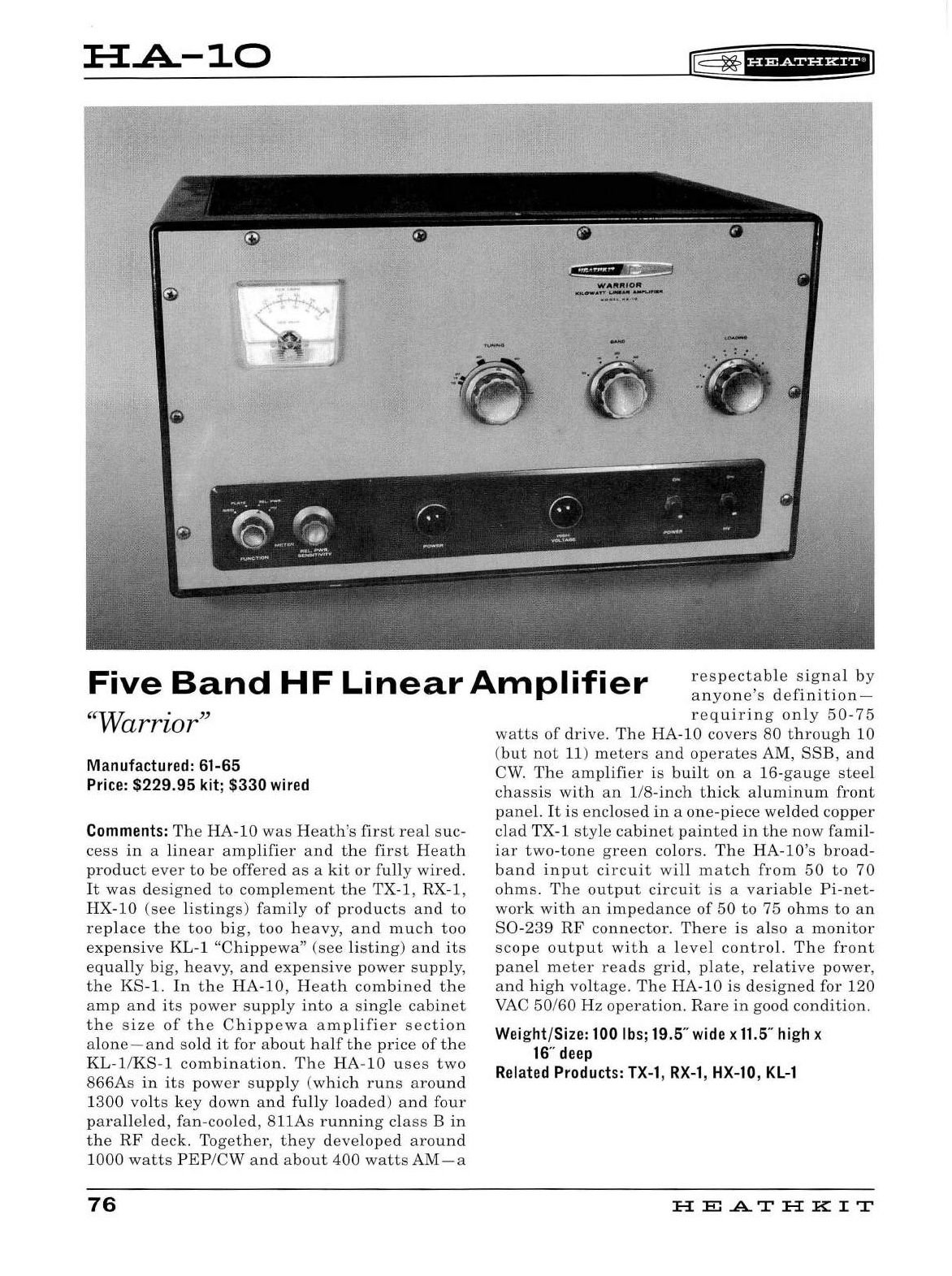
HA.-10
rE=
~
fU@i§fH+IJ
Five
Band
HF
Linear
Amplifier
respectable
signa
l
by
anyone's
definition-
"Warrior''
Manufactured: 61-65
Price:
$229.95 kit; $330
wired
Comments:
The
HA-10
was
H
eath
's
first
real
suc
-
cess
in
a
linear
amplifier
and
the
first
Heath
product
ever
to
be
offered
as
a
kit
or
fu
ll
y
wired.
It
was
d
esigned
to
complement
the
TX-1, RX-1,
HX-10
(see
listings)
fami
ly
of
product
s
and
to
replace
the
too
big,
too
h
eavy,
and
much
too
expensive
KL-1
"Chippewa"
(see
listing)
and
it
s
equally
bi
g,
he
avy,
and
ex
p
ens
ive
power
sup
pl
y,
the
KS-1.
In
the
HA-10
,
Heath
combined
the
amp
an
d
its
power
supply
into
a
sing
le
cabinet
the
size
of
the
Chippewa
amplifier
sect
ion
alone-and
sold
it
for
about
half
the
price
of
the
KL-1
/
KS-1
combination.
Th
e
HA-10
us
es
two
866As
in
its
power
supply
(whic
h
runs
aro
und
1300
vol
ts
key
down
and
fully
load
ed)
and
four
parallel
ed,
fan-cooled
, 811As
running
cl
ass
B
in
the
RF
deck.
Together,
they
developed
around
1000
watts
PEP
/
CW
and
about
400
watts
AM-a
76
r
equiring
only
50
-75
watts
of
drive.
The
HA
-1
0
covers
80
through
10
(but
not
11)
meters
and
operates
AM,
SSB,
and
CW.
The
amp
lifier
is
bui
lt
on
a
16-gauge
steel
chassis
with
an
1/8-inch
thick
aluminum
front
panel.
It
is
enclosed
in
a
one
-
piece
welded
copper
clad
TX-1
style
cabinet
painted
in
the
now
famil-
iar
two-tone
gree
n
colors.
The
HA
-lO
's
broad
-
band
input
circuit
wi
ll
match
from
50
to
70
ohms.
The
output
circuit
is
a
variable
Pi-net-
work
with
an
impedance
of
50
to
75
ohms
to
an
S0
-
239
RF
connector
.
There
is
also
a
monitor
scope
output
with
a
level
control.
Th
e
front
pane
l
meter
reads
grid,
pl
ate,
relative
power,
and
high
voltage
.
The
HA-10
is
d
esig
ned
for
120
VAC
50
/60
Hz
operation.
R
are
in
good
condition.
Weight/Size:
100
lbs;
19.5"
wide
x
11.5
"
high
x
16
"
deep
Related
Products:
TX-1
,
RX-1,
HX-10,
KL-1
H
El
.AT
HK
IT
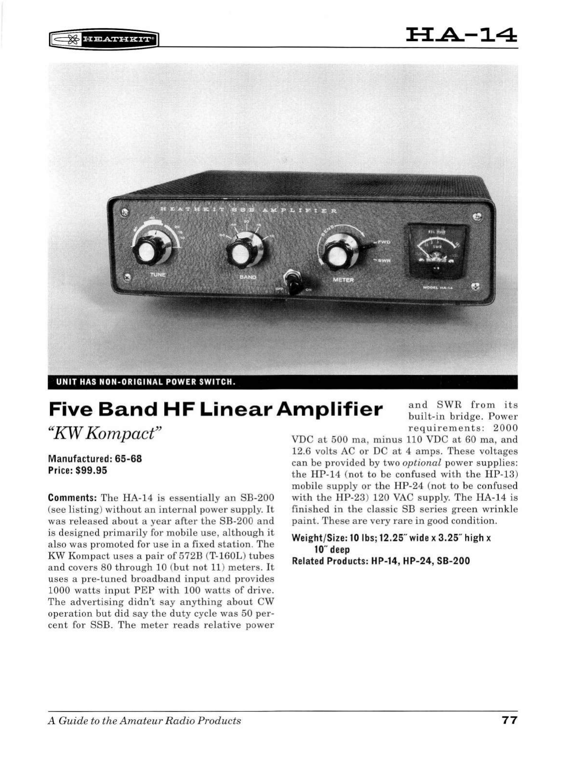
lE
~
'§f
ffif
f
§'Hi'J
:H:A-14
UNIT
HAS
NON-ORIGINAL
POWER
SWITCH.
Five
Band
HF
Linear
Amplifier
and
SWR
from
its
built-in
b
ri
dge.
Pow
er
"KW Kompact"
Manufactured: 65-68
Price:
$99.95
Comments:
The
HA-14
is
essentially
an
SB-200
(see
li
s
tin
g)
without
an
internal
p
owe
r s
uppl
y.
It
was
re
le
ase
d
about
a
yea
r
after
the
SB-200
and
is
d
es
igned
primaril
y for
mobil
e u
se,
although
it
also
was
promoted
for
use
in
a fixed
sta
tion.
Th
e
KW
Komp
act
u
ses
a
pair
of
572B
(
T-160L
)
tub
es
and
covers
80
throu
gh
10
(
but
not
11)
mete
rs
.
It
use
s a
pre-tuned
bro
a
dband
input
an
d
pro
v
id
es
1000
watts
input
PEP
with
100
watts
of
driv
e.
The
a
dv
er
ti
s
ing
didn
't
say
an
yt
hin
g
about
CW
operation
but
did
say
the
dut
y cycle
was
50
per-
cent
for
SSB.
Th
e m eter
re
ads
re
la
tive
pow
er
A
Guid
e to the
Amat
e
ur
Radio
Products
requir
eme
nts:
2000
VDC
at
500
ma
,
minus
110 VDC
at
60
ma
, a
nd
12.6 vo
lt
s AC
or
DC
at
4
amps.
Th
es
e
voltages
can
be
provided
by
two
optional
pow
er
supplies:
the
HP-14
(
not
to
be
confus
ed
with
the
HP-1
3)
mobil
e s
upply
or
the
HP-24
(not
to
be
confu
sed
with
the
HP-23
)
120
VAC
supply.
The
HA-14
is
fini
shed
in
the
cl
ass
ic SB
ser
i
es
gree
n
wrinkle
paint.
These
are
very
rare
in
good
condition.
Weight/Size:
10
lbs;
12.25"
wide
x 3.25"
high
x
10"
deep
Related
Products:
HP-14, HP-24, SB-200
77
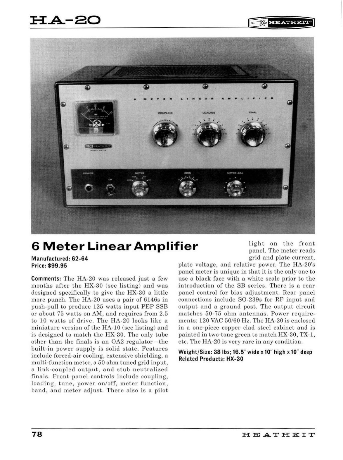
H.A-80
f=
~
f§f@fUHiiJ
e
M•T•"
LtN•A•
A•P&..tfltalt
6
Meter
Linear
Amplifier
light
on
the
front
pane
l.
The
meter
reads
grid
and
plate
current,
Manufactured:
62-64
Price:
$99.95
Comments:
Th e
HA
-20
was
re
l
eased
ju
st
a few
mont
h s
after
the
HX
-
30
(see
li
sting)
and
was
des
i
gned
specifically
to
give
th e
HX
-30 a
little
more
punc
h. The
HA
-20
uses
a
pair
of
6146s
in
push
-
pull
to
produce
125
watts
input
P
EP
SSB
or
about
75
watts
on
AM,
and
requires
from
2.5
to
10
watts
of
drive.
The
HA-20
looks
like
a
miniature
version
of
the
HA-10
(see
listing)
an
d
is
designed
to
match
the
HX
-
30
.
The
only
tu
be
other
than
the
fina
ls is
an
OA2
regu
l
ator
- th e
bui
lt -
in
power
supp
ly
is
so
li
d
state.
Features
incl
u
de
forced-
air
coo
li
ng,
extensive
s
hi
el
ding,
a
multi
-
functio
n
meter,
a
50
ohm
tuned
g
ri
d
input,
a
link
-
coup
led
outp
u
t,
and
stub
ne
u
tralized
fina
ls.
Front
pane
l
contro
ls i
nclude
coupling,
loading,
tune,
power
on/off,
meter
function,
band,
and
meter
adjust.
There
also
is
a
pi
l
ot
78
plate
voltage,
and
re
l
ative
power.
Th e HA-20's
pane
l
meter
is
unique
in
that
it
is
the
on
ly
one
to
use
a
black
face
wit
h a
white
sca
le pr
ior
to
the
introductio
n
of
the
SB
series
.
There
is
a
rear
pane
l
contro
l
for
bias
adjustment.
R
ear
pane
l
connections
include
S0-239s
for
RF
input
and
output
and
a
ground
post.
The
outp
ut
circuit
matc
h
es
50
-75
ohm
antennas.
Power
require-
ments:
1
20
VAC
50
/60 Hz. The
HA
-20 is
enclosed
in
a
one
-
piece
copper
clad
steel
cabinet
and
is
pa
i
nted
in
two
-
tone
green
to
match
HX
-30, TX-1 ,
etc.
T
he
HA-20
is
very
rare
in
any
cond
ition
.
Weight/Size: 38
lbs;
16.5"
wide
x
10
"
high
x
10
"
deep
Related
Products:
HX-30
HE
.AT
HK
IT
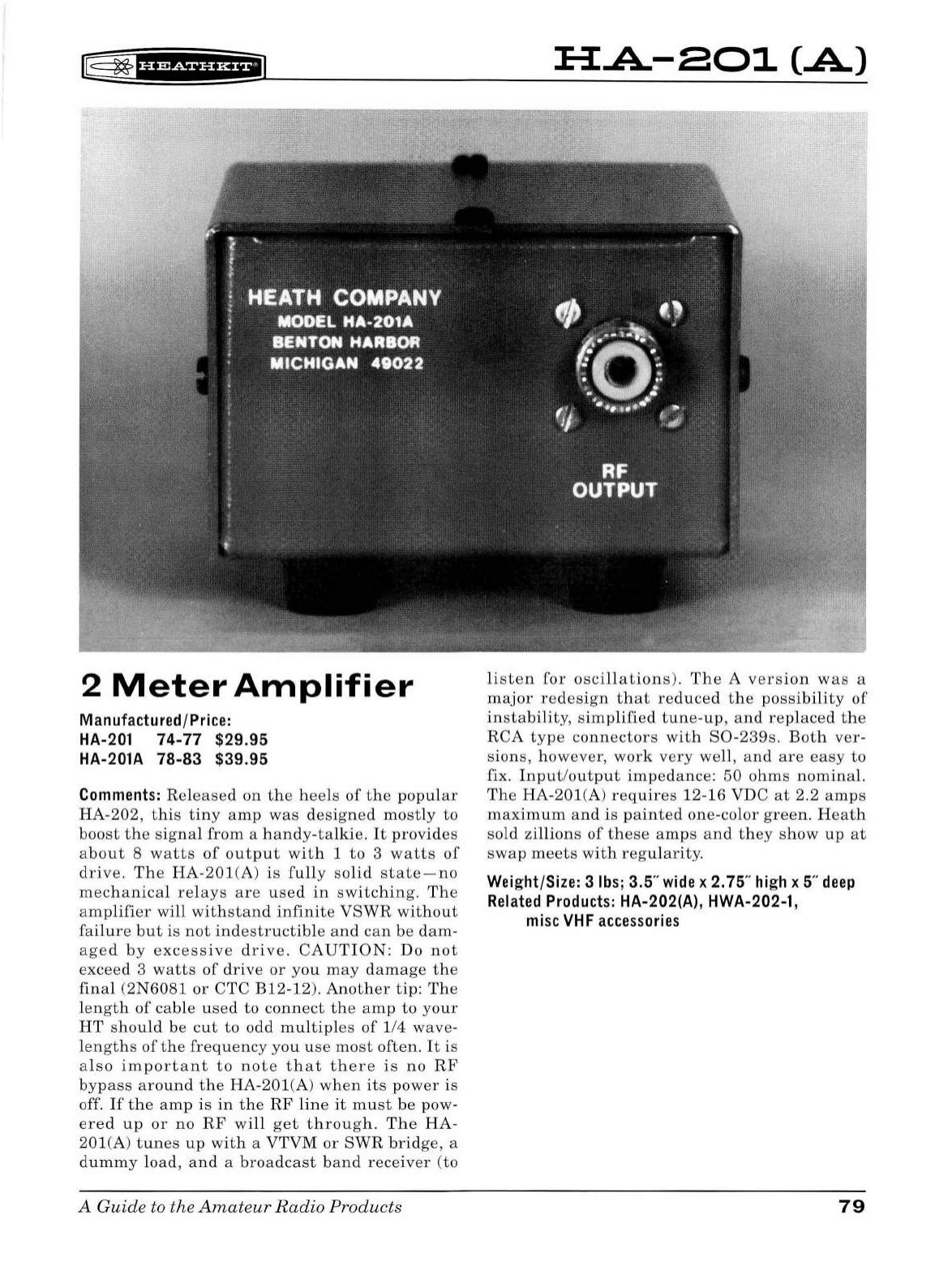
lE;
~
'Hif
f
§f
Hiil
2
Meter
Amplifier
Manufactured/Price:
HA-201
74-77
$29.95
HA-201A
78-83 $39.95
Comments:
Rel
eased
on
t h e
heels
of
the
p
opular
HA
-
202
,
this
ti
ny
amp
was
designed
mostly
to
boost
the
signa
l
from
a
ha
n
dy
-
ta
l
kie.
It
provides
about
8
watts
of
output
with
1
to
3
watts
of
drive.
The
HA
-
201(A
)
is
fu
ll
y
solid
state-no
mechanical
re
l
ays
are
use
d
in
switching.
The
amplifier
will
withstand
infinite
VSWR
without
failure
but
is
not
indestructib
le
and
can
be
dam-
aged
by
excessive
drive
.
CAUTION:
Do
not
exceed
3
watts
of
drive
or
you
may
damage
the
final
(2N
6081
or
CTC
B12
-12).
Another
ti
p:
The
length
of
cable
used
to
connect
th
e
amp
to
your
HT
should
be
cut
to
odd
m
ul
tipl
es
of
114
wav
e-
l
engths
of
the
frequency
you
use
most
often
.
It
is
a l
so
important
to
note
t h
at
there
is
no
RF
bypass
around
the
HA-201(A)
when
its
power
is
off.
If
the
amp
is
in
the
RF
li
ne
it
must
be pow-
ered
up
or
no
RF
will
get
t h
rough.
T
he
HA-
201(A
)
tunes
up
with
a
VTVM
or
SWR
br
i
dg
e, a
dummy
load,
and
a
broadcast
band
receiver
(
to
A
Guide
to the
Amateur
Radio Products
H.A-801
(.A)
listen
for
oscillations
).
The
A ve
rsion
was
a
major
redesig
n t h
at
re
du
ced
the
possibility
of
in
stability,
simplified
tu
ne
-
up
,
and
rep
l
aced
the
RCA
type
connectors
wit
h
S0-239s.
Both
ver-
s
ions
, h
owever
,
work
very
well
,
and
are
eas
y
to
fix. I
nput
/
out
p
ut
impedance:
50
ohms
nominal.
The
HA
-201(A)
requires
12-16 VDC
at
2.2
amps
maximum
and
is
painted
one-color
green
.
Heath
sold zi
ll
ions
of
these
amps
and
they
sh ow
up
at
swap
meets
with
regular
ity.
Weight/Size: 3
lbs;
3.5
..
wide
x 2.75"
high
x 5"
deep
Related
Products:
HA-202(A), HWA-202-1,
misc
VHF
accessories
79
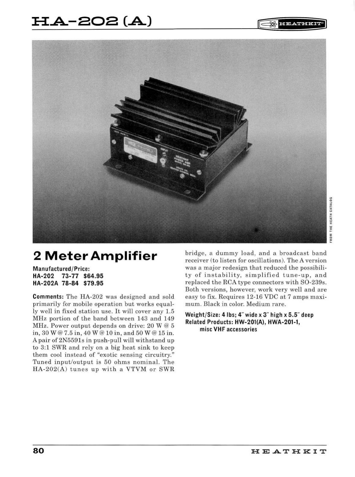
:a:.A-aoa
(.A)
2
Meter
Amplifier
Manufactured/Pri
ce:
HA
-202 73-
77
$64.95
HA-202A
78-84
$79.95
Comments:
The
HA
-
202
was
designed
and
sold
primarily
for
mobile
operation
but
works
equa
l-
ly
well
in
fixed
station
use.
It
will
cover
any
1.5
MHz
portion
of
the
band
between
143
and
149
MH
z.
Power
output
depends
on
drive:
20 W @ 5
in,
30
W@7.5
in,
40
W@
10
in,
and
50W@15
in.
A
pair
of
2N5591s
in
pus
h-
pu
ll
will
wit
h
stand
up
to
3:1
SWR
and
rely
on
a big
heat
sink
to
keep
th
em
cool
instead
of
"exotic
sensing
circuitry."
Tuned
input
/
output
is
50
ohms
nominal.
The
HA-202(A)
tunes
up
wi
th
a
VTVM
or
SWR
80
r&
~
·ue+tna+1
bridge
, a
dummy
l
oad,
and
a
broadcast
band
receiver
(to
li
sten
for osc
ill
ations).
The A
version
was
a
major
redesign
that
reduced
the
possibili-
ty
of
instability,
simplified
tune
-
up,
and
replaced
the
RCA
type
co
n
nectors
wit
h
S0
-
239s.
Both
versions,
however,
work
very
well
and
are
easy
to
fix. R
equires
12-16 VDC
at
7
amps
maxi
-
mum.
Bl
ack
in
color
.
Medium
rare.
Weight/Size: 4
lbs
; 4"
wide
x 3"
high
x 5.5"
deep
Related
Products:
HW-201(A), HWA-201-1,
misc
VHF
accessories
HE.A.TH
KIT
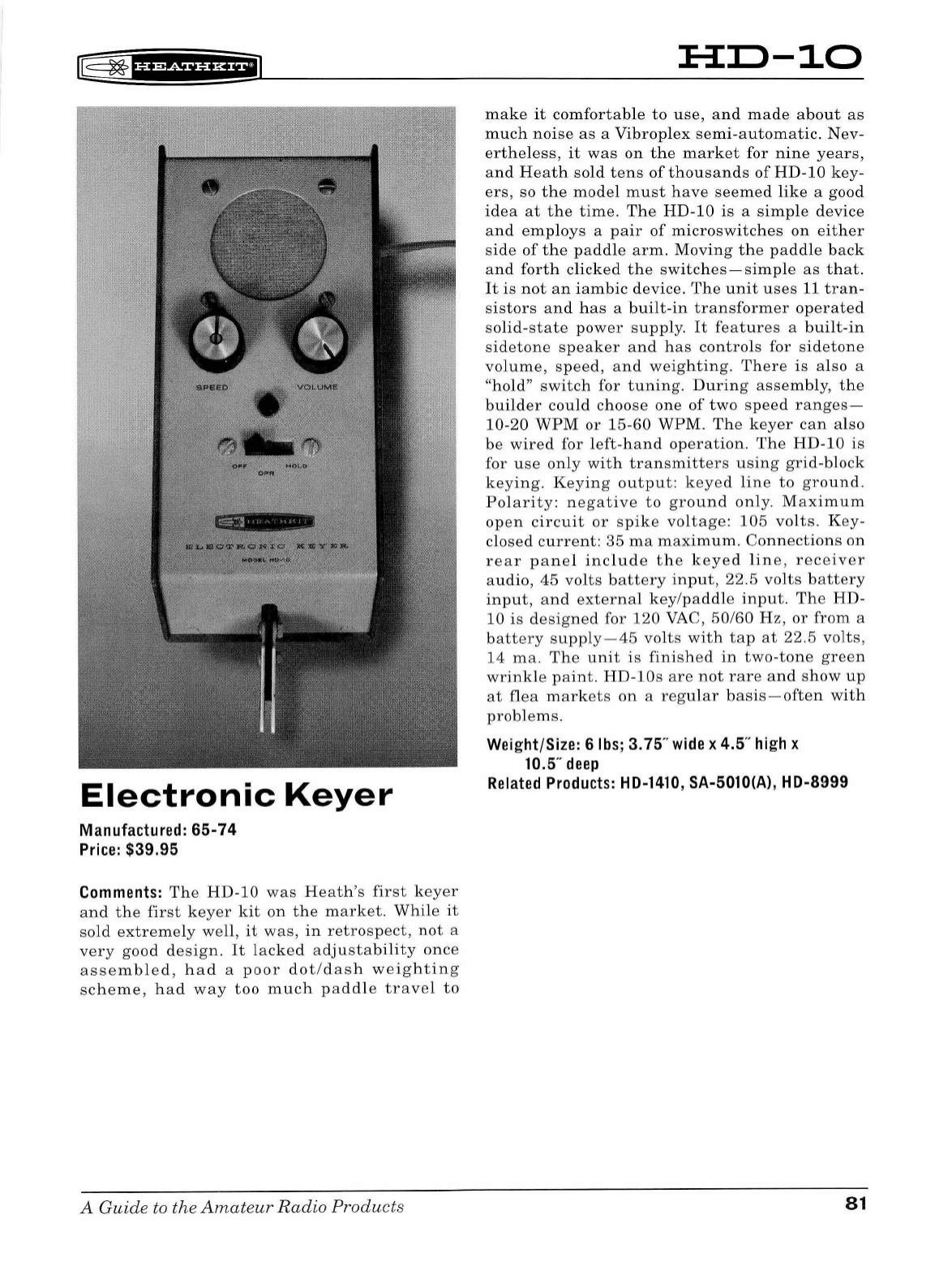
l@
~
f
d&Wi#f
H+iil
Electronic
Keyer
Manufactured:
65-74
Price:
$39.95
Comments:
The
HD-10
was
Heath
's
first
keyer
and
the
first
keyer
kit
on
the
market.
While
it
so
ld
extremely
well,
it
was,
in
retrospect,
not
a
very
good
design.
It
lacked
adjustability
once
assembled,
had
a
poor
dot
/
dash
weighting
scheme,
had
way
too
much
paddle
travel
to
A Guide
to
the
Amateur
Radio
Products
:H:I:>-10
make
it
comfortable
to
use,
and
made
about
as
much
noise
as
a
Vibroplex
semi-automatic.
Nev-
ertheless,
it
was
on
the
market
for
nine
years,
and
Heath
sold
tens
of
thousands
of
HD-10
key-
ers,
so
the
model
must
have
seemed
like
a
good
idea
at
the
time.
The
HD-10
is
a
simple
device
and
employs
a
pair
of
microswitches
on
either
side
of
the
paddle
arm.
Moving
th
e
paddle
back
and
forth
clicked
the
switches-simple
as
that.
It
is
not
an
iambic
device.
The
unit
uses
11
tran-
sistors
and
has
a
built-in
transformer
operated
solid-state
power
supply.
It
features
a
built-in
sidetone
speaker
and
has
controls
for
sidetone
volume,
speed
,
and
weighting.
There
is
also
a
"hold"
switch
for
tuning
.
During
assembly,
the
builder
could
choose
one
of
two
speed
ranges-
10-20
WPM
or
15-60
WPM.
The
keyer
can
also
be
wired
for
left-hand
operation
.
The
HD-10
is
for
use
only
with
transmitters
using
grid-block
keying.
Keying
output:
keyed
line
to
ground.
Polarity:
negative
to
ground
only.
Maximum
open
circuit
or
spike
voltage:
105
volts.
Key-
closed
current:
35
ma
maximum.
Connections
on
rear
panel
include
the
keyed
line,
receiver
audio,
45
volts
battery
input,
22.5
volts
battery
input,
and
external
key/paddle
input.
The
HD-
10
is
designed
for
120
VAC
,
50
/6
0
Hz
,
or
from
a
battery
supply-45
volts
with
tap
at
22.5
volts,
14
ma.
The
unit
is
finished
in
two-tone
green
wrinkle
paint.
HD-lOs
are
not
rar
e
and
show
up
at
flea
markets
on
a
regular
basis
-
often
with
problems.
Weight/Size: 6
lbs;
3.75"
wide
x 4.5"
high
x
10.5"
deep
Related
Products:
HD-1410,
SA-5010(A), HD-8999
81
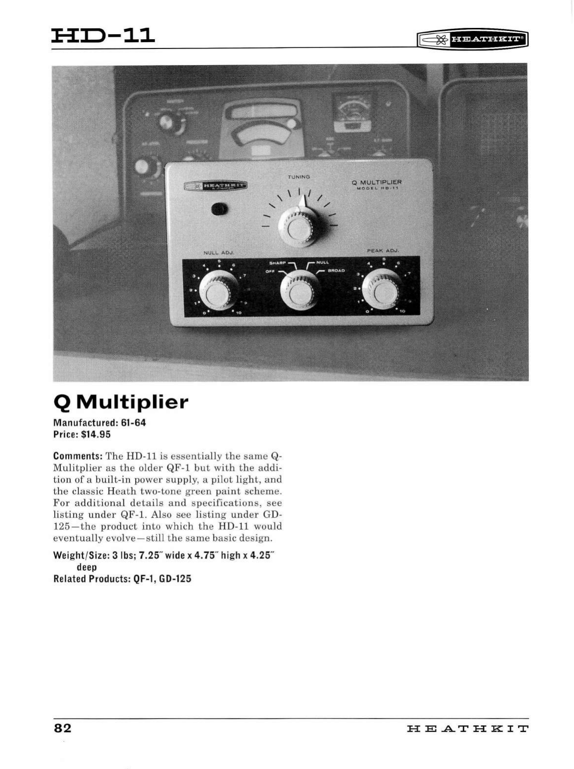
:H:D-11
!C
;.i;
!if.fii'f!mil
Q
Multiplier
Manufactured:
61
-64
Price:
$14.95
-
Comment
s:
The
HD
-11
is
essentially
the
same
Q-
Mulitplier
as
the
older
QF-1
but
with
the
addi-
tion
of
a
bui
lt-
in
power
supply,
a
pilot
light
,
and
the
classic
Heath
two
-
ton
e
green
paint
scheme.
For
additional
detai
ls
and
specifications
,
see
listing
under
QF
-1. Also
see
listing
under
GD-
125-the
product
into
which
the
HD-11
would
eventually
evolve-still
the
same
ba
sic
de
s
ign
.
We
i
ght
/
Size:
3
lbs
; 7.25"
wide
x 4.75"
hi
gh x 4.25"
deep
Related
Pr
oduct
s:
QF-1
,
GD-125
82
®=
~
f
Ui#i§f
Hil
Q
MULTIPLIER
MOO
I L
HD
~
11
HE
.AT
HK
IT
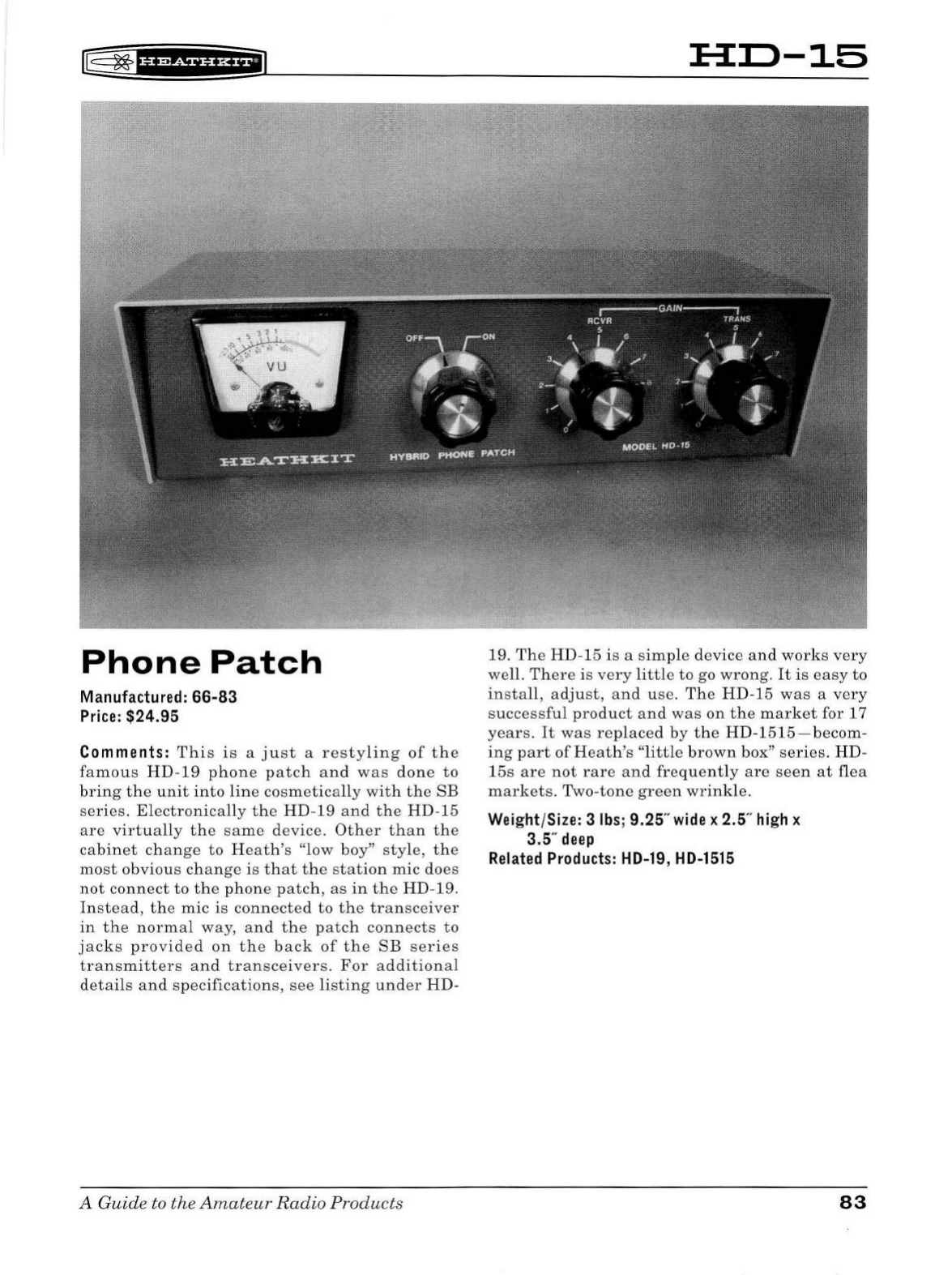
lB
~
fff
MiHHEiJ
Phone
Patch
Manufactured:
66-83
Price
: $24.95
Comments:
This
is
a
just
a
restyling
of
t h e
famous
HD-19
pho
n e
patch
and
was
done
to
bring
th e
unit
into
line
cosmetically
wit
h
the
SB
series
. E l
ectronically
the
HD-19
and
the
HD-15
are
virtually
the
same
device
.
Other
than
the
cabinet
change
to
Heath's
"low boy"
style,
the
most
obvious
change
is
that
the
station
mic
does
not
conn
ect
to
the
phone
patch,
as
in
the
HD
-19.
Instead,
the
mic
is
connected
to
the
transceiver
in
the
normal
way,
and
the
patch
connects
to
jacks
provided
on
the
back
of
the
SB
series
transmitters
and
transceivers.
For
additional
detai
ls
and
specifications,
see
listing
under
HD-
A Guide to the
Amateur
Radio
Products
:H:D-15
19.
The
HD
-15
is
a
simple
device
and
works
very
well. Th
ere
is
very
li
tt
le
to
go
wrong.
It
is
easy
to
install,
adjust,
and
use
.
The
HD-15
was
a
very
successful
product
and
was
on
th e
market
for 17
years.
It
was
replaced
by
the
H D
-1515-becom-
i
ng
part
of
Heath's
"little
b
rown
box"
series.
HD-
1
5s
are
not
rare
an
d
frequently
are
seen
at
fl
ea
markets.
Two-
tone
green
wrink
le.
Weight/Size: 3
lbs;
9.25"
wide
x 2.5"
high
x
3.5"
deep
Related
Products:
HD-19
,
HD-1515
83
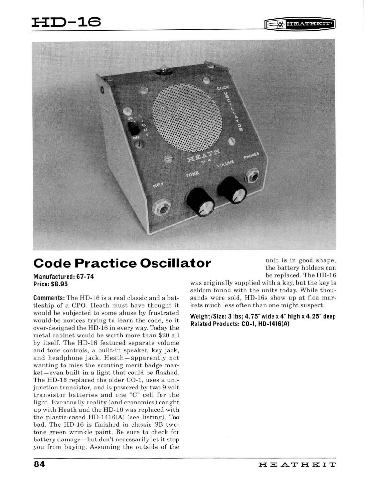
:H:D-16
~
~
f
H&df§fHilJ
Code
Practice
Oscillator
unit
is
in
good
shape,
the
battery
holders
can
Manufactured: 67-
74
Price:
$8.95
Comments:
The
HD-16
is
a
real
clas
sic
and
a
bat-
tleship
of
a
CPO
.
Heath
must
have
thought
it
would
be
subjected
to
some
abuse
by
frustrated
would-be
novices
trying
to
learn
the
code, so
it
over
-
designed
the
HD
-16
in
every
way.
Today
the
metal
cabinet
would
be
worth
more
than
$20
all
by
itself.
The
HD-16
featured
separate
volume
and
tone
controls,
a
built-in
speaker,
key
jack,
and
headphone
jack.
Heath-apparently
not
wanting
to
miss
the
scouting
merit
badge
mar-
ket-even
built
in
a
light
that
could
be
flashed.
The
HD-16
replaced
the
older
C0
-1,
uses
a
uni-
junction
transistor,
and
is
powered
by
two
9
volt
transistor
batteries
and
one
"C"
cell
for
the
light.
Eventually
reality
(
and
economics)
caught
up
with
Heath
and
the
HD-16
was
replaced
with
the
plastic
-
cased
HD-1416(A)
(see
listing).
Too
bad.
The
HD-16
is
finished
in
classic
SB
two-
tone
green
wrinkle
paint.
Be
sure
to
check
for
battery
damage
-
but
don
't
necessarily
let
it
stop
you
from
buying.
Assuming
the
outside
of
the
84
be
replaced.
The
HD
-
16
was
originally
supplied
with
a
key
,
but
the
key
is
seldom
found
with
the
units
today.
While
thou
-
sands
were
sold
,
HD-16s
show
up
at
flea
mar-
kets
much
less
often
than
one
might
suspect.
Wei
ght/Size: 3
lbs
; 4.75"
wide
x 4"
hi
gh x 4.25"
deep
Related
Products:
C0-1
,
HD-1416(A)
H E
..A..T
HK
IT
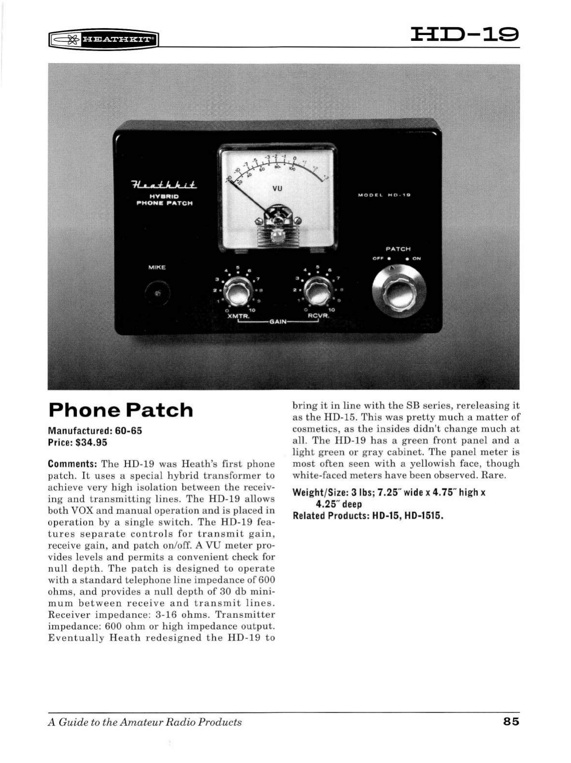
Phone
Patch
Manufactured: 60-65
Price:
$34.95
Comments:
The
HD-1
9
was
Heath's
first
phone
patch.
It
uses
a
special
hybrid
transformer
to
achieve
very
high
isolation
between
the
receiv-
ing
and
transmitting
lines
.
The
HD-19
allows
both
VOX
and
manual
operation
and
is
placed
in
operation
by
a
single
switch.
The
HD-19
fea
-
tures
separa
te
controls
for
transmit
gain,
receive
gain,
and
patch
on/off. A
VU
meter
pro-
vides
levels
and
permits
a
convenient
check
for
null
depth
.
The
patch
is
designed
to
operate
with
a
standard
telephone
line
impedance
of
600
ohms,
and
provides
a
null
depth
of
30
db
mini-
m
um
between
receive
and
transmit
lines
.
Receiver
impedance
:
3-16
ohms
.
Transmitter
impedance:
600
ohm
or
high
impedance
output
.
Eventually
Heath
redesigned
the
HD-19
to
A Guide to the
Amat
e
ur
Radio
Products
:H:D-19
bring
it
in
line
with
the
SB
series,
rereleasing
it
as
the
HD-15.
This
was
pretty
much
a
matter
of
cosmetics,
as
the
insides
didn't
change
much
at
all.
The
HD-19
has
a
green
front
panel
and
a
light
green
or
gray
cabinet.
The
panel
meter
is
most
often
seen
with
a
ye
llo
wish
face,
though
white-faced
meters
have
been
observed.
Rare.
Weight/Size: 3
lbs;
7.25"
wide
x
4.
75"
high
x
4.25"
deep
Related
Products:
HD-15,
HD-1515.
85
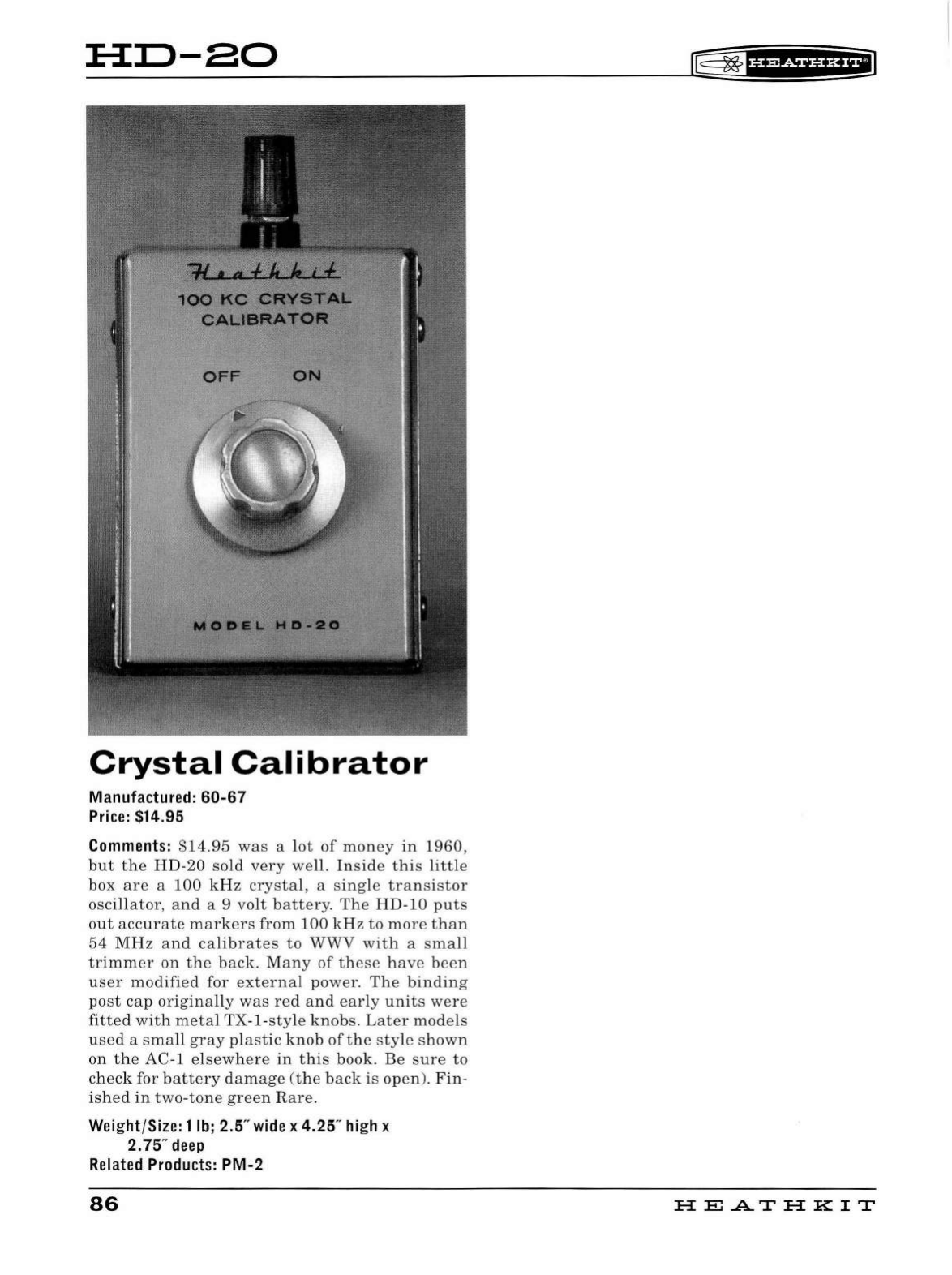
HD-80
Crystal
Calibrator
Manufactured:
60-67
Price:
$14.95
Comments:
$14.95
was
a
lot
of
money
in
1960,
but
the
HD
-20
sold
very
well.
In
side
this
little
box
are
a
100
kHz
crystal,
a
sing
le
transistor
oscillator,
and
a 9
volt
battery.
The
HD-10
puts
out
accurate
markers
from
100
kHz
to
more
than
54
MHz
and
calibrates
to
WWV
with
a
sma
ll
trimmer
on
the
back.
Many
of
these
have
been
user
modified
for
external
power.
The
binding
post
cap
originally
was
red
an
d
early
units
were
fitted
with
metal
TX
-1-
sty
le
knobs.
Later
mode
ls
used
a
sma
ll
gray
plastic
knob
of
the
sty
le sh
own
on
the
AC-1
elsewhere
in
this
book
. Be
sure
to
check
for
battery
damage
(t
he b
ack
is
open).
Fin
-
ished
in
two-tone
gree
n
Rare.
Weight/Size: 1
lb;
2.5"
wide
x 4.25"
high
x
2.75"
deep
Related
Products:
PM-2
86
lE=
~f
HMii'H+I
H
El
.AT
HK
IT
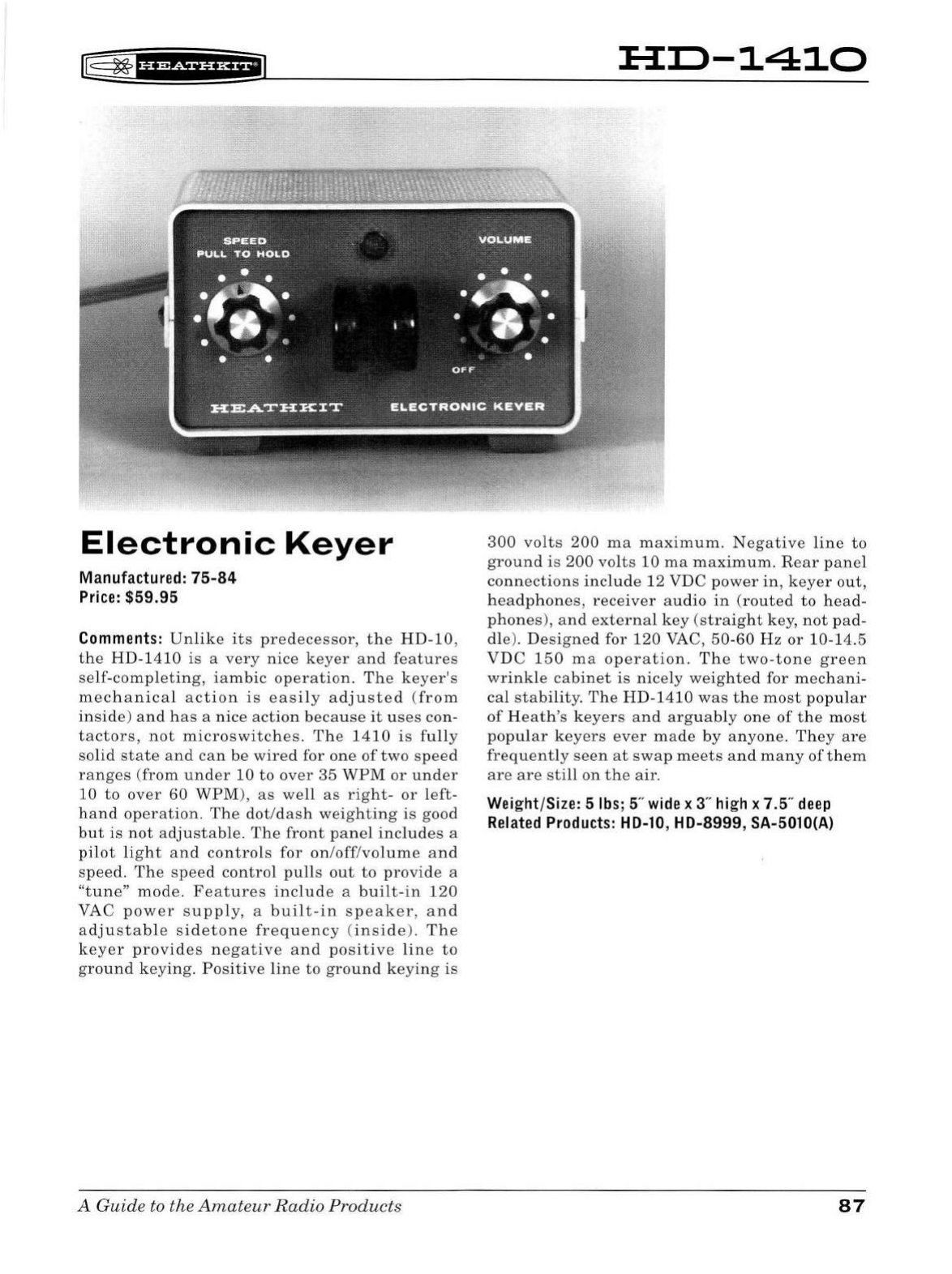
I@
~
fHMiHH+i
Electronic
Keyer
Manufactured:
75-84
Price:
$59.95
Comments:
Unlike
its
predecessor,
the
HD-10,
the
HD
-1
410
is
a
very
nice
keyer
and
features
se
lf-
comp
l
eting
,
iambic
operatio
n . T
he
keyer's
mecha
n
ical
action
is
eas
il
y a d
juste
d
(from
inside)
and
has
a
nice
action
beca
u
se
it
u
ses
con-
tactors,
not
microswitches
.
The
1410
is
fu
ll
y
solid
state
and
can
be
wired
for
one
of
two
speed
ra
n
ges
(
from
under
10
to
over
35
WPM
or
under
10
to
over
60
WPM),
as
well
as
right-
or
l
eft
-
hand
operation
.
The
d
ot
/
dash
we
i
ghting
is
good
but
is
not
adjustable
.
The
front
panel
includes
a
p
il
ot
light
and
controls
for
on/off/volume
and
speed.
The
speed
control
pu
lls
out
to
provide
a
"t
u
ne"
mode
.
Features
include
a
bui
lt -
in
120
VAC
power
supply
, a
built
-
in
speaker
,
and
adjustab
le
sidetone
freq
u
ency
(inside
). Th e
keyer
provides
negative
and
positive
l
ine
to
ground
keying.
Positive
line
to
ground
keying
is
A Guide to the
Amateur
Radio
Products
Hil-1410
300
volts
200
ma
maxim
um.
Negative
line
to
ground
is
200
vol
ts
10
ma
maximum.
Rear
panel
connections
in
clude
12
VDC
power
in
,
keyer
ou
t,
h
eadphones,
r
eceiver
audio
in
(route
d
to
head
-
ph
ones)
,
and
externa
l
key
(straight
key,
not
pad
-
dl
e).
Designe
d for
120
VAC,
50
-60
Hz
or
10-14.5
VDC
150
ma
operation.
The
t
wo-tone
green
wrink
le
cabi
n
et
is
nicely
weighted
for
mecha
ni-
cal
sta
bi
lity.
Th
e
HD-
1410
was
t he
most
pop
ul
ar
of
Heath's
keyers
an d
arg
u
ably
one
of
the
most
popu
l
ar
keye
r s
ever
made
by
an
yone.
They
are
frequent
ly
seen
at
swap
meets
an d
many
of
t h
em
are are
still
on
t he
air.
Wei
ght/Size: 5
lbs
; 5"
wide
x 3"
high
x 7.5"
deep
Related
Products:
HD-10
, HD-8999,
SA-5010{A}
87
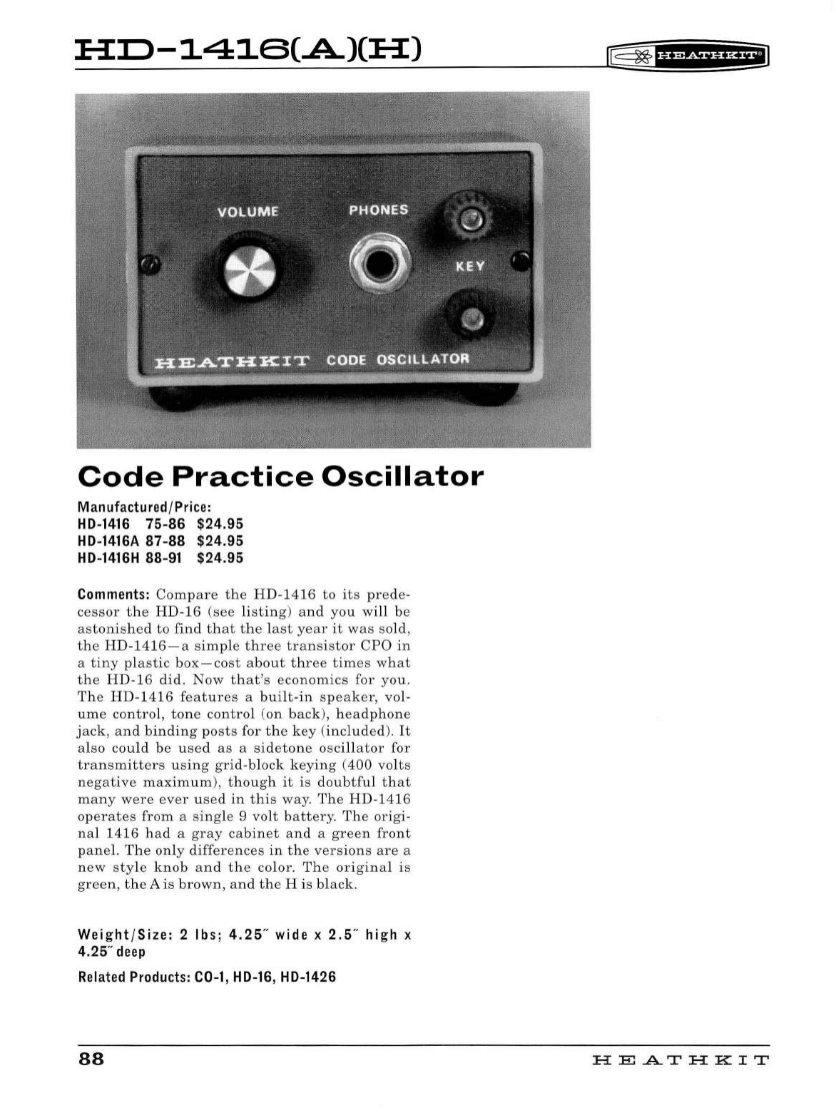
:H::0-1416(A.)(:H:)
Code
Practice
Oscillator
Manufactured/Price:
HD-1416
75-86
$24.95
HD-1416A
87-88
$24.95
HD-1416H
88-91 $24.95
Comments:
Compare
the
H
D-14
16
to
its
prede-
cessor
the
HD-16
(see
listing)
and
you
wi
ll
be
astonis
h
ed
to
find
th
at
the
l
ast
year
it
was
sold,
the H D-
1416-a
simple
three
transistor
CPO
in
a
tiny
pl
astic
box-cost
about
th
ree
times
what
t he HD-16 did.
Now
that's
economics
for
you.
Th e
HD
-1 416
features
a
built
-in
speaker,
vol-
u
me
control,
tone
contro
l
(on
back),
headphone
jack,
a
nd
bin
di
ng
post
s for
the
key
(included).
It
also co
ul
d
be
used
as
a
si
d
eto
ne osc
ill
ator
for
transmitters
using
grid-b
l
ock
keying
(400
vol
ts
negative
maximum
),
though
it
is
doubtful
t h
at
many
were
ever
used
in
t h
is
way
.
The
HD
-1416
operates
from
a
sing
le 9 volt
battery
.
The
origi-
nal
1416
had
a
gray
cabinet
an
d a
green
front
pane
l.
The
only
differ
e
nces
in
the
versions
are
a
new
style
knob
and
the
color.
The
origina
l
is
green,
the
A
is
brown,
and
t he H is
black.
Weight/Size:
2 lbs;
4.25
" wide x
2.5
" high x
4.25"
deep
Related
Products:
C0-1
,
HD-16
, HD-1426
88
(E;
~
f
UP&f
HHilJ
H E
.A..T
H K I T
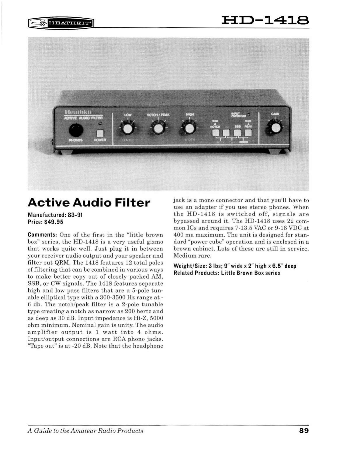
~
~
·ue&tne+il
Active
Audio
Filter
Manufactu
re
d:
83-91
Price
: $49 .95
Comments:
One
of
the
first
in
the
"little
brown
box"
series,
the
HD-1418
is
a
very
useful
gizmo
that
works
quite
well.
Just
plug
it
in
between
your
receiver
audio
output
and
your
speaker
and
filter
out
QRM.
Th
e
1418
features
12
total
poles
of
filtering
that
can
be
combined
in
various
ways
to
make
better
copy
out
of
closely
packed
AM,
SSB,
or
CW
signals.
The
1418
features
separate
high
and
low
pass
filters
that
are
a 5-
pole
tun-
able
elliptical
type
with
a
300
-
3500
Hz
range
at
-
6
db
.
The
notch
/
peak
fil
ter
is
a 2-
pole
tunable
type
creating
a
notch
as
narrow
as
200
hertz
and
as
deep
as
30
dB.
Input
impedance
is
Hi
-
Z,
5000
ohm
minimum.
Nominal
gain
is
unity
.
The
audio
amplifier
output
is
1
watt
into
4
ohms.
Input
/
output
connections
are
RCA
phono
jacks.
"
Tape
out"
is
at
-20 dB.
Note
that
the
headphone
A
Guide
to
the
Amateur
Radio
Products
HD-1418
jack
is
a
mono
connector
and
that
you'll
have
to
use
an
adapter
if
you
use
st
ereo
phones.
When
the
HD
-
1418
is
switched
off,
signals
are
bypassed
around
it
.
The
HD
-
1418
u
ses
22 com-
mon
ICs
a
nd
requires
7-13.5 VAC
or
9-18
VDC
at
400
ma
maximum.
The
unit
is
designed
for
stan
-
dard
"power
cube"
operation
and
is
enclosed
in
a
brown
cabinet.
Lot
s
of
these
are
still
in
service.
Medium
rare.
Wei
ght/Size: 3
lbs
; 9"
wide
x 2"
high
x 6.5"
deep
Related
Products:
Little
Brown
Box
series
89
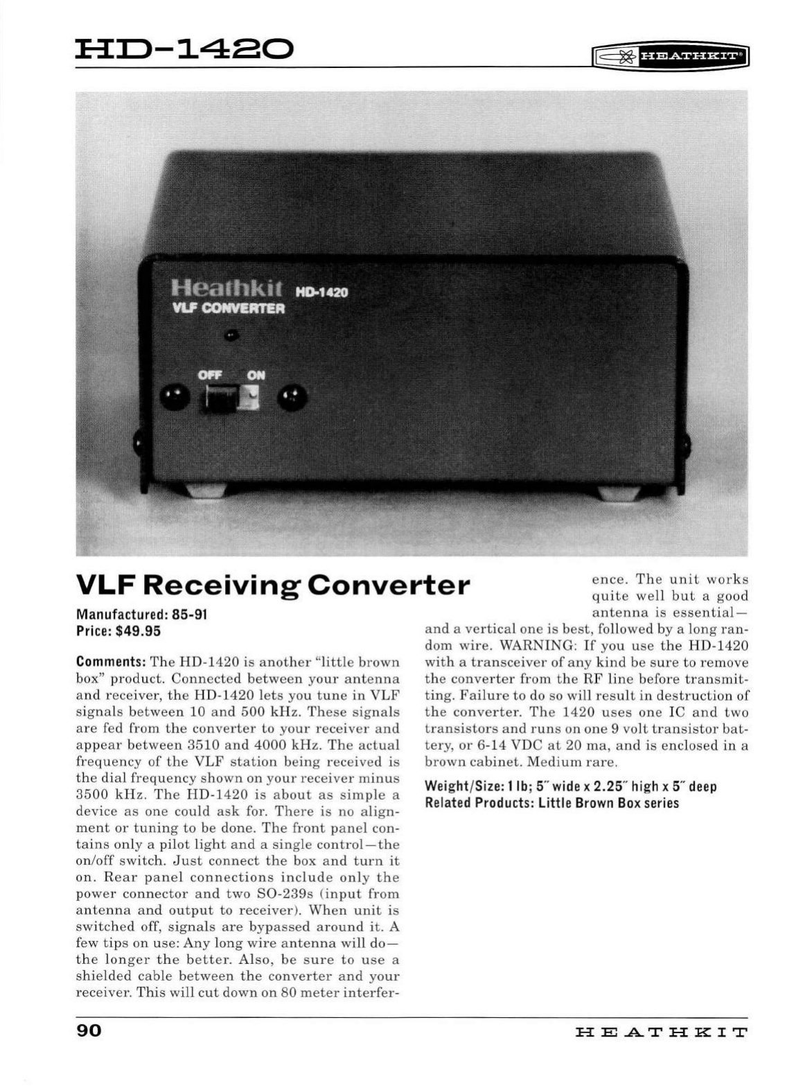
:E-3::0-1480
r§:
2*
IH?&f
UH+IJ
VLF
Receiving
Converter
ence.
The
unit
works
quite
well
but
a
good
Manufactured: 85-91
Price:
$49.95
Comments:
The
HD-1
420
is
another
"
little
brown
box"
product.
Connected
betw
een
your
antenna
and
receiver,
the
HD-1420
l
ets
you
tune
in
VLF
signals
between
10
an
d
500
kHz.
Th
ese
signa
ls
are
fed
from
the
converter
to
your
receiver
and
appear
between
35
10
a
nd
4000
kHz.
The
act
u
al
frequency
of
the
VLF
station
being
received
is
the
di
al
frequency
shown
on
your
receiver
minus
35
00
kHz
.
Th
e
HD-1420
is
about
as
s
impl
e a
device
as
one
could
ask
fo
r.
There
is
no
align
-
ment
or
tuning
to
be
done
.
Th
e
front
p
anel
con-
tains
on
ly a
pilot
li
ght
and
a
sing
le
control-the
on/off
switch
.
Ju
st
conne
ct
th
e box
an
d
turn
it
on.
Rear
pan
el
connect
ion
s
include
only
the
power
connector
and
two
S0-239s
(
input
from
antenna
an
d
output
to
receiver
).
When
unit
is
switched
off
,
signals
are
byp
assed
aroun
d
it.
A
few
tips
on
use:
Any
long
wir
e
antenna
will
clo-
the
lon
ger
the
better.
Al
so
,
be
s
ur
e
to
use
a
s
hi
e
ld
ed
cab
le
b
etween
the
converter
a
nd
your
receiver.
This
will
c
ut
down
on
80
meter
int
e
rfer-
90
antenna
is
essential
-
and
a
vertica
l
one
is
best,
followed
by
a l
ong
ran
-
dom
wire
.
WARNING:
If
you
u
se
the
HD-1420
with
a
transceiver
of
any
kind
be
s
ure
to
remove
th
e
converter
from
the
RF
lin
e
before
transmit-
tin
g.
Fai
lu
re
to
do so
will
result
in
destruction
of
the
converter.
The
1420
u
ses
one
IC
and
two
transistors
and
runs
on
one
9 vo
lt
transistor
bat
-
tery,
or
6-14
VDC
at
20
ma,
an
d
is
enclosed
in
a
brown
cabinet.
Medium
rare.
Weight/Size: 1
lb;
5"
wide
x 2.25"
high
x 5"
deep
Related
Products:
Little
Brown
Box
series
HE
A.TH
KIT

lE=
~
f
H?&f
HHE'J
:a::o-14aa
CAJ
Antenna
Noise
Bridge
range:
0-
200
ohms.
Capacitance
range
:
plus
or
minus
60
pF.
Manufactured /
Price:
HD-1422 85-89 $49.95
HD-1422A 89-91 $49.95
Comments:
The
HD
-
1422
Antenna
Noise
Bridg
e
is a
very
u
se
ful,
though
little
under
sto
od, gizmo.
Valuable
for
the
serious
antenna
experimenter,
it
may
be
of
little
interest
to
the
average
"a
ppli-
ance
operator,"
and
Heath
probably
di
dn't
sell
many
of
these.
Unlik
e
an
SWR
bridge
,
which
tells
you
how
well
an
antenna
is
matched
to
your
transmitter
, a
noise
bridg
e t e
lls
you
what
is
causing
any
mi
sm
atch.
The
HD
-
1422
is
a
tone-
modulated
,
broadband
noi
se
generator
coupled
to
an
impedance
bridge.
Using
your
station
receiver
,
the
impedance
bridge
measures
the
resistive
and
reactive
components
of
your
anten-
na.
The
1
422
may
also
be
used
to
pre
-
tune
an
antenna
tuner
,
to
tune
quarter
wave
transmis-
sion
lines,
a
nd
to
find
the
value
of
unknown
capacitors
and
inductors.
A
ll
in
all,
a
hand
y
de
vice
-
for
the
serious
HF
antenna
person.
Hav
i
ng
t he
instruction
book
would
be
very
he
lp-
fu
l
in
learning
to
u
se
th e
HD-1422.
Resistance
A Guide to the
Amateu
r
Radio
Products
Operating
range
:
1-30
MHz.
Front
pane
l
includes
power
on/
off
and
pilot
li
ght
and
con
-
tro
ls
for
resista
n
ce
and
reactance.
The
rear
panel
ha
s
two
80
-
239
connectors
(marked
"unknown"
and
"receiver"
), a
ground
l
ug,
and
a
standard
DC
external
power
connector.
The
unit
can
be
calibrated
using
your
station
receiver.
T
he
HD
-1422
is
designed
to
ru
n
on
one
9-volt
battery
or
9-
11
VDC
at
45
ma
externa
l
power
.
As
far
as
I
can
determine,
there
is
no
difference
between
the
1
422
and
th
e
1422A.
Enclosed
in a
brown
cabinet.
You
don't
see
many
of
the
se
since
not
too
many
were
so
ld
and
most
peop
le
who
bou
ght
th
em
sti
ll
u
se
them
.
Weight/Size: 2
lbs
; 5"
wide
x 2.25"
high
x 5"
deep
Related
Products:
Little
Brown
Box
series
91
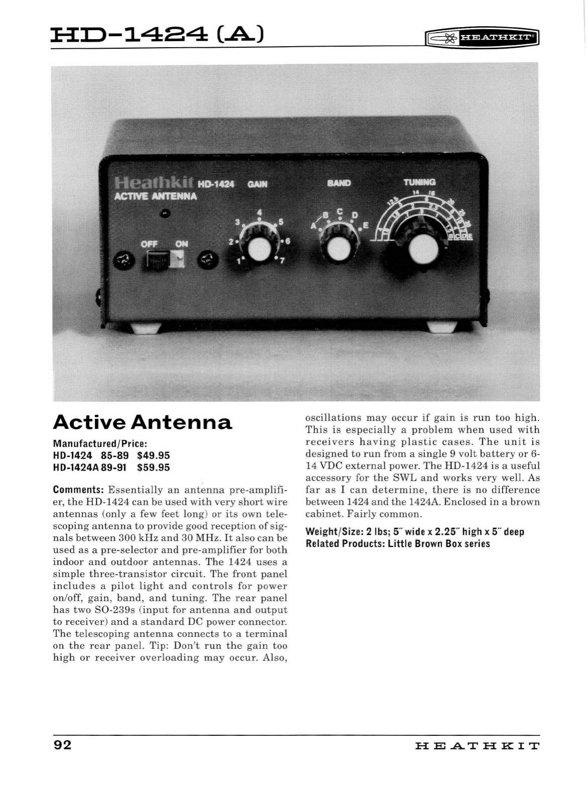
HI:>-1484
(.A)
Active
Antenna
Manufactured/Price:
HD-1424
85-89
$49.95
HD-1424A 89-91 $59.95
Comments:
Essentially
an
antenna
pre-amplifi-
er
,
the
HD-1424
can
be
used
with
very
short
wire
antennas
(only
a few
feet
long
)
or
its
own
tele
-
scoping
antenna
to
provide
good
reception
of
sig
-
nals
between
300
kHz
and
30
MHz
.
It
also
can
be
used
as
a
pre
-
selector
and
pre-amplifier
for
both
indoor
and
outdoor
antennas.
The
1424
uses
a
simple
three
-
transistor
circuit
.
The
front
panel
includes
a
pilot
light
and
controls
for
power
on/off,
gain
,
band
,
and
tuning.
The
rear
panel
has
two
S0-239s
(
input
for
antenna
and
output
to
receiver)
and
a
standard
DC
power
connector.
The
telescoping
antenna
connects
to
a
terminal
on
the
rear
panel.
Tip:
Don't
run
the
gain
too
high
or
receiver
overloading
may
occur.
Also,
92
oscillations
may
occur
if
gain
is
run
too
high
.
This
is
especially
a
problem
when
used
with
receivers
having
plastic
cases.
The
unit
is
designed
to
run
from
a
sing
le 9
volt
battery
or
6-
14
VDC
external
power.
The
HD-1424
is
a
useful
accessory
for
the
SWL
and
works
very
well
.
As
far
as
I
can
determine,
there
is
no
difference
between
1424
and
the
1424A.
Enclosed
in
a
brown
cabinet.
Fairly
common.
Wei
g
ht
/
Si
z
e:
2
lb
s;
5"
wide
x 2.25"
hi
gh x 5"
deep
Related
Products:
Little
Brown
Box
series
HE
.AT
HK
IT
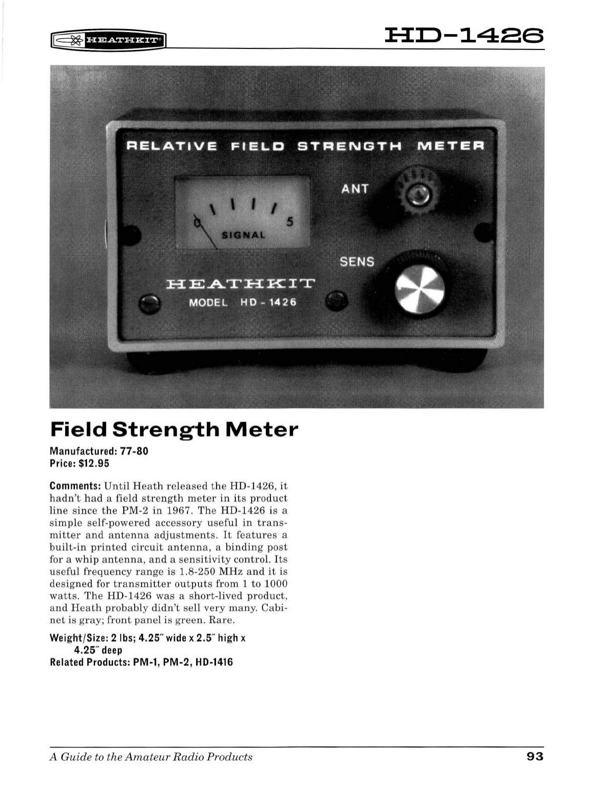
[(
~f¥'¥4Hi*i*l
Field
Strength
Meter
Manufactured:
77-80
Price:
$12.95
Comments:
Until
Heath
released
the
HD-1426
,
it
hadn't
had
a
field
strength
meter
in
its
product
line
since
the
PM-2
in
1967.
The
HD-1426
is
a
simple
self-powered
accessory
useful
in
trans-
mitter
and
antenna
adjustments.
It
features
a
built-in
printed
circuit
antenna,
a
binding
post
for a
whip
antenna,
and
a
se
nsitivity
control.
Its
useful
frequency
range
is
1.8-250
MHz
and
it
is
designed
for
transmitter
outputs
from
1
to
1000
watts
.
The
HD-1426
was
a
short-lived
product,
and
Heath
probably
didn
't
se
ll
very
many
.
Cabi-
net
is
gray;
front
panel
is
green
.
Rare.
Weight/Size: 2
lbs;
4.25"
wide
x 2.5"
high
x
4.25"
deep
Related
Products:
PM-1, PM-2,
HD-1416
A Guide to the
Amateur
Radio
Products
HD-1486
93
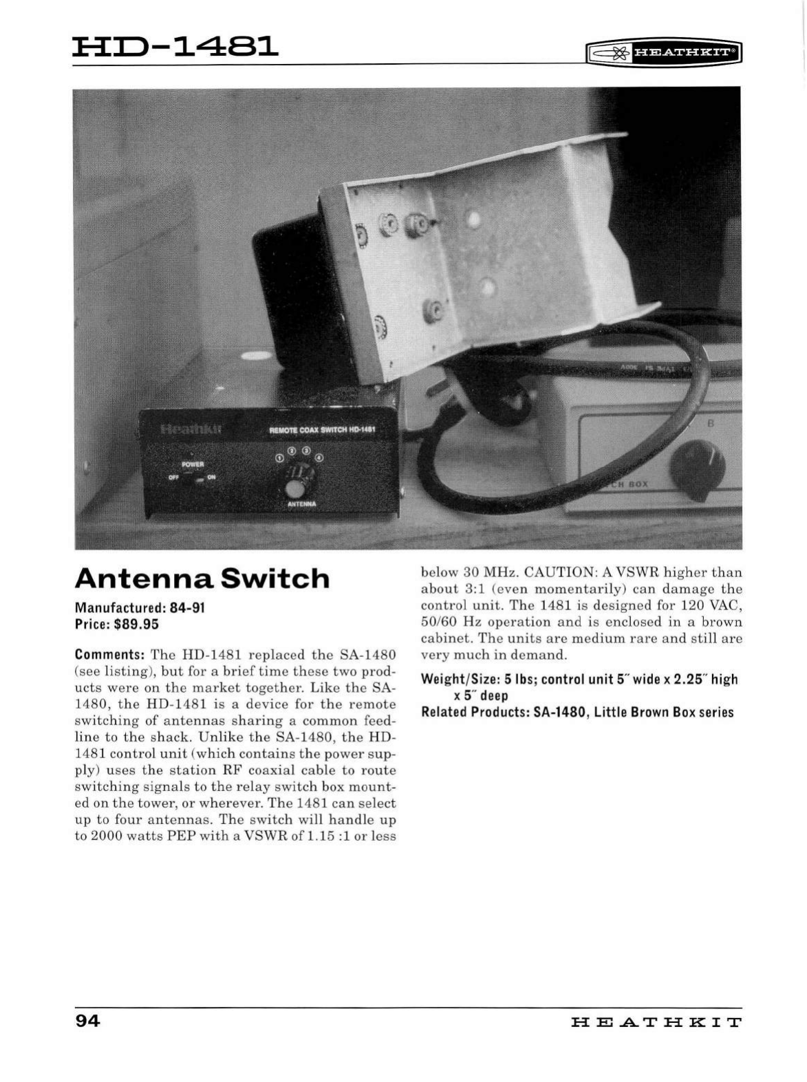
:H:D-1481
Antenna
Switch
Manufactured: 84-91
Price:
$89.95
Comments:
The
HD-
1
481
replaced
the
SA
-
1480
(see
listing
),
but
for a
brief
time
these
two
prod-
ucts
were
on
the
market
together.
Like
the
SA-
1480
,
the
HD-1481
is
a
device
for
the
remote
switc
hing
of
antennas
sharing
a
common
feed-
line
to
the
shack.
Un
li
ke
the
SA-1480,
the
HD
-
1481
contro
l
unit
(w
hich
contains
the
power
sup-
ply)
uses
the
station
RF
coaxial
cable
to
route
switching
signals
to
the
relay
switch
box
mount
-
ed
on
th
e
tower,
or
wherever.
The
1481
can
select
up
to
four
antennas.
The
sw
itch
will
handle
up
to
2000
watts
PEP
with
a
VSWR
of
1.15
: 1
or
less
94
[@
~
f§f
ff§i§f
HilJ
below
30
MHz.
CAUTION:
A
VSWR
higher
than
about
3:1
(eve
n
momentarily)
can
damage
the
control
unit
.
The
1481
is
designed
for
120
VAC,
50160
Hz
operation
and
is
enclosed
in
a
brown
cabinet
.
The
units
are
medium
rare
and
still
are
very
much
in
demand
.
Weight
/
Size:
5
lbs;
control
unit 5"
wide
x 2.25"
high
x 5"
deep
Related
Products:
SA-1480
, Little
Brown
Box
series
HE
.AT
HK
IT
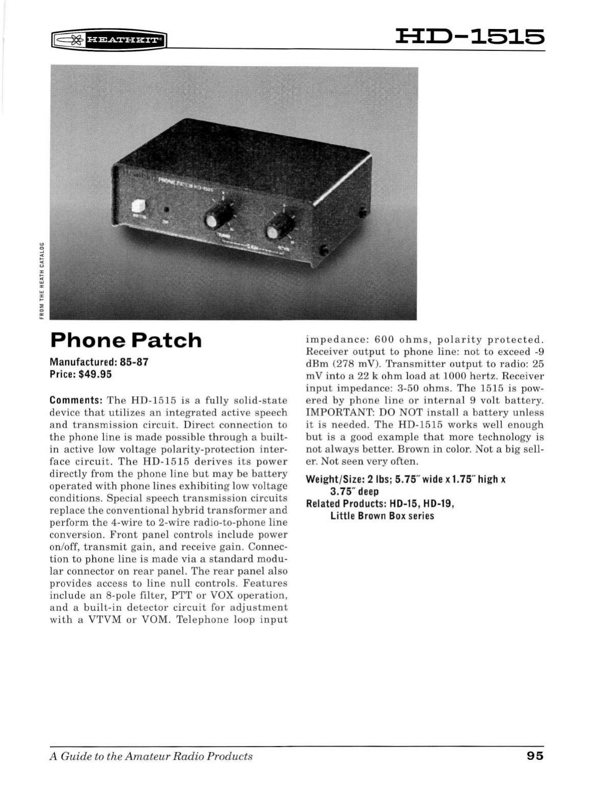
®
~
'#
1
*Si¥f
&fi
Phone
Patch
Manufactured:
85-87
Pr
i
ce
: $49.95
Comments:
The
HD-1515
is
a
fully
solid-state
device
that
utilizes
an
integrated
active
speech
and
transmission
circuit.
Direct
connection
to
the
phone
line
is
made
possible
through
a
bui
lt -
in
active
low
voltage
polarity-protection
inter
-
face
circuit.
The
HD-1515
derives
its
power
directly
from
the
phone
line
but
may
be
battery
operated
with
phone
line
s
exhibiting
low
voltage
conditions.
Special
speech
tr
a
nsmis
s
ion
circuits
re
place
the
conventional
hybrid
transformer
and
perform
th
e
4-wire
to
2-wire
radio-to-phone
line
conversion.
Front
panel
controls
include
power
on
/off,
tran
sm
it
gain,
and
rec
eive
gain.
Connec-
tion
to
phone
lin
e
is
ma de
via
a
standard
modu
-
lar
connector
on
r
ear
panel.
Th
e
re
ar
panel
also
provides
access
to
line
null
controls.
Features
include
an
8-pole
filter
,
PTT
or
VOX
operation,
and
a
built-in
d
etector
circuit
for
adj
u
stme
nt
with
a
VTVM
or
VOM.
Telephon
e
loop
input
A Guide to the
Amateur
Radio
Products
HIJ-1515
impedance:
600
ohms
,
polarity
protected.
Receiver
output
to
phone
line:
not
to
exceed
-9
dBm
(278
m V).
Transmitter
output
to
radio:
25
m V
into
a
22
k
ohm
load
at
1000
hertz.
Receiver
input
impedance:
3-50
ohms.
The
1515
is
pow-
ered
by
phone
line
or
internal
9
volt
battery.
I
MPORTANT:
DO
NOT
install
a
battery
unless
it
is
needed.
The
HD
-
1515
works
well
enough
but
is
a good
example
that
more
technology
is
not
always
better.
Brown
in
color.
Not
a
big
sell-
er.
Not
seen
very
often.
Wei
ght/Size: 2 lb
s;
5. 75"
wide
x
1.
75"
hi
gh x
3.75"
deep
Rel
ated
Produ
c
ts:
HD-15
,
HD-19
,
Little
Brown
Bo
x
series
95
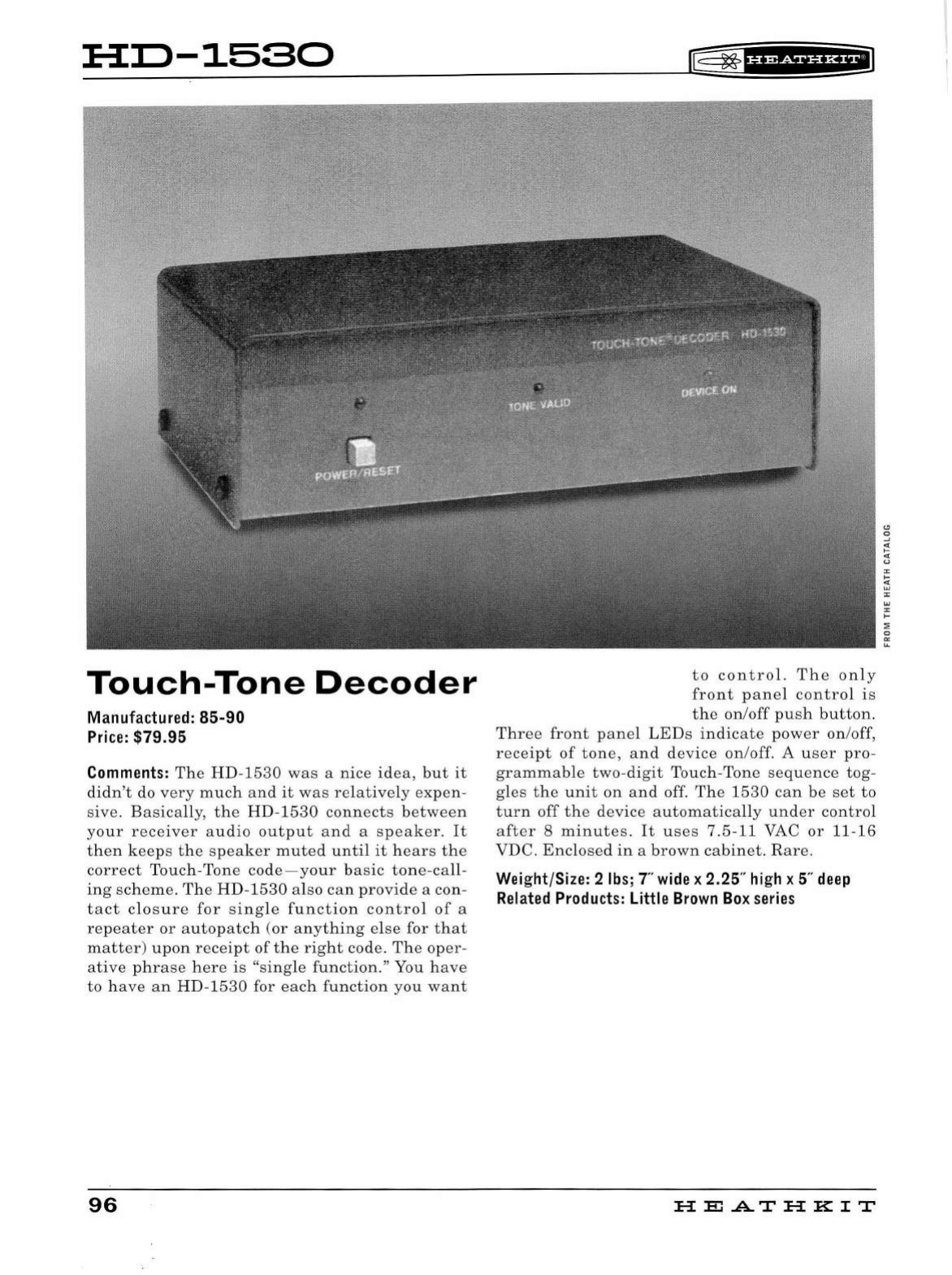
HD-1580
Touch-Tone
Decoder
Manufactured:
85-90
Price:
$79.95
Comments:
The
HD-1530
was
a
nice
idea,
but
it
didn
't do
very
much
and
it
was
relatively
expen
-
sive
.
Basically,
the
HD-1530
connects
between
your
receiver
audio
output
and
a
speaker.
It
then
keeps
the
speaker
muted
until
it
hears
the
correct
Touc
h-
Tone
code
-y
our
basic
tone
-
call-
ing
scheme.
Th
e
HD
-
1530
also
can
provide
a con-
tact
closure
for
sing
le
functio
n
contro
l
of
a
repeate
r
or
autopatch
(or
anything
else
for
that
matter)
upon
receipt
of
the
right
code.
The
oper-
ative
phrase
here
is
"s
ingle
function."
You
have
to
have
an
HD
-1530
for
each
function
you
want
96
rE=
~
fH?df§fHEI
to
control.
The
on
ly
front
panel
control
is
th e
on
/off
push
button
.
Three
front
pane
l
LEDs
indicate
power
on
/off,
receipt
of
tone,
and
device
on
/off. A
user
pro
-
grammab
le
two-digit
Touch-Tone
se
quence
tog-
gles
the
unit
on
and
off.
The
1530
can
be
set
to
turn
off
the
device
automatica
ll
y
under
contro
l
after
8
minutes.
It
uses
7 .5-11 VAC
or
11-16
VD
C.
Enclosed
in
a
brown
cabinet.
Rar
e.
Weight/Size: 2
lbs;
T'
wide
x 2.25"
high
x 5"
deep
Related
Products:
Little
Brown
Box
series
H
El
AT
HK
IT
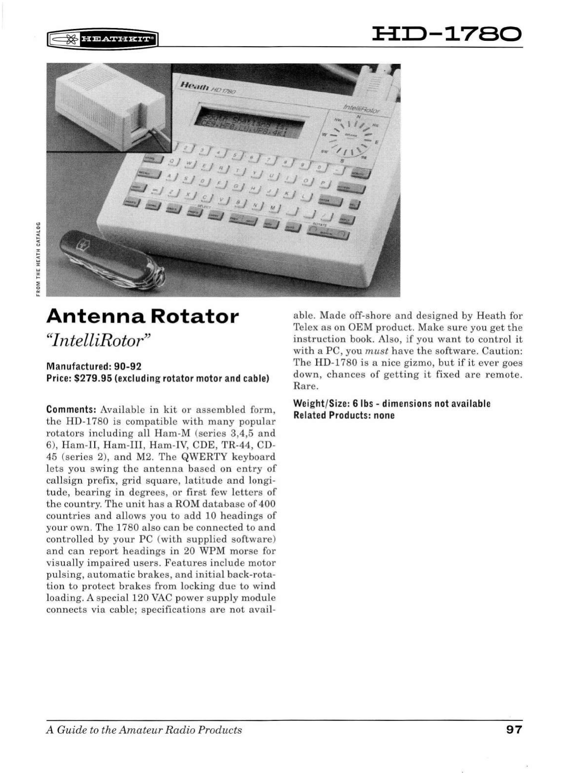
[§
~
fff&ifii*f@
Antenna
Rotator
"IntelliRotor"
Manufactured:
90-92
Price:
$279.95 (excluding rotator
motor
and
cable)
Comments:
Ava
il
able
in
kit
or
assemb
l
ed
form,
the
HD-
1780
is
compatib
le
wit
h
many
popular
rotators
including
a
ll
Ham
-M
(series
3,4,5
and
6),
Ham-II
,
Ham
-II
I,
Ham
-
IV,
CD
E,
TR
-44, CD-
45
(ser
i
es
2),
and
M2.
The
QWERTY
keyboard
lets
you
swing
the
antenna
based
on
entry
of
ca
ll
sign
prefix,
grid
sq
u
are,
l
at
i
tude
an
d
longi
-
tude,
bearing
in
degrees,
or
first
few l
etters
of
the
country.
The
unit
has
a
ROM
database
of
400
countries
and
a
ll
ows
you
to
ad
d
10
head
i
ngs
of
your
own.
T
he
1
780
also
can
be
connecte
d
to
and
contro
ll
ed
by
your
PC
(
with
supplied
software)
and
can
report
headings
in
20
WPM
morse
for
visua
ll
y
impai
r
ed
users.
Features
incl
ud
e
motor
pu
l
sing,
automatic
brakes,
and
in
i
tia
l
back
-
rota-
tion
to
protect
brakes
from
locking
due
to
win
d
l
oading.
A
spec
ial
120
VAC
power
supp
ly
module
connects
via
ca
bl
e;
specifications
are
not
avai
l-
A Guide to the
Amateu
r
Radio
Products
HD-1780
able.
Made
off
-
shore
and
designed
by
H
eath
for
Telex
as
on
OEM
product.
Make
sure
you
get
the
i
nstruction
book. Also,
if
you
want
to
contro
l
it
with
a
PC,
you
must
have
the
software
.
Caution:
The
HD
-178
0 is a
nice
gizmo,
b
ut
if
it
ever
goes
down,
chances
of
getting
it
fixed
are
remote.
Rare.
Weight/Size: 6
lbs
-
dimensions
not
available
Related
Products:
none
97
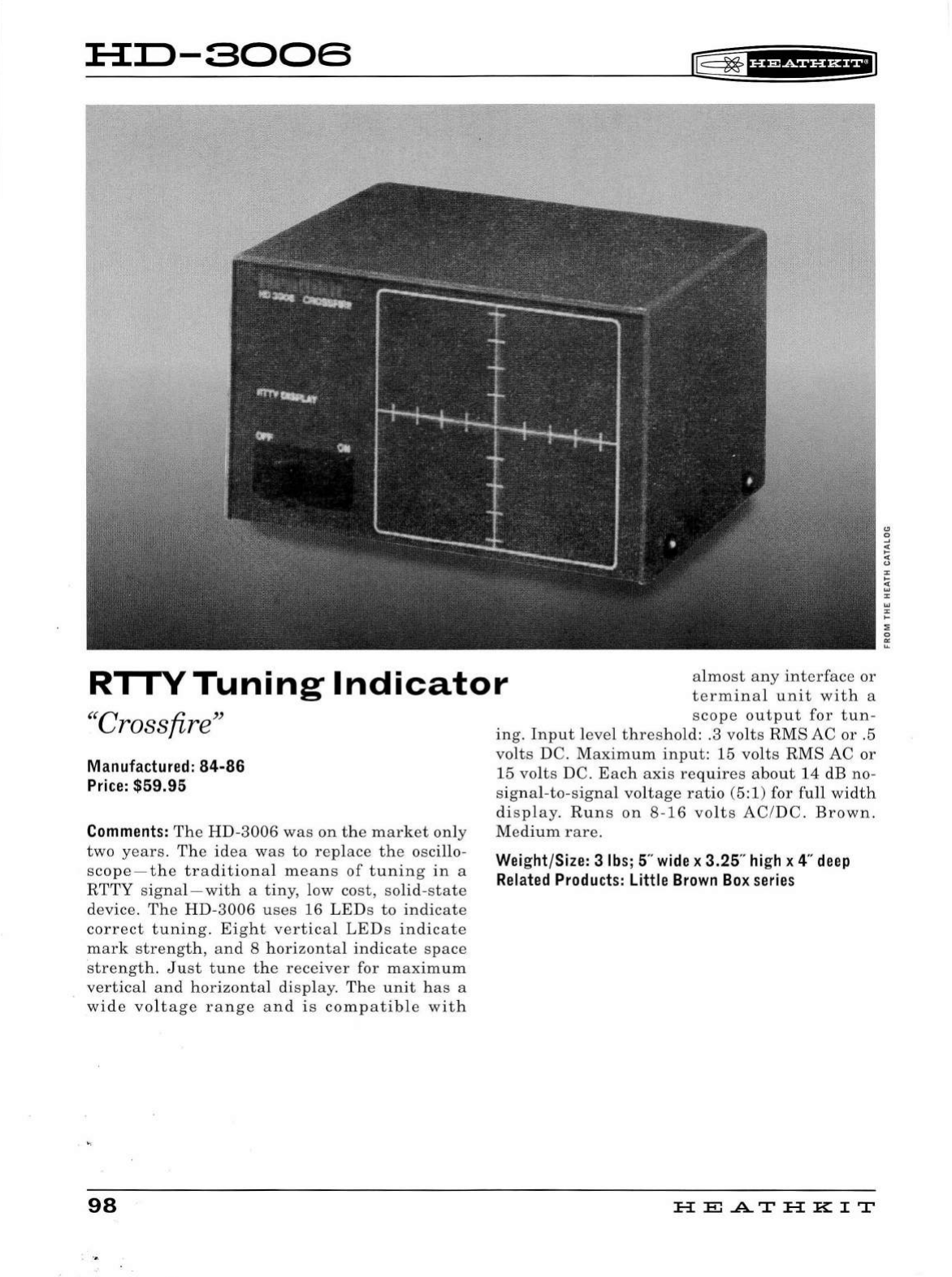
:B:I:>-SOOS
II5
~
f
U@i§'&fi
RI
I
VTuning
Indicator
almost
any
interface
or
terminal
unit
with
a
scope
output
for
tun
-
"Crossfire"
Manufactured:
84-86
Price:
$59.95
Comments:
The
HD-3006
was
on
the
market
on
ly
two
years.
The
idea
was
to
rep
l
ace
the
oscillo-
scope
-
the
t r
aditiona
l
means
of
tuning
in
a
RTTY
signal-with
a
tiny,
low
cost,
solid-state
device.
The
HD
-
3006
uses
16
LEDs
to
indicate
correct
tuning.
Eight
vertica
l
LEDs
indicate
mark
strength,
and
8
horizontal
indicate
space
strength
.
Just
tune
t he
receiver
for
maximum
vertical
and
horizontal
display.
The
unit
has
a
wide
voltage
range
and
is
compatib
le
wit
h
98
ing.
Input
level
threshold
: .3
volts
RMS
AC
or
.5
vol
ts
DC.
Maximum
input:
15
volts
RMS
AC
or
15 vol
ts
DC.
Each
axis
requires
about
14
dB
no-
signal
-
to
-
signal
voltage
ratio
(5:1) for
full
width
display
.
Runs
on
8-
16
vo
l
ts
AC
/
DC.
Brown.
Medium
rare
.
Weight/Size: 3
lbs;
5"
wide
x 3.25"
high
x 4"
deep
Related
Products:
Little
Brown
Box
series
H
El
.AT
HK
IT
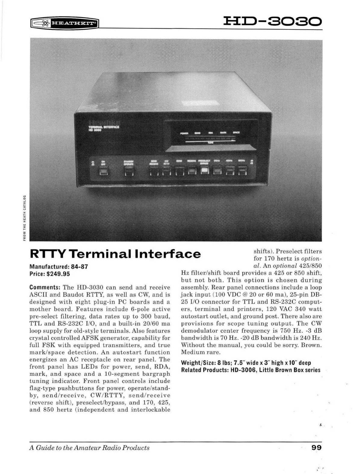
lB
~
'§f
if
f
Hi*i@
H:O-SOSO
RI
I
VTerminal
Interface
sh
ifts).
P
reselect
filters
for
170
hertz
is
option
-
Manufactured:
84-87
Price:
$249.95
Comments:
The
HD-3030
can
se
nd
a
nd
receive
ASCII
and
Baudot
RTTY
,
as
we
ll
as
CW,
an
d is
designed
with
eight
p
lu
g
-in
PC
boards
and
a
moth
er
bo
ar
d. F
ea
tur
es
include
6-pole
ac
tiv
e
pre-s
e
lect
filtering
,
data
rates
up
to
300
ba
ud
,
TTL
and
RS-232C
I/O, a
nd
a
built-in
20/60
ma
loop
supp
ly for
old-style
terminals.
Also
features
crystal
controlled
AFSK
generator,
capability
for
full
FSK
with
equipped
tran
smit
t
ers,
and
true
mark/space
det
ecti
on
.
An
autostart
function
energizes
an
AC
receptacle
on
rear
pan
el.
The
front
panel
h
as
LEDs
for
power,
se
nd,
RDA
,
mark,
and
space
and
a
10-s
eg
ment
bargraph
t
unin
g
indicator.
Front
panel
contro
ls
includ
e
flag-type
pushbuttons
for power, ope
rate/stand-
by
,
se
nd
/
receive,
CW
/
RTT
Y,
send
/
rece
i
ve
(
rever
se
shift),
preselect/byp
ass,
and
170
,
425
,
and
850
hertz
(i
ndependent
an
d
inter
lo
ckab
le
A
Guide
to the
Amateur
Rad
io
Products
al.
An
optional
425/850
H z
filter/shift
board
provides
a
425
or
850
shift,
but
not
both.
This
option
is
chosen
during
assemb
l
y.
Rear
panel
connectio
n s
include
a loop
j
ack
in
put
(
100
VDC @ 20
or
60
ma
),
25-pin
DB-
25
I/O
connector
for
TTL
and
RS-232C
comput
-
ers,
terminal
and
printers,
120
VAC
340
watt
autostart
out
let
,
an
d
gro
und
post.
There
also
are
provisions
for
scope
tuning
output.
Th
e
CW
demodulator
ce
nter
freq
u
ency
is
750
Hz
. -3
dB
bandwidth
is
70
Hz.
-20
dB
bandwidth
is
240
Hz.
Without
the
manual
,
you
could
be
sorry.
Brown
.
Me
dium
rare
.
Weight/Size: 8
lbs;
7.5"
wide
x 3"
high
x
10
"
deep
Related
Products:
HD-3006, Little
Brown
Box
series
99
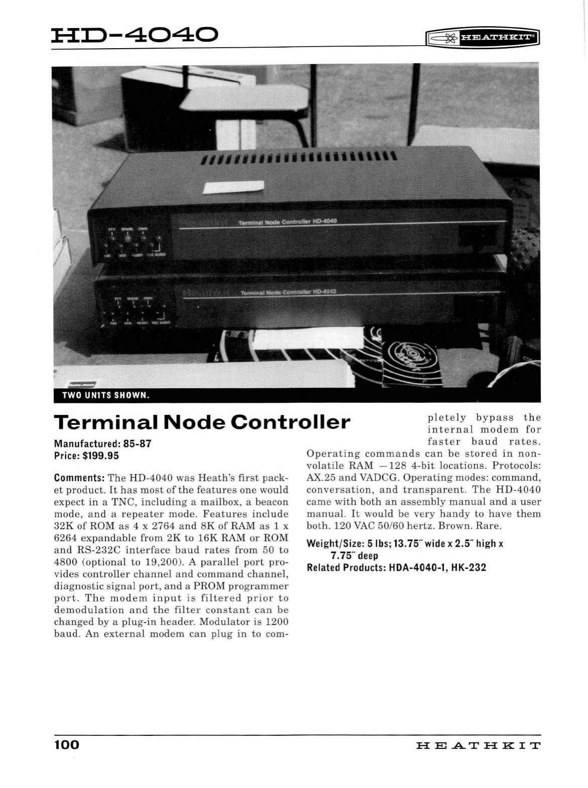
:H:IJ-4040
r®
~
'Hiii§f
i*+IJ
Terminal
Node
Controller
pletely
bypass
the
internal
modem
for
Manufactured:
85-87
Price:
$199
.95
Comments:
The
HD-4040
was
Heath's
first
pack-
et
product.
It
has
most
of
the
feat
ur
es
one
would
expect
in
a
TNC,
including
a
mailbox
, a
beacon
mode,
and
a
repeater
mode.
Features
include
32K
of
ROM
as
4 x
2764
an
d
SK
of
RAM
as
1 x
6264
expan
dabl
e
from
2K
to
16K
RAM
or
ROM
an
d
RS-232C
interface
baud
rates
from
50
to
4800
(optiona
l
to
19,200
). A
parallel
port
pro
-
vides
controller
channel
and
command
channel
,
diagnostic
sig
n
al
port
,
and
a
PROM
programmer
port.
The
modem
input
is
filtered
prior
to
demodulation
an
d
the
filter
consta
nt
can
be
changed
by
a
plug-in
header.
Modulator
is
1200
baud.
An
externa
l
modem
can
plug
in
to
com-
100
faster
baud
rates.
Operating
commands
can
be
stored
in
non-
volatile
RAM
-128
4-
bit
l
ocations.
Protocols
:
AX.25
and
VADCG.
Operating
modes:
command,
conversation,
a
nd
transparent.
The
HD
-
4040
came
with
both
an
assemb
ly
manual
and
a
user
manual.
It
would
be
very
h
andy
to
h
ave
them
both.
120
VAC
50
/
60
hertz.
Brown.
Rare
.
Weight/Size: 5lbs;13.75"
wide
x 2.5"
high
x
7.75"
deep
Related
Products:
HDA-4040-1 , HK-232
HE
AT
HK
IT
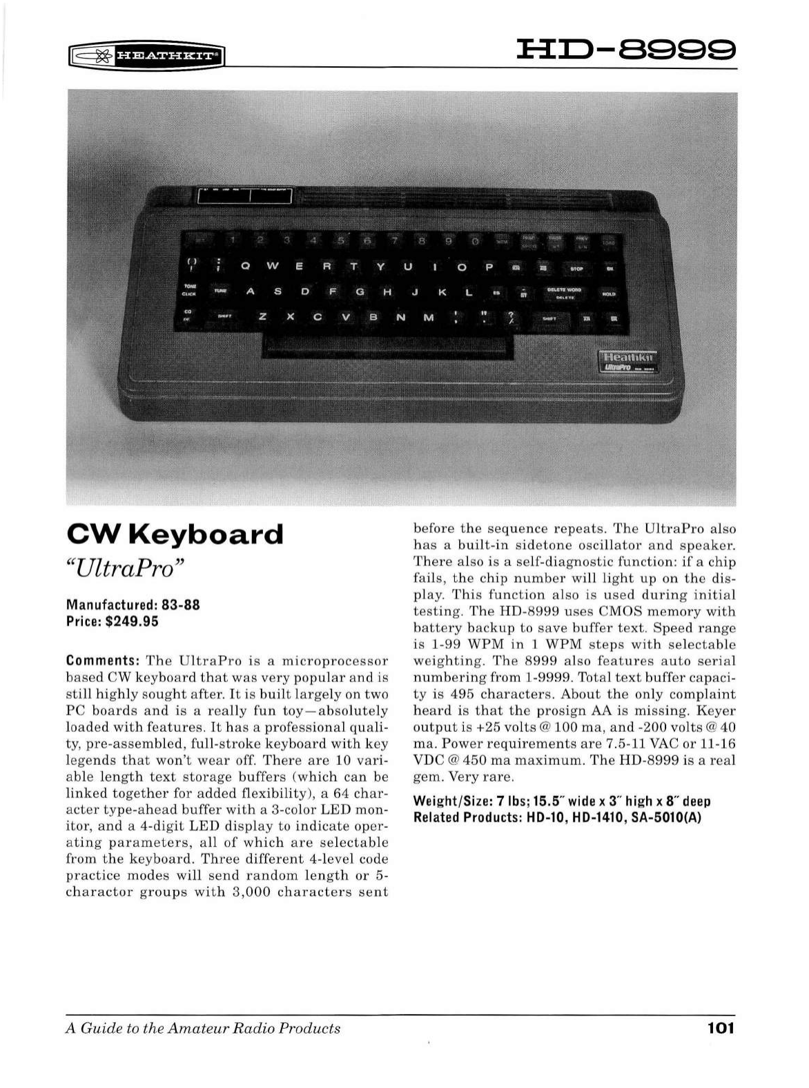
r@
~
'bdi§'Hf@
CW
Keyboard
"UltraPro"
Manufactured:
83-88
Price:
$249.95
Comments:
The
UltraPro
is
a
microprocessor
based
CW
keyboard
that
was
very
popular
and
is
still
highly
sought
after
.
It
is
built
large
ly
on
two
PC
boards
and
is
a
really
fun
toy-absolutely
loaded
with
features.
It
has
a
professional
quali
-
ty
,
pre
-
assemb
l
ed,
full-stroke
keyboard
with
key
l
ege
nds
that
won't
wear
off.
There
are
10
vari-
able
length
text
storage
buffers
(w
hic
h
can
be
linked
together
for
added
flexibility),
a
64
char-
acter
type-ahead
buffer
with
a 3-color
LED
mon
-
itor,
and
a 4-
digit
LED
display
to
indicate
oper-
a
ting
parameters,
all
of
which
are
se
l
ectable
from
the
keyboard
.
Three
different
4-l
evel
code
practice
modes
w
ill
send
random
lengt
h
or
5-
charactor
groups
wit
h
3,000
characters
sent
A Guide to the
Amateu
r
Radio
Products
HI:l-8999
before
the
sequence
repeats.
The
UltraPro
also
has
a
built
-
in
sidetone
oscillator
and
speaker.
There
also
is
a
self-d
i
agnostic
function
:
if
a
chi
p
fails,
the
chip
number
will
light
up
on
the
dis
-
play.
This
function
also
is
used
during
initia
l
testing.
The
HD-8999
uses
CMOS
memory
with
battery
backup
to
save
buffer
text
.
Speed
range
is
1-99
WPM
in
1
WPM
steps
with
selectable
weighting
.
The
8999
also
features
auto
serial
numbering
from
1-
9999.
Total
text
buffer
capaci
-
ty
is
495
characters.
About
the
only
complaint
heard
is
that
the
pros
i
gn
AA
is
missing.
Keyer
output
is
+25
volts
@
100
ma,
and
-
200
vol
ts
@
40
ma.
Power
requireme
n
ts
are
7.5-11 VAC
or
11-16
VDC @
450
ma
maximum.
The
HD-8999
is
a
real
gem.
Very
rare.
Wei
ght/Size: 7
lbs
; 15.5"
wide
x 3"
high
x 8"
deep
Related
Products:
HD-10
,
HD-1410
, SA-5010(A)
101
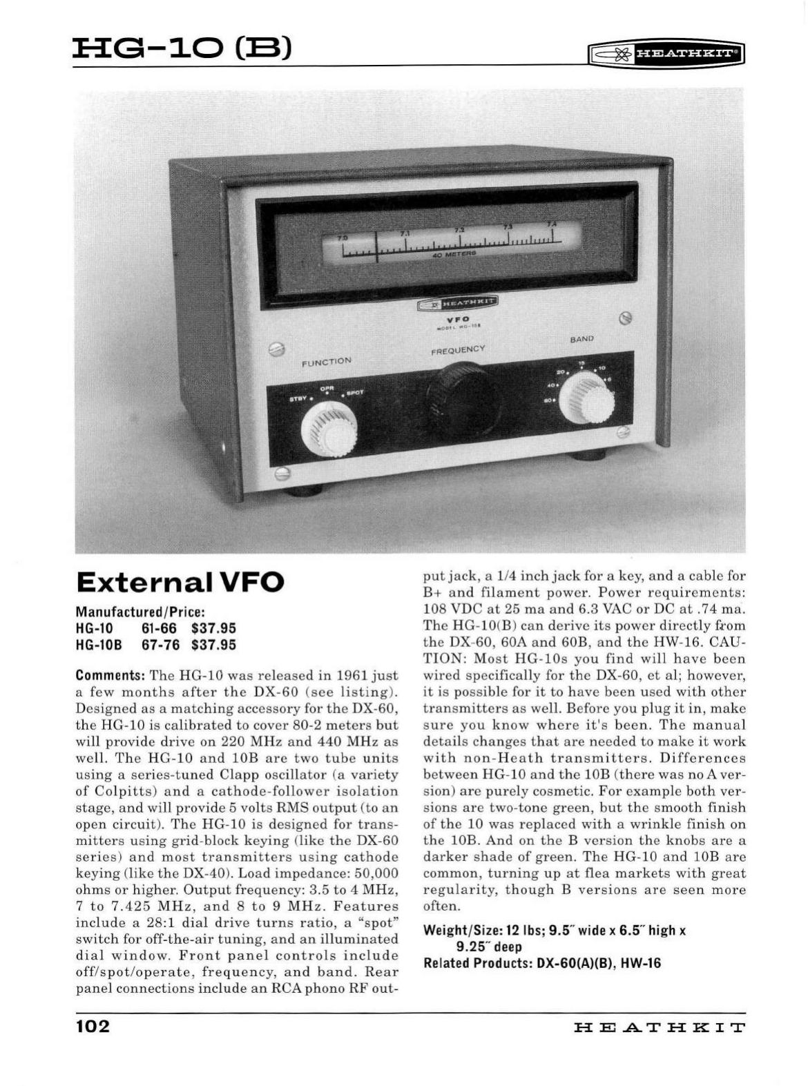
:H:G-10
CB)
External
VFO
Manufactured/Price:
HG-10
61-66 $37.95
HG-108 67-76 $37.95
Comments:
The
HG
-1 0
was
released
in
1961
ju
st
a
few
mont
h s
after
the
DX
-
60
(see
listing
).
Designed
as
a
matc
h
ing
accessory
for th e DX-60,
the
HG
-
10
is
calibrated
to
cover
80-2
meters
b
ut
will
provide
drive
on
220
MHz
and
44
0
MHz
as
well.
The
HG
-
10
and
lOB
are
two
tube
un
its
using
a
series
-
tune
d
Clapp
oscill
ator
(a
var
i
ety
of
Col
pitts)
and
a
cathode
-fo
ll
ower
isolation
stage,
and
wi
ll
provide
5 vol
ts
RMS
output
(to
an
open
circuit).
The
H G-
10
is
designed
for
trans
-
mitters
using
grid-block
keying
(like
the
DX-60
series)
and
most
transmitters
using
cathode
keying
(
like
the
DX-
40
).
Load
impedance:
50,000
ohms
or
hig
her.
Output
frequency:
3.5
to 4 MHz,
7
to
7.425
MHz,
and
8
to
9
MHz.
Features
include
a 28:1
dia
l
drive
turns
ratio,
a "s
pot"
switch
for
off
-th
e-air
tuning,
and
an
i
ll
umina
t
ed
dia l
window
.
Front
pane
l
controls
incl
u
de
off
/
spot
/
operate,
freque
ncy, a n d
band.
Rear
panel
connections
include
an
RCA
phono
RF
out-
102
E
~
fff
WiUH+iJ
put
jack,
a 1/4
inch
jack
for a key,
and
a
cable
for
B+
and
filament
power
.
Power
requirements:
108
VDC
at
25
ma
and
6.3 VAC
or
DC
at
.
74
ma
.
The
HG-lO(B)
can
derive
its
power
directly
frnm
the
DX-60, 60A
and
60B,
and
the
HW-16. CAU-
TION:
Most
HG-
l
Os
you
find
wi
ll
have
been
wired
specifica
ll
y for
the
DX-
60
,
et
al;
however,
it
is
possib
le for
it
to
have
been
u
se
d
with
oth
er
transmitters
as
we
ll
.
Before
you
plug
it
in,
make
sure
you
know
where
it's
been.
The
manua
l
detai
ls
changes
that
are
needed
to
make
it
work
with
non
-
Heath
transmitters
.
Differe
n
ces
between
HG-10
an
d
the
lOB (
there
was
no
Aver
-
sion)
are
purely
cosmetic
.
For
examp
le
both
ver
-
sions
are
two
-
tone
green,
but
the
smooth
finish
of
the
10
was
rep
l
aced
with
a
wrink
le
finis
h
on
the
lOB.
And
on
th e B
version
the
knobs
are
a
darker
shade
of
green.
Th
e
HG-10
and
lOB
are
common,
tu
rning
up
at
flea
markets
with
great
regu
l
arity,
thoug
h B
versions
are
seen
more
often
.
Weight/Size:
12
lbs;
9.5"
wide
x 6.5"
high
x
9.25"
deep
Related
Products:
DX-60(A)(B),
HW-16
HE
.AT
HK
IT
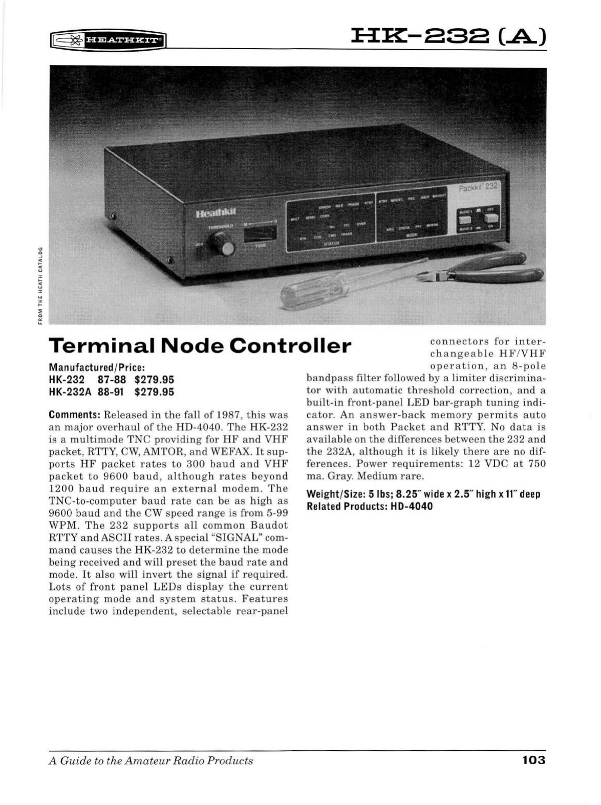
[@
~
f¥'¥5i§fi*fiJ
:a::K-asa
(.A)
V.I'
....
~(ol
1ttl
unr-4"1
HI.
#hJ
(....,(1'
f""ll
.....
,.
••X-"
Terminal
Node
Controller
connectors
for
inter-
changeable
H F /
VHF
Manufactured /
Price:
HK-232 87-88 $279.95
HK-232A 88-91 $279.95
Comments:
Rel
eased
in
the
fall
of
1987,
this
was
an
ma
j
or
overhau
l
of
the
HD-4040.
The
HK-
232
is
a
mu
l
timode
TNC
providing
for
HF
and
VHF
packet,
RT
TY,
CW
, AMTOR,
and
WEFAX. It
sup
-
ports
H F
packet
rates
to
300
baud
an
d
VHF
packet
to
9600
baud,
al
though
rates
beyond
1200
b
aud
require
a n
externa
l
modem.
The
TNC-
to-
comp
u
ter
bau
d
rate
can
be
as
h
igh
as
9600
baud
and
the
CW
speed
range
is
from
5-
99
WPM
. Th e
232
supports
a
ll
common
Baudot
RTTY
and
ASC
II
rates.
A
specia
l
"SIGNAL"
com-
mand
causes
the
HK
-
232
to
determine
th e
mode
being
received
and
wi
ll
preset
the
baud
rate
and
mode
.
It
also
will
invert
the
signal
if
required
.
Lots
of
front
pane
l
LED
s
dis
pl
ay
t he
current
operating
mode
and
system
status.
Features
include
two
independe
n
t,
se
l
ectab
le
rear-panel
A
Guide
to the
Amateur
Radio
Products
operation
,
an
8-pole
bandpass
filter
fo
ll
owed
by
a
limiter
discrimina
-
tor
with
automatic
threshold
correction,
and
a
bui
l
t-
in
front-panel
LE
D
bar
-
graph
tuning
indi
-
cator.
An
answer
-
back
memory
permits
auto
answer
in
both
Packet
and
RTTY. No
data
is
avai
l
ab
le
on
the
differences
between
the
232
and
the
232A,
although
it
is
likely
there
are
no
dif-
ferences.
Power
req
u
irements:
12
VDC
at
750
ma.
Gray.
Med
i
um
rare.
Weight/Size: 5
lbs
; 8.25"
wide
x 2.5" hi
gh
x
ff'
deep
Related
Products
: HD-4040
103
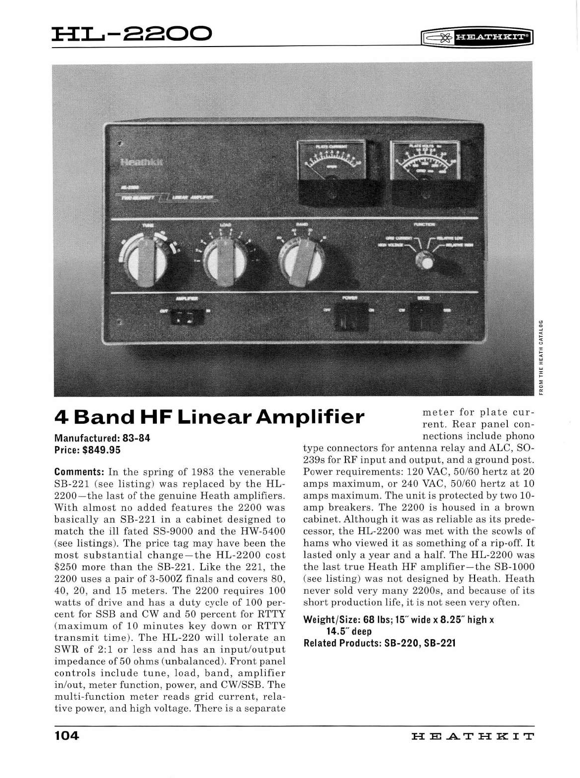
HL...-aaoo
lF
~
fH&iHH+I
4
Band
HF
Linear
Amplifier
meter
for
plate
cur-
rent.
Rear
panel
con
-
nections
include
phono
Manufactured:
83-84
Price:
$849.95
Comments:
In
the
spring
of
1983
the
venerable
SB
-
221
(see
listing
)
was
replaced
by
the
HL-
2200-the
last
of
the
genuine
Heath
amplifiers.
With
almost
no
added
features
the
2200
was
basica
ll
y
an
SB-221
in
a
cabinet
designed
to
match
the
ill
fated
SS-9000
and
the
HW-5400
(see
listings).
The
price
tag
may
have
been
the
most
substantial
change-the
HL-2200
cost
$250
more
than
the
SB-221.
Like
the
221,
the
2200
uses
a
pair
of
3-500Z
finals
and
covers
80,
40
, 20,
and
15
meter
s.
The
2200
requires
100
watts
of
drive
and
has
a
duty
cycle
of
100
per-
cent
for
SSE
and
CW
and
50
percent
for
RTTY
(maximum
of
10
minutes
key
down
or
RTTY
transmit
time).
The
HL
-
220
will
tolerate
an
SWR
of
2: 1
or
less
and
has
an
input/output
impedance
of
50
ohms
(
unbalanced).
Front
panel
controls
include
tune,
load,
band,
amplifier
in
/
out,
meter
function
,
power
,
and
CW
/
SSB.
The
multi-function
meter
reads
grid
current,
rela-
tive
power
,
and
high
voltage.
There
is
a
separate
104
type
connectors
for
antenna
relay
and
ALC,
S0-
239s
for
RF
input
and
output
,
and
a
ground
post
.
Power
requirements:
120
VAC ,
50
/60
hertz
at
20
amps
maximum
,
or
240
VAC,
50
/60
hertz
at
10
amps
maximum.
Th
e
unit
is
protected
by
two
10-
amp
breakers.
The
2200
is
housed
in
a
brown
cabinet.
Although
it
was
as
reliable
as
its
prede
-
cessor,
the
HL-2200
was
met
with
the
scowls
of
hams
who
viewed
it
as
something
of
a
rip
-off. It
lasted
only
a
year
and
a
half.
The
HL
-
2200
was
th
e
last
true
Heath
HF
amplifier
-
the
SB-1000
(see
listing)
was
not
des
i
gn
ed
by
Heath.
Heath
never
sold
very
many
2200s,
and
becau
se
of
its
short
production
life
,
it
is
not
seen
very
often.
Wei
ght/Size: 68
lbs
;
15
"
wide
x 8.25"
hi
gh x
14.5"
deep
Related
Products
: SB-220,
SB-221
H
El
.AT
HK
IT
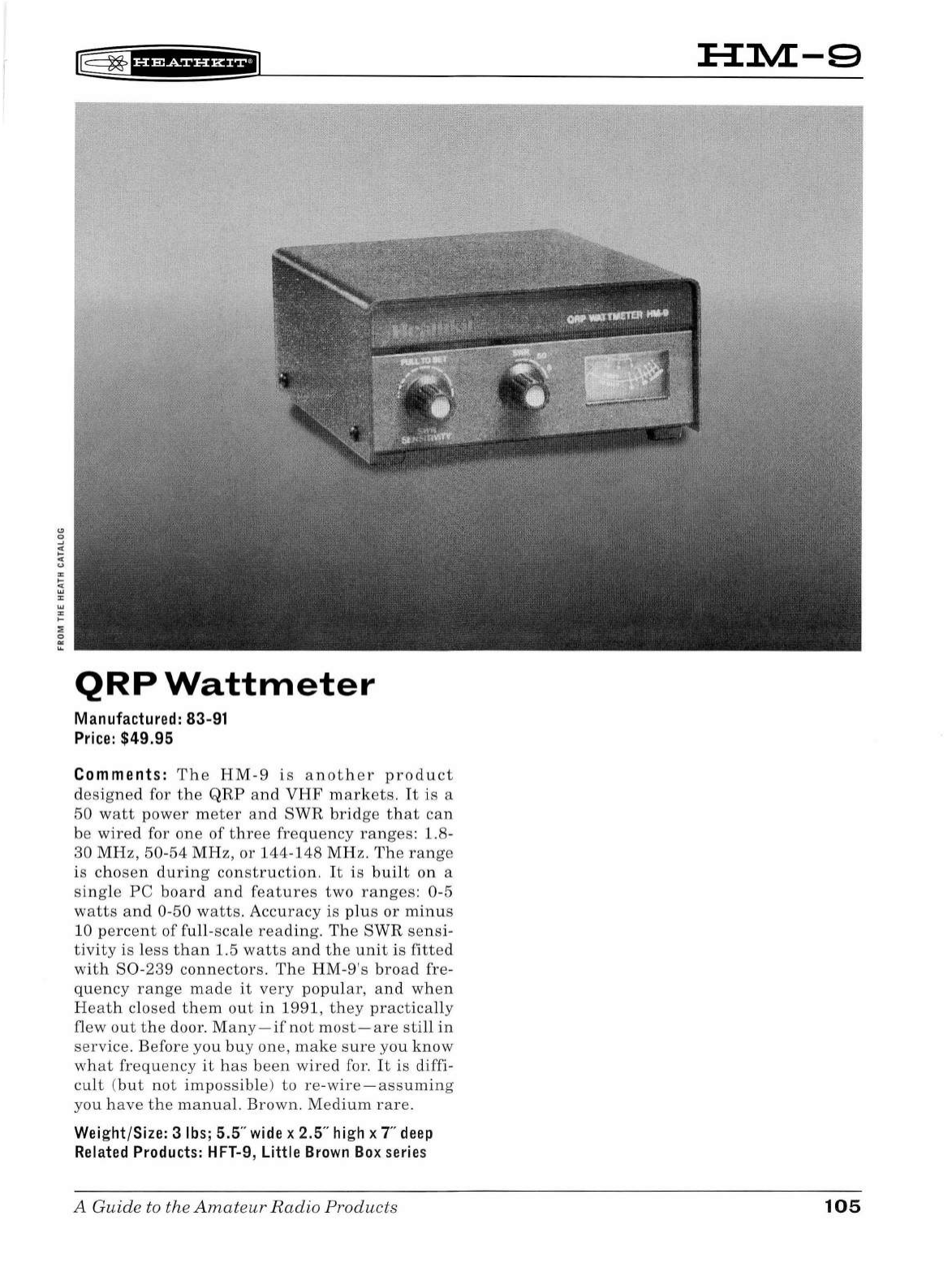
r@
~
'§fk&iHi*iiJ
QRP
Wattmeter
Manufactured: 83-91
Price:
$49.95
Comments: T h e
HM
-9
is
another
product
designed
for
the
QRP
and
VHF
markets.
It
is
a
50
watt
power
meter
and
SWR
bridge
th
at
can
be
wired
for
one
of
three
frequency
ranges:
1.8
-
30
MHz,
50-54
MHz,
or
144-148
MHz
. Th e
range
is
chosen
during
construction.
It
is
bu
il
t
on
a
sing
le
PC
board
and
features
two
ranges:
0-5
watts
and
0-50
watts.
Accuracy
is
plus
or
minus
10
percent
of
full-scale
reading
.
The
SWR
sensi-
tivity
is
less
than
1.5
watts
and
the
unit
is
fitted
with
80
-239
connectors
.
Th
e
HM
-9's
broad
fre-
quency
range
made
it
very
popular
,
and
when
H
eat
h
closed
them
out
in
1991
,
they
practically
flew
out
the
door
.
Many
-
if
not
mo
st
-
are
still
in
service.
B
efore
you
buy
one
,
make
sure
you
know
what
frequ
e
ncy
it
has
been
wired
for.
It
is
diffi-
cult
(
but
not
impossible
)
to
re-wire-assuming
you
have
the
manual.
Brown
.
Medium
rare
.
Wei
g
ht
/
Size:
3
lbs
; 5.5"
wi
de x 2. 5"
high
x T
deep
Related
Products:
HFT-9, Little Brown Box
se
rie
s
A Guide
to
the
Amateur
Radio
Products
:H:M-9
105
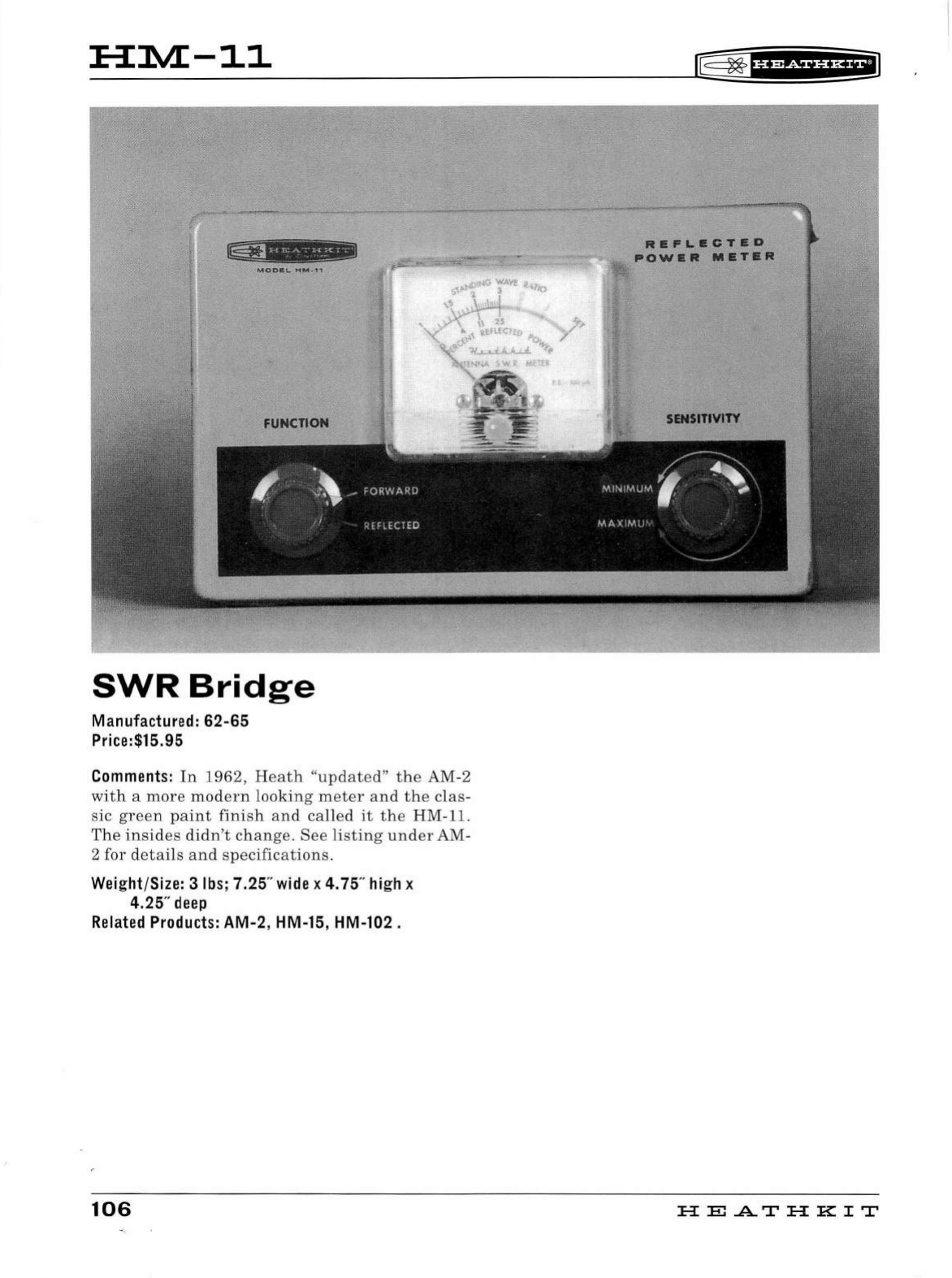
:H:1VL-11
'
!
FUNCTION
SWR
Bridge
Manufactured: 62-65
Price:$15.95
Comments:
In
1962,
He
ath
"
upd
ated"
the
AM-2
with
a
more
mod
ern
looking
meter
an
d
the
clas-
sic
green
paint
finish
and
called
it
the
HM-11.
The
in
sides
didn
't
change.
See
li
sting
und
er
AM-
2 for d
etai
ls
and
specifications
.
Weight
/
Size:
3
lbs;
7.25"
wide
x
4.
75"
high
x
4.25"
deep
Related
Products:
AM-2, HM-15, HM-102.
106
®=
~
f
U#&iUH+il
RB
..
L•CT•D
POW•R
M•T•R
SENSmVITY
HE
.AT
HK
IT
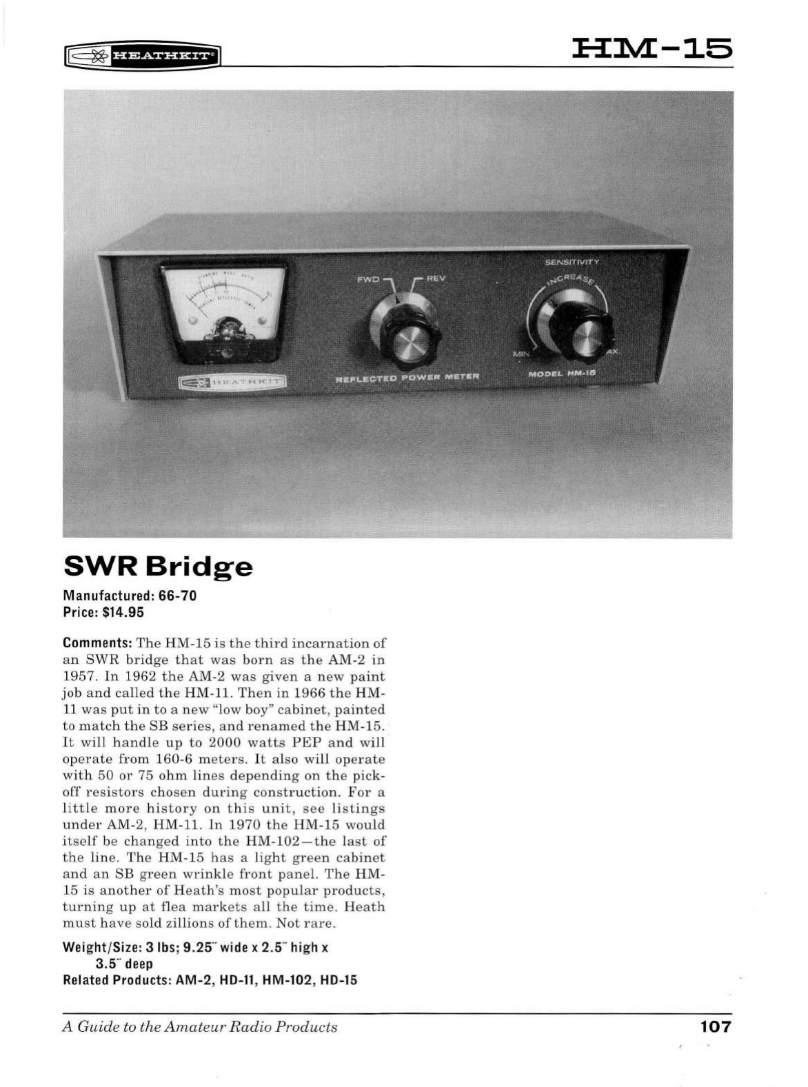
SWR
Bridge
Manu
fa
ctured:
66-70
Price:
$14.95
Comments:
The
HM-15
is
the
third
incarnation
of
an
SWR
bridge
that
was
born
as
the
AM-2
in
1957.
In
1962
the
AM-2
was
given
a
new
paint
job
and
called
the
HM-11.
Then
in
1966
the
HM-
11
was
put
in
to
a
new
"low boy"
cabinet,
painted
to
match
the
SB
series
,
and
renamed
the
HM-15.
It
will
handle
up
to
2000
watts
PEP
and
will
operate
from
160
-6
meters
.
It
also
will
operate
with
50
or
75
ohm
lines
depending
on
the
pick-
off
resistors
chosen
during
construction.
For
a
little
more
history
on
this
unit,
see
l
istings
under
AM-2, HM-11.
In
1970
the
HM-15
wou
ld
itself
be
changed
into
the
HM-102
-
the
last
of
the
line.
The
HM-15
ha
s a
light
green
cabinet
and
an
SB
green
wrinkl
e
front
panel.
The
HM-
15
is
another
of
Heath's
most
popular
products,
turning
up
at
flea
mark
e
ts
all
the
time
. He
ath
must
have
sold
zillions
of
them
.
Not
rare
.
Wei
g
ht
/
Size:
3
lbs
; 9.25"
wide
x 2.5"
hi
gh x
3.5"
deep
Related
Products:
AM-2,
HD-11
, HM-102,
HD-15
A Guide to the
Amateur
Radio
Products
:H:1VL-15
107
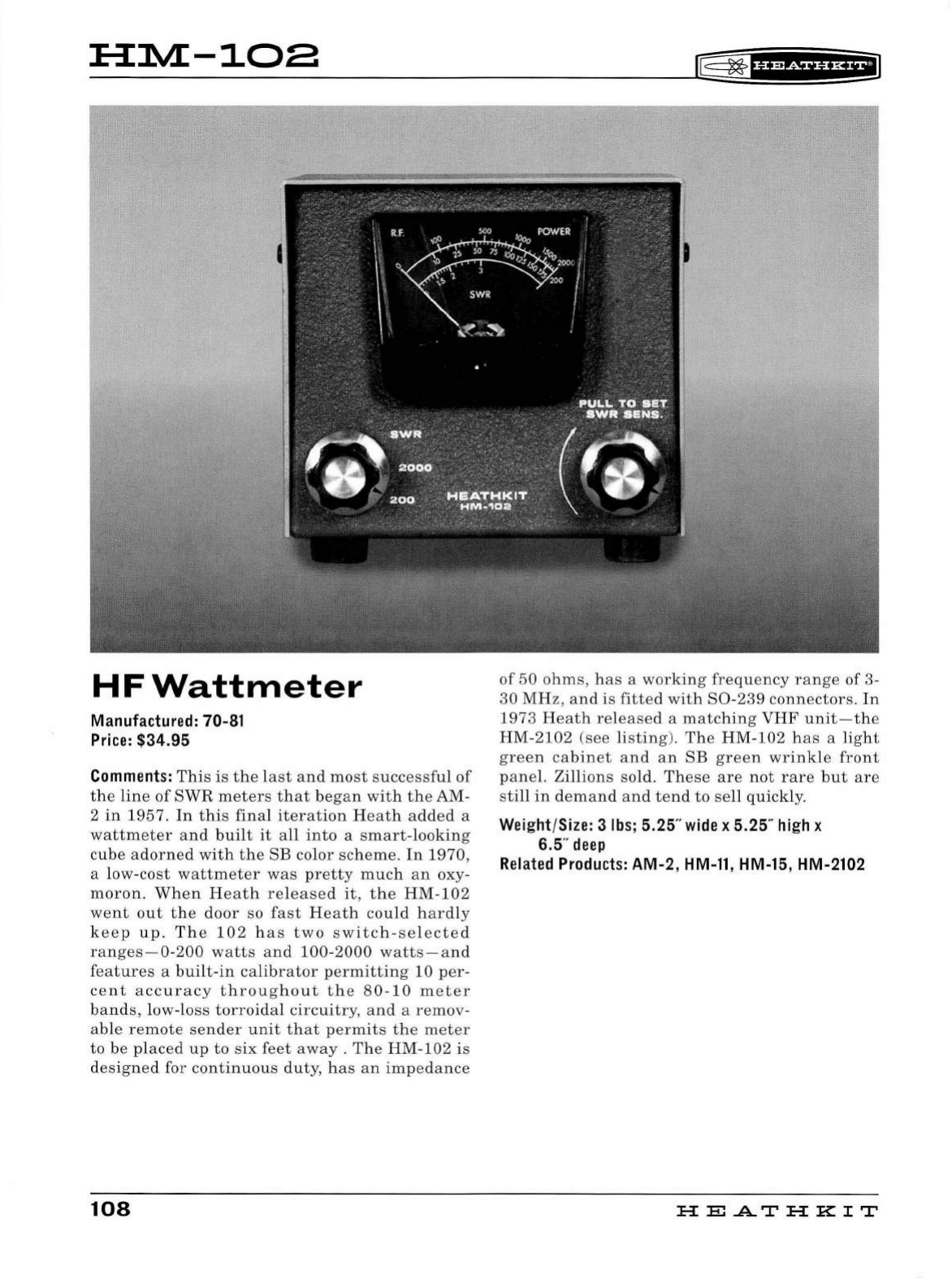
:H:1VL-108
HFWattmeter
Manufactured: 70-81
Price:
$34.95
Commen
ts
:
This
is
the
last
and
most
successful
of
the
line
of
SWR
meters
that
began
with
the
AM-
2
in
1957.
In
this
final
iteration
Heath
added
a
wattmeter
and
built
it
all
into
a
smart-looking
cube
adorned
with
the
SB
color
scheme
.
In
1970
,
a low-
cost
wattmeter
was
pretty
much
an
oxy-
moron
.
When
Heath
released
it,
the
HM
-
102
went
out
the
door
so
fast
Heath
cou
ld
hardly
keep
up.
T h e
102
has
two
switch
-
selected
ranges-0
-
200
watts
and
100
-
2000
watts-and
features
a
bu
i
lt-in
calibrator
permitting
10
per-
cent
accuracy
throughout
the
80-10
meter
bands,
low
-l
oss
torroidal
circuitry,
and
a
remov
-
able
remote
sender
unit
that
permits
the
meter
to
be
placed
up
to
six
feet
away
.
The
HM
-
102
is
designed
for
continuous
duty,
has
an
impedance
108
~
~
1
Hi&ii'H+i1
of
50
ohms,
has
a
working
frequency
range
of
3-
30
MHz
,
and
is
fitted
with
80
-
239
connectors.
In
1973
Heath
re
l
eased
a
matching
VHF
unit-t
h e
HM
-
2102
(see
listing).
The
HM
-
102
h
as
a
light
green
cabinet
and
an
SB
green
wr
i
nkle
front
pane
l. Zill
ions
sold.
These
are
not
rare
but
are
still
in
demand
and
tend
to
se
ll
quickly.
Wei
ght/Size: 3
lbs
; 5.25"
wide
x 5.25"
high
x
6.5"
deep
Related
Products:
AM-2,
HM-11,
HM-15, HM-2102
HE
AT
HK
IT
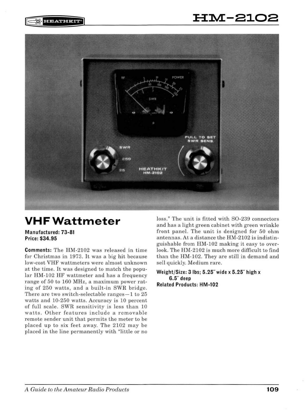
iE
~
1u+1ua+@
VHFWattmeter
Manufactured: 73-81
Price:
$34.95
Comments:
The
HM-2102
was
released
in
time
for
Christmas
in
1973.
It
was
a
big
hit b
ecause
low
-
cost
VHF
wattmeters
were
al
most
unknown
at
the
time.
It
was
designed
to
match
the
popu
-
l
ar
HM-102
HF
wattmeter
and
has
a
frequency
range
of
50
to
160
MHz,
a
maximum
power
rat
-
ing
of
250
watts,
and
a
built-
in
SWR
bridge.
There
are
two
switch-selectab
le
ranges-1
to 25
watts
and
10-250
watts
.
Accuracy
is
10
percent
of
fu
ll
scale.
SWR
sensitivity
is
less
than
10
watts.
Other
features
include
a
removable
remote
sender
unit
that
permits
the
meter
to
be
placed
up
to
six
feet
away.
The
2102
may
be
placed
in
the
line
permanently
with
"
little
or
no
A Guide to the
Amateu
r
Radio
Products
H:L\IL-8108
loss."
The
unit
is
fitted
with
S0
-
239
connectors
and
h
as
a
light
green
cabinet
wi
th
gree
n
wrink
le
front
panel.
The
unit
is
designed
for
50
ohm
antennas
.
At
a
distance
the
HM
-
2102
is
indistin
-
guishab
le
from
HM
-102
making
it
easy
to
over-
look.
The
HM-2102
is
much
more
diffic
ul
t
to
find
than
the
HM-102.
They
are
st
ill
in
de
m
and
and
sell
qu
ickly
.
Medium
rare
.
Weight/Size: 3
lbs;
5.25"
wide
x 5.25"
high
x
6.5"
deep
Related
Products:
HM-102
109
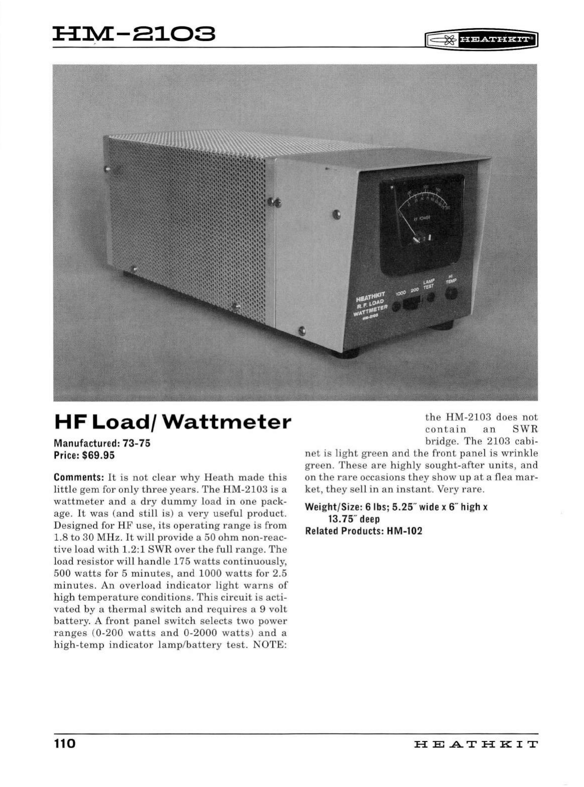
HM-8103
HF
Load/
Wattmeter
Manufactured:
73-
75
Price:
$69.95
Comments:
It
is
not
clear
why
Heath
made
this
li
ttle
gem
for
on
ly
three
years.
The
HM
-
2103
is
a
wattmeter
and
a
dry
dummy
load
in
one
pack-
age
.
It
was
(and
st
ill
is) a
very
usefu
l
product.
D
esigne
d for
HF
use,
its
op
erating
range
is
from
1.
8
to
30
MHz
.
It
w
ill
prov
i
de
a
50
ohm
non-reac-
tive
loa
d
wit
h 1.2:1
SWR
over
the
fu
ll
range.
The
l
oad
resistor
wi
ll
hand
le 175
watts
continuous
l
y,
500
watts
for 5
min
u
tes,
and
1000
watts
for 2.5
m
inutes.
An
over
l
oad
indicator
light
warns
of
h
igh
temperature
conditions.
This
circ
u
it
is
acti
-
vated
by
a th
erma
l
switc
h
and
requires
a 9 volt
battery
. A
front
pane
l
switch
se
l
ects
two
power
ranges
(0-200
watts
and
0-2000
watts)
an
d a
h
igh
-
temp
in
d
icator
lamp/battery
test.
NOTE:
110
lG=
~
fif&iHH+il
t h e
HM-2103
does
not
contain
an
SWR
br
~
dge.
The
2103
cabi-
net
is
light
green
and
the
front
pane
l
is
wr
i
nkle
green.
These
are
hi
ghly
sought
-
after
units,
and
on
the
rare
occasions
they
show
up
at
a
flea
mar-
ket,
t h
ey
se
ll
in
an
i
nsta
nt .
Very
rare
.
Weight/Size: 6
lbs
; 5.25"
wide
x 6"
high
x
13.75"
deep
Related
Products:
HM-102
HE
..AT
HK
IT
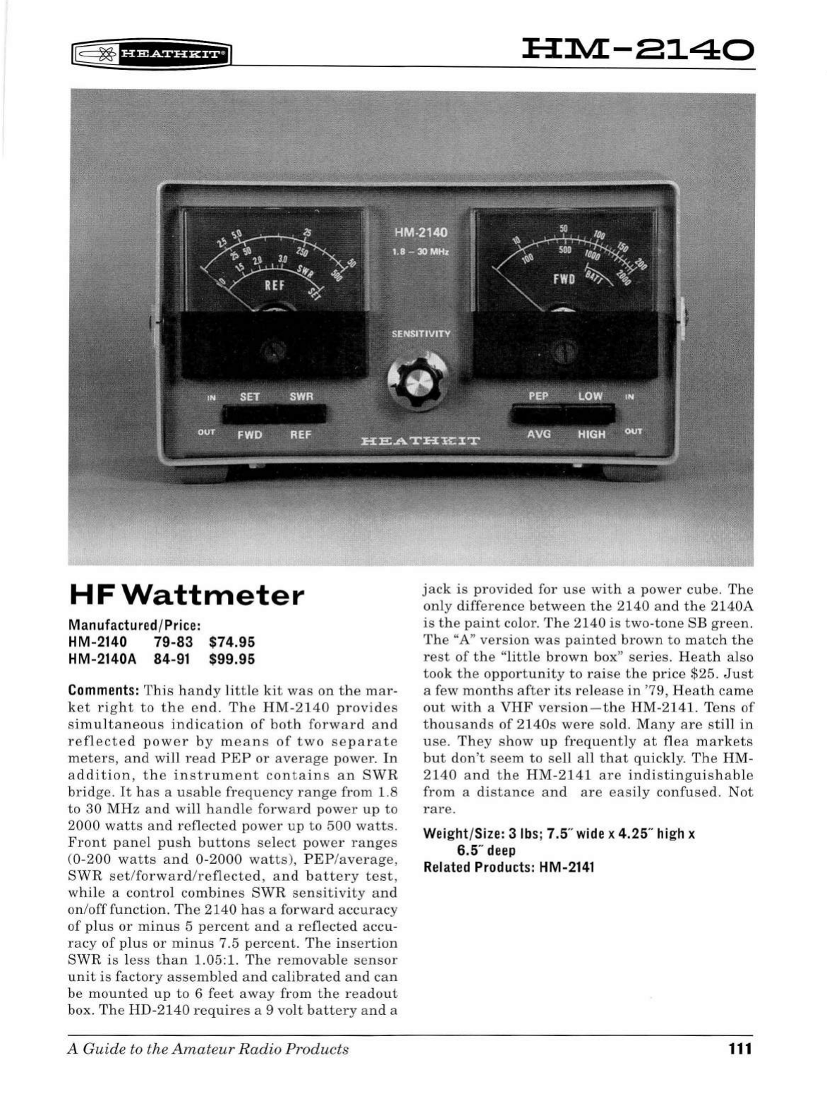
lE
~
B'*Sii'HWiJ
HFWattmeter
Manu
fa
ctured
/
Pri
c
e:
HM-2140
79-83
HM-2140A 84-91 $74.95
$99.95
Comments
:
This
handy
little
kit
was
on
the
mar
-
ket
right
to
the
end.
The
HM
-
2140
provides
simultaneous
indication
of
both
forward
and
reflected
power
by
means
of
two
separate
meters
,
and
will
read
PEP
or
average
power.
In
addition,
the
instrument
contains
an
SWR
bridge
.
It
has
a
usable
frequency
range
from
1.8
to
30
MHz
and
will
h a
ndle
forward
power
up
to
2000
watts
and
reflected
power
up
to
500
watts.
Front
pan
el
push
buttons
select
power
ranges
(
0-200
watts
and
0-2000
watts
),
PEP
/
average,
SWR
set/forward/reflected,
a
nd
battery
test,
while
a
control
combines
SWR
sensitivity
and
on/off
function
.
The
2140
has
a
forward
accuracy
of
plus
or
minus
5
percent
and
a
reflected
accu-
racy
of
plu
s
or
minus
7 .5
percent.
The
insertion
SWR
is
less
than
1.05
:1.
The
removable
sensor
unit
is
factory
assembled
and
calibrated
and
can
be
mounted
up
to
6
feet
away
from
the
readout
box
.
The
HD-2140
requires
a 9
volt
battery
and
a
A Guide to the
Amateur
Radio
Products
HM-8140
jack
is
provided
for
us
e
with
a
power
cube.
The
only
difference
between
the
2140
and
the
2140A
is
the
paint
co
l
or
.
The
2140
is
two-tone
SB
green.
The
"A"
version
was
painted
brown
to
match
the
rest
of
the
"little
brown
box"
series.
Heath
also
took
the
opportunity
to
raise
the
price
$25.
Just
a few
months
after
its
release
in
'79,
Heath
came
out
with
a VHF
version-the
HM-2141.
Tens
of
thousands
of
2140s
were
sold
.
Many
are
still
in
use
.
They
show
up
frequently
at
flea
markets
but
don
't
seem
to
sell
all
that
quickly
.
The
HM-
2140
and
the
HM-2141
are
indistinguishable
from
a
di
s
tance
and
are
easily
confused.
Not
rare.
Wei
g
ht
/
Size:
3
lbs
; 7.5"
wide
x 4.25"
hi
gh x
6.5"
deep
Related
Products
:
HM-2141
111
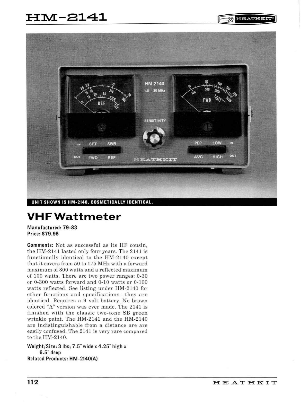
HM-8141
UNIT
SHOWN IS
HM-2140,
COSMETICALLY
IDENTICAL.
VHFWattmeter
Manufactured:
79-83
Price:
$79.95
Comments:
Not
as
s
ucces
sfu
l
as
its
HF
cousin,
the
HM-2141
la
sted
only
four
years.
The
2141
is
functionally
identical
to
the
HM-2140
except
that
it
covers
from
50
to
175
MHz
with
a
forward
maximum
of
300
watts
and
a
reflected
maximum
of
100
watts.
Th
ere
are
two
power
ranges:
0-30
or
0-
300
watts
forward
and
0-10
watts
or
0-100
watts
reflected.
See
listing
und
er
HM-2140
for
other
functions
and
specifications
-
they
are
identical.
Requires
a 9
volt
battery.
No
brown
colored
"A"
version
was
ever
made.
The
2141
is
finished
with
the
classic
two-tone
SB
green
wrinkle
paint.
The
HM-2141
an
d
the
HM-2140
are
indistinguishable
from
a
distance
are are
easi
ly
confused.
The
2141
is
very
rare
compared
to
the
HM-2140.
Weight/Size: 3
lbs;
7.5"
wide
x 4.25"
high
x
6.5
..
deep
Related
Products:
HM-2140(A)
112
lE=
~
f
UMf§fH+il
HE.A.TH
KIT
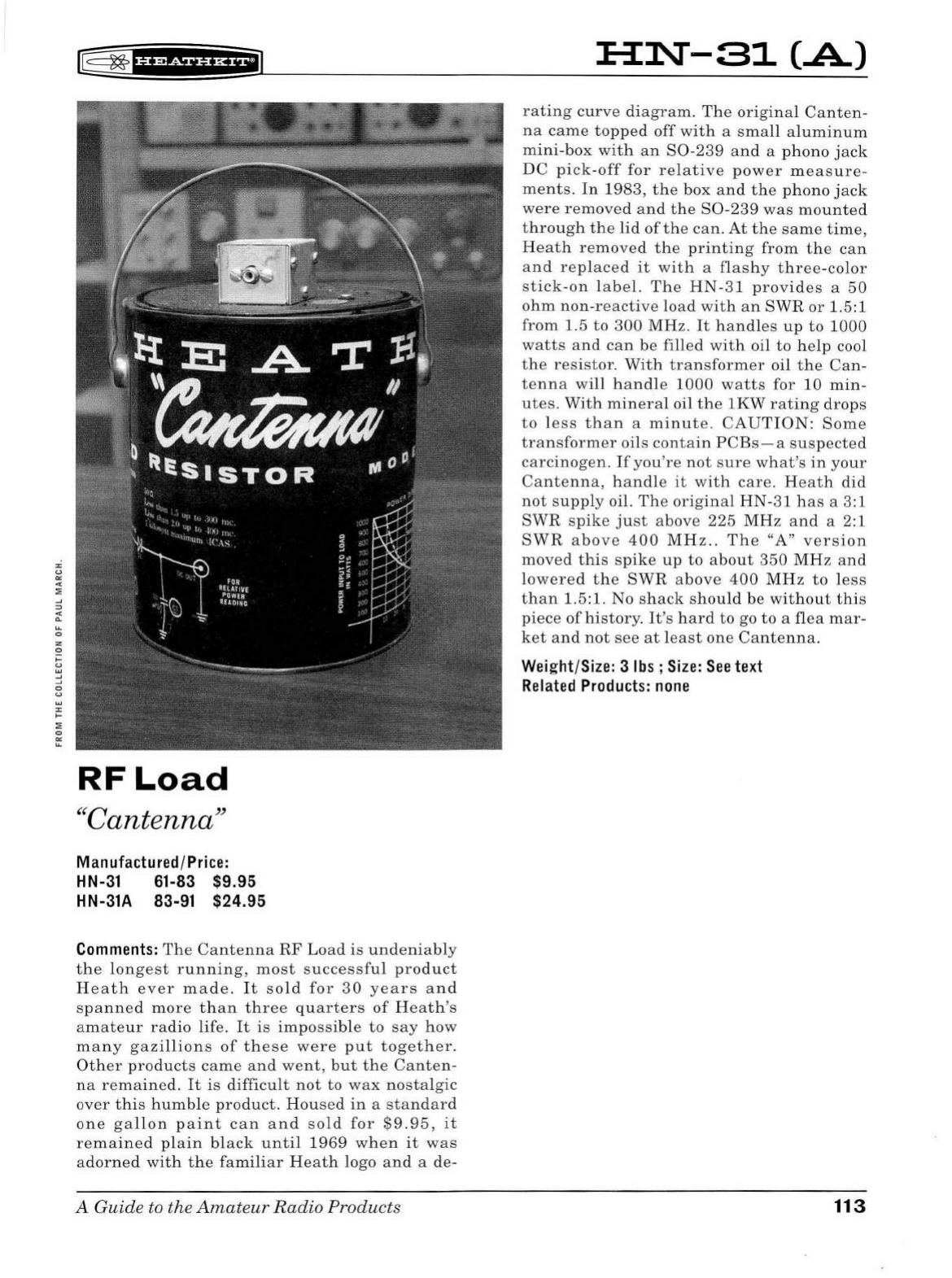
"'
"
"'
"
:.'
-'
=>
"
0..
~
0
z
0
>==
"
w
-'
-'
0
"
w
"'
1-
:;o
0
"'
~
K§
~
fU@SiHi*iiJ
RF
Load
''
Cant
en
na
"
Manufactured/
Price:
HN-31
61-83 $9.95
HN-31A 83-91 $24.95
Comments:
The
Cantenna
RF
Load
is
undeniab
ly
the
l
ongest
running,
most
successful
product
Heath
ever
made
.
It
sold
for
30
years
and
spanned
more
than
three
quarters
of
Heat
h's
amateur
radio
life. It
is
impossib
le
to
say
how
many
gazillions
of
these
were
put
together.
Other
products
came
and
went,
but
the
Canten
-
na
remained
.
It
is
difficult
not
to
wax
nostalgic
over
this
humb
le
product.
Housed
in
a
standard
one
gallon
paint
can
and
so
ld
for
$9.95,
it
remained
plain
black
unt
il
1969
when
it
was
adorned
with
the
familiar
Heath
logo an d a de-
A Guide
to
the
Amateur
Radio
Products
HN-31
(.A)
rating
curve
diagram
.
The
original
Canten-
na
came
topped
off
with
a
small
al
uminum
mini-box
with
an
S0-239
and
a phono
jack
DC
pick-off
for
relative
power
measure-
ments
.
In
1983,
the
box
and
the
phono
jack
were
removed
and
the
S0
-
239
was
mounted
through
the
lid
of
the
can.
At
the
same
time,
Heath
removed
the
printing
from
the
can
and
replaced
it
with
a
flashy
three-color
stick
-
on
label.
Th
e
HN-31
provides
a
50
ohm
non-reactive
load
with
an
SWR
or
1.5
:1
from
1.5
to
300
MHz.
It
handles
up
to
1000
watts
and
can
be
filled
with
oil
to
help
cool
the
resistor
.
With
transformer
oil
the
Can
-
tenna
will
handl
e
1000
watts
for
10
min
-
utes.
With
mineral
oil
the
lKW
rating
drops
to
less
than
a
minute
.
CAUTION:
Some
transformer
oils
contain
PCBs-a
suspected
carcinogen.
If
you're
not
s
ure
what's
in
your
Cantenna,
handl
e
it
with
care.
Heath
did
not
supply
oil.
The
original
HN-31
has
a
3:
1
SWR
s
pike
just
above
225
MHz
and
a 2:1
SWR
above
400
MHz
..
The
"A"
version
moved
this
spike
up
to
a
bout
350
MHz
and
lowered
the
SWR
a
bove
400
MHz
to
l
ess
than
1.5:1.
No
shack
should
be
wit
h
out
this
piece
of
history.
It
's
hard
to
go
to
a
flea
mar-
ket
and
not
see
at
l
east
one
Cantenna
.
Wei
ght/
Size
: 3 lbs ;
Size:
See
text
Related
Products:
none
113
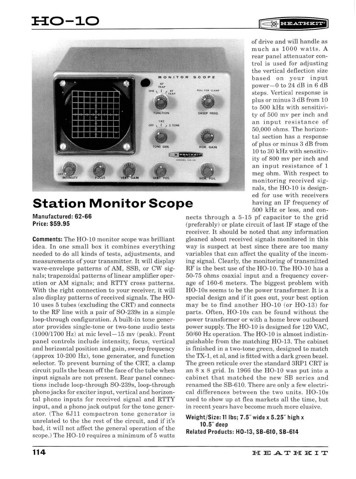
:a::o-10
AF
lRAf'
S
IN
E \ I I T
:ip
fUNCllON
I <C
,.,
,.
,.
lE§
~
f
H&f
HHFIJ
~
WlfP
FREQ
.
•
fONE GilN. HOR. GAIN
of
dri
ve
and
will h
an
dle
as
much
as
1000
watts.
A
rear
panel
atte
nu
ator
con-
trol
is
used
for
adjusting
the
vertical
deflection
size
based
on
your
input
power
- 0
to
24 dB
in
6 dB
steps.
Vertical
response
is
plus
or
minus
3 dB
from
10
to
500
kHz
with
sens
itivi-
ty
of
500
mv
per
inch
and
an
input
resistance
of
50,000
ohms.
The
horizon
-
tal
section
has
a
response
of
plus
or
minus
3 dB
from
10 to 30
kHz
with
sens
itiv-
ity
of
800
mv
per
inch
and
an
input
resistance
of
1
meg
ohm.
With
respect
to
monitoring
received
sig
-
nals,
the
H0
-10
is
des
i
gn
-
ed
for
use
with
receivers
having
an
IF
frequency
of
500
kHz
or
l
ess
,
an
d con-
t
e§#
'.ili.l;imu'"'
Station
Monitor
Scope
Manufactured:
62-66
Price:
$59.95
Comments:
The
H0-10
monitor
scope
was
brilliant
idea.
In
one
small
box
it
combines
everything
needed
to
do
all
kinds
of
tests,
adjustments,
and
measurements
of
your
transmitter.
It
will
disp
l
ay
wave-envelope
patterns
of
AM, SSB,
or
CW sig-
nal
s;
trapezoidal
patterns
oflinear
amplifier
oper-
ation
or
AM
signals;
an
d
RTTY
cross
patterns.
With
the
right
connection
to
your
receiver,
it
will
also
display
patterns
of
received
signals.
Th
e
H0-
10
uses
5
tubes
(excluding
the
CRT)
and
connects
to
the
RF
line
with
a
pair
of
S0-239s
in
a
sim
ple
loop-through
configuration.
A
built-in
tone
ge
ner-
ator
provides
sing
le-ton
e
or
two-tone
audio
tests
(
1000
/
1700
Hz)
at
mic level
-15
mv
(peak).
Front
panel
controls
include
intensity,
focus,
vertical
and
horizontal
position
and
gain,
sweep
frequency
(approx
10-200 Hz),
tone
generator,
an
d
function
selector.
To
prevent
burning
of
the
CRT, a
clamp
circuit
pulls
the
beam
off
the
face
of
the
tube
when
input
signals
are
not
present.
Rear
panel
connec-
tions
include
loop-throu
gh
S0-239s,
loop-through
phono
jacks
for
exciter
input,
vertical
an
d
horizon
-
tal
phono
inputs
for
rece
i
ved
si
gna
l a
nd
RTTY
input,
and
a
phono
jack
output
for
the
tone
gener-
ator.
(
Th
e
6Jll
compactron
tone
generator
is
unr
elated
to
the
the
rest
of
the
circuit,
and
if
it
's
bad
,
it
will
not
affect
the
genera
l
operation
of
the
scope.)
The
H0-10
requires
a
minimum
of
5
watts
114
n
ects
through
a
5-15
pf
capacitor
to
the
grid
(preferably)
or
plate
circuit
of
last
IF
stage
of
the
receiver.
It
s
hould
be
noted
that
any
information
gleaned
about
received
signals
monitored
in
this
way
is
suspect
at
best
si
nc
e
there
are
too
many
variables
that
can
affect
the
quality
of
the
incom-
ing
signa
l.
Clearly,
the
monitoring
of
transmitted
RF
is
the
best
use
of
the
H0-10.
Th
e
H0-10
ha
s a
50-75
ohms
coaxial
input
and
a
frequency
cover-
age
of
160
-6
meters.
The
biggest
problem
with
HO-lO
s
seems
to
be
the
power
transformer.
It
is a
special
design
and
if
it
goes
out,
your
best
option
may
be
to
find
a
noth
er
H0-10
(or
H0-13
)
for
part
s.
Often,
HO-lOs
can
be
found
without
the
pow
er
transformer
or
with
a
home
brew
outb
oard
power
supp
ly.
The
H0-10
is
designed
for
120
VAC,
50/60
Hz
operation.
The
H0-10
is
almost
indistin
-
guishable
from
the
matching
H0-13.
The
ca
bin
et
is
finished
in
a
two-tone
green,
d
esigned
to
match
the
TX-1,
et
al,
and
is
fitted
with
a
dark
green
bezel.
The
green
reticu
le
over
the
standard
3
RP1
C
RT
is
an
8 x 8
gri
d.
In
1966
the
H0-10
was
put
into
a
cabinet
that
matched
the
new
SB
series
and
renamed
the
SB-610.
There
are
only a few elec
tri
-
cal
differences
between
the
two
units.
HO
-
lOs
used
to
show
up
at
flea
markets
all
the
time,
but
in
recent
years
have
become
much
more
e
lu
sive.
Weight/Size:
11
lbs;
7.5
..
wide
x 5.25"
high
x
10.5
..
deep
Related
Products:
H0-13,
SB-610
,
SB-614
HE
A.TH
KIT
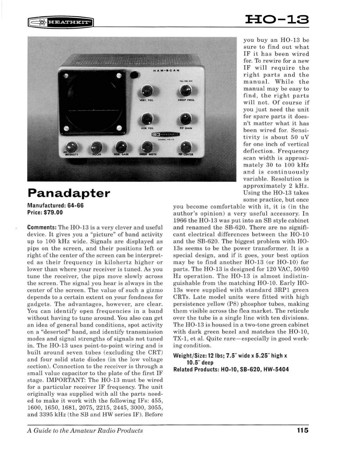
r@
~ff
'*Sf
ff
Hf
I
Pan
adapter
Manufactured:
64-66
Price:
$79.00
Comments:
The
H0-13
is
a
very
clever
and
useful
device.
It
gives
you
a
"picture"
of
band
activity
up
to
100
kHz
wide.
Signals
are
displayed
as
pips
on
the
screen,
and
their
positions
l
eft
or
right
of
the
center
of
the
screen
can
be
interpret-
ed
as
their
frequency
in
kilohertz
higher
or
lower
than
where
your
receiver
is
tuned.
As
you
tune
the
receiver,
the
pips
move
slowly
across
the
screen
.
The
signal
you
hear
is
always
in
the
center
of
the
screen.
The
va
lu
e
of
such
a
gizmo
depends
to
a
certain
extent
on
your
fondness
for
gadgets
.
The
advantages,
however,
are
clear.
You
can
identify
open
frequencies
in
a
band
without
having
to
tune
aro
und.
You also
can
get
an
idea
of
genera
l
band
conditions,
spot
activity
on
a
"deserted"
band,
and
identify
transmission
modes
and
signal
strengths
of
signals
not
tuned
in.
The
H0-13
uses
point-to-point
wiring
and
is
built
around
seven
tubes
(excluding
the
CRT)
and
four
solid
state
diodes
(
in
the
low
voltage
section
).
Connection
to
the
receiver
is
through
a
small
value
capacitor
to
the
plate
of
the
first
IF
stage
.
IMPORTANT:
The
H0-13
must
be
wired
for a
particular
receiver
IF
frequency.
Th
e
unit
originally
was
supplied
with
all
the
parts
need-
ed
to
make
it
work
with
the
following
IF
s:
455,
1600, 1650,
1681,
2075,
2215,
2445,
3000,
3055,
and
3395
kHz
(the
SB
and
HW
series
IF
).
Before
A Guide to the
Amateur
Radio
Products
H0-13
you
buy
an
H0-13
be
sure
to
find
out
what
IF
it
has
been
wired
for.
To
rewire
for a
new
IF
will
require
the
right
parts
and
the
manual.
While
the
manual
may
be
easy
to
find,
the
right
parts
will
not.
Of
course
if
you
just
need
the
unit
for
spare
parts
it
does-
n't
matter
what
it
ha
s
been
wired
for.
Sensi-
tivity
is
about
50
uV
for
one
inch
of
vertical
deflection.
Frequency
scan
width
is
approxi-
mately
30
to
100
kHz
and
is
continuously
variable.
Resolution
is
approximately
2
kHz.
Using
the
H0-13
takes
some
practice,
but
once
you
become
comfortable
with
it,
it
is
(in
the
author's
opinion)
a
very
useful
accessory.
In
1966
the
H0-13
was
put
into
an
SB
sty
le
cabinet
and
renamed
the
SB-620.
There
are
no
signifi-
cant
electrical
differences
between
the
H0-10
and
the
SB-620.
The
biggest
problem
with
H0-
13s
seems
to
be
the
power
transformer.
It
is
a
specia
l
design,
and
if
it
goes,
your
best
option
may
be
to
find
another
H0-1
3
(or
H0-10)
for
parts.
The
H0-13
is
designed
for
120
VAC,
50/60
H z
operation.
The
H0-13
is
almost
indistin-
guishable
from
the
matching
H0-10.
Early
H0-
13s
were
supp
li
ed
with
standard
3RP1
green
CRTs.
Lat
e
model
unit
s
were
fitted
with
high
persistence
yellow
(PS)
phosphor
tubes,
making
them
visible
across
the
flea
market.
The
reticule
over
the
tube
is
a
sing
le
lin
e
with
ten
divisions.
The
H0-13
is
hou
se
d
in
a
two-tone
green
cabinet
with
dark
green
bezel
and
matches
the
H0-10,
TX-1,
et
al.
Quite
rare-especially
in
good
work-
in
g
condition.
Weight/Size:
12
lbs;
7.5"
wide
x 5.25"
high
x
10.5"
deep
Related
Products:
H0-10, SB-620, HW-5404
115
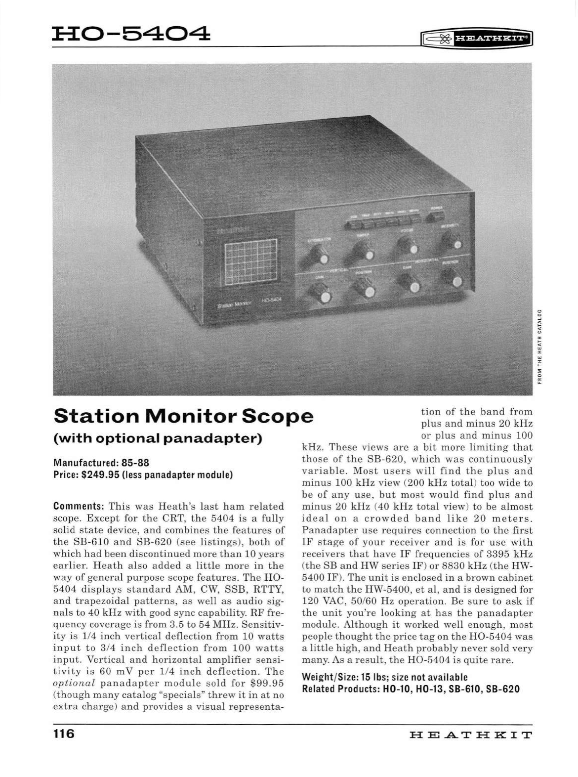
::H:0-5404
rE=
~
f
HW?HHEI
Station
Monitor
Scope
tion
of
t he
band
from
plu
s
and
minus
20
kHz
or
plus
and
minus
100
(with
optional
panadapter)
Manufactured:
85-88
Price:
$249.95
(less
panadapter
module)
Comments:
This
was
Heath's
last
ham
related
scope.
Except
for
th
e CRT,
the
5404
is
a
full
y
s
olid
state
device,
and
combines
the
features
of
the
SB
-
610
and
SB-620
(see
listings),
both
of
which
had
been
discontinued
more
than
10
years
earlier.
Heath
al
so
added
a
little
more
in
the
way
of
general
purpose
scope
features.
Th
e
H0-
5404
displays
standard
AM
,
CW
,
SSE,
RTTY,
and
trapezoidal
patterns,
as
well
as
audio
sig-
nals
to
40
kHz
with
good
sync
capability.
RF
fre
-
quency
coverage
is
from
3.5
to
54
MHz.
Sensitiv-
ity
is
1/4
inch
vertical
deflection
from
10
watts
input
to
3/4
inch
deflection
from
100
watts
input.
Vertical
and
horizontal
amplifier
se
n
si
-
tivity
is
60
mV
per
1/4
inch
defl
ect
ion.
The
optional
panadapter
module
sold
for
$99.95
(though
many
catalog
"specia
ls"
threw
it
in
at
no
extra
charge
)
and
provides
a
vis
ual
representa-
116
kH
z.
These
views
are
a
bit
more
limiting
that
those
of
the
SB-620,
which
was
contin
uou
sly
variable.
Most
users
will
find
t
he
plus
and
minus
100
kHz
view
(200
kHz
total)
too
wide
to
be
of
any
use,
but
most
would
find
plus
and
minus
20
kHz
(40
kHz
total
view
)
to
be
a
lmo
st
id
ea
l
on
a
crowded
band
lik
e
20
meters.
Pan
a
dapt
er
use
requires
connect
ion
to
the
first
IF
stage
of
your
receiver
an
d
is
for
use
with
receivers
that
have
IF
frequencies
of
3395
kHz
(the
SB
and
HW
series
IF
)
or
8830
kHz
(
the
HW-
5400
IF
).
The
unit
is
enclosed
in
a
brown
cabinet
to
match
the
HW-5400,
et
al,
and
is
designed
for
120
VAC,
50/60
Hz
operation
.
Be
s
ure
to
ask
if
the
unit
you're
looking
at
has
the
panadapter
module
.
Although
it
worked
well
enough,
most
people
thought
the
price
tag
on
the
H0-5404
was
a
little
high,
and
Heath
probably
never
sold
very
many.
As a
result,
the
H0-5404
is
quite
rare.
Weight/
Size:
15
lbs;
size
not
available
Related
Products:
H0-10, H0-13, SB-610, SB-620
H
El
.AT
HK
IT
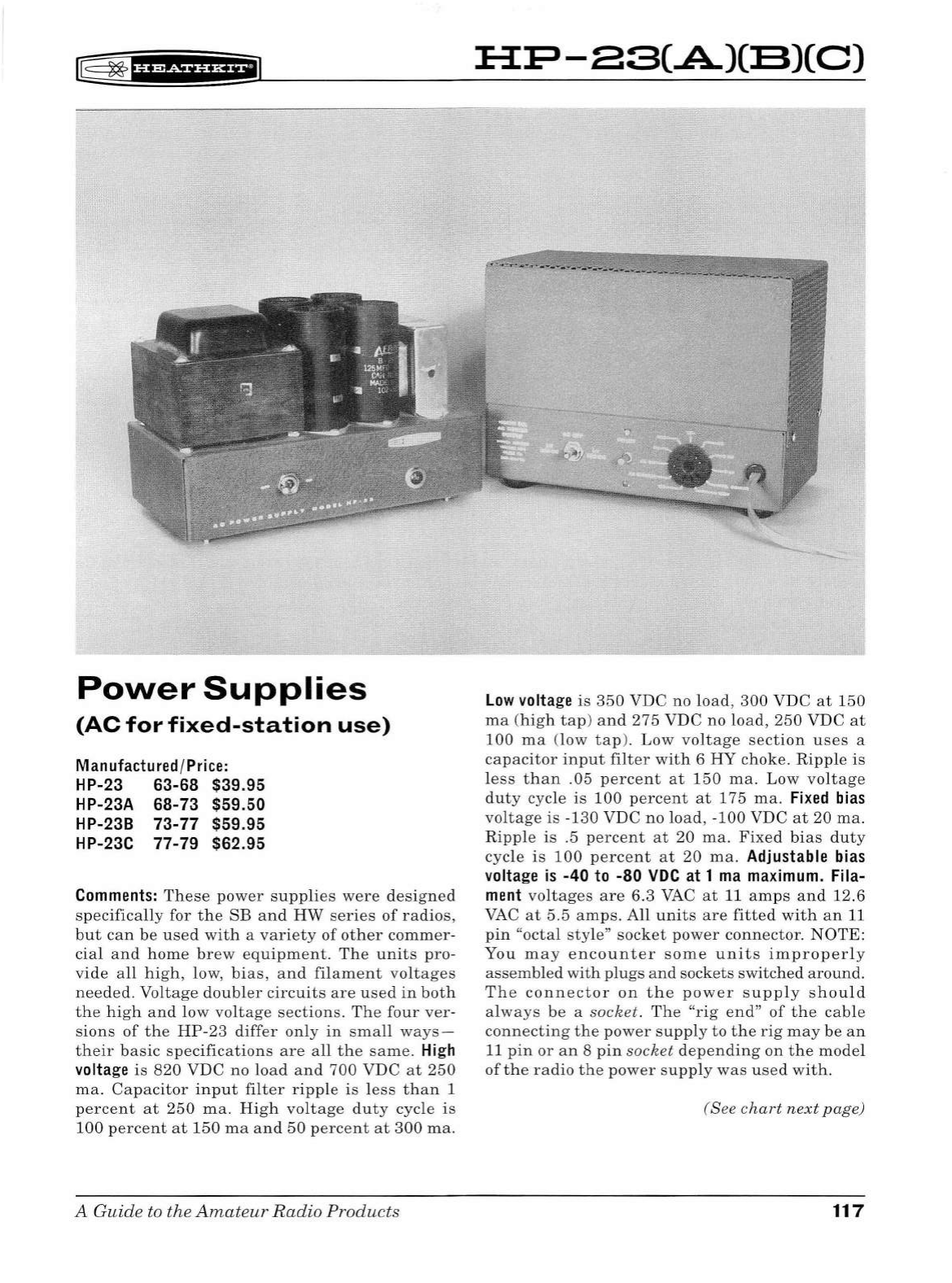
rr§
~
1
u&&f
Ui*f'1
Power
Supplies
(AC
for
fixed-station
use)
Manufactured /
Price:
HP-23 63-68 $39.95
HP-23A 68-73 $59.50
HP-23B
73-77
$59.95
HP-23C 77-79 $62 .95
Comments:
These
power
supplies
were
designed
specifically
for
the
SB
and
HW
series
of
radios,
but
can
be
used
with
a
variety
of
other
commer-
cia
l
and
home
brew
equipment.
The
units
pro
-
vide
all
high,
low,
bias,
and
filament
voltages
needed.
Voltage
doubler
circuits
are
used
in
both
the
high
and
low
voltage
sections
.
The
four
ver-
sions
of
the
HP
-23
differ
only
in
small
ways-
their
basic
specifications
are
all
the
same.
Hi
gh
volta
ge
is
820
VDC
no
load
and
700 VDC
at
250
ma.
Capacitor
input
filter
ripple
is
less
than
1
percent
at
250
ma.
High
voltage
duty
cycle
is
100
percent
at
150
ma
and
50
percent
at
300
ma.
A Guide to the
Amateur
Radio
Products
:B:P-ES(.A)(:B)(C)
Low
volta
ge
is
350
VDC no l
oad,
300
VDC
at
150
ma
(high
tap
)
and
275
VDC
no
load,
250
VDC
at
100
ma
(low
tap).
Low
voltage
section
uses
a
capacitor
input
filter
with
6
HY
choke.
Ripple
is
l
ess
than
.05
percent
at
150
ma.
Low
voltage
duty
cycle
is
100
percent
at
175
ma.
Fixed
bi
as
voltage
is
-130
VDC
no
load,
-100
VDC
at
20
ma.
Ripple
is
.5
percent
at
20
ma.
Fixed
bias
duty
cycle
is
100
percent
at
20
ma.
Adjustab le
bi
as
volta
ge is
-40
to -80
VDC
at
1
ma
maximum.
Fila-
me
nt
voltages
are
6.3
VAC
at
11
amps
and
12.6
VAC
at
5.5
amps
.
All
units
are
fitted
with
an
11
pin
"octal
style"
socket
power
connector.
NOTE:
You
may
encounter
some
units
improperly
assembled
with
plugs
and
sockets
switched
around.
The
connector
on
the
power
supply
should
al
ways
be
a
socket.
The
"rig
end"
of
the
cable
connecting
the
power
supp
ly
to
the
rig
may
be
an
11
pin
or
an
8
pin
socket
depending
on
the
model
of
the
radio
the
power
supp
ly
was
used
with.
(See
chart
next
page)
117
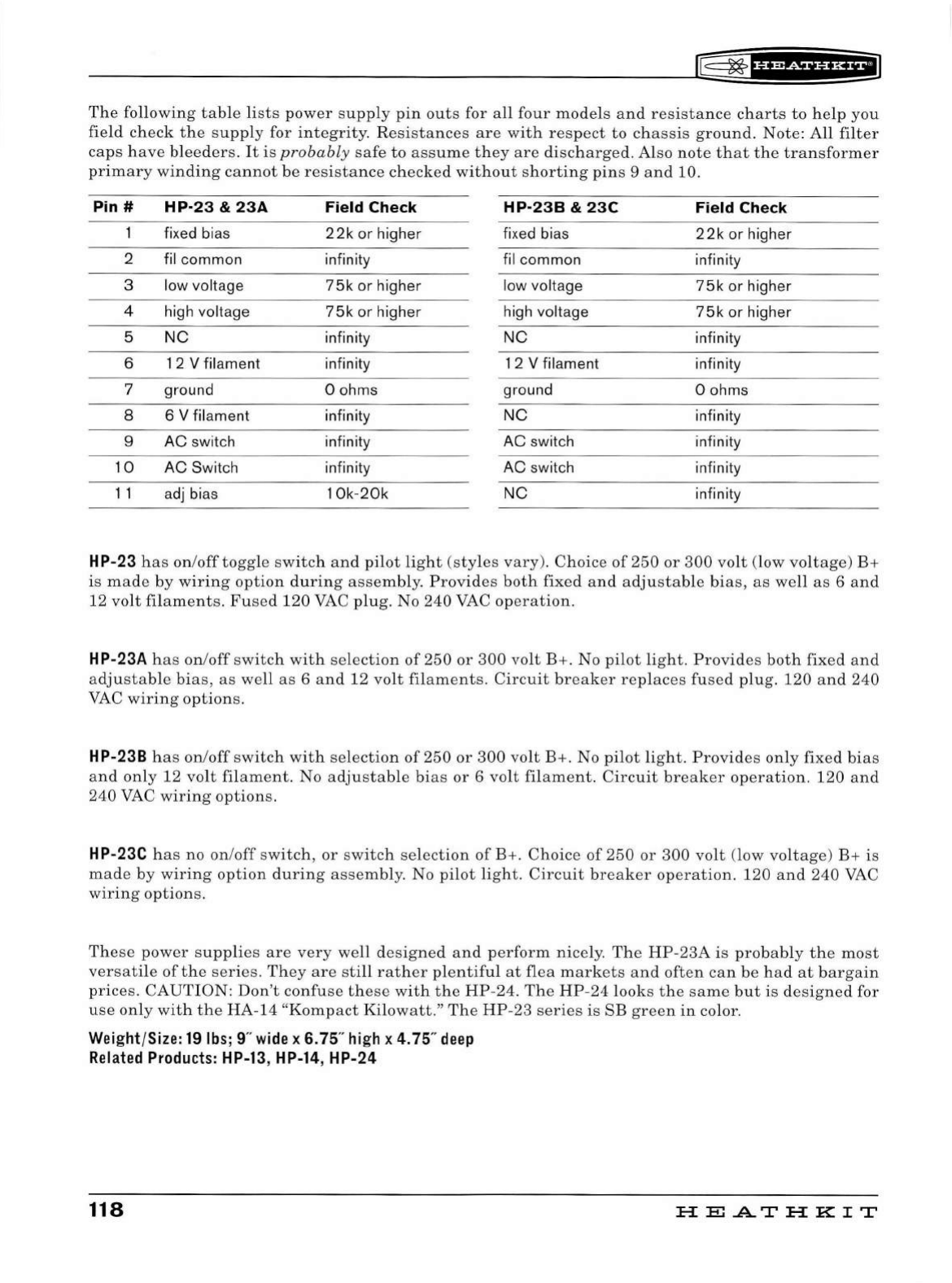
f§
~
1
H¥Sf
¥'i*il
The
following
table
li
s
ts
power
supp
ly
pin
outs
for
all
four
models
and
resistance
charts
to
help
you
field
check
the
supp
ly
for
integrity.
Resistance
s
are
with
r
es
pect
to
chassis
ground
.
Note:
All
filter
caps
have
bleeder
s.
It
is
probabl
y
safe
to
assume
they
are
di
sc
har
ged.
Al
so
note
th
at
the
tran
s
former
primary
win
din
g
cannot
be
resistance
check
ed
wit
hou
t
shorting
pins
9 a
nd
10.
Pin #
HP·23
&
23A
Field Check
HP-238
&
23C
Field Check
fix
ed
bias
22k
or higher fixed bias
22k
or higher
2 fil common infinity fil common infinity
3 low voltage
75k
or
higher low voltage
75k
or
higher
4 high voltage
75k
or
higher high voltage
75k
or
higher
5
NC
infinity
NC
infinity
6 1 2 V filament infinity 1 2 V filament infinity
7 ground 0 ohms ground 0 ohms
8 6 V filament infinity
NC
infinity
9
AC
switch infinity
AC
switch infinity
10
AC
Switch infinity
AC
switch infinity
11
adj
bias 1
Ok-20k NC infinity
HP-23
ha
s
on
/
off
toggl
e
switch
and
pilot
light
(sty
les
vary).
C
hoic
e
of
250
or
300
volt
(low
vo
lt
age)
B+
is
mad
e
by
wirin
g
option
durin
g
ass
embly.
Provides
both
fixed
and
adjustab
le
bia
s,
as
well
as
6
and
12
volt
filaments
.
Fused
120
VAC
plug.
No
240
VAC
operation.
HP-23A
ha
s
on/off
sw
itch
with
se
l
ecti
on
of
250
or
300
volt
B+.
No
pilot
li
g
ht
.
Pro
v
id
es
both
fixed a
nd
adjustable
bias,
as
well
as
6
and
12
vo
lt
filame
nt
s.
Circuit
breaker
re
pl
aces
fused
plug.
120
and
240
VAC
wiring
options.
HP-238
ha
s
on
/
off
sw
itch
with
se
lection
of
250
or
300
volt
B+
.
No
pilot
light
.
Provid
es
only
fixed
bia
s
and
only
12
volt
fila m e
nt.
No
adjustab
le
bi
as
or
6
volt
filament.
Circuit
breaker
operation.
120
and
240
VAC
wiri
ng
options.
HP-23C
has
no
on
/
off
sw
itch
,
or
sw
itch
selection
of
B+
.
Choice
of
250
or
3
00
volt
(low v
oltag
e) B+ is
made
by
wiring
option
during
assem
bly
.
No
pilot
light
.
Circuit
break
er
operation.
120
and
240
VAC
wiring
options.
Thes
e
power
s
uppli
es
are
very
well
design
ed a
nd
p
er
form
nicely
.
Th
e
HP-23A
is
probably
the
most
v
ersa
til
e
of
the
ser
i
es
.
They
are
sti
ll
rather
pl
en
tiful
at
fl
ea
markets
and
often
can
be
had
at
b
arga
in
pric
es
.
CAUT
ION:
Don
't
confus
e
th
ese
with
the
HP-24
.
Th
e
HP-24
lo
oks
th
e
same
but
is
designed
for
use
only
with
the
HA-14
"
Komp
ac
t
Kilowatt
."
Th
e
HP-23
series
is
SB
green
in
color
.
Weight/Size:
19
lbs;
9"
wide
x 6. 75"
high
x
4.
75"
deep
Related
Products:
HP-13,
HP-14, HP-24
118
HEATHKIT
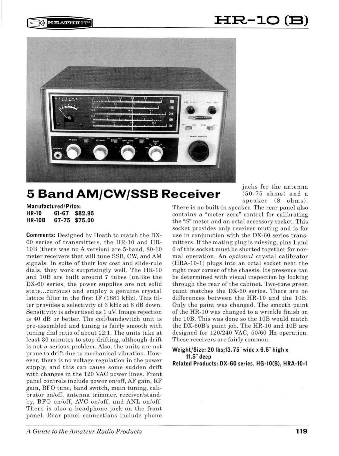
r8
~
f
UiSiHi*+il
H~-10(:8)
OH
AJI<\.
oo
"'"
"
<'••
••
<1
oe
.
·
·~
·
·
-
·
-
5
Band
AM/CW/SSB
Receiver
jacks
for
the
antenna
(50
-
75
ohms)
and
a
spea
k
er
(8
ohms)
.
Manufactured /Price:
HR-10
61-67 $82.95
HR-108
67-75 $75.00
Comments:
Designed
by
Heath
to
match
the
DX-
60
series
of
transmitters,
the
HR-10
and
HR-
lOB
(there
was
no A
version)
are
5-
band
,
80
-
10
meter
receivers
that
will
tune
SSE,
CW,
and
AM
signa
ls.
In
spite
of
the
ir
low
cost
and
slide
-
rule
dia
ls,
they
work
surpr
i
sing
ly
we
ll
.
The
HR
-
10
and
lOB
are
bu
ilt
around
7
tubes
(unlike
the
DX-
60
series,
t h e
power
supplies
are
not
solid
state
...
curious)
and
employ
a
genuine
crystal
lattice
fi
l
ter
in
th e
first
IF
(168
1
kHz)
.
This
fil-
ter
provides
a
selectivity
of
3 kH z
at
6 dB down.
Sensitivity
is
advertised
as
1 u
V.
Image
rejection
is
40
dB
or
better
.
The
coil/
bandswitch
unit
is
pre-assembled
and
tuning
is
fairly
smooth
with
tuning
dial
ratio
of
about
12:1.
The
units
take
at
least
30
minutes
to
stop
drifting,
although
drift
is
not
a
serious
problem.
Also,
the
units
are
not
prone
to
drift
due
to
mec
h
anica
l
vibration.
How-
ever,
there
is
no
voltage
regulation
in
the
power
supply
,
and
this
can
cause
some
sudden
drift
with
ch
anges
in
the
120
VAC
power
lines.
Front
panel
controls
include
po
wer
on/off,
AF
gain,
RF
gain
,
BFO
tune,
band
switch
,
main
tuning,
cali
-
brator
on
/off,
antenna
trimmer,
receiver
/
stand-
by,
BFO
on
/off, AVC
on/off,
and
ANL
on
/off.
There
is
also
a
headp
h
one
jack
on
the
front
panel.
Rear
pane
l
connections
include
phono
A
Guide
to
the
Amateu
r
Radio
Products
There
is
no
bui
lt-
in
speaker.
Th e
rear
pane
l also
contains
a
"meter
zero"
control
for
calibrat
i
ng
the
"S"
meter
and
an
octal
accessory
sock
et.
Th
is
socket
provides
on
ly
receiver
muting
and
is
for
use
in
conjunction
wit
h
the
DX-60
ser
i
es
trans-
mitters.
If
the
mating
plug
is
missing,
pins
1
and
6
of
t
hi
s
socket
must
be
shorted
together
for
nor-
ma
l
operation.
An
optional
crystal
ca
l
ibrator
(HRA
-
10-1)
pl
ugs
into
an
octa
l
socket
near
the
right
rear
corner
of
the
chassis.
Its
presence
can
be
determined
with
vi
sua
l
inspection
by
l
ooking
thro
ugh
the
rear
of
t he
cabinet.
Two-ton e
green
paint
matches
the
DX-60
ser
i
es.
The
r e
are
no
differences
between
the
HR
-
10
and
t he
lOB.
Only
t h e
paint
was
changed
.
Th
e
smooth
paint
of
the
HR
-10
was
changed
to
a
wrinkle
finish
on
the
lOB.
This
was
done
so
the
lOB
wou
ld
matc
h
the
DX-60B's
paint
job.
The
HR
-10
and
lOB
are
designed
for
120/240
VAC
,
50/60
Hz
op
eration.
These
receivers
are
fairly
common.
Weight/Size:
20
lbs;13.75"
wide
x 6.5"
high
x
11
.5"
deep
Related
Products:
DX-60
series
, HG-10(8),
HRA-10-1
119
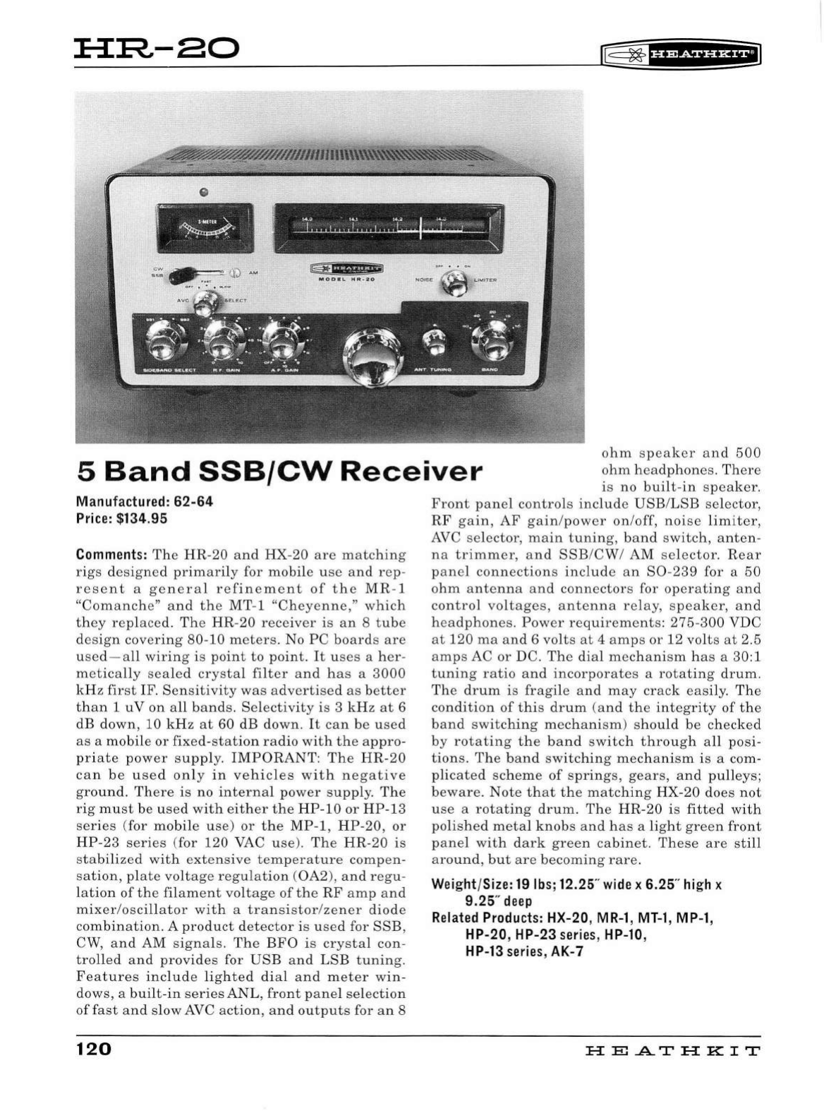
:B:R,-80
rr5=
~
fHidiHHfi
=
' I
1
~
SMU~~
~
C l
L!S#
'
iff
'
*"dEWI
5
Band
SSB/CW
Rece
iv
e r
ohm
speaker
and
500
ohm
headphones.
There
is
no
built-
in
speaker.
Manufa
ctured
: 62
-64
Pr
ic
e: $134.95
Comme
nt
s:
The
HR-20
and
HX-20
are
matching
rigs
designed
primarily
for
mobile
use
and
rep
-
r
ese
nt
a
general
refinement
of
the
MR-1
"C
omanch
e"
and
the
MT
-1 "
Chey
e
nne
,"
which
they
replaced.
Th
e
HR-20
receiver
is
an
8
tube
d
es
ign
covering
80-10
meters
. No
PC
board
s
are
used-all
wiring
is
point
to
point.
It
use
s a
her-
m e
ticall
y
sealed
crysta
l
filter
and
has
a
3000
kHz
first
IF.
Sensitivity
was
advertise
d
as
better
than
1
uV
on
all
bands.
Selectivity
is
3
kHz
at
6
dB
down,
10
kHz
at
60
dB
down
.
It
can
be
used
as
a
mobile
or
fixed
-
station
radio
with
the
appro
-
priate
power
supply.
I
MPORANT:
The
HR
-
20
ca n
be
used
only
in
vehicles
with
negative
ground.
There
is
no
internal
power
supp
l
y.
The
rig
must
be
used
with
either
th e
HP
-
10
or
HP-13
series
(for
mobile
use)
or
the
MP
-1,
HP-20
,
or
HP-23
series
(for
120
VAC
use
).
The
HR
-20
is
stabilized
with
ex
te
nsive
temperature
compen
-
sation,
plate
voltage
regulation
(
0A2
),
and
regu-
lation
of
the
filament
voltage
of
th
e
RF
amp
and
mixer
/osc
illator
with
a
transistor/zener
diode
combination
. A
product
detector
is
used
for
SSB,
CW,
and
AM
signa
ls.
The
BFO
is
crystal
con
-
trolled
and
provides
for
USB
and
LSB
tuning.
Features
includ
e
lig
h
ted
dia
l
and
meter
win
-
dows, a
built-in
series
ANL,
front
panel
sel
e
ction
of
fast
and
slow
AVC
action
, a nd
outputs
for a n 8
120
Front
panel
controls
include
USB
/
LSB
selector,
RF
gain,
AF
gain/power
on/off,
noise
limiter
,
AVC
selector,
main
tuning,
band
s
witch,
anten-
na
trimmer
,
and
SSB
/
CW
/
AM
se
lector
.
Rear
panel
connections
include
an
S0-239
for a
50
ohm
antenna
and
connectors
for
operating
and
control
voltages,
antenna
rela
y,
s
peak
er,
and
h
ea
dphones
.
Power
requir
e
ments:
275-300
VDC
at
120
ma
and
6
volts
at
4
amps
or
12
volts
at
2.5
amps
AC
or
DC.
The
dial
mechani
sm
ha
s a 30:1
tuning
ratio
and
incorporates
a
rotating
drum
.
The
drum
is
fragile
and
may
crack
easil
y.
The
condition
of
this
drum
(a
nd
the
integrity
of
the
band
switching
mechanism
)
should
be
checked
by
rotating
the
band
switch
through
all
posi-
tions.
The
band
switching
mechanism
is
a com-
plicated
scheme
of
springs,
gears,
and
pulleys;
beware
.
Note
that
the
matching
HX-20
does
not
use
a
rotating
drum.
The
HR-20
is
fitted
with
polished
meta
l
knobs
and
has
a
light
green
front
panel
with
dark
green
cabinet
.
These
are
still
a
round,
but
are
becoming
rare
.
Weight
/
Size:
19
lbs
; 12.25"
wide
x 6.25"
hi
gh x
9.25"
deep
Related
Products:
HX-20,
MR-1,
MT-1
,
MP-1
,
HP-20, HP-23
ser
i
es
,
HP-10
,
HP
-
13
series
, AK-7
HE
.AT
HK
IT
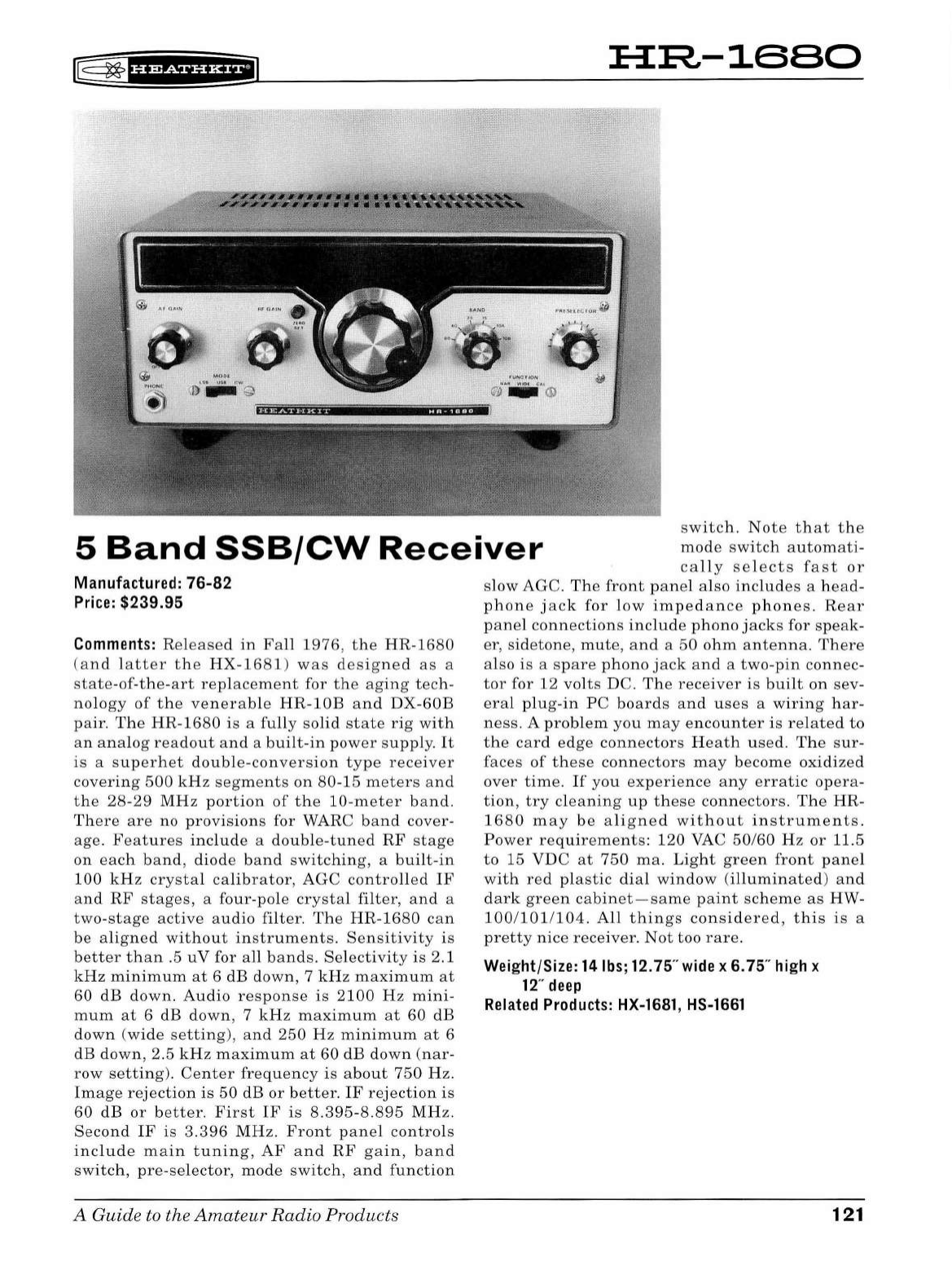
HR-1680
5
Band
SSB/CW
Receiver
switch.
Note
that
the
mode
switch
automati-
cal
ly
selects
fast
or
Manufactured: 76-82
Price:
$239.95
Comments:
Released
in
Fall
1976
,
the
HR-1680
(
and
latter
the
HX-1681
)
was
designed
as
a
state-of
-th
e-art
replacement
for
the
aging
tech-
nology
of
the
venerable
HR-lOB
and
DX-
60B
pair.
The
HR
-1680
is
a
fully
solid
state
rig
with
an
analog
readout
and
a
built-in
power
supply.
It
is
a
superhet
double-conversion
type
receiver
covering
500
kHz
segments
on
80
-1
5
meters
and
the
28-29
MHz
portion
of
the
10-meter
band.
There
are
no
provisions
for WARC
band
cover
-
age.
Features
include
a
double-tuned
RF
stage
on
each
band,
diode
band
switching,
a
built-in
100
kHz
crystal
calibrator,
AGC
controlled
IF
an
d
RF
stages,
a
four-pole
crystal
filter,
and
a
two-stage
active
audio
filter.
The
HR-1680
can
be
aligned
without
in
str
uments
.
Sensitivity
is
better
than
.5
uV
for
all
bands.
Selectivity
is
2.1
kHz
minimum
at
6 dB
down
, 7
kHz
maximum
at
60
dB
down.
Audio
response
is
2100
Hz
mini-
mum
at
6 dB
down
, 7
kHz
maximum
at
60 dB
down
(w
ide
se
tting
),
and
250
Hz
minimum
at
6
dB
down
, 2.5
kHz
maximum
at
60
dB
down
(nar-
row
setting).
Center
frequency
is
a
bout
750
Hz.
Image
rejection
is
50
dB
or
better.
IF
rejection
is
60
dB
or
better.
First
IF
is
8.395-8.895
MHz.
Second
IF
is
3.396
MHz.
Front
panel
controls
include
main
tuning,
AF
and
RF
gain,
band
switch,
pre-selector,
mode
switch,
and
function
A Guide to the
Amateur
Radio
Products
slow
AGC.
The
front
panel
also
includes
a
head-
phone
jack
for
low
impedance
phones.
Rear
panel
connections
include
phono
jacks
for
speak
-
er
,
sidetone,
mute,
and
a
50
ohm
antenna.
There
also
is
a
spare
phono
jack
and
a
two-pin
connec-
tor
for 12
volts
DC.
The
rece
i
ver
is
built
on
sev-
eral
plug-in
PC
boards
and
uses
a
wiring
har-
ness.
A
problem
you
may
encounter
is
related
to
the
card
edge
connectors
He
ath
used.
The
sur-
faces
of
these
connectors
may
become
oxidized
over
time.
If
you
experience
any
erratic
opera-
tion,
try
cleaning
up
these
connectors.
The
HR-
1680
may
be
aligned
wit
hou
t
instruments.
Power
requirements:
120
VAC
50/60
Hz
or
11.5
to
15
VDC
at
750
ma.
Light
green
front
panel
with
red
plastic
dial
window
(illuminated)
and
dark
green
cabinet
-sa
me
paint
scheme
as
HW-
100
/
1011104.
All
things
considered,
this
is
a
pretty
nice
receiver
.
Not
too
rare.
Weight/Size:
14
lbs;
12.75"
wide
x 6.75"
high
x
12
"
deep
Related
Products:
HX-1681,
HS-1661
121
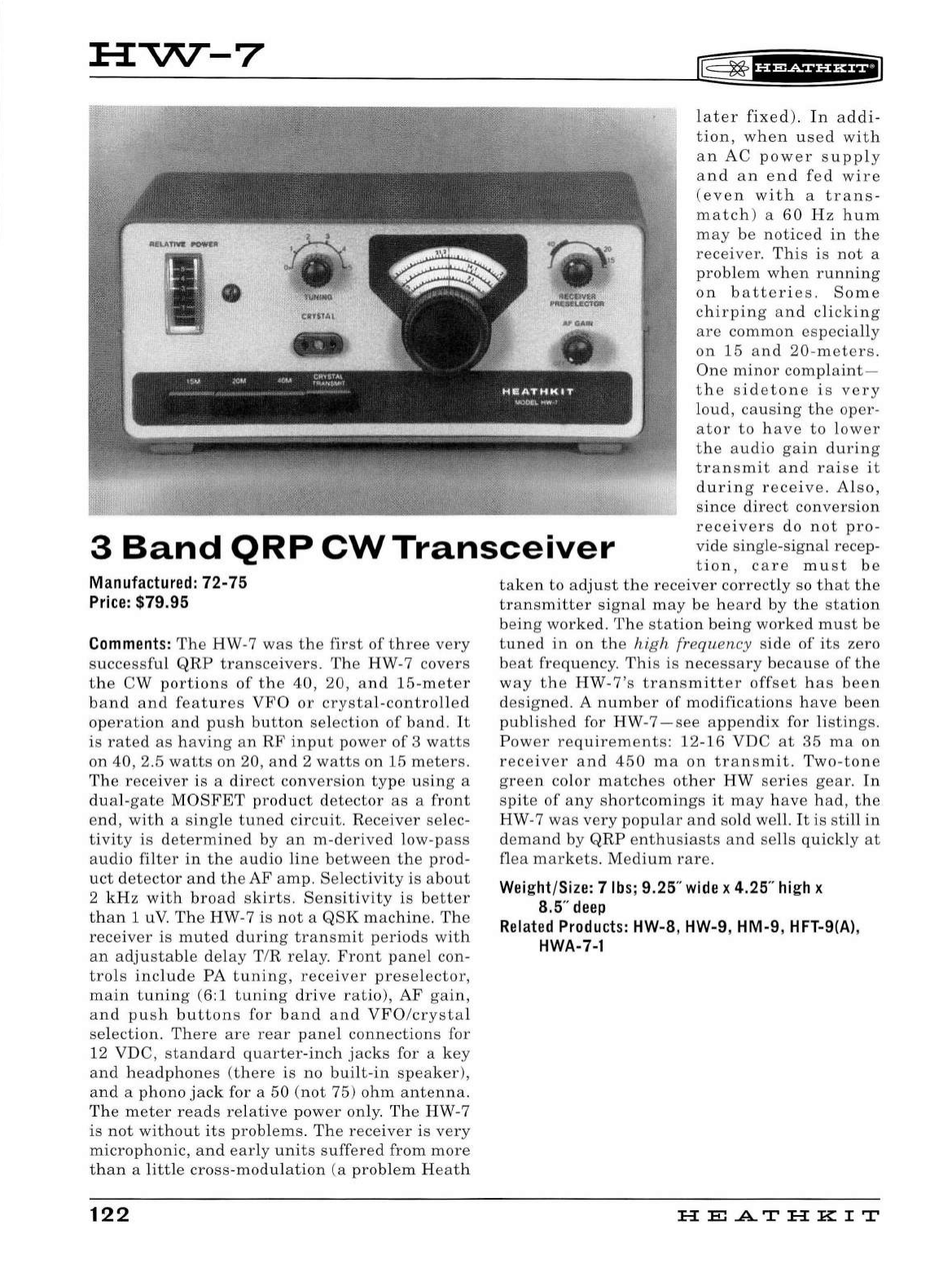
HVV--7
[§
~
·ua+tHHEi
3
Band
QRP
CW
Transceiver
later
fixed)
.
In
addi-
tion,
when
used
with
an
AC
power
supply
and
an
end
fed
wire
(even
with
a
trans-
match
) a
60
Hz
hum
may
be
noticed
in
the
receiver.
This
is
not
a
problem
when
running
on
batteries.
Some
chirping
and
clicking
are
common
especially
on
15
and
20-meters.
One
minor
complaint-
the
sidetone
is
very
loud,
causing
the
oper-
ator
to
have
to
lower
the
audio
gain
during
transmit
and
raise
it
during
receive
.
Also,
since
direct
conversion
receivers
do
not
pro-
vide
single-signal
recep-
tion,
care
must
be
Manufactured:
72-
75
Price:
$79.95
Comments:
The
HW
-7
was
the
first
of
three
very
successful
QRP
transceivers
.
The
HW-7
covers
the
CW
portions
of
the
40,
20,
and
1
5-meter
band
and
fea
t
ures
VFO
or
crystal-controlled
operation
and
push
button
selection
of
band.
It
is
rated
as
having
an
RF
input
power
of
3
watts
on
40,
2.5
watts
on
20,
and
2
watts
on
15
meters.
Th e
receiver
is
a
direct
conversion
type
using
a
du
al
-
gate
MO
SFET
prod
u
ct
detector
as
a
front
end,
with
a
single
tuned
circuit
.
Receiver
selec-
tivity
is
determined
by
an
m-
derived
low-
pass
audio
filter
in
the
audio
line
between
the
prod
-
uct
detector
and
the
AF
amp.
Selectivity
is
about
2
kHz
with
broad
skirts.
Sensitivity
is
better
than
1 uV.
The
HW-7
is
not
a
QSK
machine.
The
receiver
is
muted
during
transmit
periods
with
an
adjustab
le
delay
T/R
re
lay.
Front
panel
con-
trols
include
PA
tuning,
receiver
preselector,
main
tuning
(6:1
tuning
drive
ratio),
AF
gain,
and
push
buttons
for
band
and
VFO/crystal
se
l
ection.
There
are
rear
panel
connections
for
12
VDC
,
standard
quarter-inch
jacks
for a
key
and
headphones
(there
is
no
built-in
speaker),
and
a
phono
jack
for a
50
(not
75)
ohm
antenna.
The
meter
reads
relative
power
only.
The
HW
-7
is
not
without
its
problems.
The
receiver
is
very
microphonic,
and
early
units
suffered
from
more
than
a
little
cross-modulation
(a
problem
Heath
122
taken
to
adj
u
st
the
receiver
correct
ly so
that
the
transmitter
signal
may
be
heard
by
th
e
station
being
worked.
The
station
being
worked
must
be
tuned
in
on
the
high
frequency
side
of
its
zero
beat
frequency.
This
is
necessary
because
of
the
way
the
HW
-
7's
transmitter
offset
h
as
been
designed
. A
number
of
modifications
h
ave
been
published
for
HW
-7 -
see
appendix
for
listings
.
Power
requirements:
12
-
16
VDC
at
35
ma
on
receiver
and
450
ma
on
transmit.
Two-tone
green
color
matches
ot
h
er
HW
series
gear.
In
spite
of
any
shortcomings
it
may
have
had,
the
HW-7
was
very
popular
and
sold
well.
It
is
still
in
demand
by
QRP
enthusiasts
and
sells
quickly
at
flea
markets.
Medium
rare.
Wei
ght/Size: 7
lbs
; 9.25"
wide
x 4.25"
high
x
8.5"
deep
Related
Products:
HW
-8, HW-9, HM-9,
HFT-9(A)
,
HWA-7-1
HE
A.TH
KIT
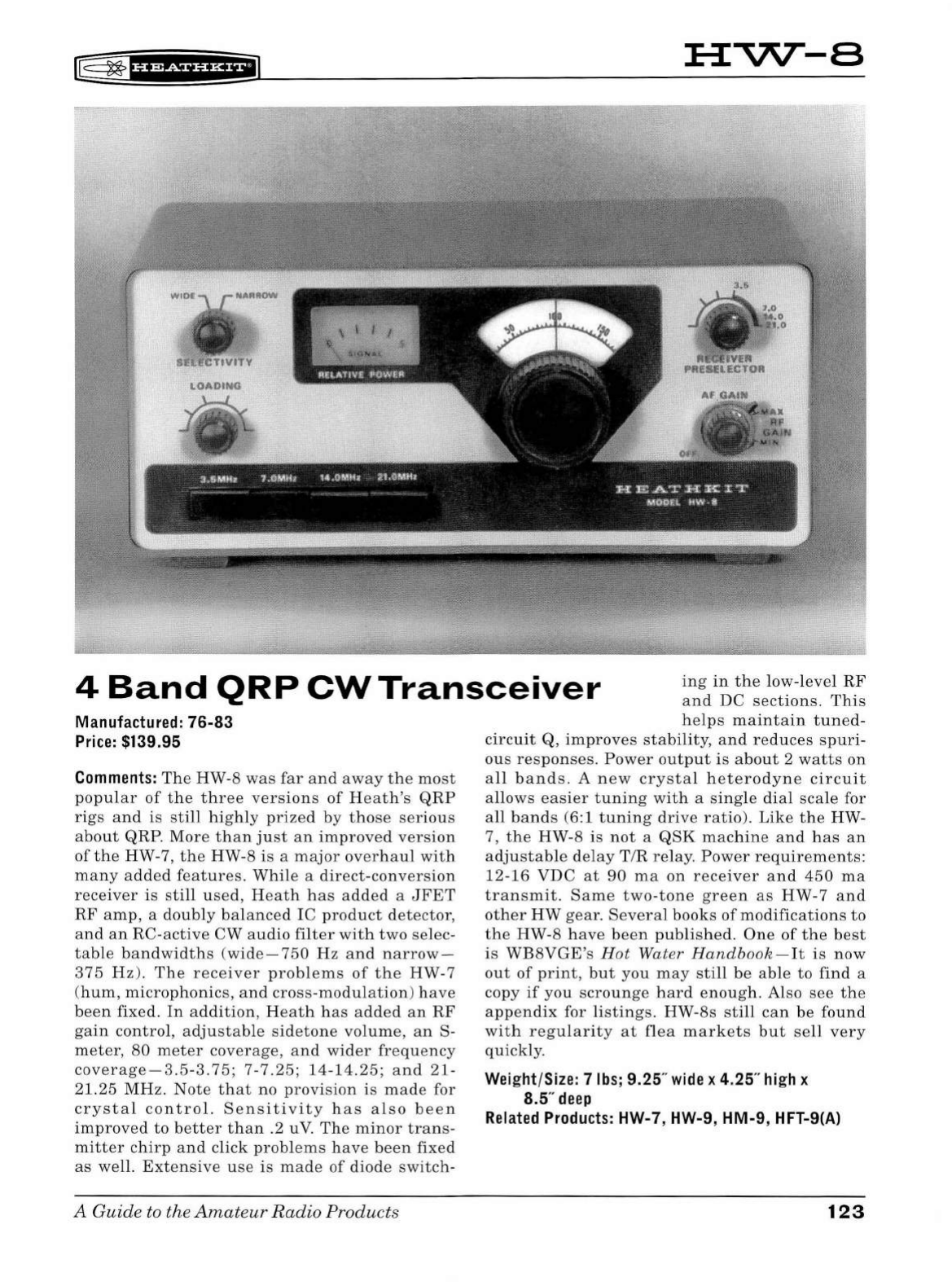
f8
~
f
§f
#tSii'&f
i
:H:"V\T-
B
4
Band
QRP
CW
Transceiver
ing
in
the
low-level
RF
and
DC
sections
.
This
Manufactured:
76-83
Price:
$139.95
Comments:
The
HW-8
was
far
and
away
the
most
popular
of
the
three
versions
of
Heath
's
QRP
rigs
and
is
still
highly
prized
by
those
serious
about
QRP.
More
than
just
an
improved
version
of
the
HW-7,
the
HW-8
is
a
major
overhaul
with
many
added
features.
While
a
direct-conversion
receiver
is
still
used
,
Heath
has
added
a
JFET
RF
amp,
a
doubly
balanced
IC
product
detector,
and
an
RC-active
CW
audio
filter
with
two
selec-
table
bandwidths
(
wide-750
Hz
and
narrow-
375
Hz
).
The
receiver
problems
of
the
HW-7
(
hum,
microphonics,
and
cross
-
modulation)
have
been
fixed.
In
addition
,
Heath
has
added
an
RF
gain
contro
l,
adjustable
sidetone
volume,
an
S-
meter,
80
meter
coverage,
and
wider
frequency
coverage-3.5-3.75;
7-7.25
;
14-14.25;
and
21-
21.25
MHz.
Note
that
no
provision
is
made
for
crystal
control.
Sensitivity
has
also
been
improved
to
better
than
.2 uV.
The
minor
trans-
mitter
chirp
and
click
problems
have
been
fixed
as
well
.
Extensive
use
is
made
of
diode
switch-
A
Guide
to
the
Amateur
Radio
Products
helps
maintain
tuned-
circuit
Q,
improves
stability,
and
reduces
spuri
-
ous
responses.
Power
output
is
about
2
watts
on
all
bands.
A
new
crystal
heterodyne
circuit
allows
easier
tuning
with
a
single
dial
scale
for
all
bands
(6:1
tuning
drive
ratio)
.
Like
the
HW-
7,
the
HW-8
is
not
a
QSK
machine
and
has
an
adjustable
delay
T/R
relay
.
Power
requirements
:
12-16
VDC
at
90
ma
on
receiver
and
450
ma
transmit.
Same
two
-to
ne
green
as
HW-7
and
other
HW
gear.
Severa
l
books
of
modifications
to
the
HW-8
have
been
published.
One
of
the
best
is
WB8VGE's
Hot
Water
Handbook
-
It
is
now
out
of
print,
but
you
may
still
be
able
to
find
a
copy
if
you
scrounge
hard
enough.
Also
see
the
appendix
for
listings.
HW-8s
still
can
be
found
with
regularity
at
flea
markets
but
sell
very
quickly.
Weight/Size: 7
lbs;
9.25"
wide
x 4.25"
high
x
8.5"
deep
Related
Products:
HW-7, HW-9, HM-9, HFT-9(A)
123
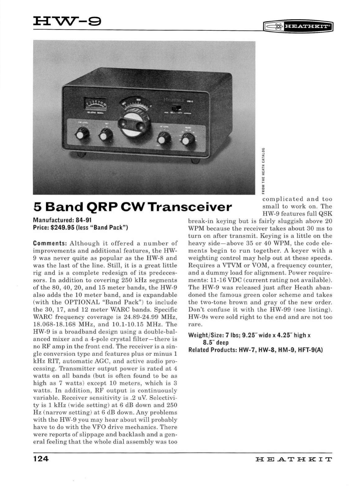
HVV--9
f0
~
fh&iHHil
5
Band
QRP
CW
Transceiver
comp
l
icated
and
too
small
to
work
on.
The
HW-9
features
full
QSK
Manufactured: 84-91
Price:
$249.95
(less
"Band
Pack")
Comments: Al
thoug
h
it
offered
a
number
of
improvements
and
ad
ditional
features,
the
HW
-
9
was
never
qu
ite
as
popu
l
ar
as
th e H W-8
an
d
was
the l
ast
of
the
li
ne.
Sti
ll
,
it
is
a
great
litt
le
rig
and
is
a
comp
l
ete
redesign
of
its
pr
ede
ces
-
sors
. In
addition
to
covering
250
kHz
segments
of
the
80
, 40,
20,
and
15
mete
r
bands,
t he HW-9
also
adds
the
10
meter
band,
and
is
expandab
le
(
wit
h
the
OP
TI
ONA
L
"Band
Pack"
)
to
inclu
de
the
30
, 17,
and
12
meter
WA
RC
bands.
Specific
WARC
frequency
coverage
is
24.
89-24.99
MHz,
18.
068-18.168
MHz,
and
10.1
-1
0.15
MHz.
The
HW-9
is
a
broadband
design
using
a
doubl
e
-ba
l-
anced
mixer
and
a 4-pole
crystal
filter-there
is
no
RF
amp
in
the
front
end.
The
receiver
is
a s
in
-
gle
conversion
type
and
features
plus
or
minus
1
kHz
RIT
,
automatic
AGC,
and
active
audio
pro
-
cessing.
Transmitter
output
pow
er
is
rated
at 4
watts
on
all
bands
(but
is
often
found
to
be
as
high
as
7
watts)
ex
cept
10
met
ers,
which
is
3
watts.
In
a
ddition
,
RF
outp
ut
is
continuous
ly
variabl
e.
Receiver
sensitivity
is
.2 uV.
Sel
ect
ivi
-
ty
is
1
kHz
(wide
setting)
at
6 dB
down
and
250
Hz
(
narrow
setting)
at
6 dB
down
.
Any
probl
e
ms
with
the
HW
-9
you
may
h
ear
about
wi
ll
probably
have
to
do
with
the
VFO
drive
mechanics.
There
were
reports
of
sl
ippage
and
backla
sh
and
a
gen
-
era
l
feeling
that
the
whole
dial
assemb
ly
was
too
124
break
-
in
keying
but
is
fair
ly
sluggis
h
above
20
WP
M
because
the
receiver
takes
about
30
ms
to
turn
on
after
transmit
.
Keying
is
a
li
tt
le
on
th e
heavy
s
ide
-
abov
e
35
or
40
WPM
, th e
code
ele-
ments
begin
to
run
together.
A
keyer
with
a
weighting
control
may
he
lp
out
at
these
speeds.
Req
u
ires
a VTVM
or
VOM, a
frequency
counter,
an
d a
dummy
l
oad
for
alignment.
Power
req
u
ire-
me
n
ts:
11-16
VDC
(c
urrent
rating
not
avai
la
bl
e).
The
HW
-9
was
re
l
eased
just
after
Heat
h
aba
n-
doned
th
e
famous
green
color
scheme
and
takes
the
two
-
tone
brown
and
gray
of
the
new
or
d
er
.
Don't
confuse
it
wit
h
the
HW
-99
(see
l
isting
).
HW-9s
were
sold
right
to
the
end
and
are
not
too
rare.
Weight/
Size:
7
lbs
; 9.25"
wide
x 4.25"
high
x
8.5
..
d
eep
Relat
ed
Prod
u
cts:
HW-7, HW-8, HM-9, HFT-9(A)
HE
..AT
HK
IT
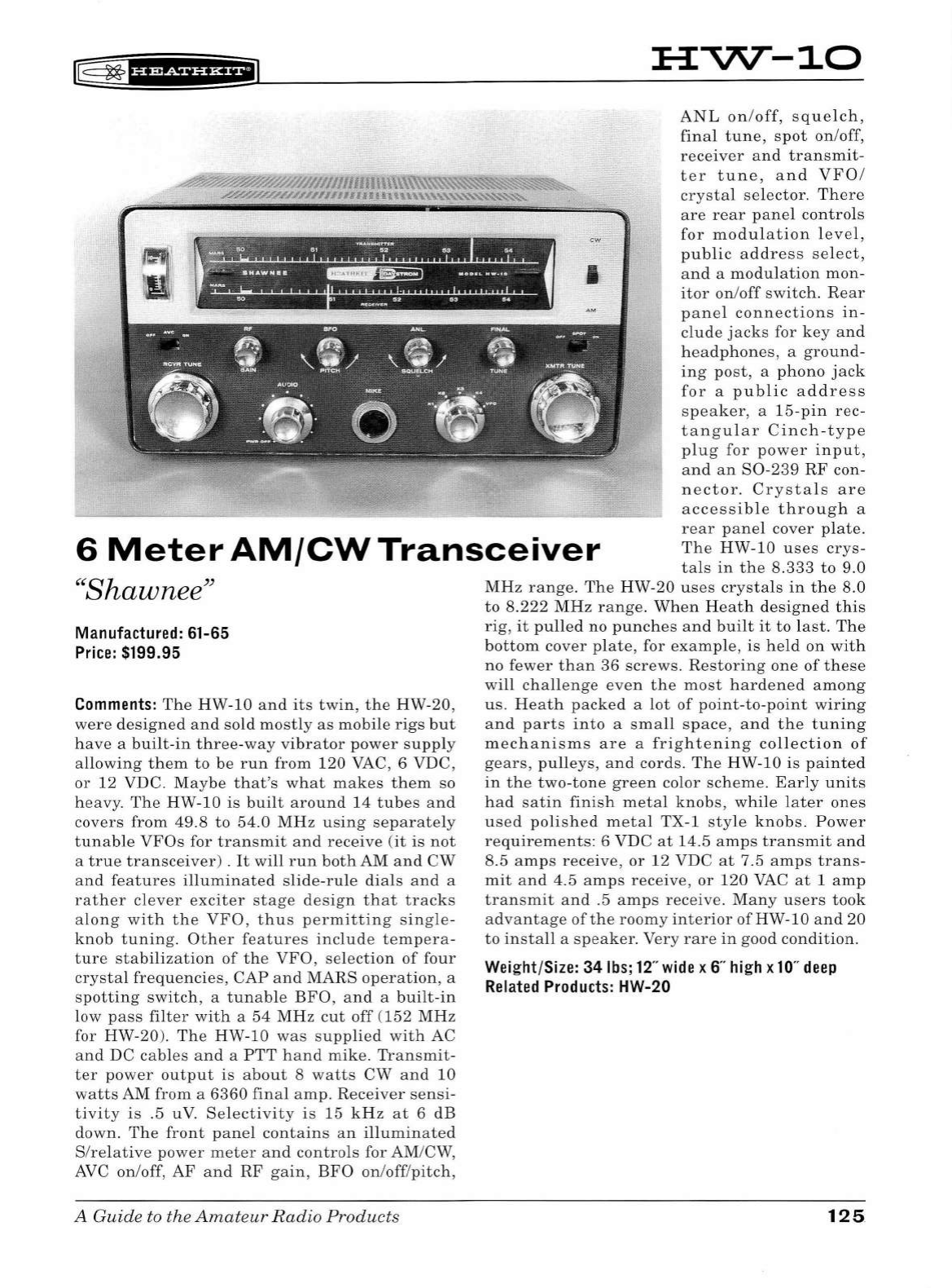
~
~
'Hidii'Hfi
HVV--10
~//11/llllllUU\\\\\\.~~~~
ANL
on
/
off,
squelc
h ,
final
tune,
spot
on
/off,
receiver
and
transmit
-
ter
tune,
an
d
VFO/
crysta
l
se
l
ector
.
Th
ere
are
rear
pane
l
co
n
tro
ls
for
modulat
i
on
l
evel,
public
ad
d
ress
se
l
ect,
and
a
modu
l
ation
mon
-
itor
on
/
off
switch.
Rear
panel
connections
in
-
clude
jacks
for
key
and
h
ea
dphones,
a
ground
-
ing
post,
a
phono
jack
for
a
pub
l
ic
address
speaker,
a 15-
pin
rec-
tangular
Cinch
-
type
plug
for
power
in
put
,
and
an
S0
-
239
RF
con-
nector.
Crysta
l s
are
accessib
le
throug
h a
rear
pane
l
cover
pl
ate.
The
HW-10 u
ses
crys-
ta
ls
in
the
8.333
to
9.0
/AY.Q'H/////,U#UltlO~
.
alH\'IA'\.'\''-\.'-"'-"-'-'-~~~
I
6
Meter
AM/CW
Transceiver
''
Shawnee"
Manufactured: 61-65
Price:
$199.95
Comments:
The
HW-
10
and
its
twin,
the HW-20,
were
designed
an
d
sold
mostly
as
mobi
le ri
gs
but
have
a b
ui
lt
-
in
t h
ree
-
way
vibrator
power
su
pp
ly
allowing
them
to
be
run
from
120
VAC, 6 VDC,
or
12
VDC
.
May
be th
at's
what
makes
th
em
so
heavy.
The
HW
-10 is
bui
lt
around
14
t
ub
es
and
covers
from
49.8
to
54
.0
MHz
using
separate
ly
tunable
VFOs
fo
r
transmit
and
receive
(it
is
not
a
true
transceiver)
.
It
will
run
both
AM
and
CW
and
features
i
ll
uminated
slide-ru
le d
ia
ls
and
a
rather
clever
exciter
stage
design
that
tracks
a l
ong
with
the
VFO,
thus
permitting
single-
knob
tuning.
Other
features
include
tempera
-
ture
stabilization
of
the
VFO,
selection
of
four
crystal
frequencies
,
CAP
and
MARS
operat
ion, a
spotting
switc
h , a
tunable
BFO,
and
a
built
-
in
low
pass
filter
with
a
54
MHz
cut
off
(1
52
MHz
for
HW-20
).
The
HW
-10
was
supplied
with
AC
and
DC
cables
and
a
PTT
hand
mike.
Transmit
-
ter
power
output
is
about
8
watts
CW
and
10
watts
AM
from
a
6360
final
amp.
Receiver
sensi
-
tivity
is
.5 uV.
Se
l
ectivity
is
15 k H z
at
6
dB
down.
The
front
pane
l
contains
an
ill
u
minated
S/re
l
ative
power
meter
and
contro
ls for
AM
/CW,
AVC
on
/off,
AF
and
RF
gain,
BFO
on
/
off
/
pitch,
A Guide to the
Amateur
Radio
Products
MHz
range.
Th
e HW-20
uses
crys
tals in
th
e 8.0
to
8.222
M
Hz
ran
ge.
When
Heath
d
esig
ned
this
rig,
it
pu
ll
ed no pu
nches
and
built
it
to
l
ast.
Th
e
bottom
cover
pl
ate,
for
example,
is
h e
ld
on
wit
h
no
fewer
tha
n
36
screws
.
Restoring
one
of
th
ese
will
cha
ll
enge
even
the
most
hardene
d
among
us.
Heat
h
packed
a l
ot
of
point-to-point
wiring
and
parts
into
a
sma
ll
space,
and
t h e
tuni
ng
mechanisms
are
a
frightening
co
ll
ectio
n
of
gears,
pulleys,
a
nd
cords.
T
he
HW
-10 is p
ainted
in
the
two
-
to
ne
green
color
scheme.
Ear
ly
un
its
had
satin
fi
ni
sh
metal
knobs,
while l
ater
ones
used
polis
h ed m
eta
l TX-1
style
kn
obs.
Power
requirements:
6 VDC
at
14
.5
amps
transmit
and
8.5
amps
rece
ive,
or
12 VDC
at
7.5
amps
trans
-
mit
and
4.5
amps
receive,
or
1
20
VAC
at
1
amp
transmit
and
.5
amps
receive.
Many
users
took
a
dvantage
of
the
roomy
interior
ofHW-
10
and
20
to
install
a
speaker.
Very
rare
in
good
condition.
Weight/Size: 34
lbs;
12
"
wide
x 6"
high
x
10
"
deep
Related
Produ
c
ts
: HW-20
125
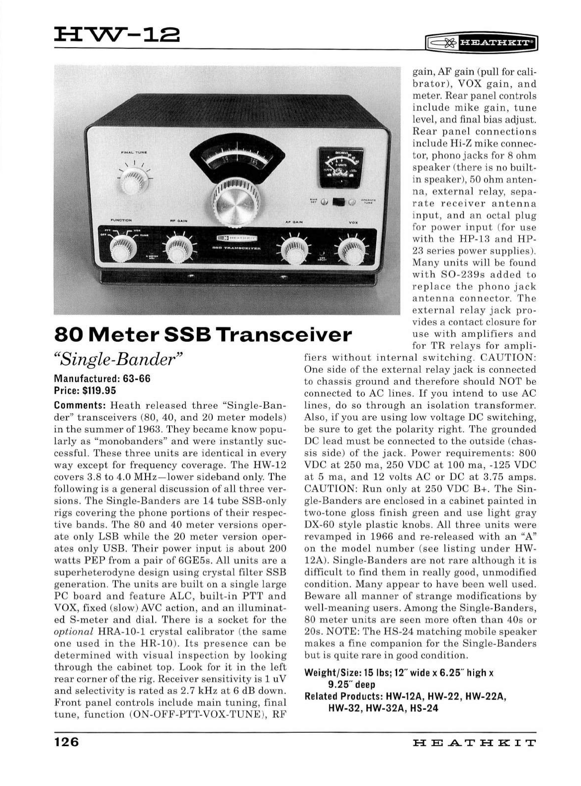
H
""'\l'\T
-12
®
~
f
UWiff
Hi
I
gain,
AF
gain
(pull
for cali-
•
80
Meter
SSB
Transceiver
brator)
,
VOX
gain
,
and
meter.
Rear
panel
controls
include
mike
gain
,
tune
level,
and
final
bias
adjust.
Rear
panel
connections
include
Hi-Z
mike
connec-
tor,
phono
jacks
for 8
ohm
speaker
(t
here
is
no
built
-
in
speaker),
50
ohm
anten
-
na,
external
relay,
sepa-
rate
receiver
antenna
input,
and
an
octal
plug
for
pow
er
input
(for
use
with
the
HP-13
and
HP-
23
series
power
supplies).
Many
units
will
be
found
with
S0-239s
added
to
replace
the
phono
j
ac
k
antenna
connector.
The
external
relay
jack
pro-
vides
a
contact
closur
e for
use
with
amplifiers
and
for
TR
relays
for
ampli-
((
Si
ng
le-Bander"
Manufactured:
63-66
Price:
$119.95
Comments:
Heath
released
three
"Single-Ban-
der"
transceivers
(80, 40,
and
20
meter
models)
in
the
summer
of
1963.
They
became
know
popu-
l
arly
as
"monobanders"
and
were
instantly
suc-
cessful.
These
three
units
are
identica
l
in
every
way
except
for
frequency
coverage.
The
HW-12
covers
3.8
to
4.0
MHz-lower
sideband
only.
The
fo
ll
owing
is
a
general
discussion
of
all
three
ver
-
sions.
The
Single-Banders
are
14
tube
SSE-only
rigs
covering
the
phone
portions
of
their
respec-
tive
bands
.
The
80
and
40
meter
versions
oper
-
ate
only
LSB
while
the
20
meter
version
oper-
ates
only
USB
.
Their
power
input
is
about
200
watts
PEP
from
a
pair
of
6GE5s.
All
units
are
a
superheterodyne
design
using
crystal
filter
SSB
generation.
The
units
are
bui
lt
on
a
single
large
PC
board
and
feature
ALC,
built-in
PTT
and
VOX,
fixed
(slow)
AVC
action,
and
an
illuminat-
ed
S-meter
and
dial.
There
is
a
socket
for
the
optional
HRA
-10-1
crystal
calibrator
(t
he
sa
me
one
used
in
the
HR-10
).
Its
presence
can
be
determined
with
visual
inspection
by
looking
through
the
cabinet
top.
L
ook
for
it
in
the
left
rear
corner
of
the
rig.
Receiver
sensitivity
is
1
uV
and
selectivity
is
rated
as
2. 7
kHz
at
6 dB down.
Front
panel
controls
include
main
tuning
,
fina
l
tune,
function
(
ON
-
OFF
-
PTT
-
VOX-TUNE
),
RF
126
fiers
without
internal
switching.
CAUTION:
One
side
of
the
ex
ternal
relay
jack
is
connected
to
chassis
ground
and
therefore
should
NOT
be
connected
to
AC
lines.
If
you
intend
to
use
AC
lines,
do so
through
an
isolation
transformer.
Also,
if
you
are
using
low
voltage
DC
switching,
be
sure
to
get
the
pol
arity
right.
The
grounded
DC
lead
must
be
connected
to
the
outside
(c
has-
sis
side)
of
the
jack
.
Power
requirements:
800
VDC
at
250
ma,
250
VDC
at
100
ma,
-
125
VDC
at
5
ma,
and
12
volts
AC
or
DC
at
3.75
amps.
CAUTION:
Run
only
at
250
VDC B+.
The
Sin
-
gle-Banders
are
enclosed
in
a
cabinet
painted
in
two-tone
gloss
finish
green
and
use
light
gray
DX-60
style
pl
astic
knobs.
All
three
units
were
revamped
in
1966
and
re-released
with
an
"A"
on
the
model
number
(see
listing
u
nder
HW
-
12A).
Single
-
Banders
are
not
rare
although
it
is
difficult
to
find
them
in
really
good,
unmodified
condition.
Many
appear
to
have
been
well
used
.
Beware
all
manner
of
strange
modifications
by
well
-
meaning
users
.
Among
the
Sing
le-
Banders,
80
meter
units
are
seen
more
often
than
40s
or
20s.
NOTE:
The
HS
-
24
matching
mobi
le
speaker
make
s a
fine
companion
for
the
Sing
l
e-Banders
but
is
quite
rare
in
good
condition.
Wei
ght/Size:
15
lbs;
12
"
wide
x 6.25"
high
x
9.25"
deep
Related
Products
:
HW-12A
, HW-22, HW-22A,
HW-32, HW-32A, HS-24
HEATHKIT
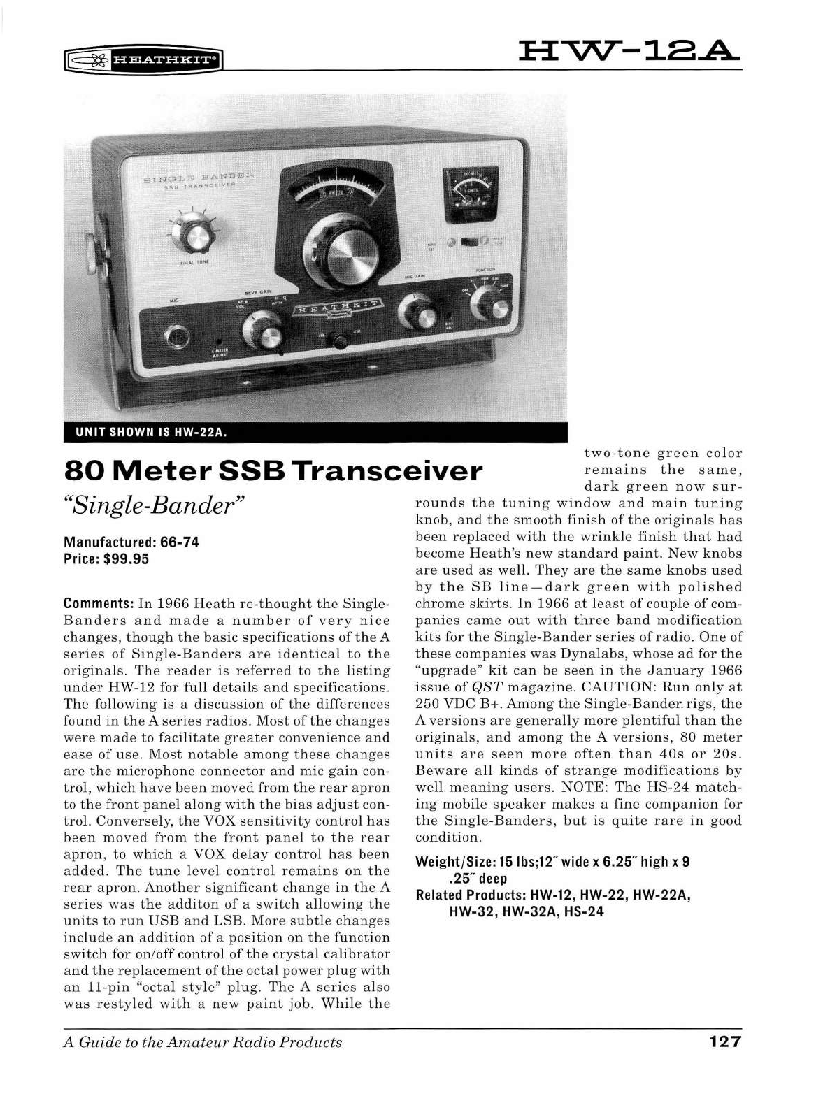
l@=
~
1
UMii'&iil
HVV--18.A
Sl
NQt
...
L
BA1'1'D
Ei'.R.
SSl•
l
AANSCE!Vf
A:
\ l
./
~
•
UNIT
SHOWN IS
HW-22A.
80
Meter
SSB
Transceiver
two-tone
green
col
or
remains
the
same,
dark
green
now
sur
-
"S.
l B d "
ing e-
an
er
Manufactured: 66-74
Price:
$99.95
Comments:
In
19
66
Heath
re
-
thought
t he
Single
-
Banders
and
made
a n u
mber
of
very
nice
chan
ges,
thoug
h
the
basic
sp
ecifications
of
the
A
ser
i
es
of
Sing
le-
Banders
are
identica
l
to
the
or
i
ginals.
The
reader
is
referred
to
the
listing
un
d
er
HW
-12 for
full
detai
ls
and
specifi
c
ations
.
Th
e
fo
ll
owing
is a
discussion
of
the
differences
fo
un d
in
the
A
ser
i
es
radios.
Most
of
the ch
anges
were
made
to
facilitate
greater
convenience
and
ease
of
use.
Most
notab
le
among
these
ch
anges
are
t he
microp
h
one
connector
and
mic
gain
con-
tro
l,
which
have
been
move
d
from
the
rear
apron
to
th e
front
pane
l al
ong
with
the
bias
adj
u
st
con-
trol.
Converse
ly,
the
VOX
se
n
sitivity
contro
l
has
been
moved
from
the
front
pane
l
to
the
rear
apron,
to
whic
h a VOX
de
l
ay
control
has
been
ad
d
ed.
The
tune
level
control
remains
on
the
rear
apron
.
Another
significant
change
in
the
A
ser
i
es
was
the
additon
of
a
switch
allowing
the
units
to
run
USB
and
LSB.
More
subtle
changes
in
cl
ude
an
ad
diti
on
of
a posi
tion
on
the
function
sw
i
tch
for on/o
ff
control of
t he
crystal
ca
li
brator
an
d
the
rep
l
acement
of
the
octa
l
power
pl
ug
with
an
11
-pin
"
octa
l
style
" pl
ug.
The
A
series
also
was
re
s
tyled
wi
th
a
new
paint
job.
Whi
le
the
A Guide to the
Amateur
Radio
Products
ro
u
nds
the
tuning
window
and
main
tuning
knob,
and
th e
smooth
finis
h
of
the
origina
ls
has
been
replaced
with
the
wrinkle
finish
that
had
become
H
eath's
new
standard
paint.
New
knobs
are
used as
we
ll
.
They
are
the
same
knobs
used
by
the
SB
li
ne-dark
green
with
polished
ch
rome
skirts
. In
1966
at
l
east
of
coup
le
of
com
-
panies
came
out
with
three
band
modification
ki
ts
for
the
Sing
le-
Bander
series
of
rad
i
o.
One
of
these
companies
was
D
yna
l
abs,
whose
ad for
the
"u
pgrade"
kit
can
be
seen
in
the
January
1966
issue
of
QST
magazine.
CAUTIO
N:
Ru
n o
nly
at
250
VDC
B
+.
Among
t h e
Sing
le-
Bander
.
rigs,
the
A
versions
are
genera
ll
y
more
pl
entifu
l t h
an
the
origina
ls,
an
d
among
the
A
versions
,
80
meter
units
are
seen
more
often
than
40s
or
20s.
Beware
all
kinds
of
strange
modifications
by
well
meaning
users
.
NOTE
: T
he
HS
-
24
match
-
i
ng
mobile
speaker
makes
a
fine
compan
i
on
for
the
Single
-
Ba
n
ders,
but
is
quite
rare
in
good
condition.
Weight/Size:
15
lbs;12
"
wide
x 6.25"
high
x 9
.25"
deep
Related
Products:
HW-12
, HW-22, HW-22A,
HW-32, HW-32A, HS-24
127
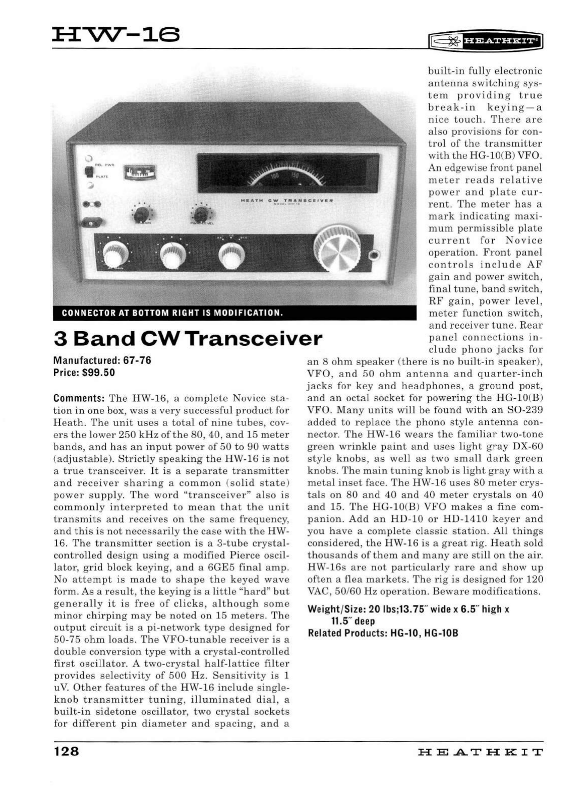
HVV--16
CONNECTOR
AT
BOTTOM
RIGHT
IS
MODIFICATION.
~
~
f
U@Siif
H+i
built-in
fully
electronic
antenna
switching
sys-
tem
providing
true
break-in
keying-a
nice
touch.
There
are
also
provi
s
ions
for
con
-
trol
of
the
transmitter
with
the
HG-lO(B) VFO.
An
edgewise
front
panel
meter
reads
relative
power
and
plate
cur-
rent.
The
meter
has
a
mark
indicating
maxi-
mum
permissible
plate
current
for
Novice
operation.
Front
pane
l
controls
include
AF
gain
and
power
switch,
fina
l
tune,
band
switch,
RF
gain
,
power
l
eve
l,
meter
function
switch,
3
Band
CW
Transceiver
and
receiver
tune.
Rear
panel
connections
in-
clude
phono
jacks
for
Manufactured: 67-76
Price:
$99.50
Comments:
The
HW
-1
6, a
complete
Novice
sta
-
tion
in
one
box,
was
a
very
successful
product
for
Heath
.
Th
e
unit
uses
a
total
of
nine
tubes
, cov-
ers
th e
lower
250
kHz
of
the
80,
40,
and
15
meter
bands,
and
h
as
an
input
power
of
50
to
90
watts
(adjustable).
Strictly
speaking
the
HW
-
16
is
not
a
true
tran
sceiver.
It
is
a
separate
transmitter
and
receiver
sharing
a
common
(s
olid
state)
power
supp
l
y.
The
word
"transceiver"
a l
so
is
commonly
interpreted
to
mean
that
the
unit
transmits
and
receives
on
the
same
frequency
,
and
t h
is is
not
necessari
ly
the
case
with
the
HW
-
16.
The
transmitter
section
is
a 3-
tube
crystal
-
contro
ll
ed
design
using
a
modified
Pierce
oscil-
lator,
grid
block
keying,
and
a
6GE5
fina
l
amp
.
No
attempt
is
made
to
shape
the
keyed
wave
form. As a
resu
l
t,
the
keying
is
a
little
"hard"
but
genera
ll
y it
is
free
of
clicks,
although
some
minor
chirping
may
be
noted
on 15
meters
.
The
output
circuit
is
a
pi-network
type
designed
for
50
-75
ohm
loads
.
The
VFO
-
tunable
receiver
is
a
double
conversion
type
with
a
crystal
-
contro
ll
ed
first
oscillator.
A
two
-
crysta
l h
alf
-
lattice
filter
provides
selectivity
of
500
Hz.
Sensitivity
is 1
uV.
Other
features
of
the
HW-16
include
sing
le-
knob
transmitter
tu
n
ing,
i
llu
minate
d
dial,
a
built
-
in
sidetone
oscillator,
two
crysta
l
sockets
for
different
pin
diameter
and
spacing,
and
a
128
an
8
ohm
speaker
(th
ere
is
no
built
-
in
speaker),
VFO,
and
50
ohm
antenna
and
quarter
-
inch
jacks
for
key
and
headphones
, a
ground
post,
and
an
octal
socket
for
powe
r
ing
the
HG-lO(B)
VFO
.
Many
units
wi
ll
be
found
with
an
S0
-
239
added
to
replace
the
phono
style
antenna
con-
nector.
The
HW
-
16
wears
the
familiar
two-tone
green
wrink
le
paint
and
uses
light
gray
DX-60
style
knobs,
as
we
ll
as
two
small
dark
green
knobs.
The
main
tun
i
ng
knob
is
light
gray
with
a
metal
inset
face.
The
HW-16
uses
80
meter
crys-
tals
on
80
and
40
an
d
40
meter
crysta
ls
on
40
and
15.
The
HG
-lO(B)
VFO
makes
a
fine
com-
panion.
Add
an
HD
-1 0
or
HD
-
1410
keyer
and
you
have
a
comp
l
ete
classic
station.
All
things
considered,
the
HW-16
is
a
great
rig.
Heath
so
ld
thousands
of
them
and
many
are
still
on
the
air.
HW
-
16s
are
not
particu
l
arly
rare
and
show
up
often
a
flea
markets.
The
rig
is
designed
for 120
VAC,
50/60
Hz
operation.
Bewar
e
modifications.
Weight/Size: 20 lbs;13.75"
wide
x 6.5
..
high
x
11.5
"
deep
Related
Products:
HG-10
, HG-108
HE
.AT
HK
IT
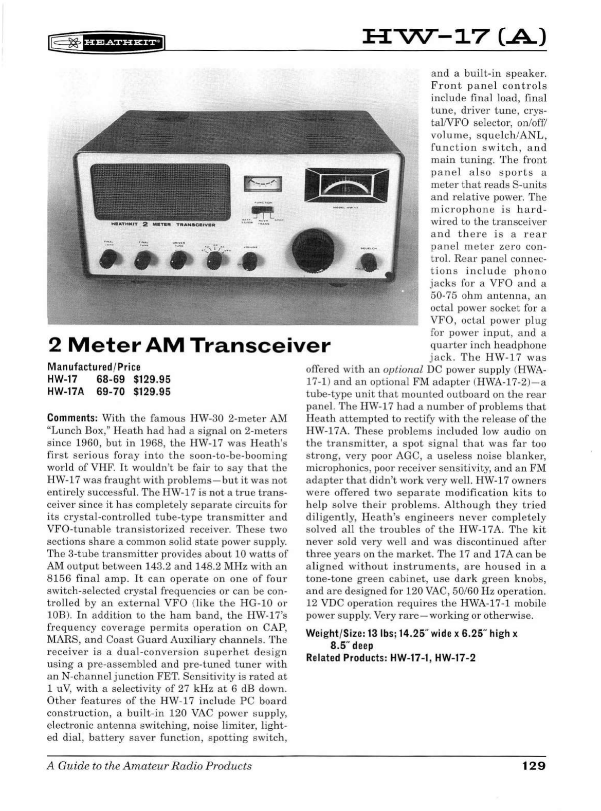
K§
~1uestua+1
lf
-
.
-
,
-~
-
J
.....
.
~
....
....... u • ........ ,,
:a:vv-
-17
(.A)
and
a
built-in
speaker.
Front
panel
controls
include
final
load
,
final
2
Meter
AM
Transceiver
tune,
driver
tune,
crys-
taWFO
selector, on/off/
volume,
squelch/ANL,
function
switch
,
and
main
tuning,
The
front
p
ane
l
also
sports
a
meter
that
reads
S-units
and
relative
power
,
The
microphone
is
hard-
wired
to
the
transc
eiver
and
there
is
a
rear
panel
meter
zero
con
-
trol.
Rear
panel
connec-
tions
include
phono
jacks
for a
VFO
and
a
50-75
ohm
antenna,
an
octal
pow
er
socket
for a
VFO,
octal
power
plug
for
power
input,
and
a
quarter
inch
headphone
jack.
The
HW-17
was
Manufactured/Price
HW-17
68-69 $129.95
HW-17A
69-70 $129.95
Comments:
With
th
e
famous
HW-30 2
-m
eter
AM
"Lunch
Box,"
Heath
had
had
a
signal
on
2
-m
eters
since
1960
,
but
in
1968,
the
HW-17
was
Heath
's
first
serious
foray
into
the
so
on-to-be-booming
world
of
VHF.
It
wouldn't
be
fair
to
say
that
the
HW-17
was
fraught
with
problems-but
it
was
not
entire
ly
successful.
The
HW-17 is
not
a
true
trans
-
ceiver
since
it
has
completely
separate
circuits
for
its
crystal-controlled
tube-type
tran
sm
itter
and
VFO
-tun
able
transistorized
receiver
.
Thes
e
two
sections
share
a
common
solid
state
power
supply.
The
3
-tub
e
transmitter
provides
about
10
watts
of
AM
output
b
etwee
n 143.2
and
148.2
MHz
with
an
8156
final
amp,
It
can
operate
on
one
of
four
switch-selected
crystal
frequencies
or
can
be con-
trolled
by
an
external
VFO
(like
the
HG-10
or
lOB).
In
addition
to
the
ham
band
,
the
HW-l
7's
frequency
coverage
permits
operation
on
CAP,
MARS,
and
Coast
Guard
Auxiliary
channels.
The
receiver
is
a
dual-conver
s
ion
superhet
de
s
ign
using
a
pre-assembled
and
pre-tun
ed
tuner
with
an
N-channel
junction
FET.
Sensitivity
is
rated
at
1 u
V,
with
a
selectivity
of
27
kHz
at
6 dB
down
.
Other
features
of
the
HW-17
includ
e
PC
board
construction,
a
built-in
120
VAC
power
supply,
electronic
antenna
switc
hing,
noise
limiter,
light-
ed
dial,
battery
saver
fun
ction,
spotting
switch,
A
Guide
to the
Amateur
Radio
Products
offered
with
an
optional
DC
power
supply
(HWA-
17-1)
and
an
optional
FM
adapter
(HWA-17-2)- a
tube-type
unit
that
mount
ed
outboard
on
the
rear
panel.
Th
e HW-17
had
a
number
of
problems
that
Heath
attempted
to
rectify
with
the
release
of
the
HW-17A.
These
problems
included
low
audio
on
the
transmitter
, a
spot
signal
that
was
far
too
strong,
very
poor AGC, a
useless
noise
blanker,
microphonics, poor
receiver
sensitivity,
and
an
FM
adapter
that
didn
't
work
very
well. HW-17
owners
were
offered
two
separate
modification
kits
to
help
solve
their
problems.
Although
they
tried
diligently,
Heath
's
engineers
never
completely
solved
all
the
troubles
of
the
HW-17
A.
Th
e
kit
never
sold
very
well
and
was
discontinued
after
three
years
on
the
market.
The
17
and
1 7 A
can
be
aligned
without
instruments,
are
housed
in
a
tone-tone
green
cabinet,
use
dark
green
knobs,
and
are
designed
for
120
VAC, 50/60
Hz
operation.
12 VDC
operation
requires
the
HWA-17-1 mobile
power
supply. Very
rare-working
or
otherwise.
Weight/Size:
13
lbs;
14.25"
wide
x 6.25"
high
x
8.5"
deep
Related
Products:
HW-17-1,
HW-17-2
129
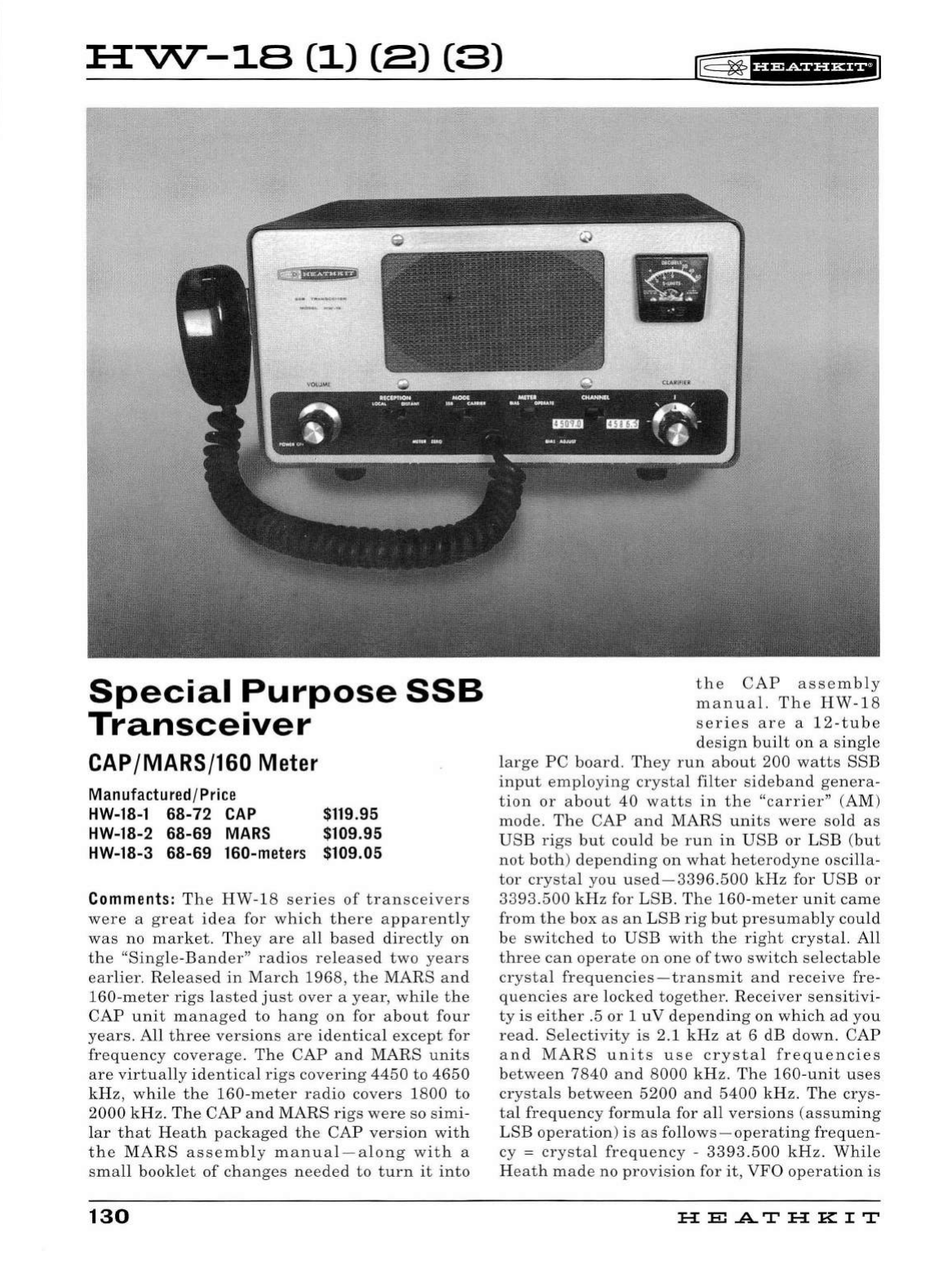
HVV--18
(1)
(8) (3)
rE=
~
f
Hidf
UH+i
G'
"'
>54;51+4
i1
Special
Purpose
SSB
Transceiver
CAP
/MARS/160
Meter
Manufactured/Price
HW-18-1
68-72
CAP
$119.95
HW
-1
8-2
68-69
MARS $109.95
HW-18-3
68-69
160-mete
rs
$109 .
05
Comments:
The
HW-18
series
of
transceivers
were
a
great
idea
for
which
there
apparently
was
no
market.
They
are
all
based
directly
on
the
"Single-Bander"
radios
released
two
years
earlier.
Released
in
March
1968
,
the
MARS
and
160-meter
rigs
lasted
just
over
a
year,
while
the
CAP
unit
managed
to
hang
on
for
about
four
years.
All
three
versions
are
identical
except
for
frequency
coverage.
The
CAP
and
MARS
units
are
virtually
identical
rigs
covering
4450
to
4650
kHz,
while
the
160
-
meter
radio
covers
1800
to
2000
kHz.
The
CAP
and
MARS
rigs
were
so
simi-
lar
that
Heath
packaged
the
CAP
version
with
the
MARS
assembly
manual-along
with
a
small
booklet
of
changes
needed
to
turn
it
into
130
•
the
CAP
assembly
manual.
The
HW-18
series
are
a
12
-
tube
design
built
on
a
single
large
PC
board.
They
run
about
200
watts
SSB
input
employing
crystal
filter
sideband
genera-
tion
or
about
40
watts
in
the
"carrier"
(AM)
mode.
The
CAP
and
MARS
units
were
sold
as
USB
rigs
but
could
be
run
in
USB
or
LSB
(but
not
both)
depending
on
what
heterodyne
oscilla
-
tor
crystal
you
used-3396.500
kHz
for
USB
or
3393.500
kHz
for
LSB
.
The
160
-
meter
unit
came
from
the
box
as
an
LSB
rig
but
presumably
could
be
switched
to
USB
with
the
right
crystal.
A
ll
three
can
operate
on
one
of
two
switch
selectab
le
crystal
frequencies-transmit
and
receive
fre-
quencies
are
locked
together
.
Receiver
sensitivi
-
ty
is
either
.5
or
1
uV
depending
on
which
ad
you
read.
Selectivity
is
2.1
kHz
at
6
dB
down
.
CAP
and
MARS
units
use
crystal
frequencies
between
7840
and
8000
kHz
.
The
160-unit
uses
crystals
between
5200
and
5400
kHz.
The
crys-
tal
frequency
formu
la for
all
versions
(assuming
LSB
operation)
is
as
follows-operating
frequen-
cy =
crystal
frequency
-
3393.500
kHz.
While
Heath
made
no
provision
for
it
,
VFO
operation
is
HE
.AT
HK
IT
t
~fH&iH&EiJ
possible
by
connecting
the
VFO
output
directly
to
one
of
the
crystal
sockets
(observe
polarity)
via
a
short
length
of
RG-58U
.
VFO
output
should
be
between
1
and
2
volts
RMS.
Features
of
the
HW-18
series
include
fixed
tuned
opera-
tion,
solid-state
T/R
switching,
illuminated
S-
meter,
and
built-in
speaker.
Note
that
there
is
no
built-in
power
supply,
and
that
these
rigs
are
intended
primarily
for
SSB
operation.
AM
oper-
ation
is
not
recommended
for
more
than
30
sec
-
onds
at
a
time.
Front
panel
controls
include
on
/
off
/
volume,
clarifier
(
adjusts
receiver
fre-
quency
plus
or
minus
100
Hz),
reception
("local""
or
"distant"),
mode
(SSB
or
"carrier
"),
meter
function,
and
channel
selector.
There
are
front
panel
screw
driver
adjustments
for
S-meter
zero
and
bias
setting.
A
rear
panel
control
adjusts
mic
gain.
Rear
panel
connections
include
a
phono
connector
for a
50
ohm
antenna,
an
11
pin
octal-style
plug
for
power
input
(for
use
with
the
HP-13
or
HP-23
series
power
supplies),
and
a
ground
post.
The
microphone
is
hard-wired
to
the
unit
through
the
middle
of
the
front
panel.
Requires
only
a
VTVM
and
a
dummy
load
for
alignment.
Power
requirements:
800
VDC
at
250
ma,
250
VDC
at
100
ma,
-130
VDC
at
5
ma,
and
12
volts
AC
or
DC
at
3. 75
amps
.
CAUTION:
Run
only
at
250
VDC B+.
Two-tone
green
wrinkle
fin-
ish
matches
other
HW
series
radios
.
The
front
panel
of
all
three
versions
is
labeled
only
"HW-
18," so
the
easiest
way
to
tell
them
apart
is
to
look
at
the
serial
plate-usually
found
on
the
rear
apron-which
will
include
the
dash
1, 2,
or
3.
The
clever
person
should
be
able
to
put
one
of
these
on
75
meters
without
too
much
trouble.
To
the
best
of
my
knowledge
such
a
modification
has
never
been
described
in
any
of
the
popular
magazines
.
Since
not
many
were
ever
so
ld
,
all
three
are
quite
rare,
but
the
160-meter
version
is
the
rarest
of
all.
Weight/Size:
16
lbs;
12.25"
wide
x 6.25"
high
x
10"
deep
Related
Products:
HP-13,
HP-23
A Guide to the
Amateur
Radio
Products 131
::;;
0
"'
...
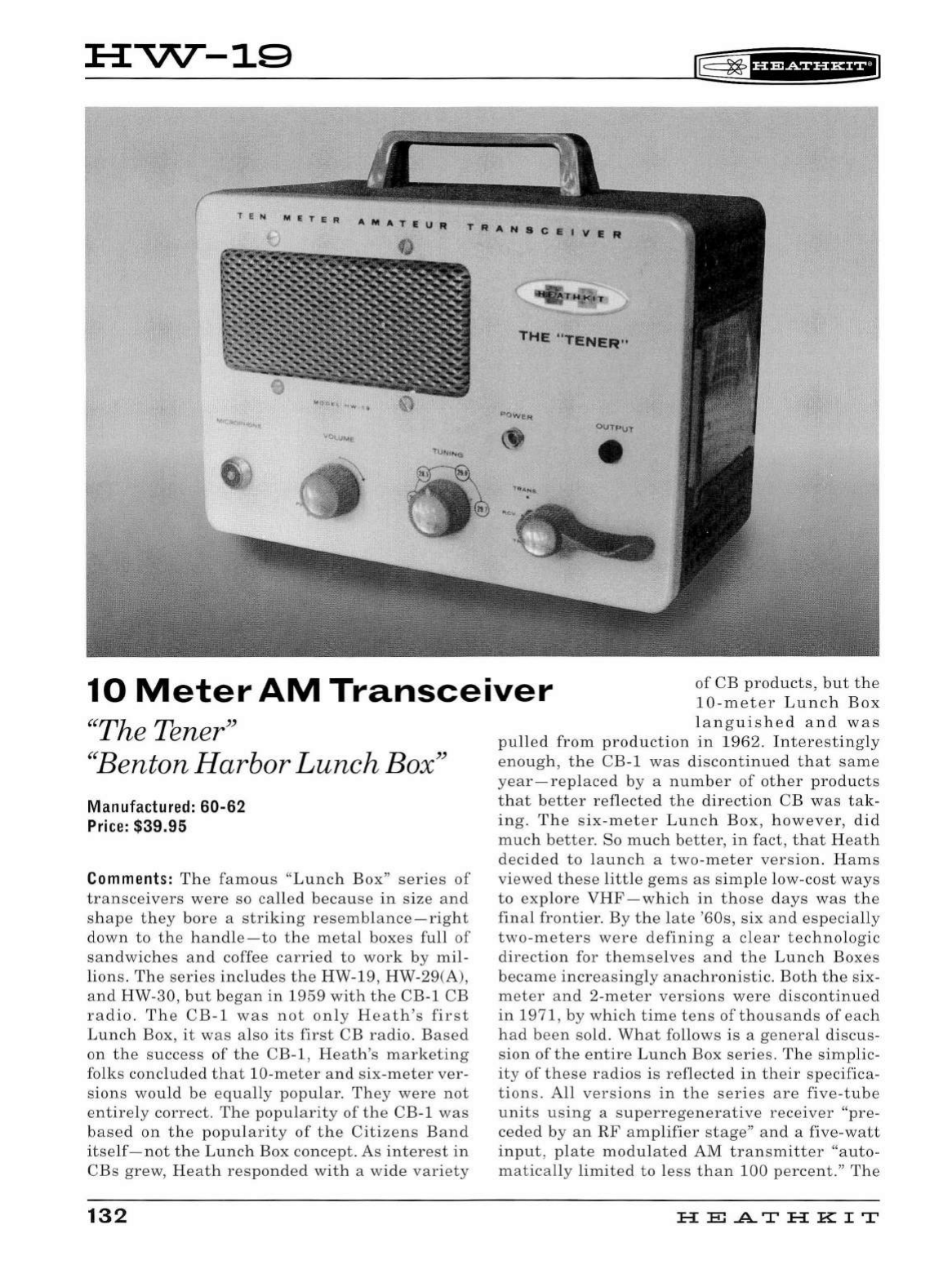
H-VV--19
~
~fbfSii'HEI
T E N M E T E R
THE "TENER"
10
Meter
AM
Transceiver
of
CB
products
,
but
the
10
-
meter
Lunch
Box
"The Tener"
''
Benton
Harbor
Lunch
Bo
x"
Manufactured: 60-62
Price:
$39.95
Comments:
The
famo
u s "
Lunch
Box
"
serie
s
of
transceivers
wer
e so
called
becau
se
in
size
and
s
hap
e
th
ey
bor
e a s
trikin
g
resembl
a
nce-right
down
to
the
h
and
le
-to
the
metal
boxes
full
of
sandwiches
and
coffee
carried
to
work
by
mil-
lion
s .
The
se
rie
s
include
s
th
e
HW-19,
HW-29
(A),
and
HW-30
,
but
b
ega
n
in
1959
with
th
e CB-1 CB
radio.
Th
e
CB-1
was
not
only
H
ea
th
's
fir
st
Lunch
Box,
it
was
also
it
s
first
CB
radio.
B
ase
d
on
the
success
of
the
CB-1,
He
a
th'
s
mark
e
ting
folks
concluded
th
at
10-m
et
er
and
six
-met
er
ver
-
s
ion
s
would
be
eq
uall
y
popular
.
Th
ey
were
not
e
ntirel
y
correct.
The
popul
ar
it
y
of
the
CB-1
was
ba
se
d
on
the
popularity
of
the
Citizens
Band
its
e
lf
-
not
the
Lunch
Box
concept.
As
inter
est
in
CBs
grew,
Heath
responded
w
ith
a
wide
variety
132
l
anguishe
d
and
was
pulled
from
production
in
1962.
Interestingly
en
ough,
the
CB-1
wa
s dis
continued
that
same
year-replaced
by a
number
of
other
products
that
better
reflected
the
direction
CB
was
tak
-
ing.
The
s
ix-m
ete
r
Lun
ch
Box
,
however,
did
much
be
tt
e
r.
So
much
b
et
ter,
in
fact
,
that
Heath
dec
ided
to
lau
nch
a
two-meter
version.
Hams
vi
ewe
d
these
little
gems
as
si
mpl
e
low-cost
ways
to
explore
VHF-which
in
t
ho
se
days
wa
s
the
fin
al
frontier.
By
the
l
ate
'
60s,
six
a
nd
especially
t wo-met
ers
were
defining
a
cle
ar
technologic
dir
ec
tion
for
th
e
mselv
es
a
nd
th
e
Lunch
Boxe
s
bec
am
e
increa
s
in
gly
ana
c
hroni
stic
.
Both
the
s
ix
-
meter
an
d 2
-m
et er
versions
wer
e
discontinued
in
1971
,
by
which
tim
e ten s
of
thou
sa
nd
s
of
ea
ch
h ad b
een
sold.
What
follows is a
gene
ral
discus-
sion
of
the
entire
Lunch
Box
series.
The
s
implic-
ity
of
th
ese
radios
is
r e
fl
ecte
d
in
th
e
ir
specifica-
tion
s.
All
versions
in
the
se
ri
es
are
fiv
e-t
ub
e
unit
s u s
ing
a s
up
e
rre
gen e
rativ
e
rece
iv
er
"
pre-
ceded
by
an
RF
a
mplifi
er
stage"
and
a
five-watt
input,
plate
modulated
AM
tran
sm
itter
"
auto-
ma
tic
a
ll
y
limit
ed
to
l
ess
tha
n
100
percent.
"
The
HE
.AT
HK
IT
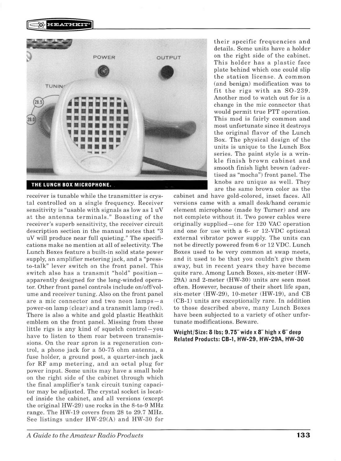
POWER
OUTPUT
their
specific
frequencies
and
details.
Some
units
have
a
holder
on
the
right
side
of
the
cabinet
.
This
holder
has
a
plastic
face
TUNIN
" •
,;;~;;;;.
·~·,.·····
~·~······
•••••••••
, ...•....
•••••••
"'•••••r
THE LUNCH
BOX
MICROPHONE.
receiver
is
tunable
while
the
transmitter
is
crys-
tal
controlled
on
a
sing
le
frequency.
Receiver
sens
iti
vity
is "
usable
with
signals
as
low
as
1
uV
at
the
antenna
terminals
."
Boasting
of
the
receiver's
superb
sensitivity,
the
receiver
circuit
description
sect
ion
in
the
manual
notes
that
"3
u V
will
produce
near
full
quieting."
The
specifi-
cations
make
no
mention
at
all
of
selectiv
ity.
The
Lunch
Boxes
feature
a
built-in
solid
state
power
supply,
an
amplifier
metering
jack,
and
a
"press-
to-talk"
l
ever
switch
on
the
front
panel.
This
switc
h a l
so
has
a
transmit
"
hold
"
position-
apparent
ly
designed
for
the
long-winded
opera-
tor.
Oth
er
front
panel
controls
include
on/off/vol-
ume
and
receiver
tuning.
Also
on
the
front
pan
el
are
a
mic
connector
and
two
neon
l
amps-a
power-on
lamp
(
clear
)
and
a
transmit
lamp
(red).
There
is
also a
white
and
gold
plastic
Heathkit
emblem
on
the
front
panel.
Missing
from
these
little
rigs
is
any
kind
of
squelch
control-you
have
to
li
ste
n
to
them
roar
between
transmis-
si
ons
.
On
the
rear
apron
is
a
re
ge
neration
con-
trol,
a
phono
jack
for a
50
-75
ohm
antenna,
a
fuse
holder,
a
ground
post,
a
quarter-inch
jack
for
RF
a
mp
metering,
and
an
octal
plug
for
power
input.
Some
unit
s
may
ha
ve
a
sma
ll
hole
on
the
right
side
of
the
cabinet
through
which
the
final
am
plifier
's
tank
circuit
tuning
capaci
-
tor
may
be
adjusted.
The
crysta
l
socket
is
loc
at
-
ed
insid
e
th
e
cabinet
,
and
all
versions
(except
the
original
HW-29)
u
se
rocks
in
the
8-to
-9
MHz
range.
The
HW-19
covers
from
28
to
29.7
MHz.
See
listing
s
under
HW-29
(A)
and
HW-30
for
A
Guid
e to the
Amat
e
ur
Radio
Products
plate
behind
which
one
could
slip
the
station
license.
A
common
(and
benign)
modification
was
to
fit
the
rigs
with
an
S0-239.
Another
mod
to
watch
out
for
is
a
change
in
the
mic
connector
that
would
permit
true
PTT
operation.
This
mod
is
fairly
common
and
most
unfortunate
since
it
destroys
the
original
flavor
of
the
Lunch
Box
.
The
physical
design
of
the
units
is
unique
to
the
Lunch
Box
series.
The
paint
style
is
a
wrin-
kle
finish
brown
cabinet
and
smooth
finish
li
ght
brown
(adver-
tised
as
"mocha")
front
panel.
The
knobs
are
unique
as
well.
They
are
the
same
brown
color
as
the
cabinet
and
have
go
ld-color
ed,
inset
faces.
All
versions
came
with
a
sma
ll
desk
/
hand
ceramic
element
microphone
(
made
by
Turner)
and
are
not
complete
without
it.
Two
power
cables
were
originally
supplied-one
for
120
VAC
operation
and
one
for
use
with
a 6-
or
12-VDC
optional
external
vibrator
power
supply.
The
units
can
not
be
directly
powered
from
6
or
12 VDC.
Lunch
Boxes
used
to
be
very
common
at
swap
meets,
and
it
used
to
be
that
you
couldn't
give
them
away
,
but
in
recent
years
th
ey
have
become
quite
rare
.
Among
Lunch
Bo
xes,
six
-meter
(HW-
29A)
and
2-meter
(HW
-30)
units
are
seen
most
often.
However,
because
of
their
short
life
span,
six-meter
(HW-29),
10-meter
(HW
-19
),
and
CB
(CB-1)
units
are
exceptionally
rare.
In
addition
to
those
described
above,
many
Lunch
Boxes
have
been
subjected
to
a
variety
of
other
unfor-
tunate
modifications.
Beware.
Weight/Size: 8
lbs;
9.75"
wide
x 8"
high
x
6"
deep
Related
Products:
CB-1,
HW-29, HW-29A, HW-30
133
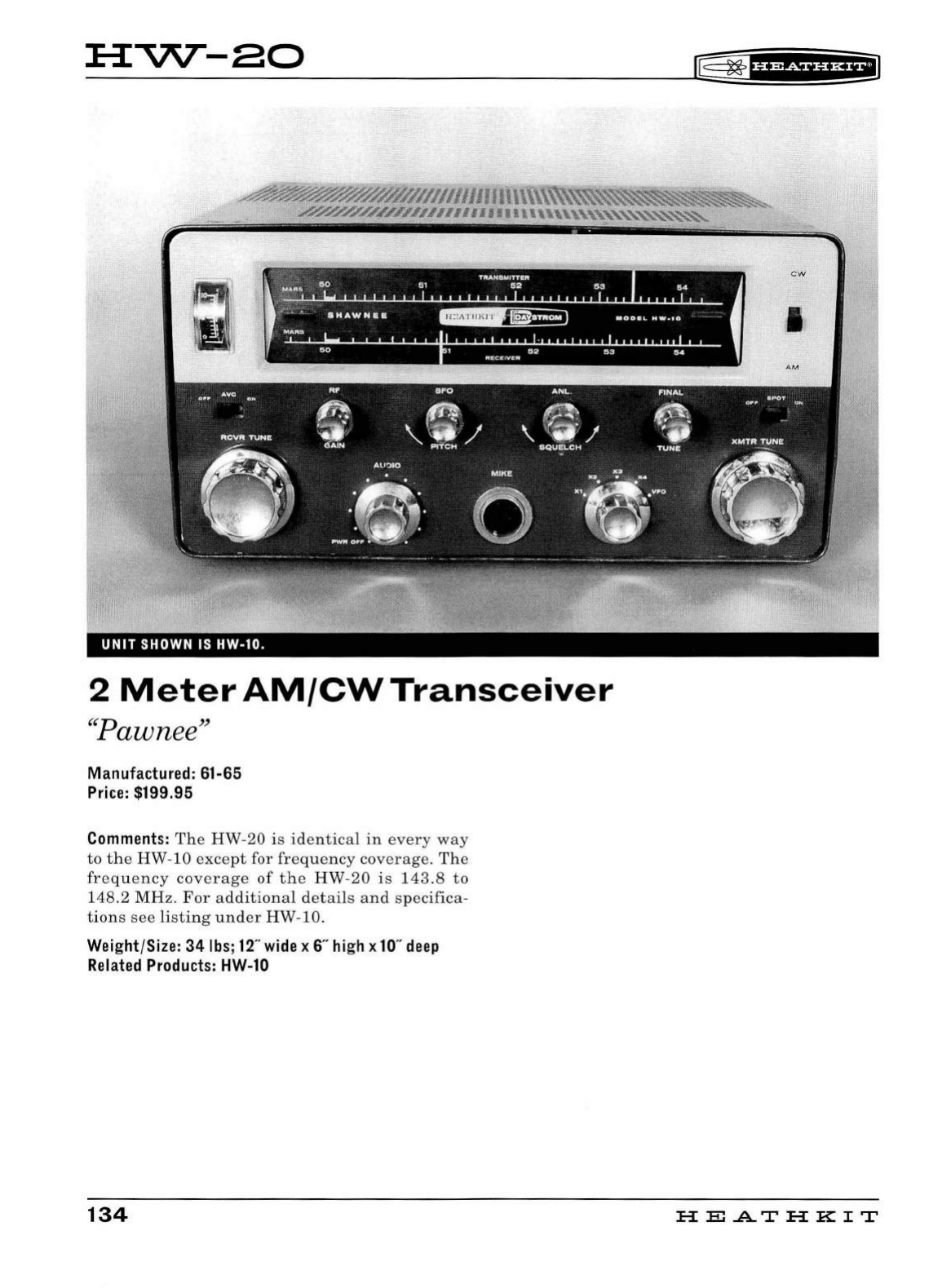
:a:vv--ao
~
~
1
u&&f#f&+i
~
TA.4H8MITTBA
~
50
51
52
63
64
MA"$
r • "
SHAWNiiE
•0
0
•1-
Hw-10
MAlltS
50
1
52
S3
54
RECEIVER
CW
=
•.
1 I
UNIT
SHOWN IS HW-10.
2
Meter
AM/CW
Transceiver
"Pawnee"
Manufactured: 61-65
Price: $199.95
Comments:
The
HW-20
is
identical
in
every
way
to
the
HW-10
except
for
frequency
coverage
.
The
frequency
coverage
of
the
HW-20
is
14
3.8
to
148.2
MHz.
For
additional
details
and
specifica-
tions
see
listing
under
HW-10.
Weight/Size:
34
lbs; 12" wide x 6" high x 10"
deep
Related Products: HW-10
134
AM
HEATHKIT
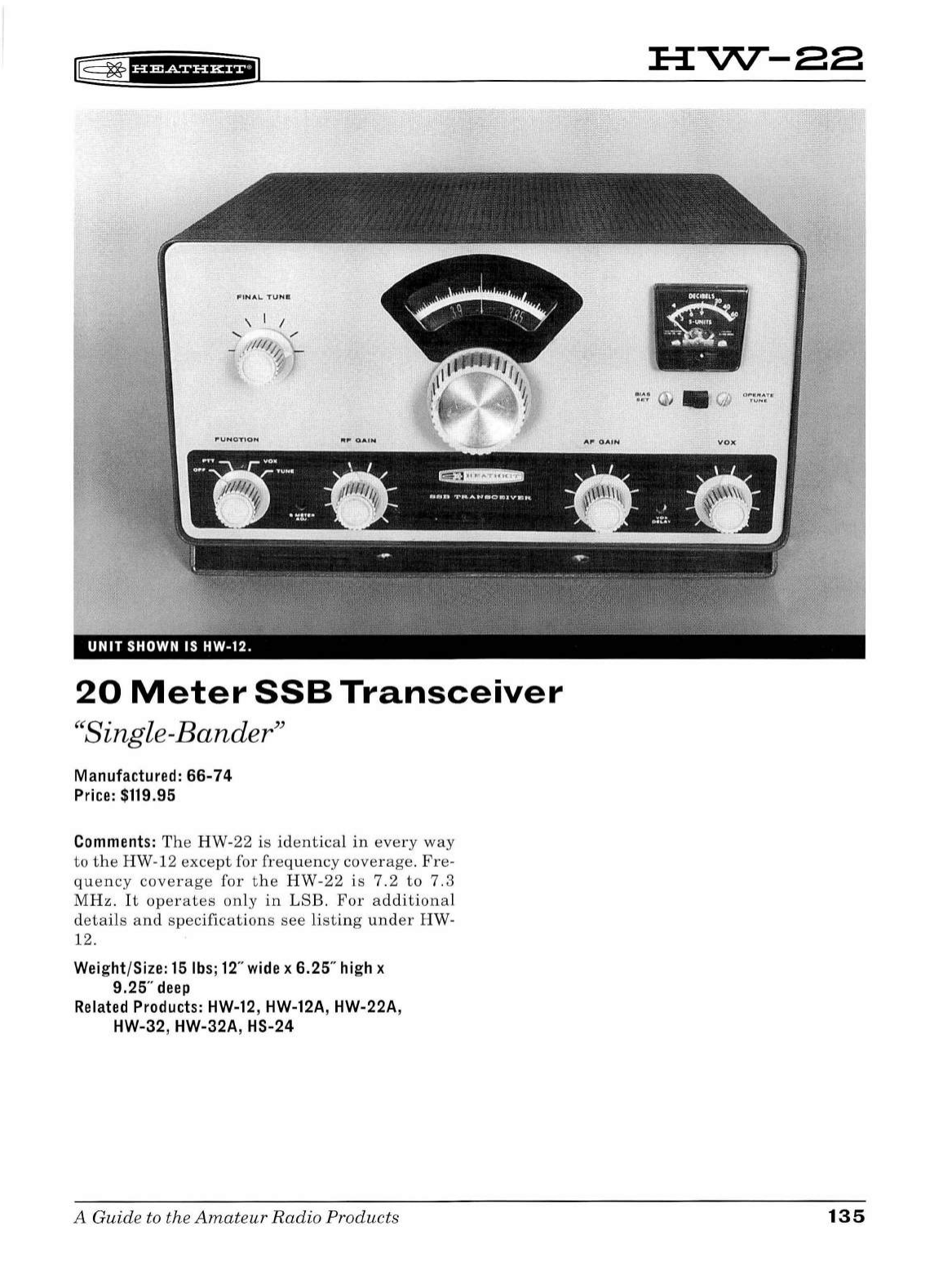
l8
~
f
U&iHH+il
FINAL.
TVNI!:
20
Meter
SSB
Transceiver
"Single-Bander"
Manufactured: 66-74
Price:
$119.95
Comments:
The
HW-22
is
identical
in
every
way
to
the
HW-12
except
for
frequency
coverage.
Fre
-
quency
coverage
for
the
HW
-
22
is
7.2
to
7.3
MHz.
It
operates
only
in
LSB.
For
additional
details
and
s
pecifications
see
listing
under
HW
-
12.
Weight
/
Size:
15
lbs
;
12
"
wide
x 6.25"
hi
gh x
9.25"
deep
Related
Products:
HW-12
,
HW
-
12A
, HW-22A,
HW-32, HW-32A, HS-24
A G
uide
to the
Amateur
Radio
Products
:a::vvr-aa
'
•
135
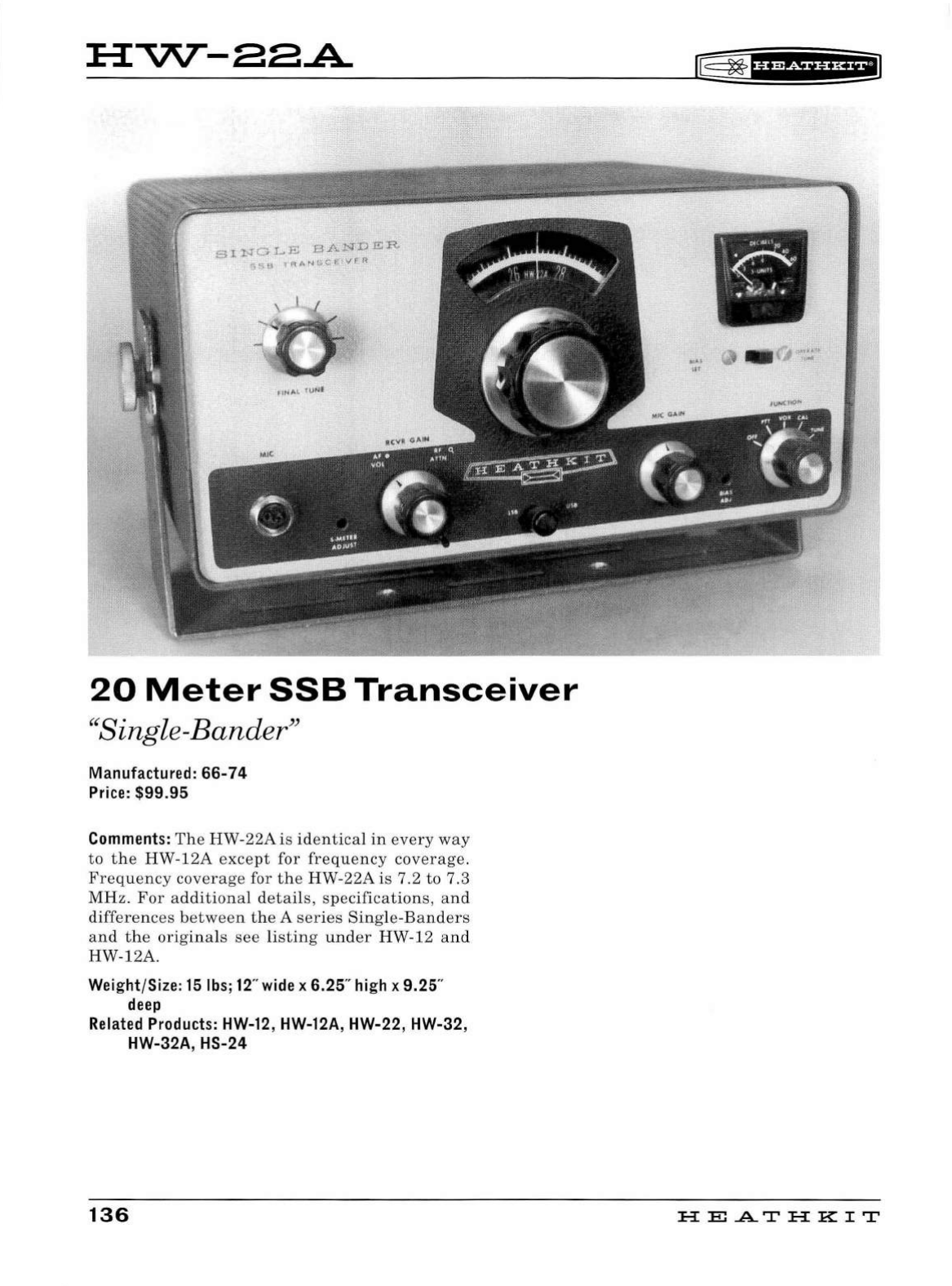
H-v\T-aa.A
\ I I
;o
20
Meter
SSB
Transceiver
"
Sin
gle-Bander"
Manufactured:
66-74
Price:
$99.95
Comments:
The
HW-22A
is
identical
in
every
way
to
the
HW-12A
except
for
frequency
coverage.
Frequency
coverage
for
the
HW-22A
is
7.2
to
7.3
MHz
.
For
additional
details,
specifications,
an
d
differences
between
the
A
series
Sing
le-
Banders
and
t
he
origina
ls
see
listing
u
nder
HW-12
an
d
HW-12A.
Weight/Si
ze:
15lbs;
12
"wide x
6.25
" high x 9.25"
deep
Related Products:
HW-12
, HW-12A, HW-22, HW-32,
HW-32A, HS-24
136
[§
~
1uw+ue;1
HE.A.TH
KIT
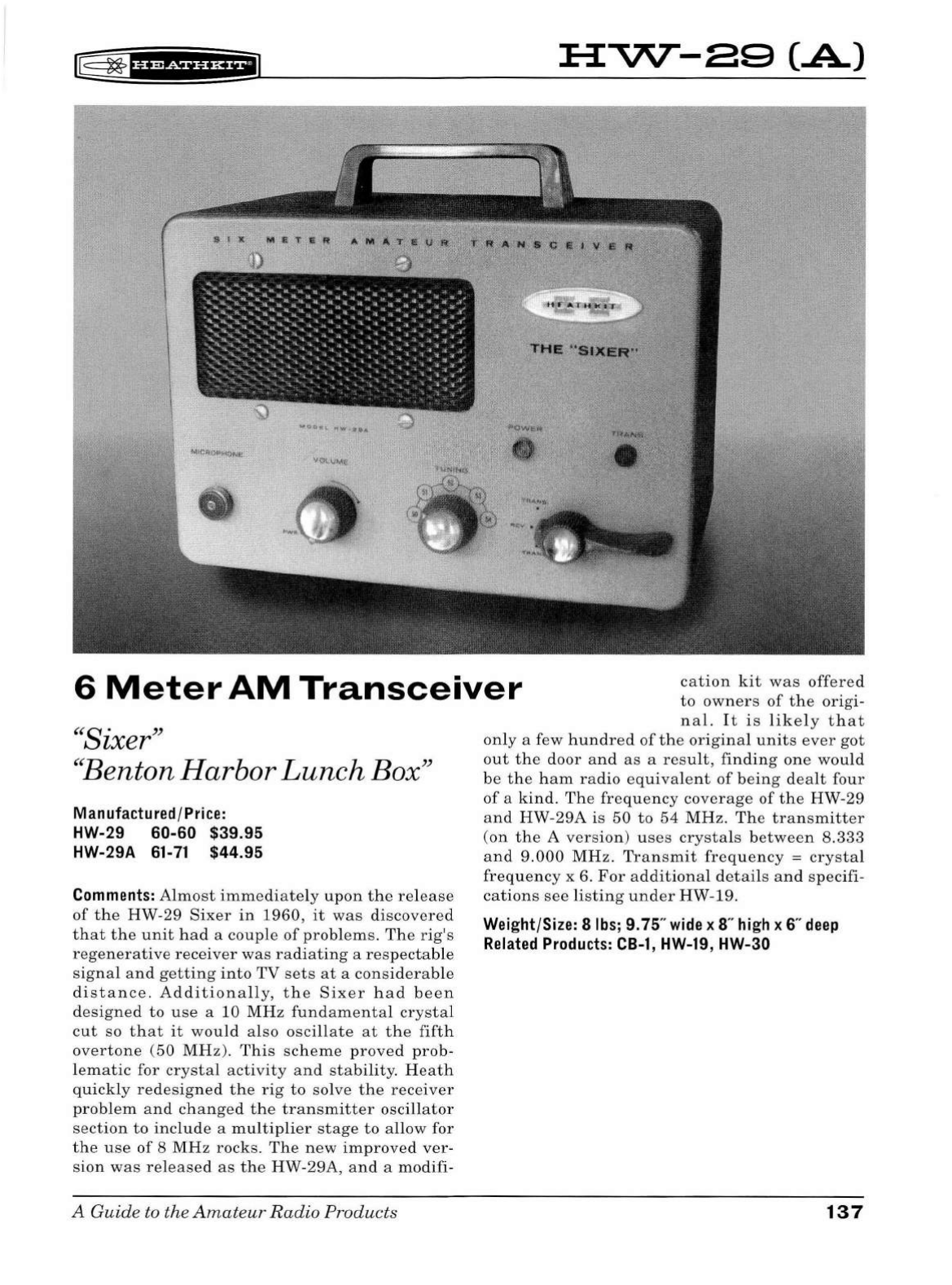
l8
~
f
bidii'Hf@
HVV--89
(.A)
6
Meter
AM
Transceiver
cation
kit
was
offered
to
owners
of
the
origi-
"Sixer"
"Benton Harbor Lunch
Box"
Manufactured/Price:
HW-29 60-60 $39.95
HW-29A
61-71
$44.95
Comments:
Almost
immediately
upon
the
rel
ease
of
the
HW-29
Sixer
in
1960,
it
was
discovered
that
the
unit
had
a
couple
of
problems
.
The
rig's
regenerative
receiver
was
radiating
a
respectable
signal
an
d
gett
in
g
into
TV
sets
at
a
considerable
distance.
Additionally,
the
Sixer
had
been
designed
to
use
a 10
MHz
fundamental
crystal
cut
so
that
it
would
also
oscillate
at
the
fifth
overtone
(50
MHz).
This
scheme
proved
prob-
lematic
for
crystal
activity
and
stability.
H
eat
h
quickly
redesigned
the
rig
to
solve
the
receiver
problem
and
changed
the
transmitter
oscillator
section
to
include
a
multiplier
stage
to
allow
for
the
use
of
8
MHz
rocks.
The
new
improved
ver-
sion
was
released
as
the
HW-29A,
and
a
modifi-
A
Guide
to
the
Amateur
Radio
Products
n
al.
It
is
likely
that
only
a few
hundred
of
the
original
units
ever
got
out
the
door
and
as
a
result,
finding
one
would
be
the
ham
radio
equivalent
of
being
dealt
four
of
a
kind.
The
frequency
coverage
of
the
HW-29
and
HW-29A
is
50
to
54
MHz.
Th
e
transmitter
(on
the
A
version)
u
ses
crystals
between
8.333
and
9.000
MHz.
Transmit
frequency
=
crystal
frequency
x 6.
For
additional
details
and
specifi-
cations
see
listing
under
HW-19.
Weight/Size: 8
lbs;
9.75"
wide
x
8"
high
x
6"
deep
Related
Products:
CB-1,
HW-19, HW-30
137
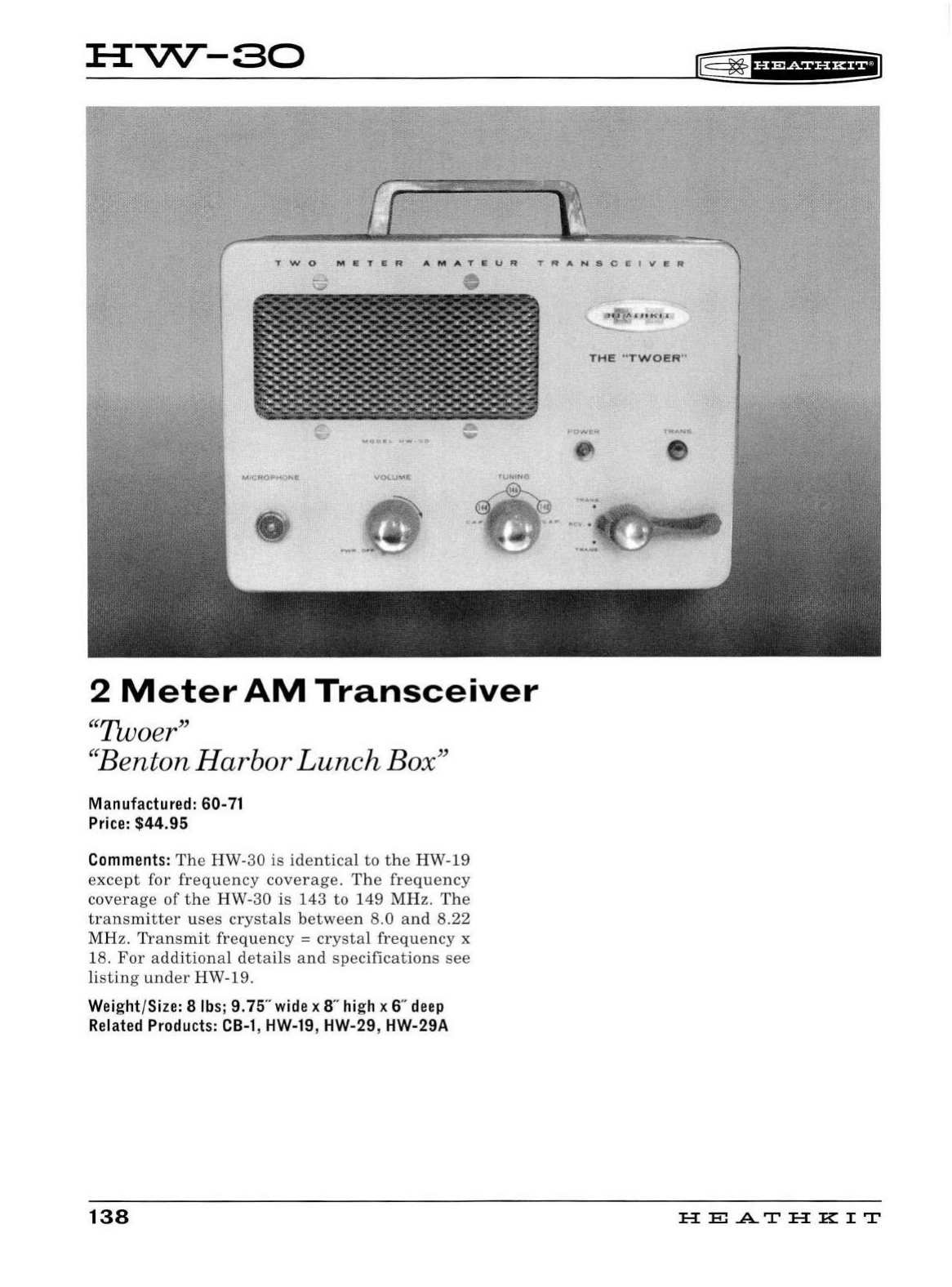
H"'V\T-80
[@
~
'h#§idi*iil
TWO
M
ETER
AMATE
UR
TRANSCEIVER
2
Meter
AM
Transceiver
"Twoer"
''Benton
Harbor
Lunch
Bo
x"
Manufactured:
60-
71
Price:
$44.95
Comments:
The
HW
-30
is
identical
to
the
HW
-19
except
for
frequency
coverage
.
The
frequency
coverage
of
t he
HW-30
is
143
to
149
MH
z.
The
transmitter
u
ses
crysta
ls
between
8.0
and
8.22
M
Hz.
Transm
it
frequency
=
crystal
fre
q
uency
x
18.
For
additional
detail
s
and
specifications
see
listing
under
HW-19.
Weight/Size: 8 lbs;
9.75
" wide x 8" high x 6"
deep
Related Products:
CB-1
, HW-19,
HW
-29, HW-29A
138
I
tt
K'
i r
THE
"T
WOER
"
HE
.AT
HK
IT
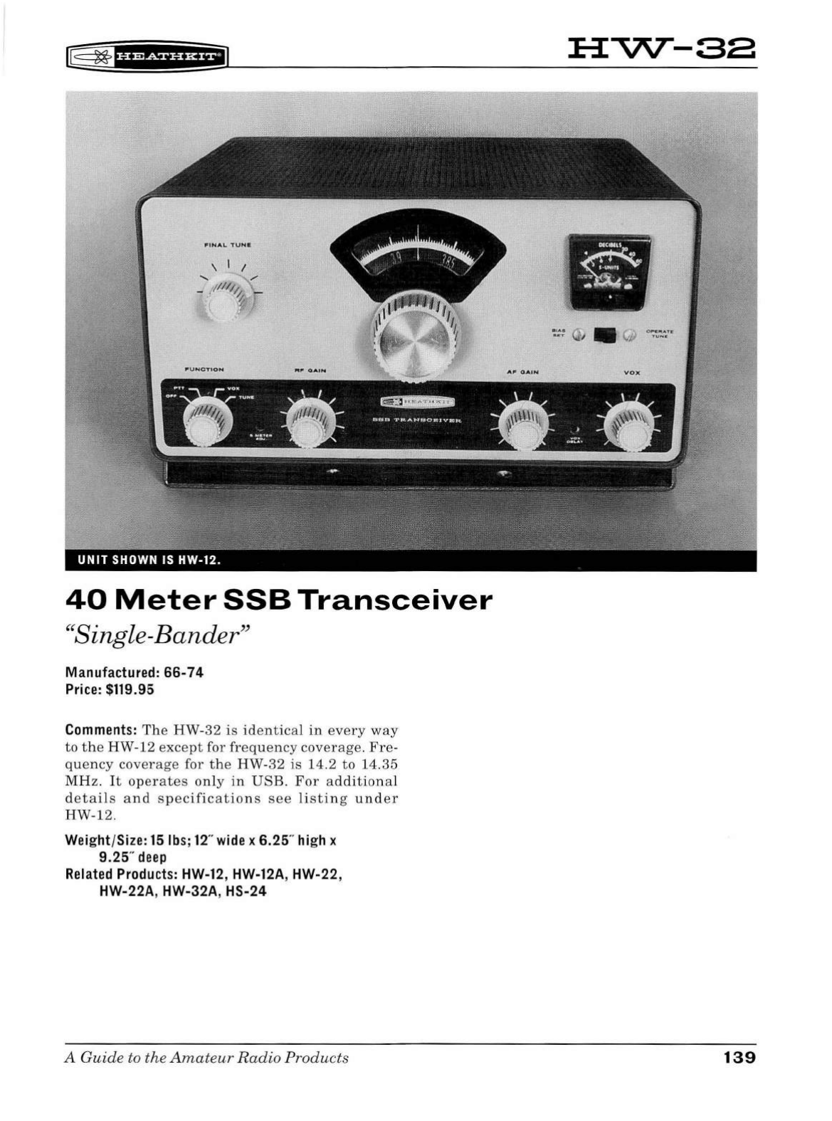
l@
~
f
H#iHHEi
F'I N A L
'TUNR
\ I I
.....
..........
,,.
_ ;/
Ill
/;,
\ _
:' / 1
\ . .
40
Meter
SSB
Transceiver
"Single-Bander"
Manufactured:
66-74
Price: $119.95
Comments:
The
HW
-
32
is
identica
l
in
every
way
to
the
HW
-12
except
for
freq
u
ency
coverage.
Fre-
quency
coverage
for
the
HW-32
is
14
.2
to
14.35
MHz.
It
operates
only
in
USB
. F
or
additional
details
and
specifications
see
li
sting
unde
r
HW-12.
Weight/Size:
15lbs;12
" wide x
6.25"
high x
9.25
"
deep
Related Products: HW-12 , HW-12A, HW-22,
HW-22A, HW-32A, HS-24
A
Guide
to the
Amateur
Radio
Products
:a:vv--sa
~
.
139
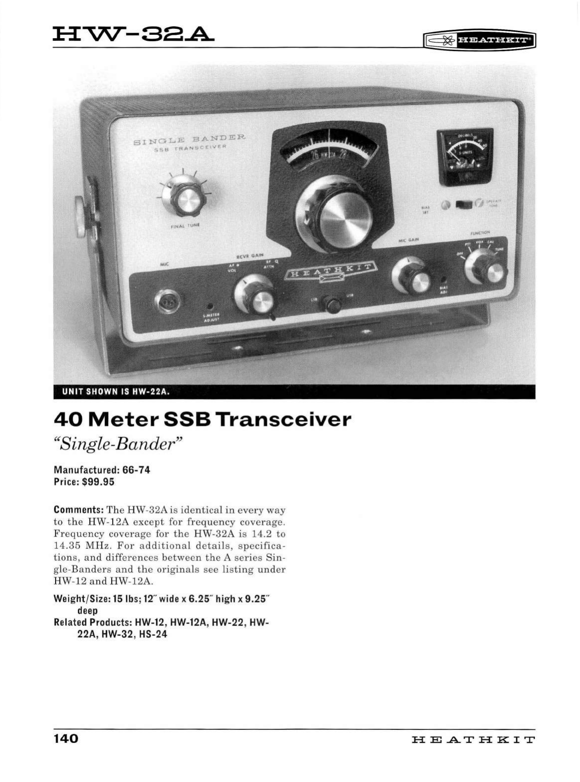
H"'V\T-SEA
UNIT
SHOWN IS
HW-22A.
40
Meter
SSB
Transceiver
"Single-Bander"
Manufactured:
66-74
Price:
$99.95
Comments:
The
HW-32A
is
identical
in
every
way
to
the
HW-12A
except
for
freq
u
ency
coverage.
Fr
eq
uency
coverage
for
the
HW-32A
is
14.2
to
14.35
MHz
.
For
a
dditional
details,
specifica-
tion
s,
and
differences
between
the
A
series
Sin
-
gle-B
anders
and
the
originals
see
li
st
in
g
under
HW-12
and
HW-12A.
Weight/Size:
15
lbs;
12
" wide x
6.25
" high x
9.25
"
deep
Related Products: HW-12, HW-12A, HW-22, HW-
22A, HW-32, HS-24
140
~
~'i'@i§iHEIJ
HE
.AT
HK
IT
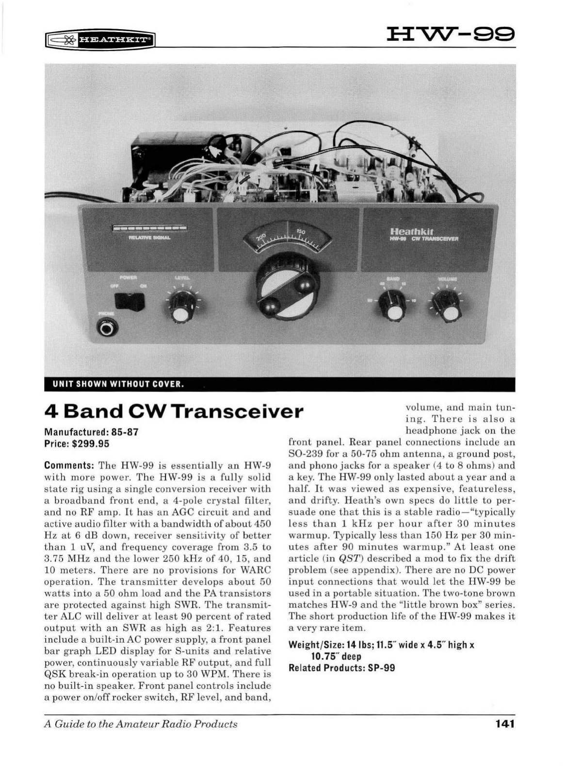
l8
~
·ua+tHH+il
HVV--99
UNIT
SHOWN
WITHOUT COVER.
4
Band
CW
Transceiver
volume
,
and
main
tun-
ing.
There
is
also
a
Manufactured:
85-87
Price:
$299.95
Comments:
The
HW-99
is
essentially
an
HW-9
with
more
power.
The
HW
-
99
is
a
fu
ll
y
soli
d
state
rig
using
a
single
conversion
receiver
with
a
broadband
front
end,
a 4-pole
crysta
l
filter,
and
no
RF
amp.
It
has
an
AGC
circuit
and
and
active
audio
fil
ter
with
a
bandw
i
dth
of
about
450
Hz
at
6
dB
down,
receiver
sens
i
tivity
of
better
than
1 uV,
and
frequency
coverage
from
3.5
to
3.75
MH z
and
the
lower
250
kHz
of
40,
15,
and
10
meters.
There
are
no
provisions
for WARC
operation.
The
transmitter
develops
about
50
watts
into
a
50
ohm
load
and
the
PA
transistors
are
protected
against
hi
gh
SWR.
The
transmit
-
ter
ALC
will
deliver
at
l
east
90
percent
of
rated
output
with
an
SWR
as
high
as
2:1.
Features
include
a
built-in
AC
power
supp
l
y,
a
front
pane
l
bar
graph
L
ED
display
for
S-units
and
relative
power,
continuously
variable
RF
output,
and
full
QSK
break
-
in
op
eration
up
to
30
WPM.
There
is
no
bui
lt -
in
speaker.
Front
pane
l
contro
ls
include
a
power
on
/off
rocker
switch,
RF
l
evel,
an d
band,
A Guide to the
Amateu
r
Radio
Products
headphone
jack
on
the
front
panel.
R
ear
pane
l
connections
include
an
S0-239
for a
50-75
ohm
antenna,
a
ground
post,
and
phono
jacks
for a
speaker
(4
to
8
ohms)
an
d
a
key
.
The
HW
-99
only
l
asted
about
a
year
and
a
half.
It
was
viewed
as
expensive,
featureless,
and
drifty.
Heath's
own
specs
do
little
to
per-
suade
one
that
this
is
a
stable
radio
-
"typically
less
than
1
kHz
per
hour
after
30
minutes
warmup
.
Typica
lly
less
than
150
Hz
per
30
min-
utes
after
90
minutes
warmup."
At
l
east
one
article
(in
QST)
described
a
mod
to
fix
the
drift
problem
(see
appendix
).
There
are
no
DC
power
input
connections
that
would
let
the
HW-99
be
used
in
a
portab
le
situation.
The
two-tone
brown
matches
HW
-9
and
the
"little
brown
box"
series.
The
sh
ort
production
li
fe
of
the
HW-99
makes
it
a
very
rare
item
.
Weight/Size:
14
lbs;
11.5
"
wide
x 4.5"
high
x
10.
75"
deep
Related
Products:
SP-99
141
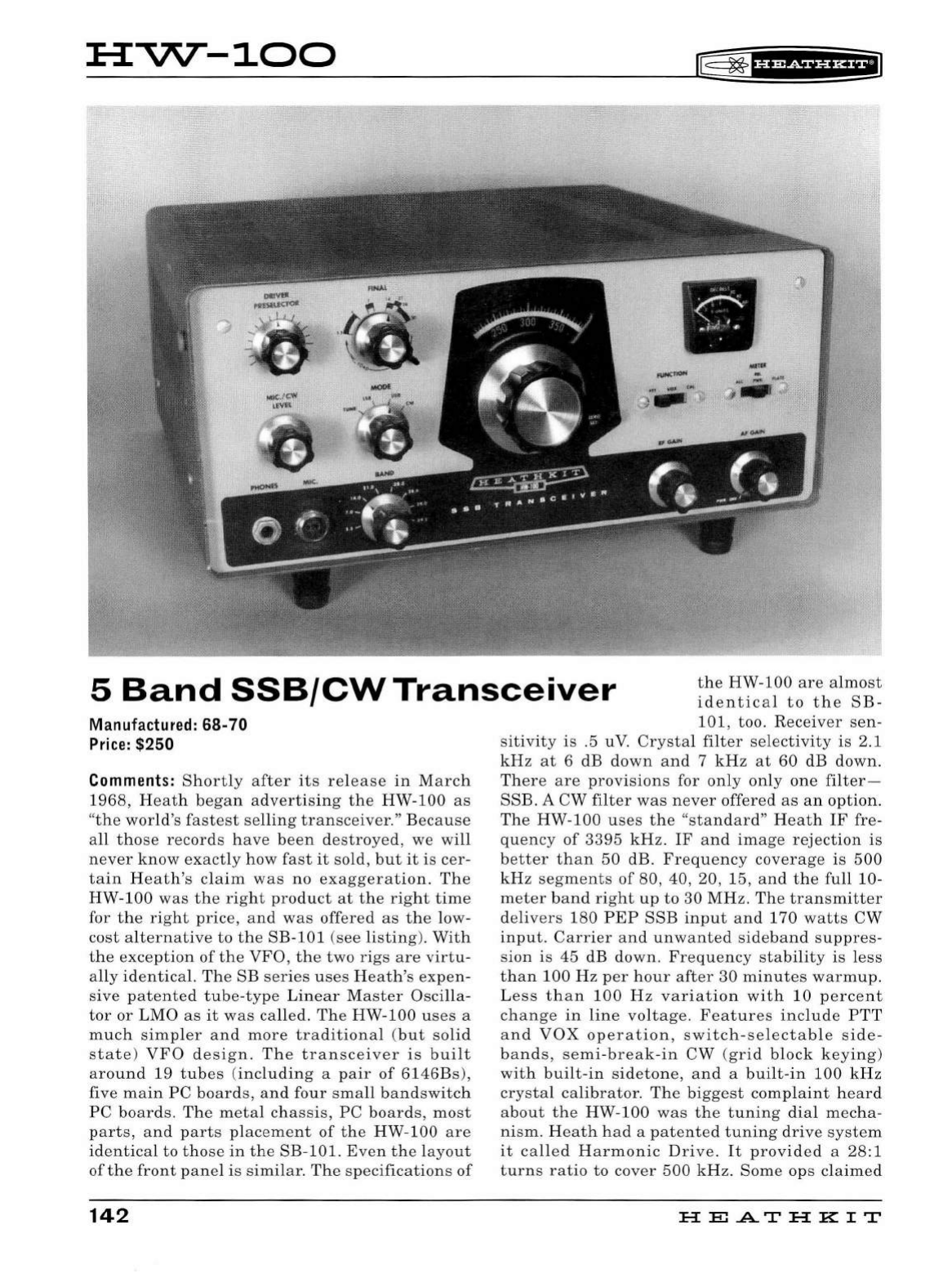
HVV--100
~
~
1
UR&ihH+I
5
Band
SSB/CW
Transceiver
the
HW
-
100
are
a
lmost
identic
a l
to
the
SB-
Manu
fa
ctured:
68-
70
Pr
ice:
$250
Comments:
Shortly
after
it
s
release
in
March
1968,
H
ea
th
began
advertising
th
e
HW
-
100
as
"t
he
world
's
fast
est
se
lling
tran
sce
iver."
Beca
use
a
ll
those
records
have
b
een
de
stroye
d,
we
will
ne
ver
know
exactly
how
fast
it
sold,
but
it
is
cer-
tain
H
eat
h's
claim
was
no
exaggeration.
The
HW-1
00
was
the
right
product
at
the
right
time
for
the
right
pric
e, a
nd
was
offer
ed
as
the
low
-
cost
alternative
to
the
SB-101
(see
listing
).
With
the
exception
of
the
VFO
,
the
two
rigs
ar
e
virt
u-
ally
id
en
tic
al.
Th
e
SB
ser
i
es
use
s H
ea
th
's
expen
-
s
ive
pat
e
nted
tub
e-ty
pe
Linear
M
as
ter
Osci
lla
-
tor
or
LMO
as
it
was
call
ed.
The
HW-100
uses
a
much
s
impler
and
more
traditional
(
but
so
lid
sta
te
)
VFO
de
si
gn.
Th
e
tran
sceive
r is b
uilt
around
19
tub
es
(
including
a
pai
r
of
6146Bs),
five
main
PC
board
s, a
nd
four
sma
ll
band
sw
itch
PC
boards.
The
metal
chassis,
PC
boards
,
mo
st
parts,
and
part
s
pl
ace
me
nt
of
the
HW-100
a
re
identical
to
those
in
the
SB-101.
Even
th
e layo
ut
of
the
front
pan
el is s
imilar
.
The
spec
ifications
of
142
101,
too
.
Receiv
er
sen
-
si
tivit
y is .5 uV.
Crystal
filter
se
l
ect
ivit
y
is
2.1
kHz
at
6 dB
down
and
7
kH
z
at
60
dB
down.
Th
ere
are
provi
sio
ns
for
only
only
on
e
filter-
SSB.
A
CW
filt
er
was
n
ever
offer
ed
as
an
option.
The
HW-100
u
ses
the
"sta
ndard
"
Heath
IF
fre
-
qu
ency
of
3395
kHz.
IF
a
nd
ima
ge
rejection
is
better
than
50
dB.
Fr
e
qu
e
ncy
cove
rage
is
500
kHz
seg
me
nts
of
80, 40, 20, 15,
and
th
e
full
10-
meter
ba
nd
right
up
to
30
MH
z.
The
tran
s
mitter
de
liver
s
180
PEP
SSB
input
and
170
watts
CW
input.
Carrier
an
d
unwanted
sideband
s
uppres
-
s
ion
is
45
dB
down.
Frequency
s
tabilit
y is l
ess
than
100
Hz
p
er
hour
after
30
minutes
warmup.
L
es
s
than
100
Hz
vari
a
tion
with
10
p
er
cent
change
in
lin
e
voltage.
F
ea
tu
res
include
PTT
a
nd
VOX
operation
,
sw
itch-
se
l
ec
tabl
e s
ide-
ba
nd
s,
se
mi-b
reak
-in
CW
(
grid
block
keying
)
with
built-in
sidetone
,
an
d a
built
-
in
100
kHz
crystal
calibrator.
The
bi
gges
t
comp
l
aint
h
ea
rd
a
bout
the
HW-100
was
the
tuning
dial
mec
ha-
nism.
H
ea
th
ha d a
patent
ed
tunin
g
drive
sys
tem
it
called
Harmonic
Driv
e.
It
provided
a
28:1
turns
ratio
to
cover
500
kHz
.
Som
e
ops
claimed
HE
.AT
HK
IT
~
~
f§fWfUH+il
it
was
fu
ll
of
wobble
and
back
l
as
h.
Pop
ul
ar
ham
magazines
pub
li
shed
mods
to
replace
the
dial
with
a
better
one
.
In
the
author's
opinion
th
ese
complaints
were
overb
l
own.
Front
pane
l
con-
trols
in
clude
b
and
and
mode
se
l
ectors,
load,
final
tune,
driver
pr
es
elector,
mic
/
CW
leve
l,
and
slide
switches
for
meter
fu
nction
and
PTTNOX/CA
L. R
ear
panel
connections
i
nclude
a
quarter
inc
h
key
jack
,
phono
j
acks
for
ALC
input,
8
ohm
speaker,
and
a
50
-75 oh m
antenna
.
There
is
a lso a
spare
ph
ono
jack.
In
addition
th
ere
is
an
11-pin
"octal
style"
power
input
plug
and
a
ground
post
.
Advertising
copy
refers
to
a
separate
rear
panel
jack
for
"
RF
output"
(
in
addition
to
an
antenna
jack
),
but
examples
ofrig
with
this
jack
h
ave
not
been
found
, alt h
ough
th
e
re
is
an
unused
ho
le
in
the
rear
pane
l
that
might
h
ave
been
used
for
this
purpose
.
Th
e
re
are
access
holes
in
the
l
ower
right
side
of
the
cabinet
for
screw
dr
i
ver
adjustment
of
controls
for
meter
zero,
bia
s,
and
VOX.
The
HW
-1
00
has
no
interna
l
speaker
or
power
supp
ly
and
is
designed
for
use
with
t he
HP-23
or
HP-13
series
of
power
supplies.
Power
requirem
e
nts
are
700
-
850
VDC
at
250
ma,
300
VDC
and
150
ma,
-115
VDC
at
10
ma,
and
12 volt s AC
or
DC
at
4.75
amps.
The
two-ton
e
green
s
tyli
ng also
incorpo
-
rates
SB
series
knobs
.
See
listing
for
SB
-
100
regard
in
g
information
about
mo
di
ficatio
n
of
the
driver
preselector
contro
l.
All
t
hi
ngs
cons
i
dered
,
the
HW
-1
00
is a
fine
rig
and
many
are
sti
ll
on
the
air
. Thou
gh
they
are
st
ill
fair
ly
co
m
mon,
the
HW
-
100
is
much
rarer
that
the
HW
-101
(see
listing).
Weight/Size: 22
lbs;
15
"
wide
x 6.25"
high
x
13.5"
deep
Related
Products:
HW-101
, HW-104, SB-600,
SB
accessories
A Guide to the
Amateu
r
Radio
Products
143


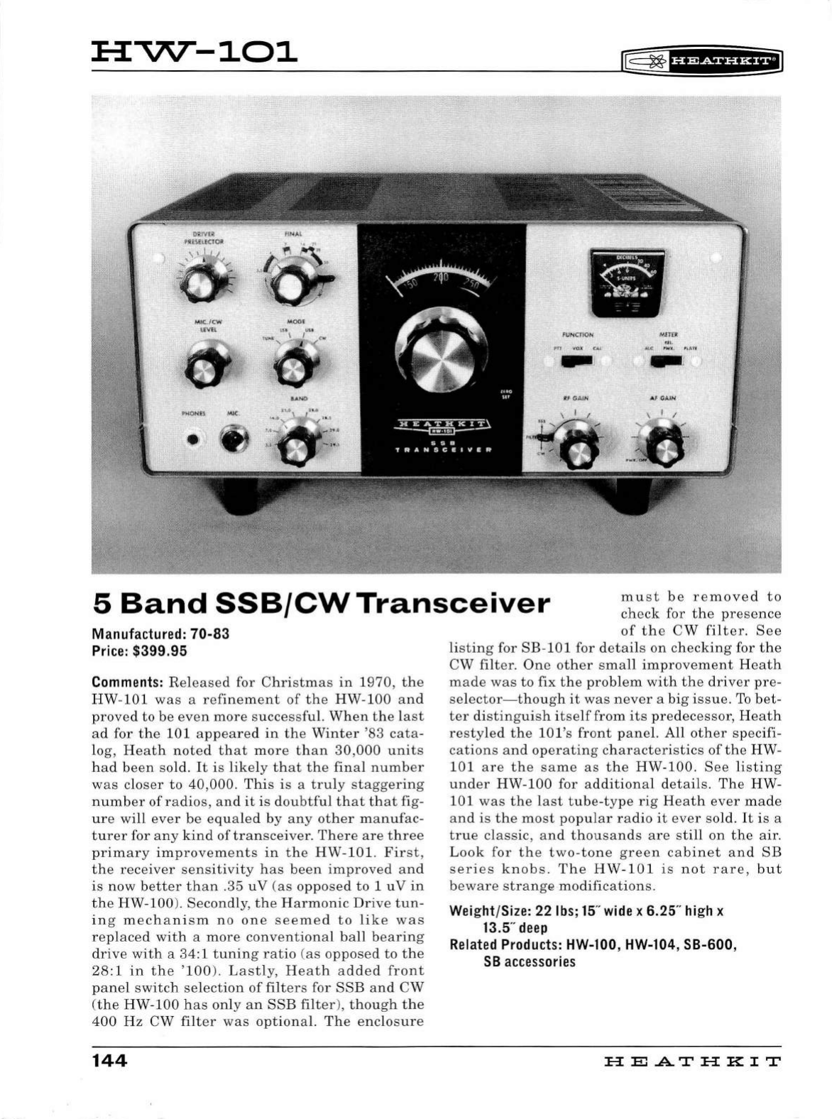
:a:
""'\7\T
-101
~ ~
1
H+SiUH+I
•
F\J
N
C}IOI{
Mf1
'£
JI
5
Band
SSB/CW
Transceiver
must
be
removed
to
check
for
the
presence
Manufactured: 70-83
Price
: $399.95
Comments
:
Released
for
Christmas
in
1970
,
the
HW-101
was
a
refinement
of
the
HW
-
100
and
proved
to
be
even
more
successful.
When
the
last
ad
for
the
101
appeared
in
the
Winter
'
83
cata-
log,
Heath
noted
that
more
than
30,000
units
had
been
sold.
It
is
likely
that
the
final
number
was
closer
to
40
,
000
.
This
is
a
truly
staggering
number
of
radios
,
and
it
is
doubtful
that
that
fig-
ure
will
ever
be
equaled
by
any
other
manufac-
turer
for
any
kind
of
transceiver.
There
are
three
primary
improvements
in
the
HW-101.
First,
the
receiver
sensitivity
has
been
improved
and
is
now
better
than
.
35
uV
(as
opposed
to
1
uV
in
the
HW-100).
Secondly,
the
Harmonic
Drive
tun
-
ing
mechanism
no
one
seemed
to
like
was
replaced
with
a
more
conventional
ball
bearing
drive
with
a 34: 1
tuning
ratio
(
as
opposed
to
the
28:1
in
the
'100
).
Lastly,
Heath
added
front
panel
switch
selection
of
filters
for
SSB
and
CW
(the
HW-100
has
only
an
SSB
filter
),
though
the
400
Hz
CW
filter
was
optional.
The
enclosure
144
of
the
CW
filter.
See
listing
for
SB-101
for
details
on
checking
for
the
CW
filter.
One
other
small
improvement
Heath
made
was
to
fix
the
problem
with
the
driver
pre-
selector-though
it
was
never
a
big
issue.
To
bet
-
ter
distinguish
itself
from
its
predecessor,
Heath
restyled
the
lOl's
front
panel.
All
other
specifi-
cations
and
operating
characteristics
of
the
HW-
101
are
the
same
as
the
HW-100.
See
listing
under
HW-100
for
additional
details.
The
HW-
101
was
the
last
tube
-
type
rig
Heath
ever
made
and
is
the
most
popular
radio
it
ever
sold.
It
is
a
true
classic,
and
thousands
are
still
on
the
air.
Look
for
the
two-tone
green
cabinet
and
SB
series
knobs.
The
HW
-
101
is
not
rare,
but
beware
strange
modifications.
Wei
ght/Size: 22
lbs
;
15
"
wide
x 6.25"
hi
gh x
13.5"
deep
Related
Products:
HW-100, HW-104, SB-600,
SB
accessor
i
es
HEATHKIT
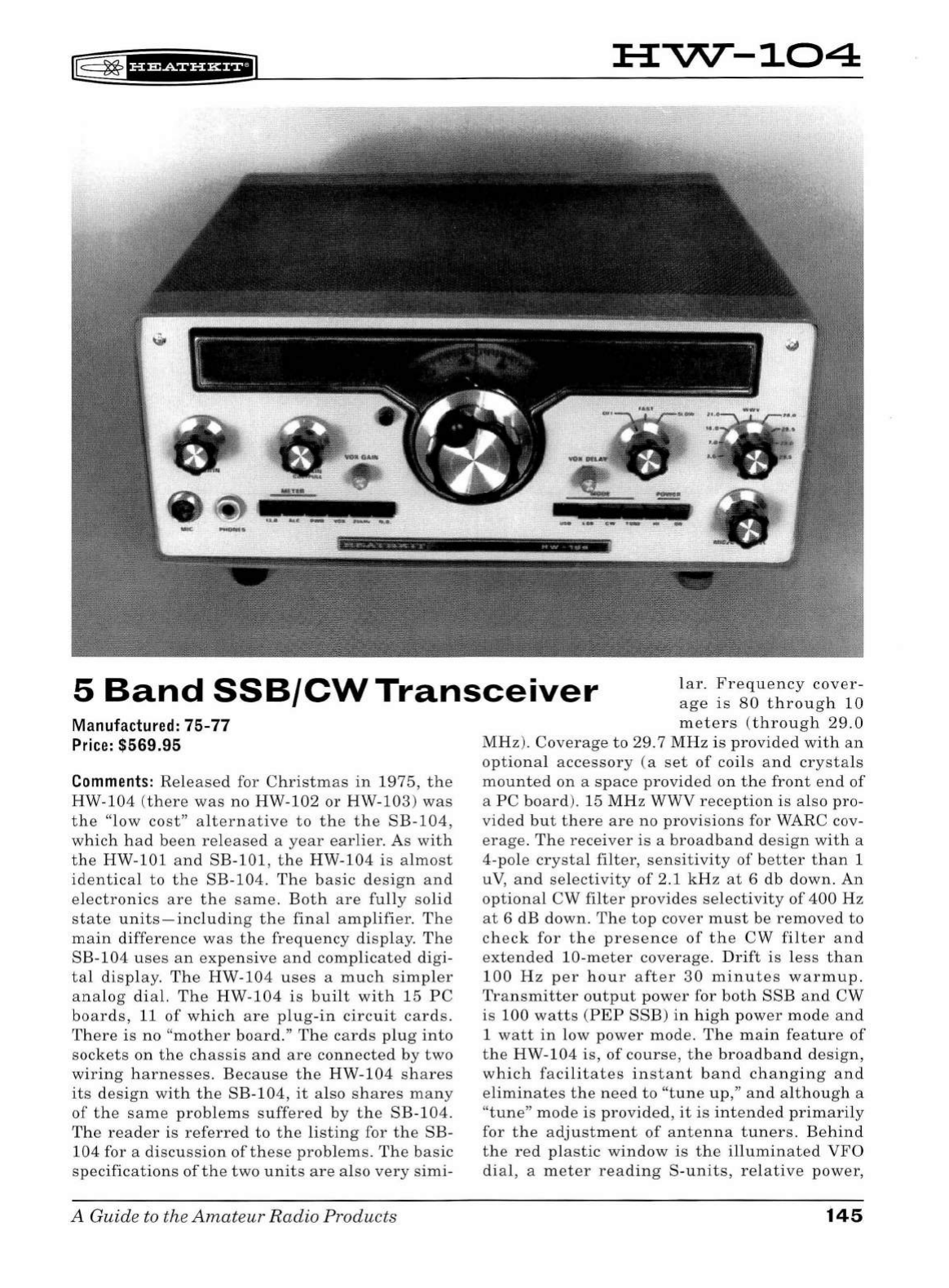
~ ~
f§fiSii'Hii
HVV-104
5
Band
SSB/CW
Transceiver
lar
.
Frequency
cover-
age
is
80
through
10
Ma
nufactured
:
75-77
Pr
i
ce:
$569.95
Comments:
Released
for
Christmas
in
1975
,
the
HW-104
(
th
ere
was
no
HW
-
102
or
HW-103
)
was
the
"low
cost"
alternative
to
th
e
the
SB-104,
which
had
b
ee
n
released
a
year
earlier.
As
with
th
e
HW-101
and
SB-101
,
the
HW-104
is
almost
identical
to
the
SB-104.
The
basic
d
es
ign
an
d
electronics
are
th
e
sa
me
.
Both
are
fully
so
lid
state
unit
s -
including
th
e
final
amplifier.
Th
e
main
differ
ence
was
the
fr
eq
uency
display.
The
SB-104
us
es
an
expensive
and
complicated
digi-
tal
displa
y.
The
HW-104
u
ses
a
much
simpler
analog
di
al.
The
HW-104
is
built
with
15
PC
boards
, 11
of
which
are
plug
-
in
circuit
card
s.
Th
e
re
is
no
"
mother
board.
"
The
cards
plug
into
sockets
on
the
chassis
and
are
connected
by
two
wi
r
ing
h
ar
n
ess
es.
Be
cause
the
HW
-
104
shares
its
d
es
ign
with
th
e
SB-104
,
it
also
shares
many
of
the
same
probl
ems
suffered
by
the
SB
-
104.
Th
e
reader
is
referred
to
th
e
listin
g for
the
SB-
104
for a
di
scu
ss
ion
of
these
problem
s.
The
basic
speci
fication
s
of
the
two
unit
s
are
also
very
sim
i-
A Guide to the
Amat
e
ur
Radio
Products
m e
ters
(through
29.0
MHz).
Coverage
to
29. 7
MHz
is
provided
with
an
optional
accessory
(a
set
of
coils
and
crystals
mounted
on
a
space
provided
on
the
front
e
nd
of
a
PC
board
).
15
MHz
WWV
rece
ption
is
also
pro-
vided
but
there
are
no
provisions
for WARC cov-
erage.
Th
e
receiver
is
a
broadband
d
es
ign
with
a
4-pole
crystal
filt
er,
sensitivity
of
b
ette
r
than
1
uV
,
and
se
lec
tivit
y
of
2.1
kH
z
at
6
db
down
.
An
optional
CW
filter
provides
se
lectivit
y
of
400
Hz
at
6 dB
down
.
Th
e
top
cov
er
must
be
removed
to
ch
eck
for
the
pr
ese
nce
of
the
CW
filter
a
nd
extended
10-meter
coverage.
Drift
is
les
s
than
100
Hz
p
er
hour
after
30
minut
es
warmup.
Transmitter
output
power
for
both
SSB
and
CW
is
100
watts
(PEP
SSB)
in
high
pow
er
mod
e
and
1
watt
in
low
pow
er
mod
e.
The
main
feature
of
the
HW
-
104
is,
of
course,
the
broadb
a
nd
d
es
ign,
which
facilitates
instant
band
changing
a
nd
e
liminate
s
the
ne
ed
to
"t
un
e
up
,"
and
although
a
"tu
ne
"
mod
e is
provided,
it
is
intended
primarily
for
the
adjustment
of
ant
en
na
tuners
. Be
hind
th
e
red
plastic
window
is
the
illuminated
VFO
di
al, a m e
ter
reading
S-unit
s,
relative
power
,
145
ALC
and
13.8
VDC,
and
an
illuminated
window
for
display
of
your
callsign.
(The
clever
person
will
figure
out
some
way
to
change
or
eliminate
the
callsign).
Front
panel
contro
ls
include
push
button
selection
of
meter
function,
power
off/on,
VOX,
25
kHz
calibrator,
and
optional
noise
blanker.
Push
buttons
also
select
operating
mode
and
power
level.
Other
front
panel
con-
trols
include
AF
and
RF
gain
(
pull
for
100
kHz
calibrator),
main
tuning,
AGC
speed,
band,
mic/CW
level,
VOX
gain,
and
VOX delay.
Rear
panel
controls
include
sidetone
level,
anti-VOX,
and
a
switch
to
select
separate
or
common
antenna
connections.
Rear
panel
connections
include
phono
jacks
for
the
following:
phone
patch
in
and
out,
aux
audio,
key, 4-8
ohm
speak-
er
(there
is
no
internal
speaker),
VFO
in
and
out,
ALC,
driver
output,
IF
output,
receiver
antenna
,
common
antenna,
and
two
spares.
For
normal
operation
there
must
be
a
jumper
cable
between
the
VFO
"in"
and
"out"
jacks.
There
are
also
two
11-pin
"
octal
style"
connectors
- a
plug
for 12 VDC
power
input
and
an
accessory
jack
for
use
with
the
SB-644
external
VFO.
For
nor-
mal
operation
there
must
be
a
jumper
wire
between
pins
2
and
5
of
the
accessory
socket
.
Antenna
switching
is
via
a
mechanical
relay.
CW
operation
is
semi-break-in.
NOTE:
The
card
edge
connectors
used
in
the
HW-104
almost
cer
-
tainly
will
develop
oxidation
over
time
leading
to
erratic
operation.
These
connectors
should
be
thoroughly
cleaned.
The
HW-104
is
designed
for
use
with
an
external
12
VDC
power
supply.
Power
requirements:
13.8
VDC
nominal
at
2.5
amps
low
power,
20
amps
high
power.
WARN-
ING:
DC
input
voltage
must
NOT
EXCEED
16
volts
or
damage
will
result
.
REVERSE
POLARI-
TY
will
also
result
in
damage
as
the
HW-104
is
not
polarity
protected.
The
HW-104
was
the
last
of
the
classically
styled
"Hot
Water"
high
fre
-
quency
rigs
and
may
have
been
one
of
the
least
successful
primarily
due
to
its
price
and
prob-
lems
.
The
two-tone
green
cabinet
matches
other
HW
series
units.
Clean
HW-104s
in
good
condi-
tion
are
very
rare.
Wei
g
ht
/
Size:
31lbs;
14.
5"
wide
x 5.75"
hi
gh x
14
"
deep
Rela
ted
Produ
c
ts:
HW-100,
HW
-
101
,
HS-1661
146
rG=
~
'UR&iif
Hil
HE
A..T
HK
IT
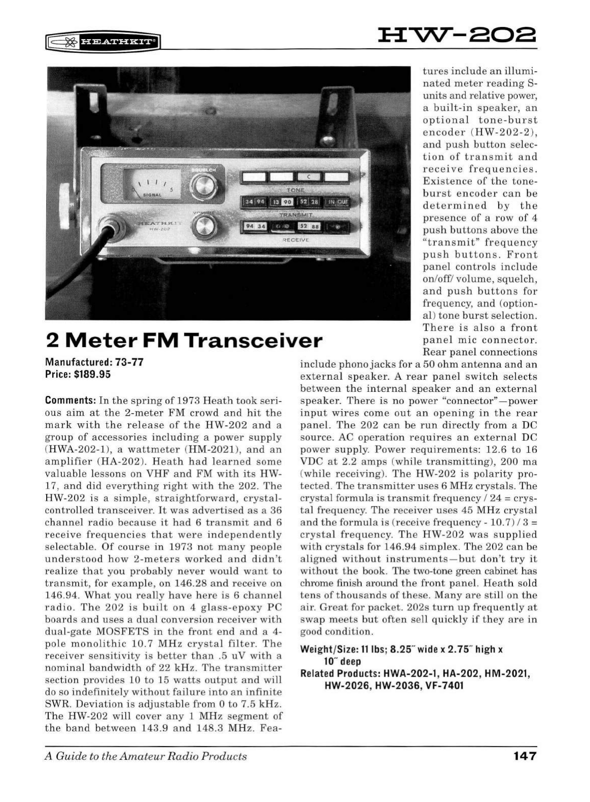
!:@
~
ff'?tSiH&iil
:a:vv--aoa
2
Meter
FM
Transceiver
tures
include
an
illumi
-
nated
meter
reading
S-
units
and
relat
ive power,
a
built
-
in
speaker,
an
optional
tone-burst
encoder
(
HW-202-2),
and
push
button
se
lec-
tion
of
transmit
and
receive
frequencies.
Existence
of
the
tone-
burst
encoder
can
be
determined
by
the
presence
of
a
row
of
4
push
buttons
above
the
"
transmit
"
frequency
push
buttons.
Front
panel
controls
include
on
/off/
volume
,
squelch,
and
push
buttons
for
frequency,
and
(option
-
al)
tone
burst
selection.
Th
ere
is
also
a
front
panel
mic
connector
.
Rear
panel
connections
Manufactured:
73-77
Price:
$189.95
Comments
:
In
the
spring
of
1973
He
ath
took
se
ri-
ous
aim
at
the
2-
meter
FM
crowd
an
d
hit
the
mark
with
the
release
of
the
HW-202
and
a
gro
up
of
accessories
including
a
power
supply
(HWA
-202-1
),
a
wattmeter
(
HM-2021
),
and
an
amplifier
(
HA-202
).
Heath
had
l
earned
some
valuab
le
l
essons
on
VHF
and
FM
with
its
HW-
17,
and
did
everything
right
with
th
e 202.
The
HW
-
202
is
a
simple,
straightforward,
crystal
-
controlled
transceiver.
It
was
advertised
as
a
36
channe
l
radio
because
it
h
ad
6
transmit
and
6
receive
frequencies
that
were
ind
epe
nd
ently
selecta
bl
e.
Of
course
in
197
3
not
many
people
understood
how
2-meters
worked
and
didn't
realize
that
you
probably
never
would
want
to
transmit,
for
example,
on
146.28
and
receive
on
14
6.94.
What
you
rea
lly
hav
e
her
e
is
6
channel
radio.
The
202
is
built
on
4 gl
ass
-
epoxy
PC
boards
and
uses
a
dual
conv
ers
ion
receiver
with
dual
-
gate
MOSFETS
in
the
front
end
and
a 4-
pole
monolithic
10
. 7
MHz
crystal
filter
.
The
receiver
sensitivity
is
bett
er
than
.5
uV
with
a
nominal
bandwidth
of
22
kHz
.
Th
e
transmitter
section
provides
10
to
15
watts
output
and
will
do so
indefinitely
without
failure
into
an
infinit
e
SWR.
Devi
ation
is
adjustab
le
from
0
to
7.5
kHz.
The
HW-202
will
cover
any
1
MHz
segment
of
the
band
between
143.9
and
148
.3
MHz
.
Fea-
A
Guide
to the
Amateur
Radio
Products
include
phono
jack
s for a
50
ohm
antenna
and
an
exter
nal
spea
ker
. A
rear
pane
l
switch
selects
between
the
int
erna
l
speaker
and
an
externa
l
speaker.
There
is
no pow
er
"connector"
-power
input
wires
come
out
an
opening
in
th
e
rear
pane
l.
The
202
can
be
run
directl
y
from
a DC
source.
AC
operation
r
eq
uir
es
an
externa
l
DC
power
supply.
Power
requirements:
12.6
to
16
VDC
at
2.2
amps
(
while
transmitting),
200
ma
(
while
receiving
).
The
HW-202
is
polarity
pro-
tected.
Th
e
transmitter
u
ses
6
MHz
crystals
.
The
crysta
l
formu
la
is
transmit
frequency
I
24
=
crys-
tal
frequency.
Th
e
rece
iv
er
uses
45
MHz
crystal
and
the
formula
is
(
receive
frequency
-10. 7) I 3 =
crystal
frequency.
The
HW-202
was
supplied
with
crystals
for
146.94
simp
lex
.
The
202
can
be
aligne
d
without
instruments-but
don
't
try
it
without
the
book.
The
two-tone
green
cabinet
has
chrome finish aro
und
the
front
pan
el.
Heath
sold
tens
of
thousands
of
these.
Many
are
still
on
the
air.
Great
for
packet
.
202s
turn
up
frequently
at
swap
me
ets
but
often
sell
quickly
if
they
are
in
good
condition.
Weight/Size:
11
lbs;
8.25"
wide
x 2. 75"
high
x
10
"
deep
Related
Products:
HWA-202-1, HA-202, HM-2021,
HW-2026, HW-2036, VF-7401
147
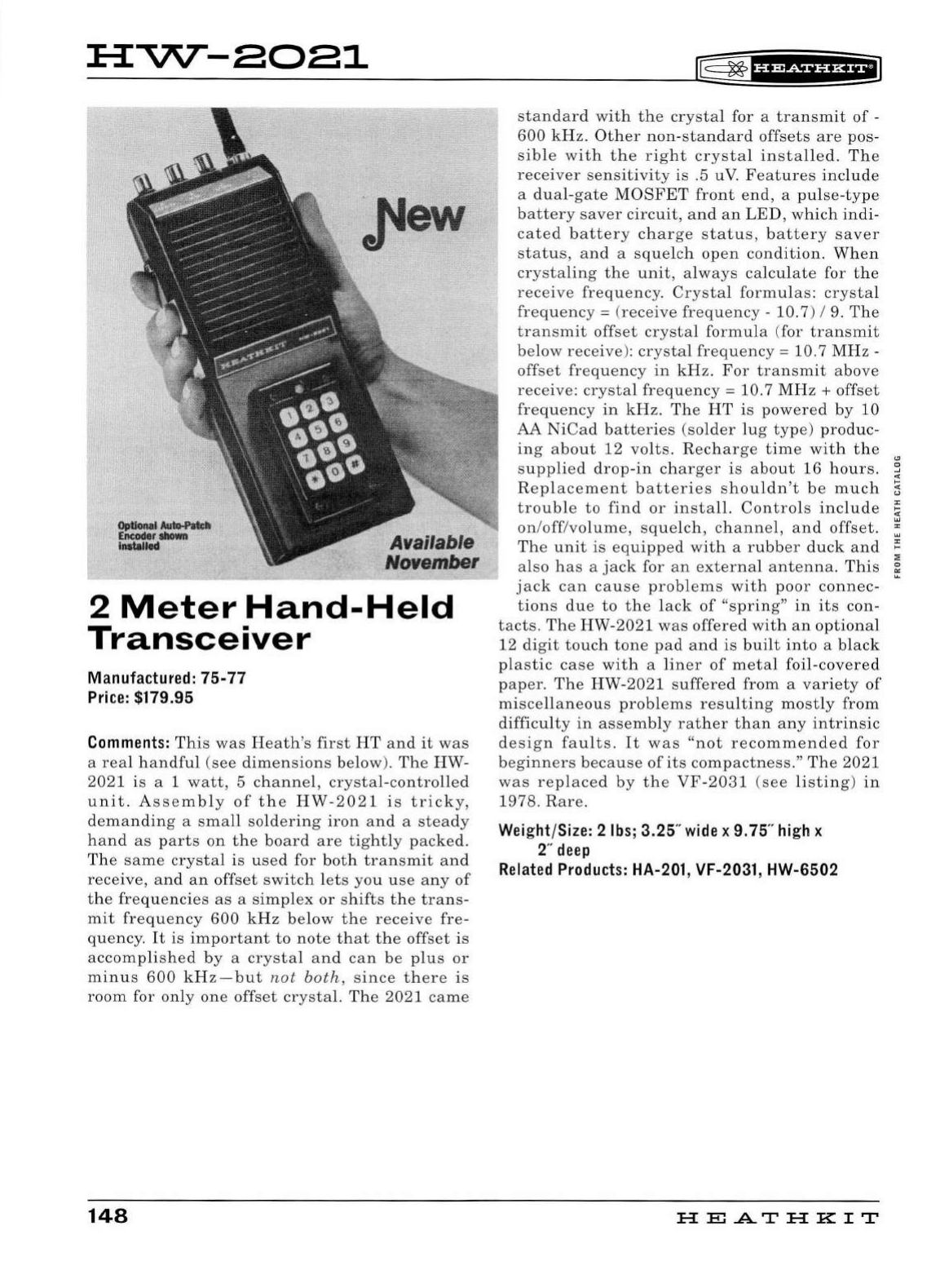
:a:vv--aoa1
Available
No'1ember
2
Meter
Hand-Held
Transceiver
Manufactured:
75-77
Price:
$179.95
Comments:
This
was
Heath
's
fir
st
HT
and
it
was
a
real
h
an
dful
(see
dim
ensio
n s
below
).
Th
e HW-
2021
is a 1
watt
, 5 c
hann
el,
crystal-controlled
unit.
Assembly
of
the
HW-2021
is
tricky,
demanding
a sm a
ll
so
ld
ering
iron
an
d a
stea
dy
hand
as
parts
on
the
bo
ard
are
tightly
packed.
Th
e
same
crystal
is
used
for bo
th
transmit
and
rece
ive
,
an
d
an
offset
switch
let s you
us
e
any
of
the
fr
eq
u
enc
ie
s
as
a
simplex
or
s
hift
s
the
trans-
mit
fr
eq
u e
ncy
600
kHz
below
t h e
receive
fre
-
quency
.
It
is
import
a
nt
to
note
th
at
the
offset
is
accomplishe
d by a
crystal
an
d
can
be
plus
or
m
inu
s
600
kH
z
-but
not
both,
si
nce
there
is
room
for
only
one
offset
crysta
l.
Th
e
2021
came
148
standar
d
with
the
crystal
for a
transmit
of
-
600
kHz.
Oth
er
non-standard
offsets
are
pos
-
s
ibl
e
wit
h
the
right
crystal
in
sta
ll
ed
.
Th
e
receiver
sensitivi
ty
is
.5 uV.
Features
include
a
du
al-
ga
te
MOSFET
front
en
d, a
pul
se
-
type
battery
save
r
circ
uit
, a
nd
an
LED
,
which
indi-
cated
battery
c
ha
rge
sta
tu
s,
battery
saver
status,
an
d a
squelch
open
condition.
When
crysta
li
ng
the
unit
, a
lwa
ys
calcu
lat
e for
the
receive
frequency
.
Crysta
l
formu
l
as:
crysta
l
freq
u
ency
= (
receive
frequency
-10.7) I 9.
Th
e
transmit
offset
crystal
formul
a (for
tr
a
nsmit
below
receive
):
crysta
l
freq
ue
ncy=
10. 7
MHz
-
offs
et
frequency
in
kHz.
Fo
r
transmit
above
receiv
e:
crysta
l
frequency=
10
.7
MHz+
offset
frequency
in
kHz
.
Th
e
HT
is
powered
by
10
AA
NiCad
b
atter
ie
s (s
older
lu
g
type
)
pr
oduc-
ing
abo
ut
12
vo
lts.
Recharge
time
with
the
"'
s
uppli
ed
drop-in
cha
rger
is
about
16
hours.
~
R
eplacement
batteries
s
houldn
't
be
much
5
trouble
to
find
or
install.
Controls
incl
ude
~
'"
on
/
off
/v
olume,
sq
uelch,
channel,
and
offset.
~
The
unit
is
equipped
wit
h a rubber duck
and
;:
:;
also h
as
a j
ack
for
an
exte
rn
al a
ntenn
a.
Thi
s
~
ja
ck
can
cause
problems
with
poor
co
nnec-
tions
due
to
the
la
ck
of
"spri
ng"
in
it
s con-
tacts.
Th
e
HW-2021
was
offered
wit
h
an
optional
12 di
git
touch
tone
pad
an
d
is
built
into
a
black
plastic
case
with
a
li
ner
of
metal
foil-cove
red
paper.
The
HW-2021
s
uff
ered
from
a
variety
of
miscellaneous
problems
res
ultin
g
mo
stly
from
difficult
y
in
assembly
rather
than
any
intrinsic
design
fa
ult
s.
It
was
"no
t r
ecommende
d
for
beginners
b
ecause
of
it
s
compactn
ess
."
Th
e 2021
was
replaced
by
the
VF
-
2031
(
see
li
sting)
in
1978
. R
are.
Weight/Size: 2
lbs;
3.25"
wide
x 9. 75"
high
x
2"
deep
Related
Products:
HA-201, VF-2031, HW-6502
HE.A.TH
KIT
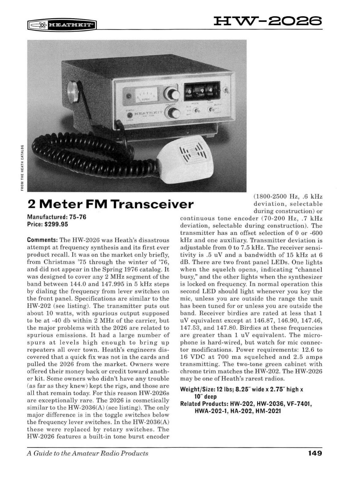
r8
~
f
Hiif
HH+il
Hvv--aoas
2
Meter
FM
Transceiver
(1800-2500
Hz,
.6
kHz
deviation,
se
l
ectab
le
during
construction)
or
Manufactured:
75-76
Price:
$299.95
Comments:
The
HW-2026
was
Heath's
disastrous
attem
pt
at
frequency
syn
th
esis
and
its
first
ever
product
recall.
It
was
on
th
e
ma
rket
on
ly briefly,
from
Christmas
'75
through
the
winter
of
'
76
,
and
did
not
ap
pea
r
in
the
Spring
1976
cata
log.
It
was
designed
to
cover
any 2
MHz
segment
of
the
band
b
etween
144
.0
an
d
147
.
995
in
5
kHz
steps
by
dialing
the
frequency
from
lever
switc
h
es
on
the
front
panel.
Specifications
are
simi
lar
to
the
HW-202
(
see
li
sting
).
Th
e
transmitter
puts
out
about
10
watts,
with
sp
u
rious
output
s
uppo
sed
to
be
at
-40
db
within
2
MHz
of
th
e
carrier,
but
the
major
problems
with
the
2026
are
re
lat
ed
to
spurio
u s
emissions
.
It
had
a
la
rge
number
of
spurs
at
levels
high
enough
to
bring
up
repeaters
all
over
town.
Heath's
engineers
dis
-
covered
that
a
quick
fix
was
not
in
the
cards
and
pulled
the
2026
from
the
market
.
Owners
were
offered
their
money
back
or
credit
toward
anoth
-
er
kit.
Some
owners
w
ho
didn't
hav
e
any
trouble
(
as
far
as
they
knew
)
kept
the
rigs
,
and
those
are
all
that
remain
today
.
For
this
reason
HW
-
2026s
are
exceptiona
lly
rare.
Th
e
2026
is
cosmetica
ll
y
simi
l
ar
to
the
HW-
2036(A) (
see
listing)
.
The
on
ly
major
difference
is
in
the
toggle
switc
he
s
below
the
frequency
lev
er
switc
hes.
In
the
HW-2036
(A)
these
were
rep
l
aced
by
rotary
switc
he
s.
The
HW-2026
features
a
built-in
tone
burst
encoder
A Guide to the
Amateur
Radio
Products
continuous
tone
encoder
(
70-200
Hz,
. 7
kHz
deviation,
se
lectable
durin
g
construction).
The
transmitter
ha
s
an
offset
se
lection
of
0
or
-
600
kHz
and
one
auxiliary
.
Transmitter
deviation
is
adjustab
le
from
0
to
7.5
kHz
.
The
receiver
sensi
-
tivity
is
.5
uV
and
a
bandwidth
of
15
kHz
at
6
dB.
Th
ere
are
two
front
panel
LED
s.
One
lights
when
th
e
sq
uelch
opens,
indicating
"ch
anne
l
busy,"
and
the
other
lights
whe
n
the
synthesizer
is
locked
on
frequency.
In
normal
operation
this
secon
d
LED
s
hould
light
whe
n
ever
you
key
the
mic,
unl
ess
you
are
outside
the
range
th
e
unit
has
been
tune
d for
or
unl
ess
you
are
outside
the
band.
Receiver
birdies
are
rated
at
le
ss
that
1
uV
eq
uiv
alent
except
at
146.87, 146.90,
147
.46,
147.53,
and
147
.80.
Birdies
at
these
frequencies
are
greater
than
1
uV
eq
ui
va
l
ent.
The
micro-
phone
is
hard-wired,
but
watch
for
mic
connec-
tor
modifications.
Power
req
uir
ements
: 12.6
to
16
VDC
at
700
ma
squelche
d
and
2.5
amps
transmitting.
Th
e
two-tone
green
cabinet
with
chrome
trim
matches
the
HW
-202.
The
HW-2026
may
be
one
of
He
ath
's
rarest
radios.
Weight/Size:
12
lbs;
8.25"
wide
x
2.
75"
high
x
10
"
deep
Related
Products:
HW-202, HW-2036, VF-7401 ,
HWA-202-1,
HA
-202, HM-2021
149
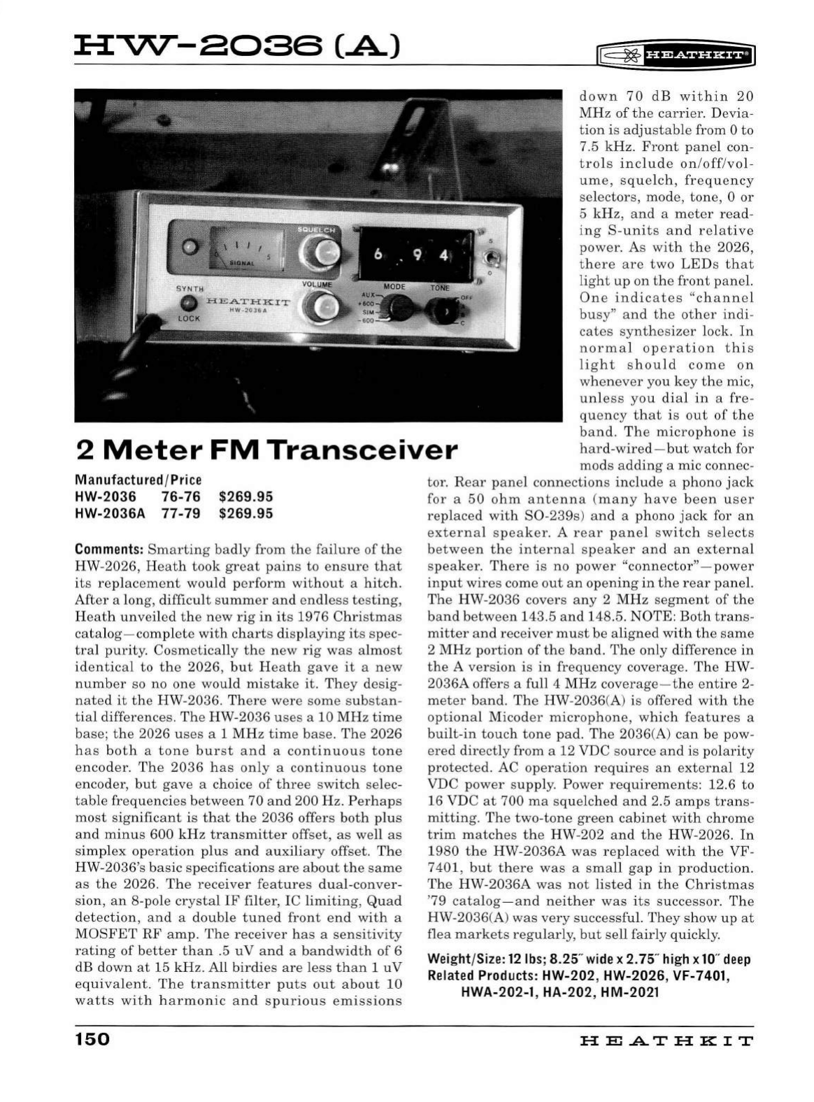
HVV--2036
(.A)
~
~
fH?&iH&+i
down
70
dB
within
20
MHz
of
the
carrier.
Devia
-
tion
is
adjustable
from 0
to
7
.5
kHz.
Front
panel
con-
trols
include
on
/
off
/
vol
-
ume
,
squelch,
frequency
selectors,
mode,
tone,
0
or
5
kHz,
and
a
meter
read-
ing
8 -
units
and
relative
power.
As
with
the
2026
,
there
are
two
LEDs
that
light
up
on
the
front
panel.
One
indicates
"channel
busy
"
and
the
other
indi-
cates
synthesizer
lock.
In
normal
operation
this
light
should
com
e
on
whenever
you
key
the
mic,
unless
you
dial
in
a
fre
-
quency
that
is
out
of
the
band.
The
microphone
is
hard-wired-but
watch
for
2
Meter
FM
Transceiver
mods
adding
a mic connec-
tor.
Rear
panel
connections
include
a
phono
jack
for
a
50
ohm
antenna
(
many
have
been
user
rep
l
aced
wit
h
S0-239s
)
and
a
phono
jack
for
an
externa
l
speak
er. A
rear
panel
switch
selects
between
the
interna
l
speaker
and
an
external
speaker.
There
is
no
power
"connector"
-power
input
wires
come
out
an
opening
in
the
rear
panel.
The
HW
-2036
covers
any
2 MHz
segment
of
the
band
between
143.5
and
148.5. NOTE:
Both
trans-
mitter
and
receiver
mu
st
be
aligned
with
the
same
2 MHz
portion
of
the
band.
The only
difference
in
the
A
version
is
in
frequency
coverage
.
The
HW
-
2036A offers a full 4
MHz
coverage
-
the
entire
2-
meter
band.
The
HW
-2036(A) is offered
with
the
optional
Micoder
microphone,
which
features
a
bu
il
t-in
touch
tone
pad.
The
2036
(A)
can
be
pow-
ered
directly
from
a 12 VDC
source
and
is
polarity
protected
. AC
operation
requ
i
res
an
external
12
VDC
power
supply
.
Power
requirements:
12.6
to
16 VDC
at
700
ma
sq
u
elched
and
2.5
amps
trans
-
mitting.
The
two-tone
green
cabinet
with
chrome
tr
im
matches
the
HW-202
and
the
HW-2026
.
In
1980
the
HW-2036A
was
rep
l
aced
with
the
VF
-
7401,
but
there
was
a
small
gap
in
production
.
The
HW-2036A
was
not
listed
in
the
Christmas
'79
cata
l
og-and
neither
was
its
successor
.
The
HW-2036(A)
was
very
successfu
l.
They
show
up
at
flea
markets
regularly
,
but
se
ll
fairly
quickly
.
Manufactur
ed
/
Price
HW-2036 76-76
HW-2036A 77-79 $269.95
$269.95
Comments
:
Smarting
badly
from
the
failure
of
the
HW-2026,
Heath
took
great
pains
to
ensure
that
its
replacement
would
perform
without
a
hitch
.
After
a
long
,
difficult
summer
and
endless
testing,
Heath
unveiled
the
new
rig
in
its
1976
Christmas
cata
l
og-complete
wit
h
charts
displaying
its
spec
-
tral
purity.
Cosmetica
ll
y
the
new
rig
was
almost
identical
to
the
2026
,
but
Heath
gave
it
a
new
number
so no one
wou
ld
mistake
it.
They
desig
-
nated
it
the
HW-2036.
There
were
some
substan
-
tial
differences.
The
HW-2036
uses
a 10
MHz
time
base;
the
2026
uses
a 1
MHz
time
base.
Th
e
2026
has
both
a
tone
burst
and
a
continuous
tone
encoder.
The
2036
has
only
a
continuous
tone
encoder,
but
gave
a choice
of
three
switch
selec-
table
frequencies
between
70
and
200
Hz
.
Perhaps
most
significant
is
that
the
2036
offers
both
pl
us
and
minus
600
kHz
transmitter
offset,
as
we
ll
as
simp
l
ex
operation
plus
and
auxiliary
offset.
The
HW-2036's
basic
specifications
are
about
the
same
as
the
2026
.
The
receiver
features
dua
l-
conver-
sion,
an
8-pole
crystal
IF filter, IC
limiting,
Qua
d
detection,
and
a
doub
le
tuned
front
end
with
a
MOSFET
RF
amp
.
The
receiver
has
a
sensitivity
rating
of
better
than
.5
uV
and
a
bandwidth
of
6
dB
down
at
15
kHz.
All
birdies
are
less
than
1 u V
equivalent
. Th e
transmitter
puts
out
about
10
watts
with
harmon
ic
and
spurious
emissions
150
Weight
/
Size:
12
lbs
; 8.25"
wide
x
2.
75"
high
x
10
"
deep
Related
Products:
HW-202, HW-2026,
VF-
7401
,
HWA-202-1 , HA-202, HM-2021
H
El
.AT
HK
IT
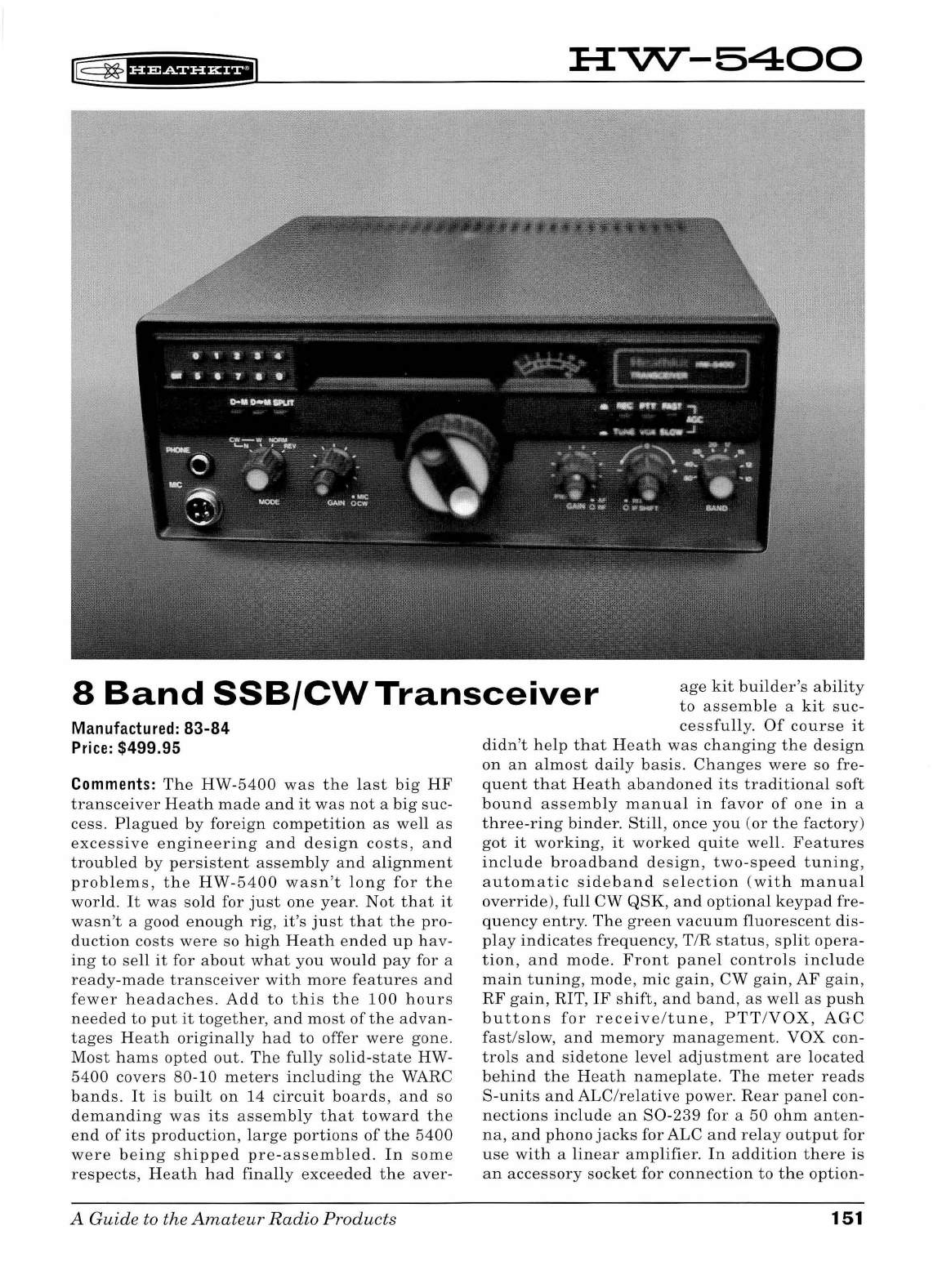
lE=
~
f
UWSiff
H+i
H-VV--5400
8
Band
SSB/CW
Transceiver
age
kit
builder's
ability
to
assemble
a
kit
sue
-
Manufactured:
83-84
Price:
$499.95
Comme
n
ts:
The
HW-5400
was
the
last
big
HF
transceiver
Heath
made
and
it
was
not
a
big
suc
-
cess.
Plagued
by
foreign
competition
as
well
as
excessive
engineering
and
design
costs,
and
troubled
by
persistent
assembly
and
alignment
problems,
the
HW
-
5400
wasn
't
long
for
the
world.
It
was
sold
for
just
one
year.
Not
that
it
wasn't
a good
enough
rig,
it's
just
that
the
pro
-
duction
costs
were
so
high
Heath
ended
up
hav-
ing
to
sell
it
for
about
what
you
would
pay
for a
ready
-
made
transceiver
with
more
features
and
fewer
headaches.
Add
to
this
the
100
hours
needed
to
put
it
together
,
and
most
of
the
advan-
tages
Heath
originally
had
to
offer
were
gone.
Most
ham
s
opted
out
.
The
fully
solid-state
HW-
5400
covers
80-10
me
ters
including
the
WARC
bands.
It
is
built
on
14
circuit
boards,
and
so
demanding
was
its
assembly
that
toward
the
end
of
its
production,
large
portions
of
the
5400
were
being
shipped
pre
-
assembled
.
In
some
respects,
Heath
had
finally
exceeded
the
aver-
A Guide to the
Amateur
Radio
Products
cessfully.
Of
course
it
didn't
help
that
Heath
was
changing
the
design
on
an
almost
daily
basis.
Changes
were
so fre-
quent
that
Heath
abandoned
its
traditional
soft
bound
assembly
manual
in
favor
of
one
in
a
three-ring
binder.
Still
,
once
you
(
or
the
factory)
got
it
working,
it
worked
quite
well.
Features
include
broadband
design,
two-speed
tuning,
automatic
sideband
selection
(with
manual
override),
full
CW
QSK,
and
optional
keypad
fre-
quency
entry.
The
green
vacuum
fluorescent
dis-
play
indicates
frequency
, T/R
status
,
split
opera-
tion
,
and
mode.
Front
panel
controls
include
main
tuning,
mode
,
mic
gain,
CW
gain,
AF
gain,
RF
gain,
RIT,
IF
shift,
and
band
,
as
well
as
push
buttons
for
receive
/
tune,
PTT
/
VOX,
AGC
fast
/slow,
and
memory
managem
e
nt.
VOX con-
trols
and
sidetone
level
adjustment
are
located
behind
th
e
Heath
nam
e
plate.
The
meter
reads
S-units
and
ALC/
relative
power.
Rear
panel
con-
nections
include
an
S0
-
239
for a 50
ohm
anten-
na,
and
phono
jacks
for ALC
and
relay
output
for
use
with
a
linear
amplifier.
In
addition
there
is
an
accessory
socket
for
connection
to
the
option-
151
al
HWA-5400-1
power
supply
/
speaker
.
This
very
inconvenient
connector
provides
audio
to
a
speaker
,
serves
as
a
power
input
for
memory
back-up,
and
has
"an
essential
sensor
line
for
proper
operation
and
remote
on/off
switching
at
the
radio."
There
is
also
a
connector
for
DC
power
input.
A
rear
pan
el
sw
itch
disables
the
linear
relay
for
more
quiet
operation
when
not
using
an
amplifier.
The
HW-5400
uses
an
optica
l
encoder
type
tuning
scheme.
In
add
ition
,
the
main
tuning
knob
is
fitted
wit
h a
metal
insert
in
one
of
its
two
finger
indents.
Touching
this
indent
causes
the
rece
iv
er
to
tune
in
1
kHz
steps
instead
of
the
normal
50
Hz
steps-very
clever.
Heath
patented
the
idea.
Receiver
sensitivity
is
better
than
.
35
u
V.
Selectivity
with
standard
fil-
ter
is
2
kHz
at
6 dB
down
.
With
optional
SSB
fil-
ter
se
l
ectivity
is
1.8
kHz
at
6
dB
down
.
CW
active
audio
filter
is
250
Hz
at
6 dB
down
cen
-
tered
at
700
Hz.
Overall
stability
is
less
than
50
ppm
drift
from
turn
-on.
Numerous
weak
"
birdies"
and
other
miscellaneous
strange
noises
are
down
far
enough
that
they
should
not
get
in
your
way.
Transmitter
output
power
is
100
watts
PEP
and
CW
minim
um
except
on
10
meters,
which
is
80
watts
minimum.
Power
output
is
continuous
ly
variab
le.
The
PA
transistors
are
thermally
protected
against
hi
gh
SWR
and
wi
ll
deliver
90
percent
of
the
rated
power
with
an
SWR
of
less
than
2:1.
Early
units
had
real
prob-
l
ems
with
the
CW
wave
shape
and
l
ength.
Not
only
was
the
rise
time
abrupt,
but
the
transmit-
ter
took
a
full
26
mi
lli
seconds
to
shut
off
upon
key
up.
This
made
CW
spee
ds
at
or
above
20
WPM
impossib
le.
Heath
wou
ld
supp
ly a fix for
this
problem
to
anyone
who
asked
and
incorpo-
rated
a
permanent
fix
into
la
ter
units.
Whether
or
not
the
unit
you
'
re
lo
oking
at
has
this
prob-
lem
is
impossible
to
say
with
only
visua
l
inspec-
tion.
Missing
is
a
way
to
shut
off
the
AGC.
In
the
end,
Heath
realized
the
HW-5400
was
too
com
-
plicated
and
too
expensive
given
fierce
competi-
tion
from
other
ready
-m
ade
rigs.
They
pulled
it
from
production
and
cut
their
loses
saying,
in
effect,
"enoug
h
is
eno
u
gh."
H
eath
lost
a l
ot
of
money
on
this
5400
and
vowed
never
to
do
it
again.
The
5400
requires
a
frequency
counter
and
a VOM
or
VTVM
with
an
RF
probe
for
align
-
ment.
Power
requirements:
13.8
VDC
nominal
at
20
amps
(transmit).
Requires
an
externa
l
power
supply.
Two-tone
brown
cabinet
.
Rare
.
Weight/Size: 24
lbs;
11.5"
wide
x
5"
high
x
14
"
deep
Related
Products:
HWA-5400-1
152
®
~fHBSif'Hil
HE
.AT
HK
IT
~
~fH?&iHHi#l
2
Meter
Hand-Held
Transceiver
Manufactured: 85-86
Price:
$199.95
Comments:
The
HW-6502
is
a
fully
assembled
HT
and
was
Heath's
last
2-m
e
ter
product.
Buckling
under
the
weight
of
economic
reality,
foreign
competition,
and
a
changing
consumer
market,
Heath
pulled
out
of
the
two-meter
competition
in
1986
and
never
came
back-at
l
east
not
with
its
own
radios.
The
HW-6502
includes
a
built-in
CTCSS
encoder
with
all
availab
le
frequencies.
Features
include
an
S/
battery
meter,
se
l
ectab
le
5
watt,
1.5
watt,
and
300
mW
power
output
lev-
el
s,
and
thumbwheel
frequency
se
l
ectio
n
with
+5
kHz
and
±600
kHz
offset
switches.
Frequency
range
is
1
44.0
to
147.995
MHz
.
Sensitivity
is
.25
uV.
OPT
IO
NAL
speaker
/
mic
avai
l
able.
H
eat
h
a
lso
offered
the
HW-6502
with
an
OPTIONAL
"M
obil
e
Console."
Design
ed for
mobile
installa-
tion,
this
fully
assemb
l
ed
console
had
a
opening
A Guide to
th
e
Amateur
Radio
Produ
cts
HVV-6502
into
which
the
HT
could
be
ins
er
ted
.
Cab
l
es
from
the
console
provid
ed
power
and
antenna
connec
-
tion
s.
The
console,
in
turn,
was
avai
l
able
wit
h
an
OPTIONAL
25
watt
a
mplifier.
The
HW-
6502
and
its
companion
Mobile
Conso
le
were
sold
for
just
over
a
year;
this
was
Heath
's l
ast
attempt
at
se
ll
ing
its
own
HT
s.
The
HTs
that
followed-the
HWS-2
(4)(XL)
series-were
made
for
Heath
by
Standard
and
are
not
listed
in
this
book
.
The
6502
and
conso
le
are
very
rare.
Weight/Size: 1
lb;
size
not
available
Related
Products:
HW-2021, VF-2031
153
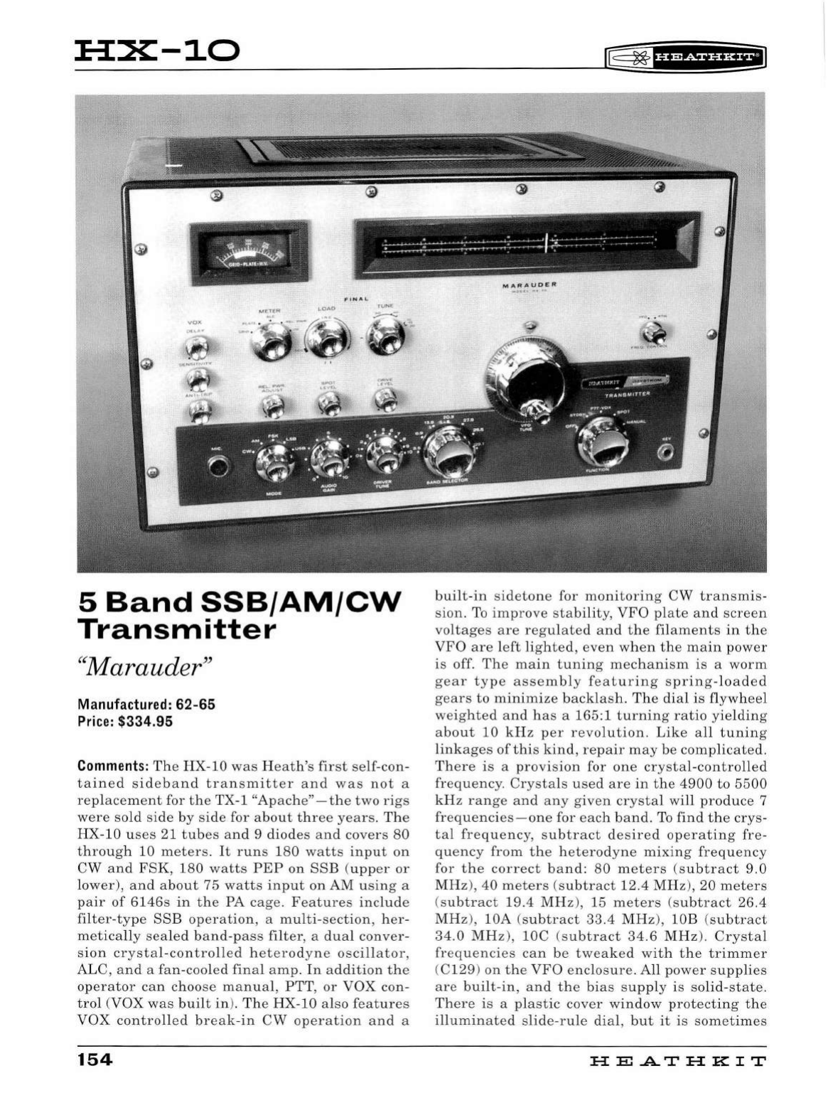
HX-10
iE=
~
'H?diU&il
. -
-
--~
~
-.
~
!
E=:::::i.~···~··-~~:::-_.::.:.:
f
*:·:··.:·"'"
.. : . . '
----
JU
N
!!
5
Band
SSB/AM/CW
Transmitter
"7' IT d "
1narau er
Manufactured:
62-65
Price: $
334
.
95
Comments:
The
HX-10
was
H
ea
th
's
fir
st
se
lf-con-
tained
sideband
tran
s
mitt
er
and
wa
s
not
a
replacem
ent
for
the
TX-1 "Ap
ac
he
"
-the
two
rig
s
were
s
old
s
ide
by
s
ide
for
about
thr
ee
years.
The
HX
-
10
u
ses
21
tubes
and
9
diodes
an
d
co
ve
rs
80
through
10
met
ers
.
It
runs
180
watts
input
on
CW a
nd
FSK,
180
watt
s
PEP
on
SSE
(
upp
er
or
low
er),
and
a
bout
75
watts
input
on AM u
si
ng a
pair
of
6146s
in
t
he
PA
cage.
Fe
at
ur
es
includ
e
filt
er
-
typ
e
SSE
operation,
a
multi-
sect
ion
, h
er
-
me
ti
ca
ll
y
sea
led
band-p
ass
filter
, a
dual
conver
-
s
ion
crystal-controlled
h
etero
d
yne oscillator,
ALC,
and
a
fan-cooled
final
a
mp.
In
a
ddition
the
op
era
tor
ca
n
choose
ma
nu
al,
PTT
,
or
VOX con-
trol
(VOX
was
built
in
).
Th
e
HX
-10
also
features
VOX
contro
ll
ed
break
-
in
CW
op
erat
ion
an
d a
154
!'Y'IARAUO£A'
..
:>11
• ~
..
.
..
-..
......
built
-
in
s
ideton
e
for
monitoring
CW
tran
s
mi
s-
sion.
To
improve
s
tability
,
VFO
pl
ate
and
sc
re
en
voltages
are
r
eg
ul
ated
a
nd
the
fila
ments
in
th
e
VFO
ar
e le
ft
li
g
ht
ed,
eve
n
when
the
main
pow
er
is off.
Th
e
main
tuning
mechanism
is
a w
orm
gear
t yp e
assembly
featuring
s
prin
g-
load
ed
gears
to
minimize
backlash.
The
dial
is
flywh
ee
l
weighted
a
nd
has
a 165:1
turning
ratio
yie
l
din
g
abo
ut
10
kH z p
er
revo
l
ution.
Like
all
tunin
g
link
a
ges
of
thi
s
kind
,
repair
may
be c
omplicat
ed.
Th
ere
is a
pro
vis
ion
for
on
e
cr
ysta
l-
contro
ll
ed
frequency
.
Cry
sta
ls
u
se
d
are
in
the
4900
to
5500
kHz
range
and any
give
n
crystal
w
ill
produc
e 7
frequencies-one
for
eac
h ba
nd
.
To
find
the
cr
ys
-
t al
frequ
ency, s
ubtr
act
d
es
ired
operating
fr
e-
quency
from
the
h
etero
d
yne
mi
xing
fr
eq
u
ency
for
the
correc
t
band:
80
meters
(s
ubtr
a
ct
9.0
MH
z),
40
meters
(su
btract
12.4
MHz
),
20
meters
(s
ubtract
19.4
MHz
),
15
meters
(s
ubtract
26.4
MHz),
lOA (s
ubt
ract
33.4
MHz)
,
lOE
(s
ubtr
act
34.0
MHz)
, lOC (s
ubt
ract
34.
6
MHz)
.
Crystal
frequencies
can
be
tweak
ed
with
the
trimmer
(C 129)
on
the
VFO
enclos
u
re.
All
pow
er
su
ppli
es
are
built-in,
and
the
bias
s
upply
is solid-s
tat
e.
Th
ere
is
a
plastic
cover
window
protecting
the
illuminated
s
lid
e-
rule
dial,
but
it
is
somet
im
es
HE.ATHKIT
[[
~
1
H&ifi&E*1
found
to
be mi
ssing
in
u
nits
picke
d up
at
fl
ea
markets.
Care
m
ust
be
ta
k
en
not
to
damage
th e
dia
l
marki
n
gs
or
the
pointer.
Every
contro
l
need-
ed
for
norma
l
operation
is
avai
l
able
on
the
front
panel.
Th
ese
contro
ls
in
cl
ude
the
mode
switc
h ,
audio
gain,
dr
i
ver
tune
,
band
se
lector,
main
tun-
ing
(note
that
th e
main
tu
ning
kno
b h
as
a
0-100
sca
le
on
it
),
frequency
contro
l (VFO
or
XTAL),
drive
l
eve
l,
spot
l
eve
l,
meter
function,
fina
l
load,
fina
l
tune,
and
controls
for VOX
operation.
The
front
panel
also
has
a mic
connector
and
a
key
jack.
There
is
a
control
on
the
rear
apron
of
the
HX-10 for
adjustment
of
the
scope
monitor
level.
Rear
pane
l
connectors
include
an
S0
-
239
for a
50-75
ohm
antenna,
a
phono
jack
for
spotting
signa
l
output,
a ph
ono
j
ack
for
phone
patch
input,
a
quarter
inch
jack
for
FSK
keyboard
input,
a
120
VAC
power
recep
t
acle
(switched),
a
ground
post,
and
an
octa
l
accessory
socket.
Th
is
socket
provides
connections
for
rece
i
ver
muting,
external
amp
li
fier
cutoff
bias,
connec
t
ions
to
receiver
audio
,
and
power
for a
120
VAC
exter-
na
l
relay
.
There
is
al
so
a ph
ono
jack
for
monitor-
ing
the
RF
wit
h
an
oscilloscope.
For
use
with
120
VAC
50
/
60
Hz
on
l
y.
Two-tone
green
finis
h wi
th
polis
h
ed
ch
rome
knobs.
This
was
the
l
ast
rig
Heat
h
made
in
the
"
big
/
heavy
"
style
. Cl
ean
HX-
l
Os
in
good cond
ition
are
medi
um
rare
.
Weight/Size: 92
lbs;
19
"
wide
x
11.5
"
high
x
16
"
deep
Related
Products:
TX-1,
RX-1,
HA-10
A
Guide
to the
Amateur
Radio
Pr
oducts
155
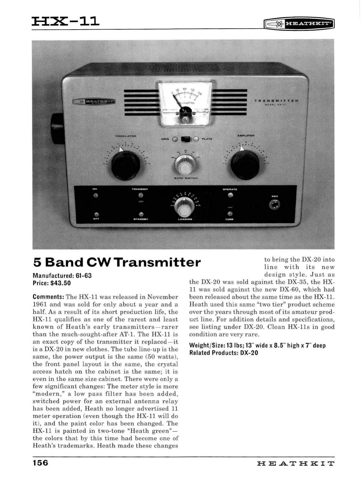
HX-11
!"§:
~
f
H+Sii'HflJ
TRA!'f•llllTT•l'l
wocua
.
·
•Ot
~
111
5
Band
CW
Transmitter
to
bring
the
DX-20
into
lin
e
with
its
new
Manufactured: 61-63
Price:
$43.50
Comments:
The
HX-11
was
released
in
November
1961
an
d
was
so
ld
for
only
about
a
year
and
a
half.
As
a
res
ult
of
it
s s
hort
production
lif
e,
the
HX
-11
qualifies
as
one
of
the
rarest
and
le
ast
known
of
Heath's
early
transmitters
-
rarer
than
the
much-sought
-
after
AT-1.
The
HX-11
is
an
exact
copy
of
the
transmitter
it
replaced-it
is
a DX-20
in
new
clothes.
The
tube
line
-
up
is
the
sa
me
,
the
power
output
is
the
same
(
50
watts),
the
front
panel
l
ayout
is
the
same,
the
crysta
l
access
hatch
on
the
ca
bin
et
is
the
same;
it
is
even
in
the
same
size
cabinet.
There
were
only
a
few
sign
ific
ant
changes
:
Th
e
meter
sty
le
is
more
"
modern,"
a
low
pass
filter
has
been
ad
d
ed,
switche
d
power
for
an
external
antenna
relay
h
as
been
added,
Heath
no
lon
ger
advertise
d
11
meter
operation
(even
though
the
HX-11
will
do
it),
and
the
paint
color
has
been
changed.
The
HX-11
is
painted
in
two
-
tone
"Heath
green"
-
the
co
lors
that
by
this
time
had
become
one
of
Heath's
trademarks.
Heath
mad
e
these
changes
156
design
style.
Just
as
the
DX-20
was
so
ld
against
the
DX-
35,
the
HX-
11
was
sold
against
the
new
DX-60,
which
had
been
released
about
the
same
time
as
the
HX-11.
Heath
used
this
same
"two
tier"
product
scheme
over
the
years
through
most
of
its
amateur
prod
-
uct
line.
For
addition
d
etai
ls
an
d
spe
cifications,
see
listing
und
er
DX-20.
Clean
HX-lls
in
good
condition
are
very
rare.
Weight/Size:
13
lbs;
13
"
wide
x 8.5"
high
x T
deep
Related
Products:
DX-20
FIE
AT
FI
KIT
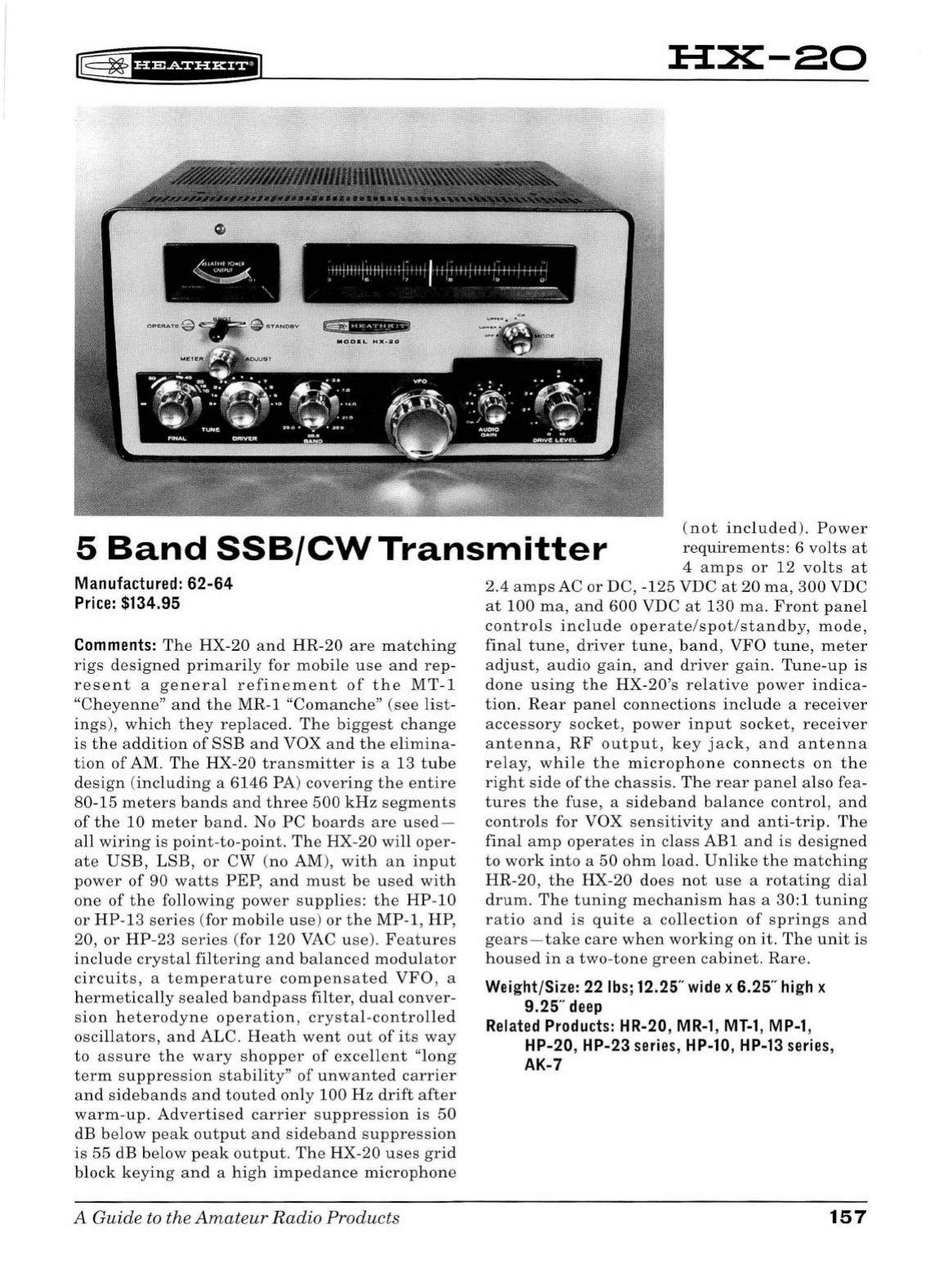
~
~
H'*Sf
Hi*fi
HX-80
. -
···1H
..
1+tft11•
·: .: ..
1.
,
t1•·111·ttd~-~~.,_,_._,
,
I~
7 1a g o
---~
-
~
"ii''
'"f
'
'*
5
Band
SSB/CWTransmitter
(not
included).
Power
requirements:
6
volts
at
4
amps
or
12
volts
at
Manufactured:
62-64
Price:
$134.95
Comments:
T
he
HX-20
and
HR-20
are
matching
rigs
designed
primari
ly for
mobile
use
and
rep-
resent
a
general
refinement
of
the
MT-1
"Cheyenne"
and
the
MR-1
"Comanche"
(see
list
-
ings
),
which
they
rep
l
aced.
The
biggest
change
is
the
ad
d
ition
of
SSB
and
VOX
and
the
elimina
-
tion
of
AM
.
The
HX-20
transmitter
is
a 13
tube
design
(
including
a
6146
PA)
covering
the
entire
80
-15
meters
bands
and
three
500
kHz
segments
of
th e
10
meter
band.
No
PC
boards
are
used-
a
ll
wiring
is
point-to
-
point.
The
HX
-
20
wi
ll
oper
-
ate
USB,
LSB,
or
CW
(no AM),
with
an
input
power
of
90
watts
PEP,
and
must
be
used
with
one
of
the
following
power
supplies
:
the
HP-10
or
HP
-13
series
(for
mobile
u
se)
or
the
MP-1,
HP,
20,
or
HP-23
series
(for
120
VAC
use).
Features
include
crysta
l
filtering
and
balanced
modulator
circuits,
a
temperature
compensated
VFO
, a
hermetically
sealed
bandpass
filter,
dua
l
conve
r-
s
ion
heterodyne
operation,
crystal
-
controlled
oscillators,
and
ALC.
Heath
went
out
of
its
way
to
assure
the
wary
shopper
of
excelle
nt
"long
term
suppression
stability"
of
unwanted
carrier
and
sidebands
and
touted
only
100
Hz
drift
after
warm-up.
Advertised
carrier
suppression
is
50
dB
below
peak
output
and
sideband
suppression
is
55
dB
below
peak
ou
tput
.
The
HX-20
uses
grid
block
keying
and
a
high
impedance
microphone
A Guide to the
Amateur
Radio
Products
2.4
amps
AC
or
DC, -
125
VDC
at
20
ma,
300
VDC
at
100
ma,
and
600
VDC
at
130
ma.
Front
panel
controls
include
operate
/
spot
/
standby,
mode
,
final
tune,
driver
t u
ne,
band,
VFO
tune,
meter
adjust,
audio
gain,
and
driver
gain.
Tune-up
is
done
u
sing
the
HX
-
20
's
relative
power
indica-
tion.
Rear
pa
n
el
connections
include
a
receiver
accessory
socket,
power
input
socket,
receiver
antenna,
RF
output,
key
jack,
and
antenna
relay,
while
the
mi
crop
h
one
connects
on
the
right
side
of
the
chassis.
The
rear
panel
also
fea-
tures
t he
fuse,
a
si
d
eband
bala
nce
contro
l,
and
controls
for VOX
sensitiv
i
ty
and
anti
-
trip
.
The
final
amp
operates
in
class
ABl
and
is
designed
to
work
into
a
50
ohm
load
.
Unlike
th
e
matching
HR-20,
the
HX-20
does
not
use
a
rotating
dial
drum.
The
tuning
mechanism
has
a 30:1
tuning
ratio
and
is
quite
a
collection
of
spr
i
ngs
and
gears-take
care
when
working
on
it.
The
unit
is
housed
in
a
two-tone
green
cabinet
.
Rare
.
Weight/Size: 22
lbs
; 12.25"
wide
x 6.25"
high
x
9.25"
deep
Related
Products:
HR-20,
MR-1
,
MT-1
,
MP-1
,
HP-20, HP-23
series
,
HP-10
,
HP-13
series
,
AK-7
157
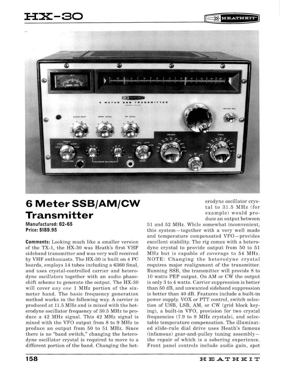
HX-80
6
Meter
SSB/AM/CW
Transmitter
Manufactured:
62-65
Price:
$189.95
Comments
:
Looking
much
like
a
smaller
version
of
the
TX-1,
the
HX
-
30
was
Heath's
first
VHF
sideband
transmitter
and
was
very
well
received
by
VHF
enthusiasts
. Th e
HX-30
is
bui
lt
on
4
PC
boards,
employs
14
tubes
including
a
6360
final
,
an
d
uses
crystal-contro
ll
ed
carrier
and
hetero
-
dyne
oscillators
together
with
an
audio
phase
-
s
hift
scheme
to
generate
the
output
.
The
HX-30
will
cover
any
one
1
MHz
portion
of
the
six
-
meter
band
.
The
basic
frequency
generation
me
t
hod
works
in
the
fo
ll
owing
way. A
carrier
is
pro
d
uced
at
11.5
MHz
and
is
mixed
with
the
het
-
erodyne
oscillator
frequency
of
30.5
MHz
to
pro
-
duce
a
42
MHz
signal.
This
42
MHz
signal
is
mixed
with
the
VFO
ou
tput
from
8
to
9 MHz
to
produce
an
output
from
50
to
51
MHz.
Since
there
is
no
"
band
switch,"
ch
anging
the
hetero
-
dyne
oscillator
crystal
is
required
to
move
to
a
different
port
i
on
of
the
band.
Changing
the
h
et
-
158
IE=
~
f§fdf§fi*il
erodyne
osc
ill
ator
crys
-
tal
to
31.
5
MHz
(
for
examp
l
e)
would
pro-
duce
an
output
between
51
and
52
MHz
.
While
somewhat
inconvenient,
this
system-together
with
a
very
well
made
and
temperature
compensated
VFO-provides
exce
ll
ent
stability.
The
rig
comes
with
a
hetero-
dyne
crysta
l
to
p
rovide
output
from
50
to
51
MHz
but
is
capab
le
of
coverage
to
54
MHz
.
NOTE:
Changing
the
heterodyne
crystal
requires
major
realignment
of
the
transmitter.
Running
SSB,
the
tran
s
mitter
will
provide
8
to
10
watts
PEP
output.
On
AM
or
CW
the
ou
tput
is
on
ly 3
to
4
watts.
Carrier
suppression
is
better
than
50
dB,
and
unwanted
sideband
su
ppression
is
better
than
40
dB.
Features
include
a
bu
i
lt
-
in
power
supp
ly, VOX
or
PTT
control,
switch
se
lec-
tion
of
USB,
LS
B, AM,
or
CW
(grid
block
key
-
ing)
, a
built-in
VFO,
provision
for
two
crysta
l
frequencies
(7.9
to
9
MHz
crystals
),
and
se
lec-
tab
le
temperature
compensation
.
The
illuminat
-
ed
slide-ru
le
dia
l
drive
uses
H
eat
h's
famous
(
infamous
)
gear-and-pulley
tuning
as
se
mbly-
the
repair
of
which
is
a
sober
i
ng
experience
.
Front
pane
l
controls
i
nclude
audio
gain,
spot
HE
.AT
HK
IT
r@
~u•+SiU&EiJ
level,
RF
level,
function,
carrier
balance,
mode,
driver
tune,
final
tune,
frequency
control,
meter
adjust,
and
main
tuning,
while
the
output
load-
ing
and
coupling
controls
are
inconveniently
placed
inside
the
cabinet.
Also
on
the
front
panel
are
the
mic
and
k
ey
jacks
and
a
red
panel
light
that
indicates
"on
air"
status.
Controls
for
the
ad
justment
of
VOX
and
bias
are
located
on
the
rear
apron
along
with
an
S0
-
239
for a
50
-75
ohm
a
ntenna,
a
gro
und
post
,
and
an
11
pin
"oc
tal
sty
le
"
accessory
soc
k
et.
Pin
s
on
this
socket
include
four
sets
of
contacts
that
open
or
close
with
transmit,
a
switched
117 VAC
output
for
use
with
an
antenna
relay,
and
a
chassis
ground
.
Alignment
of
th
e
HX-30
required
a
VTVM,
a
dummy
load
, a
scope
, a
sine
wave
audio
genera
-
tor
,
and
a
frequency
meter.
All
things
consid-
e
red,
the
HX-30
was
a
very
well
-de
signed
trans-
mitter
and
produces
a
clean,
sta
ble
sig
nal
with
great
audio
and
soli
d
CW.
The
unit
is
en
clo
sed
in
a
copper-clad
st
eel
cabinet
and
wears
H
eat
h's
"official"
colors-two
-
tone
green.
The
knobs
are
polished
aluminum,
as
opposed
to
the
bru
shed
al
uminum
knobs
used
on
the
VHF-1.
Also
note
that
the
main
tuning
knob
is
a "s
pinner
knob."
The
HX
-
30
is
de
signed
for
120
VAC,
50/60
Hz
operation.
Rare
in
good
con
dition.
Weight/Size: 46
lbs;
16.5"
wide
x
10
"
high
x
10"
deep
Related
Products:
VHF-1
, HA-20
A Guide to the
Amateur
Radio
Products
159
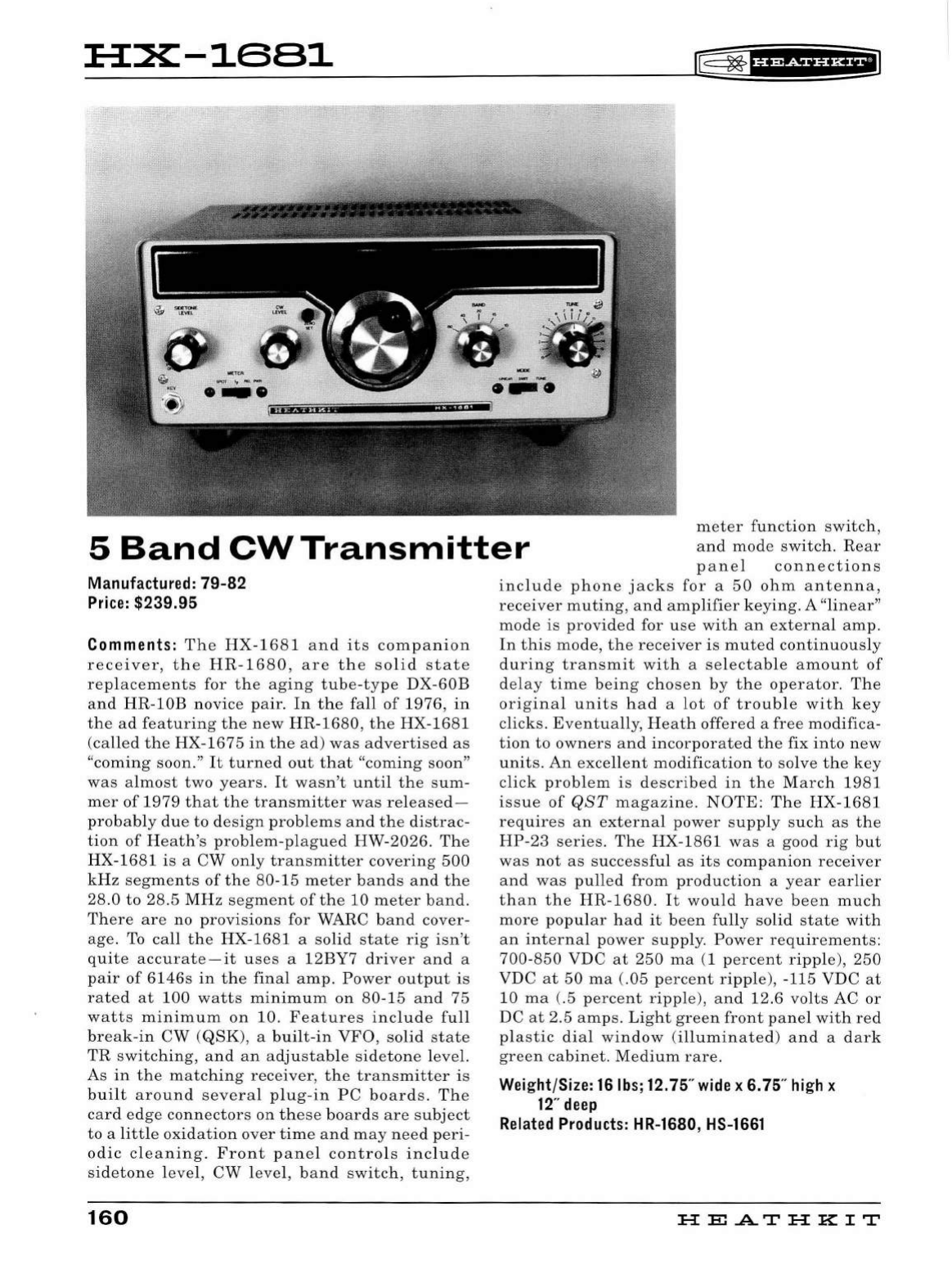
:a:x~1ss1
IE=~
f
if
P§f
§f
Hii
5
Band
CW
Transmitter
meter
function
switch,
and
mode
switch.
Rear
panel
connections
Manufactured:
79-82
Price:
$239.95
Comments:
The
HX-1681
and
its
companion
receiver,
the
HR-1680,
are
the
solid
state
replacements
for
the
aging
tube-type
DX-60B
and
HR-lOB
novice
pair.
In
the
fall
of
1976,
in
the
ad
featuring
the
new
HR-1680,
the
HX-1681
(called
the
HX-1675
in
the
ad)
was
advertised
as
"coming
soon."
It
turned
out
that
"coming
soon"
was
almost
two
years
.
It
wasn't
until
the
sum-
mer
of
1979
that
the
transmitter
was
released-
probably
due
to
design
problems
and
the
distrac-
tion
of
Heath's
problem-plagued
HW-2026.
The
HX-1681
is
a
CW
only
transmitter
covering
500
kHz
segments
of
the
80-15
meter
bands
and
the
28.0
to
28.5
MHz
segment
of
the
10
meter
band
.
There
are
no
provisions
for WARC
band
cover
-
age.
To
call
the
HX-1681
a
solid
state
rig
isn't
quite
accurate-it
uses
a
12BY7
driver
and
a
pair
of
6146s
in
the
final
amp.
Power
output
is
rated
at
100
watts
minimum
on
80
-15
and
75
watts
minimum
on
10.
Features
include
full
break-in
CW
(QSK), a
built-in
VFO,
solid
state
TR
switching,
and
an
adjustable
sidetone
level.
As
in
the
matching
receiver,
the
transmitter
is
built
around
several
plug-in
PC
boards.
The
card
edge
connectors
on
these
boards
are
subject
to
a
little
oxidation
over
time
and
may
need
peri-
odic
cleaning.
Front
panel
contro
ls
include
sidetone
level,
CW
level,
band
switch,
tuning,
160
include
phone
jacks
for
a
50
ohm
antenna,
receiver
muting,
and
amplifier
keying.
A
"linear"
mode
is
provided
for
use
with
an
external
amp.
In
this
mode,
the
receiver
is
muted
continuously
during
transmit
with
a
selectable
amount
of
delay
time
being
chosen
by
the
operator.
The
original
units
had
a
lot
of
trouble with
key
clicks.
Eventually,
Heath
offered
a
free
modifica-
tion
to
owners
and
incorporated
the
fix
into
new
units.
An
excellent
modification
to
solve
the
key
click
problem
is
described
in
the
March
1981
issue
of
QST
magazine.
NOTE:
The
HX-1681
requires
an
external
power
supply
such
as
the
HP-23
series.
The
HX-1861
was
a good
rig
but
was
not
as
successful
as
its
companion
receiver
and
was
pulled
from
production
a
year
earlier
than
the
HR-1680.
It
would
have
been
much
more
popular
had
it
been
fully
solid
state
with
an
internal
power
supply.
Power
requirements:
700-850
VDC
at
250
ma
(1
percent
ripple),
250
VDC
at
50
ma
(.05
percent
ripple),
-115
VDC
at
10
ma
(.5
percent
ripple),
and
12.6
volts
AC
or
DC
at
2.5
amps.
Light
green
front
panel
with
red
plastic
dial
window
(illuminated)
and
a
dark
green
cabinet.
Medium
rare.
Weight/Size: 16lbs;12.75"
wide
x 6.75"
high
x
12"
deep
Related
Products:
HR-1680,
HS-1661
H
El.A.TH
KIT
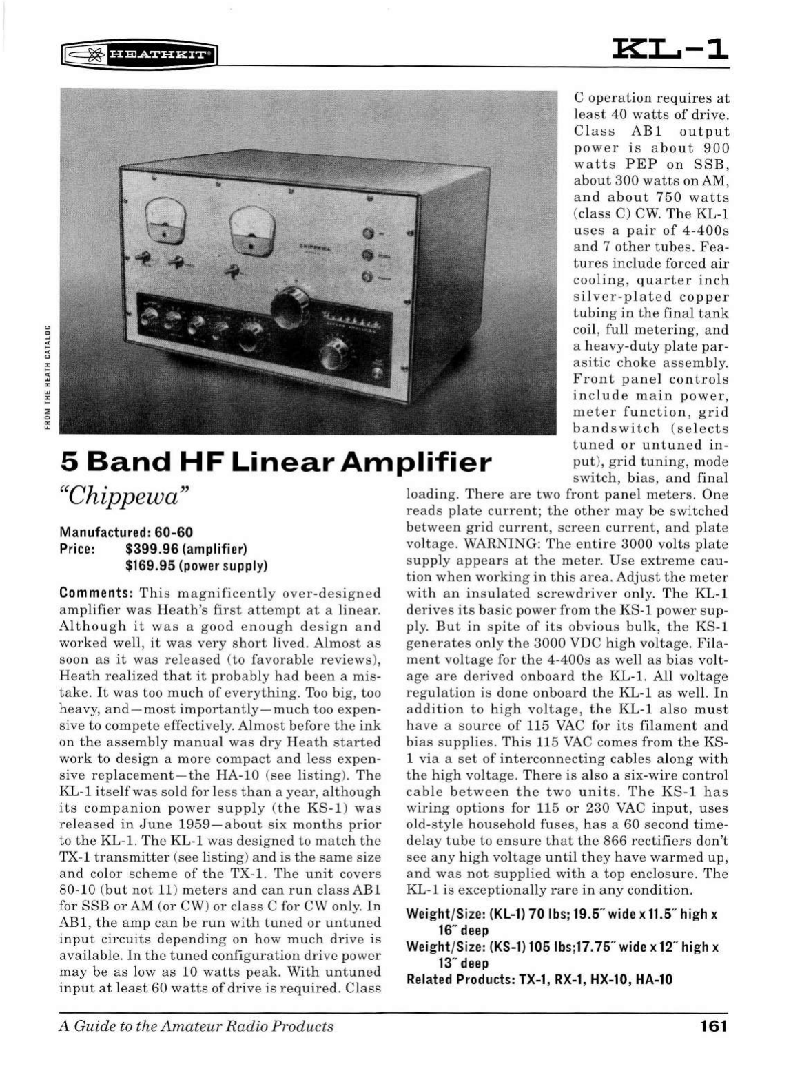
~
~tH+SiHi*fil
KL-1
5
Band
HF
Linear
Amplifier
C
operation
requires
at
lea
st
40
watts
of
drive.
C
la
ss
ABl
output
power
is
about
900
watts
PEP
on
SS
B ,
abo
ut
30
0
watts
on
AM,
and
about
750
watts
(
cla
ss
C)
CW.
Th
e KL-1
uses
a
pair
of
4-400s
an
d 7
other
t
ub
es.
Fea-
tures
includ
e
forced
air
cooling
,
quarter
inch
si
l
ver
-pl
ate
d
copper
tubing
in
the
final
tank
co
il
,
full
metering
,
and
a h
eavy-
du
ty
plate
par-
as
iti
c c
hok
e
assemb
ly.
Front
pan
el
con
tro
l s
include
m
ain
power,
meter
function
,
grid
bandswitch
(se
l
ec
t s
t
un
ed
or
untun
ed
in-
put),
gr
id
tuning,
mo
de
sw
i
tch,
bi
as,
and
fi
nal
"Chippewa"
Manufactured:
60-60
Price:
$399.96
(amplifier)
$169.95 (power supply)
Comments:
This
mag
ni
ficent
ly
over-designed
am
pli
fier
was
H
eath's
first
attempt
at
a
lin
ea
r.
A
lth
oug
h
it
was
a
good
enough
design
and
worked
well
,
it
was
very
short
lived.
A
lm
ost
as
soon
as
it
was
released
(
to
favorab
le
reviews),
Heath
realized
that
it
probably
had
been
a
mis-
take.
It
was
too
much
of
everything.
Too
big
,
too
heavy
, a
nd-most
importantly-m
uch
too
expen
-
si
ve
to
compete
effectively.
Almos
t
before
th
e
in
k
on
th
e
assemb
ly
manual
was
dry
Heath
started
work
to
d
esign
a
more
compact
and
less
expe
n-
s
ive
replacement-the
HA-10
(
see
listing
).
The
KL-1
itse
lf
was
so
ld
for l
ess
than
a
year,
a
lth
ough
its
companion
power
supp
ly
(t
h e
KS-1)
was
re
l
eased
in
June
1959-
a
bout
six
months
prior
to the KL-1.
The
KL-1
wa
s
designed
to
match
the
TX-1
transmitter
(see li
sting)
and
is
th
e
same
size
an
d
co
l
or
scheme
of
the
TX
-1.
The
unit
covers
80
-10 (
but
not
11)
meters
and
can
run
class
ABl
for
SSB
or
AM
(or
CW
)
or
class
C for
CW
only
.
In
ABl,
the
amp
can
be
run
wit
h
tuned
or
unt
une
d
input
circuits
d
epending
on
how
much
dri
ve
is
available
.
In
the
tuned
configuration
drive
power
may
be
as
low
as
10
watts
peak.
W
ith
un
tune
d
input
at
l
east
60
watts
of
drive
is
required.
Cl
ass
A
Guide
to the
Amateur
Radio
Products
load
ing.
There
are
two
fro
nt
panel
meters.
One
reads
plate
c
ur
rent;
the
other
may
be
switched
betw
ee
n
grid
current,
scree
n c
urr
ent
,
and
plate
vo
lt
age
.
WARNING:
Th
e e
nti
re
3
000
vo
lt
s
plate
supp
ly
appears
at
the
meter.
Use
extreme
cau-
tion
wh
en
working
in
thi
s
area.
A
dju
st
the
meter
with
an
i
nsu
lat
ed
screwdriver
only.
The
KL-1
deri
ves
its
basic
power
from
the
KS-1
power
sup
-
ply.
But
in
spite
of
its
obvious
bulk
,
the
KS-1
generates
on
ly
the
3000
VDC
high
vo
ltag
e.
Fila-
ment
vo
lt
age
for
the
4-400s
as
we
ll
as
bias
vo
lt-
age
are
derived
on
bo
ard
th
e KL-1.
All
voltage
regu
l
at
i
on
is
done
onboard
the
KL-1
as
we
ll.
In
a
dditi
on
to
hi
gh
voltage,
the
KL-1
a lso
must
have
a
source
of
115
VAC
for
its
filament
and
bias
s
uppli
es.
This
115
VAC
comes
from
the
KS-
1
via
a
set
of
int
erco
nn
ect
in
g
ca
bl
es
a
lon
g
with
the
hi
gh vol
tage
.
Ther
e
is
also
a
six
-
wire
control
cab
le
between
the
two
units.
The
KS-1
has
wiring
options
for 115
or
230
VAC
input,
uses
old-
sty
le
household
fus
es,
h
as
a 60
second
time-
delay
tube
to
ensure
that
the
866
rectifiers
don't
see
any
hi
gh
vol
tage
until
the
y
have
warmed
up
,
and
was
not
supplie
d
wit
h a
top
enclos
ur
e.
The
KL-1
is
exceptionally
rare
in
any
condition
.
Weight/Size: (KL-1)
70
lbs; 19.5" wide x
11.5
" high x
16
" deep
Weight/Size: (KS-1) 105 I bs;17.
75"
wide x 12" high x
13
" deep
Related Products: TX-1,
RX-1,
HX-10, HA-10
161
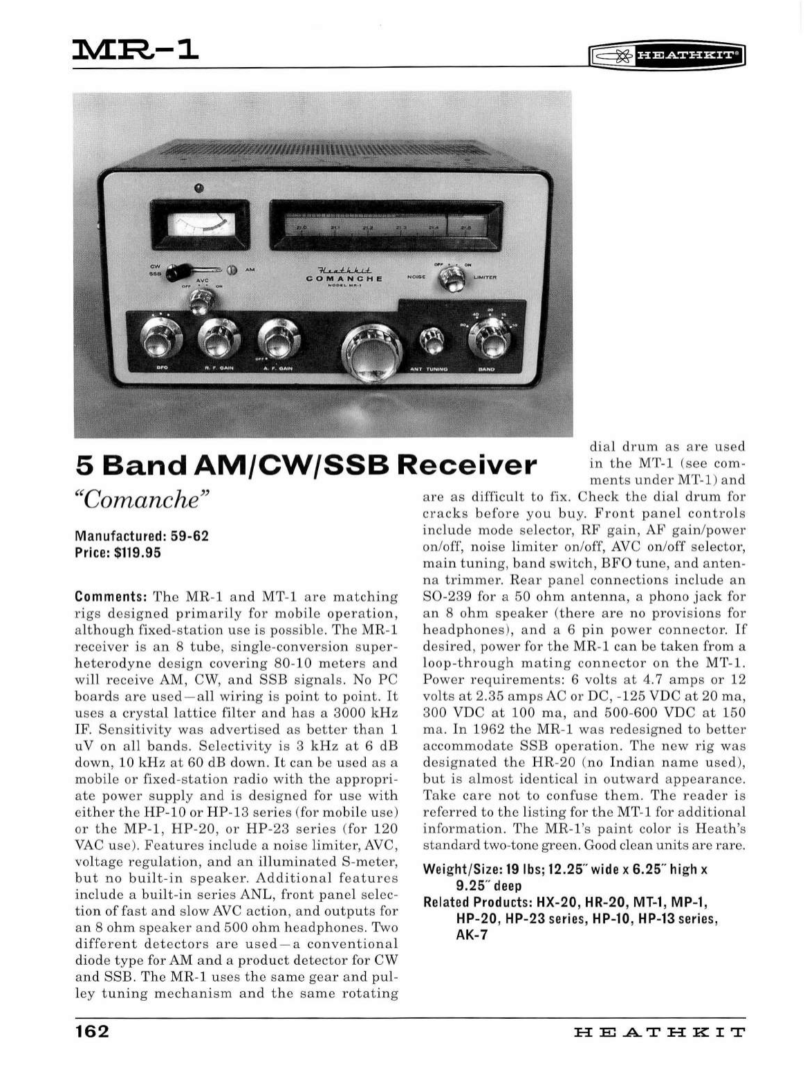
M:R--1
~
~
f
i'Pdii'HilJ
0
--~
-
~·,.;;;~-~~~
-
~,:..--<;-y:;ff'.'~,oJ<7o'''
~~
~
?.,.
$,,'),"£""
'
°"N
..
fLl...J..,L
COMANC
H E
5
Band
AM/CW/SSB
Receiver
dial
drum
as
are
u
sed
in
the
MT-1
(see
com-
ments
under
MT-1)
and
''
Coman
ch
e"
Manufactur
ed:
59-62
Price:
$119.95
Comments:
The
MR
-1
and
MT
-1
are
matching
rigs
designed
primarily
for
mobile
operation,
although
fixed
-
stat
i
on
use
is
possible
.
The
MR-1
receiver
is
an
8
tube,
sing
le-
conversion
super-
h
etero
d
yne
design
coveri
ng
80-10
meters
and
wi
ll
receive
AM, CW,
an
d
SSB
signa
ls. No
PC
boards
are
used-a
ll
wiring
is
point
to
point.
It
u
ses
a
crysta
l l
attice
filter
and
has
a
3000
kHz
I
F.
Sensitivity
was
advertised
as
better
than
1
uV
on
all
bands
.
Selectivity
is
3
kHz
at
6
dB
down,
10
kHz
at
60 dB
down
.
It
can
be
used
as
a
mobile
or
fixed
-
station
radio
with
the
appropri-
ate
power
supply
and
is
designed
for
use
with
either
the
HP
-
10
or
HP-13
series
(for
mobile
use)
or
the
MP-1
,
HP-20,
or
H
P-23
series
(
for
120
VAC
use).
Features
i
nclude
a
noise
limiter,
AVC,
voltage
regu
l
ation
,
and
an
illuminated
S-
meter
,
but
no
built
-
in
s
peaker.
Additional
features
include
a
built-in
series
ANL
,
front
panel
selec
-
tion
of
fast
and
slow
AVC
action,
and
outputs
for
an
8
ohm
speaker
and
500
ohm
headphones.
Two
di
fferent
detectors
are
used-a
conventional
d
iode
type
for AM
and
a
product
detector
for
CW
and
SSB.
The
MR-1
uses
the
same
gear
and
pu
l-
l
ey
tuning
mechan
i
sm
and
the
same
rotating
162
are
as
difficult
to
fix.
Check
the
dial
drum
for
cracks
before
you
buy.
Front
panel
controls
include
mode
se
lector
,
RF
gain,
AF
gain
/
power
on/off,
noise
limiter
on
/off, AVC
on/off
se
lector,
main
tuning,
band
switch,
BFO
tune,
and
anten-
na
trimm
er.
Rear
pan
el
connections
include
an
S0-239
for a
50
ohm
antenna,
a
pho
n o
jack
for
an
8
ohm
speaker
(
there
are
no
provisions
for
h
ea
dp
h
ones
),
and
a 6
pin
power
connector.
If
desired
,
power
for
the
MR
-1
can
be
taken
from
a
loop-
throug
h
mating
connector
on
the
MT-1.
Power
requirements:
6
volts
at
4. 7
amps
or
12
volts
at
2.35
amps
AC
or
DC, -
125
VDC
at
20
ma,
300
VDC
at
100
ma,
and
500
-
600
VDC
at
1
50
ma.
In
1962
the
MR
-1
was
redesigned
to
better
accommodate
SSB
operation.
The
new
rig
was
desig
n
ated
the
HR-20
(no
In
d
ian
name
used
),
but
is
almost
identica
l
in
outward
appearance.
Take
car
e
not
to
confuse
them.
The
reader
is
referred
to
the
listing
for
the
M
T-
1 for
additional
information.
The
MR
-l 's
paint
color
is
Heath
's
standard
two-
tone
green.
Good
clean
units
are
rare
.
Weight/Size:
19
lbs;
12.25"
wide
x 6.25"
high
x
9.25"
deep
Related
Products:
HX-20, HR-20,
MT-1
,
MP-1
,
HP-20, HP-23
series,
HP-10,
HP-13
series,
AK-7
HE
.AT
HK
IT
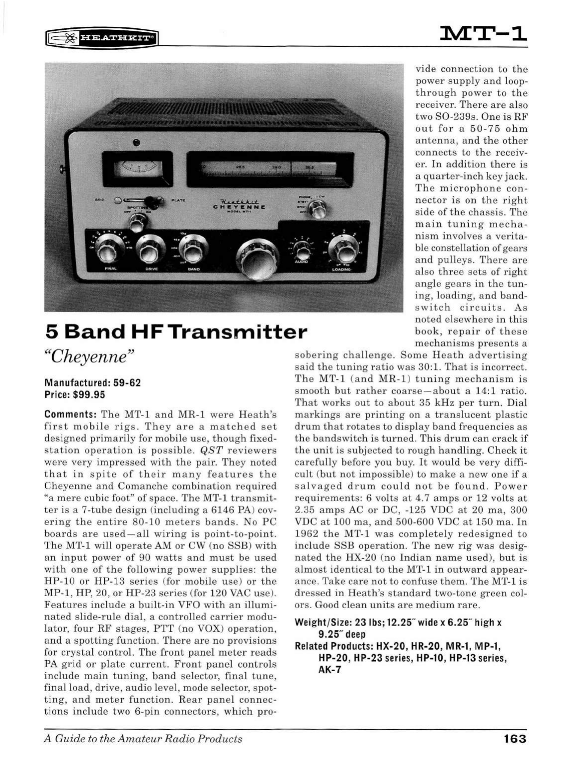
rE
~1ua+tnH;t
lVLT-1
vide
connection
to
the
-·I
5
Band
HF
Transmitter
power
supply
and
loop-
through
power
to
the
rece
iver.
There
are
also
two
S0-239s.
One
is
RF
out
for
a
50-75
ohm
antenna,
and
the
other
connects
to
the
receiv-
er.
In
addition
there
is
a
quarter
-in
ch
key
jack.
The
microphone
con-
nector
is
on
the
right
side
of
the
chassis
.
The
main
tuning
mecha-
ni
sm
involve
s a
verita-
ble
constellation
of
gears
and
pulleys
.
There
are
also
three
sets
of
right
angle
gears
in
the
tun-
in
g,
loading
,
and
band-
s
witch
circuits.
As
noted
elsewhere
in
this
book,
repair
of
these
mechanisms
pres
e
nts
a
"Cheyenne"
Manufactured: 59-62
Price:
$99.95
Comments:
The
MT-1
and
MR-1
were
He
a
th's
first
mobile
rig
s .
They
are
a
matched
set
designed
primarily
for
mobile
use,
though
fixed-
station
operation
is
possible
.
QST
reviewers
were
very
impressed
with
the
pair
.
They
noted
that
in
spite
of
their
many
features
the
Cheyenne
and
Comanche
combination
required
"a
mer
e
cubic
foot"
of
s
pace.
The
MT-1
transmit
-
ter
is
a
7-tube
design
(
including
a
6146
PA) cov-
ering
the
entire
80-10
m
ete
rs
bands.
No
PC
boards
are
used-all
wiring
is
point-to-point.
The
MT-1
will
op
era
te
AM
or
CW
(no
SSB)
with
an
input
power
of
90
watts
and
must
be
used
with
one
of
the
following
power
supplies:
the
HP-10
or
HP-13
series
(for
mobile
u
se)
or
the
MP-1
, HP, 20,
or
HP-23
series
(for
120
VAC
use
).
Featur
es
include
a
built-in
VFO
with
an
illumi-
nated
s
lide-rule
dial,
a
controlled
carrier
modu
-
lator,
four
RF
stages,
PTT
(
no
VOX)
operation,
and
a
spotting
function.
There
are
no
provi
s
ions
for
crystal
control.
The
front
panel
meter
reads
PA
grid
or
plate
current.
Front
pan
el
controls
include
main
tuning,
band
selector,
final
tune,
final
load
,
drive,
audio
level
,
mode
selector,
s
pot-
ting,
and
meter
function.
Rear
panel
connec-
tions
include
two
6-pin
connectors,
which
pro-
A Guide to the
Amateur
Radio
Products
sobering
challenge.
Some
Heath
advertising
said
the
tuning
ratio
was
30: 1.
That
is
incorrect.
The
MT-1
(a
nd
MR-1
)
tuning
mechanism
is
smooth
but
rather
coarse-about
a
14:1
ratio.
That
works
out
to
about
35
kHz
per
turn.
Dial
markings
are
printing
on
a
translucent
plastic
drum
that
rotates
to
display
band
frequencies
as
the
bandswitch
is
turned.
This
drum
can
crack
if
the
unit
is
s
ubjected
to
rough
handling.
Check
it
carefully
before
you
buy.
It
would
be
very
diffi-
cult
(
but
not
impossible
)
to
make
a
new
one
if
a
salvaged
drum
could
not
b e
found.
Power
requirements:
6
volts
at
4.7
amps
or
12
volts
at
2.35
amps
AC
or
DC
, -125
VDC
at
20
ma,
300
VDC
at
100
ma
,
and
500-600
VDC
at
150
ma.
In
1962
the
MT
-1
was
completely
redesigned
to
include
SSB
operation
.
Th
e
new
rig
was
desig-
nated
the
HX-20
(
no
Indian
name
used),
but
is
almost
identical
to
the
MT-1
in
outward
appear
-
anc
e.
Take
ca
re
not
to
confuse
them
.
The
MT-1
is
dressed
in
Heath's
standard
two-tone
green
col-
ors
. Good
clean
units
are
medium
rare.
Weight/Size: 23
lbs;
12.25"
wide
x 6.25"
high
x
9.25"
deep
Related
Products:
HX-20, HR-20,
MR-1,
MP-1,
HP-20, HP-23
series,
HP-10,
HP-13
series,
AK-7
163
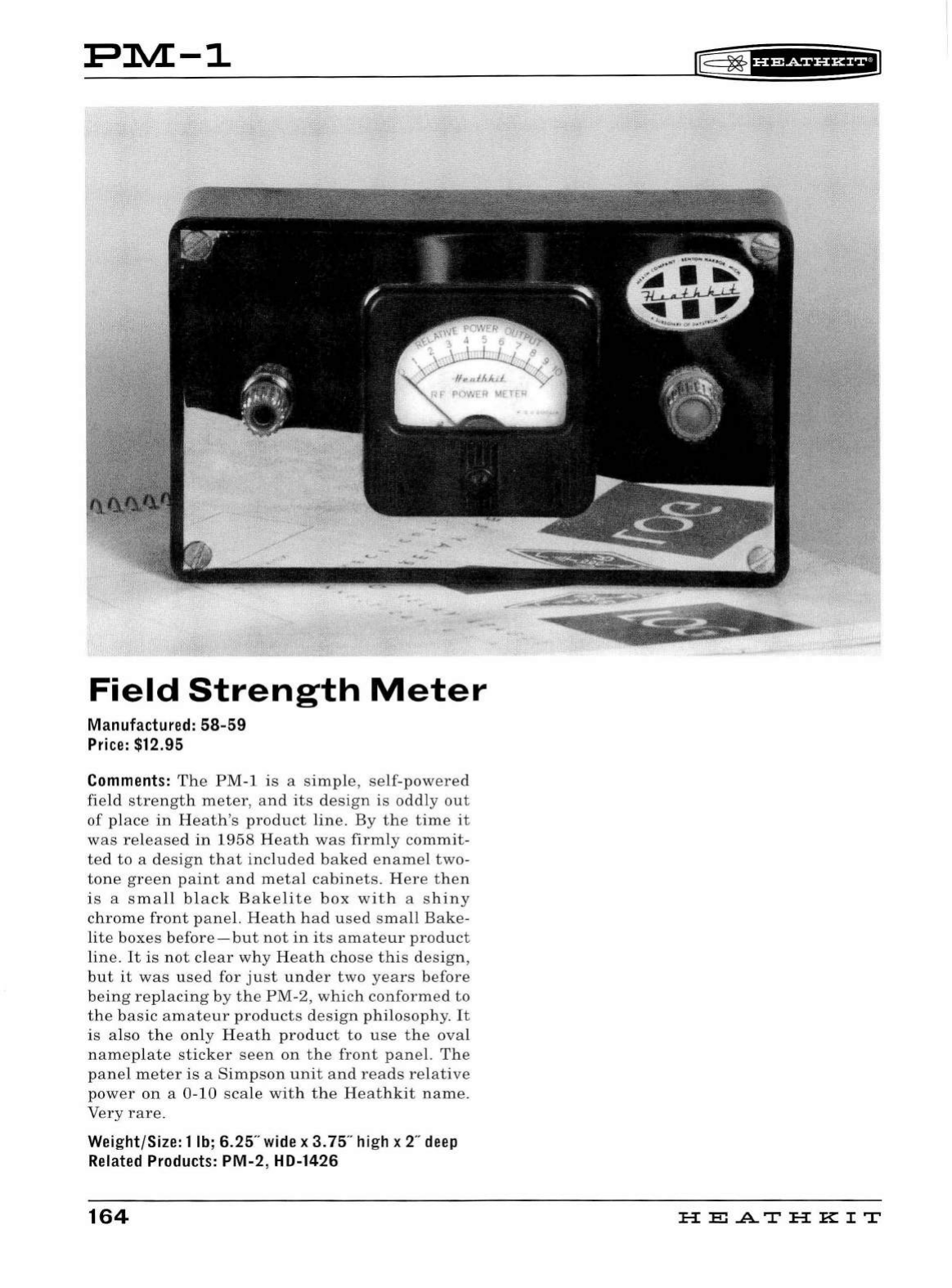
PlVL-1
Field
Strength
Meter
Manufactured:
58-59
Price
: $12.95
Comments:
The
PM-1
is
a s
imple
,
sel
f-power
ed
field
strength
meter,
a
nd
its
d
es
ign
is
oddl
y
out
of
place
in
Heath
's
product
lin
e. By
the
time
it
was
released
in
1958
He
at
h w
as
firmly
commit-
ted
to
a d
esig
n
that
includ
ed b
ake
d en
ame
l
two-
tone
green
paint
and
met
al
cabinet
s. H
ere
then
is a s
mall
bla
ck B a
kelit
e
box
with
a s
hin
y
chrome
front
pan
el. H e
ath
had
u
se
d
sma
ll
Bak
e-
lite
bo
xes
befor
e
-but
not
in
it
s
amate
ur
product
line.
It
is
not
cl
ear
why
H
ea
th
c
ho
se
thi
s d
es
i
gn,
but
it
was
used
for
ju
st
under
two
years
before
be
in
g
repl
ac
in
g by
the
PM-2,
which
co
nform
ed
to
the
b
as
ic
amateur
p
ro
duct
s
de
s
ign
philo
sop
h
y.
It
is
also
th
e
only
He
at
h
product
to
use
the
oval
na m
ep
lat
e s
tick
er
see
n
on
th
e
front
pan
el.
Th
e
pan el
met
er
is
a
Simpson
unit
an
d
reads
re
lati
ve
power
on
a
0-10
s
cal
e
with
th
e H
ea
thkit
name.
Very
rare.
Wei
ght/Size: 1
lb
; 6.25"
wide
x 3. 75" h
ig
h x 2" deep
Related
Products
:
PM
-2, HD-1426
164
l§:
~
'if
Mf
§f
i*fl
HEATHKIT
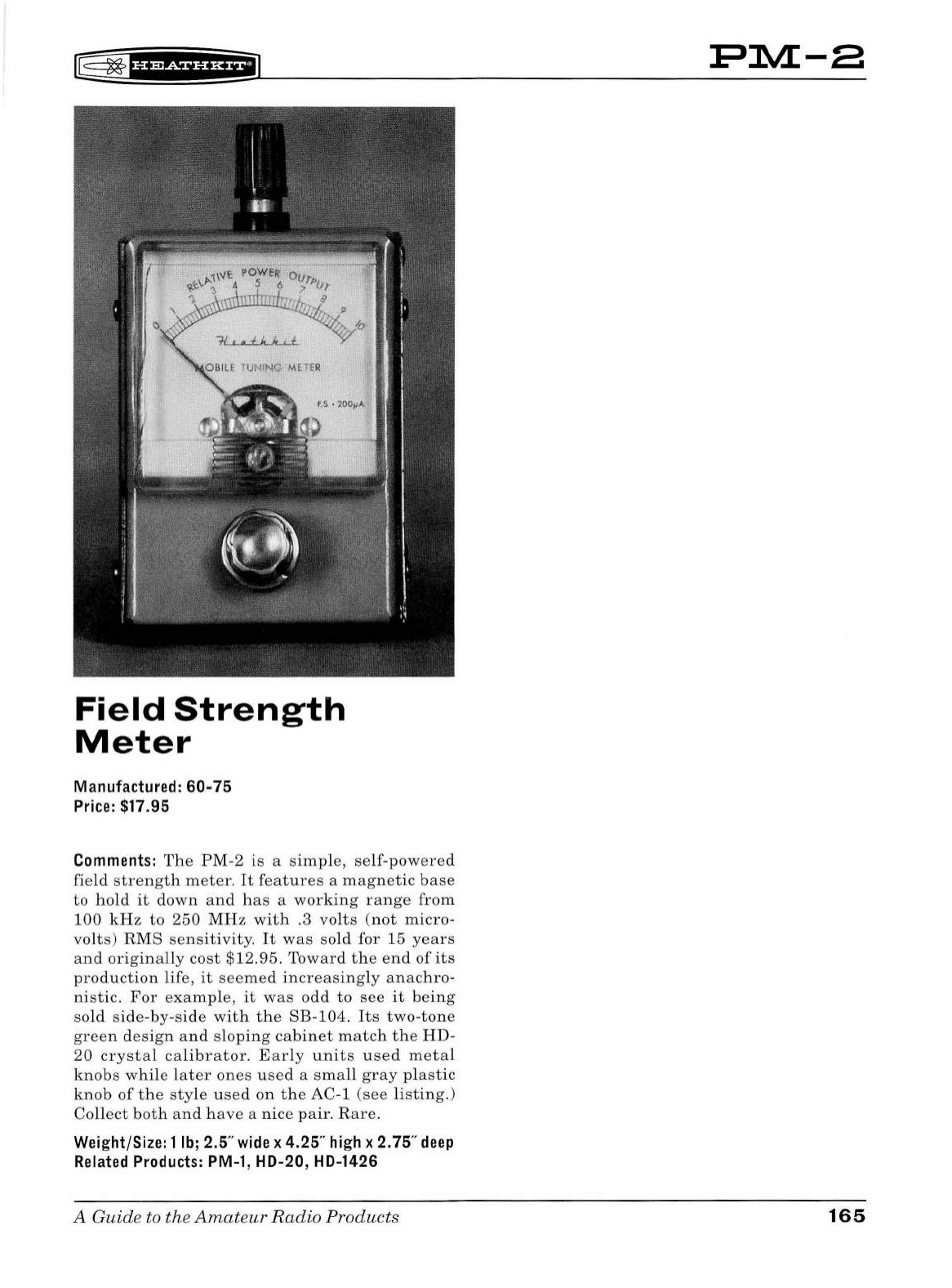
rE
~
·u+Si¥f
H+'J
Field
Strength
Meter
Manufactured: 60-75
Price:
$17.95
Comments:
The
PM
-2
is
a
simp
le,
self
-
powered
field
strength
meter.
It
features
a
magnet
ic
base
to
ho
ld
it
down
and
has
a
working
range
from
100
kHz
to
250
MHz
with
.3
volts
(not
micro-
volts)
RMS
se
n
sitivity.
It
was
sold
for
15
years
and
or
i
ginally
cost
$12.95.
Toward
t he en d
of
its
production
life,
it
seemed
increasingly
anachro-
nistic
.
For
example,
it
was
odd
to
see
it
being
sold
side
-
by-si
de
with
the
SB
-
104
.
Its
two-tone
green
design
and
sloping
cabinet
match
the
HD-
20
crystal
calibrator.
E
arly
units
used
metal
knobs
while
later
ones
u
sed
a
small
gray
pl
astic
knob
of
the
style
used
on
the
AC-1
(see
li
sting.)
Co
ll
ect
both
an
d h
ave
a nice
pair.
Rare.
Weight/Size: 1
lb;
2.5"
wide
x 4.25"
high
x 2.75"
deep
Related
Products:
PM-1
, HD-20, HD-1426
A Guide to the
Amateu
r Radio Products
PlVL-8
165
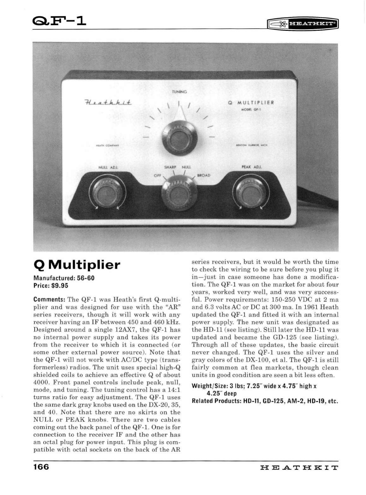
QF'-1
Q
Multiplier
Ma
nu
fa
ctu
r
ed:
56-60
Price:
$9.95
TUN
IN
G
\ \
Commen
t
s:
The
QF-1
was
Heath
's
first
Q-multi-
plier
and
was
designed
for
use
with
the
"AR"
series
receivers
,
though
it
will
work
with
any
receiver
having
an
IF
between
450
and
460
kHz.
Designed
around
a
single
12AX7,
the
QF
-1
has
no
internal
power
supply
and
takes
its
power
from
the
receiver
to
which
it
is
connected
(or
some
other
external
power
source).
Nate
that
the
QF-1
will
not
work
with
AC/DC
type
(
trans-
formerless)
radios.
The
unit
uses
special
high
-Q
shielded
coils
to
achieve
an
effective
Q
of
about
4000.
Front
panel
controls
include
peak
,
null
,
mode
,
and
tuning.
The
tuning
control
has
a 14:1
turn
s
ratio
for
easy
adjustment.
The
QF-1
uses
the
same
dark
gray
knobs
used
on
the
DX-20,
35,
and
40.
Note
that
there
are
no
skirts
on
the
NULL
or
PEAK
knobs.
There
are
two
cables
coming
out
the
back
panel
of
the
QF-1.
One
is for
connection
to
the
receiver
IF
and
the
other
has
an
octal
plug
for
power
input
.
This
plug
is
com-
patible
with
octal
sockets
on
the
back
of
the
AR
166
®=
~
fHR&iHH+IJ
I / Q
MULTIPLIER
series
receivers,
but
it
would
be
worth
the
time
to
check
the
wiring
to
be
sure
before
you
plug
it
in
-
just
in
case
someone
has
done
a
modifica-
tion.
The
QF-1
was
on
the
market
for
about
four
years,
worked
very
well,
and
was
very
success-
ful.
Power
requirements:
150-250
VDC
at
2
ma
and
6.3
volts
AC
or
DC
at
300
ma.
In
1961
Heath
updated
the
QF-1
and
fitted
it
with
an
internal
power
supply.
The
new
unit
was
designated
as
the
HD-11
(see
listing
).
Still
later
the
HD-11
was
updated
and
became
the
GD-125
(see
listing)
.
Through
all
of
these
updates,
the
basic
circuit
never
changed.
The
QF
-1
uses
the
silver
and
gray
colors
of
the
DX-100,
et
al.
The
QF-1
is
still
fairly
common
at
flea
markets,
though
clean
units
in
good
condition
are
seen
a
bit
less
often.
Wei
g
ht
/
Size:
3
lbs
; 7.25"
wide
x
4.
75"
hi
gh x
4.25"
deep
Related
Products:
HD-11
,
GD-125
,
AM
-2,
HD-19
,
etc.
HE
A..T
HK
IT
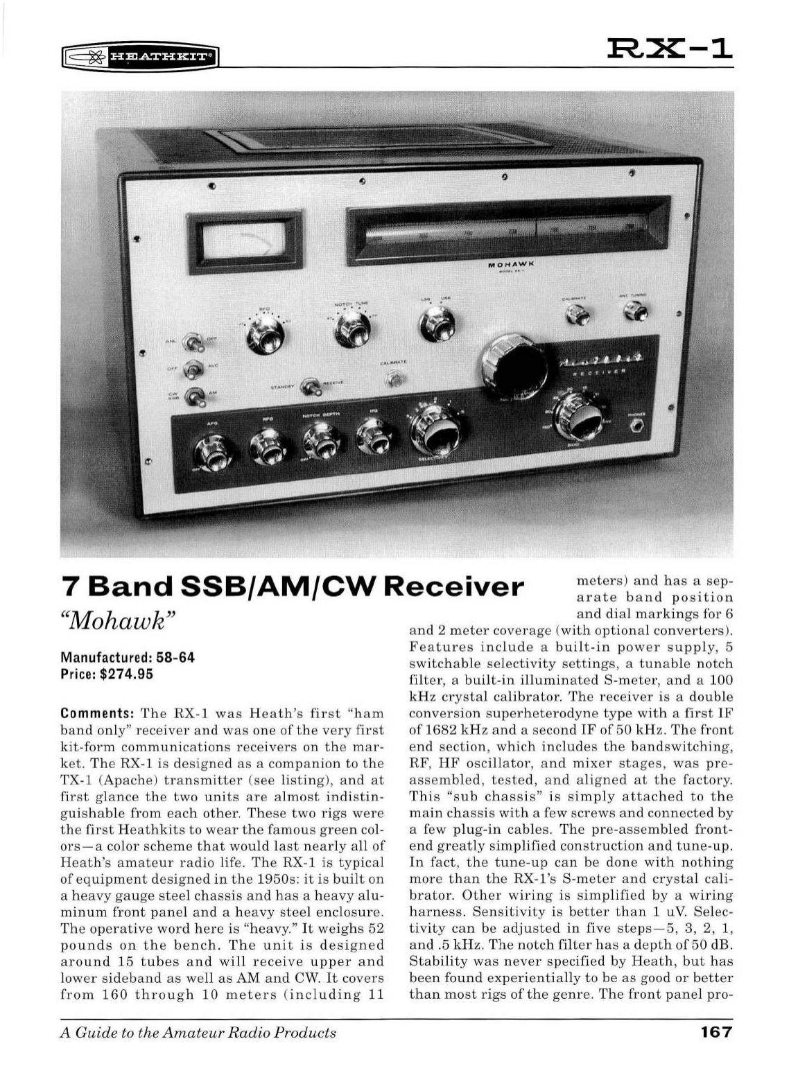
r@
~
u•@tUHEil
:R,X-1
,
-"
...
. ...
.
...
~
.
·
·
.·
.. .,
i
.,,
7
Band
SSB/AM/CW
Receiver
meters)
and
has
a
sep-
arate
band
position
"Mohawk"
Manufactured:
58-64
Price:
$274.95
Comments:
The
RX
-1
was
Heath's
first
"ham
band
o
nl
y"
rece
i
ver
and
was
one
of
the
very
first
kit
-
form
communications
receivers
on
th e
mar
-
ket.
The
RX-1 is
designed
as
a
companion
to
the
TX-1 (
Apache
)
transmitter
(see
l
isting),
and
at
first
gl
ance
the
two
units
are
almost
in
d
istin
-
guishab
le
from
each
ot
her.
These
two
rigs
were
the
first
Heathkits
to
wear
the
famous
green
col-
ors
- a
color
scheme
that
wou
ld
last
nearly
all
of
Heath
's
amateur
radio
life
.
The
RX-1
is
typical
of
equipment
designed
in
the
1950s
:
it
is
bui
lt
on
a
heavy
gauge
steel
chassis
and
has
a
heavy
alu-
minum
front
panel
and
a
heavy
stee
l
enclosure.
The
operative
word
here
is
"heavy."
It
we
i
ghs
52
pounds
on
the
bench.
The
unit
is
designed
aroun
d
15
tubes
and
wi
ll
receive
upper
and
lower
si
deband
as
well
as
AM
and
CW
.
It
covers
from
1
60
through
10
meters
(
includ
in
g
11
A Guide to the A
mateu
r R adio Products
and
dia
l
marki
n
gs
for 6
and
2
meter
coverage
(with
optional
converters)
.
Features
include
a
bu
il
t-in
power
su
pply,
5
switc
h
ab
le
selectivity
settings,
a
tunab
le
notch
filter,
a
bui
lt
-in
illumi
n
ated
S-
meter,
an
d a 100
kHz
crystal
calibrator.
The
receiver
is
a
double
convers
i
on
superhetero
d
yne
type
with
a
first
IF
of
1682
kHz
and
a
second
IF
of
50
kHz.
Th
e
front
end
section,
which
incl
u
des
the
bandswitching,
RF,
HF
oscillator,
and
mixer
stages,
was
pre-
assembled,
tested,
and
aligned
at
the
factory.
This
"sub
chassis"
is
simply
attache
d
to
the
main
ch
assis
with
a few
screws
and
connected
by
a few pl
ug-in
cables.
The
pre-assemb
l
ed
front-
end
greatly
simplified
construction
and
tune-up
.
In
fact,
the
tune
-
up
ca
n
be
done
with
nothing
more
than
the
RX-l's
S-meter
and
crysta
l cali-
brator.
Other
wiring
is
simplified
by
a
wiring
harness.
Sensitivity
is
better
t h
an
1 u
V.
Se
lec-
tivity
can
be
adjusted
in five
steps-5,
3, 2, 1,
and
.5
kHz.
The
notch
fi
lt
er
has
a
depth
of
50
dB.
Stabi
lit
y
was
never
specified
by
Heath,
but
has
been
found
experientia
lly
to
be
as
good
or
better
than
most
rigs
of
the
genre.
The
front
pa
n
el
pro-
167
vides
controls
for
RF,
IF
and
AF
gain
(with
power
switch),
notch
tuning,
notch
depth,
ANL,
AVC,
BFO,
and
the
bandswitch.
Additionally
there
are
controls
for
main
tuning,
calibrator
set,
calibrator
on
/
off,
antenna
trimmer,
receive
/
standby,
mode,
and
selectivity.
There
is
also
a
standard
quarter-inch
headphone
jack
on
the
front
panel.
The
rear
panel
has
an
S0
-
239
connector
for a
50-75
ohm
antenna
and
screw
terminals
for
50
-75
ohm
or
150
-
300
ohm
anten
-
na.
There
are
also
screw
terminals
for 8
ohm
and
500
ohm
audio
output.
CAUTION:
Do
not
oper-
ate
the
receiver
without
a
speaker
or
head-
phones
connected
.
An
octal
accessory
socket
pro-
vide
access
to
B+, 6.3 VAC, AVC,
and
receiver
muting.
In
addition
there
is
a
rear
panel
switched
120
VAC
receptacle
and
a
1.5
amp
car-
tridge
fuse.
The
dial
mechanism
is
another
of
Heath's
gear
and
pulley
assemblies
and
uses
a
rotating
drum
with
markings
for
each
band
.
This
drum
is
illuminated
and
rotates
as
the
bandswitch
is
turned.
The
drum
is
pl
astic
and
can
crack
with
rough
handling
.
Be
sure
to
check
it
before
you
buy.
The
RX-1
is
designed
for
120
VAC
,
50
/
60
Hz
operation
.
The
unit
has
a
two-
tone
green
front
panel
with
darker
green
copper
clad
cabinet
.
Early
RX-ls
were
shipped
with
satin
finish
aluminum
knobs,
while
later
ver-
sions
used
polished
knobs.
Heath
sold
the
RX-1
for
about
seven
years,
and
although
thousands
were
sold,
few
remain.
In
1963
the
RX
-1
was
replaced
by
the
sleek
SB
-
300
-
patterned
after
the
Collins
S
line
.
Heath
continued
to
sell
the
RX-1
until
supplies
ran
out
early
in
1964.
Clean
RX-ls
in
good
working
order
are
medium
rare.
Wei
ght/Size: 66
lbs;
19.5"
wide
x
11.
75"
high
x
16
"
deep
Related
Product
s:
TX-1
,
HX-10
,
KL-1
,
HA-10
,
AK-5
168
~
~
fHWiHHFI
HE
.A..T
HK
IT
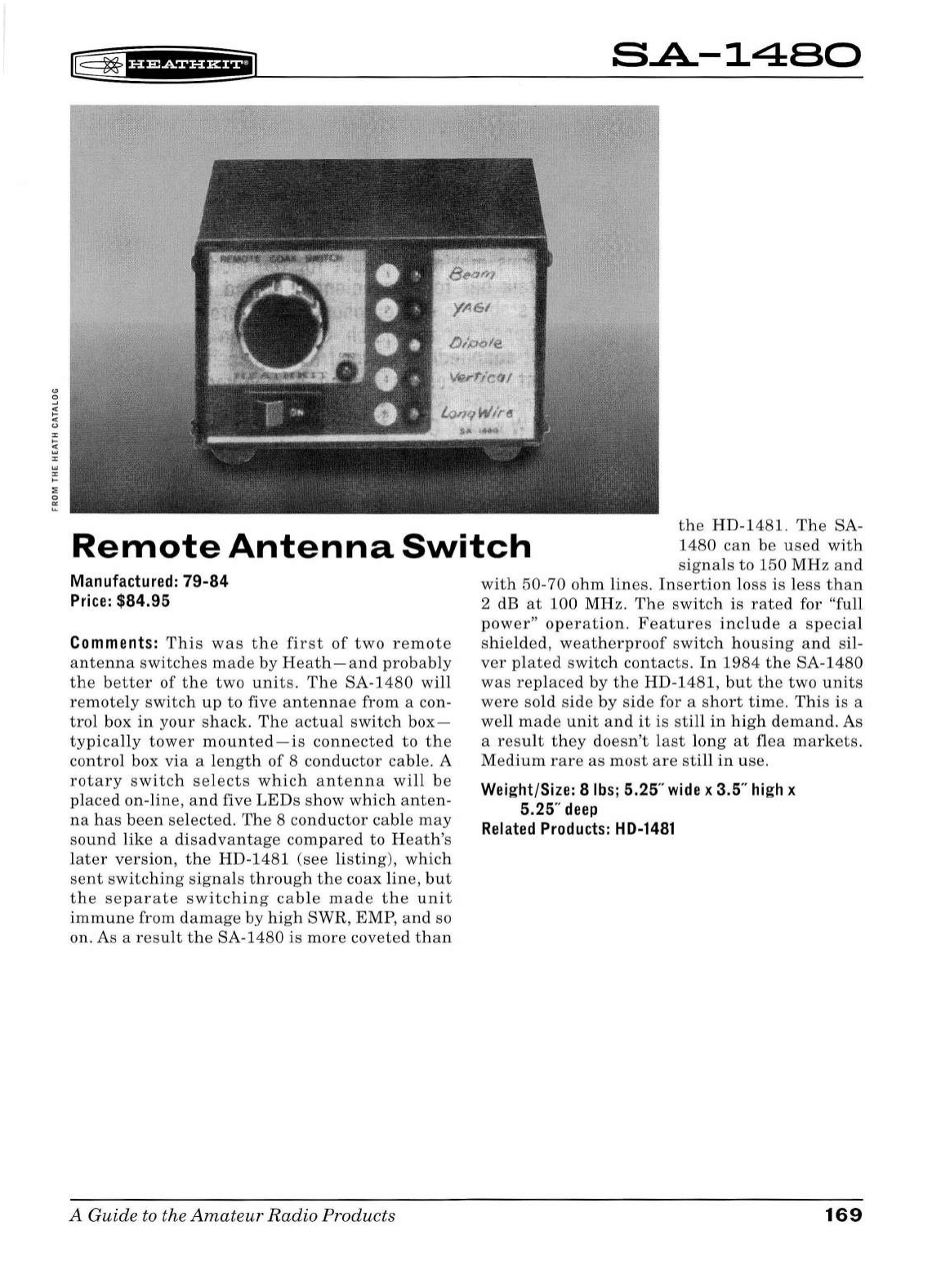
rE
~
'Hiif
UH+i
S.A-1480
the
HD-1481.
The
SA-
1480
can
be
used
with
Remote
Antenna
Switch
signals
to
150
MHz
and
with
50-70
ohm
lines.
Ins
ertio
n
loss
is
less
than
2 dB
at
100
MHz.
The
switch
is
rated
for "fu
ll
power"
operation.
Features
include
a
specia
l
s
hi
e
lded
,
weatherproof
switch
hou
sing
and
si
l-
ver
plated
switc
h
contacts.
In
1984
the
SA-1480
was
replaced
by
the
HD-1481,
but
the
two
units
were
sold
side
by
side
for a
short
time
.
This
is
a
well
mad
e
unit
and
it
is
still
in
high
demand.
As
a
result
they
doe
sn't
last
long
at
flea
mark
ets.
Medium
rare
as
most
are
still
in
use.
Manufactured:
79-84
Price:
$84.95
Comments:
This
was
the
first
of
two
remote
antenna
switches
made
by
Heath-and
probably
the
better
of
the
two
units.
The
SA-1480
will
remotely
switc
h
up
to
five
anten
na
e
from
a con-
trol
box
in
your
shack.
Th
e
act
ual
switch
box-
typically
tower
mounted-is
connected
to
the
control
box
via
a l
engt
h
of
8
conductor
cable.
A
rotary
switch
selects
which
antenna
will
be
placed
on-line,
and
five
LEDs
show
which
anten-
na
has
been
selected
.
The
8
conductor
cable
may
sound
lik
e a
disadvantage
compared
to
H
eath's
l
ater
version,
the
HD-1481
(see
li
sting),
which
sent
sw
itchin
g
signals
through
the
coax
line
,
but
the
separate
switching
cable
made
the
unit
immune
from
damage
by
high
SWR, EMP,
and
so
on. As a
result
the
SA-1480
is
more
coveted
than
A
Guide
to the
Amateur
Radio
Products
Weight/Size: 8
lbs;
5.25"
wide
x 3.5"
high
x
5.25"
deep
Related
Products:
HD-1481
169
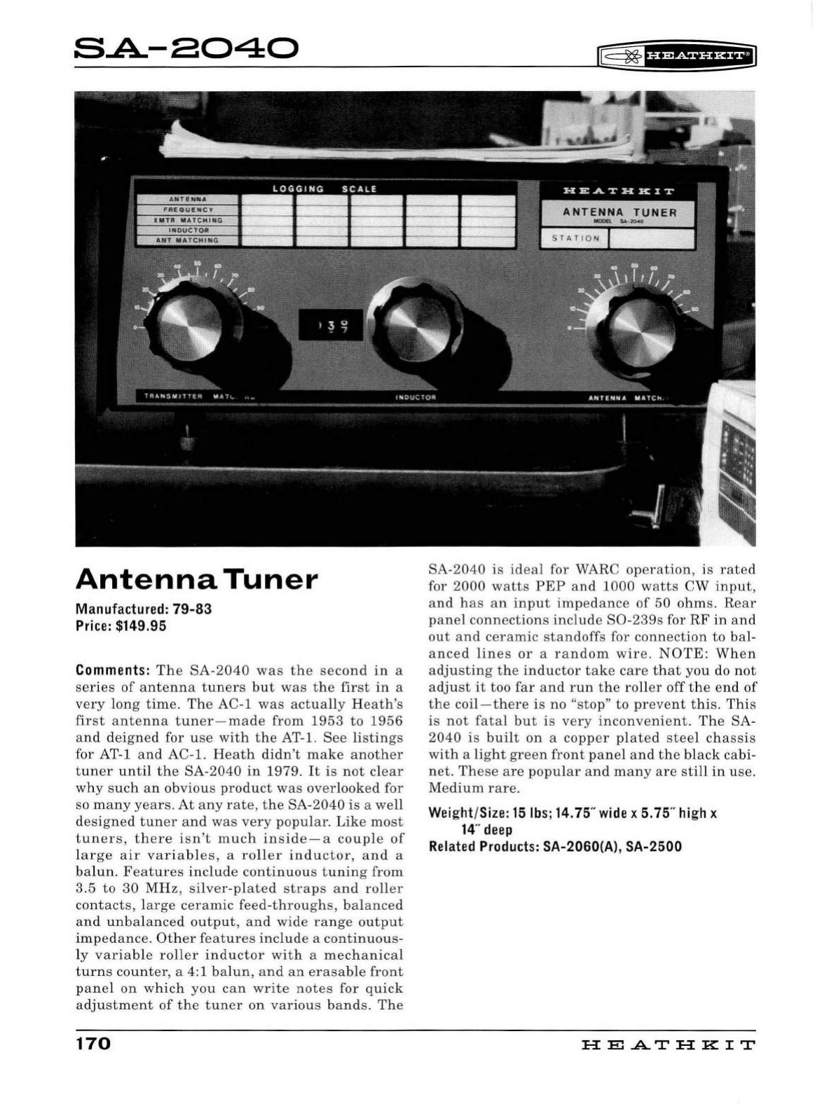
S..A.-8040
Antenna
Tuner
Ma
nufac
t
ured:
79-83
Price:
$149.95
Commen
t
s:
The
SA-2040
was
the
second
in
a
series
of
antenna
tuners
but
was
the
first
in
a
very
long
time.
The
AC-1
was
actually
Heath's
first
antenna
tuner-made
from
1953
to
1956
and
deigned
for
use
with
the
AT-1.
See
listings
for AT-1
and
AC-1.
Heath
didn't
make
another
tuner
until
the
SA-2040
in
1979
.
It
is
not
clear
why
such
an
obvious
product
was
overlooked
for
so
many
years
.
At
any
rate
,
the
SA-2040
is
a
well
designed
tuner
and
was
very
popular
.
Like
most
tuners,
there
isn
't
much
inside
- a
couple
of
large
air
variables,
a
roller
inductor,
and
a
balun.
Features
include
continuous
tuning
from
3.5
to
30
MHz,
silver-plated
straps
and
roller
contact
s,
large
ceramic
feed-throughs,
bal
a
nced
and
unbalanced
output,
and
wide
range
output
impedance
.
Other
features
include
a
continuous-
ly
variable
roller
inductor
with
a
mechanica
l
turns
counter,
a 4:1
balun,
and
an
erasable
front
pane
l
on
which
you
can
write
notes
for
quick
adjustment
of
the
tuner
on
various
bands
.
The
170
r§:
~
f
U?&f
HH+iJ
SA-2040
is
ideal
for WARC
operation,
is
rated
for
2000
watts
PEP
and
1000
wa
tts
CW
input,
and
h
as
an
input
impedance
of
50
ohms.
Rear
panel
connections
include
S0-239
s for
RF
in
and
out
and
ceramic
standoffs
for
connection
to
bal-
anced
lines
or
a
random
wire
.
NOTE
:
When
adjusting
the
inductor
take
care
that
you
do
not
adjust
it
too
far
and
run
the
roller
off
the
end
of
the
coil-there
is
no
"stop"
to
prevent
this
.
This
is
not
fatal
but
is
very
inconvenient
.
The
SA
-
2040
is
built
on
a
copper
plated
steel
chassis
with
a
light
green
front
panel
and
the
black
cabi
-
net.
These
are
popular
and
many
are
still
in
use
.
Medium
rare.
Wei
g
ht
/
Size:
15lbs;14.75"
wide
x 5.75"
hi
gh x
14
"
deep
Related
Products:
SA-2060(A), SA-2500
HE.A.TH
KIT
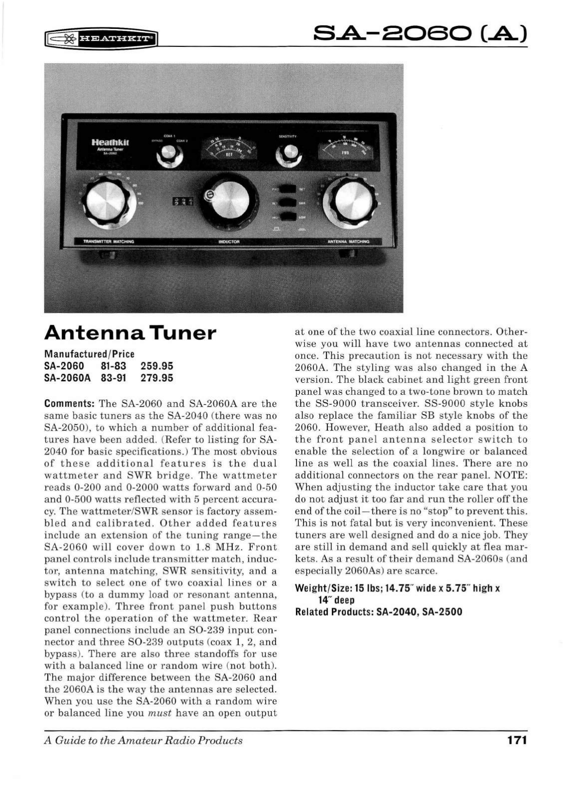
IT§
~
f
H@Sf
i'HiiJ
Antenna
Tuner
Manufactured/Price
SA-2060 81-83
SA-2060A 83-91 259.95
279.95
Comments:
The
SA-2060
and
SA-2060A
are
the
same
basic
tuners
as
the
SA-2040
(
there
was
no
SA-2050),
to
which
a
number
of
additional
fea
-
tures
have
been
added.
(
Refer
to
listing
for SA-
2040
for
basic
specifications.)
The
most
obvious
of
these
additional
features
is
the
dual
wattmeter
and
SWR
bridge
.
The
wattmeter
reads
0-200
and
0-2000
watts
forward
and
0-50
and
0-500
watts
reflected
with
5
percent
accura-
cy.
The
wattmeter
/
SWR
sensor
is
factory
assem-
bled
and
calibrated.
Other
added
features
include
an
extension
of
the
tuning
range-the
SA
-2
060
will
cover
down
to
1.8
MHz.
Front
panel
controls
include
transmitter
match,
induc-
tor,
antenna
matching,
SWR
sensitivity,
and
a
switch
to
select
one
of
two
coaxial
lines
or
a
bypass
(to a
dummy
load
or
resonant
antenna,
for
example).
Three
front
panel
push
buttons
control
the
operation
of
the
wattmeter.
Rear
panel
connections
include
an
80-239
input
con-
nector
and
three
80
-239
outputs
(coax 1, 2,
and
bypass
).
There
are
also
three
standoffs
for
use
with
a
balanced
line
or
random
wire
(
not
both).
The
major
difference
between
the
SA-2060
and
the
2060A
is
the
way
the
antennas
are
selected
.
When
you
use
the
SA
-2060
with
a
random
wire
or
balanced
line
you
must
have
an
open
output
A
Guide
to the
Amateur
Radio
Products
S.A-8060
(.A)
at
one
of
the
two
coaxial
line
connectors.
Other-
wise
you
will
have
two
antennas
connected
at
once.
This
precaution
is
not
necessary
with
the
2060A.
The
styling
was
also
changed
in
the
A
version.
The
black
cabinet
and
light
green
front
panel
was
changed
to
a
two-tone
brown
to
match
the
SS-9000
transceiver.
SS-9000
style
knobs
also
replace
the
familiar
SB
sty
le
knobs
of
the
2060.
However
,
Heath
also
added
a
position
to
the
front
panel
antenna
selector
switch
to
enable
the
selection
of
a
longwire
or
balanced
line
as
well
as
the
coaxial
lines.
There
are
no
additional
connectors
on
the
rear
panel.
NOTE:
When
adjusting
the
inductor
take
care
that
you
do
not
adjust
it
too
far
and
run
the
roller
off
the
end
of
the
coil-there
is
no
"stop"
to
prevent
this.
This
is
not
fatal
but
is
very
inconvenient.
These
tuners
are
well
designed
and
do a
nice
job.
They
are
still
in
demand
and
sell
quickly
at
flea
mar-
kets.
As
a
result
of
their
demand
SA-2060s
(and
especially
2060As)
are
scarce.
Weight/Size: 15lbs;14.75"
wide
x 5.75"
high
x
14
"
deep
Related
Products:
SA-2040, SA-2500
171
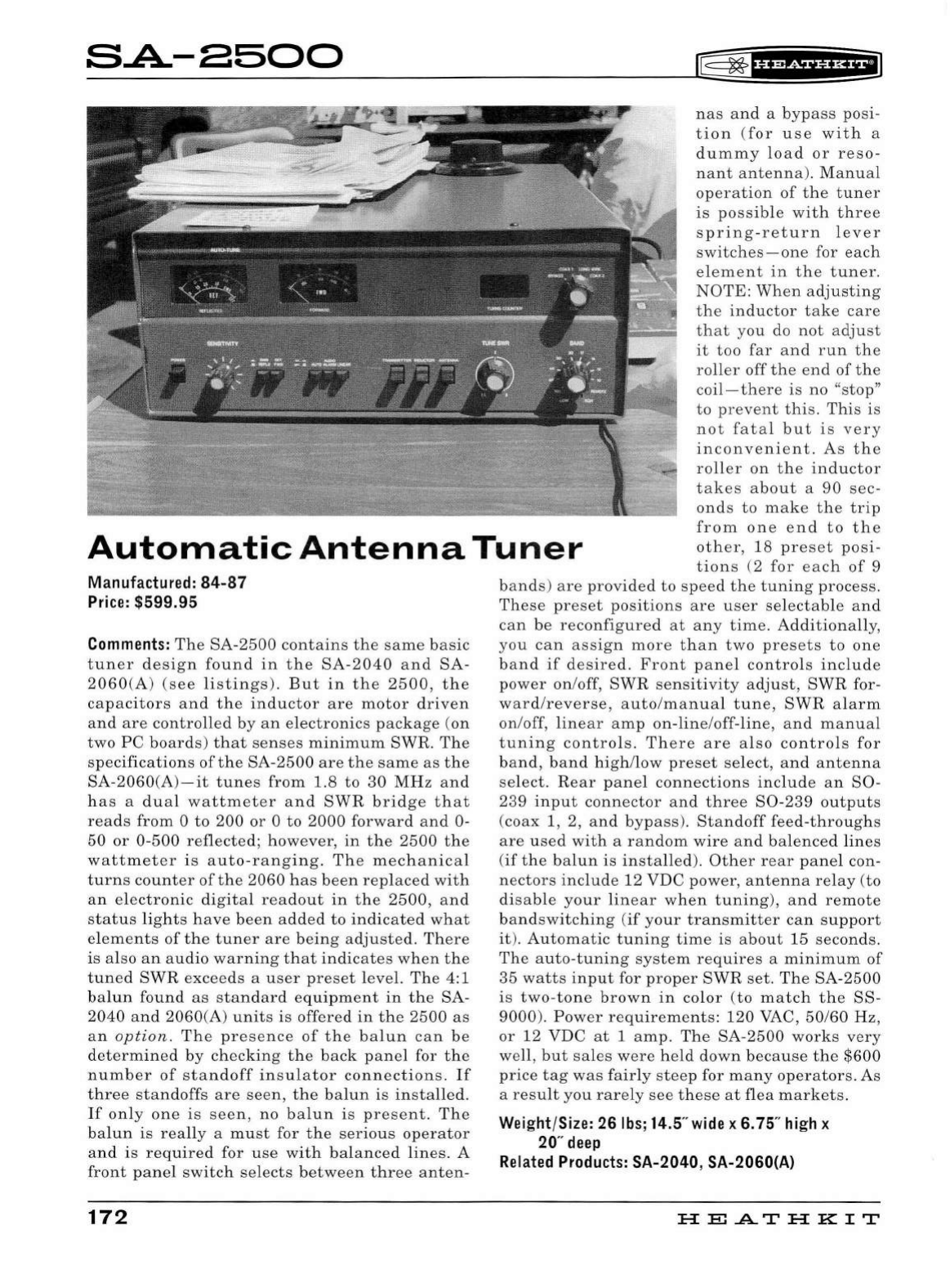
SA.-8500
ITf=
~
f
H@Siif
Hiil
Automatic
A
ntenna
T
une
r
nas
and
a
bypass
posi
-
tion
(
for
use
with
a
dummy
load
or
reso-
nant
antenna
).
Manual
operation
of
the
tuner
is
possible
with
thre
e
spring-return
lever
switches-one
for
each
el
em e
nt
in
th
e
tuner.
NOTE:
When
adjusting
th
e
inductor
t a
ke
car
e
that
y
ou
do not a
dju
st
it
too
far
a
nd
r
un
the
roll
er
off
the
e
nd
of
th
e
coil-ther
e
is
no
"
stop
"
t o p
re
vent
thi
s.
This
is
no
t
fatal
but
is
ver
y
inconveni
e
nt.
As
th
e
roll
er
on
the
inductor
tak
es
about
a
90
sec-
ond
s
to
make
the
trip
from
one
end
to
th
e
other,
18
pre
s
et
posi-
tion
s (2
for
each
of
9
Manufacture
d:
84-
87
Price
: $599.95
Comment
s:
The
SA-2500
contains
the
same
basic
tuner
design
found
in
the
SA
-
2040
and
SA-
2060(A)
(see
listings)
.
But
in
the
2500,
the
capacitors
and
the
inductor
are
motor
driven
and
are
controlled
by
an
electronics
package
(on
two
PC
boards
)
that
senses
minimum
SWR.
The
specifications
of
the
SA-2500
are
the
same
as
the
SA-2060(A)-it
tunes
from
1.8
to
30
MHz
and
has
a
dual
wattmeter
and
SWR
bridge
that
reads
from
0
to
200
or
0
to
2000
forward
and
0-
50
or
0-
500
reflected;
however,
in
the
2500
the
wattmeter
is
auto
-
ranging.
The
mechanical
turns
counter
of
the
2060
has
been
replaced
with
an
electronic
digital
readout
in
the
2500,
and
status
lights
have
been
added
to
indicated
what
el
ements
of
the
tuner
are
being
adjusted.
There
is
also
an
audio
warning
that
indicates
when
the
tuned
SWR
exceeds
a
user
preset
level.
The
4:1
balun
found
as
standard
equipment
in
the
SA
-
2040
and
2060
(A)
units
is
offered
in
the
2500
as
an
option
.
The
pres
e
nce
of
the
balun
can
be
determined
by
checking
the
back
panel
for
the
number
of
standoff
insulator
connections.
If
three
standoffs
are
seen,
the
ba
l
un
is
installed.
If
only
one
is
seen,
no
balun
is
pr
e
sent.
The
ba
l
un
is
really
a
must
for
the
serious
operator
and
is
required
for
use
with
balance
d
lines
. A
front
panel
switch
selects
between
three
anten-
172
bands
)
ar
e
provided
to
speed
the
tuning
process
.
These
preset
positions
are
user
selectable
and
can
be
reconfigured
at
any
time
.
Additionall
y,
you
can
assign
mor
e
than
two
presets
to
one
band
if
desired.
Front
panel
controls
include
power
on
/off,
SWR
sensitivity
adjust,
SWR
for-
ward/reverse
,
auto/manual
tune
,
SWR
alarm
on
/
off
,
linear
amp
on-line
/
off-line
,
and
manual
tuning
controls
.
There
are
also
controls
for
band,
band
high
/
low
preset
select
,
and
antenna
select.
Rear
panel
connections
include
an
80-
239
input
connector
and
three
80
-
239
outputs
(
coax
1, 2,
and
bypass
).
Standoff
feed-throughs
are
used
with
a
random
wire
and
balenced
lines
(if
the
balun
is
installed).
Other
rear
panel
con-
ne
ctors
include
12
VDC
power,
antenna
relay
(
to
disable
your
linear
when
tuning)
,
and
remote
bandswitching
(if
your
transmitter
can
support
it
).
Automatic
tuning
time
is
about
15
seconds.
The
auto-tuning
system
requires
a
minimum
of
35
watts
input
for
proper
SWR
set.
The
SA-2500
is
two-tone
brown
in
color
(to
match
the
88
-
9000).
Power
requirements:
120
VAC,
50
/60
Hz
,
or
12
VDC
at
1
amp
.
The
SA
-
2500
works
very
well,
but
sales
were
held
down
because
the
$600
price
tag
was
fairly
steep
for
many
operators.
As
a
result
you
rarely
see
these
at
flea
markets.
Wei
g
ht
/
Size:
26
lbs
; 14.5" wi
de
x 6.75"
high
x
20"
deep
Related
Products:
SA-2040, SA-2060(A)
HE
.A..T
HK
IT
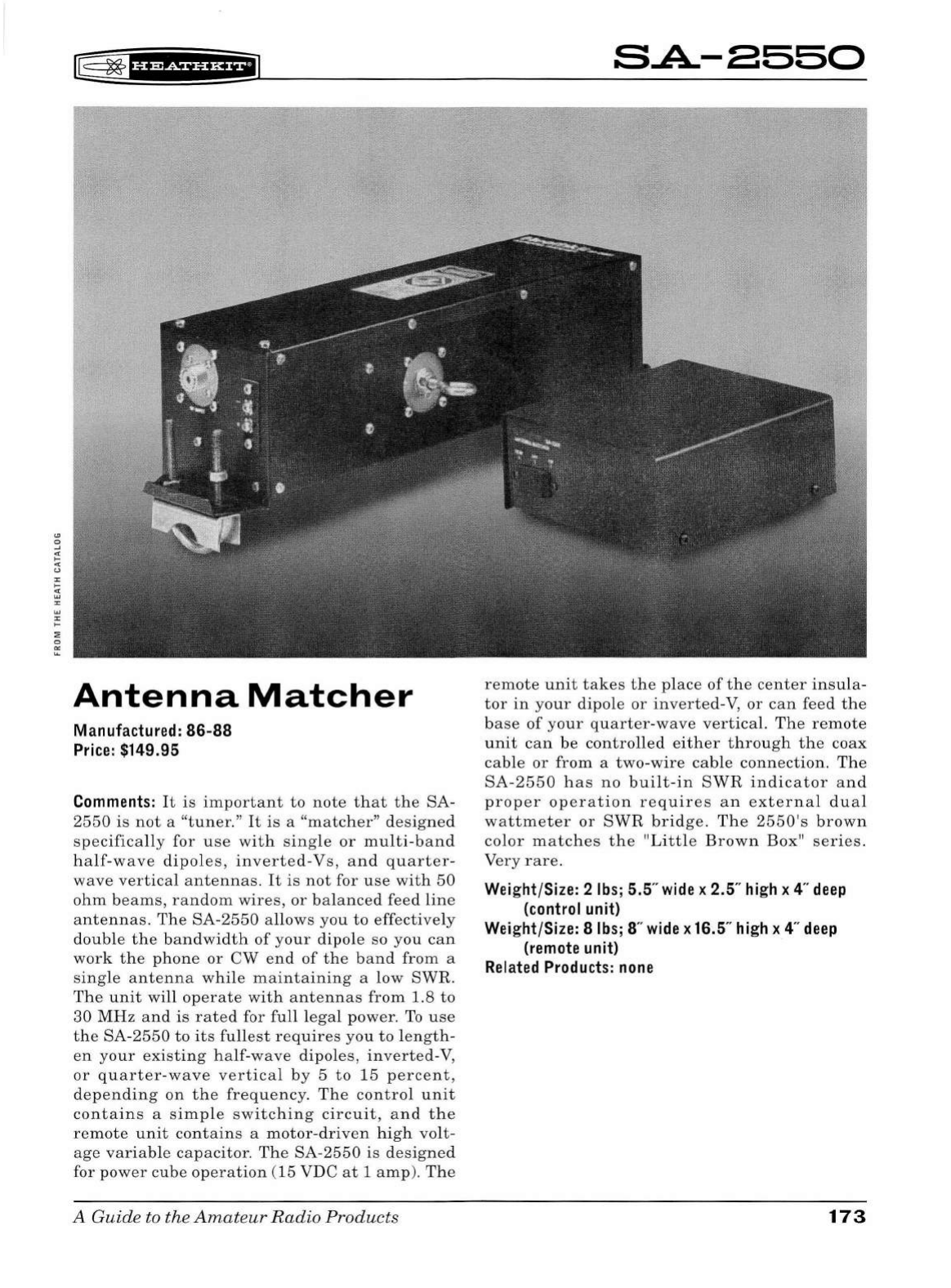
rE
~
1uw+ua+1
Antenna
Matcher
Manufactured:
86-88
Price:
$149.95
Comments:
It
is
important
to
note
that
the
SA
-
2550
is
not
a
"tuner."
It
is
a
"matcher"
designed
specifically
for
use
with
single
or
mu
l
ti-band
half-wave
dipo
l
es,
inverted
-
Vs,
and
quarter-
wave
vertical
antennas.
It
is
not
for
use
with
50
ohm
beams,
random
wires,
or
balanced
feed
line
antennas.
The
SA-2550
allows
you
to
effectively
double
the
bandwidth
of
your
dipole
so
you
can
work
the
phone
or
CW
end
of
the
band
from
a
single
antenna
while
maintaining
a
low
SWR.
The
unit
will
operate
with
antennas
from
1.8
to
30
MHz
and
is
rated
for
full
legal
power
.
To
use
the
SA-2550
to
its
fullest
requires
you
to
length-
en
your
existing
half-wave
dipoles,
inverted-V,
or
quarter
-
wave
vertical
by
5
to
15
percent,
depending
on
the
frequency.
The
control
unit
contains
a
simple
switching
circuit,
and
the
remote
unit
contains
a
motor-driven
high
volt
-
age
variable
capacitor.
The
SA
-
2550
is
designed
for
power
cube
operation
(15 VDC
at
1
amp
).
The
A Guide to the
Amateur
Radio
Products
SA.-8550
remote
unit
takes
the
place
of
the
center
insula-
tor
in
your
dipole
or
inverted-V,
or
can
feed
the
base
of
your
quarter
-
wave
vertical.
The
remote
unit
can
be
controlled
either
through
the
coax
cable
or
from
a
two-wire
cable
connection.
The
SA-2550
has
no
bui
l
t-in
SWR
indicator
and
proper
operation
requires
an
external
dual
wattmeter
or
SWR
bridge.
The
2550's
brown
color
matches
the
"Little
Brown
Box"
series
.
Very
rare.
Weight/Size: 2
lb
s; 5.5
..
wide
x 2.5"
hi
gh x 4"
deep
(con
t
rol
unit)
Wei
ght/Size: 8
lbs
; 8"
wide
x 16.5"
hi
gh x 4"
deep
(remote
unit)
Related
Products:
none
173
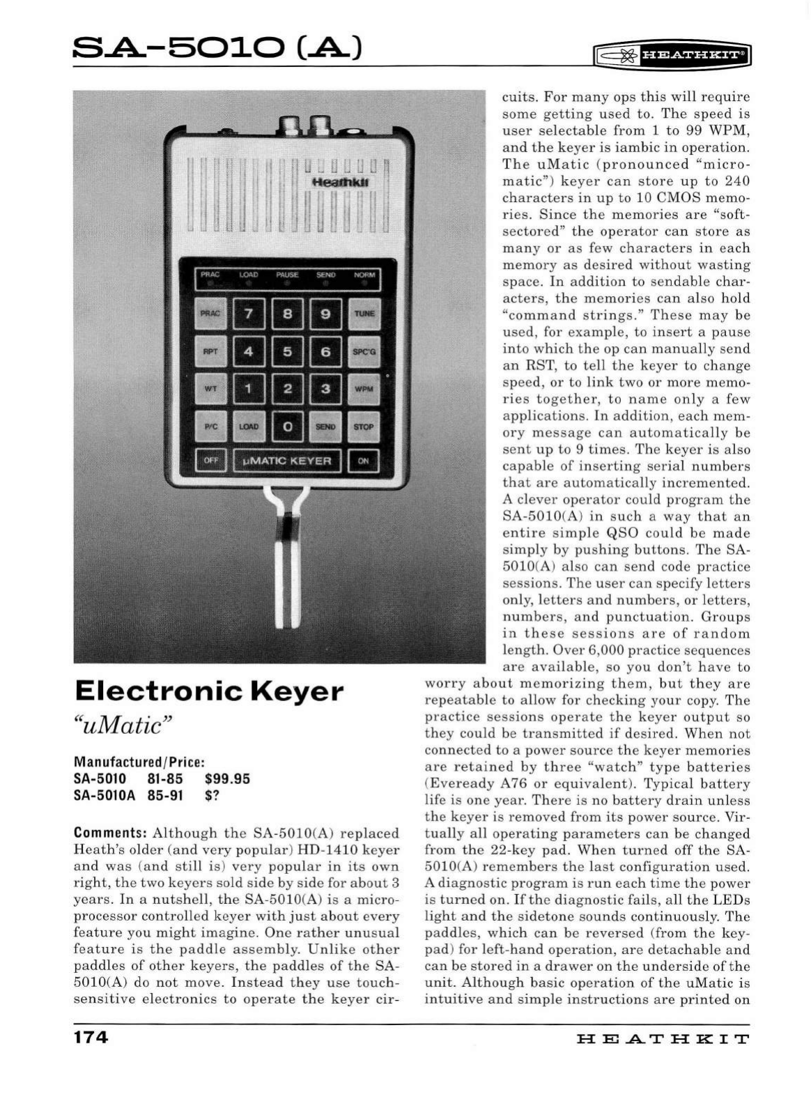
SA-5010(.A)
WT
Electronic
Keyer
"u
Matic"
Manufactured/Price:
SA-5010 81-85
$99.95
SA-5010A 85-91 $?
Comments:
Although
th
e
SA-5010
(A)
replaced
Heath's
older
(and
very
popular)
HD-1410
keyer
and
was
(a
nd
still
is)
very
popular
in
its
own
right,
the
two
key
ers
so
ld
side
by
side
for
about
3
years.
In
a
nutshell,
the
SA-5010
(A)
is
a
micro-
processor
controlled
key
er
with
ju
st
about
every
feature
you
might
imagine
.
One
rather
unusual
feat
ur
e
is
t
he
paddle
assembly.
Unlike
other
paddles
of
other
keyers,
the
paddles
of
the
SA-
5010(A)
do
not
move.
In
stea
d
they
use
touch
-
sens
iti
ve
el
ectronics
to
operate
the
keyer
c
ir-
174
®
~
1
U¥fhi*il1
cuits
.
For
many
ops
this
will
require
some
getting
used
to.
The
speed
is
user
se
l
ectable
from
1
to
99
WPM
,
and
the
keyer
is
iambic
in
operation.
Th
e
uMatic
(
pronounced
"micro
-
matic"
)
key
er
can
store
up
to
240
characters
in
up
to
10
CMOS
memo-
ries
.
Since
the
memories
are
"soft-
sectored"
the
operator
can
store
as
many
or
as
few
characters
in
each
memory
as
desired
without
wasting
space.
In
addition
to
sendable
char-
acters,
the
memories
can
also
hold
"
command
stri
ng
s."
These
may
be
used,
for
example,
to
insert
a
pause
into
which
the
op
can
manually
send
an
RST
,
to
tell
the
k
eye
r
to
change
speed,
or
to
link
two
or
more
memo-
ries
together,
to
name
only
a
few
applications.
In
addition,
each
mem-
ory
messag
e
can
automatically
be
sent
up
to
9
times.
The
keyer
is
a
lso
capable
of
inserting
seria
l
numbers
that
are
automatically
increm
e
nted.
A
clever
operator
could
program
the
SA-5010
(A)
in
such
a
way
that
an
entire
simp
le
QSO
could
be
made
s
impl
y
by
pu
s
hing
buttons.
The
SA-
5010
(A)
also
can
send
code
practice
sessions.
The
user
can
specify
le
tters
only
,
letters
and
numbers
,
or
l
etters,
numbers,
and
punctu
a
tion.
Groups
in
these
sessions
are
of
random
l
ength.
Over
6,000
practice
sequences
are
available,
so
you
don't
have
to
worry
about
memorizing
th
em,
but
they
are
repeatable
to
allow
for
checking
your
copy.
The
practic
e
sessions
operate
the
k
eye
r
output
so
they
could
be
transmitted
if
desired
.
When
not
connected
to
a
power
source
the
keyer
memories
are
retained
by
three
"watc
h"
type
batteries
(
Eveready
A 76
or
equivalent).
Typical
battery
life
is
one
year.
There
is no
battery
drain
unless
the
keyer
is
removed
from
its
power
source.
Vir
-
tually
a
ll
operating
parameters
can
be
changed
from
the
22
-
key
pad
.
When
turned
off
the
SA-
5010(A)
remembers
the
last
configuration
used.
A
diagno
s
tic
program
is
run
each
time
the
power
is
turned
on.
If
the
diagnostic
fails
, a
ll
the
LEDs
light
and
the
sidetone
sounds
continuously.
The
paddles,
which
can
be
reversed
(
from
the
key
-
pad
) for
left-hand
operation
,
are
detachable
and
can
be
store
d
in
a
drawer
on
the
underside
of
the
unit.
Although
basic
operation
of
the
uMatic
is
int
uitiv
e a
nd
simp
le
instructions
are
print
ed
on
HE
.AT
HK
IT
r@
~
f
b¥Sii'H+ii1
the
underside,
the
manual
will
be
essential
to
an
understanding
of
the
more
complex
operations.
Sidetone
volume
and
pitch
as
well
as
separate
right-and
l
eft-paddle
sensitivity
can
be
changed
from
access
holes
on
the
underside.
The
rear
panel
contains
two
keying
jacks.
One
is
for posi-
tive
keying
(250
volts
at
100
ma),
and
the
other
is
for
negative
keying
(-200
volts
at
40
ma).
These
jack
s
are
protected
and
will
key
the
trans-
mitter
continuously
if
the
wrong
one
is
u
sed.
NOTE:
Use
coaxial
cable
between
the
keyer
and
the
transmitter.
Th
ere
is
also
a
miniature
phon
e
jack
for
headphones
, a
4-pin
connector
for
an
external
paddle,
and
a
power
jack
.
The
SA-
5010(A)
has
a
built-in
full
wave
bridge
rectifier
allowi
ng
it
to
run
from
either
an
AC
or
DC
source.
Power
requirements:
11-16
VDC
at
200
ma
(
polarity
not
critical)
or
8.5
VAC
at
1
amp.
The
membrane
keypad
is
attac
h
ed
to
the
keyer
with
self
-
stick
backing
and,
over
time,
can
begin
to
peel
off
,
espec
i
ally
on
the
paddle
end
where
the
ribbon
connector
cable
is
attached.
This
con-
dition
is
fixable
with
the
careful
application
of
a
variety
of
adhesives
.
Because
the
uMatic
uses
CMOS
chips
it
is
subject
to
damage
by
static
electricity
-
static
sparks
from
your
fin
gers
touching
the
paddles,
for
examp
le.
Since
the
microprocessor
(a
3870)
is
custom
-m
ade
for
the
unit,
a
replacement
could
be
very
difficult
to
find.
Earl
y
versions
were
plagued
by
stat
ic
dam-
age
problems.
The
A
version
is
more
immune
but
both
should
be
treated
carefully
with
respect
to
static.
It
is
not
uncommon
to
find
these
keyers
with
factory
repair
label
s
on
the
bottom
.
The
SA-5010
h
ad
a
number
of
minor
glitches
includ-
ing
being
bothered
by
stray
RF
from
the
tr
ans
-
mitter.
Thi
s
could
cause
the
unit
to
send
random
dots
or
d
ashes
.
Most
of
these
probl
ems
were
cleaned
up
in
the
5010A.
Units
are
occasionally
seen
with
home
brew
paddles.
Th
e
paddles
are
removable
and
can
be
stored
in
a
draw
that
pulls
out
of
the
back.
The
SA-5010
has
a
beige
case.
The
A
version
is
gray.
Medium
rare.
Weight/Size: 3
lbs;
4.25"
wide
x 1.75"
high
x
6"
deep
Related
Products:
HD-10,
HD-1410,
HD-8999
A Guide to the
Amateur
Radio
Products
175
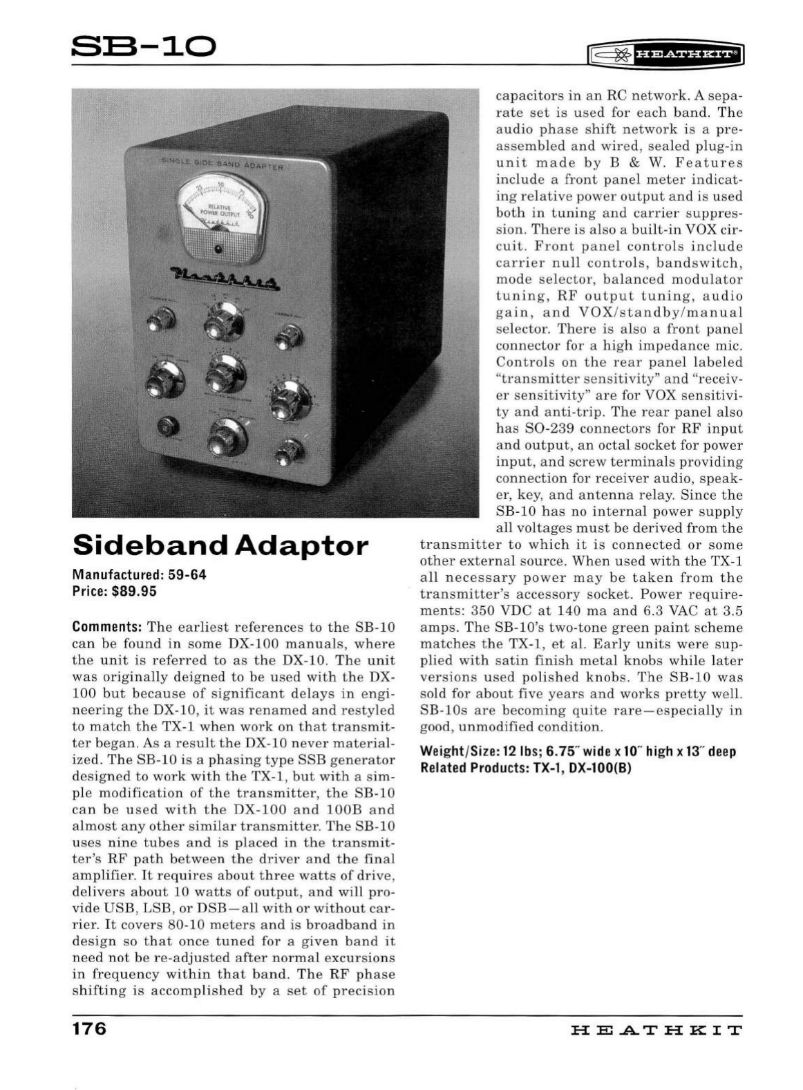
SB-10
Sideband
Adaptor
Manu
fac
tured
:
59-64
Price:
$89.95
Comments:
The
ear
li
e
st
references
to
the
SE-10
can
be
found
in
so
me
DX-100
manuals
,
where
the
unit
is
referred
to
as
the
DX-10.
Th
e
unit
was
origin
a
lly
deigned
to
be
used
with
th
e DX-
100
but
becau
se
of
significant
del
ays
in
e
ngi-
n
ee
ring
the
DX-10,
it
wa
s
renamed
and
restyled
to
match
the
TX-1
when
work
on
that
tran
sm
it
-
ter
began.
As a r
es
ult
the
DX-10
nev
er
materi
al-
ized.
The
SE-10
is
a
phasing
type
SSE
generator
d
es
igned
to
work
with
the
TX-1,
but
with
a s
im-
pl
e
modification
of
the
transmitter
,
the
SE-10
can
be
u
se
d
with
the
DX
-
100
and
lOOE
and
a
lmost
any
other
similar
transmitter
.
The
SE-10
uses
nine
tubes
and
is
placed
in
the
transmit
-
t
er
's
RF
path
betwee
n
th
e
driver
a
nd
th
e
final
amplifier
.
It
requires
about
three
watts
of
dri
ve
,
de
livers
about
10
watts
of
output,
and
will
pro-
vide
USE,
LSE
,
or
DSE-all
with
or
without
car-
rier.
It
covers
80-10
meter
s
and
is
broadb
a
nd
in
design
so
that
onc
e
tuned
for
a g
iven
band
it
need
not
be
re-adjusted
after
norm
al
excursions
in
frequency
within
that
ba
nd
.
The
RF
phase
shifting
is
acc
omplished
by
a
se
t
of
precision
176
rE=
~
1ua+tna+1
capacitors
in
an RC
network
. A
se
pa-
rate
set
is
u
se
d for
eac
h
band.
The
a
udio
phase
s
hift
n
etwor
k is a
pre-
asse
mbl
ed
an
d
wired
,
sea
led
plug-in
unit
made
by
E & W. F
eatures
includ
e a
front
panel
meter
indicat
-
in
g rel
at
ive
power
output
and
is
used
both
in
tunin
g a
nd
carrie
r s
uppres-
sion.
Ther
e is also a
built-in
VOX
cir
-
cuit.
Front
panel
contro
ls
include
carrier
null
contro
l
s,
bandswitch,
mod
e
selec
to
r,
balanced
modul
a
tor
tunin
g,
RF
output
tuning,
au
dio
ga
in
,
and
VOX
/
stan
db
y/
manual
selector.
Th
ere
is
al
so a
front
panel
conn
ec
tor
for a
high
impedance
mic.
Controls
on
the
rear
panel
l
abe
led
"
transmitter
se
n
sitiv
i
ty"
and
"receiv
-
er
sens
itivit
y"
are
for VOX
sensitivi-
ty
a
nd
anti-trip.
Th
e
rea
r p
ane
l a
lso
ha
s
S0-239
connectors
for
RF
input
a
nd
output,
an
octal
so
cket
fo
r
power
input
,
and
screw
terminals
providing
connection
for
receiver
audio,
spea
k-
er, key, a
nd
a
ntenna
relay.
Sinc
e
the
SE
-
10
has
no
internal
power
s
upp
ly
a
ll
voltages
mu
st
be
d
er
ived
from
the
transmitter
to
which
it
is
conn
ect ed
or
s
ome
other
exter
nal
so
urce
.
Wh
en
us
ed
with
th
e TX-1
a
ll
ne
cessary
power
may
be
t a k en
from
the
transmitter's
accessory
socket .
Power
require-
me
nt
s:
35
0 VDC
at
140
ma
a
nd
6.3 VAC at
3.5
amps.
Th
e
SE-lO'
s
two-ton
e
green
paint
sc
heme
match
es
the
TX-1,
et
al.
Early
units
w
ere
sup-
plied
with
s
atin
finish
me
tal
knob
s
whil
e
later
versions
used
polished
knobs
.
The
SE
-
10
was
so
ld
fo
r a
bout
five
years
a
nd
works
prett
y well.
SE-lOs
ar e beco
ming
quite
rare
-es
peci
a
ll
y
in
good,
unmodifi
ed
condition.
Wei
ght/Si
ze:
12
lbs
; 6.75"
wide
x
10
"
hi
gh x
13
"
deep
Rela
t
ed
Products
:
TX-1
, DX-100(8}
HE.A.TH
KIT
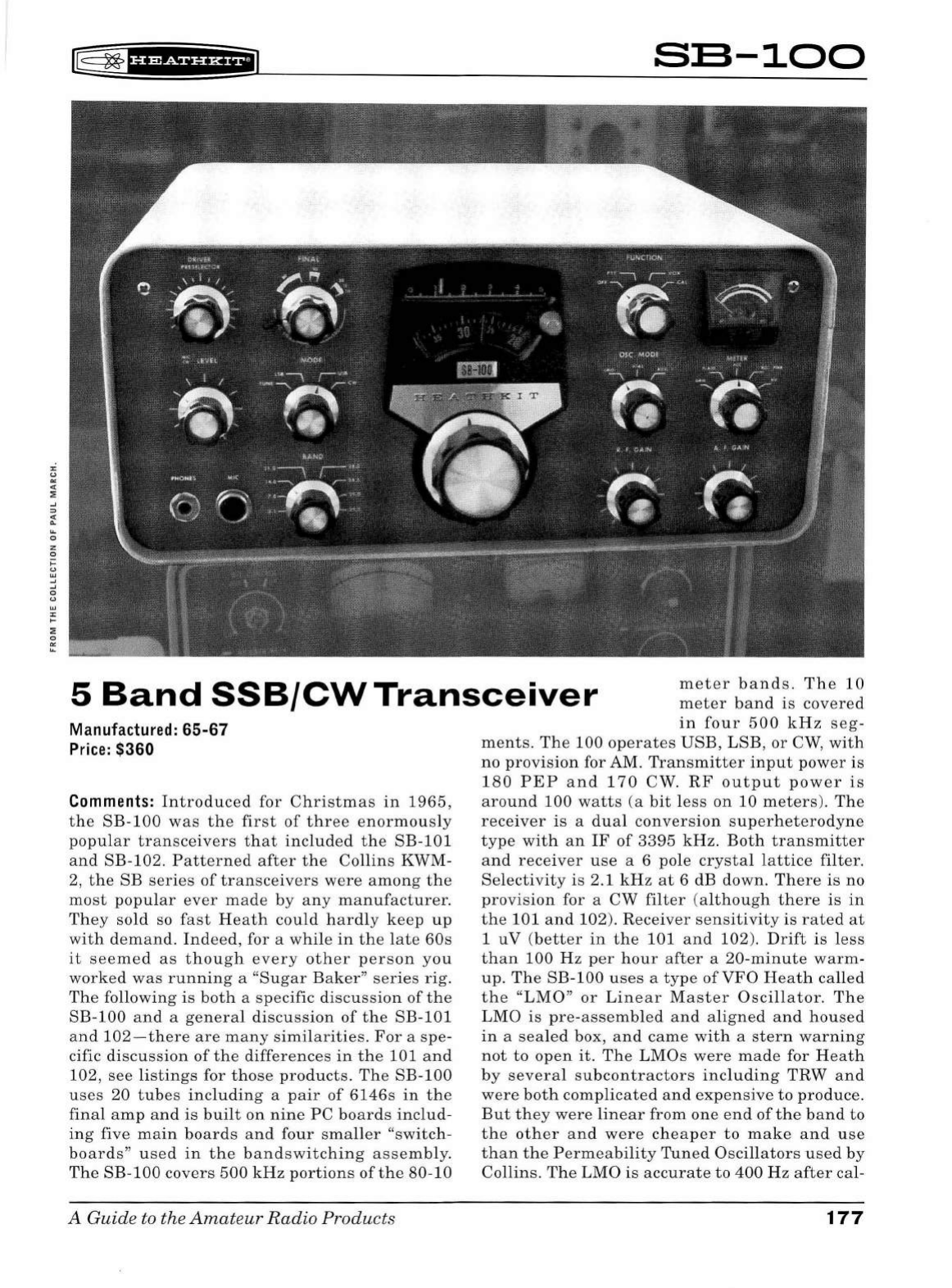
:z:
"
"'
"
::;
..J
:::>
:.
..
0
z
0
....
~
..J
..J
0
"
w
:z:
....
::;
0
"'
..
rr§
~
fH&iHHEil
SB-100
5
Band
SSB/CW
Transceiver
meter
bands
.
The
10
meter
band
is
covered
in
four
500
kHz
seg
-
Manufactured :
65-67
Pr
ice
: $360
Comments:
Introduced
for
Christmas
in
1965
,
the
SB-100
was
the
first
of
three
enormously
popular
transceivers
that
included
the
SB
-
101
and
SB-102
.
Patterned
after
the
Collins
KWM-
2,
the
SB
series
of
transceivers
were
among
the
most
popular
ever
made
by
any
manufacturer.
They
sold
so
fast
Heath
could
hardly
keep
up
with
demand.
Indeed,
for a
while
in
the
late
60s
it
seemed
as
though
every
other
person
you
worked
was
running
a "
Sugar
Baker"
series
rig.
The
following
is
both
a
specific
discussion
of
the
SB-100
and
a
general
discussion
of
the
SB-101
and
102-there
are
many
similarities.
For
a
spe-
cific
discussion
of
the
differences
in
the
101
and
102,
see
listings
for
those
products.
The
SB-100
uses
20
tubes
including
a
pair
of
6146s
in
the
final
amp
and
is
built
on
nine
PC
boards
includ-
ing
five
main
boards
and
four
smaller
"switch
-
boards
"
used
in
the
bandswitching
assembly.
The
SB
-
100
covers
500
kHz
portions
of
the
80-10
A
Guide
to the
Amateur
Radio
Products
ments.
The
100
operates
USB,
LSB,
or
CW,
with
no
provision
for AM.
Transmitter
input
power
is
180
PEP
and
1
70
CW.
RF
output
power
is
around
100
watts
(a
bit
less
on
10
meters).
The
receiver
is
a
dual
conversion
superheterodyne
type
with
an
IF
of
3395
kHz
.
Both
transmitter
and
receiver
use
a 6
pole
crystal
lattice
filter.
Selectivity
is
2.1
kHz
at
6 dB
down.
There
is
no
provision
for a
CW
filter
(although
there
is
in
the
101and102)
.
Receiver
sensitivity
is
rated
at
1 u V
(better
in
the
101
and
102).
Drift
is
less
than
100
Hz
per
hour
after
a
20-minute
warm
-
up
.
The
SB-100
uses
a
type
ofVFO
Heath
called
the
"LMO"
or
Linear
Master
Oscillator
.
The
LMO
is
pre-assembled
and
aligned
and
housed
in
a
sealed
box,
and
came
with
a
stern
warning
not
to
open
it.
The
LMOs
were
made
for
Heath
by
several
subcontractors
including
TRW
and
were
both
complicated
and
expensive
to
produce
.
But
they
were
linear
from
one
end
of
the
band
to
the
other
and
were
cheaper
to
make
and
use
than
the
Permeability
Tuned
Oscillators
used
by
Collins
.
The
LMO
is
accurate
to
400
Hz
after
cal
-
177
ibration
from
the
nearest
100
kHz
point.
The
dia
l
drive
mechanism
is
relatively
simp
le,
has
a
good
feel
and
good
resetability,
and
is
reason-
ab
ly
free
from
backlash.
Basic
features
include
PTT
and
VOX
operation,
LMO
or
crystal
con-
trolled
transmit
or
transceiver
(one
crystal
posi-
tion),
built
-
in
TR
switching,
and
a
built-in
100
kHz
crystal
calibrator.
See
listing
for
SB-640
for
crystal
frequency
formula
for
crystal
contro
ll
ed
operation.
Front
pane
l
controls
include
main
tuning,
driver
tuning
and
preselector,
final
tun-
ing,
final
loading,
mic
and
CW
level,
mode,
band,
function,
frequency
control
(XTAL
or
LMO),
meter
function,
RF
gain,
AF
gain
,
and
a
dial
calibration
knob
.
The
illuminated
panel
meter
will
read
ALC/S-units
,
relative
power
,
high
voltage
,
grid
current,
and
plate
current.
Internal
controls
include
VOX
sensitivity
,
delay
and
anti-trip,
carrier
null
(
control
and
capaci-
tor),
meter
zero,
CW
sidetone
leve
l,
relative
power
meter
adjust
, PA
bias
,
headphone
gain
,
and
neutralizing.
Rear
pane
l
connections
include
quarter
-
inch
key
jack
and
phono
connec
-
tors
for
an
eight
ohm
speaker,
600
ohm
output,
phone
patch
input
, ALC
input
,
RF
output,
and
receiver
antenna
input.
There
is
also
an
11
pin
"octal
style"
pl
ug
for
power
input
and
an
anten
-
na
selector
switch
to
select
separate
or
common
antennae
for
transmit
and
receive.
Many
of
these
rigs
have
been
modified
and
fitted
wit
h
an
S0-239
to
replace
the
phono
RF
output
connec-
tor.
Other
acceptable
modifications
include
the
installation
of
phono
jacks
needed to
operate
the
SB-
650
frequency
disp
l
ay
and
addition
(or
use)
of
spare
jacks
to
support
the
SB-610
and
/
or
SB
-
620.
The
SB-100, SB-101,
and
HW-100,
as
well
as
SB-102s
with
the
last
four
digits
of
the
serial
number
lower
than
5446,
have
a
minor
prob
l
em
with
the
driver
preselector
peaking
in
a
slightly
different
spot
for
transmit
and
receive.
To
make
them
peak
in
the
same
place
Heath
offered
a
simple
mod
(much
simpler
than
the
one
described
in
QST).
The
presence
of
this
mod
can
be
determined
by
checking
for a
three
l
ug
termi-
na
l
strip
soldered
to
one
of
the
shields
between
two
of
the
small
PC
boards
in
the
bandswitch
assembly.
It
shou
ld
be
noted
that
this
preselec
-
tor
prob
l
em
is
very
minor
and
most
ops
don't
bother
fixing
it.
Units
with
other
modifications
should
be
avoided
except
for
parts
.
NOTE:
Because
of
mechanical
changes
in
the
SB-
102's
solid
state
LMO,
it
is
not
possible
to
retrofit
an
SB-
100
or
101
with
an
LMO
from
a
102.
The
100
series
of
transceivers
has
no
built-in
power
sup-
ply
and
is
designed
for
use
with
the
HP-13
and
178
~
~
fHMii'Hil
HP
-
23
series
power
supplies
.
Power
require-
ments:
700-800
VDC
at
250
ma,
300
VDC
at
1509
ma,
-110
VDC
at
10
ma,
and
12
volts
AC
or
DC
at
4.76
amps.
The
SB
series
of
products
all
use
a
two-tone
green
wrinkle
paint
scheme.
The
paint
color
and
texture
varied
from
batch
to
batch
and
from
year
to
year,
so
finding
two
SB
units
of
the
exact
same
paint
shade
and
texture
may
not
be
easy.
By
the
time
the
SB-102
was
released
in
1970,
Heath
had
developed
a
full
line
of
accessories
for
the
SB
line
,
and
no
SB
series
station
is
complete
without
all
of
them
.
These
include
the
SB
-2XX
series
of
amplifiers
and
the
SB-6XX
series
of
accessories
and
are
listed
else-
where
in
this
book
-
see
re
l
ated
products
below.
Together
with
the
SB
transceivers
they
created
a
high
performance
station
without
equal
in
the
hobby.
Once
common,
SB
-lOOs
are
now
quite
rare
-
especially
in
good
condition.
Wei
g
ht
/
Size
:
23lb
s;
1
5"
wi
de
x 6.75"
hi
gh x
14
"
deep
Rel
at
ed
Products:
SB-
1
01
,
SB-102
, SB-200(201),
SB-220(221), SB-300(301), SB-303,
SB-310
,
SB-313
, SB-400(401), SB-600,
SB-610
,
SB-620,SB-630 ,SB-640 ,SB-500 ,SB-650
HE.ATHKIT
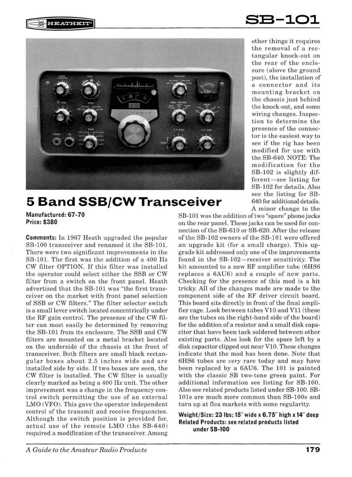
rr§
~
f
i'iiif
Hi*fil
SB-101
other
things
it
requires
the
removal
of
a
rec-
tangular
knock-out
on
the
rear
of
the
enclo-
sure
(above
the
ground
post),
the
installation
of
a
connector
and
its
mounting
bracket
on
the
chassis
just
behind
the
knock-out,
and
some
wiring
changes.
Inspec-
tion
to
determine
the
presence
of
the
connec-
tor
is
the
easiest
way
to
see
if
the
rig
has
been
modified
for
use
with
the
SB-640.
NOTE:
The
modification
for
the
SB-102
is
slightly
dif-
ferent-see
listing
for
SB-102
for
details.
Also
see
the
listing
for
SB-
640 for additional details.
5
Band
SSB/CW
Transceiver
A
minor
change
to
the
SB-101
was
the
addition
of two "
spare"
phono
jacks
on
the
rear
panel.
These
jacks
can
be
used
for con-
nection
of
the
SB-610
or
SB-620.
After
the
release
of
the
SB-102
owners
of
the
SB-101
were
offered
an
upgrade
kit
(for
a
small
charge).
This
up-
grade
kit
addressed
only
one
of
the
improvements
found
in
the
SB-102-receiver
sensitivity.
The
kit
amounted
to
a
new
RF
amplifier
tube
(6HS6
replaces
a
6AU6)
and
a
couple
of
new
parts.
Checking
for
the
presence
of
this
mod
is
a
bit
tricky.
All
of
the
changes
made
are
made
to
the
component
side
of
the
RF
driver
circuit
board.
This
board
sits
directly
in
front
of
the
final
ampli
-
fier
cage.
Look
between
tubes
VlO
and
Vll
(these
are
the
tubes
on
the
right-hand
side
of
the
board)
for
the
addition
of
a
resistor
and
a
small
disk
capa-
citor
that
have
been
tack
soldered
between
other
existing
parts.
Also
look
for
the
space
left
by
a
disk
capacitor
clipped
out
near
VlO.
These
changes
indicate
that
the
mod
has
been
done.
Note
that
6HS6
tubes
are
very
rare
today
and
may
have
been
replaced
by
a
6AU6.
The
101
is
painted
with
the
classic
SB
two-tone
green
paint
.
For
additional
information
see
listing
for
SB-100.
Also
see
related
products
listed
under
SB-100. SB-
lOls
are
much
more
common
than
SB-lOOs
and
turn
up
at
flea
markets
with
some
regularity.
Manufactured: 67-70
Price:
$380
Comments:
In
1967
Heath
upgraded
the
popular
SB-100
transceiver
and
renamed
it
the
SB-101.
There
were
two
significant
improvements
in
the
SB-101.
The
first
was
the
addition
of
a
400
Hz
CW
filter
OPTION.
If
this
filter
was
installed
the
operator
could
select
either
the
SSB
or
CW
filter
from
a
switch
on
the
front
panel.
Heath
advertised
that
the
SB-101
was
"
the
first
trans-
ceiver
on
the
market
with
front
panel
selection
of
SSB
or
CW
filters."
The
filter
selector
switch
is
a
small
lever
switch
located
concentrically
under
the
RF
gain
control.
The
presence
of
the
CW fil-
ter
can
most
easily
be
determined
by
removing
the
SB-101
from
its
enclosure
.
The
SSB
and
CW
filters
are
mounted
on
a
metal
bracket
located
on
the
underside
of
the
chassis
at
the
front
of
transceiver.
Both
filters
are
small
black
rectan-
gu
l
ar
boxes
about
2.5
inches
wide
and
are
installed
side
by
side.
If
two
boxes
are
seen,
the
CW
filter
is
installed.
The
CW
filter
is
usually
clearly
marked
as
being
a
400
Hz
unit.
The
other
improvement
was
a
change
in
the
frequency
con-
trol
switch
permitting
the
use
of
an
external
LMO
(
VFO)
.
This
gave
the
operator
independent
control of
the
transmit
and
receive
frequencies.
Although
the
switch
position
is
provided
for,
actual
use
of
the
remote
LMO
(the
SB-640)
required
a
modification
of
the
transceiver.
Among
A
Guide
to the
Amateur
Radio
Products
Weight/Size: 23
lbs;
15"
wide
x 6. 75"
high
x
14"
deep
Related
Products
:
see
related
products
listed
under
SB-100
179
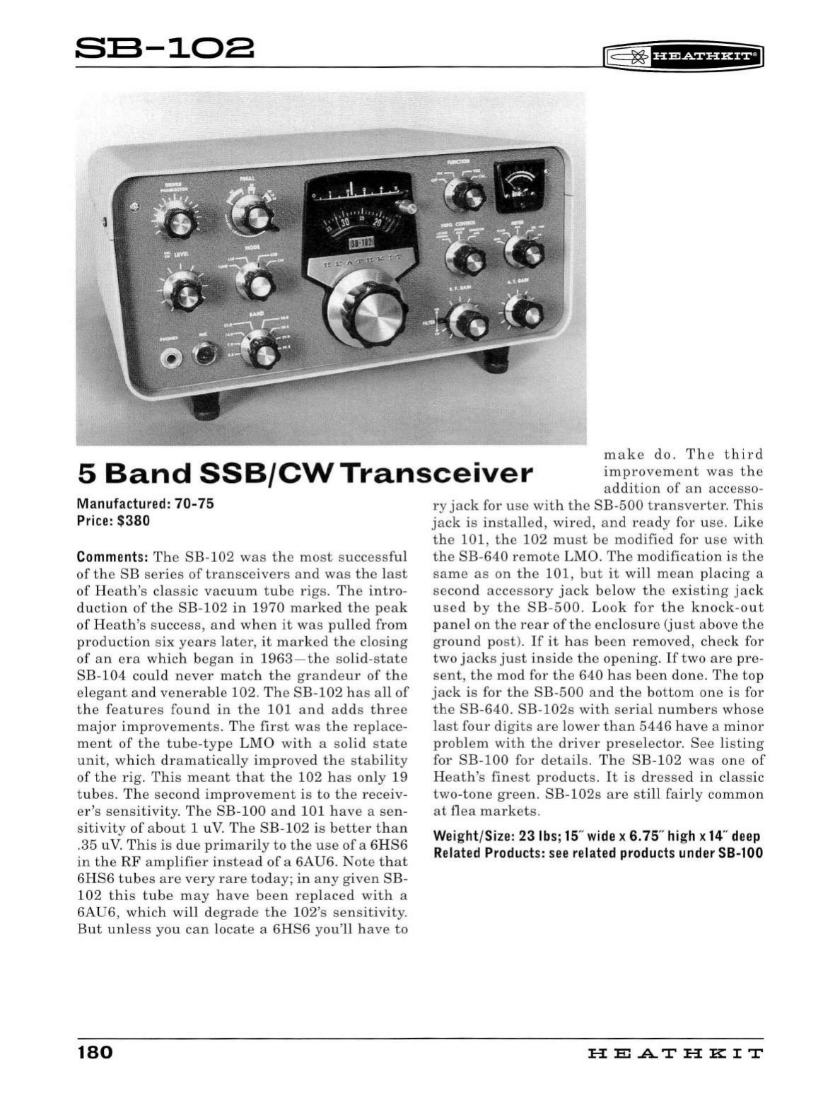
s:s-1oa
If:
~
f
if
Mf
§f
i*fiJ
5
Band
SSB/CW
Transceiver
make
do.
The
third
improvement
was
the
addition
of
an
accesso-
Manufactured:
70-75
Price:
$380
Comments:
The
SB
-
102
was
the
most
successfu
l
of
the
SB
series
of
transceivers
and
was
the
last
of
Heath's
classic
vacuum
tube
rigs.
The
intro
-
duction
of
the
SB-102
in
1970
marked
the
peak
of
Heath's
success,
and
when
it
was
pulled
from
production
six
years
later
,
it
marked
the
closing
of
an
era
which
began
in
1963-the
solid
-
state
SB-
104
could
never
match
the
grandeur
of
the
elegant
and
venerable
102.
The
SB-
102
has
all
of
the
features
found
in
the
101
and
adds
three
major
improvements.
The
first
was
the
rep
lace-
ment
of
the
tube
-
type
LMO
with
a
solid
state
unit,
which
dramatically
improved
the
stability
of
the
rig.
This
meant
that
the
102
has
on
ly 19
tubes.
The
second
improvement
is
to
the
receiv
-
er's
sensitivity.
The
SB-100
and
101
have
a
sen
-
sitivity
of
about
1 uV.
The
SB-102
is
better
than
.35 u
V.
This
is
due
primarily
to
the
use
of
a
6HS6
in
the
RF
amplifier
instead
ofa
6AU6.
Note
that
6HS6
tubes
are
very
rare
today;
in
any
given
SB-
102
this
tube
may
have
been
replaced
with
a
6AU6
,
which
will
degrade
the
102's
sensitivity
.
But
unless
you
can
locate
a
6HS6
you'll
have
to
180
ry
jack
for
use
with
the
SB
-
500
transverter.
This
jack
is
installed,
wired
,
and
ready
for
use.
Like
the
101,
the
102
must
be
modified
for
use
with
the
SB
-
640
remote
LMO.
The
modification
is
the
same
as
on
the
101,
but
it
will
mean
placing
a
second
accessory
jack
below
the
existing
jack
used
by
the
SB-500
.
Look
for
the
knock-out
panel
on
the
rear
of
the
enclosure
(just
above
the
ground
post).
If
it
has
been
removed,
check
for
two
jacks
just
inside
the
opening.
If
two
are
pre-
sent,
the
mod
for
the
640
has
been
done
.
The
top
jack
is
for
the
SB-500
and
the
bottom
one
is for
the
SB-640.
SB-102s
with
serial
numbers
whose
last
four
digits
are
lower
than
5446
have
a
minor
problem
with
the
driver
preselector
.
See
listing
for
SB
-
100
for
details.
The
SB-102
was
one
of
Heath's
finest
products.
It
is
dressed
in
classic
two-tone
green.
SB-102s
are
sti
ll
fairly
common
at
flea
markets.
Weight/Size: 23
lbs
;
15
"
wide
x 6. 75"
high
x
14
"
deep
Related
Products:
see
related
products
under
SB-100
HEATHKIT
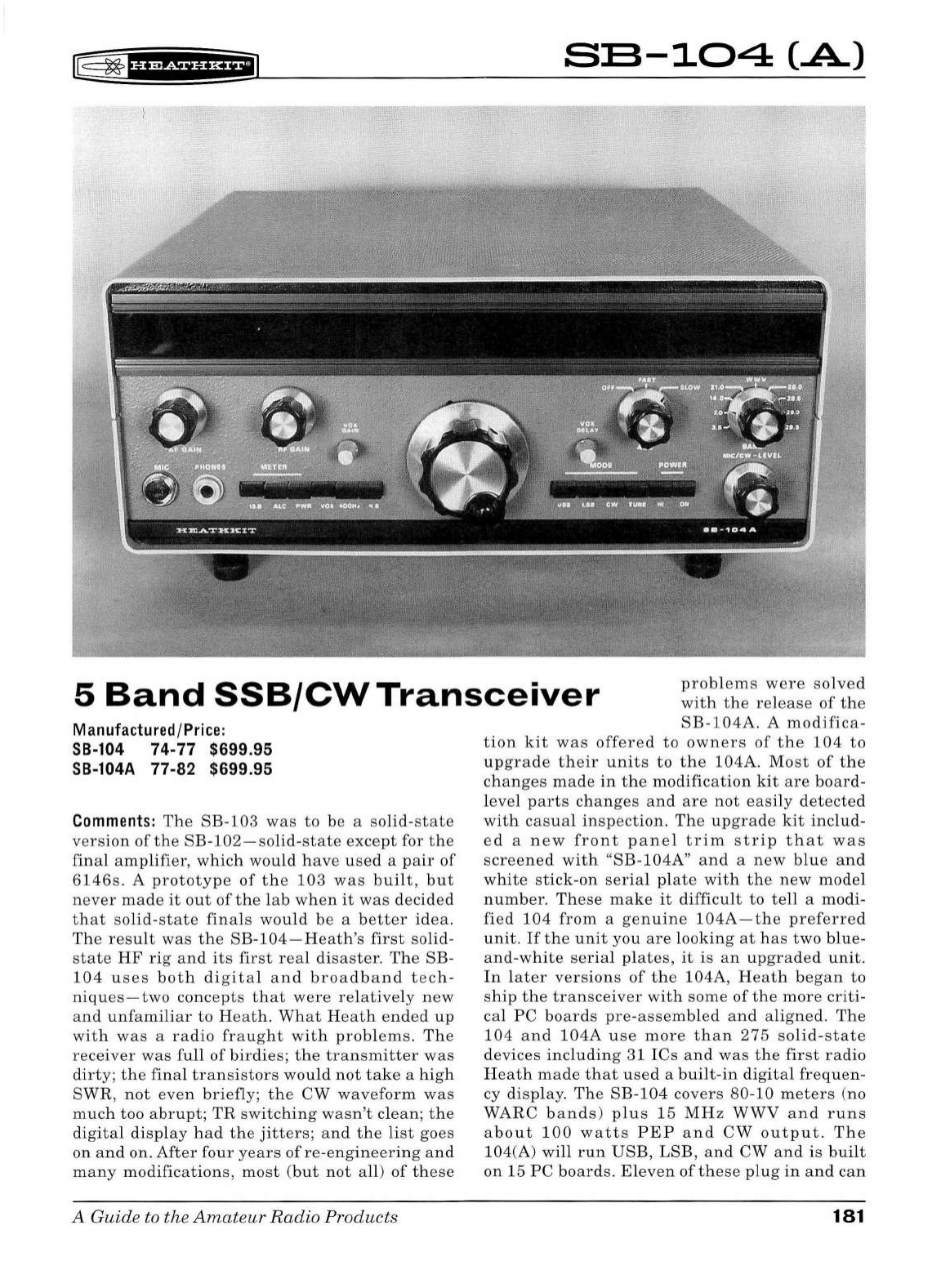
l8
~
f
bi&f
HH+iil
S:S-104
(.A)
5
Band
SSB/CW
Transceiver
problems
were
solved
with
the
release
of
the
SB
-
104A
. A
modifica-
Manufactured/
Price:
SB-104
74-77
$699.95
SB-104A
77-82
$699.95
Comments:
The
SB
-
103
was
to
be
a
solid-state
version
of
the
SB
-102-solid
-
state
except
for
the
final
amplifier,
which
wo
ul
d
have
used
a
pair
of
6146s.
A
prototype
of
the
103
was
b
uil
t,
but
never
made
it
out
of
the
l
ab
when
it
was
decided
that
solid-state
finals
would
be
a
better
idea.
The
resu
lt
was
the
SB
-1
04
-
Heath's
first
solid-
state
HF
rig
and
its
first
real
disaster
.
The
SB-
104
uses
bot
h
digita
l
and
broadban
d
tech
-
niques-two
concepts
that
were
relative
ly
new
and
unfamiliar
to
Heat
h.
What
Heath
ended
up
with
was
a
radio
fraught
with
problems
.
The
receiver
was
fu
ll
of
bird
ies;
the
transm
i
tter
was
dirty;
the
fina
l t
ransistors
would
not
take
a
high
SWR,
not
even
briefly
; th e
CW
waveform
was
much
too
abrupt;
TR
switching
wasn
't
clean;
the
digita
l di
sp
l
ay
h
ad
the
ji
tters;
and
the
li
st
goes
on
and
on.
After
four
years
of
re
-
engineer
i
ng
and
many
modifications,
most
(but
not
a
ll
)
of
these
A Guide
to
the
Amateu
r R adio Products
tion
kit
was
offered
to
owners
of
the
104
to
upgrade
their
units
to
the
104A.
Most
of
the
changes
made
in
the
modification
kit
are
board
-
l
evel
parts
changes
a
nd
are
not
easily
detecte
d
with
casual
inspection.
The
upgrade
kit
includ
-
ed
a
new
front
pane
l
trim
strip
t h
at
was
screened
with
"SB
-
10
4A"
and
a
new
bl
ue
an
d
white
stick-on
seria
l
pl
ate
wit
h
the
new
mode
l
number.
These
make
it
difficu
lt
to
te
ll
a
modi
-
fied
104
from
a
genu
i
ne
104A-the
preferred
unit.
If
the
u
nit
you
are
looking
at
has
two
blue-
and-white
seria
l
plates,
it
is
an
upgraded
unit
.
In
l
ater
versions
of
t h e
104A,
H
eath
b
egan
to
ship
th e
transceiver
with
some
of
the
more
criti
-
ca
l
PC
boards
pre-assemb
l
ed
and
aligned.
The
104
and
1
04A
use
more
than
275
solid-state
devices
inclu
d
ing
31
ICs
and
was
the
first
radio
Heat
h
made
th
at
use
d a
built
-in
digita
l
frequen
-
cy
disp
lay. The
SB
-
104
covers
80-10
meters
(
no
WARC
bands)
plus
15
MHz
WWV
and
runs
about
1
00
watts
PE
P
and
CW
output.
The
104(A)
wi
ll
run
USB,
L
SB,
and
CW
an
d
is
bui
lt
on
15
PC
boards.
El
eve
n
of
these
plug
in
and
can
181
be
extended
for
ease
of
servicing
and
adjustment
while
the
transceiver
is
operating.
Features
include
a
broadband
no-tune
design,
built-in
CW
sidetone,
push-button
selection
of
most
func-
tions
including
meter
function,
VOX,
mode,
and
power
on
/off.
There
is
also
a
QRP
mode
that
yields
about
one
watt
of
output
power.
No
crys-
tal
calibrator
is
required
.
Receiver
sensitivity
is
less
than
1 u
V.
Selectivity
is
2 .1
kHz
at
6
dB
down
.
There
is
an
optional
400
Hz
CW
filter,
and
an
optional
noise
blanker.
Drift
is
less
than
100
Hz
per
hour
after
a
30-minute
warm
-u
p.
TR
switching
is
done
with
a
mechanical
relay,
so
true
QSK
is
not
possible.
Front
panel
controls
include
the
aforementioned
push
buttons
,
AF
and
RF
gain,
AGC fast/slow/off, VOX
gain
and
delay,
bandswitch
,
mic
/
CW
level
,
and
main
tun-
ing.
The
main
tuning
knob
is
a
"spinner"
type
and
slues
at
the
rate
of
30
kHz
per
revolution.
In
addition
to
the
digital
display
(seven
segment
neon
type),
the
front
panel
also
sports
a
meter
that
reads
both
S-units
and
relative
power
and
the
call
letters
of
the
station.
(The
clever
person
should
be
able
to
figure
out
a
way
to
replace
the
call
letters
with
his
or
her
own
.)
Rear
panel
con-
trols
include
VOX
anti
-trip
,
sidetone
level,
and
a
switch
for
selection
of
separate
or
common
antennas.
Rear
panel
connections
include
a
standard
quarter-inch
key
jack
and
phono
type
jacks
for
phone
patch
in
and
out,
linear
amp
ALC
input,
a
four
ohm
speaker,
receiver
audio
input,
VFO
input
and
output,
IF
output,
driver
output,
and
two
spares
.
There
is
also
a
ground
post
,
an
11-pin
"octal
style"
power
plug,
and
an
accessory
socket
(
which
includes
relay
output)
.
The
SB
-104
comes
with
both
an
assembly
and
an
operations
manual-try
to
get
them
both
.
Also
try
hard
to
get
the
card
extender
boards
that
came
with
the
radio.
They
are
a
virtual
necessi-
ty
for
working
on
the
rig.
Any
SB-104(A)
series
transceiver
should
be
regarded
as
having
one
or
more
problems
solvable
only
by
the
most
ski
ll
ed
technicians,
and
claims
of
their
being
in
good
182
li5
~fH@SiHH+I
working
order
should
be
regarded
with
a
degree
of
skepticism.
The
SB-104
(A)
was
an
expensive
endeavor
for
Heath
and
one
from
which
it
never
saw
a
profit
.
The
104(A)
is
designed
for
use
with
the
HP-1144
power
supply
.
Power
requirements:
12 VDC
at
20
amps
maximum
transmit
, 2
amps
receive.
The
SB-104
(A)
used
the
classic
SB
two-
tone
green
wrinkle
finish
and
SB
series
knobs.
Not
too
rare
.
Caveat
emptor!
Weight/Size: 31lbs;14.5"
wide
x 5.75"
high
x
14"
deep
Related
Products:
SB-230, SB-604,
SB-614,
SB-
634, SB-644(A),
HP-1144
HE
.AT
HK
IT
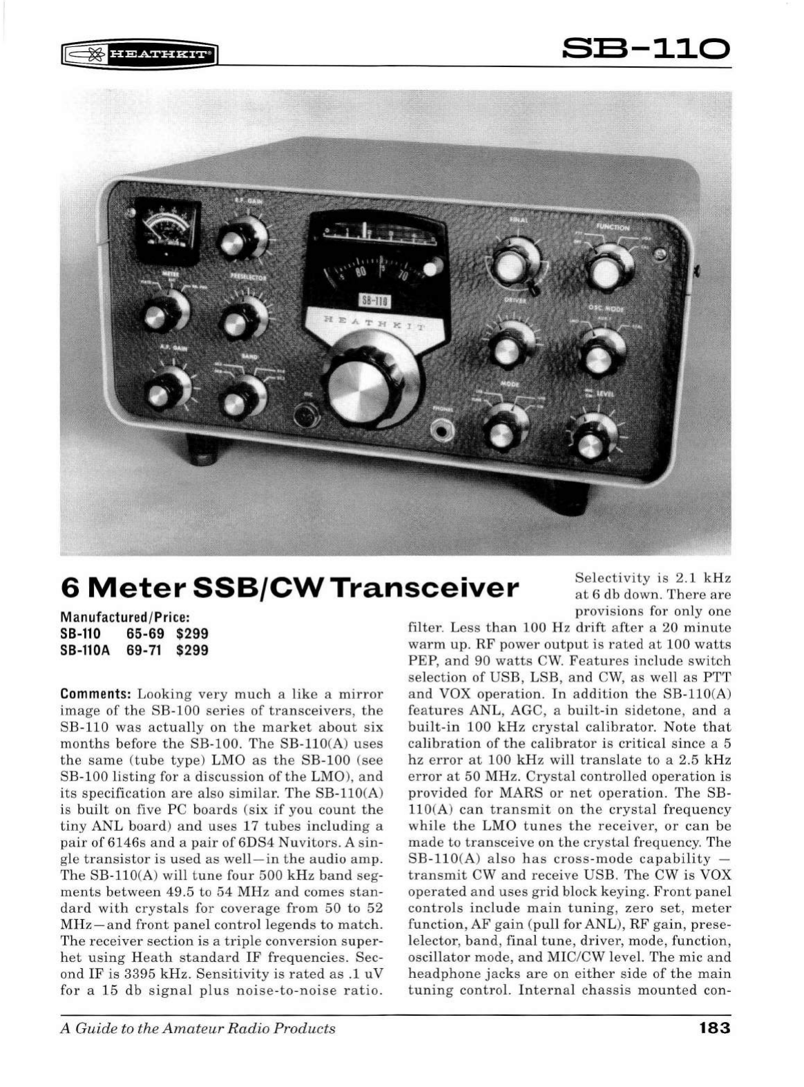
[
~
f#
1
#¥iifl*f;i]
SB-110
6
Meter
SSB/CW
Transceiver
Selectivity
is
2 .1
kHz
at
6
db
down.
There
are
Manufactured/Price:
SB-110
65-69
$299
SB-110A
69-
71
$299
Comments:
Looking
very
much
a
lik
e a
mirror
image
of
the
SB-100
series
of
transceivers,
the
SB
-110
was
actua
lly
on
the
market
about
six
months
before
the
SB-100
.
The
SB-llO(A)
uses
the
same
(tube
type)
LMO
as
the
SB-100
(see
SB
-100
listing
for a
discussion
of
the
LMO
),
and
its
specification
are
also
similar.
The
SB-llO(A)
is
built
on
five
PC
boards
(six
if
you
count
the
tiny
ANL
board)
and
uses
17
tubes
including
a
pair
of
6146s
and
a
pair
of
6DS4
Nuvitors.
A
sin
-
gle
transistor
is
used
as
well-in
the
audio
amp.
The
SB-llO(A
)
will
tune
four
500
kHz
band
seg-
ments
between
49.5
to
54
MHz
and
comes
stan
-
dard
with
crystals
for
coverage
from
50
to
52
MHz-and
front
panel
control
legends
to
match.
The
receiver
section
is
a
triple
conversion
super-
het
using
Heath
standard
IF
frequencies.
Sec-
ond
IF
is
3395
kHz
.
Sensitivity
is
rated
as
.1
uV
for
a
15
db
signal
plus
noise-to-noise
ratio.
A Guide to the
Amateur
Radio
Products
provisions
for
only
one
filter.
Less
than
100
Hz
drift
after
a
20
minute
warm
up.
RF
power
output
is
rated
at
100
watts
PEP
,
an
d
90
watts
CW
.
Features
include
switch
selection
of
USB,
LSB
,
an
d CW,
as
well
as
PTT
and
VOX
operation.
In
addition
the
SB-110
(A)
features
ANL,
AGC,
a
built-in
sidetone,
and
a
built-in
100
kHz
crystal
calibrator.
Not
e
that
calibration
of
the
calibrator
is
critical
since
a 5
hz
error
at
100
kHz
will
translate
to
a 2.5
kHz
error
at
50
MHz.
Crysta
l
controlled
operation
is
provided
for
MARS
or
net
operation.
The
SB-
110(A)
can
transmit
on
the
crystal
frequency
while
the
LMO
tunes
the
receiver,
or
can
be
made
to
transceive
on
the
crystal
frequency
.
The
SB-110(A)
a
lso
has
cross-mode
capability
-
transmit
CW
and
receive
USB.
The
CW
is
VOX
operated
and
us
es
grid
block
keying.
Front
panel
controls
include
main
tuning,
zero
set
,
meter
function,
AF
gain
(pull
for ANL),
RF
gain,
prese-
lelector
,
band,
final
tune,
driver,
mod
e,
function,
oscillator
mode,
and
MIC
/
CW
l
eve
l.
The
mic
and
headphone
jacks
are
on
eit
h
er
side
of
the
main
tuning
control.
Internal
chassis
mounted
con-
183
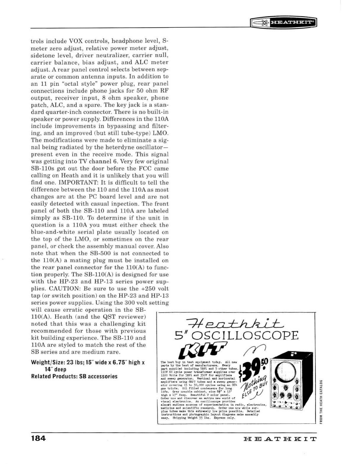
trols
include
VOX
controls,
headphone
l
eve
l, S-
meter
zero
a
dju
st,
relative
power
meter
adju
st
,
sidetone
level,
driver
neutralizer,
carrier
null,
carrier
balance,
bias
adjust,
and
ALC
meter
adjust.
A
rear
panel
control
selects
between
sep
-
arate
or
common
antenna
inputs.
In
a
ddition
to
an
11
pin
"octal
sty
le"
power
plug
,
rear
panel
connections
include
phone
j
acks
for
50
ohm
RF
output
,
receiver
input
, 8
ohm
speaker,
phone
patch,
ALC,
and
a
spare.
The
key
jack
is
a
stan-
d
ard
quarter-inch
connector.
There
is
no
built-in
speaker
or
power
supply.
Diff
ere
nc
es
in
the
llOA
include
improv
ements
in
b
ypass
in
g
and
filter-
ing
,
and
an
improved
(
but
still
tube-type
) LMO.
The
modifications
were
made
to
e
liminat
e a sig-
nal
being
radiated
by
the
h
eterdyne
oscillator-
present
even
in
the
rece
iv
e
mode
.
Thi
s
sig
nal
was
getting
into
TV
channel
6. Very few
original
SB-llOs
got
out
the
door
b
efore
the
FCC
came
calling
on
Heath
and
it
is
unlikely
that
you
will
find
one.
IMPORTANT:
It
is
difficult
to
tell
the
difference
between
the
110
and
the
llOA
as
most
ch
anges
are
at
the
PC
board
l
eve
l
and
are
not
easily
detected
wit
h
casual
inpection.
The
front
panel
of
both
the
SB-110
and
llOA
are
l
abe
led
s
imply
as
SB-110.
To
determine
if
the
unit
in
question
is
a
llOA
you
must
either
check
the
blue-and-white
serial
plate
usually
loc
ated
on
the
top
of
the
LMO
,
or
sometimes
on
the
rear
panel,
or
check
the
assembly
manual
cover. Also
not
e
that
when
the
SB-500
is
not
connecte
d
to
the
llO(A)
a
mating
plug
must
be
installed
on
the
rear
panel
connector
for
the
llO(A)
to
func-
tion
properly.
Th
e
SB
-llO
(A)
is
de
signed
for u
se
with
the
HP-23
an
d
HP-13
series
power
s
up-
pli
es
.
CAUTION:
Be
sure
to
use
the
+2
50
volt
tap
(
or
switch
position
)
on
the
HP-23
and
HP-13
series
power
su
pplies.
Using
the
300
volt
setti
ng
will
cause
erratic
operation
in
the
SB-
llO
(A).
Heath
(and
the
QST
rev
i
ewer)
not
ed
that
this
was
a
challenging
kit
recommended
for
those
with
previous
ki
t
building
experience.
Th
e
SB-110
and
llOA
are
sty
led
to
match
th
e
rest
of
the
SB
ser
ie
s
and
are
medium
rare
.
Weight/Size: 23lbs;15"
wide
x 6.75"
high
x
14"
deep
Related
Products:
SB
accessories
184
~fHiif§fi*EiJ
HE.A.TH
KIT
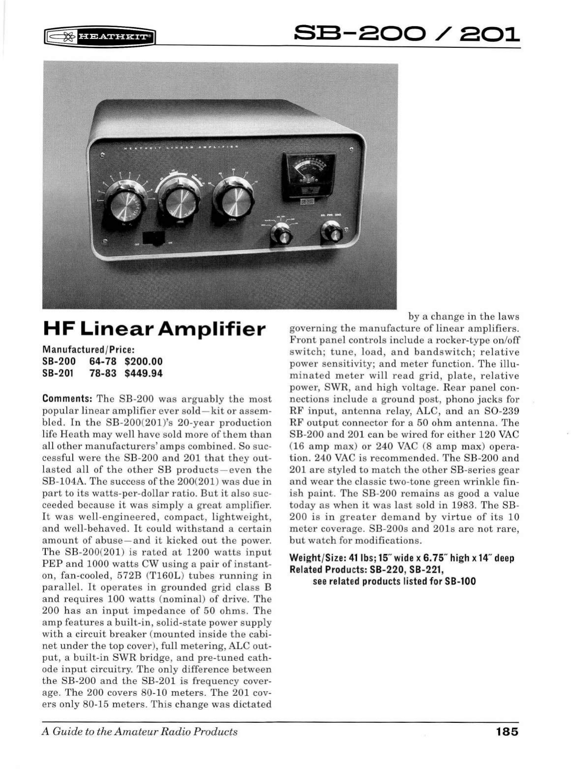
~
~1ua&tna11
HF
Linear
Amplifier
Manufactured/Price:
SB-200 64-78 $200.00
SB-201
78-83 $449.94
Comments:
The
SB-200
was
arguably
the
most
popular
linear
amplifier
ever
sold-kit
or
assem
-
bl
ed.
In
the
SB-200(201)'s
20-year
production
life
He
at
h
may
well
have
sold
more
of
them
than
all
other
manufacturers
'
amps
combin
ed. So
suc-
ce
ss
ful
were
the
SB-200
and
201
that
they
out-
lasted
all
of
the
other
SB
products
-e
ven
the
SB-104A.
The
success
of
the
200(201)
was
due
in
part
to
it
s
watts-per
-d
ollar
ratio.
But
it
also
suc-
cee
ded
becau
se
it
was
si
mply
a
great
a
mplifier.
It
was
well-engineered,
compact
,
lightw
e
ight
,
and
well-behaved.
It
co
uld
withstand
a
certain
amount
of
abuse
-
and
it
kicked
out
the
power
.
Th
e
SB-200
(
201)
is
r
ate
d
at
1200
watts
input
PEP
and
1000
watts
CW u s
ing
a
pair
of
in
s
tant-
on,
fan-cooled,
572B
(
T160L
)
tub
es
running
in
parallel.
It
operates
in
grounded
grid
cl
ass
B
and
requires
100
watts
(
nominal
)
of
driv
e.
Th
e
200
ha
s
an
input
impedanc
e
of
50
ohms.
Th
e
amp
fe
at
ur
es
a
built-in
,
solid-state
pow
er
supply
w
ith
a
circuit
breaker
(m
ounted
insid
e
the
cabi-
net
und
er
the
top
cover),
full
metering
, ALC
out-
put
, a
built-in
SWR
bridge
,
and
pre-tuned
cath-
ode
input
circuitry.
Th
e
only
diff
ere
nc
e
between
th
e
SB-200
an
d
the
SB-201
is
fr
eq
u
ency
co
ver-
age
.
Th
e
200
covers
80-10
meters.
Th
e
201
cov-
ers
only
80-15
meters.
This
change
wa
s
dictated
A
Guide
to
th
e
Amateur
Radio
Products
s:s-aoo/ao1
by
a
change
in
th
e
laws
governing
the
manufacture
of
linear
a
mplifier
s.
Front
panel
controls
include
a
rocker-typ
e
on/off
sw
itch
;
tune
, loa d , a
nd
band
sw
itch;
r e
lativ
e
power
se
n
sitiv
ity;
and
meter
function.
The
illu-
minat
ed m
eter
will
r
ea
d
grid
,
plate
,
relative
power,
SWR,
and
high
voltage.
Rear
pan
el con-
nec
tion
s
includ
e a
ground
post
,
phono
ja
c
ks
for
RF
input
,
an
tenna
relay,
ALC,
and
an
S0-239
RF
ou
t
put
connector
for a
50
ohm
antenna.
Th
e
SB-200
and
201
can
be
wir
ed for
either
120
VAC
(16
amp
max)
or
240
VAC
(8
amp
max
)
opera-
tion.
240
VAC
is
recommended.
The
SB
-200
and
201
are
styled
to
match
th
e
other
SB-seri
es
gear
and
w
ear
th
e
classic
two-tone
green
wrinkle
fin-
ish
paint.
The
SB-200
remains
as
good a
value
today
as
wh
en
it
was
last
so
ld
in
1983.
Th
e SB-
200
is
in
greater
d
ema
nd
by
virtue
of
its
10
me
ter
coverage.
SB-200s
and
201s
are
not
rare,
but
watch
for
modifications
.
Weight/Size: 41lbs;15"
wide
x 6.75"
high
x
14"
deep
Related
Products:
SB-220,
SB-221
,
see
related
products
listed
for
SB-100
185
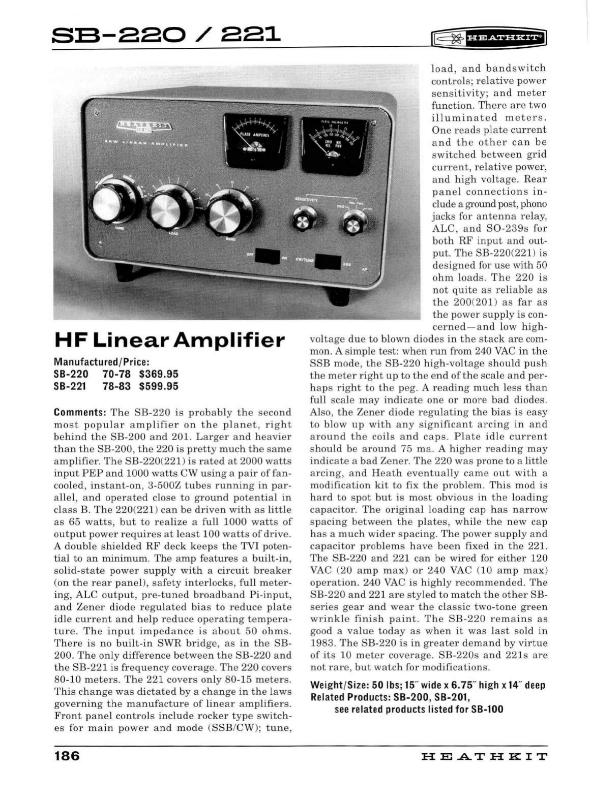
s:s-220/221
HF
Linear
Amplifier
Manufactured/Price:
SB-220 70-78 $369.95
SB-221
78-83 $599.95
Comments:
The
SB-220
is
probably
the
second
most
popular
amplifier
on
the
planet,
right
behind
the
SB
-
200
and
201.
Larger
and
heavier
than
the
SB-200,
the
220
is
pretty
much
the
same
amplifier.
The
SB-220
(
221)
is
rated
at
2000
watts
input
PEP
and
1000
watts
CW
using
a
pair
offan
-
cooled,
instant
-on, 3-
500Z
tubes
running
in
par-
alle
l,
and
operated
close
to
ground
potential
in
class
B.
The
220(221
)
can
be
driven
with
as
little
as
65
watts,
but
to
realize
a full
1000
watts
of
output
power
requires
at
least
100
watts
of
drive.
A
double
shie
l
ded
RF
deck
keeps
the
TVI poten-
tia
l
to
an
min
i
mum.
The
amp
features
a
built
-
in,
solid-state
power
supp
ly
wit
h a
circuit
breaker
(on
the
rear
panel),
safety
interlocks
,
full
meter-
ing,
ALC
output,
pre
-tu
ned
broadband
Pi
-
input,
and
Zener
diode
regulated
bias
to
reduce
plate
idle
current
and
he
lp
reduce
operating
tempera
-
ture.
The
input
impedance
is
about
50
ohms.
There
is
no
built-in
SWR
bridge,
as
in
the
SB-
200.
The
only
difference
between
the
SB
-
220
and
the
SB
-221
is
frequency
coverage.
The
220
covers
80-10
meters.
The
221
covers
on
ly
80
-15
meters.
This
change
was
dictated
by
a
change
in
the
l
aws
governing
the
manufacture
of
linear
amplifiers.
Front
panel
contro
ls
include
rocker
type
switch-
es
for
main
power
and
mo
de
(SSB/CW);
tune,
186
rE=
~
tH?tS?UH+IJ
load,
and
bandswitch
controls;
relative
power
sensitivity;
and
meter
function
.
There
are
two
illuminated
meters.
One
reads
plate
current
and
the
other
can
be
switched
between
grid
current,
relative
power,
and
high
voltage.
Rear
panel
connections
in
-
clude a ground post, phono
jacks
for
antenna
relay,
ALC,
and
S0-239s
for
both
RF
input
and
out-
put.
The
SB-220
(221)
is
designed
for
use
with
50
ohm
loads.
The
220
is
not
quite
as
reliable
as
the
200(201
)
as
far
as
the
power
supply
is
con-
cerned-and
low
high-
voltage
due
to
blown
diodes
in
the
stack
are
com-
mon
. A
simp
le
test
:
when
run
from 240
VAC
in
the
SSB
mode,
the
SB-220
high-voltage
shou
ld
push
the
meter
right
up
to
the
end
of
the
sca
le
and
per
-
haps
right
to
the
peg
. A
reading
much
less
than
full
sca
le
may
indicate
one
or
more
bad
diodes
.
Also,
the
Zener
diode
regulating
the
bias
is
easy
to
blow
up
with
any
significant
arcing
in
an
d
around
the
coils
and
caps.
Plate
id
le
current
should
be
around
7 5
ma.
A
higher
reading
may
indicate
a
bad
Zener
.
The
220
was
prone
to
a l
ittle
arcing
,
and
Heath
eventually
came
out
with
a
modification
kit
to
fix
the
problem.
This
mod
is
hard
to
spot
but
is
most
obvious
in
the
loading
capacitor.
The
or
i
ginal
loading
cap
has
narrow
spacing
between
the
plates,
while
the
new
cap
has
a
much
wider
spacing.
The
power
supply
and
capacitor
prob
l
ems
have
been
fixed
in
the
221.
The
SB-220
and
221
can
be
wired
for
either
120
VAC (20
amp
max)
or
240
VAC (10
amp
max)
operation.
240
VAC
is
h
igh
ly
recommended.
The
SB-220
and
221
are
styled
to
match
the
other
SB-
series
gear
and
wear
the
classic
two
-
tone
green
wrinkle
finish
paint.
The
SB-220
remains
as
good a
value
today
as
when
it
was
last
sold
in
1983.
The
SB
-
220
is
in
greater
demand
by
virtue
of
its
10
meter
coverage.
SB
-
220s
and
22ls
are
not
rare,
but
watch
for
modifications
.
Wei
ght/Size: 50
lbs
;
15
"
wide
x 6. 75"
hi
gh x
14
"
deep
Related
Products:
SB-200, SB-201,
see
related
products
listed
for
SB-100
HEATHKIT
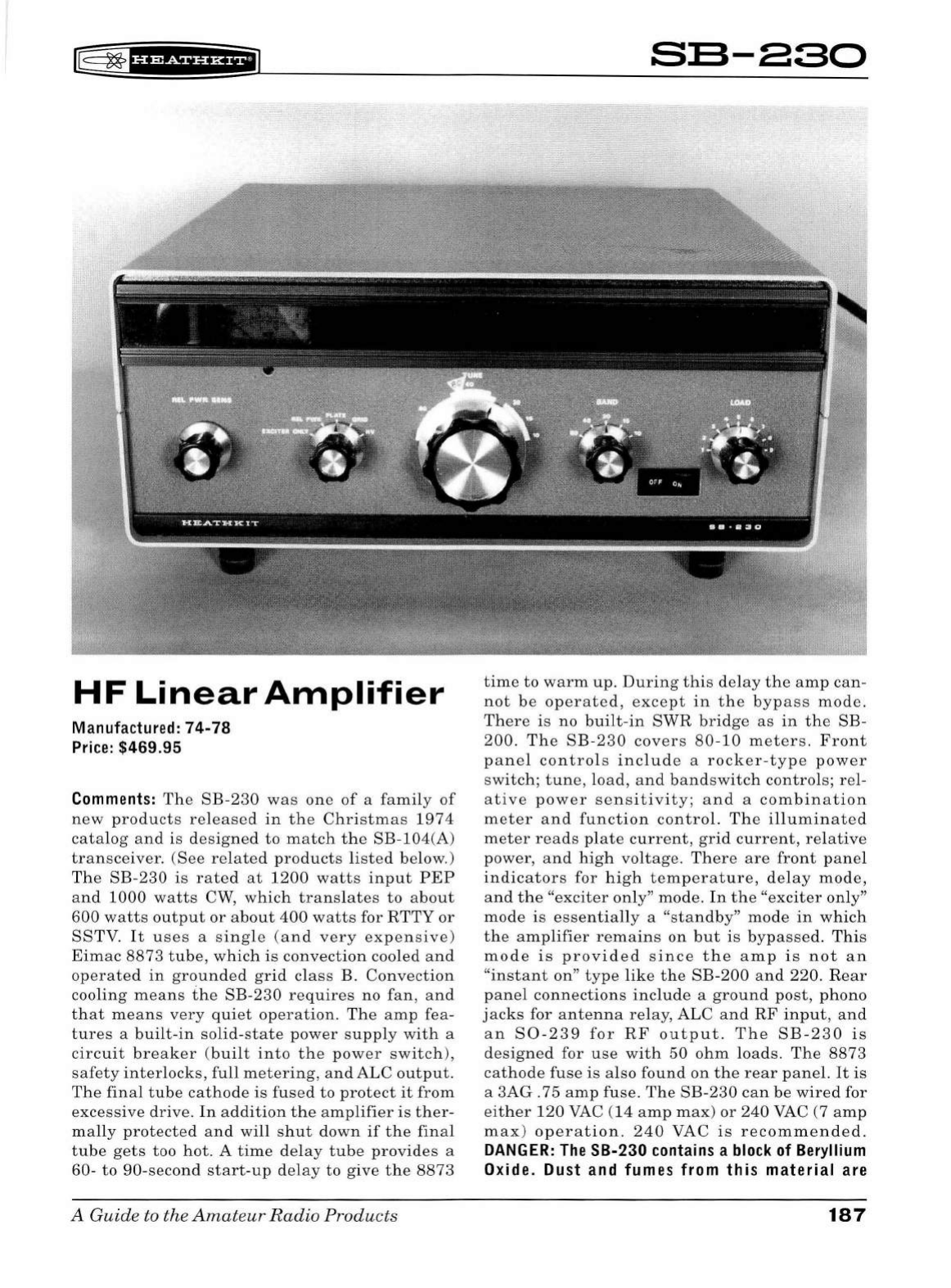
HF
Linear
Amplifier
Manu
fac
ture
d:
7 4-78
Pr
ice:
$469.95
Comments
:
The
SB-230
was
one
of
a
family
of
new
products
released
in
the
Christmas
1974
catalog
and
is
designed
to
match
the
SB-104(A)
transceiver.
(See
related
products
listed
below
.)
The
SB-230
is
rated
at
1200
watts
input
PEP
and
1000
watts
CW,
which
translates
to
about
600
watts
output
or
about
400
watts
for
RTTY
or
SSTV.
It
us
es
a
single
(and
very
expensive)
Eimac
8873
tube,
which
is
convection
cooled
and
operated
in
grounded
grid
clas
s B.
Convection
cooling
means
the
SB-230
requires
no
fan,
and
that
means
very
quiet
operation.
The
amp
fea
-
tures
a
built-in
solid
-
state
power
supply
with
a
circuit
breaker
(
built
into
the
power
switch),
safety
interlocks,
full
metering,
and
ALC
output.
The
final
tube
cathode
is
fus
ed
to
protect
it
from
excessive
drive.
In
addition
the
amplifier
is
ther-
mally
protected
and
will
shut
down
if
the
final
tube
gets
too
hot.
A
time
delay
tube
provides
a
60-
to
90-second
start
-
up
delay
to
give
the
8873
A Guide to the
Amateur
Radio
Products
s:s-aso
time
to
warm
up.
During
this
de
lay
the
amp
can-
not
be
operated,
except
in
the
bypass
mode.
There
is
no
built-in
SWR
bridge
as
in
the
SB-
200.
The
SB
-
230
covers
80-10
meters.
Front
panel
contro
ls
include
a
rocker
-
type
power
switch;
tune,
l
oad
,
and
bandswitch
controls;
rel-
ative
power
sensitivity;
and
a
combination
meter
and
function
control.
The
illuminated
meter
reads
pl
ate
current,
grid
current,
relative
power,
and
high
voltage
.
There
are
front
panel
indicators
for
hig
h
temperature,
delay
mode,
and
the
"exciter
on
ly"
mode.
In
the
"exciter
only"
mode
is
essentially
a
"standby"
mode
in
which
the
amplifier
remains
on
but
is
bypassed.
This
mode
is
provided
since
the
amp
is
not
an
"instant
on"
type
like
the
SB
-
200
and
220
.
Rear
panel
connections
include
a
ground
post,
phono
jacks
for
antenna
relay,
ALC
and
RF
input
,
and
an
S0
-
239
for
RF
output.
The
SB-230
is
designed
for
use
with
50
ohm
loads.
The
8873
cathode
fus
e
is
also
found
on
the
rear
panel.
It
is
a
3AG
.75
amp
fuse.
The
SB-230
can
be
wired
for
either
120
VAC
(14
amp
max)
or
240
VAC (7
amp
max)
operat
i
on.
240
VAC
is
recommended.
DANGER:
The
SB-230
cont
a
ins
a
block
of
Beryllium
Oxide. Dust
and
fumes from this material are
187
DEADLY
POISON!
The
Beryllium
Oxide
block
is
used
as
part
of
the
heat
sink
for
the
8873
and
is
located
in
a
rear
panel
cut-out
between
the
8873
and
the
large
finned
heat
sink
on
the
rear
panel.
DO
NOT
drill,
chip,
crush,
saw,
or
file
the
Beryl-
lium
block.
It
should
be
handled
only
with
pro-
tective
gloves
and
eye
wear
. Also
note
that
the
gooey
heat
sink
compound
is
dangerous.
Wash
your
hands
immediately
after
contact
with
the
Beryllium
block
or
the
heat
sink
compound.
The
Beryllium
and
the
heat
sink
compound
should
be
handled
with
the
utmost
care
and
treated
like
the
hazardous
materials
they
really
are.
Anoth-
er
minor
hazard
(but
one
to
watch
out
for)
is
the
temperature
of
the
large
heat
sink
on
the
rear
panel.
In
normal
operation
the
temperature
of
the
heat
sink
may
rise
to
as
high
as
7 5 0 F -
as
hot
as
the
tip
of
a
soldering
iron.
Keep
the
ampli-
fier
clear
of
combustible
materials
and
be
sure
to
provide
adequate
ventilation.
The
SB-230
is
a
good
basic
amplifier
and
will
perform
well
pro-
viding
it
is
not
pushed
too
hard.
It
is
well
pro
-
tected
from
a
variety
of
adverse
conditions
and
is
easy
to
operate.
The
SB-230
fell
victim
to
the
popularity
of
Heath's
older
SB-201
and
221
amplifiers,
which
continued
to
sell
well.
Poor
sales
caused
Heath
to
pull
the
230
off
the
mar-
ket
in
1978-several
years
before
the
rest
of
the
SB-104
family. No
doubt
the
toxicity
of
the
heat
sink
(and
its
potential
liability)
play
ed a
part
in
the
decision
to
discontinue
the
230
as
well.
It
is
interesting
to
note
that
Heath
continued
to
sell
both
the
SB-201
and
SB
-
221
until
1983-long
after
the
230
was
gone.
Finished
in
classic
two-
tone
SB
green.
SB-230s
are
medium
rare
.
Wei
g
ht
/
Si
ze: 50
lbs
;
15
"
wide
x 6.75"
hi
gh x
14
"
deep
Related
Products:
see
related
pr
oducts
under
SB-104(A)
188
lE
~
fHMiHHFIJ
HE
.A..T
HK
IT
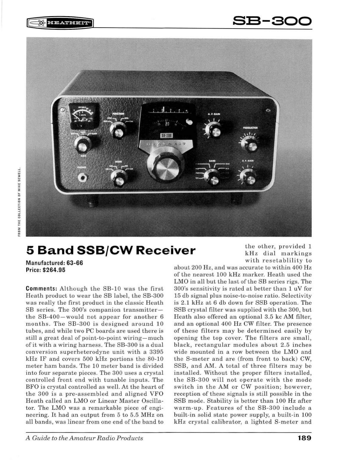
~
0
z
0
t;
'"
_,
_,
0
"
'"
"
....
:;;
0
"'
~
II§
~
1
¥'&fHi*fiJ
SB-300
5
Band
SSB/CW
Receiver
the
other,
provided
1
kHz
dial
markings
with
resetablility
to
Manufactured: 63-66
Price:
$264.95
Comments:
Although
the
SB-10
was
the
first
Heath
product
to
wear
the
SB
label
,
the
SB-300
was
r
ea
lly
the
first
product
in
the
classic
Heath
SB
series.
The
300's
companion
transmitter-
the
SB
-
400
-
would
not
appear
for
another
6
months.
The
SB
-
300
is
designed
around
10
tubes,
and
while
two
PC
boards
are
used
there
is
still
a
great
deal
of
point
-
to-point
wiring-much
of
it
with
a
wiring
harness.
The
SB-300
is
a
dual
conversion
superheterodyne
unit
with
a 33
95
kHz
IF
and
covers
500
kHz
portions
the
80-10
meter
ham
bands
.
The
10
meter
band
is
divided
into
four
separate
piece
s.
The
300
u
ses
a
crystal
controlled
front
end
with
tunable
inputs.
The
BFO
is
crystal
contro
ll
ed
as
well.
At
the
heart
of
the
300
is
a
pre-assembled
and
aligned
VFO
Heath
called
an
LMO
or
Linear
Master
Oscilla
-
tor.
The
LMO
was
a
remarkable
pi
ece
of
engi-
neering.
It
had
an
output
from
5
to
5.5
MHz
on
all
bands
,
was
linear
from
one
end
of
the
band
to
A Guide to the
Amateur
Radio
Products
about
200
Hz
,
and
was
accurate
to
within
400
Hz
of
the
nearest
100
kHz
marker.
H
ea
th
used
the
LMO
in
all
but
the
last
of
the
SB
series
rigs.
The
300's
sensitivity
is
rated
at
better
than
1 u V for
15
db
signal
plus
noise-to-noi
se
ratio.
Selectivity
is
2.1
kHz
at
6
db
down
for
SSB
operation.
The
SSB
crystal
filter
was
supplied
with
the
300,
but
Heath
also
offered
an
optional
3.5
kc
AM
filter
,
and
an
optional
400
Hz
CW
filter
.
The
presence
of
these
filters
may
be
determined
easily
by
opening
the
top
cover.
The
filters
are
small,
bl
ack,
rectangular
modules
about
2.5
inches
wide
mounted
in
a
row
betw
ee
n
the
LMO
and
the
S-meter
and
are
(fr
om
front
to
back
) CW,
SSB
,
and
AM. A
total
of
three
filters
may
be
installed.
Without
the
proper
fil
ters
installed
,
the
SB-300
will
not
operate
with
the
mode
switch
in
the
AM
or
CW
po
s
ition
;
however
,
reception
of
these
signa
ls
is
still
possible
in
the
SSB
mode.
Stability
is
better
than
100
Hz
after
warm-up.
Features
of
the
SB-300
include
a
bu
ilt
-
in
solid
state
power
supply,
a
bui
lt -
in
100
kHz
crystal
calibrator
, a
lighted
S-
meter
and
189
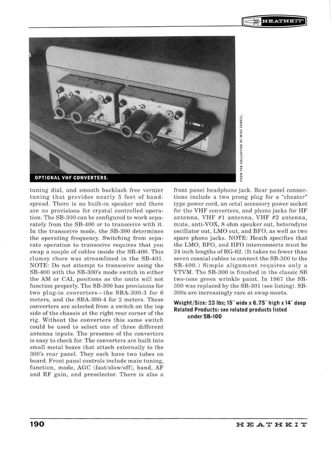
tuning
dial
,
and
smooth
backlash
free
vernier
tuning
that
provides
nearly
5
feet
of
band
-
spread.
There
is
no
built-in
speaker
and
there
are
no
provisions
for
crystal
controlled
opera-
tion.
The
SB-
300
can
be
configured
to
work
sepa
-
rately
from
the
SB-400
or
to
transceive
with
it
.
In
the
transceive
mode,
the
SB
-
300
determines
the
operating
frequency.
Switching
from
sepa
-
rate
operation
to
transceive
requires
that
you
swap
a
couple
of
cables
inside
the
SB-400
.
This
clumsy
chore
was
streamlined
in
the
SB
-
401.
NOTE:
Do
not
attempt
to
transceive
using
the
SB-400
with
the
SB
-
300's
mode
switch
in
either
the
AM
or
CAL
positions
as
the
units
will
not
function
properly.
The
SB-300
has
provisions
for
two
plug-in
converters-the
SBA-300-3
for
6
meters,
and
the
SBA
-
300-4
for 2
meters.
These
converters
are
se
l
ected
from
a
switch
on
the
top
side
of
the
chassis
at
the
right
rear
corner
of
the
rig.
Without
the
converters
this
same
switch
cou
ld
be
used
to
select
one
of
three
different
antenna
inputs.
The
presence
of
the
converters
is
easy
to
check
for.
The
converters
are
built
into
small
metal
boxes
that
attach
externally
to
the
300's
rear
panel.
They
each
have
two
tubes
on
board.
Front
panel
controls
include
main
tuning,
function,
mode,
AGC
(fast/slow
/
off
),
band
,
AF
and
RF
gain,
and
preselector.
There
is
also a
190
IE=
~
fHiSf§fHil
~
0
z
0
,_
"
w
-'
-'
0
"
w
"'
,_
:;
0
~
~
front
panel
headphone
jack.
Rear
panel
connec
-
tions
include
a
two
prong
plug
for a
"cheater"
type
power
cord,
an
octal
accessory
power
socket
for
the
VHF
converters,
and
phono
jacks
for
HF
antenna,
VHF
#1
antenna
,
VHF
#2
antenna,
mute,
anti-VOX,
8
ohm
speaker
out,
heterodyne
oscillator
out
,
LMO
out,
and
BFO,
as
well
as
two
spare
phono
jacks.
NOTE:
Heath
specifies
that
the
LMO,
BFO
,
and
HFO
interconnects
must
be
24
inch
lengths
ofRG-62
.
(It
takes
no
fewer
than
seven
coaxia
l
cab
l
es
to
connect
the
SB-300
to
the
SB
-
400.)
Simple
alignment
requires
only
a
VTVM.
The
SB
-
300
is
finished
in
the
classic
SB
two
-
tone
green
wrink
le
paint.
In
1967
the
SB-
300
was
replaced
by
the
SB-301
(see
listing).
SB-
300s
are
increasingly
rare
at
swap
meets.
We
ig
ht/Size: 23
lbs
;
15
"
wide
x 6. 75" h
ig
h x
14
"
deep
Related
Products:
see
related
products
listed
under
SB-100
HEA.THKIT
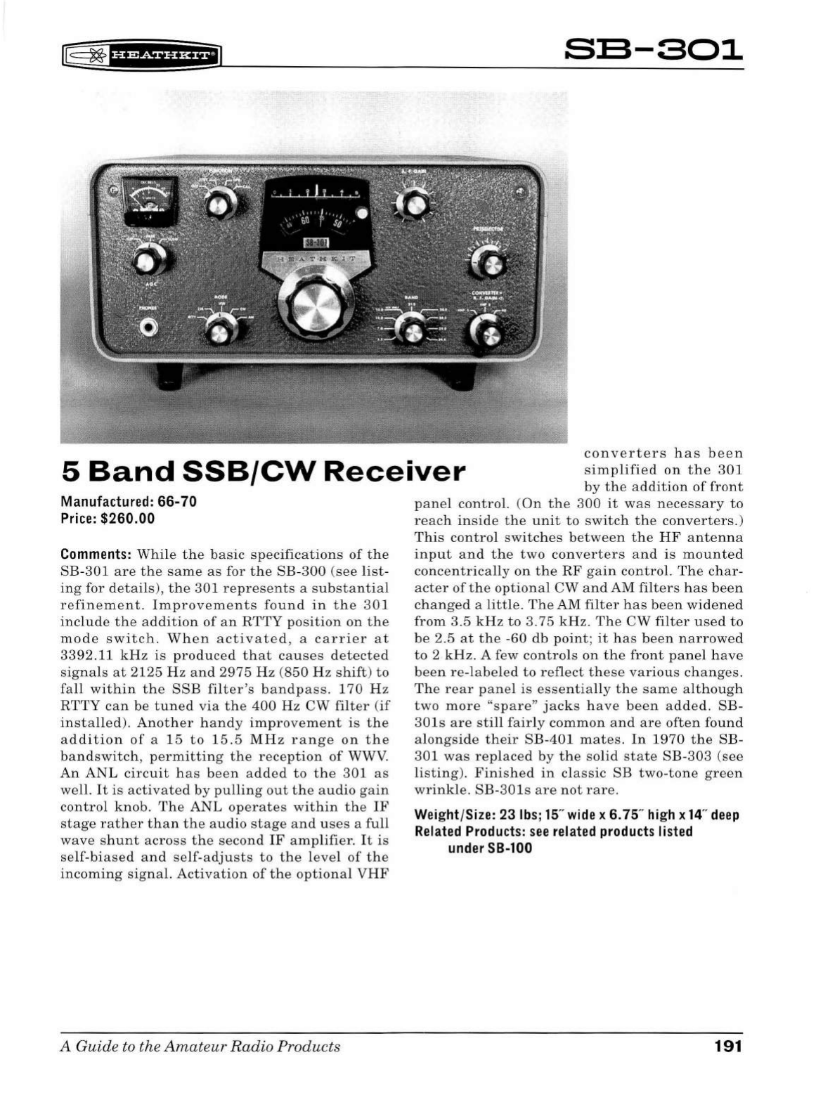
[§
8*
f
§ff
df
if
i*f
;i]
SE-301
5
Band
SSB/CW
Receiver
converters
has
been
simplified
on
the
301
by
the
addition
of
front
Manufactured: 66-70
Price:
$260.00
Comments:
While
the
basic
specifications
of
the
SB-301
are
the
same
as
for
the
SB-300
(see
list-
ing
for
details
),
the
301
represents
a s
ubstantial
refinement.
Improvem
e
nts
found
in
the
301
includ
e
the
addition
of
an
RTTY
position
on
the
mode
switch
.
When
activated,
a
carrier
at
3392.11
kHz
is
produced
that
causes
detected
sig
nals
at
2125
Hz
and
2975
Hz
(850
Hz
shift)
to
fall
within
the
SSB
filter's
bandpass.
170
Hz
RTTY
can
be
tuned
via
the
400
Hz
CW
filt
er
(
if
installed).
Another
handy
improvement
is
the
addition
of
a
15
to
15
.5
MHz
range
on
the
bandswitch
,
permitting
the
reception
of
WWV.
An
ANL
circuit
has
been
added
to
the
301
as
we
ll.
It
is
activated
by
pulling
out
the
audio
gain
control
knob.
The
ANL
operates
within
the
IF
stage
rather
than
the
audio
stage
and
uses
a
full
wave
shunt
across
the
second
IF
amplifier.
It
is
se
lf-b
iased
and
self-adjusts
to
the
level
of
the
incoming
signal.
Activation
of
the
optional
VHF
A
Guide
to
the
Amateur
Radio
Products
panel
control.
(On
the
300
it
was
necessary
to
reach
inside
the
unit
to
switch
the
converters.)
This
control
switches
b
etwee
n
the
HF
antenna
input
and
the
two
converter
s
and
is
mounted
concentric
a
lly
on
the
RF
gain
control.
The
char
-
acter
of
the
optional
CW
and
AM
filters
has
been
changed
a
little.
The
AM
filter
has
been
widened
from
3.5
kHz
to
3.75
kHz.
The
CW
filter
used
to
be
2.5
at
th
e -60
db
point;
it
has
been
narrowed
to
2
kHz.
A few
contro
ls
on
the
front
panel
have
been
re-labeled
to
reflect
these
various
changes.
The
rear
panel
is
essentially
the
same
although
two
more
"s
pare"
jacks
have
been
added.
SB-
301s
are
still
fairly
common
and
are
often
found
alongside
their
SB-401
mates
.
In
1970
the
SB-
301
was
replaced
by
the
solid
state
SB-303
(see
listing).
Finished
in
cl
ass
ic SB
two-tone
green
wrinkle.
SB-301s
are
not
rare.
Weight/Size: 23
lbs;
15"
wide
x 6. 75"
high
x
14
"
deep
Related
Products:
see
related
products
listed
under
SB-100
191
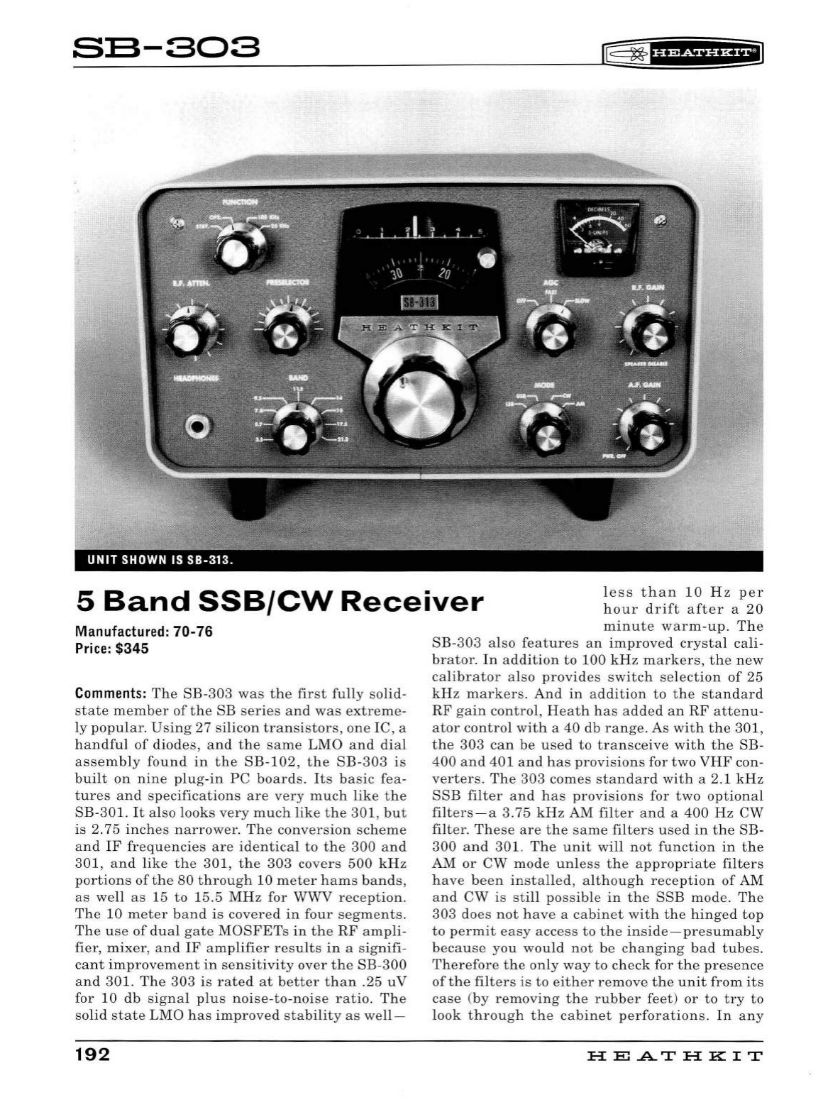
S:S-303
rF
~
fHWiUHEi
5
Band
SSB/CW
Receiver
less
than
10
Hz
per
hour
drift
after
a
20
Manufactured:
70-
76
Price:
$345
Comments:
The
SB-303
was
the
first
fully
solid
-
state
member
of
the
SB
series
and
was
extre
me-
ly
popular.
Using
27
silicon
transistors,
one
IC, a
handfu
l
of
diodes,
and
the
same
LMO
and
di
al
assembly
found
in
the
SB-102,
the
SB-303
is
built
on
nine
plug
-in
PC
boards
.
Its
basic
fea-
tures
and
specifications
are
very
much
like
the
SB-301.
It
also
looks
very
much
lik
e
the
301,
but
is
2. 75 i
nches
narrower.
The
conversion
scheme
a
nd
IF
frequencies
are
identical
to
the
300
a
nd
301,
an
d
like
the
301,
the
303
covers
500
kHz
portions
of
the
80
through
10
meter
hams
bands
,
as
well
as
15
to
15.5
MHz
for WWV
reception.
Th
e 10
meter
band
is
covered
in
four
segments.
Th
e
use
of
dual
gate
MOSFETs
in
the
RF
am
pli-
fier
,
mixer,
and
IF
amplifier
resu
lt
s
in
a
signifi-
cant
impro
vem
ent
in
sens
itivit
y
over
the
SB-300
a
nd
30
1.
The
303
is
rated
at
better
than
.25
uV
for
10
db
sig
n
al
plus
noise
-
to
-
noise
ratio.
Th
e
solid
state
LMO
has
improved
stability
as
we
ll-
192
minute
warm
-up
.
The
SB-303
also
features
an
improv
ed
crysta
l
cali
-
br
ator
.
In
additio
n
to
100
kHz
markers,
the
n
ew
calibrator
also
provides
switch
se
l
ection
of
25
kH
z
markers.
And
in
additio
n
to
the
stan
dard
RF
ga
in
control,
Heath
has
added
an
RF
attenu-
ator
control
with
a
40
db
range.
As
with
the
301,
the
303
can
be
used
to
transceive
with
the
SB
-
400
a
nd
401
and
has
provisions
for
two
VHF
con-
verters.
The
303
comes
standar
d
with
a 2.1
kHz
SSB
filter
a
nd
has
provisions
for
two
optional
filters-a
3.75
kHz
AM
filter
and
a
400
Hz
CW
filter
.
Th
ese
are
the
same
filters
used
in
the
SB-
300
and
301.
The
un
it
will
not
function
in
the
AM
or
CW
mod
e
unl
ess
the
a
pp
ropr
i
ate
fil
ters
h
ave
been
installed,
alt
h
ough
reception
of
AM
and
CW
is
sti
ll
possible
in
the
SSB
mode.
The
303
does
not
have
a
cabinet
with
the
hin
ged
top
to
permit
easy
access
to
the
inside
-
presumably
because
you wo
uld
not
be
changing
bad
tubes.
Th
erefore
the
only
way
to
chec
k for
the
presence
of
the
filters
is
to
ei
ther
remove
the
unit
from
its
case
(by
removing
the
r
ubb
er
feet
)
or
to
try
to
look
throug
h
the
cabinet
perforations
.
In
any
H
El
.AT
HK
IT
r8
~
f
H&f
Ui*FiJ
case,
the
filters
are
located
just
behind
the
power
transformer,
which
is
located
just
behind
the
S-meter.
There
is
room
for
three
filters
and
they
are
(from
l
eft
to
right
as
view
from
the
front)
SSE,
CW,
and
AM.
The
CW
and
AM
filters
may
or
may
not
be
labeled
as
such.
As
mentioned
earlier,
the
PC
board
may
be
unplugged
for
ser
-
vice.
But
to
unplug
some
of
them
requires
that
the
bandswitch
control
shaft
be
removed
first.
PC
board
extender
cards
were
originally
sup-
plied
with
the
SB-303
but
are
rarely
found
with
the
unit
at
flea
markets.
Front
panel
controls
include
function,
converter
(for
selection
of
HF
antenna
or
VHF
converters),
band
,
RF
attenua-
tor,
main
tuning,
zero
set,
AGC
(fast,
slow, off),
mode,
AF
gain/power
on
-off,
and
RF
gain
(
pull
to
disable
speaker)
.
There
is
no
ANL.
Internal
con-
trols
include
IF/Audio-bias
adjust,
meter
zero,
meter
full
scale,
BFO
power
supply
adjust,
100
kHz
adjust
,
RTTY
wide/narrow
shift,
and
CW
shift.
Rear
panel
connections
include
a
quarter-
inch
headphone
jack
and
phono
jacks
for
HF
input,
VHF
#1
input,
VHF
#2
input,
mute,
anti-
VOX, 8
ohm
speaker
(there
is
no
built-in
speak-
er)
,
HFO
out
,
BFO
out,
LMO
out,
and
CW
shift.
There
are
also
four
spare
jacks
as
well
as
an
"octa
l
sty
le"
accessory
socket
providing
power
for
the
optional
VHF
converters
and
input
for a
RTTY
keyboard
.
The
303's
built-in
power
supply
can
be
wired
for
120
or
240
VAC
50/60
Hz
opera-
tion
and
is
protected
with
a
rear
panel
circuit
breaker.
The
303
is
a
nice
receiver-even
by
today's
standards.
SB-303s
are
still
fairly
com-
mon
and
are
often
found
alongside
their
SB-401
mates
.
Painted
in
classic
SB
two-tone
green
wrinkle.
Weight/Size: 17lbs;12.25"
wide
x 6.75"
high
x
14
"
deep
Related
Products:
see
related
products
listed
under
SB-100
A
Guide
to the
Amateur
Radio
Products
193
"'
::
"
....
"
"
:r
....
~
:r
w
:r
....
::;
0
"'
~
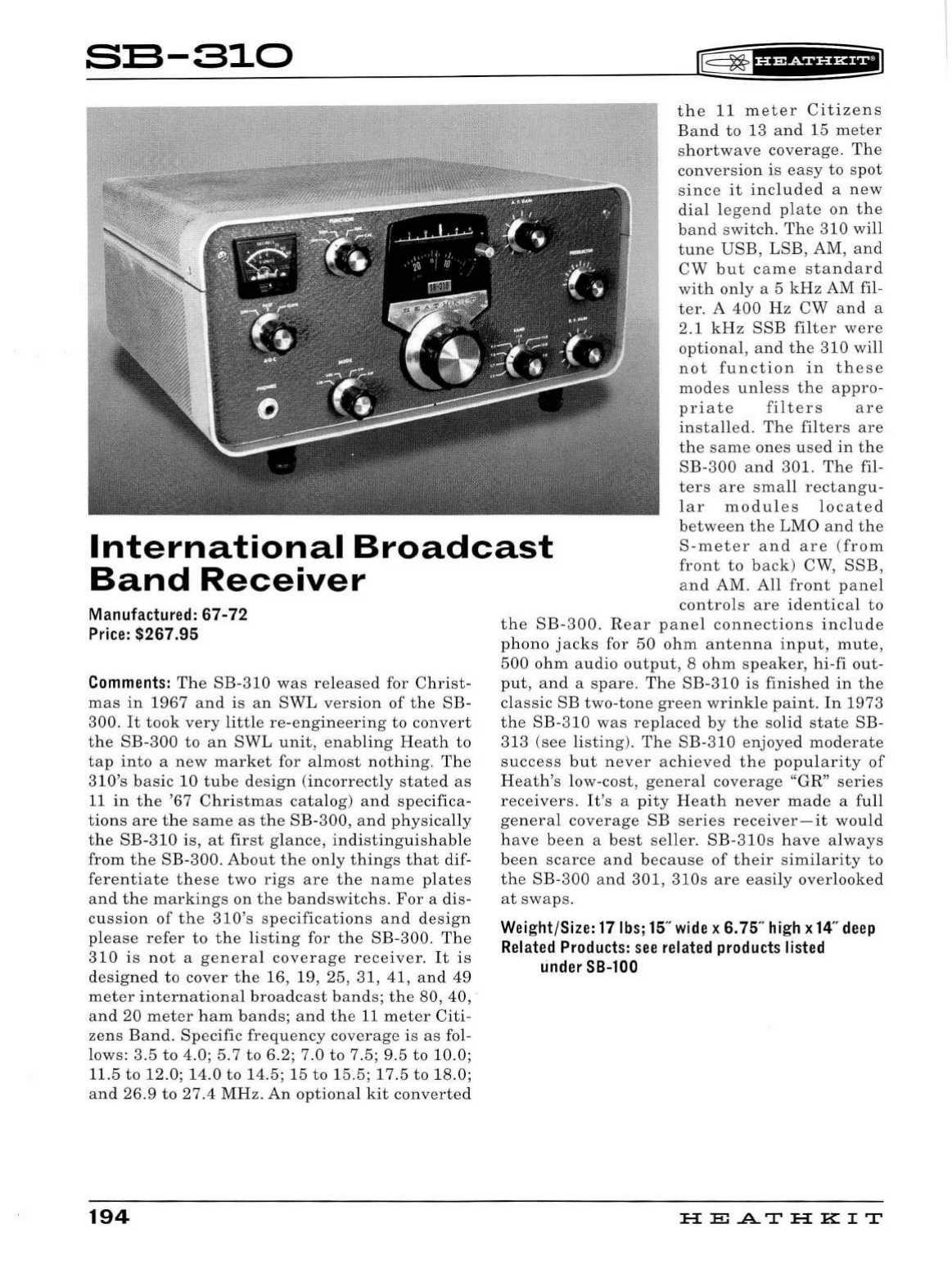
S:S-810
rE=
3* f
HR&f
§f
HfiJ
International
Broadcast
Band
Receiver
the
11
meter
Citizens
Band
to
13
and
15
meter
shortwave
coverage.
The
conversion
is
easy
to
spot
since
it
included
a
new
dial
l
ege
nd
plate
on
the
band
switch.
The
310
will
tune
USB
,
LSB
, AM,
and
CW
but
came
standard
with
only
a 5
kHz
AM fil-
ter
. A
400
Hz
CW
and
a
2.1
kHz
SSB
filter
were
optional
,
and
the
310
will
not
function
in
th
ese
modes
unle
ss
the
appro-
pri
ate
filters
are
in
sta
lled.
The
filters
are
th
e
same
ones
u
se
d
in
the
SB-300
and
301.
The
fil-
ters
are
small
rectangu
-
lar
modules
locat
e d
betw
ee
n
the
LMO
and
the
S-met
e r
and
are
(from
front
to
back
)
CW
,
SSB,
and
AM
.
All
front
panel
controls
are
identical
to
Manufacture
d:
67-72
Pr
i
ce:
$267.95
Comments:
The
SB
-
310
was
released
for
Christ
-
mas
in
1967
and
is
an
SWL
version
of
the
SB
-
300.
It
took
very
little
re-engineering
to
convert
the
SB-300
to
an
SWL
unit,
enabling
Heath
to
tap
into
a
new
market
for
almost
nothing.
The
310's
basic
10
tube
de
s
ign
(incorrectly
stated
as
11
in
the
'67
Christmas
catalog)
and
specifica-
tions
are
the
same
as
the
SB-300,
and
physically
the
SB
-
310
is,
at
first
glance,
indistinguishable
from
the
SB-300
.
About
the
only
things
that
dif-
ferentiate
these
two
rigs
are
the
name
plates
and
the
markings
on
the
bandswitchs
.
For
a dis-
cussion
of
the
3 lO's
specifications
and
design
please
refer
to
the
listing
for
the
SB-300.
The
310
is
not
a
general
coverage
receiver.
It
is
designed
to
cover
th
e 16,
19,
25,
31
, 41 ,
and
49
meter
international
broadcast
bands;
the
80, 40, ·
and
20
meter
ham
bands;
and
the
11
meter
Citi-
zens
Band
.
Specific
frequency
coverage
is
as
fol-
lows: 3.5
to
4.0;
5.7
to
6.2; 7.0
to
7.5; 9.5
to
10.0;
11.5
to
12.0
;
14.0
to
14
.5; 15
to
15.5
;
17
.5
to
18.0;
and
26.9
to
27.4
MHz.
An
optional
kit
converted
194
the
SB-300.
Rear
panel
connections
include
phono
jacks
for
50
ohm
antenna
input,
mute,
500
ohm
audio
output
, 8
ohm
speaker,
hi-fi
out
-
put,
and
a
spare.
The
SB-310
is
finished
in
the
clas
sic
SB
two-tone
green
wrinkle
paint.
In
1973
the
SB-310
was
replaced
by
the
solid
state
SB-
313
(s
ee
listing
).
The
SB-310
enjoyed
moderate
success
but
never
achieved
the
popularity
of
Heath
's
low-cost
,
general
coverage
"GR"
series
receivers.
It's
a
pity
Heath
never
made
a
full
general
coverage
SB
series
receiver-it
would
have
been
a
best
seller.
SB-310s
have
always
been
scarce
and
because
of
their
similarity
to
the
SB-300
and
301,
310s
are
easily
overlooked
at
swaps.
Wei
g
ht
/
Size:
17lb
s;
15
"
wide
x 6.75"
hi
gh x
14
"
deep
Related
Products:
see
related
product
s
listed
under
SB-100
HE
.AT
HK
IT
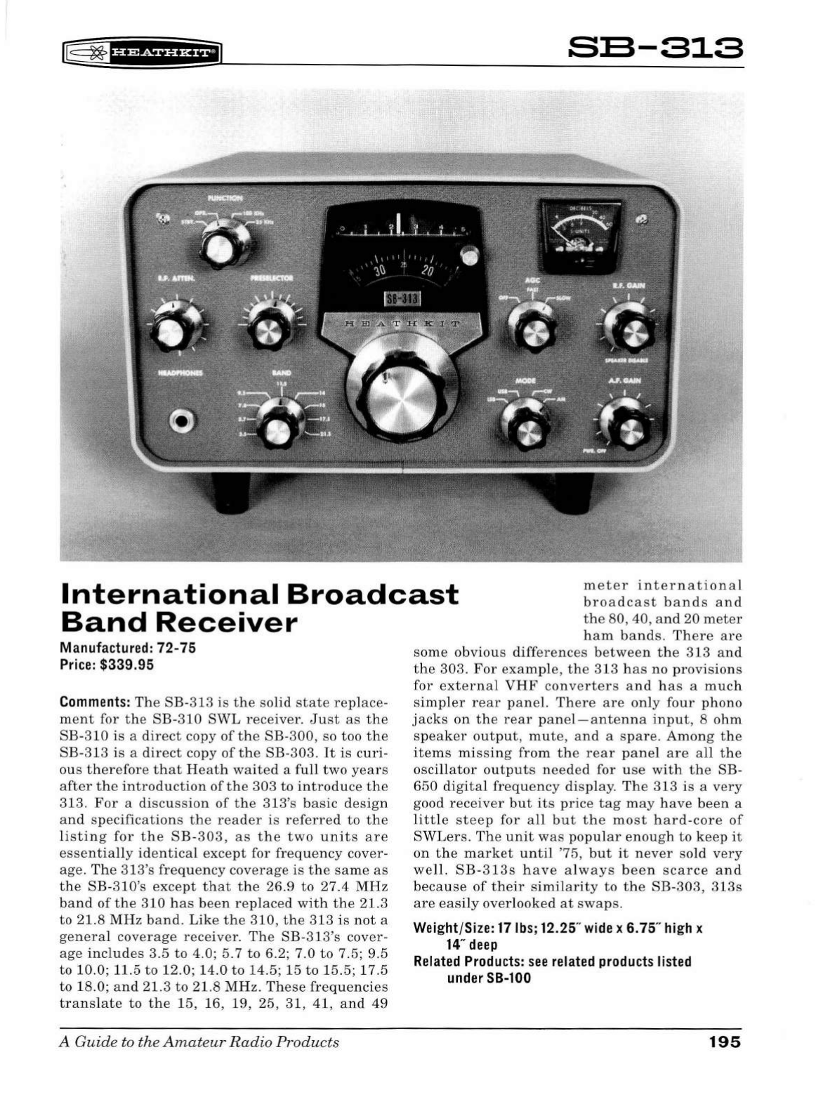
~ ~
1
H+Sii'H+i
s:s-a1a
International
Broadcast
Band
Receiver
meter
internationa
l
broadcast
bands
and
the
80, 40,
and
20
meter
ham
bands.
Th
ere
are
Manufactured: 72-75
Price:
$339.95
Comments:
T
he
SB-3
13 is
the
solid
state
rep
l
ace
-
ment
for
the
SB
-310
SW
L
receiver.
Just
as
the
SB-
310
is
a
direct
copy
of
the
SB-300,
so
too
the
SB-
313
is
a
direct
copy
of
t he
SB
-
303.
It
is
cu
ri-
ous
therefore
that
Heat
h
waited
a
fu
ll
two
years
after
th e
introduction
of
the
303
to
introd
uce
the
313.
For
a
disc
u
ssion
of
t he
313's
basic
des
i
gn
and
specifications
the
reader
is
referred
to
the
list
i
ng
for
the
SB
-
303,
as
the
two
u n
its
are
essentia
ll
y i
dentica
l
except
for
freq
u
ency
cover
-
age.
Th
e 313's
freq
u
ency
coverage
is
the
same
as
the
SB-
310's
except
th
at
t he
26
.9
to
27.4
MHz
band
of
the
310
h
as
been
re
pl
aced
wit h
the
21.3
to
21.8
MHz
band.
L
ike
the
310,
the
313
is
not
a
gen
era
l
coverage
receiver
.
The
SB-313
's
cover-
age
includes
3.5
to
4.
0;
5.7
to
6.
2;
7.0
to
7.5;
9.5
to
10.0; 11.5
to
12.0; 14. 0
to
14
.5; 15
to
15.5; 17.5
to
18.0;
an
d
21.3
to
21.8
MHz.
Th
ese
frequenc
i
es
translate
t o
the
15,
16,
19,
25,
31,
41,
and
49
A Guide to the
Amateu
r
Radio
Pr
oducts
some
obvious
differences
b
etween
the
313
an
d
the
303
.
For
exam
pl
e,
the
313
h
as
no
pr
ovisions
for
external
VHF
converters
and
h
as
a
muc
h
si
mp
l
er
rear
panel.
Th
ere
are
on
ly
fo
ur ph ono
jacks
on
the
rear
p
ane
l-
antenna
inp
u
t,
8 ohm
sp
eaker
ou
tput,
mute,
and
a
spare.
Am
ong
the
items
missing
from
t h e
rear
p
ane
l
are
a
ll
the
oscillator
out
p
uts
nee
d
ed
for
u
se
wi
th
the
SB
-
650
di
gita
l
frequency
di
sp
l
ay
. T
he
313
is a
very
good
rece
i
ver
but
its
p
rice
tag
may
h
ave
been
a
litt
le
steep
for
a
ll
but t h e
most
h
ard
-
core
of
SWLers
. The
unit
was
pop
ul
ar
eno
u
gh
t o
keep
it
on th e
market
until
'75,
but
it
never
so
ld
very
well.
SB
-
313s
have
al
ways
b
een
scarce
and
beca
u
se
of
their
si
milarity
to
the
SB
-
303,
31
3s
are
easi
ly
overlooked
at
swaps.
Weight/Size: 17lbs;12.25"
wide
x 6.75"
high
x
14
"
deep
Related
Products:
see
related
products
listed
under
SB-100
195
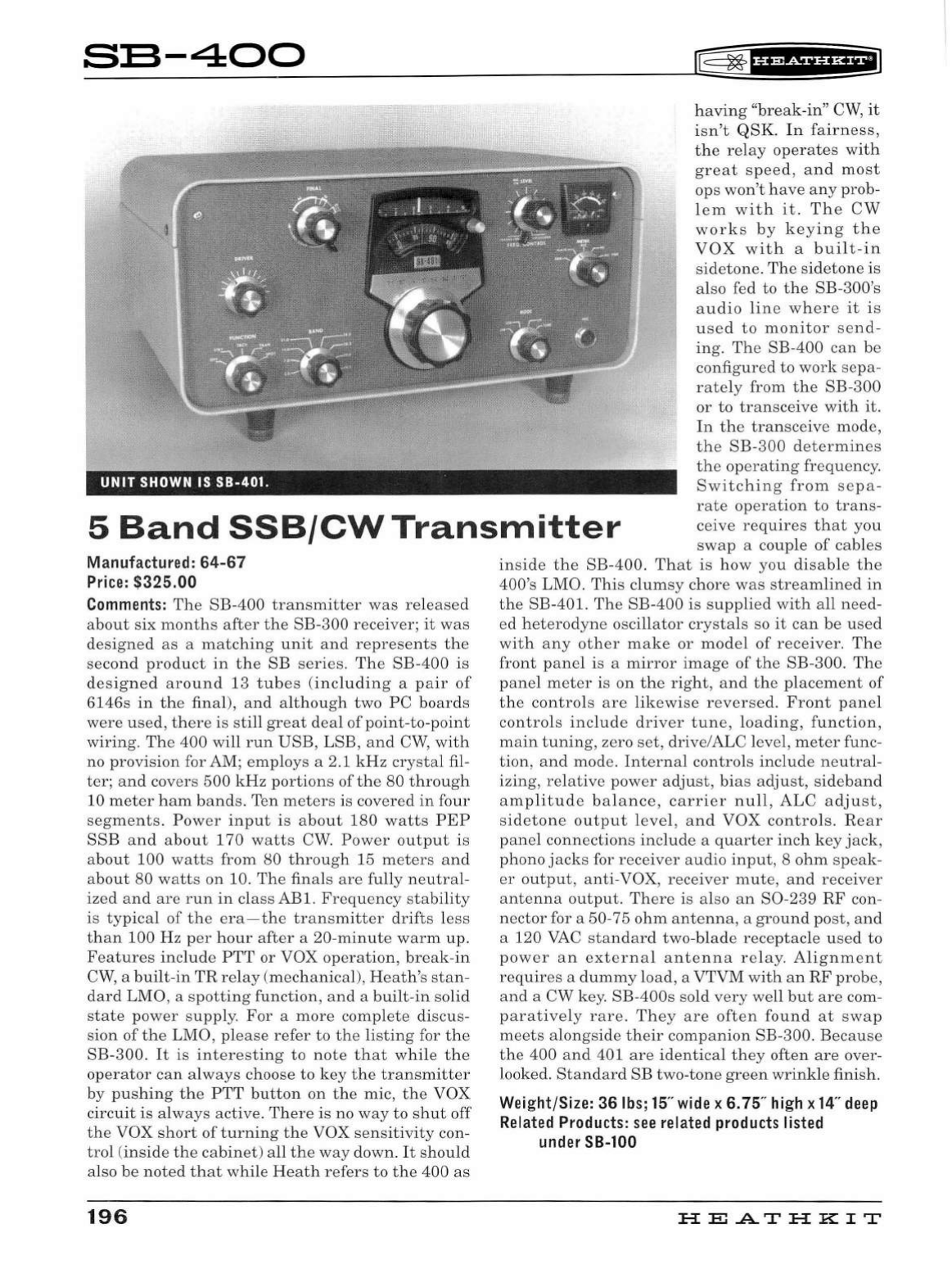
S:S-400
UNIT
SHOWN IS
SB-401.
E
~
fff*Sii'&iil
having
"break
-in"
CW,
it
isn't
QSK. In
fa
i
rness,
the
relay
operates
wi
th
great
speed,
and
most
ops
won
't
have
any
prob-
lem
with
it.
The
CW
works
by
keying
the
VOX
with
a
built-in
sidetone.
The
sidetone
is
also fed to
the
SB-300's
audio
line
where
it
is
u
se
d
to
monitor
send
-
ing.
The
SB-
400
can
be
configured to
work
sepa-
rately
from
the
SB-300
or
to
transceive
with
it.
In
th
e
transceive
mode,
th
e SB-
300
dete
rmines
th
e op
erati
ng
frequency.
Switching
from
se
pa-
5
Band
SSB/CWTransmitter
rat
e
operation
to
trans-
ceive
requires
that
you
swap
a couple
of
cab
l
es
Manufactured:
64-67
P
rice
: $325.00
Co
mment
s:
The
SB-400
transmitter
was
re
l
eased
about
six
month
s
after
the
SB-300 receiver;
it
was
designed
as
a
matching
unit
and
repres
e
nts
th
e
second
product
in
the
SB
series
.
The
SB-400
is
designed
around
13
tubes
(
including
a
pair
of
6146s
in
the
final
),
and
al
though
two
PC
boards
were
used
,
there
is
sti
ll
great
deal
of
point
-to-
point
wiring.
The
400 will
run
USB,
LSB,
and
CW,
with
no
provision
for AM;
emp
loys a 2.1
kHz
cr
ys
ta
l fil-
ter
;
and
covers
500
kHz
portions
of
th
e
80
through
10
meter
ham
bands.
Ten
meters
is
covered
in
four
segments.
Power
input
is
about
180
watts
PEP
SSB
and
about
170
watts
CW
.
Power
output
is
about
100
watts
from
80
through
15
meter
s
and
about 80
watts
on
10.
The
finals a
re
fully
neutr
al-
ized
and
are
run
in
class
ABl.
Fr
eque
ncy
st
ability
is
typical
of
the
e
ra-th
e
transmitter
drifts
l
ess
than
100 Hz
per
hour
after
a
20-minute
warm
up.
Features
include
PTT
or
VOX
operation,
break-in
CW,
a
bui
l
t-in
TR
relay
(
mechanical),
Heath's
stan-
dard
LMO, a
spotting
function,
and
a bu
ilt
-
in
so
lid
state
power
supply.
For
a
more
complete
discus-
sion
of
the
LMO,
please
refer
to
the
listing
for
the
SB-300
.
It
is
inter
est
ing
to
note
that
while
the
operator
can
al
ways
choose
to
key
the
transmitter
by pu
shing
the
PTT
bu
tton
on
the
mic,
the
VOX
ci
rcuit
is
always
active.
Ther
e is no
way
to
shut
off
the
VOX
short
of
turning
the
VOX
sensitivity
con-
trol
(inside
the
cabinet
)
all
the
way
down.
It
should
also
be
noted
that
whi
le
Heath
refers
to
the
400
as
196
inside
the
SB-400.
That
is
how
you
disabl
e
th
e
400's LMO.
This
clum
sy
chore
was
stream
lined
in
the
SB-401.
Th
e SB-400
is
s
upplied
with
all
need
-
ed
heterodyn
e
oscillator
cry
sta
ls so
it
can
be
used
with
any
other
make
or
model
of
receiver.
The
front
panel
is a
mirror
image
of
the
SB-300.
Th
e
panel
meter
is on
the
right,
and
the
pl
acement
of
the
controls
are
likewise
r e
versed
.
Front
panel
controls
include
driver
t u
ne,
loading,
function
,
main
tuning,
zer
o set ,
drive
/ALC level,
meter
func-
tion,
and
mode.
Internal
control
s
include
neutral-
izing,
relative
pow
er
adjust,
bias
adjust,
sideband
amplitude
balance,
carri
er
null,
ALC
adjust,
sidetone
output
l
eve
l,
and
VOX
controls.
Rear
pane
l
connections
include
a
quarter
inch
ke
y
jack
,
phono
jack
s for
receiver
audio
input
, 8
ohm
speak
-
er
output
, anti-VOX,
receiver
mute,
and
receiver
antenna
output
.
There
is also
an
S0-239
RF
con-
nector
for a 50-75
ohm
antenna,
a
ground
post
,
and
a 120
VAC
standard
two-bl
ade
receptacle
used
to
power
an
external
antenna
r elay.
Alignment
requires
a
dummy
load, a VTVM
with
an
RF
probe
,
and
a
CW
key. SB-400s sold
very
well
but
are
com-
paratively
rare.
They
are
of
ten
found
at
swap
meets
al
ongsid
e
their
companion
SB-300.
Becaus
e
the
400
and
401
are
identical
they
often
are
over-
looked.
Standard
SB two-
tone
green
wrink
le finish.
Wei
ght
/Size: 36lbs;
15
"
wide
x 6.75"
high
x
14
"
deep
Related
Products:
see
related
products
listed
under
SB-100
HE..ATHKIT
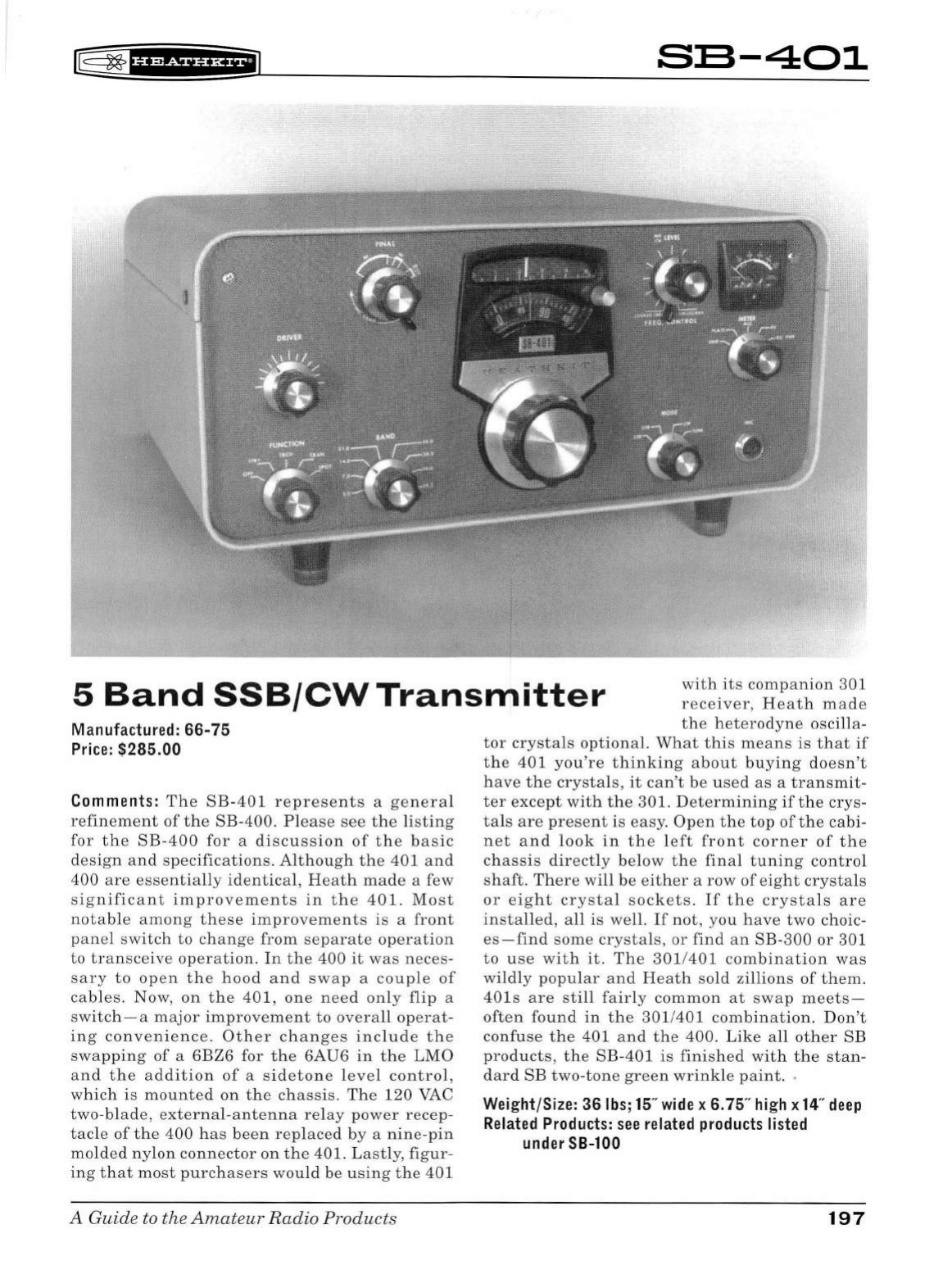
K§
~
B
1
¥SiUHfiJ
S:S-401
5
Band
SSB/CWTransmitter
with
its
companion
301
receiver,
Heath
made
the
heterodyne
oscilla-
Manufactured:
66-75
Price:
$285.00
Comments:
The
SB
-
401
represents
a
general
refinement
of
the
SB
-400.
Please
see
the
li
s
ting
for
th
e
SB-400
for
a
discussion
of
the
basic
design
a
nd
s
pecifications.
Altho
u
gh
the
401
and
400
are
esse
ntially
identical,
Heath
made
a few
significant
improvements
in
t
he
40
1.
Most
no
tab
le
among
these
im
prov
ements
is a
front
pan
el
sw
itch
to
change
from
separate
operation
to
transceive
operation
.
In
the
400
it
was
neces-
sary
to
open
the
hood
and
swap
a
couple
of
cables.
Now,
on
the
401,
one
need
on
ly
flip
a
switch-a
major
improvement
to
overall
op
er
at-
ing
conveni
e
nc
e.
Other
changes
include
th
e
swapp
in
g
of
a 6BZ6 for
the
6AU6
in
the
LMO
and
the
addit
ion
of
a s
id
etone
level
control
,
which
is
mounted
on
the
chassis
.
The
120
VAC
two
-
blade,
external-ante
nn
a
re
l
ay
power
recep-
tacle
of
the
400
h
as
b
een
replaced
by
a
nine
-
pin
molded
nylon
connector
on
the
401. L
astly,
figur-
ing
that
most
purchasers
would
be
using
th
e
401
A Guide
to
the
Amateur
Radio
Products
tor
crystals
optional.
What
this
means
is
that
if
the
401
you're
thinking
about
buying
doesn
't
have
the
crystals
,
it
can't
be
used
as
a
transmit-
ter
except
with
the
301. D
ete
rmining
ifthe
crys-
tals
are
present
is
easy.
Open
the
top
of
the
cabi-
net
and
look
in
the
left
front
corner
of
the
chassis
directly
below
th
e
final
tuning
control
shaft.
There
will
be
either
a
row
of
eight
crystals
or
eight
crystal
sockets.
If
the
crysta
ls
are
installed,
all
is
well.
If
not
,
you
have
two
choic-
es
-find
some
cry
sta
ls,
or
find
an
SB-300
or
301
to
u
se
with
it.
The
301/401
combination
was
wi
ldl
y
popular
and
Heath
so
ld
zi
llion
s
of
them.
401s
are
still
fairly
common
at
swap
meets-
often
found
in
the
301/401
combination.
Don
't
confuse
the
401
and
the
400.
Like
all
other
SB
products
,
the
SB-401
is
finished
with
the
stan-
dard
SB
two
-
tone
green
wrink
le
paint
. .
Weight/Size: 36lbs;15"
wide
x 6.75"
high
x
14
"
deep
Related
Products:
see
related
products
listed
under
SB-100
197
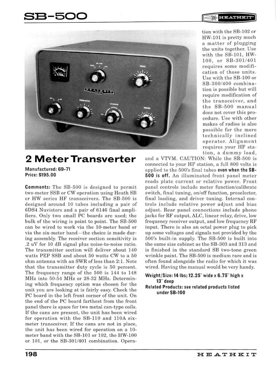
S:S-500
2
Meter
Transverter
Manufactured: 69-71
Price:
$195.00
Comments:
The
SB-500
is
de
signed
to
permit
two-meter
SSB
or
CW
operation
using
H
eath
SB
or
HW
series
HF
transceivers.
The
SB-500
is
designed
aro
und
10
tubes
including
a
pair
of
6DS4
Nuvistors
and
a
pair
of
6146
final
ampli-
fiers.
Only
two
small
PC
boards
are
u
sed;
the
bulk
of
the
wiring
is
point
to
point.
The
SB-500
can
be
wired
to
work
via
the
10-meter
band
or
via
the
six
-
meter
b
and-the
choice
is
made
dur-
ing
assembly.
The
receiver
section
sensitivity
is
.2 u V for 10
dB
signa
l
plus
noise
-
to
-
noise
ratio.
The
transmitter
section
will
deliver
about
140
watts
PEP
SSB
and
about
50
watts
CW
to
a
50
ohm
antenna
with
an
SWR
ofless
than
2:1.
Note
that
the
transmitter
duty
cycle
is
50
percent.
The
frequency
range
of
the
500
is
144
to
148
MHz
into
50-54
MHz
or
28-32
MHz.
D
etermin-
ing
which
frequency
option
was
chosen
for
the
unit
you
are
lookin
g
at
is
fairly
easy.
Check
the
PC
board
in
the
left
front
corner
of
the
unit.
On
the
end
of
the
PC
bo
ar
d
farthest
from
the
front
panel
there
is
space
for
two
metal
can-type
coils.
If
the
cans
are
present,
the
unit
ha
s
been
wired
for
operation
with
the
SB-110
and
llOA
six-
meter
transceiver.
If
the
cans
are
not
in
place,
the
unit
has
been
wired
for
operation
on
a
10
-
meter
band
with
the
SB-101or102,
the
HW-100
or
101,
or
the
SB
-
301/401
combination.
Opera-
198
l®
~
tH+SidHEI
tion
with
the
SB-102
or
HW
-
101
is
pretty
much
a
matter
of
plugging
the
units
together.
Use
with
the
SB-101,
HW-
100,
or
SB-301/401
requires
some
modifi-
cation
of
those
units.
Use
with
the
SB-100
or
SB-300
/
400
combina-
tion
is
possible
but
wi
ll
require
modification
of
the
transceiver,
and
the
SB
-
500
manual
does
not
cover
this
pro-
cedure
.
Use
with
other
makes
of
radios
is
also
possible
for
the
more
technically
inclined
operator.
Alignment
requires
your
HF
sta-
tion,
a
dumm
y
lo
ad,
and
a VTVM.
CAUTION:
While
the
SB-500
is
connected
to
your
HF
station,
a
full
800
vo
lt
s
is
applied
to
the
500's
final
tubes
even
when
the
SB-
500
is
off.
An
illuminated
front
panel
meter
reads
plate
current
or
relative
power.
Front
panel
controls
include
meter
function/calibrate
switch,
final
tuning
,
on
/
off
function,
preselector,
final
loading,
an
d
driver
tuning.
Interna
l con-
trols
include
relative
power
adjust
and
bias
a
dju
st.
Rear
panel
connections
includ
e
phono
jacks
for
RF
output,
ALC,
linear
r elay,
drive,
low
frequency
receiver
output,
and
low
frequency
RF
input.
Th
ere
is
also
an
octa
l
power
plug
to
pick
up
some
voltages
and
signals
not
provided
by
the
500's
built-in
supp
l
y.
The
SB-500
is
built
into
the
same
size
cabinet
as
the
SB-303
and
313
an
d
is
finished
in
the
sta
nd
ard
SB
two
-
tone
green
wrinkle
paint.
The
SB-500
is
medium
rare
and
is
often
found
alongside
the
radio
for
which
it
was
wired.
Ha
ving
the
manual
would
be
very
handy.
Weight/Size: 14lbs;12.25"
wide
x 6.75"
high
x
13
"
deep
Related
Products:
see
related
products
listed
under
SB-100
HE
A.TH
KIT
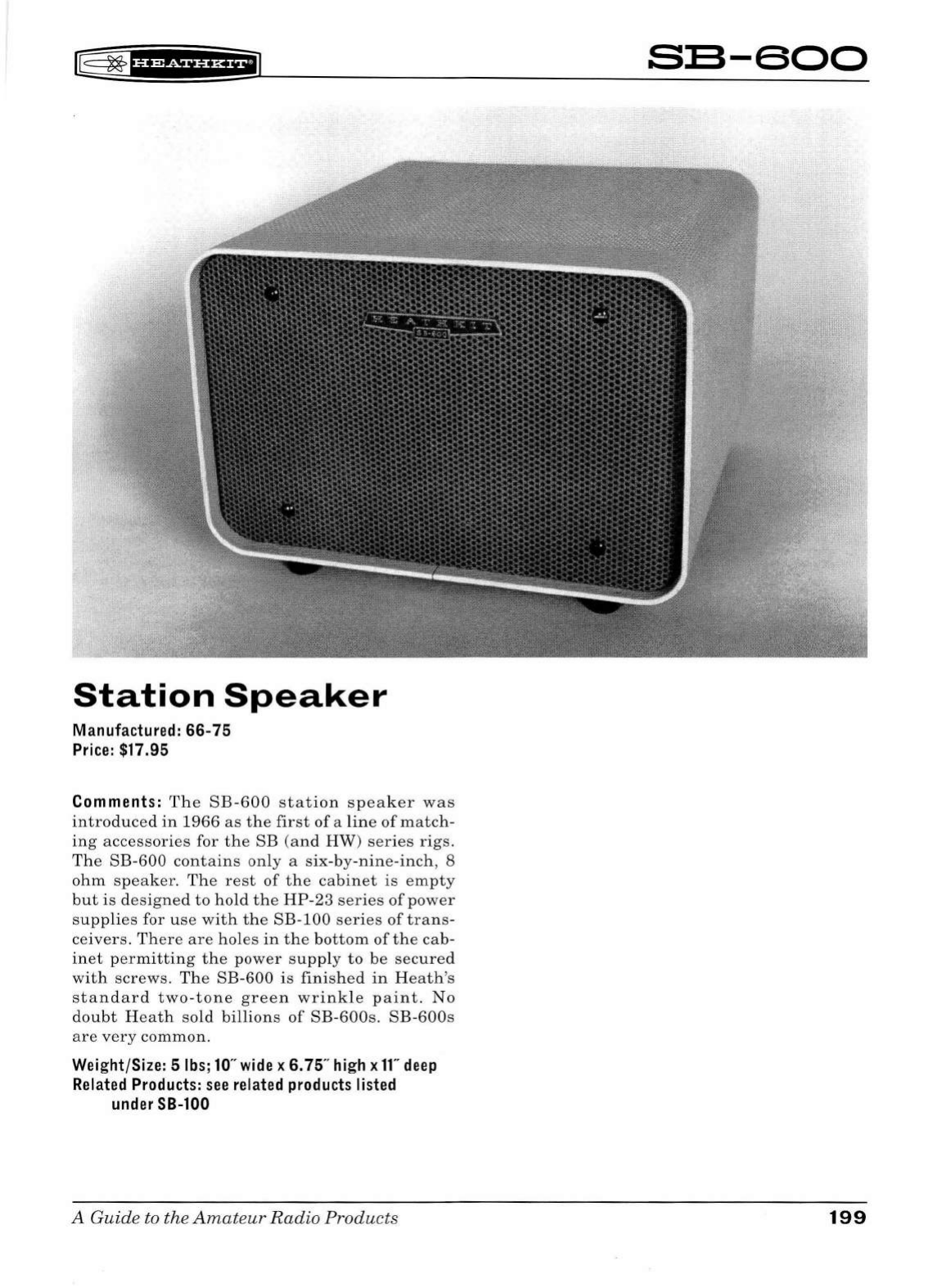
~
~
f¥
1
i3iif
Hf;iJ
Station
Speaker
Manufactured: 66-75
Price:
$17.95
Comments:
The
SB-600
station
speaker
was
introduc
ed
in
1966
as
the
first
of
a
lin
e
of
match-
ing
accessories
for
the
SB
(an
d
HW)
series
rigs.
Th
e
SB-600
contains
on
ly a
six
-by
-nin
e
-inch
, 8
ohm
speaker
.
Th
e
rest
of
the
cabinet
is
em
pt
y
but
is
designed
to
hold
the
HP-23
series
of
power
supplies
for
use
with
the
SB-100
series
of
trans-
ceivers
.
There
are
holes
in
the
bottom
of
the
cab-
inet
p
erm
itting
the
power
sup
pl
y
to
be
secured
with
screws.
Th
e
SB-600
is
finished
in
Heath's
standard
two-tone
green
wrinkle
paint.
No
doubt
Heath
so
ld
billions
of
SB-600s.
SB-600s
are
very
common.
Weight/Size: 5lbs;10"
wide
x 6. 75"
high
x
11"
deep
Related
Products:
see
related
products
listed
under
SB-100
A
Guide
to the
Amateur
Radio
Products
SB-600
199

S:S-604
Station
Speaker
Manufactured: 74-82
Price:
$33.95
Comments:
The
SB
-
604
contains
only
a five-
by
-
seven
-inch
3.2
ohm
speaker
.
There
are
no
indica-
tors
or
displays
of
any
kind
behind
the
red
plas-
tic
window.
The
rest
of
the
cabinet
is
empty
but
is
designed
to
hold
the
HP-1144
power
supplies
for
use
with
the
SB-104(A)
transceiver.
There
are
holes
in
the
bottom
of
the
cabinet
permitting
the
power
supply
to
be
secured
with
screws.
The
604
is
finished
in
Heath's
standard
two-tone
green
wrinkle
paint.
Curiously,
SB-604s
are
not
all
that
common.
Weight/Size: 10lbs;10.25"
wide
x 7.25"
high
x
15.25"
deep
Related
Products:
see
related
products
listed
under
SB-104
200
r®~fHiSii'Hil
HEATHKIT
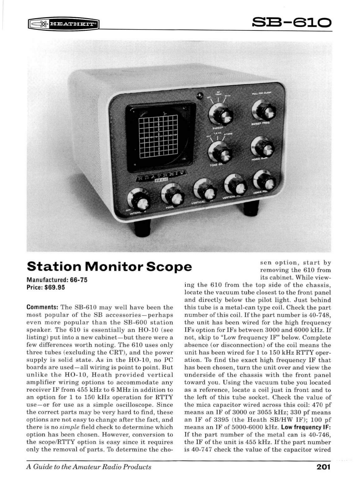
[@
~
1
#f?dfifi*f'J
SB-610
Station
Monitor
Scope
sen
option,
start
by
removing
the
610
from
its
cabinet.
While
view-
Manufactured: 66-75
Price:
$69.95
Comments:
The
SB-610
may
well
have
been
the
most
popular
of
the
SB
accessories-perhaps
even
more
popular
than
the
SB-600
station
speaker.
The
610
is
essentially
an
H0-10
(see
listing)
put
into
a
new
cabinet-but
there
were
a
few
differences
worth
noting.
The
610
uses
only
three
tubes
(excluding
the
CRT)
,
and
the
power
supply
is
solid
state
.
As
in
the
H0-10,
no
PC
boards
are
used-all
wiring
is
point
to
point.
But
unlike
the
H0-10,
Heath
provided
vertical
amplifier
wiring
options
to
accommodate
any
receiver
IF
from
455
kHz
to
6
MHz
in
addition
to
an
option
for 1
to
150
kHz
operation
for
RTTY
use-or
for
use
as
a
simple
oscilloscope.
Since
the
correct
parts
may
be
very
hard
to
find,
these
options
are
not
easy
to
change
after
the
fact
,
and
there
is
no
simple
field
check
to
determine
which
option
has
been
chosen.
However,
conversion
to
the
scope
/
RTTY
option
is
easy
since
it
requires
on
ly
the
removal
of
parts.
To
determine
the
cho-
A
Guide
to
the
Amateur
Radio
Products
ing
the
610
from
the
top
side
of
the
chassis,
locate
the
vacuum
tube
closest
to
the
front
panel
and
directly
below
the
pilot
light.
Just
behind
this
tube
is
a
metal-can
type
coil.
Check
the
part
number
of
this
coil.
If
the
part
number
is
40
-
748,
the
unit
has
been
wired
for
the
high
frequency
IFs
option
for
IFs
between
3000
and
6000
kHz.
If
not,
skip
to
"Low
frequency
IF"
below.
Complete
absence
(or
disconnection)
of
the
coil
means
the
unit
has
been
wired
for 1
to
150
kHz
RTTY
oper-
ation
.
To
find
the
exact
high
frequency
IF
that
has
been
chosen,
turn
the
unit
over
and
view
the
underside
of
the
chassis
with
the
front
panel
toward
you.
Using
the
vacuum
tube
you
located
as
a
reference,
locate
a coil
just
in
front
and
to
the
left
of
this
tube
socket.
Check
the
value
of
the
mica
capacitor
wired
across
this
coi
l:
4 70
pf
means
an
IF
of
3000
or
3055
kHz;
330
pf
means
an
IF
of
3395
(the
Heath
SB
/
HW
IF);
100
pf
means
an
IF
of
5000-6000
kHz.
Low
frequency
IF:
If
the
part
number
of
the
metal
can
is
40
-7
46,
the
IF
of
the
unit
is
455
kHz
.
If
the
part
number
is
40-7
4 7
check
the
value
of
the
capacitor
wired
201
across
the
bottom
of
the
IF:
200
pf
means
an
IF
of
1000
kHz;
100
pf
means
an
IF
of
1600
to
1680
kHz;
56
pf
means
an
IF
of
2075,
2215,
or
2475
kHz.
In
th
e
end
all
this
may
be
a
moot
point
since
critical
analysis
of
incoming
signals
dis-
played
on
the
610
isn't
really
po
ss
ibl
e
in
th
e
first
place
-t
h
ere
are
just
t
oo
many
variab
le
that
can
effect
the
waveforms
shown
.
The
SB-610
's
grea
t-
es
t
strength,
however,
is
in
the
moniotring
of
transmitted
energy.
The
610
will
work
on
any
frequency
from
160
to
6
meters.
And
there
is
a
low
power
option
for
use
with
QRP
and
CB
rigs.
(N
ormally
the
610
requires
a
minimum
of
15
watts
of
drive.
)
The
low
power
wiring
option
is
easy
to
spot.
On
th
e
undersid
e
of
the
chassis
look
for a
tunable
type
coil
wired
in
and
"float-
ing
"
between
the
S0-239
jack
s
and
the
attenua-
tor
switch
on
th
e
rear
panel.
The
frequencies
of
the
two-tone
generator
have
been
changed
to
1500
and
1950
Hz.
You
can
choose
a
si
ngl
e
tone
output
(
1500
Hz)
or
the
two
-
ton
e
signal.
Because
they
are
subjected
to
high
voltages,
resistors
in
the
int
en s
ity,
focus
,
horizontal,
and
vertical
position
circuits
will
degrade
over
time
,
usually
drifting
up
in
value.
The
result
will
be
an
inabil-
ity
to
effecti
vel
y
control
one
or
more
of
th
ese
functions.
This
is a co
mmon
ailment
in
SB-620s
but
one
that
is
easy
to
cure.
Th
e
tubes
are
also
s
ubjected
to
voltages
that
will
cause
them
to
fade
faster
that
one
might
expect.
Rear
pan
el
connections
includ
e a
pair
of
loop-
through
S0-
239s
for
RF
input
an
d
output,
a
pair
of
loop-
through
phono
jack
s (
exciter
input
for
lin
earity
checks
),
a
phono
jack
for
tone
output,
a
nd
phono
jack
s for
vertical
and
hori
zo
ntal
input
(
fo
r
RTTY
of
scope
u
se)
.
Ultim
a
tely,
the
SB
-
610
is
mo
st
u
seful
in
monitoring
transmitted
RF
or
for
RTTY.
The
610
is
finished
in
Heath's
standard
two-tone
green
wrinkle
paint
and
matches
the
rest
of
the
SB
lin
e.
Heath
sold
tens
of
thou
sands
of
SB-610
s.
Th
ey
are
not
rare,
a
nd
they
turn
up
frequently
at
swap
meets.
Weight/Size: 10lbs;10"
wide
x 6.75"
high
x
11"
deep
Related
Products:
H0-10, H0-5404;
SB-614;
see
related
products
listed
under
SB-100
202
l®
~
fHR&fi'HEiJ
HE.A.TH
KIT
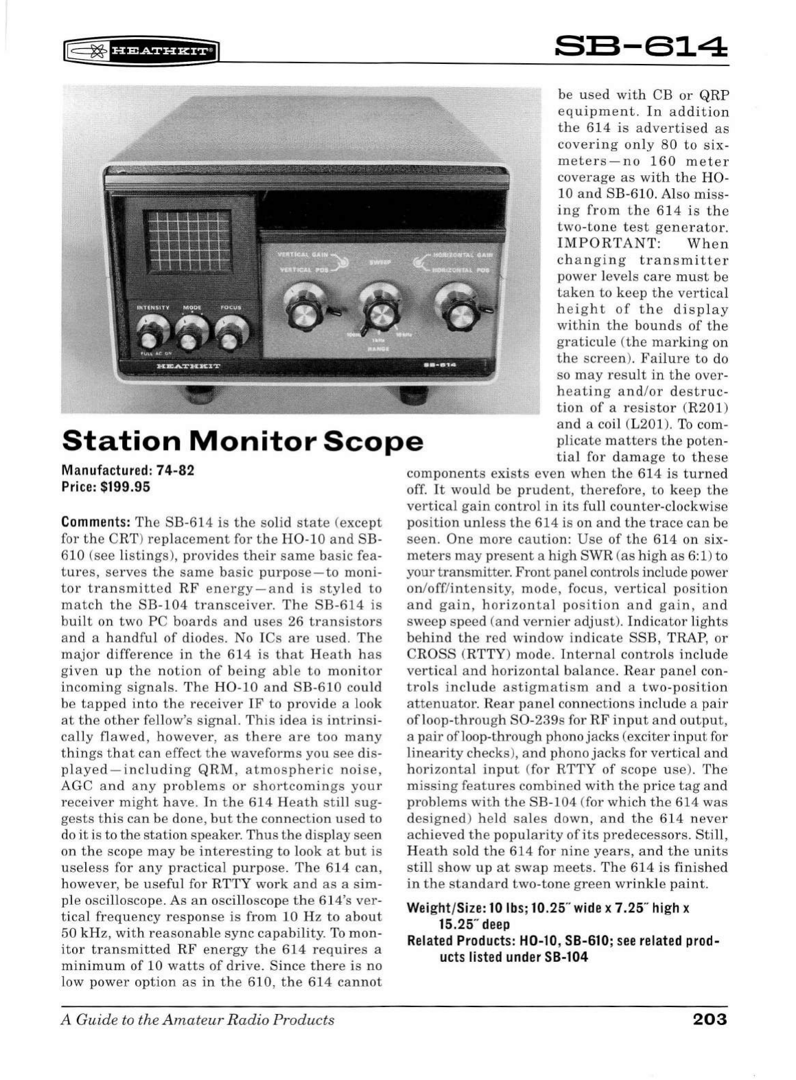
[[
~
1
H&if'Hfil
SE-614
be
used
wit
h CB
or
QR
P
equ
i
pment
.
In
add
i
tio
n
Station
Monitor
Scope
the
614
is
advertised
as
covering
on
ly
80
to
six
-
meters
-
no
1
60
meter
coverage
as
wit
h
the
H0 -
10
and
SB-610. Also
miss
-
i
ng
from
t h e 6 14
is
the
two
-
tone
test
generator.
IMPORTAN
T: Wh
en
changing
transm
i
tter
power
l
evels
care
mu
st
be
taken
to
kee
p th e
ve
r
tica
l
height
of
t h e
disp
l
ay
within
the
boun
ds of
the
graticule
(
the
marki
ng
on
the
screen
).
Fai
lu
re
to
do
so
may
result
in
the
over
-
heating
an
d/
or
d
estruc
-
tion
of
a
res
i
stor
(R
201)
and
a coil (L201). To
com
-
plicate
m
atters
t he po
ten-
tia
l
for
damage
to
th
ese
Manufactured: 74-82
Price:
$199.95
Comments:
The
SB-614
is
the
solid
state
(ex
cept
for
the
CRT)
replaceme
nt
fo
r
the
H0
-10
and
SB
-
610
(s
ee
listings
),
provides
their
same
basic
fea
-
tures,
serves
the
same
basic
purpose
-
to
moni
-
tor
transmitted
RF
energy-and
is
sty
led
to
match
the
SB-104
transceiver.
The
SB
-
614
is
bui
lt
on
two
PC
boards
and
uses
26
transistors
and
a
handful
of
diodes. No
ICs
are
used
.
The
major
differ
e
nce
in
the
614
is
that
Heath
h
as
given
up
the
notion
of
being
able
to
mon
i
tor
incoming
si
gna
ls. The H
0-10
and
SB-610
could
be
tapped
into
the
rece
i
ver
IF
to
provide
a l
ook
at
the
other
fe
ll
ow's
signal.
This
idea
is
intrinsi
-
ca
ll
y
flawed
,
however,
as
there
are
too
many
things
that
can
effect
the
waveforms
you
see
di
s-
pl
ayed
-
including
QRM,
atmosp
h
eric
noise,
AGC
and
any
problems
or
shortcomings
your
receiver
might
h
ave.
In
the
614
Heath
still
sug-
gests
th
is
can
be
done
, but th e
connection
used
to
do
it
is
to
the
station
speaker
.
Thus
the
d
isp
l
ay
seen
on
the
scope
may
be
interesting
to
look
at
but
is
useless
for
any
practica
l pu
rpose.
The
614
can,
h
owever,
be
usefu
l for
RTT
Y work
and
as
a sim-
ple
osci
ll
oscope.
As
an
oscilloscope
the
614's
ver
-
tica
l
frequency
res
p
onse
is
from
10
Hz
to
abo
ut
50
kHz,
with
reasonab
le
sync
capab
il
ity. To
mon
-
itor
transmitted
RF
energy
the
614
requires
a
mi
n
imum
of
10
watts
of
dr
i
ve
.
Since
th
ere
is
no
low
power
option
as
in
the
610,
the
614
cannot
A Guide
to
the
Amateur
Radio Products
components
exists
even
wh
en
the
614
is
tu
rne
d
off.
It
wo
ul
d
be
prudent
,
therefore,
to
kee
p
the
verti
c
al
gain
contro
l
in
its
fu
ll
counter
-cl
ockwise
pos
it
i
on
un
l
ess
the
614
is
on
and
the
trace
can
be
seen
.
One
more
caution
:
Use
of
the
614 on
six
-
meters
may
pres
e
nt
a
high
SWR
(as
h
igh
as
6:1)
to
your
transmitter
.
Front
panel
controls include power
on
/
off
/
intensity,
mode,
focus,
ver
ti
ca
l
pos
i
tion
and
gain,
horizontal
position
a n d
gain,
and
swee
p
speed
(and
vernier
ad
just)
. I
ndicator
li
ghts
behin
d the
red
wi
ndow
indicate
SSB,
TRAP,
or
CR
OSS
(RTTY)
mode.
Interna
l con
tro
ls
in
cl
ude
vertical
and
horizonta
l
ba
l
ance
.
Rear
pane
l con-
tro
ls
include
astigmatism
and
a
two
-
pos
i
tio
n
atten
u
ato
r.
Rear
pane
l
connections
incl
ud
e a
pai
r
ofloop-throug
h
S0-239s
for
RF
i
nput
an
d ou
tp
u
t,
a
pair
ofloop
-th
rough
phono
jacks
(exciter
inp
ut for
linear
i
ty
checks
),
and
phono
jacks
for
vertica
l
an
d
h
orizonta
l
in
p
ut
(
for
RTTY
of
scope
u
se).
The
missing
features
combined
wit
h
the
price
tag
an
d
prob
l
ems
with
the
SB-104 (for which
the
614
was
designed)
h eld
sales
down,
and
th e 614
never
ac
h
ieved
the
popu
l
arity
of
its
predecessors.
St
ill
,
H
eat
h so
ld
the
614 for
nine
years,
and
t he u
nits
st
ill show
up
at
swap
meets.
Th e 614
is
fin
i
she
d
in
the
sta
n
dard
two
-
to
ne
green
wri
n
kle
pai
nt.
Weight/Size: 10lbs;10.25"
wide
x 7.25"
high
x
15.25"
deep
Related
Products:
H0-10,
SB-610;
see
related
prod-
ucts
listed
under
SB-104
203
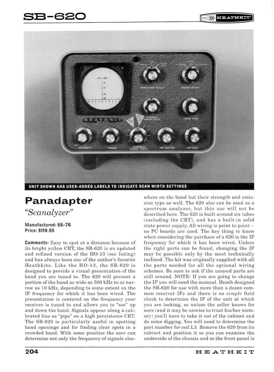
s:s-sao
Pan
adapter
"Scanalyzer"
Manufactured:
66-76
Price:
$119.95
Comments:
Easy
to
spot
at
a di
sta
nc
e
because
of
its
bright
ye
llow
CRT
,
the
SB-620
is
an
updated
and
refined
version
of
the
H0
-13
(see
listing)
and
has
alw
ays
been
one
of
the
a
uth
or's
favorite
Heathkits
.
Like
the
H0-13,
the
SB-620
is
d
esigned
to
provide
a
visual
presentation
of
the
band
you
are
tuned
to
.
The
620
will
pr
e
sent
a
portion
of
the
band
as
wide
as
500
kHz
to
as
nar-
row
as
10
kHz,
depending
to
some
extent
on
the
IF
frequency
for
which
it
has
been
wir
ed.
The
presentation
is
centered
on
the
frequency
your
receiver
is
tuned
to
and
allows
you
to
"see"
up
and
do
wn
the
band.
Signals
a
pp
ear
a
lon
g a
ca
li-
br
ated
line
as
"pi
ps"
on
a
hi
gh
persistence
CRT.
Th
e
SB
-
620
is
particularly
u
sefu
l
in
spotting
band
openings
and
for
finding
clear
spots
in
a
crowded
band.
With
some
practice
the
user
can
det
ermine
not
only
the
frequency
of
signa
ls
else-
204
l®~fif¥SiUHfi
where
on
the
band
but
their
strength
and
em
is-
sion
type
as
well.
The
620
also
can
be
used
as
a
spectr
um
analyzer,
but
this
use
will
not
be
described
here.
Th
e
620
is
built
around
six
tubes
(ex
cluding
the
CRT
),
and
has
a
built
-
in
so
lid
state
power
supply.
All wi
ring
is
point
to
point-
no
PC
boards
are
used.
The
key
thing
to
know
when
considering
the
purchas
e
of
a
620
is
the
IF
frequency
for
which
it
has
been
wired.
Unless
the
right
parts
can
be
found
, ch
anging
the
IF
may
be
possible
only
by
the
most
technica
ll
y
inclined.
The
kit
was
originally
s
upplied
with
all
the
parts
needed
for
all
the
optional
wiring
schemes.
Be
sure
to
ask
if
the
unused
parts
are
still
around
.
NOTE:
If
you
are
going
to
change
the
IF
you
will
need
the
manual.
He
ath
designed
the
SB-620
for
use
with
more
than
a
dozen
com-
mon
receiver
IFs
and
there
is
no s
imple
field
check
to
determine
the
IF
of
the
unit
at
which
you
are
lookin
g, so
unless
the
se
ll
er
knows
for
sure
(a
nd
it
may
be
unwise
to
trust
his/her
mem-
ory
)
you'll
have
to
take
it
out
of
the
cabinet
a
nd
do
some
digging.
You
will
need
to
determine
the
part
number
for coil L3.
Remove
the
620
from
its
cabinet
and
position
it
so
you
can
exam
in
e
the
underside
of
the
chassis
and
so
the
front
pane
l
is
HE.A.THKIT
~
~
f
§f
Mf
Hi*fil
facing
to
your
right.
With
the
unit
so
pos
i
tioned,
the
area
to
examine
is
in
the
l
ower
right
corner
of
the
unit.
In
this
corner
l
ocate
two
tube
sock
-
ets
.
To
locate
coil L3 look
to
the
2 o'clock
position
from
the
upper
tube
sock
et.
Use
t h e
fo
ll
owing
chart
to
determine
th e IF.
L3
Part#
40-774
40-775
40-808
40-776
40-807
40-776
IF
Frequency
455
kHz
1000
kHz
1600-2245
kHz
*
3000
or
3055
kHz
*
5200
or
6000
kHz
*
3395
kHz
(Heath
SB
and
HW
series)
'!'
To
make
a
precise
determination
will
require
the
manual.
Also
note
that
to
re-establish
the
Heath
3395
kHz
I F
it
will
be
necessary
to
change
another
coil (L2)
from
part
number
40-
590
to
part
number
52-
101.
For
a
ll
IF
changes
the
values
of
a few
resistors
and
capacitors
will
need
to
be
changed
as
we
ll
.
Because
they
are
subjected
to
high
voltages,
resistors
in
the
intensity,
focus,
horizontal,
and
vertical
position
circuits
will
degrade
over
time
,
usua
lly
drifting
up
in
va
l
ue.
The
result
will
be
an
inability
to
effectively
control
one
or
more
of
these
functions.
This
is
a
common
ailment
in
SB
-
620s
but
one
that
is
easy
to
cure.
The
tubes
are
also
subjected
to
voltages
that
will
cause
them
to
fade
faster
that
one
might
expect.
And,
by
the
way,
there
is
no
functiona
l
reason
that
the
3RP7
CRT
can
't
be
replaced
wi
th
a
standard
persis
-
tence
3RP1
(
as
foun d
in
the
SB
-610
and
614
).
The
620
uses
a
pair
of
not
-
so-easy
-
to
-
find
NE
-
83
neon
lamps.
Note
t h
at
an
NE -2
or
other
neon
bulb
will
not
suffice
as
a
replacement.
One
is
used
in
the
sweep
generator
and
the
other
is
used
as
a vol
tage
regulator
that
doubles
as
the
pi
l
ot
light.
The
alignment
procedure
is
not
too
complicated
but
does
req
u
ire
a
hig
h
-qua
l
ity
RF
generator
and
an
accurate
aud
io
generator
.
Con
-
nection
to
the
receiver
is
done
via
the
pl
ate
of
A
Guide
to
the
Amateur
Radio
Products
the
mixe
r
just
preceding
the
first
IF
amp
li
fier
and
will
require
you
to
tweak
up
your
receiver
a
bit
to
compe
n
sate
for the
additiona
l
load.
The
manual
contai
n s
exact
hook
up
instructions
for
many
com
mo
n
ra
dios
includ
i
ng
Coll
ins,
Drake,
Eico,
Ha
ll
icra
f
ters,
Nationa
l,
RME,
and
Swan.
Heath
discont
i
nue
d
the
620
in
1976
and
it
was
-
n't
unti
l 1
988
that
another
panada
p
ter
was
re
l
ease
d-
the
H0
-
5404
monitor
scope
(the
panadap
t
er
mo
dule
was
optional)
. T
he
SB
-
620
is
finished
in
Heath
's
two
-
tone
green
wrinkle
paint
an
d
ma
t
ches
the
rest
of
the
SB
line.
It
is
designed
for 1
20
/
240
VAC,
50
/
60
Hz
operation.
The
S
B-
620
actua
ll
y
works
very
we
ll
and
enjoyed
moderate
success.
620s
used
to
be
very
common
at
flea
markets
but
have
become
much
more
scarce
in
recent
years.
Weight/Size: 10lbs;
10
"
wide
x 6.75"
hi
gh x
11'
'
deep
Related
Products:
H0-13, H0-5404,
see
related
products
listed
under
SB-100
205
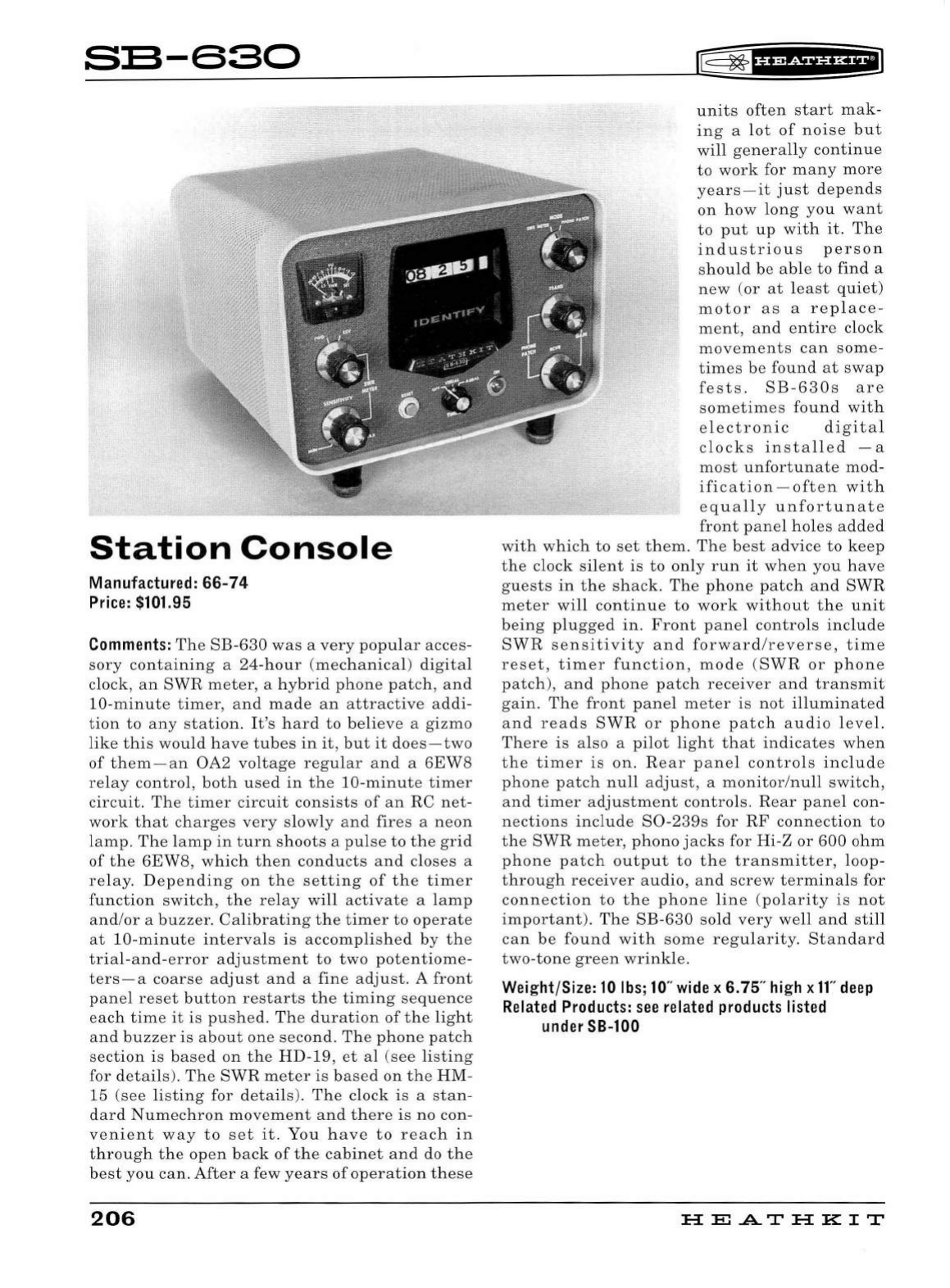
S:S-630
Station
Console
Manufactured: 66-74
Price:
$101.95
Comments:
The
SB
-
630
wa
s a
very
popular
acces
-
sory
containing
a
24-hour
(mechanical)
digital
clock,
an
SWR
meter,
a
hybrid
phone
patch,
and
10-minut
e
timer
,
and
mad
e
an
attractive
addi-
tion
to
any
station
.
It's
hard
to
believe
a
gizmo
like
this
wou
ld
have
tubes
in
it,
but
it
do
es-two
of
them-an
OA2
voltage
regular
an
d a
6EW8
re
la
y
contro
l,
both
used
in
the
10-minute
timer
circuit.
The
timer
circuit
consists
of
an
RC
net-
work
that
charges
very
slow
ly
and
fires
a
neon
l
amp
.
The
l
amp
in
turn
shoots
a p
ul
se
to
the
grid
of
the
6EW8
,
which
then
conducts
an
d
closes
a
relay.
D
epending
on
the
setting
of
the
timer
function
switch,
the
re
l
ay
will
activate
a l
amp
an
d/
or
a
buzzer.
Calibrating
the
timer
to
operate
at
10-minut
e
intervals
is
accomplished
by
the
trial-and-
e
rror
a
dju
st
ment
to
two
potentiome
-
ters
- a
coarse
a
dju
st
and
a
fine
adjust.
A
front
panel
reset
button
restarts
the
timing
sequence
each
time
it
is
pushed
.
Th
e
duration
of
the
li
g
ht
an
d
buzzer
is
about
one
second.
Th
e
phone
patch
section
is
based
on
the
HD-19
,
et
al
(see
li
sting
for
details
).
The
SWR
meter
is
based
on
the
HM-
15
(see
li
sting
for
deta
il
s).
Th
e clock is a
stan
-
dard
Numechron
movement
and
there
is no
con
-
venient
way
to
set
it
.
You
have
to
reach
in
through
the
open
back
of
the
cabinet
and
do
the
b
es
t
you
can.
After
a few
years
of
op
era
tion
the
se
206
lE=
~
f
hfif§fHfi
units
often
start
mak
-
ing
a
lot
of
noise
but
will
genera
lly
continue
to
work
for
many
more
years-it
just
depends
on
how
long
you
want
to
put
up
with
it.
The
industrious
person
should
be
ab
le
to
find
a
new
(
or
at
lea
st
quiet)
motor
as
a
replace
-
ment,
and
entire
clock
movements
can
some-
times
be
found
at
swap
fests
.
SB-630s
are
sometimes
found
with
e
le
ctronic
digital
clocks
installed
- a
most
unfortunate
mod-
ification
-
often
with
equa
ll
y
unfortunate
front
panel
hole
s
added
with
which
to
set
them.
The
best
advice
to
keep
the
clock s
il
ent
is
to
only
run
it
when
you
have
guests
in
the
s
hack.
The
phone
patch
and
SWR
meter
will
continue
to
work
without
the
unit
being
plugged
in.
Front
panel
controls
include
SWR
sensitivity
and
forward/reverse,
time
reset,
timer
function
,
mode
(
SWR
or
phone
patch),
and
phone
patch
receiver
an
d
transmit
gain
.
The
front
pane
l
meter
is
not
illumin
ate
d
a
nd
reads
SWR
or
phone
patch
audio
level.
There
is a
lso
a
pilot
light
that
indicates
when
the
timer
is
on.
Rear
panel
controls
include
phone
patch
null
adjust
, a
monitor
/
null
switch
,
an
d
timer
adjustment
controls.
Rear
pane
l con-
nections
include
S0
-
239s
for
RF
connection
to
the
SWR
meter,
phono
jacks
for Hi-Z
or
600
ohm
phone
patch
output
to
the
transmitter,
loop-
through
receiver
audio,
and
screw
termina
ls for
co
nn
ect
ion
to
t h e
phone
lin
e (pol
arity
is
not
important).
The
SB-
630
sold
very
well
and
sti
ll
can
be
found
with
some
regularity.
Standard
two-tone
green
wrinkle.
Weight/Size:
10
lbs;
10
"
wide
x 6. 75"
high
x ff'
deep
Related
Products:
see
related
products
listed
under
SB-100
HEA.THKIT
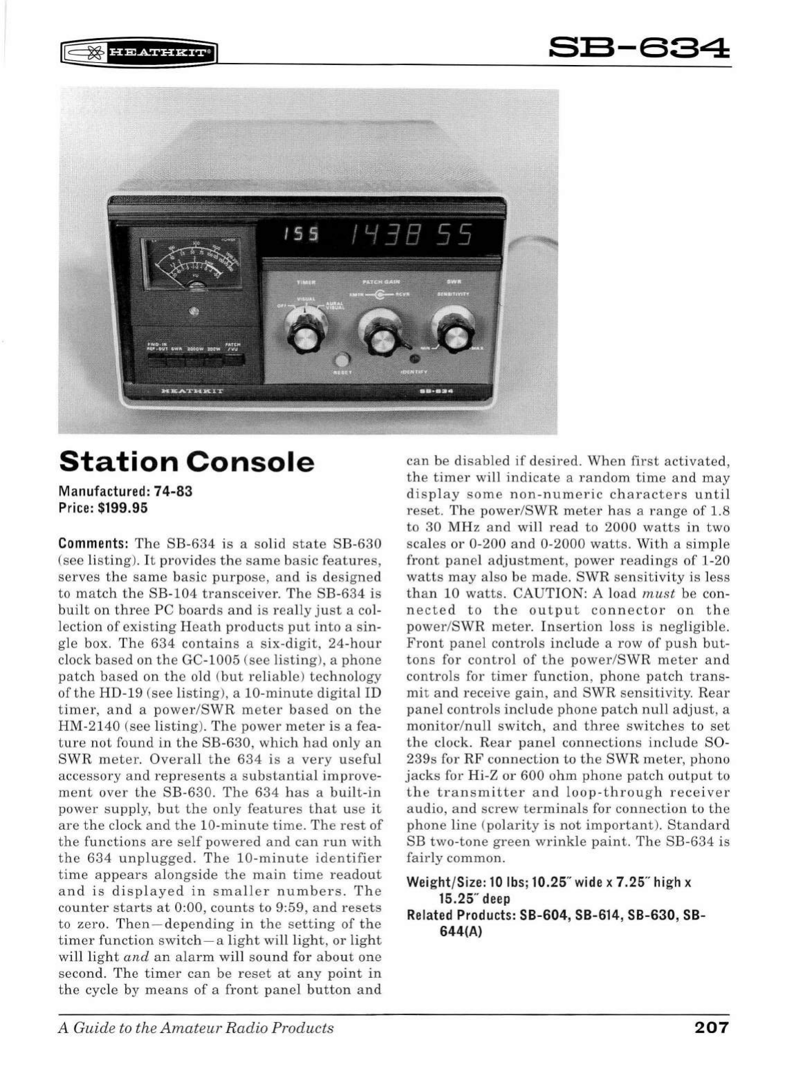
rE
~
f
§f
Rdf
#fi*f
il
Station
Console
Manufactured:
74-83
Price:
$199.95
Comments:
The
SB-634
is
a
solid
state
SB-630
(see
li
sting).
It
provides
the
same
basic
features,
serves
the
same
basic
purpose,
and
is
designed
to
match
the
SB-104
transceiver.
The
SB-634
is
built
on
three
PC
boards
and
is
really
just
a col-
lection
of
existing
Heath
product
s
put
into
a s
in-
gle
box.
The
634
contains
a
six-digit,
24-hour
clock b
ased
on
the
GC-
1005
(se
e
listing
),
a
phone
patch
based
on
the
old
(but
reliable)
technology
of
the
HD-19
(s
ee
listing),
a
10-minute
digital
ID
timer,
and
a
power/SWR
meter
based
on
the
HM-2140
(see
listing
).
The
power
meter
is
a fea-
ture
not
found
in
the
SB-630,
which
had
only
an
SWR
meter.
Overall
the
634
is
a
very
useful
accessory
and
represents
a
substantial
improve-
ment
over
the
SB
-
630.
The
634
has
a
built-in
power
sup
pl
y,
but
the
only
features
that
use
it
are
the
clock
and
the
10-mi
nute
time.
The
rest
of
the
functions
are
se
lf
powered
and
can
run
with
the
634
unplugged.
The
10-minute
identifier
time
appears
alongside
the
main
time
readout
and
is
displayed
in
sma
ll
er
numbers.
The
counter
starts
at
0:00,
co
unt
s
to
9:59,
and
resets
to
zero.
Then-depending
in
the
setting
of
the
timer
function
switch-a
light
will
light,
or
light
will
light
and
an
a
larm
will
sound
for a
bout
one
second.
The
timer
can
be
reset
at
any
point
in
the
cycle
by
means
of
a
front
panel
button
and
A Guide to the
Amateur
Radio
Products
SB-634
can
be
disabled
if
de
sire
d.
When
first
activated,
the
tim
er
will
indicate
a
random
time
and
may
di
s
play
some
non-numeric
characters
until
reset.
The
power/SWR
met
er
h
as
a
range
of
1.8
to
30
MHz
and
will
read
to
2000
watts
in
two
sca
l
es
or
0-200
and
0-2000
watts.
With
a
simple
front
panel
adjustment,
power
readings
of
1-20
watts
may
also
be
made.
SWR
sensitivity
is
less
than
10
watts
.
CAU
TION:
A lo
ad
must
be
con-
nected
to
the
output
connector
on
th
e
power
/
SWR
meter
.
In
sert
ion
lo
ss
is
negligib
le.
Front
panel
controls
include
a
row
of
push
but-
tons
for
control
of
the
power
/
SWR
meter
and
controls
for
timer
function
,
phone
patch
trans-
mit
and
receive
ga
in
,
an
d
SWR
sensitivity.
Rear
panel
controls
include
phone
patch
null
adjust,
a
monitor
/
null
switch,
and
three
sw
itches
to
set
the
clock.
Rear
panel
connections
include
S0-
239s
for
RF
conn
e
ction
to
the
SWR
meter,
phono
j
acks
for
Hi
-Z
or
600
ohm
phone
patch
output
to
the
transmitter
and
loop
-
through
receiver
audio,
and
screw
terminals
for
connection
to
the
phone
line
(
polarity
is
not
important
).
Standard
SB
two-tone
green
wrinkle
paint
.
The
SB-634
is
fairly
common.
Weight/Size: 10lbs;10.25"
wide
x 7.25"
high
x
15.25"
deep
Related
Products:
SB-604, SB-614, SB-630,
SB-
644(A)
207
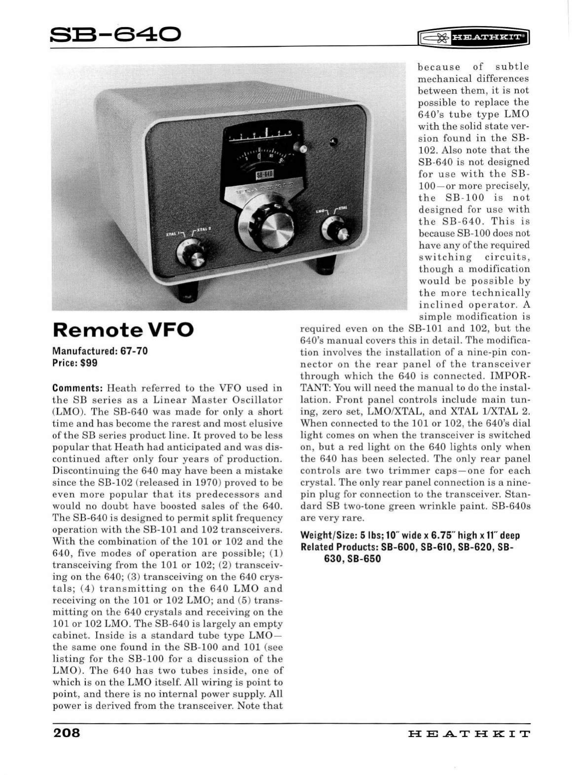
S:S-640
RemoteVFO
Man
ufac
tur
ed:
67-70
Pr
i
ce
: $99
Comments:
Heath
referred
to
the
VFO
used
in
the
SB
series
as
a
Line
a r M
as
ter
Oscillator
(
LMO
).
The
SB
-
640
was
made
for
only
a
short
time
a
nd
has
become
the
rarest
and
most
elusive
of
the
SB
series
product
line.
It
prov
ed
to
be
less
popular
that
H
ea
th
had
anticipated
and
was
di
s-
continued
after
only
four
years
of
production
.
Discontinuing
the
640
may
have
been
a
mistake
si
nce
the
SB-
102
(
released
in
1970
)
proved
to
be
eve
n
more
popular
that
its
predec
essors
and
would
no
doubt
have
boos
ted
sales
of
the
640.
The
SB
-
640
is
designed
to
permit
split
frequency
operation
with
the
SB-101
and
102
transceivers
.
With
the
combination
of
the
101
or
102
and
the
640,
five
modes
of
operation
are
possible;
(1)
transceiving
from
the
101
or
102; (2)
transceiv
-
ing
on
the
640; (3)
transceiving
on
the
640
crys
-
tals;
(4)
transmitting
on
the
640
LMO
and
receiving
on
the
101
or
102
LMO;
and
(5)
trans
-
mitting
on
the
640
crystals
and
receiving
on
the
101or102
LMO.
The
SB-640
is
larg
e
ly
an
empty
cabinet.
Inside
is
a
standard
tube
type
LMO-
the
same
one
found
in
the
SB-100
and
101
(see
listing
for
the
SB
-
100
for
a
discussion
of
the
LMO
).
The
640
has
two
tubes
in
s
ide,
one
of
which
is
on
the
LMO
itself.
All
wiring
is
point
to
point
,
and
there
is
no
internal
power
supply
.
All
power
is
derived
from
the
transceiver.
Note
that
208
lt=
~
fHMfUHEI
because
of
subtle
mechanical
differences
between
them,
it
is
not
possible
to
replace
the
640's
tube
type
LMO
with
the
s
olid
state
ve
r-
sion
found
in
the
SB
-
102.
Also
note
that
the
SB-640
is
not
designed
for
use
with
the
SB-
100
-
or
more
pr
eci
se
ly
,
the
SB-100
i s
not
designed
for
u
se
with
the
SB-640.
Thi
s
is
because
SB-100 does
not
have
any
of
the
required
sw
itching
circuits,
though
a
modification
would
b e
possible
by
the
mor
e
technically
inclined
operator.
A
simple
modification
is
required
eve
n
on
the
SB-
101
and
102,
but
the
640's
manual
covers
this
in
detail.
The
modifica
-
tion
involv
es
the
in
sta
llation
of
a
nine-pin
con-
nector
on
the
rear
panel
of
the
transceiver
through
which
the
640
is
connect
ed.
IMPOR
-
TANT: You
will
need
the
manual
to
do
the
instal
-
lation.
Front
panel
controls
include
main
tun
-
ing,
zero
set,
LMO/XTAL,
and
XTAL 1/XTAL 2.
When
connected
to
the
101
or
102
,
the
640's
dia
l
light
comes
on
when
the
transceiver
is
switched
on,
but
a
red
light
on
the
640
lights
only
when
the
640
has
been
selected.
The
only
rear
pane
l
controls
are
two
trimmer
caps-one
for
each
crystal.
The
only
rear
panel
connection
is
a
nine
-
pin
plug
for
connection
to
the
tran
sce
iver.
Stan-
dard
SB
two
-
tone
green
wrinkle
pa
int.
SB
-
640s
are
very
rare.
Wei
ght/Size: 5
lbs
;
10
"
wide
x 6. 75"
hi
gh x
11"
deep
Related
Produc
ts
: SB-600,
SB-610
, SB-620,
SB-
630, SB-650
HE.A.THKIT
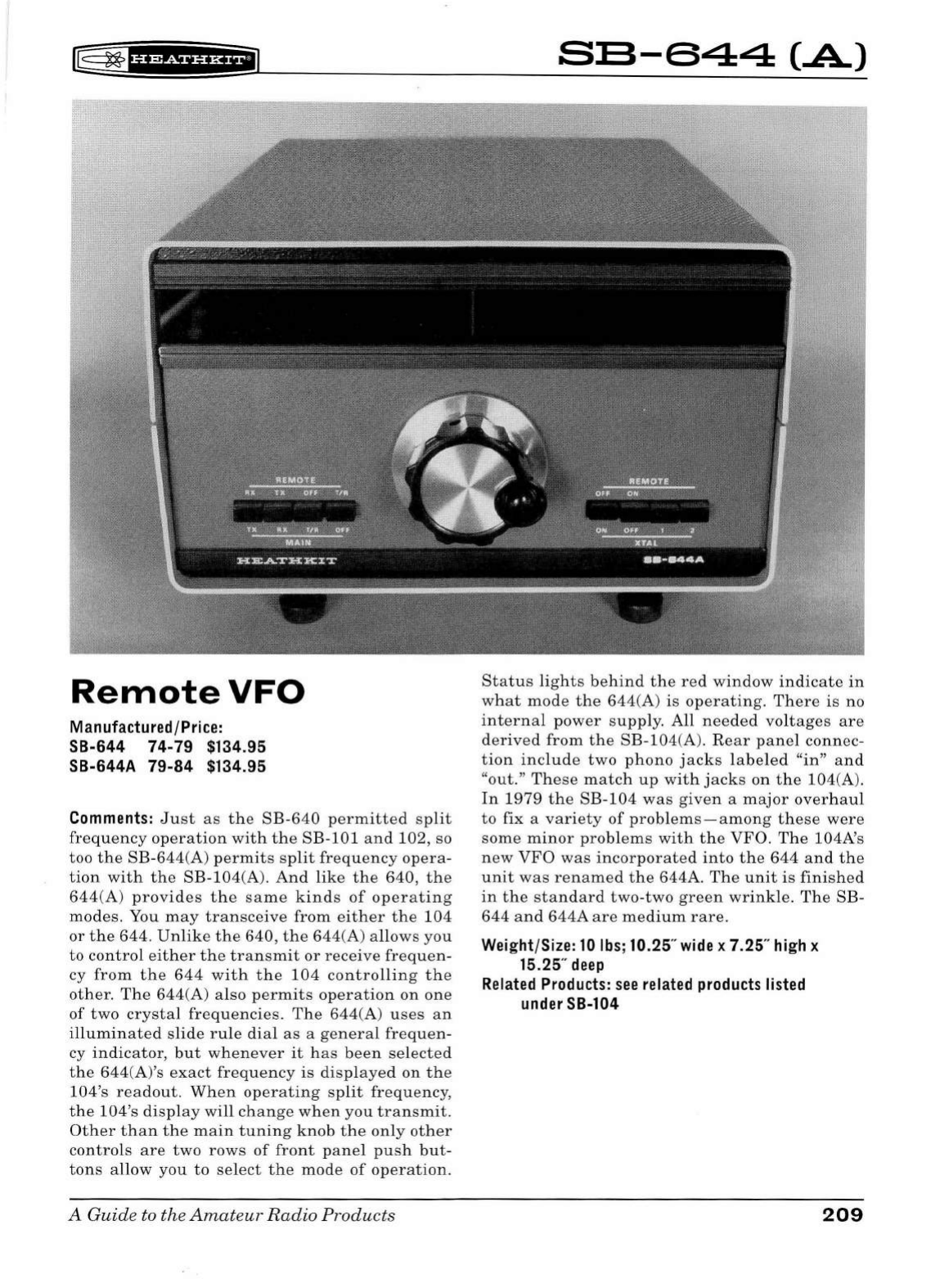
fE
~
1
HSf
§f
i*fiJ
RemoteVFO
Manufactured/Price:
SB-644 74-79 $134.95
SB-644A 79-84 $134.95
Comments:
Just
as
the
SB-640
permitted
split
frequency
operation
with
the
SB-101and102,
so
too
the
SB-644(A)
permits
split
frequency
opera-
tion
with
the
SB-104(A).
And
like
the
640,
the
644(A)
provides
the
same
kinds
of
operating
modes.
You
may
transceive
from
either
the
104
or
the
644.
Unlike
the
640,
the
644(A)
allows
you
to
control
either
the
transmit
or
receive
frequen-
cy
from
the
644
with
the
104
controlling
the
other.
The
644(A)
also
permits
operation
on
one
of
two
crystal
frequencies.
The
644(A)
uses
an
illuminated
slide
rule
dial
as
a
general
frequen-
cy
indicator,
but
whenever
it
has
been
selected
the
644(A)'s
exact
frequency
is
displayed
on
the
104's
readout.
When
operating
split
frequency,
the
104's
display
will
change
when
you
transmit.
Other
than
the
main
tuning
knob
the
only
other
controls
are
two
rows
of
front
panel
push
but-
tons
allow
you
to
se
lect
the
mode
of
operation.
A Guide to the
Amateur
Radio
Products
SE-644
(.A)
Status
lights
behind
the
red
window
indicate
in
what
mode
the
644(A)
is
operating.
There
is
no
internal
power
supply
. All
needed
voltages
are
derived
from
the
SB-104(A).
Rear
panel
connec-
tion
include
two
phono
jacks
labeled
"in"
and
"out
."
These
match
up
with
jacks
on
the
104(A).
In
1979
the
SB-104
was
given
a
major
ov
er
haul
to
fix a
variety
of
problems-among
these
were
some
minor
problems
with
the
VFO.
The
104A's
new
VFO
was
incorporated
into
the
644
and
the
unit
was
renamed
the
644A.
The
unit
is
finished
in
the
standard
two-two
green
wrinkle.
The
SB-
644
and
644A
are
medium
rare.
Weight/Size:
10
lbs;
10.25"
wide
x 7.25"
high
x
15.25"
deep
Related
Products:
see
related
products
listed
under
SB-104
209
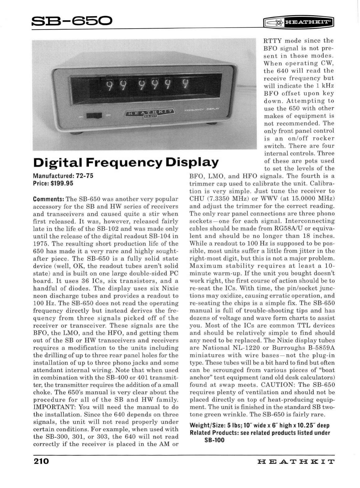
S:S-650
w=~
tH&ii'Hii
Digital
Frequency
Display
RTTY
mod
e s
ince
the
BFO
sign al
is
not
pr
e-
sent
in
those
modes.
Wh
en
op
era
t
ing
CW,
the
640
will
rea
d
the
receive
freq
u
ency
but
will
indic
ate
the
1 k
Hz
BFO
offset
upon
key
down
.
Attempting
to
use
the
650 w
ith
other
makes
of
eq
uipm
ent
is
not
recomme
nd
ed.
Th
e
only
front
panel c
ont
ro
l
is
a n
on/off
r
ock
er
sw
itch.
There
are
fo
ur
int
erna
l
controls.
Thr
ee
of
these
are
pot
s u
se
d
to
se
t
th
e l
eve
ls
of
the
Man
u
fa
ctur
ed:
72-75
Price
: $
199
.95
Comment
s:
The
SB-650
w
as
another
very
popul
ar
ac
ce
sso
ry
for
th
e
SB
a
nd
HW
ser
i
es
of
receivers
and
transceivers
and
cau
se
d
quite
a
stir
wh
en
first
released.
It
was,
how
ever,
released
fairly
la
te
in
the
life
of
th
e
SB-102
and
was
ma de
only
until
the
release
of
th
e
di
g
ital
readout
SB
-
104
in
1975.
The
resulting
s
hort
production
li
fe
of
the
650
ha
s
made
it
a
very
rare
and
hi
g
hl
y soug
ht-
after
piec
e.
Th
e
SB-650
is
a
full
y s
olid
state
device (well,
OK
,
th
e
readout
tubes
aren't so
lid
sta
te
) a
nd
is
built
on
one
la
rg
e
doubl
e-
sided
PC
board
.
It
u
ses
36
IC
s,
six
tr
a
nsi
sto
r
s,
a
nd
a
handful
of
diod
es.
The
displ
ay
us
es
six
Nixi
e
ne
on
discharge
tub
es
and
provide
s a
re
a
dout
to
100
H
z.
Th
e
SB-650
does
not
read
the
op
era
ting
frequency
directly
but
in
s
tead
derive
s
the
fre-
quency
from
three
s
ignals
picked
off
of
th
e
receiv
er
or
tran
s
ceiv
er.
The
se
si
gna
ls
are
th
e
BFO
,
the
LMO
, a
nd
the
HFO
,
and
ge
ttin
g
them
out
of
the
SB
or
HW
tran
s
ceiv
ers
a
nd
rec
eiv
ers
requires
a
modification
to
th
e
units
including
the
drillin
g
of
up
to
three
rear
panel
hol
es
for
th
e
installation
of
up
to
three
phono
jacks
and
s
om
e
attendant
internal
wiring
.
Not
e
th
at
wh
en u
se
d
in
combination
with
the
SB-400
or
401
tr
ans
mit-
ter,
th
e
transmitt
er re
quire
s
the
a
ddition
of
a
small
chok
e.
The
650
's
manual
is v
ery
cl
ear
about
the
proc
e
dure
for
all
of
th
e
SB
a
nd
HW
family.
IMPORTANT
: You
will
n
ee
d
the
ma
nu
al
to
do
the
in
s
tallation.
Sinc
e
th
e
640
depends
on
thr
ee
s
ignal
s,
the
unit
will
not
read
properl
y
und
er
certain
conditions.
For
ex
a
mple
,
when
us
ed
with
the
SB-300
,
301
,
or
303,
the
640
will
not
r
ea
d
correctly
if
the
receiver
is
plac
ed
in
th
e AM
or
210
BFO
,
LMO
,
an
d
HFO
sig
nal
s.
Th
e
fourth
is a
trimmer
ca
p u
se
d
to
calibrate
th
e
unit.
Calibra-
tion
is
very
si
mpl
e.
Ju
st
tun
e
the
receiver
to
CHU
(7.3
35
0
MHz
)
or
WWV
(a
t 15.
0000
MHz
)
a
nd
a
dju
st
th
e
trimmer
for
the
corr
ect
rea
din
g.
Th
e
only
rear
panel
co
nn
ect
ion
s
are
thr
ee
phono
sockets-o
n e
for
eac
h s
ign
al.
Int
er
connecting
cables
should
be m a de
from
RG58A/U
or
e
qui
va
-
le
nt
a
nd
s
hould
be
no
long
er
th
an 18
inches.
Whil
e a
rea
dout
to
100
Hz
is
s
uppo
se
d
to
be
pos
-
s
ibl
e,
mo
st
unit
s s
uff
er a
littl
e
from
jitt
er
in
the
right-mo
st
digit
,
but
thi
s
is
not
a ma
jor
probl
em .
Ma
x
imum
st a
bilit
y
requires
at
lea
st a
10-
minute
warm-up
.
If
the
unit
you
bought
do
es
n't
work
right,
th
e
fir
st
co
ur
se
of
ac
tion
s
hould
be
to
re
-
seat
the
ICs.
With
tim
e,
th
e
pin
/s
ock
et
junc
-
tions
may
oxidize
,
ca
u s
in
g
errat
ic
operation,
a
nd
re-seating
th
e
chips
is
a s
impl
e fix .
Th
e
SB-650
m
an
ual
is
full
of
troubl
e-s
hootin
g
tips
a
nd
ha
s
do
zens
of
voltage
a
nd
wave
form
ch
ar
ts
to
a
ss
ist
you. Most
of
the
IC
s ar e
common
TTL
d
ev
ic
es
a
nd
s
hould
be
relatively
s
impl
e
to
find
should
any
need
to
be
replaced.
Th
e
Nixie
displ
ay
tub
es
are
National
NL-1220
or
Burrou
g
hs
B-
5859A
miniatur
es
with
w
ir
e b
ases
-not
th
e plu g
-in
type.
Th
ese
tub
es will
be
a
bit
ha
rd
to find
but
often
can
be
scro
un
ge
d
from
various
pi
eces
of
"
boat
a
nchor
"
test
e
quipm
en
t (
and
old desk
calculators
)
found
at
swa
p m
ee
ts.
CAUTION:
Th
e
SB-650
re
qui
res
pl
e
nt
y
of
ventilation
a
nd
s
hould
not
be
plac
ed
dir
ec
tly
on
top
of
heat
-
producin
g
equip-
ment.
Th
e
unit
is finished
in
th
e s
tanda
rd
SB
two-
ton
e
green
wrink
le.
Th
e SB-
650
is
fa
irl
y
rare.
Wei
ght/Size: 5
lbs
;
10
"
wide
x 6"
high
x 10.25"
deep
Related
Products:
see
related
products
listed
under
SB-100
HE.A.TH
KIT
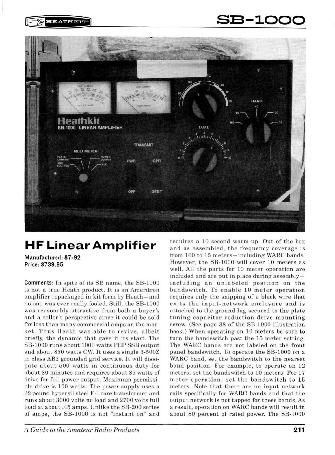
[§
~
f
i'?f#f
Hi*f
iJ
HF
Linear
Amplifier
Manufactur
ed:
87-92
Pr
i
ce:
$739.95
Comments:
In
spite
of
its
SB
name,
the
SB-1000
is
not
a
true
Heath
product.
It
is
an
Ameritron
amplifier
repackaged
in
kit
form
by
Heath-and
no
one
was
ever
really
fooled.
Still,
the
SB-1000
was
reasonably
attractive
from
both
a
buyer's
and
a
seller's
perspective
since
it
could
be
sold
for
less
than
many
commercial
amps
on
the
mar-
ket.
Thus
Heath
was
able
to
revive,
albeit
briefly,
the
dynamic
that
gave
it
its
start
.
The
SB-1000
runs
about
1000
watts
PEP
SSB
output
and
about
850
watts
CW
.
It
uses
a
single
3-500Z
in
class
AB2
grounded
grid
service.
It
will
dissi-
pate
about
500
watts
in
continuous
duty
for
about
30
minutes
and
requires
about
85
watts
of
drive
for
full
power
output.
Maximum
permissi-
ble
drive
is
100
watts.
The
power
supply
uses
a
22
pound
hypersil
steel
E-I
core
transformer
and
runs
about
3000
volts
no
load
and
2700
volts
full
load
at
about
.45
amps.
Unlike
the
SB
-
200
series
of
amps,
the
SB-1000
is
not
"instant
on"
and
A
Guide
to the
Amateur
Radio
Products
SE-1000
requires
a 10
second
warm-up.
Out
of
the
box
and
as
assembled,
the
frequency
coverage
is
from
160
to
15
meters-including
WARC
bands.
However,
the
SB-1000
will
cover
10
meters
as
well.
All
the
parts
for
10
meter
operation
are
included
and
are
put
in
place
during
assemb
l
y-
incl
uding
an
unlabeled
position
on
the
bandswitch.
To
enable
10
meter
operation
requires
only
the
snipping
of
a
black
wire
that
exits
the
input-network
enclosure
and
is
attached
to
the
ground
lug
secured
to
the
plate
tuning
capacitor
reduction
-
drive
mounting
screw.
(See
page
38
of
the
SB-1000
illustration
book.)
When
operating
on
10
meters
be
sure
to
turn
the
bandswitch
past
the
15
meter
setting.
The
WARC
bands
are
not
labeled
on
the
front
panel
bandswitch.
To
operate
the
SB-1000
on
a
WARC
band,
set
the
bandswitch
to
the
nearest
band
position.
For
example,
to
operate
on
12
meters,
set
the
bandswitch
to
10
meters.
For
17
meter
operation,
set
the
bandswitch
to
15
meters.
Note
that
there
are
no
input
network
coils
specifically
for WARC
bands
and
that
the
output
network
is
not
tapped
for
these
bands.
As
a
resu
l
t,
operation
on
WARC
bands
will
result
in
about
80
percent
of
rated
power.
The
SB
-
1000
211
features
a
variable
ALC
providing
a
negative-
going
ALC
voltage
from
0-20
volts
.
True
QSK
operation
is
possible
with
the
optional
QSK
board.
The
QSK
board
mounts
a
lmo
st
directly
above
the
power
transfomer.
Unless
you
can
remove
the
unit
from
its
cabinet,
the
best
way
to
check
for
the
presence
of
the
QSK
board
is
to
look for a
rear
panel
screw
that
had
to
be
added
to
mount
the
board
.
This
screw
is
locat
ed
just
above
and
to
the
right
of
the
S0-239
RF
output
connector
.
There
are
two
large
illuminated
panel
meters.
One
is
dedicated
to
grid
current
and
the
other
will
monitor
plate
current,
plate
voltage,
ALC,
and
power
output.
Front
panel
controls
include
plate
tune,
load
,
band,
meter
function,
main
power,
and
operate/standby.
The
only
rear
panel
control
is
the
ALC
output
adjustment.
Rear
panel
connections
include
S0-239
RF
input
and
output
connectors
and
phono
jacks
for
TR
relay,
ALC
out,
and
-12 vo
lt
s
(also
for
TR
relay)
.
Th
ere
is
also
a
ground
post.
Although
the
SB-
1000
can
be
wired
for
either
120
or
240
VAC
operation,
on
ly a
120
VAC
line
cord
and
plug
were
sup
pli
ed.
If
you
want
to
change
to
240
VAC
operation
(
preferred
)
you'll
have
to
find
the
cor
-
rect
plug,
do a
bit
of
re-wiring,
and
install
the
correct
fuses.
The
SB-1000
was
the
l
ast
amp
H
eat
h
ever
sold,
but
because
it
is
not
a
genuine
Heath
product,
it
is
not,
in
the
author's
opinion,
much
of
a
collector's
piece.
It
is,
however,
a
reli-
able,
well-designed
product
and
should
be
con-
sidered
by
anyone
in
the
market
for
a
good
amplifier.
Toward
the
end,
He
at
h
blew
out
its
remaining
stock
of
SB-lOOOs
with
s
ub
stantia
l
discounts.
Finished
in
two-tone
gray
with
red
dial
pointers.
Medium
rare.
Weight/Size: 48
lbs;
14.5"
wide
x 8.25"
high
x
14
"
deep
Related
Products:
SB-200,
SB-201,
SB-220,
SB-
221,
SB-230, HL-2200
212
f®~'§f
iSii'Hil
HEATHKIT
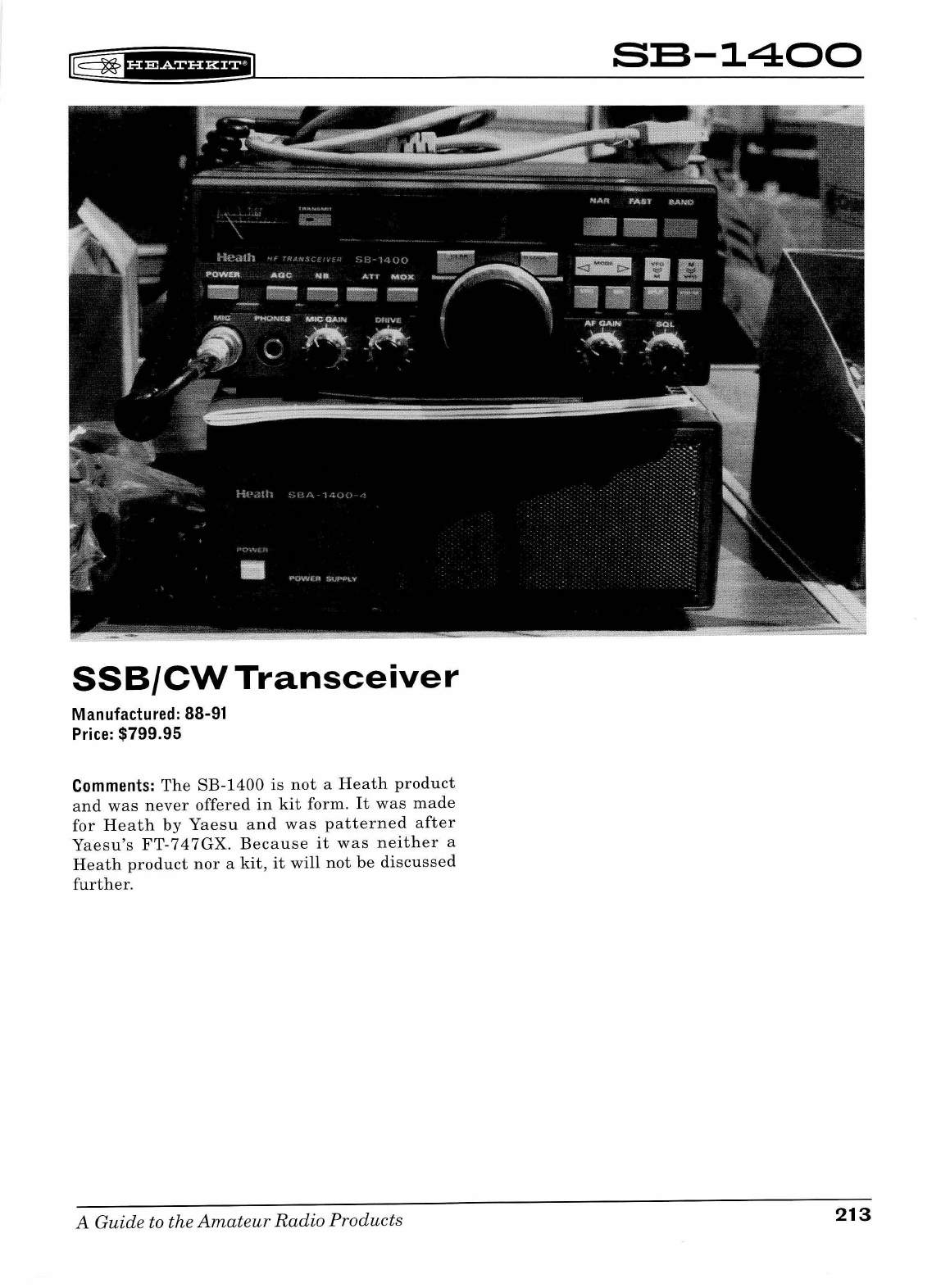
l@
~
f
U?&iHH+i
SSB/CW
Transceiver
Manufactured: 88-91
Price:
$799.95
Comments:
The
SB-1400
is
not
a
Heath
product
and
was
never
offered
in
kit
form.
It
was
made
for
Heath
by
Yaesu
and
was
patterned
after
Yaesu's
FT-747GX
.
Because
it
was
neither
a
Heath
product
nor
a
kit,
it
will
not
be
discussed
further.
A Guide to the
Amateur
Radio
Products
S:S-1400
213
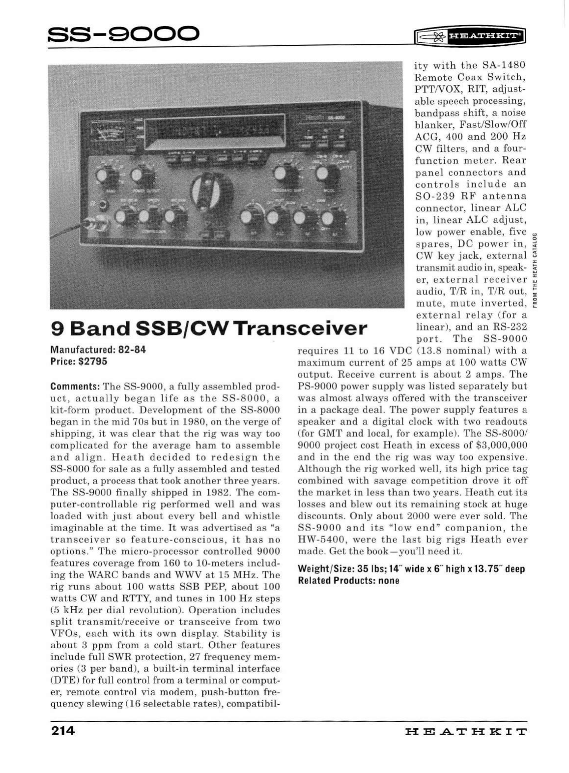
SS-9000
f=
~
fHffiif§fH+il
ity
with
the
SA-1480
Remote
Coax
Switch,
PTTNOX,
RIT,
adjust-
able
speech
processing,
bandpass
shift,
a
noise
blanker,
Fast
/
Slow
/
Off
ACG,
400
and
200
Hz
CW
filters
,
and
a four-
function
meter.
Rear
panel
connectors
and
controls
include
an
S0-239
RF
antenna
connector,
linear
ALC
in
,
linear
ALC
adjust,
low
power
enable,
five
"'
::
spares,
DC
power
in,
;:
9
Band
SSB/CW
Tran
sce
i
ver
CW
key
jack,
external
~
transmit
audio in, speak- 3
er
,
external
receiver
~
audio,
T/R
in,
T/R
out,
;
mute
,
mute
inverted
,
~
external
relay
(for
a
linear
),
and
an
RS-232
port.
The
SS-9000
Manufactured:
82-84
Pr
i
ce:
$2795
Comments:
The
SS
-
9000,
a
fully
assembled
prod
-
uct
,
actually
beg
an
life
as
the
SS-8000,
a
kit-form
product.
Development
of
the
SS-8000
began
in
the
mid
70s
but
in
1980
,
on
the
verge
of
shipping,
it
was
cl
ear
that
the
rig
was
way
too
complicated
for
the
average
ham
to
assemble
and
align
.
Heath
decided
to
redesign
the
SS
-
8000
for
sale
as
a
fully
assemb
l
ed
and
tested
product,
a
proc
ess
that
took
another
three
years
.
The
SS
-
9000
fina
ll
y
shipped
in
1982.
The
com-
puter-controllable
rig
performed
well
and
was
loaded
with
just
abo
ut
every
be
ll
and
whistle
imaginab
le
at
the
time.
It
was
advertised
as
"a
transceiver
so
feature-conscious,
it
has
no
options
."
The
micro-processor
contro
ll
ed
9000
features
coverage
from
16
0
to
10-
meters
includ
-
ing
the
WARC
bands
and
WWV
at
15
MHz.
The
rig
runs
about
100
watts
SS
E
PEP,
about
100
watts
CW
and
RTTY,
and
tunes
in
100
Hz
steps
(5
kHz
per
dial
revolution).
Operation
includes
split
transmit/receive
or
tra
n
sce
i
ve
from
two
VFOs,
each
wit
h
its
own
display.
Stabi
li
ty
is
about
3
ppm
from
a cold
start
.
Other
features
include
full
SWR
protection
,
27
frequency
mem-
ories
(3
per
band),
a b
ui
lt-
in
term
i
nal
interface
(D
TE)
for
fu
ll
control
from
a
termina
l or com
put-
er
,
remote
contro
l
via
mo
d
em,
pus
h
-button
fre
-
quency
sl
ewi
ng (16
se
l
ecta
bl
e
rates),
compatibi
l-
214
requires
11
to
16
VDC
(13.8
nominal)
with
a
maximum
current
of
25
amps
at
100
watts
CW
output.
Receive
current
is
about
2
amps
.
The
PS-9000
power
supply
was
list
ed
separately
but
was
almost
always
offered
with
the
transceiver
in
a
package
deal.
The
pow
er
supply
features
a
speaker
and
a
digita
l
clock
with
two
readouts
(for
GMT
and
local
, for
example).
The
SS-8000
/
9000
project
cost
Heath
in
excess
of
$3,000
,
000
and
in
th
e
end
the
rig
was
way
too
expensive
.
Although
the
rig
worked
well,
its
high
price
tag
combined
with
savage
competition
drove
it
off
the
market
in
less
than
two
years.
Heath
cut
its
l
osses
and
blew
out
its
remaining
stock
at
huge
discounts.
Only
about
2000
were
ever
sold.
The
SS-9000
and
its
"l
ow
end"
companion
,
the
HW
-
5400,
were
the
last
big
rigs
Heath
ever
made.
Get
the
book-you
'
ll
need
it
.
Weight/Size: 35
lbs
;
14
"
wide
x 6"
hi
gh x
13.
75"
deep
Related
Products:
none
HEATHKIT
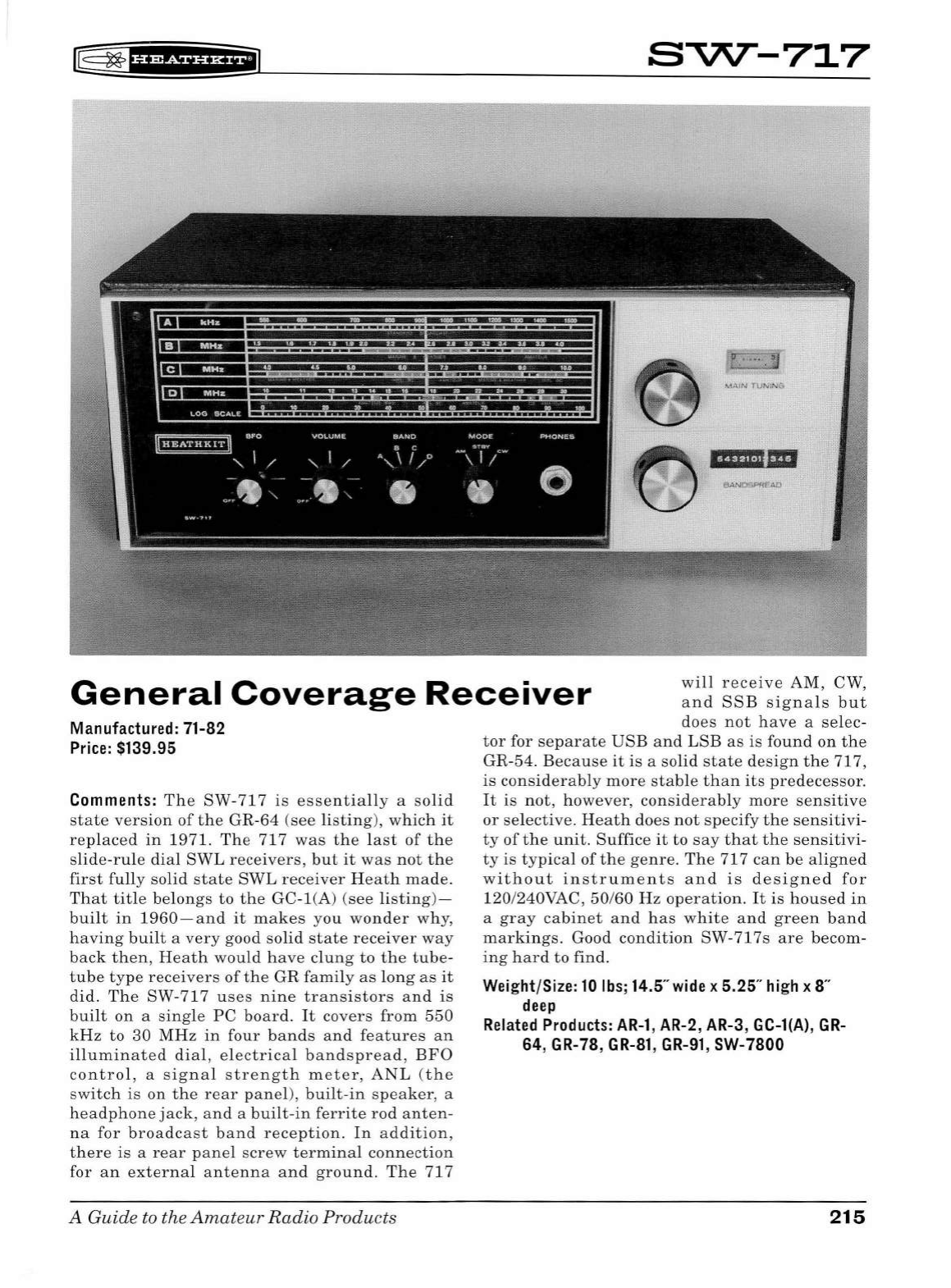
f8
~
f
Hi5¥¥f
i*+
i
s~-717
HFfli.ii"'
General
Coverage
Receiver
will
receive
AM
,
CW
,
and
SSB
signals
but
does
not
have
a
se
lec-
Manufactured: 71-82
Price:
$139.95
Comments:
The
SW
-
717
is
essentially
a
solid
state
version
of
the
GR
-
64
(see
li
sti
ng)
,
which
it
replaced
in
1971.
The
717
was
the
last
of
the
slide-rule
dial
SWL
receivers,
but
it
was
not
the
first
fully
solid
state
SWL
receiver
He
a
th
made
.
That
title
belongs
to
the
GC-
l(A)
(s
ee
listing)
-
built
in
1960
-a
nd
it
makes
you
wonder
why,
having
built
a
very
good
solid
state
receiver
way
back
then,
H
ea
th
would
have
clung
to
the
tube-
tube
type
receivers
of
the
GR
family
as
long
as
it
did.
The
SW-717
us
es
nine
transistors
and
is
built
on
a
single
PC
board.
It
cove
rs
from
550
kHz
to
30
MHz
in
four
bands
and
features
an
illuminated
dial
,
electrical
bandspread
,
BFO
control,
a
signal
strength
meter,
ANL
(
the
sw
itch
is
on
the
rear
panel)
,
built-in
speaker,
a
headphone
jack
, a
nd
a
built-in
ferrite
rod
anten-
na
for
broadcast
band
reception.
In
addition,
there
is
a
rear
panel
sc
rew
terminal
connection
for
an
external
antenna
and
ground.
The
717
A Guide to the
Amat
eur
Radio
Products
tor
for
separate
USB
and
LSB
as
is
found
on
the
GR-54
.
Because
it
is
a
solid
state
design
the
717,
is
considerably
more
stable
than
its
predecessor.
It
is
not,
however,
considerably
more
sensitive
or
selective.
Heath
does
not
specify
the
sensitivi
-
ty
of
the
unit.
Suffice
it
to
say
that
th
e
sensitivi
-
ty
is
typical
of
the
genre.
The
71 7
can
be
aligned
without
instruments
and
is
designed
for
120
/240VAC,
50
/60
Hz
operation
.
It
is
housed
in
a
gray
cabinet
and
has
white
and
green
band
markings.
Good
condition
SW-717s
are
becom-
ing
hard
to
find
.
Wei
ght/Size:
10
lbs;
14.5"
wide
x 5.25"
hi
gh x 8"
deep
Related
Products:
AR-1
,
AR-2
,
AR-3
, GC-l(A),
GR
-
64,
GR-78
,
GR-81
,
GR-91
, SW-7800
215
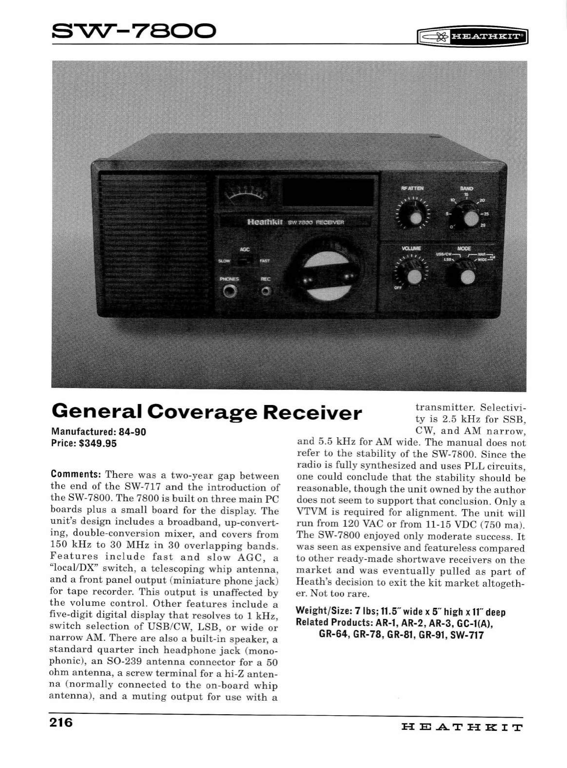
s~-7eoo
~
~f
U¥iiiHil
General
Coverage
Receiver
transmitter
.
Selectivi-
ty
is
2.5
kHz
for
SSB
,
CW,
and
AM
nar
row,
Manufactured: 84-90
Price:
$349.95
Comments:
There
was
a
two-year
gap
between
the
end
of
the
SW-717
and
the
introduction
of
the
SW-7800.
The
7800
is
built
on
three
main
PC
boards
plus
a
small
board
for
the
display.
The
unit's
design
includes
a
broadband,
up-convert-
ing,
double-conversion
mixer,
and
covers
from
150
kHz
to
30
MHz
in
30
overlapping
bands.
Features
includ
e
fast
and
slow
AGC,
a
"local/DX"
switch,
a
telescoping
whip
antenna,
and
a
front
panel
output
(miniature
phone
jack)
for
tape
recorder.
This
output
is
unaffected
by
the
volume
control.
Other
features
include
a
five-digit
digital
display
that
resolves
to
1
kHz,
switch
selection
of
USB/CW,
LSB,
or
wide
or
narrow
AM.
There
are
also
a
built-in
speaker,
a
standard
quarter
inch
he
adphone
jack
(mono-
phonic),
an
S0-239
antenna
connector
for
a
50
ohm
antenna,
a
screw
terminal
for a
hi-Z
anten-
na
(norma
lly
connected
to
the
on-board
whip
antenna),
and
a
muting
output
for
use
with
a
216
and
5.5
kHz
for
AM
wide.
The
manual
does
not
refer
to
the
stability
of
the
SW-7800.
Since
the
radio
is
fully
synthesized
and
uses
PLL
circuits,
one
could
conclude
that
the
stability
should
be
reasonable,
though
the
unit
owned
by
the
author
does
not
seem
to
support
that
conclusion.
Only
a
VTVM
is
required
for
alignment.
The
unit
will
run
from
120
VAC
or
from
11-15 VDC
(750
ma).
The
SW-
7800
enjoyed
only
moderate
success.
It
was
seen
as
expensive
and
featureless
compared
to
other
ready-made
shortwave
receivers
on
the
market
and
was
eventually
pulled
as
part
of
Heath's
decision
to
exit
the
kit
market
altogeth-
er.
Not
too
rare.
Weight/Size: 7
lbs;
11.5"
wide
x
5"
high
x
11"
deep
Related
Products:
AR-1,
AR-2, AR-3, GC-l(A),
GR-64, GR-78,
GR-81,
GR-91,
SW-717
HE
AT
HK
IT
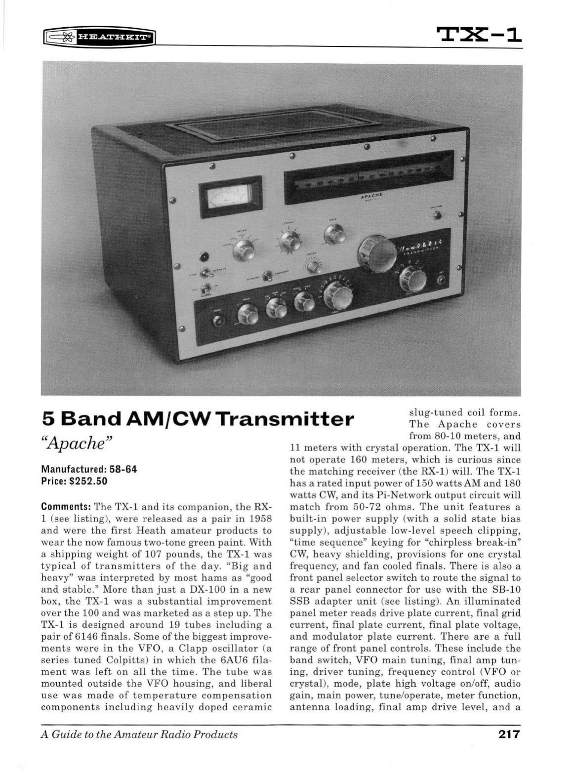
~
~f§fifSiffiiffl
TX-1
5
Band
AM/CW
Transmitter
slug-tuned
coil
forms.
The
Apache
covers
from
80-10
meters,
and
"Apache"
Manufactured:
58-64
Price:
$252.50
Comments:
The
TX-1
and
its
companion,
the
RX-
1 (
see
listing
),
were
released
as
a
pair
in
1958
and
were
the
first
Heath
amateur
products
to
wear
the
now
famous
two-tone
green
paint
.
With
a
shipping
weight
of
107
pounds,
the
TX-1
was
typical
of
transmitters
of
the
day.
"Big
and
heavy"
was
interpreted
by
most
hams
as
"good
and
stab
le."
More
than
just
a DX-100
in
a
new
box, t he TX-1
was
a
substantia
l
improvement
over
the
100
and
was
marketed
as
a
step
up
.
The
TX-1 is
designed
around
19
tub
es
including
a
pair
of
6146
finals.
Some
of
the
biggest
improve-
ments
were
in
the
VFO
, a
Clapp
oscillator
(a
series
tuned
Colpitts
)
in
which
the
6AU6
fila-
ment
was
left
on
a
ll
the
time.
The
tube
was
mounted
outside
the
VFO
housing,
and
liberal
use
was
made
of
temperature
compensation
components
including
heavily
doped
ceramic
A
Guide
to the
Amateur
Radio
Products
11
meters
with
crystal
operation.
Th
e TX-1
will
not
operate
160
meters,
which
is
curious
since
the
matching
receiver
(t
he RX-1) will.
The
TX-1
has
a
rated
input
power
of
150
watts
AM
and
180
watts
CW,
and
its
Pi-Network
output
circuit
will
match
from
50-72
ohms.
The
unit
features
a
built-in
power
supp
ly
(with
a
so
lid
state
bias
sup
ply
),
adjustable
low-l
eve
l
speech
clipping,
"time
sequence"
keying
for
"chirp
le
ss
break-in"
CW,
heavy
shielding,
provisions
for
one
crystal
frequency,
and
fan
cooled
finals.
There
is
also a
front
panel
selector
switch
to
route
the
signal
to
a
rear
panel
connector
for
use
with
the
SB-10
SSE
adapter
unit
(see
li
sting).
An
illuminated
panel
meter
reads
dri
ve
plate
current
,
final
grid
current
,
final
plate
current
,
final
pl
ate
voltage,
and
modulator
plate
current
.
There
are
a
full
range
of
front
panel
controls.
These
include
the
band
switc
h ,
VFO
main
tuning,
final
amp
tun-
ing
,
driver
tuning,
frequency
control
(VFO
or
crystal),
mode,
plate
high
voltage
on/off,
audio
gain,
main
power,
tune
/
operate,
meter
fun
ction,
antenna
loading
,
final
amp
drive
l
eve
l,
an
d a
217
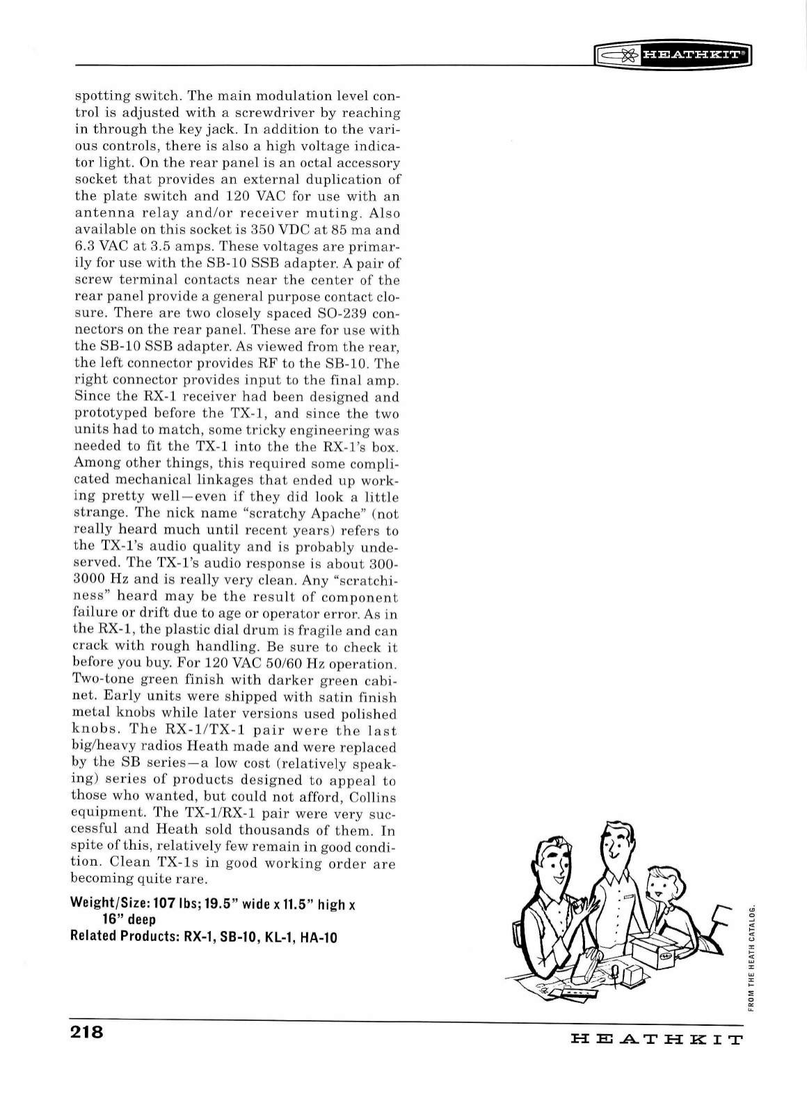
spotting
switch.
The
main
modulation
level
con-
trol
is
adjusted
with
a
screwdriver
by
reaching
in
through
the
key
jack.
In
addition
to
the
vari-
ous
controls,
there
is
also
a
high
voltage
indica-
tor
light.
On
the
rear
panel
is
an
octal
accessory
socket
that
provides
an
external
duplication
of
the
plate
switch
and
120
VAC for
use
with
an
antenna
relay
and/or
receiver
muting.
Also
available
on
this
socket
is
350
VDC
at
85
ma
and
6.3 VAC
at
3.5
amps
.
These
voltages
are
primar-
ily
for
use
with
the
SB-10
SSB
adapter
. A
pair
of
screw
terminal
contacts
near
the
center
of
the
rear
panel
provide
a
general
purpose
contact
clo-
sure.
Th
ere
are
two
closely
spaced
S0-239
con-
nectors
on
the
rear
panel.
These
are
for
use
with
the
SB-10
SSB
adapter.
As
viewed
from
the
rear,
the
left
connector
provides
RF
to
the
SB-10
.
The
right
connector
provides
input
to
the
final
amp.
Since
the
RX-1
receiver
had
been
designed
and
prototyped
before
the
TX-1,
and
since
the
two
units
had
to
match,
some
tricky
engineering
was
needed
to
fit
the
TX-1
into
the the
RX-l's
box.
Among
other
things,
this
required
some
compli-
cated
mechanical
linkages
that
ended
up
work-
ing
pretty
well-
even
if
they
did
look
a
little
strange.
The
nick
name
"scratchy
Apache
"
(not
really
heard
much
until
recent
years)
refers
to
the
TX-l's
audio
quality
and
is
probably
unde-
served.
The
TX-l's
audio
response
is
about
300-
3000
Hz
and
is
really
very
clean.
Any
"
scratchi-
ness"
heard
may
be
the
result
of
component
failure
or
drift
due
to
age
or
operator
error.
As
in
the
RX-1,
the
plastic
dial
drum
is
fragile
and
can
crack
with
rough
handling.
Be
sure
to
check
it
before
you
buy.
For
120
VAC
50/60
Hz
operation.
Two-tone
green
finish
with
darker
green
cabi-
net.
Early
units
were
shipped
with
satin
finish
metal
knobs
while
later
versions
used
polished
knobs.
The
RX-1/TX-l
pair
were
the
last
big/heavy
radios
Heath
made
and
were
replaced
by
the
SB
series-a
low
cost
(relatively
speak-
ing)
series
of
products
designed
to
appeal
to
those
who
wanted,
but
could
not
afford,
Collins
equipment.
The
TX-1/RX-l
pair
were
very
suc-
cessful
and
Heath
sold
thousands
of
them.
In
spite
of
this,
relatively
few
remain
in
good
condi-
tion.
Clean
TX-ls
in
good
working
order
are
becoming
quite
rare
.
Weight/Size: 107lbs;19.5"
wide
x
11.5"
high
x
16"
deep
Related
Products:
RX-1,
SB-10,
KL-1,
HA-10
218
rE=
~
1
u&&f
Ui*il
HE
A..T
HK
IT
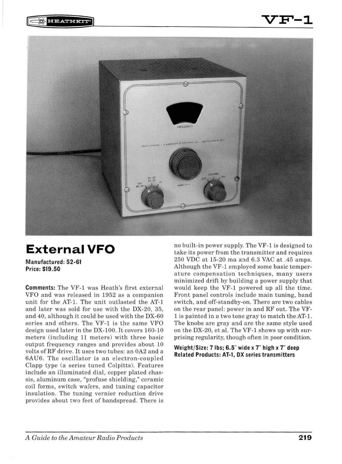
f8
~
f
#f
?f
iHHEiJ
External
VFO
Manufactured: 52-61
Price:
$19.50
Comments:
The
VF-1
was
He
a
th's
first
extern
al
VFO
and
was
released
in
1952
as
a
companion
unit
for
the
AT-1.
The
unit
outlasted
the
AT-1
and
later
was
sold
for
use
with
the
DX-20,
35,
and
40,
although
it
could
be
used
with
the
DX-60
series
and
others.
The
VF-1
is
the
same
VFO
design
used
later
in
the
DX-100
.
It
covers
160-10
meters
(
including
11
meters
)
with
three
basic
output
frequency
ranges
and
provides
about
10
vo
lt
s
of
RF
drive.
It
uses
two
tubes:
an
OA2
and
a
6AU6.
The
oscillator
is
an
electron-coup
l
ed
Clapp
type
(a
series
tuned
Colpitts).
Featur
es
include
an
illuminated
dial,
copper
plated
chas-
sis,
aluminum
case
, "
profuse
shielding,''
ceramic
coil
forms,
switch
wafers,
and
tuning
capacitor
insulation
.
The
tuning
vernier
reduction
drive
provides
about
two
feet
of
bandspread
.
Th
ere
is
A Guide to the
Amat
e
ur
Radio
Produ
cts
VF'-1
no
built
-in
power
supply
.
The
VF-1
is
designed
to
take
its
power
from
the
transmitter
and
r e
quires
250
VDC
at
15-20
ma
and
6.3
VAC
at
.45
amps.
Although
th
e
VF-1
employed
some
basic
temper
-
ature
compensation
techniques,
many
users
minimized
drift
by
building
a
power
supp
ly
that
would
keep
the
VF
-1
powered
up
all
the
time.
Front
panel
controls
include
main
tuning
,
band
switch,
and
off-standby-on.
There
are
two
cables
on
the
rear
panel:
power
in
and
RF
out.
The
VF-
1
is
painted
in
a
two
ton
e
gray
to
match
the
AT-1.
Th
e
knobs
are
gray
and
are
the
same
style
used
on
the
DX-20,
et
al.
The
VF-1
shows
up
with
sur
-
prising
regularity,
though
often
in
poor
condition.
Weight/Size: 7
lbs;
6.5
..
wide
x
T'
high
x
T'
deep
Related
Products:
AT-1,
DX
series
transmitters
219
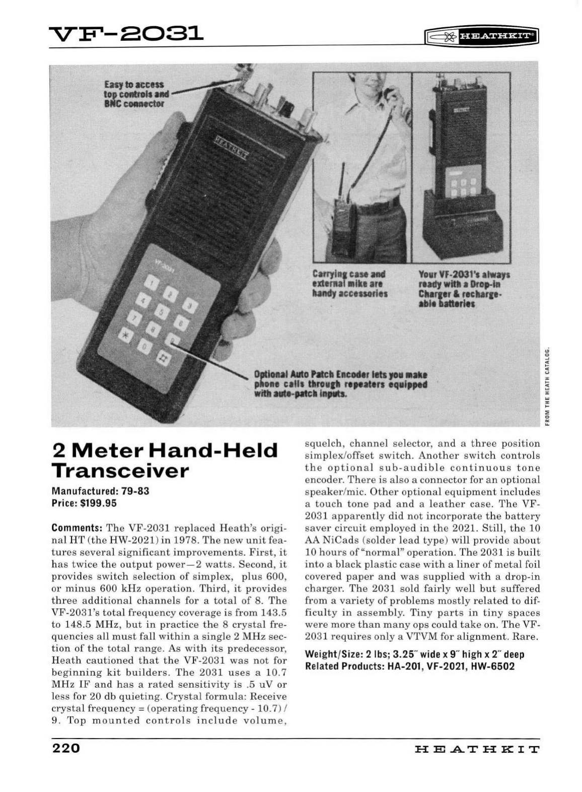
VF'-8081
Catryl11
1
case
and
ext
erul
11
i
ke
a
re
ha
ndy
accessories
r=
~
'i'5Sf
¥f
HEI
Yo
ur
VF-
2G3
1'
s
alWays
rtadf
witlt
•
°'°'""'
Charpr &
rec
harp-
ab
lt
batteries
Ootioul
Auto
htch
Eneodtr
lets
JO•
•akl
phone
ca
lls
tltNH
IP
rtpottn
eqalpptd
With
atltt-Jatclt
mptlb.
2
Meter
Hand-Held
Transceiver
M
anu
fa
ctured:
79-83
Pri
c
e:
$199.95
Comments:
The
VF-2031
replaced
Heath's
origi-
nal
HT
(the
HW-2021)
in
1978.
The
new
unit
fea-
tures
several
significant
improvements.
First,
it
has
twice
the
output
power-2
watts
.
Second
,
it
provides
switch
selection
of
simplex,
plus
600,
or
minus
600
kHz
operation
.
Third,
it
provides
three
additional
channels
for a
total
of
8.
The
VF
-
2031's
total
frequency
coverage
is
from
143.5
to
148.5
MHz,
but
in
practice
the
8
crystal
fre-
quencies
all
must
fall
within
a
single
2
MHz
sec-
tion
of
the
total
range.
As
with
its
predecessor
,
Heath
cautioned
that
the
VF-2031
was
not
for
beginning
kit
builders.
The
2031
uses
a
10.7
MHz
IF
and
has
a
rated
sensitivity
is
.5
uV
or
less
for
20
db
quieting
.
Crystal
formula
:
Receive
crystal
frequency
= (
operating
frequency
-10. 7) I
9.
Top
mounted
contro
l s
include
volume,
220
squelch
,
channel
selector
,
and
a
three
position
simpl
e
x/offset
switch.
Another
switch
controls
the
optional
sub-audible
continuous
tone
encod
e
r.
There
is
also
a
connector
for
an
optional
speaker
/mic.
Other
optional
equipment
includes
a
touch
tone
pad
and
a
leath
er
case
.
The
VF-
2031
apparently
did
not
incorporate
the
battery
saver
circuit
employed
in
the
2021.
Still,
the
10
AA
NiCads
(solder
lead
type)
will
provide
about
10
hours
of
"
normal"
operation.
The
2031
is
built
into
a
black
plastic
case
with
a
liner
of
metal
foil
cover
ed
paper
and
was
supplied
with
a
drop
-
in
charg
er.
The
2031
sold
fairly
well
but
suffered
from
a
variety
of
problems
mostly
related
to
dif-
ficulty
in
assembly.
Tiny
parts
in
tiny
spaces
we
re
more
than
many
ops
could
take
on.
The
VF
-
2031
requires
on
ly a
VTVM
for
alignment
.
Rare
.
Wei
g
ht
/
Si
z
e:
2
lbs
; 3.25"
wide
x 9"
hi
gh x 2"
deep
Related
Products:
HA-20
1,
VF
-
2021
, HW-6502
HE.ATHKIT
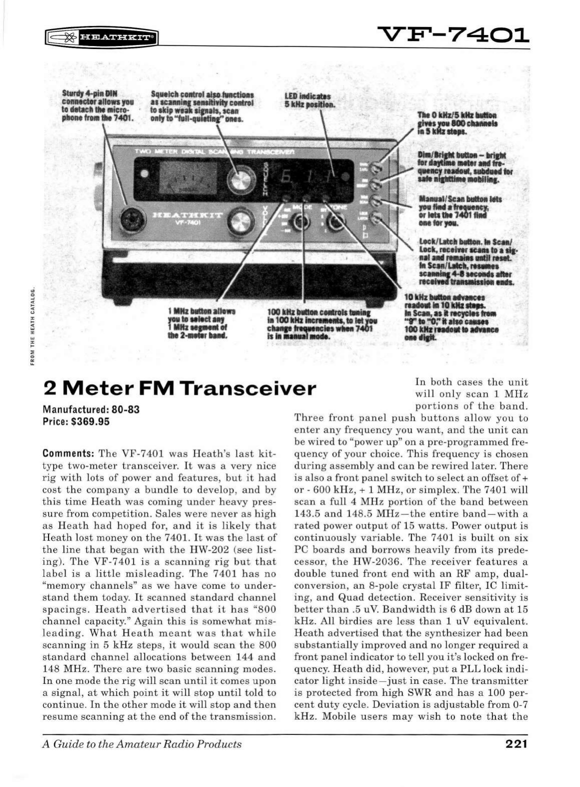
[§
~fh&iUHEiJ
VF'-7401
2
Meter
FM
Transceiver
In
both
cases
the
unit
will
only
scan
1
MHz
Manufactured: 80-83
Price:
$369.95
Comments:
The
VF
-
7401
was
Heath's
last
kit-
type
two-meter
transceiver.
It
was
a
very
nice
rig
with
lots
of
power
and
features,
but
it
had
cost
the
company
a
bundle
to
develop,
and
by
this
time
Heath
was
coming
under
heavy
pres-
sure
from
competition.
Sales
were
never
as
high
as
Heath
had
hoped
for,
and
it
is
likely
that
Heath
lost
money
on
the
7401.
It
was
the
last
of
the
line
that
began
with
the
HW-202
(see
list-
ing).
The
VF-7401
is
a
scanning
rig
but
that
l
abel
is
a
little
misleading.
The
7401
has
no
"memory
channels"
as
we
have
come
to
under-
stand
them
today
.
It
scanned
standard
channel
spacings.
Heath
advertised
that
it
has
"800
channel
capacity."
Again
this
is
somewhat
mis-
l
eading.
What
Heath
meant
was
that
while
scanning
in
5
kHz
steps
,
it
would
scan
the
800
standard
channel
allocations
between
144
and
148
MHz.
There
are
two
basic
scanning
modes.
In
one
mode
the
rig
will
scan
until
it
comes
upon
a
signal,
at
which
point
it
will
stop
until
told
to
continue.
In
the
other
mode
it
will
stop
and
then
resume
scanning
at
the
end
of
the
transmission.
A Guide
to
the
Amateur
Radio
Products
portions
of
the
band.
Three
front
panel
push
buttons
allow
you
to
enter
any
frequency
you
want,
and
the
unit
can
be
wired
to
"power
up"
on
a
pre-programmed
fre-
quency
of
your
choice
.
This
frequency
is
chosen
during
assembly
and
can
be
rewired
later.
There
is
also
a
front
panel
switch
to
select
an
offset
of+
or
-
600
kHz,+
1
MHz,
or
simplex.
The
7401
will
scan
a
full
4
MHz
portion
of
the
band
between
143.5
and
148.5
MHz-the
entire
band-with
a
rated
power
output
of
15
watts.
Power
output
is
continuously
variable.
The
7
401
is
built
on
six
PC
boards
and
borrows
heavily
from
its
prede-
cessor,
the
HW-2036.
The
receiver
features
a
double
tuned
front
end
with
an
RF
amp,
dual-
conversion,
an
8-pole
crystal
IF
filter,
IC
limit-
ing,
and
Quad
detection.
Receiver
sensitivity
is
better
than
.5 uV.
Bandwidth
is
6 dB
down
at
15
kHz.
All
birdies
are
less
than
1
uV
equivalent.
Heath
advertised
that
the
synthesizer
had
been
substantially
improved
and
no
longer
required
a
front
panel
indicator
to
tell
you
it's
l
ocked
on
fre-
quency
.
Heath
did,
however,
put
a
PLL
lock
indi-
cator
light
inside-just
in
case.
The
transmitter
is
protected
from
high
SWR
and
has
a
100
per-
cent
duty
cycle.
Deviation
is
adjustable
from
0-7
kHz.
Mobile
users
may
wis
h
to
note
that
the
221
operating
temperature
range
is
from
+15
to
+125
F.
Depending
on
where
you
live,
these
lim-
its
could
easily
be
exceeded
in
your
car
.
The
7401
features
a
CTCSS
CPL)
tone
encoder.
The
user
can
choose
from
three
tones
via
a
front
panel
switch.
Tone
frequencies
are
selected
during
assembly.
Front
panel
controls
include
volume,
squelch,
offset
,
tone
,
scan
mode,
scan/manual,
display
brightness,
a 5
kHz
select,
and
three
tuning
buttons
- 1
MHz,
100
kHz,
and
10
kHz.
The
front
panel
also
features
a
red
LED
indicat-
ing
5
kHz
selection,
a
green
LED
indicating
a
unsquelched
or
"channel
busy"
condition,
and
a
three
digit
LED
frequency
display.
Unlike
the
HW-2036,
the
mic
on
the
VF-7401
is
detachable.
The
mic
connector
is
a
standard
4-pin
DIN
con-
nector.
Rear
panel
includes
power
amp
tuning,
power
level
controls,
a
12
VDC
power
connector,
an
external
speaker
jack,
and
an
80-239
anten-
na
connector.
The
7401
requires
12.6
to
16
VDC
(13.8
nominal)
and
is
polarity
protected.
Receive
current
consumption
is
550
ma
(squelched),
750
ma
maximum
.
On
transmit
the
current
con-
sumption
is
4
amps
maximum.
Heath
packaged
the
7401
in
a
black
cabinet
with
a
light
blue
front
panel
,
and
this
was
the
only
Heath
radio
product
to
use
this
color
scheme
besides
the
rig's
matching
power
supply.
The
VF-7401
is
among
the
rarest
of
Heath
products
and
is
seldom
seen
at
swap
meets.
Weight/Size:
12
lbs;
8.25"
wide
x
2.
75"
high
x
10"
deep
Related
Products:
HW-202, HW-2026,
HW-2036(A), HWA-202-1, HA-202, HM-2102
222
rE=
~
f
UMfifiif
IJ
HE.A.TH
KIT
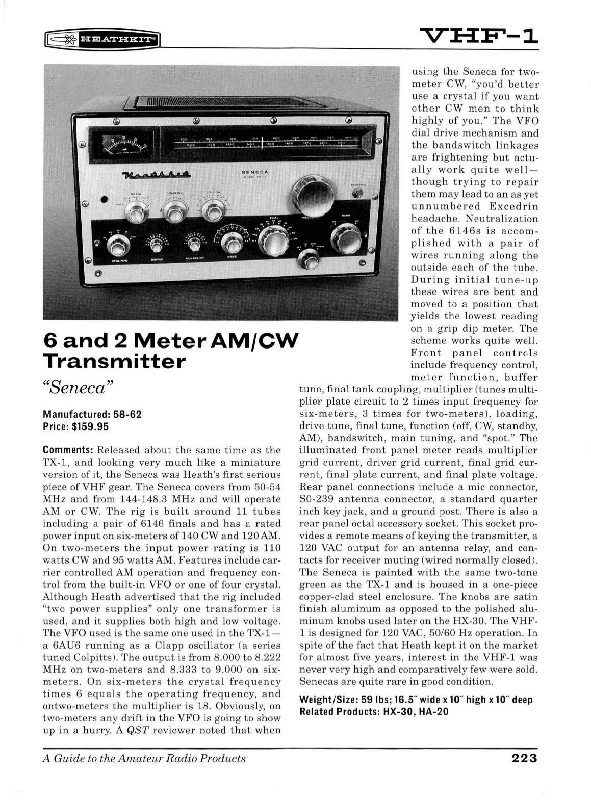
l8
~
fH&SiUH+iJ
•
6
and
2
Meter
AM/CW
Transmitter
"Seneca"
Manufactured: 58-62
Price:
$159.95
Comments:
Rel
eased
about
the
same
time
as
the
TX
-1,
and
l
ooking
very
much
like
a
miniature
version
of
it,
the
Seneca
was
Heath's
first
serious
piece
of
VHF
gear.
The
Se
n
eca
covers
from
50-
54
MHz
and
from
1
44
-148.3
MHz
and
will
operate
AM
or
CW.
The
rig
is
bu ilt
around
11
tubes
including
a
pair
of
6146
fina
ls
and
h
as
a
rated
power
i
nput
on
six-meters
of
140
CW
and
120
AM.
On
two
-
meters
the
i
np
ut
power
rating
is
110
watts
CW
and
95
watts
AM.
Feat
u
res
include
car
-
rier
controlled
AM
operation
and
frequency
con-
trol
from
the
built-in
VFO
or
one
of
fo
ur
crystal.
Al
though
Heath
advertise
d
that
the
rig
included
"two
power
supp
l
ies"
on
ly
one
transformer
is
used
,
and
it
supplies
both
high
and
low
voltage
.
The
VFO
used
is
the
same
one
used
in
the
TX-l-
a
6AU6
running
as
a
Clapp
oscillator
(a
series
tuned
Colpitts
).
The
output
is
from
8.
000
to
8.222
MHz
on
two-meters
and
8.
333
to
9.000
on
six
-
meters.
On
six-meters
the
crystal
frequency
times
6
equals
the
operating
frequency,
and
ontwo-meters
the
mu
l
tip
l
ier
is
18. Obviously,
on
two-
meters
any
drift
in
the
VFO
is
going
to
show
up
in
a
hurry.
A
QST
rev
i
ewer
note
d
that
when
A
Guide
to the
Amateur
Radio Products
using
the
Seneca
for
two
-
meter
CW,
"you'd
better
use
a
crystal
if
you
want
other
CW
men
to
think
high
ly
of
you."
The
VFO
dia
l
drive
mechanism
and
the
bandswitch
linkages
are
frightening
but
actu
-
a
ll
y
work
quite
we
ll-
t h
ough
trying
to
repair
them
may
lead
to
an
as
yet
unnumbered
Exce
d
rin
headache
.
Neutralization
of
the
6146s
is
accom
-
plished
with
a
pair
of
wires
running
al
ong
the
outside
each
of
the
tube.
During
initial
tune-up
these
wires
are
bent
and
moved
to
a
position
that
yie
l
ds
t he l
owest
reading
on
a
grip
dip
meter
.
Th
e
sch
eme
works
quite
we
ll
.
Front
panel
contro
ls
include
freq
u
ency
control
,
meter
function,
buffer
tune,
final
tan
k co
upli
ng,
mu
l
tiplier
(tunes
m
ul
ti-
plier
pl
ate
cir
cu
it
to
2
times
input
freq
u
ency
for
si
x-meters,
3
times
for
two-meters),
l
oadi
ng,
drive
tune,
fina
l
tune,
functio
n (off,
CW,
standby,
AM),
bandswitch,
main
tuning,
and
"spot."
The
illuminated
front
pane
l
meter
reads
multiplier
grid
current
,
driver
grid
current
,
final
grid
cur-
rent,
fina
l
plate
current,
and
fina
l pl
ate
voltage
.
Rear
pane
l
co
n
nections
include
a mic
connector,
S0
-
239
antenna
connector
, a
standard
quarter
inc
h
key
jack,
and
a
ground
post.
Th
ere
is
also a
rear
p
ane
l
octal
accessory
socket.
This
socket
pro
-
vides
a
remote
means
of
keying
the
transmitter,
a
120
VAC
outp
ut for
an
antenna
re
lay,
and
con-
tacts
for
receiver
mu
ting
(wired
normally
closed).
The
Seneca
is
painted
with
the
same
two-
tone
gree
n
as
the
TX-1
and
is
ho
u
sed
in
a
one
-piece
copper
-
clad
steel
enclosure.
The
knobs
are
satin
finish
alumin
um
as
opposed
to
the
polished
alu-
minum
knobs
u
sed
later
on
the
HX-30. The VH
F-
1 is d
esigned
for
120
VAC
,
50
/60
Hz
operation
.
In
spite
of
the
fact
that
Heath
kept
it
on
t he
market
for al
most
five
years,
interest
in
the
VHF-1
was
never
very
h
igh
and
comparatively
few
were
sold.
Senecas
are
quite
rare
in
good
condition.
Weight/Size: 59
lbs;
16.5"
wide
x
10
"
high
x
10
"
deep
Related
Products:
HX-30, HA-20
223
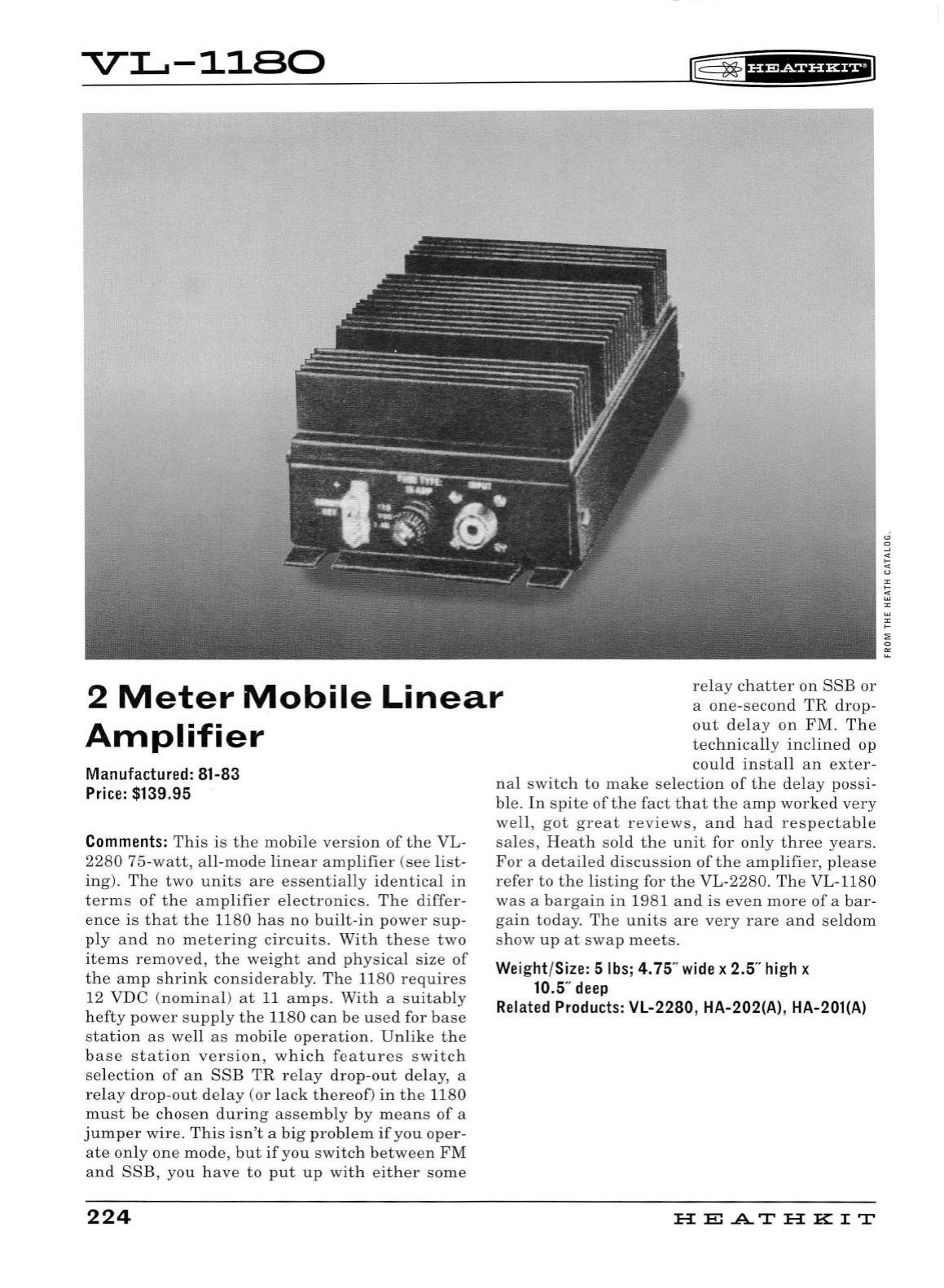
-V-L..-1180
~
~
fi'MiH&+I
2
Meter
Mobile
Linear
Amplifier
re
la
y
chatter
on
SSE
or
a
one-second
TR
drop-
out
delay
on
FM.
The
technically
inclined
op
co
uld
install
an
exter
-
Manufactured: 81-83
Price:
$139.95
Comments:
This
is
the
mobile
version
of
the
VL-
2280
75-watt,
all
-
mod
e
lin
ear
amplifier
(see
li
st
-
ing).
The
two
units
are
essentia
ll
y
identical
in
terms
of
the
amplifier
electronics
.
The
differ-
ence
is
that
the
1180
has
no
built
-
in
pow
er
sup-
ply
and
no
met
er
in
g
circuits.
With
these
two
items
removed,
the
weight
and
physical
size
of
the
amp
shrink
considerab
ly
.
The
1180
requires
12 VDC
(nomina
l)
at
11
am
ps.
With
a
suitably
h
ef
ty
power
supp
ly
the
1180
can
be
u
se
d for b
ase
station
as
well
as
mobile
operation.
Unlike
the
base
station
version,
which
features
switch
sel
ection
of
an
SSE
TR
relay
drop
-
out
de
lay, a
re
l
ay
drop
-
out
delay
(or l
ack
thereof)
in
the
1180
must
be
chosen
during
assembly
by
means
of
a
jump
er
wire.
Thi
s i
sn't
a
big
problem
if
you
oper-
ate
only
one
mod
e,
but
if
you
switch
between
FM
an
d
SSE,
you
have
to
put
up
wit
h e
ith
er
some
224
nal
switch
to
make
se
l
ection
of
the
del
ay
possi-
ble.
In
spite
of
the
fact
that
the
amp
worked
very
well,
got
great
reviews
,
and
had
respectab
le
sa
l
es,
Heath
sold
the
unit
for
only
three
years.
For
a
detailed
discussion
of
the
amplifier
,
please
refer
to
the
li
sting
for
the
VL-2280.
The
VL-1180
was
a
bargain
in
1981
and
is
eve
n
more
of
a
bar
-
gain
today
.
The
uni
ts
are
very
rare
and
se
ldom
show
up
at
swap
m
eets.
Weight/Size: 5
lbs;
4.75"
wide
x 2.5"
high
x
10.5"
deep
Related
Products:
VL-2280, HA-202(A), HA-201(A)
H
El
.AT
HK
IT
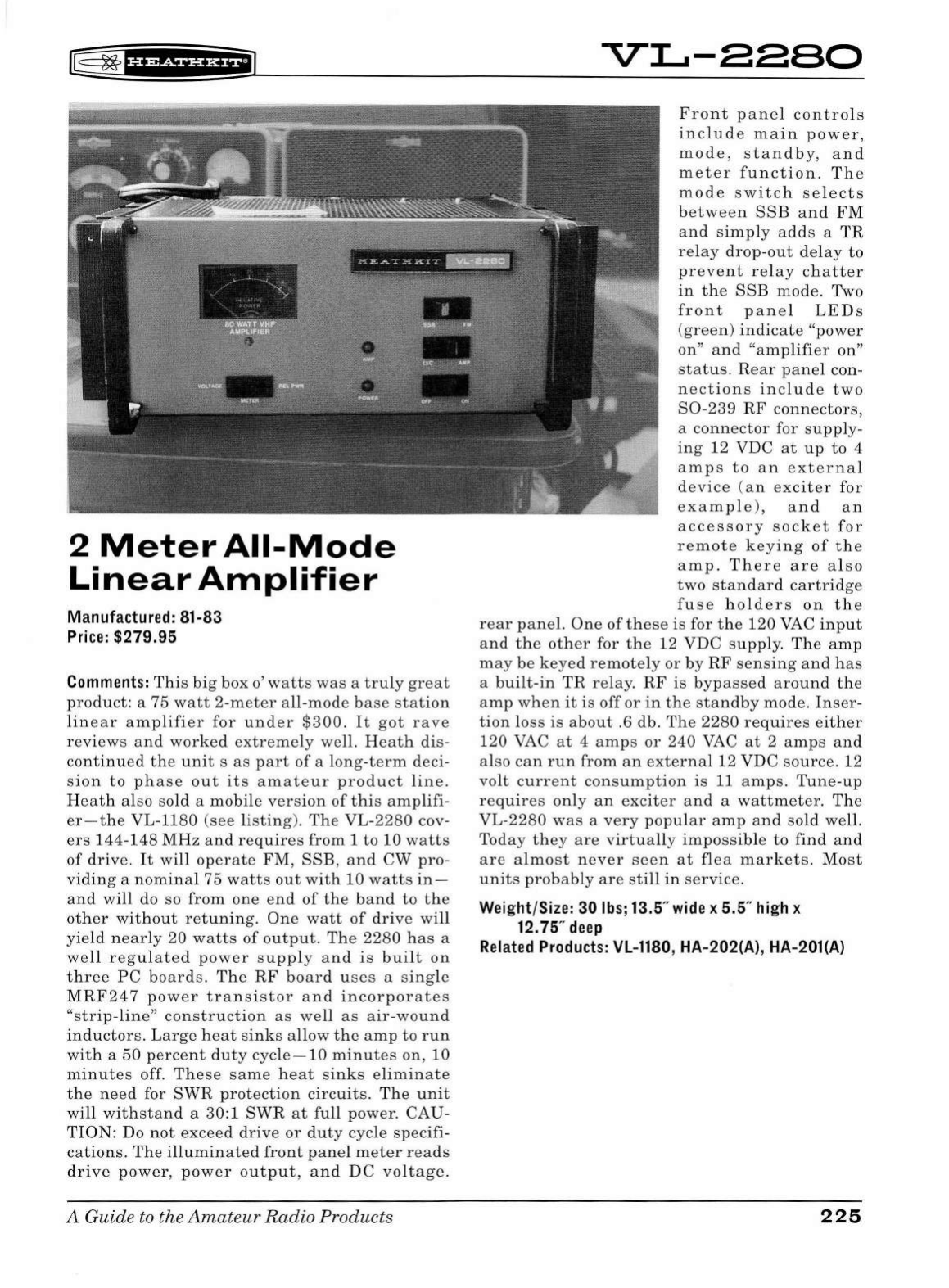
~
~
f
i'?&f
Ui*f'J
2
Meter
All-Mode
Linear
Amplifier
Manufactured: 81-83
Price:
$279.95
Comments:
This
big
box
o'
watts
was
a
truly
great
product:
a 75
watt
2-meter
all-mode
base
station
linear
amplifier
for
under
$300.
It
got
rave
reviews
and
worked
extremely
well.
Heath
dis-
continued
the
unit
s
as
part
of
a
long-term
deci
-
sion
to
phase
out
its
amateur
product
line.
Heath
also
sold
a
mobile
version
of
this
amplifi
-
er-the
VL-1180
(
see
listing).
The
VL-2280
cov-
ers
144-148
MHz
and
requires
from
1to10
watts
of
drive
.
It
will
operate
FM,
SSB,
and
CW
pro-
viding
a
nominal
75
watts
out
with
10
watts
in-
and
will
do so
from
one
end
of
the
band
to
the
other
without
retuning.
One
watt
of
drive
will
yield
near
ly
20
watts
of
output.
The
2280
has
a
well
regulated
power
supply
and
is
built
on
three
PC
boards.
The
RF
board
uses
a
single
MRF247
power
transistor
and
incorporates
"strip-line"
construction
as
well
as
air-wound
inductors.
Large
heat
sinks
allow
the
amp
to
run
with
a
50
percent
duty
cycle-
10
minutes
on, 10
minutes
off.
These
same
heat
sinks
eliminate
the
need
for
SWR
protection
circuits.
The
unit
will
withstand
a
30:1
SWR
at
full
power.
CAU
-
TION:
Do
not
exceed
drive
or
duty
cycle
specifi-
cations.
The
illuminated
front
panel
meter
reads
drive
power,
power
output,
and
DC
voltage.
A Guide to the
Amateur
Radio
Products
vi..-aaao
Front
panel
controls
include
main
power,
mode,
standby,
and
meter
function
.
The
mode
switch
selects
between
SSB
and
FM
and
simply
adds
a
TR
relay
drop-out
delay
to
prevent
relay
chatter
in
the
SSB
mode
. Two
front
panel
LEDs
(green)
indicate
"power
on"
and
"
amplifier
on
"
status.
Rear
panel
con-
nections
include
two
80-239
RF
connectors
,
a
connector
for
supply-
ing
12
VDC
at
up
to
4
amps
to
an
external
device
(
an
exciter
for
example),
and
an
accessory
socket
for
remote
keying
of
the
amp.
There
are
a l
so
two
standard
cartridge
fuse
holders
on
the
rear
panel.
One
of
these
is
for
the
120
VAC
input
and
the
other
for
the
12
VDC
supply
.
The
amp
may
be
keyed
remotely
or
by
RF
sensing
and
has
a
built-in
TR
relay.
RF
is
bypassed
around
the
amp
when
it
is
off
or
in
the
standby
mode
.
Inser-
tion
loss
is
about
.6
db
.
The
2280
requires
either
120
VAC
at
4
amps
or
240
VAC
at
2
amps
and
also
can
run
from
an
external
12 VDC
source
. 12
volt
current
consumption
is
11
amps.
Tune
-
up
requires
only
an
exciter
and
a
wattmeter
.
The
VL-2280
was
a
very
popular
amp
and
sold
well.
Today
they
are
virtually
impossible
to
find
and
are
a l
most
never
seen
at
flea
markets
.
Most
units
probably
are
still
in
service.
Wei
ght/Size: 30
lbs
; 13.5"
wide
x 5.5"
hi
gh x
12.75"
deep
Rel
a
ted
Products:
VL-1180
, HA-202(
A)
, HA-201(A)
225
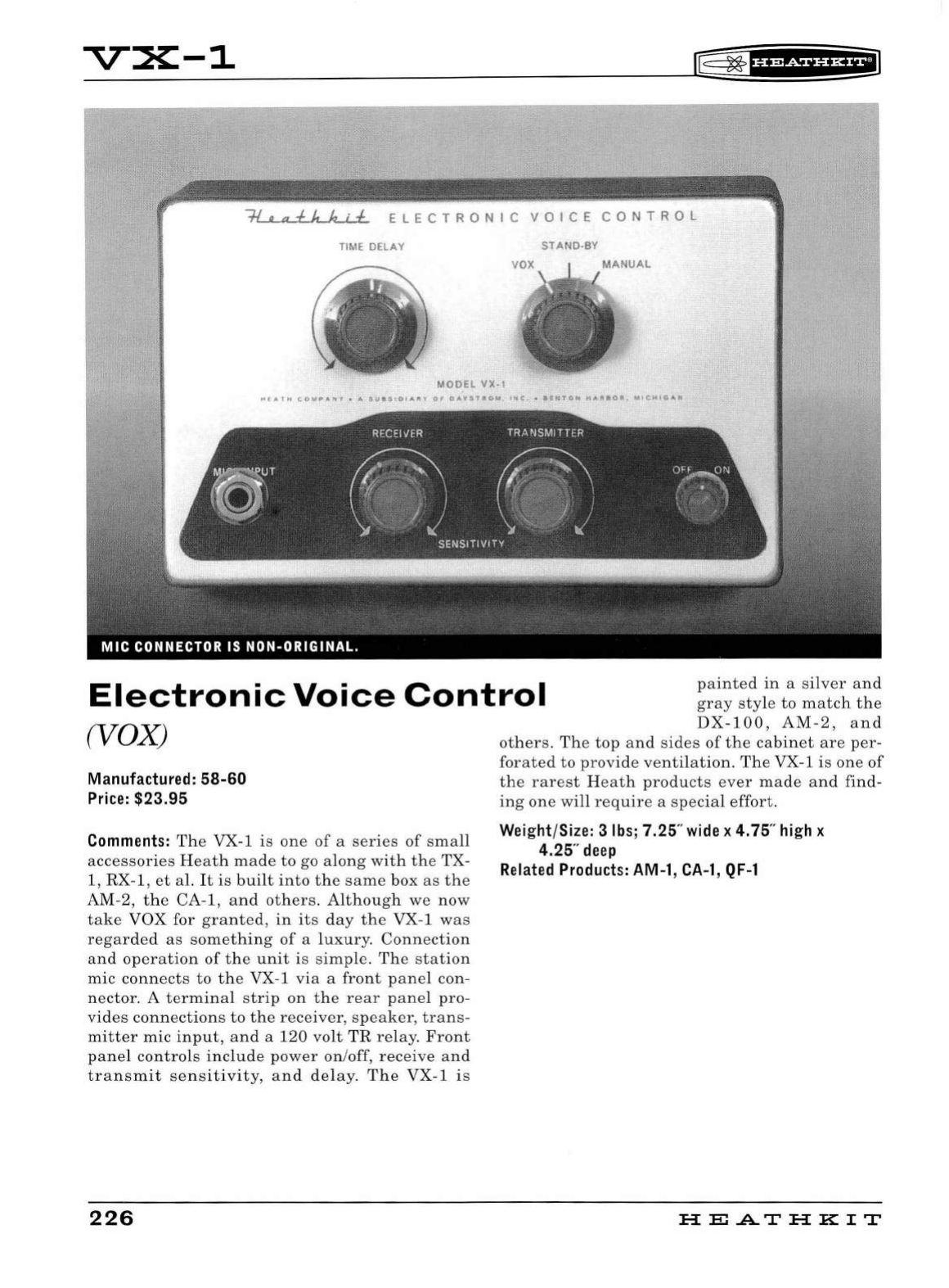
-V-X-1
~fhffiff§'Hfil
~
ELECTRONIC
VOICE
CONTROL
TIME DELAY
STAND-BY
MANUAL
I
MODEL VX-1
Electronic
Voice
Control
painted
in
a
silver
and
gray
style
to
match
the
(VOX)
Manufactured: 58-60
Price:
$23.95
Comments:
The
VX-1
is
one
of
a
series
of
small
accessories
Heath
made
to
go
along
with
the
TX-
1, RX-1 ,
et
al.
It
is
built
into
the
same
box
as
the
AM-2,
the
CA-1,
and
others.
Although
we
now
take
VOX for
granted,
in
its
day
the
VX-1
was
regard
ed
as
something
of
a
luxury.
Connection
and
operation
of
the
unit
is
simple.
The
s
tation
mic
connects
to
the
VX-1
via
a
front
panel
con-
nector
. A
terminal
st
rip
on
the
rear
panel
pro-
vides
connections
to
the
receiver,
speaker,
trans-
mitter
mic
input,
and
a
120
volt
TR
relay
.
Front
panel
controls
include
power
on
/off,
receive
a
nd
transmit
sensitivity,
and
delay
.
The
VX
-1
is
226
DX-100,
AM-2,
and
others.
Th
e
top
and
sides
of
the
cabinet
are
per-
forated
to
provide
ventilation.
The
VX-1
is
one
of
the
rarest
H
eat
h
products
ever
made
and
find-
ing
one
will
require
a
special
effort.
Weight/Size: 3
lbs;
7.25"
wide
x 4.75"
high
x
4.25"
deep
Related
Products:
AM-1,
CA-1,
QF-1
HEATHKIT
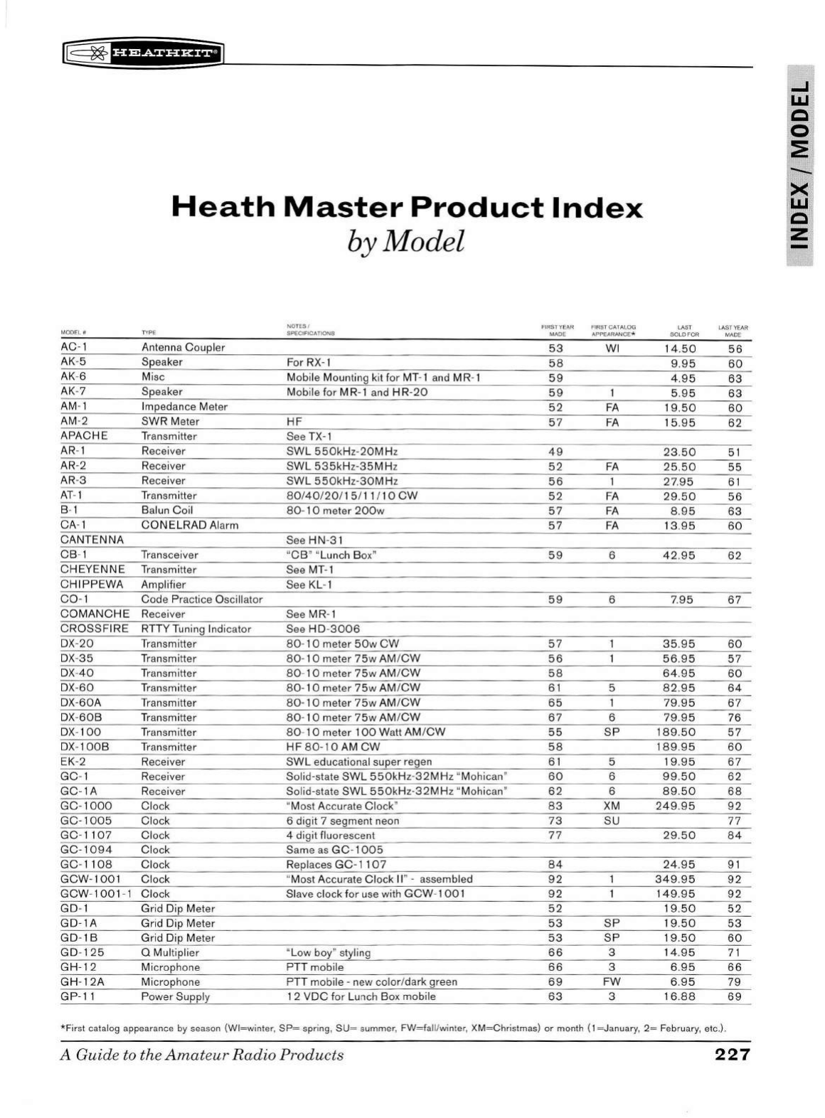
[
~fb#fSiHHEiJ
MODEL #
AC-1
AK
-5
AK-6
AK-7
AM-1
AM-2
APACHE
AR
-1
AR-2
AR
-3
AT-1
B-1
CA
- 1
CANTENNA
CB
- 1
CHEYENNE
CHIPPEWA
C0-1
COMANCHE
CROSSFIRE
DX
-
20
DX
-
35
DX-
40
DX-60
DX
-
60A
D
X-60B
D
X-
100
DX
- 1
OOB
EK-2
GC
- 1
GC
-1A
GC-1000
GC-1005
GC
-
1107
GC-1094
GC-1108
GCW-1001
GCW
-
1001
- 1
GD-1
GD-1A
GD-lB
GD-125
GH-12
GH-12A
GP-11
Heath
Master
Product
Index
by Model
NOTES / FIR
ST
YEAR FIRST CATALOG
TYPE SPEC IFICATIONS
MA
DE
APPEARANCE*
Antenna Coupler
53
WI
Speaker For
RX-1
58
Misc Mobile Mounting kit
for
MT-1
and
M R-1
59
Speaker Mobile for MR-1 and
HR
-
20
59
1
Impedance Meter
52
FA
SWR Meter
HF
57
FA
Tr
ansmitter See
TX-1
Re
ce
iver
SWL
550kHz
-
20MHz
49
Receiver
SWL
535kHz-35MH
z
52
FA
Receiver
SWL
550kHz-30MHz
56
Tr
ansmitter
80/40/20/
15/11I10
CW
52
FA
Balun
Coil
80
- 1 0 meter
200w
57
FA
CONELRAD
Alarm
57
FA
See
HN
-3 1
Transceiver
"CB"
"Lunch Box"
59
6
Transmitter See MT-1
Am
plifier S
ee
KL
- 1
Code Practice Os
ci
ll
ator
59
6
Re
ce
iver See MR-1
RTTY Tuning
In
dicator See
HD
-
3006
Transmitter
80
-
10
meter
50w
CW
57
Tr
ansmitter
80
-
10
meter
75w
AM /
CW
56
Tr
ansmitter
80
-
10
meter
75w
AM/CW
58
Tr
ansmitter
80-10
meter
75w
AM /
CW
61
5
Transmitter
80-10
meter
75w
AM
/CW
65
1
Tr
ansmitter
80
-
10
meter
75w
AM /
CW
67
6
Tr
ansmitter
80
-
10
meter
100
Watt
AM
/C
W
55
SP
Tr
ansmitter
HF
80-10
AM
CW
58
Receiver
SWL
educa
ti
onal super regen
61
5
Re
ceiver Solid-state
SWL
550kHz
-
32M
Hz "Mohican"
60
6
Receiver Solid-state
SWL
550kHz
-
32MH
z "Mohican"
62
6
Clock "Most Accurate
Clo
ck"
83
XM
Clock 6 dig it 7
se
gment n
eo
n
73
SU
Clock 4 digit fluorescent
77
Clock Same
as
GC-1005
Clock Replaces
GC-1107
84
Clock "Most Accurate Clock
II
" - assembled
92
Clock Slave clock
for
use
with
GCW
-
1001
92
Grid Dip Meter
52
Grid
Dip Meter
53
SP
Grid Dip Meter
53
SP
0 Multiplier "Low boy" styling
66
3
Microphone PTT mobile
66
3
Microphone PTT mobile -new color/dark green
69
FW
Power Supply 1 2
VDC
for
Lu
nch
B
ox
mobile
63
3
LAST LA
ST
YEAR
SOLO FOR
MAD
E
14
.50
56
9.
95
60
4.95
63
5.
95
63
19
.50
60
15
.95
62
23
.
50
51
25
.
50
55
27
.95
61
29.50
56
8.95
63
13
.
95
60
42.95
62
7.95
67
35
.
95
60
56
.95
57
64
.
95
60
82.95
64
79
.
95
67
79
.95
76
189.50
57
189
.
95
60
19.95
67
99
.
50
62
89
.
50
68
249
.95
92
77
29
.
50
84
24
.9 5 9 1
349.95
92
149.
95
92
1
9.50
52
19
.
50
53
19.50
60
14
.95
71
6.95
66
6.9 5
79
16
.
88
69
*First
catalog appearance by season
(W
l=
winter,
SP=
spr
in
g,
SU
= summer,
FW=fa
ll/w
inter,
XM=Christmas)
or
month ( 1 = J
an
uary,
2=
February, etc.).
A
Guid
e to the
Amat
eur
Radio
Products
227
...I
LI.I
c
0
:?!
><
LI.I
c
z
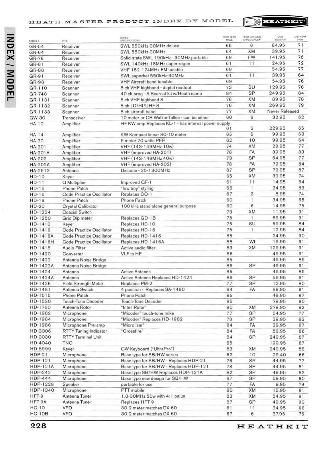
z
c
1'11
><
s
0
c
1'11
r-
HE.A.TH
])l.[.ASTER.
PRODUCT
INDEX
BY
])l.[ODEL
MODEL
II
TYPE
GR
-54 Receiver
GR
-64 Receiver
GR
-
78
Receiver
GR
-81 Receiver
GR-88
Receiver
GR-91
Receiver
GR
-98
Receiver
GR
-
110
Scanner
GR
-
740
Scanner
GR-1131
Scanner
GR
-
1132
Scanner
GR
-
1133
Scanner
GW-30
Transceiver
HA
-
10
Ampl
ifier
HA
-
14
Amplifier
HA
-
20
Amplifier
HA
-20
1 Amplifier
HA
-20
1 A Amplifier
HA
-
202
Amplifier
HA-
202A
Amplifier
HA-2
513
Antenna
HD
-
10
Keyer
HD
-
11
0 Multiplier
HD
-
15
Phone Patch
HD
-
16
Code
Practi
ce
Oscillator
HD-19
Phone Patch
HD
-
20
Crystal Calib
ra
tor
HD-1234
Coaxial Switch
HD
-
1250
Grid
Dip meter
HD
-
1410
Keyer
HD
-
1416
Code
Practice Oscillator
HD-1416A
Code Practice Oscillator
HD-1416H
Code
Practice Oscillator
HD-1418
Audio Filter
HD
-
1420
Converter
HD
-
1422
Antenna Noise Bridge
HD
-
1422A
Antenna Noise Bridge
HD
-
1424
Antenna
HD
-
1424A
Antenna
HD-1426
Field Strength Meter
HD
-
1481
An
ten
na
Switch
HD
-
1515
Phone Patch
HD
-
1530
Tou
ch-
Ton
e Decoder
HD
-
1780
Antenna Rotor
HD
-
1982
Microphone
HD
-
1984
Microphone
HD
-
19
86
Microphone P
re
-amp
HD-3006
RTTY Tuning Indicator
HD
-3
030
RTTY Terminal Unit
HD
-
4040
TNC
HD
-
8999
Keyer
HDP-21
Microphone
HDP
-12
1 Microphone
HDP
-121 A Microphone
HDP
-242
Microphone
HDP
-
444
Microphone
HDP
-
1228
Speaker
HDP
-
1340
Microphone
HFT
-9 Antenna Tuner
HFT
-
9A
Antenna Tuner
HG-10
VFO
HG
-
10B
VFO
228
NOTES
/
SPECIFICATIONS
SWL
550kHz-30MHz
delu
xe
SWL
550kHz
-
30MHz
Solid-state
SWL
1
90kHz
-
30M
Hz portable
SWL
140kHz-1
BM Hz super regen
VHF
152
-
174MHz
FM tunable
SWL
superhet
550kHz
-
30MHz
VHF
Aircraft band tunable
8
ch
VHF
highband -digital readout
40
ch
prog - A Bearcat kit w/Heath name
8
ch
VHF
highband 8
8
ch
LO/HI
/
UHF
8
8
ch
aircraft band
10
meter
or
CB
Walkie-Talkie -can be either
FIRST YEAR
MADE
65
64
69
61
69
61
69
73
84
76
76
77
60
HF
KW
amp Replaces KL-1 -has internal power supply
61
KW
Kompact linear
80-1
0 meter
65
6 meter
70
watts
PEP
62
VHF(143-149MHz
10
w)
74
VHF
(improved
HA
-
201)
78
VHF
(143-149MHz
40
w)
73
VHF
(improved
HA
-
202)
78
Discone - 2 5-1
300M
Hz
87
65
Improved OF-1
61
"low boy" styling
66
Replaces
C0
-1
67
Phone Patch
60
100
kHz sta
nd
alone general purpose
60
73
Replaces GD-1 B
75
Replaces H D-1 0
75
Replaces H D-1 6
75
Replaces H D-1
41
6 8 5
Replaces H D-1
41
6A
88
Active audio filter
83
VLF to
HF
86
85
89
Active Antenna 8 5
Acti ve Antenn a Replaces H D-
1424
89
Repl aces PM-2
77
4 position -Replaces SA-1
480
84
Phone Patch
85
Tou
ch-
Ton
e
Decoder
85
"lntelliRotor"
90
"
Micoder
" touch-tone mike
77
"Micoder"
Replaces
HD
-
1982
78
"Microlizer"
84
"Crossfi
re
"
84
8 4
85
CW
Keyboard ("
Ul
traPro")
83
Base type
for
SB/HW
series
62
B
ase
type
for
SB
/
HW
-Replaces
HDP
-2 1
76
Base type
for
SB
/
HW
-Repl aces
HDP
- 1
21
78
Base type
SB/HW
Replaces
HDP
- 1
21
A
82
Base type new design
for
SB
/
HW
87
port
ab
le
for
use
77
PTT
mobile
80
1.8
-
30MHz
50w
with 4 : 1 balun
83
Replaces
HFT
-9
87
8
0-2
meter matches DX
-60
61
80 -2 meter matches DX
-60
67
r@~fUiSii'&+i
FIRST
CATALOG
APPEARANCE
*
6
XM
FW
11
11
SU
SP
XM
XM
XM
6
5
5
10
XM
FA
SP
FA
SP
XM
11
3
6
XM
SU
WI
XM
SP
SP
SP
FA
XM
SP
SP
FA
FA
SP
XM
10
SP
SP
SP
SP
FA
XM
XM
SP
11
6
LAST LAST YEAR
SOLD FOR MADE
84.95
71
39.95
71
141.95
76
24.95
72
54.95
77
39.95
64
54.95
76
129
.95
76
249.95
84
89.95
78
269.95
79
Never Released
32.95
62
229.95
65
99.95
68
99.95
64
29.95
77
39.95
83
64.95
77
79.95
84
79.95
87
39.95
74
14
.95
64
24.95
83
8.95
74
34.95
65
14.95
75
11
.95
91
69.95
91
59.95
84
12.95
8 4
24.95
90
19.95
91
129.95
91
49.95
91
49
.95
89
49.95
91
49
.95
89
59.95
91
12.95
8 0
89.95
91
49.95
87
79.95
90
279.95
92
54.95
77
39.95
83
39.95
87
59.95
86
249.95
87
199
.95
87
249.95
88
29.40
66
44
.95
77
44
.9 5
81
49.95
82
59.95
90
9.95
79
15
.95 81
54.95
91
4
9.95
90
34.95
66
37
.95
76
HE
AT
HK
IT
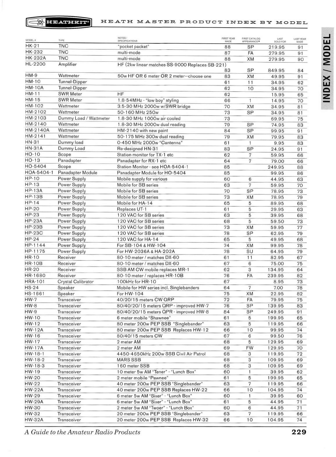
~
~f#'Mfffi*+'J
HEATH
:r.l.I:ASTER
PRODUCT
INDEX
BY
:r.1.I:ODEL
MOD
EL#
TY
PE
HK
-2 1
TNC
H
K-232
TNC
HK
-
232
A
TNC
HL
-2200
Amplifier
HM
-9 Wattmeter
HM
-10
Tunnel-Dipper
HM
-
10A
Tunnel-Dipper
HM-11 SWR Meter
HM
-
15
SWR Meter
HM
-
10
2 Wattmeter
HM
-
2102
Wattmeter
HM-
2103
Du
mmy Load I Wattmeter
HM
-
2140
Wattmeter
HM
-
2140A
Wattmeter
HM
-2 141 Wattmeter
HN-3 1 Dummy load
HN
-3 1A Dummy Load
H0
-
10
Scope
H0
- 13 Panadapter
H0-5404
Scope
HOA
-5404-
1 Panadapter Module
HP
-10
Power Supply
HP
- 13 Power Supply
HP
- 13A Power Supply
HP
- 13 B Powe r Supply
HP
-
14
Power Supply
HP
-
20
Power Supply
HP
-
23
Power Supply
HP
-
23
A Power Supply
HP
-
23
B Power Supply
HP
-23
C Power Supply
HP
-
24
Power Supply
HP
-
1144
Power Supply
HP
-
1175
Power Supply
HR-
10
Receiver
HR-
10B
Receiver
HR-
20
Receiver
HR- 1
680
Receiver
HRA
-101 Crystal Calibrator
HS-
24
Speaker
HS
- 1661 Speaker
HW
-7
Tr
ansceiver
HW
-8
Transcei
ve
r
HW
-9
Tr
ansceiver
HW
-
10
Tr
ansceiver
HW-12
Transcei
ve
r
HW
- 12A
Tr
ansceiver
HW-1 6 Transceiver
HW-17
Tr
ansceive r
HW
- 17A Transceiver
HW
-18-1 Transceiver
HW
-
18-2
Transceiver
HW
- 1
8-3
Transceiver
HW
- 19
Tr
anscei
ve
r
HW
-20
Transceiver
HW
-
22
Transceiver
HW
-
22
A Transcei
ve
r
HW
-
29
Transceiver
HW
-29
A Transceiver
HW-30
Transceiver
HW
-
32
Transceiver
HW
-
32A
T
ra
nsceiver
NOTES /
SPECIFICATIONS
FIRST
YEAR
MADE
"pocket packet"
88
mu~
-
mode
87
mu~-mode
88
HF
(2kw
linear matches
SS
-9
000
Repl aces
SB-221)
83
50w
HF
OR
6 meter
OR
2 meter
-c
hoose one
83
61
62
HF
62
1.8-
54M
Hz - "low bo
y"
styling
66
3.
5-30
MHz
2000w
w/SWR bridge
70
50-160
MHz
250w
73
1
.8-3
0 MHz 1
OOOw
air cooled
73
1.
8-30
MHz
2000w
dual reading
79
HM-2140
with new paint
84
50
- 1 7 5 MHz
30
0w dual read ing
79
0-
450
MHz
2000w
"Cantenn
a"
61
Re
-designed H N-3 1
83
Station monitor for TX- 1 etc
62
P
an
adapter for
RX-1
etc
64
Station Monitor -see
HOA
-
5404
- 1 8 5
Panadapter Module
for
H0
-
5404
85
Mobile supply for various
60
Mobil e for
SB
series
63
Mob
il
e
for
SB
series
70
Mob
il
e for
SB
se
ries
73
Mobile for
HA-14
65
Replaces UT- 1
61
120
VAC
for
SB
series
63
1
20
VAC
for
SB
series
68
1
20
VAC
for
SB
series
73
1
20
VAC
for
SB
series
78
120VACfor
HA-14
65
For
SB
-
104
&
HW-104
74
F
or
HW
-
2036A
&
HA-202A
78
80
- 1 0 meter I matches
DX
-60
61
80-
1 0 meter I matches D
X-60
67
SSB
AM
CW
mobile replaces MR- 1
62
80-
1 0 meter I
re
places H R- 1
OB
76
1
OOk
Hz
fo r
HR-10
67
Mobile for
HW
series incl. Singlebanders
64
For
HW
-
104
75
40/20/15
meters
CW
QRP
72
80
/
40
/
20
/
15
meters
ORP-
improved
HW
-7
76
80/
40
/
20/
1 5 meters
QPR
-improved
HW
-8
84
6 meter mobile "Shawnee"
61
80
meter
200w
PEP
SSB
"Singlebander"
63
80
meter
200w
PEP
SSB
Replaces
HW
-
12
66
80
/
40
/ 1 5 meters
CW
67
2 meter
AM
68
2 meter AM
69
4450
-
4650kHz
200w
SSB
Civil Air Patrol
68
MARS
SSB
68
1
60
meter
SSB
68
1 0 meter
5w
AM
"Tener" - "Lunch Box"
60
2 meter mobile "Pawnee"
61
40
meter
200w
PEP
SSB
"Singlebander"
63
40
meter
200w
PEP
SSB
Replaces
HW
-22
66
6 meter
5w
AM "Sixer" - "Lunch Box"
60
6 meter
5w
AM "Sixer" - "Lunch Box"
61
2 meter
5w
AM "Twoer" - "Lunch B
ox
"
60
20
meter
200w
PEP
SSB
"Singlebander"
63
20
meter
200
w
PEP
SSB
R
ep
laces
HW
-32
66
A Guide
to
the
Amateur
Radio Products
FIRST
CA
TA L
OG
APP
E
ARANCE
*
SP
FA
XM
SP
XM
11
10
XM
SP
SP
SP
XM
SP
7
7
6
7
SP
XM
5
5
5
5
XM
SP
5
XM
SU
11
6
3
FA
7
XM
FA
SP
SP
5
5
10
6
5
FW
3
3
3
5
7
10
5
6
7
10
LAST
SOLD
FOR
2 1
9.95
279.9
5
279
.95
849
.9 5
49.95
34.95
34.9
5
15
.9 5
14.95
34.95
3 4 .9 5
69
.
95
74
.
95
99
.
95
79
.95
9.95
24
.95
59
.9 5
79.00
249.95
99.9
5
44
.
95
59.95
78.95
78.95
89.95
29.95
39
.95
59
.
50
59.95
62.95
49.95
99.95
64
.95
82.95
75.00
134
.
95
239
.
95
8.95
7.00
22
.
95
79
.
95
1
39
.
95
249.95
1
99.95
11
9.
95
99.95
99
.
50
129.95
12
9.95
11
9.
95
10
9.95
109.95
39.95
1
99.95
11
9.95
104
.9 5
39.95
44
.9 5
44
.95
11
9.9
5
104.
95
LA
ST
YE
AR
MADE
9 1
91
90
84
91
62
70
65
70
8 1
8 1
75
83
91
83
83
91
66
66
88
86
63
70
73
79
68
63
68
73
77
79
68
78
79
67
75
64
82
73
78
82
75
83
9 1
65
66
74
76
69
70
72
69
69
6 2
65
66
74
60
71
71
66
74
229
...J
LLI
c
0
2:
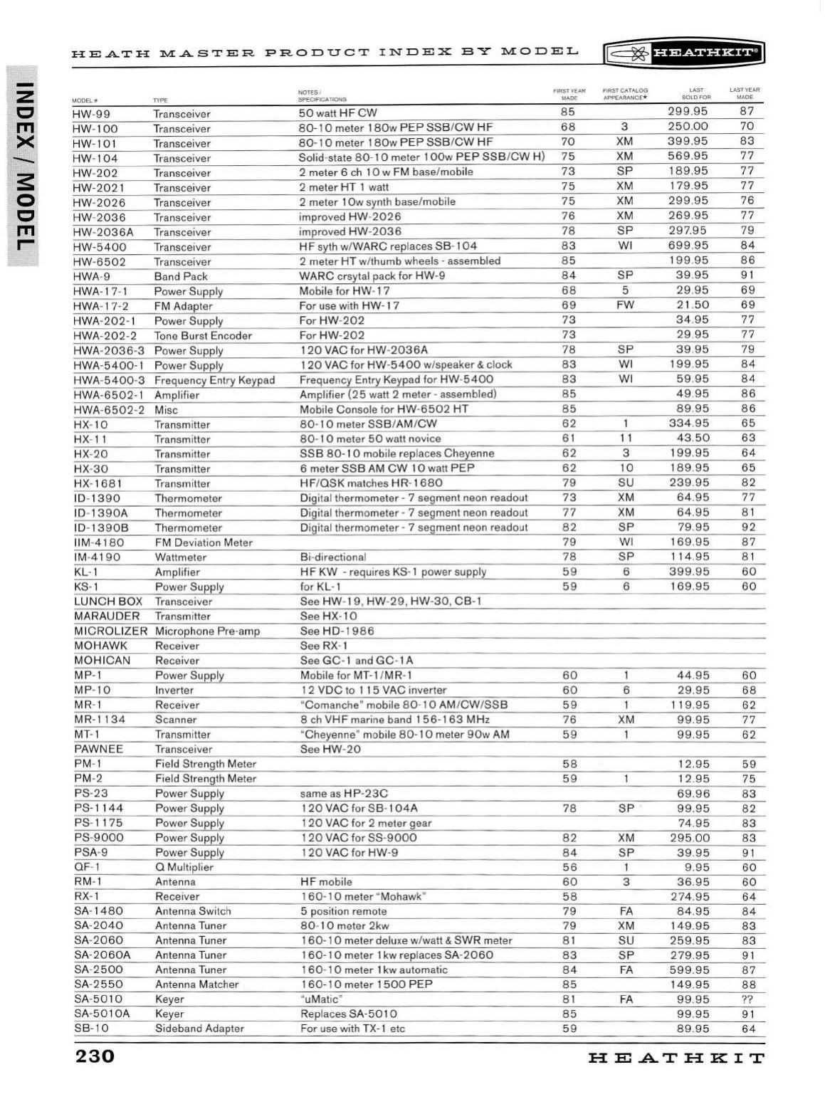
z
c
ITI
x
-
:s:
0
c
ITI
r-
HE.A.TH
JY.[.ASTER
PRODUCT
INDEX
:SY
JY.[QDEL
l@
~
fHPdi#i&il
NOTES I FIRST
YEAR
FIRST CATALOG LAST LAST
YEA
R
MODEL
# SPECIFICATIONS MADE APPEARANCE* SOLD FOR
MADE
HW
-9 9
Tr
anscei
ve
r
50
watt
HF
CW
85
299.95
87
HW
-
10
0
Tr
ansceiver 80-1 0 meter
180w
PEP
SSB
/
CW
HF
68
3
250.00
70
HW
-101 Transcei
ve
r 8 0 -
10
meter 18 0w
PEP
S
SB
/C
W
HF
70
XM
399.95
8 3
HW
- 10 4 Tra nsceiver Solid-state
80
- 1 0 meter 1 O
Ow
PEP
SSB/CW H) 7 5 XM
569
.
95
77
HW
-202
Tr
anscei
ve
r 2 meter 6 ch
10
w FM base/mobile
73
SP
1
89
.
95
77
HW
-202
1
Tr
ansceiver 2 meter HT 1
wa
tt
75
XM 1
79
.
95
77
HW
-2026
Transceiver 2 meter 1
Ow
sy
nth base/mobile
75
XM
299.95
76
HW-
2036
T
ra
ns
ce
i
ve
r improved
HW
-20
26
76
XM
269
.
95
77
HW
-
2036
A Transceiver improv
ed
HW
-2036
78
SP
297
.
95
79
HW
-
54
00
T
ra
nsceiver
HF
syth w/WARC r
ep
laces
SB
- 1
04
83
WI
699
.
95
8 4
H
W-6502
Tr
ansceiver 2 meter HT w/
th
umb wheels -
as
sembl
ed
8 5 19 9.
95
86
HWA
-9 Ba
nd
Pack WARC crsytal pack for
HW
-9 8 4
SP
39.95
9 1
HWA- 17- 1 Power Sup
pl
y Mob
il
e for
HW
- 1 7
68
5
29
.
95
69
HWA
- 17-2 FM Adapter For u
se
wi
th
HW
-17
69
FW
2 1
.50
69
HWA-
202-
1 Power Supply For
HW
-20 2 73
34.95
77
HWA
-202
-2 Tone Burst
En
coder F
or
HW
-2
02
73
29.95
77
HWA
-203
6-3 Power Supply
120
VAC
for
HW
-
203
6A
78
SP
39.95
79
HWA
-5400-
1 Power Supply 1 20 VAC for
HW
-
540
0 w/speaker & clock
83
WI 1
99
.
95
84
HWA-
5400-3
Frequency
En
try Keypad Frequency Entry Keypad
for
HW
-5400
83
WI 5
9.9
5 8 4
HWA-65
02
-1
Am
p
li
fier Ampli
fi
er
(25
watt 2 meter - assembled)
85
49
.
95
86
HWA
-650
2-2 Misc Mobile Console for
HW
-
6502
HT
8 5
89.95
86
HX-10 Transmitter 80 -
10
meter S
SB
/AM /CW
62
334.95
65
H
X-
11
Tran
sm
itter
80-
1 0 meter
50
watt novice 6 1 11 43. 50
63
H
X-
20 Tran
sm
itter
SSB
80-1 0 mobile re
pl
aces Cheye
nn
e
62
3 1
99
.
95
64
HX-
30
Tr
ansmitter 6 meter SSB
AM
CW 10 watt
PEP
62
10 1
89
.
95
65
H
X-
1
68
1 Transmitter
HF
/O
SK
matches
HR
- 1
680
79
SU
239.95
82
10
-
13
90
Th
ermometer Digital thermometer - 7 segment n
eo
n r
ea
dout
73
XM
64
.
95
77
ID-1
390
A Thermometer Digital thermometer - 7 segment neon
re
adout
77
XM
64.95
8 1
ID- 1
390
B
Th
ermometer Di gital thermometer - 7 segment neon r
ea
d
ou
t
82
SP
79.95
92
ll
M-
4180
FM Deviati
on
Meter
79
WI
169
.
95
8 7
IM-4 1
90
Wattmeter Bi-di rec
ti
onal
78
SP
11
4.95
8 1
KL- 1 Amplifier
HF
KW -requires KS- 1 power supply
59
6
399
.
95
60
KS- 1 Power Supply
for
KL- 1
59
6 1
69.95
60
LUNCH
BO
X
Tr
ansceiver See
HW
- 19 ,
HW
-
29
,
HW
-3
0, C B- 1
MARAUDER
Transmitter S
ee
H
X-
10
MI CROLIZER Microphone P
re
-amp See
HD
- 1
986
M
OHAW
K Receiver See RX- 1
MOHI
CAN Receiver See GC
-1
and G C- 1 A
MP
- 1 Power Supply Mob
il
e for MT-1 / M R-1
60
4 4 .
95
60
MP
- 10
In
verter 1 2 VDC to 1 15 VAC inverter
60
6
29.95
68
MR-1 Receiver "C omanche" mobi le
80
- 10
AM
/
CW
/SSB
59
119
.
95
62
MR-
11
34
Scanner 8
ch
VHF
marin e band 1
56-
1
63
MH
z
76
XM 99 .
95
77
MT- 1 Trans
mi
tter "Cheye
nn
e" mob
il
e 8 0 -10 meter
90w
AM
59
99.95
62
PAWNEE Tra nsceiver See
HW
-
20
PM- 1
Fi
eld Strength Meter
58
1
2.95
59
PM-2 Field Strength Meter
59
12.95
75
PS-
23
Power Supply same
as
HP
-2 3C
69.96
83
PS-
1144
Power Supply 1 20 VAC for SB- 10
4A
78
sp
·
99.9
5
82
PS-
11
75 Power Supply 1
20
VAC for 2 meter gear 74 .
95
83
PS-
9000
Power Supply 1 20 VAC for SS-
90
00
82
XM
295
.
00
83
PSA-9 Power Supply 1
20
V
AC
for
HW
-9 8 4
SP
39
.
95
9 1
QF- 1 Q Multiplier
56
9.
95
60
RM
- 1 Ante
nn
a
HF
mob
il
e
60
3
36
.
95
60
RX-1 Receiver 1
60-
1 0 meter "Mohawk"
58
27
4.95
64
SA-
14
80
Anten
na
Switch 5 position remote
79
FA
84.95
84
SA
-20
4 0 Ante
nn
a
Tun
er 8 0 - 1 0 meter 2kw
79
XM 1
49
.
95
8 3
SA-
2060
Ante
nn
a
Tu
ne
r 1
60
- 1 0 meter deluxe w/watt & SWR meter 8 1 SU
259
.
95
83
SA-2
06
0A
Antenn a Tuner 1
6
0-
1 0 meter 1 kw re
pl
aces SA-
206
0
83
SP
279.95
9 1
SA-2
50
0 Ante
nn
a
Tu
ner 1 60-1 0 meter 1 kw automa
ti
c
84
FA
599.95
87
SA-
2550
Antenna Matc
he
r 1 6
0-
1 0 meter 1
500
PEP
8 5
149
.
95
88
SA-5 0 10 Keyer "
uM
atic" 8 1
FA
99
.
95
??
SA-5 0 1 OA Keye r
Re
places SA-5
01
0
85
99.95
g 1
SB-
10
Sideband Adapter
Fo
r u
se
wi
th
T
X-
1 etc
59
89
.
95
64
230
HE.ATHKIT
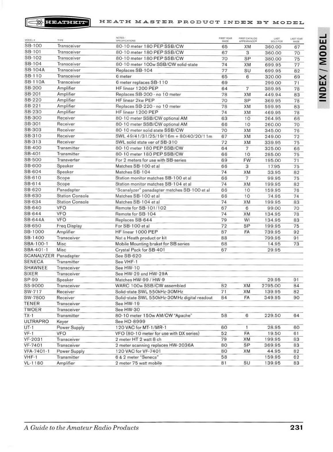
g
~fU@iHi*ii
HEATH
:r..l.I:ASTE:R
PRODUCT
INDEX
BY
:r..1.I:ODE:L
MO
DEL#
NOTES I FIRST YEAR FIRST
CAT
A
LOG
SPECIFIC
ATI
ONS MADE APP
EA
R
AN
CE*
rYPE LAST
LA
ST
YEAR
SOLO FOR
MA
DE
SB
-
100
Transceiver
80
- 1 0 meter 180
PEP
SSB
/
CW
65
XM
360
.
00
67
SB
-101
Tr
ansceiver 8 0 -
10
meter 18 0
PEP
SSB
/
CW
67
3
360
.
00
70
SB
-
102
Tr
ansceiver
80-
10
meter
180
PEP
SSB
/C
W
70
SP
380.00
75
SB-104
Tr
ansceiver
80
-
10
meter 1
OOw
SSB
/
CW
solid-state
74
XM
699
.9 5
77
SB
-
104A
Tr
ansceiver Replac
es
SB
-
104
77
SU 6
99.9
5
82
SB
-
110
Tr
anscei
ve
r 6 meter
65
6
320
.
00
69
SB-1
lOA
Tr
ansceiver 6 meter replaces
SB-11
0 6 9
299.00
71
SB
-
200
Amplifier
HF
lin
ea
r 1
200
PEP
64
7 3
89.9
5
78
SB
-
20
1 Amplifier R
ep
laces
SB-200
-no
10
meter
78
XM
44
9.9
4
83
SB
-
220
Amplifier
HF
lin ear 2kw
PEP
70
SP
36
9.95
78
SB
-
22
1 Amplifier Replaces
SB-2
20
-no
10
meter
78
XM 5
99
.
95
83
SB
-
230
Amplifier HF lin ear
1200
PEP
74
XM
46
9.95
78
SB
-3
00
Receiver 8 0 -
10
meter
SSB
/
CW
optional AM
63
1 0
264
.9 5
66
SB
-
30
1 Receiver
80-
10
meter
SSB
/
CW
optional
AM
66
10
260.00
70
SB
-
303
Recei
ve
r
80-
10
meter sol
id
state
SSB
/
CW
70
XM
345
.
00
76
SB
-3
10
Receiver
SWL
4 9/
41
/
31
/
25
/
19
/
16m
+ 8 0 /
40
/
20
/
11
m
67
XM
249.00
72
SB
-3
13
Receiver
SWL
solid state ver of
SB-310
72
XM
339.95
75
SB
-
400
Tr
ansmitter
80
- 1 0 meter 18 0
PEP
SSB
/
CW
64
7
325
.
00
66
SB-
40
1
Tr
ansmitter
80
-
10
meter 180
PEP
SSB
/C
W
66
10
285.00
75
SB
-
500
Tr
ansverter For 2 meters for u
se
wi
th
SB
-se
ries
69
FW
195
.
00
71
SB-600
Speaker Matches SB-1
00
et
al
66
3
17
.
95
75
SB
-
604
Speaker Matches
SB
-
104
74
XM
33
.95
82
SB
-6 10 Sco
pe
Station monitor matches
SB-100
et
al
66
7
99
.9 5
75
SB
-6
14
Scope Station monitor matches
SB-104
et al
74
XM 19
9.95
82
SB
-
620
Panadap
te
r "Scanalyzer"
pa
nadapter matches
SB
-
100
et al
66
10
159 .
95
76
SB-630
St
at
ion Console Matches S B-1
00
et al
66
10
74.9
5
74
SB
-
634
Station Console Matches
SB-104
et al
74
XM
1
99
.9 5
83
SB-640
VFO Remote for
SB-101
/
102
67
6
99.0
0
70
SB
-
644
VFO Remote
for
S B- 1
04
74
XM
134
.9 5 78
SB-644A
VFO Replaces
SB-644
79
WI
134
.95
83
SB
-
650
Freq Di splay For SB-1
00
et al
72
SP
1
99.9
5
75
SB-1000
Amplifier
HF
lin
ea
r
1000
PEP
87
FA
73
9.
95
92
SB
-
1400
Tr
ansceiver Not a H
ea
th
product or kit
88
799.95
91
SBA
-
100
- 1
Mi
sc Mobil e Mounting braket
for
SB
seri
es
68
14
.95
73
SBA-401-1
Mi
sc Crystal Pack for
SB
-
401
67
29
.95
SCANALYZER Panadapter See
SB
-
620
SENECA
Tr
ansmitter
SeeVHF-1
SHAWNEE
T
ra
nsceiver See
HW
-
10
SI
XER
Tr
ansceiver S
ee
HW
-
29
a
nd
HW
-
29
A
SP
-
99
Speaker Matches
HW
-
99
I
HW
-9
29
.9 5
91
SS-9
000
Tr
ansceiver
WARC
1
OOw
SSB
/
CW
assembled
82
XM
2795.00
84
SW-717
Re
ceiver Solid-state
SWL
550kHz-30MHz
71
XM
139
.95
82
SW-
7800
Receiver Solid-state
SWL
550
k
Hz-30MHz
digital readout
84
FA
349
.9 5
90
TENER
Tran
sceiver See
HW
-
19
TWO
ER T
ra
nsceiver S
ee
HW
-
30
TX- 1
Tr
ansmitter
80-1
0 meter 1
50w
AM /
CW
"Apache"
58
6
229
.
50
64
ULTRAPRO
Ke
ye
r See
HD-8999
UT- 1 Power Supply 1
20
VAC
for
MT-1
/MR- 1
60
28
.95
60
VF- 1 VFO VFO
(80
- 1 0 meter for use with DX
se
rie
s)
52
FA
19.
50
61
VF
-203
1
Tr
ansceiver 2 meter HT 2 watt 8
ch
79
XM
199.95
83
VF-7
401
Tr
ansceiver 2 meter scanning replaces
HW
-2
036A
80
SP
369
.
95
8 3
VFA-
7401-1
Power Supply 1
20
VAC for
VF
-7
401
80
XM
44
.
95
82
VHF
- 1 T
ra
nsmitter 6 & 2 mete r "Seneca"
58
159
.
95
62
VL-
1180
Amplifier 2 meter
75
watt mobile
81
SU
139
.
95
8 3
A
Guid
e to
th
e
Amat
eur
Radio
Produ
cts
231
..J
I.LI
c
0
:E
--

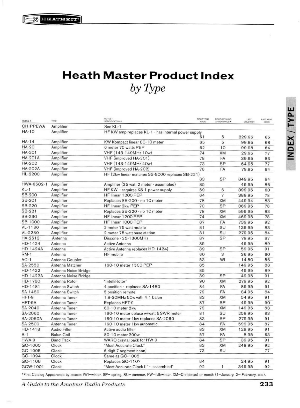
~
~f
U¥Sf
Hi*+il
Heath
Master
Product
Index
by Type
UJ
a.
NOTES /
FIRST
YEAR FIRST
CATALO
G l.AST LAST YEAR >
MODEL#
TYPE SPE
CIFIC
ATIONS MADE APPEARANCE*
SOLO
FOR
MADE
CHIPPEWA
Amplifier See KL-1
I-
HA-
10
Amplifier
HF
KW
amp replaces KL- 1 -
ha
s internal power supply
-.....:
61
5
229.95
65
><
HA-14
Amplifier
KW
Kompact linear
80-1
0 meter
65
5
99.95
68
UJ
HA-20
Amplifier 6 meter
70
watts
PEP
62
10
99
.9 5
64
c
HA
-201 Amplifier
VHF(143-149MHz
10
w)
74
XM
29
.9 5
77
z
HA-2
01
A Amplifier
VHF
(improved HA-
20
1)
78
FA
39.95
83
HA-
202
Amplifier
VHF
(
143
-
149MHz
40w)
73
SP
64
.
95
77
HA
-202
A Amplifier
VHF
(improved
HA
-
202)
78
FA
79.95
84
HL
-
2200
Amplifier
HF
(2kw
linear matches SS-9
000
replaces
SB-221)
83
SP
849.95
84
HWA
-6502-1
Amplifier Amplifier
(25
watt 2 meter -assembled)
85
49
.95
86
KL-1 Amplifier
HF
KW
-requires
KS-1
power supply
59
6
399.95
60
SB-200
Amplifier
HF
linear
1200
PEP
64
7
389
.9 5
78
SB-201
Amplifier Replaces
SB
-
200
-no 1 0 meter
78
XM
449
.
94
83
SB-220
Amplifier
HF
linear 2kw
PEP
70
SP
369
.
95
78
SB-221
Amplifier Replaces
SB
-2
20
-no
10
meter
78
XM
599.95
83
SB
-230
Amplifier
HF
linear
1200
PEP
74
XM
469.95
78
SB
-
1000
Amplifier
HF
linear
1000
PEP
87
FA
739.9
5
92
VL-1180
Amplifier 2 meter 7 5 watt mobile
81
SU
13
9.
95
83
VL-
2280
Am
plifier 2 meter
75
watt base station 8 1 SU
279
.9 5
84
HA
-
2513
Antenna Discone -
25
-
1300MH
z
87
SP
79
.
95
87
HD-1424
Ant
en
na Active Antenna
85
49.95
89
HD
-
14
24
A Antenna Active Antenna replaces
HD
-
14
24)
89
SP
59
.
95
9 1
RM
- 1 Antenna
HF
mobile
60
3
36.95
60
AC-1 Antenna Coupler
53
WI
14
.
50
56
SA-
2550
Antenna Matcher
160
- 10 meter
1500
PEP
85
149
.9 5
88
HD
-
1422
Antenna Noise Bridge
85
49
.95
89
HD
-
14
22A
Antenna Noise Bridge
89
SP
49.95
9 1
HD-17
80
Antenna Rotor "lntelli Rotor"
90
XM
279.95
92
HD
-
14
81
Antenna Switch 4 position -replaces SA-1
480
84
FA
89.9
5
91
SA-
1480
Antenna Switch 5 position remote
79
FA
84.95
84
HFT
-9 Antenna
Tun
er 1.8-
30MHz
50w
with 4 : 1 balun
83
XM
54.95
91
HFT
-9A
Antenna Tuner Replaces H FT-9
87
SP
49
.
95
90
SA-
2040
Antenna
Tun
er
80
-
10
meter 2kw
79
XM
149
.
95
83
SA-2060
Antenna Tuner 1
60-1
0 meter delu
xe
w/watt &
SWR
meter 8 1 SU
259
.95
83
SA-2060
A Antenna
Tun
er 1
60-
1 0 meter 1 kw replaces SA-
2060
83
SP
279.95
9 1
SA-
2500
An
ten na Tuner 1
60-10
meter 1 kw automatic
84
FA
599
.95
87
HD
-1418
Audio Filter Active audio filter
83
XM
12
9.95
91
B- 1 Balun
Coil
80-1 0 meter
200w
57
FA
8.95
63
HWA-9
Ba
nd
Pack
WARC
crsytal pack
for
HW
-9
84
SP
39
.95 9 1
GC-1000
Clock "Most Accurate Clock"
83
XM
249
.
95
92
GC-1005
Clock 6 digit 7 segment neon)
73
SU
77
GC-1094
Clock Same
as
GC-1
005
GC-1108
Clock Replaces
GC-1107
84
24.95
9 1
GCW-1001
Clock "Most Accurate Clock
11
" - assembled"
92
349
.95
92
*First
Cata
log App
ea
rance
by
seaso
n
(W
l
=w
int
er
,
SP=
spring, SU= summer, FW=fall/winter, XM=Christmas)
or
month ( 1 =J anua
ry
, 2= February,
etc
.
).
A Guide to the
Amat
eur
Radio
Produ
cts
233
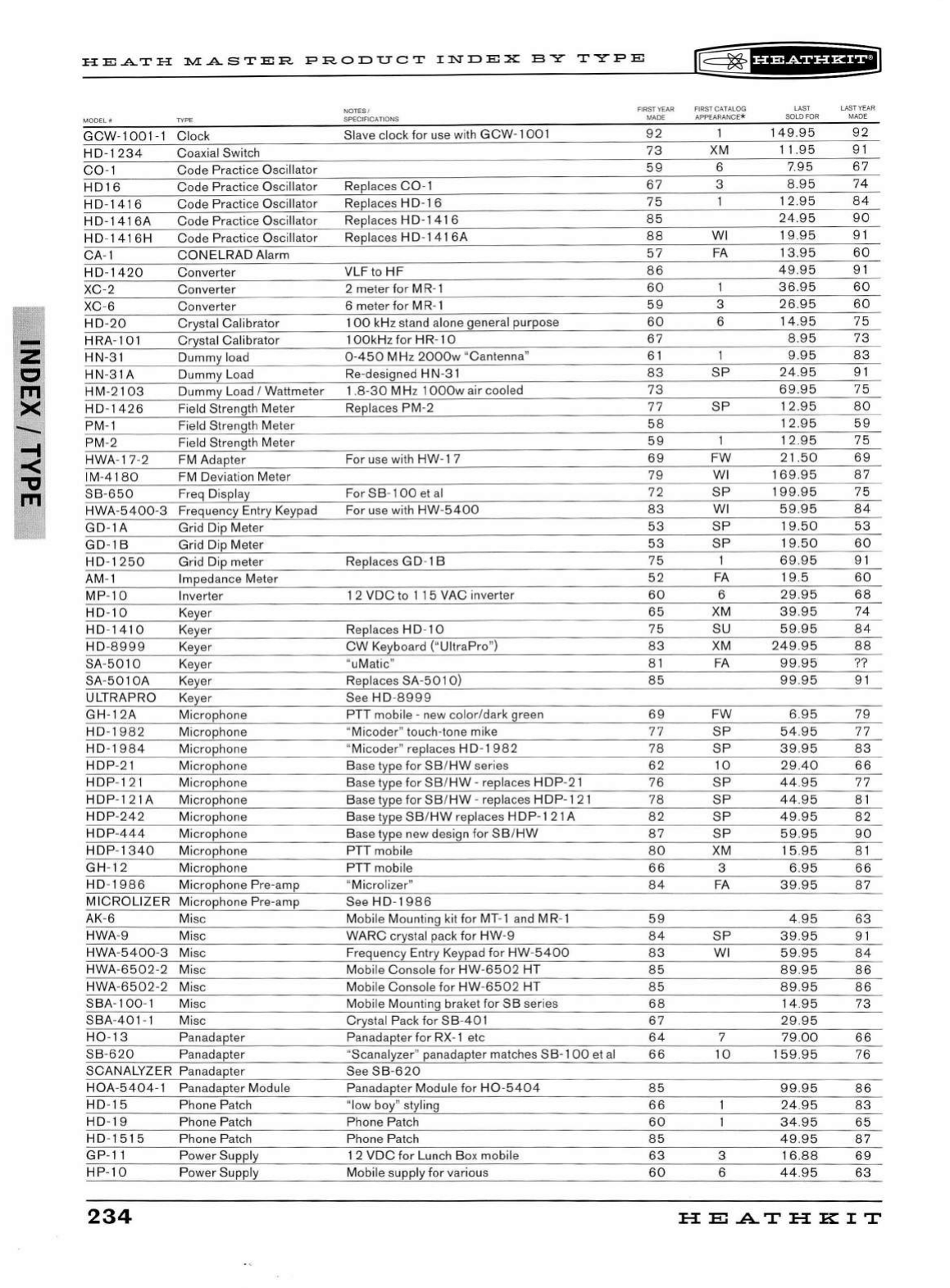
-
z
c
m
><
.....
-<
.,,
m
HE.A.TH
:r..1.1:.ASTER
PRODUCT
INDEX
BY
TYPE
[[$=
~1
nest
HH+IJ
MODEL#
TYP
E
GCW
-100
1-1
Clock
HD
-
1234
Coaxial Switch
C0
- 1 Code Practice Oscillator
HD16
Code Practice Osci
ll
ator
HD
-141 6 Code Practice Oscillator
HD-1416A
Code Practice Oscillator
HD
-
1416H
Code Practice Osci llat
or
CA
- 1
CONELRAD
Alarm
HD
-
1420
Converter
XC
-2
Converter
XC
-6 Converter
HD
-20
Crystal Calibrator
HRA
-101 Crystal Calibrator
HN-
31
Dummy load
HN-3 1A Dummy
Lo
ad
HM-2103
Dummy Load I Wattmeter
HD
-
14
26
Fi
e
ld
Strength Meter
PM-1 Field Strength Meter
PM-2 Field Strength Meter
HWA- 17-2 FM Adapter
IM-4180
FM
Deviation Meter
SB-650
Freq Displ
ay
HWA-5400-3
Frequency Entry Keypad
GD-1A
Grid Dip Meter
GD-1B
Grid Dip Meter
HD
-
1250
Grid Dip meter
AM
- 1 Impedance Meter
MP
-
10
In
verter
HD-10
Keyer
HD
-
1410
Keyer
HD
-
8999
Key
er
SA-
5010
Key
er
SA-
501
OA
Key
er
ULTRAPRO Keyer
GH-12A
Microphone
HD-1982
Microphone
HD-1984
Microphone
HDP
-
21
Microphone
HDP
- 1
21
Microphone
HDP
- 1
21A
Microphone
HDP
-242
Microphone
HDP
-
444
Microphone
HDP
-
1340
Microphone
GH
- 12 Microphone
HD
-
19
86
Microphone Pre-amp
MICROLIZER
Microphone Pre-amp
AK
-6 Misc
HWA-9 Misc
HWA
-5400
-3 Misc
HWA
-6502-2
Misc
HWA
-
6502-2
Misc
SBA
-
100
- 1 Misc
SBA
-
401-1
Misc
H0
-
13
Panadapter
SB
-
620
Panadapter
SCANALYZER Panadapter
HOA
-
5404-1
Panadapter Module
HD
-
15
Ph
one Patch
HD
-
19
Ph
one Patch
HD
-
1515
Phone Patch
GP-11
Power Supply
HP
-10
Power Supply
234
NOTES /
SPECIFICA
TI
ONS
Slave clock for use with
GCW-1001
Replaces
C0
-1
Replaces H
D-1
6
Replaces H D-1
41
6
Replaces H
D-141
6A
VLF to
HF
2 meter
for
M R- 1
6 meter for M
R-1
1
00
kHz stand alone general purpose
1
OOkHz for HR
-10
0-450
MHz
2000w
"Cantenna"
Re-designed
HN
-
31
1.8-30
MHz 1
OOOw
air cooled
Replaces PM-2
For use with HW-1 7
For
SB
- 1
00
et
al
For
use
with
HW-5400
Replaces GD-1 B
1 2
VDC
to 1 15 VAC inverter
Replaces H
D-1
0
CW
Keyboard
("
Ul
traPro")
"
uMatic
11
Replaces SA-
5010)
See
HD
-8999
PTT mobile - new color/dark green
"Micoder" touch-tone mike
"Micoder" replaces H D-
1982
Base type for
SB
/
HW
series
Base type for
SB
/
HW
-replaces H DP-21
B
ase
type for
SB
/
HW
-replaces
HD
P-1
21
Base type
SB
/
HW
replaces H
DP
-1
21
A
Base type new design for
SB
/
HW
PTT mobile
PTT mobile
11
Microli
z
er
11
See
HD
- 1
986
Mobile Mounting kit for MT-1
and
MR- 1
WARC
crystal pack
for
HW
-9
Frequency Entry Keypad for
HW
-
5400
Mobile Console for HW-
6502
HT
Mobile Console for
HW
-
6502
HT
Mobile Mounting brake!
for
SB
series
Crystal Pack for
SB-40
1
Panadapter
for
RX-1
etc
"Scanalyzer" panadapter matches SB-1
00
et
al
See
SB-620
Pan
adapter Module
for
H0
-
5404
"low boy" styling
Phone Patch
Phone Patch
1 2
VDC
for
Lun
ch
Box mobile
Mobile supply for
va
rious
FIRST
YEAR
FIRST CATALOG LAST LAST
YEAR
MADE APPEARANCE*
SOL
O
FOR
MADE
92
149
.95
92
73
XM
11.95
9 1
59
6 7.95
67
67
3
8.95
74
75
12.95
84
85
24.95
90
88
WI
19.95
91
57
FA
13.95
60
86
49
.
95
91
60
36.95
60
59
3
26.95
60
60
6 14.
95
75
67
8.95
73
61
9.95
83
83
SP
24.95
91
73
69.95
75
77
SP
12.95
80
58
12
.95
59
59
12.95
75
69
FW
21.50
69
79
WI
16
9.
95
87
72
SP
199.95
75
83
WI
59.95
84
53
SP
19
.50
53
53
SP
19.50
60
75
69.95
9 1
52
FA
19.5
60
60
6
29.95
68
65
XM
39.95
74
75
SU
59.95
8 4
83
XM
249.95
88
81
FA
99.95
??
85
99.95
9 1
69
FW
6.95
79
77
SP
54.95
77
78
SP
39.95
83
62
10
29.40
66
76
SP
44.95
77
78
SP
44.95
8 1
82
SP
49.95
82
87
SP
59.95
90
80
XM
15.95
8 1
66
3
6.95
66
84
FA
39
.
95
87
59
4.95
63
84
SP
39.95
91
83
WI
59.95
84
85
89.95
86
85
89.95
86
68
14
.95
73
67
29.95
64
7
79.00
66
66
10
15
9.
95
76
85
99.95
86
66
24.95
83
60
34.95
65
85
49.95
87
63
3 16.
88
69
60
6
44.95
63
HEATHKIT
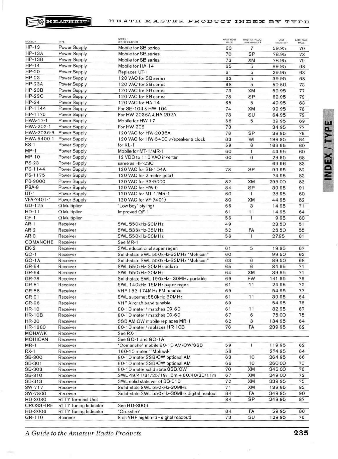
l@
~
f
Hi&ii'i*Eil
HEATH
;r.,1,IASTER
PRODUCT
INDEX
BY
TYPE
MODE
L#
TY
PE
HP-13
Power Supply
HP-13A
Power Supply
HP
-
13B
Power Supply
HP-14
Power Supply
HP-20
Power Supply
HP-23
Power Supply
HP
-
23A
Power Supply
HP
-2
3B
Power Supply
HP-23C
Power Supply
HP
-
24
Power Supply
HP
-
1144
Power Supply
HP-1175
Power Supply
HWA-17-1 Power Supply
HWA-202
- 1 Power Supply
HWA-2036
-3 Power Supply
HWA-
5400-1
Power Supply
KS-1
Power Supply
MP-1 Power Supply
MP-10
Power Supply
PS-23
Power Supply
PS-1144
Power Supply
PS-
1175
Power Supply
PS-9000
Power Supply
PSA-9 Power Supply
UT-1
Power Supply
VFA-7401 - 1 Power Supply
GD-125
Q Multiplier
HD-11 Q Multiplier
QF-1 Q Multiplier
AR
- 1 Receiver
AR-2 Receiver
AR
-3
Re
ceiver
COMANCHE
Receiver
EK-2
Re
ce
iver
GC-1 Receiver
GC-lA
Receiver
GR-54
Receiver
GR-64
Receiver
GR-
78
Re
ceiver
GR-81 Receiver
GR-88
Receiver
GR-91 Receiver
GR-98
R
ec
eiver
HR-
10
Receiver
HR-10B
Re
ceiver
HR-20
Receiver
HR-1680
Recei
ve
r
MOHAWK
Receiver
MOHICAN
Re
cei
ve
r
M
R-1
Receiver
RX-1
Receiver
SB-300
Receiver
SB-301
Receiver
SB-303
Receiver
SB-31 0 Receiver
SB-313
Rece
iv
er
SW-71 7 Receiver
SW-7800
R
ec
eiver
H
D-3030
RTTY Terminal Unit
CROSSFIRE
RTTY Tuning Indicator
H D-
3006
RTTY Tuning Indicator
G
R-1
1 0 Scanner
NOT
ES
/
SPECI
FI
CATIONS
Mobile for
SB
series
Mobile for
SB
series
Mobile for
SB
series
Mobile
for
HA-
14
Replaces UT- 1
120
VAC
for
SB
series
1
20
VAC for
SB
series
120
VAC
for
SB
series
1
20
VAC
for
SB
series
120
VAC
for
HA-14
For
SB
-
104
& HW-1
04
For
HW-2036A
&
HA
-
202A
Mobile for
HW
- 1 7
For
HW
-
202
1
20
VAC for
HW
-
2036A
1
20
VAC
for
HW-5400
w/s
pe
aker & clock
for KL- 1
Mobile
for
MT-1
/M
R-1
1 2
VDC
to 1 1 5 VAC inverter
same
as
HP-23C
1
20
VAC for
SB-104A
120
VAC for 2 meter gea
r)
120
VAC for SS-9
000
120
VAC
for
HW-9
120
VAC
for
MT-1
/MR-1
120
VAC
for
VF-
7401)
"Low boy" styling)
Improved
QF
- 1
SWL
550kHz-20MHz
SWL
535kHz
-
35MHz
SWL
550kHz-30MHz
See
MR
- 1
SWL
educational super regen
Solid-state
SWL
550kHz-32MHz
"Mohican"
Solid-state
SWL
550kHz
-
32MHz
"Mohican"
SWL
550kHz-30MHz
delu
xe
SWL
550kHz
-
30MHz
Solid-state
SWL
1
90kHz
-
30M
Hz
portable
SWL
140kHz-18M
Hz
super regen
VHF
152-174MHz
FM tunable
SWL
superhet
550kHz-30MHz
VHF
Aircraft band tunable
80-1 0 meter I matches
DX-60
80-1 0 meter I matches
DX
-
60
SSB
AM
CW
mobile replaces MR- 1
80-1 0 meter I replaces H R- 1
OB
See
RX
- 1
See
GC
- 1
and
GC
- 1 A
"Comanche" mobile 80-1 0
AM
/
CW
/
SSB
160-10
meter ""Mohawk"
80-1 0 meter
SSB
/
CW
optional AM
80 - 1 0 meter
SSB
/
CW
optional AM
80
- 1 0 meter
so
lid state
SSB
/
CW
SWL
49
/
41
/
31
/
25
/
19
/ 1 6m +
80
/
40
/
20
/
11
m
SWL
solid sta
te
ver of
SB
-
310
Solid-state
SWL
550kHz
-
30MHz
Solid-state
SWL
550kHz
-
30MHz
digital readout
See
HD
-
3006
11
Crossfire"
8
ch
VHF
highband -digital readout)
A
Guid
e to the
Amat
e
ur
Radio
Products
FI
RS
T
YEA
R FIRST CATALOG
LA
ST LAST Y
EAR
MADE APPEARANCE* SOLD
FO
R MADE
63
7
59
.9 5
70
70
SP
78.9
5
73
73
XM
78.95
79
65
5
89.9
5
68
61
5
29.95
63
63
5
39
.
95
68
68
5
59.50
73
73
XM
59
.
95
77
78
SP
62
.9 5 79
65
5
49.95
68
74
XM
99
.
95
78
78
SU
64
.
95
79
68
5
29.95
69
73
34
.
95
77
78
SP
39
.9 5 79
83 WI
199
.
95
84
59
6
169
.
95
60
60
44
.
95
60
60
6
29
.
95
68
69.96
83
78
SP
99
.
95
82
74
.
95
83
82
XM
295
.
00
83
84
SP
39
.
95
91
60
28.95
60
80
XM
44
.
95
82
66
3
14.95
71
61
11
14
.
95
64
56
9.
95
60
49
23
.
50
51
52
FA
25
.
50
55
56
27
.
95
61
61
5
19
.
95
67
60
99
.
50
62
63
6
89
.
50
68
65
6
84
.
95
71
64
XM
39
.
95
71
69
FW
141 .
95
76
61
11
24
.
95
72
69
54
.95 77
61
11
39
.
95
64
69
54
.
95
76
61
11
82
.
95
67
67
6
75
.
00
75
62
3
134.95
64
76
FA
239.95
82
59
119.95
62
58
274
.
95
64
63
10
264
.
95
66
66
10
260
.
00
70
70
XM
345
.
00
76
67
XM
249
.
00
72
72
XM
339
.
95
75
71
XM
139
.
95
82
84
FA
349
.
95
90
84
SP
249
.
95
87
84
FA
59
.
95
86
73
SU
129.95
76
235
-
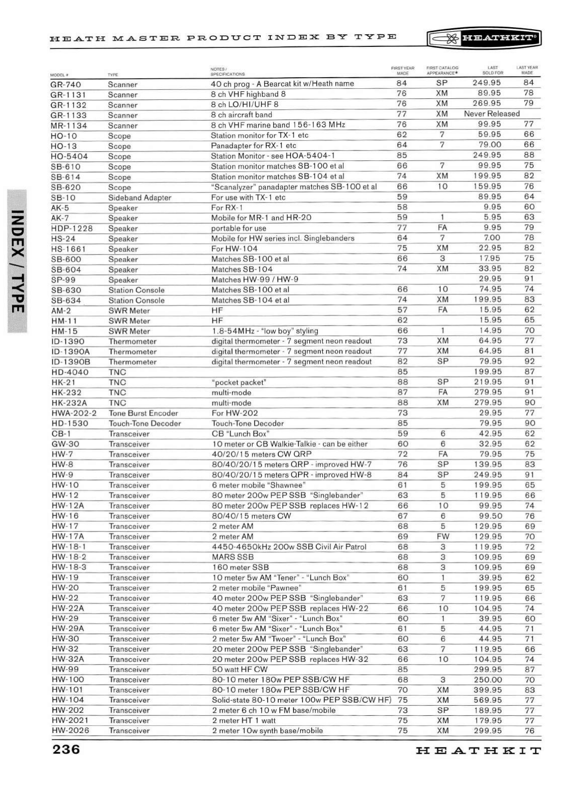
--
HEA..TH
~A..STER
PRODUCT
INDEX
BY
TYPE
rE=~fh@ih&il
MODEL#
TYPE
GR
-
740
Scanner
GR
-
1131
Scanner
GR-1132
Scanner
GR
-
1133
Scanner
MR-1134
Scanner
H0
-
10
Scope
H0-13
Scope
H0
-5404
Scope
SB
-
610
Scope
SB
-
614
Scope
SB
-
620
Scope
SB
-
10
Sideband
Ad
apter
AK
-5 Speaker
AK-7 Speaker
HDP
-
122
8 Speaker
HS
-24
Speaker
HS-
1661
Speaker
SB-600
Speaker
SB
-
604
Speaker
SP-99
Speaker
SB-630
Station Console
SB-634
Station Con
so
le
AM
-2
SWR
Meter
HM
-
11
SWR Meter
HM-15
SWR Meter
ID-1390
Thermometer
ID-1390A
Thermometer
ID-
1390B
Thermometer
HD-4040
TNC
HK
-
21
TNC
HK
-
232
TNC
HK-232A
TNC
HWA-
202
-2
Ton
e
Bur
st
En
coder
HD
-
1530
Touch-Tone
De
coder
CB-1 Tran sceiver
GW
-
30
Transceiver
HW-7
Transceiver
HW
-8 Transcei
ve
r
HW
-9 Transceiver
HW-10
Tr
ansceiver
HW
-12 Tran sceiver
HW
-
12A
Transceiver
HW
-
16
Transceiver
HW
-17
Tr
ansceiver
HW-17A
Transceiver
HW
-18-1
Tr
ansceiver
HW-18
-2 Tran sceiver
HW
-
18-3
Tr
ansceiver
HW-19
Transceiver
HW
-
20
Transceiver
HW
-
22
Transceiver
HW
-
22A
Tr
ansceiver
HW-29
Transceiver
HW
-
29A
Transcei
ve
r
HW-30
Transceiver
HW
-
32
Transcei
ve
r
HW-32A
Transceiver
HW
-
99
Tr
ansceiver
HW-100
Tran
sceiver
HW
-101
Tr
ansceiver
HW
-
104
Tran
sceiver
HW
-
202
Transceiver
HW-2021
Tran
sceiver
HW-2026
Tr
ansceiver
236
NOTES /
SP
ECIFICATIONS
FIRST
YEAR
FIRST CATALOG
MADE APPEARANCE*
40
ch
prog - A Bearcat kit w/Heath name
84
SP
8 ch
VHF
highband 8
76
XM
8
ch
LO
/HI/
UHF
8
76
XM
8
ch
aircraft band
77
XM
8
ch
VHF
marine band 1 5 6-1
63
MHz
76
XM
Station monitor
for
TX- 1 etc
62
7
Panadapter for
RX
-1
etc
64
7
Station Monitor -see
HOA
-
5404-1
85
Station monitor matches SB-1
00
et
al
66
7
Station monitor matches SB-1
04
et al
74
XM
"Scanalyzer" panadapter matches SB-1
00
et
al
66
10
For
use
with T
X-
1 etc
59
For
RX
- 1
58
Mobile for M
R-1
a
nd
H
R-20
59
portable for
use
77
FA
Mobile
for
HW
series incl. Sing lebanders
64
7
For
HW
-
104
75
XM
Matches
SB
-
100
et al
66
3
Match
es
S B- 1
04
74
XM
Matches
HW
-
99
I
HW-9
Match
es
SB-100
et
al
66
10
Matches
SB
-
104
et
al
74
XM
HF
57
FA
HF
62
1 .8-
54M
Hz
- "low boy" styling
66
digital thermometer - 7 segment
ne
on readout
73
XM
digital thermometer - 7 seg ment neon
re
ado
ut
77
XM
digital
th
ermometer - 7 segment neon reado
ut
82
SP
85
"pocket packet"
88
SP
multi-mode
87
FA
multi-mode
88
XM
For
HW
-
202
73
Tou
ch
-
Ton
e Decoder
85
CB
"Lunch Bo
x"
59
6
1 0 meter or
CB
Walkie-Talkie -
can
be
either
60
6
40/20/15
meters
CW
QRP
72
FA
80/40/20
/ 1 5 meters QR P - improved
HW
-7
76
SP
80/40/
20
/ 1 5 meters
QPR
-improv
ed
HW-8
84
SP
6 meter mobile "Shawnee" 6 1 5
80
meter
200w
PEP
SSB
"Singlebander"
63
5
80
meter
200w
PEP
SSB
r
ep
laces HW-1 2
66
10
80/40/
15
meters
CW
67
6
2 meter
AM
68
5
2 meter
AM
69
FW
4450
-
4650kHz
200w
SSB
Civil Air Patrol
68
3
MARS
SSB
68
3
1
60
meter
SSB
68
3
1 0 meter
5w
AM
"
Ten
er" - "Lunch Box"
60
2 meter mob
il
e "Pawnee"
61
5
40
meter
200w
PEP
SSB
"Singlebander"
63
7
40
meter
200w
PEP
SSB
replaces
HW
-
22
66
10
6 meter
5w
AM "Sixer" - "Lun
ch
Box"
60
6 meter 5w AM "Sixer" - "Lun
ch
B
ox
"
61
5
2 meter 5w AM "Twoer" - "Lunch Bo
x"
60
6
20
meter
200w
PEP
SSB
"Singlebander"
63
7
20
meter
200w
PEP
SSB
replaces
HW
-
32
66
10
50
watt
HF
CW
85
80 -
10
meter
180w
PEP
SSB
/
CW
HF
68
3
80-10
meter
180
w
PEP
SSB
/
CW
HF
70
XM
Solid-state
80-
10
meter 1
OOw
PEP
SSB
/
CW
HF)
75
XM
2 meter 6
ch
1 0 w FM base/mobile
73
SP
2 meter HT 1 watt
75
XM
2 meter 1
Ow
sy
nth base/mobile
75
XM
LAST
LAST
YEAR
SOLD FOR MADE
249.95
84
89.95
78
269
.
95
79
Never Released
99.95
77
5
9.95
66
79.00
66
249.95
88
99.95
75
1
99.95
82
159
.95
76
89.95
64
9.95
60
5.95
63
9.95
79
7.
00
78
22.95
82
17.95
75
33.95
82
29.95
91
74
.
95
74
1
99.95
83
15.95
62
15
.95
65
14.95
70
64.95
77
64.95
81
79.95
92
199
.95
87
219.95
91
279.95
91
279.95
90
29.95
77
79.9
5
90
42
.95
62
32
.
95
62
79.95
75
139.95
83
249.95
9 1
199
.95
65
119
.95
66
99.95
74
99
.50
76
129.95
69
129
.95
70
119.95
72
109
.95
69
109
.95
69
39.95
62
199
.95
65
119
.95
66
104
.95
74
39.95
60
44.95
7 1
44.95
71
119
.95
66
104
.9 5
74
299.95
87
250.00
70
399.95
83
569.95
77
189.95
77
179.95
77
299.95
76
HEATHKIT
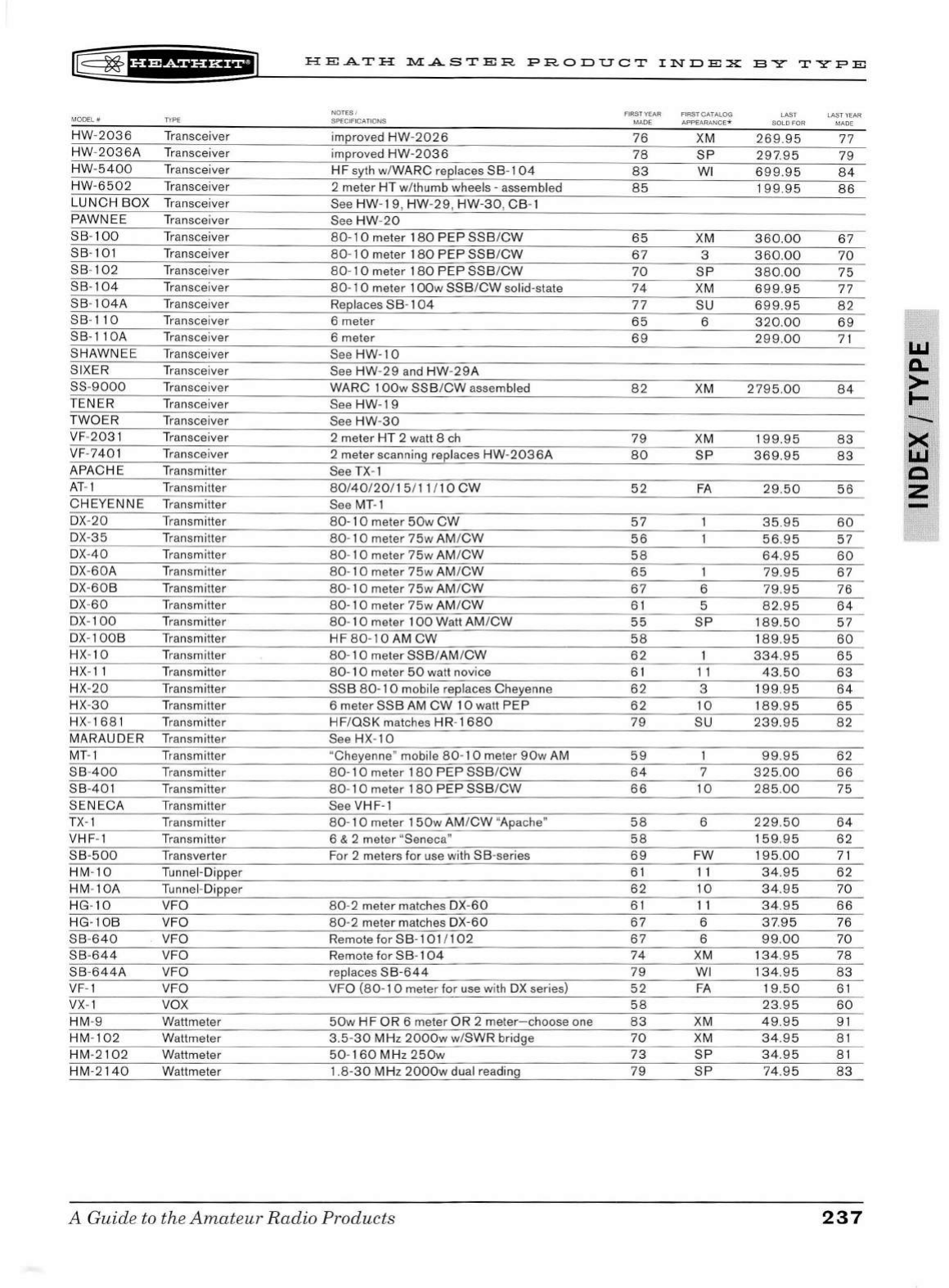
r8
2*
1
§f¥5¥Hi*+i
HEATH
MASTER
PRODUCT
INDEX
E-Y
T"YFE
NOTES / FIR
ST
YEAR
FI
RST
CATALOG
MADE APPEARANCE*
MODEL#
TYPE
SPECIFICATIONS LAST LAST YEAR
SOLD FOR MADE
HW
-
2036
Transceiver improved
HW
-2026
76
XM
269.95
77
HW
-
2036
A T
ra
nsceiver improved
HW-2036
78
SP
297
.9 5
79
HW
-5400
Tr
anscei
ve
r
HF
syth w/
WARC
replaces
SB
-
104
83
WI
699.95
84
HW-
6502
Tr
ansceiver 2 meter
HT
w/thumb wheels - assem
bl
ed
85
1
99.9
5
86
LUNCH
BOX
Tr
ansceiver See
HW
-
19
,
HW
-
29
,
HW-30
,
CB
- 1
PAWNEE
Tr
anscei
ve
r See
HW-
20
S B-1
00
Tr
ansceiver
80-
10
meter
180
PEP
SSB
/
CW
65
XM
360.00
67
S B-1
01
Tr
ansceiver
80
-
10
meter 1
80
PEP
SSB
/
CW
67
3
360
.
00
70
SB
- 1
02
Tr
ansceiver
80
-
10
meter 1
80
PEP
SSB
/
CW
70
SP
380
.
00
75
SB-104
Tr
ansceiver
80-
1 0 meter 1
OOw
SSB/CW
solid
-s
tate
74
XM
699
.9 5 77
SB-
104A
Tr
ansceiver Replaces S B- 1
04
77
SU
699.95
82
SB
-
110
Tr
ansceiver 6 meter
65
6
320
.
00
69
SB-1
lOA
Transcei
ve
r 6 meter
69
299
.0
0 7 1
SHAWNEE
Transcei
ve
r See
HW
-
10
SI
XE
R Transceiver See
HW
-29
and
HW
-
29A
SS-
9000
Tr
ansceiver
WARC
1
OO
w
SSB
/
CW
assembl
ed
82
XM
2795
.
00
84
TENER
Tr
ansceiver See
HW-19
TWO
ER
Tr
ansceiver See
HW
-
30
VF
-
2031
Tr
ansceiver 2 meter HT 2 watt 8 ch
79
XM 1
99.95
83
VF
-
740
1
Tr
anscei
ve
r 2 meter scanning replaces
HW
-2036
A
80
SP
369
.95
83
APACHE
Transmitter See TX-1
AT
- 1 Transmitter
80/
40
/20/
15
/
11
I 1 0
CW
52
FA
29.50
56
CHEYENNE
Tr
ansmitter See MT-1
D
X-20
Transmitter
80-
1 0 meter
50w
CW
57
3 5.95
60
D
X-35
Transmitter 80-1 0 meter 7
5w
AM/
CW
56
56
.
95
57
DX-
40
Transmitter
80-10
meter
75w
AM
/
CW
5 8
64
.9 5
60
D
X-60A
Transmitter
80-
10
meter
75w
AM /
CW
65
79
.9 5
67
D
X-60
B Transmitter
80-1
0 meter 7 5w AM /
CW
67
6
79
.
95
76
DX-
60
Tr
ansm itter
80-
10
meter
75w
AM /
CW
61
5
82.9
5
64
D
X-
100
Tr
ansmitter
80-
1 0 meter 1
00
Watt AM /
CW
55
SP
1
89.50
5 7
DX-1
OOB
Transmitter HF
80-1
0 AM
CW
58
1
89.9
5
60
HX-
10
Tr
an
sm
itter
80-
10
meter
SSB
/AM /
CW
62
334
.9 5
65
H
X-
11
Tr
an
sm
itter
80-
1 0 meter
50
watt novice
61
11
43
.
50
63
H
X-20
Tr
ansmitter SS B
80-
10
mobi
le
replaces Cheyenne
62
3
19
9.95
64
HX-
30
Tr
ansmitter 6 meter SSB AM
CW
10
watt
PEP
62
10
189
.9 5
65
HX
-1
68
1 Transm itter
HF
/OSK
matches
HR-1680
79
SU
239.95
82
MARAUDER
Transmitter See HX-
10
MT-1
Tr
ansmitter "Cheyenne" mobile
80
- 1 0 meter
90w
AM
59
99.95
62
SB
-
400
Transmitter
80-
10
meter 1
80
PEP
SSB
/
CW
64
7
325
.
00
66
SB-401
Tr
ansmitter 80-
10
meter 1
80
PEP
SSB
/
CW
66
10
285
.
00
75
SENECA
Tr
ansmitter See VHF-1
T
X-
1
Tr
ansmitter
80-
10
meter 1
50w
AM /
CW
"Apache"
58
6
229
.
50
64
VHF
- 1
Tr
ansmitter 6 & 2 meter "Seneca" 5 8 159 .
95
62
SB-500
Transverter For 2 meters for
us
e with
SB
-series
69
FW
195
.
00
71
HM
-
10
Tunnel-Dipper
61
11
34
.95
62
HM
-10
A Tunnel -Dipper
62
10
34.95
70
HG
-
10
VFO 80-2 meter matc
he
s DX-
60
61
11
34
.9 5
66
HG-10B
VFO
80-
2 meter matches
DX-60
67
6
37.9
5
76
SB
-
640
VFO Remote for
SB-101
I 1
02
67
6
99.00
70
SB-644
VFO Remote for
SB
- 1
04
74
XM
1
34.95
78
SB
-
644
A VFO replaces
SB-644
79
WI 1
34.9
5
83
VF- 1 VFO
VF
O
(80-
1 0 meter
for
use
wi
th
DX series)
52
FA
1
9.50
61
VX
- 1 vox
58
23.9
5
60
HM
-9 Wattmeter
50w
HF
OR
6 meter
OR
2 meter-choose one
83
XM
49
.
95
91
HM
-
102
Wattmeter 3.5-
30
MHz
2000w
w/SWR bridge
70
XM
34
.9 5 8 1
HM
-2
10
2 Wattmeter
50
-
160
MHz
250w
73
SP
34.95
81
HM-2140
Wattmeter 1.
8-30
MH
z
2000w
du
al reading
79
SP
74
.
95
83
A
Guid
e to the
Amateur
Rad
io
Products
237
LIJ
0..
>
I-
--

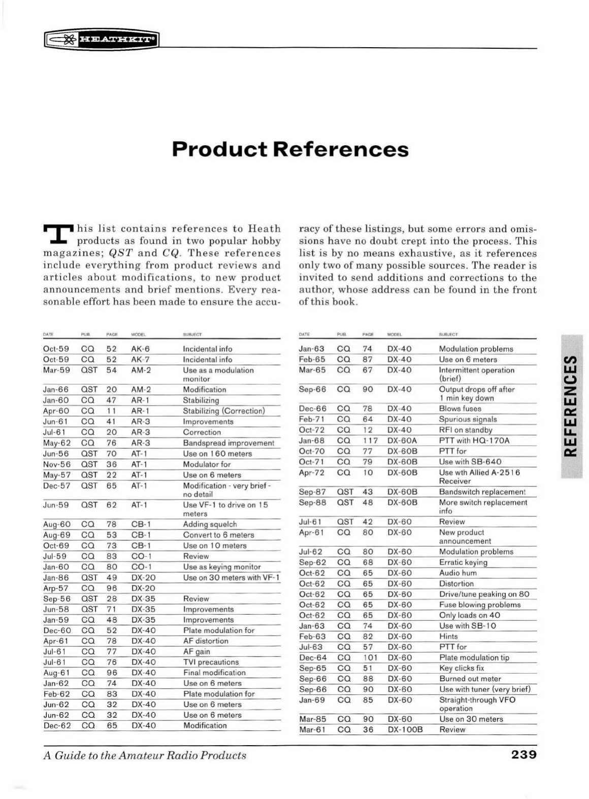
IE
~fU@SiiBifi
Product
References
T
his
list
contains
references
to
H
eat
h
products
as
found
in
two
popul
ar h
obby
magazines;
QST
an
d CQ.
These
references
include
ev
e
ryt
hin
g
from
product
reviews
an
d
articles
about
m
odifications
,
to
new
product
announcem
e
nts
and
brief
mentions.
Every
rea
-
sonab
le
effort
has
be
en
made
to
ens
ur
e
the
accu-
DATE PUB. PAGE MODEL
Oc
t-5
9
ca
52
AK
-6
O
ct-59
ca
52
AK-7
Mar-
59
OST
54
AM-2
Jan-66
OST
20
AM-2
J
an-60
ca
47
AR-1
Apr-
60
ca
11
AR-1
Jun-
61
ca
41
AR-3
Jul-
61
ca
20
AR-3
May-62
ca
76
AR
-3
Jun-56
OST
70
AT
- 1
Nov-5 6
OST
36
AT
-1
May-57
OST
22
AT-1
Dec-
57
OST
65
AT
- 1
J
un
-
59
OST
62
AT-1
Aug -
60
ca
78
CB-1
Au
g-
69
ca
53
CB
- 1
O
ct-69
ca
73
CB-1
Jul
-59
ca
83
C0-1
Jan-
60
ca
80
C0
- 1
J
an
-
86
OST
49
D
X-20
Arp-57
ca
96
D
X-20
Sep-56
OST
28
DX-
35
Jun-
58
OST
71
DX-
35
J
an
-59
ca
4 8 DX-
35
D
ec-60
ca
5 2 D
X-40
Apr-
61
ca
78
DX-
40
Jul-
61
ca
77
DX-
40
Jul-61
ca
76
D
X-
40
Au
g-61
ca
96
DX-
40
Jan
-62
ca
74
D
X-40
F
eb-62
ca
83
DX-
40
Jun-
62
ca
32
DX-
40
Jun-62
ca
32
D
X-
40
D
ec-62
ca
65
D
X-40
SUBJECT
In
c
id
ental info
In
cidental info
U
se
as
a modulation
m
on
itor
Modification
Sta
bi
li
zing
Stabilizing (Correction)
Im
provements
Correction
Bandspread improvement
Use on 1
60
meters
Modu lato r for
U
se
on
6 meters
Modifi cation -
ve
ry brief -
no detail
U
se
VF-1
to drive
on
1 5
meters
Ad
d
in
g squel
ch
Convert to 6 meters
Use
on
1 0 meters
Review
Use
as
keying monitor
U
se
on
30
meters with VF- 1
Review
Improvemen
ts
Improvements
Plate modulation
for
AF distortion
AF gain
TVI precautions
Final modification
U
se
on 6 meters
Plate modulation
for
Use
on
6 meters
Use
on
6 mete
rs
Modification
A Guide to the
Amateur
Radio
Products
racy
of
these
li
stings
,
but
some
errors
and
om
is-
s
ion
s
have
no d
oubt
crept
into
the
process.
This
list
is
by
no
means
exhaustive,
as
it
references
on
ly
two
of
many
possib
le
sources.
The
r
eader
is
invited
to
sen
d
additions
and
correctio
n s
to
the
author
,
whose
address
can
be
fou
nd
in
the
front
of
this
book.
DATE
PUB
. PAGE MODEL
Jan-
63
ca
74
DX
-
40
Fe
b-
65
ca
87
D
X-40
Mar
-65
ca
67
D
X-
40
Sep-66
ca
90 DX-
40
D
ec-66
ca
78
DX-
40
Feb-
71
ca
64 D
X-40
Oct-
72
ca
12 D
X-40
Jan-68
ca
117
DX-
60A
Oct
-70
ca
77
DX-
60B
Oct-7 1
ca
79
D
X-60
B
Apr-
72
ca
10
D
X-60
B
Sep-
87
OST
43
DX-
60B
Sep-88
OST
48
D
X-60B
Jul-6 1
OST
42
DX-
60
Apr-61
ca
80
D
X-60
Jul-
62
ca
80
D
X-60
Sep-62
ca
68
D
X-
60
Oct-
62
ca
65
DX-
60
Oct-
62
ca
65
DX-
60
Oct-
62
ca
65
DX
-
60
Oct-
62
ca
65
D
X-60
Oct-
62
ca
65
D
X-60
Jan
-63
ca
74
DX
-
60
Feb-
63
ca
82
D
X-60
Jul
-63
ca
57
D
X-60
De
c-6 4
ca
1
01
D
X-60
Sep-
65
ca
51
D
X-60
Sep-66
ca
88
D
X-60
Sep-66
ca
90
D
X-60
J
an-69
ca
85
D
X-60
Mar-
85
ca
90
DX
-60
Mar-
61
ca
36
D
X-
100B
SUBJECT
Modulation problems
Use on 6 meters
Intermittent operation
(brief)
Output drops
off
after
1 min
key
down
Blows
fu
ses
Spurious signals
RFI
on
standby
PTT wi
th
H0
-
170A
PTT for
U
se
wi
th
SB-640
U
se
wth Allied A-251 6
Recei
ve
r
Bandswitch r
ep
la
ce
ment
More switch replacement
info
Review
New product
announcement
Modulati
on
problems
Erratic keying
Audio
hu
m
Distortion
Drive/tune peaking on 80
Fu
se blowing problems
Only loads on
40
U
se
wi
th
SB-10
Hints
PTT
for
Plate modulation tip
Key
clic
ks
fix
Burned out meter
U
se
with tuner (very brief)
Straight-through VFO
operation
U
se
on
30
meters
Review
239
Cl)
LIJ
(.)
z
LIJ
0:::
LIJ
LL.
LIJ
cc:
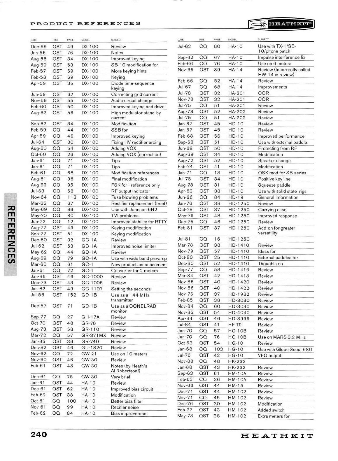
::a
ITI
.,,
ITI
::a
ITI
z
(')
ITI
en
PRODUCT
REFERENCES
DATE P
UB
PAGE MODEL SUBJECT
Dec-
55
OST
49
Jun-56
OST
76
Aug-56
OST
34
Aug-
59
OST
53
Feb-57 OST
59
Feb-
58
OST
69
Apr-59
OST
35
Jun-
59
OST
62
Nov-59
OST
55
Feb-60
OST
50
Aug-
62
OST
56
Sep-
62
OST
34
F
eb-59
ca
44
Apr
-59
ca
46
Jul-64
OST
80
Aug -
60
ca
54
O
ct-60
ca
26
Jan
-61
ca
71
Jan-
61
ca
71
Feb-
61
ca
68
Aug-61
ca
96
Aug
-62
ca
95
Jul-
63
ca
58
Nov-
64
ca
113
Mar-65
ca
67
May-69
ca
83
May-
70
ca
80
Jun-
72
ca
12
Aug-
77
OST
49
Sep-77 OST
51
De
c-
60
OST
32
Jul-62
OST
53
Ma
y-
62
ca
44
Aug-69
CO
79
Mar-
60
ca
61
Jan-61
ca
72
J
an-86
OST
46
Dec-
73
OST
43
Jan-82
OST
49
Ju
l-56
OST
152
De
c-
57
OST
71
Sep-
77
ca
27
Oct
-70
OST
48
A
ug-73
OST
5 8
Mar-72
ca
57
Jan-
85
OST
36
Dec-
82
OST
46
Nov
-62
CO
72
Nov-
60
OST
46
Feb-6 1
OST
48
Dec-6 1
ca
75
Jun-61
OST
44
De
c-6 1
OST
62
Feb-
62
OST
38
Oct-
61
CO
100
Nov-6 1
ca
99
F
eb-62
ca
84
240
DX-100
DX
-
100
DX-100
DX-100
DX-100
DX
-
100
DX-100
DX-100
DX-100
DX-100
DX
-
100
DX-100
DX-100
D
X-
100
DX-100
DX-100
DX-100
DX-100
DX-100
DX-
10
0
DX-100
DX-100
DX-100
DX
-
100
DX-
100
D
X-
100
DX
-
100
DX-100
DX-100
DX
-
100
GC-lA
GC-lA
GC-lA
GC-1A
GC-1
GC-1
GC-1000
GC-1005
GC
-1
10
7
GD-18
GD-18
Review
Notes
Improved keying
SB
-
10
modification
for
Mor
e keying hints
Keying
Diode time-sequence
keying
Correcting grid current
Audio circuit change
Improved keying
and
drive
Hi
gh
modulator stand -
by
current
Modification
SSB
for
Improved keying
Fi
xing HV rectifier arcing
Adding VOX
Adding VOX (correction)
Tips
Tips
Modification references
Final modification
FSK for -reference only
RF
output indicator
Fu
se
blowing problems
Rectifier replacement (brief)
Use with Johnson
6N2
TVI problems
Improved stability for RTTY
Keying modification
Keying modification
Review
Improved noise limiter
Review
U
se
with wide band pre-amp
New product announcement
Converter
for
2 meters
Review
Review
Setting the seconds
U
se
as
a 1
44
MH
z
transmitter
Use
as
a
CONELRAD
monitor
GH-17A
Review
GR
-
78
Review
GR
-
110
Review
GR-371
MX
Re
view
GR-740
Review
GU
- 1
820
Review
GW
-2 1 U
se
on
10
meters
GW-30
Review
GW
-
30
Notes (by Heath's
Al
Robertson!)
GW-30
Very brief
HA
- 1 0 Review
HA
- 1 0 Improved bias circuit
HA
- 1 0 M
od
ification
HA-1 0 Better bias filter
HA
- 1 0 Recifier noise
HA-1 0 Bi
as
improvement
rE=~fH&ih&+I
DATE PUB. PAGE
MODEL
SUBJEC
T
Jul-
62
ca
80
Sep-
62
ca
67
Feb-
66
ca
76
Nov-
65
OST
89
F
eb
-
66
ca
52
Jul-67
ca
68
Jul-
78
OST
32
Nov-
78
OST
32
Jul-
75
ca
51
Aug-73 OST
52
Jul-75
ca
51
Ja
n-67
OST
45
Jan-67
OST
45
Feb-68
OST
56
Sep-
68
OST
51
Jun-
69
OST
50
A
ug-69
OST
34
Aug-72
OST
52
Feb-
74
OST
41
Jan-
71
ca
18
Jul-78
OST
34
Au
g-
78
OST
31
A
pr-83
OST
38
Jun-66
ca
84
Jan
-76
OST
38
O
ct-78
OST
37
M
ay
-
79
OST
48
D
ec-75
ca
46
F
eb
-8 1
OST
37
Ju
l-8 1
CO
16
Mar-78
OST
38
Nov-
79
OST
57
O
ct-80
OST
25
Dec-80
OST
52
Sep-
77
ca
58
Mar-
84
OST
42
Nov
-8
6 OST
40
N
ov-86
OST
40
Nov-
76
OST
37
Feb-
85
OST
38
N
ov-84
CO
60
Nov-85
OST
54
Apr-84
OST
46
Jul-84
OST
41
Jun-
70
ca
57
Jun -
70
ca
76
O
ct-63
OST
54
Jan-68
ca
1
03
Jul-
76
OST
42
Nov-
88
ca
48
J
an
-
88
OST
43
Sep-63
OST
61
F
eb
-
63
ca
36
N
ov-66
OST
44
Dec-71 OST
44
Nov-
71
ca
45
Dec-
76
OST
30
F
eb
-
77
OST
43
May-78
OST
38
HA
-10
HA
-
10
HA
-
10
HA
-
14
HA
-
14
HA
-
14
HA
-201
HA
-
20
1
HA
-2
01
HA-202
HA
-
202
HD
-
10
HD
- 10
HD
-
10
HD
-10
HD
-10
HD
- 10
HD
-
10
HD
- 10
HD-1 0
HD
-
10
HD
-
10
HD
-
10
HD
- 19
HD
- 1
250
HD-1250
HD
- 1
250
HD
- 1
250
HD
- 1
250
HD
-
1250
HD
-14
10
HD
-
1410
HD
-
1410
HD
-14
10
HD
-
1416
HD
-141 8
HD
-1420
HD
-
1422
HD
- 1
982
HD
-3030
HD
-
3030
HD
-
4040
HD
-
8999
HF
-T9
HG
-
108
HG
-108
HG
-
10
HG
- 10
HG-10
HK
-232
HK
-232
HM
-
10A
HM
-10A
HM
-
15
HM
-
102
HM
-
10
2
HM-102
HM
- 1
02
HM
-
10
2
U
se
wi
th
T
X-
1 /
SB
-
1 O/phone patch
Impul
se
interference fix
U
se
on
6 meters
Review (Incorrectly
ca
ll
ed
HW-1 4
in
review)
Review
Improvements
COR
COR
Review
Review
Re
view
Review
Review
Improved performance
Use with externa l paddle
Protecting from RF
Modification
Speaker
cha
ng
e
Modification
OSK
mod
for
SB
-series
Positive key lin e
Squeeze paddle
U
se
with
so
lid state rigs
General information
Review
Carrying case
Improved response
Review
Add-on for greater
versatility
Rev
ie
w
Id
eas for
External paddles
for
Th
oughts
on
Review
Review
Review
Review
Re
view
Review
Rev
ie
w
Review
Rev
ie
w
Review
Review
Use
on
MARS 3.2 MHz
Review
Use with Globe Scout
680
VFO output
Review
Review
Review
Review
Review
Review
Modific
at
ion
Added switch
Extra meters for
HEATHKIT
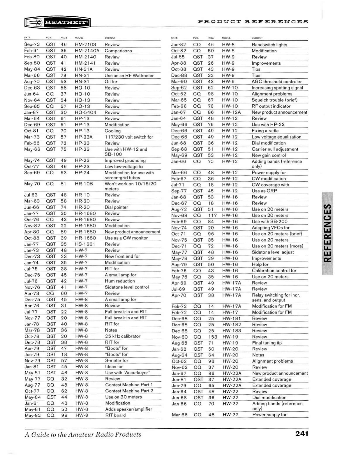
rr§
~
1
H?dff'i*fi1
DATE
Sep-73
Feb-91
Feb-80
Sep-80
May-8 4
M
ar-66
Aug-
70
Dec-63
Ju
n-64
Nov-64
Sep-
65
Jan
-
87
Mar-
64
Dec-69
Oct-
81
Mar
-73
Feb-66
May-66
May
-74
Oct-
77
Sep-69
May-70
Jul-63
Mar-
63
Jun-
66
Jan-77
Oct-76
Nov-82
Apr-80
O
ct-88
Jan-77
Jan-
73
Dec-73
Jan
-74
Jul-75
Dec-75
Jul-76
Nov-76
Apr-
73
Dec-75
Apr-76
Jul-77
Nov-77
Jan-78
Mar-78
Oct-78
Dec-78
Apr-79
Jun-79
Nov-79
Jan-81
May-81
May-77
Aug
-77
Oct-77
May-84
Jan-8 1
May-81
May-
82
PU B PAGE MODEL SUBJECT
OST
46
OST
35
OST
40
OST
41
OST
42
OST
79
OST
53
OST
58
ca
37
OST
54
ca
57
OST
30
OST
61
OST
51
ca
70
OST
57
OST
72
OST
75
OST
49
OST
46
ca
53
ca
81
OST
48
OST
58
OST
74
OST
35
ca
43
OST
22
ca
89
OST
39
OST
35
OST
48
OST
23
OST
35
OST
38
OST
45
OST
42
OST
41
ca
60
OST
45
OST
31
OST
22
OST
20
OST
40
OST
36
OST
20
OST
38
OST
47
OST
18
OST
57
OST
45
OST
46
ca
32
ca
48
ca
62
OST
44
ca
48
ca
52
ca
98
HM
-2
103
Re
view
H M-2
140A
Comparisons
H M-
2140
Review
HM
-2141
HN-3 1A
HN-
31
HN-3 1
H0-10
H0
-10
H0
-
13
H0
-
13
H0
-
5404
HP
-
13
HP-13
HP
-
13
HP-23A
HP
-
23
HP-23
HP-23
HP-23
HP
-24
HR
-
10B
HR-10
HR
-20
HR
-20
HR
-
1680
HR-
1680
HR-
16
80
HR-
1680
HR-
1680
HS
-166
1
HW
-7
HW-7
HW-7
HW
-7
HW
-7
HW
-7
HW-7
HW
-7
HW
-8
HW
-8
HW-8
HW
-8
HW-8
HW
-8
HW
-8
HW
-8
HW
-8
HW-8
HW
-8
HW-8
HW-8
HW
-8
HW
-8
HW-8
HW
-8
HW
-8
HW
-8
HW
-8
Re
view
Review
U
se
as
an
RF Wattmeter
Oil for
Review
Re
view
Re
view
Re
view
Re
view
Review
Modification
Cooling
117
/
230
vo
lt
sw
itch for
Review
U
se
with HW-1 2
and
SB
-
100
Improved grounding
Low low-voltage fix
Modification for use with
screen-grid tubes
Won 't work
on
10/1
5/20
meters
Review
Re
view
Dial pointer
Re
view
Review
Modifi
ca
tion
New product announcement
Us
e
as
a
CW
monitor
Re
view
Review
New front
end
for
Modification
RIT for
A sma
ll
amp
for
Hum reduction
Sidetone level control
Re
vi
ew
A small amp for
Review
Full break-in
and
RIT
Full break-in a
nd
RIT
RITfor
Not
es
2 5 kHz calibrator
RIT for
"Boots"
for
"Boots"
for
S-meter for
Ide
as
for
U
se
with "Accu-keyer"
Review
Contest Machine Part 1
Contest Machine Part 2
U
se
on
30
meters
Modifi
ca
tion
Adds speaker/amplifier
RIT board
A Guide to the
Amateur
Radio
Products
DATE
Jun-82
Oct-
82
Jul-85
Apr
-88
Oct-88
Dec-
88
Mar-90
Sep-62
Oct-62
Mar-6 5
Feb-66
Jan-67
Jan-
64
May-
66
Dec-66
Dec-66
Jun-68
Sep-68
May
-69
Jan-66
Ma
r-66
Feb-
67
Jul-71
Sep-77
Jan-68
Dec
-67
Aug
-72
Nov-68
Feb
-
69
Nov-74
Oct-71
Nov-75
Dec-
71
May-77
May-78
Aug-
79
Feb
-76
May-76
Apr-69
Jul-69
Apr-70
Feb-72
Feb-72
Dec
-68
Dec-68
Dec-
68
Nov-
60
Aug-65
Jan
-62
Aug-64
Oct-62
Nov-62
Jan
-67
Jun-81
Jan
-79
Jan
-64
Jun-68
Jan-66
Mar-
66
PRODUCT
REFERENCES
PAGE MODEL
ca
46
HW
-8
ca
50
HW-8
OST
37
HW-9
OST
26
HW
-9
OST
43
HW
-9
OST
32
HW
-9
OST
43
HW
-9
OST
62
HW
-
10
ca
98
HW
-
10
ca
67
HW
-
10
ca
76
HW-10
ca
86
HW
-12
A
OST
48
HW
-
12
OST
75
HW-12
OST
49
HW
-
12
OST
49
HW
-
12
OST
36
HW
-12
OST
51
HW-12
OST
53
HW
-
12
ca
70
HW
-
12
ca
48
HW
-
12
ca
36
HW-12
ca
18
HW
-12
OST
45
HW-12
OST
53
HW-16
ca
18
HW
-
16
OST
51
HW
-
16
ca
117
HW-16
ca
84
HW
-
16
OST
20
HW
-16
ca
96
HW-16
OST
35
HW
-
16
ca
72
HW
-
16
OST
48
HW-16
OST
29
HW
-
16
OST
50
HW-16
ca
43
HW-16
ca
35
HW-16
OST
49
HW
-17A
OST
49
HW-17A
OST
38
HW
-
17A
ca
14
HW-17A
ca
14
HW-17
ca
25
HW
-181
ca
25
HW
-
182
ca
25
HW-18
3
ca
153
HW-19
OST
71
HW-19
OST
50
HW
-20
OST
64
HW-20
ca
98
HW
-
20
ca
37
HW
-
20
ca
86
HW-22A
OST
37
HW-22A
ca
65
HW-22A
OST
48
HW-22
OST
36
HW-22
ca
70
HW-22
ca
48
HW-22
SUBJECT
Bandswitch lights
Modification
Review
Improvements
Tips
Tips
AGC
threshold controler
Increasing spotting signal
Alignment problems
Squelch trouble (brief)
RF output indicator
New product announcement
Review
Use with
HP-23
Fi
xing a rattle
Low voltage equalization
Dial modification
Carrier null
ad
justment
New gain control
Adding bands (reference
only)
Power supply
for
CW
modification
CW
coverage with
U
se
as
ORP
Review
Re
view
U
se
on
20
meters
Use
on
20
meters
U
se
with
SB-200
Ad
apting VFOs for
Use
on
20
meters (brief)
U
se
on
20
meters
Use
on
20
meters (more)
Sidetone level adjust
Improvements
Help
for
Calibration control for
Use
on
20
meters
Re
view
Review
Rel
ay
switching for
in
cr.
sens.
and
output
Modification
for
FM
Modification for FM
Review
Review
Review
Review
Fin al tuning tip
Re
view
Notes
Alignment problems
Review
New product announcement
Extended coverage
Extended coverage
Review
Dial modification
Adding bands (reference
only)
Power supply
for
241
Cl)
I.LI
(,)
z
I.LI
ci:::
I.LI
.
LL.
1
~
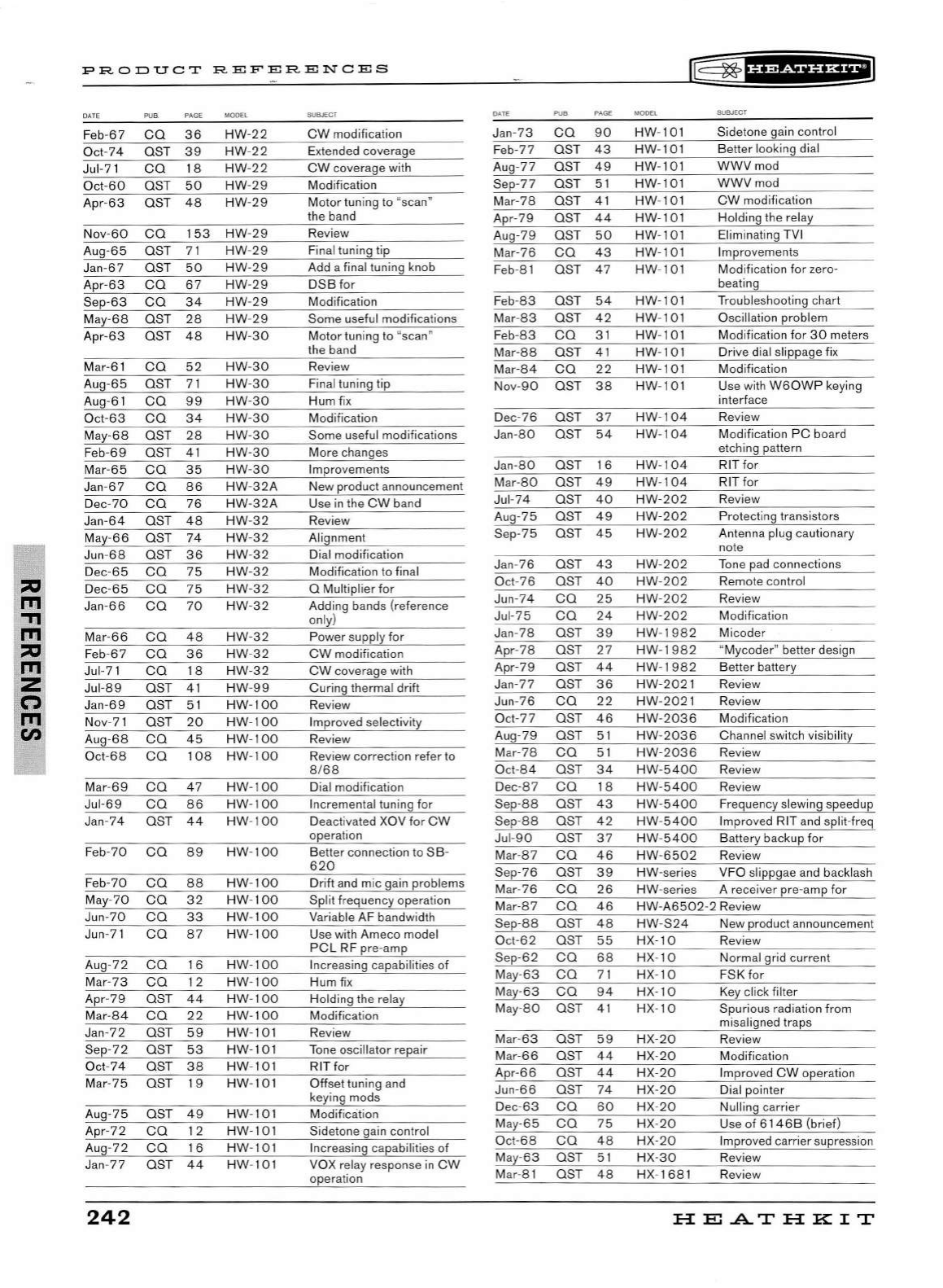
"'
'"
"Tl
ITI
"'
ITI
z
(")
ITI
en
PRODUCT
REFERENCES
DATE
PUB
. PAGE MODEL
Feb-
67
ca
36
HW
-22
Oct-74
OST
3g
HW
-
22
Jul-7 1
ca
18
HW
-
22
Oct
-60
OST
50
HW
-
29
Apr-
63
OST
48
HW
-
29
Nov-
60
co
153
HW
-
29
Au
g-65
OST
71
HW
-
29
Jan-67
OST
50
HW
-29
Apr-
63
co
67
HW
-
29
Sep-63
co
34
HW
-2 9
Ma
y-68
OST
28
HW
-
29
Apr
-63
OST
48
HW
-
30
Mar-61
co
52
HW
-30
Aug-
65
OST
71
HW
-
30
Aug-6 1
ca
99
HW
-
30
Oct-
63
ca
34
HW
-
30
May-
68
OST
28
HW
-
30
F
eb-69
OST
41
HW
-30
Mar-65
co
35
HW
-
30
J
an-67
ca
86
HW-32A
Dec-
70
ca
76
HW
-32
A
Jan-64
OST
48
HW
-
32
May-
66
OST
74
HW
-
32
Jun-
68
OST
36
HW
-
32
De
c-
65
co
75
HW
-32
D
ec-65
co
75
HW
-
32
Jan-
66
ca
70
HW
-
32
M
ar-66
ca
48
HW
-32
Feb-
67
co
36
HW
-
32
Jul-
71
ca
18
HW
-32
Jul-
89
OST
41
HW
-
99
Jan-69
OST
51
HW
-
100
Nov-
71
OST
20
HW-100
Aug-
68
co
45
HW
-
100
O
ct-68
co
108
HW-100
Mar-
69
co
47
HW
-100
Jul-
69
co
86
HW
-
10
0
Jan-74
OST
44
HW
-1
00
F
eb-70
co
89
HW
-
100
F
eb-70
co
88
HW
-
100
May-
70
ca
32
HW
-
100
Jun-70
co
33
HW
- 1
00
Jun-
71
co
87
HW
-
100
Aug -
72
co
16
HW
-
100
Mar-7 3
ca
12
HW
-
100
Apr-
79
OST
44
HW
-
100
Mar-84
co
22
HW-100
Jan-
72
OST
59
HW
-101
Sep-
72
OST
53
HW
-101
Oct-
74
OST
38
HW
-101
Mar-
75
OST
19
HW
-101
Aug-75
OST
49
HW
-101
Apr-
72
co
12
HW
-101
Aug-7 2
co
16
HW
-101
Jan
-77
OST
44
HW
-101
242
SUBJECT
CW
modification
Extended coverage
CW
coverage with
Modification
Motor tunin g to "scan"
the band
Review
Final tuning tip
Add a final tun ing knob
DSB
for
Modification
Some usefu l modifications
Motor tuning to "scan"
the band
Review
Final tuning tip
Hum fix
Modification
Some useful modifications
More changes
Improvements
New product a
nn
ounceme
nt
Use
in
the
CW
band
Review
Alignment
Di
al
modification
Modification to final
0 Multiplier
for
Adding bands (reference
on
l
y)
Power supply for
CW
modifi
ca
tion
CW
coverage with
Curing thermal drift
Review
Improved
se
lectivity
Review
Review correction refer to
8168
Di
al
modificati
on
Incremental tuning for
Deactivated XOV for
CW
operation
Better connection to
SB
-
620
Drift and mic gain problems
Split frequency operation
Variable AF bandwidth
U
se
with Ameco model
PCL
RF pre-amp
In
creasi
ng
capabilities of
Hum
fi
x
Holding
th
e relay
Modification
Review
Tone oscillator repair
RIT for
Off
set tuning and
keying mods
Modification
Sidetone ga
in
control
In
creasing capabiliti
es
of
VOX relay respon
se
in
CW
operation
DATE
Jan-73
Feb-77
Aug-
77
Sep-77
Mar-78
Apr-79
Aug-79
Mar-76
Feb-81
F
eb
-
83
Mar-
83
F
eb-83
M
ar-88
M
ar-84
No
v-
90
De
c-76
Ja
n-80
Jan-
80
Ma
r-80
Jul-
74
Au
g-75
Sep-75
Jan-76
Oct-
76
Jun -
74
Ju
l-
75
Jan-78
Apr-
78
Apr-79
Jan-77
Jun-
76
Oc
t-77
Au
g-
79
Mar-
78
Oct-
84
D
ec-87
Sep-88
Sep-88
Jul-
90
Mar-
87
Sep-76
Mar-
76
Mar-
87
Sep-88
Oct-
62
Sep-
62
M
ay-
63
M
ay-
63
M
ay-
80
Mar-
63
Mar-
66
Ap
r-66
Jun-
66
Dec-
63
May-
65
Oc
t-
68
M
ay
-
63
Mar-8 1
l®~fHP&fHHEiJ
PUB
. PAGE MODEL SUBJECT
ca
90
OST
43
OST
49
OST
51
OST
41
OST
44
OST
50
ca
43
OST
47
OST
54
OST
42
ca
31
OST
41
ca
22
OST
38
OST
37
OST
54
OST
16
OST
49
OST
40
OST
49
OST
45
OST
43
OST
40
ca
25
ca
24
OST
39
OST
27
OST
44
OST
36
co
22
OST
46
OST
51
co
51
OST
34
co
18
OST
43
OST
42
OST
37
co
46
OST
39
co
26
ca
46
OST
48
OST
55
co
68
co
71
co
94
OST
41
OST
59
OST
44
OST
44
OST
74
ca
60
co
75
co
48
OST
51
OST
48
HW
-101
HW-101
HW
-101
HW
-101
HW
-101
HW
-101
HW-101
HW
-101
HW
-101
HW-101
HW
-10
1
HW
-101
HW-101
HW-101
HW
-101
HW-104
HW-104
HW-104
HW
-
104
HW
-
202
HW-20
2
HW-202
HW
-202
HW
-
202
HW
-
202
HW-
202
HW-1
g32
HW-1982
HW
-1
982
HW-2
021
HW-2021
HW-2036
HW
-
2036
HW
-2
036
HW-5400
Sidetone
ga
in
control
Better
lo
oking dial
WWVm
od
WWVm
od
CW
modification
Holding
th
e relay
Elimin
at
in
g TVI
Improvements
Modification
for
zero-
beating
Troubleshoot
in
g chart
Osci
ll
ation problem
Modification
for
30
meters
Dri
ve
dial slippage fi x
Modification
U
se
wi
th
W 6
0WP
keying
interface
Re
view
Modification
PC
board
etching pattern
RIT for
RIT for
Review
Protecting transistors
Antenna plug cautionary
note
Tone
pad
connections
Remote control
Review
Modification
Micoder
"Mycoder" better design
Better battery
Re
view
Review
Modificati
on
Channel switch visibility
Re
v
ie
w
Re
view
HW
-5400
Review
HW
-5400
Frequency slewing speedup
HW
-5400
Improved RIT a
nd
split-fr
eq
HW
-
5400
Battery backup for
HW
-6502
Review
HW
-series VFO slippg
ae
and backlash
HW
-series A receiver pre
-a
mp for
HW-A6502
-2 Review
HW
-
S24
New product announcement
H
X-10
H
X-10
HX- 10
H
X-10
H
X-10
H
X-20
HX-
20
H
X-20
H
X-20
HX-20
HX-
20
H
X-20
H
X-30
HX
-
16
8 1
Re
view
Normal grid current
FSK for
Key
click filter
Spurious radiation from
mi
sa
lign
ed
traps
Review
Modification
Improved
CW
operation
Dial pointer
Nulling carrier
Use
of
6146B
(brief)
Improv
ed
carrier supression
Review
Re
view
HE.ATHKIT
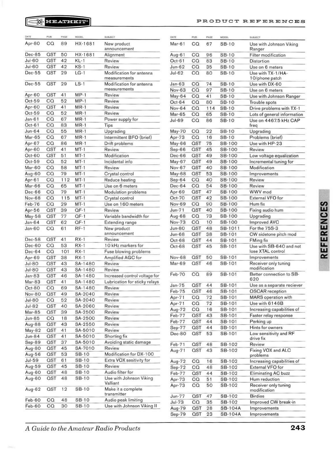
®
~1ue+tnH11
DATE
PUB
PAGE MODEL
Apr-
80
CO
89
HX-1 681
Dec-85 OST
50
HX-1681
Jul
-60
OST
42
KL-1
Jul-60
OST
42
KS-1
Dec-
55
OST
29
LG-1
Dec-55 OST
29
LS-1
Apr-
60
OST
41
MP-1
Oct-59
CO
52
MP-1
Apr
-60
OST
41
MR-1
Oct-59
CO
52
MR-1
Jan-6 1
CO
67
MR-1
Oct-
61
CO
83
MR- 1
Jun
-
64
CO
55
MR-1
Mar-
65
CO
67
MR-1
Apr-
67
CO
86
MR-1
Apr-
60
OST
41
MT-1
Oct-60
OST
51
MT-1
Oct
-59
CO
52
MT-1
Mar-60
CO
58
MT-1
Aug-60
CO
79
MT-1
Apr-
61
CO
112
MT-1
Mar-
66
CO
65
MT- 1
Dec-
66
CO
79
MT-1
Nov-68
CO
115
MT-1
Feb-76
CO
29
MT-1
Apr-56
OST
39
OF-1
May-58
OST 77 OF-1
Jan-64
OST
62
OF
- 1
Jan-60
co
61
RF-1
Dec-
58
OST
41
RX-1
De
c-
60
co
53
RX-1
De
c-
64
co
101
RX-1
Apr-
69
OST
38
RX-1
Jul
-8
0 OST
43
SA-14
80
Jul-
80
OST
43
SA-1480
Jan
-
83
OST
46
SA-
1480
Mar-83
OST
41
SA-1480
Oct-
80
co
69
SA-
1480
No
v-80 OST
49
SA-2040
Jul
-80
co
52
SA-2040
Jul-
82
OST
40
SA-
2060
Mar-
85
OST
39
SA-2500
Jun-8 5
co
18
SA-
2500
Aug-88 OST
43
SA-2550
May-
82
OST
41
SA-5010
Jun-84
OST
41
SA-5010
Sep-
89
OST
37
SA-5010
Aug-80
OST
45
SA-7010
Aug-
56
OST
53
SB
-
10
Jul
-59
OST
61
SB-10
Aug
-
59
OST
45
SB
-
10
Aug-60
OST 4 8
SB-10
Aug-60
OST
48
SB-10
Aug-
62
OST 12
SB
-
10
Feb-60
co
48
SB-10
Feb
-6
0
co
30
SB-10
SUBJE
CT
New product
announcement
Alignment
Review
Review
Modifi
ca
tion for antenna
measurements
Modification for antenna
measurements
Review
Review
Review
Review
Power supply for
Tips
Upgrading
Intermittent
BFO
(brief)
Drift problems
Re
view
Modification
Incidental info
Review
Crystal control
Reduce heating
Use
on
6 meters
Modulation problems
Crystal control
Use on 1
60
meters
Review
Variable bandwidth for
Extending rang e
New product
announcement
Review
1
0 kHz markers for
Fuse blowing problems
Amplifi
ed
AGC
for
Revi
ew
Review
Incre
ase
d control vo
lt
age
for
Lubrication
for
sticky relays
Re
view
Review
Review
Re
v
ie
w
Review
Review
Review
Review
Shorting fi x
Avoiding static dam
age
Re
view
Modifi
ca
tion
for
DX-1
00
Extra VOX sesitivity for
Review
Audio filter for
Use with Johnson Viking
Valliant
Make it a complete
transmitter
Audio peak limiting
Use with John
so
n Viking
II
A
Guid
e to the
Amat
e
ur
Radio
Products
DATE
Mar-61
Aug-
61
Oct-
61
Jun-62
Jul-62
Ja
n-63
Nov-63
May-
64
Oct-
64
No
v-
64
Mar-
65
Jul-
69
M
ay-
70
Apr-73
Ma
y-
66
Sep-
66
Dec-
66
M
ay-
67
Nov-67
M
ay
-
68
Sep-
64
Dec-64
Apr-69
Oct
-
70
No
v-
69
Jun-
71
Aug -
68
Nov-
73
Jun-80
Jun-
68
Oct-
68
Oc
t-
68
No
v-
68
Mar-
69
Feb-
70
Jan-75
Feb-
75
Apr-
71
Apr-71
Aug-72
Feb
-
77
Feb
-
77
Sep-77
Dec-
80
Feb-71
Aug
-
71
Aug-72
Sep-
72
Feb
-77
Apr-73
Apr-
73
Jun-
77
Jul-73
Aug-79
Sep-
79
PRODUCT
REFERENCES
PUB
PAGE MODEL
co
67
SB
-
10
co
96
SB
-
10
co
83
SB-10
co
35
SB-10
co
80
SB
-
10
co
74
SB
-
10
co
97
SB-10
co
41
SB-10
co
80
SB
-
10
CO
114
SB
-
10
CO
65
SB-10
CO
86
SB-10
CO
22
SB
-
10
CO
16
SB-10
OST 75
SB-100
OST
45
SB-100
OST
49
SB-100
OST
49
SB-100
OST
40
SB
-
100
OST
53
SB
-
100
CO
40
SB-100
CO
54
SB-100
OST
47
SB
-
100
OST
42
SB
-
100
CO
90
SB-100
OST
40
SB
-
100
co
73
SB
-
100
co
10
SB-100
OST
48
SB-1011
OST
38
SB-101
OST
44
SB-101
OST
45
SB-101
OST
50
SB-101
OST 4 6
SB-101
co
89
SB
-101
OST
44
SB-101
OST
46
SB
-101
co
72
SB-101
co
72
SB-101
co
16
SB
-101
OST
43
SB-101
OST
44
SB-101
OST
44
SB-101
OST
53
SB-101
OST
48
SB
-
102
OST
43
SB-102
co
16
SB-102
co
48
SB-102
OST
44
SB-102
co
51
SB-102
co
50
SB-102
OST
47
SB-102
co
35
SB-102
OST
28
SB
-
104A
OST
23
SB-104A
SUBJECT
Use with Johnson Viking
Ranger
Filter modification
Distortion
Use
on
6 meters
Use with
TX-1
/HA-
1 O/phone patch
Use with
DX
-
60
Use
on
6 meters
Use with Johnson Ranger
Trouble spots
Drive problems with
TX-1
Lots
of
general information
Useon44675kHzCAP
freq
Upgrading
Problems (brief)
Use with
HP-23
Re
vi
ew
Low voltage equalization
Incremental tuning
for
Modificat
io
n
Improvements
Review
Revi
ew
WWVmod
External VFO
for
Hum fi x
Fixing audio hum
Upgrading
Improved AVC
For
th
e
75S-3
CW
sidetone pitch mod
FMing fix
Us
e with
SB
-
640
and
not
lo
se
XTAL control
Improvements
Receiver only tuning
modification
Better
co
nnection to
SB
-
620
Use
as
a separate reciever
OSCAR
reception
MARS operation with
Use with
6146B
Incr
eas
ing capabilities of
Faster relay response
Perking
up
Hints
for
owners
Low
se
nsitivity
and
RF
drive fi x
Review
Fi
xing VOX
and
ALC
problems
Incre
asi
ng
capabilities of
External VFO
for
Eliminating
AC
buzz
Hum reduction
Receiver only tuning
modifi
ca
tion
Birdies
Improved
CW
break-in
Improvements
Improvements
243
z
La.I
0:::
La.I
LL
La.I
0:::
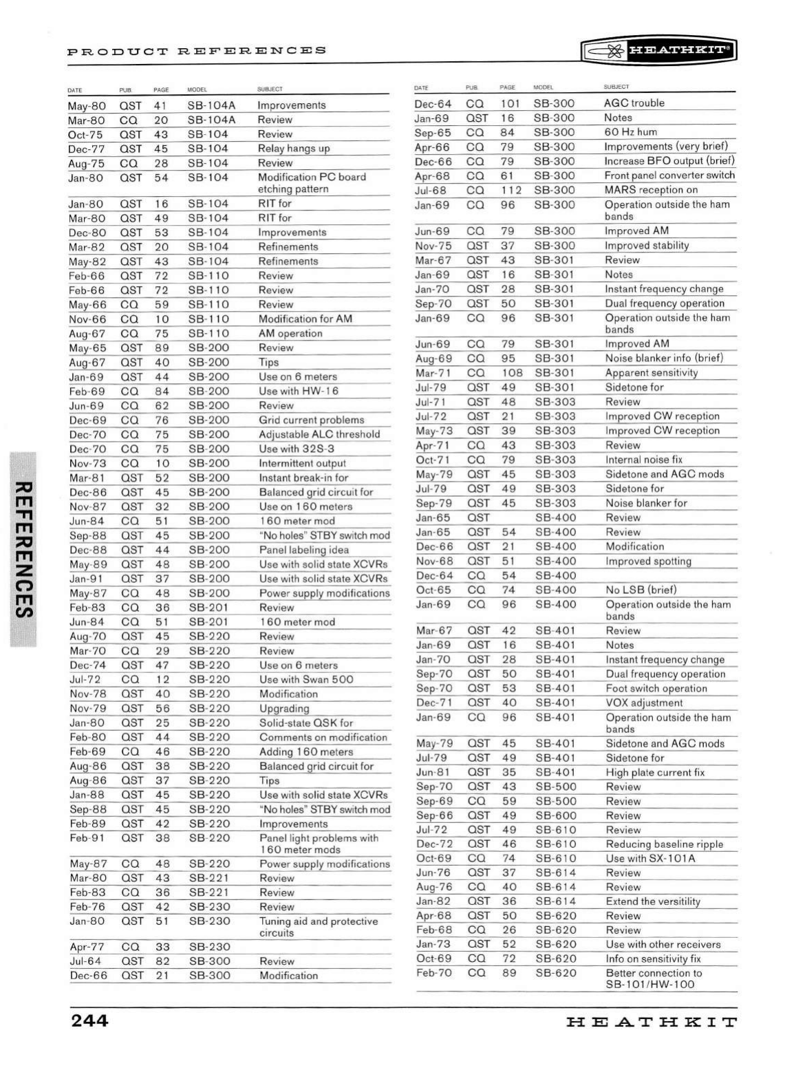
PRODUCT
REFERENCES
D
ATE
PUB PAGE MODEL
May
-80
OST
41
SB-104A
Ma
r-80
ca
20
SB-104A
Oct
-75
OST
43
SB
-
104
Dec
-77
OST
45
SB-104
Aug-
75
ca
28
SB-104
Jan-80
OST
54
SB-104
J
an-80
OST
16
SB-104
M
ar-80
OST
49
SB-104
Dec-80
OST
53
SB
-
104
Mar-
82
OST
20
SB
-
104
May-82 OST
43
SB-104
Feb-66 OST
72
SB-110
Feb-66 OST
72
SB
-
110
M
ay-66
ca
59
SB
-
110
Nov
-66
ca
10
SB
-
110
Aug-67
ca
75
SB-110
M
ay
-
65
OST
89
SB-200
Aug
-67
OST
40
SB
-
200
J
an-69
OST
44
SB-200
F
eb-69
ca
84
SB-200
Jun
-69
ca
62
SB
-
200
D
ec-69
ca
76
SB-200
Dec-
70
ca
75
SB-200
D
ec-70
ca
75
SB
-
200
Nov
-73
ca
10
SB-200
Mar-8 1
OST
52
SB-200
Dec-
86
OST
45
SB-200
Nov-
87
OST
32
SB-200
Jun-84
ca
51
SB
-
200
Sep-88
OST
45
SB-200
D
ec-88
OST
44
SB-200
M
ay-89
OST
48
SB-200
Jan-91
OST
37
SB
-
200
May-87
ca
4 8
SB-200
F
eb-83
ca
36
SB-201
Jun
-84
ca
51
SB-201
Aug-
70
OST
45
SB
-
220
Mar-
70
ca
29
SB
-
220
D
ec-74
OST
47
SB
-
220
Jul
-72
ca
12
SB-220
Nov-
78
OST
40
SB-220
N
ov-79
OST
56
SB-220
J
an
-
80
OST
25
SB-220
Feb-
80
OST
44
SB-220
Fe
b-69
ca
46
SB-220
Aug
-86
OST
38
SB-220
Aug
-86
OST
37
SB
-
220
J
an-88
OST
45
SB-220
Sep-88
OST
45
SB-220
Feb-89
OST
42
SB
-
220
Feb-91
OST
3 8
SB-220
M
ay
-
87
ca
48
SB
-
220
Mar-
80
OST
43
SB-221
F
eb-83
ca
36
SB-221
Feb-76
OST
42
SB
-
230
Jan
-80
OST
51
SB-230
Apr-7 7
ca
33
SB-230
Jul
-64
OST
82
SB-300
D
ec-66
OST
21
SB-300
244
SUBJECT
Improvements
Review
Review
Relay hangs up
Review
Modification
PC
board
etching pattern
RIT for
RIT for
Improvements
Refinements
Refinements
Review
Review
Review
Modifi
ca
tion
for
AM
AM
operation
Review
Tips
Use
on
6 meters
U
se
with
HW
- 1 6
Review
Grid current problems
Adjust
ab
le
ALC threshold
Us
e
wi
th
32S-3
Intermittent output
In
stant break-in
for
Balanced grid circuit for
U
se
on
1
60
meters
1
60
meter mod
"No holes" STBY
swi
t
ch
mod
Panel labeling idea
Use with solid state XCVRs
U
se
with solid state XCVRs
Power supply modifications
Review
1
60
meter mod
Re
v
ie
w
Review
U
se
on
6 meters
U
se
with S
wa
n
500
Modification
Upgrading
Solid-state
OSK
for
Comments
on
modification
Adding 1
60
meters
Balanced grid circuit for
Tips
U
se
with solid state XCVRs
"No
hol
es
" STBY
sw
it
ch
mod
Improvements
Panel light problems with
1
60
meter mods
Power supply modifications
Review
Revi
ew
Review
Tuning a
id
and
protective
circuits
Re
v
ie
w
M
od
ificati
on
DATE
De
c-64
Ja
n-69
Sep-65
Apr
-66
De
c-66
Apr
-68
Jul
-68
Jan-
69
Jun
-69
N
ov-75
Mar-
67
Jan-69
Jan-70
Sep-
70
Jan
-69
Jun
-69
Au
g-
69
Mar-7 1
Ju
l-79
Jul-71
Jul-
72
May-
73
Apr-
71
Oct-7 1
May-79
Jul-
79
Sep-79
Jan
-65
Jan
-65
Dec-
66
Nov-
68
De
c-64
Oct-
65
Jan
-69
Mar-
67
Jan-
69
Jan-70
Sep-
70
Sep-70
De
c-
71
Jan-69
M
ay
-
79
Jul-79
Jun-8 1
Sep-70
Sep-69
Sep-
66
Jul-72
Dec-72
Oct-
69
Jun-76
Aug-76
Jan-82
Apr-
68
Feb-68
J
an
-
73
Oct-
69
Feb-70
PUB PAGE MODEL
ca
1o1
sB-300
OST
16
SB-300
ca
84
SB
-30
0
ca
79
s B
-300
ca
79
sB
-
300
ca
61
SB-300
ca
1 1 2
sB-300
CO
96
SB
-300
ca
79
SB
-
300
OST
37
SB
-
300
OST
43
SB
-
30
1
OST
16
SB-301
OST
28
SB-301
OST
50
SB-301
ca
96
SB
-
30
1
ca
79
SB-301
ca
95
SB-
30
1
ca
108
s
B-301
OST
4 9
SB
-
30
1
OST
48
SB-
303
OST
2 1 SB
-303
OST
39
SB-
303
ca
43
s B-
303
ca
79
SB
-
303
OST
45
SB
-
303
OST
49
SB-303
OST
45
SB
-
303
OST
SB
-
400
OST
54
SB
-
400
OST
2 1
SB
-
400
OST
51
SB-
400
ca
54
s B-
400
ca
74
SB-
400
ca
96
SB-
400
OST
42
SB
-
401
OST
16
SB
-
401
OST
28
SB-
401
OST
50
SB-401
OST
53
SB
-40
1
OST
40
SB
-
401
ca
96
SB
-40
1
OST
45
SB
-
401
OST
49
SB-
401
OST
35
SB-401
OST
43
SB-500
ca
59
SB
-
500
OST
49
SB
-
600
OST
49
SB
-
610
OST
46
SB
-6
10
ca
74
SB
-
610
OST
37
SB
-6
14
ca
40
SB
-614
OST
36
SB-614
OST
50
SB
-620
ca
26
SB-620
OST
52
SB-620
ca
72
SB
-620
ca
89
SB-620
lE=~fH@f§'EiiJ
SUBJECT
AGC
trouble
Notes
60
Hz hum
Improvem
en
ts (very brief)
Increase
BFO
output (brief)
Front panel con
ve
rter
sw
itch
MARS reception
on
Operation outside the ham
bands
Improved AM
Improved stab
il
ity
Re
view
Notes
In
stant frequency change
Du
al frequency operation
Op
eration o
ut
s
id
e
th
e ham
bands
Improved
AM
Noise blanker info (brief)
Apparent sensitivity
Sidetone
for
Review
Improved
CW
reception
Improv
ed
CW
reception
Review
Internal noise fix
Sidetone a
nd
AGC
mods
Sidetone
for
Noi
se
blanker for
Review
Review
Modification
Improved spott
in
g
No
LSB
(brief)
Oper
at
ion o
ut
s
id
e the
ham
bands
Re
view
Not
es
In
stant frequency change
Dual frequency operation
Foot switch operation
VOX
ad
justment
Ope
ra
tion outside the h
am
bands
Sidetone a
nd
AGC
mods
Sidetone
for
High plate current fix
Rev
ie
w
Re
view
Review
Review
Reducing baseline ripple
U
se
wi
th
S
X-
101 A
Rev
ie
w
Re
view
E
xte
nd
the versitility
Review
Re
view
Use with other recei
ve
rs
Info on sensitivity fi x
Better connection
to
SB-101
/
HW-100
HE
.AT
HK
IT
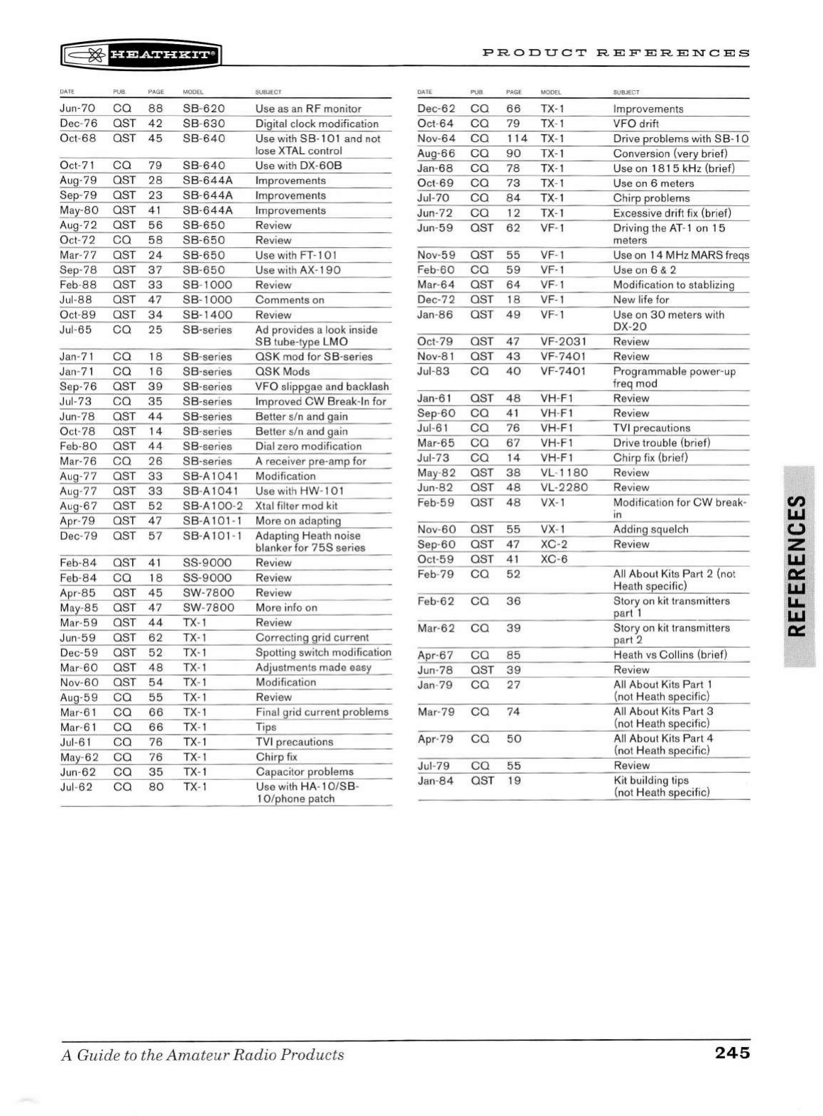
l&
~fH¥SiHH+@
DATE
PUB. PAGE MODEL
Ju
n-70
ca
88
SB
-
620
D
ec-76
OST
42
SB
-
630
O
ct-68
OST
45
SB
-
640
Oct-
71
ca
79
SB
-
640
Au
g-79
OST
28
SB-644A
Sep-79
OST
23
SB
-
644A
M
ay-80
OST
41
SB
-
644A
Au
g-
72
OST
56
SB-650
Oct-
72
ca
58
SB-650
Mar-
77
OST
24
SB-650
Sep-78
OST
37
SB-650
F
eb-88
OST
33
SB
- 1
000
Jul
-88
OST
4 7
SB
- 1
00
0
Oct-
89
OS
T
34
SB-1400
Jul-
65
CO
25
SB-series
Jan-7 1
ca
18
SB
-seri
es
Jan-7 1
ca
16 SB-series
Sep-76
OST
39
SB-series
Jul
-73
ca
35
SB-ser
i
es
Jun
-78
OST
44
SB-series
Oct-78
OST
14
SB
-series
F
eb-80
OST
44
SB-ser
ies
Mar-76
ca
26
SB
-series
Aug-77
OST
33
SB-A1041
A
ug
-
77
OST
33
SB
-A
1041
Aug-67 OST
52
SB-A
100
-2
Apr-
79
OST
47
SB-A101-1
D
ec
-
79
OST
57
SB-A101
- 1
Fe
b-84
OST
41
SS-9000
F
eb-84
ca
18
SS-9000
Apr-85
OST
45
SW-7800
May-85
OST
47
SW
-
7800
Mar-
59
OST
44
TX- 1
Jun-
59
OST
62
T
X-1
D
ec-59
OST
52
T
X-
1
Mar-60
OST
48
T
X-1
Nov-
60
OST
54
TX- 1
Aug-
59
ca
55
TX-1
Mar-6 1
ca
66
T
X-
1
Mar-61
ca
66
TX-1
Jul-6 1
ca
76
TX- 1
May-
62
ca
76
TX- 1
Jun
-62
ca
35
T
X-
1
Jul-
62
ca
80
TX- 1
SUBJECT
U
se
as
an RF monitor
Digital clock modification
U
se
with S B-101 a
nd
not
lose XTAL control
U
se
with D
X-60
B
Improvements
Impr
ovements
Improvements
R
ev
iew
Review
Use with FT-101
U
se
with AX-1
90
Review
Comments
on
Review
Ad provides a look
in
side
SB
tube-type
LMO
OSK
mod
for
SB-series
OSK
Mods
VFO slippg
ae
a
nd
b
ack
lash
Improved
CW
Break- In for
Better s/n a
nd
ga
in
Better s/n a
nd
gain
Dial zero modification
A receiver pre-amp for
Modification
U
se
with
HW
- 10 1
Xtal filter mod kit
More on adapting
Adapting Heath noi
se
blanker for 7
5S
seri
es
Review
Review
Re
view
Mor
e info
on
Review
Correc
ting gr
id
current
Spotting switch modification
Adjustments made easy
Modificati
on
Revi
ew
Final grid current problems
Tips
TVI precautions
Chirp
fix
Cap
ac
itor problems
U
se
with
HA
- 1 O/S B-
1 O/phone patch
A Guide to the
Amateur
Radio
Products
PRODUCT
REFERENCES
DATE
PUB
PAGE MODEL
Dec
-62
ca
66
T
x-
1
Oct
-64
ca
79
T
x-
1
Nov-64
ca
114
T
x-
1
Aug-66
ca
9 0 T
X-
1
Jan-6 8
ca
78
Tx
- 1
Oct
-69
ca
73
Tx-1
Jul-70
ca
8 4 T
x-
1
Jun-72
ca
12
Tx
- 1
Jun-
59
OST
62
VF-1
Nov-5 9
OST
5 5 VF- 1
Feb-
60
ca
5 9 VF-1
Mar
-64
OST
64
VF-1
De
c-72
OST
18 VF-1
Jan-86
OST
49
VF
- 1
Oct-79
OST
47
VF-2031
Nov-8 1
OST
43
VF-7401
Jul
-83
ca
40
VF-7401
Jan-61
OST
48
VH-
F1
Sep-60
ca
41
VH-
F1
Jul-61
ca
76
VH-F1
Mar-65
ca
67
VH-F1
Jul-
73
ca
14
VH-F1
May-
82
OST
38
VL-
11
80
Jun-
82
OST
48
VL-2280
F
eb-59
OST
48
VX-1
Nov-
60
OST
55
VX
- 1
Sep-
60
OST
47
XC-2
Oct-59 OST
41
XC-6
Feb-7 9
ca
52
Feb
-62
ca
36
M
ar-62
ca
39
Apr
-67
ca
8 5
Jun-78
OST
39
Jan-
79
ca
27
Mar-
79
ca
74
Apr
-79
ca
50
Jul
-79
ca
55
Jan-
84
OST
19
SUBJECT
Improvements
VFO drift
Dri
ve
problems wi
th
S
B-1
0
Conversion (very brief)
U
se
on
1 8 1 5 kHz (b
ri
ef)
U
se
on
6 meters
Chirp
problems
Excessive drift
fi
x (brief)
Driving the
AT
- 1
on
1 5
meters
U
se
on 1 4 MHz MARS freqs
U
se
on 6 & 2
Modification
to
stab
li
zing
New life for
U
se
on
30
meters with
D
X-20
Review
Review
Pr
ogra
mm
able power-up
freq mod
Review
Review
TVI precautions
Dri
ve
trouble (brief)
Chirp
fi x (brief)
Review
Re
view
Modificati
on
for
CW
break-
in
Adding squel
ch
Review
All About Kits Part 2 (not
Heath specifi
c)
Story on kit tran
sm
itters
part 1
Story
on
kit transmitters
part 2
Heath
vs
Collins (brief)
Review
All About Kits Part 1
(not Heath specifi
c)
All Ab out Kits Part 3
(not Heath specifi
c)
All About Kits Part 4
(not H
ea
th
specifi
c)
Review
Kit building tips
(not Hea
th
specifi
c)
245
Cl)
LIJ
(.)
z
LIJ
Q:::
LIJ
LL.
LIJ
Q:::
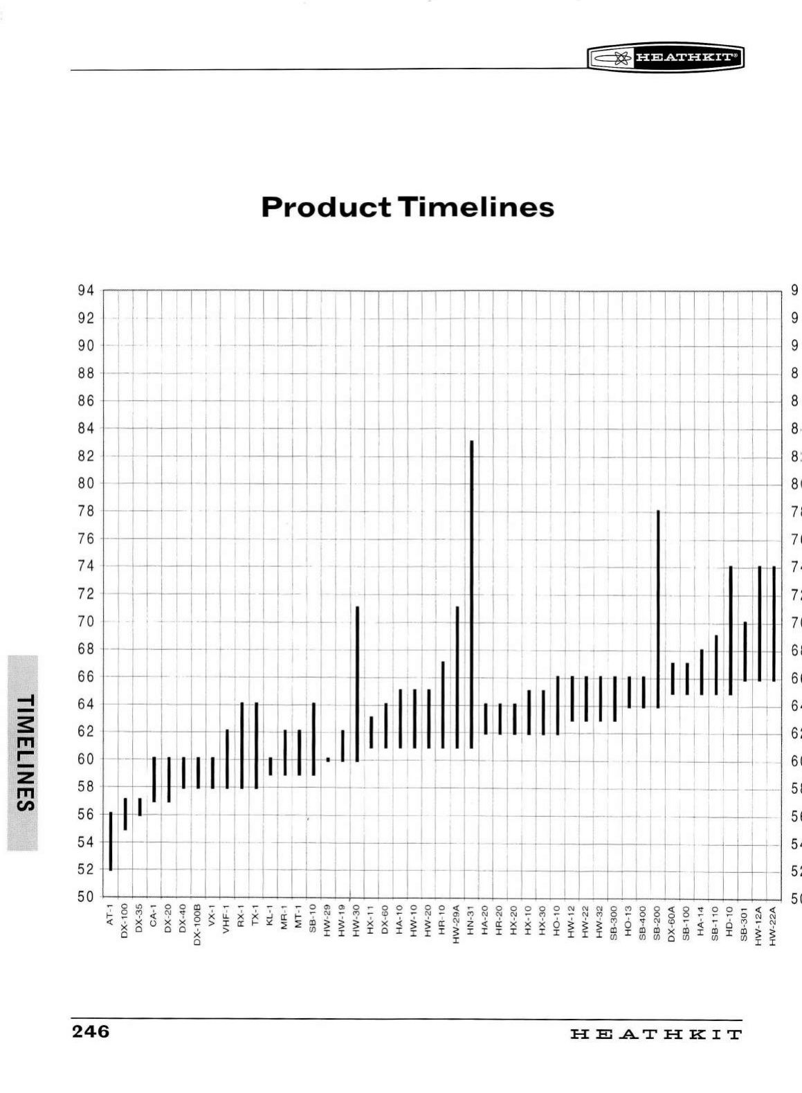
/
-t
-
s
FTI
r-
-
z
rr1
en
IE=
~f
U¥54H&+I
Product
Timelines
9 4
~
I
~
I
~
I
I
-.--
!
~
I
...,--,-1~
1
-.,.-
1
~
I
1--
~
1
t-
~
1
---,.--,-
!
--,--
:
.,..-,-
I
-,-----,..
!
-,--,----,--,.--.,-
! I I
--,-----,
I l
-.,.-
l
..,...-,-
'I
-,---,--,----,
I
--,-----,
!
--,--,
9
:~
·~
·
.
~·
.·.
i i ! .
l~t~tl11
~~t-:
I ' I
~tltui-rc
. I l ' I :
' ' I I I ' I i I ' I I I ! I I I I : !
8 8 -
--j---
' ' I I I 1
---r--t-
·
--
-
~'--4-
!
--
·
--
I i I : i .
~
-H
I I I I
I I ' I J I I I I
i I
l:
IT~
i
Ii
----:--1n·
r-li
i :
r--
-8
8 4
+
--+--+--+-
-+--+--
~
I
-+-+-+--+----+-+
,--
+
+--~+--+--+--+--___,____,11--t---1--t--t--t
i
l-+--
c-+--
\+-1
+--I
+--+--+--+--1---11-----+-----t
--t
88
·.·
8 2 ' I
t-
-
-
-~~
I I I ' I I
80
+
--
l----+-
-l!.-
+--
1--
I
:,
1'
' ' I -
u..i.1
i I I I
II
I---+--+---:
-1-------1
81
7
8 -l
--t---l----l1-1-+-
_ i I I 7
1
I I
7 6 +--+-+---+--+--+--t------+--l
I I I
7 4 -I
-+-+-!
--+--+---+----l-----+--------+---
1
--+------+----+---+
-! ' I ' I I I ' t
ltr
! :
p-1
I I 7
'
~ ~
:_
·---+-
_
_,___,j
!f---+-~1---+--iil
__
+----+-I.
I, .
---1-r-
1
~IT
l
~
-
~
t D ' ! . - . I I j w µ I
~
,11
l r
~
1·: :::
::
~;
1
'I'
1.
I I I 1 I I '
68
I -I
1-
1--~~
I :
--
I I I I • '
~
.
+-1--+
~
l
-1
~
61
: :
--+----+----+---
i -- i i I
11«1·.'
-
1
1
_~
! I
~
1:
++
j
1·
-1 ' 1· l 11 rl1 m : --. I : :
6 2 -l---+----+-+-+--+--+---+----+•-+-l
+-
l
-+--+
o+o-+-1-+--I- I : :
II
-1
---t-1-+-1
+-
l
-+-
l+
I L Ii . I I :
~
I i 6;
:~
:
l
---+-
-
~t---l
-l
·
---t-o
+
..
----1
---t-I
Jl
-l- J - 1 1
1 -
1
J
H-
·
1
:
..
JJ~
-1 J 1 1
ll
::
I i I I I I i I I
_L
' I I ; :
SE
I j I
111
!,
5 4
-+-
.+-
----ll----t---+--+--
-f----~-
--
- . - - - I I I - 5 4
-
l--t--t--l--+--t--1-----t-__,__l
-l--l-r
II-
-
~
-
----
--+--t---'----1-1
--+---1-.-------1;
-----r---+---t--t-t--
Ill-+-
---!----+----1-----1--
1 5 2
50
+--+-+-+---+--+-i-+--+--+~
:
-+-+-+-+-1---'~'-+--~'-+-
'-+---
+-4--+-+--+--+-+--+--;--+--'--+--L-L---f--+--+-l--l-~
50
86
8
·
'-------'--1-----1---
I 7 l
5 6
~J
--+--
J
-+---+----
11
---
5 2 -- •
-t---t---+-----+
----+---I
---
246
HEATHKIT
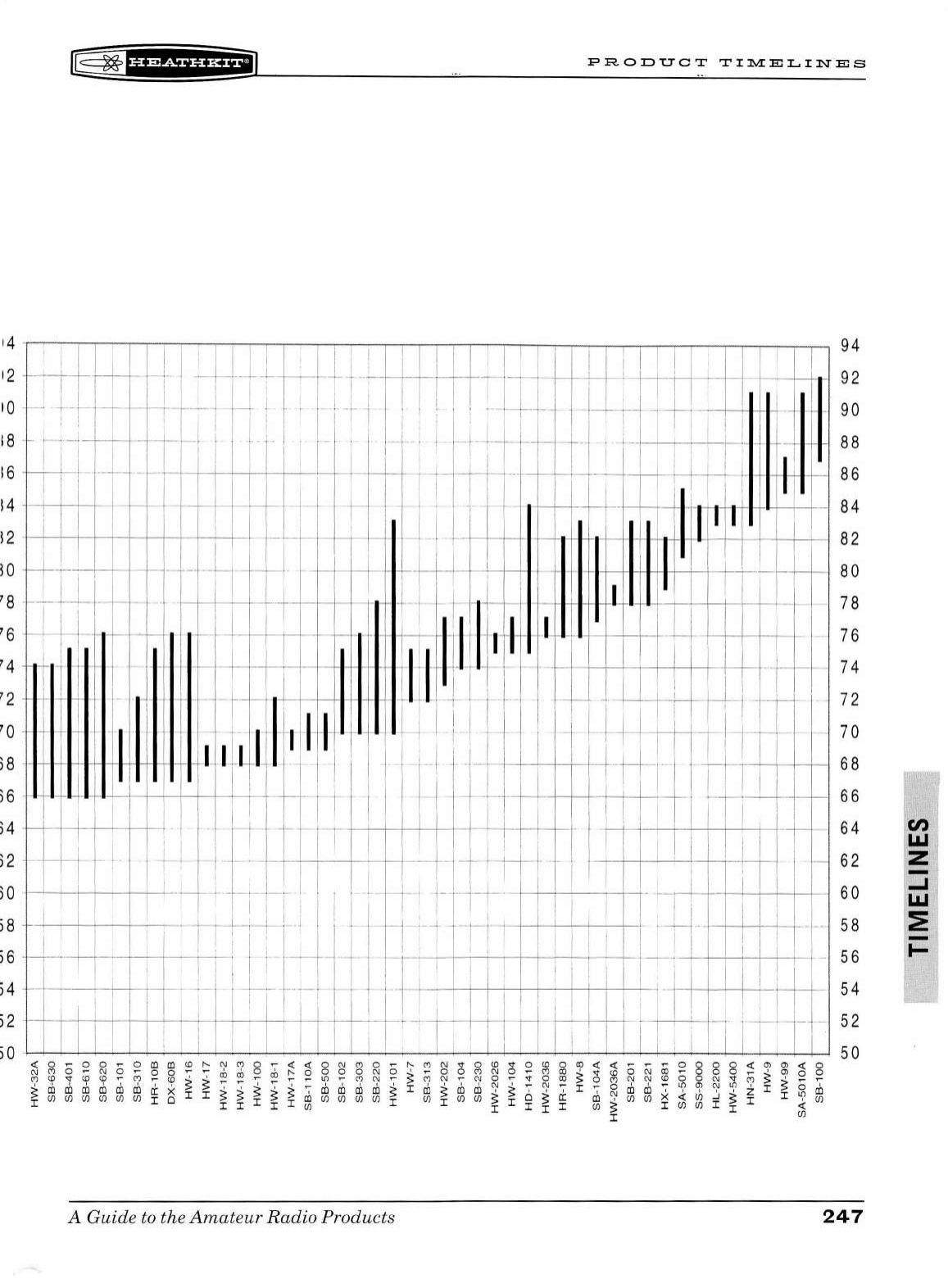
r§
~f§ffSfi'HfiJ
PRODUCT
TIJY.I:ELINES
14 I
94
•2
i I u
W-J
I I lE_+
11
ttl
i
ffi'
!J
lJ+!
I : I
11
92
10
_ J J i
L-~
1
_J_
j _ i
__
I
-i-
i : , ! 1 : _ _ ,
__
I
~l+.,
1
r . _
90
! I I .
I'
I I . I 1
LU
18
!11
11
I I I . I - I 1
-Hi
:
tt1
I I I I I
~-
T
88
: : I ' I I ' .
[IJ
! I I I i ! l ' I : i ::
i I ! ;
JJ
I I I I 11 I
12
. ! I L I
-·
• I - I 82
'.~
~
i-
' -
-:
1-i~
:
+-r
I
~
-I 11 I ' ' i . .
~~
' 6 I I I
·-
· - I I l -I I
~
I i I
I-
7 6
7 4 I I I I ! I I i
t-
~
~
7 4
7 2 I
e=-l
·-1-~-,--
-
1!
!,I.
,11
~-
--rr_
-7 2
7 0 - - - . + ---H,- I I I -
I~
. I f I
tt
-
f-t-1
~
1-
- - 7 0
)
:
86
11
L
~
,
-I 1
11
i -
_,
!
_._
. I I r M T r
tt
I 6 8
~
:i4
I I .
-1-
i---1
~
ITI
I I I
66
~2
! :
I.
-
ii
-11 I ' I I .
rn
I I I I I I
..
. , --
64
, I
·-··
·
1~+
..
I I i . - ' ' I -
62
60
I i ! i ,
·r+-"
I i i .
11
ir
+ , i : i -
+-r-
i , ,
60
58 - :
II
1:·
1TI-~~
1
-
1
l,L
-r;
1
ni
1
!1i
1 •1
-li
I!.
--
S8
5 6 -1 I I , , ! I I
1:--
.
r-
-·--
-I I I . I
i.
I I i .
-1.·
i I
1,.
i·
-5 6
54
' . I I I I I I I '
54
I i I 1
-
..
-,1
T r !
,--
-i-i~-1
1 I 1
1 I · I 1 . i - 1 : . ; 1
I ! I i : I I i I I I I I I I I ! : I I i I I 1-
1-,
--
--
5
2
52
50
50
~
0
~
0 0
~
0 m m
~ ~
N M 0 ~ ~
~
0 N M 0 ~
~
M N v 0
~
v 0
~
0
ro
~ ~
~
~
~ 0 0 0 0
~
m m
~
0
~ ~ ~
m
~ ~
M
~
g
~ ~ ~ ~ ~ ~
~
~ ~ ~
g
~
~ ~
M
~ ~ ~ ~ ~
; 8
~ ~ ~
~
~ ~ ~
0 8
~
~ ~
~
~ ~
~
~
ro ro ro ro ro ro
~
x
~ ~
> >
~
>
~ ~
ro
ro ro
ro
~
r
ro
~
ro
ro
~
~
~
~
~
r
~
~
ro ro
~
~ ~ ~ ~
z r
~ ~
ro
I
(/)
(/)
(/) (/) (/) (/)
I 0 > > I > I m
(/)
(/) (/) (/)
I
(/)
I
(/)
(/)
~
I 0
~
~
m >
(/)
(/)
x
~
~
~I
~
I '
(/)
I I I
<JJ
I I I I
<JJ
> I
<JJ
v,
I
~
I
<JJ
A Guide to the A
mateur
Radio Products
247
Cl)
I.LI
z
...J
I.LI
:E
I-
r
l®~fdi&i¥'Hii1
248
HEATHKIT

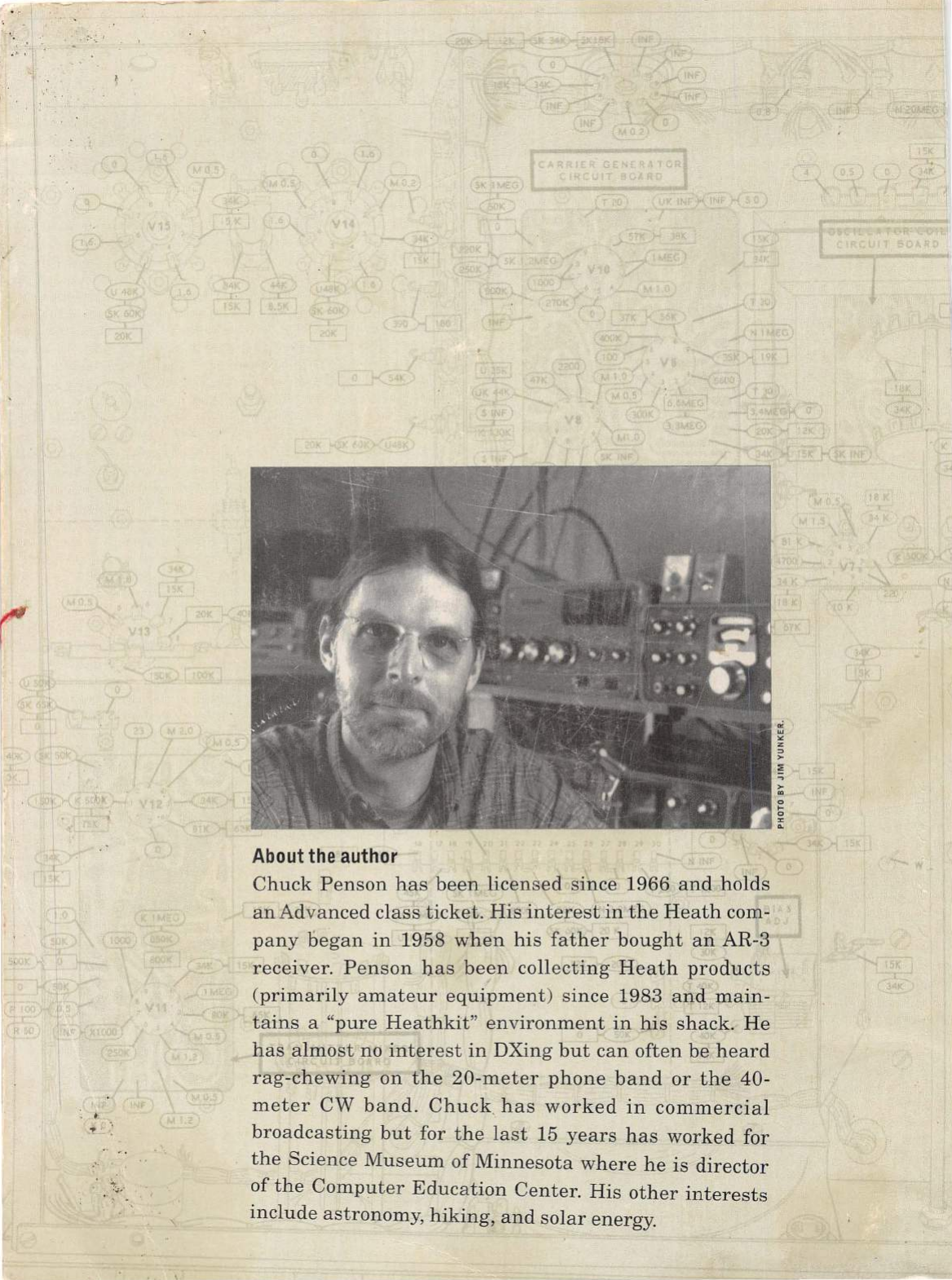
; .
.
>.:
'
. '
About
the
author
Chuck
Penson
has
been
licensed
since
1966
and
holds
an
Advanced
class
ticket.
His
interest
in
the
Heath
com-
pany
began
in
1958
when
his
father
bought
an
AR
-3
receiver.
Penson
has
been
collecting
Heath
products
(primarily
amateur
equipment)
since
1983
and
main-
tains
a
"pure
Heathkit"
environment
in
his
shack.
He
has
almost
no
interest
in
DXing
but
can
often
be
heard
rag
-che
wing
on
the
20-meter
phone
band
or
the
40-
meter
CW
band.
Chuck
has
worked
in
commercial
broadcasting
but
for
the
last
15
years
has
worked
for
the
Science
Museum
of
Minnesota
where
he
is
director
of
the
Computer
Education
Center.
His
other
interests
include
astronomy,
hiking,
and
solar
energy.
