Hoja De Datos Administrador Flujo Flo Boss 107
Hoja-de-Datos_FloBos.. Hoja-de-Datos_FloBoss-107-Flow-Manager
User Manual: Hoja-de-Datos Administrador-de-Flujo-FloBoss-107
Open the PDF directly: View PDF ![]() .
.
Page Count: 9
FB107 Product Data Sheet
D301233X012 October 2014
Remote Automation Solutions
FloBoss™ 107 Flow Manager
The FloBoss™ 107 Flow Manager (FB107) is a microprocessor-
based controller that monitors, measures, and controls
equipment in a remote environment. Designed for
expandability, the FB107 provides the functions required for a
variety of field automation applications. You can use the FB107
for:
Applications requiring flow computation.
Control applications.
o Proportional, Integral, and Derivative (PID) control
loops.
o Logic sequencing control using Function Sequence
Tables (FSTs).
o IEC-61131 programmed applications.
Custom applications for measurement, communications,
and control.
For detailed firmware capabilities, see Product Data Sheet
FB107:FW1.
The FB107 is capable of measuring up to four meter runs
through a variety of differential and linear meters. Meter inputs
can utilize analog or digital transmitters, pulse inputs, or
modbus variables. You can add an optional Multi-Variable Sensor
(MVS) module to provide an interface to remote MVS
transmitters for multiple run applications.
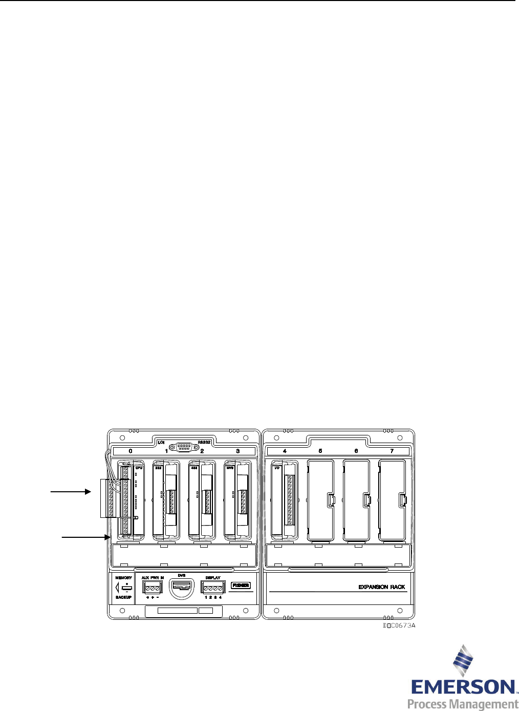
The FB107 has four slots on the main unit with four additional
slots on the optional expansion rack. Slot 0 is for the central
processing unit (CPU) module, which includes three
communication ports, a resistance temperature detector (RTD)
input, power input, and loop output power. Optionally, the
CPU module can include a 6-point configurable I/O assembly.
Slots 1 and 2 on the main unit can contain communication
modules. Slots 1, 2, and 3 on the main unit and slots 4, 5, 6,
and 7 on the optional expansion rack can contain
input/output (I/O), MVS, and application modules.
Use ROCLINK™ 800 Configuration Software to configure the
FB107, extract data, and monitor its operation.
The FB107 has the following features:
Capable of measurement for differential pressure
elements and linear meter applications.
Expandable I/O – Six points on the optional CPU I/O
assembly and up to six I/O modules (with expansion rack).
Configurable operating speed to optimize low power
consumption.
Standard and extended history archiving.
Field-side surge and short-circuit protection.
Local storage of monitored, measured, and calculated
data.
Local control of field equipment, including valves and
motors.
Local and remote communication capabilities.
High levels of data security.
Battery backed memory and data configuration.
WirelessHART™ support
FloBoss 107 with optional Expansion Rack
CPU I/O
Assembly
(optional)
CPU
Module

FB107 October 2014
2 www.EmersonProcess.com/Remote
Hardware
Extensive use of the latest technology in short-circuit
protection reduces the need for fuses on the I/O,
application, MVS, and communications modules and
decreases maintenance calls.
The FB107 is available with an isolated CPU. Isolation occurs
between the CPU and the field logic. Four CPU options are
available for the FB107:
Non-isolated CPU with I/O
Non-isolated CPU without I/O
Isolated CPU with I/O
Isolated CPU without I/O
The FB107’s backplane provides connections for the CPU,
I/O, MVS, application, and communication modules. You
can add an expansion rack to increase I/O by four slots. The
FB107 can have up to six optional I/O cards.
The CPU module is located in slot 0 of the main FB107 unit.
An LED (light-emitting diode) indicator on the CPU shows
the device power status.
You can configure the I/O on the optional CPU I/O assembly
to set the loop output power to 10 volts dc or 24 volts dc.
I/O modules support 24 volts dc loop output power.
The intent of the 24 volts dc loop output power is to power
external devices that require 24 volts dc to ground. This
allows the external device to send the FB107 a 4 to 20 mA
signal based on pressure, temperature, or level.
The 10 volts dc loop output power is intended for low-power
transmitters. The loop current is designed to deliver 80 mA
to power field devices that connect back to the two analog
inputs as 1 to 5 volts dc signals.
The resistance temperature detector (RTD) measures the
flowing temperature. The RTD wires connect directly to the
RTD connector on the CPU.
Using ROCLINK 800 software, you can write licenses to the
FB107, providing extended functionality, such as the use of
various user programs.
Memory
The FB107 has three types of memory:
Boot Flash – System initialization and diagnostics.
Flash ROM (Read-Only Memory) – Firmware image.
SRAM (Static Random Access Memory) – Data Logs and
configuration.
Communications
The FB107 supports up to four communication ports. The
CPU module has three built-in communication ports:
Local Operator Interface (RS-232) – LOI for
asynchronous serial communication.
EIA-485 (RS-485) – COM1 for asynchronous serial
communication.
EIA-232 (RS-232) – COM2 for serial communication.
The Local Operator Interface (LOI) port’s DB9 connector
provides an EIA-232 (RS-232) link between the FB107 and a
personal computer.
LEDs display the RX (receive) and TX (transmit) signals for
the LOI and COM2 ports on the CPU module. LEDs display
the transmit (A) and receive (B) signals for the COM1 port on
the CPU module.
The FB107 supports communication protocols, including
ROC protocol and Modbus protocol. A FB107 can act as a
Modbus slave device (ASCII or RTU) or it can function as a
Modbus host on COM1 on the CPU module, COM2 on the
CPU module, slot 1 of the device, and slot 2 of the device.
You can install an optional communication module in slot 1
or 2 on the main FB107. When a communication module is
installed in slot 2, the communications port (COM2) on the
CPU is redirected to this module. Optional communication
modules include an EIA-232 (RS-232) module, EIA-485 (RS-
485) module, dial-up modem module, Enhanced
Communication Module (ECM module) with USB and
Ethernet ports, IEC 62591 Interface Module, and the
Network Radio Module.
The EIA-232 (RS-232) module provides point-to-point
asynchronous serial communications. EIA-232 (RS-232)
communications provide the physical interface for
connecting serial devices, such as gas chromatographs and
radios. For more information, refer to Product Data Sheet
FB107:COM.
The EIA-485 (RS-485) module provides asynchronous serial
communications for multi-drop units on a serial network
over long distances using inexpensive twisted-pair cables.
For more information, refer to Product Data Sheet
FB107:COM.
The Dial-up Modem module provides communication over a
Public-Switched Telephone Network (PSTN) at up to 2400
bits per second (bps). For more information, refer to Product
Data Sheet FB107:DIAL.
The Enhanced Communication Module (ECM module)
provides communications over one four-session Ethernet
port and one Universal Serial Bus (USB) 2.0 port. For more
information, refer to Product Data Sheet FB107:ECM.
The Network Radio Module (NRM) provides a wireless
solution for importing and/or exporting over-the-air
messages and information. For more information, refer to
Product Data Sheet FB107:NRM.

October 2014 FB107
www.EmersonProcess.com/Remote 3
Inputs and Outputs
You can install optional I/O modules in slots 1 through 3 on
the main FB107 and in slots 4 through 6 on the expansion
rack. You can install an optional I/O module in slot 7 on the
expansion rack when a module other than I/O is installed in
slot 1 on the main FB107.
The 6-point I/O assembly that installs on the CPU module
and the 6-point I/O module provide the same selections for
I/O. Five of the six points of I/O are software-selectable. The
six points of I/O consist of:
Two analog inputs or discrete inputs.
One analog output or discrete output.
One discrete output.
Two pulse inputs or discrete inputs.
You can use analog current inputs of 4 to 20 mA when the
250-ohm resistor is selected in the AI configuration using
ROCLINK 800 software.
The 8-point AI/DI module adds eight user-selectable analog
input or discrete input channels to the FB107. For more
information, refer to Product Data Sheet FB107:AIDI.
The 6-point AO/DO module adds six user-selectable analog
output or discrete output channels to the FB107. For more
information, refer to Product Data Sheet FB107:AODO.
The Discrete Output Relay module adds six channels of
discrete outputs to the FB107. For more information, refer
to Product Data Sheet FB107:DOR.
The Resistance Temperature Detector (RTD) module adds
three channels with the ability to monitor various RTD
sensors. For more information, refer to Product Data Sheet
FB107:RTD.
I/O Interfaces
The Application module is preloaded with a specific
application and has a RS-485 communications port. The
module provides a way to add programs to the FB107 by
simply installing a module that includes all point type
information and screens required by the application. For
more information, refer to Product Data Sheet FB107:APP.
The HART® (Highway Addressable Remote Transducer)
module allows the FB107 to communicate with HART
devices using the HART protocol. For more information,
refer to Product Data Sheet FB107:HART.
An Multi-Variable Sensor (MVS) module can interface with
up to six MVS transmitters on up to four meter runs. You can
install the MVS module in slots 1 through 3 on the main
FB107 and in slots 4 through 7 on the expansion rack,
regardless of the position of any other type of module. For
more information, refer to Product Data Sheet FB107:MVS.
A Dual-Variable Sensor (DVS) can be used to measure
differential and static pressure if the FB107 is mounted in a
FloBoss 107E enclosure. For more information, refer to
Technical Specification DVS205.
A Pressure Module (PM) can be used to measure up to two
pressure inputs if the FB107 is mounted in a FloBoss 107E
enclosure. For more information, refer to Product Data Sheet
FB107:ENC.
IEC 62591 Interface Module which connects to the Smart
Wireless Field Link for radio connection to the
WirelessHART™ field devices. For more information, refer to
Product Data Sheet FB107:62591.
Enclosures
A steel enclosure and a polycarbonate enclosure are
available for the FB107. Refer to Product Data Sheet
FB107:ENC for more information about the available
enclosures.
Measurement Canada
Measurement Canada approval is available on the FB107.
The Measurement Canada version of the FB107 consists of a
four-slot FB107 running Measurement Canada firmware and
housed in a polycarbonate enclosure (without an external
LOI port) with an LCD Touchpad (view only). For more
information on the firmware, refer to Product Data Sheet
FB107:FW1. For more information on the polycarbonate
enclosure, refer to Product Data Sheet FB107:ENC.
Note: Analog inputs on the 6-point I/O CPU assembly and
on the 6-point I/O module may not be used as AGA
measurement inputs for Measurement Canada.

FB107 October 2014
4 www.EmersonProcess.com/Remote
FloBoss 107 Flow Manager
CPU Module
Processor 32-bit Renesas HD64F2378 processor with selectable clock rates of 29.4 Mhz, 14.7 Mhz and
3.7 Mhz.
Clock Type Real Time. Year/Month/Day and Hour/Minute/ Second. Backed up by
the battery on the backplane and the super capacitor in the CPU
module.
Clock Accuracy Within 13 seconds per month at –20°C to 70°C (–4°F to 158°F).
Diagnostics These conditions are monitored and alarmed: RTD point fail, module integrity, logic voltage,
battery voltage, charge in, and battery temperature.
Isolation (optional) 1500 Vdc
Light-Emitting Diodes (LEDs) PWR: Indicates power is applied properly to the FB107.
Tx Indicates if the FB107 is transmitting through an EIA-232 (RS-232)
communication port.
Rx Indicates if the FB107 is receiving through an EIA-232 (RS-232)
communication port.
A Indicates transmit status through an EIA-485 (RS-485) communication
port.
B Indicates receive status through an EIA-485 (RS-485) communication
port.
Communications
Ports on CPU module LOI (Local Operator
Interface)
EIA-232 (RS-232) format. Software configurable, 300 to 115.2K bps
rate selectable. DB9 connection.
485 (COM1) EIA-485 (RS-485) 300 to 115.2 K bps rate, serial interface. Standard for
differential data transmission over distances of up to 1220 m (4000 ft).
COM2 (232) EIA-232 (RS-232) 300 to 115.2 K bps rate, host serial interface.
Standard for single-ended data transmission over distances of up to 15
m (50 ft).
Communication Modules
(optional)
EIA-232 (RS232) For more information, refer to Product Data Sheet FB107:COM.
EIA-485 (RS-485) For more information, refer to Product Data Sheet FB107:COM.
Dial-up Modem
Module
Provides communication over a Public-Switched Telephone Network
(PSTN) at up to 2400 bits per second (bps). For more information, refer
to Product Data Sheet FB107:DIAL.
Enhanced
Communication
Module
Provides communications over one four-session Ethernet port and one
Universal Serial Bus (USB) 2.0 port. For more information, refer to
Product Data Sheet FB107:ECM.
Network Radio
Module (NRM)
Provides a wireless solution for importing and/or exporting over-the-air
messages and information. For more information, refer to Product Data
Sheet FB107:NRM
Protocols ROC or Modbus slave (ASCII or RTU) on all ports. Modbus host using COM1 or COM2 port on
the CPU module or optional communication module installed in slot 1 or slot 2.
Inputs/Outputs
RTD Input on CPU module Quantity 1
Type 3 or 4-wire RTD 100Ω platinum element with alpha of 0.00385.

October 2014 FB107
www.EmersonProcess.com/Remote 5
Terminals “SCR” current source, “RTD+” signal positive input, “RTD−” signal
negative input, and “GND” negative ground return reference.
Sensing Range1 –40 to 240°C (–40 to 464°F) (default).
Accuracy1 ±0.2°C (0.64°F) over sensing range (includes linearity, hysteresis,
repeatability).
Ambient
Temperature
Effects per 28°C
(50°F)
±0.50°C (0.90°F) for process temperatures from
–40 to 240°C (–40 to 464°F).
Filter Band-pass hardware filter
Resolution 16 bits
Sample Period 1 second minimum
1
The accuracy depends on the span calibrated for the sensing range of the RTD Input. The
sensing range is the difference between the calibrated zero and calibrated span. The
sensing range may be changed from the defaults during calibration. When the sensing
range is less than or equal to 300°C, the accuracy is 0.2°C. When the sensing range is
greater than 300°C, the accuracy is 0.5°C. Sensing range limits are –40 to 800°C.
6-Point I/O CPU Assembly
(optional)
Two analog inputs or discrete inputs.
One analog output or discrete output.
One discrete output.
Two pulse inputs or discrete inputs.
For more information, refer to Product Data Sheet FB107:IO1.
I/O Modules (optional) 6-Point I/O Module Two analog inputs or discrete inputs.
One analog output or discrete output.
One discrete output.
Two pulse inputs or discrete inputs.
For more information, refer to Product Data Sheet FB107:IO1.
8-Point AI/DI
Module
Eight analog inputs or discrete inputs. For more information, refer to
Product Data Sheet FB107:AIDI.
6-Point AO/DO
Module
Six analog output or discrete outputs. For more information, refer to
Product Data Sheet FB107:AODO.
Discrete Output
Relay Module
Six channel discrete outputs. For more information, refer to Product
Data Sheet FB107:DOR.
Resistive
Temperature
Device (RTD)
Module
Three channels for measuring the resistance of 2-wire, 3-wire, or 4-
wire, 100-ohm, platinum RTD sensors. For more information, refer to
Product Data Sheet FB107:RTD.
I/O Interfaces (optional) Application
Module
Module preloaded with a specific application and RS-485
communications port. The module provides a way to add programs to
the FB107 by simply installing a module that includes all point types
and screens that are part of the application. For more information,
refer to Product Data Sheet FB107:APP.
Dual-Variable
Sensor (DVS)
A DVS can be used to if the FB107 is mounted in a FloBoss 107E
enclosure. For more information, refer to Technical Specification
DVS205.
HART Module Four software-selectable input/output channels. For more information,
refer to Product Data Sheet s FB107:HART.
IEC 62591
(WirelessHART)
Interface Module
Supports up to 20 WirelessHART field devices. Provides both process
variables and diagnostic data to the FB107 and supports HART Pass-
Through to AMS Device Manager. For more information, refer to
Product Data Sheet FB107:62591.

FB107 October 2014
6 www.EmersonProcess.com/Remote
Multi-Variable
Sensor (MVS)
Module
One MVS interface with up to six transmitters. For more information,
refer to Product Data Sheet FB107:MVS.
Pressure Module
(PM)
A PM can be used to measure up to two pressure inputs if the FB107 is
mounted in a FloBoss 107E enclosure. For more information, refer to
Product Data Sheet FB107:ENC.
Power
External Power Charging Input 8 to 30 Vdc, 3 A max, 33 W max, reverse polarity protection
Input Power Without CPU isolation and
no I/O
280 mW
Without CPU isolation, 6-
I/O points, and Loop
Output Power @ 80 mA
3.5 W
With CPU isolation and no
I/O
490 mW
With CPU isolation, 6-I/O
points, and Loop Output
Power @ 80 mA
4.1 W
With LCD Touchpad
Display
100 mW standby
Backplane 65 mW
Loop Output Power
(on CPU module)
80 mA maximum @ 24 or 10 Vdc
Physical
Dimensions Base 204 mm H by 153 mm W by 140 mm D
(8 in. H by 6 in. W by 5.5 in. D)
Base plus
Expansion Rack
204 mm H by 306 mm W by 140 mm D
(8 in. H by 12 in. W by 5.5 in. D)
Weight Base with CPU
module
0.76 Kg (1.68 lbs)
Expansion Rack
(empty)
0.42 Kg (0.93 lbs)
Wiring 16 to 24 AWG at the removable terminal block.
Enclosure (optional) Refer to Product Data Sheet FB107:ENC for available enclosures.
Environmental
Operating Temp –40 to 75°C (–40 to 167°F)
Storage Temp –50 to 85°C (–58 to 185°F)
Operating Humidity 5 to 95%, non-condensing
Radiated Emissions Meets FCC Part 15, Class A
Vibration Tested to ISA 75.13 1996 with an abbreviated endurance dwell test.
October 2014 FB107
www.EmersonProcess.com/Remote 7
Approvals
Product Markings for Hazardous
Locations
CSA C/US Certified by CSA as Model W40155 (enclosure not supplied),
Model W40168 (FB107E steel enclosure), and
Model W40184 (FB107E polycarbonate enclosure)
Class I, Division 2, Groups A, B, C, & D
Evaluated per
Approval
Standards
CAN/CSA C22.2 No. 0-M91 (R2001)
CAN/CSA C22.2 No. 94-M91
CSA C22.2 No. 142-M1987
CSA C22.2 No. 213-M1987
UL Std. No. 50, September 4, 2007
UL Std. No. 916, December 23, 1998
UL Std. No. 1604, April 28, 1994
ANSI/ISA 12.27.01-2003
CE Marked Certified by Sira as Model W40190.
ATEX Cert Sira 10ATEX4059X
IECEx Cert IECEx SIR 10.0028X
Product Markings for Hazardous Locations:
Ex nA IIC T4 Gc, –40°C ≤ Tamb ≤ 75°C
II 3 G.
Evaluated per
Approval
Standards
ATEX:
EN 60079-0 (2006 & 2007 ed 5)
EN 60079-15 (2005 ed 3)
EMC:
EMC Directive 2004/108/EC
EN61000-4-2 (Electrostatic Discharge)
EN61000-4-3 (Radiated Immunity)
EN61000-4-4 (Fast Transients)
EN61000-4-5 (Surges)
EN61000-4-6 (Conducted RF)
EN 55011 (Class B Emissions)
IECEx:
IEC 60079-0 (2007-10 ed 5)
IEC 60079-15 (2005-03 ed 3)
Australian C-Tick Certified as Model W40190
Product Markings for Metrology Measurement
(Industry) Canada
Approved as Model W40184 (FB107E polycarbonate enclosure with no
flow sensor attached)
Approval No.: AG-0590C
AGA8 (1992) Detail
AGA8 (1992) Gross Method 1
AGA8 (1992) Gross Method 2
AGA7 Turbine meter
AGA3 (1992) Orifice meter
Notes:
Analog inputs on the 6-point I/O CPU assembly and on the 6-
point I/O module may
not
be used as AGA measurement
inputs.

FB107 October 2014
8 www.EmersonProcess.com/Remote
Miscellaneous Approvals Spectrum
Approval for the
Network Radio
Module
USA, Canada, Australia, New Zealand
GOST GOST-R Certificate Ex naL IIC T4
INMETRO Certified by INMETRO as Model W40190
NCC 12.1097 X
Marking: Ex nA IIC T4 (-40°C ≤ Tamb ≤ 75°C) Gc
Special conditions for safe use: As described in the certificate of
conformity for the product.
Nederlands
Meetinstituut
(NMi)
ISO 5167-2:2003 (Orifice plates)
AGA3:1992 (Orifice metering in natural gas)
AGA7 (Turbine meter)
AGA8-DC92 (Gas compressibility)
ISO 6976 (Gas characteristics)

October 2014 FB107
Headquarters:
Emerson Process Management
Remote Automation Solutions
6005 Rogerdale Road
Houston, TX 77072 U.S.A.
T +1 281 879 2699 | F +1 281 988 4445
www.EmersonProcess.com/Remote
© 2006-2014 Remote Automation Solutions, a business unit of Emerson Process Management.
All rights reserved.
Emerson Process Management Ltd, Remote Automation Solutions (UK), is a wholly owned
subsidiary of Emerson Electric Co. doing business as Remote Automation Solutions, a business
unit of Emerson Process Management. FloBoss, ROCLINK, ControlWave, Helicoid, and
OpenEnterprise are trademarks of Remote Automation Solutions. AMS, PlantWeb, and the
PlantWeb logo are marks owned by one of the companies in the Emerson Process Management
business unit of Emerson Electric Co. Emerson Process Management, Emerson and the Emerson
logo are trademarks and service marks of the Emerson Electric Co. All other marks are property
of their respective owners.
The contents of this publication are presented for informational purposes only. While every
effort has been made to ensure informational accuracy, they are not to be construed as
warranties or guarantees, express or implied, regarding the products or services described herein
or their use or applicability. Remote Automation Solutions reserves the right to modify or
improve the designs or specifications of such products at any time without notice. All sales are
governed by Remote Automation Solutions’ terms and conditions which are available upon
request. Remote Automation Solutions does not assume responsibility for the selection, use or
maintenance of any product. Responsibility for proper selection, use and maintenance of any
Remote Automation Solutions product remains solely with the purchaser and end-user.
Europe:
Emerson Process Management
Remote Automation Solutions
Unit 8, Waterfront Business Park
Dudley Road, Brierly Hill
Dudley UK DY5 1LX
T +44 1384 487200 | F +44 1384 487258
www.EmersonProcess.com/Remote
North American/Latin America:
Emerson Process Management
Remote Automation Solutions
6005 Rogerdale Road
Houston TX USA 77072
T +1 281 879 2699 | F +1 281 988 4445
www.EmersonProcess.com/Remote
Middle East/Africa:
Emerson Process Management
Remote Automation Solutions
Emerson FZE
P.O. Box 17033
Jebel Ali Free Zone – South 2
Dubai U.A.E.
T +971 4 8118100 | F +971 4 8865465
www.EmersonProcess.com/Remote
Asia-Pacific:
Emerson Process Management
Remote Automation Solutions
1 Pandan Crescent
Singapore 128461
T +65 6777 8211| F +65 6777 0947
www.EmersonProcess.com/Remote
Remote Automation Solutions
