Honda 400ex
User Manual: Honda 400ex
Open the PDF directly: View PDF ![]() .
.
Page Count: 263 [warning: Documents this large are best viewed by clicking the View PDF Link!]
- Cover
- Contents
- 1. General Info
- 2. Frame/ Body Panels/ Exhaust
- 3. Maintenance
- 4- Lubrication System
- 5- Fuel System
- 6- Engine Removal/ Installation
- 7- Cylinder Head/ Valve
- 8- Cylinder/ Piston
- 9- Clutch/ Gearshift Linkage
- 10. Alternator/ Starter Clutch
- 11. Crankcase/ Tranny/ Crankshaft
- 12. Front wheel/ suspension/ steering
- 13. Rear WHEEL/SUSPENSION
- 14. HYDRAULIC DISC BRAKE
- 15. BATTERY/CHARGINGSYSTEM
- 16. IGNITION SYSTEM
- 17. ELECTRIC STARTER
- 18. LIGHTS/SWITCHES
- 19. Wiring Diagrams
- 20. Trouble Shooting
- 21. Index
~
HOW
TO
USE
THIS
MANUAL
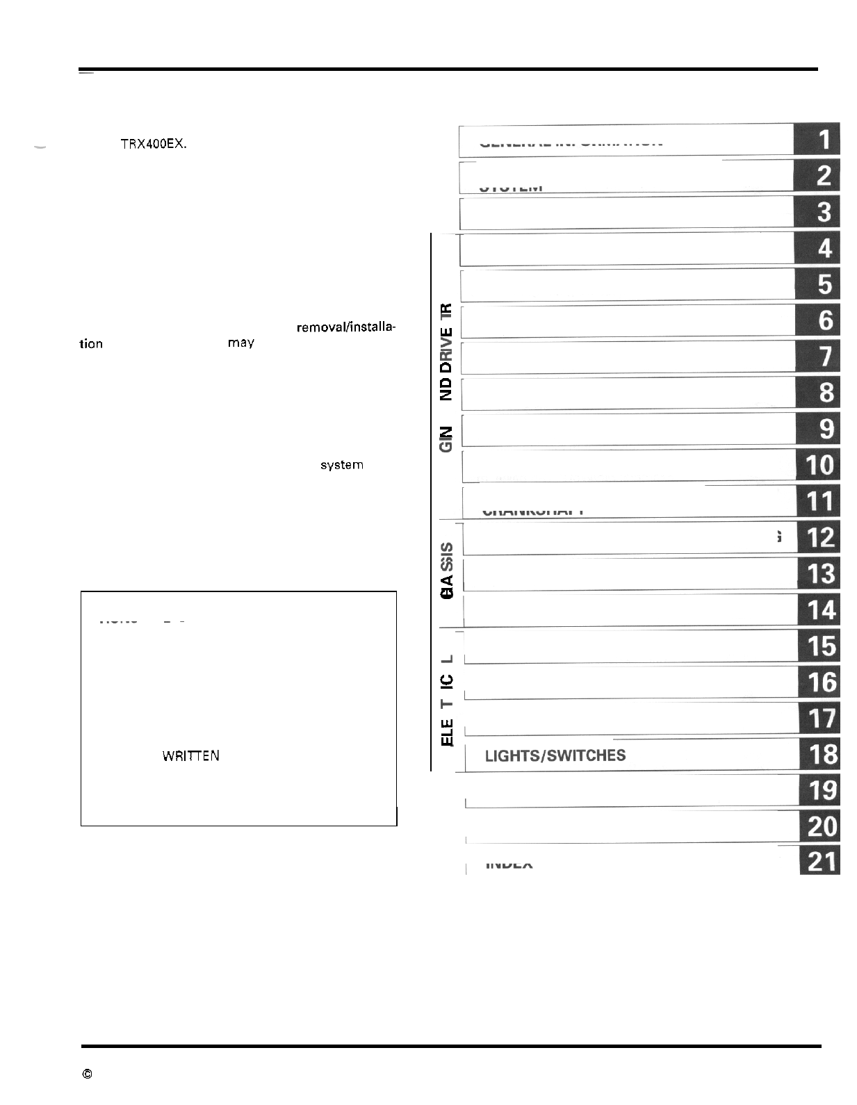
This service manual describes the service procedures
-
for the
TRX400EX.
Follow the Maintenance Schedule (Section
3)
recom
-
mendations
to
ensure that the vehicle is
in
peak oper
-
ating condition and the emission levels are within the
standards
set
by the California Air Resources Board.
Performing the first scheduled maintenance
is
very
important.
It
compensates for the initial wear
that
occurs during the break
-
in period.
Sections
1
and
3
apply to the whole motorcycle.
Section
2
describes procedures for removalfinstalla-
tion of components that may be required to perform
service described in the following sections.
Sections
4
through
18
describe parts
of
the motorcy
-
cle, grouped according to location.
Find the section you want
on
this page, then turn to
the table of contents on the first page of the section.
Most sections start with an assembly or system illus
-
tration, service information and troubleshooting for
the section. The subsequent pages give detailed pro
-
cedures.
If
you don't know the source of the trouble, go to sec
-
tion
20,
Troubleshooting.
.
-
ALL INFORMATION, ILLUSTRATIONS, DIREC
-
TIONS AND SPECIFICATIONS INCLUDED
IN
....
~ ~
THIS PUBLICATION ARE BASED ON THE LAT
-
EST PRODUCT INFORMATION AVAILABLE AT
THE TIME OF APPROVAL FOR PRINTING.
HONDA MOTOR
CO.,
LTD. RESERVES THE
RIGHT TO MAKE CHANGES AT ANY TIME
WITHOUT NOTICE AND WITHOUT INCURRING
ANY OBLIGATION WHATEVER. NO PART OF
THIS PUBLICATION MAY BE REPRODUCED
WITHOUT WRllTEN PERMISSION. THIS MAN
-
UAL
IS
WRITTEN FOR PERSONS WHO HAVE
ACQUIRED BASIC KNOWLEDGE OF MAINTE
-
NANCE ON HONDA MOTORCYCLES, MOTOR
SCOOTERS
OR
ATVS.
HONDA MOTOR CO.. LTD
SERVICE PUBLICATIONS OFFICE
CONTENTS
GENERAL INFORMATION
FRAMEIBODY PANELS/EXHAUST
SYSTEM
MAINTENANCE
LUBRICATION SYSTEM
FUELSYSTEM
a
+
ENGINE REMOVAL/INSTALLATION
2
E
CYLINDER HEAD/VALVE
0
0
z
CYLINDER/PISTON
a
z
CLUTCH/GEARSHIFT LINKAGE
5
U
Y
W
ALTERNATOR/STARTER CLUTCH
CRANKCASEITRANSMISSIONI
CRANKSHAFT
FRONT WHEEL/SUSPENSION/STEERING
~JI
REAR WHEEL/SUSPENSION
"
s
HYDRAULIC DISC BRAKE
BATTERY/CHARGING SYSTEM
A
a
!!!
U
IGNITION SYSTEM
K
F
ELECTRIC STARTER
YI
WIRING DIAGRAM
TROUBLESHOOTING
INDEX
Date
of
Issue: September,
1998
0
HONDA
MOTOR
CO.,
LTD.
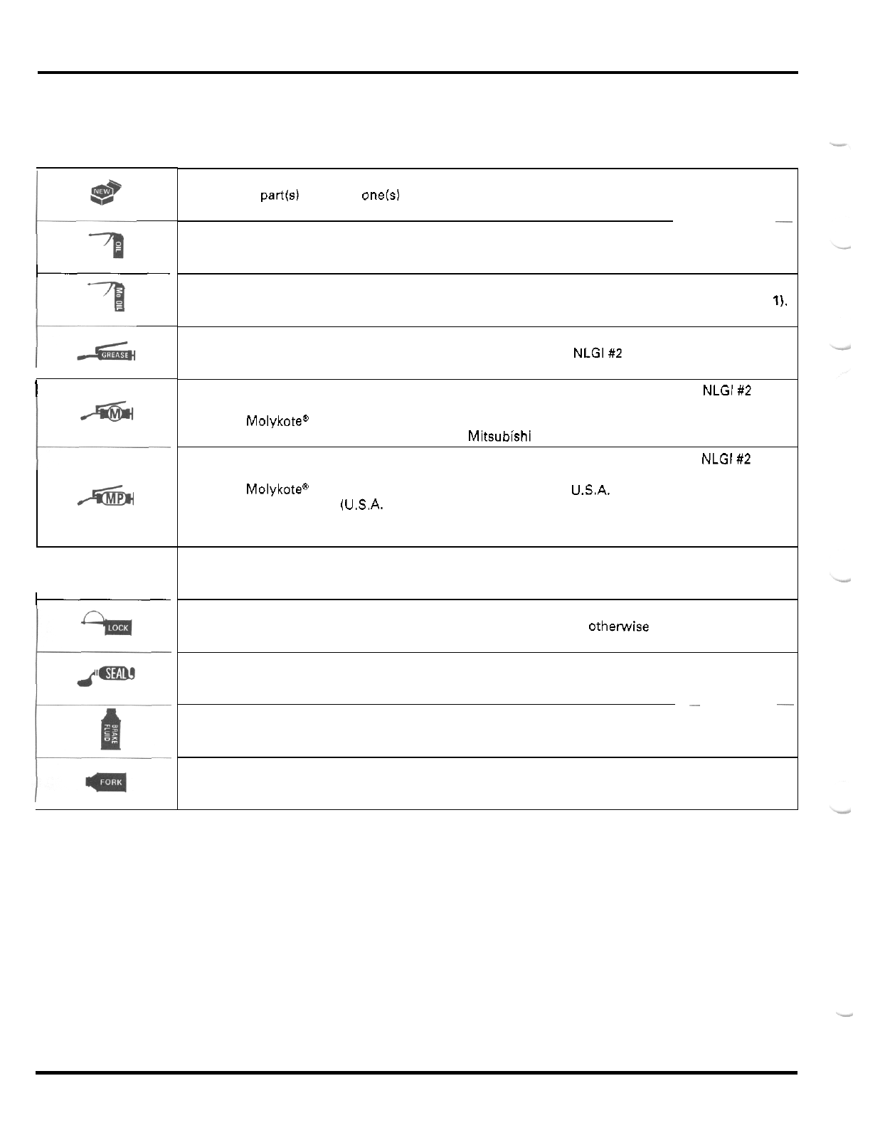
SYMBOLS
The symbols used throughout this manual show specific service procedures. If supplementary information is required per
-
taining to these symbols.
it
would be explained specifically in the
text
without the use of the symbols.
I
I
I
-
-
Replace the part(s) with new one(s1 before assembly.
Use recommended engine oil, unless otherwise specified.
Use molybdenum oil solution (mixture of the engine oil and molybdenum grease
in
a ratio of
1
:
1).
Use multi
-
purpose grease (Lithium based multi
-
purpose grease NLGl#2 or equivalent)
Use molybdenum disulfide grease (containing more than
3%
molybdenum disulfide, NLGl#2 or
equivalent).
Example: Molykote"
BR
-
2
plus manufactured by Dow Corning, U.S.A.
Use molybdenum disulfide paste (containing more than
40%
molybdenum disulfide, NLGl#2 or
equivalent).
Example: Molykotea G
-
n paste, manufactured by Dow Corning, USA.
Multi
-
purpose M
-
2 manufactured by Mitsubishi Oil, Japan
Honda Moly
60
(U.S.A. only)
Rocol ASP manufactured by Rocol Limited, U.K.
Rocol Paste manufactured by Sumico Lubricant, Japan
Use silicone grease.
Apply a locking agent. Use a middle strength locking agent unless othelwise specified.
Apply sealant.
~
Use
DOT
4
brake fluid. Use the recommended brake fluid unless otherwise specified.
Use Fork or Suspension Fluid.
1.
GENERAL INFORMATION
GENERAL SAFETY 1
-
1 LUBRICATION
&
SEAL POINTS 1
-
16
SERVICE RULES 1
-
2 CABLE
&
HARNESS ROUTING 1
-
18
MODEL IDENTIFICATION 1
-
3 EMISSION CONTROL SYSTEMS 1
-
23
SPECIFICATIONS 1
-
4 EMISSION CONTROL INFORMATION
TORQUE VALUES 1
-
11
TOOLS 1
-
14
LABEL 1
-
24
I
GENERAL
SAFETY
CARBON MONOXIDE
If
the engine must be running to do some work, make
sure the area is well ventilated. Never run the engine in
an enclosed area.
-
USED ENGINE OIL
The exhaust contains poisonous carbon monoxide gas
that may cause loss of consciousness and may lead to
death.
Run the engine in an open area or with an exhaust evac
-
uation system in an enclosed area.
GASOLINE
Work in
a
well ventilated area. Keep cigarettes, flames
or sparks away from the work area or where gasoline is
stored.
Gasoline is extremely flammable and is explosive under
certain conditions. KEEP OUT
OF
REACH
OF
CHILDREN.
HOT
COMPONENTS
Engine and exhaust system park become very hot and
remain hot for some time after the engine is run. Wear
insulated gloves or wait until the engine and exhaust
system have cooled before handling these parts.
Used engine oil may cause skin cancer if repeatedly
left
in contact with the skin for prolonged periods. Although
this is unlikely unless
you
handle used oil
on
a daily
basis, it is still advisable to thoroughly wash
your
hands
with soap and water as soon as possible after handling
used oil. KEEP OUT
OF
REACH
OF
CHILDREN.
BRAKE DUST
Never use an air hose or dry brush to clean brake
assemblies. Use an OSHA
-
approved vacuum cleaner
or
alternate method approved by OSHA, designed to mini
-
mize the hazard caused by
air
borne asbestos fibers.
Inhaled asbestos fibers have been found to cause respi-
ratorv disease and cancer.
BRAKE FLUID
CAUTION:
Spilling fluid
on
painted, plastic or rubber parts will
damage them. Place a clean shop towel over these
parts whenever the system is serviced. KEEP OUT
OF
REACH
OF
CHILDREN.
1
-
1
GENERAL
INFORMATION
BAlTERY HYDROGEN GAS
81
ELECTROLYTE
The
battery gives of explosive gases; keep sparks,
flames and cigarettes away. Provide adequate venti
-
lation when charging or using the battery in an
enclosed space.
The battery contains sulfuric acid (electrolytel.
Contact with skin or eyes may cause severe burns.
Wearprotective clothing and a face shield.
-
If
electrolyte gets on your skin, flush with water.
-
If
electrolyte gets in your eyes, flush
with
water
for at least
15
minutes and call a physician, imme
-
diately.
Electrolyte is poisonous.
-If swallowed, drink large quantities
of
wafer or
milk and follow with milk
of
magnesia or vegetable
oil and
call
a physician. KEEP
OUT
OF
REACH
OF
CHILDREN.
SERVICE
RULES
1.
Use genuine HONDA or HONDA
-
recommended parts and lubricants or their equivalents. Parts that don't meet HONDAs
2.
Use the special tools designed for this product to avoid damage and incorrect assembly.
3.
Use only metric tools when servicing the motorcycle. Metric bolts, nuts and screws are not interchangeable with English
4.
Install new gaskets, O
-
rings, cotter pins, and
lock
plates when reassembling.
5.
When tightening bolts or nuts, begin with the larger diameter or inner bolt first. Then tighten to the specified torque diago-
6.
Clean parts in cleaning solvent upon disassembly. Lubricate any sliding surfaces before reassembly.
7.
After reassembly, check all parts for proper installation and operation.
8.
Route
all
electrical wires as show on pages
1
-
18
through
1
-
22,
Cable &Harness routing.
design specifications may cause damage to the motorcycle.
fasteners.
nally
in
incremental steps unless
a
particular sequence is specified.
-
1
-
2
GENERAL INFORMATION
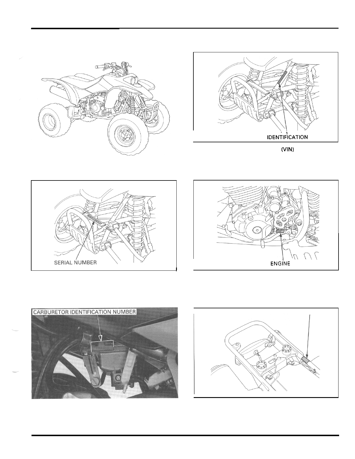
MODEL IDENTIFICATION
I
VEHICLE
IDENTIF'ICATION
NUMBER
left side frame down tube.
FRAME
I
I
The frame serial number
is
stamped on the front side of
the frame.
The Vehicle Identification Number (VIN)
is
located on the
The engine serial number is stamped on the lower left
of
ENGiNE SERIALNUMBER
I
the crankcase.
I
COLOR LABEL
The carburetor identification number is stamped
on
the
left
side of the carburetor body.
The color label is attached on the frame crossmember
under the seat. When ordering color
-
coded parts, always
specify the designated color code.
1
-
3
GENERAL INFORMATION
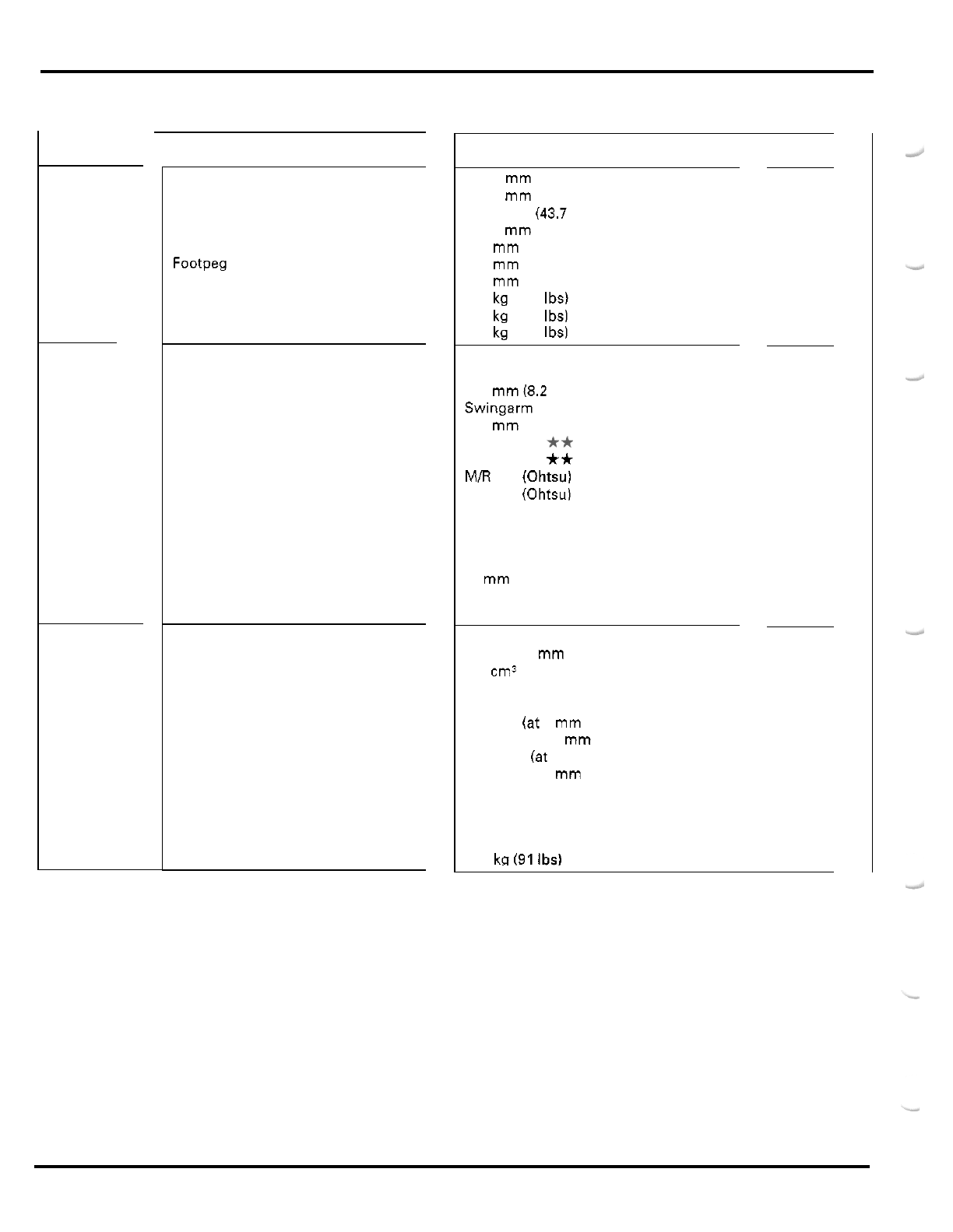
SPECIFICATIONS
-
GENERAL
DIMENSIONS
FRAME
ENGINE
ITEM
Overall length
Overall width
Overall height
Wheelbase
Seat height
Footpeg height
Ground clearance
Dry weight
Curb weight
Maximum weight capacity
Frame type
Front suspension
Front wheel travel
Rear suspension
Rear axle travel
Front tire size
Rear tire size
Front tire brand
Rear tire brand
Front brake
Rear brake
Caster angle
Camber angle
Trail length
Fuel tank capacity
Fuel tank reserve capacity
Cylinder arrangement
Bore and stroke
Displacement
Compression ratio
Valve train
Intake valve opens
closes
Exhaust valve opens
closes
Lubrication system
Oil pump type
Cooling system
Air filtration
Engine dry weight
SPECIFICATIONS
1,835
mm
(72.2 in)
1,150
mm
(45.3 in)
1,110
rnm
(43.7 in)
1,230
mm
(48.4 in)
810
mm
(31.9 in)
353
mm
(13.9 in)
110
mm
(4.3 in)
170 kg (375 Ibs)
178 kg (392 Ibs)
110 kg (243 Ibs)
Double cradle
Double wish
-
bone
209
mm
(8.2 in)
Swingarm
230
mm
(9.1 in)
AT22
x 7
-
10
**
AT20 x 10
-
9
**
M/R 101 (Ohtsu)
M/R
501 (Ohtsu)
Hydraulic disc x
2
Hydraulic disc
6.5
"
-
0.8
"
28
mm
(1.1
in)
10
liters (2.6
US
gal,
2.2
Imp gal)
1.6 liters (0.42
US
gal, 3.52 Imp gal)
Single cylinder, 15
"
inclined from vertical
85.0 x 70.0
mm
(3.35 x 2.76 in)
397 cm3 (24.2 cu
-
in)
9.1
:
1
Silent multi
-
link chain driven SOHC with rocker arms
5
"
BTDC
(at
1
mm
lift)
40
"
ABDC
(at
1
mm
lift)
40
"
BBDC (at
1
mrn
lift)
5
"
ATDC (at
1
mm
lift)
Forced pressure (dry sump)
Trochoid
Air cooled
Oiled urethane foam
41.5
kn
(91
Ibs)
1
-
4
GENERAL INFORMATION
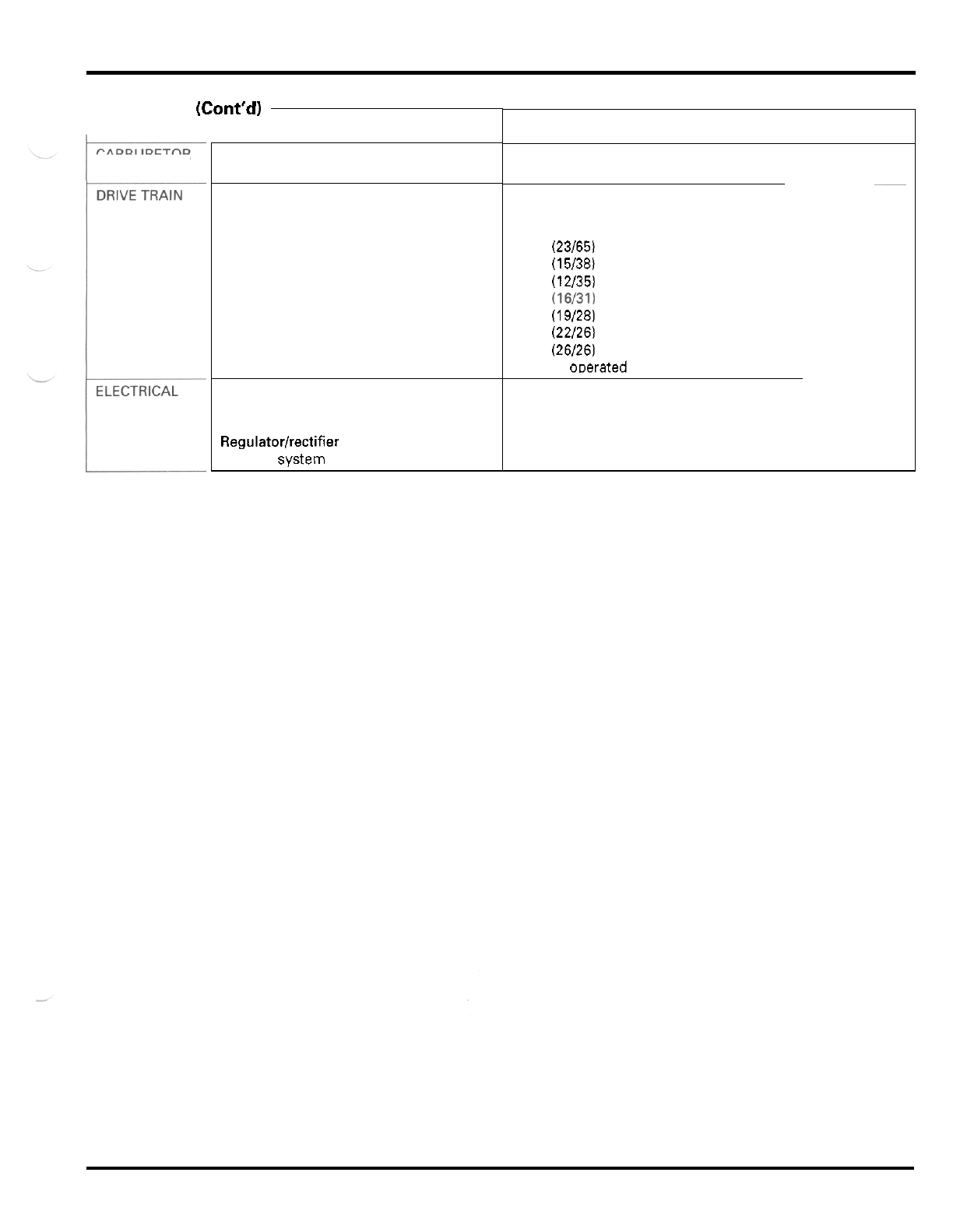
GENERAL
(Cont'd)
r
CARBURETOR
ITEM
Carburetor type
Throttle bore
Clutch system
Clutch operation system
Transmission
Primary reduction
Final reduction
Gear ratio
1st
2nd
3rd
4th
5th
Gearshift pattern
Ignition system
Starting system
Charging system
Regulatortrectifier
Lighting system
SPECIFICATIONS
Piston valve
38
mm
(1.5
in)
Multi
-
plate, wet
Cable operating
Constant mesh, 5
-
speeds
2.826 (23/65)
2.533 (15/38)
2.916 (12/35)
1.937 (16/31)
1.473 (19/28)
1.181 (22/26)
1.000 (26/26)
Left foot oDerated return svstern.
1
-
N
-
2
-
3
-
4
-
5
ICM (Capacitive Discharge Ignition)
Electric starter motor
Single phase output alternator
Single phase
full
wave rectification
Battery
1
-
5
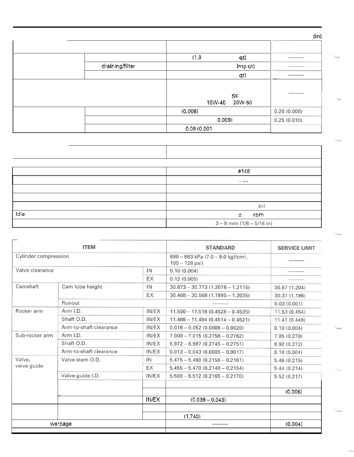
GENERAL INFORMATION
ITEM STANDARD
Engine oil capacity After draining
After draininglfilter change
After disassem bly
Recommended engine
oil
Oil pump Tip clearance
Body clearance
Side clearance
Unit:
mm
(in)
SERVICE LIMIT
1.8 liters (1.9 US qt, 1.6 Imp qt)
1.85 liters (1.95 US qt, 1.63 Imp qt)
2.2 liters (2.3
US
qt, 1.9
Imp
qt)
Honda GN4 or HP4 4
-
stroke oil or
equivalent motor oil
API service classification
SF
or SG
Viscosity:
SAE
1OW-40 or 2OW-50
0.15 (0.006)
0.15
-
0.22 (0.006
-
0.009)
0.02
-
0.09
(0.001
-
0.004)
I
ITEM
-
SPECIFICATIONS
0.12
10.005)
Main jet #148
Jet needle clip position
Pilot screw opening
Float level
3rd groove from top
See page 5
-
13
18.5
mm
10.73 in)
Idle speed 1,400
f
100 rpm
Throttle lever free play 3-8mm(1/8-5/16in)
Valve spring
Stem
-
to
-
guide clearance IN
0.010
-
0.037 (0.0004
-
0.0015) 0.12 10.005)
-
EX
0.030
-
0.057 (0.0012
-
0.0022) 0.14
(0.006)
Valve seat width INEX 1.0
-
1.1 (0.039-0.043) 2.0
(0.08)
Free length Inner 37.19 (1.464) 36.3 11.43)
Outer 44.20 (1.740) 43.1
(1.70)
Cylinder head warpage
-
0.10 (0.004)
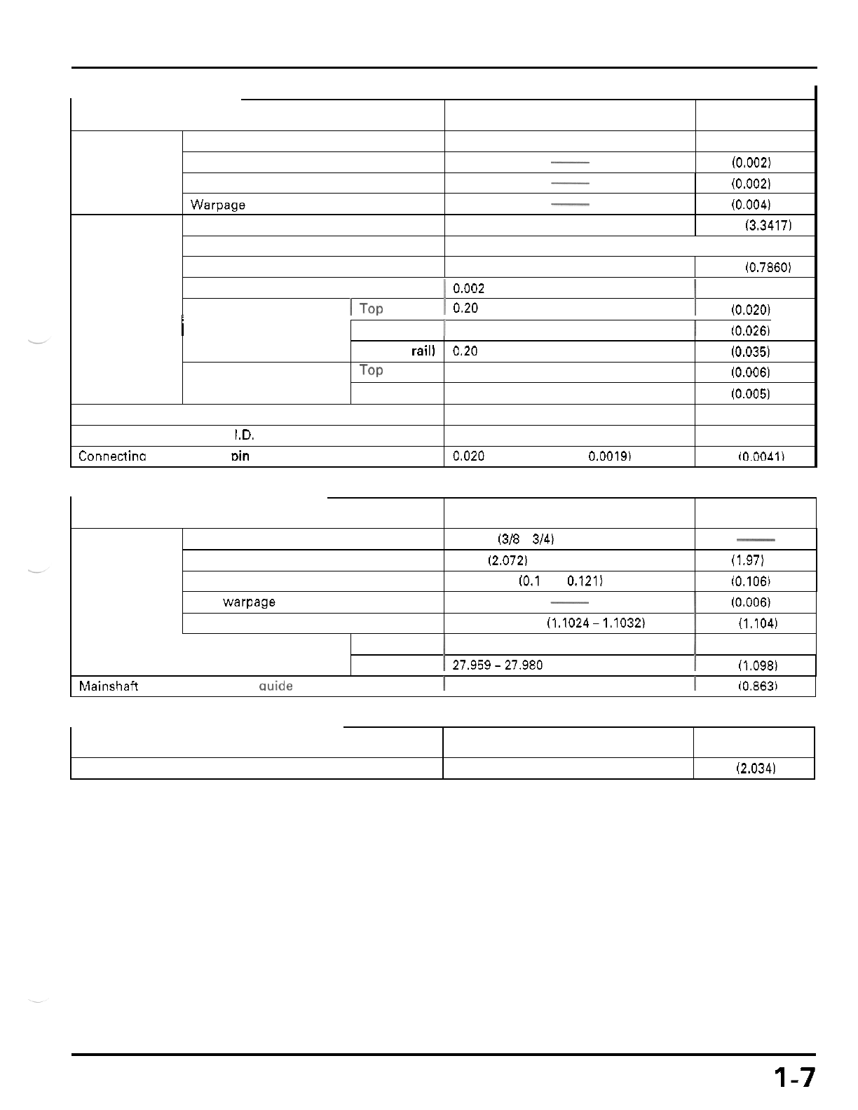
GENERAL INFORMATION
ITEM
Cylinder
I.D.
Out of round
STANDARD SERVICE LIMIT
85.000
-
85.010 (3.3465
-
3.3468) 85.10 (3.350)
0.05 (0.002)
-
Piston,
-
Taper
0.05 (0.002)
Warpage
0.10 (0.004)
Piston
O.D.
at
15
(0.6)
from
bottom
-
84.960
-
84.985 (3.3449
-
3.3459) 84.880 (3.3417)
Piston
-
to
-
piston pin clearance
I
0.002
-
0.014 (0.0001
-
0.0006)
I
0.20
-
0.35
(0.008
-
0.014)
I
0.096 (0.0038)
1
0.50 (0.020)
Piston ring end gap
1
TOP
Piston pin
O.D.
19.994
-
20.000 (0.7872
-
0.7874) 19.964 (0.78601
I
Second
I
0.35
-
0.50 (0.014
-
0.020)
I
0.65 10.026)
Clutch
Piston ring
-
to
-
ring
groove clearance
Oil (side rail)
0.90 (0.035)
TOP
0.030
-
0.065 (0.0012
-
0.0026) 0.14
(0.006)
Second
0.015
-
0.050
(0.0006
-
0.0020) 0.12 (0.005)
0.20
-
0.70
(0.008
-
0.028)
Cylinder
-
to
-
piston clearance
Connecting rod small end
I.D.
Connectino rod
-
to
-
Diston
Din
clearance
Outer guide
0.01 5
-
0.050
(0.0006
-
0.0020)
20.020
-
20.041 (0.7882
-
0.7890)
0.020
-
0.047
10.0008
-
0.0019)
0.10 (0.004)
20.067 (0.7900)
0.103
(0.OOAII
I
22.05 (0.868)
I.D.
O.D.
I
27.959-27.980 (1.1007
-
1.1016)
I
27.90 (1.098)
1
22.010
-
22.035 (0.8665
-
0.8675)
ITEM
Mainshafi
O.D.
at
clutch outer wide
I
21.959
-
21.980 (0.8645
-
0.8654)
I
21.91 (0.863)
STANDARD SERVICE LIMIT
Lever free play
Spring free length
Disc thickness
1-7
10
-
20
(3/8
-
3/4)
52.64 (2.072)
50.0
(1.97)
2.92
-
3.08 (0.1 15
-
0.121)
-
2.69 10.106)
Plate
warpage
-
I
0.15
(0.006)
Outer
I.D.
28.000
-
28.021 (1.1024- 1.1032)
1
28.04 (1.104)
ITEM
Starter driven gear
boss
O.D.
STANDARD SERVICE LIMIT
51.705
-
51.718 (2.0356
-
2.0361) 51.67 (2.034)
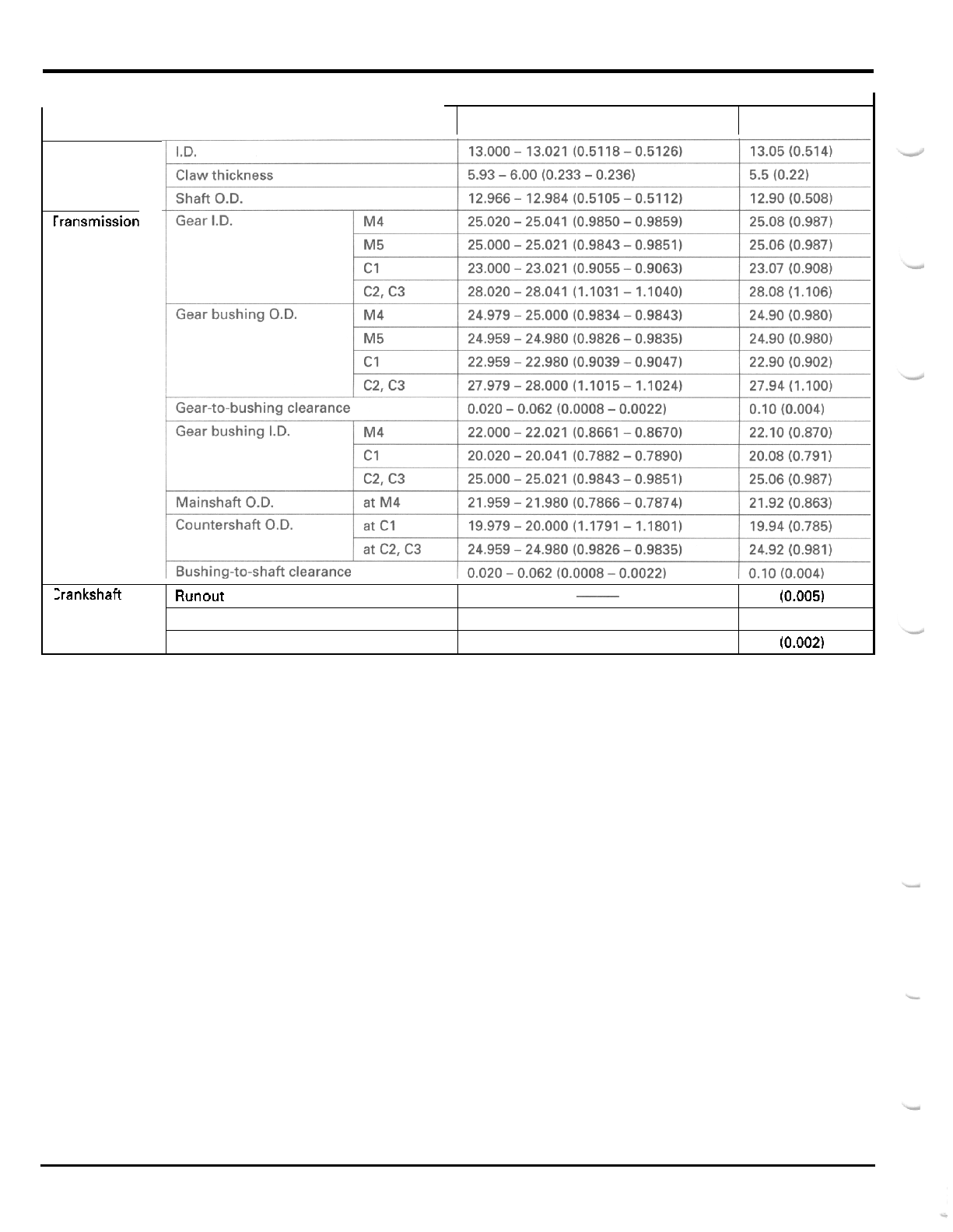
GENERAL INFORMATION
ITEM STANDARD
SERVICE
LIMIT
rransmission
:rankshaft
~
Runout
0.12
(0.005)
Big
end
side
clearance
Big
end radial clearance
0.05
-
0.45
(0.002
-
0.018)
0.006
-
0.018
(0.0002
-
0.0007)
0.6
(0.02)
0.05
(0.002)
1
-
8
.
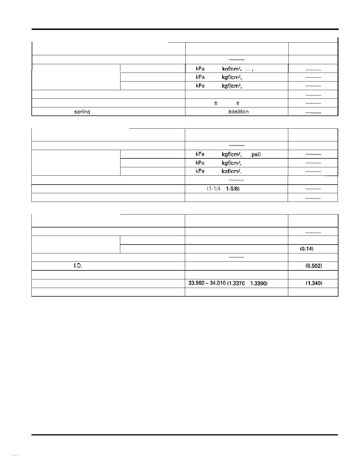
ITEM STANDARD SERVICE LIMIT
-
Minimum tire tread depth
Cold tire pressure
I
Standard
27
kPa
10.275
kaWcm2.
4.0
osil
-
4.0 (0.16)
Minimum
Maximum
Tie
-
rod distance between the ball joints
Toe
Shock absorber spring adiuster standard position
-
.,
23
kPa
(0.235
kgf/cmz.
3.4
psi)
31
kPa
(0.315
kgf/cmz,
4.6
psi)
__
370.2 (14.57)
-
Toe
-
in:
17
f
15
(0.7
f
0.6)
4th from softest Dosition
-
~
-
1
-
9
ITEM
Minimum tire tread depth
Cold tire pressure Standard
Minimum
Maximum
STANDARD SERVICE LIMIT
-
4.0
(0.16)
27
kPa
(0.275
kgf/cm2,
4.0
psi)
23
kPa
(0.235
kgWcmz,
3.4
psi)
31
kPa
10.315
kaWcm2.
4.6
osil
-
-
-
Axle runout
Drive chain slack
Shock absorber spring installed length
~
-
3.0 10.12)
30
-
40 (1-1/4
-
1-5/8)
-
231.5 (9.11)
-
-
HYDRAULIC DISC BRAKE
ITEM
Recommended brake fluid
Brake disc thickness Front
Rear
Brake disc runout
Master cylinder I.D.
Master piston O.D.
Caliper cylinder
I.D.
Caliper piston O.D.
STANDARD SERVICE LIMIT
DOT
4
brake fluid
-
2.8
-
3.2 (0.1
1
-
0.13) 2.5 (0.10)
3.8
-
4.2 (0.15
-
0.17) 3.5 (0.14)
-
0.30 10.012)
12.75
(0.502)
12.65 10.498)
34.02
(1.340)
33.87 11.333)
12.700
-
12.743
(0.5000
-
0.5017)
12.657
-
12.684 (0.4983
-
0.4994)
33.960-34.010 (1.3370
-
1,3390)
33.895
-
33.928 (1.3344
-
1.3357)
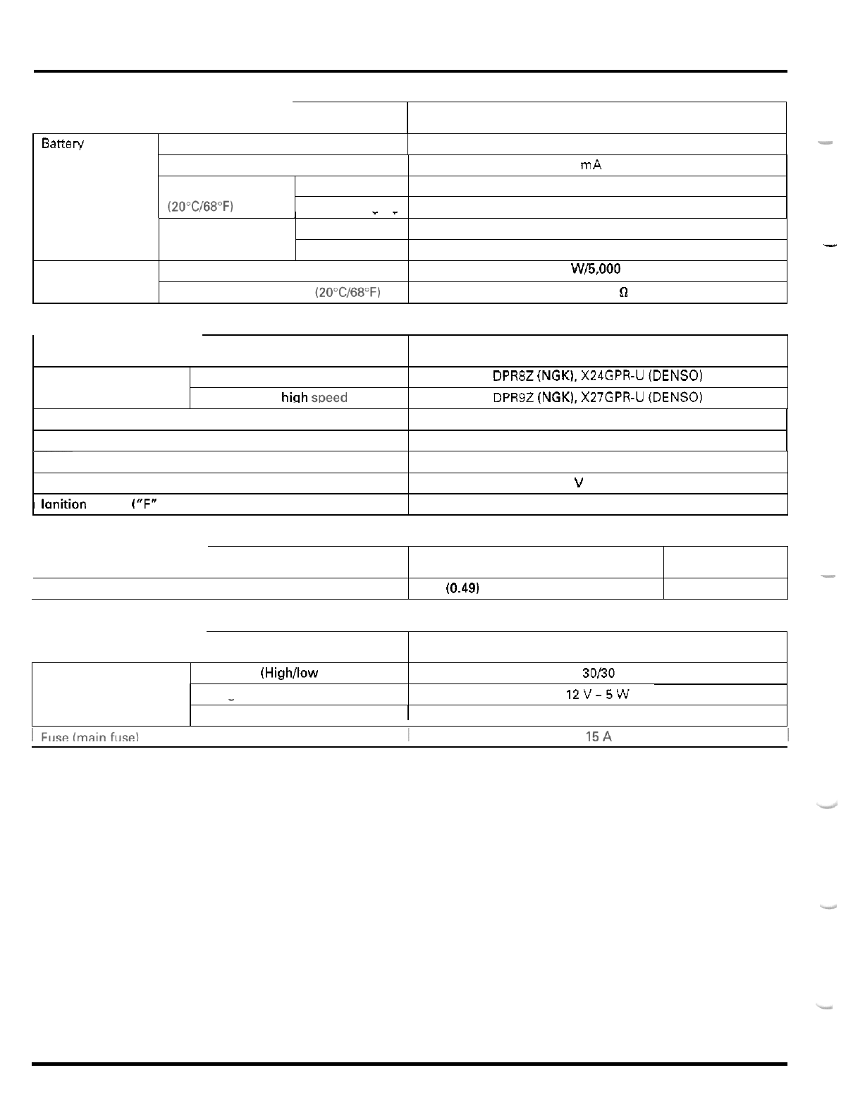
ITEM
r
SPECIFICATIONS
Batten/ 12 V
-
8Ah
-
Capacity
Current leakage
Voltage
(2OoC/68"F) Needs charaina
Fully charged
0.1 mA max.
13.0
-
13.2
V
Below 12.3
V
Alternator
1
__
Charging current Normal
0.9
A x 5
-
10 h
Capacity 147 W/5,000 rpm
Charaina coil resistance (2OoC/68"F)
I
Quick 4.0 Ax 1.0 h
0.1
-
1.0
n
ITEM SPECIFICATIONS
Spark plug Standard DPR8Z (NGK), X24GPR-U (DENSO)
DPR9Z
(NGK), X27GPR-U (DENSO)
For extended hiah weed ridina
Bulbs
Spark plug gap 0.6
-
0.7 mrn (0.024
-
0.028 in)
-
Neutral indicator
I
12
v
-
3.4
w
Ignition coil primary peak voltage
1
-
10
100
V
minimum
~~
Ignition pulse generator peak voltage
Exciter coil peak voltage
I
lanition timina
("F"
mark)
0.7
V
minimum
100
V
minimum
8
"
BTDC
at
idle
ITEM STANDARD
Starter motor brush length 12.5
(0.49)
-
SERVICE LIMIT
8.5
(0.33)
r
ITEM SPECIFICATIONS
Headlight (High/low beam)
12
v
-
30/30
w
x
2
Taillight 12V-5W
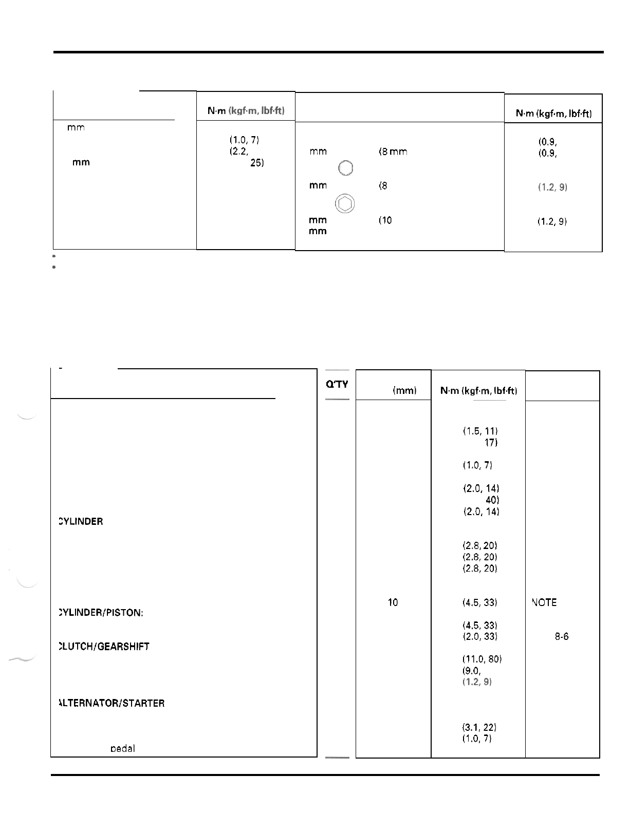
GENERAL INFORMATION
TORQUE
VALUES
-
STANDARD
FASTENER TYPE
5
mm
bolt and nut
6
mm
bolt and nut
8
mm
bolt and nut
10
mm
bolt and nut
12
mm
bolt and nut
TORQUE
N.m
(kgf.m. Ibf4t)
5
(0.5, 3.6)
10 (1.0,7)
22 (2.2, 16)
34 (3.5, 25)
54 (5.5, 40)
FASTENER TYPE
5
mm
screw
6
mm
screw
6
mm
flange bolt
(8
rnm
head, small flange)
6
mm
flange bolt
(8
mm
head, large flange)
(0
6
mm
flange bolt
(10
mm
head) and nut
8
mm
flange bolt and nut
10
mm
flange bolt and nut
TORQUE
N.m
(kgfm, Ibf4t)
4 (0.4, 2.9)
9 (0.9. 6.5)
9 (0.9. 6.5)
12 (1.2,9)
12 (1.2,9)
26 (2.7.20)
39 (4.0. 29)
-
Torque specifications listed below are for important fasteners.
-
Others should be tightened to standard torque values listed above.
NOTES:
1.
Apply locking agent to the threads.
2.
Apply oil to the threads and seating surface.
3.
Apply grease to the threads and seating surface.
4.
ALOC bolt. replace with a new one.
5.
Castle nut: tighten to the specified torque and further tighten until its grooves align with
the
cotter pin hole,
6.
Stake.
-
ENGINE
ITEM
MAINTENANCE:
Spark plug
Valve adjusting hole cap
Valve adjusting lock nut
Crankshaft hole cap
Timing hole cap
Engine
oil
drain bolt (crankcase)
Engine
oil
drain bolt (oil tank)
Engine oil strainer screen
(at
oil tank)
Oil pipe joint flare nut
ZYLINDER HEADIVALVE:
Cylinder head cover bolt
Rocker arm shaft
Intake sub
-
rocker arm shaft
Exhaust sub
-
rocker arm shaft
Cam sprocket bolt
Cam tensioner plug
Cylinder head nut
:YLINDER/PISTON:
Cylinder bolt
Cylinder stud bolt
Clutch center lock nut
Primary drive gear nut
Gearshift drum stopper arm pivot bolt
Gearshift spindle return spring pin
Flywheel bolt
Starter clutch bolt
Left crankcase cover stud bolt
Gearshift Dedal Dinch bolt
:LUTCH/GEARSHIFT LINKAGE:
4LTERNATORISTARTER CLUTCH:
an
~
1
4
1
1
1
1
1
2
1
2
2
2
2
1
4
4
4
1
1
1
1
1
6
1
1
4
-
THREAD
DIA.
(mml
12
36
7
30
14
12
10
27
16
8
14
14
12
7
6
10
10
10
18
18
6
8
12
8
6
6
TORQUE
N.m
1kgf.m. IbfW
18 (1.8, 13)
15 (1.5, 11)
24 (2.4, 17)
8 (0.8, 5.8)
10
(1.0.7)
25 (2.5, 18)
20
(2.0.
14)
54 (5.5, 40)
20 (2.0. 14)
23
(2.3,
17)
27 (2.8,
20)
27 (2.8.20)
27
(2.8,20)
20 (2.0,
14)
4 (0.4, 2.9)
44 (4.5,33)
44 (4.5.33)
20 (2.0,33)
108 (11.0.80)
88
(9.0. 65)
12 (1.2,9)
24 (2.4, 17)
127 (13.0. 94)
30 (3.1.22)
10 (1.0.7)
20
(2.0,
14)
REMARKS
NOTE
1
VOTE
1
NOTE
1
NOTE
1
VOTE
2
NOTE
2
oage
8-6
VOTE
2,6
VOTE
2
VOTE
2
VOTE
1
1
-
1
1
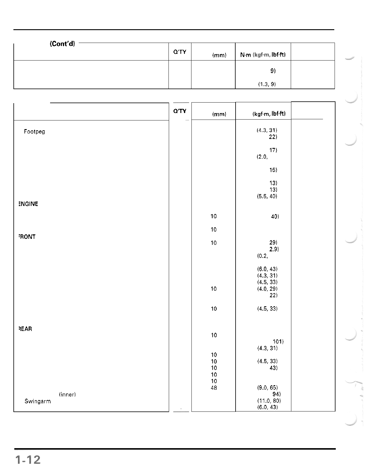
THREAD TORQUE
-
ENGINE
(Cont'd)
QTY
DIA.
(mm)
N.m
(kgf.m, IbfW
ITEM
CRANKCASE/TRANSMlSSlON/CRANKSHAFT:
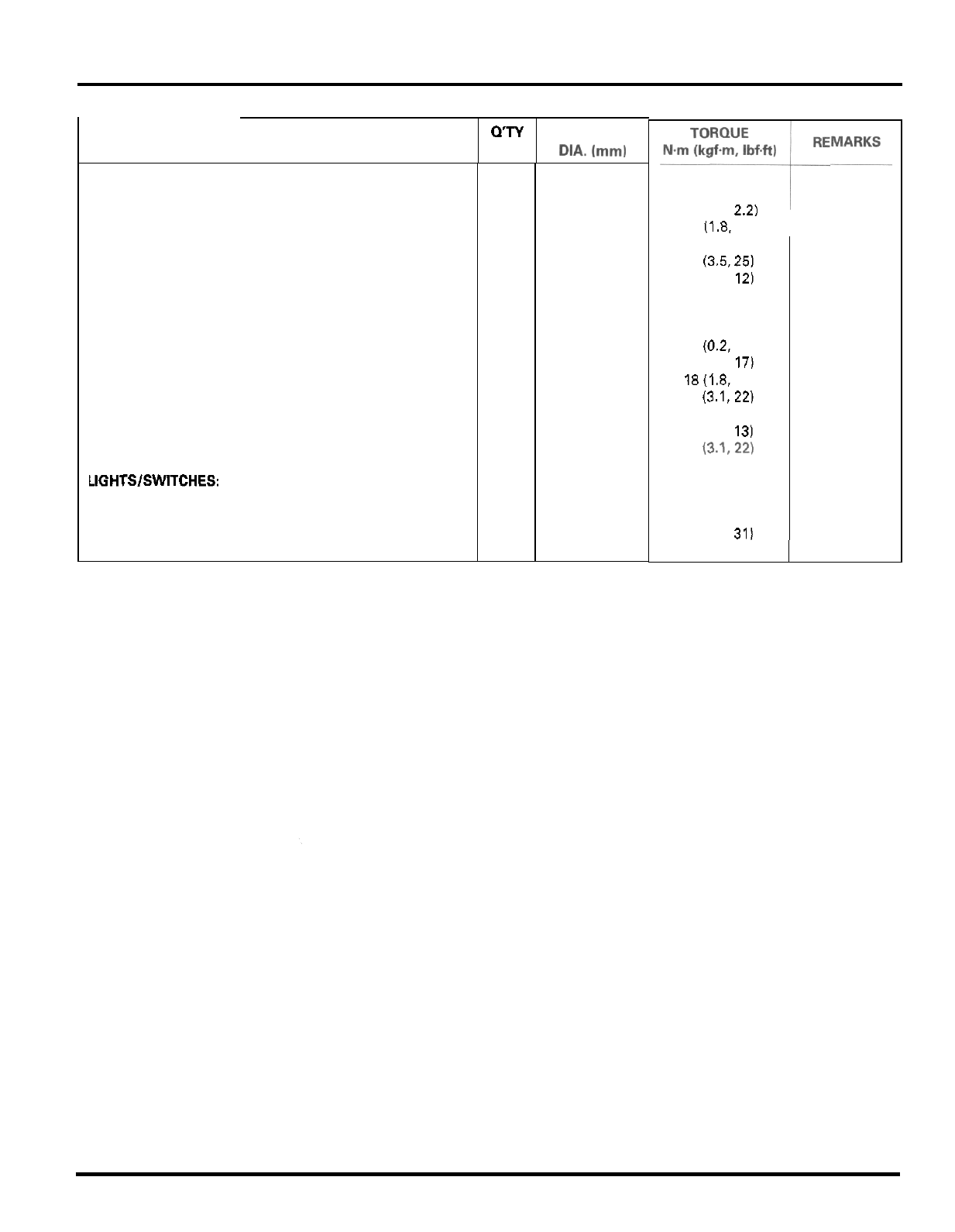
LIGHTSISWITCHES
Mainshaft bearing setting plate bolt
2 6 12 (1.2,
9)
Neutral switch
1 10 13 (1.3,9)
.
FRAME
ITEM
WAME/BODY PANELS/EXHAUST
SYSTEM:
Footpeg bracket bolt
Skid plate bolt
Muffler mounting bolt
Muffler band bolt
Exhaust pipe protector bolt
Axle bearing holder pinch bolt
Front master cylinder reservoir cap screw
Parking brake arm lock nut
Rear master cylinder push
rod
lock nut
Tie
-
rod lock nut
Upper engine hanger nut
Front engine hanger nut
bolt
Lower engine hanger nut
Handlebar lower holder nut
Throttle housing cover screw
Left handlebar switch housing screw
Front wheel nut
Front wheel hub nut
Front brake disc bolt
Shock absorber mounting nut
Upper and lower arm pivot nut
Upper and lower arm ball joint nut
Tie
-
rod ball joint lock nut
Tie
-
rod stud joint nut
Steering shaft end nut
Steering shaft holder bolt
3EAR WHEELISUSPENSION:
Rear wheel nut
Rear wheel hub nut
Rear brake disc bolt
Shock absorber mounting nut
Shock link
-
to
-
swingarm nut
Shock arm
-
to
-
frame nut
Shock arm
-
to
-
shock link nut
Final driven sprocket nut
Axle lock nut (outer)
(inner)
Swingarm pivot nut
Caliper stopper pin
HAINTENANCE
iNGlNE REMOVALIINSTALLATION
:RONT WHEEL/SUSPENSION/STEERING
REMARKS
NOTE
1
0"
4
4
2
2
2
4
2
1
1
4
1
1
4
1
2
3
2
8
2
6
4
8
4
4
4
1
2
8
2
4
2
1
1
1
4
1
1
1
1
THREAD
DIA.
(mml
10
8
8
8
6
8
4
8
8
12
10
10
8
10
10
4
5
10
14
8
10
10
12
12
10
14
8
10
18
8
10
10
10
10
10
48
14
12
48
TORQUE
N.m
(kgf.m, IbfW
42 (4.3.31)
30 (3.1, 22)
32 (3.3, 24)
23 (2.3, 17)
20 (2.0. 14)
21 (2.1, 15)
2 (0.2, 1.4)
18 (1.8, 13)
18 (1.8, 13)
54 (5.5,40)
74 (7.5, 54)
54 (5.5, 40)
26 (2.7, 20)
74 (7.5, 54)
39 (4.0, 29)
4 (0.4, 2.9)
2 (0.2, 1.4)
64 (6.5, 47)
59 (6.0, 43)
42 (4.3.31)
44 (4.5.33)
39
(4.0,
29)
29 (3.0, 22)
54 (5.5, 40)
44 (4.5,33)
69 (7.0, 51)
32 (3.3, 24)
64 (6.5, 47)
137 (14.0, 101)
42 (4.3,31)
59 (6.0, 43)
44 (4.533)
59
(6.0,
43)
59
(6.0,
43)
59
(6.0,
43)
88 (9.0,65)
128 (13.0, 94)
108 (11.0,80)
59 (6.0,43)
REMARKS
NOTE
4
NOTE
5
NOTE
4
NOTE
5
NOTE
3,5
NOTE
4
NOTE
1
NOTE
1
NOTE
1
GENERAL INFORMATION
QTY
ITEM THREAD
DIA.(~~)
HYDRAULIC BRAKE:
Caliper bleed valve
Front brake caliper pad pin plug
Front brake caliper pad pin
Rear brake caliper pad pin
Brake hose oil bolt
Brake pipe joint nut
Front brake lever pivot bolt
Rear master cylinder mounting bolt
Front brake caliper slide pin
Front brake caliper bracket pin
Front brake caliper mounting bolt
Rear brake caliper slide pin
Rear brake caliper bracket pin
Rear brake caliper mounting bolt
Rear brake caliper parking brake base bolt
nut
Rear master cylinder reservoir hose joint screw
LIGHTSISWITCHES:
DTHERS:
Headlight mounting bolt
Sub
-
frame lower mounting bolt
Sub
-
frame upper mounting bolt
6
(0.6,
4.3)
3 (0.3,
2.2)
18
11.8.
13)
18 (1.8, 13)
34 (3.5,
25)
17
(1.7,
12)
6
(0.6,
4.3)
6
(0.6,
4.3)
13 (1.3,
9)
2
(0.2,
1.4)
23 (2.3,
17)
18(1.8,
13)
30
(3.1,22)
23 (2.3,
17)
18 (1.8, 13)
30 (3.1,22)
23 (2.3, 171
4
(0.4,
2.9)
42 (4.3, 31)
3
8
4 10
4
10
2
8
4
10
2
10
1
6
1
6
2
6
1
4
2
8
2
8
2
8
1
8
1
8
2
8
2
8
2
4
2
8
2
10
NOTE 4
NOTE
1
NOTE 4
NOTE 1
NOTE 4
54
(5.5,
40)
1
-
13
GENERAL INFORMATION
TOOLS
NOTES:
1.
Equivalent commercially available in
U.S.A.
2.
Not available in
U.S.A.
3.
Alternative tool
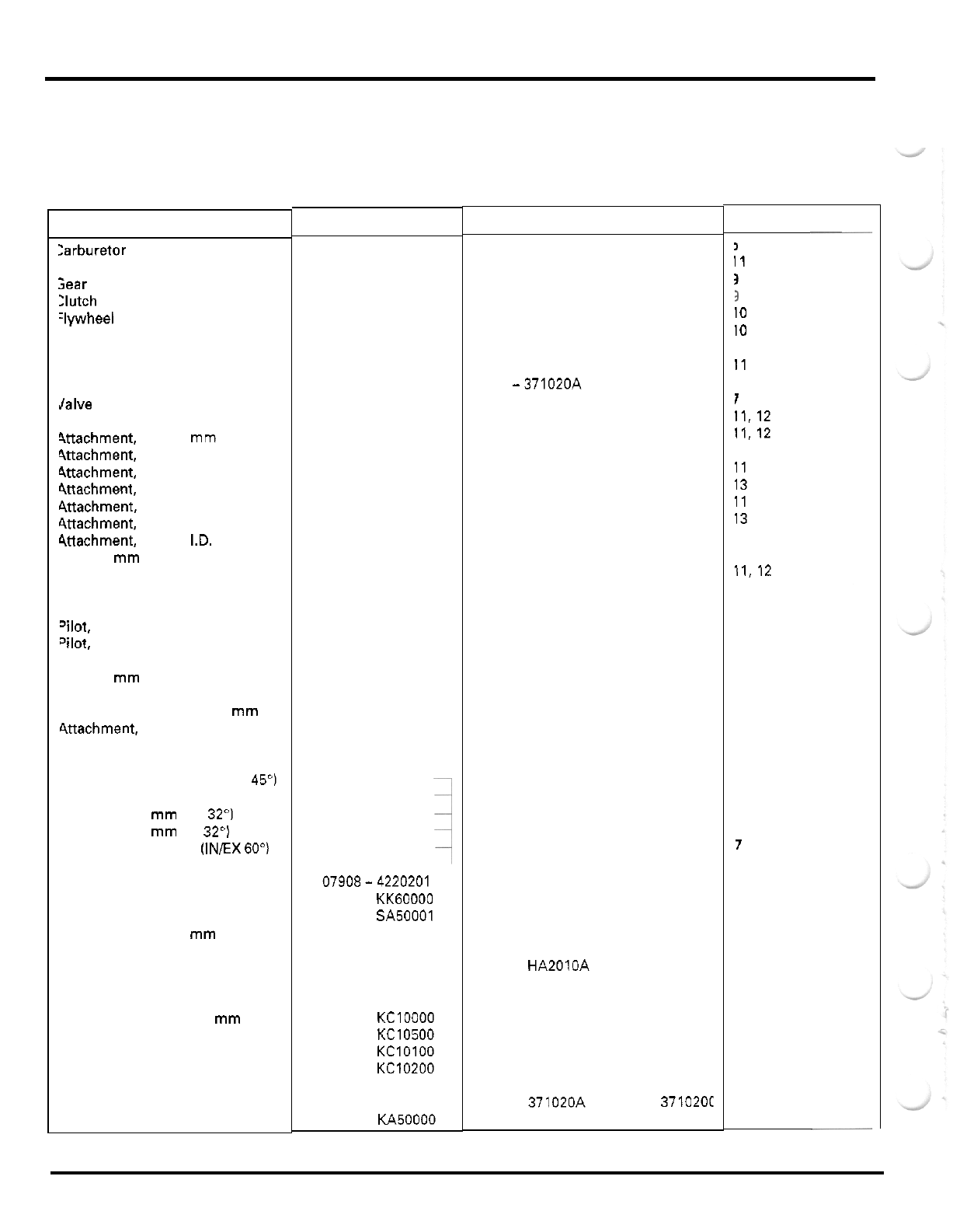
DESCRIPTION
zarburetor float level gauge
Jniversal bearing puller
;ear holder
:lutch center holder
:lywheel holder
iotor puller
iemover weight
lalve guide driver,
5.5
mm
Sttachment.
32 x 35
mm
Wachment,
37
x
40
mm
Wachment,
42 x 47
mm
4ttachment.
52
x
55
mm
ittachment,
62
x
68
mm
ittachment,
72
x
75
mm
4ttachment.
24
x
26
mm
4ttachment.
35
mm
I.D.
Pilot,
12
mm
Pilot,
15
mm
Pilot,
17
mm
"
ilot,
20
mm
?lot,
25
mm
Wot,
30
mm
'ilot,
40
mm
Pilot,
22
mm
Bearing remover shaft
Bearing remover head,
15
mm
ittachment,
28 x 30
mm
Driver
Valve spring compressor
Valve seat cutter,
29
mm
(EX
45")
Valve seat cutter,
35
mm
(IN
45
"
)
Flat cutter,
30
mm
(EX
32")
Flat
cutter,
35
mm
(IN
32")
Interior cutter,
30
mm
(INEX
60")
Cutler holder,
5.5
mm
Pilot screw wrench
Compression gauge attachment
Snap ring pliers
Lock nut wrench,
45
mm
Lock nut wrench,
56
mm
Remover handle
Bearing remover,
17
mm
Bearing remover set,
15
mm
-
bearing remover,
15
mm
-
remover shaft
-
remover head
-
sliding weight
Needle bearing remover
TOOL NUMBER
07401
-
0010000
07631
-
0010000
07724
-
0010100
07724
-
0050002
07725
-
0040000
07733
-
0020001
07741
-
0010201
07742
-
0010100
07746
-
0010100
07746
-
0010200
07746
-
0010300
07746
-
0010400
07746
-
0010500
07746
-
0010600
07746
-
0010700
07746
-
0030400
07746
-
0040200
07746
-
0040300
07746
-
0040400
07746
-
0040500
07746
-
0040600
07746
-
0040700
07746
-
0040900
07746
-
0041000
07746
-
0050100
07746
-
0050400
07746
-
1870100
07749
-
0010000
07757
-
0010000
07780
-
0010300
07780
-
0010400
07780
-
0012200
07780
-
0012300
07780
-
0014000
07781
-
0010101
07908-4220201
07908
-
KK60000
07914
-
SA50001
07916
-
1870101
07916
-
HA20000
07936
-
3710100
07936
-
3710300
07936
-
KClOOOO
07936
-
KC10500
07936
-
KClOlOO
07936
-
KC10200
07741
-
0010201
07946
-
KA50000
REMARKS
NOTE
1
NOTE
2
NOTE
1
NOTE
1
NOTE
3
07933
-
3950000 (U.S.A.
only)
NOTE
3:
07936 -371020A
or
07936
-
3710200
NOTE
1
NOTE
1
NOTE
1
NOTE
3:
07916
-
HA2010A (U.S.A.
only)
NOTE
2
NOTE
2
NOTE
2
NOTE
3:
07936
-
371020A
or
07936
-
3710201
i
i1
3
3
10
10
11
1
11.12
11.12
11.12
11
13
11
13
13
11
11,12
3,
11, 12, 13
12
11
11
13
11
12
12
9
9,
11, 12, 13
7
7
7
7
7
7
7
5
7
14
13
13
11
11
11
13
REF.
SECTION
~
1
-
14
GENERAL INFORMATION
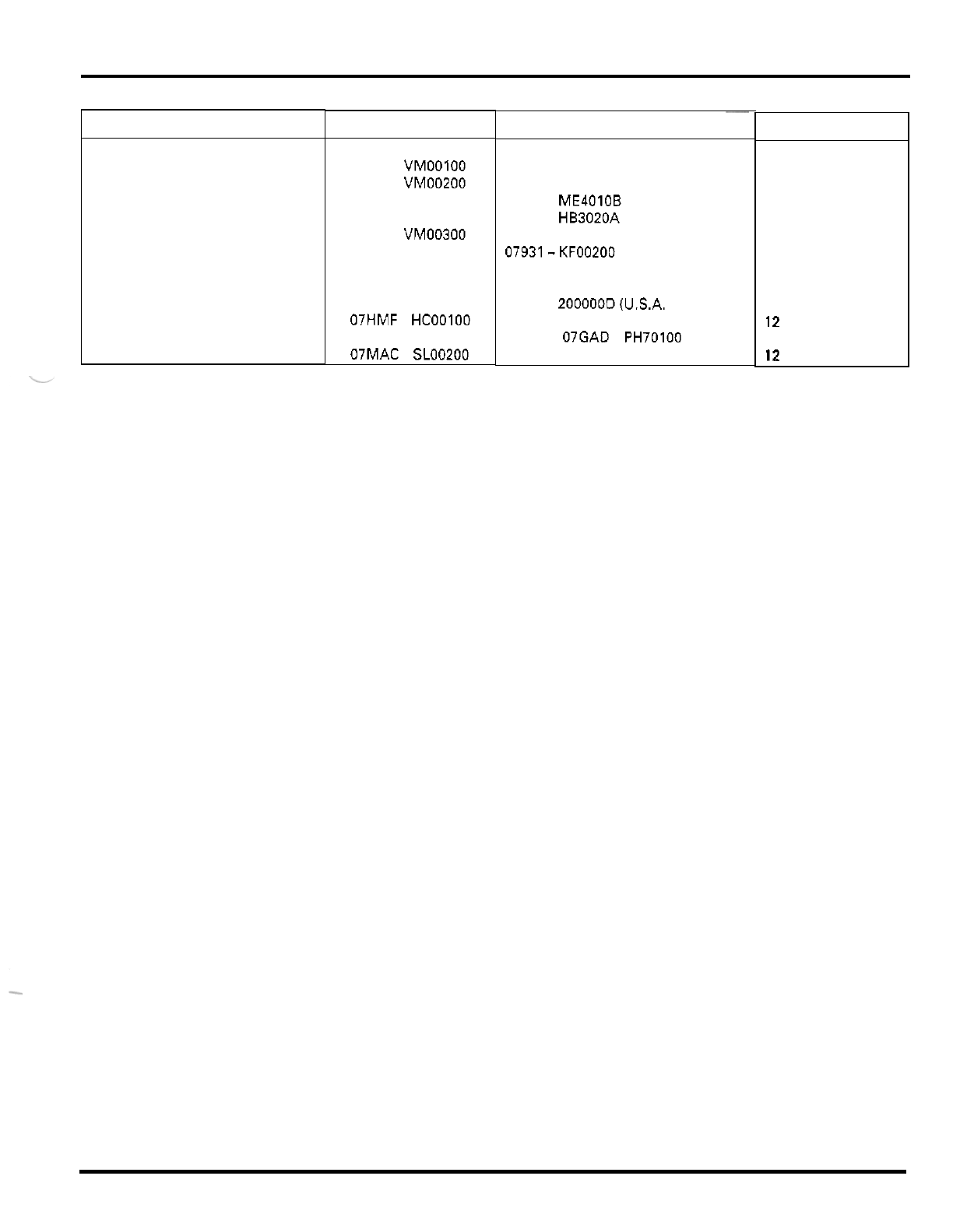
DESCRIPTION
Crankcase assembly
tool
-
assembly collar
-
assemblv shaft
-
threaded adaptor
Assembly collar
Valve guide reamer, 5.5 mm
Spherical bearing driver
Ball
joint remover
TOOL
NUMBER
07965
-
VMOOOOO
07965
-
VMOOlOO
07965
-
VM00200
07965
-
VM00300
07965
-
VMOOlOO
07984
-
2000001
07HMF
-
HCOOlOO
07MAC
-
SLOO200
~~
REMARKS
NOTE
2
NOTE 3:
07931
-
ME4010B and
07931
-
HB3020A
NOTE 3:
07931-KF00200
NOTE
3
07984
-
200000D
(U.S.A. only)
NOTE
2
NOTE
3:
07GAD
-
PH70100
REF.
SECTION
11
12.13
7
12
12
1
-
15
GENERAL INFORMATION
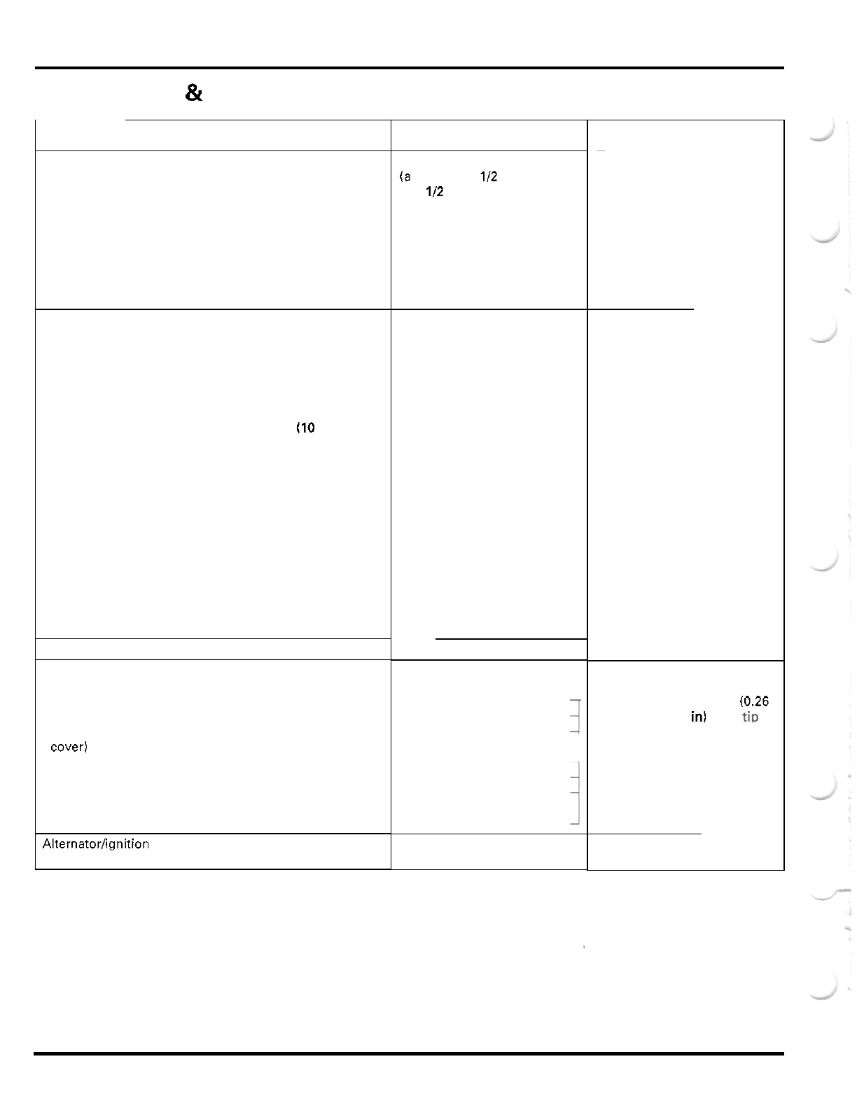
LUBRICATION
&
SEAL POINTS
-
ENGINE
LOCATION
Camshaft journals and cam lobes
Rocker arm slipper surfaces
Sub
-
rocker arm slipper surfaces
Valve stem (valve guide sliding surface)
Clutch outer guide inner and outer surfaces
Piston pin outer surface
Connecting rod small end inner surface
Transmission gear rotating surfaces
Transmission gear shift fork grooves
Connecting rod big end bearing
Rocker arm shaft sliding surfaces
Sub
-
rocker arm shaft sliding surfaces
Cam chain
Cylinder head nut threads and seating surfaces
Piston outer surface and piston pin hole
Piston rings
Cylinder bore
Cylinder bolt threads and seating surfaces
(10
mm only)
Clutch arm spindle
Clutch lifter piece
Clutch disc lining
Clutch center lock nut threads and seating surface
Primary drive gear nut threads and seating surface
Flywheel bolt threads and seating surface
Transmission gear teeth
Shift fork shaft
Shift fork guide pins and inner surfaces
Shift drum grooves
Each bearing rotating area
Each O
-
ring whole surface
Each oil seal outer surface
Each oil seal lip
Rocker arm shaft threads
Sub
-
rocker arm shaft threads
Gearshift cam plate bolt threads
Left crankcase cover stud bolt threads
Alternator wire clamp bolt threads (inside left crankcase
Ignition pulse generator bolt threads
Mainshaft bearing setting plate bolt threads
Cam chain tensioner slider bolt threads
Cam sprocket bolt threads
Starter clutch bolt threads
Alternatorfignition pulse generator wire grommet seating
cover)
surface
MATERIAL
Molybdenum oil solution
(a
mixture of
112
engine oil
and
112
molybdenum
disulfide grease)
Engine
oil
Multi
-
purpose grease
Locking agent
Liquid sealant
REMARKS
Coating area (page
7
-
22)
Coating area (page
7
-
22)
Coating width:
6.5
mm
10.26
in) from
ti[)
Coating width:
5
mm
(0.2
in)
1
-
16
GENERAL INFORMATION
Front shock absorber dust seal lips
Air cleaner intake duct
-
to
-
housing mating surface
Throttle cable outer inside
Clutch cable outer inside
-
FRAME
Thronle cable end
Throttle lever pivot and dust seal lip
Brake lock cable end
Brake lock arm pivot
Front wheel hub dust seal lips
Steering shaft bushing inner surface
Steering shaft dust seal lips
Upper and lower arm pivot bearings
Upper and lower arm pivot dust seal lips
Shock arm and link bearings
Shock arm and link dust seal lips
Swingarm pivot bearings
Swingarm pivot dust seal lips
Rear brake pedal pivot
Rear brake pedal pivot dust seal lips
Rear axle bearing holder outer surface
Rear axle bearing holder dust seal lips
Rear brake caliper stay inner surface
Rear axle splines (brake disc and driven flange)
Rear axle outer lock nut stopper ring
Rear wheel hub nut threads and seating surfaces
Rear shock absorber upper needle bearing
Rear shock absorber dust seal lips
LOCATION
Engine oil
Cable lubricant
MATERIAL
Multi
-
purpose grease
..
Front brake lever
-
to
-
master piston contacting area
Front brake lever pivot
Rear brake master piston
-
to
-
push rod contacting area and
Brake caliper pin bolt boots inside
Rear brake caliper parking brake shaft sliding surface
Brake master piston and cups
Brake caliper piston and piston seals
Rear brake master cylinder hose joint O
-
ring
Rear brake caliper piston shaft O
-
ring
Clutch switch retainer screw
Rear axle outer and inner lock nut threads
Rear brake master cylinder hose joint screw threads
boot groove
Front shock absorber lower bushings
1
Molybdenum disulfide Daste
Hand Grip Cement (U.S.A.
only) or equivalent
Silicone grease
DOT
4
brake fluid
Locking agent
Brake lock cable outer inside
Handlebar grip rubber inside
1
Honda Bond A or Honda
REMARKS
Apply
1
g per each dust seal
Fill up
3
g per each bearing
Apply
3
g per each bearing
Apply
1
g per each dust seal
.
1
-
17
GENERAL INFORMATION
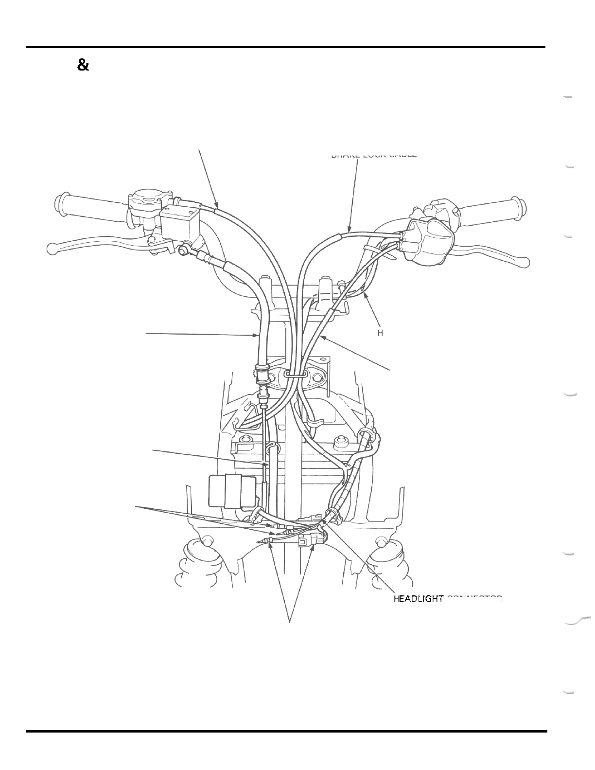
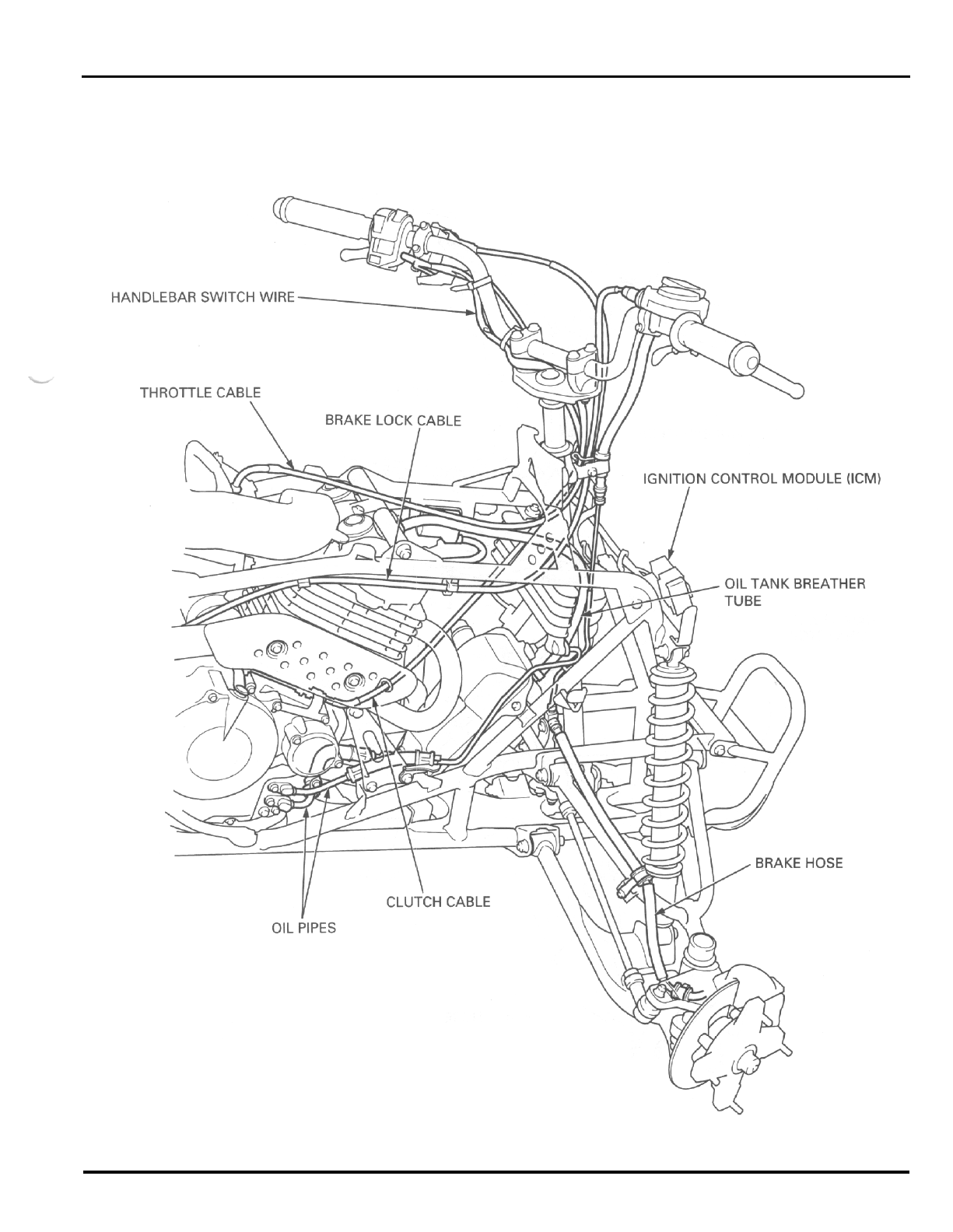
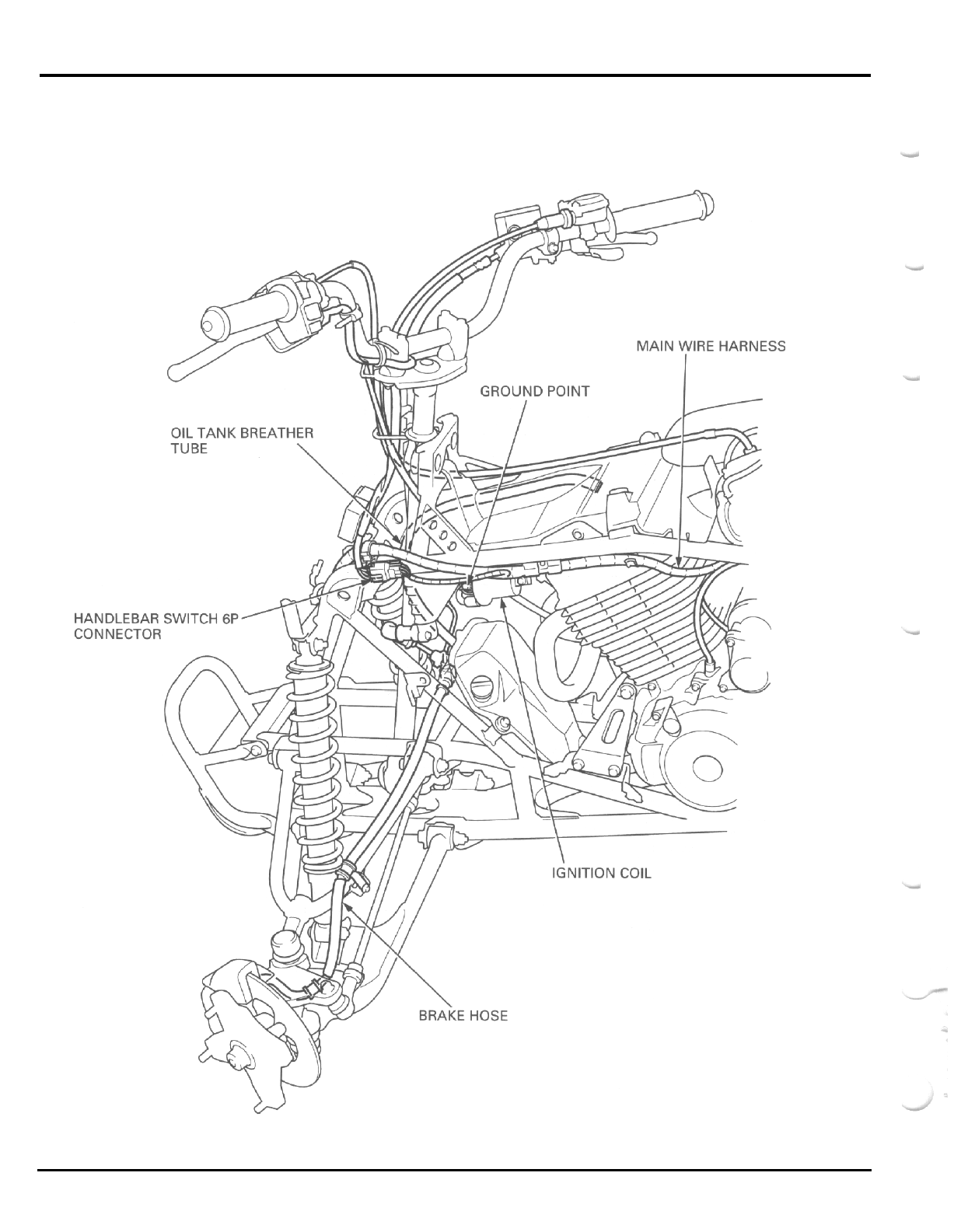
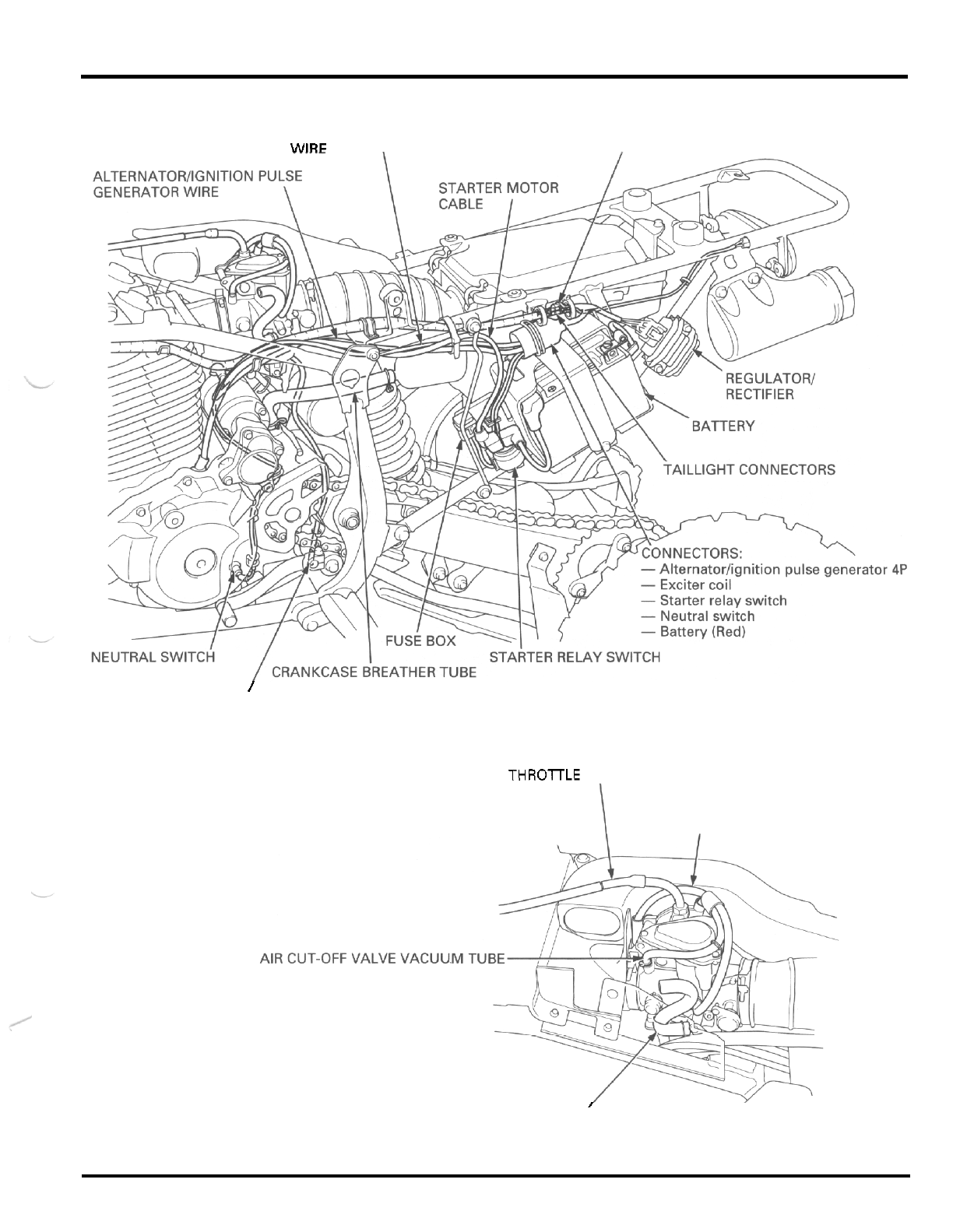
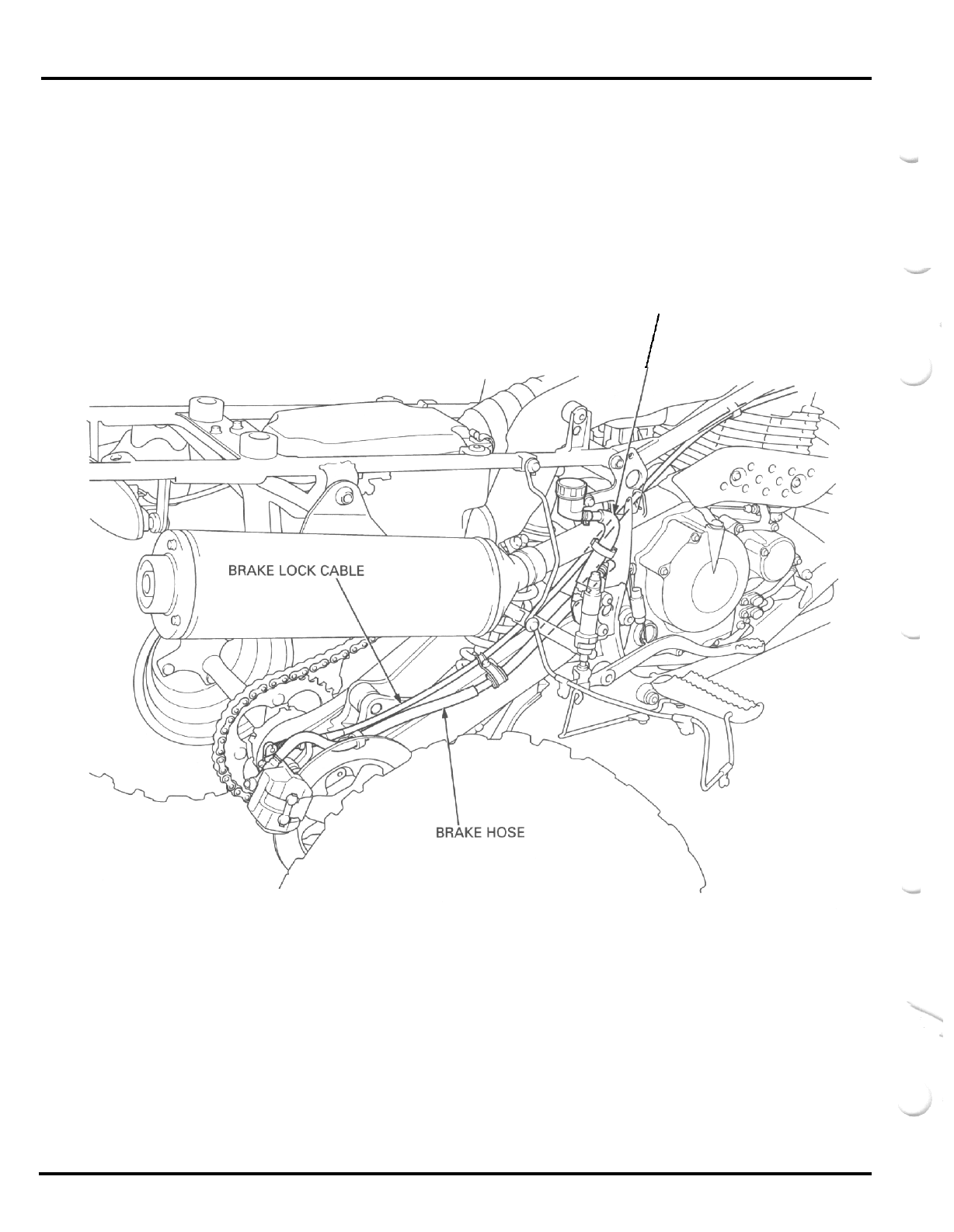
CABLE
&
HARNESS ROUTING
-
THROTTLE CABLE BRAKE LOCK CABLE
BRAKE HOSE ANDLEBAR SWITCH
WIRE
CLUTCH CABLE
OIL
TANK BREATHER
TUBE
NEUTRAL INDICATOR
CONNECTORS
EADLIGHT CONNECTOR
IGNITION SWITCH CONNECTORS
1
-
18
GENERAL INFORMATION
.
1
-
19
GENERAL INFORMATION
1
-
20
GENERAL INFORMATION
NEUTRAL SWITCH
WlRF
\
DIODE
/
CARBURETOR DRAIN TUBE
THROlTLE CABLE
CARBURETOR
AIR
VENT TUBE
I
I
FUEL TUBE
1
-
21
GENERAL INFORMATION
MASTER
CYLINDER
RESERVOIR HOSE
I
1
-
22
GENERAL INFORMATION
EMISSION CONTROL SYSTEMS
The California Air Resources Board (CARB) requires manufacturers to certify that their ANs comply with applicable exhaust
emissions standards during their useful life, when operated and maintained according to the instructions provided.
SOURCE
OF
EMISSIONS
The combustion process produces carbon monoxide and hydrocarbons. Controlling hydrocarbon emissions is very important
because, under certain conditions, they react to form photochemical smog when subjected to sunlight. Carbon monoxide
does not react in the same way, but
it
is toxic.
Honda Motor Co., Ltd. utilizes lean carburetor settings as well as other systems, to reduce carbon monoxide and hydrocar
-
bons.
EXHAUST EMISSION CONTROL SYSTEM
-
The exhaust emission control system is composed of
a
lean carburetor setting, and
no
adjustments should be made except
idle speed adjustment with
the
throttle stop screw. The exhaust emission control system is separate from the crankcase emis
-
sion control system.
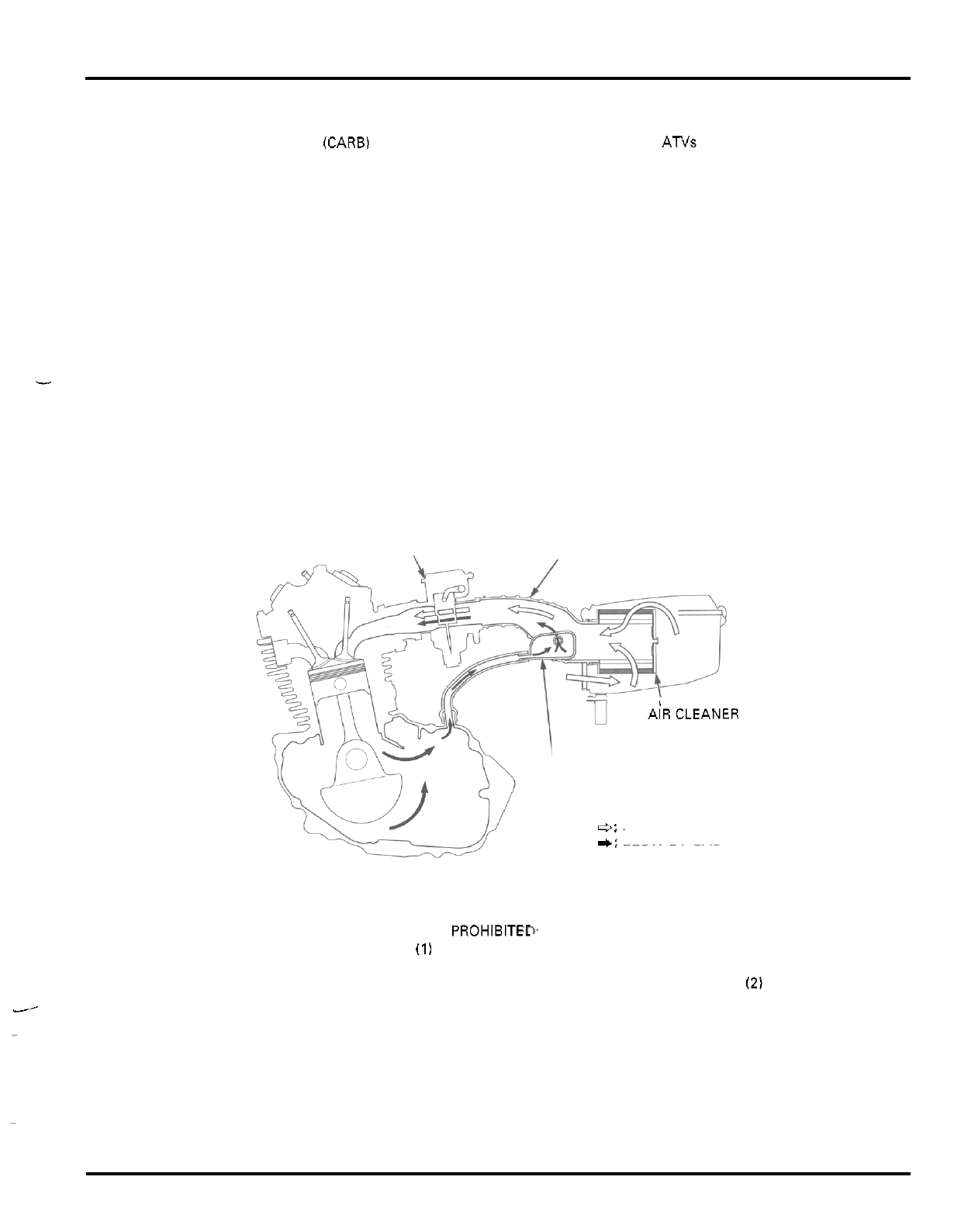
CRANKCASE EMISSION CONTROL SYSTEM
The engine is equipped with
a
closed crankcase system to prevent discharging crankcase emissions into the atmosphere.
Blow
-
by gas is returned to the combustion chamber through the air cleaner and carburetor.
AIR CLEANER CONNECTING TUBE
CARBURETOR
1
AiRCLEANER
CRANKCASE BREATHER STORAGE
e:
FRESH AIR
-+:
BLOW
-
BY GAS
TANK
NOISE EMISSION CONTROL SYSTEM
TAMPERING WITH THE NOISE CONTROL SYSTEM
IS
PROHIBITE- US. federal law prohibits, or Canadian provincial laws
prohibit the following acts or the causing thereof:
(11
The removal or rendering inoperative by any person, other than for pur
-
poses of maintenance, repair or replacement, of any device or element of design incorporated into any new vehicle for the
purpose of noise control prior to its sale or delivery to the ultimate purchaser or while
it
is in use;
(2)
the use of the vehicle
after such device or element of design has been removed or rendered inoperative by any person.
J
~
AMONG THOSE ACTS PRESUMED TO CONSTITUTE TAMPERING ARE THE ACTS LISTED BELOW
1.
Removal of or puncturing
of
the muffler, baffles, header pipes or any other component which conducts exhaust gases.
2.
Removal of, or puncturing of any part of the intake system.
3.
Lack of proper maintenance.
4.
Replacing any moving parts of the vehicle, or parts of the exhaust or intake system, with parts other than those specified
-
by the manufacturer.
1
-
23
GENERAL INFORMATION
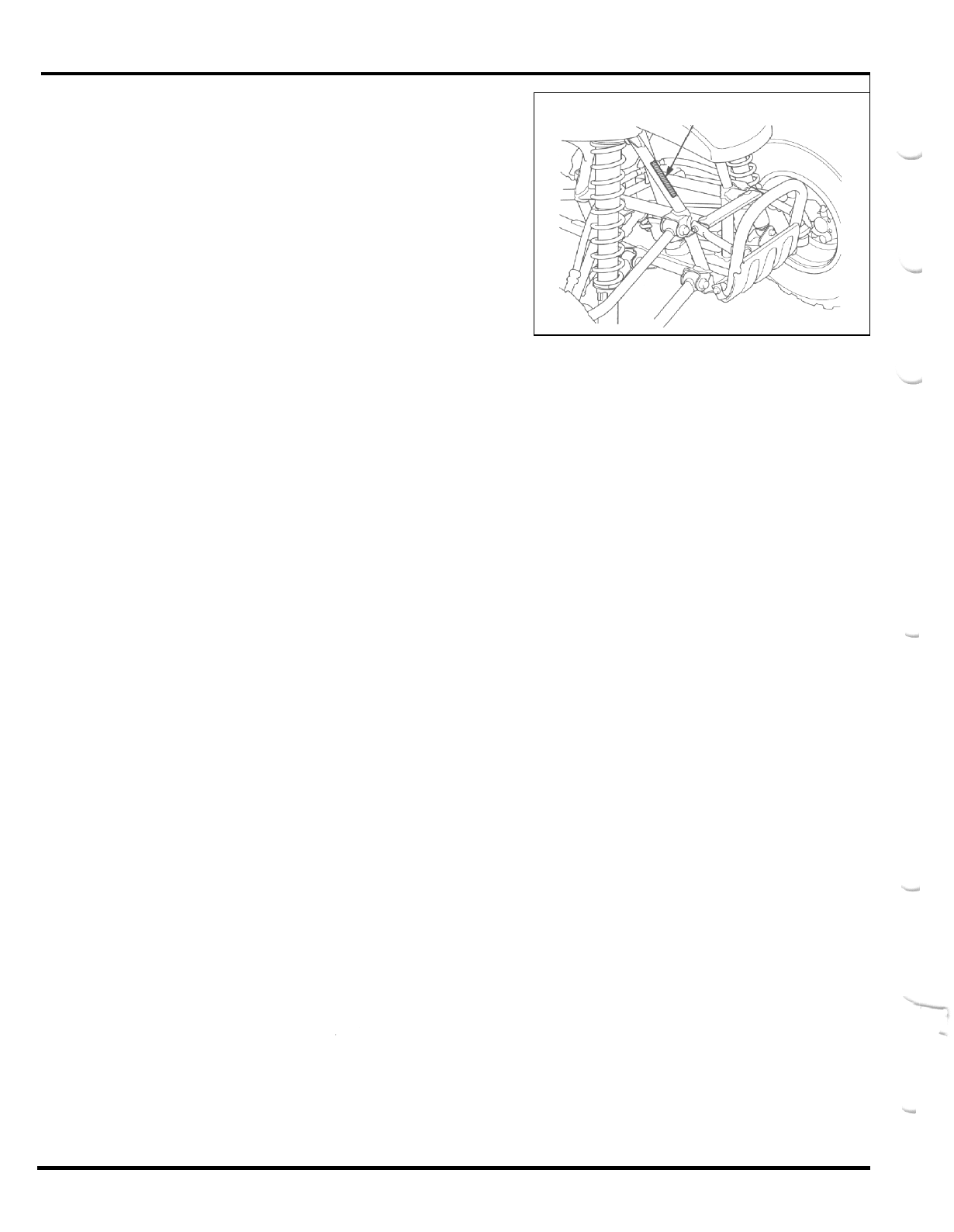
EMISSION CONTROL INFORMATION
LABEL
The Vehicle Emission Control Information Label
is
attached on the right side frame down tube.
VEHICLE EMISSION CONTROL
INFORMATION LABEL
1
-
24
2.
FRAME/BODY PANELS/EXHAUST SYSTEM
SERVICE INFORMATION 2
-
1 FUEL TANK
&
HEAT PROTECTOR 2
-
4
TROUBLESHOOTING 2
-
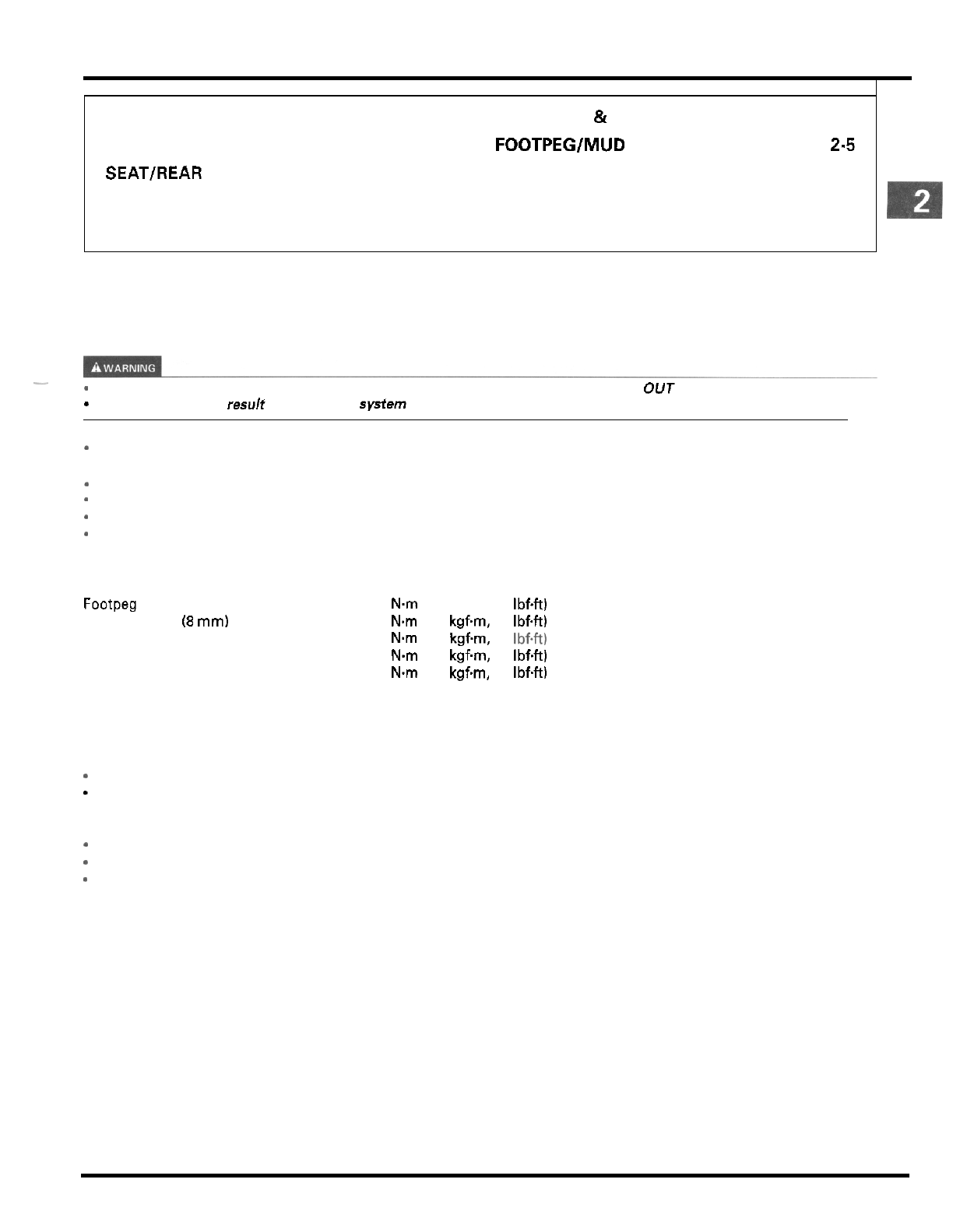
1 FOOTPEG/MUD GUARD 2-5
SEAT/REAR FENDER 2
-
2 SKID PLATE 2
-
5
FRONT FENDER 2
-
2 EXHAUST SYSTEM 2
-
6
SIDE COVER 2
-
3
SERVICE INFORMATION
GENERAL
Gasoline is extremely flammable and
is
explosive under certain conditions. KEEP OUT
OF
REACH OF CHILDREN.
-
Serious burns may result
if
the exhaust system is not allowed to cool
before
components are removed or serviced.
-
-
Work in
a
well ventilated area. Smoking or allowing flames or sparks in the work area or where gasoline
is
stored can
cause
a
fire or explosion.
This section covers removal and installation of the body panels, fuel tank and exhaust system.
-
Always replace the gaskets when removing the exhaust system.
*
Always inspect the exhaust system for leaks after installation.
*
Refer to section
18
for light and switch information.
TORQUE VALUES
Footpeg bracket bolt
Skid plate bolt
(8
mm)
Muffler mounting bolt
Muffler band bolt
Exhaust pipe protector bolt
42
Nm
(4.3
kgfm,
31
Ibf4t)
30
Nm
(3.1
kgfm,
22
IbfW
32
Nm
(3.3
kgfm,
24
Ibf4t)
23
Nm
(2.3
kgf.m,
17
IbfW
20
N.m
(2.0
kgfm,
14
IbfW
TROUBLESHOOTING
Excessive
exhaust
noise
*
Broken exhaust system
-
Exhaust gas leaks
Poor
performance
*
Deformed exhaust system
*
Exhaust gas leaks
*
Clogged muffler
2
-
1
FRAMElBODY
PANELSlEXHAUST
SYSTEM
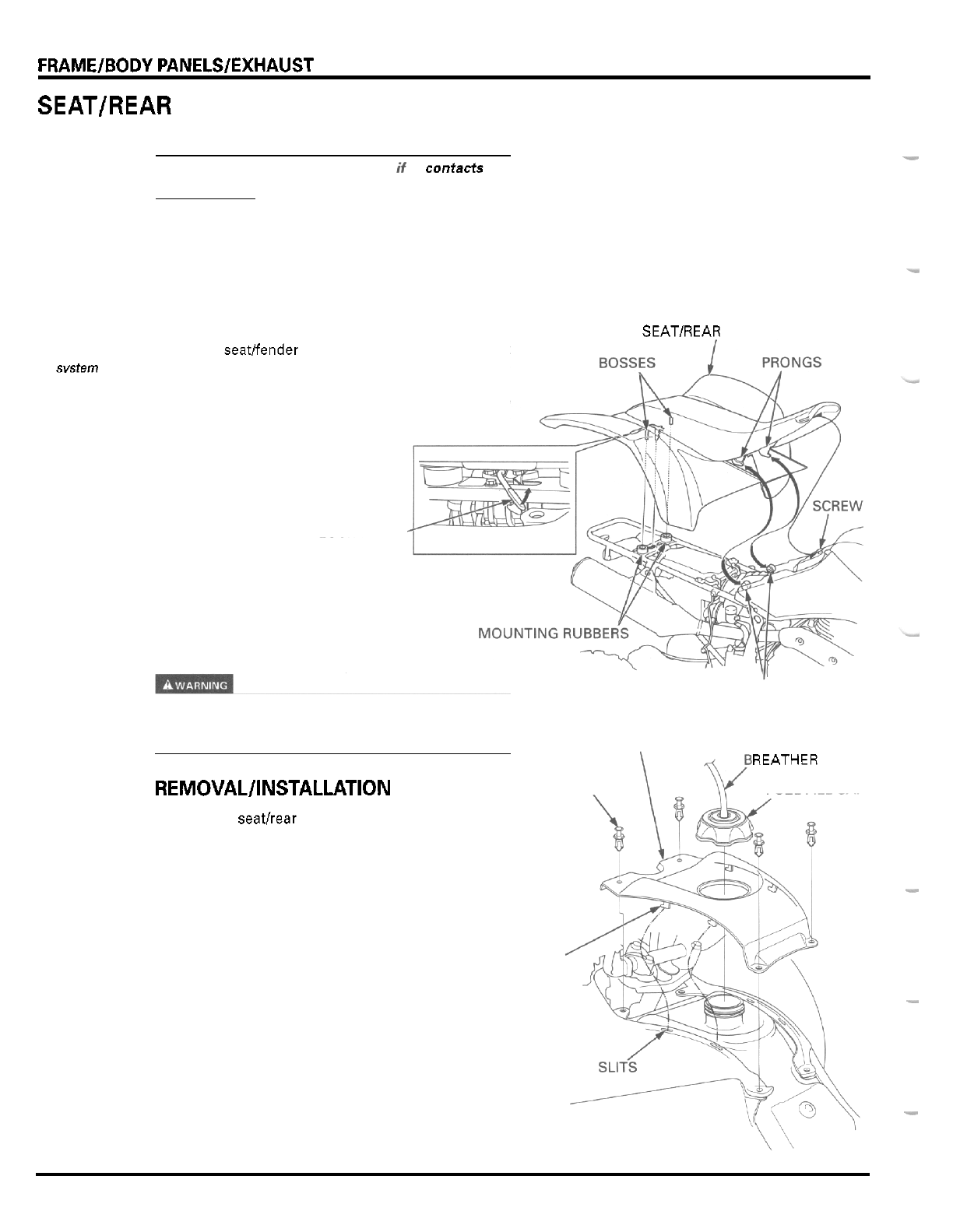
SEAT/REAR FENDER
CAUTION:
D
O
not allow the
assembly to
contact the
muffler when the
exhaust
svstem
is
hot.
FRONT
The rear fender may be deformed
if
it
contacts
the
muffler while the exhaust system is hot.
REMOVAL
Unlock the seat by turning the lock lever upward.
Raise the seatlfender assembly up and remove it.
INSTALLATION
-
SEAT/REAR FENDER
Install the seatlfender assembly by inserting the hook
between the screw and fuel tank and the prongs onto
the front mounting rubbers of the frame.
Push the seatlfender assembly forward and align the
mounting bosses with the rear mounting rubbers,
then press down to lock
it.
LOCK LEVER
FENDER
MOUNTING RUBBERS
Gasoline
is
extremely flammable and is explosive
under certain conditions. KEEP
OUT
OF
REACH
OF
CHILDREN.
UPPERCOVER
REMOVAL/INSTALLATION
TRIM
CLIPS FUEL FILL CAP
Remove the seatbear fender assembly.
Release the four trim clips by raising the center pin
and remove them.
Remove the breather tube and fuel fill cap.
Release the four tabs from the slits in the fender while
sliding the fuel tank upper cover rearward and remove
it.
TABS
Install the fuel fill cap.
REATHER TUBE
-
-
-
2
-
2
SIDE
COVER
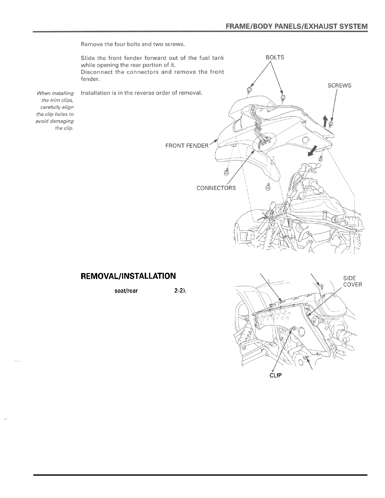
REMOVAL/INSTALLATION
Remove the seathear fender (page
2-2).
Remove the screw and two trim clips.
Release the side cover from the three tabs of the
front fender by sliding it forward and remove the side
cover.
Installation is in the reverse order
of
removal.
When installing
the trim clips,
carefully align
the clip holes to
avoid damaging
the clip.
TABS
\
TRIM
CLIP
\
TRIM
dLlP
SCREW
2
-
3
FRAMElBODY
PANELS/EXHAUST
SYSTEM
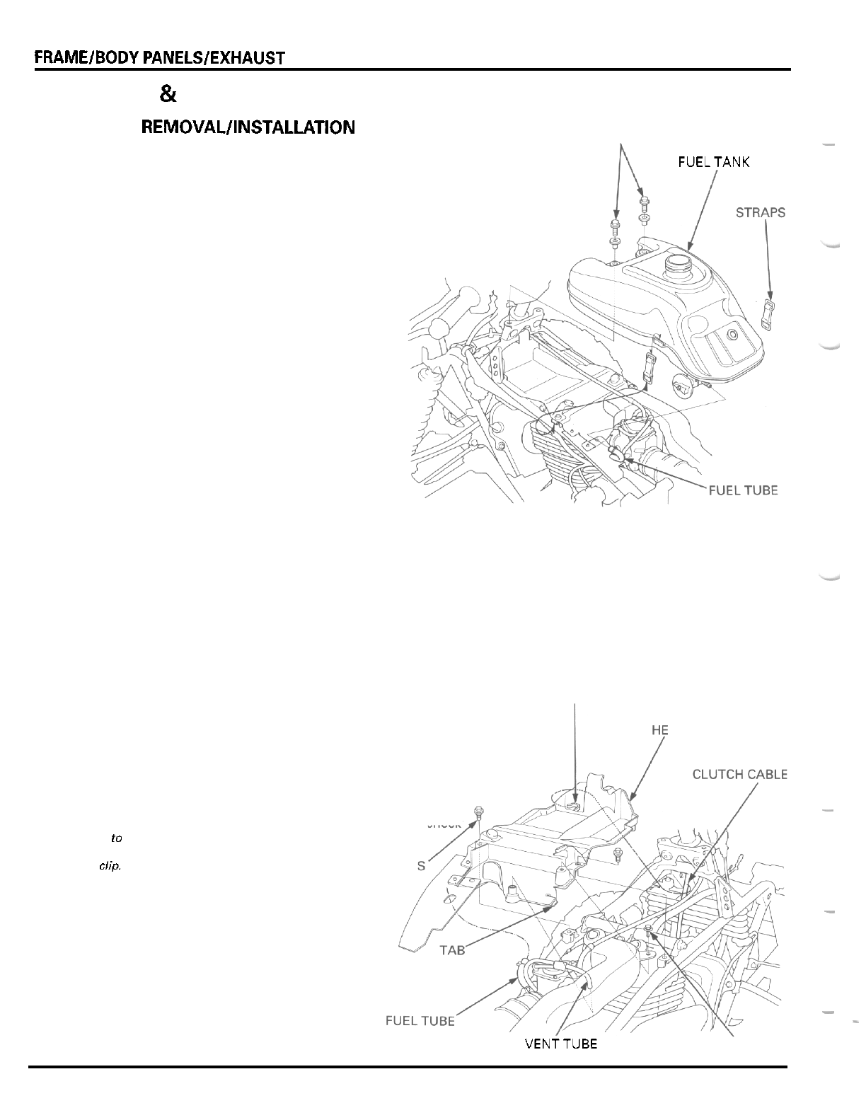
FUEL TANK
&
HEAT PROTECTOR
-
BOLTS
REMOVAL/INSTALLATION
Remove the front fender (page
2
-
2).
FUELTANK
FUEL
TANK
Turn the fuel valve
OFF.
Disconnect the fuel tube from the fuel valve.
Unhook the mounting straps.
Remove the two mounting bolts and the fuel tank.
TANK
UNDER
HEAT PROTECTOR
Remove the carburetor air vent tube from the tube
holder in the heat protector.
Remove the clutch cable from the cable guide on the
protector.
Release the trim clip by raising the center pin and
remove
it.
Remove the fuel tube from the protector rubber.
Remove the two mounting bolts.
Release the two tabs on the rear side of the protector
and remove the protector from the frame.
Installation is in the reverse order of removal.
After installation, turn the fuel valve ON and check
the fuel line for leakage.
GUIDE
AT PROTECTOR
When installing
carefullyalign
the clip holes
to
avoid damaging
the trim clip,
-
the clip.
MOUNTING BOLT
-
-
-
AIR
VENTTUBE TRIM CLIP
2
-
4
FRAMElBODY PANELSlEXHAUST SYSTEM
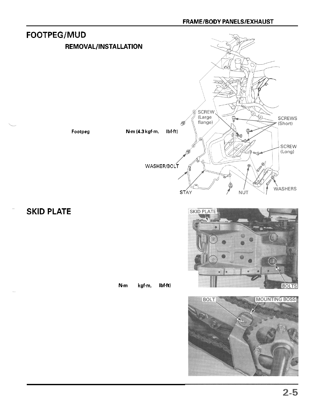
FOOTPEG/MUD GUARD
REMOVAL/INSTALLATION
Remove the five screws, nut and the mud guard.
Remove the washer bolt from the footpeg bottom and
the inner mud guard stay.
Remove the bolt and washer and the outer mud guard
stay from the stay hole in the footpeg.
Remove the two socket bolts and washers and the
footpeg.
Installation is in the reverse order of removal.
TORQUE
Footpeg bracket bolt:
42
Nm
14.3
kgfm
31
IbfW
y’
WASHEWBOLT
OUTER MUD GUARD STAY
INNER MUD GUARD ST WASHER BOLT SOCKET BOLTS
~
SKIDPLATE
REMOVAL
Remove the five bolts and the skid plate from the
swingarm.
INSTALLATION
Hook the chain guard of the skid plate onto the
mounting boss on the swingarm, install the
6
mm bolt
and new four
8
mm bolts and tighten them.
TORQUE
8
mm
bolt:
30
Nm
13.1
kgfm,
22
IbfW
-
FRAME/BODY PANELSlEXHAUST SYSTEM
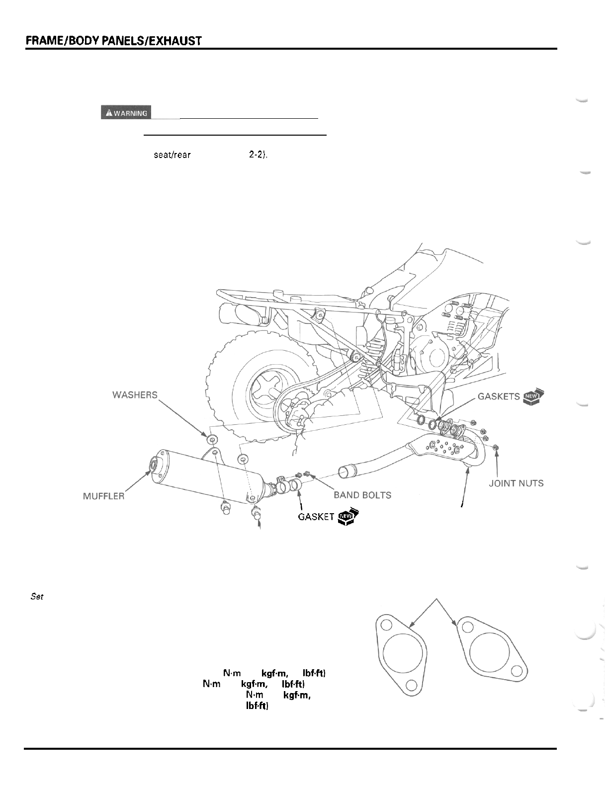
EXHAUST
SYSTEM
REMOVAL
Do
not service the exhaust system while
it
is
hot.
Remove the seatkear fender (page
2-2).
MUFFLER
Loosen the muffler band bolts.
Remove the upper and lower muffler mounting
bolts
and washers (between the muffler and frame).
Remove the muffler.
Remove the muffler gasket.
EXHAUST PIPE
Remove the joint nuts and the exhaust pipe.
Remove the joint gaskets.
Set
the
exhaust
pipe
flange
as
shown.
I
'
GASKET&?
I
EXHAUST PIPE
MOUNTING
BOLTS
INSTALLATION
Install new joint and muffler gaskets.
Install the exhaust pipe and muffler in the reverse
order of removal by loosely tightening
all
fasteners.
Tighten the joint nut first, then tighten the mounting
bolts and the band bolts.
TORQUE:
Muffler
mounting bolt:
32
N.m
(3.3
kgfm,
24
Ibf4t)
Muffler
band bolt:
23
Nm
(2.3
kgfm,
17
Ibf.ft)
Exhaust pipe
protector bolt:
20
Nm
(2.0
kgfm,
14
IbfW
After installation, inspect the exhaust system for leaks.
EXHAUST PIPE FLANGE:
-
View from front side:
-
2
-
6
3.
MAINTENANCE
ITEM
Throttle lever free play
Spark plug Standard
For extended high speed riding
Spark plug gap
Valve clearance Intake
Exhaust
Recommended engine oil
SERVICE INFORMATION
MAINTENANCE SCHEDULE
FUEL LINE
THROTTLE OPERATION
AIR CLEANER
AIR CLEANER HOUSING DRAIN TUBE
SPARK PLUG
VALVE CLEARANCE
ENGINE OIL
ENGINE OIL FILTER
ENGINE OIL STRAINER SCREEN
IN
OIL TANK
ENGINE IDLE SPEED
DRIVE CHAIN
SPECIFICATIONS
3
-
8 mm (118
-
5/16 in1
DPREZ (NGK), X24GPR-U (DENSO)
DPR9Z (NGK), X27GPR-U (DENSO)
0.6
-
0.7
mm (0.024
-
0.028 in)
0.10 mm (0.004 in)
0.12 mm
(0.005
in)
Honda GN4 or HP4 4
-
stroke oil or eauivalent motor oil
3
-
1
3
-
3
3
-
4
3
-
4
3
-
5
3
-
6
3
-
6
3
-
7
3
-
9
3
-
1
1
~~
Engine oil capacity
3
-
12
3
-
12
3
-
13
After draining
After drainingtfilter change
DRIVE CHAIN SLIDER
BRAKE FLUID
BRAKE PADS WEAR
BRAKE SYSTEM
SKID PLATE AND ENGINE GUARD
CLUTCH SYSTEM
SUSPENSION
SPARK ARRESTER
NUTS, BOLTS, FASTENERS
WHEELS/TIRES
STEERING SHAFT HOLDER BEARING
STEERING SYSTEM
3
-
14
3
-
1 4
3
-
1 5
3
-
15
3
-
17
3
-
17
3
-
18
3
-
19
3
-
19
3
-
19
3
-
20
3
-
20
SERVICE INFORMATION
GENERAL
-
If
the engine must be running to do some work, make sure the area is well ventilated. Never run the engine in an
enclosed area. The exhaust contains poisonous carbon monoxide gas that may cause loss
of
consciousness and lead to
death. Run the engine in an open area
or
with an exhaust evacuation system in an enclosed area.
SPECIFICATIONS
I
After disassemblv
Engine idle speed
Viscosity: SAE IOW-40 or 2OW
-
50
1.8 liters (1.9 US qt,
1.6
Imp qt)
1.85 IiterS (1.95
US
qt, 1.63 Imp qt)
2.2
liters
(2.3
US
qt, 1.9 Imp qt)
1,400
f
100 rpm
3
-
1
Clutch lever free play
Drive chain slack
Recommended brake fluid
10
-
20 mm (318
-
314 in)
-.
30
-
40 mm (1
-
114
-
1-5B in)
DOT
4
brake fluid
Cold tire pressure
(FronffRear) Standard
Minimum
27
kPa
(0.275 kgf/cm2,4.0 psi)
23
kPa
10.235 kof/cm?. 3.4
Dsil
Maximum 31
kPa
(0.315 kgf/cmZ, 4.6 psi)
Tire size Front AT22 x 7
-
10
**
Rear
Front
Rear
TORQUE
VALUES
AT20 x 10-9
**
M/R 101
M/R
501
Spark plug 18 Nm (1.8 kgfm, 13 IbfW
Valve adjusting hole cap 15 Nm
(1.5
kgfm,
11
IbfW
Valve adjusting lock nut 24 Nm (2.4 kgfm, 17 IbfW
Crankshaft hole cap 8 Nm (0.8 kgfm. 5.8 IbfW
Timing hole cap 10 Nm (1.0 kgfm, 7 IbfW
Engine
oil
drain bolt (crankcase) 25 Nm (2.5 kgfm, 18 IbfW
Engine oil drain bolt (oil tank) 20 Nm (2.0 kgfm,
14
IbfW
Engine oil strainer screen (at oil tank) 54 Nm (5.5 kgh, 40 IbfW
Oil pipe joint flare nut 20 Nvn (2.0 kgfm.
14
I
bfW
Axle bearing holder pinch bolt
21
Nm (2.1 kgfm, 15 IbfW
Front master cylinder reservoir cap screw
2
Nm (0.2 kgfm, 1.4 IbfW
Parking brake arm lock nut
18
Nm (1.8 kgfm, 13 IbfW
Rear master cylinder push rod lock nut 18 N.m (1.8 kgh, 13 IbfW
Tie
-
rod lock nut 54 Nm (5.5 kgh, 40 IbfW
Minimum tread depth (FronffRear)
3
-
2
1
4.0 mm (0.16 in)
Toe Toe
-
in:
17
f
15 mm (0.7f 0.6 in)
MAINTENANCE
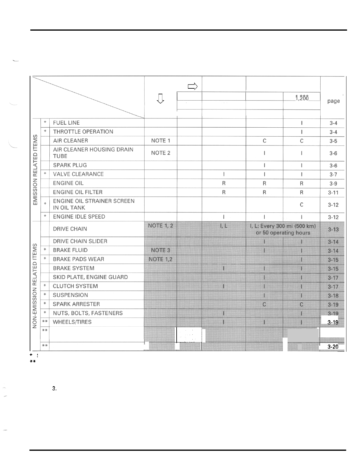
MAINTENANCE SCHEDULE
Perform the PRE
-
RIDE INSPECTION in the Owner's Manual at each scheduled maintenance period.
I:
Inspect and Clean, Adjust, Lubricate
or
Replace
if
necessary.
C:
Clean
R:
Replace A: Adjust
L:
Lubricate
.-
ITEMS
1
FREQUENCY WHICHEVER INITIAL REGULAR
COMES FIRST MAINTENANCE MAINTENANCE INTERVAL
mi 100
600
1,200
Refer
to
km
150
1,000
2,000
ITEMS NOTE HOURS
20
100
200
paw
FREQUENCY WHICHEVER INITIAL REGULAR
COMES FIRST
d
MAINTENANCE MAINTENANCE INTERVAL
U
NOTE
*!
mi 100
600
1,200
Refer
to
km
150
1,000
2,000
paw
HOURS
20
100
200
t
3-19
STEERING SHAFT HOLDER
BEARING
.
-
STEERING SYSTEM
I'
L
L
L
I
I
3
-
20
I
3-20
1
~
Should be serviced by your Honda dealer, unless the owner has proper
tools
and service data and
is
mechanicallv aualified.
**
In the interest of safety, we recommend these items be serviced only by your Honda dealer.
NOTES 1. Service more frequently if the AN
is
ridden in dusty areas, sand or snow.
2.
Service more frequently
if
the ATV is ridden
in
very wet or muddy conditions.
3.
Replace every
2
years. Replacement requires mechanical
skill.
3
-
3
MAINTENANCE
I
ADJUSTER
/
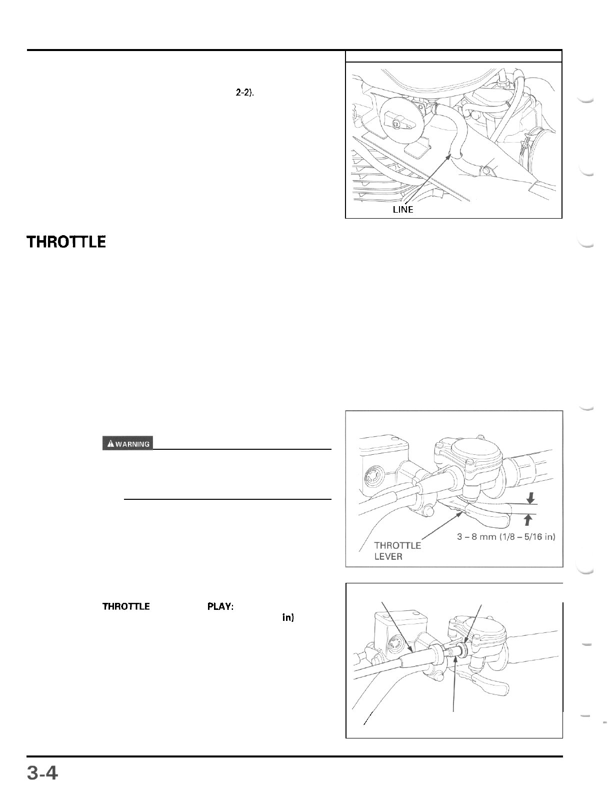
FUEL LINE
-
-
Remove the front fender (page
2-2).
Check the fuel line for deterioration, damage or leak
-
age.
Replace the fuel line
if
necessary.
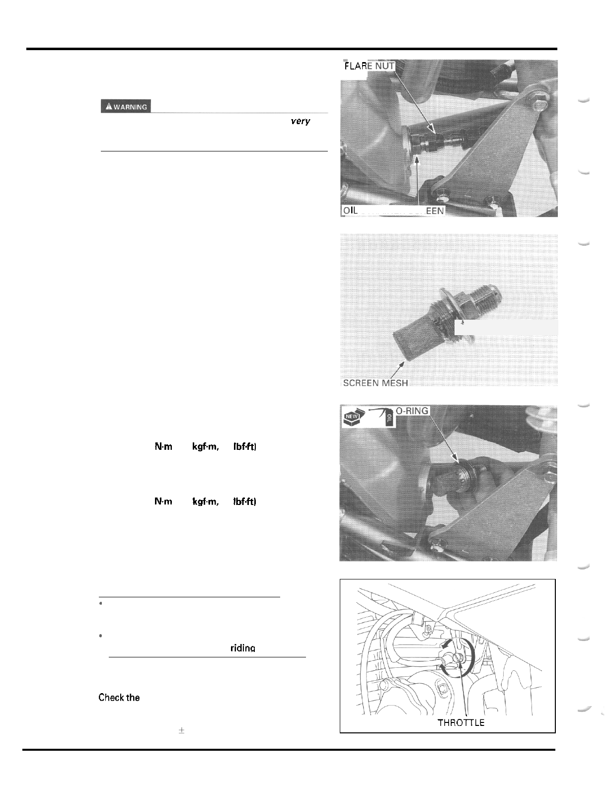
THROlTLE OPERATION
Check for any deterioration or damage to the throttle
cable. Check that the throttle lever for smooth opera
-
tion. Check that the throttle opens and automatically
closes in
all
steering positions.
If
the throttle lever does not return properly, lubricate
the throttle cable and overhaul and lubricate the
throttle housing.
For cable lubrication: Disconnect the throttle cable
at
its upper end. Thoroughly lubricate the cable and its
pivot point with
a
commercially available cable lubri
-
cant or a light weight oil.
If the throttle lever still does not return properly,
replace the throttle cable.
Reusing
a
damaged or abnormally bent or kinked
throttle cable can prevent proper throttle slide
operation and may lead to
a
loss
of
throttle control
while riding.
With the engine idling, turn the handlebar all the way
to the right and left to ensure that the idle speed does
not change.
If
idle speed increases, check the throttle
lever free play and the throttle cable connection.
Measure the throttle lever free play at the tip of the
throttle lever.
THROITLE LEVER
FREE
PLAY:
3
-
8
mm
1118
-
5/16
in1
Throttle lever free play can be adjusted at upper end
of the throttle cable.
Loosen the lock nut, turn the adjuster as required and
tighten the lock nut.
Install the rubber boot securely.
F
U
E
L
LI~E
BOOT
LOCK NUT
I
MAINTENANCE
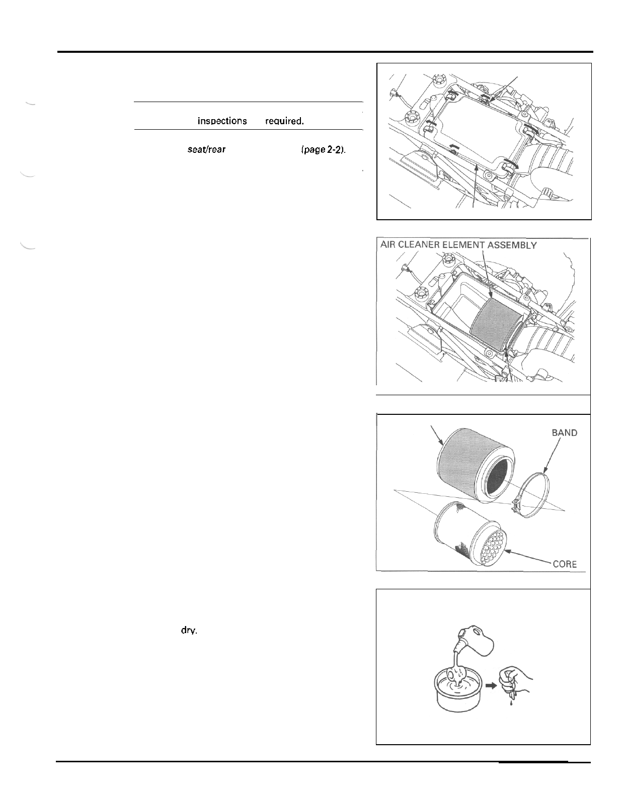
AIR CLEANER
NOTE:
If the vehicle is used in dusty areas, sand or snow,
more freauent inwections are rewired.
Remove the seathear fender assembly (page
2-2).
Release the six retaining clips from the air cleaner
housing covet and remove the cover.
Loosen the air cleaner element band screw.
Remove the air cleaner element assembly from the
housing.
Remove the element band and the element core from
the air cleaner element.
Wash the element
in
non
-
flammable or high flash
point solvent such
as
kerosene.
Squeeze out the solvent thoroughly, and allow the
element to
dry.
RETAINING
CLIPS
COVER
I
S
CREW
I
ELEMENT
WASH SQUEEZE
OUT
3
-
5
MAINTENANCE
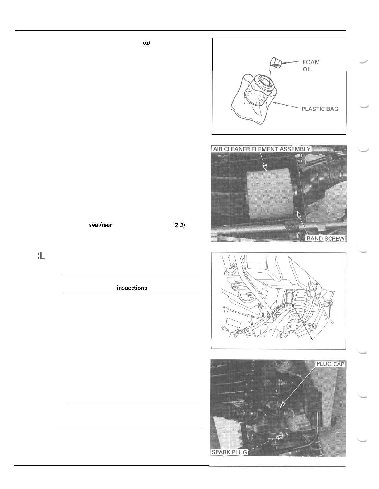
AIR
C
Apply approximately
20
g
(0.7
oz)
of Pro Honda Foam
Filter
Oil
or equivalent oil from the inside of the ele
-
ment.
Place the element into
a
plastic bag and spread the
oil evenly by hand.
Install the element core into the air cleaner element
properly.
Install the element band onto the air cleaner element
and the element assembly over the connecting tube
flange in the housing securely.
Tighten the band screw.
Install the air cleaner housing cover and secure
it
with the retaining clips.
Install the seathear fender assembly (page
2-2).
EANER
HOUSING DRAIN TUBE
NOTE:
If the vehicle is used in very wet or muddy condi
-
tions, more frequent insDections are reauired.
Remove the drain tube from bottom of the air cleaner
housing to empty any deposits.
Install the drain tube securely.
SPARK PLUG
Disconnect the spark plug cap and clean around the
spark plug base.
NOTE:
Clean around the spark plug base with compressed
air before removing the plug, and be sure that no
debris is allowed to enter the combustion chamber.
Remove the spark plug.
PRO HONDA
:AM
FILTER
\'
DRAIN TUBE
3
-
6
MAINTENANCE
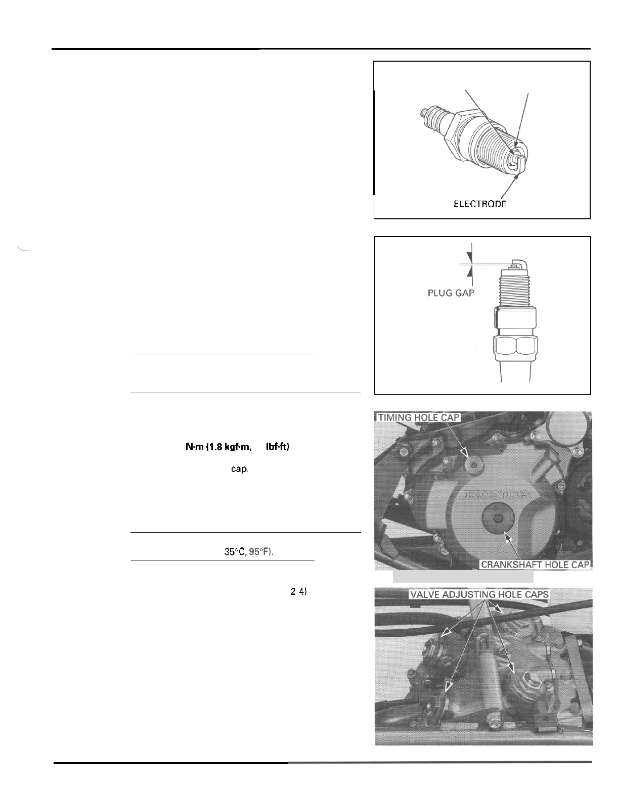
Check the insulator for cracks or damage, and the
electrodes for wear, fouling or discoloration. Replace
the plug if necessary (recommended spark plug:
page 3
-
1).
Clean the spark plug electrodes with a wire type
brush or special plug cleaner.
Check the gap between the center and side electrodes
with a wire
-
type feeler gauge. If necessary, adjust the
gap by bending the side electrode carefully.
SPARK PLUG
GAP
0.6
-
0.7
mm
(0.024
-
0.028
in)
CAUTION:
To
prevent damage to the cylinder head, hand
-
tighten
the spark plug before using
a
wench to tighten to the
specified torque.
Reinstall the spark plug in the cylinder head and
hand tighten, then torque to specification.
TORQUE
18
Nm
11.8
kgfm,
13
IbfW
Connect the spark plug cap,
VALVE CLEARANCE
NOTE:
Inspect and adjust the valve clearance while the
engine is cold (below 35"C,
95'F).
Remove the following:
-
fuel tank and heat protector (page
2-4)
-
timing hole cap and crankshaft hole cap
-
valve adjusting hole caps.
CENTER ELECTRODE
\
INSULATOR
S
I
D
E
ELECTRO~
3
-
7
MAINTENANCE
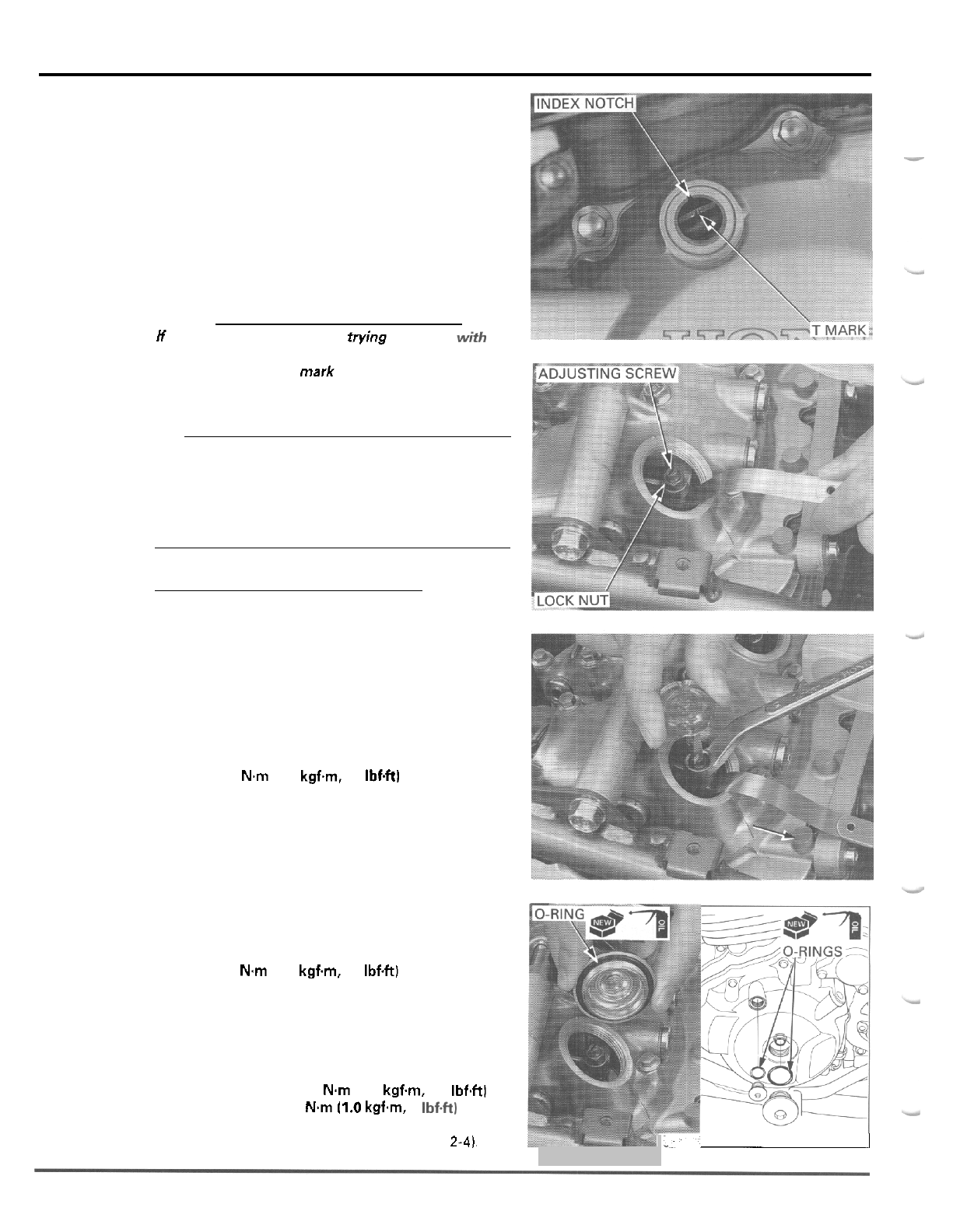
Rotate the crankshaft only counterclockwise to align
the T mark on the flywheel with the index notch in
the left crankcase cover.
Make sure the piston
is
TDC (Top Dead Center) on
the compression stroke.
This position can be obtained by confirming that
there is slack in the sub
-
rocker arm.
If
there
is
no
slack, it is because the piston is moving through the
exhaust stroke to TDC. Rotate the crankshaft one full
turn counterclockwise and match up the T mark
again.
CAUTION:
If
the
T
mark is passed when trying to align it with the
index notch, rotate the crankshaft counterclockwise
again and align the
T
mark with the index notch. This
must be done
to
prevent the one
-
way decompressor
system from functioning and to obtain the correct
valve clearance.
Check the clearance of
all
valves
by
inserting
a
feeler
gauge between the adjusting screw and sub
-
rocker
arm.
NOTE:
When checking the clearance, slide the feeler gauge
from the inside out in the direction of the arrow.
VALVE CLEARANCES IN:
0.10
mm
(0.004
in)
EX
0.12
mm
(0.005
in)
Adjust by loosening the lock nut and turning the
adjusting screw until there is
a
slight drag on the
feeler gauge.
Hold
the adjusting screw and tighten the lock nut.
TORQUE
24
N.m
(2.4
kgfm,
17
Ibf4t)
After tightening the lock nut, recheck the valve clear
-
ance.
Coat new O
-
rings and install them into the grooves in
the adjusting hole caps.
Install the adjusting hole caps and tighten them.
TORQUE:
15
N.m
(1.5
kgf.m,
11
IbfW
Coat new O
-
rings and install them onto the crank
-
shaft hole cap and timing hole cap.
Install the caps and tighten them.
TORQUE:
Crankshaft hole
cap:
8
Nm
(0.8
kgf.m,
5.8
Ibf4tl
Timing hole
cap:
10
N.m
11.0
kgf.m,
7
Ibf.ft1
Install the heat protector and fuel tank (page
2-4),
-I
3
-
8
MAINTENANCE
ENGINE
OIL
Engine and exhaust system parts become very hot
and remain hot
for
some time after the engine
is
run.
Wear insulated aloves.
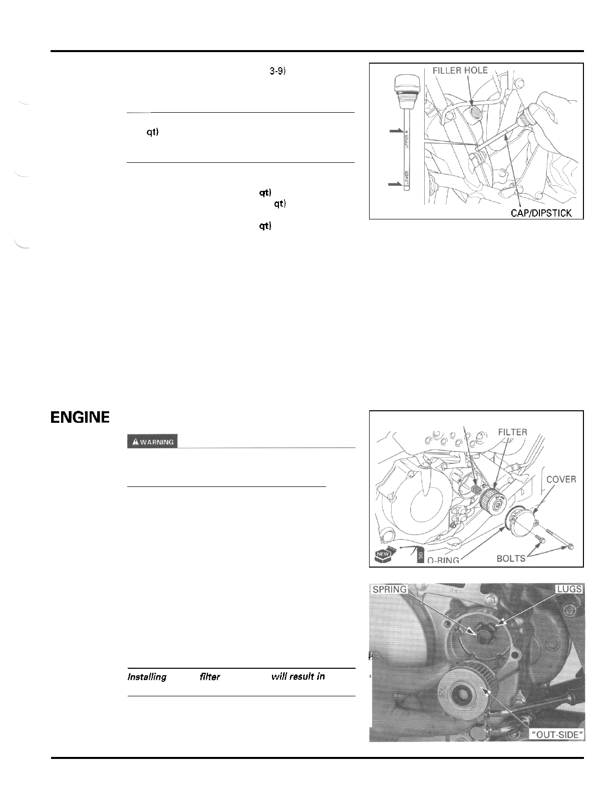
FILLER
HOLE
LEVEL CHECK
NOTE:
-
Check the oil level after starting the engine and
allowing the oil to circulate through the engine
thoroughly.
It
is especially important on dry sump
engine, due to the comparatively large volume of
oil.
-
Do
not snap the throttle while idling or the oil level
reading will be inaccurate.
Place the vehicle on level ground.
Start the engine and let
it
idle for a
5
minutes. If the
air temperature is below
10°C
(50"FL
let the engine
idle for an additional
5
minutes (a total of
10
minutes).
Stop the engine.
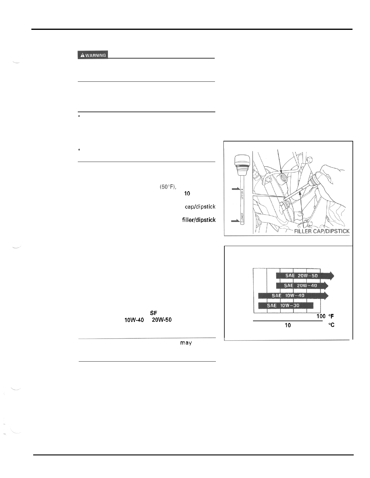
After
a
few minutes, remove the oil filler capldipstick
from the oil tank and wipe it clean.
Check the oil level by inserting the oil filler/dipstick
into
the
oil filler hole without screwing
it
in.
The engine contains
a
sufficient amount
of
oil if the
oil level
is
between the upper and lower level marks
on the dipstick.
If the oil level is near or below the lower level mark,
and the recommended engine oil up to the upper
level mark.
RECOMMENDED ENGINE
OIL
Honda GN4 or HP4 4
-
stroke oil or equivalent
motor oil
API
service classification
SF
or SG
Viscosity: SAE 1OW-40 or 2OW-50
NOTE:
OIL
VISCOSITIES
0 20
40
60
80
100
"F
-
20
-
10 0
10
20
30
40 "C
Other viscosities shown in the chart may be used
when the average temperature in your riding area is
within the indicated range.
Reinstall the filler capldipstick.
3
-
9
MAINTENANCE
At
Crankcase
Oil
Check
Bolt
NOTE
*
The crankcase oil level check bolt
is
useful when
checking the lubrication; the oil pump adjusts the
oil
level
so
that the crankcase is always kept
at
the
proper level. If this check shows otherwise, some
portion of the lubrication system
is
not working
properly.
*
Do not check the oil level immediately after the
engine has been operated
at
high speeds. Make
sure
that
vehicle is
on
firm level ground while
idling. Allow the engine to idle for
a
few minutes
to stabilize the oil levels.
The crankcase oil level is correct if the oil
is
flush
with the bottom of the check bolt hole.
OIL
CHANGE
CAUTION:
Used engine oil may cause skin cancer if repeatedly
left in contact with the skin for prolonged periods.
Although this is unlikely unless
you
handle used oil
on a daily basis, it
is
still advisable to thoroughly
wash your hands with soap and water as
soon
aspos-
sible after handling used oil.
NOTE:
Change the oil with the engine warm to assure com-
Dlete and raDid drainino.
Start the engine and
let
it
idle for few minutes.
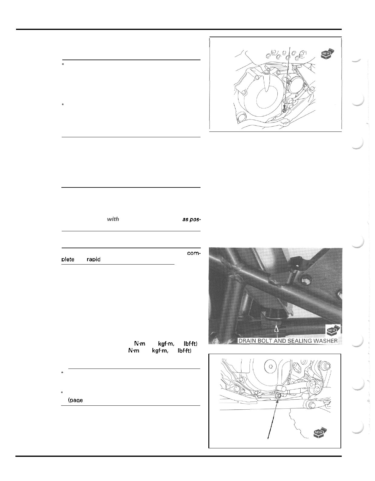
Stop the engine and remove the oil filler capldipstick.
Remove the oil tank and crankcase drain bolts with
the sealing washers and drain the engine oil.
After the oil has drained, install the drain bolts with
new sealing washers.
TORQUE:
Crankcase drain
bolt
25
N.m
(2.5
kgfm,
18
Mft)
Oil
tank drain
bolt:
20
N.m
(2.0
kgfm,
14
IbfW
NOTE:
-
If maintenance is required for the oil tank oil
strainer screen, perform the maintenance
on
the
screen before filling the oil tank (page
3
-
12).
-
Pour in the engine oil after replacing the oil filter
(page
3
-
11).
1
OIL CHECK
BOLT
AND SEALING WASHER
1
I
\e*
DRAIN BOLT AND SEALING WASHER
3
-
1
0
MAINTENANCE
EhGlNE
OIL
FILTER
Pour the recommended oil (page
3-9)
into the oil tank
up to the upper level mark
on
the dipstick.
NOTE:
SPRING
~
The engine takes about
1.85
liters
(1.95
US
qt,
1.63
Imp qt) at oil and filter change. Because only
a
por
-
tion of that oil
is
held in the oil tank, you cannot add
the full amount initially.
OIL
CAPACITY:
1.8
liters
(1.9
US
qt,
1.6
Imp
qt)
at draining
1.85
liters
(1.95
US
qt,
1.63
Imp qt) at draining/
filter change
2.2
liters
(2.3
US
qt,
1.9
Imp
qt)
at disassembly
Install the oil filler capldipstick.
Place the vehicle
on
firm level ground.
Start the engine and let it idle for
a
few minutes with
-
out snapping the throttle.
Stop the engine and add the recommended oil up to
the upper level mark on the dipstick.
Install the filler capldipstick.
Start the engine and recheck the oil level (page
3
-
91.
After replacing, make sure there are
no
oil leaks.
FILLER
CAPIDIPSTICK
Engine and exhaust system parts become very hot
and remain hot for some time after the engine
is
run.
Wear insulated gloves.
Drain the engine oil (page
3
-
10).
Remove the following:
-
cover bolts
-
filter cover with O
-
ring
-
oil filter
-
spring.
Coat
a
new O
-
ring with engine oil and install
it
in the
cover groove.
Install the spring between the lugs and a new oil filter
with the “OUT
-
SIDE” mark facing out, then set the fil
-
ter cover onto the filter and tighten the bolts securely.
ii.
CAUTION
installing
the oil filter backwards wi// resun
in
severe
engine damage.
Fill the engine and oil tank with the engine oil.
,
3
-
1
1
MAINTENANCE
-
ENGINE
OIL
STRAINER
SCREEN
IN
OIL
TANK
FLAR
Engine and exhaust system parts become very hot
and remain hot for some time after the engine
is
run.
Wear insulated gloves.
Drain the engine oil (page 3
-
10).
Disconnect the oil pipe from the lower side of the oil
tank by loosening the flare nut.
IL
STRAINER
SCR
Remove the oil strainer screen.
Wash the strainer screen thoroughly in high flash
point solvent until
all
accumulated dirt has been
removed.
Blow the screen dry with compressed air, or leave
it
in
a
well ventilated place until the solvent has evaporated.
Before installing the strainer screen,
it
should be
examined closely for damage.
6
Coat
a
new O
-
ring with engine oil and install it onto
the oil strainer screen.
Install the strainer screen and tighten it.
TORQUE:
54 N.m (5.5 kgf.m, 40 Ibf+tl
Connect the oil pipe over the strainer by screwing the
flare nut. Tighten the flare nut.
TORQUE:
20
N.m
(2.0
kgf.m, 14 Ibf4t)
Fill
the engine and oil tank with the engine oil (page
3
-
10).
I
ENGINE
IDLE
SPEED
NOTE:
-
Inspect and adjust the idle speed after
all
other
engine maintenance items have been performed
and are within specifications.
*
Engine must be warm for accurate adjustment.
Ten minutes of stop
-
and
-
ao riding
is
sufficient.
Warm up the engine, shift the transmission into neu
-
tral and place the vehicle on
a
level surface.
Checkthe idle speed and adjust by turning the throttle
stop screw as required.
IDLE SPEED
1,400
*
100 rpm
THRO~LE
STOP
SCREW
3
-
1
2
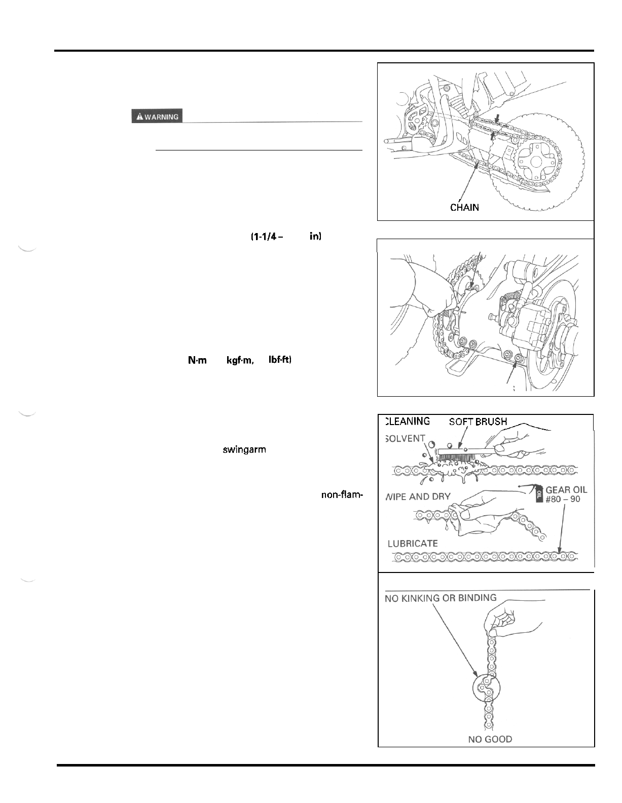
MAINTENANCE
DRIVE
CHAIN
CHAIN
SLACK
INSPECTION
Never
inspect and adjust the drive chain while the
engine
is
running.
Turn the ignition switch
OFF,
shift the transmission
into neutral.
Check the slack
in
the drive chain upper run midway
between the sprockets.
CHAIN SLACK
30
-
40
mm 11-1/4- 1-5/8
in1
ADJUSTMENT
Loosen the axle bearing holder pinch bolts.
Turn the axle bearing holder until the correct drive
chain slack is obtained, using the hex wrench in the
tool kit as shown.
Tighten the holder pinch bolts.
TORQUE
21 N.m (2.1 kgf.m, 15
IbfW
Recheck the drive chain slack and free wheel rotation.
If
the chain slack is excessive when the bearing hold
-
er is turned fully rearward (the correct slack cannot
be obtained), replace the drive chain
with
a new one.
To
replace the drive chain, remove the drive sprocket
cover (page
6
-
2)
and swingarm (page 13
-
13).
CLEANING
AND
INSPECTION
Clean the chain with a
soft
brush using a non-flam-
mable or high flash point solvent and wipe
it
dry.
Be sure the chain has dried completely before lubri
-
cating.
Inspect the drive chain for possible damage or wear.
Replace any chain that has damaged rollers, loose fit
-
ting links, or otherwise appears unserviceable.
Installing a new chain
on
badly worn sprockets
will
cause the new chain to wear quickly. Inspect and
replace the sprockets
as
necessary.
LUBRICATION
Lubricate the drive chain with Pro Honda Chain Lube
or equivalent chain lubricant designed for specifically
for use
on
O
-
ring chains.
Some commercially available chain lubricants may
contain solvents which could damage the O
-
rings.
Wipe
off
the excess chain lube.
DRIVE
CAAIN
U
BEARING HOLDER
PINCH BOLTS
:LEANING S0F;T
BRUSh
3
-
1
3
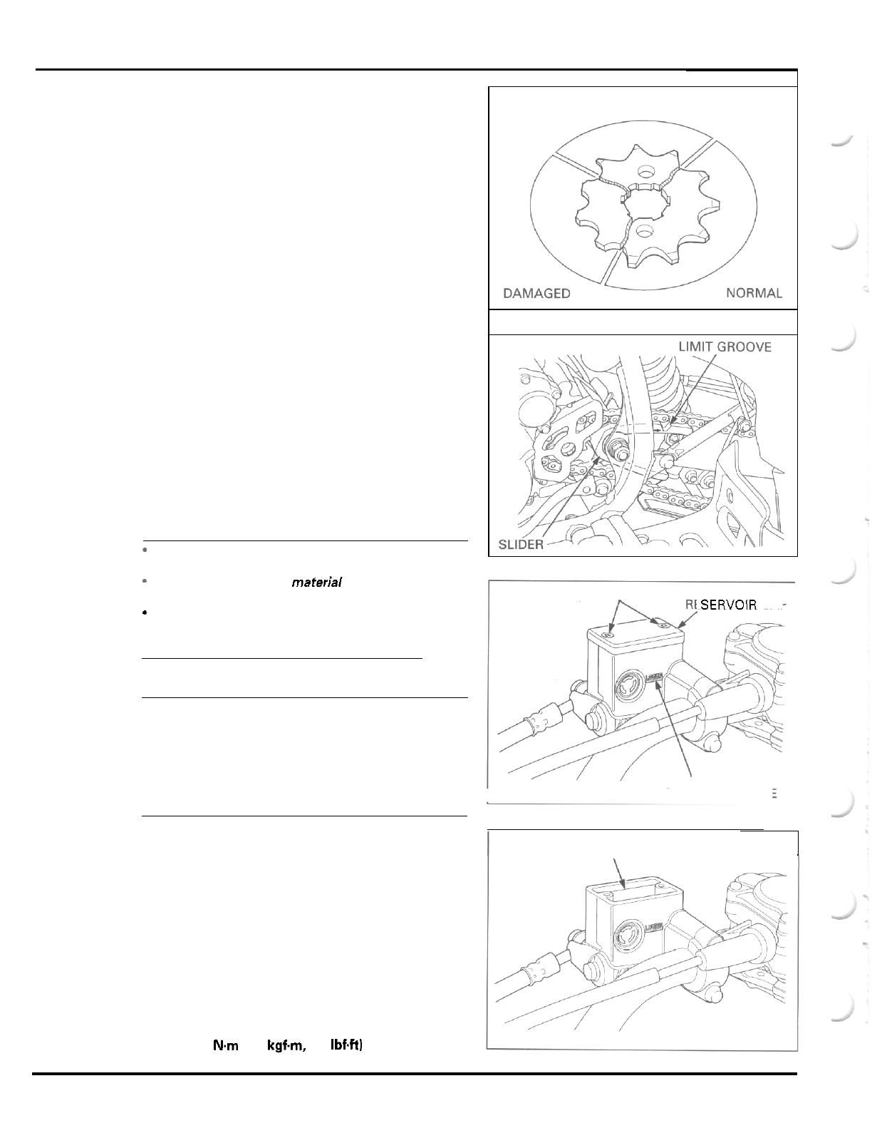
MAINTENANCE
SPROCKET INSPECTION
Inspect the drive and driven sprocket teeth for dam
-
age or wear. Replace if necessary.
Never use
a
worn chain on new sprockets. Both chain
and sprockets must be in good condition, or the new
replacement parts will wear rapidly.
Check the attachment bolt and nuts
on
the drive and
driven sprockets. If any are loose, torque them.
DRIVE CHAIN SLIDER
Check the drive chain slider for wear.
Replace the chain slider if
it
is
worn to the bottom
of
the wear limit groove.
Refer to section
13
for drive chain slider replacement.
BRAKE FLUID
CAUTION
-
Do
not mix different types of fluid,
as
they are not
compatible with each other.
-
Do
not allow foreign material to enter the system
when filling the reservoir.
*
Avoid spilling fluid on painted, plastic or rubber
parts. Place a rag over these parts whenever the
system is serviced.
NOTE:
When the fluid level is low, check the brake pads for
wear (page 3
-
17). A low fluid level may be due to wear
of the brake pads.
If
the brake pads are worn, the
caliper pistons are pushed out, and this accounts for
WORN
SCREWS SERVOIR CAP
a low reservoir level.
If
the brake pads are not worn and the fluid level
is
low, check entire system for leaks (page 3
-
17). LOWER LEVEL LINE
FRONT
BRAKE
Turn the handlebar to the left side
so
that the reser
-
voir is level and check the front brake reservoir level
through the sight glass.
If
the level is near the
"
LOWER
"
level line, remove
the reservoir cap, set plate and diaphragm, and fill
the reservoir with
DOT
4
brake fluid from
a
sealed
container to the casting ledge.
Install the diaphragm, set plate and reservoir cap and
tighten the cap screws.
I
CASTING LEDGE
1
TORQUE:
2
N.m
(0.2
kgfm,
1.4
IbfW
3
-
1
4
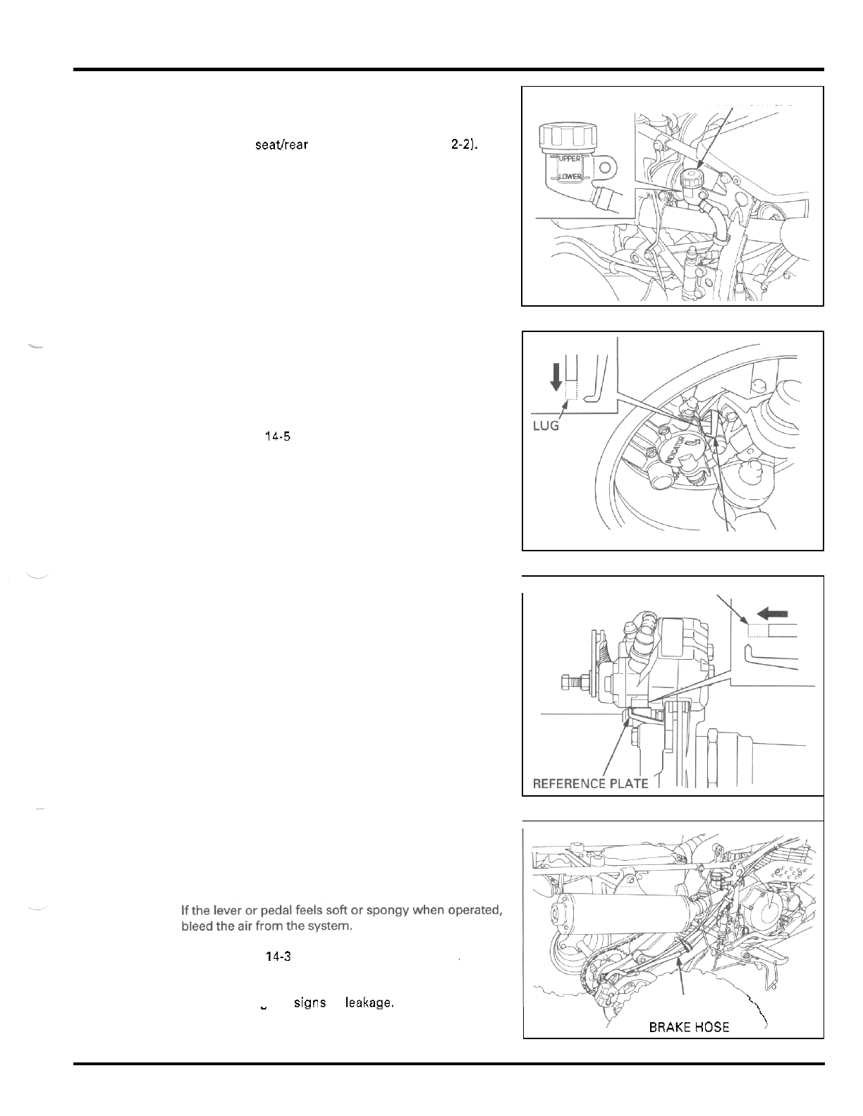
MAINTENANCE
REAR BRAKE
Place the vehicle on
a
level surface.
Remove the seathear fender assembly (page
2-2).
Check the fluid level in the rear brake reservoir.
If the level is near the
"
LOWER
"
level line, remove
the reservoir cap, set plate and diaphragm, and fill
the reservoir with
DOT
4
brake fluid from
a
sealed
container to the
"
UPPER
"
level line.
Install the diaphragm, set plate and reservoir cap.
Install the seatlrear fender assembly (page
2
-
21.
-
BRAKE
PADS
WEAR
Check the brake pad for wear.
Replace the brake pads if the wear limit indicator (lug
end) aligns with the reference plate.
Refer to page
14-5
for brake pad replacement.
BRAKE
SYSTEM
RESERVOIR CAP
{[\\
Y?5
REFERENCE PLATE
I
LUG
INSPECTION
FOR
AIR IN
SYSTEM
Firmly apply the brake lever or pedal, and check that
no air has entered the system.
Refer to page
14-3
for air bleeding procedures.
Inspect the brake hoses and fittings for deterioration,
cracks. damaae or sians of leakage.
\
\
"
-
-
\
\
BRAKEHOS€
Tighten any loose fittings.
Replace hoses, pipes and fittings as required.
3
-
1
5
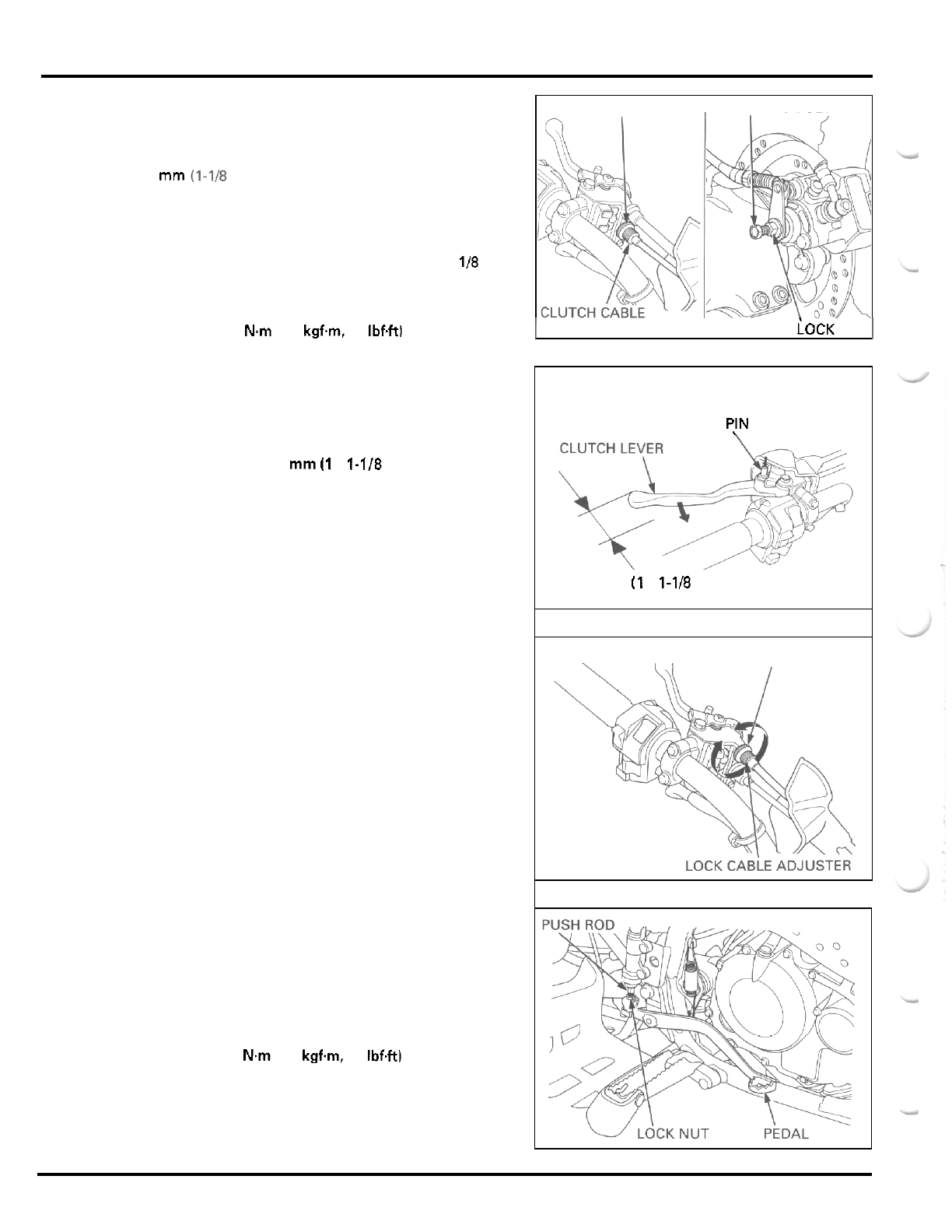
MAINTENANCE
BRAKE LOCK CABLE ADJUSTMENT
LOCK NUT ,ADJUSTING
BOLT
A
lock cable
adjustment may
be required
if
the
parking brake
does not hold
the rear wheels
securely.
Slide the dust cover
off
the lever bracket.
To
adjust the clutch lever free play to more than
30
mm
(1-1B
in), loosen the lock nut
at
the clutch lever
and turn the adjuster
all
the way in.
Loosen the lock nut
at
the brake arm on the caliper
and turn the adjusting bolt clockwise until bolt resis
-
tance
is
felt. Then turn the adjusting bolt
118
turn
counterclockwise and tighten the lock nut while hold
-
ing the adjusting bolt.
TORQUE
18
N.m
(1.8 kgfm, 13 IbfW
LOCK NUT
I
I
1
ADJUSTER
Squeeze the clutch lever while pushing the brake lock
pin down until firm resistance is felt and measure the
brake lock cable free play
at
the end of the clutch
lever.
FREE PLAY
25
-
30
mm
(1
-
1.118
in)
To adjust the free play, loosen the lock nut and turn
the adjuster
at
the brake lock arm on the clutch lever
bracket.
Tighten the lock nut while holding the adjuster.
Adjust the clutch lever free play (page
3
-
19).
BRAKE PEDAL HEIGHT
Adjust the brake pedal to the desired height.
Loosen the lock nut and turn
the
push rod to obtain
the pedal height.
Tighten the lock nut after adjustment has been made.
TORQUE:
18
Nm
(1.8
kgfm,
13 Ibf.ft)
LOCK P!N
,
25
-
30
mm
(1
-
1-118
in)
\
A
LOCK NUT
3
-
1
6
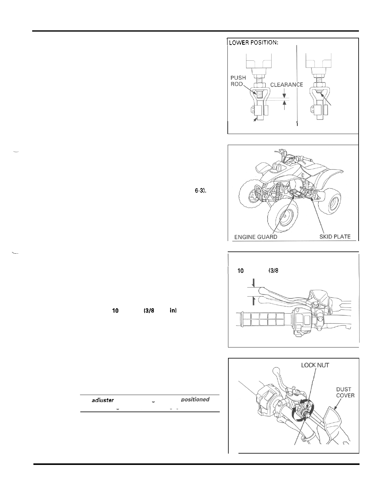
MAINTENANCE
If
adjusting the brake pedal to the lower position,
make sure that the clearance between the lower end
of
the push rod and the brake pedal does not fall
below
1
mm
(0.04
in).
If
adjusting to the higher position, make sure that a
portion
of
the lower end
of
the push rod thread
is
vis
-
ible inside the joint.
-
SKID
PLATE, ENGINE
GUARD
Check the skid plate and engine guard for cracks,
damage or looseness.
Tighten any loose fasteners. Replace the skid plate
and engine guard as required (page
2
-
5
and
6-3).
.-
CLUTCH
SYSTEM
Inspect the clutch cable for kinks or damage, and
lubricate the cable if necessary.
Measure the clutch lever free play at the end of the
lever
FREE
PLAY
10
-
20
mm
13/8
-
3/4
in1
ISPOSITION: HIGHER POSITION:
THREAD
PEDAL
'
I
I
10
-
20
mm
(3/8
-
3/4
in)
Minor adjustments are made at the clutch lever.
Slide the dust cover
off
the lever bracket, loosen the
lock nut and turn the adjuster.
Tighten the
lock
nut securely.
CAUTION
The
adjuster mav be damaaed if
it
is
DoSitiOned
too
-
far
out,
leaving minimal thread engagement.
If
the adjuster is threaded out neat its limit and the
correct free play cannot be obtained, turn the
adjuster all the way
in
and back out one turn.
Tighten the lock nut and make a major adjustment as
described following page.
\
\
(d
ADJUST
E
R
3
-
1
7
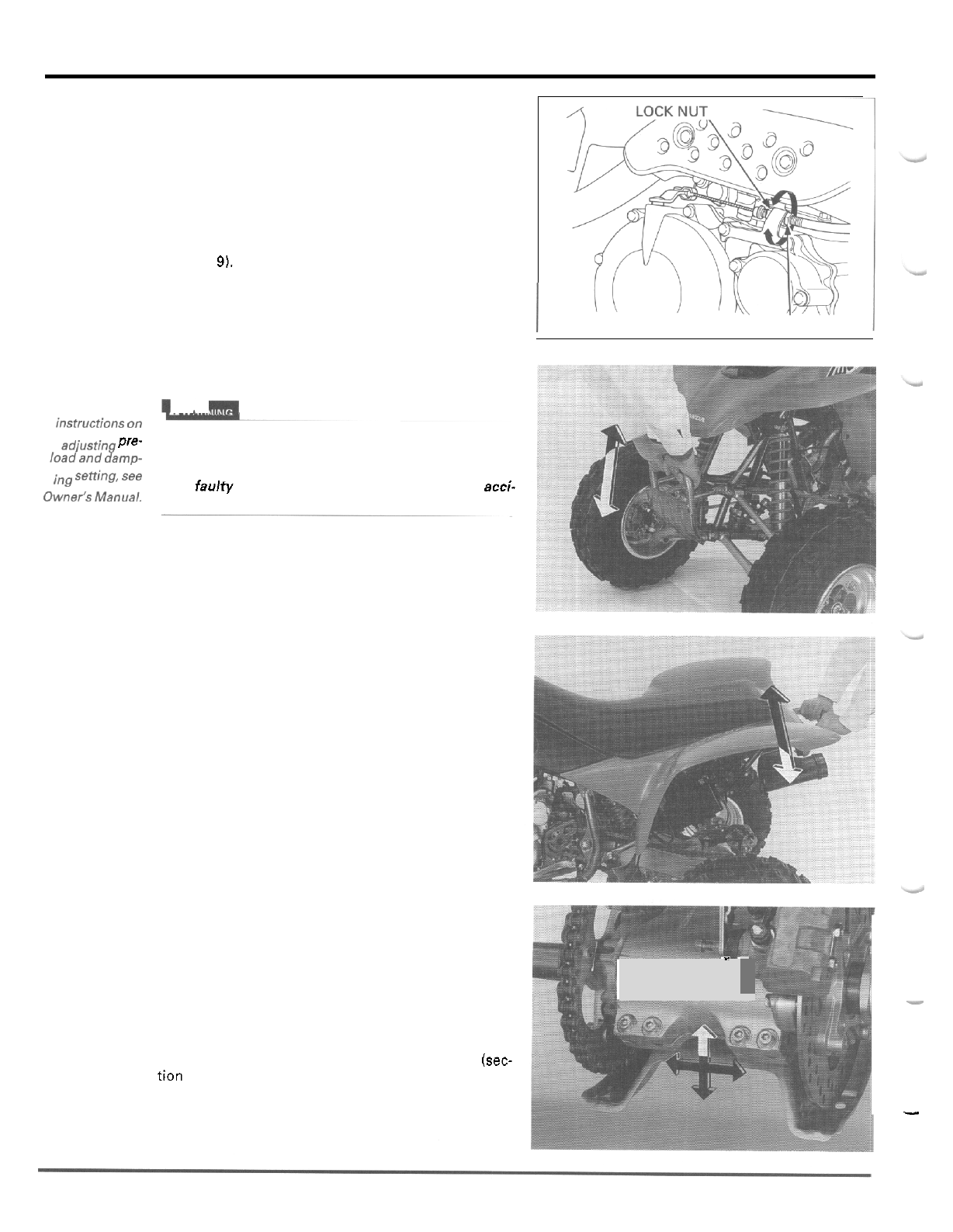
MAINTENANCE
Major adjustments are made with the lower adjusting
nut
at
the engine.
Loosen the lock nut and turn the adjusting nut.
After adjustment is complete, tighten the lock nut
securely while holding the adjusting nut.
Check the clutch operation.
If
the free play cannot be obtained, or the clutch slips
during test ride, disassemble and inspect the clutch
(section
91.
SUSPENSION
For
detailed
!
I
.
1__
instructions
On
Pre-
load
and
damp-
senin%
see
Loose,
worn or damaged suspension parts impair
vehicle stability and control. Repair
or
replace any
damaged components before riding. Riding a
ATV
with faulty suspension increases your risk of an acci-
Owner's
dent and possible injury.
FRONT
Check the action of the shock absorbers by com
-
pressing them several times.
Check the entire shock absorber assembly for signs
of leaks, damage or loose fasteners.
Replace damaged components which cannot be
repaired.
Tighten all nuts and bolts.
Refer to section
12
for shock absorber service.
REAR
Check the action
of
the shock absorber by compress
-
ing
it
several times.
Check the entire shock absorber assembly for signs
of leaks, damage or loose fasteners.
Replace damaged components which cannot be
repaired.
Tighten
all
nuts and bolts.
ADJUSTING NUT
I
Refer to section
13
for shock absorber and linkage
service.
Raise the rear wheel
off
the ground and support the
vehicle securely.
Check for worn swingarm bearings by grabbing the
swingarm and attempting to move the wheels side to
side.
Replace the bearings if any looseness
is
noted (sec-
tion
13).
-
'
,
I
3
-
1
8
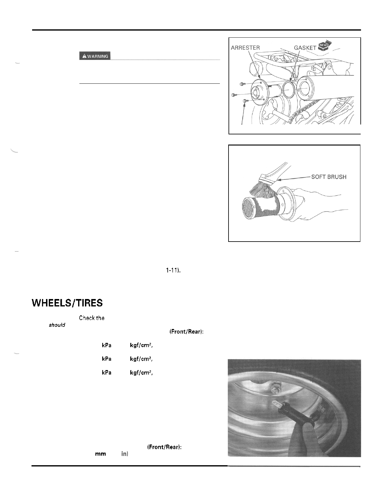
MAINTENANCE
SPARK ARRESTER
Wait
until
the exhaust system has cooled before
removing or installing the arrester. Touching the hot
exhaust may result
in
severe
burns.
Remove the three bolts and the spark arrester with
the gasket.
-
Use
a
brush to remove carbon deposits from the
screen mesh, being careful not to damage the screen
mesh.
The screen mesh must be free of breaks and holes.
Replace the spark arrester if necessary.
Install the spark arrester with
a
new gasket and tight
-
en the bolts securely.
~
NUTS, BOLTS, FASTENERS
Check that all chassis nuts and bolts are tightened to
their correct torque values (page
1-11),
Check that
all
cotter pins, safety clips, hose clamps
and cable stays are in place and properly secured.
WHEELS/TIRES
B
O
L
T
S
I
Tirepressure
should be
checked when
the tires are
Standard:
COLD.
-
Minimum:
Maximum:
Checkthe tire pressure with the tire pressure gauge.
RECOMMENDED TIRE PRESSURE (FrontlRear):
27
kPa
(0.275
kgf/cm2,
4.0
psi)
23
kPa
(0.235
kgf/cm2,
3.4
psi)
31
kPa
(0.315
kgf/cm2,
4.6
psi)
Check the tires for cuts, embedded nails, or other
damage.
Check the front and rear wheels for trueness (refer to
section
12
and
13).
Measure the tread depth
at
the center of the tires.
Replace the tires when the tread depth reaches the
following limits.
MINIMUM
TREAD DEPTH (FrontlRear):
4.0
mm
(0.16
in1
3
-
1
9
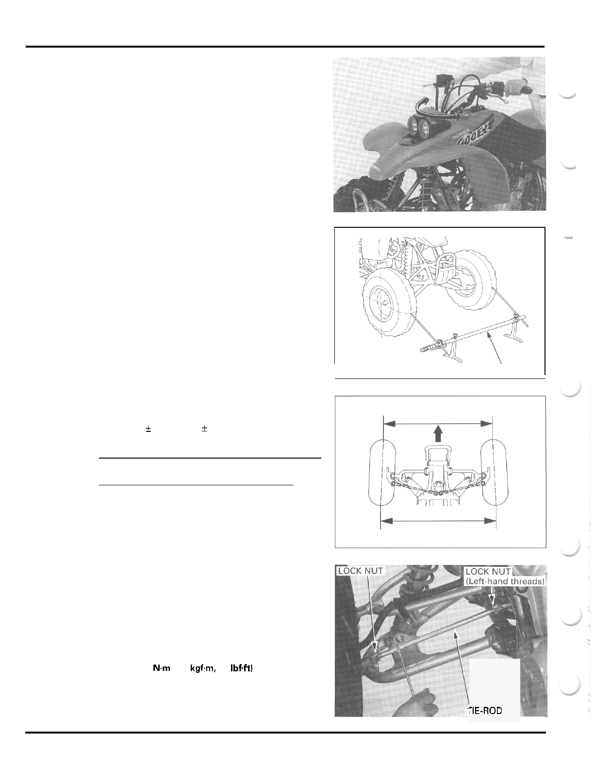
MAINTENANCE
STEERING SHAFT HOLDER BEARING
Make sure the
cables do not
vehicle securely.
interfere with the
rotation
of
the
side.
handlebar
Raise the front wheels
off
the ground and support the
Check that the handlebar moves freely from side to
If the handlebar moves unevenly, binds, or has hori
-
zontal movement, inspect the steering shaft holder
bushing and bearings (section
12).
STEERING SYSTEM
Place the vehicle on level ground with the front
wheels facing straight ahead.
Mark the centers of the tires with chalk to indicate the
axle center height.
Align the gauge with the marks on the tires as
shown.
Check the readings on the gauge scales.
Slowly move the vehicle back until the wheels have
turned
180
"
so
the marks on the tires are aligned with
the gauge height on the rear side.
Measure the toe on the rear pan of the tires
at
the
same points with no load on the vehicle.
TOE
-
IN:
17
f
15
mm
(0.7
f
0.6
in)
NOTE:
Toe
-
in means the rear measurement is greater than
the front measurement.
When the toe
is
out of specification, adjust
it
by
changing the length of the tie
-
rods equally by loosen
-
ing the lock nuts and turning the tie
-
rods while hold
-
ing the ball joints.
After adjusting each tie
-
rod, rotate both ball joints in
the same direction with the tie
-
rod axis until they
stop against the ball joint stud.
Hold
them in that
position and tighten the tie
-
rod lock nuts.
TORQUE
54
N.m
15.5
kgfm,
40
IbfW
After finally tightening the lock nuts, make sure the
ball joints operate properly by rotating the tie
-
rods,
to make sure both ball joints have equal play.
I
TOE
-
'
GAUGE
I
FRONT
-
REAR
7E-ROD
3
-
20

MEMO
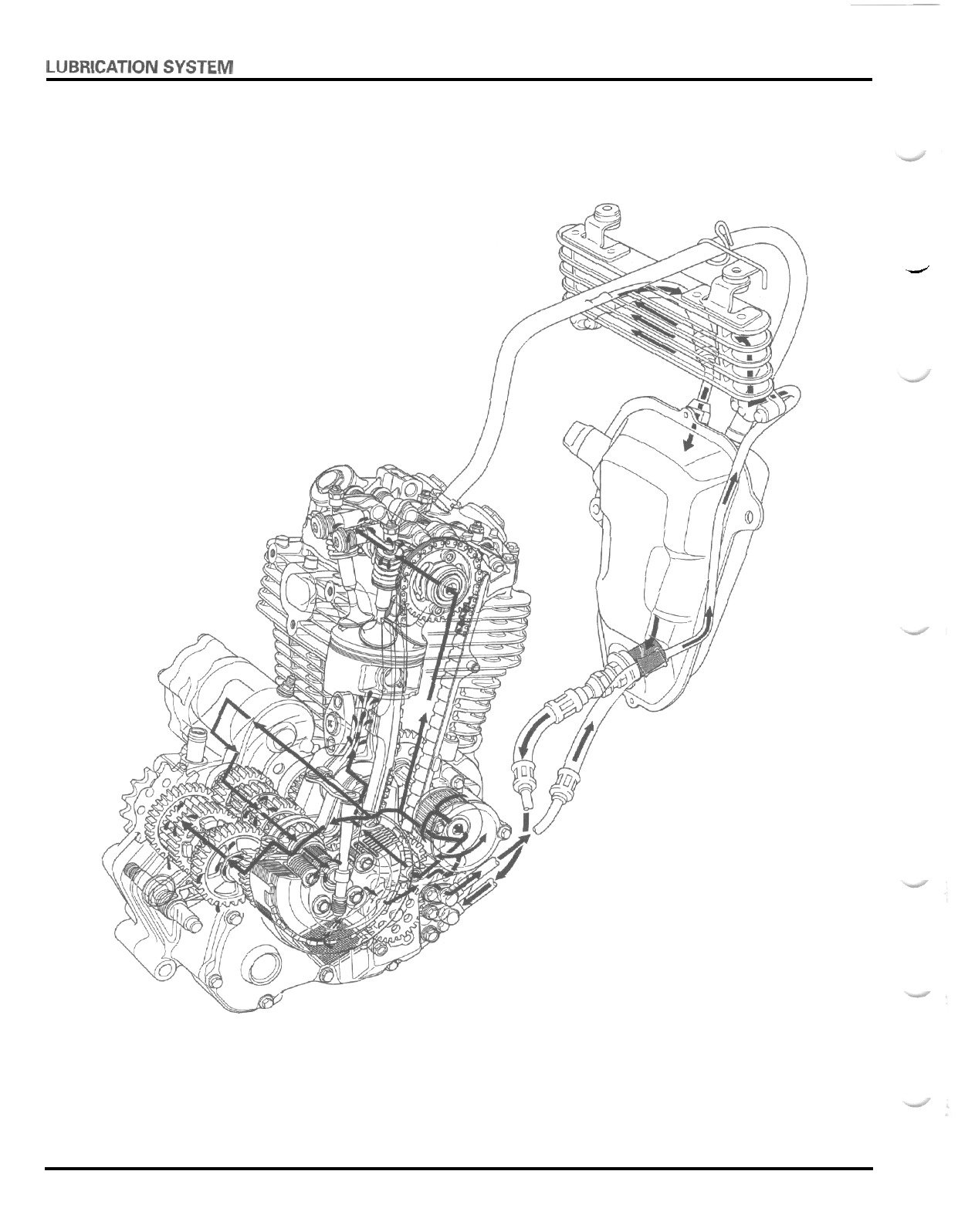
4-0
P
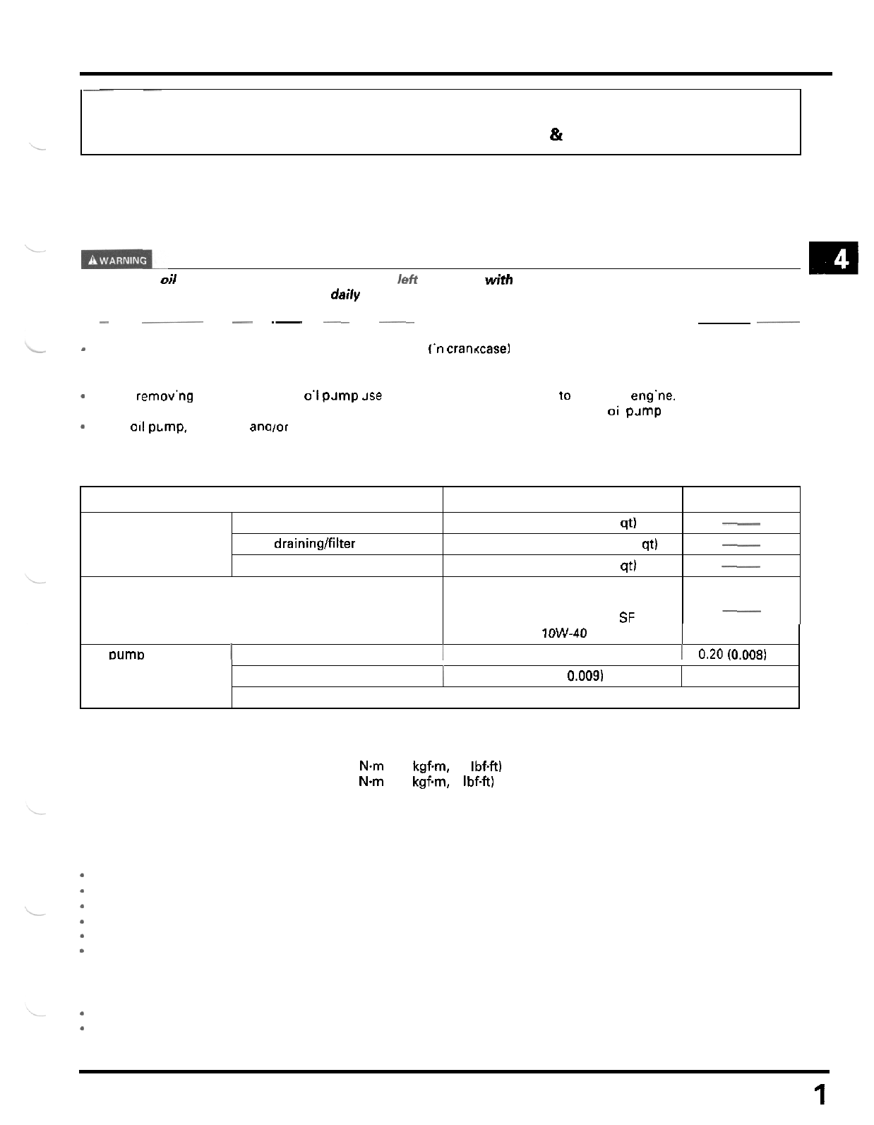
4.
LUBRICATION
SYSTEM
ITEM
Engine oil capacity After draining
After draining/filter change
After disassembly
Recommended engine oil
~ ~~
SERVICE INFORMATION
TROUBLESHOOTING
STANDARD
SERVICE
LIMIT
1.8 liters (1.9 US qt, 1.6 Irnp qt)
1.85 liters (1.95
US
qt, 1.63 Imp qt)
2.2 liters (2.3 US
qt.
1.9 Irnp qt)
Honda GN4
or
HP4 4
-
stroke oil or
equivalent motor oil
API service classification SE.
SF
or SG
__
-
__
__
4
-
1
OIL PUMP &STRAINER
4
-
1
OIL COOLER
81
OIL TANK
Body clearance
1
0.15
-
0.22 (0.006
-
0.009)
4
-
2
4
-
6
0.25 (0.010)
SERVICE INFORMATION
GENERAL
m
Used
engine
oil
may cause
skin
cancer
if
repeatedly If& in contact with the
skin
forprolongedperiods. Although this is
unlikely unless
you
handle used oil on a daily basis, it
is
still advisable to thoroughly wash
your
hands
with soap and
water as
soon
as possible after handling used oil. KEEP
OUT
OF
REACH
OF
CHILDREN.
-
This section covers service
of
the oil pump, oil stra'ner
('n
crancasel and oil cooler.
For oil level check, oil change, oil filter replacement and oil strainer (at oil tank) cleaning, refer to section 3.
The service procedures in this section can be performed witn the engine installed
in
the frame.
-
When remov'ng ano instal ing the
0'1
pJmp Jse care not
to
allow dust or dirt
10
enter the eng'ne.
.
If
any portion of the oil pump is worn beyond the specif'ed service I'mits. replace the oi pJmp as an assembly.
-
After
011
pLmp. oil cooler anoior oil p'pes has been installed, check [hat there are
no
oil leaks.
-~
--
-
.-
-
.~ .~
SPECIFICATIONS
Viscosity:
SAE
1OW-40
Oil
DumD
I
Tip clearance
1
0.15 (0.006)
I
0.20
(0.008)
TORQUE
VALUES
Oil
pipe joint flare nut
Oil pump assembly bolt 20 Nm (2.0 kgfm, 14 IbfW
13 Nm (1.3 kgfm, 9 Ibf-ft)
TROUBLESHOOTING
Oil level
too
low
-
high
oil consumption
-
Oil consumption
-
External oil leak
Worn piston rings or incorrect piston ring installation
*
Worn cylinder
*
Worn valve guide or stem seals
*
Oil
pump worn or damaged
Oil contamination
.
Oil or filter not changed often enough
*
Worn piston rings or incorrect piston ring installation
*
Worn valve guide or stem seals
4
-
1
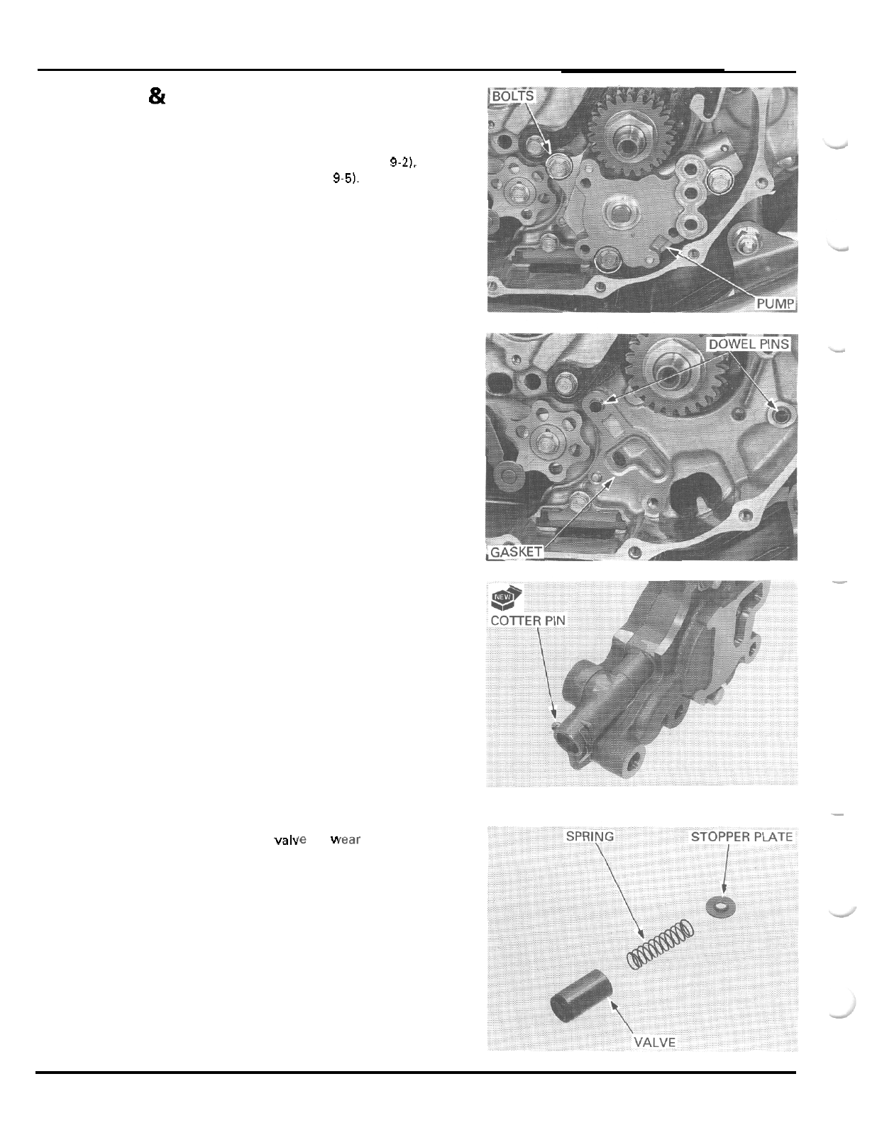
LUBRICATION
SYSTEM
OIL
PUMP
&
STRAINER
REMOVAL
Remove the right crankcase cover (page
9-21,
Remove the clutch outer (page
9-5).
Remove the three mounting
bolts
and the oil pump.
Remove the gasket and two dowel pins.
Remove the following:
-
cotter pin
-
stopper plate
-
spring
-
valve
RELIEF VALVE CHECK
for
YI
Check the spring and vah or damage.
Install the valve, spring and stopper plate into the oil
pump, then insert a new cotter pin from the pump
body side and secure
it.
4
-
2
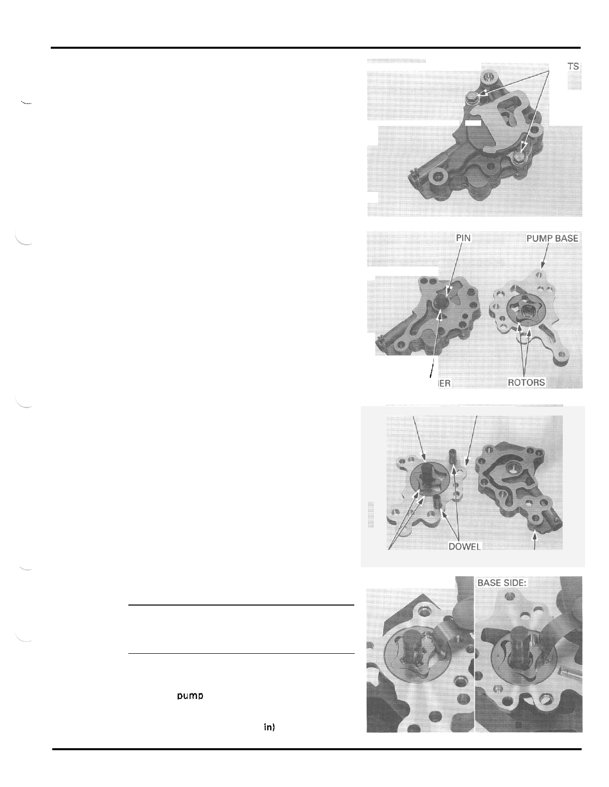
LUBRICATION
SYSTEM
DISASSEMBLY
BOL
Remove the two bolts and separate the pump base
i
from the pump spacer.
Remove the following:
-
drive pin
-
thrust washer
-
inner rotor
-
outer rotor
Separate the pump body from the pump spacer.
Remove the following:
-
pump shaft
-
drive pin
-
dowel pins
-
inner rotor
-
outer rotor
INSPECTION
i
WASH
SHAFT
AND
PIN
PUMP
BODY
ROTORS
PINS
PUMP
SPACER
BODY SIDE:
NOTE:
Measure at several places and use the largest read
-
ing to compare the service limit. If any portion of the
oil pump is worn beyond the specified service limits,
replace the oil pump
as
an assembly.
Install the inner and outer rotors into the pump base
and pump body.
Install the DumD shaft with the drive pin into the
inner rotor and measure rotor tip clearance.
SERVICE
LIMIT
0.20
mm
10.008
in1
4
-
3
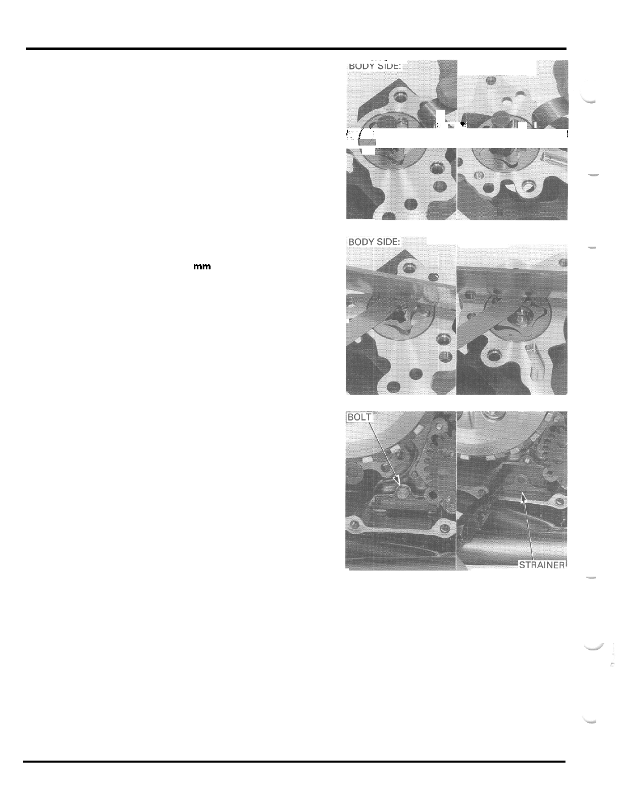
LUBRICATION
SYSTEM
..
BASE SIDE:
-
.
-
-
Measure the pump body clearance.
SERVICE
LIMIT
0.25
mm
10.010
in)
:i
c
F
'i;
I
is
!
-
Measure the pump side clearance.
SERVICE
LIMIT
0.12
mm
(0.005
in)
BASE SIDE:
-
-
-
OIL
STRAINER CLEANING
Remove the bolt and pull the strainer out of the
crankcase.
Wash the strainer screen thoroughly in high flash
point solvent.
Before installing the oil strainer,
it
should be checked
for damage.
Install the
oil
strainer into the crankcase and tighten
the bolt securely.
-
4
-
4
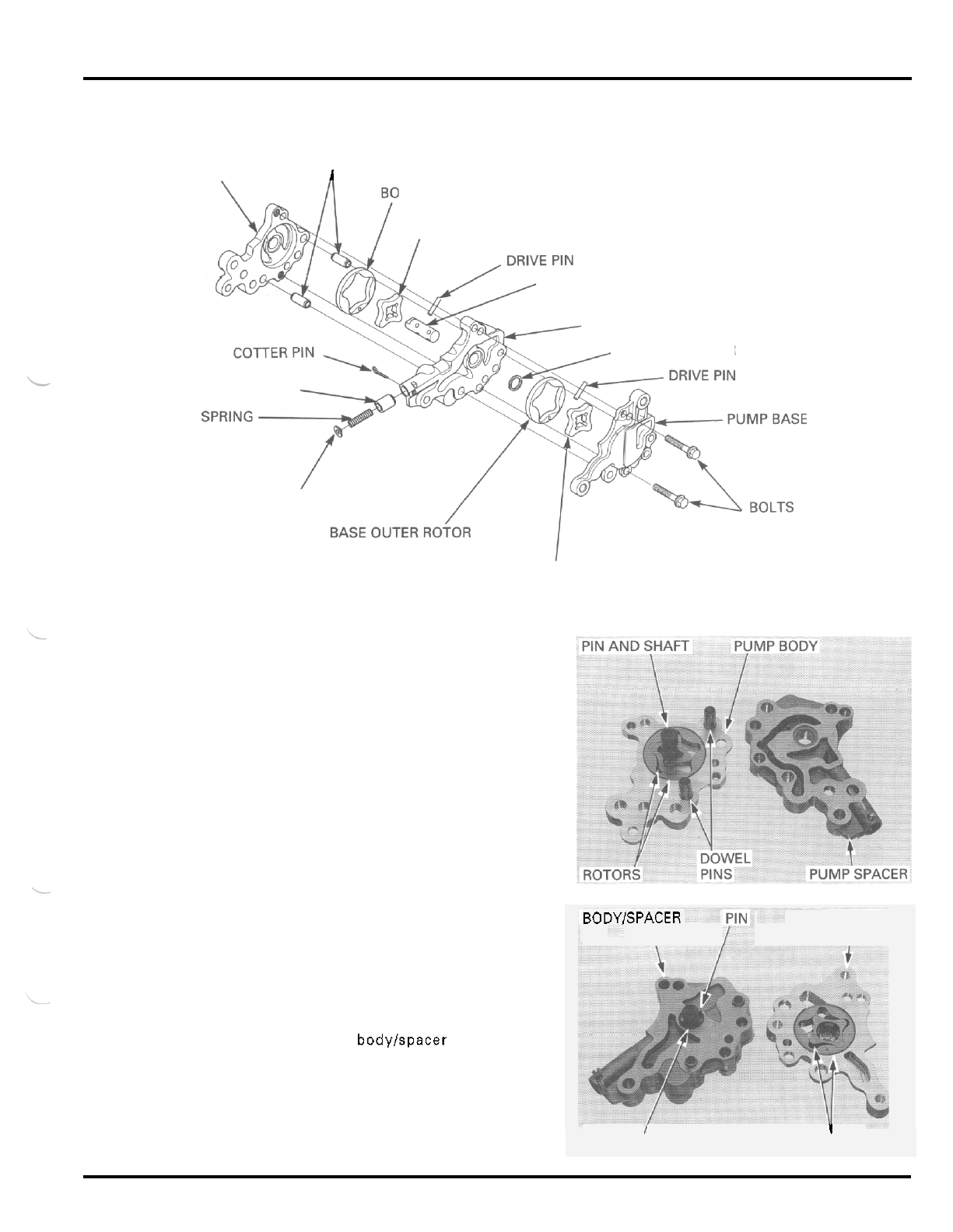
LUBRICATION
SYSTEM
ASSEMBLY
PUMP BODY DOWEL PINS
1
DY OUTER ROTOR
BODY INNER ROTOR
PUMP SHAFT
PUMP SPACER
THRUST WASHER
RELIEF VALVE
STOPPER PLATE
BASE INNER ROTOR
Install the following into the pump body:
-
outer rotor with the punch mark facing the pump
spacer
-
inner rotor
-
drive pin and shaft with the stepped end facing
pump body
-
dowel pins
Assemble the pump body and spacer.
Install the following onto the pump shaft and into the
pump base.
-
thrust washer
-
drive pin
-
outer rotor with the punch mark facing the pump
base
-
inner rotor
Assemble the pump bodylspacer assembly and
pump base by aligning the drive pin with the slots in
the inner rotor.
PUMP BASE
I
BODY/SPACER
\
1
WASHER ROTORS
4
-
5
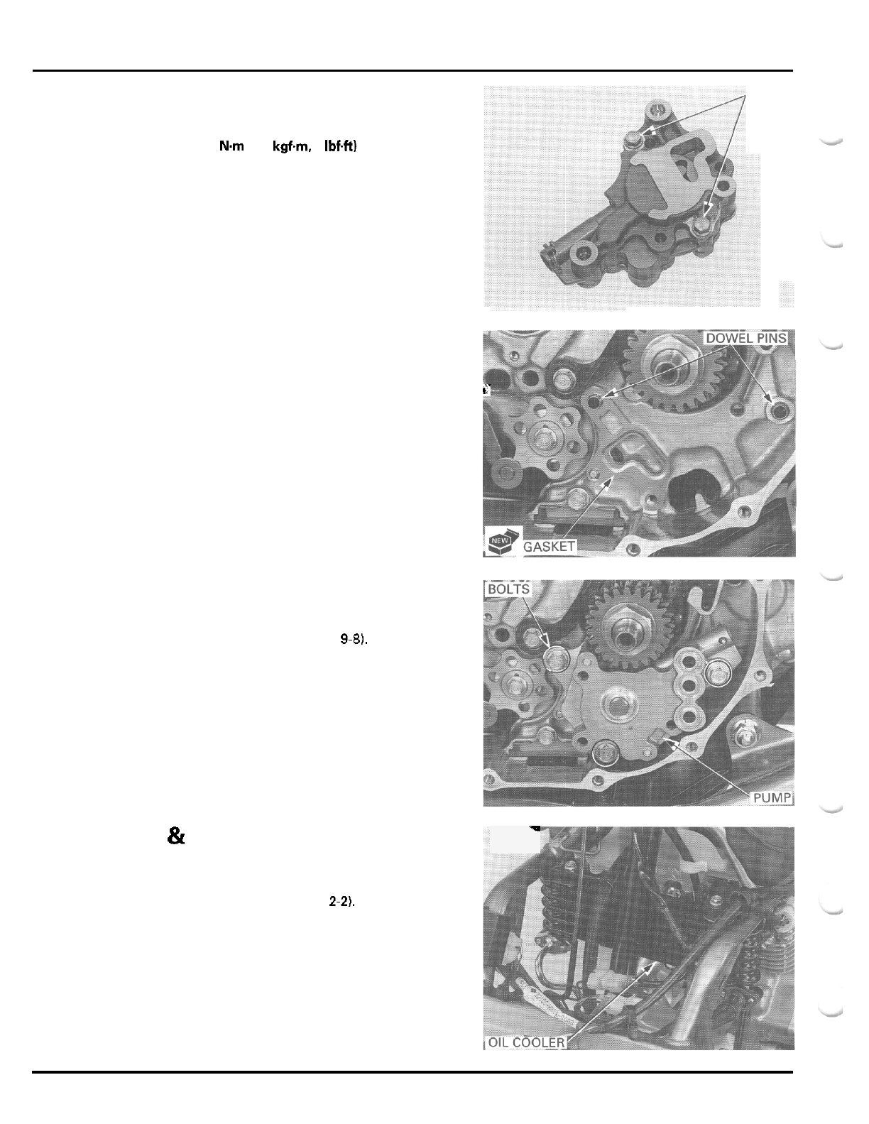
LUBRICATION
SYSTEM
BOLTS
Be
sure that there are no gap between the mating
surfaces and tighten the two bolts.
TORQUE:
13
N.m
(1.3
k9f.m. 9
IbfW
INSTALLATION
Install the two dowel pins and
a
new gasket.
i'
Set the pump assembly onto the crankcase and tight
-
en
the
three bolts securely.
Install the clutch assembly (page
9-81,
Install the right crankcase cover (page
9
-
12).
1
OIL
COOLER
&
OIL
TANK
INSPECTION
Remove the front fender (page
2-2).
Check the
oil
cooler air passage for clogging or dam
-
age.
Check for any oil leakage from the oil cooler,
oil
tank
and pipe joints.
4
-
6
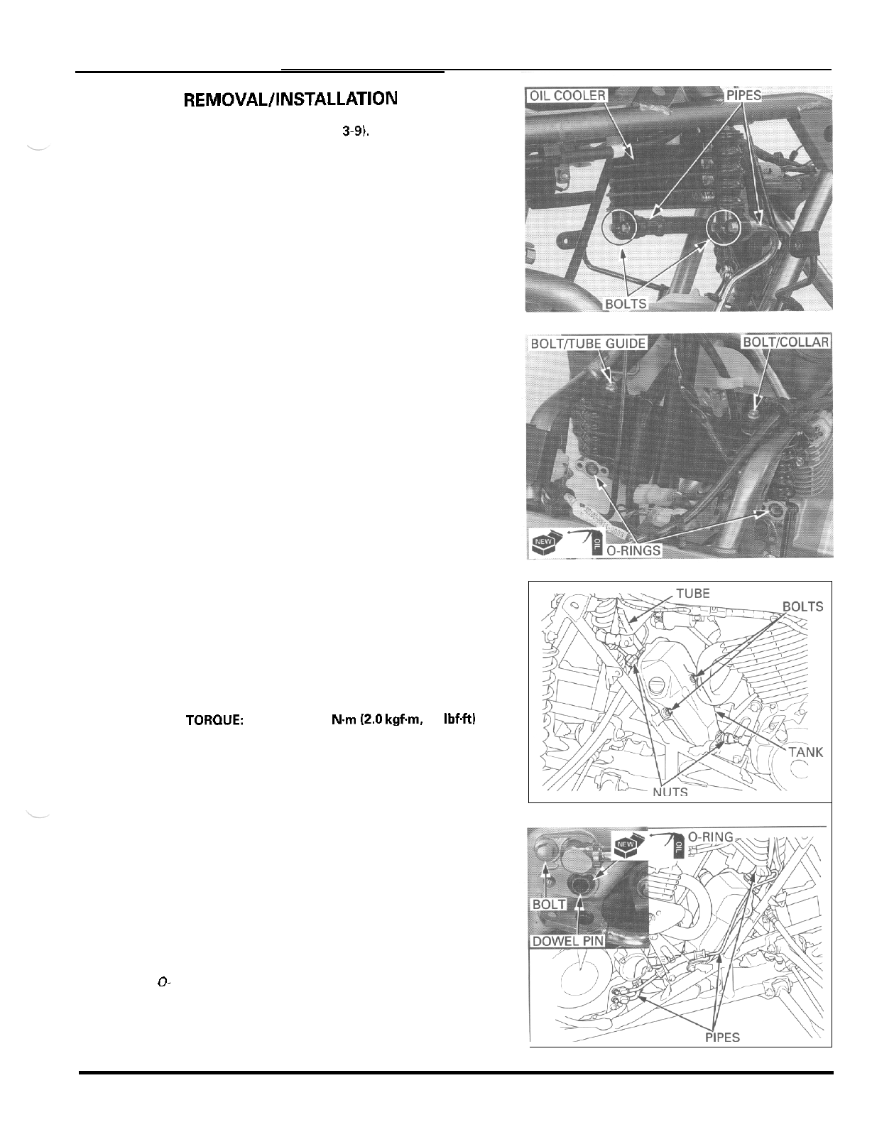
LUBRICATION
SYSTEM
REMOVAL/INSTALLATlON
Drain the engine oil (page
3-9).
OIL
COOLER
Disconnect the oil pipes from the oil cooler by
removing the joint bolts and remove the O
-
rings.
Remove the two mounting bolts and the oil cooler.
Installation is in the reverse order of removal
Replace the
0
-
rings with new
ones and coat
them with
engine oil.
OIL
TANK
Disconnect the oil tank breather tube.
Disconnect the oil pipes by loosening the flare nuts.
Remove the tank mounting bolts and the oil tank
from the mounting rubber.
Installation
is
in the reverse order of removal.
TOROUE: Flare
nuts:
20
Nm
(2.0 kgfm,
14
IbfW
-
-
Replace the
0-
rings with new
ones and coat
them with
engine oil.
OIL
PIPES
Disconnect the oil pipes from the oil cooler and oil
tank (see above).
Disconnect the oil pipes from the engine by remov
-
ing the bolts.
Remove the dowel pins and O
-
rings.
Check the oil pipes for clogging or damage.
Installation
is
in the reverse order
of
removal.
4
-
7
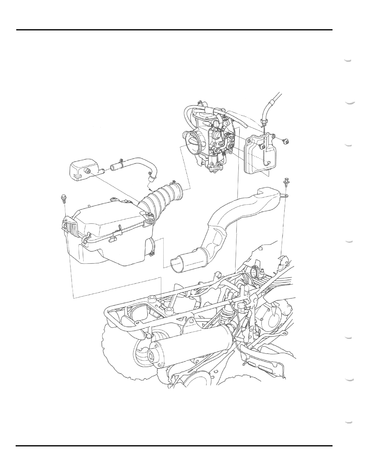
FUEL
SYSTEM
5
-
0
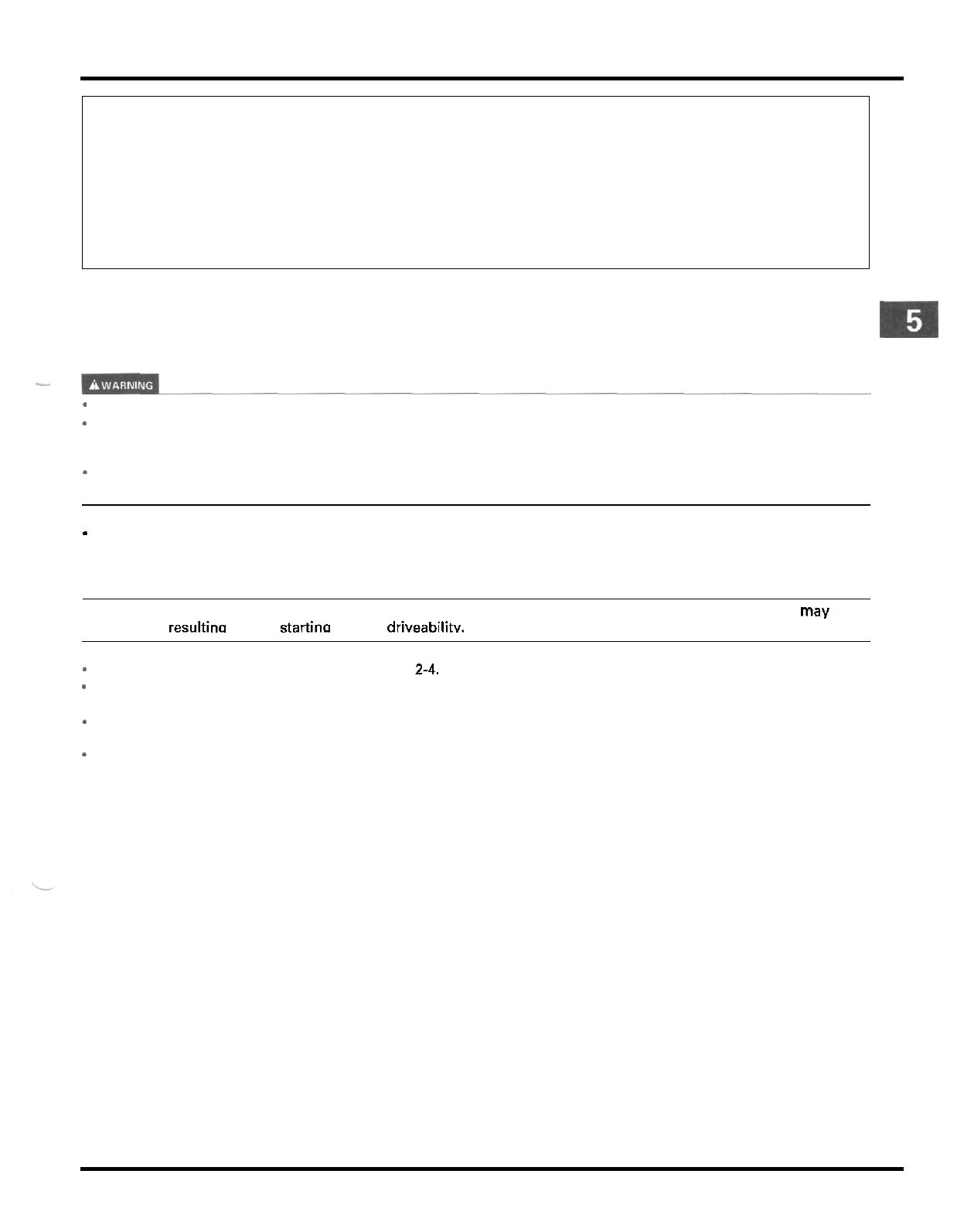
5.
FUEL
SYSTEM
SERVICE INFORMATION 5
-
1 CARBURETOR INSTALLATION 5
-
12
TROUBLESHOOTING 5
-
2 PILOT SCREW ADJUSTMENT 5
-
13
CARBURETOR REMOVAL 5
-
3 HIGH ALTITUDE ADJUSTMENT 5
-
14
CARBURETOR DISASSEMBLY/ AIR CLEANER HOUSING 5
-
15
INSPECTION 5
-
3
CARBURETOR ASSEMBLY 5
-
7
SERVICE INFORMATION
GENERAL
-
*
Gasoline is extremely flammable and is explosive under certain conditions.
KEEP
OUT
OF
REACH
OF
CHILDREN.
If
the engine must be running to do some work make sure the area is well
-
ventilated. Never run the engine in an
enclosed area. The exhaust contains poisonous carbon monoxide gas that may cause loss
of
consciousness and lead
to death. Run the engine in an open area or with an exhaust evacuation system in an enclosed area.
-
Bending or twisting the control cable will impair smooth operation and could cause the cable to stick or bind, result
-
ing in loss of vehicle control.
-
Work in
a
well ventilated area. Smoking or allowing flames or sparks in the work area or where gasoline is stored can
cause
a
fire or explosion.
NOTE:
If the vehicle is
to
be stored for more than one month, drain the float chamber. Fuel left in the float chamber may cause
clooaed iets. resultina in hard startina or Door driveabilitv.
*
For
fuel tank removal and installation, see page
2-4.
-
Before disassembling the carburetor, place an approved fuel container under the carburetor, loosen the drain screw
and drain the carburetor.
After removing the carburetor, cover the intake port of the cylinder head with shop towel to prevent any foreign
material from dropping into the engine.
-
When disassembling the fuel system parts, note the locations
of
the O
-
rings. Replace them with new ones on
reassemblv.
5
-
1
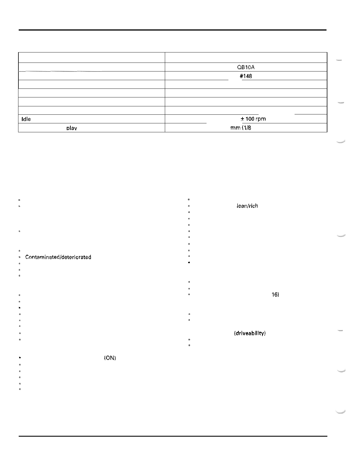
FUEL
SYSTEM
SPECIFICATIONS
ITEM
SPECIFICATIONS
-
Carburetor identification number QBlOA
Main jet
#I48
Slow jet
#38
________
Jet needle clip position
Pilot screw opening
Float level
Idle speed
Throttle lever free Dlav
TOOL
Carburetor float level gauge
07401
-
0010000
Pilot screw wrench 07908
-
4220201
3rd groove from top
See page 5
-
13
-
18.5
mm
(0.73
in)
1,400
f
100
rpm
3
-
8
mm
(1/8
-
5/16
in)
TROUBLESHOOTING
Engine cranks but won't start
*
No
fuel in tank
*
No
fuel to carburetor
-
Clogged fuel stainer
-
Clogged fuel line
-
Clogged fuel tank breather tube
*
Too
much fuel getting to the engine
-
Clogged air cleaner
-
Flooded carburetor
*
Intake air
leak
-
Contaminatedldeteriorated
fuel
*
Improper choke operation
*
Improper throttle operation
*
No
spark at plug (faulty ignition system
Lean mixture
*
Clogged fuel jets
*
Faulty float valve
*
Float level too low
*
Restricted fuel line
Clogged carburetor air vent tube
*
Restricted fuel tank breather tube
*
Intake air leak
*
Faulty throttle valve
Rich mixture
*
Starting enrichment valve close
(ON)
-
Clogged air jets
*
Faulty float valve
-
Float level too high
*
Dirty air cleaner
-
Worn jet needle or needle jet
section 16)
Engine stalls, hard to start, rough idling
-
Restricted fuel line
*
Contaminated/ deteriorated fuel
*
Misadjusted idle speed
-
Misadjusted pilot screw
*
Restricted fuel tank breather tube
*
Clogged air cleaner
*
Clogged slow circuit
*
Starting enrichment valve close
(ON)
-
Faulty ignition system (section
16)
Afterburn when engine braking is used
*
Lean mixture in slow circuit
-
Faulty air cut
-
off valve
*
Faulty ignition system (section
16)
Fuel mixture too leanlrich
Intake air leak
Backfiring or misfiring during acceleration
-
Lean mixture
*
Faulty ignition system (section
16)
Poor performance (driveability) and poor fuel economy
*
Clogged fuel system
*
Faulty ignition system (section 16)
-
5
-
2
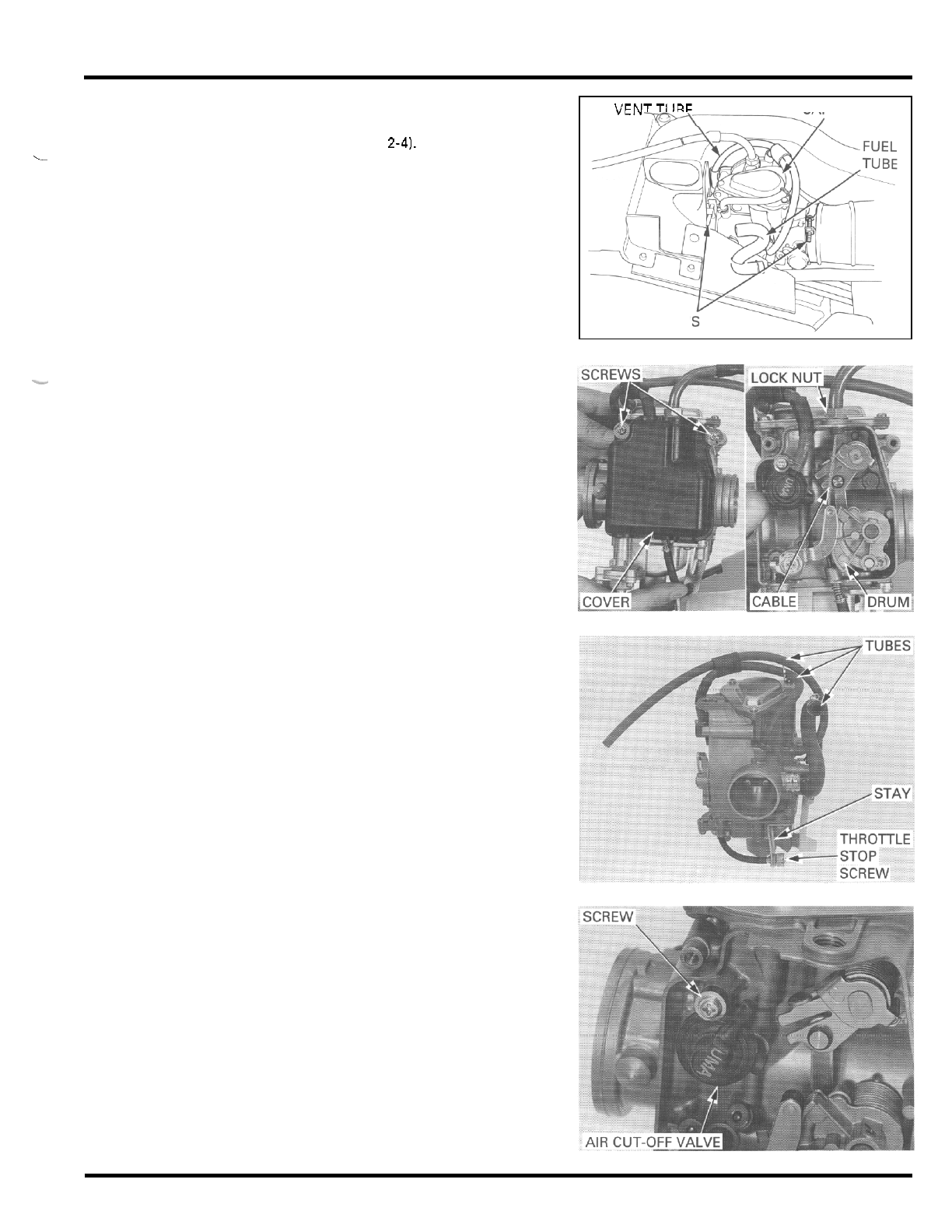
FUEL
SYSTEM
CARBURETOR REMOVAL
Remove the fuel tank (page
2-41.
Place and approved fuel container under the drain
tube. Loosen the drain screw and drain the carbure
-
tor.
Remove the air vent tube from the heat protector and
the fuel tube from the heat protector rubber.
Disconnect the drain tube from the carburetor.
Loosen the connecting tube band and insulator band
screws.
Release the carburetor from the connecting tube and
-_
-
Remove the two screws and the throttle linkage
cover.
Disconnect the throttle cable from the throttle drum.
Loosen the cable lock nut and remove the carburetor
from the cable outer.
CARBURETOR DISASSEMBLY/
INSPECTION
Disconnect the tubes from the carburetor body.
Remove the throttle stop screw stay attaching screw
and the throttle stop screw by turning counterclock
-
wise.
AIR
CUT
-
OFF
VALVE
AIR VENTTUBE CARBURETOR
=-/
BAND SCREW
Remove the attaching screw and the air cut
-
off valve.
Remove the O
-
rings and joint pipe.
5
-
3
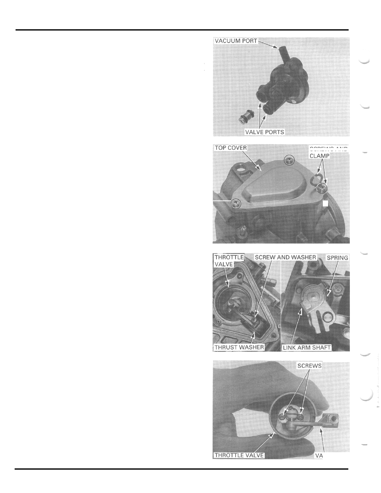
FUEL
SYSTEM
Apply vacuum to the vacuum port.
The vacuum should maintained.
Air should not flow through the valve
ports
when the
vacuum
is
applied, and should flow when the vacu
-
um
is
not applied.
THROTTLE
VALVE
Remove the three screws, clamp and top cover.
Remove the O
-
ring from the body groove.
Remove the valve arm set screw and washer.
Pull the link arm shaft out of the carburetor body
while holding the throttle linkage.
Remove the return spring and the thrust washer.
Remove the throttle valve assembly from the carbu
-
retor body, being careful not to damage the jet nee
-
dle.
Remove the
two
screws and valve arm.
Remove the jet needle.
SCREWSAND
-
*(
-
LVE
ARM
5
-
4
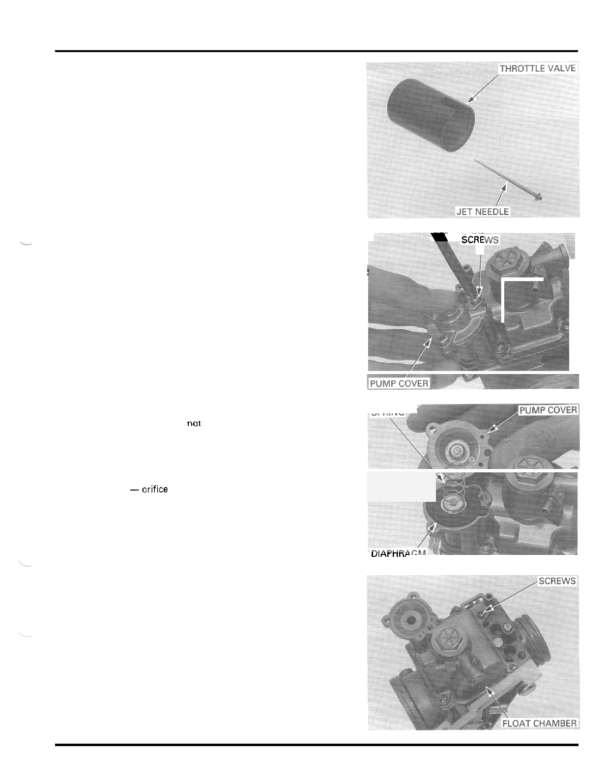
FUEL
SYSTEM
Check the jet needle for stepped wear or damage.
Check the throttle valve for scoring, scratches or
damage.
‘I;
cmE
I
ACCELERATOR
PUMP
Remove the three screws while holding the accelera
-
I
I
tor pump cover.
Remove the pump cover, spring and the diaphragm,
SPRING
*
being careful not to damage it.
Visually check the following:
-
diaphragm for deterioration or pin holes
-
spring for deterioration
-
diaphragm shaft for excessive wear or damage
-orifice in cover for clogging or restriction
uinrnnr
FLOAT AND JETS
Remove the four screws and the float chamber.
5
-
5
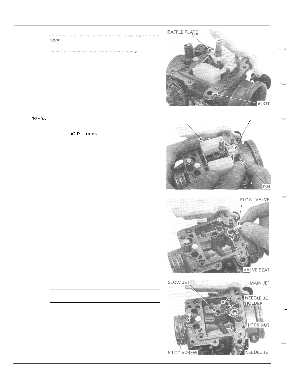
FUEL
SYSTEM
Remove the baffle plate and the diaphragm shaft
boot.
BAFFLE PLATE
Check the boot for deterioration or damage.
-
-
FLOATVALVE
-
FLOAT
\
/
'99-
'00
Remove the float pin, float and float valve.
After
'00
Remove the float pin by gently tapping with a suitable
pin driver
(O.D.
2
mml.
Check the float for damage or fuel in the float.
-
Check the float valve and valve seat for scoring,
scratches, clogging or damage.
Check the tip of the float valve, where it contacts the
valve seat, for stepped wear or contamination.
Check the operation of the float valve.
Remove the slow jet and main jet.
Loosen the lock nut and remove the needle jet holder
and needle jet.
CAUTION:
Handle the jets with care. They can easily be scored
or scratched.
.
-
Turn the pilot screw in and carefully count the num
-
-.
ber of turns until
it
seats lightly. Make
a
note of this
to use as
a
reference when reinstalling the pilot
screw.
CAUTION
Damage to the pilot screw seat will occur if the pilot
-
screw is tightened against the seat.
5
-
6
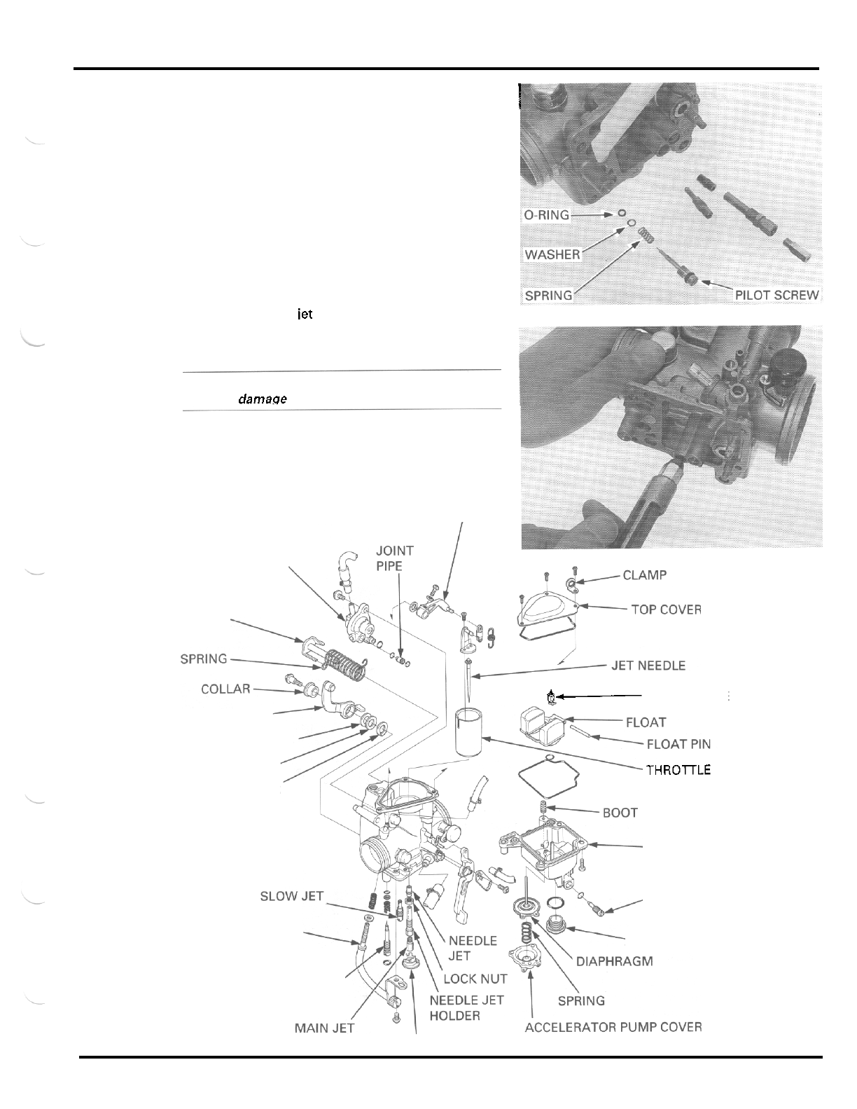
FUEL
SYSTEM
I
Remove the pilot screw, spring, washer and O
-
ring.
I
Check each jet for wear or damage.
Check the pilot screw for wear or damage.
Clean the jets with cleaning solvent and blow open
with compressed
air.
i
CARBURETOR CLEANING
Remove the following:
-
air cut
-
off valve
-
thronle valve
-
accelerator pump
-
main iet, needle iet holder, needle jet and slow jet
-
pilot screw.
CAUTION:
Cleaning the air and fuel passages with a piece
of
wire will darnacre the carburetor body.
Blow open all air and fuel passages
in
the carburetor
body with compressed air.
THROTTLE VALVE ARM
CARBURETOR ASSEMBLY
AIR CUT
-
OFF VALVE
LINK ARM SHAFT
$2-
FLOAT VALVE
THROTTLE LINK ARM
PLASTIC WASHER
PLANE WASHER THROTTLE VALVE
SPRING WASHER
FLOAT CHAMBER
DRAIN SCREW
FLOAT CHAMBER CAP
THROTTLE STOP SCREW
PILOT SCREW
BAFFLE PLATE
5
-
7
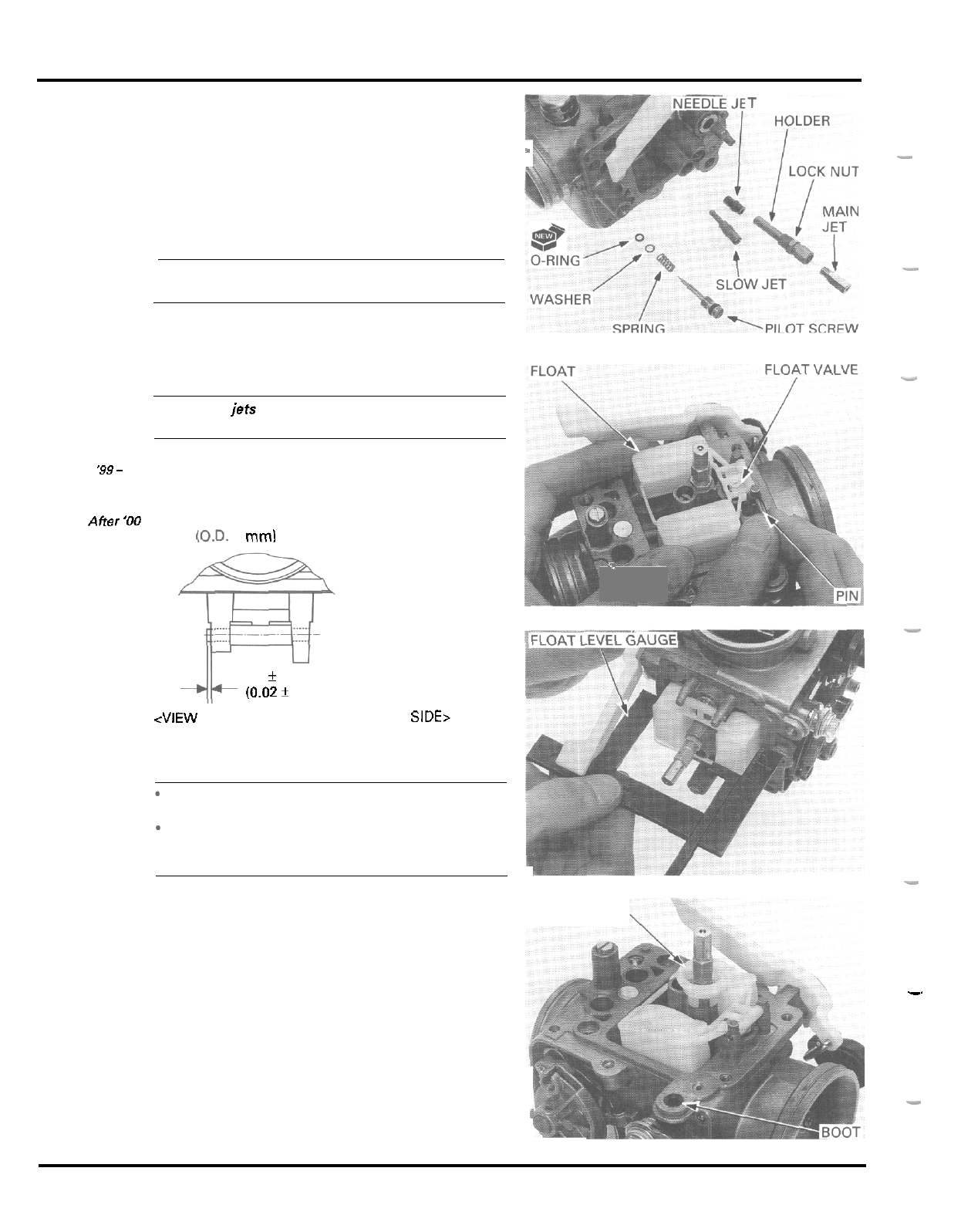
FUEL
SYSTEM
..
FLOAT
AND
JETS
T NEEDLEJET
Install the pilot screw with the spring, washer and a
new O
-
ring and return
it
to its original position as
noted during removal.
Perform the pilot screw adjustment if new pilot screw
is
installed.
CAUTION:
Damage to the pilot screw seat
will
occur
if
the pilot
screw
is
tightened against the seat
Install the needle jet, needle jet holder and tighten
the
lock
nut. Install the main jet and slow jet.
CAUTION:
Handle the
jets
with
care. They can easily be scored
or
scratched.
I
'
-
-"
-.
'99-
'00
Hang the float valve onto the float arm lip.
Install the float valve, float and
float
pin.
Affer
'00
Install the float pin by gently tapping with
a
suitable pin
driver
(OD.
2
mml
as shown.
-_
0.5
f
0.3
mm
(0.02k
0.01
in)
<VIEW
FROM
AIR
CLEANER
HOUSING
SIDE>
FLOAT LEVEL INSPECTION
NOTE:
*
Check the float level after checking the float valve,
valve seat and float.
-
Set the float level gauge
so
that
it
is perpendicular
to the float chamber face at the highest point of
the float.
-
With the float valve seated and the float arm just
touching the valve, measure the float level with the
float level gauge.
TOOL
Carburetor float level gauge
FLOAT LEVEL
18.5
mm
(0.73
in)
The float cannot be adjusted.
Replace the float assembly if the float level
is
out of
specification.
Install the diaphragm shaft boot of the accelerator
pump until it is flush with the carburetor body.
Install the baffle plate by aligning its groove with the
lug on the carburetor body as shown.
BAFFLE PLATE
07401
-
0010000
-.
-
8
5
-
8
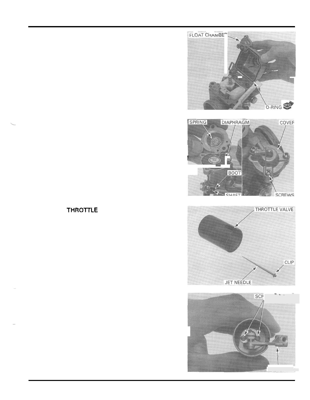
FUEL
SYSTEM
i-l_
-
.
-
-. .
.
. .
- -
Install
a
new O
-
ring into the float chamber groove
securely.
Install the float chamber, being careful not to pinch
the boot and tighten the four screws.
ACCELERATOR
PUMP
Insert the diaphragm shaft into the float chamber
through the boot and set the diaphragm rib into the
groove properly.
To
avoid damage to the boot, turn
1
the shaft slowly when inserting.
!
I
I
5;
Place the spring onto diaphragm. Install and hold the
pump cover, being careful not to pinch the
diaphragm and tighten the three screws.
THROlTLE VALVE
Install the needle clip onto the jet needle.
STANDARD CLIP POSITION:
3rd
groove
from
top
Insert the jet needle into the throttle valve.
~
-
-
II
I
-
Assemble the throttle valve and valve arm with the
two screws.
Install the throttle valve assembly into the carburetor
body, being careful not to damage the jet needle.
~
i
EWS
"
'
VALVE
ARM
5
-
9
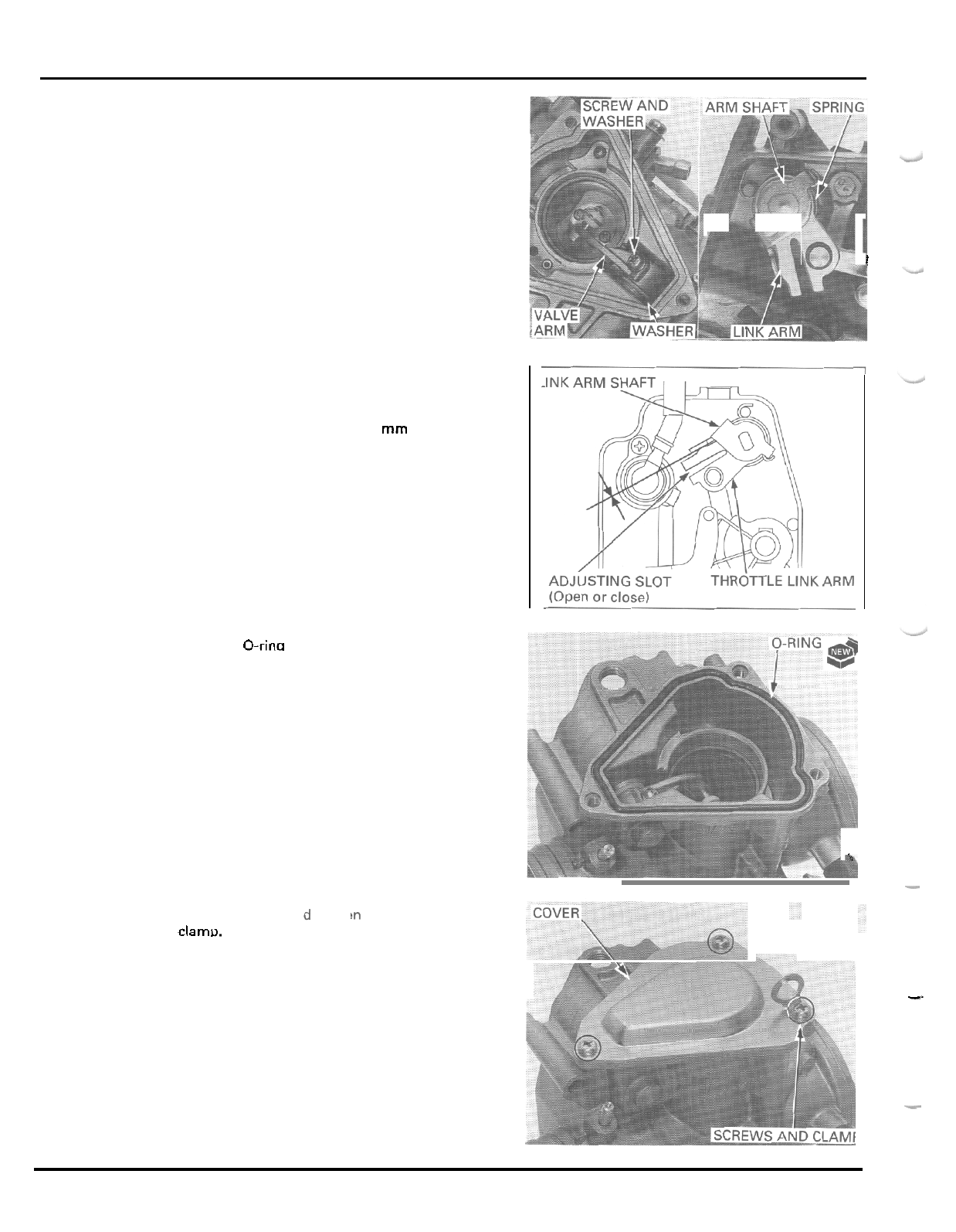
FUEL
SYSTEM
Set the thrust washer between the valve arm and car
-
buretor body (throttle drum side).
Insert the link arm shaft through the throttle link arm,
spring, carburetor body, washer and valve arm while
hanging the spring ends as shown.
Align the screw holes in the valve arm and shaft and
tighten the screw with the washer.
I
Make sure that the piston and butterfly throttle valves
are fully closed.
Make sure the clearance between the link arm shaft
and throttle link arm is
0.1
-
0.3
mm
(0.004
-
0.012
in).
Adjust synchronization by opening or closing the slot
in the throttle link arm.
body.
Install
a
new 0-rina into the groove in the carburetor
Install the top cover an
the clamo. tighte
i
-
the three screws with
-.
5
-
1
0
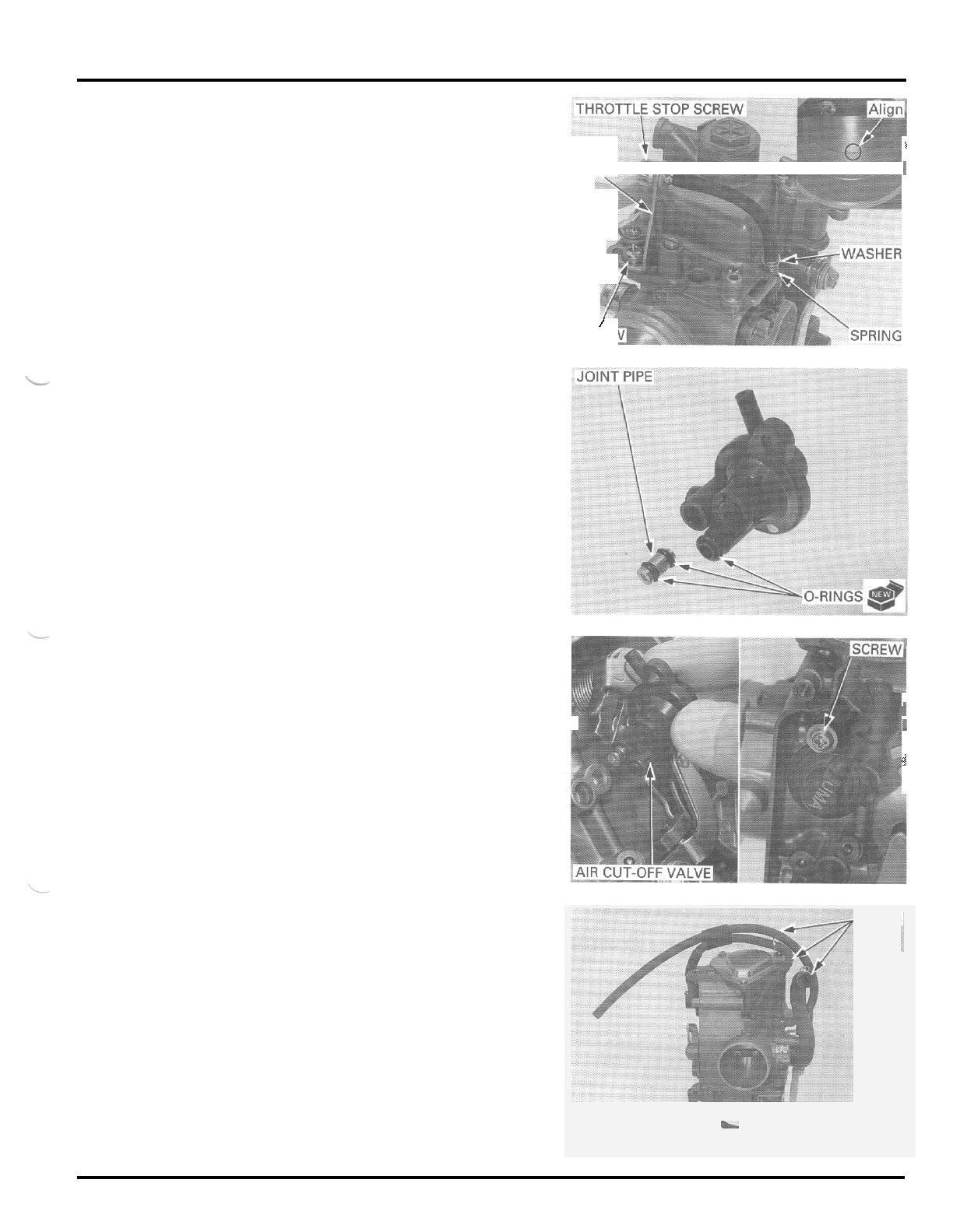
FUEL
SYSTEM
Install the throttle stop screw with the washer and
spring by screwing
it
clockwise.
Secure the
stay
with the screw
by
aligning its hole
and
boss.
1
STAY
!
-h
Turn the throttle stop screw to align the butterfly
throttle valve with the edge of the outside by
-
pass
hole in the carburetor.
/
SCREV
AIR
CUT
-
OFF
VALVE
Install new O
-
rings onto the air cut
-
off valve into the
joint pipe.
Install the joint pipe into the air cut
-
off valve with the
stepped side facing out (valve side).
i
Install the air cut
-
off valve and secure
it
with the screw.
i
Connect the vacuum, air vent and fuel tubes
as
shown.
J
TUBES
5
-
1
1
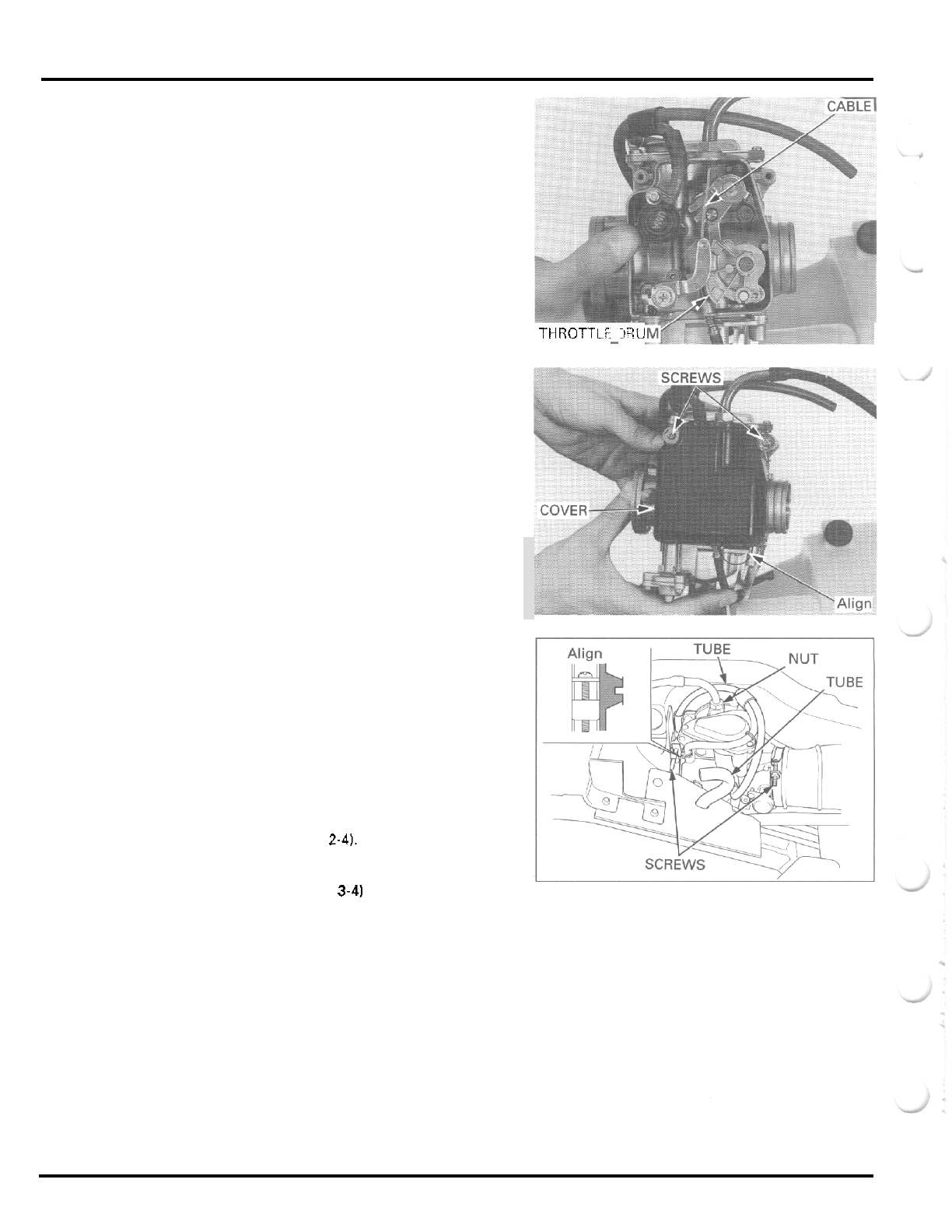
FUEL
SYSTEM
CARBURETOR INSTALLATION
Install the throttle cable outer to the carburetor body
and connect the cable inner to the throttle drum.
Install the throttle linkage cover by aligning the tab
with the slit in the carburetor and secure it with the
two
screws.
Install the carburetor into the insulator and connect
-
ing tube securely.
Align the lug
on
the carburetor with the groove in the
insulator and tighten the band screws.
Tighten the throttle cable lock nut.
Connect the drain tube to the carburetor.
Install the air vent tube into the heat protector.
Insert the fuel tube through the protector rubber.
Install the fuel tank (page
2-4).
Check the following:
-
throttle operation (page
3-41
-
engine idle speed (page
3
-
12)
Adjust the pilot screw if
it
was replaced (page
5
-
13).
THROTlLi
JQU
-
5
-
1
2
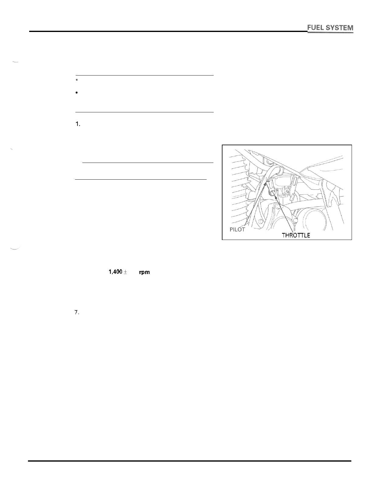
PILOT SCREW ADJUSTMENT
IDLE DROP PROCEDURE
-
NOTE:
The pilot screw is factory pre
-
set and no adjustment
is necessary unless the pilot screw
is
replaced.
-
Use a tachometer with graduations of
50
rpm or
smaller that will accurately indicate
a
50
rpm
change.
1.
Turn the pilot screw clockwise until
it
seats lightly,
then back
it
out to the specification given. This
is
an initial setting prior to the final pilot screw
adjustment.
CAUTION:
Damage to the pilot screw seat will occur if the pilot
screw is tightened against the seat.
TOOL
Pilot
screw wrench
07908
-
4220201
INITIAL OPENING:
2
-
1/4
turns out
2.
Warm up the engine to operating temperature.
Stop and go riding for
10
minutes is sufficient.
3.
Stop the engine and connect
a
tachometer accord
-
ing to the tachometer manufacturer’s instructions.
4.
Start the engine and adjust the idle speed with the
throttle stop screw.
IDLE SPEED:
1.40 100
rpm
5.
Turn the pilot screw in or out slowly to obtain the
6.
Lightly open the throttle
2
-
3
times, then adjust
7.
Turn the pilot screw in gradually until the engine
8.
Turn the pilot screw out to the final opening.
FINAL OPENING:
1
turn
out
9.
Readjust the idle speed with the throttle stop screw.
highest engine speed.
the idle speed with the throttle stop screw.
speed drops by
50
rpm.
SCREW THROTTLE STOP SCREW
5
-
1
3
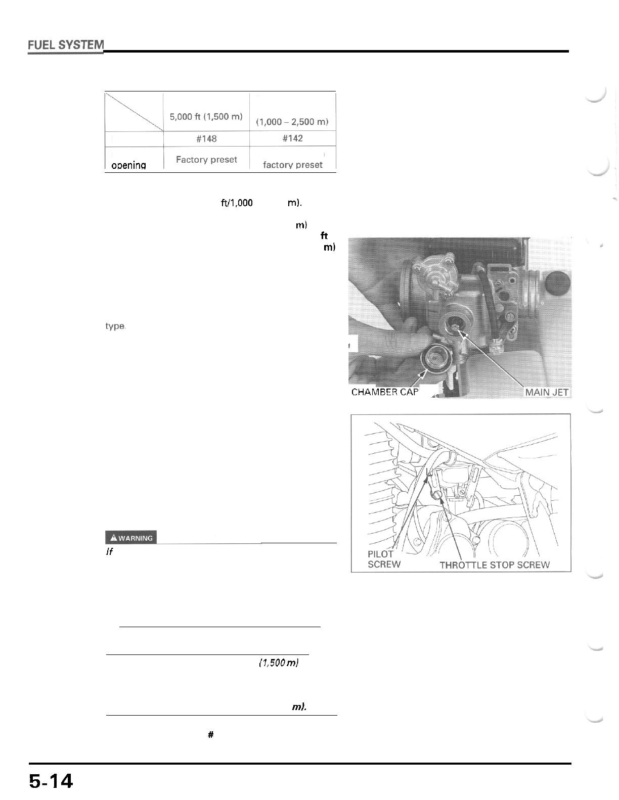
HIGH
ALTITUDE ADJUSTMENT
Between
3,000
-
8,000
ft
Below
Main jet
Pilot screw
oDeninq
1
turns in from
The carburetor must
be
adjusted for high altitude rid
-
ing (between
3,000
-
8,000
ft/l,OOO
-
2,500
m).
STANDARD SETTING:
Below
5,000
ft
11,500
ml
HIGH ALTITUDE SETTING:
Between
3,000
-
8,000
ft
(1.000
-
2,500
ml
The high altitude carburetor adjustment is performed
as follows:
Remove the carburetor (page
5
-
3)
and the float cham
-
ber cap.
Replace the standard main jet with the high altitude
HIGH ALTITUDE MAIN JET
#142
I
Check that the O
-
ring on the chamber cap is
in
good
condition and replace
it
with a new one if necessary.
Install the chamber cap and the carburetor.
CHAbiatii
wr
_,
Turn
-
in the pilot screw the specified number of turns
from the initial setting.
TOOL
Pilot
screw wrench
07908
-
4220201
HIGH ALTITUDE PILOT SCREW OPENING:
1
turn
in
from
initial
opening
Start the engine and adjust the idle speed at high
alti
-
tude to ensure proper high altitude operation.
If
the engine must be running to do some work,
make sure the area is well
-
ventilated. Never run the
engine in an enclosed area. The exhaust contains
poisonous carbon monoxide gas that may cause loss
of
consciousness and lead to death. Run the engine
in an open area or with an exhaust evacuation system
in an enclosed area.
CAUTION:
Sustained operation below
5,000
ft
(1,500
ml
with the
high altitude settings may cause engine overheating
and engine damage. Install the standard main jet
and screw out the pilot screw the specified number
of
turns, when riding below
5,000
ft
11,500
ml.
STANDARD MAIN
JET
#
148
Pilot
screw change
for
low
altitude:
1
turn
out
5-14
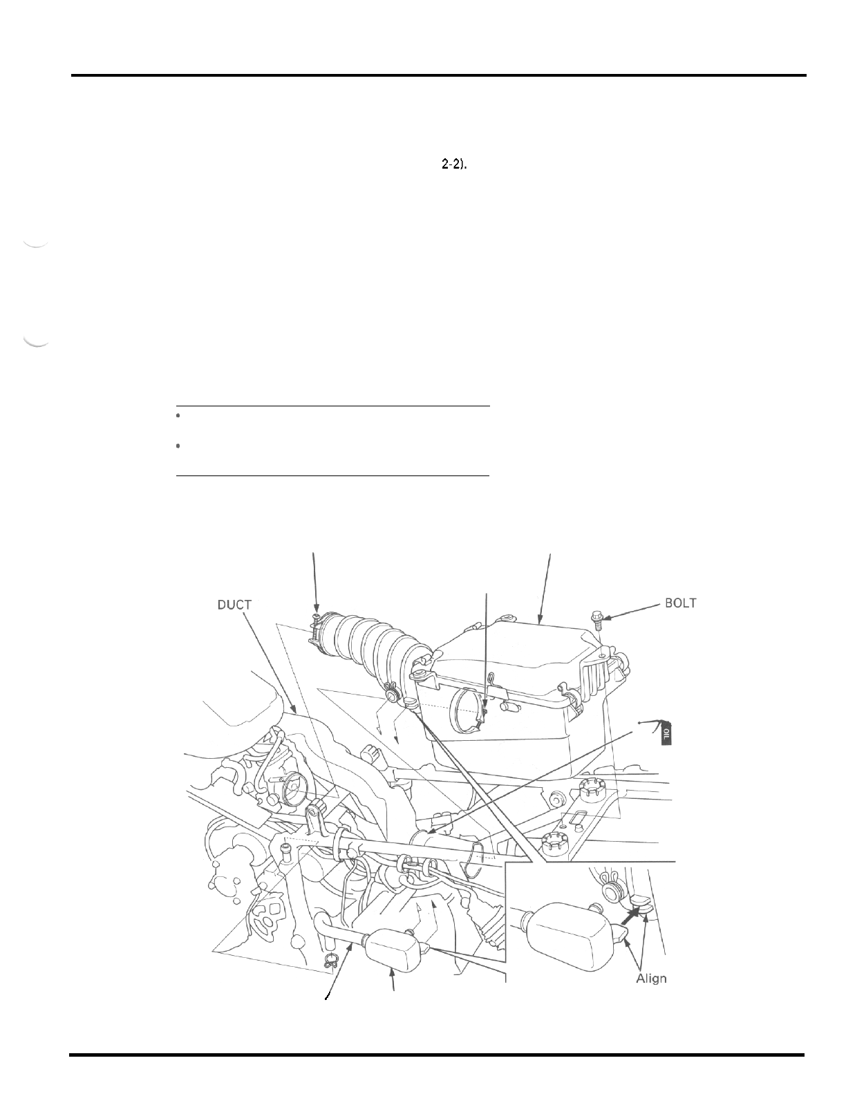
FUEL
SYSTEM
AIR
CLEANER
HOUSING
REMOVAL/INSTALLATION
Remove the seat/rear fender assembly (page
2-2).
Disconnect the crankcase breather tube and remove
the crankcase breather storage tank from the air
cleaner connecting tube.
Remove the mounting bolt.
Loosen the connecting tube band and intake duct
band screws.
Remove the air cleaner housing from the carburetor
and inlet duct.
Installation is in the reverse order
of
removal.
NOTE:
*
Apply oil to the mating surface
of
the intake
duct
and housing.
*
When installing the crankcase breather storage
tank, align its tab with the connecting tube slit.
SCREW AIR CLEANER HOUSING
SCREW
.
-
I
/
BREATHER TUBE C
RANKCASE
BREATHER
STORAGE TANK
5
-
1
5
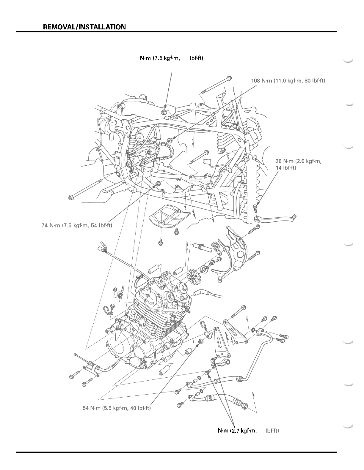
ENGINE REMOVAL/INSTALLATION
74 N.m 17.5
kgfm,
54
IbfW
I
26
N.m (i.7
kgfm.
20
Ibf+tl
6
-
0
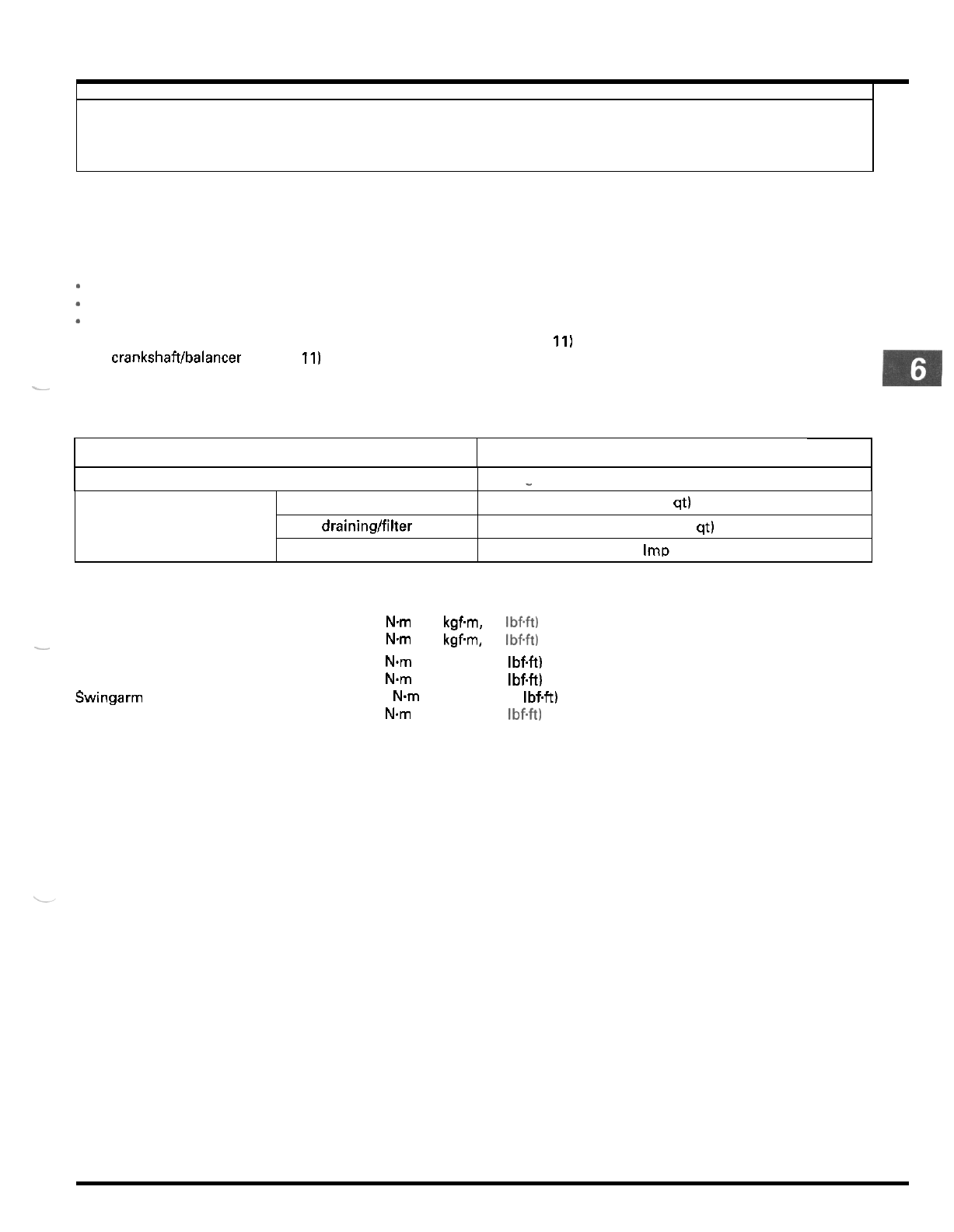
6.
ENGINE REMOVAL/INSTALLATION
ITEM
SERVICE INFORMATION
6
-
1
ENGINE INSTALLATION
6
-
4
ENGINE REMOVAL
6
-
2
SPECIFICATIONS
SERVICE INFORMATION
. .
Engine oil capacity After draining
After draining/filter change
After disassembly
GENERAL
*
Afloor jack or other adjustable support is required to support and maneuver the engine.
*
When removing and installing the engine, tape the frame around the engine beforehand for frame protection.
*
The following components require engine removal for service:
-
transmission (including shift fork, drum and shift spindle) (section 111
-
crankshaft/balancer (section 11)
Other components can be serviced with the engine installed
in
the frame.
-
SPECIFICATIONS
-
1.8 liters (1.9
US
qt, 1.6 Imp qt)
1.85 liters (1.95
US
qt. 1.63 Imp qt)
2.2 liters (2.3
US
at, 1.9
IrnD
at)
TORQUE VALUES
Upper engine hanger nut
-
Front engine hanger nut
bolt
Lower engine hanger nut
Swingarm pivot nut
Gearshift pedal pinch bolt
74 N.m
(7.5
kgfvn, 54 Ibf+t)
54
Nm
(5.5
kgfm,
40
Ibf.ft)
26 Nm (2.7 kgfm, 20 IbfW
74 Nm (7.5 kgfm, 54 IbfW
108 Nm (11.0 kgfm, 80 IbfW
20 Nm (2.0 kgfm, 14 Ibf4t)
6
-
1
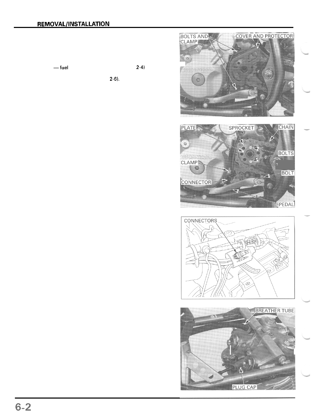
ENGINE REMOVAL/INSTALLATION
ENGINE
REMOVAL
Drain the engine oil (page
3
-
91
Remove the following:
-fuel tank and heat protector (page
2-41
-
carburetor assembly (page
5
-
3)
-
exhaust system (page
2-6).
Loosen the rear axle for maximum drive chain slack
(page
3
-
13).
Remove the two bolts, sprocket cover, sprocket pro
-
tector and clamp.
Remove the fixing plate bolts.
Remove the fixing plate by aligning the splines of the
plate and countershaft.
Pull
the drive sprocket off the countershaft and
remove the sprocket from the chain.
Remove the pinch bolt and the gearshift pedal.
Release the neutral switch wire from the clamp and
disconnect the connector.
Disconnect the alternator connectors and release the
wire from the wire band and clamp.
T
Disconnect the spark plug cap.
Disconnect the cylinder head breather tube.
I
?
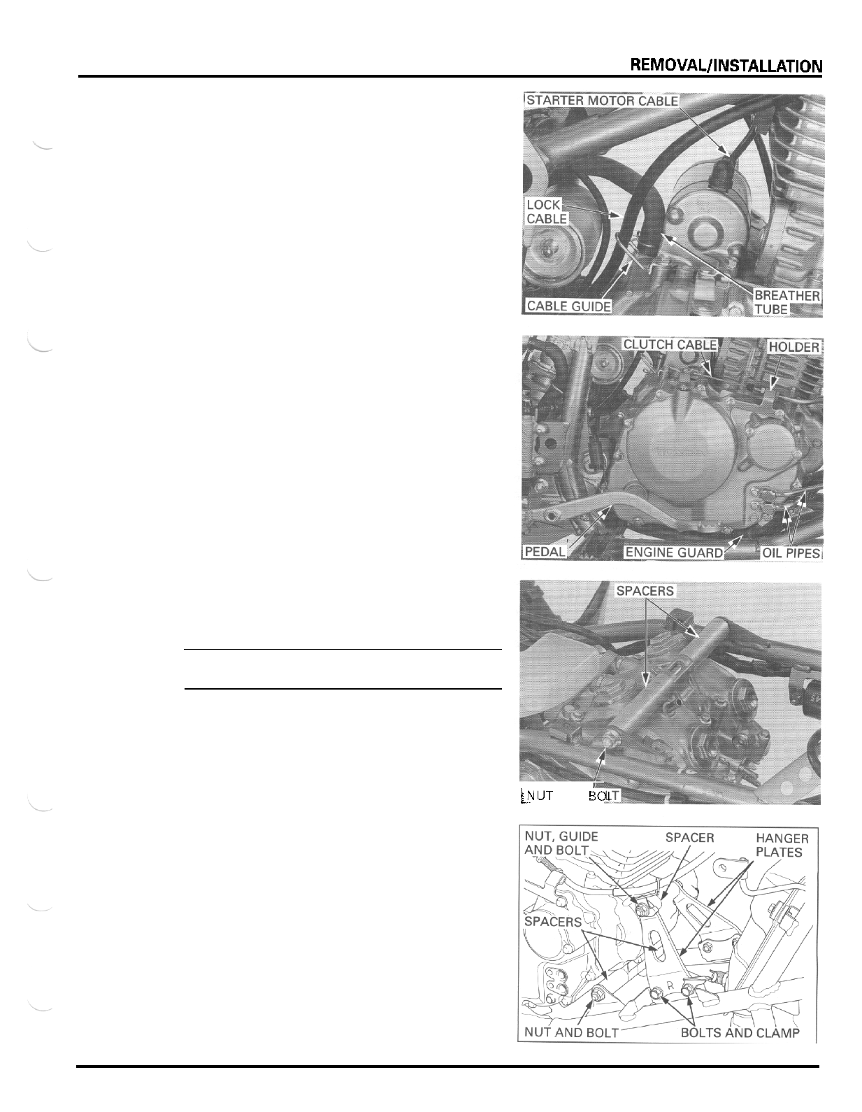
ENGINE REMOVAL/INSTALLATION
Disconnect the starter motor cable by removing the
terminal nut.
Disconnect the crankcase breather tube from the
engine.
Release the brake lock cable from the cable guide by
removing the mounting bolt.
Loosen the clutch cable lock nut. Remove the holder
bolts and cable holder and disconnect the clutch
cable from the clutch arm.
Disconnect the oil pipes from the engine by remov
-
ing the bolts. Remove the dowel pins and O
-
rings.
Remove the brake pedal (page
14
-
20).
Remove the two bolts and engine guard.
Support the engine with a floor jack or other
adjustable support.
NOTE:
The jack height must be continually adjusted to
relieve stress for ease
of
bolt removal.
Remove the upper engine hanger nut, spacers and
bolt.
Remove the front engine hanger nut, cable guide,
spacer and bolt.
Remove the front engine hanger bolts, pipe clamp
and hanger plates.
Remove the lower engine hanger nut, spacers and
bolt.
(1
LNUT
AND
501
6
-
3
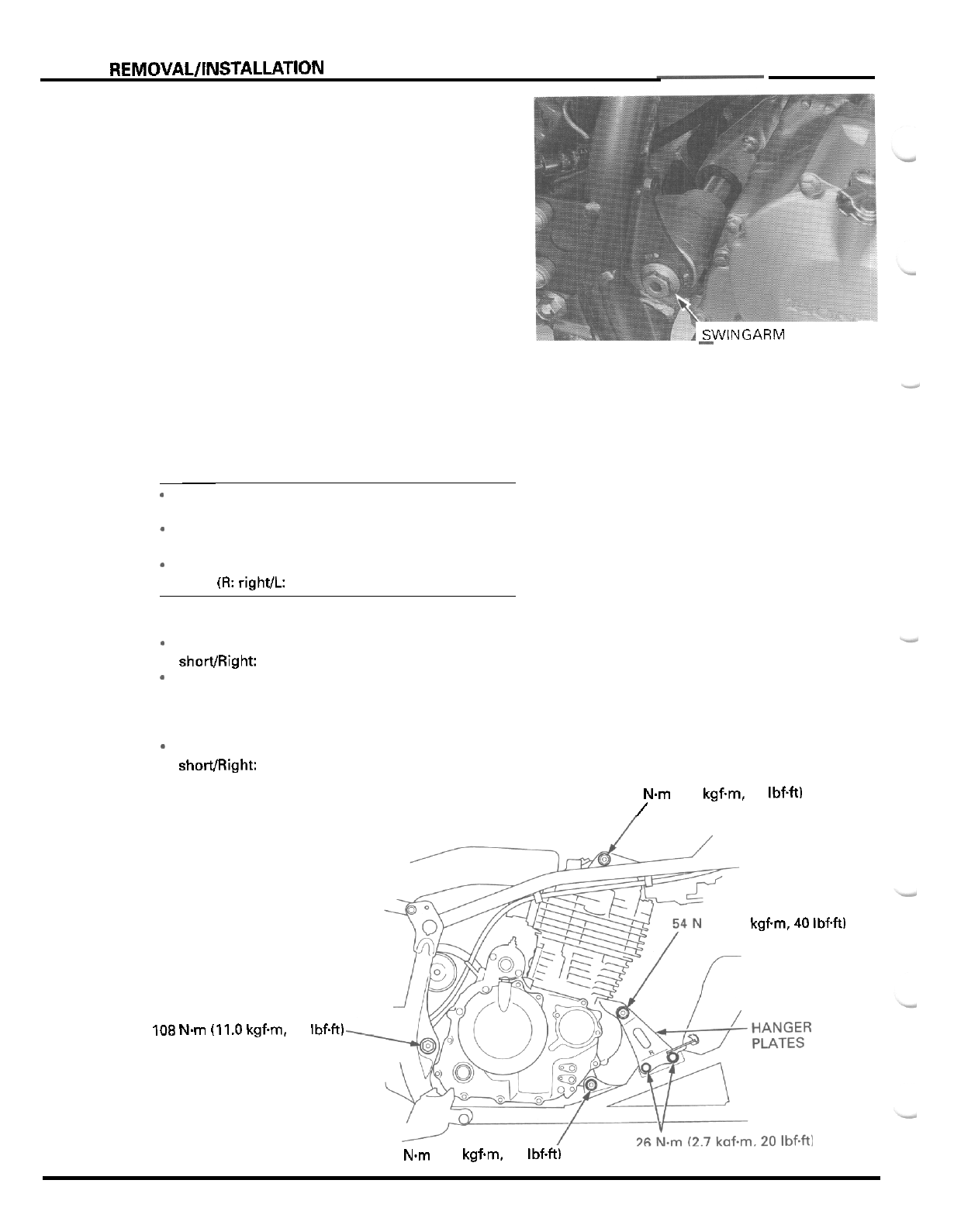
ENGINE
REMOVAL/INSTALLATION
Remove the swingarm pivot nut and bolt.
Remove the engine out of the frame to the right.
ENGINE
INSTALLATION
Install the engine into the frame from the right side in
the reverse order of removal.
NOTE:
SWINGARM
PIVOT
BOLT'
-
*
Before installing, make sure that the pivot collars
are installed into the swingarm pivots.
-
Note the installation direction of the mounting
bolts and the position of the spacers.
-
The front hanger plates are identified by marks
them
(R:
right/l: left).
.
Install the swingarm pivot bolt and nut.
*
Install the lower engine hanger bolt, spacers (Left:
shorVRight: long) and nut.
-
Install the front engine hanger plate with the bolts
and clamp.
Install the front engine hanger bolt, spacer (right
side of the engine), guide and nut.
-
Install the upper engine hanger bolt, spacers (Left
shomight: long) and nut.
74
Nm
(7.5
kgfm,
54
1bf.h)
/
Tighten the nuts to the specified torque.
108
Nm
(11.0
kgfm
m
(5.5
kgfm
40
IbfW
80
IbfW
74
Nm
(7.5
kgfm,
54
Ibf4t)
6
-
4
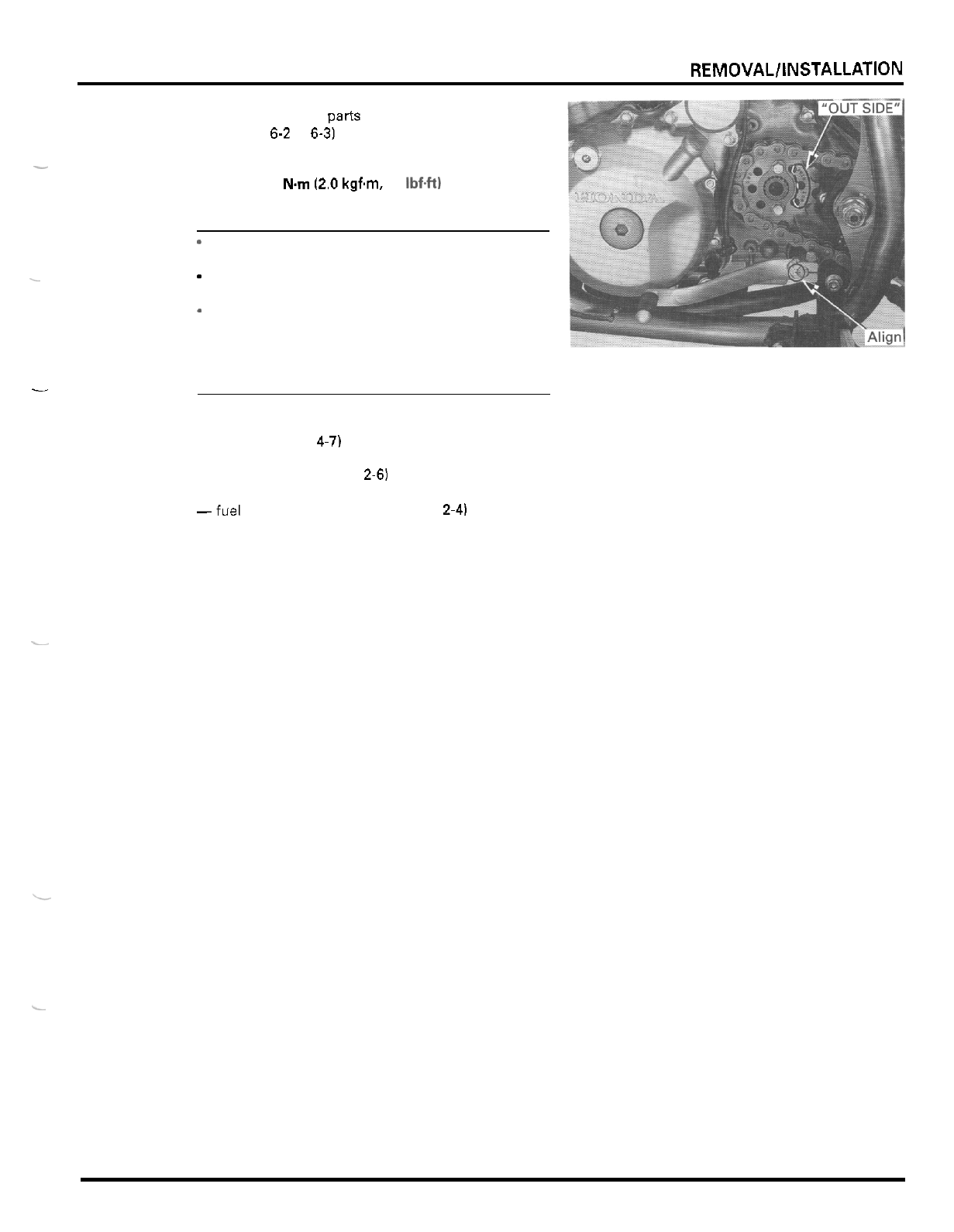
ENGINE REMOVAL/INSTALLATION
Install the removed parts from engine removal proce
-
dure (page 6-2 to 6-3) in the reverse order or removal.
TORQUE:
Gearshift pedal
pinch
bolt:
20
Nm
12.0
kgfm,
14
Ibf4t)
-
NOTE:
*
Route the wires, cables and tubes properly (page
1
-
18).
-
When installing the gearshift pedal, align the
punch marks on the pedal and spindle.
-
When installing the drive sprocket, install with the
"
OUT
SIDE
"
mark facing out. Set the fixing plate
into the countershaft groove and move
it
to align
the bolt holes in the plate and sprocket then tighten
the bolts.
1
Install the following:
-
oil pipes (page
4-7)
-
brake pedal (page
14
-
20)
-
exhaust system (page 2-61
-
carburetor assembly (page
5
-
12)
-fuel tank and heat protector (page
2-4)
Perform the following adjustments:
-
drive chain (page 3
-
13)
-
clutch cable (page 3
-
17)
-
throttle cable (page 3
-
4)
Fill
with engine oil (page 3
-
9).
6
-
5
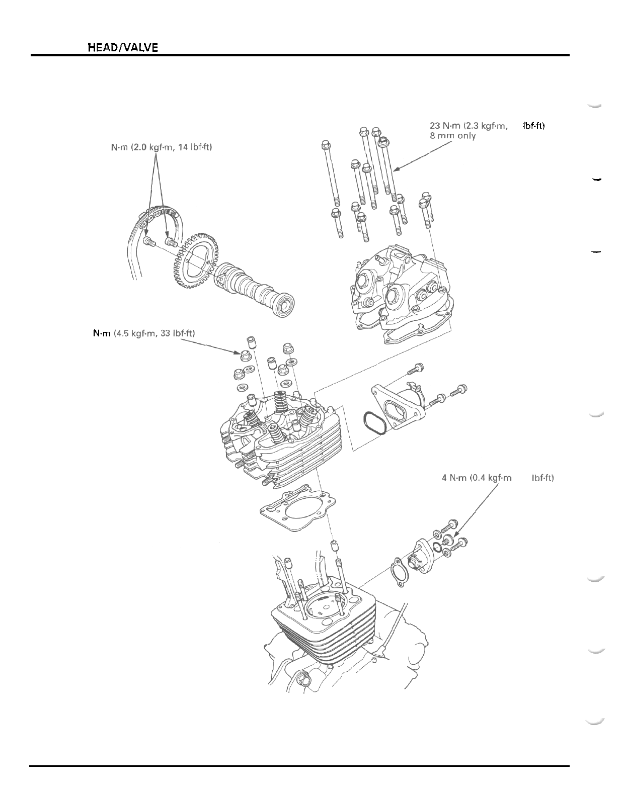
CYLINDER HEAD/VALVE
20
44
Nm
17
IbfW
,
2.9
Ibf.ft)
I
I
7
-
0
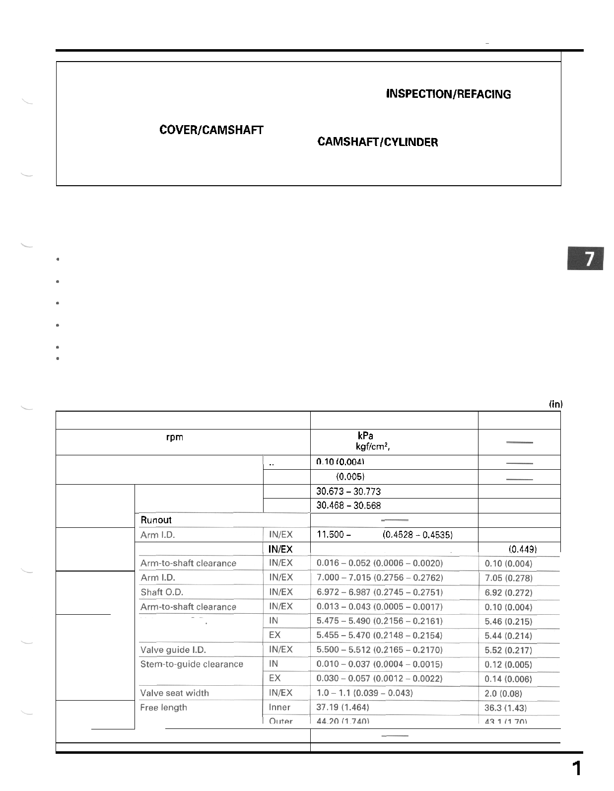
7.
CYLINDER
HEAD/VALVE
ITEM
Cylinder compression at rpm
1
IN
~
SERVICE INFORMATION 7
-
1 VALVE GUIDE REPLACEMENT 7
-
12
TROUBLESHOOTING 7
-
3 VALVE SEAT INSPECTION/REFACING 7
-
13
CYLINDER COMPRESSION 7
-
4 CYLINDER HEAD ASSEMBLY/
CYLINDER HEAD COVER/CAMSHAFT INSTALLATION 7
-
16
REMOVAL 7
-
4 CAMSHAFT/CYLINDER HEAD COVER
DISASSEMBLY 7
-
9
CYLINDER HEAD REMOVAL/ INSTALLATION 7
-
18
STANDARD
SERVICE LIMIT
686
-
883
kPa
(7.0
-
9.0
kgf/cm',
100
-
128
psi)
0.10
in
nna
-
-
SERVICE INFORMATION
Cam
lobe height
~
GENERAL
..
.
.
.
.
-
,
-.
-
-
.
,
EX
0.12 (0.005)
-
IN
30.673-30.773 (1.2076
-
1.2115) 30.57 (1.204)
30.37 (1.196)
EX
30.468-30.568 (1.1995
-
1.2035)
-
This section covers service
of
the camshaft. rocker arms, cylinder head and valves. These parts can be serviced with
the engine installed in the frame.
Runout
Shaft
O.D.
1
IN/EX
*
When disassembling, mark and store the disassembled parts to ensure that they are reinstalled in their original loca
-
tions.
-
Clean
all
disassembled parts with cleaning solvent and dry them by blowing them
off
with compressed air before
inspection.
*
Camshaft and lubricating oil is fed through oil passages in the cylinder head. Clean the oil passages before assem
-
bling cylinder head.
-
Pour clean engine oil into the oil pocket
in
the cylinder head during assembly to lubricate the camshaft.
*
Be careful not to damage the mating surfaces when removing the cylinder head cover and cylinder head.
Do
not
strike the head cover and cylinder head too hard during removal.
SPECIFICATIONS
Unit:
mm
(in)
-
0.03 (0.001)
11.53 (0.454)
11,500- 11.518 (0.4528-0.4535)
11.466
-
11.484 (0.4514
-
0.4521) 11.41 (0.449)
____
-
Valve clearance
Camshaft
Rocker arm
Sub
-
rocker arm
Valve,
valve guide
Valve spring
Valve stem
O.D.
7
-
'1
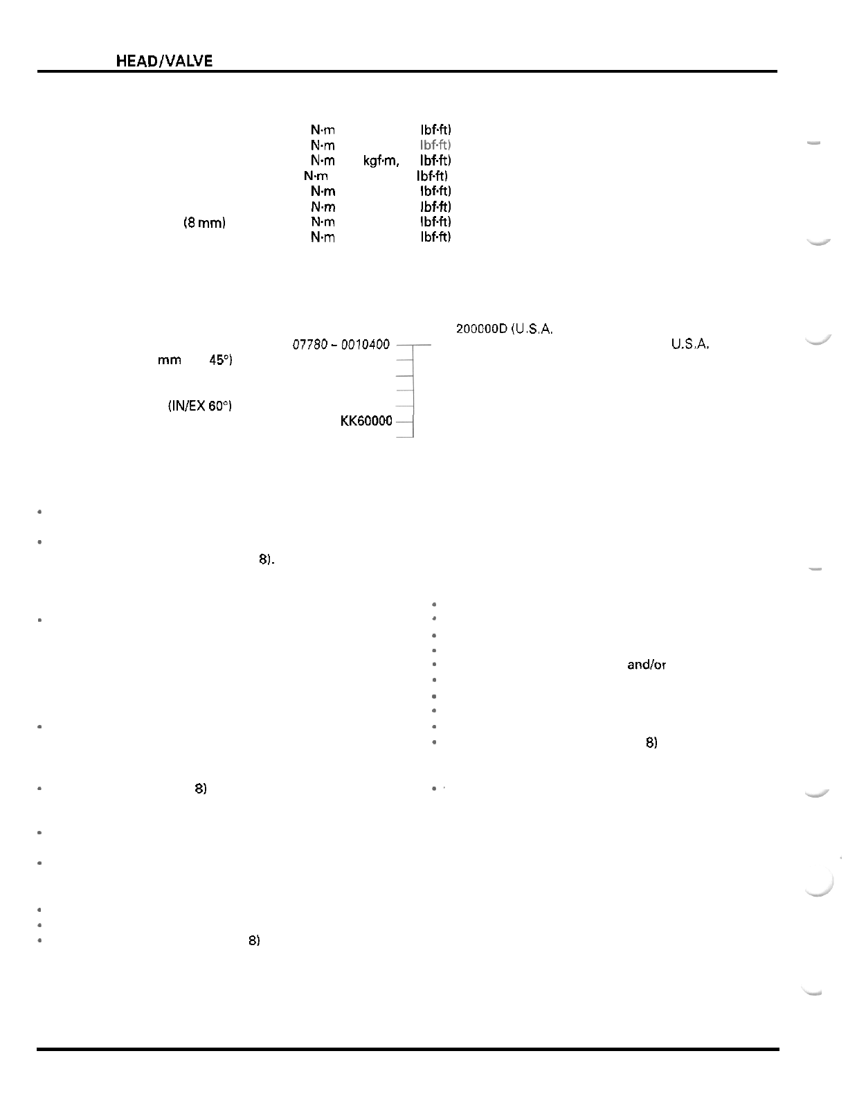
CYLINDER HEADNALVE
TORQUE
VALUES
Upper engine hanger nut
Cylinder head nut
Cam sprocket bolt
Cam chain tensioner plug
Rocker arm shaft
Sub
-
rocker arm shaft
Cylinder head cover bolt
(8
mm)
Spark plug
TOOLS
Valve spring compressor
Valve guide driver, 5.5 mm
Valve guide reamer,
5.5
mm
Valve seat cutter,
35
mm
(IN
45
"
)
Valve seat cutter, 29 mm (EX 45")
Flat cutter, 35 mm (IN 32
"
)
Flat cutter,
30
mm (EX 32
"
)
Interior cutter, 30 mm
(INIEX 60")
Compression gauge attachment
Cutter holder,
5.5
mm
54 N.m (5.5 kgfm, 40 IbfW
20
Nm (2.0 kgf.m, 14 IbfW Apply locking agent to the threads
4
Nm (0.4 kgfm, 2.9 IbfW
27 N.m
(2.8
kgfm, 20 IbfW Apply locking agent to the threads
27 Nm (2.8 kgfm, 20 IbfW Apply locking agent
to
the threads
26 Nm
(2.7
kgfm, 20 IbfW
18 N.m (1.8 kgfm, 13 IbfW
44
Nm (4.5 kgfm, 33 Ibf.ft) Apply oil to the threads and seating surface
-
07757
-
0010000
07742
-
0010100
07984
-
2000001 or 07984
-
200000D
(U.S.A. only)
077ao-ooi0400
07780
-
0010300
07780
-
0012300
07780
-
0012200
07780
-
001
4000
07908
-
KK60000
07781
-
0010101
or equivalent commercially available
in
U.S.A.
TROUBLESHOOTING
-
Engine top
-
end problems usually affect engine performance. These can be diagnosed by a compression test, or by tracing
top
-
end noise with
a
sounding rod or stethoscope.
-
If the performance
is
poor at low speeds, check for
a
white smoke in the crankcase breather tube. If the tube
is
smoky.
check for sized piston ring (section
8).
-
Compression
too
low,
hard starting
or
poor performance
at
low
speed
-
Valves
-
Incorrect valve adjustment
-
Burned or bent valves
-
Incorrect valve timing
-
Broken valve spring
-
Uneven valve seating
-
Valve stuck open
-
Leaking or damaged cylinder head gasket
-
Warped or cracked cylinder head
-
Loose spark plug
-
Cylinder head
-
Cylinderlpiston (section
8)
Compression
too
high
-
Excessive carbon build
-
up
on
piston head or combus
-
tion chamber
*
Worn or damaged decornpressor system
Excessive smoke
Worn valve stem or valve guide
*
Damaged stem seal
*
Cylinderlpiston problem (section
8)
Excessive noise
-
Incorrect valve clearance
*
Sticking valve or broken valve spring
*
Excessive worn valve seat
-
Worn or damaged camshaft
*
Worn or damaged rocker arm and/or shaft
*
Worn rocker arm follower or valve stem end
-
Worn cam chain
*
Worn or damaged cam chain tensioner
-
Worn cam sprocket teeth
-
Cylinderlpiston problem (section
8)
Rough idle
*
'
Low cylinder compression
7
-
2
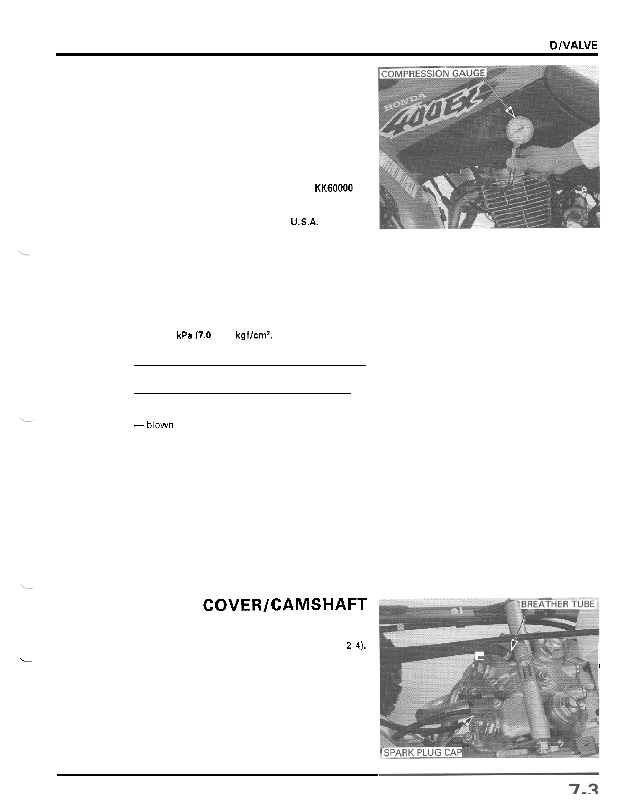
CYLINDER HE A WVALVE
CYLINDER COMPRESSION
Warm up the engine to normal operating temperature.
Stop the engine, disconnect the spark plug cap and
remove the spark plug.
Install the compression gauge with the gauge attach
-
ment into the spark plug hole.
TOOL
Compression gauge attachment
07908
-
KK60000
or
equivalent com
-
mercially available
in
USA.
Shift the transmission in neutral and open the choke
lever
(OFF).
Open the throttle
all
the way and crank the engine
with the starter motor until the gauge reading stops
rising. The maximum reading is usually reached
within
4
-
7
seconds.
COMPRESSION PRESSURE
686
-
883
kPa
(7.0
-
9.0
kgf/cm*,
100
-
128
psi)
NOTE:
Check that there is no leakage at the gauge connec
-
tion,
Low compression can be caused
by:
-blown cylinder head gasket
-
improper valve adjustment
-
valve leakage
-
worn piston ring or cylinder
High compression can be caused by:
-
carbon deposits in combustion chamber or on pis
-
ton head
CYLINDER HEAD COVER/CAMSHAFT
REMOVAL
Remove the fuel tank under heat protector (page
2-4).
Remove the spark plug cap.
Disconnect the crankcase breather tube from the
head cover.
L
I
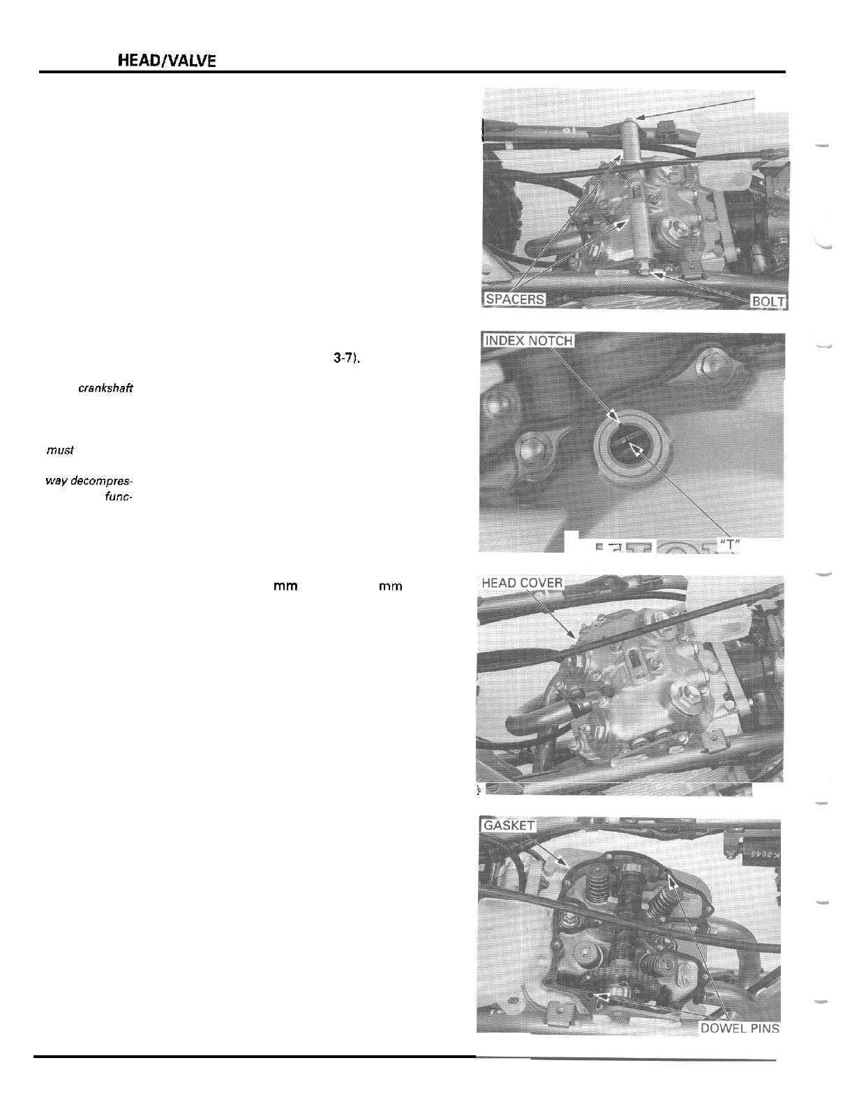
CYLINDER
HEAD/VALVE
Remove the upper engine hanger nut, bolt and spacers. NUT
-
I
I
Remove the timing hole cap, crankshaft hole cap and
valve adjusting hole caps (page
3-71,
The crankshaff
Rotate the crankshaft counterclockwise and align the
should be turned
"
T
"
mark on the flywheel with the index notch in the
clockwise. This
Make sure that the piston is
at
TDC (Top Dead
must be done
to
Center) on the compression stroke.
prevent the one
-
The rocker arms should be loose.
waydecornpres-
If
the rocker arms are tight, rotate the crankshaft
sorsystern func-
counterclockwise one full turn and realign the
"
T
"
tioning
mark with the index notch.
only counter
-
left crankcase cover.
1..
;i
7,-7
F~=.>-:;;"T"
,MARK:
-
Loosen the twelve
6
mm bolts and
8
mm bolt in a
crisscross pattern in
2
or
3
steps.
Remove the bolts and the cylinder head cover.
r
-
Remove the gasket and dowel pins.
-
-
7
-
4
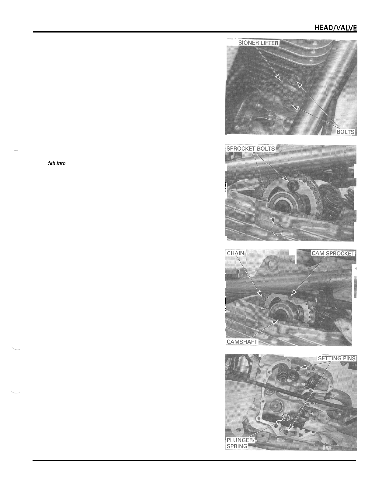
CYLINDER HEADlVALVE
-_
~
TEN
___
Loosen the cam chain tensioner lifter plug.
Remove the two bolts, cam chain tensioner lifter and
gasket
.
-
Becarefulnotto
Remove the cam sprocket bolt.
let the sprocket
Rotate the crankshaft counterclockwise one turn and
bolts fallinto the
remove the other cam sprocket bolt.
crankcase,
I
i
Remove the cam sprocket from the camshaft flange.
Attach a piece of wire to the cam chain to prevent
it
from falling into the crankcase.
Lift the camshaft and remove
it.
Remove the cam sprocket from the cam chain.
i
I
i
1
,
I
-
Remove the plunger, spring and bearing setting pins,
being careful not to drop them into the crankcase.
7
-
5
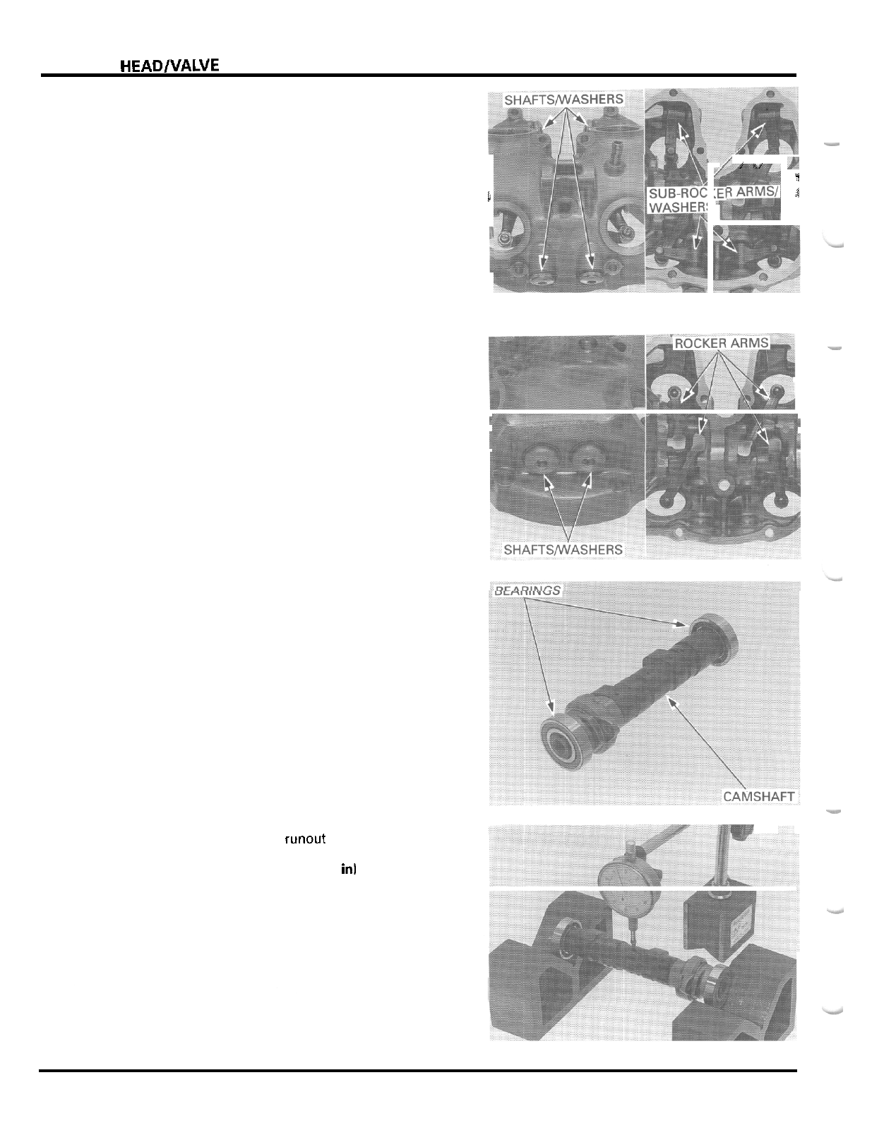
CYLINDER HEAD/VALVE
CYLINDER HEAD COVER DISASSEMBLY
Hold the cylinder head cover securely and loosen the
the mating surface of the cylinder head cover.
-
sub
-
rocker arm shafts, being careful not to damage
Remove the shafts, sealing washers, sub
-
rocker arms
and wave washers.
l
i
i,
P
1
1
-
Hold the cylinder head cover securely and loosen the
rocker arm shafts, being careful
not
to damage the
mating surface of the cylinder head cover.
Remove the shafts, sealing washers and rocker arms.
INSPECTION
CAMSHAFT
Check the cam and journal surfaces of the camshaft
for scoring, scratches or evidence of insufficient
lubrication.
Check the oil holes in the camshaft for clogging.
Turn the outer race
of
each bearing with your finger.
The bearings should turn smoothly and quietly.
Replace the bearing if the outer race does not turn
smoothly and quietly.
-
Measure the camshaft runout using
a
dial indicator.
SERVICE LIMIT:
0.03
mm
(0.001
in1
7
-
6
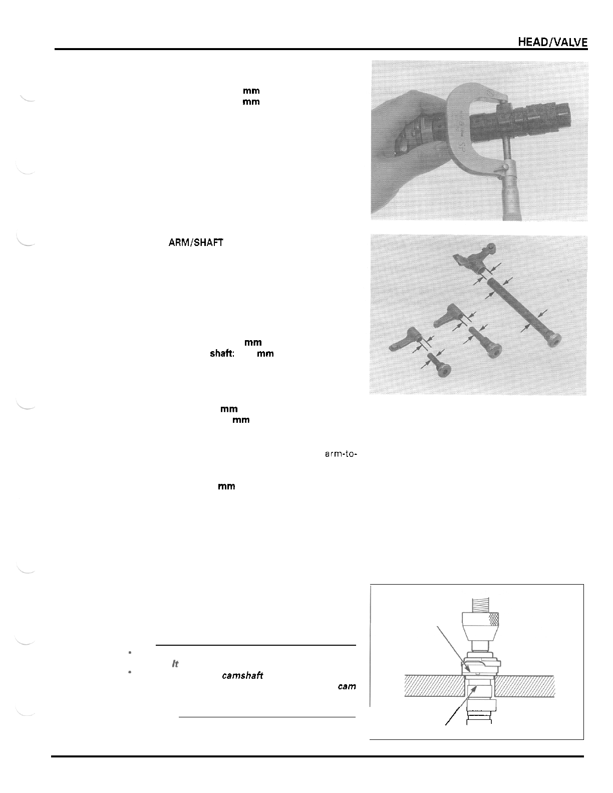
CYLINDER HEAD/VALVE
Measure each cam lobe height,
SERVICE LIMIT
IN
30.57
mm
(1.204
in)
EX
30.37
mm
(1.196
in)
ROCKER ARMlSHAFT
Check the rocker arms and shafts for wear or damage.
If the rocker arm slipper surface is worn or damaged,
check the camshaft cam lobe and oil passages.
Measure each rocker arm shaft O.D.
SERVICE LIMITS
Rocker arm
shaft:
11.41
mm
(0.449
in)
Sub
-
rocker arm
shaft
6.92
mm
(0.272
in)
Measure each rocker arm I.D.
SERVICE LIMITS:
Rocker arm:
11.53
mm
(0.454
in)
Sub
-
rocker arm:
7.05
mm
(0.278
in)
Subtract each rocker arm shaft O.D. from the corre
-
sponding rocker arm
I.D.
to obtain the rocker arm-to-
shaft clearance.
SERVICE LIMIT
0.10
mm
(0.004
in)
DECOMPRESSOR DISASSEMBLY
Set the camshaft assembly onto the hydraulic press
by supporting the reverse decompressor cam flange.
CAUTION
Do
not support the assembly by the sprocket
flange.
If
will break or crack
its
flange.
When setting the camshafl assembly, take care
not to contact the support blocks against the
cam
lobe or decompressor cam to avoid damaging
them when pressing.
*
Press the camshaft out of the sprocket flange.
Hold: REVERSE
DECOMPRESSOR
CAM
\
/R
DECOMPRESSOR CAM
7
-
7
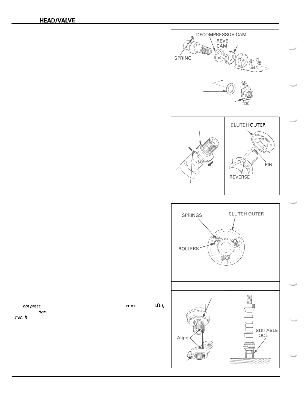
CYLINDER
HEAD/VALVE
DECOMPRESSOR CAM
SPRING
Remove the following:
-
thrust washer
-
one
-
way clutch (clutch outer, rollers and springs)
-
reverse decompressor cam
-
stopper pin
-
decompressor cam
-
spring
INSPECTION
Check the one
-
way clutch outer, rollers and springs
for wear or damage.
Check both cams for wear or damage.
Check the cam's sliding surface on the camshaft for
scoring or wear.
DECOMPRESSOR
ASSEMBLY
CLUTCH
OUTER
DECOMPRESSOR
CAM
Lubricate the cams, one
-
way clutch and washer,
Install the spring into the camshaft hole, then install
the decompressor cam while holding the spring.
Assemble the reverse decompressor cam and clutch
outer with the stopper pin and install the assembly
onto the camshaft.
RSE DECOMPRESSOF
ONE WAY CLUTCH
WASHER
CAM SPROCKET FLANGE
Install the springs and rollers into the clutch outer
grooves
as
shown.
Install the thrust washer onto the clutch outer.
Do
notpress
on
Using
a
suitable tool (collar with
19
mm or more I.D.1,
the flange
por-
press the sprocket flange onto the camshaft by align
-
tion.
It
will
break
ing the wide groove with the wide tooth.
or crack.
WASHER
SPROCKET FLANGE
7
-
8
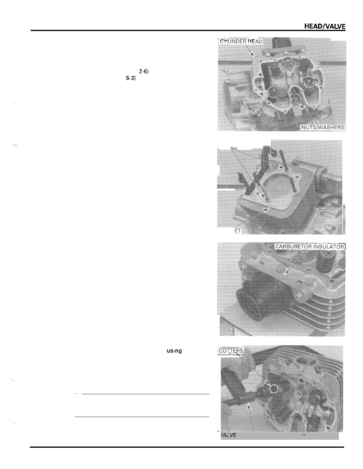
CYLINDER HEAD/VALVE
*
-
*
-
-
.----
I
_
I
CYLINDER HEAD REMOVAL/
DISASSEMBLY
r\,,
,..,-rn
I
Ir
A
Remove the following:
-
exhaust system (page
2-6)
-
carburetor (page
5-3)
-
cylinder head cover and camshaft (page
7
-
3)
-
spark plug
Remove the four cap nuts and washers, being careful
not to drop them into the crankcase.
Do
not strike the
Remove the cylinder head.
cylinder head
too
hard.
~
-
Remove the gasket and dowel pins.
DOWEL
PINS
-v.
GASKI
Remove the three bolts and the carburetor insulator
from the cylinder head.
Remove the O
-
ring from the carburetor insulator.
i
Remove the valve spring cotters uslng the valve
%CKRs
spring compressor.
.\
TOOL
Valve
spring
compressor
07757
-
0010000
CAUTION
To
prevent
loss
of
tension,
do
not compress the
valve springs more than necessary to remove the
cotters.
~
-
\
/ALVE
SPRING
COMPRESSOR
.-
7
-
9
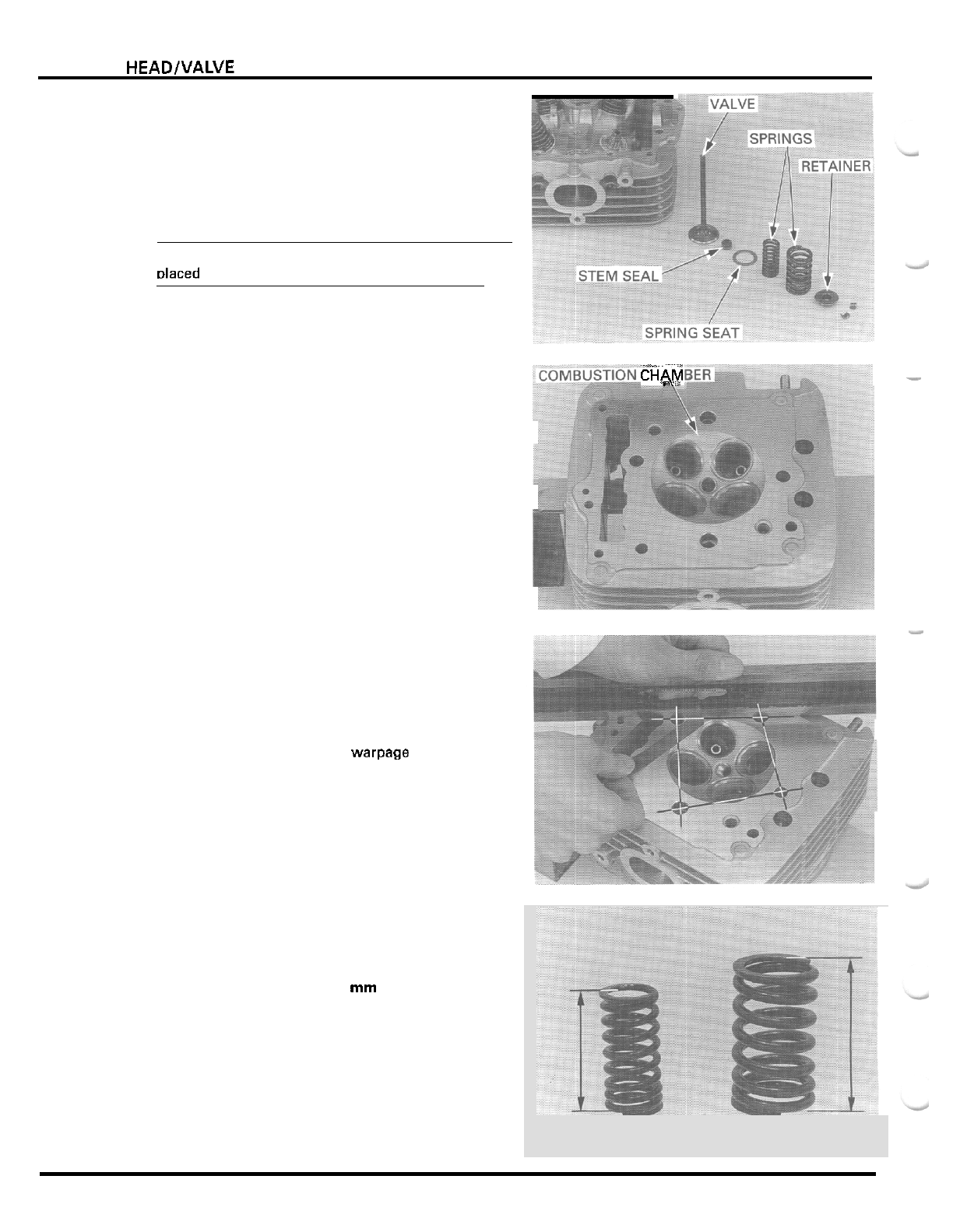
CYLINDER HEADNALVE
Remove the following:
-
spring retainer
-
inner and outer valve springs
-
valve
-
stem seal
-
valve spring seat
NOTE:
Mark
all
parts during disassembly
so
they can be
Dlaced back in their original locations.
CTAM
-
Remove the carbon deposits from the combustion
-5
chamber and clean
off
the gasket surface, being care
-
ful not to damage the gasket and valve seat surfaces.
INSPECTION
CYLINDER HEAD
Check the spark plug hole and valve areas for cracks.
Check the cylinder head for warpage with
a
straight
edge and feeler gauge.
SERVICE
LIMIT
0.10
mm
(0.004
in)
VALVE
SPRING
Measure the valve spring free length.
SERVICE
LIMITS
Inner:
36.3
mm
11.43 in)
Outer: 43.1
mm
(1.70 in)
7
-
1
0
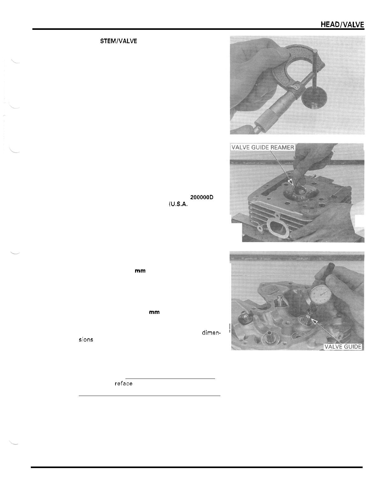
CYLINDER HEADlVALVE
VALVE STEMlVALVE GUIDE
Check that the valve moves smoothly in the guide.
Check the valve for bending, burning or abnormal
wear.
Measure each valve stem O.D. and record it.
SERVICE LIMITS:
IN:
5.46
mm
(0.215
in)
EX
5.44
mm
10.214
in)
Ream the valve guide to remove any carbon build
-
up
before measuring the guide.
Insert the reamer from the combustion chamber side
of the head and always rotate the reamer clockwise.
TOOL
Valve guide reamer,
5.5
mm
07984
-
2000001
or
07984
-
200000D
(U.S.A. only)
Measure each valve guide I.D. and record
it.
SERVICE LIMIT
5.52
mrn
(0.217
in)
Subtract each valve stem O.D. from the correspond
-
ing guide I.D. to obtain the stem
-
to
-
guide clearance.
SERVICE LIMITS
IN:
0.12
mm
(0.005
in)
EX
0.14
mrn
(0.006
in)
If the stem
-
to
-
guide clearance exceeds the service
limit, determine if
a
new guide with standard dimen-
sions would bring the clearance within tolerance.
If
so,
replace any guides as necessary and ream to fit.
If the stem
-
to
-
guide clearance exceeds the service
limit
with
a
new guide, also replace the valve.
NOTE:
!
Inspect and reface the valve seats whenever the
valve guides are replaced (page
7
-
13).
7
-
1
1
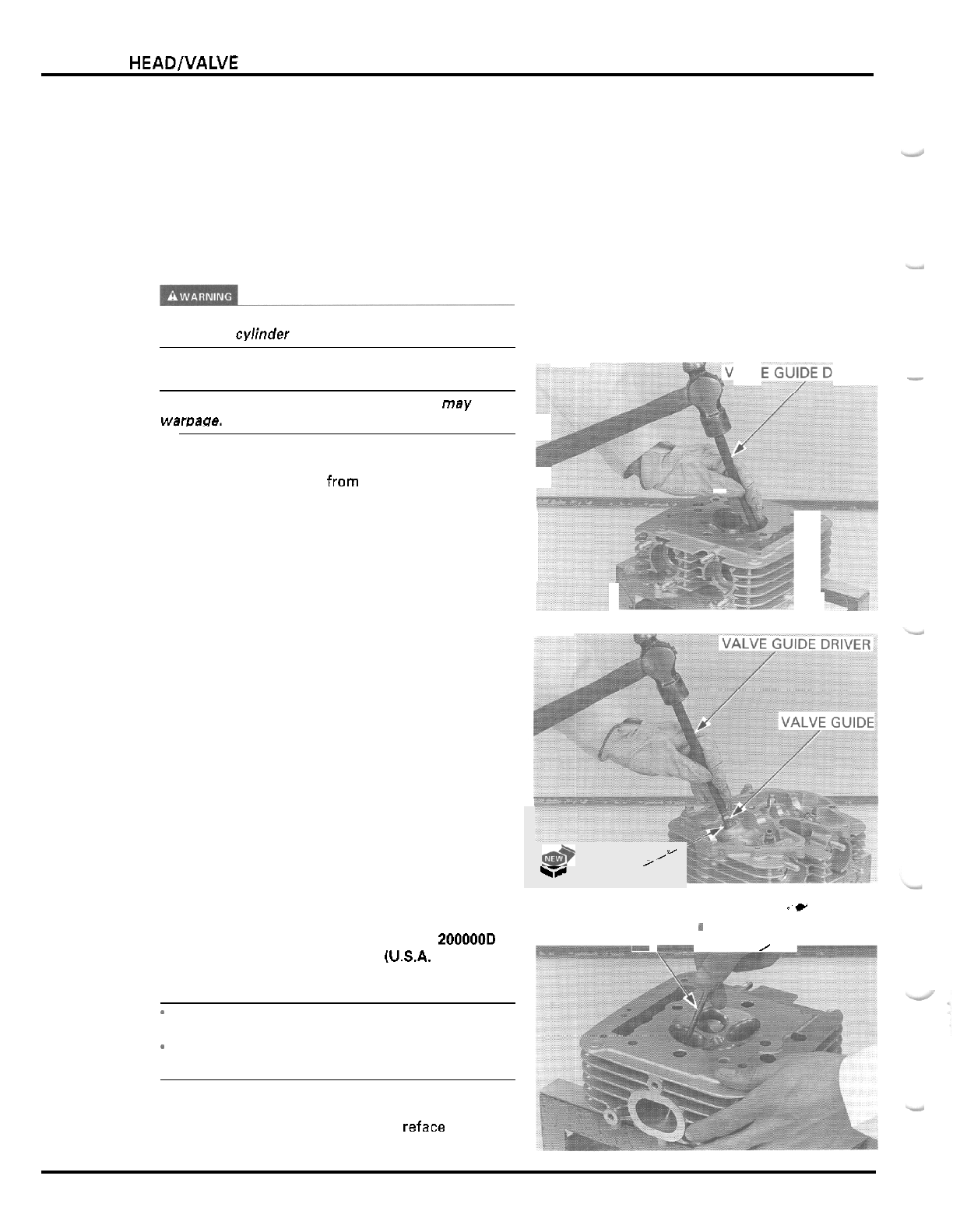
CYLINDER HEAD/VALVE
VALVE GUIDE REPLACEMENT
Chill new valve guides in the freezer section of
a
refrigerator for about an hour.
Heat the cylinder head to 130
-
140°C
(275
-
290°F)
with
a
hot plate or oven.
Do
not heat the cylinder
head beyond 150
"
(300°F).
Use temperature indicator
sticks, available from welding supply stores, to be
sure the cylinder head is heated to the proper tem
-
perature.
Wear heavy gloves to avoid burns when handling
the heated cy1;nder head.
CAUTION:
Using
a
torch to heat the cylinder head may cause
warDage.
Support the cylinder head and drive the valve guides
out of the cylinder head from the combustion cham
-
ber side.
TOOL
Valve guide driver,
5.5
mm
07742
-
0010100
ALV
RIVER
-
Install new O
-
rings onto the new valve guides.
Drive the new valve guides in the cylinder head from
the camshaft side while the cylinder head is still heated.
TOOL
Valve guide driver,
5.5
mm
Let the cylinder head cool to room temperature.
07742
-
0010100
Ream the new valve guides.
Insert the reamer from the combustion chamber side
of
the head and always rotate the reamer clockwise.
TOOL
Valve guide reamer,
5.5
mm
07984
-
2000001
or
07984
-
200000D
(U.S.A.
only)
NOTE:
-
Take care not to tilt or lean the reamer in the guide
while reaming.
*
Use cutting oil on the reamer during this opera
-
tion.
Clean the cylinder head thoroughly to remove any
metal particles after reaming and reface the valve
seat (page 7
-
14).
Y
&
/'
\#
O
-
RING'
.c
VALVE GUIDE REAMER'
f
*=
\
*a-*
/
7
-
1
2
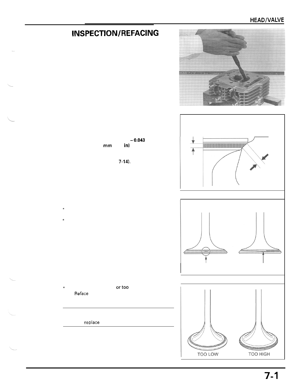
CYLINDER HEADNALVE
VALVE SEAT INSPECTION/REFACING
INSPECTION
.~
Clean all intake and exhaust valves thoroughly to
remove carbon deposits.
Apply a light coating of Prussian Blue to each valve
seat.
Tap the valve against the valve seat several times
without rotating the valve, to check for proper valve
seat contact.
Remove the valve and inspect the valve seat face.
The valve seat contact should be within the specified
width and even all around the circumference.
STANDARD:
1.0
-
1.1
mm
(0.039
-0.043
in)
SERVICE
LIMIT
2.0
mm
(0.08
in)
If the valve seat
width
is not within specification,
reface the valve seat (page
7-14].
Inspect the valve seat face for:
-
Uneven seat width:
-
Damaged face:
-
Replace the valve and reface the valve seat.
-
Replace the valve and reface the valve seat.
UNEVEN SEAT
WIDTH
I
I
DAMAGED FACE
-
Contact area (too high ortoo low)
-
Reface the valve seat.
NOTE:
The valve cannot be ground. If the valve face is
burned or badly worn or
if
it
contacts the seat
unevenly, redace the valve
7-1
3
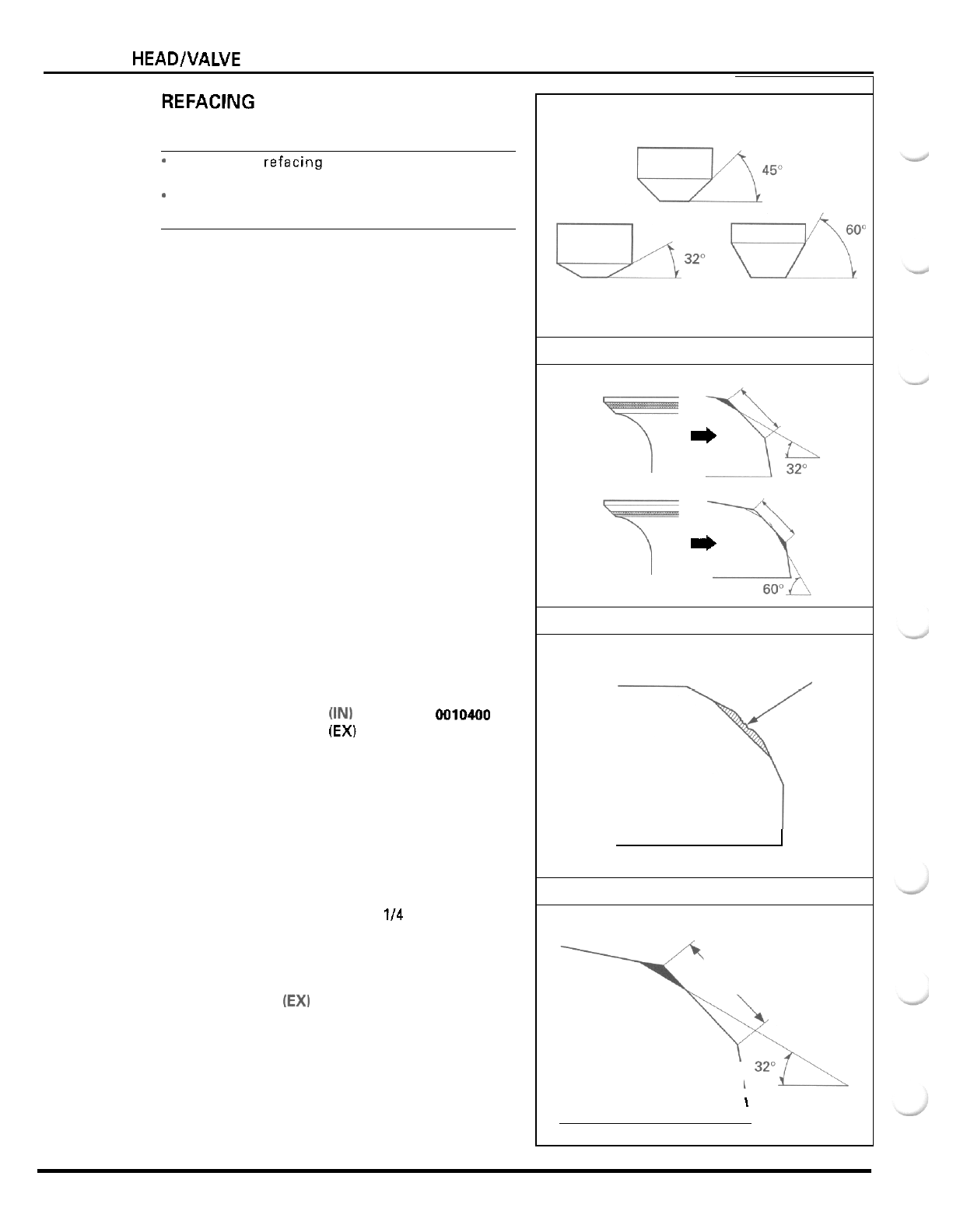
CYLINDER HEAD/VALVE
REFACING
NOTE:
*
Follow the refacing manufacturer's operating
instructions.
-
Be careful not to grind the seat more than neces
-
sary.
If the contact area
is
too high
on
the valve, the seat
must be lowered using
a
32
"
flat cutter.
If
the contact area is too low
on
the valve, the seat
must be raised using a
60
"
interior cutter.
Using a
45
"
seat cutter, remove any roughness or
irregularities from the seat.
TOOLS
Valve seat cutter,
35
mm
(IN1
Valve seat cutter,
29
mm
(EX)
07780
-
0010400
07780
-
0010300
Cutter holder,
5.5
mm
07781
-
0010101
or equivalent commercially available
in
U.S.A.
Using
a
32
"
flat cutter, remove
114
of the existing
valve seat material.
TOOLS:
Flat cutter,
35
mm
(IN)
07780
-
0012300
Flat cutter,
30
mm
(EX)
07780
-
0012200
Cutter holder,
5.5
mm
07781
-
0010101
or equivalent commercially available
in
U.S.A.
OLD SEAT
WIDTH
CONTACT TOO HIGH
*
OLD SEAT
WIDTH
CONTACT TOO LOW
*
ROUGHNESS
\
OLD SEAT WIDTH
\
1
7
-
14
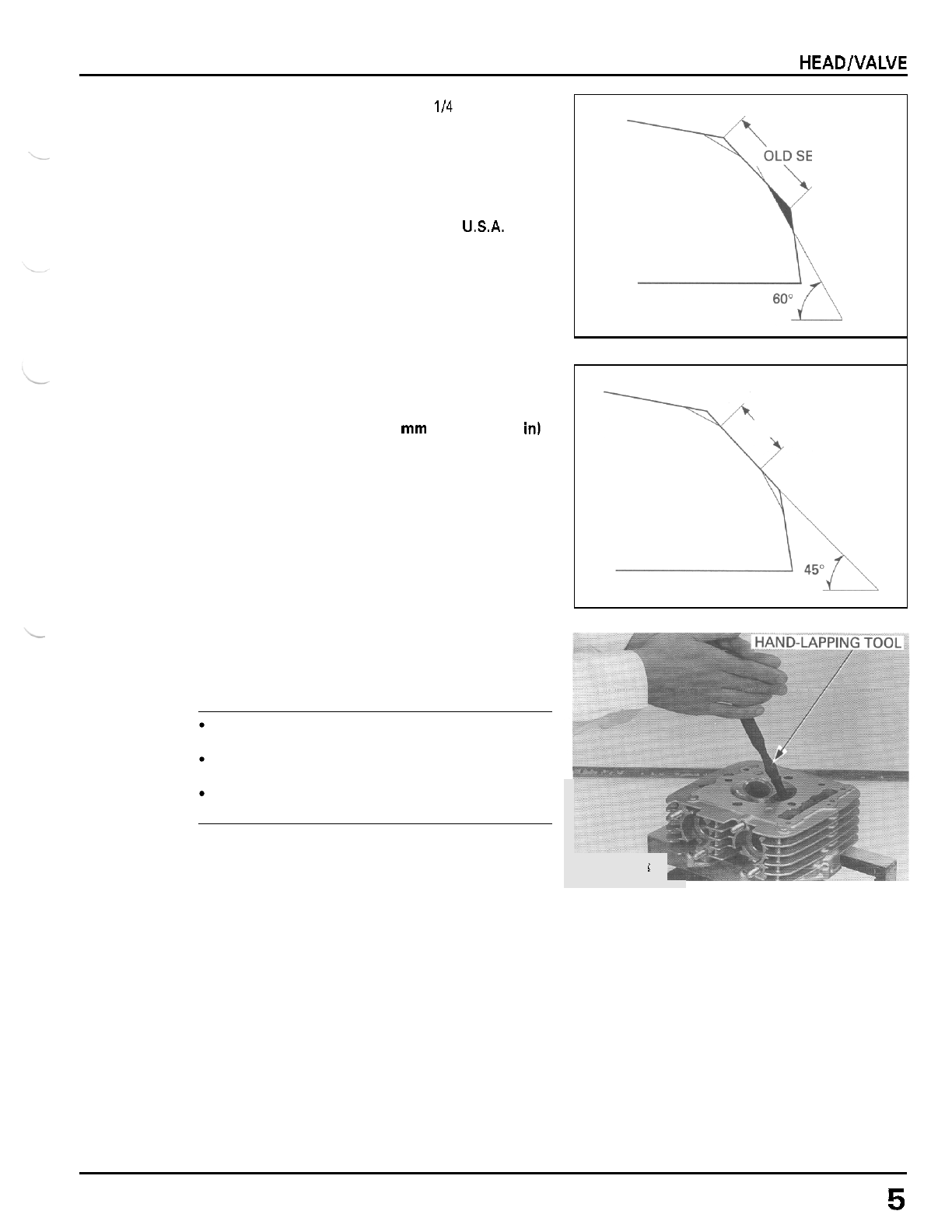
CYLINDER HEAD/VALVE
Using a
60
"
interior cutter, remove
114
of the existing
valve seat material.
TOOLS:
Interior cutter,
30
mm
07780
-
0014000
Cutter holder,
5.5
mm
07781
-
0010101
or
equivalent commercially available
in
USA.
Using
a
45
"
seat cutter, cut the seat to the proper
width.
VALVE SEAT
WIDTH:
1.0
-
1.1
mm
(0.039
-
0.043
in)
Make sure that
all
pitting and irregularities are
removed.
OLD SEAT WIDTH
-+
1.0
-
1.1
mm
(0.039
-
0.043
in)
After cutting the seat, apply lapping compound to the
valve face, and lap the valve using light pressure.
CAUTION
Excessive lapping pressure may deform or dam
-
age the seat.
Change the angle
of
lapping tool frequently to
prevent uneven seat wear.
Do
not allow lapping compound to enter the
guides.
After lapping, wash any residual compound
off
the
cylinder head and valve and recheck the seat contact.
i
7
-
1
5
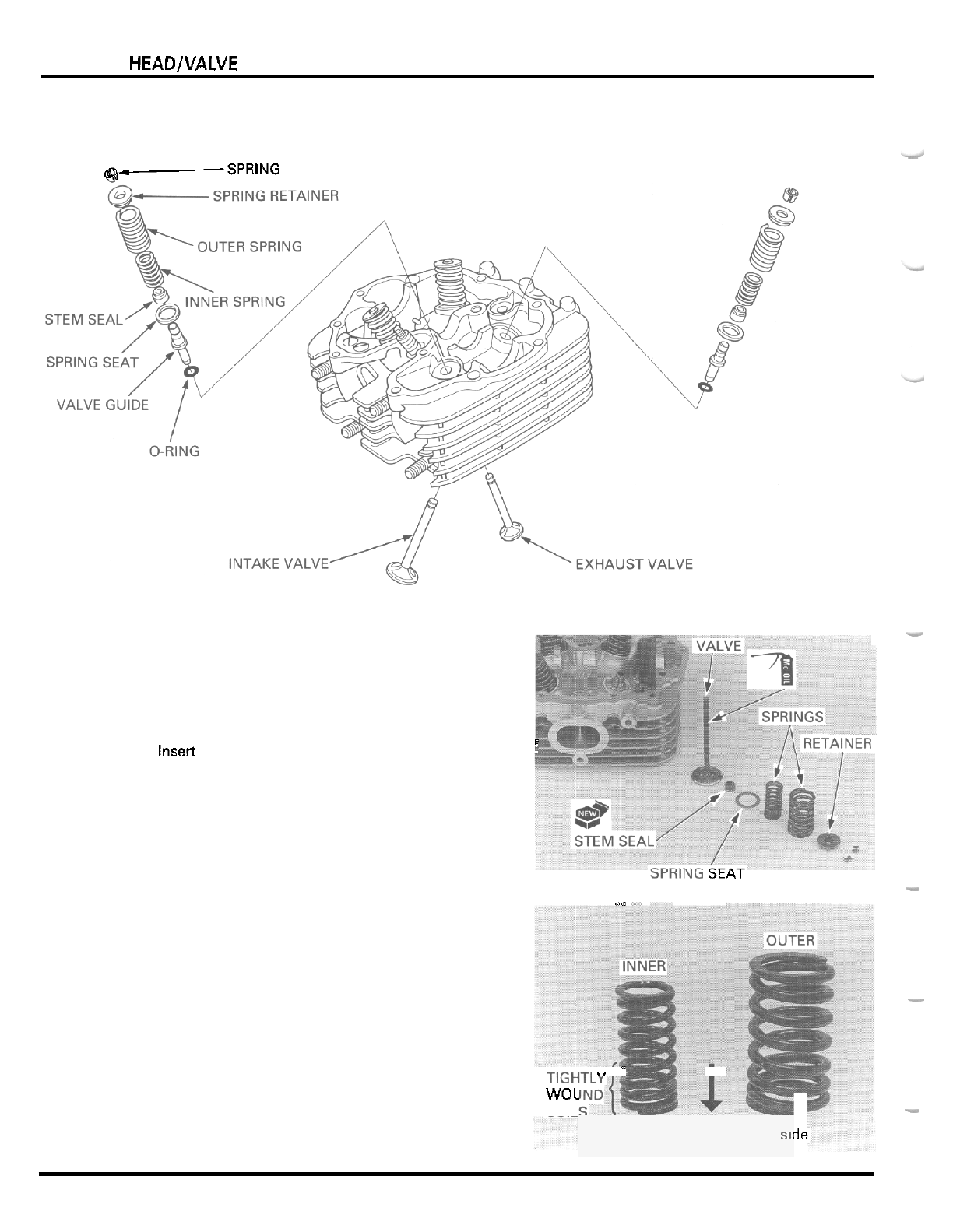
CYLINDER HEAD/VALVE
CYLINDER HEAD ASSEMBLY/
INSTALLATION
-
@-SPRING
COTTER
Blow through the oil passage in the cylinder head
with compressed air.
Install the valve spring seats.
Install new stem seals.
Lubricate the valve stem sliding surface with
molyb
-
denum oil solution.
lnsett the valve into the guide while turning
it
slowly
to avoid damage to the stem seal.
i
r
>rKll\b
btAl
-
.
.. -.
Install the inner and outer valve springs with the
tightly wound coils facing the combustion chamber.
Install the spring retainer.
-
TIGH"
I,
I
-
I
WOL
COIL
-
Combustion chamber
511
3e
7
-
1
6
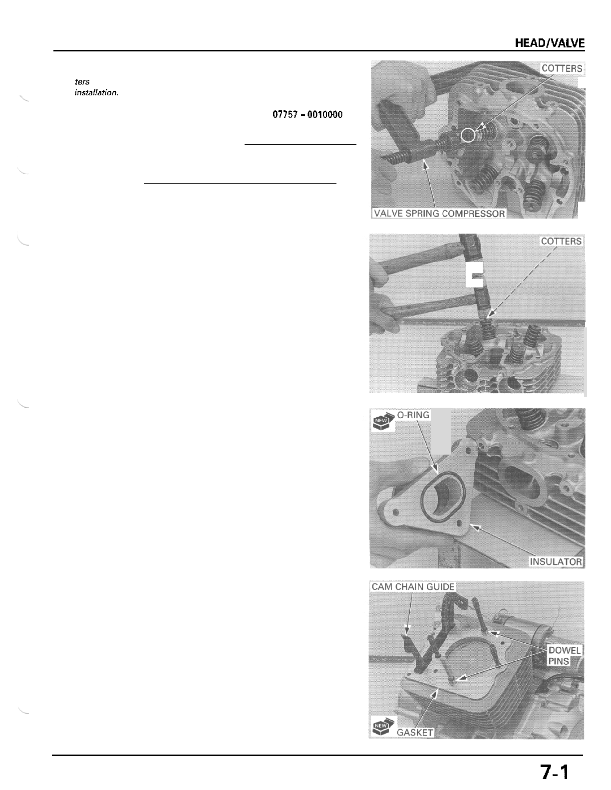
CYLINDER HEADlVALVE
Grease the
cot
-
ters
to
ease
compressor.
insfallation.
Install the valve spring cotters using the valve spring
TOOL
Valve spring compressor
07757-0010000
CAUTION:
To
prevent loss
of
tension,
do
not compress the
valve springs more than necessary to install the cot
-
ters.
Support the cylinder head
so
that the valve heads
will not contact anything that cause damage.
Tap the valve stems gently with
two
plastic hammers
as shown to seat the cotters firmly.
Coat a new O
-
ring with oil and install
it
into the
groove in the carburetor insulator.
Install the carburetor insulator onto the cylinder head
and tighten the three bolts securely.
Clean
the
cylinder mating surface.
Make sure that the cam chain guide bosses are posi
-
tioned in the cylinder grooves.
Install the dowel pins and a new gasket.
7-1
7
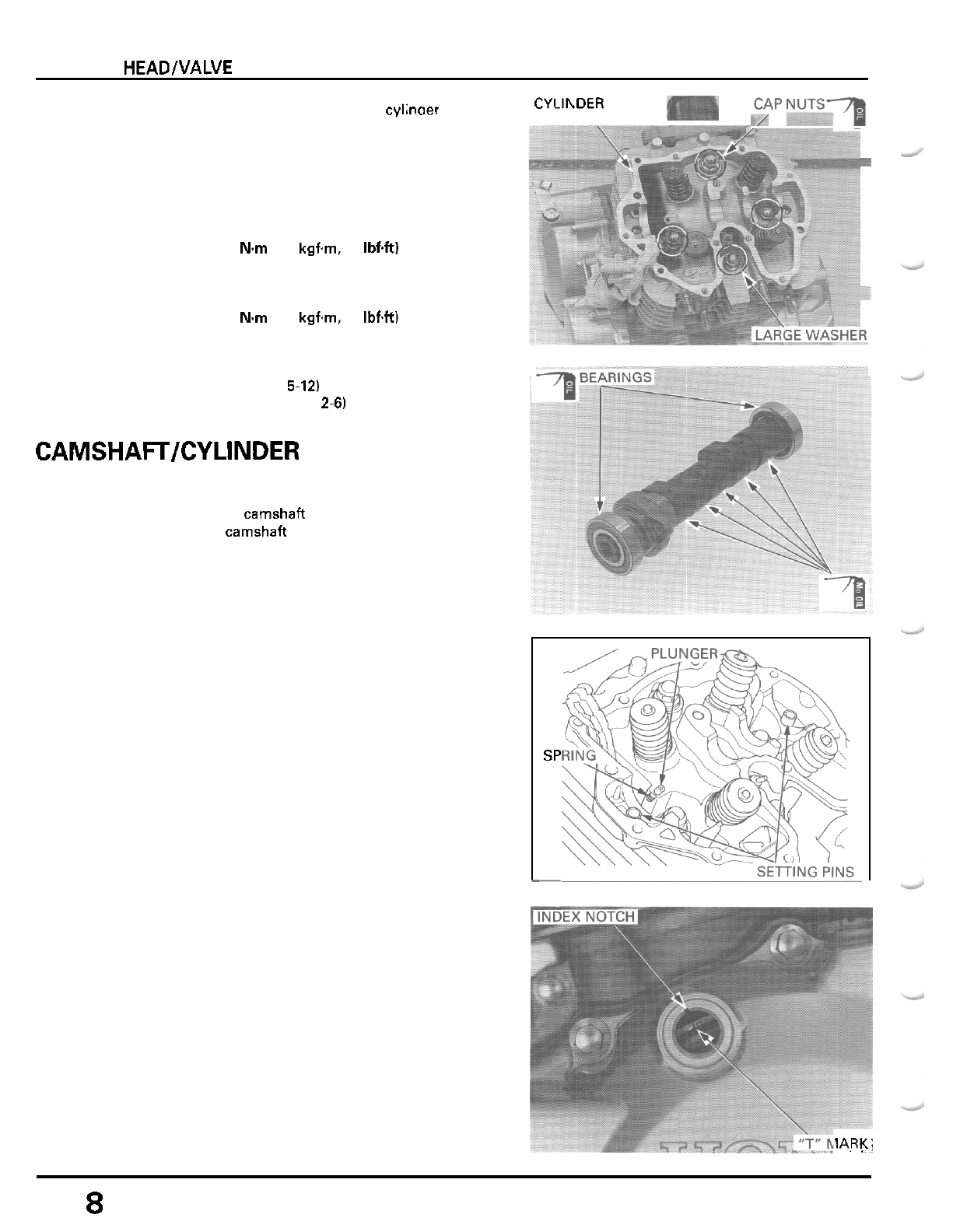
CYLINDER HEADWALVE
Install the bearing setting pins, spring and plunger,
being careful not to drop them into the crankcase.
\/
CAP
NuTs-a
Route the cam cnain tnrough the cylhoer head and
instal. the cylinoer head
onto
the cylinder.
CYLlhDER
HEAD
\
SP
-
Apply oil to the cylinder head nut threads and seating
surfaces.
Install the cylinder head nuts with the washers and
tighten them in
a
crisscross pattern in
2
or
3
steps.
Note the position
of
the large washer.
TOROUE:
44
Nm
(4.5
kgfm,
33
IbfW
Install and tighten the spark plug.
TOROUE:
18
N.rn
(1.8
kgfm,
13
Ibf4t)
Install the following:
-
camshaft and cylinder head cover
-
carburetor (page
5-12)
-
exhaust system (page
2-6)
CAMSHAFTKYLINDER HEAD COVER
INSTALLATION
Lubricate the camshah bearing with oil.
Install the camshafl bearings with the sealed side
of
the sprocket side bearing facing out.
Apply molybdenum oil solution to the cam lobes and
journal.
!ARK:
7
-
1
8
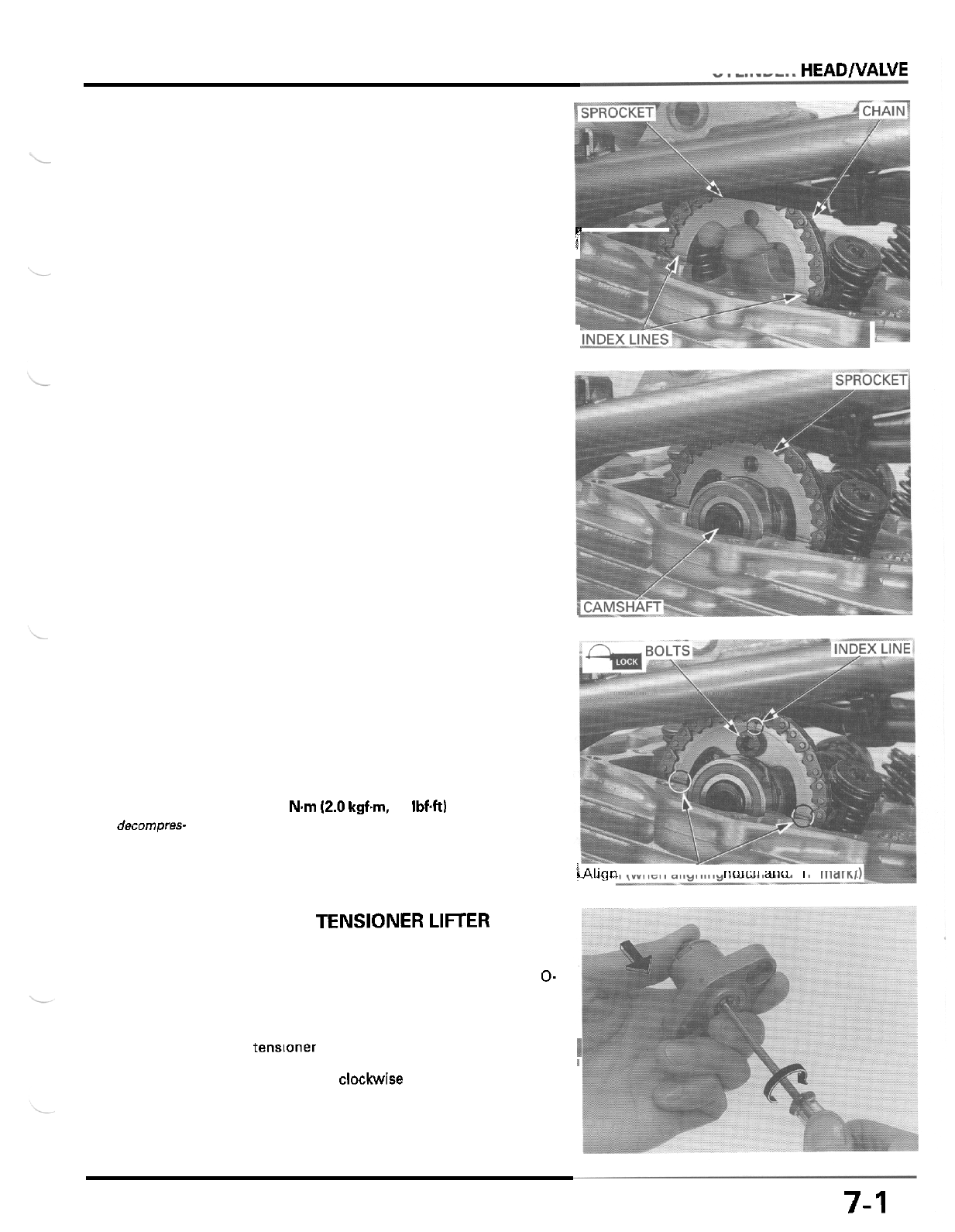
CYLINDER HEADNALVE
The crankshaft
should be turned
only counter
-
clockwise. This
must be done to
prevent the one
-
way decompres-
sor
system func
-
tioning.
Install the cam sprocket onto the cam chain
so
that
the index lines on the sprocket with the upper surface
of the cylinder head.
Install the camshaft onto the cylinder head through
cam sprocket.
Install the cam sprocket onto the camshaft flange
securely.
Make sure that the index lines
on
the cam sprocket
with the upper surface of the cylinder head when the
"
T
"
mark on the flywheel is aligned with the index
notch in the left crankcase cover.
F
I
Apply locking agent to the cam sprocket bolt threads.
Align the bolt holes in the cam sprocket and
camshaft flange and install the cam sprocket bolt.
Turn the crankshaft counterclockwise one turn and
install the remaining cam sprocket bolt.
Tighten the INDEX LINE side bolt first.
TORQUE:
20
Nm
12.0
kgfm,
14
IbfW
Turn the crankshaft counterclockwise one turn and
tighten the other cam sprocket bolt
to
the same
toque. \Align
c
...~
(when aligning
rioicii
aiiu
I
IIWTK,
CAM CHAIN TENSIONER LIFTER
INSTALLATION
Remove the cam chain tensioner lifter plug and
0-
ring.
Check the lifter operation:
-
The tensloner shaft should not go into the body
k
when
it
is pushed.
1
-
When
it
is turned clockwlse with
a
screwdriver, the
tensioner shaft should be pulled into the body.
The shaft springs out
of
the body as
soon
as
the
screwdriver is released.
7-1
9
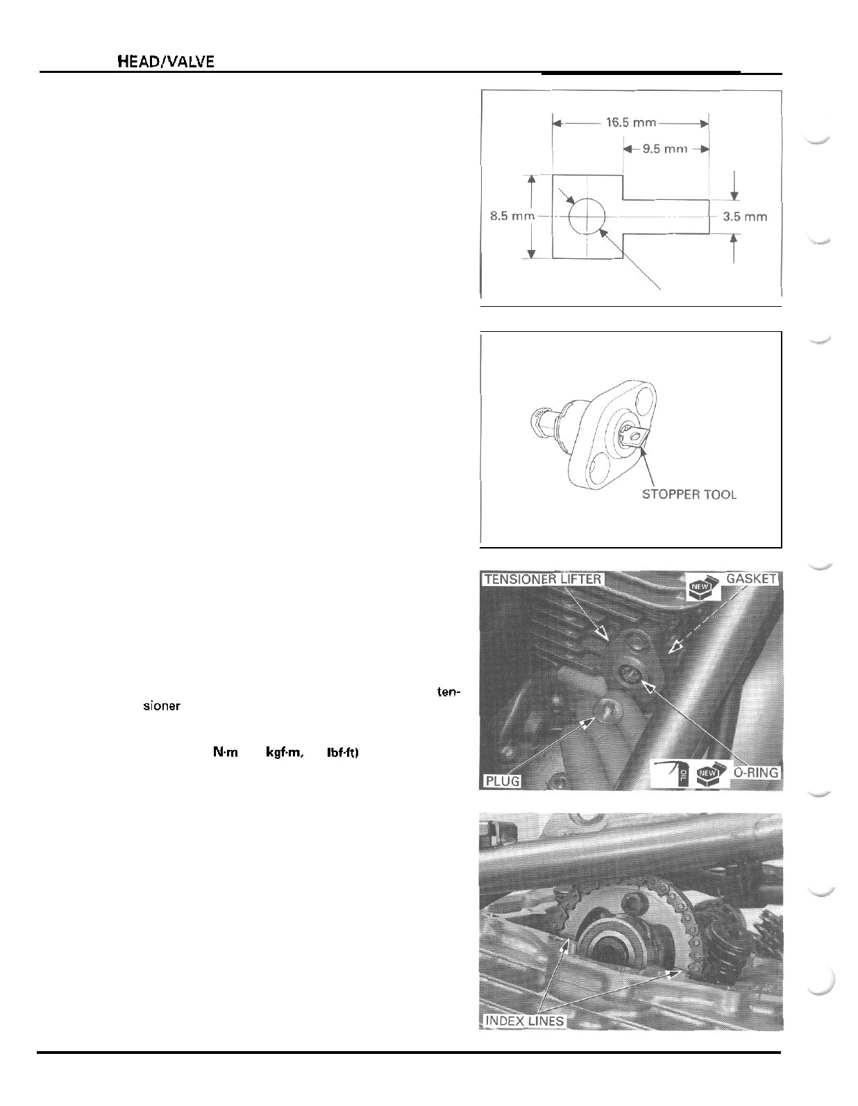
CYLINDER HEAD/VALVE
Make
a
tensioner shaft stopper tool
of
a
thin piece of
steel
(0.8
mm thick) using the diagram.
Turn the tensioner shaft clockwise with the stopper
tool to retract the tensioner, then insert the stopper
fully to hold the tensioner in the fully retracted posi
-
tion.
Install
a
new gasket onto the cam chain tensioner
lifter.
Install the tensioner lifter onto the cylinder and tighten
the two mounting bolt securely.
Remove the stopper tool from the tensioner lifter.
Coat
a
new O
-
ring with oil and install it into the ten-
sioner lifter groove.
Install and tighten the tensioner lifter plug.
TORQUE:
4
Nm
(0.4
kgfm,
2.9
Ibf4t)
Make sure that the index lines on the cam sprocket
with the upper surface of the cylinder head when the
"
T
"
mark on the flywheel is aligned with the index
notch in the left crankcase cover.
7
-
20
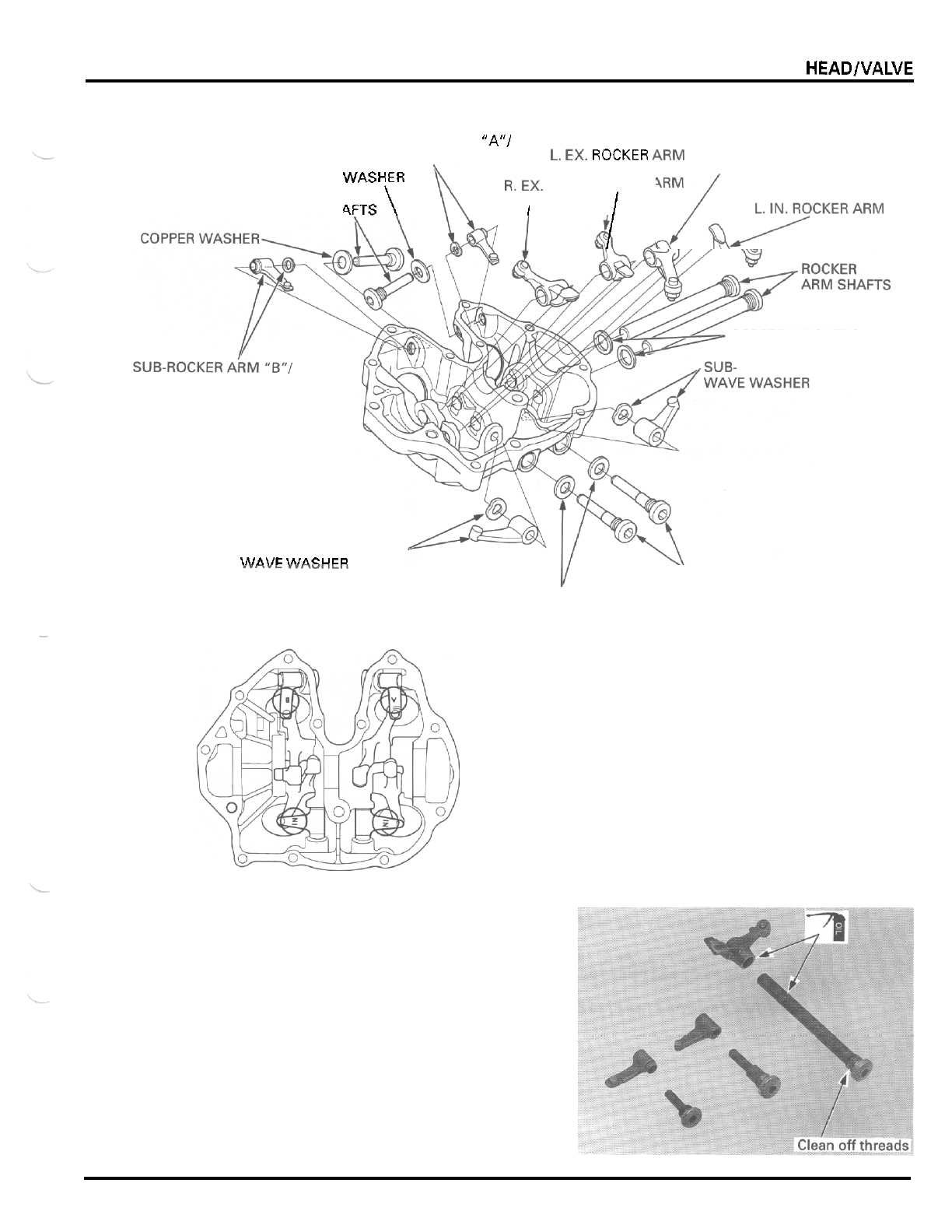
CYLINDER HEAD/VALVE
CYLINDER HEAD COVER ASSEMBLY
R.
IN.
ROCKER ARM
SUB
-
ROCKER ARM "A"/
L,
EX, ROCKER ARM
COPPER WASHT WAVE WASHER
\
R,EX.
/
n/R,RARM
ROCKER ARM
EXHAUST SUB
-
ROCKER ARM SHAFTS
I
COPPER WASHERS
ROCKER ARM
"
IN
"
/
WAVE WASHER
SUB
-
ROCKER
ARM
"
IN
"
/
\AlA\lE
1AIACUER
..-Y.,LI.
IN
T
AKE
SUB
-
ROCKER
COPPER ARM SHAFTS
WASHERS
.
-.
--
Clean
the
threads
of
each rocker arm shaftthoroughly.
Apply
engine oil to the rocker arm and
shaft
sliding
surfaces.
7
-
21
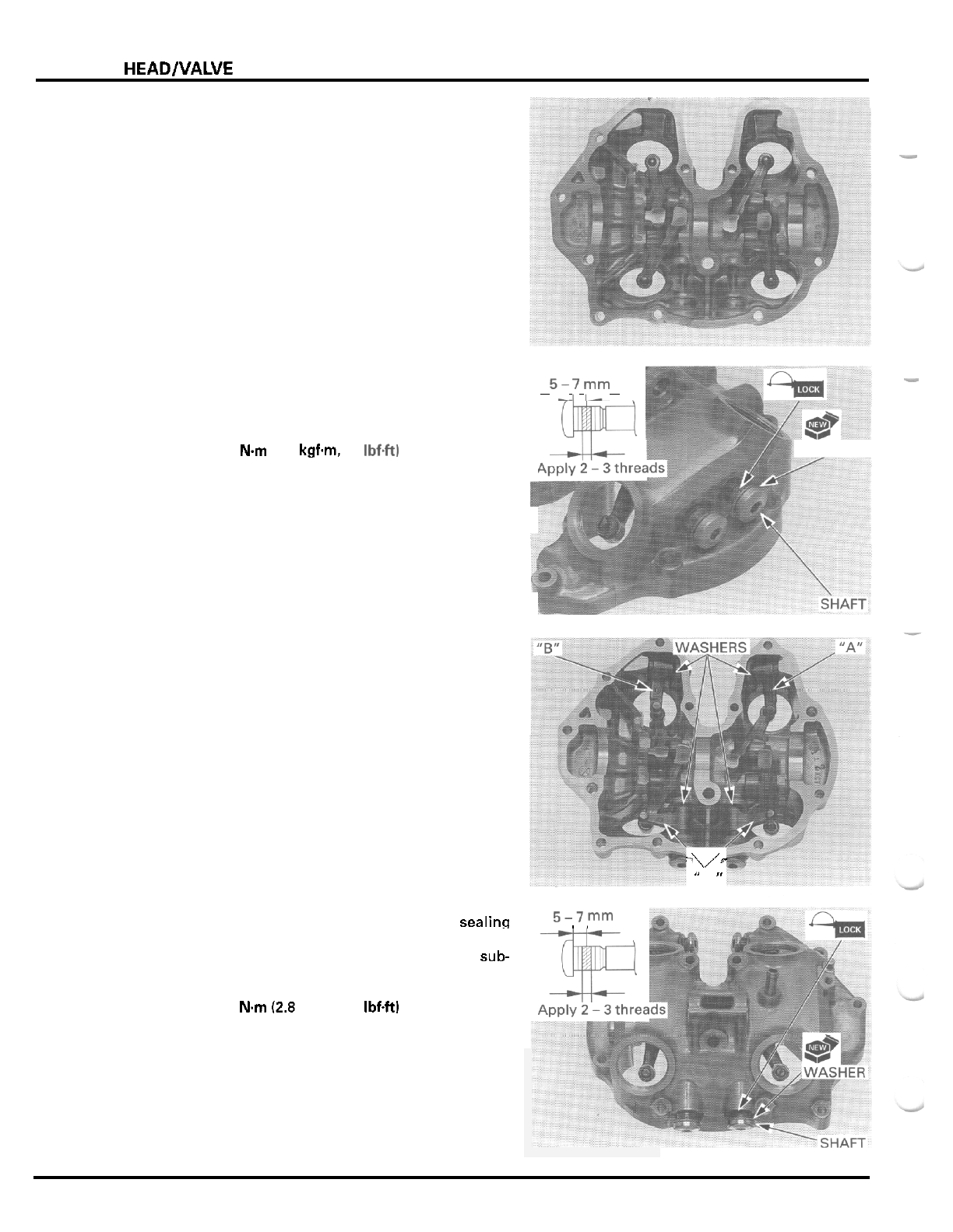
CYLINDER HEAD/VALVE
Install the rocker arms in the cylinder head cover as
shown.
-
Install the rocker arm shafts with new sealing washers.
5i
7
y-"
-
Apply
locking agent to the
2
-
3
threads
of
the rocker
arm shafts and tighten the shafts.
WASHER
TORQUE: 27
Nm
12.8 kgfm.
20
Ibf4t)
Install the sub
-
rocker arms and wave washers in the
cylinder head cover as shown, noting each identifica
-
tion mark as shown.
Install the sub
-
rocker arm shafts with new sealing
5-7
,.
.
washers.
Apply
locking agent to the
2
-
3
threads
of
the sub-
rocker arm shafts and tighten the shafts.
TORQUE: 27
Nm
(2.8 kgfm, 20
IbfW
-\/
"
"
I
N
"
7
-
22
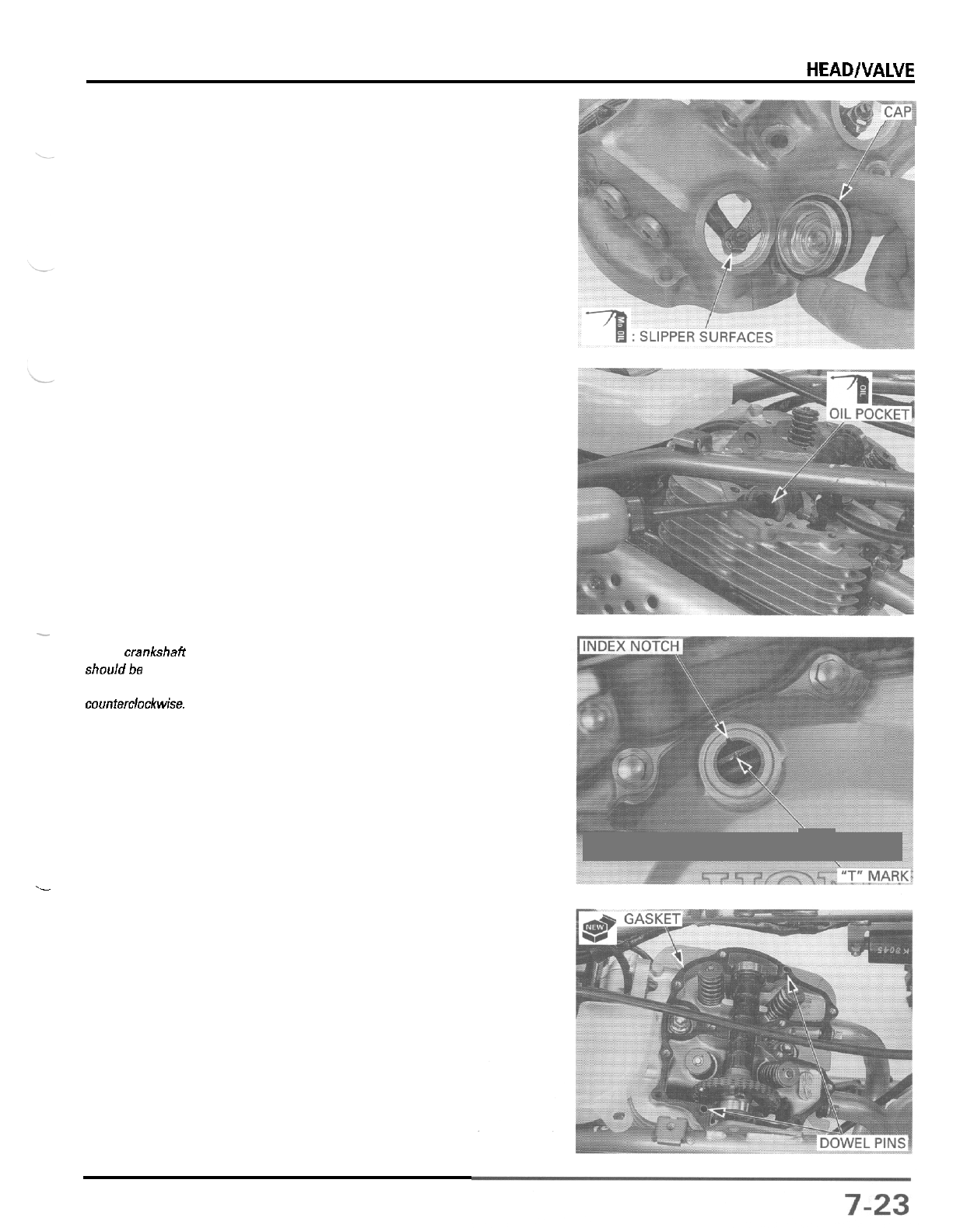
CYLINDER HEAD/VALVE
CYLINDER HEAD COVER INSTALLATION
Apply molybdenum oil solution to the slipper surfaces
of
the rocker arms and sub
-
rocker arms.
Clean the mating surfaces
of
the cylinder head and
head cover.
Pour engine oil into the
oil
pocket in the cylinder head.
-
The crankshaff
shouldbe turned
only
counterclockwise.
down.
This must be
done to prevent
the one
-
way
decompressor
system
functioning.
Rotate the crankshaft counterclockwise and align the
"
T
"
mark on the flywheel with the index notch in the
left crankcase cover
so
that the cam lobes are facing
._
Install the dowel pins and
a
new gasket
\
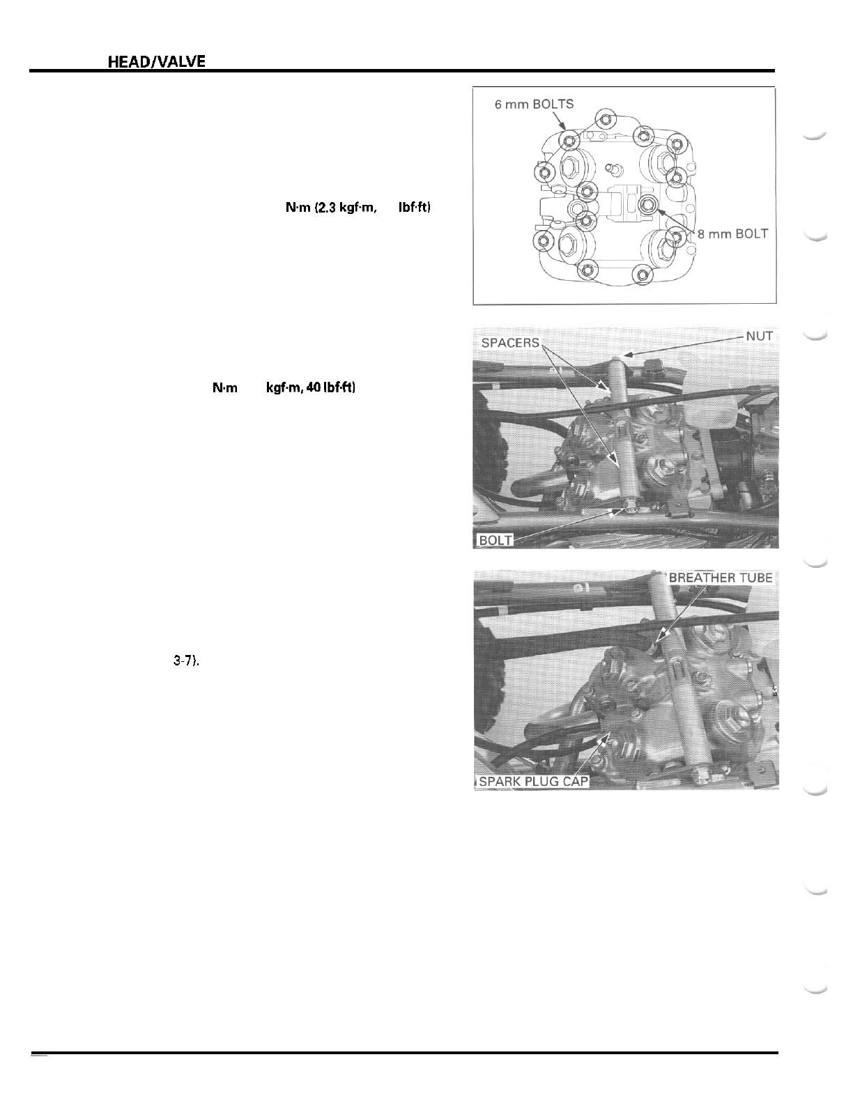
CYLINDER
HEADlVALVE
Install the valve adjusting hole caps.
Install the cylinder head cover onto the cylinder head.
Install the
8
mm
and
6
rnrn
cylinder head cover bolts
and tighten them in
a
crisscross pattern in
2
or
3
steps.
TORQUE:
8
mm
bolt:
23
Nm
(2.3
kgfm
17
IbfW
Install the spacers, upper engine hanger bolt and nut,
and tighten the nut.
TORQUE:
54
Nm
(5.5
kgfm
40
IbfW
Connect the crankcase breather tube to the cylinder
head cover.
Install the spark plug cap.
Check the valve clearances and adjust
if
necessary
(page
3-7).
i
~
7
-
24

MEMO
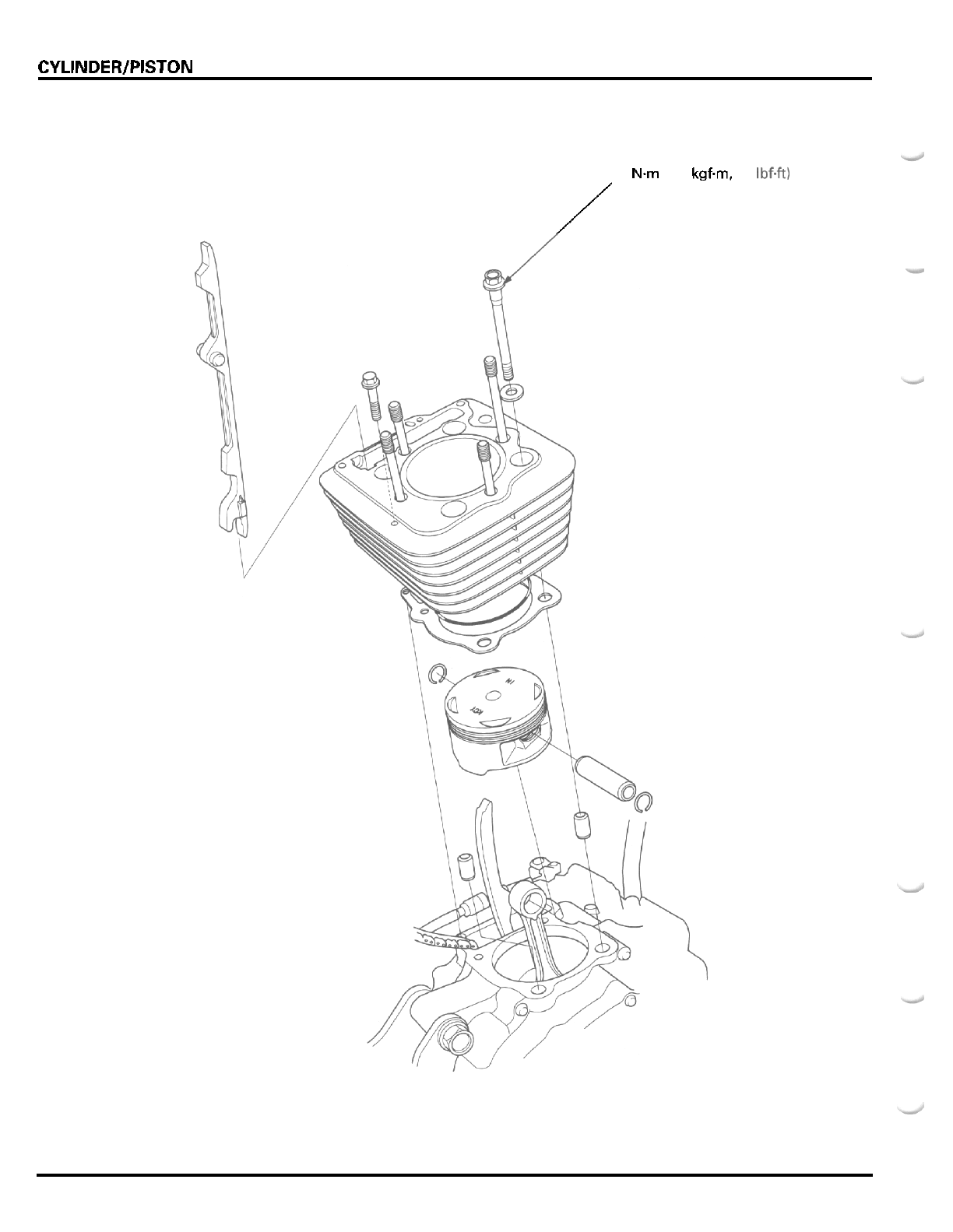
CYLINDER/PISTON
44
Nm
(4.5
kgfm,
33
Ibf.ft)
/
8
-
0
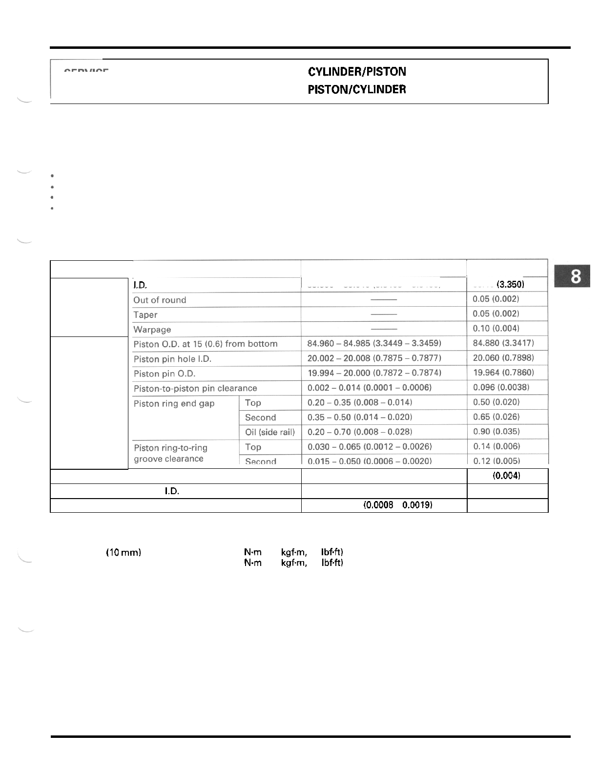
8.
CYLINDER/PISTON
Cylinder
-
to
-
piston clearance
Connecting rod small end
I.D.
Connecting rod
-
to
-
piston pin clearance
SERVICE INFORMATION
8
-
1
CYLINDER/PISTON REMOVAL
8
-
3
TROUBLESHOOTING
8
-
2
PlSTONlCYLlNDER INSTALLATION
a
-
7
0.015
-
0.050
(0.0006
-
0.0020)
20.020
-
20.041 (0.7882
-
0.7890)
0.020
-
0.047
lO.0008
-
0.0019)
0.10 (0.004)
20.067 (0.7900)
0.103 (0.0041)
SERVICE
INFORMATION
GENERAL
-
The cylinder and piston can be serviced with the engine installed in the frame.
*
Take care not to damage the cylinder wall and piston.
-
Do
not damage mating surfaces by using
a
screwdriver when removing the cylinder.
-
Camshaft lubricating oil is fed through the oil passage in the cylinder. Clean the oil passage before installing the
cylinder.
SPECIFICATIONS
Unit:
mm
(in)
ITEM STANDARD SERVICE
LIMIT
I.D.
I
85.000
-
85.010 (3.3465
-
3.3468)
I
85.10 (3.350)
Cylinder
Piston,
piston pin, pis
-
ton ring
TORQUE VALUES
Cylinder bolt
(10
mm)
Cylinder stud bolt
44
Nm
(4.5
kgfm,
33
IbfW
20
Nm
(2.0
kgfm
14
IbfW
Apply oil to the threads and seating surface
8
-
1

CYLINDER/PISTON
TROUBLESHOOTING
Compression too
low,
hard starting or poor performance
at
low
speed
*
Leaking cylinder head gasket
*
Worn. stuck or broken piston ring
-
Worn or damaged cylinder and piston
Compression too high, overheating or knocking
-
Excessive carbon built
-
up on piston head or combustion
chamber
Excessive smoke
-
Worn cylinder, piston or piston rings
*
Improper installation
of
piston rings
*
Scored or scratched piston or cylinder wall
Abnormal
noise
-
Worn piston pin or piston pin hole
*
Worn connecting rod small end
*
Worn cylinder, piston or piston rings
8
-
2
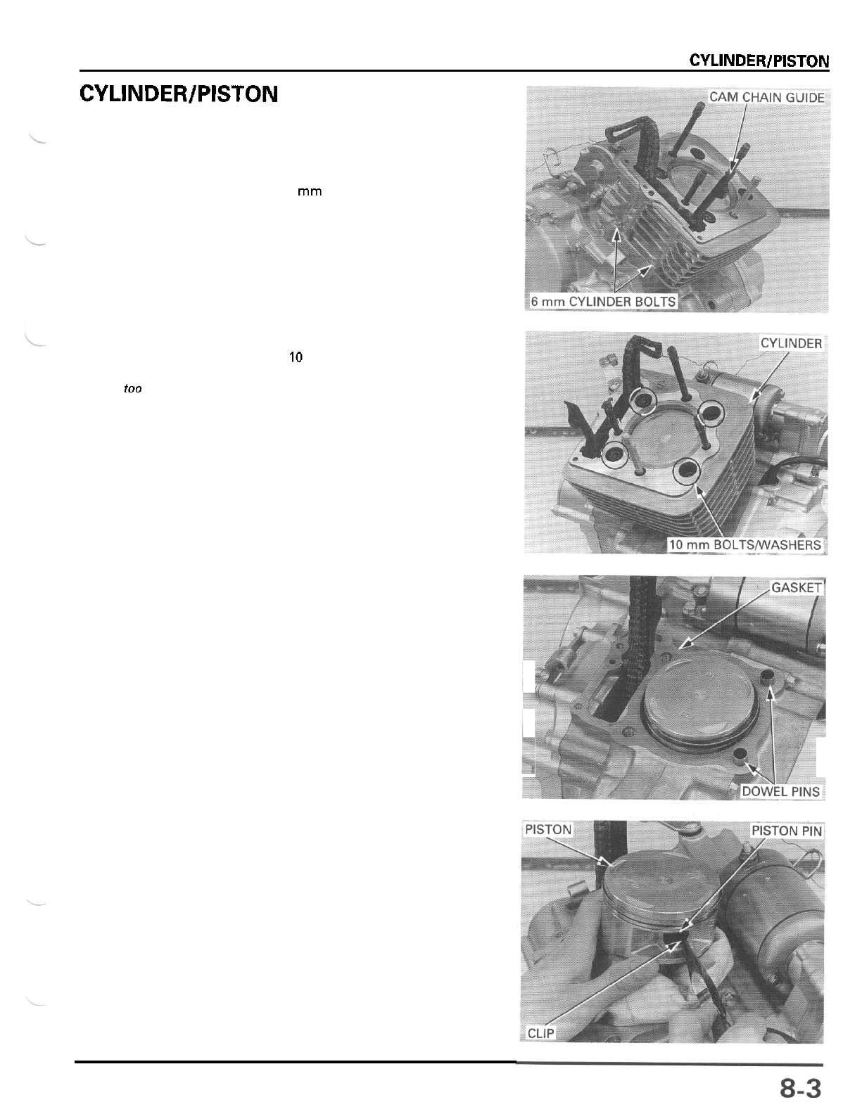
CYLINDER/PISTON
CYLINDER/PISTON REMOVAL
CYLINDER REMOVAL
Remove the cylinder head (section
7).
Remove the
two
6
mm cylinder bolts.
Remove the cam chain guide (front).
Remove the four
10
mm cylinder bolts and washers.
Remove the cylinder.
Do
not strike the
cylinder
too
hard
and do
not
dam
-
age the mating
surface with a
screwdriver.
Remove the gasket and dowel pins.
PISTON REMOVAL
Place a clean shop towel over the crankcase to pre
-
vent the clip from falling into the crankcase.
Remove the piston pin clips with the pliers.
Push the piston pin out
of
the piston and connecting
rod, and remove the piston.
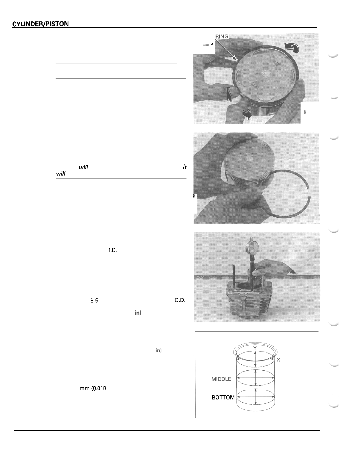
CVLINDER/PISTON
Spread each piston ring and remove
it
by lifting up
at
a
point opposite the gap.
CAUTION:
Do
not damage the piston ring by spreading the
ends too far.
PISTON
),*
”
Clean carbon deposits from the piston.
CAUTION
Clean carbon deposits
from
the ring grooves with
a
ring that wi// be discarded. Never use a wire brush; if
wi// scratch the groove.
i
INSPECTION
CYLINDER
Inspect the cylinder bore for scratch or wear.
Measure the cylinder
I.D.
at three levels in an
X
and
Y
axis.
Take the maximum reading to determine the cylinder
wear.
SERVICE
LIMIT
85.10
mm
13.350
in)
Calculate the cylinder
-
to
-
piston clearance.
Refer
to
page
8-5
for measurement
of
the piston O.D.
SERVICE
LIMIT
0.10
mm
(0.004
in1
Calculate the cylinder taper and out
-
of
-
round at three
levels in an
X
and
Y
axis. Take the maximum reading
to determine the taper and out
-
of round.
SERVICE LIMITS
Taper:
0.05
mm
(0.020
in1
Out
-
of
-
round:
0.05
mm
10.020
in)
The cylinder must be rebored and an oversize piston
fitted if the service limits are exceeded.
The
0.25
mm
(0.010
in) and
0.50
mm
(0.020
in)
over
-
size pistons are available.
The cylinder must be rebored
so
that the clearance
for an oversize piston
is
0.015
-
0.050
mm
(0.0006
-
0.0020
in).
r
I
TOP
’
-
’
-
BOTOM
8
-
4
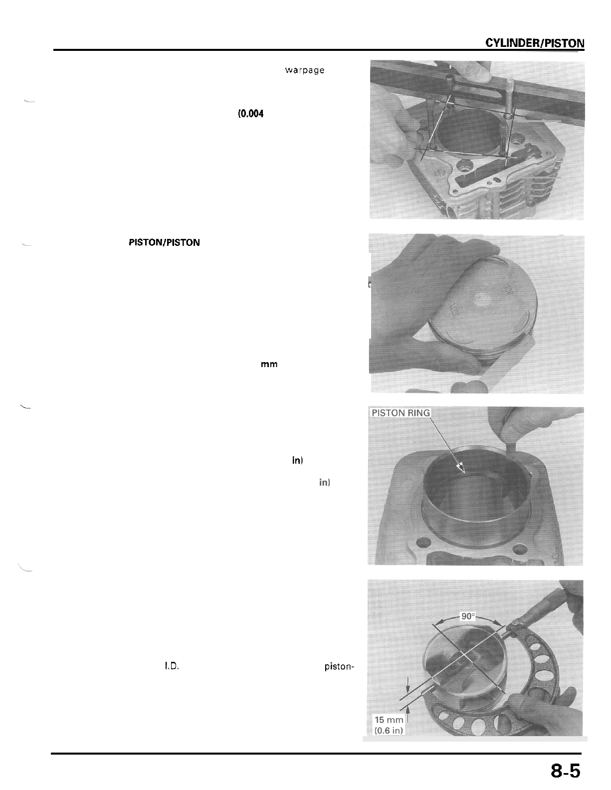
CYLINDER/PISTON
Check the top
of
the cylinder for warpage with a
straight edge and feeler gauge across the studs and
bolt holes as shown.
SERVICE LIMIT
0.10
mm
(0.004
in)
-
I_
-
PlSTONlPlSTON RING
Inspect the piston rings for movement by rotating the
rings. The rings should be able to move in their
E
grooves without catching.
r
Push the ring until the outer surface
of
the piston ring
is nearly flush with the piston and measure the ring
-
to
-
ring groove clearance.
SERVICE LIMITS: Top: 0.14
mm
(0.006
in)
Second:
0.12
mrn
(0.005
in)
i
Insert each piston ring into the bottom
of
the cylinder
squarely using the piston.
Measure the ring end gap.
SERVICE LIMITS Top:
0.50
mm
(0.020
in)
Second: 0.65
mm
(0.026
in)
Oil (side rail):
0.9
mm
(0.04
in1
Measure the piston pin
O.D.
90
"
to the piston pin
hole and
at
point
15
mm
(0.6
in) from bottom
of
the
piston skirt.
SERVICE LIMIT 84.880
mm
(3.3417
in)
Compare this measurement against the maximum
cylinder
I.D.
measurement and calculate the piston-
to
-
cylinder clearance (page
8
-
4).
8-5
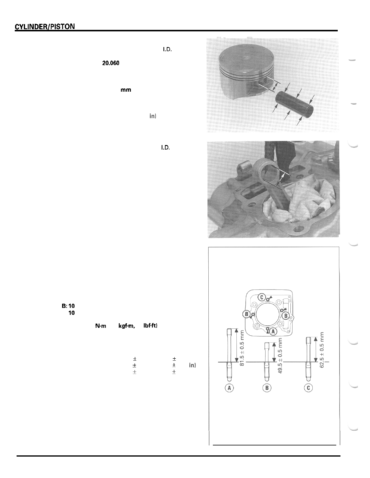
CYLINDER/PISTON
-a
-
I_
Measure piston pin hole
I.D.
in an
X
and
Y
axis. Take
the maximum reading to determine the
I.D.
SERVICE
LIMIT 20.060 mm (0.7898
in)
Measure the piston pin
O.D.
at three points.
SERVICE
LIMIT: 19.964 mm (0.7860
in)
-
Calculate the piston
-
to
-
piston pin clearance.
-
SERVICE
LIMIT
0.096
mm (0.0038
in1
Measure the connecting rod small end
I.D.
SERVICE
LIMIT: 20.067 mm (0.7900
in)
Calculate the connecting rod
-
to
-
piston pin clearance.
SERVICE
LIMIT: 0.103 mm (0.0041
in)
CYLINDER STUD BOLT REPLACEMENT
Remove the stud bolts from the cylinder
Install new stud bolts in their proper positions and
tighten them.
A
10
x
92 mm
stud
bolt
6:
10
x
60
mm
stud bolt
C:
10
x
73 mm
stud bolt
TORQUE
20 N.m 12.0 kgf.m, 14
IbfW
After installation, measure the stud height from the
cylinder surface.
SPECIFIED
HEIGHT:
A
81.5
k
0.5
mm (3.21
k
0.02
in)
B
49.5
k
0.5
mm (1.95
f
0.02
in1
C:
62.5
k
0.5
mm (2.46
+
0.02
in)
Adjust the stud height if necessary.
8
-
6
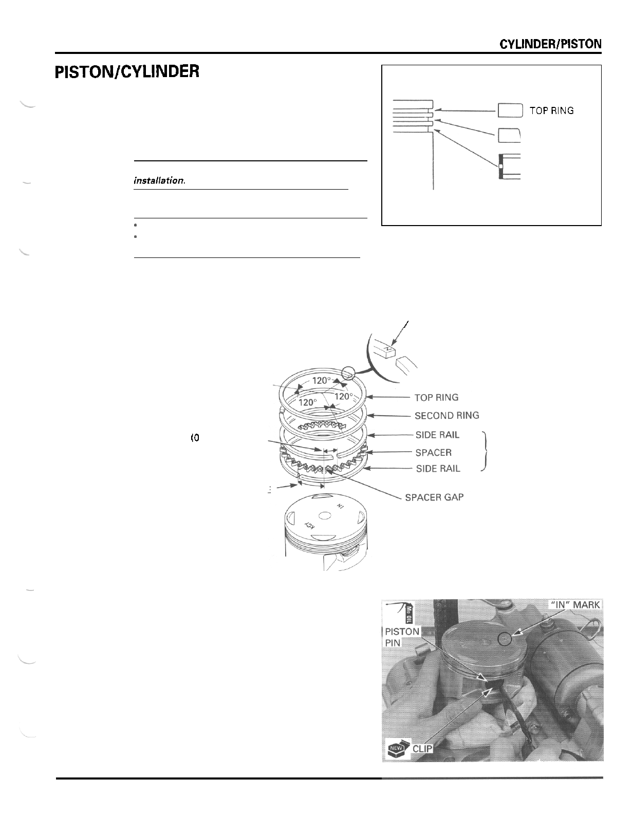
CYLINDER/PISTON
PISTON/CYLINDER INSTALLATION
PISTON RING INSTALLATION
Carefully install the piston rings into the piston ring
grooves with the markings facing up.
CAUTION:
Be careful not to damage the piston and rings during
-
installafion.
D
TOPRING
SECOND RING
OIL
RING
Stagger the piston ring end gaps
120
"
degrees apart
from each other.
Stagger the side rail end gaps as shown.
MARK
/
20
mm
(0
8
in)
OR
MORE
20
mm
(0.8
in)
OR
MORE
NOTE:
*
Do
not confuse the top and second rings.
-
To install the oil ring, install
the
spacer first, then
install the side rails.
OIL
RING
-
PISTON INSTALLATION
Place
a
clean shop towel over the crankcase to pre
-
vent the clip from falling into the crankcase.
Apply molybdenum oil solution to the piston pin
outer surface and connecting rod inner surface.
Install the piston with the
"
IN
"
mark toward the
intake side and insert the piston pin through the pis
-
ton and connecting rod.
Install new piston pin clips into the grooves of the
piston pin hole.
8
-
7
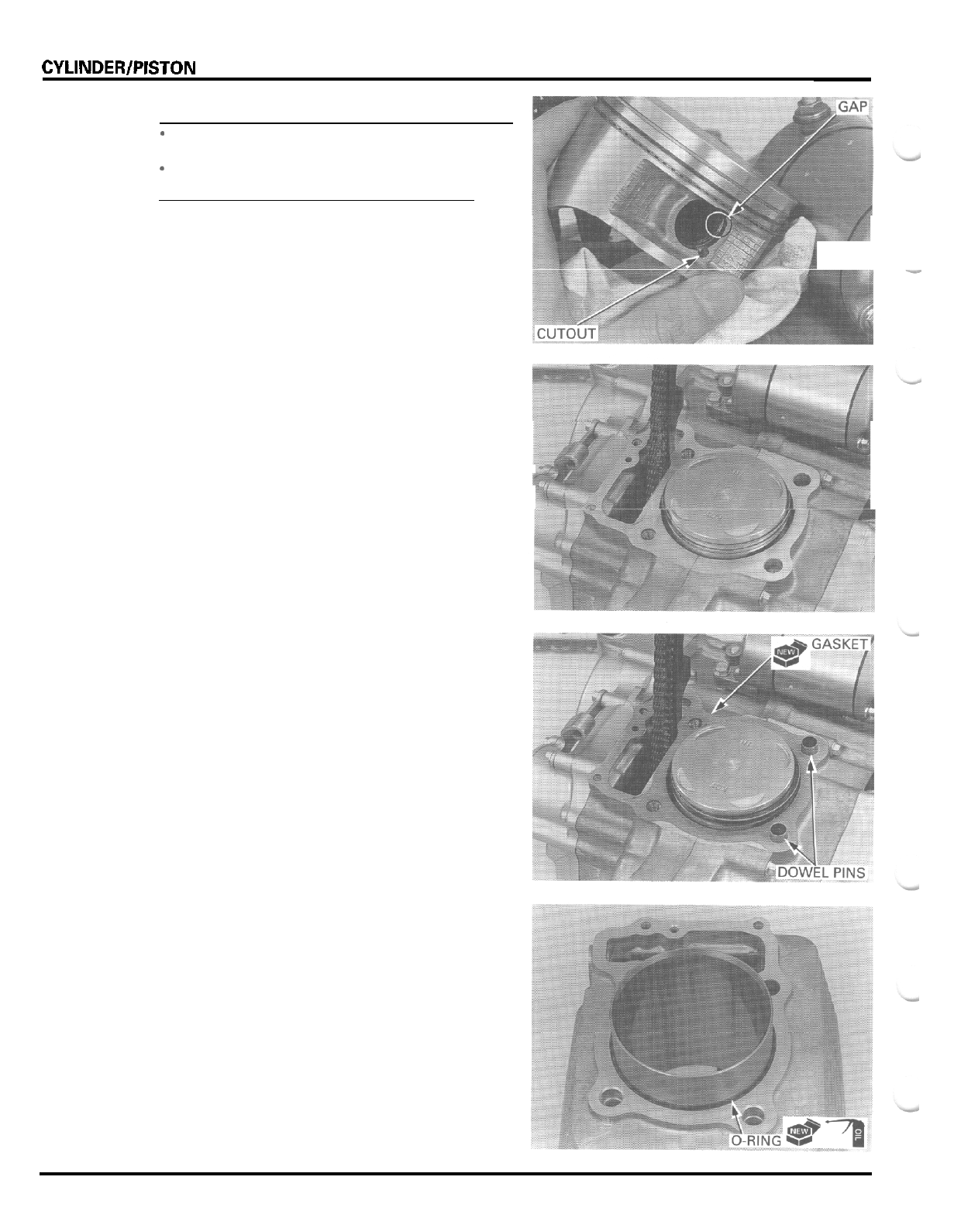
CYLINDER/PISTON
NOTE:
-
Make sure that the piston pin clips are seated
securely.
-
Do
not align the piston pin clip end gap with the
piston cutout.
CYLINDER INSTALLATION
Clean the gasket surfaces of the cylinder and crank
-
case thoroughly, being careful not to damage
it,
and
careful not to allow gasket material into the crank
-
case.
Install the dowel pins and
a
new gasket
Coat
a
new O
-
ring with
oil
and install it into the
groove in the cylinder
bottom.
8
-
8
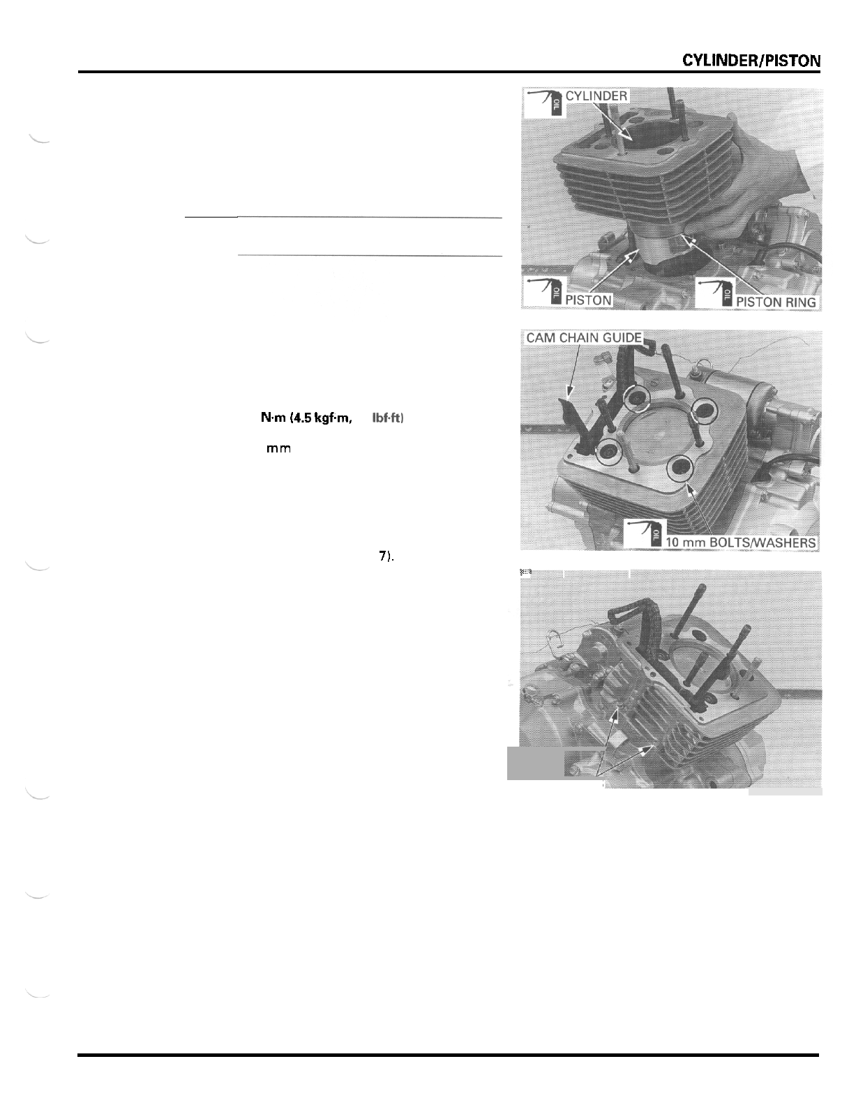
CYLINDER/PISTON
Apply oil to the cylinder wall, piston and piston ring
outer surfaces.
,
Route the cam chain through the cylinder and install
the cylinder over the piston while compressing the
piston rings with your fingers.
CAUTION:
Be careful
not
to
damage
the
piston
rings
and
cylin
-
der wall.
Apply oil to the
10
mm cylinder bolt threads and
seating surfaces and install them with the washers.
Tighten the bolts in
a
crisscross pattern in
2
or
3
steps.
TORQUE:
44
Nm
(4.5
kgfm, 33
Ibf+tl
Install the
6
mm cylinder bolts and tighten them
securely.
Install the cam chain guide into the cylinder and
crankcase, aligning the bosses with the grooves in
the cylinder.
Install the cylinder head (section
7).
p.
-
-
-
-//
6
rnrn
BOLTS
8
-
9
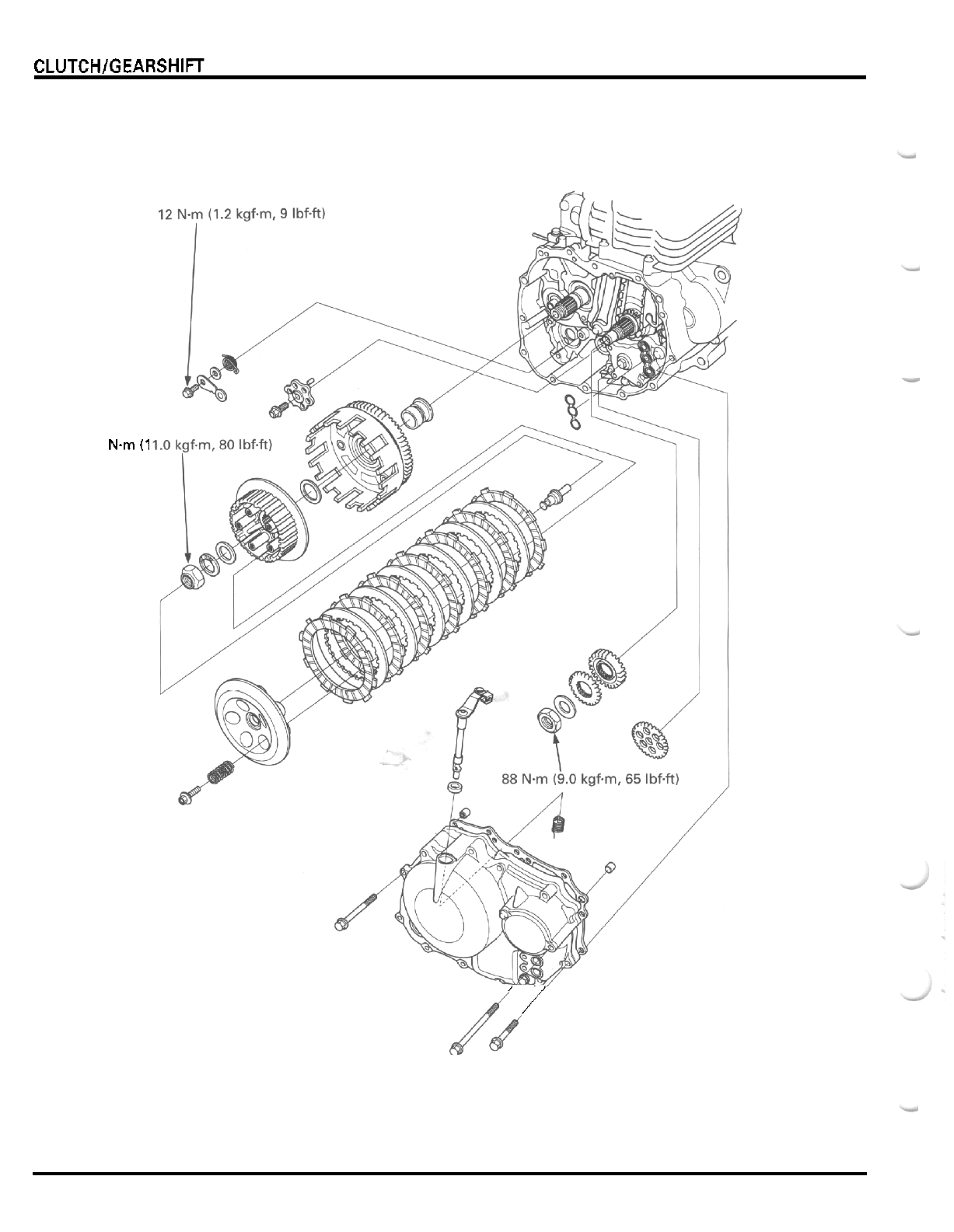
CLUTCHlGEARSHlFT LINKAGE
108
Nm
(1
,,
/
9
-
0
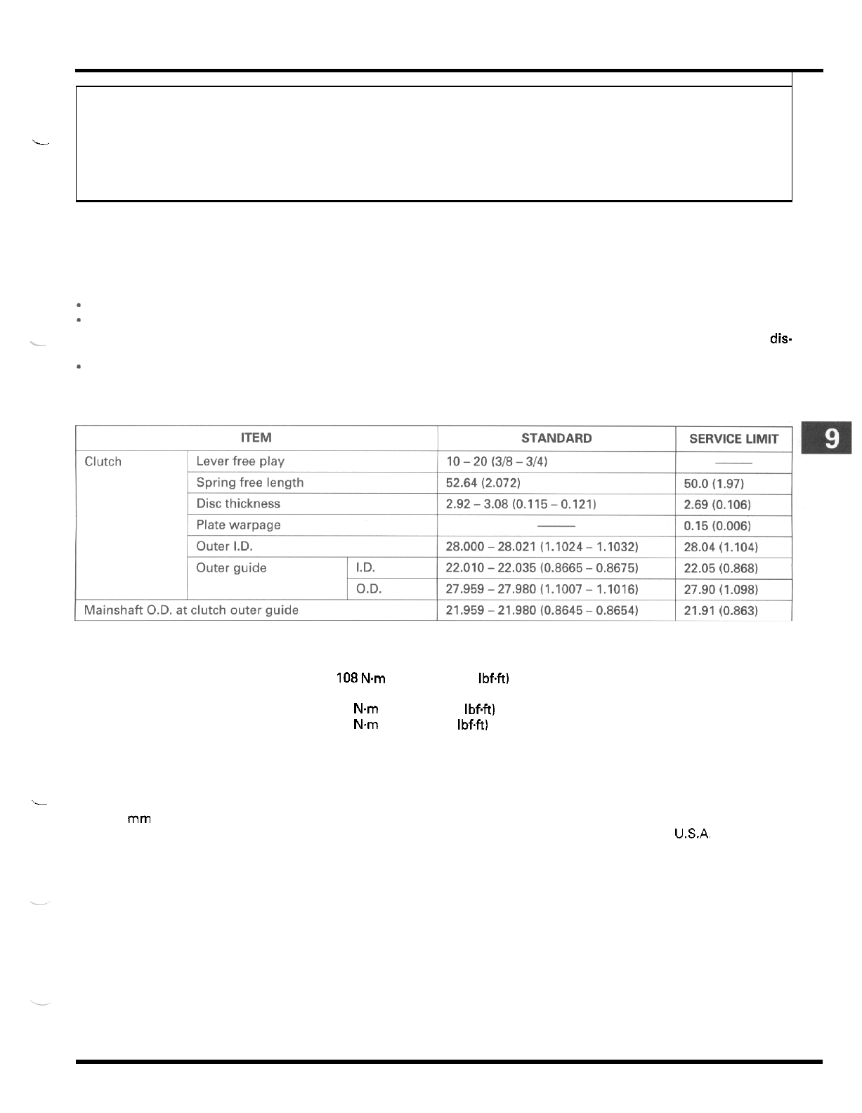
9.
CLUTCH/GEARSHIFT LINKAGE
L
SERVICE INFORMATION 9
-
1 PRIMARY DRIVE GEAR 9
-
10
TROUBLESHOOTING
9
-
2
GEARSHIFT LINKAGE 9
-
1 1
RIGHT CRANKCASE COVER REMOVAL 9
-
3 RIGHT CRANKCASE COVER
INSTALLATION 9
-
12
CLUTCH 9
-
5
-
SERVICE INFORMATION
GENERAL
-
The clutch and gearshift linkage can be serviced with the engine installed in the frame.
*
Engine oil viscosity and level and the use of oil additives have an effect on clutch operation. Oil additives of any kind
are specifically not recommended. When the clutch does not disengage or the motorcycle creeps with the clutch dis-
engaged, inspect the engine oil and oil level before servicing the clutch system.
*
The crankcase must be separated when the transmission, shift drum
and
shift forks require service (section 11).
L
SPECIFICATIONS
Unit:
mm
(in)
TORQUE
VALUES
Clutch center lock nut
Primary drive gear nut
Gearshift drum stopper arm bolt
TOOLS
108 Nm (11.0 kgfm,
80
IbfW
88
Nm
(9.0
kgfm,
65
IbfW
12
Nm
(1.2 kgfm,
9
IbfW
Apply oil to the threads and seating surface.
Stake.
Apply oil to the threads and seating surface.
Driver
Attachment, 28
x
30
mm
Pilot, 17
mm
Clutch center holder
Gear holder
._
07749
-
0010000
07746
-
1870100
07746
-
0040400
07724
-
0050002
or equivalent commercially available
in
USA,
07724
-
0010100 not available in U.S.A.
9
-
1

CLUTCH/GEARSHIFT LINKAGE
TROUBLESHOOTING
Clutch lever too hard
*
Damaged, kinked or dirty clutch cable
-
Improperly routed clutch cable
-
Damaged clutch lifter mechanism
-
Faulty clutch lifter plate bearing
Clutch
will
not disengage or motorcycle creeps with
clutch disengaged
*
Too
much clutch lever free play
*
Warped clutch plates
-
Faulty clutch lifter
*
Clutch
slips
-
No
clutch lever free play
*
Clutch lifter sticking
*
Worn clutch discs
-
Weak clutch springs
-
Oil
additive used
Hard to shift
*
Improper clutch operation
-
Incorrect engine oil viscosity
*
Incorrect clutch adjustment
*
Bent or damaged gearshift spindle
Damaged gearshift cam
Bent fork shaft or damaged shift forks and shift drum
(section
11)
Improper oil viscosity or oil additive used
Transmission jumps out
of
gear
Broken shift drum stopper arm
Weak or broken shift linkage return springs
-
Worn or damaged gearshift cam
*
Bent fork shaft or worn shift forks and shift drum
(section
11)
-
Worn gear dogs or slots (section
11)
9
-
2
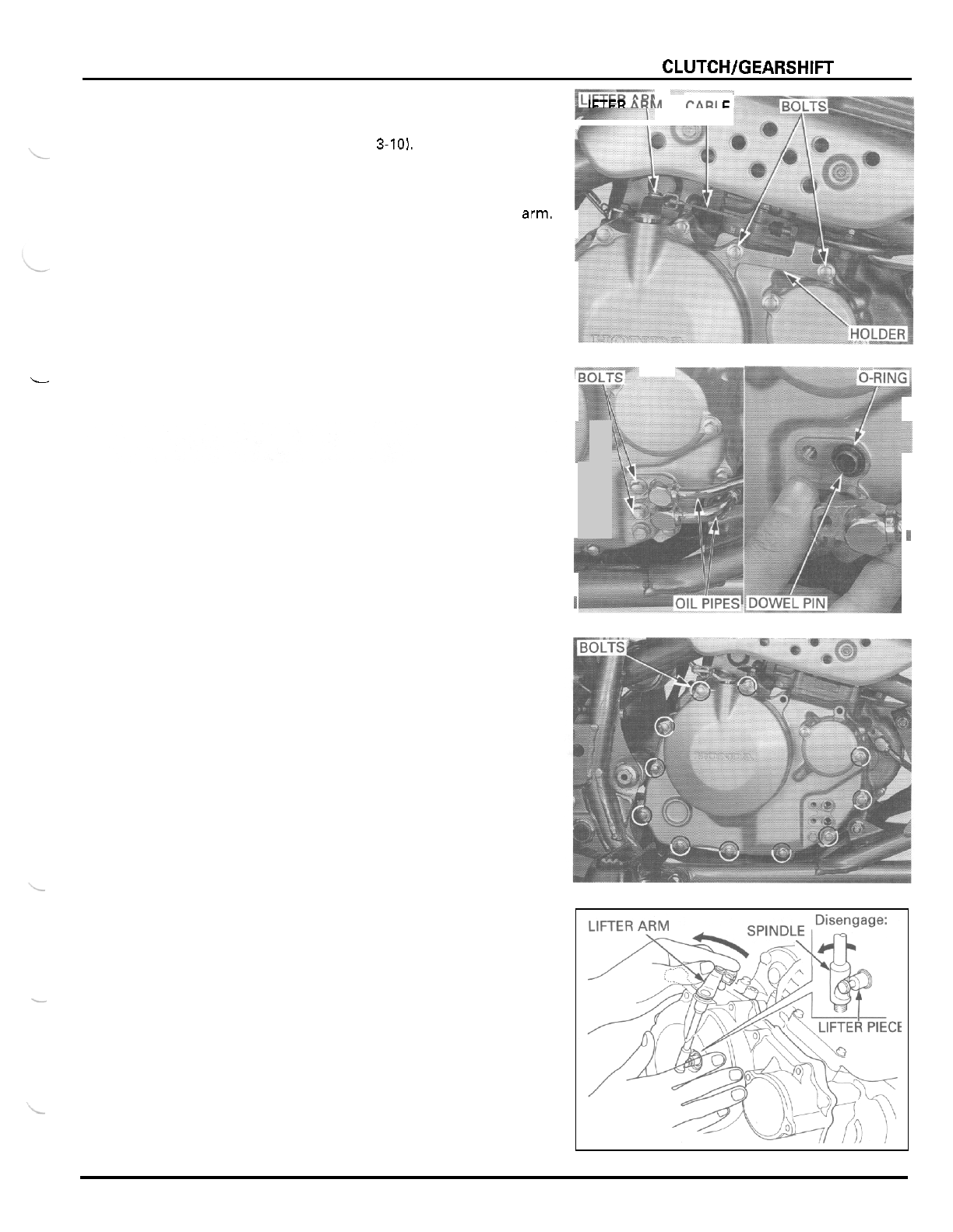
L
CLUTCHlGEARSHlFT LINKAGE
RIGHT
CRANKCASE COVER REMOVAL
1-
I
IETFR
ARM
-I-----
PAR1
E
Drain the engine oil (page
3-10),
Remove the rear brake pedal (page
14
-
20).
Remove the two bolts and clutch cable holder, and
disconnect the clutch cable from the clutch lifter arm.
-
fi
Remove the bolts, oil pipes O
-
rings and dowel pins
from the right crankcase cover.
Remove the right crankcase cover bolts.
Theclutch lifter
spindle is
engaged with
the clutch lifter
piece inside the
right crankcase
cover.
Remove the right crankcase cover while turning the
clutch lifter arm counterclockwise to disengage the
lifter arm spindle from the lifter piece.
-
9
-
3
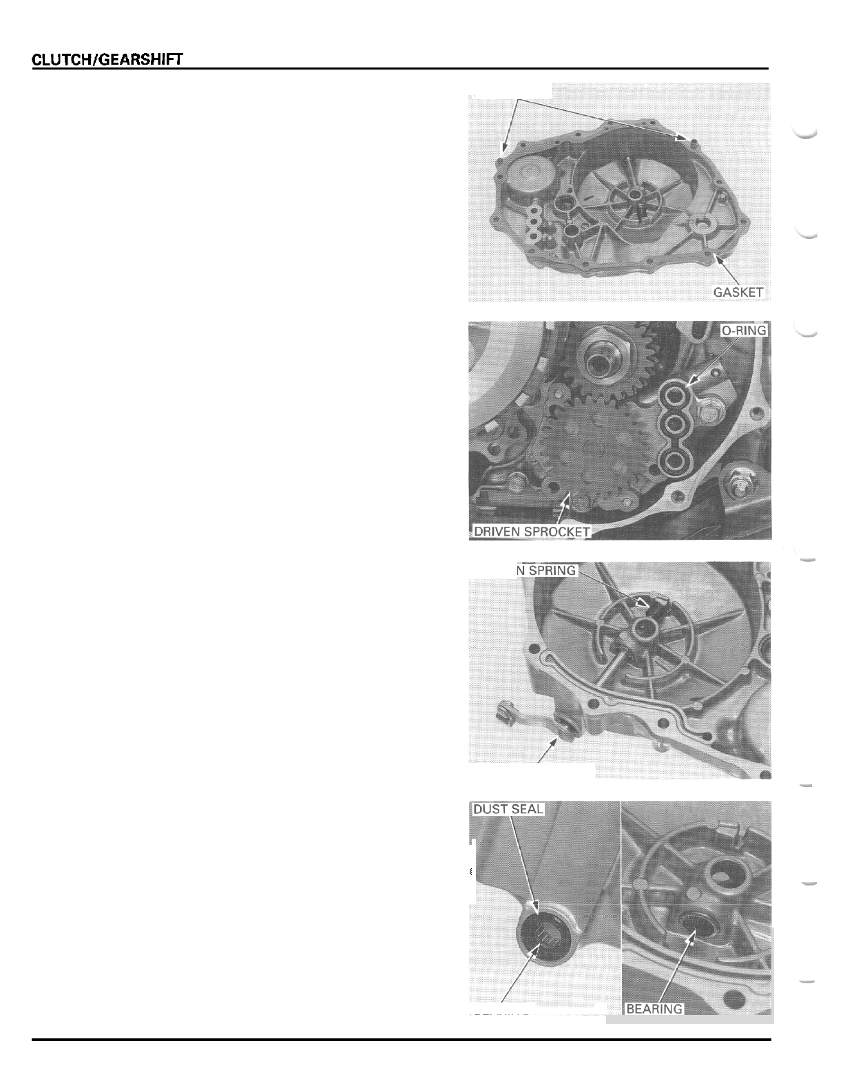
CLUTCHlGEARSHlFT LINKAGE
Remove the gasket and dowel pins.
Remove the O
-
ring and oil pump driven sprocket from
the oil pump.
DOWEL
-
PINS
-
CLUTCH
LIFTER
ARM
RETUR
Remove the clutch lifter arm and return spring from
the right crankcase cover.
Check the lifter arm spindle for wear or damage.
Check the return spring for fatigue or damage.
-
LIFTER
ARM
Check the spindle dust seal and needle bearings for
wear or damage.
Replace any faulty parts.
I
-
-
BEARING
9
-
4
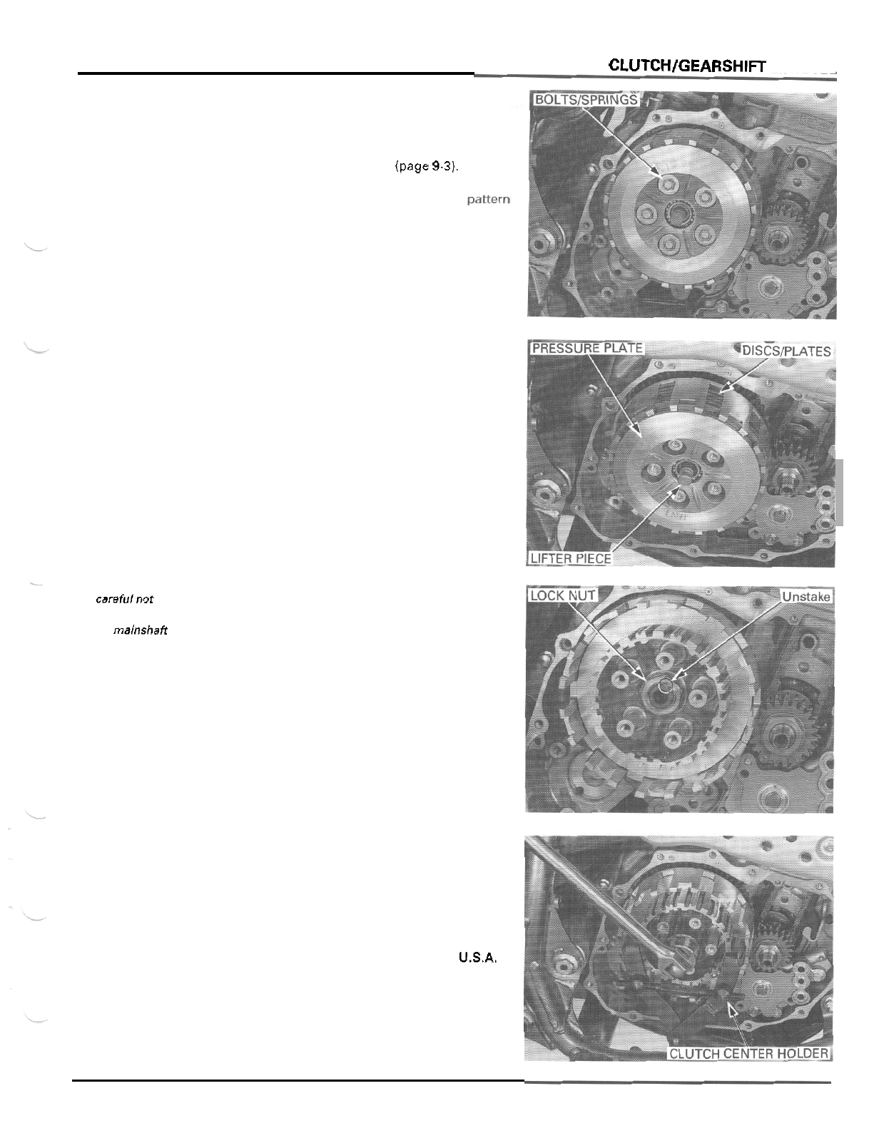
CLUTCH
DISASSEMBLY
CLUTCHlGEARSHlFT LINKAGE
Remove the right crankcase cover (page
9-3).
Loosen the clutch spring bolts in
a
crisscross p2w-m
in several steps.
Remove the bolts and springs.
Remove the pressure plate and lifter piece.
Remove the clutch discs and plates.
-
Be carefulnor to
damage the
mainshaff
threads.
Unstake the clutch center lock nut.
Hold the clutch center with the special tool and
remove the clutch center lock nut.
TOOL:
Clutch center holder
07724
-
0050002
or
equivalent
commercially
available in
USA.
9
-
5
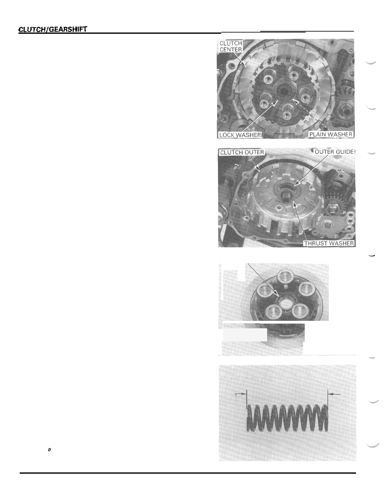
CLUTCH/GEARSHIFT LINKAGE
Remove the lock washer, plain washer and clutch
center.
Remove the thrust washer, clutch outer and clutch
outer guide.
INSPECTION
LIFTER
BEARING
Turn the inner race of the lifter bearing with your fin
-
ger.
The bearing should turn smoothly and quietly.
Also
check that the outer race of the bearing fits
tightly in the pressure plate.
Replace the bearing if the inner race does not turn
smoothly, quietly, or if the outer race fits loosely in
the pressure plate.
Drive the bearing out of the pressure plate.
Drive
a
new bearing into the plate with its mark side
facing up.
TOOLS
Driver
07749
-
0010000
Attachment,
28
x
30
mm
07746
-
1870100
Pilot,
17
rnrn
07746
-
0040400
CLUTCH
SPRING
Measure the clutch spring free length.
SERVICE LIMIT
50.0
mm
11.97
in)
Replace
the
clutch springs
as
a
set.
I
BEARING
-
9
-
6
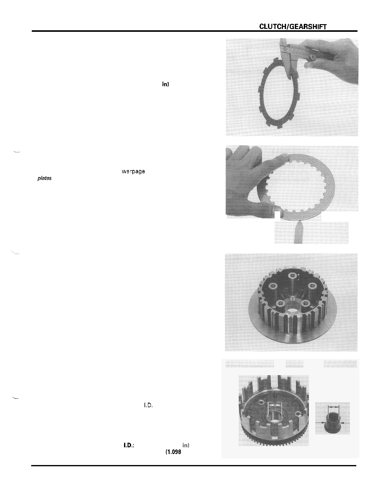
CLUTCH/GEARSHIFT LINKAGE
-
~
CLUTCH DISC
Check the clutch discs for signs
of
scoring or discol
-
Measure the clutch disc thickness.
SERVICE LIMIT 2.69
mm
10.106
in)
Replace the
-
clutch discs and
oration.
plates as a set.
-
CLUTCH PLATE
Replace the
clutchdiscsand
plares as
a
set
Check the plates for discoloration.
Check the plate warpage on a surface plate
using
a
feeler gauge.
SERVICE LIMIT 0.15
mm
10.006
in)
CLUTCH CENTER
Check the clutch center and pressure plate for nicks,
indentations or abnormal wear made by the plates.
CLUTCH OUTER/OUTER GUIDE
Check the primary driven gear teeth for wear or dam
-
age.
Check the slots in the clutch outer for nicks, indenta
-
tion or abnormal wear made by the clutch discs.
Measure the clutch outer
1.0.
SERVICE LIMIT: 28.04
mm
(1.104
in)
Measure the clutch outer guide
I.D.
and
O.D.
SERVICE LIMITS: I.D.:
22.05
mm
10.868
in1
O.D.:
27.90
mm
(1.098
in)
._
9
-
7
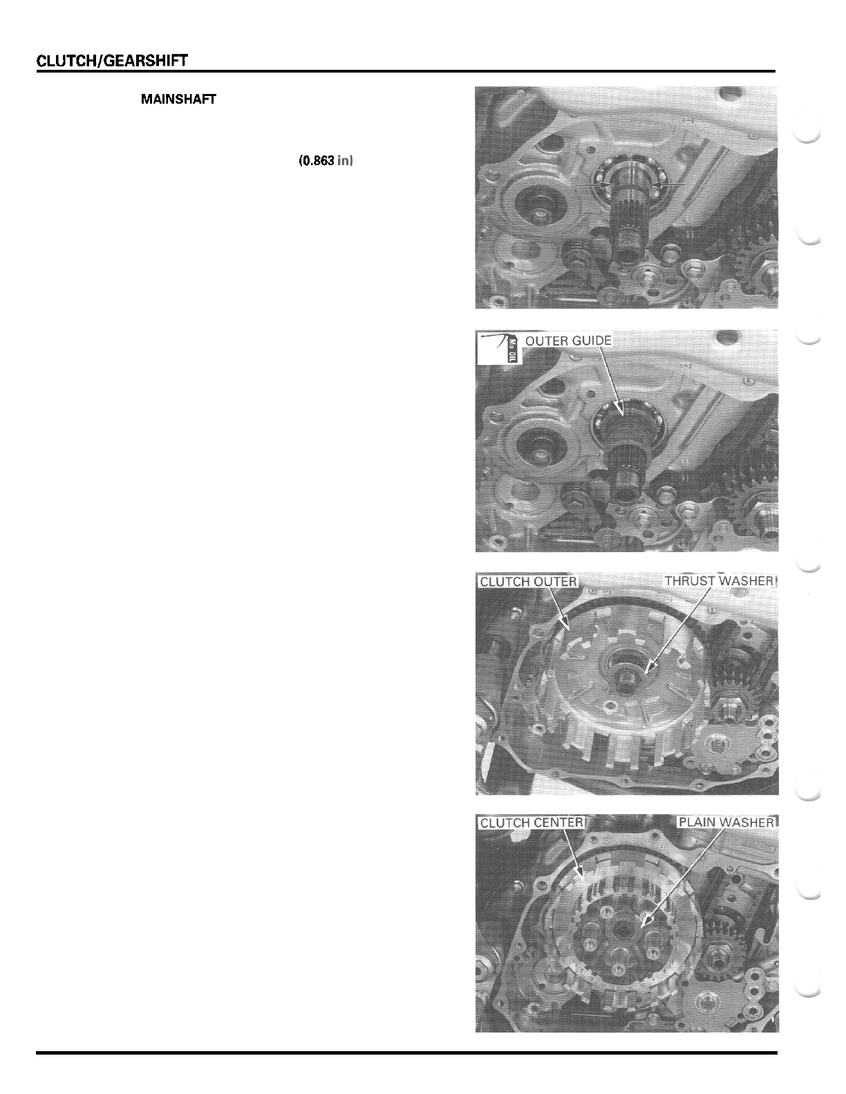
CLUTCH/GEARSHlFT LINKAGE
MAINSHAFT
Measure the mainshaft
O.D.
at
the clutch outer guide.
SERVICE
LIMIT
21.91
mm
(0.863
in1
ASSEMBLY
Coat the clutch outer guide with molybdenum oil
solution and install it onto the mainshaft with the
flange side facing the crankcase.
Install the clutch outer and thrust washer.
Install the clutch center and plain washer.
9
-
8
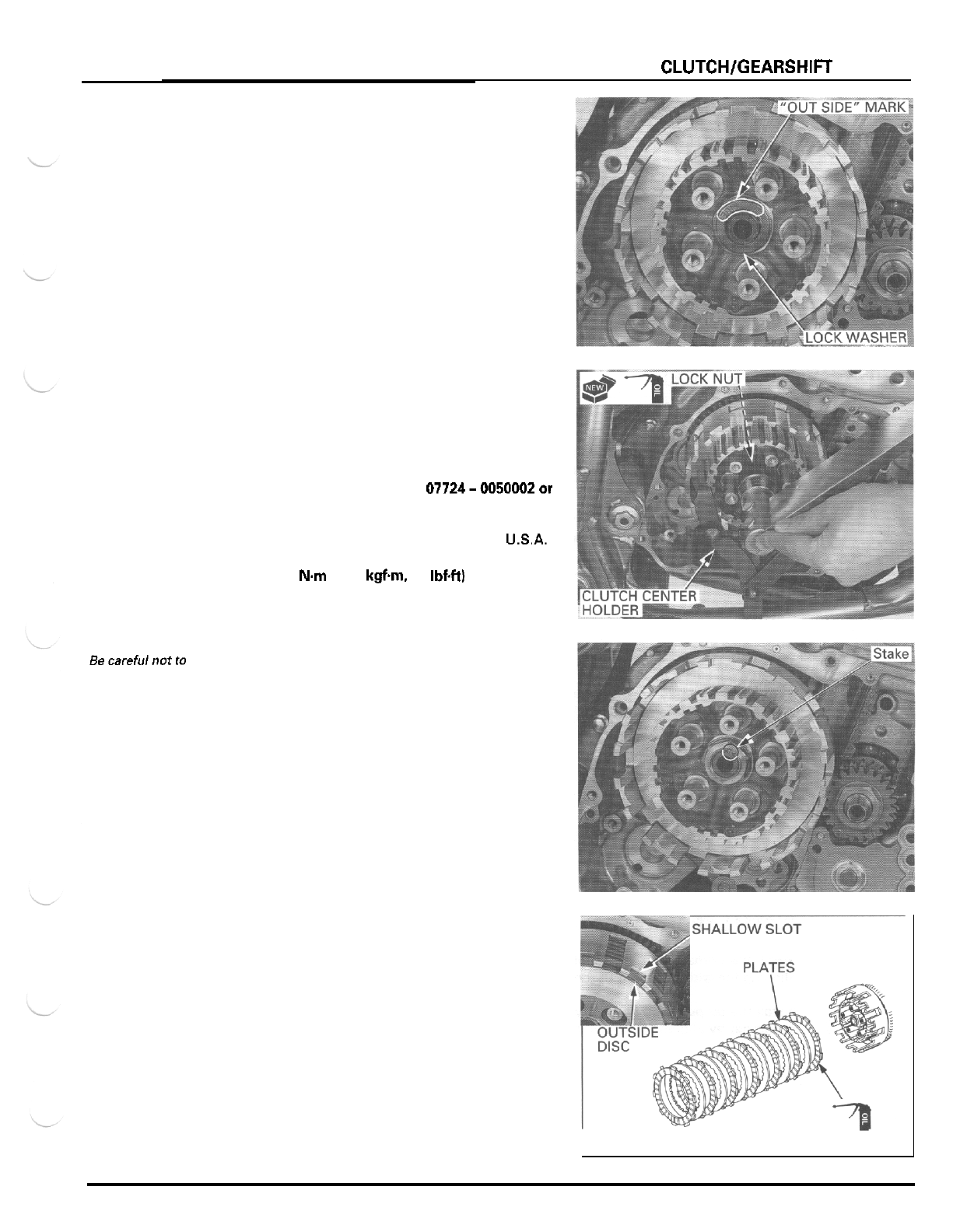
CLUTCHlGEARSHlFT LINKAGE
Install the lock washer
with
the
"
OUTSIDE
"
mark fac
-
ing
out.
Apply
oil
to the threads and seating surface
of
a new
clutch center lock nut and install
it
onto the mainshaft.
Hold the clutch center with the special tool and tighten
the lock nut.
TOOL
Clutch center holder
07724-0050002or
equivalent
commercially
available
in
USA.
TORQUE:
108
N.m
(11.0
kgfm
80
IbfW
Becarefulnotto
mainshaft
threads.
Stake the clutch center lock nut into the mainshaft
damage the
groove.
Coat the clutch discs
with
clean engine oil.
Install the seven clutch discs and six plates alternately,
starting with the disc.
Install the
out
-
side clutch
disc tabs into the
shallow slots in
the clutch outer.
I
DISCS
9
-
9
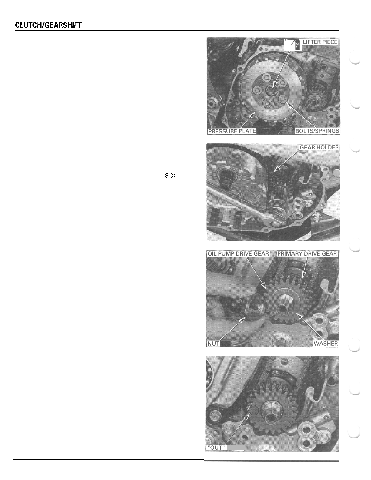
CLUTCHlGEARSHlFT LINKAGE
Apply oil to the clutch lifter piece whole surface and
lifter bearing.
Install the clutch lifter piece and pressure plate.
Install the clutch springs and bolts.
Tighten the bolts in
a
crisscross pattern in several
steps.
Install the right crankcase cover (page
9
-
12).
PRIMARY DRIVE GEAR
REMOVAL
Remove the right crankcase cover (page
9-3).
Disassemble the clutch to the clutch center thrust
washer (page
9
-
5).
Install the special tool between the primary drive and
driven gear as shown, loosen the primary drive gear
nut.
TOOL
Gear holder
07724
-
0010100
not
available
in
U.S.A.
Remove the clutch outer.
Remove the primary drive gear nut, washer, oil pump
drive gear and primary drive gear from the crankshaft.
INSTALLATION
Install the primary drive gear onto the crankshaft by
aligning the wide groove with the wide tooth.
Install the oil pump drive gear with the
"
OUT
"
mark
facing out by aligning the wide groove with the wide
tooth.
9
-
1
0
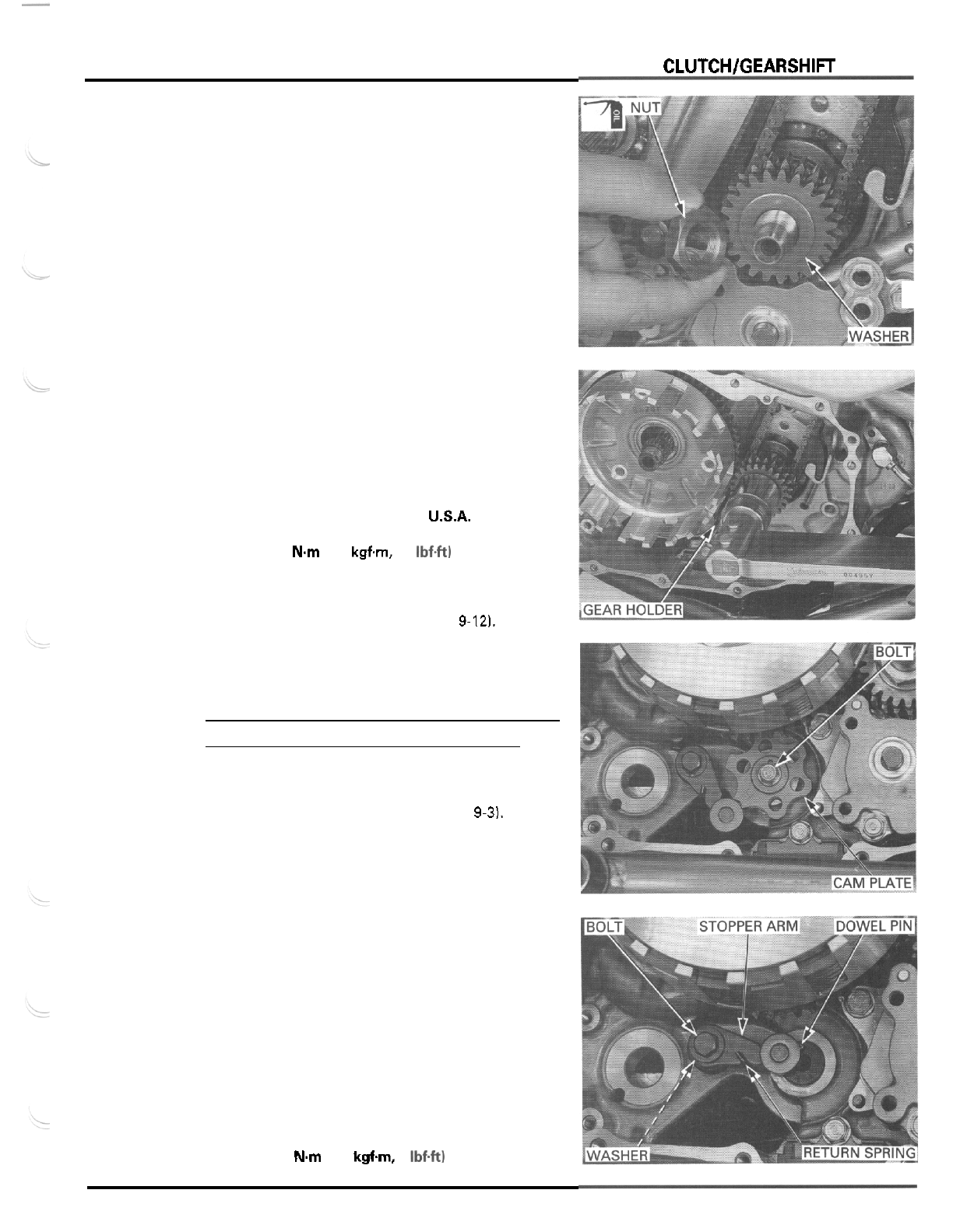
CLUTCH/GEARSHIFT
LINKAGE
Apply oil to the primary drive gear nut threads and
seating surface.
Install the washer and primary drive gear nut.
Remove the oil pump (page
4
-
21.
Install the clutch outer onto the mainshaft.
Install the special tool between the primary drive and
driven gears as shown and tighten the primary drive
gear nut.
TOOL
Gear holder
07724
-
0010100
not available in
USA.
TORQUE
88
Nm
(9.0
kgfm,
65
Ibf.ft)
Assemble the clutch (page
9
-
81.
Install the oil pump (page
4
-
61.
Install the right crankcase cover (page
9-12).
GEARSHIFT LINKAGE
NOTE:
For gearshift spindle service, refer to section
11
REMOVAL
Remove the right crankcase cover (page
9-3).
Remove the bolt and gearshift cam plate,
Remove the bolt, stopper arm, washer and return
spring.
Remove the dowel pin from the shift drum.
Check the gearshift cam and stopper arm for wear or
damage.
Check the stopper arm return spring for fatigue or
damage.
INSTALLATION
Install the dowel pin into the shift drum.
Install the return spring, washer (between the arm and
spring), stopper arm and bolt, and tighten the bolt.
TORQUE:
12
Nm
(1.2
kgfm,
9
Ibf.ft)
9
-
1
1
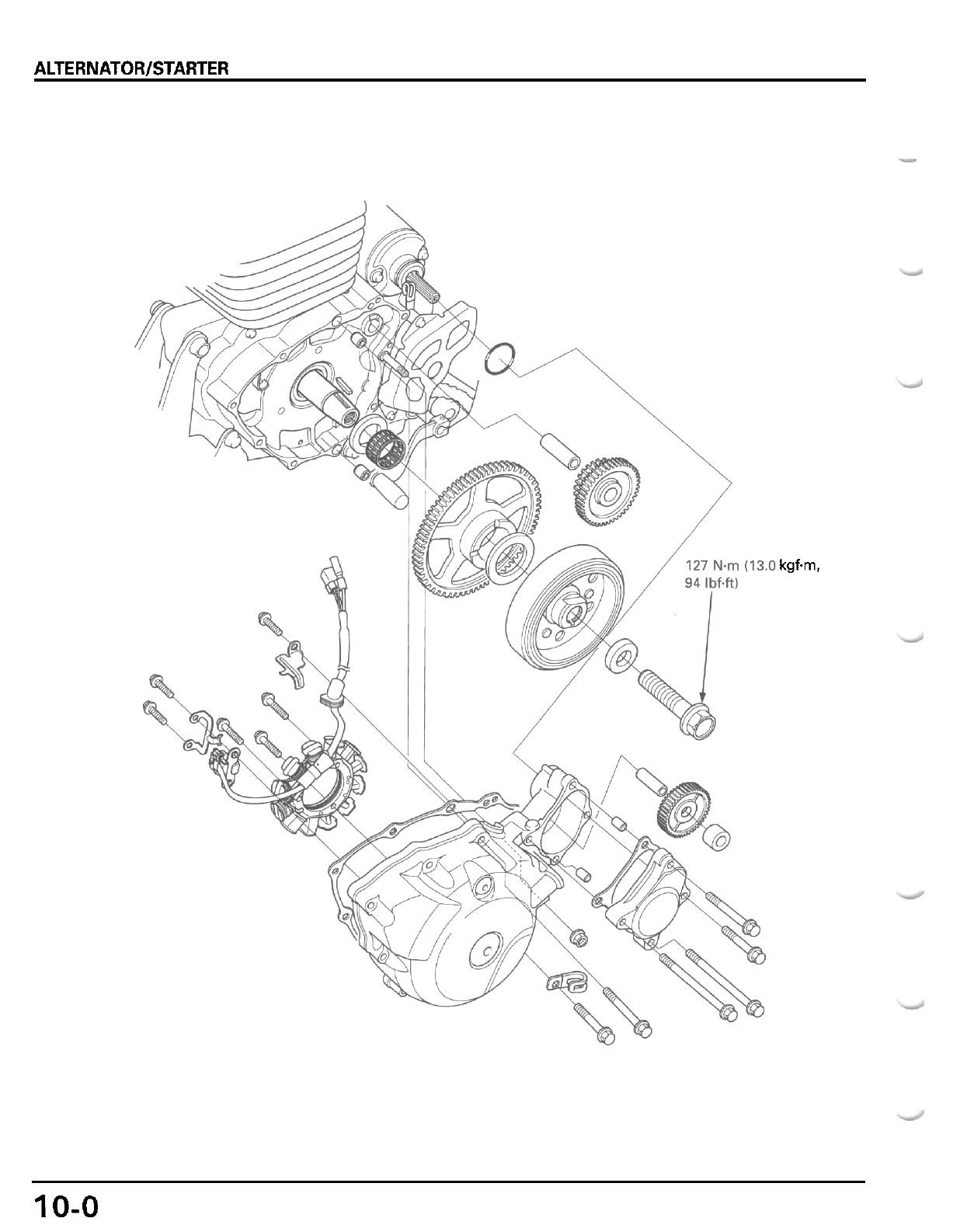
ALTERNATOR/STARTER CLUTCH
-
kgfm.
10-0
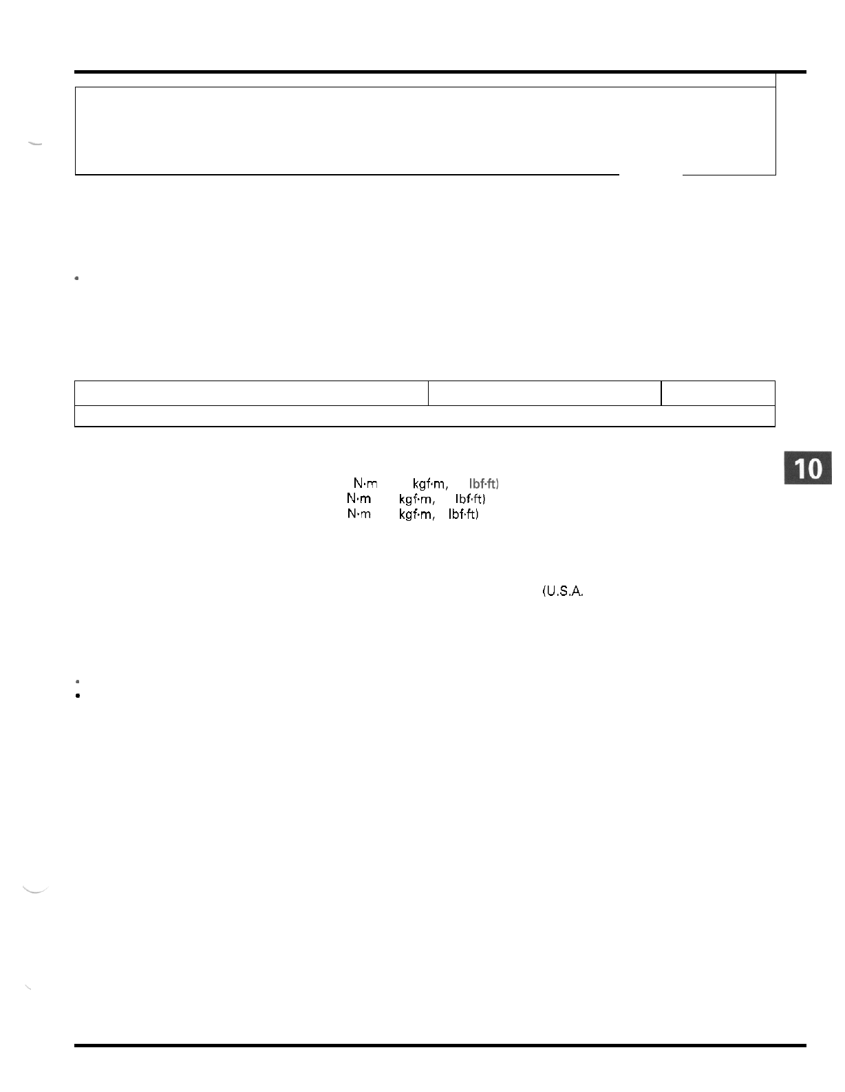
10.
ALTERNATOR/STARTER CLUTCH
ITEM
SERVICE INFORMATION
10-1
FLYWHEEL REMOVAL
10
-
5
TROUBLESHOOTING
10
-
1
STARTER CLUTCH
10
-
6
ALTERNATOR STATOR
10
-
2
FLYWHEEL INSTALLATION
10
-
8
-
STANDARD
SERVICE
LIMIT
TORQUE VALUES
Flywheel bolt
Starter clutch bolt
Left crankcase stud bolt
TOOLS
Flywheel holder
Rotor puller
127 Nm (13.0 kgf.m, 94 Ibf.ft)
30
N.m (3.1 kgf.m, 22 IbfW
10 Nm (1.0 kgf.m, 7 IbfW
Apply oil to the threads and seating surface.
Apply locking agent to
the
threads.
07725
-
0040000 or equivalent commercially available in U.S.A.
07733
-
0020001 or 07933
-
3950000 (U.S.A. only)
TROUBLESHOOTING
Starter motor turns,
but
engine does not turn
-
Faulty starter clutch
-
Damaged starter idle and reduction gears
10
-
1
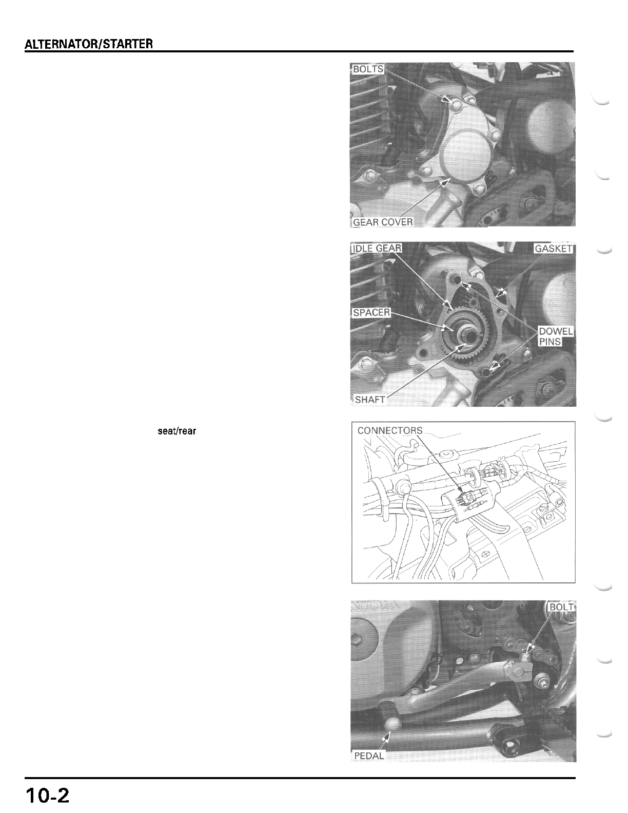
ALTERNATOR/STARTER CLUTCH
ALTERNATOR STATOR
LEFT CRANKCASE COVER REMOVAL
Remove the four bolts and the starter idle gear cover.
Remove the gasket and dowel pins.
Remove the spacer, starter idle gear and shaft from
the left crankcase cover.
Remove the seatlrear fender (page
2
-
2).
Disconnect the alternator connectors.
Remove the pinch
bolt
and gearshift pedal from the
gearshift spindle.
10-2
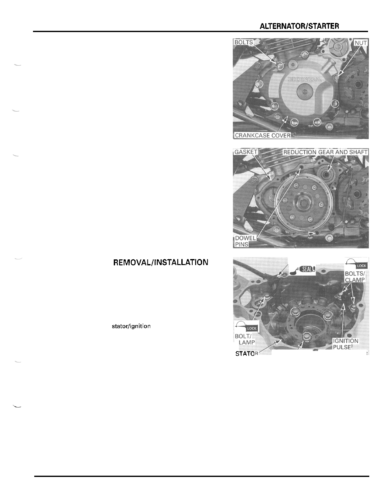
ALTERNATOR/STARTER CLUTCH
Remove the nut, seven bolts and the
left
crankcase
cover.
-
L
-
'L
.
-
Remove the gasket and dowel pins.
Remove the starter reduction gear shaft and gear.
STATOR REMOVAL/INSTALLATION
Remove the bolt and wire clamp.
Remove the two ignition pulse generator bolts and
wire clamp.
Remove the three stator bolts.
Remove the wire grommet and statorlignition pulse
generator assembly from the left crankcase cover.
Install the statorlignition pulse generator assembly
onto the left crankcase cover.
Apply sealant to the wire grommet seating surface
and install
it
into the cover groove properly.
Install the stator bolts and tighten them securely.
Apply locking agent to the ignition pulse generator
bolt threads.
Install the wire clamp onto the ignition pulse genera
-
tor
and tighten the two bolts securely.
Apply locking agent to the wire clamp bolt threads.
Install the wire clamp and tighten the bolt securely.
,GROMMET
C
s......
.
BOLTS
GENERATOR
10
-
3
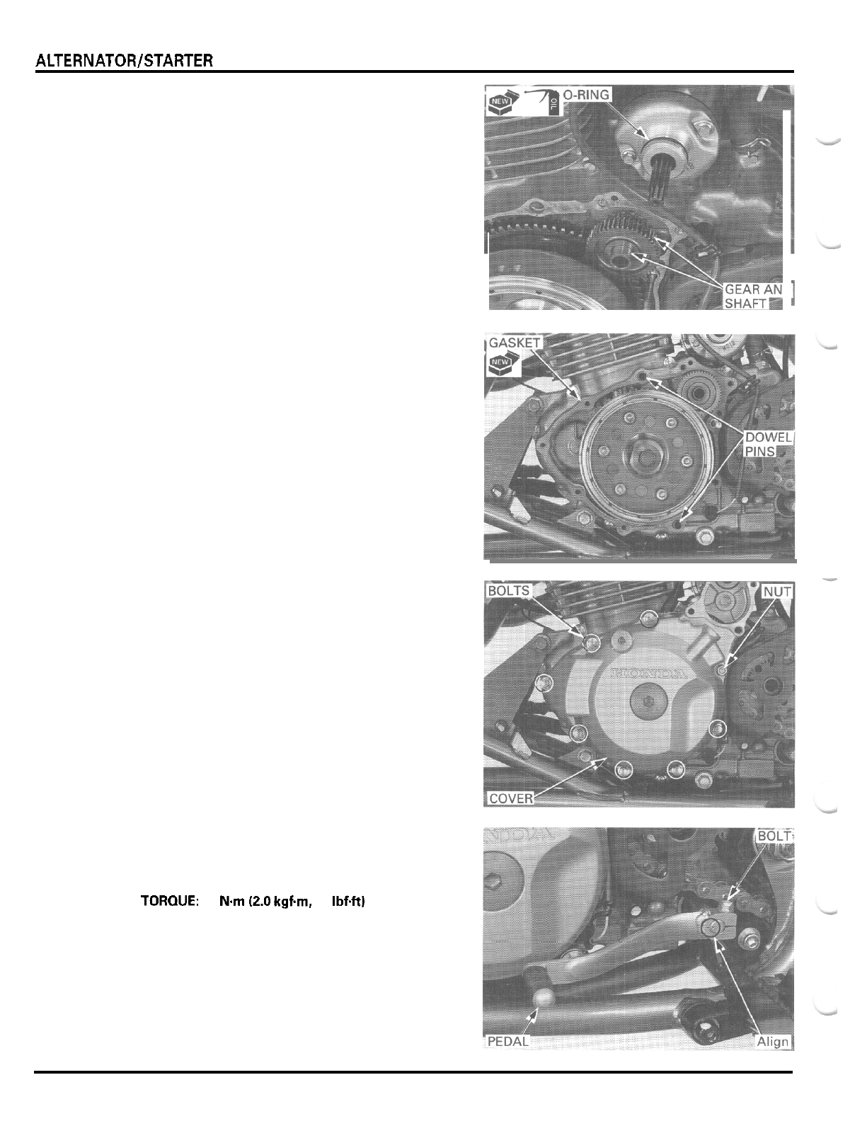
ALTERNATOR/STARTER CLUTCH
LEFT
CRANKCASE COVER
INSTALLATION
Install the starter reduction gear and shaft.
Coat
a
new O
-
ring with oil and install it into the
starter motor groove.
Install the dowel pins and
a
new gasket
Install the left crankcase cover, being careful not to
pinch the neutral switch wire.
Install the nut and seven bolts, and tighten them
securely.
Install the gearshift pedal onto the gearshift spindle,
aligning the punch marks on the pedal and spindle.
Install the gearshift pedal pinch bolt and tighten it.
TOROUE:
20
Nm
(2.0
kgfm,
14
Ibf4t)
...
10
-
4
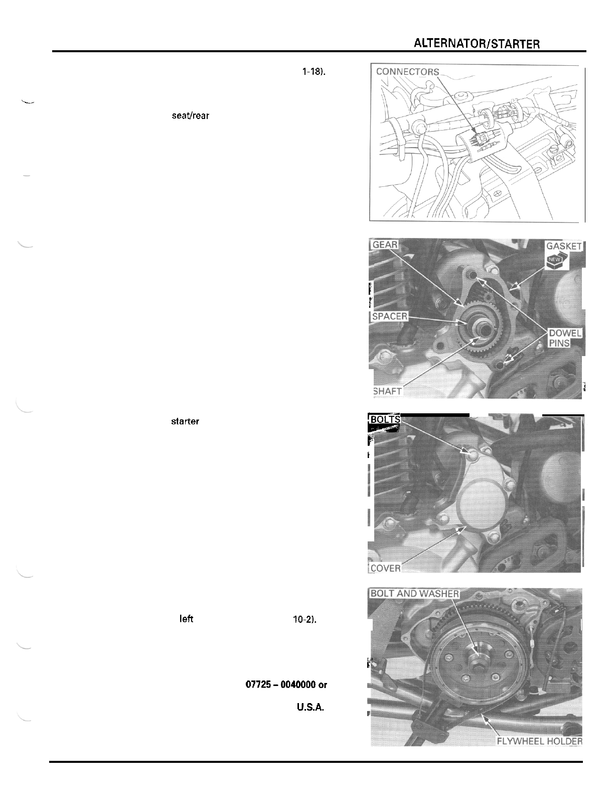
ALTERNATORlSTARTER CLUTCH
Route the alternator wire properly (page
1-18).
Connect the alternator connectors.
Install the seatlrear fender (page
2
-
21.
L
-
Install the starter idle gear shaft, gear and spacer
in
the left crankcase cover.
Install the dowel pins and
a
new gasket.
i
i
r--
Install the starter idle gear cover and tighten the four
bolts securely.
CF.
i
i
3
FLY
W
H
E
E
L
R
E
MOVAL
Remove the left crankcase cover (page
10-2).
I
Hold the flywheel
with
the special tool and loosen the
flywheel bolt.
r"'
TOOL
t
Flywheel holder 07725-0040000or
I.
equivalent commercially
available
in
USA.
Remove the flywheel bolt and special washer.
I
10
-
5
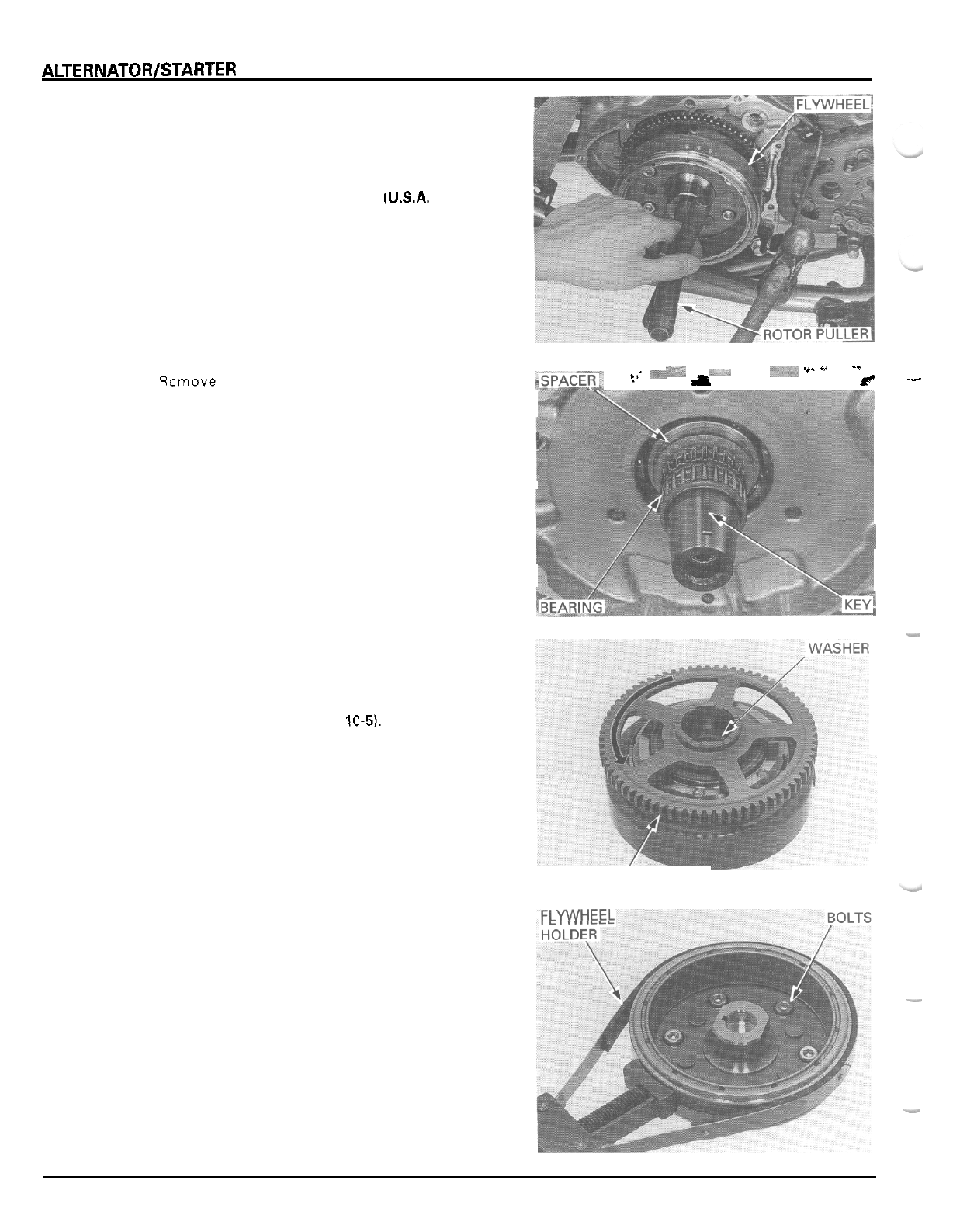
ALTERNATOR/STARTER CLUTCH
Remove the flywheel using the special tool.
TOOL
Rotor puller 07733
-
0020001or
07933
-
3950000
[U.S.A.
only)
Remove the
3.7
mm
washer and starter drive gear.
".
"
-.
b-
Remove the needle bearing, spacer anu woooruff
,_SPAEL
?"
'*c
i
rr-
key.
STARTER CLUTCH
REMOVAL
Remove the flywheel (page
10-5).
Remove the starter driven gear while turning it coun
-
terclockwise.
Remove the washer.
DRIVEN
GEAR
Hold
the flywheel with the special tool and remove
the starter clutch bolts.
TOOL
Flywheel holder
07725
-
0040000
Remove the starter clutch assembly from the flywheel.
Remove the sprag clutch from the starter clutch
outer.
FLYWHEEL
-
-
10
-
6
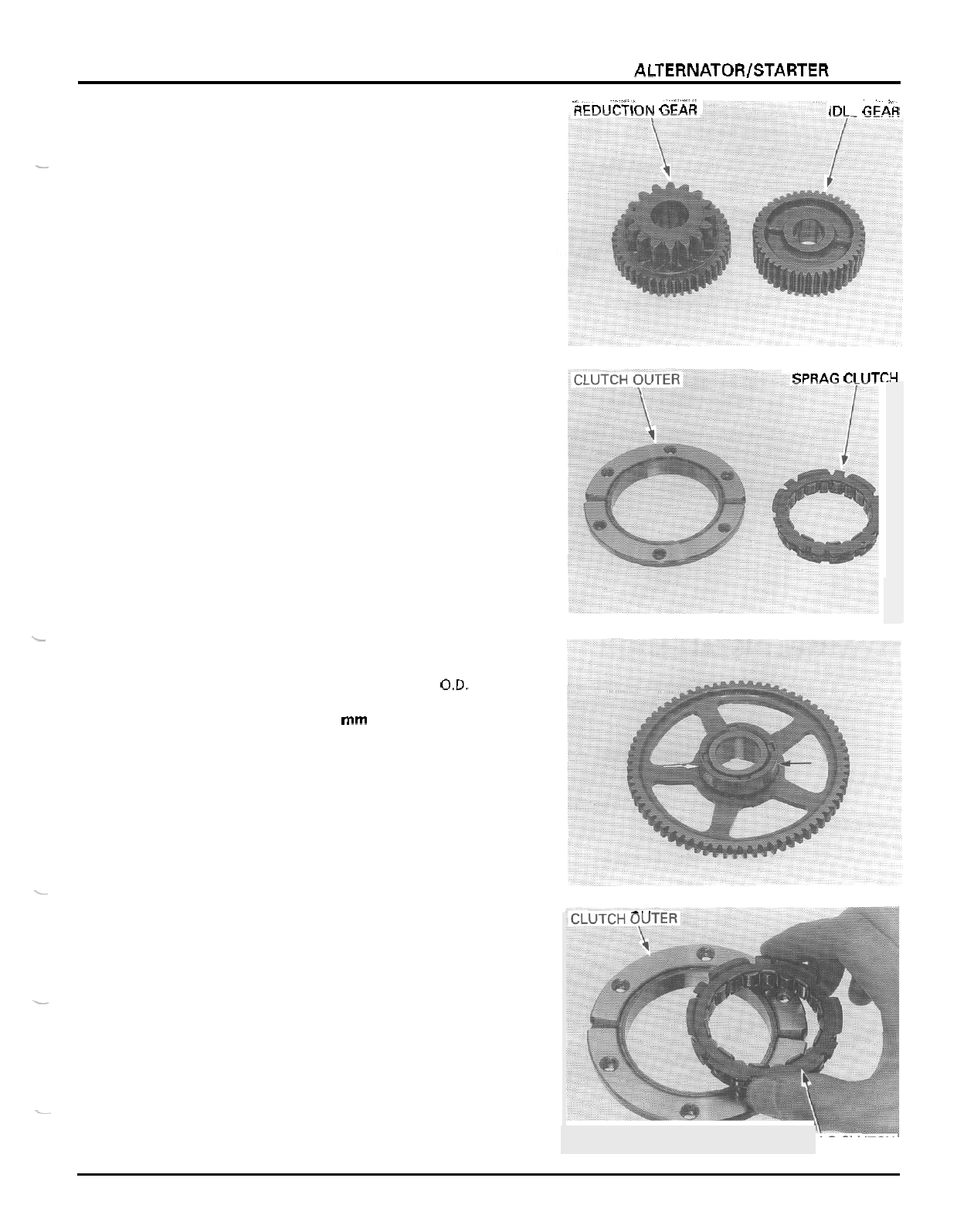
ALTERNATOWSTARTER CLUTCH
im
F
GFAR
bmi
iriinN
GFAR
INSPECTION
Check the starter idle gear and reduction gear for
-
wear or damage.
Check the starter clutch outer and sprag clutch for
abnormal wear or damage.
SPRAG
ri
(ITCH
Check the starter driven gear teeth for wear or damage.
Measure the starter driven gear boss
O.D.
SERVICE
LIMIT
51.67
mm
(2.034
in)
L
.
_.
INSTALLATION
Install the sprag clutch into the starter clutch outer
with the flange side facing the flywheel side.
-
-
10
-
7
SPR
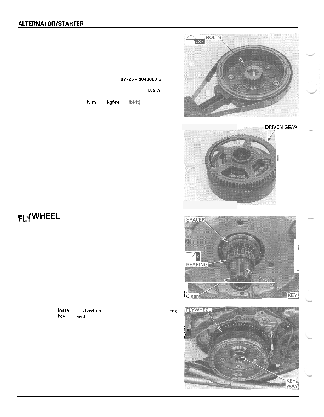
ALTERNATOR/STARTER CLUTCH
Apply locking agent to the starter clutch bolt threads.
Install the starter clutch assembly onto the flywheel
and install the bolts.
Hold the flywheel
with
the special tool
and
tighten
the bolts.
TOOL
Flywheel holder 07725-0040000or
equivalent commercially
available
in
USA.
TORQUE:
30
N.m
(3.1
kgf.m,
22
Ibf.ft)
Install the starter driven gear with the washer while
turning
it
counterclockwise.
Make sure that the starter driven gear turns counter
-
clockwise smoothly and does not turn clockwise.
Install the flywheel.
7RIVENGEAR
-
/
Fl
Install the starter drive gear.
ic
fWHEEL INSTALLATION
-
Lubricate the needle bearing with oil.
Install the
5.6
mm spacer and needle bearing onto the
crankshaft.
Clean any
oil
from the tapered portions of the crank
-
shaft and flywheel.
Install the woodruff key
in
the crankshaft key groove.
I
i
lnsta
I
the flvwhcel on tne crankshaft, aligning tne
kcy way
mitn
rhe woodruff key.
ii.
i
10
-
8
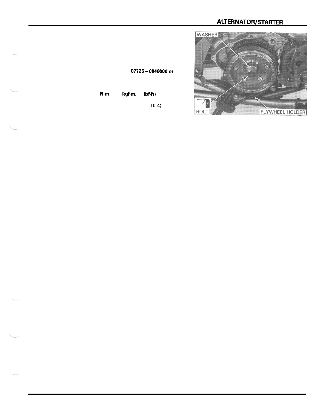
ALTERNATORlSTARTER CLUTCH
Apply
oil
to the flywheel bolt threads and seating sur
-
face, and install the special washer and
bolt.
Hold the flywheel with the special tool and tighten
-
the bolt.
TOOL
Flywheel holder 07725-0040000or
equivalent commercially
available in
U.S.A.
TORQUE:
127
Nm
113.0 kgfm,
94
Ibf4t)
Install the left crankcase cover (page
10-41,
10
-
9
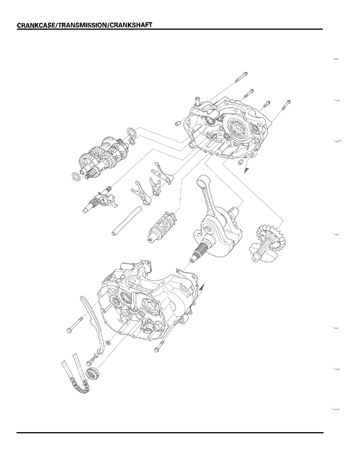
CRANKCASE/TRANSMISSION/CRANKSHAFT
-
11
-
0
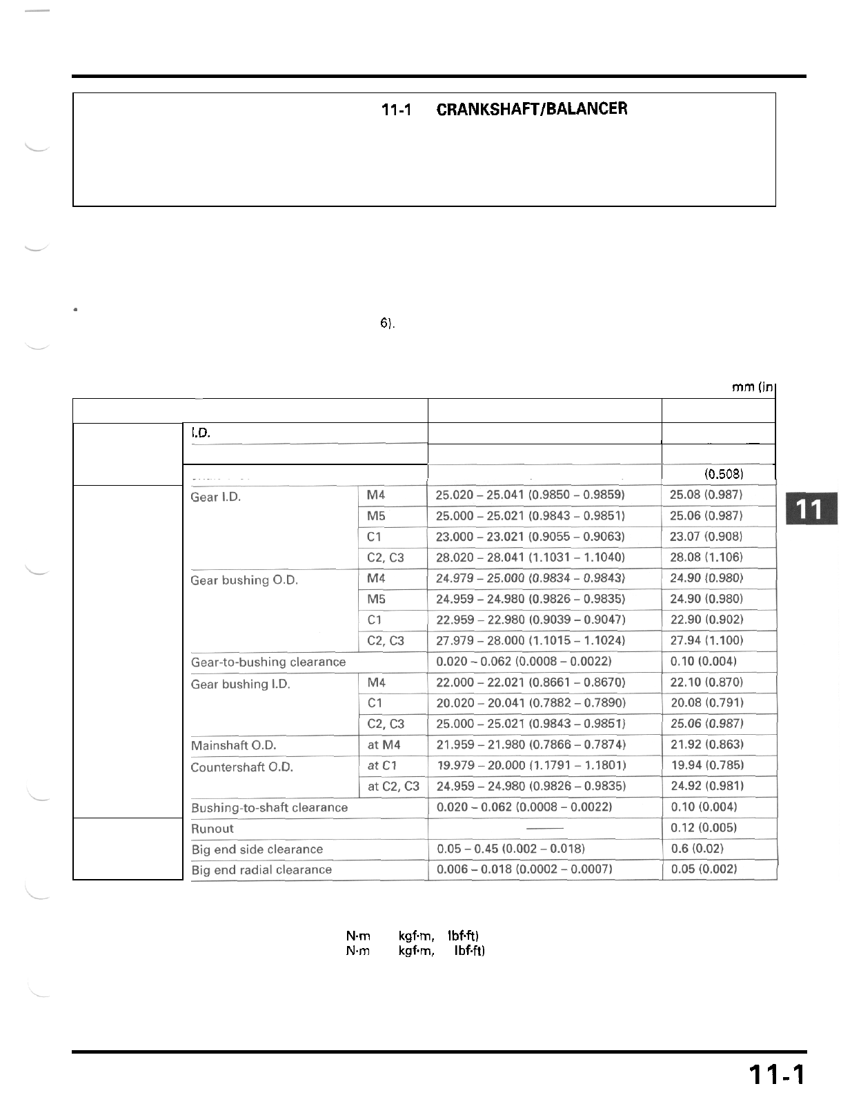
1
1.
CRANKCASE/TRANSMISSION/CRANKSHAFT
~
ITEM
I.D.
SERVICE
-
INFORMATION 11-1 CRANKSHAFTlBALANCER
11
-
9
TROUBLESHOOTING 11
-
2 CRANKCASE BEARING REPLACEMENT 11
-
12
CRANKCASE SEPARATION 11
-
3 CRANKCASE ASSEMBLY
11
-
15
TRANSMISSION 11
-
4
SERVICE
IN
FORMATI0
N
GENERAL
The crankcase halves must be separated to service the transmission and crankshaft.
To
service these parts, the
engine must be removed from the frame (section
6).
.
Be careful not to damage the crankcase mating surfaces when servicing.
STANDARD
SERVICE
LIMIT
13.000
-
13.021 (0.5118
-
0.5126) 13.05 10.514)
I
SPECIFICATIONS
Unit:
mm
lin
Claw thickness
Shaft
O.D. 12.966
-
12.984 (0.5105
-
0.5112)
5.93
-
6.00 (0.233
-
0.236)
~______
Shift fork
Transmission
Crankshaft
5.5 (0.22)
12.90 (0.508)
TORQUE VALUES
Mainshaft bearing setting plate bolt
Gearshift spindle return spring
pin
bolt
12 Nm (1.2
kgfm.
9
IbfW
24
Nm
12.4
kgfm,
17
IbfW Apply locking agent to the threads
11-1
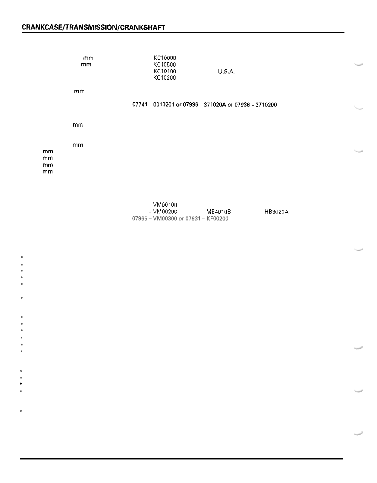
CRANKCASEITRANSMISSIONlCRANKSHAFT
TOOLS
Bearing remover set,
15
mm
-
bearing remover,
15
mm
-
remover shaft
-
remover head
-
sliding weight
Bearing remover,
17
mm
Remover handle
Remover weight
Driver
Attachment,
32 x 35
mm
Attachment,
37 x 40
mm
Attachment,
42
x
47
mm
Attachment,
52 x 55
mm
Attachment,
72 x 75
mm
Pilot,
12 mm
Pilot,
15
mm
Pilot,
17
mm
Pilot,
22
mm
Pilot,
25
mm
Pilot,
30
mm
Universal bearing puller
Crankcase assembly tool
-
assembly collar
-
assembly shaft
-
threaded adaptor
TROUBLESHOOTING
Excessive engine noise
*
Worn, seized or chipped transmission gears
*
Worn transmission bearing
*
Worn or damaged connecting rod bearings
*
Worn crankshaft main journal bearing
-
Worn connecting rod small end
.
Worn balancer bearing
-
Improper balancer installation
Transmission jumps out
of
gear
-
Worn gear dogs or dog holes
-
Worn shift drum guide groove
-
Worn shift fork guide pin
*
Worn gear shifter groove
Worn shift fork
*
Bent shift fork shaft
Hard
to
shift
-
Damaged shift fork
*
Bent shift fork shaft
*
Damaged shift fork guide pin
Damaged shift drum guide groove
Abnormal vibration
*
Improper balancer timing
07936
-
KCIOOOO
not available in U.S.A.
07936
-
KC10500
07936
-
KClOlOO
not available in USA.
07936
-
KC10200
not available in U.S.A.
07741
-
0010201
or
07936
-
371020A
or
07936
-
3710200
07936
-
3710300
07936
-
3710100
07741-0010201or07936-371020Aor07936-3710200
07749
-
0010000
07746
-
0010100
07746
-
0010200
07746
-
0010300
07746
-
0010400
07746
-
0010600
07746
-
0040200
07746
-
0040300
07746
-
0040400
07746
-
0041000
07746
-
0040600
07746
-
0040700
07631
-
0010000
or equivalent commercially available
in
U.S.A.
07965
-
VMOOOOO
not available in U.S.A.
07965
-
VMOOIOO
07965 -VM00200
or
07931
-
ME4010B
and
07931
-
HB3020A
07965-VM00300or07931-KF00200
11
-
2
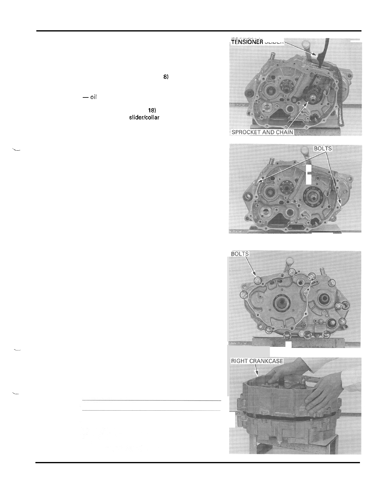
i
1
i
CRANKCASEITRANSMISSIONICRANKSHAFT
CRANKCASE
SEPARATION
Remove the following:
-
engine (section
6)
-
cylinder head (section
7)
-
cylinder and piston (section
8)
-
clutch, gearshift linkage, primary drive gear
-oil pump (section 41
-
flywheel (section 101
-
starter motor (section 18)
-
bolt, tensioner sliderlcollar and washer
-
cam chain
-
cam chain drive sprocket
(section
9)
-11_
TENSiONER
SLIDER
-
two right crankcase bolts
-3
Loosen the eleven left crankcase
bolts
in
a
crisscross
pattern in
2
or
3
steps and remove them.
Place the crankcase assembly with the left side down.
Remove the right crankcase from the left crankcase
while tapping them
at
several locations with
a
soft
hammer.
CAUTION:
Do
not
pry
the crankcase apart
with
a
screwdriver.
-
-
11
-
3
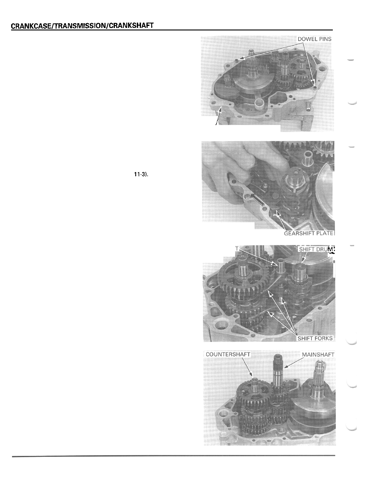
CRANKCASElTRANSMlSSlONlCRANKSHAFT
Remove the gasket and dowel pins.
TRANSMISSION
DISASSEMBLY
Separate the crankcase (page
11-3).
Pull
the gearshift plate away from the shift drum and
remove the gearshift spindle.
Pull the shift fork shaft out of the left crankcase and
shift forks.
Remove the shift forks and shift drum.
Remove the mainshaft and countershaft assembly
as
a
set.
Disassemble the mainshaft and countershaft.
I
GASKET
-
-
-1
rr?:
FORK
SHAF
11
-
4
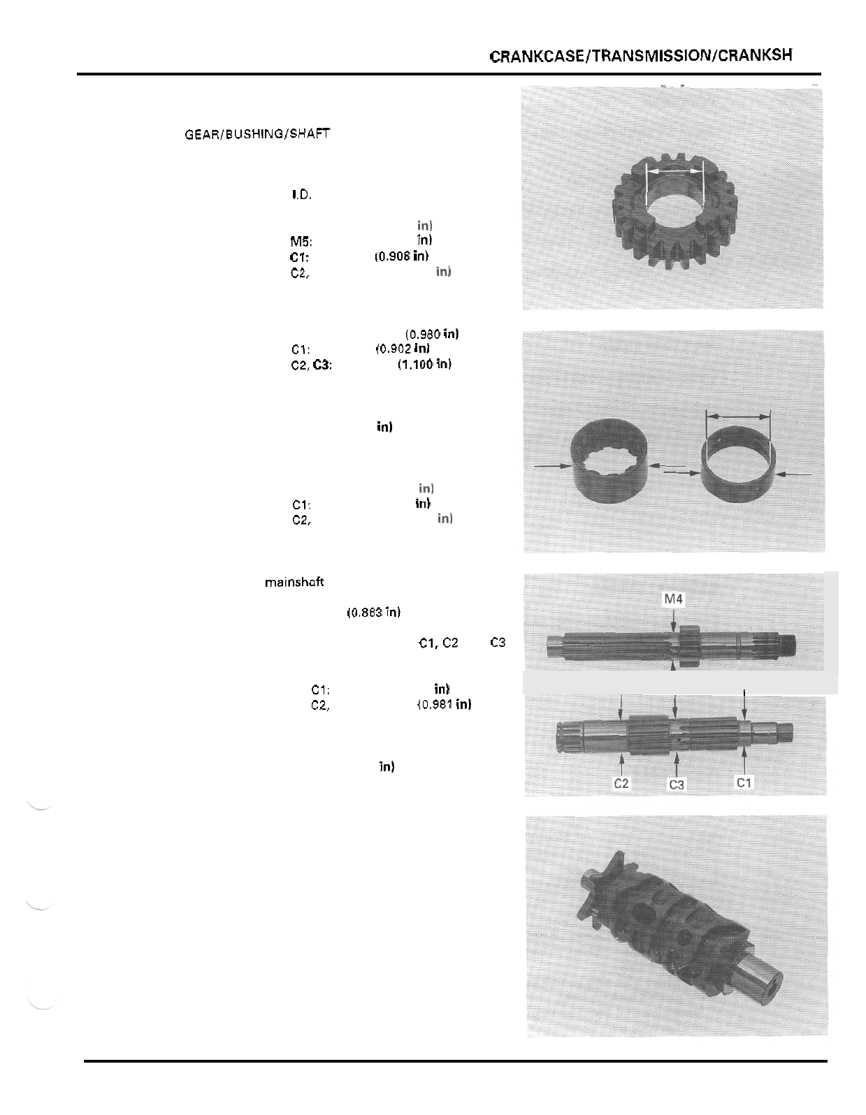
CRANKCASE/TR ANSMISSION/CRANKSH AFT
"^
-
INSPECTION
GEAR/BUSHING/SHAFT
Check the gear dogs and teeth for abnormal wear or
damage.
Measure the gear
I.D.
SERVICE LIMITS: M4 25.08
mm
(0.987
in1
M5: 25.06
mm
(0.987
in)
C1: 23.07
mm
(0.908
in)
C2, C3: 28.08
mm
(1.106
in1
Measure the gear bushing
O.D.
SERVICE LIMITS: M4, M5: 24.90
mm
(0.980
in1
C1: 22.90
mm
10.902
in1
C2.
c3:
27.94
mm
(1.100
in1
Calculate the gear
-
to
-
bushing clearance.
SERVICE LIMIT 0.10
mm
(0.004
in)
Measure the gear bushing
I.D.
SERVICE LIMITS: M4 22.10
mm
(0.870
in1
C1: 20.80
mm
(0.791
in1
C2, C3: 25.06
mm
(0.987
in1
Check the mainshaft and countershaft for abnormal
wear or damage.
Measure the malnshaft
O.D.
at
the
M4
gear.
SERVICE LIMIT 21.92
mm
(0.863
in)
Measure the countershaft
O.D.
at
the
C1, C2
and C3
gears.
SERVICE LIMITS At C1: 19.94
mm
(0.785
in)
At
C2, C3 24.92
mm
(0.981
in1
Calculate the gear bushing
-
to
-
shaft clearance.
SERVICE LIMIT 0.10
mm
10.004
in)
SHIFT DRUM
Check the shift drum guide grooves for abnormal
wear or damage.
Check the shift drum journals for scoring, scratches
or evidence of insufficient lubrication.
I
I
11
-
5
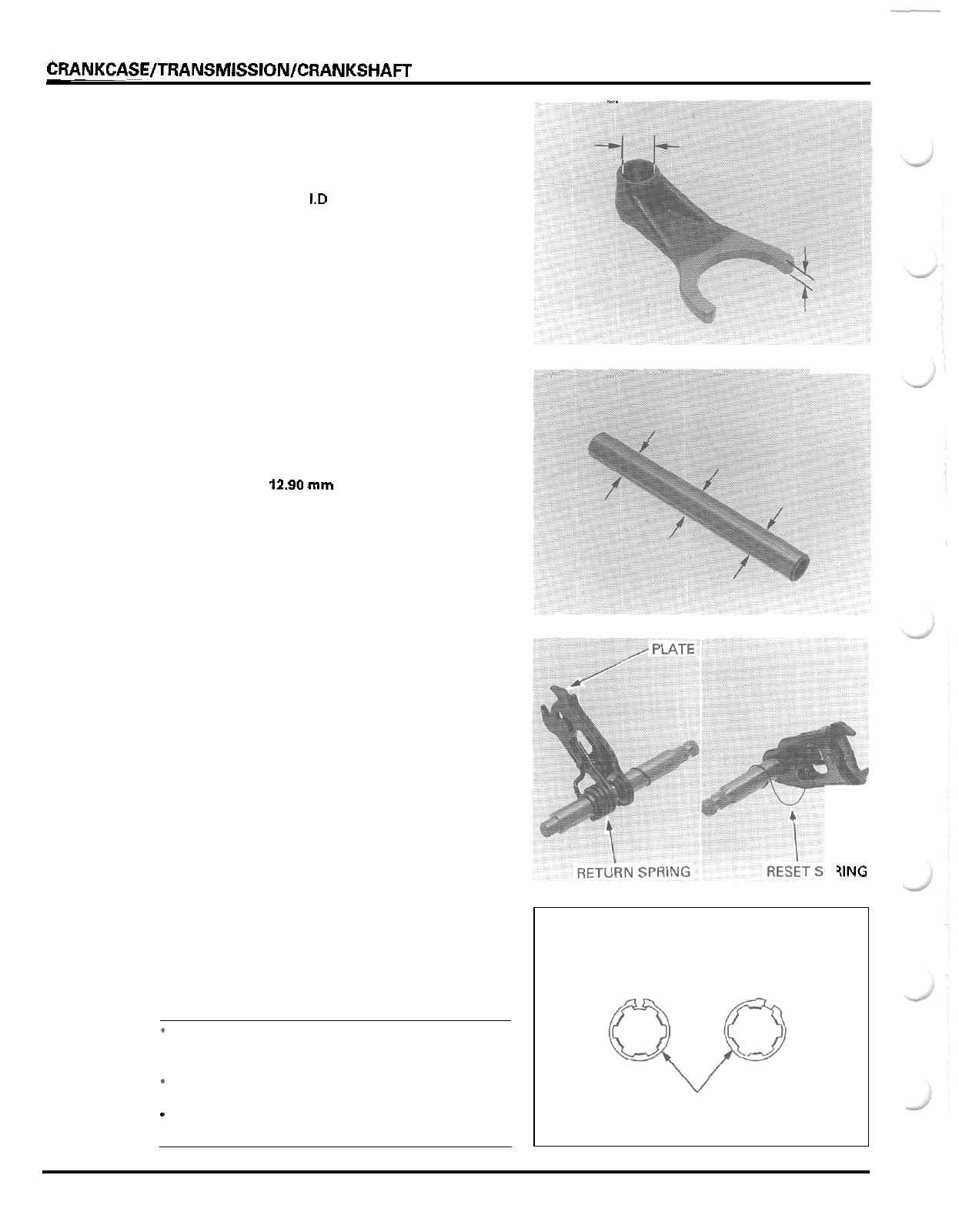
CRANKCASE/TRANSMISSION/CRANKSHAm
. .-
.
SHIFT
FORK
Check the shift fork guide pins for abnormal wear or
damage.
Measure the shift fork
1.D
SERVICE LIMIT 13.05
mm
(0.514
in)
Measure the shift fork claw thickness.
SERVICE LIMIT 5.5
mm
(0.22
in)
SHIFT
FORK
SHAFT
Check the shift fork shaft for damage or bending
Measure the shift fork shaft
O.D.
SERVICE LIMIT
12.90
mm
(0.508
in)
GEARSHIFT
SPINDLE
Check the gearshift plate for wear or damage.
Check the return spring and reset spring for fatigue
or damage.
ASSEMBLY
Clean
all
parts
in
solvent and dry them thoroughly.
7ING
Apply molybdenum
oil
solution to the gear teeth,
sliding surface, shifter grooves and bushings.
Assemble the mainshaft and countershaft.
NOTE:
*
Always install the thrust washer and snap ring
with the chamfered (rolled) edge facing away from
the thrust load.
*
Install the snap ring
so
that its end gap aligns with
the groove in the splines.
-
Make sure that the snap ring is fully seated in the
shaft groove after installing it.
CORRECT INCORRECT
SNAP
RING
11
-
6
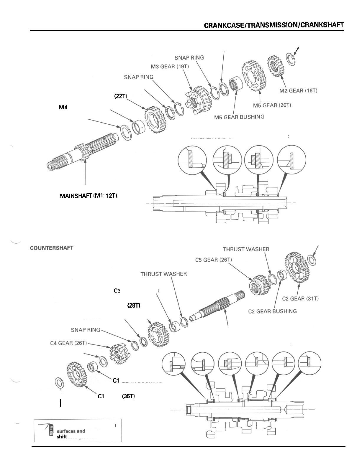
CRANKCASE/TRANSMISSION/CRANKSHAFT
MAINSHAFT
THRUST WASHER
SPLINE WASHER
/
SPLINE WASHER
M4 GEAR (22T)
M4
GEAR BUSHING
THRUST WASHER
WASHER AND SNAP RING DIRECTION:
I
MAINSHAFT
(Ml:
12T)
THRUST
WASHER
C3
GEAR BUSING
C3 GEAR (28T)
SPLINE WASHER
\
COUNTERSHAFT
WASHER AND SNAP RING DIRECTION:
THRUST WAS HER
C1 GEAR BUSHING
T
C1 GEAR (35T)
I
THRUST WASHER
:
Gear
and
bushing
rotating
~
shift
fork
grooves
11
-
7
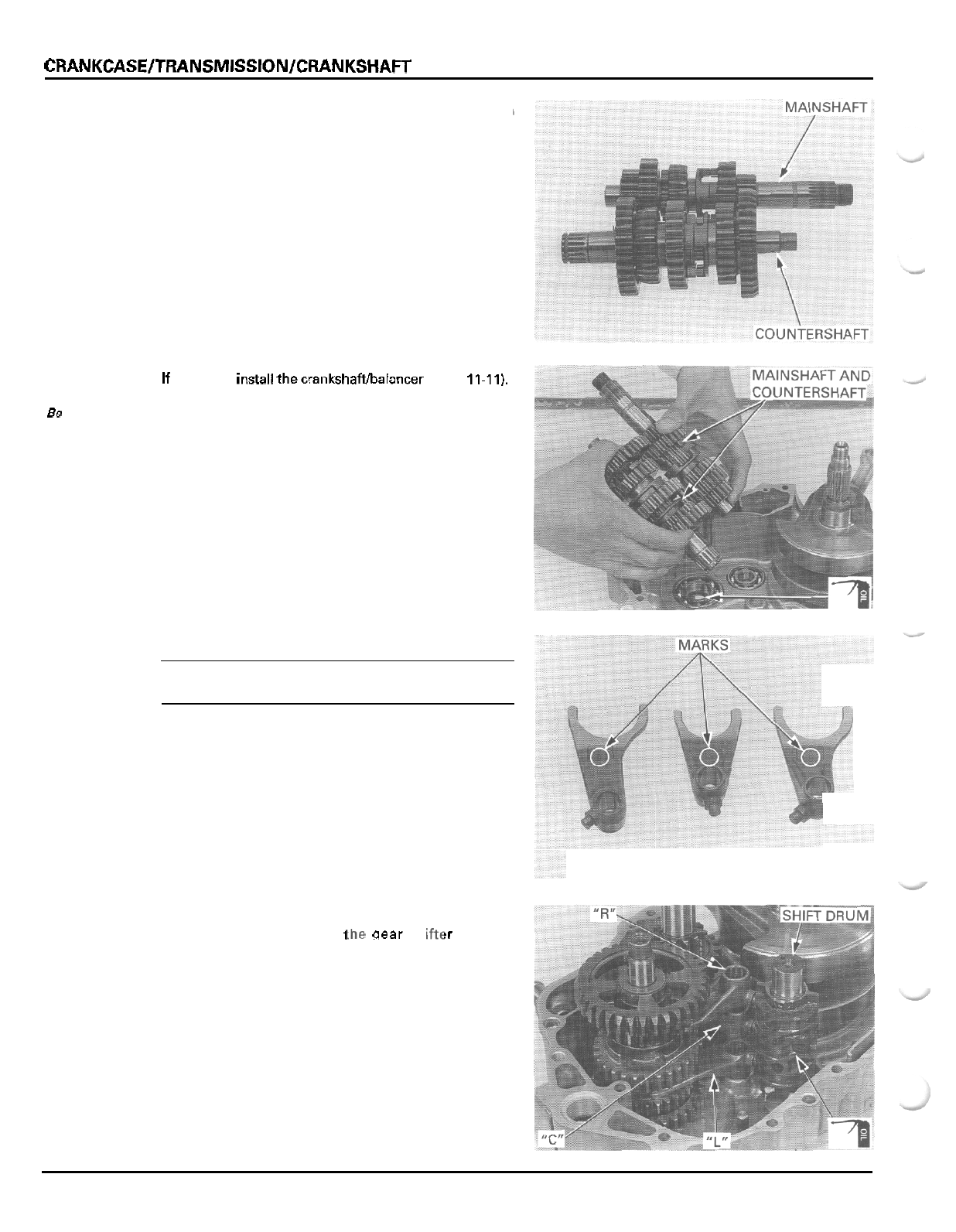
CRANKCASE/TRANSMISSION/CRANKSHAFT
Check the gears for freedom of movement or rotation
on
the shaft.
Engage the mainshaft and countershaft gears.
If removed, insall thecrankshaftbalancer (page
11-11),
Apply oil
to
the countershaft oil seal lip.
Install the mainshaft and countershaft assemblies as
a set into the left crankcase.
Be
sure
to
install
the thrust
washers.
NOTE:
Each shift fork has an identification mark;
L
for the
left fork,
C
for the center fork
and
R
for the right fork.
Coat the shift forks with oil.
Install the shift forks into
i
!
gear shi !r grooves
with their identification marks facing up (right
crankcase side).
Apply oil to the shift drum guide pin grooves and
journals.
Install the shift drum and insert the shift fork guide
pins into the shift drum guide pin grooves.
11
-
8
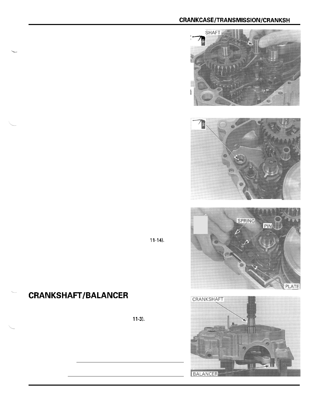
CRANKCASE/TRANSMISSION/CRANKSH
AFT
FORK
'3
Coat the shift fork shaft with oil.
Install the shift fork shaft through the shift forks and
into the left crankcase.
L
i
Apply oil to the gearshift spindle oil seal lip
Install the gearshift spindle by aligning the return
spring ends with the spring pin bolt while pulling the
gearshift plate.
Engage the gearshift plate with the shift drum.
I
Assemble the crankcase halves (page 11-14),
.,
--
CRANKSHAFT/BALANCER
REMOVAL
Separate the crankcase (page 11-31,
Remove the transmission (page
11
-
4)
Remove the crankshaft and balancer from the left
crankcase using
a
hydraulic press while holding
them.
CAUTION
Be
careful not to damage the crankcase mating sur
-
face and crankshaft
assembly.
11
-
9
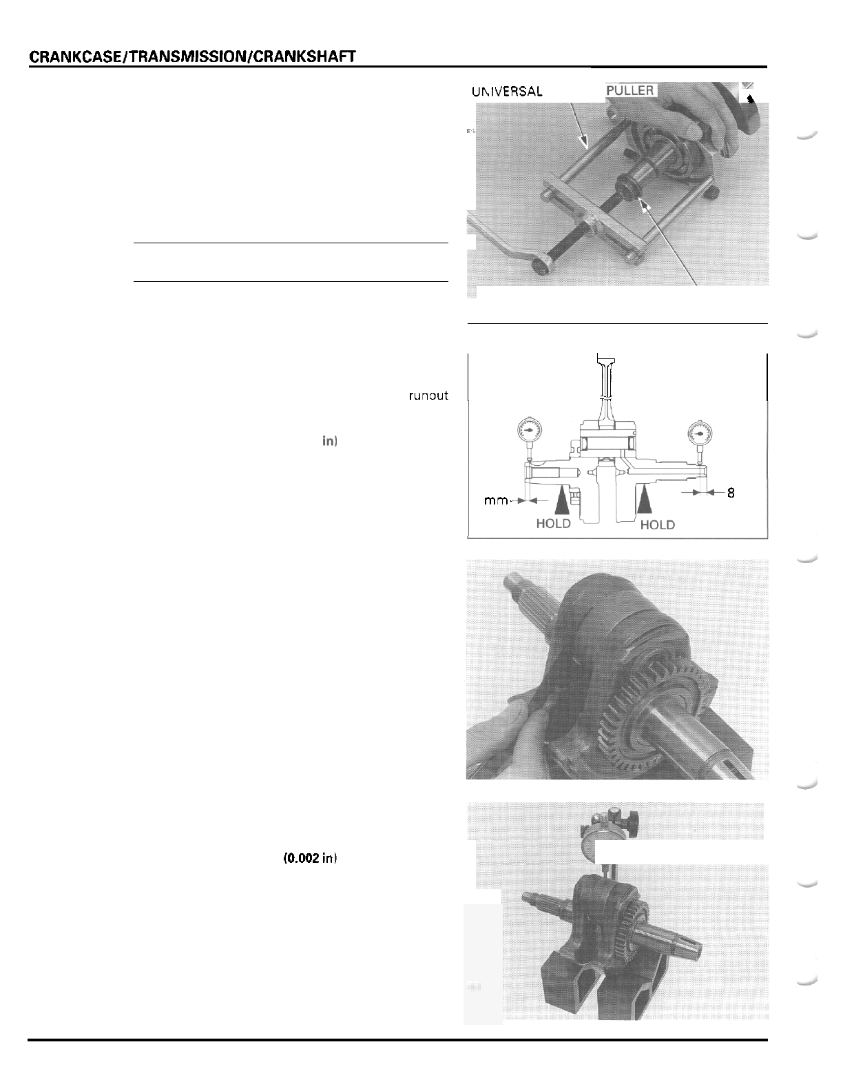
CRANKCASE/TRANSMlSSlON/CRANKSHAFT
If
the left crankshaft bearing is left on the crankshaft,
remove
it
using the bearing puller with a suitable
protector.
TOOL
Universal bearing puller
07631
-
0010000
or
equivalent commercially
available
in
U.S.A.
NOTE:
Always replace the left crankshaft bearing with a new
one when the crankshaft is removed.
INSPECTION
CRANKSHAFT
Set the crankshaft as shown and measure the runout
using a dial indicator.
SERVICE
LIMIT
0.12
mm
10.005
in1
-/
i
UhlVERSAL
BEARING
#.
PROTECTOR
I
P
I
6
mm-
Measure the radial clearance at the connecting rod
big end
in
an
X
and
Y
directions.
SERVICE
LIMIT:
0.05
mm
(0.002
in)
m
-8
mm
Measure the side clearance between the connecting
rod big end and crank weight with a feeler gauge.
SERVICE
LIMIT
0.6
mm
10.02
in)
11
-
10
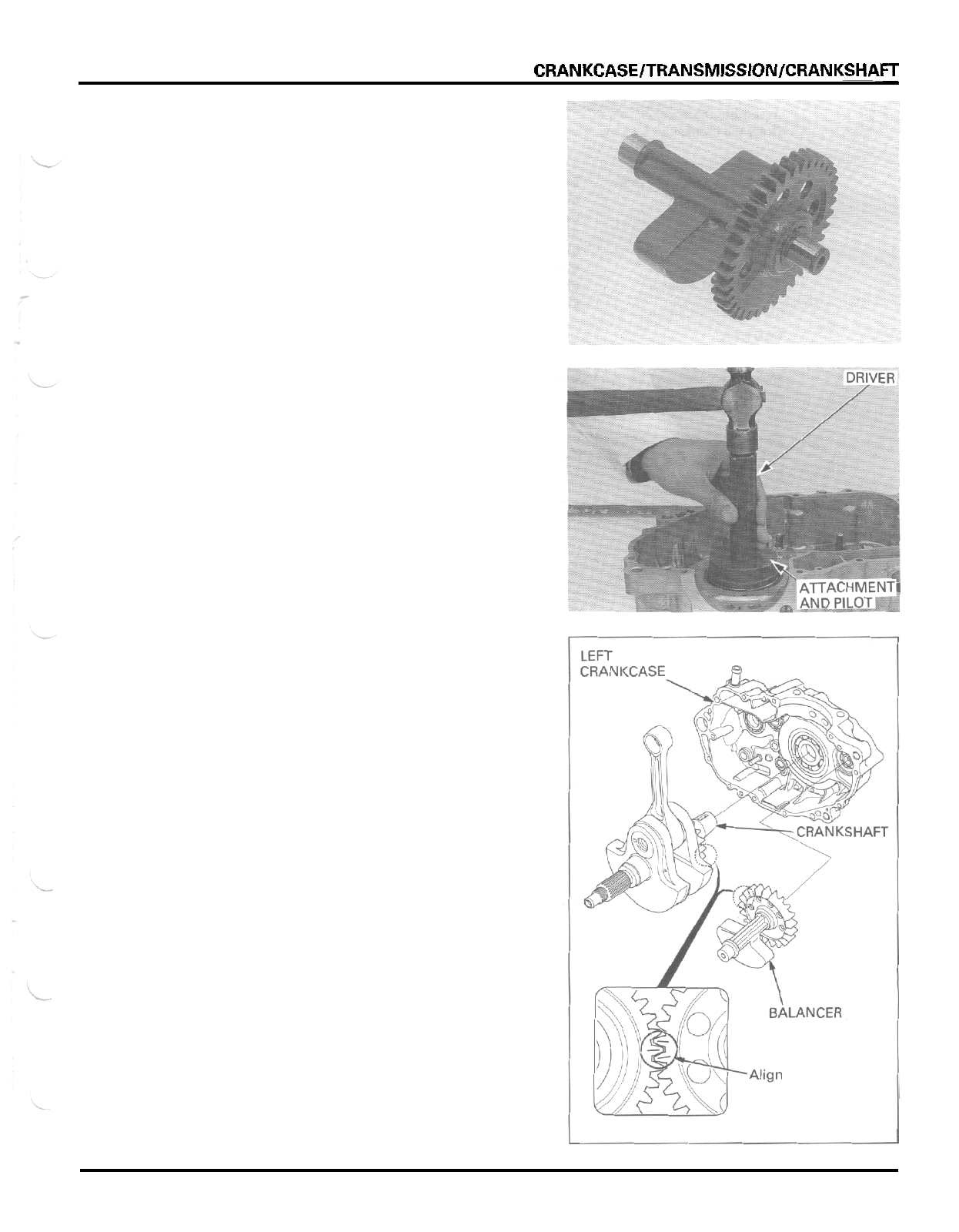
CRANKCASE/TRANSMISSION/CRANKSHAFT
BALANCER
Check the balancer gear for wear or damage.
INSTALLATION
Apply oil to
a
new crankshaft bearing.
Drive the crankshaft bearing into the left crankcase
with the marking side facing up.
TOOLS
Driver 07749
-
0010000
Attachment, 72
x
75 mm 07746
-
0010600
Pilot.
30
mm 07746
-
0040700
Engage the balancer and crankshaft by aligning the
index lines on the balancer drive and driven gears as
shown, and install the crankshaft and balancer
together into the left crankcase.
11
-
11
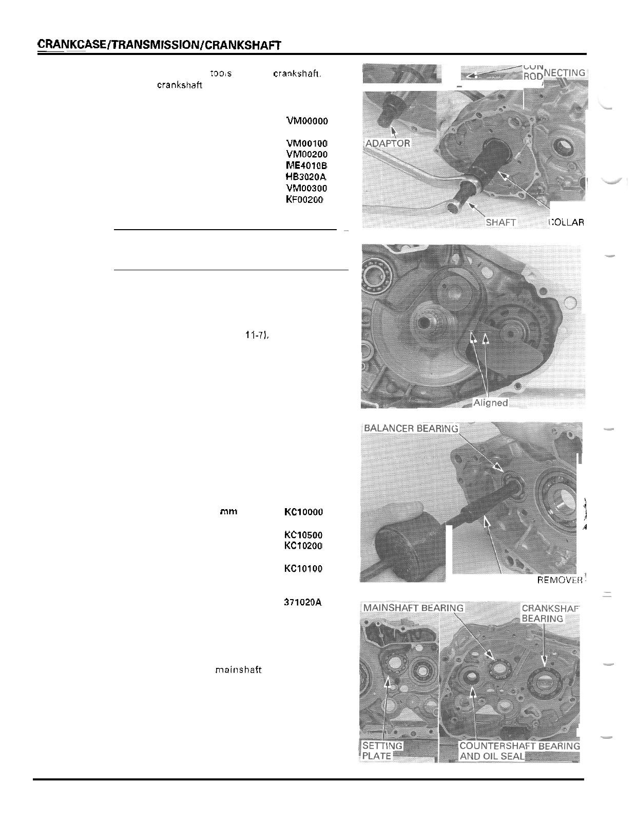
CRANKCASElTRANSMlSSlONlCRANKSHAFT
-/ROD
cob.
Assemble the special
tools
onto the crankshah.
Draw tne crankshatt into the bearing 'nner race.
-
TOOLS:
Crankcase assembly tool 07965
-
VMOOOOO
not available in U.S.A.
-
Assembly collar 07965
-
VMOOlOO
-
Assembly shaft 07965
-
VM00200 or
07931
-
ME40100 and
07931
-
HB3020A
07965
-
VM00300 or
07931
-
KF00200
-
Threaded adaptor
CAUTION:
~
Be careful not to let the connecting rod press against
the crankcase mating surface while drawing the
crankshaft.
After drawing the crankshaft in, make sure that the
index lines on the crank weight and balancer weight
are aligned.
Install the transmission (page
11-7).
Assemble the crankcase halves (page
11
-
14).
\
:OLLAR
-
CRANKCASE BEARING REPLACEMENT
-
RIGHT
CRANKCASE
BEARING
Remove the balancer bearing with the special tools.
TOOLS:
Bearing remover set, 15
mm
-
Bearing remover, 15
mm
i
07936
-
KClOOOO
not available in U.S.A.
07936
-
KC10500
07936
-
KC10200
not available
in
U.S.A.
07936
-
KClOlOO
not available
in
U.S.A.
i
.1
-
Remover, 15
mm
-
Remover shaft
BEARING
REMOVEFi'
-
Sliding weight 07741
-
0010201 or
-
-
07936
-
371020A or
07936
-
3710200
Remove the two bolts and mainshaft bearing setting
plate.
Drive the crankshaft, mainshaft and countershaft
bearings out
of
the right crankcase.
Remove the countershaft oil seal.
-
11
-
12
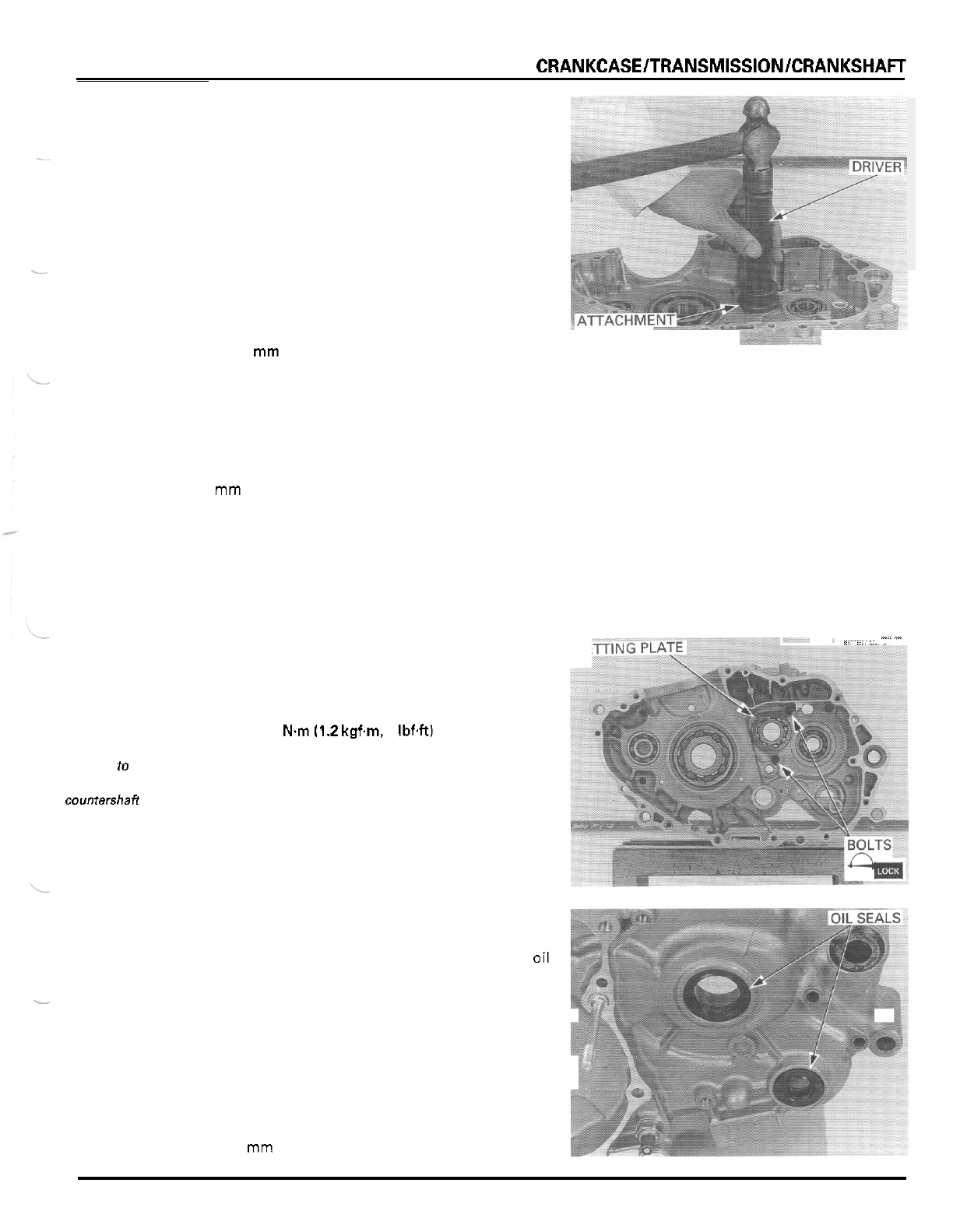
CRANKCASElTRANSMlSSlONlCRANKSHAFT
Apply
oil
to new bearings.
Drive the mainshaft, crankshaft and balancer bear
-
ings in with the marking side facing up using the spe
-
cial
tools.
TOOLS:
Mainshaft bearing:
Driver
07749
-
0010000
Attachment,
42
x
47
mm
07746
-
0010300
Pilot,
22
mm
07746
-
0041000
Crankshaft bearing:
Driver
07749
-
0010000
Attachment,
72
x
75
mm
07746
-
0010600
AND
-
PILOT
-
Be
sure
to
align the
notch in the
couniershafl
oil
seal
with
ihe
crankcase
passage.
Pilot,
30
mm
07746
-
0040700
Balancer bearing:
Driver
07749
-
0010000
Attachment,
37
x
40
mm
07746
-
0010200
Pilot,
15
mm
07746
-
0040300
Drive a new countershaft
oil
seal in using
a
suitable
24
mm
socket.
Drive the countershaft bearing in with the sealed side
facing down using the special tools.
TOOLS:
Driver
07749
-
0010000
Attachment,
42
x
47
mm
07746
-
0010300
Pilot.
17
mm
07746
-
0040400
SE
Apply locking agent to the mainshaft bearing setting
plate bolt threads.
Install the setting plate
and
tighten the bolts.
TORQUE:
12
N.m
11.2
kgf.m,
9
IbfW
lll~i
:
.
.
--
/&.
LEFT CRANKCASE
Remove the countershaft and gearshift spindle
oil
seals.
-
i
k
Use
24
mm
socket
or
suitable tool.
11
-
13
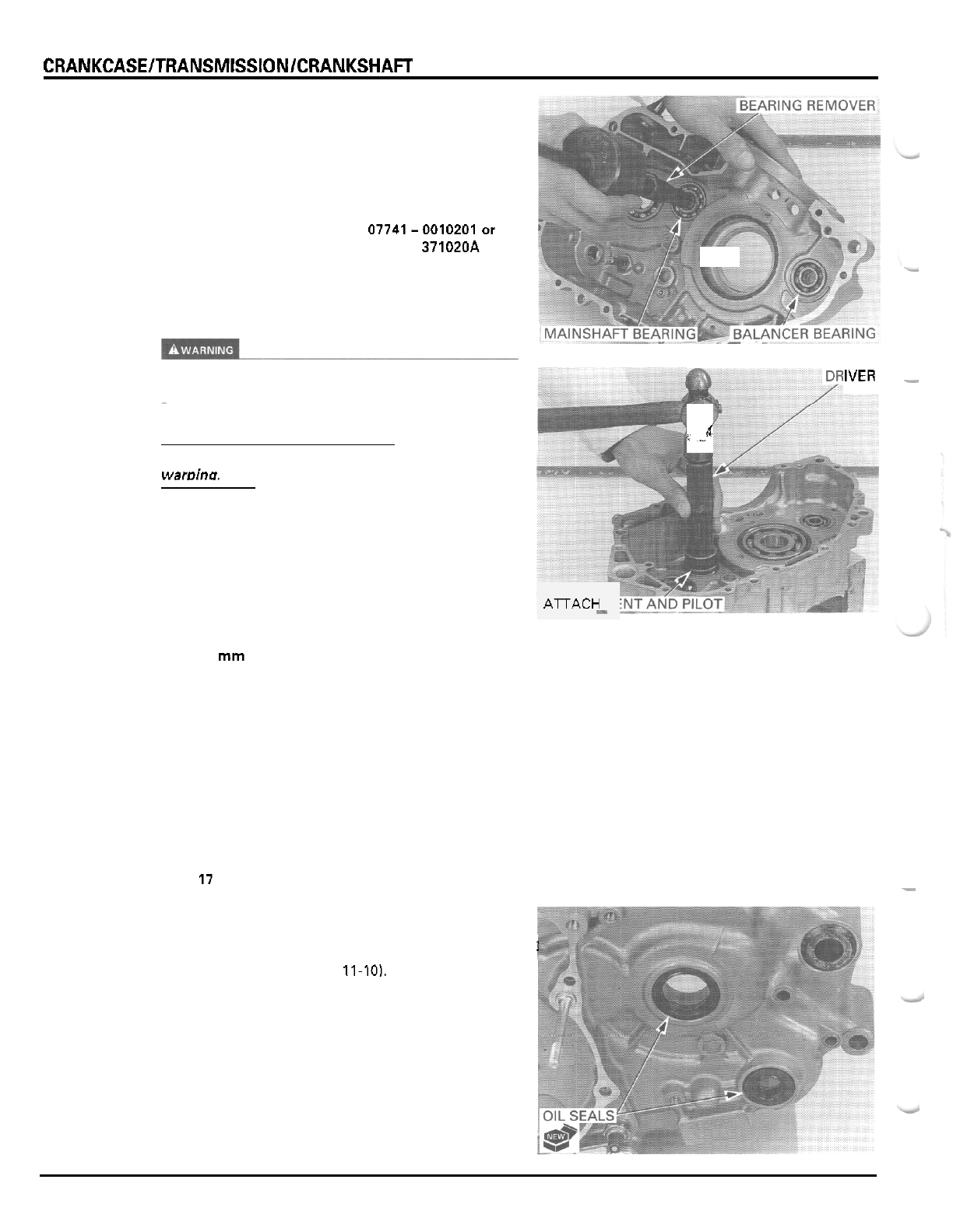
CRANKCASElTRANSMlSSlONICRANKSHAFT
Remove the mainshaft bearing using the special
tools.
TOOLS:
Mainshaft bearing:
Bearing remover, 17 mm 07936
-
3710300
Remover handle 07936
-
3710100
Sliding weight 07741-0010201or
07936
-
371020A or
07936
-
3710200
Heat the crankcase 80°C
(176°F)
evenly using
a
heat
gun and remove the balancer bearing.
Always wear insulated gloves when handling the
crankcase after
it
has been heated.
CAUTION:
Do
not use a torch
to
heat the case;
it
may cause
waroina.
Apply oil to new bearings.
Drive the countershaft and balancer bearings in with
the marking side facing up using the special tools.
TOOLS
Countershaft bearing:
Driver 07749
-
0010000
Attachment, 52
x
55 mm 07746
-
0010400
Pilot, 25
mm
07746
-
0040600
Balancer bearing:
Driver 07749
-
0010000
Attachment, 32
x
35
mm
07746
-
0010100
Pilot, 12
mm
07746
-
0040200
Drive the mainshaft bearing
in
with the sealed side
facing down using the special tools.
TOOLS:
Driver 07749
-
0010000
Attachment, 37
x
40
mm 07746
-
0010200
Pilot,
17
mm
07746
-
0040400
Install new countershaft and gearshift spindle oil
seals.
IVER
-
A
L..
ATrACH
M
E
-
1
Install the crankshaft (page
11-10),
Install the transmission (page
11
-
7).
Assemble the crankcase halves (page
11
-
14).
11
-
14
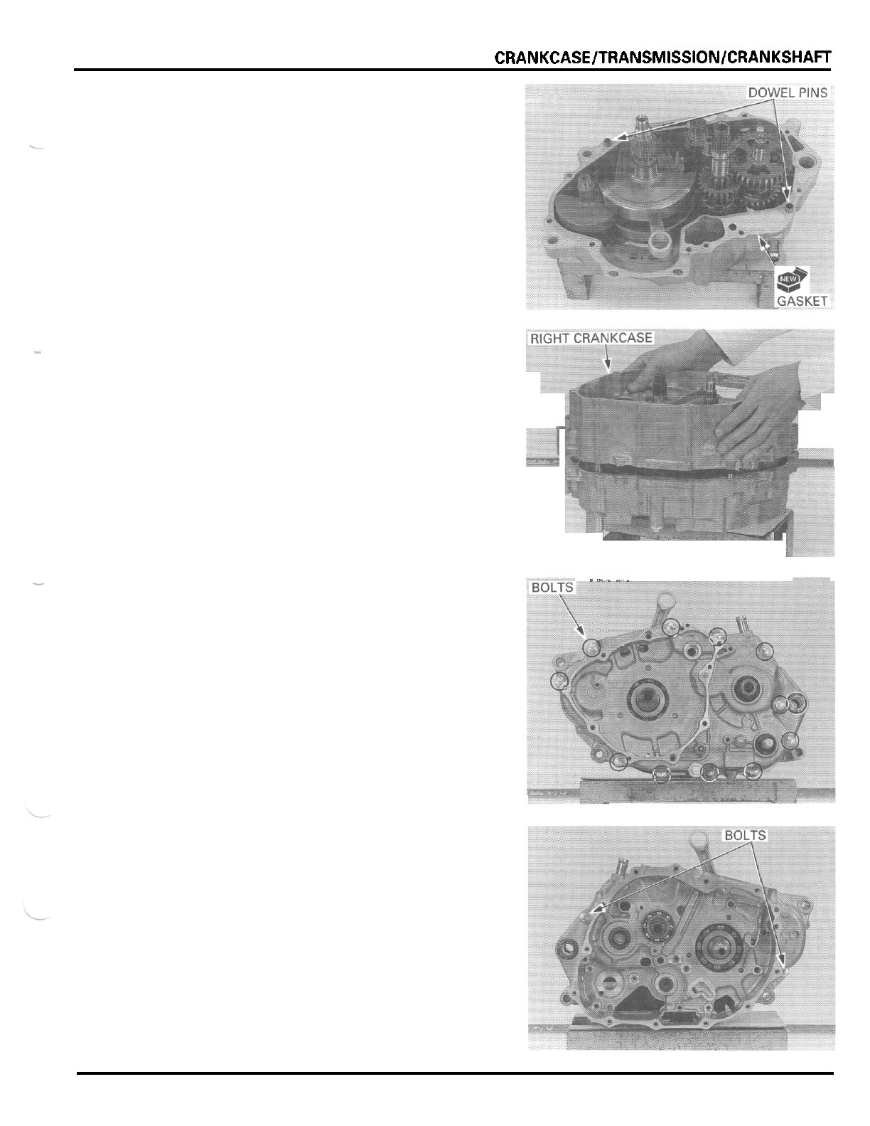
CRANKCASE/TRANSMlSSlON/CRANKSHAFT
CRANKCASE
ASSEMBLY
Clean the left and
right
crankcase mating surfaces
thoroughly, being careful not to damage them.
Install the dowel pins and a new gasket.
-~
-
Make sure all the parts are installed
in
the left
crankcase.
Install the right crankcase over the left crankcase.
.-
..-*..-
,..
..
-
Install the left crankcase bolts and tighten them in a
crisscross pattern
in
2
or
3
steps.
Install and tighten the right crankcase bolts.
11
-
15
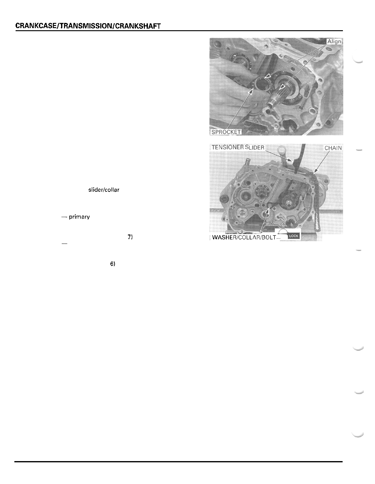
CRANKCASEITRANSMISSIONlCRANKSHAFT
Install the cam chain drive sprocket onto the crank
-
shaft, by aligning the wide groove with the wide
tooth.
I
Install the cam chain onto the drive sprocket and
;TENSIONER
s
-.
through the crankcase.
Apply locking agent
to
the cam chain tensioner bolt
threads.
Install the washer (between the crankcase and slider),
tensioner sliderlcollar and bolt, and tighten the bolt
securely.
Install the following:
-primary drive gear, clutch, gearshift linkage (sec
-
-
piston and cylinder (section
8)
-
cylinder head (section
7)
~
oil pump (section
4)
-
starter motor (section
18)
-
engine (section
6)
tion
9)
i
WASHER;COLLA&OLT
.
.~
-
flywheel (section
10)
-
11
-
16

MEMO
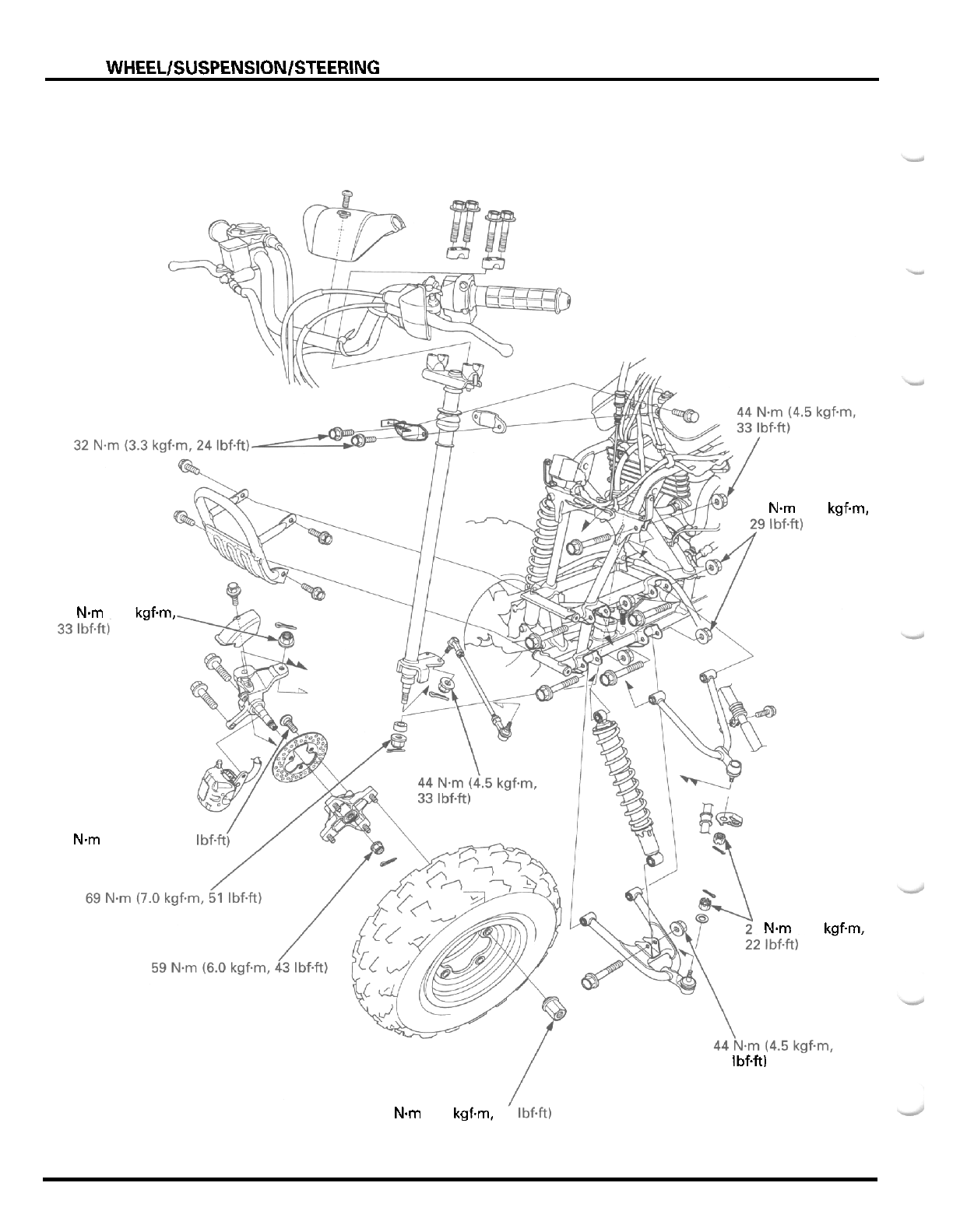
FRONT
WHEELlSUSPENSlONlSTEERlNG
39
Nm
(4.0
kgfm,
44
Nm
(4.5 kgfm,
42
Nm
(4.3 kgfm,
31
1bf.e
9
Nm
(3.0
kgf.m,
33 IbfW
64
Nm
(6.5 kgfm,
47
Ibf.ft)
12
-
0
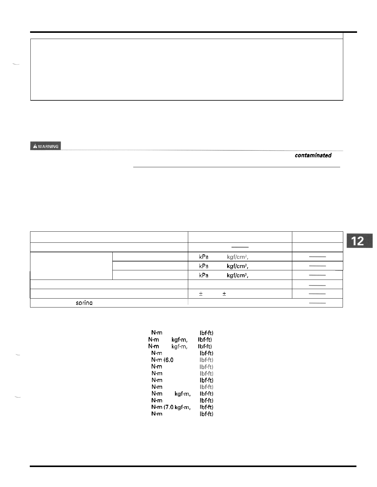
12.
FRONT
WHEEL/SUSPENSION/STEERING
ITEM
Minimum tire tread depth
Cold tire pressure Standard
Minimum
SERVICE INFORMATION 12
-
1 TIRES 12
-
9
TROUBLESHOOTING 12
-
2 SUSPENSION ARM 12
-
12
HANDLEBAR 12
-
3 FRONT SHOCK ABSORBER 12
-
16
THROTTLE HOUSING 12
-
5 STEERING SHAFT AND TIE
-
ROD 12
-
17
FRONT WHEEL AND HUB 12
-
6
-
~
STANDARD
SERVICE
LIMIT
4.0 (0.16)
27 kPa (0.275 kgf/cmZ, 4.0 psi)
23 kPa (0.235 kgf/cm2,
3.4
psi)
-
-
SERVICE
INFORMATION
GENERAL
A
contaminated brake disc
or
pad reduces stopping power. Discard contaminated pads and clean
a
contaminated disc
with
a
high qualify brake degreasing agent
Maximum
Tie
-
rod distance between the ball joints
Toe
~
31 kPa (0.315 kgf/cm2, 4.6 psi)
370.2 (14.57)
-
17
f
15 (0.7
f
0.6)
-
-
I
Shock absorber sDrina adiuster standard nosition
1
4th
from softest nosition
-
TORQUE VALUES
Handlebar lower holder nut
Throttle housing cover screw
Left
handlebar switch housing screw
Front wheel hub nut
Front brake disc bolt
Shock absorber mounting nut
Upper and lower arm pivot nut
Upper and lower arm ball joint
nut
Tie
-
rod ball joint lock nut
Tie
-
rod stud joint nut
Steering shaft end nut
Steering shaft holder bolt
-
Front wheel nut
-
39
Nm
(4.0 kgfm, 29 IbfW
4
Nm
(0.4 kgfm, 2.9
IbfW
2
Nm
(0.2 kgfm, 1.4
IbfW
64
N.m
(6.5 kgfm, 47 IbfW
59
N.m
(6.0
kgfm, 43 Ibf+t)
42
Nm
(4.3 kgfm, 31 Ibf.ft)
44
Nm
(4.5 kgfm, 33 Ibf.ft)
39
Nm
(4.0 kgfm. 29 IbfW
29
Nm
(3.0 kgfm, 22 Ibf+t)
54
Nm
(5.5
kgfm.
40
IbfW
44
N-m
(4.5 kgfm, 33
IbfW
69
N.m
(7.0 kgfm,
51
Ibf4t)
32
Nm
(3.3 kgfm, 24
IbfW
Castle nut
ALOC bolt
Castle nut
12
-
1
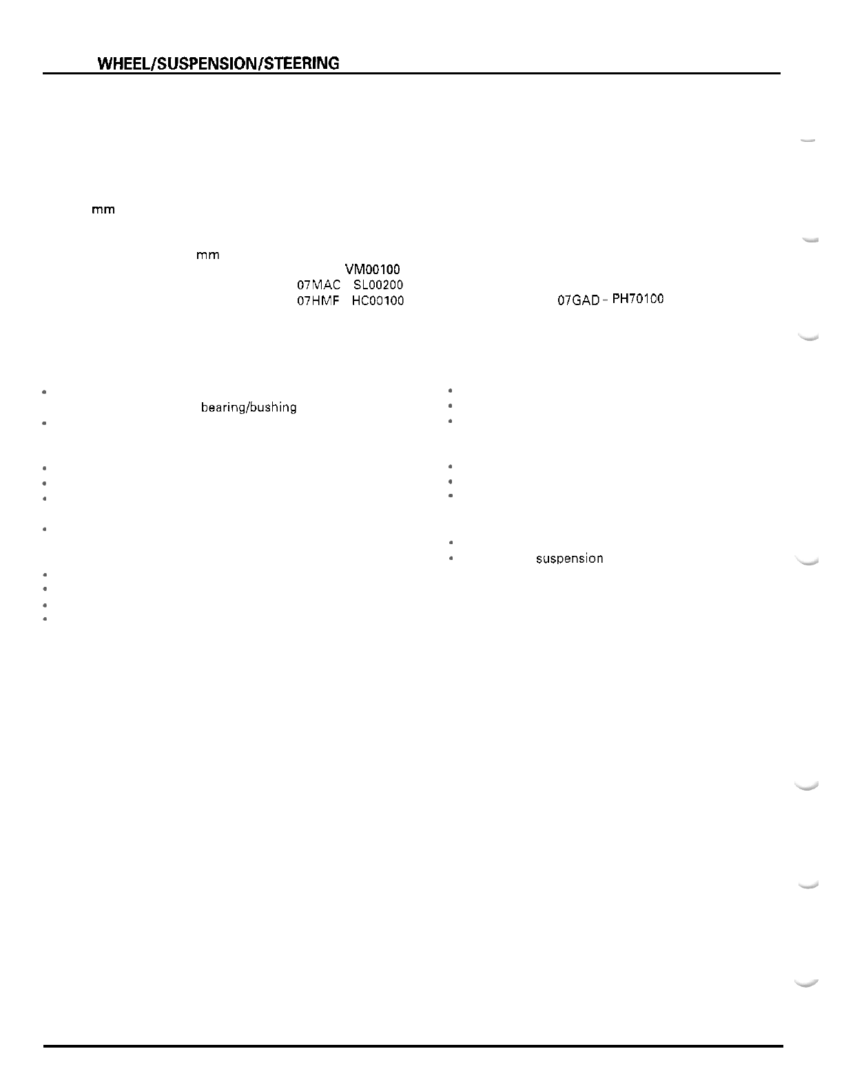
FRONT WHEEL/SUSPENSION/STEERlNG
TOOLS
Driver
Attachment, 32
x
35 mm
Attachment, 37
x
40
mm
Attachment, 42
x
47
mm
Pilot, 15
mm
Pilot, 17 mm
Pilot, 20 mm
Bearing remover shaft
Bearing remover head,
15
mm
Assembly collar
Ball joint remover
Spherical bearing driver
TROUBLESHOOTING
Hard steering
.
Damaged steering shaft bearinglbushing
*
Insufficient tire pressure
Steers one side or does not track straight
*
Incorrect wheel alignment
-
Unequal tire pressure
Bent tie
-
rod, suspension arm or frame
.
Worn or damaged wheel hub bearings
Weak shock absorber
Steering shaft holder too tight
Front wheel wobbling
-
Bent rim
-
Worn or damaged wheel hub bearings
*
Faulty tire
-
Wheel hub not tightened properly
07749
-
0010000
07746
-
0010100
07746
-
0010200
07746
-
0010300
07746
-
0040300
07746
-
0040400
07746
-
0040500
07746
-
0050100
07746
-
0050400
07965
-
VMOOlOO
07MAC
-
SLOO200
07HMF
-
HCOOlOO not available in U.S.A. or 07GAD
-
.
PH70100
Soft
suspension
-
Weak shock absorber spring
-
Faulty shock absorber damper
*
Loose front suspension fasteners
Hard suspension
Bent shock absorber damper rod
-
Improperly installed suspension arms
*
Faulty suspension arm spherical bearings
Front suspension noise
Binding suspension link
Loose front susuension fasteners
12
-
2
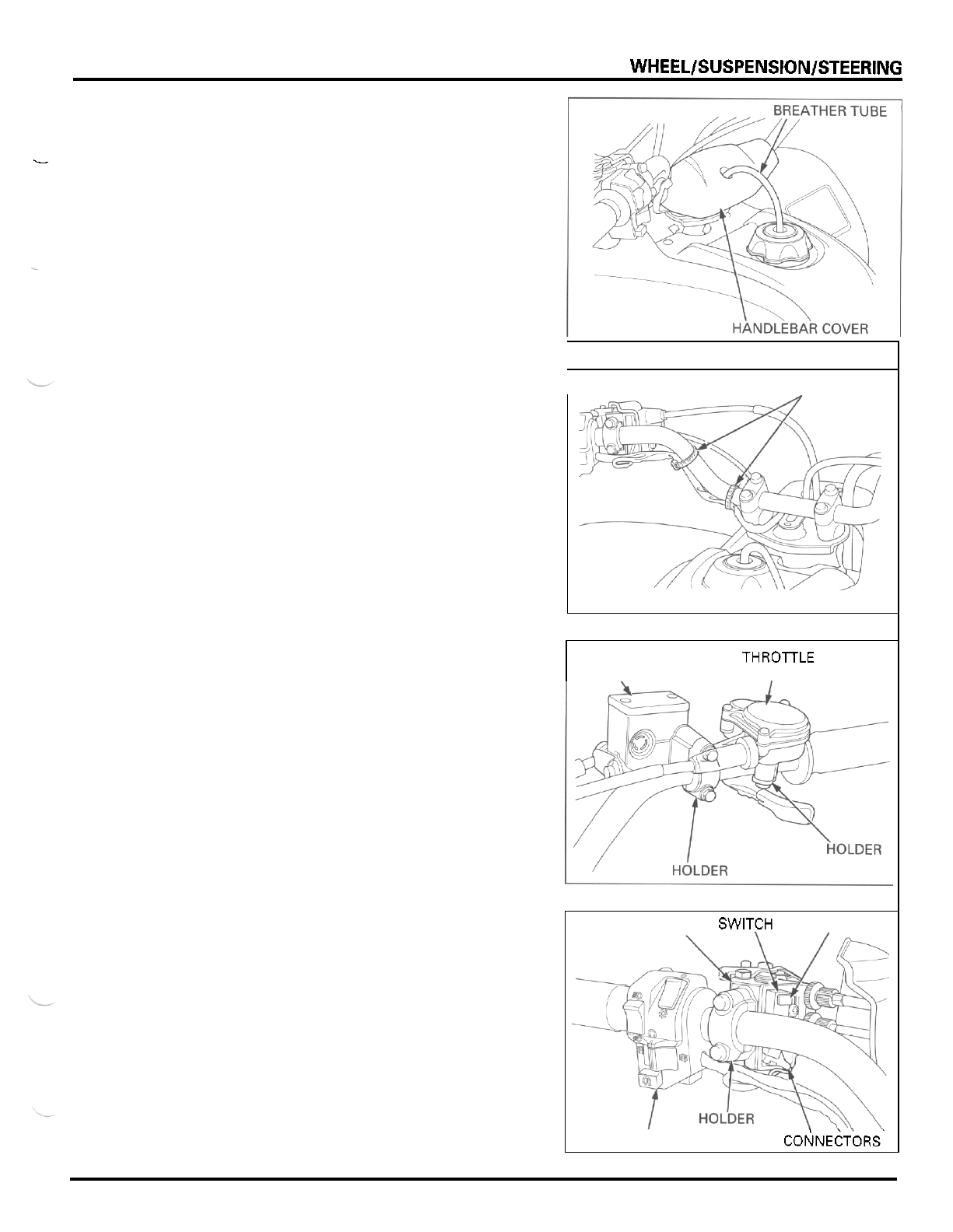
FRONT
WHEEL/SUSPENSlON/STEERlNG
HANDLEBAR
REMOVAL
c
Remove the fuel tank breather tube from the handle
-
bar cover.
Remove the handlebar cover attaching bolt, being
careful not to let the bolt fall into the steering shaft.
Remove the cover by releasing its ends
off
the han
-
~
dlebar carefully.
Remove the wire bands.
I
BANDS
Remove the
two
screws, holder and throttle housing.
Remove the two bolts, holder and master cylinder.
Slide the boot
off
the clutch lever bracket.
Remove the screw and clutch switch retainer.
Remove the clutch switch out of the clutch lever
bracket and disconnect the connectors,
Remove the
two
bolts, holder and clutch lever bracket.
Remove the
two
screws and handlebar switch hous
-
ing.
MASTER THROTLE HOUSING
CYLINDER
I
LEVER BRACKET SWITCH RETAINER
SWITCH
H
O
USING COF~NECTORS'
12
-
3
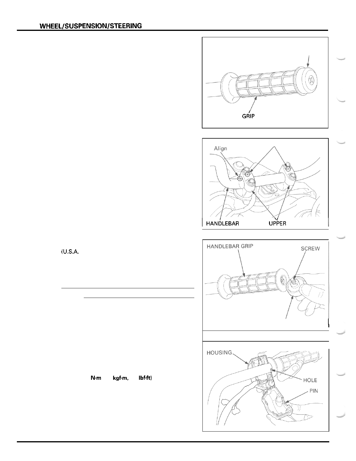
FRONT
WHEEL/SUSPENSION/STEERlNG
Remove the screw and grip end.
Remove the handlebar grip.
Remove the four bolts and the upper holders:
Remove the handlebar from the lower holders.
INSTALLATION
Place the handlebar onto the lower holders and align
the punch mark on the handlebar with the top
of
the
lower holder.
Install the upper holders with the punch marks facing
forward. Install the four bolts and tighten the forward
bolts first, then tighten the rear bolts.
Apply Honda Bond
A
or Honda Hand Grip Cement
(U.S.A. only) to the inside surface of the handlebar
grip and to the clean surface of the handlebar.
Wait
3
-
5
minutes and install the grip. Rotate the
grip for even application of the adhesive.
NOTE:
Allow the adhesive to dry for an hour before using.
Install the grip end with the screw securely by align
-
ing the flats.
Install the handlebar switch housing by aligning its
locating pin with the hole in the handlebar.
Install the two attaching screws and tighten the
upper screw first, then tighten the lower screw.
TORQUE:
2
Nm
(0.2
kgfm,
1.4
1bf.h)
GRIP
END
I
HANDLEBAR GdlP
PUNCH MARKS
I
HANI~LEBAR
U&ER
HOLDERS
I
I
G
R
I
P
E
N
D
SWITCH
I
12
-
4
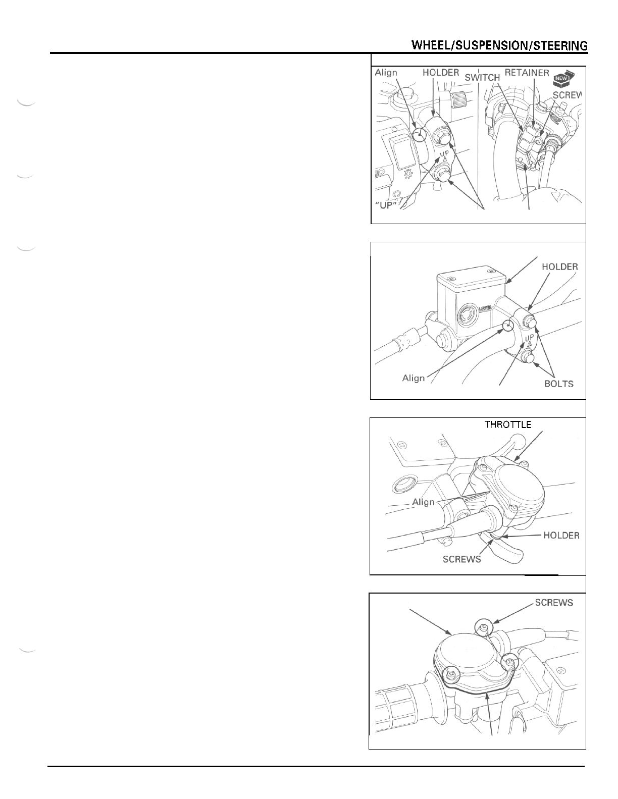
FRONT WHEELISUSPENSIONISTEERING
Install the clutch lever bracket and holder with the
"
UP
"
mark facing up.
Align the slit of the lever bracket with the punch mark
on
the handlebar, and tighten the upper bolt first,
then the lower bolt.
Connect the clutch switch to the connectors and
install
it
into the clutch lever bracket.
Secure the switch with the retainer and a new screw.
Cover the bracket with the boot securely.
Install the master cylinder and holder with the
"
UP
"
mark facing up.
Align the
slit
of the master cylinder with the punch
mark
on
the handlebar, and tighten the upper bolt
first. then the lower bolt.
Install the throttle housing and holder against the
master cylinder.
Align the lug
on
the throttle housing with the slit of
the master cylinder, and tighten the forward screw
first, then the rear screw.
Secure the handlebar switch wire with the wire
bands (page
1
-
18).
Install the handlebar cover and breather tube in
the
reverse order of removal.
THROTTLE
HOUSING
DISASSEMBLY
Remove the three attaching screws and the throttle
housing cover.
Remove the gasket.
MARK
BOLTS
CONNECTORS
MASTER CYLINDER
"
UP
"
MARK
THROTTLE HOUSING
COVER
GA
S
KET
12
-
5
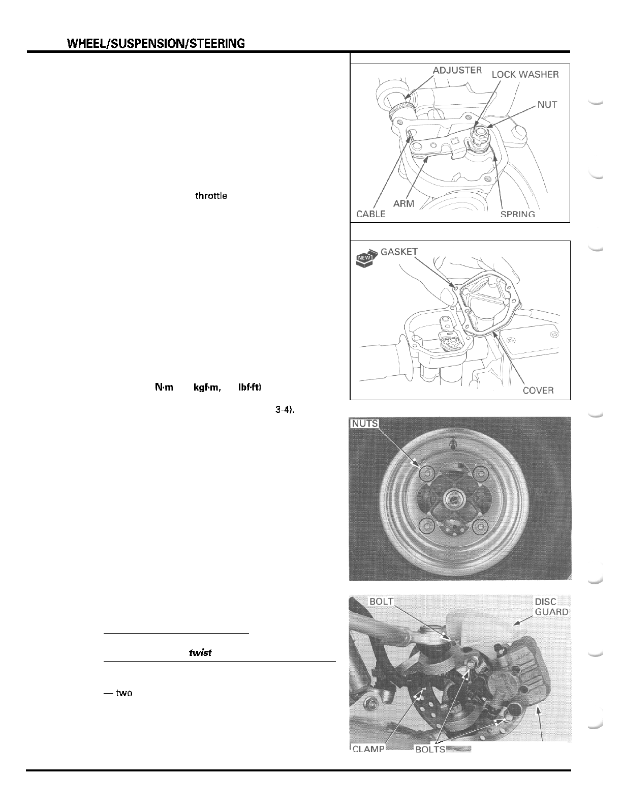
FRONT WHEELISUSPENSIONISTEERING
Slide the boot
off
the throttle cable adjuster
Loosen the cable adjuster.
Bend down the lock washer tab and remove the pivot
nut, lock washer, throttle arm and return spring, then
the throttle lever with the plastic washer.
Disconnect the throttle cable from the throttle arm.
Remove the dust seal from the housing bottom.
ASSEMBLY
Apply grease to the thronle lever pivot in the hous
-
ing.
Coat
a
new dust seal lip with grease and install
it
into
the housing until
it
is fully seated.
Connect the cable to the throttle arm.
Insert the throttle lever with the washer into the
housing and install the throttle arm with the spring
over the throttle lever pivot by aligning the flat sur
-
faces.
Install
a
new lock washer and the pivot nut.
Tighten
the
pivot nut and bend up the washer tab
against the nut.
Install the housing cover with a new gasket and tighten
the three screws.
TORQUE:
4
Nm
10.4 kgfm,
2.9
IbfW
Adjust the throttle lever free play (page
3-41,
FRONT
WHEEL
AND
HUB
WHEEL REMOVAL
Loosen the wheel nuts
Place the support block under the frame to raise the
front wheel
off
the ground.
Remove the nuts and wheel.
HUB
DISASSEMBLY
CAUTION:
Support the caliper
so
that
it
does not hang
from
the
brake hose.
Do
not twist or bend the brake hose.
Remove the following:
-two
mounting bolts and brake caliper
-
brake hose from the clamp
-
bolt and disc guard
Y
CALIPER
12
-
6
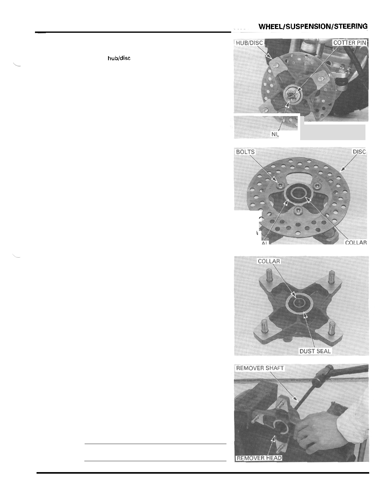
-
three bolts and brake disc
-
side collars
-
dust seals.
-
cotter pin
-
hub nut
-
wheel hubldisc
:"-I
IT
c
i
DUST
SE
Turn the inner race
of
each bearing with your finger.
The bearings should turn smoothly and quietly.
Also
check
that
the bearing outer race fits tightly in the
hub.
Remove and discard the bearings
if
the races do not
turn smoothly and quietly or if they fit loosely in the
hub.
FRONT
WHEEL/SUSPENSlON/STEERlNG
12
-
7
Replace
the
bearings in
pairs.
Install the bearing remover head into the bearing.
From opposite side, install the bearing remover shaft
and drive the bearing out of the wheel hub.
Remove the distance collar and drive out the other
bearing.
TOOLS
Bearing remover shaft
07746
-
0050100
Bearing remover head,
15
mm
07746
-
0050400
NOTE
Replace the wheel bearings in pairs.
Do
not reuse old
bearings.
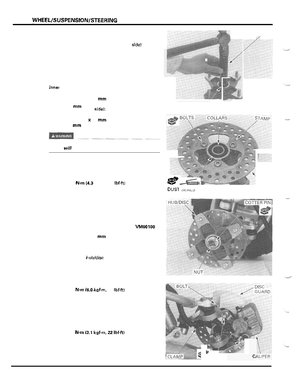
FRONT
WHEEL/SUSPENSION/STEERING
DRIVER
/
HUB
ASSEMBLY
Drive in
a
new inner bearing (brake disc side1 squarely
with the marking side facing up until it
I
S
fully seated.
Install the distance collar with the large dia. facing
the inner bearing.
Drive in a new outer bearing squarely with the mark
-
ing side facing up until
it
is
fully seated.
TOOLS
Inner bearing (disc side):
Driver
07749
-
0010000
Attachment.
42
x
47
mm
07746
-
0010300
Pilot,
20
mm
07746
-
0040500
ATTACHMENT AND
PILOT
Outer bearing (wheel sideJ:
Driver
07749
-
0010000
Pilot,
15
mm
07746
-
0040300
-
Attachment,
32
x
35
mm
07746
-
0010100
Do
not
get
grease
on
the
brake disc or
stopping
power
will
be reduced.
Install the brake disc with the stamp facing up (away
from the hub).
Install new disc bolts and tighten them in
2
-
3
steps.
TORQUE:
42
Nm
(4.3
kgfm,
31
Ibf4tl
Apply grease to new dust seal lips.
Install the dust seals into the wheel hub until they are
flush with the hub surface.
TOOLS:
Disc side:
Wheel side:
Assembly collar
07965
-
VMOOlOO
Attachment,
32
x
35
mm
07746
-
0010100
Install the side collars.
Install the wheel hubldisc onto the knuckle and the
hub nut.
Tighten the hub nut
to
the specified torque and fur
-
ther tighten it until its grooves align with the cotter
pin hole.
TORQUE:
59
Nm
(6.0
kgfm,
43
Ibf4t)
Install
a
new cotter pin.
Secure the brake hose with the clamp on the knuckle.
Install the brake caliper with new mounting bolts and
tighten them.
TORQUE:
30
Nm
13.1
kgfm,
22
Ibf4tJ
Install the disc guard and tighten the bolt.
\
Qm
**
DUSl
il~fi~a
DISC
x
P
BOLTS
C/
12
-
8
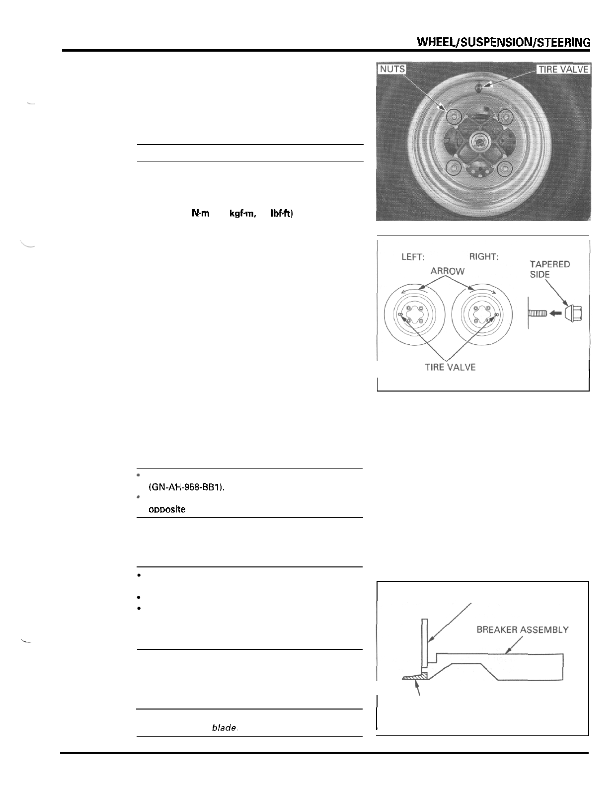
FRONT
WHEEL/SUSPENSION/STEERlNG
WHEEL INSTALLATION
Install the wheel onto the hub with the tire valve fac
-
ing out and the arrow mark facing in the normal
rotating direction.
NOTE:
-
Do not interchange the left and right tires.
Install the wheel nuts with the tapered side facing
inward and tighten them.
TORQUE:
64
N.m
(6.5
kgfm,
47
Ibftt)
TIRES
REMOVAL
NOTE:
.
L
Remove
the
core from the valve stem.
CAUTION
Use of the bead breaker tool is required for tire
removal.
Do
not damage the bead seating area of the rim.
Use
Coats
220
Tire Changer or equivalent to
remove the tire from the rim. If a tire changer is
not available, tire irons may be used, but take
care not to scratch the wheel.
I
TIRE.‘VALVE
I
-
This service requires the Universal Bead Breaker
(GN-AH-958-661).
-
Remove and install the
tire
from the rim side
omosite the valve stem.
PRESS
BLOCK
Install the blade for
9/11”
rims onto the breaker arm
assembly.
CAUTION:
Use
of
an improper size blade may result in damage
to the rim, tire or b/ade.
I
\
I
\
BLADE
12
-
9
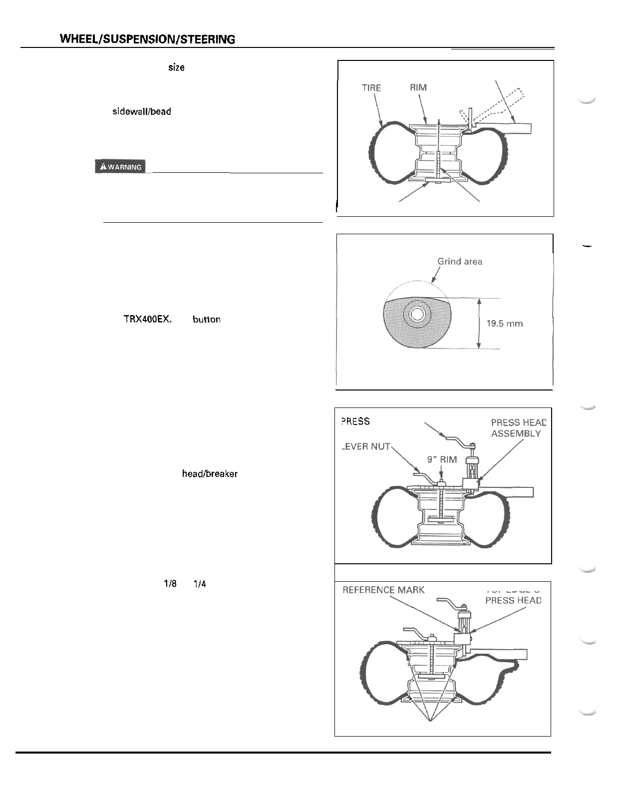
FRONT
WHEEL/SUSPENSION/STEERlNG
WHITE
NYLON BUTTON:
Place the proper size adaptor onto the threaded shaft
and then put the wheel over the threaded shaft and
adaptor.
Lube the bead area with water, pressing down on the
tire sidewalllbead area in several places to allow the
water to run into and around the bead. Also lube area
where the breaker arm will contact the sidewall
of
the
tire.
I
Use only water
as
a lubricant removing
or
mounting
tires. Soap or some mounting lubricants may leave a
slippery residue which can cause the tire to shift on
the rim and lose air pressure during riding.
While holding the breaker arm assembly
at
an
approximate
45
"
position, insert the blade of the
breaker arm between the tire and rim. Push the
breaker arm inward and downward until
it
is
in the
horizontal position with its press block in contact
with the rim.
Only one white nylon button is used for the wheels
on the TRX400EX. The button must be ground across
the rounded surface to within
1.5
mm of the center
hole. Install the button on the right side of the press
head
(as
viewed when installed on tire).
With the breaker arm in the horizontal position, place
the breaker press head assembly over the breaker arm
press block. Make sure the press head bolt is backed
out all the way and then position the nylon button on
the press head against the inside edge of the rim.
Insert the threaded shaft through the appropriate
hole in the breaker press head assembly. When
installing the press head block onto the breaker arm,
you may have to rotate the press head assembly to
draw the blade fully under the wheel rim. Then,
straighten the press headlbreaker arm assembly and
tighten the lever nut until both ends of the breaker
press head assembly are in firm contact with the rim.
Tighten the press head bolt until the reference mark
on the press block is aligned with the top edge of the
press head.
Do
not tighten past this reference mark.
If
the rest of the bead cannot be pushed down into
the center of the rim by hand, loosen the press head
bolt and the lever nut.
Rotate the breaker arm assembly and breaker press
head assembly
118
to
114
the circumference of the
rim.
Tighten the lever nut and then tighten the press head
bolt as described.
Repeat this procedure
as
necessary until the remain
-
der
of
the bead can be pushed down into the center
of the rim.
Assemble the Universal Bead Breaker on the other
side of the wheel and break the bead following the
same procedures.
Remove the tire from the rim using
a
tire changer
machine of tire irons and rim protectors.
Remove tire from rim that has the smallest shoulder
area to simplify removal.
BREAKER ARM ASSEMBLY
\
I
ADAPTER THREADED SHAFT
'RESS
HEAD BOLT
TOP EDGE
OF
RIM
BEAD BLOCKS
12
-
1
0
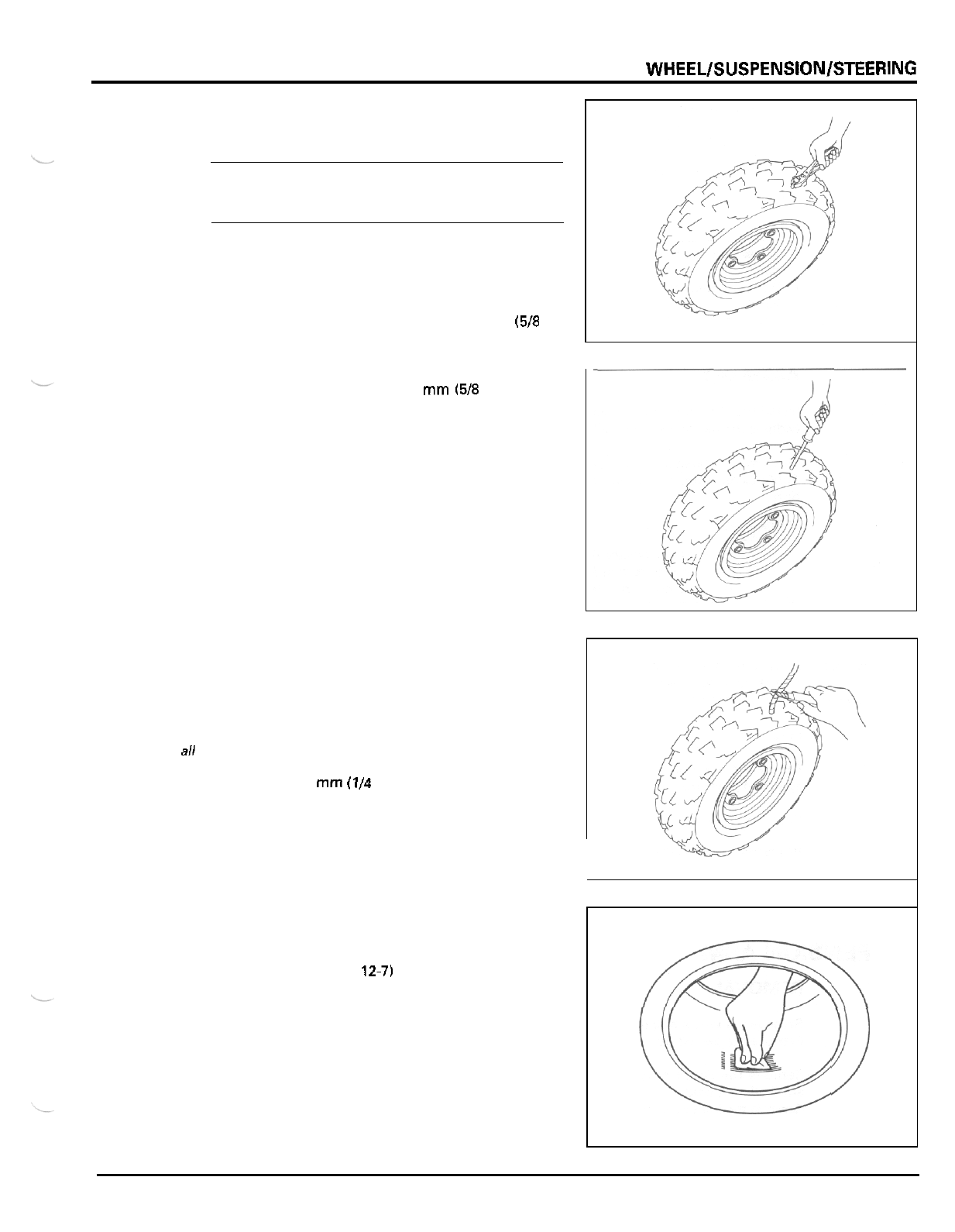
FRONT
WHEELlSUSPENSlONlSTEERlNG
TIRE
REPAIR
NOTE:
Use the manufacturer’s instructions for the tire repair
kit you are using. If your kit does not have instruc
-
tions, use the procedures provided here.
Check the tire for puncturing objects.
Chalk mark the punctured area and remove the punc
-
turing object.
Inspect and measure the injury.
Tire repairs for injuries lager than
15
mm
(518
in)
should be a section repair.
Section repairs should be done by
a
professional tire
repair shop.
If
the injury
is
smaller than
15
mm
(5/8
in). proceed
with the repair as described here.
Install
a
rubber plug into the injury as follows:
Apply
a
cement to
a
plug inserting needle and work
the needle into the injury to clean and lubricate it.
Do
this three times.
Do
not
let
the cement dry.
Insert and center
a
rubber plug through the eye
of
the inserting needle.
Apply cement to the rubber plug.
Push the inserting needle with plug into the injury
until the plug
is
slightly above the tire.
Twist the needle and remove
it
from the tire; the plug
will stay in the tire.
Trim the plug
6
mm
(114
in) above the tire surface.
Repeat the above procedure if the puncture
is
large.
Do
not use more than two plugs per injury.
Becarefulnotto
push
the plug
all
the way into the
tire
to
prevent
it
from
falling
inside.
Allow the repair to dry. Drying time will vary with air
temperature. Refer to the tire repair kit manufactur
-
er’s recommendations.
Inflate the tire and test the seal by dabbing a small
amount of cement around the plug. Escaping air will
cause
a
bubble in the cement. If there is leakage,
remove the tire (page
12-7)
and apply
a
cold patch
to
the inside
of
the tire as described.
If a plug has been inserted, trim it even with the inner
tire surface.
Temporarily place a rubber patch that
is
at least twice
the size of the puncture over the injury. Make
a
mark
around the patch, slightly larger than the patch itself.
Rough the area marked inside the tire with a tire
buffer or a wire brush. Clean the rubber dust from
the buffed area.
12
-
1
1
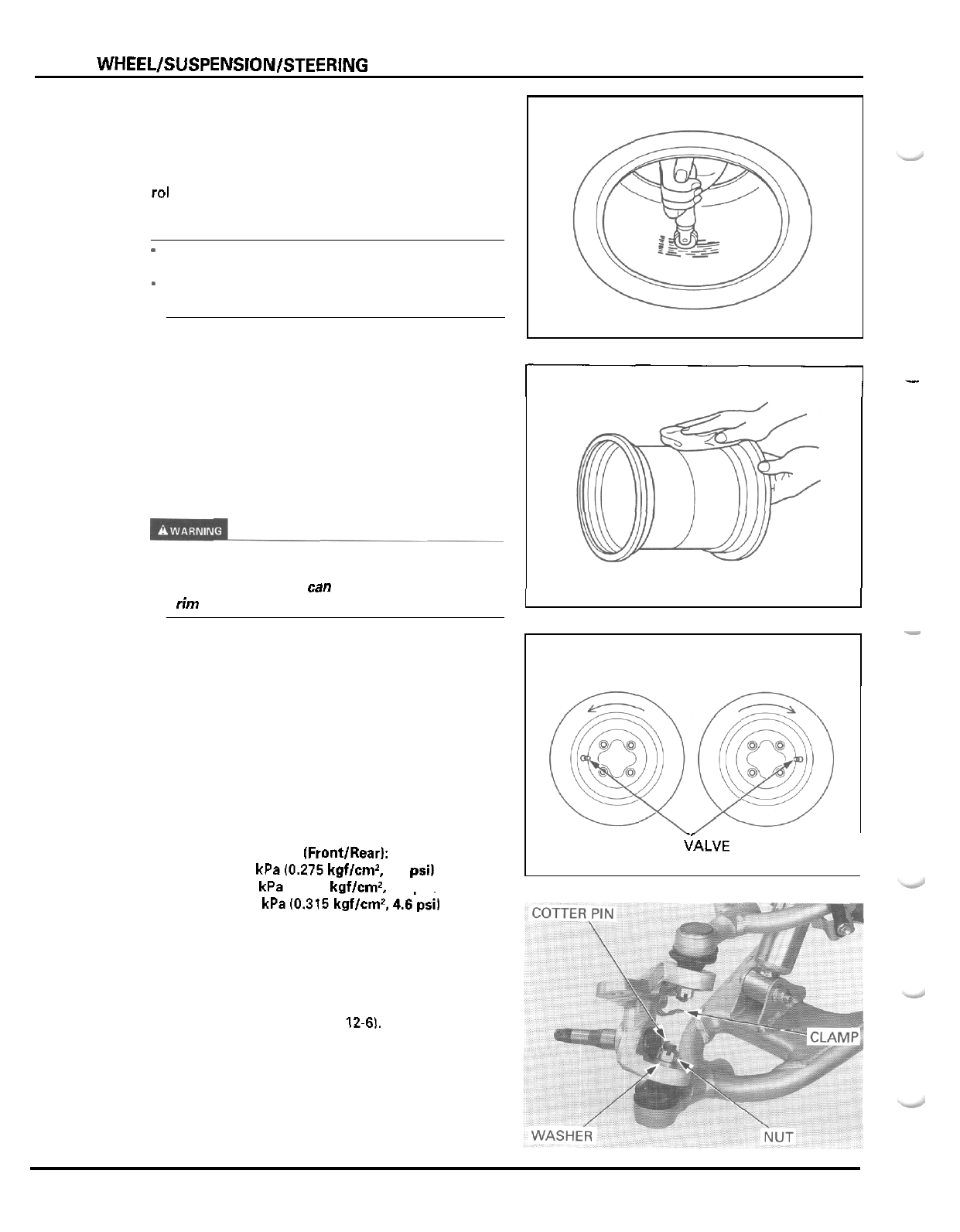
FRONT WHEELISUSPENSIONISTEERING
Apply cement over the area marked and allow it to
dry.
Remove the lining from the patch and center
it
over
the injury.
Press the patch against the injury using
a
special
rol
I
e
r.
NOTE:
*
Allow cement to dry until tacky before applying
patch.
-
Do not touch the cement with dirty or greasy
hands.
ASSEMBLY
Install the tire onto the rim, where the rim shoulder
width
is
the narrowest, to simplify installation.
Clean the rim bead seat and flanges.
Apply clean water to the rim flanges, bead seat and
base.
Use
only
water as
a
lubricant removing or mounting
tires. Soap or some mounting lubricants may leave a
slippery residue which
wn
cause the tire to shift on
the rim and lose air pressure during riding.
Install the valve core in the valve stem.
Install the front tire with the arrow mark facing in the
normal rotating direction.
Install the rear tire with the
“OUT
SIDE”
facing the
tire valve.
Inflate the tire to seat the tire bead.
Deflate the tire. Wait
1
hour and inflate the tire to the
specified pressure.
Check for air leaks and install the valve cap.
COLD
TIRE PRESSURE lFront/Rear):
Front tire:
Reartire:
Standard:
27
kPa
10.275
kgflcm’,
4.0
psi)
Minimum:
23
kPa
10.235
kciflcmz.
3.4
osil
fl-
-
FRONT TIRE:
LEFT
RIGHT
TIRE
CALVE
I
Maximum:
31
kPa
10.315
kgflcmz, 4.6psil
SUSPENSION
ARM
REMOVAL
Remove the wheel hub (page
12-61.
Remove the tie
-
rod from the knuckle (page
12
-
17).
Remove the cotter pins from the upper and lower
arm ball joint studs.
Remove the joint nuts, clamp and washer,
12
-
1
2
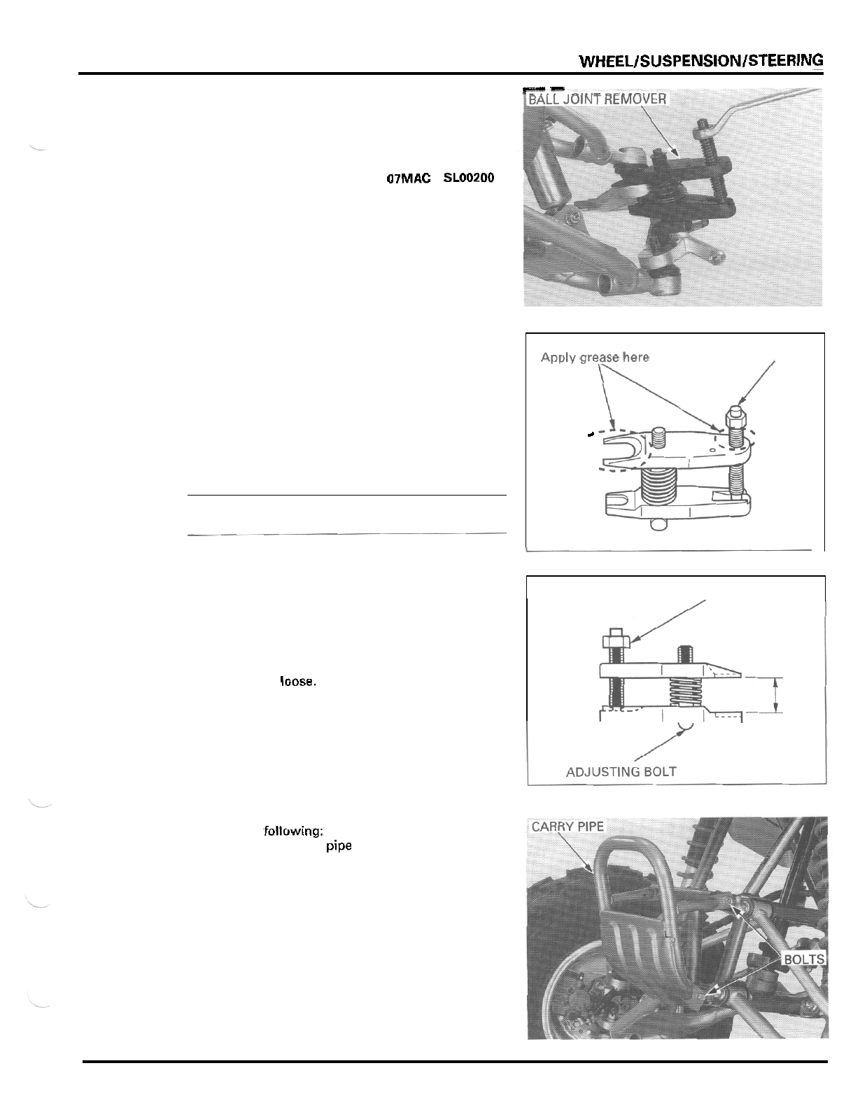
FRONT
WHEEL/SUSPENSION/STEERlNG
rz--
_.______^,,r^
Apply grease to the ball joint remover
at
the point
shown.
This will ease installation of the tool and prevent
damage to the pressure bolt threads.
Insert the jaws carefully. making sure that you do not
damage the ball joint boot.
Adjust the jaw spacing by turning the pressure bolt.
NOTE:
If
necessary, apply penetrating type lubricant to
loosen the ball joint.
Release the ball joints of the upper and lower arms
off
the knuckle, using the special tool according to
the following instructions.
PRESSURE BOLT
Apply
grease
here
c
,
,
I
.
TOOL
Ball
joint
remover
Once the tool is in place, turn the adjusting bolt as
07MAC
-
SLOOZOO
PRESSURE
,
BOLT
necessary to make the jaws parallel.
Then hand
-
tighten the pressure bolt and recheck the
jaws to make sure they are still parallel.
Tighten the pressure bolt with a wrench until the ball
joint stud pops
loose.
Remove the knuckle from the upper and lower arms.
L
ADJUSTING BOLT
Remove the following:
-
four bolts and carry pipe
12
-
1
3
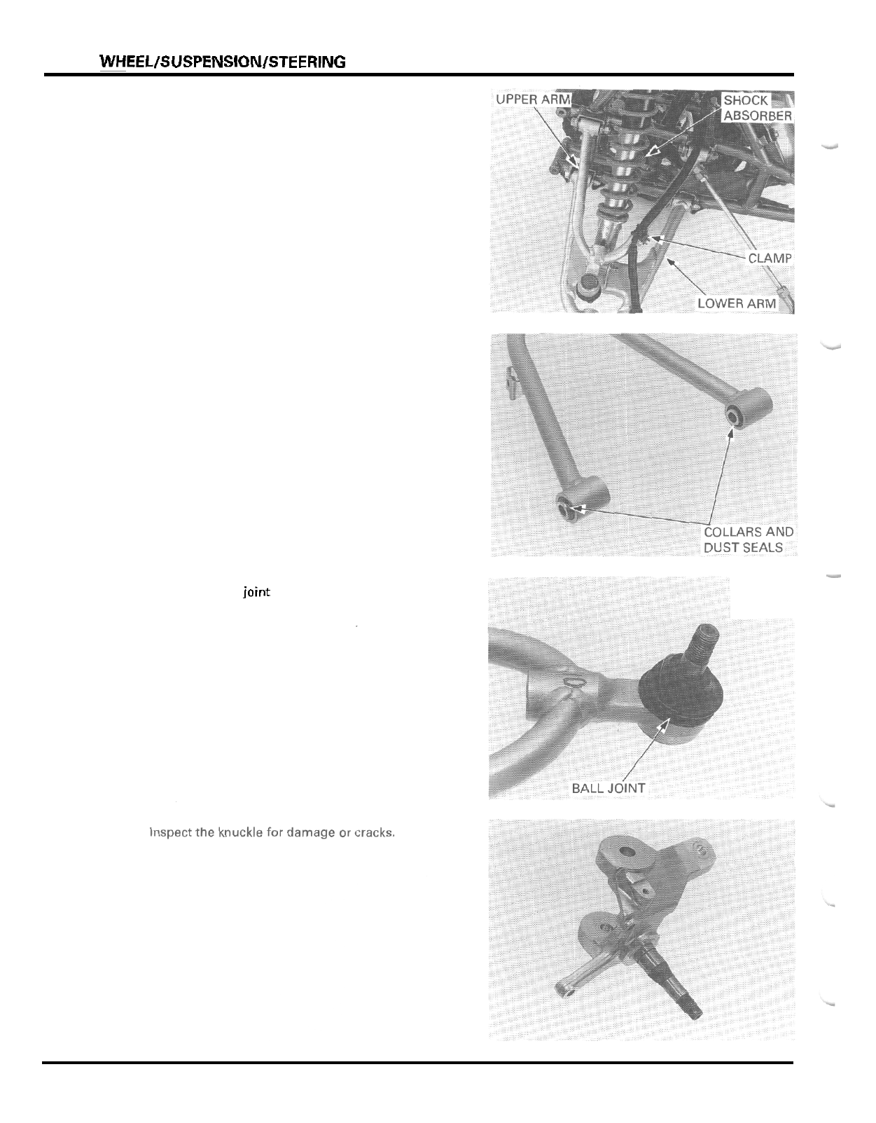
FRONT
WHEEL/SUSPENSION/STEERlNG
-
bolt and brake hose clamp from the upper arm
-
upper arm pivot nuts, bolts and upper arm
-
shock absorber lower mounting nut and bolt
-
lower arm pivot nuts, bolts and lower arm
Remove the pivot collars and dust seals.
INSPECTION
Check the pivot collars, dust seals and spherical bear
-
ings for wear or damage.
Inspect the ball joint rubber for tears of other damage
-
by
moving the ball joint studs.
It
should move freely and smoothly
12
-
14
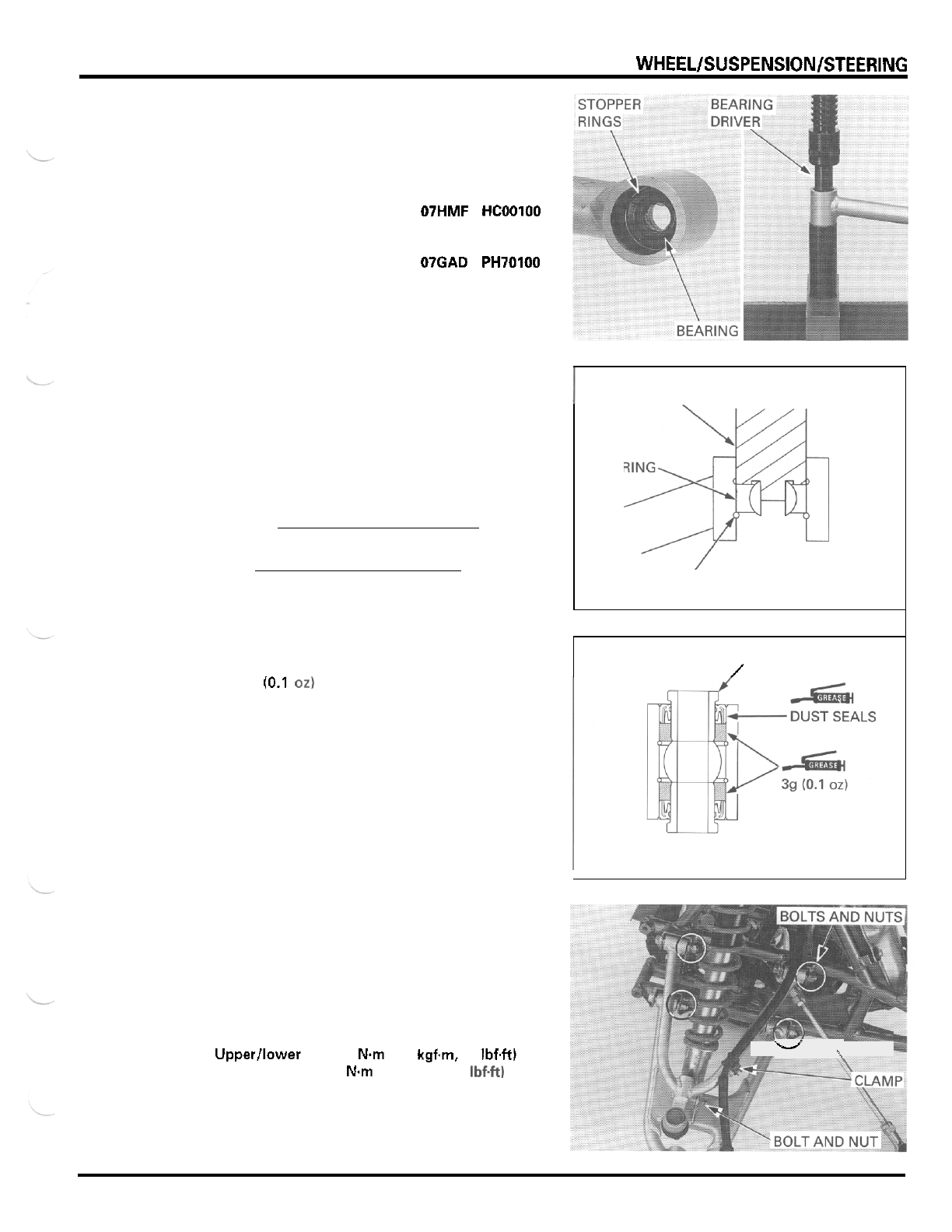
FRONT
WHEELlSUSPENSlONlSTEERlNG
PIVOT BEARING REPLACEMENT
Remove the stopper rings.
Press the spherical bearing out
of
the arm pivot.
TOOL
Spherical bearing driver
07HMF
-
HCOOlOO
not
available
in
U.S.A. or
O7GAD
-
PH70100
Install
a
new stopper ring into the groove in the arm
pivot properly.
Press a new bearing into the arm pivot until
it
con
-
tacts the stopper ring, using the same tool.
Install
a
new stopper ring into the opposite side
groove.
NOTE:
Spherical bearing case is split as part
of
manufacturing
process.
INSTALLATION
Pack
3
g
(0.1
02)
of
grease into each arm pivot as
shown.
Coat new dust seal lips with grease and install them
into the arm pivots until they are flush with the pivot
ends.
Install the pivot collars into the dust seals.
Install the following:
-
upper and lower arm with pivot bolts from front
-
pivot nuts
-
shock absorber lower mounting bolt and nut
-
brake hose clamp with bolt
TORQUE:
side
Upperllower arm:
39
Nm
(4.0
kgfm,
29
IbfW
Shock absorber:
44
Nm
(4.5
kgfm,
33
Ibf.ft)
I
BEARING
DRIVER
BEARING
*
STOPPER RING
COLLARS
/
W
\
12
-
1
5
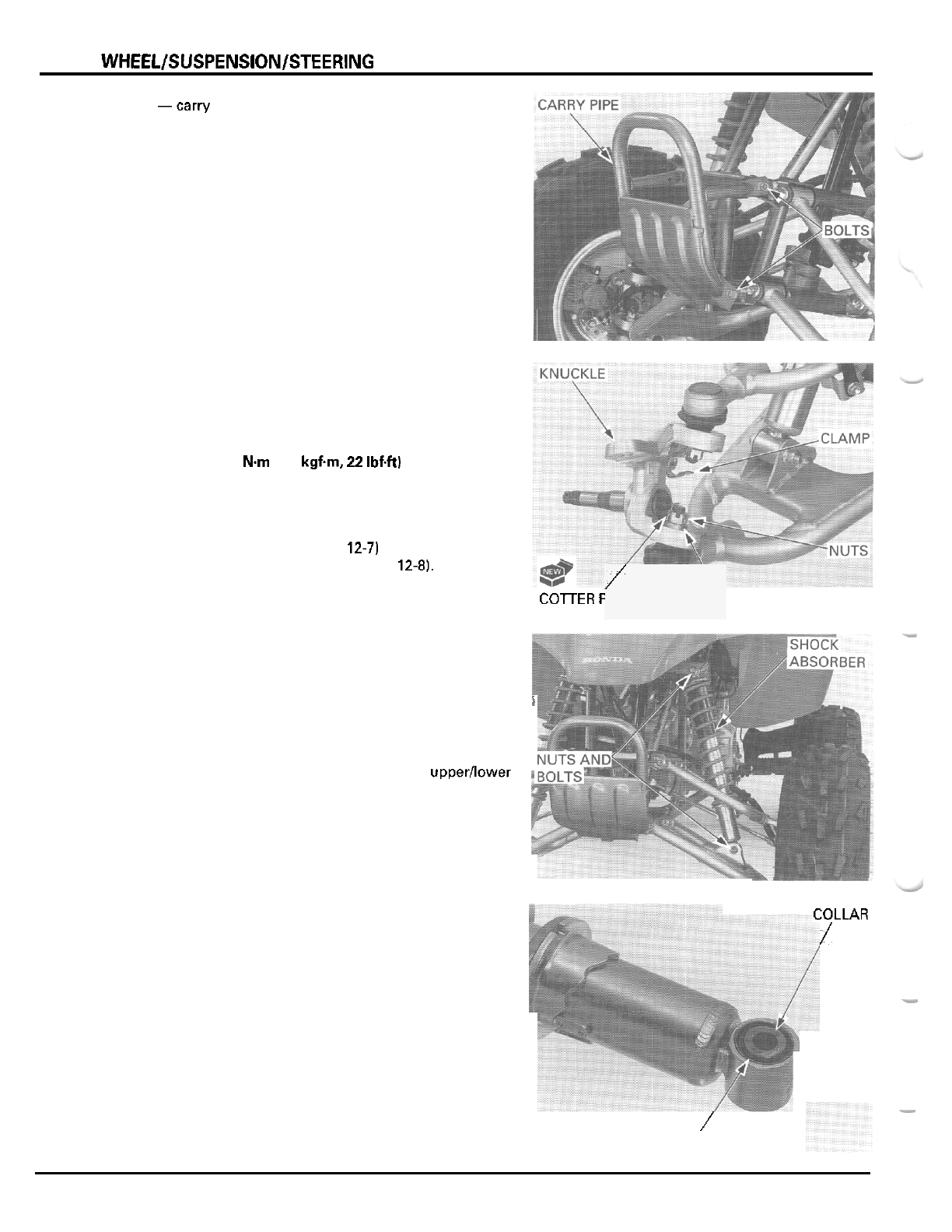
FRONT
WHEEL/SUSPENSlON/STEERING
-carry pipe with four bolts
Install the knuckle onto the upper and lower arms
with the joint nuts, washer and clamp.
Tighten each nut to the specified torque and further
tighten until its grooves align with the cotter pin hole.
TORQUE:
29
Nm
(3.0
kgfm,
22
IbfW
Install new cotter pins.
Install the following:
-
tie
-
rod into knuckle (page
12-7)
-
wheel hub and front wheel (page
12-81,
Adjust the toe (page
3
-
22).
FRONT
SHOCK
ABSORBER
REMOVAL
Support the vehicle with
a
support block to raise the
front wheels
off
the ground.
Support the lower arm and remove the upperllower
mounting nuts, bolts and shock absorber.
INSPECTION
Remove the lower pivot collar and dust seals.
Check the pivot collar and dust seals for wear or
damage.
COTTER
F
\
WAS
/
'INS
HER
i
TOLLAR
/
-
/
DUST
SEALS
12
-
1
6
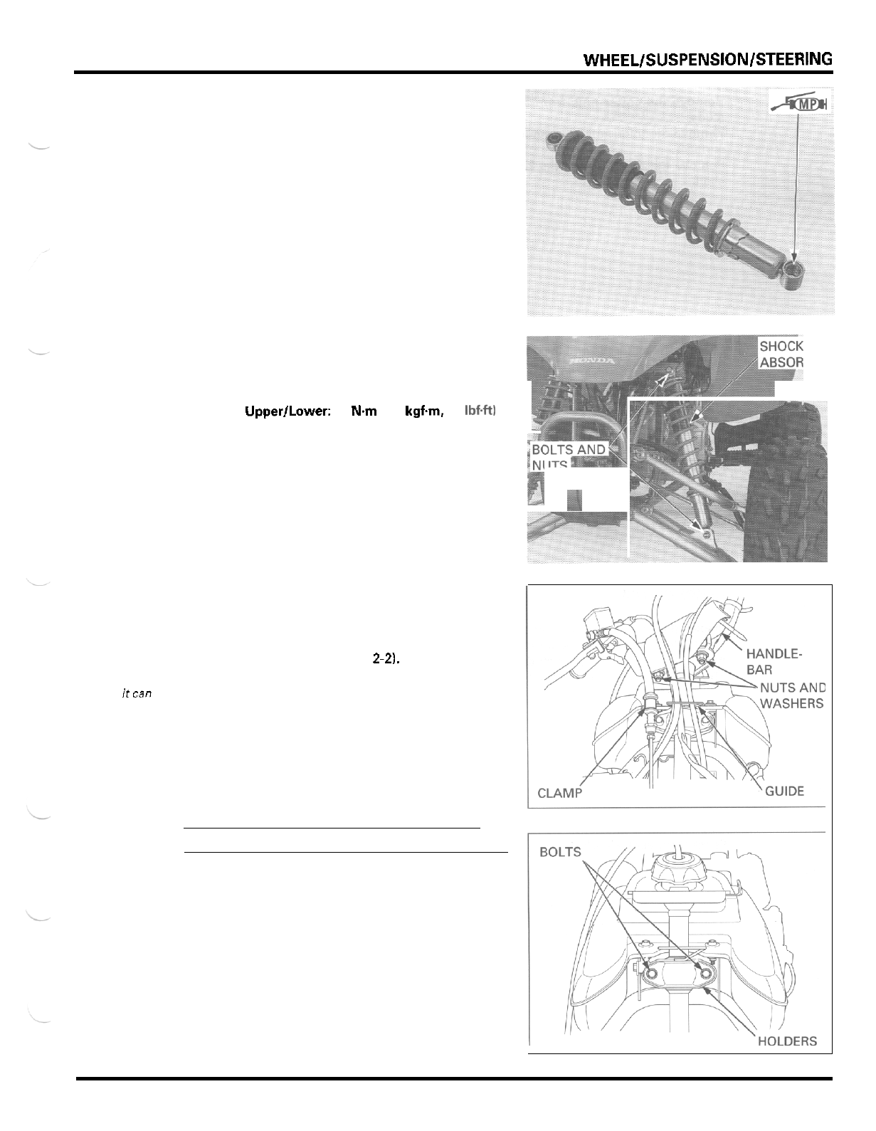
FRONT
WHEEL/SUSPENSION/STEERlNG
Check the bushings for wear or damage.
Check the damper unit for leakage or other damage.
Replace the shock absorber assembly if necessary.
INSTALLATION
Apply molybdenum disulfide paste to the lower
bushing of the shock absorber.
Coat new dust seal lips with molybdenum disuifide
paste and install them into the lower pivot.
Install the lower pivot collar.
Install the shock absorber with the mounting bolts
from front side.
BER
install the mounting nuts and tighten them.
TORQUE: Upper/Lower:
44
N.m
(4.5
kgf.m,
33
1bf.W
STEERING SHAFT AND TIE
-
ROD
REMOVAL
When removing
the tie
-
rod only,
itcan be
removed without
guide.
removingthe
Remove the front fender (page
2-21,
Release the cables and wire harness from the cable
Remove the bolt and brake hose clamp from the
front fender.
steering shaft holder.
Remove the handlebar lower holder nuts, washers
and the handlebar assembly from the steering shaft.
CAUTION:
Do
not twist
or
bend
the brake hose
and
pipe.
Remove the two bolts and the steering shaft holders.
12
-
1
7
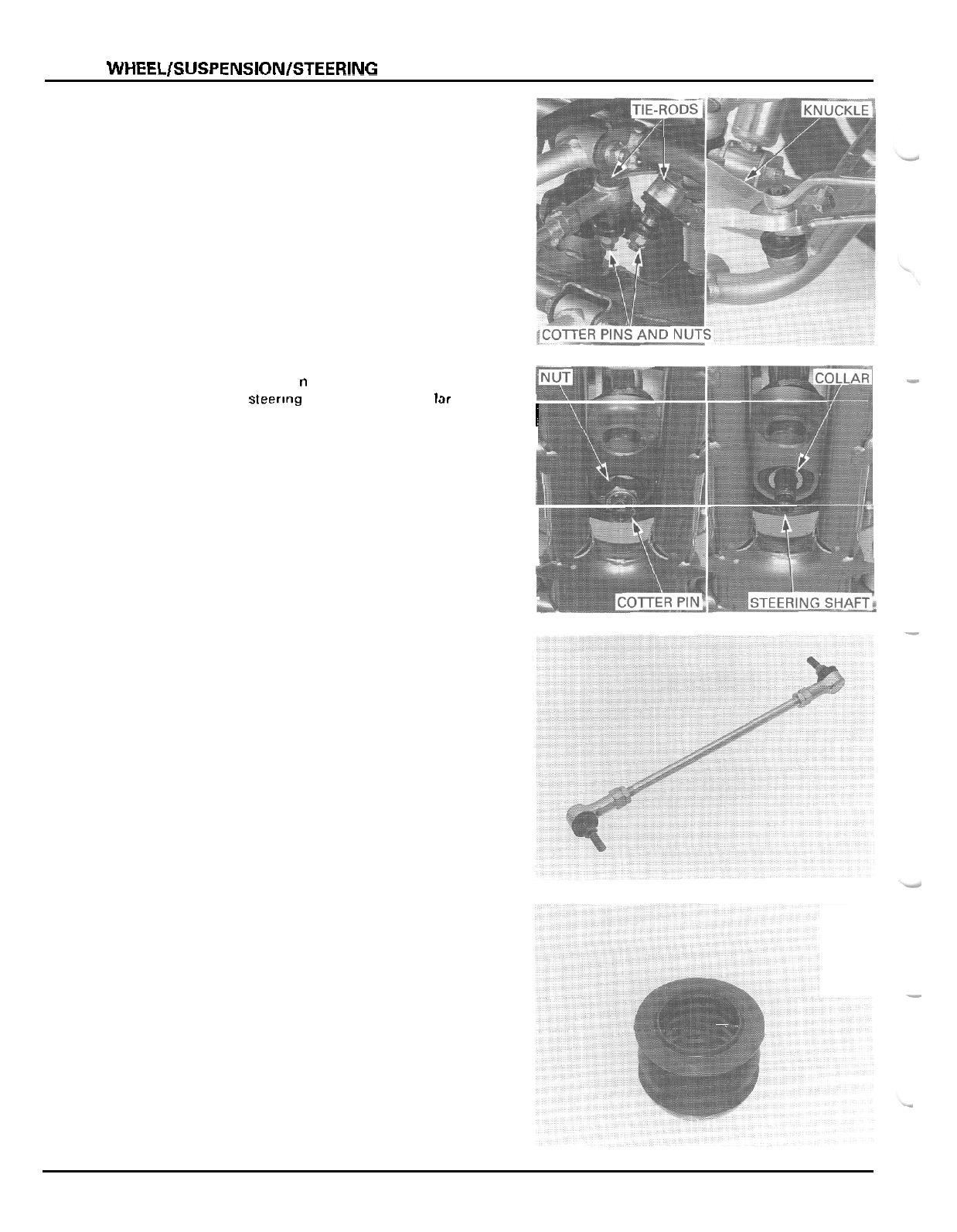
FRONT
WHEELlSUSPENSlONlSTEERlNG
Remove the cotter pins from the tie
-
rod ball joint
studs.
Remove the joint nuts by holding the joint stud flat
surfaces.
Remove the tie
-
rods from the knuckles and steering
shaft.
Remove the cotter
p
n
and tne steering shaft end
nut
Remove the steerlng snaft and shaft co lar from tne
I
frame.
i
INSPECTION
Inspect the tie
-
rod for distortion or damage.
Inspect the
ball
joint rubbers for tears of other dam
-
age by moving the ball joint studs.
They should move freely and smoothly.
Check the steering shaft bushing for wear or damage.
-
..
12
-
1
8
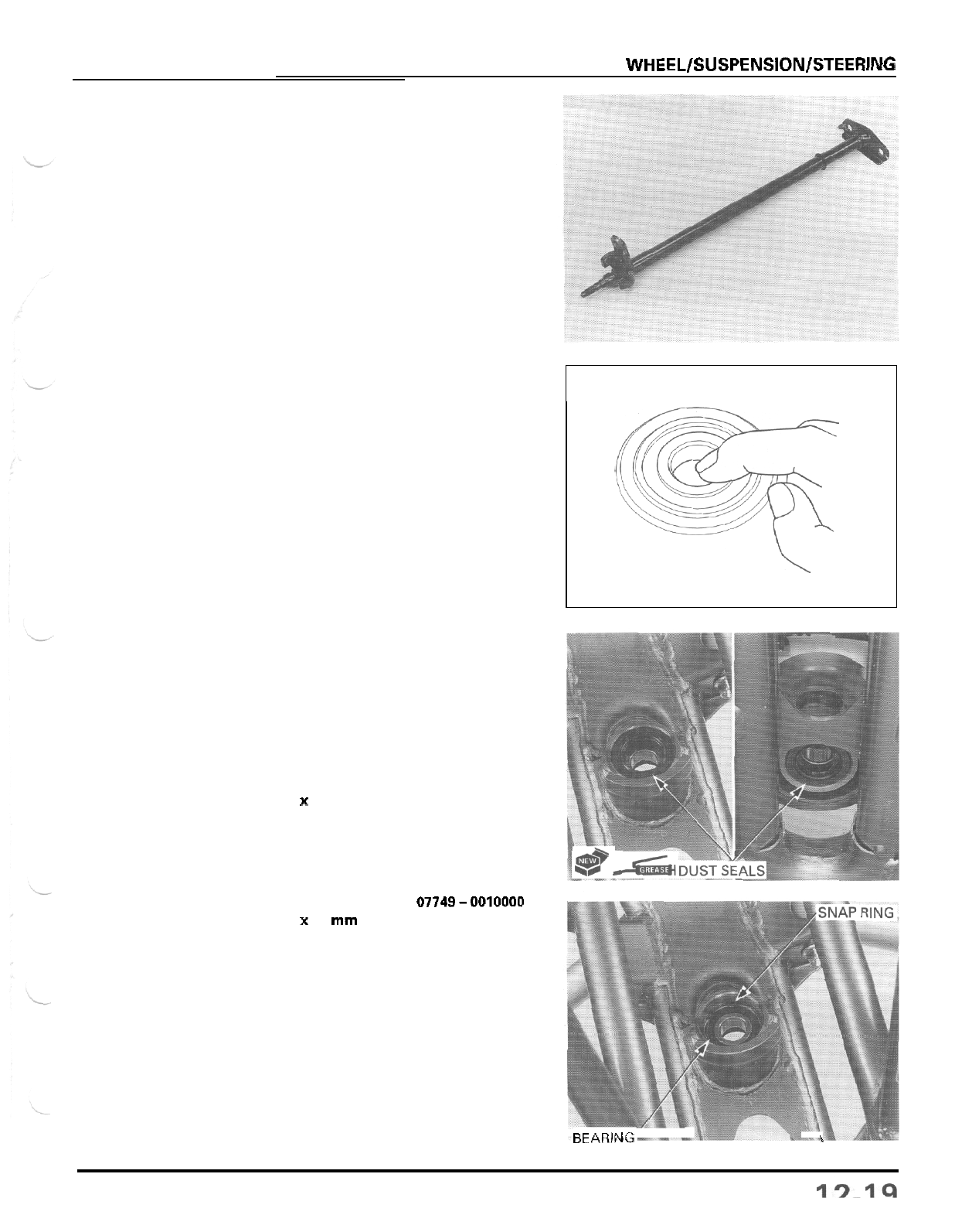
FRONT
WHEEL/SUSPENSION/STEERlNG
Check the steering shaft for distortion or damage.
Turn the inner race of each bearing with your finger.
The bearing should turn smoothly and quietly.
Also
check that the bearing outer race fits tightly in the
frame.
Remove and discard the bearing if the race do not
turn smoothly and quietly, if
it
fits loosely in the
frame.
BEARING
REPLACEMENT
Remove the dust seals
Remove the snap ring.
Drive the steering shaft bearing out of the frame.
TOOLS:
Driver
07749
-
0010000
Attachment,
32
x
35
mm
07746
-
0010100
Drive in
a
new bearing squarely with the marking
side facing up until
it
is fully seated.
TOOLS:
Driver
07749-0010000
Attachment,
37
x
40
mm
07746
-
0010200
Pilot,
17
mm
07746
-
0040400
Install the snap ring into the groove properly.
Coat new dust seals with grease and install them
until they are flush with the frame edge.
BEARING
i
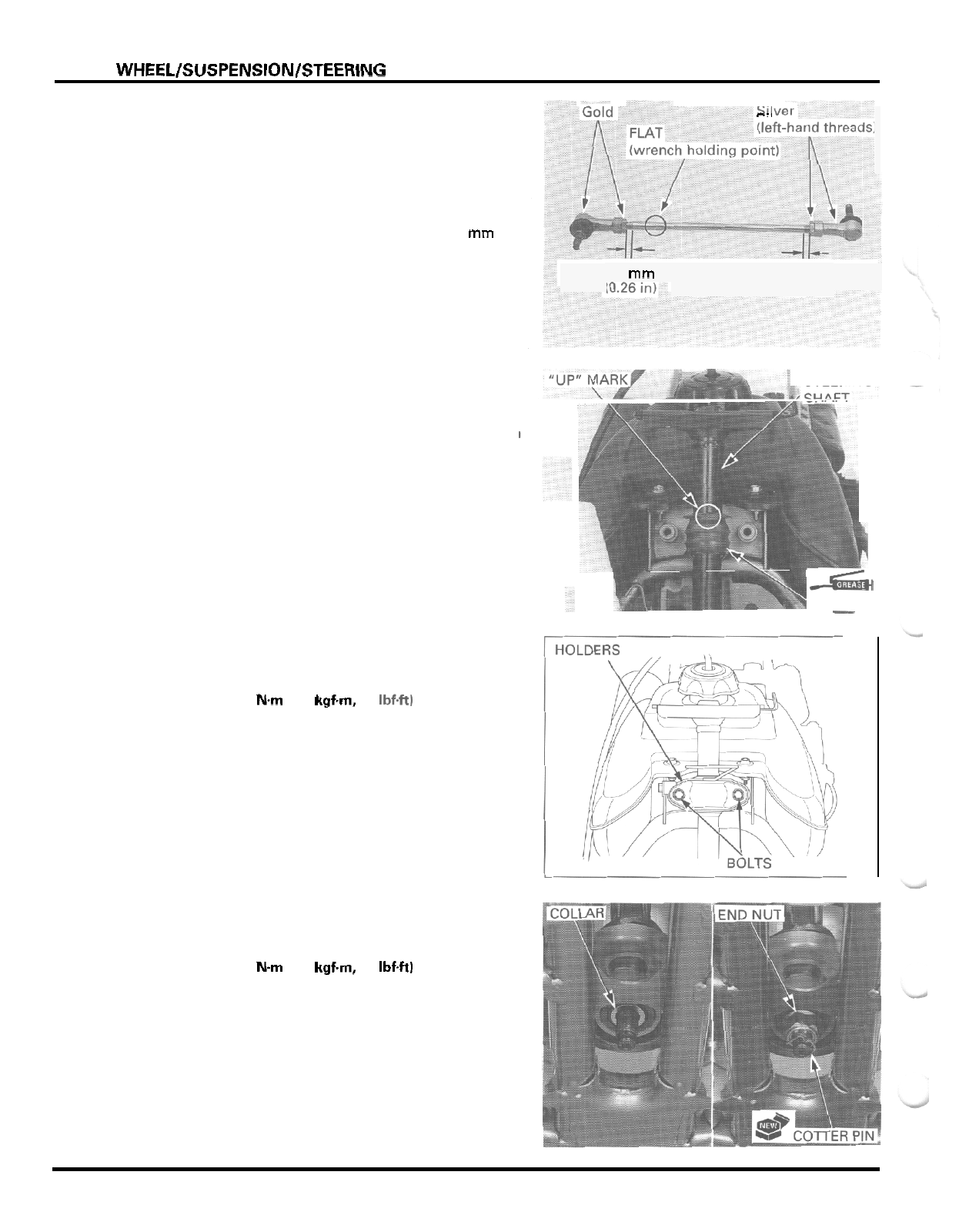
FRONT WHEELISUSPENSIONISTEERING
TIE
-
ROD ASSEMBLY
c.,
.
When the tie
-
rod ball joints will be replaced, install
the ball joints and lock nuts as shown.
Adjust the tie
-
rod length
so
that the distance between
each lock nut and thread end is
6.5
mm
(0.26
in). (A
difference between both ends distances is
3
mm
(0.1
in) max.
Temporarily tighten the lock nuts while the ball joints
position are
180
"
from each other.
Tighten these
nuts after
installing the tie
-
rod into the
knuckle and
steering shaft.
INSTALLATION
Apply grease to the shaft bushing inner surface.
Install the shaft bushing onto the steering shaft with
the
"
UP
"
mark facing up.
Install
the
steering shaft into the shaft bearing.
Install the shaft holders with the two bolts as shown.
Tighten the holder bolts.
TORQUE:
32
Nm
13.3
kgfm,
24
Ibf4t)
Install the shaft collar into the dust seal.
Install the end nut and tighten
it.
TORQUE:
69
Nm
17.0
kgfm,
51
Ibf4t)
Install a new cotter pin.
6.5
rnm
6.5
rnm
(0.26
in)
.
-
STEERING
I
-5Ai
BUSHING
I
12
-
20
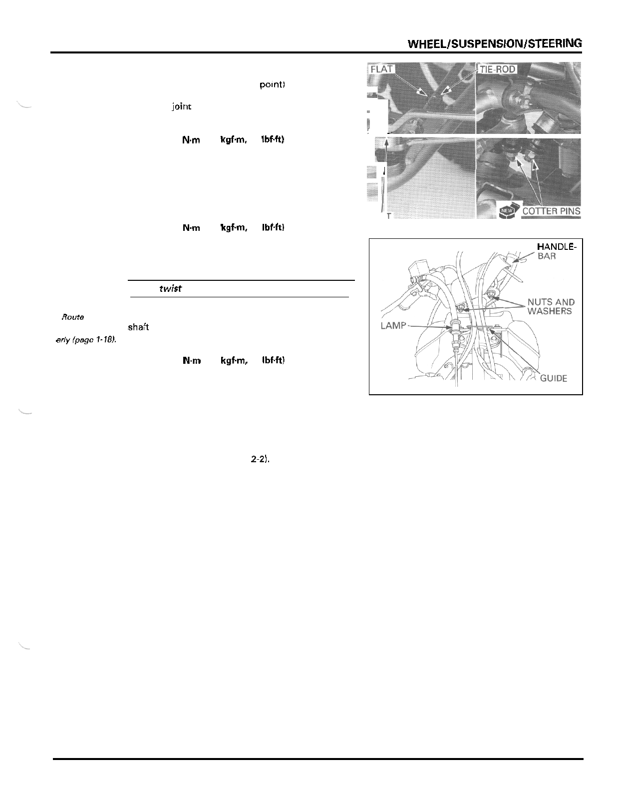
FRONT
WHEELlSUSPENSlONlSTEERlNG
Install the tie
-
roo into the steer ng shaft and knuckles
with the flat lwrench holding point1 side facing the
--.
knuckle.
Install the joint nuts and tighten them by holding the
joint stud flat surfaces.
!
,
..
TORQUE 44 N.m 14.5 kgf.m,
33
IbfW
If
the ball joints were replaced, tighten the lock nuts
Rotate both ball joints with the tie
-
rod axis until they
stop against the ball joint studs. Hold them in that
position and tighten the ball joint lock nuts.
following procedure:
c7
1
1
NUT
TORQUE: 54 Nm 15.5 kgfm, 40 Ibf4t)
Install new cotter pins into the tie
-
rod ball joint studs.
CAUTION:
Do
not
twist
or
bend the brake hose and
pipe.
.
-
Route the wire
andcableprop
-
erlylpage
1-18),
Tighten the nuts.
Install the handlebar assembly onto the steering
shaft with the lower holder nuts and washers.
TORQUE:
39
Nm
14.0 kgf.m,
29
IbfW
Install the cables and wire harness into the guide
on
HANDLE-
C
the shaft holder.
I
Install the brake hose onto steering shaft holder with
the clamp bolt.
Adjust the toe (page
3
-
20).
Install the front fender (page
2-2).
12
-
21
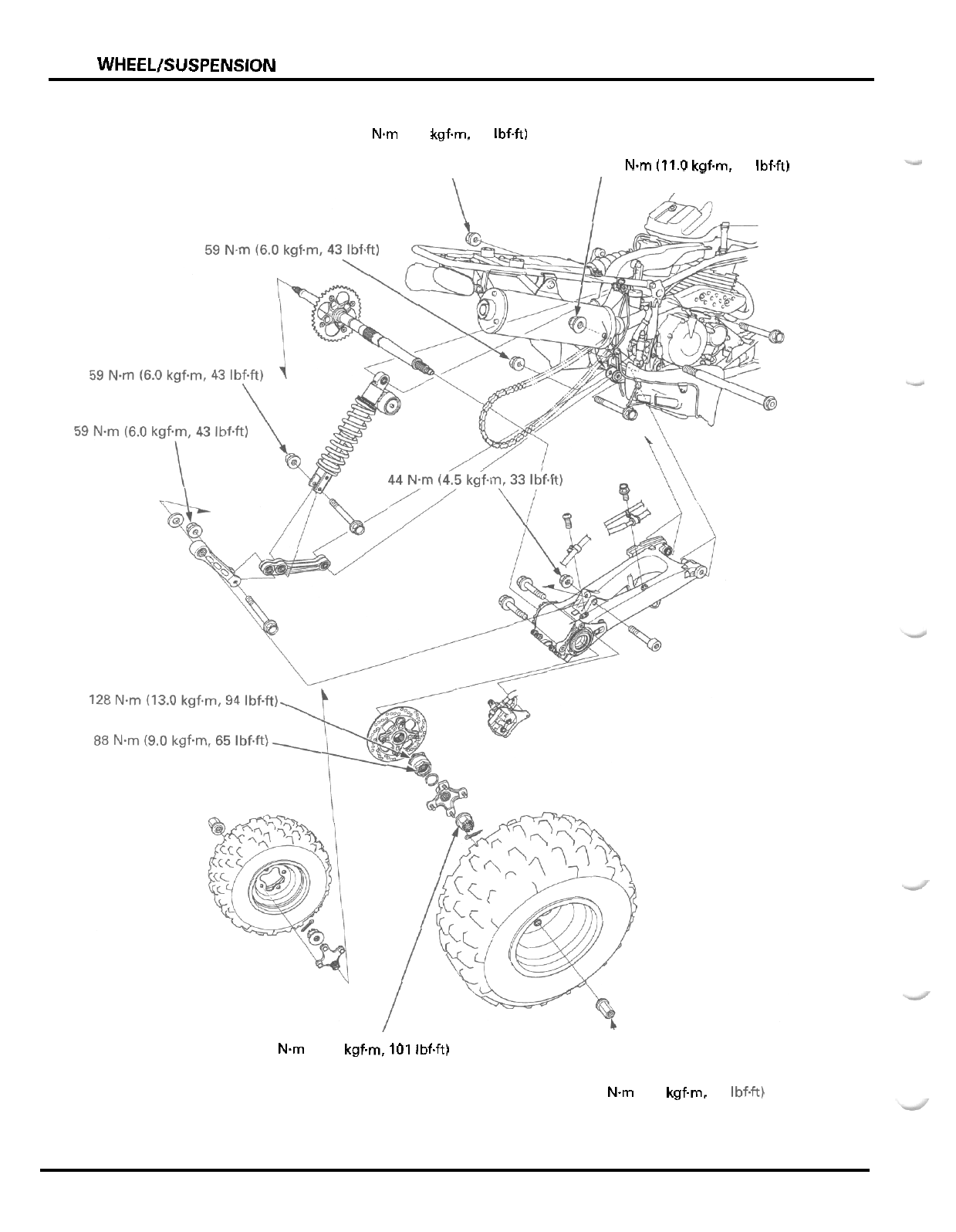
REAR
WHEEL/SUSPENSION
59
N.m
(6.0
kgfm, 43 Ibf4tl
108
Nm
(11.0
kgf.m,
80
Ibf4t)
\
\
I
137
Nm
(14.0 kgfm, 101 IbfW
64
N.m
(6.5
kgf.m. 47 Ibf.ft)
13
-
0
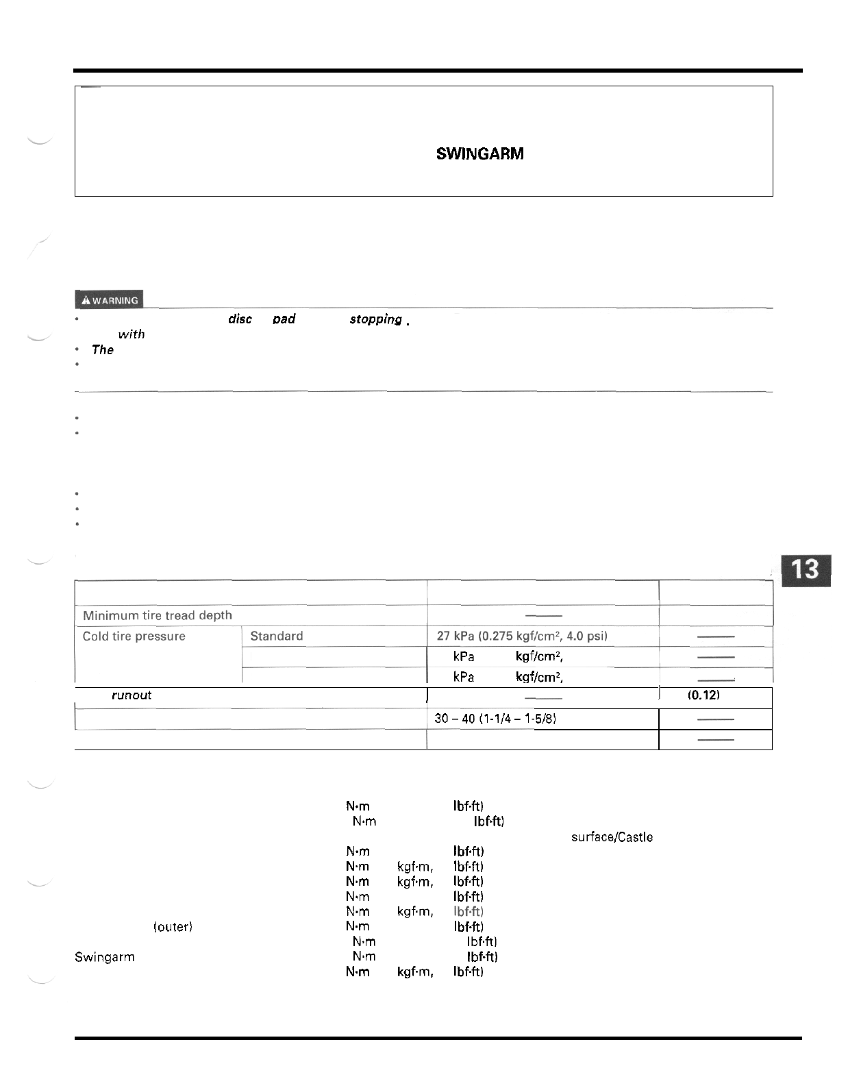
13.
REAR
WHEEL/SUSPENSION
Drive chain slack 30-40(1-1/4-1-5/8)
~
SERVICE INFORMATION 13
-
1 REAR SHOCK ABSORBER 13
-
9
TROUBLESHOOTING 13
-
2 SHOCK LINKAGE 13
-
11
REAR WHEEL 13
-
3 SWINGARM 13
-
13
REAR AXLE 13
-
3
-
SERVICE
INFORMATION
GENERAL
Shock absorber spring installed length
1
231.5 (9.11)
A
contaminated brake disc or Dad reduces stODpino Dower. Discard contaminated Dads and clean a contaminated
-
.. _.
disc
with
a
high
quality brake degreasing agent.
The shock absorber contains nitrogen under
high
pressure. Do not allow fire or heat near the shock absorber.
Before disposal of the shock absorber, release the nitrogen by pressing the valve core. Then remove the valve from
the shock absorber reservoir.
A jack or other support is required to support the vehicle.
When using the lock nut wrench for the axle lock nuts, use
a
deflecting beam type torque wrench 20 inches long. The
lock nut wrench increases the torque wrench's leverage,
so
the torque wrench reading
will
be less than the torque
actually applied to the lock nut. The specification given is the actual torque applied to the lock nut, not the reading on
the torque wrench.
Do
not overtighten the lock nut. The specification later in the text gives both actual and indicated.
Refer to section 12 for tire information.
Refer to section 3 for drive chain information.
Refer to section
14
for brake system information.
SPECIFICATIONS
Unit: mm
(in)
ITEM
STANDARD
I
SERVICE
LIMIT
I
4.0 (0.16)
-
Mini m u
m
-
Maximum
I
31 kPa (0.315 kgf/cm', 4.6 psi)
-
I
23
kPa
(0.235 kgf/cm2, 3.4 psi)
Axle runout
-
I
3.0 10.12)
I
TORQUE
VALUES
Rear wheel nut
Rear wheel hub nut
Shock
absorber mounting nut
Shock link
-
to
-
swingarm nut
Shock arm
-
to
-
frame nut
Shock arm
-
to
-
shock link nut
Final driven sprocket nut
Axle lock nut (outer)
(inner)
Swingarm pivot nut
Caliper stopper pin
64 Nm (6.5 kgfm. 47 IbfW
137 Nm (14.0 kgfm. 101 IbfW
59
Nm
(6.0 kgfm, 43 Ibf.ft)
44
Nm
(4.5 kgfm, 33 IbfW
59
Nm
(6.0 kgfm, 43
IbfW
59 Nm (6.0 kgfm, 43 IbfW
59 Nm (6.0 kgfm, 43 Ibf.ft)
88
Nm
(9.0
kgfm, 65 IbfW
128 Nm (13.0 kgfm, 94 IbfW
108 Nm (11.0 kgfm
80
IbfW
59
Nm
(6.0 kgfm. 43 IbfW
Apply grease to the threads and seating surface/Castle nut
Apply locking agent to the threads
Apply locking agent to the threads
Apply locking agent to the threads
13
-
1

REAR WHEEL/SUSPENSION
TOOLS
Driver
Attachment,
24
x
26
mm
Attachment,
62
x
66
mm
Attachment,
35
mm
I.D.
Pilot,
17
mm
Pilot,
40
mm
Lock nut wrench,
56
mm
Lock nut wrench,
45
mm
Needle bearing remover
Assembly collar
TROUBLESHOOTING
Rear wheel wobbling
*
Bent rim
*
Worn or damaged rear axle bearings
*
Faulty rear tire
Axle fastener not tightened properly
*
Faulty swingarm pivot bearings
Rear wheel turns hard
*
Faulty rear axle bearings
-
Bent rear axle
*
Rear brake drag
*
Drive chain too tight
Soft
suspension
-
Weak shock absorber spring
*
Incorrect suspension adjustment
*
Oil leakage from damper unit
Hard suspension
*
Incorrect suspension adjustment
*
Damaged rear suspension pivot bearings
-
Bent damper rod
Rear suspension noise
-
Faulty rear shock absorber
*
Loose rear suspension fasteners
*
Worn rear suspension pivot bearings
07749
-
0010000
07746
-
0010700
07746
-
0010500
07746
-
0030400
07746
-
0040400
07746
-
0040900
07916
-
HA20000
or
07916
-
HA2010A (U.S.A. only)
07916
-
1870101
or equivalent commercially available in U.S.A.
07946
-
KA50000
07965
-
VMOOIOO
13
-
2
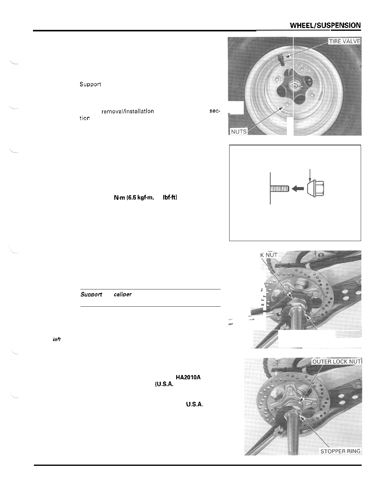
REAR
WHEELlSUSPENSlON
REAR WHEEL
REMOVAL
Loosen the wheel nuts.
Supporr the vehicle with
a
support block to raise the
rear wheels
off
the ground.
Remove the nuts and wheel.
For tire removallinstallation and repair, refer to sec-
tion
12.
INSTALLATION
Install the tire onto the hub with the tire valve facing
out.
Install the wheel nuts with the tapered side facing
inward and tighten them.
TORQUE: 64
Nm
16.5
kgfm
47
IbfW
REAR AXLE
REMOVAL
TAPERED SIDE
INNER
LOC
i
CAUTION:
k
i
Suooort the caliDer
so
that
it
does not hang from the
~
brake hose.
Do
not twist or bend the brakehose.
-
I(
%.
~
-
-
-.
Remove the rear brake caliper (page
14
-
6).
-
,
.
-
1_
\
.
-
Thelocknuts
has
left
hand
Loosen the axle inner lock nut while holding the
outer lock nut, using the special tools.
threads
OUTER
LOCK
NUT
TOOLS
Lock nut wrench,
56
mm
07916
-
HA20000
or
07916
-
HA2010A
(U.S.A.
only)
07916
-
1870101 or
equivalent commercially
available
in
USA.
Lock nut wrench,
45
mm
Loosen the outer lock nut until the stopper ring can
be removed, using same tool.
Remove the stopper ring from the axle groove.
13
-
3
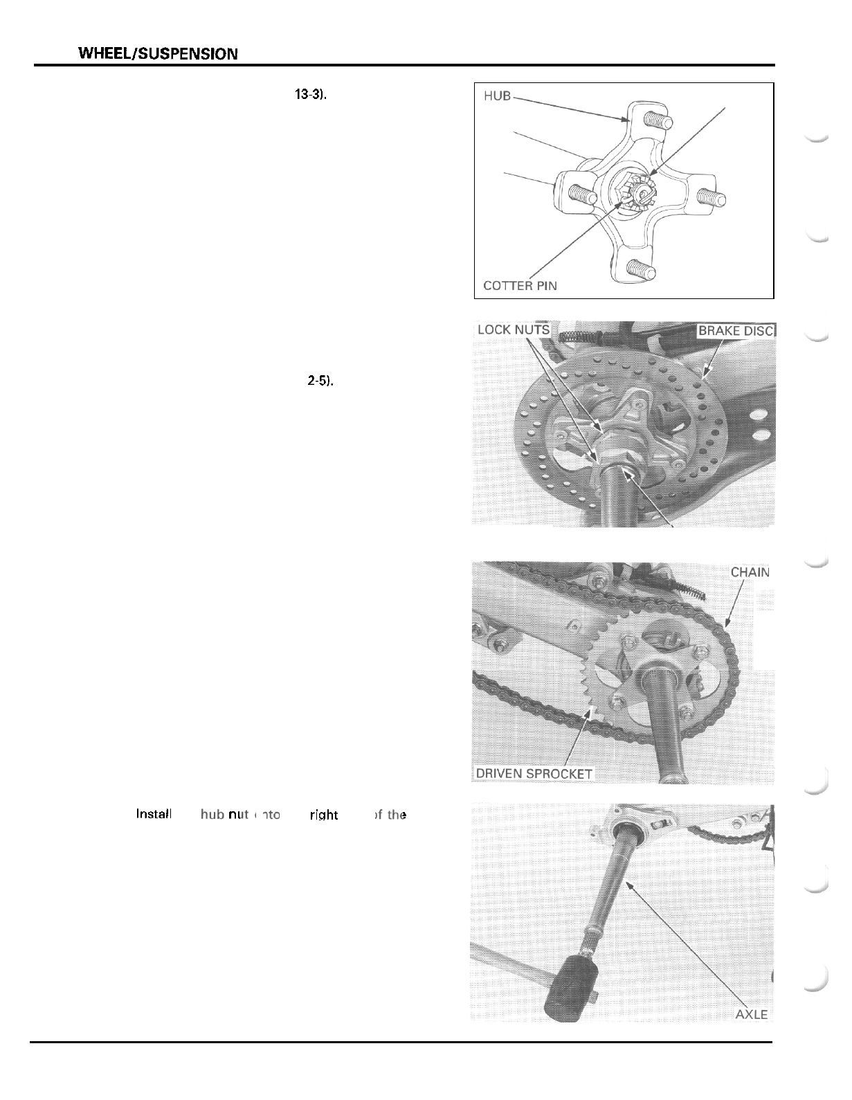
REAR
WHEELlSUSPENSlON
Remove the wheels (page
13-31,
Remove the cotter pin and the hub nut.
Remove the right wheel hub.
Remove the stopper ring, outer and inner lock nuts
from the axle.
Remove the skid plate (page
2-5).
Remove the brake disclhub by sliding
it
outward.
Remove the O
-
ring from the inside of the disc hub.
Loosen the rear axle for maximum drive chain slack
(page
3
-
13).
Remove the drive chain from the driven sprocket.
If the sprocket must be replaced, remove the four
nuts, bolts and the driven sprocket.
Install the
ni
31
,
the right end
c
prevent the threads from beingdamage.
NUT
‘STOPPER
RING
!
axle to
Remove the axle by driving the axle out of the bear
-
ing holder in the swingarm, using a rubber mallet.
13
-
4
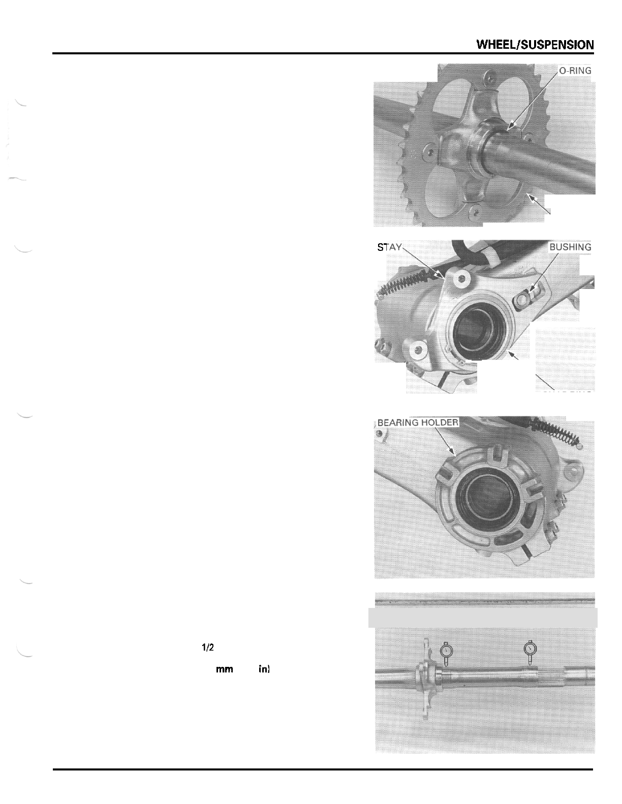
REAR
WHEELlSUSPENSlON
Remove the O
-
ring.
Remove the nuts, bolts and driven sprocket.
Remove the snap ring from the bearing holder.
s1
Remove the caliper stay and stopper bushing.
Remove the O
-
rings from the bearing holder and stay
groove.
\
SPROCKET
\
SNAP
KING
Remove the axle bearing holder to the
left
by tapping
it lightlyfrom the right side.
Remove the
0-rings from
the holder grooves.
Remove the dust seals.
INSPECTION
Set the axle in V
-
blocks and measure the axle runout
with
a
dial indicator.
Actual runout
is
112
the total indicator reading.
SERVICE
LIMIT
3.0
mm
(0.12
in1
13
-
5
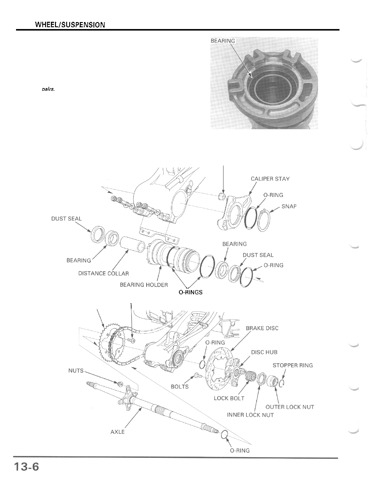
REAR WHEEL/SUSPENSION
Replace the axle
bearings
in
osirs.
Turn the inner race of each bearing with your finger.
The bearings should turn smoothly and quietly.
Also
check that the bearing outer race fits tightly in the
holder.
Remove and discard the bearings if the races do not
turn smoothly and quietly or if they fit loosely in the
holder.
INSTALLATION
STOPPER
BUSHING
I
0-~NGS
BOLTS
DRIVEN
SPROCKET
I
'
RING
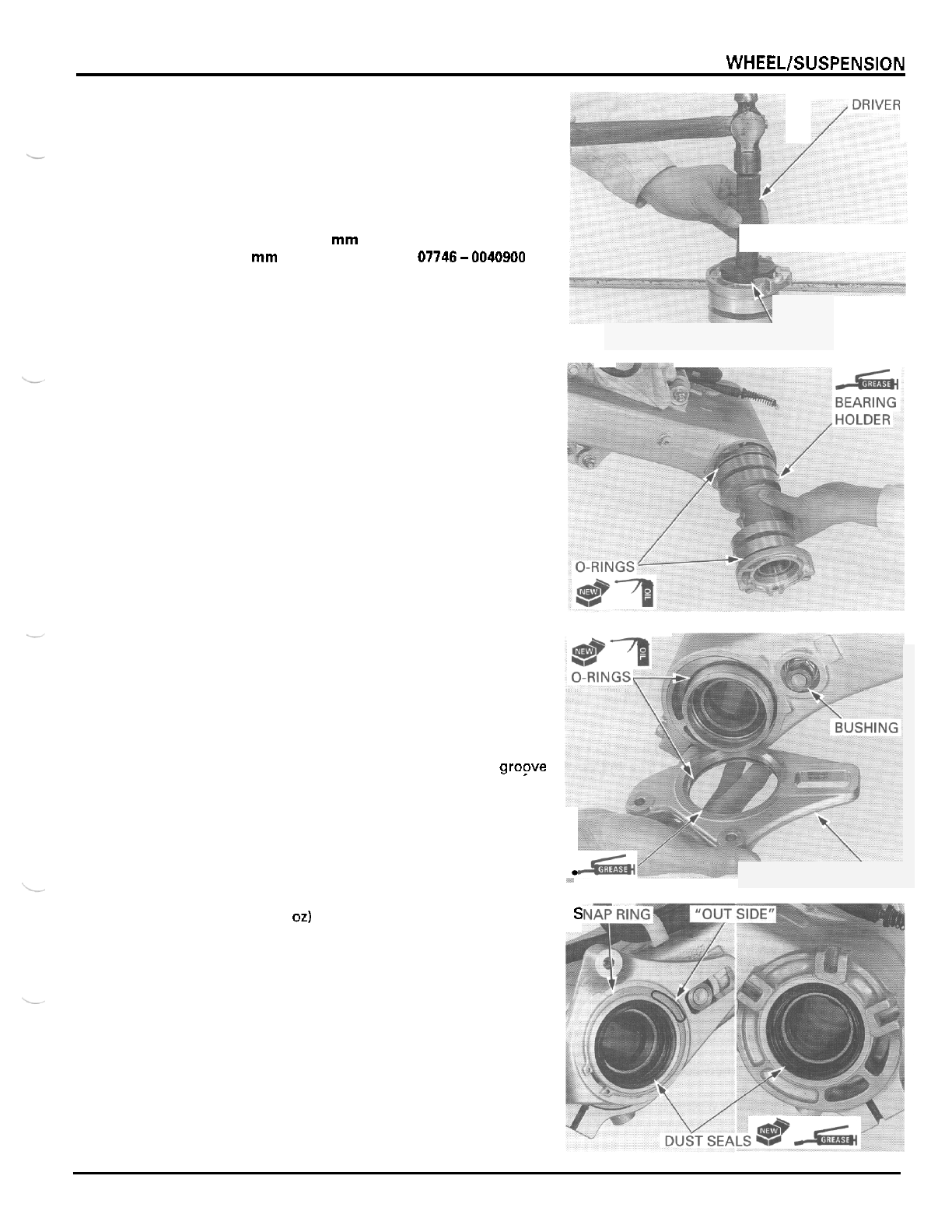
REAR WHEELlSUSPENSlON
Drive in
a
new right bearing (brake disc side) squarely
with the marking side facing up until
it
is fully seated.
Install the distance collar.
Drive in a new left bearing squarely with the marking
side facing up until
it
is fully seated.
TOOLS
Driver
07749
-
0010000
Attachment,
62
x
68
mm
07746
-
0010500
Pilot,
40
mm
07746-0040900
ATTACHMENTA
a
-
-
Clean the bearing holder outer surface and the
swingarm inner surface.
Coat new O
-
rings with oil and install them into the
grooves in the bearing holder.
Apply grease to the bearing holder outer surface.
Install the bearing holder into the swingarm until it is
fully seated, being careful not to damage the O
-
rings.
ND
PILOT
Coat new O
-
rings with oil and install them into the
caliper stay groove and onto the bearing holder.
Install the bushing onto the stopper bolt.
Apply grease to the inner surface of the caliper stay
and install the stay onto the bearing holder and bush
-
ing.
Install the snap ring into the bearing holder gropve
with the
"
OUT
SIDE
"
facing out to secure the caliper
stay.
-
STAY
Pack
1
g
(0.04
oz)
of grease into each new dust seal
lip cavity.
Install the dust seals until they are flush with the
bearing holder
S
13
-
7
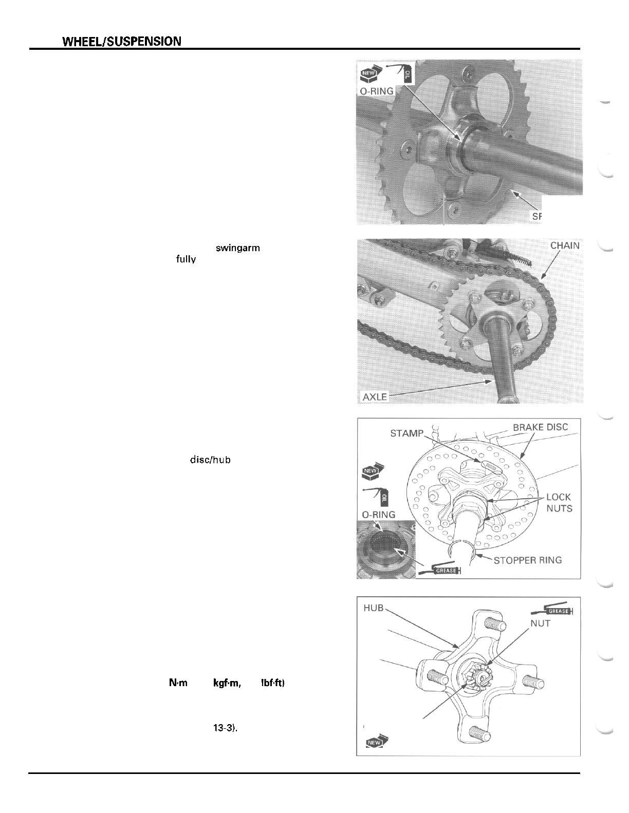
REAR
WHEELlSUSPENSlON
Install the driven sprocket with the chamfered side of
the bolt holes facing in.
Coat
a
new O
-
ring with oil and install
it
between the
-
driven sprocket flange and axle.
Apply grease
to
the hub nut threads and seating sur
-
face.
Install the wheel hub and hub nut onto the axle.
Tighten the hub nut to the specified torque and fur
-
ther tighten
it
until its grooves align with the cotter
pin hole.
TORQUE:
137
N.m
(14.0
kgfm,
101
IbfW
Install
a
new cotter pin.
Install the wheels (page
13-3).
Install the axle into the swingarm through the drive
chain until
it
is fully seated. Install the chain over the
driven sprocket.
Coat
a
new O
-
ring with oil and install
it
into the
groove in the disc hub.
Apply grease to the disc hub splines.
Install the brake disclhub onto the axle with the
stamp facing out.
Install the inner and outer lock nuts onto the axle.
Install the stopper ring but do not install
it
into the
ring groove yet.
'ROCKET
COTTER
PIN'
**
Q$*
13
-
8
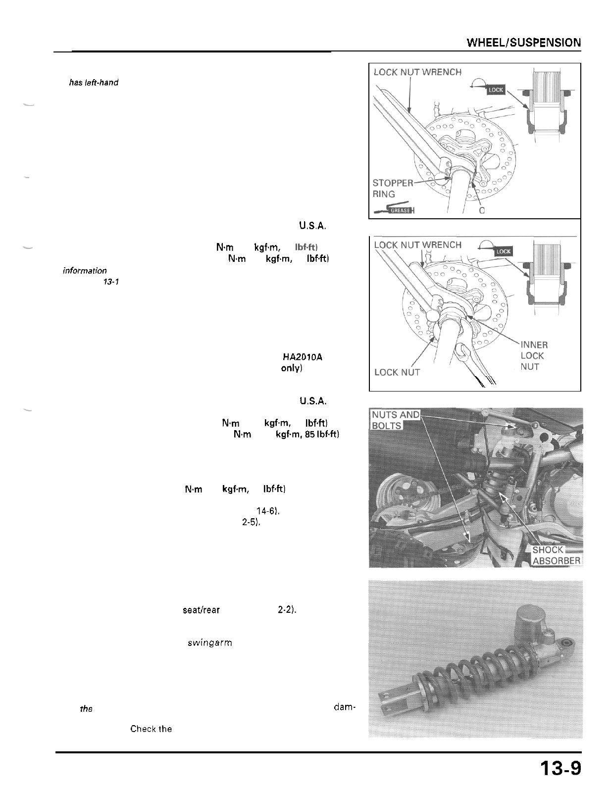
REAR WHEELlSUSPENSlON
Thelocknuts
haslen-hand
threads.
Turn the outer lock nut clockwise until the stopper
ring groove is covered with the outer lock nut and
apply locking agent to the lock bolt threads as shown.
Turn the outer lock
nut
counterclockwise until the
ring groove
is
visible and install the stopper ring into
the groove.
Apply grease to the stopper ring (outer lock nut seat
-
ing surface) and turn the outer lock nut to seat
it
against the stopper ring.
Tighten the outer lock nut.
TOOL
Lock
nut
wrench,
45
mm
-
-
07916
-
1870101 or
equivalent commercially
available
in
U.S.A.
-
Refer to torque
wrench reading
mformation
on
page
13-1
"
SERVICE
lock bolt threads.
INFORMATION
"
.
TORQUE: Actual:
88
Nm
(9.0 kgf.m, 65 Ibf4t)
Indicated: 79
N.m
(8.1 kgf.m, 59 IbfW
Apply locking agent to the inner lock nut area of the
Tighten the inner lock nut while holding the outer
lock nut.
TOOLS
Lock nut wrench, 56 mm 07916
-
HA20000
or
07916
-
HA2010A
(U.S.A. only)
07916
-
1870101 or
equivalent commercially
available in U.S.A.
TORQUE: Actual: 128
N.m
(13.0 kgf.m, 94 Ibf4tl
Lock nut wrench, 45
mm
-
Indicated: 115
N.m
(11.7
kgf.m.85 Ibf4t)
Tighten the driven sprocket nuts if the sprocket was
removed.
TORQUE 59
N.m
(6.0 k9f.m. 43 IbfW
Install the brake caliper (page
14-6).
Install the skid plate (page
2-5).
Adjust the drive chain slack (page
3
-
13)
REAR
SHOCK
ABSORBER
REMOVAL
UTER
LOCK NUT
WRENCH
\\
Remove the seatlrear fender (page
2-21.
Support the vehicle with a support block to raise the
rear wheels
off
the ground.
Support the swingarm and remove the mounting
nuts, bolts and the shock absorber.
INSPECTION
Becarefulnot to
lose
the needle
bearing.
Remove the upper pivot collar and check the needle
bearing, pivot collar and dust seals for wear or dam-
Checkthe damper unit for leakage or other damage.
Replace the shock absorber assembly if necessary.
rollers
of the
age.
13-9
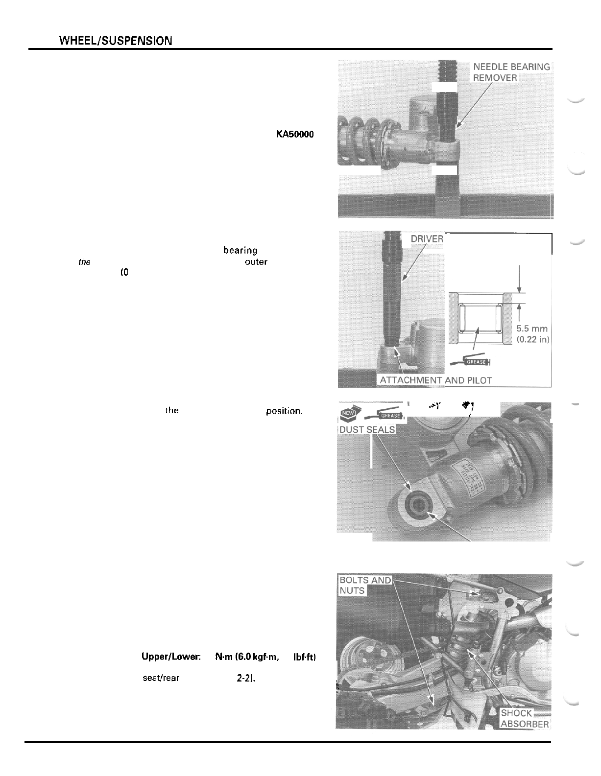
REAR WHEEL/SUSPENSION
BEARING REPLACEMENT
Press
the
mark
-
ing side
of
the
bearing.
Remove the dust seals.
Press the needle bearing out
of
the shock absorber.
TOOL
Needle bearing remover 07946
-
KA50000
DRYER
I
Apply grease to new needle bearing rollers.
Carefully press the needle bearina into the shock
absorber until the depth from the outer surface is
5.5
mm
(0
22
in).
TOOLS:
Driver 07749
-
0010000
Attachment, 24
x
26 mm 07746
-
0010700
Pilot, 17 mm 07746
-
0040400
-
"I
1
ry
/
Make sure that the need
e
rollers
are
in positJon.
Apply
grease to new dust seal lips and install them
into the upper pivot until they are seated against the
needle bearing.
Install the pivot collar.
'PIVOT
COLLAR
INSTALLATION
Set the shock absorber onto the shock link and into
the frame and install the mounting bolts from the
right side.
Install the mounting nuts and tighten them.
TORQUE: Upper/Lower: 59
Nm
16.0
kgf.m,
43 Ibf.ft)
Install the seathear fender (page
2-2).
i
13
-
1
0
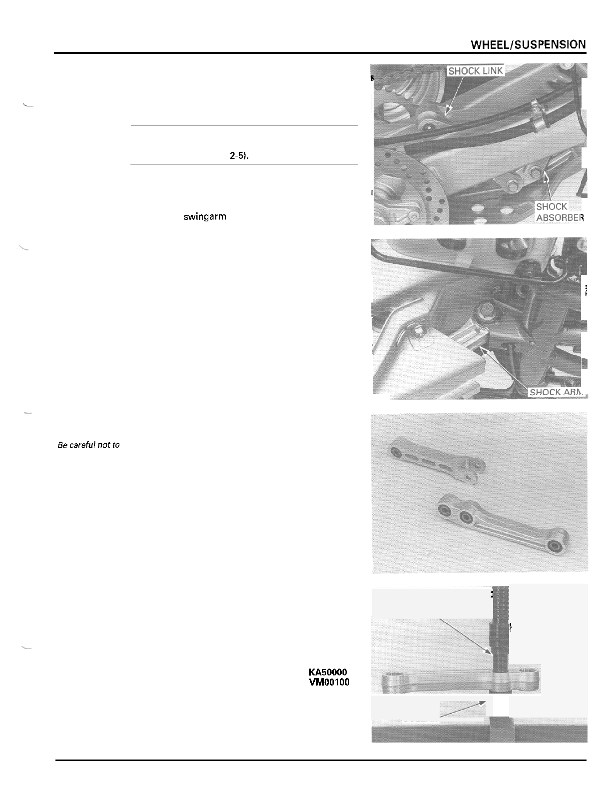
REAR WHEELlSUSPENSlON
SHOCK
LINKAGE
I
REMOVAL
i
NOTE:
The linkage can be serviced with the skid plate
installed, although
it
is easier to service if the skid
plate is removed (page
2-51,
Support the vehicle with
a
support block to raise the
rear wheels
off
the ground.
~
Support the swingarm and remove the following:
1
-
shock absorber lower mounting nut and bolt
-
shock arm
-
to
-
shock link nut and bolt
-
shock link
-
to
-
swlngarm nut and bolt
-
shock link and washer
-
shock arm
-
to
-
frame nut and bolt
-
shock arm
1
?
-
INSPECTION
Becarefulnotto
lose
the
needle
rollers
of
the
bearing.
Remove the pivot collars and check the needle bear
-
ings, pivot collars and dust seals for wear or damage.
BEARING REPLACEMENT
Remove the dust seals.
Press the needle bearing out of the shock arm and
shock link.
TOOLS:
Needle bearing remover
07946
-
KA50000
Assembly collar
07965
-
VMOOIOO
-
NEEDLE BEARING
i
REMOVER
\
COLLAR
/
I
13
-
1
I
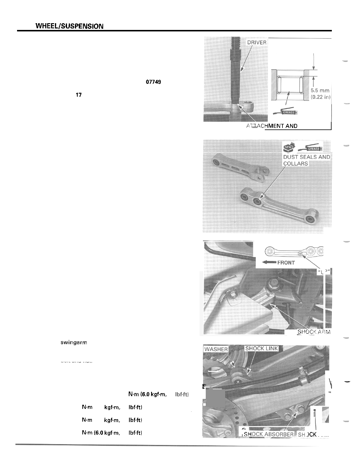
REAR
WHEEL/SUSPENSION
Press the mark
-
ing side
of
the
bearing
Note the installa
-
tion
of
the pivot
bolts. All bolts
are installed
from
the right
side.
Apply grease to new needle bearing rollers.
Carefully press the needle bearing into the shock arm
and shock link until the depth from the outer surface
is
5.5
mm
(0.22
in).
TOOLS:
Driver
07749
-
0010000
Attachment,
24
x
26
mm
07746
-
0010700
Pilot,
17
mm
07746
-
0040400
-
-
p'iiACHMENTAND
*-
PILOT
Make sure that the needle rollers are in position.
-
Apply grease to new dust seal lips and install them
into the pivots until they are seated against the nee
-
dle bearings.
Install the pivot collars.
-
INSTALLATION
Install the shock arm into the frame with the
"
UP
"
mark facing up and the bolt and nut.
StiOCJ.
A?M
-.
-
install the shock link over the shock arm and into the
swingarm with the washer (left side of the shock
link), bolts and nuts.
Connect the shock absorber
to
the shock link with the
bolt and nut.
Tighten the linkage and shock absorber mounting nuts.
TORQUE:
F"
\-
Shock arm
-
to
-
frame:
59
Nm
(6.0
kgfm,
43
Ibf4t)
Shock arm
-
to
-
shock link
Shock link
-
to
-
swingarm:
Shock absorber mounting:
1
b,
7
59
Nm
(6.0
kgfm,
43
Ibf4tl
44
Nm
14.5
kgfm,
33
IbfW
59
Nm
(6.0
kgfm,
43
Ibf4t)
-
I
n
0
sc,
)CK
ARM
-
13
-
1
2
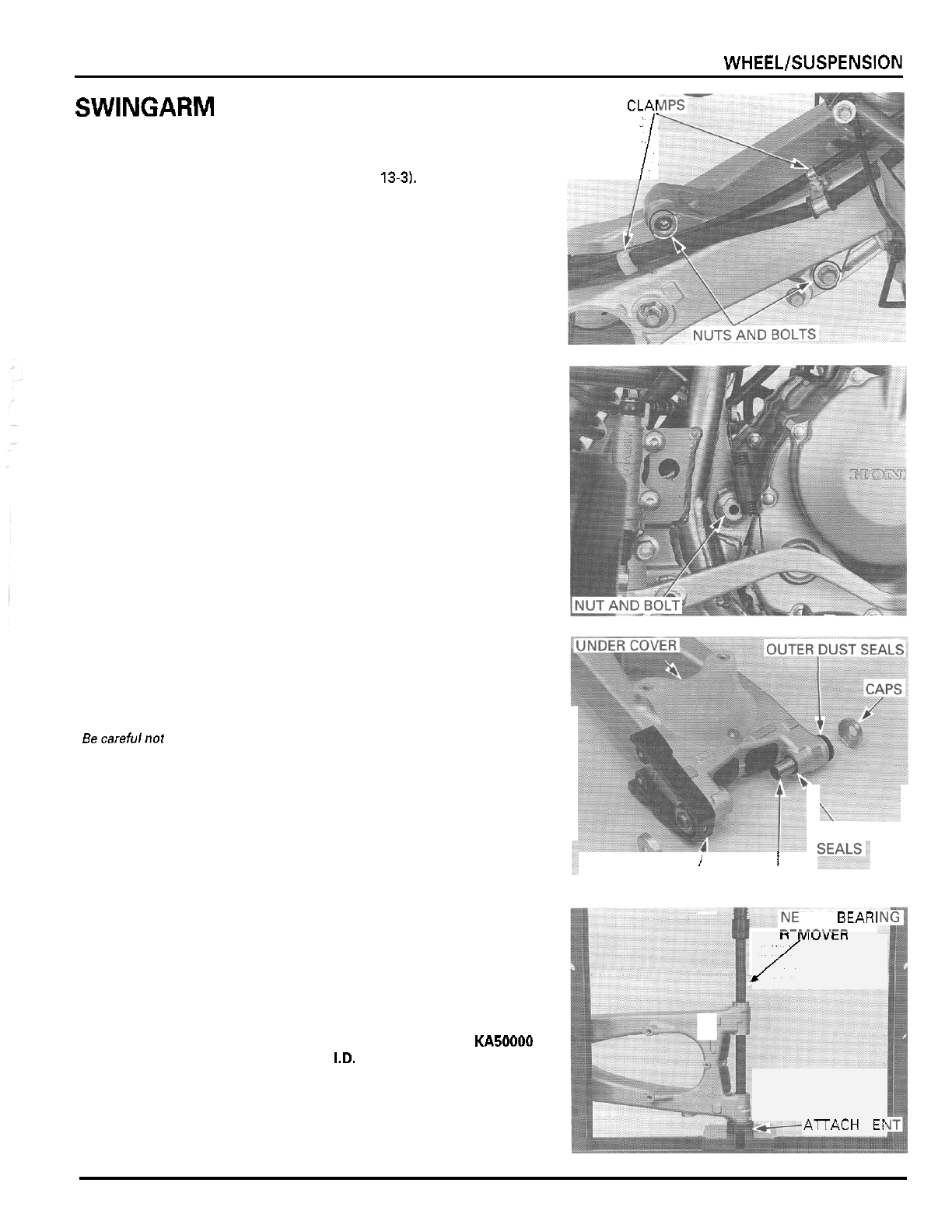
.
REAR WHEEL/SUSPENSION
SWINGARM
REMOVAL
Remove the rear axle (page
13-31,
Support the swingarm and remove the following:
-
screw and brake hose clamp
-
bolt and brake hosellock cable clamp
-
shock absorber lower mounting nut and bolt
-
shock link
-
to
-
swingarm nut and bolt
-
swingarm pivot nut and bolt
-
swingarm from the frame
CLAr
I
-
dust seal caps and outer dust seals
-
under cover and chain slider if necessary.
INSPECTION
Becarefulnot to
lose
the needle
rollers
of
the
bearing.
Remove the pivot collars and check the needle bear
-
ings, pivot collars and dust seals for wear or damage.
\
n
t
iviuvtn
/
I.+---
AnACH
M
EF
INNER
DUST
/
I
SLIDER COLLARS
BEARING REPLACEMENT
EDLE BEAR1
Remove the inner dust seals.
Press the needle bearing and thrust bushing
out
of
the swingarm.
TOOLS:
Needle bearing remover 07946
-
KA50000
Attachment, 35
mm
I.D.
07746
-
0030400
13
-
1
3
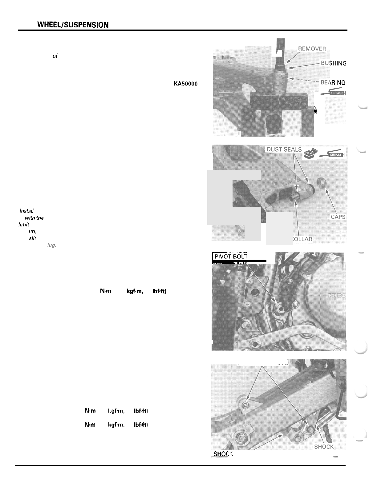
REAR
WHEEL/SUSPENSION
Press the
marking side
of
the bearing.
Instail the slider
with the wear
limit groove fac
-
ing
up,
aligning
its slit with the
lug.
Apply grease to new needle bearing rollers.
Carefully press the needle bearing and thrust bush
-
ing into the swingarm pivot until the bushing is fully
seated.
TOOL
Needle bearing remover
07946
-
KA50000
Pack grease into new inner dust seal lip cavities.
Install the inner dust seals until they are flush with
the pivot surfaces.
Install the pivot collars.
INSTALLATION
Install the following if they are removed:
-
under cover with the bolt
-
chain slider with the bolts and collars
Pack grease into new outer dust seal lip cavities.
Install the outer dust seals onto the swingarm pivots
and the seal caps over the dust seal securely.
Set the swingarm into the frame, take care to prevent
removing the dust seal caps, and install
the
pivot bolt
from the right side.
Install the pivot nut and tighten it.
TORQUE:
108
N.m
(11.0
kgfm,
80
Ibf.ft)
Connect the shock link to the swingarm and the
shock absorber to the shock arm by inserting the
pivot bolts from the right side.
Install the nuts and tighten them.
TORQUE:
Shock link
-
to
-
swingarm:
Shock absorber mounting:
44
Nm
(4.5
kgfm,
33
Ibf.ftl
59
N.m
(6.0
kgfm,
43
Ibf4tl
NEEDLE BEARING
RFhfln\/FR
?
SHlNG
-
\RING
/
-
;i
-
-
-
JPIVOT'BOLT
AND
N
JT
BOLTS AND NUTS
SHOCI:
LINK'
-_I_
-
ABSORBER
-
13
-
14
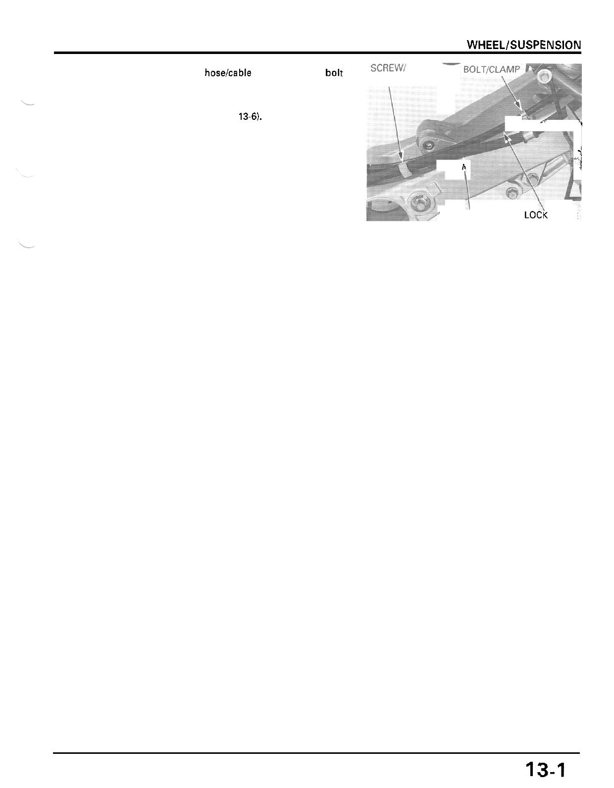
REAR WHEELlSUSPENSlON
Install the brake hoselcable clamp with the bolt to
secure the brake lock cable.
Install the brake hose clamp with the screw.
Install the rear axle (page
13-6).
SCREW/
CLAMP
1
s
i
h
7
I
\
’
BRAKE HOSE LOCK CABLE
.
13-1
5
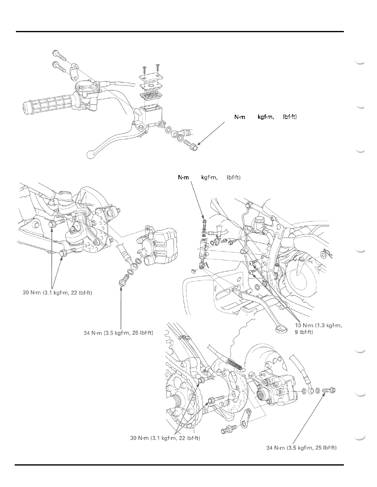
HYDRAULIC DISC BRAKE
34
Nm
(3.5 kgfm, 25 IbfW
34
Nm
(3.5 kgfm, 25 Ibf.ft)
14
-
0
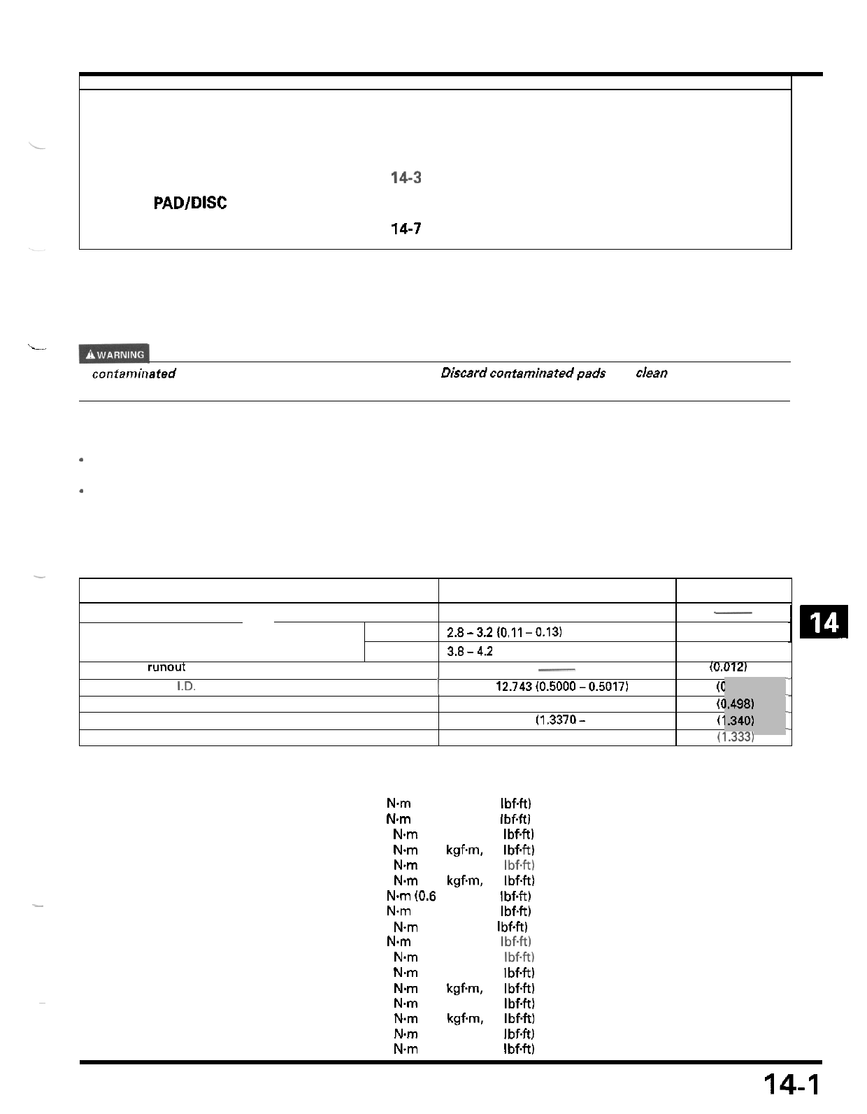
14.
HYDRAULIC DISC
BRAKE
-
ITEM
STANDARD
SERVICE
LIMIT
~
Recommended brake fluid
Brake disc thickness Front
2.8-3.2(0.11 -0.13) 2.5 (0.10)
Rear
3.8-4.2 (0.15
-
0.17) 3.5 (0.14)
Brake disc runout
__
0.30 (0.012)
Master cylinder
ID.
I
12.700
-
12.743(0.5000-0.5017) 12.75
(C
Master piston
O.D.
12.65
(C
Caliper cylinder
I.D.
33.960
-
34.010 (1.3370- 1.3390) 34.02
(1
Caliper piston
O.D.
33.895
-
33.928 (1.3344
-
1.3357) 33.87
(1:ssSl
DOT
4
brake fluid
-
-
12.657
-
12.684 (0.4983
-
0.4994)
-
-
SERVICE INFORMATION 14
-
1 FRONT BRAKE CALIPER 14
-
10
TROUBLESHOOTING 14
-
2 REAR MASTER CYLINDER 14
-
13
BRAKE FLUID REPLACEMENT/ REAR BRAKE CALIPER 14
-
16
AIR BLEEDING
14-3
BRAKE PEDAL 14
-
20
BRAKE PAD/DISC 14
-
5
FRONT MASTER CYLINDER
14-7
:m
SERVICE
INFORMATION
GENERAL
L
A
confarninafed brake disc or pad reduces stopping
power.
Diswrd
contaminatedpads and clean
a
contaminated disc
with
a
high
quality brake degreasing agent.
1.502)
1.498)
1.3401
-
Caliper bleed valve
6
Nm
(0.6
kgfm,
4.3
IbfW
3
Nm
(0.3
kgfm,
2.2
IbfW
18
Nm
(1.8
kgfm
13
IbfW
34
Nm
(3.5
kgfm,
25
Ibf.ft)
17
Nm
(1.7
kgf.m,
12
IbfW
6
N.m
(0.6
kgfm,
4.3
IbfW
6
Nm
(0.6
kgfm,
4.3
Ibf4t)
13
Nm
(1.3
kgfm,
9
Ibf4t)
2
Nm
(0.2
kgfm,
1.4
Ibf.ft)
23
Nm
(2.3
kgfm,
17
Ibf.ft)
18
Nm
(1.8
kgfm,
13
IbfW
30
Nm
(3.1
kgfm,
22
IbfW
23
Nm
(2.3
kgfm,
17
IbfW
18
Nm
(1.8
kgfm,
13
Ibf-ft)
30
Nm
13.1
kgfm,
22
IbfW
23
N.m
(2.3
kgfm
17
IbfW
Front brake caliper pad pin plug
Front brake caliper pad pin
Brake hose oil bolt
Brake pipe joint nut
Front brake lever pivot bolt
nut
Rear master cylinder mounting bolt
Rear master cylinder reservoir hose joint screw
Front brake caliper slide pin
Front brake caliper bracket pin
Front brake caliper mounting bolt
Rear brake caliper slide pin
Rear brake caliper bracket pin
Rear brake caliper mounting bolt
Rear brake caliper parking brake base bolt
Rear brake caliper pad pin
18
Nm
(1.8
kgfm,
13
IbfW
~
ALOC bolt
Apply locking agent to the threads
ALOC bolt
Apply locking agent to the threads
ALOC bolt
Apply locking agent to the threads
~
14-1
HYDRAULIC DISC BRAKE
TOOL
Snap ring pliers
TROUBLESHOOTING
Brake leverlpedal
soft
or spongy
*
Air in hydraulic system
-
Leaking hydraulic system
-
Contaminated brake padldisc
-
Worn caliper piston seals
*
Worn master cylinder piston cups
-
Worn brake padldisc
-
Contaminated caliper
-
Contaminated master cylinder
*
Caliper not sliding properly
-
Low brake fluid level
*
Clogged fluid passage
-
Warpedldeformed brake disc
*
Stickinglworn caliper piston
Stickinglworn master piston
-
Bent brake leverlpedal
Brake leverlpedal hard
-
Clogged/restricted hydraulic system
-
Stickinglworn caliper piston
-
Stickinglworn master piston
*
Caliper
not
sliding properly
-
Bent brake leverlpedal
Brake
grab
or
pull
one side
*
Misaligned disc or wheel
*
Contaminated brake padldisc
*
Warpedldeformed brake disc
-
Caliper not sliding properly
Brake drag
-
Contaminated brake padldisc
*
Badly worm brake pad/disc
*
Warpedldeformed brake disc
*
Caliper
not
sliding properly
*
Cloggedlrestricted fluid passage
*
Misaligned disc
Sticking caliper piston
07914
-
SA50001
-
14-2
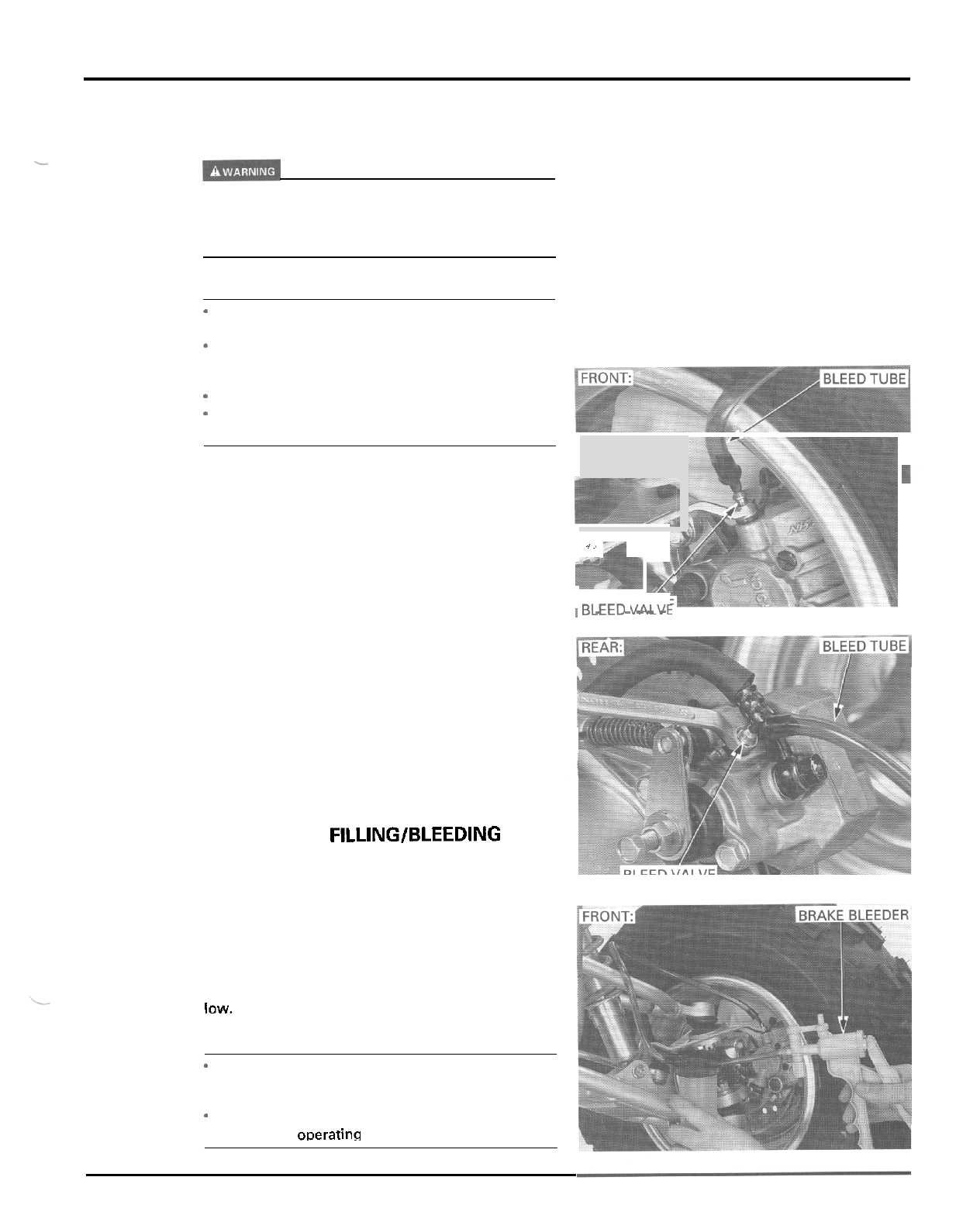
HYDRAULIC DISC BRAKE
BRAKE FLUID REPLACEMENT/
AIR BLEEDING
-
A
contaminated brake disc or pad reduces stopping
power. Discard contaminated pads and clean a cont
-
aminated disc with a high quality brake degreasing
agent.
CAUTION
-
Do
not allow foreign material to enter the system
when filling the reservoir.
*
Avoid spilling fluid on painted, plastic or rubber
parts. Place a rag over these parts whenever the
system is serviced.
Use onlv
DOT
4
brake fluid from a sealed container.
*
-
Do
not mix different types
of
fluid. They are not
compatible.
BRAKE FLUID DRAINING
Remove the reservoir cap, set plate and diaphragm
(page
3
-
14
for front, page
3
-
15
for rear).
1
.,
-
-
Connect the bleed tube to the bleed valve.
Loosen the bleed valve and pump the brake lever or
pedal until no more fluid flows out of the bleed valve.
~
BLEtL;
.t:i,.,,-Vt
.
-
-
-
-
.
BRAKE FLUID FILLING/BLEEDING
Close the bleed valve.
Fill the reservoir with
DOT
4
brake fluid from
a
sealed
container.
Connect a commercially available brake bleeder to
the bleed valve.
Pumo the brake bleeder and loosen the bleed valve.
Add brake fluid when the fluid level in the reservoir
is
low.
NOTE:
*
Check the fluid level often while bleeding the
brake to prevent air from being pumped into the
system.
When using
a
brake bleeding tool, follow the man.
ufacturer's oDerating instructions.
*
I
14
-
3
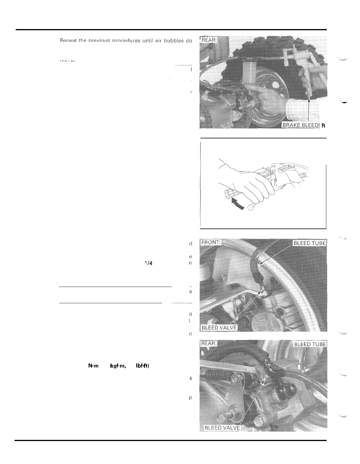
HYDRAULIC
DISC
BRAKE
not appear in the bleed tube.
NOTE:
~~
If air
is
entering the bleeder from around the bleed
valve threads, seal the threads with teflon tape.
Close the bleed valve and operate the brake lever
or
pedal. If it still feels spongy, bleed the system again.
If a brake bleeder is not available. use the following
procedure:
Pump up the system pressure with the brake lever or
pedal until lever or pedal resistance
is
felt.
Connect
a
bleed tube to the bleed valve and bleed
the system as follows:
1.
Squeeze the brake lever or depress the brake
pedal, open the bleed valve
114
turn and then
close
it.
NOTE:
Do
not release the brake lever or pedal until the
bleed valve has been closed.
2.
Release the brake lever or pedal slowly and wait
several seconds after it reaches the end of its travel.
Repeat the steps 1 and
2
until air bubbles do not
appear in the bleed tube.
Tighten the bleed valve.
TORQUE:
6
Nm
10.6
kgfm,
4.3
Ibf4t)
Fill
the reservoir to the upper level line with DOT 4
brake fluid from a sealed container.
Install the diaphragm, set plate and reservoir cap
(page
3
-
14
for front, page
3
-
15
for rear).
1
R
14
-
4
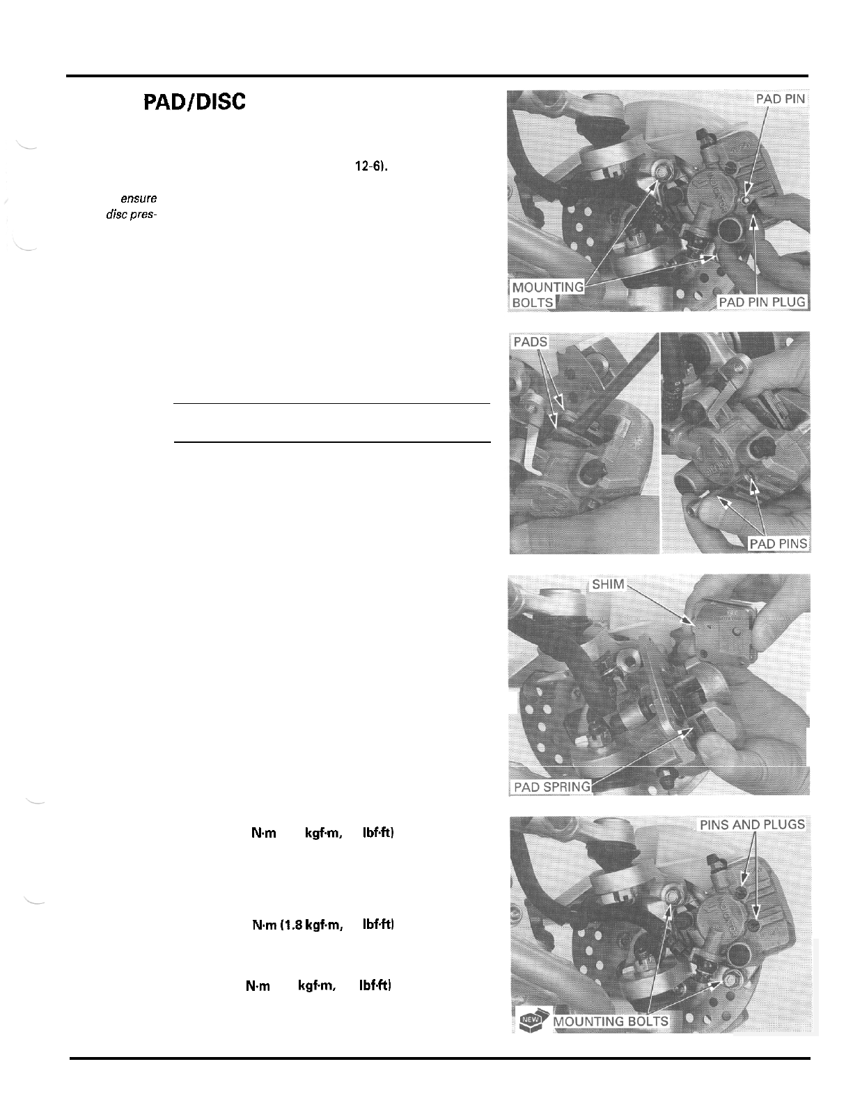
HYDRAULIC DISC BRAKE
BRAKE
PAD/DISC
FRONT BRAKE PAD REPLACEMENT
Always
replace
the brake pads in
pairs
to
ensure
even discpres-
sure.
Remove the front wheel (page
12-6).
Remove the pad pin plugs and loosen the pad pins.
Release the brake hose from the clamp.
Remove the mounting bolts and front brake caliper.
Push the caliper piston all the way in to allow instal
-
lation
of
new brake pads.
NOTE:
Check the brake fluid level in the brake reservoir
as
this operation causes the level to rise.
Pull the pad pins out of the caliper body while push
-
ing in the pads against the pad spring.
Remove the brake pads.
Make sure that the pad spring is in position as
shown.
Install new brake pads into the caliper body with the
shim facing toward the piston.
Install the pad pins by pushing in the pads against
the pad spring to align the pad pin holes in the pads
and caliper body.
Install the front brake caliper
so
the disc
is
positioned
between the pads, being careful not to damage the
pads.
Install new mounting bolts and tighten them.
TORQUE:
30
N.m
(3.1
kgf.m,
22
Ibf4t)
Secure the brake hose with the clamp.
Tighten the pad pins.
TORQUE:
18
N.m
(1.8
kgfm,
13
IbfW
Install the pad pin plugs and tighten them.
TORQUE
3
N.m 10.3 kgf.m,
2.2
IbfW
Operate the brake lever to seat the caliper piston
against the pads.
14
-
5
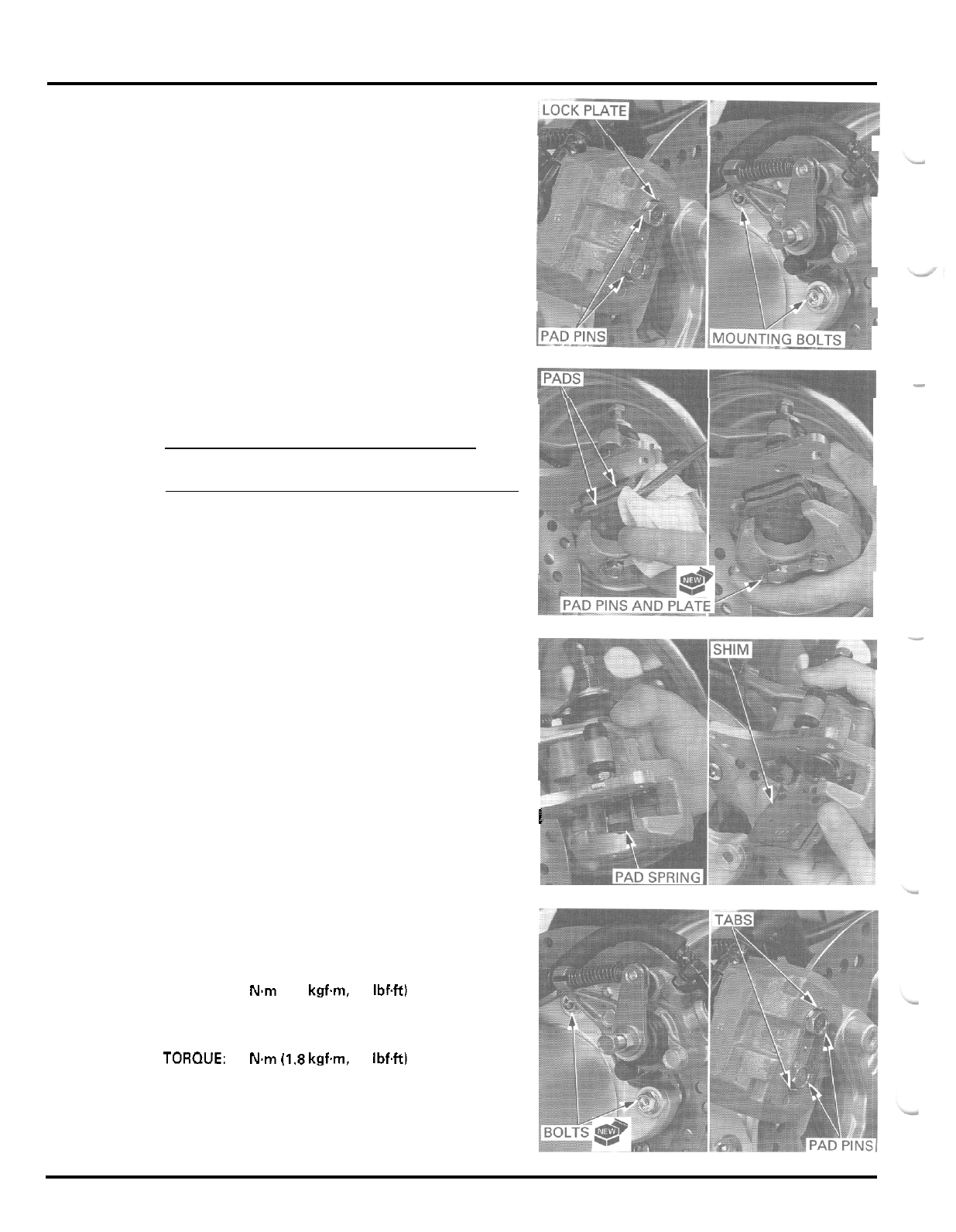
HYDRAULIC DISC
BRAKE
REAR BRAKE PAD REPLACEMENT
Alwaysreplace
Straighten the lock plate tabs and loosen the pad
the brake pads in
pins.
pairs
to
ensure
even discpres
-
sure.
Remove
the
mounting bolts and rear brake caliper.
Push the caliper piston
all
the way in to allow instal
-
lation of new brake pads.
NOTE:
Check the brake fluid level in the brake reservoir as
this operation causes the level to rise.
Pull the pad pins out of the caliper body with the lock
plate while pushing in the pads against the pad
spring.
Remove the brake pads.
Make sure that the pad spring is in position as
shown.
Install new brake pads into the caliper body with the
shim facing toward the piston.
Install the pad pins with
a
new lock plate by pushing
in the pads against the pad spring to align the pad
pin holes in the pads and caliper body.
Install the rear brake caliper
so
the disc is positioned
between the pads, being careful not to damage the
pads.
Install new mounting bolts and tighten them.
TORQUE:
30
Nm
(3.1
kgf.m,
22
Ibf4t)
Tighten the pad pins.
TOROUE:
18
Nm
(1.8
kgfm,
13
IbfW
Bend up the lock plate tabs against
the
pad pins.
Operate the brake pedal to seat the caliper piston
against the pads.
I
1
14
-
6
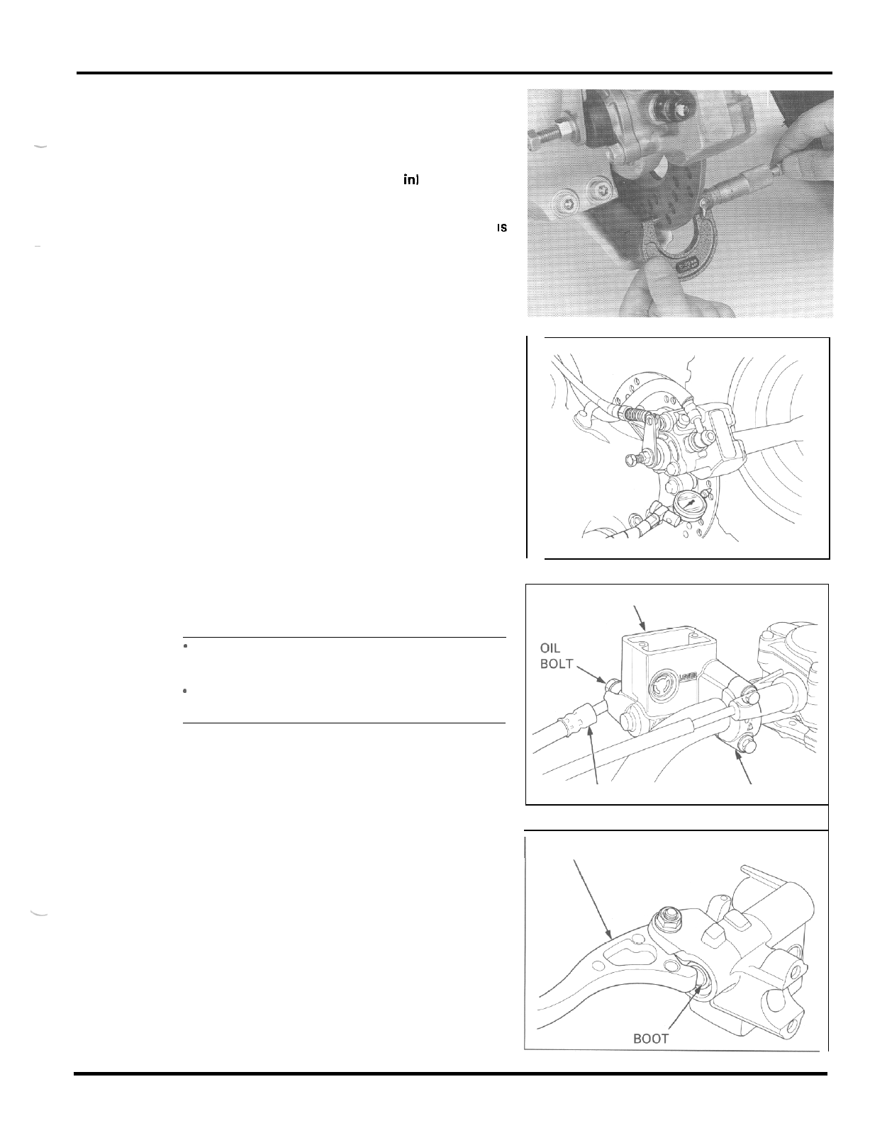
HYDRAULIC DISC BRAKE
BRAKE DISC INSPECTION
Visually inspect the disc for damage or cracks.
Measure the brake disc thickness at several points.
SERVICE
LIMIT
Front:
2.5
mm
(0.10
in1
Rear:
3.5
mm
(0.14
in)
Replace the brake disc if the smallest measurement
IS
-
~
less than service limit.
Check the brake disc for warpage.
SERVICE
LIMIT
0.30
mm
10.012
in)
Check the bearing for excessive play, if the warpage
exceeds the service limit.
Replace the brake disc if
the
bearings are normal.
FRONT
MASTER
CYLINDER
CAUTION:
-
Avoid spilling fluid on painted, plastic or rubber
park. Place
a
rag over these parts whenever the
system is serviced.
When removing the oil bolt, cover the end of the
hose to prevent contamination.
-
DISASSEMBLY
Drain the brake fluid from the front brake hydraulic
system (page
14
-
3).
Disconnect the brake hose from the master cylinder
by removing the oil bolt and sealing washers.
Remove the master cylinder holder bolts, holder and
the master cylinder.
Remove the following:
-
pivot nut, bolt and brake lever
-
piston boot
MASTER CYLINDER
BRAKE
H
O
S
E
H
OLDER
I
LEVER
14
-
7
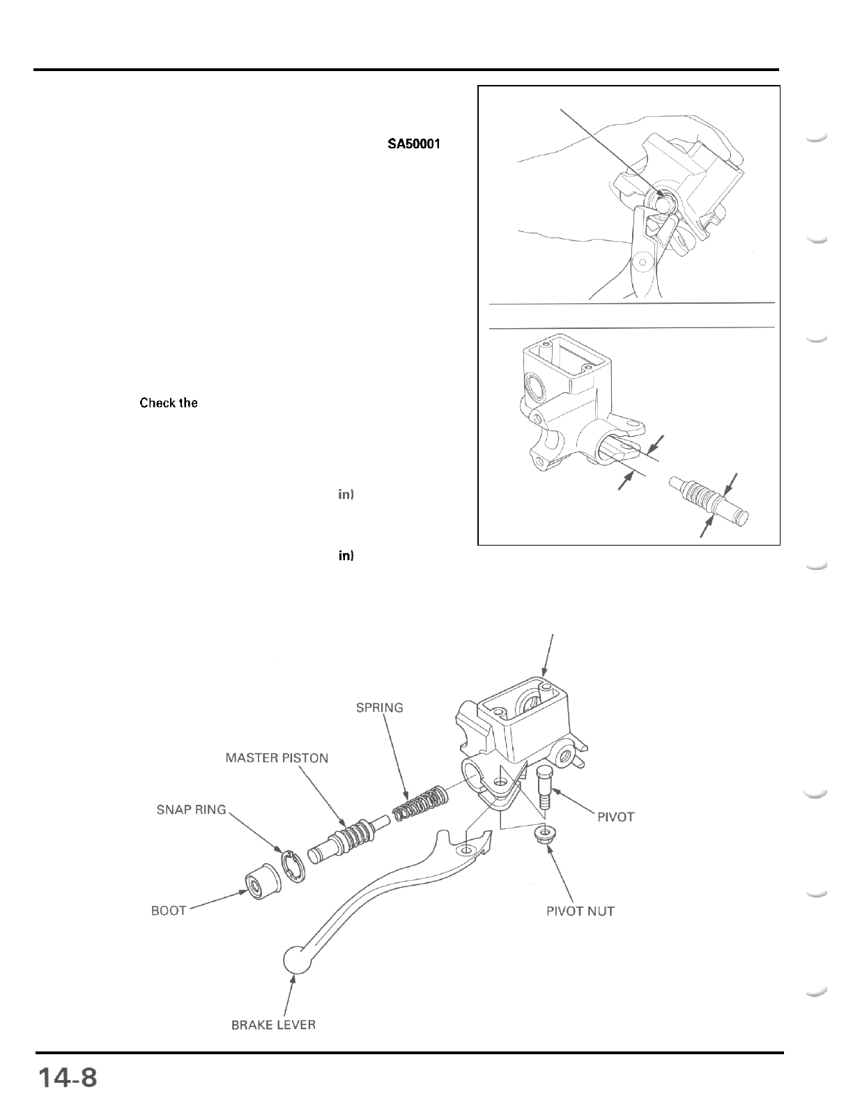
HYDRAULIC DISC BRAKE
-
snap ring
TOOL
Snap
ring
pliers
-
master piston
-
spring
07914
-
SA50001
Clean the master cylinder, reservoir and master pis
-
ton in clean brake fluid.
INSPECTION
Check the piston cups for wear, deterioration or dam
-
age.
Checkthe spring for damage.
Check the master cylinder and piston for scoring,
scratches or damage.
Measure the master cylinder
I.D.
SERVICE
LIMIT
12.75
mm
(0.502
in1
Measure the master piston
O.D.
SERVICE
LIMIT:
12.65
mm
(0.498
in1
ASSEMBLY
SNAP
RING
MASTER
CYLINDER
BOLT
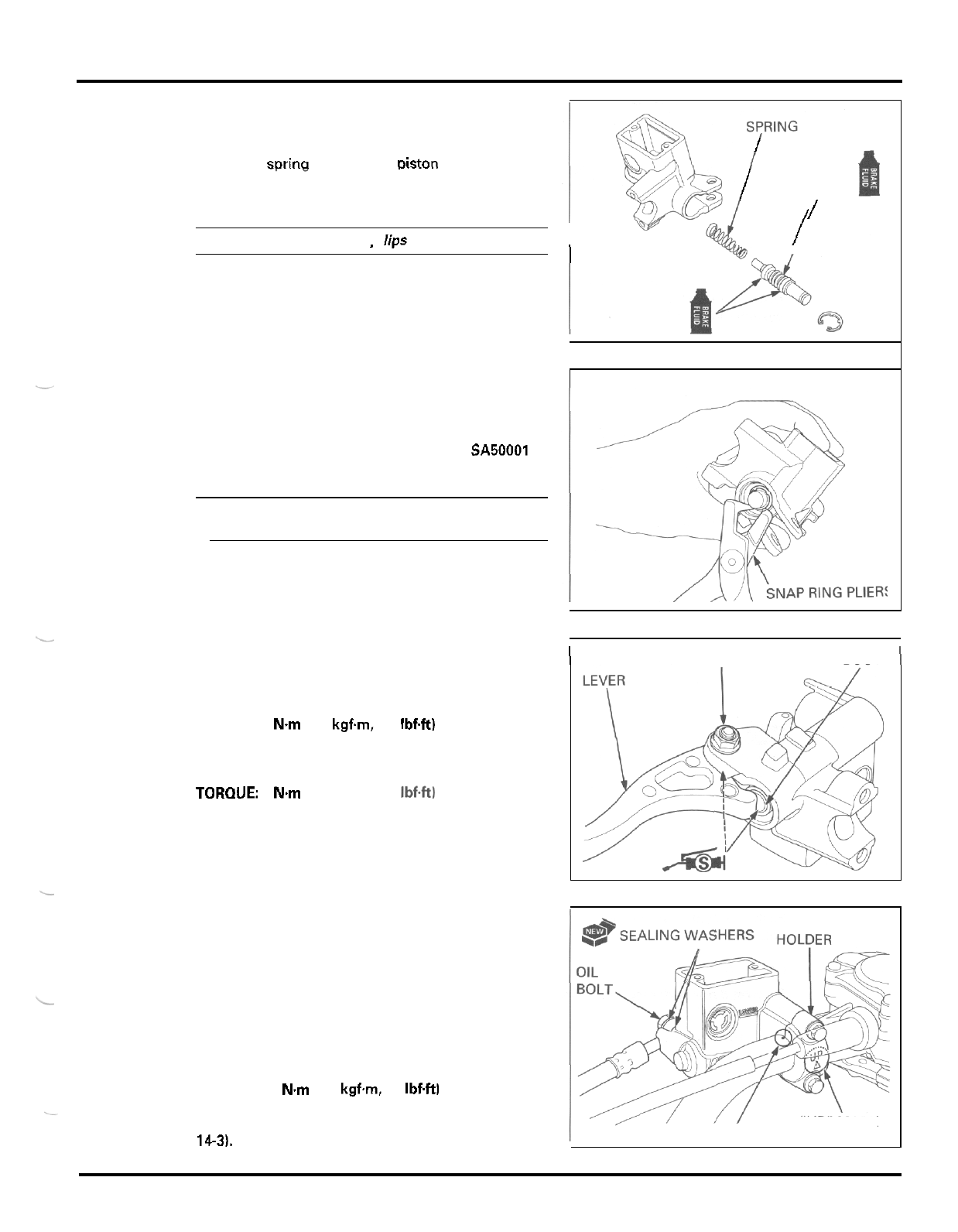
HYDRAULIC DISC BRAKE
Coat the master piston and piston cups with clean
brake fluid.
Install the spring onto the master piston.
Install the sorina and master Diston into the master
.I
cylinder.
CAUTION:
Do
not allow the oiston
C
U
D
lim
to turn inside out.
I
/
I
/
PISTON
/
I
..
Install the snap ring into the groove in the master
cylinder, using the special tool.
TOOL
Snap
ring
pliers
CAUTION:
07914
-
SA50001
Be certain the
snap
ring
is
firmly seated in the
groove.
Install the boot into the master cylinder and the
groove in the piston.
Apply silicone grease to the brake lever contacting
surface of the piston.
Apply silicone grease to the brake lever pivot.
Install the brake lever and pivot bolt, and tighten
it.
TORQUE:
6
Nm
(0.6
kgfm,
4.3
IbfW
Install the pivot nut and tighten
it.
TORQUE:
6
Nm
(0.6
kgfm,
4.3
Ibf4tl
I
BOLT
AND NUT
BOOT
1
Install the master cylinder and holder with the
"
UP
"
mark facing up.
Align the end of the master cylinder with the punch
mark on the handlebar, and tighten the upper bolt
first, then tighten the lower bolt.
Connect the brake hose to the master cylinder with
the oil bolt and new sealing washers by aligning the
hose joint with the stopper groove.
Tighten the
oil
bolt.
TORQUE:
34
Nm
(3.5
kgfm,
25
IbfW
Fill
and bleed the front brake hydraulic system (page
14-3).
"
UP
"
MARK
P
U
N
C
H
M
ARK
14
-
9
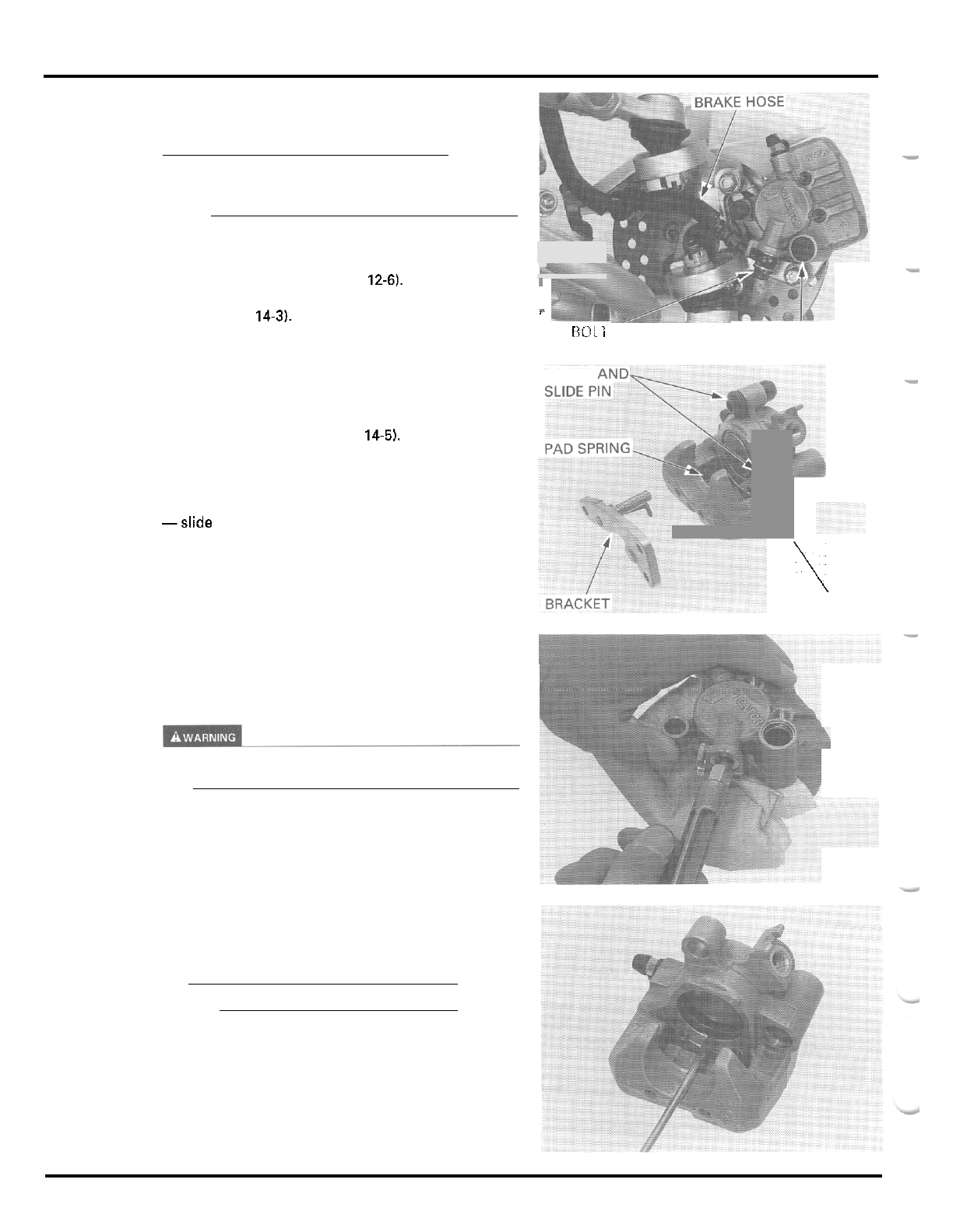
HYDRAULIC DISC BRAKE
FRONT BRAKE CALIPER
CAUTION
Avoid spilling fluid on painted, plastic or rubber
parts. Place a rag over these parts whenever the
sys
-
tem is serviced.
DISASSEMBLY
Remove the front wheel (page
12-61.
Drain the brake fluid from the front brake hydraulic
system (page
14-3).
Disconnect the brake hose from the front brake
caliper by removing the oil bolt and sealing washers.
Remove the dust plug and loosen the caliper slide
pin.
Removethe brake pads (page
14-5).
Loosen the slide pin and remove the following:
-
caliper bracket and washer
-
pad spring
-slide pin and boots
Place the shop towel over the piston.
Position the caliper body with the piston down and
apply small squirts of air pressure to the fluid inlet to
remove the piston.
A
-
I
/L
OIL
RO!
i
'
a
'LUG AND
SLIDE
PIN
\
BOOTS
-
\
WASHER
Do
not use high pressure air or bring the nozzle too
close to the inlet.
Push the dust seal and piston seal
in
and lift them
out.
CAUTION:
Be careful not to damage the piston sliding surface.
Clean the seal grooves, caliper cylinder and piston
with clean brake fluid.
14
-
1
0
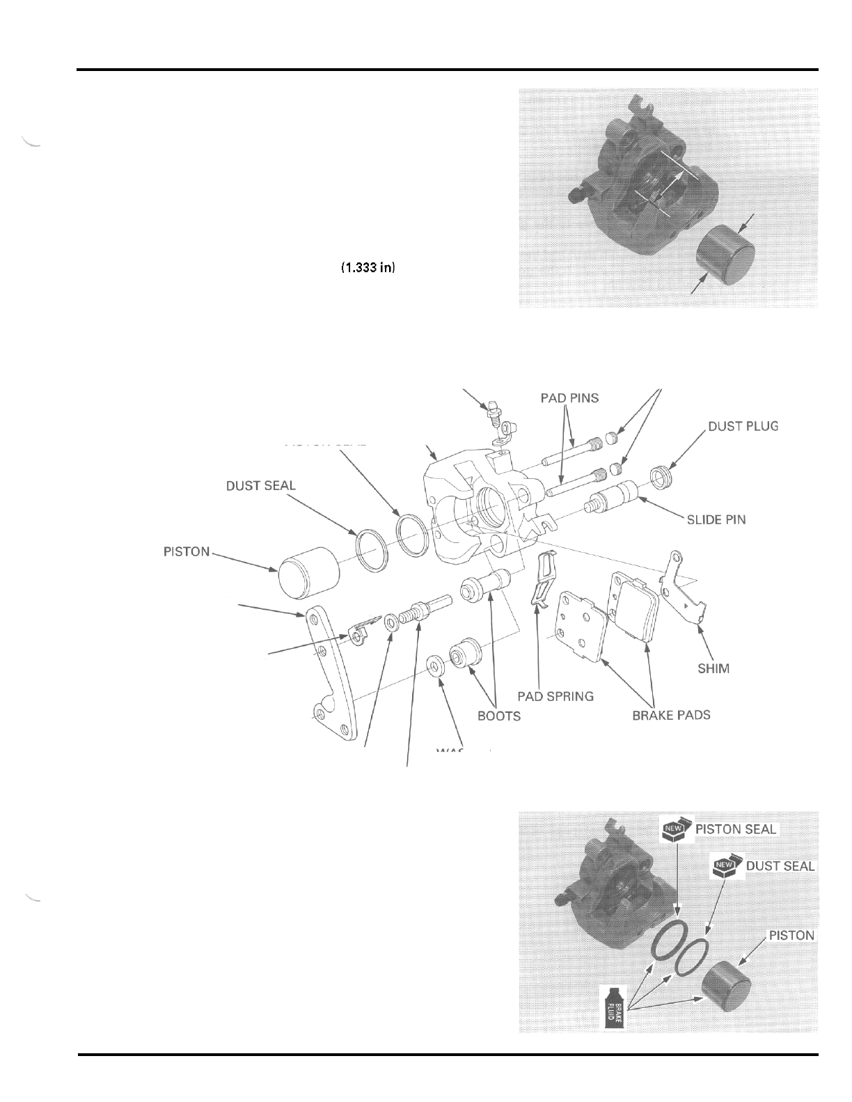
HYDRAULIC DISC BRAKE
INSPECTION
Check the caliper cylinder and piston for scoring,
scratches or damage.
Measure the caliper cylinder I.D.
SERVICE
LIMIT:
34.02
mm
(1.340
in)
Measure the caliper piston O.D.
SERVICE
LIMIT
33.87
mm
(1.333
in1
ASSEMBLY
BLEED VALVE PAD PIN PLUGS
\
CALIPER BODY
PISTON SEAL
\
CALIPER BRACKET
WEAR REFERENCE PLATE
WASHER WASHER
BRACKET PIN
Coat new piston seal and dust seal with clean brake
fluid and install them into the seal grooves
in
the
caliper.
Coat the caliper piston with clean brake fluid and
install
it
into the caliper cylinder
with
the opening
toward the caliper body.
14
-
1
I
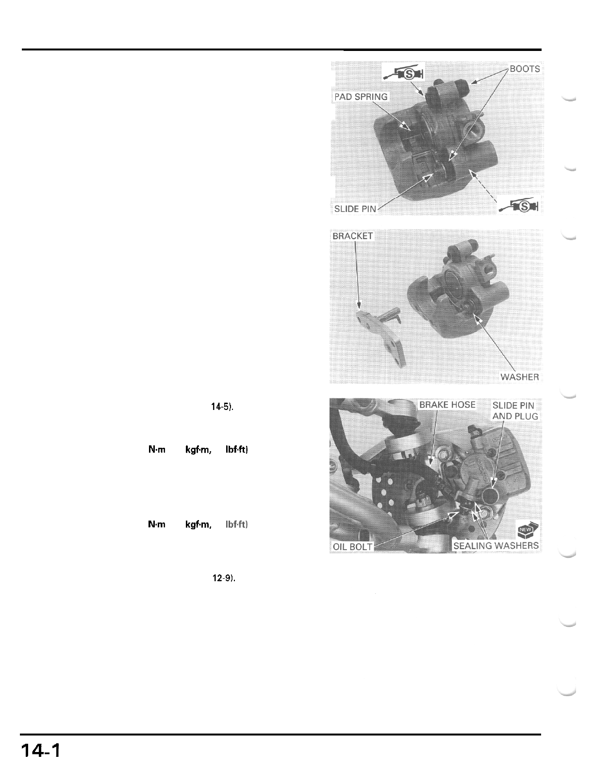
HYDRAULIC DISC BRAKE
Install the pad spring as shown.
If
the pin boots are hard or deteriorated, replace
them with new ones.
Install the bracket pin boot into the caliper body and
pack silicone grease
to
the
inside of the boot.
Apply silicone grease to the grease groove in the
slide pin.
Install the slide pin boot and the slide pin
so
the boot
ribs properly align with the grooves in the caliper
body and slide pin.
Install the caliper bracket over the caliper body with
the spring washer (between the slide pin and bracket)
and thread the slide pin into the bracket, being care
-
ful not to damage the pin boot.
Make sure
that
the boots are seated securely into the
pin grooves.
Install the brake pads (page 14-5).
Tighten the slide pin and install the dust plug.
TORQUE: 23
Nm
(2.3
kgfm,
17
IbfW
Connect the brake hose to the brake caliper with the
oil bolt and new sealing washers, and tighten the oil
bolt by aligning the hose joint with the stopper
groove.
TORQUE: 34
Nm
(3.5
kgfm,
25
Ibf.ft)
Fill
and bleed the front brake hydraulic system (page
14
-
3).
Install the front wheel (page 12-91,
14-1
2
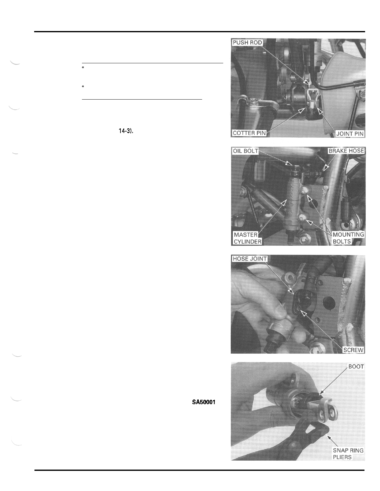
HYDRAULIC DISC BRAKE
REAR MASTER CYLINDER
CAUTION:
-
Avoid spilling fluid
on
painted, plastic
or
rubber
parts. Place a rag over these parts whenever the
system is serviced.
When
removing the oil bolt, cover the end of the
hose
to
prevent contamination.
-
DISASSEMBLY
Drain the brake fluid from the rear brake hydraulic
system (page
14-3).
Disconnect the push rod from the brake pedal by
removing the cotter pin and joint pin.
Disconnect the brake hose from the master cylinder
by removing the oil bolt and sealing washers.
Remove the master cylinder mounting bolts.
Disconnect the reservoir hose joint from the master
cylinder by removing the joint screw.
Remove the O
-
ring.
Clean the master cylinder and master piston
in
clean
brake fluid.
Remove the boot from the master cylinder.
Remove the snap ring and push rod using the special
tool.
TOOL
Snap
ring
pliers
Remove the master piston and spring.
07914
-
SA50001
14
-
1
3
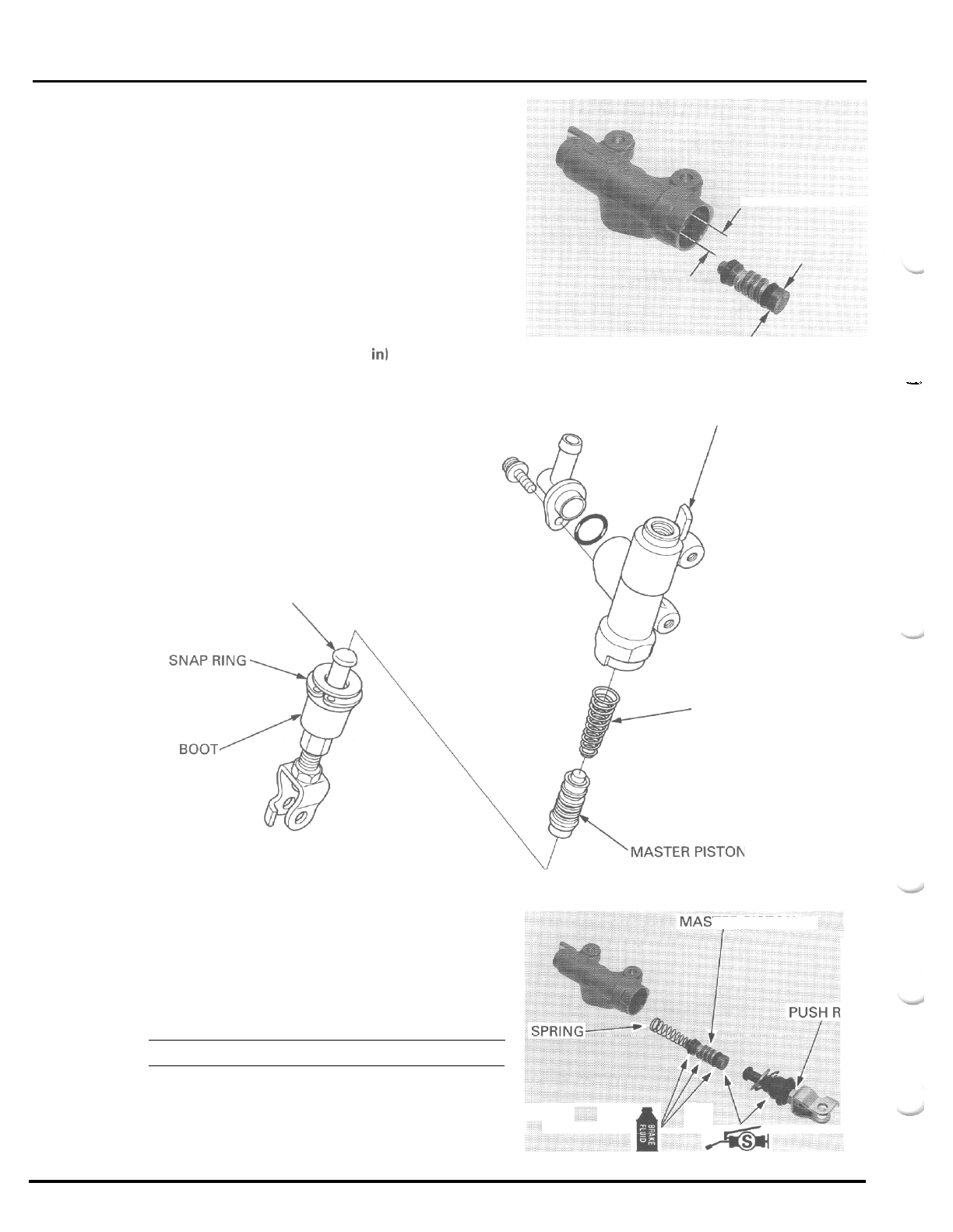
HYDRAULIC
DISC
BRAKE
scratches or damage.
Measure the maser cylinder
I.D.
SERVICE
LIMIT 12.75
mm
10.502
in)
Measure the master piston O.D.
SERVICE
LIMIT 12.65
mm
10.498
in1
ASSEMBLY
INSPECTION
Check the piston cups for wear, deterioration or dam
-
age.
Check the spring for damage.
Check the master cylinder and piston for scoring,
-
-.
MASTER CYLINDER
I
L
PUSH
ROD
SPRING
TER PISTON
OD
Coat the master piston and piston cups with clean
brake fluid
Install the spring onto the master piston.
Install the spring and master piston into the master
cylinder.
CAUTION:
Do
not allow the piston cup lips to turn inside out.
Apply silicone grease to the push rod contacting area
of the master piston and the boot groove in the push
rod.
14
-
14
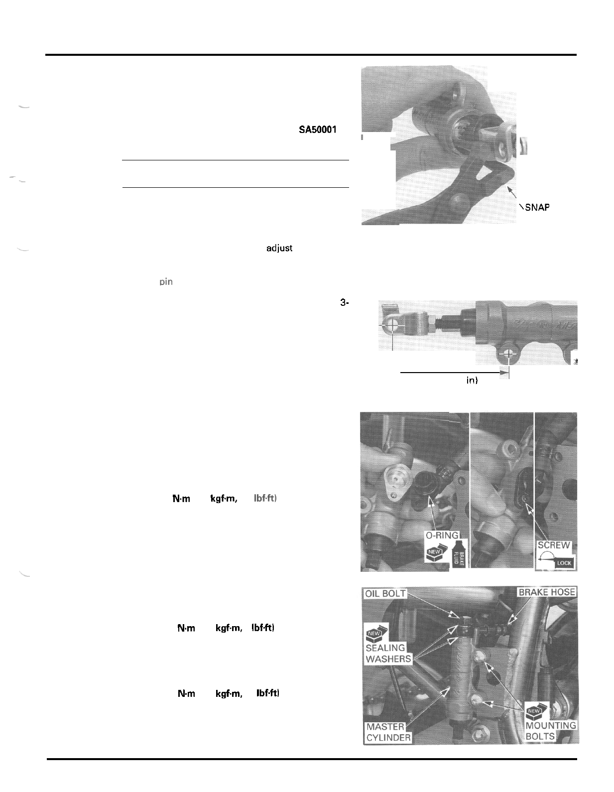
HYDRAULIC DISC BRAKE
Install the push rod into the master cylinder and the
snap ring into the groove in the master cylinder,
using the special tool.
TOOL
Snap
ring
pliers
-
07914
-
SA50001
1
CAUTION:
Be certain the
snap
ring is firmly seated in the
-
groove.
-
Install the piston boot into the master cylinder and
the groove in the push rod.
If
the push rod joint
is
reinstalled, adjust the push rod
length
so
that the distance from the center of the
master cylinder lower mounting hole to the center
of
the ioint Din hole is
80
mm
(3.1
in).
\SNAP
RING
PLIERS
Tighten the lock nut.
Adjust the brake pedal height if necessary (page
3-
16).
1
-1
80
mm
(3.1
in)
Coat
a
new O
-
ring with brake fluid and install it onto
the hose joint
Apply locking agent to the joint screw threads.
Connect the reservoir hose joint to the master cylin
-
der and secure it with the joint screw.
TORQUE:
2
Nm
(0.2
kgf.m, 1.4 Ibf.ft)
Install the master cylinder with new mounting bolts
and tighten them.
TORQUE
13
Nm
11.3 kgfm 9 IbfW
Connect the brake hose to the master cylinder with
the
oil
bolt and new sealing washers, and tighten the
oil bolt.
TORQUE: 34
Nm
(3.5 kgfm,
25
IbfW
14
-
1
5
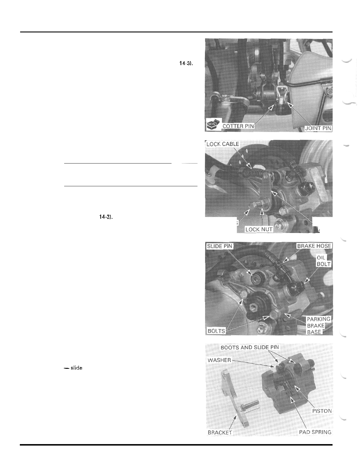
HYDRAULIC DISC BRAKE
Connect the push rod to the brake pedal with the
joint pin and secure
it
with a new cotter pin.
Fill and bleed the rear hydraulic system (page
14-3).
REAR BRAKE CALIPER
CAUTION:
~
Avoid spilling fluid
on
painted, plastic
or
rubber
parts. Place a rag over these parts whenever the
sys
-
tem
is
serviced.
DISASSEMBLY
Drain the brake fluid from the rear brake hydraulic
system (page
14-3).
Loosen the lock nut and remove the adjusting bolt
and brake arm. Disconnect the brake lock cable from
the brake arm and remove
it
from the cable stay.
Remove the two bolts and parking brake base.
Remove the O
-
ring.
Disconnect the brake hose from the rear brake caliper
by removing the oil bolt and sealing washers.
Loosen the caliper slide pin,
Remove the brake pads (page
14
-
6).
ADJUSTING
BOLT
RM
Loosen the slide pin and remove the following:
-
caliper bracket and washer
-
pad spring
-slide pin and boots
-
caliper piston
B
14
-
1
6
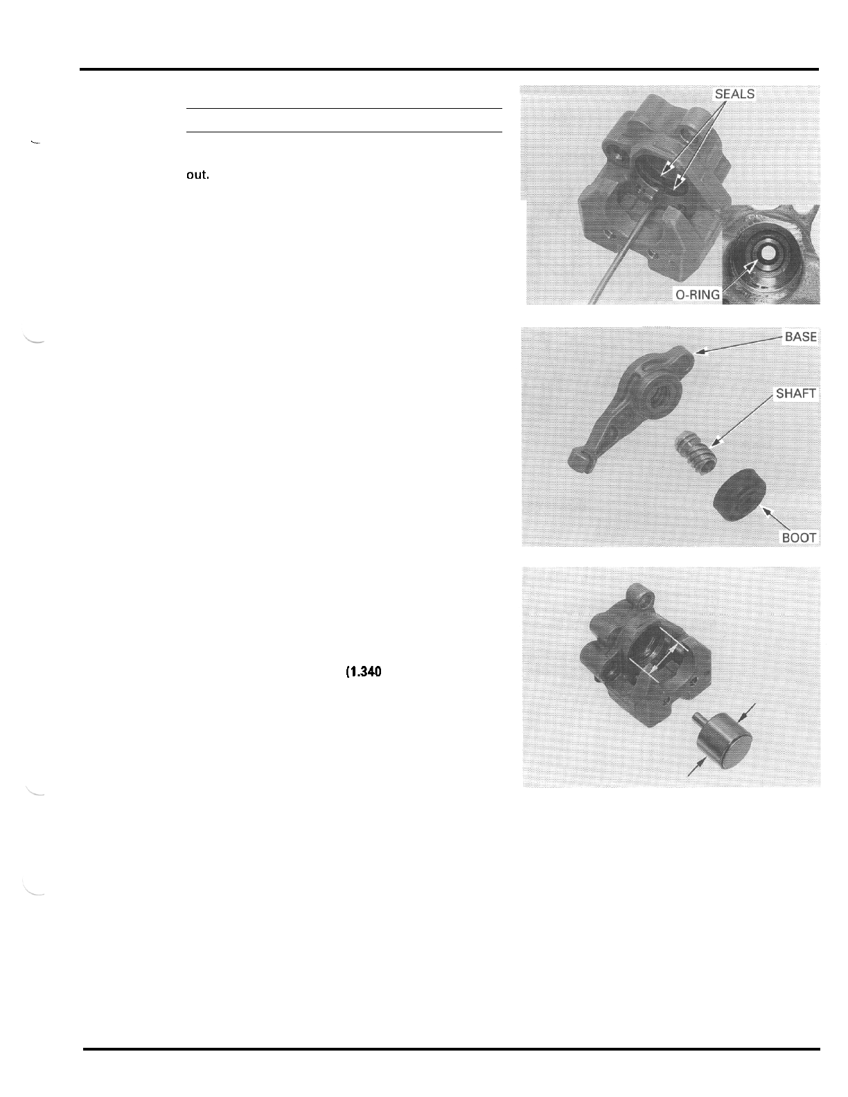
c
HYDRAULIC DISC BRAKE
CAUTION:
Be
careful
not
to
damage the piston sliding
surface.
Push the dust seal and piston seal
in
and
lift
them
out.
Remove the O
-
ring.
Clean the seal grooves, caliper cylinder and piston
with clean brake fluid.
INSPECTION
CABLE LOCK BRAKE
Remove the shaft boot and the brake shaft.
Check the shaft and base threads
for
wear or dam
-
age.
HYDRAULIC BRAKE
Check the caliper cylinder and piston for scoring,
scratches
or
damage.
Measure the caliper cylinder
I.D.
SERVICE LIMIT 34.02
mm
(1.340
in)
Measure the caliper piston
O.D.
SERVICE LIMIT 33.87
mm
(1.333
in)
14
-
17
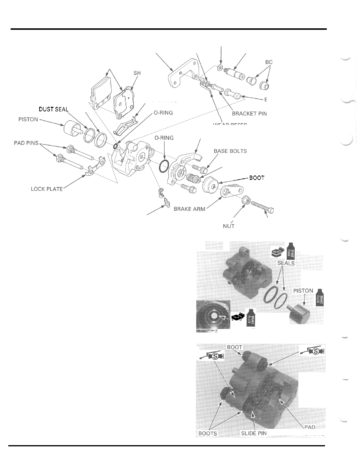
HYDRAULIC
DISC
BRAKE
WASHER
ASSEMBLY
CALIPER BRACKET WASHER
1
SLIDE PIN
OTS
BRAKE PADS
IM
PISTON SEAL PAD SPRING
DUSTSEAL
\
BOOT
SZN
BLEED VALVE
WEAR REFERENCE PLATE
-RING
PARKING BRAKE BASE
BRAKE SHAFT
-BOOT
\
LOCK NU? ADJUSTING BOLT
Coat
a
new O
-
ring with clean brake fluid and install
it
into the caliper.
Coat new piston seal and dust seal with clean brake
fluid and install them into the seal grooves.
Coat the caliper piston with clean brake fluid and
install
it
into the caliper cylinder.
**
&
O-RING
Install the pad spring as shown.
If the pin boots are hard or deteriorated, replace
them with new ones.
Install the bracket pin boot into the caliper body and
pack silicone grease to the inside of the boot.
Apply silicone grease to the grease groove in the
slide pin.
Install the slide pin boots and the slide pin
so
the
boot ribs properly align with the grooves in the
caliper body and slide pin.
-
SPRING
14
-
18
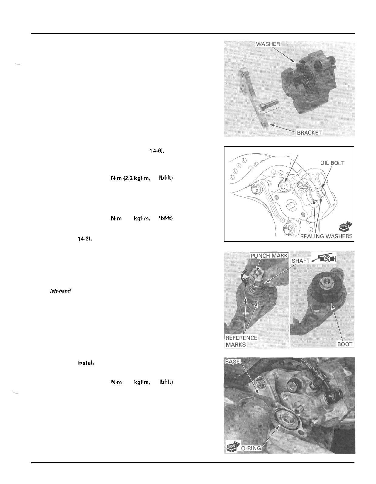
HYDRAULIC
DISC
BRAKE
Install the brake pads (page
14-61,
Tighten the slide pin.
TORQUE
23 N.m 12.3 kgf.m, 17 IbfW
Connect the brake hose to the brake caliper with the
oil bolt and new sealing washers, and tighten the oil
bolt.
TORQUE:
34 N.m (3.5 kgf.m, 25 IbfW
Fill
and
bleed the rear brake hydraulic system (page
14-3).
Install the caliper bracket over the caliper body with
the spring washer (between the slide pin and bracket)
and thread the slide pin into the bracket, being care
-
ful not to damage the pin boot.
Make sure that the boots are seated securely into the
pin grooves.
-
SLIDE
PIN
Apply silicone grease to the brake shaft outer sur
-
face.
Position the shaft
so
that its punch mark
is
within the
reference marks on the base and thread
it.
Screw the shaft in fully and make sure that the punch
mark
is
within the reference marks.
If the shaft boot is hard or deteriorated, replace
it
with new one. Install the boot over the brake base
and into the shaft groove properly.
The brake shaft
has left-hand
threads.
Instal, a new O
-
ring into the base groove and rhe
brake base onto the ca iper body w'th the two bolts.
TORQUE:
23 N.m 12.3 kgf.m. 17 IbfW
14
-
19
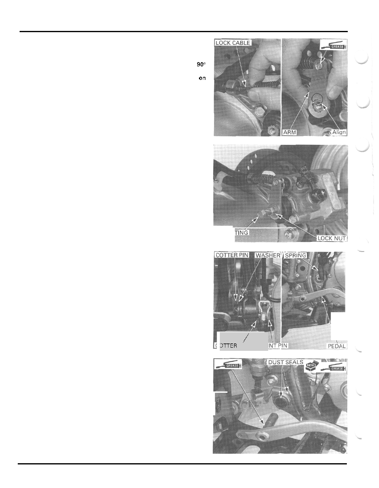
HYDRAULIC DISC BRAKE
Apply grease to the lock cable end.
Install the lock cable into the stay and connect
it
to
the brake arm.
Turn the brake shaft clockwise approximately
90"
from fully seated position and install the brake arm
onto the brake shaft by aligning the punch marks
on
the arm and shaft.
Loosely install the lock nut and adjusting bolt.
Adjust the lock cable free play (page
3
-
16).
BRAKE
PEDAL
REMOVAL
Disconnect the push rod from the brake pedal by
removing the cotter pin and joint pin.
Remove the return spring from the pedal.
Remove the cotter pin, washer and the brake pedal.
INSTALLATION
Coat new dust seal lips with grease and install them
into the pedal pivot in the frame.
Apply grease to the pedal pivot groove and install the
pedal.
ADJUS
BOLT
-
\
i
3TTER
PIN
JO
14
-
20
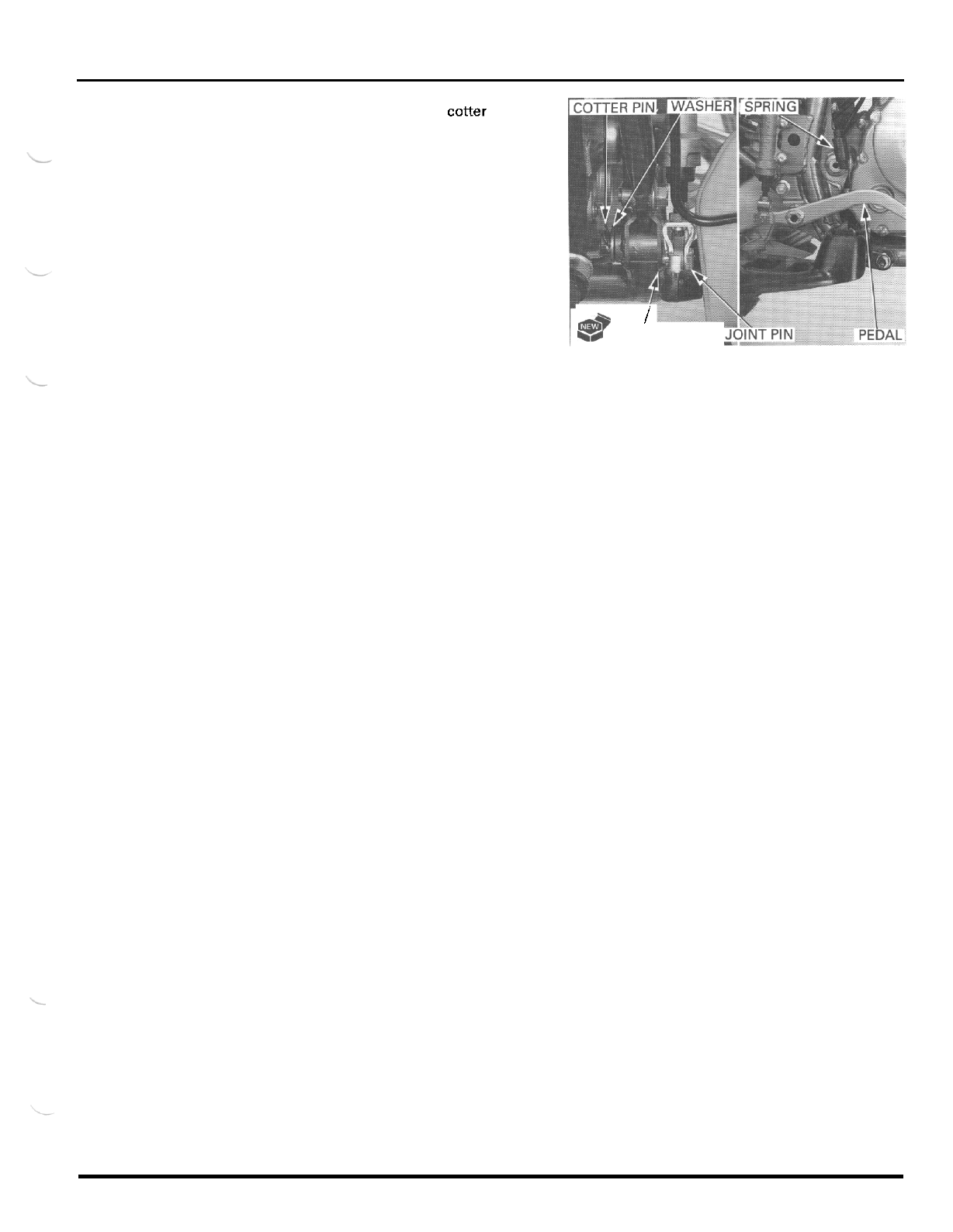
HYDRAULIC DISC BRAKE
Secure the pedal with the washer and cotter pin.
Hook
the return spring to the pedal.
Connect the push rod to the pedal with the joint
and secure the joint pin with
a
new cotter pin.
Din
l
a$*
+p
COTTERPIN
14
-
21
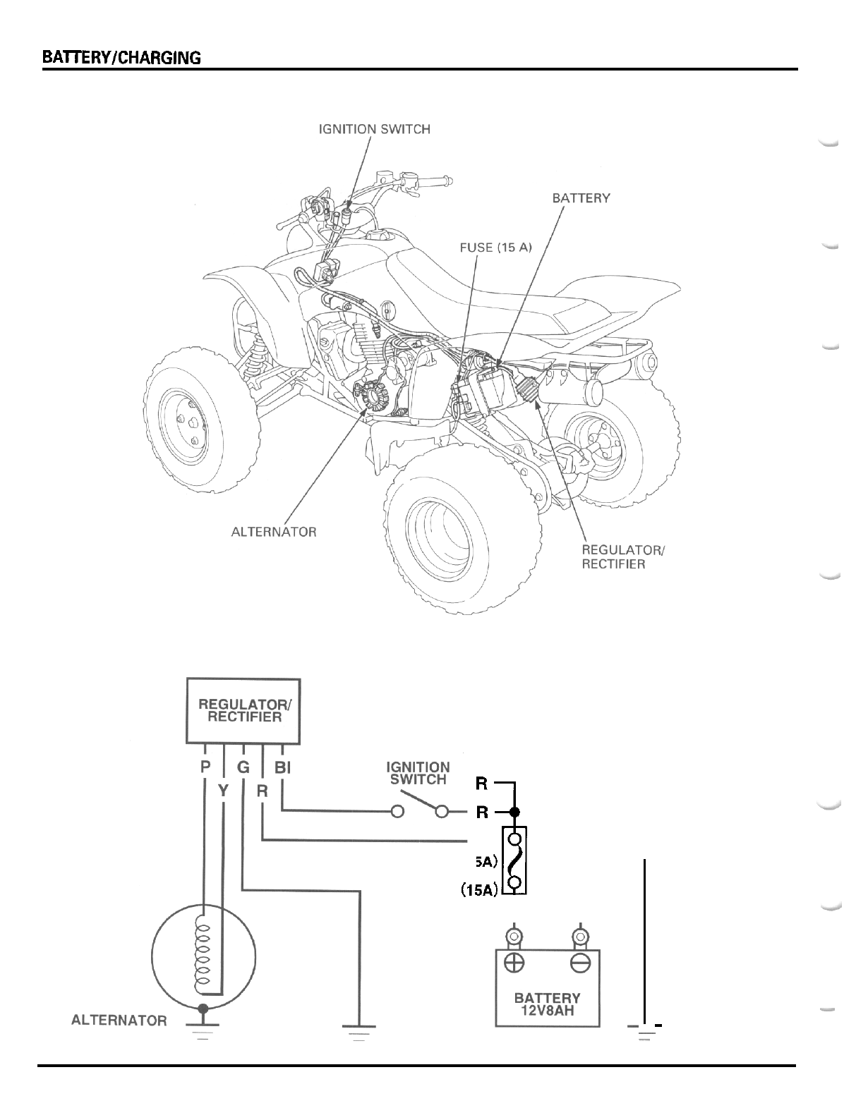
BAlTERY/CHARGING SYSTEM
FUSE
(15A)
"r$
r
BI
:
Black
R
:
Red
-
P
:
Pink
G
:
Green
-
~
-
15
-
0
15.
BATTERY/CHARGING
SYSTEM
~~
SERVICE INFORMATION 15
-
1 CHARGING SYSTEM INSPECTION
15
-
5
TROUBLESHOOTING
15
-
3
REGULATOR/RECTIFIER 15
-
6
BAlTERY 15
-
4 ALTERNATOR CHARGING COIL
15
-
7
-
SERVICE
INFORMATION
..~
GENERAL
*
The
battery gives
off
explosive gases; keep sparks, flames and cigarettes away. Provide adequate ventilation when
._
charging.
The battery contains sulfuric acid felectrolvte/. Contact with skin
or
eyes may cause severe burns. Wear protective
clothing and a face shield.
-
If electrolyte gets on your skin, flush with water.
-
If electrolyte gets in your eyes, flush
with
water for at least
15
minutes and call a physician immediately.
-
If
swallowed, drink large quantifjes of water
or
milk and follow
with
milk
of
magnesia or vegetable
oil
and call a
-
-
Electrolyte is poisonous.
phvsician.
KEEP
OUT
OF
REACH
OF
CHILDREN.
.
Always turn
off
the ignition switch before disconnecting any electrical component.
CAUTION:
~~ ~
Some electrical components may be damaged if terminals
or
connectors are connected or disconnected while the igni
-
tion switch is
ON
and current is present.
*
For extended storage, remove the battery, give
it
a
full charge, and store it in
a
cool, dry place.
*
For
a
battery remaining in
a
stored vehicle, disconnect the negative battery cable from the battery.
NOTE:
The maintenance free battery must be replaced when
it
reaches the end of its service life.
CAUTION:
The batterv cam shouldnot be removed. AttemRting to remove the sealins caps from the cells mav damaue the batten/.
~
*
The battery can
he
damaged if overcharged or undercharged, or if left to discharge for long periods. These same con
-
ditions contribute
to
shortening the
"
life span
"
of the battery. Even under normal use. the performance of the battery
deteriorates after
2
-
3
years.
Battery voltage may recover after battery charging, but under heavy load, the battery voltage will drop quickly and
eventually die
out.
For this reason, the charging system is often suspected as the problem. Battery overcharge often
results from problems in the battery itself, which may appear to be an overcharging symptom. If
one
of the battery
cells is shorted and battery voltage does not increase, the regulator/rectifier supplies excess voltage to the battery.
Under these conditions, the electrolyte level goes down quickly.
-
Before troubleshooting the charging system. check for proper use and maintenance of the battery. Check
if
the bat
-
tery
is
frequently under heavy load, such as having the headlight and taillight
ON
for long periods of time without rid
-
ing the vehicle.
-
The battery will self
-
discharge when the vehicle is not in use. For this reason, charge the battery every
two
weeks to
prevent sulfation from occurring.
-
Filling
a
new battery with electrolyte will produce some voltage, but in order to achieve its maximum performance,
always charge the battery. Also. the battery life
is
lengthened when
it
is initially charged.
.
When checking the charging system, always follow the steps in the troubleshooting flow chart (page
15-3).
-
For alternator service, refer to section
10.
~
15
-
1
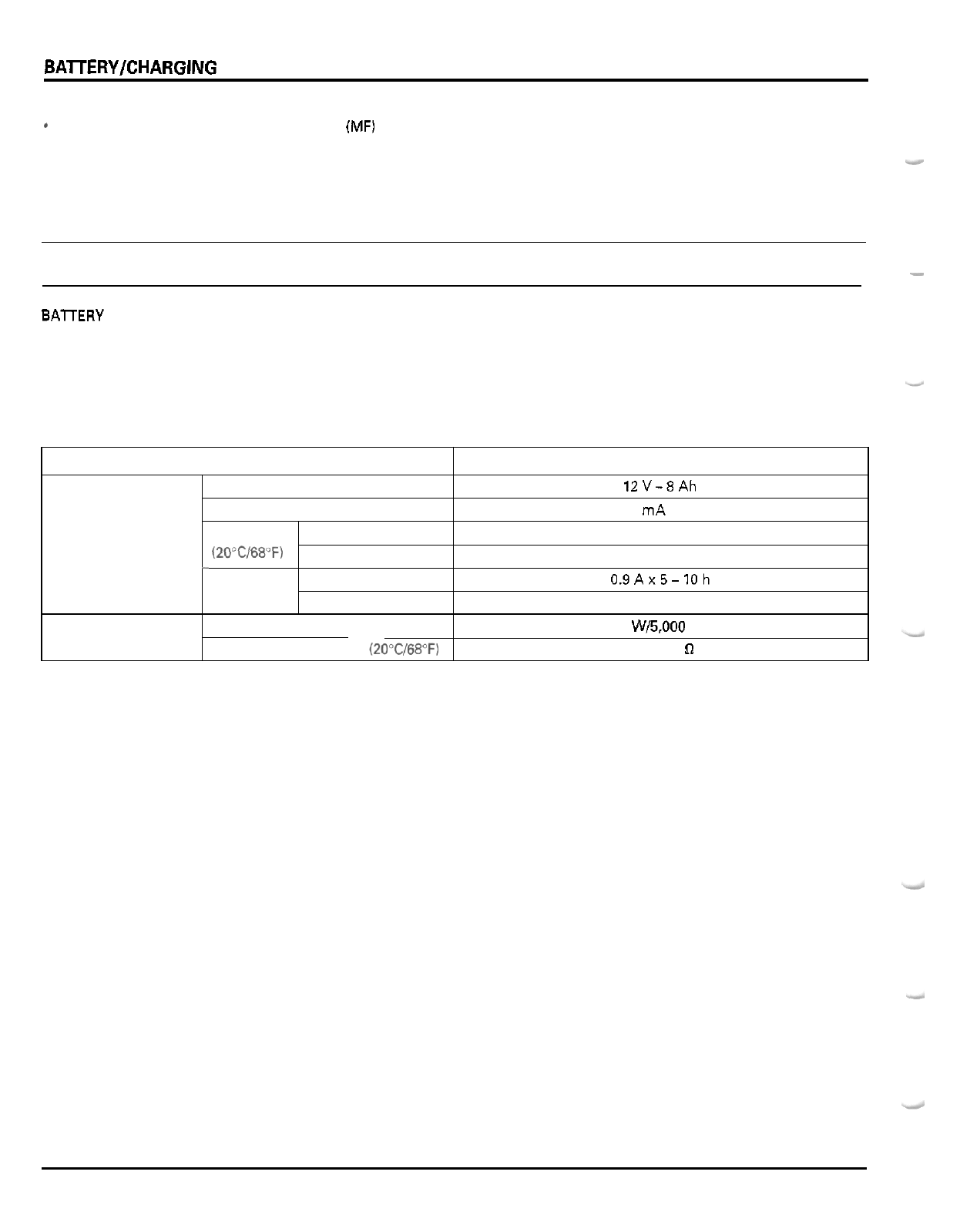
BAlTERYICHARGING SYSTEM
Battery charging
@
This
model comes with
a
maintenance free
(MF)
battery. Remember the following about
MF
batteries.
-
Use only the electrolyte that comes with the battery.
-
Use all of the electrolyte.
-
Seal the battery properly.
-
Never open the seals again.
CAUTION:
ITEM
Battery Capacity
Current leakage
Voltage Fully charged
(20"c/68"F) Needs charging
Charging Normal
current
-
Quick
Alternator Capacity
Charging coil resistance (2O"C/68"F)
For battery charging, do not exceed the charging current and time specified on the battery. Using excessive current or
extending the charging time may damage the battery.
-
SPECIFICATIONS
12V-8Ah
0.1 mA max.
13.0
-
13.2
V
Below 12.3
V
0.9Ax5-10h
4.0
Ax
10
h
147
W/5,000 rpm
0.1
-
1.0
n
BAlTERY TESTING
Refer to the instructions
in
the Operation Manual for the recommended battery tester for details about battery testing
The recommended battery tester puts
a
"
load
"
on
the battery
so
that the actual battery condition can be measured.
Recommended battery
tester BM
-
210
-
AH, BM
-
210, or BATTERY MATE
or
equivalent
SPECIFICATIONS
15
-
2
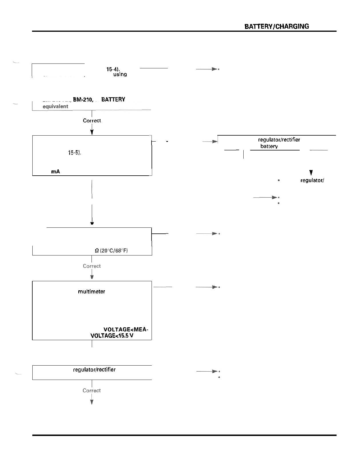
BAlTERYICHARGING
SYSTEM
TROUBLESHOOTING
4.
Measure and record the battery voltage
using a digital multimeter (page
15
-
4).
Start the engine.
Measure the charging voltage (page
15
-
51.
Compare the measurement to result of the
following calculation.
MEASURED BATTERY VOLTAGE<MEA-
SURED CHARGING VOLTAGEcl5.5
V
Battery
is
damaged or weak
-
~
-
1.
Remove the battery (page
15-4).
Incorrect
+*
Faulty battery
Check the batterv condition
usin(l
the rec
-
.
ommended battery tester.
RECOMMENDED BATTERY TESTER:
BM
-
210
-
AH, BM-210.
or
EATERY MATE
or
-
"7"'
I
2.
Install the battery (page
15
-
41.
Check the battery current leakage (Leak
test: page
15-5).
SPECIFIED CURRENT LEAKAGE:
0.1 rnA rnax.
-
Correct
I
5.
Perform the regulator/rectifier wire harness Incorrect
V-
Open circuit in related wire
-
Loose or poor contacts
of
related terminal
inspection (page
15
-
61.
a
Disconnect the regulatorlrectifier 6P connector
and rechecn the batten, current leakage.
-
Incorrect
-~
Correct
-1
1
-
Faulty regulator1
rectifier
.
-*
Shorted wire harness
-
Faulty ignition
sw
tch
Incorrect
V-
Faulty charging coil
t
3.
Check the alternator charging coil (page
15
-
71.
STANDARD:
0.1
-
1.0
D
I2OoC/68"F)
~
Correct
+-
Faulty battery
15
-
3
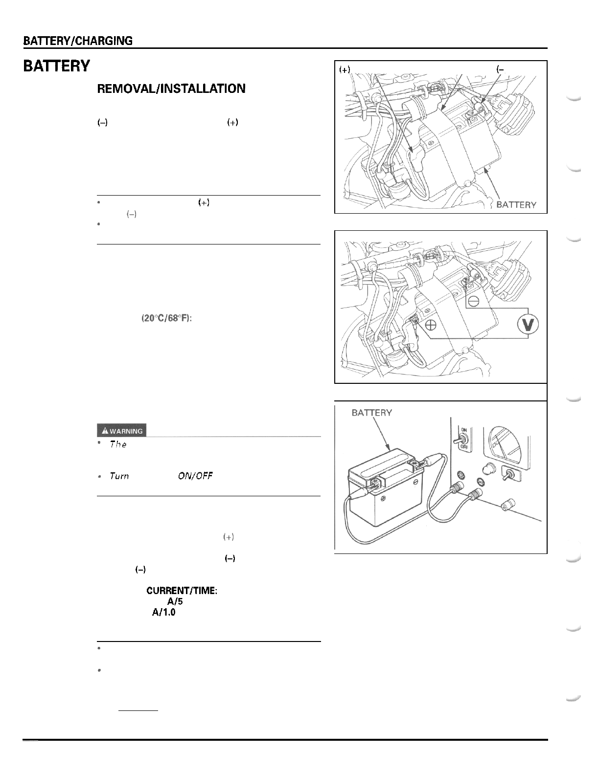
BAlTERY/CHARGING SYSTEM
BAlTERY
REMOVAL/INSTALLATION
With the ignition switch
OFF,
disconnect the negative
(-)
cable first, then the positive
(+)
cable.
Remove the two bolts, battery holder and battery
from the battery box.
Install the battery in the reverse order
of
removal.
NOTE:
-
Connect the positive
(+)
cable first, then the nega
-
tive
(-1
cable.
*
After connecting the battery cables, coat the termi
-
nals with grease.
VOLTAGE INSPECTION
Measure the battery voltage using
a
commercially
available digital multimeter.
VOLTAGE (2O0C/68"FI: Fully
charged:
13.0
-
13.2
V
Under charged: Below
12.3
V
BATTERY CHARGING
-
The battery gives off explosive gases; keep
sparks, flames and cigarettes away. Provide ade
-
quate ventilation when charging.
-
Turn the power ON/OFF at the charger, not at the
battery terminals.
Remove the battery.
Connect the charger positive
(+I
cable to the battery
positive (+)terminal.
Connect the charger negative
(-)
cable to the battery
negative
(-)
terminal.
CHARGING CURRENT/TIME:
Standard
0.9
A/5
-
10
h
Quick
4.0
A/1.0
h
CAUTION:
*
Quick charging should only
be
done in an emer
-
gency; slow charging is preferred.
-
For battery charging, do not exceed the charging
current and time specified on the battery. Using
excessive current or extending the charging time
may damage the battery.
(+)
CABLE HOLDER
(-
CABLE
~
15
-
4
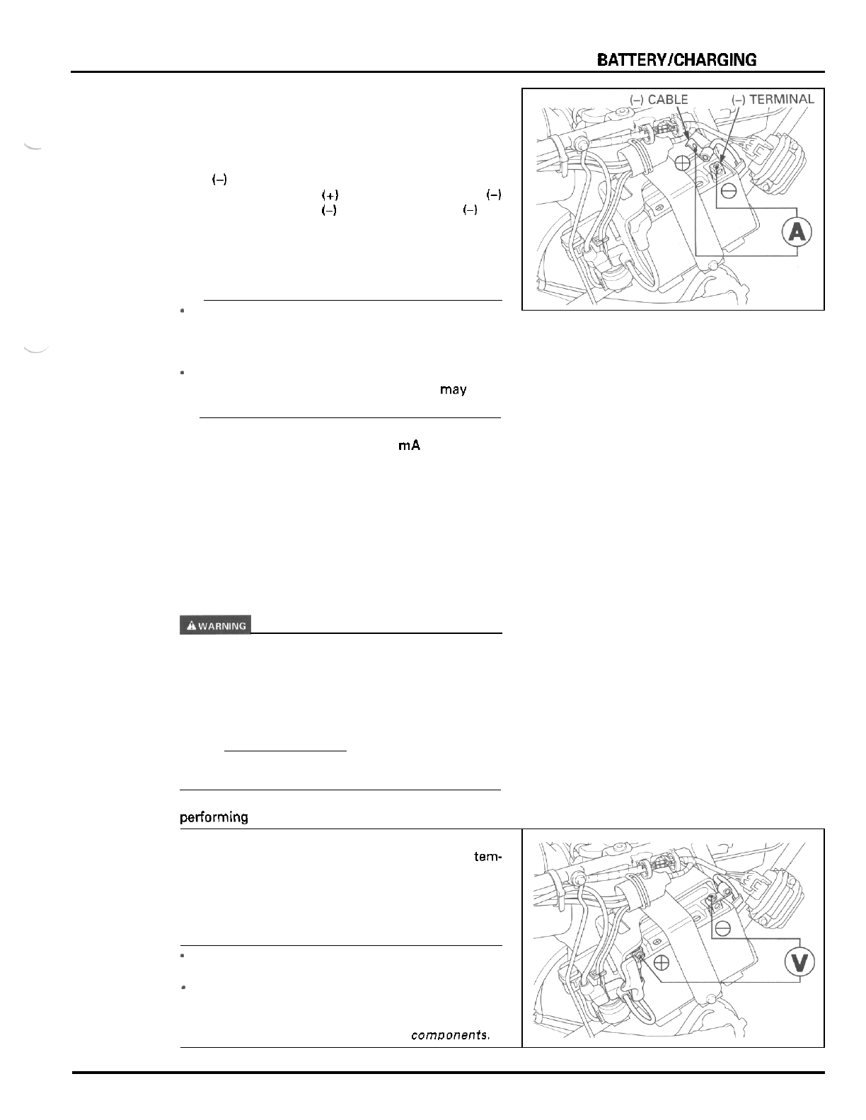
BAlTERY/CHARGING SYSTEM
CHARGING SYSTEM INSPECTION
CURRENT LEAKAGE TEST
Turn the ignition switch
OFF,
and disconnect the neg
-
ative
(-)
cable from the battery.
Connect the ammeter
(+)
probe to the negative
(4
cable and the ammeter
(-)
probe to the battery
(-)
ter
-
minal.
With the ignition switch
OFF,
check for current leak
-
age.
NOTE:
-
When measuring current using
a
tester, set
it
to
a
high range, and then bring the range down to an
appropriate level. Current flow higher than the
range selected may blow out the fuse in the tester.
-
While measuring current, do not turn the ignition
switch
ON.
A
sudden surge of current may blow
out the fuse in the tester.
'
-
SPECIFIED CURRENT LEAKAGE:
0.1
mA
max.
If current leakage exceeds the specified value,
a
shorted circuit is likely.
Locate the short by disconnecting connections
one
by one
and
measuring the current.
CHARGING VOLTAGE INSPECTION
If the engine must be running to do some work,
make sure the area is well ventilated. Never run the
engine in an enclosed area. The exhaust contains
poisonous carbon monoxide gas that may cause loss
of consciousness and may lead to death. Run the
engine in an open area or with an exhaust evacua
-
tion system in an enclosed area.
NOTE:
Be sure that the battery is in good condition before
performing this test.
I
Start the engine and warm it up to the operating
tern-
perature; stop the engine.
Connect the multimeter between the positive and
negative terminals of the battery.
CAUTION
-
To
prevent short, make absolutely certain which
are the positive and negative terminals or cable.
-
Do
not disconnect the battery or any cable in the
charging system without first switching
off
the
ignition switch. Failure to follow this precaution
can damaae the tester or electrical comnonenh.
15
-
5
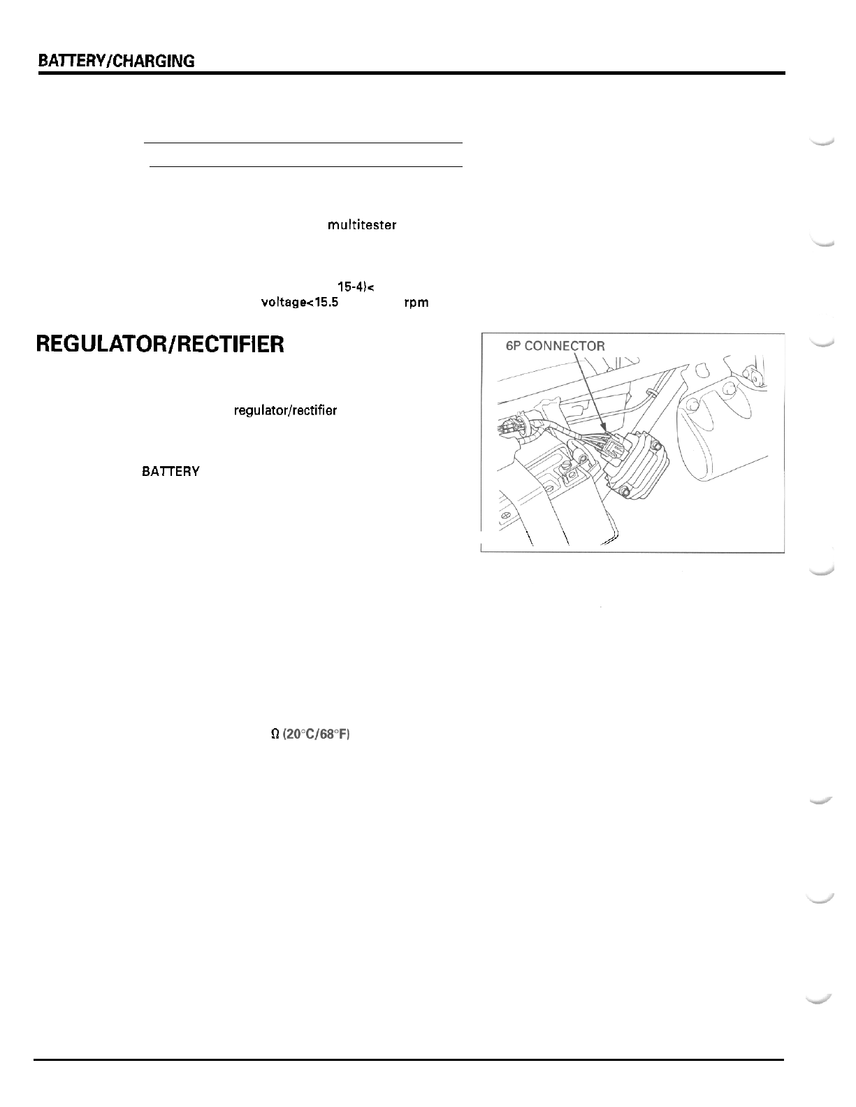
BATTERYKHARGING SYSTEM
Connect the tachometer
NOTE:
Read the instructions for tachometer operation.
Restart the engine, turn the headlight on and shift
it
to High beam.
Measure the voltage on the multitester when the
engine runs at
5,000
rpm.
STANDARD:
Measured battery voltage (page 15-4lc
Measured charging voltage45.5
Vat
5,000
rpm
REGULATOR/RECTIFIER
WIRE HARNESS INSPECTION
Disconnect the regulatorlrectifier
6P
connector.
Check the connector for loose contact or corroded
terminals.
BAlTERY LINE
Measure the voltage between the red wire terminal
and ground.
There should be battery voltage at all times.
GROUND LINE
Check the continuity between the green wire terminal
and ground.
There should be continuity at all times.
CHARGING COIL LINE
Measure the resistance between the yellow and pink
wire terminals.
STANDARD:
0.1
-
1.0
Q
(2OoC/68"F)
Check for continuity between the yellow wire termi
-
nal and ground, and
the
pink wire terminal and
ground.
There should not be continuity.
VOLTAGE FEEDBACK LINE
Measure the voltage between the black wire terminal
and ground.
There should be battery voltage with the ignition
switch ON, and no voltage with the ignition switch
OFF.
I
\\2
15
-
6
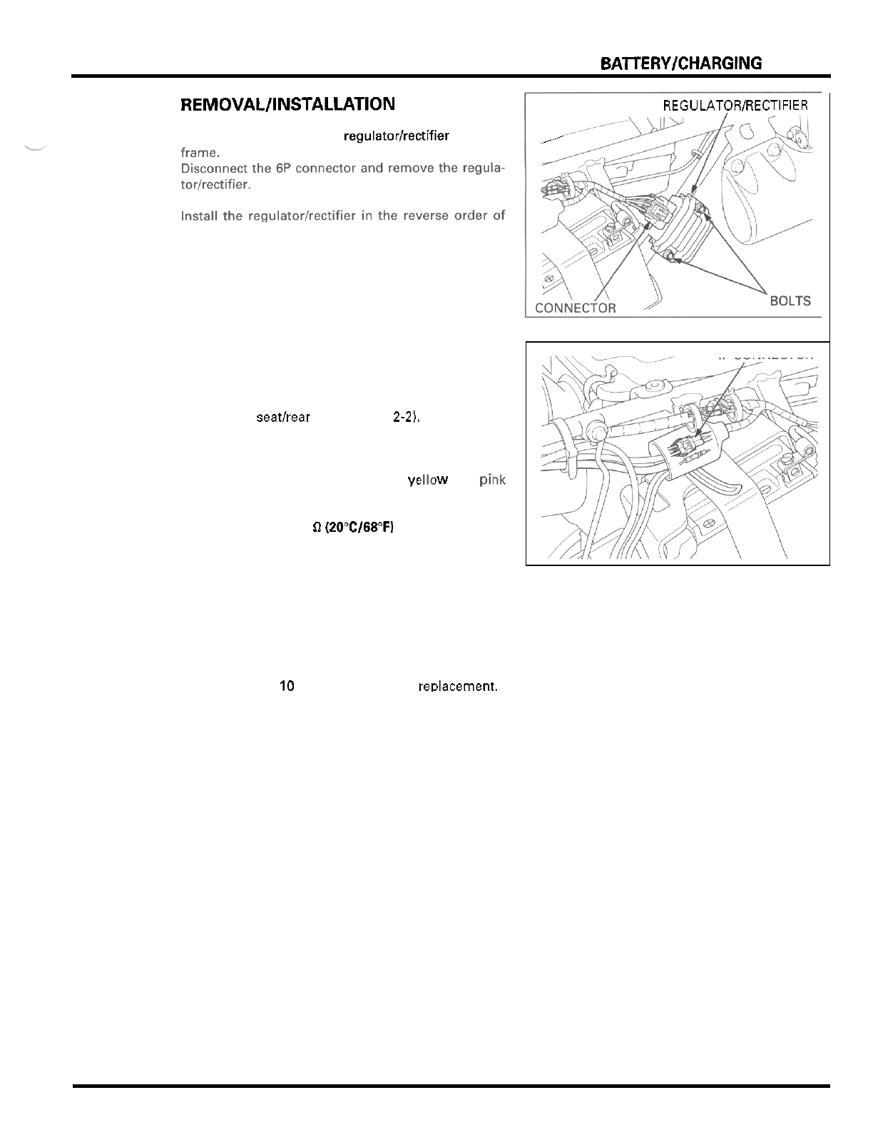
BAlTERYICHARGING SYSTEM
REMOVAL/INSTALLATION
REGULATOR/RECTIFIER
Remove the two bolts and regulatorlrectifier from the
,-
removal.
-
ALTERNATOR CHARGING COIL
INSPECTION
Remove the seathear fender (page
2-2).
Disconnect the alternator
4P
connector.
Measure the resistance between the
yt
wire terminals of the alternator side connector.
STANDARD:
0.1
-
1.0
0
(20°C/68"Fl
Check for continuity between the yellow wire termi
-
nal and ground, and the pink wire terminal and
iw
and pi1
.
ground.
There should not be continuity.
Replace the alternator stator if resistance is out of
specification, or if any wire has continuityto ground.
Refer to section
10
for alternator stator reDlacement.
4P
CONNECTOR
15
-
7
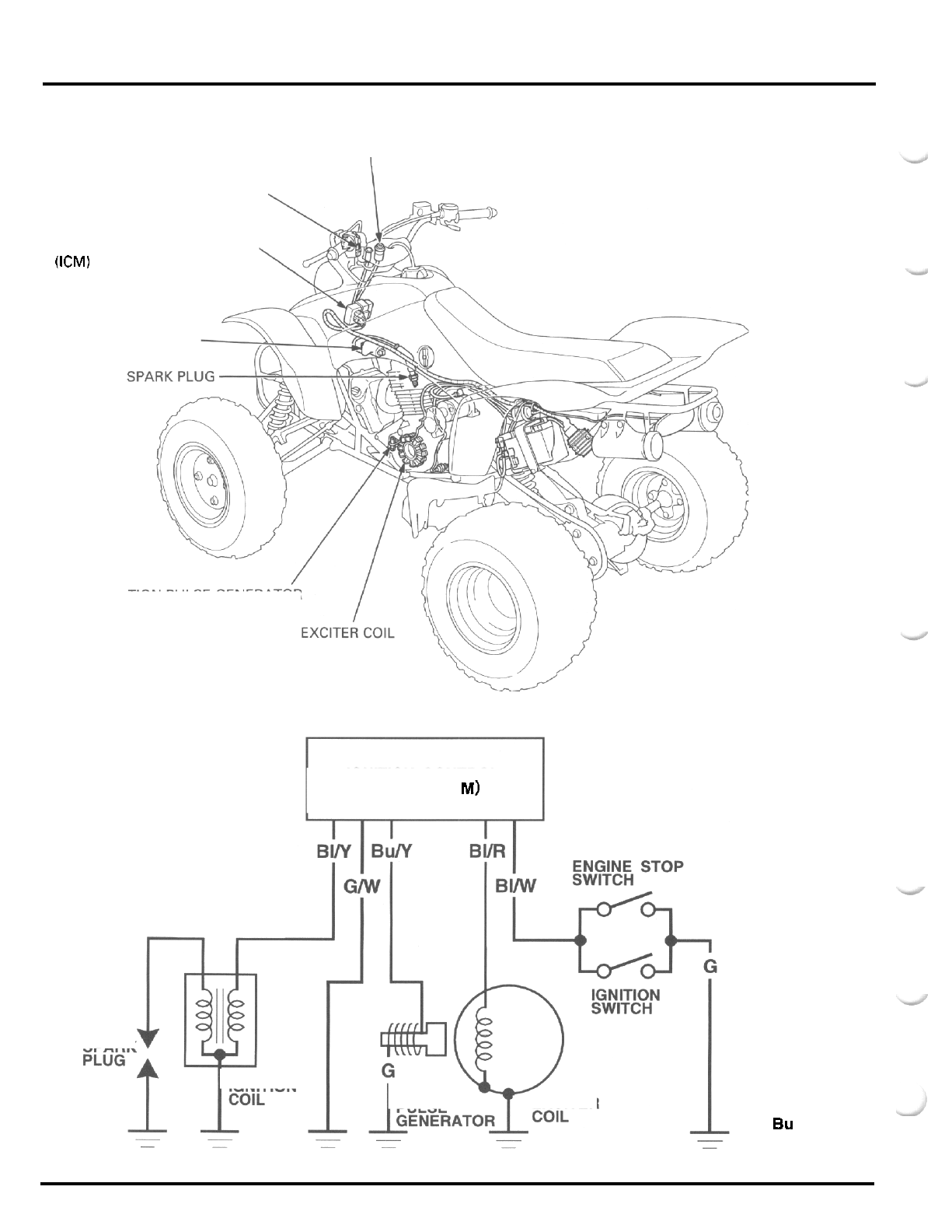
IGNITION
SYSTEM
IGNITION SWITCH
I
ENGINE STOP SWITCH
IGNITION CONTROL MODULE
(ICM)
IGNITION COIL
IGNITION PULSE GENERATOR
IGNITION CONTROL
MODULE
(I
C M)
SPARK
EXCITER
IGNITION
PULSE
IGNITION
Y
:
Yellow
G
:
Green
R
:
Red
W
:
White
BI
:
Black
Bu
:
Blue
16
-
0
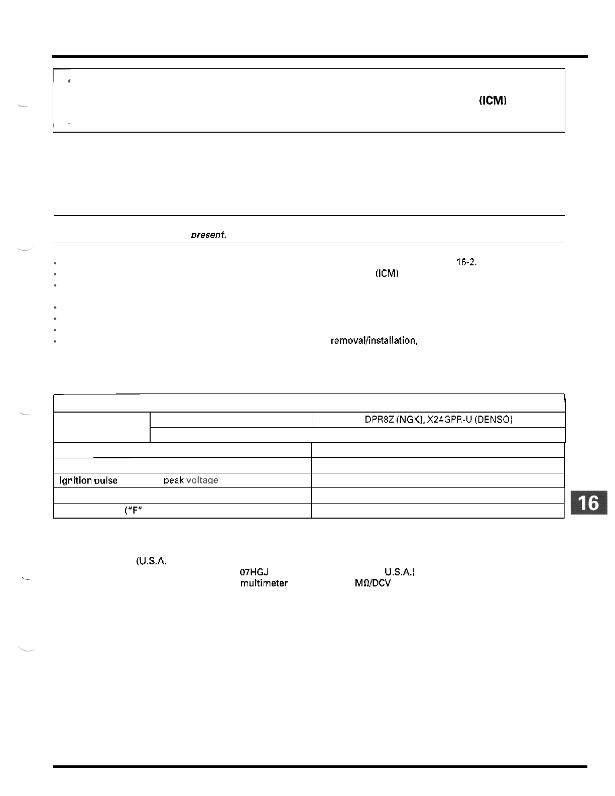
16.
IGNITION
SYSTEM
-
Spark plug Standard
SERVICE INFORMATION 16
-
1 IGNITION COIL 16
-
6
TROUBLESHOOTING
16
-
2
IGNITION CONTROL MODULE
(ICM)
16
-
6
IGNITION SYSTEM INSPECTION 16
-
3 IGNITION TIMING
16
-
7
-
DPR8Z (NGK), X24GPR-U (DENSO)
SERVICE
INFORMATION
GENERAL
CAUTION:
Some electrical components may be damaged if terminals or connectors are connected or disconnected while the igni
-
tion switch is
ON
and current is uresent.
Spark plug gap
When servicing the ignition system, alwaysfollow the steps in the troubleshooting
on
page 16-2.
The ignition timing cannot be adjusted since the ignition control module (ICM) is factory preset.
The ICM may be damaged if dropped. Also, if the connector is disconnected when current is flowing, the excessive
voltage may damage
the
ICM. Always turn
off
the ignition switch before servicing.
A
faulty ignition system is often related to poor connections. Check those connections before proceeding.
Use
a
spark plug
of
the correct heat range. Using spark plug with an incorrect heat range can damage the engine.
For ignition switch and engine stop switch inspection, see section
18.
For exciter coil and ignition pulse generator (alternator stator) removallinstallation, see section 10.
0.6
-
0.7
mm
(0.024
-
0.028
in)
SPECIFICATIONS
Ignition coil primary peak voltage
I
ITEM
100
V
minimum
I
SPECIFICATIONS
I
lanition Duke aenerator
Deak
VOltaae
0.7
V
minimum
Exciter coil peak voltage 100
V
minimum
Ignition timing ("F" mark)
TOOL
Peakvoltage tester
(U.S.A.
only) or
Peak voltage adaptor
07HGJ
-
0020100 (not available in U.S.A.) with commercially available digital
multimeter (impedance
10
MWDCV minimum)
._
8
"
BTDC
at
idle
.
-
16
-
1
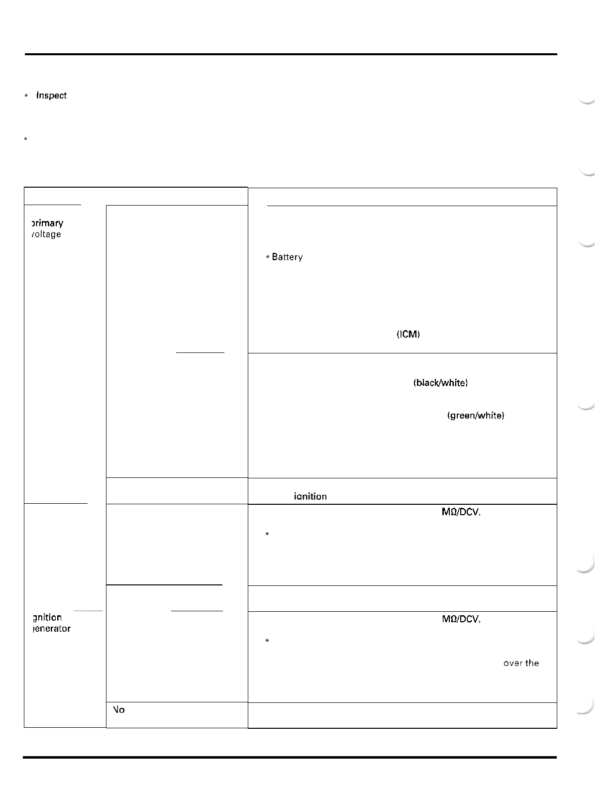
IGNITION
SYSTEM
TROUBLESHOOTING
Inspect the following before diagnosing the system.
-
Faulty spark plug
-
Loose spark plug cap or spark plug wire connections
-
Water got into the spark plug cap (Leaking the ignition coil secondary voltage)
*
If there
is
no spark
at
cylinder, temporarily exchange the ignition coil with a good one and perform the spark test.
If
there is
spark, the exchanged ignition coil
is
faulty.
No spark at spark plug
gnition coil
ximary
ioltage
ixciter coil
UNUSUAL CONDITION
anition pulse
ienerator
Low peak voltage
No
peak voltage
Peak voltage is normal, but no
spark jumps
at
plug
Low peak voltage
No
peak voltage
Low peak voltage
Uo
peak voltage.
PROBABLE CAUSE (Check in numerical order)
1.
Incorrect peak voltage adaptor connections. (System
is
normal if mea
-
sured voltage is over the specifications with reverse connections.)
2.
The multimeter impedance is too low;
10
MOIDCV.
3.
Cranking speed is too low.
*
Battery is undercharged.
4.
The sampling timing
of
the tester and measured pulse were not
synchronized. (System
is
normal if measured voltage is over the
standard voltage
at
least once.)
5.
Poorly connected connectors or an open circuit
in
ignition system.
6.
Faulty exciter coil. (Measure peak voltage.)
7.
Faulty ignition coil.
8.
Faulty ignition control module (ICM) (when above
No.
1
through
7
are normal.)
1.
Incorrect peak voltage adaptor connections. (System
is
normal if mea
-
sured voltage is over the specifications with reverse connections.)
2.
Short circuit in engine stop switch (blacklwhite) wire.
3.
Faulty ignition switch or engine stop switch.
4.
Loose or poorly connected ICM connectors.
5.
Open circuit or poor connection in ground (greenlwhite) wire
of
6.
Faulty peakvoltage adaptor.
7.
faulty exciter coil. (Measure peak voltage.)
8.
Faulty ignition pulse generator. (Measure peak voltage.)
9.
Faulty ICM (when above
No.
1
through
8
are normal.)
1.
Faulty spark plug or leaking ignition coil secondary current ampere.
2.
Faultv ianition coil.
the ICM.
1.
The multimeter impedance is too low;
10
MOIDCV.
2.
Cranking speed is too slow.
*
Battery is undercharged.
3.
The sampling timing of the tester and measured pulse were not
synchronized. (System is normal if measured voltage is over the
standard voltage at least once.)
4.
Faulty exciter coil (when above
No.
1
through
3
are normal).
1.
Faulty peak voltage adaptor.
2.
Faulty exciter coil.
1.
The multimeter impedance is too low;
10
MOIDCV.
2.
Cranking speed is too slow.
*
Battery is undercharged.
3.
The sampling timing of the tester and measured pulse were not
synchronized. (System is normal if measured voltage
is
overthe
standard voltage
at
least once.)
4.
Faulty ignition pulse generator (when above
No.
1
through
3
are
normal).
1.
Faulty peak voltage adaptor.
2.
Faulty ignition pulse generator.
16
-
2
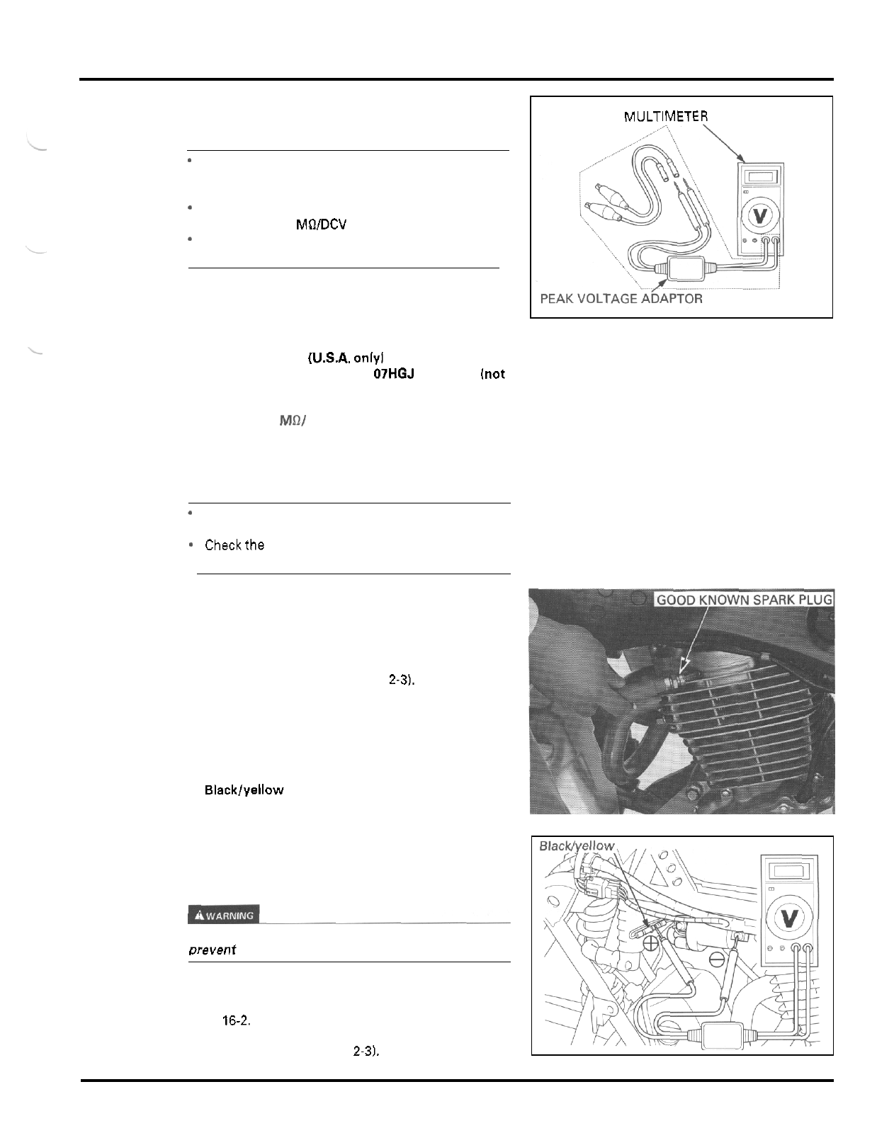
IGNITION
SYSTEM
IGNITION SYSTEM INSPECTION
NOTE:
*
If
no spark jumps at the plugs, check all connec
-
tions for loose or poor contact before measuring
each peakvoltage.
*
Use
a
commercially available digital multimeter
(impedance
10
MOIDCV minimum).
*
The display value differs depending upon the
internal impedance
of
the multimeter.
Connect the peak voltage adaptor to the digital multi
-
meter, or use the peak voltage tester.
TOOLS
Peak voltage tester
(U.S.A.
only1 or
Peak voltage adaptor
with commercially available digital multimeter
[impedance
10
Mill
DCV
minimum)
IGNITION PRIMARY PEAK VOLTAGE
07HGJ
-
0020100
[not
available
in
U.S.A.)
NOTE:
*
Check
all
system connections before this inspection.
Poor connections can cause incorrect readings.
*
Checkthe cylinder compression and check that the
spark plug
is
installed correctly
in
the cylinder.
Disconnect the spark plug cap from the spark plug.
Connect good known spark plug to the spark plug
cap and ground the spark plug to the cylinder head
as done in a spark test.
Remove the left side cover [page
2-3).
With the connector connected, connect the peak volt
-
age tester or adaptor probes to the ignition coil pri
-
mary terminal and body ground.
CONNECTION:
Blacklyellow
I+)
-
Body ground
I
-
)
Turn the ignition switch ON.
Crank the engine with the starter motor and read the
ignition coil primary voltage.
PEAK
VOLTAGE:
100
V
minimum
Avoid
touching the spark
plug
and tester probes
to
Prevent electric shock.
If the peak voltage is lower than the standard value,
follow the checks described in the troubleshooting on
page
16-2.
Install the side cover [page
2-3).
DIGITAL MULTIMETER
16
-
3
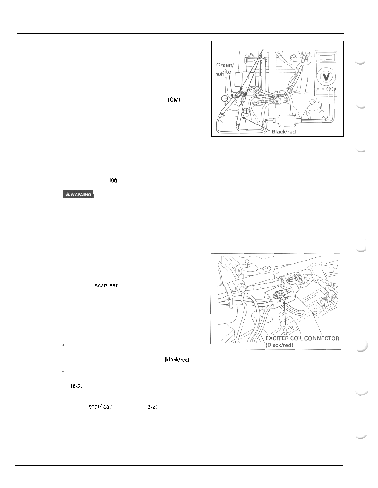
IGNITION
SYSTEM
NOTE:
Check that the cylinder compression is normal and
the spark plug is installed correctly in the cylinder
head.
Disconnect the ignition control module (ICM) connec
-
tors.
Connect the peak voltage tester or adaptor probes to
the connector terminals of the wire harness side.
CONNECTION:
EXCITER COIL PEAK VOLTAGE
wh
ICM CONNECTORS
Turn the ignition switch ON.
Crank the engine with the starter motor and read the
peak voltage.
PEAK VOLTAGE:
100
V
minimum
Avoid touching the spark plug and tester probes
to
prevent electric shock.
If the voltage measured at
ICM
connector is abnor
-
mal, measure the peak voltage
at
the exciter coil con
-
nector.
Remove the seathear fender (page
2
-
2).
Disconnect the exciter coil connector and connect the
peak voltage tester or adaptor probes to the alterna
-
tor side connector terminal and ground.
In the same manner as at the ICM connectors, mea
-
sure the peak voltage and compare
it
to
the voltage
measured
at
the ICM connectors.
*
If the peak voltage measured
at
the ICM connec
-
tors is abnormal and the one measured at the
exciter coil connector
is
normal, the blackJred wire
has an open or short circuit, or loose connections.
*
If both peak voltages are abnormal, follow the
checks described in the troubleshooting on page
16-2.
See section
10
for alternator stator replacement.
Install the seathear fender (page
2-21
16
-
4
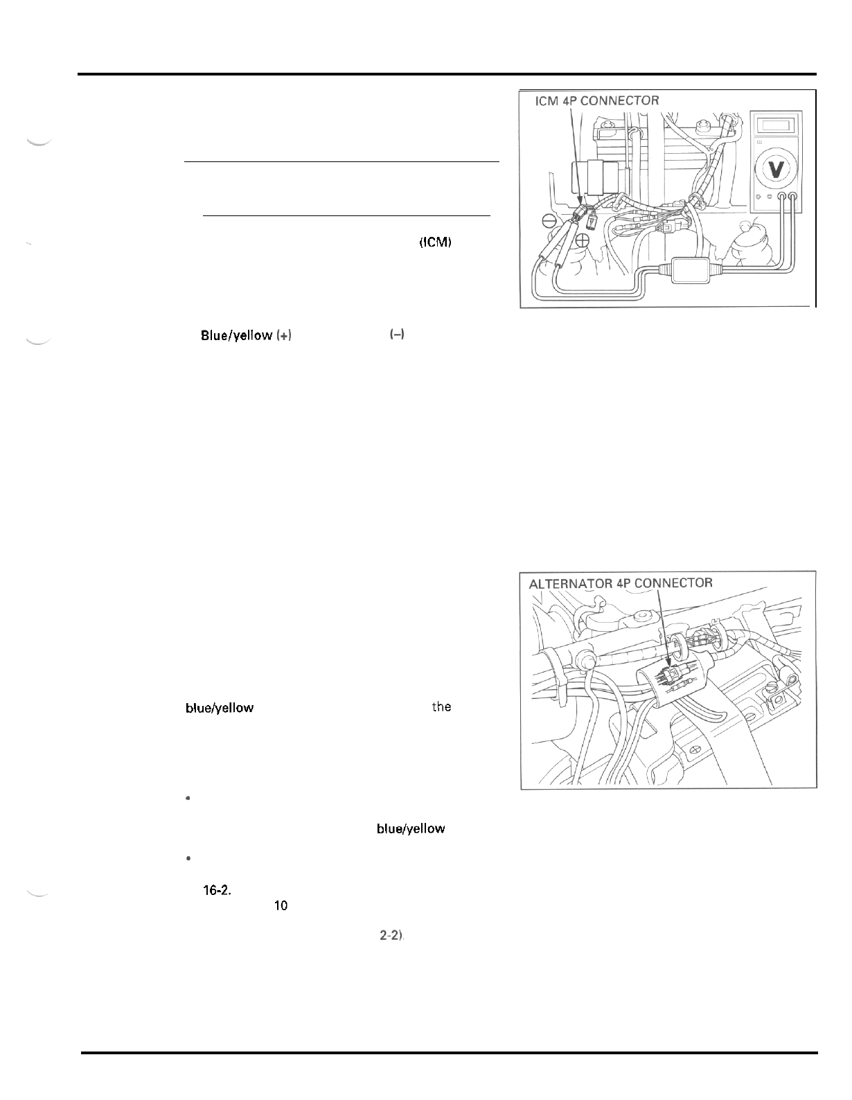
IGNITION
SYSTEM
IGNITION
PULSE
GENERATOR PEAK
VOLTAGE
NOTE
Check that the cylinder compression is normal and
the spark plug is installed correctly in the cylinder
head.
Disconnect the ignition control module (ICM)
4P
con
-
nector.
Connect the peak voltage tester or adaptor probes to
the connector terminals
of
the wire harness side.
CONNECTION:
Bluelyellow
I+)
-
Greenlwhite
(4
Turn the ignition switch
ON.
Crank the engine with the starter motor and read the
peak voltage.
PEAK VOLTAGE
0.7
V
minimum
If
the voltage measured
at
ICM connector is abnor
-
mal, measure the peak voltage
at
the alternator con
-
nector.
Remove the seatlrear fender (page
2
-
2).
Disconnect the alternator
4P
connector and connect
the peak voltage tester or adaptor probes to the
bluelyellow and green wire terminals
of
the alterna
-
tor side connector.
In the same manner as
at
the ICM connector, mea
-
sure the peak voltage and compare
it
to the voltage
measured at the ICM connector.
-
If
the peak voltage measured at the ICM connector
is abnormal and the one measured
at
the alterna
-
tor connector is normal, the bluelyellow wire has
an open or short circuit, or loose connections.
-
If
both peak voltages are abnormal, follow the
checks described in the troubleshooting on page
16-2.
See section
10
for alternator stator replacement.
Install the seatlrear fender (page
2-2),
16
-
5
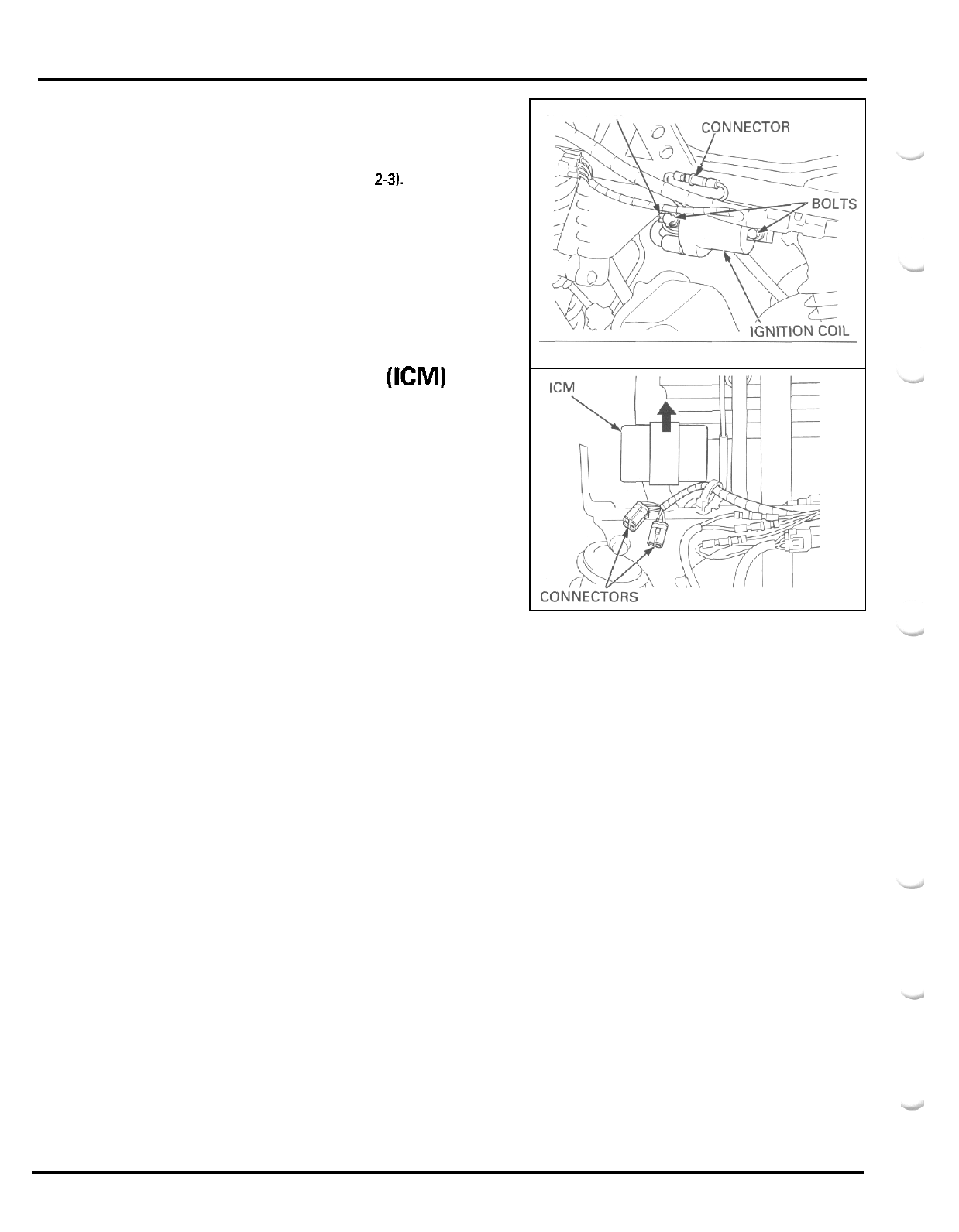
IGNITION
SYSTEM
IGNITION COIL
REPLACEMENT
Remove the left side cover (page
2-31.
Disconnect the primary coil connector.
Remove the spark plug cap from the plug.
Remove the two bolts, ground wire terminals
and
the
ignition coil from the frame.
Install
a
new ignition
coil
in the reverse order
of
removal.
IGNITION CONTROL MODULE
(ICM)
REPLACEMENT
Remove the ICM with the rubber suspension from
the stay.
Disconnect the connectors and remove the ICM.
Remove the
ICM
from the rubber suspension.
Install
a
new ICM in the reverse order
of
removal.
TERMINALS
16
-
6
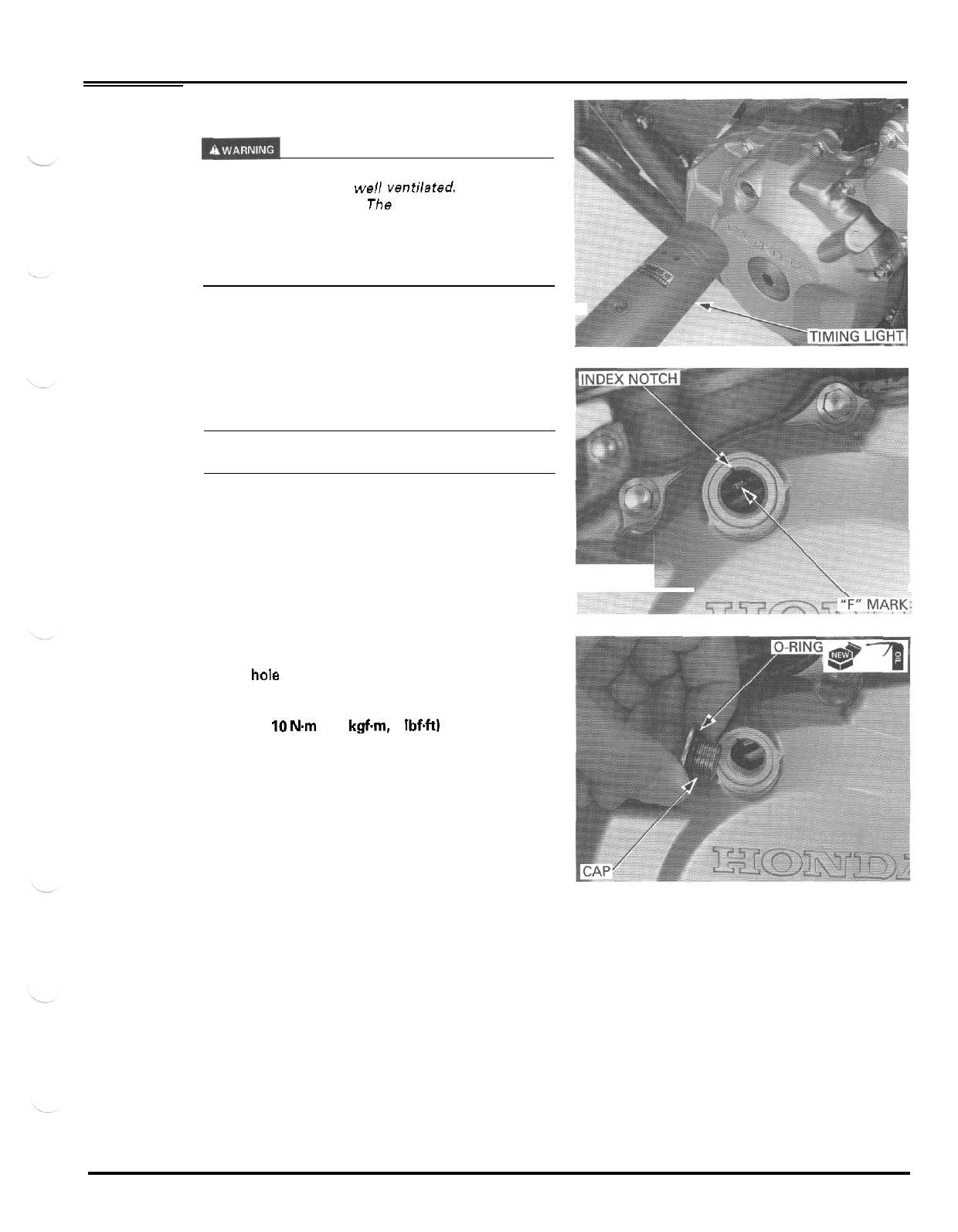
IGNITION
SYSTEM
IGNITION TIMING
If the engine must be running to do some work,
make sure the area is well ventilated. Never run the
engine in a closed area. The exhaust contains poiso
-
nous carbon monoxide gas that may cause
loss
of
consciousness and lead to death. Run the engine in
an open area or with an exhaust evacuation system
in
an
enclosed area.
Start the engine and warm
it
up operating tempera
-
ture.
Stop the engine and remove the timing hole cap.
Connect the timing light and tachometer.
NOTE:
Read the instructions for timing light and tachometer
operation.
Start the engine, let
it
idle and check the ignition tim
-
ing.
The ignition timing is correct if the
"
F
"
mark on the
flywheel aligns with the index notch in the left
crankcase cover at idle.
Increase the engine speed and make sure the
"
F
"
mark begins to move counterclockwise.
Coat
a
new O
-
ring with grease and install
it
onto the
timing hole cap.
Install
and tighten the timing hole cap.
TORQUE:
10
Nm
(1.0
kgfm
7
Ibf4t)
16
-
7
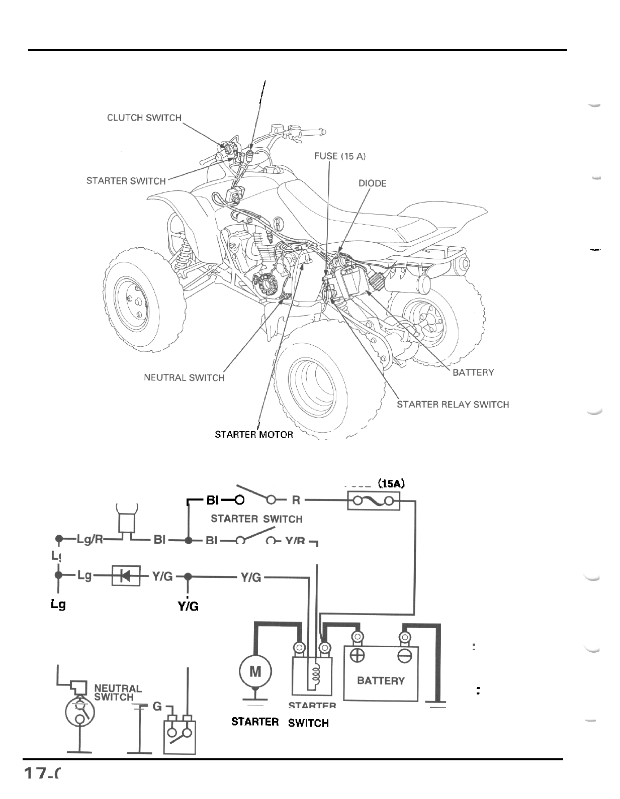
ELECTRIC
STARTER
IGNITION
SWITCH
I
STARTER’MOTOR
FUSE (15A)
IGNITION SWITCH
rBl4
NEUTRAL INDICATOR
n
I
DIODE
I.
Lg
YjG
pjd
CLUTCH
SWITCH
Y
:
Yellow
G
:
Green
R
BI
: :
Red
Black
Lg
:
Light
green
-
-
-
RELAY
-
-
STARTER SWITCH
MOTOR
17.
ELECTRIC STARTER
ITEM
SERVICE INFORMATION 17
-
1 STARTER RELAY SWITCH 17
-
9
TROUBLESHOOTING 17
-
2 CLUTCH
DIODE
17
-
10
STARTER MOTOR 17-4
-
STANDARD SERVICE LIMIT
SERVICE
INFORMATION
GENERAL
Always
turn the ignition switch
OFF
before servicing the starter motor. The motor could suddenly start, causing
rwi-
ous
injury.
17
-
1
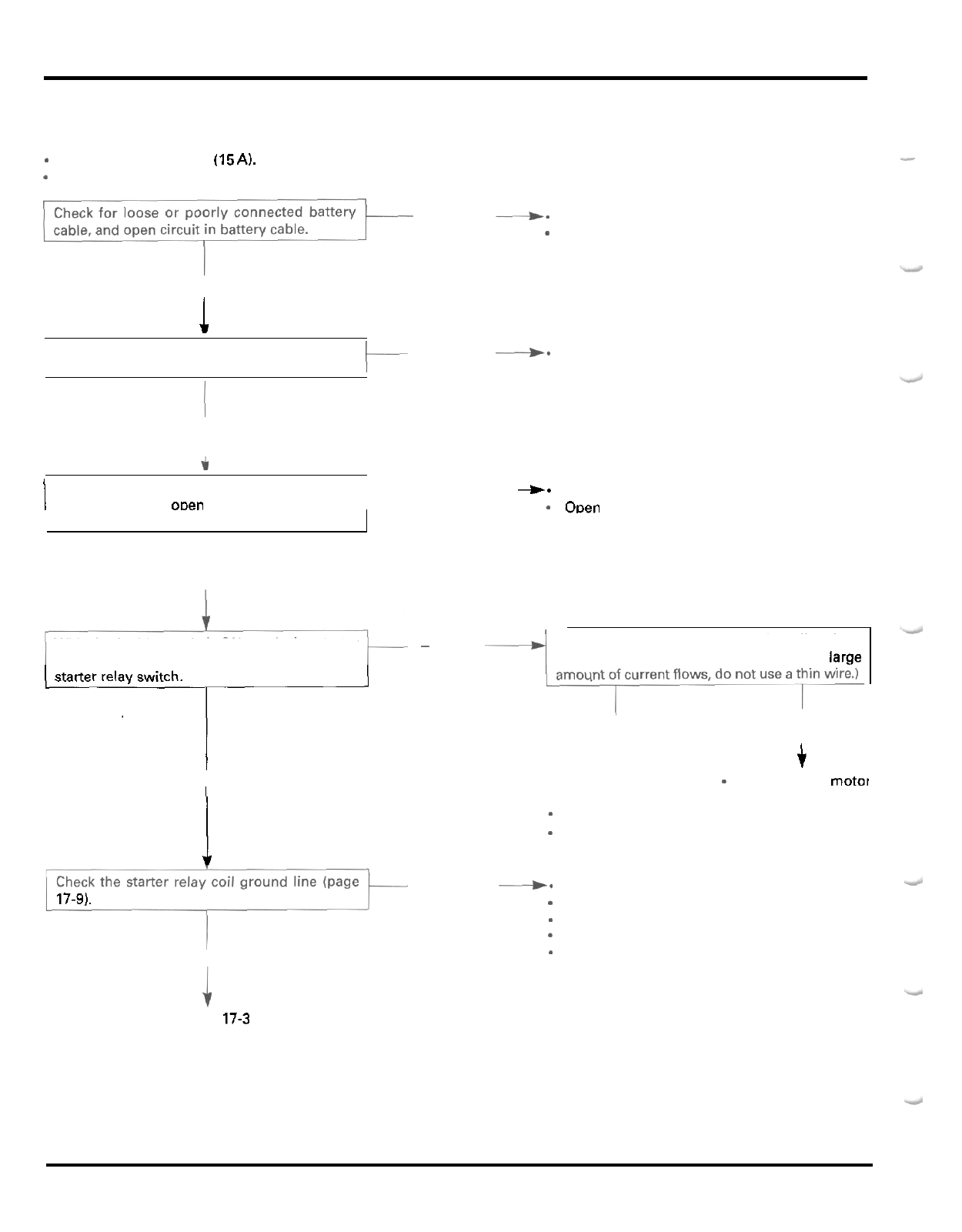
TROUBLESHOOTING
Starter
motor
will
not turn
*
Check for
a
blown fuse
(15
A).
*
Check that the battery
is
fully charged and in good condition
ELECTRIC STARTER
-
Abnormal
d-
Poorlv connected batterv cable
Open'circuit in battery cable
Normal
1
Check for loose or poorly connected starter
relav switch terminals and connectors. Abnormal
--)a
Poorly connected terminals or connectors
Normal
t
Check for loose or poorly connected starter
I
motor cable. and oDen circuit in starter motor
cable.
I
Normal
With the ignition switch ON, push the starter
switch and check for
a
"
Click
"
sound from the
starter relay switch.
1
I
No clicks
I
I
17-9).
Normal
To
page
17-3
Abnormal
+-
Poorly connected starter motor cable
-
ODen circuit in starter motor cable
Connect the starter motor terminal directly to
the battery positive terminal. (Because
a
large
~
Clicks
Starter motor turns Starter motor
does not turn
t
-
Faulty starter motor
i
-
Loose or disconnected starter motor cable
-
Faulty starter relay switch
Abnormal
+.
Faulty neutral switch
Faultydiode
-
Faulty clutch switch
-
Loose or poor connector contact
-
Open circuit in wire harness
17
-
2
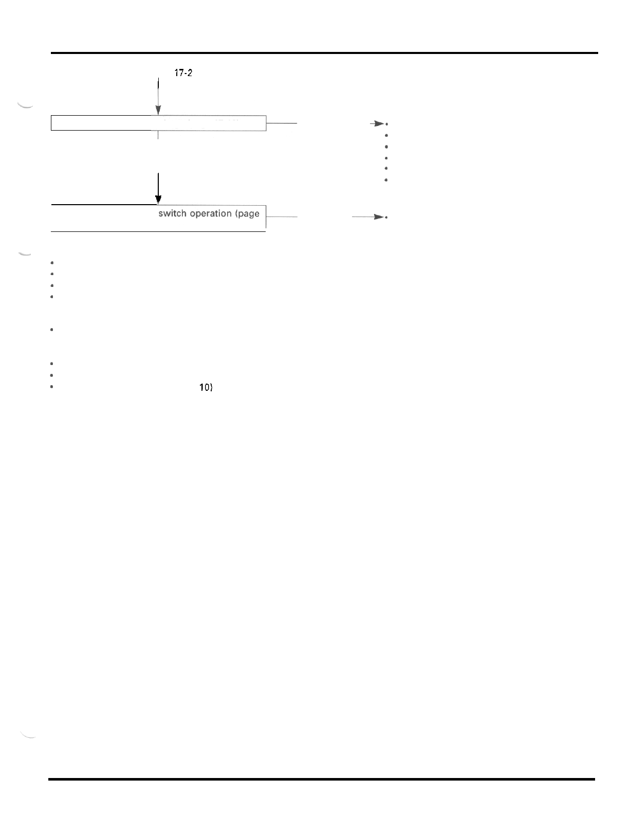
ELECTRIC
STARTER
From page 17-2
I
Check the starter relay voltage (page 17
-
10). Abnormal
Nor'mal
1
+-
Faulty ignition switch
*
Blownfuse
-
Faulty engine stop switch
-
Faulty starter switch
*
Loose or poor connector contact
*
Open circuit in wire harness
Abnormal
--).
Faulty starter relay switch
Check the starter relay
17
-
10).
.-
Starter motor turns slowly
*
Weak battery
-
Poorly connected battery cable
Poorly connected starter motor cable
Faulty starter motor
Starter motor turns,
but
engine
does
not turn
-
Faulty starter clutch (section 10)
Starter relay switch
"
clicks
"
,
but
engine
does
not
turn
over
*
Crankshaft does not turn due to engine problem
*
Faulty starter reduction gear (section 10)
*
Faulty starter idle gear (section
10)
17
-
3
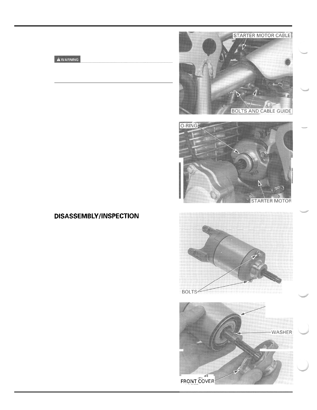
ELECTRIC
STARTER
STARTER
MOTOR
REMOVAL
Always
turn
the ignition switch
OFF
before servicing
the starter motor. The motor could suddenly start,
causing serious
injury.
Remove the rubber cap, terminal nut and starter
motor cable.
Remove the two mounting bolts, cable guide and the
starter motor from the crankcase and left crankcase
cover.
Remove the O
-
ring from the starter motor.
DISASSEMBLY/INSPECTION
Remove the starter motor case bolts.
Remove the front cover, thrust washer and seal ring.
SEAL
RING
ril
FRONT~EOVER
.A
-
17
-
4
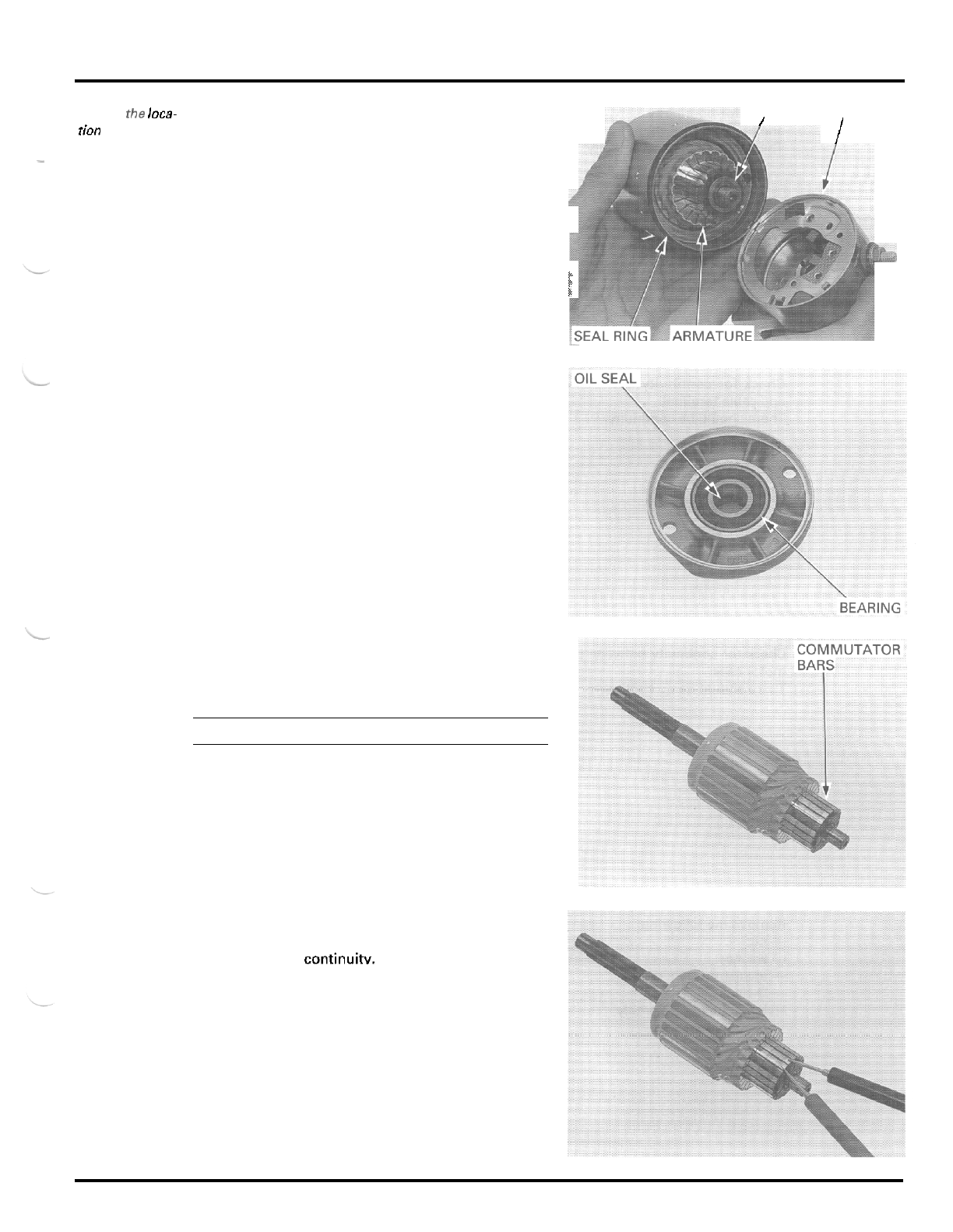
ELECTRIC STARTER
Record
the
loca-
tion
and
number
ofshims.
Remove the rear cover, shims and seal ring.
Remove the armature from the motor case.
-
SHIMS
REAR COVER
I
/
F
Check the bearing and oil seal in the front cover for
wear or damage.
Check the commutator bars of the armature
for
dis
-
coloration.
NOTE:
Do
not use emery
or
sand paper on the commutator.
Check for continuity between pairs of commutator
bars.
There should be continuitv.
17
-
5
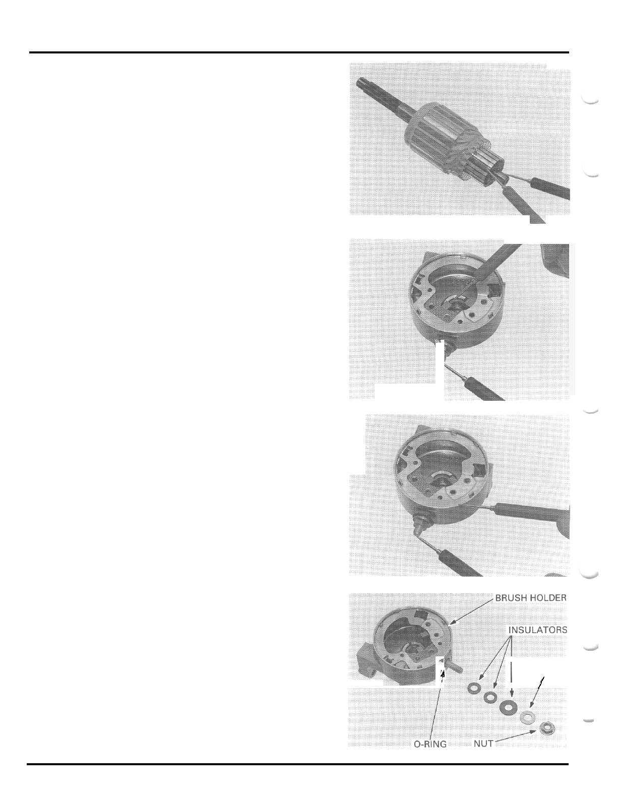
ELECTRIC STARTER
Check for continuity between each commutator bar
and the armature shaft.
There should be
no
continuity.
I
-
Check for continuity between the insulated brush
-
.
and cable terminal.
There should be continuity.
c
Check
for
continuity between the cable terminal and
motor case.
There should be
no
continuity.
Remove the following:
-
nut
-
washer
-
insulator washers
-
O
-
ring
-
brush holder assembly
li
f
I
I
I
WASHER
I
I
/
17
-
6
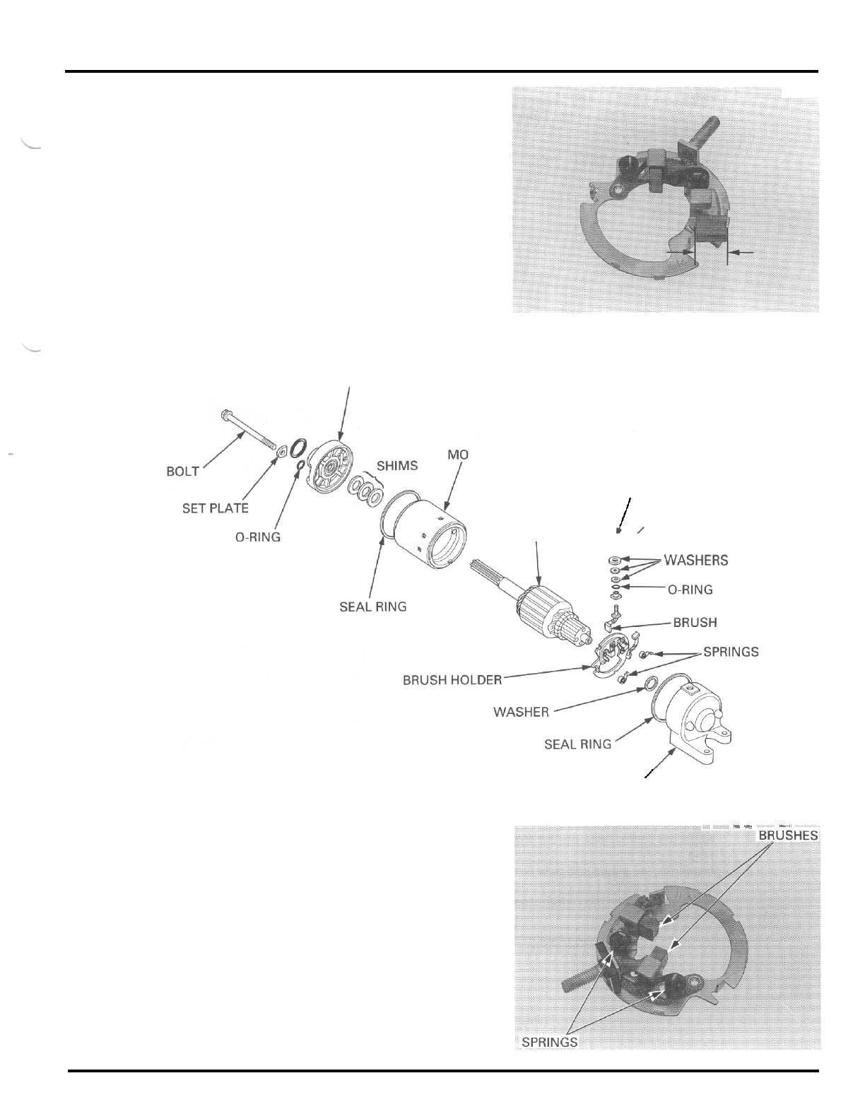
ELECTRIC STARTER
Remove
the brushes from the brush holder.
Measure the brush length.
SERVICE
LIMIT
8.5
mm
10.33
in)
ASSEMBLY
FRONT
COVER
-
TOR
CASE
NUT
ARMATURE
/
WASHER
I
INSULATOR
w
WASHERS
/
REAR COVER
-
jl_*
-
.,
=z
-_
--_
Install
the
brushes into the brush holder.
17
-
7
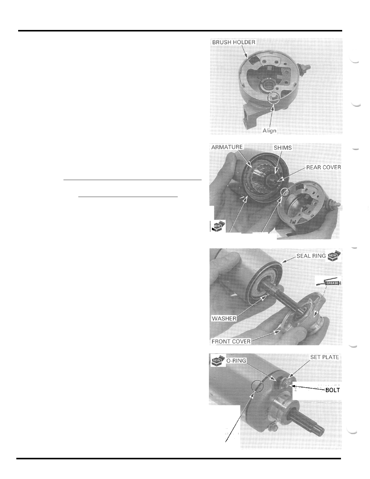
ELECTRIC STARTER
Install the brush holder assembly into the rear cover
by aligning the tab
of
the holder with the groove in
the rear cover.
Install the following:
-
new O
-
ring
-
insulator washers
-
washer
-
nut
Install the armature into the motor case while hold
-
ing the armature tightly to keep the magnet of the
case from pulling the armature against
it
CAUTION:
The
coil
may be damaged
if
the magnet
pulls
the
armature asainst the case.
Install the same number of shims in the same loca
-
tions as noted during disassembly.
Install
a
new seal ring.
Install the rear cover by aligning the brush holder tab
with the motor case groove.
Install the thrust washer and
a
new seal ring.
Apply grease to the oil seal lip in the front cover.
Install the front cover.
Align the index lines
on
the front cover and motor
case.
Install the set plates and new O
-
rings onto the motor
case bolts.
Install and tighten the motor case bolts.
G
SEAL
RING
Align
I
-BOLT
-
Align
i
17
-
8
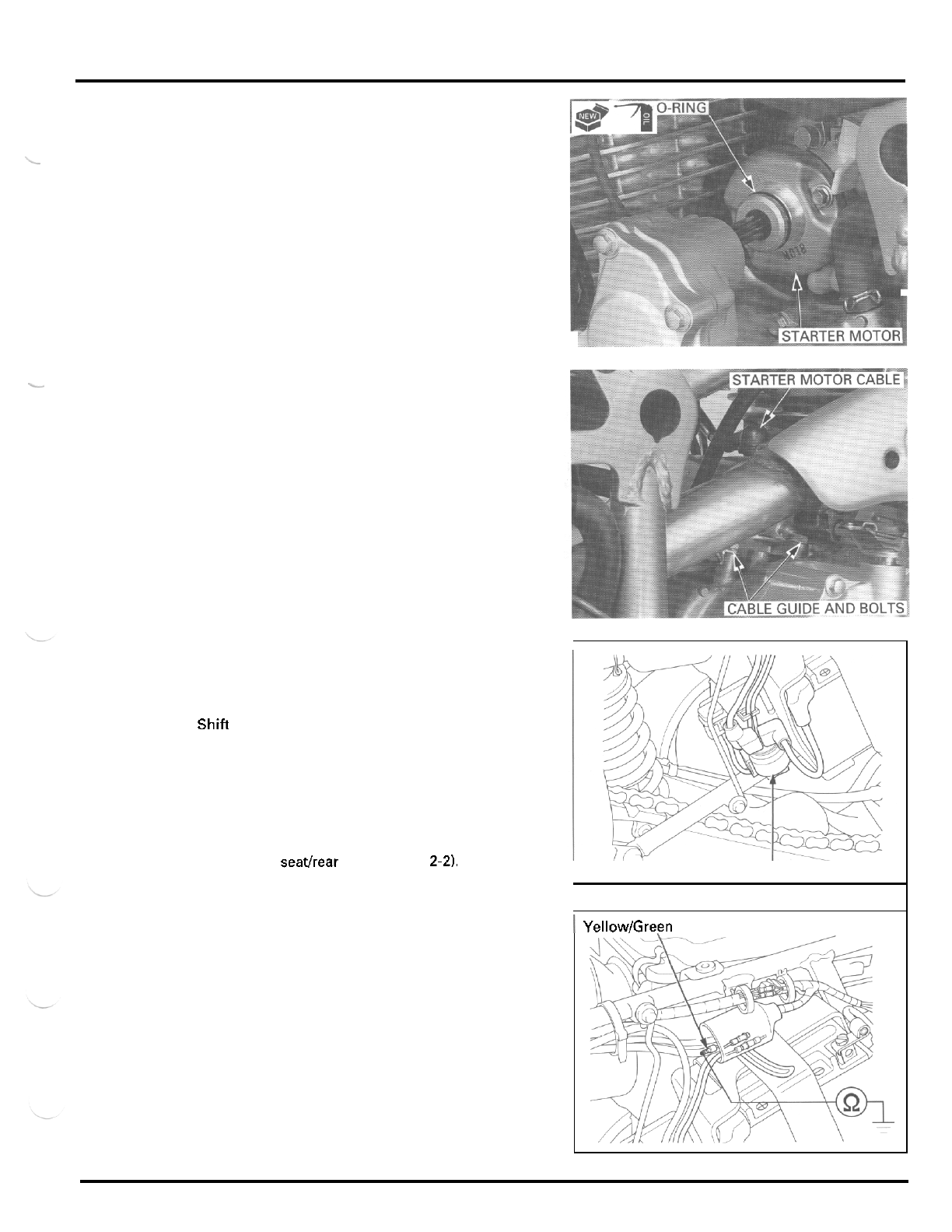
ELECTRIC STARTER
INSTALLATION
Coat
a
new O
-
ring with oil and install it into the
starter motor groove.
L
Install
the
starter motor into the left crankcase cover
and onto the crankcase.
Install the cable guide and mounting bolts, and tighten
the bolts securely.
Install the starter motor cable and terminal nut onto
the motor terminal and tighten the nut securely.
Install the rubber cap over the motor terminal securely.
STARTER RELAY SWITCH
INSPECTION
Shift the transmission into neutral.
Turn the ignition switch
ON.
Push the starter switch.
The coil is normal if the starter relay switch clicks.
If
you don't hear the switch
"
CLICK
"
. inspect the
relay switch using the procedure below.
Remove the seathear fender (page
2-21,
I
START
E
R
RELAY
SWITCH
GROUND
LINE
I
YellowlGreen
Disconnect the yellowlgreen wire connector
of
the
starter relay switch.
Check for continuity between the wire harness side
connector terminal and ground.
If there is continuity when the transmission
is
in neu
-
tral or when the clutch
is
disengaged, the ground cir
-
cuit
is
normal. (In neutral, there
is
a
slight resistance
due to the diode.)
17
-
9
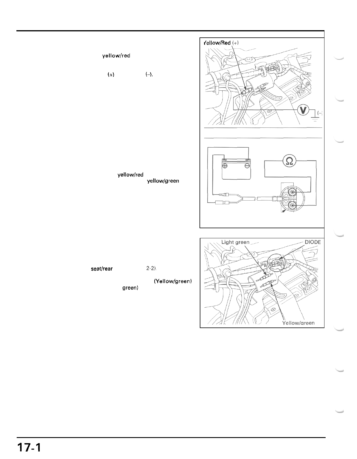
ELECTRIC STARTER
STARTER RELAY VOLTAGE
Disconnect the yellowlred wire connector
of
the
starter relay switch.
Measure the voltage between the wire harness side
connector terminal
(+)
and ground
(-).
If
the battery voltage appears only when the starter
switch is pushed with the ignition switch
ON,
the cir
-
cuit
is
normal.
OPERATION
CHECK
Disconnect the starter relay switch connectors and
cables.
Connect the fully charged
12
V
battery positive termi
-
nal to the relay switch yellow/red wire connector ter
-
minal and negative terminal to the yellowlgreen wire
connector terminal.
There should be continuity between the large termi
-
nals while the battery is connected, and
no
continuity
when the battery is disconnected.
CLUTCH
DIODE
INSPECTION
Remove the seathear fender (page
24
Disconnect the starter relay switch (Yellow/green)
and neutral switch (Light green) connectors.
Check for continuity between the wire harness side
connector terminals.
If there is continuity in one direction, the diode is nor
-
mal.
When there is continuity,
a
small resistance value will
register.
lellow/Aed
!+)
/
-
STARTER
RELAY SWITCH
17-1
0

MEMO
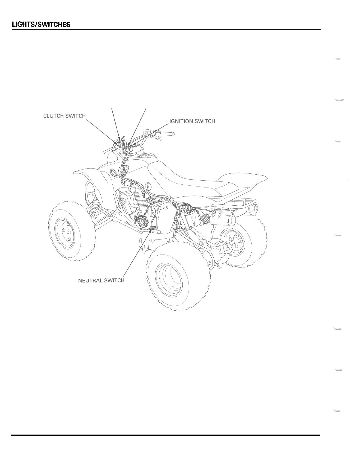
LlGHTSlSWlTCHES
-
HANDLEBAR SWITCH
\
NEUTRAL INDICATOR
18
-
0
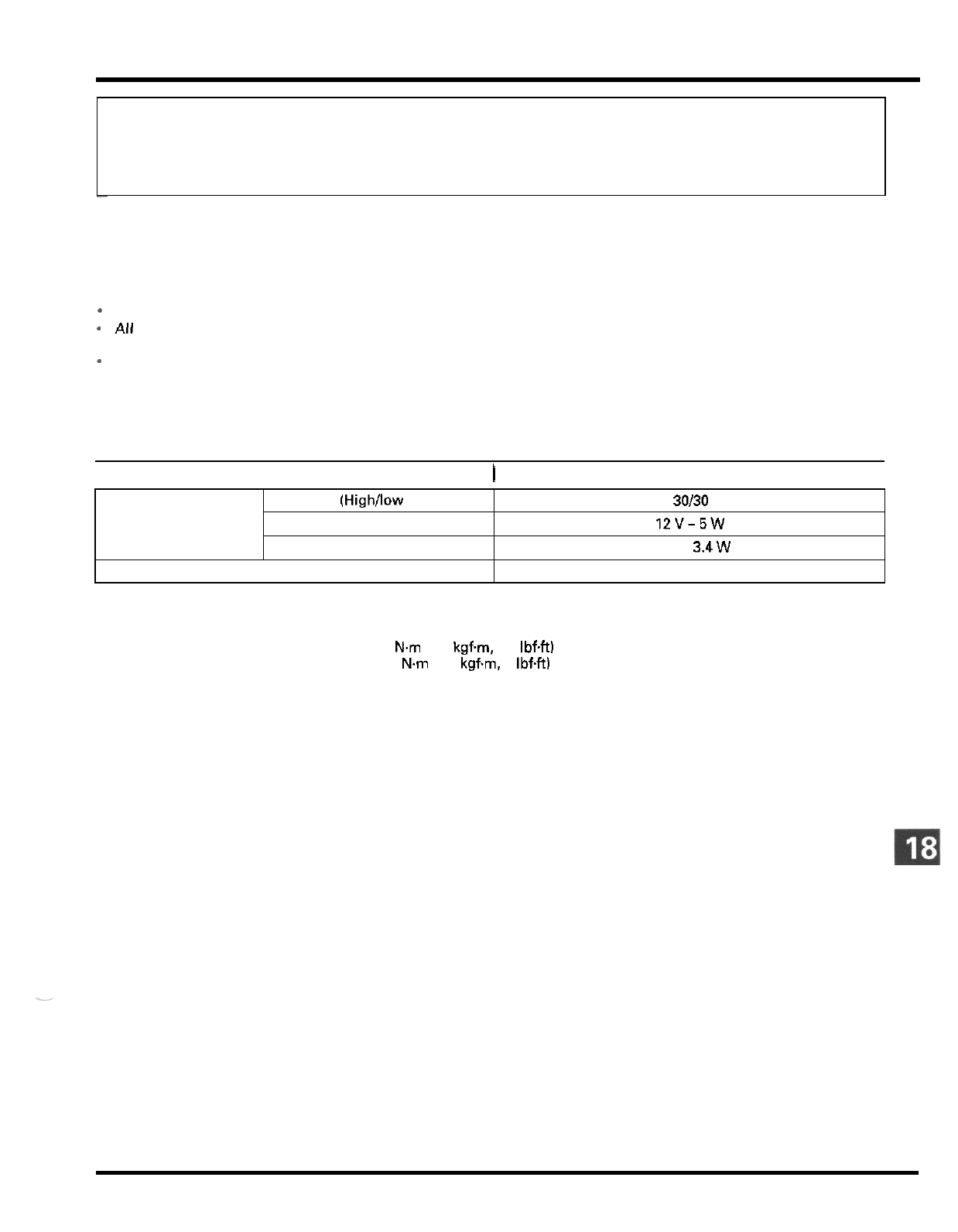
18.
LIGHTS/SWITCHES
Bulbs
SERVICE INFORMATION 18
-
1 HANDLEBAR SWITCH
BULB REPLACEMENT 18
-
2 CLUTCH SWITCH
IGNITION SWITCH 18
-
3 NEUTRAL SWITCH
Headlight (High/low beam)
Taillight
12V-5W
Neutral indicator
12
v
-
3.4w
12
v
-
30130
w
x
2
18
-
4
18
-
4
18
-
5
Fuse (main fuse)
SERVICE
INFORMATION
15A
GENERAL
-
A
continuity test can be made with the switches installed on the vehicle.
All
plastic connectors have locking tabs that must
be
released before disconnecting, and must be aligned when
reconnecting.
-
To isolate an electrical failure, check the continuity of the electrical path through the part.
A
continuity check can usu
-
ally be made without removing the part from the vehicle. Simply disconnect the connectors and connect
a
continuity
tester to the terminals or connections.
SPECIFICATIONS
I
ITEM
I
SPECIFICATIONS
I
TORQUE VALUES
Headlight mounting bolt
Neutral switch
4
Nm
(0.4
kgfm,
2.9
IbfW
13
N.m
(1.3
kgfm.
9
IbfW
18
-
1
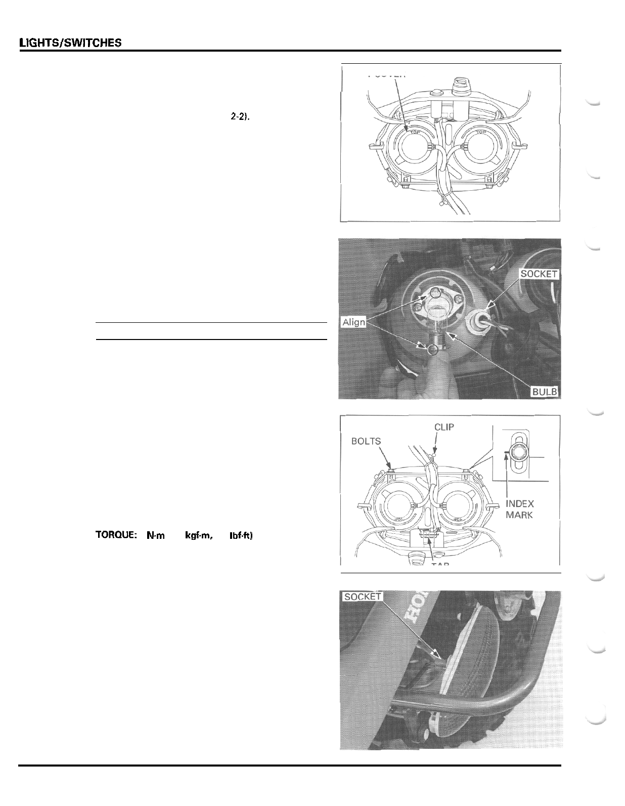
LIGHTS/SWITCHES
BULB REPLACEMENT
HEADLIGHT
Remove the front fender (page
2-2).
Remove the dust cover from the headlight.
Remove the bulb socket by turning
it
counterclock
-
wise while pushing
it
in.
Replace the headlight bulb with
a
new one.
Installation is in the reverse order
of
removal.
NOTE:
Align the bulb tab with the headlight groove.
HEADLIGHT REPLACEMENT
Release the wires from the clip.
Remove the two mounting bolts and headlight from
the front fender.
Install the headlight by aligning the tab with the slit
in the fender. Install the bolts, align the bolt centers
with the index marks, and tighten them.
TOROUE:
4
N.m
10.4
kgf.m,
2.9
Ibf.ft1
Secure the wires with the clip.
DUST
COVER
I
TAILLIGHT
Remove the bulb socket from the taillight by turning
it counterclockwise while pushing it in.
18
-
2
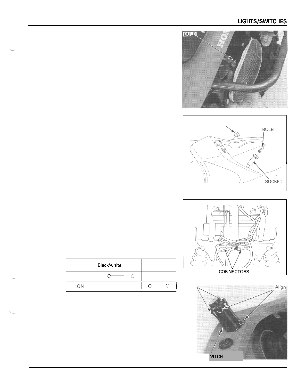
LlGHTSlSWlTCHES
Blacklwhite
Color
Position
Pull the taillight bulb out of the socket.
Install
a
new bulb and the socket in the reverse order
of removal.
-
Green Red Black
NEUTRAL INDICATOR
Remove the indicator lens from the bulb socket.
Remove the neutral indicator from the front fender.
Pull the indicator bulb out of the socket,
Install a new bulb, the lens and socket in the reverse
order of removal.
OFF
-
IGNITION
SWITCH
INSPECTION
C
lo
Disconnect the ignition switch connectors.
Check for continuity between the connector terminals
in each switch position.
Continuity should exist between the color coded
wires
as
follows:
I
ON
I
I
I+I
REPLACEMENT
Disconnect the ignition switch connectors.
Remove the ignition switch from the front fender
while pushing in the two stopper tabs.
Install new ignition switch by aligning the lug with
the groove in the front fender.
Connect the ignition switch connectors.
I
LENS,
CONNECTORS
TABS
IGNITIONS\
/
NITCH
18
-
3
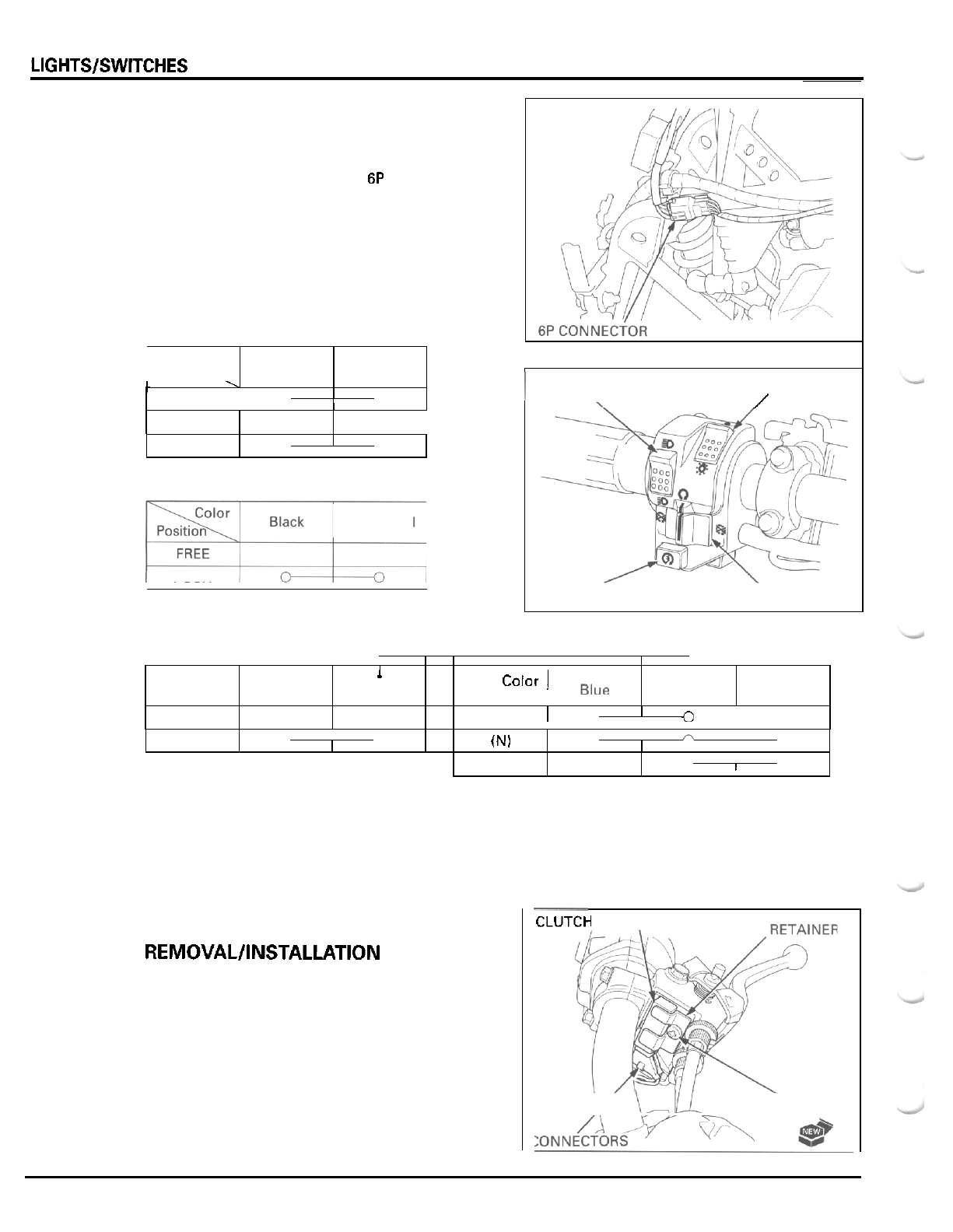
LlGHTSlSWlTCHES
Color Blackfwhite
Position
HANDLEBAR SWITCH
Green
INSPECTION
Disconnect the handlebar switch
6P
connector.
Check for continuity between the connector terminals
in each switch position.
Continuity should exist between the color coded
wires as follows:
OFF
ENGINE STOP SWITCH
0
I
0
I
Black Brown
Color
Position
OFF
u
t
OFF
0
I
0
Color
1
Blue
I
White
Position
HI
I
0
0
I
l
I
I
RUN
1
ON
0
I
0
(Nl
0
n
0
LIGHTING
/
1
DIMMER
I
I
ENGINE STOP
STARTER
LO
LIGHTING SWITCH
DIMMER
SWITCH
0
I
0
CLUTCH SWITCH
REMOVAL/INSTALLATION
Remove the screw, retainer and clutch switch from
the lever bracket.
Disconnect the wire connectors from the switch and
remove the switch.
Install the clutch switch in the reverse order of
Replace the
new one.
screw
with a
removal.
-
CLUTCk
1
SWITCH
Y
\,u
‘
S
C
R
E
W
18
-
4
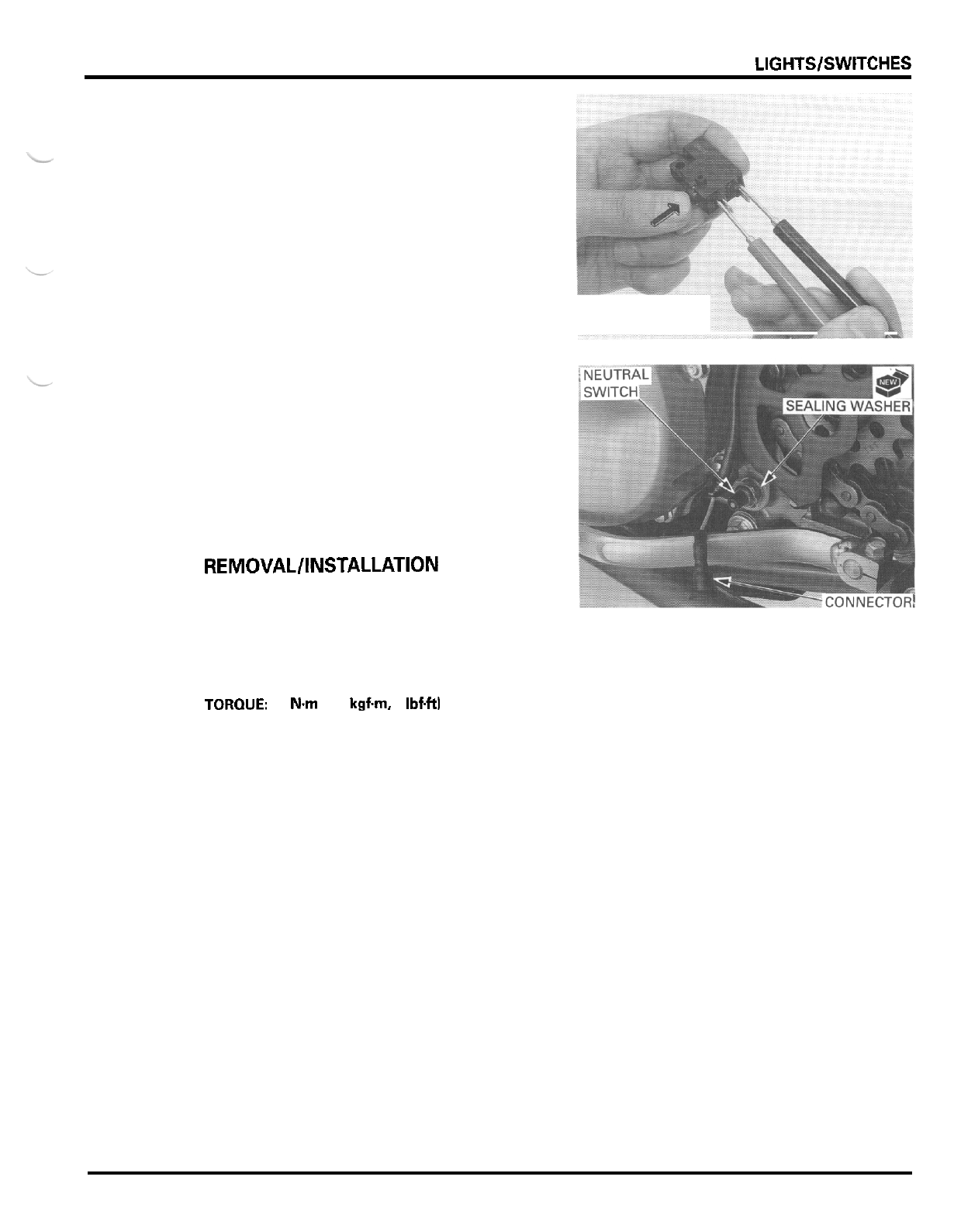
LIGHTS/SWITCHES
INSPECTION
Remove the clutch switch and check for continuity
between the switch terminals.
'
There should be no continuity with the switch
plunger pushed in, and continuity with the switch
plunger released.
.
NEUTRAL
SWITCH
INSPECTION
Disconnect the neutral switch wire connector.
Check for continuity between the switch terminal and
engine ground.
There should be continuity with the transmission in
neutral, and no continuity with the transmission in
any gear except neutral.
REMOVAL/INSTALLATION
Disconnect the neutral switch wire connector.
Remove the neutral switch from the crankcase
Install the neutral switch with a new sealing washer
and tighten it.
TOROUE:
13
Nm
(1.3
kgfm,
9
IbfW
Connect the neutral switch wire connector.
18
-
5

MEMO
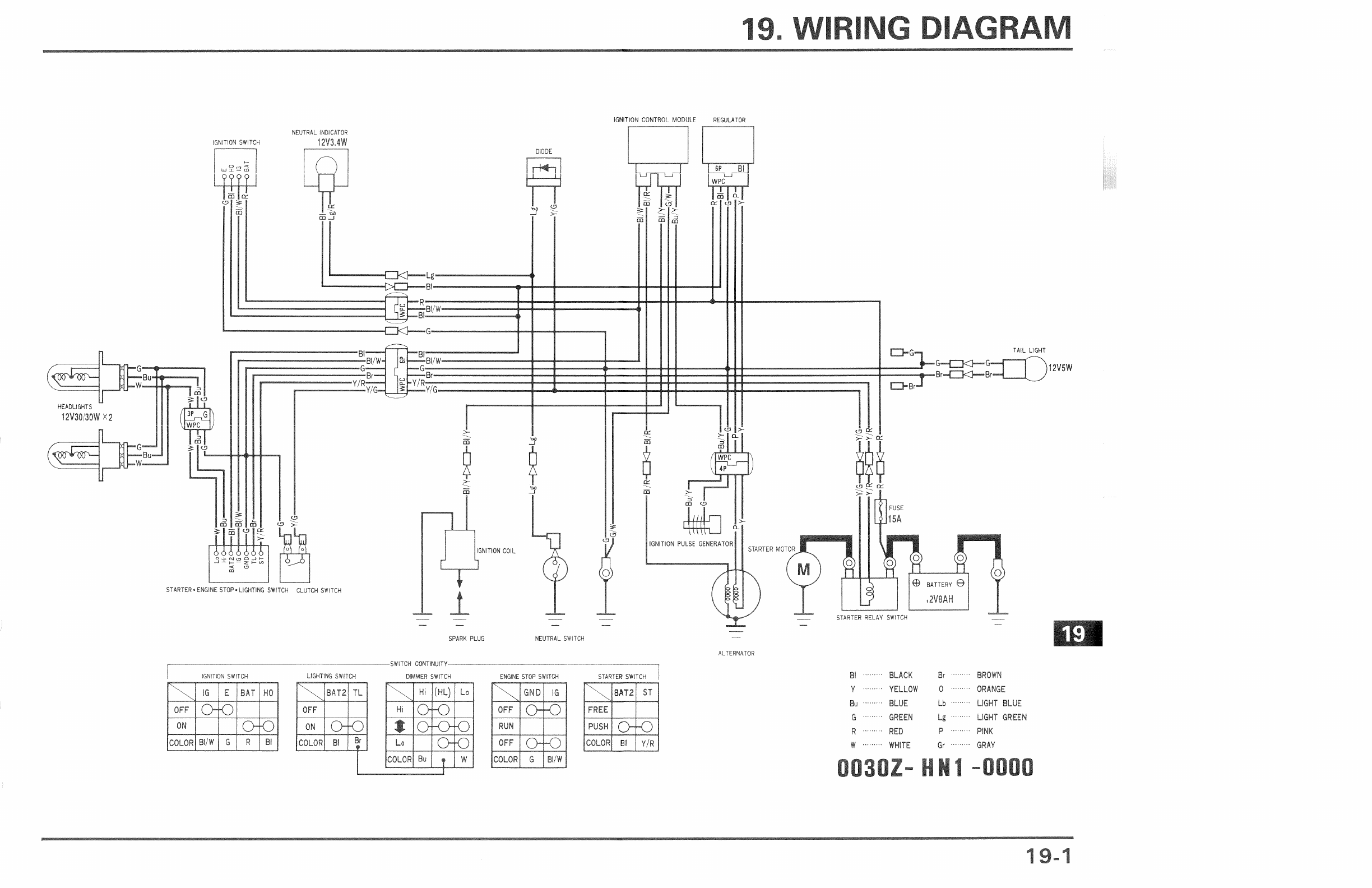
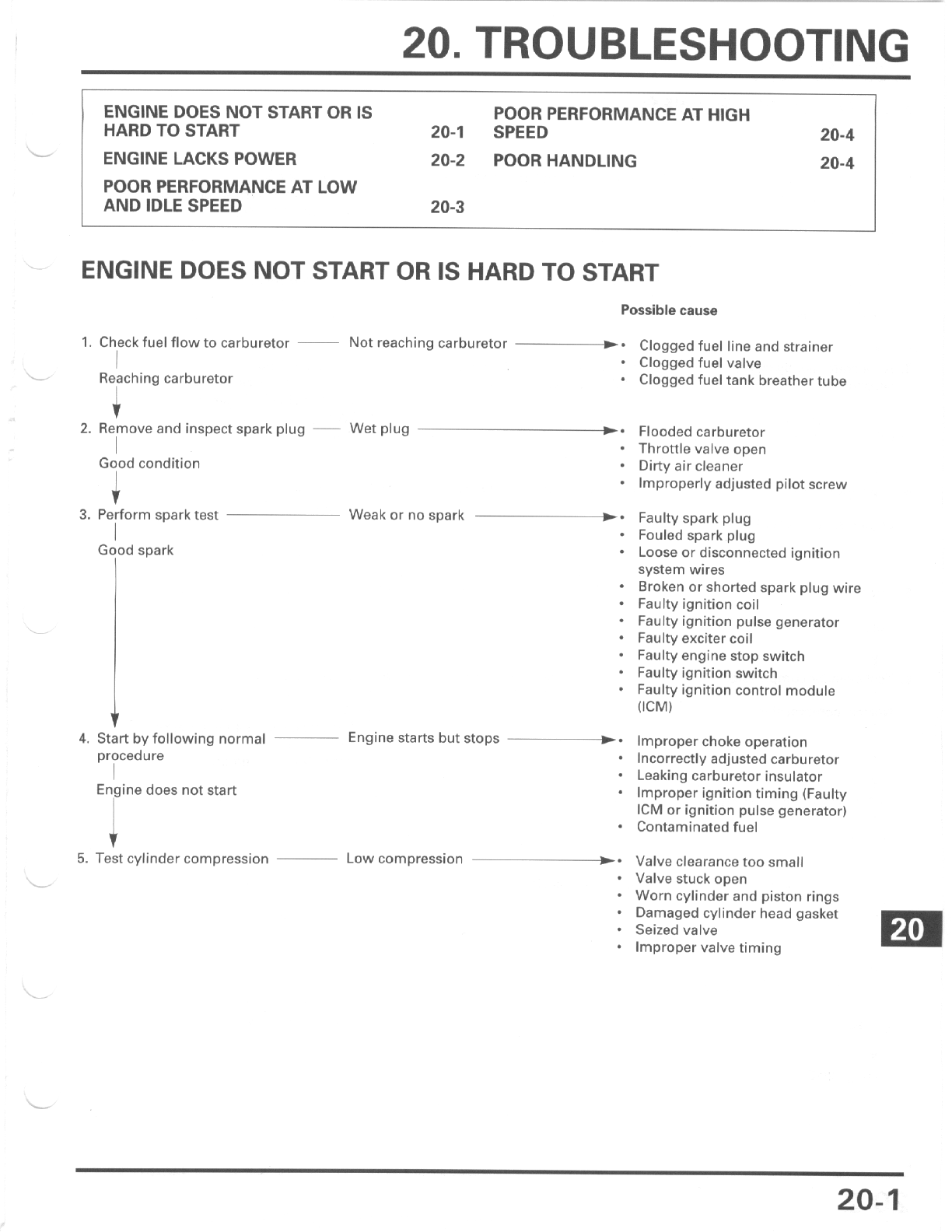
TROUBLESHOOTING
ENGINE
LACKS
POWER
Possible cause
I
1.
Raise wheel
off
the ground Wheels does not spin freely
-*
Brake dragging
and spin by hand
*
Worn or damaged wheel bearings
Wheel spins freely
*
Drive chain too tight
1
Pressure low
b.
Faulty tire valve
*
Punctured tire
4
i
I
2.
Checktire pressure
Pressure normal
I
Engine speed doesn't change
U-
Clutch slipping
accordingly when clutch is
*
Worn clutch discs/plates
released
-
Warped clutch discstplates
3.
Accelerate rapidly low to
second
Engine speed reduced when
clutch is released
*
Additive in engine oil
-
Weak clutch spring
I
Engine speed does not increase Choke valve closed
Clogged air cleaner
En ine speed increases
*
Restricted fuel flow
4.
Accelerate lightly
*
Clogged muffler
-
Restricted fuel
tank
breather tube
Incorrect
+-
Faulty ignition control module
(ICM)
1
5.
Check ignition timing
1
Cowect
-
Faulty ignition pulse generator
Low compression
+-
Valve clearance too small
*
Valve stuck open
Worn cylinder and piston rings
*
Damaged cylinder head gasket
*
Seized valve
-
Improper valve timing
J
6.
Test cylinder compression
I
Normal compression
Clogged
k-
Carburetor not serviced frequently
7.
Check carburetor for clogging
~
enough
I
I
Not clogged
Fouled or discolored
-.
Plugs not serviced frequently
enough
i
+
i
8.
Remove and inspect
spark plugs
Not fouled or discolored
I
-
Incorrect spark plug used
Incorrect
+-
Oil
level too high
*
Oil level too low
9.
Check
oil
level and condition
~
Correct
-
Contaminated oil
I
To page
20-3
I
20-2
TROUBLESHOOTING
From page
20-2
4
Possible cause
-
10.
Remove cylinder head cover
~
Valve train not lubricated
-*
and inspect lubrication properly
Valve train lubricated properly
I
I
11.
12.
Overheating
Check for engine overheating
-
Not overheating
c
I
>.
J
Accelerate or run at high speed
-
Engine knocks
>.
-c
Engine does not knock
Clogged oil passage
Clogged oil orifice
Excessive carbon build
-
up in
combustion chamber
Use
of
poor quality fuel
Clutch slipping
Lean fuel mixture
Worn piston and cylinder
Use of poor quality fuel
Excessive carbon build
-
up in
combustion chamber
Ignition timing
too
advanced
(Faulty
ICM)
Lean fuel mixture
POOR PERFORMANCE AT LOW AND IDLE SPEED
Possible cause
1.
Check carburetor pilot screw
~
Incorrect
b.
adjustment
Correct
I
2.
Check for leaking carburetor
~
-
insulator
No
leak
I
I
Leaking
*.
Weak or intermittent spark
-*
t
3.
Perform spark test
I
Good spark
Incorrect
.-
4.
Check ignition timing
>.
i
See section
5
Loose carburetor insulator bands
Damaged carburetor insulator
Faulty carburetor insulator O
-
ring
Faulty spark plug
Fouled spark plug
Loose or disconnected ignition sys
-
tem wires
Broken or shorted spark plug wire
Faulty ignition coil
Faulty ignition pulse generator
Faulty exciter coil
Faulty engine stop switch
Faulty ignition switch
Faulty ignition control module (ICM)
Faulty
ICM
-
Faulty ignition pulse generatoi
20
-
3
TROUBLESHOOTING
POOR PERFORMANCE AT
HIGH
SPEED
Possible
cause
-
1.
Disconnect fuel tube
at
Fuel flow restricted
+-
Restricted fuel tube
carburetor
*
Restricted fuel tank breather tube
Fuel
flows
freely
-
Faulty fuel valve
-
Clogged fuel strainer
I
-
Clogged
b.
Carburetor not serviced frequently
2.
Check carburetor for clogging
___
enough
i
I
I
Not clogged
Incorrect
+.
Cam sprockets not installed properly
.c
I
3.
Checkvalve timing
Correct
Incorrect
b-
Faulty ignition control module (ICM)
I
*
Faulty ignition pulse generator
I
i
4.
Check ignition timing
Correct
Weak
+.
Faulty valve spring
5.
Check valve spring
I
$.
Not weak
POOR HANDLING
Possible
cause
1.
If steering is heavy
t.
Steering shaft holder bolts too tight
*
Damaged steering shaft bushing
-
Damaged shaft ball bearing
t-
Excessive wheel bearing play
-
Bent rim
*
Improper installed wheel hub
*
Excessively worn swingarm pivot
bearings
*
Bentframe
2.
If any wheel is wobbling
3.
If vehicle pulls to one side
+.
Tire air pressure incorrect
*
Faulty shock absorber
-
Bent tie
-
rod
-
Incorrect tie
-
rod adjustment
*
Bent swingarm
-
Bent frame
*
Improper wheel alignment
20
-
4
21
.
INDEX
.................................
AIR CLEANER
3
-
5
AIR
CLEANER
HOUSING
.........................................
5-15
AIR CLEANER HOUSING DRAIN TUBE
..................
3
-
6
ALTERNATOR STATOR
...........................................
10-2
BATTERY
...................................................
......
15.4
BRAKE
FLUID
............................................................
3-14
BRAKE FLUID REPLACEMENT/AIR BLEEDING
......
14-3
BRAKE PAD/DISC
................................................
14
-
5
BRAKE PADS WEAR
.....
.............................
3
-
15
BRAKE PEDAL
.....................................
BRAKE SYSTEM
..................................
BULB REPLACEMENT
..............................................
18-2
CABLE &HARNESS ROUTING
...............................
1-18
CAMSHAFT/CYLINDER HEAD COVER
INSTALLATION
....................................................
7
-
18
-
ALTERNATOR CHARGING COIL
.............................
15.7
.-
.
-
CARBURETOR ASSEMBLY
......................................
5-7
CARBURETOR DISASSEMBLY/INSPECTION
.........
5-3
CARBURETOR INSTALLATION
....................
5
-
12
CARBURETOR REMOVAL
..............................
CHARGING SYSTEM INSPECTION
...............
CLUTCH
...............
...............................................
9-5
CLUTCH DIODE
..............
............................
17
-
10
CLUTCH SWITCH
................................
CLUTCH SYSTEM
................................
CRANKCASE ASSEMBLY
........................................
11
-
15
CRANKCASE BEARING REPLACEMENT ................
11-12
CRANKCASE SEPARATION
.................
CRANKSHAFT/BALANCER
..................
CYLINDER COMPRESSION
.................
CYLINDER HEAD ASSEMBLY/INSTALLATION
......
7
-
16
CYLINDER HEAD COVEWCAMSHAFT REMOVAL
7-4
CYLINDER HEAD REMOVAVDISASSEMBLY
.........
7-9
CYLINDER/PISTON REMOVAL
................................
8-3
DRIVE CHAIN
...................................................
3
-
13
DRIVE CHAIN SLIDER
..............................................
3
-
14
EMISSION CONTROL INFORMATION LABEL ........
1
-
24
EMISSION CONTROL SYSTEMS
............................
1
-
23
ENGINE IDLE SPEED
................................................
3
-
12
ENGINE INSTALLATION
..........................................
6-4
ENGINE OIL
...............................................
ENGINE OIL FILTER
...................................
ENGINE OIL STRAINER SCREEN IN OIL TANK
.....
3
-
12
ENGINE REMOVAL ..
..............................
6-2
EXHAUST SYSTEM
......
...........................
2-6
FLYWHEEL INSTAL
FLYWHEEL REMOV
FOOTPEG/MUD GUARD
..........................................
2-5
FRONT BRAKE CALIPER
..........................................
14
-
10
FRONT FENDER
..........................
..................
2-2
FRONT MASTER CYLINDER
......
FRONT SHOCK ABSORBER
.......
FRONT WHEEL AND HUB .......................................
12-6
FUEL LINE
.................................................................
3-4
FUEL TANK
&
HEAT PROTECTOR
..........................
2-4
GEARSHIFT LINKAGE
................
...................
3-11
GENERAL SAFETY
...................................................
1-1
HANDLEBAR
.............................................................
12
-
3
HANDLEBAR SWITCH ..............................................
18-4
HIGH ALTITUDE ADJUSTMENT
.............................
5
-
14
I
...
.~
..
IGNITION COIL
.........................................................
16-6
IGNITION CONTROL MODULE
(ICM)
.....................
16-6
IGNITION SWITCH
...................................................
18
-
3
IGNITION SYSTEM INSPECTION
............................
16-3
IGNITION TIMING
....................
16-7
LUBRICATION
&
SEAL POINTS
..............................
1
-
16
MAINTENANCE SCHEDULE
....................................
3-3
MODEL IDENTIFICATION
........................................
1-3
NEUTRAL SWITCH
...................................................
18
-
5
NUTS, BOLTS, FASTENERS
....................................
3
-
19
OIL COOLER &OIL TANK
........................................
4
-
6
OIL PUMP
&
STRAINER
...........................................
4
-
2
PILOT SCREW ADJUSTMENT
.....
5
-
13
PISTON/CYLINDER INSTALLATION
.......................
8-7
PRIMARY DRIVE GEAR
............................................
3-10
REAR AXLE
...............................................................
13-3
REAR BRAKE CALIPER
.............................................
14
-
16
REAR MASTER CYLINDER
......................................
14
-
13
REAR SHOCK ABSORBER
.......................................
13
-
9
REAR WHEEL
............................................................
13-3
REGULATOR /RECTIFIER
.........................................
15-6
RIGHT CRANKCASE COVER INSTALLATION
........
9
-
12
SEAT/REAR FENDER
................................................
2-2
SERVICE INFORMATION
ALTERNATOWSTARTER CLUTCH
...............
10-1
BATTERY/ CHARGING SYSTEM
..................
15-1
CLUTCH/GEARSHIFT LINKAGE ....................
9-1
CRANKCASEFRANSMISSION/
CYLINDER HEADNALVE
...............................
7-1
CYLINDER/PISTON
........................................
8-1
CRANKSHAFT
...........................................
11-1
ELECTRIC STARTER
......................................
17-1
ENGINE REMOVAUINSTALLATION
............
6
-
1
~ ~~~~~~~ ~ ~ ~~ ~
FRAME/BODY PANELSEXHAUST SYSTEM
..
2-1
FRONT
WHEEL/SUSPENSION/STEERlNG
...
12
-
1
FUEL SYSTEM
...............................................
5-1
HYDRAULIC DISC BRAKE
.............................
14-1
IGNITION SYSTEM
........................................
16
-
1
LIGHTS/SWITCHES
.......................................
18
-
1
LUBRICATION SYSTEM ................................
4-1
MAINTENANCE
.............................................
3
-
1
REAR WHEEUSUSPENSION
........................
13-1
SERVICE RULES
.......................................................
1
-
2
SHOCK LINKAGE
......................................................
13-11
SIDE COVER
..............................................................
2
-
3
SKID PLATE
..............................................................
2-5
SKID PLATE AND ENGINE GUARD
........................
3
-
17
SPARK ARRESTER
.........................................
............................................................
w
......................................................
SPARK PLUG
3-6
SPECIFICATIONS
1-4
STARTER CLUTCH
...................................................
10-6
~~~~~~ ~~~ ~~~ ~
STARTER MOTOR
....................................................
17-4
STARTER RELAY SWITCH
.......................................
17-9
STEERING SHAFT AND TIE-ROD
............................
12
-
17
STEERING SHAFT HOLDER BEARING
...................
3
-
20
STEERING SYSTEM
.................................................
3
-
20
SUSPENSION
...........................................................
3
-
18
SUSPENSION ARM
..................................................
12-12
SWINGARM
..............................................................
13
-
13
21
-
1
INDEX
THROTTLE HOUSING
..............................................
12
-
5
THROTTLE OPERATION
..........................................
3-4
TIRES
....................................................................
12
-
9
TOOLS
....................................................................
1
-
14
TORQUE VALUES
..................................
1-11
TRANSMISSION
.......................................................
11-4
TROUBLESHOOTING
ALTERNATORETARTER CLUTCH
...............
10
-
1
BATrERYKHARGING SYSTEM
...........
15-3
CLUTCH/GEARSHIFT LINKAGE
....................
9
-
2
CRANKCASEflRANSMlSSlON/
CYLINDER HEADNALVE
...................
CY LINDE R/PISTON
ELECTRIC STARTER
......................................
17-2
ENGINE DOES NOT START
OR
IS
HARD
TO START
..................................................
20-1
ENGINE LACKS POWER
...............................
20-2
FRAME/BODY PANELSEXHAUST
SYSTEM
....................................................
2-1
FRONT
WHEEUSUSPENSION/STEERlNG
...
12
-
2
FUEL SYSTEM
..............
.........................
5-2
HYDRAULIC DISC BRAK
.........................
14-2
IGNITION SYSTEM
........................................
16-2
LUBRICATION SYSTEM
................................
4
-
1
POOR HANDLING
..........................................
20
-
4
POOR
PERFORMANCE AT HIGH SPEED
.....
20-4
POOR PERFORMANCE AT LOW AND IDLE
SPEED
........................................................
20
-
3
REAR WHEEUSUSPENSION
........................
13-2
VALVE CLEARANCE
................................
.......
3-7
VALVE GUIDE REPLACEMENT
...............................
7
-
12
VALVE SEAT INSPECTION/REFACING
...................
7
-
13
WHEELSflIRES
.........................................................
3
-
19
WIRING DIAGRAM
...................................................
19
-
1
CRANKSHAFT
...........................................
11
-
2
.
.
.
.
.
.
21
-
2
