9815Flyleaf ICAO DOC 9815 Manual On Laser Emitters And Flight Safety (2003)
User Manual:
Open the PDF directly: View PDF ![]() .
.
Page Count: 86

International Civil Aviation Organization
Approved by the Secretary General
and published under his authority
Manual on Laser
Emitters and
Flight Safety
First Edition — 2003
Doc 9815
AN/447


International Civil Aviation Organization
Approved by the Secretary General
and published under his authority
Manual on Laser
Emitters and
Flight Safety
First Edition — 2003
Doc 9815
AN/447

AMENDMENTS
The issue of amendments is announced regularly in the ICAO Journal and in the
monthly Supplement to the Catalogue of ICAO Publications and Audio-visual
Training Aids, which holders of this publication should consult. The space below
is provided to keep a record of such amendments.
RECORD OF AMENDMENTS AND CORRIGENDA
AMENDMENTS CORRIGENDA
No. Date Entered by No. Date Entered by
(ii)

(iii)
FOREWORD
Adequate lighting is necessary for all visual tasks. An
excess of light, however, can detrimentally affect vision to
the extent of rendering it ineffective. In aviation, a pilot
may experience high levels of lighting when flying into the
sun or looking at very bright artificial light sources such as
searchlights. The invention (in 1957) of the laser* is a
significant addition to the known aviation-related problems
associated with high-intensity lights.
Laser is an acronym for light amplification by stimulated
emission of radiation; this technique can produce a beam of
light of such intensity that permanent damage to human
tissue, in particular the retina of the eye, can be caused
instantaneously, even at distances of over 10 km. At lower
intensities, laser beams can seriously affect visual
performance without causing physical damage to the eyes.
There are, however, many useful applications of laser
technology, such as high-speed automatic scanning of bar
codes, laser printing, welding and cutting, micro-surgery,
communication by means of fibre optics, recording of
music, gyroscopes, light displays and the ubiquitous laser
pointer used by lecturers worldwide. Lasers are associated
with almost every aspect of modern life.
Whilst protection of the pilot against deliberate or
accidental laser beam strikes has been of interest to military
aviation medicine specialists for many years, it was only
with the advent of the laser light display for entertainment
or commercial purposes and subsequent accidental
illumination of civil aircraft from such displays that civil
aviation medicine specialists have become more concerned.
By 2001, many pilots had experienced incapacitation
following accidental laser beam strikes. Over 600 incidents
have been recorded worldwide, the majority of reports
coming from the United States (see Chapter 4, page 4-1 for
a summary of two significant incidents). It may be expected
that most civil aircraft laser beam strikes will be
inadvertent, but powerful laser emitters that can be
accurately targeted are now available at relatively low cost,
so the possibility of malicious use of such devices in the
future cannot be ignored.
In view of the increasing risk to flight safety posed by the
more widespread use of laser emitters around airports,
ICAO formed a study group in 1999 to evaluate the laser
risk and consider whether new Standards or Recommended
Practices (SARPs) were necessary.
The study group consisted of experts in ophthalmology and
vision care, light engineering and physics, flight operations
and regulatory aviation medicine. These experts were
nominated in part by four Contracting States: Canada,
Netherlands, United Kingdom and United States and in part
by the Aerospace Medical Association and the International
Federation of Airline Pilots’ Associations.
At the first meeting of the study group, documentation was
presented indicating that there was considerable
international concern that lasers might pose a significant
and increasing risk to flight safety and that without ICAO
action, development of necessary controls in individual
Contracting States would be inconsistent, insufficient or
worse, non-existent.
During 1999 and 2000, the Aviation Medicine Section of
the ICAO Secretariat, with the assistance of the study
group, developed the laser-related SARPs that are now
included in Annexes 11 and 14 to the Convention.
However, these SARPs do not provide the necessary
practical guidance for implementation of relevant
regulations in States. The study group, therefore,
recommended that a manual be written focussing on the
medical, physiological and psychological effects on flight
crew of exposure to laser emissions.
The information and guidance material provided in this
manual is primarily directed to decision-makers at
government level, laser operators, air traffic control
officers, aircrew, aviation medicine consultants to and
medical officers of the regulatory authorities, and doctors
involved in clinical aviation medicine, occupational health
and preventive medicine. The manual is aimed both at
reducing the need for regulatory authorities to seek
individual expert advice and at reducing inconsistencies
between Contracting States in the implementation of
national regulations.
∗The term laser has more than one meaning, see Glossary.

(iv) Manual on laser emitters and flight safety
In addition, it can be used to support training provided by
operators to flight crew with respect to the effect of laser
emitters on operational safety. It is recommended that the
information contained in Chapter 4, particularly in relation
to preventative procedures, be included in the operations
manual.
This manual contains information and guidance provided
by the study group. Comments from States and other
parties outside ICAO would be appreciated. They should be
addressed to:
The Secretary General
International Civil Aviation Organization
999 University Street
Montréal, Quebec H3C 5H7
Canada

(v)
TABLE OF CONTENTS
Page Page
Glossary . . . . . . . . . . . . . . . . . . . . . . . . . . . . . . . . . . . (vii)
List of abbreviations, symbols and units . . . . . . . . . (xi)
Chapter 1. Physics of lasers . . . . . . . . . . . . . . . . 1-1
1.1 Introduction to laser emitters . . . . . . . . . . . 1-1
1.2 Components of a laser . . . . . . . . . . . . . . . . 1-1
1.3 Types of lasers . . . . . . . . . . . . . . . . . . . . . . 1-2
1.4 Beam properties . . . . . . . . . . . . . . . . . . . . . 1-4
1.5 Characteristics of materials . . . . . . . . . . . . 1-6
Chapter 2. Laser hazard evaluation . . . . . . . . . . 2-1
2.1 Purpose . . . . . . . . . . . . . . . . . . . . . . . . . . . . 2-1
2.2 Background . . . . . . . . . . . . . . . . . . . . . . . . . 2-1
2.3 Accessible emission limit (AEL) . . . . . . . . 2-1
2.4 Laser hazard classification . . . . . . . . . . . . . 2-2
2.5 Nominal ocular hazard distance (NOHD) . 2-2
2.6 Optical density (OD) . . . . . . . . . . . . . . . . . 2-3
2.7 Other factors . . . . . . . . . . . . . . . . . . . . . . . . 2-3
Chapter 3. Laser beam bioeffects and
their hazards to flight operations . . . . . . . . . . . . . 3-1
3.1 Introduction . . . . . . . . . . . . . . . . . . . . . . . . 3-1
3.2 The hazard . . . . . . . . . . . . . . . . . . . . . . . . . 3-1
3.3 Biological tissue damage mechanisms . . . 3-2
3.4 The skin . . . . . . . . . . . . . . . . . . . . . . . . . . . 3-4
3.5 The eye . . . . . . . . . . . . . . . . . . . . . . . . . . . . 3-5
3.6 Ocular laser beam damage terminology . . 3-8
3.7 Laser beam bioeffects . . . . . . . . . . . . . . . . 3-8
3.8 Laser beam bioeffects and air operations . 3-10
3.9 The future . . . . . . . . . . . . . . . . . . . . . . . . . . 3-15
3.10 Medical evaluation of laser beam
incidents . . . . . . . . . . . . . . . . . . . . . . . . . . . 3-15
Chapter 4. Operational factors and
training of aircrew . . . . . . . . . . . . . . . . . . . . . . . . . . 4-1
4.1 Background . . . . . . . . . . . . . . . . . . . . . . . . 4-1
4.2 Situational awareness . . . . . . . . . . . . . . . . . 4-2
4.3 Orientation in flight . . . . . . . . . . . . . . . . . . 4-2
4.4 Preventative procedures . . . . . . . . . . . . . . . 4-3
Chapter 5. Airspace safety . . . . . . . . . . . . . . . . . 5-1
5.1 General . . . . . . . . . . . . . . . . . . . . . . . . . . . . 5-1
5.2 Airspace restrictions . . . . . . . . . . . . . . . . . . 5-1
5.3 Aeronautical assessment . . . . . . . . . . . . . . 5-4
5.4 Control measures . . . . . . . . . . . . . . . . . . . . 5-5
5.5 Determinations . . . . . . . . . . . . . . . . . . . . . . 5-5
5.6 Incident-reporting requirements . . . . . . . . . 5-7
Chapter 6. Documentation of incidents after
suspected laser beam illumination . . . . . . . . . . . . 6-1
6.1 Background . . . . . . . . . . . . . . . . . . . . . . . . 6-1
6.2 Procedures . . . . . . . . . . . . . . . . . . . . . . . . . 6-1
6.3 Documentation . . . . . . . . . . . . . . . . . . . . . . 6-1
Chapter 7. Medical examination following
suspected laser beam illumination . . . . . . . . . . . . 7-1
7.1 General . . . . . . . . . . . . . . . . . . . . . . . . . . . . 7-1
7.2 Procedures . . . . . . . . . . . . . . . . . . . . . . . . . 7-1
Appendix A. Notice of proposal to conduct
outdoor laser operation(s) . . . . . . . . . . . . . . . . . . . . A-1
Appendix B. Suspected laser beam incident
report and suspected laser beam exposure
questionnaire . . . . . . . . . . . . . . . . . . . . . . . . . . . . . . B-1
Appendix C. Amsler grid testing procedure . . . C-1


(vii)
GLOSSARY
Note.— The definitions of the terms listed below are
based on a pragmatic approach. The terms defined are
therefore limited to those actually used in this manual. This
listing is not intended to constitute a dictionary of terms
used in the laser field as a whole.
Absorption. Transformation of radiant energy to a different
form of energy (usually heat) by interaction with matter.
Accessible emission limit (AEL). The maximum accessible
emission power or energy permitted within a particular
laser class.
Accessible radiation. Optical radiation to which the human
eye or skin may be exposed in normal usage.
Actinic radiation. Electromagnetic radiation in the visible
and ultraviolet part of the spectrum capable of
producing photochemical changes.
Aerodrome reference point (ARP). The designated
geographical location of an aerodrome.
After-image. An image that remains in the visual field after
an exposure to a bright light.
Attenuation. The decrease in the laser beam power or
energy as it passes through an absorbing or scattering
medium.
Average power. The total energy imparted during exposure
divided by the exposure duration.
Aversion response. Closure of the eyelid or movement of
the head to avoid an exposure to a noxious stimulant or
bright light. In laser safety standards, the aversion
response (including blink reflex time) is assumed to
occur within 250 milliseconds (0.25 s).
Beam. A collection of rays that may be parallel, divergent
or convergent.
Beam diameter. For the purpose of this manual, the beam
diameter is the radial distance across the centre of a
laser beam where the irradiance is 1/e times the centre-
beam irradiance (or radiant exposure for a pulsed laser).
Beam waist. The minimum dimension of a cross section of
the beam.
Buffer angle. An angle added to the beam divergence or
intended laser projection field in order to ensure a
protection zone.
Buffer zone. A volume of air surrounding the laser beam,
all potential locations of the laser beam and all
hazardous diffuse or specular reflections, where the
maximum permissible exposure (MPE) or visual
interference levels are exceeded. It includes the beam
divergence or scanning extent of the laser beam plus the
buffer angle and the full range of the laser beam to the
point where the MPE or any applicable visual in-
terference level is not exceeded. Natural terrain or beam
masks may truncate part of this volume.
Cavity. The optical assembly of a laser usually containing
two or more highly reflecting mirrors which reflect
radiation back into the active medium of the laser.
Collateral radiation. Any electromagnetic radiation
emitted by a laser, except the laser beam itself, which is
necessary for the operation of the laser emitter or is a
consequence of its operation.
Collimated beam. A beam of radiation with very low
divergence or convergence and therefore effectively
considered parallel.
Continuous wave (CW). The output of a laser which is
operated in a continuous rather than a pulsed mode. In
laser safety standards, a laser operating with a
continuous output for a period greater than 0.25 s is
regarded as a CW laser.
Critical level. The minimum effective irradiance from a
visible laser beam which can interfere with critical task
performance due to transient visual effects.
Diffraction. Deviation of part of a beam, determined by the
wave nature of radiation and occurring when the
radiation passes the edge of an opaque obstacle.

(viii) Manual on laser emitters and flight safety
Diffuse reflection. The component of a reflection from a
surface which is incapable of producing a virtual image
such as is commonly found with flat finish paints or
rough surfaces. A matt surface will reflect the laser
beam in many directions. Viewing a diffuse reflection
from a matt surface may produce either a small or a
large retinal image, depending on the viewer distance
and the size of the illuminated surface.
Divergence (
ϕ
). For the purpose of this manual, the
divergence is the increase in the diameter of the laser
beam with distance from the exit aperture, based on the
full angle at the point where the irradiance (or radiant
exposure for pulsed lasers) is 1/e times the maximum
value.
Electromagnetic radiation. The flow of energy consisting
of orthogonally vibrating electric and magnetic fields.
Electromagnetic radiation includes optical radiation,
X-rays and radio waves.
Electromagnetic spectrum. The range of frequencies or
wavelengths over which electromagnetic radiations are
propagated. The spectrum ranges from short wave-
lengths, such as gamma rays and X-rays, through
visible radiation to longer wavelength radiations of
microwaves, and television and radio waves.
Energy. The capacity for doing work. Energy content is
commonly used to characterize the output from pulsed
lasers and is generally expressed in joules (J).
Excited state. The state of an atom or molecule when it is
in an energy level with more energy than in its normal
or “ground” state.
Exposure duration. The duration of a pulse or a series or
a train of pulses, or of continuous emission of laser
radiation incident upon the human body.
Flash-blindness. The inability to see (either temporarily or
permanently) caused by bright light entering the eye
and persisting after the illumination has ceased.
Free radical. An atom or group of atoms in a transient
chemical state containing at least one unpaired electron.
Free radicals may be produced within or introduced into
biological tissue where they may cause damage.
Gaussian beam profile. The bell-shaped profile of a laser
beam when the laser is operating in the simplest mode.
Glare. A temporary disruption in vision caused by the
presence of a bright light (such as an oncoming car’s
headlights) within an individual’s field of vision. Glare
is unassociated with biological damage and lasts only as
long as the bright light is actually present within the
individual’s field of vision.
Hazard. Something with the potential to cause harm to
people, property or the environment.
Hazard zone. The space within which the level of radiation
during operation of a laser emitter exceeds the
applicable exposure limit. See also nominal hazard
zone (NHZ).
Infrared radiation. For the purpose of this manual,
electromagnetic radiation with wavelengths that lie
within the range 700 nm to 1 mm.
Instrument flight rules (IFR). A set of rules governing the
conduct of flight under instrument meteorological
conditions.
Interlock. See safety interlock.
Invisible laser beam. A laser emission with a wavelength
either shorter than 400 nm or longer than 700 nm. Laser
sources near these defining limits may be capable of
producing a visual stimulus.
Irradiance (E). The power per unit area, expressed in watts
per square centimetre (W/cm2) or watts per square
metre (W/m2).
Laser. 1) An acronym for light amplification by stimulated
emission of radiation. 2) A device that produces an
intense, coherent, directional beam of optical radiation
by stimulating emission of photons by electronic or
molecular transitions to lower energy levels.
Laser-beam critical flight zone (LCFZ). See protected
flight zones a).
Laser-beam free flight zone (LFFZ). See protected flight
zones b).
Laser-beam free level. The maximum level of visible optical
radiation which is not expected to cause any visual
interference to an individual performing critical tasks.
Laser-beam sensitive flight zone (LSFZ). See protected
flight zones c).
Laser emitter. Same as laser 2).
Laser safety officer (LSO). An individual who is knowl-
edgeable in the evaluation and control of laser hazards
and has responsibility for oversight of the control of
those hazards.

Glossary (ix)
Laser source. See source.
Light (visible radiation). A form of electromagnetic
radiation capable of producing a visual stimulus to the
human eye. Its wavelength range is approximately from
400 nm to 700 nm (between ultraviolet and infrared).
Laser sources of an equivalent power slightly outside
this range may be capable of producing less intense
visual stimuli.
Limiting aperture (Df). The diameter of a circle over which
irradiance or radiant exposure is averaged for
comparison to the maximum permissible exposure
(MPE).
Local laser working group (LLWG). A group, convened to
assist in evaluating the potential effect of laser
emissions on aircraft operators in the vicinity of the
proposed laser activity. Participants may include, but
are not limited to, representatives from the aerodrome
tower, area control centre, aerodrome management,
airspace users, local officials, military representatives,
qualified subject experts, laser manufacturers and the
laser proponent.
Maximum permissible exposure (MPE). The inter-
nationally accepted maximum level of laser radiation to
which human beings may be exposed without risk of
biological damage to the eye or skin.
Mitigation. Use of control measures aimed at neutralizing
the effect of laser beams on flight safety.
Nominal hazard zone (NHZ). The space within which the
level of the direct, reflected or scattered radiation
during operation of a laser emitter exceeds the
applicable maximum permissible exposure (MPE).
Exposure levels beyond the boundary of the NHZ are
below the applicable MPE level.
Nominal ocular hazard distance (NOHD). The distance
along the axis of the laser beam beyond which the
appropriate maximum permissible exposure (MPE) is
not exceeded (i.e. an indication of the “safe viewing”
distance). An equivalent term for skin exposure is “skin
hazard distance”.
Normal flight zone (NFZ). See protected flight zones d).
Optical density (OD). A physical property of a material that
quantifies the attenuation of the laser beam.
Optical radiation. Part of the electromagnetic spectrum
comprising infrared, visible and ultraviolet radiations.
Photon. In quantum mechanics, the smallest particle of
optical radiation.
Pointing accuracy. The maximum angle of expected error
in beam direction during all projected uses of the laser
emitter.
Population inversion. The condition needed for light
amplification to occur whereby the number of atoms in
an excited state is greater than the number of atoms in
a lower energy state.
Power. The rate at which energy is emitted, transferred or
received. Unit: watts (joules per second).
Proponent. The legal entity (corporation, company,
individual) applying to conduct an outdoor laser
operation at a specific time and location.
Protected flight zones. Airspace specifically designated to
mitigate the hazardous effects of laser radiation.
a) Laser-beam critical flight zone (LCFZ). Airspace
in the proximity of an aerodrome but beyond the
laser-beam free flight zone (LFFZ) where the
irradiance is restricted to a level unlikely to cause
glare effects.
b) Laser-beam free flight zone (LFFZ). Airspace in
the immediate proximity to the aerodrome where
the irradiance is restricted to a level unlikely to
cause any visual disruption.
c) Laser-beam sensitive flight zone (LSFZ). Airspace
outside, and not necessarily contiguous with, the
LFFZ and LCFZ where the irradiance is restricted
to a level unlikely to cause flash-blindness or after-
image effects.
d) Normal flight zone (NFZ). Airspace not defined as
LFFZ, LCFZ or LSFZ but which must be protected
from laser radiation capable of causing biological
damage to the eye.
Pulsed laser. A laser that delivers its energy in individual
pulses lasting less than 0.25 s. See repetitively-pulsed
laser.
Pulse duration. The duration of a laser pulse, usually
measured as the time interval between the half-power
points on the leading and trailing edges of the pulse.

(x) Manual on laser emitters and flight safety
Pulse repetition frequency (PRF). The number of pulses
that a laser produces over an applicable time frame
divided by that time frame. For uniform pulse trains
lasting over 1 s, the PRF is the number of pulses
emitted by the laser in 1 s. Unit: hertz (Hz).
Radian. A unit of angular measure equal to the subtended
angle at the centre of a circle by an arc whose length is
equal to the radius of the circle. 1 radian = 57.3
degrees; 2π radians = 360 degrees.
Radiant energy (Q). Energy emitted, transferred or
received as radiation. Unit: joule (J).
Radiant exposure (H). The laser beam energy per unit area,
expressed in joules per square centimetre (J/cm2) or
joules per square metre (J/m2).
Radiant power (
Φ
). Power emitted, transferred or received
as radiation. Unit: watt (W).
Reflection. Deviation of radiation following incidence on a
surface. A reflection can be either diffuse or specular.
See diffuse reflection and specular reflection.
Refraction. The redirection of light as it passes from one
medium to another.
Repetitively-pulsed laser. A laser producing multiple pulses
of radiant energy occurring in sequence with a pulse
repetition frequency (PRF) greater than 1 Hz.
Retinal hazard region. Wavelengths between 400 nm and
1400 nm.
Safety interlock. 1) A device which is activated upon entry
to a laser laboratory or enclosure, which terminates
laser operation or reduces personnel exposure to below
the maximum permissible exposure (MPE). 2) A device
that is activated upon removal of the protective housing
of a laser in such a way as to prevent exposure above
the maximum permissible exposure (MPE).
Scanning laser beam. Laser radiation that moves, i.e. has
a time-varying direction, source or pattern of
propagation with respect to a stationary frame of
reference.
Scintillation. Rapid changes in irradiance levels in a cross-
section of a laser beam, caused by variations of the
index of refraction in a medium as a consequence of
temperature and pressure fluctuations.
Sensitive level. The minimum effective irradiance from a
visible laser beam, which can cause temporary vision
impairment and therefore interfere with performance of
vision-dependent tasks. Illumination at this level may
cause after-images or flash-blindness.
Source. A laser emitter or a laser-illuminated reflecting
surface.
Specular reflection. A mirror-like reflection that usually
maintains the directional characteristics of a laser beam.
Terminated beam. An output from a laser which is directed
into airspace but is confined by a suitable object that
blocks the beam or prohibits the continuation of the
beam at levels capable of producing psychological
effects or visual disruption.
Transmission. Passage of radiation through a medium. If
not all the radiation is absorbed, that which passes
through is said to be transmitted.
Ultraviolet radiation. Electromagnetic radiation with
wavelengths shorter than those of visible radiation, for
the purpose of this manual: 180 to 400 nm.
Vestibular apparatus. The organ of equilibrium in the inner
ear. Because of its complicated anatomy, it is also
called the labyrinth. It consists of the semicircular
canals and the otolith organs.
Visible radiation. See light.
Visual flight rules (VFR). A set of rules governing the
conduct of flight under visual meteorological
conditions.
Visual interference level. A visible laser beam, with an
irradiance less than the maximum permissible exposure
(MPE), that can produce a visual response which
interferes with the safe performance of sensitive or
critical tasks by aircrew or other personnel. This limit
varies in accordance with the particular zone where the
laser is operating. A generic term for critical level,
sensitive level or laser-free level.
Wavelength (λ). The distance between two successive
points on a periodic wave that have the same phase. It
is commonly used to provide a numeric description of
the colour of visible laser radiation.

(xi)
LIST OF ABBREVIATIONS, SYMBOLS AND UNITS
ADI attitude direction indicator
AEL accessible emission limit
AGL above ground level
ANSI American National Standards Institute
ARP aerodrome reference point
ATC air traffic control
ATIS automatic terminal information service
CIE International Commission on Illumination
(Commission Internationale de l’Éclairage)
CW continuous wave
CZED critical zone exposure distance
Dflimiting aperture
DME distance measuring equipment
FAA Federal Aviation Administration
FDA U.S. Food and Drug Administration
FLIR forward looking infrared
FSEL flight safe exposure limits
H radiant exposure
HSI horizontal situation indicator
HUD head-up display
Hz hertz
IFR instrument flight rules
ILS instrument landing system
IMC instrument meteorological conditions
IR infrared
J joule
λwavelength
laser light amplification by stimulated emission
of radiation
LCFZ laser-beam critical flight zone
LED light emitting diode
LEP laser eye protection
LFED laser free exposure distance
LFFZ laser-beam free flight zone
LIDAR light detection and ranging
LLWG local laser working group
LSA loss of situational awareness
LSFZ laser-beam sensitive flight zone
LSO laser safety officer
MFD multifunction display
MIL maximum irradiance level
MOVL minimal ophthalmoscopically visible lesion
MPE maximum permissible exposure
mrad milliradian
MSL mean sea level
navaid aid to air navigation
Nd:YAG neodymium yttrium-aluminium-garnet
NFZ normal flight zone
NHZ nominal hazard zone
NIR near infrared
nm nanometre
NM nautical mile
NOHD nominal ocular hazard distance
NOTAM notice to airmen
NSHD nominal sensitivity hazard distance
NVD night vision device
NVG night vision goggles
OD optical density
PCP pre-corrected power
ϕbeam divergence
Φradiant power
PRF pulse repetition frequency
Q radiant energy
SAE Society of Automotive Engineers
SD spatial disorientation
SIAP standard instrument approach procedure
STAR standard terminal arrival route
SZED sensitive zone exposure distance
TVI temporary visual impairment
TVL temporary vision loss
UTC coordinated universal time
UV ultraviolet
VCF visual correction factor
VCP visually corrected power
VED visual effect distance
VFR visual flight rules
VMC visual meteorological conditions
Wwatt
YAG yttrium-aluminium-garnet

(xii) Manual on laser emitters and flight safety
Definitions of units
e. A term for the irrational number that corresponds to the base of natural logarithms: 2.71828183… .
Hertz (Hz). The unit that expresses the frequency of a periodic oscillation in cycles per second.
Joule (J). A unit of energy. Joules = watts × seconds.
Milliradian (mrad). A unit of angular measure used for beam divergence. A milliradian is about 0.057 degree (one
seventeenth of a degree) or 3.44 minutes of arc.
Watt (W). A unit of power. 1 watt = 1 joule per second.
1-1
Chapter 1
PHYSICS OF LASERS
1.1 INTRODUCTION TO LASER EMITTERS
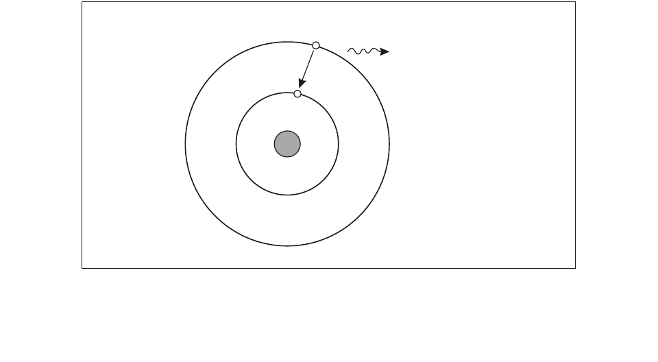
1.1.1 A basic insight into how a laser works helps in
understanding the hazards incurred when a laser emitter is
used. As shown in Figure 1-1, electromagnetic radiation is
emitted whenever a charged particle (e.g. an electron) gives
up energy. This happens every time an electron drops from
a higher energy state, Q1, to a lower energy state, Q0, in an
atom or ion as occurs in a fluorescent light. This can also
happen from changes in the vibrational or rotational state of
molecules.
1.1.2 The colour of light is determined by its
frequency or wavelength. The shorter wavelengths are the
ultraviolet (UV) and the longer wavelengths are the
infrared (IR). The smallest particle of light energy is
described in quantum mechanics as a photon. The energy in
joules, E, of a photon is determined by its frequency,
in
hertz (Hz), and Planck’s constant, h (6.63 × 10⁻³⁴ J • s), as
follows:
1.1.3 The velocity of light in a vacuum, c, is 3 × 10⁸
metres per second (m/s). The wavelength, λ, of light is
related to the frequency as follows:
1.1.4 The difference in energy levels across which an
excited electron drops determines the wavelength of the
emitted light. As the energy increases, the wavelength
decreases.
1.2 COMPONENTS OF A LASER
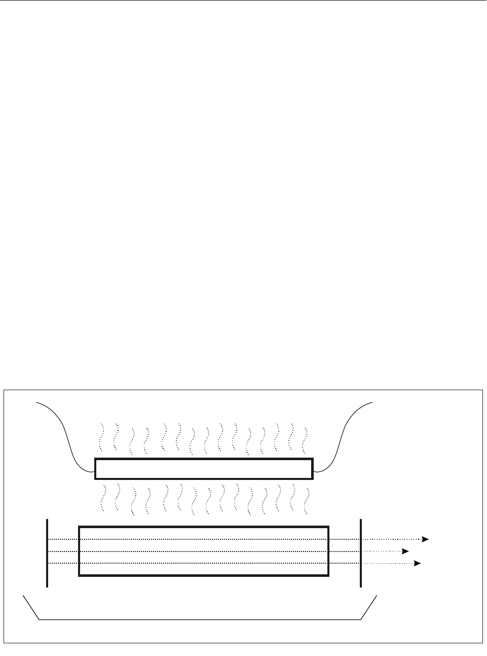
1.2.1 As shown in Figure 1-2, the three basic
components of a laser are:
• Lasing medium (crystal, gas, semiconductor, dye,
etc.)
v
Ehv×=
λc
v
--=
Figure 1-1. Emission of radiation from an atom by transition of
an electron from a higher energy state to a lower energy state
Q Lower energy state
0
Q Higher energy state
1
photon energy
hv = Q – Q
10
1-2 Manual on laser emitters and flight safety
• Pump source (adds energy to the lasing medium,
e.g. xenon flash lamp, electrical current to cause
electron collisions, radiation from another laser, etc.)
• Optical cavity (typically bound by reflectors to act
as the feedback mechanism for light amplification)
1.2.2 Electrons in the atoms of the lasing medium
normally reside in a steady-state lower energy level. When
energy from a pump source is added to the atoms of the
lasing medium, the majority of the electrons are excited to
a higher energy level, a phenomenon known as population
inversion. This phenomenon must occur in order to achieve
light amplification.
1.2.3 The excited state is an unstable condition for
these electrons. They will stay in this state for a short time
and then decay back to their original energy state. This
decay can occur in two ways — spontaneously or by
stimulation. If, before an excited electron spontaneously
decays, it is hit with a photon with a certain wavelength,
the electron will be stimulated into decay and will emit a
photon of the same wavelength and in the same direction as
the incident photon. If the direction of this reaction is
parallel to the optical axis of the cavity, the emitted photons
travel back and forth in the cavity stimulating more and
more transitions and releasing more and more photons all
in the same direction and with the same wavelength. The
light energy is therefore amplified. Since one of the mirrors
is a partial reflector, part of the amplified energy is emitted
as a laser beam.
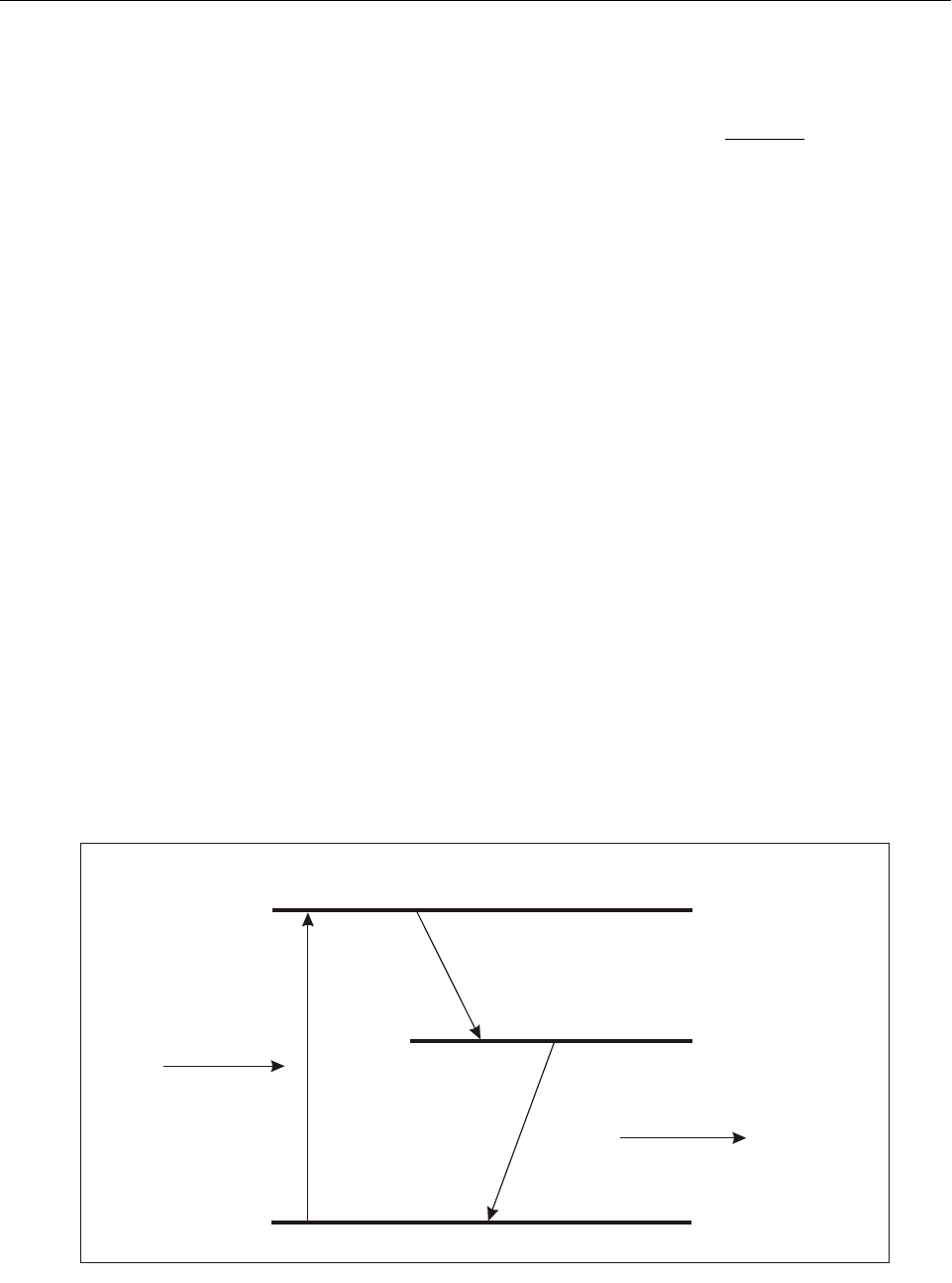
1.2.4 In practice, it is very difficult to obtain a
population inversion when utilizing only one excited
energy level. Electrons in this situation have a tendency to
decay to their ground state very quickly. As shown in
Figure 1-3, a lasing medium typically has at least one
excited (metastable) state where electrons can be trapped
long enough (microseconds to milliseconds) to maintain a
population inversion so that lasing can occur. Although
laser action is possible with only two energy levels, most
lasers have four or more levels.
1.3 TYPES OF LASERS
1.3.1 There are a number of methods used in
producing laser energy. Common methods include the use
of semiconductors, liquid dye, solid state, gas and metal
vapour. Although the technology behind each type can be
quite different, the resulting laser energy has the same basic
characteristics (see Table 1-1).
1.3.2 In recent years, the semiconductor laser (laser
diode) has become the most prevalent laser type. The laser
diode is a light emitting diode (LED) with an optical cavity
to amplify the light emitted from the energy band gap that
exists in semiconductors.
Figure 1-2. Diagram of solid state laser
Pump source
Lasing medium
Partial
reflector
Laser
output
Optical cavity
Total
reflector

Chapter 1. Physics of lasers 1-3
Table 1-1. Examples of common lasers
Lasing medium Laser method Spectral region Wavelength
Argon fluoride Gas UV 193 nm
Xenon chloride Gas UV 308 nm
Helium cadmium Gas UV
Blue
325 nm
442 nm
Argon Gas Blue
Green
488 nm
514 nm
Krypton Gas Blue
Green
Yellow
Red
476 nm
528 nm
568 nm
647 nm
Copper vapour Metal vapour Green
Yellow
510 nm
578 nm
Frequency-doubled Nd:YAG Solid state Green 532 nm
Helium neon Gas Green
Yellow
Orange
Red
Near IR
543 nm
594 nm
612 nm
633 nm
1.15 µm
Rhodamine 6G Liquid dye Visible 550–650 nm
Gold vapour Metal vapour Red 628 nm
Gallium aluminium arsenide Semiconductor Visible – near IR 670–830 nm
Ruby Solid state Red 694 nm
Alexandrite Solid state Near IR 700–815 nm
Gallium arsenide Semiconductor Near IR 840 nm
Titanium sapphire Solid state Near IR 840–1 100 nm
Nd:YAG Solid state Near IR 1.06 µm
Erbium:glass Solid state Mid IR 1.54 µm
Erbium:YAG Solid state Mid IR 2.94 µm
Carbon dioxide Gas Far IR 10.6 µm
1-4 Manual on laser emitters and flight safety
1.3.3 Lasers can operate continuously (continuous
wave or CW) or may produce pulses of laser energy. Pulsed
laser systems are often repetitively pulsed. The pulse rate or
pulse repetition frequency (PRF) as well as pulse duration
and peak power are extremely important in evaluating
potential biological hazards. Due to damage mechanisms in
biological tissue, repetitively pulsed lasers can often be
more hazardous than a CW laser with the same average
power.
1.4 BEAM PROPERTIES
Laser output intensity
1.4.1 Lasers either emit continuously or produce
discrete pulses of optical radiation. When dealing with
continuous wave (CW) lasers, beam power is used. Beam
energy is used for single pulse lasers. However, when
dealing with repetitively pulsed lasers, either parameter can
be used. Care must be taken to ensure that the correct
parameter is considered when comparisons with safety
thresholds are made.
1.4.2 Laser power is the rate with which laser energy
is emitted. This means that at any given instant, a laser can
produce a certain quantity of laser power. Laser energy is a
measure of the amount of optical radiation received in a
given period of time (such as a single laser pulse). Power
is typically given in watts (W) and energy is typically given
in joules (J). They are mathematically related as follows:
Irradiance and radiant exposure
1.4.3 With the exception of what is absorbed by the
atmosphere, the amount of energy available at the output of
the laser will be the same amount of energy contained
within the beam at any point downrange. Figure 1-4
illustrates a typical laser beam with a sampling area smaller
than the cross-sectional area of the beam. The amount of
energy available within the sampling area will be
considerably less than the amount of energy available
within the total beam. Irradiance describes the power per
unit area, and radiant exposure describes the energy per
unit area of a laser beam.
Laser modes (laser power distribution)
1.4.4 Laser beams can have complex patterns and
shapes. The optical power distribution within a laser beam
(called the laser mode) is typically expressed with either a
single bell-shaped (Gaussian) power density profile or a
1 watt = 1 joule
1 sec
Figure 1-3. Diagram of three-level laser energy
Ground energy level
Stimulated emission
of radiation
Metastable energy level
Spontaneous
energy decay
Excited energy level
Pumping
energy
Q
e
Q
m
Q
o
Chapter 1. Physics of lasers 1-5
combination of multiple bell-shaped profiles. A uniform
(constant) power mode is actually a combination of many
Gaussian profiles overlapping each other. The ideal laser is
considered to have a single Gaussian profile for most laser
applications. This mode is often assumed in order to
simplify laser hazards analyses.
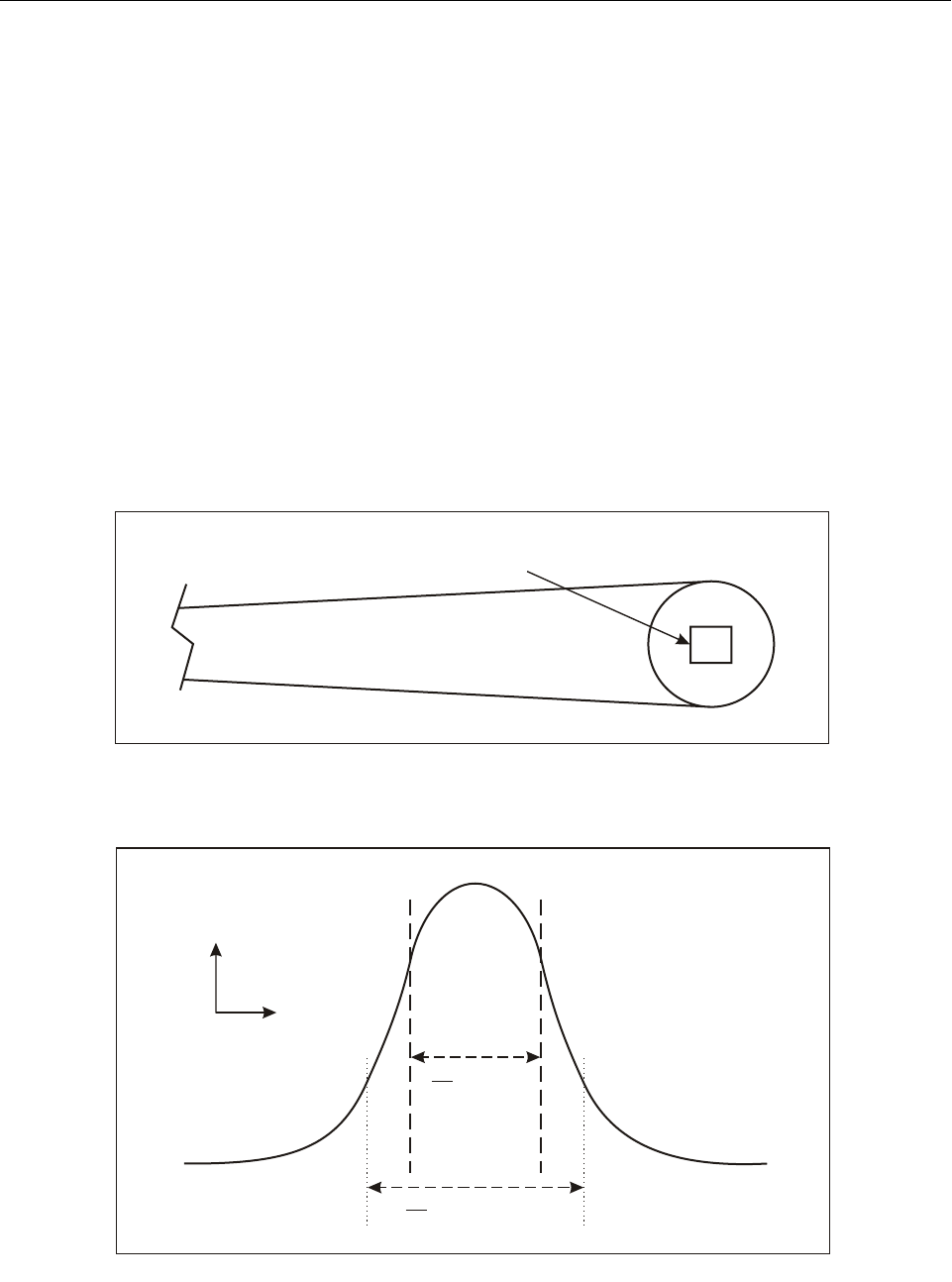
1.4.5 Since a Gaussian distribution has no
mathematical beginning or ending (see Figure 1-5), defining
the diameter of a laser beam can be difficult. To solve this
problem, one can define the diameter of a laser beam by
determining the diameter of an aperture that would allow
only a certain percentage of the total beam output to pass
through. The 1/e beam diameter is defined as the size of an
aperture that would block 36.8 per cent (1/e) of the beam
output (allowing 63.2 per cent to pass). This is the method
most often used for laser safety evaluations. Some laser
manufacturers will specify their laser beam diameters
assuming an aperture that blocks 13.5 per cent (1/e2) of the
output (allowing 86.5 per cent to pass). The 1/e beam
diameter is equal to the 1/e2 beam diameter divided by the
square root of 2 (i.e. 1.414).
Line width
1.4.6 Light from a conventional light source is
extremely broadband (containing wavelengths across the
electromagnetic spectrum). If one were to place a filter that
would pass only a very narrow band of wavelengths (e.g. a
green filter) in front of a white or broadband light source,
only that colour or wavelength region would be seen
exiting the filter (see Figure 1-6).
Figure 1-4. Illustration of irradiance
Figure 1-5. Beam diameter
Sampling area
1 cm
1 cm
Distance
Intensity
Beam
diameter
Beam diameter
1
e
1
2
e

1-6 Manual on laser emitters and flight safety
1.4.7 Light from the laser is similar to the light seen
from the filter. However, instead of a narrow band of
wavelengths, none of which is dominant as in the case of
the filter, there is a much narrower bandwidth about a
dominant centre frequency emitted from the laser. The
colour or wavelength of light being emitted depends on the
type of lasing material being used. For example, if a
neodymium:yttrium aluminium garnet (Nd:YAG) crystal is
used as the lasing material, light with a wavelength of
1 064 nm will be emitted. Certain materials and gases are
capable of emitting more than one wavelength. The wave-
length of the light emitted in such a case is dependent on
the optical configuration of the laser.
Divergence
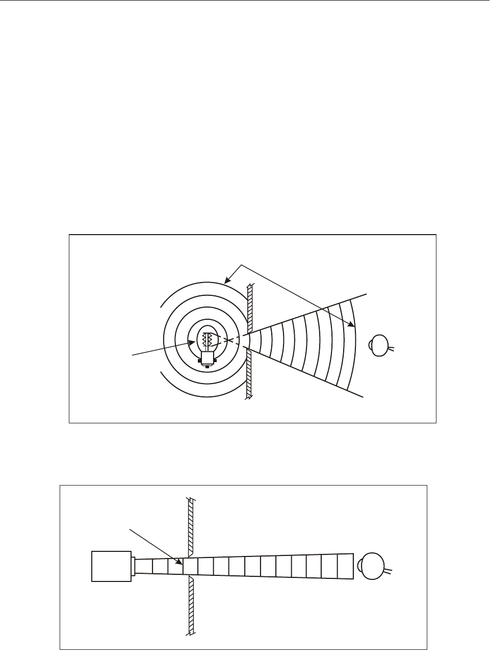
1.4.8 Light from a conventional light source diverges
(spreads rapidly) as illustrated in Figure 1-7. The power or
energy per unit area may be large at the source, but it
decreases rapidly as an observer moves away from the
source. In contrast, the output of the laser shown in
Figure 1-8 has a very small divergence and the beam ir-
radiance or radiant exposure at shorter distances is almost
the same at the observer as at the source. Thus, within a
narrow beam, relatively low-power lasers are able to
project more energy than can be obtained from much more
powerful conventional light sources.
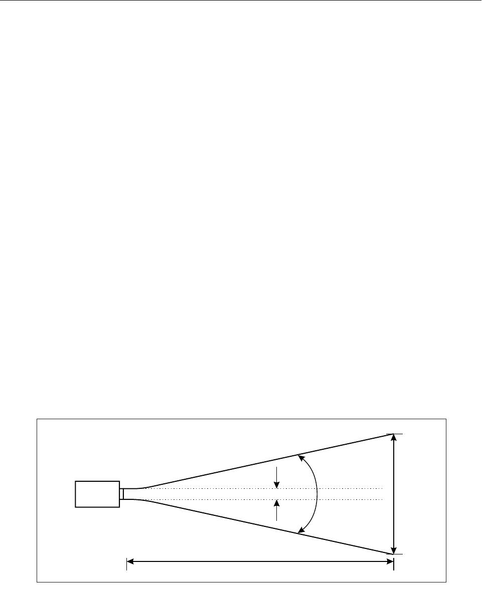
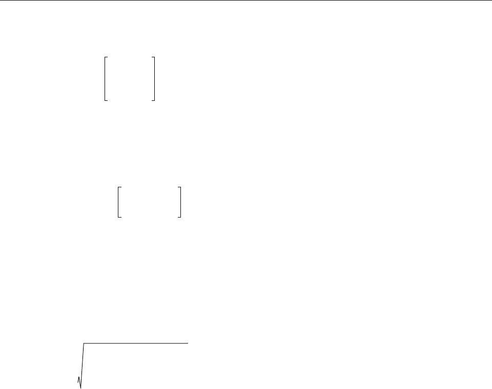
1.4.9 The divergence, ϕ, of a laser beam used in laser
safety calculations is defined as the full angle of the beam
spread measured between those points which include laser
energy or irradiance equal to 1/e of the maximum value. As
a laser beam propagates through space, it produces a profile
as shown in Figure 1-9. The beam diameter, DL, is a
function of range, r, from the exit port or beam waist and
can be calculated as:
where a is the 1/e beam diameter at the exit port or beam
waist.
1.5 CHARACTERISTICS OF MATERIALS
Reflection
1.5.1 Materials can reflect, absorb and transmit light
rays. Reflection of light is best illustrated by a mirror. If
light rays strike a mirror, almost all of the energy incident
on the mirror will be reflected. Figure 1-10 illustrates how
a plastic or glass surface will act on an incident light ray.
The sum of energy transmitted, absorbed and reflected will
equal the amount of energy incident upon the surface.
1.5.2 A surface is specular (mirror-like) if the size of
surface imperfections and variations are much smaller than
the wavelength of incident optical radiation. When
irregularities are randomly oriented and are much larger
than the wavelength, then the surface is considered diffuse.
In the intermediate region, it is sometimes necessary to
regard the diffuse and specular components separately.
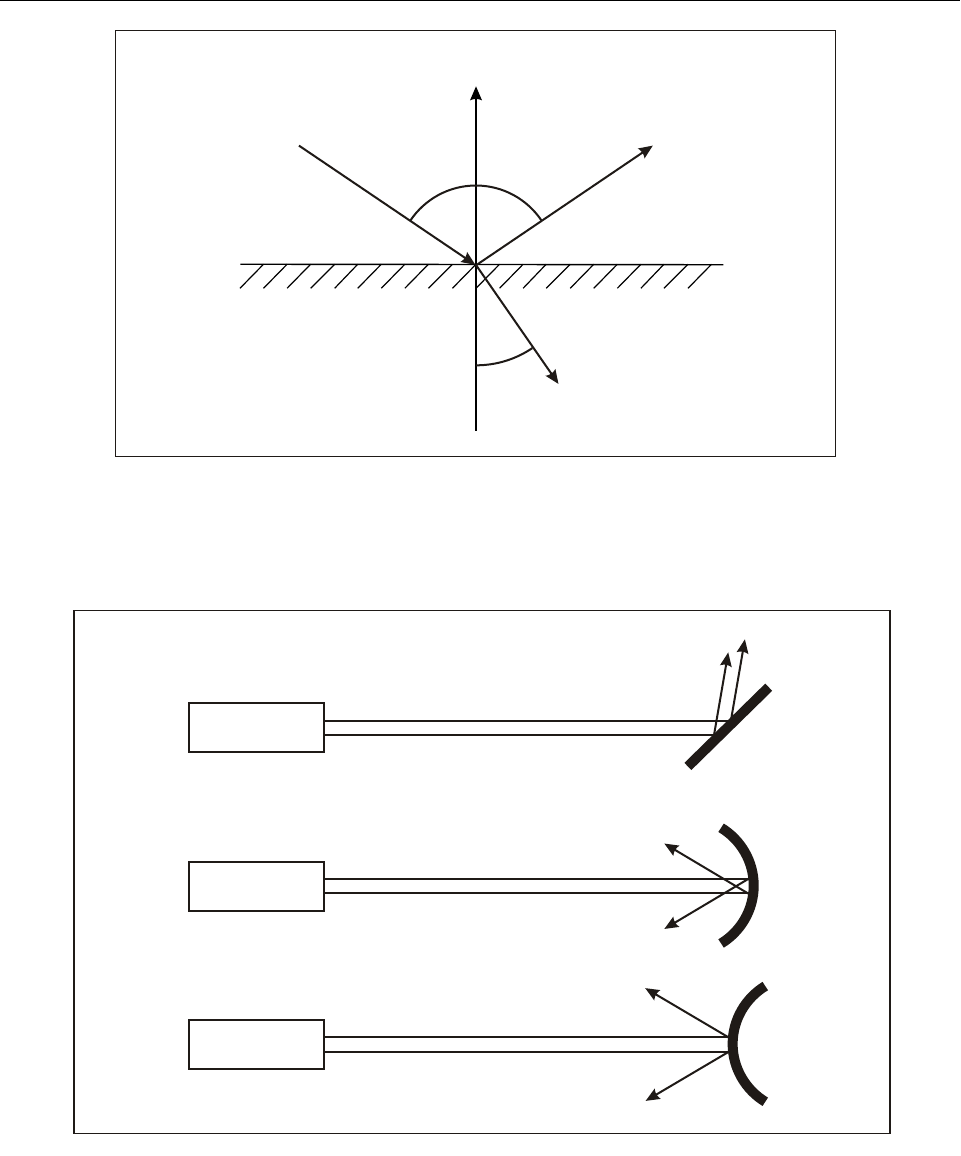
1.5.3 A flat specular surface will not change the
divergence of the incident light beam significantly. Curved
specular surfaces, however, will change the beam
divergence. The amount that the divergence is changed is
DLa2r2ϕ2
+=
Figure 1-6. Laser line width
“Line filter” with
broadband source
Laser source
Broadband source
Chapter 1. Physics of lasers 1-7
dependent on the curvature of the surface. Figure 1-11
demonstrates these two types of surfaces and how they will
reflect an incident laser beam. The divergence and the
curvature of the reflector have been exaggerated to better
illustrate the effects. The value of irradiance measured at a
specific range from the reflector will be less after reflection
from the curved surface than after reflection from the flat
surface, unless the curved reflector focuses the beam near
or at that range.
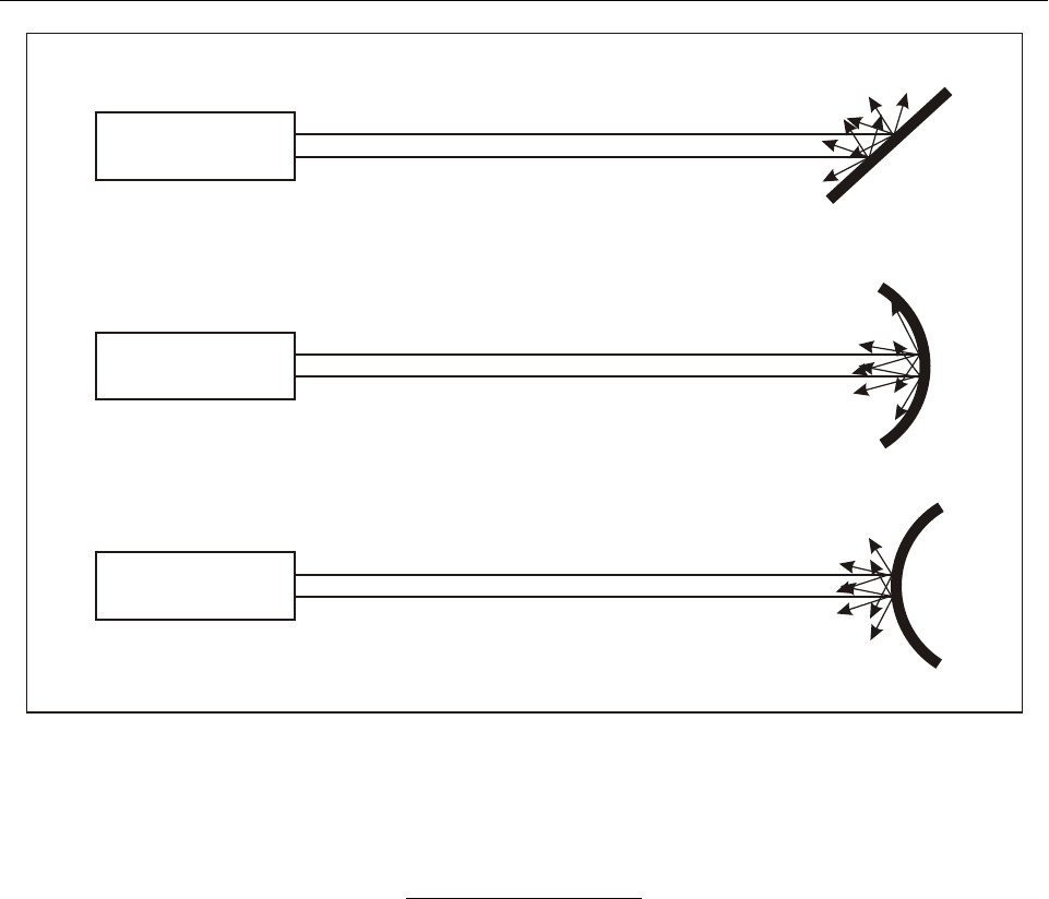
1.5.4 A diffuse surface will reflect the incident laser
beam in all possible directions. The beam path is not
maintained when the laser beam strikes a diffuse reflector.
Whether a surface is a diffuse reflector or a specular
reflector will depend upon the wavelength of the incident
laser beam. A surface that would be a diffuse reflector for
a visible laser beam might be a specular reflector for an IR
laser beam. As illustrated in Figure 1-12, the effect of
various curvatures of diffuse reflectors makes little
difference on the reflected beam. The phenomenon known
as scatter is the diffuse reflection from very small particles
in the air.
Refraction
1.5.5 Refraction is the deflection of a ray of light
when it passes from one medium into another. If light is
incident upon an interface separating two transmitting
media (such as an air-glass interface), some light will be
Figure 1-7. Divergence of conventional light beam
Figure 1-8. Divergence of laser beam
Wavefront
Conventional
source
Aperture
Observer
Laser
Wavefront
Aperture Observer
1-8 Manual on laser emitters and flight safety
transmitted while some will be reflected from the surface.
If no energy is absorbed at the interface, T + R = 1.00
where T and R are the fractions of the incident beam
intensity that are transmitted and reflected. T and R are
called the transmission and reflection coefficients,
respectively. These coefficients depend not only upon the
properties of the material and the wavelength of the
radiation but also upon the angle of incidence.
1.5.6 The angle that an incident ray of radiation forms
with the normal (perpendicular) to the surface will
determine the angle of refraction and the angle of reflection
(the angle of reflection equals the angle of incidence). The
relationship between the angle of incidence (θ) and the
angle of refraction (θ') is:
n sin (θ) = n' sin (θ')
where n and n' are the indices of refraction of the media
that the incident and transmitted rays move through,
respectively (see Figure 1-10).
1.5.7 Since refraction can change the irradiance or
radiant exposure, it can either increase or reduce a laser
hazard.
Absorption
1.5.8 As light propagates through the atmosphere or
any medium, its total power or energy is attenuated by
absorption and scattering. After propagating a distance, r,
through the atmosphere, intensity, I, is given by:
I = I0e–
µ
r
where I0 is the initial intensity and
µ
is the atmospheric
attenuation coefficient. The units of
µ
must be the inverse
to that of r, that is, if r is represented in cm, then
µ
must
be represented in cm–1 so that the term
µ
r is dimensionless.
1.5.9 This equation shows that the intensity falls off
exponentially as a function of the distance from the laser
source. The attenuation coefficient is dependent on the
wavelength of the laser. Because of the combination of
absorption and scattering effects, the attenuation coefficient
is a complex function of wavelength having a large value at
some wavelengths and a small value at others.
Scintillation
1.5.10 Scintillation is caused by random variations in
the index of refraction of the atmosphere through which the
beam is passing. These index variations are caused by
localized temperature and pressure fluctuations. This results
in a focusing effect which creates hot spots in the beam
pattern, most pronounced at long ranges. Scintillation of a
laser beam creates a flickering pattern of light similar to
what one might expect at the bottom of a swimming pool
when the water surface is not calm and the sun shines into it.
Figure 1-9. Geometry of laser beam
r
D
L
a
f
Laser
Chapter 1. Physics of lasers 1-9
Figure 1-10. Light ray incident to a glass surface
Figure 1-11. Specular reflectors
Normal
Incident ray Reflected ray
Transmitted
(refracted) ray
n
n’
qq
q’
Laser
Laser
Laser
1-10 Manual on laser emitters and flight safety
Figure 1-12. Diffuse reflectors
Laser
Laser
Laser

2-1
Chapter 2
LASER HAZARD EVALUATION
2.1 PURPOSE
The purpose of a laser hazard evaluation is to minimize the
potential for injury to personnel from a laser emitter. As
part of this evaluation, the accessible emission limit (AEL),
laser classification, nominal ocular hazard distance
(NOHD) and optical density (OD) required for personnel
protection are determined. In addition, engineering and
administrative control measures should be considered.
2.2 BACKGROUND
2.2.1 The retina is especially sensitive to laser light
beams for two reasons:
a) irradiance from a conventional source, such as a
light bulb, is reduced with increasing distance from
the source according to the inverse square law, i.e.
the irradiance is reduced as a function of the square
of the distance from the source. Since a laser beam
is collimated, it does not follow the inverse square
law and its irradiance for a given power output is
usually far greater at a given distance than that from
a conventional light source; and
b) if light from a conventional source is focused by
means of a reflecting surface, as in a searchlight,
the irradiance downrange of the source is greater
than would be expected according to the inverse
square law. However, it is not possible to collimate
conventional light energy. For a given power
output, a conventional light source cannot,
therefore, produce a light beam which has an
irradiance similar to that of a laser beam.
2.2.2 Collimated light rays reaching the eye are
focused by the cornea and lens onto a very small area of the
retina similar to the way parallel light rays from the sun can
be focused by a magnifying glass into a spot of sufficient
irradiance to burn paper. A laser beam can have an
irradiance which exceeds that of the sun, even if the laser
is of relatively low power (e.g. 5 milliwatt) and the
observer is at a considerable distance from the source. In
this context, the focusing ability of the eye is very
important. Laser light passing through a pupil of 7 mm
diameter can be focused into a spot on the retina only 2–20
µm big. It can be calculated that the irradiance of
collimated light is increased up to 100 000 times from the
cornea to the retina.
2.3 ACCESSIBLE EMISSION LIMIT (AEL)
2.3.1 The AEL is defined as the maximum accessible
emission power or energy permitted within a particular
class. The class 1 AEL is the value to which laser output
parameters are compared. The class 1 AEL is calculated by
multiplying the maximum permissible exposure (MPE) by
the area of the limiting aperture.
Maximum permissible exposure (MPE)
2.3.2 The MPE is a function of wavelength, exposure
time and the nature of exposure (intrabeam, diffuse
reflection, eye or skin). MPE values are determined from
biological studies and are published in regional, national
(e.g. American National Standards Institute ANSI Z136.1)
and international (e.g. International Electrotechnical
Commission IEC 60825-1) laser safety standards.
2.3.3 MPE values are expressed in terms of irradiance
or radiant exposure and are given in W/cm2 or J/cm2 (W/m2
or J/m2). They represent the maximum levels to which a
person can safely be exposed without incurring biological
damage. However, sub-damage threshold effects may be
significant at exposure levels below the MPE.
Limiting aperture (Df)
2.3.4 The limiting aperture (Df) is the maximum
diameter of a circle over which irradiance or radiant

2-2 Manual on laser emitters and flight safety
exposure can be averaged. It is a function of wavelength
and exposure duration. These values are provided in
national and international laser safety standards. The
limiting aperture is a linear measurement and is thus
expressed in terms of cm or mm.
2.3.5 The MPE for eye exposure in the 400 to 1 400
nm band (retinal hazard region) is based upon the total
energy or power collected by the night-adapted human eye,
which is assumed to have an entrance aperture of 7 mm in
diameter. This diameter is the limiting aperture. To
determine the potential hazard, the maximum energy or
power that can be transmitted through this aperture must be
determined. This amount is compared to the class 1 AEL.
For lasers with wavelengths outside the retinal hazard region
and for the skin, other limiting apertures may apply (see
applicable national or international standards).
2.4 LASER HAZARD CLASSIFICATION
2.4.1 Laser hazard classifications are used to indicate
the level of laser radiation hazard inherent in a laser system
and the extent of safety controls required. These range from
class 1 lasers, which are safe for direct beam viewing under
most conditions, to class 4 lasers, which require the most
strict controls.
2.4.2 Classification is based only on unaided and
5-cm-aided viewing conditions. This means that the power
or energy that can pass through the limiting aperture
(known as the effective power or energy) is compared to the
appropriate AEL when determining hazard classification.
The laser classification system is summarized below (for a
full description, reference should be made to the applicable
national or international standards).
Class 1 lasers
2.4.3 Class 1 lasers are lasers which cannot emit
radiation in excess of the class 1 AEL (based on the
maximum possible duration inherent in the design or
intended use of the laser) or which have adequate
engineering controls to restrict access to the laser radiation
from an embedded higher class of laser. This does not,
however, necessarily mean that the system is incapable of
doing harm. Since only unaided and 5-cm-aided viewing
conditions are considered, hazards may still be posed when
viewing optics with a greater optical gain than 7.14 (5-cm
optics) are used or if access to the interior of the laser
emitter is possible.
Class 2 lasers
2.4.4 Class 2 lasers are low-power visible (400 to
700-nm wavelength) lasers and laser systems that can emit
an accessible output exceeding the class 1 limits but not
exceeding the class 1 AEL for a 0.25 second exposure
duration. The class 1 AEL for a 0.25 second exposure
duration is 1 mW. Invisible lasers cannot be class 2.
Class 3 lasers
2.4.5 Class 3 is subdivided into 3a and 3b (3A and 3B
in international standards). Class 3a lasers are medium-
power lasers with an output between 1 and 5 times the
class 1 AEL (class 2 AEL for visible lasers) based on the
appropriate exposure duration. All other lasers at any
wavelength not classified as class 1 or class 2 with a power
less than 500 mW and unable to produce more than 125 mJ
in 0.25 seconds are defined as class 3b (3B). The Inter-
national Electrotechnical Commission (IEC) international
standard also has a limit on irradiance for class 3A lasers
of 25 Wm–2 (2.5 mW cm–2).
Class 4 lasers
2.4.6 Class 4 lasers are high-power lasers including
all lasers in excess of class 3 limitations. These lasers can
often be fire hazards. Both specular and diffuse reflections
are likely to be hazardous.
2.5 NOMINAL OCULAR
HAZARD DISTANCE (NOHD)
2.5.1 The NOHD is the maximum range at which the
power or energy entering the limiting aperture can exceed
the class 1 AEL. This value expresses the minimum safe
distance from which a person can directly view a laser
source without a biological damage hazard. The class 1
AEL is calculated by multiplying the MPE by the area of a
circle with a diameter of the limiting aperture (Df).
2.5.2 The following equation describes the
relationship between energy through a limiting aperture, Qf,
(effective energy) to total energy, Qo, of a Gaussian laser
A
EL MPE πDf
2
-----
2
×× MPE πDf
2
⋅⋅
4
-----------------------------
----
==
Chapter 2. Laser hazard evaluation 2-3
beam, given the 1/e beam diameter, DL, the aperture
diameter, Df, and neglecting atmospheric losses.
2.5.3 When including the effects of divergence, at-
mospheric attenuation and viewing aids (see 1.4.9, 1.5.8 to
1.5.10 and 3.7.7, respectively, for further explanation), this
equation becomes:
where G represents the effective optical gain and τ
represents the transmission of viewing aids.
2.5.4 If the class 1 AEL (the maximum safe level of
exposure) is substituted for Qf (the actual exposure that
could be received), the range, r, becomes the NOHD.
Making these substitutions and solving for NOHD results in
the following:
2.6 OPTICAL DENSITY (OD)
2.6.1 Since some lasers or laser systems may produce
energy or power millions of times that of the class 1 AEL,
the use of logarithms is the preferred method to express
personnel protection requirements. To fully specify the eye
protection requirements for a particular laser system,
unaided and aided OD values are calculated.
2.6.2 To determine the OD of eyewear required to
protect personnel from incident laser radiation, the ratio of
the effective energy, Qf, to the class 1 AEL is used as
shown:
2.6.3 To consider the effects of binoculars or other
viewing aids, the change in the effective energy will
produce different OD values and must be considered if
those viewing conditions are possible. However, the
maximum OD will never be more than:
2.6.4 This equation assumes that all laser energy is
concentrated into the limiting aperture with no transmission
loss through optics. This is the worst case condition.
2.7 OTHER FACTORS
2.7.1 In performing a laser hazard evaluation, other
issues must be considered. Things such as critical task
impairment, properly working safety interlocks, standard
operating procedures, and signs and labels are integral
factors in establishing a safe environment for laser
operation. The significance of specific control measures
depends upon the laser hazard classification. A start-up
delay, for example, should not be necessary for a class 2
laser device. Applicable national or international laser
safety standards list the control measures required for each
laser hazard class.
Buffer zones
2.7.2 With outdoor lasers, a buffer zone should be
established and utilized for each laser system. A buffer
zone is a conical volume centered on the laser’s line of
sight with its apex at the laser aperture using a specified
buffer angle. Within the buffer zone, the beam will be
contained with a very high degree of certainty. The laser
system’s buffer zone depends on the aiming accuracy and
boresight retention of the laser system. Typically, the laser
system’s buffer zone is equal to five times the system’s
aiming accuracy. The typical buffer angles for lasers used
outdoors are 10 mrad for hand-held lasers and 5 mrad for
lasers on a stable platform.
Nominal hazard zone (NHZ)
2.7.3 The volume of space defined by all locations
capable of exceeding the class 1 AEL (including the buffer
zone) is known as the nominal hazard zone (NHZ). Anyone
outside the NHZ is considered to be safe from laser
hazards. Anyone within the NHZ should be protected by
either procedural safeguards or personnel protection
equipment (e.g. laser safety goggles). Small specular
reflectors in the laser beam path can create unwanted beams
and should be considered in determining the NHZ.
Qf
Q
o
-
----- 1e
Df
DL
-------
–2
–
=
Qf
Q
oτeµr⋅–
⋅⋅
-
------------------------------1e
GD
f
2
⋅
a2r2ϕ2
⋅+
-----------------------------
–
–
=
N
OHD 1
ϕ
--- Df2G
×–
1n 1 AEL
QoτeµNOHD⋅–
⋅⋅
-------------------------------------------–
---------------------------------------------------------------- a
2
–=
O
D10
Qf
AEL
-----------
log=
OD 10
Qo
AEL
-----------
log=

2-4 Manual on laser emitters and flight safety
Laser-beam sensitive, laser-beam critical and
laser-beam free flight zones
2.7.4 Biologically safe exposure of the eye to a visible
laser beam can create unwanted effects that can reduce or
destroy the ability of a person to perform a task. These
effects can be very hazardous if the task is safety-critical
(e.g. landing an aircraft). Three visual interference levels
have been defined and are described in 2.7.5 and in greater
detail in 3.8. These values are as follows:
• sensitive level — 100 µW/cm2
• critical level — 5 µW/cm2
• laser beam free level — 50 nW/cm2
2.7.5 The sensitive level approximates the level at
which a person could experience severe, lingering after-
effects from exposure to a laser beam. The critical level
approximates the level to which a person could experience
significant loss of vision during exposure to a laser beam
and some residual, lingering after-effects. The laser beam
free level approximates the level at which a person would
receive a distracting glare but no after-effects. The laser
beam sensitive, critical and free flight zones are the
respective volumes of space where levels above these are
prohibited.
2.7.6 Determining the distances associated with these
visual interference levels is done the same way as when
evaluating the NOHD values. The values mentioned in
2.7.4 are substituted for the appropriate MPE, new AEL
values are determined, and the range is recalculated. Note
that these values are only relevant to visible laser beams.
These values have no meaning for wavelengths outside the
visible spectrum (400–700 nm).
Non-beam hazards
2.7.7 Although laser radiation is the most obvious
hazard associated with laser systems, many other hazards
should be considered in a laser hazard evaluation. These are
known as non-beam hazards. The following list shows
several non-beam hazards common to laser use:
• collateral radiation
• compressed gases
• confining space
•cryogenics
• electrical
• electromagnetic interference
• ergonomics
•explosion
•fire
• laser dyes
• mechanical
•noise
• toxic materials
• trailing cables/pipes
• waste disposal
•X-rays

3-1
Chapter 3
LASER BEAM BIOEFFECTS AND
THEIR HAZARDS TO FLIGHT OPERATIONS
3.1 INTRODUCTION
3.1.1 The development of the laser and the industrial
application of laser technology stand out as some of the
most significant scientific contributions of the 20th century.
Presently, lasers are found virtually everywhere, from
supermarkets and schools to satellites and operating rooms,
and have become fundamental components in consumer
products and complex industrial devices, including
sophisticated weapon systems. The accessibility of the
technology and the significant reduction in cost place lasers
at almost everyone’s disposal. Furthermore, the application
of laser technology to modern society is still emerging and
its future potential appears boundless.
3.1.2 However, if used improperly, laser energy also
poses a significant biohazard. Consequently, even the most
innocuous laser pointer can become a safety hazard, either
through direct bioeffects or by causing a disruption of
critical performance tasks in hazardous situations.
3.1.3 Not surprisingly, as lasers proliferate, an ever-
increasing number of laser beam-related incidents, some
from misadventure and others caused by intentional misuse,
have been reported. A significant number of these incidents
involve aircraft operations, both civil and military. Low-
flying helicopters, as used by police and for medical
evacuation, are particularly vulnerable, not only because of
their proximity to the ground but also because of their
proximity to ground-based lasers. In some aviation
environments, even the most trivial of laser beams have the
potential to become a lethal threat, e.g. by distraction of
aircrew during a critical phase of flight. This chapter will
elaborate on the bioeffects and damage mechanisms of
laser beam energy particularly from the perspective of its
effects on aircraft operations. However, the ongoing
development of new lasers and the continued advances in
research associated with lasers and their effects make this
a vast and still evolving area of biological science.
Therefore, this chapter will only serve to be an overview of
particular aspects of those effects, namely their bioeffects
and how they relate to aircraft operations. Other technical
publications exist that cover this topic more compre-
hensively, some of which are listed in the bibliography at
the end of this chapter.
3.1.4 Depending on power and other physical
characteristics, laser beams have the potential to generate a
variety of bioeffects, including the capacity to vapourize
biological tissue, either in part or in full, sometimes
destroying the entire organism. This chapter, however, will
be limited to those laser beam bioeffects likely to be
encountered within civilian aircraft operations and pri-
marily those affecting the skin and the eye. The major part
of this chapter will address this risk from the perspective of
its potential effect on vision, since this is the primary
aeromedical concern.
3.2 THE HAZARD
3.2.1 The spectrum of electromagnetic radiation
ranges from the shortest of cosmic rays at 10–5 nm to very
long waves in the order of 1014 nm (100 km), as associated
with communications and power sources. Each of these
wavelengths is associated with photons of varying energy.
The shorter the wavelength, the higher the energy asso-
ciated with the photons at that specific wavelength. For
tissue interactions at the atomic level, the higher the level
of energy associated with these photons, the higher the risk
for biological effects. Therefore, radiation of shorter
wavelengths has the greatest potential to be biologically
hazardous.
3.2.2 The sun is the source for most of the natural
electromagnetic radiation reaching the earth. Fortunately,
the atmosphere protects the surface of the planet from many

3-2 Manual on laser emitters and flight safety
of these wavelengths and their associated hazards, but a
significant portion of the electromagnetic spectrum still
penetrates this protective barrier to become an en-
vironmental biohazard. In addition, industrial sources can
create hazardous radiation in any environment.
3.2.3 The optical radiation portion of the
electromagnetic spectrum can interact with the human eye
and skin. Optical radiation extends from the shortest
ultraviolet wavelength, at 100 nm, through the visible
spectrum up to and including longer IR wavelengths around
1 mm (106 nm), such as those associated with radar. The
optical radiation portion of the electromagnetic spectrum
can be a biohazard when associated with visible and
invisible laser beams.
3.2.4 The International Commission on Illumination
(CIE) has divided the optical radiation portion of the
spectrum into the bands listed in Table 3-1, which include
IR, visible (VIS) and UV wavelengths:
3.2.5 The atmospheric contents normally shield the
surface of the planet from UVC radiation. Wavelengths
below 180 nm are completely blocked by the atmosphere.
Without this protection, biological life on the planet would
not be possible. Although not a naturally occurring
biological threat, any of these wavelengths can be
artificially generated and exploited by means of laser-based
technology.
3.3 BIOLOGICAL TISSUE
DAMAGE MECHANISMS
3.3.1 In order for phototoxic damage to occur in a
biological tissue, radiation must be absorbed by some
molecular constituent of that biological tissue. If the
radiation passes through the tissue without molecular
absorption, no biological damage occurs. However, most
molecules have the ability to absorb at least some portion
of the electromagnetic spectrum. It is possible to plot, for
any given tissue, those ranges of radiation (wavelengths) to
which that individual tissue is sensitive. That tissue plot
represents a summation of the individual sensitivities of all
of its constituent molecules and is known as the action
spectrum. In many cases, the action spectra of different
individual tissues have been precisely calculated and they
are associated with very specific wavelengths. Most action
spectra have been well described for the different tissue
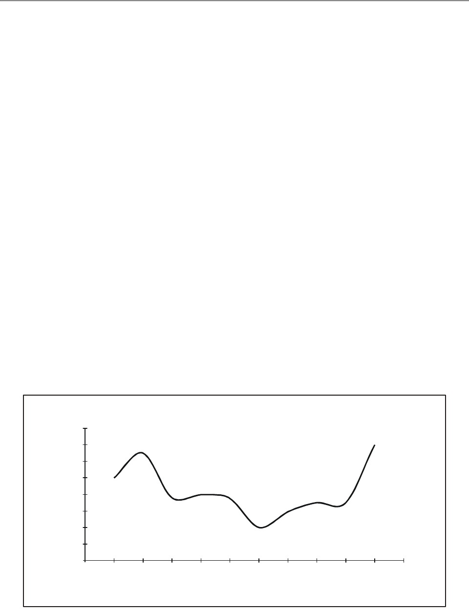
types. A classic example of this is the action spectrum for
photokeratitis (inflammation of the cornea), which is
related to excessive ultraviolet exposure (see Figure 3-1).
Table 3-1. Optical radiation spectral bands
3.3.2 In order for biological damage to occur, a
molecule must absorb the photons emitted by the radiation
source. The Grotthus-Draper Law states that photons must
be absorbed by a molecule before a photochemical effect
can occur. The Stark-Einstein Law states that only one
photon has to be absorbed by a molecule to cause an effect.
If a photon is absorbed, then biological damage may occur
as a consequence of one of three main damage mechanisms
or any combination thereof: photochemical (photolytic),
thermal (photocoagulative) and acoustico-mechanical.
3.3.3 Within any given biological tissue, the amount
of damage that occurs represents a summation of all these
mechanisms as well as other propagated local tissue effects;
therefore, tissue damage will usually extend beyond the
immediate confines of individual molecular locations. In
some cases, tissue damage can be induced at a considerable
distance from the location of the absorbing molecules,
e.g. from oedema or vascular disruption.
Photochemical damage
3.3.4 Photochemical (photolytic) damage occurs
when the energy of an incoming photon is high enough to
break (lyse) existing chemical bonds within individual
molecules. The effect of this is to alter or destroy the
absorbing molecules and to transform them into unwanted
free radicals. A considerable amount of research and
interest continues regarding the acute and chronic tissue
effects from the generation of free radicals, regardless of
cause. A large portion of an organism’s ability to resist the
long-term consequences of tissue-free radicals that are
generated on a daily basis involves many chemical
mediators that repair this damage and remove these free
radicals from individual tissues in order to neutralize their
potential negative effects. When these damage repair
Spectral band Wavelength (nm)
UVC 100–280
UVB 280–315
UVA 315–400
VISIBLE 400–700*
IRA 700–1 400
IRB 1 400–3 000
IRC 3 000–1 000 000
* Although the visible range can be regarded to extend beyond
700 nm, usually up to 770 nm or even higher in some in-
dividuals, by convention and to maintain consistency with
other accepted international standards, the visible range will be
limited to 400–700 nm in this manual.
Chapter 3. Laser beam bioeffects and their hazards to flight operations 3-3
mechanisms or mediators cannot compensate for the rate of
free-radical generation, many acute and chronic diseases
are known to follow. Examples of these include cataracts,
macular degeneration, corneal degenerations and a variety
of degenerative skin conditions, from loss of elasticity
(wrinkles) to skin cancers.
3.3.5 The shorter the wavelength, the higher the
energy associated with those particular photons. High-
energy photons, for example UVC, have sufficient energy
to break carbon-to-carbon bonds, which are some of the
strongest biochemical bonds in living tissue. This is why
atmospheric UVC absorbers, such as oxygen, ozone, water,
carbon dioxide and other atmospheric constituents, are
critically linked to human survival on earth. Thus, it is the
energy associated with these shorter UV wavelengths that
accounts for a significant portion of the photochemical
damage seen in both the skin and the eye. In fact,
wavelengths shorter than 320 nm are regarded as the active
actinic ultraviolet range. Lasers can provide a concentrated
source of photons at virtually any wavelength and thus are
quite efficient at causing photochemical damage, either
from low-intensity long exposures or high-intensity short
exposures.
Thermal damage
3.3.6 When an inorganic or organic molecule absorbs
a photon, this additional new energy drives the molecule
into one of several types of unstable excited states, the most
unstable of which is often referred to as a triplet state.
These states are very unstable. The newly acquired level of
excess energy is usually shed quickly and these states,
therefore, are of extremely short duration. In some cases,
the release of energy occurs visibly by re-radiation of the
energy as light at another wavelength, either as
phosphorescence or fluorescence. Generally, however, this
energy is released as an exothermic reaction by giving off
heat. Depending on the amount of heat generated and the
thermal sensitivity of the surrounding tissues, if normal
thermal dissipating mechanisms fail to compensate or are
overloaded, this thermal process will then induce thermal
damage. The heat can damage surrounding proteins and
other tissues well beyond the immediate surrounds of the
absorbing molecules. This explains why the visual effects
of a retinal burn from a laser beam can be much larger than
expected from the size of the visible retinal lesion.
Acoustico-mechanical damage
3.3.7 Acoustico-mechanical damage occurs as a
consequence of high energy, short-duration exposures to
laser beams. This damage mechanism consists of several
sub-processes. These include acoustic shock waves induced
by the impact of the laser beam itself and several
consequences thereof. For example, ultra-fast elevations of
tissue temperature can generate steam bubbles in the tissue.
Mechanically, this can either destroy surrounding tissue as
Figure 3-1. Action spectrum for photokeratitis
0
0.2
0.4
0.6
0.8
1
1.2
1.4
1.6
220 230 240 250 260 270 280 290 300 310 320
Wavelength in nanometres (nm)
Threshold exposure in J/cm × 10
-2 -2

3-4 Manual on laser emitters and flight safety
a function of being a space-occupying lesion or by inducing
additional shock waves, which then propagate into and
through various neighbouring tissues inducing even further
structural damage. In addition, the ability of radiation to
create a highly ionized state of matter (plasma) in
combination with this steam-generating process can result
in a cavitation process with formation of bubbles that can
further disrupt delicate tissue structures. Such effects can be
very dramatic and may affect areas up to 200 times larger
than the thermal damage area. This cavitation process, also
called an optical breakdown, can be used quite effectively,
e.g. by a Nd:YAG laser, to create mechanical disruption of
tissue. This effect is used clinically by ophthalmologists to
cut through opacifications of the posterior capsule of the
lens (capsulotomy) which may form after extracapsular lens
extraction, to lyse tissue bands deeper in the eye and to
create holes in the iris (iridotomy) to treat angle closure
glaucoma.
3.3.8 The types of bioeffects and related tissue
damage induced by a laser beam in either the skin or the
eye are dependent on many variables, including the
physical characteristics of the laser emitter itself, the
environmental setting and the biological characteristics of
the target tissue and its surrounding structures.
3.3.9 The physical characteristics related to the laser
emitter itself are discussed in depth in Chapter 1. The most
important are:
• wavelength
• initial beam size
• power and power density
• beam divergence
• output mode (pulsed or CW)
• pulse properties (PRF, pulse width, etc.)
3.3.10 The ability of any given laser beam to induce
bioeffects and generate damage can be tempered or
enhanced by environmental factors. This is particularly
germane with respect to the eye. Such environmental
factors include:
• ambient luminance (which determines the level of
light adaptation)
• distance from laser source
• atmospheric conditions
• angle of incidence
• intervening optical interfaces
• viewing conditions (unaided or with magnification
device)
3.3.11 The individual sensitivity of any biological
tissue to any given radiation can be artificially increased
(damage threshold decreased) by the use of certain
photosensitizing agents or medications. There is a large and
growing list of assorted pharmaceutical agents, both topical
and systemic, that can make an individual more vulnerable
to biological damage in some tissues in any given setting.
In some cases, this can elevate tissue sensitivity to such a
degree that a known non-damaging level of a particular
radiation can suddenly and unexpectedly become a
significant biohazard. A list of some common photo-
sensitizers is provided in Table 3-2.
3.4 THE SKIN
3.4.1 The wavelength sensitivity range of the skin and
the eye to optical radiation are generally very similar.
While the likelihood of a skin injury is statistically higher
because the skin has a much larger vulnerable surface area
than the eye, the actual operational consequences of such
skin effects are generally trivial. Furthermore, this
vulnerability of the skin can easily be diminished by simple
protective measures, such as covering the exposed areas
with garments or chemical blocking agents. Nonetheless,
when exposed to optical radiation, the skin can suffer the
consequences, both acute and chronic, of all three
biological tissue-damage mechanisms. The typical acute
skin injury is likely to be a surface burn that may be severe
enough to require medical management. Cumulative effects
manifest themselves later in life as chronic conditions, such
as wrinkles, skin folds (e.g. cutis rhomboidalis nuchae) and
skin cancers. It is estimated that 80 per cent of the lifetime
carcinogenic exposure to UV radiation occurs before age
21. Proper UV protection should be diligently followed
from the earliest possible age; especially important is the
protection of infants.
3.4.2 It is possible to disrupt skin and entire
organisms with more powerful lasers such as those
developed for military, industrial and scientific use. It is,
however, unlikely that acute skin damage from a laser
beam will disable aircrew, either physically or
psychologically, and thus play a role in the disruption of
safe air operations. Additional information is available in
technical publications dealing with induced skin damage.
Unnecessary exposure to radiation, particularly UV, should
be avoided to reduce potential toxic cutaneous effects, both
acute and chronic. The amount of UV radiation increases
with altitude, as a general rule increasing three to four per
cent for every 300 m (1 000 ft) gain in altitude.

Chapter 3. Laser beam bioeffects and their hazards to flight operations 3-5
Table 3-2. Common photosensitizing agents
3.5 THE EYE
3.5.1 It is the acute disruption in visual performance
and the potential of laser beams to induce ocular damage that
are of paramount importance to aircrew in the performance
of their duties and which implies a threat to flight safety.
3.5.2 Optical radiation can be divided into two
general regions with respect to the potential of a laser beam
to cause damage: the retinal hazard region and the non-
retinal hazard region. The wavelengths of the retinal hazard
region include the visible and near infrared (NIR) band and
represent those wavelengths that are transmitted through
the optical media of the eye (cornea, aqueous humour, lens
and vitreous body) and are focused on the retina. This band
includes the entire visible range between 400 and 700 nm,
up to the end of the near infrared (IR-A) range at 1 400 nm.
3.5.3 The non-retinal hazard region refers to those
wavelengths that are mostly absorbed by anterior ocular
tissues (cornea and lens) without significant transmission
posteriorly to the retina. This band includes UV and the
longer IR bands, those greater than 1 400 nm (IR-B and
IR-C). Although some of the non-retinal hazard radiation
can be transmitted through some ocular tissues, almost all
of it is normally absorbed before it reaches the retina. This
absorption process, however, can also have acute and
chronic effects on the absorbing tissues themselves,
especially if normal repair capabilities are exceeded. The
classical example of this is the crystalline lens, which is the
final tissue barrier to UV radiation. It absorbs virtually all
of the residual UV radiation that passes through the cornea
and the aqueous humour.
3.5.4 This absorption process induces changes within
the lens, such as yellowing, which make it a more effective
blue-wavelength and UV filter. But the absorption may also
result in increasing opacification of the lens in the form of
nuclear and cortical sclerosis (senile cataract) that
eventually disrupts overall visual performance. Once the
lens is removed surgically, this normal barrier to UV
radiation is also removed and thus retinal tissue is now
exposed to higher levels of UV that normally would have
been absorbed by the natural lens. This necessitates
additional sun protection even in individuals with im-
planted intraocular lenses (IOL) containing UV radiation-
absorbing additives because such lenses do not reliably
protect the retina against UV radiation.
3.5.5 The characteristics of each ocular tissue with
respect to optical radiation will now be discussed in more
detail. Figure 3-2 is provided to facilitate the discussion.
The cornea
3.5.6 The multi-layered cornea is a clear ocular
structure, which contributes the bulk of the light-bending
power (refractive power) of the eye as it naturally focuses
incoming light rays on the retina. The cornea can absorb
virtually 100 per cent of UV wavelengths shorter than
280 nm (UVC). This is usually of little importance as the
atmosphere already absorbs almost all of the natural UVC,
even at the highest flight levels. Artificial sources that
generate UVC within the environment are a different
matter. The overall absorption of the UV radiation band by
the cornea decreases as the wavelength increases, so that
more and more UV radiation is gradually passed on
through the aqueous humour to the lens. At 360 nm, the
cornea absorbs about 34 per cent of the UV radiation. On
the other hand, the cornea absorbs very little of the visible
and NIR portions of the spectrum, passing over 95 per cent
of this range on to the retina as a more concentrated or
focused beam.
3.5.7 Absorption of excessive UV radiation by the
cornea can cause corneal tissue damage as a function of its
action spectrum. The classic example of this is photo-
keratitis associated with arc-welding, artificial suntanning
or exposures to high levels of environmental UV radiation,
such as that typical of snow and water activities. UV
radiation has also been identified as causing several types
of corneal degeneration often referred to as climatic droplet
keratopathies, such as Bietti’s corneal degeneration and
Labrador Keratopathy. Damage repair mechanisms and the
replicating nature of the corneal epithelium generally limit
such effects to only a temporary condition, albeit an
extremely painful one. Such exposures can be epidemic as
Antibiotics (tetracyclines)
Chlordiazepoxide (Librium®)
Chlorthiazides
Cyclamates
Furocoumarins (psoralens)
Griseofulvin
Nalidixic acid
Oestrogens/progesterones
Phenothiazines
Porphyrins (porphyria)
Sulfonamides
Sulfonylurea
Tretinoin (retinoic acid, vitamin A acid, Retin-A®)
Triacetyldiphenolisatin (laxative)

3-6 Manual on laser emitters and flight safety
described by Xenophon in Anabasis where large multitudes
of Greek soldiers at altitude were incapacitated by “solar
blindness” during an organized military retreat. However,
with very high-intensity laser beams, it is possible to induce
stromal damage deep in the cornea. This would cause
formation of a permanent corneal scar with the potential
loss of vision depending on its location. Fortunately, such
powerful UV radiation laser emitters are not readily
available.
3.5.8 UV radiation-induced corneal injury is usually
superficial, temporary and reversible. Nonetheless, it can be
very disabling and painful. A severe acute corneal lesion
could render aircrew visually incapacitated.
The aqueous humour
3.5.9 The aqueous humour is a transparent fluid with
very few floating cellular elements. It does, however,
absorb some of the UV radiation that gets through the
cornea but not in any appreciable quantities. Similarly, it
passes IR and visible radiation virtually unattenuated
through to the lens.
The lens
3.5.10 The crystalline lens provides the final focusing
element of the optical structures of the eye. While it provides
substantially less refractive power than the cornea, it is the
only dynamic focusing element with the ability to refine the
final focus on the retina. It does so automatically and almost
instantaneously. It is also, essentially, the last tissue barrier to
any of the UV radiation that penetrates the cornea and
aqueous humour. The lens absorbs increasing amounts of
UV radiation above 300 nm (UVB), such that it absorbs
approximately 50 per cent of UV radiation at 360 nm
(UVA). As addressed earlier, the penalty for providing this
final barrier of UV radiation protection for the retina is
increasing yellowing and other changes that eventually result
in opacification and cataract formation (cataractogenesis).
3.5.11 The UV radiation absorption capability of the
anterior segment of the eye results in virtually no UV
radiation shorter than 300 nm being passed into the vitreous
body and only about one to two per cent of UVB and UVA
passing through the lens. A unique window of UV radiation
transmission has been identified in the lens through which
a disproportionate amount of UV radiation at 320 nm
(UVA) is transmitted. This is of some interest but does not
represent a significant vulnerability. Since the lens is an
avascular and encapsulated structure, its ability to dissipate
heat and other damage effects is very limited, a factor
which ultimately contributes to cataract formation later in
life. The lens transmits visible and near IR radiation
virtually unattenuated but with some scatter. However, the
lens will absorb mid-infrared energy (IRB) such that it is
possible to induce lenticular damage with levels of IR
energy that are not high enough to induce corneal damage.
The lens will also absorb increasing amounts of short,
visible wavelengths (violet and blue) as it yellows with age.
The vitreous humour
3.5.12 The vitreous humour or vitreous body (corpus
vitreum) is an optically clear structure composed of
gelatinous and aqueous material with few structural fibres
and cells. It does, however, have some very limited ability
to absorb UV radiation and by design passes visible and
NIR radiation to the retina virtually without attenuation.
The retina
3.5.13 The retina contains the neural elements and
photoreceptors (rods and cones) of the visual system and it
is the prime concern with respect to phototoxic damage
induced by any optical radiation.
3.5.14 Retinal susceptibility to photolytic damage
increases as the wavelength decreases. Furthermore, the
absorption of the retinal pigment epithelium is higher in the
near UV range than in the visible range. Therefore, thermal
retinal damage can occur if UV reaches the retina in
significant amounts. While normally protected from UV by
the anterior segment of the eye, the retina is vulnerable to
UV exposure, especially from 320 nm radiation. The retinal
sensitivity to UVA radiation has also been demonstrated in
aphakic eyes.
3.5.15 The retina is uniquely configured to respond to
the narrow band of solar radiation that typically reaches the
surface of the planet, namely the visible spectrum. As
mentioned previously, that spectrum generally extends
from 400–700 nm, but the retina is particularly more
sensitive to certain wavelengths within that range. That
sensitivity peaks at approximately 555 nm (yellow-green)
due to cone sensitivity under photopic conditions (daylight)
but shifts down towards shorter wavelengths, reaching
approximately 510 nm (blue-green) at twilight, which
coincides with the peak rod sensitivity under scotopic
conditions (night). This shift between cone sensitivity and
rod sensitivity is known as the Purkinje Shift.
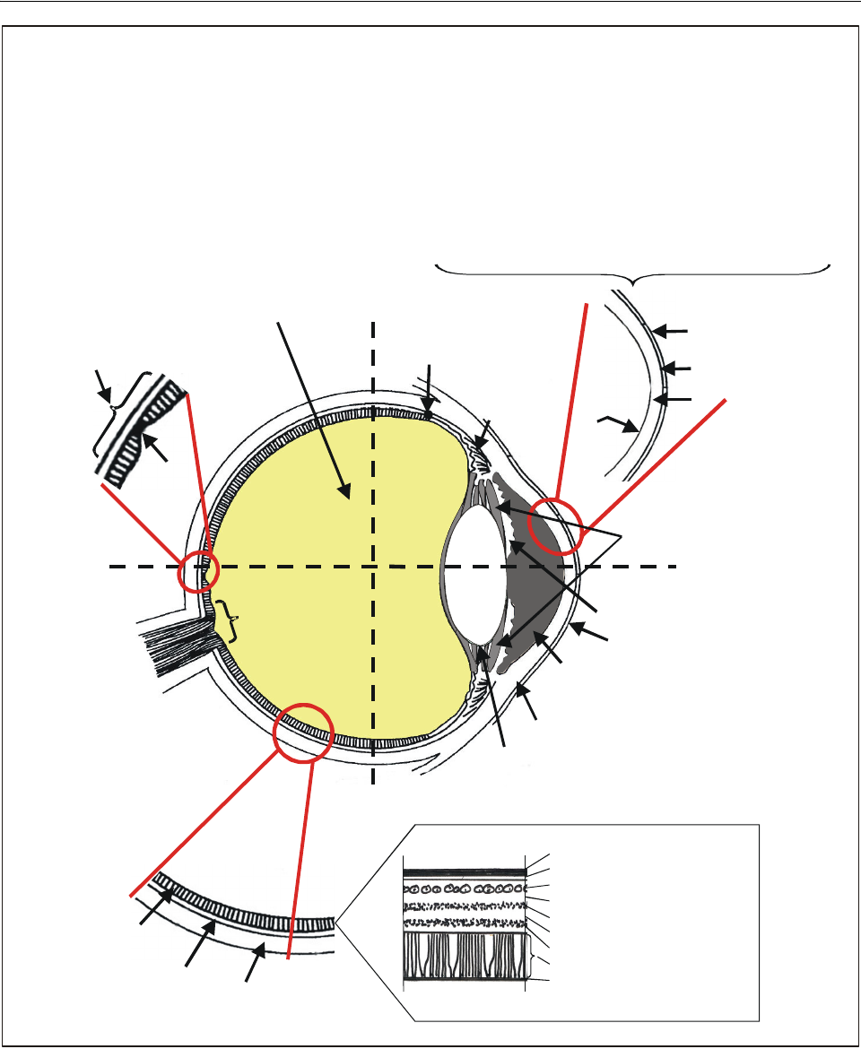
Chapter 3. Laser beam bioeffects and their hazards to flight operations 3-7
Figure 3-2. The anatomy of the eye
ora serrata
(anterior ending
of retina)
ANTERIOR
vitreous body
equator
anterior chamber
iris
optic nerve
lens
capsule
POSTERIOR
optic disc
ciliary
body
cornea
corneal-scleral
limbus
visual axis
pars
plana
retina
choroid
sclera
vitreous
humour
5
4
3
1
2
RETINA:
A
NTERIOR SEGMENT
(CORNEA):
Top view of left eye
1. epithelium
2. Bowman’s layer
3. stroma
4. endothelium and Descemet’s membrane
5. anterior chamber (contains the aqueous humour)
Internal limiting membrane
Nerve fiber layer
Ganglion cell layer
Inner plexiform layer
Inner nuclear layer
Outer plexiform layer
Outer nuclear layer
Rods and cones
Retinal pigment epithelium
Vitreous
Choroid
Layers of the retina
foveola
~1º
macula lutea with
fovea centralis ~5º
posterior chamber
lens

3-8 Manual on laser emitters and flight safety
3.5.16 In some cases, a physiological retinal reaction
to UV and IR radiation can be documented. While IR
radiation is generally invisible, it has been possible to
demonstrate spectral sensitivity in the human eye as high as
1 064 nm (Sliney, et al., 1976).1
3.5.17 To initiate the visual process, the retina must
absorb visible radiation. The retina is also capable of
absorbing IR radiation. This absorbable radiation (visible
and IR) defines the in-band range and classifies those
lasers that emit photons within this band as having in-band
laser threat wavelengths.
3.5.18 As mentioned previously, the potential for any
given laser beam to induce bioeffects is not only a function
of the physical characteristics of the laser beam itself, but
also of assorted environmental or atmospheric conditions
present at the time. To these variables, certain biological
characteristics of the eye must be added that also modify
damage thresholds in the eye. These include:
• pupil size
•age
• photosensitivity level
• tissue vascular supply
• clarity of the ocular media (transmission and
scatter)
• level of light adaptation
• type of tissue exposed
3.6 OCULAR LASER BEAM
DAMAGE TERMINOLOGY
There are a few specific terms relevant when addressing
laser-beam damage in an eye. These are:
a) Maximum permissible exposure (MPE). The MPE
is that level of laser beam energy below which
exposure to a laser beam is not expected to produce
adverse biological damage. There are differences in
MPE calculations depending on whether the laser
beam is pulsed or continuous. MPEs for the skin and
eye for any laser beam and exposure condition are
available in the American National Standards
Institute ANSI Z136-1-2000,2 the International
Electrotechnical Commission (IEC) 60825-1: 19983
and other related international documents.
b) Nominal ocular hazard distance (NOHD). The
NOHD is the distance from a laser beam beyond
which the MPE is not exceeded. Within the NOHD,
the MPE may be exceeded and biological damage
may be expected. It therefore defines the so-called
“safe range” from any given laser emission. That
“safe range” relates to actual biological damage and
not necessarily to disruptions in visual performance.
c) Minimal ophthalmoscopically visible lesion
(MOVL). The MOVL can be defined as the
minimal lesion caused by a laser beam exposure,
which can be seen by direct ophthalmoscopy.
Tissue damage may not be immediately apparent
and it may take over 24 hours for a lesion to
become visible. In general, the energy required to
produce an MOVL increases as a function of
distance from the fovea on the retina. Radiant
exposure and irradiance thresholds capable of
creating MOVLs have been determined for most
common laser beam wavelengths.
3.7 LASER BEAM BIOEFFECTS
3.7.1 The range of potential bioeffects associated with
laser beam illumination is a continuum of reversible and
irreversible histological damages dependent on the physical
laser beam characteristics, environmental factors and
vulnerability of the tissue.
3.7.2 It is therefore possible to define a broad range
and continuum of potential bioeffects, involving the optical
radiation range, that include both pathological damages
(either reversible or irreversible) and performance impacts,
all of which represent a threat to safe air operations
(Figure 3-3). This ranges from distraction, glare and dazzle
through flash-blindness, assorted after-images and residual
scotomas, to retinal burns, retinal hemorrhages and even an
ocular hole. It also includes physical and psychological
phenomena that may further disrupt visual and cognitive
function during a particular task. Consequently, it is not
necessary for the MPE to be exceeded or the NOHD to be
violated before a potentially significant effect will occur.
1. Sliney, D.H., R.T. Wangemann, J.K. Franks and M.L.
Wolbarsht. “Visual Sensitivity of the Eye to Infrared Laser
Radiation”. Journal of the Optical Society of America,
66(4): pp. 339–341.
2. American National Standards Institute ANSI Z136.1-2000.
“American National Standard for the Safe Use of Lasers”.
3. International Electrotechnical Commission IEC 60825-1:
1998. “Safety of Laser Products, Part 1; Equipment
Classification, Requirements, and User’s Guide”.
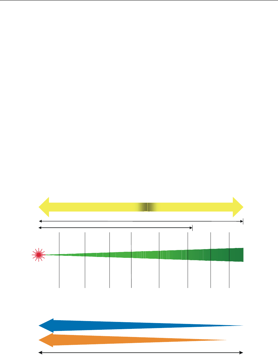
Chapter 3. Laser beam bioeffects and their hazards to flight operations 3-9
3.7.3 At the very minimum, any visible laser beam can
be potentially distracting and psychologically disruptive.
During a critical phase of flight, even a low-powered laser
beam could prove lethal to crew and passengers while not
having the power to cause any biological tissue damage.
3.7.4 A single exposure to a laser beam may induce
several effects at the same time. Such an exposure can be
distracting (on occasion even terrifying), induce glare or
dazzle effects, cause flash-blindness and create after-images
and scotomas, as well as being capable of creating a retinal
burn or hole or inducing an intraocular haemorrhage.
3.7.5 A laser beam capable of inducing a retinal burn
will also induce a surrounding area of oedema and other
related biological tissue damage or bioeffects that will
encompass a much broader area beyond the confines of the
actual visible lesion itself. The MOVL refers to the smallest
laser beam induced lesion that is ophthalmoscopically
visible and refers only to lesions visible with direct view
examination devices and does not extend to microscopic
examination techniques. Specialized equipment is needed
to see areas of microscopic damage induced by laser beam
exposure. However, it can be anticipated that these changes
are an ever-present part of the tissue bioeffect continuum
and are invariably present in and around any discrete laser
beam induced focal lesion. This collateral damage is
primarily due to other tissue damage mechanisms, such as
distal effects from occlusion of proximal blood supply or
oedema that disrupts adjacent cell structures and com-
presses local blood vessels.
3.7.6 Generally, the susceptibility of the human eye to
actual damage is also a function of the environmental
luminance and level of light adaptation at the time of
exposure. For example, any given laser beam would have
to be significantly more powerful to induce similar
photopic (daylight) bioeffects, such as flash-blindness,
glare, dazzle and distraction, than such an illumination
under mesopic (twilight) or scotopic (night) conditions. For
the same average power, a pulsed laser beam will have a
higher peak power and is therefore more hazardous than a
CW laser beam. However, when it comes to many of the
potential bioeffects common to all laser beams, the clinical
and subjective difference between pulsed and CW beams is
irrelevant.
3.7.7 Due to their light-collecting capability, viewing
aids, such as periscopes, telescopes and binoculars, have a
potential to increase the amount of laser radiation entering
Figure 3-3. Ranges of laser beam bioeffects
LASER
SOURCE
•Tissue
vaporization •Retinal
haemorrhage
•Ocular holes
•MOVL
•Retinal
burn
•Irreversible
scotomas
•Histological
damage
•Irreversible
scotomas
•NOHD
•MPE
•Flash-blindness
•After-images
•Reversible
scotomas
•Glare
•Dazzle
•Distraction
IRREVERSIBLE REVERSIBLE
TRANSITION ZONE
VISUAL EFFECTS
PSYCHOLOGICAL EFFECTS
Near INFRARED
DISTANCE
VISIBLE

3-10 Manual on laser emitters and flight safety
the eye, thus increasing the hazard. This would increase the
NOHD and OD requirements for eye protection. When the
beam diameter is made 50 per cent smaller, the power
density of the beam is quadrupled.
3.7.8 Imaging devices that do not provide direct
viewing of a laser beam, such as night vision goggles
(NVG) or forward looking infrared (FLIR) sensors, do not
transmit the incoming laser photons directly to the human
eye. These devices use visible photons that have been
newly generated and then multiplied using photosensitive
materials. The output of these devices is not a laser beam.
The new photons emitted out of the viewing port of such
devices are considerably different from those that actually
enter the light-gathering device. Consequently, although
such sensors and their data can be disturbed or destroyed by
a laser beam, they do provide a significant level of laser
beam eye protection along their line of sight.
3.8 LASER BEAM BIOEFFECTS
AND AIR OPERATIONS
3.8.1 This section will elaborate on the individual
features of the bioeffects continuum as they relate to the
eye and air operations. These bioeffects include:
• distraction
• glare (also referred to as dazzle)
• flash-blindness
• after-images
• scotomas
• retinal burns
• retinal haemorrhages
• globe rupture
•other
Distraction
3.8.2 When a person sees a bright light, particularly at
night, the natural reaction is to look at it. While in flight,
aircrews are particularly sensitive to unexpected bright
lights. Such a light may be perceived as representing a
potential threat, such as the prospect of a collision with
another aircraft or a ground obstacle. Pilots, because of
their extensive training in combination with normal
biological reflexes, instinctively divert their attention
toward any new unexpected light in order to assess its
significance. A distraction that occurs during a critical
phase of flight could have serious consequences unrelated
to the light source’s ability to induce actual ocular damage.
If the light is a laser beam illumination that exceeds the
MPE, then even a brief direct visualization of the laser
beam before a compensatory blink occurs could result in
irreversible biological damage, as well as acute disturb-
ances in visual performance.
3.8.3 Due to the strobe effect of some pulsed laser
beams, they can be more distracting than CW laser beams
of the same average power.
3.8.4 If the light proves to only be a trivial distraction,
attention can be rapidly refocused to the aeronautical task
at hand with little more than perhaps an inconsequential
time penalty. However, if the light is bright enough,
residual psychological and visual bioeffects can prevent
resumption of normal visual and cognitive function and
related performance tasks.
3.8.5 When a suspected laser beam exposure occurs,
experience has shown that there will be an immediate
psychological reaction as a direct consequence of what may
initially be perceived as a serious eye injury, especially if
the light is strong enough to induce persistent visual effects.
The resulting mindset will persist until some functional
vision returns but will not completely dissipate until it
resolves completely or assurances are given that no
permanent damage has occurred. Therefore, there may be a
period of time during which the exposed aircrew members
may be functionally disabled, visually and/or psycho-
logically. Reactions to such events are an unpredictable
aspect of human nature, but experience has taught us that
significant exposures to laser beams under these conditions
can result in serious psychological disruptions, inciting
panic and necessitating transfer of control of the aircraft to
the other flight crew members.
Glare and dazzle
3.8.6 Glare and dazzle are two terms often used
interchangeably that refer to temporary disruptions in
visual acquisition without biological damage. Glare can be
caused by virtually any light and is particularly disruptive
under scotopic viewing conditions, especially when the
eyes are fully dark-adapted. However, any glare source in
the cockpit is undesirable. Glare is regarded to be a source-
fixed effect, meaning that as the position of gaze shifts
away from the light source, glare effects are diminished.
Glare only occurs when the light source is on. The length
of time during which glare is in effect is not only a function
of how long the light is viewed but also of the overall dark-
adaptation state and pupil size in the target eye. Glare can
be divided into discomfort glare and disability glare.
Discomfort glare refers to glare of high enough il-
lumination that forces the viewer to turn away. Discomfort

Chapter 3. Laser beam bioeffects and their hazards to flight operations 3-11
glare tends to be exacerbated when the overall ambient
illumination is low. Disability glare refers to the inability to
see an object because of the light. Veiling glare represents
the ability of glare to impede visualization of structures
around the glare source beyond the actual size of the glare
source itself and is a more functional representation of the
true level of visual performance degradation.
3.8.7 Disability glare from an external light can be
reduced by any intervening interfaces, such as windscreens,
canopies or other optical media that scatter incident light.
Scratched or dirty spectacles, contact lenses, as well as the
cornea and crystalline lens, may also attenuate the
disability glare. However, the more scatter that occurs, the
greater the degrading effect from veiling glare.
3.8.8 Some interface materials can also reradiate at
different wavelengths; thus an invisible laser beam can
cause reradiation at a visible wavelength. This effect is not
likely to be significant outside the NOHD for the invisible
laser beam.
3.8.9 It has been shown that glare sensitivity increases
with age as it is a function of age-related changes in the
optical media, particularly the crystalline lens. In general, a
visible laser beam is a very bright light that can be an
extremely effective cause of disability glare. Laser beam
induced glare can be initiated by both CW and pulsed laser
beams, although it tends to be more of a concern with a
CW laser beam source. It also appears that within the visual
spectrum, all wavelengths have approximately the same
scattering characteristics. Consequently, all colours have
the capacity to induce glare.
Flash-blindness
3.8.10 Flash-blindness is a visual interference effect
caused by a bright light that persists after the light is
terminated. Flash-blindness persists while an eye attempts to
recover from an exposure to the bright light. The ability of
any given light source to induce flash-blindness is directly
related to the brightness of the light and the level of dark
adaptation in the target eye at the time of the exposure. It
can be shown that the brighter the environmental luminance
levels to which an eye is adapted at the time of the exposure,
the brighter the light needed to induce flash-blindness. The
corollary to this is that the brighter the light in any given
situation, the longer the ensuing flash-blindness period. This
relates directly to the ability of the eye to recover from
bleaching of the photosensitive pigments caused by the new
bright extrinsic light. During the period of recovery, the
luminance conditions of the objects being viewed as a
primary task will also determine how long it takes to
recover functionally from the flash-blindness. If the visual
task being undertaken at the time of exposure is well
illuminated, recovery times will be shorter than recovery
from poorly illuminated visual tasks. These recovery times
reflect differences between the photochemical rejuvenation
rate of rods and that of cones.
3.8.11 Flash-blindness can last from several seconds
to several minutes and has been shown to be more
prolonged in older individuals, largely based on the speed
and efficiency of recovery mechanisms and richness of
vascular supply available in the target ocular tissue. CW
and pulsed laser beams are equally adept at inducing flash-
blindness.
After-images
3.8.12 After-images refer to perceptions, or so-called
after-effects, which persist following illumination with a
bright light. They are often described as light, dark or
coloured spots following exposure. Such after-images are
essentially a type of flash-blindness, although after-image
effects may last for more prolonged periods of time, often
well beyond recovery of the ability to perform visual tasks
required while in the cockpit. After-image effects may
include colour distortion that represents selective cone
pigment depletion similar to those induced with flash-
blindness. However, after-images may persist for much
longer periods than flash-blindness and can persist from
minutes to hours or several days. They can also have
different effects depending on the characteristic of the
background under observation. Like flash-blindness, after-
images also tend to last longer in older individuals. Their
intensity, density and duration are in direct proportion to
the intensity of the instigating light.
3.8.13 After-images can occur following illumination
with both visible and invisible radiation. The latter reflects
normal retinal sensitivity to some of these wavelengths, i.e.
to some limited UV or IR bands, or is an expression of
actual biological damage.
Scotomas
3.8.14 A scotoma is an after-effect which is either
temporary (reversible) or permanent. A scotoma in its most
benign form represents a resolving residual after-image.
However, it can also be permanent and may thus reflect the
earliest sign of permanent biological tissue damage.
Scotomas typically follow flash-blindness reflecting normal
biochemical recovery of photosensitive pigments in both
rods and cones. The typical scotoma can be caused by
exposure to a bright light but can also be caused by some
non-visible wavelengths.

3-12 Manual on laser emitters and flight safety
3.8.15 A permanent scotoma can be either relative or
absolute. A relative scotoma is an area of the visual field in
which objects of a certain size, brightness or colour may be
seen while other objects that are smaller, less bright or of a
different colour are not seen. This indicates damage to the
retina but not complete loss of function. It is a reflection of
the degree of tissue damage in the immediate area or to its
vascular supply at a more distant location.
3.8.16 An absolute scotoma, on the other hand, is a
more pronounced manifestation of visual damage and
essentially represents an area of the visual field where no
object, regardless of size, colour or luminance, is visible. In
effect, it represents a part of the retina where there is no
longer any functioning neural retina remaining as a result
of direct localized tissue damage or disruption of vascular
supply or neural pathways elsewhere.
3.8.17 The visual performance ramifications of such
scotomas are related to their size and location. Even the
smallest of absolute scotomas can have devastating visual
consequences if it occurs directly in the fovea (central
vision), as opposed to a few degrees away.
3.8.18 Retinal cones mediate fine visual acuity and
are maximally concentrated in and around the fovea,
achieving their densest population in a specialized area
called the foveola. Here the visual acuity is maximal as
illustrated in Figures 3-4 and 3-5. This highest level in
cone-mediated visual acuity at that location is known as
central vision. Cone population density, however, quickly
drops off as a function of distance from the fovea,
especially outside a 10-degree radius from the fovea.
3.8.19 This cone distribution accounts for the fact that
6/6 or better visual acuity occurs within the central one
degree of the fovea, in the foveola. By five degrees away,
visual efficiency has dropped off to approximately 6/12 to
6/18 and by 10 degrees away, visual degradation reaches
6/18 to 6/24. Vision outside the fovea is referred to as
peripheral vision, which typically degrades to 6/60 to
6/120 levels as cones become less common and more
widely spaced.
3.8.20 Therefore, it is the precise location of any
permanent ocular damage relative to the fovea that will
determine the resulting level of functional visual acuity.
Any focal lesion in the eye will produce a scotoma.
Permanent scotomas are usually associated with observable
retinal lesions, but the area of scotoma may be much larger
than the size of the retinal lesion suggests because of
collateral histological damage in surrounding tissue.
Consequently, the size and location of the retinal lesion will
determine the overall visual effect of any given lesion in an
eye.
Retinal burns
3.8.21 A retinal burn represents more significant and
permanent damage induced by intense radiation and is very
characteristic of laser beam induced phototoxic damage. A
laser beam focused on the retina is more likely to cause
injury than a non-focused beam. The ability of a laser beam
to induce such damage is used as a surgical tool to treat
certain ophthalmological disorders, such as retinal tears and
diabetic retinopathy. In the latter case, approximately 1 500
deliberate retinal burns are created with an argon laser
beam to reduce the risks of retinal neovascularization that
occurs in about five percent of diabetes mellitus cases.
However, such laser beam induced events in normal eyes
are otherwise significant, unwanted occurrences. It is also
possible that other histological damage, occurring at levels
not observable ophthalmoscopically, can account for sur-
prising amounts of visual damage without an apparent
retinal burn. As mentioned previously, the size of any area
of retinal damage will generally extend beyond the confines
of the visible lesion because of the other tissue-damage
mechanisms. A small retinal burn that closes or interrupts
vascular supply or neural pathways can affect a much larger
area of retina, although collateral blood flow may temper
this effect to some degree.
3.8.22 It is the ability of a laser beam to induce a
retinal burn that is one of the most ominous unwanted
effects in a normal eye, and any resultant visual conse-
quences will be a direct function of the size and location of
the lesion.
3.8.23 Direct viewing of a high-powered laser beam
on the visual axis will cause burns that have greater visual
ramifications than off-axis burns. The retina can sustain
many small burns in the periphery without any obvious
physiological consequence. These peripheral lesions, while
not usually symptomatic, indicate the presence of a
significant laser beam exposure in the given operational
environment. In addition, a laser beam has the ability to
remain quite powerful even after reflection from shiny
surfaces, so that those whose visual attention are directed
away from the primary laser beam may still receive an on-
axis reflection from an unexpected quadrant of gaze. In
some cases, certain reflective sources, such as concave
mirrors, may concentrate the laser beam even further. Other
observations related to the ability of a laser beam to induce
a retinal burn reveals that the energy requirements to induce
such a lesion generally increase as the distance from the
fovea increases. Similarly, it has been shown that repetitive
re-exposures (multiple subthreshold exposures) in any
given area may reduce the threshold for inducing biological
damage at that location. This further supports the need to
redirect gaze immediately away from any laser beam that
enters the eye.
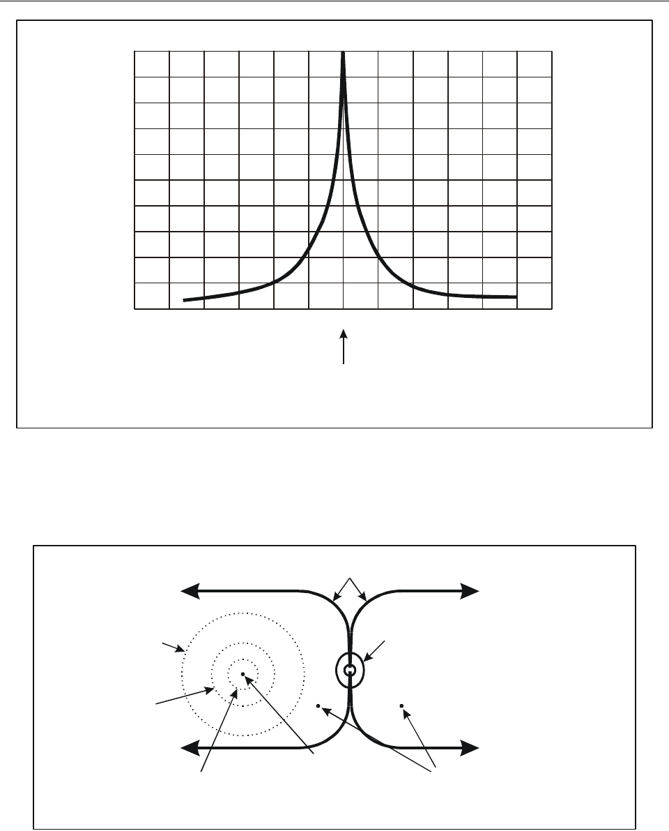
Chapter 3. Laser beam bioeffects and their hazards to flight operations 3-13
Figure 3-4. Visual acuity as a function of cone distribution
Figure 3-5. Visual acuity as a function of retinal location
60 40 20 0 20 40 60
Foveola
Degrees away from foveola
High-contrast Snellen acuity
6/4.5
6/6
6/7.5
6/9
6/15
6/60
6/30
20/15
20/20
20/25
20/30
20/50
20/100
20/200
Vascular arcade
Posterior pole
(area centralis):
≥
6 mm (20°)
6/30 – 6/60
Parafovea:
≥
3 mm (10°)
6/18 – 6/24
Fovea (macula):
1.5 mm (5°)
6/12 – 6/18
Foveola:
0.33 mm (1°)
6/3 – 6/6
Optic disc (physiological blind spot):
Outside posterior pole
(peripheral retina):
6/60 – 6/120
1.5 mm (5°) × 1.75 mm (7°)

3-14 Manual on laser emitters and flight safety
Retinal haemorrhages
3.8.24 A retinal haemorrhage will occur if a laser
beam disrupts a blood vessel somewhere in the eye. The
characteristics of that haemorrhage will depend on the
location of the damaged blood vessel within the retina, its
distribution and the orientation of the cell structure at the
disruption site. Haemorrhages involving superficial retinal
vessels will tend to follow the nerve fibre layer and assume
a flame-shaped configuration as the blood follows the nerve
fibres out radially from the optic nerve. Haemorrhages in
retinal layers deeper than the nerve fibre layer tend to be
dot- or blot-shaped. This blood can originate from deeper
vascular supplies, such as from the choroid (middle layer)
of the eye. It is also possible to disrupt a vessel or vascular
plexus to the extent that a large intraocular bleed occurs.
This blood may either collect on the retinal surface as a
preretinal haemorrhage or diffuse into the vitreous cavity.
Blood that enters the vitreous body will tend to remain
localized, particularly in younger individuals, but with
increasing age, the jelly-like vitreous body liquefies and
will allow blood to diffuse throughout the entire vitreous
cavity. This change in the vitreous body with age is a
normal aging process known as vitreal liquefaction, but it
may also occur as a result of other pathological processes
such as trauma.
3.8.25 A haemorrhagic event can have significant
visual impact. Recovery will depend on the location of the
bleed and other induced cytoarchitectural disruptions, as
well as the rate of reabsorption of the blood, e.g. from the
vitreous body, where it acts as a light-blocking filter. In
general, blood in the vitreous cavity will take approximately
six to twelve months to resolve spontaneously but will not
always do so. In many cases, removal of the cloudy vitreal
contents will be required surgically (vitrectomy) to restore a
clear ocular medium within the vitreous cavity. In some
cases, blood in the vitreous body will fibrose into localized
areas of vitreal opacification or induce fibrous strands that
can produce retinal traction or retinal tears.
Globe rupture
3.8.26 It is possible with a laser beam to disrupt tissue
to such an extent that neither a burn nor a haemorrhage
occurs, but rather a tear in the tissue is caused. This can be
a deleterious effect from exposure to high-peak power laser
beams of certain wavelengths. But this can also be used
therapeutically to disrupt unwanted membranes or traction
bands within the eye. Such tissue disruption may be
complete, either extending through an entire tissue layer,
such as the retina and choroid, or with more powerful laser
beams, to create a tear or hole in the entire outer coat of the
eye, the sclera-globe rupture. Such laser beams would need
to be very powerful to retain that capability at considerable
distances and would not likely be associated with laser
beams routinely encountered in civil aviation. Furthermore,
lasers of this peak power at extended ranges are likely to
have other much more significant effects that would
overshadow the eye and vision considerations.
Other bioeffects
3.8.27 In addition to the previous discussion of the
psychological and ocular effects associated with laser beam
exposures, there are other bioeffects that need to be
addressed. It is quite common in response to a perceived
bright light, particularly if it induces symptoms or a lesion,
for those affected to rub their eyes. This can induce
mechanical trauma to the cornea and conjunctiva that is
unrelated to the biological damage mechanisms of laser
beams. For example, excessive rubbing can induce con-
junctival haemorrhages and superficial epithelial lesions of
the cornea or even corneal abrasions that can induce further
symptoms and discomfort that are unrelated to, but often
attributed to, the laser beam itself. This can become even
more problematic if the rubbing occurs over contact lenses,
especially lenses made from rigid materials.
3.8.28 As a result, best corrected visual acuities and
any ocular damage must be carefully recorded in the
medical record so that a determination can be made, either
by on-scene medical examiners or by subject matter experts
who later review such cases as to cause and effect. A
corneal and retinal drawing should always be made to show
the precise location and configuration of any lesions related
to the event. This is extremely important especially since
these events invariably become medical, occupational, legal
and political controversies at some point.
3.8.29 Beyond the description of biological damage
mechanisms and related bioeffects associated with laser
beams, consideration should be given to the visual
performance ramifications of this damage from a different
perspective. Those categories of visual performance that
are related to either temporary or permanent laser beam
effects include: central visual acuity, peripheral visual
acuity, colour perception, contrast sensitivity and
stereopsis. Therefore, the consequences of specific laser
beam induced lesions must also be viewed with regard to
their ability to affect these other areas of visual
performance. In many cases, these visual functions will be
tested to determine deviations from normal and to monitor
recovery. It should be noted that colour perception
screening (which should include both red/green and
yellow/blue testing) can be particularly useful in

Chapter 3. Laser beam bioeffects and their hazards to flight operations 3-15
identifying phototoxic retinal damage and may indicate
laser beam damage even when the Amsler grid and Snellen
visual acuity tests are normal. This ability to identify
phototoxic events with colour vision tests has been shown
to exceed the ability of the Amsler grid to identify the
presence of an actual laser beam related injury. Therefore,
colour vision testing (including red/green and blue/yellow
testing) remains a significant tool to assess the level and
degree of potential damage related to any light or laser
beam exposure.
3.8.30 Individual variations in affected eyes make
accurate prediction of rate and degree of recovery almost
impossible. The closer the lesion to the macula, the greater
the likelihood of significant visual impairment, but
appearance alone is not always a good indicator of
function. Some eyes with significant lesions seen with the
ophthalmoscope have surprisingly good visual function.
Other eyes may have significantly reduced visual function
with very little to see ophthalmoscopically. The normal
retina is transparent and it is only with some of the newer
instruments, such as the confocal scanning ophthalmoscope
that subtle retinal changes can be studied. The most subtle
lesions may be impossible to detect except with electron
microscopy. Corneal lesions are somewhat easier to
evaluate clinically. As with the retina, location is critical. A
small corneal scar in the visual axis will affect vision
severely, while a dense peripheral corneal scar may have no
effect on visual acuity.
3.9 THE FUTURE
3.9.1 Although much is known about laser beam
bioeffects, the proliferation of laser technology mandates
continued research as new laser beam wavelengths and
laser characteristics are developed. Several areas of concern
related to laser beam exposure remain to be defined, such
as cumulative effects as a result of repetitive low-intensity
exposures and age-related sensitivities.
3.9.2 Another area of interest is neuroprotective
drugs. While no effective neuroprotective agents have yet
been identified, several types are being pursued in the
hopes of eliminating or decreasing retinal sensitivity to
injury from laser beam exposure.
3.9.3 On the other hand, the increasing use of a variety
of medications can potentially photosensitize the skin and
the eyes, increasing their susceptibility to phototoxic
damage. Research in this area remains difficult. It is
expensive, complicated, time consuming and would need to
encompass a huge and ever-expanding pharmacopoeia of
both natural and synthetic drugs.
3.10 MEDICAL EVALUATION OF
LASER BEAM INCIDENTS
3.10.1 The medical tools and methodologies
recommended for evaluating suspected laser beam induced
injuries are described in Chapter 7. It is extremely
important that every effort be made to promptly record all
relevant details of the exposure at the earliest opportunity
as this may have critical occupational, medical, legal and
operational value to all parties concerned. Experience
shows that in many such exposures, damage attributed to
laser beam illuminations has, in fact, another cause. The
following report gives an example of this.
On 29 November 1996, at about 6:50 p.m. local
time, the captain of an Embraer 120 sustained an
eye injury when hit by a laser beam during
approach to Los Angeles, California (United
States). The aircraft was at 6 000 feet MSL in VMC
on right base for a visual approach to runway 24R.
The captain was looking for other traffic through
the right window of the cockpit when he was struck
in his right eye by a bright blue beam of light. As
the flight continued, it became more difficult for the
captain to see with his right eye because of
increasing pain and tearing. By the time the aircraft
was established on final approach, the captain was
in so much discomfort that he relinquished the
control to the co-pilot who completed the landing.
The captain requested immediate medical attention,
and examination at a local hospital revealed
multiple flash burns to his right cornea. The captain
was also examined by specialists at Armstrong
Laboratory, Brooks AFB, San Antonio, Texas. This
examination revealed no evidence of permanent
effects from the exposure. Investigators from the
FDA attempted without success to identify the
source of the laser beam. There were no NOTAMs
in effect for laser light activity in the Los Angeles
area at the time of the incident.
(Summary of NTSB Full Narrative Report
LAX97IA056)
3.10.2 In this report, the initial diagnosis of corneal
damage (“multiple flash burns to his right cornea”) cannot
be directly attributed to a visible laser beam because light
passes through the cornea without affecting it. The damage
to the cornea was most likely caused by rubbing of the eye
in response to the light beam exposure.
3.10.3 The inability of some examiners to correctly
diagnose an injury following laser beam exposure can be
attributed to a lack of understanding of the significance of

3-16 Manual on laser emitters and flight safety
the events involved and inadequate experience with this
kind of injury. It is common for people to vigorously rub
their eyes in response to an insult they may have received,
whether it was from radiation or particulate matter. They
often do so instinctively, sometimes in a state of panic and
in such a coarse way that they induce ocular damage to the
conjunctiva and cornea. This damage can be misconstrued
as caused by the laser beam itself when, in fact, it was a
self-induced mechanical trauma after the event. It is
therefore absolutely critical, when such events occur, that
these patients be examined by subject-matter experts with
adequate experience and knowledge of laser beam injury
patterns and source characteristics. Only such experts can
definitively establish whether or not such events are related
to a laser beam exposure.
3.10.4 Physical characteristics and other historical
details related to the laser beam and exposure setting need
to be evaluated carefully. For the most part, this will be
beyond the capability of ordinary medical practioners who
lack a comprehensive background in lasers and their
bioeffects. In the absence of national laser injury
management centres, an international point of contact
should be established to help facilitate the recording of
such incidents.
References
American National Standards Institute ANSI Z136.3-1996.
“Laser Safety and the Healthcare Environment”.
Boettner, E.A. and J.R. Wolter. “Transmission of the
Ocular Media”. Investigative Ophthalmology and Visual
Science 1, pp. 776–783.
Green, R.P., R.M. Cartledge, F.E. Cheney and
A.R. Menendez. “Medical Management of Combat Laser
Eye Injuries”. USAFSAM-TR-88-21, October 1988.
[Requests can be addressed to: Freedom of Information Act
Office (FOIA), 311th CS/SCSD, 8101 Arnold Drive,
Brooks AFB, TX 78235-5367, United States.]
International Electrotechnical Commission IEC 60825-8:
1999. “Safety of Laser Products, Part 8; Guidelines for the
Safe Use of Medical Laser Equipment”.
Ivan, D.J. and H.J. O’Neill. “Laser Induced Acute Visual
and Cognitive Incapacitation of Aircrew, Protection
Management, and Cockpit Integration”. AGARDOGRAPH
AGARD-AR-354, Chapter 11: pp. 73–85, April 1998.
[Requests can be addressed to: NATO Research and
Technology Organization, BP-25, 7 Rue Ancelle, F-92201,
Neuilly-Sur-Seine, CEDEX, France.]
Lerman, S. Radiant Energy and the Eye. Macmillan
Publishing Co., Inc. New York, 1980.
Sliney, D.H. and M.L. Wolbarsht. Safety with Lasers and
Other Optical Sources — A Comprehensive Handbook.
Plenum Press, New York, 1982.
Thomas, S.R. “Review of Personnel Susceptibility to
Lasers: Simulation in Simnet-D for CTAS-2.0”. AL/OE-
TR-1994-0060, January 1994.
[Requests can be addressed to: Freedom of Information Act
Office (FOIA), 311th CS/SCSD, 8101 Arnold Drive,
Brooks AFB, TX 78235-5367, United States.]
Zuclich, J.A. and J. Taboada. “Ocular Hazard from UV
Laser Exhibiting Self-Mode-Blocking”. Applied Optics 17,
pp. 1 482–1 484.

4-1
Chapter 4
OPERATIONAL FACTORS
AND TRAINING OF AIRCREW
4.1 BACKGROUND
4.1.1 An increasing incidence of in-flight laser beam
illuminations of flight crew personnel has been reported in
recent years. Incidents have occurred primarily near
airports located in close proximity to large cities, resort
destinations and entertainment venues. Such illuminations
have resulted in aversion responses (blinking, squinting,
head movement), temporary visual impairment (TVI),
temporary vision loss (TVL), a variety of psychological
effects and evasive actions.
On 19 November 1993, at 10 p.m. local time, a
B-737 departing Las Vegas, Nevada (United States)
was struck by a green laser beam at 500 feet AGL.
The beam entered the cockpit through the co-pilot’s
window, flash-blinding both pilots for 5-10 seconds.
The co-pilot reported problems with his right eye
and needed medical attention at the end of the
flight. The captain of the flight stated as his opinion
that if the laser beam had passed through the front
windshield illuminating both pilots at a more direct
angle, they would have lost control of the aircraft.
The laser beam source was reported to have been
located at one of the hotels near the airport.
(Summary of Report of Irregularity, dated
24 November 1993)
4.1.2 During the following two years in the vicinity of
Las Vegas airport, there were more than 150 laser beam
illuminations of air carriers, regional carriers, military
aircraft and local helicopter operators, including emergency
and law enforcement operators.
On 30 October 1995, at 6:10 p.m. local time, a
B-737 was climbing through 4 500 feet AGL on
departure from Las Vegas when the first officer,
who was the flying pilot, was hit by a laser beam.
He immediately experienced eye pain and was
completely blinded in the right eye. After-image
effects also impaired vision in his left eye. He
reported that his inability to see lasted 30 seconds
and for an additional period of two minutes he was
unable to interpret any instrument indications. The
captain assumed control of the aircraft and
continued the climb.
(Summary of NTSB Aviation Accident/Incident
Database Report LAX96IA032)
4.1.3 These incidents made it clear that TVI at
illumination levels much lower than those normally
associated with physical eye injury could affect flight
safety. On 11 December 1995, a moratorium on all outdoor
laser activities in Las Vegas was declared.
4.1.4 There are two situations where outdoor laser
operations may compromise aviation safety. The first is
where the MPE is exceeded and physical injury to the eye
can occur. The second is the situation where the MPE is not
exceeded, but where there is a potential for functional
impairment, such as flash-blindness, after-image and glare
that can interfere with the visual tasks of the pilots during
critical phases of flight. The two excerpts above are
believed to be examples of the second situation.
4.1.5 There are obvious flight safety risks associated
with laser beam illumination during critical phases of flight
(especially procedures requiring steady-state turns). These
are caused by ocular, vestibular and psychological effects,
which individually or combined may lead to loss of
situational awareness (LSA). TVI leaves the pilot reliant
upon other sensory input, which may provide inadequate but
compelling information, resulting in incorrect decisions.
TVI can lead to startle, distraction, disruption, disorientation
and in extreme cases, complete incapacitation.
4.1.6 Pilots receive most of their flight information
visually, and in order to maintain situational awareness in a

4-2 Manual on laser emitters and flight safety
dynamic environment, they rely on frequent reference to
their instruments. This reliance is greater at night and
becomes total in instrument meteorological conditions
(IMC).
4.1.7 It is important to understand how trained pilots
interpret, integrate and process information without visual
reference to the outside world. Thorough instrument flight
training is a prerequisite for maintaining normal task per-
formance, information integration and situational aware-
ness when operating under instrument flight rules (IFR).
4.1.8 Pilots use a visual scan technique of glancing at,
rather than dwelling upon, the flight instruments. Pilots
construct mental images of their position in space from
information provided by the flight instruments. Spatial
orientation is maintained through the brain’s comparison of
visual inputs with a pre-existing mental model. When
conditions permit, this model is continually updated with
reference to the outside world for comparison and
processing.
4.2 SITUATIONAL AWARENESS
4.2.1 Situational awareness (SA) is the accuracy by
which a person’s perception of his environment mirrors
reality. SA is determined by several factors. Anything that
leads to a loss of SA can create a flight safety hazard. One
of the most critical factors, and the one most likely to be
affected by laser beam illumination, is spatial orientation.
4.2.2 Loss of spatial orientation is called spatial
disorientation (SD). It can be classified into three types:
• Type I (unrecognized SD) occurs when a person is
unaware of being disorientated;
• Type II (recognized SD) occurs when a person is
aware of being disorientated and is able to
compensate for it; and
• Type III (incapacitating SD) occurs when a person
is aware of being disorientated but is unable to
compensate for it.
4.2.3 A laser beam illumination may cause all three
types of SD but is most likely to cause Types II and III.
4.3 ORIENTATION IN FLIGHT
4.3.1 Orientation in flight is determined primarily by
cues provided by the following four senses:
a) Sight (vision). This is the single most important
sense for maintaining spatial orientation during
flight. When vision is impaired, spatial orientation
is degraded because motion and position cues
provided by other senses are not reliable during
flight.
Vision can be divided into peripheral and central
vision. Peripheral vision provides low resolution
but is highly sensitive to movement and light. It is
primarily concerned with the question of “where”,
thus supporting spatial orientation. Central vision
provides high resolution and colour perception but
is less sensitive to light. It is primarily concerned
with the question of “what”. With the loss of visual
orientation cues, inadequate but compelling in-
formation from other senses causes a variety of
illusions, sometimes leading to overwhelming SD.
b) Vestibular sense (sense of equilibrium). The
vestibular apparatus provides information from the
inner ear about motion and balance. In addition, the
middle ear provides information about ambient
pressure changes. Normally, visual input will
suppress input from other senses. Because flight
motion is different from that of everyday activities,
the loss of visual input is critical, as vestibular
information alone may result in illusory perception
of flight attitude and motion. For example, to
stimulate the inner ear, an angular acceleration of
0.5 to 2.2 degrees per second per second is
required. When the angular acceleration ceases,
such as when a constant rate turn has been
established, the vestibular apparatus is no longer
able to detect the turn. If visual input is absent,
pilots will not recognize that the aircraft continues
to turn.
c) Proprioception (kinaesthetic sense). A variety of
sensory nerve endings in the skin, the capsules of
joints, muscles, ligaments and deeper supporting
structures are stimulated mechanically and, hence,
are influenced by the forces acting on the body.
These proprioceptive mechano-receptors provide
useful equilibrium information based on sensation
of position and movement. The kinaesthetic sense is
better known to pilots as “seat-of-the-pants”. Alone,
the kinaesthetic perception of an aircraft’s attitude
in space is unreliable but can easily be overcome by
more vital sensory input.
d) Hearing (audition). The auditory system provides
information about sound level, pitch and direction.

Chapter 4. Operational factors and training of aircrew 4-3
Pilots learn to recognize certain sounds during
flight. For example, airflow over the windscreen
during acceleration and deceleration of the aircraft
and the change in pitch as the engine power-setting
changes can be detected.
4.3.2 Loss of visual references caused by a laser beam
illumination, coupled with inadequate information from the
vestibular apparatus, the proprioceptive mechano-receptors
and the auditory system, may result in SD (often referred to
by pilots as “vertigo”), which can lead to accidents.
Disorientation demonstration courses and laser-awareness
training are therefore recommended.
4.4 PREVENTATIVE PROCEDURES
Pre-flight procedures
• Notices to airmen (NOTAMs) should be consulted
for location and operating times of laser activities
and alternate routes should be considered.
• Aeronautical charts should be consulted for
permanent laser activities (theme parks, research
facilities, etc.).
In-flight procedures prior to entering
airspace with known laser activity
• Exterior lights should be turned on to aid ground
observers in locating and identifying aircraft.
• The autopilot should be engaged.
• One pilot should stay on instruments to minimize
the effects of a possible illumination.
• Flight deck lights should be turned on.
In-flight procedures during and after
laser beam illumination of the cockpit
4.4.1 If a pilot is exposed to a bright light suspected
to be a laser beam, the following steps are recommended to
reduce the risk unless the specific action would com-
promise flight safety:
• Look away from the light source.
• Shield eyes from the light source.
• Declare visual condition to other pilots.
• Transfer control of the aircraft to another pilot.
• Switch over to instrument flight.
• Engage autopilot.
• Manoeuvre or position the aircraft such that the
laser beam no longer illuminates the flight deck.
• Assess visual function, e.g. by reading instruments
or approach charts.
• Avoid rubbing eyes.
• Notify air traffic control (ATC) of a suspected in-
flight laser beam illumination and, if necessary,
declare an emergency.
4.4.2 It is important to notify appropriate authorities
of a suspected in-flight laser beam illumination. Upon
landing, the pilot should notify the authorities and provide
details about the incident, then seek immediate medical
evaluation, preferably by a qualified vision specialist.
Documentation of incidents and medical examinations are
covered in Chapters 6 and 7, respectively.


5-1
Chapter 5
AIRSPACE SAFETY
5.1 GENERAL
5.1.1 This chapter provides guidance for determining
and minimizing the potential adverse effects of outdoor
laser operations on aviation safety. Provisions* concerning
laser emitters and protected flight zones are contained in:
Annex 11 — Air Traffic Services
“2.17.5 Adequate steps shall be taken to prevent
emission of laser beams from adversely affecting flight
operations.”
Annex 14 — Aerodromes, Volume I — Aerodrome Design
and Operation
“Laser emissions which may endanger
the safety of aircraft
“5.3.1.2 Recommendation.— To protect the safety of
aircraft against the hazardous effects of laser emitters, the
following protected zones should be established around
aerodromes:
—a laser-beam free flight zone (LFFZ)
—a laser-beam critical flight zone (LCFZ)
—a laser-beam sensitive flight zone (LSFZ)
“Note 1.— Figures 5-10, 5-11 and 5-12 may be used to
determine the exposure levels and distances that adequately
protect flight operations.
“Note 2.— The restrictions on the use of laser beams in
the three protected flight zones, LFFZ, LCFZ and LSFZ,
refer to visible laser beams only. Laser emitters operated by
the authorities in a manner compatible with flight safety
are excluded. In all navigable air space, the irradiance
level of any laser beam, visible or invisible, is expected to
be less than or equal to the maximum permissible exposure
(MPE) unless such emission has been notified to the
authority and permission obtained.
“Note 3.— The protected flight zones are established in
order to mitigate the risk of operating laser emitters in the
vicinity of aerodromes”.
5.1.2 Contracting States may be guided by the
following text examples when controlling the hazards of
laser beam emissions or enacting regulations in accordance
with Annexes 11 and 14:
a) No person shall intentionally project, or cause to be
projected, a laser beam or other directed high
intensity light at an aircraft in such a manner as to
create a hazard to aviation safety, damage to the
aircraft or injury to its crew or passengers.
Note.— Also see Annex 14, Volume I, 5.3.1.1.
b) Any person using or planning to use lasers or other
directed high-intensity lights outdoors in such a
manner that the laser beam or other light beam may
enter navigable airspace with sufficient power to
cause an aviation hazard shall provide written
notification to the competent authority.
c) No pilot-in-command shall deliberately operate an
aircraft into a laser beam or other directed high-
intensity light beam unless flight safety is protected.
This may require mutual agreement by the operator
of the laser emitter or light source, the pilot-in-
command and the competent authority.
5.2 AIRSPACE RESTRICTIONS
5.2.1 To protect the safety of aviation in the vicinity
of aerodromes, heliports and certain other areas, such as
low-level visual flight rules (VFR) corridors, it is necessary
to protect the affected airspace against hazardous laser
* The provisions are not intended to confer any responsibility
onto airport operators.

5-2 Manual on laser emitters and flight safety
beams. For non-visible laser beams, the nominal ocular
hazard distance (NOHD) value is the sole consideration.
For visible laser beams, in addition to the NOHD, visual
disruption must also be considered.
5.2.2 According to 5.3.1.2 in Annex 14, airspace
around aerodromes should be designated as laser-beam
sensitive flight zones, laser-beam critical flight zones, and
laser-beam free flight zones, in order to prevent visible
laser beams from interfering with a pilot’s vision, even if
the maximum permissible exposure (MPE) is not exceeded.
The beam from a visible laser must not enter any zone,
when the irradiance is greater than the corresponding visual
interference level, unless adequate protective means are
employed to prevent personnel exposure. Lasers with beam
irradiances less than the MPE but exceeding the sensitive
level or critical level, may be operated in the sensitive zone
or critical zone, respectively, if adequate means are used to
prevent aircraft from entering the beam path.
Laser-beam free flight zone (LFFZ)
5.2.3 The LFFZ is the airspace in the immediate
proximity to the aerodrome, up to and including 600 m
(2 000 ft) above ground level (AGL), extending 3 700 m
(2 NM) in all directions measured from the runway centre
line, plus a 5 600 m (3 NM) extension, 750 m (2 500 ft) on
each side of the extended runway centre line of each
useable runway. Within this zone, the intensity of laser
light is restricted to a level that is unlikely to cause any
visual disruption. The following conditions are applicable
to LFFZ:
a) parallel runways are measured from the runway
centre line toward the outermost edges, plus the
airspace between runway centre lines;
b) within this airspace, the irradiance is not to exceed
50 nW/cm2 unless some form of mitigation is
applied. The level of brightness thus produced is
indistinguishable from background ambient light;
and
c) to allow laser operations below the arrival path, a
1:40 slope may be applied to the 5 600 m exten-
sions. This slope is calculated from the runway
threshold.
Laser-beam critical flight zone (LCFZ)
5.2.4 The LCFZ is the airspace within 18 500 m
(10 NM) of the aerodrome reference point (ARP), from the
surface up to and including 3 050 m (10 000 ft) AGL (see
Figures 5-1, 5-2 and 5-3). This zone may have to be
adjusted to meet air traffic requirements. Within this
airspace the irradiance is not to exceed 5 µW/cm2 unless
some form of mitigation is applied. Although capable of
causing glare effects, this irradiance will not produce a
level of brightness sufficient to cause flash-blindness or
after-image effects.
Laser-beam sensitive flight zone (LSFZ)
5.2.5 The LSFZ is the airspace outside the LFFZ and
LCFZ where the irradiance is not to exceed 100 µW/cm2
unless some form of mitigation is applied. The level of
brightness thus produced may begin to produce flash-
blindness or after-image effects of short duration; however,
this limit will provide protection from serious effects. The
LSFZ need not necessarily be contiguous with the other
flight zones.
Normal flight zone (NFZ)
5.2.6 The NFZ is any navigable airspace not defined
as LFFZ, LCFZ or LSFZ. The NFZ must be protected from
laser radiation capable of causing biological damage to the
eye.
5.2.7 Figures 5-1 through 5-3 define the zones
established to protect aircraft in navigable airspace. The
dimensions indicated are given as guidance but have been
found to protect safety well.
5.2.8 The amount of airspace affected by a laser
operation varies with the laser systems output power, which
is measured in watts or joules. The following maximum
irradiance levels (MILs) can be used for evaluating laser
activities in close proximity to an aerodrome:
a) LFFZ: MIL is equal to or less than 50 nW/cm2;
b) LCFZ: MIL is equal to or less than 5 µW/cm2;
c) LSFZ: MIL is equal to or less than 100 µW/cm2;
and
d) NFZ: MIL is equal to or less than the MPE for CW
or pulsed lasers.
Note.— Items a), b) and c) refer to visible laser
emissions only.
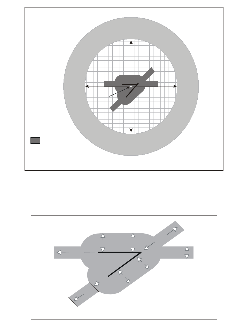
Chapter 5. Airspace safety 5-3
Figure 5-1. Protected flight zones
Figure 5-2. Multiple runway laser-beam free flight zone (LFFZ)
To be determined by
local aerodrome
operations
Aerodrome
reference
point
Laser-beam
free flight
zone
18 500 m
Laser-beam
sensitive
flight zone
Laser-beam
critical
flight zone
Note.— The dimensions indicated are given as guidance only.
3 700 m
9 300 m
5 600 m
3 700 m
3 700 m
3 700 m
9 300 m
3 700 m
1 500 m
Note.— The dimensions indicated are given as guidance onl
y
.
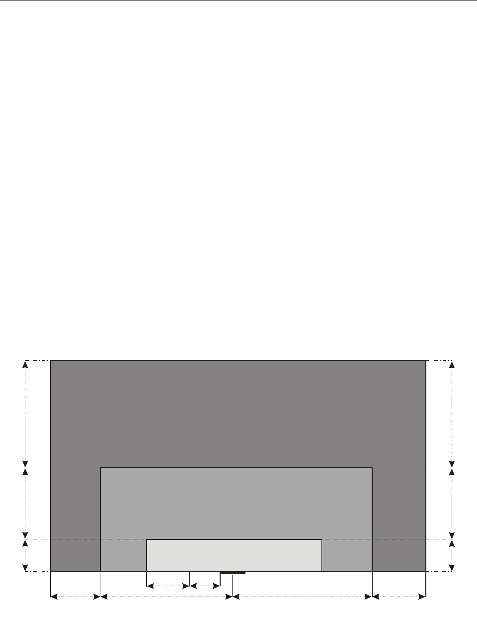
5-4 Manual on laser emitters and flight safety
5.2.9 Protective means (mitigation) are required to
protect pilots and other personnel when the visual
interference level is exceeded. Redundant systems are
advisable in locations noted for heavy air traffic.
5.3 AERONAUTICAL ASSESSMENT
5.3.1 The procedures outlined below may be used to
evaluate the potential effect of laser activity on aircraft
operations. The proponent should notify the competent
authority in sufficient time to allow an aeronautical assess-
ment to be completed.
5.3.2 A Contracting State may provide a submission
form which, when completed, will provide sufficient
information for an aeronautical assessment to be
completed. A sample “Notice of Proposal to Conduct
Outdoor Laser Operations” form and instructions are
attached in Appendix A. The competent authority should:
a) determine the location of the laser activity and the
laser MPE and NOHD;
b) plot the LFFZs, LCFZs and LSFZs at aerodromes;
c) establish additional LSFZs, if required, to protect
locations of aviation activity that may also be
affected, such as substantial helicopter traffic
operating below 300 m (1 000 ft), VFR corridors,
the airspace around high-energy lasers used to
support astronomical observatories, active training
areas, etc.;
d) consider the laser operations in relationship with
the established zones. Use the MILs established by
the competent authority when evaluating laser
activities in proximity to an aerodrome;
e) review airspace and aircraft operations that may be
affected by the proposal;
f) coordinate with local officials, e.g. aerodrome
managers, air traffic managers, military represen-
tatives, local police organizations;
g) convene a local laser working group (LLWG) if the
operations appear to be complex or controversial;
h) consider the proponent’s proposed mitigation
measures and any additional measures taken to
Figure 5-3. Protected flight zones with indication of maximum
irradiance levels for visible laser beams
To be
determined
To be
determined
5 600 m 3 700 m
18 500 m 18 500 m
Aerodrome reference point
AGL is based on published aerodrome elevation
600 m
AGL
600 m
AGL
2 400 m AGL
2 400 m AGL
To be determined by
local aerodrome operations
To be determined by
local aerodrome operations
PROTECTED FLIGHT ZONES
Elevation
Laser-beam critical flight zone
5 W/cm
µ
2
Laser-beam free flight zone
50 nW/cm
2
Laser-beam sensitive flight zone
100 W/cm
µ
2

Chapter 5. Airspace safety 5-5
ensure that aircraft operators will not be exposed to
laser emissions that have the potential to impair
their performance of duties. Such measures include,
but are not limited to, physical, procedural, manual
and automated control measures;
i) compile a cumulative impact assessment on per-
manent or long-term laser operations effects on
local operations;
j) assess the capability of the affected ATC facilities
to provide real-time management of air traffic to
ensure no cockpit illuminations by the laser beams;
k) coordinate with the proponent, identify objection-
able effects and negotiate appropriate mitigation to
protect aviation safety; and
l) communicate to the proponent and all participating
authorities the completed aeronautical assessment.
If the proposal is complex or controversial, the
competent authority should document all pertinent
information and disseminate copies as appropriate.
5.4 CONTROL MEASURES
Physical, procedural and automated control measures
established to ensure that aircraft operations will not be
exposed to levels of illumination greater than the respective
MILs considered acceptable should meet one or more of the
descriptions listed below:
a) ATC control measures:
1) NOTAM;
2) Voice advisory (e.g. automatic terminal
information system (ATIS), pilot-controller
communications);
3) Airspace restrictions;
whereas the proponent must ensure that the operator control
measures are in accordance with one or more of the
following:
b) Operator control measures:
1) The laser beam may be physically blocked
(terminated beam) to prevent laser light from
being directed into protected volumes of
airspace.
2) The laser beam divergence and output power or
pulse energy emitted through the system
aperture may be adjusted to meet appropriate
exposure levels.
3) Beams can be directed in a specific area.
Directions should be specified by giving
bearing in the azimuth scale 0–360 degrees and
elevation in degrees ranging from 0–90 degrees,
where 0 degrees is horizontal and 90 degrees is
vertical. Both true and magnetic bearings
should be given.
4) Manual operation of a shutter or beam-
termination system can be used in conjunction
with airspace observers. Observers should be
trained and able to see sufficient airspace
surrounding beam paths to terminate the beam
prior to illumination of aircraft.
5) Scanning the laser beam may reduce the level
of illumination; however, it may increase the
potential risk of illumination.
6) Automated systems designed to detect aircraft
and automatically terminate or redirect the
beam or shutter the system may be used. The
proponent should include detailed information
that describes the operation of the automated
system, its effectiveness and how it can be
tested for full functionality prior to each use.
5.5 DETERMINATIONS
5.5.1 If the proponent’s notification satisfies the
requirements of the aeronautical assessment, the competent
authority should issue, as a minimum, the following:
a) a statement advising the proponent that his
notification satisfies the requirements of the
competent authority and is approved subject to
conditions or limitations (such as aircraft spotter
requirements), as applicable;
b) a statement to the proponent that changes should
not be incorporated into the proposed activity once
permission has been granted, unless approved by
the competent authority in writing;
c) a statement that the proponent notify the
appropriate authority or their designated represen-
tative of any changes to show start/stop times or
cancellation 24 hours in advance;

5-6 Manual on laser emitters and flight safety
d) a statement that approval does not relieve the
sponsor or operator of responsibility for complying
with the mitigation agreed upon, the laws, ordin-
ances or regulations of any relevant authority; and
e) NOTAM. (See examples in 5.5.4.)
5.5.2 If the proponent’s notification does not satisfy
the requirements of the aeronautical assessment, the
competent authority should issue a statement advising the
proponent that an objection is being issued. Specifically, it
should indicate why the proponent does not satisfy safety
requirements, and that new data or other appropriate
information may be submitted for consideration. If
negotiations to resolve any objectionable effects have not
been successful, the objection should stand.
5.5.3 To enhance aviation safety, a NOTAM should be
prepared alerting pilots of known laser activities. It is
important to emphasize the hazardous effects and other
related phenomena that may be caused by laser beams.
5.5.4 The competent authority should provide
information for the publication of a NOTAM* as shown in
the following sample formats. Laser activities that last
more than 180 days should be considered permanent (e.g.
annual ongoing activities). Information pertaining to such
activities should be published in applicable aviation
publications.
Sample publication format
of temporary laser activity
LASER LIGHT DEMONSTRATION WILL BE
CONDUCTED AT (place, city, province or state),
(NAVAID ID, type, radial) RADIAL (dist.) NAUTICAL
MILES, (lat./long.). BEAMS FROM SITE PROJECTING
(direction) BETWEEN RADIALS (xxx-xxx), ON (dates),
BETWEEN (time/UTC). LASER LIGHT BEAMS MAY
BE INJURIOUS TO PILOTS/AIRCREW AND
PASSENGERS EYES WITHIN (nominal ocular hazard
distance) VERTICALLY AND/OR (nominal ocular hazard
distance) LATERALLY OF THE LIGHT SOURCE.
FLASH-BLINDNESS OR COCKPIT ILLUMINATION
MAY OCCUR BEYOND THESE DISTANCES.
LASER RESEARCH WILL BE CONDUCTED AT (place,
city, province or state, lat./long.), ON/FROM (dates),
BETWEEN (times/UTC), AT AN ANGLE OF (degree),
FROM THE SURFACE, PROJECTING UP TO (height)
MSL AVOID AIRBORNE HAZARD BY (NM). THIS
LASER LIGHT BEAM MAY BE INJURIOUS TO
PILOTS/AIRCREW AND PASSENGERS EYES.
AIRBORNE TO GROUND LASER ACTIVITY WILL BE
CONDUCTED ON (dates), BETWEEN (lat./long.,
altitude) AND BELOW. AVOID AIRBORNE HAZARD
BY (NM). THIS LASER BEAM MAY BE INJURIOUS
TO PILOTS/AIRCREW AND PASSENGERS EYES.
AIRBORNE LASER ACTIVITY WILL BE
CONDUCTED ON/FROM (dates), AT/FROM (times/
UTC), BETWEEN (NAVAID ID, type, radial) RADIAL
(dist.) NAUTICAL MILES, (lat./long.), AND (NAVAID
ID, type, radial) RADIAL (dist.) NAUTICAL MILES, (lat./
long.), BETWEEN (altitude) MSL AND (altitude) MSL (or
the surface). AVOID AIRBORNE HAZARD BY (NM).
THE LASER LIGHT BEAM MAY BE INJURIOUS TO
PILOTS/AIRCREW AND PASSENGERS.
Sample publication format
of a permanent laser site
(place, city, province or state).
UNTIL FURTHER NOTICE A LASER LIGHT
DEMONSTRATION WILL BE CONDUCTED NIGHTLY
BETWEEN SUNDOWN AND DAWN AT THE (place,
city, province or state) (NAVAID ID, type radial) RADIAL
AT LAT./LONG. RANDOM BEAMS ILLUMINATING
(directions indicated) QUADRANTS. THE BEAM MAY
BE INJURIOUS TO EYES IF VIEWED WITHIN (NOHD
dist.) VERTICALLY AND (NOHD dist.) LATERALLY OF
THE LIGHT SOURCE. FLASH-BLINDNESS OR
COCKPIT ILLUMINATION MAY OCCUR BEYOND
THESE DISTANCES.
NOTAMs concerning temporary laser activity at
Harboøre in København FIR (issued by the Civil
Aviation Administration, Denmark)
XXXXX/XX NOTAMN
Q) EKDK/QWXXX/V/B/W/000/103/
A) EKDK B) 0006091900 C) 0006102200
D) DAILY 1900-2200
E) TEMPO NAV WRNG. LASER LIGHTSHOW WILL
TAKE PLACE AT HARBOOERE PSN 563713N
0081130E. THE LASERBEAM MAY CAUSE
BLINDNESS IF VIEWED WITHIN A VERTICAL
DISTANCE OF 500FT AND HORIZONTAL DISTANCE
* More information about the NOTAM format can be found in
Annex 15.

Chapter 5. Airspace safety 5-7
OF 0.5NM OF THE LIGHT SOURCE.
FLASHBLINDNESS OR COCKPIT ILLUMINATION
MAY OCCUR WITHIN A VERTICAL DISTANCE OF
8300FT AND A HORIZONTAL DISTANCE OF 8NM
F) GND
G) 8300FT MSL
XXXXX/XX NOTAMN
Q) EKDK/QWXXX/V/B/W/000/103/
A) EKDK B) 0006091900 C) 0006102200
D) DAILY 1900-2200
E) TEMPO NAV WRNG. AIRBORNE TO GROUND
LASER ACTIVITY WILL TAKE PLACE WITHIN A
10NM RADIUS OF HARBOOERE PSN 563713N
0081130E. THE LASERBEAM WILL OPERATE FROM
10,000FT MSL DOWNWARD AND MAY CAUSE
BLINDNESS IF VIEWED WITHIN A VERTICAL
DISTANCE OF 5000FT AND HORIZONTAL DISTANCE
OF 2.5NM OF THE LIGHT SOURCE.
FLASHBLINDNESS OR COCKPIT ILLUMINATION
MAY OCCUR WITHIN A VERTICAL DISTANCE OF
5300FT AND A HORIZONTAL DISTANCE OF 8NM
F) GND
G) 8300FT MSL
5.6 INCIDENT-REPORTING REQUIREMENTS
Contracting States may wish to establish an incident-
reporting system to provide a means of monitoring
unauthorized use of lasers in airspace. Rapid notification
of an incident will assist in the investigation and possible
enforcement action against the offender. Sample incident
report formats are found in Appendix B.


6-1
Chapter 6
DOCUMENTATION OF INCIDENTS
AFTER SUSPECTED LASER BEAM ILLUMINATION
6.1 BACKGROUND
Laser beams with the potential to compromise flight safety
may be visible or invisible. Laser beams may cause damage
to the retina, especially at higher levels of exposure. The
bright light from visible laser beams can cause glare, after-
images and flash-blindness. Exposure to invisible laser
beams may result in pain, vision loss or skin burns, but they
are not normally associated with glare and flash-blindness.
Damage to the tissue of the eye’s cornea and conjunctiva
requires a higher exposure level than that required to cause
damage to the retina. This is due, in part, to the eye’s
natural focusing mechanism that can increase the energy
per unit area delivered to the retina. Besides glare, flash-
blindness and after-images, other symptoms of laser beam
light exposure may include pain, eye fatigue, tearing, eye
irritation and headache. Laser beam light can and has
interfered with safe and efficient performance of flight
procedures by causing temporary distraction, disorientation
and visual incapacitation.
6.2 PROCEDURES
Whenever an unexpected illumination by an unknown
source occurs, a laser incident should be suspected and
reported. It is recommended that all suspected laser beam
incidents be reported to the national aviation medicine and
flight safety authorities. In general, individuals should,
without delay, consult an optometrist, ophthalmologist or
designated medical examiner whenever they have
experienced a suspected laser beam exposure. Those with
persistent symptoms or abnormal clinical findings may
require referral to an ophthalmologist for further medical
evaluation and treatment.
Note.— Chapter 7, entitled “Medical Examination
Following Suspected Laser Beam Illumination”, provides
guidance for evaluating aircrew and other aviation per-
sonnel who may have been injured or incapacitated by a
laser beam illumination.
6.3 DOCUMENTATION
6.3.1 Documentation of a suspected laser beam
illumination incident has three important functions. First, it
provides information on the effectiveness of current
policies and procedures used to protect the navigable
airspace against hazardous laser beams. Second, it provides
a protocol for medical assessment. Third, it provides
updates on new devices or sources of hazardous laser
beams that may affect visual performance.
6.3.2 Guidance on how to document suspected laser
beam illumination incidents is provided in Appendix B.
The two forms (Suspected Laser Beam Incident Report and
Suspected Laser Beam Exposure Questionnaire) may be
used for investigation of illumination incidents. The report
should be completed by the illuminated persons as soon as
possible after the incident. The questionnaire may be used
by an official of the competent authority during the initial
interview.


7-1
Chapter 7
MEDICAL EXAMINATION FOLLOWING
SUSPECTED LASER BEAM ILLUMINATION
7.1 GENERAL
7.1.1 All cases of suspected laser beam exposure
should be promptly reported to the medical section of the
competent authority. In cases of suspected laser beam
exposure, two forms should be used:
a) Suspected Laser Beam Incident Report. This form
is to be completed by the persons illuminated.
b) Suspected Laser Beam Exposure Questionnaire.
This form may be used by the competent authority
during the initial interview of an exposed person.
Note.— Samples of these two forms can be found in
Appendix B.
7.1.2 The following information provides guidance
for the medical examination and evaluation of those who
may have been exposed to a laser beam.
7.2 PROCEDURE
7.2.1 A basic ocular examination should be performed
on any person suspected of having been exposed to a laser
beam to verify that no permanent damage has occurred and
to confirm normal ocular health. An optometrist, ophthal-
mologist or a designated medical examiner may complete
the basic examination.
Basic ocular examination
• History (review Suspected Laser Beam Exposure
Questionnaire, if available)
• External examination
• Best corrected visual acuity (near and far) in each
eye separately
• Amsler grid for each eye separately (see
Appendix C)
• Stereopsis (specify test used)
• Colour-vision testing with pseudoisochromatic
plates of each eye separately
• Confrontation visual fields of each eye separately
• Nondilated funduscopy on each eye separately
7.2.2 If the results of this examination are normal and
the person does not have persistent visual complaints,
further examinations are not necessary.
7.2.3 If the results of the basic examination are
abnormal or questionable, an intermediate ocular exam-
ination to assess the condition of the person’s eyes should
be performed. An optometrist or an ophthalmologist may
complete the intermediate examination.
Intermediate ocular examination
• Pupils of each eye separately
• Slit lamp of each eye separately
• Automated visual fields of each eye separately
• Motility (ductions and versions; cover test)
• Dilated funduscopy on each eye separately
7.2.4 If the results of this examination are normal and
the person does not have persistent visual complaints,
further examinations are not necessary.
7.2.5 If the results of the intermediate ocular
examination are abnormal or if visual complaints persist,
the person should be referred to an ophthalmologist
(preferably a retinal specialist), as advised by the aviation
medicine section of the competent authority. This
ophthalmologist should conduct an advanced ocular
examination.

7-2 Manual on laser emitters and flight safety
Advanced ocular examination
• Retinal photography
• Comprehensive testing of colour vision (to include
blue/yellow tests)
• Electrodiagnostic tests, as needed
• Scanning laser ophthalmoscopy, as needed
• Fluorescein angiography, as needed

A-1
Appendix A
NOTICE OF PROPOSAL TO CONDUCT
OUTDOOR LASER OPERATION(S)
Note.— The sample form below was adapted by ICAO and reproduced with the permission of the Federal Aviation Administration.
NOTICE OF PROPOSAL TO CONDUCT OUTDOOR LASER OPERATION(S)
1. GENERAL INFORMATION
2. BRIEF DESCRIPTION OF OPERATION
3. ON-SITE OPERATION INFORMATION
4. ATTACHMENTS
5. DESIGNATED CONTACT PERSON (if further information is needed)
To : (Competent Authority) From: (Applicant) Report date:
Event or facility
Customer Site address
GEOGRAPHIC LOCATION
Latitude ________ deg (
°
) ________ min (′)________ sec (″)Longitude ________ deg (
°
) ________ min (′)________ sec (″)
Ground elevation at site
(above Mean Sea Level)
Laser elevation above ground
(if on buildings, etc.)
Determined by: G GPS G Map G Other
(specify)
DATE(S) AND TIME(S) OF LASER OPERATION
Testing and alignment Operation
Operator(s)
On-site phone #1 On-site phone #2
BRIEF DESCRIPTION OF CONTROL MEASURES
Number of laser configurations [Fill out one copy of page 2 of this notice (“Laser Configuration”) for each configuration.]
List any additional attachments needed to evaluate this operation (could include maps, diagrams, and details of control measures).
Name Position
Phone Fax E-mail
STATEMENT OF ACCURACY
To the best of my knowledge, the information provided in this Notice of Proposal is accurate and correct.
Name (if different from contact person) Position
Signature Date

A-2 Manual on laser emitters and flight safety
LASER CONFIGURATION
Fill out one copy of this form for each laser or laser configuration used at the Outdoor Laser Operations site.
1. CONFIGURATION INFORMATION
2. BEAM CHARACTERISTICS AND CALCULATIONS (check one Mode of Operation only, and fill in only that column)
3. BEAM DIRECTION(S)
4. DISTANCES CALCULATED FROM ABOVE DATA
4. (Fill in all three columns for NOHD. If a visible laser, fill in all three columns for SZED, CZED, and LFED.)
5. CALCULATION METHOD
Name of event/facility This page is configuration number _____ of _____ Report date
Brief description of configuration
Mode of Operation G Single pulse G Continuous wave G Repetitively pulsed
Laser Type
(lasing medium)
Power
Watts (W)
(not applicable) Maximum power Average power
Pulse Energy
Joules (J)
(not applicable)
Pulse Width
Seconds (s)
(not applicable)
Pulse Repetition Frequency
Hertz (Hz)
(not applicable) (not applicable)
Beam Diameter @ 1/e points
Centimetres (cm) (not mm)
Beam Divergence 1/e @ full angle
Milliradians (mrad)
Wavelength(s)
Nanometres (nm)
MAXIMUM PERMISSIBLE EXPOSURE (MPE) CALCULATIONS (will be used to calculate NOHD)
MPE
W/cm2
(not applicable)
MPE per pulse
J/cm2
(not applicable)
VISUAL EFFECT CALCULATIONS (will be used only for visible lasers to calculate SZED, CZED and LFED)
Pre-corrected Power (PCP)
Watts (W)
Pulse Energy (J)*4Maximum Power (from above) Average Power OR Pulse Energy
(J) x PRF (Hz)
Visual Correction Factor (VCF)
Enter “1.0” or use Table 5
Visually Corrected Power
PCP x VCF
Azimuth (degrees) G True G Magnetic Magnetic variation (degrees)
Minimum elevation angle (degrees, where horizontal = 0°) Maximum elevation angle (degrees)
Slant range (ft) Horizontal distance (ft) Vertical distance (ft)
NOMINAL OCULAR HAZARD DISTANCE
NOHD (based on MPE)
VISUAL EFFECT DISTANCES
If the laser has no wavelengths in the visible range (400–700 nm), enter “N/A (non-visible laser)” in all blocks below.
For visible lasers, if the calculated visual effect distance is less (shorter distance) than the NOHD, you must enter “Less than NOHD”.
SZED (for 100
µ
W/cm2 level)
CZED (for 5
µ
W/cm2 level)
LFED (for 50 nW/cm2 level)
G Commercial software (print product name) G Other [describe method (spreadsheet, calculator, etc.)]

Appendix A A-3
The information in this form will be used by the Competent Authority to perform an aeronautical study to evaluate the safety
of a proposed laser operation. Provide all information that the Authority may need to perform the study. If additional details
are necessary, list these in the “Attachments” section of this form.
To: Enter the name, address, phone and fax of the Competent Authority’s Office responsible for the area which includes the
laser operation site. (A list of Offices is available at the end of these instructions.)
From: Enter the name, address, phone, fax, and E-mail of the applicant. This is the party primarily responsible for the laser
safety of this operation. In some cases, the applicant is a manufacturer or a governmental agency, and the laser is located at
a different site. In such a case, list the applicant here; the site location is filled in elsewhere in the form.
Report date: This is the date the report is prepared or sent to the Authority. It is not the date of the laser operation.
1. GENERAL INFORMATION
Event or facility: Enter the event name (for temporary shows) or the facility name (for permanent installations).
Customer: If the laser user is different from the applicant, fill in the “Customer” section; if not, enter “Same as applicant”.
Site address: Street address, city, province or state.
GEOGRAPHIC LOCATION
Latitude and longitude: Be sure that latitude and longitude are specified in degrees, minutes and seconds. Some maps or
devices may give this information in “Degrees.Decimal” form; this must be converted into degrees, minutes and seconds.
Ground elevation at site: This is the elevation in feet above Mean Sea Level, at the show site. It can be found on a
topographic map or other resource.
Laser elevation above ground: If the laser is on a building or other elevated structure, enter the laser’s height in feet above
the ground.
Note.— For lasers on aircraft or spacecraft, attach additional information on the flight locations and altitudes.
DATE(S) AND TIME(S) OF LASER OPERATION
Testing and alignment: Enter the date(s) and time(s) during which testing and alignment procedures will take place.
Operation: Enter the date(s) and time(s) during which laser light will enter airspace.
2. BRIEF DESCRIPTION OF OPERATION
This should be a general overview. Specific laser configurations at the operation are described in detail using the Laser
Configuration form on page 2. If necessary, attach additional pages.
3. ON-SITE OPERATION INFORMATION
Operator(s): List names and/or titles of operators.
INSTRUCTIONS FOR FILLING OUT NOTICE OF PROPOSAL FORM (page 1)

A-4 Manual on laser emitters and flight safety
On-site phones: There should be at least one working, direct phone link to the operator, or equivalent way of quickly
reaching the operator (e.g. phoning to a central station that reaches the operator via radio). Two telephone numbers are listed
on the form, so one can be used as an alternate or backup.
BRIEF DESCRIPTION OF CONTROL MEASURES
Describe the control measure(s) used to protect airspace; for example, termination on a building (where the beam path is not
accessible by aircraft including helicopters), use of observers, use of radar and imaging equipment, physical methods of
limiting the beam path, etc. The more that the operation relies on the control measures to ensure safety, the more detailed
the description should be.
4. ATTACHMENTS
Number of laser configurations: List how many “Laser Configurations” you are submitting with this proposal. If a
particular set-up operates with more than one laser, with different beam characteristics (power settings, pulse modes,
divergence, etc.) or has multiple output devices (example: projector heads), then each should be analysed as a separate Laser
Configuration using the form on page 2.
List additional attachments: You may need to add attachments such as maps, diagrams and details of control measures.
Include whatever materials you feel are necessary to assist the Authority in sufficiently evaluating your proposal.
5. DESIGNATED CONTACT PERSON
This is the person whom the Authority will contact if additional information is needed. This should be the person with the
most knowledge about laser safety at this operation. However, it could also be a central contact person who interfaces
between the Authority and the laser operation personnel. The Designated Contact Person must work for or represent the
applicant listed in the “From:” area at the top of the form.
STATEMENT OF ACCURACY
The Designated Contact Person should sign the form. However, in some cases the responsibility for the accuracy of the
information may rest with another person, such as a Laser Safety Officer who is not acting as the contact. Therefore, the
person who has the authority to bind the applicant must sign the form.
A single outdoor operation may have a number of lasers or “laser configurations” — power settings, pulse modes, divergence,
etc. On the Notice of Proposal form (page 1), in the first row of the Attachments table, enter the number of different laser
configurations for the outdoor operation. Then, fill out one Laser Configuration form (page 2) for each different configuration
to be analysed.
Alternative analysis: This form and accompanying tables must cover a wide variety of laser configurations. They are
necessarily simplified, and they make conservative assumptions. Some laser configurations may warrant a more complex
analysis. Any such alternative analysis should be based on established methods. Both the methods and the calculations must
be documented. (See ICAO Doc 9815 for further information.)
1. CONFIGURATION INFORMATION
Brief description of configuration: Describe the beam projecting or directing system. Include description of site layout.
Attach additional information if more space is required.
INSTRUCTIONS FOR FILLING OUT LASER CONFIGURATION FORM (page 2)

Appendix A A-5
2. BEAM CHARACTERISTICS AND CALCULATIONS
This section requires data about the laser beam’s characteristics. The data can be obtained from direct measurement,
manufacturer specifications or specialized instruments. You can also derive data by making reasonable, conservative
assumptions (for example, that a certain value makes the beam more hazardous than it would be in reality). All data should
err on the side of safety. In borderline situations where data accuracy is crucial to compliance, provide additional data on
measurement techniques, data sources and assumptions.
Mode of operation: Determine the mode of operation for this configuration: Single Pulse, Continuous Wave, or Repetitively
Pulsed. Put a check in the appropriate column. Fill out only that column for the remainder of this Beam Characteristics and
Calculations section.
• Single Pulse: Lasers that produce a single pulse of energy with a pulse width <0.25 seconds or a pulse repetition
frequency <1 Hz.
• Continuous Wave: A laser that produces a continuous (non-pulsed) output for a period >0.25 seconds.
• Repetitively Pulsed: Lasers that produce recurring pulses of energy at a frequency of 1 Hz or faster.
Note on “repetitively pulsed” vs. scanning: “Repetitively pulsed” refers to lasers that naturally emit repetitive pulses,
such as Q-switched lasers. The form and tables are not intended for analysing pulses due to scanning the beam over a viewer
or aircraft (examples: graphics or beam patterns used in laser displays; scanned patterns used for LIDAR). Pulses resulting
from scanning are often extremely variable in pulse width and duration. Therefore, for a conservative analysis, assume the
beam is static (non-scanned). Should you rely on scanning to be in compliance, you must 1) provide a more comprehensive
analysis, documenting your methods and calculations, and 2) document and use scan-failure protection devices.
Laser Type: Enter the lasing medium, for example, “Argon”, “Nd:YAG”, “Copper-vapour”, “CO2”, etc.
Power: If a continuous wave laser (Column 2), fill in the power in watts. If a repetitively pulsed laser (Column 3), fill in
the average power in watts [energy per pulse (J) × pulse repetition frequency (Hz)]. For both types of power, this is the
maximum power during the operation that enters airspace.
For simplicity and safety you can enter a higher value, the maximum power of the laser; this ignores any additional losses
in optical components in the beam path, before the beam enters airspace.
Pulse Energy and Pulse Width: If a single pulse laser (Column 1) or repetitively pulsed laser (Column 3), fill in the pulse
energy in joules and the pulse width in seconds. This is the maximum power that enters airspace. For simplicity and safety
you can enter a higher value, the maximum pulse energy of the laser; this ignores any additional losses in optical components
in the beam path, before the beam enters airspace.
Beam Diameter: Provide the beam diameter using the 1/e peak-irradiance points.
Note.— Diameter is often expressed in millimetres; however, in this form you must enter the diameter in centimetres.
Beam Divergence: The beam divergence is the full angle given at the 1/e points. If you know the diameter or divergence
measured at the 1/e2 points instead, multiply by 0.707 to convert to 1/e diameter or divergence.
Note.— Diameter and divergence measurements can be complex. You can use simplifying assumptions for safety. It is
safer to assume the beam divergence is smaller than it really is.
For example, as a beam travels from the laser through a laser show projector, the divergence generally increases. To be
conservative (safer), use the smaller divergence of the beam at the laser, before it goes through the projector. This will assume
the beam is tighter (and thus more hazardous) than it really is.

A-6 Manual on laser emitters and flight safety
Wavelength(s): Enter the wavelengths of laser light that enter airspace.
If the laser emits multiple wavelengths, each wavelength will need to be analysed separately to find their MPEs and
NOHDs. In addition, for lasers emitting visible wavelengths, each wavelength can be analysed separately to find the Visual
Effect Distances (SZED, CZED, and LFED corresponding to LSFZ, LCFZ, and LFFZ). This process is described in more
detail in the Visual Effect Distances instructions below.
In all cases of multiple-wavelength lasers, you must document your methods and calculations. If you do not analyse all
wavelengths in full, then you must explicitly state your simplifying, conservative assumptions.
MAXIMUM PERMISSIBLE EXPOSURE CALCUATIONS
MPE and MPE per pulse: Provide the Maximum Permissible Exposure (MPE) calculation results in the applicable block.
This will be used later to determine the Nominal Ocular Hazard Distance (NOHD).
The easiest way to find the MPE is to use Tables 1 to 4 as described immediately below. These tables provide a simple,
conservative method. If you require less conservative levels, use the American National Standards Institute (ANSI) Z136
series of standards or other established methods. Both the methods and calculations must be documented.
• Single Pulse (Column 1): Use Table 1 to find the MPE. Fill in the “MPE per pulse” block in the Single Pulse column.
• Continuous Wave (Column 2): Use Table 2 to find the MPE. Fill in the “MPE” block in the Continuous Wave
column.
• Repetitively Pulsed (Column 3): Lasers that produce recurring pulses of energy can produce an additional hazard
above that of a single pulse or continuous wave laser. The MPE is adjusted for repetitively pulsed lasers based on its
pulse repetition frequency. The adjusted MPE is designated as MPEPRF. The MPEPRF can be determined using either
the per-pulse energy or the average power. This document provides a simplified method for calculating the MPEPRF
for average power with wavelengths in the visible and infrared region. (ANSI Z136 series can provide a less
conservative value in some cases.) Although designated MPEPRF, the values should be placed in either the “MPE” or
“MPE per pulse” blocks of the repetitively pulsed column. Following are the simplified methods for determining the
MPEPRF for:
1. Ultraviolet wavelengths: Reference the American National Standards Institute ANSI Z136 series.
2. Visible wavelengths: Use Table 3 to determine the MPEPRF. Table 3 results have already applied the correction
factor to the CW MPE. Fill in the “MPE” block in the Repetitively Pulsed column.
3. Infrared wavelengths:
a) Use Table 2 to find the CW MPE.
b) Use Table 4 to find the infrared pulse repetition correction factor.
c) Multiply the CW MPE times the infrared pulse repetition correction factor to give the MPEPRF. Fill in the
“MPE” block in the Repetitively Pulsed column.
Note for Repetitively Pulsed lasers: The simplified methods of Tables 2 to 4 use the Average Power to determine the
MPE in W/cm2. It is possible with other methods to use the Pulse Energy to determine the MPE per pulse in J/cm2. Only
one of the two MPEs is required.
VISUAL EFFECT CALCUATIONS (for visible lasers only)
If the laser has no wavelengths in the visible range (400–700 nm), enter “N/A — non-visible laser” in these blocks and go
to the next section (Beam Directions).

Appendix A A-7
For visible lasers, the Authority is concerned about beams that are eye-safe (below the MPE) but are bright enough to
distract aircrews. In accordance with ICAO Recommendations (see Annex 14, Volume I — Aerodrome Design and
Operations, 5.3.1.2), the Authority has therefore established Laser-beam Sensitive, Laser-beam Critical and Laser-beam Free
Flight Zones where aircraft should not be exposed to light above 100 µW/cm2, 5 µW/cm2, and 50 nW/cm2, respectively.
Because apparent brightness varies with wavelength — green is more visible than red or blue — a visual correction factor
can be applied if desired. This has the effect of allowing more power for red and blue beams than for green beams. For any
visible laser, you must submit Visual Effect Calculations.
Pre-Corrected Power: The PCP is the power before applying any visual correction factor. The method used to determine
the PCP depends on which type of laser you are using:
• Single Pulse (Column 1): Multiply the Pulse Energy (J) by 4, and enter in the form. Note.— This technique averages
the pulse’s energy over the 0.25 sec maximum pulse duration and is a conservative approximation of the visual effect
of a pulse. If you use less conservative calculations, you must document your methods and calculations.
• Continuous Wave (Column 2): The Pre-Corrected Power is the same as the maximum power of the laser. Enter the
same value you previously filled out in the Power (W) block of the form.
• Repetitively Pulsed (Column 3):
A) If you filled out the Power (W) block on the form, enter that value.
B) If you filled out the Pulse Energy (J) block on the form, multiply that value times the Pulse Repetition Frequency
(Hz) to determine the average power.
Visual Correction Factor and Visually Corrected Power: The VCF takes into account the beam’s apparent brightness,
which varies depending on wavelength. Once you find the VCF, you can then determine the VCP. You have a choice of
methods, depending on how precise you want to be:
1) For the simplest, most conservative analysis of a single- or multiple-wavelength beam: Assume there is no
correction factor at all — the laser is at maximum apparent brightness (VCF of 1.0). In the Visual Correction Factor
block of the form, enter “1.0 (assumed)” for the Visual Correction Factor. In the Visually Corrected Power block,
enter the same value you filled out for the Pre-Corrected Power.
2) For a single-wavelength beam: To find the Visual Correction Factor, use Table 5. To find the Visually Corrected
Power, multiply the Visual Correction Factor by the Pre-Corrected Power. (An example calculation is provided at
Table 5, example 1.)
3) For a beam with multiple wavelengths, choose one method:
A) Make a simplifying, conservative assumption. Use Table 5 to determine which wavelength has the largest Visual
Correction Factor (is the most visible). Enter this in the Visual Correction Factor block of the form. To find the
Visually Corrected Power, multiply this Visual Correction Factor by the Pre-Corrected Power of the laser (all
wavelengths). Note.— You must attach data and calculations showing how you arrived at the Visually Corrected
Power.
B) Analyse each wavelength separately, then sum them. First, determine the Pre-Corrected Power for each
wavelength. Next, use Table 5 to find the Visual Correction Factor for each wavelength. Multiply each
wavelength’s Pre-Corrected Power by its Visual Correction Factor, to find the Visually Corrected Power (VCP)
for that wavelength. Add all the VCPs together to determine the total VCP. Enter the total VCP in the “Visually
Corrected Power” block of the form. (An example calculation is provided in Table 5, example 2.) Note.— You
must attach data and calculations showing how you arrived at the Visually Corrected Power.
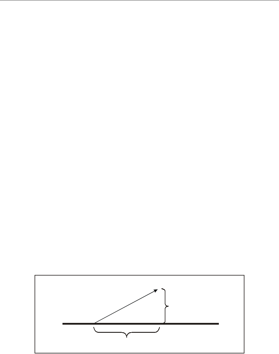
A-8 Manual on laser emitters and flight safety
3. BEAM DIRECTIONS
Provide the pointing directions of the beam projections for this configuration.
Azimuth: If the beam is moved horizontally during the operation, enter the movement range under “Azimuth”; for example,
“20 to 50 degrees”. Make sure you give the range going clockwise; otherwise your data will be interpreted as directing the
beam everywhere but where you intend. Specify if azimuth is in true or magnetic readings.
Magnetic Variation: Provide the magnetic variation for the location if this is known (this must be done if you mark the
“Magnetic” check box or if you are using a compass as part of your control measures).
For some configurations, additional information about the beam direction may be needed. For example: lasers that are very
widely separated at the Geographic Location listed on page 1, or a laser used on an aircraft or spacecraft which is moving
and/or shoots downwards. If this additional information is useful for the Authority to evaluate the proposal, then attach the
information to this form.
4. DISTANCES CALCULATED FROM ABOVE DATA
There are four distances that are important in evaluating the safety of outdoor operations. Here are brief definitions:
• Nominal Ocular Hazard Distance (NOHD): The beam is an eye hazard (is above the MPE), from the laser source
to this distance.
• Sensitive Zone Exposure Distance (SZED): The beam is bright enough to cause temporary vision impairment, from
the source to this distance. Beyond this distance, the beam is 100 µW/cm2 or less.
• Critical Zone Exposure Distance (CZED): The beam is bright enough to cause a distraction interfering with critical
task performance, from the source to this distance. Beyond this distance, the beam is 5 µW/cm2 or less.
• Laser-Free Exposure Distance (LFED): Beyond this distance, the beam is 50 nW/cm2 or less — dim enough that
it is not expected to cause a distraction.
For each of these four distances, it is important to know the distance directly along the beam (the Slant Range) as well as
the ground covered (the Horizontal Distance) and the altitude (the Vertical Distance). The diagram shows these three
distances.
Horizontal distance
Vertical
distance
Slant
range
Appendix A A-9
NOMINAL OCULAR HAZARD DISTANCE
NOHD Slant Range: Use Equation 6.1 for Single Pulse, or for Repetitively Pulsed if you calculated the Pulse Energy and
MPEPRF. Use Equation 6.2 for Continuous Wave, or for Repetitively Pulsed if you calculated the Average Power and MPE.
Equation 6.1
Where:
SRNOHD = NOHD Slant Range in feet
Q = Pulse Energy (J)
ϕ = Beam Divergence (mrad)
MPEH = MPE per pulse in J/cm2
1366 = Conversion factor used to convert centimetres into feet and radians into milliradians
Equation 6.2
Where:
SRNOHD = NOHD Slant Range in feet
ϕ = Beam Divergence (mrad)
Φ = Power (W)
MPEE = MPE in W/cm2
1366 = Conversion factor used to convert centimetres into feet and radians into milliradians
Example: A 40-watt CW laser has a beam divergence of 1.5 milliradians
Given:
ϕ = 1.5 mrad
Φ = 40 W
MPEE = 0.00254 (2.54 mW/cm2, from Table 2)
Solve Equation 6.2:
= 3092 ft
NOHD Horizontal Distance is the distance along the ground. Note that the horizontal distance uses the minimum elevation
angle. Calculate the horizontal distance using the equation:
HD = SRNOHD ×cos(Minimum Elevation Angle)
Where:
HD = Horizontal distance along the ground. The units are the same as for the Slant Range. If SR is in feet, then HD will
also be in feet.
SRNOHD = NOHD Slant Range
Minimum Elevation Angle = Data from “Minimum elevation angle” block on form.
Example: The NOHD Slant Range is 1000 feet, and the beam is elevated at 30 degrees above horizontal. The Horizontal
Distance along the ground is 1000 ×cos(30), or 866 feet.
SRNOHD
1366 Q×
ϕ2MPEH
×
----------------------------=
SRNOHD
1366 Φ×
ϕ2MPEE
×
----------------------------=
SRNOHD
1366 40×
1.520.00254×
----------------------------------- 54640
0.005715
---------------------- 9560804===

A-10 Manual on laser emitters and flight safety
NOHD Vertical Distance is the distance above the ground. Note that the vertical distance uses the maximum elevation angle.
Calculate the vertical distance using the equation:
VD = SRNOHD ×sin(Maximum Elevation Angle)
Where:
VD = Vertical distance (altitude). The units are the same as for the Slant Range. If SR is in feet, then VD will also be in
feet.
SRNOHD = NOHD Slant Range
Maximum Elevation Angle = Maximum elevation angle of laser beam as provided on form.
Example: The NOHD Slant Range is 1000 feet, and the beam is elevated at 30 degrees above horizontal. The Vertical
Distance (altitude) is 1000 ×sin(30) or 500 feet.
VISUAL EFFECT DISTANCES
Fill in this section only if one or more of the laser wavelengths are visible (in the range 400–700 nm).
• If the laser is outside the visible range, enter “N/A — non-visible laser” in all SZED, CZED, and LFED blocks.
• If the laser is visible, then perform the SZED, CZED, and LFED calculations below.
Important: For some visible pulsed lasers, the SZED, CZED, and LFED may be calculated to be less (shorter distance) than
the NOHD. If this is the case, for safety reasons do not enter the distance numbers in the applicable block. Instead, you must
enter that the distance is “Less than NOHD”. This is because in this case, the NOHD (eye-damage distance) would be the
most important for calculating safety distances and airspace to be protected.
SZED Slant Range: Use the following equation:
Equation 6.3
Where:
SRSZED = SZED Slant Range
ϕ = Beam Divergence (mrad)
ΦVCP = Visually Corrected Power (from form)
3700 = Conversion factor used to convert centimetres into feet and radians into milliradians
SZED Horizontal Distance: Use the following equation. For details, see the NOHD Horizontal Distance instructions above.
HD = SRSZED ×cos(Minimum Elevation Angle)
SZED Vertical Distance: Use the following equation. For details see the NOHD Vertical Distance instructions above.
VD = SRSZED ×sin(Maximum Elevation Angle)
SRSZED
3700
ϕ
------------ΦVCP
×=

Appendix A A-11
CZED Slant Range, Horizontal Distance and Vertical Distance: Multiply the SZED values above by 4.5. Example: If
SZED Slant Range was 5 000 feet, HD was 866 feet, and VD was 500 feet, then the CZED SR is 22 500 feet, HD is 3 897
feet and VD is 2 250 feet.
LFED Slant Range, Horizontal Distance and Vertical Distance: Multiply the SZED values above by 45.
5. CALCULATION METHOD
List the method by which the calculations were performed.
Source note for equations: The equations above are derived from ANSI Z136.1 and have been re-expressed to a simpler
form as follows: Beam divergence (ϕ) is entered in milliradians, making the first ANSI fraction 1000/ϕ instead of 1/ϕ. The
radical (square root) sign is used instead of raising to a power of 0.5. Under the radical, the expression 4/π is reduced to
1.27, while beam diameter (a2) is not used since its contribution to the overall slant range distance is negligible. ANSI results
are in cm; to convert to feet, a conversion factor of 0.0328 is used (1 cm = 0.0328 ft). There are now two numeric constants,
1 000 (from the milliradians fraction) and 0.0328, which are multiplied into a single constant, 32.8, to give results in feet.
For results in cm, use “1 000” as the constant; for results in metres, use “10”.
Note.— The assumption that a constant can be used to derive the CZED and LFED from the previously-calculated SZED
is valid only if atmospheric attenuation is ignored. Should you be relying on atmospheric attentuation for a safety factor, you
must use a more detailed analysis which independently calculates these three Visual Effect Distances.

A-12 Manual on laser emitters and flight safety
Table 1. Single Pulse Selected Maximum Permissible Exposure (MPE) Limits
To find CA:
For wavelength = 700 to 1050 nm, CA = 100.002 (wavelength – 700)
Example 1: Laser wavelength is 850 nm; CA = 100.002(850 – 700) = 100.002*150 = 100.3 = 1.995
Example 2: Laser wavelength is 933 nm; CA = 100.002(933 – 700) = 100.002*233 = 100.466 = 2.924
To find CC:
For wavelength = 1050 to 1150 nm, CC = 1.0
For wavelength = 1150 to 1200 nm, CC = 100.018 (wavelength – 1150)
For wavelength = 1200 to 1400 nm, CC = 8.0
Example 3: Laser wavelength is 1175 nm; CC = 100.018(1175 – 1150) = 100.018*25 = 100.45 = 2.8
To find t: “t” is the pulse duration in seconds.
Wavelength
(nm)
Exposure Duration
(sec)
MPE
(J/cm2)
Ultraviolet
180 to 400 10–9 to 10 Reference American National Institute
Standard (ANSI)
Z136 series
Visible
400 to 700 <10–9
10–9 to 18 ×10–6
18 ×10–6 to 10
0.25
Reference ANSI Z136 series
0.5 ×10⁻⁶
1.8 ×t0.75 × 10–3
0.64 ×10⁻³
Infrared
700 to 1 050 <10–9
10–9 to 18 ×10–6
18 ×10–6 to 10
0.25
10
Reference ANSI Z136 series
0.5 ×CA×10–6
1.8 ×CA×t0.75 ×10–3
0.64 ×CA×10–3
10 ×CA×10–3
1 050 to 1 400 <10–9
10–9 to 50 ×10–6
50 ×10–6 to 10
10
Reference ANSI Z136 series
5.0 ×CC×10–6
9×CC×t0.75 ×10–3
50 ×CC×10–3
1 400 to 1 500 <10–9
10–9 to 10–3
10–3 to 10
10
Reference ANSI Z136 series
0.1
0.56 ×t0.25
1.0
1 500 to 1 800 <10–9
10–9 to 10
10
Reference ANSI Z136 series
1.0
1.0
1 800 to 2 600 <10–9
10–9 to 10–3
10–3 to 10
10
Reference ANSI Z136 series
0.1
0.56 ×t0.25
1.0
2 600 to 10 000 <10–9
10–9 to 10–7
10–7 to 10
10
Reference ANSI Z136 series
10 ×10–3
0.56 ×t0.25
1.0
Appendix A A-13
Table 2. CW Mode Maximum Permissible Exposure (MPE) Limits
Values are for selected wavelengths for unintentional viewing.
Example 1: Laser wavelength is visible; MPE = 0.00254 W/cm2
Example 2: Laser wavelength is 850 nm; MPE = (100.002(850 – 700))(1.01 × 10⁻³) = (100.002*150)(0.00101) = (100.3) × 0.00101
= 1.995 × 0.00101 = 0.002 W/cm2
Example 3: Laser wavelength is 1175 nm; MPE = (100.018(1175 – 1150))(5 × 10⁻³) = (100.018*25)(0.005) = (100.45) × 0.005
= 2.818 × 0.005 = 0.01409 W/cm2
“Unintentional viewing”: Exposure durations used for unintentional viewing of a CW exposure are 0.25 seconds or shorter
for visible lasers, and 10 seconds or shorter for infrared lasers. (For visible light, it is assumed that within 0.25 seconds, the
person will blink or will move to avoid the light. For infrared, it is assumed that the laser will not stay in the same spot for
more than 10 seconds, due to normal body movement.)
Source: ANSI Z136.1 Table 5 for CW Exposure.
Wavelength
(nm)
MPE
(W/cm2)
Ultraviolet
180 to 400 Reference American National Standards Institute ANSI
Z136 series
Visible
400 to 700 2.54 ×10⁻³
Infrared
700 to 1 050 (100.002(wavelength – 700))(1.01 ×10⁻³)
1 050 to 1 150 5×10⁻³
1 150 to 1 200 (100.018(wavelength – 1150))(5 ×10⁻³)
1 200 to 1 400 4.0 ×10⁻²
1 400 to 10 000 0.1

A-14 Manual on laser emitters and flight safety
Table 3. Maximum Permissible Exposure — Pulse Repetition Frequency (MPEPRF) Limits for Visible Lasers
For unintentional viewing of repetitively pulsed visible (400–700 nm) laser light with pulse width between 1 ns and 18 µs.
If the laser’s pulse repetition frequency falls between two table entries, use the more conservative (smaller) value of the two
resulting MPEPRF values.
Note.— This table for MPEPRF is based on repetitively pulsed lasers with a pulse width between 1 ns and 18 µs. These
MPEPRF numbers can be used to estimate larger pulse widths, and will provide a conservative (safer) result.
Not intended for scanning analysis: This table is intended for lasers that naturally emit repetitive pulses, such as Q-switched
lasers. It is not intended for analysing “scanned” pulses, caused by moving the beam quickly over a viewer or aircraft.
(Examples: graphics or beam patterns used in laser displays, or scanned patterns used for atmospheric analysis.) Pulses
resulting from scanning are often extremely variable in pulse width and duration, and thus require a more stringent analysis.
Pulse
Repetition
Frequency
(Hz)
MPEPRF
(W/cm2)
Pulse
Repetition
Frequency
(Hz)
MPEPRF
(W/cm2)
Pulse
Repetition
Frequency
(Hz)
MPEPRF
(W/cm2)
17.07 ×10–07 30 9.06 ×10–06 5 000 4.20 ×10–04
21.19 ×10–06 40 1.12 ×10–05 10 000 7.07 ×10–04
31.61 ×10–06 50 1.33 ×10–05 15 000 9.58 ×10–04
42.00 ×10–06 75 1.80 ×10–05 20 000 1.19 ×10–03
52.36 ×10–06 100 2.24 ×10–05 25 000 1.41 ×10–03
62.71 ×10–06 150 3.03 ×10–05 30 000 1.61 ×10–03
73.04 ×10–06 200 3.76 ×10–05 40 000 2.00 ×10–03
83.36 ×10–06 250 4.45 ×10–05 50 000 2.36 ×10–03
93.67 ×10–06 500 7.48 ×10–05 55 000 2.54 ×10–03
10 3.98 ×10–06 1 000 1.26 ×10–04 100 000 2.54 ×10–03
15 5.39 ×10–06 1 500 1.70 ×10–04
20 6.69 ×10–06 2 000 2.11 ×10–04
25 7.91 ×10–06 2 500 2.50 ×10–04

Appendix A A-15
Table 4. Correction Factors (MPEpulsed / MPEcw) for Repetitively Pulsed Infrared Lasers
Use to find MPEPRF of repetitively pulsed infrared (700–1 400 nm) laser light with pulse width between 1 ns and 18 µs.
*The MPE for lasers which operate at a PRF greater (faster) than 55 000 Hz for wavelengths 700–1 050 nm (or 22 000 Hz
for wavelengths 1 050–1 400 nm) is the same as for continuous wave lasers, so the correction factor is 1.
To find the MPE for repetitively pulsed infrared lasers, multiply the CW Mode MPE by a correction factor from this table.
If the laser’s pulse repetition frequency falls between two table entries, use the more conservative (smaller) value of the two
resulting correction factors.
Example: A laser operating at a pulse repetition frequency (PRF) of 12 000 Hz emits infrared light at 850 nm. First, go to
Table 2 and find the CW Mode MPE for the 850 nm wavelength, which is 0.002 W/cm2 (see example 2 from Table 2). Next,
from the table above determine which of the right two columns should be used; in this case, the column labelled “For
wavelength 700–1 050 nm”. The laser’s PRF of 12 000 Hz falls between the 10 000 and 15 000 rows, so use the more
conservative (smaller) value of the 10 000 Hz PRF: 2.8 × 10⁻¹. The correction factor is thus 0.28. Multiply this by the CW
Mode MPE found from Table 2 to get a MPEPRF of 0.28 × 0.002 W/cm2 = 0.00056 W/cm2 = 5.6 × 10⁻⁴ W/cm2.
Pulse Repetition
Frequency
(Hz)
Correction
Factor
For wavelengths
700–1 050 nm
Correction
Factor
For wavelengths
1 050–1 400 nm
12.8×10⁻⁴ 5.5 ×10⁻⁴
59.4×10⁻⁴ 1.8 ×10⁻³
10 1.6 ×10⁻³ 3.1 ×10⁻³
15 2.1 ×10⁻³ 4.2 ×10⁻³
20 2.6 ×10⁻³ 5.2 ×10⁻³
25 3.1 ×10⁻³ 6.2 ×10⁻³
50 5.3 ×10⁻³ 1.0 ×10⁻²
75 7.1 ×10⁻³ 1.4 ×10⁻²
100 9.0 ×10⁻³ 1.7 ×10⁻²
150 1.2 ×10⁻² 2.4 ×10⁻²
200 1.5 ×10⁻² 2.9 ×10⁻²
250 1.8 ×10⁻² 3.5 ×10⁻²
500 3.0 ×10⁻² 5.9 ×10⁻²
1 000 5.0 ×10⁻² 1.0 ×10⁻¹
2 000 8.0 ×10⁻² 1.7 ×10⁻¹
3 000 1.1 ×10⁻¹ 2.3 ×10⁻¹
4 000 1.4 ×10⁻¹ 2.8 ×10⁻¹
5 000 1.7 ×10⁻¹ 3.3 ×10⁻¹
10 000 2.8 ×10⁻¹ 5.6 ×10⁻¹
15 000 3.8 ×10⁻¹ 7.5 ×10⁻¹
20 000 4.7 ×10⁻¹ 9.3 ×10⁻¹
21 000 4.8 ×10⁻¹ 9.7 ×10⁻¹
22 000 5.0 ×10⁻¹ 1.00*
23 000 5.2 ×10⁻¹ 1.00
24 000 5.4 ×10⁻¹ 1.00
25 000 5.5 ×10⁻¹ 1.00
30 000 6.3 ×10⁻¹ 1.00
40 000 7.9 ×10⁻¹ 1.00
50 000 9.3 ×10⁻¹ 1.00
55 000 1.00* 1.00

A-16 Manual on laser emitters and flight safety
Table 5. Visual Correction Factor for Visible Lasers
Use for visible lasers only (400–700 nm).
To find the Visually Corrected Power (VCP) for a specified wavelength, multiply the Visual Correction Factor (VCF) for the
wavelength (from the table above) by the Average Power. If the laser’s wavelength falls between two table entries, use the
more conservative (larger) value of the two resulting VCFs.
Example 1: A frequency-doubled YAG laser emits 10 watts of 532 nm continuous wave light. From the table, 532 is between
530 and 540; use the more conservative (larger) Visual Correction Factor of 540 nm: 9.524 × 10⁻¹. Multiply the VCF of
0.9524 by the Average Power of 10 watts to obtain the Visually Corrected Power of 9.524 watts.
Example 2: An 18-watt argon laser emits 10 watts of 514 nm light, and 8 watts of 488 nm light, both continuous wave.
Calculate each wavelength separately, then add the resulting Visually Corrected Powers together.
10 watts at 514 nm: From the table, 514 is between 510 and 520; use the more conservative (larger) VCF of 520 nm:
7.092 × 10⁻¹. Multiply the VCF of 0.7092 by the Average Power of 10 watts to obtain the Visually Corrected Power of
7.092 watts.
Laser
Wavelength
(nm)
Visual Correction
Factor
(VCF)
400
410
420
430
440
450
460
470
480
490
500
510
520
530
540
550
555
560
570
580
590
600
610
620
630
640
650
660
670
680
690
700
4.0 ×10⁻⁴
1.2 ×10⁻³
4.0 ×10⁻³
1.16 ×10⁻²
2.30 ×10⁻²
3.80 ×10⁻²
5.99 ×10⁻²
9.09 ×10⁻²
1.391 ×10⁻¹
2.079 ×10⁻¹
3.226 ×10⁻¹
5.025 ×10⁻¹
7.092 ×10⁻¹
8.621 ×10⁻¹
9.524 ×10⁻¹
9.901 ×10⁻¹
1.0 ×100–
9.901 ×10⁻¹
9.524 ×10⁻¹
8.696 ×10⁻¹
7.576 ×10⁻¹
6.329 ×10⁻¹
5.025 ×10⁻¹
3.817 ×10⁻¹
2.653 ×10⁻¹
1.751 ×10⁻¹
1.070 ×10⁻¹
6.10 ×10⁻²
3.21 ×10⁻²
1.70 ×10⁻²
8.2 ×10⁻³
4.1 ×10⁻³
(VCF = 1)

Appendix A A-17
8 watts at 488 nm: From the table, 488 is between 480 and 490; use the more conservative (larger) VCF of 490 nm:
2.079 × 10⁻¹. Multiply the VCF of 0.2079 by the Average Power of 8 watts to obtain the Visually Corrected Power of
1.6632 watts.
Finally, add the two VCPs together: 7.092 + 1.6632 = 8.7552. The 18-watt laser in this example has a Visually Corrected
Power of only 8.7552 watts. Note that the 10-watt YAG in Example 1 appears brighter to the eye (9.5 WVCP) than an 18-watt
argon (8.8 WVCP).
Source: The Visual Correction Factor used in this table (CF) is the CIE normalized efficiency photopic visual function curve
for a standard observer. The luminance (lm •cm–2) is the measured irradiance multiplied by CF and 683. The effective irradiance
is the actual (measured) irradiance multiplied by CF. The effective irradiance (W •cm–2) multiplied by 683 lm •W–1 is the
illuminance (lm •cm–2). The term “Visually Corrected Power” divided by the area of the laser beam is the “effective irradiance”,
as used in this document.


B-1
Appendix B
SUSPECTED LASER BEAM INCIDENT REPORT AND
SUSPECTED LASER BEAM EXPOSURE QUESTIONNAIRE
SUSPECTED LASER BEAM INCIDENT REPORT
This form may be used by local ATC or airline authorities to report a suspected laser beam exposure. When completed, the
report should be forwarded to the competent authority as soon as possible for further investigation.
Name _____________________________________________________________ Age _______________________________
Position (pilot, co-pilot, controller, etc.) _________________________________ Phone _____________________________
Type of vision correction worn at time of incident (spectacles/contact lenses) _____________________________________
Type of aircraft _______________________________________________________________________________________
Aircraft ID or call _____________________________________________________________________________________
Date and time of incident (UTC) _________________________________________________________________________
Date and time report is being completed (UTC) _____________________________________________________________
Environmental factors:
Weather conditions __________________________________________________________________________________
VMC/IMC _________________________________________________________________________________________
Ambient light level (day, night, sunlight, dawn, dusk, starlight, moonlight, etc.) ________________________________
__________________________________________________________________________________________________
Location of incident:
Near (aerodrome/city/NAVAID) ________________________________________________________________________
Radial and distance _________________________________________________________________________________
Phase of flight _____________________________________________________________________________________
Type/name of approach or departure procedure ___________________________________________________________
Heading/approximate heading if in turn _________________________________________________________________
Altitude (AGL) ____________________________ (MSL) __________________________________________________
Aircraft bank and pitch angles _________________________________________________________________________
Angle of incidence:
Did the light hit your eye(s) directly or from the side? _____________________________________________________
__________________________________________________________________________________________________

B-2 Manual on laser emitters and flight safety
Light description:
Colour ____________________________________________________________________________________________
Nature of beam (constant/flicker/pulsed) ________________________________________________________________
Light source (stationary or moving) ____________________________________________________________________
Do you feel you were intentionally tracked? _____________________________________________________________
Relative intensity (flashbulb, headlight, sunlight) __________________________________________________________
Duration of exposure (seconds) ________________________________________________________________________
Was the beam visible prior to the incident? ______________________________________________________________
Position of light source (relative to geographical feature or aircraft) __________________________________________
__________________________________________________________________________________________________
Circle the window where the light entered the cockpit:
Left left-front centre right-front right other __________________
Elevation of the beam from horizontal (degrees) __________________________________________________________
Effect on individual:
Describe visual*/psychological/physical effects ___________________________________________________________
__________________________________________________________________________________________________
__________________________________________________________________________________________________
Duration of visual effects (seconds/minutes/hours/days) ____________________________________________________
Do you intend to seek medical attention? ________________________________________________________________
__________________________________________________________________________________________________
Note.— This is recommended if even minor symptoms were experienced.
Effect on operational or cockpit procedures: ________________________________________________________________
_____________________________________________________________________________________________________
_____________________________________________________________________________________________________
* Examples of common visual effects:
After-image. An image that remains in the visual field after an exposure to a bright light.
Blind spot. A temporary or permanent loss of vision of part of the visual field.
Flash-blindness. The inability to see (either temporarily or permanently) caused by bright light entering the eye and
persisting after the illumination has ceased.
Glare. A temporary disruption in vision caused by the presence of a bright light (such as an oncoming car’s headlights)
within an individual’s field of vision. Glare lasts only as long as the bright light is actually present within the individual’s
field of vision.
— — — — — — — —

Appendix B B-3
SUSPECTED LASER BEAM EXPOSURE QUESTIONNAIRE
This questionnaire may be filled out by the competent authority during interviews with persons exposed to laser beams. This
information will be used to aid in any subsequent investigation and provide important medical and statistical data for the
review of regulatory and enforcement issues associated with new laser beam applications and threats to aviation safety. The
completed form should be forwarded to the appropriate aviation authority as soon as possible.
1. Did anyone else see the light beam? ___________________________________________________________________
2. What was the colour(s) of the light? __________________________________________________________________
Did the colour(s) change during the exposure? ___________________________________________________________
3. Did the light come on suddenly, and did it become brighter as you approached it?______________________________
_________________________________________________________________________________________________
4. Was the light continuous or did it seem to flicker? _______________________________________________________
If it flickered, how rapidly and regularly? _______________________________________________________________
5. Did the light fill your cockpit or compartment? __________________________________________________________
6. How would you describe the brightness of the light? _____________________________________________________
Was it equally bright in all areas or was it brighter in one area?_____________________________________________
7. Did you attempt an evasive manoeuvre? _______________________________________________________________
If so, did the beam follow you as you tried to move away? ________________________________________________
How successful were you in avoiding it? _______________________________________________________________
8. Do you know the source of the light emission? __________________________________________________________
9. Can you estimate how far away the light source was from your location? _____________________________________
Was the source moving? _____________________________________________________________________________
10. What was between the light source and your eyes — windscreen, glasses, contact lenses, etc.? ___________________
Did any of these sustain damage by the light? ___________________________________________________________
11. Was the light coming directly from its source or did it appear to be reflected off other surfaces? __________________
Were there multiple sources of light? __________________________________________________________________
12. Did you look straight into the light beam or off to the side? ________________________________________________
13. How long was the exposure? _________________________________________________________________________
Did the light seem to track your path or was there incidental contact? ________________________________________
14. At what time of the day did the incident occur? _________________________________________________________
15. What was the visibility? ____________________________________________________________________________
What were the atmospheric conditions — clear, overcast, rainy, foggy, hazy, sunny? ____________________________

B-4 Manual on laser emitters and flight safety
16. What tasks were you performing when the exposure occurred? _____________________________________________
Did the light prevent or hamper you from doing those tasks, or was the light more of an annoyance? ______________
17. What were the visual effects you experienced (after-image, blind spot, flash-blindness, glare*)? __________________
18. How long did any symptoms you experienced from the exposure last? _______________________________________
Are any symptoms (tearing, light sensitivity, headaches, etc.) still present? ____________________________________
19. Did you touch or rub your eyes at the time of the incident? _______________________________________________
20. Did you have your eyes examined after the incident? _____________________________________________________
If so, when and by whom? __________________________________________________________________________
What were the results of this visit? ____________________________________________________________________
21. Did you report the incident? _________________________________________________________________________
If so, to whom (ATC, medical personnel, safety officer, etc.) and when? ______________________________________
* Examples of common visual effects:
After-image. An image that remains in the visual field after an exposure to a bright light.
Blind spot. A temporary or permanent loss of vision of part of the visual field.
Flash-blindness. The inability to see (either temporarily or permanently) caused by bright light entering the eye and
persisting after the illumination has ceased.
Glare. A temporary disruption in vision caused by the presence of a bright light (such as an oncoming car’s headlights)
within an individual’s field of vision. Glare lasts only as long as the bright light is actually present within the individual’s
field of vision.
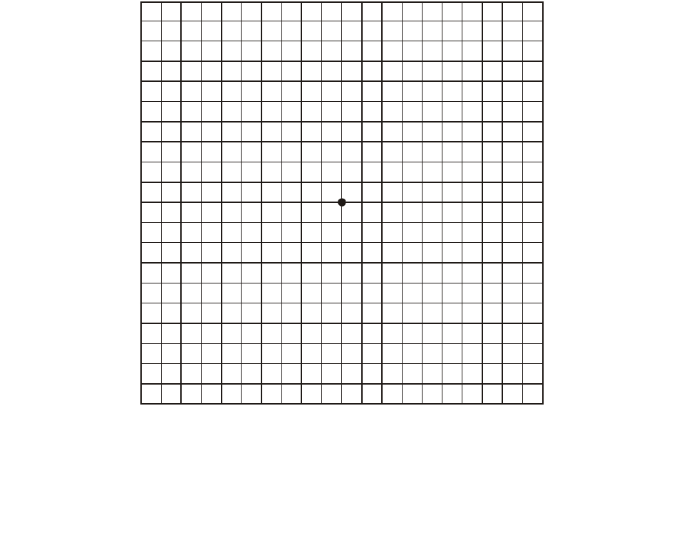
C-1
Appendix C
AMSLER GRID TESTING PROCEDURE
The Amsler grid test is designed to detect defects in the central visual field of an eye, corresponding to retinal lesions as
small as 50 micrometres.
The chart below is sized to be viewed at a distance of 28–30 cm, the usual distance for reading tests. At this distance the
test will examine the central 20 degrees of the patient’s field of vision for abnormalities, with each small square equivalent
to 1 degree. Before using this chart:
a) the refraction of the eye in question must be exactly corrected for this distance;
b) the chart must be clearly and evenly illuminated as for a reading test;
c) all artificial mydriasis and any ophthalmoscopy immediately before the examination must be avoided; and
d) the other eye should be covered, preferably with an occluder.

C-2 Manual on laser emitters and flight safety
While continually urging the patient to look steadily upon the central point, ask the following questions. Record the responses
and ask the patient to carefully draw any abnormal results on the grid chart.
1. Do you see the spot in the centre of the square chart?
2. Keeping your gaze fixed upon the spot in the centre, can you see the four corners of the big square? Can you also
see the four sides of the square? In other words, can you see the whole square?
3. Keeping your gaze fixed upon the spot in the centre, do you see the network intact within the whole square? Are there
any interruptions in the network of squares, such as holes or spots? Is it blurred in any place? If so, where?
4. Keeping your gaze fixed upon the spot in the centre, are both the horizontal and vertical lines straight and parallel?
In other words, is every small square equal in size and perfectly regular?
5. Keeping your gaze fixed upon the spot in the centre, do you see any movement of certain lines? Is there any vibration
or wavering, shining or colour tint? If so, where?
6. Keeping your gaze fixed upon the spot in the centre, at what distance from this point do you see the blur or distortion?
How many small intact squares do you find between the blur or distortion and the centre point where your gaze is
fixed?
— END —


© ICAO 2003
09/03, E/P1/2000
Order No. 9815
Printed in ICAO
