U909.indb IDEC Timer RTE Series
User Manual: IDEC-timer-RTE-Series
Open the PDF directly: View PDF ![]() .
.
Page Count: 15
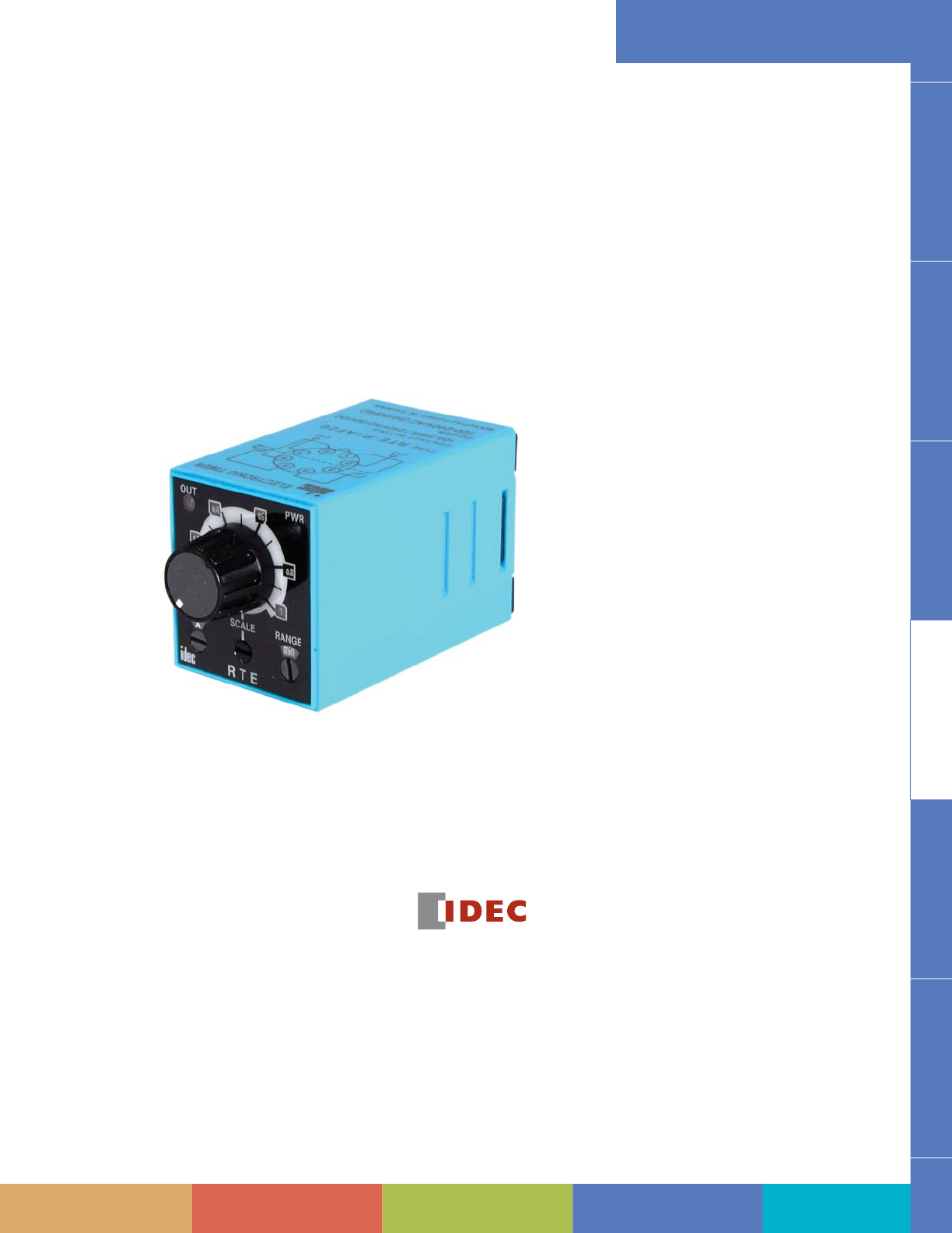
Table of Contents Automation & Sensing - Pg. 1 Safety - Pg. 315 Switching & Controls - Pg. 439 Index - Pg. 911
For more information on this product family, visit our website.
Additional resources include:
• New and updated product information
• Downloadable software demos & upgrades
• Part confi guration tool & cross reference
• Online stock check & ordering
• IDEC fi eld sales & distributor search
• Online literature request
• Downloadable manuals & CAD drawings
• Manufacturer’s suggested retail price list
• Product training schedule & locations
• Advertising & trade show schedules
• Press releases & FAQs
Switches & Pilot Lights Display Lights Relays & Sockets Timers Terminal Blocks Circuit Breakers
Switching & Controls
www.idec.com/timer
Selection Guide ........................................... 792
RTE Series — Analog Timers .....................798
Accessories .................................................... 803
Dimensions ....................................................804
GT3A Series — Analog Timers ..................805
GT3D — Digital Timers .............................813
GT3F Series — True OFF Delay Timers .......826
GT3S (Star-Delta) Timers ............................831
GT3W Series — Dual Time Range Timers .834
GT3 Series ................................................... 838
Accessories ...................................................838
Dimensions ....................................................842
GE1A Series — ON Delay Timers ..............844
Accessories .................................................... 846
Dimensions ....................................................847
GT5P Series — ON Delay Timers ...............848
Accessories .................................................... 851
Dimensions ....................................................852
GT5Y Series — ON Delay Timers ............... 853
Accessories .................................................... 856
Dimensions ....................................................857
General Instructions for All Timer Series ..858
Timers
http://waterheatertimer.org/How-to-wire-off-delay-timer.html
Selection Guide Timers
792 www.idec.com
Switches & Pilot LightsDisplay LightsRelays & SocketsTimersTerminal Blocks
Circuit Breakers
Selection Guide
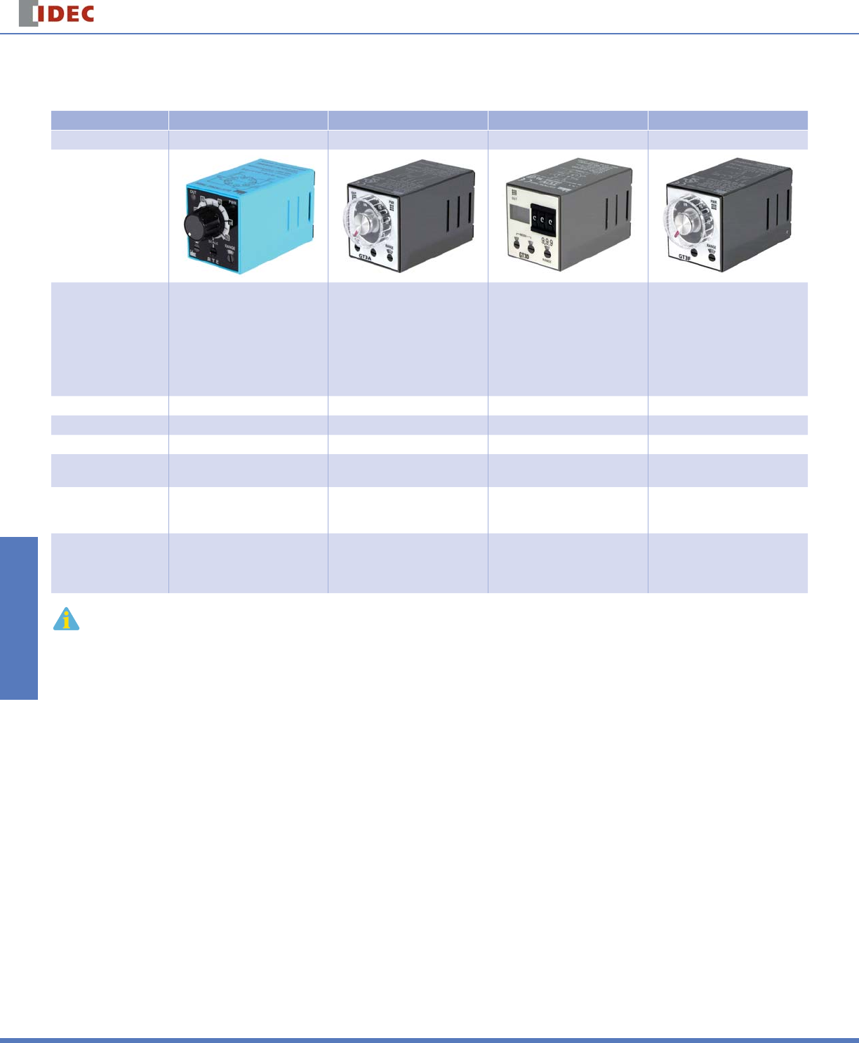
Selection Guide: RTE, GT3A, GT3D, and GT3F Series
Series Model RTE GT3A GT3D GT3F
Page 798 805 813 826
Appearance
Mode of Operation
ON-delay
Interval
OFF-delay
One-shot
Cycle (ON fi rst)
Cycle (OFF fi rst)
Signal OFF delay
Signal ON/OFF delay
ON-delay
Interval
OFF-delay
One-shot
Cycle (off fi rst)
Cycle (on fi rst)
Signal OFF delay
Signal ON/OFF delay
ON-delay
Interval
One-shot
One-shot ON delay
Cycle
Signal OFF delay
Signal ON/OFF delay
True OFF-delay
Time Range 0.1 second to 600 hrs 0.1 second to 180 hrs 0.01 second to 99.9 hrs 0.1 to 600 seconds
Contact Confi guration DPDT SPDT, DPDT SPDT, DPDT SPDT, DPDT
Repeat Accuracy ±0.25% maximum ±0.2% maximum ±0.3% maximum ±0.4% maximum
Contact Load Rating
(resistive) 10A, 240V AC SPDT: 3A, 250V AC
DPDT: 5A, 240V AC
SPDT: 3A, 250V AC
DPDT: 5A, 240V AC 5A, 250V AC
Available Operating
Voltage
100-240V AC
12V DC
24V AC/DC
100 to 240V AC
12V DC
24V AC/DC
100 to 240V AC
24V AC/DC
100 to 240V AC
24V AC/DC
Approvals
UL Listed
c-uL Listed
TUV
CE
UL Listed
c-uL Listed
CE
UL recognized
TUV
CSA
CE
UL Listed
c-uL Listed
CE
1. For Timing Diagrams Overview, see page 794.
2. For all series specifi c instructions, accessories, and dimensions, see the individual series section.
Selection Guide
Timers
793
USA: 800-262-IDEC Canada: 888-317-IDEC
Switches & Pilot Lights Display Lights Relays & Sockets Timers Terminal Blocks Circuit Breakers
Selection Guide
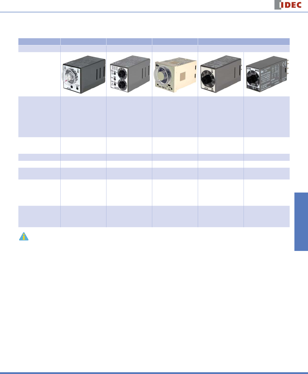
Selection Guide: RTE, GT3A, GT3D, and GT3F Series
Series Model GT3S GT3W GE1A GT5P GT5Y
Page 831 834 844 848 853
Appearance
Mode of Operation Star-Delta
Sequential start
ON-delay
Recycler and instantaneous
Recycler OFF start
Recycler ON start
Interval
Interval ON delay
Sequential interval
ON-delay ON-delay ON-delay
Time Range
Star side: 0.05s to 100s
Star-delta Switching Time:
0.05, 0.1, 0.25, 0.5 seconds
0.1s to 300 hrs 0.1s to 10 hrs 0.1s to 10 minutes 0.1s to 1 hour
Contact Confi guration SPST-NO DPDT SPDT, DPDT SPDT DPDT, 4PDT
Repeat Accuracy ±0.2% maximum ±0.2% maximum ±0.2% maximum ±0.2% maximum ±0.2% maximum
Contact Load Rating
(resistive) 5A, 250V AC/30VDC 3A, 250V AC
5A, 120V AC/30V DC 5A, 240V AC 5A, 250V AC 5A, DPDT: 250V AC
3A, 4PDT: 250V AC
Available Operating
Voltage 100 to 240V AC
100 to 240V AC
12V DC
24V AC/DC
24V AC/DC
110 to 120V AC
220 to 240V AC
100 to 120V AC
200 to 240V AC
12V DC
24V DC
100 to 120V AC
200 to 240V AC
12V DC
24V DC
24V AC
Approvals
UL Listed
c-uL Listed
CE
UL Listed
c-uL Listed
CE
UL Listed
c-uL Listed
TUV
CE
UL recognized
TUV
CSA
CE
UL Listed
c-uL Listed
CE
1. For Timing Diagrams Overview, see page 794..
2. For all series specifi c instructions, accessories, and dimensions, see the individual series section.
Timing Diagrams Overview Timers
794 www.idec.com
Switches & Pilot LightsDisplay LightsRelays & SocketsTimersTerminal Blocks
Circuit Breakers
Timing Diagrams Overview
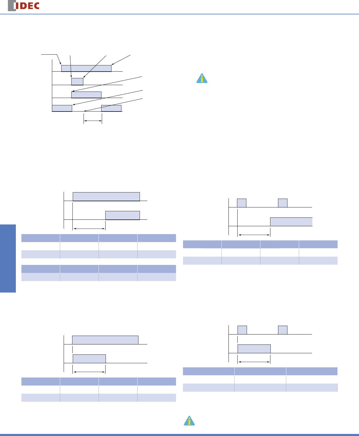
Guide to Reading Timing Function Diagrams
Timer Power
Input Signal
NO Contact
NC Contact
Set Time
Power
Applied
Power
Removed
NO Contact Closes
NC Contact Opens
Timer Begins Counting
Start Input
Terminals Shorted
Start Input
Terminals Opened
1. If power is disconnected during actual timing, most electronic timers reset to the
preset time, ready for the re-application of supply voltage
(except for GT3F “true OFF Delay”).
2. NO = Normally open.
3. NC = Normally closed.
Timing Function Diagrams Overview
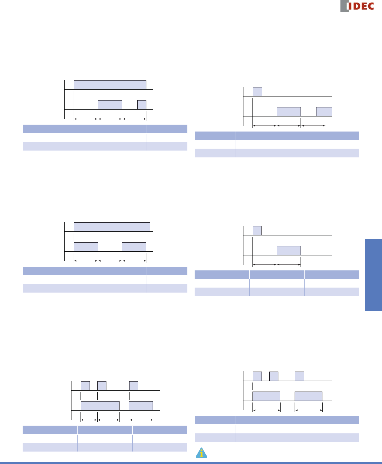
ON-Delay 1 (power start)
When voltage is applied to the coil, the relay contacts remain in the off state
and the set time begins. When the set time has elapsed, the relay contacts
transfer to the on state. The contacts remain in the on state until the timer is
reset. The timer is reset by removing the coil voltage. Applicable models: RTE-
P(B)1, GT3A-1, -2, -3, GT3D-1, -2, -3, -4, and GE1A.
T
Power
Output
Type No. GT3A-1, -2, -3 GT3D-1, -2, -3, -4 RTE-*1
Mode A 1-A A
See Page 805 813 798
Type No. GE1A GT5P GT5Y
See Page 844 813 853
Interval 1 (power start)
When voltage is applied to the coil, the relay contacts transfer immediately to
the on state and the set time begins. When the set time has elapsed, the relay
contacts transfer to the off state. The contacts remain in the off state until the
timer is reset. The timer is reset by removing the coil voltage. Applicable models:
RTE-P(B)1, GT3A-1, -2, -3, and GT3D-1, -2, -3, -4.
T
Power
Output
Type No. GT3A-1, -2, -3 GT3D-1, -2, -3, -4 RTE-*1
Mode B 1-B B
See Page 805 813 798
ON-Delay 2 (signal start)
Voltage is applied to the coil at all times. When a start input is supplied, the
relay contacts remain in the off state and the set time begins. When the set
time has elapsed, the relay contacts transfer to the on state. The contacts
remain in the on state until the timer is reset. The timer is reset by applying a
reset input or by removing the coil voltage. Applicable models: GT3A-4, GT3D-4
and RTE-P(B) 2.
T
Start Input
Output
Type No. GT3A-4 GT3D-4 RTE-*2
Mode A 2-A A
See Page 805 813 798
Interval 2 (signal start)
Voltage is applied to the coil at all times. When a start signal is supplied, the
relay contacts transfer immediately to the on state and the set time begins.
When the set time has elapsed, the relay contacts transfer to the off state. The
contacts remain in the off state until the timer is reset. The timer is reset by ap-
plying a reset input or by removing the coil voltage. Applicable models: GT3A-5
and GT3D-4.
T
Start Input
Output
Type No. GT3A-5 GT3D-4
Mode A 2-E
See Page 805 813
1. T = set time, T’ = shorter than set time, Ts = one shot output time
2. For more detailed timing diagrams, see specifi cations for individual timer models.
Timing Diagrams Overview
Timers
795
USA: 800-262-IDEC Canada: 888-317-IDEC
Switches & Pilot Lights Display Lights Relays & Sockets Timers Terminal Blocks Circuit Breakers
Cycle 1 (power start, OFF fi rst)
When voltage is applied to the coil, the contacts remain in the off state and the
set time begins. At the end of the set time, the contacts transfer to the on state
and remain in the on state until the set time elapses. The timer cycles between
the two states until power is removed from the coil. Removing the coil voltage
resets the timer. The set time for both the on state and the off state is the
same. Applicable models: GT3A-1, -2, -3, GT3D-1, -2, -3, -4 and RTE-P(B)1.
TTT
Power
Output
Type No. GT3A-1, -2, -3 GT3D-1, -2, -3, -4 RTE-*1
Mode C 1-C C
See Page 805 813 798
Cycle 3 (power start, ON fi rst)
When voltage is applied to the coil, the contacts immediately transfer to the on
state and the set time begins. At the end of the set time, the contacts transfer
to the off state and remain in the off state until the set time elapses. The timer
cycles between the two states until power is removed from the coil. Removing
the coil voltage resets the timer. The set time for both the off state and the
on state is the same. Applicable models: GT3A-1, -2, -3, GT3D-1, -2, -3, -4 and
RTE-P(B)1.
TTT
Power
Output
Type No. GT3A-1, -2, -3 GT3D-1, -2, -3, -4 RTE-*1
Mode D 1-D D
See Page 805 813 798
One Shot 1 (signal start, retriggerable)
Voltage is applied to the coil at all times. When a start signal is supplied, the
contacts immediately transfer to the on state and the set time begins. If another
start signal is supplied (before set time has elapsed) the set time restarts,
as the contacts remain in the on state. Successive pulses at a frequency
greater than the set time will cause the contacts to remain in the “On state”
indefi nitely. When the set time has elapsed the contacts transfer back to the off
state. The contacts remain in the off state until the next start signal is supplied
(no reset is necessary). The timer can be reset by application of a reset input or
by removing coil voltage. Applicable models: GT3A-6 and GT3D-4.
TTT
Start Input
Output
Type No. GT3A-6 GT3D-4
Mode A 3-C
See Page 805 813
Cycle 2 (signal start, OFF fi rst)
Voltage is applied to the coil at all times. When a start signal is supplied, the
relay contacts remain in the off state and the set time begins. At the end of the
set time, the contacts transfer to the on state and remain in the on state until
the set time elapses. The timer cycles between the two states until the timer
is reset. The set time for both the on state and the off state are the same. The
timer is reset by application of a reset input or by removing coil voltage. Ap-
plicable models: GT3A-4, GT3D-4 and RTE-P(B) 2.
TTT
Start Input
Output
Type No. GT3A-4 GT3D-4 RTE-*2
Mode B 2-B B
See Page 805 813 798
One Shot Cycle (signal start)
Voltage is applied to the coil at all times. When a start signal is supplied, the con-
tacts remain in the off state and the set time begins. At the end of the set time,
the contacts transfer to the on state and remain in the on state for the set time.
After the set time has elapsed, the contacts return to the off state. The contacts
remain in the off state until the timer is reset. The timer is reset by application of
a reset input or by removing coil voltage. Applicable models: GT3A-5 and GT3D-4.
TT
Start Input
Output
Type No. GT3A-5 GT3D-4
Mode B 2-F
See Page 805 813
One Shot 2 (signal start)
Voltage is applied to the coil at all times. When a start signal is supplied, the
contacts immediately transfer to the on state and the set time begins. If another
start signal is supplied (before set time has elapsed), the set time will not be
affected. When the set time has elapsed, the contacts transfer back to the off
state. The contacts remain in the off state until the next start signal is supplied
(no reset is necessary). The timer can be reset by application of a reset input or
by removing coil voltage. Applicable models: GT3A-6, GT3D-4, and RTE-P(B)2.
TT
Start Input
Output
Type No. GT3A-6 GT3D-4 RTE-*2
Mode C 3-E F
See Page 805 813 798
1. T = set time, T’ = shorter than set time, Ts = one shot output time
2. For more detailed timing diagrams, see specifi cations for individual timer models.
Timing Diagrams Overview Timers
796 www.idec.com
Switches & Pilot LightsDisplay LightsRelays & SocketsTimersTerminal Blocks
Circuit Breakers
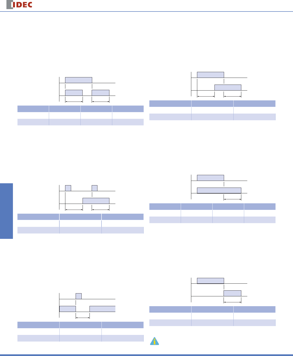
Signal ON/OFF-Delay 1
Voltage is supplied to the coil at all times. When a maintained start signal is
supplied, the contacts immediately transfer to the on state and the set time be-
gins. When the set time has elapsed, the contacts transfer to the off state. The
contacts remain in the off state until the start signal is removed. The contacts
transfer back to the on state and remain in the on state for the set time. When
the set time has elapsed, the contacts transfer to the off state and remain in the
off state until the start signal is supplied again (no reset is necessary). The timer
is reset by application of a reset input or by removing coil voltage. Applicable
models: GT3A-4, GT3D-4 and RTE-R(B)2.
TT
Start Input
Output
Type No. GT3A-4 GT3D-4 RTE-*2
Mode C 2-C D
See Page 805 813 798
Signal ON/OFF-Delay 3
Voltage is supplied to the coil at all times. When a momentary start signal is
supplied, the contacts remain in the off state and the set time begins. When the
set time has elapsed, the contacts transfer to the on state. The contacts remain
in the on state until another momentary input is supplied. The contacts then
remain in the on state for the set time. When the set time has elapsed, the con-
tacts transfer to the off state and remain in the off state until the start signal is
supplied again (no reset is necessary). The timer is reset by application of a reset
input or by removing coil voltage. Applicable models: GT3A-6 and GT3D-4.
TT
Start Input
Output
Type No. GT3A-6 GT3D-4
Mode D 3-F
See Page 805 813
One Shot ON-Delay (signal start)
When voltage is applied to the coil, the preset time is initiated and the contacts
remain in the off state for the preset time. Following the preset time, the
contacts transfer to the on state, and remain in the on state until the start input
is supplied. Following the start input, the contacts transfer to the off state for
the preset time. After the preset time has elapsed, the contacts transfer back to
the on state and remain there until either the next start input is supplied or the
timer is reset. The timer can be reset by either a reset input or removal of the
coil voltage. Applicable models: GT3A-6 and GT3D-4.
T
Start Input
Output
Type No. GT3A-6 GT3D-4
Mode B 3-D
See Page 805 813
Signal ON/OFF-Delay 2
Voltage is supplied to the coil at all times. When a maintained start signal is
supplied, the contacts remain in the off state and the set time begins. When
the set time has elapsed, the contacts transfer to the on state. The contacts
remain in the on state until the start signal is removed. Once the start signal
is removed, the contacts remain in the on state and the set time begins again.
Once the set time has elapsed, the contacts transfer back to the off state. The
timer is ready for the next start signal. The timer is reset by the application of a
reset signal or removal of power. Applicable models: GT3A-5 and GT3D-4.
TT
Start Input
Output
Type No. GT3A-5 GT3D-4
Mode C 3-A
See Page 805 813
Signal OFF-Delay 1
Voltage is applied to the coil at all times. When a start signal is supplied, the
contacts immediately transfer to the on state. The set time begins when the
start signal is removed. When the set time has elapsed, the contacts transfer
to the off state. The contacts remain in the off state until the next start signal is
supplied (no reset is necessary). The timer can be reset by application of a reset
input or by removing coil voltage. Applicable models: RTE-P(B)2, GT3A-4, and
GT3D-4.
T
Start Input
Output
Type No. GT3A-4 GT3D-4 RTE-*2
Mode D 2-D E
See Page 805 813 798
Signal OFF-Delay 2
Voltage is applied to the coil at all times. When a maintained start signal is sup-
plied, the contacts remain in the off state. When the “start signal is removed”,
the contacts transfer to the “On state” and the set time begins. When the set
time has elapsed, the contacts transfer back to the off state. They remain in
the off state until the next start signal is supplied (no reset is necessary. The
timer can be reset by application of a reset input or by removing coil voltage.
Applicable models: GT3A-5 and GT3D-4.
T
Start Input
Output
Type No. GT3A-5 GT3D-4
Mode D 3-B
See Page 805 813
1. T = set time, T’ = shorter than set time, Ts = one shot output time
2. For more detailed timing diagrams, see specifi cations for individual timer models.
Timing Diagrams Overview
Timers
797
USA: 800-262-IDEC Canada: 888-317-IDEC
Switches & Pilot Lights Display Lights Relays & Sockets Timers Terminal Blocks Circuit Breakers
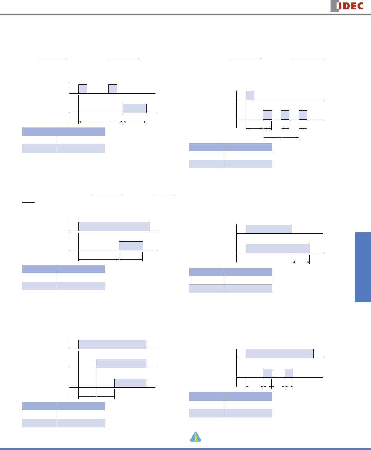
ON-Delay One-Shot Output 1 (signal start)
Voltage is applied to the coil at all times. When a momentary start signal is sup-
plied, the contacts remain in the off state and the preset time begins. Following
the preset time, the contacts transfer to the on state and remain in the on state
for the one-shot preset time. Following the one-shot preset time, the contacts
transfer back to the off state and remain there until the timer is reset. The timer
can be reset by applying either a reset input or removal of the coil voltage. Ap-
plicable model: GT3D-8.
TsT
Start Input
Output
Type No. GT3D-8
Mode 1
See Page 813
ON-Delay One-Shot Output 2 (signal start)
Voltage is applied to the coil at all times. When a maintained start signal is sup-
plied, the contacts remain in the off state and the preset time begins. Following
the preset time (start input is still present), the contacts transfer to the on state
and remain in the on state for the one-shot preset time. When the one-shot
preset time has elapsed, contacts transfer back to the off state and remain
there until timer is reset. The timer can be reset by a reset input, removal of the
coil voltage or removal of start input. Applicable model: GT3D-8.
TsT
Start Input
Output
Type No. GT3D-8
Mode 3
See Page 813
Sequential Start (power start)
When voltage is applied to the coil, both contacts remain in the OFF state
and the set time, T1, begins. When T1 has elapsed, output 1 comes on and T2
begins. When T2 has elapsed, output 2 comes on. Both outputs remain on until
power is removed from the coil. Applicable model: GT3W-A.
T1 T2
Start Input
Output
Type No. GT3W-A
Mode A
See Page 834
Cycle One-Shot Output (signal start)
Voltage is applied to the coil at all times. When a momentary start signal is sup-
plied, the contacts remain in the off state and the preset time begins. Following
the preset time, the contacts transfer to the on state. The contacts remain in
the on state for the one-shot preset time. After the one-shot preset time has
elapsed, the contacts transfer back to the off state. The contacts remain in the
off state for the preset time minus the one-shot preset time. The timer cycles
between on and off states until the timer is reset by a reset input or removal of
the coil voltage. Applicable model: GT3D-8.
T
TTs Ts
T
Ts
Start Input
Output
Type No. GT3D-8
Mode 2
See Page 813
True Power-OFF Delay
When voltage is applied, output comes on immediately; when voltage is
removed from the coil, the timer begins timing (internal capacitors power the
timing circuit). When time has expired, contacts transfer back to the OFF state. If
power is reapplied before the elapsed time has expired, the timing function will
reset back to the starting point. Applicable models: GT3F-1, 2.
T
Start Input
Output
Type No. GT3F-1, 2
Mode Power OFF-Delay
See Page 826
Recycler Outputs (power start)
When voltage is applied to the coil, both contacts remain in the off state and
time T1 begins. When T1 has elapsed, both contacts transfer to the ON state
and T2 begins. When T2 has elapsed, both contacts transfer back to the OFF
state and T1 begins again. The cycle continues until power is removed, at which
time both contacts transfer back to the OFF state. Applicable model: GT3W-A.
T1 T2 T1 T2
Start Input
Output
Type No. GT3W-A
Mode D
See Page 834
1. T = set time, T’ = shorter than set time, Ts = one shot output time
2. For more detailed timing diagrams, see specifi cations for individual timer models.
RTE Series Timers
798 www.idec.com
Switches & Pilot LightsDisplay LightsRelays & SocketsTimersTerminal Blocks
Circuit Breakers
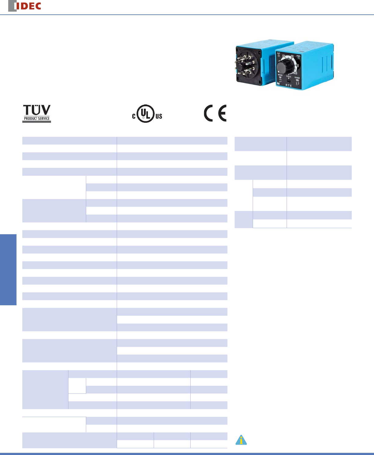
RTE Series — Analog Timers
Key features of the RTE series include:
20 time ranges and 10 timing functions
Time delays up to 600 hours
Space-saving package
High repeat accuracy of ± 0.2%
ON and timing OUT LED indicators
Standard 8- or 11-pin and 11-blade termination
2 form C delayed output contacts
10A Contact Rating
•
•
•
•
•
•
•
•
Cert. No. E9950913332316 (EMC, RTE)
Cert. No. BL960813332355 (LVD, RTE)
UL Listed
File No. E66043
General Specifi cations Contact Ratings
Operation System Solid state CMOS Circuit Contact Confi guration 2 Form C, DPDT
(Delay output)
Allowable Voltage /
Allowable Current 240V AC, 30V DC / 10A
Maximum Permissible
Operating Frequency 1800 cycles per hour
Rated
Load
Resistive 10A 240V AC, 30V DC
Inductive 7A 240V AC, 30V DC
Horse Power
Rating 1/6 HP 120V AC, 1/3 HP 240V AC
Life Electrical 500,000 op. minimum (Resistive)
Mechanical 50,000,000 op. minimum
Operation Type Multi-Mode
Time Range 0.1sec to 600 hours
Pollution Degree 2 (IE60664-1)
Over voltage category III (IE60664-1)
Rated Operational Voltage
AF20 100-240V AC(50/60Hz)
AD24 24V AC(50/60Hz)/24V DC
D12 12V DC
Voltage Tolerance
AF20 85-264V AC(50/60Hz)
AD24 20.4-26.4V AC(50/60Hz)/21.6-26.4V DC
D12 10.8-13.2V DC
Input off Voltage Rated Voltage x10% minimum
Ambient Operating Temperature -20 to +65ºC (without freezing)
Ambient Storage and Transport Temperature -30 to +75ºC (without freezing)
Relative Humidity 35 to 85%RH (without condensation)
Atmospheric Pressure 80kPa to 110kPa (Operating), 70kPa to 110kPa (Transport)
Reset Time 100msec maximum
Repeat Error ±0.2%, ±20msec*
Voltage Error ±0.2%, ±20msec*
Temperature Error ±0.5%, ±20msec*
Setting Error ±10% maximum
Insulation Resistance 100MΩ minimum (500V DC)
Dielectric Strength
Between power and output terminals: 2000V AC, 1 minute
Between contacts of different poles: 2000V AC, 1 minute
Between contacts of the same pole:1000V AC, 1 minute
Vibration Resistance 10 to 55Hz amplitude 0.5mm2 hours in each of 3 axes
Shock Resistance
Operating extremes: 98m/sec2 (10G)
Damage limits: 490m/sec2 (50G)
3 times in each of 3 axes
Degree of Protection IP40 (enclosure) (IEC60529)
Power Consumption
(Approx.)
TYPE RTE-P1, -B1 RTE-P2, -B2
*For the value of the error against a preset
time, whichever the largest. applies.
AF20 120V AC/60Hz 6.5VA 6.6VA
240V AC/60Hz 11.6VA 11.6VA
24V AC 60Hz/DC 3.4VA/1.7W 3.5VA/1.7W
D12 1.6W 1.6W
Mounting Position Free
Dimensions RTE-P1, P2 40Hx 36W x 77.9D mm
RTE-B1, B2 40Hx 36W x 74.9D mm
Weight (Approx.) RTE-P1 RTE-P2 RTE-B1, -B2
87g 89g 85g

RTE Series
Timers
799
USA: 800-262-IDEC Canada: 888-317-IDEC
Switches & Pilot Lights Display Lights Relays & Sockets Timers Terminal Blocks Circuit Breakers
Part Numbering Guide
RTE series part numbers are composed of 4 part number codes. When ordering a RTE series part, select one code from each category.
Example: RTE-P1AF20
RTE — P 1 AF20
j Series k Terminal
Style
l Function
Group
m Input Voltage
Part Numbers: RTE Series
Description Part Number Code Remarks
j Series RTE series RTE For internal circuits, see next page.
k Terminal Style Pin P Select one only.
Blade B
l Function Group
ON-delay, interval, cycle OFF, cycle ON 1 Each function group has different timing functions.
ON-delay, cycle OFF, cycle ON, signal
ON/OFF delay, OFF-delay, one-shot 2 See page 794.
m Input Voltage
100 to 240V AC(50/60Hz) AF20
24V AC(50/60Hz)/24V DC AD24
12V DC D12
Part Numbers
Voltage Power Triggered Start Input Triggered
8-Pin Blade 11-Pin Blade
12V DC RTE-P1D12 RTE-B1D12 RTE-P2D12 RTE-B2D12
24V AC/DC RTE-P1AD24 RTE-B1AD24 RTE-P2AD24 RTE-B2AD24
100-240V AC RTE-P1AF20 RTE-B1AF20 RTE-P2AF20 RTE-B2AF20
Time Range Determined by Time Range Selector and Dial Selector
Dial 0 - 1 0 - 3 0 - 10 0 - 30 0 - 60
Range
Second 0.1 sec - 1 sec 0.1 sec - 3 sec 0.2 sec - 10 sec 0.6 sec - 30 sec 1.2 sec - 60 sec
Minute 1.2 sec - 1 min 3.6 sec - 3 min 12 sec - 10 min 36 sec - 30 min 1.2 min - 60 min
Hour 1.2 min - 1 hr 3.6 min - 3 hr 12 min - 10 hr 36 min - 30 hr 1.2 hr - 60 hr
10 Hours 12 min - 10 hr 36 min - 30 hr 2 hr - 100 hr 6 hr - 300 hr 12 hr - 600 hr
RTE Series Timers
800 www.idec.com
Switches & Pilot LightsDisplay LightsRelays & SocketsTimersTerminal Blocks
Circuit Breakers
Timing Diagrams
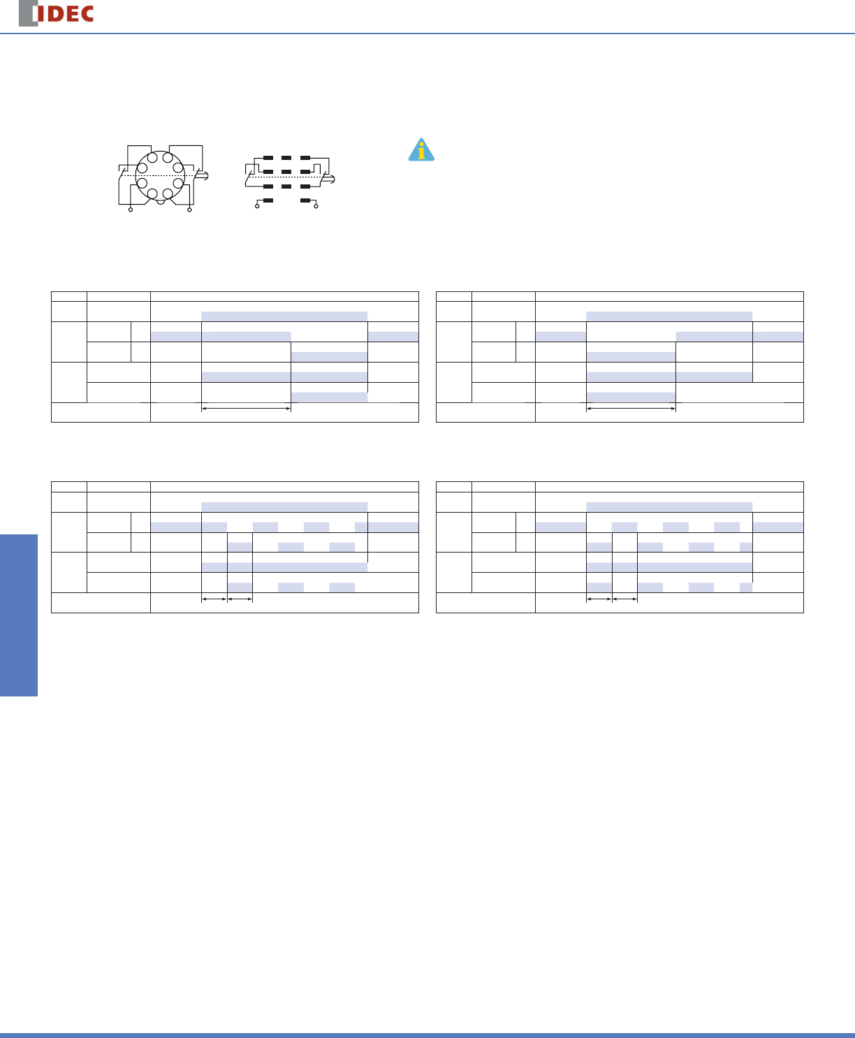
RTE-P1, -B1
1
2
3
45
6
7
8
(~/
-
)(~/
+
)
RTE-P1
23
AB
9
1
(~/
-
)(~/
+
)
456
78
RTE-B1
1. RTE-B1: Do not apply voltage to terminals #2, #5 & #8.
2. IDEC sockets are as follows: RTE-P1: SR2P-06* pin type socket,
RTE-B1: SR3B-05* blade type socket, (*-may be followed by suffi x
letter A,B,C or U).
A: ON-Delay 1 (power start)
Set timer for desired delay, apply power to coil. Contacts transfer after preset time has elapsed, and
remain in transferred position until timer is reset. Reset occurs with removal of power.
Item Terminal Number Operation
Power (1) 2 - 7
(2) A - B
Delayed
Contact
(1) 1 - 4, 5 - 8
(2) 1 - 7, 3 - 9 (NC)
(1) 1 - 3, 6 - 8
(2) 4 - 7, 6 - 9 (NO)
Indicator
PWR
OUT
Set Time T
C: Cycle 1 (power start, OFF fi rst)
Set timer for desired delay, apply power to coil. First transfer of contacts occurs after preset delay has
elapsed, after the next elapse of preset delay contacts return to original position. The timer now cycles
between on and off as long as power is applied (duty ratio 1:1).
Item Terminal Number Operation
Power (1) 2 - 7
(2) A - B
Delayed
Contact
(1) 1 - 4, 5 - 8
(2) 1 - 7, 3 - 9 (NC)
(1) 1 - 3, 6 - 8
(2) 4 - 7, 6 - 9 (NO)
Indicator
PWR
OUT
Set Time TT
B: Interval (power start)
Set timer for desired delay, apply power to coil. Contacts transfer immediately, and return to original
position after preset time has elapsed. Reset occurs with removal of power.
Item Terminal Number Operation
Power (1) 2 - 7
(2) A - B
Delayed
Contact
(1) 1 - 4, 5 - 8
(2) 1 - 7, 3 - 9 (NC)
(1) 1 - 3, 6 - 8
(2) 4 - 7, 6 - 9 (NO)
Indicator
PWR
OUT
Set Time T
C: Cycle 3 (power start, ON fi rst)
Functions in same manner as Mode C, with the exception that fi rst transfer of contacts occurs as soon
as power is applies. The ratio is 1:1. Time On = Time Off
Item Terminal Number Operation
Power (1) 2 - 7
(2) A - B
Delayed
Contact
(1) 1 - 4, 5 - 8
(2) 1 - 7, 3 - 9 (NC)
(1) 1 - 3, 6 - 8
(2) 4 - 7, 6 - 9 (NO)
Indicator
PWR
OUT
Set Time TT
RTE Series
Timers
801
USA: 800-262-IDEC Canada: 888-317-IDEC
Switches & Pilot Lights Display Lights Relays & Sockets Timers Terminal Blocks Circuit Breakers
Timing Diagrams con’t
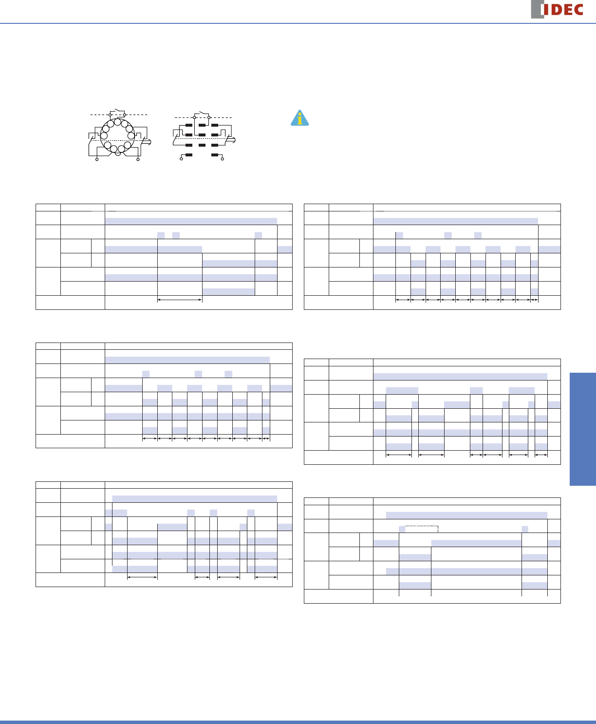
RTE-P2, -B2
RTE-P2
11 10
9
1
2
3
4
567
8
(
~
/
-
)(
~
/
+
)
start
external
control
signal
RTE-B2
23
AB
9
1
(
~/
-
)(
~/
+
)
456
78
start
external
control
signal 1. RTE-P2: Do not apply voltage to terminals #5, #6 & #7.
2. RTE-B2: Do not apply voltage to terminals #2, #5 & #8.
3. IDEC sockets are as follows: RTE-P2: SR3P-05* pin type socket,
RTE-B2: SR3B-05* blade type socket, (*-may be followed by suffi x
letter A,B,C or U).
A: ON-Delay 2 (signal start)
When a preset time has elapsed after the start input turned on while power is on, the NO output
contact goes on.
Item Terminal Number Operation
Power (A) 2 - 10
(B) A - B
Start (A) 5 - 6
(B) 2 - 5
Delayed
Contact
(A) 1 - 4, 8 - 11
(B) 1 - 7, 3 - 9 (NC)
(A) 1 - 3, 9 - 11
(B) 4 - 7, 6 - 9 (NO)
Indicator
PWR
OUT
Set Time T
C: Cycle 4 (signal start, ON fi rst)
When the start input turns on while power is on, the NO contact goes on. The output oscillates at a
preset cycle (duty ratio 1:1).
Item Terminal Number Operation
Power (A) 2 - 10
(B) A - B
Start (A) 5 - 6
(B) 2 - 5
Delayed
Contact
(A) 1 - 4, 8 - 11
(B) 1 - 7, 3 - 9 (NC)
(A) 1 - 3, 9 - 11
(B) 4 - 7, 6 - 9 (NO)
Indicator
PWR
OUT
Set Time TTTTTTTTTa
E: Signal OFF-Delay
When power is turned on while the start input is on, the NO output contact goes on. When a preset
time has elapsed after the start input turned off, the NO output contact goes off.
Item Terminal Number Operation
Power (A) 2 - 10
(B) A - B
Start (A) 5 - 6
(B) 2 - 5
Delayed
Contact
(A) 1 - 4, 8 - 11
(B) 1 - 7, 3 - 9 (NC)
(A) 1 - 3, 9 - 11
(B) 4 - 7, 6 - 9 (NO)
Indicator
PWR
OUT
Set Time TTaTTa
B: Cycle 2 (signal start, OFF fi rst)
When the start input turns on while power is on, the output oscillates at a preset cycle (duty ratio 1:1),
starting while the NO contact off.
Item Terminal Number Operation
Power (A) 2 - 10
(B) A - B
Start (A) 5 - 6
(B) 2 - 5
Delayed
Contact
(A) 1 - 4, 8 - 11
(B) 1 - 7, 3 - 9 (NC)
(A) 1 - 3, 9 - 11
(B) 4 - 7, 6 - 9 (NO)
Indicator
PWR
OUT
Set Time TTTTTTTTTTa
D: Signal ON/OFF-Delay
When the start input turns on while power is on, the NO output contact goes on. When a preset time
has elapsed while the start input remains on, the output contact goes off. When the start input turns
off, the NO contact goes on again. When a preset time has elapsed after the start input turned off, the
NO contact goes off.
Item Terminal Number Operation
Power (A) 2 - 10
(B) A - B
Start (A) 5 - 6
(B) 2 - 5
Delayed
Contact
(A) 1 - 4, 8 - 11
(B) 1 - 7, 3 - 9 (NC)
(A) 1 - 3, 9 - 11
(B) 4 - 7, 6 - 9 (NO)
Indicator
PWR
OUT
Set Time T T Ta T T Ta
F: One-Shot (signal start)
When the start input turns on while power is on, the NO output contact goes on. When a preset time
has elapsed, the NO output contact goes off.
Item Terminal Number Operation
Power (A) 2 - 10
(B) A - B
Start (A) 5 - 6
(B) 2 - 5
Delayed
Contact
(A) 1 - 4, 8 - 11
(B) 1 - 7, 3 - 9 (NC)
(A) 1 - 3, 9 - 11
(B) 4 - 7, 6 - 9 (NO)
Indicator
PWR
OUT
Set Time
RTE Series Timers
802 www.idec.com
Switches & Pilot LightsDisplay LightsRelays & SocketsTimersTerminal Blocks
Circuit Breakers
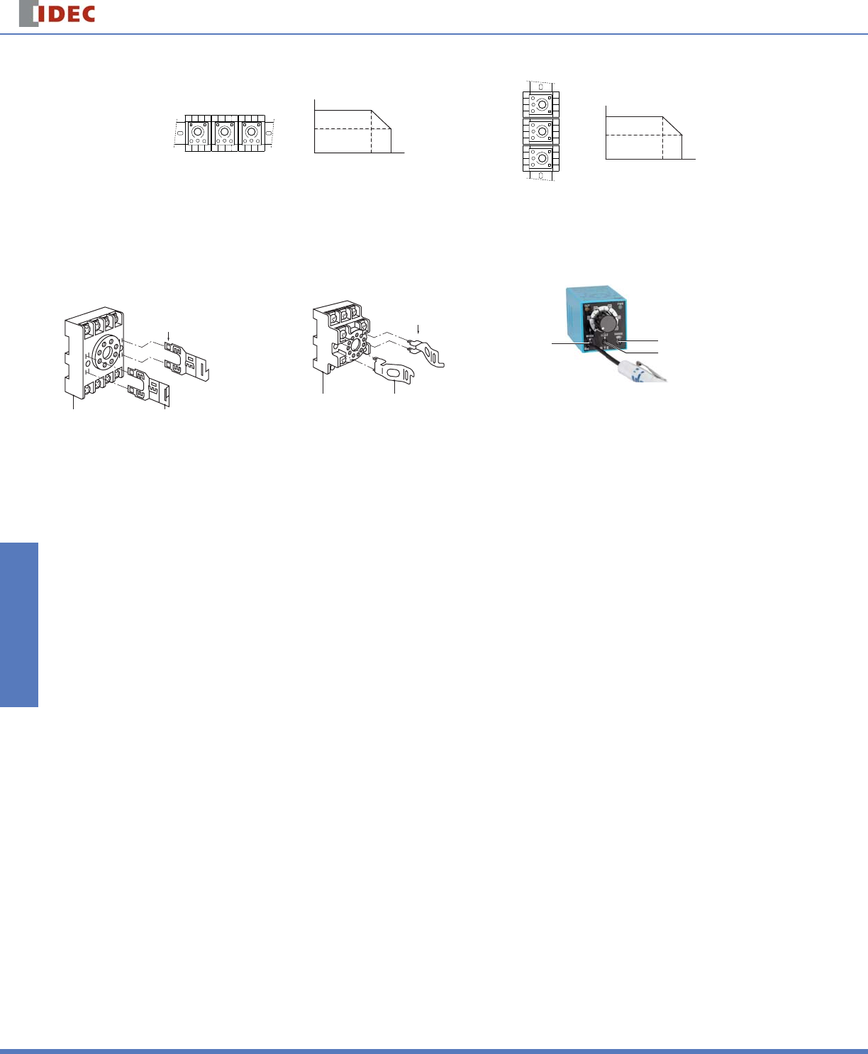
Temperature Derating Curves
Mounting A
50
º
C65
º
C
10A
7A
Ambient Temperature
Allowable
Current
Mounting A
Derating Curve
Mounting B
50
º
C65
º
C
7A
5A
Ambient Temperature
Allowable
Current
Mounting B
Derating Curve
Instructions
Installation of Hold-Down Springs
DIN Rail Mount Socket
Socket SR2P-06 Hold-down Spring (sold separately)
SFA-202 (use two springs)
Insert the springs into the outer
slots with the projections
facing inside.
Socket SR2P-05
Insert the springs
into the slots.
Hold-down Spring (sold separately)
SFA-203 (use two springs)
Switch Settings
jOperator Mode Selector
kScale Selector
lTime Range Selector
j
k
l
1. Turn the selectors securely using a fl at screw-
driver 4mm wide (maximum).
Note that incorrect setting may cause malfunc-
tion. Do not turn the selectors beyond their limits.
2. Since changing the setting during timer operation
may cause malfunction, turn power off before
changing.
Safety Precautions
Special expertise is required to use Electronic Timers.
All Electronic Timers are manufactured under IDEC’s rigorous quality control
system, but users must add a backup or fail safe provision to the control
system when using the Electronic Timer in applications where heavy damage
or personal injury may occur should the Electronic Timer fail.
Install the Electronic Timer according to instructions described in this catalog.
Make sure that the operating conditions are as described in the specifi ca-
tions. If you are uncertain about the specifi cations, contact IDEC in advance.
In these directions, safety precautions are categorized in order of importance
under Warning and Caution.
Warnings
Warning notices are used to emphasize that improper operation may cause
severe personal injury or death.
Turn power off to the Electronic timer before starting installation, removal,
wiring, maintenance, and inspection on the Electronic Timer.
Failure to turn power off may cause electrical shocks or fi re hazard.
•
•
•
•
•
•
Do not use the Electronic Timer for an emergency stop circuit or inter-
locking circuit. If the Electronic Timer should fail, a machine malfunction,
breakdown, or accident may occur.
Caution
Caution notices are used where inattention might cause personal injury or dam-
age to equipment.
The Electronic Timer is designed for installation in equipment. Do not install
the Electronic Timer outside equipment.
Install the Electronic Timer in environments described in the specifi cations. If
the Electronic Timer is used in places where it will be subjected to high-tem-
perature, high-humidity, condensation, corrosive gases, excessive vibrations,
or excessive shocks, then electrical shocks, fi re hazard, or malfunction could
result.
Use an IEC60127-approved fuse and circuit breaker on the power and output
line outside the Electronic Timer.
Do not disassemble, repair, or modify the Electronic Timer.
When disposing of the Electronic Timer, do so as industrial waste.
•
•
•
•
•
•
RTE Series
Timers
803
USA: 800-262-IDEC Canada: 888-317-IDEC
Switches & Pilot Lights Display Lights Relays & Sockets Timers Terminal Blocks Circuit Breakers
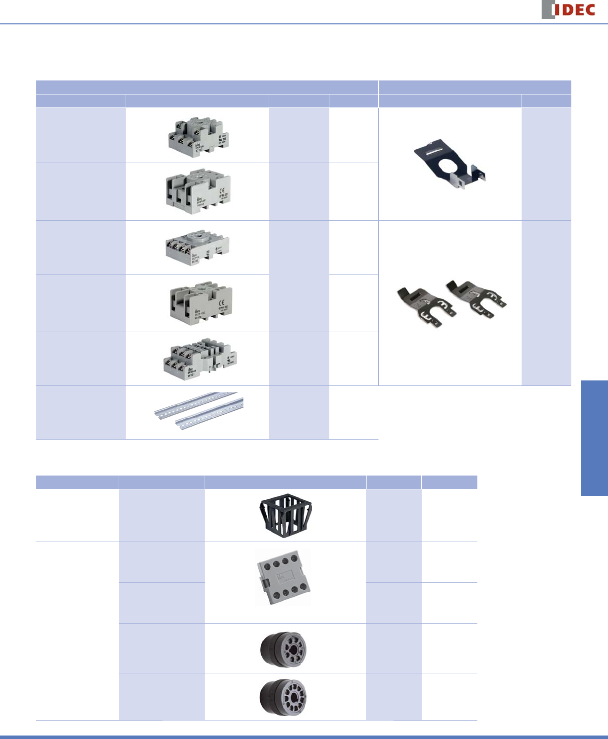
Accessories
DIN Rail Mounting Accessories
DIN Rail/Surface Mount Sockets and Hold-Down Springs
DIN Rail Mount Socket Applicable Hold-Down Springs
Style Appearance Use with Timers Part Number Appearance Part Number
11-Pin Screw Terminal
(dual tier) RTE-P2 SR3P-05
SFA-203
11-Pin FingerSafe Socket RTE-P2 SR3P-05C
8-Pin Screw Terminal
RTE-P1
SR2P-06
SFA-2028-Pin Fingersafe Socket SR2P-05C
11-Blade Screw Terminal RTE-B1
RTE-B2 SR3B-05
DIN Mounting Rail
Length 1000mm — BNDN1000
Panel Mounting Accessories
Flush Panel Mount Adapter and Sockets that use an Adapter
Accessory Description Appearance Use with Part No.
Panel Mount Adapter Adaptor for fl ush panel
mounting RTE timers All RTE timers RTB-G01
Sockets for use with
Panel Mount Adapter
8-pin screw terminal
(Shown: SR6P-M08G Wiring Socket Adapter)
RTE-P1 SR6P-M08G
11-pin screw terminal RTE-P2 SR6P-M11G
8-pin solder terminal RTE-P1 SR6P-S08
11-pin solder terminal RTE-P2 SR6P-S11
RTE Series Timers
804 www.idec.com
Switches & Pilot LightsDisplay LightsRelays & SocketsTimersTerminal Blocks
Circuit Breakers
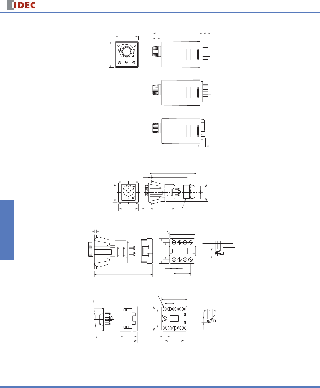
Dimensions
36.0
77.9
40.0
13.0
7.3
13.7
RTE-P1 (8 pin) Terminal Style
RTE-P2 (11 pin)Terminal Style
RTE-B1/RTE-B2 (11 blade) Terminal Style
Panel Mount Adapter
RTE Timer, 8-Pin and 11-Pin with SR6P-S08 or SR6P-S11
Back Wiring Socket
1.7
48
48
11 61.2
Panel Thickness 0.8 to 5mm
42.5
98 maximum
RTE Timer, 8-Pin with SR6P-M08G
ø3.6 min.
8-M3.5 Terminal Screw
2187
34 5 6
6.9 max.
30.4
44.6
Panel Thickness 0.8 to 5mm
80.5
7
9.8 × 3
44.6
3.5 max. 5.6 min.
RTE Timer, 11-Pin with SR6P-M11G
ø3.6 min.
11-M3.5 Teminal Screws
6.9 max.
92
4389
10
211
5
176
3.5 max. 5.8 min.
30.5 7
8.5 × 4
16.7
45
34
45

General Instructions Timers
858 www.idec.com
Switches & Pilot LightsDisplay LightsRelays & SocketsTimersTerminal Blocks
Circuit Breakers
General Instructions for All Timer Series
Load Current
With inductive, capacitive, and incandescent lamp loads, inrush current more
than 10 times the rated current may cause welded contacts and other undesired
effects. The inrush current and steady-state current must be taken into consider-
ation when specifying a timer.
Contact Protection
Switching an inductive load generates a counter-electromotive force (back EMF)
in the coil. The back EMF will cause arcing, which may shorten the contact life
and cause imperfect contact. Application of a protection circuit is recommended
to safeguard the contacts.
Temperature and Humidity
Use the timer within the operating temperature and operating humidity ranges
and prevent freezing or condensation. After the timer has been stored below
its operating temperature, leave the timer at room temperature for a suffi cient
period of time to allow it to return to operating temperatures before use.
Environment
Avoid contact between the timer and sulfurous or ammonia gases, organic sol-
vents (alcohol, benzine, thinner, etc.), strong alkaline substances, or strong acids.
Do not use the timer in an environment where such substances are prevalent. Do
not allow water to run or splash on the timer.
Vibration and Shock
Excessive vibration or shocks can cause the output contacts to bounce, the
timer should be used only within the operating extremes for vibration and shock
resistance. In applications with signifi cant vibration or shock, use of hold down
springs or clips is recommended to secure a timer to its socket.
Time Setting
The time range is calibrated at its maximum time scale; so it is desirable to use
the timer at a setting as close to its maximum time scale as possible. For a more
accurate time delay, adjust the control knob by measuring the operating time
with a watch before application.
Input Contacts
Use mechanical contact switch or relay to supply power to the timer. When
driving the timer with a solid-state output device (such as a two-wire proximity
switch, photoelectric switch, or solid-state relay), malfunction may be caused by
leakage current from the solid-state device. Since AC types comprise a capaci-
tive load, the SSR dielectric strength should be two or more times the power
voltage when switching the timer power using an SSR.
Generally, it is desirable to use mechanical contacts whenever possible to apply
power to a timer or its signal inputs. When using solid state devices, be cautious
of inrushes and back-EMF that may exceed the ratings on such devices. Some
timers are specially designed so that signal inputs switch at a lower voltage
than is used to power the timer (models designated as “B” type).
Timing Accuracy Formulas
Timing accuracies are calculated from the following formulas:
Repeat Error = ± 1 x Maximum Measured Value – Minimum Measured Value x 100%
2 Maximum Scale Value
Voltage Error = ± Tv - Tr x 100%
Tr
Tv: Average of measured values at voltage V
Tr: Average of measured values at the rated voltage
Temperature Error = ± Tt - T20 x 100%
T20
Tt: Average of measured values at °C
T20: Average of measured values at 20°C
Setting Error = ± Average of Measured Values - Set Value x 100%
Maximum Scale Value
