IG 20 User Manual
User Manual:
Open the PDF directly: View PDF ![]() .
.
Page Count: 30

IG-20 miniature Inclinometer User manual
SBG Systems 1/30 IG20UM.5
IG-20: two-axis
Inclinometer
Document : IG20UM.5
Revision: 5 – 27 June 2012
SBG Systems
3bis, chemin de la Jonchère
92500 Rueil Malmaison
FRANCE
Email : support@sbg-systems.com
Phone: +33 (0)1 80 88 45 00

IG-20 miniature Inclinometer User manual
SBG Systems 2/30 IG20UM.5
Revision History
Revision
Date
Author
Information
5
27 June 2012
Alexis GUINAMARD
Renumbered connectors pins to be consistent with
manufacturers
Updated company address details
4
1-Dec-09
Alexis GUINAMARD
Updated specifications for newer devices
Added self test specifications
Added user buffer management
3
16 Feb 2009
Alexis GUINAMARD
Minor editorial updates
Added CE conformity declaration
2
12 Dec. 2008
Alexis GUINAMARD
Updated fixed coordinate frame definition
Removed obsolete sampling frequency configuration
1
1. Sept. 2008
Alexis GUINAMARD
First release of this document
© 2007 – 2011, SBG Systems SAS. All rights reserved. Information in this document is subject to change
without notice. Copy or redistribution of this document is forbidden without express authorization of SBG
Systems.

IG-20 miniature Inclinometer User manual
SBG Systems 3/30 IG20UM.5
Index
1. Introduction ................................................................................................................................................................. 4!
1.1. Product description .......................................................................................................................................................................... 4!
1.2. Ordering information ........................................................................................................................................................................ 5!
1.3. Block diagram .................................................................................................................................................................................. 5!
1.3.1. Internal computations ............................................................................................................................................................. 5!
1.3.2. Sensors .................................................................................................................................................................................. 5!
1.3.3. Specifications ......................................................................................................................................................................... 6!
1.4. Presentation of the development kit ................................................................................................................................................ 7!
1.4.1. Content of a development kit .................................................................................................................................................. 7!
1.4.2. Quick start with provided software ......................................................................................................................................... 8!
1.5. Communicate with the device .......................................................................................................................................................... 9!
1.5.1. The C library sbgCom ............................................................................................................................................................ 9!
1.5.2. Low level communication with IG-20 .................................................................................................................................... 10!
1.5.3. Matlab and Labview integration ........................................................................................................................................... 10!
2. Output provided by IG-20 ......................................................................................................................................... 11!
2.1. Sensors output ............................................................................................................................................................................... 11!
2.1.1. Calibrated sensors output .................................................................................................................................................... 11!
2.1.2. Raw sensors output .............................................................................................................................................................. 11!
2.1.3. Device Status ....................................................................................................................................................................... 11!
2.2. Orientation output .......................................................................................................................................................................... 12!
2.2.1. Euler Angles ......................................................................................................................................................................... 12!
2.2.2. Rotation matrix (Direction Cosine Matrix) ............................................................................................................................. 12!
2.2.3. Quaternions .......................................................................................................................................................................... 13!
2.2.4. Other useful conversion formulas ......................................................................................................................................... 14!
2.3. Coordinate systems ....................................................................................................................................................................... 15!
3. Configure your IG-20 ................................................................................................................................................ 16!
3.1. Protocol configuration .................................................................................................................................................................... 16!
3.1.1. Protocol mode ...................................................................................................................................................................... 16!
3.1.2. Output mode ......................................................................................................................................................................... 16!
3.1.3. User ID ................................................................................................................................................................................. 16!
3.1.4. User Buffer ........................................................................................................................................................................... 16!
3.1.5. Default output mask ............................................................................................................................................................. 16!
3.1.6. Normal / Continuous modes ................................................................................................................................................. 17!
3.2. Sensors configuration .................................................................................................................................................................... 17!
3.2.1. Internal low pass cut-off frequencies .................................................................................................................................... 17!
3.3. Internal computation loop configuration ......................................................................................................................................... 18!
3.3.1. Filter frequency ..................................................................................................................................................................... 18!
3.3.2. Advanced options ................................................................................................................................................................. 18!
3.4. Coordinate frames transformation ................................................................................................................................................. 18!
3.4.1. Pre Rotations ........................................................................................................................................................................ 18!
3.4.2. Post Rotations ...................................................................................................................................................................... 19!
4. Electrical and mechanical specifications .................................................................................................................. 20!
4.1. Absolute maximum ratings ............................................................................................................................................................ 20!
4.2. Box version specifications ............................................................................................................................................................. 21!
4.2.1. Mechanical outline for IG-20 ................................................................................................................................................ 21!
4.2.2. Box device connectors ......................................................................................................................................................... 22!
4.3. OEM version specifications ........................................................................................................................................................... 23!
4.3.1. Device footprint for IG-20 ..................................................................................................................................................... 23!
4.3.2. OEM device connectors ....................................................................................................................................................... 24!
4.4. UsbToUart interface ....................................................................................................................................................................... 25!
4.4.1. Cable provided ..................................................................................................................................................................... 25!
5. Limitations and advises for optimal operation ........................................................................................................... 26!
5.1. Environmental considerations ........................................................................................................................................................ 26!
5.2. Accelerations & Vibrations ............................................................................................................................................................. 26!
5.3. Power supply ................................................................................................................................................................................. 26!
6. Warranty and Support ............................................................................................................................................... 27!
6.1. Support information ....................................................................................................................................................................... 27!
6.2. Warranty ........................................................................................................................................................................................ 27!
6.2.1. Return procedure ................................................................................................................................................................. 27!
6.2.2. Return address ..................................................................................................................................................................... 27!
Appendix A.!CE Declaration of conformity ............................................................................................................ 28!
Appendix B.!Older devices specifications ............................................................................................................. 29!

IG-20 miniature Inclinometer User manual
SBG Systems 4/30 IG20UM.5
1. Introduction
1.1. Product description
The IG-20 is a miniature two axis inclinometer that includes a tri-axial accelerometer. Based on this MEMS
sensor and using an on board processing, the IG-20 outputs an accurate 2d orientation (roll, pitch) in quasi-
static conditions by tracking the earth gravity.
Thanks to an advance calibration procedure, the IG-20 delivers accurate results over a wide temperature
range. Each product is individually calibrated to get the best of the embedded sensors.
The SBG Systems’ calibration procedure corrects all sensors errors such as bias and gain variations over
temperature, misalignment and cross-axis.
The IG-20 can be purchased in Box, as well as in OEM version, making it very easy to integrate in any
system or application.
This product is perfect for platform stabilization or as a G-Meter.
Outputs provided by the IG-20 are:
• Orientation (Euler Angles, Matrix or Quaternion),
• Sensor calibrated data (3D Acceleration, Temperatures),
• Raw sensor data.
IG-20 miniature Inclinometer User manual
SBG Systems 5/30 IG20UM.5
1.2. Ordering information
Standard version is the box version, with ± 2g accelerometers, and
RS232 communications.
Standard product codes are:
• IG-20-A1P1-B
1.3. Block diagram
1.3.1. Internal computations
The IG-20 measures the local gravity and computes an orientation valid in ±180° for roll and ±80° for pitch
axes. The device can measure a very accurate 2d inclination, in static conditions.
1.3.2. Sensors
Accelerometers are sampled with a 16 bits sigma-delta Analog to Digital Converter. High speed sampling (1
kHz) improves the sensor immunity in vibrating environments.
1.3.2.1. Factory calibration procedure
Our products are provided with fully calibrated accelerometers. We calibrate and test each product in our
factory. Calibration report is also shipped with each product.
This calibration procedure allows taking the maximum precision of each sensor. This procedure contains:
• Temperature compensation of gain and bias,
• Cross-axis and misalignment effects compensation.
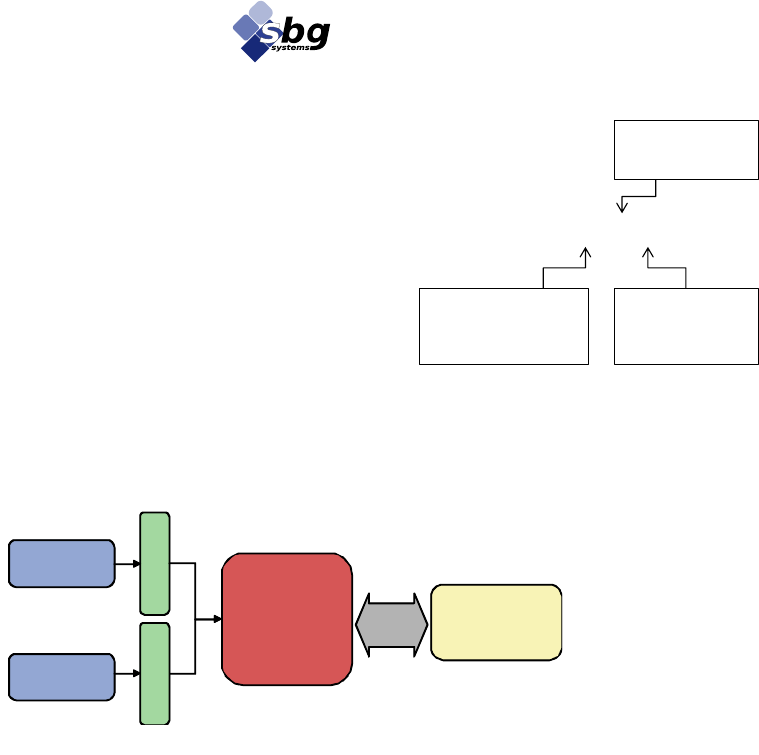
Figure 1: Simplified block diagram of the IG-20
3 axis
Accelerometers
Temperature
Sensors
1
6
b
i
t
s
A
/
D
CPU
Attitude
computation
+
Calibration
data stored in
flash
1
2
b
i
t
s
A
/
D
3D Accelerations
2D Orientation
Temperature
RS232
IG-20-A#P#-#
Accelerometers range:
1: 2g
2: 5g
3: 18g
Protocol mode:
1: RS232
2: Serial TTL form at
Packaging:
B : Box version
O : OEM version

IG-20 miniature Inclinometer User manual
SBG Systems 6/30 IG20UM.5
1.3.3. Specifications
All specifications are valid in the full temperature range -40°C to 85°C unless otherwise specified.
Parameter
Specification
Remarks
Attitude
Sensing range
± 180°
± 80°
Roll
Pitch
Static accuracy
± 0.3° (Pitch, Roll)
Repeatability
< 0.1°
Resolution
< 0.05°
Output frequency
0.01 to 200 Hz
0.01 to 75 Hz
Calibrated sensor data only
Attitude output
Standard Sensors
Accelerometers
Measurement range
± 2 g
Accelerometers available in 2g and 18g
Non-linearity
< 0.2% of FS
Bias stability
± 2 mg
Over temperature range
Noise density
0.22 mg/√Hz
Alignment error
< 0.1°
Bandwidth
50 Hz
Sampling rate
1 000 Hz
Communication
Output modes
Euler angles, Quaternion, Matrix,
Calibrated sensor data,
Raw sensor data.
Each output can be enabled or disabled
by the user
Interface options
Serial (RS-232 or TTL 3.3V),
USB using provided usbToUart
Serial data rate
9 600 to 230 400 bps
User selectable
Physical
Dimensions (OEM)
27x30x14 mm
Dimensions (Box)
36x49x22 mm
Weight (OEM)
9 g
Weight (Box)
38 g
Operating temperature
-40° to 85°C
Non condensing environment
Storage temperature
-40° to 85°C
Shock limit
1 000g (Powered), 5 000 g (unpowered)
Shocks may affect performance
Enclosure
Robust and high precision aluminum
Electrical
Operating voltage
3.3 to 30 V
Power consumption
150 mW @ 5.0 V
Optimal power consumption at 5.0 V
Start-up time
< 30s
Optimal measurement
Table 1: IG-20 specifications
1.3.3.1. Optional sensors specifications:
Here are summarized the optional sensors specifications. The main differences with standard sensors are the
noise density, the linearity errors and the bias stability.
Optional Accelerometers
A2
A3
Measurement range
± 5g
± 18g
Non-linearity
< 0.2% of FS
< 0.2% of FS
Bias stability
± 5 mg
± 10 mg
Noise density
0.25 mg/√Hz
0.32 mg/√Hz
Alignment error
< 0.1°
< 0.1°
Bandwidth
50 Hz
50 Hz
Sampling rate
1 000 Hz
1 000 Hz

IG-20 miniature Inclinometer User manual
SBG Systems 7/30 IG20UM.5
1.4. Presentation of the development kit
The IG-20 SDK has been developed to make integration of the IG-20 very easy and efficient. Provided
software and libraries will give the opportunity to rapidly develop powerful applications. The addition of the
UsbToUart converter makes the connection of an IG-20 to a computer very comfortable.
1.4.1. Content of a development kit
Each IG-20 SDK is provided with the following elements:
• An IG-20,
• The calibration report of the device,
• A UsbToUart converter,
• A USB cable to connect the device (OEM versions),
• A quick start manual,
• A set of compatible screws to mount easily your IG-20
• A CD-Rom containing :
o UsbToUart converter driver,
o sbgCenter analyze software,
o sbgUpdater software,
o sbgCom library,
o Example software,
o Full documentation :
• IG-20 User Manual,
• Low Level Protocol Specifications,
• sbgCom Library Reference Manual,
• Magnetometers Calibration Tools,
• sbgCenter User Manual.
Figure 2: The IG-20 SDK
IG-20 miniature Inclinometer User manual
SBG Systems 8/30 IG20UM.5
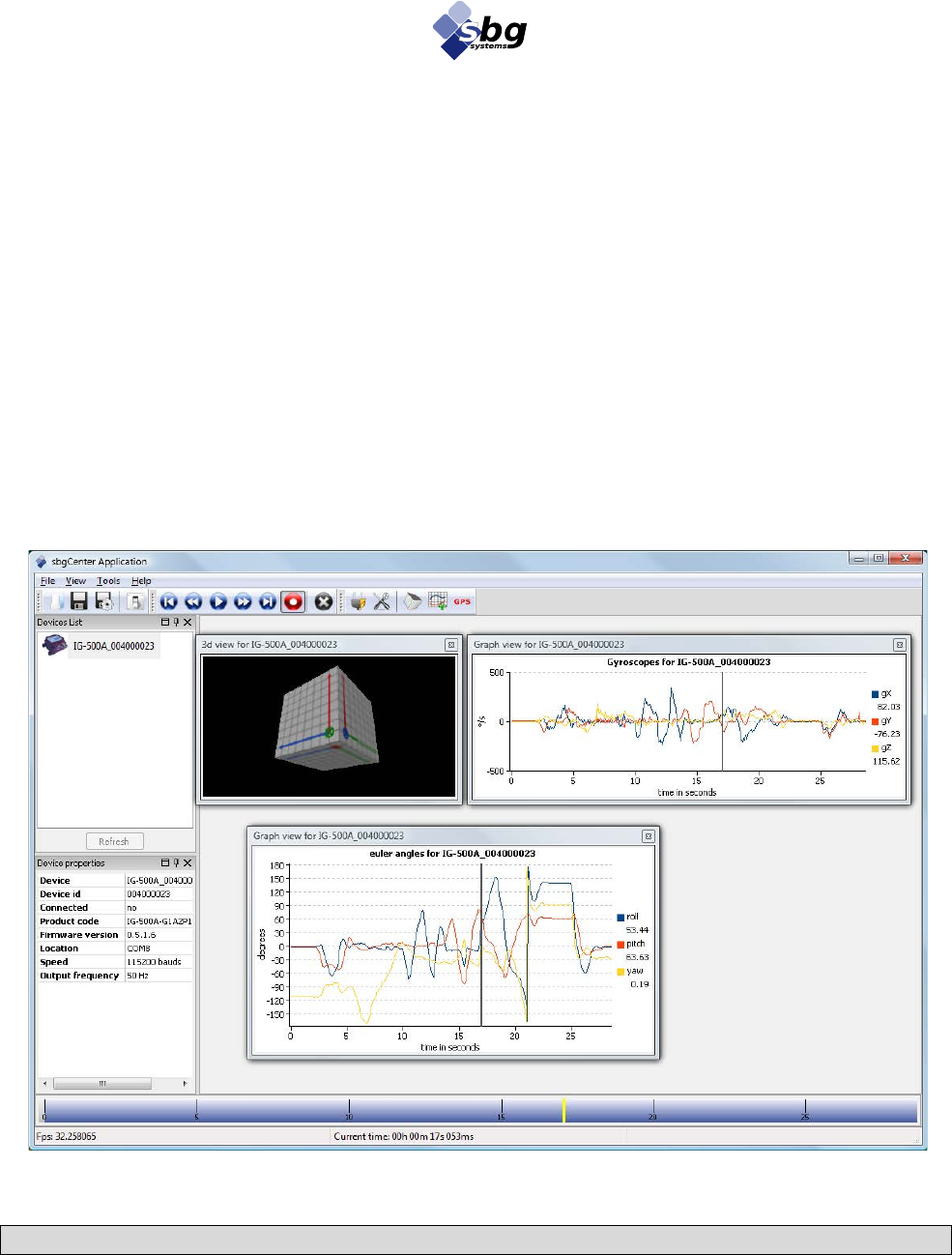
1.4.2. Quick start with provided software
1.4.2.1. The sbgCenter
The sbgCenter is a very powerful program suit. It allows to deeply analyzing outputs of the IG-20, by
displaying, recording, and exporting a set of data. Graphs can be displayed, as well as 3D representation of
orientation.
A powerful time management allows to deeply exploring any recording, with the ability to display in a single
frame 50 ms of recording, or the whole record, if it’s what the user needs.
To get a quick start of the sbgCenter, follow these steps:
1. Connect one or more IG-20 to the computer,
2. Launch sbgCenter,
3. Click on the “Refresh” button,
4. Double-click on the device in the device list,
5. Click on the 3D Cube icon to open the 3D view,
6. Start playing!
Note: Please refer to the sbgCenter User Manual for more information
Figure 3: sbgCenter is an excellent analyze tool

IG-20 miniature Inclinometer User manual
SBG Systems 9/30 IG20UM.5
1.5. Communicate with the device
SBG Systems provides multiple ways to interface the IG-20 with another system. An easy to use C library is
included in the SDK, as well as the low level protocol documentation.
1.5.1. The C library sbgCom
The IG-20 SDK provides an easy access to the device with the library sbgCom. This library allows access to
all the functionalities of the IG-20, including continuous mode of communication.
This library is developed for most popular OS: Ms Windows, Linux, and Mac OS X. It should also be easily
compiled on all UNIX platforms.
sbgCom was designed to simplify the work needed to port the library to a specific platform, by separating the
low level communication functions such as serial com port from the high level one.
Note: Please refer to the sbgCom Reference Manual to have a complete description of the library.
1.5.1.1. Example programs provided with sbgCom
Minimal example
This small C example is simply the smallest program you can write to use the IG-20. Only 6 lines of code are
needed to initialize the device, start communications and display in real time results. This example illustrates
the simplicity of use of sbgCom.
3D Cube
This 3D Cube is a small C example, which source is available in the SDK. To use it, you just have to define
the right com port and serial communication baud rate in the file “main.c” and compile the project. If
everything goes well, you should obtain the two windows below:
Figure 4: Overview of the 3D Cube example program

IG-20 miniature Inclinometer User manual
SBG Systems 10/30 IG20UM.5
1.5.2. Low level communication with IG-20
When it is not possible to use sbgCom, you can still communicate directly with the device, by implementing
its low level communication protocol based on the provided documentation.
Note: Please refer to the IG-20 Low Level Protocol Specifications to have a complete
documentation of the protocol format, the commands and their parameters.
1.5.3. Matlab and Labview integration
1.5.3.1. Matlab
The sbgMatlab plug-in developed by SBG Systems allows a direct access in real time to your IG-20. Main
functions of the sbgCom have been implemented in a Matlab class CSbgMatlab, providing an easy interface
for users.
The plug-in is in a DLL form on windows platforms. A UNIX version of this dynamic library is being
finalized and will be available in a next release.
A few example codes may help you in your developments. Also note that continuous mode has to be enabled
in order to retrieve outputs of the IG-20.
1.5.3.2. Labview integration
The sbgLabView library provides the full support of the IG-20 on labView. An example using this library is
provided for a better understanding of the library. Also note that continuous mode has to be enabled in order
to retrieve outputs of the IG-20.

IG-20 miniature Inclinometer User manual
SBG Systems 11/30 IG20UM.5
2. Output provided by IG-20
2.1. Sensors output
2.1.1. Calibrated sensors output
The IG-20 includes 5 calibrated sensors: 3 accelerometers and 2 temperature sensors. These 5 calibrated
sensors values can be output by the device. By calibrated value, we mean value in real units such as!𝑚⋅𝑠!!.
and compensated for any sensor errors (temperature effects, sensor misalignment)
2.1.1.1. Accelerometers values
Accelerometers calibrated values are the three accelerations measured on the device coordinate system.
Accelerometers values are expressed in!𝑚⋅𝑠!!.
Note: Accelerometers values include gravity. In order to get the delta velocities, please make sure
that you have removed the gravity component of the acceleration.
2.1.1.2. Temperature values
The temperature calibrated output is the temperature measured by the two on-board temperature sensors.
Temperature is expressed in ° C.
2.1.2. Raw sensors output
Accelerometers and Temperatures can be outputted by the IG-20 in raw form. The raw sensor output is
basically the reading of the Analog to Digital Converter. These values are not exploitable directly but may
sometimes be useful they reflect the real values of the physical sensors.
Raw values are variables of type uint16.
2.1.3. Device Status
The IG-20 performs at startup a sensor Self-Test, as well as some internal initialization checks. This self test
inform user of potential device failure. Note that the sensor self test is only reliable if the device is not
moving at startup.
The bit-field is contained in a uint32 word.
Bit
Name
Description
0
SBG_CALIB_INIT_STATUS_MASK
Set to 1 if the calibration structure is well initialized
1
SBG_SETTINGS_INIT_STATUS_MASK
Set to 1 if the settings structure is well initialized
[2 – 4]
SBG_ACCEL_X_SELF_TEST_STATUS_MASK
Set to 1 if the X/Y/Z accelerometer has passed self test
5
SBG_ACCEL_RANGE_STATUS_MASK
Set to 1 if the readings of accelerometers do not exceed
operating range.
[6 – 31]
-
Reserved
IG-20 miniature Inclinometer User manual
SBG Systems 12/30 IG20UM.5
2.2. Orientation output
2.2.1. Euler Angles
Euler angles are a commonly used representation of spatial orientation. Euler angles are in fact a composition
of rotation from the reference (Earth fixed) frame. This spatial orientation is defined by the sequence of the
three rotations around X, Y and Z axis of the fixed frame.
Euler angles are widely used because of their easy interpretation. The three parameters: Roll, Pitch and Yaw
define rotations around the fixed frame's axis:
• Roll (φ): Rotation around X axis. 𝜑!∈[−𝜋!;𝜋]!
• Pitch (θ): Rotation around Y axis. 𝜃!∈−!
!
!;!!
!
• Yaw (Ψ): Rotation around Z axis. 𝜓!∈[−𝜋!;𝜋]
Note: On the IG-20, we recommend using Euler angles, as it is a very simple orientation
representation. The yaw output is always set to 0 as the IG-20 does not have heading information.
2.2.2. Rotation matrix (Direction Cosine Matrix)
The Direction Cosine Matrix (DCM) is a rotation matrix that transforms one coordinate reference frame to
another. Rotation matrices are a complete representation of a 3D orientation, thus there is no singularity in
that model.
A DCM locates three unit vectors that define a coordinate frame. Here the DCM transforms the sensor
coordinate frame to the earth fixed coordinates. The DCM is the combination of the three rotation matrices
RM
φ
, RM
θ
and RM
ψ
respectively around Earth X, Y and Z axes.
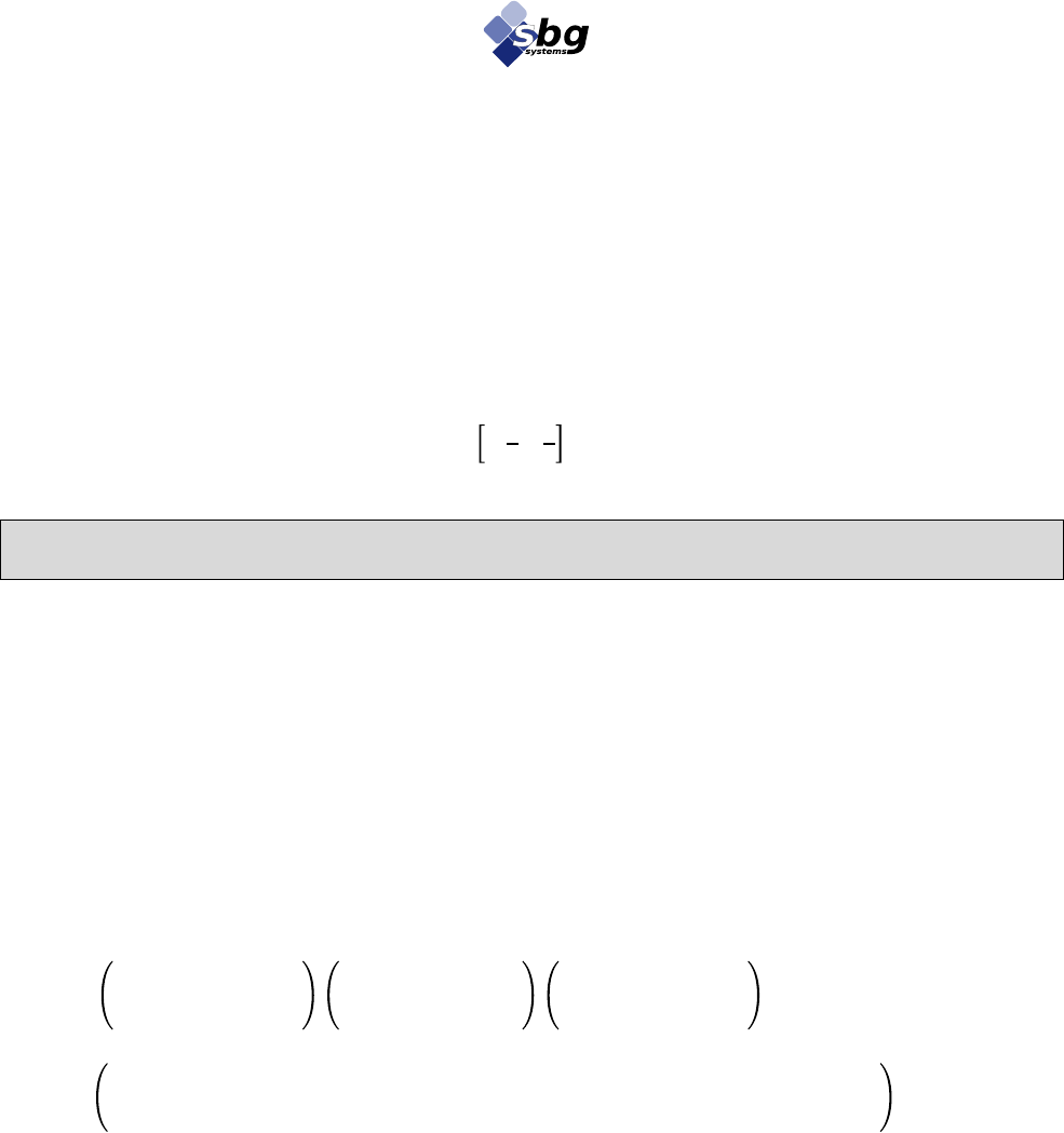
Here is defined a DCM in terms of Euler Angles:
𝐷𝐶𝑀!=!𝑅𝑀!!𝑅𝑀!!𝑅𝑀!
𝐷𝐶𝑀 =!
cos 𝜓−sin 𝜓0
sin 𝜓cos 𝜓0
001
!
cos 𝜃0sin 𝜃
010
−sin 𝜃0cos 𝜃
!
100
0cos 𝜑−sin 𝜑
0sin 𝜑cos 𝜑
𝐷𝐶𝑀 =
cos 𝜃cos!𝜓sin 𝜑sin 𝜃cos 𝜓−cos 𝜑sin 𝜓!cos 𝜑sin 𝜃cos 𝜓+sin 𝜑sin 𝜓!
cos 𝜃sin 𝜓sin 𝜑sin 𝜃sin 𝜓+cos 𝜑cos 𝜓cos 𝜑sin 𝜃!sin 𝜓−sin 𝜑cos 𝜓!
−sin 𝜃sin 𝜑cos 𝜃cos 𝜑cos 𝜃
!
As for any rotation matrix, the inverse rotation equals to the transposed matrix:
𝐷𝐶𝑀!!=𝐷𝐶𝑀!
In order to transform a vector expressed in the sensor coordinate system into the Earth fixed frame, user will
use the DCM as expressed below:
𝑉
!"#$!=𝐷𝐶𝑀 ⋅!𝑉
!"#$%&
Reciprocally:
𝑉
!"#$%& =𝐷𝐶𝑀!⋅𝑉
!"#$!

IG-20 miniature Inclinometer User manual
SBG Systems 13/30 IG20UM.5
2.2.3. Quaternions
Quaternions are an extension of complex numbers, as defined here:
𝑄=𝑞!+𝑞!⋅𝑖+𝑞!⋅𝑗+𝑞!⋅𝑘 Where i, j and k are imaginary numbers.
Particular quaternions such as ‖𝑄‖=1 can represent, as DCMs, a complete definition of the 3D orientation,
without any singularity.
Quaternion algebra do not require a lot of computational resources, they are therefore a very efficient way of
orientation representation.
The inverse rotation of Q is defined by the complex conjugate of Q, denoted!𝑄 :
𝑄=𝑞!−𝑞!⋅𝑖−𝑞!⋅𝑗−𝑞!⋅𝑘
Quaternion can be defined in terms of the DCM coefficients:
q!!=
1
2
!1+DCM!! +DCM!! +DCM!!!
𝑞!=
1
4!𝑞!
!𝐷𝐶𝑀!" −𝐷𝐶𝑀!"!!
𝑞!=!
1
4!𝑞!
(!𝐷𝐶𝑀!" −𝐷𝐶𝑀!" )!
𝑞!=
1
4!𝑞!
(!𝐷𝐶𝑀!" −𝐷𝐶𝑀!")!
Or in terms of Euler Angles:
𝑞!=
1
2
1+cos 𝜃sin 𝜓+sin 𝜑sin 𝜃sin 𝜓+cos 𝜑cos 𝜓+cos 𝜑cos 𝜃
𝑞!=
1
4!𝑞!
!(sin 𝜑cos 𝜃−cos 𝜑sin 𝜃!sin 𝜓+sin 𝜑cos 𝜓)
𝑞!=
1
4!𝑞!
!(cos 𝜑sin 𝜃cos 𝜓+sin 𝜑sin 𝜓+sin 𝜃!)!
𝑞!!=
1
4!𝑞!
!(cos 𝜃sin 𝜓–sin 𝜑sin 𝜃cos 𝜓+cos 𝜑sin 𝜓!!)

IG-20 miniature Inclinometer User manual
SBG Systems 14/30 IG20UM.5
2.2.4. Other useful conversion formulas
Some other conversion formulas can be useful for many users, and are listed below:
2.2.4.1. Quaternion to DCM
It may be useful to compute a DCM based on the quaternion’s parameters:
𝐷𝐶𝑀 =
2𝑞!
!+2𝑞!
!−12𝑞!𝑞!−2𝑞!𝑞!2𝑞!𝑞!+2𝑞!𝑞!
2𝑞!𝑞!+2𝑞!𝑞!2𝑞!
!+2𝑞!
!−12𝑞!𝑞!−2𝑞!𝑞!
2𝑞!𝑞!−2𝑞!𝑞!2𝑞!𝑞!+2𝑞!𝑞!2𝑞!
!+2𝑞!
!−1
2.2.4.2. Quaternion to Euler
Here is the quaternion is translated into Euler angles.
𝜑=tan!!!
2𝑞!𝑞!+2𝑞!𝑞!
2𝑞!
!+2𝑞!
!−1
!!
𝜃=−sin!!(!2𝑞!𝑞!−2𝑞!𝑞!)!
𝜓=tan!!2𝑞!𝑞!+2𝑞!𝑞!
2𝑞!
!+!2𝑞!
!–1
!
2.2.4.3. DCM To Euler
Finally the DCM matrix is converted into Euler Angles.
𝜑=tan!!!
𝐷𝐶𝑀!"
𝐷𝐶𝑀!!
!!
𝜃=−sin!!(!𝐷𝐶𝑀!")!
𝜓=tan!!𝐷𝐶𝑀!"
𝐷𝐶𝑀!!
!
IG-20 miniature Inclinometer User manual
SBG Systems 15/30 IG20UM.5
2.3. Coordinate systems
User has to distinguish two coordinate frames when working with an inertial measurement unit, such as the
IG-20. The first coordinate frame is the inertial (or device) coordinate frame, in which values are expressed
in this local coordinate frame. This coordinate frame follows the movements of the device. The fixed
coordinate frame represents the environment of the device.
In other words, the device frame is moving and rotating in the fixed frame. When the two frames are aligned
(X, Y, Z axes of the two frames are aligned), the device should output no rotation (yaw = pitch = roll = 0).
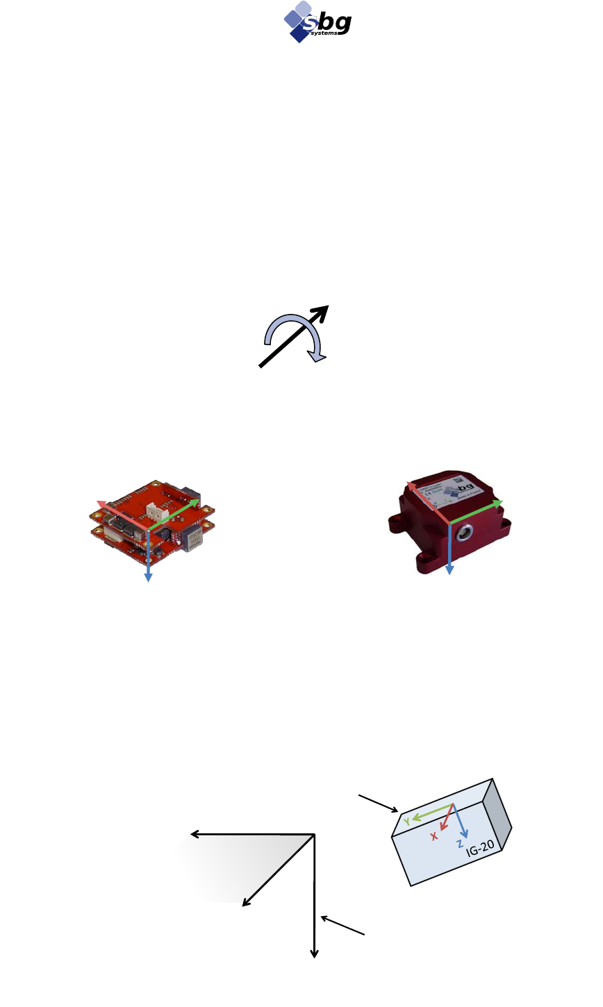
In all case, all coordinate systems are “Right handed” and the positive direction for rotations is clockwise in
the direction of the axis:
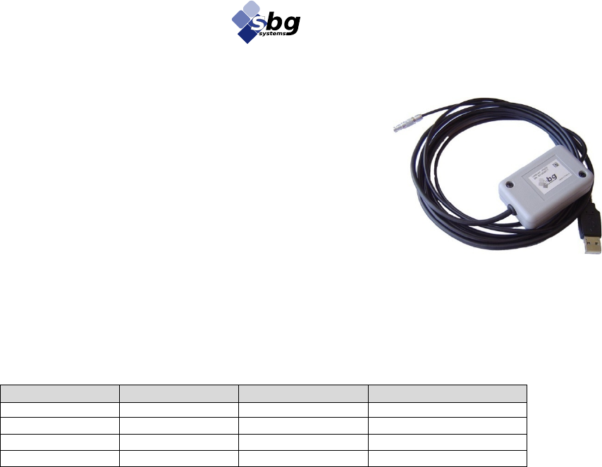
2.3.1.1. Inertial coordinate system
Below is defined the inertial coordinate frame for both OEM and Box versions.
2.3.1.2. Fixed coordinate system
The fixed coordinate frame is defined by these three vectors:
• Z vector is aligned with the local gravity, turned down,
• X vector is coplanar to the XZ plane of the device.
• Y vector is chosen such as the coordinate frame is “right-handed”.
Figure 7: Inertial coordinate frame for OEM
Version
Figure 5: Positive rotations
Figure 6: Inertial coordinate frame for Box
Version
Figure 8: Representation of a sensor in the fixed coordinate system
Y
Z
X
0
Y
Arbitrary(direction(
Z
Vertical,(Down
X
Arbitrary(direction
Device(coordinate(frame
Fixed(coordinate(frame
Y
Z
X

IG-20 miniature Inclinometer User manual
SBG Systems 16/30 IG20UM.5
3. Configure your IG-20
The IG-20 is a widely configurable device. Everything has been done to improve user experience: most of
the default configuration should be suitable to all users, but advanced users who desire to tune the IG-20 can
do this very deeply. All configurable settings can be saved in the non-volatile memory or not. Thanks to this
mechanism, the user can configure his device permanently or temporary depending on his needs.
Indeed, all settings stored in volatile memory will be erased when the device is turned off.
3.1. Protocol configuration
3.1.1. Protocol mode
The protocol mode option defines the baud rate of the serial line. User can select one of those speeds.
[9600; 19200; 38400; 57600; 115200; 230400]
Default configuration is 115200 bps.
3.1.2. Output mode
The output mode contains in fact two configurations:
• Endianness of transmitted data that can be little or big-endian to fit user platform requirements. X86
platforms use little-endian. Some other architectures such as Power PC use big-endian.
• Format for real numbers that can be either standard float IEEE 754, or 32 bits signed fixed point
numbers in [12:20] format (1 sign bit, 11 integer part bits and 20 fractional part bits).
The default configuration for output mode is big-endian, and float.
3.1.3. User ID
Each device can be configured with a user ID. This ID can help user to identify sensors if many sensors are
connected to the same computer. Default configuration is 0.
3.1.4. User Buffer
As a complement of the User ID, the IG-20 is shipped with a 640 bytes buffer reserved for user convenience.
This buffer can be written read, and saved to non volatile memory. It is possible to write a single byte or up
to 500 bytes with only one protocol operation.
3.1.5. Default output mask
The IG-20 protocol allows polling all the output information (sensors data, orientation for example) in one
frame. The default output mask is used to configure which information is included in the default output
frame.
By default, the default output mask contains a standard set of data:
• Time since reset in ms
• Orientation quaternion, Euler angles
• Accelerometers calibrated data, and temperature.

IG-20 miniature Inclinometer User manual
SBG Systems 17/30 IG20UM.5
3.1.6. Normal / Continuous modes
The normal mode is a classical Question / Answer mode. Each question of the user is acknowledged or
answered by the device. This also means that user has to spend some time to ask his questions.
The continuous mode requires less processing power and can output data more regularly. In continuous
mode, the device sends at a fixed frequency the default output frame. The device expects no answer from the
user. User has just to manage all the data that come through the serial port.
When the continuous mode is active, the user can select a frequency divider to choose the frequency of the
continuous frame. The output frequency is defined as follows:
By default, the continuous mode is enabled with the divider set at 2. The output frequency is then 50Hz.
Note: The normal mode is still functional while continuous mode is enabled.
Note 2: When continuous mode is enabled, some continuous frames can be skipped if the user is
asking some other questions and the device's answer is too big for the serial buffer. Normal mode
has always priority to the continuous mode. Once the serial buffer is not saturated anymore, the
continuous frames will be sent again.
3.2. Sensors configuration
The IG-20 includes several options that allow user to tweak sensors parameters. These settings can be useful,
for example, to reduce errors in vibrating environments.
3.2.1. Internal low pass cut-off frequencies
Setting the cut-off frequency of the internal low pass filters may help to limit the influence of vibrations on
the device.
Accelerometers sensors are filtered by an internal low pass filter. The filter cut-off frequency is configurable.
If user needs better accuracy, the cut-off frequencies can be set as low as 0.1 Hz. By setting the cut-off
frequency of the filter to the sampling frequency, the internal low pass filter is simply disabled.
Default configuration is:
• 1 Hz for accelerometers
Note: Using very low cut-off frequencies will increase precision of inclination computation.
Note 2: Setting low pass cut-off frequencies could be useful to increase IG-20 vibration immunity
but the device still need to be mechanically isolated from a vibrating part as much as possible.
FData output=FFilter
divider

IG-20 miniature Inclinometer User manual
SBG Systems 18/30 IG20UM.5
3.3. Internal computation loop configuration
The internal processing is also deeply configurable. This allows advanced users to enhance the behaviors of
the device in some particular situations.
3.3.1. Filter frequency
The internal filter frequency is configurable from 20 Hz to 200 Hz. When the device is configured to
compute an attitude, the filter frequency is always below 75 Hz. If you would like to output sensors data
faster than 75 Hz, you have to disable the attitude computation.
Default configuration is 75 Hz.
3.3.2. Advanced options
3.3.2.1. Enable attitude computation
When you are only interested in calibrated or raw sensors values, it’s possible to disable the attitude
computation. Disabling the orientation computation allows the device to output sensors data at higher update
rates.
3.4. Coordinate frames transformation
Two types of coordinate transformations are proposed: “Pre” and “Post” rotations. These two types can be
combined together, which give to the IG-20 a great flexibility.
3.4.1. Pre Rotations
Sometimes, it is hard to align the device local axes with the object on which it installed. IG-20 devices have
an easy way to manage these kinds of problems. Those three functions allow user to realign the local
coordinate frame with the object axes.
We call that kind of transformations “pre rotations” as it is applied on sensors input. Once this
transformation is set, all sensors calibrated data and orientation output will be expressed with respect of the
new coordinate frame.
Note: Calibrated sensors are affected by pre-rotations, as well as orientation output. Raw sensor
output will remain unchanged.
3.4.1.1. XY Reset
In that kind of reset, we assume that the device is strapped on the object pointing to the same heading (X axis
of the device is in the XZ plane of the object). The object must be set horizontal while calling this function.
After reset, the device's sensors data will be realigned in the object coordinate system.
3.4.1.2. XYZ Reset
For the IG-20, this procedure produces the same result as the Pre Reset XY one.
3.4.1.3. Manual transformation
Reset functions are easy to execute, but have some limits: It is not always possible to level properly the
object.
With the manual procedure, user can set a rotation matrix to perform the transformation. This is the best
method to keep the full precision of the device.

IG-20 miniature Inclinometer User manual
SBG Systems 19/30 IG20UM.5
3.4.2. Post Rotations
So called “post rotations” are transformations that are applied on the orientation output. These
transformations allow user to rotate the output coordinate frame.
These post rotations only affect orientation output. Sensors data will stay in the device local coordinate
frame.
3.4.2.1. Z Reset
This procedure isn’t applicable for the IG-20 because, the device has no yaw information.
3.4.2.2. XY Reset
It could be useful to realign the output coordinate to a local horizontal which is different from the real
horizontal If your desk is not perfectly horizontal for example, you can use the post reset XY function to
realign the output horizontal with your desk.
3.4.2.3. XYZ Reset
For the IG-20, this procedure produces the same result as the Post Reset XY one.
3.4.2.4. Manual transformation
As for “pre” rotations, a manual transformation of the output is possible, by setting the rotation matrix that
may be applied on output.
IG-20 miniature Inclinometer User manual
SBG Systems 20/30 IG20UM.5
4. Electrical and mechanical specifications
4.1. Absolute maximum ratings
Stresses above those listed under the Absolute Maximum Ratings may cause permanent damage to the
device. This is a stress rating only; functional operation of the device at these or any other conditions above
those indicated in the operational section of this specification is not implied. Exposure to absolute maximum
rating conditions for extended periods may affect device reliability.
Parameter
Rating
VDD - GND
-0.3 V to 30V
Acceleration (powered)
+ 2 000 g for 0.3s
Acceleration (unpowered)
+ 5 000 g for 0.3s
IVreg (OEM)
10 mA
Rx pin input voltage (OEM)
-0.3V to 4.0V
Rx pin input voltage (Box)
±25V
Operating temperature range
-40 to 85°C
Storage temperature range
-40 to 85°C
Table 2 : Absolute maximum ratings

IG-20 miniature Inclinometer User manual
SBG Systems 21/30 IG20UM.5
4.2. Box version specifications
4.2.1. Mechanical outline for IG-20

IG-20 miniature Inclinometer User manual
SBG Systems 22/30 IG20UM.5
4.2.2. Box device connectors
4.2.2.1. Main connector
The main connector is a Lemo receptacle which mates with a four wire Lemo connector, ref
FGG.00.304.CLAD35. Other suppliers such as ODU provide compatible connectors (ref S1L0C-P04MCC0-3500).
Figure 9: Lemo/ODU Connector
Figure 10: Pin numbering connector back face. (Solder face)
1
2 3
4
Pin
Name
Description
Type
1
RX
Serial input
INPUT
2
TX
Serial output
OUTPUT
3
GND
Ground
SUPPLY
4
VDD
Supply voltage [3.3V -> 12V]
SUPPLY
Table 3 : Device pin-out for Box version
IG-20 miniature Inclinometer User manual
SBG Systems 23/30 IG20UM.5
4.3. OEM version specifications
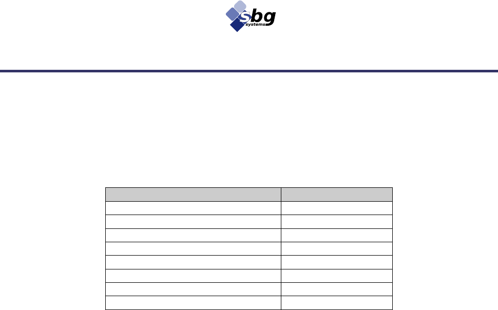
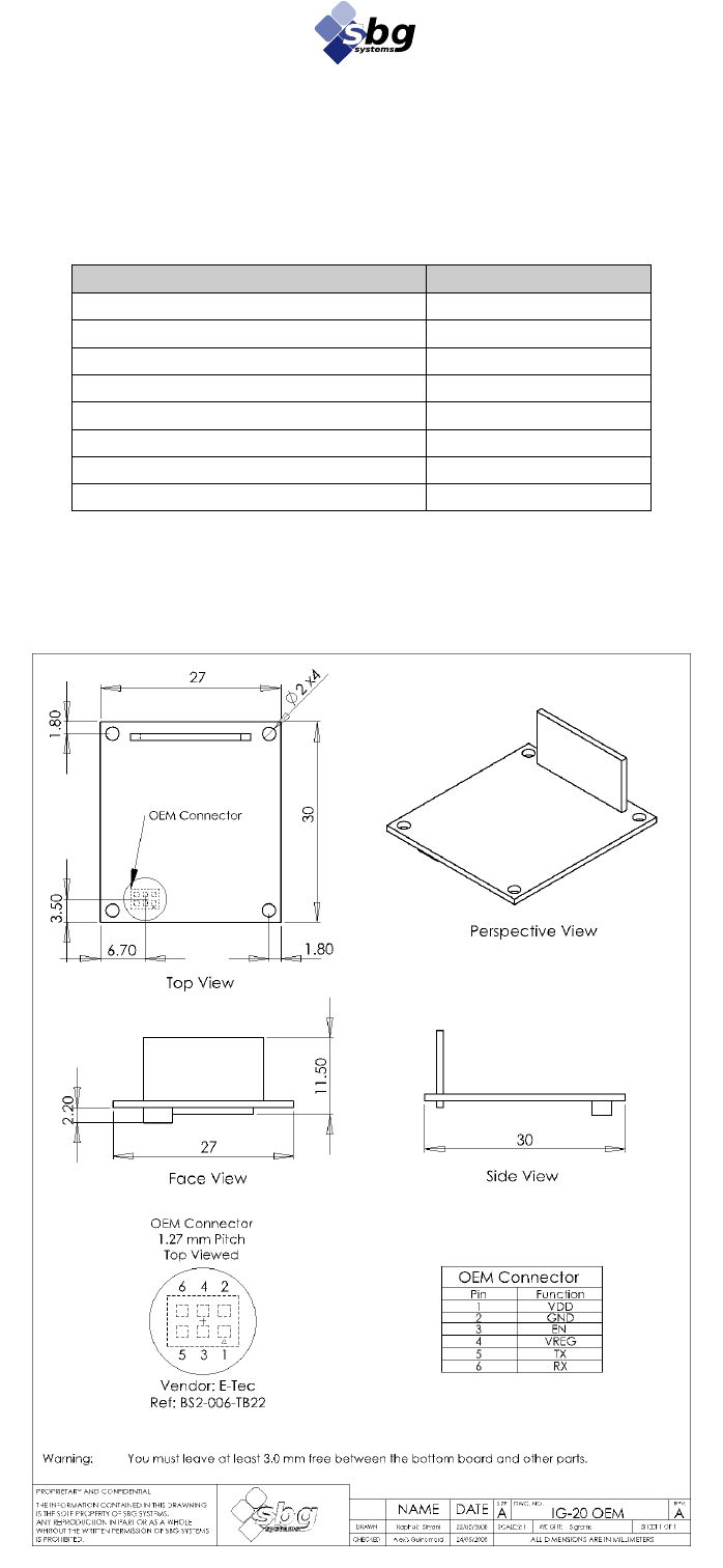
4.3.1. Device footprint for IG-20

IG-20 miniature Inclinometer User manual
SBG Systems 24/30 IG20UM.5
4.3.2. OEM device connectors
4.3.2.1. OEM Board to Board connector
OEM integration of the IG-20 is made easy by the the OEM Board to Board Connector. It is used to power
the device and communication in serial TTL format. The connector is a 2*3 ways 1.27mm pitch from
ACCA, ref BA03N-6SV2-1GT(23) which is compatible with Samtec CLP-103-02-G-D.This connector mates with
ACCA BA03N-6PV2-1GT(19) (or Samtec FTS-103-03-L-DV).
Note 1: VREG can be used to achieve a 3.3V to 5V signal conversion with a MAX3378E for
example.
Warning: Pins 5 and 6 can only be used with the 3.3V TTL serial format. Please order a TTL
version of the device if you wish to use this connector.
For RS-232 devices, pins 5 and 6 cannot be used and you should use the OEM Board connector
as described in section 4.3.2.2
4.3.2.2. OEM Board to Wire connector
To connect the IG-20 OEM version to your application, you can also use the OEM board to wire if you are
using a boxed version (RS-232) without its enclosure, you should use the OEM Board to Wire connector
located on the top of the device.
This connector mates with a 4 ways with a 1.25mm pitch; Female, Molex connector, reference 51021-0400.
This connector uses the crimp terminal Molex ref 50058 or 50079.
Warning: Please check your device’s product code to define if pins 1 and 2 are using 3.3V TTL
signals or standard RS-232 format. For OEM version, the default product code is IG-500A-G4A2P2-O
that means 3.3V TTL format. If your device has a product code with P1 instead of P2, pins 1 and 2
are using RS-232 signals, the default option for boxed versions.
Pin
Name
Description
Type
1
VDD
Supply voltage [3.3V -> 12V]
SUPPLY
2
GND
Ground
SUPPLY
3
RES
Reserved. Do not Connect
–
4
VREG
3.3 V internal regulator output.
OUTPUT
5
TX
Serial output; 3.3V TTL format.
OUTPUT
6
RX
Serial input ; 3.3V TTL format
INPUT
Table 4 : OEM connector Pinout
Pin
Name
Description
Type
1
RX
Serial input; 3.3V TTL or RS-232 format.
INPUT
2
TX
Serial output; 3.3V TTL or RS-232 format.
OUTPUT
3
VDD
Supply voltage [3.3V -> 12V]
SUPPLY
4
GND
Ground
SUPPLY
Table 5 : OEM Board connector Pinout
Figure 11: OEM Board connector
Pin 1
IG-20 miniature Inclinometer User manual
SBG Systems 25/30 IG20UM.5
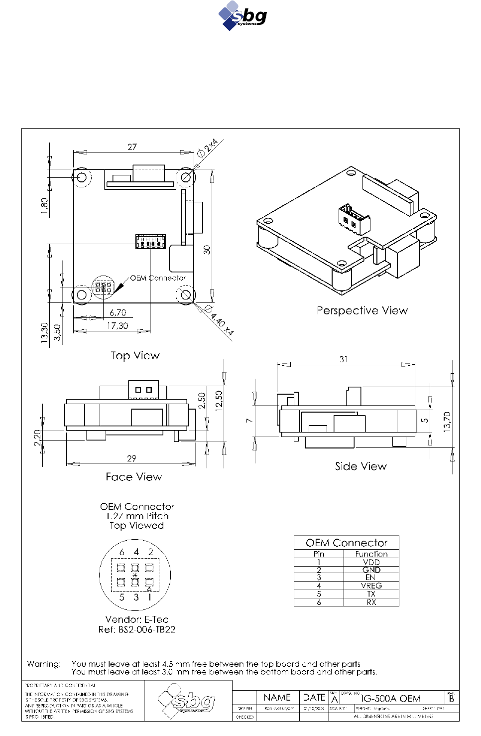
4.4. UsbToUart interface
The UsbToUart interface that is shipped has those characteristics:
• 64x42x20 mm box
• 3 meters long cable
• USB 1.1 or higher compatible
• Communication speed allowed up to 921 600 bps
4.4.1. Cable provided
A 3 meters long cable is part of the UsbToUart interface. The Lemo/ODU connector is linked to a 4 wire
Molex connector (ref 51021-0400) which mates with Molex 53047-0410 or Molex 53261-0471.
The connections on the molex connector are described in the table below:
Pin
Connection
Color (Old cable)
Color (New cable)
1
GND
Black
Black
2
IG-20 Tx
Green
Yellow
3
IG-20 Rx
Blue
Red
4
VCC
Red
Pink
Table 6 : Uart cable pinout
Figure 12: UsbToUart interface

IG-20 miniature Inclinometer User manual
SBG Systems 26/30 IG20UM.5
5. Limitations and advises for optimal operation
5.1. Environmental considerations
The normal condition for operating the IG-20 is between -40 and 85°C, in a dry and non condensing
environment. If operating beyond those specifications, the accuracy may decrease. If the device is operated
beyond absolute maximum ratings, expressed in Table 2 : Absolute maximum ratings, the device may be
damaged.
Temperature variations cannot be modeled in the sensor calibration. This is why for optimal results the
temperature during measurements should be as much stable as possible. Moreover, a 2 minutes warm-up
should be allowed to the IG-20 in order to get optimal results.
The IG-20 should be protected from humidity and dust, as it can damage the internal hardware.
The IG-20 should be protected from drops onto hard surfaces and violent handling.
5.2. Accelerations & Vibrations
As a rule of thumb, the IG-20 must be mechanically isolated as much as possible from any vibrations to get
the best performance. Vibrations generate accelerations that are measured by accelerometers. The IG-20 is
quite configurable, so by tweaking sensors sampling frequency and low-pass filters cut-off frequencies, it is
generally possible to avoid some vibrations problems.
However, in some cases, a better mechanical isolation is needed to get the full performance of the device:
• High amplitude vibrations can saturate accelerometers. This may generate a bias in acceleration
reading, and therefore an error in attitude estimate.
• High frequency vibrations can generate aliasing noise in accelerometers measurements. This can be
seen as a low oscillation of accelerometers readings. Sometimes, a tweak of the sampling frequency
can reduce this effect.
5.3. Power supply
The power supply of the IG-20 has been designed to isolate as much as possible sensors from power supply
noise. However keep in mind that a noisy power supply can decrease sensors performance. For best
performance, power supply should be isolated from high frequency by inductors or ferrite beads and from
low frequency by a regulator.

IG-20 miniature Inclinometer User manual
SBG Systems 27/30 IG20UM.5
6. Warranty and Support
6.1. Support information
Our goal is to provide the best experience to our customers. If you have any question, comment or problem
with the use of your IG-20, we would be glad to help you, so please feel free to contact us. Please do not
forget to mention your Device ID of your IG-20 (written on your IG-20’s label).
You can contact us by:
• Email : support@sbg-systems.com
• Phone : +33 (0)1 80 88 45 00
6.2. Warranty
All products shipped by SBG Systems are provided with a 1 (ONE) year warranty, from date of shipment.
6.2.1. Return procedure
Before returning any product, please contact the support team. There is maybe no need to return the product.
In case of return, please mention the following information:
• Name,
• address,
• phone number,
• Installation date,
• Description of the failure,
• Date of the failure
Please make sure there is adequate packing around all sides of the equipment.
6.2.2. Return address
Use the following address for all product returns.
SBG Systems
S.A.V.
3bis, chemin de la Jonchère
92500 Rueil Malmaison
FRANCE

IG-20 miniature Inclinometer User manual
SBG Systems 28/30 IG20UM.5
Appendix A. CE Declaration of conformity
The company,
SBG Systems SAS
3bis, chemin de la Jonchère
92500 Rueil-Malmaison
FRANCE
Hereby certifies on its sole responsibility that the products listed below:
IG-20-A1P1-B , IG-20-A2P1-B, IG-20-A3P1-B, IG-20-A1P2-B, IG-20-A2P2-B, IG-20-A3P2-B
Comply with the requirements of the following European Directives:
EMC Directive: 89/336/EEC
EN 301489-19 V1.2.1, 2002
EN 301489-1 V1.6.1, 2005
EN 61000-4-2
EN 61000-4-3
Environment to be used is light industrial / laboratory.
Class of emission is B.
The results are summarized in the Electromagnetic Compatibility Test Report #: RC-030-M42-08-103910-1.
November, the 10th 2008, Rueil-Malmaison, FRANCE
Alexis GUINAMARD
Chief Technology Officer
SBG Systems SAS
IG-20 miniature Inclinometer User manual
SBG Systems 29/30 IG20UM.5
Appendix B. Older devices specifications
Since October 2009, the IG-20 devices hardware has been updated. This update provides performance
improvements, while maintaining as much as possible backward compatibility. Some minor differences with
the new hardware are present, but migration is really straightforward. Older devices have a device
ID < 008000100, and a main board hardware revision < 2.0.0.0.
This appendix presents the particular specifications of hardware V 1.
Coordinate frame
Below is defined the inertial coordinate frame for OEM version.
Specifications
Parameter
Specification
Remarks
Standard Sensors
Accelerometers
Measurement range
± 5 g
Accelerometers available in 2g and 18g
Non-linearity
< 0.2% of FS
Bias stability
± 2 mg
Over temperature range
Noise density
0.01 g/√Hz
Alignment error
< 0.1°
Bandwidth
0.1 to 100 Hz
User selectable
Sampling rate
100 to 2 000 Hz
User selectable
Physical
Dimensions (OEM)
27x30x14 mm
Dimensions (Box)
36x49x22 mm
Weight (OEM)
5 grams
Weight (Box)
39 grams
Operating temperature
0° to 60°C
Non condensing environment
Storage temperature
-40° to 85°C
Shock limit
1 000g (Powered), 5 000 g (unpowered)
Shocks may affect performance
Electrical
Operating voltage
2.5 to 12 V
Power consumption
140 mW @ 4.0 V
Optimal consumption at 4.0 V
Start-up time
< 30s
For optimal attitude measurement
Figure 13: Inertial coordinate frame for OEM
Version
Y
Z
X
IG-20 miniature Inclinometer User manual
SBG Systems 30/30 IG20UM.5
Absolute maximum ratings
Stresses above those listed under the Absolute Maximum Ratings may cause permanent damage to the
device. This is a stress rating only; functional operation of the device at these or any other conditions above
those indicated in the operational section of this specification is not implied. Exposure to absolute maximum
rating conditions for extended periods may affect device reliability.
Parameter
Rating
VDD - GND
-0.3 V to 16V
Acceleration (powered)
+ 2 000 g for 0.3s
Acceleration (unpowered)
+ 5 000 g for 0.3s
IVreg (OEM)
10 mA
Rx pin input voltage (OEM)
-0.3V to 4.0V
Rx pin input voltage (Box)
±25V
Operating temperature range
-40 to 70°C
Storage temperature range
-40 to 85°C
Table 7 : Absolute maximum ratings
Device footprint for IG-20
