IGX HV IGXHV Catalog
User Manual: IGX-HV
Open the PDF directly: View PDF ![]() .
.
Page Count: 8

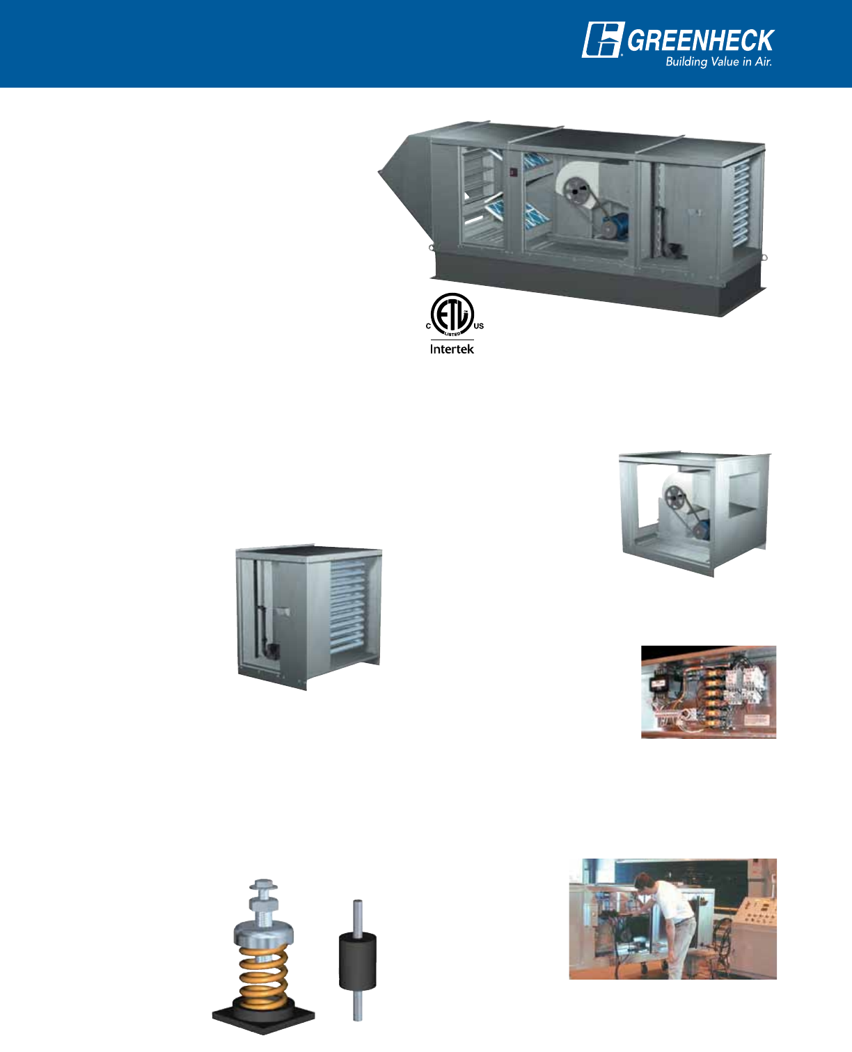
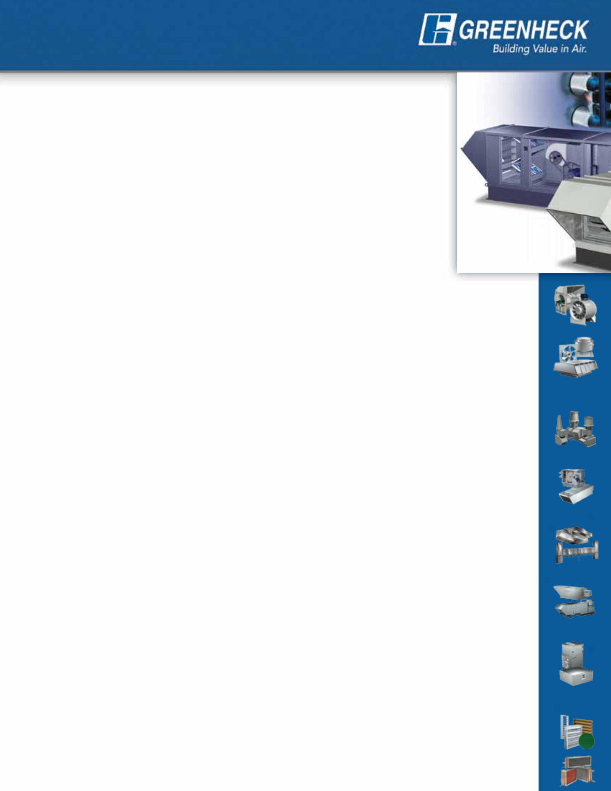
Modular Heating & Ventilating Unit
Model IGX-HV
• Indirect Gas-Fired Heating
• Evaporative • Chilled Water • DX Cooling
September
2011
2
Product Features
All Greenheck model IGX-HV units feature 80%
efficient indirect gas-fired furnace(s), filtered mixing
box section, fan section, and are ETL Listed to the
UL-1995 test standard. Heating capacities range
from 100,000 to 1,200,000 Btu/hr and airflow
volumes are available up to 15,000 cfm.
A modular design concept enables the flexibility
to customize each product for its application. Modules
are then factory assembled and wired to minimize field
installation labor. The result is a semi-custom product at
an attractive cost.
Indirect Gas-Fired Furnaces
The Greenheck furnace is designed for top-notch
performance and long life, combining quality
components with expert craftsmanship. Unique to
our furnace is a post purge cycle, which runs the
combustion fan after the unit is shut down to vent
hot air and moisture out
of the heat exchanger.
The elimination of these
corrosion catalysts adds
years to the life of the heat
exchanger.
Other key features of our
furnace are listed below:
•Powervented
•80%thermalefciency
•Seamlesstubes
•Electronicstagedgascontrols
•Electronicmodulatinggascontrols
•Aluminizedsteelorstainlesssteelheatexchanger
•Directsparkignitionsystem
•Easyaccessburnercontrols
•ETLListedtoANSIStandardZ83.8
•Solidstateautomaticignitionmodule
Vibration Isolators
The entire fan and
motor assembly is
mounted on vibration
isolators to minimize
noise transmission into
thebuilding.Neoprene
isolators are standard on
all units, spring isolators
are optional.
Model IGX-HV
Indirect Gas-Fired
Heating and Ventilating Unit
Indoor/Outdoor Installations
IGX-HV shown with horizontal discharge.
Reliable Fan Performance
Air performance ratings from Greenheck’s third-party
accredited test chamber ensure accurate data.
Fans are constructed of
heavy gauge steel and
designed for high efficiency
and low sound levels.
Wheels are statically and
dynamically balanced
to ensure vibration free
operation.
Control Center
The control center includes the following standard
components:
•Magneticmotorstarterwith
solid state overload protection
•Controltransformer
•Disconnectswitch
•Separatelyfusedmotor
•Distributionterminalstrip
Premiumgradecontrolcomponentsareselectedfor
reliable operation. All electrical components are UL
Listed,recognizedorclassied.Controlcentersare
factory prewired for single point power connection.
Factory Wired and Tested
All units are tested
prior to shipment.
Units are checked
for vibration and
proper operation.
3
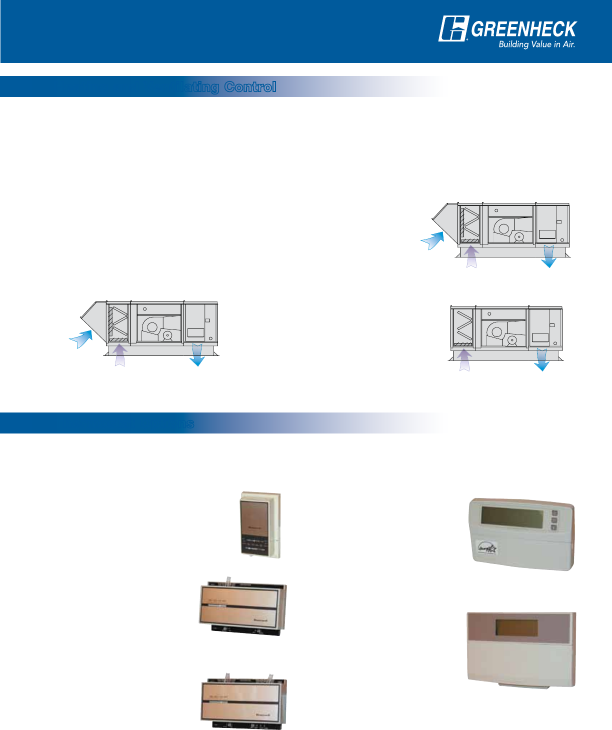
Basic bimetal thermostats with mercury switches or fully programmable electronic thermostats are available as
part of your IGX-HV system. Match your heating, cooling, staging, and operational requirements to the appropriate
thermostat.
HV2: 30%-75% Minimum Outdoor Air
The HV2 option is required when the minimum outdoor air volume
exceeds30%ofthetotalsupplyairvolume.Withhigheroutdoorair
volumes, mixed air temperatures
can vary greatly. Accordingly,
2-stage heating and/or cooling is
recommended. Also, an airstream
override thermostat is standard
with HV2 to prevent cold air
discharge (below 55˚ F) when the
thermostat is satisfied. (electronic
modulation is optional).
TC1: 1-Stage Heating / Cooling
TC1isacoiledbimetalthermostat
used for single-stage heating, cooling
or heating-cooling systems.
TC2: 2-Stage Heating
TC2isacoiledbimetal
thermostat used for 2-stage
heating systems.
TC4: Programmable
TC4hasfullseven-dayprogram
capability. The thermostat can
be set for four times and eight
temperature settings each day of
the week. It can control up to two
stages of heating and two stages
of cooling.
TC5: Deluxe Programmable
TC5hasfullseven-dayprogram
capability. The thermostat can
be set for two occupied and two
unoccupied times with adjustable
temperature settings for each day
of the week. It can control up to
three stages of heating and two
stages of cooling. The Intelligent Fan™ feature energizes the
fan continuously during occupied mode and intermittently
with a call for heating or cooling in unoccupied mode.
TC3: 2-Stage Heating / 2-Stage Cooling
TC3isacoiledbimetal
thermostat used for 2-stage
heating, cooling, or heating-
cooling systems. It includes
an adjustable heat anticipator,
stops, and a locking cover.
Three heating and ventilating options are available to provide proper tempering and fulfill varying requirements
for fresh outdoor air. In all cases, heating and cooling functions are controlled by a room thermostat provided by
GreenheckoraDDCsystem(byothers).
HV1: 0%-30% Minimum Outdoor Air
HV1 is the most common among
heating and ventilating units, allowing
you to set the minimum outdoor air
volumebetween0and30%ofthetotal
supply air volume. With the relatively
low percentage of outdoor air, mixed
air temperatures are mild and stable.
1-stage heating and/or cooling is
recommended. (2-stage or electronic
modulation is optional).
HV3: 100% Return Air
TheHV3optionisavailablewhenno
outdoor air is needed. With relatively
stable return air conditions, 1-stage
heating and/or cooling is strongly
recommended. (2-stage or electronic
modulation is optional).
Suppl
y
R
e
t
u
rn Ai
r
70
%
- 100
%
Outdoor Air
0% - 30%
Suppl
y
R
e
t
u
rn Ai
r
25
%
- 100
%
Outdoor Air
30% - 75%
Suppl
y
R
e
t
u
rn Ai
r
100
%
Suppl
y
R
e
t
u
rn Ai
r
70
%
- 100
%
Outdoor Air
0% - 30%
Suppl
y
R
e
t
u
rn Ai
r
25
%
- 100
%
Outdoor Air
30% - 75%
Suppl
y
R
e
t
u
rn Ai
r
100
%
Suppl
y
R
e
t
u
rn Ai
r
70
%
- 100
%
Outdoor Air
0% - 30%
Suppl
y
R
e
t
u
rn Ai
r
25
%
- 100
%
Outdoor Air
30% - 75%
Suppl
y
R
e
t
u
rn Ai
r
100
%
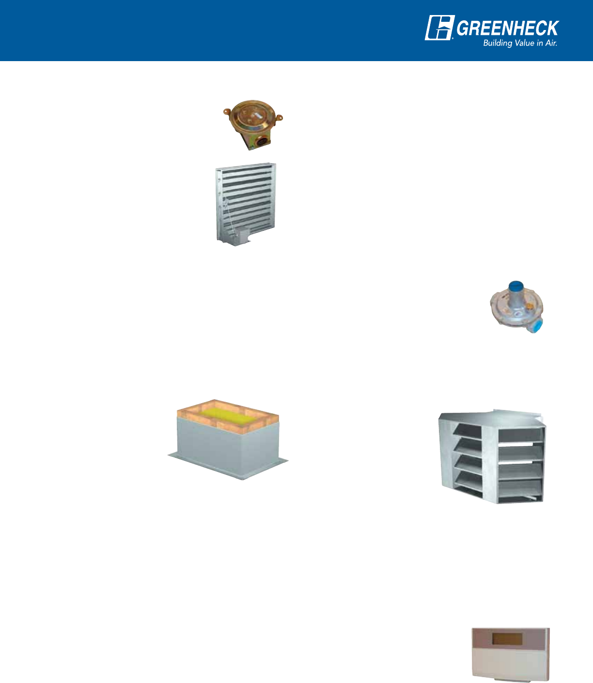
Heating and Ventilating Control
Thermostat Options
Control Options
4
Mixing Box Controls
MB1: Minimum Outdoor Air Positioner
The MB1 option includes a modulating
actuator and potentiometer that control
the outdoor air and return air damper
positions. When the unit is energized,
the dampers will travel to the position
corresponding to the potentiometer setting, providing
the desired amount of outdoor air. When the unit is
powered off, the outdoor air damper closes to prevent
backdrafting. To adjust the damper settings, simply dial
the potentiometer (shown above) to desired operating
position of the outdoor air damper.
MB2: 2-10 Volt External Signal
The MB2 option includes a modulating actuator that is
controlled by an external 2-10 volt signal. This option
is appropriate for applications that call for a building
automation system that will control the mixing box
dampers.
MB3: 4-20 mA External Signal
TheMB3optionincludesamodulatingactuatorthatis
controlledbyanexternal4-20mAsignal.LiketheMB2
option, this option is appropriate for applications that
call for a building automation system that will control
the mixing box dampers.
MB4: Manual Quadrant
TheMB4optionconsistsofamanualquadrantthat
enables the outdoor air and return air dampers to be
secured into a single position. The
primary function is to introduce the
specified minimum outdoor air volume
duringoperation.Dampersremain
in the same position when the unit is
powered off.
InadditiontotheEconomizerCoolingoptionsdescribedabove,Greenheckoffersfourmixingbox(MB)control
options for applications where a factory provided economizer package is not desired.
The mixing box (shown at right) includes
outdoor air and return air low leakage
control dampers in a face and bypass
configuration. Either two-inch pleated
or aluminum mesh filters are available
withinthemixingboxsection.Double-wall
construction is optional.
A mixing box control option must be
specified for every IGX-HV unit. Greenheck
offers eight mixing box control options
that accommodate a wide variety of
applications. The economizer cooling and
mixing box options are described below.
Specifyonlyonecontrolboxoptionperunit.
EC1: Outdoor Temperature Reference
The economizer controller positions the mixing box
dampers to achieve 55°F mixed temperature when
thethermostatcallsforcoolingANDtheoutdoorair
temperature is below the economizer
set point. If outdoor air temperature is
between 55°F and the economizer set
point, the dampers will modulate to
the 100% outdoor air position. Above
the set point, the outdoor air damper
is held at the minimum position.
The set point is field adjustable and
the outdoor air sensor is factory
mounted.
Theeconomizercontrolspackageenablesfreecoolingusingoutdoorair.Alleconomizercooling(EC)optionsinclude
amodulatingactuatorforcontrollingoutdoorandreturnairdampers,andaminimumoutdoorairpositioner.Duringa
call for heating the economizer is locked out and the outdoor air damper holds at the minimum position.
EC2: Outdoor Enthalpy Reference
SameasEC1,excepteconomizersetpointisbasedon
outdoor air enthalpy.
EC3: Airstream Temperature Reference
The economizer controller compares the temperatures of
the outdoor air and return air when the thermostat calls
for cooling. The mixing box dampers are then positioned
to maximize the airflow of the
cooler airstream. When outdoor
air temperature is sufficiently
cool, the mixing box dampers
will modulate to provide 55°F
mixed air. The outdoor air sensor
is factory mounted. The return
air sensors are field installed.
EC4: Airstream Enthalpy Reference
SameasEC3,exceptairstreamenthalpy values are
compared.
Suppl
y
R
e
t
u
rn Ai
r
Outdoor Air
Mixing Box Controls with Economizer Cooling
Mixing Box Controls (No Economizer)
5
Cooling Options
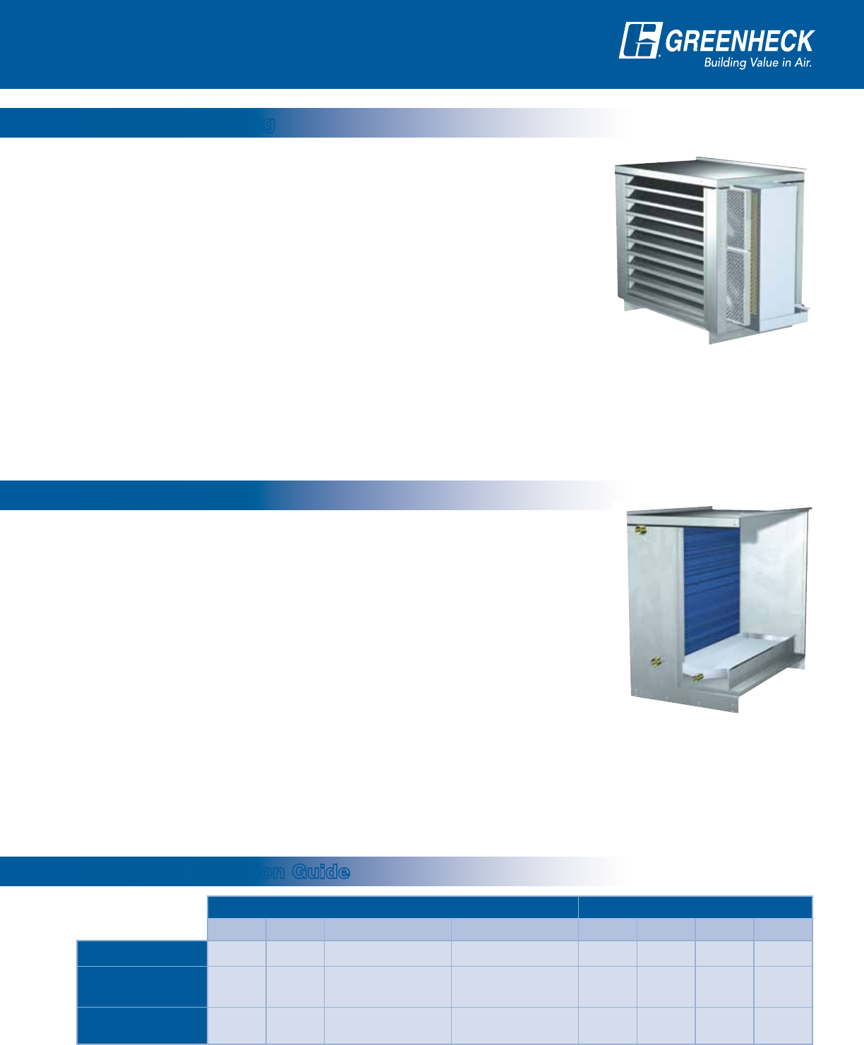
An evaporative cooling section includes a galvanized
steel housing with a louvered intake, two inch aluminum
mesh filters and a stainless steel evaporative cooling
media housing. The evaporative cooling media is
CELdekorGLASdekandhasadepthof12inchesfor
90% cooling effectiveness.
Drainandoverowlinesareconvenientlystubbed
through the side of the cooling section. The supply line
connection is field located where convenient.
IGX-HV airflow capacity for evaporative cooling is up
to14,000cfm.Below9,000cfm,evaporativecooling
modules ship attached and factory wired. Field
attachment is required for airflow above 9,000 cfm.
Mixing Box Controls:
MixingboxcontroloptionEC1isrecommendedforuse
with evaporative cooling. On a call for cooling when the
outdoor air temperature
is below the
economizer set point,
the dampers modulate
to provide cool mixed
temperatures down
to 55°F. When the
outdoor air is above the
economizer set point,
the evaporative cooling
section is energized
and the dampers travel
to the 100% outdoor air
position.
ThemixingboxoptionsareNOTrecommendedin
conjunction with evaporative cooling.
Model IGX-HV boasts the flexibility of chilled water
ordirectexpansion(DX)coolingwithcapacityto
11,000cfm.Thecoolingsectionincludesthecooling
coil, stainless steel drain pan and insulated double wall
construction.Drainandcoilconnectionsarestubbed
through the wall for convenience.
Forpropercoilsizing,useGreenheck’sComputerAided
ProductSelection(CAPS)programorcontactyourlocal
representative. Four and six row coils are available.
Coolingcoilsectionsareinstalleddownstreamofthe
mixing box section for a draw through arrangement. This
provides a streamlined transition to adjacent IGX-HV
sections.DXcoilsrequireremotecondensingunits.
Mixing Box Controls:
All mixing box and economizer control options are
availablewithchilledwaterorDXcoolingcoils.
For economizer climates,
theEC1optionis
recommended. Mixing
box options operate as
describedonpage4.
Thermostats:
The cooling coil and
mixing box control
options may use a
1-stage (chilled water
orsingle-stageDX)or
2-stage(dual-stageDX)coolingthermostat.
ThecoolingcoilandECmixingboxcontroloptions
require a 2-stage cooling thermostat. Economizer
representstherststageofcoolingandasingleDX
stage or chilled water coil represents the second stage
of cooling.
EC Options MB Options
EC1 EC2 EC3 EC4 MB1 MB2 MB3 MB4
No Cooling Yes Yes Yes Yes Yes Yes Yes Yes
Evaporative
Cooling Yes Yes Not
Recommended
Not
Recommended No No No No
Chilled Water or
DX Cooling Yes* Yes* Yes* Yes* Yes Yes Yes Yes
*Two-stage cooling thermostat required. Boldface type indicates factory recommended options.
Evaporative Cooling
Cooling Coils
Mixing Box Selection Guide

6
Air Performance
Note:Theairperformancedatashowndoesnotincludeinternalstaticpressurelossesduetoitemssuchaslters,dampersand
furnaces.Forexactairperformancedatabasedonspecicunitconguration,usetheGreenheckCAPSselectionprogram.
Model CFM
TOTAL STATIC PRESSURE in inches of WG Maximum
Furnace Size
(Input MBH)
0.50 0.75 1.00 1.25 1.50 1.75
IGX-HV-112
2,600 RPM 662 761 853 934 1009 350
BHP .58 .72 .86 1.0 1.2
3,500 RPM 756 839 920 993 1065 1133 500
BHP 1.0 1.3 1.5 1.7 1.9 2.1
4,400 RPM 871 939 1006 1073 1137 1197 600
BHP 1.8 2.1 2.4 2.6 2.9 3.1
IGX-HV-115
5,000 RPM 671 741 808 871 931 986 600
BHP 1.7 2.0 2.3 2.6 2.9 3.2
6,000 RPM 749 812 870 929 982 1035 600
BHP 2.6 2.9 3.3 3.7 4.0 4.4
7,000 RPM 833 889 943 994 1044 1093 600
BHP 3.7 4.2 4.6 5.0 5.5 5.9
Housing Size 22
Model CFM
TOTAL STATIC PRESSURE in inches of WG Maximum
Furnace Size
(Input MBH)
0.50 0.75 1.00 1.25 1.50 1.75
IGX-HV-118
7,000 RPM 566 627 685 738 790 839 1,050
BHP 2.1 2.5 2.8 3.2 3.6 4.0
8,500 RPM 636 690 740 790 836 880 1,200
BHP 3.3 3.8 4.2 4.7 5.1 5.6
10,000 RPM 712 759 805 849 891 933 1,200
BHP 5.0 5.5 6.1 6.6 7.1 7.7
IGX-HV-120
10,000 RPM 542 590 634 678 723 765 1,200
BHP 3.6 4.0 4.5 5.0 5.6 6.1
12,500 RPM 633 672 711 748 784 820 1,200
BHP 6.3 6.9 7.5 8.1 8.7 9.3
15,000 RPM 731 763 795 829 861 892 1,200
BHP 10.2 10.9 11.6 12.3 13.1 13.8
Housing Size 32
Model CFM TOTAL STATIC PRESSURE in inches of WG Maximum
Furnace Size
(Input MBH)
0.50 0.75 1.00 1.25 1.50 1.75
IGX-HV-108
800 RPM 993 1109 1216 1311 1399 100
BHP .21 .26 .31 .35 .40
1,000 RPM 1112 1228 1325 1415 1500 1579 150
BHP .34 .41 .47 .53 .59 .65
1,200 RPM 1238 1347 1445 1530 150
BHP .51 .59 .68 .75
IGX-HV-109
1,500 RPM 880 1014 1140 1255 1361 1460 200
BHP .36 .45 .54 .63 .73 .84
2,000 RPM 1004 1113 1219 1321 1417 1510 250
BHP .65 .77 .90 1.0 1.1 1.3
2,500 RPM 1154 1244 1329 1419 1503 1587 250
BHP 1.1 1.2 1.4 1.6 1.7 1.9
IGX-HV-110
2,000 RPM 805 912 1013 1110 1199 250
BHP .48 .59 .71 .84 .96
2,500 RPM 906 995 1082 1166 1247 1325 250
BHP .79 .93 1.07 1.21 1.36 1.51
3,000 RPM 1014 1097 1172 1244 1315 1386 250
BHP 1.22 1.39 1.55 1.72 1.88 2.05
Housing Size 12
7
Accessories
Air Filter Gauge
Indicates when filters become
dirty. An indicator light may be
wall/beam mounted or provided
with a remote control panel.
Motorized Dampers
Dischargedampersareavailable
to prevent backdrafts when
the fan is not in operation.
Mixing box dampers are factory
mounted and wired.
Fan Spring Vibration Isolation
Springvibrationisolatorsareavailableinlieuof
neopreneisolatorsforhousingsizesH22andH32
(fan sizes 112 and larger).
115 Volt Service Receptacle
A115voltGFCIoutletismountedexternallyinaNEMA
3Rboxfortheconvenienceofeldservicepersonnel.
A separate 115 volt power source is required.
Roof Curbs
Factory provided roof
curbs are available to
ensure compatibility
between the make-up
air unit and roof curb.
Standardconstructionis
G90 galvanized steel.
Special Coatings
Greenheck’sPermatector™powderpaintisavailableif
a painted look is desired and recommended for outdoor
installationsnearsaltwatershorelines.Decorative
baked enamel paints are also available in a variety of
colorstomatchexistingbuildingxtures.Consultyour
Greenheck representative for paint selections.
Weatherhood
A galvanized steel mist eliminating intake hood
is standard on outdoor IGX-HV models. The mist
eliminating intake hood provides a double layer of
protection against moisture entering the mixing box
section.
Propane Gas Conversion Kit
Greenheck’s indirect gas furnaces are ETL Listed for
bothnaturalgasorLP.
Duct Adapter
Ductadaptersareoptionalwithfactorysuppliedcurbs
and provide an easy method for attaching ductwork to
the curb.
Double Wall Construction
An interior metal liner is available to isolate insulation
from the airstream. One-inch thick insulation is included
with this option.
Gas Pressure Regulator
Required if building gas line pressure
exceeds IGX-HV maximum inlet gas
pressureof14in.wg.
Smoke Detector
A12/24VDCphotoelectricsmokedetectorisavailable
for duct mounting. Typical operating temperature range
is32°to131°F(0°to55°C).
Discharge Diffuser
Availableaseither3-way
diffuser for horizontal
dischargeor4-way
diffuser for downblast
discharge.
Airstream Override
This option prevents the discharge air temperature
from dropping below 55°F after the call for heating
has ended.
Warm-Up Control
AvailablewiththeTC5thermostat.Thethermostat
may be programmed to provide
a warm-up cycle prior to the
occupied start time. This ensures
immediate comfort and proper
air quality as people enter the
occupied areas.
3-Way Diffuser
Our Warranty
Greenheck warrants this equipment to be free from defects in material and workmanship for a period of one year from the
shipment date. Any units or parts which prove defective during the warranty period will be replaced at our option when returned
to our factory, transportation prepaid. Motors are warranted by the motor manufacturer for a period of one year. Should motors
furnished by Greenheck prove defective during this period, they should be returned to the nearest authorized motor service
station. Greenheck will not be responsible for any removal or installation costs.
As a result of our commitment to continuous improvement, Greenheck reserves the right to change specifications without notice.
Greenheck P.O. Box 410 • Schofield, WI 54476-0410 • Phone (715) 359-6171 • greenheck.com
Copyright © 2011 Greenheck Fan Corp. • 00.TAP.1027 R3 9-2011 SN
Specifications
General: Heating and ventilating unit shall be as
manufacturedbyGreenheckFanCorporationorapproved
equal provided all specifications are met. Greenheck model
IGX-HVisusedasthebasisofdesign.Performanceshall
be as scheduled on plans.
Furnace: Indirect gas-fired furnace shall be 80% efficient,
ETL Listed and have a blow-through fan design. Furnace
shallbecapableofoperationwithnaturalorLPgasand
have a power venting system with post purge cycle. The
heat exchanger shall be constructed of aluminized steel
orstainlesssteel.Standardfurnacefeaturesshallinclude
main gas pressure regulator, main gas valve, electronic
staged controls, direct spark ignition system, high limit and
a24voltcontroltransformer.Furnaceshallbeinsulated
and have double-wall construction.
Temperature Control: Heating and cooling output shall
be controlled by a room thermostat to maintain desired
room temperature. Economizer control shall provide the
first stage of cooling, where specified. Furnaces shall
provide one or two stages of heat output control.
Unit Casing and Frames: All frames and panels shall
be G90 galvanized steel. Where top panels are joined
there shall be a standing seam to insure positive weather
protection. All metal-to-metal surfaces exposed to the
weather shall be sealed, requiring no caulking at jobsite.
All components shall be easily accessible through
removable doors.
Insulation: Models provided with a mixing box shall be
insulated from the return section through to the supply
discharge.InsulationshallbeinaccordancewithNFPA90A
andtestedtomeetUL181erosionrequirements.Double-
wall shall be provided if specified.
Fan Section:Centrifugalfansshallbedouble-width,
double-inlet. Fan and motor shall be mounted on a
common base and shall be internally isolated. All blower
wheels shall be statically and dynamically balanced.
Ground and polished steel fan shafts shall be mounted in
permanently lubricated ball bearings (up to size 118) or
ball bearing pillow blocks (size 120 and larger). Bearings
shall be selected for a minimum L10 life in excess of
100,000hoursatmaximumcatalogedspeeds.
Motors and Drives: Motors shall be energy efficient,
complyingwithEPACTstandards,forsinglespeedODP
and TE enclosures. Motors shall be permanently lubricated,
heavy-duty type, matched to the fan load and furnished
atthespeciedvoltage,phaseandenclosure.Drivesshall
be sized for a minimum of 150% of driven horsepower.
Pulleysshallbecastandhavemachinedsurfaces,
10horsepowerandlessshallbesuppliedwithan
adjustable drive pulley.
Electrical: All internal electrical
components shall be prewired for
single point power connection. All
electrical components shall be UL
Listed,RecognizedorClassied
where applicable and wired in
compliancewiththeNational
ElectricalCode.Controlcentershall
include motor starter, control circuit
fusing,controltransformerfor24VAC
circuit, integral disconnect switch with
separate motor fusing and terminal
strip.Contactors,Class20adjustable
overload protection and single-phase
protection shall be standard.
Filter Section: Filters shall be
mounted in a V-bank arrangement
such that velocities across the filters
do not exceed 550 ft./min. Filters shall be easily accessible
through a removable access panel.
Weatherhood: Weatherhood shall be mist eliminating
type, constructed of G90 galvanized steel. The
weatherhood shall contain drainable blade louvers, backed
by mist eliminating filters to prevent moisture intake.
Mixing Box: Mixing box shall contain outside air and
return air dampers with low leakage, pressure activated,
extruded vinyl blade seals, aluminum jamb seals, Belimo
actuatorand30%efcientpleatedltersinaV-bank
arrangement. The mixing box shall modulate the amount of
outdoor and return air by use of dampers. Input signal for
return damper shall be from potentiometer, 2-10 volt signal,
4-20mAsignalormanualquadrantcontroller.
Evaporative Cooling Section: Evaporative cooling
section shall include a galvanized steel housing with
louvered intake, two-inch aluminum mesh filters and a
stainless steel evaporative cooling module all provided
by the make-up air unit manufacturer. The louver shall
be stationary type with drainable blades, designed to
withstandwindloadsof25PSF.Evaporativecoolingmedia
shallconsistofCELdekcellulosebasedmaterialwitha
depth of 12 inches for a cooling effectiveness of 90%.
Drainandoverowconnectionsshallbepipedthroughthe
side of the evaporative cooling section.
Cooling Coil:Directexpansion(DX)orchilledwater
coil shall be factory tested and rated in accordance with
AHRI410.Coilsshallhavecoppertubeswithpermanently
expandedaluminumns,12fpiorless.DXcoilsshallbe
equipped with distributors to receive expansion valves at
theliquidconnections.Drainpansshallextendatleast
12 inches downstream of coil and be sloped to drain
connection.
