IM 251E 7FA.05 With Load Coupling Spacers
User Manual: IM-251E-7FA.05
Open the PDF directly: View PDF  .
.
Page Count: 40
215ClintonRoad
NewHartford,NY13413
Tel:+13157684855
Fax:+13157684941
Email:info@riverhawk.com
INSTRUCTIONMANUALIM‐251
ForGasTurbineTensioned
StudsandNuts
Note:Thismanualiswrittenspecificallyforconnectionsthat
employtheuseofLoadCouplingSpacersplacedunderthenuts.
Ifspacersarenotused,consultmanualIM‐327
ApplicableBoltingConnections–
Fr.7FA.05GasTurbineto7FH2BGenerator
Fr.7FA.05GasTurbinetoLoadCoupling
LoadCouplingto7FH2BGenerator
ApplicableGEOrderingSheetPartNumbers
110T2635P0001
110T2635P0002
110T2635P0003
110T2635P0004
110T2635P0005
110T2635P0006
110T2635P0007
GEPowerGeneration
GENERALELECTRICCOMPANY
MLI: ____ OF ____
DATE
ISSUED:
THISDOCUMENTSHALLBEREVISEDINITSENTIRETY.ALLSHEETSOFTHISDOCUMENTARE
THESAMEREVISIONLEVELASINDICATEDINTHISVENDORSUPPLIEDDRAWINGAPPLIQUE.
C
REV
373A4040
GEDRAWINGNUMBER
VENDORSUPPLIED
THISDOCUMENTISFILEDUNDERTHEGEDRAWINGNUMBER.
GENOTTOREVISE.GEREVISIONLEVELISSHOWNONTHISAPPLIQUE.
GESIGNATURES
CHECKED:
TheRiverhawkCompanyreservestherighttoupdatethisdocumentwithoutdisseminationornotice.
ThelatestrevisionmaybeobtainedbycontactingRiverhawkCompanyorthruwww.riverhawk.com.
E
InstructionManualIM‐251
215ClintonRoad
NewHartford,NY13413
Tel:+13157684855
Fax:+13157684941
Email:info@riverhawk.com
C
REV
373A4040
GEDRAWINGNUMBER
Page2of40
E
TableofContents
SectionDescriptionPageNumber
1.0CautionsandSafetyWarnings3
2.0ScopeandGEPartNumberCrossReference4
3.0QuickChecklist6
4.0GeneralPreparations11
5.0HardwareSetPreparations14
6.0Stud,Nut,andLoadCouplingSpacerAssembly17
7.0HydraulicTensionerEquipmentAssembly20
8.0AssemblyofTensioneronStud23
9.0StudTensioning27
10.0ThreadLocking30
11.0Stud,Nut,andLoadCouplingSpacerRemoval30
12.0StorageInstructions34
13.0FrequentlyAskedQuestions35
14.0RevisionHistory38
Appendix
A118‐BoltTensioningPattern(GT‐LC)RecordSheet39
Appendix
A216‐BoltTensioningPattern(LC‐GEN)RecordSheet40

InstructionManualIM‐251
215ClintonRoad
NewHartford,NY13413
Tel:+13157684855
Fax:+13157684941
Email:info@riverhawk.com
C
REV
373A4040
GEDRAWINGNUMBER
Page3of40
E
1.0CautionsandSafetyWarnings
WARNING
Impropertooluseandthefailuretofollowthecorrectproceduresaretheprimaryroot
causesoftoolfailuresandpersonalinjuries.Alackoftrainingorexperiencecanleadto
incorrecthardwareinstallationorincorrecttooluse.Onlytrainedoperatorswithcareful,
deliberateactionsshouldusehydraulictensioners.
CAUTION
Personalinjuryandequipmentdamagecanoccuriftheproperhealthandsafetycodesand
proceduresarenotfollowed.Contactthesite’shealthandsafetyofficetodetermineall
applicablesafetyrulesandregulations.
WARNING
Theproperpersonalprotectiveequipmentmustbewornatalltimes.
CAUTION
Itisespeciallyimportanttochecktheconditionoftheconicalthreadusedtotensionthestud.
Threaddamagefrompreviousabusecanleadtofailureofthestudortensioningequipment
CAUTION
RiverhawkrecommendsthatthetensionershouldbereturnedtoRiverhawkforperiodic
inspections.Replacementofobsoletetensionersisrecommended.Functionalupgradesarealso
recommended.TheRiverhawkServiceReturnsCoordinatorshouldbenotified3‐6monthsprior
toaplannedoutagetoscheduleaninspectionservice.
WARNING
Adamagedburstdiscmustbereplacedwithaburstdiscofthesamedesignandpressure
rating.Donotsubstituteadamagedburstdiscwithadifferentdisctype,adifferentpressure
rating,oraforeignobject.
WARNING
Toavoidfailure,ensuresafety,andproperoperation,thetensionerassemblymustbeinstalled
onastudintheflangebeforebleedingandpressurizingthetensioner.Donotusethetensioner
atanypressureunlessthetoolisinstalledonastudinaflange.
CAUTION
Personalinjuryandequipmentdamagecanoccurifthepullerscrewisnotsecurelyengaged
withthetaperedthreadsofthestud.Properengagementisachievedwhenthepullerscrewis
tightinthestudandthetensionerassemblyisfreetoturn.

InstructionManualIM‐251
215ClintonRoad
NewHartford,NY13413
Tel:+13157684855
Fax:+13157684941
Email:info@riverhawk.com
C
REV
373A4040
GEDRAWINGNUMBER
Page4of40
E
WARNING
Thesafetycagemustbeinplaceatalltimes.Whenthetensionerispressurizedhandsmustbe
keptoutofdesignatedareastoavoidanypotentialforpersonalinjury.
CAUTION
Beforethreadingthepullerscrewintothestud,carefullycheckthecleanlinessofboththe
stud'sandthepullerscrew'sconicalthreads.Applyalightcoatofcleanturbineoiloraspray
lubricanttothepullerscrew.Thisprocedurewilleaseassemblyandassurepositivematingof
thethreadsbeforetightening.Donotuse“NeverSeize”ontheconicalthreads.
CAUTION
Donottightenthenutwhilethetooliscominguptopressure;waituntilpressureisachieved
beforeattemptingtotightenthenutwiththespannerring.Ifthetoolisnotproperlyinstalled,
thetoolcouldjumpoffthestudwhilecominguptopressure.
CAUTION
Donotexceedthemaximumpressuremarkedonthetensioner.Excessivepressurecandamage
thestudandpullerscrew.
WARNING
FIREHAZARD:DONOTheatwhenpullerassemblyisinplace.Personalinjuryorequipment
damagemayoccur.UseofanOxy‐Acetylenetorchisnotrecommended
WARNING
Donotuseahydraulictensionertoremoveastudwithdamagedconicalthreads.
2.0ScopeandGEPartNumberCrossReference
Thisdocumentdescribestheproceduretobeusedtoinstallthestudandnutsetssuppliedby
theRiverhawkCompanyintheflangesattheGasTurbine/LoadCouplingandLoad
Coupling/Generatorconnections.
ThevariousframeconfigurationscoveredinthismanualarelistedinSections2.1through2.4
withdifferencesasrelatedtoconnectivehardwaredefined.Listedalsoarethepertinent
hardwaredrawings(HF‐xxxx).Thesedrawingsaswellastoolingdrawings(HT‐xxxx)formpartof
thismanual.
InstructionManualIM‐251
215ClintonRoad
NewHartford,NY13413
Tel:+13157684855
Fax:+13157684941
Email:info@riverhawk.com
C
REV
373A4040
GEDRAWINGNUMBER
Page5of40
E
2.1Frame7FA.05GasTurbineto7FH2BGenerator
GEPartNumberRiverhawkP/NGEVENDOCP/N
110T2635P0001
110T2635P0002
HF‐5117
HF‐5117
GE269B8710
GE269B8710
ThehydraulictoolingusedforinstallationandremovalisRiverhawkHT‐5144andHT‐6285for
thegasturbinesideoftheloadcouplingandHT‐6019forthegeneratorsideoftheload
coupling.
ThesehardwaredrawingsdepictthestudandnutsetfortheGasTurbinetoLoadCoupling(2‐
1/4”size,Qty18)aswellastheLoadCouplingto7FH2BGenerator(2‐3/4”size,Qty16).The
GasTurbinetoLoadCouplingstudandnutsetisusedwithasetofloadcouplingspacersthat
aresuppliedseparately.
2.2Frame7FA.05GasTurbinetoLoadCoupling
GEPartNumberRiverhawkP/NGEVENDOCP/N
110T2635P0004HF‐5411GE269B8711
ThehydraulictoolingusedforinstallationandremovalisRiverhawkHT‐5144andHT‐6285.
ThesehardwaredrawingsdepictthestudandnutsetfortheGasTurbinetoLoadCoupling(2‐
1/4”size,Qty18).TheGasTurbinetoLoadCouplingstudandnutsetisusedwithasetofload
couplingspacersthataresuppliedseparately.
2.3LoadCouplingto7FH2BGenerator
GEPartNumberRiverhawkP/NGEVENDOCP/N
110T2635P0005HF‐5412GE269B8712
ThehydraulictoolingusedforinstallationandremovalisRiverhawkHT‐6019.
ThesehardwaredrawingsdepictthestudandnutsetfortheLoadCouplingto7FH2BGenerator
(2‐3/4”size,Qty16).
InstructionManualIM‐251
215ClintonRoad
NewHartford,NY13413
Tel:+13157684855
Fax:+13157684941
Email:info@riverhawk.com
C
REV
373A4040
GEDRAWINGNUMBER
Page6of40
E
2.4HydraulicTooling
GEPartNumberRiverhawkP/NGEVENDOCP/N
110T2635P0003
110T2635P0006
110T2635P0007
HT‐5144
HT‐6019
GT‐6030
AP‐0532
HT‐6285
HT‐5144
HT‐6019
GT‐6030
AP‐0532
HT‐6285
GE269B8713
GE269B8762
GE269B8763
GE359B2502
GE373A4069
GE269B8713
GE269B8762
GE269B8763
GE359B2502
GE373A4069
3.0QuickChecklist
ThefollowingchecklistisintendedasasummaryofthestepsneededtousetheRiverhawk‐
suppliedequipment.Newpersonnelorthoseexperiencedpersonnelwhohavenotusedthe
Riverhawkequipmentrecentlyareencouragedtoreadtheentiremanual.
EQUIPMENTINSPECTION
□ Checkoillevelinhydraulicpump.
□ Checkairpressureat80psi[5.5bar]minimum.(Forair‐drivenpumps)
□ Checkhydraulichosefordamage.
□ Testpump.
□ Inspecttensionerforanydamage.
NUTANDSTUDPREPARATION
□ Inspectstudsandnutsforanydamage.
□ Cleanthestuds,nuts,andloadcouplingspacers(LoadCouplingSpacersongasturbine
toloadcouplingflangeonly)
InstructionManualIM‐251
215ClintonRoad
NewHartford,NY13413
Tel:+13157684855
Fax:+13157684941
Email:info@riverhawk.com
C
REV
373A4040
GEDRAWINGNUMBER
Page7of40
E
□ Measurestudlengths.(VERYIMPORTANT)
□ Lubricatethestud’sthreadswithcleanturbineoilorspraylubricant.Lubricatethenut’s
threadsandnutfacewithcleanturbineoilorspraylubricant.
□
Installstuds,nuts,andloadcouplingspacers(off‐center)intotheflange(LoadCoupling
Spacersareplacedontheloadcouplingsideofthegasturbinetoloadcouplingflange
only)
□ Setstick‐outdimensionontheloadcouplingsideoftheflange.
□ WithAllenwrenchinbacksideofstud,firmlyseatbacksidenutusingspannerringand
pinwrench.
□ Verifystick‐outmeasurement(VERYIMPORTANT)
□ Measureandrecordstartingstudinstallationgagereadings.(GeneratorSideOnly)
TENSIONING(BoltInstallation)
□ Checktensionerdrawingforcorrectpartsandpartnumbers.
□ Applyalightcoatofcleanturbineoilorspraylubricanttothepullerscrew.DONOTUSE
“NEVERSEIZE”ONTHECONICALTHREADS.
□ Installtheretentionscrewsintotheadjacentstudsoneithersideofthestudtobe
tensioned.(GeneratorSideOnly)
□ Installthespannerringontothenut.
□ Threadthepullerscrewintothestud.
□ InsertanAllenwrenchintothebacksideofthestud.
□ InsertanotherAllenwrenchintothepullerscrew.Whileholdingthestudstill,tighten
thepullerscrewuntilhandtightandthenloosenthepullerscrew1/2ofaturn.
□ Retightenthepullerscrewandleavetight.DONOTBACKOFFPULLERSCREW.

InstructionManualIM‐251
215ClintonRoad
NewHartford,NY13413
Tel:+13157684855
Fax:+13157684941
Email:info@riverhawk.com
C
REV
373A4040
GEDRAWINGNUMBER
Page8of40
E
□ Slidethefootoverthepullerstudandorientatethefootintoposition.
□ PlaceFootExtensionblocksoneithersideofthenut.(GasTurbineSideOnly)
□ Threadthetensionerontopullerscrewuntilitstops.Thereshouldbea1/16”to3/16”
gapbetweenthefootandtensioner.
□ Placetheguardoverthetensionerandpositionguidepinintotheholeinthebackside
ofthestud.(GasTurbineSideOnly)
□ Placetheguardovertensionerandpositiontheguard’spocketedslotsintoretention
screws.(GeneratorSideOnly)
□ Tightentheguard’sknurledinterlockfittingbyhanduntilitpressesfirmlyagainst
tensioner(nogap).
□ Theretentionscrewsmustbeinsidetheguard’spocketedslots.(GeneratorSideOnly)
□ Pushthecenteroftheinterlockfittingtowardsthetensionerwhilepullingbackonthe
fitting’spulltabsuntilitlocksontothetensionerandreleasethepulltabs.
□ Installthebacksideguardtocoverstudtobetensioned.(GeneratorSideOnly)
□ Connectthehydraulicpumptothetensionerandtensionto50%.Consultmanualfor
correctpressure.
□ Usethepinwrenchtoturnthespannerringtofirmlytightennutwith20ft∙lbs[27N∙m]
oftorque.
□ Releasepressureandallowthetensionertofullyretract.
□ Disconnectthehoseandreleasetheinterlockfittingbypushingthecenterofthe
interlockfittingtowardsthetensionerwhilepullingbackonthefitting’spulltabs.
□ Removethebacksideguard.(GeneratorSideOnly)
□ Loosentheknurledinterlockfittingandremovetheguard.
□ Unscrewthetensionerfromthepullerscrew.
InstructionManualIM‐251
215ClintonRoad
NewHartford,NY13413
Tel:+13157684855
Fax:+13157684941
Email:info@riverhawk.com
C
REV
373A4040
GEDRAWINGNUMBER
Page9of40
E
□ Removethefoot,footextensions(GasTurbineSideOnly),pullerscrew,spannerring,
andinthecaseofthegeneratorsidetheretentionscrews.
□ Movetothenextstudinthepattern.Tensionallstudsto50%beforeproceedingtofinal
pressure.
□ Repeatabovestepsatfinalpressure.
□ Measurefinalstudlengthandrecordonstretchdatasheets.Calculatefinalstretch
measurement.ThegeneratorsidemustuseGT‐6030gaugetoverifyinstallation.
□ Torquethenuts'setscrews.
DETENSIONING(StudRemoval)
□ Loosennuts'setscrews
□
Inspectandcleanstuds'conicalthreads.DonotcontinueuntilALLdebrisisremoved
fromthethreads!SeeinstructionmanualIM‐220.Donottrytousethetensionerto
removeadamagedstud!
□ Applyalightcoatofcleanturbineoilorspraylubricanttothepullerscrew.DONOTUSE
“NEVERSEIZE”ONTHECONICALTHREADS.
□ Installtheretentionscrewsintotheadjacentstudsoneithersideofthestudtobe
tensioned.(GeneratorSideOnly)
□ Installthespannerringontothenut.
□ Threadthepullerscrewintothestud.
□ InsertanAllenwrenchintothebacksideofthestud.
□ InsertanotherAllenwrenchintothepullerscrew.Whileholdingthestudstill,tighten
thepullerscrewuntilhandtightandthenloosenthepullerscrew1/2ofaturn.
□ Retightenthepullerscrewandleavetight.DONOTBACKOFFPULLERSCREW.
□ Placethefootextensionblocksoneithersideofthenut.(GasTurbineSideOnly)
□ Slidethefootoverthepullerstudandorientatethefootintoposition.

InstructionManualIM‐251
215ClintonRoad
NewHartford,NY13413
Tel:+13157684855
Fax:+13157684941
Email:info@riverhawk.com
C
REV
373A4040
GEDRAWINGNUMBER
Page10of40
E
□ Threadthetensionerontopullerscrewuntilitstops.Thereshouldbea1/16”to3/16”
gapbetweenthefootandtensioner.
□ Placetheguardoverthetensionerandpositionguidepinintotheholeinthebackside
ofthestud.(GasTurbineSideOnly)
□ Placetheguardovertensionerandpositiontheguard’spocketedslotsintoretention
screws.(GeneratorSideOnly)
□ Tightentheguard’sknurledinterlockfittingbyhanduntilitpressesfirmlyagainst
tensioner(nogap).
□ Theretentionscrewsmustbeinsidetheguard’spocketedslots.(GeneratorSideOnly)
□ Pushthecenteroftheinterlockfittingtowardsthetensionerwhilepullingbackonthe
fitting’spulltabsuntilitlocksontothetensionerandreleasethepulltabs.
□ Installthebacksideguardtocoverstudtobetensioned.(GeneratorSideOnly)
□ Connectthehydraulicpumptothetensionerandtensiontofinalpressure.Consult
manualforcorrectpressure.
□ Loosennutwiththespannerringandpinwrench.
□ Releasepressureandallowthetensionertofullyretract.
□ Disconnectthehoseandreleasetheinterlockfittingbypushingthecenterofthe
interlockfittingtowardsthetensionerwhilepullingbackonthefitting’spulltabs.
□ Removethebacksideguard.(GeneratorSideOnly)
□ Loosentheknurledinterlockfittingandremovetheguard.
□ Unscrewthetensionerfromthepullerscrew.
□
Removethefoot,footextensions(GasTurbineSideOnly),pullerscrew,spannerring,
andinthecaseofthegeneratorsidetheretentionscrews.Itmaybenecessarytoinsert
anAllenwrenchintothebacksideofthestudtoremovethepullerscrew.
□ Movetonextstudinpattern

InstructionManualIM‐251
215ClintonRoad
NewHartford,NY13413
Tel:+13157684855
Fax:+13157684941
Email:info@riverhawk.com
C
REV
373A4040
GEDRAWINGNUMBER
Page11of40
E
4.0GeneralPreparations
Readandunderstandallinstructionsbeforeinstallingandtensioningstuds.
OperatorsshouldbetrainedorhavepreviousexperienceusingRiverhawktensioning
equipment.Trainingwillminimizethechanceofimproperuseoftheequipment.
Thehydraulictoolingincludingthehydraulichosesshouldbeinspectedpriortouse.Inspection
guidelinesarelistedinthefollowingsub‐sections.
Thisequipmentproducesveryhighhydraulicpressuresandveryhighforces.Operatorsmust
exercisecautionandweartheappropriatepersonalprotectiveequipmentwhenhandlingand
operatingthehydraulictooling.
High‐pressureoilfromthehydraulicpumppressurizesthetensionerwhichgeneratesavery
largeforcethatactuallystretchesthestud.Asthestudisstretchedthenutliftsofftheflange.
Thenutisthenturnedbyhandusingthesuppliedspannerring.Oncethenutistightagainstthe
flange,thepressureinthetensionerisreleased.Thehardwareisnowclampingtheflange
together.
4.1MachinePreparation
Theflangetobetensionedmustbefullyclosedpriortopositioningofstudsintheflanges.
Turningtheturbineshaftsisnotrequired,butmaybeuseful.Also,itwillbeadvantageousto
removeasmanyobstructionsaspossiblefromtheflangearea,suchasspeedprobes,shipping
plates,andconduit.
4.2Hardware–Balance
Thestudsaresuppliedincomponentbalancedsets.Astudcanbeexchangedwithanotherstud
initssetwithoutaffectedtheoverallbalanceoftheequipment.Donotexchangeastudfrom
onesetwithanotherstudfromadifferentset.WhenshippedfromRiverhawk,thestudsare
notassignedtoanyspecificholeintheloadcouplingflange;thisisoptionalandcanbedoneat
theinstallationsite.ThesetsizeisdeterminedbytherelevantGEorderdrawing(seesection
2.0).
Thenutsaresuppliedincomponentbalancedsets.Anutcanbeexchangedwithanotherinits
setwithoutaffectingtheoverallbalanceoftheequipment.Donotexchangeanutfromoneset
withanothernutfromadifferentset.WhenshippedfromRiverhawk,thenutsarenotassigned
toanyspecificholeintheloadcouplingflange;thisisoptionalandcanbedoneatthe
installationsite.ThesetsizeisdeterminedbytherelevantGEorderdrawing(seesection2.0).

InstructionManualIM‐251
215ClintonRoad
NewHartford,NY13413
Tel:+13157684855
Fax:+13157684941
Email:info@riverhawk.com
C
REV
373A4040
GEDRAWINGNUMBER
Page12of40
E
Aweightbalancecertificationissuppliedwitheachorder.Storethiscertificationinan
appropriatelocationasitwillbeneededforthepurchaseofreplacementequipment.
Theloadcouplingspacersaresuppliedseparately.LoadcouplingspacerssuppliedbyRiverhawk
areincomponentbalancedsets.ARiverhawk‐suppliedloadcouplingspacercanbeexchanged
withanotherinitssetwithoutaffectingtheoverallbalanceoftheequipment.Donotexchange
aloadcouplingspacerfromonesetwithanotherspacerfromadifferentset.Whenshipped
fromRiverhawk,theloadcouplingspacersarenotassignedtoanyspecificholeintheload
couplingflange;thisisoptionalandcanbedoneattheinstallationsite.Thesetsizeis
determinedbytherelevantGEorderdrawing(seesection2.0).
4.3Tensioner–CareandHandling
Whennotinuse,thetensionershallbemaintainedinacleanenvironmentandallcapsand
plugsforhydraulicopeningsandfittingsmustbeinplace.
Wheninuse,thetensionershallbeprotectedfromsandandgrit.
Seesection12forlongtermstoragerequirements.
4.4HandTools
Severalhandwrenchesandmicrometersmayberequiredtoperforminstallationand
measurementofthestuds:
5/8”Wrench
3/4”Wrench
AsetofAllenWrenches
3’to4’BreakerBar
10”to11”MicrometerorCaliper

InstructionManualIM‐251
215ClintonRoad
NewHartford,NY13413
Tel:+13157684855
Fax:+13157684941
Email:info@riverhawk.com
C
REV
373A4040
GEDRAWINGNUMBER
Page13of40
E
4.5SpecialTools
HydraulicTensionerKit: HT‐5144HydraulicTensioner,2‐1/4”
(GasTurbineSideOnly)
(referenceGEVENDOC269B8713)
HT‐6285TensionerFootExtensions
(GasTurbineSideOnly)
(referenceGEVENDOC373A4069)
HT‐6019HydraulicTensioner,2‐3/4”
(GeneratorSideOnly)
(referenceGEVENDOC269B8762)
StudStretchMeasuringGauge:GT‐6030StretchGauge
(GeneratorSideOnly)
(referenceGEVENDOC269B8763)
HydraulicPumpKit:AP‐0532Air‐OperatedHydraulicPump
(recommended)
(referenceGEVENDOC359B2502)
MP‐0130ManualHand‐OperatedHydraulicPump
(referenceGEVENDOC359B2506)
CAUTION
RiverhawkrecommendsthatthetensionersbereturnedtoRiverhawkforperiodic
inspections.Replacementofobsoletetensionersisrecommended.Functionalupgradesare
alsorecommended.TheRiverhawkServiceReturnsCoordinatorshouldbenotified3‐6
monthspriortoaplannedoutagetoscheduleaninspectionservice.
InstructionManualIM‐251
215ClintonRoad
NewHartford,NY13413
Tel:+13157684855
Fax:+13157684941
Email:info@riverhawk.com
C
REV
373A4040
GEDRAWINGNUMBER
Page14of40
E
5.0HardwareSetPreparations
5.1NutandLoadCouplingSpacerPreparation
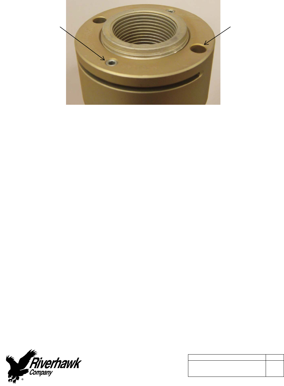
Picture5A‐RiverhawkLocknut
Ifthereisanyvisibledamageonanutorloadcouplingspacer,donotusethepartandcontact
theGeneralElectricorRiverhawkCompanyforareplacementpart.Pleasebepreparedto
supplytheturbinenumber,weightcertification,anddigitalphotographsforevaluation.
5.1.1NutandLoadCouplingSpacerCleaning‐NewInstallations
Fornewinstallations,thenutsshouldcomesealedfromthefactoryandwillneednocleaning.
5.1.2NutandLoadCouplingSpacerCleaning‐OldInstallations
Previouslyinstallednutsrequirecleaningasfollows:Wirebrushusingapetroleum‐based
solventtoremoveanyforeignmaterialonthethreads.Cleanmatingfaceswithapetroleum
basedsolventtoremoveanyforeignmaterial.
5.2StudPreparation
Checkthestudforanyvisibledamage.Ifthereisanyvisibledamage,donotusethestudand
contacttheRiverhawkCompanyforareplacementstud.Pleasebepreparedtosupplythe
turbinenumber,weightcertification,anddigitalphotographsforevaluation.
(2)Spanner
RingHoles
(2)Locking
SetScrews
InstructionManualIM‐251
215ClintonRoad
NewHartford,NY13413
Tel:+13157684855
Fax:+13157684941
Email:info@riverhawk.com
C
REV
373A4040
GEDRAWINGNUMBER
Page15of40
E
CAUTION
Itisespeciallyimportanttochecktheconditionoftheconicalthreadusedtotensionthe
stud.Threaddamagefrompreviousabusecanleadtofailureofthestudortensioning
equipment.
Theconicalthreadsofeachstudmustbecleanofgritanddirtbeforeinstallationorremoval.
Thisensurestheproperseatingofthepullerscrew.
5.2.1StudCleaning‐NewInstallations
Fornewinstallations,thestudsshouldcomesealedfromthefactoryandwillneednocleaning.
5.2.2StudCleaning‐OldInstallations
Previouslyinstalledstudsmayrequirecleaning.Cleaninternalconicalthreadsshouldhavea
brightandshinyappearance.
Ifcleaningisrequired,followthesesteps:
1. Blowoutthethreadswithcompressedairtoremoveloosedebrisanddryconical
threads.Donotapplyasolventorothercleaningsolutiontothethreadsasthismay
chemicallyattackthestud.
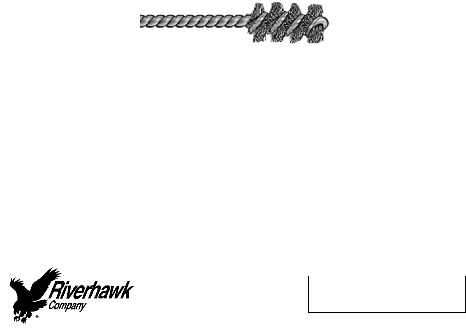
2. UseStudCleaningKit,GT‐4253orasimilar1"diameterBrasspowerbrush.
Picture5B‐BrassPowerBrush
3. Insertthebrushintoanelectricdrillandsetdrilltoruninacounterclockwisedirection
athighspeed.
4. Workthedrillinacircularmotionwhilemovingthebrushinandouttocleanallofthe
threads.Trynottoholdthebrushinoneplacetoolong,soasnottoremovethestud's
protectivecoating.
5. Blowoutthethreadswithcompressedairtoremovelooseneddebris.
6. Visuallyinspectthreadsforcleanliness.Threadsshouldbebrightandshiny.
7. Repeatifanydirtcanbeseeninthethreads.

InstructionManualIM‐251
215ClintonRoad
NewHartford,NY13413
Tel:+13157684855
Fax:+13157684941
Email:info@riverhawk.com
C
REV
373A4040
GEDRAWINGNUMBER
Page16of40
E
8. Verifythreadsarecleanbyusingadentalpicktolightlyscrapetherootofthethread.If
additionalmaterialcomesloose,repeatcleaningprocess.
9. Inspectthreadsforanydamagethatmayhavebeencausedbypreviousinstallation.
10. Donotapply“NeverSeize”tothestud’sthreads.
11. Finishthecleaningprocessbyrinsinginavolatilesolventsuchasacetoneandallowthe
studtodry.
5.3StudLengthMeasurement
5.3.1GasTurbineFlange2‐1/4”[58mm]Studs
Measureandrecordtheinitiallengthsofthestuds.Thefollowingsuggestionswillimproveyour
results.
Plantostartandfinishanyflangeinthesameday.
Studsandflangemustbeatthesametemperature.
Numbereachstudwithamarkerforlaterstretchmeasurementtracking.
Markthelocationofmeasurementonstudendwithapermanentmarker.
Measureeachstudtonearest0.001inch(.01mm).
Recordeachmeasurementonthesuppliedrecordsheets.
Donotallowthemeasuringinstrumentstositinthesun.
Thesamepersonshouldmakeallmeasurements.
InstructionManualIM‐251
215ClintonRoad
NewHartford,NY13413
Tel:+13157684855
Fax:+13157684941
Email:info@riverhawk.com
C
REV
373A4040
GEDRAWINGNUMBER
Page17of40
E
5.3.2GeneratorFlange2‐3/4”[71mm]Studs
Thegeneratorflangestudsrequiretheuseofaspecialstudinstallationgauge.Thisgauge
measurestherelativedistancefromtheendofthestudtotheflangeface.
Picture5C–StudInstallationGauge
RefertotheGT‐6030StudInstallationGaugeinstructionmanual,IM‐309.Thelatestrevision
maybeobtainedbycontactingRiverhawkCompanyorthruwww.riverhawk.com.
6.0Stud,Nut,andLoadCouplingSpacerAssembly
Refertothehardwareassemblydrawing(HF‐xxxx)listedinSection2.0ofthemanual.
1. Assemblethecylindricalnuttotheinternal,conicalthreadendofthestud.
2. Lubricatethestud’sthreadswithcleanturbineoilorspraylubricant.
3. Lubricatethenut’sthreadsandnutfacewithcleanturbineoilorspraylubricant.
4. Onthegasturbinesideonly,slidetheloadcouplingspaceroverthestuduntilit
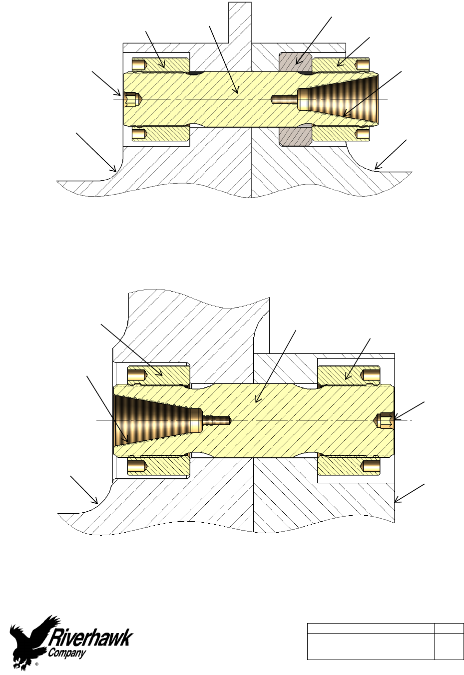
contactswiththenut.
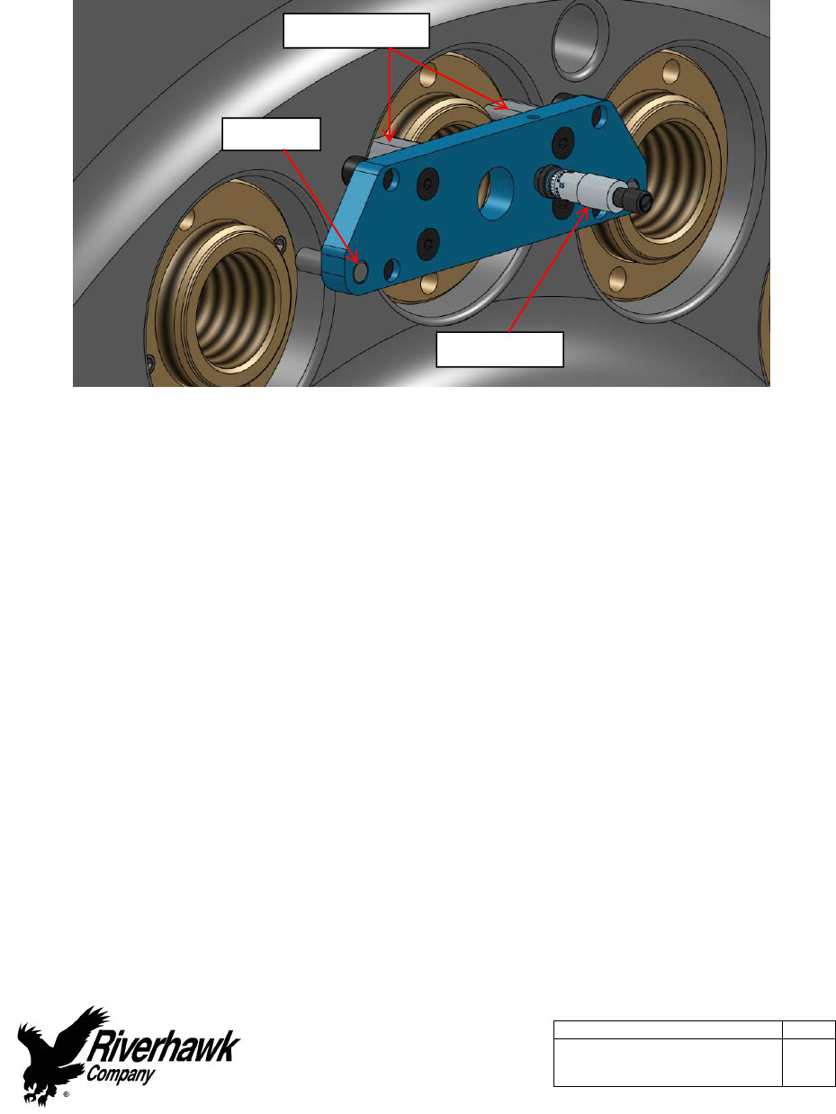
5. Slidethestud,nut,andspacerintotheflangeasshowninFigures6Aand6B.
GuideBlocks
OuterPin
Micrometer
InstructionManualIM‐251
215ClintonRoad
NewHartford,NY13413
Tel:+13157684855
Fax:+13157684941
Email:info@riverhawk.com
C
REV
373A4040
GEDRAWINGNUMBER
Page18of40
E
Figure6A–Cross‐sectionViewofGasTurbineto
LoadCouplingBoltedFlangeConnection
Figure6B–Cross‐sectionViewofLoadCouplingto
GeneratorBoltedFlangeConnection
BackSideNut
FrontSideNutStud
HexDrive
Tensioning
ConicalThread
*SetStudStick‐out
onthissideonly
LoadCoupling
FlangeGenerator
Flange
HexDrive
BackSideNutStud FrontSideNut
LoadCoupling
Flange
GasTurbine
Flange
Tensioning
ConicalThread
*SetStudStick‐out
onthissideonly
LoadCouplingSpacer
InstructionManualIM‐251
215ClintonRoad
NewHartford,NY13413
Tel:+13157684855
Fax:+13157684941
Email:info@riverhawk.com
C
REV
373A4040
GEDRAWINGNUMBER
Page19of40
E
6. Installtheothernutonthebackside.
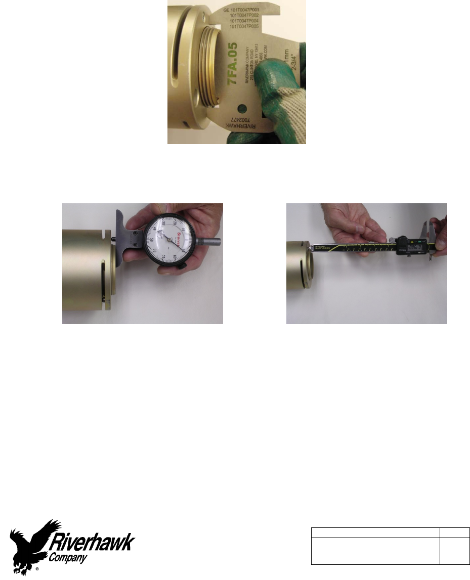
7. Adjustthenut/studassemblysothatthestudprotrudes(orsticksout)fromthefaceof
thecylindricalnutthedistancespecifiedonthehardwaredrawing(HF‐xxxx).SETTING
THISPROTRUSIONOFSTUDTONUTISCRITICALFORPROPERTENSIONEROPERATION.
Ametalstick‐outgageisprovidedwiththetensionertoassisttheoperatorinsettingthe
protrusiondimension.
Picture6C–UseofStick‐OutGageontheGas
TurbinesideoftheFlangeJoint
Picture6D–UseofDropGageto
measurestick‐out
Picture6E–UseofCalipersto
measurestick‐out
8. WithAllenwrenchinbacksideofstud,firmlyseatbacksidenutusingspannerringand
pinwrench.
9. Recheckthestudstick‐outlength.Ifthestick‐outlengthdoesnotmatchthehardware
drawing,adjustthenutsasnecessary.
10. Measureandrecordstartingstudinstallationgagereadings.(GeneratorSideOnly)

InstructionManualIM‐251
215ClintonRoad
NewHartford,NY13413
Tel:+13157684855
Fax:+13157684941
Email:info@riverhawk.com
C
REV
373A4040
GEDRAWINGNUMBER
Page20of40
E
7.0HydraulicTensionerEquipmentAssembly
7.1HydraulicEquipmentInspection
7.1.1HydraulicTensionerInspection
CAUTION
RiverhawkrecommendsthatthetensionerbereturnedtoRiverhawkforperiodicinspections.
Replacementofobsoletetensionersisrecommended.Functionalupgradesarealso
recommended.TheRiverhawkServiceReturnsCoordinatorshouldbenotified3‐6months
priortoaplannedoutagetoscheduleaninspectionservice.
Thistensionerdoesnotrequirebleeding.Seesection8.3
WARNING
Toavoidfailure,ensuresafety,andproperoperation,thetensionerassemblymustbe
installedonastudintheflangebeforepressurizingthetensioner.Donotusethetensionerat
anypressureunlessthetoolisinstalledonastudinaflange.
Cleanpullerscrewandcheckforanydebrisanddents.
Inspectthetensionerguardforanysignsofdamageincludingcrackedwelds.Anyguards
modifiedinthefieldshouldbereplaced.Bentguardsshouldbereplaced.Also,besurethe
rubberpadisinplaceonthebacksideguard,ifmissing,replace.
Inspecttheoutsideofthetensionerfordiscolorationpatternsthatmayindicatesubmersion
andinternaldamage.
Performaninventoryofthelooseequipmentsuppliedwiththetensioner.Aninventorylistis
providedonthetensioner’stechnicaldrawing(RiverhawkHT‐xxxxlistedinsection2.0and4.5).
ReplacementpartsareavailablefromRiverhawk.
7.1.1.1HydraulicTensioner’sBurstDiscReplacement
Thehydraulictensioner’sburstdiscisakeyelementintheoverallsafeuseofthehydraulic
tensioner.Theburstdisc’slocationisshownonthetensioner’stechnicaldrawing(Riverhawk
HT‐xxxxlistedinsection2.0and4.5).
Eachtensionerisshippedfromourfactorywithoneburstdiscalreadyinstalledinthetensioner
andwithanothersparediscforfieldreplacement.Extraburstdiscsareavailablefrom
Riverhawkforreplacementpurposes.

InstructionManualIM‐251
215ClintonRoad
NewHartford,NY13413
Tel:+13157684855
Fax:+13157684941
Email:info@riverhawk.com
C
REV
373A4040
GEDRAWINGNUMBER
Page21of40
E
Toreplaceadamagedburstdisc:
1. Removethehydraulicport’sdispersionnut,compressionring,anddamagedburstdisc.
2. Discardthedamagedburstdisc.
3. Cleanthedispersionnut,compressionring,newburstdisc,andthehydraulicportwitha
solventtoensureadirt‐freeinstallation.
4. Reassemblenewburstdisc,compressionring,anddispersionnutintothesame
hydraulicport.
Warning
Adamagedburstdiscmustbereplacedwithaburstdiscofthesamedesignandpressure
rating.Donotsubstituteadamagedburstdiscwithadifferentdisctype,adifferentpressure
rating,oraforeignobject.
7.1.2HydraulicPumpKitInspection
RefertotheHydraulicPumpKitInstructionManual,IM‐293(GEVENDOC373A4058).Thelatest
revisionmaybeobtainedbycontactingRiverhawkCompanyorthruwww.riverhawk.com.
InstructionManualIM‐251
215ClintonRoad
NewHartford,NY13413
Tel:+13157684855
Fax:+13157684941
Email:info@riverhawk.com
C
REV
373A4040
GEDRAWINGNUMBER
Page22of40
E
7.2HydraulicFittings
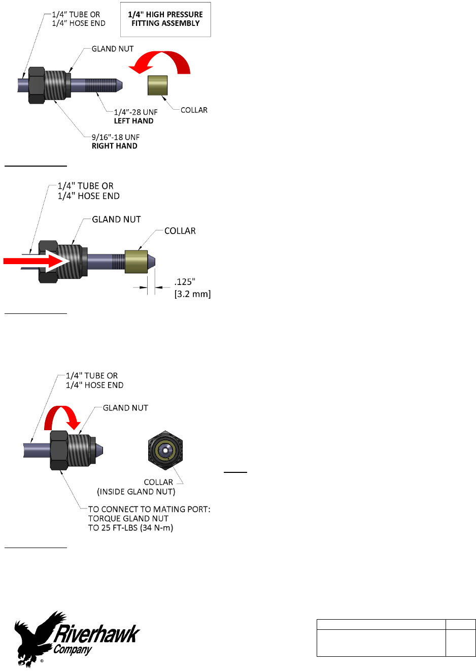
Illustration1
Riverhawkhydraulicpumpsusea1/4”High
Pressureporttoconnectitshydraulichoses.The
hoseconnectorismadefromathreepiece
assembly:aglandnut,acollar,anda1/4”tubeor
1/4”hoseend.(SeeIllustration1)
Toassemblythefitting,slidetheglandnutover
the1/4”tubeor1/4”hoseend.Turnthecollar
counter‐clockwise(lefthandthread)ontothe
tubeorhoseendasshowninIllustration1.
Illustration2
Thecollarshouldbeplaced.125”(3.2mm)from
thetipofthecone.(SeeIllustration2)Itmaybe
necessarytoadjustthiscollarwithasetofvise‐
grippliers.Becarefultonotstripthethreadsoff
thetubeorhoseend.
Illustration3
Slidetheglandnutdownoverthecollar.(See
Illustration3)Insertthe1/4”tubeor1/4”hose
endintothetensioner’squickcoupler.While
firmlyholdingthetubeorhoseendtostopitfrom
rotating,turntheglandnutclockwise(righthand
thread)andtorquetheglandnutto25FT‐LBS(34
N‐m).
Tips:
Makesureallpartsarecleanandfreefrom
debris.
Protecttheconeontheendofthe1/4”tube
or1/4”hoseendfromscratchesasthisisthe
sealingsurface.
Replaceredplasticcapswhenfinishedto
protectthethreadsandcone.
InstructionManualIM‐251
215ClintonRoad
NewHartford,NY13413
Tel:+13157684855
Fax:+13157684941
Email:info@riverhawk.com
C
REV
373A4040
GEDRAWINGNUMBER
Page23of40
E
8.0AssemblyofTensioneronaStud
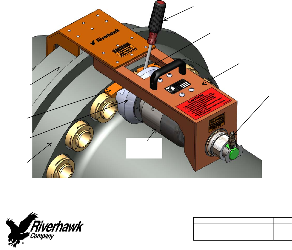
ThetensionerusedinthisapplicationcanbeidentifiedbyitsORANGEsafetyguard.Ifthe
tensioner’ssafetyguardisYELLOW,adifferentsetofinstructionsarerequired.Consultthe
Riverhawkfactoryforassistance.
8.1HandlingoftheTensioner
Thetensionerusedinthisapplicationisdesignedtorequirenospecialliftinginstructions.Do
notdropanypartofthetensionerontheoperatororothernearbypersonnel.
8.2KitAssembly
Connectthehydraulichosefromthehydraulicpumptothetensioner.
Refertothehardwareassemblydrawing(HF‐xxxx)listedinSection2.0ofthismanualandthe
tensionerassemblydrawing(HT‐xxxx)listedinSection4.5ofthismanualtodeterminehowthe
tensionermustbeassembledontheloadcouplingforitscorrectoperation.
Picture8A–FeaturesoftheHydraulicTensionerHT‐5144
SafetyGuard
Hose
Connection
Foot
PinWrench
Hydraulic
Cylinder
GasTurbine
Flange
LoadCoupling
Flange
Foot
Extension
FootExtension
InstructionManualIM‐251
215ClintonRoad
NewHartford,NY13413
Tel:+13157684855
Fax:+13157684941
Email:info@riverhawk.com
C
REV
373A4040
GEDRAWINGNUMBER
Page24of40
E
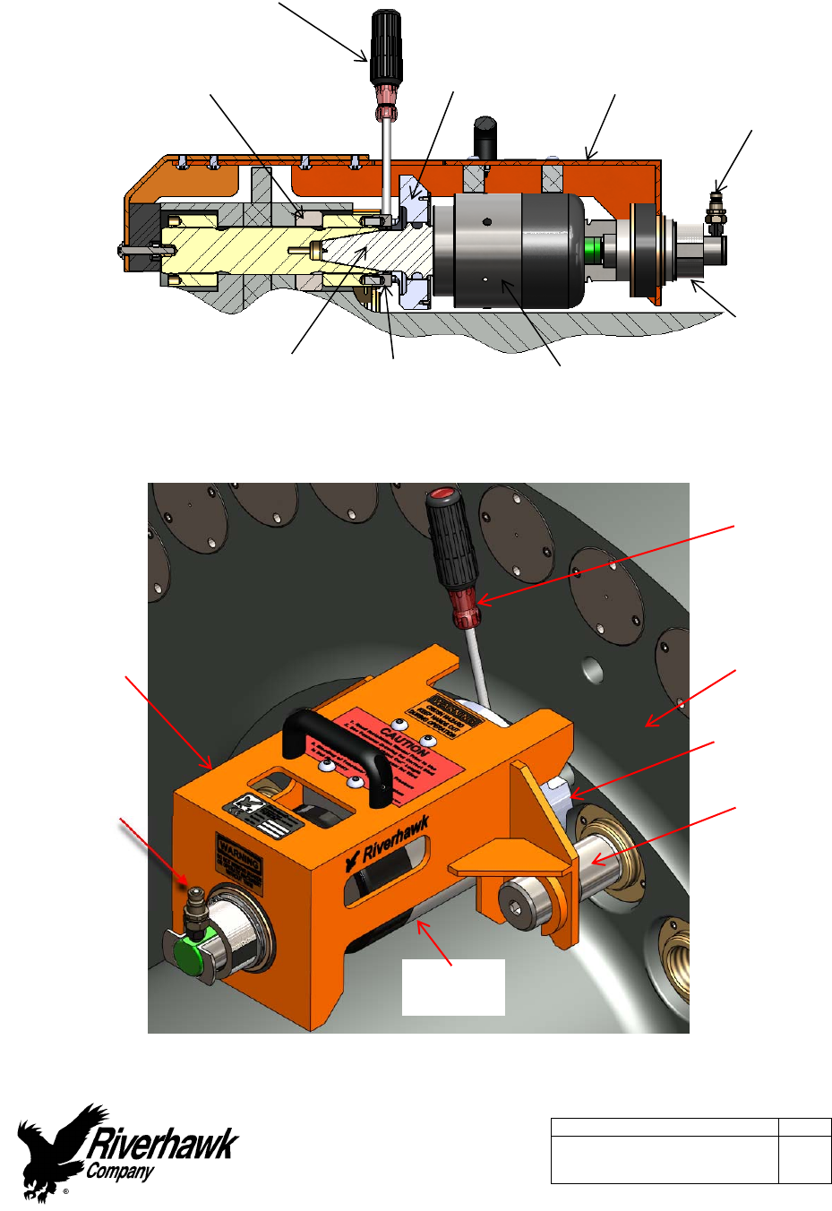
Figure8B–CutawayviewofHydraulicTensionerHT‐5144
Picture8C–FeaturesoftheHydraulicTensionerHT‐6019
PinWrench
FootSafetyGuardHose
Connection
KnurledInterlock
Fitting
HydraulicCylinderPullerScrewSpannerRing
Safety
Guard
Hose
Connection
Foot
PinWrench
Hydraulic
Cylinder
LoadCoupling
Flange
Retention
Screw
NutSpacer
InstructionManualIM‐251
215ClintonRoad
NewHartford,NY13413
Tel:+13157684855
Fax:+13157684941
Email:info@riverhawk.com
C
REV
373A4040
GEDRAWINGNUMBER
Page25of40
E
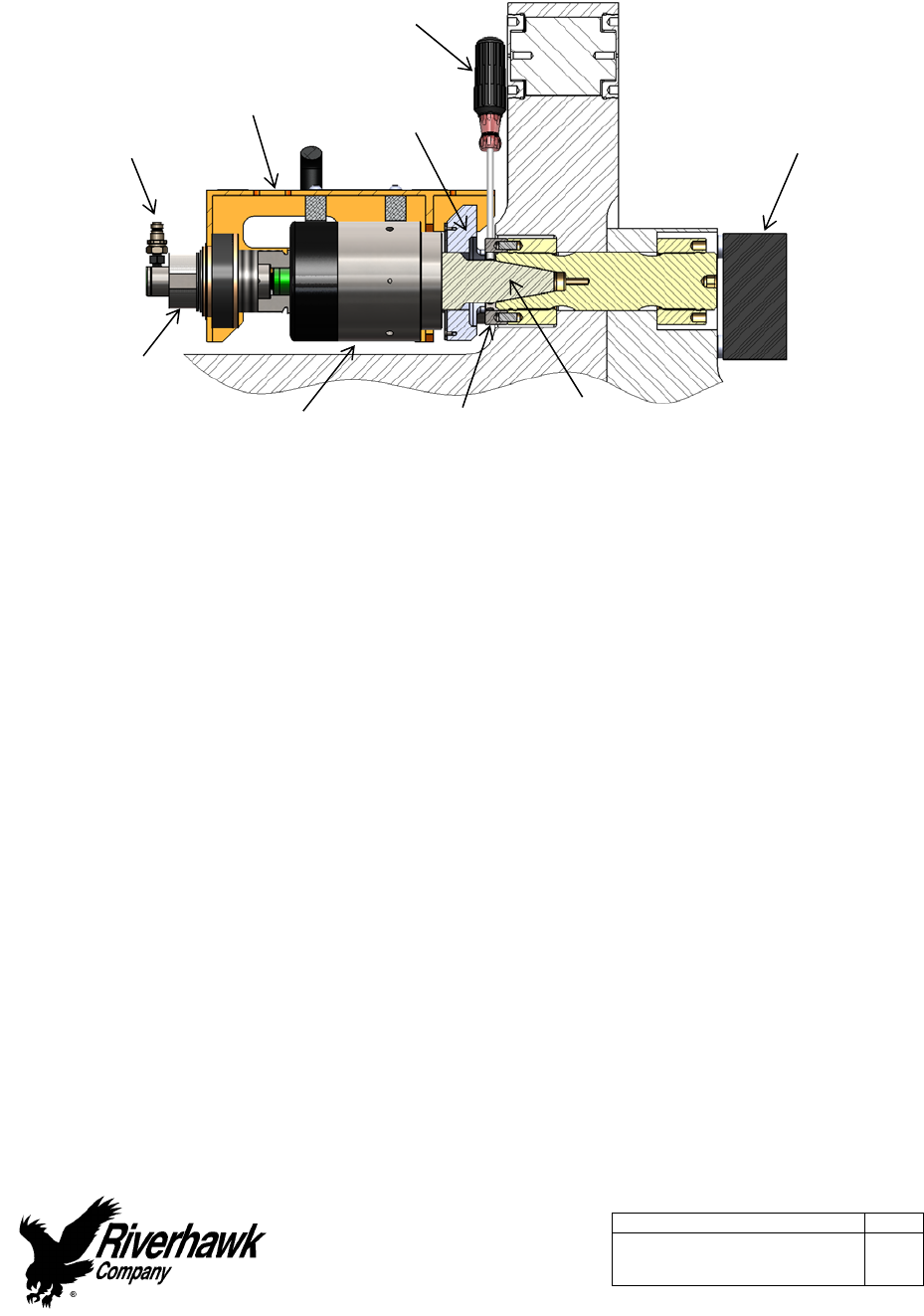
Figure8D–CutawayviewofHydraulicTensionerHT‐6019
Note:Beforethreadingthepullerscrewintothestud,carefullycheckthecleanlinessofboth
thestud'sandthepullerscrew'sconicalthreads.Applyalightcoatofcleanturbineoilora
spraylubricanttothepullerscrew.Donotuse“NeverSeize”ontheconicalthreads.This
procedurewilleaseassemblyandassurepositivematingofthethreadsbeforetightening.
Assemblysequenceisasfollows:
1. Openthehydraulicreturnvalveonthepumptoallowhydraulicfluidtobepushedback
fromthepullertoolintothepumpreservoir.(Thisisautomaticontheair‐operated
hydraulicpump)
2. Threadtheretentionscrewsintotheadjacentstudsoneithersideofthestudtobe
tensioneduntilhandtight.(GeneratorSideTensionerOnly)
3. Placethespannerringonthenut.
4. Insertthepullerscrewintothetaperedthreadofthestudandhandtighten.Besurenotto
cross‐threadthepullerscrew.
5. Placethetwofootextensionsoneithersideofthenut(GasTurbineSideOnly)
6. UsinganAllenwrench,tightenthepullerscrewandthenbackoffthepullerscrew1/2a
turn.
7. Retightenthepullerscrewbyhanduntilitisfullyinserted.DONOTBACKOFFTHEPULLER
SCREW.
8. Placethefootoverthepullerscrewandorientateitintoposition.
PinWrench
Foot
SafetyGuard
Hose
Connection
KnurledInterlock
Fitting
HydraulicCylinder PullerScrew
SpannerRing
Backside
SafetyGuard
InstructionManualIM‐251
215ClintonRoad
NewHartford,NY13413
Tel:+13157684855
Fax:+13157684941
Email:info@riverhawk.com
C
REV
373A4040
GEDRAWINGNUMBER
Page26of40
E
9. Threadthetensionerontothepullerscrewuntilitstops.Pleasenotethattheinternalstop
insidethetensionerwillcauseagapinbetweenthefootandtensioner.Thegapshouldbe
1/16”[1.6mm]to3/16”[4.8mm].DONOTATTEMPTTOTIGHTENTHETENSIONERAGAINST
THEFOOT.
9A.Placetheguardoverthetensionerandpositiontheguidepinintotheholeinthebackside
ofthestud.(GasTurbineSideTensionerOnly)
9B.Placetheorangeguardoverthetensionerandpositionthepocketedslotsintothe
retentionscrews.(GeneratorSideTensionerOnly)
10. Tightentheknurledinterlockfittingbyhanduntilitfirmlypressesagainstthetensioner.
Thereshouldbenogapbetweenthetensionertheinterlockfitting.
11. Theretentionscrewsmustbeinsidetheguard’spocketedslots.(GeneratorSideTensioner
Only)
12. Activatethecustomconnectorfromtherearofguardbypushingonthecenterwithyour
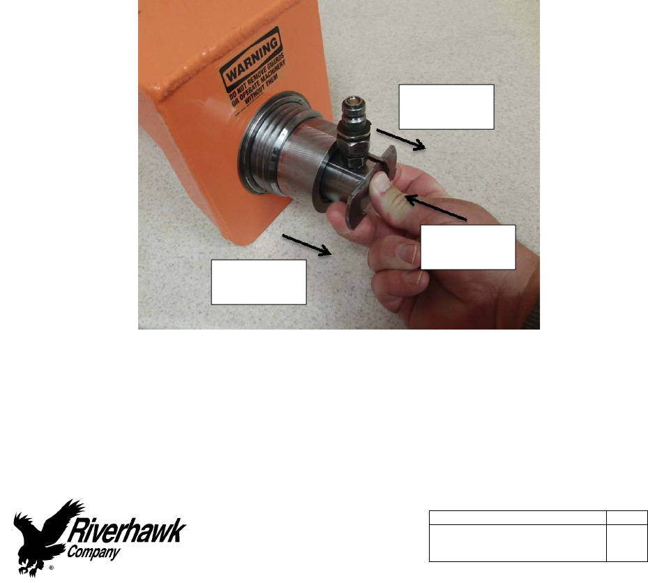
thumbandpullingthetabswithyourforefingerandmiddlefinger.Pushtheassembly
forwarduntilitlocksintothetensioner.Releasefingersfromthetabsandthenremove
thumb,Ensureconnectionisfirmlyengagedorelsethetensionerwillnotbeconnectedto
thepump.
Picture8E‐Activationofthesafetyinterlock
13. Installthebacksideguardandcentertheguardoverthestudtobetensioned.Threadthe
backsideguardintotheadjacentstudsuntilitstops.(GeneratorSideTensionerOnly)
14. Connectthehydraulicpumptothetensioner.Thetensionershouldnowbecompletely
assembledandreadyforuse.
Pulltabs
withfingers
Pulltabs
withfingers
Pushcenter
withthumb

InstructionManualIM‐251
215ClintonRoad
NewHartford,NY13413
Tel:+13157684855
Fax:+13157684941
Email:info@riverhawk.com
C
REV
373A4040
GEDRAWINGNUMBER
Page27of40
E
8.3BleedingHydraulicSystem
Bleedingofthehydraulicsystemisnotnecessarywiththistensionerdesign.
9.0StudTensioning
Thestudswillbetensionedintwosteps,at50%pressureandatfinalpressure.Followthe
tensioningsequenceforeachflangejointasdefinedontherecordsheetsfoundattheendof
thismanual.
9.1Tensioningat50%pressure
Afterthetensionerisproperlyinstalledapplyhydraulicpressuretothetool.Bringthepressure
tothe50%levelinaccordancewiththefollowingtable.
WARNING
Thesafetycagemustbeinplaceatalltimes.Keephandsoutofdesignatedareasatalltimes
whenthetensionerispressurizedotherwisepersonalinjurycanoccur.
CAUTION
Beforethreadingthepullerscrewintothestud,carefullycheckthecleanlinessofboththe
stud'sandthepullerscrew'sconicalthreads.Applyalightcoatofcleanturbineoiloraspray
lubricanttothepullerscrew.Thisprocedurewilleaseassemblyandassurepositivematingof
thethreadsbeforetightening.Donotuse“NeverSeize”ontheconicalthreads.
CAUTION
Donotexceedthemaximumpressuremarkedonthetensioner.Excessivepressurecan
damagethestudandpullerscrew.
CAUTION
Donottightenthenutwhilethetooliscominguptopressure;waituntilpressureisachieved
beforeattemptingtotightenthenutwiththespannerring.Ifthetoolisnotproperly
installed,thetoolcouldjumpoffthestudwhilecominguptopressure.
InstructionManualIM‐251
215ClintonRoad
NewHartford,NY13413
Tel:+13157684855
Fax:+13157684941
Email:info@riverhawk.com
C
REV
373A4040
GEDRAWINGNUMBER
Page28of40
E
FlangePositionStudSize50%Pressure50%Stretch
GasTurbinetoLoad
Coupling
2‐1/4"
[58mm]
9000psi
[620bar]
Donotmeasure
Donotuse
LoadCouplingto
Generator
2‐3/4"
[71mm]
10000psi
[690bar]
Donotmeasure
Donotuse
Firmlytightenthecylindricalnutswithapproximately20ft∙lbs[27N∙m]oftorqueusingthepin
wrenchandspannerring.Turnthenutuntilitbottomsontheflange.
9.2RemovingtheTensionerfromanInstalledStud
Thetensionerremovalisaccomplishedbythefollowssteps:
1. ReleasethehydraulicpressurebyeitherreleasingthehandswitchontheAP‐0532
PumpKitorbyopeningthevalveontheMP‐0130ManualPumpKitandleavethevalve
open.
2. Removethebacksideguard.(GeneratorSideTensionerOnly)
3. Unscrewtheknurledinterlockfittingattheendoftheguardandremovetheguardfrom
thetensioner.
4. Unscrewthetensionerfrompullerscrew.
5. Removethefootandthetwofootextensionsfromaroundthepullerscrew.
6. UnscrewthepullerscrewusinganAllenwrench.TappingtheAllenwrenchwitha
hammerortheuseofa3‐4’breakerbarmaybenecessarytoloosenthepullerscrew.
Donotuseanimpactwrenchasthiscandamagethepullerscrew.
7. Removethespannerringfromthenut.
8. Inthecaseofthegeneratorsideoftheloadcouplingflange,unscrewtheretention
screwsusinganAllenwrench.ItmaybenecessarytotaptheAllenwrenchwitha
hammerorusea3‐4’breakerbartoloosentheretentionscrews.Donotuseanimpact
wrenchasthiscandamagetheretentionscrews.
9. Movethetooltothenextboltholefollowingthetensioningpatternfromthestretched
recordsheetsattheendofthismanual.
9.3TensioningatFinalPressure
Repeatthepullingandtighteningprocedurestatedaboveatfullpressure.Afterallofthestuds
havebeentensioned,measurethefinalstudlength.Thefinalpressureandrequiredstretch
valuesarelistedinthefollowingtable.
InstructionManualIM‐251
215ClintonRoad
NewHartford,NY13413
Tel:+13157684855
Fax:+13157684941
Email:info@riverhawk.com
C
REV
373A4040
GEDRAWINGNUMBER
Page29of40
E
WARNING
Thesafetycagemustbeinplaceatalltimes.Keephandsoutofdesignatedareasatalltimes
whenthetensionerispressurizedotherwisepersonalinjurycanoccur.
CAUTION
Beforethreadingthepullerscrewintothestud,carefullycheckthecleanlinessofboththe
stud'sandthepullerscrew'sconicalthreads.Applyalightcoatofcleanturbineoiloraspray
lubricanttothepullerscrew.Thisprocedurewilleaseassemblyandassurepositivematingof
thethreadsbeforetightening.Donotuse“NeverSeize”ontheconicalthreads.
CAUTION
Donotexceedthemaximumpressuremarkedonthetensioner.Excessivepressurecan
damagethestudandpullerscrew.
CAUTION
Donottightenthenutwhilethetooliscominguptopressure;waituntilpressureisachieved
beforeattemptingtotightenthenutwiththespannerring.Ifthetoolisnotproperly
installed,thetoolcouldjumpoffthestudwhilecominguptopressure.
FlangePositionStudSizeFinalPressureFinalStretchGaugeReading
GasTurbinetoLoad
Coupling
2‐1/4"
[58mm]
18000psi
[1240bar]
0.018"‐0.020"
[0.51mm‐0.56mm]
‐‐‐‐‐
LoadCouplingto
Generator
2‐3/4"
[71mm]
19000psi
[1310bar]
0.014"‐0.016"
[0.36mm‐0.41mm]
0.025”‐0.030”
[0.63mm‐0.76mm]
Firmlytightenthecylindricalnutswithapproximately20ft∙lbs[27N∙m]oftorqueusingthepin
wrenchandspannerring.Turnthenutuntilitbottomsontheflange.
Failuretoachievethecorrectfinalstretchvalueswillresultinanincorrectlytensionedstud.
Incorrectstretchvaluescanbecorrectedbyuninstallingsomeoralloftheselectedstuds.Re‐
measuretheinitiallengthofthestudsandrepeattheinstallationinstructionsstuds.Excessive
stretchvariationscanalsobecorrectedbythesamemethod.
Havefinalstretchvaluesapprovedbythesupervisorresponsiblefortheinstallation.
InstructionManualIM‐251
215ClintonRoad
NewHartford,NY13413
Tel:+13157684855
Fax:+13157684941
Email:info@riverhawk.com
C
REV
373A4040
GEDRAWINGNUMBER
Page30of40
E
10.0ThreadLocking
Picture10A‐RiverhawkLocknut
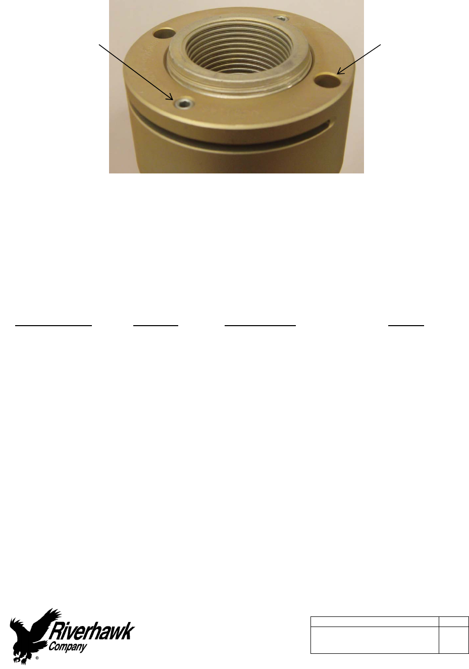
Mechanicallocknutshavetwosetscrewslocatedinthetopface.Beforethreadingthenut
ontothestud,checktobecertainthesetscrewsarefreetoturn.Oncethenutisseatedtorque
thesetscrewstothevaluesspecifiedinthefollowingtable.Whenseatedandtorquedtothe
valuesspecified,theloadcreatedbythesetscrewdisplacesthethreadofthenutintheareaof
thewebtherebycreatingthedesiredlockingaction.
FlangePositionStudSizeSetScrewSizeTorque
GasTurbinetoLoad
Coupling
2‐1/4"
[58mm]1/4"‐28UN70in∙lbs‐80in∙lbs
[7.9N∙m–9.0N∙m]
LoadCouplingto
Generator
2‐3/4"
[71mm]3/8"‐24UN200in∙lbs‐250in∙lbs
[22.6N∙m–28.2N∙m]
11.0Stud,Nut,andLoadCouplingSpacerRemoval
11.1HandlingoftheTensioner
Thetensionerusedinthisapplicationisdesignedfornospecialliftinginstructions.Donotdrop
anypartofthetensionerontheoperatororothernearbypersonnel.
(2)Spanner
RingHoles
(2)Locking
SetScrews

InstructionManualIM‐251
215ClintonRoad
NewHartford,NY13413
Tel:+13157684855
Fax:+13157684941
Email:info@riverhawk.com
C
REV
373A4040
GEDRAWINGNUMBER
Page31of40
E
11.2Stud,Nut,andLoadCouplingSpacerRemoval
WARNING
Thesafetycagemustbeinplaceatalltimes.Keephandsoutofdesignatedareasatalltimes
whenthetensionerispressurizedotherwisepersonalinjurycanoccur.
CAUTION
Beforethreadingthepullerscrewintothestud,carefullycheckthecleanlinessofboththe
stud'sandthepullerscrew'sconicalthreads.Applyalightcoatofcleanturbineoiloraspray
lubricanttothepullerscrew.Thisprocedurewilleaseassemblyandassurepositivematingof
thethreadsbeforetightening.Donotuse“NeverSeize”ontheconicalthreads.
CAUTION
Donotexceedthemaximumpressuremarkedonthetensioner.Excessivepressurecan
damagethestudandpullerscrew.
CAUTION
Donottightenthenutwhilethetooliscominguptopressure;waituntilpressureisachieved
beforeattemptingtotightenthenutwiththespannerring.Ifthetoolisnotproperly
installed,thetoolcouldjumpoffthestudwhilecominguptopressure.
Refertothehardwareassemblydrawing(HF‐xxxx)listedinSection2.0ofthismanualandthe
tensionerassemblydrawing(HT‐xxxx)listedinSection4.5ofthismanualtodeterminehowthe
tensionermustbeassembledontheloadcouplingforitscorrectoperation.
Section8.0containsdiagramsofthetensionerequipment.
Note:Beforethreadingthepullerscrewintothestud,carefullycheckthecleanlinessofboth
thestud'sandthepullerscrew'sconicalthreads.Applyalightcoatofcleanturbineoilora
spraylubricanttothepullerscrew.Donotuse“NeverSeize”ontheconicalthreads.This
procedurewilleaseassemblyandassurepositivematingofthethreadsbeforetightening.
Disassemblysequenceisasfollows:
1. Usingawirebrush(GT‐4253)andshopair,cleantheinternaltaperedthreadofthestudto
removeanydebris/depositswhichmayhaveaccumulatedduringserviceasdescribedin
section5.2.2.DonotcontinueuntilALLdebrisisremovedfromthethreads.
WARNING
Donotuseahydraulictensionertoremoveastudwithdamagedconicalthreads.
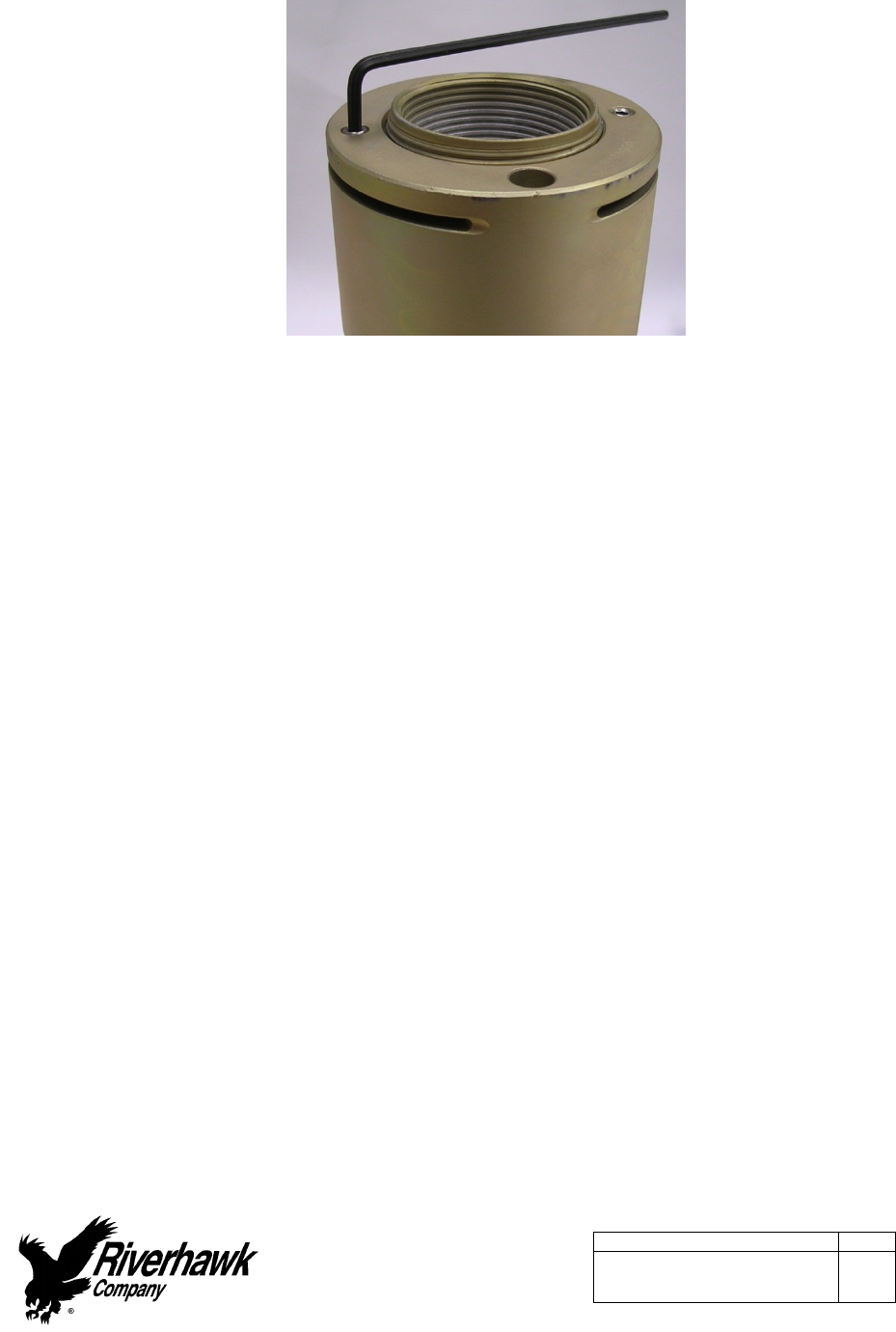
2. WithanAllen‐wrenchloosenthetwolockingsetscrewsbutdonotremovefromthenut.
InstructionManualIM‐251
215ClintonRoad
NewHartford,NY13413
Tel:+13157684855
Fax:+13157684941
Email:info@riverhawk.com
C
REV
373A4040
GEDRAWINGNUMBER
Page32of40
E
Picture11A‐Looseningofanut'ssetscrews
3. Connectthehydraulichosefromthehydraulicpumptothetensioner.
4. Openthehydraulicreturnvalveonthepumptoallowhydraulicfluidtobepushedback
fromthepullertoolintothepumpreservoir.(Thisisautomaticontheair‐operated
hydraulicpump)
5. Threadtheretentionscrewsintotheadjacentstudsoneithersideofthestudtobe
tensioneduntilhandtight.(GeneratorSideTensionerOnly)
6. Placethespannerringonthenut.
7. Insertthepullerscrewintothetaperedthreadofthestudandhandtighten.Besurenotto
cross‐threadthepullerscrew.
8. UsinganAllenwrench,tightenthepullerscrewandthenbackoffthepullerscrew1/2a
turn.
9. Retightenthepullerscrewbyhanduntilitisfullyinserted.DONOTBACKOFFTHEPULLER
SCREW.
10. Placethetwofootextensionsoneithersideofthenut(GasTurbineSideOnly)
11. Placethefootoverthepullerscrewandorientateitintoposition.
12. Threadthetensionerontothepullerscrewuntilitstops.Pleasenotethattheinternalstop
insidethetensionerwillcauseagapinbetweenthefootandtensioner.Thegapshouldbe
1/16”[1.6mm]to3/16”[4.8mm].DONOTATTEMPTTOTIGHTENTHETENSIONERAGAINST
THEFOOT.
12A.Placetheguardoverthetensionerandpositiontheguidepinintotheholeinthebackside
ofthestud.(GasTurbineSideTensionerOnly)
12B.Placetheorangeguardoverthetensionerandpositionthepocketedslotsintothe
retentionscrews.(GeneratorSideTensionerOnly)
13. Tightentheknurledinterlockfittingbyhanduntilitfirmlypressesagainstthetensioner.
Thereshouldbenogapbetweenthetensionertheinterlockfitting.
InstructionManualIM‐251
215ClintonRoad
NewHartford,NY13413
Tel:+13157684855
Fax:+13157684941
Email:info@riverhawk.com
C
REV
373A4040
GEDRAWINGNUMBER
Page33of40
E
14. Theretentionscrewsmustbeinsidetheguard’spocketedslots.(GeneratorSideTensioner
Only)
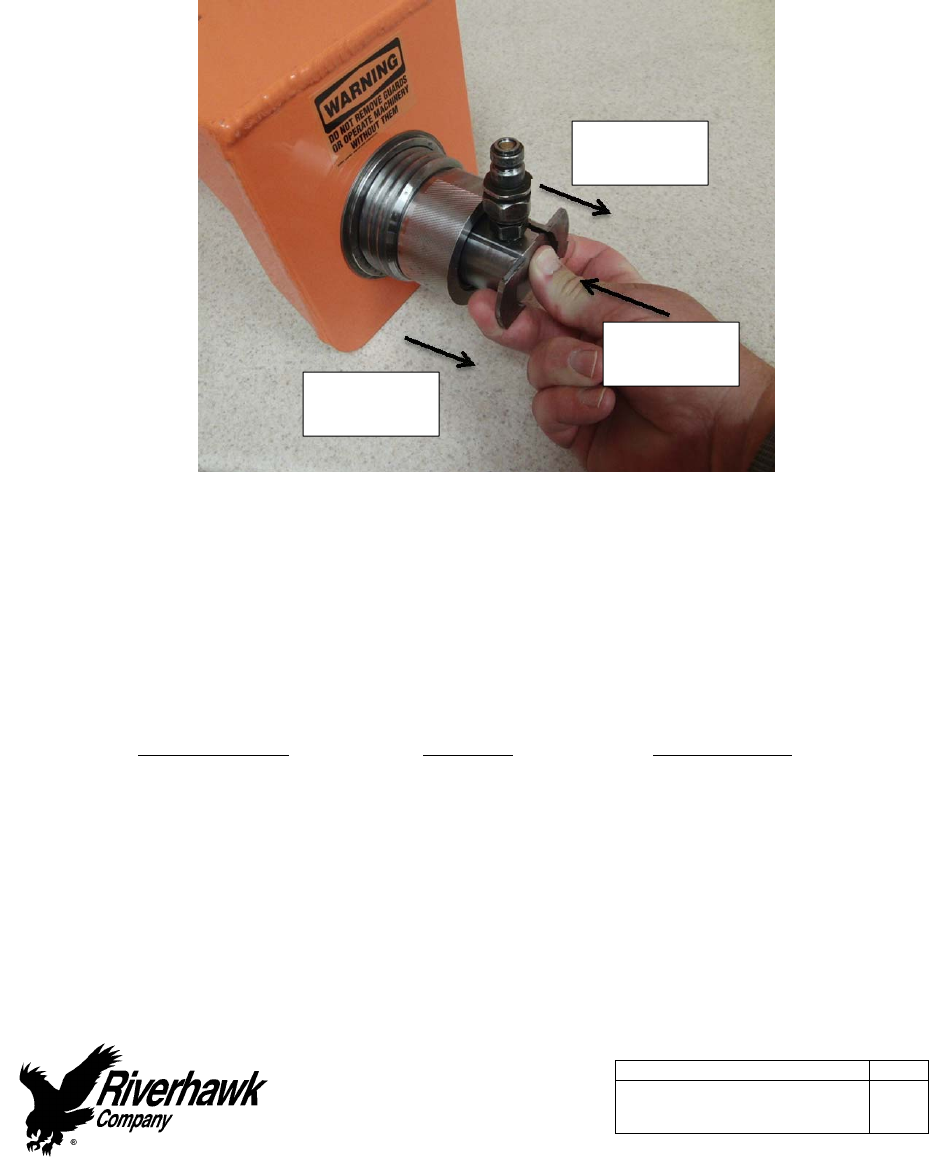
15. Activatethecustomconnectorfromtherearofguardbypushingonthecenterwithyour
thumbandpullingthetabswithyourforefingerandmiddlefinger.Pushtheassembly
forwarduntilitlocksintothetensioner.Releasefingersfromthetabsandthenremove
thumb,Ensureconnectionisfirmlyengagedorelsethetensionerwillnotbeconnectedto
thepump.
Picture11B‐Activationofthesafetyinterlock
16. Installthebacksideguardandcentertheguardoverthestudtobetensioned.Threadthe
backsideguardintotheadjacentstudsuntilitstops.(GeneratorSideTensionerOnly)
17. Connectthehydraulicpumptothetensionerandapplytheappropriatehydraulicpressure
perthistable.
FlangePositionStudSizeFinalPressure
GasTurbinetoLoad
Coupling
2‐1/4"
[58mm]
18000psi
[1240bar]
LoadCouplingto
Generator
2‐3/4"
[71mm]
19000psi
[1310bar]
Pulltabs
withfingers
Pulltabs
withfingers
Pushcenter
withthumb

InstructionManualIM‐251
215ClintonRoad
NewHartford,NY13413
Tel:+13157684855
Fax:+13157684941
Email:info@riverhawk.com
C
REV
373A4040
GEDRAWINGNUMBER
Page34of40
E
18. Turnthespannerringwiththepinwrench.Loosenandturnthenutapproximately3/4ofa
turn.
19. Releasethehydraulicpressure.
11.3.1RemovingtheTensionerfromaStud
Thetensionerremovalisaccomplishedbythefollowssteps:
1. ReleasethehydraulicpressurebyeitherreleasingthehandswitchontheAP‐0532
PumpKitorbyopeningthevalveontheMP‐0130ManualPumpKitandleavethevalve
open.
2. Removethebacksideguard.(GeneratorSideTensionerOnly)
3. Unscrewtheknurledinterlockfittingattheendoftheguardandremovetheguardfrom
thetensioner.
4. Unscrewthetensionerfrompullerscrew.
5. Removethefootandthetwofootextensionsfromaroundthepullerscrew.
6. UnscrewthepullerscrewusinganAllenwrench.TappingtheAllenwrenchwitha
hammerortheuseofa3‐4’breakerbarmaybenecessarytoloosenthepullerscrew.
Donotuseanimpactwrenchasthiscandamagethepullerscrew.
7. Removethespannerringfromthenut.
8. Inthecaseofthegeneratorsideoftheloadcouplingflange,unscrewtheretention
screwsusinganAllenwrench.ItmaybenecessarytotaptheAllenwrenchwitha
hammerorusea3‐4’breakerbartoloosentheretentionscrews.Donotuseanimpact
wrenchasthiscandamagetheretentionscrews.
9. Movethetooltothenextboltholefollowingthetensioningpatternfromthestretched
recordsheetsattheendofthismanual.
12.0StorageInstructions
Followthesedirectionstoproperlystoreyourhydraulictensionerandhydraulicpumpkitfor
longtermstorageandshipment.
Ifanydamageisobserved,contacttheRiverhawkCompanytoscheduleamaintenance
inspection.
12.1HydraulicPumpKitStorage
RefertotheHydraulicPumpKitInstructionManual,IM‐293(GEVENDOC373A4058).Thelatest
revisionmaybeobtainedbycontactingRiverhawkCompanyorthruwww.riverhawk.com.

InstructionManualIM‐251
215ClintonRoad
NewHartford,NY13413
Tel:+13157684855
Fax:+13157684941
Email:info@riverhawk.com
C
REV
373A4040
GEDRAWINGNUMBER
Page35of40
E
12.2HydraulicTensionerStorage
Checkthetensionerforanydamage
1. Cleanpullerscrewandcheckforanydebrisanddents.
2. Knurledinterlockfittingshouldbecleanandfreetorotate.
3. Inspectthetensionerguardforanysignsofdamage.Bentguardsmustbereplaced.
Ifanydamageisobserved,contacttheRiverhawkCompanytoscheduleamaintenance
inspection.
Placetheprotectiveplasticcapontheguard’sknurledinterlockfitting.
Coatthehydraulictensionerwithalightcoatofoilandplacethetensionerintotheoriginal
shippingcontainer.
12.3Storeshippingcontainer
Securethehydraulicpumpandhydraulictensionerintotheoriginalshippingcontainersusing
thesuppliedwoodbraces.
Sealtheoriginalshippingcontainerandstoreundershelterandprotectedfrommoisture,sand,
andgrit.
13.0FrequentlyAskedQuestions
Thissectioncontainssomefrequentlyaskedquestionsandproblems.Ifthestepslistedheredo
notsolveyourproblem,contacttheRiverhawkCompanythruourwebsite,email,orphonecall.
Q:
A:
CanIrentahydraulictensionerkit?
Yes,Riverhawkhasrentaltensionerkitsavailableformostofourhydraulictensioners.
Q:
A:
Atensionerhaspulleditselfoutofthestud'sconicalthreads.CanIcontinueusinga
tensioneronthisstud?
No.Boththetensionerandthestudmayhavebeendamagedandmustberemoved
fromtheworkarea.Ifthestudistensioned,aNutBusterrepairkit,fromRiverhawk,
mustbeusedtoremovethedamagedstudbydrillingoutthenut.Leavingadamaged
studinplacewillleadtoasafetyhazardonfutureoutages.

InstructionManualIM‐251
215ClintonRoad
NewHartford,NY13413
Tel:+13157684855
Fax:+13157684941
Email:info@riverhawk.com
C
REV
373A4040
GEDRAWINGNUMBER
Page36of40
E
Riverhawkcansupplyareplacementstudandnutbasedontheinitialweight
certificationsuppliedwiththehardwareset(seesection4.2).Thedamagedtensioner
shouldalsobereturnedtoRiverhawkforinspectionandrepair.
Ifastudmustbeleftinplace,paintthedamagedstudwithagenerousamountof
indelible,bright‐coloredpaint.NotifytheappropriateGESafetyandServicepersonnel.
Notethelocationofthedamagedstudintheservicesnotesforthemachine.
Q:
A:
Thehydraulictensionerhasbeentakenuptoitsfinalpressure.Thefinalstretchlengthis
shortofthefinalstretchtarget.Whatisthenextstep?
Donotincreasethehydraulicpressure.Checkifthehydraulicpumpissettotheright
pressure.Installthetensionerandre‐pressurizethetensionertothefinalpressurethen
recheckthestretchmeasurement.Ifthestretchvalueisstillshort,removethestud
fromtheholeandre‐measurethestud'sinitiallengththentrytoinstallthestudagain.
Q:
A:
Thehydraulictensionerhasbeentakenuptoitsfinalpressure.Thefinalstretchlengthis
largerthanthefinalstretchtarget.Whatisthenextstep?
Removethestudfromthebolthole.Checkifthehydraulicpumpissettotheright
pressure.Re‐measurethestud'sinitiallengththentrytoinstallthestudagain.
Q:
A:
Thetensionerisatitsfinalpressure,butthenutcannotbeloosened.
Ifthenutscannotbeloosenedatthefinalpressure,continuallyincreasingthepressure
willnothelpandcanbedangerousandinsomecasesmakeithardertoremovethenut.
Checkthenuttoseeifitssetscrewshavebeenloosened.Checkforandremoveany
corrosionaroundthenut'sthreads.Applypenetratingoilbetweenthestudandthenut.
Q:
A:
HowdoIcleantheconicalthreadsonastud?
Theconicalthreadsarebestcleanedusingaspiralwoundbrassbrushinadrillas
describedinsection5.2.2

InstructionManualIM‐251
215ClintonRoad
NewHartford,NY13413
Tel:+13157684855
Fax:+13157684941
Email:info@riverhawk.com
C
REV
373A4040
GEDRAWINGNUMBER
Page37of40
E
Q:
A:
Duringtheinitialstepsofremovingatensionedstud,thestick‐outlengthisfoundtobe
wrong.
Donotproceed.ContactRiverhawkforassistance.Withthewrongstick‐outlength,the
hydraulictensionerhasalimitedstrokeandmaynotworkproperlyandcanbe
damaged.
Q:
A:
Thehydraulicpumpappearstobeleaking.
Checkthehoseconnectiontothehydraulicpump.Ifthe1/4"highpressurefittingisnot
assembledcorrectlyasshowninsection7.2,itmaylooklikethepumpisleaking.Ifthe
problemcontinues,itmaybenecessarytoopenthepumpkit.ContactRiverhawkfor
guidance.
Q:
A:
Thehydraulichosehasacollaronitthatcan'tbemovedbyhand
Thehydraulicfittingisshowninsection7.2.Thecollarissometimesheldinplacewitha
threadlockingcompound.Thispreventsthecollarfrommovingtooeasily.Itmaybe
necessarytoadjustthiscollarwithasetofvise‐grippliers.Becarefultonotstripthe
threadsoffthetubeorhoseend.

InstructionManualIM‐251
215ClintonRoad
NewHartford,NY13413
Tel:+13157684855
Fax:+13157684941
Email:info@riverhawk.com
C
REV
373A4040
GEDRAWINGNUMBER
Page38of40
E
14.0RevisionHistory
Revision
Letter
EffectiveDateDescription
EFeb16,2014Section3.0&6.0Removedhandtighten,addedtighten
withspannerring,Section3.0&6.0addedmeasureand
recordstartinggagereadings(generatorside),Section
5.3.2revisedstudstretchmeasurementgaugetoread
studinstallationgauge,Section9.3addedgagereading
columntofinalinstallationchart(generatorside),
Appendix2renamedfinalstretchtofinalgaugereading
D12/19/13UpdatedGEpartnumberfrom106T1751P003to
110T2635P0003page6,section2.4.RS.
C12/11/13Addednotetotitlepageandchangedstretchfrom
.020/.022to.018/.020ontheturbineend.RJD.
BOct25,2013RemovedGE106T1751fromthetitlepageandsection
2.0andreplaceditwithGE110T2635,Addedreferences
toloadcouplingspacerstosections3,4.2,5.0,and6.0,
Addedreferencestofootextensionstosections3,4.5,
8.2,9.2,and11.2
AMar25,2013Correctedtypoinrupturediscwarninginsections1.0
and7.1.1.1,CorrectedarrowlocationinFigure6A,Added
referencetotensionerlisttosections7.1.1and7.1.1.1,
Addedretentionscrewarrow/texttoPicture8C,
Correctedtypeinsection8.2step12andsection11.2
step15,added“approximately”tosections9.1and9.3
‐ Mar20,2013Released
InstructionManualIM‐251
215ClintonRoad
NewHartford,NY13413
Tel:+13157684855
Fax:+13157684941
Email:info@riverhawk.com
C
REV
373A4040
GEDRAWINGNUMBER
Page39of40
E
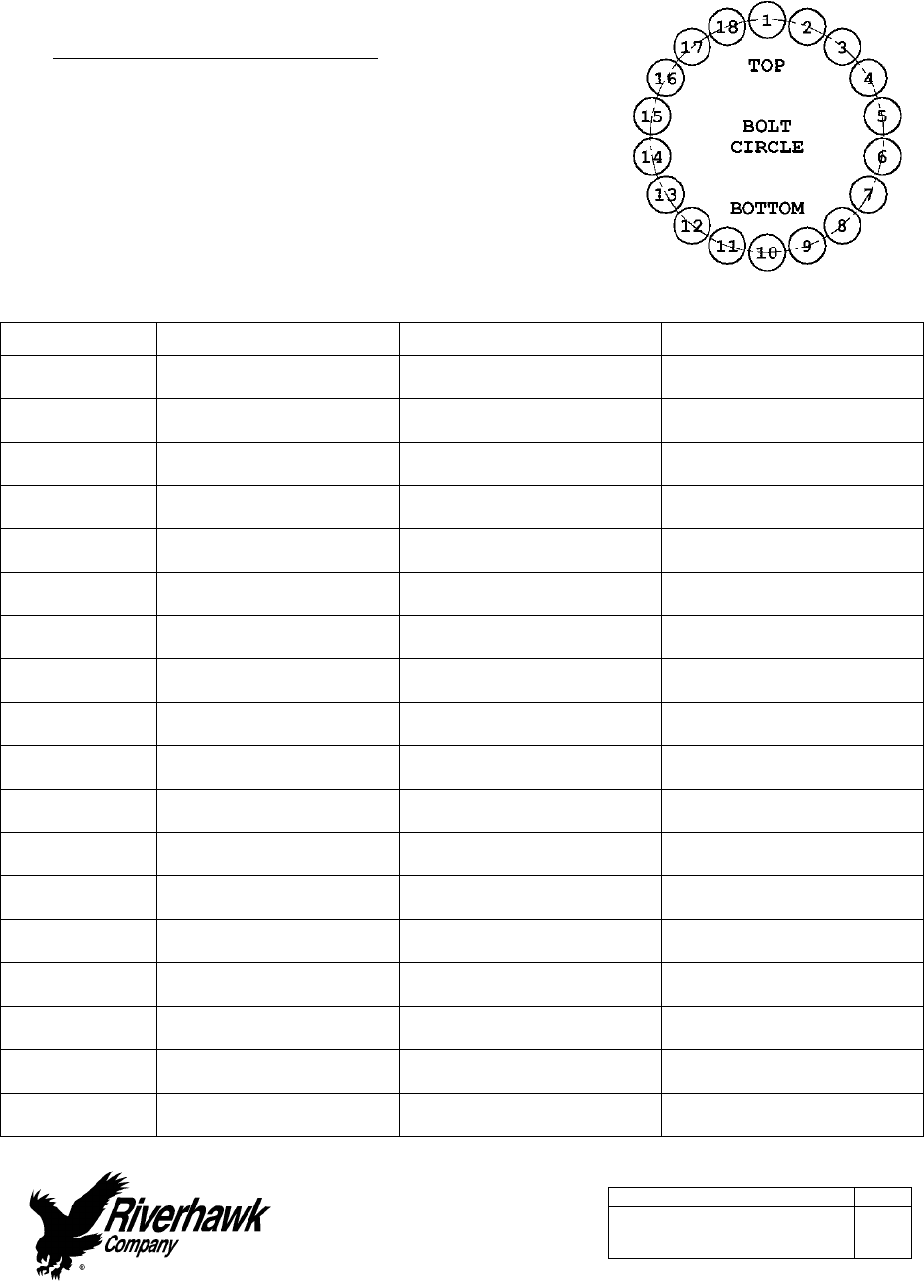
AppendixA1
STRETCHRECORDSHEETFOR
THEGASTURBINETOLOADCOUPLING
TURBINENUMBER:
DATE:
TECHNICIAN:
SUPERVISOR:
HOLENUMBERSTARTINGLENGTHFINALLENGTHFINALSTRETCH
1
10
2
11
3
12
4
13
5
14
6
15
7
16
8
17
9
18
InstructionManualIM‐251
215ClintonRoad
NewHartford,NY13413
Tel:+13157684855
Fax:+13157684941
Email:info@riverhawk.com
C
REV
373A4040
GEDRAWINGNUMBER
Page40of40
E
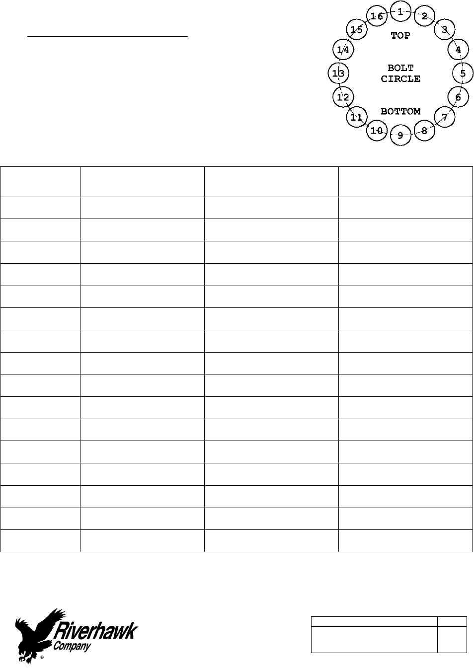
AppendixA2
STRETCHRECORDSHEETFOR
THELOADCOUPLINGTOGENERATOR
TURBINENUMBER:
DATE:
TECHNICIAN:
SUPERVISOR:
HOLENUMBERSTARTING
MEASUREMENTFINALMEASUREMENTFINALGAUGEREADING
1
9
5
13
15
7
3
11
8
16
12
4
10
2
6
14
