INS12350 3 Serial API Host Appl Prg Guide
User Manual:
Open the PDF directly: View PDF ![]() .
.
Page Count: 43

CONFIDENTIAL
Instruction
Serial API Host Appl. Prg. Guide
Document No.:
INS12350
Version:
3
Description:
Guideline for developing serial API based host applications
Written By:
JFR;ABR;JSI;PSH;AES
Date:
2012-12-04
Reviewed By:
JFR;AES;NTJ;JSI;BBR
Restrictions:
Partners Only
Approved by:
Date CET Initials Name Justification
2012-12-04 14:26:33 NTJ Niels Thybo Johansen
This document is the property of Sigma Designs Inc. The data contained herein, in whole
or in part, may not be duplicated, used or disclosed outside the recipient for any purpose.
This restriction does not limit the recipient's right to use information contained in the data if
it is obtained from another source without restriction.

INS12350-3 Serial API Host Appl. Prg. Guide 2012-12-04
Sigma Designs
Revision Record and Tables of Contents
Page ii of iv
CONFIDENTIAL
REVISION RECORD
Doc. Ver.
Date
By
Pages
affected
Brief description of changes
1
20121026
ABR
AES
JSI
JFR
ALL
Initial draft
2
20121109
AES
6.1
Initialization
3
20121130
ABR
6.4.2, 6.6.1,
6.6.3
Added details to description of exception handling w hen receiving data frames.

INS12350-3 Serial API Host Appl. Prg. Guide 2012-12-04
Sigma Designs
Revision Record and Tables of Contents
Page iii of iv
CONFIDENTIAL
Table of Contents
1 ABBREVIATIONS ...................................................................................................................... 5
2 INTRODUCTION ........................................................................................................................ 5
2.1 Purpose................................................................................................................................... 5
2.2 Audience and prerequisites....................................................................................................... 6
2.3 Terms used in this document .................................................................................................... 6
3 OVERVIEW ................................................................................................................................ 7
4 COMMUNICATION INTERFACE ................................................................................................. 8
4.1 Communication Channel Settings.............................................................................................. 8
4.1.1 RS-232 Serial port .......................................................................................................... 8
4.1.2 USB Serial port............................................................................................................... 9
5 FRAME LAYOUT ..................................................................................................................... 10
5.1 ACK frame ............................................................................................................................. 10
5.2 ACK frameNAK frame............................................................................................................. 10
5.3 CAN frame............................................................................................................................. 11
5.4 Data frame............................................................................................................................. 11
5.4.1 Start Of Frame (SOF).................................................................................................... 11
5.4.2 Length ......................................................................................................................... 12
5.4.3 Type ............................................................................................................................ 12
5.4.4 Serial API Command ID ................................................................................................ 12
5.4.5 Serial API Command Parameters .................................................................................. 12
5.4.6 Checksum .................................................................................................................... 13
6 TRANSMISSION ...................................................................................................................... 14
6.1 Initialization............................................................................................................................ 14
6.1.1 With hard reset ............................................................................................................. 14
6.1.2 Without hard reset ........................................................................................................ 14
6.2 Frame timing.......................................................................................................................... 14
6.2.1 Data frame reception timeout......................................................................................... 14
6.2.2 Data frame delivery timeout ........................................................................................... 14
6.3 Retransmission ...................................................................................................................... 15
6.4 Exception handling ................................................................................................................. 15
6.4.1 Unresponsive Z-Wave module ....................................................................................... 15
6.4.2 Persistent CRC errors ................................................................................................... 15
6.4.3 Missing callbacks.......................................................................................................... 15
6.5 Frame Flow............................................................................................................................ 16
6.5.1 Unsolicited frame flow ................................................................................................... 16
6.5.2 Request/Response frame flow ....................................................................................... 17
6.6 State Diagrams ...................................................................................................................... 18
6.6.1 Host Data Frame Reception .......................................................................................... 19
6.6.1.1 Counter maintenance............................................................................................. 21
6.6.2 Host Media Access Control ........................................................................................... 22
6.6.3 Host Request/Response Session................................................................................... 24
7 SERIAL API COMMANDS ........................................................................................................ 26
7.1 Capabilities Command............................................................................................................ 26
7.2 Node List Command............................................................................................................... 27
7.3 Set Timeouts Command ......................................................................................................... 27
7.4 Power Management Commands ............................................................................................. 28

INS12350-3 Serial API Host Appl. Prg. Guide 2012-12-04
Sigma Designs
Revision Record and Tables of Contents
Page iv of iv
CONFIDENTIAL
7.4.1 Overview...................................................................................................................... 28
7.4.1.1 I/O pins ................................................................................................................. 28
7.4.1.2 Power management configuration sequence ........................................................... 29
7.4.1.3 Power up sequence ............................................................................................... 29
7.4.1.4 Power down sequence ........................................................................................... 30
7.4.1.5 Power modes ........................................................................................................ 30
7.4.2 Pin Configuration Command.......................................................................................... 30
7.4.3 Power up Mode Configuration Command ....................................................................... 32
7.4.4 Power Up on Z-Wave Configuration Command............................................................... 32
7.4.5 Power Up on Timer Configuration Command .................................................................. 35
7.4.6 External Power Up Configuration Command................................................................... 36
7.4.7 Power down Mode Configuration Command ................................................................... 37
7.5 Ready Command ................................................................................................................... 38
7.6 Softreset Command ............................................................................................................... 38
7.7 Watchdog Commands ............................................................................................................ 39
7.8 Restrictions on functions using buffers ..................................................................................... 39
APPENDIX A SERIAL API FILES.................................................................................................. 40
Appendix A.1 Makefiles ................................................................................................................. 40
Appendix A.2 Application ............................................................................................................... 41
REFERENCES ................................................................................................................................ 42
INDEX ............................................................................................................................................ 43
Table of Figures
Figure 1. Communication via Serial API .............................................................................................. 7
Figure 2. ACK frame ........................................................................................................................ 10
Figure 3. NAK frame ........................................................................................................................ 10
Figure 4. CAN frame ........................................................................................................................ 11
Figure 5. Data frame ........................................................................................................................ 11
Figure 6. Unsolicited Data frame ....................................................................................................... 16
Figure 7. Unsolicited Data frame followed by unsolicited Data frame ................................................... 16
Figure 8. Request/Response Data frames ......................................................................................... 17
Figure 9. Request/Response Data frames followed by unsolicited Data frame ..................................... 18
Figure 10. Host Data Frame Reception ............................................................................................. 19
Figure 11. Counter Maintenance ....................................................................................................... 21
Figure 12. Host Media Access Control .............................................................................................. 22
Figure 13. Host Request/Response Session...................................................................................... 24
Figure 14. Power Management system ............................................................................................. 28
Table of Tables
Table 1. Serial API RS-232 parameters ............................................................................................... 8
Table 2. Serial API USB Windows .inf file structure .............................................................................. 9
Table 3. Data frame :: Type values ................................................................................................... 12

INS12350-3 Serial API Host Appl. Prg. Guide 2012-12-04
Sigma Designs
Appendix A Serial API files
Page 5 of 39
CONFIDENTIAL
1 ABBREVIATIONS
Abbreviation
Explanation
ACK
Acknowledgement
AES
The Advanced Encryption Standard is a symmetric block cipher algorithm. The AES is
a NIST-standard cryptographic cipher that uses a block length of 128 bits and key
lengths of 128, 192 or 256 bits. Officially replacing the Triple DES method in 2001,
AES uses the Rijndael algorithm developed by Joan Daemen and Vincent Rijmen of
Belgium.
ANZ
Australia/New Zealand
API
Application Programming Interface
ASIC
Application Specific Integrated Circuit
CAN
Cancel
DLL
Dynamic Link Library
DUT
Device Under Test
EU
Europe
GNU
An organization devoted to the creation and support of Open Source software
HK
Hong Kong
HW
Hardware
IN
India
ISR
Interrupt Service Routines
JP
Japan
LRC
Longitudinal Redundancy Check
MY
Malaysia
NAK
Not Acknowledged
NWI
Network Wide Inclusion
PA
Power Amplifier
POR
Power On Reset
PRNG
Pseudo-Random Number Generator
PWM
Pulse Width Modulator
RF
Radio Frequency
RS-232
TIA-232-F Interface Between Data Terminal Equipment and
Data Circuit-Terminating Equipment Employing Serial Binary Data Interchange
RU
Russian Federation
SDK
Software Developer‟s Kit
SIS
SUC ID Server
SOF
Start Of Frame
SPI
Serial Peripheral Interface
SUC
Static Update Controller
US
United States
USB
Universal Serial Bus
USB CDC
Universal Serial Bus Communications Device Class
WUT
Wake Up Timer
2 INTRODUCTION
2.1 Purpose
The purpose of this document is to provide a user guide for host processor application development
using the serial API interface. This guide covers the whole range of available Z-Wave chips/modules.

INS12350-3 Serial API Host Appl. Prg. Guide 2012-12-04
Sigma Designs
Appendix A Serial API files
Page 6 of 39
CONFIDENTIAL
2.2 Audience and prerequisites
The audience of this document is Z-Wave partners and Sigma Designs.
2.3 Terms used in this document
This document describes mandatory and optional aspects of the required compliance of a Z-Wave
product to the Z-Wave standard.
The guidelines outlined in IETF RFC 2119 [1] with respect to key words used to indicate requirement
levels are followed. Essentially, the key words "MUST", "MUST NOT", "REQUIRED", "SHALL", "SHALL
NOT", "SHOULD", "SHOULD NOT", "RECOMMENDED", "MAY", and "OPTIONAL" in this document are
to be interpreted as described in RFC 2119.

INS12350-3 Serial API Host Appl. Prg. Guide 2012-12-04
Sigma Designs
Appendix A Serial API files
Page 7 of 39
CONFIDENTIAL
3 OVERVIEW
The Serial Applications Programming Interface (Serial API) allows a host to communicate with a Z-Wave
chip. The host may be PC or a less powerful embedded host CPU, e.g. in a remote control or in a
gateway device. Depending on the actual chip family, the Serial API may be accessed via RS-232 or
USB physical interfaces.
A number of sample applications demonstrate how to communicate with a Z-Wave chip via the Serial
API.
The following host based sample applications are available on the SDK:
PC Controller
Demonstrates Serial API features of the static controller API
PC Installer Tool
Demonstrates Serial API features of the installer controller API
PC Bridge
Demonstrates Serial API features of the bridge controller API
ATMega Development Board Controller
Demonstrates Serial API features of the portable controller API
Figure 1. Communication via Serial API
The host based sample applications are described in the respective SDK overview documents.
Refer to [2], [3] or [4].
The serial API leverages on the Z-Wave Protocol API. The serial API introduces additional messages
related to inter-host communications. Mapping of serial API commands to the Z-Wave Protocol API calls
can be found in [5], [6] or [7]. Dedicated serial API commands are presented in section 7.
Serial API based applications MUST ensure that the required features are available in the actual Z-Wave
library, using the “Capabilities Command” see 7.1. Refer to [2], [3] or [4] for SDK library variants.
Host
Z-Wave
chip
Serial API via
RS-232 or USB

INS12350-3 Serial API Host Appl. Prg. Guide 2012-12-04
Sigma Designs
Appendix A Serial API files
Page 8 of 39
CONFIDENTIAL
4 COMMUNICATION INTERFACE
The following sections describe the Serial API.
4.1 Communication Channel Settings
4.1.1 RS-232 Serial port
A host communicating to a Serial API library via a serial port MUST use the following settings.
Parameter
Value
Baud rate
115200 bits/s
Parity
No
Data bits
8
Stop bits
1
Table 1. Serial API RS-232 parameters
The least significant bit (LSB) b0 of each byte MUST be transmitted first on the physical wire.

INS12350-3 Serial API Host Appl. Prg. Guide 2012-12-04
Sigma Designs
Appendix A Serial API files
Page 9 of 39
CONFIDENTIAL
4.1.2 USB Serial port
A host communicating to a Serial API library via a USB connection MUST obey the guidelines for the
USB communications device class (USB CDC). In many cases, Linux distributions and MacOS releases
will immediately present the Z-Wave chip USB interface as a serial port to applications.
Windows releases may need an .inf file structure in order to present the Z-Wave chip USB interface as a
serial port to applications:
Key
Value
[Version]
Signature="$Windows NT$"
Class=Ports
ClassGuid={4D36E978-E325-11CE-BFC1-08002BE10318}
Provider=%manu%
DriverVer=02/17/2010,0.0.3.0
[Manufacturer]
%manu%=ZComDev, NTx86, NTamd64
[ZComDev.NTx86]
%dev%=ZComInst, USB\VID_0658&PID_0200
[ZComDev.NTamd64]
%dev%=ZComInst, USB\VID_0658&PID_0200
[ZComInst]
include=mdmcpq.inf
CopyFiles=FakeModemCopyFileSection
AddReg=LowerFilterAddReg,SerialPropPageAddReg
[ZComInst.Services]
include = mdmcpq.inf
AddService = usbser, 0x00000002, LowerFilter_Service_Inst
[SerialPropPageAddReg]
HKR,,EnumPropPages32,,"MsPorts.dll,SerialPortPropPageProvider"
[Strings]
manu = "Sigma Designs"
dev = "UZB"
svc = "UZB"
Table 2. Serial API USB Windows .inf file structure

INS12350-3 Serial API Host Appl. Prg. Guide 2012-12-04
Sigma Designs
Appendix A Serial API files
Page 10 of 39
CONFIDENTIAL
5 FRAME LAYOUT
The host and the Z-Wave chip (ZW) communicates via a simple protocol which uses four frame types:
the ACK, NAK, CAN and Data frame types.
5.1 ACK frame
The ACK frame indicates that the receiving end received a valid Data frame.
The host MUST wait for an ACK frame after transmitting a Data frame to the Z-Wave chip.
In case of transmission errors or race conditions, the host may receive other frames or no frames at all.
The host MUST be robust towards such events. The host SHOULD queue up requests for processing
once the expected ACK frame has been received or timed out. The host MUST wait for a period of
1500ms before timing out waiting for the ACK frame.
A receiving Z-Wave chip MUST return an ACK frame in response to a valid Data frame.
7
(MSB)
6
5
4
3
2
1
0
(LSB)
ACK (0x06)
Figure 2. ACK frame
5.2 ACK frameNAK frame
The NAK frame indicates that the receiving end received a Data frame with errors.
If a transmitting host or Z-Wave chip receives a NAK frame in response to a Data frame, it MAY
retransmit the Data frame.
7
(MSB)
6
5
4
3
2
1
0
(LSB)
NAK (0x15)
Figure 3. NAK frame
A transmitting host or Z-Wave chip receiving a NAK frame MUST wait for a period before retransmitting
the Data frame. Refer to 6.3

INS12350-3 Serial API Host Appl. Prg. Guide 2012-12-04
Sigma Designs
Appendix A Serial API files
Page 11 of 39
CONFIDENTIAL
5.3 CAN frame
The CAN frame indicates that the receiving end discarded an otherwise valid Data frame.
The CAN frame is used to resolve race conditions, where both ends send a Data frame and
subsequently expects an ACK frame from the other end.
.7
(MSB)
6
5
4
3
2
1
0
(LSB)
CAN (0x18)
Figure 4. CAN frame
If a Z-Wave chip expects to receive an ACK frame but receives a Data frame from the host, the Z-Wave
chip SHOULD return a CAN frame. A host which receives a CAN frame MUST consider the dataframe
lost. The host MUST wait for a period before retransmitting the Data frame. Refer to 6.3
5.4 Data frame
The Data frame contains the Serial API command including parameters for the command in question.
Each Data frame MUST be composed of a Serial API command including parameters for the command
prepended with Start Of Frame (SOF), Length and Type fields and a Checksum byte appended.
A transmitting host or Z-Wave chip may time out waiting for an ACK frame after transmitting a Data
frame. The transmitting end MUST wait for ACK frame for a period. If no ACK frame is received, the Data
frame MAY be retransmitted; refer to 6.3.
7
(MSB)
6
5
4
3
2
1
0
(LSB)
SOF (0x01)
Length
Type
Serial API Command ID
Serial API Command Parameter 1
…
Serial API Command Parameter n
Checksum
Figure 5. Data frame
5.4.1 Start Of Frame (SOF)
The Start Of Frame (SOF) field is used for synchronization. The SOF field MUST have a value of 0x01.
A host or a Z-Wave chip waiting for new traffic MUST ignore all other byte values than 0x06 (ACK), 0x15
(NAK), 0x18 (CAN) or 0x01 (Data frame). This way, both receivers will flush garbage bytes from the
receive buffer to get back in sync after a connection glitch or a firmware restart in one of the ends.

INS12350-3 Serial API Host Appl. Prg. Guide 2012-12-04
Sigma Designs
Appendix A Serial API files
Page 12 of 39
CONFIDENTIAL
5.4.2 Length
The Length field MUST report the number of bytes in the Data frame. The value of the Length Field
MUST NOT include the SOF and Checksum fields.
A host or a Z-Wave chip receiving a Data frame SHOULD validate the length field by comparing the
number of received bytes and the Length field (expecting a difference of 2 bytes).
5.4.3 Type
The Type field MUST indicate if the Data frame type is Request or Response.
Value
Type
Description
0x00
REQ
Request.
This type MUST be used for unsolicited messages.
API callback messages MUST use the Request type.
0x01
RES
Response.
This type MUST be used for messages that are responses
to Requests.
0x02..0xFF
Reserved
Reserved values MUST NOT be used.
A receiving end MUST ignore reserved Type values.
Table 3. Data frame :: Type values
5.4.4 Serial API Command ID
The Serial API Command ID field MUST carry one of the valid API function codes defined in 7.
A host or Z-Wave chip MUST report the same Serial API Command ID in a response Data frame (refer to
5.4.3.
5.4.5 Serial API Command Parameters
The Serial API Command Parameters field MAY carry a variable number of bytes. The field MUST be at
least one byte long. A receiving end MUST derive the actual number of bytes from the Length field; refer
to 5.4.2.
Information carried in the Serial API Command Parameters field MUST comply with the API function
prototype for the Serial API Command ID carried in the Serial API Command ID field; refer to 5.4.4
API function prototypes may be found in 7.

INS12350-3 Serial API Host Appl. Prg. Guide 2012-12-04
Sigma Designs
Appendix A Serial API files
Page 13 of 39
CONFIDENTIAL
5.4.6 Checksum
The Checksum field MUST carry a checksum to enable frame integrity checks.
The checksum calculation MUST include the Length, Type, Serial API Command Data and Serial API
Command Parameters fields.
The checksum value MUST be calculated as an 8-bit Longitudinal Redundancy Check (LRC) value.
The RECOMMENDED way to calculate the checksum is to initialize the checksum to 0xFF and then
XOR each of the bytes of the fields mentioned above one at a time to the checksum value.
Checksum = 0xFF Length Type Cmd ID Cmd Parm[1] … Cmd Parm[n]
A Data frame MUST be considered invalid if it is received with an invalid checksum. Refer to 5.4.6.
A host or Z-Wave chip MUST return a NAK frame in response to an invalid Data frame.

INS12350-3 Serial API Host Appl. Prg. Guide 2012-12-04
Sigma Designs
Appendix A Serial API files
Page 14 of 39
CONFIDENTIAL
6 TRANSMISSION
6.1 Initialization
To make sure the host and the Z-Wave module are in sync at application startup, the host should begin
an initialization sequence. The initialization sequence differs a little depending on if the host has access
to a module hard reset.
6.1.1 With hard reset
1) Close host serial port if it is open
2) Assert module reset
3) Open the host serial port at 115200 baud 8N1.
4) Release module reset
5) Wait 500ms
6.1.2 Without hard reset
1) Close host serial port if it is open
2) Open the host serial port at 115200 baud 8N1.
3) Send the NAK
4) Send SerialAPI command: FUNC_ID_SERIAL_API_SOFT_RESET
5) Wait 1.5s
This solution is not recommended because it rely on retrieval and execution of the SerialAPI command
FUNC_ID_SERIAL_API_SOFT_RESET.
6.2 Frame timing
6.2.1 Data frame reception timeout
A receiving host or Z-Wave chip MUST abort reception of a Data frame if the reception has lasted for
more than 1500ms after the reception of the SOF byte. A host or Z-Wave chip MUST NOT issue a NAK
frame after aborting reception of a Data frame.
6.2.2 Data frame delivery timeout
A host or Z-Wave chip MUST wait for an ACK frame after transmitting a Data frame.
The receiver may be waiting for up to 1500ms for the remains of a corrupted frame (6.2.1).
Therefore, the transmitter MUST wait for at least 1600ms before deeming the Data frame lost.

INS12350-3 Serial API Host Appl. Prg. Guide 2012-12-04
Sigma Designs
Appendix A Serial API files
Page 15 of 39
CONFIDENTIAL
The loss of a Data frame MUST be treated as the reception of a NAK frame; refer to 6.3.
The transmitter MAY compensate for the 1600ms already elapsed when calculating the retransmission
waiting period.
6.3 Retransmission
A transmitter may time out waiting for an ACK frame after transmitting a Data frame or it may receive a
NAK or a CAN frame. In either case, the transmitter SHOULD retransmit the Data frame.
A waiting period MUST be applied before the retransmission.
The waiting period MUST be calculated per the following formula:
Twaiting = 100ms + n*1000ms
where n is incremented
at each retransmission.
n=0 is used for the first waiting
period.
A host or Z-Wave chip MUST NOT carry out more than 3 retransmissions. It should be noted that a host
MAY choose to do a hard reset of the Z-Wave module if it is not able to do a successful frame delivery
after 3 retransmissions. It is also recommended to flush/reopen the serial port after the 3
retransmissions.
6.4 Exception handling
6.4.1 Unresponsive Z-Wave module
In the unlikely event that the Z-Wave module becomes unresponsive for more than 4 seconds, it is
RECOMMENDED to issue a hard reset of the module. A module may be deemed unresponsive if it has
not responded with any character after three consecutive frame retransmissions, each with a 1600ms
interval. See section 6.1
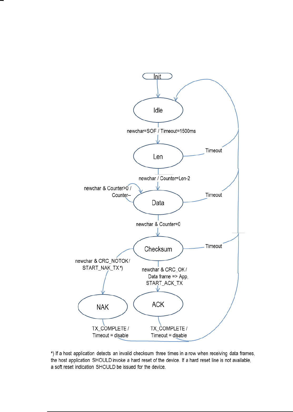
6.4.2 Persistent CRC errors
If a host application detects an invalid checksum three times in a row when receiving data frames,
the host application SHOULD invoke a hard reset of the device. If a hard reset line is not available,
a soft reset indication SHOULD be issued for the device.
6.4.3 Missing callbacks
I some situations a serial API callback may be lost due to an overflow in the UART transmit buffer. This
condition may occur if a lot of unsolicited traffic comes in from the Z-Wave side. For this reason a
SerialAPI based host application SHOULD guard all its callbacks with a timer. The timer values are given
in INS11095 for each of the Z-Wave API functions which use callbacks.

INS12350-3 Serial API Host Appl. Prg. Guide 2012-12-04
Sigma Designs
Appendix A Serial API files
Page 16 of 39
CONFIDENTIAL
6.5 Frame Flow
The frame flow between a host and a Z-Wave module (ZW) running the Serial API embedded sample
code depends on the API call. There are two classes of communication between a host and a Z-Wave
chip: Unsolicited and Request/Response. Each of the classes is presented below.
6.5.1 Unsolicited frame flow
The most basic frame flow is a Request (REQ) Data frame that is acknowledged by an ACK frame.
Figure 6. Unsolicited Data frame
An example of the frame flow outlined in the figure above could be the API call ZW_SetExtIntLevel.
A variant of the REQ Data frame flow is a request (REQ) Data frame in one direction followed by a
request (REQ) Data frame in the opposite direction. The first Data frame is acknowledged before a Data
frame is transmitted in the opposite direction.
Figure 7. Unsolicited Data frame followed by unsolicited Data frame
Data Frame (REQ)
ACK
ZW
Host
Data Frame (REQ)
ACK
ZW
Host
Data Frame (REQ - Callback)
ACK

INS12350-3 Serial API Host Appl. Prg. Guide 2012-12-04
Sigma Designs
Appendix A Serial API files
Page 17 of 39
CONFIDENTIAL
Typically, the REQ Data frame in the opposite direction will follow after some time.
An example of the frame flow outlined in the figure above could be the API call ZW_SetDefault, where
the second Data frame is carrying a callback message indicating the completion of the operation.
6.5.2 Request/Response frame flow
A Request (REQ) Data frame may be followed by a Result (RES) Data frame within an interval of a few
seconds. This flow is used for all functions which have a non-void return value. Note that due to the
simple nature of the simple acknowledge mechanism, only one REQ->RES session is allowed.
Figure 8. Request/Response Data frames
An example of the frame flow outlined in the figure above could be the API call
ZW_GetControllerCapabilities, where the Result Data frame is carrying the requested controller
capabilities.
Data Frame (REQ)
ACK
ZW
Host
Data Frame (RES)
ACK

INS12350-3 Serial API Host Appl. Prg. Guide 2012-12-04
Sigma Designs
Appendix A Serial API files
Page 18 of 39
CONFIDENTIAL
A variant of the Request/Response Data frame flow is a flow where an unsolicited Data frame follows
after the Request/Response Data frame pair. Typically, the REQ Data frame in the opposite direction will
follow after some time.
Figure 9. Request/Response Data frames followed by unsolicited Data frame
An example of the frame flow outlined in the figure above could be the API call ZW_SendSUCID, where
the Result Data frame is carrying the requested controller capabilities and the second Data frame is
carrying a callback message indicating the completion of the operation.
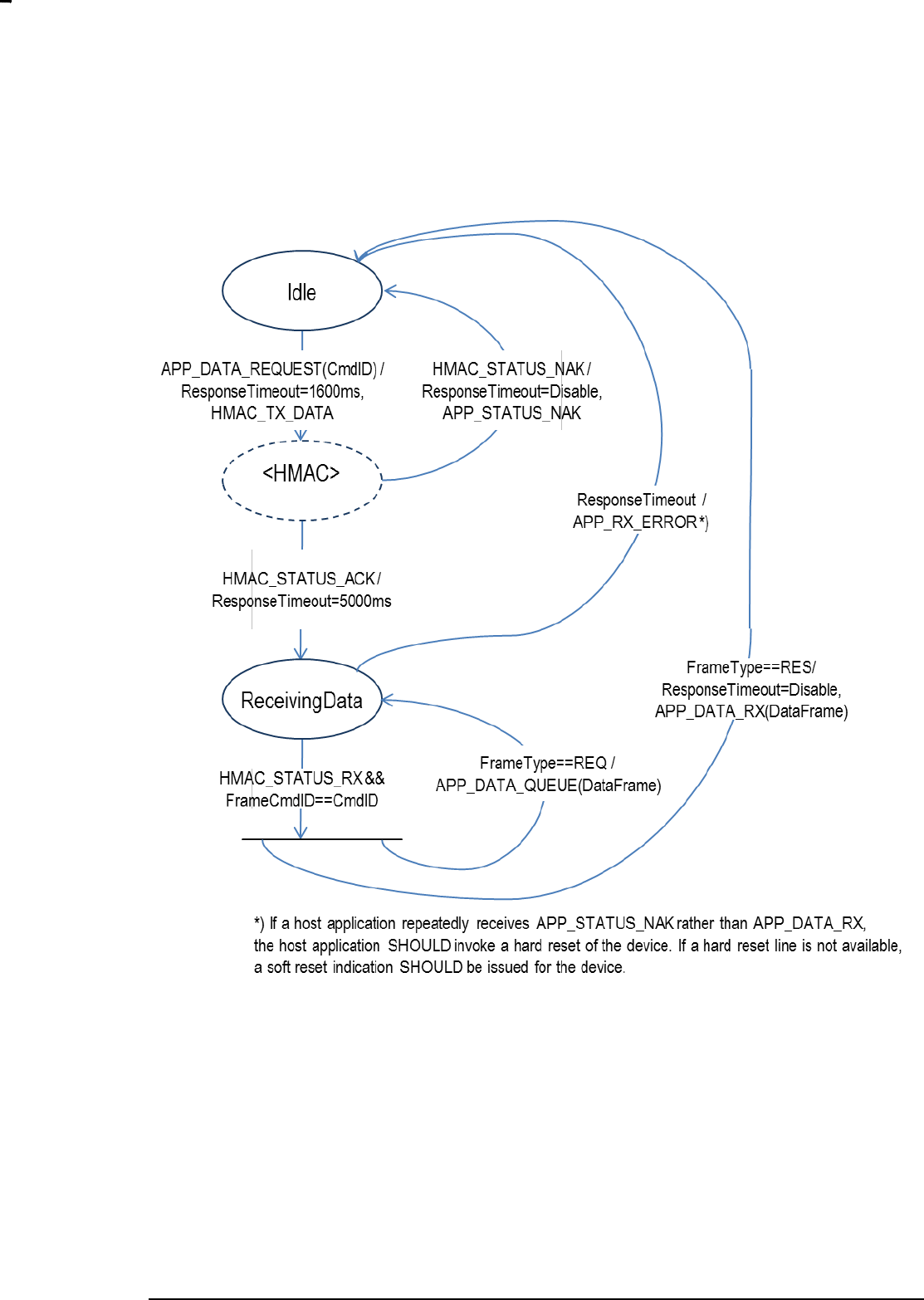
If a host application repeatedly receives a reception timeout error indication rather than a valid response
data frame, the host application SHOULD invoke a hard reset of the device. If a hard reset line is not
available, a soft reset indication SHOULD be issued for the device.
6.6 State Diagrams
This chapter outlines a transmission and reception of Control and Data frames.
Data Frame (REQ)
ACK
ZW
Host
Data Frame (RES)
ACK
Data Frame (REQ - Callback)
ACK
INS12350-3 Serial API Host Appl. Prg. Guide 2012-12-04
Sigma Designs
Appendix A Serial API files
Page 19 of 39
CONFIDENTIAL
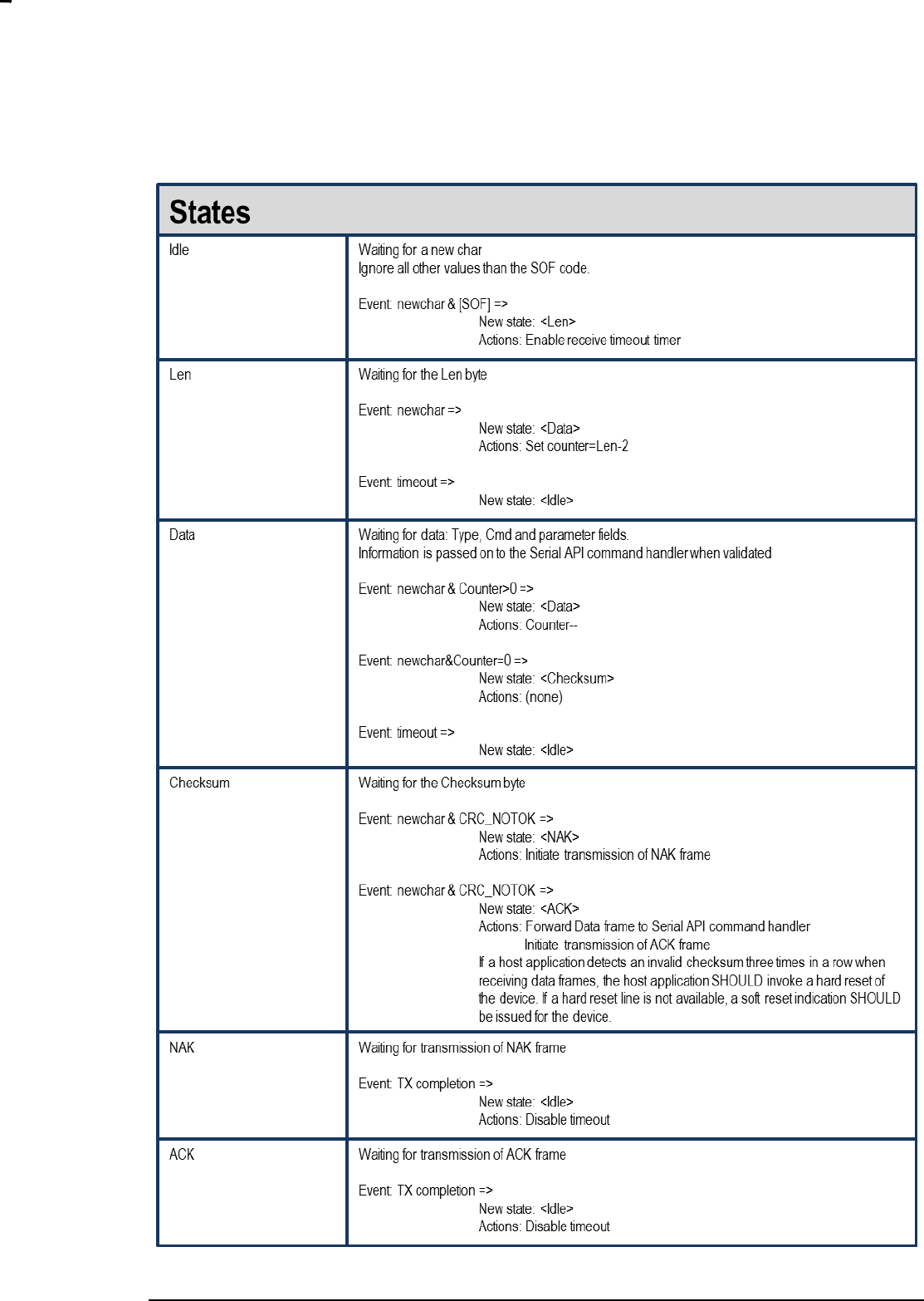
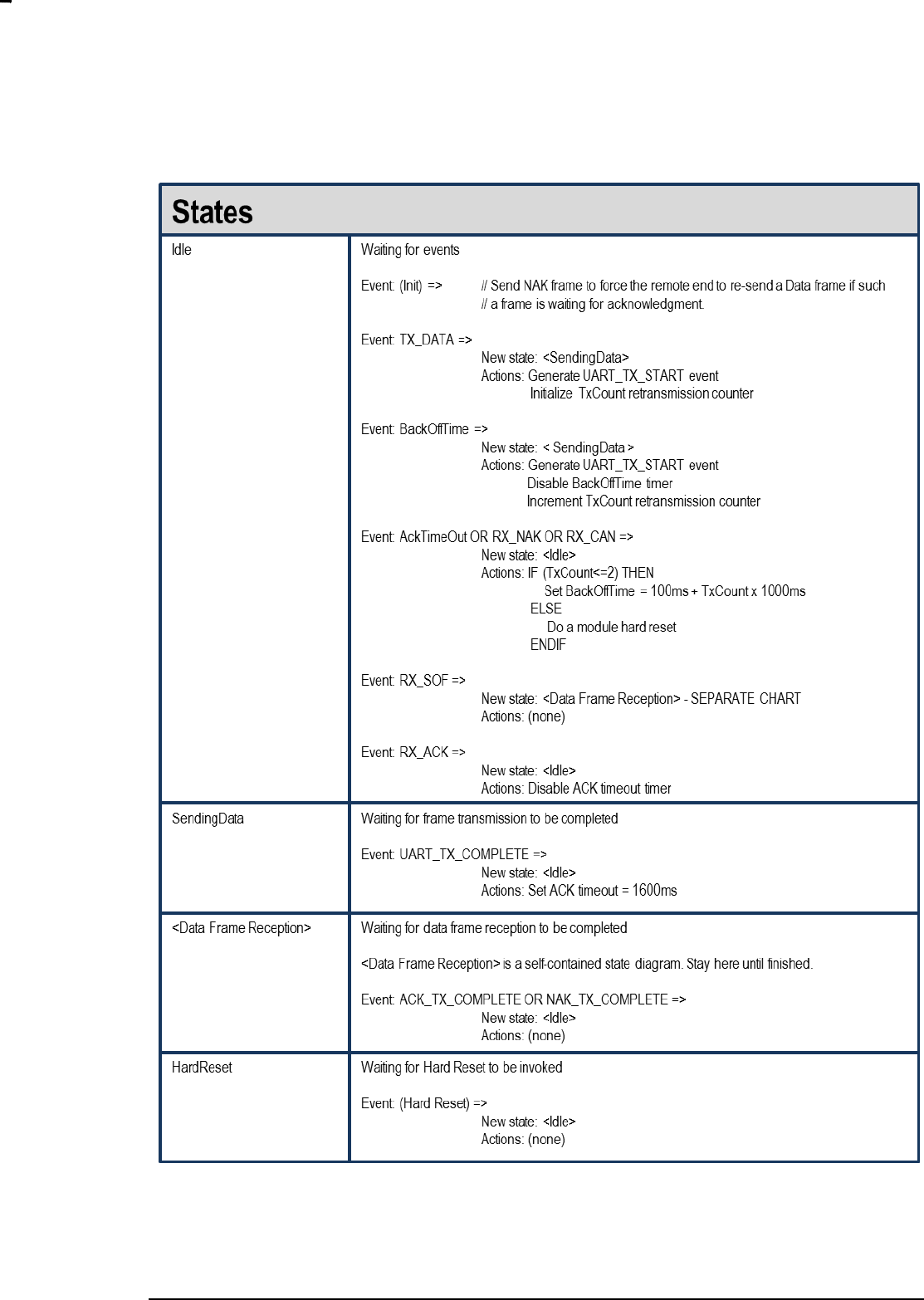
6.6.1 Host Data Frame Reception
Figure 10. Host Data Frame Reception
INS12350-3 Serial API Host Appl. Prg. Guide 2012-12-04
Sigma Designs
Appendix A Serial API files
Page 20 of 39
CONFIDENTIAL
INS12350-3 Serial API Host Appl. Prg. Guide 2012-12-04
Sigma Designs
Appendix A Serial API files
Page 21 of 39
CONFIDENTIAL
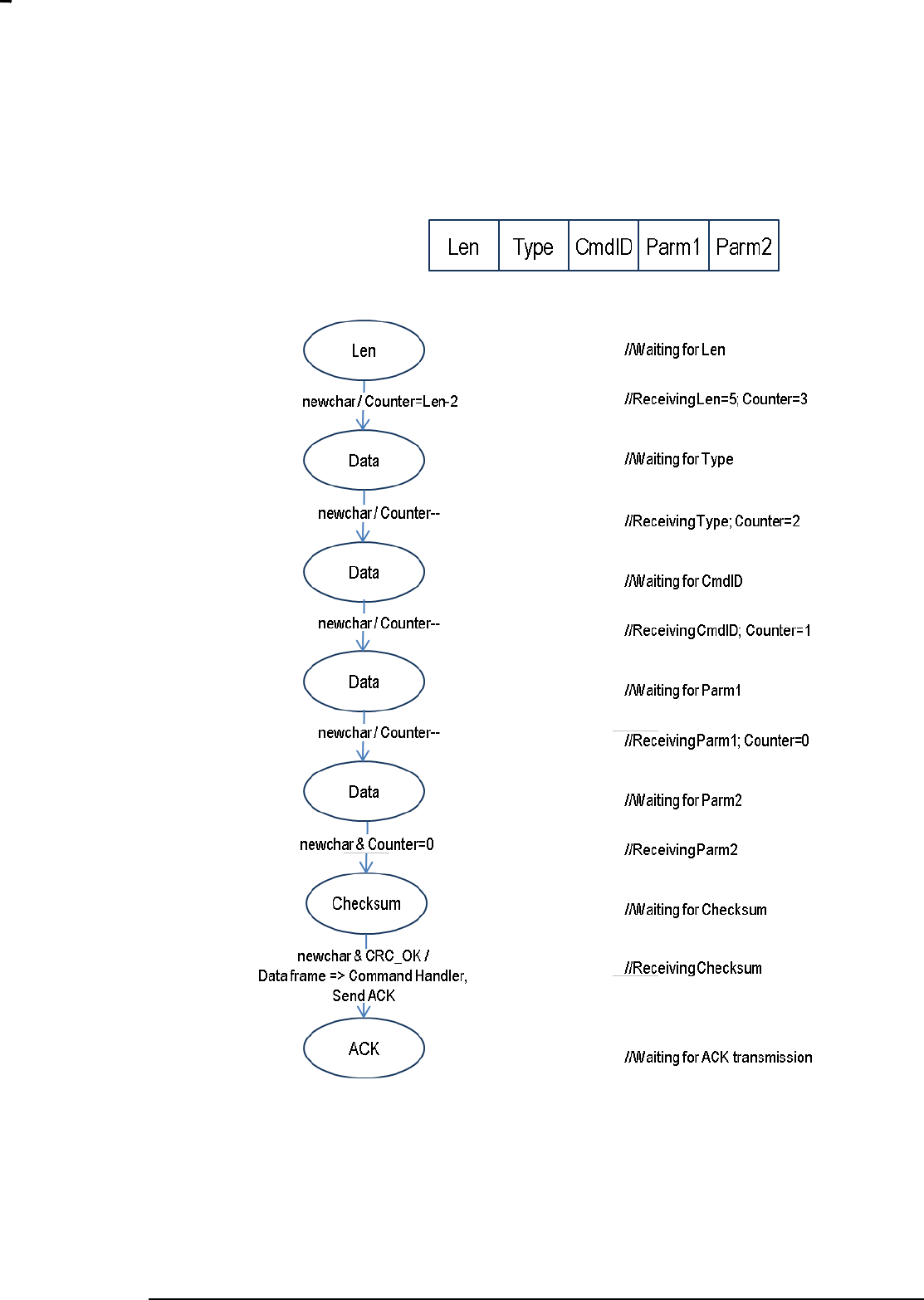
6.6.1.1 Counter maintenance
Figure 11. Counter Maintenance
INS12350-3 Serial API Host Appl. Prg. Guide 2012-12-04
Sigma Designs
Appendix A Serial API files
Page 22 of 39
CONFIDENTIAL
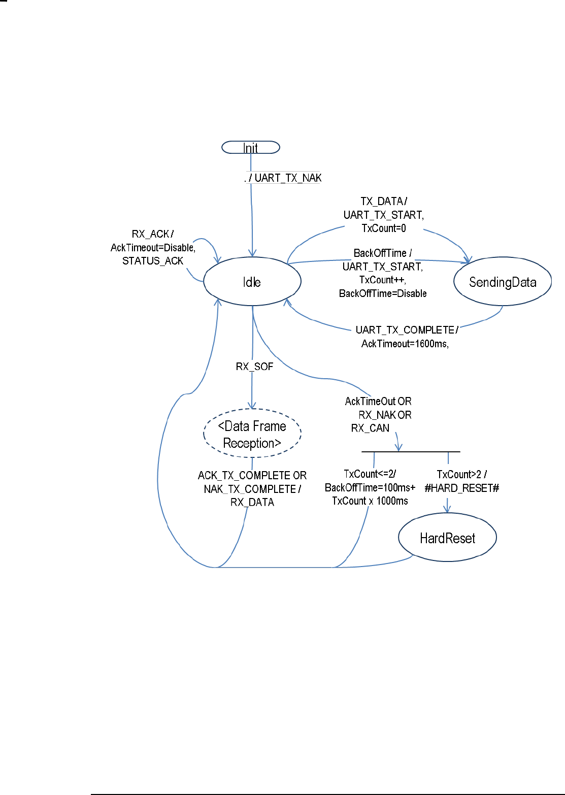
6.6.2 Host Media Access Control
Figure 12. Host Media Access Control
INS12350-3 Serial API Host Appl. Prg. Guide 2012-12-04
Sigma Designs
Appendix A Serial API files
Page 23 of 39
CONFIDENTIAL
INS12350-3 Serial API Host Appl. Prg. Guide 2012-12-04
Sigma Designs
Appendix A Serial API files
Page 24 of 39
CONFIDENTIAL
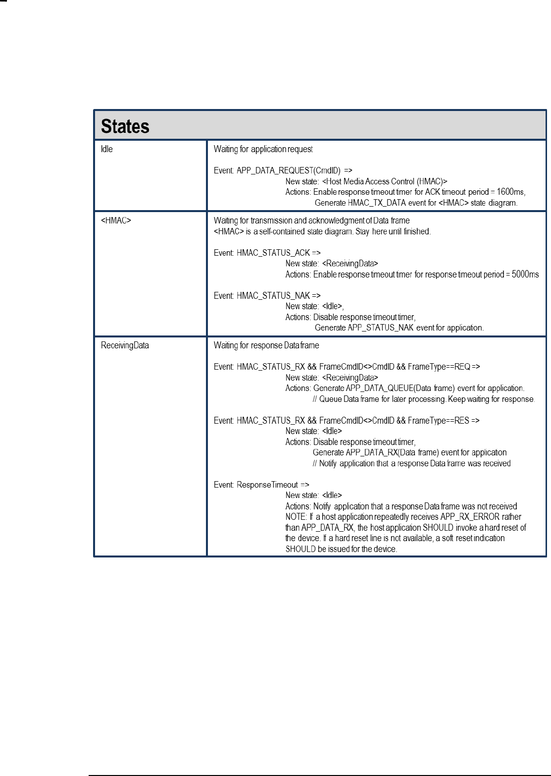
6.6.3 Host Request/Response Session
Figure 13. Host Request/Response Session
INS12350-3 Serial API Host Appl. Prg. Guide 2012-12-04
Sigma Designs
Appendix A Serial API files
Page 25 of 39
CONFIDENTIAL

INS12350-3 Serial API Host Appl. Prg. Guide 2012-12-04
Sigma Designs
Appendix A Serial API files
Page 26 of 39
CONFIDENTIAL
7 SERIAL API COMMANDS
Besides the Z-Wave API function calls described in “Z-Wave application programmers‟ guide” the
SerialAPI support a set of additional commands.
7.1 Capabilities Command
As of Serial API protocol version 4 (to determine Serial API protocol version please refer to the Serial API
Function described in paragraph 7.2) it is possible to call Serial API Capabilities Command to determine
exactly which Serial API functions a specific Serial API Z-Wave Module supports with the
FUNC_ID_SERIAL_API_GET_CAPABILITIES Serial API function:
Serial API:
HOST->ZW: REQ | 0x07
ZW->HOST: RES | 0x07 | SERIAL_APPL_VERSION | SERIAL_APPL_REVISION |
SERIALAPI_MANUFACTURER_ID1 | SERIALAPI_MANUFACTURER_ID2 |
SERIALAPI_MANUFACTURER_PRODUCT_TYPE1 |
SERIALAPI_MANUFACTURER_PRODUCT_TYPE2 |
SERIALAPI_MANUFACTURER_PRODUCT_ID1 | SERIALAPI_MANUFACTURER_PRODUCT_ID2 |
FUNCID_SUPPORTED_BITMASK[ ]
SERIAL_APPL_VERSION is the Serial API application Version number.
SERIAL_APPL_REVISION is the Serial API application Revision number.
SERIALAPI_MANUFACTURER_ID1 is the Serial API application manufacturer_id (MSB).
SERIALAPI_MANUFACTURER_ID2 is the Serial API application manufacturer_id (LSB).
SERIALAPI_MANUFACTURER_PRODUCT_TYPE1 is the Serial API application manufacturer product
type (MSB).
SERIALAPI_MANUFACTURER_PRODUCT_TYPE2 is the Serial API application manufacturer product
type (LSB).
SERIALAPI_MANUFACTURER_PRODUCT_ID1 is the Serial API application manufacturer product id
(MSB).
SERIALAPI_MANUFACTURER_PRODUCT_ID2 is the Serial API application manufacturer product id
(LSB).
FUNCID_SUPPORTED_BITMASK[ ] is a bitmask where every Serial API function ID which is
supported has a corresponding bit in the bitmask set to „1‟. All Serial API function IDs which are not
supported have their corresponding bit set to „0‟. First byte in bitmask corresponds to FuncIDs 1-8
where bit 0 corresponds to FuncID 1 and bit 7 corresponds to FuncID 8. Second byte in bitmask then
corresponds to FuncIDs 9-16 and so on.

INS12350-3 Serial API Host Appl. Prg. Guide 2012-12-04
Sigma Designs
Appendix A Serial API files
Page 27 of 39
CONFIDENTIAL
7.2 Node List Command
As of Serial API protocol version 4 it is possible to call Serial API Node List Command to determine
Serial API protocol version number, Serial API capabilities, nodes currently stored in the EEPROM (only
controllers) and chip used in a specific Serial API Z-Wave Module with the
FUNC_ID_SERIAL_API_GET_INIT_DATA Serial API function:
Serial API:
HOST->ZW: REQ | 0x02
(Controller) ZW->HOST: RES | 0x02 | ver | capabilities | 29 | nodes[29] | chip_type | chip_version
(Slave) ZW->HOST: RES | 0x02 | ver | capabilities | 0 | chip_type | chip_version
“ver” is the Serial API application Version number.
“capabilities” is a byte holding various flags describing the actual mode.
29 | 0 is the length of “nodes[]”
nodes[29] is a node bitmask.
Capabilities flag:
Bit 0: 0 = Controller API; 1 = Slave API
Bit 1: 0 = Timer functions not supported; 1 = Timer functions supported.
Bit 2: 0 = Primary Controller; 1 = Secondary Controller
Bit 3-7: reserved
The chip used can be determined as follows:
Z-Wave Chip
Chip_type
Chip_version
ZW0102
0x01
0x02
ZW0201
0x02
0x01
ZW0301
0x03
0x01
Timer functions are TimerStart, TimerRestart and TimerCancel.
7.3 Set Timeouts Command
INS12350-3 Serial API Host Appl. Prg. Guide 2012-12-04
Sigma Designs
Appendix A Serial API files
Page 28 of 39
CONFIDENTIAL
The timeout in the Serial API (as of SerialAPI version 4) can be set by using the
FUNC_ID_SERIAL_API_SET_TIMEOUTS Serial API function:
Serial API:
HOST->ZW: REQ | 0x06 | RXACKtimeout | RXBYTEtimeout
ZW->HOST: RES | 0x06 | oldRXACKtimeout | oldRXBYTEtimeout
7.4 Power Management Commands
The Serial API Power Management Commands is designed for use in a system where a Z-Wave module
is connected to a host CPU system via a serial port and a number of I/O pins are used for control of the
power to the Host CPU system.
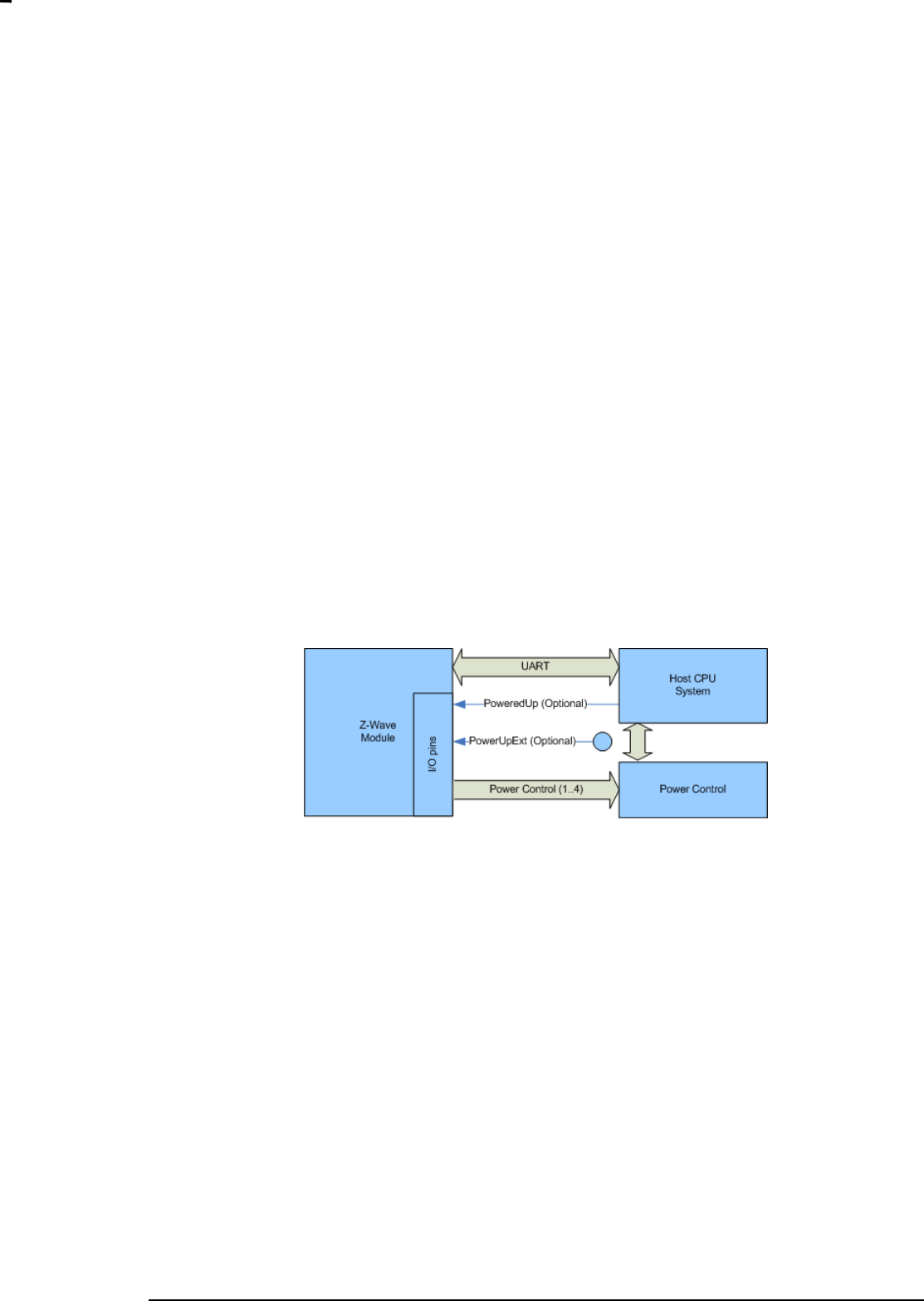
7.4.1 Overview
The power management API is designed for use in a system where a Z-Wave module is connected to a
host CPU system via a serial port and a number of I/O pins are used for control of the power to the Host
CPU system.
Figure 14. Power Management system
In a system like this it is necessary to have a communication protocol between the two CPU systems that
ensures that the correct power state is selected and the Z-Wave module and the host CPU system
always is in agreement about what power state they are using at all times.
All power management configuration and setup is done runtime using the serial API interface from the
host processor system. The Z-Wave module must therefore be powered at all times in the system and
decisions to power down the system always comes from the host CPU system. Power management is
also possible on a Z-Wave module without external non-volatile memory.
7.4.1.1 I/O pins
A number of I/O pins on the Z-Wave module and the host processor system can be used for the power
management API. No GPIO pins will be configured or changed before the host CPU configures the pin.
All GPIO pins will be in their reset state (input, pull up enabled) until the host CPU issues an serial API
command that configures or change status of a pin.
All GPIO‟s used as input on the Z-Wave module must be asserted for at least 20ms when changing level
to allow the firmware to detect the change of the input pin status.
PoweredUp pin (Optional)

INS12350-3 Serial API Host Appl. Prg. Guide 2012-12-04
Sigma Designs
Appendix A Serial API files
Page 29 of 39
CONFIDENTIAL
An input pin on the Z-Wave module is needed to communicate from the host processor to the Z-Wave
module that the host processor system is now ready to be powered down. This pin is necessary if the
host CPU system is not able to send commands on the UART during the power down sequence because
the UART driver or the OS has been stopped. If configured the PoweredUp pin is set active on system
power on.
Z-Wave module Input
Host CPU Output
PowerCtrl(1..4)
The PowerCtrl pins are used to control the power management hardware from the Z-Wave module.
Z-Wave Output
Host CPU N/A
7.4.1.2 Power management configuration sequence
When the serial API starts up for the first time it assumes that there is no power management present.
The power management is activated in the Z-Wave module by configuring the power up mode.
See section 0 for a detailed description of the serial API commands.
When configuring the power management the following sequence of events should happen:
The host configures the PoweredUp pin by using the Serial API Power Management Pin
Configuration command. (Optional)
The host configures the Power Up PowerCtrl pin(s) by using the Serial API Power Management
Pin Configuration command
The host configures the Wake up criteria‟s by using the Power Up on Z-Wave Configuration
Command (see section 7.4.4) and/or the Power Up on Timer Configuration Command (see
section 7.4.5).
7.4.1.3 Power up sequence
When powering up the following sequence of events should happen:
1. The Z-Wave module receives a command via RF that triggers a power up of the system.
2. The Z-Wave module changes the state of the power control I/O pins to the
POWER_MODE_RUNNING state
3. The Z-Wave module waits for the Serial API Ready command on the UART
4. The host CPU system powers up and sets the PoweredUp pin active. (Optional)
5. When ready the host CPU system sends the serial API Ready command.
6. When the Ready command is received the Z-Wave module sends the command that triggered
the power up to the host CPU system.

INS12350-3 Serial API Host Appl. Prg. Guide 2012-12-04
Sigma Designs
Appendix A Serial API files
Page 30 of 39
CONFIDENTIAL
7.4.1.4 Power down sequence
When powering down the following sequence of events should happen:
1. The host must have performed the configuration sequence specified in section 7.4.1.2
2. The host processor determines that the system should power down now (based on, activity,
timer, received commands, etc.)
3. The host processor sends an Serial API Set Power Mode command to the Z-Wave module
4. The Z-Wave module starts to monitor the PoweredUp pin (if configured) and continues to next
state in power down sequence when the PoweredUp pin goes NOT active.
5. The Z-Wave module changes the state of the power control I/O pins according to the power
mode requested by the host.
7.4.1.5 Power modes
The power management API supports any number of power modes that the host CPU system wants to
use. The power modes can be divided into 2 different groups:
POWER_MODE_RUNNING
In power mode running the host CPU system is running. The host CPU system can receive commands
send from the Z-Wave module on the UART.
POWER_MODE_POWERDOWN
In power mode power down the host CPU system is unable to receive commands send on the UART. All
Z-Wave RF commands received by the Z-Wave module will be discarded if they do not trigger a wakeup.
The only transition of power mode from this mode it to go to the POWER_MODE_RUNNING.
7.4.2 Pin Configuration Command
The Pin Configuration Command is used to map the power management input pin PoweredUp to a
physical IO pin.
7
6
5
4
3
2
1
0
FUNC_ID_POWER_MANAGEMENT
PM_PIN_UP_CONFIGURATION_CMD
IO Pin
Active Level

INS12350-3 Serial API Host Appl. Prg. Guide 2012-12-04
Sigma Designs
Appendix A Serial API files
Page 31 of 39
CONFIDENTIAL
IO pin (8bit):
The IO pin field specifies the physical I/O pin that should be used for this signal. The table of I/O pins is
shown below
IO Pin defines
Value
PM_PHYSICAL_PIN_P00
0x00
PM_PHYSICAL_PIN_P01
0x01
PM_PHYSICAL_PIN_P02
0x02
PM_PHYSICAL_PIN_P03
0x03
PM_PHYSICAL_PIN_P04
0x04
PM_PHYSICAL_PIN_P05
0x05
PM_PHYSICAL_PIN_P06
0x06
PM_PHYSICAL_PIN_P07
0x07
PM_PHYSICAL_PIN_P10
0x10
PM_PHYSICAL_PIN_P11
0x11
PM_PHYSICAL_PIN_P12
0x12
PM_PHYSICAL_PIN_P13
0x13
PM_PHYSICAL_PIN_P14
0x14
PM_PHYSICAL_PIN_P15
0x15
PM_PHYSICAL_PIN_P16
0x16
PM_PHYSICAL_PIN_P17
0x17
PM_PHYSICAL_PIN_P22
0x22
PM_PHYSICAL_PIN_P23
0x23
PM_PHYSICAL_PIN_P24
0x24
PM_PHYSICAL_PIN_P30
0x30
PM_PHYSICAL_PIN_P31
0x31
PM_PHYSICAL_PIN_P32
0x32
PM_PHYSICAL_PIN_P33
0x33
PM_PHYSICAL_PIN_P34
0x34
PM_PHYSICAL_PIN_P35
0x35
PM_PHYSICAL_PIN_P36
0x36
PM_PHYSICAL_PIN_P37
0x37
Active Level (8bit):
The level the PoweredUp pin should have when it is active. Optional and not given then active state
defaults to active Low.

INS12350-3 Serial API Host Appl. Prg. Guide 2012-12-04
Sigma Designs
Appendix A Serial API files
Page 32 of 39
CONFIDENTIAL
0 – Low
1 – High
7.4.3 Power up Mode Configuration Command
The Power up Mode Configuration Command is used to configure the state of the PowerCtrl pins when
the Serial API has to power up the host CPU system
7
6
5
4
3
2
1
0
FUNC_ID_POWER_MANAGEMENT
PM_POWERUP_MODE_CONFIGURATION_CMD
Number of Pins (max 4)
IO Pin 1
Level 1
IO Pin ..
Level ..
IO Pin x
Level x
Number of Pins (8 bit):
The number of pins that is contained in the command. The max number of pins is 4
IO Pin x (8 bit):
The physical pin that should be changed when the Serial API has to wake up the host CPU system. A full
list of physical pins can be found in section 7.4.2.
Level x (8 bit):
The level the output pin should have when the specified power mode is set.
0 – Low
1 – High
7.4.4 Power Up on Z-Wave Configuration Command
The Power Up on Z-Wave Configuration Command is used to specify what Z-Wave command that
should trigger a power up of the host CPU system. All Z-Wave commands received are checked if they
match the wakeup values and masks configured.

INS12350-3 Serial API Host Appl. Prg. Guide 2012-12-04
Sigma Designs
Appendix A Serial API files
Page 33 of 39
CONFIDENTIAL
7
6
5
4
3
2
1
0
FUNC_ID_POWER_MANAGEMENT
PM_POWERUP_ZWAVE_CONFIGURATION_CMD
Wakeup Match Mode
Number of match bytes (max 8)
Wakeup Value 1
Wakeup Value ..
Wakeup Value x
Wakeup Mask 1
Wakeup Mask ..
Wakeup Mask x
Wakeup Match Mode (8bit):
PM_WAKEUP_ALL
Wake up on all Z-Wave application commands received by the Z-Wave module.
PM_WAKEUP_ALL_NO_BROADCAST
Wake up on all Z-Wave application commands received by the Z-Wave module, except frames send as
broadcast frames.
PM_WAKEUP_MASK
Wake up the host CPU when receiving a Z-Wave command where the first 5 bytes of the frame matches
the specified value and mask.
Wakeup Mode define
Value
PM_WAKEUP_ ALL
0x01
PM_WAKEUP_ALL_NO_BROADCAST
0x02
PM_WAKEUP_MASK
0x03
Number of Match Bytes (8bit):
Number of bytes used to match an incoming Z-Wave command with, to see if it should trigger a wakeup.
The max number of match bytes is 8.
Wakeup Value n (8bit*x):
The wakeup value is the value an incoming Z-Wave frame should be checked against to see if it should
trigger a wakeup.
Wakeup Mask n (8 bit*x):

INS12350-3 Serial API Host Appl. Prg. Guide 2012-12-04
Sigma Designs
Appendix A Serial API files
Page 34 of 39
CONFIDENTIAL
The wakeup mask is a mask that can be used to mask out bits or bytes in the received Z-Wave frame
before it is compared with the Wakeup value.
The Wakeup value and Wakeup mask are checked like this in the Serial API
If ((Z-Wave Frame & Wakeup Mask) == Wakeup Value)
DoWakeup();
Example:
If the host CPU wants to trigger a wakeup on an Simple AV Set command with the Command Power the
following command should be send to the Z-Wave module.
The simple AV Set command has the following structure:
7
6
5
4
3
2
1
0
COMMAND_CLASS_SIMPLE_AV_CONTROL
SIMPLE_AV_CONTROL_SET
Sequence Number
Reserved
Key Attributes
Item ID MSB
Item ID LSB
AV Command MSB,1
AV Command LSB,1
In this Z-Wave command we want to match the command class, the command, the key attributes and the
AV command. We do not care about the sequence number, the reserved field and the item ID. So the
Power Up on Z-Wave command would look like this:

INS12350-3 Serial API Host Appl. Prg. Guide 2012-12-04
Sigma Designs
Appendix A Serial API files
Page 35 of 39
CONFIDENTIAL
7
6
5
4
3
2
1
0
FUNC_ID_POWER_MANAGEMENT
PM_POWERUP_ZWAVE_CONFIGURATION_CMD
PM_WAKEUP_MASK
8 (Match the 8 first bytes)
COMMAND_CLASS_SIMPLE_AV_CONTROL
SIMPLE_AV_CONTROL_SET
0 (don‟t care)
0 (key down)
0 (don‟t care)
0 (don‟t care)
0 (AV Command MSB)
0x27 (AV command Power)
0xFF (match all bits)
0xFF (match all bits)
0x00 (don‟t match)
0x07 (match bits 0,1,2)
0x00 (don‟t match)
0x00 (don‟t match)
0xFF (match all bits)
0xFF (match all bits)
7.4.5 Power Up on Timer Configuration Command
The Power Up on Timer Configuration Command is used to specify that the Z-Wave module should
power up the host CPU system after a specified time has passed.
7
6
5
4
3
2
1
0
FUNC_ID_POWER_MANAGEMENT
PM_POWERUP_TIMER_CONFIGURATION_CMD
Timer Resolution
Timer (MSB)
Timer (LSB)
Timer Resolution (8bit):
PM_TIMER_SECONDS The timer resolution is in Seconds.
PM_TIMER_MINUTES The timer resolution is in minutes.

INS12350-3 Serial API Host Appl. Prg. Guide 2012-12-04
Sigma Designs
Appendix A Serial API files
Page 36 of 39
CONFIDENTIAL
Timer Resolution define
Value
PM_TIMER_SECONDS
0x01
PM_TIMER_MINUTES
0x02
Timer (16bit):
The time that should elapse before the host CPU is set to the POWER_MODE_RUNNING again
7.4.6 External Power Up Configuration Command
The External Power Up Configuration Command is used to specify that a level change on an input pin
should trigger a power up of the host CPU system.
7
6
5
4
3
2
1
0
FUNC_ID_POWER_MANAGEMENT
PM_POWERUP_EXTERNAL_CONFIGURATION_CMD
IO Pin
Power Up Level
IO pin (8bit):
The IO pin field specifies the physical I/O pin that should be used for this signal. The full table of I/O pins
can be found in section 7.4.2
Power Up Level (8bit):
The level the input pin should trigger a power up of the host CPU system.
0 – Low
1 – High

INS12350-3 Serial API Host Appl. Prg. Guide 2012-12-04
Sigma Designs
Appendix A Serial API files
Page 37 of 39
CONFIDENTIAL
7.4.7 Power down Mode Configuration Command
The Power down Mode Configuration Command is used to request that the Z-Wave module sets a
specific power down mode. If the PoweredUp pin is configured the PowerCtrl pins will not be changed
before the PoweredUp pin goes NOT active.
7
6
5
4
3
2
1
0
FUNC_ID_POWER_MANAGEMENT
PM_POWERDOWN_MODE_CONFIGURATION_CMD
Number of Pins (max 4)
IO Pin 1
Level ..
IO Pin x
Level 1
IO Pin ..
Level x
Number of Pins (8 bit):
The number of pins that is contained in the command. The max number of pins is 4
IO Pin x (8 bit):
The physical pin that should be changed when the Serial API powers down the host CPU system. A full
list of physical pins can be found in section 7.4.2.
Level x (8 bit):
The level the output pin should have when the specified power mode is set.
0 – Low
1 – High

INS12350-3 Serial API Host Appl. Prg. Guide 2012-12-04
Sigma Designs
Appendix A Serial API files
Page 38 of 39
CONFIDENTIAL
7.5 Ready Command
The Ready Command is used by the host to inform the Z-Wave module that it is ready to receive
command on the UART.
7
6
5
4
3
2
1
0
FUNC_ID_READY
[SerialLinkState]
SerialLinkState (8 bit):
Set the Serial link state between HOST and the SerialAPI Z-Wave module.
SERIAL_LINK_DETACHED – The Serial link state should be DETACHED or SerialAPI stops sending
data to HOST until either READY is transmitted again in connected state or any valid SerialAPI
command is received from HOST.
SERIAL_LINK_CONNECTED – The Serial link state should be CONNECTED or SerialAPI sends data to
HOST when needed.
The SerialAPI Z-Wave module starts up after reset in the Serial link state DETACHED.
SerialLinkState define
Value
SERIAL_LINK_DETACHED
0x00
SERIAL_LINK_CONNECTED
0x01
7.6 Softreset Command
The host CPU system can make a software reset of the Z-Wave module by using the Softreset
Command.
7
6
5
4
3
2
1
0
FUNC_ID_SERIAL_API_SOFT_RESET
Wait 1.5 seconds after reset in order to ensure that module is ready for communication again.
Note: USB modules will to a disconnect/connect then issuing this command. This means that the module
may get a new address on the USB bus. This will make the old filehandle to the USB serial interface
invalid.

INS12350-3 Serial API Host Appl. Prg. Guide 2012-12-04
Sigma Designs
Appendix A Serial API files
Page 39 of 39
CONFIDENTIAL
7.7 Watchdog Commands
Some PC based applications cannot guarantee kicking the watchdog before timeout causing the
watchdog to reset the Z-Wave ASIC unintentionally. The following Watchdog Commands are therefore
available to avoid this:
Start watchdog: Enable watchdog and ApplicationPoll kick watchdog
Stop watchdog: Disable watchdog and stop kick watchdog in ApplicationPoll
Watchdog handling disabled when powered up and Sleep/FLiRS mode will temporary stop watchdog.
The host CPU system can start watchdog functionality by using the Serial API function
FUNC_ID_ZW_WATCHDOG_START:
7
6
5
4
3
2
1
0
FUNC_ID_ZW_WATCHDOG_START
The host CPU system can stop watchdog functionality by using the Serial API function
FUNC_ID_ZW_WATCHDOG_STOP:
7
6
5
4
3
2
1
0
FUNC_ID_ZW_WATCHDOG_STOP
7.8 Restrictions on functions using buffers
The Serial API is implemented with buffers for queuing requests and responses. This restricts how much
data that can be transferred through MemoryGetBuffer() and MemoryPutBuffer() compared to using them
directly from the Z-Wave API.
The PC application should not try to get or put buffers larger than approx. 80 bytes.
If an application requests too much data through MemoryGetBuffer() the buffer will be truncated and the
application will not be notified.
If an application tries to store too much data with MemoryPutBuffer() the buffer will be truncated before
the data is sent to the Z-Wave module, again without the application being notified.

INS12350-3 Serial API Host Appl. Prg. Guide 2012-12-04
Sigma Designs
Appendix A Serial API files
Page 40 of 39
CONFIDENTIAL
APPENDIX A SERIAL API FILES
The Serial API embedded sample code is provided on the Z-Wave Developer‟s Kit. Be aware that
altering the function ID‟s and frame formats in the Serial API embedded sample code can result in
interoperability problems with the Z-Wave DLL supplied on the Developer‟s Kit as well as commercially
available GUI applications. Regarding how to determine the current version of the Serial API protocol in
the embedded sample code please refer to the API call ZW_Version.
The Product\SerialAPI directory contains sample source code for controller/slave applications on a
Z-Wave module. The application uses also a number of utility functions described in [2], [3] or [4]
depending on SDK used.
Appendix A.1 Makefiles
MK.BAT
Make bat file for building the sample application in question. To only build applications using EU
frequency enter: MK “FREQUENCY= EU” in command prompt.
Makefile
This is the Makefile for the sample application in question defining the targets built. Refer to [2], [3] or [4]
for additional details depending on SDK used.
Makefile.common_ZW0x0x_supported_functions
This makefile makes a text file showing the supported serial API functions for the given target.
MakePatch.bat
Make hex files for patch system including the <appl>_ZW040x_<freq>_devmode_patch_RAM.hex
targeted for SRAM when using development mode.

INS12350-3 Serial API Host Appl. Prg. Guide 2012-12-04
Sigma Designs
Appendix A Serial API files
Page 41 of 39
CONFIDENTIAL
Appendix A.2 Application
Config_app.h
This header file contains defines for application version.
UART_buf_io.h / UART_buf_io.c
Low level routines for handling buffered transmit/receive of data through the UART.
conhandle.h / conhandle.c
Routines for handling Serial API protocol between PC and Z-Wave module.
serialappl.h / serialappl.c
This module implements the handling of Serial API protocol. That is, parses the frames, calls the
appropriate Z-Wave API library functions and returns results etc. to the PC. Enable/disable support of a
given Serial API function in serialappl.h header file.
serialappl_patch.c
This file contains the patched source code of serialappl.c
SerialAPI_Ctl_Bridge_ZW040x.mpw / SerialAPI_Ctl_Bridge_ZW040x_....Uv2
SerialAPI_Ctl_Installer_ZW040x.mpw / SerialAPI_Ctl_Installer_ZW040x_....Uv2
.
.
.
SerialAPI_ Slave_Routing_ZW040x_....Uv2
uVision4 *.Uv2 project files created by makefile system using uVisionProjectGenerator software.
Supported.bat
Batch file called by Makefile.common_ZW0x0x_supported_function to obtain delayed environment
variable expansion when using SET in DOS prompt.
make-supported-functions-include.bat
Windows batch script for generating SerialAPI defines for supported functions based on what exists in
library.
serialapi-supported-func-list.txtt
Template file for generating SerialAPI defines for supported functions based on what exists in library.
Enable/disable support of a given Serial API function in serialappl.h header file.

INS12350-3 Serial API Host Appl. Prg. Guide 2012-12-04
Sigma Designs
References
Page 42 of 39
CONFIDENTIAL
REFERENCES
[1] IETF RFC 2119, Key words for use in RFCs to Indicate Requirement Levels,
http://tools.ietf.org/pdf/rfc2119.pdf
[2] SD, INS12351, Instruction, Z-Wave ZW0201/ZW0301 Series Developer‟s Kit v4.54.01 Contents.
[3] SD, INS12035, Instruction, Z-Wave 400 Series Developer‟s Kit v6.02.00 Contents.
[4] SD, INS11442, Instruction, Z-Wave 400 Series Developer‟s Kit v6.11.00 (JP) Contents.
[5] SD, INS11095, Instruction, Z-Wave ZW0201/ZW0301 Appl. Prg. Guide v4.54.01.
[6] SD, INS12034, Instruction, Z-Wave 400 Series Appl. Prg. Guide v6.02.00.
[7] SD, INS10682, Instruction, Z-Wave 400 Series Appl. Prg. Guide v6.11.00 (JP).

INS12350-3 Serial API Host Appl. Prg. Guide 2012-12-04
Sigma Designs
Index
Page 43 of 39
CONFIDENTIAL
INDEX
F
FUNC_ID_SERIAL_API_GET_CAPABILITIES .................................................................................. 26
FUNC_ID_SERIAL_API_GET_INIT_DATA........................................................................................ 27
FUNC_ID_SERIAL_API_SET_TIMEOUTS ........................................................................................ 28
S
Serial API buffers............................................................................................................................. 39
Serial API Capabilities Command ..................................................................................................... 26
Serial API Data frame ...................................................................................................................... 11
Serial API frame flow ....................................................................................................................... 16
Serial API Node List Command ........................................................................................................ 27
Serial API PM External Power Up Configuration Command ................................................................ 36
Serial API PM Pin Configuration Command ....................................................................................... 30
Serial API PM Power down Mode Configuration Command ................................................................ 37
Serial API PM Power up Mode Configuration Command..................................................................... 32
Serial API PM Power Up on Timer Configuration Command ............................................................... 35
Serial API Power Management Commands ....................................................................................... 28
Serial API Ready Command ............................................................................................................. 38
Serial API Softreset Command ......................................................................................................... 38
serial API Watchdog Commands ...................................................................................................... 39
