IOU_54_Field_Maint IOU 54 Field Maint
IOU_54_Field_Maint IOU_54_Field_Maint
User Manual: IOU_54_Field_Maint
Open the PDF directly: View PDF ![]() .
.
Page Count: 36
100
54
DISC DRIVE
MAINrENANCE
FIELD
MANUAL
PRELIMINARY EDITICN
This
document
contains
proprietary
information
of
fwbhawk
Data
Sciences
Corp.
(MDS)
and
shall
not
be
disclosed
to
any
third
party,
or
used
for
any
purpose
other
than
that
for
which
it
was
supplied,
or
reproduced
without
the
prior
written
consent
of
MOS.
11/03/83
PAGE
1
1.1
GENERAL
The
IOO
54
controller
is
a
disk
controller
that
is
used
with
the
10
..
5"
Fujitsu
Eagle
(470
MB).
The
IOO
32/42/52
controllers
ensure
data
integrity
by
verifying
each
sector
imnediately
after
each
write
operation.
The
IOO
54
controller
offers
an
alternative
approach:
each
sector
may
be
written
without
verification
with
the
expectation
that
infrequent
read/write
errors
will
be
recnvered
when
the
sector
is
read
using
the
error
correction
process.
This
option
has
not
yet
been
implemented, however
it
may
be
available
in
the
near
future.
As
the
error
correction
process
is
capable
of
recovering
a
small
error
(a
single
"burst-'
of
up
to
11
consecutive
bits),
and
rot
a
large
error,
all
sectors
with
media
defects
must
be
alternated
prior
to
using
the
disk.
If
this
procedure
is
rot
followed
data
will
be
lost
inmediately
on
uncorrectable
sectors
and
sanewhat
later
on
sectors
that
become
uncorrectable
through
time.
The
disk
must
also
be
periodically
analyzed
in
order
to
detect
and
alternate
marginal
sectors.
There
will
be
a
magnetic
tape
with
each
Fujitsu
Eagle
Disk
that
will
have a
canplete
list
of
defects
on
that
particular
unit.
'!he
ATP
MISC54
will
have a
formatter
that
will
read
in
the
tape,
and
will
automatically
generate
an
al
ternate
sector
for
each
defective
sector.
1.2
SPOCIFICATIrns
PcMer
Requirerrents:
+5
VOC
4.9
Amps,
Max.,
Noise/Ripple
-
50nw
pp.
+12
VOC
200
rnAmps
-12
VOC
200
rnAmps
Regulation:
Only
the
+5
VOC
pc7Wer
must
be
regulated;
voltage
tolerance
is
specified
at
+10%.
11/03/83
PAGE
2
INSTALIATICN
2.1
SWITCH
SEI'I'!NG3
The
controller
is
usually
set
to
address
"D",
but
can
be
set
to
any
address
that
is
not
being
used
by
another
device.
The
setting
of
the
configuration
switches
depends
upon
the
disk
drive
being
used
at"1d
whether
the
verirj-after-write
check
is
enabled.
Use
the
following
table
to
set
the
configuration
switches:
Fujitsu
10.5"
Eagle
470
MB
$96
or
$16
The $80
switch
is
set
to
"I"
if
the
verify-after-write
check
is
enabled
..
1HPORrANl'
-
Until
further
notice,
all
1aJ
541 s
will
be
configured
for
verify-
after-write
(ie.
96).
2.2
CABLING
The 100 54
is
connected
to
the
disk
drive
by
two
ribbon
cables.
The
radial
cable,
which
is
connected
to
P3
on
the
1aJ
54
has
26
conductors.
The
buss
cable,
which
is
connected
to
P4
on
the
100
54
has
60
conductors.
The
red
stripe
must
face
up whenever a
cable
is
connected
to
the
100
54.
The
red
stripe
must
also
correspond
to
pin
1
on
the
disk
drives'
interface
connector
(pin
1
is
often
marked
by
an
arrowhead
on
the
interface
connector
I
or
a
pin
nunber
near
the
connector).
" .
11/03/83
PAGE
3
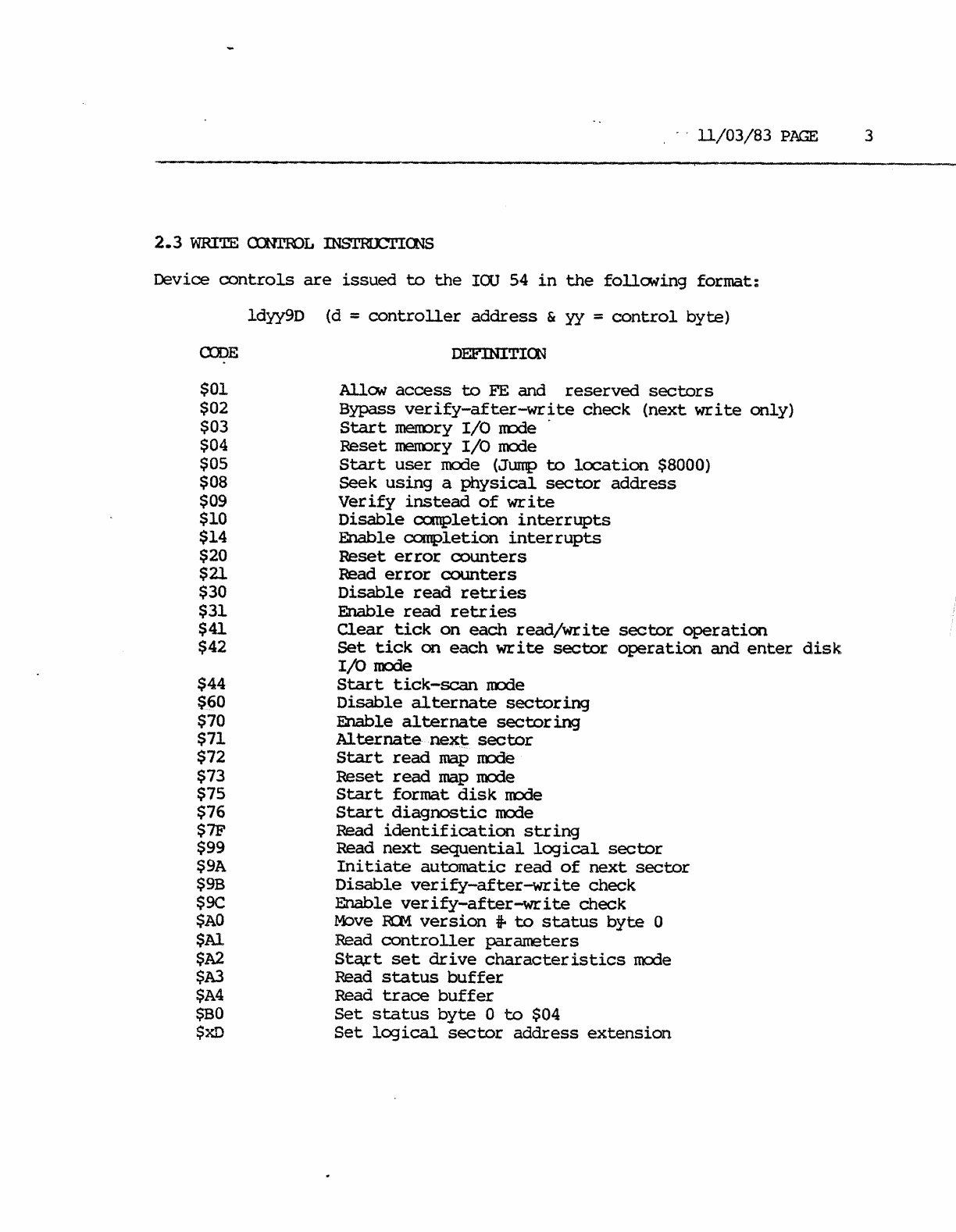
2.3
WRITE CXNrroL mS'I'RICl'ICNS
Device
controls
are
issued
to
the
IOU
54
in
the
follCMing
format:
Idyy9D
(d
=
controller
address
&
yy
=
control
byte)
OJDE DEFINITICN
$01
$02
$03
$04
$05
$08
$09
$10
$14
$20
$21
$30
$31
$41
$42
$44
$60
$70
$71
$72
$73
$75
$76
$7F
$99
$9A
$9B
$9C
$AO
$Al
$A2
$A3
$A4
$BO
$xD
AllaN
access
to
FE
and
reserved
sectors
Bypass
verify-after-write
check
(next
write
only)
Start
mem::>ry
I/O
rrode .
Reset
rnerlDry
I/O
nxXle
Start
user
mode (Jump
to
location
$8000)
Seek
using
a
physical
sector
address
Verify
instead
of
write
Disable
completion
interrupts
Enable
completion
interrupts
Reset
error
counters
Read
error
counters
Disable
read
retries
Enable
read
retr
ies
Clear
tick
on
each
read/write
sector
operation
Set
tick
on
each
write
sector
o:peration
and
enter
disk
I/O
IOCrle
Start
tick-scan
IOOde
Disable
alternate
sectoring
Enable
alternate
sectoring
Alternate
next:
sector
Start
read
map
rrode
Reset
read
map
mcde
Start
format
disk
node
Start
diagnostic
mcde
Read
identification
string
Read
next
sequential
logical
sector
Initiate
automatic
read
of
next
sector
Disable
verify-after-write
check
Enable
verify-after~ite
check
M::>ve
R:M.
version
*'
to
status
byte
0
Read
controller
parameters
St~t
set
drive
characteristics
mode
Read
status
buffer
Read
trace
buffer
Set
status
byte
0
to
$04
Set
logical
sector
address
extension
11/03/83
PAGE
4
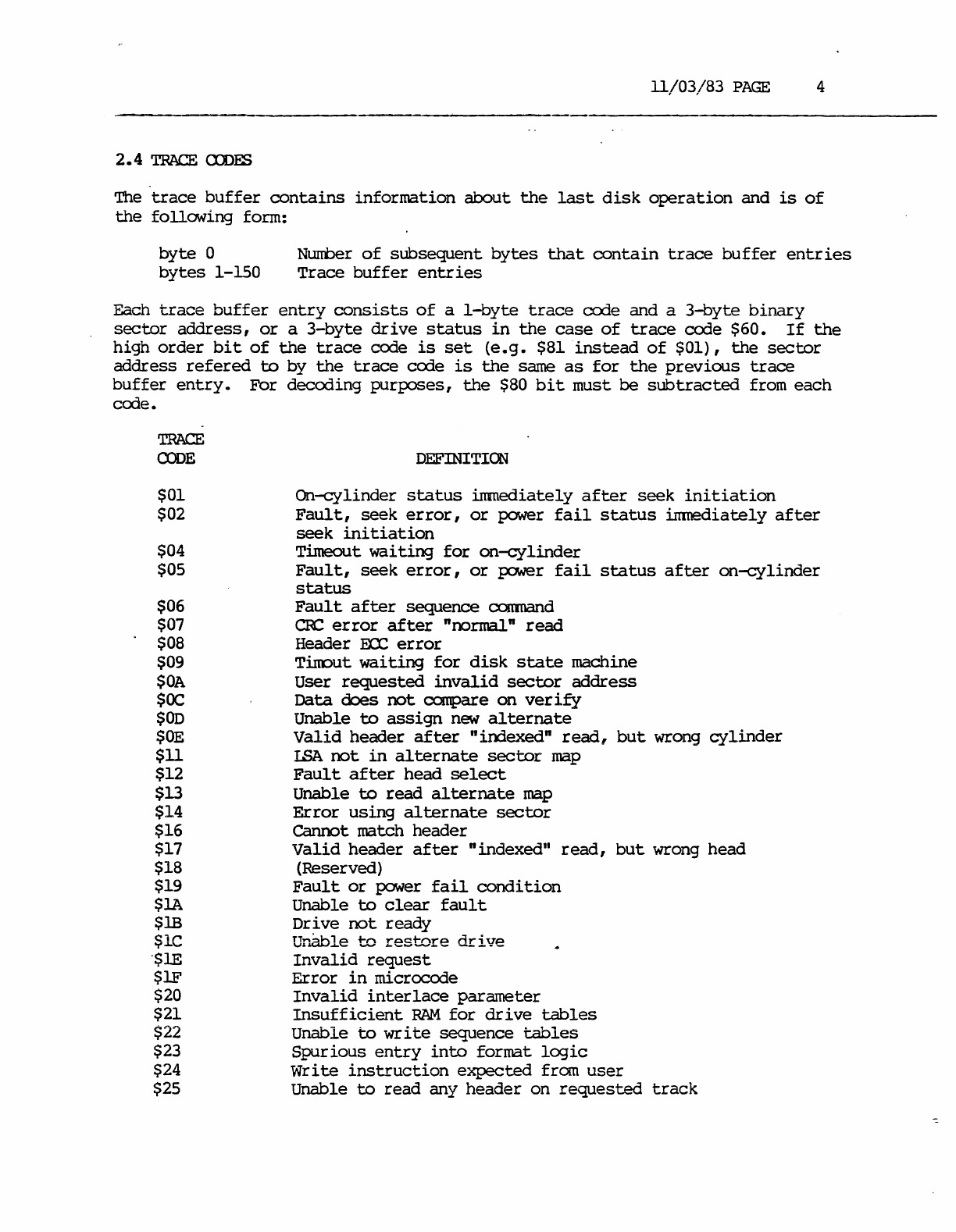
2.4
TRACE
CXDFS
The
trace
buffer
contains
information
about
the
last
disk
operation
and
is
of
the
following
form:
byte
0
bytes
1-150
Number
of
subsequent
bytes
that
contain
trace
buffer
entries
Trace
buffer
entries
Each
trace
buffer
entry
consists
of
a
I-byte
trace
code
and a
3-byte
binary
sector
address,
or
a
3-byte
drive
status
in
the
case
of
trace
code $60.
If
the
high
order
bit
of
the
trace
code
is
set
(e.g.
$81
instead
of
$01),
the
sector
address
refered
to
by
the
trace
code
is
the
same
as
for
the
previous
trace
buffer
entry.
For
decoding
purposes,
the
$80
bit
must
be
subtracted
from
each
code.
TRACE
a:>DE
$01
$02
$04
$05
$06
$07
$08
$09
$OA
SOC
SOD
$OE
$11
$12
$l3
$14
$16
$17
$18
$19
$1A
$1B
<::
1,.,
v
...
'"
"$lE
$lF
$20
$21
$22
$23
$24
$25
DEFINITICN
On-cylinder
status
immediately
after
seek
initiation
Fault,
seek
error,
or
power
fail
status
immediately
after
seek
initiation
Timeout
waiting
for
on-cylinder
Fault,
seek
error,
or
power
fail
status
after
on-cylinder
status
Fault
after
sequence
comnand
CRC
error
after
nnormal n
read
Header
EOC
error
Tinout
waiting
for
disk
state
machine
User
requested
invalid
sector
address
Data
does
not
compare
on
verify
Unable
to
assign
new
alternate
Valid
header
after
"iooexed
n
read,
but
wrong
cylinder
I.SA
not
in
alternate
sector
map
Fault
after
head
select
Unable
to
read
alternate
map
Error
using
alternate
sector
Cannot match
header
Valid
header
after
nindexed"
read,
but
wrong
head
(Reserved)
Fault
or
power
fail
condition
Unable
to
clear
fault
Dr
i
ve
not
ready
Ur~le
to
restore
drive
Invalid
request
Error
in
microcode
Invalid
interlace
parameter
Insufficient
RAM
for
drive
tables
Unable
to
write
sequence
tables
Spurious
entry
into
format
logic
Write
instruction
expected
from
user
Unable
to
read
any
header
on
requested
track
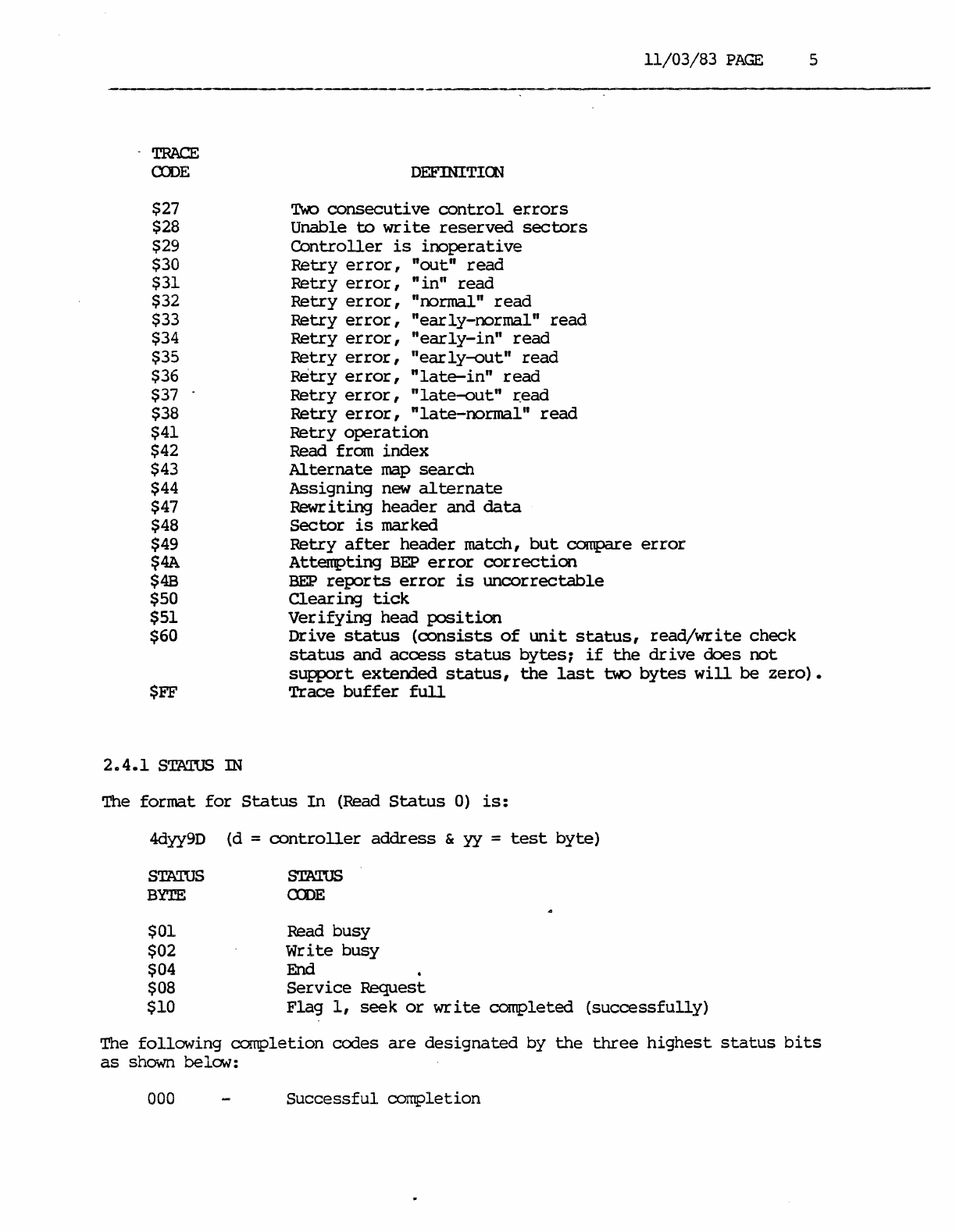
-
TRACE
CDJE
$27
$28
$29
$30
$31
$32
$33
$34
$35
$36
$37
$38
$41
$42
$43
$44
$47
$48
$49
$4A
$4B
$50
$51
$60
$FF
2.4.1
STATUS
IN
DEFINITlOO
TWo
consecutive
control
errors
Unable be
write
reserved
secbers
Controller
is
inoperative
Retry
er
ror,
"out"
read
Retry
error,
"in"
read
Retry
error,
"normal"
read
Retry
error,
"ear
ly-normal"
read
Retry
error,
"early-in"
read
Retry
error,
"early-out"
read
Retry
error,
"late-in"
read
Retry
error,
"late-out"
read
Retry
error,
"late-normal"
read
Retry
operation
Read from
index
Alternate
map
search
Assigning
new
alternate
Rewr i
ting
header
and
data
Seeber
is
marked
11/03/83
PAGE
5
Retry
after
header
match,
but
compare
error
Attempting
BEP
error
correction
BEP
reports
error
is
uncorrectable
Clearing
tick
Verifying
head
position
Drive
status
(oonsists
of
unit
status,
read/write
check
status
and
access
status
bytes;
if
the
drive
does
not
support
extended
status,
the
last
b.o
bytes
will
be
zero).
Trace
buffer
full
The
format
for
Status
In
(Read
Status
0)
is:
4dyy9D
STATUS
BYTE
$01
$02
$04
$08
$10
(d =
controller
address
&
yy
=
test
byte)
STATUS
ODE
Read
busy
Write
busy
End .
Service
Request
Flag
1,
seek
or
write
completed
(successfully)
The
following
completion
codes
are
designated
by
the
three
highest
status
bits
as
shown below:
000
Successful
completion
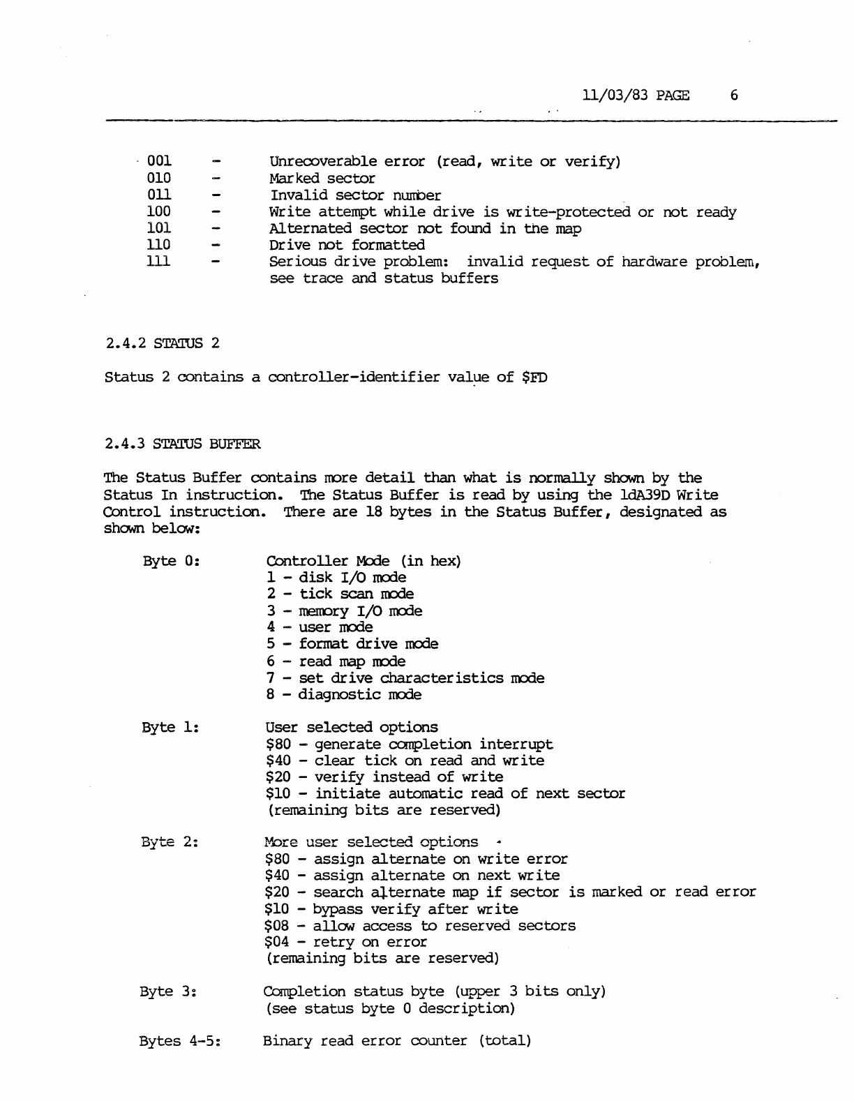
001
010
011
100
101
110
ill
2.4.2
STAWS 2
11/03/83
PAGE
6
Unrecoverable
error
(read,
write
or
verify)
Mar ked
sector
Invalid
sector
number
Write
attempt
while
drive
is
write-protected
or
not
ready
Alternated
sector
not
found
in
the
map
Drive
not
formatted
Ser
ious
dr
i ve problem:
invalid
request
of
hardware problem,
see
trace
and
status
buffers
Status
2
contains
a
controller-identifier
val~e
of
$FD
2.4.3
STAWS BUFFER
The
Status
Buffer
contains
more
detail
than
what
is
normally
shown
by
the
Status
In
instruction.
The
Status
Buffer
is
read
by
using
the
ldA39D
Write
Control
instruction.
There
are
18
bytes
in
the
Status
Buffer,
designated
as
shCMIl
below:
Byte
0:
Byte
1:
Byte
2:
Byte 3:
Bytes 4-5:
Controller
M:rle
(in
hex)
1 -
disk
I/O
mode
2 -
tick
scan
mode
3 - menory
I/O
mode
4 -
user
mode
5 - format
drive
mode
6 -
read
map
mode
7 -
set
drive
characteristics
mode
8 -
diagnostic
mode
User
selected
options
$80 -
generate
completion
interrupt
$40
-
clear
tick
on
read
and
write
$20
-
verify
instead
of
write
$10 -
initiate
automatic
read
of
next
sector
(remaining
bits
are
reserved)
~~re
user
selected
options
$80
-
assign
alternate
on
write
error
$40
-
assign
alternate
on
next
write
$20
-
search
al.ternate
map
if
sector
is
marked
or
read
error
$10
-bypass
verify
after
write
$08
-
allow
access
to
reserved
sectors
$04 -
retry
on
error
(remaining
bits
are
reserved)
Completion
status
byte
(upper 3
bits
only)
(see
status
byte
0
description)
Binary
read
error
counter
(total)
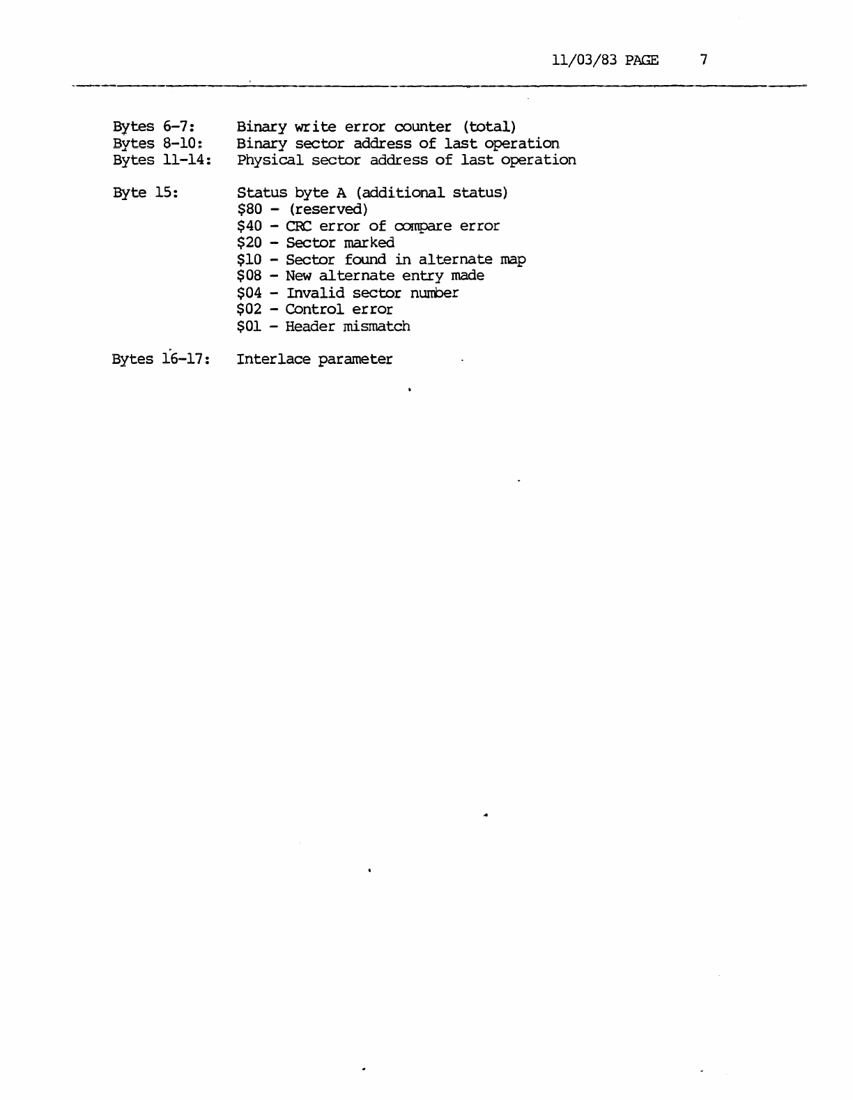
Bytes
6-7:
Bytes
8-10:
Bytes
11-14:
Byte
15:
Bytes
16-17:
11/03/83
PAGE
7
Binary
write
error
counter
(total)
Binary
sector
address
of
last
operation
Physical
sector
address
of
last
operation
Status
byte
A
(additional
status)
$80 -
(reserved)
$40 -
CRC
error
of
compare
error
$20 -
Sector
marked
$10 -
Sector
found
in
alternate
map
$08 -
New
alternate
entry
made
$04 -
Invalid
sector
number
$02 -
Control
error
$01 -Header mismatch
Interlace
parameter
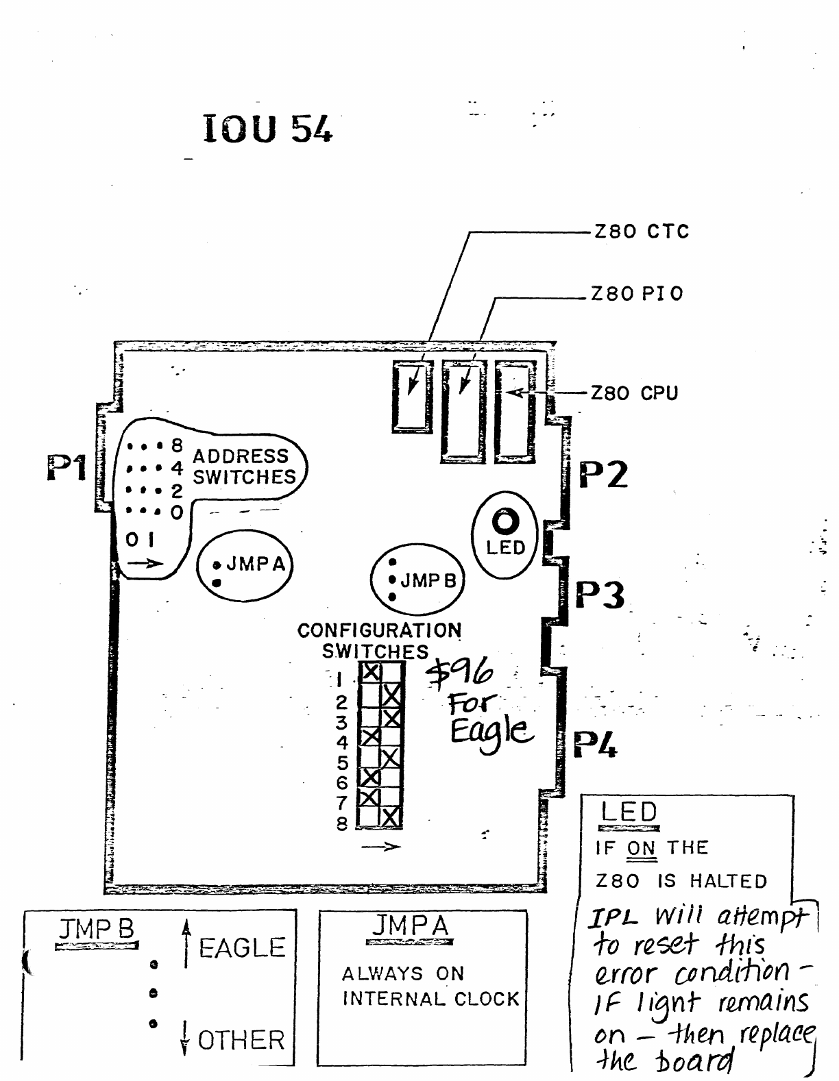
P1
IOU 54-
•
• t
OTHER
----zao
eTC
_--Z80
PIO
CfM~
CONFIGURATION
.
S~.ITCHES~~h
_':
2 -
-fOr~-
-.-.
~
~l~
5~
6~
7~
JMPA
ALVIAYS
ON
INTERNAL
CLOCK
P3
P4
-
. ;
.;.

11/03/83
PAGE
1
FAGIE
UPGRADE
PHX::EIJ.JRE
1.
Removal Of
Current
Drive
From
System
64
Cabinet.
A. Lock
the
heads
and
motor
clamp.
Refer
to
the
Black
Book
Section
on
Fujitsu.
B.
Remove
the
BUSS,
Radial,
and
Disc
Ready
Cables.
c.
Disconnect
the
power
cables.
D.
Remove
the
existing
cable
retractors.
(All
new
hardware
is
required
for
the
Eagle.)
E.
Fully
extend
the
dr
i
ve
on
its
rails
until
the
slide
locks
engage.
'lb
remove
the
drive
from
the
rails,
depress
the
b.O
buttons
on
each
side
of
the
drive
that
are
located
about
half-way
down
the
length
of
the
slide.
Continue
fUlling
the
drive,
while
supporting
it,
until
it
is
free
from
the
slides.
F.
Turn
the
dr
i ve on
its
side
and
lock
the
spindle
0
G.
Rernove
the
associated
power
sUWly.
If
no
other
disk
power
supplies
remain,
also
remove
the
fX)Wer
supply
mounting
hardware.
H.
Remove
the
rail
slides.
I.
All
removed
hardware
must
be
packaged
for
return.
Do
oot
fUt
the
pc:1Ner
supply
or
loose
hardware
in
the
same
box
with
the
disk
drive
as
damage
may
result
to
the
dr
i
ve.
2.
Installing
The New Hardware
A.
The
rails
and
slides
should
have
been
shipped
on
the
Eagle.
Remove
the
slides
from
the
drive.
B.
See
Figure
I-I.
Systems
shipped
with
Eagles
have
had
the
order
in
which
they
are
nounted
in
the
cabinet
reversed.
The
first
disk
is
rrM
directly
helCM
the
tape
drive
and
the
second
disk
is
at
the.
base
of
the
system.
Use
Holes
21-24
For
The
1st
Drive
Use
Holes
3-7
For
'!he 2nd
Drive
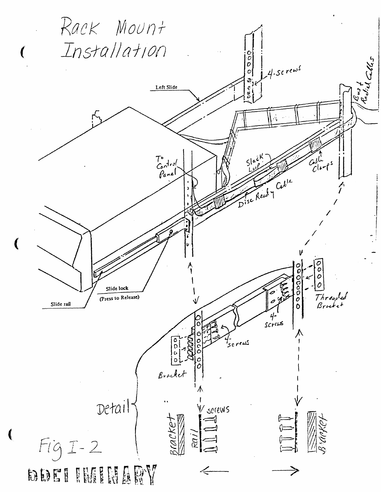
C.
Using
Figure
I-2
mount
the
rail
slides
as
shown.
Note: The
front
of
the
slides
mount
differently
~~en
the
assewbly
that
was
just
rerroved. The
slide
now
rrounts
in
front
of
the
rack
instead
of
behind
it.
11/03/83
p~
2
D.
Refer
to
Figure
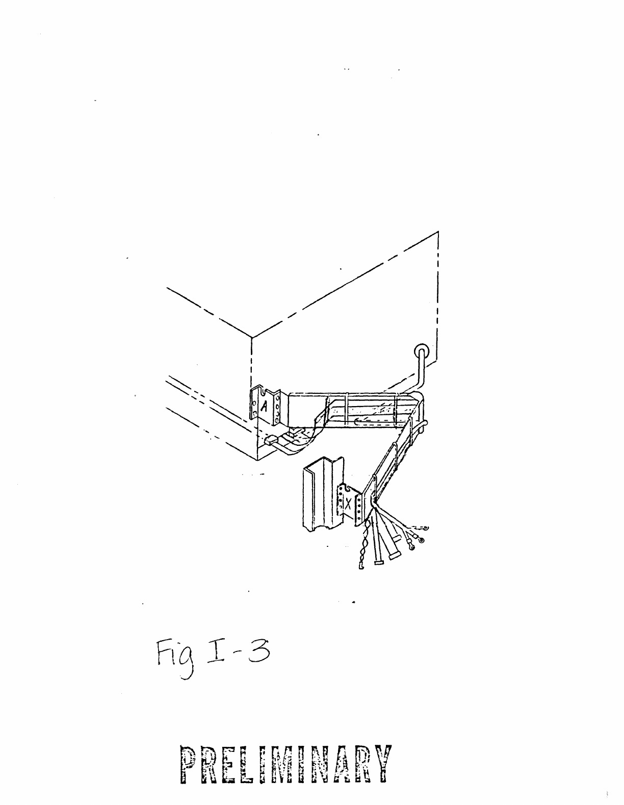
I-3.
Attach
brackets
A and X
to
the
plastic
cable
retractor
as
shown.
Attach
bracket
X
to
system
frame
one
or
two
holes
above
the
rail
slide.
E.
Slide
the
Eagle
onto
the
rails.
Qill!ION:
This
is
a
three
or
four
person
job.
The
Eagle
weighs
140
lbs.
F.
Attach
Bracket
A
to
rear
of
drive
as
shown.
G.
Details
for
routing
cables
appear
in
the
Eagle
Installation
Section
(attached)
•
H.
If
this
system
is
one
of
the
first
20
shipped,
you
will
need
to
replace
the
System
Control
Panel.
The
reason
for
this
is
the
differeoce
in
cormectors
for
the
DISC
READY
Lamps.
New
systems
are
shipped
with
two
sets
of
DISC
READY
connectors.
The
small
connectors
are
for
the
168
MB
and
84
MB
Fujitsu.
The
large
connectors
are
for
the
Eagles.
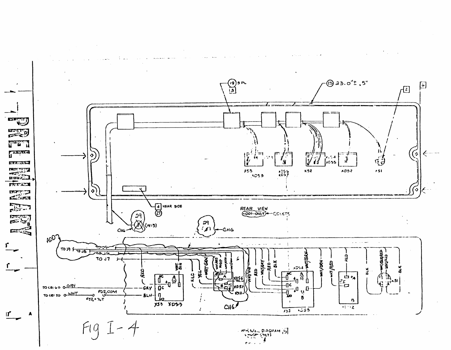
I.
To
replace
the
control
panel
renove
the
four
(4)
phillips
head
screws
as
shown
in
Figure
I-4.
If
only
a
harness
was
sent
use
wiring
diagram
belaY'
for
proper
installation.
Proceed
to
the
following
section:
INSTALIATICN
PIaEDRES
FOR
THE
FAGIE
DISK
DRIVE
,
t
I
..
;
'.
!
.;
,
,
.zz
.,Ll
i
.
~
j~'
,i
,'.
t f
lrr
~
.
If
,
~l
J.'
;
i'
! ;;
'".
j ,
! I
~
.
..
D
....
.....
C
. I
sf
[)v-i-
'C
6
-thro
l-/olLS
:2.,
..
'"
~Ir
,
..
~
,
-;
; 2
If
A
,
I
"
,
U-
p
r
.~
j ,
u\o
%:~
"'-
",0
-i..J
-I
....
I
0 -{
,.
>
"
OJ
I
I'
I -
K
v.
; ( (-"/; c e
ri£
"~
• r 7 J' • " ,
DIPSNO:lTlC.
PANEL
fl C
C2~F
OIooJIoY'J
I
~--
--------------------
--------
--
---
I~
~I
I)
Fl:-""
:,..;
r-1oo
...
H.;"
:::11
:.
TAPE~~5Y
~
I,
~I
I~
~I
18
' I
~-------j---------~
~
----
.-
-
--
--
_.
- - -
--
-
~[
-
Z.7.lZD-
I~ ~I
110
f/'''''
IN
PI't.ie......
:.~i
I~
Oft,.
.15\
~
CMI'-
,0.:'0"(
@J
,§:
I
-----------
----
-
.....
F:I-I..~-'l..
-
r.;i-.~i"~
-
---
or-
DI~
"'~S'f
@
View
J.\jJ.\
X01T:S:
lr.\USS
O11tER\HSE
SPECIFlSl
•.
Q)~1'I~EH
13.
lID!
(31)
~lb"
BE
USED
TO
Ol\.'\l:CT
~w
IXfF.R."AL
IW1TSU
UR
MARKS.\1A.~
DISK
TO
'n
IE
SYSTBI
64.
14.
lTE'1
(32)
~U')1'
BE
USED
TO
ruX"f\T:C1
AS"
~u}rllu:x
OISK
TO
l11E
SYS"fB1
6-'.
IS.
lIDI
(33)
"U~T
BE
USED
TO
ru~"\'l:cr
~\l
l\l:STER.,
DYXEA
DISK
TO
THE
SYSTBI
64.
16.
IT!:]'I
(34)
~UST
BE
USED
TO
ru~"\Ecr
A.\)'
IHr.1
DATA
l/Z"
TAPE
LlRI\'E
TO
TIlE
SYST91
64.
[1]
USE
OX
SYSTl}1
WI1l1
!\o
TAPE
DRiVe
(l\Lr.
Sl;,I:
um
44380-001
FOR
I!>SrALUTION
PPDCEWRE.
.
....--..--.---
..
~~---~
ItoJSTAu..
c'Aet...E
~=Tf<Al:.ToR
!FA.~-~r.C~'"
F
...
~t-.lI~r:::>
W.T'i04
-'lC.w,'Z.,J..
....
0
-~7Z.
/
A";S'i'S
IN
.40;..t'
..
I~D,c.ATErJ
C
t;o,
...
U.,)ca'
rI"'21.,)(.~
(-+4S~)
-rC.j2-
J
i;..
0""
~t:
...
r
~I'",e
(O'),
O'i)~
(~
..
)
01(
S.--ADD
t5')J.
Fu~
U
.....
'Ts
JAjI,H
aAl(..'f
..
...,~
'11~
Ml">
:>,o('IV&:,
TIE.
"F'Il':'{;;'
rl~RAI~";:
,£,.,1;. "'l'tI
.:.:',:",:.
.._
.... " ••
J.'
.•••••
_
,.~,
•
...-
__
..
___
" l
r'---·"
• 7 I
),
1
5
('
'Rack
Moun!
Ins-to
I)
af/o()
Slide
rail
Slide lock
(press
to
Release)
,
I
I
D(tai
I)
Left Slide
A
,
I
,
,
/
/
I
/
/
/i
I I
-'
1
_I
I
I
U"".:"'l},i
"
0'1
r;;~~~:.?
~C.~h.~
,~:Jt:?ilC4
If
A
-'II'""
---7
)(Sl
, 51 '(
r-=-~=======-=~------"-'--""""""'--"""""""'~~~""--------_J.
<
r-------~------------------------.-------------------------------------------
REAR
VIew
'
@i
:o.~C.!:'-t::'5
.
I
.
;@-C.H6
----.,;...--- . -
_.
"'-
._-----
---
I
.
! .
tt
"l.
11/03/83
PAGE
1
INSTALIATICN
PRXEllRES
FOR
THE
FAGLE
DISK
DRIVE
SHIPPThJG
RESTRAINTS
1.
Remove
the
system
side
panels.
2.
The
drive
is
held
in
place
on
its
rails
by
a
single
nut
and
bolt
(See
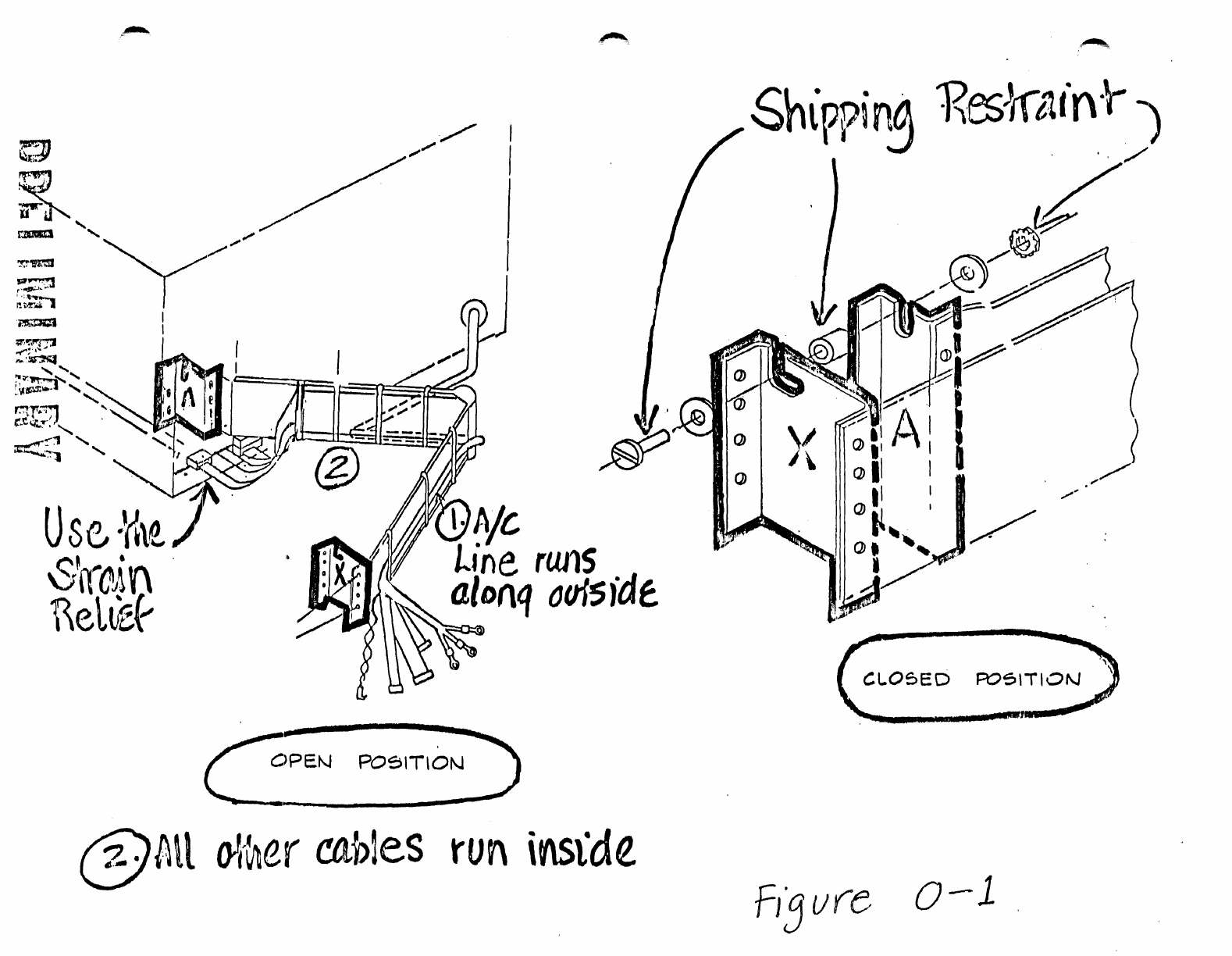
Figure
0-1).
Remove
this
assembly.
3.
Fully
extend
the
drive
on
its
rails.
4.
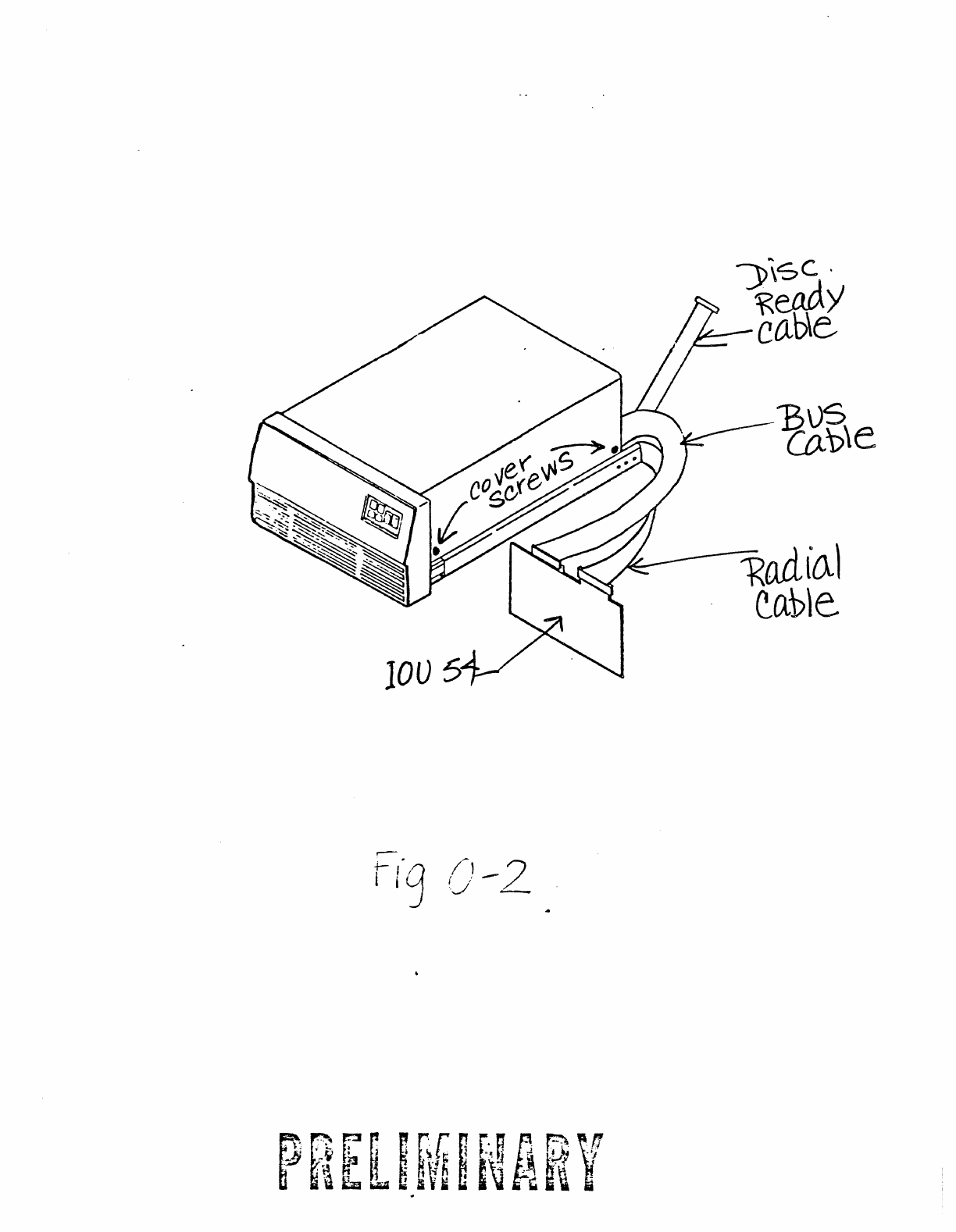
Remove
the
top
cover
by
removing
the
four
screws
located
on
each
corner
of
the
cover.
(See
Figure
0-2.)
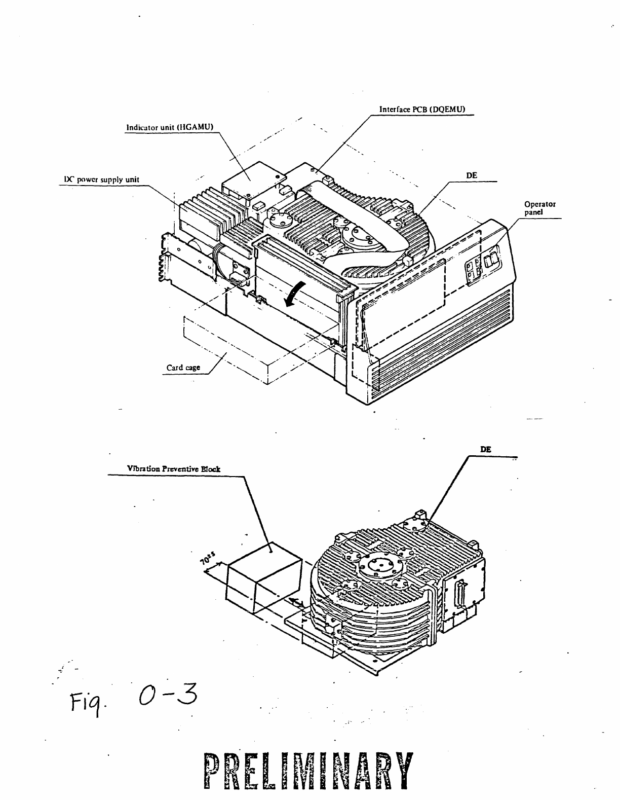
5..
a)
'lb
remove
the
Vibration
Damping
Block,
the
card
cage
must
be
laid
on
its
side.
Remove
the
two
screws
at
the
base
of
the
card
cage
(located
just
above
the
rail).
(See
Figure
0-3.)
Pull
up
on
the
card
cage
and
lay
it
over
on
its
side
..
b)
The foam
block
should
rON
be
visible.
It
is
removed
by
lifting
the
Disk
Enclosure
slightly
and p..111ing
the
block
out
towards
the
card
cage.
The
dr
i
ve
should
rON
be
resting
on
its
shock
nounts.
6.
The
final
restraint
is
the
head
lock.
See
detail
"c"
of
Figure
0-4.
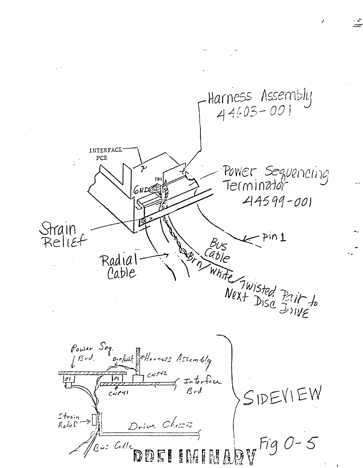
CABLING
(Refer
to
Figures
0-5
and
0-6
for
all
of
the
foilONing
steps.)
1.
Radial
Cable
to
CNP43.
2.
Buss
Cable
to
Jl
of
the
Power
Sequencing
Card.
3.
PaYer
Sequencing
Card
to
CNP41
of
the
Inter
face
Board.
Ground
Strap
to
mI.
4.
Power
Sequencing
Harness
Assenbly
to
QJP42. Brown
and
White
twisted
pair
extends
from
the
left
end
of
CNP42.
Figure
0-1
shows how
to
route
cables
on
retractor
assembly.
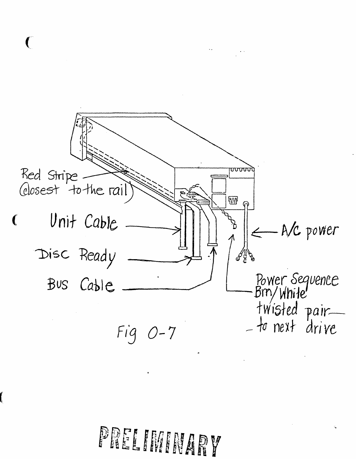
5.
Run
the
Disc
Ready
Cable
from
the
Eagle
Front
Panel
along
the
bot
tom
of
the
chassis
and
out
fran
underneath
the
Interface
Board
with
the
red
strip
facing
the
rail.
(See
Figure.0-7.)
The
Disk
Ready
Cable
should
be'
routed
as
shown
in
Figure
I-2.
Note
the
slack
loop
midway
across
the
rail.
The
first
drive
plugs
into
the
Wht/Grn
and
WhtjRed
twisted
pair.
The 2nd
drive
plugs
into
the
red/yellow
twisted
pair.
The
~
smaller
connectors
are
used
for
the
168
MB
or
84
MB
dr
i
ve.
6..
AlC.
See
Figure
0-8
(AC
Wiring
Diagram).
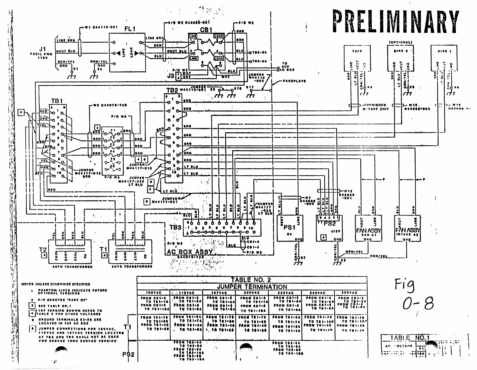
Example: DrSKl
goes
to
'IB2-6B
11/03/83
PAGE
2
and
TB3-6B and
GND
to
lug
E6.
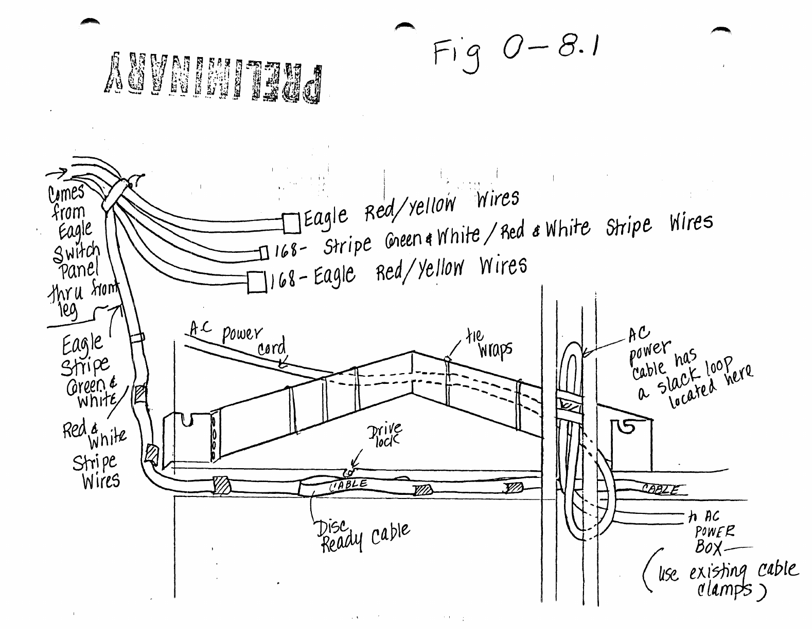
The
A!e
cable
provided
is
much
too
long.
See
Figure
0-8.1
and
note
that
cable
is
looped
and
tied
to
the
system
frame.
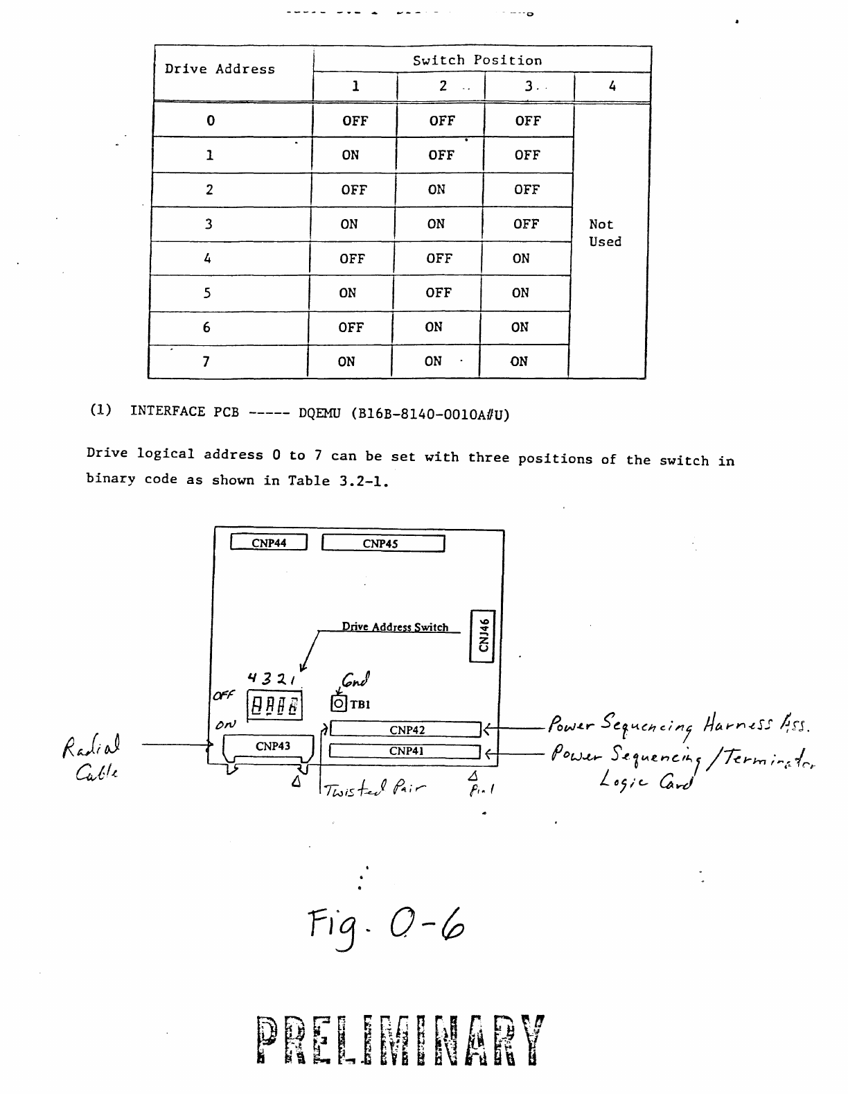
1.
Interface
Board:
Set
drive
address
switches
to
OFF.
Drive
address
is
always
o.
(See
Figure
0-6.)
2.
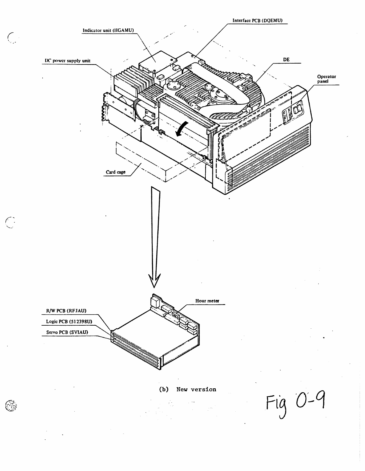
Figure
0-9
shows
the
location
of
the
Logic
PCB.
Using
Extractor
Tool
(see
Figure
0-9.1),
rerrove
the
IDgic
PCB.
Card
Extractor
is
to
remain
with
the
drive
at
all
times.
00
NOr
RElvDVE.
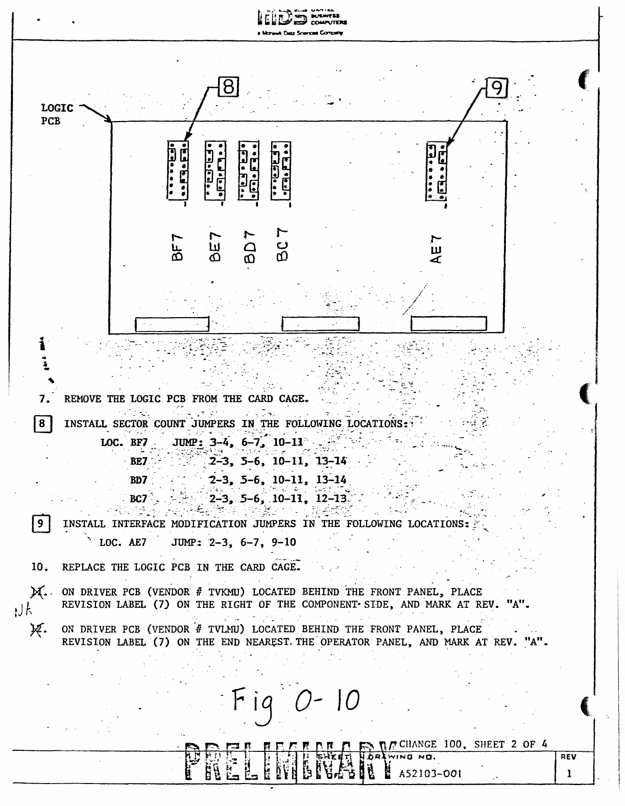
3.
Using
E:igure
0-10
verify
or
set
mini-jurrps
to
match
drawing.
OC7-BF7
set
the
Bytes
Per
Sector
and
Sectors
Per
Track.
WEJ7
sets
the
interface
control
options.
4.
Power
Sequencing/Terminator
board
has
two
pin
patches.
Refer
to
Figure
0-11.
J2
Configurations:
a.
Only
one
Eagle
in
system-
JLlIIP
1-3
and
2-4.
b.
If
2nd
Eagle
in
system-
Renove
pin
patches
and
plug
Brn/Wht
twisted
pair
from
first
drive
onto
J2,
pins
1
and
2.
Connector
is
offset
so
that
it
can't
be
put
on
backwards.
c.
If
using
Auxilary
cabinet,
continue
this
sequence
for
any
additional
Eagles.
d.
The
twisted
pair
coming
from
the
laSt
dr
i
ve
in
the
string
should
be
coiled
and
tie
wrapped
to
the
system
frame.
PCMER
SUPPLY
(Refer
To
Figure
0-12
for
the
following
steps.)
1..
Set
the
I.Dcal,lRenote
switch
to
the
IDeal
position.
2.
Set
the
Main
Line
switch
to
the
CN
position.
DRIVE
FIDNT
PANEL
(Refer
To
Figure
0-12.1.)
1.
Set
STARr
to
CN.
All
Eagles
are
to
be
left
ih
the
CN
?",.sition.
The
~r
sequencing
boards
will
cycle
the
drives
up when
the
system
is
powered
on.
2.
Set
Protect
to
OFF.
11/03/83
PAGE
3
AUJUSTMENTS/CHOCKS
1.
-
VOIATAGES
A.
Measurerrents
are
made
at
the
backplane
of
the
card
cage.
(See
Figure
0-13.)
B.
Voltages
are
adjusted
on
the
power
supply
to
within
the
tolerances
shown
on
Table
13.1.
2.
SERVO
ADJUSlMENl'S
1
..
2.
3.
4.
A.
The
drive
was
shipped
properly
aligned.
The
exact
policy
and
procedures
are
currently
being
reviewed.
Until
further
notice
DO
NOT
ATrEM?T
to
align
the
servos
on
the
Eagle
drive.
Note:
The above
statement
against
aligning
the
servos
applies
to
ali,
including
those
who
may
have
been
trained.
ATP's
have
been
shipped
to
the
field
on
the
drive.
Run DISC54
to
verify
that
the
drive
is
operational.
00
NO!'
FORMAT
the
drive.
The
alternate
sector
map
will
be
destroyed.
Attached
to
each
Eagle
drive
is
a
tape
containing
a
ropy
of
the
alternate
sector
map.
There
can
be
as
many
as
500
alternate
sectors
from
the
factory.
The
ATP
used
to
read
this
tape
onto
the
disk
is
rot
currently
working,
however
it
will
be
soon. Leave
the
tape
with
the
drive
at
all
times.
Do
not
bump
the
disc
while
it
is
running.
Errors
have
been
observed
from
the
slight
shock
to
the
drive.
This
should
not
be
encountered
unless
the
disc
is
extended
for
installation
or
maintenance.
t·
Ale
Line
rW1S
alDnq
ou1sjdt.
,---
+-IQ
I
'J
~\e
~adioJ
tab\e
Interface
PCB
(DQEMU)
Indicator unit (HGAMU)
DC
power supply unit
Vibration Preventive mock
-./
0-3
PREll~1If~ARY
DE
DE
Operator
panel
f--
--
---,--~,---;-----"
• I
1\.11'
" . !
I
~
...
--'
'_"',,,J
I
I I
~
{,
I·
I J J
\,
I I
: ' I I
I.
f , I
I \
t • I . I
1
I'"
~
-./ \
'"7-
....
1 I
• •
~
~
I 1
,
_______
L
__
Ot\--L
___
- - -
..J
INTERFACE
POl-.TER
SUPPLY
PCB
,
..
' .
'~''''~'~:-
A.
e
~--
...
,.-.
',
..
- .
,"",:_:.;"
.
. A (VIEW
FROl-1
~~cK'
~'F:-
~~i~~~"~
;..>-.
~..
' .
. .
.,.;,
.
,.~.):,.-
; .
~;::~::;;~):i~~~.'~~:;.;;~;·:;,·
.~>,.
..
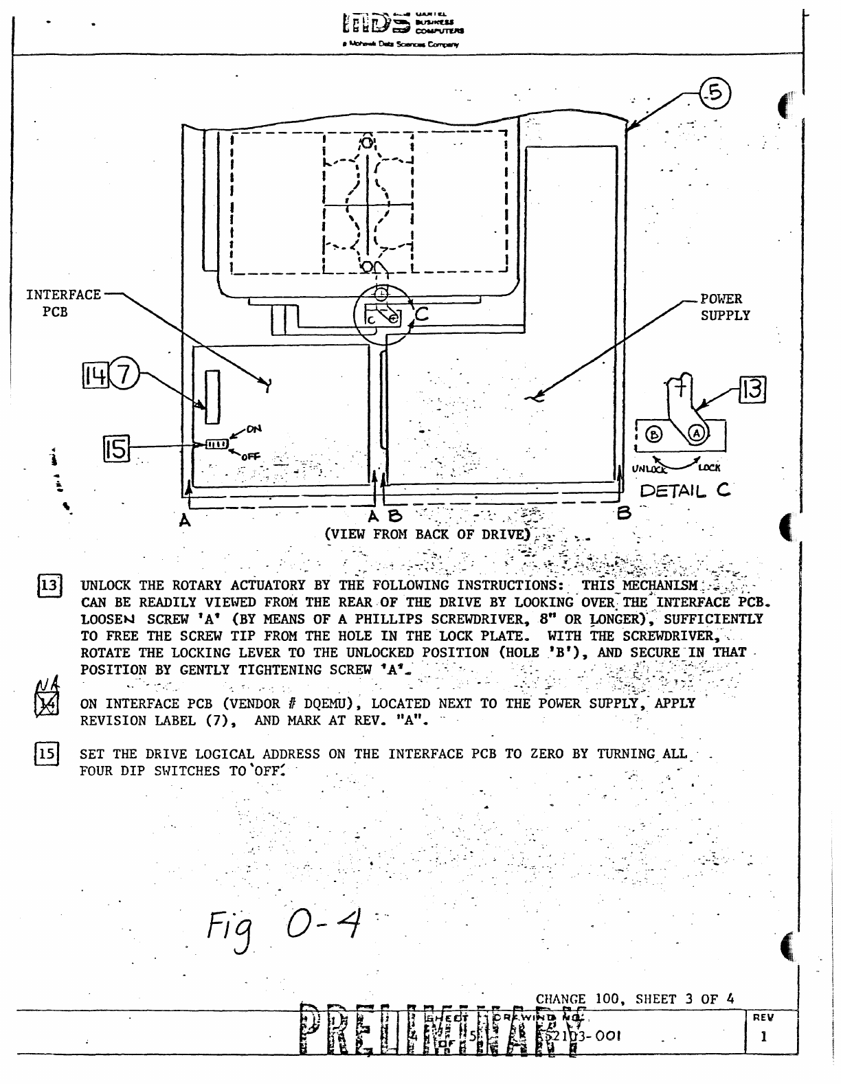
UNLOCK
THE
ROTARY
ACTUATORY
BY
THE FOLLOlflNG
INSTRUCTIONS:'
THIS'
MECHANISM.:::,,:::·:'-
CAN
BE
READILY VIElVED
FROM
THE REAR
·OFTHE
DRIVE
BY
LOOKING"
OVER-:--
THE~'INTERFACE'
PCB.
LOOSEt-J
SCREW
1
A"
(BY
MEANS
OF
A
PHILLIPS
SCREWDRIVER,S"
OR
!l>NGER)~~"
SUFFI~I.ENTLY
TO
FREE
THE
SCREW
TIP
FROM
THE HOLE
IN
THE LOCK
PLATE.
WITH
THE
SCREWDRIVER, ......
ROTATE THE LOCKING LEVER
TO
THE
UNLOCKED
POSITION
(HOLE
.IB'),
AND
SECURE
"IN
THAT "
POSITION
BY
GENTLY TIGHTENING
SCREW
-fA
.....
· . . . _
..
...
'.>:!;.
..
{7,
".:::::'~j>~:..:::."
",
-."
. .
....
:;,.
....
-":
..........
,~,
-
~
-
....
: . . --: -
ON
IN;~;F~~E
PCB
(~ENDOR'
n DQOOJ)
~
LOCATED
NEXT
TO
T~i':;OWER
'SUP;~~;~-
;;;;~~
REVISION
LABEL
(7),
AND
MARK
AT REV.
"An.
..
..
SET
THE
DRIVE LOGICAL ADDRESS
ON
THE INTERFACE PCB
TO
ZERO
BY
TURNING
ALL . _
FOUR
DIP
Sl-lITCHES
TO
'OFF~
.
:,.,
.....
-
.'
-. ." .
..
-'-":
0-1
c"
SHEET 3 OF 4
c
Hanle55
A55etnb~
'or:·
001
11
Ai,.! -")- i
,.,
I v -
."
/
"'PO
~/er:
5e~f}e
nCf
;
!3
fer
rn
J
n?!1oy
-LJ45qq-oo}
.
t?us
~
'Ra&la\~\'·{r~
.
Cable
~wrsfe
Next
r... t!
1~
ii-
-k
J)j$n
~
.
~
c!J)I!lE.
.
~
-
Drive
Address
Switch
Position
1 I 2 -. 3
..
4
0
OFF
OFF
OFF
.
1
ON
OFF
OFF
2
OFF
ON
OFF
3
ON
ON
OFF
Not
Used
4 I
OFF
OFF
ON
5
ON
OFF
ON
6
OFF
ON
ON
7
ON ON
ON
(1)
INTERFACE
PCB
-----
DQEMU
(B16B-B140-0010A#U)
Drive
logical
address
0
to
7
can
be
set
with
three
positions
of
the
switch
in
binary
code
as
shown
in
Table
3.2-1.
fJ;J
G/;(.{
CNP44
CNP4S
Drive Address Switch
('
Unit
Cable
-----~
'"l>isc
Ready
Bus
Cab
I e
---------
~
Ale
po
Vier
Power
S;juente
----Bml
While
tWI5tecl1.air~
-
ta
nelr
dri
Ve
J1
'AeIL
,,'n
t
flV
,..Wt
cu
'U-OO'
NOTU'
UNLUS
OTtII:nWISI!
srECI'.ED
'HANTON
LINU
INDICAT!
'UfUU
0'
TIONAl
VI'IIIIONI
I "0
DENOUI
"A'"
0'-
o
III!
TAIlI!
NO.
t
l
71'
UY
YUIION
IHO"N
"I!""
TO
~TULI
I
'Olt
O'HrII
VOLTAOII
1 OfIOUftD
""MIULI
".,.
Aftl
lOCAUD
IN
'N'
AC
10.
FL1
T~
.IU
....
'III
CO""'CTIONI
'0"
UOYAC,
r.
•
..
WAC
A"D
tlHAC
WIIUION
8.DCATID
A'
T
••
AND
,.1
'HALL
Mot
II
UII'
'011
I
••
ue
'"flU
IIOYAC
\,.""0
..
~.
P 2
,
JI
"
nOYAC
"'OM
CI
t-a
TO
u,.u
PIIOM
el'-'
TO
n'.toA
PIIOM
TI
t·n
TO
",
...
nOM
U
'-41
to
TI'.II
,01.
",."
'"
•.
~.""
'It
CI!I1
UN
•
~1.
TABLe
NO.2
JUMliEfq TEtlMINATION
f',
"IYAC
,'Hue:
nOVAe
IIOYAC
PIIOM
CIt·.
nOIll
CIt-I
no"
ht-.
"'OM
CI'·.
'.
TO
u,·u
TO
tl
t.'A
TO
U'.'A
TO
Ut-u
hOM
ct·
•••
nOli
tit
...
PIIOM
.1
t·,
nOM
CI
t-I
,
'0
fI'·U
t.
tit
..
"
TO
h'-'tA
TOnt·",
PROIII
TI
,-u
nOM
Ut·"
noal
U
,·n
PROM
n,
..
u
TO
U
v.,.
to
tI
,-
••
to
ttt
....
to
fI
'·U
hOM
Tlt.u
1.0
..
tu-o
'"011
Uta
..
1A0M
U,~u
' .
to
tlt·u
...
U
tat
...
• 6
tit
....
to
TI
'ioU
,
.'
"'~:
~~'~:~~
"
~
"",
...
n,-u
'<
' o
"1·14
tAOIII
tll-U
UOIII
tet-u
JO
t
....
UA
n
to
UI-UI
n •
11-"
Q
t.
tt,-
ttA
I
PRELIMINARY
.
t.
_~
10P'T'ONALJ
-...
G-;-'-:~
,ar"
l1li
...
n
l1li"
I
z
:1
•
~
1-)
'r~?'
II:
:t
l1li1
'
.,
,.,
t-
ill!
'I
...
. I
~~.
•
,.
"
"
r 7
--,
-~,
~r>-\¥
tI
DUll'
-00
•
un
:::J.
:t
•
..I II:
..J.
~L.-....~l-
• •
.."
....
::I.
::I!
l1li
J
IIII..J
FmASSY
Fm~
rXlt
At
.NTAIU
••
~..
.
..
,:T--
J"'--
: V "
"_"LlIL-
tI
E'
r;
1f0VAC
180YAC
f-._--
'ROM
Cit-I
'''OM
ClIt-'
TO
Tit-I.
TO
nt-,A
'ROM
Cit-I
'itOM
Clllt-'
TO
TI
t-'A
'0
,.
'-IIA
J
--
nOM
fit
,-,,,
"'OM
Ut-rt
/
'OUI-""
TO
n,-.o"
nOM
U
t·.",
,itO"
TIt-..,
fO
"
...
, .. TO
,.,.,11
------
Stripe
Wires
__
hRC
pOW[e
~
Box-
\.
U5e
eJ..I51i1lJf
etble.
~ltmps
)
Indicator unit (IIGAMU)
1)(' power supply
unit
'--'
R/W
PCB
(RFJAU)
Logic PCB (51
2398U)
Servo PCB (SVIAU)
Interface
PCB
(DQEMU)
(b)
New
version
DE
Operator
panel
--------
~-
..
---
.
/-
0
-------
-------
/
/---
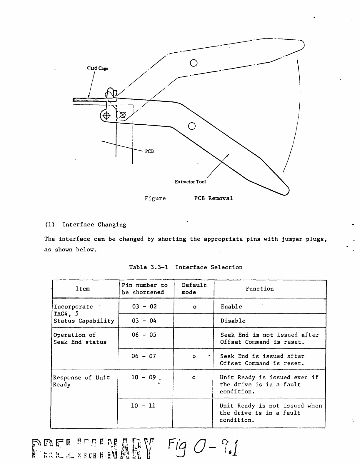
Card Cage
PCB
Figure
PCB
Removal
(1)
Interface
Changing
The
interface
can
be
changed
by
shorting
the
appropriate
pins
with
jumper
plugs,
as
shown
below.
Table
3.3-1
Interface
Selection
Item
Pin
number
to
Default
Function
be
shortened
mode
Incorporate
03 -02 0
Enable
TAG4,
5
Status
Capability
03 -04
Disable
Operation
of
~~
-05
Seek
End
is
not
issued
after
Seek
End
status
Offset
Command
is
reset.
"'..,
0
...
Seek
End
1S
~~",
••
~rl
",.f=r.o.,...
uo
-
UI
..Lo;::,uc;:.u.
CI...L
....
~
....
Offset
Conunand
is
reset.
Response
of
Unit
10
-09 • I 0
Unit
Ready
is
issued
even
if
Ready
.
the
drive
is
in
a
fault
I
condition.
10
-
11
Unit
Ready
is
not
issued
\o:hen
the
drive
is
in
a
fault
condition.
F~O-~,l
k~~rJ5~
.a.u.....o.a~~
LOGIC
PCB
7.
10.
.
-.
...
-
~
_.'
-. "
-~
........
:.
--
--:""
.-
.
-':·~·:f~·":-':,/~·?
.
'."
.-
-."
"';'
. -
...
-
,-
. ---
t-
(J,
eD
REMOVE
THE
LOGIC
PCB
FROM
THE
CARD
CAGE.
/
.:.
BD7
.-
..
;
'.~
.'
"
-2-3,
.5-6,'
10-11,
13'::"14.
/
.
/1
.r-
w
4:,
,
/I:t-
-----.
.
''','-
-,,'
......
.....
, -
'-':
.
-.
" .........
. ' ..... -
........
,
..
..
:-
"o.
-
''':..:
.
.;-"
....
:
~
.....
. .
~.
--
. :
:-
-::'.;
. --
~
.,"
. .
. Be7
~
:-
.'
.~
..
~';~":
'
'2-3,
..
5-6,
.10-11~
12-"13;"
-~
"
'".
~
..
~.,
.
~
_.
.
....
,<
•
:~·c'.~:
..:
2.'
~<
.......
:~;~:/.,:-'
.'.::
..
~.":}~
.
.-'
.
"-).,~~~:~;:\~~
.'.
-",
.
..
...
-
..
,
.....
.
INSTALL
INTERFACE
MODIFICATION
JUMPERS
IN
THE FOLLOWING
LOCATIONS:
~"-
-
.,
...
LOC.
AE7
JUMP!
'2-3,
6-7,
9-10
REPLACE
THE
LOGIC
PCB
IN
THE
CARD
CAGE.
ON
DRIVER PCB (VENDOR n
TVKMU)
LOCATED BEHIND THE FRONT
PANEL,
PLACE
REVISION
LABEL
(7)
ON
THE
RIGHT
OF THE
COMP
ON
ENT4
51-DE, AND'MARK
AT
RE~.
"A".
ON
DRIVER PCB (VENDOR
'II
TVLHU) LOCATED BEHIND THE FRONT
PANEL,
PLACE
REVISION
LABEL
(7)
ON
!HE
END
NE~ST.THE-bpERATOR
PANEL,
AND
J:1ARK
AT
REV
..
"A"
•
. .
f
~O-
10
SHEET 2 OF 4
AS2103-001
(
REV
1
C~.'J·
..
iI
~J!''(~
~
W1il
:
~rt,
ll'iJ
~
ikU.t':':;:J
'.
mtr~'~::;:1
.
~1~;:._
~':l-.:-:'
l'l!J't'~
1Iit'.t ..
~
:;I
~.z::Q
~
=~23
~
. ·'!,·l;
"
i!
~
h
T'~""
. ,
:,..,.,.
j~;-J
1
__
1/0 C
a~\_e
I
1'In
1
Fi3
0-
\ I
r------"
10
1131.
,
6(O~1\
~\~h\te.l
iw,sted -pa\r .
frorn
'P
rC
'VIO(/,0
·
J)
I
:-,
(~
I
1"1
{I(~
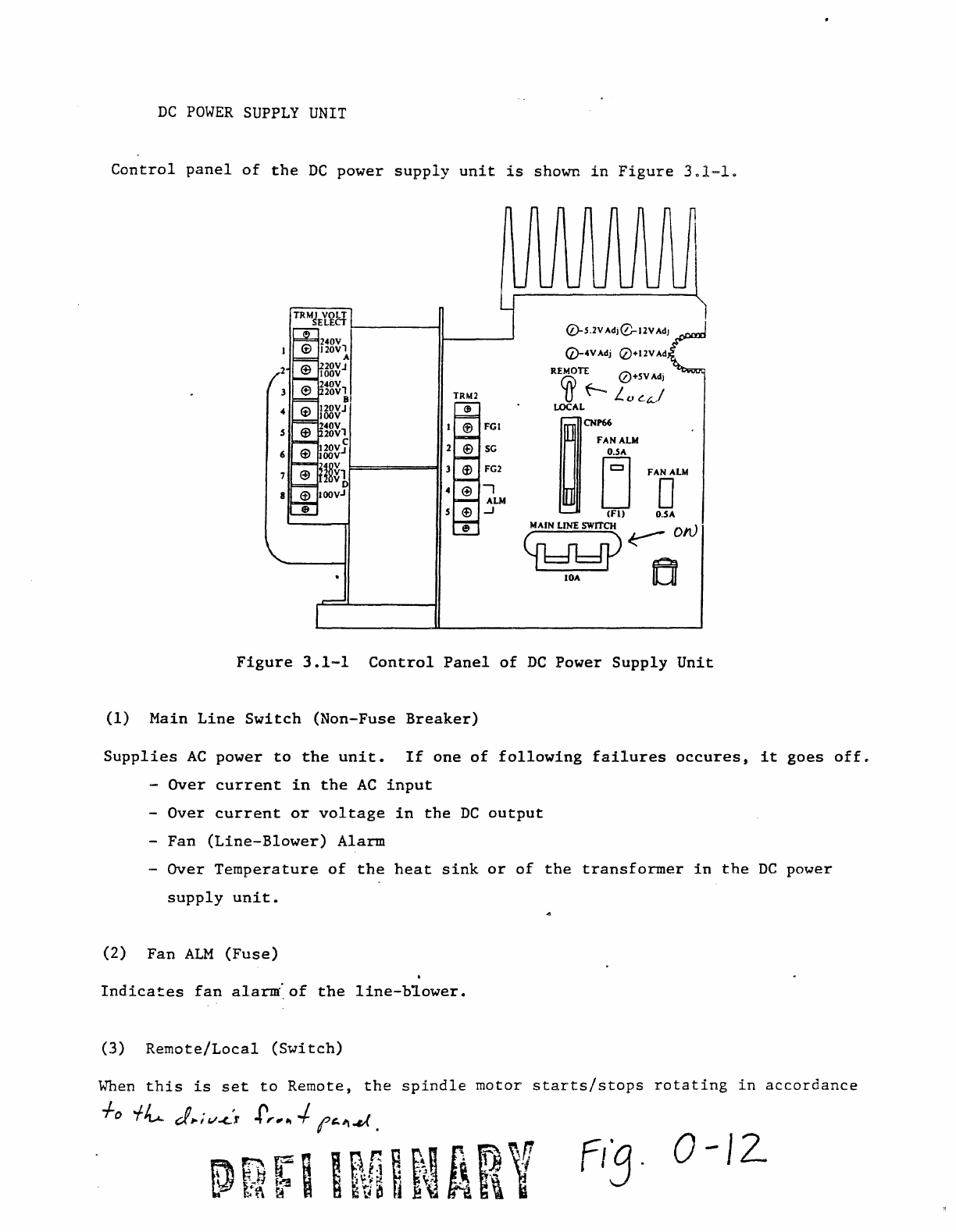
DC
POWER
SUPPLY
UNIT
Control
panel
of
the
DC
power
supply
unit
is
shown
in
Figure
301-1.
TRM2
(J
FGl
SG
FG2
-,
AU
•
...J
(lj-S.2VAdj0-12VAdJ
(l)-4VAdj
0+12VAd
REMOTE
0+
SV
Adj
Cfr>
f-
LQ~J
LOCAL
~~B
FAD~
(FI)
O.SA
e MAIN
LINE
SWITCH ON
Cf1dldj)~
lOA
fE]
Figure
3.1-1
Control
Panel
of
DC
Power
Supply
Unit
(1)
Main
Line
Switch
(Non-Fuse
Breaker)
Supplies
AC
power
to
the
unit.
If
one
of
following
failures
occures,
it
goes
off.
Over
current
in
the
AC
input
-
Over
current
or
voltage
in
the
DC
output
-
Fan
(Line-Blower)
Alarm
-
Over
Temperature
of
the
heat
sink
or
of
the
transformer
in
the
DC
power
supply
unit.
(2)
Fan
ALM
(Fuse)
Indicates
fan
alarm~of
the
line-b~ower.
(3)
Remote/Local
(Switch)
When
this
is
set
to
Remote,
the
spindle
motor
starts/stops
rotating
in
accordance
+0
-f/v...
d
..
i
v-c..',
f,.,~
-/.
('''..,,( .
'-
yz;
I n
r!
H
~
11
fi
fi]
~Q
~
~
r 8
fi
~V~
n
~~
t\
1\
t
O-J2-
Volt
ADJ
(Variable
Resistors)
Although
adjustment
should
not
be
required,
variable
resistors
are
provided
to
adjust
the
-5.2,
-4,
±12,
-5
Vdc
output
voltages
within
the
tolerance
specified,
if
necessary.
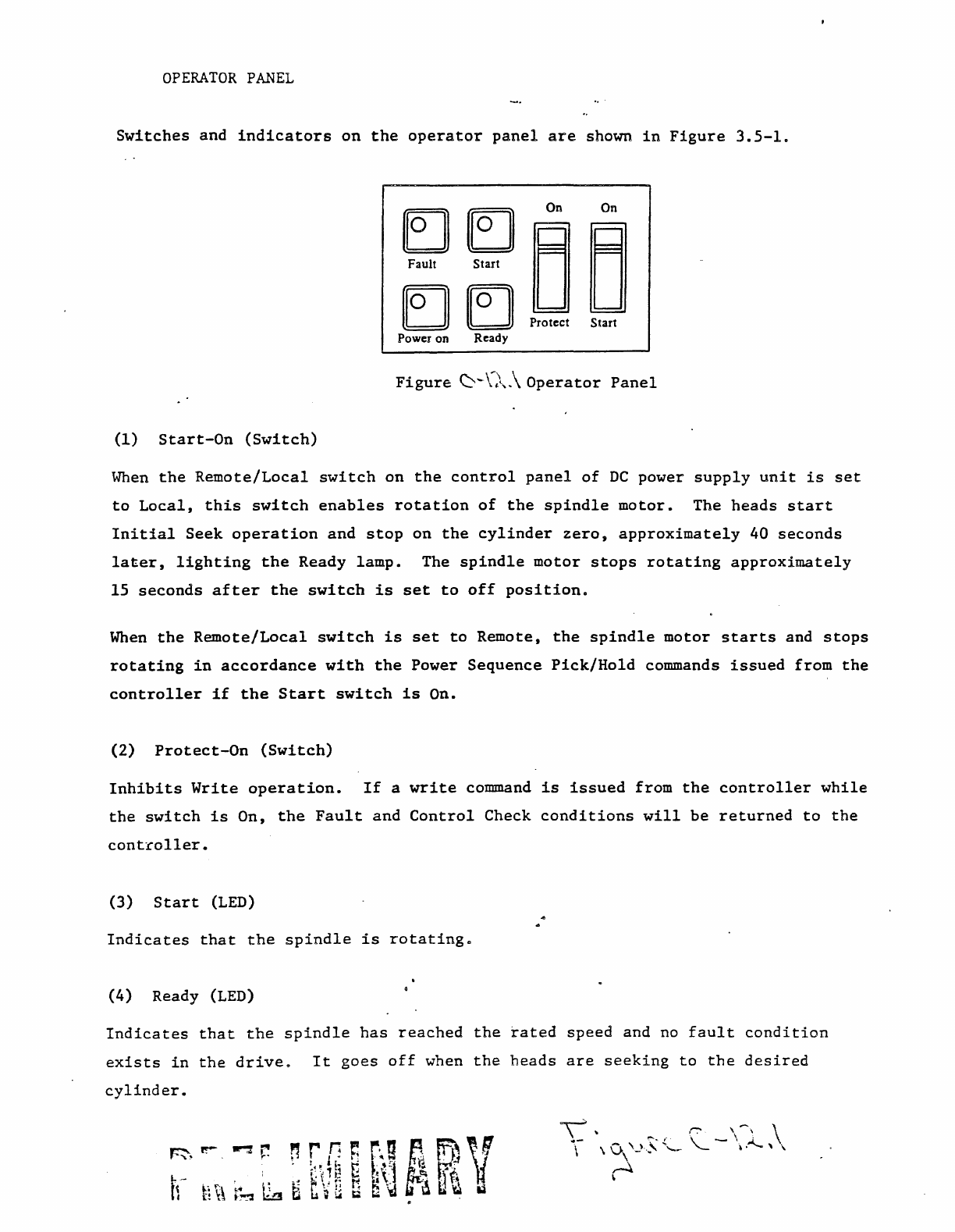
OPERATOR
PANEL
Switches
and
indicators
on
the
operator
panel
are
shown
in
Figure
3.5-1.
EJ~
On
On
Fault
Stut
~
~
~
IE]]
Protect
Star1
Power on Ready
(1)
Start-On
(Switch)
When
the
Remote/Local
switch
on
the
control
panel
of
DC
power
supply
unit
is
set
to
Local,
this
switch
enables
rotation
of
the
spindle
motor.
The
heads
start
Initial
Seek
operation
and
stop
on
the
cylinder
zero,
approximately
40
seconds
later,
lighting
the
Ready
lamp.
The
spindle
motor
stops
rotating
approximately
15
seconds
after
the
switch
is
set
to
off
position.
When
the
Remote/Local
switch
is
set
to
Remote,
the
spindle
motor
starts
and
stops
rotating
in
accordance
with
the
Power
Sequence
Pick/Hold
commands
issued
from
the
controller
if
the
Start
switch
is
On.
(2)
Protect-On
(Switch)
Inhibits
Write
operation.
If
a
write
command
is
issued
from
the
controller
while
the
switch
is
On,
the
Fault
and
Control
Check
conditions
will
be
returned
to
the
controller.
(3)
Start
(LED)
Indicates
that
the
spindle
is
rotatingm
(4)
Ready (LED)
Indicates
that
the
spindle
has
reached
the
rated
speed
and
no
fault
condition
exists
in
the
drive.
It
goes
off
when
the
heads
are
seeking
to
the
desired
cylinder.
(5)
Fault
(LED
and
Switch)
Indicates
a
Fault
condition
(i.e.,
R/W
check
status)
or
a
Seek
Error.
Depress~ng
the
indicator
switch
clears
this
condition.
(6)
Power
On
Indicates
that
the
DC
power
supply
unit
is
on.
.J
Adjustment
of
DC
Voltages
Che~~
the
DC
voltages
at
the
check
pins
of
Back
Panel
(BQGMU)
using
cigital
multimeter.
The
check
pins'
configuration
is
shown
in
Figure
13.9-2.
If
a
DC
voltage
is
out
of
the
acceptable
range
of
Table
13.9-1,
readjust
the
corresponding
RV
shown
in
Figure
13.9-1.
/
use
this pin
as
SG.
B16B-8160-0010A I
~
-4V
~~------------QG--M-----------------------'
~
-S.2V
0
~;~v.J
B u
~-12V
OV'
(
~
+UV
GI'1['
Figure.
0-/3
Top View
of
Back
Panel
Table
13./
Acceptable
Range
of
DC
Voltages
DC
Voltage
Acceptable
Range
+12
V
11.4
'\,
12
..
6 V
+5
V
4.75
'\,
5.25
V
-4
V
-3.8
'\,
-4.2
V
-5.2
V
-4.94
'\,
-5.46
V
-12
V
-11.;
'\,
-12.6
V
0-/3
