SG242580 IP Network Design Guide
IP%20Network%20Design%20Guide
User Manual:
Open the PDF directly: View PDF ![]() .
.
Page Count: 324 [warning: Documents this large are best viewed by clicking the View PDF Link!]
- Contents
- Preface
- Chapter 1. Introduction
- Chapter 2. The Network Infrastructure
- Chapter 3. Address, Name and Network Management
- 3.1 Address Management
- 3.2 Address Assignment
- 3.3 Name Management
- 3.3.1 Static Files
- 3.3.2 The Domain Name System (DNS)
- 3.3.3 Dynamic Domain Name System (DDNS)
- 3.3.4 DNS Security
- 3.3.5 Does The Network Need DNS?
- 3.3.6 Domain Administration
- 3.3.7 A Few Words on Creating Subdomains
- 3.3.8 A Note on Naming Infrastructure
- 3.3.9 Registering An Organization’s Domain Name
- 3.3.10 Dynamic DNS Names (DDNS)
- 3.3.11 Microsoft Windows Considerations
- 3.3.12 Final Word On DNS
- 3.4 Network Management
- Chapter 4. IP Routing and Design
- Chapter 5. Remote Access
- 5.1 Remote Access Environments
- 5.2 Remote Access Technologies
- 5.2.1 Remote Control Approach
- 5.2.2 Remote Client Approach
- 5.2.3 Remote Node Approach
- 5.2.4 Remote Dial Access
- 5.2.5 Dial Scenario Design
- 5.2.6 Remote Access Authentication Protocols
- 5.2.7 Point-to-Point Tunneling Protocol (PPTP)
- 5.2.8 Layer 2 Forwarding (L2F)
- 5.2.9 Layer 2 Tunneling Protocol (L2TP)
- 5.2.10 VPN Remote User Access
- Chapter 6. IP Security
- Chapter 7. Multicasting and Quality of Service
- Chapter 8. Internetwork Design Study
- Appendix A. Voice over IP
- Appendix B. IBM TCP/IP Products Functional Overview
- Appendix C. Special Notices
- Appendix D. Related Publications
- How to Get ITSO Redbooks
- List of Abbreviations
- Index
- ITSO Redbook Evaluation
IPNetworkDesignGuide
Martin W. Murhammer, Kok-Keong Lee, Payam Motallebi,
Paolo Borghi, Karl Wozabal
International Technical Support Organization
SG24-2580-01
http://www.redbooks.ibm.com

International Technical Support Organization SG24-2580-01
IP Network Design Guide
June 1999

© Copyright International Business Machines Corporation 1995 1999. All rights reserved.
Note to U.S Government Users - Documentation related to restricted rights - Use, duplication or disclosure is subject to restrictions
set forth in GSA ADP Schedule Contract with IBM Corp.
Second Edition (June 1999)
This edition applies to Transmission Control Protocol/Internet Protocol (TCP/IP) in general and selected IBM and
OEM implementations thereof.
Comments may be addressed to:
IBM Corporation, International Technical Support Organization
Dept. HZ8 Building 678
P.O. Box 12195
Research Triangle Park, NC 27709-2195
When you send information to IBM, you grant IBM a non-exclusive right to use or distribute the information in any way
it believes appropriate without incurring any obligation to you.
Before using this information and the product it supports, be sure to read the general information in Appendix C,
“Special Notices” on page 287.
Take Note!

© Copyright IBM Corp. 1995 1999 iii
Contents
Preface ......................................................ix
How This Book Is Organized . .........................................ix
The Team That Wrote This Redbook . ...................................x
CommentsWelcome ................................................xi
Chapter 1. Introduction..........................................1
1.1 The Internet Model . . . ........................................1
1.1.1 A Brief History of the Internet and IP Technologies . . . ............1
1.1.2 The Open Systems Interconnection (OSI) Model.................2
1.1.3 The TCP/IP Model........................................4
1.1.4 TheNeedforDesigninIPNetworks..........................5
1.1.5 DesigninganIPNetwork...................................6
1.2 ApplicationConsiderations....................................11
1.2.1 Bandwidth Requirements .................................11
1.2.2 Performance Requirements................................12
1.2.3 Protocols Required ......................................12
1.2.4 QualityofService/TypeofService(QoS/ToS)..................12
1.2.5 SensitivitytoPacketLossandDelay.........................13
1.2.6 Multicast..............................................13
1.2.7 Proxy-Enabled . . .......................................13
1.2.8 Directory Needs . .......................................13
1.2.9 DistributedApplications...................................14
1.2.10 Scalability ............................................14
1.2.11 Security..............................................14
1.3 PlatformConsiderations......................................14
1.4 InfrastructureConsiderations ..................................16
1.5 ThePerfectNetwork.........................................17
Chapter 2. The Network Infrastructure ............................19
2.1 Technology ................................................20
2.1.1 TheBasics ............................................20
2.1.2 LAN Technologies .......................................22
2.1.3 WAN Technologies ......................................31
2.1.4 Asynchronous Transfer Mode (ATM). . . ......................47
2.1.5 FastInternetAccess.....................................51
2.1.6 WirelessIP............................................55
2.2 The Connecting Devices ......................................57
2.2.1 Hub..................................................57
2.2.2 Bridge................................................58
2.2.3 Router................................................60
2.2.4 Switch................................................62
2.3 ATM Versus Switched High-Speed LAN ..........................67
2.4 FactorsThatAffectaNetworkDesign............................68
2.4.1 SizeMatters...........................................68
2.4.2 Geographies ...........................................68
2.4.3 Politics ...............................................68
2.4.4 TypesofApplication.....................................68
2.4.5 NeedForFaultTolerance.................................69
2.4.6 ToSwitchorNottoSwitch ................................69
2.4.7 Strategy ..............................................69
2.4.8 CostConstraints........................................69
iv IP Network Design Guide
2.4.9 Standards . . . .........................................69
Chapter 3. Address, Name and Network Management ............... 71
3.1 Address Management . . . ....................................71
3.1.1 IPAddressesandAddressClasses.........................71
3.1.2 SpecialCaseAddresses .................................73
3.1.3 Subnets ..............................................74
3.1.4 IPAddressRegistration.................................. 79
3.1.5 IP Address Exhaustion...................................80
3.1.6 ClasslessInter-DomainRouting(CIDR)......................81
3.1.7 The Next Generation of the Internet Address IPv6, IPng . ........ 83
3.1.8 Address Management Design Considerations . . . ..............83
3.2 AddressAssignment........................................ 86
3.2.1 Static................................................86
3.2.2 ReverseAddressResolutionProtocol(RARP).................86
3.2.3 BootstrapProtocol(BootP) ............................... 86
3.2.4 Dynamic Host Configuration Protocol (DHCP) . . . ..............87
3.3 Name Management .........................................89
3.3.1 StaticFiles............................................ 89
3.3.2 TheDomainNameSystem(DNS)..........................90
3.3.3 Dynamic Domain Name System (DDNS) . . .................. 104
3.3.4 DNSSecurity......................................... 104
3.3.5 DoesTheNetworkNeedDNS?........................... 106
3.3.6 DomainAdministration.................................. 107
3.3.7 A Few Words on Creating Subdomains . . . .................. 112
3.3.8 ANoteonNamingInfrastructure..........................113
3.3.9 RegisteringAnOrganization’sDomainName ................ 113
3.3.10 DynamicDNSNames(DDNS)........................... 114
3.3.11 Microsoft Windows Considerations ....................... 115
3.3.12 FinalWordOnDNS................................... 118
3.4 Network Management . . . ................................... 118
3.4.1 TheVariousDisciplines................................. 119
3.4.2 The Mechanics of Network Management . . .................. 119
3.4.3 The Effects of Network Management on Networks.............123
3.4.4 The Management Strategy. . ............................. 124
Chapter 4. IP Routing and Design .............................. 127
4.1 TheNeedforRouting ...................................... 127
4.2 TheBasics .............................................. 128
4.3 TheRoutingProtocols...................................... 130
4.3.1 StaticRoutingversusDynamicRouting..................... 131
4.3.2 RoutingInformationProtocol(RIP) ........................ 135
4.3.3 RIPVersion2 ........................................ 137
4.3.4 OpenShortestPathFirst(OSPF).......................... 138
4.3.5 BorderGatewayProtocol-4(BGP-4) ....................... 141
4.4 Choosing a Routing Protocol ................................. 142
4.5 BypassingRouters ........................................ 144
4.5.1 RouterAccelerator..................................... 144
4.5.2 Next Hop Resolution Protocol (NHRP)...................... 145
4.5.3 RouteSwitching....................................... 148
4.5.4 MultiprotocoloverATM(MPOA) ..........................149
4.5.5 VLAN IP Cut-Through .................................. 150
4.6 Important Notes about IP Design . ............................. 151
v
4.6.1 Physical versus Logical Network Design .....................152
4.6.2 FlatversusHierarchicalDesign............................152
4.6.3 CentralizedRoutingversusDistributedRouting................152
4.6.4 Redundancy ..........................................153
4.6.5 FrameSize...........................................154
4.6.6 Filtering..............................................155
4.6.7 Multicast Support ......................................155
4.6.8 Policy-BasedRouting ...................................155
4.6.9 Performance..........................................155
Chapter 5. Remote Access .....................................159
5.1 RemoteAccessEnvironments ................................159
5.1.1 Remote-to-Remote.....................................159
5.1.2 Remote-to-LAN........................................160
5.1.3 LAN-to-Remote........................................160
5.1.4 LAN-to-LAN...........................................161
5.2 Remote Access Technologies . ................................162
5.2.1 RemoteControlApproach................................163
5.2.2 RemoteClientApproach.................................163
5.2.3 RemoteNodeApproach .................................164
5.2.4 RemoteDialAccess....................................164
5.2.5 Dial Scenario Design....................................166
5.2.6 Remote Access Authentication Protocols ....................168
5.2.7 Point-to-Point Tunneling Protocol (PPTP) ....................170
5.2.8 Layer2Forwarding(L2F)................................171
5.2.9 Layer 2 Tunneling Protocol (L2TP) .........................172
5.2.10 VPNRemoteUserAccess...............................180
Chapter 6. IP Security.........................................187
6.1 SecurityIssues............................................187
6.1.1 CommonAttacks.......................................187
6.1.2 ObservingtheBasics ...................................187
6.2 SolutionstoSecurityIssues ..................................188
6.2.1 Implementations.......................................191
6.3 TheNeedforaSecurityPolicy................................192
6.3.1 NetworkSecurityPolicy..................................193
6.4 IncorporatingSecurityintoYourNetworkDesign ..................194
6.4.1 Expecting the Worst, Planning for the Worst . . ................194
6.4.2 Which Technology To Apply, and Where? ....................195
6.5 Security Technologies. ......................................197
6.5.1 SecuringtheNetwork ...................................197
6.5.2 SecuringtheTransactions................................210
6.5.3 SecuringtheData......................................215
6.5.4 SecuringtheServers....................................218
6.5.5 HotTopicsinIPSecurity.................................218
Chapter 7. Multicasting and Quality of Service.....................227
7.1 TheRoadtoMulticasting ....................................227
7.1.1 BasicsofMulticasting...................................229
7.1.2 TypesofMulticastingApplications..........................229
7.2 Multicasting...............................................229
7.2.1 Multicast Backbone on the Internet (MBONE) . ................230
7.2.2 IPMulticastTransport...................................231
7.2.3 MulticastRouting ......................................234
vi IP Network Design Guide
7.2.4 MulticastAddressResolutionServer(MARS) ................ 238
7.3 DesigningaMulticastingNetwork ............................. 239
7.4 QualityofService ......................................... 241
7.4.1 TransportforNewApplications ........................... 241
7.4.2 QualityofServiceforIPNetworks......................... 243
7.4.3 ResourceReservationProtocol(RSVP)..................... 243
7.4.4 Multiprotocol Label Switching (MPLS) ...................... 244
7.4.5 DifferentiatedServices.................................. 245
7.5 Congestion Control ........................................ 245
7.5.1 First-In-First-Out(FIFO)................................. 246
7.5.2 Priority Queuing....................................... 246
7.5.3 Weighted Fair Queuing (WFQ)............................ 246
7.6 ImplementingQoS......................................... 247
Chapter 8. Internetwork Design Study ........................... 249
8.1 SmallSizedNetwork(<80Users) ............................. 249
8.1.1 Connectivity Design . ................................... 250
8.1.2 Logical Network Design ................................. 252
8.1.3 Network Management .................................. 253
8.1.4 Addressing........................................... 254
8.1.5 Naming ............................................. 255
8.1.6 Connecting the Network to the Internet . . . .................. 255
8.2 MediumSizeNetwork(<500Users)............................ 256
8.2.1 Connectivity Design . ................................... 258
8.2.2 Logical Network Design ................................. 259
8.2.3 Addressing........................................... 261
8.2.4 Naming ............................................. 262
8.2.5 RemoteAccess....................................... 263
8.2.6 Connecting the Network to the Internet . . . .................. 264
8.3 LargeSizeNetwork(>500Users)............................. 265
Appendix A. Voice over IP ........................................271
A.1 The Need for Standardization ....................................271
A.1.1 The H.323 ITU-T Recommendations . . . ........................271
A.2 TheVoiceoverIPProtocolStack .................................273
A.3 VoiceTerminologyandParameters................................273
A.4 VoiceoverIPDesignandImplementations..........................275
A.4.1 TheVoiceoverIPDesignApproach...........................277
Appendix B. IBM TCP/IP Products Functional Overview ..............279
B.1 SoftwareOperatingSystemImplementations........................279
B.2 IBMHardwarePlatformImplementations ...........................284
Appendix C. Special Notices ......................................287
Appendix D. Related Publications .................................289
D.1 International Technical Support Organization Publications . . . ...........289
D.2 Redbooks on CD-ROMs . . . .....................................289
D.3 OtherResources..............................................289
How to Get ITSO Redbooks .................................... 291
IBM Redbook Order Form ...........................................292
viii IP Network Design Guide

© Copyright IBM Corp. 1995 1999 ix
Preface
This redbook identifies some of the basic design aspects of IP networks and
explains how to deal with them when implementing new IP networks or
redesigning existing IP networks. This project focuses on internetwork and
transport layer issues such as address and name management, routing, network
management, security, load balancing and performance, design impacts of the
underlying networking hardware, remote access, quality of service, and
platform-specific issues. Application design aspects, such as e-mail, gateways,
Web integration, etc., are discussed briefly where they influence the design of an
IP network.
After a general discussion of the aforementioned design areas, this redbook
provides three examples for IP network design, depicting a small, medium and
large network. You are taken through the steps of the design and the reasoning
as to why things are shown one way instead of another. Of course, every network
is different and therefore these examples are not intended to generalize. Their
main purpose is to illustrate a systematic approach to an IP network design given
a specific set of requirements, expectations, technologies and budgets.
This redbook will help you design, create or change IP networks implementing
the basic logical infrastructures required for a successful operation of such
networks. This book does not describe how to deploy corporate applications such
as e-mail, e-commerce, Web server or distributed databases, just to name a few.
How This Book Is Organized
Chapter 1 contains an introduction to TCP/IP and to important considerations of
network design in general. It explains the importance of applications and
business models that ultimately dictate the way a design approach will take,
which is important for you to understand before you begin the actual network
design.
Chapter 2 contains an overview of network hardware, infrastructure and standard
protocols on top of which IP networks can be built. It describes the benefits and
peculiarities of those architectures and points out specific issues that are
important when IP networks are to be built on top of a particular network.
Chapter 3 contains information on structuring IP networks in regard to addresses,
domains and names. It explains how to derive the most practical
implementations, and it describes the influence that each of those can have on
the network design.
Chapter 4 explains routing, a cornerstone in any IP network design. This chapter
closes the gap between the network infrastructure and the logical structure of the
IP network that runs on top of it. If you master the topics and suggestions in this
chapter, you will have made the biggest step toward a successful design.
Chapter 5 contains information on remote access, one of the fastest growing
areas in IP networks today. This information will help you identify the issues that
are inherent to various approaches of remote access and it will help you find the
right solution to the design of such network elements.

xIP Network Design Guide
Chapter 6 contains information on IP security. It illustrates how different security
architectures protect different levels of the TCP/IP stack, from the application to
the physical layer, and what the influences of some of the more popular security
architectures are on the design of IP networks.
Chapter 7 gives you a thorough tune-up on IP multicasting and IP quality of
service (QoS), describing the pros and cons and the best design approaches to
networks that have to include these features.
Chapter 8 contains descriptions of sample network designs for small, medium
and large companies that implement an IP network in their environment. These
examples are meant to illustrate a systematic design approach but are slightly
influenced by real-world scenarios.
Appendix A provides an overview of the Voice over IP technology and design
considerations for implementing it.
Appendix B provides a cross-platform TCP/IP functional comparison for IBM
hardware and software and Microsoft Windows platforms.
The Team That Wrote This Redbook
This redbook was produced by a team of specialists from around the world
working at the International Technical Support Organization, Raleigh Center. The
leader of this project was Martin W. Murhammer.
Martin W. Murhammer is a Senior I/T Availability Professional at the ITSO
Raleigh Center. Before joining the ITSO in 1996, he was a Systems Engineer in
the Systems Service Center at IBM Austria. He has 13 years of experience in the
personal computing environment including areas such as heterogeneous
connectivity, server design, system recovery, and Internet solutions. He is an IBM
Certified OS/2 and LAN Server Engineer and a Microsoft Certified Professional
for Windows NT. Martin has co-authored a number of redbooks during
residencies at the ITSO Raleigh and Austin Centers. His latest publications are
TCP/IP Tutorial and Technical Overview,
GG24-3376, and
A Comprehensive
Guide to Virtual Private Networks Volume 1: IBM Firewall, Server and Client
Solutions,
SG24-5201.
Kok-Keong Lee is an Advisory Networking Specialist with IBM Singapore. He
has 10 years of experience in the networking field. He holds a degree in
Computer and Information Sciences from the National University of Singapore.
His areas of expertise include ATM, LAN switches and Fast Internet design for
cable/ADSL networks.
Payam Motallebi is an IT Specialist with IBM Australia. He has three years of
experience in the IT field. He holds a degree in Computer Engineering from
Wollongong University where he is currently undertaking a Master of Computer
Engineering in Digital Signal Processing. He has worked at IBM for one year. His
areas of expertise include UNIX, specifically AIX, and TCP/IP services.
Paolo Borghi is a System Engineer in the IBM Global Services Network Services
at IBM Italia S.p.A. He has three years of experience in the TCP/IP and
Multiprotocol internetworking area in the technical support for Network

xi
Outsourcing and in network design for cross industries solutions. He holds a
degree in High Energy Particle Physics from Universita degli Studi di Milano.
Karl Wozabal is a Senior Networking Specialist at the ITSO Raleigh Center. He
writes extensively and teaches IBM classes worldwide on all areas of TCP/IP.
Before joining the ITSO, Karl worked at IBM Austria as a Networking Support
Specialist.
Thanks to the following people for their invaluable contributions to this project:
Jonathan Follows, Shawn Walsh, Linda Robinson
International Technical Support Organization, Raleigh Center
Thanks to the authors of the first edition of this redbook:
Alfred B. Christensen, Peter Hutchinson, Andrea Paravan, Pete Smith
Comments Welcome
Your comments are important to us!
We want our redbooks to be as helpful as possible. Please send us your
comments about this or other redbooks in one of the following ways:
• Fax the evaluation form found in “ITSO Redbook Evaluation” on page 309 to
the fax number shown on the form.
• Use the online evaluation form found at http://www.redbooks.ibm.com
• Send your comments in an Internet note to redbook@us.ibm.com
xii IP Network Design Guide

© Copyright IBM Corp. 1995 1999 1
Chapter 1. Introduction
We have seen dramatic changes in the business climate in the 1990s, especially
with the growth of e-business on the Internet. More business is conducted
electronically and deals are closed in lightning speed. These changes have
affected how a company operates in this electronic age and computer systems
have taken a very important role in a company’s profile. The Internet has
introduced a new turf for companies to compete and more companies are going
global at the same time to grow revenues. Connectivity has never been as
important as it is today.
The growth of the Internet has reached a stage where a company has to get
connected to it in order to stay relevant and compete. The traditional text-based
transaction systems have been replaced by Web-based applications with
multimedia contents. The technologies that are related to the Internet have
become mandatory subjects not only for MIS personnel, but even the CEO. And
TCP/IP has become a buzzword overnight.
• What is TCP/IP?
• How does one build a TCP/IP network?
• What are the technologies involved?
• How does one get connected to the Internet, if the need arises?
• Are there any guidelines?
While this book does not and cannot teach you how to run your business, it briefly
describes the various TCP/IP components and provides a comprehensive
approach in building a TCP/IP network.
1.1 The Internet Model
It has been estimated that there are currently 40,000,000 hosts connected to the
Internet. The rapid rise in popularity of the Internet is mainly due to the World
Wide Web (WWW) and e-mail systems that enable free exchanges of information.
A cursory glance at the history of the Internet and its growth enables you to
understand the reason for its popularity and perhaps, predict some trend towards
how future networks should be built.
1.1.1 A Brief History of the Internet and IP Technologies
In the 1960s and 1970s, many different networks were running their own
protocols and implementations. Sharing of information among these networks
soon became a problem and there was a need for a common protocol to be
developed. The Defense Advanced Research Projects Agency (DARPA) funded
the exploration of this common protocol and the ARPANET protocol suite, which
introduced the fundamental concept of layering. The TCP/IP protocol suite then
evolved from the ARPANET protocol suite and took its shape in 1978. With the
use of TCP/IP, a network was created that was mainly used by government
agencies and research institutes for the purpose of information sharing and
research collaboration.
In the early 1980s TCP/IP became the backbone protocol in multivendor networks
such as ARPANET, NFSNET and regional networks. The protocol suite was
2IP Network Design Guide
integrated into the University of California at Berkeley′ s UNIX operating system
and became available to the public for a nominal fee. From this point on TCP/IP
became widely used due to its inexpensive availability in UNIX and its spread to
other operating systems.
Today, TCP/IP provides the ability for corporations to merge differing physical
networks while giving users a common suite of functions. It allows interoperability
between equipment supplied by multiple vendors on multiple platforms, and it
provides access to the Internet.
The Internet of today consists of large international, national and regional
backbone networks, which allow local and campus networks and individuals
access to global resources. Use of the Internet has grown exponentially over the
last three years, especially with the consumer market adopting it.
So why has the use of TCP/IP grown at such a rate?
The reasons include the availability of common application functions across
differing platforms and the ability to access the Internet, but the primary reason is
that of interoperability. The open standards of TCP/IP allow corporations to
interconnect or merge different platforms. An example is the simple case of
allowing file transfer capability between an IBM MVS/ESA host and, perhaps, an
Apple Macintosh workstation.
TCP/IP also provides transport for other protocols such as IPX, NetBIOS or SNA.
For example, these protocols could make use of a TCP/IP network to connect to
other networks of similar protocol.
One further reason for the growth of TCP/IP is the popularity of the socket
programming interface, which is the programming interface between the TCP/IP
transport protocol layer and TCP/IP applications. A large number of applications
today have been written for the TCP/IP socket interface. The Request for
Comments (RFC) process, overseen by the Internet Architecture Board (IAB) and
the Internet Engineering Task Force (IETF), provides for the continual upgrading
and extension of the protocol suite.
1.1.2 The Open Systems Interconnection (OSI) Model
Around the time that DARPA was researching into an internetworking protocol
suite, which eventually led to TCP/IP and the Internet (see 1.1.1, “A Brief History
of the Internet and IP Technologies” on page 1), an alternative standard approach
was being led by the CCITT (Comité Consultatif International Telegraphique et
Telephonique, or Consultative Committee on International Telegraph and
Telephone), and the ISO (International Organization for Standardization). The
CCITT has since become the ITU-T (International Telecommunication Union -
Telecommunication).
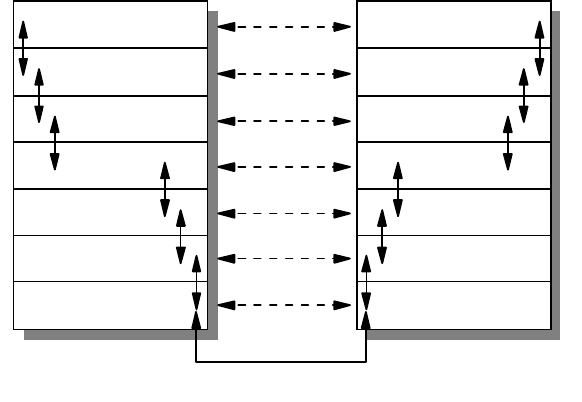
The resulting standard was the OSI (Open Systems Interconnection) Reference
Model (ISO 7498), which defined a seven-layer model of data communications,
as shown in Figure 1 on page 3. Each layer of the OSI Reference Model provides
a set of functions to the layer above and, in turn, relies on the functions provided
by the layer below. Although messages can only pass vertically through the stack
from layer to layer, from a logical point of view, each layer communicates directly
with its peer layer on other nodes.
Introduction 3
Figure 1. OSI Reference Stack
The seven layers are:
Application
The application layer gives the user access to all the lower OSI functions, and
its purpose is to support semantic exchanges between applications existing in
open systems. An example is the Web browser.
Presentation
The presentation layer is concerned with the representation of user or system
data. This includes necessary conversations (for example, a printer control
character), and code translation (for example, ASCII to EBCDIC).
Session
The session layer provides mechanisms for organizing and structuring
interaction between applications and/or devices.
Transport
The transport layer provides transparent and reliable end-to-end data transfer,
relying on lower layer functions for handling the peculiarities of the actual
transfer medium. TCP and UDP are examples of a Transport layer protocol.
Network
The network layer provides the means to establish connections between
networks. The standard also includes procedures for the operational control of
internetwork communications and for the routing of information through
multiple networks. The IP is an example of a Network layer protocol.
Data Link
The data link layer provides the functions and protocols to transfer data
between network entities and to detect (and possibly correct) errors that may
occur in the physical layer.
Application
Presentation
Session
Transport
Network
Data Link
Physical
Application
Presentation
Session
Transport
Network
Data Link
Physical
3376A\3376F1D5
4IP Network Design Guide
Physical
The physical layer is responsible for physically transmitting the data over the
communication link. It provides the mechanical, electrical, functional and
procedural standards to access the physical medium.
The layered approach was selected as a basis to provide flexibility and
open-ended capability through defined interfaces. The interfaces permit some
layers to be changed while leaving other layers unchanged. In principle, as long
as standard interfaces to the adjacent layers are adhered to, an implementation
can still work.
1.1.3 The TCP/IP Model
While the OSI protocols developed slowly, due mainly to their formal committee-
based engineering approach, the TCP/IP protocol suite rapidly evolved and
matured. With its public Request for Comments (RFC) policy of improving and
updating the protocol stack, it has established itself as the protocol of choice for
most data communication networks.
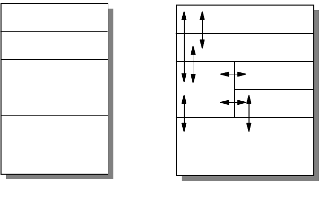
As in the OSI model and most other data communication protocols, TCP/IP
consists of a protocol stack, made up of four layers (see Figure 2 on page 4).
Figure 2. TCP/IP Stack
The layers of the TCP/IP protocol are:
Application Layer
The application layer is provided by the user’s program that uses TCP/IP for
communication. Examples of common applications that use TCP/IP are Telnet,
FTP, SMTP, and Gopher. The interfaces between the application and transport
layers are defined by port numbers and sockets.
Transport Layer
The transport layer provides the end-to-end data transfer. It is responsible for
providing a reliable exchange of information. The main transport layer protocol is
the Transmission Control Protocol (TCP). Another transport layer protocol is User
Datagram Protocol (UDP), which provides a connectionless service in
Applications
Transport
Internetwork
Network Interface
and
Hardware
Applications
TCP/UDP
ICMP
IP ARP/RARP
Network Interface
and Hardware
.......
.......
.......
.......
3376a\3376F1D2
Introduction 5
comparison to TCP, which provides a connection-oriented service. That means
that applications using UDP as the transport protocol have to provide their own
end-to-end flow control. Usually, UDP is used by applications that need a fast
transport mechanism.
Internetwork Layer
The internetwork layer, also called the internet layer or the network layer,
separates the physical network from the layers above it. The Internet Protocol (IP)
is the most important protocol in this layer. It is a connectionless protocol that
doesn't assume reliability from the lower layers. IP does not provide reliability,
flow control or error recovery. These functions must be provided at a higher level,
namely the transport layer if using TCP or the application layer if using UDP.
A message unit in an IP network is called an IP datagram. This is the basic unit of
information transmitted across TCP/IP networks. IP provides routing functions for
distributing these datagrams to the correct recipient for the protocol stack. Other
internetwork layer protocols are ICMP, IGMP, ARP and RARP.
Network Interface Layer
The network interface layer, also called the link layer or the data link layer, is the
interface to the actual network hardware. This layer does not guarantee reliable
delivery; that is left to the higher layers, and may be packet or stream oriented.
TCP/IP does not specify any particular protocol for this layer. It can use almost
any network interface available making it a flexible network while providing
backwards compatibility with legacy infrastructure. Examples of supported
network interface protocols are IEEE 802.2, X.25 (which is reliable in itself), ATM,
FDDI and even SNA.
1.1.4 The Need for Design in IP Networks
If you do not take time to plan your network, the ease of interconnection through
the use of TCP/IP can lead to problems. The purpose of this book is to point out
some of the problems and highlight the types of decisions you will need to make
as you consider implementing a TCP/IP solution.
For example, lack of effective planning of network addresses may result in
serious limitations in the number of hosts you are able to connect to your network.
Lack of centralized coordination may lead to duplicate resource names and
addresses, which may prevent you from being able to interconnect isolated
networks. Address mismatches may prevent you from connecting to the Internet,
and other possible problems may include the inability to translate resource names
to resource addresses because connections have not been made between name
servers.
Some problems arising from a badly designed or an unplanned network are trivial
to correct. Some, however, require significant time and effort to correct. Imagine
manually configuring every host on a 3000-host network because the addressing
scheme chosen no longer fits a business’ needs!
When faced with the task of either designing a new TCP/IP network or allowing
existing networks to interconnect, there are several important design issues that
will need to be resolved. For example, how to allocate addresses to network
resources, how to alter existing addresses, whether to use static or dynamic
routing, how to configure your name servers and how to protect your network are
6IP Network Design Guide
all questions that need to be answered. At the same time the issues of reliability,
availability and backup will need to be considered, along with how you will
manage and administer your network.
The following chapters will discuss these and other concerns, and provide the
information you need to make your decisions. Where possible we will provide
general guidelines for IP network design rather than discussing product-specific
or platform-specific considerations. This is because the product-specific
documentation in most cases already exists and provides the necessary details
for configuration and implementation. We will not attempt to discuss TCP/IP
applications in any depth due to the information also being available to you in
other documents.
1.1.5 Designing an IP Network
Due to the simplicity and flexibility of IP, a network can be "hacked" together in an
unordered fashion. It is common for a network to be connected in this manner,
and this may work well for small networks. The problem arises when changes are
required and documentation is not found. Worst of all, if the network
design/implementation teams leave the organization, the replacements are left
with the daunting task of finding out what the network does, how it fits together,
and what goes where!
An IP network that has not been designed in a systematic fashion will invariably
run into problems from the beginning of the implementation stage. When you are
upgrading an existing network, there are usually legacy networks that need to be
connected. Introducing of new technology without studying the limitations of the
current network may lead to unforeseen problems. You may end up trying to solve
a problem that was created unnecessarily. For example, the introduction of an
Ethernet network in a token-ring environment has to be carefully studied.
The design of the network must take place before any implementation takes
place. The design of the IP network must also be constantly reviewed as
requirements change over time, as illustrated in Figure 3 on page 7.
Introduction 7
Figure 3. IP Network Design Implementation and Change
A good IP network design also includes detailed documentation of the network for
future reference. A well designed IP network should be easy to implement, with
few surprises. It is always good to remember the
KISS
principle:
Keep It Simple,
Stupid!
1.1.5.1 The Design Methodology
The design methodology recommended for use in the design of an IP network is a
top-down design approach.
This technique of design loosely follows the TCP/IP stack. As seen in Figure 2 on
page 4, at the top of the stack lies the application layer. This is the first layer
considered when designing the IP network. The next two layers are the transport
and network layers with the final layer being the data link layer.
The design of an application is dictated by business requirements. The rules of
the business, the process flow, the security requirements and the expected
results all get translated into the application’s specification. These requirements
not only affect the design of the application but their influence permeates all the
way down to the lower layers.
Once the application layer requirements have been identified, the requirements
for the lower layers follow. For example, if the application layer has a program that
demands a guaranteed two-second response time for any network transaction,
the IP network design will need to take this into consideration and maybe place
performance optimization as high priority. The link layer will need to be designed
in such a manner that this requirement is met. Using a flat network model for the
link layer with a few hundred Windows-based PCs may not be an ideal design in
this case.
Once the design of the IP network has been completed with regard to the
application layer, the implementation of the network is carried out.
Initial Design
Deployment
Commissioning
Design Change
2580C\CH3F21
8IP Network Design Guide
The design for the network infrastructure plays an important part, as it ultimately
affects the overall design. A good example of this is the modularity and scalability
of the overall IP network. The following are some basic considerations in
designing an IP network.
1.1.5.2 Overall Design Considerations
Although much could be said about design considerations that is beyond the
scope of this book, there are a few major points that you need to know:
• Scalability
A well designed network should be scalable, so as to grow with increasing
requirement. Introduction of new hosts, servers, or networks to the network
should not require a complete redesign of the network topology. The
topology chosen should be able to accommodate expansion due to
business requirements.
• Open Standards
The entire design and the components that build the network should be
based on open standards. Open standards imply flexibility, as there may be
a need to interconnect different devices from different vendors. Proprietary
features may be suitable to meet a short term requirement but in the long
run, they will limit choices as it will be difficult to find a common technology.
• Availability/Reliability
Business requirements assuredly demand a level of availability and
reliability of the network. A stock trading system based on a network that
guarantees transaction response times of three seconds is meaningless if
the network is down three out of seven days a week!
The mean time between failures (MTBF) of the components must be
considered when designing the network, as must the mean time to repair
(MTTR). Designing logical redundancy in the network is as important as
physical redundancy.
It is too late and costly to consider redundancy and reliability of a network
when you are already halfway through the implementation stage.
• Modularity
An important concept to adopt is the modular design approach in building a
network. Modularity divides a complex system into smaller, manageable
ones and makes implementation much easier to handle. Modularity also
ensures that a failure at a certain part of the network can be isolated so
that it will not bring down the entire network.
The expendability of a network is improved by implementing a modular
design. For example, adding a new network segment or a new application
to the network will not require re-addressing all the hosts on the network if
the network has been implemented in a modular design.
• Security
The security of an organization’s network is an important aspect in a
design, especially when the network is going to interface with the Internet.
Considering security risks and taking care of them in the design stage of
the IP network is essential for complete certitude in the network.
Considering security at a later stage leaves the network open to attack until
Introduction 9
all security holes are closed, a reactive rather than proactive approach that
sometimes is very costly. Although new security holes may be found as the
hackers get smarter, the basic known security problems can easily be
incorporated into the design stage.
• Network Management
IP network management should not be an afterthought of building a
network. Network management is important because it provides a way to
monitor the health of the network, to ascertain operating conditions, to
isolate faults and configure devices to effect changes.
Implementing a management framework should be integrated into the
design of the network from the beginning. Designing and implementing an
IP network and then trying to "fit" a management framework to the network
may cause unneccessary issues. A little proactivity in the design stage can
lead to a much easier implementation of management resources.
• Performance
There are two types of performance measures that should be considered
for the network. One is the throughput requirement and the other is the
response time. Throughput is how much data can be sent in the shortest
time possible, while response time is how long a user must wait before a
result is returned from the system.
Both of these factors need to be considered when designing the network. It
is not acceptable to design a network only to fail to meet the organization’s
requirements in the response times for the network. The scalability of the
network with respect to the performance requirements must also be
considered, as mentioned above.
• Economics
An IP network design that meets all of the requirements of the organization
but is 200% of the budget, may need to be reviewed.
Balancing cost and meeting requirements are perhaps the most difficult
aspects of a good network design. The essence is in the word compromise.
One may need to trade off some fancy features to meet the cost, while still
meeting the basic requirements.
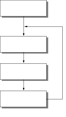
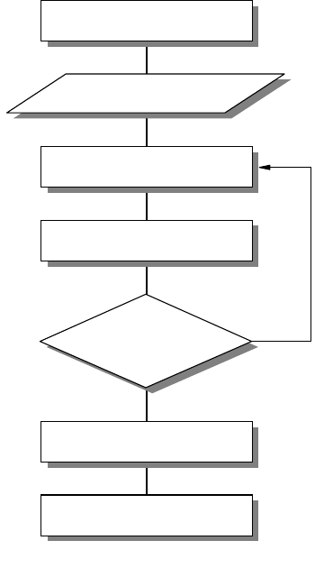
1.1.5.3 Network Design Steps
Below is a generic rule-of-thumb approach to IP network design. It presents a
structured approach to analyzing and developing a network design to suit the
needs of an organization.
10 IP Network Design Guide
Figure 4. Network Design Steps
Network Objectives
What are the objectives of this IP network? What are the business requirements
that need to be satisfied? This step of the design process needs research and
can be time consuming. The following, among other things, should be considered:
• Who are the users of the IP network and what are their requirements?
• What applications must be supported?
• Does the IP network replace an existing communications system?
• What migration steps must be considered?
• What are the requirements as defined in 1.1.5.2, “Overall Design
Considerations” on page 8?
• Who is responsible for network management?
• Should the network be divided into more manageable segments?
• What is the life expectancy of the network?
• What is the budget?
Collecting Design Information
The information that is required for building the network depends on each
individual implementation. However, the main types of information required can
be deduced from Part 1.1.5.2, “Overall Design Considerations” on page 8.
Create Design Proposal
Network Objectives
Collect Design Information
Propose Configuration
Have all designs
been considered?
Make Selection
Move to Implementation
Y
N
2580C\CH3F24

Introduction 11
It is important to collect this information and spend time analyzing it to develop a
thorough understanding of the environment and limitations imposed upon the
design of the new IP network.
Create a Proposal or Specification
Upon analysis of the collected information and the objectives of the network, a
design proposal can be devised and later optimized. The design considerations
can be met with one goal overriding others. So the network can be:
• Optimized for performance
• Optimized for resilience
• Optimized for security
Once the design priorities have been identified the design can be created and
documented.
Review
The final stage in the design process is to review the design before it is
implemented. The design can be modified at this stage easily, before any
investment is made into infrastructure or development work. With this completed,
the implementation stage can be initiated.
1.2 Application Considerations
As presented in chapter one, the TCP/IP model’s highest layer is the application
layer. As the elements that populate this layer are defined by the business
requirements of the overall system, these components must be considered the
most important in the initial design considerations with a top-down design
methodology.
The type of applications that the network needs to support and the types of
network resources these applications require, must be taken into consideration
when designing the IP network. There are a number of these issues that must be
considered for the network design, some that are common to all applications,
while others pertain to a subset of applications. These issues will be defined and
elaborated.
Remember, building a complex ATM network to send plain text in a small
workgroup of 10 users is a waste of time and resources, unless you get them for
free!
1.2.1 Bandwidth Requirements
Different applications require varying amounts of network bandwidth. A simple
SMTP e-mail application does not have the same bandwidth requirement as a
Voice over IP application. Voice and data compression have not reached that
level yet.
It is obvious that the applications your network will need to support determine the
type of network you will finally design. It is not a good idea to design a network
without considering what applications you currently require, and what
applications your business needs will require your network to support in the
future.
12 IP Network Design Guide
1.2.2 Performance Requirements
The performance requirements of the users of the applications must be
considered. A user of the network may be willing to wait for a slow response from
an HTTP or FTP application, but they will not accept delays in a Voice over IP
application - it’s hard to understand what someone is saying when it’s all broken
up.
The delay in the delivery of network traffic also needs to be considered. Long
delays will not be acceptable to applications that stream data, such as video over
IP applications.
The accuracy with which the network is able to provide data to the application is
also relevant to the network design. Differing infrastructure designs provide
differing levels of accuracy from the network.
1.2.3 Protocols Required
The TCP/IP application layer supports an ever increasing number of protocols.
The basic choice in protocol for applications is whether or not the application will
use TCP or UDP. TCP delivers a reliable connection-oriented service. UDP
delivers faster network response by eliminating the overhead of the TCP header;
however, it loses TCP’s reliability, flow control and error recovery features.
It is clear that it depends on the application’s service focus as to which protocol it
will use. An FTP application, for example, will not use UDP. FTP uses TCP to
provide reliable end-to-end connections. The extra speed provided by using UDP
does not outweigh the reliability offered by TCP.
The Trivial File Transfer Protocol (TFTP), however, although similar to FTP, is
based on a UDP transport layer. As TFTP transactions are generally small in size
and very simple, the reliability of the TCP protocol is outweighed by the added
speed provided by UDP. Then why use FTP? Although TFTP is more efficient
than FTP over a local network, it is not good for transfers across the Internet as
its speed is rendered ineffective due to its lack of reliability. Unlike FTP
applications TFTP applications are also insecure.
1.2.4 Quality of Service/Type of Service (QoS/ToS)
Quality of Service (QoS) and Type of Service (ToS) arise simply for one reason:
some users’ data is more "important" then others. And there is a need to provide
these users with "premium" service, just like a VIP queue at the airport.
The requirement for QoS and ToS that gets incorporated into an application also
has implications for the network design. The connecting devices, the routers and
switches, have to be able to ensure "premium" delivery of information so as to
support the requirement of the application.
1.2.4.1 Real-Time Applications
Some applications, such as a Voice over IP or an ordering system, need to be
real time. The need for real-time applications necessitates a network that can
guarantee a level of service.
A real-time application will need to implement its own flow control and error
checking if it is to use UDP as a transport protocol. The requirements of real-time
Introduction 13
applications will also influence the type of network infrastructure implemented. An
ATM network can inherently fulfill the requirements, however, a shared Ethernet
network will not fulfill the requirement.
1.2.5 Sensitivity to Packet Loss and Delay
An application’s sensitivity to packet loss and delay can have dramatic effects on
the user. The network must provide reliable packet delivery for these applications.
For example, a real-time application, with little buffering, does not tolerate packet
delivery delays, let alone packet loss! Voice over IP is one example of such an
application, as opposed to an application such as Web browsing.
1.2.6 Multicast
Multicasting has been proven to be a good way of saving network bandwidth.
That is true, if it has been implemented properly and did not break the network in
the first place.
Getting multicasting to work involves getting all the connecting devices, such as
routers and switches, the applications, the clients’ operating systems, and the
servers to work hand in hand. Multicasting will not work if any of these
subsystems cannot meet the requirement, or if they have severe limitations.
1.2.7 Proxy-Enabled
The ability of an application protocol to be proxyed has implications on the
bandwidth requirements and the security of the network.
An HTTP application will be easily manageable when a firewall is installed for
security, as a proxy service can be placed outside the firewall in a demilitarized
zone to serve HTTP traffic through the firewall to the application.
An application based upon the TELNET protocol will not have such an easy time
as the HTTP application. The TELNET protocol does not support proxying of its
traffic. Thus, a firewall must remain open on this port, the application must use a
SOCKS server or the application cannot communicate through the firewall. You
either have a nonworking application, an added server or a security hole.
1.2.8 Directory Needs
Various applications require directory services with the IP network. Directory
services include DNS, NIS, LDAP, X.500 and DCE, among others. The choice of
Directory services depends on the application support for these services. An
application based upon the ITU X.500 standard will not respond well to a network
with only DNS servers.
Some applications, such as those based upon the PING and TFTP protocols, do
not require directory services to function, although the difficulty in their use would
be greatly increased. Other applications require directory services implicitly, such
as e-mail applications based on the SMTP protocol.

14 IP Network Design Guide
1.2.9 Distributed Applications
Distributed applications will require a certain level of services from the IP
network. These services must be catered for by the network, so they must be
considered in the network design.
Take Distributed Computing Environment (DCE) as an example. It provides a
platform for the construction and use of distributed applications that relies on
services such as remote procedure call (RPC), the Cell Directory Service (CDS),
Global Directory Service (GDS), the Security Service, DCE Threads, Distributed
Time Service (DTS), and Distributed File Service (DFS). These services have to
made available through the network, so that collectively, they provide the basic
secure core for the DCE environment.
1.2.10 Scalability
Applications that require scalability must have a network capable to cater for their
future requirements, or be able to be upgraded for future requirements. If an
application is modular in design, the network must also be modular to enable it to
scale linearly with the application’s requirements.
1.2.11 Security
The security of applications is catered for by the underlying protocols or by the
application itself. If an application uses UDP for its transport layer, it cannot rely
on SSL for security, hence it must use its own encryption and provide its own
security needs.
Some applications that need to be run on the network do not have built-in security
features, or have not implemented standard security concepts such as SSL. An
application based on the TELNET protocol, for example, will invariably be
unsecure. If the network security requirements are such that a TELNET
application sending out unencrypted passwords is unacceptable, then either the
TELNET port must be closed on the firewall or the application must be rewritten.
Is it really worth rewriting your TELNET program?
1.3 Platform Considerations
An important step toward building an application is to find out the capabilities of
the end user’s workstation - the platform for the application. Some of the basic
questions that have to be answered include:
• Whether the workstation supports graphics or only text
• Whether the workstation meets the basic performance requirement in terms of
CPU speed, memory size, disk space and so on
• Whether the workstation has the connectivity options required
Of these questions, features and performance criteria are easy to understand and
information is readily obtainable. The connectivity option is a difficult one to
handle because it can involve many fact findings, some of which may not be
easily available. Many times, these tasks are learned through painful experience.
Take for example, the following questions that may need to be answered if we
want to develop an application that runs on TCP/IP:
• Does the workstation support a particular network interface card?
Introduction 15
• Does the network interface card support certain cabling options?
• Does the network interface card come with readily available drivers?
• Does the workstation’s operating system support the TCP/IP protocol?
• Does the workstation’s TCP/IP stack support subnetting?
• Does the operating system support the required APIs?
• Does the operating system support multiple default routes?
• Does the operating system support multiple DNS definitions?
• Does the operating system support multicasting?
• Does the operating system support advanced features such as Resource
Reservation Protocol (RSVP)?
Depending on the type of application, the above questions may not be relevant,
but they are definitely not exhaustive. You may say the above questions are trivial
and unimportant, but the impact could be far more reaching than just merely the
availability of functions. Here’s why:
• Does the workstation support a particular network interface card?
You may want to develop a multimedia application and make use of ATM’s
superb delivery capability. But the truth is, not all workstations support ATM
cards.
• Does the network interface card support certain cabling options?
Even if the network interface card is available, it may not have the required
cabling option such as a UTP port or multimode fiber SC connection port. You
may need a UTP port because UTP cabling is cost effective. But you may also
end up requiring fiber connectivity because you are the only employee located
in the attic and the connecting device is situated down in the basement.
• Does the network interface card come with readily available drivers?
Right, so we have the network interface card and it does support fiber SC
connections, but what about the bug that causes the workstation to hang? The
necessary patch may be six months away.
• Does the workstation’s operating system support the TCP/IP protocol?
It may seem an awkward question but there may be a different flavor of TCP/IP
implementation. A good example is the Classical IP (CIP) and LAN emulation
(LANE) implementation in an ATM network. Some operating systems may
support only CIP, while some may only support LANE.
• Does the workstation’s TCP/IP stack support subnetting?
In the world of IP address shortages, there may be a need to subdivide a
precious network subnet address further. And not all systems support
subnetting, especially the old systems.
• Does the operating system support the required APIs?
One popular way of developing a TCP/IP application is to use sockets
programming. But the TCP/IP stack on the user’s workstation may not fully
support it. This gets worse if there are many workstation types in the network,
each running different operating systems.
• Does the operating system support multiple default routes?

16 IP Network Design Guide
Unlike other systems, Windows 95 does not support multiple default routes. If
you are trying to develop a mission-critical application, this may be a serious
single point of failure. Some other workaround has to be implemented just to
alleviate this shortcoming.
• Does the operating system support multiple DNS definitions?
This one has the same impact as the point above. With clients capable of
having only one DNS definition, a high availability option may have to be built
into the DNS server. On the other hand, with clients capable of supporting
multiple DNS, the applications must be supported with APIs that can provide
such facilities.
• Does the operating system support multicasting?
There may be a need to deliver video to the users, and one of the ways is
through multicasting. Multicasting is a good choice as it conserves the network
bandwidth. But not all clients support multicasting.
• Does the operating system support advanced features such as RSVP?
Although standards like RSVP had been rectified for quite some time, many
operating systems do not support such features. For example, Windows 95
does not support RSVP.
1.4 Infrastructure Considerations
The applications need a transport mechanism to share information, to transmit
data or to send requests for some services. The transport mechanism is provided
by the underlying layer called the network infrastructure.
Building a network infrastructure can be a daunting task for the inexperienced.
Imagine building a network for a company with 100,000 employees and 90
different locations around the world. How do you go about building it? And where
do you begin?
As in the application consideration, building a network infrastructure involves
many decision making processes:
• What are the technologies out there?
• Which technology should I use for the LAN?
• Which technology should I use for the WAN?
• How do I put everything together?
• What is this thing called switching?
• How should the network design look?
• What equipment is required?
• How should it grow?
• How much does it cost?
• Can I manage it?
• Can I meet the deployment schedule?
• Is there a strategy to adopt?

Introduction 17
The Internet as we have it today grew out of circumstances. In the beginning, it
was not designed to be what it is today. In fact, there was not any planning or
design work done for it. It is merely a network of different networks put together,
and we have already seen its problems and limitations:
• It has almost run out of IP addresses
• It has performance problems
• It cannot readily support new generation applications
• It does not have redundancy
• It has security problems
• It has erratic response time
Work has begun on building the so-called New Generation Internet (NGI) and it is
supposed to be able to address most, if not all, of the problems that we are
experiencing with the Internet today. The NGI will be entirely different from what
we have today, as it is the first time that a systematic approach has been used to
design and build an Internet.
1.5 The Perfect Network
So, you may ask: Is there such a thing as a perfect network?
If a network manager is assigned to build a network for a company, he/she would
have to know how to avoid all the problems we have mentioned above. He or she
would use the best equipment and would have chosen the best networking
technologies available, but may still not have built a perfect network. Why?
The truth is, there is no such thing as a perfect network. A network design that is
based on today’s requirements may not address those of the future. Business
environments change, and this has a spiraling effect on the infrastructure.
Expectations of employees change, the users’ requirements change, and new
needs have to be addressed by the applications, and these in turn affect how all
the various systems tie up together, which means there is a change in the
network infrastructure involved. At best, what the network could do is to scale and
adapt to changes. Until the day it has reached its technical limitation, these are
the two criteria for a network to stay relevant; after that, a forklift operation may be
required.
Networks evolve over time. They have to do so to add value.
The above sections have highlighted that much work has to be done before an
application gets to be deployed to support a business’ needs. From the network
infrastructure to the various system designs, server deployments, security
considerations and types of client workstations, they all have to be well
coordinated. A minor error could mean back to the drawing board for the system
designer, and lots of money for the board of directors.
18 IP Network Design Guide

© Copyright IBM Corp. 1995 1999 19
Chapter 2. The Network Infrastructure
The network infrastructure is an important component in IP network design. It is
important simply because, at the end of the day, it is those wires that carry the
information. A well thought-out network infrastructure not only provides reliable
and fast delivery of that information, but it is also able to adapt to changes, and
grow as your business expands.
Building a network infrastructure is a complex task, requiring work such as
information gathering, planning, designing, and modeling. Though it deals mainly
with bits and bytes, it is more of an art than a science, because there are no fast
rules to building one.
When you build a network infrastructure, you look more at the lower three layers
of the OSI model, although many other factors need to be considered. There are
many technologies available that you can use to build a network, and the
challenge that a network manager faces, is to choose the correct one and the tool
that comes with it. It is important to know the implications of selecting a particular
technology, because the network manager ultimately decides what equipment is
required. When selecting a piece of networking equipment, it is important to know
at which layer of the OSI model the device functions. The functionality of the
equipment is important because it has to conform to certain standards, it has to
live up to the expectation of the application, and it has to perform tasks that are
required by the blue print - the network architecture.
The implementation of IP over different protocols depends on the mechanism
used for mapping the IP addresses to the hardware addresses, or MAC address,
at the data link layer of the OSI model. Some important aspects to consider when
using IP over any data link protocol are:
• Address mapping
Different data link layer protocols have different ways of mapping the IP
address to the hardware address. In the TCP/IP protocol suite, the Address
Resolution Protocol (ARP) is used for this purpose, and it works only in a
broadcast network.
• Encapsulation and overheads
The encapsulation of the IP packets into the data link layer packet and the
overheads incurred should be evaluated. Because different data link layer
protocols transport information differently, one may be more suitable than the
other.
• Routing
Routing is the process of transporting the IP packets from network to network,
and is an important component in an IP network. Many protocols are available
to provide the intelligence in the routing of the IP protocol, some with
sophisticated capabilities. The introduction of switching and some other data
link layer protocols has introduced the possibility of building switched paths in
the network that can bypass the routing process. This saves network
resources and reduces the network delay by eliminating the slower process of
routing that relies on software rather than on hardware or microcode switching
mechanisms.
• Maximum Transmission Unit (MTU)

20 IP Network Design Guide
Another parameter that should be considered in the IP implementation over
different data link layer protocols is the maximum transmission unit (MTU)
size. MTU size refers to the size of the data frame (in bytes) that has to be
transmitted to the destination through the network. A bigger MTU size means
one can send more information within a frame, thus requiring a lower total
number of packets to transmit a piece of information.
Different data link layers have different MTU sizes for the operation of the
network. If you connect two networks with different MTU sizes, then a process
called fragmentation takes place and this has to be performed by an external
device, such as a router. Fragmentation takes a larger packet and breaks it up
into smaller ones so that it can be sent onto the network with a smaller MTU
size. Fragmentation slows down the traffic flow and should be avoided as
much as possible.
2.1 Technology
Besides having wires to connect all the devices together, you have to decide the
way these devices connect, the protocol in which the devices should talk to each
other. Various technologies are available, each different from one another in
standards and implementation.
In this section, a few popular technologies are covered with each of their
characteristics highlighted. These technologies cover the LAN, WAN as well as
the remote access area. For a detailed description of each technology, please
refer to
Local Area Network Concepts and Products: LAN Architecture,
SG24-4753.
2.1.1 The Basics
It is important to understand the fundamentals of how data is transmitted in an IP
network, so that the difference in how the various technologies work can be better
understood.
Each workstation connects to the network through a network interface card (NIC)
that has a unique hardware address. At the physical layer, these workstations
communicate with each other through the hardware addresses. IP, being a higher
level protocol in the OSI model, communicates through a logical address, which
in this case, is the IP address. When one workstation with an IP address of
10.1.1.1 wishes to communicate with another with the address 10.1.1.2, the NIC
does not understand these logical addresses. Some mechanism has to be
implemented to translate the destination address 10.1.1.2 to a hardware address
that the NIC can understand.
2.1.1.1 Broadcast versus Non-Broadcast Network
Generally, all networks can be grouped into two categories: broadcast and
non-broadcast. The mechanism for mapping the logical address to the hardware
address is different for these two groups of networks. The best way of describing
a broadcast network is to imagine a teacher teaching a class. The teacher talks
and every student listens. An example of a non-broadcast network would be a
mail correspondence - at any time, only the sender and receiver of the mail know
what the conversation is about, the rest of the people don’t. Examples of
broadcast networks are Ethernet, token-ring and FDDI, while examples of
non-broadcast networks are frame relay and ATM.
The Network Infrastructure 21
It is important to differentiate the behaviors of both broadcast and non-broadcast
networks, so that the usage and limitation can both be taken into consideration in
the design of an IP network.
2.1.1.2 Address Resolution Protocol (ARP)
In a broadcast network, the Address Resolution Protocol (ARP) is used to
translate the IP address to the hardware address of the destination host. Every
workstation that runs the TCP/IP protocol keeps a table, called an ARP cache,
containing the mapping of the IP address to the hardware address of the hosts
with which it is communicating. When a destination entry is not found in the ARP
cache, a broadcast, called ARP broadcast, is sent out to the network. All
workstations that are located within the same network will receive this request
and go on to check the IP address entry in the request. If one of the workstations
recognizes its own IP address in this request, it will proceed to respond with an
ARP reply, indicating its hardware address. The originating workstation then
stores this information and commences to send data through the newly learned
hardware address.
ARP provides a simple and effective mechanism for mapping an IP address to a
hardware address. However, in a large network, especially in a bridged
environment, a phenomenon known as a broadcast storm can occur if
workstations misbehave, assuming hundreds of workstations are connected to a
LAN, and ARP is used to resolve the address mapping issue. If the workstation’s
ARP cache is too small, it means the workstation has to send more broadcasts to
find out the hardware address of the destination. Having hundreds of
workstations continuously sending out ARP broadcasts would soon render the
LAN useless because nobody can send any data.
For a detailed description of ARP, please refer to
TCP/IP Tutorial and Technical
Overview,
GG24-3376.
2.1.1.3 Proxy ARP
The standard ARP protocol does not allow the mapping of hardware addresses
between two physically separated networks that are interconnected by a router. In
this situation, when one is having a combination of new workstations and older
workstations that do not support the implementation of subnetting, ARP will not
work.
Proxy ARP or RFC 1027, is used to solve this problem by having the router reply
to an ARP request with its own MAC address on behalf of the workstations that
are located on the other side of the router. It is useful in situations when multiple
LAN segments are required to share the same network number but are connected
by a router. This can happen when there is a need to reduce broadcast domains
but the workstation’s IP address cannot be changed. In fact, some old
workstations may still be running an old implementation of TCP/IP that does not
understand subnetting.
A potential problem can arise though, and that is when the Proxy ARP function is
turned on in a router by mistake. This problem would manifest itself when displays
of the ARP cache on the workstations show multiple IP addresses all sharing the
same MAC addresses.
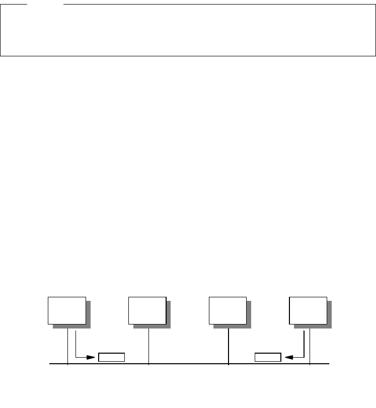
22 IP Network Design Guide
2.1.1.4 Reverse Address Resolution Protocol (RARP)
Some workstations, especially diskless workstations, do not know their IP
address when they are initialized. A RARP server in the network has to inform the
workstation of its IP address when an RARP request is sent by the workstation.
RARP will not work in a non-broadcast network.
Typically in a non-broadcast network, workstations communicate in a one-to-one
manner. There is no need to map a logical address to a hardware address
because they are statically defined. Most of the WAN protocols can be
considered as non-broadcast.
2.1.2 LAN Technologies
There are a few LAN technologies that are widely implemented today. Although
they may have been invented many years ago, they have all been proven reliable
and stood the test of time.
2.1.2.1 Ethernet/IEEE 802.3
Today, Ethernet LAN is the most popular type of network in the world. It is popular
because it is easy to implement, and the cost of ownership is relatively lower than
that of other technologies. It is also easy to manage and the Ethernet products
are readily available.
The technology was invented by Xerox in the 1970s and was known as Ethernet
V1. It was later modified by a consortium made up of Digital, Intel and Xerox, and
the new standard became Ethernet (DIX) V2. This was later rectified by the IEEE,
to be accepted as an international standard, with slight modification, and hence,
IEEE 802.3 was introduced.
The Ethernet LAN is an example of a carrier sense multiple access with collision
detection (CSMA/CD) network, that is, members of a same LAN transmit
information at random and retransmit when collision occurs. The CSMA/CD
network is a classic example of a broadcast network because all workstations
"see" all information that is transmitted on the network.
Figure 5. The Ethernet LAN as an Example of a CSMA/CD Network
Although different in specifications, the Ethernet, IEEE 802.3, Fast Ethernet
and Gigabit Ethernet LANs shall be collectively known as the Ethernet LAN in
this book.
Note
A B C D
2580B\CH2F01

The Network Infrastructure 23
In the above diagram, when workstation A wants to transmit data on the network,
it first listens to see if somebody else is transmitting on the network. If the
network is busy, it waits for the transmission to stop before sending out its data in
units called frames. Because the network is of a certain length and takes some
time for the frame from A to reach D, D may think that nobody is using the
network and proceed to transmit its data. In this case, a collision occurs and is
detected by all stations. When a collision occurs, both transmitting workstations
have to stop their transmission and use a random backoff algorithm to wait for a
certain time before they retransmit their data.
As one can see, the chance of a collision depends on the following:
• The number of workstations on the network. The more workstations, the more
likely collisions will occur.
• The length of the network. The longer the network, the greater the chance for
collisions to occur.
• The length of the data packet, the MTU size. A larger packet length takes a
longer time to transmit, which increases the chance of a collision. The size of
the frame in an Ethernet network ranges from 64 to 1516 bytes.
Therefore, one important aspect of Ethernet LAN design is to ensure an adequate
number of workstations per network segment, so that the length of the network
does not exceed what the standard specifies, and that the correct frame size is
used. While a larger frame means that a fewer number of them is required to
transmit a single piece of information, it can mean that there is a greater chance
of collisions. On the other hand, a smaller frame reduces the chance of a
collision, but it then takes more frames to transmit the same piece of information.
It was mentioned earlier that the Ethernet and IEEE 802.3 standards are not the
same. The difference lies in the frame format, which means workstations
configured with Ethernet will not be able to communicate with workstations that
have been configured with IEEE 802.3. The difference in frame format is as
follows:
Figure 6. Ethernet Frame versus IEEE 802.3 Frame
To implement Ethernet, network managers need to follow certain rules, and it can
very much tie in with the type of cables being used. Ethernet can be implemented
using coaxial (10Base5 or 10Base2), fiber optic (10BaseF) or UTP Category 3
Ethernet
Preamble
1010...1010
Start
Frame
Delimiter
1010...1011
Destination
Address
Source
Address
Length Data Frame
Check
Sequence
Preamble
1010...1010
Sync
11
Destination
Address
Source
Address
Type Data Frame
Check
Sequence
IEEE
802.3
62
Bits
2
Bits
6
Bytes
6
Bytes
2
Bytes
46-1500
Bytes
4
Bytes
56
Bits
8
Bits
6
Bytes
6
Bytes
2
Bytes
46-1500
Bytes
4
Bytes
2580B\CH2F02

24 IP Network Design Guide
cables (10BaseT). These different cabling types impose different restrictions and
it is important to know the difference. Also, Ethernet generally follows the 5-4-3
rule. That is, in a single collision domain, there can be only five physical
segments, connected by four repeaters. No two communicating workstations can
be separated by more than three segments. The other two segments must be a
link segment, that is, with no workstations attached to them.
Table 1. Comparing Ethernet Technologies
Although it was once thought that Ethernet would not scale and thus would be
replaced by other better technologies, vendors have made modifications and
improvements to its delivery capabilities to make it more efficient.
The Ethernet technology has evolved from the traditional 10 Mbps network to the
100 Mbps network or Fast Ethernet, and now to the 1 Gbps network, or better
known as Gigabit Ethernet.
The Fast Ethernet, or the IEEE 802.3u standard, is 10 times faster than the 10
Mbps Ethernet. The cabling used for Fast Ethernet is 100BaseTx, 100BaseT4
and the 100BaseFx. The framing used in Fast Ethernet is the same as that used
in Ethernet. Therefore it is very easy for network managers to upgrade from
Ethernet to Fast Ethernet. Since the framing and size are the same as that of
Ethernet and yet the speed has been increased 10 times, the length of the
network now has to be greatly reduced, or else the collision would not be
detected and would cause problems to the network.
The Gigabit Ethernet, or IEEE 802.3z standard, is 10 times faster than the Fast
Ethernet. The framing used is still the same as that of Ethernet, and thus reduces
the network distance by a tremendous amount as compared to the Ethernet.
Gigabit Ethernet is usually connected using the short wavelength (1000BaseSx)
or the long wavelength (1000BaseLx) fiber optic cables, although the standard for
the UTP (1000BaseT) is available now. The distance limitation has been resolved
with the new fiber optic technologies. For example, 1000BaseLx with a 9 micron
single mode fiber drives up to five kilometers on the S/390 OSA. An offering
called the Jumbo Frame implements a much larger frame size, but its use has
been a topic of hot debate for network managers. Nonetheless, vendors are
beginning to offer the Jumbo Frame feature in their products. IBM is offering a 9
KB Jumbo Frame feature, using device drivers from ALTEON, on the newly
announced S/390 OSA, and future RS/6000 and AS/400 implementations will
also be capable of this.
Gigabit Ethernet is mainly used for creating high speed backbones, a simple and
logical choice for upgrading current Fast Ethernet backbones. Many switches with
10Base5 10Base2 10BaseT
Topology Bus Bus Star
Cabling type Coaxial Coaxial UTP
Maximum cable
length 500m 185m 100m
Topology limitation 5-4-3 rule 5-4-3 rule 5-4-3 rule
Maximum number of
workstations on a
single segment
100 30 1 (requires the
workstation to be
connected to a hub)

The Network Infrastructure 25
100BaseT ports, like the IBM 8271 and 8275 switches, are beginning to offer a
Gigabit Ethernet port as an uplink port, so that more bandwidth can be provided
for connections to the higher level of network for access to servers.
Besides raw speed improvement, new devices such as switches now provide
duplex mode operation, which allows workstations to send and receive data at the
same time, effectively doubling the bandwidth for the connection. The duplex
mode operation requires a Category-5 UTP cable, with two pairs of wire used for
transmitting and receiving data. Therefore, the operation of duplex mode may not
work on old networks because they usually run on Category-3 UTP cables.
Most of the early Ethernet workstations are connected to the LAN at 10 Mbps
because they were implemented quite some time ago. It is still popular as the
network interface card and 10 Mbps hubs are very affordable. At this point, it is
important to note that in network planning and design, more bandwidth or a faster
network does not mean that the user will benefit from the speed. Due to the
development of higher speed networks such as Fast Ethernet and Gigabit
Ethernet, a 10 Mbps network seems to have become less popular now. The fact
is, it can still carry a lot of information and a user may not be able to handle the
information if there is anymore available. With the introduction of switches that
provides dedicated 10 Mbps connection to each individual user, this has become
even more true. Here’s what information a 10 Mbps connection can carry:
Table 2. Application Bandwidth Requirements
The question now is: Can a user clear his/her e-mail inbox, save some
spreadsheet data to the server, talk to his/her colleague through the telephony
software, watch a training video produced by the finance department and
participate in a videoconferencing meeting, all at the same time?
Giving a user a 100 Mbps connection may not mean it would be utilized
adequately. A 10 Mbps connection is still a good solution to use for its cost
effectiveness. This may be a good option to meet certain budget constrains, while
keeping an upgrade option open for the future.
Applications Mbps Bandwidth Occupied
Network applications
(read e-mail, save some spreadsheets) 2
Voice 0.064
Watching MPEG-1 training video
(small window) 0.6
Videoconferencing 0.384
Total bandwidth < 4
It is generally agreed that the maximum "usable" bandwidth for Ethernet LAN is
about 40%, after which the effect of collision is so bad that efficiency actually
begins to drop.
Note

26 IP Network Design Guide
Nowadays, with card vendors manufacturing mostly 10/100Mbps Ethernet cards,
more and more workstations have the option of connecting to the network at
100Mbps. The Gigabit Ethernet is a new technology and it is positioned to be a
backbone technology rather than being used to connect to the end users. As
standards evolve, Gigabit Ethernet will see widespread usage in the data center
and most of the servers that connect to the network at 100 Mbps today will
eventually move to a Gigabit Ethernet.
Ethernet is a good technology to deploy for a low volume network or application
that does not demand high bandwidth. Because it does not have complicated
access control to the network, it is simple and can provide better efficiency in
delivery of data. Due to its indeterministic nature of collision, response time in an
Ethernet cannot be determined and hence, another technology has to be
deployed in the event that this is needed.
Although Ethernet technology has been around for quite some time, it will be
deployed for many years to come because it is simple and economical. Its
plug-and-play nature allows it to be positioned as a consumer product and users
require very little training to se up an Ethernet LAN. With the explosion of Internet
usage and e-commerce proliferating, more companies, especially the small ones
and the small office, home office (SoHo) establishment, will continue to drive the
demand for Ethernet products.
2.1.2.2 Token-Ring/IEEE 802.5
The token-ring technology was invented by IBM in the 1970s and it is the second
most popular LAN architecture. It supports speeds of 1, 4 or 16 Mbps. There is a
new technology, called the High-Speed Token-Ring being developed by the IEEE
and it will run at 100 Mbps.
The token-ring LAN is an example of a token-passing network, that is, members
of the LAN transmit information only when they get hold of the token. Since the
transmission of data is decided by the control of the token, a token-ring LAN has
no collision.
Although different in specifications, both the IBM Token-Ring and IEEE 802.5
LANs will be collectively known as the token-ring LAN in this book.
Note

The Network Infrastructure 27
Figure 7. Passing of Token in a Token-Ring LAN
As shown in the above diagram, all workstations are connected to the network in
a logical ring manner, and access to the ring is controlled by a circulating token
frame. When station A with data to transmit to D receives the token, it changes
the content of the token frame, appends data to the frame and retransmits the
frame. As the frame passes the next station B, B checks to see f the frame is
meant for it. Since the data is meant for D, B then retransmits the frame, and this
action is repeated through C and finally to D. When D receives the frame, it
copies the information in the frame, sees the frame copied and address
recognition bits and retransmits the modified frame in the network. Eventually, A
receives the frame, strips the information from it, and releases a new token into
the ring so that other workstations may use it. The following diagram shows the
frame formats for data and token frames:
Figure 8. Token-Ring Frame Formats
As described, the token passing technique is different from Ethernet’s random
manner of access. This important feature makes a token-ring LAN deterministic
A
Token
D
BC
2580B\CH2F03
Start
Delimiter
Access
Control
Frame
Control
Destination
Address
Source
Address
Data Frame
Check
Sequence
1 1 1 6 6 710 4
End
Delimiter
1Byte
Length
Data Frame
111
Start
Delimiter
Access
Control
End
Delimiter
Byte
Length
Token Frame
2580B\CH2F04
28 IP Network Design Guide
and allows delays to be determined. Besides this difference, token-ring also
offers extensive network diagnostics and self-recovery features such as:
• Power-on and ring insertion diagnostics
• Lobe-insertion testing and online lobe fault detection
• Signal loss detection, beacon support for automatic test and removal
• Active and standby ring monitor functions
• Ring transmission errors detection and reporting
• Failing components isolation for automatic or manual recovery
It is not surprising that with such extensive features, token-ring adapters are more
expensive than the Ethernet ones because all of these functions are implemented
in the adapter microcode.
The token-ring LAN is particularly stable and efficient even under high load
conditions. The impact of an increase in the number of workstations on the same
LAN does not affect token-ring as much as it would Ethernet. It guarantees fair
access to all workstations on the same LAN and is further enhanced with an
eight-level priority mechanism. With extensive features like self recovery and auto
configuration at the electrical level, the token-ring LAN is the network of choice for
networks that require reliability and predictable response times. Networks such
as factory manufacturing systems and airline reservation systems typically use
token-ring LANs for these reasons.
2.1.2.3 Fiber Distributed Digital Interface (FDDI)
FDDI was developed in the early 1980s for high speed host connections but it
soon became a popular choice for building LAN backbones. Similar to the
token-ring LAN, FDDI uses a token passing method to operate but it uses two
rings, one primary and one secondary, running at 100 Mbps. Under normal
conditions, the primary ring is used while the secondary is in a standby mode.
FDDI provides flexibility in its connectivity and redundancy and offers a few ways
of connecting the workstations, one of which is called the dual attachment station
ring.
In a dual attachment station ring, workstations are called Dual Attachment
Stations (DAS). All of them have two ports (A and B) available for connection to
the network as shown in the following diagram:
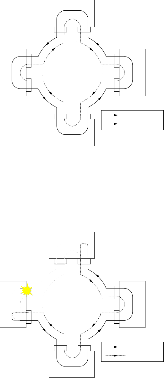
The Network Infrastructure 29
Figure 9. FDDI Dual Attachment Rings
In the above setup, the network consists of a primary ring and a secondary ring in
which data flows in opposite directions. Under normal conditions, data flows in
the primary ring and the secondary merely functions as a backup. In the event of
a DAS or cable failure, the two adjacent DASs would "wrap" their respective ports
that are connected to the failed DAS. The network now becomes a single ring and
continues to operate as shown in the following diagram:
Figure 10. FDDI Redundancy
DAS
DAS
DAS DAS
Primary Ring
Secondary Ring
2580B\CH2F05
DAS
DAS
DAS DAS
Primary Ring
Secondary Ring
2580B\CH2F06

30 IP Network Design Guide
It is easy to note the robustness of FDDI and appreciate its use in a high
availability network. Since it is similar in nature to token-ring, FDDI offers
capabilities such as self recovery and security. Because it mostly runs on fiber, it
is not affected by electromagnetic interference. Due to its robustness and high
speed, FDDI was being touted as the backbone of choice. But with the
development of 100 Mbps Ethernet technology, network managers who are going
for bandwidth rather than reliability have chosen to implement 100 Mbps Ethernet
rather than FDDI.
Though it may not be as popular as Ethernet or token-ring, one can still find many
networks operating on FDDI technology.
2.1.2.4 Comparison of LAN Technologies
It is appropriate, at this point, to compare the various LAN technologies that we
have discussed. These technologies are the most popular ones deployed, each
tend to be dominant in certain particular working environments.
Table 3. Comparing LAN Technologies
Ethernet Token-Ring FDDI
Topology Bus Ring Dual Rings
Access Method CSMA/CD Token Passing Token Passing
Speed (in Mbps) 10/100/1000 1/4/16/100 100
Broadcast/Non-
Broadcast Broadcast Broadcast Broadcast
Packet Size (Bytes) 64-1516 32-16K 32-4400
Self Recovery No Yes Yes
Data Path
Redundancy No No Yes
Predictable
Response Times No Yes Yes
Priority Classes No Yes Yes
Maximum Cable
Length Yes Yes Yes
Cost of Deployment
(relative to each
other)
Cheap Moderate Expensive
The Ethernet, token-ring and the FDDI technologies are generally referred to
as the legacy LANs, as opposed to new technology like ATM.
Note

The Network Infrastructure 31
The above table shows the difference in characteristics of each of the
technologies. From the comparisons, it shows that each of these technologies is
more suitable than the rest for certain operating requirements.
The Ethernet technology tends to be deployed in networks where network
response time is not critical to the functions of the applications. It is commonly
found in educational institutes, mainly for its cost effectiveness, and e-commerce,
for its simplicity in technical requirements. The token-ring is most suitable for
networks that require predictable network response time. Airline reservation
systems, manufacturing systems, as well as some banking and financial
applications, have stringent network response time requirements. These
networks tend to be token-ring, although there may be few exceptions. The FDDI
is commonly deployed as a backbone network in a medium- to-large networks. It
can be found in both an Ethernet or a token-ring environment. As mentioned, with
the popularity of the Internet growing and the number of e-commerce setups is
increasing at an enormous pace, Ethernet is the popular choice for building an IP
network.
Thus, in deciding on which technology is most suitable for deployment, a network
manager needs to ascertain the requirement carefully, and make the correct
decision based on the type of environment he/she operates in, the type of
applications to be supported, and the overall expectations of the end users.
2.1.3 WAN Technologies
WAN technologies are mainly used to connect networks that are geographically
separated. For example, a remote branch office located in city A connecting to
the central office in city B. Routers are usually used in WAN connectivity although
switches may be deployed.
The requirements and choices of WAN technologies are different from LAN
technologies. The main reason is that WAN technologies are usually a subscribed
service offered by carriers, and they are very costly. WAN also differs from LAN
technologies in the area of speed. While LAN technologies are running at
megabits per second, the WANs are usually in kilobits per second. Also, WAN
connections tend to be point-to-point in nature, while LAN is multiaccess.
The following table describes the differences between LAN and WAN
technologies:
Table 4. Comparing LAN and WAN Technologies
Typical Deployment
Environment Small Offices,
SoHo,
Educational
Institute,
Most Corporate
Offices,
e-Commerce
Airline,
Manufacturing Floor,
Banking,
Most
Mission-Critical
Networks
Backbone
technology for
medium and large
networks
LAN WAN
Subscribed
Service No Yes
Ethernet Token-Ring FDDI

32 IP Network Design Guide
It would seem obvious that the criteria for choosing a suitable WAN technology is
different from that of a LAN. It is very much dependent on the choice of service
offered by the carrier, the tariffs, the service quality of the carrier and availability
of expertise.
2.1.3.1 Leased Lines
Leased lines are the most common way of connecting remote offices to the head
office. It is basically a permanent circuit leased from the carrier and connects in a
point-to-point manner.
The leased line technology has been around for quite some time and many
network managers are familiar with it. With speed ranging from 64 kbps to as high
as 45 Mbps, it usually runs protocol such as IP and IPX over a point-to-point
protocol (PPP).
Routers are usually deployed to connect to leased lines to connect remote offices
to a central site. A device called a data service unit/channel service unit
(DSU/CSU) connects the router to the leased line, and for every leased line
connection, a pair of DSU/CSU is required.
Due to its cost and the introduction of many other WAN technologies, network
managers have begun to replace leased lines with some other technologies for
reasons such as cost and features.
2.1.3.2 X.25
X.25 was developed by the carriers in the early1970s, and it allows the transport
of data over a public data network service. The body that oversee its development
is the International Telecommunication Union (ITU). Since ITU is made up of most
of the telephone companies, this makes X.25 a truly international standard. X.25
is a classic example of a WAN protocol and a non-broadcast network.
The components that make up an X.25 network are:
Speed 4,10,16,100,
155, 622 Mbps,
1 Gbps
9.6, 14.4, 28.8, 56
64, 128, 256,
512 kbps
1.5, 2, 45, 155,
622 Mbps
Cost per kbps
(relative to each
other)
Cheap Very expensive
Performance of
major decision
criteria
Yes No
Cost of major
decision criteria Maybe Yes
Cost of redundancy
(as opposed to
each)
May be expensive Very expensive
Need specially
trained personnel May not Definitely
LAN WAN

The Network Infrastructure 33
• Data terminal equipment (DTE)
DTEs are the communication devices located at an end user’s premises.
Examples of DTEs are routers or hosts.
• Packet assembler/disassembler (PAD)
A PAD connects the DTE to the DCE and acts as a translator.
• Data circuit-terminating equipment (DCE)
DCEs are the devices that connect the DTEs to the main network. An example
of a DCE is the modem.
• Packet switching exchange (PSE)
PSEs are the switches located in the carrier’s facilities. The PSEs form the
backbone of the X.25 network.
X.25 end devices communicate just like how we use a telephone network. To
initiate a communication path, called a
virtual circuit
, one workstation calls
another and upon successful connection of the call, data begins to be
transmitted. As opposed to the broadcast network, there is no facility such as
ARP to map an IP address to an X.25 address. Instead, mappings are done
statically and there is no broadcast required. In an X.25 network, there are two
types of virtual circuit:
• Permanent virtual circuit (PVC)
PVCs are established for busy networks that always require the service of a
virtual circuit. Rather than making repetitive calls, the virtual circuit is made
permanent.
• Switched virtual circuit (SVC)
SVCs are used with seldom-used data transfers. It is set up on demand and is
taken down when transmission ends.
The X.25 specification maps to the first three layers of the OSI model, as shown
in the following diagram:
Figure 11. X.25 Layers versus OSI Model
The encapsulation of IP over X.25 networks is described in RFC 1356. The RFC
proposes larger X.25 maximum data packet size and the mechanism for
encapsulating longer IP packets over the original draft.
X.25
Network
Datalink
Physical
OSI
LAPB
Physical
2580B\CH2F07
34 IP Network Design Guide
When data is sent to an X.25 data communication equipment one or more virtual
circuits are opened in the network to transmit it to the final destination. The IP
datagrams are the protocol data units (PDUs) when the IP over X.25
encapsulation occurs. The PDUs are sent as X.25
complete packet sequences
across the network. That is, PDUs begin on X.25 data packet boundaries and the
M bit (more data) is used to fragment PDUs that are larger than one X.25 data
packet.
There have been many discussions about performance in an X.25 network. The
RFC 1356 specifies that every system must be able to receive and transmit PDUs
up to 1600 bytes. To accomplish the interoperability with the original draft, RFC
877, the default value for IP datagrams should be 1500 bytes, and configurable in
the range from 576 to 1600 bytes. This standard approach has been used to
accomplish the default value of 1500-byte IP packets used in LAN and WAN
environments so that one can avoid the router fragmentation process.
Typically, X.25 public data networks make use of low speed data links and a
certain number of routes is incurred before data is transmitted to a destination.
The way X.25 switches store the complete packet before sending it on the output
link causes a longer delay with longer X.25 packets. If a small end-to-end window
size is used, it also decreases the end-to-end throughput of the X.25 circuit.
Fragmenting large IP packets in smaller X.25 packets can improve the throughput
allowing a greater pipeline on the X.25 switches. Large X.25 packets combined
over low speed links can also introduce higher packet latency. Thus, the use of
larger X.25 packets will not increase the network performance but often it
decreases it and some care should be taken in choosing the packet size.
It is also noted that some switches in the X.25 network will further fragment
packets, so the performance of a link is also decided by the characteristics of the
carrier’s network.
A different approach for increasing performance relies on opening multiple virtual
channels, but this increases the delivering costs over the public data networks.
However, this method can overcome problems introduced by the limitation of a
small X.25 window size increasing the used shares of the available bandwidth.
The low speed performance of X.25 can sometimes pose problems for some
TCP/IP applications that time out easily. In this manner, other connecting
protocols would have to be deployed in place of X.25. With the advent of
multiprotocol routers, you can find TCP/IP running on other WAN protocols while
X.25 is used for other protocols. In fact, with the proliferation of TCP/IP networks,
a new way transporting connections started to emerge: that of transporting X.25
networks across a TCP/IP network.
An example is the X.25 Transport Protocol (XTP) provided by the 221X Nways
Multiprotocol routers family. This protocol works as a protocol forwarder,
transferring the incoming X.25 packets to the final X.25 connection destination
using the TCP/IP network. A common situation is depicted in the following
diagram:
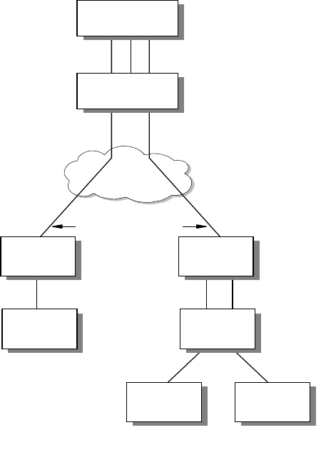
The Network Infrastructure 35
Figure 12. X.25 over IP (XTP)
2.1.3.3 Integrated Services Digital Network (ISDN)
Integrated services digital network (ISDN) is a subscribed service offered by
phone companies. It makes use of digital technology to transport various
information, including data, voice and video, by using phone lines.
There are two types of ISDN interfaces, the basic rate interface (BRI) and the
Primary Rate Interface (PRI). The BRI provides 2 x 64 kbps for data transmission
(called the B channels) and 1 x 16 kbps for control transmission (called the D
channel). The B channels are used as HDLC frame delimited 64 kbps pipes, while
the D channel can also be used for X.25 traffic. The PRI provides T1 or E1
support. For T1, it supports 23 x 64 kbps B channels and 1 x 64 kbps D channel.
The E1 supports 30 x 64 kbps for data and 1 x 64 kbps for control transmissions.
ISDN provides a "dial-on-demand" service that means a circuit is only connected
when there is a requirement for it. The charging scheme of a fixed rate plus
charges based on connections makes ISDN ideal for situations where a
permanent connection is not necessary. It is especially attractive in situations
where remote branches need to connect to the main office only for a batch update
of records.
Another useful way of deploying ISDN is to act as a backup for a primary link. For
example, a remote office may be connected to the central office through a leased
line, with an ISDN link used as a backup. Under normal operation, traffic flows
through the leased line and the ISDN link is idle. In the event of a leased line
failure, the router at the remote site can use the ISDN connection to dial to the
(DCE) (DTE)
VCs
WAN/
LAN
X.25
C lie n t
X.25
Switch
X.25
C lie n t
X.25
Client
VCs
VC VCs
TCP Connections
X.25 Server
Concentrator
Router
Remote
Router
Remote
Router
TCP Connections
2580a\7CH3
36 IP Network Design Guide
central office for connection. The IBM 2212 Access Utility, for example, is a useful
tool in this scenario.
X.31- Supports of X.25 over ISDN
The ITU standard X.31 is for transmitting X.25 packets over ISDN. This
standard provides support for X.25 with unconditional notification on the
ISDN BRI D channel.
X.31 is available from service providers in many countries. It gives the
router a 9600 bps X.25 circuit. Since the D-channel is always present, this
condition can be an X.25 PVC or SVC.
2.1.3.4 Frame Relay
Frame relay is a fast switching technique that can combine the use of fiber optic
technologies (1.544 Mbps in the US and 2.048 Mbps in Europe) with the benefits
of port sharing characteristics typical of networks such as X.25. The design point
of frame relay is that networks are now very reliable and therefore leave the error
checking to the DTE. Thus, frame relay does not perform link-level error checks
and enjoys higher performance as compared to X.25.
The frame relay network consists of switches that are provided by the carrier and
that are responsible for directing the traffic within the network to the final
destination. The routers are connected to the frame relay network as terminal
equipment, and connections are provided by standard-based interfaces.
The frame relay standards describe both the interface between the terminal
equipment (router) and the frame relay network, called user-to-network interface
(UNI), and the interface between adjacent frame relay networks, called
network-to-network interface (NNI).
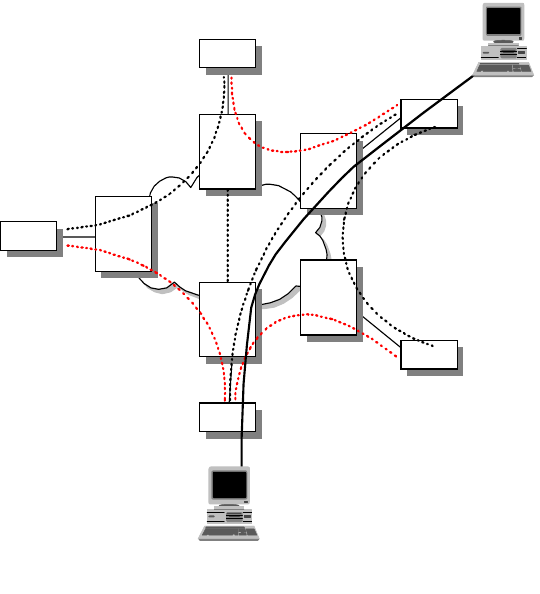
The Network Infrastructure 37
Figure 13. Frame Relay Network
There are three important concepts in frame relay that you need to know:
• Data link connection identifier (DLCI)
The DLCI is just like the MAC address equivalent in a LAN environment. Data
is encapsulated by the router in the frame relay frames and delivered through
the network based on the DLCI. The DLCI can have a local or a global
significance, both uniquely identify a communication channel.
Traffic destined for or originating from each of the partnering endstations is
multiplexed, carrying different DLCIs, on the same user-network interface. The
DLCI is used by the network to associate a frame with a specific virtual circuit.
The Address Field is either two, three or four octets long. The default frame
relay address field used by most implementations, is a two octet field. The
DLCI is a multiple bit field of the address field and whose length depend on the
address field length.
• Permanent virtual circuits (PVC)
The PVCs are predefined paths through the frame relay network that connect
two end systems to each other. They are logical paths in the network identified
locallybytheDLCIs.
As part of a subscription option, the bandwidth for PVCs is pre-allocated and
charge is imposed regardless of traffic volume.
• Switched virtual circuits (SVC)
Unlike the PVCs, SVCs are not permanently defined in the frame relay
network. The connected terminal equipment may request for a call setup when
there is a requirement to transmit data. A few options, related to the
Router
Fast Packet
Network
Router
Router
Router
Router
Frame
Relay
Switch
Frame
Relay
Switch
Frame
Relay
Switch
Frame
Relay
Switch
Frame
Relay
Switch
User A
User B
2580a\2CH3
T1
T1
T1
T1
38 IP Network Design Guide
transmission, are specified during the setup of the connection. The SVCs are
activated by the terminal equipment, such as routers connected to the frame
relay networks, and the charges applied by a public frame relay carrier are
based upon the circuit activities and are different from that of PVCs.
It is interesting to note that although regarded as a non-broadcast network,
frame relay supports the ARP protocol as well as the rest of TCP/IP routing
protocols.
Frame Relay Congestion Management
Frame relay provides a mechanism to control and avoid congestion within the
network. There are some basic concepts that need to be described:
• Forward Explicit Congestion Notification (FECN)
This is a 1-bit field that notifies the user that the network is experiencing
congestion in the direction the frame was sent. The users will take action to
relieve the congestion.
• Backward Explicit Congestion Notification (BECN)
This is a 1-bit field that notifies the user that the network is experiencing
congestion in the reverse direction of the frame. The users can slow down the
rate of delivering packets through the network to relieve the congestion.
• Discard Eligibility (DE)
This is a 1-bit field indicating whether or not this frame should be discarded by
the network in preference to other frames if there are congested nodes in the
network. The use of DE requires that everyone in the network "play the game".
In networks such as public frame relay networks, DTEs never set DE bit
because in the event of a congestion, its operation will be the first one
affected.
The congestion control mechanism ensures that no stations can monopolize the
network at the expense of others. The congestion control mechanism includes
both congestion avoidance and congestion recovery.
The frame relay network does not guarantee data delivery and relies on the
higher level protocol for error recovery. When experiencing congestion, the
network resources will inform its users to take appropriate corrective actions.
FECN/BECN bits will be set during mild congestion, while the network is still able
to transfer frames. In the event of severe congestion, frames are discarded. The
mechanism to prioritize the discarding process of frames relies on the discard
eligibility (DE) bit in the address field of the frame header. The network will start
to discard frames with the DE field set first. To avoid severe congestion from
happening, a technique called traffic shaping, by the end user systems is
deployed.
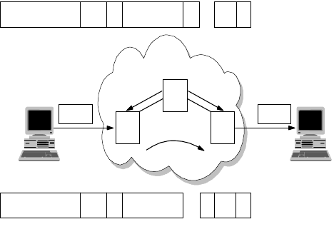
The Network Infrastructure 39
Figure 14. Frame Relay Congestion Management
Traffic Management
For each PVC and SVC, a set of parameters can be specified to indicate the
bandwidth requirement and to manage the burst and peak traffic values. This
mechanism relies on:
• Access Rate
The access rate is the maximum rate that the terminal equipment can use to
send data into the frame relay network. It is related to the speed of the access
link that connects the DTE to the frame relay switch device.
• Committed Information Rate (CIR)
The Committed Information Rate (CIR) has been defined as the amount of
data that the network is committed to transfer under normal conditions. The
rate is averaged over a period of time. The CIR is also referred to as minimum
acceptable throughput. The CIR can be set lower than or equal to the access
rate, but the DTE can send frames at a higher rate than the CIR.
• The Burst Committed (BC)
The BC is the maximum committed amount of data that a user may send to the
network in a measured period of time and for which the network will guarantee
message delivery under normal conditions.
• Burst Exceeded (BE)
The BE is the amount of data by which a user can exceed the BC during the
measured period of time. If there is spare capacity in the network, these
excess frames will be delivered to the destination. To avoid congestion, a
practical implementation is to set all these frames with the discard eligible
(DE) bit on. However, in a period of one second, the CIR plus BE rate cannot
exceed the access rate.
When circuit monitoring is enabled on the attached routers they can use CIR
and BE parameters to send traffic at the proper rate to the frame relay
network.
• Local Management Interface (LMI) Extension
The LMI is a set of procedures and messages that will be exchanged between
the routers and the frame relay switch on the health of the network through:
2580a\3CH3
BECN FECN
Congestion
A
C
Data Data
DE 1
DLCI C/R 0 DLCI (cont.) F
B
DE 1
DLCI C/R 0 DLCI (cont.)
F
B
B
40 IP Network Design Guide
• Status of the link between the connected router and switch
• Notification of added and deleted PVCs and SVCs
• Status messages of the circuits’ availability
Some of the features in LMI are standard implementations while some may be
treated as an option. Besides the status checking for the circuits, the LMI can
have optional features such as multicasting. Multicasting allows the network to
deliver multiple copies of information to multiple destinations in a network.
This is a useful feature especially when running protocols that use broadcast,
for example ARP. Also routers such as the IBM 2212 provide features such as
Protocol Broadcast which, when turned on, allows protocols such as RIP to
function across the frame relay network.
IP Encapsulation in Frame Relay
The specifications for multiprotocol encapsulation in frame relay is described in
RFC 2427. This RFC obsoletes the widely implemented RFC 1490. Changes
have been made in the formalization of the SNAP and Network Level Protocol ID
(NLPID) support, in the removed fragmentation process, address resolution in the
SVC environment, source routing BPDUs support and security enhancements.
The NLPID field is administered by ISO and the ITU. It contains values for many
different protocols including IP, CLNP, and IEEE Subnetwork Access Protocol
(SNAP). This field tells the receiver what encapsulation or what protocol follows in
a transmission.
Internet Protocol (IP) datagrams are sent over a frame relay network in
encapsulated format. Within this context, IP can be encapsulated in two different
ways: NLPID value indicating IP or NLPID value indicating SNAP. Although both
of these encapsulations are supported under the given definitions, it is
advantageous to select only one method as the appropriate mechanism for
encapsulating IP data. Therefore, IP data should be encapsulated using the
NLPID value of 0xCC indicating an IP packet. This option is more efficient
because it transmits 48 fewer bits without the SNAP header and is consistent with
the encapsulation of IP in an X.25 network.
The use of the NLPID and SNAP network layer identifier enables multiprotocol
transport over the frame relay network, thus avoiding other encapsulation
techniques either for bridged or for routed datagrams. This goal was achieved
with the RFC 1490 specifications. This multiplexing of various protocols over a
single circuit saves cost and looks attractive to network managers. But care has
to be taken so that mission-critical data is not affected by other lesser important
data traffic. Some implementations use a separate circuit to carry mission-critical
applications but a better approach is to use a single PVC for all traffic and
managing prioritization by a relatively sophisticated queuing system such as
BRS.
MTUSizeinFrameRelayNetworks
Frame relay stations may choose to support the exchange identification (XID)
specified in Appendix III of Q.922. This XID exchange allows the following
parameters to be negotiated at the initialization of a frame relay circuit: maximum
frame size, retransmission timer, and the maximum number of outstanding
information (I) frames.
The Network Infrastructure 41
If this exchange is not used, these values must be statically configured by mutual
agreement of data link connection (DLC) endpoints, or must be defaulted to the
values specified in Q.922.
There is no commonly implemented minimum or maximum frame size for frame
relay networks. Generally, the maximum will be greater than or equal to 1600
octets, but each frame relay provider will specify an appropriate value for its
network. A frame relay data terminal equipment (DTE), therefore, must allow the
maximum acceptable frame size to be configurable.
Inverse ARP
There are situations in which a frame relay station may wish to dynamically
resolve a protocol address over a PVC. This may be accomplished using the
standard ARP encapsulated within a SNAP-encoded frame relay packet.
Because of the inefficiencies of emulating broadcasts in a frame relay
environment, a new address resolution variation was developed. It is called
Inverse ARP and describes a method for resolving a protocol address when the
hardware address is already known. In a frame relay network, the known
hardware address is the DLCI. Support for Inverse ARP function is not required,
but it has proven to be useful for frame relay interface autoconfiguration.
At times, stations must be able to map more than one IP address in the same IP
subnet to a particular DLCI on a frame relay interface. This need arises from
situations involving remote access, where servers must act as ARP proxies for
many dial-in clients, each assigned a unique IP address while sharing the
bandwidth on the same DLC. The dynamic nature of such applications results in
frequent address association changes with no effect on the DLC’s status.
As with any other interface that utilizes ARP, stations may learn the associations
between IP addresses and DLCIs by processing unsolicited ARP requests that
arrive on the DLC. If one station wishes to inform its peer station on the other end
of a frame relay DLC of a new association between an IP address and that PVC,
it should send an unsolicited ARP request with the source IP address equal to the
destination IP address, and both set to the new IP address being used on the
DLC. This allows a station to "announce" new client connections on a particular
DLCI. The receiving station must store the new association, and remove any
existing association, if necessary, from any other DLCI on the interface.
IPRoutinginFrameRelayNetworks
It is common for network managers to run an IP network across a frame relay
network and there may be a need to deploy protocols that rely on a broadcast
mechanism to work. In this case, some configuration is required so that these
protocols continue to work across the frame relay network:
• OSPF over PVCs
When using a dynamic routing protocol such as Open Shortest Path First
(OSPF) over a frame relay network, the OSPF protocol has to be told about
the non-broadcast multiaccess network’s (NBMA) understanding of frame
relay. Although OSPF is usually deployed in a broadcast network, it does work
in a non-broadcast network with some configuration changes. In a
non-broadcast network, network managers have to provide a router with static
information such as the Designated Router and all the neighbors. Generally,
you need to perform the following tasks:
• Define the frame relay interface as non-broadcast.
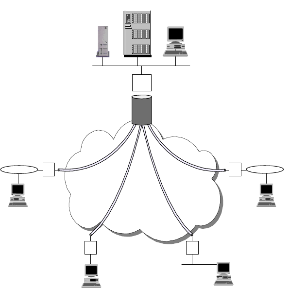
42 IP Network Design Guide
• Configure the IP addresses of the OSPF neighbors on the frame relay
network.
• Set up the router with the highest priority to become the designated router.
In most frame relay implementations, the topology is typically a star, or
so-called hub and spoke. The router at the central site has all the branches
connected to it with PVCs. Some products provide added features to simplify
the configuration for OSPF in this setup. In the IBM Nways router family, you
can use the OSPF point-to-multipoint frame relay enhancement. Network
managers just need to configure a single IP subnet for all the entire frame
relay network, instead of multiple subnets for every PVC connection. The
central router is configured to have the highest router priority so that it is
always chosen as the designated router.
Figure 15. Star Topology in a Frame Relay Network
IP Routing with SVCs
The use of SVCs in a frame relay network offers more flexibility and features such
as dial-on-demand and data path cut-through. With SVCs, network design can be
simplified and performance can be improved.
Bandwidth and cost have always been at odds when it comes to network design.
It is important to strike a balance, whereby an acceptable performance is made
available within a budget. In some cases, having permanent connectivity is a
waste of resources because information exchange takes place only at a certain
time of the day. In this case, having the ability to "dial on demand" when the
connectivity is required saves cost. The IP address of the destination is
associated with a DLCI and a call setup request is initiated when a connection to
Frame
Relay
Network
Branches
R
R R
R
Server
Host
Central
Office
R
2580a\5CH3
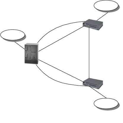
The Network Infrastructure 43
that IP address is required. After the originating workstation has sent its data, the
circuit is taken down after a certain timeout period.
Usually, remote branches are connected to the central site and there is little
requirement for them to have interconnection. Building a mesh topology using
PVCs is costly and not practical. SVCs are more suitable here because they help
to conserve network bandwidth, as well as reducing bandwidth cost. Moreover, in
a star topology configuration, inter-branches communication has to go through
the central site router, which increases the number of hops to reach the
destination.
Figure 16. SVCs in a Frame Relay Network
With SVCs, the following protocols can be implemented across the frame relay
network:
•IP
•RIP
•OSPF
•BGP-4
2.1.3.5 Serial Line IP (SLIP)
Point-to-point connections have been the mainstay for data communication for
many years. In the history of TCP/IP, the Serial Line IP (SLIP) protocol has been
the de-facto standard for connecting remote devices and you can still find its
implementation. SLIP provides the ability for two endstations to communicate
across a serial line interface and it is usually used across a low bandwidth link.
SLIP is a very simple framing protocol that describes the format of packets over
serial line interfaces and has the following characteristics:
• IP data only
As its name implies, SLIP transports only the IP protocol and the configuration
of the destination IP address is defined statically before communication
begins.
E.164
Address
=123
.17
.4
PVC
SVC
.21
E.164
Address
=456
10.0.1.20
SVC
.22
E.164
Address
=789
.18
.10
10.0.1.8
10.0.1.16
10.1.0.0
10.2.0.0
10.3.0.0
.5
.13
10.0.1.4
10.0.1.12
.6
.14
PVC
SVC
Branch B
Router
Branch C
Router
Data Center
(Router A)
2580a\6CH3
44 IP Network Design Guide
• Limited error recovery
SLIP does not provide any mechanism for error handling and recovering,
leaving all error detection responsibility to the higher level protocols such as
TCP. The checksum field of these protocols can be enough to determine the
errors that occur in noisy lines.
• Limited compression mechanism
Ironic as it may seem, the protocol itself does not provide compression,
especially for frequently used IP header fields. In the case of a TELNET
session, most of the packet headers are the same and this leads to
inefficiency in the link when too many almost identical packets are sent.
There have been some modifications to make SLIP more efficient, such as Van
Jacobson header compression, and many SLIP implementations use them.
2.1.3.6 Point-to-Point Protocol (PPP)
The Point-to-Point Protocol (PPP) is an Internet standard that has been
developed to overcome the problems associated with SLIP. For instance, PPP
allows negotiation of addresses across the connection instead of statically
defining them. PPP is a network-specific standard protocol with STD number 51.
Its status is elective and it is described in RFC 1661 and RFC 1662.
PPP implements reliable delivery of datagrams over both synchronous and
asynchronous serial lines. It also implements data compression and can be used
to route a wide variety of network protocols.
PPP has three main components:
• A method for encapsulating datagrams over serial links.
• A Link Control Protocol (LCP) for establishing, configuring and testing the
data-link connection.
• A family of Network control protocols (NCP) for establishing and configuring
different network-layer protocols. PPP is designed to allow the simultaneous
use of multiple network-layer protocols.
The format of the PPP frame is similar to the HDLC one. The Point-to-Point
Protocol provides a byte-oriented connection exchanging information and
message packets in a single format frame. The PPP Link Control Protocol (LCP)
is used to establish, configure, maintain and terminate the connection and goes
through the following phases to establish a connection:
• Link establishment and configuration negotiation
The connection for PPP is opened only when a set of LCP packets is
exchanged between the endstations’ PPP processes. Among the information
exchanged is the maximum packet size that can be carried over the link and
use of authentication. A successful negotiation leads the LCP to the Open
state.
• Link quality determination
The optional phase does not specify the policy for quality of the link but
instead provides tools such as echo request and reply.
• Authentication
The Network Infrastructure 45
The next step is going through the authentication process. Each of the end
systems is required to use the authentication protocol as agreed upon in the
link establishment stage to identify the remote peer. If the authentication
process fails the link goes to the Down state.
• Network control protocol negotiation
Once the link is open, endstations negotiate the use of various layer-3
protocols (for example, IP, IPX, DECnet, Banyan VINES and APPN/HPR) by
using the network control protocol (NCP) packets. Each layer 3 protocol has
its own associated network control protocol. For example IP has IP Control
Protocol (IPCP).
The NCP negotiation is independently managed for every network control
protocol and the specific state of the NCP (up or down) indicates if that
network protocol traffic will be carried over the link.
Authentication Protocols
PPP authentication protocols provide a form of security between two nodes
connected via a PPP link. There are different authentication protocols supported:
• Password Authentication Protocol (PAP)
PAP is described in RFC 1334. PAP provides a simple mechanism of
authentication after the link establishment. One peer sends an ID and a
password to the other peer and waits to receive an acknowledgment.
Passwords are sent in clear text and there is no encryption involved.
• Challenge/Handshake Authentication Protocol (CHAP)
CHAP is described in RFC 1994. The CHAP protocol is used to check
periodically the identity of the peer and not only at the beginning of the link
establishment. The authenticator sends a challenge message to the peer that
responds with a value calculated with a hash function. The authenticator
verifies the value of the hash function with the expected value to accept or
terminate the connection.
• Microsoft PPP CHAP (MS-CHAP)
MS-CHAP is used to authenticate Windows workstations and peer routers.
• Shiva Password Authentication Protocol (SPAP)
The SPAP is a Shiva proprietary protocol.
The authentication mechanism starts at the LCP exchange, because if one of the
end systems refuses to use an authentication protocol requested by the other the
link setup fails. Also some authentication protocols, for instance CHAP, may
require the end systems to exchange the authentication messages during
connection setup.
The Network Control Protocol (NCP)
PPP has many network control protocols (NCP) for establishing and configuring
different network layer protocols. They are used to individually set up and
terminate specific network layer protocol connections. PPP supports many NCPs
such as the following:
• AppleTalk Control Protocol (ATCP)
• Banyan VINES Control Protocol (BVCP)
• Bridging protocols (BCP, NBCP, and NBFCP)
46 IP Network Design Guide
• Callback Control Protocol
• DECnet Control Protocol (DNCP)
• IP Control Protocol (IPCP)
• IPv6 Control Protocol (IPv6CP)
• IPX Control Protocol (IPXCP)
• OSI Control Protocol (OSICP)
• APPN High Performance Routing Control Protocol (APPN HPRCP)
• APPN Intermediate Session Routing Control Protocol (APPN ISRCP)
IPCP is described in RFC 1332 and specifies some features such as the Van
Jacobson header compression mechanism or the IP address assignment
mechanism.
An endstation can either send its IP address to the peer or accept an IP address.
Moreover it can supply an IP address to the peer if the peer requests that
address. The first situation you will handle an unnumbered interface. That is that
both ends of the point-to-point connection will have the same IP address and will
be seen as a single interface. This does not create problems in the IP routing
algorithms. Otherwise the other end system of the link will be provided with its
own address.
The router will automatically add a static route directed to the PPP interface for
the address that is successfully negotiated, allowing data to be properly routed.
When the IPCP connection is ended this static route is subsequently removed.
This is a common configuration used for dial-in users.
Multilink PPP
Multilink PPP (MP) is an important enhancement that has been introduced in the
PPP extensions to allow multiple parallel PPP physical links to be bundled
together as if they were a single physical path. The implementation of multilink
PPP can accomplish dynamic bandwidth allocation and also on-demand features
to increase the available bandwidth for a single logical connection. The use of
multilink PPP is also an enhancement that can have importance in the area of
multimedia application support.
Multilink PPP is based on the fragmentation process of large frames and
rebuilding them, sequentially. When the PPP links are configured for multilink
PPP support they are said to be bundled. The multilink PPP sender is allowed to
fragment large packets and the fragmented frames are delivered with an added
multilink PPP header that basically consists of a sequence number that identifies
each fragmented packet. The multilink PPP receiver reassembles the input
packets in the correct order following the sequence numbers in the multilink PPP
header.
The virtual connection made up by multilink PPP has more bandwidth than the
original PPP link. The resulting MP bundled bandwidth is almost equal to the sum
of the bandwidths of the individual links. The advantage is that large data packets
can be transmitted within a shorter time.
The multilink PPP implementation in the Nways 221x family can accomplish both
the Bandwidth Allocation Protocol (BAP) and the Bandwidth Allocation Control
Protocol (BACP) to dynamically add and drop PPP dial circuits to a virtual link.
The Network Infrastructure 47
Multilink PPP also uses Bandwidth On Demand (BOD) to add dial-up links to an
existing multilink PPP bundle.
The multilink PPP links can be defined in two different ways:
• Dedicated link
• A dedicated link is a multilink PPP enabled interface that has been configured
as a link to a particular multilink PPP interface. If this link attempts to join
another multilink PPP bundle, it is terminated.
• Enabled link
An enabled link is simply one that is not dedicated and can become a link in
any multilink PPP bundle.
The Bandwidth Allocation Protocol (BAP) and the Bandwidth Allocation Control
Protocol (BACP) are used to increase and decrease the multilink PPP interface
bandwidth. These protocols rely on processes that when the actual bandwidth
utilization thresholds are reached they can manage to add an enabled multilink
PPP dial circuit to the MP bundle, if any is available and the negotiation process
with the partner does not fail. The dedicated links have the priority of being added
to the bundle, followed by the enabled ones.
The Bandwidth On Demand protocol (BOD) adds dial links to the MP bundle
using configured dial circuit’s telephone numbers. They are added in sequence
and lasts for the time that the bundle is in use.
Using multilink PPP needs some careful planning of the configured bundles.
Limitations exist for mixing leased lines and dial-up circuits in the same bundle.
Multilink PPP capabilities are being investigated to support multi-class functions
in order to provide a reliable data link layer protocol for multimedia traffic over low
speed links . The multilink PPP implementation in the Nways 221x router family
supports also the Multilink multi-chassis. This functionality is provided when a
remote connection can establish a layer 2 tunnel with a phone hunt group that
spans over multiple access servers (see
Access Integration Services Software
User’s Guide V3.2
, SC30-3988).
2.1.4 Asynchronous Transfer Mode (ATM)
Asynchronous transfer mode ( ATM) is a switching technology that offers high
speed delivery of information including data, voice and video. It runs at 25, 100,
155, 622 Mbps or even up to 2.4 Gbps, and is both suitable for deployment in a
LAN or WAN environment. Due to its ubiquitous nature, it can be categorized as
both a LAN or a WAN technology.
Unlike LAN technologies such as Ethernet or token-ring that transport information
in packets called frames, ATM transports information in cells. In legacy LANs,
frames can vary in size, while in ATM, the cells are of fixed size and they are all
53 bytes. ATM is a connection-oriented protocol, which means it does not use
broadcast techniques at the data link layer for delivery of information, and the
data path is predetermined before any information is sent. It offers features that
are not found in Ethernet or token-ring, one of which is called Quality of Service
(QoS). Another benefit that ATM brings is the concept of Virtual LAN (VLAN).
Membership in a group is no longer determined by physical location. Logically
similar workstations can now be grouped together even though they are all
separated.
48 IP Network Design Guide
Because ATM works differently from the traditional LAN technologies, new
communication protocols and new applications have to be developed. Before this
happens, something needs to be done to make the traditional LAN technologies
and IP applications work across an ATM network. Today, there are two standards
developed solely for this purpose:
2.1.4.1 Classical IP (CIP)
Classical IP (RFC 1577) is a way of running the IP protocol over an ATM
infrastructure. As its name implies, it supports only the IP protocol. Since ATM
does not provide broadcast service, something needs to be done to address the
mechanism for ARP, which is important in IP for mapping IP addresses to
hardware addresses. A device called the ARP server is introduced in this
standard to address this problem and all IP workstations will have to register with
the ARP server before communication can begin.
In RFC 1577, all IP workstations are grouped into a common domain called a
logical IP subnet, or LIS. And within each LIS, there is an ARP server. The
purpose of the ARP server is to maintain a table containing the IP addresses of
all workstations within the LIS and their corresponding ATM addresses. All other
workstations in a LIS are called ARP clients and they place calls, ATMARP, to the
ARP server, for the resolution of the IP address to the ATM address. After
receiving the information from the ARP server, ARP clients proceed to make calls
to other clients to establish the data path so that information can flow. Therefore,
ARP clients need to be configured with the ATM address of the ARP server before
they can operate in a CIP environment. In a large CIP network, this poses an
administrative problem if there is going to be a change in ARP server’s ATM
address. Due to this problem, it is advisable to configure the ARP server’s End
System Identifier (ESI) with a locally administered address (LSA) so that no
reconfiguration is required on ARP clients.
There is an update to the RFC, called RFC 1577+, that provides the mechanism
for multiple ARP servers within a single LIS. This is mainly to provide redundancy
to the ARP server.
Classical IP over Permanent Virtual Circuit (CIP over PVC)
There is another implementation of CIP, which is called CIP over PVC. CIP over
PVC is usually deployed over an ATM WAN connection, where the circuit is
always connected. This is typically found in service providers that operate an ATM
core switch (usually with switching capacity ranging from 50 Gbps to 100 Gbps),
with limited or no support for SVC services. In CIP over PVC, there is no need to
resolve the IP address of the destination to ATM address, as it has been mapped
statically to an ATM connection through the definition of virtual path identifier
(VPI) and virtual channel identifier (VCI) values. Because the mapping has to be
done statically, CIP over PVC is used in networks where the interconnections are
limited; otherwise, it would be an administrative burden for the network manager.
Though it may have its limitations, CIP over PVC can be a good solution to some
specific requirements. For example, if it is used to connect a remote network to a
central backbone, the network manager can set up the PVC connection in the
ATM switch to be operative only at certain times of the day. The operation of the
PVC (for example, setup and tear down) can be managed automatically by a
network management station. In this way, a network manager can limit the flow of
the remote network’s traffic to certain times of the day for security reasons or for a
specific business requirement.
The Network Infrastructure 49
Advantages of CIP
There are several advantages of using CIP, especially in the areas of
performance and simplicity:
• ATM provides higher speeds than Ethernet or token-ring
The specifications for ATM states connecting speeds of 25, 155 or even 622
Mbps. Some vendors have announced the support of link speeds of up to 2.4
Gbps. These links offer higher bandwidth than what Ethernet or token-ring can
offer.
• CIP has no broadcast traffic
Since there is no broadcast traffic in the network, the bandwidth is better
utilized for carrying information.
• Benefits of switching
All workstations can have independent conversation channels with their own
peers through the switching mechanism of ATM. This means all conversations
can take place at the same time, and the effective throughput of the network is
higher than a traditional LAN.
• Simplicity
Compared to LAN Emulation (LANE), CIP is simpler in implementation and it
utilizes fewer ATM resources, called VCs. Adding and deleting ARP clients
requires less effort than in LANE, and this makes it simpler to troubleshoot in
the event of a problem.
• Control
As mentioned in the example of CIP over PVC, traffic control can be enforced
through the setup and tear down of the PVCs. This is like giving the network
the ability to be "switched on" or "switched off".
2.1.4.2 LAN Emulation (LANE)
Unlike CIP, which provides for running only IP over ATM, LAN Emulation (LANE),
is a standard that allows multiprotocol traffic to flow over ATM. As its name
implies, LANE emulates the operation of Ethernet or token-ring so that existing
applications that run on these two technologies can operate on ATM without any
changes. It is useful in providing a migration path for the existing LAN to ATM
because it protects the investment cost in the existing applications.
The components that make up LANE are much more complicated than those in
CIP:
• LAN Emulation Configuration Server (LECS)
The LECS centralizes and disseminates information of the ELANs and LECs.
It is optional to deploy LECS, although it is strongly recommended.
• LAN Emulation Server (LES)
The LES has a rather similar job role as the ARP server in CIP. It resolves LAN
addresses to ATM addresses.
• Broadcast and Unknown Server (BUS)
The BUS is responsible for the delivery of broadcast, multicast and unknown
unicast frames.
• Lan Emulation Client (LEC)

50 IP Network Design Guide
A LEC is a workstation participating in a LANE network.
Although more complicated in terms of its implementation as opposed to CIP,
LANE enjoys some advantages in several areas:
• LANE supports multiprotocol traffic.
LANE supports all protocols and this makes migration of existing networks
easier.
• LANE supports broadcast.
However a nuisance it may be, many protocols rely on broadcast to work.
Many servers use broadcast to advertise their services or existence. Clients
use protocols such as DHCP to get their IP addresses. These services would
not be possible in a CIP environment.
• LANE provides advanced features not found in CIP
LANE provides several advanced features that are not found in CIP. One good
example is Next Hop Resolution Protocol (NHRP). With NHRP, it is possible to
improve the performance of a network through reduction in router hops.
The following table shows the difference between ATM and LAN technologies.
Table 5. Comparing ATM versus other LAN Technologies
ATM is a technology that provides a ubiquitous transport mechanism for both LAN
and WAN. In the past, LAN and WAN used different protocols to operate, such as
LAN CIP LANE
Speed (Mbps) 4/16/100/1000 25/155/622 25/155/622
Broadcast support Yes No Yes, through the
BUS
QoS No Yes Yes
Multiprotocol Yes No, only IP Yes
Shared/Dedicated
bandwidth Share/Switch Switch Switch
Transport
Data/Voice/Video
natively
No Yes Yes
Need new protocol No Yes Yes
Need new adaptor No (most PCs now
have built-in LAN
ports)
Yes Yes
Administrative
effort in installation
of client
Minimal Need to specify ARP
server’s ATM
address
CanjoinanELAN
through any
combination of the
following :
-LECSaddress
- LES/BUS address
- ELAN names
Overheads
(header vs total
packet size)
Low
(< 2%) High
(>10%) High
(> 10%)
The Network Infrastructure 51
Ethernet for LAN and ISDN for WAN. This complicates design and makes
maintaining the network costly because more protocols are involved, and
managers need to be trained on different protocols. With ATM, it is possible to
use it for both LAN and WAN connections and to make the network
homogeneous.
2.1.5 Fast Internet Access
In recent years, the number of users on the Internet has grown exponentially and
more and more users are subscribing to Internet service providers (ISPs) for
access. Most home users still connect to ISPs through an analog modem, with
initial speeds at a mediocre 9.6 kbps. With advancements in modem technology,
the speed has increased to 14.4 kbps, to 28.8 kbps, then to 33.6 kbps and finally
to 56 kbps. Some users have even signed up for ISDN services at 128 kbps or
256 kbps but these are few.
With the advent of e-commerce and multimedia rich applications proliferating on
the Internet, this "last mile" technology has proved to be a serious bottleneck.
Vendors are developing new technologies to "broaden the last mile pipe" and
there are two major technologies today that do this: the cable modem and the
xDSL technology.
These technologies, besides providing higher bandwidth for "surfers", have
opened a new door for network managers who may be looking at new
technologies for their company. With more employees working away from the
office, application design has taken a new turn. In the past, application
developers have always assumed that all users are connected via the LAN
technologies, and bandwidth is never a problem. With more and more users
working from home, application developers have now realized their application
may not run on a user’s workstation at home, because of the 28.8 kbps link at
which he or she is connected. While the company LAN has gone from 10 Mbps to
100 Mbps, and the entire corporation gears toward multimedia application
deployment, there are still some carts dragging behind. Although security may
pose a problem to the corporation, these technologies have nonetheless given
network managers some additional options in remote connectivity.
2.1.5.1 Cable Modem Network
The cable TV (CATV) infrastructure is traditionally used for the transmission of
one way analog video signals. The network infrastructure has evolved from
mostly coaxial cabling to the new Hybrid Fiber-Coaxial (HFC) network, which is
made up of a combination of fiber optic and coaxial "last mile" networks. With the
introduction of fiber optic networks and the development of new standards, the
HFC network soon became capable of two way transmission. The general
structure of a cable modem network may look like the following diagram:

52 IP Network Design Guide
Figure 17. Cable Modem and the HFC Infrastructure
The cable modem network is typically made up of high speed fiber optic
distribution rings and coaxial cabling that carry the TV signals to the subscriber’s
home. Subscribers staying in the same district are connected to a common
distribution point called a headend. The coaxial cable runs from the headend to
the homes in a tree topology and the traffic direction is predominantly from the
headend to the homes. The cable router is a specialized device that can transport
data from a data network through the CATV’s coaxial infrastructure to the homes.
It can also receive a signal from the cable modems installed in the homes and
transport it to the data network.
The subscriber’s PC is connected to the cable modem through a 10 Mbps
Ethernet Interface, so to the PC, it is exactly like connecting to a LAN. The
bandwidth of the cable modem network is asymmetric, which means the
bandwidth that is available from the headend to the subscribers (called the
downstream channel) are not the same as that in the reverse direction (called the
upstream channel). The downstream channel bandwidth ranges from 30 Mbps to
50 Mbps and all subscribers that are connected to this downstream channel
share the common bandwidth. The upstream channel ranges from 500 kbps to
800 kbps. Depending on the configuration and bandwidth requirements, a group
of subscribers can share two downstream and four upstream channels, giving a
total of 60 Mbps downstream and 2 Mbps upstream. The design of the bandwidth
distribution is such because the cable modem network is used mainly to provide
fast Internet access. And Internet access is mainly sending a few strings of
requests to a Web server for a bigger chunk of data to be displayed on a Web
browser.
Cable modem technology provides a way for fast Internet connection (easily as
100 times faster than that of analog modems) for the homes and it can possibly
be deployed for mobile workers. As a rather new technology, it has its problems
and limitations:
• Interference
Internet
CATV
Source
cm = Cable Modem
cm
cm
cm
Cable
Router
Data
Network
Backbone
HFC
2580B\CH2F08
The Network Infrastructure 53
The tree-like topology of the coaxial cable runs acts just like a big TV antenna.
It receives a lot of outside signals and is easily influenced by electromagnetic
interference. This characteristic affects especially the quality of the upstream
data and is not an easy problem to solve. Corrupted upstream data means
there will be lots of retries from the subscriber’s PC and may result in
application termination.
• Shared Network
The cable modem subscribers basically participate in an Ethernet network. All
subscribers share the same downstream bandwidth and they compete for the
same upstream bandwidth. For network managers considering deploying
cable modem technology, this will have to be taken into consideration.
• Technology not readily available
Implementing a cable modem network requires substantial investment from
the cable company in terms of upgrading the infrastructure and purchasing
new equipment. In the first place, not all areas have HFC infrastructures in
place and it may take some time before some homes get cable modem
connections.
• Standards
Many different standards that deal with implementing cable modem exist today
and one is different from the other. To name a few:
• Multimedia Cable Network System (MCNS)
• Digital Video Broadcasting (DVB)
• IEEE 802.14
These different standards make interoperability difficult and cable companies
may not want to deploy cable modem on a large scale.
2.1.5.2 Digital Subscriber Line (DSL) Network
The digital subscriber line (DSL) technology is a way of transporting data over a
normal phone line at a higher speed than the current analog modem. The term
xDSL is usually used because there are several standards to it:
• Asymmetric Digital Subscriber Line (ADSL)
• High-Speed Digital Subscriber Line (HDSL)
• Variable Digital Subscriber Line (VDSL)
The xDSL technology is capable of providing a downstream bandwidth of 30
Mbps and an upstream bandwidth of around 600 kbps. But in commercial
deployment, it is usually 1.5 Mbps downstream and maybe 256 kbps upstream.
Subscribers of xDSL technology are connected to a device called a MUX in a
point-to-point manner. The MUX aggregates a number of subscribers (usually 48,
some may go as high as 100) and has an uplink to a networking device, typically
aswitch.
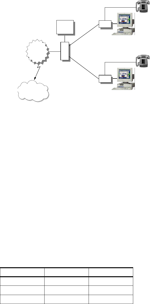
54 IP Network Design Guide
Figure 18. The xDSL Network
An interesting point to note is that, unlike a conventional analog modem, a
subscriber can still use the phone while the xDSL modem is in use. This is
because the signaling used by the xDSL modem is of a different frequency from
that used by the phone. The subscriber’s PC is connected to the modem through
an Ethernet or ATM interface. For connection through the ATM interface, CIP is
commonly used.
The xDSL technology is positioned as a competitor to the cable modem network
because both of these are competing for the same market - home Internet users.
Although mainly used for connecting home users, there are already some
companies experimenting with using xDSL for connections to the head office.
The deployment of xDSL technology was not a smooth one in the beginning due
to its severe limitations on distance. Early subscribers had to be living near the
telephone exchanges. With improvements in the technology and the deployment
of other equipment, the distance problem has slowly been resolved.
2.1.5.3 Cable Modem versus xDSL
Both the cable modem and xDSL technologies provide a "fat pipe" to subscriber
homes. While the intent is to provide fast Internet access to the subscribers,
many service providers have begun testing new technologies such as Video On
Demand and VPN services.
There are some differences between the cable modem and the xDSL technology
and they can be summarized as follows:
Table 6. Comparing High-Speed Internet Access Technologies
Cable Modem xDSL
Topology Tree Point-to-point
Infrastructure Cable TV Phone
Connectivity at PC Ethernet Ethernet/ATM
Internet
Data
Network
Backbone
M
V
X
POTS
2580B\CH2F09
ADSL
ADSL

The Network Infrastructure 55
Network managers planning to consider these technologies have to think about
the following:
•Cost
Cable companies usually charge a flat rate for cable modem services. That
means the modem can be left on all the time and communication takes place
as and when required. Phone companies usually charge xDSL service on a
duration basis, although there may be exceptions. Network managers have to
evaluate the need for constant connections versus the cost so as to make an
appropriate choice.
• Security
All the subscribers to both cable modem and xDSL networks are in a common
network. That means the network manager will have to design a security
framework so that legitimate company employees can get access to the server
while keeping intruders out of the company resource.
• Reliability
Reliability is a concern here, especially with the cable modem network.
Because it is subject to interference, it may not meet the requirements for a
reliable connection.
2.1.6 Wireless IP
Mobility has always been the key to success for many companies. Without doubt,
mobile communication will be a key component of a company’s network
infrastructure in the next few years. Much research and development has been
done on wireless communication, and in fact, wireless communication has been
around for quite some time. With the popularity of the Internet, many
developments have focused on delivering IP across a mobile network.
For many years, one of the problems with wireless communication has been the
adoption of standards and speed. But things are changing with the approval of
the IEEE 802.11 standard for wireless networks. It specifies a standard for
transmitting data over a wireless network at up to 2 Mbps or even at a higher rate
Bandwidth Users share a
common
downstream (e.g. 30
Mbps)
Point-to-Point
connection to the
MUX, usually at 1-3
Mbps
Connection Continuous (due to
cheap charging
scheme)
May not be
Continuous (due to
duration based
charging)
Availability Only to houses with
CATV wiring To houses with
phone lines
Wide spread use Limited Very limited
Potential for
business use Not really. Not all
business addresses
have CATV wiring
A viable alternative
Charge scheme Usually flat rate Flat/Duration based
Cable Modem xDSL
56 IP Network Design Guide
in the future. IEEE 802.11 uses the 2.4 GHz portion of the radio frequency. Some
research groups have even begun experimenting with a higher transmission rate
at a different frequency.
With the adoption of the IEEE 802.11 standard and vendors producing proven
products, you may have to give a wireless network serious thought. Here are
some reasons why:
• Cost saving - since wireless uses radio frequency for transmission, there is no
need to invest in permanent wiring.
• Mobility - since users are no longer tied to the physical wiring, they can have
flexibility in terms of their movement. They can still get connected to the
network as long as they are within certain range of the transmitting station.
• Ad hoc network - there may be times when an ad hoc network is required, for
example, expedition in the field. Deploying wireless technology makes sense
in this environment without incurring the cost of fix wiring.
• Competitiveness - having a mobile work force is important to some businesses
but at this time, most mobile workers still rely on phone lines for
communication. Using wireless technology is like having the last shackle
removed from the mobile workers. It makes them truly independent, but at the
same time, access to data is never an issue. One good example of such
worker is an insurance agent. With wireless technology, an agent can provide
service to his/her client anywhere, but he/she still has access to vital product
information regardless of the availability of LAN points or phone lines.
• Extreme environment - in a certain extreme environment, for example,
command and control center during a war, wireless technology may be the
only viable technology.
Wireless IP is a relatively new field to many network managers. It is important for
network managers to begin exploring it as it is set to become more popular as
there is an increase in mobile workers and the introduction of field proven
products.
2.1.6.1 Cellular Digital Packet Data (CDPD)
Cellular digital packet data (CDPD) is a way of transmitting an IP packet over a
cellular phone network. With the increase in popularity of the personal digital
assistant (PDA), many vendors are developing products as an add-on to the PDA
to enable users to connect to a mobile network. Since the connection is still slow,
at 19.2 kbps, it is mainly used for e-mail exchange and text-based information
dissemination. CDPD products are usually a modem that fits to the PDA and
provides basic TCP/IP services such as SLIP or PPP protocol.
The advantage of CDPD is of course mobility. No longer is a user tied to the
physical connection of a LAN. Information is readily available, and users need not
even look for a phone line anymore. With companies putting more workers on the
road, it is an important area that network managers should start looking into.
As a new technology, besides the maturity of standards and products, there are
several concerns that network managers should look into also. CDPD is capable
of sending data at 19.2 kbps. Taking into account the adding of a header for
reliable transmission, the actual data transfer rate is more like 9.6 kbps. With a
transmission rate like this, it is only the important text data that is transmitted.
Graphics or multimedia applications are almost out of the question. Also, one of

The Network Infrastructure 57
the most important aspects of mobile networks is of course security. Some area
that need special attention include:
• Data security
• User authentication
• Impersonation
Also, deploying CPDP technology in a network involves subscribing the service
from a service provider. This translates to extra cost involved and may not be
cheap for a company with several thousand employees. Last but not least, mobile
communication is subject to interference and failures such as poor transmission
power due to a low battery or over long distance. Error recovery becomes very
important in situations like these, and should be both at the network layer as well
as the application layer.
2.2 The Connecting Devices
A network can be as simple as two users sharing information through a diskette
or as complex as the Internet that we have today. The Internet is made up of
thousands of networks interconnected through devices called hubs, bridges,
routers and switches. These devices are the building blocks of a network and
each of them performs a specific task to deliver the information that is flowing in
the network. Some points to be considered as to which device is the most
appropriate one to implement are:
• Complexity of the requirement
If the requirement is just to extend the network length to accommodate more
users, then a bridge will do the job.
• Performance requirement
With the advent of multimedia applications, more bandwidth is required to be
made available to users. A switch, in this case, is a better choice than a hub
for building a network.
• Specific business requirement
Sometimes, a specific business requirement dictates a more granular control
of who can access what information. In this type of situation, a router may be
required to perform sophisticated control of information flow.
• Availability of expertise
Some devices require very little expertise to operate. A bridge is a simpler
device to operate than a router.
•Cost
Ultimately, cost is an important decision criterion. When all devices can have
done the job, the one with the least cost will usually be selected.
The connecting devices function at different layers of the OSI model, and it is
important to know this so that a choice can be made in using them.
2.2.1 Hub
A hub is a connecting device that all end workstations are physically connected
to, so that they are grouped within a common domain called a network segment.
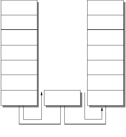
58 IP Network Design Guide
A hub functions at the physical layer of the OSI model; it merely regenerates the
electrical signal that is produced by a sending workstation, and is also known as
a repeater. It is a shared device, which means if all users are connected to a 10
Mbps Ethernet hub, then all the users share the same bandwidth of 10 Mbps. As
more users are plugged into the same hub, the effective average bandwidth that
each user has decreases. The number of hubs that you can use is also
determined by the chosen technology.
Ethernet, for instance, has specific limitations in the use of hubs in terms of
placement, distance and numbers. It is important to know the limitations so that
the network can work within specifications and not cause problems.
Figure 19. Hub Functions at the Physical Layer of the OSI Model
Most, if not all, of the hubs available in the market today, are plug and play. This
means very little configuration is required and probably everything works allright
after it is unpacked from the box. With the increasing numbers of small offices
and e-commerce, Ethernet hubs have become a consumer product. With these
hubs selling at a very low price and all performing a common function, the one
important buying decision is the price per port.
2.2.2 Bridge
A bridge is a connecting device that functions at the data link layer of the OSI
model. The primary task of a bridge is to interconnect two network segments so
that information can be exchanged between the two segments.
2580B\CH2F10
Network
Datalink
Transport
Presentation
Session
Application
Physical Physical
Hub
Network
Datalink
Transport
Presentation
Session
Application
Physical
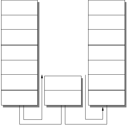
The Network Infrastructure 59
Figure 20. Bridge Functions at the Data Link Layer of the OSI Model
A bridge basically stores a packet that comes into one port, and when required to,
forwards it out through another port. Thus, it is a store-and-forward device. When
a bridge forwards information, it only inspects the data link layer information
within a packet. As such, a bridge is generally more efficient than a router, which
is a layer-3 device. The reasons for using a bridge can be any of the following:
• To accommodate more users on a network
Networks such as token-ring allow only 254 hosts to be in a single network
segment, and any additional hosts need to be in another network segment.
• To improve the performance of a network
A bridge can be used to separate a network into two segments so that
interference, such as collisions, can be contained within a certain group of
users, allowing the rest to continue to communicate with each other
undisturbed.
• To extend the length of a network
Technologies such as Ethernet specify certain maximum distances for a LAN.
A bridge is a convenient tool to extend the distance so that more workstations
can be connected.
• To improve security
A bridge can implement what is called MAC filtering, that is, selectively
allowing frames from certain workstations to pass through it. This manner
allows network managers to control access to certain information or hosts.
• To connect dissimilar networks
A bridge can also be used to connect two dissimilar networks such as one
Ethernet and one token-ring segment.
Because there are a variety of reasons for using a bridge, bridges are classified
into various categories for the functions they perform:
Datalink
2580B\CH2F11
Network
Datalink
Transport
Presentation
Session
Application
Physical Physical
Network
Datalink
Transport
Presentation
Session
Application
Physical
Bridge
60 IP Network Design Guide
• Transparent bridge
A transparent bridge is one that forwards traffic between two adjacent LANs
and it is unknown to the endstations, hence the name transparent. A
transparent bridge builds a table of MAC addresses of the workstations that it
learns and decides whether to forward a packet from the information. When
the bridge receives a packet, it checks its table to see the packet’s destination.
If the destination is on the same LAN segment as where the packet comes
from, the packet is not forwarded. If the destination is different from where the
packet comes from, the packet is forwarded. If the destination is not in the
table, the packet is forwarded to all interfaces except the one that the packet
comes from. Transparent bridges are used mainly in Ethernet LANs.
• Source route bridge
A source route bridge is used in token-ring networks whereby the sending
workstation decides on the path to get to the destination. Before sending
information to a destination, a workstation has to decide what the path should
be. The workstation does this by sending out what is known as an explorer
frame, and builds its forwarding path based on information received from the
destination.
• Source route transparent (SRT) bridge
A source route transparent (SRT) bridge is one that performs source routing
when source routing frames with routing information are received and
performs transparent bridging when frames are received without routing
information. The SRT bridge forwards transparent bridging frames without any
conversions to the outgoing interface, while source routing frames are
restricted to the source routing bridging domain. Thus, transparent frames are
able to reach the SRT and transparent bridged LAN, while the source routed
frames are limited only to the SRT and source route bridged LAN.
• Source routing - Transparent bridge (SR-TB)
In the SRT model, source routing is only available in the adjacent token-ring
LANs and not in the transparent bridge domain. A source routing-transparent
bridge (SR-TB) overcomes this limitation and allows a token-ring workstation
to establish a connection across multiple source route bridges to a workstation
in the transparent bridging domain.
Another way of classifying bridges is to divide them into local and remote bridges.
While a local bridge connects two network segments within the same building,
remote bridges work in pairs and connect distant network segments together.
A bridge is a good tool to use because it is simple and requires very little
configuration effort. With its simplicity, it is very suitable to be used in an
environment where no networking specialist is available on site. Because it only
inspects the data link layer information, a bridge is truly a multiprotocol
connecting device.
2.2.3 Router
As mentioned earlier, a router functions at layer 3 of the OSI model, the network
layer. A router inspects the information in a packet pertaining to the network layer
and forwards the packet based on certain rules. Since it needs to inspect more
information than just the data link layer formation in a packet, a router generally
needs more processing power than a bridge to forward traffic. However different
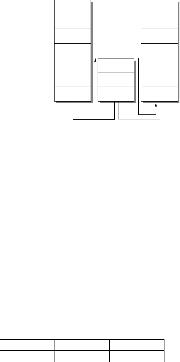
The Network Infrastructure 61
in the way they inspect the information in a packet, both router and bridge attain
the same goal: that of forwarding information to a designated destination.
Figure 21. Router Functions at the Router Layer of the OSI Model
A router is an important piece of equipment in an IP network as it is the
connecting device for different groups of networks called IP subnets. All hosts in
an IP network have a unique identifier called the IP address. The IP address is
made up of two parts called the network number and the host number. Hosts
assigned with different network numbers are said to be in different subnets and
have to be connected through an intermediate device, the router, before they can
communicate. The router, in this case, is called the default gateway for the hosts.
All information exchanged between two hosts in different subnets has to go
through the router.
The reasons for using a router are the same as those mentioned for using a
bridge. Since a router inspects more information within a packet than a bridge, it
has more powerful features in terms of making decisions based on protocol and
network information such as the IP address. With the introduction of a more
powerful CPU and more memory, a router can even inspect information within a
packet at a higher layer than the network layer. As such, new generation routers
can perform tasks such as blocking certain users from accessing such functions
as FTP or TELNET. When a router performs that function, it is said to be
filtering
.
A router is also used often to connect remote offices to a central office. In this
scenario, the router located in the remote office usually comes with a port that
connects to the local office LAN, and a port that connects to the wide area
service, such as an ISDN connection. At the central office, there is a higher
capacity router that supports more connection ports for remote office
connections.
Table 7. Comparing Bridges and Routers
Bridge Router
OSI layer Data Link Network
Network
Datalink
2580B\CH2F12
Network
Datalink
Transport
Presentation
Session
Application
Physical Physical
Network
Datalink
Transport
Presentation
Session
Application
Physical
Router

62 IP Network Design Guide
Because a router is such a powerful device, it is difficult to configure and usually
requires trained personnel to do the job. It is usually located within the data
center and costs more than a bridge. Although the reasons for using a router can
be the same as those mentioned for a bridge, some of the reasons for choosing a
router over a bridge are:
• Routers can contain broadcast traffic within a certain domain so that not all
users are affected.
• Routers can do filtering when security at a network or application level is
required.
• Routers can provide sophisticated TCP/IP services such as data link switching
(DLsW).
• Routers can provide congestion feedback at the network layer.
• Routers has much more sophisticated redundancy features.
2.2.4 Switch
A switch functions at the same OSI layer as the bridge, the data link layer. In fact,
a switch can be considered a multi-port bridge. While a bridge forwards traffic
between two network segments, the switch has many ports, and forwards traffic
between those ports.
One great difference between a bridge and a switch is that a bridge does its job
through software functions, while a switch does its job through hardware
implementation. Thus, a switch is more efficient than a bridge, and usually costs
Suppress Broadcast No Yes
Supports
fragmentation of
frames
No Yes
Cost
(relative to each
other)
Cheap Expensive
Need trained
personnel May not Yes
Filtering level MAC MAC, network
protocol, TCP port,
application level
Congestion
feedback No Yes
Used to connect
multipleremotesites No (only one) Yes
Redundancy Through spanning
tree protocol Through more
sophisticated
protocol such as
OSPF
Link failure
recovery Slow Fast
Bridge Router
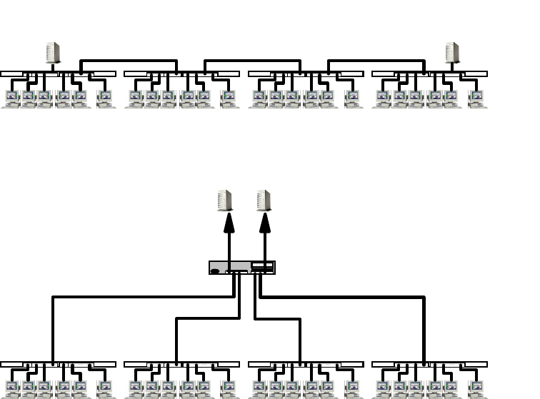
The Network Infrastructure 63
more. While the older generation switches can work only in store-and-forward
mode, some new switches, such as the IBM 8275-217, offer a new feature called
cut-through mode
whereby a packet is forwarded even before the switch has
received the entire packet. This greatly enhances the performance of the switch.
Later, a new method called
adaptive cut-through mode
was introduced whereby
the switch operates in cut-through mode and falls back to store-and-forward mode
if it discovers that packets are forwarded with CRC errors. A switch that has a
switching capacity of the total bandwidth required by all the ports is considered to
be
non-blocking
which is an important factor in choosing a switch.
Switches are introduced to partition a network segment into smaller segments, so
that broadcast traffic can be reduced and more hosts can communicate at the
same time. This is called microsegmentation, and it increases the overall network
bandwidth without doing major upgrade to the infrastructure.
Figure 22. Microsegmentation
Virtual LAN (VLAN)
With hardware prices falling and users demanding more bandwidth, more
segmentation is required and the network segments at the switch ports get
smaller until one user is left on a single network segment. More functions are also
added, one of which is called Virtual LAN (VLAN). VLAN is a logical grouping of
endstations that share a common characteristic. At first, endstations were
grouped by ports on the switch, that is, endstations connected to a certain port
belonged to the same group. This is called port-based VLAN. Port-based VLAN is
static because the network manager has to decide the grouping so that the switch
can be configured before putting it to use. Later, enhancements were made so
that switches can group endstations not by which ports they connect to, but by
which network protocol they run, such as IP or IPX. This is called a protocol
VLAN or PVLAN. Even recently, more powerful features were introduced whereby
Typical
10BaseTImplementation
Repeaters
Server Server
Switched Ethernet Replacement Using
Microsegmentation Server Server
IBM
20 Mbps
8271
20 Mbps
Repeaters
10
Mbps
10
Mbps
10 Mbps 10 Mbps
64 IP Network Design Guide
the grouping of users is done on the basis of the IP network address. The
membership of an endstation is not decided until it has obtained its IP address
dynamically from a DHCP server.
It is worthy to note that when there are multiple VLANs created within a switch,
inter-VLAN communication can be achieved only through a bridge, which is
usually made available within the switch itself, or an external router. After all,
switches at this stage are still a layer-2 device.
As hardware gets more powerful in terms of speed and memory, more functions
have been added to switches, and a new generation of switches begins to appear.
Some switches begin to offer functions that were originally found only in routers.
This makes inter-VLAN communication possible without an external router for
protocols such as TCP/IP. This is what is called
layer-3 switching
, as opposed to
the original, which was termed
layer-2 switching
.
Advantages of VLAN
The introduction of the concept of VLANs created an impact on the network
design, especially with regard to physical connectivity. Previously, users who are
connected to the same hub belonged to the same network. With the introduction
of switches and VLANs, users are now grouped logically instead of their physical
connectivity. Companies are now operating in a dynamic environment:
departmental structures change, employee movements, relocations and mobility
can only be supported by a network that can provide flexibility in connectivity.
VLAN does exactly that. It gives the network the required flexibility to support the
logical grouping independent of the physical wiring.
Because the forwarding of packets based on layer 2 information (what a bridge
does) and layer 3 information (what a router does) is done at hardware speed, a
switch is more powerful than a bridge or a router in terms of forwarding capacity.
Because it offers such a rich functionality at wire speed, more and more switches
are being installed in corporate networks, and it is one of the fastest growing
technologies in connectivity. Network managers have begun to realize that with
the increase in the bandwidth made available to users, switching might be the
way to solve network bottleneck problem, as well as to provide a new
infrastructure to support a new generation of applications. Vendors begin to
introduce new ways of building a network based on these powerful switches. One
of them, Switched Virtual Networking (SVNz) is IBM’s way of exploiting the
enormous potential of a switching network in support of business needs.
2.2.4.1 LAN Switches
LAN switches, as the name implies, are found in a LAN environment whereby
users get connected to the network. They come in different sizes, mainly based
on the number of ports that they support. Stackable LAN switches are used for
workgroup and low density connections and they are usually doing only layer-2
switching. Because of their low port density, they can be connected to each other
(hence stackable) through their switch port to form a larger switching pool. Many
other features are also added so that they can support the ever increasing need
from the users. Among the features that are most wanted are the following:
• Link aggregation
Link aggregation is the ability to interconnect two switches through multiple
links so as to achieve higher bandwidth and fault tolerance in the connection.
For example, two 10 Mbps Ethernet switches may be connected to each other
The Network Infrastructure 65
using two ports on each switch so as to achieve a dual link configuration that
provides redundancy, in case one link fails, as well as a combined bandwidth
of 20 Mbps between them.
• VLAN tagging/IEEE 802.1Q
VLAN tagging is the ability to share membership information of multiple
VLANs across a common link between two switches. This ability enables
endstations that are connected to two different switches but belong to the
same VLAN to communicate with each other as if they were connected to the
same switch. IEEE 802.1Q is a standard for VLAN tagging and many switches
are offering this feature.
• Multicast support/IGMP snooping
Multicast support, better known as IGMP snooping, allows the switch to
forward traffic only to the ports that require the multicast traffic. This greatly
reduces the bandwidth requirement and improves the performance of the
switch itself.
2.2.4.2 Campus Switches
As LAN switches get more powerful in terms of features, their port density
increases as well. This gives rise to bigger LAN switches, called campus
switches, that are usually deployed in the data center. Campus switches are
usually layer-3 switches, with more powerful hardware than the LAN switches,
and do routing at the network layer as well. Because of their high port density,
they usually have higher switching capacity and provide connections for LAN
switches. Campus switches are used to form the backbone for large networks
and usually provide feeds to even higher capacity backbones, such as an ATM
network.
2.2.4.3 ATM Switches
Because ATM technology can be deployed in a LAN or WAN environment,
many different types of ATM switches are available:
•ATMLANswitch
The ATM LAN switch is usually a desktop switch, with UTP ports for the
connection of 25 Mbps ATM clients. It usually comes with a higher
bandwidth connection port, called an uplink, for connection to higher end
ATM switches that usually run at 155 Mbps.
• ATM Campus Switch
The ATM campus switch is usually deployed in the data center and is for
concentrating ATM uplinks from the smaller ATM switches or LAN switches
with ATM uplink options. The ATM campus switch has high concentration of
ports that runs in 155 Mbps and maybe a few with 622 Mbps.
•ATMWANswitch
The ATM WAN switch, also called broadband switch, is usually deployed in
large corporations or Telcos for carrying data on wide area links and
support ranges from very low to high-speed connections. It can connect to
services such as frame relay and ISDN, or multiplex data across a few links
by using the technology called Inverse Multiplexing over ATM.
As switches develop over time, it seems apparent that switching is the way to
build a network because it offers the following advantages:
66 IP Network Design Guide
•Itisfast
With its hardware implementation of forwarding traffic, a switch is faster
than a bridge or a router.
•Itisflexible
Due to the introduction of VLANs, the grouping of workstations now is no
longer limited by their physical locations. Instead, workstations are grouped
logically, whether or not they are located within the same location.
• It offers more bandwidth
As opposed to a hub that provides shared bandwidth to the endstations, a
switch provides dedicated bandwidth to the endstations. More bandwidth is
introduced to the network without a redesign. With dedicated bandwidth, a
greater variety of applications, such as multimedia, can be introduced.
• It is affordable
The prices for LAN switches have been dropping with advances in hardware
design and manufacturing. In the past, it was normal to pay about $500 per
port for a LAN switch. Now, vendors are offering switches below $100 per port.
With vendors offering a wide array of LAN switches at different prices, it is difficult
for a network manager to select an appropriate switch. However, there are a few
issues that you should consider when buying a LAN switch:
• Standards
It is important to select a switch that supports open standards. An open
standards-based product means there is a lesser chance of encountering
problems in connecting to another vendor’s product, if you need to.
• Support for Quality of Service (QoS)
The switching capacity, the traffic control mechanism, the size of the buffer
pool and the support for multicast traffic are all important criteria to ensure
that the switch can support the demand for the QoS network.
• Features
Certain standard features have to be included because they are important in
building a switched network. These include the support for the 801.D spanning
tree protocol, SNMP protocol and remote loading of the configuration.
• Redundancy
This is especially important for the backbone switches. Because backbone
switches concentrate the entire company’s information flow, a downed
backbone switch means the company is paralyzed until the switch is back up
again. Hardware redundancy, which includes duplicate hardware as well as
hot-swappability, helps to reduce the risk and should be a deciding factor in
choosing a backbone switch.
• Management capability
It is important to have a management software that makes configuration and
changes easy. Web-based management is a good way of managing the
devices because it means that what you need is just a browser. But
Web-based management usually accomplishes a basic management task
such as monitoring and does not provide sophisticated features. You may
need a specialized management software to manage your switches.

The Network Infrastructure 67
2.3 ATM Versus Switched High-Speed LAN
One of the most debated topics in networking recently is the role of ATM in an
enterprise network.
ATM was initially promoted as the technology of choice from desktop connections,
to backbone and the WAN. It was supposed to be the technology that would
replace others and unify all connecting protocols. The fact is, this is not
happening, and will not happen for quite some time.
ATM is a good technology but not everybody needs it. Its deployment has to be
very selective and so far, it has proven to be an appropriate choice for some of
the following situations:
• When there is a need for image processing, for example, in a hospital network
where X-ray records are stored digitally and need to be shared electronically
• In a graphics intensive environment, such as a CAD/CAM network, for use in
design and manufacturing companies
• When there is a need to transport high quality video across the network, such
as advertising companies involved in video production
• When there is a need to consolidate data, voice and video on a single network
to save cost on WAN connections
The ATM technology also has its weak points. Because it transports cells in a
fixed size of 53 bytes, and with its 5-byte header, it has a considerable high
overhead. With more and more PCs pre-installed with a LAN port, adopting ATM
technology to the desktops means having to open them up and install an ATM
NIC. You also need an additional driver for using the ATM NIC. For network
managers who are not familiar with the technology, the LES, BUS, LECS, VCs,
VCCs and other acronyms are just overwhelming.
While some vendors are pushing very hard for ATM’s deployment, many network
managers are finding that their good old LANs, though crawling under heavy load,
Beware of Those Figures
It is important to find out the truth about what vendors claim on the
specification of their products. It is common to see vendors claiming their
switches have an astronomical 560 Gbps switching throughput. Vendors
seem to have their own mathematics when making statements like this and
this is usually what happens:
Let’s say they have a chassis-based backbone switch that can support one
master module with 3 Gbps switching capacity, and 10 media modules each
with 3 Gbps switching capacity. They will claim that their backbone switch is
(3+10x3) which is 33, multiply by 2 because it supports duplex operation,
and voila, you have a 66 Gbps switch. What the vendor did not tell is that all
traffic on all media modules has to pass through the master module, which
is like acting as a supervisor. In fact, the switch at most can provide 6 Gbps
switching capacity, if you agree that duplex mode does provide more
bandwidth.

68 IP Network Design Guide
are still relevant. The reasons for feeling so are none other than the legacy LANs’
low cost of ownership, familiarity with the technology and ease of implementation.
While some may still argue on the subject of which is better, others have found a
perfect solution to it: combining both technologies. Many have found that ATM as
a backbone, combined with switched LANs at the edge, provides a solution that
has the benefits of both technologies.
As a technology for backbones, ATM provides features such as PNNI, fast
reroute, VLAN capabilities and high throughput to act as a backbone that is both
fast and resilient to failure. The switched LAN protects the initial investment on
the technologies, continues to keep connections to the desktop affordable, and
due to their sheer volume, makes deployment easy.
It is important to know that both ATM and switched LANs solve the same problem:
the shortage of bandwidth on the network. Some have implemented networks
based entirely on ATM and have benefited from it. Others have stayed away from
it because it is too difficult. It is important to know how to differentiate both
technologies, and appreciate their implications to the overall design.
2.4 Factors That Affect a Network Design
Designing a network is more than merely planning to use the latest gadget in the
market. A good network design takes into consideration many factors:
2.4.1 Size Matters
At the end of the day, size does matter. Designing a LAN for a small office with a
few users is different from building one for a large company with two thousand
users. In building a small LAN, a flat design is usually used, where all connecting
devices may be connected to each other. For a large company, a hierachical
approach should be used.
2.4.2 Geographies
The geographical locations of the sites that need to be connected are important
in a network design. The decision making process for selecting the right
technology and equipment for remote connections, especially those of
cross-country nature, is different from that for a LAN. The tariffs, local expertise,
quality of service from service providers, are some of the important criteria.
2.4.3 Politics
Politics in the office ultimately decides how a network should be partitioned.
Department A may not want to share data with department B, while department C
allows only department D to access its data. At the network level, requirements
such as these are usually done through filtering at the router so as to direct traffic
flow in the correct manner. Business and security needs determine how
information flows in a network and the right tool has to be chosen to carry this
out.
2.4.4 Types of Application
The types of application deployed determines the bandwidth required. While a
text-based transaction may require a few kbps of bandwidth, a multimedia help
The Network Infrastructure 69
file with video explanations may require 1.5 Mbps of bandwidth. The performance
requirement mainly depends on application need and the challenge of a good
network is to be able to satisfy different application needs.
2.4.5 Need For Fault Tolerance
In a mission-critical network, performance may not be a key criteria but fault
tolerance is. The network is expected to be up every minute and the redundancy
required is both at the hardware level and at the services level. In this aspect,
many features have to be deployed, such as hardware redundancy, re-route
capabilities, etc.
2.4.6 To Switch or Not to Switch
One of the factors that influences the network design is whether to deploy
switching technology. Although switching seems to be enjoying popularity, it may
not be suitable in terms of cost for a small office of four users. In a large network
design, switching to the desktop may not be suitable because it would drive up
the entire project cost. On the other hand, a small company that designs
multimedia applications for its client may need a switching network to share all
the video and voice files. The decision a network manager has to make is when to
switch and where to switch.
2.4.7 Strategy
One important factor is of course a networking strategy. Without a networking
blueprint, one may end up with a multivendors, multiprotocol network that is both
difficult to manage and expand. It has been estimated that 70% of the cost of
owning a network is in maintaining it. Having a network strategy ensures that
technology is deployed at the correct place and products chosen carefully. A
network that is built upon a strategy ensures manageability and scalability.
2.4.8 Cost Constraints
The one major decision that makes or breaks a design is cost. Many a times,
network managers have to forego a technically elegant solution for a less
sophisticated design.
2.4.9 Standards
Choosing equipment that conforms to standards is an important rule to follow.
Standards means having the ability to deploy an industry-recognized technology
that is supported by the majority of vendors. This provides flexibility in choice of
equipment, and allows network managers to choose the most cost effective
solution.
As more business and transactions are conducted through the network, the
network infrastructure has become more important than ever. Network managers
need to choose the right technologies, from the backbone to the desktops, and tie
everything together to support the needs of their businesses. By now, it is obvious
that designing a network is not just about raw speed. Adopting a balanced
approach, weighing features against cost, and choosing the right technology that
is based on open standards to meet the business requirement is a right way to
begin.
70 IP Network Design Guide

© Copyright IBM Corp. 1995 1999 71
Chapter 3. Address, Name and Network Management
An IP network has two very important resources, its IP addresses and the
corresponding naming structure within the network. To provide effective
communication between hosts or stations in a network, each station must
maintain a unique identity. In an IP network this is achieved by the IP address.
The distribution and management of these addresses is an important
consideration in an IP network design.
IP addresses are inherently not easy to remember. People find it much easier to
remember names and have these names related to individual machines
connected to a network. Even applications rarely refer to hosts by their binary
identifiers, in general they use ASCII strings such as polo@itso.ibm.com. These
names must be translated to IP addresses because the network does not utilize
identifiers based on ASCII strings. The management of these names and the
translation mechanism used must also be considered by the IP network designer.
After the network has been designed and implemented, it must be managed.
Traffic flow, bottlenecks, security risks and network enhancements must be
monitored. Systems for this type of management are available and should be
incorporated in the IP network’s initial design, so as to avoid many headaches
with ad hoc processes coupled together at a later date.
3.1 Address Management
As mentioned previously, the distribution and management of network-layer
addresses is very important. Addresses for networks and subnets must be well
planned, administered and documented. Because network and subnet addresses
cannot be dynamically assigned, an unplanned or undocumented network will be
difficult to debug and will not be scalable.
As opposed to the network itself, devices attached to the network can generally
be configured for dynamic address allocation. This allows for easier
administration and a more robust solution. The following section deals with the
issues faced by technologies used in address management
3.1.1 IP Addresses and Address Classes
The IP address is defined in RFC 1166 - Internet Numbers as a 32-bit number
having two parts:
IP address = <network number><host number>
The first part of the address, the network number, is assigned by a regional
authority (see 3.1.4, “IP Address Registration” on page 79), and will vary in its
length depending on the class of addresses to which it belongs. The network
number part of the IP address is used by the IP protocol to route IP datagrams
throughout TCP/IP networks. These networks may be within your enterprise and
under your control, in which case, to some extent, you are free to allocate this
part of the address yourself without prior reference to the Internet authority, but if
you do so, you are encouraged to use the private IP addresses that have been
reserved by the Internet Assigned Number Authority (IANA) for that purpose (see
3.1.2.4, “Private IP Addresses” on page 74). However, your routing may take you
into networks outside of your control, using, for example, the worldwide services

72 IP Network Design Guide
of the Internet. In this second case, it is imperative that you obtain a unique IP
address from your regional Internet address authority (see 3.1.4, “IP Address
Registration” on page 79). This aspect of addressing will be discussed in more
depth later in this chapter.
The second part of the IP address, the host number, is used to identify the
individual host within a network. This portion of the address is assigned locally
within a network by the authority that controls that network. The length of this
number is, as mentioned before, dependent on the class of the IP address being
used and also on whether subnetting is in use (subnetting is discussed in 3.1.3,
“Subnets” on page 74).
The 32 bits that make up the IP address are usually written as four 8-bit decimal
values concatenated with dots (periods). This representation is commonly
referred to as a dotted decimal notation. An example of this is the IP address
172.16.3.14. In this example the 172.16 is the network number and the 3.14 is the
host number. The split into network number and host number is determined by
the class of the IP address.
There are five classes of IP addresses. These are shown in Figure 23.
Figure 23. IP Address Classes
This diagram shows the division of the IP address into a network number part and
a host number part. The first few bits of the address determine the class of the
address and its structure. Classes A, B and C represent unicast addresses and
make up the majority of network addresses issued by the InterNIC. A unicast
address is an IP address that refers to a single recipient. To address multiple
recipients you can use broadcast or multicast addresses (see 3.1.2, “Special
Case Addresses” on page 73).
Class A addresses have the first bit set to 0. The next 7 bits are used for the
network number. This gives a possibility of 128 networks (27). However, it should
be noted that there are two cases, the all bits 0 number and the all bits 1 number,
which have special significance in classes A, B and C. These are discussed in
3.1.2, “Special Case Addresses” on page 73. These special case addresses are
123
01 8 6 4 1
110
1110
11110
0
Class B
Class C
Class D
Class E
netID
10
Class A
netID
multicast
future use
hostID
netID
hostID
hostID
Address, Name and Network Management 73
reserved, which gives us the possibility of only 126 (128-2) networks in Class A.
The remaining 24 bits of a Class A address are used for the host number. Once
again, the two special cases apply to the host number part of an IP address. Each
Class A network can therefore have a total of 16,777,214 hosts (224 -2). Class A
addresses are assigned only to networks with very large numbers of hosts
(historically, large corporations). An example is the 9.0.0.0 network, which is
assigned to IBM.
The Class B address is more suited to medium-sized networks. The first two bits
of the address are predefined as 10. The next 14 bits are used for the network
number and the remaining 16 bits identify the host number. This gives a
possibility of 16,382 networks each containing up to 65,534 hosts.
The Class C address offers a maximum of 254 hosts per network and is therefore
suited to smaller networks. However, with the first three bits of the address
predefined to 110, the next 21 bits provide for a maximum of 2,097,150 such
networks.
The remaining classes of address, D and E, are reserved classes and have a
special meaning. Class E addresses are reserved for future use while Class D
addresses are used to address groups of hosts in a limited area. This function is
known as multicasting and is elaborated on in Chapter 7, “Multicasting and
Quality of Service” on page 227.
3.1.2 Special Case Addresses
We have already come across several addresses that have been reserved or
have special meanings. We will now discuss these special cases in more detail.
3.1.2.1 Source Address Broadcasts
As we have seen, both the network number and host number parts of an address
have the reserved values of all bits 0 and all bits 1. The first value of all bits 0 is
seen only as a source IP address and can be used to identify this host on this
network (both network and host number parts set to all bits 0 - 0.0.0.0) or a
particular host on this network - <network part>, <host part>=whatever.
Both the cases described above would relate only to situations where the source
IP address appears as part of an initialization procedure when a host is trying to
determine its own IP address. The BootP protocol is an example of such a
scenario (see 3.2.3, “Bootstrap Protocol (BootP)” on page 86).
3.1.2.2 Destination Address Broadcasts
The all bits 1 value is used for broadcast messages and, again, may appear in
several combinations. However, it is used only as a destination address.
When both the network number and host number parts of an IP address are set to
the all bits 1 value, the IP protocol will issue a limited broadcast to all hosts on the
network. This is restricted to networks that support broadcasting and will appear
only on the local segment. The broadcast will never be forwarded by any routers.
If the network number is set to a valid network address while the host number
remains set to all bits 1 then a directed broadcast will be sent to all hosts on the
specified network. For example, 172.16.255.255 will refer to all hosts on the
172.16 network. This broadcast can be extended to use subnetting, but both the
74 IP Network Design Guide
sender and any routers in the path must be aware of the subnet mask being used
by the target host (subnetting is discussed in 3.1.3, “Subnets” on page 74).
3.1.2.3 Loopback Address
Of all the broadcast addresses there is one with special significance: 127.0.0.0.
This all bits 1 Class A address is used as a loopback address and, if
implemented, must be used correctly to point back at the originating host itself. In
many implementations, this address is used to provide test functions. By
definition, the IP datagrams never actually leave the host.
The use of broadcast addresses is very much dependent on the capabilities of
the components of the network, including the application, the TCP/IP
implementation and the hardware. All of these must support broadcasting and
must react in a given way depending on the type of broadcast address. Incorrect
configurations can lead to unpredictable results, with broadcast storms flooding a
network. Broadcasting is a feature that should be used with care. It should be
avoided if possible, but in some cases, cannot be avoided.
3.1.2.4 Private IP Addresses
We have briefly discussed how the regional authorities assign official IP
addresses when an organization is required to route traffic across the Internet
(see 3.1.4, “IP Address Registration” on page 79 for further details). However,
when building their networks, many organizations do not have the requirement (or
at least they do not yet have the requirement) to route outside of their own
network. Under these circumstances the network can be assigned any IP address
that the local network administrator chooses. This practice has now been
formalized in RFC 1918 - "Address Allocation for Private Internets". This RFC
details the following three ranges of addresses, which the IANA has reserved for
private networks that do not require connectivity to the Internet:
10 The single Class A network
172.16 through 172.31 16 contiguous Class B networks
192.168.0 through 192.168.255 256 contiguous Class C networks
These addresses may be used by any organization without reference to any other
organization, including the Internet authorities. However, they must not be
referenced by any host in another organization, nor must they be defined to any
external routers. All external routers should discard any routing information
regarding these addresses, and internal routers should restrict the advertisement
of routes to these private IP addresses.
3.1.3 Subnets
The idea of a subnet is to break down the host number part of an IP address to
provide an extra level of addressability. We stated in 3.1.1, “IP Addresses and
Address Classes” on page 71 that an IP address has two parts:
<network number><host number>
Routing between networks is based upon the network number part of the address
only. In a Class A network this means that 1 byte of the IP address is used for
routing (for example, the 9 in the IBM Class A address 9.0.0.0). This is fine for
remote networks routing into the local 9 network. They simply direct everything
for the IBM network at a specified router that accepts all the 9.0.0.0 traffic.
Address, Name and Network Management 75
However, that router must then move the traffic to each of the 16,777,214 hosts
that a Class A network might have. This would result in huge routing tables in the
routers, as they would need to know where every host was.
To overcome this problem, the host number can be further subdivided into a
subnet number and a host number to provide a second logical network within the
first. This second network is known as the subnetwork or subnet. A subnetted
address now has three parts:
<network number><subnet number><host number>
The subnet number is transparent to remote networks. Remote hosts still regard
the local part of the address (the subnet number and the host number) as a host
number. Only those hosts within the network that are configured to use subnets
are aware that subnetting is in effect.
Exactly how you divide the local part of the address into subnet number and host
number is up to your local network administrator. Subnetting can be used with all
three classes of IP address A, B and C, but there are precautions to be aware of
in the different classes. Class C addresses have only a 1-byte host number to
divide into subnet and host. Care must be taken not to use too many bits for the
subnet, because this reduces the number of bits remaining for the host’s
allocation. For example, there are few networks that need to split a class C
address into 128 subnets with one host each.
3.1.3.1 Subnet Mask
A subnet is created by the use of a subnet mask. This is a 32-bit number just like
the IP address itself and has bits relating to the network number, subnet number
and host number. The bit positions in the subnet mask that identify the network
number are set to 1s to maintain the original routing. In the remaining local part of
the address, bits set to 1 indicate the subnet number and bits set to zero indicate
the host number. You can use any number of bits from the host number to provide
your subnet mask. However, these bits should be kept contiguous when creating
the mask because this makes the address more readable and easier to
administer. We also recommended that, whenever possible, you use 8 or 4 bits
for the mask. Again, this makes understanding the subnetting values a lot easier.
Let us look at a subnet mask of 255.255.255.0. This has a bit representation of:
11111111 11111111 11111111 00000000
In order for a host or router to apply the mask, it performs a logical_AND of the
mask with the IP address it is trying to route (for example, 172.16.3.14).
10000000 00001010 00000011 00001110
11111111 11111111 11111111 00000000 logical_AND
10000000 00001010 00000011 00000000
The result provides the subnet value of 172.16.3. You will notice that a subnet is
normally identified as a concatenation of the network number and subnet number.
The trailing zero is not normally shown. The original datagram can now be routed
to its destination within the network based on its subnet value.
The previous subnet mask uses a full 8 bits for the subnet number. This is a
practice we strongly recommend. However, you may decide to use a different
number of bits. Another common split is to use 4 bits for the subnet number with
the remaining bits for the host number. This may be your best option when

76 IP Network Design Guide
subnetting Class C addresses. Remember that you have only 1 byte of host
address to use. Using the first scheme it is clear what the available subnet
numbers are. The 8 bits provide an easily readable value which in our example is
3. When you use only 4 bits, things are not quite so clear at first sight.
Let us take the same Class B network address previously used (172.16) and this
time apply a subnet mask of 255.255.240.0 which has only 4 significant bits in the
third byte for the subnet number. The bit values for this mask are as follows seen
in Figure 24 on page 76.
Figure 24. 4-Bit Subnet Mask for a Class B Address
Applying this mask, the third byte of the address is divided into two 4-bit numbers:
the first represents the subnet number, while the second is concatenated with the
last byte of the address to provide a 12-bit host address.
The following table contains the subnet numbers that are possible when using
this subnet mask:
Table 8. Subnet Values for Subnet Mask 255.255.240.0
Hexadecimal value Subnet number
0000 0
0001 16
0010 32
0011 48
0100 64
0101 80
0110 96
0111 112
1000 128
1001 144
1010 160
1011 176
1100 192
1101 208
1110 224
1111 240
11111111 11111111 11110000 00000000
network number host number
subnet
number
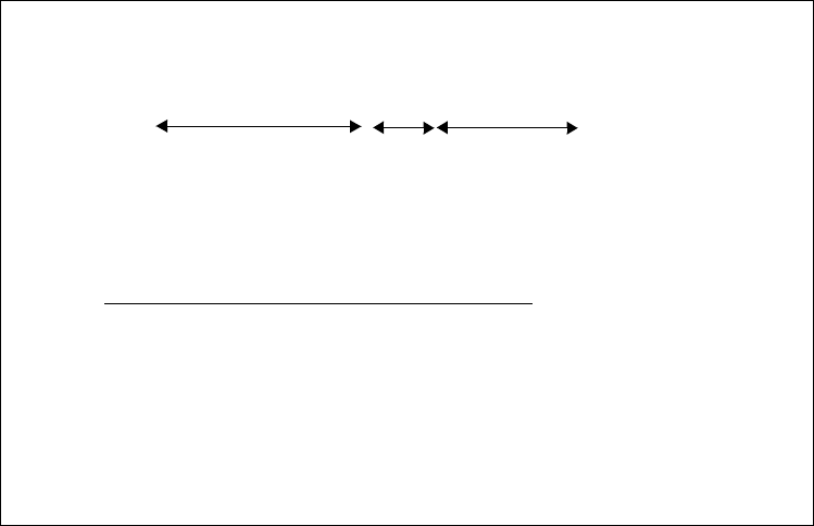
Address, Name and Network Management 77
For each of these subnet values, only 14 addresses (from 1 to 14) are valid
because of the all bits 0 and all bits 1 number restrictions. This split will therefore
give 14 subnets each with a maximum of 4094 hosts. You will notice that the
value applied to the subnet number takes the value of the full byte with
non-significant bits being set to zero. For example, the hexadecimal value 0001 in
this subnet mask assumes an 8-bit value 00010000 and gives a subnet value of
16 and not 1 as it might seem.
Applying this mask to a sample Class B address 172.16.38.10 would break the
address down as seen in Figure 25 on page 77.
Figure 25. An Example of Subnet Mask Implementation
You will notice that the host number shown above is a relative host number, that
is, it is the 1546th host on the 32nd subnet. This number bears no resemblance to
the actual IP address that this host has been assigned (172.16.38.10) and has no
meaning in terms of IP routing.
3.1.3.2 Subnetting Example
As an example, a Class B network 172.16.0.0 is using a subnet mask of
255.255.255.0. This allocates the first two bytes of the address as the network
number. The next eight bits represent the subnet number, and the last eight bits
give us the host number. This allows us to have 254 subnets each having 254
hosts and the values of each are easily recognized.
The Class B address 172.16.3.14 implies host 14 on subnet 3 of network 172.16.
Figure 26 on page 78 shows how this example can be implemented with three
subnets. All IP traffic destined for the 172.16 network is sent to Router 1.
Remember, all remote networks have no knowledge of the subnets used within
the 172.16 network. Router 1 will apply the subnet mask (255.255.255.0) to the
destination address in the incoming datagrams (a logical_AND of the subnet
mask with the address). The result identifies the subnet 172.16.3. Router 1 will
10101100 00010000 00100110 00001010
172.16 32 1546
or: 10101100 00010000 00100110 00001010
11111111 11111111 11110000 00000000 logical_AND
10101100 00010000 00100000 00000000 = 172.16.32 (subnet)
and leaves a host address of:
-------- -------- ----0110 00001010
that represents host 1546
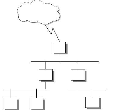
78 IP Network Design Guide
now route the datagrams to Router 2 according to its routing tables. Router 2
again applies the subnet mask to the address and again results in 172.16.3.
Router 2 identifies this as a locally attached subnet and delivers the datagram to
host 14 on that subnet.
Figure 26. Subnet Configuration Example
3.1.3.3 Subnet Types
We stated earlier that a major reason for using subnets is to ease the problem of
routing to large numbers of hosts within a network. There are a number of other
reasons why you might consider the use of subnets; for example, the allocation of
host addresses within a local network without subnets can be a problem.
Building networks of different technologies, LANs based on token-ring or
Ethernet, point-to-point links over SNA backbones, and so on, can impose severe
restrictions on network addressing and may make it necessary to treat each as a
separate network. If the limits of a network technology are reached, particularly in
terms of the numbers of connected hosts, then adding new hosts requires a new
physical network. There may also be a subset of the hosts within a network that
monopolize bandwidth and cause network congestion. Grouping these hosts on
physical networks based on their high mutual communication requirements can
ease the problem for the rest of the network. In each of the cases above you
would need to allocate multiple IP addresses to accommodate these networks.
Using subnets overcomes these problems and allows you to fully utilize the IP
addresses that you have been allocated.
Static Subnetting
In the previous example, we used the same subnet mask in each of the hosts and
routers in the 172.16 network. This can be referred to as static subnetting and
implies the use of a single subnet mask for each network being configured. An
internetwork may consist of networks of different classes, but each network will
implement only one subnet within it. This is the easiest type of subnetting to
understand and is easy to maintain. It is implemented in almost all hosts and
routers and is supported in the Routing Information Protocol (RIP), discussed in
4.3.2, “Routing Information Protocol (RIP)” on page 135, and native IP routing.
However, let us look at the allocation of hosts within a subnet. Our Class B
network (172.16.0.0) uses a subnet mask of 255.255.255.0. This allows each
subnet up to 254 hosts. If one of the subnets is a small network, perhaps a
14
R2
R1
2766
R3
172.16.1.0
172.16.3.0
172.16.5.0
172.16.0.0
External
Networks
Address, Name and Network Management 79
point-to-point link with only two host addresses, then we have wasted 252 of the
host addresses that can have been allocated within that subnet. This is a major
drawback of static subnetting.
Variable Length Subnetting
This waste can be overcome by using variable length subnetting. As the name
implies, variable length subnetting allows different subnets to use subnet masks
of differing sizes. In this way, a subnet can use a mask that is appropriate to its
size and avoid wasting addresses. By changing the length of the mask (by adding
or subtracting bits), the subnet can easily be reorganized to accommodate
changes in the networks. The drawback is that variable length subnetting is not
widely implemented among hosts. Neither native IP routing supports it nor does
the widely implemented dynamic routing protocol RIP (Routing Information
Protocol). However, RIP Version 2 and the Open Shortest Path First (OSPF)
Version 2 routing protocols do support variable length subnets. See 4.3, “The
Routing Protocols” on page 130.
3.1.4 IP Address Registration
As stated in 3.1.1, “IP Addresses and Address Classes” on page 71, any one who
wishes to use the facilities of the Internet or route traffic outside of his/her own
network must obtain a unique public IP address from an Internet Registry (IR).
This service was previously provided by the InterNIC organization, that is the
function of an IR. The authority to allocate and assign the numeric network
numbers to individuals and organizations as required has now been distributed to
three continental registries:
APNIC (Asia-Pacific Network Information Center) <http://www.apnic.net>
ARIN (American Registry for Internet Numbers) <http://www.arin.net>
RIPE NCC (Reseaux IP Europeens) <http://www.ripe.net>
These organizations have been delegated responsibility from the Internet
Assigned Number Authority (IANA), which assigns all the various numeric
identifiers that are required to operate the Internet. These identifiers can be seen
in RFC 1700 - Assigned Numbers. As the three regional organizations do not
cover all areas, they serve areas around their core service areas.
These three organizations rarely directly assign IP address for end users. The
growth in Internet activity has placed a heavy burden on the administrative
facilities of the Internet authorities; many of the day-to-day registration services
have been delegated to Internet service providers (ISPs).
The regional bodies that handle the geographic assignments of IP addresses
assign blocks of Class C addresses to individual service providers who, in turn,
re-assign these addresses to subscribers or customers.
The IANA has provided some guidelines for the allocation of IP addresses.
RFC 2050 - Internet Registry IP Allocation Guidelines
RFC 1918 - Address Allocation for Private Internets
RFC 1518 - An Architecture for IP Address Allocation with CIDR
80 IP Network Design Guide
When applying for an IP address there are a number of points you will need to
consider before filling in the forms. Will you be registering your network as an
Autonomous System (AS)? An Autonomous System is a group of IP networks
operated by one or more network operators that has a single and clearly defined
external routing policy. This implies that you plan to implement one or more
gateways and use them to connect networks in the Internet. The term gateway is
simply an historic name for a router in the IP community. The two terms can be
used interchangeably. Each AS has a unique 16-bit number associated with it to
identify the AS. An AS must therefore be registered with the IANA in a similar
manner to the IP network number. This AS identifier is also used when
exchanging routing information between ASs using exterior routing protocols.
The creation of an AS is not a normal consideration for organizations seeking
Internet connectivity. An AS is required only when exchanging routing information
with other ASs. The simple case of a customer connecting their network to a
single service provider will normally result in the customer′ s IP network being a
member of the service provider′s AS. All exterior routing is done by the service
provider. The only time customers would want to create their own ASs is when
they have multi-homed networks connected to two or more service providers. In
this case, there may be a difference in the exterior routing policies of the two
service providers and, by creating an AS, the customer can adopt a different
routing policy to each of the providers.
Another point of consideration is the establishment of a domain name. This
subject is covered in 3.3.2, “The Domain Name System (DNS)” on page 90. All
we need to say here is that domains must again be registered with the IANA.
3.1.5 IP Address Exhaustion
The allocation of IP addresses by the IANA, and its related Internet Registries,
had proceeded almost unhindered for many years. However, the growth in
Internet activity and the number of organizations requesting IP addresses in
recent years has far surpassed all the expectations of the Internet authorities.
This has created many problems, with perhaps the most widely publicized being
the exhaustion of IP addresses.
The allocation of the Class A, B and C addresses differs greatly, but with the
number of networks on the Internet doubling annually, it became clear that very
soon all classes of IP address would be exhausted.
Class A addresses, as we have already stated, are seldom allocated. Class B
addresses, the preferred choice for most medium to large networks, became
widely deployed and would have soon been exhausted, except that once the IR
had realized the potential problem, it began allocating blocks of Class C
addresses to individual organizations instead of a single Class B address.
The InterNIC has now had to change its policies on network number allocation in
order to overcome the problems that it faces. These new rules are specified in
RFC 1466 - Guidelines for Management of IP Address Space, and are
summarized as follows:
• Class A addresses from 64.0.0.0 through 127.0.0.0 will be reserved by the
IANA indefinitely. Organizations may still petition for a Class A address, but
they will be expected to provide detailed technical justification documenting
their network size and structure.
Address, Name and Network Management 81
• Allocations for Class B addresses have been severely restricted, and any
organization requesting Class B addresses will have to detail a subnetting
plan based on more than 32 subnets within its network and have more than
4096 hosts in that network.
• Any petitions for a Class B address that do not fulfill these requirements and
that do not demonstrate that it is unreasonable to build the planned network
with a block of Class C addresses will be granted a consecutively numbered
block of Class C addresses.
• The Class C address space will itself be subdivided. The range 208.0.0
through 223.255.255 will be reserved by the IANA. The range 192.0.0 through
207.255.255 will be split into eight blocks. This administrative division
allocates the blocks to various regional authorities who will allocate addresses
on behalf of the IR. The block allocation is as follows:
192.0.0 - 193.255.255 Multi-regional
194.0.0 - 195.255.255 Europe
196.0.0 - 197.255.255 Others
198.0.0 - 199.255.255 North America
200.0.0 - 201.255.255 Central and South America
202.0.0 - 203.255.255 Pacific Rim
204.0.0 - 205.255.255 Others
206.0.0 - 207.255.255 Others
The multi-regional block includes all those Class C addresses that were
allocated before this new scheme was adopted. The blocks defined as Others
are to provide for flexibility outside the regional boundaries.
• Assignment of Class C addresses from within the ranges specified will depend
on the number of hosts in the network and will be based on the following.
Less than 256 hosts - assign 1 Class C network
Less than 512 hosts - assign 2 contiguous Class C networks
Less than 1024 hosts - assign 4 contiguous Class C networks
Less than 2048 hosts - assign 8 contiguous Class C networks
Less than 4096 hosts - assign 16 contiguous Class C networks
Less than 8192 hosts - assign 32 contiguous Class C networks
Less than 16384 hosts - assign 64 contiguous Class C networks
Less than 32768 hosts - assign 128 contiguous Class C networks
Using contiguous addresses in this way will provide organizations with
network numbers having a common prefix: the IP prefix. For example, the
block 192.32.136 through 192.32.143 has a 21-bit prefix that is common to all
the addresses in the block: 192.32.136 or B′110000100010000010001′.
3.1.6 Classless Inter-Domain Routing (CIDR)
The problems that have been encountered with IP address assignments have
resulted in a move toward assigning multiple Class C addresses to organizations
in preference to single Class B addresses. The benefit to the IANA in terms of
averting the exhaustion of addresses is clear, but it can place more of a burden
82 IP Network Design Guide
on network administrators and create further problems. IP routing works only on
the network number of the A, B and C Classes of address. Each network must
therefore be routed separately and this requires a separate routing table entry for
each network. The use of subnetting within a network can ease the addressability
problems internally without placing undue burden on the routing tables of the
external networks (to whom the subnets remain unseen).
However, if you have been allocated a block of multiple Class C addresses by the
InterNIC, then there is no way to tell the external network that this group of
addresses is related. Each external router will have to route each Class C
address individually into your internal network. Once inside the internal network
you still have to route each Class C address individually, and if you were to
subnet some of the Class C addresses then you would require even more routing
table entries.
Internally this is generally not too big of a problem. You would be unlikely to
subnet Class C addresses and so you can treat each Class C address the same
as you would for a Class B subnet. Externally, however, the problem for the
Internet administrators is potentially very large. Our Class B network requires
only a single routing table entry in each of the backbone routers on the Internet.
However, if we are assigned a block of Class C addresses instead, then the
number of routing table entries increases dramatically. In a sample network of
3500 hosts, taking the values from the table we saw earlier you would need 16
Class C networks and consequently 16 routing table entries.
This problem has been named the routing table explosion problem. The solution
is a scheme known as Classless Inter-Domain Routing (CIDR). CIDR makes use
of the common IP prefix that we previously detailed in its routing rather than the
class of the network number. The IP prefix is determined by using a network
mask, in much the same way as we used a subnet mask. However, this network
mask works on the network number rather than on the host number; it identifies
the bits of the network number that will be common within the given group of
networks. The network mask is then shown as the second of a pair of 32-bit
numbers in a CIDR routing entry (the first number being the IP prefix itself). The
sample block of addresses that we used earlier, 192.32.136 through 192.32.143,
would require a single CIDR routing entry as follows: <192.32.136.0
255.255.248.0>. This process has been given several names, such as address
summarization, address aggregation or, more commonly, supernetting.
CIDR has an approach to its routing in which the best match to a routing table
entry is the one with the longest match; that is, the entry with the greatest number
of one bits in the mask. This makes the administration of CIDR very simple.
Looking back at the regional allocations of the Class C addresses, we see that in
CIDR, a single routing entry of <194.0.0.0 254.0.0.0 > would be all that is
required to route traffic over a single link from, for example, North America to
Europe. Similarly, <200.0.0.0 254.0.0.0 > would route traffic from North America
to South America over a single link. Without CIDR, each of these links would
require over 131,000 routing table entries. This example uses a very general
mask identifying all the networks within a regional division. At the regional end of
the link, the mask would be enlarged to provide more specific routes to groups of
networks within the region. To address a particular range of networks requires
only a single routing entry with a more specific IP address and a longer network
mask (providing a longer IP prefix) to override the shorter, more general entry.
Address, Name and Network Management 83
For example, a range of eight networks can be defined by the single entry
<200.10.128.0 255.255.248.0>.
This solution has provided the Internet backbone with an efficient way to route
between its gateways and as a consequence is now being widely adopted by
network service providers as well. CIDR is not widely implemented at the local
network level and so will not be a consideration for the majority of organizations
designing local networks. For a more in-depth technical description of CIDR
please refer to
TCP/IP Tutorial and Technical Overview
, GG24-3376.
3.1.7 The Next Generation of the Internet Address IPv6, IPng
The next generation of IP addressing is the Internet Protocol version 6 (IPv6), the
specifications of which can be found in RFC 1883. IPv6 addresses a number of
issues that the Internet Engineering Task Force IPng working group published in
RFC 1752. These problems included IP address exhaustion, the growth of routing
tables in backbone routers and QoS issues, such as traffic priority and type of
service.
When designing a network, the major concern with IPv6 is the future adoption of
IPv6 addresses into the network. With few host systems ready for IPv6, those
capable mostly consisting of a minority of UNIX platforms, and few if any routers
able to cope with IPv6 addressing, a period of transition is required.
During this intermediate stage, IPv6 hosts and routers will need to be deployed
alongside existing IPv4 systems. RFC 1933 - Transition Mechanisms for IPv6
Hosts and Routers and RFC 2185 - Routing Aspects of IPv6 Transition define a
number of mechanisms to be employed to ensure these systems run in
conjunction with each other, without compatibility issues.
These techniques are sometimes collectively termed Simple Internet Transition
(SIT). The transition employs the following techniques:
• Dual-stack IP implementations for hosts and routers that must interoperate
between IPv4 and IPv6
• Imbedding of IPv4 addresses in IPv6 addresses
IPv6 hosts will be assigned addresses that are interoperable with IPv4, and
IPv4 host addresses will be mapped to IPv6
• IPv6-over-IPv4 tunneling mechanisms for carrying IPv6 packets across IPv4
router networks
• IPv4/IPv6 header translation
This technique is intended for use when implementation of IPv6 is well
advanced and only a few IPv4-only systems remain.
The techniques are also adaptable to other protocols, notably Novell IPX, which
has similar internetwork layer semantics and an addressing scheme that can be
mapped easily to a part of the IPv6 address space.
3.1.8 Address Management Design Considerations
There are some considerations that must be taken into account when designing
the addressing scheme. These are split into two sections, those relating to the
network and those relating to the devices attached, such as the hosts.
84 IP Network Design Guide
3.1.8.1 The Network and Clients
The network must be designed so that it is scalable, secure, reliable and
manageable. These attributes must go hand in hand with each other. A network
that might be secure and scalable, but which is unreliable and unmanageable is
not much use. Would you like to manage an unmanageable system that fails twice
aday?
To achieve a network design that meets the above requirements, the following
issues must be considered, as well as their ramifications:
1. The network design must precede the network implementation. The structure
of the network should be known before the implementation proceeds. When a
network is implemented following a well-structured design, as opposed to an
ad hoc manner, many problems are avoided. These include:
• Illegal addresses
• Addresses that cannot be routed
• Wasted addresses
• Duplicate addresses for networks or hosts
• Address exhaustion
2. The addressing scheme must be able to grow with the network. This includes
being able to accept changes in the network, such as new subnets, new hosts,
or even new networks being added. It may even take into account changes
such as the introduction of IPv6.
3. Use dynamic addressing schemes.
4. Blocks of addresses should be assigned in a hierarchical manner to facilitate
scalability and manageability.
5. The choice of scheme, such as DHCP and BootP, depends on platform
support for the protocol. Whatever platform limitations are imposed, the
address assignment scheme that is implemented should be the one with the
greatest number of features that simplify the management of the network.
3.1.8.2 Some Thoughts on Private Addresses
As presented in 3.1.2, “Special Case Addresses” on page 73, private IP
addresses can be used to improve the security of the network. Networks that are
of medium size, or larger, should use private addresses. If the network is to be
connected to the Internet, address translation should be used for external routing.
Apart from the security features provided by using private addresses, there are
other benefits. Fewer registered IP addresses are required, because in most
networks not every host requires direct access to the Internet, only servers do.
With the use of proxy servers, the number of registered IP addresses required is
drastically reduced.
New networks are also much simpler to incorporate into the existing network. As
the network grows, the network manager assigns new internal IP addresses
rather than applying for new registered IP addresses from an ISP or a NIC.
As most companies will find it more feasible to obtain their IP addresses from
ISPs, as opposed to the regional NICs (see 3.1.4, “IP Address Registration” on
page 79), one important consideration is what happens when, due to business or
other needs, the organization needs to change its ISP. If private IP addresses
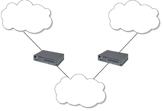
Address, Name and Network Management 85
have not been used, this translates to going through and redefining all the
addresses on the devices attached to the network. Even with DHCP, or some
other address assignment protocol (see 3.2, “Address Assignment” on page 86),
all the routers, bridges and servers will need to be reconfigured. Manually doing
this can be expensive. If private IP addresses are used with address translation,
all the configuration work is done on the address translation gateway.
However, there are some problems with address translation; there’s always a
price to pay. When two separate networks are developed with private IP
addresses, if they are required to be merged at a later date, there are some
serious implications.
First, if the same address ranges in the private address blocks have been used, it
is impossible to merge the two networks without reconfiguring one of the
networks, the duplicate addresses see to this.
If the network manager decides to go to the expense of adding a couple of
routers between the two networks, and continues to develop the networks
separately, an unwise choice in any case, the routing between the two private
networks will fail. For example, in Figure 27, we see a network configuration that
will fail. Router A will advertise its connection to the 10.0.0.0 network, but as
router B is also connected to the 10.0.0.0 network, it will ignore router A. The
reverse is also true for the same reasons. Thus, the two networks in the 10.0.0.0
range cannot communicate with each other. This is solved by using a routing
protocol that can support classless routing, such as RIP-2 or OSPF.
Figure 27. Routing Problems Faced with Discontinuous Networks
Another problem that might occur, and in fact will occur due to human nature, is
that when private IP addresses are implemented, all semblance of developing a
structured scheme for IP address allocation is forgotten. With the flood of IP
addresses available, who needs to consider spending time designing a way to
assign these addresses, there’s a whole Class A address ready to be assigned.
Router A Router B
Network A
10.1.1
Network B
10.1.3
Network C
192.168.2
2580B\CH3F24

86 IP Network Design Guide
3.2 Address Assignment
After obtaining IP addresses for your network you still need to assign them in
some fashion. There are various techniques to assign IP addresses, ranging from
the simplistic static assignment, to more complex techniques such as DHCP. This
section briefly describes the current forms of IP address assignment.
3.2.1 Static
In small networks, it is often more practical to define static IP addresses, rather
than set up and install a server dedicated to assigning IP addresses. A network
consisting of one LAN with 10 hosts attached simply does not justify a dedicated
BootP server.
Although assigning IP addresses statically is simple, there are problems with it.
Static addressing has no support for diskless workstations and maintenance of
this type of network can be expensive. IFor example, an organization has a
private network with an installed base of 150 hosts using static IP addresses, and
decides to connect to the Internet. After obtaining a block of IP addresses, the
network administrator has the choice of implementing a server capable of
address translation as a gateway or reconfiguring all 150 hosts individually.
3.2.2 Reverse Address Resolution Protocol (RARP)
Just as ARP is used to determine a host’s hardware address from its IP address,
RARP can be used to obtain an IP address from the host’s hardware address.
Obviously a RARP server is required for this technique to be used.
RARP is a simple scheme that works well. It is suited to diskless hosts on a small
network. With larger networks, RARP fails to provide a useful service due to its
use of broadcasting to communicate with the server, as routers do not forward
these packets. Thus, a RARP server will be needed on each network.
RARP suffers from the same problems as static addressing. As a RARP server
maintains a database relating hardware addresses to IP addresses, any change
in the IP addressing scheme requires a manual update of the database. Thus,
maintenance of a large RARP database can be expensive.
3.2.3 Bootstrap Protocol (BootP)
The Bootstrap Protocol (BootP) enables a client workstation to initialize with a
minimal IP stack and request its IP address, a gateway address and the address
of a name server from a BootP server. It was designed to overcome the
deficiencies in RARP.
Once again, a good example of a client that requires this service is a diskless
workstation. The host will initialize a basic IP stack with no configuration to
download the required boot code. This download is usually done using TFTP.
Hosts with local storage capability also use BootP to obtain their IP configuration
data.
If BootP is to be used in your network, then you must make certain that both the
server and client are on the same physical token-ring or Ethernet segment. BootP
can be used only across bridged segments when source-routing bridges are
Address, Name and Network Management 87
being used, or across subnets if you have a router capable of BootP forwarding
(such as the IBM 6611 or 2210 network processors).
There have been updates to BootP to allow it to interoperate with the Dynamic
Host Configuration Protocol (DHCP); these are in RFC 951 and RFC 2132.
BootP has two mechanisms of operation:
1. The BootP server can keep a list of hardware (MAC) addresses that it will
serve and an associated IP address for each hardware address.
This technique relegates the BootP server to being not much more than a
RARP server, except for the important consideration of booting diskless
workstations. The security benefits of this technique are obvious: no host can
obtain an IP address from the network unless it has a known hardware
address.
The problem with this approach is that, as with a RARP server, the BootP
server must maintain a static table of IP address assignments to hardware
addresses. This does centralize maintenance for hosts but requires monitoring
and updating. Because IP addresses are preallocated in this approach, in
other words, the host’s IP addresses are not dynamically assigned by the
BootP server, the IP addresses are not available for other hosts. For example,
if an organization has an unlikely environment of 250 hosts, only 10 of which
are ever connected to the network at a time, the organization still has only
three available IP addresses with a Class C IP address. All their IP addresses
would be occupied by the BootP server, ready to be assigned if the relevant
host connected to the network.
2. Alternatively, BootP can be configured to assign addresses dynamically. In
other words, it has a number of IP addresses that it can assign to BootP
requests.
This approach loses any security features that may have been present, as now
any host can connect to the network through a BootP request.
The advantages of this approach are:
• The maintenance of a static file is no longer required on the BootP server.
• IP addresses are no longer preassigned to hardware addresses, thus in the
same scenario as the organization referred to above, only 10 IP addresses
would be occupied, leaving 153 addresses free.
BootP configured in this way does not support diskless workstations, as it no
longer has the details required to provide the boot code to the diskless host
locally.
A BootP server can be configured to have a combination of the above techniques,
such as having a certain number of IP addresses in a static file preassigned to
the corresponding hardware addresses, while having a number of IP addresses
available for dynamic assignment to hosts making BootP requests.
3.2.4 Dynamic Host Configuration Protocol (DHCP)
The Dynamic Host Configuration Protocol (DHCP) is based on BootP and
extends the concept of a central server supplying configuration parameters to
hosts in the network. DHCP adds the capability to automatically allocate reusable
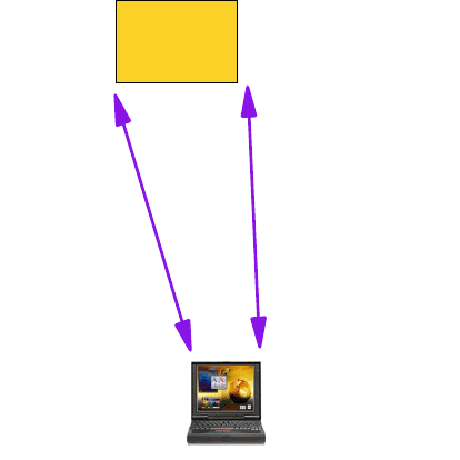
88 IP Network Design Guide
network addresses to workstations or hosts, and it supports the following
functions:
1. Automatic allocation
DHCP assigns a permanent IP address to a device.
2. Dynamic allocation
DHCP assigns a leased IP address to the device for a limited period of time.
This is the only mechanism that allows automatic reuse of addresses that had
been previously assigned but are no longer in use.
3. Manual allocation
The devices address is manually configured by the network administrator, and
the DHCP is used to inform devices of the assigned address.
3.2.4.1 DHCP Implementation
You may have more than one DHCP server in your network, each containing a
pool of addresses and leases in local storage. A client may be configured to
broadcast a request for address assignment and will select the most appropriate
response from those servers that answer the request. One big potential
advantage with DHCP is a reduction in the workload required to manually
configure addresses for all workstations in a segment. According to RFC 1541, a
DHCP server does not need to be in the same subnet or on the same physical
segment as the client.
Figure 28. A DHCP Example
An example of DHCP in operation is shown in Figure 28. A new host is added to
the token-ring (1). When it is initialized, it sends a broadcast message to the
network that will be received by any DHCP servers (2). All available servers
respond to the broadcast (3) and the client will then select the most appropriate
server (4). Once a server has been selected it will send the client the necessary
configuration parameters (5).
DHCP
server
DHCP
client
1. Initialize
2. Receive
DHCP
Message
5. Select Server
Send Configuration
3. Send
DHCP Offer
4. Choose
Offers

Address, Name and Network Management 89
3.2.4.2 DHCP and Host Names
The problem with using DHCP in an environment comes with the associated host
names. How does a network administrator assign meaningful names to hosts
when the host’s IP address changes every time it is rebooted. A dynamic DNS
system is required to work with the DHCP server.
This is exactly what has been developed. Dynamic DNS (DDNS) is covered later
in 3.3.3, “Dynamic Domain Name System (DDNS)” on page 104.
3.2.4.3 Security Implications
Using DHCP may have some impact on your installation if you are using security
implementations that map user IDs to IP addresses (sometimes called source IP
address-based security schemes). This will only cause problems if you use the
dynamic allocation or leasing capability.
3.3 Name Management
Because the average human being cannot easily remember a 12-digit (in decimal
form) IP address, some form of directory service will be required in the network
design. Increasing numbers of new applications also require host names, further
reinforcing some form of name management in an IP network.
3.3.1 Static Files
The simplest form of name resolution is through the use of static files on each
host system. This is specified in RFCs 606, 810 and 952. These RFCs defined
the hosts.txt file used for the ARPANET. RFC 952 obsoleted the previous two. It
specified the structure of the host names as they would be used in the
ARPANET’s host table.
An example that is often seen is the UNIX /etc/hosts file, although this file differs
in its structure from that of the ARPANET’s hosts.txt file. If this file exists, it will
contain a listing of all the hosts the system requires to communicate with, using
the other host’s host name. This listing supplies the host with each other host’s
host name and associated IP address.
The size of this file is directly related to the number of hosts a system requires
name resolution for. In very small networks, this system works well, but as the
network increases in size, this method becomes unmanageable.
For example, let us use a network of 20 host systems that uses static files for
name resolution. A new system is added to the network and a majority of the
hosts require name resolution to the new host. What results is:
• The network administrator goes to each host that requires access to the new
host and updates the name resolution file
• The network administrator updates a centrally maintained static host file and
then FTPs this file to each of the relevant machines.
In either scenario, the network administrator has some work to do. This amount of
work may not seem excessive, but what if there were 1000 hosts on the network.
Would you want this job?
90 IP Network Design Guide
In addition to this manual update of the files, if the network administrator did not
centrally manage the file, host name conflicts would occur constantly the size of
the host file would become too large to transfer across the network without
impacting the network’s performance. The role of maintaining these files centrally
is unthinkable when considering a large internetwork that may span countries.
The above situation is exactly what happened to the ARPANET during the infancy
of the Internet. As the number of hosts attached to ARPANET increased, so did
the size of the static file containing the host names and the associated IP
address, the hosts.txt file. It was the responsibility of an individual network
administrator to FTP the hosts.txt file from the NIC host. With a few hundred
hosts attached, this worked well. When the number of hosts approached a few
thousand, the architects realized the problem and set about seeking a solution.
3.3.2 The Domain Name System (DNS)
To solve the problems associated with the use of a static host file, the Domain
Name System (DNS) was invented. RFCs 1034 and 1035 are concerned with
DNS.
The hierarchical approach of DNS would allow for the delegation of authority and
provide organizations with a level of control they required while the distributed
database would ease the problems of the size of the database and the frequency
of its updates.
DNS is made up of three major components:
•The Domain Name Space and Resource Records specify the hierarchical
name space and the data associated with the resources held within it. Queries
to the name space extract specific types of information from the records for the
node in question.
•Name Servers are server programs that hold information about the name
space structure and the individual sets of data associated with the resources
within it.
•Resolvers are programs that extract information from the name servers in
response to client requests.
We begin our discussion of DNS with a look at each of these elements.
3.3.2.1 The Domain Name Space
The DNS name space is a distributed database holding a hierarchical,
domain-based information on hosts connected to a network. It is used for
resolving IP addresses from host names. In addition to this service, it also
provides information on the resources available on that host, such as its
hardware, operating system and the protocols and services in use.
The name space is built in a hierarchical tree structure with a root at the top. This
root is un-named and is delineated by a single period (.). The DNS tree has many
branches. These branches originate from a point called a node. Each of these
nodes corresponds to a network resource (a host or gateway).
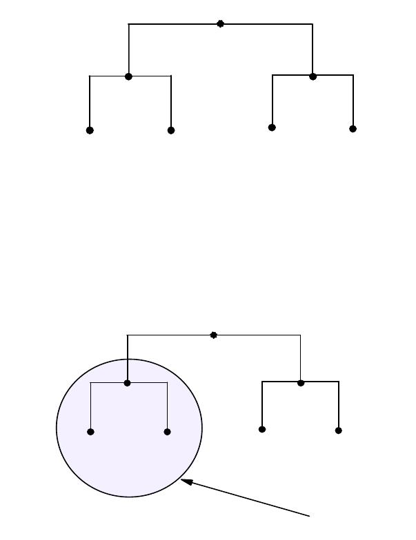
Address, Name and Network Management 91
Figure 29. The Tree Structure of DNS
We have called this structure the domain name space, but what exactly is a
domain? A domain is identified by a domain name. It consists of the part of the
name space structure that is at or below the domain name. Thus, a domain starts
at a named node and encompasses all those nodes that emanate from below it.
Let us look at an example:
Figure 30. The DNS Domain
This figure shows a domain node-A that begins at node-A. It contains the nodes
node-A, node-B and node-C. This scheme may be taken a step further to show
that as we progress out from the root, we will create subdomains. Figure 31 on
page 92 illustrates this.
node
root
node node
node_C
node_A
node_B
node
root
2580C\CH3F28
node node
node_C
node_A
node_B
node-A domain
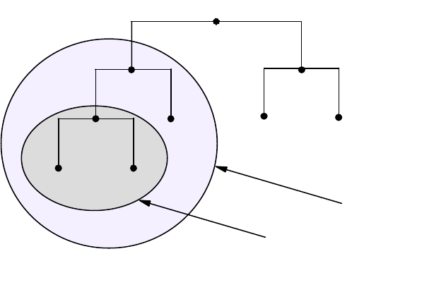
92 IP Network Design Guide
Figure 31. DNS Subdomain Example
A new domain, the node-B domain, contains node-B, node-D and node-E. The
original domain, node-A, now encompasses not only node-A, node-B, node-C,
node-D and node-E but also the subdomain created by node-B.
Domain Names
Each domain node, in other words, each network resource, is labeled with a
name of up to 63 characters in length. This label must start with a letter, end with
a letter or digit and contain only letters, digits or hyphens (-). For example:
SRI-NIC (the Network Information Centre at SRI International)
Currently, domain names are not case sensitive. A node may have a label AAA
that can be referred to as either AAA or aaa. It is strongly recommended that you
preserve the case of any names you use. Some operating systems, namely UNIX,
are case-sensitive. Another reason for preserving case in your domain names is
that future developments in DNS may possibly implement case-sensitive
services.
The name does not have to be unique in itself. Some names appear many times
in the name space. A good example of this are the names mailserver and mail.
These names appear in almost every network connected to the Internet.
However, to ensure that each node in the tree can be uniquely identified through
its domain name, it is stipulated that sibling nodes (that is, those nodes with the
same parent node) must not use the same name. This limitation applies only to
the child nodes, and the name may appear in a node with a different parent.
node
root
2580C\CH3F29
node_Enode_D
node node
node_C
node_A
node_B
node-A domain
node-B domain
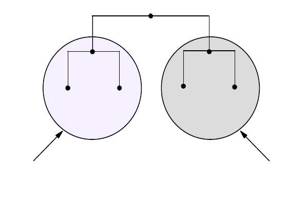
Address, Name and Network Management 93
Figure 32. Domain Names
Figure 32 illustrates how a name may appear more than once within the tree. The
name node-C appears twice in the tree, once as part of the domain node-A and
again as part of the domain node-B. Node-A and node-B are siblings (they have
the same parent node - root), so their names must be unique, otherwise things
can get confusing. Node-C and node-D in the node-A domain are also siblings
and must again be named uniquely. However, node-C in the node-B domain has a
different parent node from node-C in the node-A domain, node-B and node-A
respectively. The unique identity of each node must be maintained. This is
achieved through the use of the identity, the name, of its parent node whenever
we reference the node outside of its own domain. This scheme fully qualifies the
name and provides what is known as a fully qualified domain name (FQDN).
Reiterating, a domain name may be of two types:
•Unqualified Name: This type of name consists of only the host name given to
a particular host. As can be appreciated, throughout the world there may be
many hosts with the same unqualified name. It is impractical, if not impossible,
to specify unique host names to every machine on the Internet such that no
two machines have conflicting DNS entries.
Thus, a host’s unqualified domain name alone does not enable it to be
identified, except in the local network. A 32-bit IP address still must be used to
address hosts on the Internet.
•Fully Qualified Domain Name (FQDN): The use of an unqualified name
within a domain is the efficient way that names are used in preference to
addresses and is perfectly valid. Referring to USER1 is much easier (from a
human perspective) than using the 32-bit IP address 172.16.3.14, for example.
However, the IP address is unique within the Internet while the name node-C
(as we have shown previously) may not be. The answer is the FQDN. To
create the FQDN of a node we must use the sequence of names on the path
from the node back to the root with periods separating the names. These
names are read from left to right, with the most specific name (the lowest and
farthest from the root) being on the left. Thus, we see that the two hosts in our
previous example now have completely unique FQDNs:
node_B
root
2580C\CH3F30
node_C node_Enode_D
node_A
node_C
node-B domainnode-A domain

94 IP Network Design Guide
node-C.node-A.root and node-C.node-B.root
In practice, the name of the root domain is never shown; it has null length and
is usually represented by a period (.). When the root appears in a domain
name, the name is said to be absolute. For example:
node-C.node-A. (the root is represented by the trailing period)
This makes the FQDN totally unambiguous within the name space. However,
domain names are usually written relative to a higher level domain rather than
to the root itself. In the previous example, this would mean leaving off the
trailing period and referring to node-C relative to the node-A domain. For
example:
node-C.node-A
When you configure a TCP/IP host you are requested to enter the host name
of the host and the domain origin to which this host belongs. In the previous
example, if we configured a host in the node-C.node-A domain, we would
enter the host name as, for example, host-X and the domain origin as
node-C.node-A. Whenever a non-qualified name is entered at this host, the
resolver will append the current domain origin to the name, resulting in a
FQDN belonging to the same domain as our own host, which enables us to
refer to hosts that belong to the same domain as this host, by just entering the
unqualified host name. If we enter host-Y, the resolver will append the domain
origin building the fully qualified name host-Y.node-C.node-A before trying to
resolve the name to an IP address. If we want to refer to hosts outside our own
domain, we will enter the fully qualified name as, for example,
host-Z.node-E.node.A.
Top-Level Domain (TLD)
There is seemingly no restriction on the names that you can create for each node,
other than that of length and uniqueness among siblings. However, the NIC
decided to provide some sort of order within the name space to ease the burden
of administration. Below the root are a number of top-level domains or (TLDs).
These TLDs consist of seven generic domains established originally in the U.S. to
identify the types of organization represented by the particular branch of the tree.
These can be seen in Figure 33 on page 94.
Figure 33. The Generic Top-Level Domains
United States Only Generic Domains
gov
- Government institutions - now limited to US Federal agencies
mil
- US Military groups only
Worldwide Generic Domains
edu
- Educational institutions
com
- Commercial organizations
net
- Network providers (like NSFNET)
int
- International organizations (like NATO)
org
- Other organizations that do not fit anywhere else
2580C\CH3F31
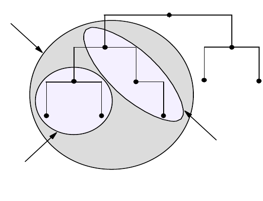
Address, Name and Network Management 95
The generic TLDs first outlined for the Domain Name System were augmented by
the two-character international country codes as detailed in the ISO 3166
standard. Known as country or geographical domains, these TLDs often have
subdomains that map to the original U.S. generic top-level domains such as .com
or .edu. A list of the current TLDs is shown in Figure 33.
DNS Zones
We have used the word zone on a number of occasions in the last section without
explaining its meaning. Divisions in the domain name space can be made
between any two adjacent nodes. The group of connected names between those
divisions is called a zone. A zone is said to be authoritative for all the names in
the connected region. Every zone has at least one node and consequently at
least one domain name and all the nodes in a zone are connected. This sounds
very much like a domain.
However, there is a subtle difference between a zone and a domain. A zone may
contain exactly the same domain names and data as a domain, and this is often
the case. If a name server has authority for the whole domain, then the zone will
in fact be the same as the domain. As networks grow, it is common that, for the
ease of administration, a domain may be divided into subdomains with the
responsibility for these subdomains being delegated to separate parts of an
organization or indeed, to a different organization completely. When this happens,
the authority for those subdomains is usually assigned to different name servers.
At this point, the zone is no longer the same as the domain. The domain contains
all the names and data for all of the subdomains, but the zone will contain only
the names and data for which it has been delegated authority.
Figure 34. Domains and Zones
Figure 34 illustrates the difference between a zone and a domain. The net
domain contains names and data for the net domain, the sub1 domain and the
sub2 domain (sub1 and sub2 are both subdomains of the net domain). However,
only domain sub1 has been delegated the authority for its resources and hence
has its own zone, the sub1 zone. The sub2 domain is still under the authority of
the net zone.
root
2580C\CH3F32
sub2
net
sub1
net zone
sub1 zone
net domain
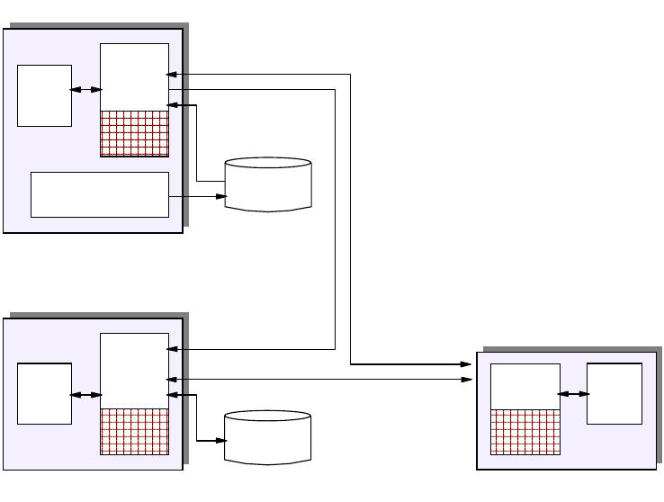
96 IP Network Design Guide
Name Servers
The second component of the Domain Name System is the name server. Name
servers are the repositories for all of the information that makes up the domain
name space. Originally, there was a single name server, operated by the NIC,
which held the single HOSTS.TXT file. The concept of the hierarchical name
space has meant that a single name server would be impractical. There are now
nine root name servers with responsibility for the top-level domains. The name
space is then divided into zones, as we have already discussed, and these zones
are distributed among the name servers such that each name server will have
authority over just a small section of the name space. This division is frequently
based on organizational boundaries, with freedom to subdivide at will. A name
server may, and often will, support more than one zone and a single zone may be
served by more than one name server.
Name servers come in the following three types:
• Primary name server - This maintains the zone data for the zones it has
authority over. Queries for this data will be answered with information from
files kept on this name server.
• Secondary name server - This has authority over a zone but does not maintain
the data on its own disks. The zone data is copied from the primary name
server database when the servers are started. This is known as a zone
transfer. The secondary then contacts the primary at regular intervals for
updates.
• Caching-only name server - This server has no authority over any zones and
contains only records pointing to other (primary or secondary) name servers.
Data is kept in a cache for future use and discarded after a time-to-live (TTL)
value expires.
Figure 35. Name Server Categories
DNS with
cache
Resolver
Local DNS database
maintenance
DNS
database
DNS
database
Resolver
DNS with
cache
Zone
Transfer
Queries
and
Responses
Primary
Secondary
DNS with
cache Resolver
Caching-only
2580C\CH3F33
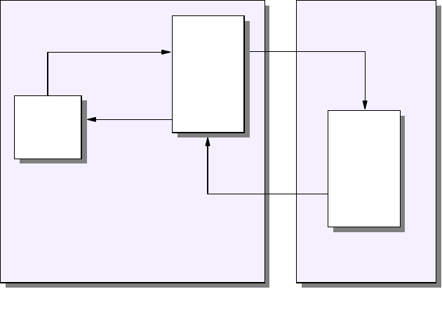
Address, Name and Network Management 97
The main function of the name server is to answer standard queries from clients.
These queries flow in DNS messages and identify the type of information that the
client wants from the database and the host in question. The name server can
answer queries in a number of ways depending on the mode of operation of the
client and server.
• Recursive mode - when a client makes a recursive query for information about
a specified domain name, the name server will respond either with the
required information or with an error, such as the domain name does not exist
(name error) or there is no information of the requested type. If the name
server does not have authority over the domain name in the query, it will send
its own queries to other name servers to find the answer. These name servers
are pointed to by the additional resource records in the database.
Figure 36. Recursive Mode Example
Notes:
1The client in domain A sends a simple query to its name server asking for
the address of a host in domain B.
2The specified name server does not have authority over domain B and has
no record of the host. The name server has an NS resource record pointing to
an authoritative name server for domain B and so it sends a query to that
name server asking for the address of the host.
3The name server in domain B returns the address of the host to the name
server in domain A.
4The name server in domain A returns the address of the host to the client.
• Non-recursive or Iterative mode - in this case, when a client makes a query,
the name server has an extra option. It will return the information if it has it. If
not, rather than ask other name servers if they have the data, it will respond to
the query with the names and addresses of other name servers for the client
to try next.
Domain A
1
4
Client
Domain B
Name
Server
Name
Server
2
3
2580C\CH3F34
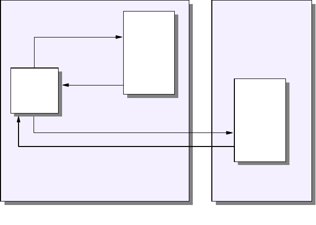
98 IP Network Design Guide
Figure 37. Non-Recursive Mode Example
Notes:
1The client in domain A sends a simple query to its name server asking for
the address of a host in domain B.
2The specified name server does not have authority over domain B and has
no record of the host. The name server has an NS resource record pointing to
an authoritative name server for domain B. But, rather than send its own query
to that name server, it responds negatively to the clients query and gives the
client the address of the name server in domain B.
3The client sends a second query, this time to the name server in domain B.
4The name server in domain B returns the address of the host to the client.
Resolvers
The resolvers are the third component of the Domain Name System. These are
the clients making queries to the name servers on behalf of programs running on
the host. These user programs make system or subroutine calls to the resolver,
requesting information from the name server. The resolver, which runs on the
same host as the user program, will transform the request into a search
specification for resource records located (hopefully) somewhere in the domain
name space. The request is then sent as a query to a name server that will
respond with the desired information to the resolver. This information is then
returned to the user program in a format compatible with the local host′s data
formats.
What exactly does the resolver have to do for the client program? There are
typically three functions that need to be performed:
1. Host name to host address translation
The client program (for example, FTP or TELNET) will provide a character
string representing a host name. This will either be a fully qualified domain
name (host.net.com.) or a simple unqualified host name. Let us use HO4 from
Domain A
1
4
Domain B
Name
Server
2
3
2580C\CH3F35
Client Name
Server
Address, Name and Network Management 99
our previous example. If the name is unqualified, the resolver code will append
a domain origin name (in our case sample.net.) to the name before passing it
to the server. This domain origin name is
of four parameters that are configured on every IP host:
IP address of the host
Host name
Domain origin name - the domain to which this host belongs
IP address of the name server(s) being used
The resolver then translates this request into a query for address (type A)
resource records and passes it to the specified name server. The server will
return one or more 32-bit IP addresses.
2. Host address to host name translation
Presented with a 32-bit IP address from the client program (perhaps SNMP),
the resolver will query the name server for a character string representing the
name of the host in question. This type of query is for PTR type resource
records from the in-addr.arpa name space. The resolver will reverse the IP
address and append the special characters in-addr.arpa before passing the
query to the name server.
3. General lookup function
This function allows the resolver to make general queries to the name server
requesting all matching resource records based on the name, class and type
specified in the query.
There are two types of resolvers, both of which make use of the routines
gethostbyname() for name to address translation and gethostbyaddr() for address
to name translation. The first, known as a full resolver, is a program distinct from
the client user program. The full resolver has a set of default name servers it
knows about. It may also have a cache to retain responses from the name server
for later use.

100 IP Network Design Guide
Figure 38. A DNS Full Resolver
Notes:
1The user program makes a call to the resolver.
2The resolver translates the call into a resource record query and passes it to
its default name server.
3The name server will attempt to resolve the query from its own database.
Assume that this is the first query and there is nothing in the cache.
4If unable to locate the requested records in its own database, the name
server will pass its own query to other name servers that it knows (if recursive
mode is being used).
5The remote name servers eventually reply with the required information.
6The local name server passes the information back to the resolver.
7The resolver translates the resource records into local file format and returns
the call to the user program.
8Both the resolver and the name server will update their caches with the
information.
The second, and possibly more common, type of resolver is the stub resolver.
This is merely a routine or routines linked to the user program. The stub resolver
will perform the same function as the full resolver but generally does not keep a
cache.
54
1
7
2
6
2580C\CH3F36
Client
Program
Cache
Database
C
a
c
h
e
Name
Server
Name
Server
8
Full
Resolver
8
3
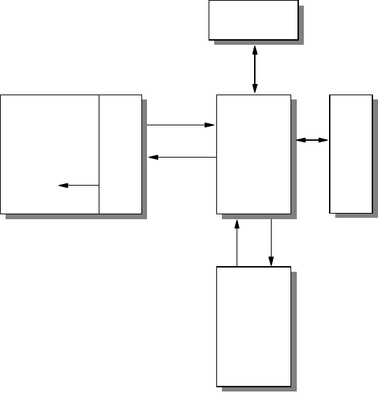
Address, Name and Network Management 101
Figure 39. A DNS Stub Resolver
Notes:
1The user program invokes the stub resolver routines; the resolver creates an
resource record (RR) query and passes it to its default name server.
2The name server will attempt to resolve the query from its own database.
Assume that this is the first query and there is nothing in the cache.
3If unable to locate the requested records in its own database, the name
server will pass its own query to other name servers that it knows (if recursive
mode is being used).
4The remote name servers eventually reply with the required information.
5The name server will update its cache with the information.
6The local name server passes the information back to the resolver.
7The resolver translates the resource records into local file format and returns
to the user program.
3.3.2.2 Domain Name System Resource Records
We have looked at the structure of the domain name space and discussed nodes
and resources. Each node is identified by a domain name and has a set of
resource information composed of resource records (RRs). The original concept
of the name system was to provide a mapping of names to addresses, but it has
proved far more useful than just that. The resource records contain information
about the node: the machine type it is running on, the operating system and
services it runs, and, more importantly, information about mail exchange within
the domain.
43
1
6
2580C\CH3F37
Database
C
a
c
h
e
Name
Server
Name
Server
5
2
User
Program
7
1
S
t
u
b
R
e
s
o
l
v
e
r
102 IP Network Design Guide
The format of a resource record and a description of each term is shown below:
name ttl class type rdata
where:
name This is an owner name, that is the domain name of the node to which
this record pertains (maximum length is 255 characters).
ttl This is the time-to-live. This is a 32-bit unsigned value in seconds that
this record will be valid in a name server cache. A zero value means
the record will not be cached but will be used only for the query in
progress. This is always the case with start of authority (SOA) records.
class This is the class of the protocol family. The following values are
defined:
Class Value Meaning
-0Reserved
IN 1 The Internet
CS 2 The CSNET class (now obsolete)
CH 3 The CHAOS class
HS 4 TheHesiodclass
type This is the type of the resource defined by this record. The following
values are defined:
Type Value Meaning
A 1 A host address.
NS 2 The authoritative name server for this domain.
CNAME 5 The primary (canonical) name for an alias.
SOA 6 Marks the start of a zone of authority in the domain
name space.
WKS 11 Describes the well-known services that are
supported by a particular protocol on this node,
TCP(FTP) for example.
PTR 12 A pointer to an address in the domain name space;
used for address to name resolution.
HINFO 13 Information about the hardware and operating
system of this node.
MX 15 Identifies the domain name of a host that will act as a
mailbox for this domain.
TXT 16 Text strings.
rdata This is the data associated with each record. The value depends on
the type of value defined, with most types having several elements:
Type Rdata value
A A 32-bit IP address (for the IN class).
NS A domain name.
CNAME A domain name.
SOA The domain name of the primary name server for this zone.
A domain name specifying the mailbox of the person
responsible for this zone.
An unsigned 32-bit serial number for the data in the zone,
usually in the format (yyyymmdd).
Address, Name and Network Management 103
A 32-bit time interval before the zone is refreshed (seconds).
A 32-bit time interval before retrying a refresh (seconds).
A 32-bit time interval before data expires (seconds).
An unsigned 32-bit minimum TTL for any RR in this zone.
WKS A 32-bit IP address.
An 8-bit IP protocol number.
A variable length bit-map (multiples of 8 bits long) with each
bit corresponding to the port of the particular service.
PTR A domain name.
HINFO A character string for CPU type (see list in RFC 1700).
A character string for Operating System type (see list in RFC
1700).
MX A 16-bit integer specifying the preference given to this RR
over others at the same owner (lower values are preferred).
A domain name.
TXT One or more character strings.
DNS Support for E-Mail
We stated earlier that the Domain Name System not only includes functions for
name to address translation and vice versa but also provides a repository for
useful information about the nodes in the name space. One such example of this
added value is the support that DNS provides for mail services.
DNS has defined a standard for mapping mailbox names into domain names
using MX (mail exchange) resource records. An MX record also defines the way
in which these records are used to provide mail routing within the Internet. The
standards define a mailbox name in the form <local-part > @<mail-domain >. For
the exact syntax of this form please refer to RFC 822 - Standard for the Format of
ARPA Internet Text Messages. DNS encodes the <local-part > as a single label.
Any special characters in the original character string can be preserved in the
DNS master file label by using backslash quoting. For example, the name
Mail.server would be coded as Mail\.server. The <mail-domain > is simply
encoded as a domain name and appended to the mailbox label. Thus, the
mailbox name Mail.server@sample.net. would have a DNS MX record name of
Mail\.server.sample.net.
The DNS MX record actually has two values in the rdata section. The one we
have just seen is the name of the mailbox host. The other is an unsigned 16-bit
integer that acts as a preference value. This is used to indicate a priority to the
MX records if there is more than one for this domain name. The lower the
preference value, the higher the priority. The following example illustrates this:
sample.net MX 5 Mail\.server.sample.net.
MX 10 Mailbox.sample.net.
We have two mailboxes defined for the sample.net. domain. The first mailbox
Mail\.server has a preference value of 5 and so is higher in priority to the second
mailbox Mailbox, which has a preference value of 10. If the mail system has mail
for user@sample.net., then it will use the MX records for the sample.net. mail
domain as seen previously and will attempt to deliver the mail to the mailbox with
the lowest preference value (in this case, Mail\.server.sample.net.). If this mailbox
is unavailable, the mail system will try Mailbox.sample.net.
104 IP Network Design Guide
3.3.3 Dynamic Domain Name System (DDNS)
As can be seen from the basic overview given, DNS can be a very helpful
management tool. The addition of a new host into the network can be simplified to
assigning the host an IP address and updating the DNS server with the host’s
name.
But what if we want more automation of the networks resource management. We
can implement a DHCP server so we no longer need to assign a static IP address
to the new host. This complicates our DNS server’s role as we can no longer add
the new host’s host name to the DNS server’s lookup table. We do not know what
IP address to associate the host name with, even if we did have the IP address.
The next time the host was rebooted, a new IP address would be assigned,
rendering the DNS table useless.
A DNS system is required that supports, without the intervention of the DNS
server’s administrator, or the need for the server to be restarted:
• An update of the host name to address mapping entry for a host in the domain
name server once the host has obtained an address from a DHCP server
• A reverse address to host name mapping service
• Updates to the DNS to take effect immediately
• Authentication of DNS updates to:
• Prevent unauthorized hosts from accessing the network
• Stop imposters from using an existing host name and remapping the
address entry for the unsuspecting host to that of its own
• A method for primary and secondary DNS servers to quickly forward and
receive changes
The solution to these issues was addressed by the IETF and addressed in RFCs
2065, 2136, 1995, 1996 and 2137. These RFCs are all proposed standard
protocols with elective status.
A dynamic name server is capable of updating the lookup table itself whenever a
DDNS aware host or DHCP server informs the DDNS server to update a host’s
host name with a certain IP address that was assigned by a DHCP server. A
dynamic name server never needs to be restarted.
The Dynamic Domain Name System (DDNS) is a superset of the Berkeley
Internet Name Domain (BIND) level 4.9.3. IBM’s implementation of DDNS differs
from the BIND implementation in that in dynamic domains, only authorized clients
can update their own data. RSA public-key digital signature technology is used for
client authentication. DDNS servers on AIX and OS/2 Warp Server (and TCP/IP
Version4.1forOS/2)canbeusedasstaticDNSserversalso.
Clearly, a DHCP server used in conjunction with a DDNS server relieves the
network and system administrators of some tedious and time-consuming
responsibilities, leaving them free for more fruitful work.
3.3.4 DNS Security
In Chapter 6, “IP Security” on page 187 we discuss the security aspects of
network design using firewalls to prevent unwanted access to your network. The
problem is that with DNS we are aiming to provide a name service to actually
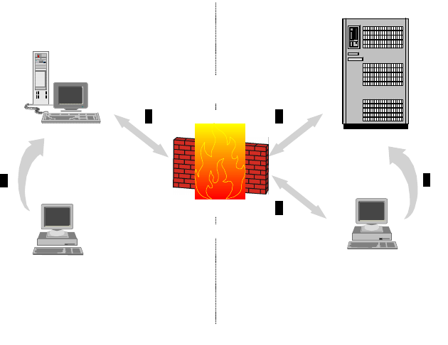
Address, Name and Network Management 105
allow people in our network to be found. We must therefore adopt a special
technique when installing a name server in relation to a firewall. This obviously
has implications for e-mail as well.
The goal of this scheme is to provide a full Domain Name System to hosts inside
the secure network while only providing information about the firewall itself to the
outside world. Let us assume you have already set up one or more name servers
within your network. These will remain virtually unchanged and will serve your
secure hosts, giving them information about your secure network. You will need to
set up a new name server on the firewall. This is often provided as a feature of
the firewall implementation. The firewall name server will respond to queries from
the outside only with information about the firewall address itself. When a host in
your secure network makes a query about a host in the non-secure network, the
name server will forward the query to the firewall name server. The firewall name
server will in turn refer the query to a name server in the non-secure network,
probably the one provided by your Internet Service Provider.
Figure 40. DNS Coexistence with Firewalls
Notes:
1Hosts inside the secure network make their normal requests to an internal
name server. Local domain names are returned directly.
2Queries for names in external domains are passed by the internal name
server to the firewall name server.
3The firewall name server will pass the queries to an external name server,
and the responses will follow the same route back to the original internal host.
4Queries from external hosts will be directed either through an external name
server or directly at the firewall name server, but in either case the firewall
name server will respond with a ″restricted″ answer.
A similar process applies to electronic mail passing through the firewall. One way
to overcome the problem is to employ a mail forwarding service on the firewall.
Secure Network Non-Secure Network
Firewall
Name
Server
Name
Server
Name
Server
1
2 32
4
4
2580C\CH3F38
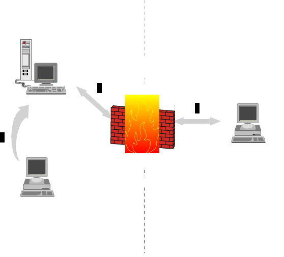
106 IP Network Design Guide
This will act as a relay for the secure mail server inside the secure network.
External hosts will direct their mail to user@firewall.company.com or
user@company.com depending on where the domain begins. Both the secure
mail server and the mail forwarder on the firewall must be configured as Relay
Hosts (DR entry in sendmail.cf file) to allow mail headers to be re-written and mail
not destined for the local host to be routed through the firewall.
Figure 41. DNS and E-Mail with Firewalls
Notes:
1Internal hosts use the secure mail server to deliver mail within the secure
network (or deliver directly themselves).
2Mail destined for external users is passed to the secure mail server for
outbound relay to the firewall mail server.
3The firewall routes mail to the outside world. Inbound mail cannot be directly
delivered to internal users but must be relayed through the firewall to the
secure mail server, which has ultimate responsibility for delivery of the mail.
3.3.5 Does The Network Need DNS?
In some networks it is more work to configure a DNS server than it is to set up a
static host file. In very small networks, typically fewer than 10 hosts, it is not worth
setting up a DNS server. This is especially the case when your business needs
do not foresee any additional hosts in the future. When is this the case?
Any network with more than 10 machines should implement DNS for the time
savings when adding a new machine to the network.
The size of the network, namely the number of hosts attached, is not the only
consideration when deciding whether or not DNS is required. If the organization
wants to use external e-mail, a DNS server must be implemented. The use of
Secure Network Non-Secure Network
Firewall
Mail
Server
Mail
Server
1
2
3
2
2580C\CH3F39
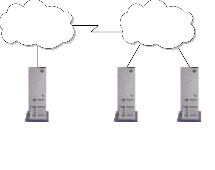
Address, Name and Network Management 107
other standard TCP/IP applications, like TELNET and FTP, is simplified greatly for
the users of the network with DNS implemented.
3.3.6 Domain Administration
Let us assume that you have decided to implement DNS. The next question you
ask is who is going to set up and run the domain. Again, the answer may depend
on the size of the network. A reasonably small network may (and probably will) be
able to take advantage of the services offered by its Internet service provider
(ISP), perhaps becoming part of the service provider’s domain (see Figure 42 on
page 107). As the network grows, you will doubtless be seeking your own identity
and wish to establish your own domain. But again, you may not need to do all the
work yourself. The service provider may be happy to set up your domain and
administer it for a fee.
The rest of this section deals with the various scenarios that can occur and the
implications for each.
3.3.6.1 Scenario One: Outsourcing of the Domain Name to the ISP
This is the easiest option as your organization no longer needs to worry about
DNS. A network topology for this is shown in Figure 42 on page 107.
You have a choice when allowing your ISP to manage your domain space. You
can either:
• Place your organization under the ISP’s own domain. Thus if your ISP is
known as ibm.com, your host’s FQHS would be host-x.ibm.com.
• Allow your ISP to host your own registered domain name.
Figure 42. Implementing DNS with the Service Provider
In both these alternatives, you must consider the implications for outsourcing the
organization’s name space to an external organization.
• The ISP will need to know when you add a machine to the network.
• The ISP may have delays in adding names to a DNS server or updating names
that have changed.
Secondary or Cache
DNS Server Secondary
DNS Server
Primary DNS
Server
Intranet ISP
2580C\CH3F40A
108 IP Network Design Guide
• Your organization’s connection to the ISP will generally be through a WAN link;
generating DNS traffic on this link may become a needless expense if a local
caching server is not implemented.
• There are security issues of allowing an external organization to control your
domain space or relying on an external organization’s domain space.
There are a number of recommended agreements that should be put in place
when using an ISP to provide domain space services for your organization. These
include:
• Agreed persons of responsibility in both organizations, yours and the ISP’s
• Define agreed response times to domain space changes. These include:
• Additions of new machines to a domain
• Updating names of existing machines
• Creation of aliases
• Agreed levels of mean time between failures (MTBF) and meantime to
recovery (MTTR)
• Agreed levels of performance for the domain name space
• Agreed security requirements
This is not an exhaustive list, but it provides a guide from which to start.
3.3.6.2 Scenario Two: Maintaining the Domain Space Locally
If you go it alone and decide to administer the organizational domain yourself,
there are a number of new issues that need to be considered.
First, it must be decided if the domain name space is to be managed centrally or
in a distributed manner. In small to medium networks, it is often easier to manage
the domain space by a centralized IT department. In larger or distributed
organizations, it may be more logical for the department administrators to
manage the domain space for their respective departments.
The advantage of maintaining a central authority for the domain name space is
the adherence to a guideline for the naming of infrastructure. In a domain space
with distributed responsibility it can become very difficult to maintain control and
manage the names. However, there are many advantages to maintaining a
distributed domain space.
The benefits of a distributed domain space include:
• Improved performance of the Domain Name System. As the DNS servers are
located on a network segment with fewer hops between the client, the
response will be improved. Local caching of names also helps to improve the
performance of the domain space significantly.
• Reduction in network traffic. Although each DNS request will still need to
access the network, if a local DNS server is available, the traffic is minimized
to local traffic. In a network of thousands of machines, DNS traffic can add up.
• Improved scalability of the Domain Name System. A distributed DNS service
will enable a modular approach to be implemented, thus making it easy to
expand the network domain name space.
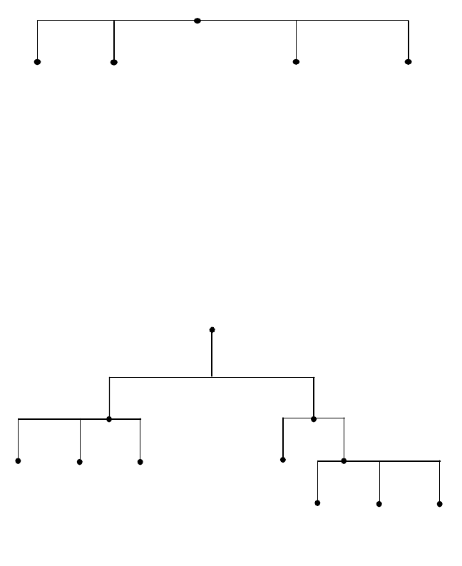
Address, Name and Network Management 109
• Reduction is high specification infrastructure. In a distributed domain name
space, the infrastructure required to serve names to client requests is
simplified. The same requirements in terms of memory, speed and processing
power are not required for the DNS servers.
• Finally, there is no single point of responsibility for the organization’s domain
space. No single department is laden with the responsibility of maintaining all
the domain space.
There are a number of models that can be used to implement your DNS.
Flat Domain Structure
This structure is presented in Figure 43 on page 109, and is a good choice for
very small networks for very small organizations. This choice is far too simplistic
for most practical uses, however, and does not take advantage of the services
available in DNS.
Figure 43. A Flat Domain Name Space
This system requires only one server, the primary name server. A secondary
name server can be implemented for redundancy purposes.
Hierarchical Domain Structure
In most organizations, of medium to large size, especially enterprises, a
hierarchical domain name space should be implemented. Figure 44 on page 109
presents an example of this model.
Figure 44. A Hierarchical Domain Name Space
2580B\CH3F40
node_1 node_2 ......
>
node_( -1)
>
node_
root
IT
node_a
sales
node_b node_cnode_a
root
2580B\CH3F41
sales
node_b node_xnode_a
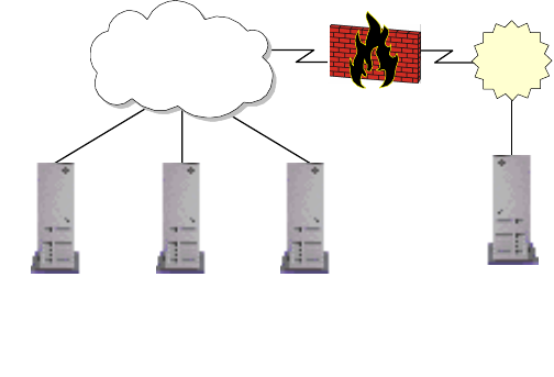
110 IP Network Design Guide
It can be seen that the sales node and the IT node both have subdomains below
them. In the case of the IT node, there are two additional subdomains, namely
node_a and sales domains.
Splitting the domain name space into smaller segments will enable it to be much
more manageable. If there are 1000 hosts under the pc subdomain and 1000
hosts under the enterprise domain, the IT DNS server serves only two domain
names, the pc DNS servers and the enterprise DNS servers. The host’s domain
names are served by their respective name servers.
It is also noticed that the names of hosts are often repeated in the domain. In a
flat domain this is not possible. The FQDN of the hosts in a hierarchical domain
space differ from one another; for example, host_a.pc.sales.rootdomain.com is
not the same machine as host_a.pc.it.rootdomain.com. This may not seem an
important consideration for a small network, but in large networks this is very
important.
It is practical to name a server by its function, like mail.rootdomain.com. This is
easy enough when you need only one mail server. But if the Sales and IT
departments of your organization are large enough to warrant separate mail
servers, it would not be possible to have two mail.rootdomain.com servers. In a
hierarchical scheme, mail.sales.rootdomain.com and mail.it.rootdomain.com are
both valid names for the servers.
3.3.6.3 Name Server Structures for Scenario Two
The domain servers can be placed inside the network. This configuration is
presented in Figure 45 on page 110. As can be seen, the DNS server(s) are on
the local network.
Figure 45. Internal Domain Server Allocation
This model can be extended to incorporate numerous DNS servers serving
multiple subdomains. Figure 46 on page 111 displays this model.
Firewall
Organizational
Intranet ISP
2580B\CH3F42
DNS
Cache Server
Secondary
DNS Server
Primary
DNS Server
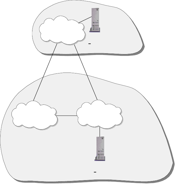
Address, Name and Network Management 111
Figure 46. Internal Domain Server Allocation with Multiple DNS Servers
In both of these scenarios, the outside world has access either to all or none of
your DNS services. This depends on the configuration of the firewall. Allowing
access to your DNS server is not a good idea, it leaves a security hole that can be
attacked.
If your organization requires some addresses be advertised on the Internet, a
better idea is to have two DNS servers. These would be placed inside the
organizational Intranet, behind the firewall, and outside the Intranet, in a
demilitarized zone, without the protection of the organizational firewall. This
scheme is presented in Figure 47.
Network B
2580B\CH3F43
DNS Server
Serves rootdomain.com
DNS Server
Serves subdomain.rootdomain.com
Network A
Network C
rootdomain.com
subdomain.rootdomain.com
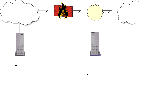
112 IP Network Design Guide
Figure 47. Implementing Internal and External Domain Name Spaces
This scheme enables the organization to have DNS services to all the internal
hosts, while limiting external DNS services to those machines listed on the
external DNS server. For large IP networks, this scheme, coupled with a
hierarchical domain name space, is recommended for the DNS implementation.
3.3.7 A Few Words on Creating Subdomains
Creating subdomains must have a structure. New subdomains should not be
needlessly added to the domain name space. There should be legitimate reasons
for splitting up a domain space into subdomains. These include:
• The number of machines whose names are being served by a DNS server. If
the number of hosts whose names are being served by the DNS server is
excessive, the performance the clients will receive will be unacceptable. In
effect, there is a flat name space model, even though it may be a few layers
down a Hierarchical domain space. See Figure 48 on page 113 for a graphical
interpretation of this.
• Organizational requirements may influence the creation of subdomains in the
domain space. The Sales department may need a separate subdomain from
the IT department.
It should be remembered that a new subdomain does not necessarily require a
new DNS server to be installed. A single DNS server can maintain multiple
domains, each with many subdomains.
DNS Server
DNS server only serves
internal domain names.
These names are
blocked at the firewall.
DNS Server
DNS server only serves external
sites.
This DNS server is in the
demilitarized zone.
Firewall
Organizational
Intranet InternetDMZ
2580B\CH3F44
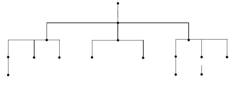
Address, Name and Network Management 113
Figure 48. Badly Structured Domain Name Space and Subdomains
3.3.8 A Note on Naming Infrastructure
When choosing names for infrastructure, it must be remembered to try to follow
some guidelines. Some recommendations for naming hosts are:
• Make host names short and simple. Host names are designed to help people
remember machine names rather than cryptic IP addresses. Creating cryptic
host names defeats the purpose of implementing DNS.
• Suffixes can be implemented to indicate the function of the host. Examples for
suffixes can be
svr
or
rtr
, representing a server and router respectively.
• Location codes can be used to indicate the location of resources. Try to avoid
using numbers of location codes as these can become confusing.
• Remember, without implementing internal and external DNS servers, some of
these recommendations can create very bad security risks. The easier it is for
you to recognize a host name, the easier it is for a potential attacker.
3.3.9 Registering An Organization’s Domain Name
The process of registering a domain name depends upon which top level domain
your organization will be implementing. The InterNIC maintains the domain name
space for the top level domains, COM, NET, ORG and EDU. The InterNIC’s Web
site is located at:
http://www.internic.net/
Registering domains under other top level domains, such as country domains for
non-US-based organizations, requires contacting the relevant domain manager
for that top-level domain.
The basic steps you need to follow are:
1. Find out if the domain name you want is available. This can be done by
searching the whois database on the InterNIC’s Web site. Many domain
names have been used by organizations already.
If you believe that a domain name that has been assigned to another
organization should belong to you, there is a way of disputing the domain
name in question. Details of this policy can be found at the InterNIC Web site.
servicessales IT
host_zhost_x
pc host_ahost_a host_b
host_a
host_a host_b
pc enterprise
com
root domain
2580B\CH3F27
114 IP Network Design Guide
2. Arrange for domain name service. This is done using one of the models shown
above. It makes no difference whether your ISP hosts your domain or your
organization is hosting the domain.
Remember, this is the DNS server that will be advertising the domain names
to the world. If you are implementing both internal and external DNS servers,
you will need to provide the external DNS server’s IP address.
The InterNIC insists on having both a primary and secondary DNS server
address before it processes your application. Your organization must provide
two IP addresses for these servers respectively.
3. Review the InterNIC's registration policies and billing procedures. The
InterNIC has these available on its Web site. It is essential to review these
before filling in the application forms.
4. The registrant will then submit the forms to the InterNIC for processing.
The InterNIC Web site maintains extensive and up-to-date information on
registering a domain name. The Web site should be visited before any steps are
taken to register a domain name.
3.3.10 Dynamic DNS Names (DDNS)
If DHCP is to be used in the network, DDNS should also be implemented. The
host will typically receive, along with the IP address and subnetmask, a host
name. The host name assigned is usually in a form like:
host19.dynamic.ibm.com
or
pc19.dhcp.ibm.com
These are two common implementations. It is a good idea to place dhcp or
dynamic as a keyword in the FQHN. This allows the network administrator to
easily identify dynamically assigned hosts.
In very large networks, it is a good idea to implement location codes in the
dynamically assigned addresses also. These do not necessarily need to be very
specific. A general code, such as a country or office code, is often sufficient. This
simplifies management of DHCP and DDNS services.
It should be remembered that DHCP and DDNS services should always be used
in conjunction with some static addresses. A Web server whose URL changes
every time it is restarted is not very useful. There are ways of binding static host
names to dynamic IP addresses, but there are as yet no standards on this topic.
The IBM DDNS server, used in conjunction with the IBM DHCP server,
implements static host names with dynamic IP addresses. After the DHCP client
has assigned a host an IP address, the host requests an RR host name to the
new IP address update. The host sends this request to the DHCP server and the
DDNS server. The DHCP server requests the DDNS server to update the PTR
RR IP address to host name for reverse lookup functionality.
This is done securely, using RSA Public Key Authentication. Further information
can be found in
Beyond DHCP - Work Your TCP/IP Internetwork with Dynamic IP
,
SG24-5280.
Address, Name and Network Management 115
3.3.11 Microsoft Windows Considerations
Microsoft implemented NetBIOS, or rather SMB that relies on NetBIOS services,
as its network protocol of choice for its Windows operating systems. With the
acceptance and dominance of TCP/IP networks, NetBIOS is often used in TCP/IP
environments.
NetBIOS by default reverts to broadcast messages. With NetBIOS over TCP/IP
(NetBT) the number of broadcast transmissions can affect the performance of the
network. This must be considered when designing the naming scheme. If the
Windows-based hosts do not have some sort of name resolution scheme
implemented they will revert to broadcasting messages.
Windows hosts can use one of three methods for name resolution.
3.3.11.1 lmhosts File
An lmhosts file acts like a static host file, as described in 3.3.1, “Static Files” on
page 89. It has the same problems associated with other static files on other
platforms. It is not a desired way of implementing name resolution, except in very
small networks, typically consisting of fewer than 10 hosts.
3.3.11.2 Windows Internet Name Service (WINS)
To avoid the problems associated with the use of broadcast transmissions and
the level of maintenance required and general impracticality of an lmhosts file in
larger networks, Microsoft developed WINS. A WINS server resolves NetBIOS
names to IP addresses.
A host configured as a WINS client will first check with the WINS server to see if
it can locate the host. If this fails, the client will look at its local lmhosts file to
resolve the name, and will then revert to the use of broadcast transmissions on
the network.
Integrating WINS with DHCP
In a DHCP environment, the worst design would be to implement DHCP for
dynamic addressing of IP addresses and then go to each host configuring WINS.
This can be avoided.
A DHCP server can provide the address of the WINS server in its response to a
DHCP client. The host DHCP client, when it leases or renews an IP address,
receives the address of a primary and secondary node as well as options to
configure the client as an H-node.
WINS Proxy Agent
If WINS is incorporated into an existing network, it is worth implementing a WINS
proxy agent. In a network that has Windows hosts that are not configured to use
WINS, the proxy agent will listen for broadcast name registration and resolution
requests. Figure 49 on page 116 shows the operation of a WINS proxy agent.
If the WINS proxy agent detects a name registration request, it verifies the
request with the WINS server to verify no other host has registered that name. It
should be noted that the name is not registered, only validated.
For name resolution requests that are broadcast onto the network, the proxy
agent first checks its own name cache to resolve the name. If this fails, the proxy
agent forwards the request to a WINS server, which replies to the proxy agent
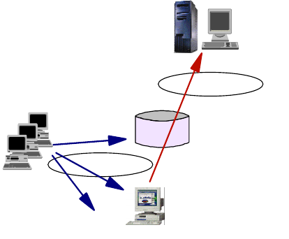
116 IP Network Design Guide
with the IP address for the requested name. The proxy agent then responds to
the client with the information from the WINS server.
With a mixed environment of Windows hosts configured, or not configured, to use
WINS, a WINS proxy agent:
• Reduces the number of client name conflicts by validating name registration
requests
• Reduces the extent of broadcast messages by responding to them
• Improves the performance
Figure 49. A WINS Proxy Agent
WINS and DNS
In a Windows environment, hosts require a NetBT and an IP host name. This is
not an ideal arrangement. Configuring these names to be the same is not a
requirement. If hosts have differing NetBT and IP host names, management can
become farcical.
WINS is a dynamic system so it requires very little maintenance. However, WINS
works in the NetBIOS name space. It is not compatible with the IP name space
used by DNS. It is a good idea to use the same host names for NetBT and IP
name spaces. This can be done by dynamically updating the DNS server with the
WINS server.
With typical DDNS servers, this is not possible as they cannot communicate with
a WINS server. Microsoft’s DNS server, however, is able to communicate with the
Microsoft WINS server. With the integration of the Microsoft DHCP server, a suite
exists capable of providing a complete solution to the automation of address and
name management for a Windows environment. Figure 50 on page 117 presents
the Microsoft model for this solution.
As only Microsoft DNS servers and a few commercial products support WINS,
basic BIND cannot be used in conjunction with a WINS server. The implication of
this is that all the DNS servers must be Microsoft DNS servers.
For example, if you have an IP network that uses WINS and whose domain is
itso.ibm.com, and if someone wanted to communicate with host_x.itso.ibm.com,
he/she would contact a DNS server that had authority for the itso.ibm.com zone in
WINS
Server
Non-WINS
Clients
Router
WINS
Proxy
Agent
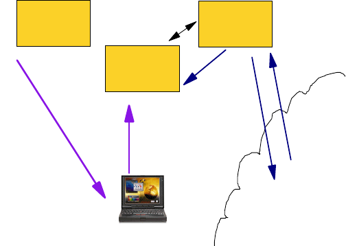
Address, Name and Network Management 117
the ibm.com domain. If host_x is a Windows host that is configured to use WINS,
a DNS server running BIND will know about host_x, that it does not receive
updates from the WINS server. Thus the remote client trying to communicate with
host_x will fail to have the name resolved.
A solution to this problem is to place all of the WINS clients in their own DNS
zone, such as wins.itso.ibm.com. All the DNS servers in this zone should be
Windows NT DNS servers or another DNS server that can be integrated with
WINS.
Figure 50. The Microsoft Windows NT DHCP - WINS - DNS Model
3.3.11.3 The Network Neighborhood Browser Service
One amenity of the graphical user interface of Microsoft Windows systems is the
feature called Network Neighborhood Browser. It allows users to easily find other
systems, particularly servers, in the network and then to attach to file and print
resources that those systems may have available or shared. The trade-off of this
service is that it creates a significant amount of traffic that you do not want to
allow over WAN links and that it requires a Windows NT domain in order to work
across multiple network segments.
The neighborhood browser service is based on broadcasts that are usually
confined to physical network segments. In a Windows workgroup environment,
the highest ranking system assumes the role of master browser for the subnet
and collects information on all other workgroups, domains and systems that have
shared resources. The ranking is determined during an election phase and goes
as follows:
1. Windows NT Primary Domain Controller (NT 4.0 wins over NT 3.5)
2. Windows NT Backup Domain Controller
3. Windows NT Member or Stand-alone Server
4. Windows NT Workstation
5. Windows 98
6. Windows 95
7. Windows for Workgroups
Once a master browser has been determined, a number of backup browsers are
defined that then gather a host of systems with shared resources.
DHCP
server DNS
server
WINS
server
DHCP
client
Query
DNS
Return
IP Address
or Host Name
Get
IP
Address
Register
Computer Name
& IP Address
Pointer to
WINS

118 IP Network Design Guide
Note: It is enough for a system to have the server service enabled in order to
appear in that list.
Clients find shared resources in the following way:
1. Find the master browser via broadcast
2. Get a list of backup browsers from the master browser
3. Get a list of servers from a backup browser
4. Get a list of shared resources from a server
However, if a workgroup spans more then one subnet, resources across subnets
cannot be found. The solution to this is to implement one or more Windows NT
domains. That introduces a new component called a domain master browser
(DMB) that is usually assumed by the primary domain controller (PDC). The DMB
builds a list of all servers and domains. In order to do that, it requires WINS.
DMBs periodically update their browse lists to master browsers on other subnets
that are registered with WINS. This will ultimately allow clients to find domain
resources anywhere in the network. A WINS server also helps clients and servers
find their PDC.
Whenever a Windows system is turned on or shut down, it causes neighborhood
browser related traffic. The same is true whenever a user browses the Network
Neighborhood application. To avoid unnecessary browser election traffic, the
participation in elections can be turned off in the following way:
Windows NT Workstation
Set the
HKEY_LOCAL_MACHINE\SYSTEM\CurrentControlSet\Services\Browser\Par
ameters\MaintainServerList value to No.
Windows 95 and 98
From the Network Control Panel, set the Browse Master parameter in
Properties tab for the File And Printer Sharing for Microsoft Networks to
Disabled.
Windows for Workgroups
Add the MaintainServerList keyword in the [network] section or the
SYSTEM.INI file and set it to No.
3.3.12 Final Word On DNS
Always remember, whenever configuring DNS systems, the goal of DNS is to
enable people to easily identify and remember hosts, without using cryptic IP
addresses.
This is the theme for the design of DNS. DNS should be implemented in this
manner. Computer systems do not require DNS, they are perfectly happy using IP
addresses. It is people who require these systems to work efficiently, so all
designs should endeavor to be people friendly.
3.4 Network Management
Imagine traveling on the highway at 80 miles an hour in a car without a steering
wheel. This is what it is like to run a network without network management in
place.
Address, Name and Network Management 119
Network management refers to having a set of processes, tools and infrastructure
to manage the computing resources that you have. You may encounter the terms
Enterprise Management, System Management, or Network Management and find
them confusing and difficult to understand. Enterprise Management refers to an
architecture, like the Tivoli Framework, that provides management solutions that
make it easier for an organization to centrally manage all of its corporate
computing resources, from hardware to network to servers to applications and
even desktop workstations. System Management usually refers to the discipline
of managing the resources on a host, for example the disk space, memory,
performance and backups, etc. Network Management, in its strict sense, refers to
the management of the network infrastructure: the networking devices, the links,
the performance of the network, etc. But in this book, we refer to network
management as a generic term.
3.4.1 The Various Disciplines
Network management involves many aspects of a company’s computing
environment. It is best to divide these into various disciplines:
• Deployment
Deployment refers to having the ability to centrally configure an application
and then distribute it to the users through the network. It is responsible for the
installation, upgrade and even removal of the applications from a central
control location.
• Availability
Availability ensures that the users are presented with a reliable and
predictable service from the applications and the rest of the computing
resources like the network. An example is the Tivoli NetView, which helps the
network administrator to manage his/her network through a graphical view of
his/her TCP/IP network infrastructure.
• Security
Security refers to the ability to provide comprehensive protection of
applications and information assets by implementing access control and
system security services.
• Operations
Operations provide tools to automate routing tasks, such as job scheduling,
storage, and remote system management. These tools relieve the network
managers of time-consuming tasks so that they can spend time on other more
critical events.
• Application Management
Application management helps improve the availability and performance of the
systems, so that user requirements can be met.
3.4.2 The Mechanics of Network Management
The mechanism for network management to work in a network relies on a few
technologies. These are standards that almost all vendors have to follow and
make available through their products.
When the Internet began to grow, network managers realized some procedures
needed to be introduced to manage the network that was slowly growing out of
120 IP Network Design Guide
hand. The Simple Network Management Protocol (SNMP) was introduced as a
"stand-in" solution and is based on the TCP/IP communication stack. This
"temporary" status was chosen because designers thought there ought to be a
better system. The Common Management Information Protocol (CMIP) was later
introduced and is based on the OSI model.
• Simple Network Management Protocol (SNMP)
The Simple Network Management Protocol (SNMP) is used in an IP network
to exchange information between hosts. SNMP uses the UDP protocol to
transport and exchange information called Protocol Data Units (PDUs). It
provides a framework that allows information to be sent so as to effect a
change in the status of the network. The information is kept by hosts in their
run-time environment in a data structure called the Management Information
Base (MIB). There are three important elements in SNMP: the manager, the
agent and the MIB. Network managers need to have a basic understanding of
these, so as to help in the network design. The manager is the host that
solicits management information from the other devices in the network. The
agent is in charge of collecting information on the operating status of a host
and maintaining it throughout the operation. The agent also replies to the
manager’s request for information in the MIB. Note that a manager can itself
be an agent to another manager.
The SNMP framework provides five basic operating steps:
• SNMPGET
The requesting workstation sends out a SNMPGET request to the
destination to solicit a specific MIB value. Information that needs to be
present in a Get request includes:
• IP address of destination
• Community name (see explanation below)
• MIB instance (see explanation below)
• SNMPSET
The SNMPSET request is sent out to the destination to instruct a change in
a specific MIB value. This usually results in a change in the operating state
of the receiving device. Information that needs to be present in a Set
request includes:
• IP address
• Community name - read-write or write-only
• MIB instance
• Target value of the MIB instance
•SNMPWALK
The SNMPWALK is just like the SNMPGET request, except that in
SNMPGET, the exact MIB instance has to be specified while SNMPWALK
allows you to specify an entire subset of a MIB tree to retrieve all
information pertaining to that subset.
• SNMPGETNEXT
The SNMPGETNEXT retrieves the information that is next in line in the MIB
tree,.
Address, Name and Network Management 121
•Trap
Traps are generated by the agents to inform the manager of an event that
happened during operations. An example is the Coldstart trap, which an
agent sends to the manager when it is first powered up. The most common
traps that come with an IP workstation are:
•Coldstart
•Warmstart
• Authentication failure
• Management Information Base (MIB)
The Management Information Base (MIB) is a logical collection of operating
data about a specific device, such as a router. The MIB contains snapshot
information, called an instance, such as device type, device configuration,
performance data and status of its interfaces. A MIB instance is denoted by a
string of numbers in the form .1.3.6.1.4.1, that represents a unique branch of
information in the structure of the MIB data structure called the MIB tree.
A change in a MIB instance value usually changes the operation of the device,
so it is important to keep MIB instances of important devices like routers,
switches and servers from malicious users. Two pieces of information need to
be presented in order to access a device’s MIB, that is, the device’s IP address
and the community name.
• Community Name
Community name in SNMP is just like a password to a user account. It is a
string of characters that the administrator of a device has chosen. The access
of MIB values is determined by a match in the community name, and operation
of the MIB value is determined by the attribute of the community name. An
administrator can configure various community names for a single device,
each with a unique attribute:
• Read-only
• Write-only
• Read-write
• Read-write-trap
SNMP is the most widely used network management protocol today. Almost all of
the devices that connect to a TCP/IP network come with an SNMP agent. In fact,
it would be difficult to find one that does not have an SNMP agent. The reasons
for SNMP’s popularity are due to the following:
•SNMPissimple
The architecture of SNMP is very simple. It is based on exchanges of
information and does its job with few resources required on the hosts.
•SNMPisflexible
SNMP provides flexibility in its MIB definition. The tree-like structure enables
new functions and devices to be introduced without affecting the original
structure. Managers just need to be informed of the new MIB value and
information can be exchanged right away.
• SNMP is easy to implement
122 IP Network Design Guide
It is easy to implement SNMP, as there is not much configuration required for
agent setup. Also, it does not occupy too much network bandwidth to operate,
and this is very attractive to network managers.
Although SNMP has its advantages, it suffers from two major problems:
• Security
In SNMP, requests and replies are sent in clear text. This poses a serious
security threat to the network as hackers are then able to intercept these
exchanges and explore sensitive data. The most obvious threat is access
to the community names, which could be used subsequently to sabotage
the network.
• Simple Data Structure
As the MIB is basically a simple data structure, it cannot contain some
complex representation of run-time environmental values. The operating
state of a device cannot be accurately reflected for this reason.
•SNMPv2
The flaws of SNMP prompted the development of SNMPv2, or SNMP Version
2. SNMPv2 introduced a few features to combat the security and data
structure, including:
• Expanded data types
• Improved efficiency with new operations like SNMPGET-BULK
• Richer functionalities in error handling and exceptions
• Minor fine tuning to the data definition language
Although it is meant to replace SNMP, SNMPv2 falls short in that as it did not
solve all of the flaws of SNMP. The security aspects is one loophole that
SNMPv2 did not solve. Because of this limitation, SNMPv2 is not widely
implemented and usedby vendors. In fact, it exists only on paper. Although we
have capable network managers, like the Tivoli NetView, which can "speak"
both SNMP and SNMPv2, we find most of the agents in the network are SNMP
agents.
•SNMPv3
The SNMPv3 is formed by the IETF to "tighten" what is left behind by
SNMPv2. It reuses the standards that have been proposed in SNMPv2 and
added features like the security and administration portions. SNMPv3 includes
the following:
• Authentication and privacy of data
• Access control to information
• Naming of entities
• Proxy relationships
• Remote management via SNMP
Although SNMPv3 looks promising and seems able to solve the problems that
are encountered by SNMP, it will be some time before it gains widespread
acceptance.
• Common Management Information Protocol (CMIP)
Address, Name and Network Management 123
The Common Management Information Protocol (CMIP) is based on the OSI
model. It was meant to replace SNMP, but it too suffered the same fate as
SNMPv2. Not many networks have implemented CMIP for its management,
except the Telcos.
The CMIP architecture is broader in scope and has more complex data
structure than that of SNMP, as it was meant to address all of SNMP’s
shortcomings. It is quite the same as that of SNMP in terms of information
exchanges, except that instead of five types of PDUs, it contains 11.
The advantage of using CMIP over SNMP is it can represent complex
operating status due to its data structure. It provides functionalities that are
not available with SNMP, and is suitable to be used in complex network
environments like that of the Telcos. It has superior security features that
ensure the confidentiality of data.
One major disadvantage of CMIP is due to its resource intensiveness. It
requires special network design consideration and capacity planning to
implement it. Examples like the Telecommunications Management Network
(TMN) is actually a network that manages another network. Another
disadvantage of CMIP is that skilled personnel is difficult to find.
Due to its complexity and completeness of what it can achieve, a CMIP-based
network manager system is very costly to develop. An example is the TMN,
which uses CMIP and the development cost for it usually runs into millions of
dollars.
3.4.3 The Effects of Network Management on Networks
One of the major concerns about implementing network management is the effect
it has on the performance of the network. It is like an oxymoron: we are
introducing some tools to make sure the network runs well, yet these tools take
up the bandwidth resources.
A major task of a network management workstation is to check on the status of
important devices. Usually, the manager does it through a heartbeat check, like a
periodic ping to the target devices. The time interval between these checks is
called the polling interval. The expected time taken by the target to reply is
decided by a value called the response time-out. When no response is received
from a target, the manager retries for a preconfigured number of times, called
retry time-out. When no response is receive after all these retries, the network
management workstation will then deduce that the target device is out of order,
proceed to recognize the event as "host is down" and send out an alert.
It is the polling interval, response time-out and number of retries that are most
crucial to ensuring that we are not overloading the network with all this checking.
Having a "busybody" network management workstation checking on an already
overloaded router just makes the situation worse. We need to strike a balance in
configuring these values and two criteria will help us:
• How critical is the target device to the operation of the network?
• What is the maximum down time of a target device you can accept before
some alarm is raise about its failure?
By answering these questions about the target devices that you have, it would be
clear which device is critical and which is not. A critical device needs to be
monitored more often, and ts failure needs to be verified very quickly. A
124 IP Network Design Guide
not-so-critical device need not be monitored as often, and its failure need not be
verified very quickly. Typically, for critical devices like routers and servers, 3
minutes for polling interval, 5 seconds for response time out and three retries
would be adequate. The not-so-critical devices will each be monitored with 10
minutes for polling interval, 10 seconds for response time-out, and three retries.
Another important aspects of network management is the trap configuration on all
the devices on the network. Most, if not all, of the IP hosts have the ability to send
traps into the network. As discussed, the purpose of traps is to inform the network
manager of certain events that happen. It is important to prevent trivial devices in
the network from sending out these events so as not to load the network with
unnecessary traffic. For example, in a normal working day, there may be a few
hundred workstations in a company’s network that get powered up and down
randomly. Imagine if they enabled the trap function, then hundreds of cold-start
traps could be generated, flooding the network with unnecessary information. On
the other hand, it may be crucial to have a router send this information, because
receiving such traps from a router can mean there was a power trip and some
investigation needs to be done. Thus, it is important for a network manager to
decide which device in the network should turn on the trap-sending function, and
which should not.
Another important decision to make is the span of control for the network
management station. Since the network management station will monitor
whatever is under its view, it is important to decide how big the view should be.
The bigger the span of control, the more traffic is generated. Usually, the view is
expanded at a subnet level. Thus, it is wise to configure the network management
station according to which subnets it should monitor and which it should not. The
problem with this method is that all devices residing in the same subnet will be
included, whether or not they are important. This situation poss a problem for
large networks, as we may only be interested in managing certain devices in the
subnet. In this case, it may be better to configure the network management
station to determine which devices to manage explicitly. This will incur additional
configuration effort, but since it is only a one-time affair, it is worth the effort.
3.4.4 The Management Strategy
It is important to have a management strategy in the beginning and incorporate it
into the design. An area that the strategy has a profound impact on is network
design. In a TCP/IP network, it is almost a standard to choose SNMP as the
network management protocol because of its widespread use. In SNMP network
design, reachability has to be ensured so that information can be exchanged
between the manager and the agents. But reachability can also invite intruders
and thus segregating the agents from the users becomes a challenge. In
networks that use ATM, it is possible to group all the managed devices within a
single IP subnet, although they may be physically separated. In this case, the
network management strategy has to be in place from the beginning as a network
designer needs to plan for the provision of the IP subnet and the assignment of
the IP address. Regardless of the type of networks, the community names need
to be decided and documented so that devices can be configured in the
implementation stage. Also, since MIB contains important operating information,
security needs to be addressed and the characteristics of the agents (which
workstation, its IP address, its own security, etc.) need to be established early in
the network design phase.
Address, Name and Network Management 125
Generally, the following steps should be followed:
• Determine the devices’ SNMP capability
• Determine the network management software’s capability
• Decide what you want to achieve with network management
• Possibly upgrade those devices that do not have SNMP capability
• Design any additional management functions through customizations of the
network management software
• Configure the agents and managers for correct community names
• Test the configurations for accuracy of data
126 IP Network Design Guide

© Copyright IBM Corp. 1995 1999 127
Chapter 4. IP Routing and Design
This chapter discusses the aspects of routing in an IP network. Routing is an
integral part of IP network design because it is the mechanism that provides
reachability for the applications. If a workstation cannot reach its server to pull off
some record, it simply cannot present data for the user to service a request.
As mentioned in 2.2.3, “Router” on page 60, the piece of hardware that is in
charge of routing is called the router, which functions at the network layer of the
OSI model. With the popularity of switching and the introduction of layer-3
switches, more and more network managers are letting the layer-3 switch take
over this function where appropriate. The difference between these are
discussed.
For network managers who are designing a network, it is important to know what
routing protocols are available, the basics of their functionality, and the
advantages and disadvantages of using them. In the design of the IP network,
network managers have to understand the effect routing has on the performance
of the network. The functioning of the applications is greatly affected if there is a
routing problem in the network. Thus, it is also important to consider possible
ways of optimizing routing, or even bypassing routing, to optimize the
performance of the network.
In 4.6, “Important Notes about IP Design” on page 151, we look at the guidelines
for designing an IP network.
4.1 The Need for Routing
The first question you may ask is about the need for routing. Of course, not every
network needs to have routing, but generally, routing is required for the following
reasons:
• Connect Dissimilar Networks
As mentioned earlier, since the IP functions at the network layer of the OSI
model, in order to connect dissimilar (whether in physical topology or IP
address) IP networks together, they have to be routed instead of bridged.
• Design Strategy
Routing is required as part of a design strategy. As will be mentioned later in
this chapter, the network should be built in a modular fashion. With modular
design, you have a collection of networks that need to be connected. And
routing is the glue that connects all these networks together.
• Security
Some security rules may need to be imposed on the network due to a
business requirement. The security rules are none other than preventing some
users from accessing sensitive data. This security check is usually done at the
network layer and is called filtering. A router provides the filtering functions
through the implementation of some rules design by the network manager.
• Connecting a Remote Office
As mentioned in 2.1.3, “WAN Technologies” on page 31, the WAN
technologies are mostly implemented by the router. The router comes with the
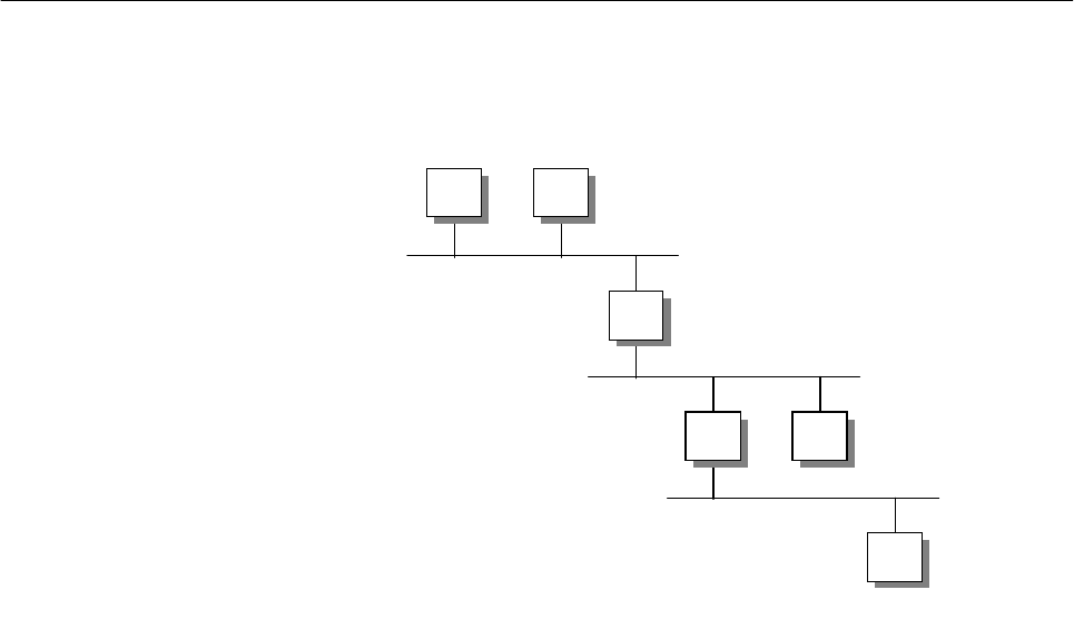
128 IP Network Design Guide
appropriate WAN interface, depending on the types of carrier service chosen
(X.25, frame relay, ISDN) and LAN interface (Ethernet or token-ring) so that a
remote office LAN can get connected back to the central office.
4.2 The Basics
Before we discuss the finer aspect of routing, it is important at this point to revise
the process of how IP packets are sent out into the network and transferred to the
destination.
Figure 51. Routed Network
The above diagram shows three IP networks connected by two routers, R1 and
R2. For different destinations, workstation A uses different ways to send its IP
packets to the destinations.
AtoB
For workstation A to send data to workstation B, it first checks its ARP cache for
workstation B’s hardware address. It issues an ARP request for workstation B’s
hardware address if it is not already in the ARP cache. After learning workstation
B’s hardware address, workstation A sends the packets into the network.
AtoC
For workstation A to send data to workstation C, A realizes that C is not on a local
subnet. A then proceeds to check its own routing table for the network that C is in.
If A’s routing table does not have the network entry, A then proceeds to send the
packets to its default router, which is R1. A uses ARP to find out the hardware
address of R1.
AtoD
For workstation A to send data to workstation D, it follows the same procedure as
that of sending data to C. The important point to note is that A does not care how
the packets traverse from R1 to R2 onto D’s network. It just passes the data to R1
and expects R1 to "route" it to the destination.
D
CR2
R1
BA
2580B\CH2F14

IP Routing and Design 129
The important thing at this stage is how R1 manages to know how to forward the
data to R2. When routers are installed in a network, they are configured with this
information (static route) or they learn from each other through some protocol
(dynamic route). With this learned information, R1 has in its routing table
information pertaining to reaching the network that D is in; that is, to reach that
network and forward traffic to R2. In its simplest form, the routing table in R1
looks like the following table:
Table 9. Sample Routing Table For R1
The difference between A sending to B, and sending to D, is that the latter
involves two routers in its data path. Routers need time to process the incoming
data, as they need to check again their routing table and decide how to forward
the traffic. In this case, when A sends data to D, the data is said to have incurred
a cost of two hops. The more hops a data has to pass through, the more delay is
introduced.
The main purpose of IP design is to investigate the effect these hops have on the
applications and optimize the design such that workstations are connected with
the smallest possible hop counts.
With the understanding of how routing takes place, it is also important to know
some of the important terms that are always associated with routing:
• Default Router
In the above example, router R1 is said to be the default router of workstation
A. Workstation A will always forward its IP packets to router R1 whenever it
needs to reach a remote network. Upon checking its routing table, router R1
will either forward workstation A’s packets to the destination or drop the packet
because it does not have the information.
The role of the default router is very important to the workstations, because it
is responsible for forwarding traffic on behalf of them to the outside world. A
malfunction default router means a loss of contact with the rest of the network,
and that means it is a system outage. Also, you begin to realize the
importance of having the ability to have multiple default routers for backup
purposes. Windows 95 workstations do not have this capability and thus, the
so-called default router redundancy would have to be implemented by some
other means.
• ICMP Redirect
In the above example, workstation C can elect either R1 or R2 as its default
router. In the event that R1 is elected as the default router, C will send data to
R1 when it needs to talk to A, B or D. Sending to A and B is straightforward: it
passes the data to R1, R1 proceeds to forward the traffic to A or B. The tricky
part is when C wants to forward data to D. SInce R1 is the default router, all
data will be forwarded to R1 from C. R1 is then going to realize that in order to
reach D, it has to forward the traffic to R2. This "bouncing" of traffic from R1 to
R2 will create extra delay and also extra traffic on the network.
To reach Mask Use
200.0.1.0 255.255.255.0 local interface
200.0.2.0 255.255.255.0 local interface
200.0.3.0 255.255.255.0 R2

130 IP Network Design Guide
To overcome this situation, routers implement the ICMP redirect, which
informs workstation D that instead of sending the data to R1, it should instead
send to R2. This would require workstation D to have the ability to handle
ICMP redirect messages that were sent out by R1. Not all workstations
support this feature and thus, it is better to avoid designing the network in this
manner.
• Routing Table
Routers in the IP network keep a routing table so that they know how to
forward traffic correctly in the network. The building of the routing tables can
be done manually by the network managers (called static routing) or it can be
learned dynamically through exchanges of information among the routers
(called dynamic routing). The difference between these two are discussed in
4.3, “The Routing Protocols” on page 130.
The performance of a router depends very much on the size of the routing
table. A bigger routing table means more information has to be processed,
which slows things down. A bigger routing table also means more processing
work is involved when routers exchange routing information. Thus, one
important aspects of network design is how to minimize the routing table size.
There are a few methods of achieving this, which will also be discussed later.
• Autonomous System (AS)
An autonomous system is a collection of networks that falls under the same
administration domain. The networks within an AS run a common routing
protocol, the Interior Gateway Protocol, and exchange information with
another AS through an Exterior Gateway Protocol.
• Intermediate Systems (ISs)
Intermediate systems (ISs) refers to those devices that can forward packets to
the required destination. A router is an example of an IS, as is a UNIX server
with a routing daemon turned on.
• End Systems (ESs)
End systems are those devices in the network that do not have the ability to
forward packets. A Windows 95 PC is an example of an ES.
• Interior Gateway Protocol (IGP)
The Interior Gateway Protocol is used for exchanges of routing information by
routers located within an autonomous system.
• Exterior Gateway Protocol (EGP)
The Exterior Gateway Protocol is used for exchanging routes between two
autonomous systems.
4.3 The Routing Protocols
There are several ways of implementing routing in an IP network. Basically,
routing can be divided into two categories:
static routing
and
dynamic routing
.
Both of these have their own merits and disadvantages and network managers
have to decide which one is suitable based on the following criteria.

IP Routing and Design 131
4.3.1 Static Routing versus Dynamic Routing
Static routing, as its name implies, is configuring the routing tables in the routers
within a network prior to operation. It is mainly used in small networks, with two or
three routers and a few IP subnets. The benefits of using static routing are as
follows:
•Itissimple
Since static routing is configured by network managers before operations of
the router, its operation is very simple: it either works or it does not work right
from the beginning.
• It has lower overheads
Since every route is configured statically, no run-time updates are necessary.
As such, it does not consume bandwidth of the network to check on the status
of partners.
• It is easy to troubleshoot
Since routing is configured before implementation, it is possible to
troubleshoot the network "on paper" first. Checking can be made offline and
rectified before effecting any changes.
Static routing can be used only in a small network, with minimal configuration
required. It is always recommended when a remote network is connected to a
central network with only one link. Since there is only one link, a default route can
be put into the remote router to forward all traffic to the central site router.
The problem associated with a static routing network is scalability. Other than the
remote connections with single links, implementing static routing in an
interconnected network in a LAN environment poses serious administrative
challenge. As network grows, more effort is required to implement the static
definitions. These definitions have to be introduced in every routers for new
networks, and any changes means having to configure most, if not all, routers.
Another problem associated with static routing is that traffic is not diverted if there
is a link failure. This poses a serious problem for networks that need intelligence
to overcome link failures. Because routing instructions are constructed before
deployment, static routing lacks the ability to adapt to any changes in the
operating environment.
The use of dynamic routing takes care of these problems and provides even more
features that are lacking in static routing, such as dynamic re-route. The main
attribute of dynamic routing is that routers build their own routing table through
information exchanged with each other during run time. No static definition is
required. Since the routers learn the routes on their own, they can react to link
failure by re-learning the way the new network is connected.
The following table illustrates the difference between static routing and dynamic
routing:
Table 10. Comparisons Between Static And Dynamic Routing
Static Routing Dynamic Routing
Route table built by network manager Route table built dynamically by router
Easy to troubleshoot Requires in-depth knowledge of the protocol
to troubleshoot

132 IP Network Design Guide
4.3.1.1 Convergence
In dynamic routing, you need to be concerned with the concept called
convergence. Convergence refers to the time it takes before all routers in the
network have a common representation of the network’s connectivity. A fast
convergence means that in the event of a network topology change, the routers
can react quickly to this change and update their routing tables to reflect the new
network connectivity. This is important because when a link fails, an alternative
path has to be discovered, if it exists.
The way routers inform each other of their status is important. There are two
ways that routers exchange updates to each other: with the distance-vector
protocol and the link state protocol.
4.3.1.2 Distance Vector Protocol
Routing tables in routers using distance vector protocols are built from the
principle that every router maintains a distance from itself to every known
destination in a distance vector table. Two parameters are needed to be present
in the tables:
• Vectors: The destinations in the internetwork
• Cost: The associated distance to reach these destinations
Each router transmits its own distance table across the internetwork and each
router calculates its own distance vector table from the information provided by
other routers.
No capability of re-route Automatic re-route
Administrative effort required to maintain
routing intelligence No administrative effort required to maintain
routing intelligence
Supported by almost all TCP/IP hosts Not all TCP/IP hosts support dynamic
routing
Used in small networks with three to four
subnets, or networks with only one or two
routers
Used in medium to large networks
Severe limitation on scalability Can scale to a large network
Static Routing Dynamic Routing
IP Routing and Design 133
Figure 52. Distance Vector - Routing Table Calculation
• Each router has an identifier and an associated cost to each of its network
links, reflecting the load of traffic or the speed (the default setting is 1,
meaning a single hop).
• The startup distance vector table contains 0 (zero) for the router itself, 1 for
directly attached networks and infinity for any other destinations.
• Each router periodically (or in case of a change) transmits its distance vector
table to its neighbors.
• Each router calculates its own distance vector table from the information
obtained from the neighbors’ tables, adding a cost to each of the destinations.
• The distance vector table is then built using the lowest cost calculated for each
destination.
Distance vector algorithm is easy to implement, but it has some disadvantages:
• The long convergence time
In a large network, the time it takes for the distance vector information to reach
every router can be long and this may cause connectivity problems.
• The protocol traffic load
The protocol requires constant updates even if there are no changes in the
network. The load on the network, especially over slow speed links, is high
and is not desirable.
• Hop count numbers
N6
N5
N1
N2
N4
Router R2
Distance Vector
Table
Net Next
Hop Metric
N1 R1 2
N2 Direct 1
N3 Direct 1
N4 R3 2
N5 R3 3
N6 R3 4
Router R3
Distance Vector
Table
Net Next
Hop Metric
N1 R2 3
N2 R2 2
N3 Direct 1
N4 Direct 1
N5 R4 2
N6 R4 3
Router R4
Distance Vector
Table
Net Next
Hop Metric
N1 R3 4
N2 R3 3
N3 R3 2
N4 Direct 1
N5 Direct 1
N6 R5 2
2580a\FCK3
R1 R1
R1
R1
R1
N3
134 IP Network Design Guide
Some routing protocols, such as RIP, define a maximum hop count. This
maximum value inevitably restricts the size of the network in terms of
expansion.
• Counting to infinity
Counting to infinity is a problem that occurs when a network becomes
unreachable, and erroneous routes to this network are still exchanged by the
routers in the network. Because this erroneous route is exchanged in a loop
fashion, its hop count increases until it reaches infinity.
There are ways of counteracting the above-mentioned problems, some of which
are described here:
• Split horizon
Split horizon is a technique whereby routers send out only routes that it can
reach from other interfaces. For example, when certain route information has
been received from interface A, the router will omit this information when it
sends back its routing information on interface A. This greatly reduces the size
of information exchange and improves performance.
• Split Horizon with poison reverse
Split horizon with poison reverse is an enhancement to split horizon by
avoiding erroneous loops due to the lack of time it takes for a router to
eliminate a route to a destination that has become unreachable. When a router
notices an error with a route, it sends out an update to indicate an infinity route
to the destination so that the rest of the routers will delete it from their
respective routing table.
• Triggered updates
With triggered updates, routers send out an update immediately when it
changes the cost of a route. This causes the rest of the routers to do the same
and helps the network to converge in a faster manner.
4.3.1.3 Link State Protocol
The growth in size of the internetworks in the past few years has led to new
routing protocols based on link state and shortest path first algorithms. These
new routing protocols overcome the problems that are encountered by a distance
vector protocol.
The operation of a link state protocol relies on the following principles:
• Routers are responsible for contacting neighbors and learning their identities.
• All routers have an identical list of links in the network and can build the
identical topology map of the network selecting the best routes to the
destinations.
• Routers build link state packets containing the lists of networks links and their
associated costs and they forward these packets to all the other routers in the
network.
Some of the traffic that is sent out in a link state protocol are:
• Hello Packets
IP Routing and Design 135
Routers use Hello packets to contact their neighbors. These hello packets are
sent using a multicast address, to reach all the devices that are running the
link state protocol.
• Link State Packets
Once neighbors have been contacted, the routers exchange information
through link state packets (LSPs). The LSP advertisements that contain the
information necessary to build the topology map are exchanged only when the
following occur:
• When a router discovers a new neighbor
• When a link to a neighbor goes down
• When the cost of a link changes
• Every 30 minutes, for example, to refresh routing tables
Link state packets have higher priority than normal traffic in the network
because they play an important role in maintaining the topology. LSPs are
exchanged through flooding and every router that receives it has to forward it
to other routers. All the LSPs need to be acknowledged with sequence number
and time stamp to avoid duplicate processing.
4.3.2 Routing Information Protocol (RIP)
The Routing Information Protocol Version 1 is commonly known as RIP and is
documented in RFC 1058. RIP is still a widely implemented protocol in many
networks, partly due to its association with UNIX. The routed daemon used in the
Berkeley Software Distribution (BSD) UNIX operating system uses RIP. RIP uses
a distance vector algorithm, which means it calculates the best path to a
destination based on the number of hops in the path. Each hop represents a
router through which a datagram must pass in order to reach the destination.
RIP uses UDP datagrams to carry information across the IP network, and uses
UDP port 520 to send and receive datagrams. The maximum size of RIP
datagrams is 512 bytes, so there can be only a limited number of routing entries
in it. Larger routing tables have to be updated with multiple datagrams. One
critical design criteria to note is that RIP uses 0xff LAN MAC all-station broadcast
for the advertising of routes. This can become a broadcast storm if there are a lot
of hosts running RIP on a single LAN segment. This does not happen on a
point-to-point network, but the use of the bandwidth is still high because the
entire routing table needs to be transported across the link. The RIP protocol can
run in two different ways:
Active mode: the normal mode used for routers that advertise their own
routing tables and update them according to the advertisements from other
neighbors.
Passive mode: the recommended way for an end device, usually a host, that
has to participate in a RIP network. In this mode the host only updates its
routing table according to the advertisements done by the neighbor routers,
but does not advertise its routing table.
RIP packets have two formats: request and response packets. The former is sent
by routers requesting neighbors to send their routing tables (or part of them). The
response packets are sent by the routers to advertise their own routing tables,
and happens periodically, for example, every 30 seconds. If triggered updates are
136 IP Network Design Guide
supported, they are sent every time a vector distance table changes. They are
also sent in response to a request packet.
RIP is very widely used and is easy to implement, but it is known to have several
limitations. These include the following:
• The maximum number of hops is 15 (16 refers to an unreachable destination),
making RIP inadequate for large networks that have more than 15 routers on
any single path.
• RIP is not a secure protocol. It does not authenticate the source of any routing
updates it receives.
• RIP cannot choose the best path based on delay, reliability or load. It does not
react to the dynamic environment of network and continue to forward on paths
that may be congested.
• RIP does not support variable length subnetting and this is one of the most
serious problems. This is in contradiction to the introduction of variable length
subnet masks, which helps to conserve IP addresses.
• RIP can take a relatively long time (compared to other protocols such as
OSPF) to converge or stabilize its routing tables after an alteration to the
network configuration. In fact a route to a destination, learned from a RIP
neighbor, is kept in the distance vector table until an alternative with a lower
cost is found or it is not re-advertised for a period of six RIP responses. This
means that it can last a long time for a route to be deleted and render a path
unusable.
4.3.2.1 Passive and Active RIP Routing Scenarios
There are times when a host needs to participate in a routing protocol for
redundancy purposes. And in most cases, it needs to know only the changes in
the routing environment and nothing else. In RIP implementation, a host that is
participating in the routing protocol can be active or passive. Both types will
receive routing table updates from other active routers, but a passive host will not
broadcast its updates. An active router will broadcast its own routing table
updates regularly every 30 seconds to all adjacent routers. The use of passive
hosts helps to cut down on unnecessary broadcasts and should be implemented
whenever possible. Figure 53 on page 137 shows a possible scenario using the
RIP protocol as a way to provide a default backup router for a host in a network.
The host on the network should run RIP in silent mode, without advertising routes
and creating broadcast load on the network. It can learn the routing tables from
the two routers running RIP in the usual active mode. If the two routers provide
connectivity to the same destinations, they can both provide a path to the
destination for the hosts. In case of a failure of the primary router, the other one
can take over the routing job so that reachability can be maintained.
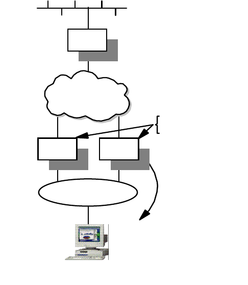
IP Routing and Design 137
Figure 53. RIP Active and Passive Routing
4.3.3 RIP Version 2
The Routing Information Protocol Version 2 (RIP-2) was created in order to fix
some of the limitations of RIP and it is documented in RFC 1723. The RIP-2
protocol is also implemented in the
gated
Version 3 daemon of the UNIX system.
While RIP-2 shares the same basic algorithms as RIP-1, it supports several new
features. The principal changes that it introduced are:
• Variable Subnet Masks
Inclusion of subnet masks in the route exchange is one major improvement.
Subnet mask information makes RIP more useful in a variety of environments
and allows the use of variable subnet masks on the network.
• Next Hop Addresses
Support for next hop addresses allows for optimization of routes in an
environment that uses multiple routing protocols. RIP-2 routers can inform
each other of the availability of a better route if one exists.
• Authentication
One significant improvement RIP-2 offers over RIP-1 is the addition of an
authentication mechanism. Essentially, it is the same extensible mechanism
provided by OSPF. Currently, only a plaintext password is defined for
authentication.
•Multicasting
RIP-2 packets may be transmitted using multicast instead of broadcast. The
use of multicasting reduces the load on the rest of the hosts on the network.
•RIP-2MIB
10.20.0.1
R2
10.20.0.2
10.10.0.0
Router
IP Network
10.20.0.0
Client
running
RIP silent
mode
10.20.0.100
R1 and R2 - Routers
running RIP active mode
Default gateway
0.0.0.00.00.0 via
10.10.02
2580a\RIP
R1
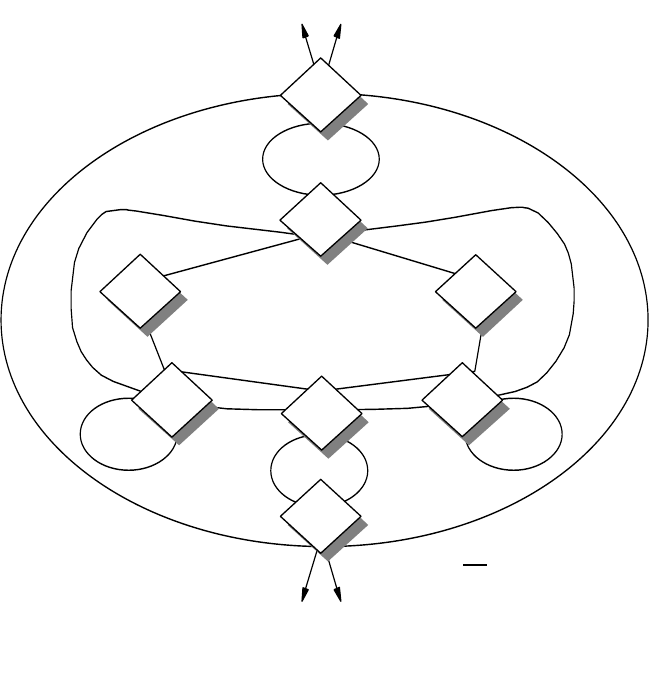
138 IP Network Design Guide
The MIB for RIP-2 allows the monitoring and control of RIP’s operation within
the router. In addition to global and per-interface counters and controls, there
are per-peer counters that provide the status of RIP-2 neighbors.
4.3.4 Open Shortest Path First (OSPF)
Open Shortest Path First (OSPF) is an interior gateway protocol that uses the link
state protocol and shortest path first algorithm to create the topology databases
of the network. The number of good features available in OSPF makes it the
preferred interior gateway protocol for use in new IP internetwork design,
especially for large networks.
With OSPF, routers maintain the operating status of each interface and the cost
for sending traffic on these interfaces. The information is then exchanged using
link state advertisements (LSAs). Upon receiving LSAs from other routers, a
router begins to build a database of destinations based on the shortest path first
algorithm. Using itself as a root in the calculation, all routers will soon have a
common topological representation of the network.
4.3.4.1 OSPF Elements
The following section describes several important terms used in the OSPF
protocol:
Figure 54. OSPF Network Elements
2580B\CH2F15
OSPF Backbone
Area 2 AB
As External Links
Area 1
AB
ASB
As External Links
AB
ASB
Area 4
AB
Area 3
IA IA
Area 4
Key
ASB
AB
IA
= AS Boundary Router
= Area Border Router
= Intra-Area Router
IP Routing and Design 139
OSPF Areas within an Autonomous System
The topology of an OSPF network is based on the concept of area. As shown in
the above diagram, within an autonomous system, the OSPF network is
organized into areas of logically grouped routers. All routers within the same
OSPF area maintain the same topology database through exchanging link state
information.
All OSPF networks must contain at least one area, called the backbone area, and
it is identified by the an area ID of 0.0.0.0. The area ID uses the same notation as
that in an IP address for addressing. For small OSPF networks, the backbone is
the only required area. For a larger network, the backbone provides a core that
connects the areas. Unlike other areas, the backbone’s subnets can be physically
separated. This is called non-contiguous. In general, the backbone area should
be contiguous, although there may be times when a non-contiguous backbone is
constructed through what is called virtual links. The virtual links are logical
connections between routers in the backbone traversing non-backbone areas.
Intra-Area, Area-Border and AS-Boundary Routers
In the OSPF topological scheme there are three types of routers. The intra-area
routers maintain the same topology database. They exchange link state
advertisements within the area with the flooding scheme among the adjacent
routers. An area border router is one that connects to more than one area. It
maintains the topology databases of the two areas and exchanges link state
advertisements in the connected areas. It is also responsible for flooding
intra-area routes. The AS-boundary routers are located in peripheral locations of
the OSPF network and exchange reachability information with routers in other
ASs using exterior gateway protocols. They are responsible for importing routing
information and flooding link state advertisements from other autonomous
systems.
Neighbor, Adjacent, Designated and Designated Backup Routers
The OSPF protocol describes a series of tasks that each router must individually
perform. These include:
• Discovering neighbors
• Electing the designated router
• Initializing the neighbors
• Propagating link state information
• Calculating the routing tables
Two routers that are connected on a common physical network are named
neighbors. Neighbor routers are discovered dynamically by the Hello protocol.
Initially, the state between two neighbors is down, then it goes into the Init state if
it receives a Hello packet, or an attempt if the Hello packet has been sent. When
a bidirectional exchange has taken place, the neighbors are in the two-way state.
In this state they can become a adjacent or designated or designated-backup
router.
To become an adjacent router, a neighbor needs to go through the states of
Exstart, Exchange, Loading and Full. Two neighbors become adjacent only if their
topology databases have been synchronized. In a point-to-point network the
neighbors must become adjacent, but this may not be true in a broadcast
network. In the latter case, adjacencies are created only between an individual
140 IP Network Design Guide
router and the designated router or the designated backup router. Only the
designated router generates link state advertisements and becomes the focal
point for forwarding all link state advertisements. The designated backup router is
expected to take over the task in case the designated router fails.
Link State Advertisements
Link state advertisements contain information about the state of a router’s links
and the network. The following are examples of link state advertisements:
• Router link advertisements
• Network link advertisements
• Summary link advertisements
• AS external link advertisements
Hello Protocol
The Hello protocol is used to establish and maintain relationships between two
neighbors.
Router ID
The router ID is a 32-bit number assigned to each router running the OSPF
protocol and uniquely identifies the router within an autonomous system.
Area ID
A 32-bit number identifying a particular area. The backbone area has an identifier
of 0.0.0.0.
4.3.4.2 OSPF Protocol Analysis
RFC 1245 and RFC 1246 are worth referencing with respect to usage of OSPF.
Basically, there are a few points that need to be taken into consideration when
using OSPF:
• Routes summarization and addressing
Route summarization is having the ability to aggregate several route entries
into one so that a routing table can be kept small and manageable. Route
summarization is achieved mainly through a wel- planned addressing scheme
of the IP address.
• OSPF topology
The OSPF protocol requires intensive CPU and memory resources to maintain
its database. Thus, care has to be taken in designing the OSPF topology
because it has an impact on the use of these resources. The larger an OSPF
area, the more calculations are required from the routers. Thus, a
recommended number of routers within an area should be less than fifty.
• Router roles and resources
Since the role of the designated router is to initiate all the exchanges, it should
be given to one that has the lighter routing load. This prevents it from being
overloaded and suffering in performance. For the same reason, the area
border router should not be connected to more than four areas.
• OSPF convergence time
The convergence time of the protocol depends on the routers’ capability to
detect changes. This can be improved with the tuning of the timing of the Hello
protocol.
IP Routing and Design 141
OSPF is extremely efficient in a stable network. It uses very little bandwidth and
is suitable for most IP networks. Moreover, it allows the use of multiple paths to a
destination for load sharing purposes to increase performance. It supports
variable subnet masks and does not impose a limit on the hop count. OSPF also
provides authentication for the exchange of routing information. It is widely
supported by router vendors and interoperability is usually not an issue.
4.3.5 Border Gateway Protocol-4 (BGP-4)
The Border Gateway Protocol (BGP-4) is an exterior gateway protocol. That is, it
is used to exchange network reachability in an inter-autonomous system routing
environment. It is documented in RFC 1771 and was developed to replace the
outdated Exterior Gateway Protocol (EGP). The BGP-4 protocol addresses a
series of problems with the exponential growth of the Internet:
• The growth of the size of routing tables that overwhelms the routers and
network administrators
• The exhaustion of the IP addresses
For these reasons the BGP-4 supports features such as the classless
interdomain routing mechanism, introduces the aggregation of routes and AS
paths and supernetting schemes. As the complexity and importance of the
Internet grows, BGP-4 also provides important features for authentication
mechanisms, minimizing the bandwidth consumption and in the application of the
routing policies.
4.3.5.1 Network Topology in BGP-4
The topological model of the BGP-4 protocol relies on two main items when a
connection between two autonomous systems exists:
• The physical shared medium on which each AS has at least one border
gateway belonging to that AS. The exchanging of packets between the two
border gateways of each AS is independent from inter-AS or intra-AS routing.
• A BGP connection, that is, a session between BGP speakers in each of the
autonomous systems for exchanging of the route in accordance to the two
gateways’ routing policies.
The following diagram shows the topological model of BGP-4:
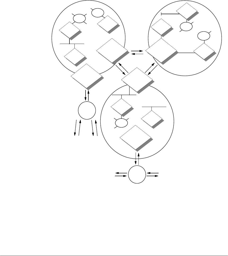
142 IP Network Design Guide
Figure 55. BGP-4 Topological Model
Most of the traffic in the network stays within each individual AS and is known as
local-traffic. The traffic that flows across the autonomous systems are known as
transit traffic. BGP-4 deals with the efficient management of the transit traffic.
BGP-4 protocol is usually used in large corporate networks or networks that need
to be connected to the Internet. Its use is complex and can only be handled by an
experienced network manager. Routers that are used in this situation usually are
high-end routers with powerful CPU processing ability and large memory size.
4.4 Choosing a Routing Protocol
In the initial phase of the IP network design, there is one important decision that a
network manager needs to make: that is, to choose a routing protocol for the
network.
While the choice between using static routing or dynamic routing may be easy,
choosing the correct dynamic routing protocol that meets your needs may not be
AS1
2580a\BGP
OSPF/RIP
OSPF/RIP
BGP Speaker
AS2
AS3
OSPF/RIP
BGP Speaker
ASX
ASX
OSPF/RIP
OSPF/RIP
OSPF/RIP
BGP Speaker
OSPF/RIP
OSPF/RIP
OSPF/RIP
BGP Speaker
OSPF/RIP
BGP Speaker
OSPF/RIP
OSPF/RIP
OSPF/RIP

IP Routing and Design 143
so straightforward. There are a few criteria that you need to consider, including
the following:
• Standard-Based Products
Network managers should always use standard-based products; this holds
true even for routing protocols. Using a vendor-proprietary protocol may lead
to difficulty in connecting to other networks in the future.
• Path Selection
The routing protocol should allow granular control on path selection for the
traffic. For example, RIP decides a path based purely on hop count. If there is
a higher bandwidth path with a slightly higher hop count, it will not be selected
even though it has better performance. Attributes like link load and
administratively assigned cost are always good features to have.
• Redundancy and Load Balancing
An important feature to have when you are running mission-critical networks is
to have routes redundancy, or even better, the ability to load balance the traffic
across multiple paths. While a redundant path gives assurance of uptime of
the network, the load balancing feature gives better utilization of the available
bandwidth that might not have been used.
• Performance/Convergence
A network is a very dynamic environment with constant changes in link status
and device operating status. Routing protocol with fast convergence will
enable the network to respond to these changes in the fastest manner and
keep the network going.
• Security
Since reachability in the network is governed by the routers, it is important that
some protection be accorded to the way updates are sent to them.
• Scalability
The routing protocol must be able to support an even larger network than what
you may have today. Protocols such as RIP impose a limit on the maximum
number of hops and this is like putting a glass ceiling on how big the network
can grow.
The following table illustrates the difference between the interior routing
protocols:
Table 11. Comparison of IP Routing Protocols
RIP RIP-2 OSPF
Protocol type Distance vector Distance vector Link state
Support for CIDR No Yes Yes
Routing decisions Hop count Hop count Cost assigned by
network manager
Convergence Long Long Short
Ease of
troubleshooting Easy Easy May be difficult
Authentication No Yes Yes

144 IP Network Design Guide
4.5 Bypassing Routers
As mentioned before, a router inspects the destination information in the packets
that are coming in, looks up its routing table for optimal path, and then forwards
the packets through to the appropriate interface. This inspection, comparisons
and decisions take time to execute and introduces delays in data delivery. An
end-to-end path that traverses a few routers introduces delays in milliseconds
and in the event of a high utilization in the router, delays may cause an upper
layer application to time out.
New techniques have been introduced to explore the possibility of reducing the
number of routers, or in the extreme, removing routers altogether from the data
path. It is important to note that it is routers that we are trying to eliminate, and
not routing. (Of course, you would think that the best is to design a network that is
a huge single subnet and then there would be no routing at all!) As mentioned in
2.2.4, “Switch” on page 62, layer-3 switching is a good alternative to installing
routers, and it should be given high consideration if possible. The techniques
discussed here are switch based, although they go beyond just pure layer-3
switching.
Most of these techniques are made available through the introduction of
switching, notably ATM. For the legacy workstations, most of these
implementations hide these shortcuts in a transparent way that does not affect
them. The workstations send out packets to their default router and expect
delivery to take place; the shortcuts that are achieved usually happen in the ATM
fabric. These techniques have been instrumental in improving network
performance and in most cases, cut down on operating costs because reliance on
high performance traditional routers has been reduced.
4.5.1 Router Accelerator
The router accelerator or self-learning IP, is a feature implemented on a switch
that enable sit to be "inserted" between a router and the switch’s interfaces. This
"interception" causes the IP packets to bypass the router and being switched to
the destination. This ability allows the performance of intra-switch traffic to be
improved, thereby eliminating external router hops in the data path. An example
of a switch with this function is the IBM 8371 Multilayer Switch.
Network size Limited Limited Large
RIP RIP-2 OSPF
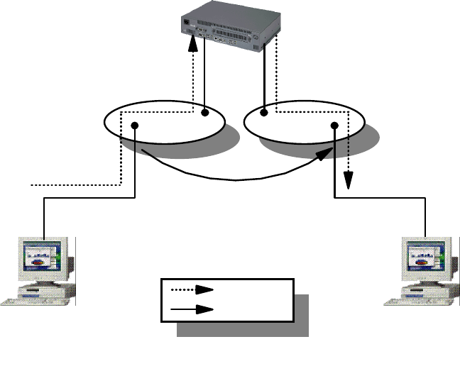
IP Routing and Design 145
Figure 56. Router Accelerator
As illustrated in the above diagram, the IBM 8371 switch has two VLANs defined,
VLAN 1 and VLAN 2. Workstation A is attached to VLAN 1 through one of the
switched port while workstation B is attached to VLAN 2. Router R is attached to
these two VLANs and is responsible for routing packets between them. In a
normal traffic flow, when workstation A wishes to send packets to workstation B, it
sends them to its default router R, which would in turn forward the data to
workstation B. In this way, the data path has to go through router R and incur a
router hop. With the self-learning IP function turned on, the switch is able to
"learn" the path taken by the traffic, and proceed to "cut" router R out of the way.
It establishes a switching path directly between workstation A and B, thereby
creating a direct switch path. In this way, traffic is switched between the two end
systems, bypassing the router, and the delay incurred through the router hop is
reduced.
The self-learning IP function is easy to implement, and it is transparent to the end
systems. There is minimal configuration required on the switch, and no
configuration changes at all for end systems. The additional benefit is the router,
R need not be upgraded due to increase in traffic flow between the two VLANs,
thereby "extending" its life expectancy.
4.5.2 Next Hop Resolution Protocol (NHRP)
The Next Hop Resolution Protocol (NHRP) is used in a non-broadcast, multi
access (NBMA) network environment. It defines a way for a source device to
"bypass" all routers between itself and its destination, and set up a direct data
path for sending traffic. The source device will determine the NBMA address of
the "next hop" to the destination. The address can be the destination itself, if it
also supports NHRP, or it can be the egress router that is nearest to the
destination.
Router R
Shortcut Established
Workstation A
VLAN 1 VLAN 2
Workstation B
Normal Path
Shortcut Path
2580B\CH2F16
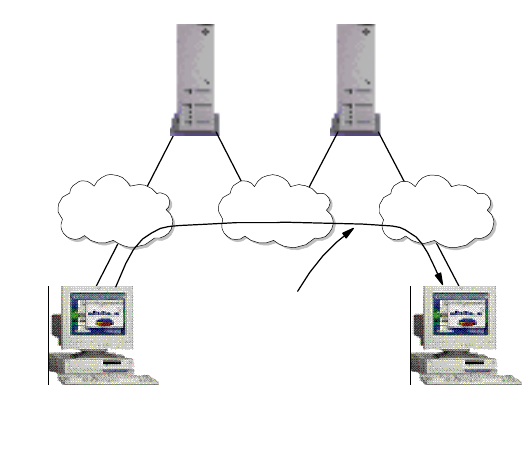
146 IP Network Design Guide
Figure 57. Next Hop Resolution Protocol (NHRP) Overview
In the above diagram, workstations A and B are both NHRP clients participating
in an ATM network. They are connected as shown with the IBM Multiprotocol
Switched Services (MSS) server 1 and MSS server 2 acting as an IP router. The
MSS servers are running the NHRP server function as well, providing the
resolution functions. With NHRP, workstation A establishes a direct virtual circuit
connection (VCC) to workstation B, thereby achieving so called zero-hop routing.
In general, NHRP provides the following advantages:
• Performance Improvement
Performance improvement can be achieved through short-cut routing and
thereby boost traffic flow.
• Reduce Router Cost
Since routers are bypassed in the traffic flow, the load on the router is minimal.
In fact, fewer routers are needed and there is no longer a need for a high
performance traditional router anymore.
The rule for NHRP, as specified in RFC 2332, does not include LANE. With the
IBM MSS Server, NHRP functionality is further extended to the following:
• Support for Non-NHRP Clients
Another benefit of MSS’s features include extending the NHRP ability to
non-NHRP clients that are located within the same subnet as the last NHRP
server. In this scenario, workstation A is an NHRP client and workstation B is
not. Traffic from workstation A can establish direct data VCC with the switch
that workstation B is connected to because A is an NHRP client. Workstation
B will still default route to MSS 2 and have MSS 2 establish a shortcut to
workstation A. This scenario is particularly useful if workstation A is a Web
server. In Web browsing, it is more important to have the content of the server
deliver as fast as possible to the client. This "asymmetric" pattern of traffic flow
suits Web traffic perfectly. This is typically called a one-hop routing scenario.
MSS 1
NHRP
Server
MSS 2
NHRP
Server
Workstation A
NHRP
Client
Subnet BSubnet A Subnet C
Workstation B
NHRP
Client
Shortcut VCC
Established by
End Systems
2580B\CH2F17
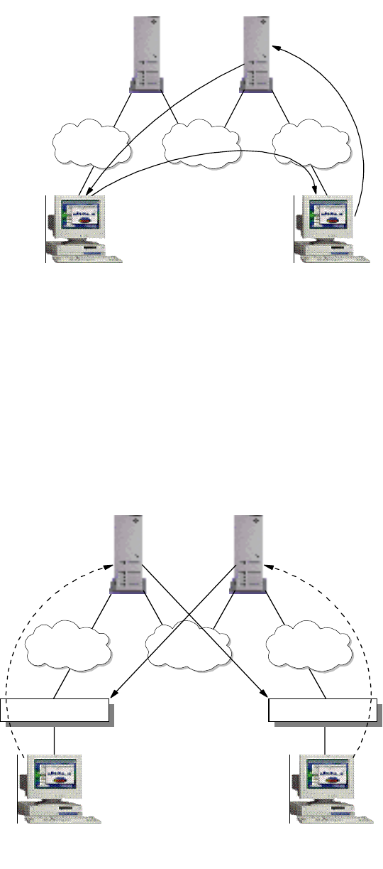
IP Routing and Design 147
Figure 58. One-Hop Routing with NHRP
• Extensions to LANE
The MSS’s implementation also provides the NHRP feature in LANE, which is
more commonly used in ATM networks. In LANE environments, workstations
are still running in legacy LANs, connected through the switches. The MSS’s
LANE enhancement provides "one-hop routing" by establishing direct VCCs
with the switches themselves. In this scenario, both traffic from workstation A
and workstation B achieved a symmetric traffic flow of one-hop routing.
Figure 59. One-hop Routing in LANE
MSS 1
NHRP
Server
MSS 2
NHRP
Server
Workstation A
NHRP
Client
Subnet BSubnet A Subnet C
Workstation B
NHRP
Client
Shortcut
2580B\CH2F18
Default Route
Shortcut
MSS 1
NHRP
Server
MSS 2
NHRP
Server
Workstation A
Subnet BSubnet A Subnet C
Workstation B
2580B\CH2F19
Switch Switch
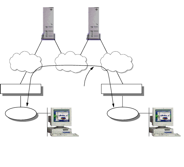
148 IP Network Design Guide
• Extensions to Inter CIP-LANE networks
The MSS’s features also extend to making NHRP available for traffic that is
crossing from a CIP network to a LANE network. This makes it extremely
flexible for network managers, in the event that there is a need for a mix of
these environments and performance needs to be enhanced.
4.5.3 Route Switching
Route switching is the technique of extending NHRP to legacy LANs so that
workstations can achieve zero-hop routing across the NBMA network. In this
case, the workstations need to have MSS route switching clients installed on top
of the network protocol stack to perform the address resolution.
Figure 60. Route Switching Overview
In the above diagram, both LAN 1 and 2 have to be similar, that is, both Ethernet
or both token-ring. The route switch client that is running in both workstation A
and B is loaded as part of the protocol stack. The legacy LANs are bridged into
the respective Emulated LANs through the switch and both MSS 1 and 2 are the
default routers for workstation A and B respectively.
When workstation A needs to send data to B, the route switch client issues an
NHRP resolution request to determine the data link layer address of B. MSS 1
then communicates with MSS 2 to obtain the necessary information, such as the
MAC address of B, the ATM address of switch 2, etc. MSS 1 then replies to the
route switching client in A with this information and the client caches it.
Communication with B is then initiated with the data link layer address, which
causes switch 1 to issue a connection request to switch 2 through LANE ARP. A
data direct VCC is then established from switch 1 to 2, and traffic flow begins.
MSS 1
NHRP
Server
MSS 2
NHRP
Server
ELAN 2ELAN 1 ELAN 3
2580B\CH2F20
Switch 1 Switch 2
Workstation A
with Route
Switching Client
LAN 1
Workstation B
with Route
Switching Client
LAN 2
Shortcut
VCC
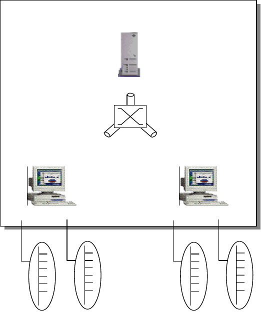
IP Routing and Design 149
4.5.4 Multiprotocol over ATM (MPOA)
Multiprotocol over ATM (MPOA) provides the efficient transfer of inter-subnet
traffic in a LANE environment through ATM VCCs without requiring a router in the
data path. It allows you to implement the concept of a virtual router across an
ATM network through the deployment of MPOA servers and MPOA clients. Figure
61 on page 149 shows the concepts of a traditional router and a virtual router.
MPOA allows the effective use of bridging and routing to locate the optimal path
within a multiprotocol environment consisting of the following:
• Hosts attached directly to the ATM network
• Hosts attached to LAN switches with ATM uplinks
• Hosts involved in VLANs
Figure 61. Multiprotocol over ATM Overview
MPOA is implemented through the use of LAN Emulation, bridging, routing and
NHRP. The virtual router model provides:
• A single router for the entire network
• One edge device participating in routing
• Routing capacity of all edge devices
There are three components to an MPOA network:
• MPOA Server (MPS)
MPOA Server ATM as a
Virtual
Router
Layer 3 Switching
MPOA Client
Layer 3 Switching
MPOA Client
2580B\CH2F21
150 IP Network Design Guide
• MPOA Client (MPC)
• Edge device with MPC functionality
The concept of MPOA involves separating the two components, forwarding traffic
and routing in a traditional routing model, and letting separate entities handle
these functions. The MPOA server (MPS) is responsible for address
management, route calculation and topology discovery. The forwarding of traffic is
done by the MPOA Client (MPC) through the ATM switch fabric. The MPS
typically resides in the ATM switch; an example is the IBM MSS server. The
MPCs are typically the ATM attached hosts and edge devices that connect the
legacy LANs to the ATM network. MPOA uses the LAN Emulation (LANE) Version
2 and NHRP as its basis to provide the concept of a virtual router. LANE provides
functions such as auto-configuration, dynamic device discovery and
inter-subnet/default path connectivity while the NHRP provides the shortcut
mechanism to achieve zero-hop routing.
MPOA also enables the inherent QoS features of ATM to be made directly
available to higher layer protocols, enabling multi-media applications to exploit
the QoS capabilities of ATM.
The main benefit of MPOA is its ability to scale as compared to a traditional
router. The route calculation capacity can be increased by adding more MPSs,
forwarding capacity can be increased by adding more MPCs, and the switching
capacity can be increased by adding more ATM switching fabrics. The virtual
router reduces a hop-by-hop transfer that is typical of a traditional routed network,
thereby improving the performance of the network. Regardless of location in the
logical model, shortcut communication channels are set up in the ATM network to
enable two hosts to communicate directly. MPOA simplifies management tasks by
providing a single router image, auto-configuration and dynamic device discovery
features. It also ensures interoperability with the existing routers within the
network by running standard routing protocols such as OSPF.
Some network managers challenge the use of MPOA feeling that because ATM
provides VLAN capability, it might be more efficient to implement a network that is
based on a flat network design. With flat network design, all hosts are in a
common VLAN and hence no router is required to interconnect subnets. The truth
is, with MPOA, network managers can implement features that are not found in a
flat network design:
• Subnetting
Subnetting allows for the classification of users, so that functions such as
security can be implemented through filtering.
• Broadcast Containment
Because users are grouped into separate VLANs, broadcast is contained.
4.5.5 VLAN IP Cut-Through
While implementations such as NHRP and MPOA require the deployment of
special devices, VLAN IP cut-through plays with the IP addressing to achieve
shortcuts in the data path. VLAN IP cut-through is provided through a feature
called Dynamic Protocol Filtering (DPF) in the IBM MSS. With DPF, VLANs are
created based on protocol and subnets, and bridging is deployed for connectivity.
DPF allows subnetted IP networks to make use of the IP cut-through facility to
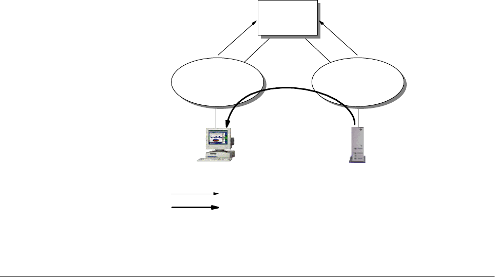
IP Routing and Design 151
improve performance. The workstations communicate directly with each other
without involving a router. One advantage of IP VLAN cut-through is that it can be
configured to allow cut-through in one direction but force a routed path in the
reverse direction. This unidirectional cut-through can be used to force client
stations to pass through the router for filtering checks while allowing servers to
send traffic directly to the clients. This is especially useful in a Web-based
application deployment.
It is important to note that VLAN IP cut-through works only in a subnetted IP
network. For example, to implement unidirectional cut-through, the following
needs to be done: for a subnetted Class B network 168.1.1.0 with a mask of
255.255.254.0, the client is configured with an IP address of 168.1.2.1 with a
mask of 255.255.255.0, while the server is configured with an IP address of
168.1.1.1 with a mask of 255.255.254.0. For the client to reach the server, it has
to go through a router. For the server to reach the client, it needs to issue an ARP
for the destination hardware address of the client. The resolution is handled by
the MSS to "fool" the server into thinking that the client is on the same subnet as
the server.
Figure 62. VLAN IP Cut-Through
4.6 Important Notes about IP Design
So far, we have discussed the building blocks for designing an IP network: the
various LAN technologies, the various hardware that provides connectivity, and
even the routing protocols that tie all the different networks together. But building
an IP network is more than just making the right decisions in choosing each of the
building blocks. All the building blocks must ultimately work in unison to meet the
stringent requirements that are imposed on the network. The success of the
network is also subject to whether other considerations are covered during the
design phase.
Client Server
1
MSS
VLAN 1
168.1.2.0
255.255.255.0
VLAN 2
168.1.1.0
255.255.255.0
Routed Path
Shortcut Path
2580C\CH4F60
152 IP Network Design Guide
However large a network is going to be, there is always the KISS principle to
remember:
Keep It Simple, Stupid!
4.6.1 Physical versus Logical Network Design
In any network design, it is important to differentiate between a physical network
design and a logical network design. In a physical network design, you are more
concerned with distance, cabling, and connectivity issues. Generally, a physical
network ties in very closely with a building’s infrastructure plan (in the case of a
large network) or a floor plan (in the case of a small network). It depicts only the
physical attachment of the devices and not any other relationships among them.
Logical design, on the other hand, is independent of physical connectivity. Logical
design shows the grouping of users by organizational structure and reflects more
accurately the requirement of the business. In the past, the IP subnets were
somewhat dictated by physical connectivity but with the introduction of switches
and the concept of VLANs, this is no longer true. These new features have made
the logical network diagram even more important.
In a logical network design, you are concerned with the boundary of subnets,
what gets to be in the same subnet and the scope these subnets cover. You are
interested in how these subnets should be connected, and at which point they are
connected. At this time, the connecting point is just a concept, not a product,
because there are many different products that can achieve the same goal. After
the entire logical network has been completed, then the choice of equipment and
the physical connections are considered.
4.6.2 Flat versus Hierarchical Design
One of the main design issues in IP network design is whether to use a flat or a
hierarchical design. While we recommend most of the IP network design use a
hierarchical model, sometimes a flat design is more suitable.
Consider a company of five persons. It does not make sense to create personnel,
finance, manufacturing and customer support departments for a company of this
size. The network that you design for this company is a flat one: every user is
connected at the same level. On the other hand, a multi-national corporation can
have as many as 200 000 employees or more. Companies of that size are divided
into divisions, departments, branches and then down to sections. The network
design for a company like this reflects the complexity of the environment and
should be made as flexible as possible to cater to changes. A hierarchical
approach is advised here, because the layering structure ensures expendability
and manageability.
4.6.3 Centralized Routing versus Distributed Routing
One of the design considerations is to choose between a centralized routing and
a distributed routing approach. Each of these approaches has its pros and cons
and network managers should know them before deciding on an approach.
The centralized routing approach is simple in the sense that all your network
subnets are concentrated in a single box - the central router. When there is a
routing problem, there is only one place to troubleshoot. Having a centralized
router means the logical network design looks like a star topology with the
centralized router at the center. The problem with a centralized routing design is
that the capacity of the network is limited by the capacities of the router, as in
IP Routing and Design 153
routing capacity and interface capacity. The candidate for a centralized router role
is usually a high-end router, which is expansive, and the increment of ports on the
router is very costly. Also, when the centralized router fails, the subnets are
disconnected. Even though redundancy may be provided through a backup
router, the fact that you need an equally powerful router makes it even more
expensive.
A distributed routing approach requires some good understanding of routing
protocols as the network is made up of several routers. In a distributed routing
approach, we do not need a high-end router because the load of the network will
be shared among all the routers. This has to be achieved by carefully analyzing
the traffic flow and making sure that not all the servers are concentrated within
one subnet. The network enjoys the routing capacity of the total sum of all the
routers, and expansion is done through the addition of routers. The distributed
routing approach has a more complex design than the centralized approach. As
the network grows, so does the complexity. With more routers to manage, there
may be a need for more technical support staff to handle the administrative tasks.
And good technical support staff is difficult to come by.
An alternative to the traditional routing approach has been the introduction of
layer-3 switching. By using a layer-3 switch with a high switching capacity, for
example, the IBM 8371 Multilayer Switch, the hierarchical design can still be used
for the network design. The benefit of using a layer-3 switch is that there is no
need for a high-end router.
Another new approach to routing design has been the introduction of the virtual
router model in MPOA, as shown in Figure 61 on page 149. MPOA combines the
benefits of a centralized router with the benefits of a distributed routing capacity.
The network routing capacity grew with the addition of more MPCs, and there is
not much requirement for a high-end router. The problem with MPOA is that it
runs only in an ATM environment.
4.6.4 Redundancy
Redundancy is an important feature in networks, especially those that support
mission-critical applications. It involves two parts: the hardware redundancy and
the data path redundancy. As mentioned in Chapter 2, “The Network
Infrastructure” on page 19, hardware redundancy ensures that the important
systems, boxes and pieces are suitably equipped to withstand component failures
and keep the network up and running all the time. Data path redundancy comes
from a properly designed logical network with appropriate routing protocol that
provides reroute capability. In a design that involves WAN, service provider
redundancy may also have to be considered.
Network redundancy is always at odds with cost constraints. Network managers
should ascertain the tolerance limit for the network and identify areas in which
failure cannot be tolerated and implement redundancy in these areas first.
Virtual Router Redundancy Protocol (VRRP)
Workstations like the Windows 95 uses default routes in their IP configuration.
The use of default routes minimizes the configuration task and processing
overheads on the workstation. The use of default routes is also popular with the
implementation of DHCP servers, which assign IP addresses to workstations and
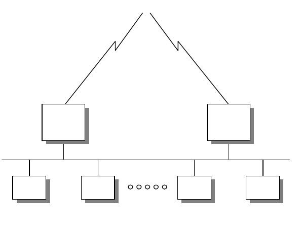
154 IP Network Design Guide
provide a default route at the same time. However, default routing creates a single
point of failure, as the loss of the default route results in a loss of connections.
The Virtual Router Redundancy Protocol (VRRP) is designed to eliminate the
problem associated with default routes. VRRP allows a pair of routers to
dynamically back up each other in a way that is transparent to the endstations.
The pair of routers share a virtual IP address, which the rest of the endstations
refer to as the default route. The primary router is responsible for forwarding
traffic that is sent to this virtual IP address. In the event of a master router failure,
the secondary router takes over the task of forwarding traffic that is addressed to
the virtual IP address.
Figure 63. VRRP Providing Default Route
The advantage of using VRRP is that a redundant default gateway is provided,
without endstations to participate in the dynamic reroute, or running a router
discovery protocol. It is highly recommended for a network that needs high
availability but having workstations that support only a single default gateway.
4.6.5 Frame Size
We have discussed in 2.1.2, “LAN Technologies” on page 22 that the frame size
adopted by a network affects its performance. Normally, adopting a larger frame
size means an endstation needs a fewer number of packets to send a piece of
information, because each packet can contain more data. The devices along the
data path, especially the routers, have to be able to handle the same frame size,
or else fragmentation takes place. Fragmentation and the reassembly of packets
slow down the traffic and will cause applications to misbehave.
One important point to note is that packet size mismatch on different devices in a
network will not cause connectivity problems. However, due to fragmentation and
reassembly, performance of the network is compromised.
The IP protocol specifications do not require a host to process IP packets that are
more than 576 bytes. It is important to make sure that the routers along the data
To C e n tra l S it e
T1 Link 64 Kbps Link
VRID=1
Virtual MAC Address
00:00:5E:00:00:01
10.1.1.1
Host Host
10.1.1.1
Host Host
Master/
Backup
Router
Backup/
Master
Router
2580a\VRRP
IP Routing and Design 155
path are able to support IP packet lengths up to the limits imposed by the LAN
technologies.
Most of the time, a router has the ability to automatically set the maximum packet
size to that of the largest supported by the LAN. Networks such as token-ring
allow you to configure the maximum packet size, which affects the size of buffers
used in the router during run time. The change in the buffers’ size in turn affects
the number of buffers available. These changes ultimately will have an effect on
the performance of the router.
4.6.6 Filtering
Filtering enables the router to inspect the content of a frame, and decide whether
to forward the frame based on certain predefined rules. The rules are usually a
translation of a business requirement, such as security. The filtering function can
be enforced at a box level or at the interface level. When filtering is done at box
level, every frame that the router receives has to go through the inspection and
comparison. At the interface level, only frames that leave or enter through that
interface are affected. The time it takes for a router to inspect a frame depends on
what information is required to make the decision. If the information required is
located at the front of the frame, for example, a MAC address, then it would take a
shorter time. However, if the information required is higher up at the OSI model,
for example, an application protocol, then it is located at the back of the frame,
which in turn increases the time taken. Thus, network managers need to consider
the consequences of introducing filtering in the network, and proper planning and
performance simulation need to be done before implementation.
4.6.7 Multicast Support
Multicast support has increased in importance due to the shortage of bandwidth
and the introduction of multimedia-based applications. Introduction of multicast
traffic is a good way of conserving network bandwidth and a router plays an
important role in its implementation. Care has to be taken in selecting the right
multicast protocol to use, for different protocols work differently and you may
eventually need to connect to another network that runs multicast too. Please
refer to Chapter 7, “Multicasting and Quality of Service” on page 227, for more
discussion on multicast support.
4.6.8 Policy-Based Routing
While traditional routing looks at the destination address within an IP packet to
forward the packet to the destination, policy-based routing works on other
attributes. For example, policy-based routing enables the router to forward traffic
based on source IP address instead of destination IP address. This is useful in
situations when explicit control on the routing needs to be enforced for some
reason. Policy-based routing is also useful when there is a need to force certain
type of traffic through one link and another type of traffic through another.
4.6.9 Performance
Performance is always the hardest thing to ensure in a network design. A
common belief is that the more bandwidth you have, the less chance for a
performance problem to occur. This may be true to some extent but
over-emphasis on increasing bandwidth may backfire sometimes due to neglect
in other aspects. Take the following design for example:
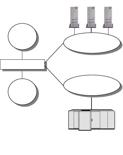
156 IP Network Design Guide
Company ABC’s network has been having performance problems because IP
users and SNA users have been sharing a single uplink to access their respective
servers. The network manager thought it would be a good idea to implement
separate VLANs in the backbone through the addition of an uplink to provide
more bandwidth. While a VLAN that has no QoS defined will serve the IP traffic,
the other VLAN with QoS implemented would serve the mission-critical SNA
traffic. The switch has been installed with two uplink interfaces and there was a
performance improvement. This design is illustrated in Figure 64 on page 156.
Due to network expansion, the switch has no more capacity and another switch
was introduced to accommodate more users. This is illustrated in Figure 65 on
page 157. The second switch has two uplinks to connect to the two VLANs, but
something is wrong after the introduction of the second switch: performance has
become worse.
Figure 64. Network Design with One Switch
Upon troubleshooting, it was realized that due to the introduction of the second
switch, a loop was introduced in the switching path and the spanning tree protocol
has blocked one of the data paths from switch 1:
IP Servers
IP
Users IP VLAN
(Non-QoS)
SNA
Host
IP VLAN
(QoS)
Switch 1
SNA
Users
2580B\CH2F22
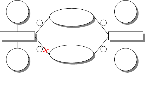
IP Routing and Design 157
Figure 65. Network Design with Two Switches
Although the above can be an extreme case of ignorance, it illustrates the many
unforeseen technical difficulties that can surface in network expansions. An
experienced network designer always has to start somewhere before he/she is
proficient in the field. As the saying goes, practice makes perfect. And hopefully,
you do not make too many mistakes along the way.
IP VLAN
(QoS)
2580B\CH2F23
IP
Users
Switch 1
SNA
Users
1
2
IP
Users
Switch 1
SNA
Users
3
4
IP VLAN
(Non-QoS)
Link 2 Blocked by Spanning Tree
158 IP Network Design Guide

© Copyright IBM Corp. 1995 1999 159
Chapter 5. Remote Access
As the demand for mobile computing increases in today’s business environment,
solutions have been developed to cater to this need. It is common for users of a
network to require to be connected from home or while they are "on the road".
However, there are some serious issues to be considered with these
technologies. These include:
• Reliability
• Manageability
• Security
• Authentication
• Encryption
• Accessibility
This chapter covers remote LAN access environments and technologies. It also
covers some of the remote LAN access solutions available from IBM.
5.1 Remote Access Environments
Remote LAN access generally refers to accessing a network device using an
external line, which is most commonly a switched telephone line. With these
technologies it is possible for the user to dial in to the LAN or dial out of the LAN
over a wide area network (WAN). There are four main environments in remote
LAN access:
• Remote-to-Remote
• Remote-to-LAN
•LAN-to-Remote
• LAN-to-LAN
5.1.1 Remote-to-Remote
A remote-to-remote environment consists of a direct physical connection
established between two or more remote workstations.
Conferences may be set up between multiple workstations creating an ad hoc
LAN over telephone lines. Without LAN adapters and without LAN wiring,
remote-to-remote workstations can access each other's LAN resources and
LAN-based applications. This environment supports users who need a simple
and low-cost WAN connection to support data, resource and program sharing.
The most common example of a remote-to-remote implementation of remote LAN
access would be a remote user using the telephone line to run applications on a
directly connected LAN server. These applications can be of any nature, common
types being groupware applications or two player computer games.
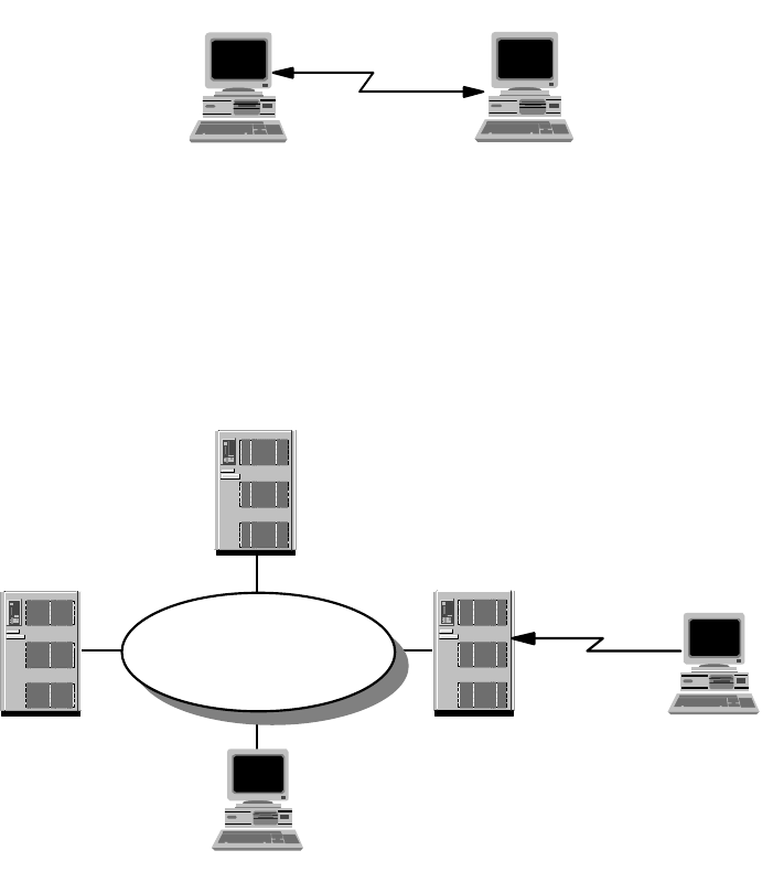
160 IP Network Design Guide
Figure 66. Remote Workstation Dial-In to Remote Workstation
5.1.2 Remote-to-LAN
A remote-to-LAN environment, sometimes called dial-in, occurs when a remote
workstation initiates a connection to a LAN workstation via some form of
WAN/LAN communication server.
Figure 67. Remote Workstation Dial-In to LAN
Once the WAN connection is established between the remote workstation and the
LAN, the remote workstation can directly address any LAN-attached workstation
configured to participate within the remote-to-LAN environment. Likewise,
because the remote workstation has its own unique address, it can receive
information directly from the participating LAN-attached workstations.
The remote workstation has access to the organizational intranet and other
application resources. The most common application this environment serves is
e-mail access.
5.1.3 LAN-to-Remote
A LAN-to-remote environment, sometimes called dial-out, occurs when a
LAN-attached workstation initiates a connection to a remote workstation via a
WAN/LAN communication server.
RW
2580D\2580D49
RW
2580D\2580D50
Remote
Workstation
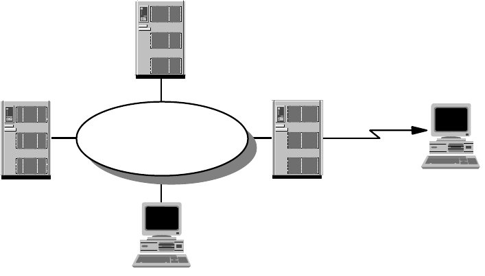
Remote Access 161
Figure 68. LAN Dial-Out to Remote Workstation
The LAN-to-remote environment has the same characteristics and capabilities as
the remote-to-LAN environment except that the LAN-attached workstation
initiates the connection. An example of LAN-to-remote would be a LAN-attached
workstation accessing a remote information server to acquire product pricing
data.
5.1.4 LAN-to-LAN
A LAN-to-LAN environment occurs when a LAN-attached workstation connects to
another LAN-attached workstation via two WAN/LAN communication servers.
This scheme is depicted in Figure 69 on page 162. The WAN connection is not a
permanent connection. It is connected on demand, as the resources are required
from the remote LAN, by the local LAN (and vice versa).
This environment normally combines the functions of the LAN-to-remote and
remote-to-LAN environments. The resulting casual bridge allows the customer to
utilize switched links rather than leased lines for a more mobile and cost-effective
solution.
2580D\2580D51
Remote
Workstation
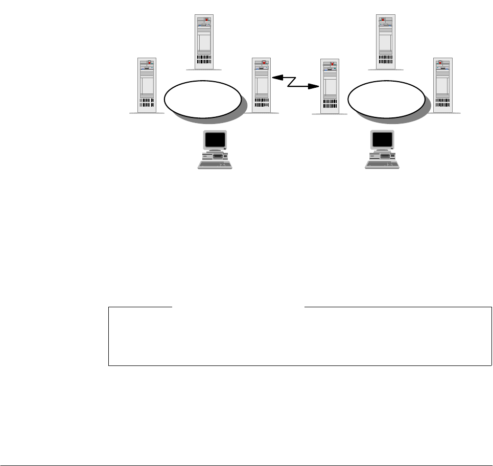
162 IP Network Design Guide
Figure 69. LAN Dial-Out to LAN
The LAN-to-LAN environment provides the capability for LAN-attached machines
to access or update information residing in remote locations and also to act as a
server for other remote workstations connecting to the LAN. Normally, the
connections are established on a temporary workstation-to-workstation basis
across the WAN.
The LAN-to-LAN environment is particularly useful for customers (with numerous
separate LAN networks) who have a need to control access on and off the LANs.
An example would be banking companies with their many branch offices. The
environment provides an inexpensive mechanism for dynamically connecting the
LANs while maintaining control over the origin of traffic flowing between them.
5.2 Remote Access Technologies
There are numerous remote LAN access products available today that vary
widely in cost and functionality. Some use standard hardware devices and are
solely software driven, while others may involve special hardware devices.
Products that involve special hardware devices may replace the LAN adapter with
a customized WAN adapter in the remote workstation and provide a compatible
hardware tap on the LAN. This LAN hardware tap varies from a specialized
adapter on the LAN file server to a stand-alone multiprocessor box. The
implementation of this approach varies widely in sophistication, cost, and
performance.
Some products utilize extensions of a remote-to-remote environment to provide
remote-to-remote and remote-to-LAN access capabilities, but do not support the
LAN-to-remote or LAN-to-LAN environments.
WS WS
FS
FS
LAN
FS
FS
LAN
LW LW
2580D\2580D52
This LAN-to-LAN environment is different from a split bridge environment. A
split bridge establishes a permanent connection among all machines on the two
LANs.
Note
Remote Access 163
Most of the remote LAN access products use one of three known technological
approaches:
• The remote control approach
• The remote client approach
• The remote node approach
Each approach provides an inherent level of functionality and limitations.
5.2.1 Remote Control Approach
One of the earliest and most pervasive software approaches is remote control.
The remote workstation using this approach dials-in to, and takes control over, a
LAN-attached workstation, which executes programs on behalf of the remote
workstation over the LAN. Keyboard and window data from the dedicated
LAN-attached system is then routed back to the remote workstation.
By routing only keyboard and window data, this approach minimizes the amount
of data that flows across the link, but it requires a dedicated machine on the LAN
for each remote workstation dialing in to the LAN.
Most remote control products transmit keyboard and screen data over the WAN in
character mode, although some companies provide transmission of graphical
screen data. Transmitting graphics images will of course be slower than
transmitting characters. However, graphics mode transmission is necessary to
support the use of graphics or graphical interfaces, which are gaining significant
importance in end user computing across the remote link. Lack of graphics
support has been a major factor in the loss of popularity for this approach.
The following are examples of remote control products:
• PC Anywhere
• Carbon Copy
• NetWare Access Server
5.2.2 Remote Client Approach
Gaining popularity today in the remote LAN access market, the remote client
approach utilizes a simple mechanism to extend the remote-to-remote
environment to service the remote workstation and allow it to share data and
applications located on a common WAN/LAN server. This may be accomplished
by replacing the LAN device drivers in the remote workstation and in
LAN-attached servers with customized device drivers that will allow them to send
and receive LAN frames across a WAN link. This provides LAN application
transparency within the remote workstation.
The new device drivers utilize existing protocols to allow remote workstations to
connect with each other to form a kind of a Virtual LAN via the WAN link. In
addition, the device drivers provide a mechanism for remote workstations to
disconnect from one another upon conclusion of the remote transaction.
Since the entire LAN frame is transported between the remote machines over the
WAN link, LAN applications running in the remote workstations can support
graphical interfaces in the same way as those running on LAN-attached
164 IP Network Design Guide
workstations (also, the LAN frames have much less fixed format information, thus
providing a more secure link encryption).
Extending the remote client approach to access information elsewhere on the
LAN from a remote workstation requires a LAN-attached server to manage
transaction data on the workstation's behalf. The remote environment is
analogous to a standard LAN client/server environment. Files and programs
residing on the common network server can be shared throughout the virtual
LAN.
The remote client approach supports small single-server networks, but does not
scale well to support large or distributed environments. Bottlenecks in both
memory and CPU capacity tend to form in the common network and file server.
Thus, most products using this approach are dedicated servers supporting a
limited number of remote connections (generally, one to 16).
Organizations requiring more connections or greater capacity than can be
accommodated by a single network server face potentially complex challenges in
duplicating and maintaining data on multiple communication servers. Accessing
data and applications that are distributed across multiple servers can be tedious
for a remote user in a remote client environment. For instance, a remote user
would have to physically disconnect from one server and reconnect to a second
server in order to access its resources, even though the two servers may be
attached to the same LAN.
The following list contains examples of remote client products:
• Lotus Notes
•cc:Mail
• Microsoft Windows NT
5.2.3 Remote Node Approach
The remote node approach replaces the device driver within a LAN-attached
communication server. The device driver enables the server to take incoming
data off a WAN and put it onto the LAN and also to take outgoing data off the LAN
and put it onto the WAN. In addition to providing the transparency and remote
LAN access capabilities of the remote client approach, the remote node provides
full addressability, allowing the remote workstation to access distributed
LAN-attached servers and peer services.
This means that a remote workstation can access information and services
wherever they reside on the LAN, rather than the LAN having to be redesigned
with a central dedicated server to accommodate access by the remote
workstation. It also means that growth in the number of local and remote LAN
users can be easily accommodated without duplicating and maintaining data files
across numerous servers.
An example of a remote node product is the IBM 2212 Router.
5.2.4 Remote Dial Access
The use of remote dial access to the corporate LAN is one of the fastest growing
areas of networking. Organizations have ever increasing requirements in giving
remote users access to corporate servers and applications.
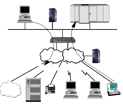
Remote Access 165
Figure 70. Dial Network Scenario
The most common situation is represented in Figure 70, where corporate
employees, like home workers, need to dial in for reaching corporate resources.
From corporate some of the public switched telephone network (PSTN) or
integrated services digital network (ISDN) attached resources can be reached
with a dial-out configuration.
The cost constraints associated with the growth of this scenario has led to
research for cost-effective solutions. Outsourcing the dial services to service
providers provides cost savings by relying on the service providers’ coverage of
the geographical area and on their ability to provide cost-effective solutions with
savings of scale.
The global reachability of the Internet is now attracting more interest.
Organizations can significantly reduce their dial costs by using the public Internet
through the attached ISPs' networks. ISPs' points of pressure (POPs) can
accommodate Network Access Points (NAPs) to avoid long-distance calls to
remote users. The Internet acts as the transport network to reach the corporate
Intranet and the associated resources. The problem with the Internet is its
inherent insecurity.
Virtual private networks (VPNs) are a group of technologies that are emerging to
solve the security issues related to the use of the public Internet for carrying
corporate data. VPNs maintain the security requirements of privacy,
confidentiality, data integrity, non-repudiation and authentications.
A number of protocols have been developed to implement VPNs. Among these
technologies is the IPSec architecture. It has been developed to address the
end-to-end security requirements for using Internet access to provide remote dial
connectivity.
Dials
Server
Servers
PSTN
PSTN
Internet
Dial-Out Dial-In
2580a\DIALSCEN
PC
Corporate
Intranet
166 IP Network Design Guide
5.2.5 Dial Scenario Design
The dial scenario has some important parameters that should be considered
when planning a solution. These parameters address the dial requirements, the
choice of implemented technology and the vendor devices to provide remote
access. We want to list the most important features related to the dial access
servers and their features.
The dial support of the IBM remote access servers is provided today by the
Nways multiprotocol router family of 2212s and 2216s. They support all the
functionality required for dial support and have added security enhancements to
support the VPN IPSec technologies. These routers also provide a complete set
of WAN/LAN interfaces and protocols.
The latest and complete specification of these devices can be found at the IBM
networking Web site:
http://www.networking.ibm.com/
The following are the main points to consider when choosing which devices meet
your requirements:
The Dial Capabilities
One of the first items of comparison among different vendors’ access devices is
their capacity (for remote access). Important features are:
• Port capacity
• Price per port
• Clocking and speed capacity of the related interfaces
• ISDN support as PRI and/or BRI interfaces
• Availability of internal modems
• Number of simultaneous calls allowed
The comparison of these parameters can give an appreciation for the positioning
of the various vendor devices.
LAN and WAN Connectivity
Access servers are evolving into a role of integrating all the network layer routing
features. The device’s capabilities as LAN and WAN connectors, and the
associated protocols supported, should be considered when choosing a device.
Protocol Support
The remote LAN (RLAN) access is provided at the data link or device driver level.
Higher level protocols can be supported in the overlaying architecture as depicted
in Figure 71 on page 167.

Remote Access 167
Figure 71. Dial Protocols Architecture
Multiprotocol support can be an important feature if LAN resources are running
different protocols. RLAN access, which is in the LAN’s native protocol, can avoid
overhead in the network resources.
Bandwidth Management Options
There are some important features, which are either derived from standards or
are vendor specific, that can better use the network resources in terms of
bandwidth. These features save useless allocation by assigning priorities to the
traffic delivered and providing bandwidth only when required. Some important
features are:
• Bandwidth on-demand support
• Queuing algorithms to provide traffic management
• Prioritizing mechanisms to achieve better and differentiated service levels
• Multilink PPP support (see “Multilink PPP” on page 46)
• Multilink PPP multi-chassis enhancements
• Dial on-demand support
• Anti-spoofing capabilities extended to different protocols
• Traffic and protocol filters
• Possibility of configuring dialer profiles
Security
Security issues are one of the most important aspects in the remote dial scenario.
The growing interest in VPN technology is creating a demand in more
sophisticated security options in a complete end-to-end solution. Any access
device should support identification and authentication protocols such as the
Password Authentication Protocol (PAP), Challenge Handshake Authentication
Protocol (CHAP) and other vendor-specific protocols. Another important security
element is the use of authentication, authorization and accounting severs, like the
standard Remote Authentication Dial-In User Service (RADIUS) or Terminal
TCP/IP NetBIOS
SNA
-3270
-5250
802.2
LLC2a
Protman NDIS Interface
DIAL NDIS
Adapter
(Com Port or ISDN Card)
2580a\DIALPROT
168 IP Network Design Guide
Access Controller Access Control System (TACACS) and TACACS+, or the
Security Dynamics SecureID two-factor authentication technologies.
Callback procedures can be enabled to provide security at very low level
protocols. Alternatively, filtering techniques can be used in the network level layer.
VPN technology requires support for tunneling protocols such as Layer 2
Tunneling Protocol (L2TP), data encryption, identification, authentication, and the
IPSec architecture.
Management
In remote LAN access, the management capabilities are becoming a critical
element as the security and accounting requirements are continuously growing.
Logging capabilities, for statistics and monitoring tools such as SNMP and
supported MIBs, can be powerful tools for problem determination, monitoring and
accounting.
The Client Access Software Support
The support of the client’s software platform is another key element in evaluating
the access devices. There is no use implementing a dial-in solution that is not
supported on the client’s platform.
5.2.6 Remote Access Authentication Protocols
Remote dial-in to the corporate intranet, as well as to the Internet, has made the
Remote Access Server (RAS) a very vital part of today's internetworking
services. As mentioned previously, more and more mobile users are requiring
access not only to central-site resources but to information sources on the
Internet. The widespread use of the Internet and the corporate intranet has fueled
the growth of remote access services and devices. There is an increasing
demand for a simplified connection to corporate network resources from mobile
computing devices such as notebook computers or palm-sized devices.
The emergence of remote access has caused significant development work in the
area of security. The Authentication, Authorization and Accounting (AAA) security
model has been developed to address the issues of remote access security. AAA
answers the questions who, what, and when, respectively. A brief description of
each of the three As in the AAA security model is presented below:
Authentication
This is the action of determining who a user (or entity) is. Authentication can
take many forms. Traditional authentication utilizes a name and a fixed
password. Most computers work this way. However, fixed passwords have
limitations, mainly in the area of security. Many modern authentication
mechanisms utilize one-time passwords or a challenge-response query.
Authentication generally takes place when the user first logs on to a machine
or requests a service from it.
Authorization
This is the action of determining what a user is allowed to do. Generally
authentication precedes authorization, but again, this is not required. An
authorization request may indicate that the user is not authenticated, that we
don't know who he/she is. In this case it is up to the authorization agent to
determine if an unauthenticated user is allowed the services in question. In
current remote authentication protocols authorization does not merely provide
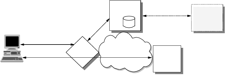
Remote Access 169
yes or no answers, but it may also customize the service for the particular
user.
Accounting
This is typically the third action after authentication and authorization. But
again, neither authentication nor authorization is required. Accounting is the
action of recording what a user is doing, and/or has done.
In the distributed client/server security database model, a number of
communication servers, or clients, authenticate a dial-in user's identity through a
single, central database, or authentication server. The authentication server
stores all the information about users, their passwords and access privileges.
Distributed security provides a central location for authentication data that is
more secure than scattering the user information on different devices throughout
a network. A single authentication server can support hundreds of
communication servers, serving up to tens of thousand of users. Communication
servers can access an authentication server locally or remotely over WAN
connections.
Several remote access vendors and the Internet Engineering Task Force (IETF)
have been in the forefront of this remote access security effort, and the means
whereby such security measures are standardized. The Remote Authentication
Dial-In User Service (RADIUS) and the Terminal Access Controller Access
Control System (TACACS) are two such cooperative ventures that have evolved
out of the Internet standardizing body and remote access vendors.
Remote Authentication Dial-In User Service (RADIUS)
RADIUS is a distributed security system developed by Livingston Enterprises.
RADIUS was designed based on a previous recommendation from the IETF's
Network Access Server Working Requirements Group. An IETF Working
Group for RADIUS was formed in January 1996 to address the standardization
of the RADIUS protocol; RADIUS is now an IETF-recognized dial-in security
solution (RFC 2058 and RFC 2138).
Figure 72. RADIUS
Terminal Access Controller Access Control System (TACACS)
Similar to RADIUS, Terminal Access Controller Access Control System
(TACACS) is an industry standard protocol specification, RFC 1492. Similar to
RADIUS, TACACS receives authentication requests from a network access
server (NAS) client and forwards the user name and password information to a
centralized security server. The centralized server can be either a TACACS
database or an external security database. Extended TACACS (XTACACS) is
Access Request
Grant/Deny
Send Configuration
NAS
RADIUS
Client
Application
Server
Other
Authentication
Server
RADIUS
Server
User Application
Connection
Authentication
Request
Grant/Deny
Connection Request
Send User Information
Grant/Deny
Corporate
Network
Remote
Client
User, Configuration,
Accounting
Databases
170 IP Network Design Guide
a version of TACACS with extensions that Cisco added to the basic TACACS
protocol to support advanced features. TACACS+ is another Cisco extension
that allows a separate access server (the TACACS+ server) to provide
independent authentication, authorization, and accounting services.
Although RADIUS and TACACS Authentication Servers can be set up in a variety
of ways, depending upon the security scheme of the network they are serving, the
basic process for authenticating a user is essentially the same. Using a modem, a
remote dial-in user connects to a remote access server (also called the network
access server or NAS), with a built-in analog or digital modem. Once the modem
connection is made, the NAS prompts the user for a name and password. The
NAS then creates the so-called authentication request from the supplied data
packet, which consists of information identifying the specific NAS device sending
the authentication request, the port that is being used for the modem connection,
and the user name and password.
For protection against eavesdropping by hackers, the NAS, acting as the RADIUS
or TACACS client encrypts the password before it sends it to the authentication
server. If the primary security server cannot be reached, the security client or
NAS device can route the request to an alternate server. When an authentication
request is received, the authentication server validates the request and then
decrypts the data packet to access the user name and password information. If
the user name and password are correct, the server sends an Authentication
Acknowledgment packet. This acknowledgment packet may include additional
filters, such as information on the user's network resource requirements and
authorization levels. The security server may, for instance, inform the NAS that a
user needs TCP/IP and/o Internet Packet Exchange ( IPX) using PPP, or that the
user needs SLIP to connect to the network. It may include information on the
specific network resource that the user is allowed to access.
To circumvent snooping on the network, the security server sends an
authentication key, or signature, identifying itself to the security client. Once the
NAS receives this information, it enables the necessary configuration to allow the
user the necessary access rights to network services and resources. If at any
point in this log-in process all necessary authentication conditions are not met,
the security database server sends an authentication reject message to the NAS
device and the user is denied access to the network.
5.2.7 Point-to-Point Tunneling Protocol (PPTP)
One of the more "established" techniques for remote connection is the
Point-to-Point Tunneling Protocol (PPTP). PPTP is a vendor solution that meets
the requirements for a VPN. It has been implemented by Microsoft on the
Windows NT, 98 and 95 (OSR2) platforms.
PPTP is an extension of the basic PPP protocol (see Figure 73 on page 171). It is
due to this fact that PPTP does not support multipoint connections, connections
must be point-to-point.
PPTP supports only IP, IPX, NetBIOS and NetBEUI. Because these are the most
commonly implemented network protocols, it is rarely an issue, especially for this
book as we are concerned with IP network design. However, this must be
considered when designing the network, more so when upgrading an existing
network.
Remote Access 171
PPTP does not change the PPP protocol. PPTP only defines a new way, a
tunneled way, of transporting PPP traffic.
PPTP is currently being replaced by implementations of L2TP. Microsoft has
announced that Windows 2000 will support L2TP. However, some vendors are still
developing solutions with PPTP.
Figure 73. PPTP System Overview
5.2.8 Layer 2 Forwarding (L2F)
Layer 2 Forwarding (L2F) was developed by Cisco Systems at the same time that
PPTP was being developed. It is another protocol that enables remote hosts to
access an organization’s intranet through public infrastructure, with security and
manageability maintained.
Cisco submitted this technology to the Internet Engineering Task Force (IETF) for
approval as a standard, and it is defined in RFC 2341.
As in the case for PPTP, L2F enables secure private network access through
public infrastructure, by building a "tunnel" through the public network between
the client and the host. The difference between PPTP and L2F is that L2F
tunneling is not dependent on IP; it is able to work with other network protocols
natively, such as frame relay, ATM or FDDI. The service requires only local dial-up
capability, reducing user costs and providing the same level of security found in
private networks.
An L2F tunnel supports more than one connection, a limitation of PPTP. L2F is
able to do this as it defines connections within the tunnel. This is especially useful
in situations where more than one user is located at a remote site, only one
dial-up connection is required. Alternatively, if tunneling is used only between the
POP and the gateway to the internal network, fewer connections are required
from the ISP, reducing costs. See Figure 74 on page 172.
L2F uses PPP for client authentication, as does PPTP, however, L2F also
supports TACACS+ and RADIUS for authentication. L2F authentication
comprises two levels, fist when the remote user connects to the ISP’s POP, and
then when the connection is made to the organization’s intranet gateway.
L2F passes packets through the virtual tunnel between endpoints of a
point-to-point connection. L2F does this at the protocol level. A frame from the
Network
Access
Server
(ISP POP)
Host
Internet
PPTP
Server
PPTP Connection (VPN)
PPP Connection
2580C\CH5F66
172 IP Network Design Guide
remote host is received at the POP, the linked framing/transparency bytes are
removed. The frame is then encapsulated in L2F and forwarded over the
appropriate tunnel. The organization’s gateway accepts the L2F frame, removes
the L2F encapsulation, and processes the incoming frame. Because L2F is a
Layer 2 protocol, it can be used for other protocols than IP, such as IPX and
NetBEUI.
Figure 74. L2F Tunnel from POP to Intranet Gateway
With L2F, a complete end-to-end secure VPN can be created and used. It is a
reliable and scalable solution. However, it has shortcomings that are addressed
with L2TP (see 5.2.9, “Layer 2 Tunneling Protocol (L2TP)” on page 172).
5.2.9 Layer2TunnelingProtocol(L2TP)
The Layer 2 Tunneling Protocol (L2TP) is one of the emerging techniques for
providing a remote connection to the corporate intranet. The L2TP protocol has
been developed merging two different protocols: the Point-to-Point Tunneling
Protocol (PPTP) and Layer 2 Forwarding (L2F).
The remote dial-in user scenario is the most common situation for using the L2TP.
The remote users do not need to make a long-distance call or use a toll-free
number to connect directly to the corporate servers, but cost constraints suggest
the use of ISPs' points of presence (POPs) as a more cost-effective solution. In
this case the dial-in user should connect to the nearest POP provided by the ISP
and then its session is routed through the ISPs and/or the Internet cloud to reach
the corporate LAN access. This environment has more then one point of critical
security and reliability issues.
The L2TP provides a technique for building a Point-to-Point Protocol (PPP) tunnel
connection that, instead of being terminated at the ISP's nearest POP, is
extended to the final corporate Intranet access gateway. The tunnel can be
initiated either by the remote host or by the ISP's gateway access. The L2TP
protocol provides a reliable way of connecting remote users in a virtual private
network that can support multiprotocol traffic, that is all the network layer
protocols supported by the PPP protocol. Moreover, it provides support for any
network layer private addressing scheme for the connection over the Internet.
The latest specification can be found in the following Internet draft; however, it is
expected that L2TP will soon be approved as a standard.
http://search.ietf.org/internet-drafts/draft-ietf-pppext-l2tp-14.txt
HostClient
POP Internet Intranet
PPD ISP Network L2F Tunnel Local Network
2580C\CH5F71
Remote Access 173
5.2.9.1 L2TP Protocol Overview
The L2TP protocol can support remote LAN access using any network layer
protocol supported by PPP over the tunnel session, and this is managed by
terminating the PPP connection directly in the corporate intranet gateway access.
There are some elements that take part in the L2TP protocol scenario:
L2TP Access Concentrator (LAC)
The LAC is located at the ISP's POP to provide the physical connection of the
remote user. In the LAC the physical media are terminated and it can be
connected to more public switched telephone network (PSTN) lines or
integrated services digital network (ISDN) lines. Over these media the user
can establish the L2TP connection that the LAC routes to one or more L2TP
servers where the tunnels are terminated. Any 221x Nways router can support
LAC functionality and based on the connection capabilities a 2210 Nways
multiprotocol router or a 2212 Nways Access Utility can be correctly positioned
on a different ISP's POPs as a LAC for the L2TP.
L2TP Network Server (LNS)
The LNS terminates the calls arriving from the remote users. Only a single
connection can be used on the LNS to terminate multiple calls from remote
users, placed on different media as ISDN, asynchronous lines, V.120, etc. The
221x Nways routers can support LNS capabilities. A 2216 Multiaccess
Concentrator can be used also as LNS when it is used as the corporate
Intranet access gateway.
Network Access Server (NAS)
The NAS is the point-to-point access device that can provide on-demand
access to the remote users across PSTN or ISDN lines.
The L2TP protocol is described in Figure 75 on page 174. The session and tunnel
establishments are handled in the following phases:
• The remote user initiates a PPP connection to the NAS.
• The NAS accepts the call.
• The end user authentication is provided by means of an authorization server
to the NAS.
• The LAC is triggered by the end user’s attempt to start a connection with the
LNS for building a tunnel with the LNS at the edge of the corporate Intranet.
Every end-to-end attempt to start a connection is managed by the LAC with a
session call. The datagrams are sent within the LAC LNS tunnel. Every LAC
and LNS device keeps track of the connected user’s status.
• The remote user is authenticated also by the authentication server of the LNS
gateway before accepting the tunnel connection.
• The LNS accepts the call and builds the L2TP tunnel.
• The NAS logs the acceptance.
• The LNS exchanges the PPP negotiation with the remote user.
• End-to-end data is now tunneled between the remote user and the LNS.
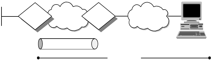
174 IP Network Design Guide
Figure 75. Layer 2 Tunnel Protocol (L2TP) Scenario
L2TP can support the following functions:
• Tunneling of single user dial-in clients
• Tunneling of small routers, for example, a router with a single static route to
set up based on an authenticated user's profile
• Incoming calls to an LNS from an LAC
• Multiple calls per tunnel
• Proxy authentication for PAP and CHAP
•ProxyLCP
• LCP restart in the event that proxy LCP is not used at the LAC
• Tunnel endpoint authentication
• Hidden attribute value pair (AVP) for transmitting a proxy PAP password
• Tunneling using a local lookup table
• Tunneling using the PPP user name lookup in the AAA subsystem
5.2.9.2 L2TP Tunnel Types
L2TP supports two types of tunnels, the compulsory model and the voluntary
model.
L2TP Compulsory Tunnels
With this model, the L2TP tunnel is established between a LAC, an ISP and an
LNS at the corporate network. This requires the cooperation of a service provider
that has to support L2TP in the first place and has to determine based upon
authentication information whether L2TP should be used for a particular session,
and where a tunnel should be directed. However, this approach does not require
any changes at the remote client, and it allows for centralized IP address
assignment to a remote client by the corporate network. Also, no Internet access
is provided to the remote client other than via a gateway in the corporate network
that allows for better security control and accounting.
An L2TP compulsory tunnel, illustrated in Figure 76 on page 175, is established
as follows:
1. The remote user initiates a PPP connection to an ISP.
2. The ISP accepts the connection and the PPP link is established.
3. The ISP now undertakes a partial authentication to learn the user name.
Internet
ISP
LNS LAC Dial
Connection
L2TP Tunnel
PPP Connection
3376\3376F4K1
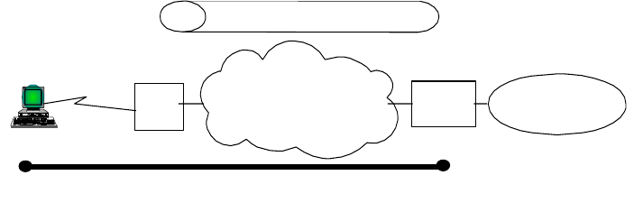
Remote Access 175
4. ISP-maintained databases map users to services and LNS tunnel endpoints.
5. LAC then initiates L2TP tunnel to LNS.
6. If LNS accepts the connection, LAC then encapsulates PPP with L2TP and
forwards the appropriate tunnel.
7. LNS accepts these frames, strips L2TP, and processes them as normal
incoming PPP frames.
8. LNS then uses PPP authentication to validate the user and then assigns the
IP address.
Figure 76. L2TP Compulsory Tunnel Model
L2TP Voluntary Tunnels
With this model, the L2TP tunnel is established between a remote client (which is
effectively acting as a LAC) and an LNS at a corporate network. This method is
similar to PPTP and is essentially transparent to an ISP but requires L2TP
support at the client. This approach allows the remote client to have Internet
access as well as one or multiple VPN connections at the same time. However,
the client ultimately ends up with being assigned multiple IP addresses; one from
the ISP for the original PPP connection, and one per L2TP VPN tunnel assigned
from a corporate network. This opens the client as well as the corporate networks
to potential attacks from the outside, and it requires client applications to
determine the correct destinations for their data traffic.
An L2TP voluntary tunnel, illustrated in Figure 77 on page 176, is established as
follows:
1. The remote user has a pre-established connection to an ISP.
2. The L2TP Client (LAC) initiates the L2TP tunnel to LNS.
3. If LNS accepts the connection, LAC then encapsulates PPP and L2TP, and
forwards through a tunnel.
4. LNS accepts these frames, strips L2TP, and processes them as normal
incoming frames.
5. LNS then uses PPP authentication to validate the user and then assign the IP
address.
LAC = L2TP Access Concentrator
LNS = L2TP Network Server
Corporate
Network
ISP Gateway
L2TP Tunnel
PPP
Client
(LNS)
Internet
(LAC)
PPP connection
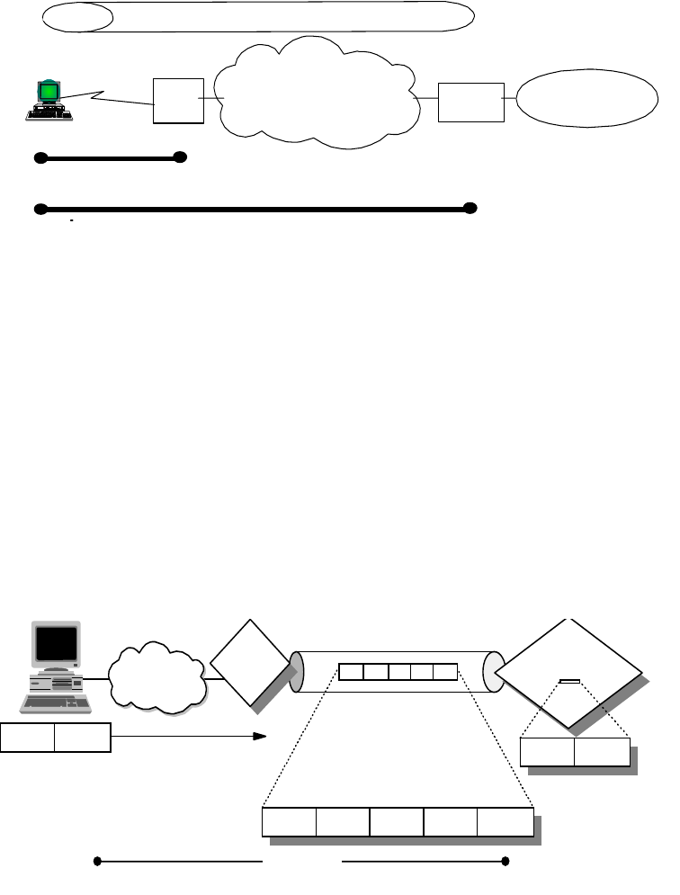
176 IP Network Design Guide
Figure 77. L2TP Voluntary Tunnel Model
5.2.9.3 Limits of the L2TP Protocol
The L2TP protocol can provide a cost-effective solution for the remote access
scenario using the Virtual Private Network technology, but there are some issues
mainly concerned with the security aspects. An L2TP tunnel is created by
encapsulating an L2TP frame inside a UDP packet, which in turn is encapsulated
inside an IP packet whose source and destination addresses define the tunnel's
endpoints as can be seen in Figure 78 on page 176. Since the outer
encapsulating protocol is IP, clearly IPSec protocols can be applied to this
composite IP packet, thus protecting the data that flows within the L2TP tunnel.
The Authentication Header (AH), Encapsulating Security Payload (ESP), and
Internet Key Exchange (IKE) protocols can all be applied in a straightforward way.
Figure 78. L2TP Tunnel Encapsulation
In fact a proposed solution to the security issues has been developed in the PPP
Extensions Working Group in the IETF to make use of the IPSec framework to
provide the security enhancements to the L2TP protocol. The use of IPsec
technologies in conjunction with the L2TP protocol can provide a secured
end-to-end connection between remote users and the corporate Intranet that can
support remote LAN connections (not only remote IP). The following reference
provides additional information on how to use IPSec in conjunction with L2TP:
http://search.ietf.org/internet-drafts/draft-ietf-pppext-l2tp-security-03
.txt
LNS = L2TP Network Server
LAC = L2TP Access Concentrator
Corporate
Network
ISP Gateway
L2TP Tunnel
L2TP
Client
(LNS)
Internet
(LAC)
(PPP connection to ISP)
PPP connection to LNS
LAC
L2TP
Code
Dial
Connection
IP UDP
PPP Connection 3376\3376F4K2
PPP Data
LNS
L2TP Router
Code Code
PPP Data
L2TP PPP Data

Remote Access 177
The IPSec framework can add to the L2TP protocol the per packet authentication
mechanism and integrity checks instead of the simple authentication of the
ending point of the tunnel that is not secured from attack by internetwork nodes
along the path of the tunnel connection. Moreover, the IPSec framework adds to
the L2TP protocol the encryption capabilities for hiding the cleartext payload and
a secured way for an automated generation and exchange of cryptographic keys
within the tunnel connection.
5.2.9.4 Comparing Remote Access Tunneling Protocols
The following table provides a quick comparison of the three predominant remote
access tunneling protocols L2TP, PPTP and L2F:
Table 12. Comparing Remote Access Tunneling Protocols
5.2.9.5 L2TP VPN Implementation Scenario
As an example of the VPN technology to provide a reliable connection among
branches and the central corporate Intranet we can use the following scenario
(see Figure 79 on page 178).
PPTP L2F L2TP
Standard/Status Internet Draft
(informational) RFC 2341
(informational) Internet Draft
(standards track)
Carrier IP/GRE IP/UDP, FR, ATM IP/UDP, FR, ATM
Private address
assignments Yes Yes Yes
Multiprotocol
support Yes Yes Yes
Call types Incoming and
outgoing Incoming Incoming and
outgoing
Control protocol Control over TCP
Port 1723 Control over UDP
Port 1701 Control over UDP
Port 1701
Encryption No encryption other
than PPP (MPPE) No encryption other
than PPP (MPPE) PPP encryption
(MPPE/ECP) or
IPSec ESP
Authentication PPP authentication PPP authentication PPP authentication
and/or IPSec
AH/ESP
Tunnel modes Typically voluntary
tunneling model Compulsory
tunneling model Compulsory and
voluntary models
Multiple calls per
tunnel No Yes Yes
PPP multilink
support No Yes Yes
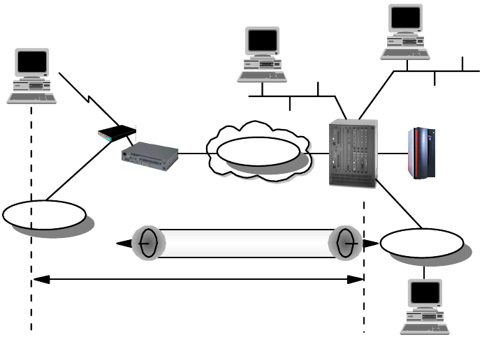
178 IP Network Design Guide
Figure 79. L2TP Tunneling Scenario with Nways Routers
The 2216 multiprotocol concentrator is used here in the central office to provide
connectivity and route traffic among the LAN segments in the central site and the
connected branches. The interconnected link represents the IP network that
provides remote connectivity and could be the ISP's backbone network or the
whole Internet.
The 2210 multiprotocol router can be used in the branch office to provide Remote
LAN Access (RLAN) for dial-in users. The central office RLAN connectivity is
delivered using the L2TP tunnel. The 2210 accepting the incoming request of the
remote dial-in user sets up a PPP tunnel directly to the 2216 in the central office.
The RLAN access to the corporate intranet resources is available to the remote
dial-in user.
Dial-In Connection
The first steps of the configuration of the dial-in connection of the remote user
are:
• The virtual interface of the dial-in user has assigned an interface number.
• The virtual interface should be configured for accepting inbound calls from
remote users and some selecting criteria can be used.
• The PPP connection parameters should then be specified in the PPP
encapsulation record, trying to achieve the goal of using similar parameters
to the client that requires access in order to minimize the negotiation
exchanges. The size of the maximum receive unit should agree with that of
the client.
• The security protocols are then configured for client authentication using a
combination of SPAP, CHAP or PAP (see“Authentication Protocols” on
page 45).
Remote User
S/390
2216-400
2210-24T
V.34
Modem
192.168.157
.59 192.168.157
192.168.157
.1
9.24.105
192.168.180
PPP Link
2580a\L2TPNWAY
L2TP Tunnel
Remote Access 179
• The client needs to have an IP address and this can be done in different
ways:
• The IP address is configured on the client itself.
• The IP address is provided by the RLAN server in the authentication
face associated to its user ID.
• The IP address is associated to the interface.
• The IP address could be provided by a DHCP server using the 2210
Proxy ARP capabilities.
User Definition
The following step is the user definition in the RLAN server. The 2210 PPP
user record should be filled with the user parameters, configuring identification
and connection parameters.
You should pay attention to the password definition if some of the
authentication protocols allow the user to change the password when
connected. Also the associated IP address of the V.34 interface should be
properly configured using a different subnet of the LAN connection or using
the unnumbered IP.
The Tunnel Interface
To connect the remote dial-in user to the LAN resources in the central office
the 2210 must be enabled to build an L2TP tunnel. The 2210 will act as a
L2TP Access Concentrator (LAC) and the 2216 in the central office as an
L2TP Network Server (LNS). The 2210 tunnel record should be provided with
the following parameters:
• Tunnel name
• Host name of the LAC
• Tunnel server endpoint IP address
• Shared secret for the tunnel authentication
Then the tunnel interface should be configured on the 2116 Router in the
corporate Intranet. Also the virtual interfaces where the PPP connections are
terminated should be added in the 2216.
PPP Users in the LNS
The last step requires the definition of the remote users in the central router to
have access to the corporate Intranet resources. The PPP users can be added
in two different ways:
• Rhelm-based tunneling need not be defined in the LAC because the user
format Username@domain is recognized by the LAC if the domain
matches the LNS host name and the PPP connection is rerouted to the
LNS itself that will identify and authenticate the remote user.
• User-based tunneling requires a definition of the user profile both in the
LAC and in the LNS.
A possible extension of this scenario is the use of the IPSec features to provide a
higher security level protection of the tunneled data. The L2TP tunnel is built
upon a UDP session and the IPSec encapsulation will be straightforward.
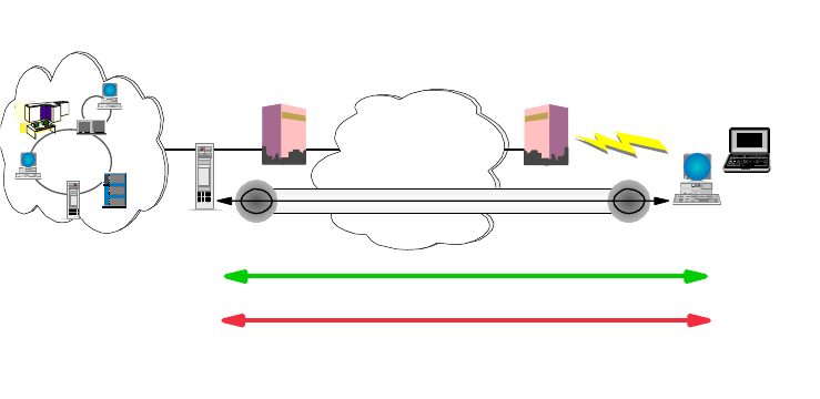
180 IP Network Design Guide
5.2.10 VPN Remote User Access
A very cost-effective solution for the remote access is the use of VPN
technologies, but the security issues in these scenarios are critical. The IETF has
developed an architecture for VPN technologies based on the Layer 3 network
protocol. IPSec (see 6.5.1.3, “The IP Security Architecture (IPSec)” on page 201)
relies basically on the concepts of IP tunneling over IP and encryption of the
packet payload to provide an end-to-end solution to the security issues.
5.2.10.1 Remote Access VPN Connection Using IPSec
One of the possible scenarios addressed by the IPSec architecture is the IP
connection of remote users to the corporate resources.
The number of people working remotely that need to have access to corporate
data and workflows is increasing and the traditional dial solutions cannot be really
cost effective. Sometimes the security requirements are stronger, dealing with
more sensible data carried over public network infrastructures. The IPSec
approach in the remote user VPN design and the vendor supported standards are
increasing and are being developed following the increasing customer interest in
this area.
The remote dial user in this scenario can make use of the Internet-wide
connectivity to avoid calling directly to the central site. The dial access of ISP's
POPs becomes the new network edge of the Intranet. In this scenario an
end-to-end secured path (tunnel) must be provided beginning in the client end
user system and ending in the corporate gateway access between the Intranet
and the Internet (see Figure 80 on page 180).
Figure 80. Remote Dial Connections VPN Scenario
If a different approach in company security policies has been chosen, the Intranet
cannot be considered a trusted network. The secured tunnel should extend from
the client to the application server inside the Intranet and behind the firewall that
provides corporate access to the Internet. This can be a possible scenario in
developing a corporate network plan that could make a deep use of the VPN
technologies to provide connectivity not only with the remote corporate users, but
to other components external to the company. Business partners and suppliers,
for example, can be allowed selected access to corporate servers and
Corporate
Intranet Home PCs,
Mobile Workers
Internet
ISP ISP
Security
Gateway
Remote
Client
Server
Encryption
Authentication
VPN
2580a\REMVPN
Remote Access 181
applications. This scenario is better accomplished by policies that do not trust the
Intranet itself, because the traffic going in and out of the corporate firewall is
generated both by internal and external users. Only a client server completely
server secured tunnel can provide reliable security. The availability of client
platforms and network nodes supporting this scenario is not yet complete.
A fundamental distinction must be made in the concepts of tunnels before
describing the design requirements of the remote access IPSec-based VPNs.
The tunnel is defined in the IPSec architecture as a pair of Security Associations
(SA), that are identified uniquely by the triple Security Parameter Index (SPI), IP
destination address and security protocol (AH or ESP). Other elements, such as
the cryptographic algorithms and keys can be specified. The SAs can be used in
tunnel mode or in transport mode, but the RFCs specify for firewalls acting as
gateways to use the tunnel mode implementation.
There are four types of tunnels that the IBM VPN products support:
Manual Tunnel
The manual tunnel implements standard IPSec components but it requires that
most of the parameters be filled manually. This approach can be used when there
is no automatic key management available. Key management is a critical
consideration when planning the use of manual tunnels because keys are also
managed manually in the start-up phase and also in the periodic refresh.
Otherwise the refreshing keys must be disabled thus leading to less security
coverage by the cryptography.
Generally the parameters that should be specified in a manual tunnel are:
• IP source and destination address
•SAtype
• IPSec protocol, policy, authentication and encryption parameters
• Source and destination key
• Source and destination SPI
• Session key lifetime
• Tunnel ID
• Replay prevention
IBM Tunnel
This tunnel uses the IP Security Protocol (IPSP) developed by IBM. This protocol
accomplishes the use of an automatic key update mechanism based on UDP port
4001. The new generated keys are exchanged in the encrypted tunnel after some
periodic intervals. The bootstrap keys are determined by the software and should
not be configured as other manual tunnel parameters. The IBM tunnel is useful
because of the automatic key refresh mechanism. However, this is a proprietary
feature that will be replaced with the standards-based Internet Key Exchange
(IKE) protocol.
Dynamic Tunnel
The dynamic tunnel uses IPSec standard components, but it is supported only by
the IBM eNetwork firewall and the two client platforms Windows 95 IPSec Client
(supplied with the eNetwork Firewall for AIX) and the OS/2 TCP/IP V4.1 IPSec
Client (in the OS/2 TCP/IP V4.1 protocol stack). The dynamic tunnel definition is
182 IP Network Design Guide
based only on the client target user and not on its IP address allowing a dynamic
IP address assignment.
The connection in the dynamic tunnel is established using the Secure Sockets
Layer (SSL) (see 6.5.2.4 “Secure Sockets Layer (SSL)” on page 213) connection
to the firewall port 4005. The tunnel is not built until the client specifies it and the
SSL server authenticates the client using an already encrypted user ID and
password and passing the tunnel policies to the remote client. Also the firewall
filters are dynamically added because the IP address of the client is not known.
Because these filters are configured at the beginning of the filter list there is no
more possibility to further restrict client access to the Intranet. Even though this
method is based on open standards for authentication, tunnel establishment and
packet-level protection, it does not exploit the latest IPSec standards and will
therefore be replaced by the Internet Key Exchange (IKE) protocol.
IKE Tunnel
This is the way that the current IPSec standards establish and refresh
cryptographic keys in order to protect Security Associations (SAs) that are used
for IPSec tunnels. IKE authenticates both parties before any keys are generated.
Essentially, IKE also provides dynamic tunnels, but we wanted to avoid confusing
the terms. IKE is described in “Internet Key Exchange Protocol (IKE)” on
page 203. It is the way that modern IPSec implementations are headed, and it is
currently being implemented in all IBM IPSec-based VPN products.
5.2.10.2 IPSec Remote Client Design Considerations
There are some aspects to deal with when planning to use the IPSec-enabled
VPN access for remote users; the most important to consider is the dynamic
environment of the remote access scenario.
The Dynamic Tunnel Support
The most important issue in this scenario is now the use of dynamic tunnels
because of the most widely diffused ISPs' behavior of using a dynamic address
configuration of the remote clients that connects to their POPs. The only
supported user-based identification and tunnel establishment is the dynamic
tunnel features provided by IKE and L2TP, or the dynamic tunnel used by the IBM
eNetwork Firewall and the Windows 95 IPSec Client and OS/2 with TCP/IP V4.1.
(see Figure 81 on page 183).
Using the IBM eNetwork Firewall as the corporate firewall gateway, these remote
clients can have access to the whole corporate Intranet without the need to deal
with key generation, refreshing and all other configuration parameters that can
introduce much overload to the network administrators.
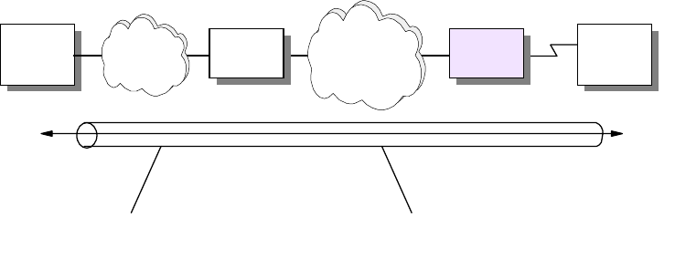
Remote Access 183
Figure 81. IPSec Tunnel
Some ISPs can provide static assignment of the IP addresses of the clients
allowing manual tunnel support. Routers can provide tunneling support and
firewalls can accomplish a static filtering configuration. For manual tunnels,
however, there is the need to deal with the configuration of the IPSec parameters.
Addressing and Routing
There are no specific issues in the routing and addressing policies other than
those already in place for connecting the Intranet to the public Internet. The
corporate LAN can still use private addresses or keep existing policies to prevent
internal addresses from being routed through the Internet. The public address of
the client will be reached through the canonical routing pointing the external
resources using the Internet/Intranet gateways.
The client has a public address that is routed across the Internet according to the
ISP's policies. The client knows the way to the corporate network using the
Internet routed subnet. This subnet is implemented at the edge of the corporate
network to have access to the Internet. The corporate firewall public address
interface is part of this subnet. The IPSec code must allow the client a different
routing for the Internet traffic (browsing, e-mail, etc.) and direct to the corporate
resources that should use the IPSec tunnel.
Client and Server Changes
The IPSec client code must be supported by the remote clients that need to
access the corporate Intranet using IPSec-enabled VPN. The servers instead can
not be reconfigured because the VPN gateway terminates the IPSec tunnels and
makes the connections transparent to the intranet application servers. Only if
planning to use complete end-to-end tunnels must the servers change.
Packet Filtering
The dynamic tunnel originated in the remote clients terminates in the corporate
firewall. The filters are dynamically added as the IP address of the remote client
is known. This cannot further restrict access to the corporate intranet. This can
be an issue if the VPN scenario is more complicated and allows in the intranet not
only the remote corporate users, but external components like partners and
suppliers. Considering the intranet is not a trusted network implies that
management of end-to-end IPSec implementations from client to the application
servers must be provided. The number of SAs that need to be managed in this
Server
Connection IPSec tunnels
Intranet FW1 Internet/
Intranet RAS Client
2580a\IPSECTUN
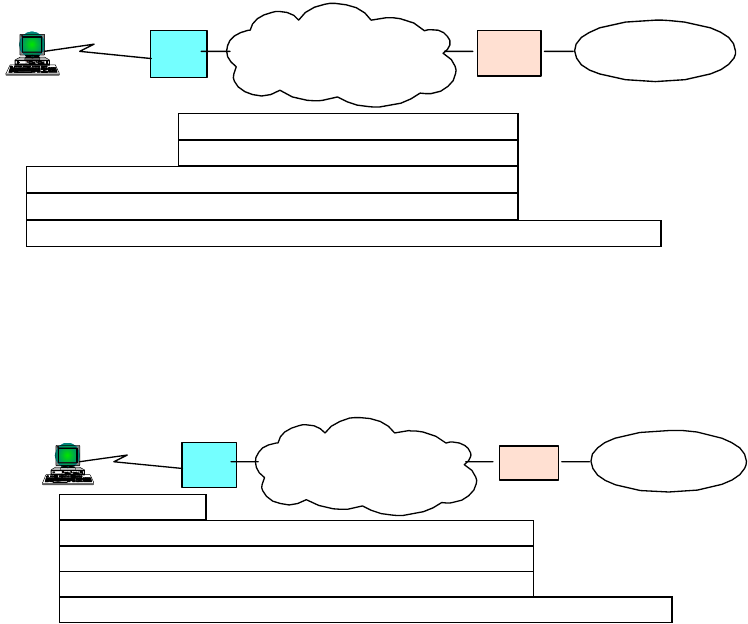
184 IP Network Design Guide
scenario can become very large and difficult to manage with today's IPSec
implementations. Developments are in place to provide directory services for
simplifying the management requirements and also the implementation of
automatic key management and generation protocols is being exploited following
the IPSec standard definitions.
5.2.10.3 Remote Access VPN Connection Using L2TP and IPSec
We have discussed the benefits of using L2TP for cost-effective remote access
across the Internet in 5.2.9, “Layer 2 Tunneling Protocol (L2TP)” on page 172.
The shortcomings of that approach are the inherently weak security features of
L2TP and the PPP connection that is encapsulated by L2TP. The IETF has
therefore recommended to use IPSec to provide protection for the L2TP tunnel
across the Internet as well as for the end-to-end traffic inside the tunnel.
Figure 82 on page 184 illustrates how IPSec can be used to protect L2TP
compulsory tunnels between a remote client and a corporate VPN gateway:
Figure 82. IPSec Protection for L2TP Compulsory Tunnel to VPN Gateway
Figure 83 on page 184 illustrates how IPSec can be used to protect L2TP
voluntary tunnels between a remote client and a corporate VPN gateway:
Figure 83. IPSec Protection for L2TP Voluntary Tunnel to VPN Gateway
Figure 84 on page 185 illustrates how IPSec can be used to protect L2TP
compulsory tunnels between a remote client and an IPSec-enabled system inside
a corporate network:
IP
L2TP
IPSec ESP
PPP
IPSec AH Compulsory
Tunnels
Corporate
Network
ISP Gateway
PPP
Client
Internet
(LNS)
(LAC)
IP
IPSec AH/ESP
L2TP
PPP
Voluntary
Tunnels
PPP
Corporate
Network
ISP Gateway
L2TP
Client
(LNS)
Internet
(LAC)
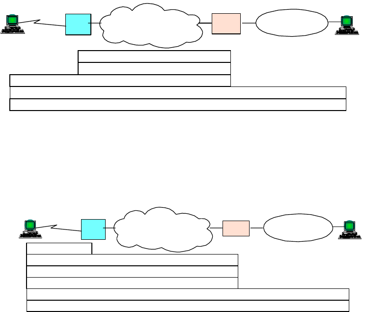
Remote Access 185
Figure 84. IPSec Protection for L2TP Compulsory Tunnel End-to-End
Figure 85 on page 185 illustrates how IPSec can be used to protect L2TP
voluntary tunnels between a remote client and an IPSec-enabled system inside a
corporate network:
Figure 85. IPSec Protection for L2TP Voluntary Tunnel End-to-End
When planning the use of VPN access in large environments the choice of
whether or not to differentiate the functionalities of the corporate firewall, which
provides the traditional Internet access from the VPN gateway, should be
evaluated to simplify the management and the critical requirement of these
resources. If the existing filtering policies are not changed when introducing the
IPSec VPN remote access, then the IPSec authentication mechanisms will keep
non-VPN traffic from accessing the corporate Intranet.
IP
L2TP
IPSec ESP
PPP
IPSec AH Compulsory
Tunnels
Corporate
Network
ISP Internet
(LAC)
Gateway
(LNS)
PPP
Client IPSec
Host
IPSec
Host
(LAC)
Corporate
Network
ISP Gateway
L2TP
Client
(LNS)
Internet
PPP IPSec AH
L2TP
PPP
Voluntary
Tunnels
IP
IPSec ESP
186 IP Network Design Guide

© Copyright IBM Corp. 1995 1999 187
Chapter 6. IP Security
This chapter discusses security issues regarding TCP/IP networks and provides
an overview of solutions to resolve security problems before they can occur. The
field of network security in general and of TCP/IP security in particular is too wide
to be dealt with in an all encompassing way in this book, so the focus of this
chapter is on the most common security exposures and measures to counteract
them. Because many, if not all, security solutions are based on cryptographic
algorithms, we also provide a brief overview of this topic for the better
understanding of concepts presented throughout this chapter.
6.1 Security Issues
This section gives an overview of some of the most common attacks on computer
security, and it presents viable solutions to those exposures and lists actual
implementations.
6.1.1 Common Attacks
For thousands of years, people have been guarding the gates to where they store
their treasures and assets. Failure to do so usually resulted in being robbed,
neglected by society or even killed. Though things are usually not as dramatic
anymore, they can still become very bad. Modern day I/T managers have realized
that it is equally important to protect their communications networks against
intruders and saboteurs from both inside and outside. We do not have to be
overly paranoid to find some good reasons why this is the case:
• Tapping the wire: to get access to cleartext data and passwords
• Impersonation: to get unauthorized access to data or to create unauthorized
e-mails, orders, etc.
• Denial-of-service: to render network resources non-functional
• Replay of messages: to get access to and change information in transit
• Guessing of passwords: to get access to information and services that would
normally be denied (dictionary attack)
• Guessing of keys: to get access to encrypted data and passwords (brute-force
attack, chosen ciphertext attack, chosen plaintext attack)
• Viruses, trojan horses and logic bombs: to destroy data
Though these attacks are not exclusively specific to TCP/IP networks, they
should be considered potential threats to anyone who is going to base his/her
network on TCP/IP, which is what the majority of enterprises, organizations and
small businesses around the world are doing today. Hackers (more precisely,
crackers
) do likewise and hence find easy prey.
6.1.2 Observing the Basics
Before even thinking about implementing advanced security techniques such as
the ones mentioned in the following sections, you should make sure that basic
security rules are in place:
• Passwords: Make sure that passwords are enforced to be of a minimum length
(typically six to eight characters), to contain at least one numeric character, to

188 IP Network Design Guide
be different from the user ID to which they belong, and to be changed at least
once every two months.
• User IDs: Make sure that every user has a password and that users are locked
out after several logon attempts with wrong passwords (typically five
attempts). Keep the passwords to superuser accounts (root, supervisor,
administrator, maint, etc.) among a very limited circle of trusted system,
network and security administrators.
• System defaults: Make sure that default user IDs are either disabled or have
passwords that adhere to the minimum requirements stated above. Likewise,
make sure that only those services are enabled that are required for a system
to fulfill its designated role.
• Physical access: Make sure that access to the locations where your systems
and users physically reside is controlled appropriately. Information security
begins at the receptionist, not at the corporate firewall.
• Help desk: Make sure that callers are properly identified by help desk
representatives or system administrators before they give out "forgotten"
passwords or user IDs. Social engineering is often the first step to attack a
computer network.
6.2 Solutions to Security Issues
With the same zealousness that intruders search for a way to get into someone's
computer network, the owners of such networks should, and most likely will, try to
protect themselves. Taking on the exposures mentioned earlier, here are some
solutions to effectively defend yourself against an attack. It has to be noted that
any of those solutions solve only a single or just a very limited number of security
problems. Therefore, a combination of several such solutions should be
considered in order to guarantee a certain level of safety and security.
• Encryption: to protect data and passwords
• Authentication and authorization: to prevent improper access
• Integrity checking and message authentication codes (MACs): to protect
against the improper alteration of messages
• Non-repudiation: to make sure that an action cannot be denied by the person
who performed it
• Digital signatures and certificates: to ascertain a party's identity
• One-time passwords and two-way random number handshakes: to mutually
authenticate parties of a conversation
• Frequent key refresh, strong keys and prevention of deriving future keys: to
protect against breaking of keys (crypto-analysis)
• Address concealment: to protect against denial-of-service attacks
• Content inspection: to check application-level data for malicious content
before delivering it into the secure network

IP Security 189
Table 13 on page 189 matches common problems and security exposures to the
solutions listed above:
Table 13. Security Exposures and Protections
Problem / Exposure Remedy Available Technologies
How to make break-ins into my
network as difficult as possible?
Install a combination of security
technologies for networks as
well as for applications.
Firewalls (IP filtering + proxy
servers+SOCKS+IPSec,
etc.). Antivirus + content
inspection + intrusion detection
software. No system defaults +
enforced password policies.
Passwords for every user and
every service/application +
ACLs. Extensive logging +
alerting + frequent log
audits/analysis. No
unauthorized dial-in + callback
How to protect against viruses,
trojan horses, logic bombs,
etc.?
Restrict access to outside
sources. Run antivirus software
on every server and
workstation. Run
content-screening software on
your gateways for application
data (mail, files, Web pages,
etc.) and mobile code (Java,
ActiveX, etc.). Update that
software frequently.
IBM/Norton AntiVirus, etc.
Content Technologies'
MIMESweeper and
WebSweeper, etc. Finjan
Surfingate, etc.
How to prevent the improper
use of services by otherwise
properly authenticated users?
Use a multi-layer access control
model based on ACLs.
Application security (DBMS,
Web servers, Lotus Notes,
etc.). Server file systems
(UNIX, NTFS, NetWare,
HPFS-386, etc.). System
security services (RACF, DCE,
UNIX, NT, etc.).
How to obtain information on
possible security exposures?
Observe security directives by
organizations such as CERT
and your hardware and
software vendors
http://www.cert.org
How to make sure that only
those people, that you want dial
into your network?
Use access control at link
establishment by virtue of
central authentication services,
two-factor authentication, etc.
RADIUS (optionally using
Kerberos, RACF, etc.),
TACACS. Security Dynamics'
SecureID ACE/Server, etc.

190 IP Network Design Guide
How do you know that your
system has been broken into?
Use extensive logging and
examine logs frequently. Use
intrusion detection programs.
Application/Service access logs
(Lotus Notes, DB2/UDB, Web
servers, etc.). System logs
(UNIX, Windows NT, AS/400,
etc.). Firewall logs and alerting
(IBM firewalls, etc.). Systems
management and alerting
(Tivoli, etc.)
How to prevent wire tappers
from reading messages?
Encrypt messages, typically
using a shared secret key.
(Secret keys offer a
tremendous performance
advantage over public/private
keys.)
SET, SSL, IPSec, Kerberos,
PPP
How to distribute the keys in a
secure way?
Use a different encryption
technique, typically
public/private keys.
PGP, S/MIME, Lotus Notes,
SET, SSL, IPSec. Kerberos (3rd
party)
How to prevent keys from
becoming stale, and how to
protect against guessing of
future keys by cracking current
keys?
Refresh keys frequently and do
not derive new keys from old
ones (use perfect forward
secrecy).
SSL, IPSec. Kerberos (time
stamps)
How to recover from loss or
theft of keys and how to meet
government regulations?
Use key escrow and key
recovery techniques and
prevent unauthorized
encryption
IBM Firewall, IBM Keyworks,
Content Technologies'
SecretSweeper
How to prevent retransmission
of messages by an impostor
(replay attack)?
Use sequence numbers. (Time
stamps are usually unreliable
for security purposes.)
IPSec
How to make sure that a
message has not been altered
in transit?
Use message digests (hash or
one-way functions).
S/MIME, Lotus Notes, SET,
Antivirus software, UNIX
passwords, SSL, IPSec
How to make sure that the
message digest has not also
been compromised?
Use digital signatures by
encrypting the message digest
with a secret or private key
(origin authentication,
non-repudiation).
S/MIME, Lotus Notes, SET,
Java security, SSL, IPSec.
How to make sure that the
message and signature
originated from the desired
partner?
Use two-way handshakes
involving encrypted random
numbers (mutual
authentication).
Kerberos, SSL, IPSec
How to make sure that
handshakes are exchanged
with the right partners
(man-in-the-middle attack)?
Use digital certificates (binding
of public keys to permanent
identities).
S/MIME,SET,SSL,IPSec
Problem / Exposure Remedy Available Technologies
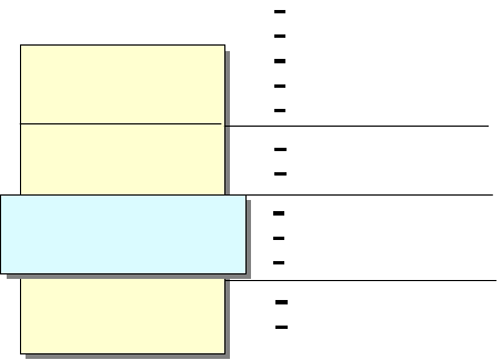
IP Security 191
In general, keep your network tight towards the outside but also keep a watchful
eye the inside because most attacks are mounted from inside a corporate
network.
6.2.1 Implementations
The following protocols and systems are commonly used to provide various
degrees of security services in a computer network. They are introduced in detail
in 6.5, “Security Technologies” on page 197.
• IP filtering
• Network Address Translation (NAT)
• IP Security Architecture (IPSec)
•SOCKS
• Secure Sockets Layer (SSL)
• Application proxies
• Firewalls
• Kerberos, RADIUS, and other authentication systems (which are discussed in
5.2.6, “Remote Access Authentication Protocols” on page 168)
• Antivirus, content inspection and intrusion detection programs
Figure 86 on page 191 illustrates where those security solutions fit within the TCP/IP
layers:
Figure 86. Security Solutions in the TCP/IP Layers
Figure 87 on page 192 summarizes the characteristics of some of the security
solutions mentioned earlier and compares them to each other. This should help
anyone who needs to devise a security strategy to determine what combination of
solutions will achieve a desired level of protection.
CHAP, PAP, MS-CHAP
Tunneling Protocols
IPSec (AH, ESP)
Packet Filtering
NAT
S/MIME, PGP
Proxy Servers
SET, PKI
Kerberos
IPSec (IKE)
Network Interface
(Data Link)
IP
(Internetwork)
TCP/UDP
(Transport)
Applications
SOCKS V5
SSL, TLS

192 IP Network Design Guide
Figure 87. Characteristics of IP Security Technologies
As mentioned earlier, an overall security solution can, in most cases, only be
provided by a combination of the listed options, for instance by using a firewall.
However, what one's particular security requirements are needs to be specified in
a security policy.
6.3 The Need for a Security Policy
It is important to point out that you cannot implement security if you have not
decided what needs to be protected and from whom. You need a security policy, a
list of what you consider allowable and what you do not consider allowable, upon
which to base any decisions regarding security. The policy should also determine
your response to security violations.
An organization's overall security policy must be determined according to security
analysis and business requirements analysis. Since a firewall, for instance,
relates to network security only, a firewall has little value unless the overall
security policy is properly defined. The following questions should provide some
general guidelines:
• Exactly who do you want to guard against?
• Do remote users need access to your networks and systems?
• How do you classify confidential or sensitive information?
• Do the systems contain confidential or sensitive information?
• What will the consequences be if this information is leaked to your competitors
or other outsiders?
• Will passwords or encryption provide enough protection?
• Do you need access to the Internet?
Solution Access
Control Encryption Authenti-
cation Integrity
Checking Key
Exchange Concealing
Internal
Addresses
PFS Session
Monitoring UDP
Support
IP Filtering YNNNNNNNY
NAT Y N N N N Y N Y
(connection) Y
L2TP Y
(connection) Y
(PPP link) Y
(call) N N Y N Y
(call) Y
IPSec Y Y
(packet) Y
(packet) Y
(packet) Y Y y N Y
SOCKS Yoptional Y
(client/user) N N Y N Y
(connection) Y
SSL Y Y
(data) Y
(system/
user)
Y Y N Y Y N
Application
Proxy Ynormally no Y
(user) Ynormally no Ynormally no Y
(connection
and data)
normally no
Remote
Access
Server
Y
(connection) some Y
(user) Nnormally no NNNY
IP Security 193
• How much access do you want to allow to your systems from the Internet
and/or users outside your network (business partners, suppliers, corporate
affiliates, etc.)?
• What action will you take if you discover a breach in your security?
• Who in your organization will enforce and supervise this policy?
This list is short, and your policy will probably encompass a lot more before it is
complete. Perhaps the very first thing you need to assess is the depth of your
paranoia. Any security policy is based on how much you trust people, both inside
and outside your organization. The policy must, however, provide a balance
between allowing your users reasonable access to the information they require to
do their jobs, and totally disallowing access to your information. The point where
this line is drawn will determine your policy.
6.3.1 Network Security Policy
If you connect your system to the Internet then you can safely assume that your
network is potentially at risk of being attacked. Your gateway or firewall is your
greatest exposure, so we recommend the following:
• The gateway should not run any more applications than is absolutely
necessary; for example, proxy servers and logging because applications have
defects that can be exploited.
• The gateway should strictly limit the type and number of protocols allowed to
flow through it or terminate connections at the gateway from either side,
because protocols potentially provide security holes.
• Any system containing confidential or sensitive information should not be
directly accessible from the outside.
• Generally, anonymous access should at best be granted to servers in a
demilitarized zone.
• All services within a corporate intranet should require at least password
authentication and appropriate access control.
• Direct access from the outside should always be authenticated and
accounted.
The network security policy defines those services that will be explicitly allowed
or denied, how these services will be used and the exceptions to these rules.
Every rule in the network security policy should be implemented on a firewall
and/or Remote Access Server (RAS). Generally, a firewall uses one of the
following methods.
Everything not specifically permitted is denied.
This approach blocks all traffic between two networks except for those
services and applications that are permitted. Therefore, each desired service
and application should be implemented one by one. No service or application
that might be a potential hole on the firewall should be permitted. This is the
most secure method, denying services and applications unless explicitly
allowed by the administrator. On the other hand, from the point of users, it
might be more restrictive and less convenient.

194 IP Network Design Guide
Everything not specifically denied is permitted.
This approach allows all traffic between two networks except for those
services and applications that are denied. Therefore, each untrusted or
potentially harmful service or application should be denied one by one.
Although this is a flexible and convenient method for the users, it could
potentially cause some serious security problems.
Remote access servers should provide authentication of users and should ideally
also provide for limiting certain users to certain systems and/or networks within
the corporate intranet (authorization). Remote access servers must also
determine if a user is considered roaming (can connect from multiple remote
locations) or stationary (can connect only from a single remote location), and if
the server should use callback for particular users once they are properly
authenticated.
6.4 Incorporating Security into Your Network Design
You have seen throughout previous chapters that the design of an IP network is
sometimes exposed to environmental and circumstantial influences that dictate
certain topologies or strongly favor one design approach over another. One such
influential topic is IP security.
6.4.1 Expecting the Worst, Planning for the Worst
In general, network administrators tend to either overemphasize or neglect
security aspects when designing their networks. It is very important that you do
not follow either of those cases but take great care that the security measures you
need to implement in your network match those specified in your overall security
policy. Once a security policy is in place, adequate technologies and their impact
on the network design can be discussed.
However, if in doubt, expect the worst and add one more layer of security. You can
remove it later if a thorough investigation reveals that it is not required. Do not
trade in security for availability or performance unless you can really justify it.
It helps to divide your network into three major zones in order to define a more
detailed security policy and the designs required to implement them at the right
points within the network. Those zones are described below and illustrated in
Figure 88 on page 195.
Core Network:
This is the network where your business-critical applications and
their supporting systems are located. This part of the network requires
maximum protection from the outside and is usually also kept apart
from internal users as an additional layer of protection.
Perimeter Network:
This is the network where your public resources are located.
These include Web and FTP servers but also application gateways
and systems that provide specialized security functions, such as
content inspection, virus protection and intrusion detection. This part
of the network is typically secured from the outside as well as the
inside to provide maximum isolation of the traffic in this network. This
part of the network may also contain internal users.
Access Network:
This is the network, whether private, public or virtual, leased or
dial-up, that is used by the outside to access your network and its
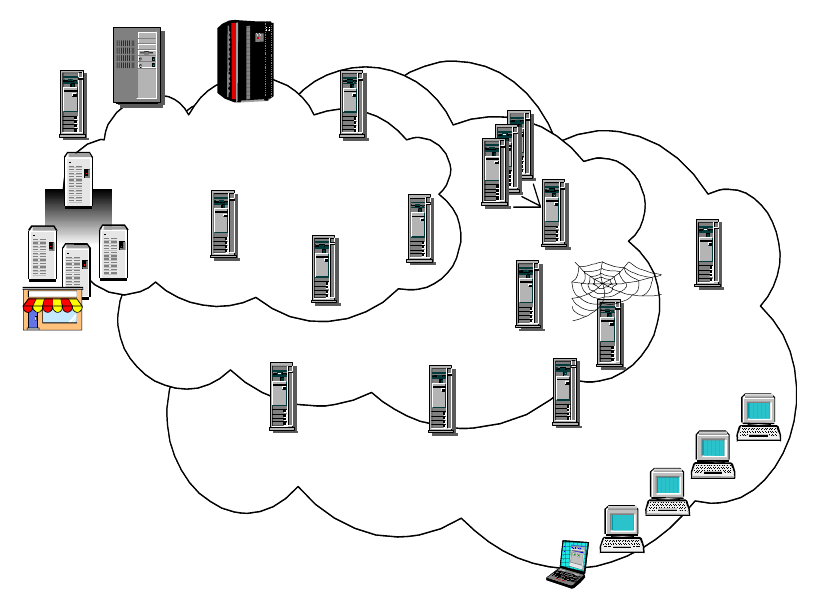
IP Security 195
services and applications. This network is typically secured to the
outside only.
The components among those zones actually implement and enforce your
security policy.
Figure 88. Network Zones and Security Components
Modern e-business requires sophisticated security technologies to be in place in
order to protect valuable data and systems that are more and more exposed to
public access. This was not the case with traditional corporate networks of the
past. This confronts network and security administrators with an increasing
complexity to find the right choice of security technologies and their placement in
the network. The following sections discuss these two issues in more detail.
6.4.2 Which Technology To Apply, and Where?
There are many security technologies available today that serve either special
purposes or complement another technology to provide any desired level of
protection. The problem that network and security administrators normally face is
which technologies they should employ and where in the network they should be
deployed in order to make the security policy effective. In addition to that, a
security policy should be manageable across technologies and security zones.
S/390
AS/400
UNIX
NT
Core Network
Core Network
Security
Management
Certificate
Certificate
Authority
Authority
Firewall
Customers
Customers
Mission-Critical Servers
Mission-Critical Servers
Suppliers
Suppliers
Distributors
Distributors
Perimeter Network
Perimeter Network
Access Network
Access Network
Mobile Employees
Mobile Employees
Business Partners
Business Partners
PC Security
PC Security
Active
Active
Content
Content
Filtering
Filtering
VPN
VPN
Single
Single
Sign-on
Sign-on
Backup
Backup
Restore
Restore
Intrusion
Intrusion
Detection
Detection
Security
Security
Auditing
Auditing
E-Mail
E-Mail
Filtering
Filtering
Web
Web
Servers
Servers
Proxy-Server
Proxy-Server
Workload
Workload
Management
Management
Internet
Internet
Access
Access
PC Anti-Virus
PC Anti-Virus
Merchant
Server
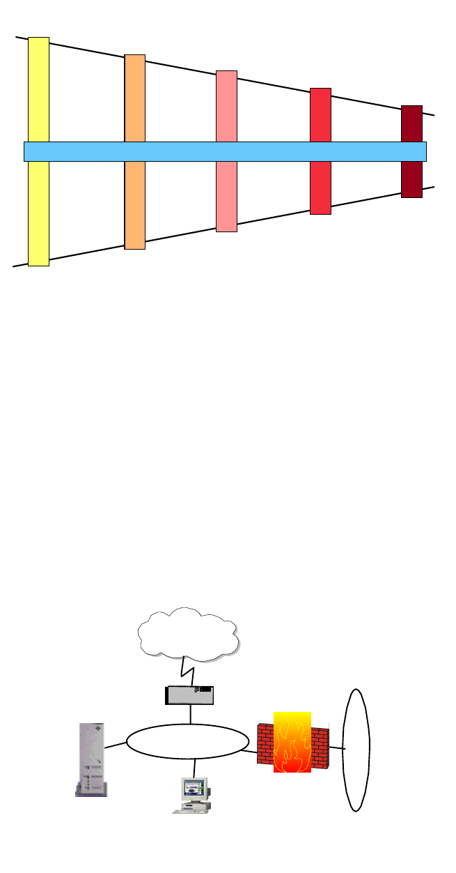
196 IP Network Design Guide
Figure 89. Placement of IP Security Technologies
6.4.2.1 Access Network Validity
To protect the access network, you can employ remote access authentication
technologies, such as RADIUS, to ensure that no unauthorized or unwanted
access attempt is granted via dial-up connections. To protect leased line
connections over private networks, either network hardware security (for
instance, encryption) or IPSec are examples of adequate protection. To protect
connections over public networks, IPSec is considered your best choice because
it provides per-packet authentication and encryption based on strong
cryptographic algorithms.
6.4.2.2 Perimeter Network Validity
To secure your perimeter network, the most common measure consists of one or
more firewalls and probably one or more demilitarized zones (DMZ).
Figure 90. Demilitarized Zone (DMZ) Securing the Perimeter Network
Remote Access
Authentication Firewall, VPN
PKI Content Inspection
Intrusion Detection
Anti-virus, PKI
PKI, SSL, VPN PKI, ACLs
Anti-virus
Local Encryption
Access Network
Validity
Perimeter Network
Validity
Data Validity
User Validity
System Validity
Policy Management
Firewall
VPN Gateway
Internet
2580C\DMZ
Public
Servers Virus Protection
Content Inspection
Intrusion Detection
Packet-filtering
Router
Corporate
Intranet
DMZ

IP Security 197
6.4.2.3 Data Validity
Once access to the network has been properly identified and authorized, it is
important that you take a look at the data that flows in and out of the network,
unless there is a requirement to allow direct access to internal systems from the
outside.
For inbound data, you want to make sure that there is a business requirement to
allow that data to enter your network, and that it does not contain objectionable or
even harmful material, such as viruses. This ensures that damage to more critical
systems inside your network is kept to a minimum wherever possible.
For outbound data, you want to make sure that there is a business requirement to
allow that data to leave your network, and that it does not contain objectionable or
even harmful material. This way you keep damage to others to a minimum which
could result either from users inside your network or from a hacker who uses your
network as a platform to attack others.
6.4.2.4 User Validity
At the end of the data path, users should be properly authenticated to the
applications they are accessing. That way, you can catch impostors who have
somehow found their way into the other side of the communication.
6.4.2.5 System Validity
The systems that provide the applications need themselves to be protected
against security breaches. Password protection, access control lists and
encryption of locally stored data can be guards against improper use, whereas
antivirus programs can keep the exposure to malicious programs low.
6.5 Security Technologies
This section provides brief descriptions of the most commonly used security
technologies in today’s networks.
6.5.1 Securing the Network
The solutions described in this section can be commonly understood to provide
protection mechanisms for network-level security.
6.5.1.1 Packet Filters
Most of the time, packet filtering is accomplished by using a router that can
forward packets according to filtering rules. When a packet arrives at the
packet-filtering router, the router extracts certain information from the packet
header and makes decisions according to the filter rules as to whether the packet
will pass through or be discarded. The following information can be extracted
from the packet header:
• Source IP address
• Destination IP address
• TCP/UDP source port
• TCP/UDP destination port
• Internet Control Message Protocol (ICMP) message type
• Encapsulated protocol information (TCP, UDP, ICMP or IP tunnel)
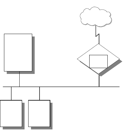
198 IP Network Design Guide
The packet-filtering rules are based on the network security policy (see 6.3.1,
“Network Security Policy” on page 193). Therefore, packet filtering is done by
using these rules as input. When determining the filtering rules, outsider attacks
must be taken into consideration as well as service level restrictions and
source/destination level restrictions.
Figure 91. Packet-Filtering Router
Service Level Filtering:
Since most services use well-known TCP/UDP port
numbers, it is possible to allow or deny services by using related port
information in the filter. For example, an FTP server listens for
connections on TCP ports 20 and 21. Therefore, to permit FTP
connections to pass through to a secure network, the router should be
configured to permit packets that contain 20 and 21 as the TCP port in
its header. On the other hand, there are some applications, such as
Network File System (NFS), which use RPC and use different ports for
each connection. Allowing these kinds of services might cause
security problems.
Source/Destination Level Filtering:
The packet-filtering rules allow a router to
permit or deny a packet according to the destination or the source
information in the packet header. In most cases, if a service is
available, only that particular server is permitted to outside users.
Other packets that have another destination or no destination
information in their headers are discarded.
Advanced Filtering:
As mentioned previously, there are different types of attacks
that threaten privacy and network security. Some of them can be
discarded by using advanced filtering rules such as checking IP
options, fragment offset and so on.
Packet-Filtering Limitations
Packet-filtering rules are sometimes very complex. When there are exceptions to
existing rules, it becomes much more complex. Although there are a few testing
utilities available, it is still possible to leave some holes in the network security.
Packet filters do not provide absolute protection for a network. For some cases, it
Internal DNS
Internal Mail
Server
Secure Network
organization.com
Client1 Client2
Router
Packet
Filter
Untrusted Network
Internet
3376A\3376F4OI
IP Security 199
might be necessary to restrict some set of information (for example, a command)
from passing through to the internal secure network. It is not possible to control
the data with packet filters because they are not capable of understanding the
contents of a particular service. For this purpose, an application level control is
required.
6.5.1.2 Network Address Translation (NAT)
Originally NAT was suggested as a short-term solution to the problem of IP
address depletion. In order to ensure any-to-any communication on the Internet,
all IP addresses have to be officially assigned by the Internet Assigned Numbers
Authority (IANA). This is becoming increasingly difficult to achieve, because the
number of available address ranges is now severely limited. Also, in the past,
many organizations have used locally assigned IP addresses, not expecting to
require Internet connectivity. The idea of NAT is based on the fact that only a
small part of the hosts in a private network is communicating outside of that
network. If each host is assigned an IP address from the official IP address pool
only when it needs to communicate, then only a small number of official
addresses are required.
NAT might be a solution for networks that have private IP address ranges or
illegal addresses and want to communicate with hosts on the Internet. In fact,
most of the time, this can be achieved also by implementing a firewall. Hence,
clients that communicate with the Internet by using a proxy or SOCKS server do
not expose their addresses to the Internet, so their addresses do not have to be
translated. However, for any reason, when proxy and SOCKS are not available or
do not meet specific requirements, NAT might be used to manage the traffic
between the internal and external network without advertising the internal host
addresses.
Consider an internal network that is based on the private IP address space, and
the users want to use an application protocol for which there is no application
gateway. The only option is to establish IP-level connectivity between hosts in the
internal network and hosts on the Internet. Since the routers in the Internet would
not know how to route IP packets back to a private IP address, there is no point in
sending IP packets with private IP addresses as source IP addresses through a
router into the Internet. As shown in Figure 92 on page 200, NAT handles this by
taking the IP address of an outgoing packet and dynamically translating it to an
official address. For incoming packets it translates the official address to an
internal address.
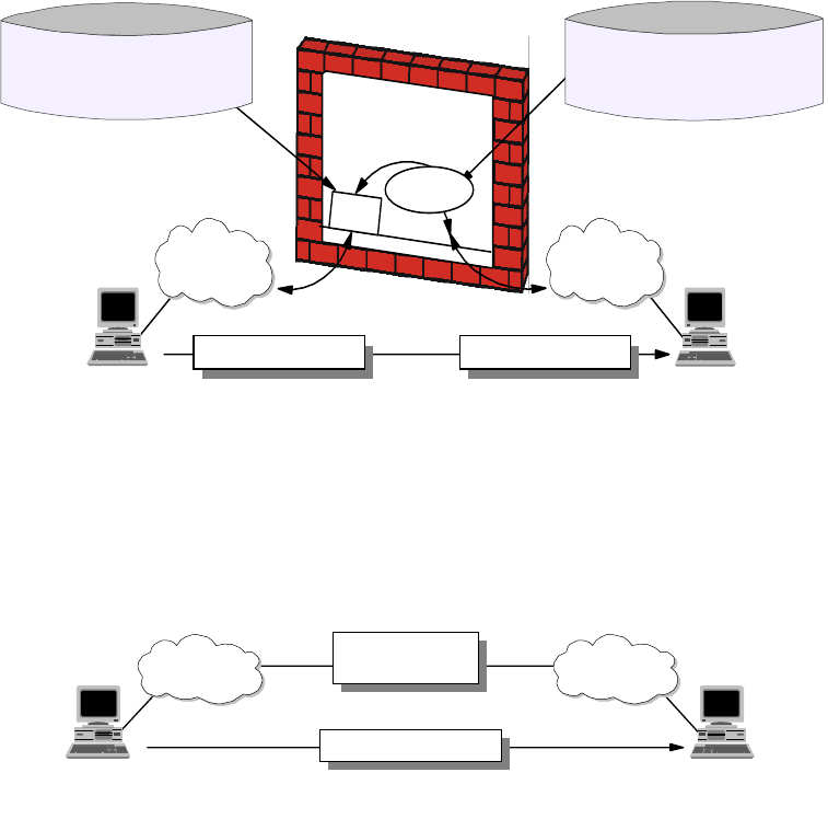
200 IP Network Design Guide
Figure 92. Network Address Translation (NAT)
From the point of two hosts that exchange IP packets with each other, one in the
secure network and one in the non-secure network, NAT looks like a standard IP
router that forwards IP packets between two network interfaces (see Figure 93 on
page 200).
Figure 93. NAT Seen from the Non-Secure Network
NAT Limitations
NAT works fine for IP addresses in the IP header. Some application protocols
exchange IP address information in the application data part of an IP packet, and
NAT will generally not be able to handle translation of IP addresses in the
application protocol. Currently, most of the implementations handle the FTP
protocol. It should be noted that implementation of NAT for specific applications
that have IP information in the application data is more sophisticated than the
standard NAT implementations.
Another important limitation of NAT is that NAT changes some or all of the
address information in an IP packet. When end-to-end IPSec authentication is
used, a packet whose address has been changed will always fail its integrity
check under the Authentication Header (AH) protocol, since any change to any bit
in the datagram will invalidate the integrity check value that was generated by the
source. Since IPSec protocols offer some solutions to the addressing issues that
were previously handled by NAT, there is no need for NAT when all hosts that
compose a given virtual private network use globally unique (public) IP
addresses. Address hiding can be achieved by IPSec's tunnel mode. If a
company uses private addresses within its intranet, IPSec's tunnel mode can
TCP/UDP
IP/ICMP
NAT
Filtering Rules
Basedonnon-translated
IP addresses (10.x.x.x)
NAT Configuration
RESERVE a.b.2.0 255.255.255.0
TRANSLATE 10.0.0.0 255.0.0.0
Non-Secure
src=a.b.1.1 dest=a.b.2.1 src=a.b.1.1 dest=10.0.1.1
10.0.0.0/8a.b.1.0/24
a.b.1.1 10.0.1.1
Filtering
Secure
3376E\3376F4OM
Non-Secure
src=a.b.1.1 dest=a.b.2.1
a.b.2.0/24a.b.1.0/24
a.b.1.1 a.b.2.1
Secure
3376E\3376F4ON
Looks like a
normal router
IP Security 201
keep them from ever appearing in cleartext in the public Internet, which
eliminates the need for NAT.
6.5.1.3 The IP Security Architecture (IPSec)
The IP Security Architecture (IPSec) provides a framework for security at the IP
layer for both IPv4 and IPv6. By providing security at this layer, higher layer
transport protocols and applications can use IPSec protection without the need of
being changed. This has turned out to be a major advantage in designing modern
networks and has made IPSec one of the most, if not the most attractive
technologies to provide IP network security.
IPSec is an open, standards-based security architecture (RFC 2401-2412, 2451)
that offers the following features:
• Provides authentication, encryption, data integrity and replay protection
• Provides secure creation and automatic refresh of cryptographic keys
• Uses strong cryptographic algorithms to provide security
• Provides certificate-based authentication
• Accommodation of future cryptographic algorithms and key exchange
protocols
• Provides security for L2TP and PPTP remote access tunneling protocols
IPSec was designed for interoperability. When correctly implemented, it does not
affect networks and hosts that do not support it. IPSec uses state-of-the-art
cryptographic algorithms. The specific implementation of an algorithm for use by
an IPSec protocol is often called a transform. For example, the DES algorithm
used in ESP is called the ESP DES-CBC transform. The transforms, as the
protocols, are published in RFCs and in Internet drafts.
Authentication Header (AH)
AH provides origin authentication for a whole IP datagram and is an effective
measure against IP spoofing and session hijacking attacks. AH provides the
following features:
• Provides data integrity and replay protection
• Uses hashed message authentication codes (HMAC), based on shared
secrets
• Cryptographically strong but economical on CPU load
• Datagram content is not encrypted
• Does not use changeable IP header fields to compute integrity check value
(ICV), which are:
• TOS, Flags, Fragment Offset, TTL, Checksum
AH adds approximately 24 bytes per packet that can be a consideration for
throughput calculation, fragmentation, and path MTU discovery. AH is illustrated
in Figure 94 on page 202.
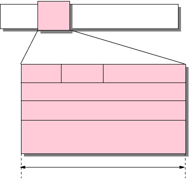
202 IP Network Design Guide
Figure 94. IPSec Authentication Header (AH)
The following transforms are supported with AH:
• Mandatory authentication transforms
• HMAC-MD5-96 (RFC 2403)
• HMAC-SHA-1-96 (RFC 2404)
• Optional authentication transforms
•DES-MAC
• Obsolete authentication transforms
• Keyed-MD5 (RFC 1828)
Encapsulating Security Payload (ESP)
ESP encrypts the payload of IP packet using shared secrets. The Next Header
field actually identifies the protocol carried in the payload. ESP also optionally
provides data origin authentication, data integrity, and replay protection in a
similar way as AH. However, the protection of ESP does not extend over the
whole IP datagram as opposed to AH.
ESP adds approximately 24 bytes per packet that can be a consideration for
throughput calculation, fragmentation, and path MTU discovery. ESP is illustrated
in Figure 95 on page 203.
AH
Hdr
IP Hdr Payload
Next Hdr Payld Lgth Reserved
Security Parameter Index (SPI)
Sequence Number
Authentication Data
(Integrity Check Value) (variable size)
32 bits
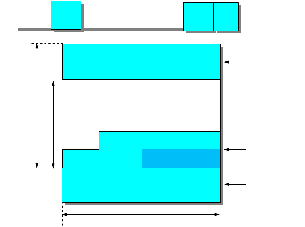
IP Security 203
Figure 95. IPSec Encapsulating Security Payload (ESP)
The following transforms are supported with ESP:
• Mandatory encryption transforms
• DES_CBC (RFC 2405)
• NULL (RFC 2410)
• Optional encryption transforms
• CAST-128 (RFC 2451)
• RC5 (RFC 2451)
• IDEA (RFC 2451)
• Blowfish (RFC 2451)
• 3DES (RFC 2451)
• Mandatory authentication transforms
• HMAC-MD5-96 (RFC 2403)
• HMAC-SHA-1-96 (RFC 2404)
• NULL (RFC 2410)
• Optional authentication transforms
•DES-MAC
Note: The NULL transform cannot be used for both encryption and authentication
at the same time.
Internet Key Exchange Protocol (IKE)
The IPSec protocols AH and ESP require that shared secrets are known to all
participating parties that require either manual key entry or out-of-band key
distribution. The problem is that keys can become lost, compromised or simply
expire. Moreover, manual techniques do not scale when there are many Security
Associations to manage (for example for an Extranet VPN). A robust key
exchange mechanism for IPSec must therefore meet the following requirements:
Authenticated
Encrypted
ESP
Hdr
IP Hdr Payload ESP
Trl ESP
Auth
32 bits
ESP Trailer
ESP Auth Data
ESP Header
Security Parameter Index (SPI)
Sequence Number
Payload Data (variable)
Pad
Length
Next
Hdr
Authentication Data
(variable)
Padding (0-255 bytes)
204 IP Network Design Guide
• Independent of specific cryptographic algorithms
• Independent of a specific key exchange protocol
• Authentication of key management entities
• Establish SA over "unsecured" transport
• Efficient use of resources
• Accommodate on-demand creation of host and session-based SAs
The Internet Key Exchange Protocol (IKE) has been designed to meet those
requirements. It is based on the Internet Security Associations and Key
Management Protocol (ISAKMP) framework and the Oakley key distribution
protocol. IKE offers the following features:
• Key generation and identity authentication procedures
• Automatic key refresh
• Solves the "first key" problem
• Each security protocol (that is, AH, ESP) has its own Security Parameter Index
(SPI) space
• Built-in protection
• Against resource-clogging (denial-of-service) attacks
• Against connection/session hijacking
• Perfect forward secrecy (PFS)
• Two-phased approach
• Phase 1 - Establish keys and SA for key exchanges
• Phase 2 - Establish SAs for data transfer
• Implemented as application over UDP, port 500
• Supports host-oriented (IP address) and user-oriented (long-term identity)
certificates
• Uses strong authentication for ISAKMP exchanges
• Pre-shared keys
• No actual keys are shared, only a token used to create keying material
• Digital signatures (using either DSS or RSA methods)
• Public key encryption (RSA and revised RSA)
• For performance reasons revised RSA uses a generated secret key
instead of a public/private key during the second Phase 1 exchange.
The differences between those authentication methods is illustrated in Figure
96 on page 205.

IP Security 205
Figure 96. Comparing IKE Authentication Methods
As mentioned before, IKE requires two phases be completed before traffic can be
protected with AH and/or ESP.
IKE Phase 1
During phase 1, the partners exchange proposals for the ISAKMP SA and agree
on one. This contains specifications of authentication methods, hash functions
and encryption algorithms to be used to protect the key exchanges. The partners
then exchange information for generating a shared master secret:
• "Cookies" that also serve as SPIs for the ISAKMP SA
• Diffie-Hellman values
• Nonces (random numbers)
• Optionally exchange IDs when public key authentication is used
Both parties then generate keying material and shared secrets before exchanging
additional authentication information.
Note: When all goes well, both parties derive the same keying material and
actual encryption and authentication keys without ever sending any keys over the
network.
IKE Phase 2
During phase 2, the partners exchange proposals for Protocol SAs and agree on
one. This contains specifications of authentication methods, hash functions and
encryption algorithms to be used to protect packets using AH and/or ESP. To
generate keys, both parties use the keying material from a previous phase 1
exchange and they can optionally perform an additional Diffie-Hellman exchange
for PFS.
The phase 2 exchange is protected by the keys that have been generated during
phase 1, which effectively ties a phase 2 to a particular phase 1. However, you
can have multiple phase 2 exchanges under the same phase 1 protection to
Authentication Method How Authentication is
Obtained Advantages Disadvantages
Pre-shared keys By creating hashes over
exchanged information Simple Shared secret must be
distributed out-of-band
prior to IKE negotiations
Can only use IP address
as ID
Digital signatures (RSA
or DSS) By signing hashes
created over exchanged
information
Can use IDs other than
IP address
Partner certificates need
not be available before
IKE negotiations
Requires certificate
operations (inline or
out-of-band)
RSA public key
encryption By creating hashes over
nonces encrypted with
public keys
Better security by adding
public key operation to
DH exchange
Allows ID protection with
Aggressive Mode
Public keys (certificates)
must be available before
IKE negotiations
Performance-intensive
public key operations
Revised RSA public
key encryption Same as above Same as above
Fewer public key
operations by using an
intermediate secret
Public keys (certificates)
must be available before
IKE negotiations
206 IP Network Design Guide
provide granular protection for different applications between the same two
systems. For instance, you may want to encrypt FTP traffic with a stronger
algorithm than TELNET, but you want to refresh the keys for TELNET more often
than those for FTP.
Systems can also negotiate protocol SAs for third-parties (proxy negotiation)
which is used to automatically create tunnel filter rules in security gateways.
6.5.1.4 Firewalls
Firewalls have significant functions in an organization's security policy. Therefore,
it is important to understand these functions and apply them to the network
properly. This chapter explains the firewall concept, network security, firewall
components and firewall examples.
A firewall is a system (or group of systems) that enforces a security policy
between a secure internal network and an untrusted network such as the
Internet. Firewalls tend to be seen as protection between the Internet and a
private network. But generally speaking a firewall should be considered as a
means to divide the world into two or more networks: one or more secure
networks and one or more non-secure networks.
A firewall can be a PC, a router, a midrange, a mainframe, a UNIX workstation, or
a combination of these that determines which information or services can be
accessed from the outside and who is permitted to use the information and
services from the outside. Generally, a firewall is installed at the point where the
secure internal network and untrusted external network meet which is also known
as a choke point.
In order to understand how a firewall works, consider the network as a building to
which access must be controlled. The building has a lobby as the only entry point.
In this lobby, receptionists welcome visitors, security guards watch visitors, video
cameras record visitor actions and badge readers authenticate visitors who enter
the building.
Although these procedures may work well to control access to the building, if an
unauthorized person succeeds in entering, there is no way to protect the building
against this intruder's actions. However, if the intruder's movements are
monitored, it may be possible to detect any suspicious activity. Similarly, a firewall
is designed to protect the information resources of the organization by controlling
the access between the internal secure network and the untrusted external
network (see Figure 97 on page 207). However, it is important to note that even if
the firewall is designed to permit the trusted data to pass through, deny the
vulnerable services and prevent the internal network from outside attacks, a
newly created attack may penetrate the firewall at any time. The network
administrator must examine all logs and alarms generated by the firewall on a
regular basis. Otherwise, it is not possible to protect the internal network from
outside attacks.
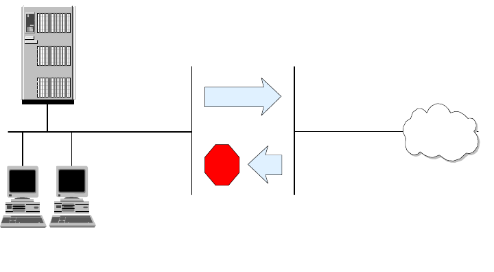
IP Security 207
Figure 97. A Firewall Controls Traffic between the Secure Network and the Internet
As mentioned previously, a firewall can be a PC, a midrange, a mainframe, a
UNIX workstation, a router, or a combination of these. Depending on the
requirements, a firewall can consist of one or more of the following functional
components:
1. Packet-filtering router
2. Application level gateway (Proxy)
3. Circuit level gateway (SOCKS)
4. Virtual private network (VPN) gateway
Each of these components has different functions and shortcomings. Generally,
in order to build an effective firewall, these components are used together.
6.5.1.5 Firewall Design
Apart from a simple packet filtering system, the following types of firewalls can be
distinguished:
Dual-Homed Gateway (Bastion Host)
A dual-homed host has at least two network interfaces and therefore at least two
IP addresses. Since the IP forwarding is not active, all IP traffic between the two
interfaces is broken at the firewall (see Figure 98 on page 208). Thus, there is no
way for a packet to pass the firewall unless the related proxy service or SOCKS is
defined on the firewall. Compared to the packet-filtering firewalls, dual-homed
gateway firewalls make sure that any attack that comes from unknown services
will be blocked. A dual-homed gateway implements the method in which
everything not specifically permitted is denied.
If an information server (such as a Web or FTP server) must give access to
outside users, it can be installed either inside the protected network or it can be
installed between the firewall and the router which is relatively insecure. If it is
installed beyond the firewall, the firewall must have the related proxy services to
give access to the information server from inside the secure network. If the
information server is installed between the firewall and the router, the router
should be capable of packet filtering and configured accordingly.
Client 1 Client 2
private.organization.com organization.com
Untrusted Network Internet
Secure Network
3376A\3376F4O8
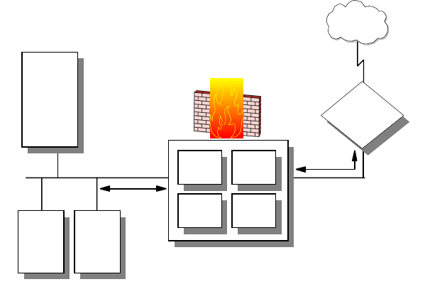
208 IP Network Design Guide
Figure 98. Dual-Homed Gateway Firewall
Screened Host Firewall
This type of firewall consists of a packet-filtering router and an application level
gateway. The router is configured to forward all traffic to the bastion host
(application level gateway) and in some cases also to the information server (see
Figure 99 on page 209). Since the internal network is on the same subnet as the
bastion host, the security policy may allow internal users to access outside
directly or force them to use proxy services to access the outside network. This
can be achieved by configuring the router filter rules so that the router accepts
only traffic originating from the bastion host.
This configuration allows an information server to be placed between the router
and the bastion host. Again, the security policy determines whether the
information server will be accessed directly by either outside users or internal
users or if it will be accessed via the bastion host. If strong security is needed,
both traffic from the internal network to the information server and from outside to
the information server can go through the bastion host.
In this configuration the bastion host can be a standard host, or if a more secure
firewall system is needed it can be a dual-homed host. In this case, all internal
traffic to the information server and to the outside through the router is
automatically forced to pass the proxy server on the dual-homed host. Since, the
bastion host is the only system that can be accessed from the outside, it should
not be permitted to log on to the bastion host. Otherwise, an intruder may easily
log on the system and change the configuration to pass the firewall easily.
Internal DNS
Internal Mail Server
Secure Network
Dual-Homed Gateway
Proxy
Servers
SOCKS
Server
Packet
Filter
External
DNS
Router
Untrusted
Network
Internet
Non-Secure Network
Client1 Client2
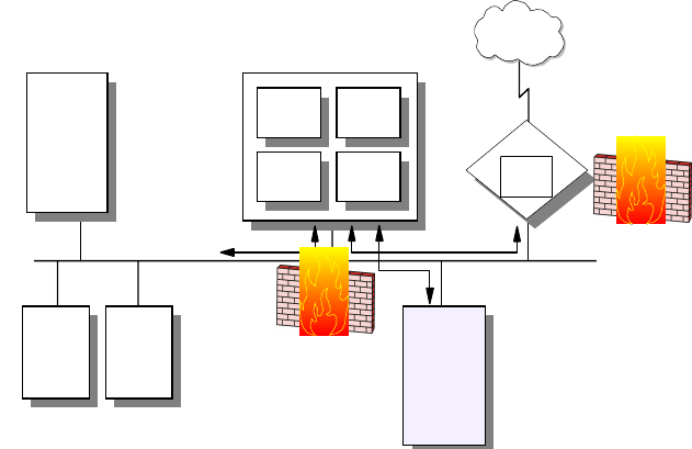
IP Security 209
Figure 99. Screened Host Firewall
Screened Subnet Firewall
This type of firewall consists of two packet-filtering routers and a bastion host.
Screened subnet firewalls provide the highest level security among the firewall
examples (see Figure 100 on page 210). This is achieved by creating a
demilitarized zone (DMZ) between the external network and internal network so
that the outer router only permits access from the outside to the bastion host
(possibly to the information server) and the inner router only permits access from
the internal network to the bastion host. Since the outer router only advertises the
DMZ to the external network, the system on the external network cannot reach
the internal network.
Similarly, the inner router advertises the DMZ to the internal network; the systems
in the internal network cannot reach the Internet directly. This provides strong
security in that an intruder has to penetrate three separate systems to reach the
internal network.
Internal DNS
Internal Mail Server
Secure Network
Bastion Host
Gateway
Proxy
Servers
SOCKS
Server
Packet
Filter
External
DNS
Public Server
(WWW, FTP)
Client1 Client2
Router
Packet
Filter
Untrusted
Network
Internet
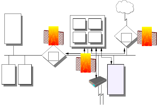
210 IP Network Design Guide
Figure 100. Screened Subnet Firewall
One of the significant benefits of the DMZ is that since the routers force the
systems on both external and internal networks to use the bastion host, there is
no need for the bastion host to be a dual-homed host. This provides much faster
throughput than achieved by a dual-homed host. Of course, this is more
complicated and some security problems can be caused by improper router
configurations.
This design can be further expanded by dual-homing the bastion host to create
two DMZs with different levels of security for public and semi-public servers.
6.5.1.6 Intrusion Detection Technologies
Firewalls and some packet-filtering routers normally provide a facility for logging
all sorts of events. However, in order to find out if your network has been
compromised, you need to evaluate those logs which will only reveal a break-in
after it has actually occurred. Logging is therefore consider a passive way of
determining the state of your network security.
Intrusion detection technology provides a way to actively monitor all traffic that
flows in and out of your network. It then matches certain patterns against your
security policy and can determine in real time if a problem occurs. You can then
opt to shut down a potentially compromised entry point in order to determine the
cause of the problem, or you can choose to monitor the break-in attempt to find
out from where it originates.
6.5.2 Securing the Transactions
The solutions described in this section can be commonly understood to provide
protection mechanisms for transaction-level security.
6.5.2.1 Proxy Servers
An application level gateway is often referred to as a proxy. Actually, an
application level gateway provides higher level control on the traffic between two
networks in that the contents of a particular service can be monitored and filtered
Internal DNS
Internal Mail Server
Secure Network Router
Packet
Filter
Bastion Host
Gateway
Proxy
Servers
SOCKS
Server
Packet
Filter
External
DNS
Demilitarized
Zone (DMZ)
Client1 Client2
Router
Packet
Filter
Untrusted
Network
Internet
Modems
Public Server
(WWW, FTP)
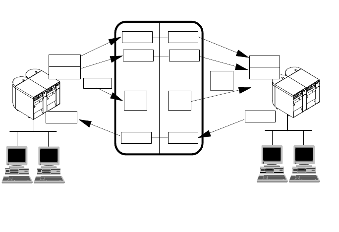
IP Security 211
according to the network security policy. Therefore, for any desired application, a
corresponding proxy code must be installed on the gateway in order to manage
that specific service passing through the gateway (see Figure 101 on page 211).
Figure 101. Application Level Gateway (Proxy Server)
A proxy acts as a server to the client and as a client to the destination server. A
virtual connection is established between the client and the destination server.
Though the proxy seems to be transparent from the point of view of the client and
the server, the proxy is capable of monitoring and filtering any specific type of
data, such as commands, before sending it to the destination. For example, an
FTP server is permitted to be accessed from outside. In order to protect the
server from any possible attacks the FTP proxy in the firewall can be configured
to deny PUT and MPUT commands.
A proxy server is an application-specific relay server that runs on the host that
connects a secure and a non-secure network. The purpose of a proxy server is to
control the exchange of data between the two networks at an application level
instead of an IP level. By using a proxy server, it is possible to disable IP routing
between the secure and the non-secure network for the application protocol the
proxy server is able to handle, but still be able to exchange data between the
networks by relaying it in the proxy server.
Please note that in order for any client to be able to access the proxy server, the
client software must be specifically modified. In other words, the client and server
software should support the proxy connection. In the previous example, the FTP
client had to authenticate itself to the proxy first. If successfully authenticated, the
FTP session starts based on the proxy restrictions. Most proxy server
implementations use more sophisticated authentication methods such as security
ID cards. This mechanism generates a unique key that is not reusable for another
connection. Two security ID cards are supported by IBM Firewall: the SecureNet
card from Axent and the SecureID card from Security Dynamics.
Compared with IP filtering, application level gateways provide much more
comprehensive logging based on the application data of the connections. For
telnetd telnet
ftpd ftp
telnetdtelnet
telnet
Application Level Gateway
http
client
browser http
client
http
Secure Network
Client 1 Client 2
Non-Secure Network
Client 1 Client 2
telnetd
ftpd
telnetd
ftp
telnet
3376A\3376F4OA
212 IP Network Design Guide
example, an HTTP proxy can log the URLs visited by users. Another feature of
application level gateways is that they use strong user authentication. For
example, when using FTP and TELNET services from the non-secure network,
users have to authenticate themselves to the proxy.
6.5.2.2 Application Level Gateway Limitations
A disadvantage of application level gateways is that in order to achieve a
connection via a proxy server, the client software should be changed to support
that proxy service. This can sometimes be achieved by some modifications in
user behavior rather than software modification. For example, to connect to a
TELNET server over a proxy, the user first has to be authenticated by the proxy
server, then by the destination TELNET server. This requires two, rather than
one, user steps to make a connection. However, a modified TELNET client can
make the proxy server transparent to the user by specifying the destination host
rather than the proxy server in the TELNET command.
6.5.2.3 SOCKS
A circuit level gateway relays TCP and also UDP connections and does not
provide any extra packet processing or filtering. A circuit level gateway can be
said to be a special type of application level gateway. This is because the
application level gateway can be configured to pass all information once the user
is authenticated, just as the circuit level gateway (see Figure 168 on page 289).
However, in practice, there are significant differences between them:
• Circuit level gateways can handle several TCP/IP applications as well as UDP
applications without any extra modifications on the client side for each
application. Thus, this makes circuit level gateways a good choice to satisfy
user requirements.
• Circuit level gateways do not provide packet processing or filtering. Thus, a
circuit level gateway is generally referred to as a transparent gateway.
• Application level gateways have a lack of support for UDP.
• Circuit level gateways are often used for outbound connections, whereas
application level gateways (proxy) are used for both inbound and outbound
connections. Generally, in cases of using both types combined, circuit level
gateways can be used for outbound connections and application level
gateways can be used for inbound connections to satisfy both security and
user requirements.
A well-known example of a circuit level gateway is SOCKS. Because data that
flows over SOCKS is not monitored or filtered, a security problem may arise. To
minimize the security problems, trusted services and resources should be used
on the outside network (untrusted network).
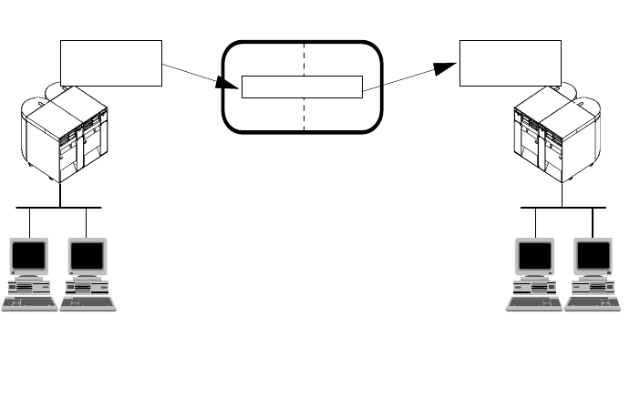
IP Security 213
Figure 102. Circuit Level Gateway
SOCKS is a standard for circuit level gateways. It does not require the overhead
of a more conventional proxy server where a user has to consciously connect to
the firewall first before requesting the second connection to the destination. The
user starts a client application with the destination server IP address. Instead of
directly starting a session with the destination server, the client initiates a session
to the SOCKS server on the firewall. The SOCKS server then validates that the
source address and user ID are permitted to establish onward connection into the
non-secure network, and then creates the second session.
SOCKS needs to have new versions of the client code (called SOCKSified
clients) and a separate set of configuration profiles on the firewall. However, the
server machine does not need modification; indeed it is unaware that the session
is being relayed by the SOCKS server. Both the client and the SOCKS server
need to have SOCKS code. The SOCKS server acts as an application level router
between the client and the real application server. SOCKSv4 is for outbound TCP
sessions only. It is simpler for the private network user, but does not have secure
password delivery so it is not intended for sessions between public network users
and private network applications. SOCKSv5 provides for several authentication
methods and can therefore be used for inbound connections as well, though
these should be used with caution. SOCKSv5 also supports UDP-based
applications and protocols.
The majority of Web browsers are SOCKSified and you can get SOCKSified
TCP/IP stacks for most platforms.
6.5.2.4 Secure Sockets Layer (SSL)
SSL is a security protocol that was developed by Netscape Communications
Corporation, along with RSA Data Security, Inc. The primary goal of the SSL
protocol is to provide a private channel between communicating applications,
which ensures privacy of data, authentication of the partners and integrity.
SSL provides an alternative to the standard TCP/IP socket API that has security
implemented within it. Hence, in theory it is possible to run any TCP/IP
SOCKS Server
Circuit Level Gateway
Secure Network
SOCKSified
Client Program
Client 1 Client 2
3376A\3376F4OB
Non-Secure Network
Unmodified
Server Program
Client 1Client 2
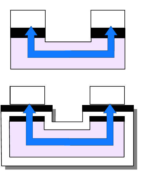
214 IP Network Design Guide
application in a secure way without changing the application. In practice, SSL is
only widely implemented for HTTP connections, but Netscape Communications
Corporation has stated an intention to employ it for other application types, such
as Network News Transfer Protocol (NNTP) and TELNET, and there are several
such implementations freely available on the Internet. IBM, for example, is using
SSL to enhance security for TN3270 sessions in its Host On-Demand, Personal
Communications and Communications Server products, as well as securing
configuration access to firewalls.
SSL is composed of two layers:
1. At the lower layer, there is a protocol for transferring data using a variety of
predefined cipher and authentication combinations, called the SSL Record
Protocol. Figure 103 on page 214 illustrates this, and contrasts it with a
standard HTTP socket connection. Note that this diagram shows SSL as
providing a simple socket interface, on which other applications can be
layered. In reality, current implementations have the socket interface
embedded within the application and do not expose an API that other
applications can use.
2. At the upper layer, there is a protocol for the initial authentication and transfer
of encryption keys, called the SSL Handshake Protocol.
Figure 103. SSL - Comparison of Standard and SSL Sessions
An SSL session is initiated as follows:
Client Server
socket API socket API
Session
Standard TCP Application
socket API socket API
Client Server
socket API socket API
Session
TCP Application using SSL
SSLRecordProtocol
3376E\3376F4OS
IP Security 215
• On the client (browser) the user requests a document with a special URL that
begins https: instead of http:, either by typing it into the URL input field, or by
clicking a link.
• The client code recognizes the SSL request and establishes a connection
through TCP port 443 to the SSL code on the server.
• The client then initiates the SSL handshake phase, using the SSL Record
Protocol as a carrier. At this point there is no encryption or integrity checking
built in to the connection.
The SSL protocol addresses the following security issues:
Privacy:
After the symmetric key is established in the initial
handshake, the messages are encrypted using this key.
Integrity:
Messages contain a message authentication code (MAC)
ensuring the message integrity.
Authentication:
During the handshake, the client authenticates the server
using an asymmetric or public key. It can also be based on
certificates.
SSL requires each message to be encrypted and decrypted and therefore, has a
high performance and resource overhead.
6.5.3 Securing the Data
The solutions described in this section can be commonly understood to provide
protection mechanisms for data level security.
6.5.3.1 Secure Multipurpose Internet Mail Extension (S-MIME)
Secure Multipurpose Internet Mail Extension (S-MIME) can be thought of as a
very specific SSL-like protocol. S-MIME is an application level security construct,
but its use is limited to protecting e-mail via encryption and digital signatures. It
relies on public key technology and uses X.509 certificates to establish the
identities of the communicating parties. S-MIME can be implemented in the
communicating end systems; it is not used by intermediate routers or firewalls.
6.5.3.2 Content Inspection Technologies
Content inspection is typically performed by special-purpose application layer
gateways (proxies). Those systems not only authenticate the use of an
application but also scrutinize the application data that traverses the proxy server.
If that data does not match a given security policy for that application it will not be
allowed to leave the proxy, and notifications may be sent to security
administrators.
Examples of this technology are HTTP proxies that scan HTTP data for certain
URLs, e-mail or MIME gateways that scan data for offensive text, or specialized
gateways that can run mobile code (for example, Java and ActiveX) in a sandbox
to determine its harmfulness to a user’s system or application.
6.5.3.3 Virus Protection Technologies
Computer viruses are special pieces of code of a usually destructive nature. They
attach themselves to certain file types and travel from one system to another
when infected files are copied or sent over a network. Once a virus reaches a
computer, it spreads itself over as many files as possible to ensure the maximum
likelihood of further transportation as well as maximum destruction. Some
216 IP Network Design Guide
particularly disastrous viruses modify partition and boot sector information on
hard drives and render infected systems completely unusable.
Antivirus software is designed to identify viruses and to stop them before they can
continue their destructive work and travel to more systems. Viruses usually have
a special signature that they leave behind on infected files like a trail. Antivirus
software stores many of those signatures in a database and can thus check files
against virus signatures to determine whether they have been infected. A good
antivirus database also knows the file sizes of widely used application software
executables and can check the integrity of such files.
It is important to determine if a file is infected by a virus as early as possible in
order to contain the potential risk. We therefore recommend that you use virus
protection software in the DMZ and on any internal system that communicates
with the outside.
6.5.3.4 General Purpose Encryption
Encryption is an efficient way to make data unreadable to unintended recipients.
If handled properly, it is a very effective way to provide security. However, if
handled poorly, encryption can be a threat to your data rather than a protection.
Remember that encryption requires keys to transform cleartext into ciphertext
and vice versa. If those keys get lost or stolen, for instance by a system
administrator who leaves the company without handing in encryption keys
previously under his/her custody, your data is compromised and, what’s worse,
you may not be able to access it anymore (but your competitors might).
Therefore, as part of your security policy, you should clearly define if encryption is
at all necessary, and if so, for what types of data, at what points in the network,
and who should be authorized to use it.
There are generally two ways to protect against the loss or theft of encryption
keys:
Key Escrow
This technique provides for the storage and retrieval of keys and data in case
keys get lost or stolen. Keys are stored with a trusted third party (recovery
agent or key guardian), as a whole or in parts, on independent storage media,
to be retrieved as required. The trusted third party could be a company key
administrator located on company premises, or an external agency. This
ensures that the keys remain in a company’s possession even after a system
administrator or whoever used the keys leaves the company.
Key Recovery
This technique was designed to allow law enforcement agencies (LEA) to
recover the keys for decrypting secret messages of suspicious parties. Of
course, you can also use this approach to recover your own keys yourself, but
it is a rather complicated process and less practical than key escrow.
One way of implementing key recovery is by inserting key recovery blocks in
the data stream at random intervals and/or when the keys change. Those key
recovery blocks are encrypted with the public key of a trusted third party (key
recovery agent). The key recovery agents can decrypt keys with their private
keys, then encrypt retrieved keys with the public key of an LEA and send them
to the LEA. LEAs can decrypt keys with their private keys and then decrypt the
previously retrieved ciphertext messages.
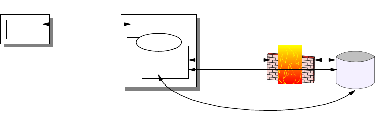
IP Security 217
Export/Import Regulations
Whenever you choose to use encryption you have to make sure what level of
encryption is legally allowed to be used in your country and for the nature of your
business. Usually, banks can employ higher levels of encryptions than home
office users, and some countries are more restrictive than others. In the United
States encryption is regulated by the Department of Commerce.
6.5.3.5 Securing Web-Enabled Applications
A common technique that has been developed during recent years is called
Web-enablement. This means that legacy applications that have been originally
developed for terminals are made accessible to Web browsers to avoid having to
rewrite those applications. That also provides greater flexibility in accessing those
applications from anywhere inside or outside a company’s network. In order to
provide security to applications that have been modernized in such a way, there
are typically two approaches:
1. Using Web Browsers and Connectors
This approach uses a special type of application gateway called connector to
transfer data between the application server and a Web server which then
serves that data to a user’s Web browser. Security in this environment can be
provided as follows:
• Use SSL between the browser and Web server
• Use a proxy or SOCKS server between the application gateway and
application server across a firewall
• Use a native (non-TCP/IP) protocol between application gateway and
application server (SNA, NetBIOS, DRDA, IPX, etc.)
This should provide sufficient security against TCP/IP attacks, but it can
require two protocol stacks at the gateway.
Figure 104. Web-Enabled Application Using Connectors
2. Using Download Clients
This approach uses a special type of application client that a user can
download from a Web server. That client, usually implemented as a Java
applet or ActiveX control, can then access the application server directly or via
an application gateway. Security in this environment can be provided as
follows:
• Protect the client code with digital signatures and certificates
• Use SSL to protect downloads of the application client code from the Web
server
• Use SSL and a proxy server, or SSL tunneling via SOCKS, across a firewall
Web Client
Browser TCP/IP, HTTP,
SSL
TCP/IP, Proxy
TCP/IP, SOCKS
Native Protocol
Firewall/Proxy
Legacy
Application
Server
HTTP
Native Client
or Gateway
Connector
Web Server
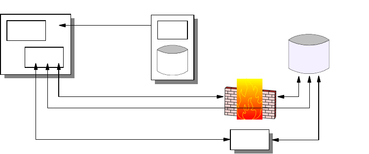
218 IP Network Design Guide
• Use SSL to access an application gateway, then use a native (non-TCP/IP)
protocol to access the application server
This approach places less overhead on the Web server and offers more
flexibility to the client while providing adequate security.
Figure 105. Web-enabled Application Using Download Client
6.5.4 Securing the Servers
The solutions described in this section can be commonly understood to provide
protection mechanisms for system level security.
6.5.4.1 Multi-Layer Access Control
Major server operating systems and applications provide a variety of access
controls for resources (such as file systems, database tables, program objects,
etc.) to allow you to define in a granular way who is allowed to access what
resources and at what time. It is important that you understand those
mechanisms and use them effectively to secure your systems for both local and
as network access.
6.5.4.2 Antivirus Programs
As mentioned before, viruses can severely damage your systems and cause loss
of mission-critical data and applications. It is therefore recommended that you
use virus protection software on all systems that are allowed to be accessed from
the outside or to receive data from outside systems in whatever way.
6.5.5 Hot Topics in IP Security
The solutions described in this section are among the most eagerly discussed
topics in modern IP security. They will certainly influence the ways that networks
are designed and that security is perceived from a total solution perspective.
6.5.5.1 Virtual Private Networks
The Internet has become a popular, low-cost backbone infrastructure. Its
universal reach has led many companies to consider constructing a secure virtual
private network (VPN) over the public Internet. The challenge in designing a VPN
for today's global business environment will be to exploit the public Internet
backbone for both intra-company and inter-company communication while still
providing the security of the traditional private, self-administered corporate
network.
Web Client
Browser
Client
TCP/IP, Proxy, SSL
TCP/IP, SOCKS,
SSL
TCP/IP, HTTP,
SSL
TCP/IP, SSL
Native
Protocol
Firewall/Proxy
Legacy
Application
Server
HTTP
Download
Gateway
Web Server
Client
Code
IP Security 219
With the explosive growth of the Internet, companies are beginning to ask: "How
can we best exploit the Internet for our business?". Initially, companies were
using the Internet to promote their company's image, products, and services by
providing World Wide Web access to corporate Web sites. Today, however, the
Internet potential is limitless, and the focus has shifted to e-business, using the
global reach of the Internet for easy access to key business applications and data
that reside in traditional I/T systems. Companies can now securely and cost
effectively extend the reach of their applications and data across the world
through the implementation of secure virtual private network (VPN) solutions.
Figure 106. Virtual Private Networks
A virtual private network (VPN) is an extension of an enterprise's private intranet
across a public network such as the Internet, creating a secure private
connection, essentially through a private tunnel. VPNs securely convey
information across the Internet connecting remote users, branch offices, and
business partners into an extended corporate network, as shown in Figure 106 on
page 219. Internet service providers (ISPs) offer cost-effective access to the
Internet (via direct lines or local telephone numbers), enabling companies to
eliminate their current, expensive leased lines, long-distance calls, and toll-free
telephone numbers.
Summarized below are the requirements that must be met by VPN
implementations to provide an adequate corporate network infrastructure over a
public network:
Data Origin Authentication and Non-Repudiation
Verifies that each datagram was undeniably originated by the claimed sender.
Data Integrity
Verifies that the contents of the datagram were not changed in transit.
Data Confidentiality
Conceals the cleartext of a message, typically by using encryption.
Replay Protection
Ensures that an attacker cannot intercept a datagram and play it back at some
other time.
Corporate
Intranet Business
Partner/
Supplier
Intranet
Branch
Office
Intranet
Internet
Remote
Access
VPN
VPN
VPN
220 IP Network Design Guide
Key Management
Ensures that your VPN policy can be implemented with little or no manual
configuration.
Performance, Availability and Scalability
Ensures that the VPN itself is not a hindrance to your business, that it can
grow with your business, and that it can accommodate future technologies as
they evolve.
A 1997 VPN Research Report by Infonetics Research, Inc., estimates savings
from 20% to 47% of wide area network (WAN) costs by replacing leased lines
to remote sites with VPNs. And, for remote access VPNs, savings can be 60%
to 80% of corporate remote access dial-up costs. Additionally, Internet access
is available worldwide where other connectivity alternatives may not be
available.
The technology to implement these virtual private networks has just become
standardized. Some networking vendors today are offering non-standards-based
VPN solutions that make it difficult for a company to incorporate all its employees
and/or business partners/suppliers into an extended corporate network. However,
VPN solutions based on Internet Engineering Task Force (IETF) standards will
provide support for the full range of VPN scenarios with more interoperability and
expansion capabilities. Those standard-based technologies are IPSec and L2TP.
The key to maximizing the value of a VPN is the ability for companies to evolve
their VPNs as their business needs change and to easily upgrade to future
TCP/IP technology. Vendors who support a broad range of hardware and
software VPN products provide the flexibility to meet these requirements. VPN
solutions today run mainly in the IPv4 environment, but it is important that they
have the capability of being upgraded to IPv6 to remain interoperable with your
business partners’ and/or suppliers’ VPN solutions. Perhaps equally critical is the
ability to work with a vendor who understands the issues of deploying a VPN. The
implementation of a successful VPN involves more than technology. The vendor's
networking experience plays heavily into this equation.
Following the steps below will help you, in most cases, to arrive at an appropriate
VPN design and solution:
Scenarios to Be Implemented
Business partner/supplier, remote access, multiple combinations
Required Levels of Protection
Authentication, encryption, key exchange, end-to-end, performance
Projected Growth of VPN Topology
IKE vs manual tunnels
Infrastructure
ISP bandwidth and L2TP support, network transition, IPSec support, cost
Product selection
Best-of-breed vs one-size-fits-all vs single vendor, cost
Rollout
In-house vs outsourced service, cost
IP Security 221
6.5.5.2 Virtual Private Network Scenarios
In this section we look at the three most likely business scenarios well suited to
the implementation of a VPN solution.
This section provides a general, overview-type description of those scenarios.
Technical issues and configuration details are provided in the redbook
A
Comprehensive Guide to Virtual Private Networks, Volume I
:
IBM Firewall, Server
and Client Solutions
, SG24-5201.
Branch Office (Site-to-Site or Intranet) VPN
The branch office scenario securely connects two trusted intranets within your
organization. Your security focus is on both protecting your company′ s intranet
against external intruders and securing your company′ s data while it flows over
the public Internet. For example, suppose corporate headquarters wants to
minimize the costs incurred from communicating to and among its own branches.
Today, the company may use frame relay and/or leased lines, but wants to explore
other options for transmitting its internal confidential data that will be less
expensive, more secure, and globally accessible. By exploiting the Internet,
branch office connection VPNs can be easily established to meet the company′ s
needs.
Figure 107. Branch Office VPN
As shown in Figure 107 on page 221, one way to implement this VPN connection
between the corporate headquarters and one of its branch offices is for the
company to purchase Internet access from an ISP. Firewalls, or routers with
integrated firewall functionality, or in some cases a server with IPSec capability,
would be placed at the boundary of each of the intranets to protect the corporate
traffic from Internet hackers. With this scenario, the clients and servers need not
support IPSec technology, since the IPSec-enabled firewalls (or routers) would be
providing the necessary data packet authentication and encryption. With this
approach, any confidential information would be hidden from untrusted Internet
users, with the firewall denying access to potential attackers.
With the establishment of branch office connection VPNs, the company′ s
corporate headquarters will be able to communicate securely and cost effectively
to its branches, whether located locally or far away. Through VPN technology,
each branch can also extend the reach of its existing intranet to incorporate the
other branch intranets, building an extended, enterprise-wide corporate network.
And this company can easily expand this newly created environment to include its
Corporate
Intranet
Branch
Office
Intranet
Internet
ISP ISP
Firewall
Router
Firewall
Router
Client
Server
Encr
y
ption
Authentication
VPN
222 IP Network Design Guide
business partners, suppliers, and remote users, through the use of open IPSec
technology.
Business Partner/Supplier (Extranet) VPN
Industry-leading companies will be those that can communicate inexpensively
and securely to their business partners, subsidiaries, and vendors. Many
companies have chosen to implement frame relay and/or purchase leased lines to
achieve this interaction. But this is often expensive, and geographic reach may be
limited. VPN technology offers an alternative for companies to build a private and
cost-effective extended corporate network with worldwide coverage, exploiting
the Internet or other public network.
Suppose you are a major parts supplier to a manufacturer. Since it is critical that
you have the specific parts and quantities at the exact time required by the
manufacturing firm, you always need to be aware of the manufacturer′ s inventory
status and production schedules. Perhaps you are handling this interaction
manually today, and have found it to be time consuming, expensive and maybe
even inaccurate. You’d like to find an easier, faster, and more effective way of
communicating. However, given the confidentiality and time-sensitive nature of
this information, the manufacturer does not want to publish this data on its
corporate Web page or distribute this information monthly via an external report.
To solve these problems, the parts supplier and manufacturer can implement a
VPN, as shown in Figure 108 on page 222. A VPN can be built between a client
workstation, in the parts supplier’s intranet, directly to the server residing in the
manufacturer’s intranet. The clients can authenticate themselves either to the
firewall or router protecting the manufacturer’s intranet, directly to the
manufacturer’s server (validating that they are who they say they are), or to both,
depending on your security policy. Then a tunnel could be established, encrypting
all data packets from the client, through the Internet, to the required server.
Figure 108. Extranet VPN
Optionally, the tunnels into the intranet could be terminated at a special VPN
gateway in a DMZ. This would allow additional security checks, such as virus
protection and content inspection, to be performed before data from an external
system was allowed into the corporate network.
With the establishment of this VPN, the parts supplier can have global, online
access to the manufacturer′s inventory plans and production schedule at all times
Manufacturer's
Intranet Business Partner/
Supplier
Intranet
Internet
ISP ISP
Firewall
Router
Firewall
Router
Client
Server
Encr
y
ption
Authentication
VPN
IP Security 223
during the day or night, minimizing manual errors and eliminating the need for
additional resources for this communication. In addition, the manufacturer can be
assured that the data is securely and readily available to only the intended parts
supplier(s).
One way to implement this scenario is for the companies to purchase Internet
access from an Internet service provider (ISP), then, given the lack of security of
the Internet, either a firewall or IPSec-enabled router, or a server with IPSec
capability can be deployed as required to protect the intranets from intruders. If
end-to-end protection is desired, then both the client and server machines need
to be IPSec-enabled as well.
Through the implementation of this VPN technology, the manufacturer would be
able to easily extend the reach of their existing corporate intranet to include one
or more parts suppliers (essentially building an extended corporate network)
while enjoying the cost-effective benefits of using the Internet as their backbone.
And, with the flexibility of open IPSec technology, the ability for this manufacturer
to incorporate more external suppliers is limitless.
Remote Access VPN
A remote user, whether at home or on the road, wants to be able to communicate
securely and cost effectively back to his/her corporate intranet. Although many
still use expensive long-distance and toll-free telephone numbers, this cost can
be greatly minimized by exploiting the Internet. For example, you are at home or
on the road but need a confidential file on a server within your intranet. By
obtaining Internet access in the form of a dial-in connection to an ISP, you can
communicate with the server in your intranet and access the required file.
One way to implement this scenario is to use a remote access tunneling protocol
such as L2TP, PPTP or L2F. Another way is to use an IPSec-enabled remote
client and a firewall, as shown in Figure 109 on page 223. Ideally, you may wish
to combine both solutions which will provide the best protection and the most
cost-effective way of remote access. The client accesses the Internet via dial-up
to an ISP, and then establishes an authenticated and encrypted tunnel between
itself and the firewall at the intranet boundary.
Figure 109. Remote Access VPN
By applying IPSec authentication between the remote client and the firewall, you
can protect your intranet from unwanted and possibly malicious IP packets. And
Corporate
Intranet Home PCs,
Mobile Workers
Internet
ISP ISP
Firewall
Router
Client
Server
Encr
y
ption
Authentication
VPN
224 IP Network Design Guide
by encrypting traffic that flows between the remote host and the firewall, you can
prevent outsiders from eavesdropping on your information. A more detailed
discussion of the remote access scenario is provided in 5.2.10, “VPN Remote
User Access” on page 180.
6.5.5.3 Digital Certificates and Public Key Infrastructures (PKI)
The solution to many modern security technologies is the digital certificate. A
digital certificate is a file that binds an identity to the associated public key. This
binding is validated by a trusted third party, the certification authority (CA). A
digital certificate is signed with the private key of the certification authority, so it
can be authenticated. It is issued only after a verification of the applicant. Apart
from the public key and identification, a digital certificate usually contains other
information too, such as:
• Date of issue
• Expiration date
• Miscellaneous information from issuing CA (for example, serial number)
Note: There is an international standard in place for digital certificates: the ISO
X.509 protocols.
Now the picture looks different from an ordinary challenge before establishing a
connection. The parties retrieve each other's digital certificate and authenticate it
using the public key of the issuing certification authority. They have confidence
that the public keys are real, because a trusted third party vouches for them. The
malicious online shopping mall is put out of business.
It is easy to imagine, however, that one CA cannot cover all needs. What happens
when Bob's certificate is issued by a CA unknown to Alice? Can she trust that
unknown authority? Well, this is entirely her decision, but to make life easier, CAs
can form a hierarchy, often referred to as the trust chain. Each member in the
chain has a certificate signed by its superior authority. The higher the CA is in the
chain, the tighter security procedures are in place. The root CA is trusted by
everyone and its private key is top secret.
Alice can traverse the chain upward until she finds a CA that she trusts. The
traversal consists of verifying the subordinate CA's public key and identity using
the certificate issued to it by the superior CA. When a trusted CA is found up in
the chain, Alice is ensured that Bob's issuing CA is trustworthy. In fact this is all
about the delegation of trust. We trust your identity card if somebody we trust
signs it. And if the signer is unknown to us, we can go upward and see who signs
for the signer, etc.
An implementation of this concept can be found in the SET protocol, where the
major credit card brands operate their own CA hierarchies that converge to a
common root. Lotus Notes authentication, as another example, is also based on
certificates, and it can be implemented using hierarchical trust chains. PGP also
uses a similar approach, but its trust chain is based on persons and it is a
distributed Web rather than a strict hierarchical tree.
The most important and without doubt the most difficult part of this is to create
and distribute certificates on a large scale, for a variety of purposes (such as,
signing, encrypting or both) and across many independent users, systems,
companies and service providers. Equally important is to have a directory of
IP Security 225
public keys and a certificate revocation list (CRL) where those certificates are
listed that have been invalidated before their expiration date (for instance,
because of theft, misuse or compromised associated private keys).
Systems that issue and store certificates and CRLs, systems that use certificates
and formats that describe the contents of certificates, and protocols that
distribute certificates and certificate requests together comprise a public key
infrastructure. In order to use certificates, you will have to set one up in your
enterprise, between your company and your business partners, or just retrieve
certificates occasionally from a CA over the Internet, depending on your business
requirements and implemented security technologies.
Unfortunately, not all that you need to do is based on fully developed and mature
standards so you may have to piece together a solution. The sources listed below
should help you find more information about public key infrastructure standards:
RSA Public Key Crypto System (PKCS)
Standards for PKI algorithms, formats and messages.
http://www.rsa.com/rsalabs/pubs/PKCS/
IETF Public Key Infrastructure (PKIX) Working Group
Standards for PKI protocols, policies, formats and messages based on X.509.
http://www.ietf.org/html.charters/pkix-charter.html
OpenGroup Common Data Security Architecture (CDSA)
Open software framework for crypto-APIs and PKI services, developed by Intel
and adopted by IBM, Netscape and others.
http://developer.intel.com/ial/security/cdsa/FAQ.htm
6.5.5.4 Directory-Enabled Networking (DEN)
In September 1997, Cisco Systems Inc. and Microsoft Corporation announced
the so-called Directory-Enabled Networks Initiative (DEN) as a result of a
collaborative work. Many companies, such as IBM, either support this initiative or
even actively participate in ad hoc working groups (ADWGs). DEN represents an
information model specification for an integrated directory that stores information
about people, network devices and applications. The DEN schema defines the
object classes and their related attributes for those objects. In such, DEN is a key
piece to building intelligent networks, where products from multiple vendors can
store and retrieve topology and configuration-related data. Since DEN is a
relatively new specification, products supporting it cannot be expected until about
one to two years after its first draft, which was published late in 1997.
Of special interest is that the DEN specification defines LDAP Version 3 as the
core protocol for accessing DEN information, which makes information available
to LDAP-enabled clients and/or network devices. More information about the DEN
initiative can be found on the founders’ Web sites or at:
http://murchiso.com/den/
226 IP Network Design Guide

© Copyright IBM Corp. 1995 1999 227
Chapter 7. Multicasting and Quality of Service
The applications that we see today are a far cry from those that were developed
just a few years ago. Then, applications were mainly text based, with specially
trained users sitting in front of a terminal deciphering the cryptic information that
was displayed on the screen. Today, we have applications that provide graphic
aids, voice explanations and even video supplements. And these applications are
used by users from offices and homes, some even with very little training in
information technology.
This evolution has brought about significant changes in many areas: from the new
expectations of users, to the design of the applications, to the network
infrastructure, and the need for more bandwidth. These changes have resulted in
new technologies being introduced to satisfy the requirement, and one of them is
the concept of multicasting.
Besides multicasting, other technologies, such as Resource Reservation Protocol
(RSVP) and Real-Time Protocol (RTP), have been developed to cope with other
demands. For the first time, Quality of Service (QoS) in TCP/IP has been taken
seriously by network managers and ways are being explored to look into its
deployment.
7.1 The Road to Multicasting
Until recently, the concept of information retrieval in computer systems has been
request and reply. That is, a client station sends its queries to a server for some
information and the server in turn replies with the necessary answer. This
communication model has the following characteristics:
• The conversation is one-to-one.
• It is always the client that initiates the conversation.
• The performance of the entire system depends on how many conversations
the server can engage in concurrently.
• The network’s job is merely to transport requests and replies, usually a pretty
simple job to accomplish.
• The network devices, that is, routers, hubs or switches, do not participate in
the conversations.
• It is server-centric. The server is the most important component in the entire
system, and the scalability of the system is dependent on the server: more
memory, more disk space and more CPU power.
The advent of desktop publishing technology has made the production of
graphics easy and accessible to almost everyone in the network. As the saying
goes, a picture speaks a thousand words, incorporating graphics makes a
document easier to understand. From this point on, information exchanged in the
network includes data and graphics. Although there was an increase in the load
of the network due to this, the load was after all still manageable. The invention of
the Web technology further exploited the use of graphics and application
development took a new dimension. From information comprising drawings, we
have high quality pictures and even motion video today.
228 IP Network Design Guide
The new ways of doing business in the 1990s have made the availability of
information more important. Now, decisions are made on the availability of
information, and a delay in getting to this information may even cause millions of
dollars. Not only is the availability of information important now, but users want
the information to be delivered in the quickest way possible. The need for
real-time applications has never been so urgent.
With the increase in the power of computer systems, corporations are able to rely
on it to process complex tasks to yield more information. Systems such as data
mining and Enterprise Resource Planning (ERP) have been developed to provide
for information that would have been impossible a few years back. With the
introduction of these "monstrous" applications, information exchange has gone
from a few flows of transactions to thousands.
New technologies such as Voice over IP (VoIP) and videoconferencing enable
network managers to make use of their network infrastructure to deliver new
services to users. The introduction of these technologies not only helps network
managers cut down on costs, but also to consolidate the infrastructures for
manageability.
The introduction of multimedia, the need for real-time applications, the need for
systems such as ERP, and the convergence of data, voice and video services
have caused some concerns: that the network is no longer able to handle the
demand.
7.1.0.1 How Does the Network Cope?
Network managers have seen these changes for quite some time and they
realized that something needed to be done to the network. The initial reaction to
the problem was related to bandwidth. It seemed obvious that since performance
had degraded, the solution was to increase the bandwidth so that performance
can be improved.
One of the steps for improving network performance was to upgrade the
technology: for example, migrating 10 Mbps Ethernet to Fast Ethernet. The next
solution was to introduce switching to the network. With the introduction of
microsegmentation, broadcasts were cut down and speed was improved. Finally,
network managers resorted to upgrading the routers, thinking that with bigger
routing capacity, the problems can be resolved.
But soon, network managers realized that these actions were only short-term. In
the long run, with more and more applications introduced, the problems began to
creep back. At the same time, they had also learned the following:
• Bandwidth is never enough, no matter what improvement has been made to
the network. Traditional applications seem to have this bottomless appetite
that throwing bandwidth at the problems is no longer able to solve them.
• Sometimes bandwidth may not be the problem but latency is. New applications
have surfaced and they do not need much bandwidth to operate. Instead,
these applications demand certain performance characteristics from the
network, such as low latency. One example is Voice over IP. It needs merely 8
kbps to function, but requires low latency to work well.

Multicasting and Quality of Service 229
7.1.1 Basics of Multicasting
In its simplest sense, multicasting is a technique for delivering information to
clients in a one-to-many fashion. Sometimes, a many-to-many situation may also
happen. Generally, it can be thought of as a "push" technology.
Compared to the traditional application systems that we mentioned in 7.1, “The
Road to Multicasting” on page 227, the characteristics of a system that makes
use of multicasting are:
• The conversation is one-to-many or many-to-many.
• The server provides the information, even though the clients may not need it.
• The performance of the entire system depends on the performance of the
network.
• The network’s job, besides transporting the usual requests and replies,
involves new responsibilities such as keeping track of which client is interested
in which information, how to deliver the information to a client and how to
ensure that adequate bandwidth is available, etc.
• The network devices, such as routers, hubs or switches, must participate in
the exchange of information.
• It is network-centric. The network is the most important component in the
entire system, and the scalability of the system is dependent on the network:
more bandwidth controls, more switching capability and more intelligence.
The major benefit that multicasting brings is that network bandwidth is conserved.
In the one-to-one conversation model, the total bandwidth required to deliver the
information equals the actual bandwidth required by the application multiplied by
the number of clients. This poses a serious problem as the number of clients
increases sharply and scalability becomes a problem. With multicasting, the total
bandwidth required is only the actual bandwidth required by the application.
7.1.2 Types of Multicasting Applications
People usually associate multicasting with video streaming, but this is not the
actual case. There are many types of applications for which multicasting is
suitable and they may be divided into two categories: non-tolerant and tolerant.
Non-tolerant applications expect information to be delivered possibly with no
delays and errors. The cost for receiving erroneous data, or worse, no data, is so
high that the network needs to be designed for maximum uptime and best
performance possible. Examples of such systems are videoconferencing, voice,
stock exchange systems, and military networks.
Tolerant applications, on the other hand, can afford to have minimal description.
These applications are also to be scheduled by the network managers to kick off
at certain times of the day when the network is less busy. Examples of such
applications are video-based education, software distribution and database
replications.
7.2 Multicasting
Although standards for multicasting have been proposed since the late 1980s, the
popularity of multicast did not take off until the formation of the Multicast
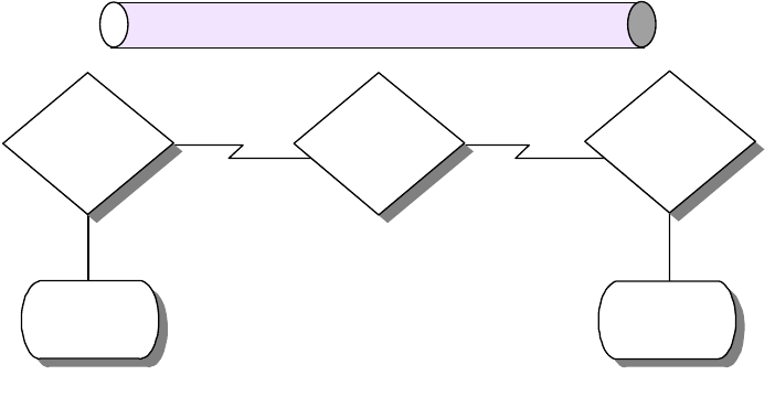
230 IP Network Design Guide
Backbone on the Internet (MBONE). As mentioned in Chapter 2, “The Network
Infrastructure” on page 19, the MAC sublayer of the IEEE model has three
classes of address: unicast, multicast and broadcast. The concept of having the
ability to address a group of endstations at the MAC layer is usually termed Link
Layer Multicasting. Many of the LAN and WAN technologies support multicasting,
such as Ethernet, token-ring and frame relay. IP multicasting, however, occurs at
the network layer of the OSI model, and hence, it is classified as network layer
Multicasting. Since this book is mainly about the IP network, we shall focus only
on IP multicasting.
7.2.1 Multicast Backbone on the Internet (MBONE)
The Multicast Backbone on the Internet (MBONE) is a worldwide network defined
virtually over the Internet to support mainly audio and video traffic. It uses a
numbers of tunnels linking networks that can support IP multicast. A tunnel is a
point-to-point link between two endstations across the Internet, and it
encapsulates multicast traffic in unicast packets to transfer the multicast. If the
endstation is a router, it will run a multicast routing protocol, and if it is a host, it
will run services such as the
mrouted
in the UNIX system.
The tunnels in MBONE are used as a temporary solution as not all the routers on
the Internet support IP multicasting. This poses a scalability problem, because
more tunnels have to be set up if the network expands. More tunnels mean more
traffic of the same kind is transported, which in the first place, is a problem that
multicasting is trying to solve. Because it runs over the Internet, the MBONE
provides limited bandwidth for sending data and the suggested maximum
bandwidth that a video can consume is 128 kbps. The routers in the MBONE are
configured such that if there is a congestion problem due to excessive traffic, they
will begin to drop packets.
Figure 110. Multicast Tunnel
7.2.1.1 How to Connect to MBONE
There are a few steps that you need to complete if you are interested in
connecting your network to the MBONE:
• Check with you ISP for MBONE support
Multicast
Router
Tunnel
Multicast
Island
Multicast
Router
Multicast
Island
Unicast
Router
2580a\F6S4
Multicasting and Quality of Service 231
You need to call your ISP to find out whether they are connected to the
MBONE. You also need to find out whether the ISP provides mutlticast feed
or tunnels to link your network to the MBONE.
• Turn on IP Multicast routing
Make sure your router supports IP multicasting. Currently, the MBONE
uses DVMRP for routing IP multicast traffic. Products such as the IBM 2212
Access Utility and the IBM 8210 MSS Server support the Distance Vector
Multicast Routing Protocol (DVMRP). You need to enable the router to
forward IP multicast traffic, and depending on the ISP’s setup, you may also
need to set up a tunnel to a destination IP address to receive the feed.
• Configure Workstations for IP Multicasting
Workstations need to be enabled to handle IP multicast traffic. Particularly,
they need to support IGMPv2 so as to join a multicast group.
• Install MBONE Applications
There are applications developed for MBONE that can receive the multicast
traffic, such as displaying a video presentation. You may need to download
these applications to the workstations.
7.2.2 IP Multicast Transport
The TCP protocol provides a reliable transport mechanism for the higher layer
protocols, but it is not suited for use in multicasting because it operates in a
point-to-point manner. Instead,the UDP protocol is used for IP multicasting.
In IP multicasting, the selection of the multicast address is crucial. Also, network
managers need to control the way hosts join a group, and how routers exchange
multicast routing information.
7.2.2.1 IP Multicast Addresses
IP Multicast uses Class D IP addresses, and they range from 224.0.0.0 to
239.255.255.255. For each multicast IP address used, there can be a number of
hosts listening to it. These hosts are said to belong to a multicast group and the
IP addresses represent that group. The Class D address can be classified into
three groups:
• Permanently Assigned
The IP address range from 224.0.0.0 to 224.0.0.255 is permanently assigned
by IANA for certain applications, such as routing protocols. These addresses
are never forwarded outside the local network. The list of IP addresses
assigned are documented in RFC 1700. Some of the well-known addresses
are:
• 224.0.0.0 Base address (Reserved)
• 224.0.0.1 All systems on this subnet
• 224.0.0.2 All routers on this subnet
• 224.0.0.4 DVMRP routers
• 224.0.0.5 OSPFIGP all routers
• 224.0.0.6 OSPFIGP designated routers
• 224.0.0.7 ST routers
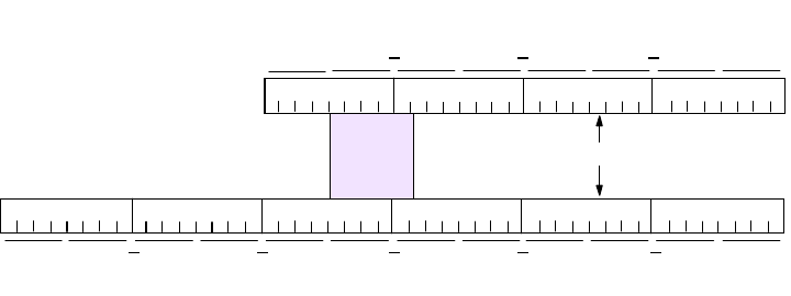
232 IP Network Design Guide
• 224.0.0.8 ST hosts
• 224.0.0.9 RIP2 routers
• 224.0.0.10 IGRP routers
• 224.0.0.11 Mobile agents
• Transient Addresses
They are in the range from 224.0.1.0 to 238.255.255.255. Any address that is
not permanent is transient and is available for assignment as needed on the
Internet. Transient groups cease to exist when their membership drops to zero.
• Transient Administered Addresses
They are in the range from 239.0.0.0 to 239.255.255.255 and are reserved for
use inside private intranets.
Class D Address and MAC Address Mapping
As mentioned, the network interface card exchanges information by using a MAC
address rather than an IP address. Therefore, to join a multicast group, an
application running on a host must somehow inform its network device driver that
it wishes to be a member of a specified group. The device driver software itself
must map the multicast IP address to a physical multicast address, so that it can
receive the necessary information.
Networks such as Ethernet supports multicasting and the MAC address range
from X’01005E000000’ to X’01005E7FFFFF’ is reserved for multicasting. This
range has 23 usable bits. The 32-bit multicast IP addresses are mapped to the
MAC addresses by placing the low-order 23 bits of the Class D address into
the low-order 23 bits of the address block as shown in the following diagram:
Figure 111. Mapping of Class D IP Address To MAC Address
Out of the 28 bits of the Class D IP address that vary, 5 are not used.
Therefore, there will be 32 different multicast IP addresses that will eventually
map onto a common MAC address. These duplications have to be resolved by
higher layer protocols so that the data can be passed on to the correct
applications.
7.2.2.2 The Group Membership
All hosts that are listening to a particular multicast IP address are said to be in the
same group. The membership of a group is dynamic, that is, members join a
group at will, and leave anytime they want. Senders need only one piece of
Class D Address: 224.11.9.7
Not
Used
000000010000000001011110000010110000100100000111
11100000000010110000100100000111
Low-Order 23 Bits Mapped
E0 B97000
0100E
B
500097
2580C\CH7F01
Multicasting and Quality of Service 233
information to send traffic, and that is the multicast IP address to send to. When a
sender sends traffic, it does not matter whether there is any hosts listening.
7.2.2.3 Internet Group Management Protocol (IGMP)
When a host wishes to join a multicast group, it signals its intention to the router
that is situated in the same subnet, by using the Internet Group Management
Protocol (IGMP). The first version of IGMP, IGMPv1, is documented in RFC 1112.
However, it has been updated twice, and IGMPv2 and IGMPv3 are now available.
It is important to make sure that if you plan to implement IP multicasting, the
router and the hosts are capable of supporting IGMP, preferably IGMPv2.
IGMP basically specifies conversations between the router and the hosts that are
directly attached to its subnet. The router sends out the Host Membership Query
message periodically to solicit information while the hosts reply with the Host
Membership Report messages. There are a few activities in the network that
require the IGMP protocol:
• Joining a group
To join a group, the host sends a Host Membership Report message into the
network. The router that is located on the same subnet receives the message
and sets a flag to indicate that at least one host on that subnet is a member of
a particular multicast group. By default, all hosts on the subnet are members
of the all hosts group (224.0.0.1).
• Maintaining a group
Multicast routers send out the Host Membership Query message periodically
to the all hosts 224.0.0.1 multicast address to check if there are still active
members for the groups it maintains. All the hosts on the same subnet can
receive each other’s reply to the router’s query. Thus not all the hosts in a
common group will reply, and this is called a Report Suppression. The
purpose of report suppression is to save network bandwidth, because it does
not matter how many members there are in a group. If the router does not
receive any reply on a particular group, it assumes that there is no more
member for that group and cease to forward traffic for that group.
• Leaving a group
In IGMPv1, there are no specifications for leaving a group. The router can still
be forwarding traffic to a group even though there are no more members, but it
will realize the situation after a timeout on its query message.
IGMPv2 was developed to address some of the flaws of IGMPv1. It is
documented in RFC 2236. Some of its enhancements include:
• Leave Group message
The purpose of the Leave Group message is to reduce the latency time
between the last receiver’s leaving and the time when the router stops to
deliver the multicast traffic. This helps to prevent wastage of bandwidth and
overloading the router unnecessarily.
• Quarrier election
In a subnet with many multicast routers, the one with the lowest IP address will
automatically be elected the multicast quarrier. This feature differs from that of
IGMPv1, where routers have to rely on the multicast routing protocol to decide
234 IP Network Design Guide
which one should be the multicast quarrier. The quarrier election mechanism
simplifies the process and makes the election easy.
• Group-Specific Query message
The group-specific query enhancement enables the router to transmit a query
message to a specific group rather than to all the groups.
7.2.3 Multicast Routing
IP multicast routing is the process whereby routers in a network exchange
information on the transfer of multicast traffic. Similar to the normal IP unicast
traffic, which the routers exchange routing information by using protocols such as
OSPF, the routes use multicast routing protocols to exchange routing information.
One of the important characteristics of IP multicasting is the maintenance of
distribution trees in the routers. A router makes use of the distribution trees to
keep track of the flows of traffic, and considerable amount of the processor’s
resources is spent on referring to and maintaining the data structure. The various
multicast routing protocols have their own way of maintaining the distribution
trees and it is this that makes them different in their implementation.
Dense Mode versus Sparse Mode
The multicast routing protocols can be grouped into two categories: the
dense
mode
and the
sparse mode
.
The dense mode assumes a high concentration of hosts participating in the
multicast, and traffic is flooded in the network to find multicast routes. Examples
of a dense mode protocol are Distance Vector Multicast Routing Protocol
(DVMRP), Multicast Open Shortest Path First (MOSPF) and Protocol
Independent Multicasting-Dense Modem (PIM-DM).
The sparse mode, on the other hand, assumes that hosts are distributed thinly
over the network. A flooding mechanism is not used and bandwidth consumption
is not as high as that of the dense mode. Examples of sparse mode protocol are
Protocol Independent Multicasting-Sparse Mode (PIM-SM) and Core-Based Tree
(CBT).
7.2.3.1 Distance Vector Multicast Routing Protocol (DVMRP)
The Distance Vector Multicast Routing Protocol (DVMRP) was the first multicast
routing protocol to be developed and it is still widely used in the MBONE today.
DVMRP is based on the RIP, and thus decisions on routes are similar to that of
RIP.
DVMRP makes use of a mechanism called the Reverse Path Multicasting (RPM),
whereby datagrams follow multicast delivery trees from a source to all members
of a multicast group, replicating the packet only at necessary branches in the
delivery tree.
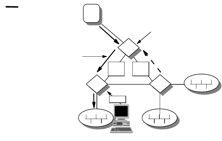
Multicasting and Quality of Service 235
Figure 112. Reverse Path Multicasting (RPM)
The trees are calculated and updated dynamically to track the membership of
individual groups. When a datagram arrives at an interface, the reverse path to
the source of the datagram is determined by examining a DVMRP routing table of
known source networks. If the datagram arrives at an interface that would be
used to transmit datagrams back to the source, then it is forwarded to the
appropriate list of downstream interfaces. Otherwise, it is not on the optimal
delivery tree and should be discarded. Reverse path forwarding checks to
determine when multicast traffic should be forwarded to downstream interfaces.
In this way, source-rooted shortest path trees can be formed to reach all group
members from each source network of multicast traffic. In order to ensure that all
DVMRP routers have a consistent view of the path back to a source, a routing
table is propagated to all DVMRP routers as an integral part of the protocol. Each
router advertises the network number and mask of the interfaces it is directly
connected to as well as relay neighbor routers. DVMRP requires an interface
metric to be configured on all physical and tunnel interfaces.
Since DVMRP is widely used in the Internet, network managers who wish to
implement DVMRP need to understand some commonly used terms.
Understanding these terms will be useful when you need to discuss the technical
details with your ISP.
• Neighbor Discovery
A DVMRP router discovers its neighbor dynamically by sending neighbor
probe messages on local multicast-capable network interfaces and tunnel
interfaces. These messages are sent periodically to the All-DVMRP-Routers
IP multicast addresses. Each neighbor probe message contains a list of
neighbor DVMRP routers for which neighbor probe messages have been
received on that interface. In this way, neighbor DVMRP routers can ensure
that they are seen by each other.
• Dependent Downstream Routers
Multicast Delivery
Path from Source=S
and Group Address=G
2580a\F6K6
Members of Group G are
present on subnetwork R1.
Therefore, link 1-2 is part
of the delivery tree.
Router 3 determines there are
no members. It sends prune
message upstream to Router
1. Link 1-3 is pruned from the
delivery tree.
Link
1-2
S
Link
1-3
Join
R1
1
23
236 IP Network Design Guide
DVMRP uses the route exchange as a mechanism for upstream routers to
determine if any downstream routers are dependent on them for forwarding
traffic from a particular source network. DVMRP accomplishes this by using a
technique called poison reverse.
• Designated Forwarder
When two or more multicast routers are connected to a multi-access network,
it can be possible for duplicate packets to be forwarded onto the network.
DVMRP prevents this from happening by electing a forwarder for each source.
The router with the lowest metric to a source network will be the designated
forwarder. In the event there are more than one possible forwarder because
they cost the same, then the one with the lowest IP address becomes the
designated forwarder for the network.
• Tunnel Interfaces
Because not all IP routers support native multicast routing, DVMRP includes
direct support for tunneling IP multicast datagrams. The IP multicast
datagrams are encapsulated in unicast IP packets and addressed to the
routers that do support native multicast routing. DVMRP treats tunnel
interfaces in an identical manner to physical network interfaces. Most, if not all
of the multicast connections are done in this manner.
• Prune Mechanism
Routers at the edges of a network with leaf networks will remove their leaf
interfaces that have no group members associated with an IP multicast
datagram. If a router removes all of its downstream interfaces, it notifies the
upstream router that it no longer wants traffic destined for a particular group.
This is accomplished by sending a DVMRP prune message to the upstream
router. This continues until the unnecessary branches are removed from the
delivery tree.
• Graft Mechanism
Once a tree branch has been pruned from a multicast delivery tree, packets
will not be forwarded to the interface that resides in that branch. However,
since IP multicast supports dynamic group membership, hosts may join a
multicast group at any time. In this case, DVMRP routers use the graft
mechanism to cancel the pruning that is taking place, so that multicast traffic
will continue to be forwarded.
Implementing DVMRP has a few advantages. It is widely used on the Internet and
MBONE and almost all routers from all vendors support it. It supports tunneling
so that it can be implemented across a network with routers that do not support
multicasting. One problem associated with DVMRP is the scalability issue. Being
a dense mode protocol, it uses a flooding mechanism and this is inefficient for a
large network. Since part of its function is based on RIP, it shares the same
problems that are associated with RIP, such as hop count limitation and
nonoptimized path selection. DVMRP will probably be used for quite some time,
and in most cases, it may be the only choice to get connected to an ISP. For
multicast routing within your intranet, it is better to use another routing protocol.
7.2.3.2 Multicast OSPF (MOSPF)
MOSPF is the multicast extension that is built on top of OSPF Version 2 and
defined in RFC 1584. MOSPF is not actually a separate multicast routing protocol
like DVMRP. It makes use of the existing OSPF topology database to compute a
Multicasting and Quality of Service 237
source-rooted shortest path delivery tree. MOSPF makes use of a flooding
mechanism to provide group memberships through the link state advertisements
(LSAs). The path of a multicast datagram can be calculated by building a
shortest-path tree (SPT) rooted at the datagram’s source. All branches not
containing multicast members are pruned from the tree. The designated router in
the network communicates with the rest of the routers by the flooding
mechanism. Therefore, in a large network with many routers, this may be a
concern.
MOSPF implementation is simple for a network that is already running OSPF.
There is not much configuration required. One of the limitations of MOSPF is
when group membership is dynamic. The rapid changes cause recalculation and
routers may be bogged down with all these resource-intensive activities. Another
limitation of MOSPF is that it works only with OSPF and not any other routing
protocol. Since most of the large networks run OSPF, it is convenient to run
DVMRP with the ISP, and then run MOSPF within the intranet.
7.2.3.3 Protocol Independent Multicasting (PIM)
Protocol Independent Multicasting (PIM) is a new multicast routing protocol
developed by the IETF. PIM is independent of any underlying unicast routing
protocol, such as OSPF, and it has been developed in two parts to accomplish the
task in different environments, namely, PIM Dense Mode (PIM-DM) and PIM
Sparse Mode (PIM-SM).
PIM-DM is almost the same as DVMRP and is suitable for use in an environment
in which the members of a group congregate at a common network. PIM-SM has
a different concept from PIM-DM. It is based on an approach called the
Core-Based Tree (CBT) and is suitable for use in an environment in which the
members are distributed widely in the network.
PIM-DM assumes that when a source starts sending, all downstream systems
want to receive multicast datagrams. Initially, multicast datagrams are flooded to
all areas of the network. If some areas of the network do not have group
members, PIM-DM will prune off the forwarding branch by setting up a prune
state. The prune state has an associated timer, which on expiration, will turn into
a forward state, allowing traffic to go down the branch previously in the prune
state. The prune state contains source and group address information. When a
new member appears in a pruned area, a router can graft toward the source of
the group, turning the pruned branch into a forward state.
PIM-DM is easy to configure and implement and its simple flood and prune
mechanism makes it a very reliable protocol. One drawback of PIM-DM is that it
does not support tunneling. This requires that all the routers in a network support
the protocol in order to provide multicasting to the network.
PIM-SM works with having a router designated as a common point where a
sender for a group meets the receivers. This common point is called a
Rendezvous Point (RP). The RP is the center of focus for PIM-SM because all
traffic from the sender and the receivers have to pass through it. PIM-SM works
on the basis that multicast traffic will be blocked unless explicitly asked for. The
RP receives explicit join messages from other routers that have group members.
It will then forward traffic only to those interfaces that have received the join
requests. When there is more than one router located in a subnet, the one with
238 IP Network Design Guide
the highest IP address is selected as the Designated Router (DR), which will be
responsible for sending join and prune messages.
The tree maintained by an RP may not be optimized. There may be an odd
situation where the sender and the receivers are close to each other, but still have
to connect through the RP, which may be located far away. A situation like this will
require the PIM-SM to switch from a shared tree to a source-based shortest-path
tree.
PIM-SM is suitable for networks with group members dispersed within the
network. As work continues to be done on the protocol, it will evolve to provide
more sophisticated features for optimization.
7.2.3.4 Core-Based Tree (CBT)
The Core-Based Tree is a new routing protocol developed for multicast routing. It
is somewhat similar to PIM-SM, in which there is also a common distribution
point, called a core. The join and leave messages are sent to the core and all
traffic has to pass through it.
The CBT routers that have local members send explicit join requests to the core
router. Each group creates a different tree and all members use the same tree to
receive the multicast traffic. CBT only forwards traffic based on explicit request.
This is unlike PIM-DM, which uses a flooding mechanism followed by a prune
operation. In CBT, all join requests must be acknowledged by the core router
before any operation is done to the tree.
So far, CBT is not widely implemented by router vendors.
7.2.4 Multicast Address Resolution Server (MARS)
So far, we have been dealing with multicasting techniques that work on a
broadcast network. In a non-broadcast network, multicasting has to be done in a
different manner. The LAN Emulation in an ATM implementation does provide a
BUS for broadcast and multicast services, so IP multicasting will work normally in
a LAN Emulation environment. For networks running Classical IP, some service is
required.
Multicast Address Resolution Server (MARS) provides support for IP multicast
over a Classical IP network. Since all connections in ATM are established through
the ATM address, there has to be some mapping done between the multicast IP
address and the ATM address. The mapping in MARS is done very much the
same way as the Classical IP approach. In Classical IP implementation, each IP
address is mapped onto one ATM address. In MARS, each multicast IP address
is mapped onto several ATM addresses. Clients who wish to receive a multicast
traffic indicate that to the MARS server which then adds the client’s ATM address
to the mapping table for the desired multicast address(es).
Implementation of a MARS network requires the following components:
• A MARS server
• A group of endstations that wish to listen to the common multicast
transmission. This group is called a cluster, and the endstations are called
MARS clients. In MARS implementation, the MARS clients have to be located
within a single logical IP subnet (LIS).
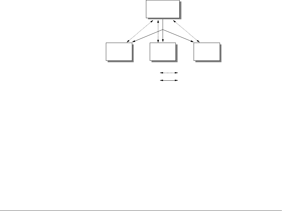
Multicasting and Quality of Service 239
Figure 113. MARS Control Connections
All the MARS clients establish connections with the MARS server through MARS
control messages. Clients use the private control virtual curcuit (VC) to register to
the MARS server, and a separate point-to-multipoint VC is used by the MARS
server to update all members in a group of any changes.
There are two ways for a sender to transmit its traffic to the receivers. In the first
case, the sender set up a point-to-multipoint VC to all the members in the cluster.
The list of members is obtained from the MARS server. In the second case, a
server called a Multicast Server (MCS) is set up. The sender sets up a
point-to-point VC with the MCS, and the MCS sets up a point-to-multipoint to the
rest of the members. The IBM 8210 MSS server can be both a MARS server and
an MCS at the same time.
7.3 Designing a Multicasting Network
Designing a network that is capable of multicasting is a complicated task. There
are many aspects that need to be looked into besides those that are considered
for a normal network.
• Behavior of applications
A need for a multicast network is usually driven by the applications. Because
different multicast applications behave differently, and have different
requirements on the network, it is important to know the mechanics of how the
applications function. Areas such as bandwidth requirement, the way it is
activated, and error recovery of the applications have to be considered. For
example, an MPEG-2 video stream may not be suitable in a network that is
already plagued with performance problems. Also, some applications may
have a limitation on the range of multicast IP addresses supported.
• Address mapping to MAC layer
Because only the lower 23 bits of the multicast IP address are mapped onto
the MAC address, not every multicast stream will be mapped onto a unique
MAC address. In fact, there will be 32 multicast IP addresses that are going to
share a single MAC address. In this case, it is important to know how the
applications are going to behave in a situation like this, and whether the clients
have the ability to handle this.
MARS
Server
Private Control VC
Cluster Control VC
MARS
Client
MARS
Client
MARS
Client
2580C\CH7F02
240 IP Network Design Guide
• Address assignment
A multicast IP address can range from 224.00.0 to 239.255.255.255. For a
network that is going to introduce IP multicasting, it is important to have a
multicast IP address assignment strategy. Since the receivers need to indicate
their interest by indicating a multicast IP address to listen to, this usually
translates into hard coding of the address in some software code. If there is no
strategy in assigning a multicast IP address, the addresses may change for
whatever reasons, and the developers have to recode the software to reflect
the changes. Network managers need to decide which range of multicast IP
address to use, and ensures that all applications support the range. Also,
proper assignment authority needs to be in placed, so that the chance of
having duplicate multicast IP address is cut down.
• Choosing a multicast routing protocol
In a large network, there are many subnets that are connected by routers. A
multicast routing protocol needs to be implemented in order that all
workstations can receive the multicast traffic. Choosing a right multicast
routing protocol is important here. The points that network managers need to
understand include the flooding mechanism, the bandwidth requirement and
optimization. For a network that is going to receive a multicast feed from a
public network, it is extremely important to choose the right protocol. Since
most likely DVMRP is going to be used for connectng to the ISP, the interior
multicast routing protocol must be able to interoperate with DVMRP.
• Choosing the right equipment
When implementing a multicast network, it is important to make sure that all
the equipment, from the sender, router, switch or hub, to the receivers must
support the chosen protocols. Hence it is important to have guidelines on the
choice of equipment when making a purchase. For the sender and the
receivers, it is important to ensure that they support IGMPv2. For the routers,
it is important to ensure that they support DVMRP, and at least one other
routing protocol. Nowadays, newly introduced switches have features like
IGMP snooping. This ensures that traffic is only forwarded to the port with the
registered member attached, although there may be other endstations in the
same VLAN connected to other ports.
• Placement of key functions
In networks such as LAN Emulation, the BUS is responsible for handling the
multicast forwarding. In LAN Emulation networks, the router is usually the one
providing the LES/BUS and the unicast routing services. In a busy network,
the router may be overwhelmed with the load on the BUS and its unicast
routing. Thus, it is recommended that the BUS function be separated from the
unicast routing function. In PIM, the role of the core router is crucial because it
is the focal point of all the senders and receivers. Thus, network managers
need to ensure that it has enough processing power to handle the task. In
DVMRP, the requirement is different. The flooding mechanism requires that all
the routers in the network must have certain processing ability.
• Testing
Multicasting is a new area into which many network managers have not
ventured. One of the most important criteria for a successful implementation is
testing. The effect of multicasting on the current network has to be ascertained
and it would be suicidal just to roll out the service without proper testing. Also,

Multicasting and Quality of Service 241
the testing phase provides a good test bed for network managers to learn
more about multicasting technology and the behavior of all the equipment
involved. For this reason, it is advisable to set up the test bed separately from
a production network.
7.4 Quality of Service
The Internet applications that we have today all work on a common characteristic:
that of a best-effort service. Effort service means all that data can be delayed or
worse, lost along the transmission path. Internet applications today employ error
recovery service to handle transmission errors and in the worst scenario, will stop
functioning completely.
The concept of Quality of Service (QoS) comes in because there are users who
are willing to pay a premium to get better service. On top of this, new applications
that require high bandwidth and certain delivery quality have emerged recently
prompting many network managers to look into providing "premium service" on
the network.
7.4.1 Transport for New Applications
Basically, there are two ways of transporting multimedia traffic over a network: the
packet format or the stream format. The packet format makes use of network
protocols such as IP to transport the multimedia traffic, while stream format is
directly translating the media information into the data link layer, such as the ATM
cells.
Stream format multimedia is rare because very few networks are capable of
supporting it. Also, with the popularity of the Internet, it makes more sense for a
company to develop its multimedia product to ride on the IP transport. Thus, we
can find more multimedia products that support TCP/IP rather than direct support
for ATM.
The delivery of multimedia traffic is very different from that of pure text because of
its reference to time. For example, to do a videoconferencing on the network, both
the video images and the voice must be delivered to the destination within a
specific time. Usually, both the video and audio are encoded separately, and the
encoded data is sent out separately also. At the receiving end, there must be
some mechanism to do a proper ordering of the data receive, and also to
synchronize both the image and the voice, so that users at the receiving end can
make sense of the data received. The following diagram illustrates this idea:
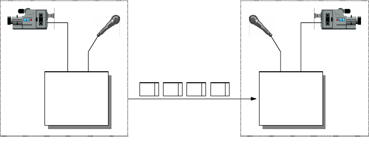
242 IP Network Design Guide
Figure 114. Sending Video and Audio Data during Videoconferencing
7.4.1.1 Real-Time Protocol (RTP)
The Real-Time Protocol (RTP) is one that provides the ability to make scenario
like the above possible. RTP makes use of UDP as its transport to provide for
timely delivery of data, albeit at the expense of reliability. RTP provides
synchronization of media data through a timestamping mechanism, so that the
receiver can play back the media data in the correct order.
The main job of RTP is to provide payload identification, sequence numbering of
data and time stamping. Its packet header provides the following information:
• Payload Type
The payload type is a 7-bit field that specifies two categories of data: audio
and video.
• 16-Bit Sequence Number
The sequence number is used by the receiver to restore the packet order and
detect packet loss. Every RTP packet gets a sequence number.
•TimeStamp
The time stamp field contains a value that represents the time when the data
was sampled.
• Synchronization Source (SSRC)
The synchronization source is a 32-bit number that is randomly generated to
uniquely identify a source. The synchronization number is used by the receiver
to assemble the packets from a particular source for playback.
• Contributing Source (CSRC)
The contributing source field contains the contributing sources for the data in
the RTP packet. This is used when a mixer has been deployed to combine
different streams of RTP packets with the same payload type from different
senders.
Most of the multimedia applications on the Internet today make use of RTP to
provide services. Some of the examples are:
• Cu-SeeMe
•IP/TV
(V)
(A)
A V A V
(V) (A)
2580C\CH7F03
Multicasting and Quality of Service 243
• Intel Internet Video Phone
• BambaPhone
7.4.1.2 Real-Time Control Protocol (RTCP)
The RTP protocol is usually associated with the Real-Time Control Protocol
(RTCP). While RTP provides a way of transporting the multimedia data across the
network, it does not have a feedback mechanism to tell the sender what is
happening in the network.
The RTCP augments the functions of RTP by providing a feedback mechanism
about the quality of the RTP traffic. RTCP is responsible for providing sender and
receiver reports that include information such as statistics and packet counts. It
uses a separate UDP port, usually one higher, than that of the RTP protocol.
RTCP provides several functions through different packet types, some of which
are listed below:
• Sender Report (SR)
The sender report is sent by the source of an RTP stream to inform the
receiver what it should have received.
• Receiver Report (RR)
The receiver report has the same function as that of the sender report, with
information such as the cumulative number of packets lost and the highest
sequence number received.
• Source Description Items (SDES)
The source description items packet is used from the RTP sender to provide
more information about itself, such as the e-mail address of the user, phone
number and location.
7.4.2 Quality of Service for IP Networks
QoS separates network traffic into different classes, and the network provides
different treatment for this traffic. Mechanisms are introduced in the network
devices to forward traffic based on different priorities so that important
applications will be less affected by network congestion.
It is important to note that for users to enjoy the benefit of QoS, it must be
implemented end-to-end. That is, the application, operating system, and the
network must have the ability to agree on a certain traffic contract.
Currently, there are many groups working on different technologies to provide
QoS on the network, and they are listed below.
7.4.3 Resource Reservation Protocol (RSVP)
Resource Reservation Protocol was developed by the IETF and is documented in
RFC 2205. It enables an application to make a request to the network for a
certain guaranteed service.
The request for service in RSVP is done dynamically and requires the routers in
the network to participate. Rather than let the sender request for service, RSVP
requires the receiver to initiate the request instead. The QoS of the connection
between a sender and a receiver is made along each hop in the path from the
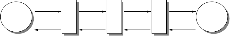
244 IP Network Design Guide
receiver to the sender. A reservation consists of a set of parameters that
determine the nature of the connection. The application must be enabled with
RSVP capability so that the reservation can be made. IBM provides an additional
capability whereby the router, such as the IBM 2212 Access Utility, can make the
RSVP request on behalf of a non-RSVP-capable application.
The following diagram shows how a sequence of messages are used in
establishing a reservation that provides QoS to a particular traffic flow.
Figure 115. RSVP Message Flow
The establishment of an RSVP connection is done through the sending of the
PATH message from the sender to the receiver. The PATH message describes the
details of the QoS requirement. The receiver sends back an RESV message that
requests network resources along the path. Routers along the path may check for
bandwidth availability and decide whether to honor the request. In the event of a
failure, a RESVERR is sent to the sender.
RSVP supports several link types, including:
• LAN - Ethernet, token-ring
• Frame relay - PVC and SVC
• PPP links that are on a permanent connection basis
7.4.4 Multiprotocol Label Switching (MPLS)
The growth of the Internet is far exceeding the layer-3 processing power of the
traditional routers. With the maturity of layer- 2 switching technology and the
reduction in hardware prices, new switching technologies have been developed to
offer solutions to the problem. Multiprotocol Label Switching is one such
technology that aims to offer QoS in a network.
MPLS works over any layer-2 technology, be it ATM, frame relay, or Ethernet. Its
primary goal is to standardize a base technology that integrates a label-swapping
forwarding paradigm with layer-3 routing. Currently, the effort on MPLS is to focus
on IP protocol, while support for the rest of the network layer protocols will be
available in the future.
MPLS aims to change the way routers forward packets through the introduction of
a label field. Traditional routers keep a routing table of all the destinations in the
network and when a packet arrives, it is checked with this table for a forwarding
decision. This is repeated in every routers along the data path until the packet
reaches its destination. In MPLS, the first router, besides checking for the
destination in the routing table, also adds a label in the packet. The rest of the
routers along the data path, upon receiving the packet, no longer need to check
against their own routing table. Instead, the label field is compared with a label
ReceiverSender
Path
RESV
R1
Path
RESV
R2
Path
RESV
R3
Path
RESV
2580C\CH7F04

Multicasting and Quality of Service 245
table so that the routers know which port to use to forward the packet. This
mechanism of forwarding a packet makes it more efficient than the traditional way.
A common strategy from the vendors on supporting QoS on MPLS is to map it to
the ATM QoS. Unfortunately, different vendors do it differently and it will be some
time before MPLS can be deployed extensively.
7.4.5 Differentiated Services
Differentiated Services, or Diff-Serv, is a new technology that is being worked on
by the IETF to provide QoS on the network. It is meant to be a "simple"
technology that can be deployed on the Internet for service providers to introduce
service classes.
Diff-Serv makes use of the type of Service (ToS) field in the IP packet to provide
tagging, thus requiring very little modification to the IP structure. This is very
important as it makes support for Diff-Serv much easier than the rest of the
technologies. The tagging field, called the DS byte, marks every IP packet so that
it receives a certain forwarding preference at each hop. There are currently three
options in the tag, that is, assured-and-in-profile, assured-and-out-of-profile, and
none. The none option is what we have today on the Internet, which is equivalent
to the best-effort service. The rest of the options will be defined by an important
component in Diff-Serv, which is called the service level agreement (SLA). The
SLA is a contractual agreement between an ISP and a customer which specifies
the details of the traffic classification and forwarding preferences.
Since Diff-Serv is still in its infancy stage, nobody knows whether it will be widely
accepted. But its simplicity and scalability can potentially make it a popular way of
implementing QoS.
7.5 Congestion Control
Congestion control is an area that needs to be discussed when we talk about
QoS. Because we have learned that bandwidth is never enough, throwing our
money at bandwidth will never solve the problem of network delays. In fact, we
believe that avoiding congestion is far better than trying to solve it. When a
network gets congested, the effect is far more than just delays in the delivery of
data. With congestion comes application timeouts, more error recoveries, more
connection re-establishments, and more bandwidth wasted on these retries.
Therefore, by arresting the congestion problem early, we may be able to avoid
more serious problems.
Congestion control is usually done by the connecting devices, such as a router
and switches. And the mechanics of congestion control lie mainly on queuing
theory. These devices have built-in intelligence to handle traffic forwarding and all
of them are based on some queuing theory. When packets arrive at a router, they
need to be processed so that the router knows to which interface to forward these
packets. Just like when you go to the bank, you join a queue to be served by the
tellers, these packets arrive at the router, waiting to be served by the processor.
Congestion control focuses on the processing of the queue, and there are
different ways of implementing it. The following sections list some of the common
ones.
246 IP Network Design Guide
7.5.1 First-In-First-Out (FIFO)
The first-in-first-out (FIFO) method is the easiest to implement and has been the
way traffic is handled in a TCP/IP network. The FIFO method means the first
packet to arrive gets processed by the router and the rest of the packets join a
single queue in order of arrival time. The logic for FIFO is easy to implement and
does not require much decision making about how to handle the queue.
Congestion occurs when the queue is filled up faster than the speed at which
packets are processed. In this case, those packets that do not get into the queue
are discarded. There is no QoS implemented in the FIFO method because there
is no way of "jumping" the queue. High priority traffic gets the same treatment as
low priority traffic.
In the past, a good way of solving the congestion problem in the FIFO method
was to increase the queue size, which translated to increasing the hardware
memory, and increasing the processing speed, which translates to more
expensive, high performance hardware. But network managers have realized that
this did not solve congestion problem totally, and have begun to look for other,
better ways.
7.5.2 Priority Queuing
Imagine going to the check-in counters in the airport and finding the queue to be
one mile long. And you realize that you are a premium member and get to join
another queue that is empty. This is the theory of priority queuing.
Priority queuing separates network traffic into various classes and processes
them in order of importance. There are usually a few different queues, for
example, urgent, high, normal and low. The packets that are in the urgent queue
will always get processed first, followed by those in the high queue, and finally the
ones in the normal and low-priority queues. With priority queuing, it is possible to
deliver QoS.
One important thing to note is the distribution of applications in these categories.
The aim of priority queuing is to "drop" the unimportant traffic and ensure the
delivery of urgent priority traffic. Thus there should be more applications
classified as low priority than those classified as urgent priority. In fact, we are
back to the FIFO queuing method if we classify most of the applications as urgent
priority.
With priority queuing, network managers can classify applications into various
categories, and have the network process the traffic from these applications
based on their importance. A voice-over-IP application may be classified as
urgent priority, while the Web traffic may be classified as low priority. This way,
the network can deliver good quality voice transmission, even under a heavy load.
7.5.3 Weighted Fair Queuing (WFQ)
Weighted Fair Queuing (WFQ) has the ability to provide predictable response
times for different traffic, even when there is both high bandwidth and low
bandwidth traffic.
WFQ has the ability to identify a traffic flow and assign a weight to this flow. The
traffic flow may be a video stream or simply a TELNET session. WFQ’s aim is to
ensure that each flow gets its fair share of the bandwidth, so that high bandwidth

Multicasting and Quality of Service 247
traffic (the video stream) will not monopolize the network, and the low bandwidth
application (the TELNET session) continues to work.
In WFQ, a flow may be identified through the protocol, source and destination
address, the port numbers or circuit identifier, such as the data link connection
identifier (DLCI) value in frame relay. A portion of the bandwidth is reserved for
the low bandwidth flows while the balance is for the high bandwidth flows. Since
WFQ is able to identify a flow, it has the ability to "break up" a bursty flow, which
sends information in huge chunks of data, so that the bandwidth can be fairly
utilized by the rest of the applications. Each flow is given a weight and the lower
the weight, the more preference it will be given by the network.
WFQ is used by RSVP to allocate bandwidth and resources to provide QoS to the
network.
7.6 Implementing QoS
Implementing QoS in a network is difficult because of the numerous technical
challenges. For a network that involves external entities such as ISPs, it is even
more challenging.
Implementing QoS requires a strategy that dictates which technologies to be
deployed, how applications should be developed and policies for the reservation
of bandwidth. On the application end, choices must be made on which application
to use and how to use it. Applications that support true QoS are few and far
between, and finding programmers who are well versed in QoS programming is
even rarer. The operating system must also provide a set of application
programming interfaces (APIs) that would provide QoS services to the
application. For existing applications, that means changes are necessary. On the
network end, the connecting devices must be upgraded to support chosen
technology, and in the worst case, new purchases have to be made. The network
must also be configured with the new policies of which users get to request
premium service and how the rest of the users are treated in the network.
As in the case of multicasting, implementing QoS requires substantial testing and
it may not be easy to do. The problem with testing of QoS is that the problem
must exist first. See, the purpose of QoS is to ensure certain traffic gets priority
over the rest in the event of congestion. So in order to test QoS, congestion must
be introduced in the network. Only with congestion in the network can a network
manager see whether his/her implementation is successful. Also, to qualify the
test, test tool must be introduced to ensure different classes of traffic are actually
treated differently by the network. Again, it is not advisable to do this test during
normal office hours, which means many late nights for the network manager.
248 IP Network Design Guide

© Copyright IBM Corp. 1995 1999 249
Chapter 8. Internetwork Design Study
In this chapter, we try to apply what we have discussed and build networks that
are of different sizes. Each of these networks is designed differently because of
its size, requirement and considerations.
However different these networks may be, the design considerations are based
on the following:
• Budget
• Nature of applications
• Availability of expertise
• Fault tolerance, in terms of application, system and network access
• Ease of configuration
• Management
8.1 Small Sized Network (<80 Users)
We have classified a small size network to be below 80 users. Networks of this
size are usually built based on the following constraints:
• Low budget for IT expense
• Little expertise in the various technologies
• Network need not be fault tolerant
• Mostly off-the-shelf applications
• Mostly basic requirements, such as e-mail, word processing, printing, file
sharing
As usual, the first step in the design is to identify the applications that are being
used on the network. A small network tends to use off-the-shelf software such as
word processing and spreadsheet. These applications consume very little
bandwidth because most of the time, the users are working on their individual
workstations on the data file. The only time bandwidth is required is when the
users open the files from the server or save them back to the server. The server,
in this case, is typically a Windows NT server or a Novell NetWare Server. These
two servers usually run their own protocol, that is, NetBEUI and IPX respectively.
However, they do support TCP/IP also. With the popularity of TCP/IP, it is
common to find these servers running TCP/IP. In fact, this is a better way to do it,
because the network need not support multiple protocols. A single protocol
network is simpler to design, and in the event of a problem, easier to
troubleshoot. Running a single protocol on the network is also cheaper, for
example, in the event that a router is required, only an IP router is required, rather
than a multiprotocol one. An IP-only router is much cheaper than a multiprotocol
one and this is significant in contributing to a lower running cost.
In a small network, the file server is usually the most important component
because it is the center of focus. Besides providing a file sharing capability, it also
provides printing services, and may double up as a Web server also. The backup
device, in this case a tape drive, is usually built in and management of the server
is the most important task for the system administrator.
250 IP Network Design Guide
In a small network, there is usually only one or two system administrators in
charge of running the show. The system administrator is responsible for every
aspect of the network, from server management, to backup tasks, to connecting
new devices, to the installation of workstations, and even troubleshooting PC
problems. Due to the nature of the job, the system administrator is usually a
generalist rather than an expert in a particular area of technology. The job is not
easy as expectations of the system administrators is very high and they have to
be responsible for every aspect of the network. Because they are generalists,
they tend to be better inareas such as server management, rather than router
expertise.
Therefore, the design strategy for a small size network usually has the following
characteristics:
• Low cost equipment
• Shared bandwidth for most users, switched for a selective few
• A central switch acting as a backbone
• Flat network design
• Little fault tolerance
• Minimal management required
• High growth provisioning of 20-50%
The above design philosophy enables the system administrator to concentrate on
the most important asset: the management of the server. Small companies, if
they are very successful, tend to grow very fast in terms of size. The percentage
increase is usually higher than that of a big company. For example, a company of
10 that increased to 20 would have grown 100 percent! Thus, provisioning for
growth in a small network has to be slightly higher than that in a large network
design.
We will design a network for an up-and-coming legal firm, Motallebi & Lee, with
the following requirements:
• Connect 50 users to a network
• Connect 10 printers to the network
• Connect the company’s database and internal e-mail services to the network,
hosted on a Windows NT server
The company also requires connectivity to the Internet:
• Users require connectivity to the Internet
• Several systems require access to external e-mail, the Web and FTP
connectivity
• A future Web site may be implemented
8.1.1 Connectivity Design
The connectivity design for such a network is relatively simple, which is basically
a switched Ethernet backbone with shared access to the desktop. The aim is
tocome out with a design that is both cost effective and catered for future
expansion, if necessary.
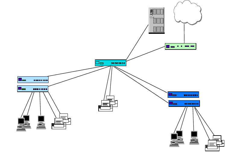
Internetwork Design Study 251
The cabling for the network is the standard Categor-5 UTP, concentrated in a
modest computer room that has been converted from a store room. All the
connecting devices, as well as the server, are located within that room. The
printers are fitted with built-in Ethernet ports and they are located together with
the users.
The first step is to identify different groups of users based on computer resources
requirements. In this case, we separate users into a power user group and
anon-power user group. The power user group tends to be the legal assistants
who need to print a lot of documentation, pull large documents from the server, or
save presentation files into the server. They tend to use high-end PCs that come
fitted with a 10/100 Mbps Ethernet card. The non-power user groups tend to be
administrative assistants who do more manual tasks such as answering phone
calls and assisting in clerical work. They use the network mainly for reading
e-mail and doing some simple word processing. They tend to have lower-end
PCs, or even hand-me-downs. The physical diagram may look like the following:
Figure 116. Physical Diagram for aSmall Network - Phase 1
The aim of separating the users into two groups is of course to save cost. We can
use a 10 Mbps hub (IBM 8242-008) with an uplink, to connect the non-power
users to the network. A hub is always a good tool to concentrate users to a
network because it is cheap and is more than adequate to serve the non-power
users. The power users can be connected to the network through a 10 Mbps
Ethernet switch (IBM 8275-217) with an uplink, or directly to the backbone. The
backbone of the network is a 10/100 Mbps switch (IBM 8271-F12) that is used to
provide uplink ports for the hubs, as well as connect the server and printers. For
connection to the Internet, a small router is required. The IBM 2210 Nways router
is a good choice as it is cost effective and provides an ISDN connection to the
ISP. It is connected to the network with a 10 Mbps Ethernet port. There is no need
...
Ethernet 10 Mbps Hubs
...
Printers
Power Users
IBM 8271-F12
IBM 8242-016
IBM 8275-217
Ethernet 10/100
Mbps Switch
100 Mbps Ethernet 10 Mbps
Switch
Internet
IBM 2210-1S4 Router
Non-power
Users
10 Mbps
Printers
Printers
100 Mbps
10 Mbps
10 Mbps
Server
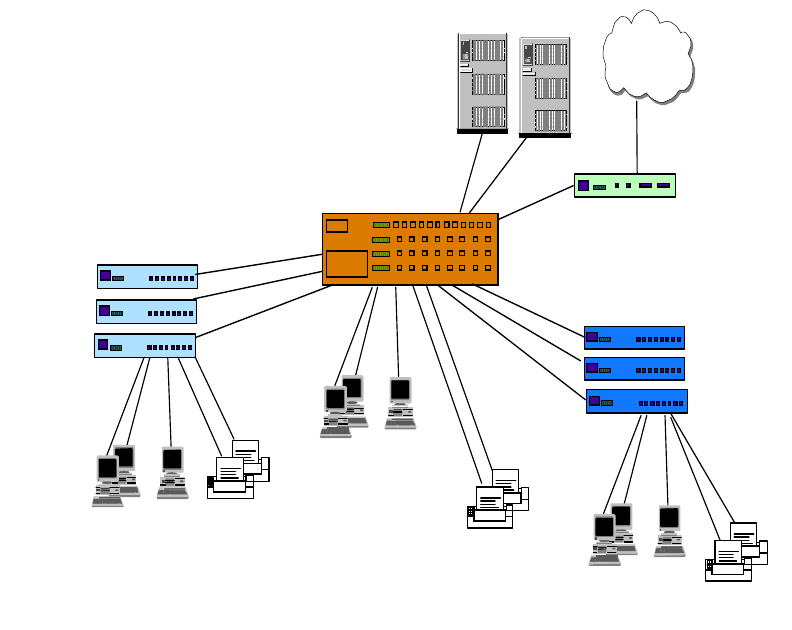
252 IP Network Design Guide
for the router to connect to the network at 100 Mbps because the bottleneck is
always the WAN link, connecting at 64 Kbps at the ISDN end, the 10 Mbps
Ethernet interface is more than enough.
Notice that in this network, the reliability of the network is very much dependent
on the reliability of the equipment. In a network like this, network failure is usually
caused by equipment failure. Thus, it is important to select equipment from
reputable manufacturers. The IBM Ethernet switches are both cost effective and
high quality, so they are a very good choice for this network.
The design has also taken user expansion into consideration. The backbone
switch provides a capacity of 12 ports and has spare ports for connecting
additional devices. The hubs and the 10 Mbps switches have spare ports for
connecting users. The design can also cater for an extensive expansion plan: the
backbone switch can be replaced with the IBM 8275-326 Ethernet switch, which
provides 24 10/100 Mbps switched ports. With the added capacity of backbone
switched ports, more servers and 10 Mbps switches can be added. With more
ports available at the backbone switch, a few "privileged" users can actually be
connected directly at 100 Mbps to the backbone. The physical diagram for the
network will look something like the following:
Figure 117. Physical Diagram for a Small Network - Phase 2
8.1.2 Logical Network Design
The logical network design for a network of this size is usually a flat network and
for our example, we have every device in a single subnet because there is no
...
Ethernet
10 Mbps Hubs
...
Printers
Power Users
IBM 8275-326
IBM 8242-008
IBM 8275-217
Ethernet 10/100
Mbps Switch
100 Mbps Ethernet 10 Mbps
Switch
Internet
IBM 2210-1S4 Router
Non-power
Users
10 Mbps
Printers
Printers
100 Mbps
...
10 Mbps
100 Mbps
Power Users 10 Mbps
Servers
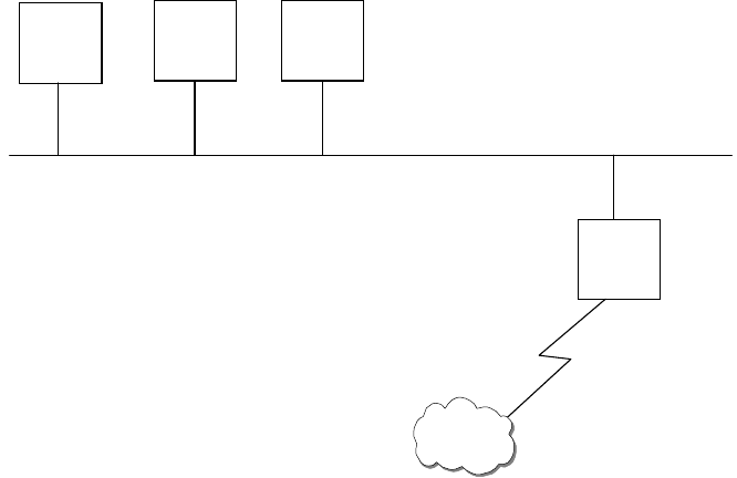
Internetwork Design Study 253
security required in terms of access. The logical network design is independent of
the physical connectivity, reflecting only the Layer 3 map (IP map) of the network,
as illustrated in the following diagram:
Figure 118. Logical Network Design for a Small Network
The IP address used for the network is reflected in the network. Although there is
only one server in the network, you can see that a range of IP addresses has
been assigned to the server. In an IP network, especially the logical design, it is
always important to think ahead, make provisions for expansion. The range
assigned to servers means that we can cater up to 20 servers in the future. The
reasons are the same as for printers and users. Notice that the range catered for
a router is much smaller as compared to the rest. Typically for a network of this
size, there is no need for many routers, thus we need not reserve a big range. An
exception is in a large network, where a backbone subnet is mainly made up of a
lot of routers; then the IP address assignment is different.
8.1.3 Network Management
It is important to note that no matter what size a network is, there must be some
form of network management in place. Network management is important as it is
used for configuration and monitoring purposes. The extent of network
management requirements depend on the size of the network and of course, the
budget. For network of this size, it may be costly to have a dedicated network
management workstation due to budget constraints. In this case, a Web-based
approach may provide a good answer.
The hub that we have chosen here is a non-manageable one. The reason being,
we want to provide connectivity to the non-power users at the lowest cost. There
may be times when certain features, such as manageability, have to be sacrificed
for cost reasons. Of course, without cost constraints, the IBM 8237 Ethernet hub
may be a better choice because it has both basic and advanced management
agents. The backbone switch, the IBM 8271-F12, and the 10 Mbps Ethernet
switch, the IBM 8275-217, are both manageable from a Web browser which is all
that is required from the system administrator’s workstation. Thus, for a small
Server Printer Users
Router
Internet
192.168.1.1
to
192.168.1.20
192.168.1.21
to
192.168.1.50
192.168.1.51
to
192.168.1.249
192.168.1.250
to
192.168.1.254

254 IP Network Design Guide
network rollout, it is important to choose equipment that is Web manageable. In a
tight budget situation, "freebies" like this go a long way.
8.1.4 Addressing
With a network of this size, a Class C address should be used. A private Class C
address has been chosen for our network and it is in the following range:
192.168.1.0 to 192.168.1.255
It is not necessary that a company of this size use a Class A or Class B address.
8.1.4.1 Address Assignment
There are a few considerations that we will look at before we decide on an
addressing scheme for this network. The two major considerations are:
• How many users are attached to the network?
• How much change is expected within the network? In other words, how often
will a network resource require to be added, removed, renamed, etc.
If your network consists of fewer than 20 machines, the likelihood that you have a
dedicated person assigned to network administration is very small. Setting up a
DHCP server can be a daunting task for someone who does not have any
experience with these systems. Although the maintenance of a DHCP server is
quite low, the cost of outsourcing the initial installation and the ongoing
maintenance can be prohibitive for small organizations.
If the number of hosts on the network is unlikely to change in the foreseeable
future in most networks of this size, 20 machines or fewer, it is permissible to use
static IP addressing. With such small numbers of machines, it would be ridiculous
to implement a subnetting scheme. The Static IP address assignment would in
this case be the most effective scheme, both in terms of cost and in terms of man
hours required to implement the scheme.
If the network is expected to grow in size at a significant rate, the use of static IP
addressing would not be recommended. With small networks, DHCP is usually
not a requirement, however, when looking into the future of the organization, if the
number of resources on the network requiring IP addresses has grown to 100 and
there are now subnets within the network, it may be a very long night switching to
DHCP. If you see that the network is going to grow enough to require a DHCP
server in the future, it is best to implement it when the network is small, simple
and manageable.
In a network of 80 users, the organization will typically have a few departments,
with each department requiring certain levels of inter-departmental security and
privacy. For example, the Human Resources department will not want all the
employees to have access to the HR database!
It is important to note that when using a Web browser to manage devices, the
caching has to be disabled on the browser. If this is not done, the browser may
fetch the status page from the cache, and this may not reflect accurately the
true status of the devices.
Note
Internetwork Design Study 255
With this type of network topology, installing a new host can be a little more
complicated because a subnet mask must also be defined. The real complication
comes however, when you need to change a network’s address. Imagine
changing all the network resource addresses in one try, at a network down time.
The change must be done in one try as the hosts will not be able to communicate
with each other if some addresses are changed and others not. Having the hosts
request new addresses from a central server is much easier. DHCP enables
central management of an organization’s addressing requirements. It is worth the
effort to set up a DHCP server to manage all the addressing issues.
It must be remembered that as it was decided to use DHCP, we need to
implement a DDNS server also. Complexity breeds complexity!
8.1.5 Naming
In networks of 20 machines or fewer, most of the hosts only require access to one
or two servers that act as file servers, mail servers and print servers. If each of
these services was serviced by individual resources, in other words, each service
had its own hardware with its own network resource name, a total of three, maybe
four, if there is an internal HTTP/FTP server serving intranet services, domain
names required to be resolved by each machine. With such a low number of
reference hosts, the use of a flat host’s file is an acceptable solution. It is not
worth the time and cost of implementing a fully fledged DNS system for the
organization.
A DNS server would be advantageous, however, when expanding the network to
80 machines or more.. It should also be considered that a network of this size
should be using DHCP, so if any inter-host communication is required, like file
and print sharing between users, a DDNS server is required.
Looking at Figure 118 on page 253, we see that there are no subnets in the
organization’s Intranet. The IP design is a flat network and the simplest naming
structure to map the network with would also be a flat name space. The
organization
will
implement subnets as it grows. So things are bound to get more
complicated.
The organization may have a few departments in it at this size, and it may well be
worth implementing a hierarchical DNS domain for the organization while there is
little complexity. It will be harder to migrate to a hierarchical DNS space when the
organization’s needs have become so complicated that an entire re-design of the
naming structure is required.
Considering the size of the network, a single primary DNS server, and one
secondary DNS server for redundancy, would be sufficient to serve the needs of
the network.
8.1.6 Connecting the Network to the Internet
The infrastructure of the network is now fully functional, and all the required
components are in place. The network, however, is isolated from the Internet.
Connecting the network to the Internet requires a few more considerations.
First, the most important consideration is the IP addresses. In the design of the
isolated network above, private IP addresses were used in the Class C range.

256 IP Network Design Guide
The addresses in this range are
not
routed by the Internet routers. The Internet
will
not
be accessible without some help.
The advantages of using the private IP address range is the added security and
the ability to implement the network without any time-consuming and costly
applications for IP addresses to the regional Network Information Center (NIC) or
ISPs. The down side is that the network is not connectable to the global Internet
directly without some changes, or implementing some additional infrastructure,
such as network address translation (NAT).
For commercial connection to the Internet, ISPs generally charge a company
based on bandwidth and per IP address or per IP class block. In our design, we
recommend subscribing to an address block of eight addresses in the beginning
and maybe a larger one if needed. The network design uses the IBM 2210 Nways
router to translate the internal IP addresses to the Internet IP addresses. The IBM
2210 Nways router is a good choice here because the software already has an
built-in NAT function.
Should the organization want to implement Web site, the design presented
implements the Web server and the external DNS server on the ISP’s network.
For a single Web site that does not have any e-commerce features, it is not cost
effective to implement a full in-house Web solution. The extra infrastructure would
outweigh the benefits of housing the Web site on the organization’s local network.
Outsourcing the external DNS, e-mail, and HTTP servers provides the best
solution.
8.2 Medium Size Network (<500 Users)
We have classified a medium size network to be between 200 and 500 users.
Companies of this size usually have a small MIS department taking care of the
entire information system. They may also own a mid-range system, such as the
AS/400 and have dedicated programmers developing applications on the system.
The characteristics of companies of this size are:
• Fixed annual budget for IT expenditure
• MIS department taking charge of the information system
• Develop own in-house applications
• Availability of one or a few dedicated network engineers
• Invest in server/host fault tolerance features
• May provide dial-in service to mobile workers
In a medium size network, the applications tend to be a mix of off-the-shelf and
in-house developed ones. The AS/400 is a proven platform for application
development and many in-house applications are developed to run on it. In the
past, almost all of these in-house applications were host based, and end users
were connected either to the AS/400 through fixed function (nonprogrammable)
terminals (FFTs) or a 5250 emulation program running on the PC. The PC would
also need to run the required protocol stack, such as the PC LAN Support
program. Since file sharing and printing were still required, the user’s PC would
also need another protocol stack such as the IPX to access a NetWare server.
Internetwork Design Study 257
Making these two protocols work concurrently on the same PC was not easy, and
it actually warranted a redbook on it!
With the growing popularity of the TCP/IP protocol, almost all hosts have the
capability to support it. Thus, it makes sense to unify all the protocols in a LAN to
TCP/IP. With a single protocol, the PC can access the file server, such as
NetWare, OS/2 or Windows NT, and the host, such as the AS/400. It can access
new applications, which are mostly developed on the latest technologies such as
the Web and Java. Running only TCP/IP protocol provides for a wider selection of
technologies such as Layer 3 switching, RSVP or network dispatching. The file
server is no longer the most important component anymore. The host, the
network, and the applications are all crucial to the MIS department. In fact, the
center of focus is on exploiting the various technologies on a unified platform. The
network, mainly a backbone providing TCP/IP connectivity, becomes the
foundation for future application development.
In a medium size network, the MIS department usually employs people with a
specific skill set. There are usually system administrators who take care of the
mid-range host and the file servers. There is usually one or a few network
administrators who are in charge of the network infrastructure. With each of them
taking care of a specific area, they are usually familiar with the technologies in
each area.
The design strategy for a medium size network is based on the following:
• Cost-effective equipment
• Mostly switched connections for users, shared bandwidth for a selective few
• High performance Layer 3 backbone switch
• Hierarchical network design, if needed
• Growth provisioning of 10-20%
In the following design, we are required to create a proposal for an aeronautical
servicing company, with these requirements:
• Connecting 300 users to a network
• The company has an AS/400 host and eight Windows NT file servers
• There are six departments in the company, each with its own applications:
• Marketing - mainly e-mail with external customers, calendaring, word
processing, presentation applications
• Customer Support - mainly handling customer queries, accessing the host
for in-house developed applications
• Finance - make use of word processing, spreadsheet, and host
applications
• MIS - development of applications on the AS/400. The current applications
are mainly RPG programs, but they have started developing Java
applications on the AS/400
• Human Resources - mainly word processing
• Engineering - make use of CAD/CAM workstations for engineering work.
Currently using high performance PC, although there are plans to buy
high-end UNIX workstations
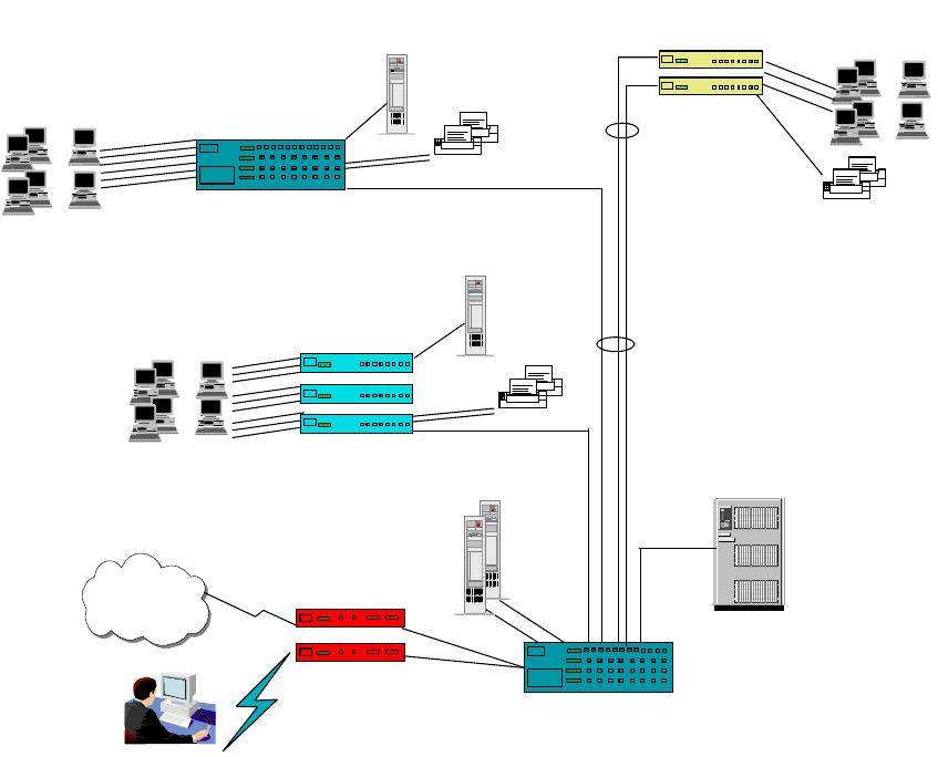
258 IP Network Design Guide
• Provide dial-up capabilities for the 15 managers
8.2.1 Connectivity Design
The design concept here is a switched Ethernet backbone, with mostly switched
connections to the desktop.
For a network of this size, there are usually a few wiring closets located in various
places and these closets are eventually connected to a computer center through
fiber optic or UTP cables. In our case, the company occupies three buildings, with
each workstation connected to the wiring closet in its respective building through
Category-5 UTP cables. The wiring closets are connected to the computer center,
located at the central building, through fiber optic cables.
Figure 119. Connectivity Diagram for a Medium Size Network
Since the strategy of the company is to have all applications developed on
Internet technologies, such as the Web, Java and multimedia, a fully switched
design is adopted. The design philosophy is:
• Power users, such as the Engineering department, will have 100 Mbps
switched connections to the desktop.
• Because Marketing users deal with graphics presentation, they will be
connected to the 10 Mbps switch in a ratio of 16 users to a switch.
100 BaseFX
100 BaseT
Internet Servers
Printers
Server
...
...
10 Mbps Ethernet
Switches
Printers
Server
...
...
Printers
...
...
IBM 8275-217
IBM 8275-324
IBM 8371-A16 with
- 24 x 10/100BaseT
- 8 x 100BaseFx
10/100 Mbps
Ethernet Switches
10/100 Ethernet
Backbone Switch
AS/400
IBM 2210-12E
Mobile
Users
IBM 2210-24E
Engineering Customer Support,
Human Resources
Marketing,
MIS
IBM 8275-225
10 Mbps Ethernet
Switches
Internetwork Design Study 259
• Since Customer Support and Human Resources users require fewer
computing resources, they are connected to the 10 Mbps switch in a ratio of
24 to a switch.
• Except for the server in the Engineering department, all the servers are
connected to the backbone switch at 100 Mbps. The engineering server is
connected to the switch in the Engineering department at 100 Mbps. Since the
Engineering department deals with intense graphics applications, it is better to
locate its server together with the user. This is better reflected in the logical
network diagram, which is described later on.
The switch that we have chosen is the IBM 8275-225 Ethernet switch. It connects
the desktop at 10 Mbps and has an uplink module with 100BaseFX ports. The
Engineering department has an IBM 8275-324 Ethernet switch. It connects up to
24 users per switch, with 100BaseT uplinks. The switch that we use for the
backbone is the IBM 8371 Multilayer switch. It is a Layer 3 switch with a switching
capacity of 10 Gbps, and has been configured with 24 x 100BaseT ports and 8 x
100BaseFX ports. In the network, we have also installed two IBM 2210 Nways
routers to provide connectivity to the Internet and for dialup users.
As a company that is fast growing, the network design has taken expansion into
consideration as well. The IBM 8371 switch can be fitted with ATM or Gigabit
uplinks. So the company can consider having an ATM backbone or Gigabit
Ethernet backbone in the future. Another way is to install another IBM 8371
switch and connect these two switches through port trunking. In this manner, we
have expanded the port capacity of the backbone without changing the logical
design of the network.
8.2.2 Logical Network Design
We have chosen a hierarchical network design for this network. The reasons for
doing so follow:
• The Engineering department network is pretty much self-contained, with users
accessing mainly their own server. Having engineering users in one subnet
enables them to keep their heavy traffic local, so that other users will not be
affected.
• Each department is looking into having their own server for keeping their own
departmental files. For security reasons, some may disallow others to access
them. By putting each department in its own IP subnet, security can be
implemented through filtering in the future.
• The MIS department does application prototyping, and they do not want this to
affect the rest of the network. MIS can introduce a new server for testing
purposes in their own subnet, and this should not affect the rest.
In the logical network design, each department is assigned one full Class C
address as follows:
• MIS - 192.168.1.0
• Customer Support - 192.168.2.0
• Human Resource - 192.168.3.0
• Marketing - 192.168.4.0
• Engineering - 192.168.5.0
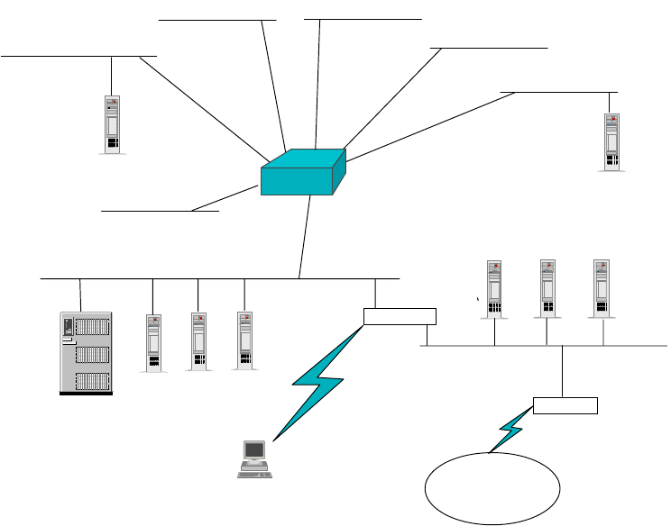
260 IP Network Design Guide
• Finance - 192.168.6.0
Moreover, we created a subnet, 192.168.7.0, to house the AS/400 and the rest of
the servers, such as e-mail and common file server. This subnet is called the
server farm. For dial-in users, they will be assigned to subnet 192.168.8.0. The
logical network design is illustrated in the following diagram:
Figure 120. Logical Network Design for a Medium Size Network
Because the company is providing Internet access to the users, as well as
developing company Web sites on the Internet, we have incorporated a screened
subnet firewall in our design.
TheIBM 2210-24E is configured with an eight-port Dial Access adapter. This 2210
comes with two Ethernet ports. One is attached to the secured network, which is
the server farm, the other is connected to the public network subnet. The public
network subnet is one that has been assigned legitimate public IP addresses, and
it contains the external Web and FTP servers. The SOCKS server is also located
in the public network subnet. Users from the company’s internal network have to
make use of this SOCKS server for connection to the Internet. The eight-port Dial
Access adapter comes with eight built-in 56 Kbps modems and is used by the
mobile users to dial into the company’s network. This router disallows traffic from
the public network subnet to cross into the secured network, but not the other way
around.
The IBM 2210-12E is configured with one Ethernet port and two WAN ports. The
Ethernet port connects to the public network, while one of the WAN ports has
been configured for an ISDN connection to the ISP. The other WAN port is
reserved for future connections. This router advertises the public network to the
Server Server Server
Server
Layer 3
Switch
Router
2210-24E
with
Network
Dispatcher Router
2210-12E
with
Network
Diapatcher
AS/400
Internet
Server
Customer
Support
Marketing
Engineering
MIS
Finance
Server
Public Network
Secured Network
SOCKS
Server
192.168.1.0
192.168.2.0
192.168.3.0
192.168.6.0
192.168.5.0
192.168.7.0
Human
Resouces
192.168.4.0
192.168.8.0
Internetwork Design Study 261
Internet, and only allows traffic from the Internet to access the public network
subnet only.
This design ensures that the company’s internal network is protected from the
outside world, but users from the internal network can gain access to the public
network subnet.
Since the company is treating the Internet as an important tool to do business,
there is a requirement for a high availability Web server. As part of the design,
both the 2210 routers also come with the network dispatching function. This
ensures a high performance, load sharing and redundant Web services for both
internal and external users.
8.2.3 Addressing
As seen from the logical network diagram, Figure 120 on page 260, the network
is split into eight subnets, one subnet for each department, one subnet for the
common servers, and one subnet for the dial-in users. There is also the public
network subnet that will be given a public IP address.
Rather than obtaining public IP addresses, private Class C addresses will be
used in this network. Any network of this size should use private IP addresses.
There is no advantage in implementing a Class B address range with a Class C
subnet mask (255.255.255.0) over using actual Class C addresses in a network
of this size.
The address range used will be:
192.168.1.0 to 192.168.8.0
The entire network uses a Class C mask, that is, 255.255.255.0.
8.2.3.1 Address Assignment
As part of the logical design, the address assignment uses the following
assignment strategy:
• Servers use 192.168.n.1 to 192.168.n.20
• Printers use 192.168.n.21 to 192.168.n.49
• Users use 192.168.n.50 to 192.168.n.249
• Routers use 192.168.n.250 to 192.168.n.254
In a network of this size, it is not feasible, for maintenance reasons, to use a static
IP address assignment scheme. A DHCP system should be used with a DDNS
name management system (see 8.2.4, “Naming” on page 262).
A DHCP system will allow management of the IP addresses of all the subnets
from a central location. This will reduce troubleshooting complexity and improve
the manageability of the network. If the network is upgraded in the future, the new
subnets allocated can be easily incorporated into the network with the DHCP
server.
DHCP servers are available on all server platforms. IBM AIX and OS/2 Warp
Server offer integrated DHCP and DDNS servers. Microsoft Windows NT has an
integrated DHCP server but it does not currently ship with a DDNS server
262 IP Network Design Guide
(Microsoft does offer a DDNS server). In its product announcements, Microsoft
has stated that Windows 2000 will include a DDNS server.
As the number of machines is not excessively large (200 to 400 hosts), a single
server for DHCP and DDNS services is sufficient.
The address ranges assigned by the DHCP server should be one block in each C
Class network. The block of addresses should be in the same range of host
addresses for each subnet.
block 192.168.1.50 to 192.168.1.249
block 192.168.2.50 to 192.168.2.249
block 192.168.3.50 to 192.168.3.249
block 192.168.4.50 to 192.168.4.249
block 192.168.5.50 to 192.168.5.249
block 192.168.6.50 to 192.168.6.249
block 192.168.8.50 to 192.168.8.249
These blocks of addresses allow for 200 hosts to be connected onto a single
subnet. If more than this number of hosts is required in a single subnet, a new C
Class address can be assigned.
The reason for not delegating all of the addresses to the DHCP server is that
servers, printers and routers, among other network devices, will require static IP
addresses. The above scheme leaves enough room for servers, printers or other
devices that require static IP addresses, as well as gateway addresses. It is good
to follow this convention in all of the subnets so troubleshooting is simplified.
An organization of this size generally requires an organizational database, mail
services and other services, to be managed and housed centrally. This is usually
done for security, manageability and economic reasons. An organizational "server
farm" should be implemented. A new subnet should be added to the network for
these servers, in this case, the subnet consists of:
192.168.7.0 - Organizational Server Farm
The organizations MIS department is responsible for these mission-critical
services. Segmenting them into their own subnet improves the security and
manageability, while also improving the scalability of the network in the future.
Because servers need to be accessible all the time they should have static IP
addresses. Therefore we have not included the server subnet, 192.168.7.0, in the
DHCP server.
8.2.4 Naming
With the number of hosts attached to the network, and the number of
departments represented by subnets on the network, a DNS structure must be
implemented.
The Domain Name System (DNS) should consist of a hierarchical structure. A
good structure to follow would be to have an organizational domain name, such
as ibm.com as the root domain for the organization. The organization should then
implement subdomains for each department at a minimum. Some departments
may require additional subdomains.
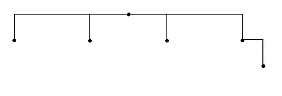
Internetwork Design Study 263
Figure 121 on page 263 presents a design for the organization’s DNS
architecture. The root domain name should be chosen now. This name should be
the domain name that the organization wishes to use as its registered domain
name. It would be a very good idea to register this domain name before choosing
it. If it is already used by another similarly named organization, it can be very
complicated in renaming your domain to another domain name in the future. This
is important when the network is connected to the Internet.
The IT domain has an extra subdomain that should always be implemented when
an organization expects to implement remote access services (mainly for auditing
reasons).
The departmental domains can be split further into subdomains if required. This
is left up to the system administrator to implement. It is important to note that too
many subdomains will increase the complexity of DNS, thus increasing the
difficulty in troubleshooting.
Figure 121. DNS Structure for Medium Size Network
As noted in“Naming” on page 262, the use of DHCP imposes a new requirement,
that is, the implementation of a DDNS server. The DDNS server will allow inter-
host communication while allowing dynamic reassigning of host names.
8.2.5 Remote Access
In our network design, remote users are connected to the network through Dial-In
Access to LANs (DIALs) and one subnet has been allocated for the dial-in users.
The hosts connecting to the network through remote access should be assigned
addresses from a separate subnet, so that granular control can be imposed if
necessary. As dial-in connections are subjected to hacking, it is important to keep
the user names and passwords confidential. This enables improved security and
also accounting. In our network design, the following IP range has been
assigned:
192.168.8.0 - Organizations Remote Access
The company requires dia- in access for 15 managers. As we are expecting a
maximum concurrent login rate of eight users, one of the 2210 Nways router has
been fitted with an eight-port Dial Access adapter.
The remote users configure their home PCs to dial into the company using the
PPP protocol. For security reasons, the following will be implemented:
• A dial-back service will be implemented. That is, a remote user initiates a call
to the router and triggers the router to dial back to the user. In this manner,
finance IT
remote
2580C\CHAF82
hr sales
ibm.com
264 IP Network Design Guide
calls are accounted for, and the router may even be restricted to call a certain
number.
• Remote users have to authenticate themselves through a login ID and a
password.
For IP address assignment, the design caters for the router to forward DHCP
requests from home PCs to the DHCP server. Thus, there is no need to configure
IP addreses in the home PCs, making the administration job easier.
8.2.6 Connecting the Network to the Internet
It is assumed that a network of this size that requires connectivity to the Internet
will need its own set of IP services. These include FTP, HTTP, TELNET and
e-mail services, as well as security. These are the basic services that an
organization typically requires. These services must be planned for and
integrated with the rest of network.
The organization has one major decision to make, whether to outsource the IP
services to its ISP. In a network of this size, it is recommended that these
services bemaintained in-house. The following design is for an in-house solution.
8.2.6.1 Addresses
The network devices communicating with the Internet will require public IP
addresses. Looking at the services required, and the size of the network, it is
decided that all the services can be hosted on one server.
Thus, there is only a requirement for three public addresses to be obtained from
the organization’s ISP. These would be for the organizational firewall, the services
server hosting FTP, HTTP and e-mail services, the primary DNS server (the
secondary DNS server can also be hosted by the services server). All these
servers should have their IP addresses assigned statically.
8.2.6.2 Naming
First, the organizational domain name must be registered with the relevant
authority. This allows the rest of the Internet to see and communicate with the
organization. This step should have already been done, per above.
In order to register a domain name with a naming authority, IP addresses must be
known for both the primary and secondary DNS servers. The primary DNS server
should be implemented on dedicated hardware - in other words it should have its
own server. For a network of this size, the performance of the hardware does not
need to be phenomenal. An average server dedicated to this task will manage the
domain names well.
To reduce WAN traffic, the primary DNS server may be placed on the ISP site.
This will reduce the overall traffic over the WAN link, with the local servers and
hosts using the secondary DNS. This design is not implemented here as the
primary DNS server would lie outside of the organization’s demilitarized zone.
Thu,s all of the organization’s DNS queries would be resolved by the DNS server
placed in the demilitarized zone. A second secondary DNS server may be placed
in the organizational server farm, if DNS traffic begins to affect the performance
of the 2210 router between the server farm and the demilitarized zone.

Internetwork Design Study 265
8.3 Large Size Network (>500 Users)
Large networks are usually made up of numerous medium size networks
internetworked together. They are often the results of gradual expansion through
the years and may not have been designed from the beginning. The
characteristics of a large network environment are:
• Internetwork of networks, with a mix of technologies such as Ethernet,
token-ring, FDDI and ATM.
• Involves multiprotocol such as TCP/IP, IPX, SNA or NetBIOS.
• Fault tolerance features for mission-critical applications, such as hardware
redundancies, network path redundancies and extensive investment on
backup services.
• Fairly large MIS department to take care of the information system
• In-house application development teams that constantly look at the
deployment of new Internet technologies such as Java and multimedia
applications.
• Availability of experts in areas such as system management, network
infrastructure and management.
• Substantial amount of company’s annual budget is spent on IT investment.
A good example of a large network is a university network. A university network is
often made up of numerous medium size networks that are owned by various
faculties. There may be a central computer center that is in charge of the entire
university’s information system but each faculty probably has control of its own
network. Thus, you may find a fairly simple network in say, the arts faculty, and a
complex network in the engineering faculty. The reason for this is the nature of
the work involved in these departments. The arts faculty may at most provide
basic network connections and need only a simple network, while the engineering
faculty provides extensive IT curriculum from programming to network design,
and has set up various labs for the students. These labs may have different
networking requirements and may result in different networks being deployed.
Therefore, the networks in engineering and computer departments tend to be a
mix of technologies. It is also common to find various LAN technologies being
deployed by different faculties and these technologies are somehow connected to
a campus backbone, typically using FDDI or even ATM technologies.
Within the environment, the diversity of endstations is also very great. You may
find Windows 98 PCs, IBM RS/6000s, HP workstations, Sun workstations,
mainframes, mid-range systems such as VAX and Apple Macintosh workstations.
These workstations may be running a mix of protocols such as NetBEUI, TCP/IP,
SNA and AppleTalk, and connecting these networks poses a big challenge. Due
to the popularity of the Internet, these endstations do have something in common,
and that is, they are all capable of supporting the TCP/IP protocol.
Very few network managers have the opportunity to design and build a large
network from the beginning. Most of the time, they "inherit" the network and have
to maintain the network for day-to-day use. Or they may have to entertain ad hoc
requests for connections to certain networks. The most probable thing to happen
is that they may end up doing the most challenging job, and that is, migrating the
network to a new one. Migrating a network is much more difficult than building
one from scratch. Besides selecting new technologies that would solve existing
266 IP Network Design Guide
limitations, you have to make sure that the introduction of the new network does
not affect the daily operations of the old one. You have to ensure that the change
is of minimal impact, if not transparent, to the users. You have to ensure that the
"cut over" of technology is successful. You have to ensure the availability of a
fallback plan if something goes wrong. There are so many other concerns that
you have to take note of, we could probably write another redbook on the topic of
migration.
Whether you are building a large network from scratch or migrating from a current
network, you need a networking master plan. The master plan states the
networking strategy to adopt and this ultimately affects all the decisions made in
terms of technology selection and equipment purchase. Developing a networking
master plan is not trivial because it requires extensive knowledge and many years
of experience. A networking consultant is usually engaged for such a task and the
cost for hiring such a service is not cheap.
With the advent of switching technology and many success stories, it is then
obvious that switching has found its way into many organization’s networking
master plans. The following pointers may help if you are considering such a plan:
• A networking model that is based on switching technology
• An open networking platform that allows the interconnections of various LAN
and WAN technologies
• Provisions of QoS for better use of bandwidth
• Deploying a mix of ATM and LAN technologies
• A hybrid design of using ATM as the backbone, and LAN switching at the
peripheral
• A common connectivity protocol, that is, TCP/IP
• Migrate the various legacy LAN technologies to a switched architecture, be it
switched Ethernet or switched token-ring
• Deploying MPOA at the core of the network
• Choosing only standard-based technologies and products
• Selecting a single vendor that has the ability to provide end-to-end solutions,
that is, from products, to application, to management, and services
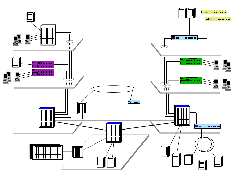
Internetwork Design Study 267
Figure 122. General Concept for a Large Network Connectivity
The pointers are clearly illustrated in the above diagram. Utilizing the latest
offerings from the IBM networking products, the illustrated network encompasses
the following:
• IBM 8265 ATM Switch - providing fully redundant high speed switching
backbone that consolidates all LAN technologies.
• IBM 8210 MSS Server - providing the intelligence of the network through its
MPOA server function, and providing uplinks for the FDDI networks.
• IBM 8371 Multilayer Switch - providing uplinks for all the Ethernet connections
and offering high performance switching through its MPOA client function.
• IBM 8270 Token-Ring Switch - providing uplinks for all the token-ring
connections and high speed switching through its MPOA client function.
• IBM 2216 Multiaccess Connector - capable of providing ESCON connections
to the S/390 hosts and WAN accesses through its rich WAN interface
supports.
• IBM 2212 Access Utility - providing access to the central network for remote
networks and dial-in users.
• IBM 25 Mbps ATM module - providing desktop ATM connections, that are most
suitable for graphics intensive workstations.
Downlinks to basement
hub with 2 xOC3 ATM
ATM Backbone
Downlinks to basement
hub with 100 Mbps
Layer 3 Ethernet Switch
IBM 8371-A16
10/100 Mbps Switch
IBM 8275-326
10 Mbps Ethernet Switch
IBM 8275-217/225
...
...
...
...
25 Mbps ATM
Workstations
Token-Ring Switch
IBM 8270
Downlinks to basement
hubwithOC-3ATM
IBM 8265 ATM Switch with
MSS Server
8371 MLS module
Servers
IBM 8265 ATM Switch with
25 Mbps ATM module
IBM 8265 ATM Switch
with MSS Server
OC-3
S/390
100BaseT
OC-3 FDDI
IBM 2216 Nways
Multiaccess
Connector
WAN
IBM 2212 Access
Utility
Servers
268 IP Network Design Guide
• The IBM Ethernet/Token-Ring workgroup and desktop switches for cost
effective connections for users with minimal networking requirements.
The above diagram illustrates a general concept in designing a large size
network. The network consists of a backbone that links several networks
together. To use the networking lingo, it consists of an ATM network at the core,
with several edge networks providing uplinks for the legacy LANs.
The core is the most important part of the network here, because it provides the
common platform for internetworking the various legacy LANs. The use of ATM
provides for a high speed switching backbone, that is both scalable and fault
tolerant. The design of the ATM core usually has the following characteristics:
• Redundant hardware, in terms of switching fabric, I/O controller, fans, power
supplie, etc.
• Hardware that provides hot-swap capabilities for modules, power supplies and
switching fabric, etc.
• In the case of a core that consists of multiple ATM switches, redundant
physical links are used to interconnect these switches.
• For mission-critical edge networks, redundant physical uplinks are provided on
the edge switch to the core.
• Redundant ATM services, such as LES, BUS and LECS.
• High speed takeover of primary resources by the backup in case of failure, for
example, LES/BUS take over or IP gateway takeover, etc.
• Redundant data path (for example, IP data path) provided for all the edge
networks.
• Rich set of ATM services, such as PNNI, ILMI (interim local management
interface), traffic management and congestion control.
The edge devices, in this case, the switches that provide ATM uplinks for the
legacy LANs, are deployed based on the technologies used in the legacy LANs.
In the above diagram, both Ethernet and token-ring switches are deployed to
connect the legacy Ethernet and token-ring networks to the ATM core
respectively. With the advent of the MPOA technology, choosing an edge device
has grown from merely looking at port density and price to more sophisticated
features. One important aspect to look for is the support for the MPOA client
(MPC) function in the edge device. In the MPOA model, high speed switching is
achieved through the distribution of the forwarding engines across the entire
network. The forwarding engine is provided by the edge device and this only
happens if the edge device is capable of supporting MPC functions. Also, since
the edge device is providing the forwarding muscle for the data, its switching and
ATM uplink capacities become critical now. The more switching power an edge
device has, the more data it can forward. The more ATM uplink an edge device
has, the more data it can send into the ATM backbone. In Figure 122 on page
267, the IBM 8371 Multilayer Switch is used for this purpose. It provides MPC
functions for establishing the shortcut data paths, and it has a switching capacity
of 10 Gbps. Also, it provides a 622 Mbps uplink into the ATM backbone to provide
high speed access to the core.
It is important to note that having a reliable networking infrastructure is not good
enough. Performance and physical redundancy aside, availability of services
such as LES/BUS, IP gateway, DNS services and Web services are also
Internetwork Design Study 269
important. In the above illustration, the redundancies of LES/BUS and IP
gateways services are provided by the multiple MSS servers. Also, DNS services
can be enhanced using multiple DNS servers. For Web server performance,
improvement and redundancy, the IBM WebSphere family of products is
deployed.
The design and deployment strategy of the above services may be beyond the
capability of some network managers. Therefore, it is important to engage a
vendor that not only has the capability to build the first three layers of the OSI
model, but also has the ability to provide services that correspond to the other
layers of the OSI model, and deliver the services. A "one-stop shop" approach is
recommended for the following reasons:
Choosing one vendor to provide all services makes your life easier when there is
a problem - there is only one party to go after. Imagine having company A build
the backbone, and company B provide the edge devices. And the server
hardware is provided by company C that runs software that is provided by
company D. When company E comes in and delivers the customization service,
nothing works. You can expect some finger pointing among the various vendors
before the problem is resolved.
Many vendors claim that their product is standards based, and interoperability is
not an issue. They are wrong. Interoperability is a big issue and should not be
taken lightly. For example, it is still a fact that not all vendors’ so-called MPOA
compliant products can interoperate. The safest bet for a network manager then,
is to choose a vendor that provides a full spectrum of connectivity options, from
ATM, to Ethernet, to token ring, to FDDI, to WAN, etc.
Many success stories are created through the "one-stop shop" approach. The
Nagano Olympics is one fine example. Some of the largest ATM network
installations use all IBM products. These installations provide a good reference
for a network manager, but most importantly, they mean the vendor has the
experience to deliver a project of large magnitude.
270 IP Network Design Guide

© Copyright IBM Corp. 1995 1999 271
Appendix A. Voice over IP
The Voice over IP scenario is now very attractive for a lot of applications and
business opportunities. Much effort has been put into technology development
and some scenarios today are not only possible, but can really lead to cost
savings and new opportunities. The voice and data network integration can lead
to cost savings, merging two different infrastructures in one, with scaling benefits
now that the technical solutions are available.
On the other side, the possibility of running voice over the Internet itself is also
extremely attractive because IP technology is very low in cost and bandwidth is
almost free on the Internet (only the monthly charges of the ISPs). This can
reduce dramatically the costs for long-distance phone calls.
In this chapter, you will see in detail the requirements for planning the Voice over
IP deployment in a corporate intranet and the Internet opportunities together with
an overview of the standardization process and technologies developed in this
area.
A.1 The Need for Standardization
The very rapid and growing diffusion of multimedia applications has a first
shortcoming in the fact that they have been developed with their own protocols
and compression algorithms to transport the Voice over IP networks. Therefore,
most of today’s Internet telephone programs are incompatible with each other. To
provide Voice over IP, or better yet Voice over Internet, to a larger group of
people, it is necessary to define a standard for the protocols and the voice
compression algorithms.
The Voice over IP Forum, which consists of members from different
telecommunications companies, is developing a standard that has a basic
component in the International Telecommunication Union (ITU) standard H.323. It
describes the specifications for transmitting multimedia traffic in a packet
network.
The VoIP Forum is a working group in the International Multimedia
Teleconferencing Consortium. The VoIP Forum Service Interoperability
Implementation Agreement (the VoIP IA) is an effort to define specifications that
could provide a complete Internet telephony interoperability protocol. The
objectives are to provide interoperability among equipment of different
manufacturers, define standards for client software and gateways for the public
telephone network.
A.1.1 The H.323 ITU-T Recommendations
H.323 is an ITU-T standard for multimedia videoconferencing on packet-switched
networks. Its formal title is "Visual Telephone Systems and Equipment for Local
Area Networks which Provide a Non-Guaranteed Quality of Service". The H.323
specifications were completed in 1996 and new work for introducing
enhancements began in January 1998 for H.323 Version 2.
272 IP Network Design Guide
The H.323 does not specify the different types of QoS, but rather describes
components equipment, terminals and services for multimedia in the LAN
environments. The basic elements described in the H.323 recommendations are:
Terminals
The H.323 terminal specification is not a specification for a particular terminal
type. Instead it specifies the protocols necessary to support multimedia
terminal function. So the H.323 specifies most of the capabilities required for
terminals and not the physical design and structure. The terminals should be
capable of supporting system control protocols and specifications such as
H.245, Q.931 and RAS capabilities.
For handling data-sharing traffic, they need the T.120 protocol. For video,
examples are the H.261 or H.262 CODEC. And for audio, they need the
G.711, G.723 and G.729 CODEC together with the RTP and RTCP.
Other specifications may be included as new developments lead to better
implementations. The H.323 specifies two different types of terminals:
• The Corporate network terminal, which needs high quality and high
function to perform multiway videoconferencing or point-to-point voice
connections.
• The Internet terminal, which needs to be optimized for minimum bandwidth
requirements.
H.323 terminals have built-in multipoint capability for ad-hoc conferences and
a multicast feature that allows three to four people on a call without centralized
mixing or switching.
Gateways
The H.323 gateways provide interoperability between IP-connected H.323
terminals and other audio devices such as normal telephones. These devices
can be either directly connected to the gateway or the PSTN network. The
gateway must provide all the functions for mapping one protocol set to the
other in the call signaling controls and multiplexing or transcoding.
Multipoint Control Units (MCUs)
An MCU consists of a Multipoint Controller (MC) and a Multipoint Processor
(MP). This H.323 component provides conference management, media
processing and the multipoint conference model. The MCU supports media
distribution for unicast and multicast data.
The Gatekeeper
The H.323 gatekeeper provides the functions of a directory server and system
supervisor. Its main described functions are:
Directory Server (Address Translation) Function
This function translates an H.323 alias address to an IP address using
information obtained at terminal registration. The user has a meaningful
name that can be in the typical e-mail format.
The Supervisory (Call Admission Control) Functions
The gatekeeper can grant or deny permission to make the call. In doing this
it can apply bandwidth limits to manage the network traffic and so prevent
congestion occurring. The gatekeeper can also provide address translation
between Internet and external addresses.

Voice over IP 273
Call Signaling
The gatekeeper may route calls in order to provide supplementary services
or to provide Multipoint Controller functionality for calls with a large number
of parties.
Call Management
Because the gatekeeper controls network access it is also the logical place
to perform call accounting and management.
A.2 The Voice over IP Protocol Stack
The Voice over IP needs a set of protocols that must perform different functions.
The can be seen in a stack pile of layers according to their logical dependencies
(see Figure 123 on page 273).
The Voice over IP stack makes large use of ITU-T H.323 recommendations and
also introduces other components for services not described in the H.323. The
IETF protocols are the principal source.
Figure 123. Voice over IP Protocol Stack
A.3 Voice Terminology and Parameters
There are some basic concepts in voice technology that need to be defined to
complete the overview of the Voice over IP scenario.
CODEC
The coder-decoder functions transform the analog voice signals into a digital
stream of bits. The way that different algorithms use for translating the analog
signals to digital ones can differ in the bits required per time unit.
Pulse Code Modulation (PCM)
PCM converts the analog voice signal to the digital: one sampling the
wave form 8000 times per second, according to the Nyquist theorem
and the fact that normal speech is always below the 4000 Hz frequency.
The amplitude of the wave form is coded in 8 bits using a logarithmic
scale that privileges the low-amplitude signals. The transmission rate for
the digital signal of a single channel in PCM is 8 bits times the 8000
G.723.1/G.729/G.711
H.323
RTP/UDP
IP (IntServ, DiffServ)
MP (Multilink PPP)
Physical
2580D\VOICEOV
274 IP Network Design Guide
samples, giving the standard 64 kbps. The PCM coding is standardized
in the G.711 specifications. The compression delay introduced by
processing the voice wave form is less than 1 ms.
The new compression algorithms used in sampling digital voice make use of
analyses of common speech behavior and parameterize only the differences
from these standards. In this way they obtain a reduced transmission rate that
requires less bandwidth to be transmitted. There are different coding
schemes, like the linear predictive coding (LPC), the code excited linear
prediction (CELP) and the multipurpose multilevel quantization (MP-MLQ).
The ITU-T describes the standardized formats of these algorithms for
compressing the voice.
G.728
Describes the 16 kbps CELP voice compression.
G.729
This ITU-T standard describes the 8 kbps Conjugate Structured Algebraic
CELP (CS-ACELP) voice compression. The two different schemes (G.729
and G.729 Annex A) differ in the required processing capabilities. These
algorithms have been designed for implementation by Digital Signal
Processors (DSPs) in order to minimize the introduced delay for processing
time.Thistimeis10ms.
G.723.1
The G.723.1 offers a relatively high degree of compression with an output
bit rate of either 5.3 or 6.4 kbps using an MP-MLQ algorithm or a
CS-ACELP one. The compression delay introduced by DSPs is 30 ms.
The way for evaluating the quality of the compressed voice obtained by using
the CODECs is measured by a parameter called Mean Option Score (MOS).
The quality of the voice is perceived by the listeners is subjective. This method
utilizes different voice samples and many listeners to obtain an average value
of the perceived voice in a scale from 1 ( bad value) to 5 (excellent value).
CODECs have more or less score in the MOS parameter according to the very
compressed rate and the behavior of the algorithm to predict the speech
patterns.
Signaling
There are many protocols developed to provide in-band or off-band signaling,
that is, the sequence of exchanged parameters to provide the connection
setup and control. The most common example is determining when the line of
the PSTN network has gone off hook or on hook. This is determined starting
from a ground base: the dial tone. The two ways of providing it are the
loop-start (commonly used by PSTN networks) or the ground-start (often used
in PBX). Other commonly used signaling techniques mainly among PBX are:
• E&M (Ear & Mouth, or receive and transmit)
•Delay
• Immediate
•Winkstart
Delay
The delay component in a network is due to the transmission time and the
routing and processing time. The first part is a fixed component in a defined

Voice over IP 275
path and depends on the speed of wave propagation in the medium or that of
the light in a fiber cable. The processing delay is instead introduced in each
node by the time it takes to analyze the contents of the header of the network
protocol and pass the packet from the input queue to the output one. For voice
processing and the ends of the path there is a delay time introduced by the
DSP processor to compress and reconstruct the form of the analog voice
wave. Delay in the voice transmission is acceptable until it remains under 200
ms.
Jitter
The variation that occurs in a packet network in the delivery of the different
packets introduces a delay between the time that a packet arrives at the
destination and the time that it was expected. The typical synchronous voice
traffic can hardly tolerate the effects produced by the jitter and the voice
transmitted can easily become not understandable. To avoid the jitter, the
devices should use playout buffers and play back the transmitted voice. There
are devices that can use a fixed value of playback, using the maximum delay
that the network should introduce and others that can use a mechanism to
adapt to the varying delays in the network.
Echo
The echo effect occurs due to the different impedance among parts of the
physical network infrastructure. The normal echo effect is well tolerated and
we are used to hearing our voice in the receiver, but with a delay less than 25
ms. If this delay increases, a real echo effect is produced and the quality of the
transmitted language becomes worse. Echo cancellers are used in network
devices to avoid echo effects. They use techniques that rely on saving the
inverse of the voice transmitted and subtracting it from the received message
after the estimated time that the returning echo will take to come back to the
sender.
A.4 Voice over IP Design and Implementations
The scenario of the Voice over IP implementations is rapidly evolving because the
use of the Internet can be a potential high opportunity for many ISPs. However,
with today’s technologies and the not QoS enabled Internet, companies are trying
to gain advantages for Voice over IP technologies within their own networks. In
more controlled networks with a single management and careful plan multimedia
applications can be deployed. Also, Voice over IP technologies offer the
opportunity of merging the current network infrastructures of voice and data.
Toll Bypass
The costs of communication infrastructures are growing and many companies
are trying to optimize them. The possibility of merging networking
infrastructures for voice and data traffic is one of the driving items. Voice over
IP is the last-born techniques in this area, but the perspectives of cost
reductions are wider because of the low cost of IP networking devices and the
fact that they are suitable for many company scenarios. Technologies like ATM
have been engineered for this specific purpose and offer QoS features that are
really demanding for an IP architecture. The main drawbacks are the
associated costs and the fact that the IP is very widely diffused in data
networks and application development. Also, Voice over Frame Relay is a
possible alternative that is becoming popular in this scenario.
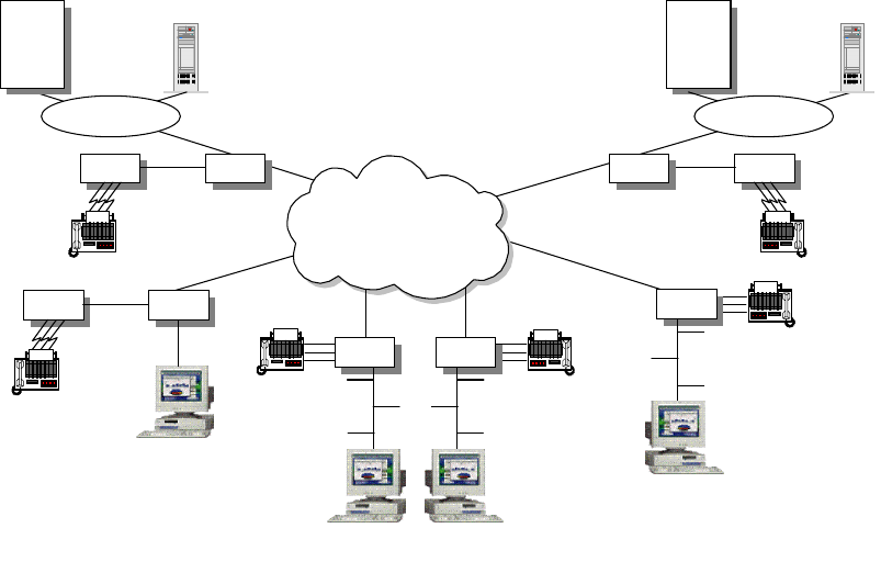
276 IP Network Design Guide
The PBX Trunking Replacement and in general the PSTN toll bypass is the
most common scenario in the data and voice integration scenario and can
lead to cost savings of up to 90% if compared with PSTN carriers. The toll
bypass allows corporations to connect their PBX to VoIP-enabled routers and
route the voice trunking traffic over the data network infrastructure (see Figure
124).
Figure 124. PBX Trunking Replacement and Toll Bypass
Another typical scenario is the use of Voice over IP to replace voice only traffic
in small offices or branches while introducing or re-engineering the data
network. In this scenario small PBX or single terminal equipment can be
plugged into VoIP-enabled routers to route voice traffic to the corporate HQ.
Also, the fax relay system is a candidate for being routed into the data
network. The few demanding real-time requirements and the high volume of
fax traffic in international calls should be considered.
Web Call Centers
There is a wide range of applications that can leverage the contents and the
value-added services that can be provided using the Internet model and that
the multimedia support can exploit. The main drawback in these applications
is the not (yet) multimedia-enabled Internet in its global structure. The call
centers application is a possible scenario. The Internet end user can make
use of multimedia support in order to access the call center personnel directly.
This can give more value-added to the Web contents and capability to directly
address customers’ needs. This single and integrated multimedia Web site
can reduce the costs of toll-free numbers for the company and be simpler and
more accessible to the end user instead of the traditional telephone call. The
function of a call center is enhanced in the capabilities of interaction with
customers and also enables and simplifies casual customers’ inquires.
Hong Kong
Singapore
San Francisco
Host
Servers
PBX 2216
PBX 2216
Client
IP
Intranet
Sydney
2212
Client
Melbourne
2210
Client
Los Angeles
2210
Client
Host
Servers
PBX2216
2580D\VOFR
Voice over IP 277
The call center scenario is only one of the possibilities that a
multimedia-enabled Internet can provide. The remote conferencing and
collaborative work are also possible, and they can have a more restricted
application within the corporate intranet instead of the whole Internet.
The use of remote multimedia applications is also a powerful tool for
telemedicine and distance learning and training possibilities. In this last case
we see that the Next Generation Internet (NGI) project and the Internet2 are
currently driving the application development and the evolution of the network
infrastructure to deploy this scenario in some research centers and
universities.
ISPs as Telephony Carriers
If QoS can be deployed across the Internet or to some part of it, it can be
possible for an ISP to become a telephony carrier. This opportunity is very
attractive for ISPs because of the wide telephony market and the potential
competitive costs for long-distance calls in the IP network. Using the H.323
architecture, a multimedia H.323 terminal can place a call not only on another
multimedia device, but also on a common telephone using the gateway of the
ISP to the PSTN network.
A.4.1 The Voice over IP Design Approach
In a network design that would enable the voice transport capabilities over IP, the
delay and latency time are the first parameters that need to be considered.
Network resources must be carefully planned to achieve the total end-to-end
delay under the 200 ms threshold that guarantees an acceptable voice quality. If
QoS is deployed within the network a more dynamic resource allocation can be
planned, otherwise careful planning is required in order to allocate the bandwidth
and processing resources in the voice traffic path and the sharing techniques with
the best-effort traffic.
Delay
Delay in voice transmission depends on fixed parameters like the compression
algorithms in the dedicated processors and in variable ones, like the routers
routing processing time and the transmission time within the available
bandwidth on a link. This variable part must be planned carefully using the
techniques that we discussed in the Integrated Services approach and in the
Differentiated Services one.
Signaling
In planning the integration of Voice over IP, we need to take care of the
signaling techniques that are used among voice devices. This is the case of
replacing the trunks among PBX. There are some standard signaling
protocols, but also the tuning of many parameters should be considered not as
a simple and straightforward task in the choice of the network devices and in
the implementation plan.
CODEC
Some techniques can be used or simply enabled on network devices in order
to optimize the bandwidth required, such as silence suppression and voice
quality, as for the echo cancellation algorithms. But the key point to start
planning the quality in a voice-enabled network is the CODEC that will be used
according with the end users’ requirements.
278 IP Network Design Guide
In developing the Voice over IP plan, you should consider the costs associated
with the voice transport within a company. One advantage is the possibility of
associating a fixed cost at least to the intracompany calls. The most likely
approach is the toll bypass. In this case it is important to understand the
intracompany voice traffic and costs. The geographical location of the company
branches and the voice network structure should be considered. Some
parameters that can be a starting point in the plan are as follows:
• The location of company sites (long-distance call traffic or local)
• The number of users at each location
• The existing PBX and interPBX trunks
The integration of the data and voice structures can make use of scale savings if
carefully planned. The physical links and bandwidth resources can share data
and voice traffic. In most cases the two networks have a duplicated structure.
Also the bandwidth requirements can be different and the high volume data traffic
can be delivered during off-peak hours when there is no need for the voice part.
In general in this scenario there is a starting point for evaluating the mean traffic
requirements using the voice network utilization statistics and the costs due to the
PSTN charges. From this data we can have detailed voice cost specifications as:
• The number of intracompany calls for each branch
• The mean duration of calls
• The traffic due to fax calls
• The mean of concurrent calls per office
Some network devices can accomplish the integration of locations with few users
with small investments in the network infrastructure. The goal is to reduce the
cost associated with enabling the whole network to accomplish the voice
requirements. If the network infrastructure has been developed according to
some criteria this effort can be concentrated only on backbone resources and to
the specific branches that will merge data and voice traffic, reducing the initial
investments.
Also, the quality of the final voice delivery services is a starting point for the
evaluation of the required resources in the plan.

© Copyright IBM Corp. 1995 1999 279
Appendix B. IBM TCP/IP Products Functional Overview
This appendix presents an overview of the main TCP/IP functions, protocols and
applications that can be found in IBM operating systems and hardware platforms.
B.1 Software Operating System Implementations
The tables below list the major TCP/IP protocols and applications as they are
implemented and supported by IBM software platforms. Because of their
significance in the PC market, from corporate to end user, and because of IBM's
dedication to providing a comprehensive suite of applications and middleware in
that area, the latest versions of the Windows operating systems from Microsoft
are also included.
Table 14. Operating Systems - Protocol Support
OS/390
V2R6 OS/400
V4R3 AIX V4.3 OS/2
V4.1 Windows
NT 4.0 Windows
98
Base Protocols
IP XXXXXX
TCP XXXXXX
UDP XXXXXX
ARP XXXXXX
RARP X X
ICMP XXXXXX
PING XXXXXX
TracerouteX XXXX
IPv6 X8X
Application Protocols
DNS XXXXXC
NSLOOKUP X X X X
HOST X X X
FINGER X9XCC
FTP XXXXX
1C
IMAP X IBM2IBM2C
LPR/LPDXXXXX
MIME XXXXXX
NETSTATXXXXXX
NIS X
ONC-RPCXXXIBM
7
POP SXXIBM
2IBM2C

280 IP Network Design Guide
Notes:
1. Server function provided by Microsoft Internet Information Server (Windows
NT Server) or Personal Web Server (Windows NT Workstation)
2. Server function provided by Lotus Domino, client included in Web browser
3. Server function provided by IBM eNetwork Communications Server, client
included in operating system
4. Server function provided by IBM eNetwork Communications Server
5. Client function provided by IBM eNetwork Personal Communications
6. Active RIP provided by Windows NT Server, passive RIP provided by Windows
NT Workstation
7. Function provided by IBM TCP/IP for OS/2 NFS Kit
8. Prototype
9. Via NSLOOKUP
Table 15. Operating Systems - Special Protocols and Services
Rexec/RshXSXXC
SMTP XXXXIBM
2C
SNMP XXXXXX
Talk X X
TELNETXXXXCC
TFTP XXXXC
TimeD X X
TN3270 X S IBM4IBM3IBM4,5 C(IBM)5
TN3270E S IBM4IBM3IBM4,5 C(IBM)5
TN5250 S C C(IBM)5C(IBM)5
X Windows C X OEM
Routing Protocols
StaticRoutingXXXXXX
RIP-1 XXXXX
6Passive
RIP-2 XXXXX
OSPF X X
BGP-4 X X
CIDR X X X X
Legend:
X=implemented, C+client implementation only, S=server implementation,
n/a=not applicable, OEM=requires additional non-IBM software,
IBM=requires additional IBM software
OS/390
V2R6 OS/400
V4R3 AIX V4.3 OS/2
V4.1 Windows
NT 4.0 Windows
98
Dynamic IP
OS/390
V2R6 OS/400
V4R3 AIX V4.3 OS/2
V4.1 Windows
NT 4.0 Windows
98

IBM TCP/IP Products Functional Overview 281
BootP SSXXS
1
BootP/DHCP
Forwarding XXXXX
DHCP SSXXXC
DDNS (secure
updates) X XXC
(IBM)25 C
(IBM)25
DDNS
Incremental
Zone Transfer
XXX
ProxyArec X X X
Directory and File Services
DCE IBM2IBM2IBM2IBM2IBM2
NFS XSXIBM
3
AFS Transarc Transarc
LDAP X X IBM4,24 S(IBM)4
NetBIOS Services
NetBIOS over
TCP OEM OEMXXX
NBNS OEM OEM X5
NBDD OEM OEM
Security Services
IPFilteringXXXXX
6
FirewallXXIBM
8IBM8
SOCKS S X S(IBM)9C10 S(IBM)9C
Telnet Proxy X IBM8IBM8
FTP Proxy X X IBM11 IBM12 IBM11
HTTP Proxy X X IBM11 IBM12 IBM11
NAT XXIBM
8IBM8
SSL XXXXXX
IPSec XXXX
Kerberos X IBM2IBM2IBM2IBM2
Internet & World Wide Web Protocols
HTTP SSXS(IBM)
13 X14 X14
Java S15 XX
16 X16 X17 C
IIOP IBM18 IBM18 IBM18 IBM18
OS/390
V2R6 OS/400
V4R3 AIX V4.3 OS/2
V4.1 Windows
NT 4.0 Windows
98

282 IP Network Design Guide
Notes:
1. DHCP server can provide fixed addresses to BOOTP clients
2. Function provided by IBM DCE
3. Function provided by IBM TCP/IP for OS/2 NFS Kit
4. Server function provided by Lotus Domino
5. Using Windows Internet Name Service (WINS)
6. Only on ports and protocols, not on IP addresses
7. Refers to a combined set of security features, including IP filtering, NAT,
application proxies, SOCKS, special DNS and mail
8. Function provided by IBM eNetwork Firewall
9. Server function provided by IBM eNetwork Firewall, client included in Web
browser
10.SOCKSified TCP/IP stack
11.Function provided by IBM WebTraffic Express or IBM eNetwork Firewall
12.Function provided by IBM WebTraffic Express
13.Server function provided by Lotus Domino or Lotus Domino Go Webserver,
client included in operating system
14.Server function provided by Lotus Domino Go Webserver (IBM), or by
Microsoft Internet Information Server (Windows NT Server) or Personal Web
Server (Windows NT Server and Windows 98); client included in operating
system
NNTP S(IBM)4S(IBM)19 S(IBM)19 S(IBM)19
Gopher C C X20 C
Multicasting and Multimedia
IGMP XXXXXX
MRouteD X
RealAudio CCCC
Quality of Service (QoS)
RSVP X X X X26 X26
Differentiated
Services XX
26 X26
Load Balancing
Round Robin
DNS XXX
Network
Dispatcher C21 IBM22 IBM22
WLM X
VIPA XXX
23 X23 X23
Legend:
X=implemented, C+client implementation only, S=server implementation,
n/a=not applicable, OEM=requires additional non-IBM software,
IBM=requires additional IBM software
OS/390
V2R6 OS/400
V4R3 AIX V4.3 OS/2
V4.1 Windows
NT 4.0 Windows
98

IBM TCP/IP Products Functional Overview 283
15.Servlet support provided by IBM WebSphere Application Server or Host
On-Demand Server
16.Servlet support provided by IBM WebSphere Application Server, client
included in operating system
17.Servlet support provided by IBM WebSphere Application Server or Microsoft
Internet Information Server, client (local JVM) included in Web browser
18.Function provided by IBM WebSphere Application Server
19.Server function provided by Lotus Domino, client included in Web browser
20.Server function provided by Microsoft Internet Information Server (Windows
NT Server) or Personal Web Server (Windows NT Workstation)
21.Workload Manager (WLM) Advisor for eNetwork Dispatcher
22.Function provided by IBM eNetwork Dispatcher
23.Similar concept provided using IP alias addresses
24.Function available through IBM OS/2 LDAP Client Toolkit for C and Java
25.Function provided by IBM Dynamic IP Client for Windows 95 and Windows NT
26.Similar concept provided using Winsock V2.0 APIs
Table 16. Operating Systems - Connectivity Support
OS/390
V2R6 OS/400
V4R3 AIX V4.3 OS/2
V4.1 Windows
NT 4.0 Windows
98
Token-RingXXXXXX
EthernetV2XXXXXX
Ethernet802.3XXXX
FastEthernetX XXXX
FDDI XXXXXX
ATMCIPXXX X
ATM L ANE X X X
X.25 IBM1XXIBM
2X7
Frame Relay IBM3XXX
6
ISDN IBM3XXXXX
PPP IBM3XXXXX
SLIP IBM3XXXXX
Sonet IBM3XX
Enterprise
Extender XIBM
4
MPTN XXIBM
4IBM4IBM4,5 IBM5
MPC+ X
SNALink X IBM2
CTC X
Legend:
X=implemented, C+client implementation only, S=server implementation,
n/a=not applicable, OEM=requires additional non-IBM software,
IBM=requires additional IBM software

284 IP Network Design Guide
Notes:
1. Function provided by NCP and NPSI
2. Function provided by IBM TCP/IP for OS/2 Extended Networking Kit
3. Function provided by channel-attached IBM 2216 Router
4. Function provided by IBM eNetwork Communications Server
5. Function provided by IBM eNetwork Personal Communications
6. Function provided by IBM RouteXpander/2 in conjunction with IBM WAC
adapter
7. Function provided by Remote Access Service (Windows NT Server only)
B.2 IBM Hardware Platform Implementations
This section lists the IBM hardware products TCP/IP supports for selected
connectivity options.
Table 17. IBM Hardware Platforms TCP/IP Support
2210
MRS 2212
Access
Utility
2216
MAS Network
Utility 8210
826X
MSS
3746
MAE
IP Routing and Management Support
RIP-1 XXXXXX
RIP-2 XXXXXX
RIPngforIPv6XXXX
OSPF XXXXXX
BGP-4XXXXXX
CIDR XXXX X
DVMRPXXXXXX
MOSPFXXXXXX
PIM-DM for
IPv6 XXXX
IPv4 XXXXXX
IPv6 XXXX X
SNMP XXXXXX
Multiprotocol Support
PPP XXXX X
TN3270E
Server XXXX
1
DLSW XXXX X
DLUR XXXX X
HPR XXXXXX
Enterprise
Extender XXXXXX

IBM TCP/IP Products Functional Overview 285
IPX XXX X
AppleTalk 2 X X X X
Banyan VINES X X X X
Decnet IV, V X X X X
NetBIOSXXXX X
High Availability, Load Balancing, Quality of Service (QoS)
Network
Dispatcher XXXX X
TN3270E
Server Advisor X
Dual Power X2X3X
N+1 Fans X2
RSVP XXXX
VRRP XXXX X
Voice over IP Support
Voice over
Frame Relay X4X4
Security Services
NAT XXX X
L2TP XXX X
IPSec X X X X
RADIUSXXXX X
Connectivity Support
ATM
(155 Mbps) XXXX
LE Server X
LE Support X X X X
IPoverATMX XXXX
Token-RingXXXXXX
Fast
Token-Ring X
EthernetXXXXXX
Fast Ethernet X X X
FDDI XXXX
2210
MRS 2212
Access
Utility
2216
MAS Network
Utility 8210
826X
MSS
3746
MAE

286 IP Network Design Guide
Notes:
1. Supported by the TN1 model
2. Available for 2216-400
3. Available for 8260 and 8265
4. Statement of Direction
ESCON
Channel XX X
Parallel
Channel XX X
HSSI X X X
ISDNBRIXXX X
ISDNPRIXXX X
FrameRelayXXXX X
X.25 XXXX X
2210
MRS 2212
Access
Utility
2216
MAS Network
Utility 8210
826X
MSS
3746
MAE

© Copyright IBM Corp. 1995 1999 287
Appendix C. Special Notices
This publication is intended to discuss aspects of TCP/IP network design. The
information in this publication is not intended as the specification of any
programming interfaces that are provided by products mentioned in this book.
See the PUBLICATIONS section of the IBM Programming Announcement for
mentioned products for more information about what publications are considered
to be product documentation.
References in this publication to IBM products, programs or services do not imply
that IBM intends to make these available in all countries in which IBM operates.
Any reference to an IBM product, program, or service is not intended to state or
imply that only IBM's product, program, or service may be used. Any functionally
equivalent program that does not infringe any of IBM's intellectual property rights
may be used instead of the IBM product, program or service.
Information in this book was developed in conjunction with use of the equipment
specified, and is limited in application to those specific hardware and software
products and levels.
IBM may have patents or pending patent applications covering subject matter in
this document. The furnishing of this document does not give you any license to
these patents. You can send license inquiries, in writing, to the IBM Director of
Licensing, IBM Corporation, North Castle Drive, Armonk, NY 10504-1785 USA.
Licensees of this program who wish to have information about it for the purpose
of enabling: (i) the exchange of information between independently created
programs and other programs (including this one) and (ii) the mutual use of the
information which has been exchanged, should contact IBM Corporation, Dept.
600A, Mail Drop 1329, Somers, NY 10589 USA.
Such information may be available, subject to appropriate terms and conditions,
including in some cases, payment of a fee.
The information contained in this document has not been submitted to any formal
IBM test and is distributed AS IS. The information about non-IBM ("vendor")
products in this manual has been supplied by the vendor and IBM assumes no
responsibility for its accuracy or completeness. The use of this information or the
implementation of any of these techniques is a customer responsibility and
depends on the customer's ability to evaluate and integrate them into the
customer's operational environment. While each item may have been reviewed by
IBM for accuracy in a specific situation, there is no guarantee that the same or
similar results will be obtained elsewhere. Customers attempting to adapt these
techniques to their own environments do so at their own risk.
Any pointers in this publication to external Web sites are provided for
convenience only and do not in any manner serve as an endorsement of these
Web sites.
Any performance data contained in this document was determined in a controlled
environment, and therefore, the results that may be obtained in other operating
environments may vary significantly. Users of this document should verify the
applicable data for their specific environment.
288 IP Network Design Guide
The following document contains examples of data and reports used in daily
business operations. To illustrate them as completely as possible, the examples
contain the names of individuals, companies, brands, and products. All of these
names are fictitious and any similarity to the names and addresses used by an
actual business enterprise is entirely coincidental.
Reference to PTF numbers that have not been released through the normal
distribution process does not imply general availability. The purpose of including
these reference numbers is to alert IBM customers to specific information relative
to the implementation of the PTF when it becomes available to each customer
according to the normal IBM PTF distribution process.
The following terms are trademarks of the International Business Machines
Corporation in the United States and/or other countries:
The following terms are trademarks of other companies:
C-bus is a trademark of Corollary, Inc. in the United States and/or other countries.
Java and all Java-based trademarks and logos are trademarks or registered
trademarks of Sun Microsystems, Inc. in the United States and/or other countries.
Microsoft, Windows, Windows NT, and the Windows logo are trademarks of
Microsoft Corporation in the United States and/or other countries.
PC Direct is a trademark of Ziff Communications Company in the United States
and/or other countries and is used by IBM Corporation under license.
ActionMedia, LANDesk, MMX, Pentium and ProShare are trademarks of Intel
Corporation in the United States and/or other countries.
UNIX is a registered trademark in the United States and/or other countries
licensed exclusively through X/Open Company Limited.
SET and the SET logo are trademarks owned by SET Secure Electronic Transaction
LLC.
Other company, product, and service names may be trademarks or service marks
of others.
AIX Application System/400
APPN AS/400
AT CICS
DB2 DRDA
eNetwork ESCON
IBM Global Network IBM
IMS MVS/ESA
Netfinity Nways
Operating System/2 OS/2
OS/390 OS/400
RACF RISC System/6000
RS/6000 S/390
SP System/390
VTAM WebSphere
XT 400

© Copyright IBM Corp. 1995 1999 289
Appendix D. Related Publications
The publications listed in this section are considered particularly suitable for a
more detailed discussion of the topics covered in this redbook.
D.1 International Technical Support Organization Publications
For information on ordering these ITSO publications see “How to Get ITSO
Redbooks” on page 291.
•
TCP/IP Tutorial and Technical Overview,
GG24-3376
•
A Comprehensive Guide to Virtual Private Networks, Vol. I: IBM Firewall,
Server and Client Solutions
, SG24-5201
•
Beyond DHCP - Work Your TCP/IP Internetwork with Dynamic IP
, SG24-5280
•
MSS Release 2.1, Including MSS Client Domain Client
, SG24-5231
•
Customer-Implemented Networking Campus Solution II
, SG24-5226
•
Local Area Network Concepts and Products: LAN Architecture,
SG24-4753
D.2 Redbooks on CD-ROMs
Redbooks are also available on the following CD-ROMs. Click the CD-ROMs
button at http://www.redbooks.ibm.com/ for information about all the CD-ROMs
offered, updates, and formats.
D.3 Other Resources
These publications are also relevant as further information sources:
• 2212 Access Utility Introduction and Planning Guide,
GA27-4215-01
• AIS Protocol Configuration Reference Volume 1, V3.2,
SC30-3990
• AIS Protocol Configuration Reference Volume 2, V3.2,
SC30-3991
• Multiprotocol Switched Services (MSS) Server Installation and Initial
Configuration Guide,
GA27-4140
• 8265 Nways ATM Switch User’s Guide,
SA33-0456
• 8265 Nways ATM Switch Command Reference Guide,
SA33-0458
• 8371 Networking Multilayer Ethernet Switch Software User’s Guide,
GC30-9688
CD-ROM Title Collection Kit Number
System/390 Redbooks Collection SK2T-2177
Networking and Systems Management Redbooks Collection SK2T-6022
Transaction Processing and Data Management Redbooks Collection SK2T-8038
Lotus Redbooks Collection SK2T-8039
Tivoli Redbooks Collection SK2T-8044
AS/400 Redbooks Collection SK2T-2849
RS/6000 Redbooks Collection (BkMgr) SK2T-8040
Netfinity Hardware and Software Redbooks Collection SK2T-8046
RS/6000 Redbooks Collection (PDF Format) SK2T-8043
Application Development Redbooks Collection SK2T-8037
290 IP Network Design Guide
•
Access Integration Services Software User’s Guide, V3.2
, SC30-3988
•
IBM White Papers
(found at http://www.networking.ibm.com/nethard.hml):
• Advantages of Multiprotocol Switched Services (MSS)
• Desktop ATM versus Fast Ethernet
• ATM Positioning in LAN Environment
• Networked Video Technology
•LANDirections
• Migration to Switched Ethernet LANs
•
Top-Down Network Design,
by Priscilla Oppenheimer, Ciscopress, ISBN
1-57870-069-8
•
Computer Networks, Third Edition,
by Andrew S. Tanenbaum, Prentice Hall,
ISBN 0-13-394248-1
•
DNS and BIND, Third Edition,
by Paul Ablitz and Cricket Liu, O’Reilly &
Assoc., Inc., 1998, SR23-8771, ISBN 1-56592-512-2
•
Multicast Networking and Applications,
by C. Kenneth Miller, Addison-Wesley
Longman, Inc.,1999, SR23-8816, ISBN 0-201-30979-3
•
Maximum Security,
by Anonymous, Sams.net Publishing, 1997, SR23-8958,
ISBN 1-57521-268-4

© Copyright IBM Corp. 1995 1999 291
How to Get ITSO Redbooks
This section explains how both customers and IBM employees can find out about ITSO redbooks, redpieces, and
CD-ROMs. A form for ordering books and CD-ROMs by fax or e-mail is also provided.
•Redbooks Web Site http://www.redbooks.ibm.com/
Search for, view, download or order hardcopy/CD-ROM redbooks from the redbooks web site. Also read
redpieces and download additional materials (code samples or diskette/CD-ROM images) from this redbooks site.
Redpieces are redbooks in progress; not all redbooks become redpieces and sometimes just a few chapters will
be published this way. The intent is to get the information out much quicker than the formal publishing process
allows.
•E-mail Orders
Send orders via e-mail including information from the redbooks fax order form to:
•Telephone Orders
•Fax Orders
This information was current at the time of publication, but is continually subject to change. The latest information for
customer may be found at http://www.redbooks.ibm.com/ and for IBM employees at http://w3.itso.ibm.com/.
In United States
Outside North America
e-mail address
usib6fpl@ibmmail.com
Contact information is in the “How to Order” section at this site:
http://www.elink.ibmlink.ibm.com/pbl/pbl/
United States (toll free)
Canada (toll free)
Outside North America
1-800-879-2755
1-800-IBM-4YOU
Country coordinator phone number is in the “How to Order” section at
this site:
http://www.elink.ibmlink.ibm.com/pbl/pbl/
United States (toll free)
Canada
Outside North America
1-800-445-9269
1-403-267-4455
Fax phone number is in the “How to Order” section at this site:
http://www.elink.ibmlink.ibm.com/pbl/pbl/
IBM employees may register for information on workshops, residencies, and redbooks by accessing the IBM
Intranet Web site at http://w3.itso.ibm.com/ and clicking the ITSO Mailing List button. Look in the Materials
repository for workshops, presentations, papers, and Web pages developed and written by the ITSO technical
professionals; click the Additional Materials button. Employees may also view redbook. residency, and workshop
announcements at http://inews.ibm.com/.
IBM Intranet for Employees

292 IP Network Design Guide
IBM Redbook Order Form
Please send me the following:
We accept American Express, Diners, Eurocard, Master Card, and Visa. Payment by credit card not
available in all countries. Signature mandatory for credit card payment.
Title Order Number Quantity
First name Last name
Company
Address
City Postal code
Telephone number Telefax number VAT number
Invoice to customer number
Country
Credit card number
Creditcardexpirationdate SignatureCard issued to

© Copyright IBM Corp. 1995 1999 293
List of Abbreviations
AAA
Authentication,
Authorization and
Accounting
AAL
ATM Adaptation Layer
AFS
Andrews File System
AH
Authentication Header
AIX
Advanced Interactive
Executive Operating
System
API
application programming
interface
APPN
Advanced Peer-to-Peer
Networking
ARP
Address Resolution
Protocol
ARPA
Advanced Research
Projects Agency
AS
autonomous system
ASCII
American Standard Code
for Information Interchange
ASN.1
Abstract Syntax Notation 1
AS/400
Application System/400
ATM
asynchronous transfer
mode
BGP
Border Gateway Protocol
BIND
Berkeley Internet Name
Domain
BNF
Backus-Naur Form
BPDU
bridge protocol data unit
BRI
basic rate interface
BSD
Berkeley Software
Distribution
CA
Certification Authority
CBC
Cipher Block Chaining
CCITT
Comité Consultatif
International
Télégraphique et
Téléphonique (now ITU-T)
CDMF
Commercial Data Masking
Facility
CDPD
cellular digital packet data
CDS
Cell Directory Service
CERN
Conseil Européen pour la
Recherche Nucléaire
CGI
Common Gateway
Interface
CHAP
Challenge Handshake
Authentication Protocol
CICS
Customer Information
Control System
CIDR
Classless Inter-Domain
Routing
CIX
Commercial Internet
Exchange
CLNP
Connectionless Network
Protocol
CMIP
common management
information protocol
CORBA
Common Object Request
Broker Architecture
COS
Class of Service
CPCS
Common Part
Convergence Sublayer
CPU
Central Processing Unit
CRL
certificate revocation list
CSMA/CD
carrier sense multiple
access with collision
detection
CSU
channel service unit
DARPA
Defense Advanced
Research Projects Agency
DAS
dual attaching system
DCE
Distributed Computing
Environment
DCE
data circuit-terminating
Equipment
DDN
Defense Data Network
DDNS
Dynamic Domain Name
System
DEN
Directory-Enabled
Networking
294 IP Network Design Guide
DES
Digital Encryption
Standard
DFS
DistributedFileService
DHCP
Dynamic Host
Configuration Protocol
DLC
Data Link Control
DLCI
data link connection
identifier
DLL
Dynamic Link Library
DLSw
data link switching
DLUR
Dependent LU Requester
DLUS
Dependent LU Server
DME
Distributed Management
Environment
DMI
Desktop Management
Interface
DMTF
Desktop Management Task
Force
DMZ
Demilitarized Zone
DNS
Domain Name System
DOD
U.S. Department of
Defense
DOI
Domain of Interpretation
DOS
Disk Operating System
DSA
digital signature algorithm
DSAP
Destination Service
Access Point
DSS
Digital Signature Standard
DTE
Data Terminal Equipment
DTP
Data Transfer Process
DVMRP
Distance Vector Multicast
Routing Protocol
EBCDIC
Extended Binary
Communication Data
Interchange Code
EGP
Exterior Gateway Protocol
ESCON
Enterprise Systems
Connection
ESP
Encapsulating Security
Payload
FDDI
Fiber Distributed Data
Interface
FQDN
fully qualified domain name
FR
frame relay
FTP
File Transfer Protocol
GGP
Gateway-to-Gateway
Protocol
GMT
Greenwich Mean Time
GSM
Group Special Mobile
GUI
Graphical User Interface
HDLC
high-level data link control
HMAC
Hashed Message
Authentication Code
HPR
High Performance Routing
HTML
Hypertext Markup
Language
HTTP
Hypertext Transfer Protocol
IAB
Internet Activities Board
IAC
Interpret As Command
IANA
Internet Assigned Number
Authority
IBM
International Business
Machines Corporation
ICMP
Internet Control Message
Protocol
ICSS
Internet Connection
Secure Server
ICV
integrity check value
IDEA
International Data
Encryption Algorithm
IDLC
Integrated Data Link
Control
IDRP
Inter-Domain Routing
Protocol
IEEE
Institute of Electrical and
Electronics Engineers
IESG
Internet Engineering
Steering Group
IETF
Internet Engineering Task
Force
IGMP
Internet Group
Management Protocol
IGN
IBM Global Network
IGP
Interior Gateway Protocol
295
IIOP
Internet Inter-ORB
Protocol
IKE
Internet Key Exchange
IMAP
Internet Message Access
Protocol
IMS
Information Management
System
IP
Internet Protocol
IPC
Interprocess
Communication
IPSec
IP Security Architecture
IPv4
Internet Protocol Version 4
IPv6
Internet Protocol Version 6
IPX
Internetwork Packet
Exchange
IRFT
Internet Research Task
Force
ISAKMP
Internet Security
Association and Key
Management Protocol
ISDN
integrated services digital
network
ISO
International Organization
for Standardization
ISP
Internet service provider
ITSO
International Technical
Support Organization
ITU-T
International
Telecommunication Union -
Telecommunication
Standardization Sector
(was CCITT)
IV
Initialization Vector
JDBC
Java Database
Connectivity
JDK
Java Development Toolkit
JES
Job Entry System
JIT
Java Just-in-Time Compiler
JMAPI
Java Management API
JVM
Java Virtual Machine
JPEG
Joint Photographic Experts
Group
LAC
L2TP Access Concentrator
LAN
local area network
LANE
LAN emulation
LAPB
Link Access Protocol
Balanced
LCP
Link Control Protocol
LDAP
Lightweight Directory
Access Protocol
LE
LAN Emulation (ATM)
LLC
Logical Link Layer
LNS
L2TP Network Server
LPD
Line Printer Daemon
LPR
Line Printer Requester
LSAP
Link Service Access Point
L2F
Layer 2 Forwarding
L2TP
Layer 2 Tunneling Protocol
MAC
message authentication
code
MAC
medium access control
MARS
Multicast Address
Resolution Server
MD2
RSA Message Digest 2
Algorithm
MD5
RSA Message Digest 5
Algorithm
MIB
Management Information
Base
MILNET
Military Network
MIME
Multipurpose Internet Mail
Extensions
MLD
Multicast Listener
Discovery
MOSPF
Multicast Open Shortest
Path First
MPC
Multi-Path Channel
MPEG
Moving Pictures Experts
Group
MPLS
Multiprotocol Label
Switching
MPOA
Multiprotocol over ATM
MPTN
Multiprotocol Transport
Network
296 IP Network Design Guide
MS-CHAP
Microsoft Challenge
Handshake Authentication
Protocol
MTA
Message Transfer Agent
MTU
Maximum Transmission
Unit
MVS
Multiple Virtual Storage
Operating System
NAT
network address
translation
NBDD
NetBIOS Datagram
Distributor
NBNS
NetBIOS Name Server
NCF
Network Computing
Framework
NCP
Network Control Protocol
NCSA
National Computer
Security Association
NDIS
Network Driver Interface
Specification
NetBIOS
Network Basic
Input/Output System
NFS
Network File System
NHRP
Next Hop Routing Protocol
NIC
Network Information
Center
NIS
Network Information
Systems
NIST
National Institute of
Standards and Technology
NMS
Network Management
Station
NNI
network-to-network
interface
NNTP
NetworkNewsTransfer
Protocol
NRZ
Non-Return-to-Zero
NRZI
Non-Return-to-Zero
Inverted
NSA
National Security Agency
NSAP
Network Service Access
Point
NSF
National Science
Foundation
NTP
Network Time Protocol
NVT
Network Virtual Terminal
ODBC
Open Database
Connectivity
ODI
Open Datalink Interface
OEM
Original Equipment
Manufacturer
ONC
Open Network Computing
ORB
Object Request Broker
OSA
Open Systems Adapter
OSI
Open Systems
Interconnection
OSF
Open Software Foundation
OSPF
Open Shortest Path First
OS/2
Operating System/2
OS/390
Operating System for the
System/390 platform
OS/400
Operating System for the
AS/400 platform
PAD
packet
assembler/disassembler
PAP
Password Authentication
Protocol
PDU
protocol data unit
PGP
Pretty Good Privacy
PI
Protocol Interpreter
PIM
Protocol Independent
Multicast
PKCS
Public Key Cryptosystem
PKI
Public Key Infrastructure
PNNI
Private
Network-to-Network
Interface
POP
Post Office Protocol
POP
point of presence
PPP
Point-to-Point Protocol
PPTP
Point-to-Point Tunneling
Protocol
PRI
primary rate interface
297
PSDN
Packet Switching Data
Network
PSE
packet switching exchange
PSTN
public switched telephone
network
PVC
permanent virtual circuit
QLLC
Qualified Logical Link
Control
QOS
Quality of Service
RACF
Resource Access Control
Facility
RADIUS
Remote Authentication
Dial-In User Service
RAM
Random Access Memory
RARP
Reverse Address
Resolution Protocol
RAS
Remote Access Service
RC2
RSA Rivest Cipher 2
Algorithm
RC4
RSA Rivest Cipher 4
Algorithm
REXEC
Remote Execution
Command Protocol
RFC
Request for Comments
RIP
Routing Information
Protocol
RIPE
Réseaux IP Européens
RISC
Reduced Instruction-Set
Computer
ROM
Read-only Memory
RPC
remote procedure call
RSH
Remote Shell
RSVP
Resource Reservation
Protocol
RS/6000
IBM RISC System/6000
RTCP
Real-Time Control Protocol
RTP
Real-Time Protocol
SA
Security Association
SAP
Service Access Point
SDH
Synchronous Digital
Hierarchy
SDLC
Synchronous Data Link
Control
SET
Secure Electronic
Transaction
SGML
Standard Generalized
Markup Language
SHA
Secure Hash Algorithm
S-HTTP
Secure Hypertext Transfer
Protocol
SLA
service level agreement
SLIP
Serial Line Internet
Protocol
SMI
Structure of Management
Information
S-MIME
Secure Multipurpose
Internet Mail Extension
SMTP
Simple Mail Transfer
Protocol
SNA
Systems Network
Architecture
SNAP
Subnetwork Access
Protocol
SNG
Secured Network Gateway
(former product name of
the IBM eNetwork Firewall)
SNMP
Simple Network
Management Protocol
SOA
start of authority
SoHo
small office, home office
SONET
Synchronous Optical
Network
SOCKS
SOCK-et-S (An internal
NEC development name
that remained after
release)
SPI
Security Parameter Index
SSL
Secure Sockets Layer
SSAP
Source Service Access
Point
SSP
Switch-to-Switch Protocol
SSRC
Synchronization Source
SVC
Switched Virtual Circuit
298 IP Network Design Guide
TACACS
Terminal Access Controller
Access Control System
TCP
Transmission Control
Protocol
TCP/IP
Transmission Control
Protocol / Internet Protocol
TFTP
Trivial File Transfer
Protocol
TLPB
Transport-Layer Protocol
Boundary
TLS
Transport Layer Security
TMN
Telecommunications
Management Network
ToS
Type of Service
TRD
Transit Routing Domain
TTL
Time to Live
UDP
User Datagram Protocol
UID
Unique Identifier
UNI
user-to-network interface
URI
Uniform Resource
Identifier
URL
Uniform Resource Locator
UT
Universal Time
VC
virtual circuit
VCI
virtual channel identifier
VM
Virtual Machine Operating
System
VPI
virtual path identifier
VPN
Virtual Private Network
VRML
Virtual Reality Modeling
Language
VRRP
Virtual Router Redundancy
Protocol
VTAM
Virtual
Telecommunications
Access Method
WAN
wide area network
WWW
WorldWideWeb
XID
exchange identifier
XDR
External Data
Representation
XML
Extensible Markup
Language
X11
X Window System Version
11
X.25
CCITT Packet Switching
Standard
X.400
CCITT and ISO
Message-handling Service
Standard
X.500
ITU and ISO Directory
Service Standard
X.509
ITU and ISO Digital
Certificate Standard
3DES
Triple Digital Encryption
Standard

© Copyright IBM Corp. 1995 1999 299
Index
Symbols
/etc/hosts file 89
Numerics
1000BaseLx 24
1000BaseSx 24
1000BaseT 24
100BaseFX 259
100BaseFx 24
100BaseT 259
100BaseT4 24
100BaseTx 24
10Base2 23
10Base5 23
10BaseF 23
10BaseT 24
2210 MRS 284
2212 Access Utility 284
2216 MAS 284
3746 MAE 284
3DES 203
5250 emulation 256
5-4-3 rule 24
801.D spanning tree protocol 66
8210 826X MSS 284
A
abbreviations 293
access control 122,193,218
Access Network 194,196
Access Rate 39
accounting 167,168,170
ACL 189
acronyms 293
ActiveX 189,217
adaptive cut-through mode 63
address assignment 46
address mapping 19
Address Resolution Protocol (ARP) 21
address translation 84
ad-hoc network 56
Advanced Filtering 198
AH 181,200,204,205
AIX 104
AIX V4.3 279
analog modem 54
antivirus database 216
antivirus programs 197
antivirus software 216
APNIC (Asia-Pacific Network Information Center) 79
AppleTalk 265
AppleTalk Control Protocol (ATCP) 45
application layer 3,4
application layer requirements 7
application level gateway 210
Application Management 119
APPN High Performance Routing Control Protocol (APPN
HPRCP) 46
APPN Intermediate Session Routing Control Protocol (AP-
PN ISRCP) 46
APPN/HPR 45
ARIN (American Registry for Internet Numbers) 79
ARP 5,33,38,40,48
ARP broadcast 21
ARP cache 21
ARP reply 21
ARP Server 48
ARPANET 1,89
AS/400 24,190,256
ASCII 3
Asymmetric Digital Subscriber Line (ADSL) 53
asynchronous 44
Asynchronous Transfer Mode 47
ATM 13,15,20,47,49,54,68,124,171,238,241,244,
259,265,275
ATM address 48,238
ATM core switch 48
ATM network 48
ATM switch 65,267
ATM WAN switch 65
attack 187,217
authentication 45,57,104,114,122,137,141,165,
168,170,174,177,179,185,188,189,190,191,201,
204,213,220
Authentication Header (AH) 176,201
authentication protocol 167
authentication server 169
authentication transforms 202,203
Authentication, Authorization and Accounting (AAA) 168
authorization 167,168,170,173,188,194
auto configuration 28
automatic allocation 88
Autonomous System (AS) 80
availability 6,8,119,137,154,194,220
B
backbone switch 66,259
backup 35
backup browser 117
Backward Explicit Congestion Notification (BECN) 38
bandwidth 25,26,34,39,43,46,49,51,52,57,63,66,
78,122,131,135,141,155,167,228,229,241,244,
245,247,249,266,271,277
Bandwidth Allocation Control Protocol 46
Bandwidth Allocation Protocol 46
Bandwidth On Demand (BOD) protocol 47,167
Banyan VINES 45
Banyan VINES Control Protocol (BVCP) 45
Basic Rate Interface (BRI) 35
Bastion Host 207
Berkeley Internet Name Domain (BIND) 104
BIND 116
Blowfish 203
300 IP Network Design Guide
BootP 73,84,86
BootP forwarding 87
BootP request 87
BootP server 86
Branch Office VPN 221
bridge 59,64
Bridging protocols (BCP, NBCP, and NBFCP), 45
broadcast 20,33,40,41,47,49,62,63,73,115,135,
139,228,238
broadcast address 74
Broadcast and Unknown Server (BUS) 49
Broadcast Containment 150
broadcast storm 21,74
browse list 118
browser election 118
brute-force attack 187
budget 9,25,42,249,256,265
Burst Exceeded (BE) 39
Business Partner/Supplier VPN 222
business requirements 7,11,192,197,225
C
cable model 51
cable modem 51,53,54
cable modem network 52
cable router 52
cable TV (CATV) 51
cabling options 15
Caching-only name server 96
CAD/CAM 67,257
Call center 276
call center 276
Callback 168
Callback Control Protocol 46
campus switch 65
carrier 31,36,276
Carrier Sense, Multiple Access/Collision Detection (CS-
MA/CD) 22
CAST-128 203
CBT 238
CCITT 2
Cell Directory Service (CDS) 14
cells 47,67
Cellular Digital Packet Data (CDPD) 56
certificate revocation list (CRL) 225
certification authority (CA) 224
Challenge Handshake Authentication Protocol (CHAP)
167
Challenge/Handshake Authentication Protocol (CHAP) 45
CHAP 178
child node 92
chosen ciphertext attack 187
chosen plaintext attack 187
CIDR 82
CIDR routing entry 82
ciphertext 216
circuit level gateway 212
circuit monitoring 39
Class A address 72,80,85
Class B address 73,77,80
Class C address 73,75,79,80,254,259
Class D address 73,231
Class E address 73
classes of IP address 72
Classical IP 48,238
Classless Inter-Domain Routing (CIDR) 82
cleartext 216
code excited linear prediction (CELP) 274
CODEC 273,277
collision 23,24,26,59
collision domain 24
Committed Information Rate (CIR) 39
Common Data Security Architecture (CDSA) 225
Common Management Information Protocol (CMIP) 122
Communications Server 169,214
Community Name 121
compression 11,44
compression algorithms 277
compression delay 274
confidentiality 165
congestion 78,245
congestion avoidance 38
congestion control 38,245
congestion feedback 62
congestion recovery 38
connector 217
content inspection 188,189,191,194,215,222
Contributing Source (CSRC) 242
Cookies 205
Core Network 194
Core-Based Tree (CBT) 234,237
cost of ownership 68
CRC errors 63
cryptanalysis 188
cryptographic algorithm 181,187,196,201,204
cryptographic key 177,201
cut-through mode 63
D
DARPA 1,2
Data circuit-terminating equipment (DCE) 33
Data Confidentiality 219
data integrity 165,219
Data link connection identifier (DLCI) 37
data link layer 3,19,47
Data Link Switching (DLsW) 62
Data Origin Authentication 219
Data Service Unit/Channel Service Unit (DSU/CSU) 32
Data terminal equipment (DTE) 33
DCE 13,189
DDNS 114
DDNS server 114,116,255,261
DECnet 45
DECnet Control Protocol (DNCP) 46
default router redundancy 129
delay 12,13,229,245,274,277
demilitarized zone 13,111,193,196,209
denial-of-service 187
denial-of-service attack 188,204
dense mode 234
301
Dependent Downstream Routers 235
DES_CBC 203
design 6
addressing scheme 83
DNS 118
information 10
management 124
multicasting 239
proposal 10
review 10
security 194
study 249
design information 10
design issues 5
design methodology 7
Designated Forwarder 236
Designated Router (DR) 238
DES-MAC 202,203
device driver 164,166
DHCP 84,87,114,115,254
DHCP server 88,104,114,179,254,261,264
Dial on-demand 167
dial-in 160,165,168,170,256,261,267
Dial-in Access to LANs (DIALs) 263
dial-on-demand 35,42
dial-out 160,165
dial-up 194,220,258
dictionary attack 187
Differentiated Services 245,277
Diffie-Hellman 205
digital certificate 224
Digital Signal Processors (DSPs) 274
digital signature 104,188,204,217
Digital Subscriber Line (DSL) 53
Digital Video Broadcasting (DVB) 53
directory services 13
Directory-Enabled Networks (DEN) 225
Discard Eligibility (DE) 38
diskless workstations 87
dissimilar networks 59
Distance Vector Multicast Routing Protocol (DVMRP) 234
distributed applications 14
Distributed File Service (DFS) 14
Distributed Time Services (DTS) 14
DLCI 41
DMZ 210,216,222
DNS 13,90,92,103,106,116,118,255,263
DNS message 97
DNS name space 90
DNS server 110,114,117,255,269
DNS traffic 108,264
DNS tree 90
DNS Zones 95
documentation 6,7
domain master browser 118
domain name 91,92,94,97,102,105,113
domain name space 90,95,98,101
Domain Name System (DNS) 90
domain node 92
domain origin 94,99
downstream channel 52
DRDA 217
drivers 15
DS byte 245
DSS 204
DTE 36
Dual Attachment Station Ring 28
Dual Attachment Stations (DAS) 28
Dual-homed Gateway 207
duplex mode 25
duplicate resource names 5
DVMRP 231,234,236,237,240
dynamic allocation 88
dynamic domain 104
Dynamic Domain Name System (DDNS) 104
Dynamic Host Configuration Protocol (DHCP) 87
dynamic IP address 87,114,182
dynamic routing 5
Dynamic Tunnel 181
E
EBCDIC 3
echo 275
echo cancellation algorithms 277
electromagnetic interference 30,53
Encapsulating Security Payload (ESP) 176,202
encapsulation 19,40
encryption 14,168,177,180,181,188,190,192,196,
201,205,214,215,216,220
encryption key 216
encryption transforms 203
End System Identifier (ESI) 48
end-to-end delay 277
Enterprise Management 119
Enterprise Resource Planning (ERP) 228
ESCON 267
ESP 181,204,205
Ethernet 20,22,25,31,47,52,53,58,86,228,244,
250,258,265,267
Ethernet (DIX) V2 22
exchange identification (XID) 40
exhaustion of IP addresses 80
explorer frame 60
Export/Import Regulations 217
external DNS server 112,256
external name server 105
Extranet VPN 203,222
F
Fast Ethernet 24,25,228
fault tolerance 69,249,250,256,265
FDDI 20,28,31,171,265,267
feedback 243
fiber optic 51,258
file server 249
filtering 61,127,150,151,155
firewall 13,105,111,181,188,192,196,199,206,221,
264
firewall name server 105
302 IP Network Design Guide
first-in-first-out (FIFO) 246
fixed function terminals (FFTs) 256
flat domain 110
flat name space 255
flat network 250,255
flexibility 64
flooding 124,236
flow control 12
Forward Explicit Congestion Notification (FECN) 38
FQDN 110
fragmentation 20,46,201
frame 23,38
Frame relay 244
frame relay 20,36,41,171,230
frame relay interface 41
frame relay network 40
frame size 23
FTP 4,12,98,194,206,255,264
FTP proxy 211
FTP server 260
full resolver 99
fully qualified domain name (FQDN) 93
G
G.723.1 274
G.728 274
G.729 274
gethostbyaddr() 99
gethostbyname() 99
Gigabit Ethernet 24,25,26,259
Global Directory Services (GDS) 14
Gopher 4
Graft mechanism 236
H
H.323 architecture 277
H.323 gatekeeper 272
H.323 gateway 272
H.323 specifications 271
H.323 terminal specification 272
H.323 version 2 271
hash function 45
hashed message authentication codes (HMAC) 201
HDLC frame 35
hierarchical DNS Domain 255
hierarchical Domain Name Space 109,112
hierarchical network 257,259
High Speed Token-Ring 26
High-Speed Digital Subscriber Line (HDSL) 53
HMAC-MD5-96 202,203
HMAC-SHA-1-96 202,203
H-node 115
hospital network 67
Host Membership Query 233
Host Membership Report 233
host number 61,72,75
Host On-Demand 214
Host On-Demand Server 283
host table 89
HPFS-386 189
HTTP 12,13,214,215,255,264
HTTP proxy 212
hub 58,251,253
Hybrid Fiber-Coaxial (HFC) 51
I
IBM 2212 Access Utility 244
IBM DCE 282
IBM Dynamic IP Client for Windows 95 and Windows NT
283
IBM eNetwork Communications Server 280,284
IBM eNetwork Dispatcher 283
IBM eNetwork Firewall 181,282
IBM eNetwork Personal Communications 280,284
IBM hardware products 284
IBM OS/2 LDAP Client Toolkit for C and Java 283
IBM RouteXpander/2 284
IBM RS/6000 265
IBM software platforms 279
IBM Tunnel 181
IBM WAC adapter 284
IBM WebSphere Application Server 283
IBM WebTraffic Express 282
ICMP 5,197
IDEA 203
IEEE 802.11 55
IEEE 802.14 53
IEEE 802.3 22,23
IEEE 802.3u 24
IEEE 802.3z 24
IGMP 5
IGMPv2 231,233,240
IKE 176
IKE authentication methods 205
IKE Phase 1 205
IKE Phase 2 205
IKE Tunnel 182
implementation 6
in-addr.arpa name space 99
in-band signaling 274
Integrated Services 277
Integrated Services Digital Network 165
Integrated Services Digital Network (ISDN) 35
Integrity checking 188
internal name server 105
Internet
limitations 17
Internet Architecture Board (IAB) 2
Internet Assigned Numbers Authority (IANA) 79,199
Internet Engineering Task Force (IETF) 2,169,220
Internet Group Management Protocol (IGMP) 233
Internet Key Exchange (IKE) 176,181,182
Internet Key Exchange Protocol (IKE) 204
Internet Protocol (IP) 5,40
Internet Protocol version 6 (IPv6) 83
Internet Registry (IR) 79
Internet Security Associations and Key Management Pro-
tocol (ISAKMP) 204
Internet Service Provider (ISP) 107
303
Internet Service Providers (ISPs) 51,79,219
Internet2 277
internetwork layer 5
InterNIC 113
Intranet VPN 221
intrusion detection 190,191,194,210
Inverse Multiplexing Over ATM 65
IP address 48,61,64,71,104,113,114,115,118,120,
124,127,139,150,155,179,183,197,213,232,238,
272
IP addresses 255
IP Control Protocol (IPCP) 45,46
IP datagram 34
IP multicasting 230
IP network 61,71,80,112,116,120
IP packet 176,245
IP prefix 81,82
IP Security Architecture (IPSec) 201
IP Security Protocol (IPSP) 181
IP spoofing 201
IP subnets 61
IPng 83
IPSec 165,176,180,183,189,190,191,196,200,201,
203,220,221
IPSec technology 223
IPSec Tunnel 183
IPv4 201,220
IPv6 83,201,220
IPv6 Control Protocol (IPv6CP) 46
IPX 2,32,45,63,83,170,172,217,249,256,265
IPX Control Protocol (IPXCP) 46
ISAKMP SA 205
ISDN 36,51,251,260
ISO 2,40,224
Iterative mode 97
ITU-T 2
J
Java 189,217,257,265
jitter 275
Jumbo Frame feature 24
K
Kerberos 189,191
key distribution 203
Key escrow 216
key exchange protocol 201,204
key management 204,220
Key recovery 216
key recovery agent 216
key refresh 188
Keyed-MD5 202
L
L2F 172,223
L2F encapsulation 172
L2TP 201,220,223
L2TP Access Concentrator (LAC) 173,179
L2TP Compulsory Tunnel 174
L2TP Network Server (LNS) 173,179
L2TP tunnel 178
L2TP Voluntary Tunnel 175
LAN Emulation 238,240
LAN Emulation (LANE) 49
Lan Emulation Client (LEC) 49
LAN Emulation Configuration Server (LECS) 49
LAN Emulation Server (LES) 49
LAN switch 64
latency 228,277
Layer 2 Forwarding (L2F) 171,172
Layer 2 Tunneling Protocol (L2TP) 168,172
layer-3 switching 64,257
LDAP 13
leased IP address 88
leased line 32
Leave Group 233
legacy application 217
legacy networks 6
limited broadcast 73
linear predictive coding (LPC) 274
Link aggregation 64
Link Control Protocol (LCP) 44
link encryption 164
Link Layer Multicasting 230
link state advertisements (LSAs) 237
LIS 48
lmhosts file 115
load balancing 143
local bridge 60
Local Management Interface (LMI) Extension 39
logic bomb 187
logical IP subnet 48
logical ring 27
logon attempts 188
long wavelength 24
loopback address 74
Lotus Domino 280,282,283
Lotus Domino Go Webserver 282
Lotus Notes 190,224
M
MAC address 19,21,37,60,87,148,155,232,239
MAC filtering 59
Macintosh 2,265
mailbox 103
management framework 9
Management Information Base (MIB) 120,121
management strategy 124
manual allocation 88
Manual Tunnel 181
MARS client 238
MARS server 238
master browser 117
master plan 266
maximum packet size 44
Maximum Receive Unit 178
Maximum Transmission Unit (MTU) 20
MBONE 234
304 IP Network Design Guide
Mean Option Score (MOS) 274
Mean Time Between Failure (MTBF) 8
Mean Time to Repair (MTTR) 8
message authentication code (MAC) 188,215
MIB 124,168
MIB instance 120
MIB tree 121
microsegmentation 63,228
Microsoft Internet Information Server 280,282,283
Microsoft PPP CHAP (MS-CHAP) 45
mission-critical applications 40
mission-critical network 69
mobile computing 159
mobile user 168
modular design 8
modularity 8
MOSPF 236
MPEG-2 239
MPLS 244
MPOA 266
MPOA client 267
mrouted 230
MSS server 267
MTU size 20,23
Multicast Address Resolution Server (MARS) 238
multicast application 239
Multicast Backbone On The Internet (MBONE) 229
multicast group 233,234,236
multicast IP address 238,239
Multicast Open Shortest Path First (MOSPF) 234
multicast quarrier 233
multicast routing protocol 240
multicast routing protocols 234
Multicast support/IGMP snooping 65
multicasting 13,15,40,73,137,229,241
Multilink PPP 167
multilink PPP 46,47
multimedia applications 242,265,271
Multimedia Cable Network System (MCNS) 53
multimedia traffic 241
multiple default routes 15
multiple DNS definitions 15
Multipoint Control Units (MCUs) 272
multi-port bridge 62
Multiprotocol Label Switching 244
multiprotocol router 34
multi-protocol traffic 49
multiprotocol transport 40
multipurpose multilevel quantization (MP-MLQ) 274
MUX 53
MVS 2
MX record 103
N
name management 116
name registration 115
Name Server 90
NAT Limitations 200
Neighbor Discovery 235
neighbor probe 235
NetBEUI 170,172,249,265
NetBIOS 2,115,170,217,265
NetBIOS name space 116
NetBIOS over TCP/IP 115
Netscape 214
NetWare 189,249,256
Network Access Points (NAP) 165
network access server (NAS) 170
network access servers (NAS) 173
Network Address Translation (NAT) 191,199,256
network architecture 19
network bandwidth 11
Network Control Protocols (NCP) 44
network design 19
Network File System (NFS) 198
network infrastructure 16,19,119,265,278
network interface card 14,20,232
network layer 3,230
Network Level Protocol ID (NLPID) 40
network management 9,118,119,121,123,124,253
Network Neighborhood Browser 117
Network News Transfer Protocol (NNTP 214
Network News Transfer Protocol (NNTP) 214
network number 61,71,75
network objectives 10
network security 192,198
network security policy 193
network segment 23,59,63,117
Network Utility 284
networking blueprint 69
networking infrastructure 275
network-to-network interface (NNI) 36
New Generation Internet (NGI) 17
Next Generation Internet (NGI) 277
Next Header field 202
Next Hop Resolution Protocol (NHRP) 50
NFS 198
NFSNET 1
NIS 13
non repudiation 165
non-blocking 63
non-broadcast 20,22,38,145
non-broadcast multiaccess networks (NBMA) 41
Nonces 205
Non-Repudiation 219
Non-repudiation 188
non-tolerant applications 229
NTFS 189
NULL 203
O
Oakley 204
off-band signaling 274
official IP address 74
One-time password 188
open standards 8
OS/2 257
OS/2 IPSec Client 181
OS/2 V4.1 279
OS/2 Warp Server 104
305
OS/390 V2R6 279
OS/400 V4R3 279
OSA 24
OSI 2,19,33,57,123,230,269
OSI Control Protocol (OSICP) 46
OSI Reference Model 2
OSPF 41,79,85,137,138,139,140,237
OSPF network 139
OSPF point-to-multipoint 42
OSPF topological scheme 139
Outsourcing 107
overhead 67
P
Packet assembler/disassembler (PAD) 33
packet filtering 207
packet format 241
packet loss 13
Packet switching exchange (PSE) 33
packet-filtering 197,210
PAP 178
parent node 93
password authentication 193
Password Authentication Protocol (PAP) 45,167
Passwords 187
path 47,60,180,244,268,275,277
PATH message 244
path MTU discovery 201
PBX Trunk Replacement 276
Perfect forward secrecy (PFS) 204
performance 9,12,14,34,42,63,69,90,108,115,
123,140,143,150,156,162,190,194,204,215,220,
229,239,264,269
Perimeter Network 194,196
permanent circuit 32
permanent IP address 88
Permanent Virtual Circuit (PVC) 33,37
Personal Communications 214
personal digital assistant (PDA) 56
Personal Web Server 280,282
PGP 190,224
physical layer 4
PIM Dense Mode (PIM-DM) 237
PIM Sparse Mode (PIM-SM) 237
PIM-DM 238
PIM-SM 238
PING 13
plug-and-play 26
PNNI 68,268
Points of Presence (POPs) 172
point-to-point 31
Point-to-Point Protocol (PPP) 44
Point-to-Point Tunneling Protocol (PPTP) 170,172
polling interval 123
port 197,215
port sharing 36
port trunking 259
port-based VLAN 63
power user 251,258
PPP 32,56,170,190,244,263
PPP interface 46
PPTP 201,223
presentation layer 3
Pre-shared keys 204
primary DNS server 255,264
primary domain controller (PDC) 118
Primary name server 96
primary name server 109
Primary Rate Interface (PRI) 35
primary ring 29
priority queuing 246
private IP address 74,84,199,255,261
private key 204,224
proposal 11
Protocol Data Unit (PDU) 34,120
Protocol Independent Multicasting (PIM) 237
Protocol Independent Multicasting-Dense Modem
(PIM-DM) 234
Protocol Independent Multicasting-Sparse Mode (PIM-SM
234
Protocol SA 205
protocol stack 4,5
protocol VLAN 63
Proxy ARP 179
proxy negotiation 206
proxy server 211,212,215
proxy service 13
Proxy-ARP 21
Prune mechanism 236
PSTN Toll bypass 276
public IP address 79,200,261,264
public key 204,224
public key authentication 205
public key encryption 204
Public Key Infrastructure (PKIX) 225
Public Switched Telephone Network 165
Pulse Code Modulation (PCM) 273
PVC 48
Q
QoS 243,245,247,266,275
Quality Of Service (QoS) 66
Quality of Service (QoS) 12,47,227,241
R
RACF 189
RADIUS 171,189,191,196
random number handshake 188
RARP 5,22,86
RARP request 22
RARP server 22
RC5 203
Real Time Protocol (RTP) 227,242
real-time applications 12,228
Real-Time Control Protocol (RTCP) 243
Receiver Report (RR) 243
Recursive mode 97
recursive query 97
redundancy 8,28,62,66,69,136,153,255,269
306 IP Network Design Guide
registered Domain Name 107
registered IP address 84
reliability 6,8,12,28,55,136,172,252
remote access authentication 196
Remote Access Server 168
Remote Access Server (RAS) 193
remote access server (RAS) 168
Remote Access Service 284
Remote Access VPN 223
Remote Authentication Dial-In User Service (RADIUS)
167,169
remote bridge 60
remote client 163
remote control 163
remote LAN access 159,166
remote node 163,164
Remote Procedure Call (RPC) 14
Rendezvous Point (RP) 237
repeater 58
replay attack 187
Replay Protection 219
Report Suppression 233
Resolver 90,98
resource records (RRs) 90,101
Resource Reservation Protocol (RSVP) 227
response time 9,26,246
response timeout 123
RESV message 244
Reverse Path Multicasting (RPM) 234
review 11
RFC 1027 21
RFC 1034 90
RFC 1035 90
RFC 1112 233
RFC 1166 71
RFC 1334 45
RFC 1356 33
RFC 1466 80
RFC 1490 40
RFC 1492 169
RFC 1518 79
RFC 1541 88
RFC 1577 48
RFC 1584 236
RFC 1661 44
RFC 1662 44
RFC 1700 79,103,231
RFC 1752 83
RFC 1828 202
RFC 1883 83
RFC 1918 74
RFC 1994 45
RFC 1995 104
RFC 1996 104
RFC 2050 79
RFC 2058 169
RFC 2065 104
RFC 2132 87
RFC 2136 104
RFC 2137 104
RFC 2138 169
RFC 2205 243
RFC 2236 233
RFC 2341 171
RFC 2401 201
RFC 2402 201
RFC 2403 202,203
RFC 2404 202,203
RFC 2405 203
RFC 2410 203
RFC 2412 201
RFC 2427 40
RFC 2451 201,203
RFC 606 89
RFC 810 89
RFC 822 103
RFC 877 34
RFC 951 87
RFC 952 89
RFC1933 83
RFC2185 83
RIP 135,136,234
RIP-2 85,137
RIPE NCC (Reseaux IP Europeens) 79
RLAN 178
router 61,64
routing 19
routing algorithms 46
routing information 80
Routing Information Protocol (RIP) 78
RPC 198
RPG 257
RS/6000 24
RSA 204,213
RSA Public Key Crypto System (PKCS) 225
RSA public-key 104
RSVP 15,243,247,257
RTCP 272
RTP 272
S
S/390 24,267
S/MIME 190
scalability 8,14,84,108,220
Screened Host Firewall 208
screened subnet firewall 209,260
secondary DNS server 255,264
Secondary name server 96
secure mail server 106
Secure Multipurpose Internet Mail Extension (S-MIME)
215
Secure Sockets Layer (SSL) 182,191
security 8,14,30,51,55,57,62,84,89,104,108,113,
119,122,127,150,165,167,170,176,180,187,189,
190,191,193,194,208,212,216,217,223
security administrator 195
Security Association 181,203
security breaches 197
security database 169
security gateway 206
307
security holes 193
Security Parameter Index (SPI) 181
security policy 192,193,194,206,215,222
Security Service 14
security solutions 191
security strategy 191
security technologies 195,225
security zones 195
Sender Report (SR) 243
Serial Line IP (SLIP) 43
service level agreement 245
service level agreement (SLA) 245
Service Level Filtering 198
session hijacking 201,204
session layer 3
SET 190,224
shared secret 202,203
Shiva Password Authentication Protocol (SPAP) 45
short wavelength 24
shortest-path tree (SPT) 237
sibling node 92
Simple Network Management Protocol (SNMP) 120
single mode fiber 24
Site-to-Site VPN 221
SLIP 56,170
SMB 115
S-MIME 215
SMTP 4,11,13
SN 2
SNA 217,265
SNAP 40
snapshot information 121
SNMP 66,120,121,168
SNMP agent 121
SNMP framework 120
SNMP network design 124
SNMPGET 120
SNMPGET-BULK 122
SNMPGETNEXT 120
SNMPSET 120
SNMPv2 122
SNMPv3 122
SNMPWALK 120
Social engineering 188
socket programming interface 2
SOCKS 189,191,199,207,212,217
SOCKS server 13
SOCKSified 213
SOCKSv4 213
SOCKSv5 213
Source Description Items (SDES) 243
source route bridge 60
source route transparent (SRT) bridge 60
source routing-transparent bridge (SR-TB) 60
Source/Destination Level Filtering 198
source-routing bridge 86
SPAP 178
sparse mode 234
specification 11
split bridge 162
SSL 14,190,217
SSL Handshake Protocol 214
SSL Record Protocol 214
SSL tunneling 217
star topology 43
static IP address 86,104,254
static subnetting 78
store-and-forward 59,63
stream format 241
structured approach 9
stub resolver 100
subdomain 92,95,110,112
subnet mask 75
subnet number 75
subnet value 77
subnetting 15,72,73,75,82,150,254
Subnetwork Access Protocol (SNAP) 40
subscribed service 31,35
subscriber 52,53
supernetting 82
switch 62,64,250,253,259
Switched Virtual Circuit (SVC) 33,37
Switched Virtual Networking 64
Synchronization Source (SSRC) 242
synchronous 44
System defaults 188
System Management 119
T
TACACS 189
TCP 12,197,231
TCP/IP protocol suite 4
Telco Management Network (TMN) 123
TELNET 13,214,246,264
Telnet 4,206
Terminal Access Controller Access Control System
(TACACS) 167,169
TFT 12
TFTP 13,86
TheBurstCommitted(BC) 39
throughput 9,67,201
time-to-live 96,102
Tivoli Framework 119
TN3270 214
token frame 27
token-ring 20,26,28,30,47,60,86,230,244,265,267
tolerant applications 229
top-level domain 94
traffic flow 244
transient address 232
Transmission Control Protocol (TCP) 4
transmission rate 273
transparent bridge 60
transport layer 3,4
transport mechanism 16
transport mode 181
Trap 121
trojan horse 187
troubleshooting 250,262
TTL 201
308 IP Network Design Guide
tunnel 181
tunnel establishment 182
tunnel interface 179,236
tunnel mode 181,200
two-factor authentication 168
Type of Service (ToS) 12
type-of-service (TOS) field 245
U
UDP 12,120,176,197,231
UNIX 2,83,89,92,190,206,230,257
upstream channel 52
User Datagram Protocol (UDP) 4
User IDs 188
user-to-network interface (UNI) 36
V
V.34 179
Van Jacobson header compression 44
Variable Digital Subscriber Line (VDSL) 53
variable length subnetting 79
video over IP 12
video stream 247
video-conferencing 229
Video-On-Demand 54
Virtual Channel Identifier (VCI) 48
virtual circuit 33,37
Virtual LAN (VLAN) 47,63,163
Virtual Path Identifier (VPI) 48
virtual private network (VPN) 165,218
virtual tunnel 171
virus 215
virus protection 194,216,218,222
VLAN 68,240
VLAN tagging/IEEE 802.1Q 65
Voice and Data 11
voice compression algorithms 271
Voice over frame relay 275
Voice over Internet 271
Voice over IP 13,228,271,275,278
Voice over IP Forum 271
Voice over IP stack 273
voice quality 277
VPN 54
VPN design 180
VPN gateway 185
VPN solution 220
VPN technology 167,222
W
Web server 249,256,260,269
Weighted Fair Queuing (WFQ) 246
Windows 95 IPSec Client 181
Windows 98 279
Windows environment 116
Windows Internet Name Service (WINS) 115,282
Windows NT 190,249,257
Windows NT 4.0 279
Windows NT domain 118
Windows operating systems 115,279
Windows workgroup 117
WINS client 115,117
WINS proxy agent 115,116
WINS server 115,116,118
Winsock V2.0 283
wireless communication 55
X
X.25 32,33,36,40
X.25 data packet 34
X.25 network 34
X.25 switch 34
X.25 Transport Protocol (XTP) 34
X.31 36
X.500 13
X.509 215,224,225
xDSL 51,53,54
Z
zone transfer 96

© Copyright IBM Corp. 1995 1999 309
ITSO Redbook Evaluation
IP Network Design Guide
SG24-2580-01
Your feedback is very important to help us maintain the quality of ITSO redbooks. Please complete this
questionnaire and return it using one of the following methods:
• Use the online evaluation form found at http://www.redbooks.ibm.com
• Fax this form to: USA International Access Code + 1 914 432 8264
• Send your comments in an Internet note to redbook@us.ibm.com
Which of the following best describes you?
_ Customer _ Business Partner _ Solution Developer _ IBM employee
_ None of the above
Please rate your overall satisfaction with this book using the scale:
(1 = very good, 2 = good, 3 = average, 4 = poor, 5 = very poor)
Overall Satisfaction __________
Please answer the following questions:
Was this redbook published in time for your needs? Yes___ No___
If no, please explain:
What other redbooks would you like to see published?
Comments/Suggestions: (THANK YOU FOR YOUR FEEDBACK!)

SG24-2580-01
Printed in the U.S.A.
IP Network Design Guide SG24-2580-01
