IR 22 2 ANCHOR BOLTS CONNECTING STEEL TO CONCRETE 2205A Rev11 03 10
User Manual: 2205A
Open the PDF directly: View PDF ![]() .
.
Page Count: 2

DSA IR 22-2 Anchor Bolts Connecting
(rev 11-03-10) Steel to Concrete Page 1 of 2
California Department of General Services . Division of the State Architect . Interpretation of Regulations Document
ANCHOR BOLTS CONNECTING
STEEL TO CONCRETE IR 22-2
References:
California Code of Regulations (CCR), Title 24
Part 2: California Building Code (CBC)
2001 CBC, Sections 1923A, 2205A.11 and 2205A.12
2007/2010 CBC, Section 2204A.2.2,
AISC 360-05, Section J9
Title 8, Industrial Relations, Sections 1710(f) (1) (A) and 1710(b)
Discipline: Structural
Revised 11-03-10
Revised 11-01-07
Revised 03-19-07
Issued 01-30-07 as CR 22-1
This Interpretation of Regulations (IR) is intended for use by the Division of the State Architect (DSA) staff, and as a resource for
design professionals, to promote more uniform statewide criteria for plan review and construction inspection of projects within the
jurisdiction of DSA which includes State of California public elementary and secondary schools (grades K-12), community colleges
and state-owned or state-leased essential services buildings. This IR indicates an acceptable method for achieving compliance with
applicable codes and regulations, although other methods proposed by design professionals may be considered by DSA.
This IR is reviewed on a regular basis and is subject to revision at any time. Please check the DSA web site for currently effective
IRs. Only IRs listed in the document at http://www.dgs.ca.gov/dsa/Resources/IRManual.aspx at the time of plan submittal to DSA
are considered applicable.
Purpose: This Interpretation of Regulations (IR) is applicable to cast-in-place anchor bolts
used to fasten structural steel to concrete. The purpose of this IR is to clarify the
dimensional requirements, and the acceptability of both full diameter body and reduced
body diameter style bolts. This IR is not applicable to anchor bolts used to attach wood
elements to concrete or to masonry (refer to IR 23-5), bolts used for steel to steel
connections, or post-installed bolts (refer to IR 19-1).
1. DESIGN REQUIREMENTS: Cut-thread or rolled-thread bolts of full diameter
body style shall meet the requirements of American Society of Mechanical Engineers
(ASME) standard ASME B18.2.1 or ASME B18.2.6 (Section 3 below). Full body style bolts
may be designed per Sections 1.1 or 1.2 below.
Rolled-thread bolts of reduced diameter body style shall meet the requirements of ASME
B18.2.1 (Section 4 below). Reduced body style bolts shall be designed per Section 1.1
below.
1.1 The construction documents shall indicate that the anchor bolts must meet the
requirements of ASTM F-1554. The anchor bolts shall be designed in accordance
with ACI 318, Appendix D.
1.2 When the anchor bolts are designed in accordance with CBC, Section 1911A.2
(Section 1923A.1 in the 2001 CBC), the body or shank diameters (from Table 3-1
below) shall be specified on the construction documents and utilized for the design.
The body or shank diameters herein specified shall supersede ASTM F-1554.
In addition, the minimum number of anchor bolts required for a column base plate is four
(4), per Title 8, Industrial Relations, Section 1710 (f) (1) (A). Steel posts weighing 300 lbs.
or less, as defined by Title 8, Section 1710 (b), are not subject to this requirement.
Base plate holes for anchor bolts may be oversized per AISC 360, Section J9 and AISC
Manual of Steel Construction, Table 14-2 (for projects submitted under the 2001 CBC, refer
to Section 2205A.11).
2. BACKGROUND: Dimensional requirements for bolts are given in ASME B18.2.1,
“Square and Hex Bolts and Screws,” and ASME B18.2.6, “Fasteners for Use in Structural
Applications.” Bolt threads are formed either by cutting or rolling. Dimensional
requirements for threads are given in ASME B1.1, “Unified Inch Screw Thread (UN and UNR
Thread Form),” and ASME B1.3M, “Screw Thread Gaging Systems for Dimensional
Acceptability – Inch and Metric.”
DSA IR 22-2 Anchor Bolts Connecting
(rev 11-03-10) Steel to Concrete Page 2 of 2
Anchor bolts are manufactured from bolt blanks, which is a headed smooth rod or bar
intended for subsequent threading. Blanks come in full body diameter and reduced body
diameter styles.
2.1 Cut-Thread Bolts. The original blank is full diameter body style, and equal to the
major thread (outside) diameter. Threads are formed by cutting and removing metal
from the blank.
2.2 Full Diameter Body Style Rolled-Thread Bolts. The original blank is full diameter
body style, and the threaded length portion is reduced to the thread pitch diameter
during extrusion. Threads are formed by rotating dies that displace the metal.
2.3 Reduced Diameter Body Style Rolled-Thread Bolts. Similar to full diameter body
style rolled-thread bolts, except the blank diameter is reduced for the entire bolt
length.
2.4 Commercially, the terms “cut-thread” and “rolled-thread” may not indicate the
method of forming threads. The term “cut-thread bolt” may refer to either a cut-
thread bolt or a full diameter body style rolled-thread bolt. The term “rolled-thread
bolt” may refer to a reduced diameter body style rolled-thread bolt.
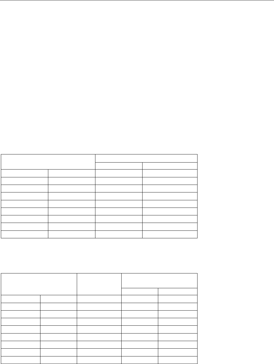
3. FULL DIAMETER BODY STYLE BOLTS: Dimensional requirements for cut-
thread or rolled-thread bolts with full diameter body style are given in Table 3-1.
Table 3-1 Diameters of Full Diameter Body Style Bolts 1, 2
Nominal Body or Shank Diameter (inches)
3
Size (inches)
Max.
Min.
1/2
0.5000
0.515
0.482
5/8
0.6250
0.642
0.605
3/4
0.7500
0.768
0.729
7/8
0.8750
0.895
0.852
1
1.0000
1.022
0.976
1-1/4
1.2500
1.277
1.223
1-1/2
1.5000
1.531
1.470
1-3/4
1.7500
1.785
1.716
2
2.0000
2.039
1.964
4. REDUCED DIAMETER BODY STYLE BOLTS: Dimensional requirements for
rolled-thread bolts with reduced diameter body style are given in Table 4-1.
Table 4-1 Diameters of Reduced Diameter Body Style Bolts 1, 2
Nominal
Threads per
Inch
Body or Shank 3
Diameter (inches)
Size (inches)
(TPI) 4
Max.
Min.
1/2
0.5000
13
0.482
0.444
5/8
0.6250
11
0.605
0.559
3/4
0.7500
10
0.729
0.677
7/8
0.8750
9
0.852
0.795
1
1.0000
8
0.976
0.910
1-1/4
1.2500
7
1.223
1.148
1-1/2
1.5000
6
1.470
1.381
1-3/4
1.7500
5
1.716
1.608
2
2.0000
4-1/2
1.964
1.843
Notes:
1) Adopted from ASME B18.2.1
and ASME B18.2.6.
2) For bolt diameters not indicated,
refer to ASME B18.2.1 and B18.2.6.
3) The body or shank of a bolt is
the smooth portion between the
head and the threads.
Notes:
1) Body diameters are based on
ASME B18.2.1, Table 2, Notes
7 & 13, and ASTM B1.1, UNRC
or 8 UNR series, Class 2A threads.
2) For bolt diameters not indicated,
refer to ASME B18.2.1, B18.2.6
and ASTM B1.1.
3) The body or shank of a bolt is the
smooth portion between the head
and the threads.
4) TPI means threads per inch (ASTM
B1.1, UNRC or 8 UNR series,
Class 2A threads).
