Hi Speed USB Hub Controller UM10011 ISP1521
User Manual: UM10011
Open the PDF directly: View PDF ![]() .
.
Page Count: 53
- 1. General description
- 2. Features
- 3. Applications
- 4. Ordering information
- 5. Block diagram
- 6. Pinning information
- 7. Functional description
- 8. Configuration selections
- 9. Hub controller description
- 10. Descriptors
- 11. Hub requests
- 12. Limiting values
- 13. Recommended operating conditions
- 14. Static characteristics
- 15. Dynamic characteristics
- 16. Application information
- 17. Test information
- 18. Package outline
- 19. Abbreviations
- 20. References
- 21. Revision history
- 22. Tables
- 23. Figures
- 24. Contents

1. General description
The ISP1521 is a stand-alone Universal Serial Bus (USB) hub controller IC that complies
with Universal Serial Bus Specification Rev. 2.0. It supports data transfer at high-speed
(480 Mbit/s), full-speed (12 Mbit/s) and low-speed (1.5 Mbit/s).
The upstream facing port can be connected to a Hi-Speed USB host or hub or to an
Original USB host or hub. If the upstream facing port is connected to a Hi-Speed USB host
or hub, then the ISP1521 will operate as a Hi-Speed USB hub. That is, it will support
high-speed, full-speed and low-speed devices connected to its downstream facing ports. If
the upstream facing port is connected to an Original USB host or hub, then the ISP1521
will operate as an Original USB hub. That is, high-speed devices that are connected to its
downstream facing ports will operate in full-speed mode instead.
The ISP1521 is a full hardware USB hub controller. All Original USB devices connected to
the downstream facing ports are handled using a single Transaction Translator (TT), when
operating in a cross-version environment. This allows the whole 480 Mbit/s upstream
bandwidth to be shared by all the Original USB devices on its downstream facing ports.
The ISP1521 has seven downstream facing ports. If not used, ports 3 to 7 can be
disabled. The vendor ID, product ID and string descriptors on the hub are supplied by the
internal ROM; they can also be supplied by an external I2C-bus EEPROM or a
microcontroller.
The ISP1521 is suitable for self-powered hub designs.
An analog overcurrent detection circuitry is built into the ISP1521, which can also accept
digital overcurrent signals from external circuits; for example, Micrel MOSFET switch
MIC2026. The circuitry can be configured to trip on a global or an individual overcurrent
condition.
Each port comes with two status indicator LEDs.
Target applications of the ISP1521 are monitor hubs, docking stations for notebooks,
internal USB hub for motherboards, hub for extending Intel Easy PCs, hub boxes, and so
on.
ISP1521
Hi-Speed USB hub controller
Rev. 07 — 4 February 2010 Product data sheet

CD00222695 © ST-ERICSSON 2010. All rights reserved.
Product data sheet Rev. 07 — 4 February 2010 2 of 53
ISP1521
Hi-Speed USB hub controller
2. Features
Complies with:
Universal Serial Bus Specification Rev. 2.0
Advanced Configuration and Power Interface (ACPI), OnNow and USB power
management requirements
Supports data transfer at high-speed (480 Mbit/s), full-speed (12 Mbit/s) and
low-speed (1.5 Mbit/s)
Self-powered capability
Configurable number of ports
Internal Power-On Reset (POR) and low voltage reset circuit
Port status indicators
Integrates high performance USB interface device with hub handler, ST-Ericsson
Serial Interface Engine (SIE) and transceivers
Built-in overcurrent detection circuit
Individual or ganged power switching, individual or global overcurrent protection, and
nonremovable port support by I/O pins configuration
Simple I2C-bus (master or slave) interface to read device descriptor parameters,
language ID, manufacturer ID, product ID, serial number ID and string descriptors from
a dedicated external EEPROM, or to allow the microcontroller to set up hub
descriptors
Visual USB traffic monitoring (GoodLink1) for the upstream facing port
Uses 12 MHz crystal oscillator with on-chip Phase-Locked Loop (PLL) for low
ElectroMagnetic Interference (EMI)
Supports temperature range from −40 °C to +70 °C
Available in LQFP80 package
3. Applications
Monitor hubs
Docking stations for notebooks
Internal hub for USB motherboards
Hub for extending Easy PCs
Hub boxes
4. Ordering information
1. GoodLink is a trademark of ST-Ericsson.
Table 1. Ordering information
Commercial
product code
Package description Packing Minimum sellable
quantity
ISP1521BEUM LQFP80; 80 leads; body 12 ×12 ×1.4 (mm) 13 inch tape and reel dry pack 1000 pieces
xxxx xxxxxxxxxxxxxxxxxxxxxxxxxxxxxx x xxxxxxxxxxxxxx xxxxxxxxxx xxx xxxxxx xxxxxxxxxxxxxxxxxxxxxxx xxxxxxxxxxxxxxxxxxxxxx
xxxxx xxxxxx xx xxxxxxxxxxxxxxxxxxxxxxxxxxxxx xxxxxxxxxxxxxxxxxxxxxx xxxxxxxxxxx xxxxxxx xxxxxxxxxxxxxxxxxxx
xxxxxxxxxxxxxxxx xxxxxxxxxxxxxx xxxxxx xx xxxxxxxxxxxxxxxxxxxxxxxxxxxxxxxx xxxxxxxxxxxxxxxxxxxxxxxx xxxxxxx
xxxxxxxxxxxxxxxxxxxxxxxxxxxxxxxxxxxxxxxxxxxxxx xxxxxxxxxxx xxxxx x x
CD00222695 © ST-ERICSSON 2010. All rights reserved.
Product data sheet Rev. 07 — 4 February 2010 3 of 53
ISP1521
Hi-Speed USB hub controller
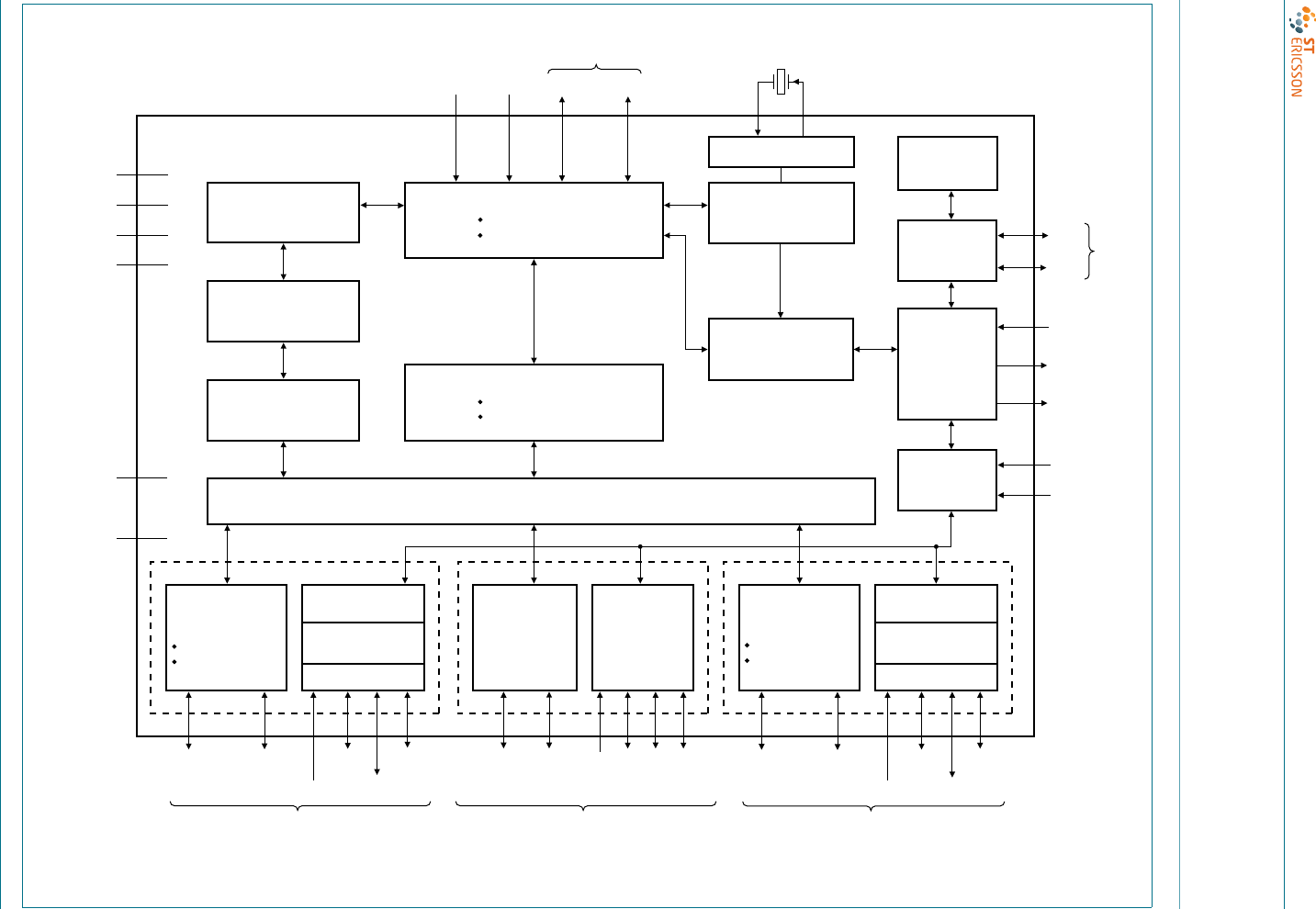
5. Block diagram
Fig 1. Block diagram
mld710
I2C-BUS
CONTROLLER
POWER
SWITCH
OVERCURRENT
DETECTION
LINK LEDS LINK LEDS
BIT CLOCK
RECOVERY
PLL
ANALOG
TRANSCEIVER
ORIGINAL USB
HI-SPEED USB
ROUTING LOGIC
ST-ERICSSON PIE
ST-ERICSSON SIE
PORT
CONTROLLER
HUB
CONTROLLER
RAM
ROM
MINI-HOST
CONTROLLER
HUB REPEATER
ORIGINAL USB
HI-SPEED USB
ANALOG TRANSCEIVER
ORIGINAL USB
HI-SPEED USB
TRANSACTION
TRANSLATOR
VCC1
RPU DM0 DP0
SDA
ADOC
NOOC
TEST
SCL
I2C-bus
12 MHz
upstream port 0
XTAL1 XTAL2
RREF
VCC2
VCC3
VCC4
VREF(5V0)
POWER
SWITCH
OVERCURRENT
DETECTION
ANALOG
TRANSCEIVER
ORIGINAL USB
HI-SPEED USB
downstream
port 1 downstream
port 2 to port 6 downstream
port 7
DM7
DM1 DP1
OC1_N
PSW1_N
GRN1_N
AMB1_N DP7
ISP1521
OC7_N
PSW7_N
GRN7_N
AMB7_N
19 20 23 24 72 73 48 49 36 37 65 66
1
60
41
79
80
43424375
11, 50
17, 56
30, 70
13, 52
31, 69
GND
2, 6, 8,
12, 14,
18, 29,
44, 47,
51, 53,
57, 71
RESET_N
HUBGL_N
78
40
PORT 1 PORTS 2 to 6 PORT 7
CD00222695 © ST-ERICSSON 2010. All rights reserved.
Product data sheet Rev. 07 — 4 February 2010 4 of 53
ISP1521
Hi-Speed USB hub controller
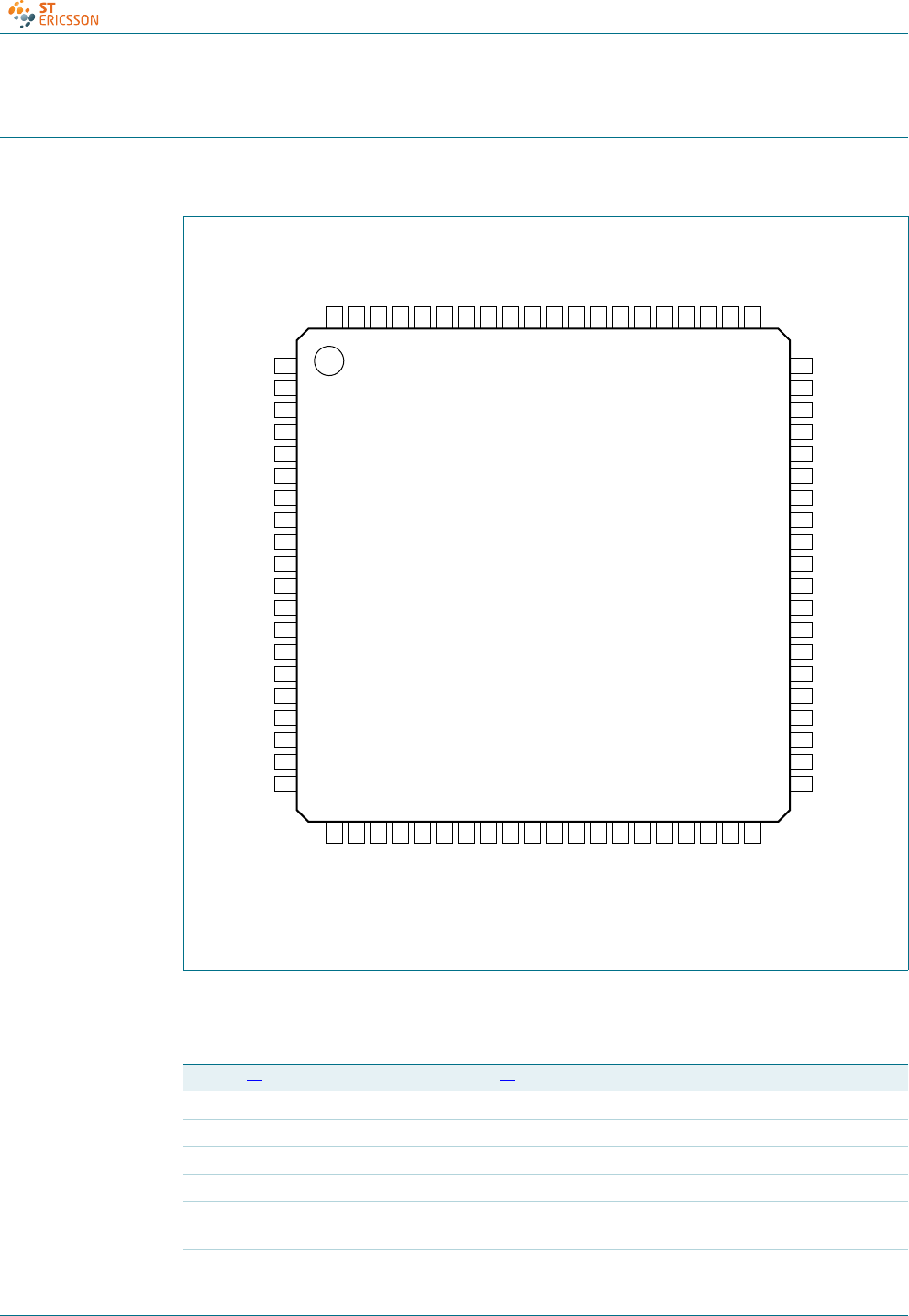
6. Pinning information
6.1 Pinning
6.2 Pin description
Fig 2. Pin configuration
ISP1521BEUM
TEST NOOC
GND DP4
DM0 DM4
DP0 GND
RPU VCC2
GND DP3
RREF DM3
GND GND
DM5 VCC4
DP5 GND
VCC1 VCC1
GND DP7
VCC4 DM7
GND GND
DM6 DP2
DP6 DM2
VCC2 GND
GND XTAL2
DM1 XTAL1
DP1 ADOC
TEST_LOW SDA
TEST_HIGH SCL
OC1_N HUBGL_N
PSW1_N AMB5_N
OC6_N GRN5_N
PSW6_N AMB6_N
OC5_N GRN6_N
PSW5_N AMB1_N
GND GRN1_N
VCC3 GND
VREF(5V0) VCC3
OC4_N VREF(5V0)
PSW4_N AMB2_N
OC3_N GRN2_N
PSW3_N AMB7_N
OC7_N GRN7_N
PSW7_N AMB3_N
OC2_N GRN3_N
PSW2_N AMB4_N
RESET_N GRN4_N
1
2
3
4
5
6
7
8
9
10
11
12
13
14
15
16
17
18
19
20
60
59
58
57
56
55
54
53
52
51
50
49
48
47
46
45
44
43
42
41
21
22
23
24
25
26
27
28
29
30
31
32
33
34
35
36
37
38
39
40
80
79
78
77
76
75
74
73
72
71
70
69
68
67
66
65
64
63
62
61
mld712
Table 2. Pin description
Symbol[1] Pin Type Description[2]
TEST 1 - connect to ground through a 100 kΩresistor
GND 2 - ground supply
DM0 3 AI/O upstream facing port 0 D− connection (analog)
DP0 4 AI/O upstream facing port 0 D+ connection (analog)
RPU 5 AI pull-up resistor connection; connect this pin through a resistor of
1.5 kΩ±5% to 3.3V
GND 6 - ground supply

CD00222695 © ST-ERICSSON 2010. All rights reserved.
Product data sheet Rev. 07 — 4 February 2010 5 of 53
ISP1521
Hi-Speed USB hub controller
RREF 7 AI reference resistor connection; connect this pin through a resistor of
12 kΩ±1 % to an analog band gap ground reference
GND 8 - ground supply
DM5 9 AI/O downstream facing port 5 D− connection (analog)[3]
DP5 10 AI/O downstream facing port 5 D+ connection (analog)[3]
VCC1 11 - supply voltage 1 (3.3 V) (analog)
GND 12 - ground supply
VCC4 13 - supply voltage 4 (3.3 V) (crystal and PLL)
GND 14 - ground supply
DM6 15 AI/O downstream facing port 6 D− connection (analog)[3]
DP6 16 AI/O downstream facing port 6 D+ connection (analog)[3]
VCC2 17 - supply voltage 2 (3.3 V) (transceiver)
GND 18 - ground supply
DM1 19 AI/O downstream facing port 1 D− connection (analog)[4]
DP1 20 AI/O downstream facing port 1 D+ connection (analog)[4]
TEST_LOW 21 - connect to GND
TEST_HIGH 22 - connect to 5.0 V through a 10 kΩ resistor
OC1_N 23 AI/I overcurrent sense input for downstream facing port 1
(analog/digital)
PSW1_N 24 I/O output — power switch control output (open-drain) with an internal
pull-up resistor for downstream facing port 1
input — function of the pin when used as an input is given in
Tab l e 5
OC6_N 25 AI/I overcurrent sense input for downstream facing port 6
(analog/digital)
PSW6_N 26 I/O output — power switch control output (open-drain) with an internal
pull-up resistor for downstream facing port 6
input — function of the pin when used as an input is given in
Tab l e 5
OC5_N 27 AI/I overcurrent sense input for downstream facing port 5
(analog/digital)
PSW5_N 28 I/O output — power switch control output (open-drain) with an internal
pull-up resistor for downstream facing port 5
input — function of the pin when used as an input is given in
Tab l e 5
GND 29 - ground supply
VCC3 30 - supply voltage 3 (3.3 V) (digital)
VREF(5V0) 31 - reference voltage (5 V ±5 %); used to power internal pull-up
resistors of PSWn_N pins and also for the analog overcurrent
detection
OC4_N 32 AI/I overcurrent sense input for downstream facing port 4
(analog/digital)
Table 2. Pin description …continued
Symbol[1] Pin Type Description[2]

CD00222695 © ST-ERICSSON 2010. All rights reserved.
Product data sheet Rev. 07 — 4 February 2010 6 of 53
ISP1521
Hi-Speed USB hub controller
PSW4_N 33 I/O output — power switch control output (open-drain) with an internal
pull-up resistor for downstream facing port 4
input — function of the pin when used as an input is given in
Tab l e 5
OC3_N 34 AI/I overcurrent sense input for downstream facing port 3
(analog/digital)
PSW3_N 35 I/O output — power switch control output (open-drain) with an internal
pull-up resistor for downstream facing port 3
input — function of the pin when used as an input is given in
Tab l e 5
OC7_N 36 AI/I overcurrent sense input for downstream facing port 7
(analog/digital)
PSW7_N 37 I/O output — power switch control output (open-drain) with an internal
pull-up resistor for downstream facing port 7
input — function of the pin when used as an input is given in
Tab l e 5
OC2_N 38 AI/I overcurrent sense input for downstream facing port 2
(analog/digital)
PSW2_N 39 I/O output — power switch control output (open-drain) with an internal
pull-up resistor for downstream facing port 2
input — function of the pin when used as an input is given in
Tab l e 5
RESET_N 40 I asynchronous reset input; when reset is active, the internal switch
to the 1.5 kΩ external resistor is opened, and all pins DPn and DMn
are 3-state; it is recommended that you connect to any one of the
3.3 V VCC pins through an RC circuit; refer to the schematics in
ISP1521 Hi-Speed USB hub demo board user manual (UM10011)
ADOC 41 I analog or digital overcurrent detect selection input; LOW selects
digital mode and HIGH (3.3 V or 5.0 V) selects analog mode
XTAL1 42 I crystal oscillator input (12 MHz)
XTAL2 43 O crystal oscillator output (12 MHz)
GND 44 - ground supply
DM2 45 AI/O downstream facing port 2 D− connection (analog)[4]
DP2 46 AI/O downstream facing port 2 D+ connection (analog)[4]
GND 47 - ground supply
DM7 48 AI/O downstream facing port 7 D− connection (analog)[3]
DP7 49 AI/O downstream facing port 7 D+ connection (analog)[3]
VCC1 50 - supply voltage 1 (3.3 V) (analog)
GND 51 - ground supply
VCC4 52 - supply voltage 4 (3.3 V) (crystal and PLL)
GND 53 - ground supply
DM3 54 AI/O downstream facing port 3 D− connection (analog)[3]
DP3 55 AI/O downstream facing port 3 D+ connection (analog)[3]
VCC2 56 - supply voltage 2 (3.3 V) (transceiver)
GND 57 - ground supply
Table 2. Pin description …continued
Symbol[1] Pin Type Description[2]

CD00222695 © ST-ERICSSON 2010. All rights reserved.
Product data sheet Rev. 07 — 4 February 2010 7 of 53
ISP1521
Hi-Speed USB hub controller
DM4 58 AI/O downstream facing port 4 D− connection (analog)[3]
DP4 59 AI/O downstream facing port 4 D+ connection (analog)[3]
NOOC 60 I no overcurrent protection selection input; connect this pin to HIGH
(3.3 V) to select no overcurrent protection; if no overcurrent is
selected, all OC_N pins must be connected to VREF(5V0)
GRN4_N 61 I/O output — green LED port indicator (open-drain) for downstream
facing port 4
input — function of the pin when used as an input is given in
Tab l e 9
AMB4_N 62 I/O output — amber LED port indicator (open-drain) for downstream
facing port 4
input — function of the pin when used as an input is given in
Tab l e 8
GRN3_N 63 I/O output — green LED port indicator (open-drain) for downstream
facing port 3
input — function of the pin when used as an input is given in
Tab l e 9
AMB3_N 64 I/O output — amber LED port indicator (open-drain) for downstream
facing port 3
input — function of the pin when used as an input is given in
Tab l e 8
GRN7_N 65 I/O output — green LED port indicator (open-drain) for downstream
facing port 7
input — function of the pin when used as an input is given in
Tab l e 9
AMB7_N 66 I/O output — amber LED port indicator (open-drain) for downstream
facing port 7
input — function of the pin when used as an input is given in
Tab l e 8
GRN2_N 67 I/O output — green LED port indicator (open-drain) for downstream
facing port 2
input — function of the pin when used as an input is given in
Tab l e 9
AMB2_N 68 I/O output — amber LED port indicator (open-drain) for downstream
facing port 2
input — function of the pin when used as an input is given in
Tab l e 8
VREF(5V0) 69 - reference voltage (5 V ±5 %); used to power internal pull-up
resistors of PSWn_N pins and also for the analog overcurrent
detection
VCC3 70 - supply voltage 3 (3.3 V) (digital)
GND 71 - ground supply
GRN1_N 72 I/O output — green LED port indicator (open-drain) for downstream
facing port 1
input — function of the pin when used as an input is given in
Tab l e 9
Table 2. Pin description …continued
Symbol[1] Pin Type Description[2]

CD00222695 © ST-ERICSSON 2010. All rights reserved.
Product data sheet Rev. 07 — 4 February 2010 8 of 53
ISP1521
Hi-Speed USB hub controller
[1] Symbol names ending with underscore N (for example, NAME_N) represent active LOW signals.
[2] The maximum current the ISP1521 can sink on a pin is 8 mA.
[3] To disable a downstream port n, connect both pins DPn and DMn to VCC (3.3 V); unused ports must be
disabled in reverse order starting from port 7.
[4] Downstream ports 1 and 2 cannot be disabled.
AMB1_N 73 I/O output — amber LED port indicator (open-drain) for downstream
facing port 1
input — function of the pin when used as an input is given in
Tab l e 8
GRN6_N 74 I/O output — green LED port indicator (open-drain) for downstream
facing port 6
input — function of the pin when used as an input is given in
Tab l e 9
AMB6_N 75 I/O output — amber LED port indicator (open-drain) for downstream
facing port 6
input — function of the pin when used as an input is given in
Tab l e 8
GRN5_N 76 I/O output — green LED port indicator (open-drain) for downstream
facing port 5
input — function of the pin when used as an input is given in
Tab l e 9
AMB5_N 77 I/O output — amber LED port indicator (open-drain) for downstream
facing port 5
input — function of the pin when used as an input is given in
Tab l e 8
HUBGL_N 78 O hub GoodLink LED indicator output; the LED is off until the hub is
configured; a transaction between the host and the hub will blink the
LED off for 100 ms
SCL 79 I/O I2C-bus clock (open-drain); see Ta b l e 11
SDA 80 I/O I2C-bus data (open-drain); see Table 11
Table 2. Pin description …continued
Symbol[1] Pin Type Description[2]

CD00222695 © ST-ERICSSON 2010. All rights reserved.
Product data sheet Rev. 07 — 4 February 2010 9 of 53
ISP1521
Hi-Speed USB hub controller
7. Functional description
7.1 Analog transceivers
The integrated transceivers directly interface to USB lines. They can transmit and receive
serial data at high-speed (480 Mbit/s), full-speed (12 Mbit/s) and low-speed (1.5 Mbit/s).
7.2 Hub controller core
The main components of the hub core are:
•ST-Ericsson Serial Interface Engine (SIE)
•Routing logic
•Transaction Translator (TT)
•Mini-Host Controller
•Hub repeater
•Hub controller
•Port controller
•Bit clock recovery.
7.2.1 ST-Ericsson serial interface engine
The ST-Ericsson Serial Interface Engine (SIE) implements the full USB protocol layer. It is
completely hardwired for speed and needs no firmware intervention. The functions of this
block include: synchronization, pattern recognition, parallel or serial conversion, bit
(de-)stuffing, CRC checking and generation, Packet IDentifier (PID) verification and
generation, address recognition, and handshake evaluation and generation.
7.2.2 Routing logic
The routing logic directs signaling to appropriate modules (mini-Host Controller, Original
USB repeater and Hi-Speed USB repeater) according to the topology in which the hub is
placed.
7.2.3 Transaction translator
The Transaction Translator (TT) acts as a go-between mechanism that links devices
operating in Original USB mode and Hi-Speed USB upstream mode. For the ‘IN’ direction,
data is concatenated in TT buffers till the proper length is reached, before the host takes
the transaction. In the reverse direction (OUT), the mini-host dispenses the data
contained in TT buffers over a period that fits into the Original USB bandwidth. This
continues until all outgoing data is emptied. TT buffers are used only on split transactions.
7.2.4 Mini-Host Controller
The internal mini-host generates all the Original USB IN, OUT or SETUP tokens for the
downstream facing ports, while the upstream facing port is in high-speed mode. The
responses from the Original USB devices are collected in TT buffers, until the end of the
complete split transaction clears TT buffers.

CD00222695 © ST-ERICSSON 2010. All rights reserved.
Product data sheet Rev. 07 — 4 February 2010 10 of 53
ISP1521
Hi-Speed USB hub controller
7.2.5 Hub repeater
A hub repeater manages connectivity on a per packet basis. It implements packet
signaling connectivity and resume connectivity. There are two repeaters in the ISP1521: a
Hi-Speed USB repeater and an Original USB repeater. The only major difference between
these two repeaters is the speed at which they operate. When the hub is connected to an
Original USB system, it automatically switches itself to function as an Original USB hub.
7.2.6 Hub and port controllers
The hub controller provides status report. The port controller provides control for individual
downstream facing ports; it controls the port routing module. Any port status change will
be reported to the host using the hub status change (interrupt) endpoint.
7.2.7 Bit clock recovery
The bit clock recovery circuit extracts the clock from the incoming USB data stream.
7.3 Phase-locked loop clock multiplier
A 12 MHz-to-480 MHz clock multiplier Phase-Locked Loop (PLL) is integrated on-chip.
This allows the use of low-cost 12 MHz crystals. The low crystal frequency also minimizes
EMI. No external components are required for the operation of the PLL.
7.4 I2C-bus controller
A simple serial I2C-bus interface is provided to transfer vendor ID, product ID and string
descriptor from an external I2C-bus EEPROM or microcontroller. A master/slave I2C-bus
protocol is implemented according to timing requirements as mentioned in I2C-bus
standard specifications. The maximum data count during I2C-bus transfers for the
ISP1521 is 256 bytes.
7.5 Overcurrent detection circuit
An overcurrent detection circuit is integrated on-chip. The main features of this circuit are:
self reporting, automatic resetting, low-trip time and low cost. This circuit offers an easy
solution at no extra hardware cost on the board.
7.6 GoodLink
Indication of a good USB connection is provided through the GoodLink technology. An
LED can be directly connected to pin HUBGL_N through an external 330 Ω resistor.
During enumeration, the LED momentarily blinks on. After successful configuration, the
LED blinks off for 100 ms upon each transaction.
This feature provides a user-friendly indication of the status of the hub, the connected
downstream devices, and the USB traffic. It is a useful diagnostics tool to isolate faulty
USB equipment, and helps to reduce field support and hotline costs.
7.7 Power-on reset
The ISP1521 has an internal Power-On Reset (POR) circuit.
CD00222695 © ST-ERICSSON 2010. All rights reserved.
Product data sheet Rev. 07 — 4 February 2010 11 of 53
ISP1521
Hi-Speed USB hub controller
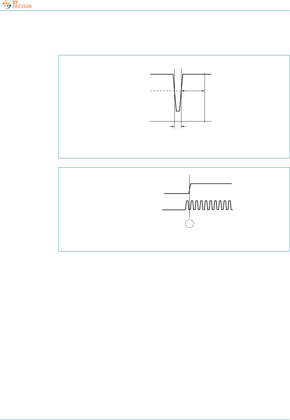
The triggering voltage of the POR circuit is 2.03 V nominal. A POR is automatically
generated when VCC goes below the trigger voltage for a duration longer than 1 μs.
At t1: clock is running and available.
Fig 3. Power-on reset timing
Stable external clock is to be available at A.
Fig 4. External clock with respect to power-on reset
004aaa388
t
1
V
CC
2.03 V
0 V
≤ 683 μs
POR
POR
EXTERNAL CLOCK
A
004aaa365

CD00222695 © ST-ERICSSON 2010. All rights reserved.
Product data sheet Rev. 07 — 4 February 2010 12 of 53
ISP1521
Hi-Speed USB hub controller
8. Configuration selections
The ISP1521 is configured through I/O pins and, optionally, through an external I2C-bus,
in which case the hub can update its configuration descriptors as a master or as a slave.
Tabl e 3 shows configuration parameters.
[1] Multiple ganged power mode is reported as individual power mode; refer to Universal Serial Bus Specification Rev. 2.0.
[2] When the hub uses global overcurrent protection mode, the overcurrent indication is through wHubStatus field bit 1 (overcurrent) and
the corresponding change bit (overcurrent change).
Table 3. Configuration parameters
Mode and selection Option Configuration method
Pin control Software control
Control pin Reference Affected field Reference
Number of downstream
facing ports
2 ports
3 ports
4 ports
5 ports
6 ports
7 ports
DM1/DP1 to
DM7/DP7
see Section 8.1.1 bNbrPorts0 see Table 22
Power switching mode none
ganged
multiple ganged[1]
individual
PSW1_N to
PSW7_N
see Section 8.1.2 wHubCharacteristics:
bits D1 and D0
see Table 22
bPwrOn2PwrGood:
time interval
Overcurrent protection
mode
none
global[2]
multiple ganged
individual
NOOC and
OC1_N to
OC7_N
see Section 8.1.3 wHubCharacteristics:
bits D4 and D3
see Table 22
Nonremovable ports any port can be
nonremovable
AMBn_N see Section 8.1.4 wHubCharacteristics:
bit D2 (compound hub)
see Table 22
DeviceRemovable:
bit map
Port indicator support no
yes
all GRNn_N see Section 8.1.5 wHubCharacteristics:
bit D7
see Table 22

CD00222695 © ST-ERICSSON 2010. All rights reserved.
Product data sheet Rev. 07 — 4 February 2010 13 of 53
ISP1521
Hi-Speed USB hub controller
8.1 Configuration through I/O pins
8.1.1 Number of downstream facing ports
To discount a physical downstream facing port, connect pins DP and DM of that
downstream facing port to VCC (3.3 V) starting from the highest port number (7); see
Tabl e 4 .
The sum of physical ports configured is reflected in the bNbrPorts field.
8.1.2 Power switching
Power switching of downstream ports can be done individually or ganged, where all
ports are simultaneously switched with one power switch. The ISP1521 supports both
modes, which can be selected using input PSWn_N; see Tabl e 5 .
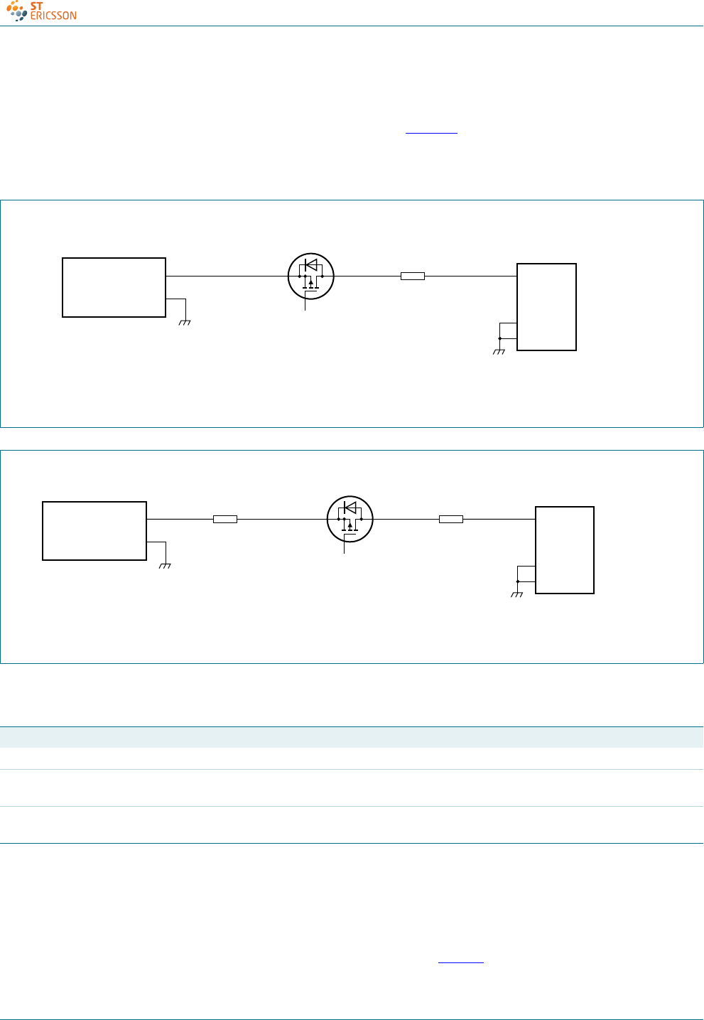
8.1.2.1 Voltage drop requirements
Self-powered hubs are required to provide a minimum of 4.75 V to its output port
connectors at all legal load conditions. To comply with Underwriters Laboratory Inc. (UL)
safety requirements, the power from any port must be limited to 25 W (5 A at 5 V).
Overcurrent protection may be implemented on a global or individual basis.
Assuming a 5 V ±3 % power supply, the worst-case supply voltage is 4.85 V. This only
allows a voltage drop of 100 mV across the hub Printed-Circuit Board (PCB) to each
downstream connector. This includes a voltage drop across the:
•Power supply connector
•Hub PCB (power and ground traces, ferrite beads)
•Power switch (FET on-resistance)
•Overcurrent sense device
The PCB resistance and power supply connector resistance may cause a drop of 25 mV,
leaving only 75 mV as the voltage drop allowed across the power switch and overcurrent
sense device. Individual voltage drop components are shown in Figure 5.
Table 4. Downstream facing port number pin configuration
Number of physical
downstream facing port
DM1/DP1 DM2/DP2 DM3/DP3 DM4/DP4 DM5/DP5 DM6/DP6 DM7/DP7
715kΩ
pull-down
15 kΩ
pull-down
15 kΩ
pull-down
15 kΩ
pull-down
15 kΩ
pull-down
15 kΩ
pull-down
15 kΩ
pull-down
615kΩ
pull-down
15 kΩ
pull-down
15 kΩ
pull-down
15 kΩ
pull-down
15 kΩ
pull-down
15 kΩ
pull-down
VCC
515kΩ
pull-down
15 kΩ
pull-down
15 kΩ
pull-down
15 kΩ
pull-down
15 kΩ
pull-down
VCC VCC
415kΩ
pull-down
15 kΩ
pull-down
15 kΩ
pull-down
15 kΩ
pull-down
VCC VCC VCC
315kΩ
pull-down
15 kΩ
pull-down
15 kΩ
pull-down
VCC VCC VCC VCC
215kΩ
pull-down
15 kΩ
pull-down
VCC VCC VCC VCC VCC
CD00222695 © ST-ERICSSON 2010. All rights reserved.
Product data sheet Rev. 07 — 4 February 2010 14 of 53
ISP1521
Hi-Speed USB hub controller
For global overcurrent detection, an increased voltage drop is needed for the overcurrent
sense device (in this case, a low-ohmic resistor). This can be realized by using a special
power supply of 5.1 V ±3 %, as shown in Figure 6.
The PCB resistance may cause a drop of 25 mV, which leaves 75 mV for the power switch
and overcurrent sense device.
PSWn_N pins have integrated weak pull-up resistors inside the chip.
8.1.3 Overcurrent protection mode
The ISP1521 supports all overcurrent protection modes: none, global and individual.
No overcurrent protection mode reporting is selected when pin NOOC = HIGH. Global
and individual overcurrent protection modes are selected using pins PSWn_N, following
power switching modes selection scheme; see Ta bl e 6 .
(1) Includes PCB traces, ferrite beads, and so on.
Fig 5. Typical voltage drop components in self-powered mode using individual overcurrent detection
5 V
POWER SUPPLY
± 3 % regulated −
+4.85 V (min)
004aaa264
low-ohmic
PMOS switch
ISP1521
power switch
VBUS
D+
D−
GND
SHIELD
4.75 V (min)
downstream
port
connector
hub board
resistance(1)
voltage drop
25 mV
voltage drop
75 mV
(PSWn_N)
(1) Includes PCB traces, ferrite beads, and so on.
Fig 6. Typical voltage drop components in self-powered mode using global overcurrent detection
5.1 V KICK-UP
POWER SUPPLY
± 3 % regulated −
+4.95 V(min)
004aaa265
low-ohmic
PMOS switch
VBUS
D+
D−
GND
SHIELD
4.75 V(min)
downstream
port
connector
hub board
resistance(1)
voltage drop
25 mV
voltage drop
75 mV
low-ohmic
sense resistor
for overcurrent
detection
voltage drop
100 mV
ISP1521 power
switch
(PSWn_N)
Table 5. Power switching mode: pin configuration
Power switching mode PSW1_N PSW2_N PSW3_N PSW4_N PSW5_N PSW6_N PSW7_N
None ground ground ground ground ground ground ground
Ganged internal
pull-up
ground ground ground ground ground ground
Individual internal
pull-up
internal
pull-up
internal
pull-up
internal
pull-up
internal
pull-up
internal
pull-up
internal
pull-up

CD00222695 © ST-ERICSSON 2010. All rights reserved.
Product data sheet Rev. 07 — 4 February 2010 15 of 53
ISP1521
Hi-Speed USB hub controller
For global overcurrent protection mode, only PSW1_N and OC1_N are active; that is, in
this mode, the remaining overcurrent indicator pins are disabled. To inhibit the analog
overcurrent detection, OC_N pins must be connected to VREF(5V0).
Both analog and digital overcurrent modes are supported; see Tab le 7 .
For digital overcurrent detection, the normal digital TTL level is accepted on overcurrent
input pins. For analog overcurrent detection, the threshold is given in Section 14. In this
mode, to filter out false overcurrent conditions because of in rush and spikes, a dead time
of 15 ms is built into the IC, that is, overcurrent must persist for 15 ms before it is reported
to the host.
8.1.4 Nonremovable port
A nonremovable port, by definition, is a port that is embedded inside the hub application
box and is not externally accessible. The LED port indicators (pins AMBn_N) of such a
port are not used. Therefore, the corresponding amber LED port indicators are disabled to
signify that the port is nonremovable; see Table 8.
More than one nonremovable port can be specified by appropriately connecting the
corresponding amber LED indicators. At least one port should, however, be left as a
removable port.
The detection of any nonremovable port sets the hub descriptor to a compound hub.
8.1.5 Port indicator support
The port indicator support can be disabled by grounding all green port indicators (all
pins GRNn_N); see Table 9. This is a global feature. You cannot disable port indicators for
only one port.
Table 6. Overcurrent protection mode pin configuration
Power switching mode NOOC PSW1_N PSW2_N PSW3_N PSW4_N PSW5_N PSW6_N PSW7_N
None HIGH ground ground ground ground ground ground ground
Global LOW internal
pull-up
ground ground ground ground ground ground
Individual LOW internal
pull-up
internal
pull-up
internal
pull-up
internal
pull-up
internal
pull-up
internal
pull-up
internal
pull-up
Table 7. Overcurrent detection mode selection pin configuration
Pin ADOC Mode selection Description
3.3 V or 5.0 V analog threshold ΔVtrip
Ground digital normal digital TTL level
Table 8. Nonremovable port pin configuration
AMBn_N (n = 1 to 7) Nonremovable port
Ground nonremovable
Pull-up with amber LED removable

CD00222695 © ST-ERICSSON 2010. All rights reserved.
Product data sheet Rev. 07 — 4 February 2010 16 of 53
ISP1521
Hi-Speed USB hub controller
8.2 Device descriptors and string descriptors settings using I2C-bus
8.2.1 Background information on I2C-bus
The I2C-bus is suitable for bidirectional communication between ICs or modules. It
consists of two bidirectional lines: SDA for data signals, and SCL for clock signals. Both
these lines must be connected to a positive supply voltage through a pull-up resistor.
The basic I2C-bus protocol is defined as:
•Data transfer is initiated only when the bus is not busy.
•Changes in the data line occur when the clock is LOW, and must be stable when the
clock is HIGH. Any changes in data lines when the clock is HIGH will be interpreted as
control signals.
8.2.1.1 Different conditions on I2C-bus
The I2C-bus protocol defines the following conditions:
Not busy — both SDA and SCL remain HIGH.
START — a HIGH-to-LOW transition on SDA, while SCL is HIGH.
STOP — a LOW-to-HIGH transition on SDA, while SCL is HIGH.
Data valid — after a START condition, data on SDA must be stable for the duration of the
HIGH period of SCL.
8.2.1.2 Data transfer
The master initiates each data transfer using a START condition and terminates it by
generating a STOP condition. To facilitate the next byte transfer, each byte of data must
be acknowledged by the receiver. The acknowledgment is done by pulling the SDA line
LOW on the ninth bit of the data. An extra clock pulse must be generated by the master to
accommodate this bit.
For details on the operation of the bus, refer to The I2C-bus specification.
8.2.1.3 I2C-bus address
The address of the ISP1521 is given in Tab le 10.
Table 9. Port indicator support: pin configuration
GRN1_N to GRN7_N Port indicator support
Ground not supported
LED pull-up green LED for at least one port supported
Table 10. I2C-bus slave address
Bit MSB Slave address LSB Write
A7 A6 A5 A4 A3 A2 A1
Value 00110100
CD00222695 © ST-ERICSSON 2010. All rights reserved.
Product data sheet Rev. 07 — 4 February 2010 17 of 53
ISP1521
Hi-Speed USB hub controller
8.2.2 Architecture of configurable hub descriptors
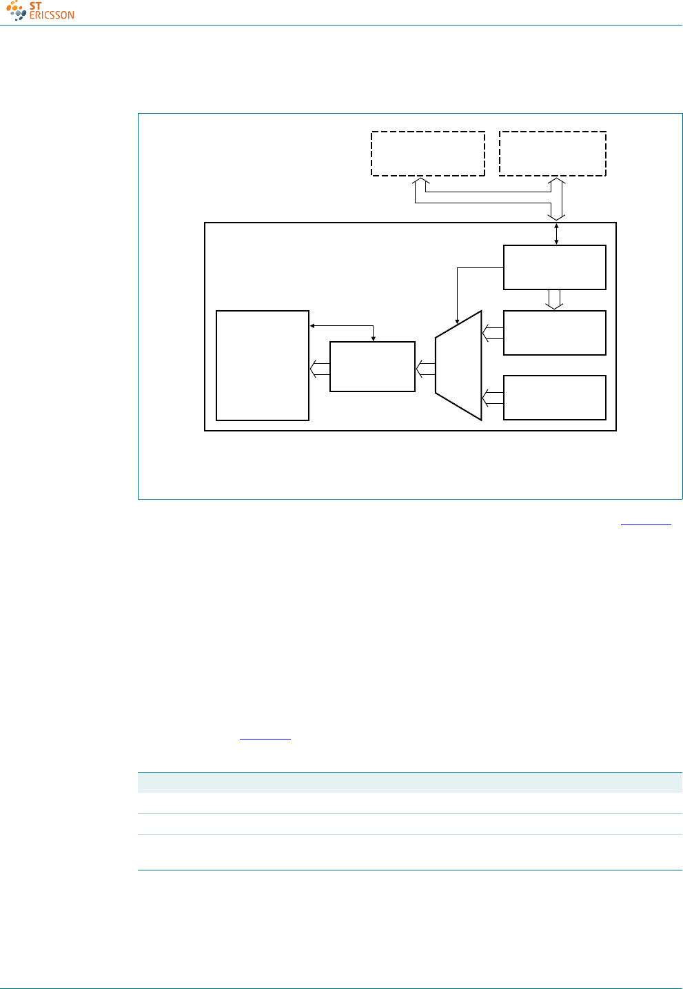
Configurable hub descriptors can be masked in the internal ROM memory; see Figure 7.
These descriptors can also be supplied from an external EEPROM or a microcontroller.
The ISP1521 implements both the master and slave I2C-bus controllers. The information
from the external EEPROM or the microcontroller is transferred into the internal RAM
during the power-on reset. A signature word is used to identify correct descriptors. If the
signature matches, the content of the RAM is chosen instead of the ROM.
When external microcontroller mode is selected and while the external microcontroller is
writing to the internal RAM, any request to configurable descriptors will be responded to
with a Not AcKnowledge (NAK). There is no specified time-out period for the NAK signal.
This data is then passed to the host during the enumeration process.
The three configuration methods are selected by connecting pins SCL and SDA in the
manner given in Tab le 11.
The I2C-bus cannot be shared between the EEPROM and the external microcontroller.
Fig 7. Configurable hub descriptors
Table 11. Configuration method
Configuration method SCL SDA
Internal ROM ground ground
External EEPROM 2.2 kΩ-to-4.7 kΩ pull-up 2.2 kΩ-to-4.7 kΩ pull-up
External microcontroller driven LOW by the
microcontroller during reset
2.2 kΩ-to-4.7 kΩ pull-up
mld711
MICROCONTROLLER SERIAL EEPROM
MASTER/SLAVE
I2C-BUS INTERFACE
signature
match
RAM
(256 bytes)
DESCRIPTOR
GENERATOR
INTERFACE
ROM
(256 bytes)
MUX
HUB CORE
I2C-bus

CD00222695 © ST-ERICSSON 2010. All rights reserved.
Product data sheet Rev. 07 — 4 February 2010 18 of 53
ISP1521
Hi-Speed USB hub controller
8.2.3 ROM or EEPROM map
Remark: A 128-byte EEPROM supports one language ID only, and a 256-byte EEPROM
supports two language IDs.
8.2.4 ROM or EEPROM detailed map
Fig 8. ROM or EEPROM map
mld714
Signature
00h
02h
10h
7Fh
FFh
80h
0Ah
Device Descriptor
String Descriptor
(first Language ID):
iManufacturer string
iProduct string
iSerial Number string
String Descriptor
(second Language ID):
iManufacturer string
iProduct string
iSerial Number string
Language ID
Table 12. ROM or EEPROM detailed map
Address
(hex)
Content Default
(hex)
Example
(hex)
Comment
Signature descriptor
00 signature (low) 55 - signature to signify valid data comment
01 signature (high) AA -
Device descriptor
02 idVendor (low) CC - ST-Ericsson vendor ID
03 idVendor (high) 04 -
04 idProduct (low) 21 - ISP1521 product ID
05 idProduct (high) 15 -
06 bcdDevice (low) 00 - device release; silicon revision increments
this value
07 bcdDevice (high) 02 -
08 RSV, iSN, iP, iM - 00 if all the three strings are supported, the
value of this byte is 39h
09 reserved - FF -
String descriptor Index 0 (language ID)
0A bLength[1] - 06 two language ID support
0B bDescriptorType - 03[2] STRING
0C wLANGID[0] - 09 LANGID code zero (first language ID)
(English USA in this example)
0D - 04
0E wLANGID[1] - 09 LANGID code one (second language ID)
(English UK in this example)
0F - 08

CD00222695 © ST-ERICSSON 2010. All rights reserved.
Product data sheet Rev. 07 — 4 February 2010 19 of 53
ISP1521
Hi-Speed USB hub controller
String descriptor Index 1 (iManufacturer)[3]
10 bLength - 2E string descriptor length (manufacturer ID)
11 bDescriptorType - 03[2] STRING
12 13 bString - 53 00 S of ST-Ericsson
14 15 - 54 00 T
16 17 - 2D 00 -
18 19 - 45 00 E
1A 1B - 72 00 r
1C 1D - 69 00 i
1E 1F - 63 00 c
20 21 - 73 00 s
22 23 - 73 00 s
24 25 - 6F 00 o
26 27 - 6E 00 n
28 29 - FF FF
2A 2B - FF FF
2C 2D - FF FF
2E 2F - FF FF
30 31 - FF FF
32 33 - FF FF
34 35 - FF FF
36 37 - FF FF
38 39 - FF FF
3A 3B - FF FF
3C 3D - FF FF
String descriptor Index 2 (iProduct)
3E bLength - 10 string descriptor length (product ID)
3F bDescriptorType - 03[2] STRING
40 41 bString - 49 00 I of ISP1521
42 43 - 53 00 S
44 45 - 50 00 P
46 47 - 31 00 1
48 49 - 35 00 5
4A 4B - 32 00 2
4C 4D - 31 00 1
String descriptor Index 3 (iSerialNumber)
Remark: If supported, this string must be unique.
4E bLength - 3A string descriptor length (serial number)
4F bDescriptorType - 03[2] STRING
50 51 bString - 39 00 9 of 947337877678 = wired support
Table 12. ROM or EEPROM detailed map …continued
Address
(hex)
Content Default
(hex)
Example
(hex)
Comment

CD00222695 © ST-ERICSSON 2010. All rights reserved.
Product data sheet Rev. 07 — 4 February 2010 20 of 53
ISP1521
Hi-Speed USB hub controller
52 53 - 34 00 4
54 55 - 37 00 7
56 57 - 33 00 3
58 59 - 33 00 3
5A 5B - 37 00 7
5C 5D - 38 00 8
5E 5F - 37 00 7
60 61 - 37 00 7
62 63 - 36 00 6
64 65 - 37 00 7
66 67 - 38 00 8
68 69 - 20 00
6A 6B - 3D 00 =
6C 6D - 20 00
6E 6F - 77 00 w
70 71 - 69 00 i
72 73 - 72 00 r
74 75 - 65 00 e
76 77 - 64 00 d
78 79 - 20 00
7A 7B - 73 00 s
7C 7D - 75 00 u
7E 7F - 70 00 p
80 81 - 70 00 p
82 83 - 6F 00 o
84 85 - 72 00 r
86 87 - 74 00 t
String descriptor Index 1 (iManufacturer) second language
88 bLength - 2E string descriptor length (manufacturer ID)
89 bDescriptorType - 03[2] STRING
8A 8B bString - 53 00 S of ST-Ericsson
8C 8D - 54 00 T
8E 8F - 2D 00 -
90 91 - 45 00 E
92 93 - 72 00 r
94 95 - 69 00 i
96 97 - 63 00 c
98 99 - 73 00 s
9A 9B - 73 00 s
9C 9D - 6F 00 o
Table 12. ROM or EEPROM detailed map …continued
Address
(hex)
Content Default
(hex)
Example
(hex)
Comment

CD00222695 © ST-ERICSSON 2010. All rights reserved.
Product data sheet Rev. 07 — 4 February 2010 21 of 53
ISP1521
Hi-Speed USB hub controller
9E 9F - 6E 00 n
A0 A1 - FF FF
A2 A3 - FF FF
A4 A5 - FF FF
A6 A7 - FF FF
A8 A9 - FF FF
AA AB - FF FF
AC AD - FF FF
AE AF - FF FF
B0 B1 - FF FF
B2 B3 - FF FF
B4 B5 - FF FF
String descriptor Index 2 (iProduct)
B6 bLength - 10[1] string descriptors (product ID)
B7 bDescriptorType - 03[2] STRING
B8 B9 bString - 49 00 I of ISP1521
BA BB - 53 00 S
BC BD - 50 00 P
BE BF - 31 00 1
C0 C1 - 35 00 5
C2 C3 - 32 00 2
C4 C5 - 31 00 1
String descriptor Index 3 (iSerialNumber)
C6 bLength - 16[1] string descriptors (serial number)
C7 bDescriptorType - 03[2] STRING
C8 C9 bString - 36 00 6 of 6565943193
CA CB - 35 00 5
CC CD - 36 00 6
CE CF - 35 00 5
D0 D1 - 39 00 9
D2 D3 - 34 00 4
D4 D5 - 33 00 3
D6 D7 - 31 00 1
D8 D9 - 39 00 9
DA DB - 33 00 3
DC DD - FF FF
DE DF - FF FF
E0 E1 - FF FF
E2 E3 - FF FF
E4 E5 - FF FF
Table 12. ROM or EEPROM detailed map …continued
Address
(hex)
Content Default
(hex)
Example
(hex)
Comment

CD00222695 © ST-ERICSSON 2010. All rights reserved.
Product data sheet Rev. 07 — 4 February 2010 22 of 53
ISP1521
Hi-Speed USB hub controller
[1] If this string descriptor is not supported, this bLength field must be programmed with value 02h.
[2] If this string descriptor is not supported, this bDescriptorType field must be used (programmed with any
value, for example, 03h).
[3] String descriptor index (iManufacturer) starts from address 0Eh for one language ID support and 10h for
two languages ID support.
E6 E7 - FF FF
E8 E9 - FF FF
EA EB - FF FF
EC ED - FF FF
EE EF - FF FF
F0 F1 - FF FF
F2 F3 - FF FF
F4 F5 - FF FF
F6 F7 - FF FF
F8 F9 - FF FF
FA FB - FF FF
FC FD - FF FF
FE - FF
FF - FF upper boundary of all string descriptors
Table 12. ROM or EEPROM detailed map …continued
Address
(hex)
Content Default
(hex)
Example
(hex)
Comment

CD00222695 © ST-ERICSSON 2010. All rights reserved.
Product data sheet Rev. 07 — 4 February 2010 23 of 53
ISP1521
Hi-Speed USB hub controller
9. Hub controller description
Each USB device is composed of several independent logic endpoints. An endpoint acts
as a terminus of communication flow between the host and the device. At design time,
each endpoint is assigned a unique number (endpoint identifier; see Ta bl e 1 3 ). The
combination of the device address (given by the host during enumeration), the endpoint
number, and the transfer direction allows each endpoint to be uniquely referenced.
The ISP1521 has two endpoints: endpoint 0 (control) and endpoint 1 (interrupt).
[1] IN: input for the USB host; OUT: output from the USB host.
9.1 Endpoint 0
According to the USB specification, all devices must implement a default control endpoint.
This endpoint is used by the host to configure the USB device. It provides access to the
device configuration and allows generic USB status and control access.
The ISP1521 supports the following descriptor information through its control endpoint 0:
•Device descriptor
•Device_qualifier descriptor
•Configuration descriptor
•Interface descriptor
•Endpoint descriptor
•Hub descriptor
•Other_speed_configuration descriptor
The maximum packet size of this endpoint is 64 bytes.
9.2 Endpoint 1
Endpoint 1 can be accessed only after the hub has been configured by the host (by
sending the Set Configuration command). It is used by the ISP1521 to send the status
change information to the host.
Endpoint 1 is an interrupt endpoint. The host polls this endpoint once every 255 ms. After
the hub is configured, an IN token is sent by the host to request the port change status. If
the hub detects no change in the port status, it returns a NAK to this request, otherwise
the Status Change byte is sent. Tab l e 14 shows the content of the change byte.
Table 13. Hub endpoints
Function Endpoint
identifier
Transfer type Direction[1] Maximum packet
size (bytes)
Hub ports 0 to 7 0 control OUT 64
IN 64
1 interrupt IN 1

CD00222695 © ST-ERICSSON 2010. All rights reserved.
Product data sheet Rev. 07 — 4 February 2010 24 of 53
ISP1521
Hi-Speed USB hub controller
10. Descriptors
The ISP1521 hub controller supports the following standard USB descriptors:
•Device
•Device_qualifier
•Other_speed_configuration
•Configuration
•Interface
•Endpoint
•Hub
The hub returns descriptors based on the mode of operation: full-speed or high-speed.
Table 14. Status Change byte: bit allocation
Bit Name Value Description
0 Hub Status Change 0 no change in the hub status
1 change in the hub status detected
1 to 7 Port n Status Change 0 no change in the status of port n (n = 1 to 7)
1 change in the status of port n (n = 1 to 7)
Table 15. Device descriptor
Offset
(bytes)
Field name Value (hex) Comments
Full-speed High-speed
0 bLength 12 12 descriptor length = 18 bytes
1 bDescriptorType 01 01 type = DEVICE
2 bcdUSB 00 00 refer to Universal Serial Bus Specification Rev. 2.0
30202
4 bDeviceClass 09 09 HUB_CLASSCODE
5 bDeviceSubClass 00 00 HubSubClassCode
6 bDeviceProtocol 00 01 HubProtocolHSpeedOneTT
7 bMaxPacketSize0 40 40 packet size = 64 bytes
8 idVendor CC CC ST-Ericsson vendor ID (04CC); can be customized
90404
10 idProduct 21 21 the ISP1521 product ID; can be customized
11 15 15
12 bcdDevice 00 00 device ID; can be customized
13 02 02
14 iManufacturer 01 01 can be customized
15 iProduct 02 02 can be customized
16 iSerialNumber 03 03 can be customized; this value must be unique
17 bNumConfigurations 01 01 one configuration

CD00222695 © ST-ERICSSON 2010. All rights reserved.
Product data sheet Rev. 07 — 4 February 2010 25 of 53
ISP1521
Hi-Speed USB hub controller
[1] Value in units of 2 mA.
Table 16. Device_qualifier descriptor
Offset
(bytes)
Field name Value (hex) Comments
Full-speed High-speed
0 bLength 0A 0A descriptor length = 10 bytes
1 bDescriptorType 06 06 type = DeviceQualifierType
2 bcdUSB 00 00 refer to Universal Serial Bus Specification Rev. 2.0
30202
4 bDeviceClass 09 09 HUB_CLASSCODE
5 bDeviceSubClass 00 00 HubSubClassCode
6 bDeviceProtocol 00 01 HubProtocolHSpeedOneTT
7 bMaxPacketSize0 40 40 packet size = 64 bytes
8 bNumConfigurations 01 01 number of configurations
Table 17. Other_speed_configuration descriptor
Offset
(bytes)
Field name Value (hex) Comments
Full-speed High-speed
0 bLength 09 09 descriptor length = 9 bytes
1 bDescriptorType 07 07 type = OtherSpeedConfigurationType
2 wTotalLength 19 19 TotalConfByte
30000
4 bNumInterfaces 01 01 -
5 bConfigurationValue 01 01 -
6 iConfiguration 00 00 no string supported
7 bmAttributes E0 E0 self-powered
A0 A0 others
8 bMaxPower 00 00 self-powered
Table 18. Configuration descriptor
Offset
(bytes)
Field name Value (hex) Comments
Full-speed High-speed
0 bLength 09 09 descriptor length = 9 bytes
1 bDescriptorType 02 02 type = CONFIGURATION
2 wTotalLength 19 19 total length of configuration, interface and endpoint
descriptors = 25 bytes
30000
4 bNumInterfaces 01 01 one interface
5 bConfigurationValue 01 01 configuration value = 1
6 iConfiguration 00 00 no configuration string descriptor
7 bmAttributes E0 E0 self-powered
8bMaxPower
[1] 00 00 self-powered

CD00222695 © ST-ERICSSON 2010. All rights reserved.
Product data sheet Rev. 07 — 4 February 2010 26 of 53
ISP1521
Hi-Speed USB hub controller
[1] Value in units of 2 ms.
Table 19. Interface descriptor
Offset
(bytes)
Field name Value (hex) Comments
Full-speed High-speed
0 bLength 09 09 descriptor length = 9 bytes
1 bDescriptorType 04 04 type = INTERFACE
2 bInterfaceNumber 00 00 -
3 bAlternateSetting 00 00 no alternate setting
4 bNumEndpoints 01 01 status change (interrupt) endpoint
5 bInterfaceClass 09 09 HUB_CLASSCODE
6 bInterfaceSubClass 00 00 HubSubClassCode
7 bInterfaceProtocol 00 00 -
8 bInterface 00 00 no interface string descriptor
Table 20. Endpoint descriptor
Offset
(bytes)
Field name Value (hex) Comments
Full-speed High-speed
0 bLength 07 07 descriptor length = 7 bytes
1 bDescriptorType 05 05 type = ENDPOINT
2 bEndpointAddress 81 81 endpoint 1 at address number 1
3 bmAttributes 03 03 interrupt endpoint
4 wMaxPacketSize 01 01 packet size = 1 byte
50000
6 bInterval FF 0C polling interval
Table 21. Hub descriptor
Offset
(bytes)
Field name Value (hex) Comments
Full-speed High-speed
0 bDescLength 09 09 descriptor length = 9 bytes
1 bDescriptorType 29 29 type = HUB
2 bNbrPorts 07 07 number of enabled downstream facing ports; selectable by
the DP/DM strapping
06 06
05 05
04 04
03 03
02 02
3 wHubCharacteristics A9 A9 see Table 22
40000
5 bPwrOn2PwrGood[1] 32 32 ganged or individual mode = 100 ms
00 00 no power switching mode = 0 ms
6 bHubContrCurrent 64 64 -
7 DeviceRemovable 00 00 seven downstream facing ports, no embedded port
8 PortPwrCtrlMask FF FF -

CD00222695 © ST-ERICSSON 2010. All rights reserved.
Product data sheet Rev. 07 — 4 February 2010 27 of 53
ISP1521
Hi-Speed USB hub controller
11. Hub requests
The hub must react to a variety of requests initiated by the host. Some requests are
standard and are implemented by any USB device whereas others are hub-class specific.
11.1 Standard USB requests
Tabl e 2 3 shows supported standard USB requests.
Table 22. wHubCharacteristics bit description
Bit Function Value Description
D0, D1 logical power switching mode 00 ganged
01 individual and multiple ganged
10 none
11 -
D2 compound hub selection 0 non-compound
1 compound
D3, D4 overcurrent protection mode 00 global
01 individual and multiple ganged
10 none
11 -
D5 - - -
D6 - - -
D7 port indicator 0 global feature
1-
Table 23. Standard USB requests
Request bmRequestType
byte 0
(bits7to0)
bRequest
byte 1
(hex)
wValue
bytes 2, 3
(hex)
wIndex
bytes 4, 5
(hex)
wLength
bytes 6, 7
(hex)
Data response
Address
Set Address 0000 0000 05 device
address[1]
00, 00 00, 00 none
Configuration
Get Configuration 1000 0000 08 00, 00 00, 00 01, 00 configuration value
Set Configuration (0) 0000 0000 09 00, 00 00, 00 00, 00 none
Set Configuration (1) 0000 0000 09 01, 00 00, 00 00, 00 none
Descriptors
Get Configuration
Descriptor
1000 0000 06 00, 02 00, 00 length[2] configuration interface
and endpoint descriptors
Get Device Descriptor 1000 0000 06 00, 01 00, 00 length[2] device descriptor
Get String Descriptor (0) 1000 0000 06 03, 00 00, 00 length[2] language ID descriptor
Get String Descriptor (1) 1000 0000 06 03, 01 00, 00 length[2] manufacturer string
Get String Descriptor (2) 1000 0000 06 03, 02 00, 00 length[2] product string
Get String Descriptor (3) 1000 0000 06 03, 03 00, 00 length[2] serial number string

CD00222695 © ST-ERICSSON 2010. All rights reserved.
Product data sheet Rev. 07 — 4 February 2010 28 of 53
ISP1521
Hi-Speed USB hub controller
[1] Device address: 0 to 127.
[2] Returned value in bytes.
[3] MSB specifies endpoint direction: 0 = OUT, 1 = IN. The ISP1521 accepts either value.
11.2 Hub class requests
Tabl e 2 4 shows hub class requests.
Feature
Clear Device Feature
(Remote_Wakeup)
0000 0000 01 01, 00 00, 00 00, 00 none
Clear Endpoint (1)
Feature (Halt/Stall)
0000 0010 01 00, 00 81, 00 00, 00 none
Set Device Feature
(Remote_Wakeup)
0000 0000 03 01, 00 00, 00 00, 00 none
Set Endpoint (1)
Feature (Halt/Stall)
0000 0010 03 00, 00 81, 00 00, 00 none
Status
Get Device Status 1000 0000 00 00, 00 00, 00 02, 00 device status
Get Interface Status 1000 0001 00 00, 00 00, 00 02, 00 zero
Get Endpoint (0) Status 1000 0010 00 00, 00 00/80, 00[3] 02, 00 endpoint 0 status
Get Endpoint (1) Status 1000 0010 00 00, 00 81, 00 02, 00 endpoint 1 status
Table 23. Standard USB requests …continued
Request bmRequestType
byte 0
(bits7to0)
bRequest
byte 1
(hex)
wValue
bytes 2, 3
(hex)
wIndex
bytes 4, 5
(hex)
wLength
bytes 6, 7
(hex)
Data response
Table 24. Hub class requests
Request bmRequestType
byte 0
(bits7to0)
bRequest
byte 1
(hex)
wValue
bytes 2, 3
(hex)
wIndex
bytes 4, 5
(hex)
wLength
bytes 6, 7
(hex)
Data
Descriptor
Get Hub Descriptor 1010 0000 06 descriptor type
and index
00, 00 length[1] descriptor
Feature
Clear Hub Feature
(C_LOCAL_POWER)
0010 0000 01 00, 00 00, 00 00, 00 none
Clear Port Feature 0010 0011 01 feature[2], 00 port[3], 00 00, 00 none
Set Port Feature 0010 0011 03 feature[2], 00 port[3], 00 00, 00 none
Status
Get Hub Status 1010 0000 00 00, 00 00, 00 04, 00 hub status and
change status
Get Port Status 1010 0011 00 00, 00 port[3], 00 04, 00 port status and
change status
TT
ClearTTBuffer 0010 0011 08 Dev_Addr,
EP_nr
01, 00 00, 00 none
ResetTT 0010 0000 09 00, 00 01, 00 00, 00 none
GetTTState 1010 0011 10 TT-flags 01, 00 -[4] TT state

CD00222695 © ST-ERICSSON 2010. All rights reserved.
Product data sheet Rev. 07 — 4 February 2010 29 of 53
ISP1521
Hi-Speed USB hub controller
[1] Returned value in bytes.
[2] Feature selector value; see Table 25.
[3] Downstream port identifier: 1 to N where N is the number of enabled ports (2 to 7).
[4] Returns vendor-specific data.
11.3 Detailed responses to hub requests
11.3.1 Get configuration
This request returns the configuration value of the device. This request returns 1 byte of
data; see Table 26.
StopTT 0010 0011 11 00, 00 01, 00 00, 00 none
Test modes
Test_J 0010 0011 03 15, 00 port[3], 01 00, 00 none
Test_K 0010 0011 03 15, 00 port[3], 02 00, 00 none
Test_SE0_NAK 0010 0011 03 15, 00 port[3], 03 00, 00 none
Test_Packet 0010 0011 03 15, 00 port[3], 04 00, 00 none
Test_Force_Enable 0010 0011 03 15, 00 port[3], 05 00, 00 none
Table 24. Hub class requests …continued
Request bmRequestType
byte 0
(bits7to0)
bRequest
byte 1
(hex)
wValue
bytes 2, 3
(hex)
wIndex
bytes 4, 5
(hex)
wLength
bytes 6, 7
(hex)
Data
Table 25. Hub class feature selector
Feature selector name Recipient Value
C_HUB_LOCAL_POWER hub 00
C_HUB_OVER_CURRENT hub 01
PORT_CONNECTION port 00
PORT_ENABLE port 01
PORT_SUSPEND port 02
PORT_OVER_CURRENT port 03
PORT_RESET port 04
PORT_POWER port 08
PORT_LOW_SPEED port 09
C_PORT_CONNECTION port 16
C_PORT_ENABLE port 17
C_PORT_SUSPEND port 18
C_PORT_OVER_CURRENT port 19
C_PORT_RESET port 20
PORT_TEST port 21
PORT_INDICATOR port 22

CD00222695 © ST-ERICSSON 2010. All rights reserved.
Product data sheet Rev. 07 — 4 February 2010 30 of 53
ISP1521
Hi-Speed USB hub controller
11.3.2 Get device status
This request returns 2 bytes of data; see Tab le 2 7.
11.3.3 Get interface status
The request returns 2 bytes of data; see Tab l e 28 .
11.3.4 Get endpoint status
The request returns 2 bytes of data; see Tab l e 29 .
11.3.5 Get hub status
The request returns 4 bytes of data; see Tab l e 30 .
Table 26. Get hub configuration response
Bit Function Value Description
0 configuration value 0 device is not configured
1 device is configured
1to7 reserved 0 -
Table 27. Get device status response
Bit Function Value Description
0 self-powered 1 self-powered
1 remote wake-up 0 disabled
1 enabled
2to15 reserved 0 -
Table 28. Get interface status response
Bit Function Value Description
0to15 reserved 0 -
Table 29. Get endpoint status response
Bit Function Value Description
0 halt 0 endpoint is not halted
1 endpoint is halted
1to15 reserved 0 -
Table 30. Get hub status response
Bit Function Value Description
0 local power source 0 local power supply good
1 local power supply lost (inactive)
1 overcurrent indicator 0 no overcurrent condition currently exists
1 a hub overcurrent condition exists
2to15 reserved 0 -
16 local power status change 0 no change in the local power status
1 local power status has changed

CD00222695 © ST-ERICSSON 2010. All rights reserved.
Product data sheet Rev. 07 — 4 February 2010 31 of 53
ISP1521
Hi-Speed USB hub controller
11.3.6 Get port status
This request returns 4 bytes of data. The first word contains port status bits (wPortStatus),
and the next word contains port status change bits (wPortChange). The contents of
wPortStatus is given in Table 3 1 , and the contents of wPortChange is given in Tabl e 32 .
17 overcurrent indicator change 0 no change in overcurrent
1 overcurrent status has changed
18 to 31 reserved 0 -
Table 30. Get hub status response …continued
Bit Function Value Description
Table 31. Get port status response (wPortStatus)
Bit Function Value Description
0 current connect status 0 no device is present
1 a device is present on this port
1 port enabled or disabled 0 port is disabled
1 port is enabled
2 suspend 0 port is not suspended
1 port is suspended
3 overcurrent indicator 0 no overcurrent condition exists
1 an overcurrent condition exists
4 reset 0 reset signaling is not asserted
1 reset signaling is asserted
5to7 reserved 0 -
8 port power 0 port is in the powered-off state
1 port is not in the powered-off state
9 low-speed device attached 0 full-speed or high-speed device is
attached
1 low-speed device is attached
10 high-speed device attached 0 full-speed device is attached
1 high-speed device is attached
11 port test mode 0 not in port test mode
1 in port test mode
12 port indicator control 0 displays default colors
1 displays software controlled color
13 to 15 reserved 0 -
Table 32. Get port status change response (wPortChange)
Bit Function Value Description
0 connect status change 0 no change in the current connect status
1 change in the current connect status
1 port enable or disable change 0 port is enabled
1 port is disabled

CD00222695 © ST-ERICSSON 2010. All rights reserved.
Product data sheet Rev. 07 — 4 February 2010 32 of 53
ISP1521
Hi-Speed USB hub controller
11.4 Various get descriptors
bmRequestType — 1000 0000b
bmRequest — GET_DESCRIPTOR = 6
2 suspend change 0 no change
1 resume complete
3 overcurrent indicator change 0 no change in the overcurrent indicator
1 change in the overcurrent indicator
4 reset change 0 no change
1 reset complete
5to15 reserved 0 -
Table 32. Get port status change response (wPortChange) …continued
Bit Function Value Description
Table 33. Get descriptor request
Request name wValue wIndex Data
Descriptor index Descriptor type Zero/language ID
Get device
descriptor
00 01 0 device descriptor
Get configuration
descriptor
00 02 0 configuration interface and
endpoint descriptors
Get language ID
string descriptor
00 03 0 language ID support string
Get manufacturer
string descriptor
01 03 n manufacturer string in LANGID n
Get product string
descriptor
02 03 n product string in LANGID n
Get serial number
string descriptor
03 03 n serial number string in LANGID n

CD00222695 © ST-ERICSSON 2010. All rights reserved.
Product data sheet Rev. 07 — 4 February 2010 33 of 53
ISP1521
Hi-Speed USB hub controller
12. Limiting values
[1] Valid only when supply voltage is present.
[2] Test method available on request.
[3] Equivalent to discharging a 100 pF capacitor through a 1.5 kΩ resistor (Human Body Model).
13. Recommended operating conditions
[1] All internal pull-up resistors are connected to this voltage.
Table 34. Limiting values
In accordance with the Absolute Maximum Rating System (IEC 60134).
Symbol Parameter Conditions Min Max Unit
VCC(3V3) supply voltage (3.3 V) −0.5 +4.6 V
VREF(5V0) input reference voltage 5.0 V −0.5 +6.0 V
VI(5V0) input voltage on 5 V buffers 3.0 V < VCC <3.6V [1] −0.5 +6.0 V
VI(3V3) 3.3 V input voltage 3.0 V < VCC <3.6V −0.5 +4.6 V
VO(3V3) output voltage on 3.3 V buffers −0.5 +4.6 V
Ilu latch-up current VI<0V or V
I>V
CC -100mA
Vesd electrostatic discharge voltage on pins DM1 to DM7, DP1 to DP7,
OC1_N to OC7_N, and all
VREF(5V0) and GND pins; ILI <1μA
[2][3] −4000 +4000 V
on all other pins; ILI <1μA[2][3] −2000 +2000 V
Tstg storage temperature −40 +125 °C
Table 35. Recommended operating ranges
Symbol Parameter Conditions Min Typ Max Unit
VCC(3V3) supply voltage (3.3 V) 3.0 3.3 3.6 V
VREF(5V0) input reference voltage 5.0 V [1] 4.5 5.0 5.5 V
VI(3V3) 3.3 V input voltage 0 - VCC V
VI(5V0) input voltage on 5 V tolerant pins 0 - VREF(5V0) V
Tamb ambient temperature −40 - +70 °C

CD00222695 © ST-ERICSSON 2010. All rights reserved.
Product data sheet Rev. 07 — 4 February 2010 34 of 53
ISP1521
Hi-Speed USB hub controller
14. Static characteristics
[1] Irrespective of the number of devices connected, the value of ICC is always 91 mA in full-speed.
[2] Total supply current for 3.3 V supply voltage.
[3] Including Rpu drop current.
[1] All pins are 5 V tolerant.
Table 36. Static characteristics: supply pins
VCC = 3.0 V to 3.6 V; Tamb =
−
40
°
Cto+70
°
C; unless otherwise specified.
Symbol Parameter Conditions Min Typ Max Unit
Full-speed
IREF(5V0) supply current 5 V - 0.5 - mA
ICC(tot) total supply current ICC(tot) =I
CC1 +I
CC2 +I
CC3 +I
CC4 [1][2] -91-mA
High-speed
ICC(tot) total supply current no device connected [2][3] - 183 - mA
one active device connected - 231 - mA
two active devices connected - 276 - mA
three active devices connected - 318 - mA
four active devices connected - 362 - mA
five active devices connected - 400 - mA
six active devices connected - 446 - mA
seven active devices connected - 492 - mA
Table 37. Static characteristics: digital input and output
VCC = 3.0 V to 3.6 V; Tamb =
−
40
°
Cto+70
°
C; unless otherwise specified.[1]
Symbol Parameter Conditions Min Typ Max Unit
Digital input pins
VIL LOW-level input voltage - - 0.8 V
VIH HIGH-level input voltage 2.0 - - V
ILI input leakage current −1- +1μA
Schmitt-trigger input pins
Vth(LH) positive-going threshold voltage 1.4 - 1.9 V
Vth(HL) negative-going threshold voltage 0.9 - 1.5 V
Vhys hysteresis voltage 0.4 - 0.7 V
Overcurrent detection pins OC1_N to OC7_N
ΔVtrip overcurrent detection trip voltage ΔV=V
BUS −VOCn_N 45 84 110 mV
Digital output pins
VOL LOW-level output voltage - - 0.4 V
VOH HIGH-level output voltage 2.4 - - V
Open-drain output pins
IOZ off-state output current −1- +1μA

CD00222695 © ST-ERICSSON 2010. All rights reserved.
Product data sheet Rev. 07 — 4 February 2010 35 of 53
ISP1521
Hi-Speed USB hub controller
[1] All pins are 5 V tolerant.
[2] The bus capacitance (Cb) is specified in pF. To meet the specification for VOL and the maximum rise time (300 ns), use an external
pull-up resistor with Rmax = 850 / CbkΩ and Rmin =(V
CC −0.4) / 3 kΩ.
[3] Output fall time VIH to VIL.
Table 38. Static characteristics: I2C-bus interface block
VCC = 3.0 V to 3.6 V; Tamb =
−
40
°
Cto+70
°
C; unless otherwise specified.
Symbol Parameter Conditions Min Typ Max Unit
Input pin SCL and input/output pin SDA[1]
VIL LOW-level input voltage - - 0.9 V
VIH HIGH-level input voltage 2.1 - - V
Vhys hysteresis voltage 0.15 - - V
VOL LOW-level output voltage - - 0.4 V
tffall time Cb=10pFto400pF [2][3] -0250ns
Table 39. Static characteristics: USB interface block (DP0 to DP7 and DM0 to DM7)
VCC = 3.0 V to 3.6 V; Tamb =
−
40
°
Cto+70
°
C; unless otherwise specified.
Symbol Parameter Conditions Min Typ Max Unit
Input levels for high-speed
VHSSQ high-speed squelch detection threshold
voltage (differential signal amplitude)
squelch detected - - 100 mV
no squelch detected 150 - - mV
VHSCM high-speed data signaling common-mode
voltage range
−50 - +500 mV
Output levels for high-speed
VHSOI high-speed idle level −10 - +10 mV
VHSOH high-speed data signaling HIGH-level
voltage
360- 440mV
VHSOL high-speed data signaling LOW-level
voltage
−10 - +10 mV
VCHIRPJ Chirp J level (differential voltage) [1] 700 - 1100 mV
VCHIRPK Chirp K level (differential voltage) [1] −900 - −500 mV
Input levels for full-speed and low-speed
VIL LOW-level input voltage - - 0.8 V
VIH HIGH-level input voltage driven 2.0 - - V
VIHZ HIGH-level input voltage (floating) 2.7 - 3.6 V
VDI differential input sensitivity |DP −DM|0.2 - - V
VCM differential common-mode range 0.8 - 2.5 V
Output levels for full-speed and low-speed
VOL LOW-level output voltage 0 - 0.3 V
VOH HIGH-level output voltage 2.8 - 3.6 V
VCRS output signal crossover voltage [2] 1.3- 2.0V
Leakage current
ILZ off-state leakage current −1- +1μA
Capacitance
Cin input capacitance pin to GND - - 20 pF

CD00222695 © ST-ERICSSON 2010. All rights reserved.
Product data sheet Rev. 07 — 4 February 2010 36 of 53
ISP1521
Hi-Speed USB hub controller
[1] For minimum value, the HS termination resistor is disabled and the pull-up resistor is connected. Only during reset, when both the hub
and the device are capable of high-speed operation.
[2] Characterized only, not tested. Limits guaranteed by design.
Resistance
ZINP input impedance 10 - - MΩ
Termination
VTERM termination voltage for pull-up resistor on pin
RPU
3.0- 3.6V
Table 39. Static characteristics: USB interface block (DP0 to DP7 and DM0 to DM7) …continued
VCC = 3.0 V to 3.6 V; Tamb =
−
40
°
Cto+70
°
C; unless otherwise specified.
Symbol Parameter Conditions Min Typ Max Unit
CD00222695 © ST-ERICSSON 2010. All rights reserved.
Product data sheet Rev. 07 — 4 February 2010 37 of 53
ISP1521
Hi-Speed USB hub controller
15. Dynamic characteristics
[1] Recommended accuracy of the clock frequency is 500 ppm for the crystal.
[2] Suggested values for external capacitors when using a crystal are 22 pF to 27 pF.
[1] All pins are 5 V tolerant.
Table 40. Dynamic characteristics: system clock timing
Symbol Parameter Conditions Min Typ Max Unit
Reset
tW(POR) internal power-on reset pulse
width
0.2 - 1 μs
tW(RESET_N) external RESET_N pulse width 0.2 - - μs
Crystal oscillator
fclk clock frequency crystal [1][2] -12-MHz
External clock input
δclock duty cycle - 50 - %
Table 41. Dynamic characteristics: overcurrent sense timing
VCC = 3.0 V to 3.6 V; Tamb =
−
40
°
Cto+70
°
C; unless otherwise specified.
Symbol Parameter Conditions Min Typ Max Unit
Overcurrent sense pins OC1_N to OC7_N
ttrip overcurrent trip response time from
OCn_N LOW to PSWn_N HIGH
see Figure 9 --15ms
Overcurrent input: pins OCn_N; power switch output: pins PSWn_N.
Fig 9. Overcurrent trip response timing
mbl032
V
BUS
0 V
overcurrent
input
V
BUS
0 V
power switch
output
t
trip
ΔV
trip
Table 42. Dynamic characteristics: digital pins
VCC = 3.0 V to 3.6 V; Tamb =
−
40
°
Cto+70
°
C; unless otherwise specified.[1]
Symbol Parameter Conditions Min Typ Max Unit
tt(HL),
tt(LH)
output transition time 4 - 15 ns

CD00222695 © ST-ERICSSON 2010. All rights reserved.
Product data sheet Rev. 07 — 4 February 2010 38 of 53
ISP1521
Hi-Speed USB hub controller
Table 43. Dynamic characteristics: high-speed source electrical characteristics
VCC = 3.0 V to 3.6 V; Tamb =
−
40
°
Cto+70
°
C; test circuit Figure 21; unless otherwise specified.
Symbol Parameter Conditions Min Typ Max Unit
Driver characteristics
tHSR rise time 10 % to 90 % 500 - - ps
tHSF fall time 90%to10% 500 - - ps
Clock timing
tHSDRAT high-speed data rate 479.76 - 480.24 Mbit/s
tHSFRAM microframe interval 124.9375 - 125.0625 μs
tHSRFI consecutive microframe interval
difference
1 - four high-speed
bit times
ns
Table 44. Dynamic characteristics: full-speed source electrical characteristics
VCC = 3.0 V to 3.6 V; Tamb =
−
40
°
Cto+70
°
C; test circuit Figure 22; unless otherwise specified.
Symbol Parameter Conditions Min Typ Max Unit
Driver characteristics
tFR rise time CL=50pF; 10%to90% of
|VOH −VOL|
4- 20ns
tFF fall time CL=50pF; 90%to10% of
|VOH −VOL|
4- 20ns
tFRFM differential rise and fall time
matching
[1] 90 - 111.1 %
VCRS output signal crossover voltage [1][2] 1.3- 2.0V
Data source timing[2]
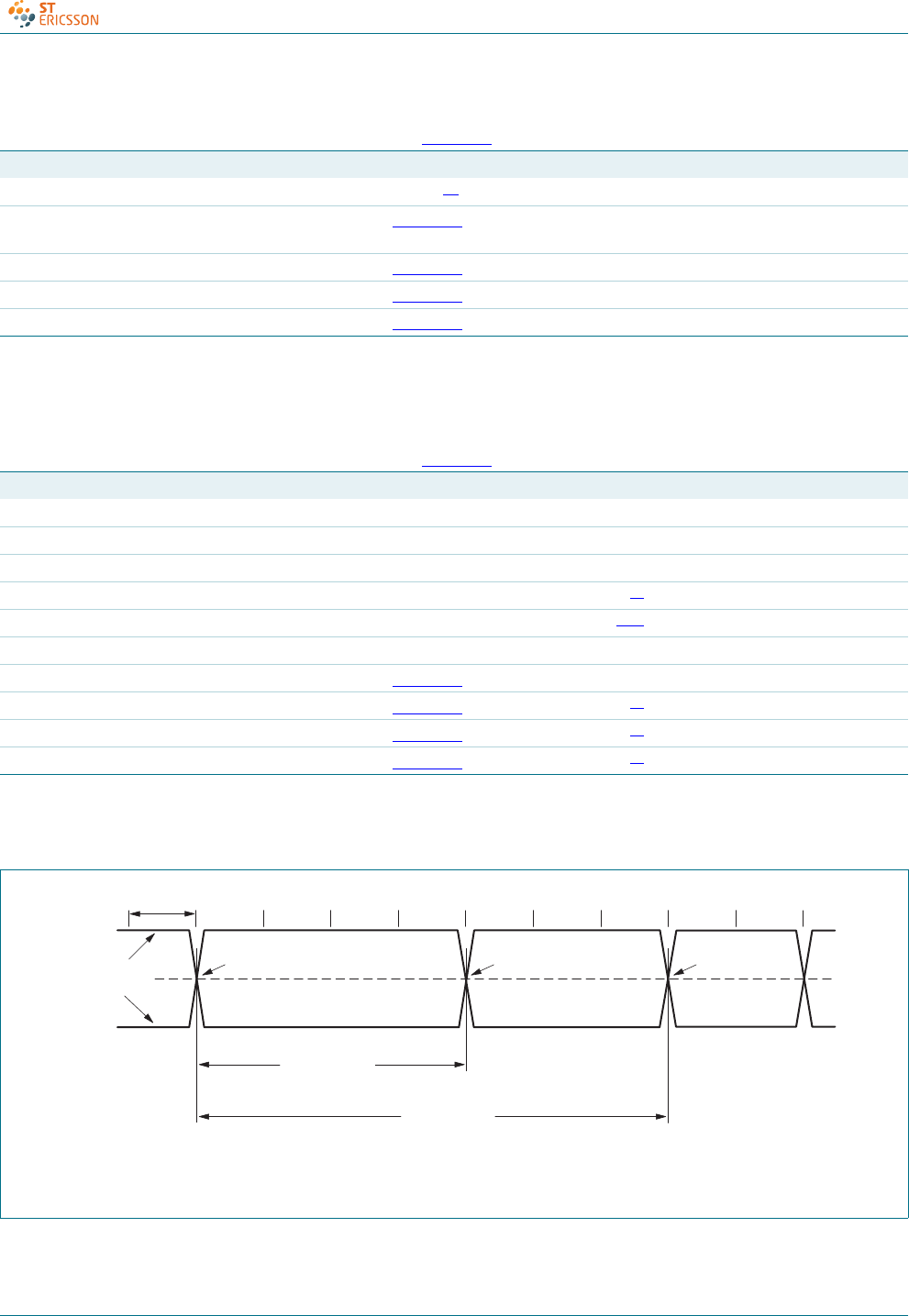
tDJ1 source jitter total (including
frequency tolerance) to next
transition
see Figure 10 [1] −3.5 - +3.5 ns
tDJ2 source jitter total (including
frequency tolerance) for paired
transitions
see Figure 10 [1] −4- +4ns
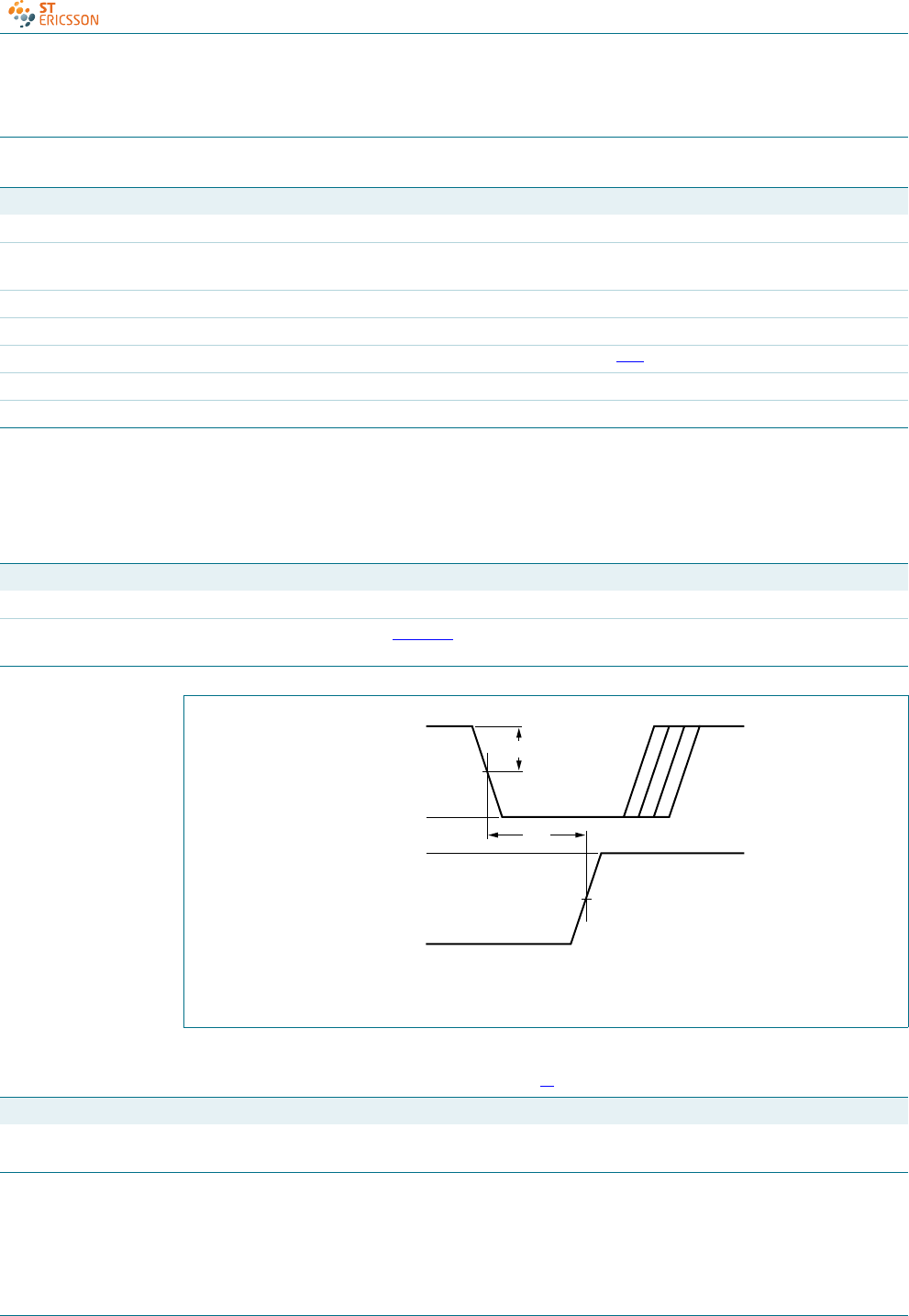
tFEOPT source SE0 interval of EOP see Figure 11 160- 175ns
tFDEOP source jitter for differential transition
to SE0 transition
see Figure 11 −2- +5ns
Receiver timing[2]
tJR1 receiver jitter to next transition see Figure 12 −18.5 - +18.5 ns
tJR2 receiver jitter for paired transitions see Figure 12 −9- +9ns
tFEOPR receiver SE0 interval of EOP accepted as EOP; see Figure 11 82 - - ns
tFST width of SE0 interval during
differential transition
rejected as EOP; see Figure 13 --14ns
CD00222695 © ST-ERICSSON 2010. All rights reserved.
Product data sheet Rev. 07 — 4 February 2010 39 of 53
ISP1521
Hi-Speed USB hub controller
[1] Excluding the first transition from the idle state.
[2] Characterized only, not tested. Limits guaranteed by design.
[1] Excluding the first transition from the idle state.
[2] Characterized only, not tested. Limits guaranteed by design.
Hub timing (downstream ports configured as full-speed)[2]
tFHDD hub differential data delay (without
cable)
see Figure 14; CL= 0 pF - - 44 ns
tFSOP data bit width distortion after SOP see Figure 14 −5- +5ns
tFEOPD hub EOP delay relative to tHDD see Figure 15 0- 15ns
tFHESK hub EOP output width skew see Figure 15 −15 - +15 ns
Table 44. Dynamic characteristics: full-speed source electrical characteristics …continued
VCC = 3.0 V to 3.6 V; Tamb =
−
40
°
Cto+70
°
C; test circuit Figure 22; unless otherwise specified.
Symbol Parameter Conditions Min Typ Max Unit
Table 45. Dynamic characteristics: low-speed source electrical characteristics
VCC = 3.0 V to 3.6 V; Tamb =
−
40
°
Cto+70
°
C; test circuit Figure 22; unless otherwise specified.
Symbol Parameter Conditions Min Typ Max Unit
Driver characteristics
tLR rise time 75 - 300 ns
tLF fall time 75 - 300 ns
tLRFM rise and fall time matching [1] 80 - 125 %
VCRS output signal crossover voltage [1][2] 1.3- 2.0V
Hub timing (downstream ports configured as full-speed)
tLHDD hub differential data delay see Figure 14 --300ns
tLSOP data bit width distortion after SOP see Figure 14 [2] −60 - +60 ns
tLEOPD hub EOP delay relative to tHDD see Figure 15 [2] 0- 200ns
tLHESK hub EOP output width skew see Figure 15 [2] −300 - +300 ns
TPERIOD is the bit duration corresponding with the USB data rate.
Fig 10. Source differential data jitter
mgr870
TPERIOD
differential
data lines
crossover point crossover point crossover point
consecutive
transitions
N × TPERIOD + tDJ1
paired
transitions
N × TPERIOD + tDJ2
+3.3 V
0 V
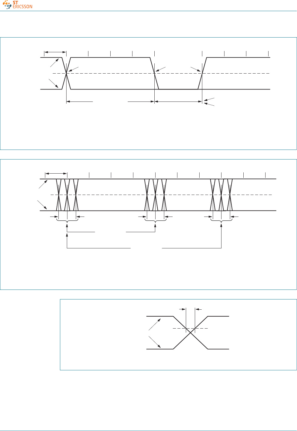
CD00222695 © ST-ERICSSON 2010. All rights reserved.
Product data sheet Rev. 07 — 4 February 2010 40 of 53
ISP1521
Hi-Speed USB hub controller
TPERIOD is the bit duration corresponding with the USB data rate.
Full-speed timing symbols have a subscript prefix ‘F’, low-speed timing a prefix ‘L’.
Fig 11. Source differential data-to-EOP transition skew and EOP width
mgr776
T
PERIOD
differential
data lines
crossover point
differential data to
SE0/EOP skew
N × T
PERIOD
+ t
DEOP
source EOP width: t
EOPT
receiver EOP width: t
EOPR
crossover point
extended
+3.3 V
0 V
TPERIOD is the bit duration corresponding with the USB data rate.
tJR is the jitter reference point.
Fig 12. Receiver differential data jitter
mgr871
T
PERIOD
t
JR
differential
data lines
+3.3 V
0 V
t
JR1
t
JR2
consecutive
transitions
N × T
PERIOD
+ t
JR1
paired
transitions
N × T
PERIOD
+ t
JR2
Fig 13. Receiver SE0 width tolerance
mgr872
differential
data lines
+3.3 V
0 V
tFST
VIH(min)
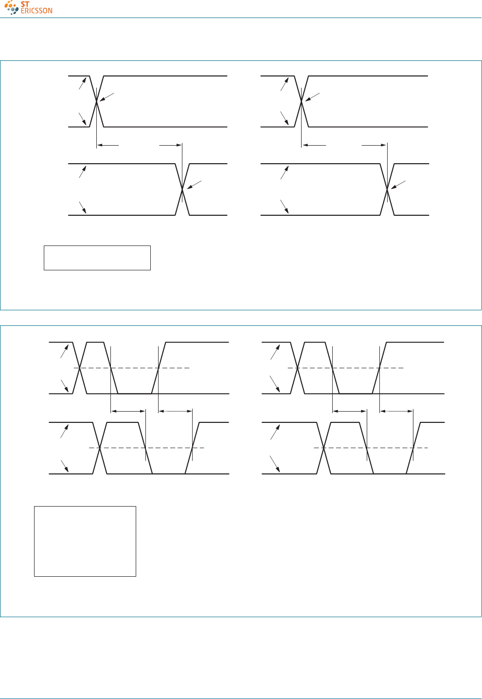
CD00222695 © ST-ERICSSON 2010. All rights reserved.
Product data sheet Rev. 07 — 4 February 2010 41 of 53
ISP1521
Hi-Speed USB hub controller
Full-speed timing symbols have a subscript prefix ‘F’, low-speed timing a prefix ‘L’.
Fig 14. Hub differential data delay and SOP distortion
mgr777
SOP distortion:
tSOP = tHDD (next J) − tHDD(SOP)
(A) downstream hub delay (B) upstream hub delay
upstream
differential
data lines
hub delay
downstream
tHDD
hub delay
upstream
tHDD
downstream
differential
data lines
downstream
differential
data
upstream
differential
data
crossover
point crossover
point
crossover
point
crossover
point
+3.3 V
0 V
+3.3 V
0 V
Full-speed timing symbols have a subscript prefix ‘F’, low-speed timing a prefix ‘L’.
Fig 15. Hub EOP delay and EOP skew
mgr778
tEOP+
tEOP−tEOP+
tEOP−
crossover
point
extended
crossover
point
extended
EOP delay:
tEOP = max (tEOP−, tEOP+)
EOP delay relative to tHDD:
tEOPD = tEOP − tHDD
EOP skew:
tHESK = tEOP+ − tEOP−
(A) downstream EOP delay (B) upstream EOP delay
upstream
differential
data lines
downstream
port
crossover
point
extended
crossover
point
extended
upstream
end of cable
downstream
differential
data lines
+3.3 V
0 V
+3.3 V
0 V
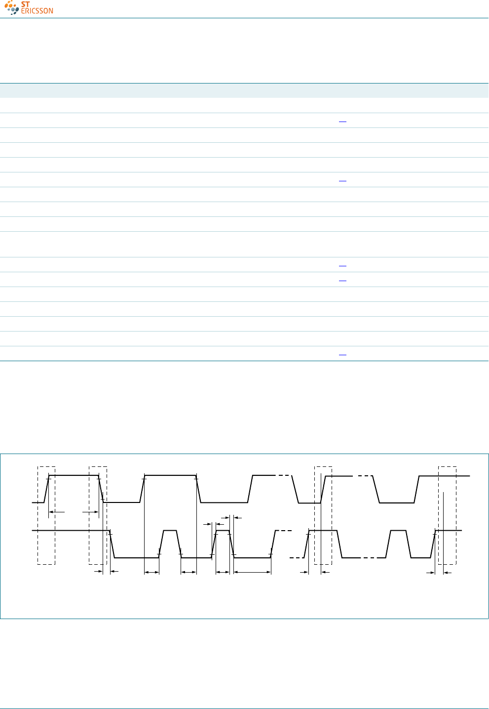
CD00222695 © ST-ERICSSON 2010. All rights reserved.
Product data sheet Rev. 07 — 4 February 2010 42 of 53
ISP1521
Hi-Speed USB hub controller
[1] fSCL =1⁄64 ×fXTAL.
[2] Rise time is determined by Cb and pull-up resistor value Rp (typical 4.7 kΩ).
[3] Set-up time for (repeated) START condition.
[4] Hold time for (repeated) START condition.
[5] SCL LOW to data-out valid time.
Table 46. Dynamic characteristics: I2C-bus (pins SDA and SCL)
VCC and Tamb within recommended operating range; VDD =5V; V
SS =V
GND ; VIL and VIH between VSS and VDD.
Symbol Parameter Conditions Min Typ Max Unit
Clock frequency
fSCL SCL clock frequency fXTAL =12MHz [1] 0 93.75 100 kHz
General timing
t(SCL)L LOW period of the SCL clock 4.7 - - μs
t(SCL)H HIGH period of the SCL clock 4.0 - - μs
trrise time SDA and SCL signals [2] - - 1000 ns
tffall time SDA and SCL signals - - 300 ns
Cbcapacitive load for each bus line - - 400 pF
SDA timing
tBUF bus free time between a STOP and
START condition
4.7 - - μs
tSU;STA setup time for the START condition [3] 4.7 - - μs
tHD;STA hold time for the START condition [4] 4.0 - - μs
tSU;DAT data setup time 250 - - ns
tHD;DAT data hold time 0 - - μs
tSU;STO STOP condition setup time 4.0 - - μs
Additional I2C-bus timing
tVD;DAT data valid time [5] --0.4μs
Fig 16. I2C-bus timing
PS Sr P
004aaa814
tHD;STA
tBUF
tSU;STA
tSU;DAT
tf
t(SCL)H t(SCL)L tSU;STO
tr
tHD;DAT
SDA
SCL
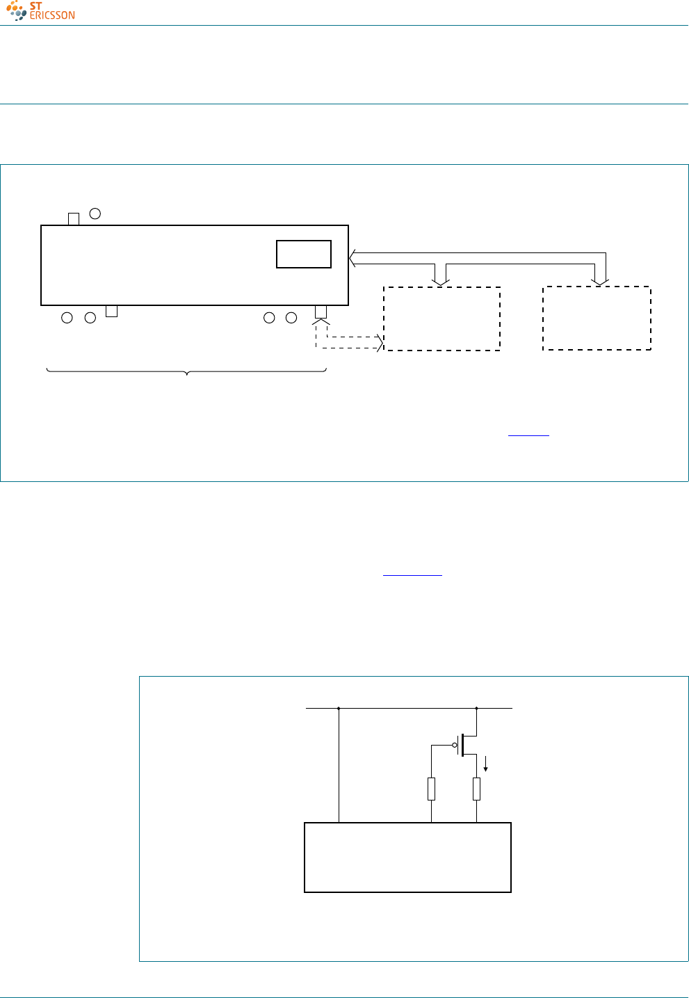
CD00222695 © ST-ERICSSON 2010. All rights reserved.
Product data sheet Rev. 07 — 4 February 2010 43 of 53
ISP1521
Hi-Speed USB hub controller
16. Application information
16.1 Descriptor configuration selection
16.2 Overcurrent detection limit adjustment
For an overcurrent limit of 500 mA per port, a PMOS with RDSon of approximately 100 mΩ
is required. If a PMOS with a lower RDSon is used, analog overcurrent detection can be
adjusted by using a series resistor; see Figure 18.
ΔVPMOS =ΔVtrip =ΔVtrip(intrinsic) −(IOC(nom) ×Radj(oc)), where:
ΔVPMOS = voltage drop on PMOS
IOC(nom) =0.6μA.
The I2C-bus cannot be shared between the EEPROM and the external microcontroller; see Ta b l e 11 .
(1) The function on port 7, which is a nonremovable port, is optional.
Fig 17. Descriptors configuration selection application diagram
004aaa302
ISP1521 ROM
external microcontroller
acting as I
2
C-bus master
USB function
EEPROM
I
2
C-bus
green and
amber LEDs,
port 1
green and
amber LEDs,
port 7
(1)
7 USB downstream facing ports
. .
upstream
facing port GoodLink
(1) Radj(oc) is optional.
Fig 18. Adjusting analog overcurrent detection limit (optional)
004aaa260
VREF(5V0)
Radj(oc)(1)
5 V
ISP1521
OCn_NPSWn_N
IOC
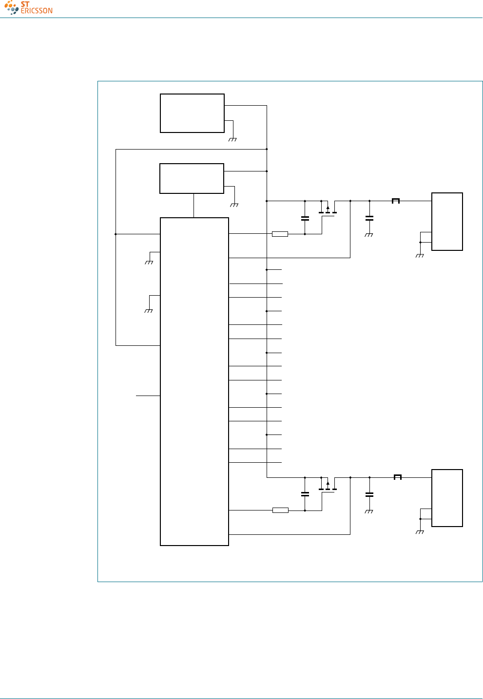
CD00222695 © ST-ERICSSON 2010. All rights reserved.
Product data sheet Rev. 07 — 4 February 2010 44 of 53
ISP1521
Hi-Speed USB hub controller
16.3 Self-powered hub configurations
Fig 19. Self-powered hub; individual port power switching; individual overcurrent
detection
PSW1_N
PSW2_N
TEST_HIGH
OC1_N
OC2_N
PSW7_N
OC7_N
5 V ± 3 %
POWER SUPPLY−
+
1
VBUS
D+
D−
GND
port 2
to
port 6
SHIELD
+4.75 V
(min)
+4.85 V (min)
VREF(5V0)
GND
ISP1521
120 μF
ferrite bead
downstream
port connector
T1
T7
0.1 μF
47 kΩ
004aaa304
3.3 V LDO
VOLTAGE
REGULATOR
VCC
ADOC
7
VBUS
D+
D−
GND
SHIELD
+4.75 V
(min)
120 μF
ferrite bead
0.1 μF
47 kΩ
TEST_LOW
PSW3_N
OC3_N
PSW4_N
OC4_N
PSW5_N
OC5_N
PSW6_N
OC6_N
3.3 V or
5.0 V
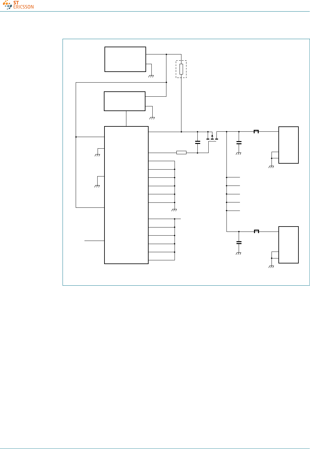
CD00222695 © ST-ERICSSON 2010. All rights reserved.
Product data sheet Rev. 07 — 4 February 2010 45 of 53
ISP1521
Hi-Speed USB hub controller
Fig 20. Self-powered hub; ganged port power switching; global overcurrent detection
PSW1_N
TEST_HIGH
OC1_N
5.1 V ± 3 %
POWER SUPPLY
(kick-up)
−
+
1
V
BUS
D+
D−
GND
port 2
to
port 6
SHIELD
+4.75 V
(min)
+4.95 V (min)
V
REF(5V0)
GND
ISP1521
120 μF
ferrite bead
downstream
port connector
T1
0.1 μF
47 kΩ
004aaa306
V
CC
ADOC
7
V
BUS
D+
D−
GND
SHIELD
+4.75 V
(min)
120 μF
ferrite bead
low-ohmic
sense resistor
for overcurrent
detection
OC2_N
OC3_N
OC4_N
OC5_N
OC6_N
OC7_N
+5 V
PSW3_N
PSW2_N
PSW4_N
PSW5_N
PSW6_N
PSW7_N
TEST_LOW
3.3 V LDO
VOLTAGE
REGULATOR
3.3 V or
5.0 V
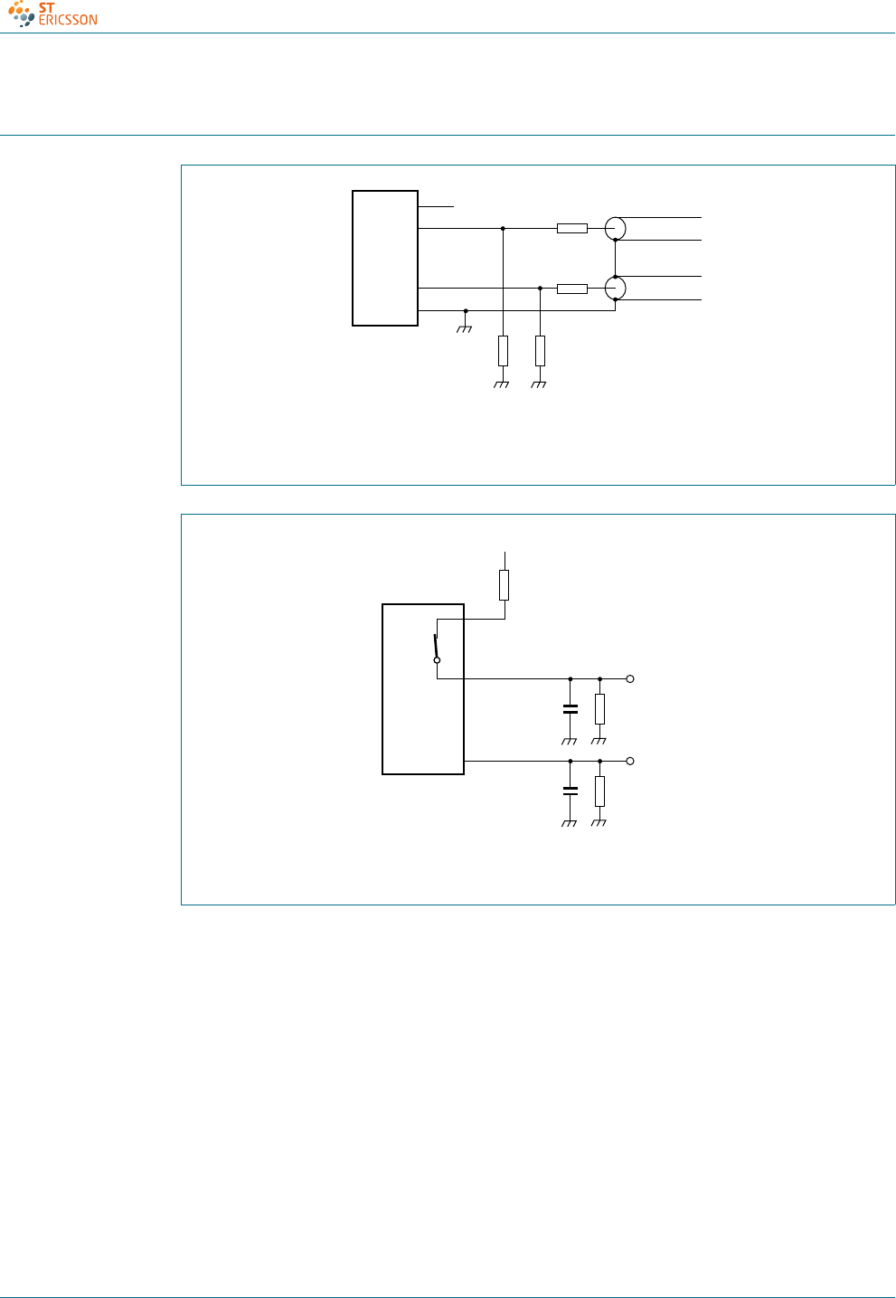
CD00222695 © ST-ERICSSON 2010. All rights reserved.
Product data sheet Rev. 07 — 4 February 2010 46 of 53
ISP1521
Hi-Speed USB hub controller
17. Test information
(1) Transmitter: connected to 50 Ω inputs of a high-speed differential oscilloscope.
Receiver: connected to 50 Ω outputs of a high-speed differential data generator.
Fig 21. High-speed transmitter and receiver test circuit
(1) CL= 50 pF for full-speed.
Fig 22. Full-speed test circuit
mdb273
DMn
DPn
50 Ω coax
50 Ω coax
DUT
GND
VBUS
143 Ω
15.8 Ω
15.8 Ω
143 Ω
(1)
D−
D+
CL(1)
(1)
15 kΩ
DPn
DMn
RPU
3.3 V
1.5 kΩ ± 5%
DUT
mdb274
CL(1) 15 kΩ
test point
full-
speed
test point
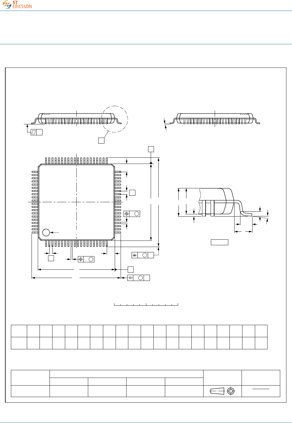
CD00222695 © ST-ERICSSON 2010. All rights reserved.
Product data sheet Rev. 07 — 4 February 2010 47 of 53
ISP1521
Hi-Speed USB hub controller
18. Package outline
Fig 23. Package outline SOT315-1 (LQFP80)
UNIT A
max. A1A2A3bpcE
(1) eH
ELL
pZywv θ
REFERENCES
OUTLINE
VERSION EUROPEAN
PROJECTION ISSUE DATE
IEC JEDEC JEITA
mm 1.6 0.16
0.04 1.5
1.3 0.25 0.27
0.13 0.18
0.12 12.1
11.9 0.5 14.15
13.85 1.45
1.05 7
0
o
o
0.15 0.10.21
DIMENSIONS (mm are the original dimensions)
Note
1. Plastic or metal protrusions of 0.25 mm maximum per side are not included.
0.75
0.30
SOT315-1 136E15 MS-026 00-01-19
03-02-25
D(1) (1)(1)
12.1
11.9
HD
14.15
13.85
E
Z
1.45
1.05
D
bp
e
θ
EA1
A
Lp
detail X
L
(A )
3
B
20
c
D
H
bp
E
HA2
vMB
D
ZD
A
ZE
e
vMA
X
1
80
61
60 41
40
21
y
pin 1 index
wM
wM
0 5 10 mm
scale
LQFP80: plastic low profile quad flat package; 80 leads; body 12 x 12 x 1.4 mm SOT315-1

CD00222695 © ST-ERICSSON 2010. All rights reserved.
Product data sheet Rev. 07 — 4 February 2010 48 of 53
ISP1521
Hi-Speed USB hub controller
19. Abbreviations
20. References
[1] Universal Serial Bus Specification Rev. 2.0
[2] The I2C-bus specification
[3] ISP1521 Hi-Speed USB hub demo board user manual (UM10011)
Table 47. Abbreviations
Acronym Description
ACPI Advanced Configuration and Power Interface
CRC Cyclical Redundancy Check
EEPROM Electronically Erasable Programmable Read-Only Memory
EMI ElectroMagnetic Interference
EOP End-of-Packet
ESD ElectroStatic Discharge
FET Field-Effect Transistor
HS High-Speed
LSB Least Significant Bit
MSB Most Significant Bit
MOSFET Metal Oxide Silicon Field Effect Transistor
NAK Not AcKnowledge
PCB Printed-Circuit Board
PID Packet IDentifier
PLL Phase-Locked Loop
SIE Serial Interface Engine
SOP Start-of-Packet
TT Transaction Translator
TTL Transistor-Transistor Logic
USB Universal Serial Bus

CD00222695 © ST-ERICSSON 2010. All rights reserved.
Product data sheet Rev. 07 — 4 February 2010 49 of 53
ISP1521
Hi-Speed USB hub controller
21. Revision history
Table 48. Revision history
Revision Release date Data sheet status Change notice
7 20100204 Product data sheet -
Modifications: •Updated the filename according to the latest corporate standards.
•Table 37 “Static characteristics: digital input and output”: updated ΔVtrip.
•Figure 9 “Overcurrent trip response timing”: changed VCC to VBUS.
•Figure 21 “High-speed transmitter and receiver test circuit”: changed VCC to VBUS.
6 20090929 Product data sheet -
5 20090129 Product data sheet -
4 20060330 Product data sheet -
3 (9397 750 13702) 20041124 Product data -
2 (9397 750 11691) 20040212 Product data -
1 (9397 750 10691) 20030625 Preliminary data -

CD00222695 © ST-ERICSSON 2010. All rights reserved.
Product data sheet Rev. 07 — 4 February 2010 50 of 53
ISP1521
Hi-Speed USB hub controller
22. Tables
Table 1. Ordering information . . . . . . . . . . . . . . . . . . . . .2
Table 2. Pin description . . . . . . . . . . . . . . . . . . . . . . . . . .4
Table 3. Configuration parameters . . . . . . . . . . . . . . . .12
Table 4. Downstream facing port number pin
configuration . . . . . . . . . . . . . . . . . . . . . . . . . .13
Table 5. Power switching mode: pin configuration . . . .14
Table 6. Overcurrent protection mode pin configuration 15
Table 7. Overcurrent detection mode selection pin
configuration . . . . . . . . . . . . . . . . . . . . . . . . . .15
Table 8. Nonremovable port pin configuration . . . . . . . .15
Table 9. Port indicator support: pin configuration . . . . .16
Table 10. I2C-bus slave address . . . . . . . . . . . . . . . . . . .16
Table 11. Configuration method . . . . . . . . . . . . . . . . . . .17
Table 12. ROM or EEPROM detailed map . . . . . . . . . . .18
Table 13. Hub endpoints . . . . . . . . . . . . . . . . . . . . . . . . .23
Table 14. Status Change byte: bit allocation . . . . . . . . . .24
Table 15. Device descriptor . . . . . . . . . . . . . . . . . . . . . . .24
Table 16. Device_qualifier descriptor . . . . . . . . . . . . . . .25
Table 17. Other_speed_configuration descriptor . . . . . .25
Table 18. Configuration descriptor . . . . . . . . . . . . . . . . .25
Table 19. Interface descriptor . . . . . . . . . . . . . . . . . . . . .26
Table 20. Endpoint descriptor . . . . . . . . . . . . . . . . . . . . .26
Table 21. Hub descriptor . . . . . . . . . . . . . . . . . . . . . . . . .26
Table 22. wHubCharacteristics bit description . . . . . . . . .27
Table 23. Standard USB requests . . . . . . . . . . . . . . . . . .27
Table 24. Hub class requests . . . . . . . . . . . . . . . . . . . . .28
Table 25. Hub class feature selector . . . . . . . . . . . . . . . .29
Table 26. Get hub configuration response . . . . . . . . . . .30
Table 27. Get device status response . . . . . . . . . . . . . . .30
Table 28. Get interface status response . . . . . . . . . . . . .30
Table 29. Get endpoint status response . . . . . . . . . . . . .30
Table 30. Get hub status response . . . . . . . . . . . . . . . . .30
Table 31. Get port status response (wPortStatus) . . . . . .31
Table 32. Get port status change response
(wPortChange) . . . . . . . . . . . . . . . . . . . . . . . .31
Table 33. Get descriptor request . . . . . . . . . . . . . . . . . . .32
Table 34. Limiting values . . . . . . . . . . . . . . . . . . . . . . . . .33
Table 35. Recommended operating ranges . . . . . . . . . .33
Table 36. Static characteristics: supply pins . . . . . . . . . .34
Table 37. Static characteristics: digital input and output .34
Table 38. Static characteristics: I2C-bus interface block .35
Table 39. Static characteristics: USB interface block (DP0 to
DP7 and DM0 to DM7) . . . . . . . . . . . . . . . . . .35
Table 40. Dynamic characteristics: system clock timing .37
Table 41. Dynamic characteristics: overcurrent sense
timing . . . . . . . . . . . . . . . . . . . . . . . . . . . . . . . .37
Table 42. Dynamic characteristics: digital pins . . . . . . . .37
Table 43. Dynamic characteristics: high-speed source
electrical characteristics . . . . . . . . . . . . . . . . . .38
Table 44. Dynamic characteristics: full-speed source
electrical characteristics . . . . . . . . . . . . . . . . . .38
Table 45. Dynamic characteristics: low-speed source
electrical characteristics . . . . . . . . . . . . . . . . . .39
Table 46. Dynamic characteristics: I2C-bus (pins SDA and
SCL) . . . . . . . . . . . . . . . . . . . . . . . . . . . . . . . .42
Table 47. Abbreviations . . . . . . . . . . . . . . . . . . . . . . . . . .48
Table 48. Revision history . . . . . . . . . . . . . . . . . . . . . . . . 49

CD00222695 © ST-ERICSSON 2010. All rights reserved.
Product data sheet Rev. 07 — 4 February 2010 51 of 53
ISP1521
Hi-Speed USB hub controller
23. Figures
Fig 1. Block diagram . . . . . . . . . . . . . . . . . . . . . . . . . . . .3
Fig 2. Pin configuration . . . . . . . . . . . . . . . . . . . . . . . . . .4
Fig 3. Power-on reset timing . . . . . . . . . . . . . . . . . . . . .11
Fig 4. External clock with respect to power-on reset . . . 11
Fig 5. Typical voltage drop components in self-powered
mode using individual overcurrent detection . . . .14
Fig 6. Typical voltage drop components in self-powered
mode using global overcurrent detection . . . . . . .14
Fig 7. Configurable hub descriptors. . . . . . . . . . . . . . . .17
Fig 8. ROM or EEPROM map . . . . . . . . . . . . . . . . . . . .18
Fig 9. Overcurrent trip response timing . . . . . . . . . . . . .37
Fig 10. Source differential data jitter . . . . . . . . . . . . . . . .39
Fig 11. Source differential data-to-EOP transition skew and
EOP width . . . . . . . . . . . . . . . . . . . . . . . . . . . . . .40
Fig 12. Receiver differential data jitter . . . . . . . . . . . . . . .40
Fig 13. Receiver SE0 width tolerance . . . . . . . . . . . . . . .40
Fig 14. Hub differential data delay and SOP distortion . .41
Fig 15. Hub EOP delay and EOP skew . . . . . . . . . . . . . .41
Fig 16. I2C-bus timing . . . . . . . . . . . . . . . . . . . . . . . . . . .42
Fig 17. Descriptors configuration selection application
diagram . . . . . . . . . . . . . . . . . . . . . . . . . . . . . . . .43
Fig 18. Adjusting analog overcurrent detection limit
(optional) . . . . . . . . . . . . . . . . . . . . . . . . . . . . . . .43
Fig 19. Self-powered hub; individual port power switching;
individual overcurrent detection . . . . . . . . . . . . . .44
Fig 20. Self-powered hub; ganged port power switching;
global overcurrent detection . . . . . . . . . . . . . . . .45
Fig 21. High-speed transmitter and receiver test circuit. .46
Fig 22. Full-speed test circuit. . . . . . . . . . . . . . . . . . . . . .46
Fig 23. Package outline SOT315-1 (LQFP80) . . . . . . . . .47

CD00222695 © ST-ERICSSON 2010. All rights reserved.
Product data sheet Rev. 07 — 4 February 2010 52 of 53
ISP1521
Hi-Speed USB hub controller
24. Contents
1 General description . . . . . . . . . . . . . . . . . . . . . . 1
2 Features . . . . . . . . . . . . . . . . . . . . . . . . . . . . . . . 2
3 Applications . . . . . . . . . . . . . . . . . . . . . . . . . . . . 2
4 Ordering information. . . . . . . . . . . . . . . . . . . . . 2
5 Block diagram . . . . . . . . . . . . . . . . . . . . . . . . . . 3
6 Pinning information. . . . . . . . . . . . . . . . . . . . . . 4
6.1 Pinning . . . . . . . . . . . . . . . . . . . . . . . . . . . . . . . 4
6.2 Pin description . . . . . . . . . . . . . . . . . . . . . . . . . 4
7 Functional description . . . . . . . . . . . . . . . . . . . 9
7.1 Analog transceivers . . . . . . . . . . . . . . . . . . . . . 9
7.2 Hub controller core . . . . . . . . . . . . . . . . . . . . . . 9
7.2.1 ST-Ericsson serial interface engine . . . . . . . . . 9
7.2.2 Routing logic . . . . . . . . . . . . . . . . . . . . . . . . . . . 9
7.2.3 Transaction translator . . . . . . . . . . . . . . . . . . . . 9
7.2.4 Mini-Host Controller . . . . . . . . . . . . . . . . . . . . . 9
7.2.5 Hub repeater. . . . . . . . . . . . . . . . . . . . . . . . . . 10
7.2.6 Hub and port controllers . . . . . . . . . . . . . . . . . 10
7.2.7 Bit clock recovery . . . . . . . . . . . . . . . . . . . . . . 10
7.3 Phase-locked loop clock multiplier . . . . . . . . . 10
7.4 I2C-bus controller . . . . . . . . . . . . . . . . . . . . . . 10
7.5 Overcurrent detection circuit. . . . . . . . . . . . . . 10
7.6 GoodLink . . . . . . . . . . . . . . . . . . . . . . . . . . . . 10
7.7 Power-on reset . . . . . . . . . . . . . . . . . . . . . . . . 10
8 Configuration selections. . . . . . . . . . . . . . . . . 12
8.1 Configuration through I/O pins . . . . . . . . . . . . 13
8.1.1 Number of downstream facing ports. . . . . . . . 13
8.1.2 Power switching . . . . . . . . . . . . . . . . . . . . . . . 13
8.1.2.1 Voltage drop requirements . . . . . . . . . . . . . . . 13
8.1.3 Overcurrent protection mode . . . . . . . . . . . . . 14
8.1.4 Nonremovable port . . . . . . . . . . . . . . . . . . . . . 15
8.1.5 Port indicator support . . . . . . . . . . . . . . . . . . . 15
8.2 Device descriptors and string descriptors settings
using I2C-bus . . . . . . . . . . . . . . . . . . . . . . . . . 16
8.2.1 Background information on I2C-bus . . . . . . . . 16
8.2.1.1 Different conditions on I2C-bus . . . . . . . . . . . . 16
8.2.1.2 Data transfer . . . . . . . . . . . . . . . . . . . . . . . . . . 16
8.2.1.3 I2C-bus address . . . . . . . . . . . . . . . . . . . . . . . 16
8.2.2 Architecture of configurable hub descriptors . 17
8.2.3 ROM or EEPROM map. . . . . . . . . . . . . . . . . . 18
8.2.4 ROM or EEPROM detailed map. . . . . . . . . . . 18
9 Hub controller description . . . . . . . . . . . . . . . 23
9.1 Endpoint 0. . . . . . . . . . . . . . . . . . . . . . . . . . . . 23
9.2 Endpoint 1. . . . . . . . . . . . . . . . . . . . . . . . . . . . 23
10 Descriptors. . . . . . . . . . . . . . . . . . . . . . . . . . . . 24
11 Hub requests . . . . . . . . . . . . . . . . . . . . . . . . . . 27
11.1 Standard USB requests . . . . . . . . . . . . . . . . . 27
11.2 Hub class requests . . . . . . . . . . . . . . . . . . . . . 28
11.3 Detailed responses to hub requests . . . . . . . . 29
11.3.1 Get configuration . . . . . . . . . . . . . . . . . . . . . . 29
11.3.2 Get device status . . . . . . . . . . . . . . . . . . . . . . 30
11.3.3 Get interface status. . . . . . . . . . . . . . . . . . . . . 30
11.3.4 Get endpoint status. . . . . . . . . . . . . . . . . . . . . 30
11.3.5 Get hub status . . . . . . . . . . . . . . . . . . . . . . . . 30
11.3.6 Get port status . . . . . . . . . . . . . . . . . . . . . . . . 31
11.4 Various get descriptors . . . . . . . . . . . . . . . . . 32
12 Limiting values . . . . . . . . . . . . . . . . . . . . . . . . 33
13 Recommended operating conditions . . . . . . 33
14 Static characteristics . . . . . . . . . . . . . . . . . . . 34
15 Dynamic characteristics. . . . . . . . . . . . . . . . . 37
16 Application information . . . . . . . . . . . . . . . . . 43
16.1 Descriptor configuration selection . . . . . . . . . 43
16.2 Overcurrent detection limit adjustment . . . . . 43
16.3 Self-powered hub configurations . . . . . . . . . . 44
17 Test information . . . . . . . . . . . . . . . . . . . . . . . 46
18 Package outline. . . . . . . . . . . . . . . . . . . . . . . . 47
19 Abbreviations . . . . . . . . . . . . . . . . . . . . . . . . . 48
20 References. . . . . . . . . . . . . . . . . . . . . . . . . . . . 48
21 Revision history . . . . . . . . . . . . . . . . . . . . . . . 49
22 Tables . . . . . . . . . . . . . . . . . . . . . . . . . . . . . . . . 50
23 Figures . . . . . . . . . . . . . . . . . . . . . . . . . . . . . . . 51
24 Contents. . . . . . . . . . . . . . . . . . . . . . . . . . . . . . 52

CD00222695 © ST-ERICSSON 2010. All rights reserved.
Product data sheet Rev. 07 — 4 February 2010 53 of 53
ISP1521
Hi-Speed USB hub controller
Please Read Carefully:
The contents of this document are subject to change without prior notice. ST-Ericsson makes no representation or warranty of any nature
whatsoever (neither expressed nor implied) with respect to the matters addressed in this document, including but not limited to warranties of
merchantability or fitness for a particular purpose, interpretability or interoperability or, against infringement of third party intellectual property
rights, and in no event shall ST-Ericsson be liable to any party for any direct, indirect, incidental and or consequential damages and or loss
whatsoever (including but not limited to monetary losses or loss of data), that might arise from the use of this document or the information in it.
ST-Ericsson and the ST-Ericsson logo are trademarks of the ST-Ericsson group of companies or used under a license from
STMicroelectronics NV or Telefonaktiebolaget LM Ericsson.
All other names are the property of their respective owners.
© ST-Ericsson, 2010 - All rights reserved
Contact information at www.stericsson.com under Contacts
www.stericsson.com
