ISrc LEBT User Manual
User Manual:
Open the PDF directly: View PDF ![]() .
.
Page Count: 27
Doc ESS-0123103 Rev 1
Date 2017-Dec-11
Version
1.0
State
Final version
User manual of the ESS ISRC and LEBT
Audience Affiliation
Owner
Jean-François DENIS CEA
Authors
Jean-François DENIS CEA
Reviewers
Françoise Gougnaud CEA
Approvers
Florence Ardelier CEA
2(27)
TABLE OF CONTENTS
1. INTRODUCTION ...................................................................................................................................... 4
2. Presentation ............................................................................................................................................. 4
2.1 Source (Isrc) ..................................................................................................................................... 4
2.2 LEBT .................................................................................................................................................... 4
3. SYSTEM CONFIGURATION .................................................................................................................. 5
3.1 Hardware: ESS Control Box ........................................................................................................ 5
3.1.1 Isrc ............................................................................................................................................... 5
3.1.2 LEBT ........................................................................................................................................... 5
3.2 Network architecture ................................................................................................................... 6
3.3 IP address of devices..................................................................................................................... 7
3.4 Software: Linux ............................................................................................................................... 8
3.4.1 Server ......................................................................................................................................... 8
3.4.2 Client .......................................................................................................................................... 8
4. EPICS CONTROL SOFTWARE ............................................................................................................. 8
4.1 Overview ........................................................................................................................................... 8
4.1.1 Isrc modules ............................................................................................................................ 8
4.1.2 LEBT modules ......................................................................................................................... 9
4.2 Database ............................................................................................................................................ 9
4.2.1 Isrc ............................................................................................................................................... 9
4.2.2 LEBT ........................................................................................................................................ 11
4.3 IOC ..................................................................................................................................................... 13
4.3.1 Startup scripts ..................................................................................................................... 13
4.3.1.1 source-vme.cmd ......................................................................................................... 13
4.3.1.2 ipc-source.cmd ............................................................................................................ 16
4.3.1.3 ipc-lebt.cmd ................................................................................................................. 16
4.3.2 Booting configuration ....................................................................................................... 17
4.3.3 Services starting ................................................................................................................. 18
5. Operator Interface .............................................................................................................................. 18
5.1 Main User interface: source.opi ............................................................................................. 18
5.1.1 Main tab: source control .................................................................................................. 19
5.1.1.1 Magnetron .................................................................................................................... 19
5.1.1.2 Automatic Tuning Unit (ATU) ............................................................................... 20
5.1.1.3 Magnetic System ........................................................................................................ 20
5.1.1.4 High Voltage Power supply .................................................................................... 21
5.1.1.5 Repeller Power supply ............................................................................................. 21
3(27)
5.1.1.6 Sensors........................................................................................................................... 22
5.1.1.7 Vacuum status ............................................................................................................. 22
5.1.2 Interlock tab ......................................................................................................................... 23
5.1.3 Vaccum tab ............................................................................................................................ 23
5.2 Diagnostic User interface: second-source.opi .................................................................. 24
5.2.1 Faraday Cup .......................................................................................................................... 25
5.2.2 IRIS ........................................................................................................................................... 25
5.2.3 Doppler ................................................................................................................................... 25
5.2.4 EMU ......................................................................................................................................... 26
6. LIST OF ABBREVIATIONS ................................................................................................................ 27
4(27)
1. INTRODUCTION
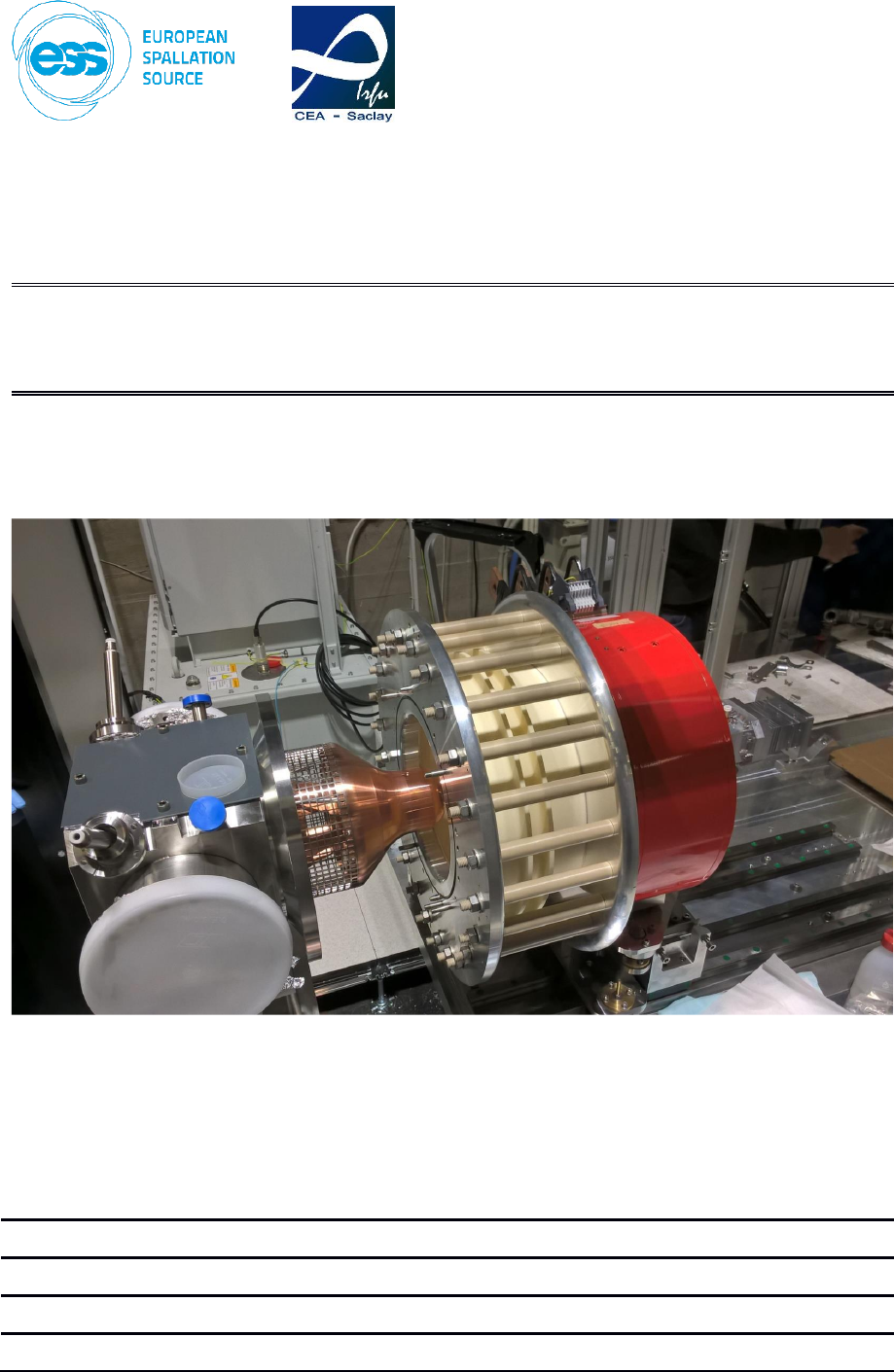
The European Spallation Source (ESS) ion source is based on ECR technology and it’s currently develop
at INFN-LNS in Catania. The beam will be extracted with an energy of 75 keV. The ion source will be
followed by a magnetic Low Energy Beam Transport line, which consists of 2 solenoids, a pre chopper
system, and an iris in order to modulate the beam intensity from 6.3 to 62.5 mA at the target window.
CEA is in charge of the control command for the source and Low Energy Beam Transmission (LEBT).
It’s based on Experimental Physics and Industrial Control System (EPICS).
This document will present the control command of the ESS Source and the LEBT. If more information
are needed on a control of a device, please refer to the documentation dedicated.
2. PRESENTATION
2.1 Source (Isrc)
The devices to be controlled are located on the HV platform and at ground potential. In order to prevent
damages for instrumentations due to HV discharges all the devices interacting with the beam line and
platform shall be adequately grounded. The link between the HV plateform and the ground is done by
an optical fiber.
Devices to be controlled on the HV platform are:
- Magnetron
- Automatic tuning Unit (ATU)
- MFC, vacuum gauge & valve
- COILS Power supply
- PLC ( remote I/O)
- Ethercat remote I/O ( sensors, temperatures)
Devices to be controlled at the ground are:
- High Voltage power supply
- Repeller electrode
- PLC
- Ethercat Remote I/O (Sensors, temperatures)
2.2 LEBT
The LEBT is composed of:
- Faraday Cup
- Power supplies dedicated to steerers, solenoids.
- The chopper
- The IRIS
- Two EMUs vertical and horizontal
- Doppler
- And other devices, but not on the charge of CEA.

5(27)
3. SYSTEM CONFIGURATION
3.1 Hardware: ESS Control Box
The control command uses the Control Box provided by ICS. It’s based on a VME-64x architecture and
Industrial PC (NEXCOM NISE 6500).
3.1.1 Isrc
The ISRC VME crate is composed of:
Description
Name
Observations
Mother board
IFC1210 (IOXOS)
VME-64X
DACQ Board
ACQ420FMC
4 channels, 16 bits, +/- 10V, 2 MSample, FMC format
Timing Generator
MRF-EVG-230
VME format
Timing Receiver
MRF-EVR-230
VME Format
Table 2: ISRC VME Control Box composition
3.1.2 LEBT
Excepted for both EMU, the devices installed on the LEBT are controlled by the IPC of the source
(IPC_ISRC-LEBT).
The EMUs VME crate is composed of:
Description
Name
Observations
Mother board
IFC1210 (IOXOS)
VME-64X
DACQ Board
ACQ420FMC
4 channels, 16 bits, +/- 10V, 2 MSample, FMC format
Timing Receiver
MRF-EVR-230
VME Format
Table 3: EMU VME Control Box composition
6(27)
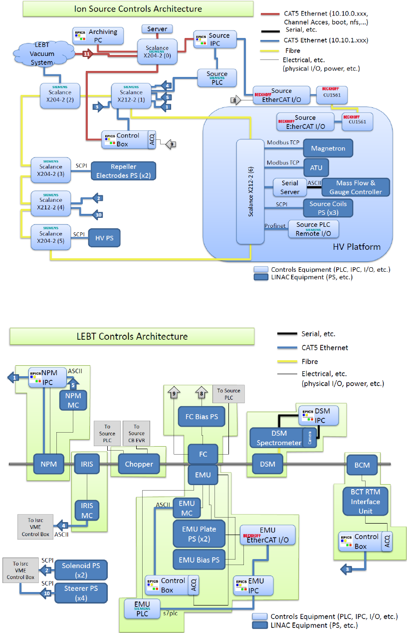
3.2 Network architecture
Figure 1: Isrc Network architecture
Figure 2: LEBT network architecture

7(27)
3.3 IP address of devices
Description
Name
IP ADDRESS
NETWORK
IP ADDRESS SUBNETWORK (CA)
MAIN DEVICES
Main server
Server
172.16.30.135
10.10.0.1
User or Devell PC
Devenv
172.16.30.136
10.10.0.10
Archivage
Sispck16
---
10.10.0.11
VME Source
VME_SOURCE
---
10.10.0.15
IPC Source
IPC_ISRC-LEBT
---
10.10.0.16
VME EMU
VME_EMU
---
10.10.0.19
IPC_EMU
IPC_EMU
---
10.10.0.18
Doppler PC
Doppler
---
10.10.0.20
SOURCE DEVICES
ATU
SAIREM AI4S
---
10.10.1.36:502
Magnetron
SAIREM
GMP20KED
---
10.10.1.38:502
HV PS
FUG
HCH15K100K
---
10.10.1.37:2101
Reppeler PS
FUG
HCP353500
---
10.10.1.34:2101
Coils PS
TDK GEN10500
---
10.10.1.31/32/33/:8003
MFC & Gauge
MOXA GATE-
WAY
---
10.10.1.20
PLC
PLC-Source
---
Interface IPC : 10.10.2.2
Interface VME : 10.10.1.30 (I/O on
HV)
Remote IO : 10.10.1.29
LEBT DEVICES
Steerer PS 1
SORENZEN
SGA30x501d
---
10.10.1.53 :5025
Steerer PS 2
SORENZEN
SGA30x501d
---
10.10.1.54:5025
Steerer PS 3
SORENZEN
SGA30x501d
---
10.10.1.55 :5025
Motor Controller
IRIS
GEOBRICK
---
10.10.1.40
Motor Controller
EMU Ver. and Hor.
GEOBRICK
---
10.10.3.42 (Subnet on IPC_EMU)
PLC EMU
PLC-EMU
---
10.10.2.3 (Subnet on IPC_EMU)
Solenoid PS
SOL1-PS
---
10.10.1.35
Solenoid PS
SOL2-PS
---
10.10.1.36
*CA: Channel Access Table 1: IP addresses of devices of ISRC and LEBT

8(27)
3.4 Software: Linux
3.4.1 Server
The installation of the main server is full compliant with the INKIND EEE Server:
https://confluence.esss.lu.se/display/DE/In-kind+EEE+server+setup
3.4.2 Client
The installation of the client is full compliant with the IN-KIND EEE Devenv:
https://confluence.esss.lu.se/display/DE/In-kind+physical+DM+setup
4. EPICS CONTROL SOFTWARE
4.1 Overview
A module is developed for each device. In the following tables is presented all modules used to control
and test the Source (Isrc) and LEBT:
4.1.1 Isrc modules
Device
Module
Magnetron
m-epics-sairemgmp20ked
ATU
m-epics-sairemai4s
MFC
m-epics-vac_ctrl_mks946
m-epics-vac_mfc_mks_gv50a
m-epics-vac_gauge_mks_vgd
COILS Power supply
1. m-epics-tdkgen10500
PLC
1. m-epics-plc-source
HV Power supply
2. m-epics-fug
Faraday Cup
3. m-epics-faradaycup
FastAcquisistion
4. m-epics-fastacquisition
DataAcquisition
5. m-epics-dataacquisition
Table 2: List of modules used for Isrc
The module m-epics-source is used essentially to load all devices modules with their EPICS database.
It contains main screens and only one database for sensors and ISEG power supply (Faraday Cup).It
has the following structure.
Folder
File
Description
Makefile
makefile of the module
db
source-sensors.substitutions
Substitution file to create Database
doc
ISrcEPICSmanual.pdf
this document
opi
source.opi
Main opi
opi
Source-second.opi
Diags OPI

9(27)
Folder
File
Description
opi/scripts
DiagOpiSwitch.js
javascript used by Source-second.opi to switch views
opi/scripts
PlcOpiSwitch.js
javascript used by Source-second.opi to switch views for the
PLC part
Startup
Source-vme.cmd
IOC startup script on the VME
Startup
Source-ipc.cmd
IOC startup script on the IPC
Table 3: m-epics-source module structure
The last version tagged on bitbucket of ESS is: v1.2.0-catania
4.1.2 LEBT modules
Device
Module
Steerers PS
1. m-epics-sorensenXG125120
Solenoids PS
m-epics-sorensenSGA30x501d
Iris
m-epics-iris
EMU
m-epics-emu
EMU (PLC)
m-epics-emu-plc
EMU (PMAC)
2. m-epics-emu-pmac
Doppler
6. m-epics-doppler
Chopper
7. m-epics-chopper
Table 4: List of modules used for LEBT
The module m-epics-lebt is used essentially to load all devices modules with their EPICS database. It
has the following structure.
Folder
File
Description
Makefile
makefile of the module
db
Lebt.substitution
Substitution file
doc
ISrc-LEBT_usermanual.pdf
this document
Startup
lebt-ipc.cmd
IOC startup script on the IPC
Table 5: m-epics-lebt module structure
The last version tagged on bitbucket of ESS is: v0.2.0
4.2 Database
4.2.1 Isrc
This database is used essentially to control sensors and ISEG power supply (Faraday cup). These
measures are done by Ethercat remote I/O. To reduce the cost of Ethercat controller, the I/O of the
chopper located on the LEBT were added to this list (Red).

10(27)
EQPT
DEVICE NAME
AREA
SIGNALS
DEVICE
CHANNEL
Temperature1 - coil1 exit
temperature (copper)
(PT100)
LNS-ISRC-
10:ISS-Coil-01
HV
TempR
ES3208 (1)
Chan 1
Temperature2 - coil2 exit
temperature (copper)
(PT100)
LNS-ISRC-
10:ISS-Coil-02
HV
TempR
ES3208 (1)
Chan 2
Temperature3 - coil3 exit
temperature (copper)
(PT100)
LNS-ISRC-
10:ISS-Coil-03
HV
TempR
ES3208 (1)
Chan 3
Temperature4 - plasma
chamber (PT100)
LNS-ISRC-
10:PBI
HV
tempPlasmR
ES3208 (1)
Chan 4
Temperature5 - match-
ing transformer (PT100)
LNS-ISRC-
10:PBI
HV
TempMatch-
TransR
ES3208 (1)
Chan 5
Temperature6 - collima-
tor (PT100)
NC - TBD
Ground
TempR
ES3208 (2)
Chan 1
Temperature7 - chopper
(PT100)
LNS-ISRC-
10:PBI-PrChop
Ground
TempR
ES3208 (2)
Chan 2
Temperature8 – temper-
ature ambiant (PT100)
LNS-ISRC-
10:PBI
Ground
TempAmbR
ES3208 (2)
Chan 3
Temperature9 - humid-
ity (PT100)
LNS-ISRC-
10:PBI
Ground
TempHumR
ES3208 (2)
Chan 4
BIAS Power supply FC1
– Set current
LNS-ISRC-
10:PBI-PSFC-01
Ground
RepCurS
ES4104
Chan1
BIAS Power supply FC1
– Set Voltage
LNS-ISRC-
10:PBI-FC1
Ground
RepVolS
ES4104
Chan2
LEBT Chopper Setpoint
LNS-LEBT-
010:BMD-Chop
Groud
VolS
ES4104
Chan3
BIAS Power supply FC1
– Get Current
LNS-ISRC-
10:PBI-FC1
Ground
RepCurR
ES3164
Chan1
BIAS Power supply
FC1 – Get Voltage
LNS-ISRC-
10:PBI-FC1
Ground
RepVolR
ES3164
Chan2
BIAS Power supply
FC1 – Set ON
LNS-ISRC-
10:PBI-FC1
Ground
RepOnS
ES2124
Chan1
LEBT Chopper voltage
LNS-LEBT-
010:BMD-Chop
Ground
VolR
ES3164
Chan3
LEBT Chopper current
LNS-LEBT-
010:BMD-Chop
Ground
CurR
ES3164
Chan4
Table 6: Ethercat remote I/O

11(27)
The substitution file is:
4.2.2 LEBT
This database is used to control power supplies of Steerers, Solenoids, Chopper, Iris.
The substitution file is:
######################### INPUT ANA 0-10V ########################################
file ecat2el316x.template
{
pattern {PREFIX,CH_ID, SLAVE_IDX, PDO_IDX,EGU,ESLO,EOFF}
{"LNS-ISRC-010:PBI","TempAmbR",2 ,0, "mA", 0.003051850947599719,"-30"}
{"LNS-ISRC-010:PBI","TempHumR",2 ,1, "V", 0.002136296,"0"}
{"LNS-ISRC-010:PBI-FC-BPS","CurR",3 ,0, "mA", 0.000244148,"0"}
{"LNS-ISRC-010:PBI-FC-BPS","VolR",3 ,1, "V", 0.09155553,"0"}
}
######################### OUTPUT ANA 0-10V ########################################
file ecat2el41xx.template
{
pattern {PREFIX,CH_ID, SLAVE_IDX,PDO_IDX, EOFF, ESLO, DRVL, DRVH, PREC,EGU}
{"LNS-ISRC-010:PBI-FC-BPS","CurS", 4 ,0, 0,0.000244148, 0, 8,1,"mA"}
{"LNS-ISRC-010:PBI-FC-BPS","VolS", 4 ,1, 0 , 0.09155553, 0, 1500,1,"V"}
{"LNS-LEBT-010:BMD-Chop","VolS", 4 ,2, 0,0.0003051850947599719, 0, 10,2,"kV"}
}
############################ PT100 ################################################
file "ecat2el3208.template"
{
pattern {PREFIX,CH_ID, SLAVE_IDX, PDO_IDX,EGU,ESLO}
{"LNS-ISRC-010:ISS-Coil-01","TempR",8 , 0, C, 0.1}
{"LNS-ISRC-010:ISS-Coil-02","TempR",8 , 1, C, 0.1}
{"LNS-ISRC-010:ISS-Coil-03","TempR",8 , 2, C, 0.1}
{"LNS-ISRC-010:PBI","TempPlasmR",8,3 , C, 0.1}
{"LNS-ISRC-010:PBI","TempMatchTransR",8,4 , C, 0.1}
}
######################### SLAVES #################################################
file ecat2slave.template
{
pattern {PREFIX,DTYP,MOD_ID,SLAVE_IDX,DEVICENAME}
# {"LNS-ISRC-010:PBI","ES3208","ES32081",1,""}
{"LNS-ISRC-010:PBI","ES3164","ES31641",2,""}
{"LNS-ISRC-010:PBI","ES3164","ES31642",3,""}
{"LNS-ISRC-010:PBI","EL4104","EL4104",4,""}
{"LNS-ISRC-010:PBI","EL2124","EL2124",5,""}
{"LNS-ISRC-010:PBI","ES3208","ES32082",8,""}
}
############### STEERERS POWER SUPPLIES ###############
file sorensenXG125120.template
{
pattern
{ proto_file, secsub, disdevidx, connection_name,VOLT_HOPR,VOLT_LOPR,CURR_HOPR,CURR_LOPR,VOLT_PROT_HOPR, VOLT_PROT_LOPR”}
{“../misc/sorensenXG125120.proto”,” PWRC-SteerPS-H1”, "LNS-LEBT-010","SteerPS-H1","12.5","0","120","0","15",”1”}
{“../misc/sorensenXG125120.proto”,” PWRC-SteerPS-V1”, "LNS-LEBT-010","SteerPS-V1","12.5","0","120","0","15",”1”}
{“../misc/sorensenXG125120.proto”,” PWRC-SteerPS-H2”, "LNS-LEBT-010","SteerPS-H2","12.5","0","120","0","15",”1”}
{“../misc/sorensenXG125120.proto”,” PWRC-SteerPS-V2”, "LNS-LEBT-010","SteerPS-V2","12.5","0","120","0","15",”1”}
}
############### SOLENOID POWER SUPPLIES ###############
file sorensen30x501d.template
{
pattern { proto_file, secsub, disdevidx, connection_name}
{“../misc/sorensen30x501d.proto”,” PWRC-SolPS-01”, "LNS-LEBT-010","SolPS-01}
{“../misc/sorensen30x501d.proto”,” PWRC-SolPS-02”, "LNS-LEBT-010","SolPS-02}
}

12(27)
The Ethercat remote IO of the chopper used the same Ethercat controller than the source.
Substitution file of the chopper looks like:
############### MOTOR IRIS ############################
file motor_iris.template
{
pattern {P M MOTOR EGU SCAN PREC SPORT}
{LEBT IRIS 1 mm ".1 second" 3 GEOBRICK_ASYN}
{LEBT IRIS 2 mm ".1 second" 3 GEOBRICK_ASYN}
{LEBT IRIS 3 mm ".1 second" 3 GEOBRICK_ASYN}
{LEBT IRIS 4 mm ".1 second" 3 GEOBRICK_ASYN}
{LEBT IRIS 5 mm ".1 second" 3 GEOBRICK_ASYN}
{LEBT IRIS 6 mm ".1 second" 3 GEOBRICK_ASYN}
}
file get_value_pmac.template
{
pattern {P, M ,NAME, DESC, EGU, P-VARIABLE, PREC, SCAN , SPORT}
{LEBT, IRIS, INIT_PROCESSING, "inidcates if a init procedure is running", Boolean, P4800, 0
".1 second",GEOBRICK_ASYN}
{LEBT, IRIS, LAST_COMMAND, "LAST_COMMAND of iris's position send", mm, P4805, 0, ".1 second"
GEOBRICK_ASYN}
{LEBT, IRIS, APERTURE_MIN, "get the aperture min", mm, P4829, 0, ".1 second", GEOBRICK_ASYN}
{LEBT, IRIS, INIT_PROCEDURE_DONE, "if this PC=0 => init procedure not done", boolean
P4837, 0, ".1 second", GEOBRICK_ASYN}
{LEBT, IRIS, CABLING_ISSUE, "bit cacling issue (limit or power motor",Boolean, P4889, 0
".1 second", GEOBRICK_ASYN}
{LEBT, IRIS, IRIS_MOVING, "iris is running a program?", Boolean, M5280, 0, ".1 second"
GEOBRICK_ASYN}
}
file set_value_pmac.template
{
pattern {P M NAME DESC
EGU DRVL DRVH CALC VAL ADEL MDEL PREC P-VARIABLE
SPORT}
{LEBT IRIS INIT "launch an init procedure" boolean
0 1 A 0 -1 -1 0 P4800 GEO-
BRICK_ASYN}
{LEBT IRIS APERTURE "set an aperture" mm 1
76 A 0 0 0 0 P4801 GEOBRICK_ASYN}
{LEBT IRIS VELOCITY "velocity between 1 (slow) and 5 (fast)" mm/s 1
5 10*A 5 0 0 0 P4803 GEOBRICK_ASYN}
{LEBT IRIS OFFSET_X "move the center of the iris" mm
-20 20 A 0 0 0 3 P4807 GEO-
BRICK_ASYN}
{LEBT IRIS OFFSET_Y "move the center of the iris" mm
-20 20 A 0 0 0 3 P4808 GEO-
BRICK_ASYN}
{LEBT IRIS BLADES_KIND "set iris blades kind"
boolean 0 1 A 0 0 0 0 P4838
GEOBRICK_ASYN}
}
file console.template
{
pattern {P M SPORT}
{LEBT IRIS GEOBRICK_ASYN}
}

13(27)
4.3 IOC
4.3.1 Startup scripts
4.3.1.1
source-vme.cmd
This startup IOC runs on the VME. Its controls all power supplies, acquisition for the Faraday Cup,
Magnetron, ATU, and the timing system. The control software of the source requires the following ICS
EPICS modules (only explicit IOC dependencies are listed).
Table 7: List of modules+version used on the VME-SOURCE
Module
Version
Description
Modbus
2.9.0-ESS0
modbus driver
Streamdevice
2.7.7
Streamdevice driver
Ps-fug
1.0.2
HV Power supply application
sairemgmp20ked
1.0.1
Magnetron application
Sairemai4s
1.0.1
ATU application
tdkgen10500
1.0.1
COILS Power supply application
vac_ctrl_mks946
1.0.1
MFC - MKS946 application
vac_gauge_mks_vgd
2.0.2
vac_mfc_mks_gv50a
2.0.5
Ifcdaq
0.2.1+build0
Acquisition driver
FastAcquisition
1.0.4
Fast Acquisition application
DataAcquisition
1.1.2
Acquisition treatment application
mrfioc2
2.7.13-ESS0
Timing driver
Pev
0.1.2
Faradaycup
1.1.1
Faraday cup application
PVArchiving
1.0.2
Archiving application driver
######################### SETTING Volt: OUTPUT ANA 0-10V ########################################
file ecat2el41xx.template
{
pattern {PREFIX,CH_ID, SLAVE_IDX,PDO_IDX, EOFF, ESLO, DRVL, DRVH, PREC,EGU}
{"LNS-LEBT-010:BMD-Chop","VolS", 4 ,2, 0,0.0003051850947599719, 0, 10,2,"kV"}
}
######################### MEASURE Volt and Curent: INPUT ANA 0-10V
########################################
file ecat2el316x.template
{
pattern {PREFIX,CH_ID, SLAVE_IDX, PDO_IDX,EGU,ESLO,EOFF}
{"LNS-LEBT-010:BMD-Chop","VolR",3 ,2, "kV", 0.0003051850947599719,"0"}
{"LNS-LEBT-010:BMD-Chop","CurR",3 ,3, "mA", 0.0003051850947599719,"0"}
}

14(27)
The startup script begins with the require statements.
The following environment variables are created.
Configuration of the timing system (EVG & EVR).
require modbus, 2.9.0-ESS0
require streamdevice, 2.7.7
require ps-fug, 1.0.2
require sairemgmp20ked, 1.0.1
require sairemai4s, 1.0.1
require tdkgen10500, 1.0.1
require vac_ctrl_mks946, 1.0.1
require vac_gauge_mks_vgd, 2.0.2
require vac_mfc_mks_gv50a, 2.0.5
require ifcdaq,0.2.1+build0
require FastAcquisition,1.0.4
require DataAcquisition,1.1.1
require mrfioc2,2.7.13-ESS0
require pev,0.1.2
require faradaycup,1.1.+
require acct,0.0.+
require autosave,5.0.0
require PVArchiving,1.0.2
# ARCHIVE macros #
epicsEnvSet("ARCHIVE-MACRO","LNS-ISRC-010:ISS")
# Configuration Timing #
epicsEnvSet("SYS","LNS-ISRC-010")
epicsEnvSet("EVENT_14HZ","14")
# Configuration EVG #
epicsEnvSet("EVG","EVG")
epicsEnvSet("EVG_VMESLOT","2")
# Configuration EVR #
epicsEnvSet("EVR","EVR0")
epicsEnvSet("EVR_VMESLOT","5")
# Channel access maximum size since large waveforms will be transferred.
epicsEnvSet EPICS_CA_MAX_ARRAY_BYTES 40000000
# Configuration EVG
mrmEvgSetupVME($(EVG), $(EVG_VMESLOT), 0x100000, 1, 0x01)
dbLoadRecords("evg-vme-230.db", "DEVICE=$(EVG), SYS=$(SYS), EvtClk-FracSynFreq-
SP=88.0525, TrigEvt0-EvtCode-SP=$(EVENT_14HZ), Mxc1-Frequency-SP=14, Mxc1-TrigSrc0-SP=1")
mrmEvgSoftTime("$(EVG)")
# Configuration EVR
mrmEvrSetupVME($(EVR), $(EVR_VMESLOT), 0x3000000, 5, 0x026)
dbLoadRecords("evr-vme-230.db", "DEVICE=$(EVR), SYS=$(SYS), Link-Clk-SP=88.0525, Fron-
tOut0-Src-SP=0, FrontOut0-Ena-SP=1, FrontUnivOut0-Src-SP=0, FrontUnivOut0-Ena-SP=1, Pul0-
Prescaler-SP=77, Pul0-Width-SP=20000, Pul0-Delay-SP=0")
dbLoadRecords("evr-pulserMap.template", "DEVICE=$(EVR), SYS=$(SYS), EVT=$(EVENT_14HZ),
PID=0, F=Trig, ID=0")

15(27)
Configuration of devices on the HV platform
Configuration of devices at ground
IOC initialization followed by process variables initialization.
################### Configuration acquisition ##############
dbpf $(SYS):CARD0:NSAMPLES 100
dbpf LNS-ISRC-010:PBI-FC1:CurR:LinearConversion 0.000000062
dbpf LNS-ISRC-010:PBI-BCM:CurR:LinearConversion 0.000000093132
dbpf $(SYS):CARD0:SAMPLINGRATE 1000000
dbpf $(SYS):CARD0:SAMPLINGRATE 250000
dbpf $(SYS):CARD0:TRIGGERSOURCE "EXT-GPIO"
sleep(1)
dbpf $(SYS):CARD0-STAT ON
sleep(3)
dbpf $(SYS):CARD0-STAT RUNNING
sleep(1)
dbpf $(SYS):CARD0-STAT RUNNING
# Auto switch on and off cold cathod
seq switch_cc_state
# TIMING GENERATOR: timestamp synchronisation
dbpf $(SYS)-$(EVG):SyncTimestamp-Cmd 1
# Archiving configuration
dbpf $(ARCHIVE-MACRO):PVS "LNS-ISRC-010:PBI-FC1:CurR,LNS-ISRC-010:PBI-BCM:CurR")
dbpf $(ARCHIVE-MACRO):Archive 0
dbpf $(ARCHIVE-MACRO):Archive 0
# Sairem GMP20KED [Magnetron]
drvAsynIPPortConfigure("conn-LNS-ISRC-ISS-Magtr", "10.10.1.38:502", 0, 0, 1)
modbusInterposeConfig("conn-LNS-ISRC-ISS-Magtr", 0, 1000, 0)
drvModbusAsynConfigure("sgmp20ked-modbus-write-word", "conn-LNS-ISRC-ISS-Magtr", 1, 6, 0,
9, 0, 1000, "Function6")
drvModbusAsynConfigure("sgmp20ked-modbus-read-word", "conn-LNS-ISRC-ISS-Magtr", 1, 3,
100, 109, 0, 1000, "Function3")
dbLoadRecords("sairemgmp20ked.db")
# Sairem AI4S [ATU]
drvAsynIPPortConfigure("conn-LNS-ISRC-ISS-ATU", "10.10.1.36:502", 0, 0, 1)
modbusInterposeConfig("conn-LNS-ISRC-ISS-ATU", 0, 1000, 0)
drvModbusAsynConfigure("sai4s-modbus-write-word", "conn-LNS-ISRC-ISS-ATU", 0, 6, 0, 10,
0, 1000, "Function6")
drvModbusAsynConfigure("sai4s-modbus-read-word", "conn-LNS-ISRC-ISS-ATU", 0, 3, 100, 5,
0, 1000, "Function3")
dbLoadRecords("sairemai4s.db")
# TDK Lambda Genesys 10-500 [Coils]
drvAsynIPPortConfigure("CoilsPS-01", "10.10.1.31:8003")
drvAsynIPPortConfigure("CoilsPS-02", "10.10.1.32:8003")
drvAsynIPPortConfigure("CoilsPS-03", "10.10.1.33:8003")
dbLoadRecords("tdkGen10500.db")
############################################################
################# MKS946 [Vacuum] ########################
############################################################
# High Voltage MKS946
drvAsynIPPortConfigure("mks946", "10.10.1.20:4001")
dbLoadRecords("vac-mfc-mks-gv50a.db", "DEVNAME=VEVMC-01100, CONNAME=mks946, ADDRESS=001,
PORT1=1, PORT2=2")
dbLoadRecords("vac-gauge-mks-vgd.db", "DEVNAME=VEVMC-01100, CONNAME=mks946, ADDRESS=001,
PORT1=3, PORT2=4")
dbLoadRecords("vac-ctrl-mks946.db", "DEVNAME=VEVMC-01100, CONNAME=mks946, ADDRESS=001")
# FUG HCH 15k-100k [High Voltage Power Supply]
drvAsynIPPortConfigure("HVPS", "10.10.1.37:2101")
dbLoadRecords("fughch15k100k.db")
# FUG HCP 35-3500 [Repeller Power Supply]
drvAsynIPPortConfigure("RepPS-01", "10.10.1.34:2101")
dbLoadRecords("fughcp353500.db")
# configuration DTACQ board
# Initialize the driver (Crate slot 1, FMC slot 2)
ndsCreateDevice(ifcdaq, CARD0, card=0, fmc=2)
# configuration Archiving
ArchiveConfigure("$(REQUIRE_pvarchiving_PATH)","10.10.0.11:17665")
dbLoadRecords("PVArchiving.template",PREFIX=$(ARCHIVE-MACRO))

16(27)
4.3.1.2
ipc-source.cmd
This startup IOC runs on the IPC_ISRC-LEBT. It controls the PLC, different sensors and the ISEG power
supply used for the Faraday cup. The control software of the source requires the following ICS EPICS
modules (only explicit IOC dependencies are listed).
Module
Version
Description
Ecat2db
0.4.3
ethercat driver
S7plc
1.0.0
S7PLC driver
Plc-source
1.0.3
PLC
Table 8: List of modules used on the IPC
The startup script begins with the require statements.
Configuration of devices
4.3.1.3
ipc-lebt.cmd
This startup IOC runs on the IPC_ISRC-LEBT. It controls the chopper, power supplies (Steerers,
Solenoids), Iris. For the chopper, the Ethercat part uses the same controller than used for sensors.
For both EMU it’s a dedicated VME and IPC. The control software of the LEBT requires the following ICS
EPICS modules (only explicit IOC dependencies are listed).
Module
Version
Description
m-epics-sorenzenxg
0.4.3
Steerer Power supplies
m-epics-sorensenSG
1.0.0
Solenoid Power supplies
m-epics-iris
1.1.0
IRIS
Ecat2db
0.4.3
ethercat driver
Table 9: List of modules used on the IPC
require ecat2db,0.4+
require source,1.1+
require s7plc, 1.1.0
require plc-source, 1.0+
require autosave,5.0+
# PLC configuration
s7plcConfigure("plc", "10.10.2.2", 2000, 138, 24, 1, 1000, 500)
dbLoadRecords("output.db")
dbLoadRecords("input.db")
# Beckhoff module (Iseg PS and PT100)
ecat2configure(0,500,1,1)
dbLoadTemplate(source-sensors.substitutions)

17(27)
The startup script begins with the require statements.
Configuration of devices
4.3.2 Booting configuration
At each boot of VME or IPC, scripts will executed in order for instance to configure IP or to load kernel
module. A script a dedicated for each machine inside the directory: /opt/startup/bot/{VME_NAME or
IPC_NAME}
For the VME, inside the directory
/opt/startup/boot/VME_SOURCE/
For the IPC, inside the directory
/opt/startup/boot/IPC_ISRC-LEBT/
Require source, 1.1.0-catania
< /opt/epics/modules/source/1.1.0-catania/startup/source-ipc.cmd
#FMCModules.sh => load kernel module for timing(mrf)and acquisition(pev)
#! /bin/bash
modprobe mrf
ioxos_load pev-linux-ppc
#ip.sh => configure IP address
#! /bin/bash
ifconfig eth0 10.10.1.1 netmask 255.255.255.0
ip route add 192.84.151.3 via 10.10.0.1 dev eth1
#pev_irq.sh => IRQ priority
#ethercat.sh => load kernel module for ethercat
#! /bin/bash
modprobe ec_master main_devices=”a0:36:9f:78:0c:4d”
modprobe ec_generic
#ip.sh => configure IP address
#! /bin/bash
ifconfig enp5s0 10.10.2.1 netmask 255.255.255.0
nmcli con mod enp5s0 connection.autoconnect yes
ifconfig enp1s0f0 10.10.1.2 netmask 255.255.255.0
require asyn,4.31+
require streamdevice, 2.7.7
require sorensenxg125120, 0.2+
require sorensensga30x501d,0.3+
require lebt,0.2+
require iris, 1.1+
require tpmac,3.11.2-ESS0
## SOLENOIDS
drvAsynIPPortConfigure("SolPS-01", "10.10.1.50:5025")
drvAsynIPPortConfigure("SolPS-02", "10.10.1.51:5025")
## STEERERS
drvAsynIPPortConfigure("SteerPS-H1", "10.10.1.52:5025")
drvAsynIPPortConfigure("SteerPS-H2", "10.10.1.53:5025")
drvAsynIPPortConfigure("SteerPS-V1", "10.10.1.54:5025")
drvAsynIPPortConfigure("SteerPS-V2", "10.10.1.55:5025")
## GEOBRICK (IRIS)
pmacAsynIPConfigure("GEOBRICK_ASYN", "10.10.1.40:1025")
dbLoadRecords("lebt.db")

18(27)
4.3.3 Services starting
At each boot of VME or IPC, IOCs will start automatically. A script a dedicated for each IOC inside the
directory: /opt/startup/ioc/{VME_NAME or IPC_NAME}/{name of the service}
For the VME, inside the directory:
/opt/startup/ioc/VME_SOURCE/source
/
For the IPC_ISRC-LEBT, inside the directory:
/opt/startup/ioc/IPC_ISRC-LEBT/source/
For the IPC_ISRC-LEBT, inside the directory:
/opt/startup/ioc/IPC_ISRC-LEBT/lebt/
5. OPERATOR INTERFACE
The control of the source is designed to use two screens. One screen is dedicated to control the source,
and another one to control all diagnostics.
5.1 Main User interface: source.opi
This main User Interface is used to control the source and the LEBT. It’s composed of tabs.
The first tab which is the main tab gives a global status of the Source.
There is also a tab for:
- Interlock PLC which gives a status of the interlock on all the injector (Isrc + LEBT)
- Vaccum PLC which gives a status of the vaccum on all the injector (Isrc + LEBT)
- LEBT which allows to control all devices installed on the LEBT.
For all other tabs, it’s a view more detailed dedicated to a device.
Require source, 1.1.0-catania
< /opt/epics/modules/source/1.1.0-catania/startup/source-vme.cmd
Require source, 1.1.0-catania
< /opt/epics/modules/source/1.1.0-catania/startup/source-ipc.cmd
Require source, 1.1.0-catania
< /opt/epics/modules/lebt/1.1.0-catania/startup/source-ipc.cmd
19(27)
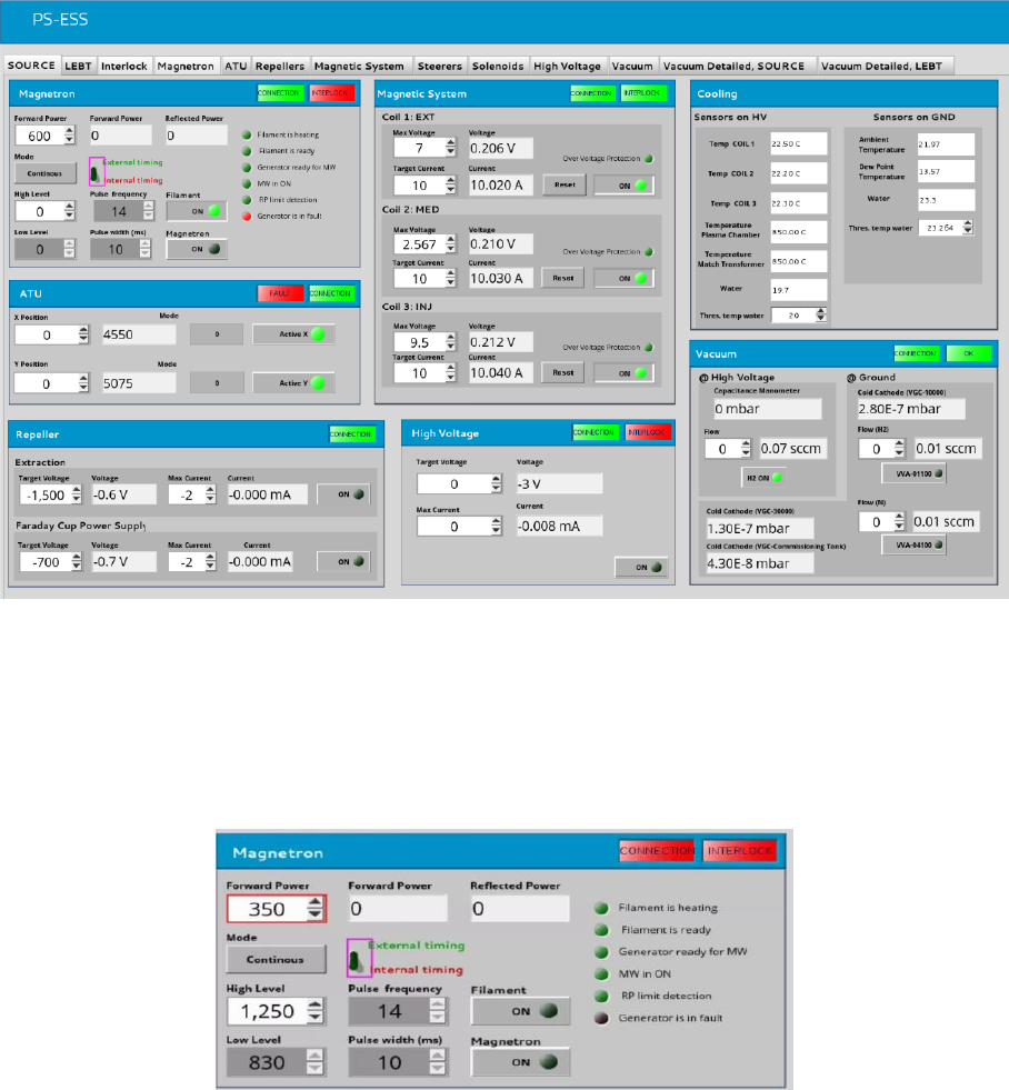
5.1.1 Main tab: source control
Figure 3: Main User Interface
The main tab is composed of subsection as descripted in following lines.
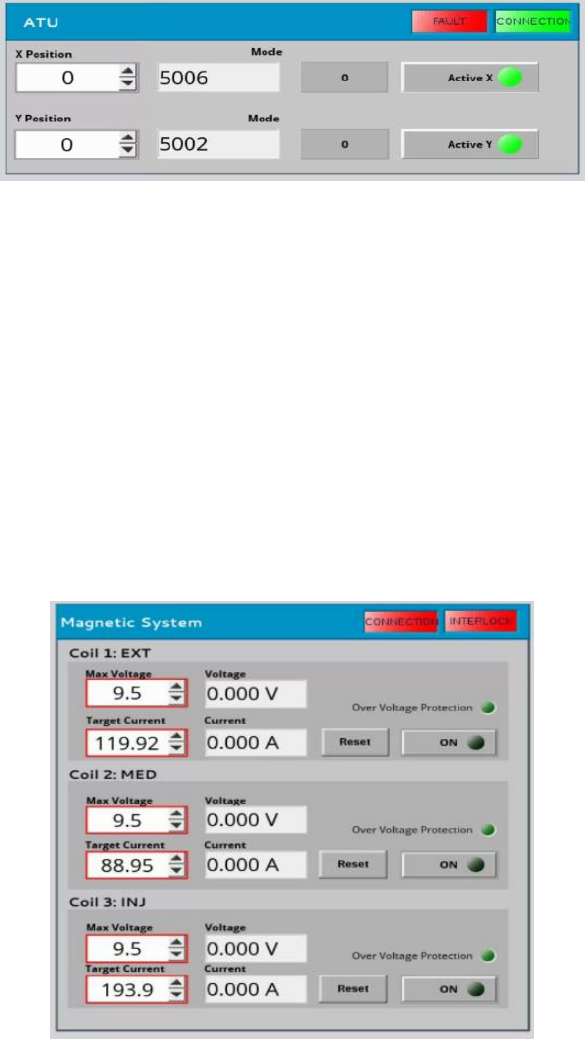
5.1.1.1
Magnetron
Figure 4: Magnetron User Interface
This subsection allows to control the magnetron and the shape of the beam. The type of pulse could be
selected: Pulse or continuous. According to this option, some parameters like Pulse Frequency or
Pulse width are enable or disable.
Leds located on the right gives the status of the magnetron: Filament is heating, MW is ON, etc…
On the top of this subsection, two square Leds represent the status of:
- The connection between the device and the VME
20(27)
- The interlock status given by the PLC interlock.
For more information please refer to: sairemgmp20ked.pdf
5.1.1.2
Automatic Tuning Unit (ATU)
Figure 5: ATU User Interface
This subsection allows to control the ATU. For each axe (X or Y) there is a button to activate the
“automatic mode”. By default, the mode is configured in “manual mode”.
On the top of this subsection, two square Leds represent the status of:
- The device (Fault mode or OK)
- The connection between the device and the VME
For more information please refer to: sairemai4s.pdf
5.1.1.3
Magnetic System
Figure 6: Magnetic system User Interface
This subsection allows to control COILS Power supplies. For each power supply, the Max voltage and
the Target current can be adjusted. A status of the Over Voltage Protection is also displayed.
On the top of this subsection, two square Leds represent the status of:
21(27)
- The connection between devices and the VME
- The interlock status given by the PLC interlock.
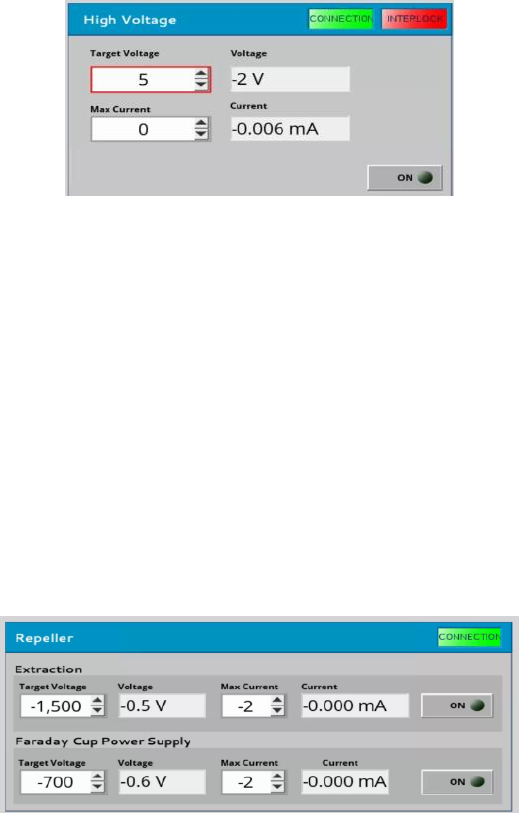
5.1.1.4
High Voltage Power supply
Figure 7: HV User interface
This subsection allows to control the High Voltage Power supply. The Max current and the Target voltage
can be adjusted.
On the top of this subsection, two square Leds represent the status of:
- The connection between the device and the VME
- The interlock status given by the PLC interlock.
For more information please refer to: ps-fug.pdf
5.1.1.5
Repeller Power supply
Figure 8: Reppeler User Interface
This subsection allows to control the Repeller Power supply. The Max current and the Target voltage can
be adjusted.
On the top of this subsection, on square Led indicates the status of the connection between the device
and the VME.
For more information please refer to: ps-fug.pdf
22(27)
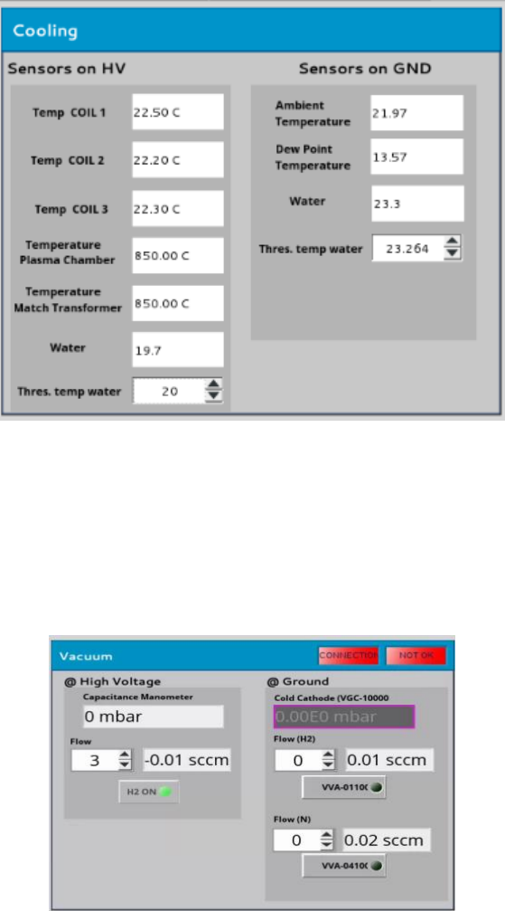
5.1.1.6
Sensors
Figure 9: Cooling User Interface
This subsection allows to display all sensors around the source located at the ground and on the High
Voltage platform.
5.1.1.7
Vacuum status
Figure 10: Vacuum User Interface
This subsection allows to control hydrogen injection and the open/close valve on the High Voltage
platform.
On the top of this subsection, two squares Leds indicates the status of:
- The connection between the device and the VME.
- The status of the device (Fault mode or OK)
For more information please refer to: mks946.pdf
23(27)
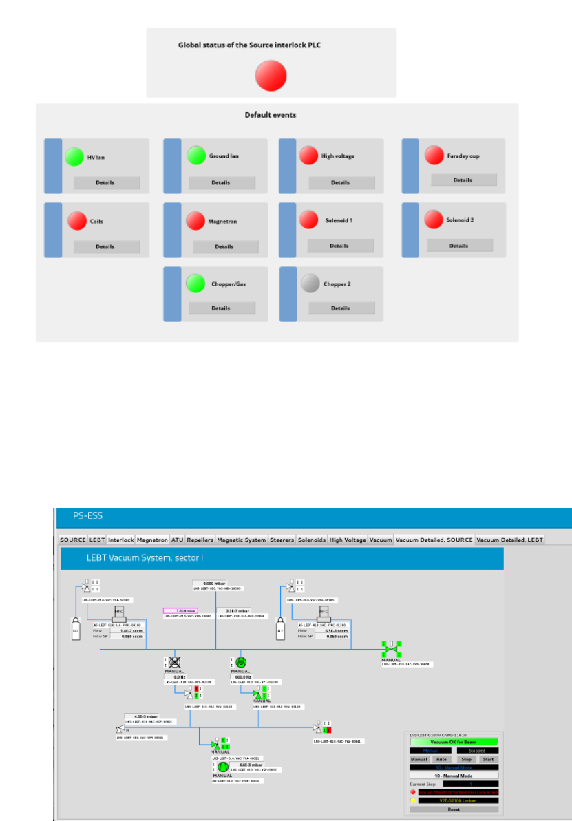
5.1.2 Interlock tab
This tab is dedicated to have an overview of all Interlocks on the Source and LEBT.
For more information about the EPICS part please refer to: ESS_Source_PLC_usermanual.pdf
5.1.3 Vaccum tab
This tab is dedicated to have an overview of the Vaccum on the Source and LEBT.
Figure 11: LEBT Vacuum system (Source)
24(27)
Figure 12: LEBT vacuum system
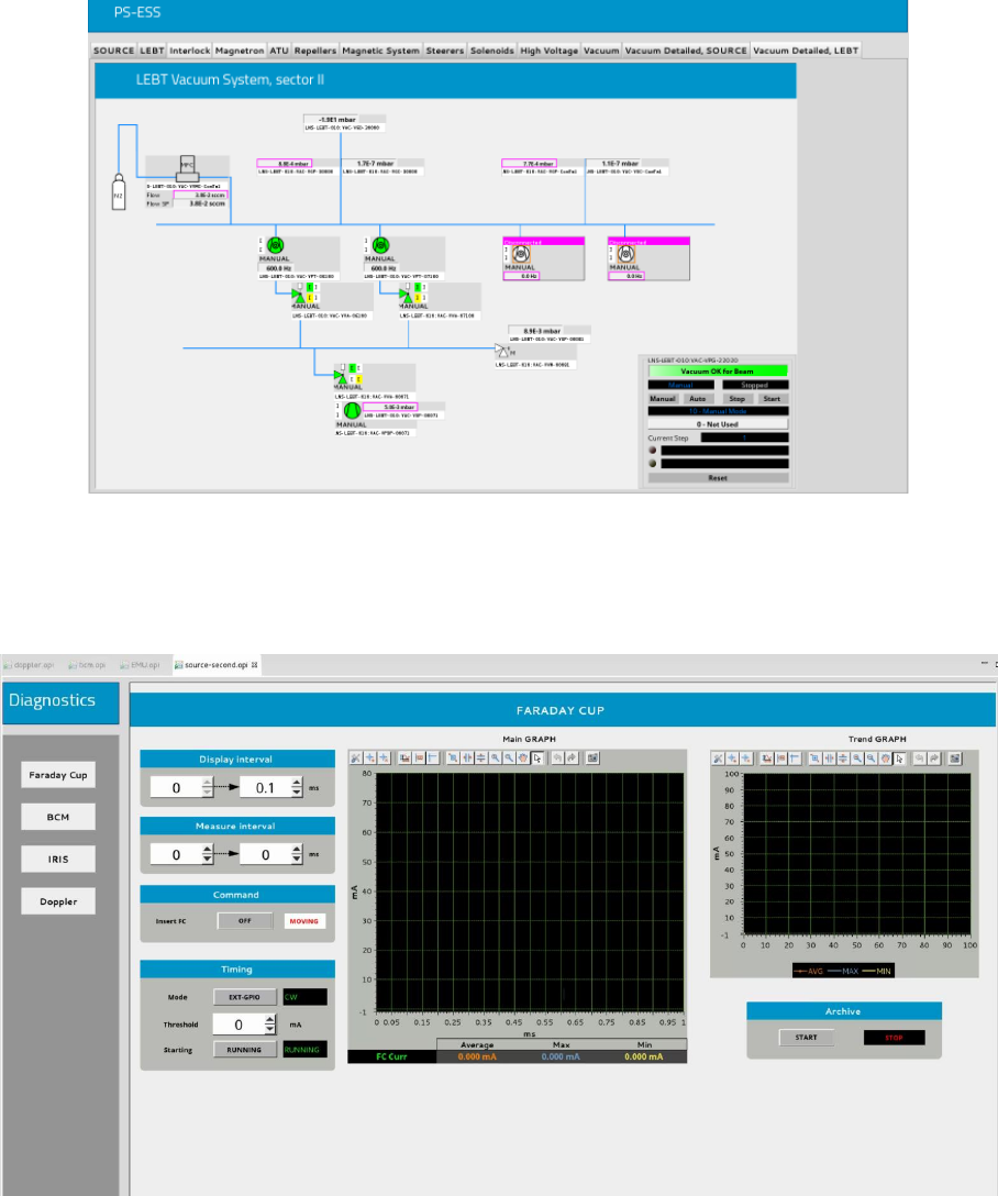
5.2 Diagnostic User interface: second-source.opi
Figure 13: second-source.opi => Diagnostics User Interface
This screen is composed on two parts:
- On the left, a menu to select the diagnostic
- On the right, an embedded display to display the User Interface
dedicated to the diagnostic selected
25(27)
On this document will be treated only the User interface of diagnostics. For more details of a diagnostic,
please refers to the dedicated documentation.
5.2.1 Faraday Cup
When the button Faraday Cup is selected, this OPI appears:
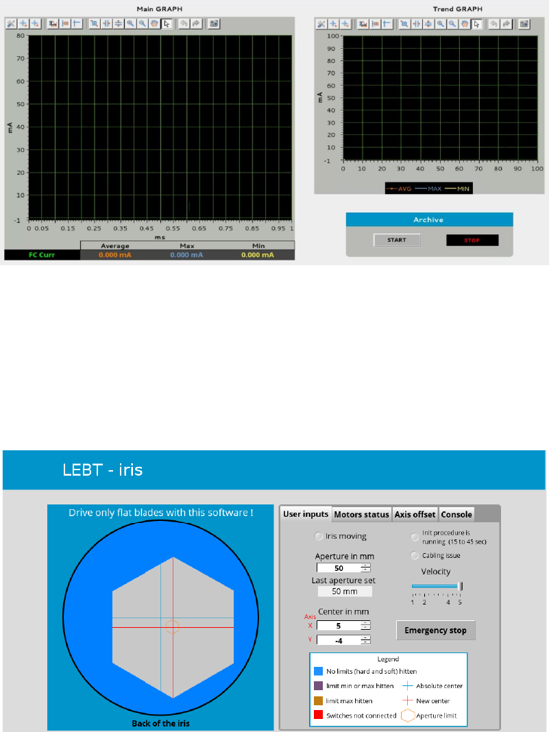
Figure 14: Display the beam on the Faraday Cup
For more information please refer to: FaradayCup_usermanual.pdf
5.2.2 IRIS
When the button IRIS is selected, this OPI appears:
For more information please refer to: Iris_control_systeme_documentation_v1.pdf
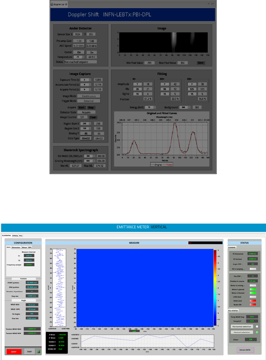
5.2.3 Doppler
When the button DOPPLER is selected, this OPI appears:
26(27)
For more information please refer to: Doppler_Shift_Software.pdf
5.2.4 EMU
When the button EMU is selected, this OPI appears:
For more information please refer to: documentation in progress…

27(27)
6. LIST OF ABBREVIATIONS
Abbreviation
Definition
GUI
Graphical User Interface
IOC
ISRC
LEBT
EPICS
MFC
ATU
HV
I/O
EEE
EVG
EVR
IPC
Input Output Controller
Source
Low Energy Beam Transport
Experimental Physics and Industrial Control System
Mass Flow Controller
Automatic Tuning Unit
High Voltage
Input/Ouput
ESS Epics Environment
Event Generator
Event Receiver
Industrial Personal Computer
