Industrial Data Logger IIo T User Manual
User Manual:
Open the PDF directly: View PDF ![]() .
.
Page Count: 35
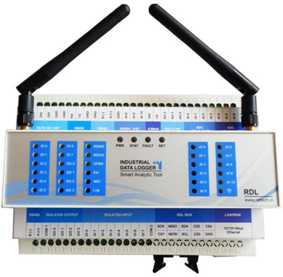
Industrial Data Logger
IIoT 4.0

Data Logger IIoT4.0
www.rdltech.in Page 1 of 35
Contents
1. Introduction .......................................................................................................................................... 2
2. Features ................................................................................................................................................ 3
3. Benefits ................................................................................................................................................. 4
4. Applications ........................................................................................................................................... 4
5. Block Diagram ....................................................................................................................................... 5
6. Pin-out ................................................................................................................................................... 6
7. Programming IDE .................................................................................................................................. 8
8. Product Specification ............................................................................................................................ 8
8.1. Digital Input ................................................................................................................................... 8
8.2. Digital Output .............................................................................................................................. 10
8.3. Analog Input ................................................................................................................................ 11
8.4. SD Card ........................................................................................................................................ 14
8.5. RTC .............................................................................................................................................. 14
8.6. FRAM ........................................................................................................................................... 15
8.7. PWDT (Physical Watch Dog Timer) ............................................................................................. 16
8.8. Flash ............................................................................................................................................ 17
8.9. Ethernet ...................................................................................................................................... 18
8.10. ESP32/XBEE/LoRA/RS485 ........................................................................................................ 19
8.11. GSM ......................................................................................................................................... 21
8.12. RS485 Modbus ........................................................................................................................ 23
8.13. RS232/FT232/Program ............................................................................................................ 25
8.14. DAC .......................................................................................................................................... 26
8.15. Status LED Display ................................................................................................................... 27
8.16. RDL Bus.................................................................................................................................... 28
8.17. STM32 ..................................................................................................................................... 29
9. Power Supply ...................................................................................................................................... 30
10. Order Information Table ................................................................................................................. 31
11. References and Datasheets ............................................................................................................ 33
Data Logger IIoT4.0
www.rdltech.in Page 2 of 35
1. Introduction
RDL data logger is a comprehensive real time industrial automation tool. The product is
designed to seamlessly integrate with the IoT and Analytical processing systems.
Supporting multiple I/O options, interfaces data logger is a perfect fit to build custom
automation solutions.
The state of art design incorporates carefully selected devices with minimum power
requirements, stable operation in industrial environment and up to date feature set.
The product architecture incorporates functionally partitioned across multiple
controllers to ensure minimum down-time and interruptions on the production lines.
Data Logger IIoT4.0
www.rdltech.in Page 3 of 35
2. Features
o 8x ADC 0 - 10V / 4 - 20mA
o 3x DAC 0-10V
o 1x 4-20ma Transmitter
o 3x ADC/IO 0-5v
o 8x DI 24v & 3x DO
o 2x RS485 Modbus*
o 10/100 MBPS Ethernet
o 1x RS232
o 1x Quad band GSM /GPRS Modem*
o 1x External PWDT
o 1x SD card , RTC ,FLASH & FRAM
o 1x XBee /ESP32/Lora/RS485*
o 12/24V DC to DC Converter
o RDL Extension BUS with SPI /I2C
/IO
o Mega2560 Controller
o Enable with STM32F030RCTx Co-
controller for Advanced
programming

Data Logger IIoT4.0
www.rdltech.in Page 4 of 35
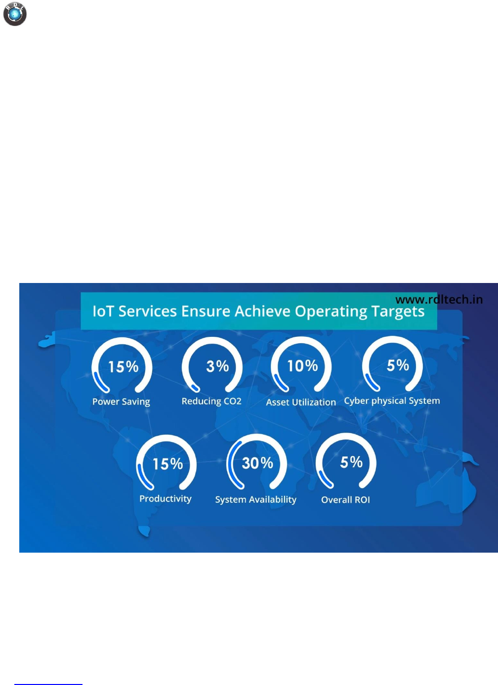
3. Benefits
Reduce Supplier dependency and cost by complete ownership of the solution.
Automation requirements keep increasing and changing with time, engaging external
supplier is cost and loss of productive time. Open Platform Model allows to build
custom solutions with minimal R&D cost. Our platform and tools will enable a base
solution to be built and deployed with 1 person month of effort with basic
programming skills.
o Simplified logging network as RDL Data Logger supports multiple features
o Paper-less Production environment
o Production count, rejections
o Machine availability and Downtimes
o Preventive maintenance
o Performance Forecasting
o Enable Management by IT
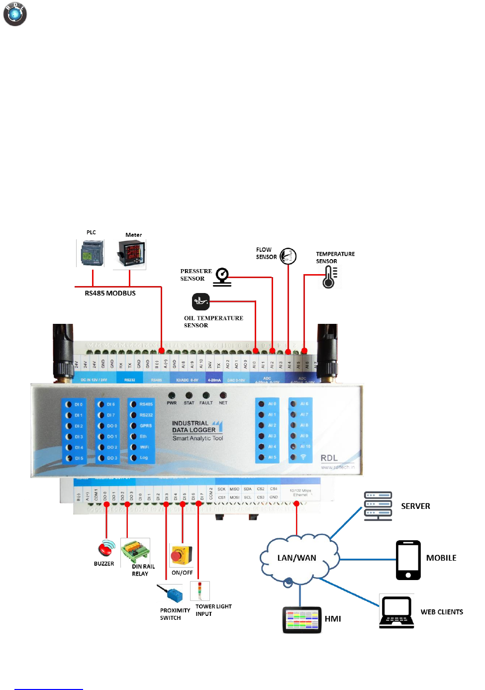
4. Applications
o Production and process monitoring.
o Utilities monitoring.
o Condition monitoring.
o Environment monitoring.
o Industrial Smart grid
o Leakage detection.
o Cold storage monitoring.
o District metering.
o Water treatment.
o Generator monitoring.
o Green House.
o Warning message in case of calamities.
o Standard SCADA Applications
Data Logger IIoT4.0
www.rdltech.in Page 5 of 35
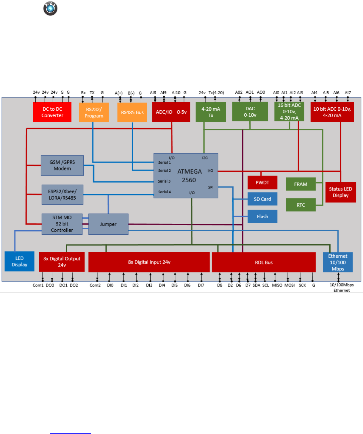
5. Block Diagram
Data Logger IIoT4.0
www.rdltech.in Page 6 of 35
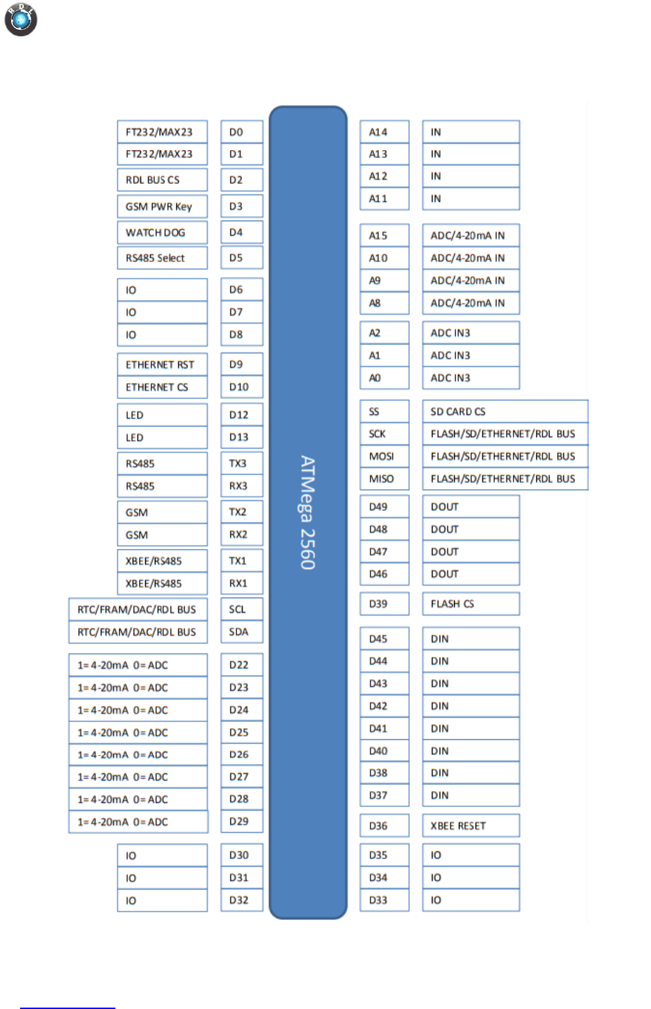
6. Pin-out

Data Logger IIoT4.0
www.rdltech.in Page 7 of 35
Pins
Functionality
D0, D1
Serial Pins. To which either FT232 can be connected or a MAX232 can
be connected.
D2
RDL Bus chip select Pin
D3
RDL chip select or slave select pin
D4
GSM power key (Software Switch). High-to-Low on this pin powers ON
the GSM.
D5
RS485 select (control) pin for serial communication.
D6 – D8, D30 –
D35
Left open to the user and can be configured either as an input or
output.
D9
Reset pin for Ethernet
D10
Chip select or slave select pin for Ethernet
D12, D13
LED pins which could be programmed for status indication as
required.
TX3, RX3
RS485 serial communication
TX2, RX2
GSM serial communication
TX1, RX1
Can either be connected to RD485 or XBEE for serial communication
SCL, SDA
Can be connected to I2C based RTC, FRAM, DAC and RDL bus
D22 – D29
Control pins to select ADC as a 0-10V Voltage reading channel or 4-
20mA Current reading channel.
D36
XBEE reset pin
D37, D38
Digital input pins
D39
Chip select or slave select pin for Flash
D40 – D45
Digital input pins
D46 – D49
Digital Output pins
MISO, MOSI, SCK
SPI pins to where number of devices could be connected
SS
Chip select or slave select pin for SD Card
A0 – A2
Analog Input Pins left open to the user
A8, A9, A10, A15
Analog Input Pins which could be configured (using pins d22-d29) to
read either voltage or current.
A11 – A14
Analog Input Pins left open to the user
Data Logger IIoT4.0
www.rdltech.in Page 8 of 35
7. Programming IDE
The hardware supports various Open Source Programming IDE including Arduino IDE,
Atmel Studio and Arduino Compatible Compiler for LabView. For more information on
this follow “Open Source Programming IDE” section of the following link.
https://rdltech.in/data-logger-iiot-4-0
8. Product Specification
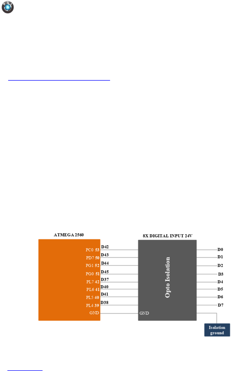
8.1. Digital Input
Specification
o Channels: 8
o Input Voltage: 0-24V
- Logic High: >11V
- Logic Low: <3V
o Isolation : 3750 VRMS
o Supports Inverted DI Status
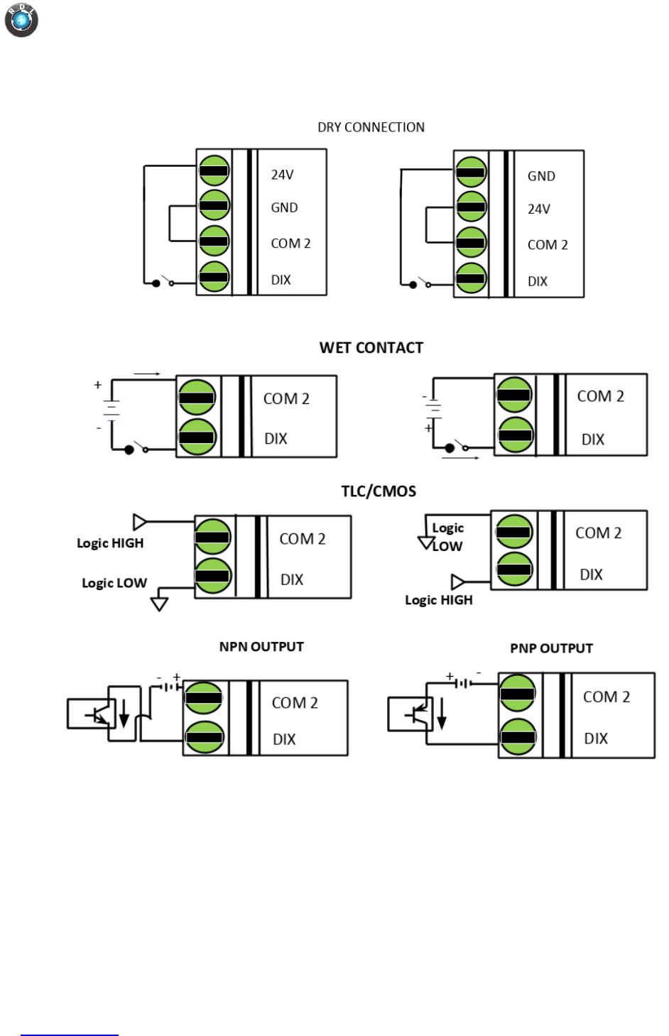
o Supported Connection: Dry and Wet both
o Maximum Frequency : 200Hz
Functional Diagram
Data Logger IIoT4.0
www.rdltech.in Page 9 of 35
Application Wiring
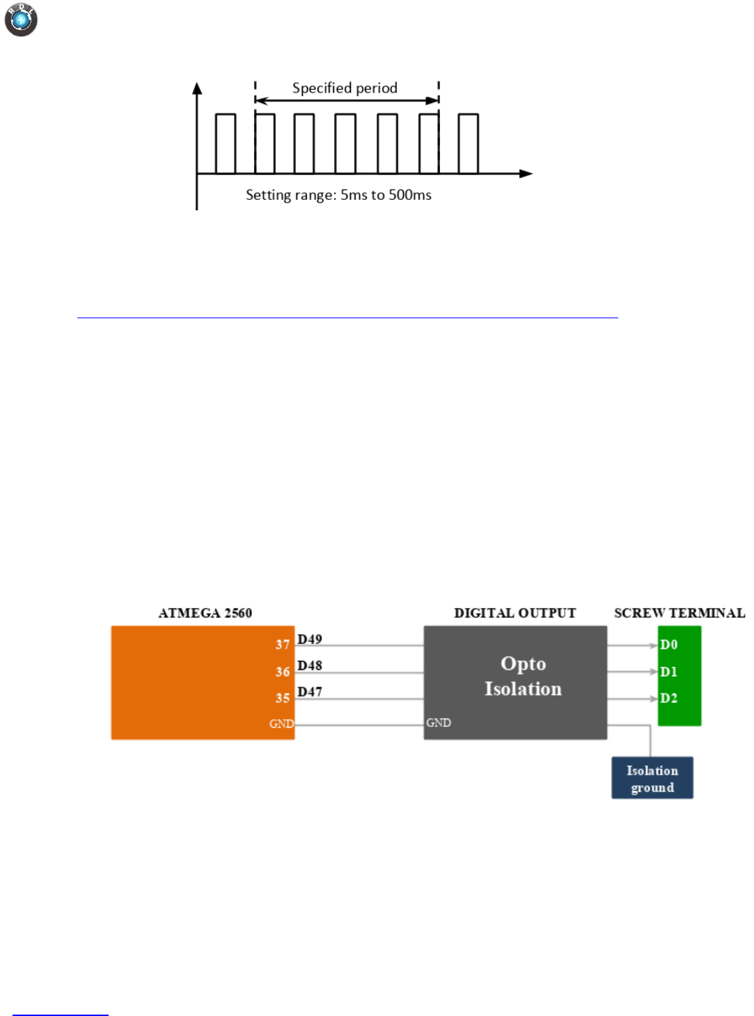
Use Case
1. Measuring Frequency
Data Logger IIoT4.0
www.rdltech.in Page 10 of 35
Example Code
You may look into the following link for example on reading a digital pin.
https://www.arduino.cc/reference/en/language/functions/digital-io/digitalread/
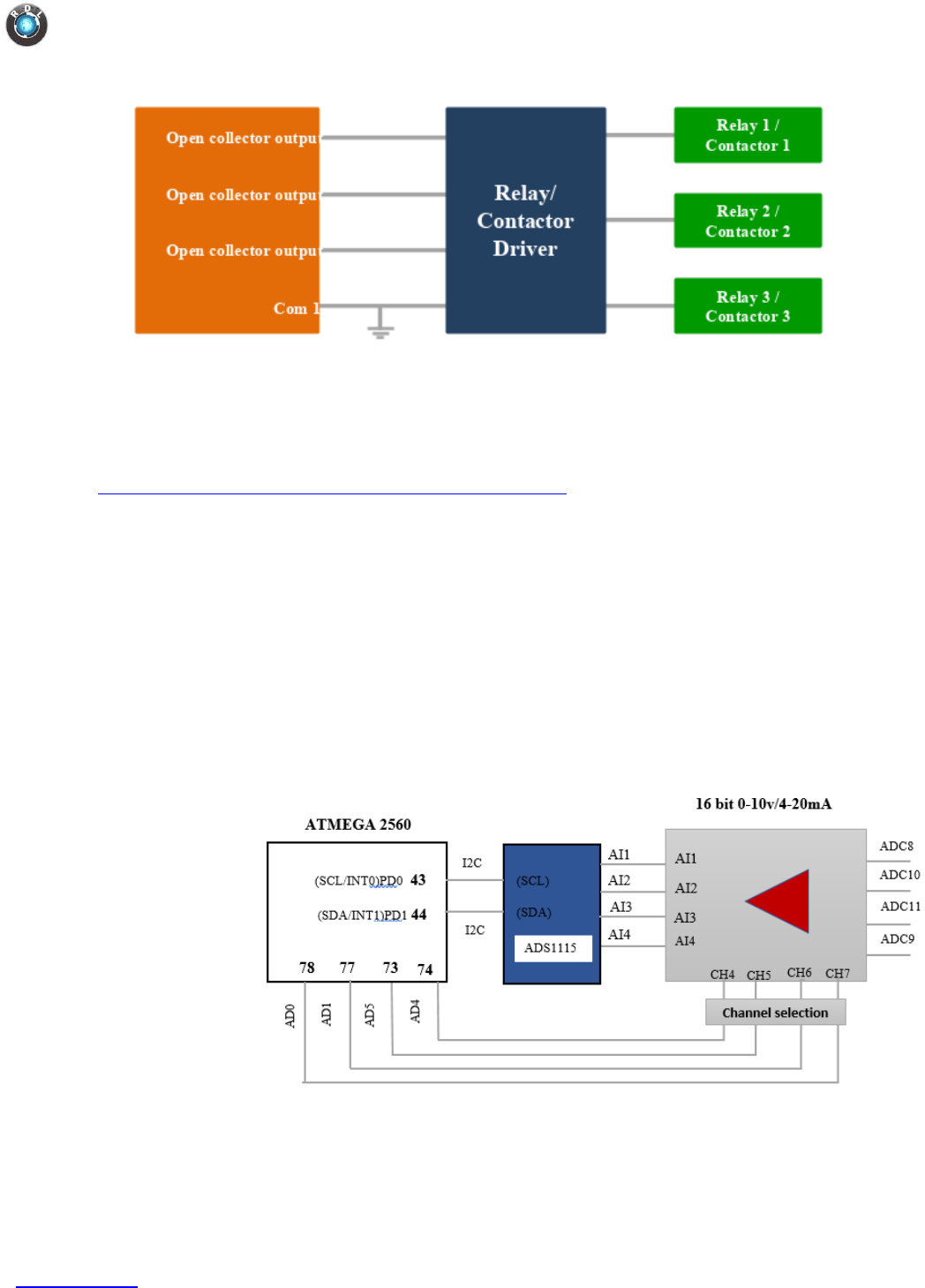
8.2. Digital Output
Specification
o Channels: 3
o Open Collector
o Isolation : 3750 VRMS
o Absolute maximum voltage - 35V, Current - 100mA
o Cut-Off Frequency : 10KHz
Functional Diagram
Application Wiring
Data Logger IIoT4.0
www.rdltech.in Page 11 of 35
Example Code
You may look into the following link for more details on writing to digital pin.
https://www.arduino.cc/en/Reference.digitalWrite
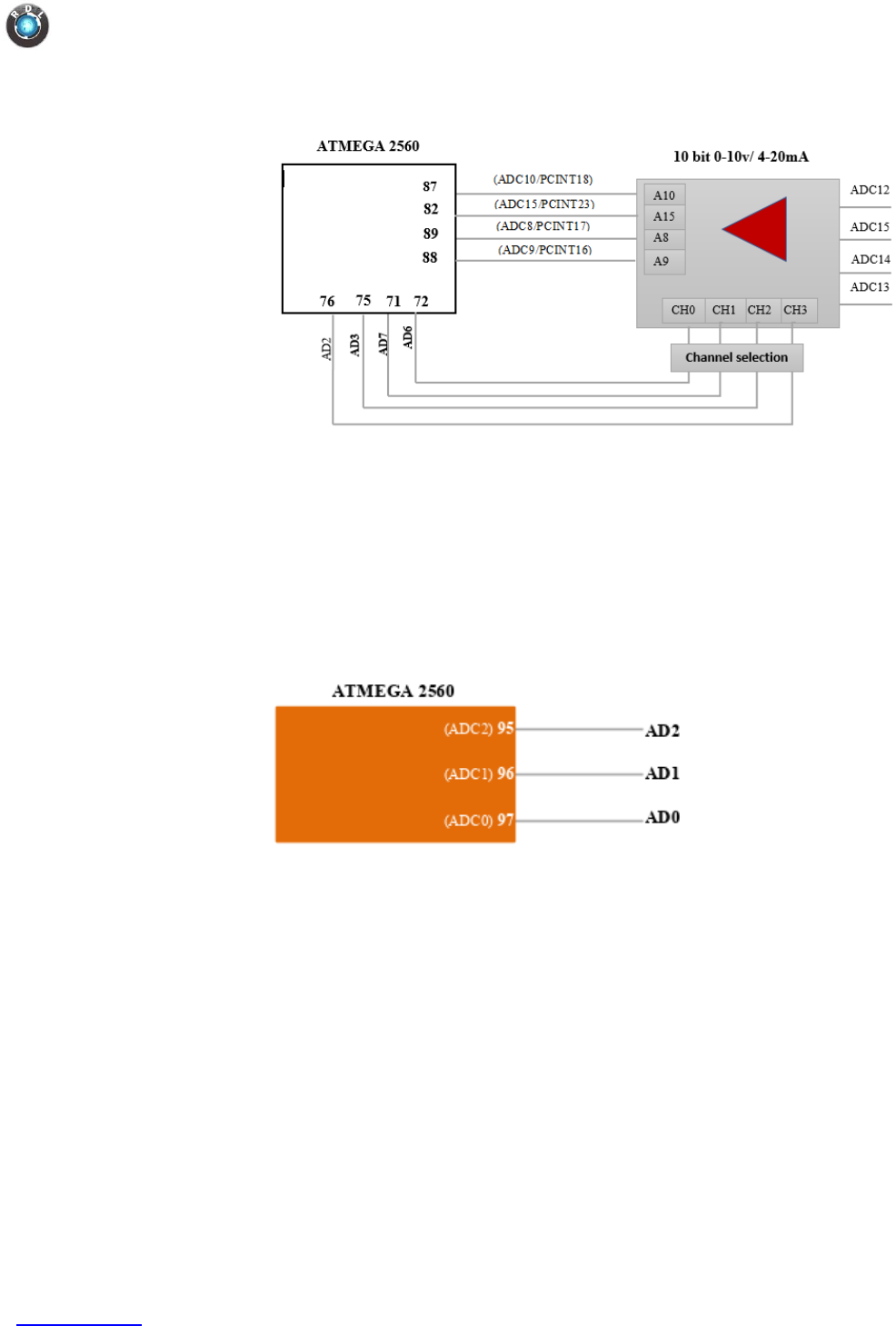
8.3. Analog Input
Specification
o Channels: 8+3
o Group 1 :
o Channel : 4
o Input : Voltage(0-10V) / Current(4-20mA)
o Resolution : 16 bits
o Sampling Rate – 860 sample/sec
o Group 2 :
o Channel : 4
o Input : Voltage(0-10V) / Current(4-20mA)
o Resolution : 10 bits
o Sampling Rate – 9.6KHz (13 clocks)
Data Logger IIoT4.0
www.rdltech.in Page 12 of 35
o Group 3 :
o Channel : 3
o Input : Voltage(0-5V)
o Resolution : 10 bits
o Sampling Rate – 9.6KHz (13 clocks)
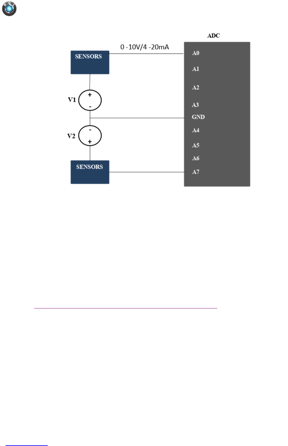
Application Wiring
1. Interfacing ADC with Sensor
Data Logger IIoT4.0
www.rdltech.in Page 13 of 35
NOTE: When an ADC Channel is configured for measuring loop current,
voltage source should never be given to the channel. If given, damage could happen
to the internal circuitry or external device connected to it.
Example Code
You may look into the following link for more details on reading analog pin.
https://www.arduino.cc/en/Tutorial/ReadAnalogVoltage#toc5
Data Logger IIoT4.0
www.rdltech.in Page 14 of 35
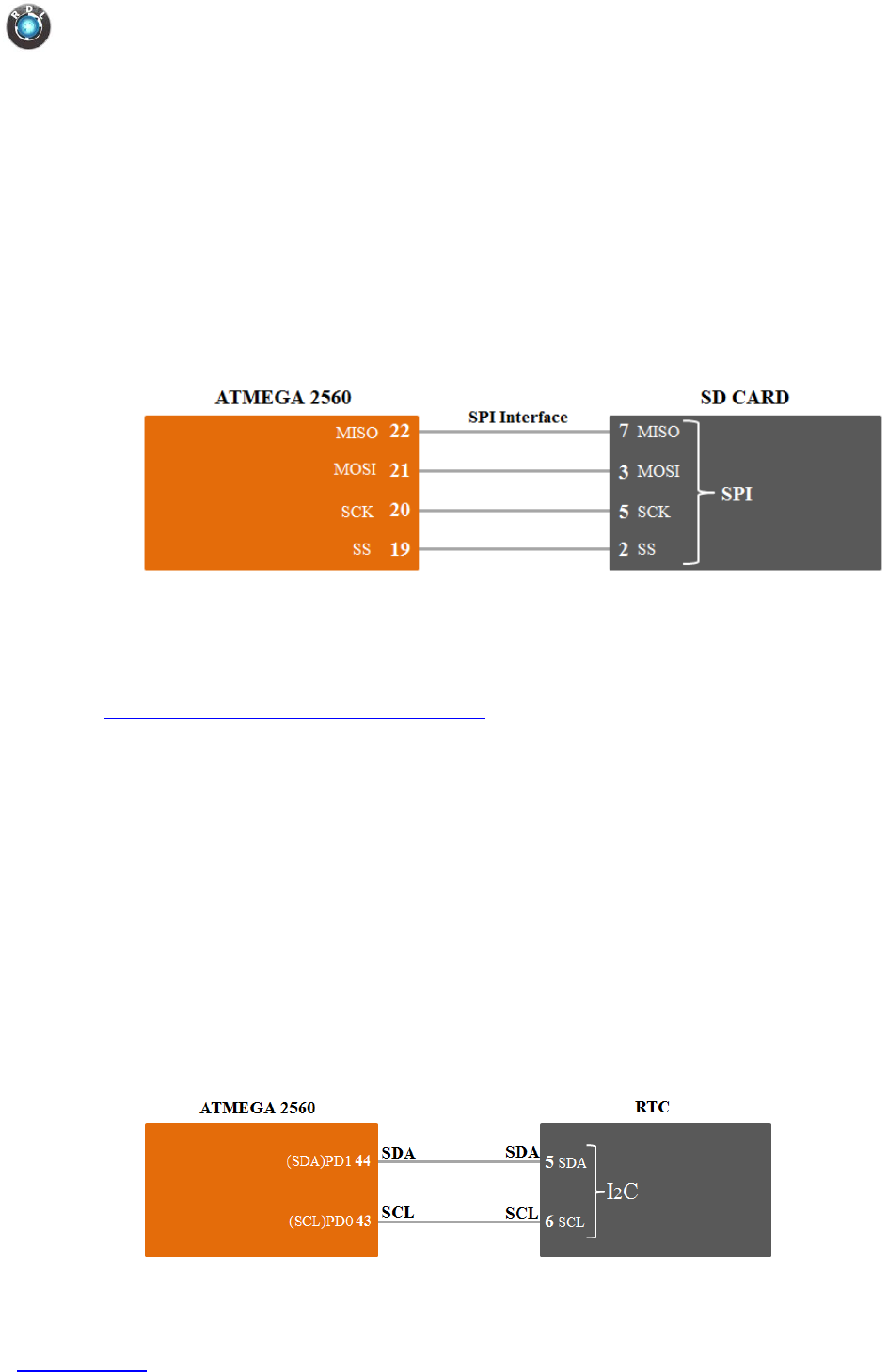
8.4. SD Card
Specification
o SPI Serial Interface
o Supports Fat File system
Functional Diagram
Example Code
You may look into the following link for example on SD Card.
https://www.arduino.cc/en/Reference/SD
8.5. RTC
Specification
o DS1307 with I2C Serial Interface
o Counts Seconds, Minutes, Hours, Date, Month, Day, and Year with Leap-Year
Compensation.
o 56-Byte, Battery-Backed, NV RAM for Data Storage
o Consumes <500nA in Battery Backup Mode with Oscillator Running
Functional Diagram
Data Logger IIoT4.0
www.rdltech.in Page 15 of 35
Example Code
You may look into the following link for example code on RTC.
https://www.arduino.cc/en/Reference/RTC
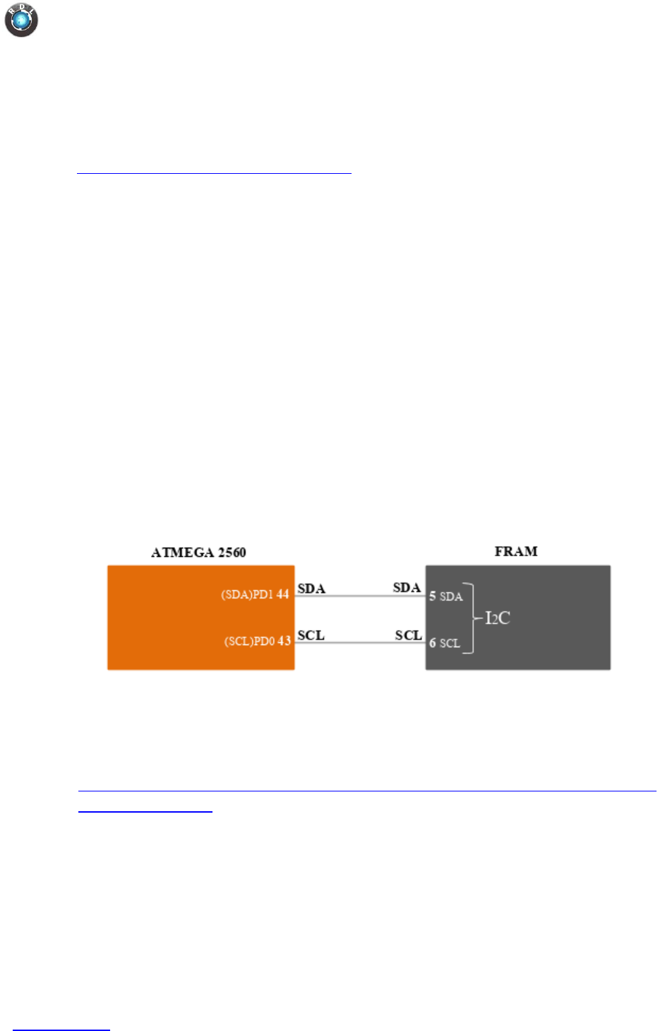
8.6. FRAM
FRAM is specifically used for applications such as production counting,
production rejection where variable subjected to continuous write cycle
Specification
o MB85RC256V, I2C compatible with Bit configuration : 32,768 words × 8 bits
o Operating frequency : 1 MHz (Max)
o Read/write endurance : 1012 times / byte
o Number of write cycles: 100 Trillion times
o Operating power supply voltage : 2.7V to 5.5V, current 200 μA
o Data Retention: 10 years (+85°C), 95 years (+55°C), over 200 years (+35°C).
Functional Diagram
Example Code
You may look into the following link for example on RTC
https://github.com/adafruit/Adafruit_FRAM_I2C/blob/master/examples/MB85RC256
V/MB85RC256V.ino
Data Logger IIoT4.0
www.rdltech.in Page 16 of 35
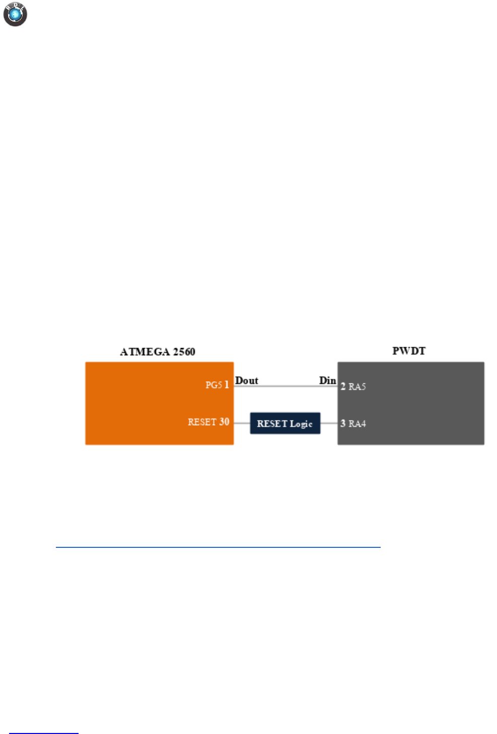
8.7. PWDT (Physical Watch Dog Timer)
External physical watchdog is connected along with inbuilt watchdog timer.
There are many instances where we need to set watch dog time for more than 8
seconds (typically bulk file upload takes in minutes). As inbuilt WDT is limited
to maximum of 8Sec, we have gone a step further to support watch dog time up
to 3 minutes.
Note: User must program PWDT to refresh before the timer (3 min) expires.
Specification
o PWDT supports up to 3minutes.
o PIC12F1840 used for PWDT
o Refresh time : 1 pulse in every 3 minutes
o Operating temperature range: –40 to 125 °C
Functional Diagram
Example Code
You may look into the following link for examples on watchdog timer.
https://folk.uio.no/jeanra/Microelectronics/ArduinoWatchdog.html
Data Logger IIoT4.0
www.rdltech.in Page 17 of 35
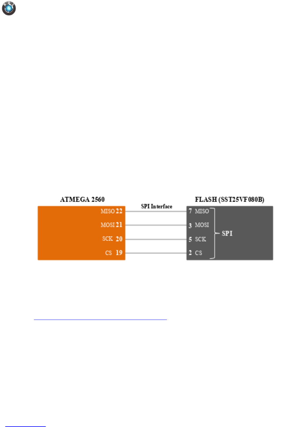
8.8. Flash
Flash is specifically used for embedded server.
Specification
o SST25VF080B - SPI Compatible: Mode 0 and Mode 3
o Memory: 8MBit
o High Speed Clock Frequency – 50 MHz
o Single Voltage Read and Write Operations – 2.7-3.6V
o Endurance: 100,000 Cycles (typical) – >100 years Data Retention
o Low Power Consumption: – Active Read Current: 10 mA (typical)
o Flexible Erase Capability – Uniform 4KB, 32KB overlay blocks and 64KB
overlay blocks
o Software Write Protection
Functional Diagram
Example Code
You may look into the following link for example on how to use flash.
https://github.com/nullboundary/SST25VF
Data Logger IIoT4.0
www.rdltech.in Page 18 of 35
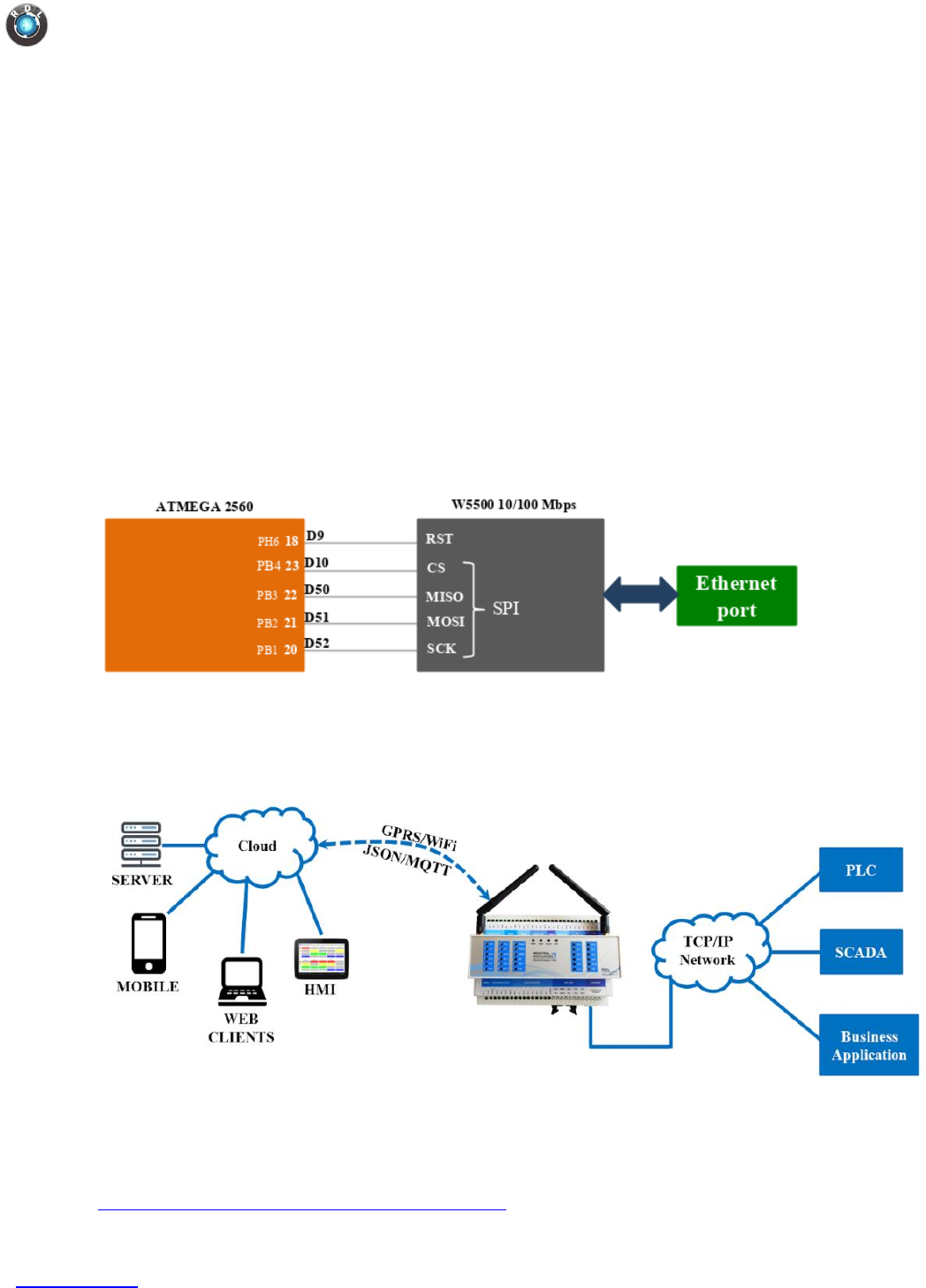
8.9. Ethernet
Ethernet is specifically used for establishing secured physical network
connectivity with local network infrastructure
Specification
o W5500 IC with SPI serial interface
o IEEE 802.3 Gigabit Ethernet Compliant
o Communication protocols: TCP/IP, HTTP, FTP, MQTT, UDP,JSON….
o 3.3V operation with 5V I/O signal tolerance
o Low Power Consumption <200mW at 1.25Gbps.
Functional Diagram
Use Case
Example Code
You may look into the following link for examples on Ethernet.
https://www.arduino.cc/en/Reference/Ethernet
Data Logger IIoT4.0
www.rdltech.in Page 19 of 35
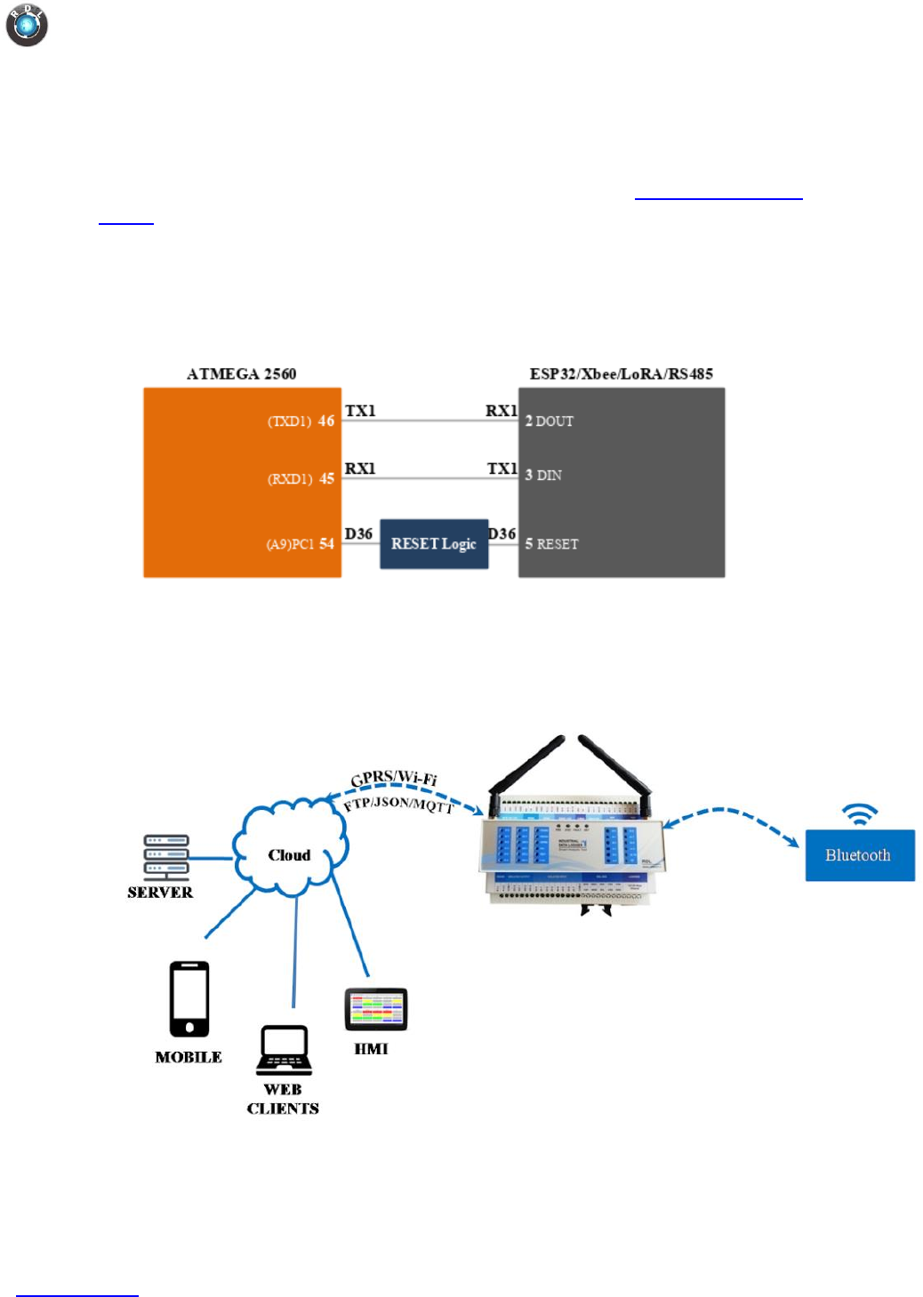
8.10. ESP32/XBEE/LoRA/RS485
This is Add-On pluggable module. One among ESP32, XBEE, LoRA or RS485 is
comes with the product. For more details on this, look into Order Information
Table.
This is specifically used for wireless connectivity with existing infrastructure.
Functional Diagram
Use Case
1. Interfacing Industrial Data Logger with Bluetooth
Data Logger IIoT4.0
www.rdltech.in Page 20 of 35
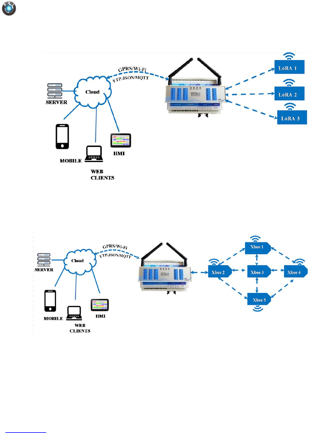
2. Interfacing Industrial Data Logger with LoRA
3. Interfacing Industrial Data Logger with Xbee
Data Logger IIoT4.0
www.rdltech.in Page 21 of 35
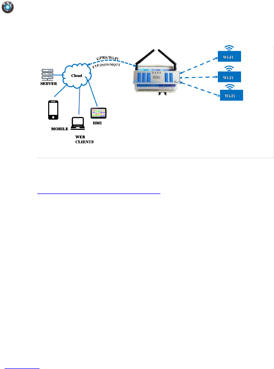
4. Interfacing Industrial Data Logger with Wi-Fi (ESP32)
Example Code
You may look into the following link for examples on esp8266.
https://www.arduino.cc/en/Reference/WiFiServer
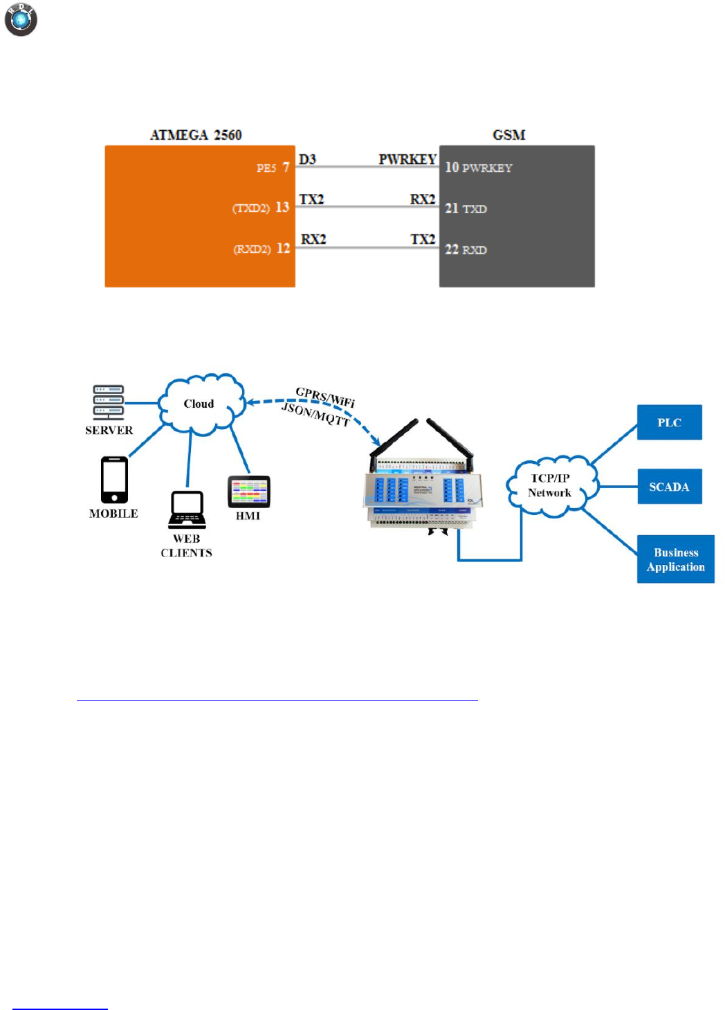
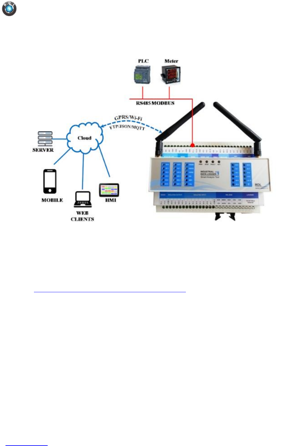
8.11. GSM
This is specifically used for M2M and remote data logging and control
applications.
Specification
o Quectel M95, Quad-Band 850/900/1800/1900MHz.
o Serial interface for direct communication with PC or MCU.
o Configurable baud rate.
o Power controlled using 29302WU IC.
o ESD Compliance.
o Enabled with Audio jack.
o With push pull SIM card holder.
o With Stub antenna and SMA connector.
o Input Voltage: 12V DC.
Data Logger IIoT4.0
www.rdltech.in Page 23 of 35
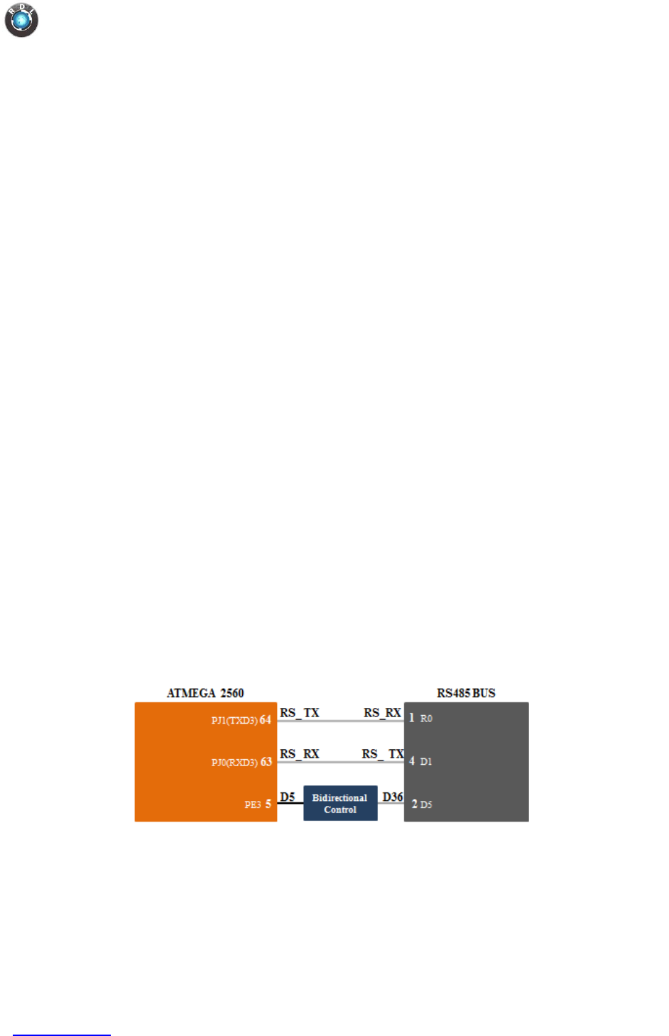
8.12. RS485 Modbus
o Modbus is an Industrial standard serial communication protocol.
o Open protocol
o Information is stored in the Slave device in four different tables.
Two tables store on/off discrete values (coils) and two store numerical
values (registers). The coils and registers each have a read-only table and
read-write table.
o Each table has 9999 values.
Each coil or contact is 1 bit and assigned a data address between 0000-270E.
Each register is 1 word = 16 bits = 2 bytes and also has data address
between 0000 and 270E.
o Supported Functions are
- Coils
- Discrete inputs
- Input Registers
- Holding Registers.
Specification
o LTC485 IC.
o Supports slave address up to 32.
o Supports Modbus protocol with RTU and ASCII formats.
o Configurable baud rate from 4800 to 115200.
o Configurable packet format (data bits, parity bit, stop bits)
Functional Diagram
Data Logger IIoT4.0
www.rdltech.in Page 25 of 35
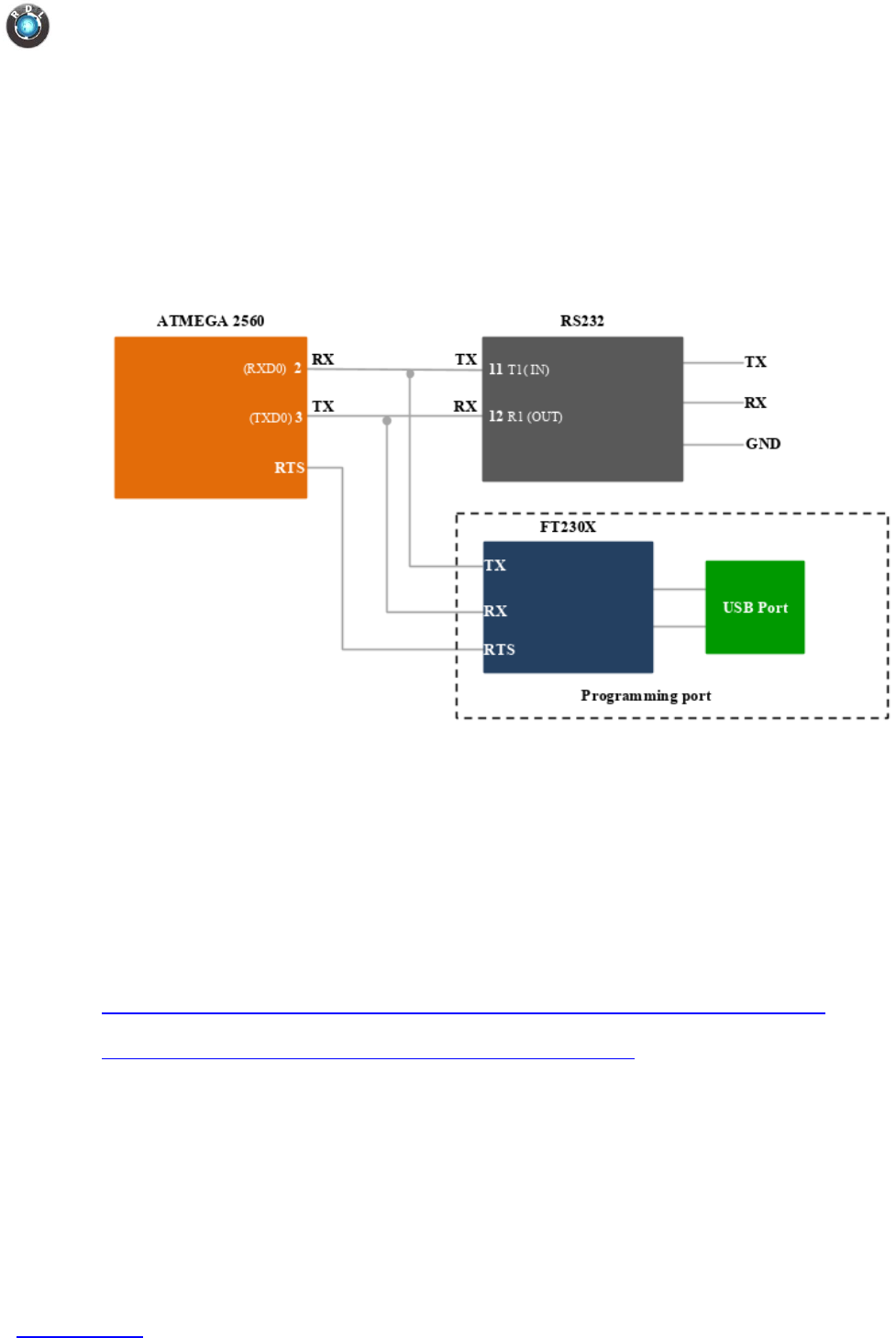
8.13. RS232/FT232/Program
Used for programming the board. When in user mode, the port could be used for
data communication.
Functional Diagram
Note: When programming the board, it is recommended to remove any
connection made to the RS232 serial pins in order to ensure proper functioning
of the system.
Example Code
You may look into the following link for examples on FT232/MAX232 serial
communication.
https://www.arduino.cc/reference/en/language/functions/communication/serial/
https://www.arduino.cc/en/Tutorial/SoftwareSerialExample
Data Logger IIoT4.0
www.rdltech.in Page 26 of 35
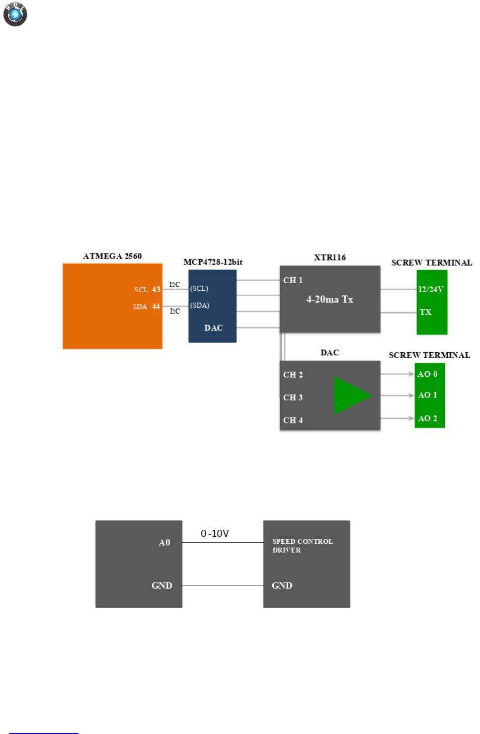
8.14. DAC
Specification
o MCP4768 with I2C serial interface
o Quad, 12-bit voltage output
o Channel: 4 (buffered outputs)
o Internal Voltage Reference
o Output Voltage Range using 0-10V
Functional Diagram
Application Wiring
1. Interfacing DAC with Motor Speed Control Module
Data Logger IIoT4.0
www.rdltech.in Page 4 of 35
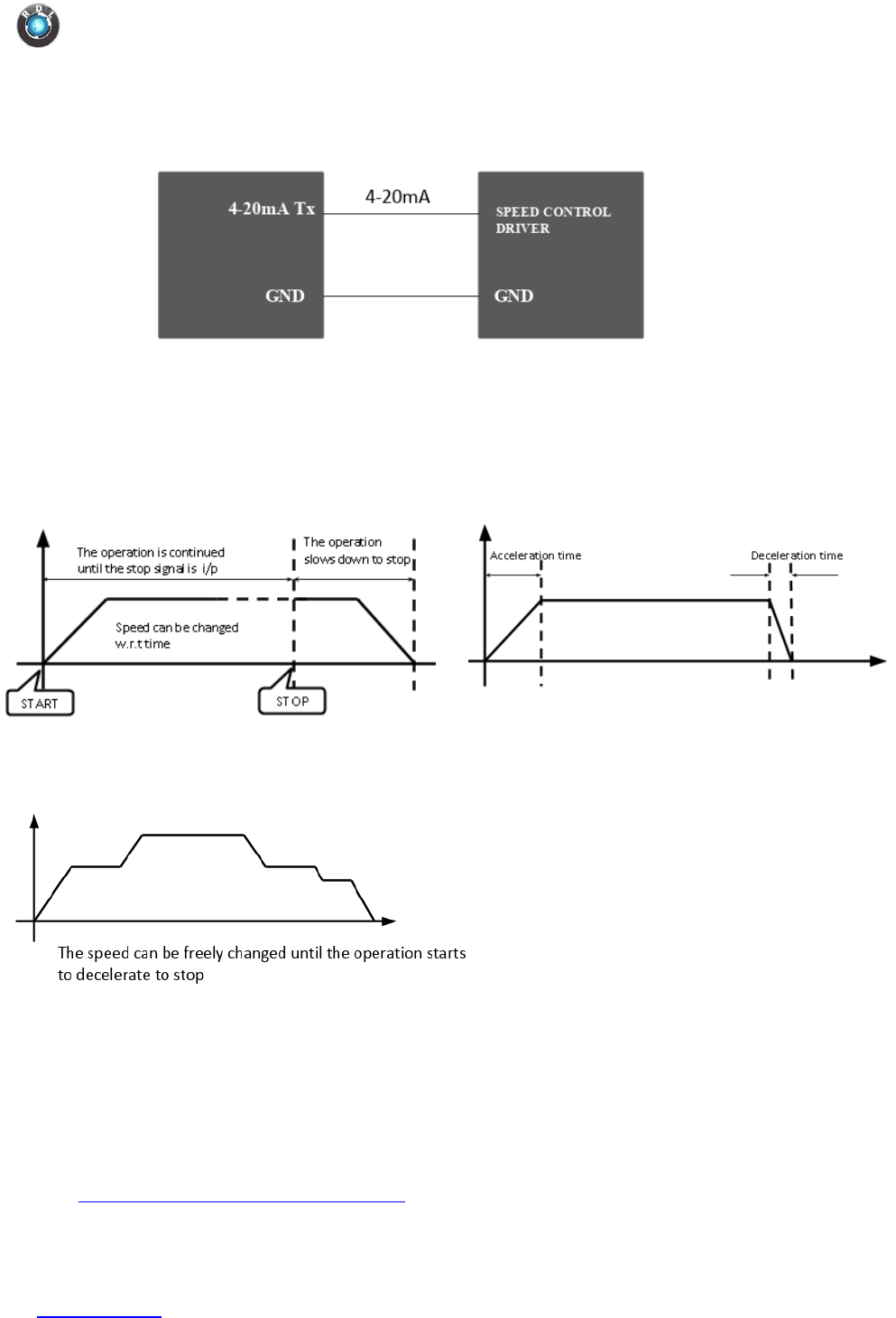
2. Interfacing DAC with Motor Speed Control Module usi ng Loop Current
Use Case
1. Motion Control 2. Acceleration and Deceleration
3. Jog Operation and Trapezoidal Control Operation
Example Code
You may look into the following link for the Arduino library and example on DAC.
https://github.com/hideakitai/MCP4728
Data Logger IIoT4.0
www.rdltech.in Page 27 of 35
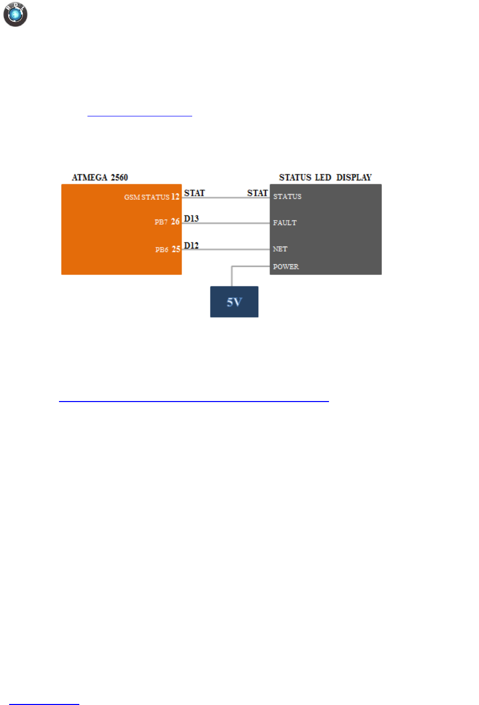
8.15. Status LED Display
Status LED’s can be programmed as per used needs for visual indication of an event.
Refer Digital Output Section
Functional Diagram
Example Code
You may look into the following link for more details on programming LED pins.
https://www.arduino.cc/en/Reference.digitalWrite
Data Logger IIoT4.0
www.rdltech.in Page 28 of 35
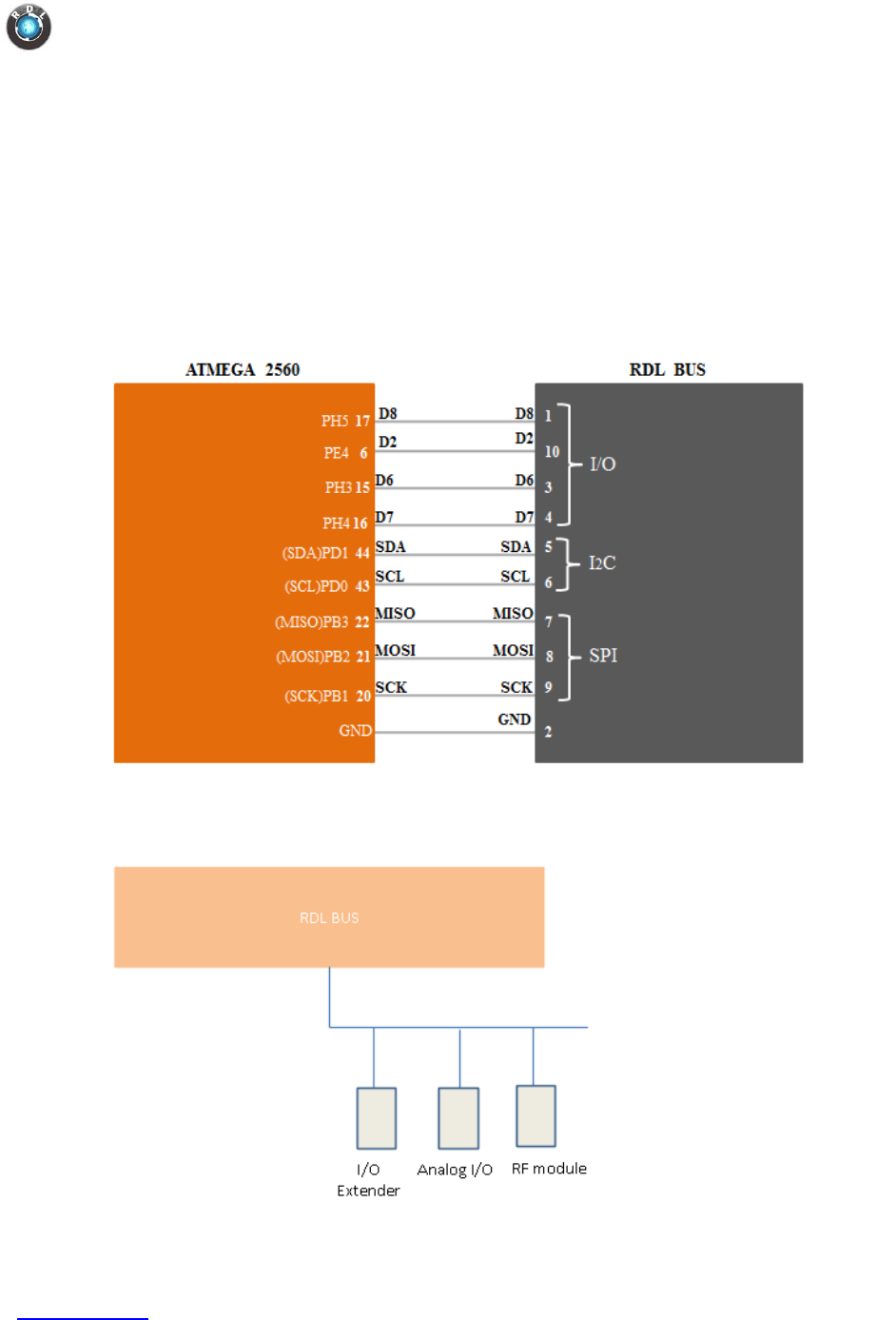
8.16. RDL Bus
Specification
o Extend I/O pins for communicating with external devices.
o Extends SPI pins, I2C pins, UART pins and Digital I/O pins.
Functional Diagram
Application Wiring
Data Logger IIoT4.0
www.rdltech.in Page 29 of 35
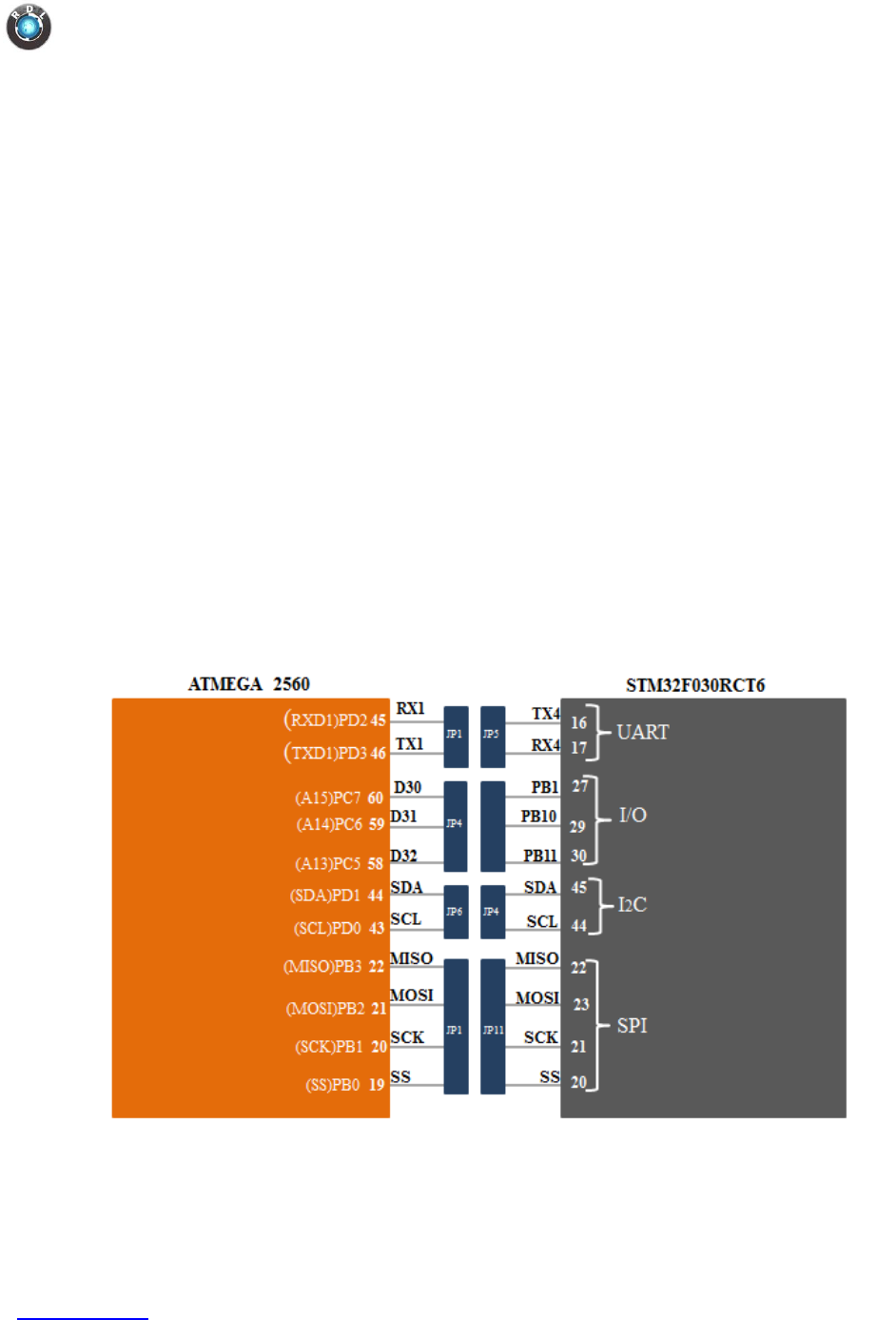
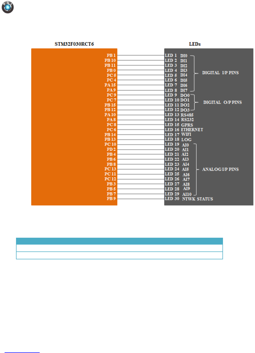
8.17. STM32
Extend I/O pins for complex controller operations so as to reduce load on AVR.
For example Complex math operations can be assigned to STM32 controller by
establishing physical connection with AVR controller.
Currently, some I/O pins are used for LED status indication as per commands
received from AVR as shown in the figure below. But user can assign complex
task on STM32 controller.
Specification
o Controller: STM32F030RCT6
o Core: ARM®32-bit Cortex®-M0 CPU with frequency 48 MHz
o 256KB flash, 32KB RAM, 51 IO pins.
o CRC calculation unit
o One 12-bit, 1.0μs ADC (up to 16 channels)
o 2 I2C, 6 USART, 2 SPI, 11 timers.
Functional Diagram
Note: Physical Connection must be enabled through jumpers to establish
communication between ATMega2560 and STM32
Data Logger IIoT4.0
www.rdltech.in Page 30 of 35
Application Diagram
9. Power Supply
Model
Input Voltage
Vmin
Vmax
7000 - 7004
12V - 36V
12V
30V
7004 - 7008
12V - 15V
12V
15V
Note: Before board power ON make sure that voltage given and model number are
proper, else you would end up damaging the module.
Data Logger IIoT4.0
www.rdltech.in Page 31 of 35
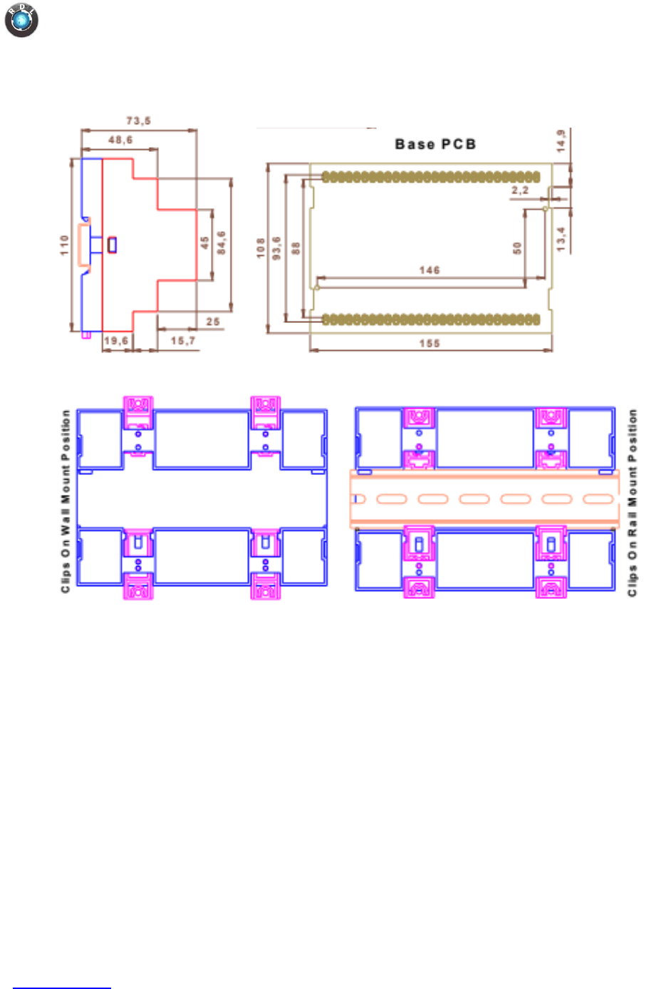
10. Mounting and Mechanical Dimensions
Data Logger IIoT4.0
www.rdltech.in Page 32 of 35
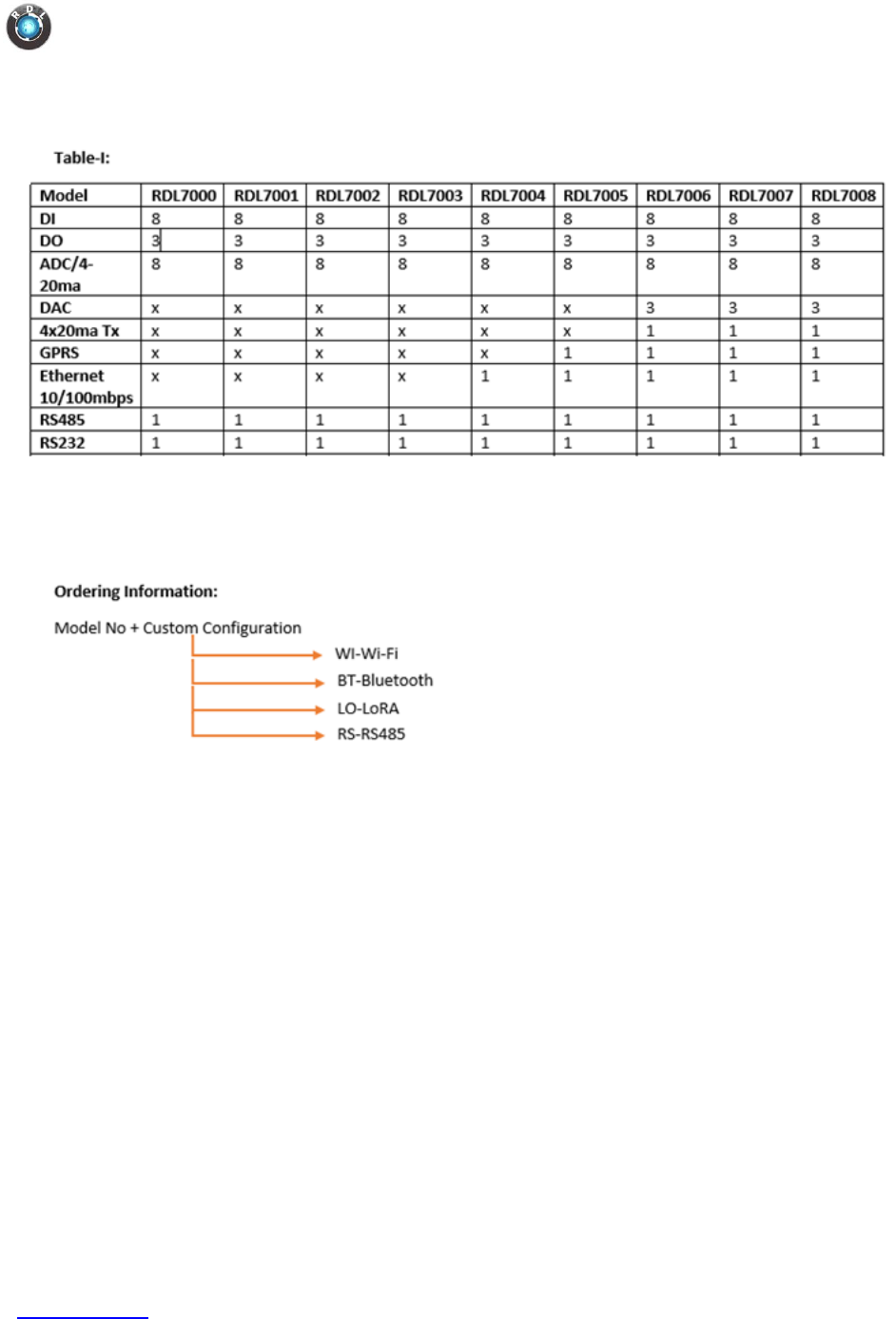
11. Order Information Table
Example:
RDL7008WI - It comes with all the above features listed in Table-I with Wi-Fi enabled.
RDL7008BT - It comes with all the above features listed in Table-I with Bluetooth enabled
RDL7008LO - It comes with all the above features listed in Table-I with LoRA enabled.
RDL7008RS - It comes with all the above features listed in Table-I with RS-485 bus.
RDL7008 - It comes with the only features listed in Table-I

Data Logger IIoT4.0
www.rdltech.in Page 33 of 35
12. References and Datasheets
1. http://ww1.microchip.com/downloads/en/DeviceDoc/Atmel-2549-8-bit-AVR-
Microcontroller-ATmega640-1280-1281-2560-2561_datasheet.pdf
2. http://www.ti.com/lit/ds/symlink/max232.pdf
3. http://ww1.microchip.com/downloads/en/DeviceDoc/40001441F.pdf
4. http://ww1.microchip.com/downloads/en/DeviceDoc/20005685A.pdf
5. http://www.ti.com/lit/ds/symlink/lm2576hv.pdf
6. https://www.vishay.com/docs/83513/tcmd1000.pdf
7. http://www.analog.com/media/en/technical-documentation/data-sheets/485fm.pdf
8. http://www.ti.com/lit/ds/symlink/lm317.pdf
9. http://www.ti.com/lit/ds/symlink/ads1115.pdf
10. http://ww1.microchip.com/downloads/en/DeviceDoc/20005045C.pdf
11. https://www.fujitsu.com/uk/Images/MB85RC256V-20171207.pdf
12. http://ww1.microchip.com/downloads/en/DeviceDoc/mic811.pdf
13. http://wizwiki.net/wiki/lib/exe/fetch.php?media=products:w5500:w5500_ds_v106e_1412
30.pdf
14. http://www.analog.com/media/en/technical-documentation/data-sheets/485fm.pdf
15. http://ww1.microchip.com/downloads/en/DeviceDoc/22187E.pdf
16. http://www.ti.com/lit/ds/symlink/xtr115.pdf
