ISM For Electrical Machinery Fundamentals 4e (Instructor's Manual)
User Manual:
Open the PDF directly: View PDF ![]() .
.
Page Count: 323 [warning: Documents this large are best viewed by clicking the View PDF Link!]
i
Instructor’s Manual
to accompany
Chapman
Electric Machinery Fundamentals
Fourth Edition
Stephen J. Chapman
BAE SYSTEMS Australia
ii
Instructor’s Manual to accompany Electric Machinery Fundamentals, Fourth Edition
Copyright 2004 McGraw-Hill, Inc.
All rights reserved. Printed in the United States of America. No part of this book may be used or reproduced in
any manner whatsoever without written permission, with the following exception: homework solutions may be
copied for classroom use.
ISBN: ???
iii
TABLE OF CONTENTS
CHAPTER 1: INTRODUCTION TO MACHINERY PRINCIPLES 1
CHAPTER 2: TRANSFORMERS 23
CHAPTER 3: INTRODUCTION TO POWER ELECTRONICS 63
CHAPTER 4: AC MACHINERY FUNDAMENTALS 103
CHAPTER 5: SYNCHRONOUS GENERATORS 109
CHAPTER 6: SYNCHRONOUS MOTORS 149
CHAPTER 7: INDUCTION MOTORS 171
CHAPTER 8: DC MACHINERY FUNDAMENTALS 204
CHAPTER 9: DC MOTORS AND GENERATORS 214
CHAPTER 10: SINGLE-PHASE AND SPECIAL-PURPOSE MOTORS 270
APPENDIX A: REVIEW OF THREE-PHASE CIRCUITS 280
APPENDIX B: COIL PITCH AND DISTRIBUTED WINDINGS 288
APPENDIX C: SALIENT POLE THEORY OF SYNCHRONOUS MACHINES 295
APPENDIX D: ERRATA FOR ELECTRIC MACHINERY FUNDAMENTALS 4/E 301
iv
PREFACE
TO THE INSTRUCTOR
This Instructor’s Manual is intended to accompany the fourth edition of Electric Machinery Fundamentals. To
make this manual easier to use, it has been made self-contained. Both the original problem statement and the
problem solution are given for each problem in the book. This structure should make it easier to copy pages from
the manual for posting after problems have been assigned.
Many of the problems in Chapters 2, 5, 6, and 9 require that a student read one or more values from a
magnetization curve. The required curves are given within the textbook, but they are shown with relatively few
vertical and horizontal lines so that they will not appear too cluttered. Electronic copies of the corresponding open-
circuit characteristics, short-circuit characteristics, and magnetization curves as also supplied with the book. They
are supplied in two forms, as MATLAB MAT-files and as ASCII text files. Students can use these files for
electronic solutions to homework problems. The ASCII files are supplied so that the information can be used with
non-MATLAB software.
Please note that the file extent of the magnetization curves and open-circuit characteristics have changed in this
edition. In the Third Edition, I used the file extent *.mag for magnetization curves. Unfortunately, after the book
was published, Microsoft appropriated that extent for a new Access table type in Office 2000. That made it hard
for users to examine and modify the data in the files. In this edition, all magnetization curves, open-circuit
characteristics, short-circuit characteristics, etc. use the file extent *.dat to avoid this problem.
Each curve is given in ASCII format with comments at the beginning. For example, the magnetization curve in
Figure P9-1 is contained in file p91_mag.dat. Its contents are shown below:
% This is the magnetization curve shown in Figure
% P9-1. The first column is the field current in
% amps, and the second column is the internal
% generated voltage in volts at a speed of 1200 r/min.
% To use this file in MATLAB, type "load p91_mag.dat".
% The data will be loaded into an N x 2 array named
% "p91_mag", with the first column containing If and
% the second column containing the open-circuit voltage.
% MATLAB function "interp1" can be used to recover
% a value from this curve.
0 0
0.0132 6.67
0.03 13.33
0.033 16
0.067 31.30
0.1 45.46
0.133 60.26
0.167 75.06
0.2 89.74
v
0.233 104.4
0.267 118.86
0.3 132.86
0.333 146.46
0.367 159.78
0.4 172.18
0.433 183.98
0.467 195.04
0.5 205.18
0.533 214.52
0.567 223.06
0.6 231.2
0.633 238
0.667 244.14
0.7 249.74
0.733 255.08
0.767 259.2
0.8 263.74
0.833 267.6
0.867 270.8
0.9 273.6
0.933 276.14
0.966 278
1 279.74
1.033 281.48
1.067 282.94
1.1 284.28
1.133 285.48
1.167 286.54
1.2 287.3
1.233 287.86
1.267 288.36
1.3 288.82
1.333 289.2
1.367 289.375
1.4 289.567
1.433 289.689
1.466 289.811
1.5 289.950
To use this curve in a MATLAB program, the user would include the following statements in the program:
% Get the magnetization curve. Note that this curve is
% defined for a speed of 1200 r/min.
load p91_mag.dat
if_values = p91_mag(:,1);
ea_values = p91_mag(:,2);
n_0 = 1200;
Unfortunately, an error occurred during the production of this book, and the values (resistances, voltages, etc.) in
some end-of-chapter artwork are not the same as the values quoted in the end-of-chapter problem text. I have
attached corrected pages showing each discrepancy in Appendix D of this manual. Please print these pages and
distribute them to your students before assigning homework problems. (Note that this error will be corrected at the
second printing, so it may not be present in your student’s books.)

vi
The solutions in this manual have been checked carefully, but inevitably some errors will have slipped through. If
you locate errors which you would like to see corrected, please feel free to contact me at the address shown below,
or at my email address schapman@tpgi.com.au. I greatly appreciate your input! My physical and email
addresses may change from time to time, but my contact details will always be available at the book’s Web site,
which is http://www.mhhe.com/engcs/electrical/chapman/.
I am also contemplating a homework problem refresh, with additional problems added on the book’s Web site mid-
way through the life of this edition. If that feature would be useful to you, please provide me with feedback about
which problems that you actually use, and the areas where you would like to have additional exercises. This
information can be passed to the email address given below, or alternately via you McGraw-Hill representative.
Thank you.
Stephen J. Chapman
Melbourne, Australia
January 4, 2004
Stephen J. Chapman
278 Orrong Road
Caulfield North, VIC 3161
Australia
Phone +61-3-9527-9372
1
Chapter 1: Introduction to Machinery Principles
1-1. A motor’s shaft is spinning at a speed of 3000 r/min. What is the shaft speed in radians per second?
S
OLUTION The speed in radians per second is
()
1 min 2 rad
3000 r/min 314.2 rad/s
60 s 1 r
π
ω
==
1-2. A flywheel with a moment of inertia of 2 kg ⋅ m2 is initially at rest. If a torque of 5 N ⋅ m
(counterclockwise) is suddenly applied to the flywheel, what will be the speed of the flywheel after 5 s?
Express that speed in both radians per second and revolutions per minute.
S
OLUTION The speed in radians per second is:
()
2
5 N m
5 s 12.5 rad/s
2 kg m
tt
J
τ
ωα
⋅
== = =
⋅
The speed in revolutions per minute is:
()
1 r 60 s
12.5 rad/s 119.4 r/min
2 rad 1 min
n
π
==
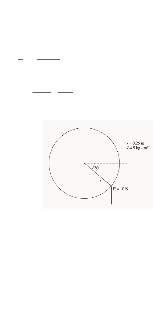
1-3. A force of 5 N is applied to a cylinder, as shown in Figure P1-1. What are the magnitude and direction of
the torque produced on the cylinder? What is the angular acceleration α of the cylinder?
S
OLUTION The magnitude and the direction of the torque on this cylinder is:
CCW ,sin
ind
θτ
rF=
()()
ind 0.25 m 10 N sin 30 1.25 N m, CCW
τ
=°=⋅
The resulting angular acceleration is:
2
2
1.25 N m 0.25 rad/s
5 kg mJ
τ
α
⋅
== =
⋅
1-4. A motor is supplying 60 N ⋅ m of torque to its load. If the motor’s shaft is turning at 1800 r/min, what is
the mechanical power supplied to the load in watts? In horsepower?
S
OLUTION The mechanical power supplied to the load is
()( )
1 min 2 rad
60 N m 1800 r/min 11,310 W
60 s 1 r
P
π
τω
== ⋅ =
2
()
1 hp
11,310 W 15.2 hp
746 W
P
==
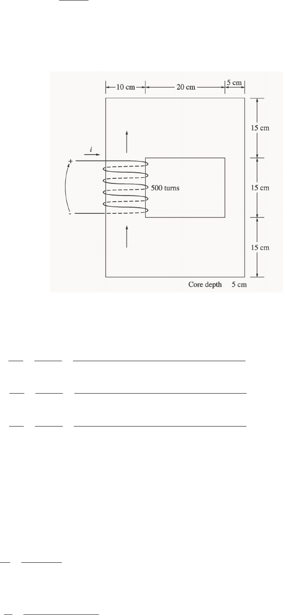
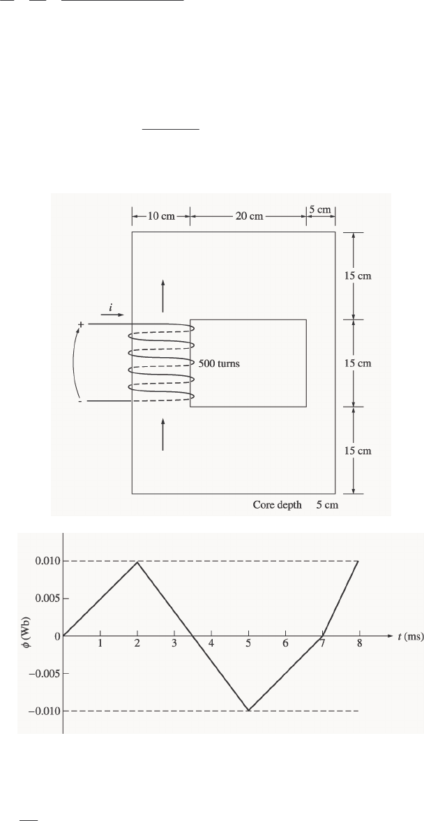
1-5. A ferromagnetic core is shown in Figure P1-2. The depth of the core is 5 cm. The other dimensions of the
core are as shown in the figure. Find the value of the current that will produce a flux of 0.005 Wb. With
this current, what is the flux density at the top of the core? What is the flux density at the right side of the
core? Assume that the relative permeability of the core is 1000.
S
OLUTION There are three regions in this core. The top and bottom form one region, the left side forms a
second region, and the right side forms a third region. If we assume that the mean path length of the flux is
in the center of each leg of the core, and if we ignore spreading at the corners of the core, then the path
lengths are 1
l = 2(27.5 cm) = 55 cm, 2
l = 30 cm, and 3
l = 30 cm. The reluctances of these regions are:
()
()
()()
17
0.55 m 58.36 kA t/Wb
1000 4 10 H/m 0.05 m 0.15 m
ro
ll
AA
µµµ π
−
== = = ⋅
×
R
()
()
()()
27
0.30 m 47.75 kA t/Wb
1000 4 10 H/m 0.05 m 0.10 m
ro
ll
AA
µµµ π
−
== = = ⋅
×
R
()
()
()()
37
0.30 m 95.49 kA t/Wb
1000 4 10 H/m 0.05 m 0.05 m
ro
ll
AA
µµµ π
−
== = = ⋅
×
R
The total reluctance is thus
TOT 1 2 3 58.36 47.75 95.49 201.6 kA t/Wb=++= + + = ⋅RRRR
and the magnetomotive force required to produce a flux of 0.003 Wb is
(
)
(
)
0.005 Wb 201.6 kA t/Wb 1008 A t
φ
== ⋅ = ⋅FR
and the required current is
1008 A t 2.52 A
400 t
iN
⋅
== =
F
The flux density on the top of the core is
()()
0.005 Wb 0.67 T
0.15 m 0.05 m
BA
φ
== =
3
The flux density on the right side of the core is
()()
0.005 Wb 2.0 T
0.05 m 0.05 m
BA
φ
== =
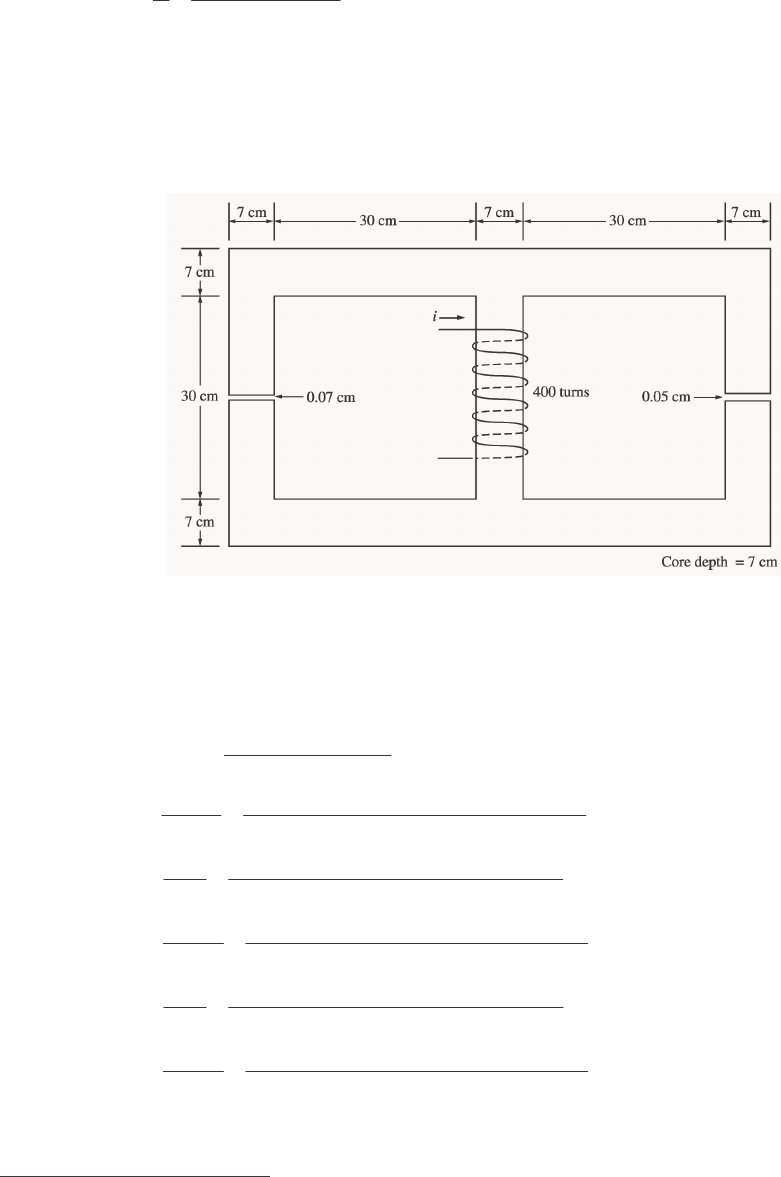
1-6. A ferromagnetic core with a relative permeability of 1500 is shown in Figure P1-3. The dimensions are as
shown in the diagram, and the depth of the core is 7 cm. The air gaps on the left and right sides of the core
are 0.070 and 0.020 cm, respectively. Because of fringing effects, the effective area of the air gaps is 5
percent larger than their physical size. If there are 4001 turns in the coil wrapped around the center leg of
the core and if the current in the coil is 1.0 A, what is the flux in each of the left, center, and right legs of
the core? What is the flux density in each air gap?
S
OLUTION This core can be divided up into five regions. Let 1
R be the reluctance of the left-hand portion
of the core, 2
R be the reluctance of the left-hand air gap, 3
R be the reluctance of the right-hand portion of
the core, 4
R be the reluctance of the right-hand air gap, and 5
R be the reluctance of the center leg of the
core. Then the total reluctance of the core is
()
()
1234
TOT 5
1234
++
=+ +++
RRRR
RR
RRRR
()
()
()()
1
17
01
1.11 m 90.1 kA t/Wb
2000 4 10 H/m 0.07 m 0.07 m
r
l
A
µµ π
−
== =⋅
×
R
()
()()()
2
27
02
0.0007 m 108.3 kA t/Wb
4 10 H/m 0.07 m 0.07 m 1.05
l
A
µπ
−
== = ⋅
×
R
()
()
()()
3
37
03
1.11 m 90.1 kA t/Wb
2000 4 10 H/m 0.07 m 0.07 m
r
l
A
µµ π
−
== =⋅
×
R
()
()()()
4
47
04
0.0005 m 77.3 kA t/Wb
4 10 H/m 0.07 m 0.07 m 1.05
l
A
µπ
−
== = ⋅
×
R
()
()
()()
5
57
05
0.37 m 30.0 kA t/Wb
2000 4 10 H/m 0.07 m 0.07 m
r
l
A
µµ π
−
== =⋅
×
R
The total reluctance is
1 In the first printing, this value was given incorrectly as 300.
4
()
()
(
)
(
)
1234
TOT 5
12 34
90.1 108.3 90.1 77.3
30.0 120.8 kA t/Wb
90.1 108.3 90.1 77.3
++ ++
=+ = + = ⋅
+++ + + +
RRRR
RR
RR RR
The total flux in the core is equal to the flux in the center leg:
(
)
(
)
center TOT
TOT
400 t 1.0 A 0.0033 Wb
120.8 kA t/Wb
φφ
== = =
⋅
F
R
The fluxes in the left and right legs can be found by the “flux divider rule”, which is analogous to the
current divider rule.
()
(
)
()
34
left TOT
1234
90.1 77.3 0.0033 Wb 0.00193 Wb
90.1 108.3 90.1 77.3
φφ
++
== =
+++ + + +
RR
RR RR
()
(
)
()
12
right TOT
12 34
90.1 108.3 0.0033 Wb 0.00229 Wb
90.1 108.3 90.1 77.3
φφ
++
== =
+++ + + +
RR
RR RR
The flux density in the air gaps can be determined from the equation BA
φ
=:
()()()
left
left
eff
0.00193 Wb 0.375 T
0.07 cm 0.07 cm 1.05
BA
φ
== =
()()()
right
right
eff
0.00229 Wb 0.445 T
0.07 cm 0.07 cm 1.05
BA
φ
== =
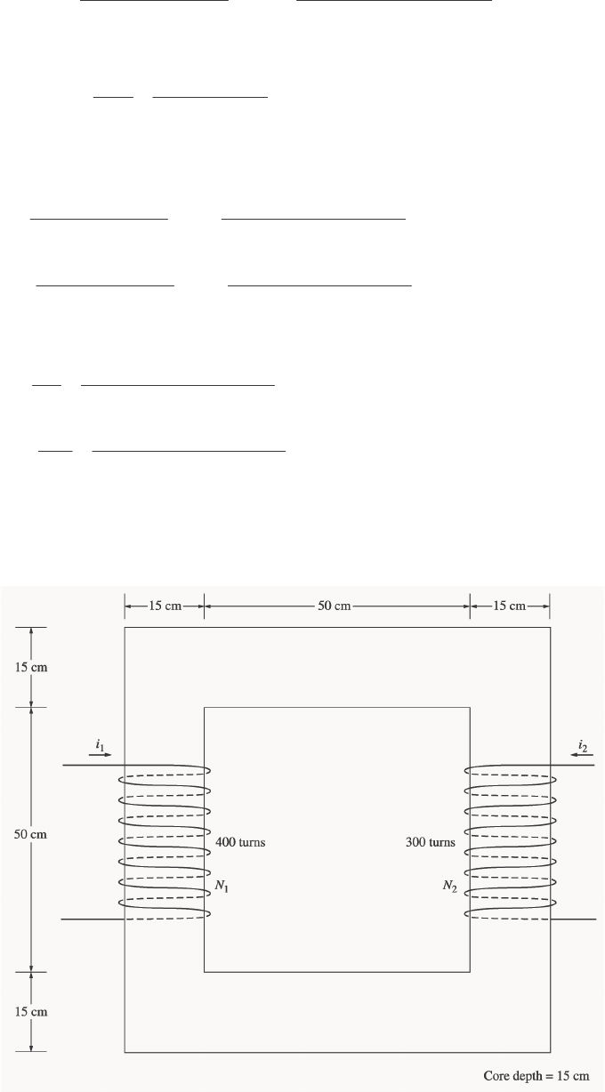
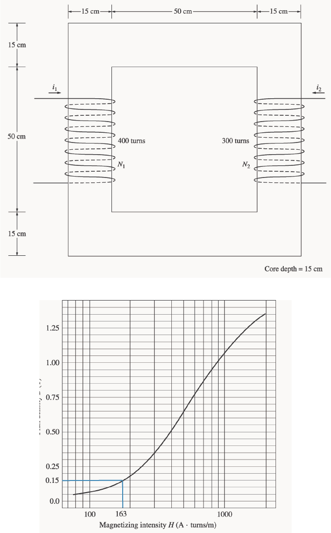
1-7. A two-legged core is shown in Figure P1-4. The winding on the left leg of the core (N1) has 400 turns, and
the winding on the right (N2) has 300 turns. The coils are wound in the directions shown in the figure. If
the dimensions are as shown, then what flux would be produced by currents i1 = 0.5 A and i2 = 0.75 A?
Assume r
µ
= 1000 and constant.
5
S
OLUTION The two coils on this core are would so that their magnetomotive forces are additive, so the total
magnetomotive force on this core is
(
)
(
)
(
)
(
)
TOT 1 1 2 2 400 t 0.5 A 300 t 0.75 A 425 A tNi Ni=+ = + = ⋅F
The total reluctance in the core is
()
()
()()
TOT 7
0
2.60 m 92.0 kA t/Wb
1000 4 10 H/m 0.15 m 0.15 m
r
l
A
µµ π
−
== = ⋅
×
R
and the flux in the core is:
TOT
TOT
425 A t 0.00462 Wb
92.0 kA t/Wb
φ
⋅
== =
⋅
F
R
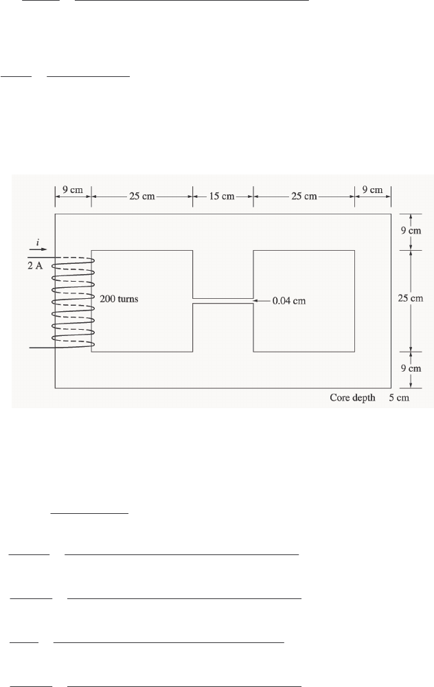
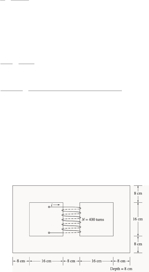
1-8. A core with three legs is shown in Figure P1-5. Its depth is 5 cm, and there are 200 turns on the leftmost
leg. The relative permeability of the core can be assumed to be 1500 and constant. What flux exists in
each of the three legs of the core? What is the flux density in each of the legs? Assume a 4% increase in
the effective area of the air gap due to fringing effects.
S
OLUTION This core can be divided up into four regions. Let 1
R be the reluctance of the left-hand portion
of the core, 2
R be the reluctance of the center leg of the core, 3
R be the reluctance of the center air gap,
and 4
R be the reluctance of the right-hand portion of the core. Then the total reluctance of the core is
()
234
TOT 1
234
+
=+++
RRR
RR
RRR
()
()
()()
1
17
01
1.08 m 127.3 kA t/Wb
1500 4 10 H/m 0.09 m 0.05 m
r
l
A
µµ π
−
== = ⋅
×
R
()
()
()()
2
27
02
0.34 m 24.0 kA t/Wb
1500 4 10 H/m 0.15 m 0.05 m
r
l
A
µµ π
−
== =⋅
×
R
()
()()()
3
37
03
0.0004 m 40.8 kA t/Wb
4 10 H/m 0.15 m 0.05 m 1.04
l
A
µπ
−
== = ⋅
×
R
()
()
()()
4
47
04
1.08 m 127.3 kA t/Wb
1500 4 10 H/m 0.09 m 0.05 m
r
l
A
µµ π
−
== = ⋅
×
R
The total reluctance is
6
()
(
)
234
TOT 1
234
24.0 40.8 127.3
127.3 170.2 kA t/Wb
24.0 40.8 127.3
++
=+ = + = ⋅
++ + +
RRR
RR
RRR
The total flux in the core is equal to the flux in the left leg:
(
)
(
)
left TOT
TOT
200 t 2.0 A 0.00235 Wb
170.2 kA t/Wb
φφ
== = =
⋅
F
R
The fluxes in the center and right legs can be found by the “flux divider rule”, which is analogous to the
current divider rule.
()
4
center TOT
234
127.3 0.00235 Wb 0.00156 Wb
24.0 40.8 127.3
φφ
== =
++ + +
R
RRR
()
23
right TOT
234
24.0 40.8 0.00235 Wb 0.00079 Wb
24.0 40.8 127.3
φφ
++
== =
++ + +
RR
RRR
The flux density in the legs can be determined from the equation BA=
φ
:
()()
left
left
0.00235 Wb 0.522 T
0.09 cm 0.05 cm
BA
φ
== =
()()
center
center
0.00156 Wb 0.208 T
0.15 cm 0.05 cm
BA
φ
== =
()()
left
right
0.00079 Wb 0.176 T
0.09 cm 0.05 cm
BA
φ
== =
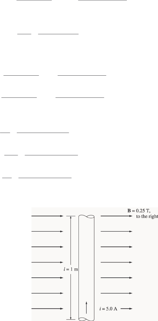
1-9. A wire is shown in Figure P1-6 which is carrying 5.0 A in the presence of a magnetic field. Calculate the
magnitude and direction of the force induced on the wire.
S
OLUTION The force on this wire can be calculated from the equation
(
)
(
)
(
)
(
)
5 A 1 m 0.25 T 1.25 N, into the pagei ilB=×= = =FlB
7
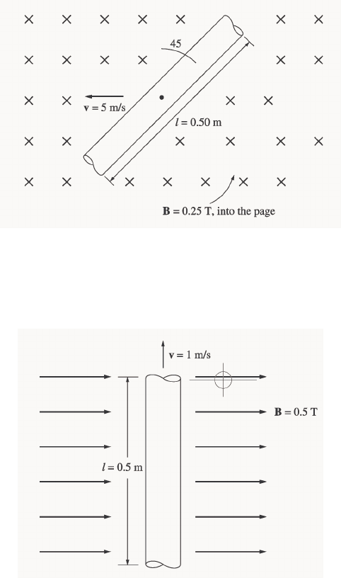
1-10. The wire is shown in Figure P1-7 is moving in the presence of a magnetic field. With the information given
in the figure, determine the magnitude and direction of the induced voltage in the wire.
S
OLUTION The induced voltage on this wire can be calculated from the equation shown below. The voltage
on the wire is positive downward because the vector quantity Bv × points downward.
() ()( )( )
ind cos 45 5 m/s 0.25 T 0.50 m cos 45 0.442 V, positive downevBl= × ⋅ = °= °=vBl
1-11. Repeat Problem 1-10 for the wire in Figure P1-8.
S
OLUTION The induced voltage on this wire can be calculated from the equation shown below. The total
voltage is zero, because the vector quantity Bv × points into the page, while the wire runs in the plane of
the page.
() ()()( )
ind cos 90 1 m/s 0.5 T 0.5 m cos 90 0 VevBl= × ⋅ = °= °=vBl
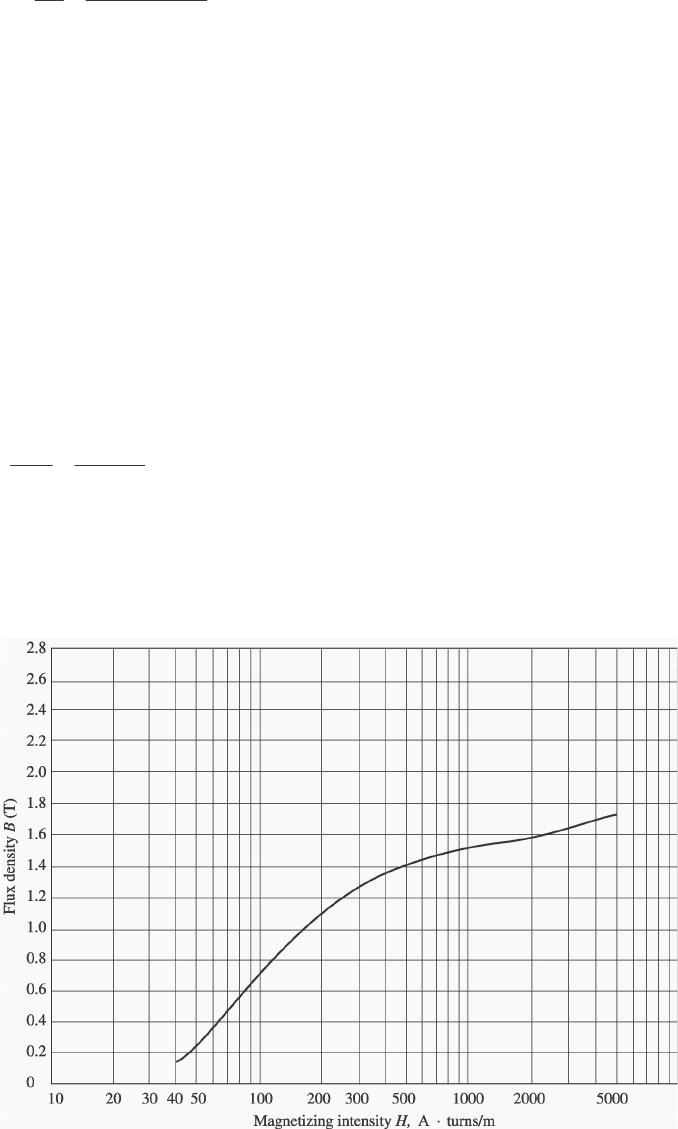
1-12. The core shown in Figure P1-4 is made of a steel whose magnetization curve is shown in Figure P1-9.
Repeat Problem 1-7, but this time do not assume a constant value of µr. How much flux is produced in the
core by the currents specified? What is the relative permeability of this core under these conditions? Was
the assumption in Problem 1-7 that the relative permeability was equal to 1000 a good assumption for these
conditions? Is it a good assumption in general?
8
S
OLUTION The magnetization curve for this core is shown below:
The two coils on this core are wound so that their magnetomotive forces are additive, so the total
magnetomotive force on this core is
()( )()( )
TOT 1 1 2 2 400 t 0.5 A 300 t 0.75 A 425 A tNi Ni=+ = + = ⋅F
Therefore, the magnetizing intensity H is
9
425 A t 163 A t/m
2.60 m
c
Hl
⋅
== = ⋅
F
From the magnetization curve,
0.15 TB=
and the total flux in the core is
(
)
(
)
(
)
TOT 0.15 T 0.15 m 0.15 m 0.0033 WbBA
φ
== =
The relative permeability of the core can be found from the reluctance as follows:
A
l
r0TOT
TOT
µµφ
== F
R
Solving for µr yields
(
)
(
)
()
()
()()
TOT
-7
TOT 0
0.0033 Wb 2.6 m
714
425 A t 4 10 H/m 0.15 m 0.15 m
r
l
A
φ
µµπ
== =
⋅×
F
The assumption that
r
µ
= 1000 is not very good here. It is not very good in general.
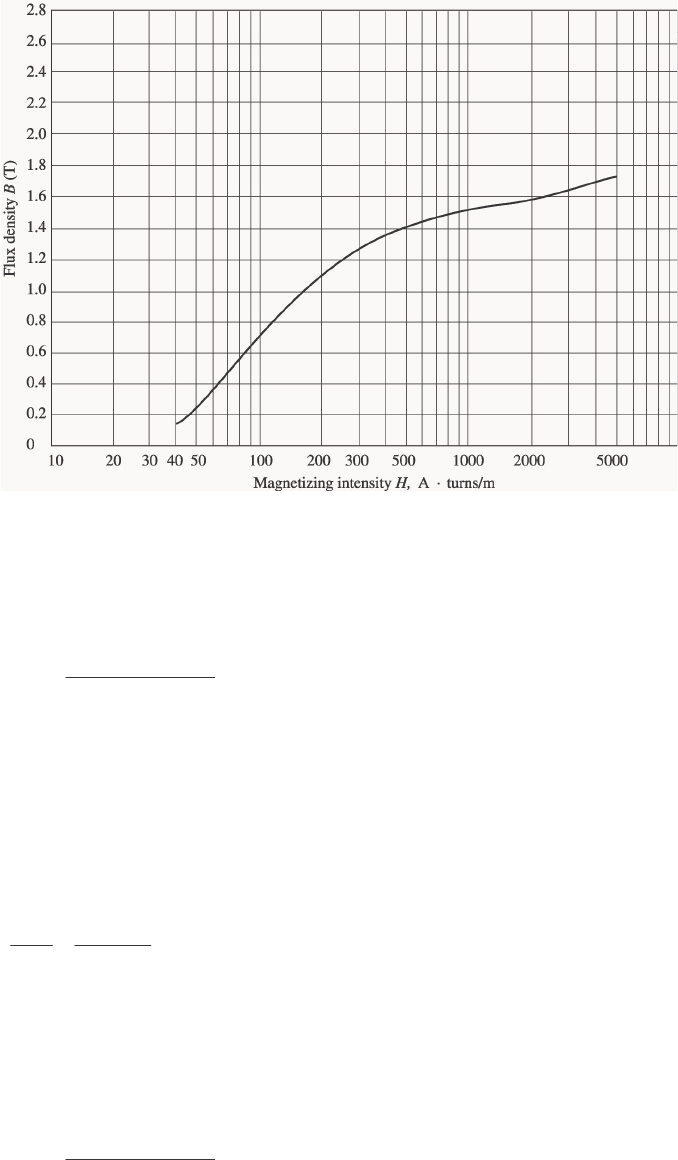
1-13. A core with three legs is shown in Figure P1-10. Its depth is 8 cm, and there are 400 turns on the center
leg. The remaining dimensions are shown in the figure. The core is composed of a steel having the
magnetization curve shown in Figure 1-10c. Answer the following questions about this core:
(a) What current is required to produce a flux density of 0.5 T in the central leg of the core?
(b) What current is required to produce a flux density of 1.0 T in the central leg of the core? Is it twice the
current in part (a)?
(c) What are the reluctances of the central and right legs of the core under the conditions in part (a)?
(d) What are the reluctances of the central and right legs of the core under the conditions in part (b)?
(e) What conclusion can you make about reluctances in real magnetic cores?
10
S
OLUTION The magnetization curve for this core is shown below:
(a) A flux density of 0.5 T in the central core corresponds to a total flux of
(
)
(
)
(
)
TOT 0.5 T 0.08 m 0.08 m 0.0032 WbBA
φ
== =
By symmetry, the flux in each of the two outer legs must be 12
0.0016 Wb
φφ
== , and the flux density in
the other legs must be
()()
12
0.0016 Wb 0.25 T
0.08 m 0.08 m
BB== =
The magnetizing intensity H required to produce a flux density of 0.25 T can be found from Figure 1-10c.
It is 50 A·t/m. Similarly, the magnetizing intensity H required to produce a flux density of 0.50 T is 70
A·t/m. Therefore, the total MMF needed is
TOT center center outer outer
Hl Hl=+F
()()()()
TOT 70 A t/m 0.24 m 50 A t/m 0.72 m 52.8 A t=⋅ +⋅ = ⋅F
and the required current is
TOT 52.8 A t 0.13 A
400 t
iN
⋅
== =
F
(b) A flux density of 1.0 T in the central core corresponds to a total flux of
()()()
TOT 1.0 T 0.08 m 0.08 m 0.0064 WbBA
φ
== =
By symmetry, the flux in each of the two outer legs must be 12
0.0032 Wb
φφ
== , and the flux density in
the other legs must be
()()
12
0.0032 Wb 0.50 T
0.08 m 0.08 m
BB== =

11
The magnetizing intensity H required to produce a flux density of 0.50 T can be found from Figure 1-10c.
It is 70 A·t/m. Similarly, the magnetizing intensity H required to produce a flux density of 1.00 T is about
160 A·t/m. Therefore, the total MMF needed is
TOT center center outer outer
HI HI=+F
(
)
(
)
(
)
(
)
TOT 160 A t/m 0.24 m 70 A t/m 0.72 m 88.8 A t=⋅ +⋅ =⋅F
and the required current is
TOT 88.8 A t 0.22 A
400 t
iN
φ
⋅
== =
This current is less not twice the current in part (a).
(c) The reluctance of the central leg of the core under the conditions of part (a) is:
(
)
(
)
TOT
cent
TOT
70 A t/m 0.24 m 5.25 kA t/Wb
0.0032 Wb
φ
⋅
== = ⋅
F
R
The reluctance of the right leg of the core under the conditions of part (a) is:
()()
TOT
right
TOT
50 A t/m 0.72 m 22.5 kA t/Wb
0.0016 Wb
φ
⋅
== = ⋅
F
R
(d) The reluctance of the central leg of the core under the conditions of part (b) is:
(
)
(
)
TOT
cent
TOT
160 A t/m 0.24 m 6.0 kA t/Wb
0.0064 Wb
φ
⋅
== = ⋅
F
R
The reluctance of the right leg of the core under the conditions of part (b) is:
()()
TOT
right
TOT
70 A t/m 0.72 m 15.75 kA t/Wb
0.0032 Wb
φ
⋅
== = ⋅
F
R
(e) The reluctances in real magnetic cores are not constant.
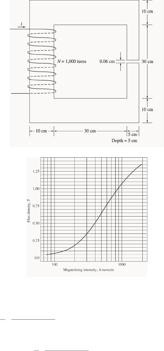
1-14. A two-legged magnetic core with an air gap is shown in Figure P1-11. The depth of the core is 5 cm, the
length of the air gap in the core is 0.06 cm, and the number of turns on the coil is 1000. The magnetization
curve of the core material is shown in Figure P1-9. Assume a 5 percent increase in effective air-gap area to
account for fringing. How much current is required to produce an air-gap flux density of 0.5 T? What are
the flux densities of the four sides of the core at that current? What is the total flux present in the air gap?
12
S
OLUTION The magnetization curve for this core is shown below:
An air-gap flux density of 0.5 T requires a total flux of
(
)
(
)
(
)
(
)
eff 0.5 T 0.05 m 0.05 m 1.05 0.00131 WbBA
φ
== =
This flux requires a flux density in the right-hand leg of
()()
right
0.00131 Wb 0.524 T
0.05 m 0.05 m
BA
φ
== =
The flux density in the other three legs of the core is
()()
top left bottom
0.00131 Wb 0.262 T
0.10 m 0.05 m
BBB A
φ
== == =
13
The magnetizing intensity required to produce a flux density of 0.5 T in the air gap can be found from the
equation ag ago
BH
µ
=:
ag
ag 7
0
0.5 T 398 kA t/m
410 H/m
B
H
µπ
−
== = ⋅
×
The magnetizing intensity required to produce a flux density of 0.524 T in the right-hand leg of the core can
be found from Figure P1-9 to be
right 410 A t/mH=⋅
The magnetizing intensity required to produce a flux density of 0.262 T in the top, left, and bottom legs of
the core can be found from Figure P1-9 to be
top left bottom 240 A t/mHHH== = ⋅
The total MMF required to produce the flux is
TOT ag ag right right top top left left bottom bottom
Hl H l H l H l H l=+ + + +F
(
)
(
)
(
)
(
)
(
)
(
)
TOT 398 kA t/m 0.0006 m 410 A t/m 0.40 m 3 240 A t/m 0.40 m=⋅ +⋅ +⋅F
TOT 278.6 164 288 691 A t=++= ⋅F
and the required current is
TOT 691 A t 0.691 A
1000 t
iN
⋅
== =
F
The flux densities in the four sides of the core and the total flux present in the air gap were calculated
above.
1-15. A transformer core with an effective mean path length of 10 in has a 300-turn coil wrapped around one leg.
Its cross-sectional area is 0.25 in2, and its magnetization curve is shown in Figure 1-10c. If current of 0.25
A is flowing in the coil, what is the total flux in the core? What is the flux density?
S
OLUTION The magnetizing intensity applied to this core is
14
(
)
(
)
()( )
300 t 0.25 A 295 A t/m
10 in 0.0254 m/in
cc
Ni
Hll
== = = ⋅
F
From the magnetization curve, the flux density in the core is
1.27 T
B=
The total flux in the core is
()
()
2
20.0254 m
1.27 T 0.25 in 0.000205 Wb
1 in
BA
φ
== =
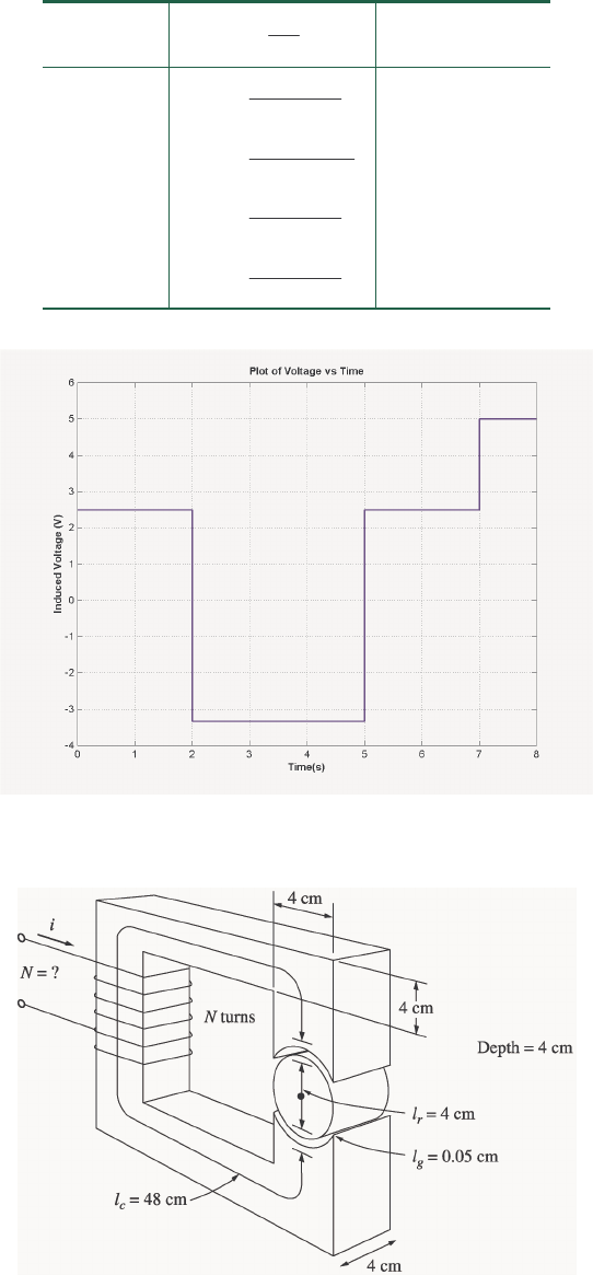
1-16. The core shown in Figure P1-2 has the flux
φ
shown in Figure P1-12. Sketch the voltage present at the
terminals of the coil.
S
OLUTION By Lenz’ Law, an increasing flux in the direction shown on the core will produce a voltage that
tends to oppose the increase. This voltage will be the same polarity as the direction shown on the core, so it
will be positive. The induced voltage in the core is given by the equation
ind
d
eN
dt
φ
=
so the voltage in the windings will be
15
Time
dt
d
N
φ
ind
e
0 < t < 2 s
()
0.010 Wb
500 t 2 s 2.50 V
2 < t < 5 s
()
0.020 Wb
500 t 3 s
− -3.33 V
5 < t < 7 s
()
0.010 Wb
500 t 2 s 2.50 V
7 < t < 8 s
()
0.010 Wb
500 t 1 s 5.00 V
The resulting voltage is plotted below:
1-17. Figure P1-13 shows the core of a simple dc motor. The magnetization curve for the metal in this core is
given by Figure 1-10c and d. Assume that the cross-sectional area of each air gap is 18 cm2 and that the
width of each air gap is 0.05 cm. The effective diameter of the rotor core is 4 cm.
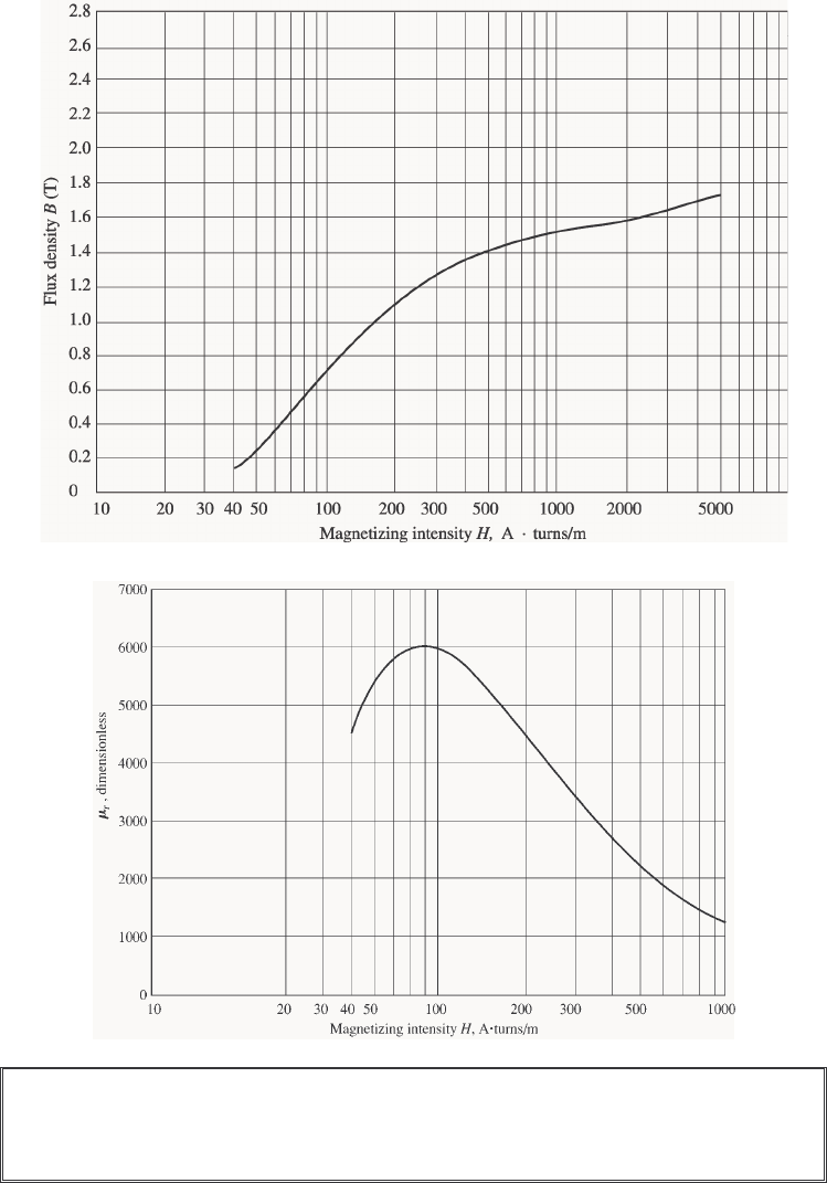
16
S
OLUTION The magnetization curve for this core is shown below:
The relative permeability of this core is shown below:
Note: This is a design problem, and the answer presented here is not unique. Other
values could be selected for the flux density in part (a), and other numbers of turns
could be selected in part (c). These other answers are also correct if the proper steps
were followed, and if the choices were reasonable.
(a) From Figure 1-10c, a reasonable maximum flux density would be about 1.2 T. Notice that the
saturation effects become significant for higher flux densities.
(b) At a flux density of 1.2 T, the total flux in the core would be
(1.2 T)(0.04 m)(0.04 m) 0.00192 WbBA
φ
== =
(c) The total reluctance of the core is:

17
TOT stator air gap 1 rotor air gap 2
=+ ++RRR RR
At a flux density of 1.2 T, the relative permeability r
µ
of the stator is about 3800, so the stator reluctance
is
()
()
()()
stator
stator 7
stator stator
0.48 m 62.8 kA t/Wb
3800 4 10 H/m 0.04 m 0.04 m
l
A
µπ
−
== =⋅
×
R
At a flux density of 1.2 T, the relative permeability r
µ
of the rotor is 3800, so the rotor reluctance is
()
()
()()
rotor
rotor 7
stator rotor
0.04 m 5.2 kA t/Wb
3800 4 10 H/m 0.04 m 0.04 m
l
A
µπ
−
== =⋅
×
R
The reluctance of both air gap 1 and air gap 2 is
()()
air gap
air gap 1 air gap 2 72
air gap air gap
0.0005 m 221 kA t/Wb
4 10 H/m 0.0018 m
l
A
µπ
−
== = =⋅
×
RR
Therefore, the total reluctance of the core is
TOT stator air gap 1 rotor air gap 2
=+ ++RRR RR
TOT 62.8 221 5.2 221 510 kA t/Wb=+++= ⋅R
The required MMF is
(
)
(
)
TOT TOT 0.00192 Wb 510 kA t/Wb 979 A t
φ
== ⋅=⋅FR
Since
Ni=F, and the current is limited to 1 A, one possible choice for the number of turns is N = 1000.
1-18. Assume that the voltage applied to a load is 208 30 V=∠−°V and the current flowing through the load is
515 A=∠ °
I.
(a) Calculate the complex power S consumed by this load.
(b) Is this load inductive or capacitive?
(c) Calculate the power factor of this load?
(d) Calculate the reactive power consumed or supplied by this load. Does the load consume reactive power
from the source or supply it to the source?
S
OLUTION
(a) The complex power S consumed by this load is
(
)
(
)
(
)
(
)
*
208 30 V 5 15 A 208 30 V 5 15 A= = ∠− ° ∠ ° = ∠− ° ∠− °
*
SVI
1040 45 VA=∠−°S
(b) This is a capacitive load.
(c) The power factor of this load is
()
PF cos 45 0.707 leading=−°=
(d) This load supplies reactive power to the source. The reactive power of the load is
(
)
(
)
(
)
sin 208 V 5 A sin 45 735 varQVI
θ
== −°=−
1-19. Figure P1-14 shows a simple single-phase ac power system with three loads. The voltage source is
120 0 V=∠°
V, and the three loads are
1530 =∠ °ΩZ 2545 =∠ °ΩZ 3590 =∠− °ΩZ
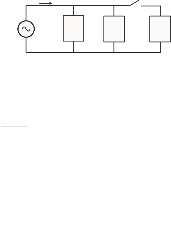
18
Answer the following questions about this power system.
(a) Assume that the switch shown in the figure is open, and calculate the current I, the power factor, and
the real, reactive, and apparent power being supplied by the source.
(b) Assume that the switch shown in the figure is closed, and calculate the current I, the power factor, and
the real, reactive, and apparent power being supplied by the source.
(c) What happened to the current flowing from the source when the switch closed? Why?
+
-
I
V
+
-
+
-
+
-
1
Z2
Z3
Z
120 0 V=∠°V
S
OLUTION
(a) With the switch open, only loads 1 and 2 are connected to the source. The current 1
I in Load 1 is
1
120 0 V 24 30 A
530 A
∠°
==∠−°
∠°
I
The current
2
I in Load 2 is
2
120 0 V 24 45 A
545 A
∠°
==∠−°
∠°
I
Therefore the total current from the source is
12
24 30 A 24 45 A 47.59 37.5 A=+=∠−° + ∠−°= ∠− °II I
The power factor supplied by the source is
(
)
PF cos cos 37.5 0.793 lagging
θ
==−°=
The real, reactive, and apparent power supplied by the source are
(
)
(
)
(
)
cos 120 V 47.59 A cos 37.5 4531 WPVI
θ
== −°=
()( )( )
cos 120 V 47.59 A sin 37.5 3477 varQVI
θ
== −°=−
(
)
(
)
120 V 47.59 A 5711 VASVI== =
(b) With the switch open, all three loads are connected to the source. The current in Loads 1 and 2 is the
same as before. The current 3
I in Load 3 is
3
120 0 V 24 90 A
590 A
∠°
==∠°
∠− °
I
Therefore the total current from the source is
123
24 30 A 24 45 A 24 90 A 38.08 7.5 A= + + = ∠− ° + ∠− ° + ∠ ° = ∠− °II I I
The power factor supplied by the source is
(
)
PF cos cos 7.5 0.991 lagging
θ
==−°=
The real, reactive, and apparent power supplied by the source are
(
)
(
)
(
)
cos 120 V 38.08 A cos 7.5 4531 WPVI
θ
== −°=

19
(
)
(
)
(
)
cos 120 V 38.08 A sin 7.5 596 varQVI
θ
== −°=−
(
)
(
)
120 V 38.08 A 4570 VASVI== =
(c) The current flowing decreased when the switch closed, because most of the reactive power being
consumed by Loads 1 and 2 is being supplied by Load 3. Since less reactive power has to be supplied by
the source, the total current flow decreases.
1-20. Demonstrate that Equation (1-59) can be derived from Equation (1-58) using simple trigonometric
identities:
()
() () () 2 cos cospt vt it VI t t
ωωθ
== − (1-58)
()
() cos 1 cos2 sin sin2pt VI t VI t
θω θω
=++ (1-59)
S
OLUTION
The first step is to apply the following identity:
()()
1
cos cos cos cos
2
αβ αβ αβ
=
The result is
()
() () () 2 cos cospt vt it VI t t
ωωθ
== −
)
()()
1
() 2 cos cos
2
pt VI tt tt
ωωθ ωωθ
=
()
() cos cos 2pt VI t
θωθ
=
Now we must apply the angle addition identity to the second term:
()
cos cos cos sin sin
αβ α β α β
−= +
The result is
[]
() cos cos2 cos sin2 sinpt VI t t
θωθωθ
=+ +
Collecting terms yields the final result:
(
)
() cos 1 cos2 sin sin2pt VI t VI t
θω θω
=++
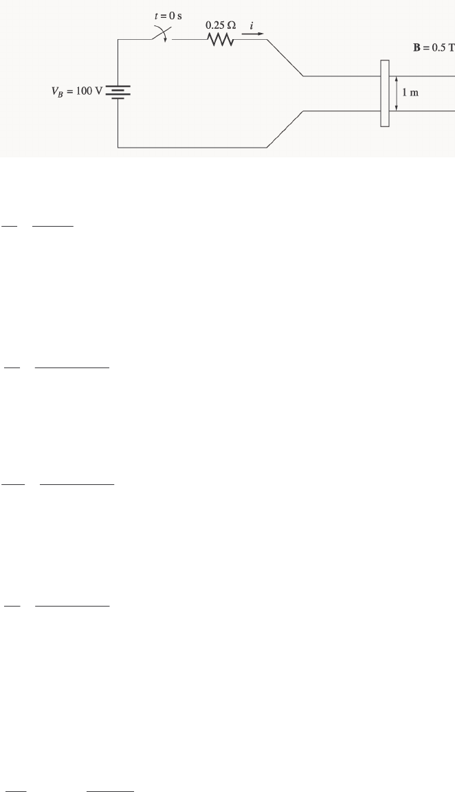
1-21. A linear machine has a magnetic flux density of 0.5 T directed into the page, a resistance of 0.25 Ω, a bar
length l = 1.0 m, and a battery voltage of 100 V.
(a) What is the initial force on the bar at starting? What is the initial current flow?
(b) What is the no-load steady-state speed of the bar?
(c) If the bar is loaded with a force of 25 N opposite to the direction of motion, what is the new steady-
state speed? What is the efficiency of the machine under these circumstances?
20
S
OLUTION
(a) The current in the bar at starting is
100 V 400 A
0.25
B
V
iR
== =
Ω
Therefore, the force on the bar at starting is
(
)
(
)
(
)
(
)
400 A 1 m 0.5 T 200 N, to the righti=×= =FlB
(b) The no-load steady-state speed of this bar can be found from the equation
vBleVB== ind
()()
100 V 200 m/s
0.5 T 1 m
B
V
vBl
== =
(c) With a load of 25 N opposite to the direction of motion, the steady-state current flow in the bar will
be given by
ilBFF == indapp
()()
app 25 N 50 A
0.5 T 1 m
F
iBl
== =
The induced voltage in the bar will be
(
)
(
)
ind 100 V - 50 A 0.25 87.5 V
B
eViR=−= Ω=
and the velocity of the bar will be
()()
87.5 V 175 m/s
0.5 T 1 m
B
V
vBl
== =
The
input power to the linear machine under these conditions is
(
)
(
)
in 100 V 50 A 5000 W
B
PVi== =
The
output power from the linear machine under these conditions is
(
)
(
)
out 87.5 V 50 A 4375 W
B
PVi== =
Therefore, the efficiency of the machine under these conditions is
out
in
4375 W
100% 100% 87.5%
5000 W
P
P
η
=× = × =
1-22. A linear machine has the following characteristics:
0.33 T into pageB= 0.50 R=Ω

21
0.5 m
l= 120 V
B
V=
(a) If this bar has a load of 10 N attached to it opposite to the direction of motion, what is the steady-state
speed of the bar?
(b) If the bar runs off into a region where the flux density falls to 0.30 T, what happens to the bar? What
is its final steady-state speed?
(c) Suppose B
V is now decreased to 80 V with everything else remaining as in part (b). What is the new
steady-state speed of the bar?
(d) From the results for parts (b) and (c), what are two methods of controlling the speed of a linear
machine (or a real dc motor)?
SOLUTION
(a) With a load of 20 N opposite to the direction of motion, the steady-state current flow in the bar will
be given by
ilBFF == indapp
()()
app 10 N 60.5 A
0.33 T 0.5 m
F
iBl
== =
The induced voltage in the bar will be
(
)
(
)
ind 120 V - 60.5 A 0.50 89.75 V
B
eViR=−= Ω=
and the velocity of the bar will be
()()
ind 89.75 V 544 m/s
0.33 T 0.5 m
e
vBl
== =
(b) If the flux density drops to 0.30 T while the load on the bar remains the same, there will be a speed
transient until app ind 10 NFF== again. The new steady state current will be
app ind
F F ilB==
()()
app 10 N 66.7 A
0.30 T 0.5 m
F
iBl
== =
The induced voltage in the bar will be
(
)
(
)
ind 120 V - 66.7 A 0.50 86.65 V
B
eViR=−= Ω=
and the velocity of the bar will be
()()
ind 86.65 V 577 m/s
0.30 T 0.5 m
e
vBl
== =
(c) If the battery voltage is decreased to 80 V while the load on the bar remains the same, there will be a
speed transient until app ind 10 NFF== again. The new steady state current will be
app ind
F F ilB==
()()
app 10 N 66.7 A
0.30 T 0.5 m
F
iBl
== =
The induced voltage in the bar will be

22
(
)
(
)
ind 80 V - 66.7 A 0.50 46.65 V
B
eViR=−= Ω=
and the velocity of the bar will be
()()
ind 46.65 V 311 m/s
0.30 T 0.5 m
e
vBl
== =
(d) From the results of the two previous parts, we can see that there are two ways to control the speed of
a linear dc machine. Reducing the flux density B of the machine increases the steady-state speed, and
reducing the battery voltage VB decreases the stead-state speed of the machine. Both of these speed control
methods work for real dc machines as well as for linear machines.
23
Chapter 2: Transformers
2-1. The secondary winding of a transformer has a terminal voltage of ( ) 282.8 sin 377 V
s
vt t=. The turns
ratio of the transformer is 100:200 (a = 0.50). If the secondary current of the transformer is
()
( ) 7.07 sin 377 36.87 A
s
it t=−°, what is the primary current of this transformer? What are its voltage
regulation and efficiency? The impedances of this transformer referred to the primary side are
eq 0.20 R=Ω 300
C
R=Ω
eq 0.750 X=Ω 80
M
X=Ω
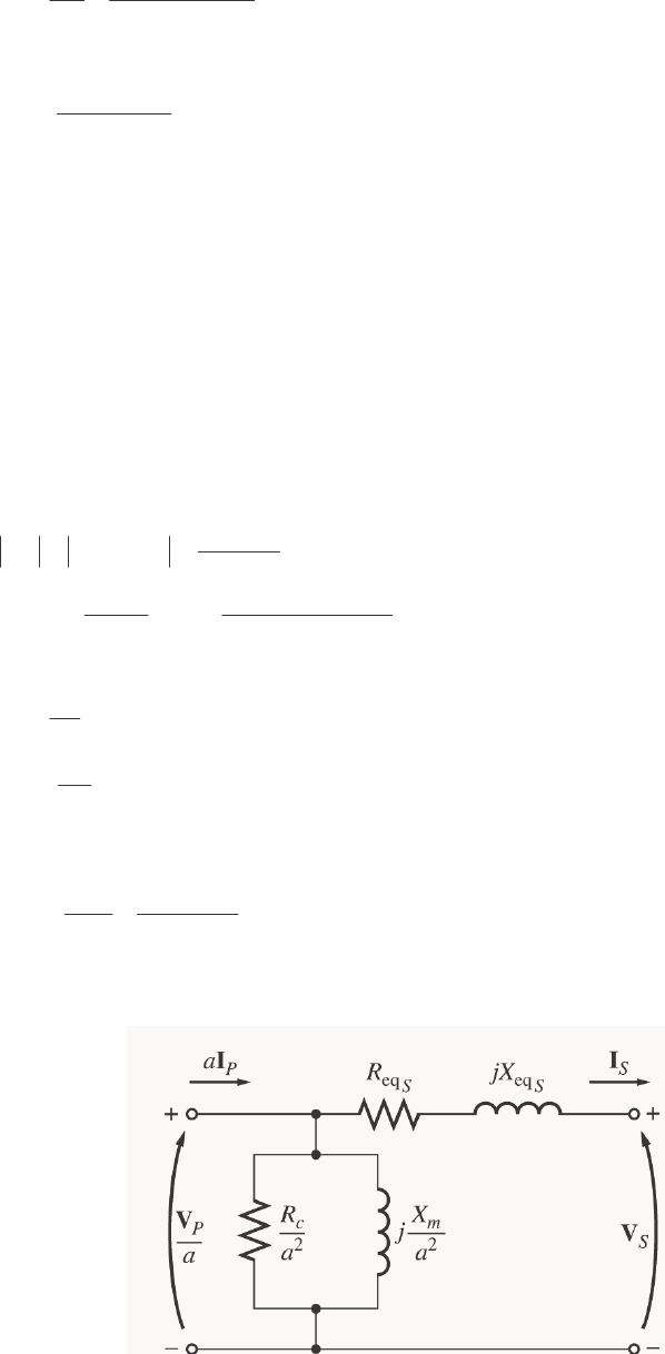
S
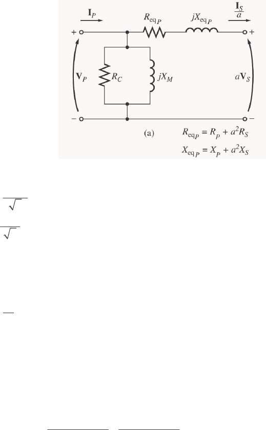
OLUTION The equivalent circuit of this transformer is shown below. (Since no particular equivalent circuit
was specified, we are using the approximate equivalent circuit referred to the primary side.)
The secondary voltage and current are
282.8 0 V 200 0 V
2
S=∠°=∠°V
7.07 36.87 A 5 -36.87 A
2
S=∠− °=∠ °I
The secondary voltage referred to the primary side is
100 0 V
SS
a
′==∠°VV
The secondary current referred to the primary side is
10 36.87 A
S
Sa
′==∠− °
I
I
The primary circuit voltage is given by
()
eq eqPSS
RjX
′′
=+ +VVI
(
)
(
)
100 0 V 10 36.87 A 0.20 0.750 106.2 2.6 V
Pj=∠°+∠− ° Ω+ Ω= ∠°V
The excitation current of this transformer is
EX
106.2 2.6 V 106.2 2.6 V 0.354 2.6 1.328 87.4
300 80
CM j
∠° ∠°
=+=+=∠°+∠−°
ΩΩ
III
EX 1.37 72.5 A=∠−°I

24
Therefore, the total primary current of this transformer is
EX 10 36.87 1.37 72.5 11.1 41.0 A
PS
′
=+ =∠− °+ ∠− °= ∠− °II I
The voltage regulation of the transformer at this load is
106.2 100
VR 100% 100% 6.2%
100
PS
S
VaV
aV
−−
=×= ×=
The input power to this transformer is
()() ()
IN cos 106.2 V 11.1 A cos 2.6 41.0
PP
PVI
θ
==
()()
IN 106.2 V 11.1 A cos 43.6 854 WP=°=
The output power from this transformer is
(
)
(
)
(
)
OUT cos 200 V 5 A cos 36.87 800 W
SS
PVI
θ
== °=
Therefore, the transformer’s efficiency is
OUT
IN
800 W
100% 100% 93.7%
854 W
P
P
η
=× = × =
2-2. A 20-kVA 8000/480-V distribution transformer has the following resistances and reactances:
Ω= 32
P
R Ω= 05.0
S
R
Ω= 45
P
X 0.06
S
X=Ω
Ω= k 250
C
R Ω= k 30
M
X
The excitation branch impedances are given referred to the high-voltage side of the transformer.
(a) Find the equivalent circuit of this transformer referred to the high-voltage side.
(b) Find the per-unit equivalent circuit of this transformer.
(c) Assume that this transformer is supplying rated load at 480 V and 0.8 PF lagging. What is this
transformer’s input voltage? What is its voltage regulation?
(d) What is the transformer’s efficiency under the conditions of part (c)?
S
OLUTION
(a) The turns ratio of this transformer is a = 8000/480 = 16.67. Therefore, the secondary impedances
referred to the primary side are
()( )
2
216.67 0.05 13.9
SS
RaR
′== Ω=Ω
()( )
2
216.67 0.06 16.7
SS
XaX
′== Ω=Ω
25
The resulting equivalent circuit is
32
Ω
250 k
Ω
j
45
Ω
j
30 k
Ω
j
16.7
Ω
13.9
Ω
(b) The rated kVA of the transformer is 20 kVA, and the rated voltage on the primary side is 8000 V, so
the rated current in the primary side is 20 kVA/8000 V = 2.5 A. Therefore, the base impedance on the
primary side is
Ω=== 3200
A 2.5
V 8000
base
base
base I
V
Z
Since baseactualpu /ZZZ =, the resulting per-unit equivalent circuit is as shown below:
0.01
78.125
j
0.0141
j
9.375
0.0043
j
0.0052
(c) To simplify the calculations, use the simplified equivalent circuit referred to the primary side of the
transformer:
32
Ω
250 k
Ω
j
45
Ω
j
30 k
Ω
j
16.7
Ω
13.9
Ω
The secondary current in this transformer is
20 kVA 36.87 A 41.67 36.87 A
480 V
S=∠−°=∠−°I
The secondary current referred to the primary side is
41.67 36.87 A 2.50 36.87 A
16.67
S
Sa
∠− °
′== = ∠− °
I
I

26
Therefore, the primary voltage on the transformer is
()
′
++
′
=SSP jXRIVV
EQEQ
(
)
(
)
8000 0 V 45.9 61.7 2.50 36.87 A 8185 0.38 V
Pj=∠°+ + ∠− °=∠°V
The voltage regulation of the transformer under these conditions is
8185-8000
VR 100% 2.31%
8000
=×=
(d) Under the conditions of part (c), the transformer’s output power copper losses and core losses are:
()()
OUT cos 20 kVA 0.8 16 kWPS
θ
== =
()
()( )
22
CU EQ 2.5 45.9 287 W
S
PIR
′
== =
22
core
8185 268 W
250,000
S
C
V
PR
′
== =
The efficiency of this transformer is
OUT
OUT CU core
16,000
100% 100% 96.6%
16,000 287 268
P
PPP
η
=×= ×=
++ ++
2-3. A 1000-VA 230/115-V transformer has been tested to determine its equivalent circuit. The results of the
tests are shown below.
Open-circuit test Short-circuit test
VOC = 230 V VSC = 19.1 V
IOC = 0.45 A ISC = 8.7 A
POC = 30 W PSC = 42.3 W
All data given were taken from the primary side of the transformer.
(a) Find the equivalent circuit of this transformer referred to the low-voltage side of the transformer.
(b) Find the transformer’s voltage regulation at rated conditions and (1) 0.8 PF lagging, (2) 1.0 PF, (3) 0.8
PF leading.
(c) Determine the transformer’s efficiency at rated conditions and 0.8 PF lagging.
S
OLUTION
(a) OPEN CIRCUIT TEST:
001957.0
V 230
A 45.0
EX ==−= MC jBGY
()( )
°=== −− 15.73
A 45.0V 230
W 30
coscos 1
OCOC
OC
1
IV
P
θ
mho 0.001873-0.000567 mho 15.73001957.0
EX jjBGY MC =°−∠=−=
Ω== 1763
1
C
CG
R
Ω== 534
1
M
MB
X
27
SHORT CIRCUIT TEST:
EQ EQ EQ
19.1 V 2.2
8.7 A
ZRjX=+ = =Ω
()()
11
SC
SC SC
42.3 W
cos cos 75.3
19.1 V 8.7 A
P
VI
θ
−−
== =°
Ω+=Ω°∠=+= 128.2558.0 3.7520.2
EQEQEQ jjXRZ
Ω= 558.0
EQ
R
Ω= 128.2
EQ jX
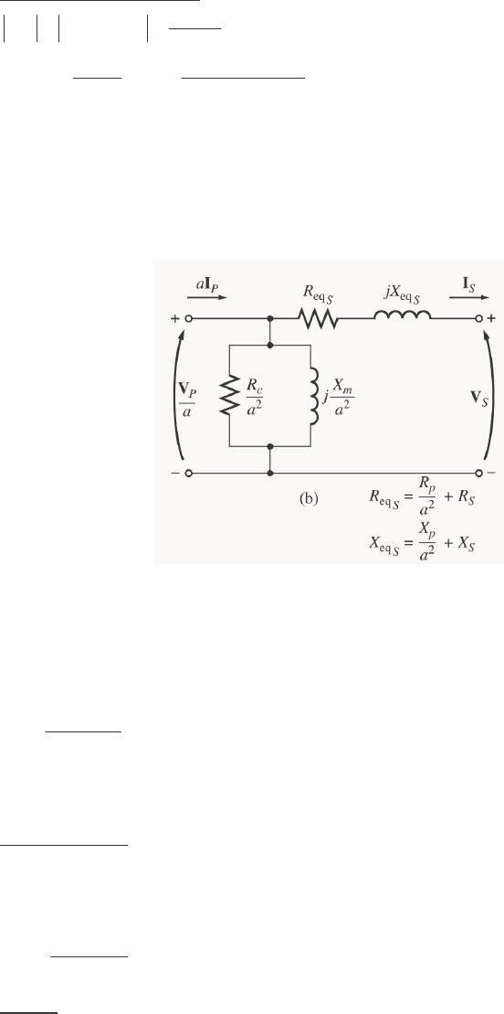
To convert the equivalent circuit to the secondary side, divide each impedance by the square of the turns
ratio (a = 230/115 = 2). The resulting equivalent circuit is shown below:
Ω= 140.0
sEQ,
R Ω= 532.0
sEQ, jX
Ω= 441
,sC
R Ω= 134
,sM
X
(b) To find the required voltage regulation, we will use the equivalent circuit of the transformer referred
to the secondary side. The rated secondary current is
A 70.8
V 115
VA 1000 ==
S
I
We will now calculate the primary voltage referred to the secondary side and use the voltage regulation
equation for each power factor.
(1) 0.8 PF Lagging:
()()
EQ 115 0 V 0.140 0.532 8.7 36 87 A
PS S
Zj.
′=+ =∠°+ + Ω ∠− °VV I
118.8 1.4 V
P
′=∠°
V
118.8-115
VR 100% 3.3%
115
=×=
(2) 1.0 PF:
()()
EQ 115 0 V 0.140 0.532 8.7 0 A
PS S
Zj
′=+ =∠°+ + Ω ∠°VV I
116.3 2.28 V
P
′=∠°
V
28
116.3-115
VR 100% 1.1%
115
=×=
(3) 0.8 PF Leading:
()()
EQ 115 0 V 0.140 0.532 8.7 36 87 A
PS S
Zj.
′=+ =∠°+ + Ω ∠ °VV I
113.3 2.24 V
P
′=∠°
V
113.3-115
VR 100% 1.5%
115
=×=−
(c) At rated conditions and 0.8 PF lagging, the output power of this transformer is
(
)
(
)
(
)
OUT cos 115 V 8.7 A 0.8 800 W
SS
PVI
θ
== =
The copper and core losses of this transformer are
(
)
(
)
2
2
CU EQ,
8.7 A 0.140 10.6 W
SS
PIR== Ω=
()
()
2
2
core
118.8 V
32.0 W
441
P
C
V
PR
′
== =
Ω
Therefore the efficiency of this transformer at these conditions is
OUT
OUT CU core
800 W
100% 94.9%
800 W 10.6 W 32.0 W
P
PPP
η
=×= =
++ + +
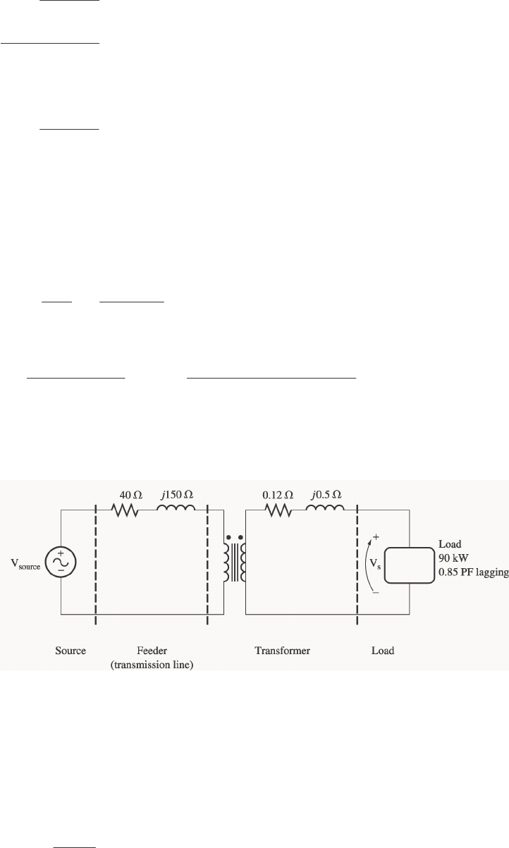
2-4. A single-phase power system is shown in Figure P2-1. The power source feeds a 100-kVA 14/2.4-kV
transformer through a feeder impedance of 40.0 + j150 Ω. The transformer’s equivalent series impedance
referred to its low-voltage side is 0.12 + j0.5 Ω. The load on the transformer is 90 kW at 0.80 PF lagging
and 2300 V.
(a) What is the voltage at the power source of the system?
(b) What is the voltage regulation of the transformer?
(c) How efficient is the overall power system?
S
OLUTION
To solve this problem, we will refer the circuit to the secondary (low-voltage) side. The feeder’s impedance
referred to the secondary side is
()
2
line
2.4 kV 40 150 1.18 4.41
14 kV
Zjj
′=Ω+Ω=+Ω

29
The secondary current S
I is given by
()()
90 kW 46.03 A
2300 V 0.85
S
I==
46.03 31.8 A
S=∠−°I
(a) The voltage at the power source of this system (referred to the secondary side) is
EQlinesource ZZ SSS IIVV +
′
+=
′
()()()()
source 2300 0 V 46.03 31.8 A 1.18 4.11 46.03 31.8 A 0.12 0.5 jj
′= ∠ ° + ∠− ° + Ω + ∠− ° + ΩV
source 2467 3.5 V
′=∠°V
Therefore, the voltage at the power source is
()
source
14 kV
2467 3.5 V 14.4 3.5 kV
2.4 kV
=∠° =∠°
V
(b) To find the voltage regulation of the transformer, we must find the voltage at the primary side of the
transformer (referred to the secondary side) under full load conditions:
EQ
Z
SSP IVV +=
′
()()
2300 0 V 46.03 31.8 A 0.12 0.5 2317 0.41 V
Pj
′=∠°+ ∠−° +Ω=∠°V
There is a voltage drop of 17 V under these load conditions. Therefore the voltage regulation of the
transformer is
2317 2300
VR 100% 0.74%
2300
−
=×=
(c) The overall efficiency of the power system will be the ratio of the output power to the input power.
The output power supplied to the load is POUT = 90 kW. The input power supplied by the source is
()( )
IN source cos 2467 V 46.03 A cos 35.3 92.68 kW
S
PV I
θ
′
== °=
Therefore, the efficiency of the power system is
OUT
IN
90 kW
100% 100% 97.1%
92.68 kW
P
P
η
=× = × =
2-5. When travelers from the USA and Canada visit Europe, they encounter a different power distribution
system. Wall voltages in North America are 120 V rms at 60 Hz, while typical wall voltages in Europe are
220 to 240 V at 50 Hz. Many travelers carry small step-up / step-down transformers so that they can use
their appliances in the countries that they are visiting. A typical transformer might be rated at 1-kVA and
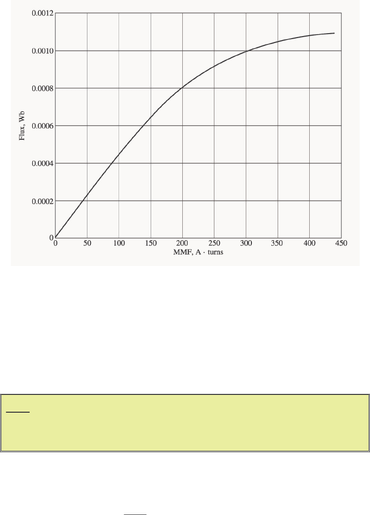
120/240 V. It has 500 turns of wire on the 120-V side and 1000 turns of wire on the 240-V side. The
magnetization curve for this transformer is shown in Figure P2-2, and can be found in file p22_mag.dat
at this book’s Web site.
30
(a) Suppose that this transformer is connected to a 120-V, 60 Hz power source with no load connected
to the 240-V side. Sketch the magnetization current that would flow in the transformer. (Use
MATLAB to plot the current accurately, if it is available.) What is the rms amplitude of the
magnetization current? What percentage of full-load current is the magnetization current?
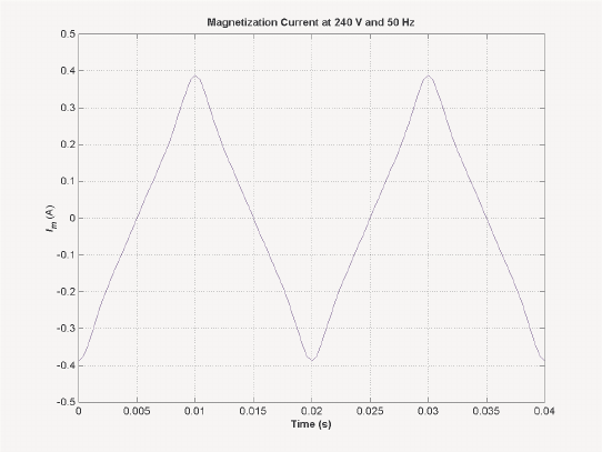
(b) Now suppose that this transformer is connected to a 240-V, 50 Hz power source with no load
connected to the 120-V side. Sketch the magnetization current that would flow in the transformer. (Use
MATLAB to plot the current accurately, if it is available.) What is the rms amplitude of the
magnetization current? What percentage of full-load current is the magnetization current?
(c) In which case is the magnetization current a higher percentage of full-load current? Why?
Note: An electronic version of this magnetization curve can be found in file
p22_mag.dat, which can be used with MATLAB programs. Column 1
contains the MMF in A ⋅ turns, and column 2 contains the resulting flux in
webers.
S
OLUTION
(a) When this transformer is connected to a 120-V 60 Hz source, the flux in the core will be given by the
equation
cos )( t
N
V
t
P
M
ω
ω
φ
−= (2-101)
The magnetization current required for any given flux level can be found from Figure P2-2, or alternately
from the equivalent table in file p22_mag.dat. The MATLAB program shown below calculates the flux
level at each time, the corresponding magnetization current, and the rms value of the magnetization current.
% M-file: prob2_5a.m
% M-file to calculate and plot the magnetization
% current of a 120/240 transformer operating at
% 120 volts and 60 Hz. This program also
31
% calculates the rms value of the mag. current.
% Load the magnetization curve. It is in two
% columns, with the first column being mmf and
% the second column being flux.
load p22_mag.dat;
mmf_data = p22(:,1);
flux_data = p22(:,2);
% Initialize values
S = 1000; % Apparent power (VA)
Vrms = 120; % Rms voltage (V)
VM = Vrms * sqrt(2); % Max voltage (V)
NP = 500; % Primary turns
% Calculate angular velocity for 60 Hz
freq = 60; % Freq (Hz)
w = 2 * pi * freq;
% Calculate flux versus time
time = 0:1/3000:1/30; % 0 to 1/30 sec
flux = -VM/(w*NP) * cos(w .* time);
% Calculate the mmf corresponding to a given flux
% using the MATLAB interpolation function.
mmf = interp1(flux_data,mmf_data,flux);
% Calculate the magnetization current
im = mmf / NP;
% Calculate the rms value of the current
irms = sqrt(sum(im.^2)/length(im));
disp(['The rms current at 120 V and 60 Hz is ', num2str(irms)]);
% Calculate the full-load current
i_fl = S / Vrms;
% Calculate the percentage of full-load current
percnt = irms / i_fl * 100;
disp(['The magnetization current is ' num2str(percnt) ...
'% of full-load current.']);
% Plot the magnetization current.
figure(1)
plot(time,im);
title ('\bfMagnetization Current at 120 V and 60 Hz');
xlabel ('\bfTime (s)');
ylabel ('\bf\itI_{m} \rm(A)');
axis([0 0.04 -0.5 0.5]);
grid on;
When this program is executed, the results are
» prob2_5a
The rms current at 120 V and 60 Hz is 0.31863
The magnetization current is 3.8236% of full-load current.
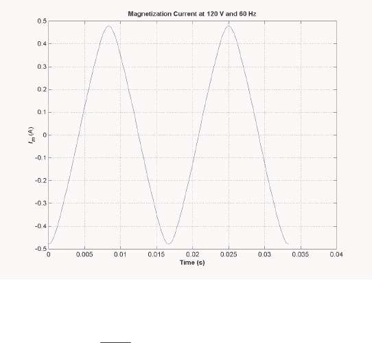
32
The rms magnetization current is 0.318 A. Since the full-load current is 1000 VA / 120 V = 8.33 A, the
magnetization current is 3.82% of the full-load current. The resulting plot is
(b) When this transformer is connected to a 240-V 50 Hz source, the flux in the core will be given by the
equation
cos )( t
N
V
t
S
M
ω
ω
φ
−=
The magnetization current required for any given flux level can be found from Figure P2-2, or alternately
from the equivalent table in file p22_mag.dat. The MATLAB program shown below calculates the flux
level at each time, the corresponding magnetization current, and the rms value of the magnetization current.
% M-file: prob2_5b.m
% M-file to calculate and plot the magnetization
% current of a 120/240 transformer operating at
% 240 volts and 50 Hz. This program also
% calculates the rms value of the mag. current.
% Load the magnetization curve. It is in two
% columns, with the first column being mmf and
% the second column being flux.
load p22_mag.dat;
mmf_data = p22(:,1);
flux_data = p22(:,2);
% Initialize values
S = 1000; % Apparent power (VA)
Vrms = 240; % Rms voltage (V)
VM = Vrms * sqrt(2); % Max voltage (V)
NP = 1000; % Primary turns
% Calculate angular velocity for 50 Hz
freq = 50; % Freq (Hz)
w = 2 * pi * freq;
% Calculate flux versus time
time = 0:1/2500:1/25; % 0 to 1/25 sec
33
flux = -VM/(w*NP) * cos(w .* time);
% Calculate the mmf corresponding to a given flux
% using the MATLAB interpolation function.
mmf = interp1(flux_data,mmf_data,flux);
% Calculate the magnetization current
im = mmf / NP;
% Calculate the rms value of the current
irms = sqrt(sum(im.^2)/length(im));
disp(['The rms current at 50 Hz is ', num2str(irms)]);
% Calculate the full-load current
i_fl = S / Vrms;
% Calculate the percentage of full-load current
percnt = irms / i_fl * 100;
disp(['The magnetization current is ' num2str(percnt) ...
'% of full-load current.']);
% Plot the magnetization current.
figure(1);
plot(time,im);
title ('\bfMagnetization Current at 240 V and 50 Hz');
xlabel ('\bfTime (s)');
ylabel ('\bf\itI_{m} \rm(A)');
axis([0 0.04 -0.5 0.5]);
grid on;
When this program is executed, the results are
» prob2_5b
The rms current at 50 Hz is 0.22973
The magnetization current is 5.5134% of full-load current.
The rms magnetization current is 0.318 A. Since the full-load current is 1000 VA / 240 V = 4.17 A, the
magnetization current is 5.51% of the full-load current. The resulting plot is

34
(c) The magnetization current is a higher percentage of the full-load current for the 50 Hz case than for
the 60 Hz case. This is true because the peak flux is higher for the 50 Hz waveform, driving the core
further into saturation.
2-6. A 15-kVA 8000/230-V distribution transformer has an impedance referred to the primary of 80 + j300 Ω.
The components of the excitation branch referred to the primary side are Ω= k 350
C
R and
Ω= k 70
M
X.
(a) If the primary voltage is 7967 V and the load impedance is ZL = 3.2 + j1.5 Ω, what is the secondary
voltage of the transformer? What is the voltage regulation of the transformer?
(b) If the load is disconnected and a capacitor of –j3.5 Ω is connected in its place, what is the secondary
voltage of the transformer? What is its voltage regulation under these conditions?
S
OLUTION
(a) The easiest way to solve this problem is to refer all components to the primary side of the
transformer. The turns ratio is a = 8000/230 = 34.78. Thus the load impedance referred to the primary
side is
()( )
2
34.78 3.2 1.5 3871 1815
L
Zjj
′=+Ω=+Ω
The referred secondary current is
()( )
7967 0 V 7967 0 V 1.78 28.2 A
80 300 3871 1815 4481 28.2
Sjj
∠° ∠°
′===∠−°
+Ω+ + Ω ∠°Ω
I
and the referred secondary voltage is
()()
1.78 28.2 A 3871 1815 7610 3.1 V
SSL
Zj
′′′
= = ∠− ° + Ω = ∠− °VI
The actual secondary voltage is thus
7610 3.1 V 218.8 3.1 V
34.78
S
Sa
′∠− °
== = ∠−°
V
V
The voltage regulation is
7967-7610
VR 100% 4.7%
7610
=×=
(b) The easiest way to solve this problem is to refer all components to the primary side of the
transformer. The turns ratio is again a = 34.78. Thus the load impedance referred to the primary side is
()( )
2
34.78 3.5 4234
L
Zjj
′=−Ω=−Ω
The referred secondary current is
()()
7967 0 V 7967 0 V 2.025 88.8 A
80 300 4234 3935 88.8
Sjj
∠° ∠°
′===∠°
+Ω+− Ω ∠−°Ω
I
and the referred secondary voltage is
()()
2.25 88.8 A 4234 8573 1.2 V
SSL
Zj
′′′
==∠°−Ω=∠−°VI
The actual secondary voltage is thus
35
8573 1.2 V 246.5 1.2 V
34.78
S
Sa
′∠− °
== = ∠−°
V
V
The voltage regulation is
7967 8573
VR 100% 7.07%
8573
−
=×=−
2-7. A 5000-kVA 230/13.8-kV single-phase power transformer has a per-unit resistance of 1 percent and a per-
unit reactance of 5 percent (data taken from the transformer’s nameplate). The open-circuit test performed
on the low-voltage side of the transformer yielded the following data:
VOC kV=138. A 1.15
OC =I kW 9.44
OC =P
(a) Find the equivalent circuit referred to the low-voltage side of this transformer.
(b) If the voltage on the secondary side is 13.8 kV and the power supplied is 4000 kW at 0.8 PF
lagging, find the voltage regulation of the transformer. Find its efficiency.
S
OLUTION
(a) The open-circuit test was performed on the low-voltage side of the transformer, so it can be used to
directly find the components of the excitation branch relative to the low-voltage side.
EX
15.1 A 0.0010942
13.8 kV
CM
YGjB=− = =
()()
11
OC
OC OC
44.9 kW
cos cos 77.56
13.8 kV 15.1 A
P
VI
θ
−−
== =°
EX 0.0010942 77.56 S 0.0002358 0.0010685 S
CM
YGjB j=− = ∠− °= −
14240
C
C
RG
== Ω
1936
M
M
XB
==Ω
The base impedance of this transformer referred to the secondary side is
()
2
2
base
base
base
13.8 kV 38.09
5000 kVA
V
ZS
== = Ω
so
(
)
(
)
EQ 0.01 38.09 0.38 R=Ω=Ω and
(
)
(
)
EQ 0.05 38.09 1.9 X=Ω=Ω. The resulting equivalent circuit
is shown below:

36
Ω= 38.0
sEQ,
R Ω= 9.1
sEQ, jX
Ω= 4240
,sC
R Ω= 936
,sM
X
(b) If the load on the secondary side of the transformer is 4000 kW at 0.8 PF lagging and the secondary
voltage is 13.8 kV, the secondary current is
()()
LOAD 4000 kW 362.3 A
PF 13.8 kV 0.8
S
S
P
IV
== =
362.3 36.87 A
S=∠−°I
The voltage on the primary side of the transformer (referred to the secondary side) is
EQPSS
Z
′=+
VVI
()()
13,800 0 V 362.3 36.87 A 0.38 1.9 14,330 1.9 V
Pj
′=∠°+∠−° +Ω=∠°V
There is a voltage drop of 14 V under these load conditions. Therefore the voltage regulation of the
transformer is
14,330 13,800
VR 100% 3.84%
13,800
−
=×=
The transformer copper losses and core losses are
()()
2
2
CU EQ,
362.3 A 0.38 49.9 kW
SS
PIR== Ω=
()
()
2
2
core
14,330 V
48.4 kW
4240
P
C
V
PR
′
== =
Ω
Therefore the efficiency of this transformer at these conditions is
OUT
OUT CU core
4000 kW
100% 97.6%
4000 kW 49.9 kW 48.4 kW
P
PPP
η
=×= =
++ + +
2-8. A 200-MVA 15/200-kV single-phase power transformer has a per-unit resistance of 1.2 percent and a per-
unit reactance of 5 percent (data taken from the transformer’s nameplate). The magnetizing impedance is
j80 per unit.
(a) Find the equivalent circuit referred to the low-voltage side of this transformer.
(b) Calculate the voltage regulation of this transformer for a full-load current at power factor of 0.8
lagging.
(c) Assume that the primary voltage of this transformer is a constant 15 kV, and plot the secondary voltage
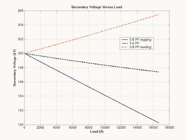
as a function of load current for currents from no-load to full-load. Repeat this process for power
factors of 0.8 lagging, 1.0, and 0.8 leading.
SOLUTION
(a) The base impedance of this transformer referred to the primary (low-voltage) side is
()
2
2
base
base
base
15 kV 1.125
200 MVA
V
ZS
== =Ω
so
(
)
(
)
EQ 0.012 1.125 0.0135 R=Ω=Ω
()( )
EQ 0.05 1.125 0.0563 X=Ω=Ω
37
()( )
100 1.125 112.5
M
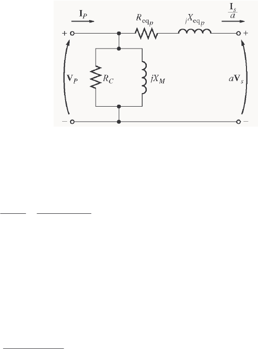
X=Ω=Ω
The equivalent circuit is
EQ, 0.0135
P
R=Ω EQ, 0.0563
P
Xj=Ω
not specified
C
R= 112.5
M
X=Ω
(b) If the load on the secondary side of the transformer is 200 MVA at 0.8 PF lagging, and the referred
secondary voltage is 15 kV, then the referred secondary current is
()()
LOAD 200 MVA 16,667 A
PF 15 kV 0.8
S
S
P
IV
′== =
16,667 36.87 A
S
′=∠−°
I
The voltage on the primary side of the transformer is
EQ,PSSP
Z
′′
=+
VV I
()()
15,000 0 V 16,667 36.87 A 0.0135 0.0563 15, 755 2.24 V
Pj=∠°+ ∠−° + Ω=∠°V
Therefore the voltage regulation of the transformer is
15,755-15,000
VR 100% 5.03%
15,000
=×=
(c) This problem is repetitive in nature, and is ideally suited for MATLAB. A program to calculate the
secondary voltage of the transformer as a function of load is shown below:
% M-file: prob2_8.m
% M-file to calculate and plot the secondary voltage
% of a transformer as a function of load for power
% factors of 0.8 lagging, 1.0, and 0.8 leading.
% These calculations are done using an equivalent
% circuit referred to the primary side.
% Define values for this transformer
VP = 15000; % Primary voltage (V)
amps = 0:166.67:16667; % Current values (A)
Req = 0.0135; % Equivalent R (ohms)
Xeq = 0.0563; % Equivalent X (ohms)
% Calculate the current values for the three
% power factors. The first row of I contains
% the lagging currents, the second row contains
% the unity currents, and the third row contains
38
% the leading currents.
I(1,:) = amps .* ( 0.8 - j*0.6); % Lagging
I(2,:) = amps .* ( 1.0 ); % Unity
I(3,:) = amps .* ( 0.8 + j*0.6); % Leading
% Calculate VS referred to the primary side
% for each current and power factor.
aVS = VP - (Req.*I + j.*Xeq.*I);
% Refer the secondary voltages back to the
% secondary side using the turns ratio.
VS = aVS * (200/15);
% Plot the secondary voltage (in kV!) versus load
plot(amps,abs(VS(1,:)/1000),'b-','LineWidth',2.0);
hold on;
plot(amps,abs(VS(2,:)/1000),'k--','LineWidth',2.0);
plot(amps,abs(VS(3,:)/1000),'r-.','LineWidth',2.0);
title ('\bfSecondary Voltage Versus Load');
xlabel ('\bfLoad (A)');
ylabel ('\bfSecondary Voltage (kV)');
legend('0.8 PF lagging','1.0 PF','0.8 PF leading');
grid on;
hold off;
The resulting plot of secondary voltage versus load is shown below:
2-9. A three-phase transformer bank is to handle 600 kVA and have a 34.5/13.8-kV voltage ratio. Find the
rating of each individual transformer in the bank (high voltage, low voltage, turns ratio, and apparent
power) if the transformer bank is connected to (a) Y-Y, (b) Y-∆, (c) ∆-Y, (d) ∆-∆, (e) open-∆, (f) open-
Y—open-∆.
S
OLUTION For the first four connections, the apparent power rating of each transformer is 1/3 of the total
apparent power rating of the three-phase transformer. For the open-∆ and open-Y—open-∆ connections,
the apparent power rating is a bit more complicated. The 600 kVA must be 86.6% of the total apparent

39
power rating of the two transformers, implying that the apparent power rating of each transformer must be
231 kVA.
The ratings for
each transformer in the bank for each connection are given below:
Connection Primary Voltage Secondary Voltage Apparent Power Turns Ratio
Y-Y 19.9 kV 7.97 kV 200 kVA 2.50:1
Y-∆ 19.9 kV 13.8 kV 200 kVA 1.44:1
∆-Y 34.5 kV 7.97 kV 200 kVA 4.33:1
∆-∆ 34.5 kV 13.8 kV 200 kVA 2.50:1
open-∆ 34.5 kV 13.8 kV 346 kVA 2.50:1
open-Y—open-∆ 19.9 kV 13.8 kV 346 kVA 1.44:1
Note: The open-Y—open-∆ answer assumes that the Y is on the high-voltage side; if the Y is on the low-
voltage side, the turns ratio would be 4.33:1, and the apparent power rating would be unchanged.
2-10. A 13,800/480 V three-phase Y-∆-connected transformer bank consists of three identical 100-kVA
7967/480-V transformers. It is supplied with power directly from a large constant-voltage bus. In the
short-circuit test, the recorded values on the high-voltage side for one of these transformers are
VSC V=560 A 6.12
SC =I W 3300
SC =P
(a) If this bank delivers a rated load at 0.85 PF lagging and rated voltage, what is the line-to-line voltage on
the primary of the transformer bank?
(b) What is the voltage regulation under these conditions?
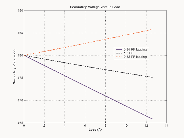
(c) Assume that the primary voltage of this transformer bank is a constant 13.8 kV, and plot the secondary
voltage as a function of load current for currents from no-load to full-load. Repeat this process for
power factors of 0.85 lagging, 1.0, and 0.85 leading.
(d) Plot the voltage regulation of this transformer as a function of load current for currents from no-load to
full-load. Repeat this process for power factors of 0.85 lagging, 1.0, and 0.85 leading.
S
OLUTION From the short-circuit information, it is possible to determine the per-phase impedance of the
transformer bank referred to the high-voltage side. The primary side of this transformer is Y-connected, so
the short-circuit phase voltage is
SC
,SC
560 V 323.3 V
33
V
V
φ
== =
the short-circuit phase current is
,SC SC 12.6 AII
φ
==
and the power per phase is
SC
,SC 1100 W
3
P
P
φ
==
Thus the per-phase impedance is
EQ EQ EQ
323.3 V 25.66
12.6 A
ZRjX=+ = = Ω
()()
11
SC
SC SC
1100 W
cos cos 74.3
323.3 V 12.6 A
P
VI
θ
−−
== =°
EQ EQ EQ 25.66 74.3 6.94 24.7 ZRjX j=+ = ∠°Ω= + Ω

40
EQ 6.94 R=Ω
EQ 24.7 Xj=Ω
(a) If this Y-∆ transformer bank delivers rated kVA (300 kVA) at 0.85 power factor lagging while the
secondary voltage is at rated value, then each transformer delivers 100 kVA at a voltage of 480 V and 0.85
PF lagging. Referred to the primary side of one of the transformers, the load on each transformer is
equivalent to 100 kVA at 7967 V and 0.85 PF lagging. The equivalent current flowing in the secondary of
one transformer referred to the primary side is
,
100 kVA 12.55 A
7967 V
S
I
φ
′==
,12.55 31.79 A
S
φ
′=∠−°I
The voltage on the primary side of a single transformer is thus
PSSP ZEQ,,,,
′
+
′
=
φφφ
IVV
()()
,7967 0 V 12.55 31.79 A 6.94 24.7 8207 1.52 V
Pj
φ
=∠°+ ∠− ° + Ω=∠°V
The line-to-line voltage on the primary of the transformer is
(
)
LL, ,
3 3 8207 V 14.22 kV
PP
VV
φ
== =
(b) The voltage regulation of the transformer is
8207-7967
VR 100% 3.01%
7967
=×=
Note: It is much easier to solve problems of this sort in the per-unit
system, as we shall see in the next problem.
(c) This sort of repetitive operation is best performed with MATLAB. A suitable MATLAB program is
shown below:
% M-file: prob2_10c.m
% M-file to calculate and plot the secondary voltage
% of a three-phase Y-delta transformer bank as a
% function of load for power factors of 0.85 lagging,
% 1.0, and 0.85 leading. These calculations are done
% using an equivalent circuit referred to the primary side.
% Define values for this transformer
VL = 13800; % Primary line voltage (V)
VPP = VL / sqrt(3); % Primary phase voltage (V)
amps = 0:0.0126:12.6; % Phase current values (A)
Req = 6.94; % Equivalent R (ohms)
Xeq = 24.7; % Equivalent X (ohms)
% Calculate the current values for the three
% power factors. The first row of I contains
% the lagging currents, the second row contains
% the unity currents, and the third row contains
% the leading currents.
41
re = 0.85;
im = sin(acos(re));
I(1,:) = amps .* ( re - j*im); % Lagging
I(2,:) = amps .* ( 1.0 ); % Unity
I(3,:) = amps .* ( re + j*im); % Leading
% Calculate secondary phase voltage referred
% to the primary side for each current and
% power factor.
aVSP = VPP - (Req.*I + j.*Xeq.*I);
% Refer the secondary phase voltages back to
% the secondary side using the turns ratio.
% Because this is a delta-connected secondary,
% this is also the line voltage.
VSP = aVSP * (480/7967);
% Plot the secondary voltage versus load
plot(amps,abs(VSP(1,:)),'b-','LineWidth',2.0);
hold on;
plot(amps,abs(VSP(2,:)),'k--','LineWidth',2.0);
plot(amps,abs(VSP(3,:)),'r-.','LineWidth',2.0);
title ('\bfSecondary Voltage Versus Load');
xlabel ('\bfLoad (A)');
ylabel ('\bfSecondary Voltage (V)');
legend('0.85 PF lagging','1.0 PF','0.85 PF leading');
grid on;
hold off;
The resulting plot is shown below:
(d) This sort of repetitive operation is best performed with MATLAB. A suitable MATLAB program is
shown below:
% M-file: prob2_10d.m
42
% M-file to calculate and plot the voltage regulation
% of a three-phase Y-delta transformer bank as a
% function of load for power factors of 0.85 lagging,
% 1.0, and 0.85 leading. These calculations are done
% using an equivalent circuit referred to the primary side.
% Define values for this transformer
VL = 13800; % Primary line voltage (V)
VPP = VL / sqrt(3); % Primary phase voltage (V)
amps = 0:0.0126:12.6; % Phase current values (A)
Req = 6.94; % Equivalent R (ohms)
Xeq = 24.7; % Equivalent X (ohms)
% Calculate the current values for the three
% power factors. The first row of I contains
% the lagging currents, the second row contains
% the unity currents, and the third row contains
% the leading currents.
re = 0.85;
im = sin(acos(re));
I(1,:) = amps .* ( re - j*im); % Lagging
I(2,:) = amps .* ( 1.0 ); % Unity
I(3,:) = amps .* ( re + j*im); % Leading
% Calculate secondary phase voltage referred
% to the primary side for each current and
% power factor.
aVSP = VPP - (Req.*I + j.*Xeq.*I);
% Calculate the voltage regulation.
VR = (VPP - abs(aVSP)) ./ abs(aVSP) .* 100;
% Plot the voltage regulation versus load
plot(amps,VR(1,:),'b-','LineWidth',2.0);
hold on;
plot(amps,VR(2,:),'k--','LineWidth',2.0);
plot(amps,VR(3,:),'r-.','LineWidth',2.0);
title ('\bfVoltage Regulation Versus Load');
xlabel ('\bfLoad (A)');
ylabel ('\bfVoltage Regulation (%)');
legend('0.85 PF lagging','1.0 PF','0.85 PF leading');
grid on;
hold off;
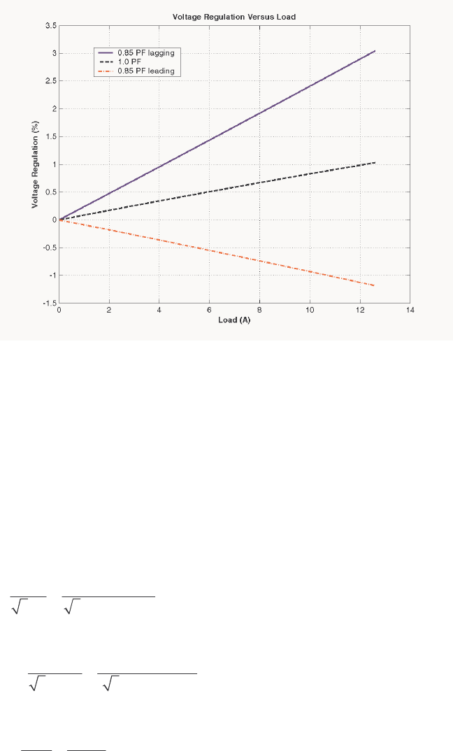
43
The resulting plot is shown below:
2-11. A 100,000-kVA 230/115-kV ∆-∆ three-phase power transformer has a per-unit resistance of 0.02 pu and a
per-unit reactance of 0.055 pu. The excitation branch elements are pu 110=
C
R and pu 20=
M
X.
(a) If this transformer supplies a load of 80 MVA at 0.85 PF lagging, draw the phasor diagram of one
phase of the transformer.
(b) What is the voltage regulation of the transformer bank under these conditions?
(c) Sketch the equivalent circuit referred to the low-voltage side of one phase of this transformer.
Calculate all of the transformer impedances referred to the low-voltage side.
S
OLUTION
(a) The transformer supplies a load of 80 MVA at 0.85 PF lagging. Therefore, the secondary line
current of the transformer is
()
80,000,000 VA 402 A
3 3 115, 000 V
LS
LS
S
IV
== =
The base value of the secondary line current is
()
base
,base
,base
100,000,000 VA 502 A
3 3 115,000 V
LS
LS
S
IV
== =
so the per-unit secondary current is
()
1
,pu
,pu
402 A cos 0.85 0.8 31.8
502 A
LS
LS
LS
I
I
−
== ∠ =∠−°I
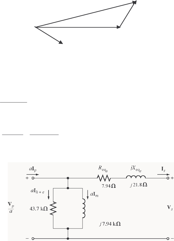
44
The per-unit phasor diagram is shown below:
I
= 0.8
∠
-31.8°
V
= 1.0
∠
0°
S
V
P
θ
(b) The per-unit primary voltage of this transformer is
()( )
EQ
1.0 0 0.8 31.8 0.02 0.055 1.037 1.6
PS
Zj=+ =∠°+ ∠− ° + = ∠°VVI
and the voltage regulation is
1.037 1.0
VR 100% 3.7%
1.0
−
=×=
(c) The base impedance of the transformer referred to the low-voltage side is:
()
2
2
,base
base
base
3 3 115 kV 397
100 MVA
V
ZS
φ
== =Ω
Each per-unit impedance is converted to actual ohms referred to the low-voltage side by multiplying it by
this base impedance. The resulting equivalent circuit is shown below:
(
)
(
)
EQ, 0.02 397 7.94
S
R=Ω=Ω
(
)
(
)
EQ, 0.055 397 21.8
S
X=Ω=Ω
(
)
(
)
110 397 43.7 k
C
R=Ω=Ω
(
)
(
)
20 397 7.94 k
M
X=Ω=Ω
Note how easy it was to solve this problem in per-unit, compared with Problem 2-10 above.
2-12. An autotransformer is used to connect a 13.2-kV distribution line to a 13.8-kV distribution line. It must be
capable of handling 2000 kVA. There are three phases, connected Y-Y with their neutrals solidly
grounded.
(a) What must the SE
/
C
NN turns ratio be to accomplish this connection?
(b) How much apparent power must the windings of each autotransformer handle?
(c) If one of the autotransformers were reconnected as an ordinary transformer, what would its ratings be?
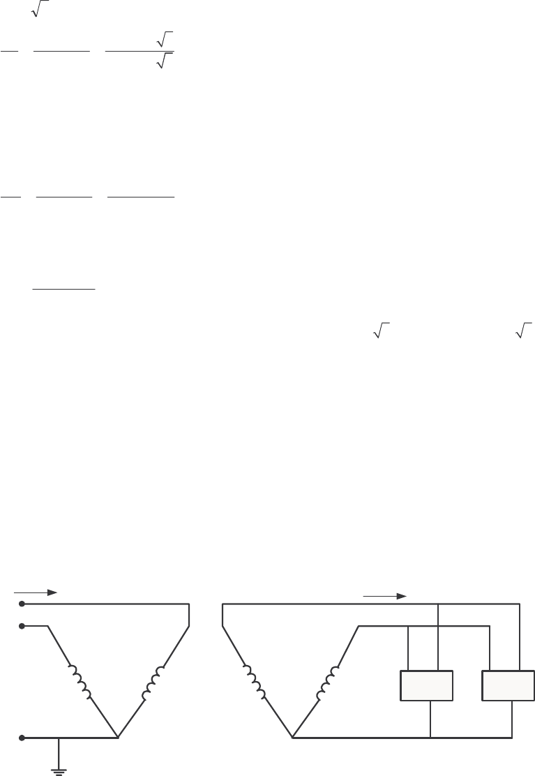
45
S
OLUTION
(a) The transformer is connected Y-Y, so the primary and secondary phase voltages are the line voltages
divided by 3. The turns ratio of each autotransformer is given by
SE 13.8 kV/ 3
13.2 kV/ 3
HC
LC
VNN
VN
+
==
SE
13.2 13.2 13.8
CC
NN N+=
SE
13.2 0.6
C
NN=
Therefore,
SE
/
C
NN = 22.
(b) The power advantage of this autotransformer is
IO SE 22 23
CCC
WC C
SNNN N
SN N
++
== =
so 1/22 of the power in each transformer goes through the windings. Since 1/3 of the total power is
associated with each phase, the windings in each autotransformer must handle
()( )
2000 kVA 30.3 kVA
322
W
S==
(c) The voltages across each phase of the autotransformer are 13.8/ 3 = 7967 V and 13.2 / 3 = 7621
V. The voltage across the common winding ( C
N) is 7621 kV, and the voltage across the series winding
(SE
N) is 7967 kV – 7621 kV = 346 V. Therefore, a single phase of the autotransformer connected as an
ordinary transformer would be rated at 7621/346 V and 30.3 kVA.
2-13. Two phases of a 13.8-kV three-phase distribution line serve a remote rural road (the neutral is also
available). A farmer along the road has a 480 V feeder supplying 120 kW at 0.8 PF lagging of three-phase
loads, plus 50 kW at 0.9 PF lagging of single-phase loads. The single-phase loads are distributed evenly
among the three phases. Assuming that the open-Y—open-∆ connection is used to supply power to his
farm, find the voltages and currents in each of the two transformers. Also find the real and reactive powers
supplied by each transformer. Assume the transformers are ideal.
S
OLUTION The farmer’s power system is illustrated below:
Load 1 Load 2
VLL,P VLL,S
+
-
IL,P IL,S
The loads on each phase are balanced, and the total load is found as:
1120 kWP=
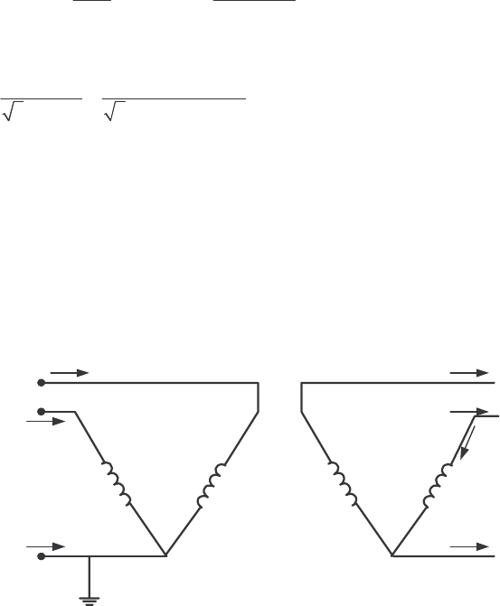
46
(
)
(
)
-1
11
tan 120 kW tan cos 0.8 90 kvarQP
θ
== =
250 kWP=
(
)
(
)
-1
22
tan 50 kW tan cos 0.9 24.2 kvarQP
θ
== =
TOT 170 kW P=
TOT 114.2 kvarQ=
11
TOT
TOT
114.2 kvar
PF cos tan cos tan 0.830 lagging
170 kW
Q
P
−−
== =
The line current on the secondary side of the transformer bank is
()()
TOT 170 kW 246.4 A
3 PF 3 480 V 0.830
LS
LS
P
IV
== =
The open-Y—open ∆ connection is shown below. From the figure, it is obvious that the secondary voltage
across the transformer is 480 V, and the secondary current in each transformer is 246 A. The primary
voltages and currents are given by the transformer turns ratios to be 7967 V and 14.8 A, respectively. If
the voltage of phase A of the primary side is arbitrarily taken as an angle of 0°, then the voltage of phase B
will be at an angle of –120°, and the voltages of phases A and B on the secondary side will be
V 0480 °∠=
AS
V and V 120480 °−∠=
BS
V respectively.
Note that line currents are shifted by 30° due to the difference between line and phase quantities, and by a
further 33.9° due to the power factor of the load.
-
--
++
+
-
VA = 7967∠0° V
VB = 7967 ∠-120° V
VAS = 480∠0° V VBS = 480∠-120° V
.
.
IAS = 246∠-63.9° A
IBS = 246∠-183.9° A
ICS = 246∠56.1° A
I
φ
B = 246∠-123.9° A
A
B
n
A
B
C
+
IAP = 14.8∠-63.9° A
IBP = 14.8∠-183.9° A
In = 14.8∠56.1° A
The real and reactive powers supplied by each transformer are calculated below:
(
)
(
)
(
)
cos 480 V 246.4 A cos 0 63.9 52.0 kW
AASA
PVI
θ
==
(
)
(
)
(
)
sin 480 V 246.4 A sin 0 63.9 106.2 kvar
AASA
QVI
θ
==
(
)
(
)
(
)
cos 480 V 246.4 A cos 120 123.9 118 kW
BBSB
PVI
φ
θ
==
(
)
(
)
(
)
sin 480 V 246.4 A sin 120 123.9 8.04 kvar
BBSB
QVI
φ
θ
==
Notice that the real and reactive powers supplied by the two transformers are radically different, put the
apparent power supplied by each transformer is the same. Also, notice that the total power AB
PP+
supplied by the transformers is equal to the power consumed by the loads (within roundoff error), while the
total reactive power AB
QQ+ supplied by the transformers is equal to the reactive power consumed by the
loads.
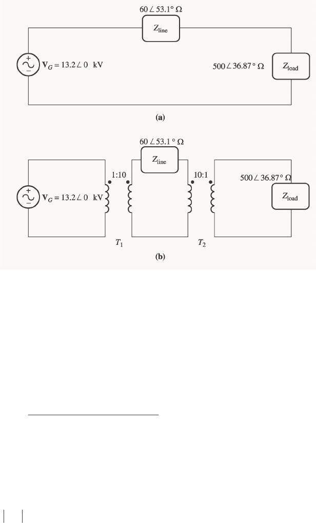
47
2-14. A 13.2-kV single-phase generator supplies power to a load through a transmission line. The load’s
impedance is load 500 36.87 Z=∠ °Ω, and the transmission line’s impedance is line 60 53.1 Z=∠ °Ω.
(a) If the generator is directly connected to the load (Figure P2-3a), what is the ratio of the load
voltage to the generated voltage? What are the transmission losses of the system?
(b) If a 1:10 step-up transformer is placed at the output of the generator and a 10:1 transformer is
placed at the load end of the transmission line, what is the new ratio of the load voltage to the generated
voltage? What are the transmission losses of the system now? (Note: The transformers may be
assumed to be ideal.)
S
OLUTION
(a) In the case of the directly-connected load, the line current is
line load
13.2 0 kV 23.66 38.6 A
60 53.1 500 36.87
∠°
== = ∠−°
∠°Ω+∠ °Ω
II
The load voltage is
(
)
(
)
load load load 23.66 38.6 A 500 36.87 11.83 1.73 kVZ==∠−°∠°Ω=∠−°VI
The ratio of the load voltage to the generated voltage is 11.83/13.2 = 0.896. The resistance in the
transmission line is
(
)
line line cos 60cos 53.1 36 RZ
θ
== °=Ω
so the transmission losses in the system are
(
)
(
)
2
2
loss line line 23.66 A 36 20.1 kWPIR== Ω=
(b) In this case, a 1:10 step-up transformer precedes the transmission line and a 10:1 step-down
transformer follows the transmission line. If the transformers are removed by referring the transmission
line to the voltage levels found on either end, then the impedance of the transmission line becomes
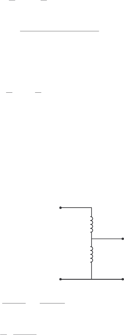
48
()
22
line line
11
60 53.1 0.60 53.1
10 10
ZZ
′==∠°Ω=∠°Ω
The current in the referred transmission line and in the load becomes
line load
13.2 0 kV 26.37 36.89 A
0.60 53.1 500 36.87
∠°
′== = ∠− °
∠°Ω+∠ °Ω
II
The load voltage is
(
)
(
)
load load load 26.37 36.89 A 500 36.87 13.185 0.02 kVZ==∠−°∠°Ω=∠−°VI
The ratio of the load voltage to the generated voltage is 13.185/13.2 = 0.9989. Also, the transmission
losses in the system are reduced. The current in the transmission line is
()
line load
11
26.37 A 2.637 A
10 10
II
== =
and the losses in the transmission line are
()()
2
2
loss line line 2.637 A 36 250 WPIR== Ω=
Transmission losses have decreased by a factor of more than 80.
2-15. A 5000-VA 480/120-V conventional transformer is to be used to supply power from a 600-V source to a
120-V load. Consider the transformer to be ideal, and assume that all insulation can handle 600 V.
(a) Sketch the transformer connection that will do the required job.
(b) Find the kilovoltampere rating of the transformer in the configuration.
(c) Find the maximum primary and secondary currents under these conditions.
S
OLUTION (a) For this configuration, the common winding must be the smaller of the two windings, and
SE 4C
NN=. The transformer connection is shown below:
+
-
+
-
120 V
600 V
N
C
N
SE
(b) The kVA rating of the autotransformer can be found from the equation
()
SE
IO
SE
45000 VA 6250 VA
4
CCC
W
C
NN NN
SS
NN
++
== =
(c) The maximum primary current for this configuration will be
6250 VA 10.4 A
600 V
P
P
S
IV
== =
and the maximum secondary current is
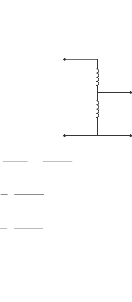
49
6250 VA 52.1 A
120 V
S
S
S
IV
== =
2-16. A 5000-VA 480/120-V conventional transformer is to be used to supply power from a 600-V source to a
480-V load. Consider the transformer to be ideal, and assume that all insulation can handle 600 V.
Answer the questions of Problem 2-15 for this transformer.
S
OLUTION (a) For this configuration, the common winding must be the larger of the two windings, and
SE
4
C
NN=. The transformer connection is shown below:
+
-
+
-
480 V
600 V
N
C
N
SE
(b) The kVA rating of the autotransformer can be found from the equation
()
SE SE SE
IO
SE SE
45000 VA 25,000 VA
C
W
NN N N
SS
NN
++
== =
(c) The maximum primary current for this configuration will be
25,000 VA 41.67 A
600 V
P
P
S
IV
== =
and the maximum secondary current is
25,000 VA 52.1 A
480 V
S
S
S
IV
== =
Note that the apparent power handling capability of the autotransformer is much higher when there is only
a small difference between primary and secondary voltages. Autotransformers are normally only used
when there is a small difference between the two voltage levels.
2-17. Prove the following statement: If a transformer having a series impedance eq
Z
is connected as an
autotransformer, its per-unit series impedance eq
Z
′ as an autotransformer will be
SE
eq eq
SE C
N
Z
Z
NN
=
′+
Note that this expression is the reciprocal of the autotransformer power advantage.
S
OLUTION The impedance of a transformer can be found by shorting the secondary winding and
determining the ratio of the voltage to the current of its primary winding. For the transformer connected as
an ordinary transformer, the impedance referred to the primary ( C
N) is:
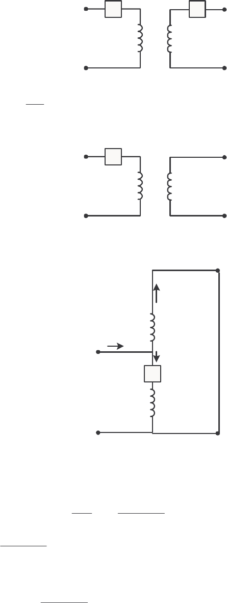
50
+
-
+
-
N
C
N
SE
V
1
V
2
Z
1
Z
2
2
eq 1 2
C
SE
N
Z
ZZ
N
=+
The corresponding equivalent circuit is:
+
-
+
-
N
C
N
SE
V
1
V
2
Z
eq
When this transformer is connected as an autotransformer, the circuit is as shown below. If the output
windings of the autotransformer are shorted out, the voltages H
V will be zero, and the voltage L
V will be
+
-
+
-
N
C
N
SE
V
L
V
H
Z
eq
.
.
+
-
-
+
V
C
V
SE
I
SE
I
L
I
C
eq
Z
CL IV =
where
eq
Z is the impedance of the ordinary transformer. However,
C
SE
CSE
C
SE
C
CSECL N
NN
N
NIIIIII +
=+=+=
or L
C
CNN
NII +
=
SE
SE
so the input voltage can be expressed in terms of the input current as:
eqeq Z
NN
N
ZL
CSE
SE
CL IIV +
==
The input impedance of the autotransformer is defined as LL
ZIV /
eq =, so

51
eqeq Z
NN
N
Z
CSE
SE
L
L
+
==
′
I
V
This is the expression that we were trying to prove.
2-18. Three 25-kVA 24,000/277-V distribution transformers are connected in ∆-Y. The open-circuit test was
performed on the low-voltage side of this transformer bank, and the following data were recorded:
line,OC 480 VV= line,OC 4.10 AI= 3,OC 945 WPφ=
The short-circuit test was performed on the high-voltage side of this transformer bank, and the following
data were recorded:
line,SC 1600 VV= line,SC 2.00 AI= 3,SC 1150 WPφ=
(a) Find the per-unit equivalent circuit of this transformer bank.
(b) Find the voltage regulation of this transformer bank at the rated load and 0.90 PF lagging.
(c) What is the transformer bank’s efficiency under these conditions?
S
OLUTION (a) The equivalent of this three-phase transformer bank can be found just like the equivalent
circuit of a single-phase transformer if we work on a per-phase bases. The open-circuit test data on the
low-voltage side can be used to find the excitation branch impedances referred to the secondary side of the
transformer bank. Since the low-voltage side of the transformer is Y-connected, the per-phase open-circuit
quantities are:
,OC 277 VV
φ
= ,OC 4.10 AI
φ
= ,OC 315 WP
φ
=
The excitation admittance is given by
,
,
4.10 A 0.01480 S
277 V
OC
EX
OC
I
YV
φ
φ
== =
The admittance angle is
()( )
,
11
,,
315 W
cos cos 73.9
277 V 4.10 A
OC
OC OC
P
VI
φ
φφ
θ
−−
=− =− =− °
Therefore,
0.01483 73.9 0.00410 0.01422
EX C M
YGjB j=− = ∠− °= −
1 / 244
CC
RG==Ω
1/ 70.3
MM
XB==Ω
The base impedance for a single transformer referred to the low-voltage side is
()
()
22
,
base,
277 V 3.069
25 kVA
S
S
V
ZS
φ
φ
== =Ω
so the excitation branch elements can be expressed in per-unit as
244 79.5 pu
3.069
C
RΩ
==
Ω 70.3 22.9 pu
3.069
M
XΩ
==
Ω
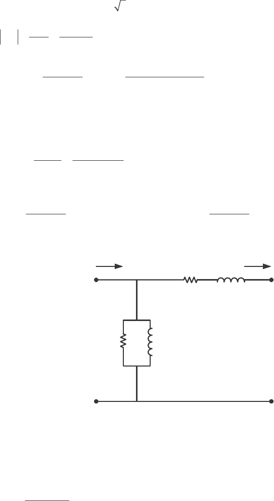
52
The short-circuit test data can be used to find the series impedances referred to the high-voltage side, since
the short-circuit test data was taken on the high-voltage side. Note that the high-voltage is ∆-connected, so
,SC SC 1600 VVV
φ
== , ,SC SC
/
3 1.1547 AII
φ
== , and ,SC SC
/
3 383 WPP
φ
== .
,
,
1600 V 1385
1.155 A
SC
EQ
SC
V
ZI
φ
φ
== = Ω
()( )
,
11
,,
383 W
cos cos 78.0
1600 V 1.155 A
SC
SC SC
P
VI
φ
φφ
θ
−−
== =°
1385 78.0 288 1355
EQ EQ EQ
ZRjX j=+ = ∠°=+ Ω
The base impedance referred to the high-voltage side is
()
()
22
,
base,
24,000 V 23,040
25 kVA
P
P
V
ZS
φ
φ
== =Ω
The resulting per-unit impedances are
288 0.0125 pu
23,040
EQ
RΩ
==
Ω 1355 0.0588 pu
23,040
EQ
XΩ
==
Ω
The per-unit, per-phase equivalent circuit of the transformer bank is shown below:
+
-
VS
VP
IS
+
-
IP
RCjXM
REQ jXEQ
0.0125 j0.0588
79.5 j22.9
(b) If this transformer is operating at rated load and 0.90 PF lagging, then current flow will be at an
angle of
()
9.0cos 1−
−, or –25.8°. The per-unit voltage at the primary side of the transformer will be
(
)
(
)
EQ 1.0 0 1.0 25.8 0.0125 0.0588 1.038 2.62
PSS
Zj=+ =∠°+ ∠− ° + = ∠ °VVI
The voltage regulation of this transformer bank is
1.038 1.0
VR 100% 3.8%
1.0
−
=×=
(c) The output power of this transformer bank is
(
)
(
)
(
)
OUT cos 1.0 1.0 0.9 0.9 pu
SS
PVI
θ
== =
The copper losses are
(
)
(
)
2
2
CU EQ 1.0 0.0125 0.0125 pu
S
PIR== =

53
The core losses are
()
2
2
core
1.038 0.0136 pu
79.5
P
C
V
PR
== =
Therefore, the total input power to the transformer bank is
IN OUT CU core 0.9 0.0125 0.0136 0.926PP PP=++=+ + =
and the efficiency of the transformer bank is
OUT
IN
0.9
100% 100% 97.2%
0.926
P
P
η
=× = × =
2-19. A 20-kVA 20,000/480-V 60-Hz distribution transformer is tested with the following results:
Open-circuit test
(measured from secondary side)
Short-circuit test
(measured from primary side)
VOC = 480 V VSC = 1130 V
IOC = 1.60 A ISC = 1.00 A
VOC = 305 W PSC = 260 W
(a) Find the per-unit equivalent circuit for this transformer at 60 Hz.
(b) What would the rating of this transformer be if it were operated on a 50-Hz power system?
(c) Sketch the equivalent circuit of this transformer referred to the primary side if it is operating at 50 Hz.
S
OLUTION
(a) The base impedance of this transformer referred to the primary side is
(
)
()
22
base,
20,000 V 20 k
20 kVA
P
P
V
ZS
== =Ω
The base impedance of this transformer referred to the secondary side is
()
()
22
base,
480 V 11.52
20 kVA
S
S
V
ZS
== =Ω
The open circuit test yields the values for the excitation branch (referred to the secondary side):
,
,
1.60 A 0.00333 S
480 V
OC
EX
OC
I
YV
φ
φ
== =
()( )
11
305 W
cos cos 66.6
480 V 1.60 A
OC
OC OC
P
VI
θ
−−
=− =− =− °
0.00333 66.6 0.00132 0.00306
EX C M
YGjB j=− = ∠− °= −
1/ 757
CC
RG==Ω
1/ 327
MM
XB==Ω
The excitation branch elements can be expressed in per-unit as
757 65.7 pu
11.52
C
RΩ
==
Ω 327 28.4 pu
11.52
M
XΩ
==
Ω
The short circuit test yields the values for the series impedances (referred to the primary side):
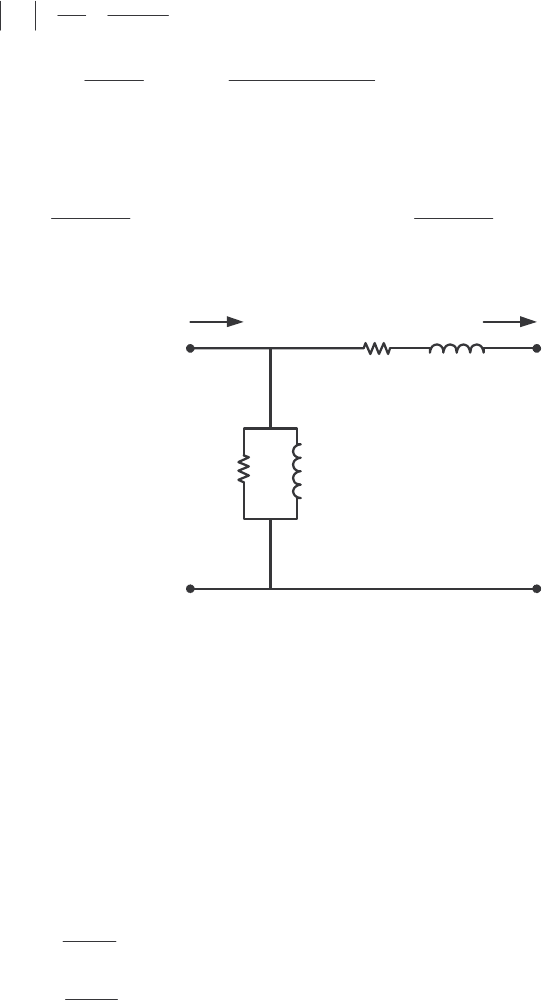
54
1130 V 1130
1.00 A
SC
EQ
SC
V
ZI
== = Ω
()()
11
260 W
cos cos 76.7
1130 V 1.00 A
SC
SC SC
P
VI
θ
−−
== =°
1130 76.7 260 1100
EQ EQ EQ
ZRjX j=+ = ∠°=+ Ω
The resulting per-unit impedances are
260 0.013 pu
20,000
EQ
RΩ
==
Ω 1100 0.055 pu
20,000
EQ
XΩ
==
Ω
The per-unit equivalent circuit is
+
-
VS
VP
IS
+
-
IP
RCjXM
REQ jXEQ
0.013 j0.055
65.7 j28.4
(b) If this transformer were operated at 50 Hz, both the voltage and apparent power would have to be
derated by a factor of 50/60, so its ratings would be 16.67 kVA, 16,667/400 V, and 50 Hz.
(c) The transformer parameters referred to the primary side at 60 Hz are:
()()
base ,pu 20 k 65.7 1.31 M
CC
RZR==Ω=Ω
()()
base ,pu 20 k 28.4 568 k
MM
XZX==Ω=Ω
()()
EQ base E ,pu 20 k 0.013 260
Q
RZR==Ω=Ω
()()
EQ base E ,pu 20 k 0.055 1100
Q
XZX==Ω=Ω
At 50 Hz, the resistance will be unaffected but the reactances are reduced in direct proportion to the
decrease in frequency. At 50 Hz, the reactances are
()
50 Hz 568 k 473 k
60 Hz
M
X
=Ω=Ω
()
EQ
50 Hz 1100 917
60 Hz
X
=Ω=Ω
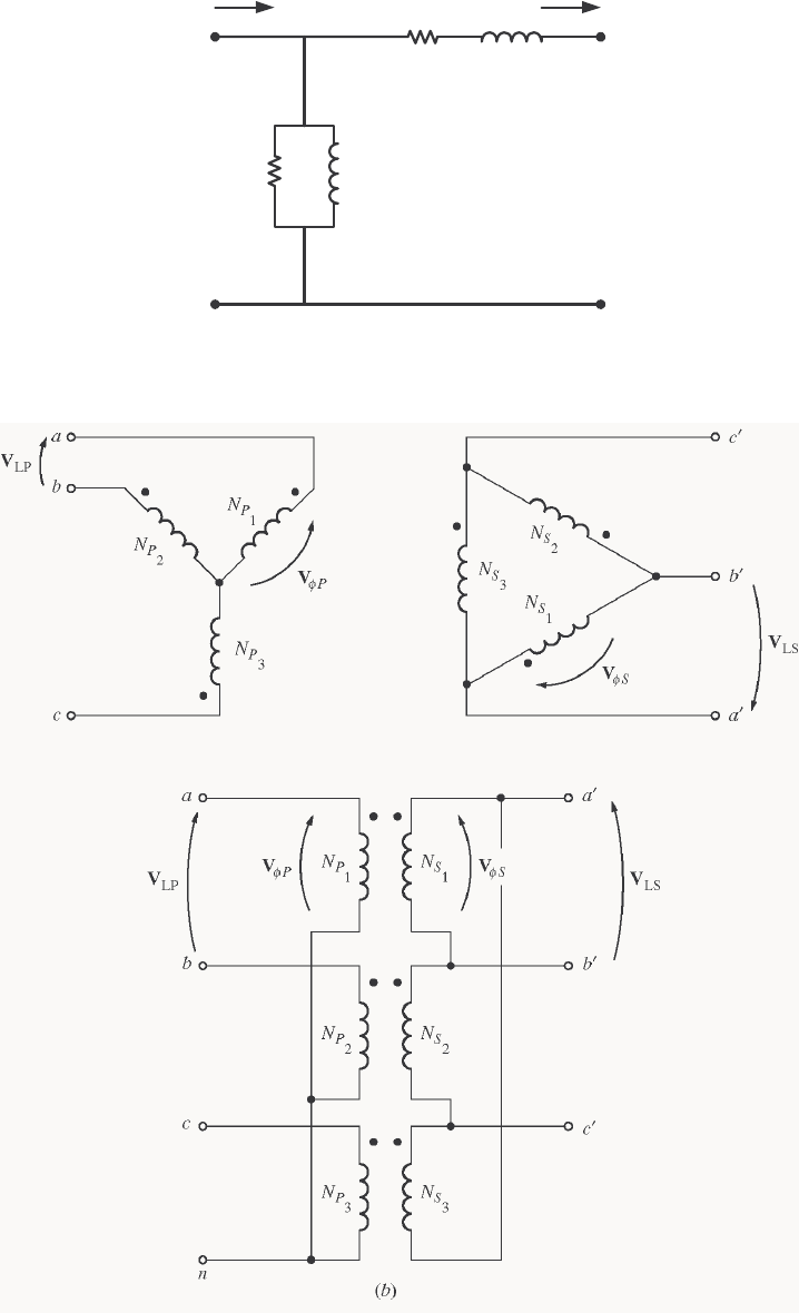
55
The resulting equivalent circuit referred to the primary at 50 Hz is shown below:
+
-
VS
VP
IS
+
-
IP
RCjXM
REQ jXEQ
1.31 MΩj473 kΩ
260 Ωj917 Ω
2-20. Prove that the three-phase system of voltages on the secondary of the Y-∆ transformer shown in Figure 2-
38b lags the three-phase system of voltages on the primary of the transformer by 30°.
S
OLUTION The figure is reproduced below:
V
C
V
B
V
A
V
C
'
V
A
'
V
B
'
++
+
+
+
+
--
-
-
-
-
--
--
--
+
+
++
++
V
A
'
V
B
'
V
C
'
V
A
V
B
V
C
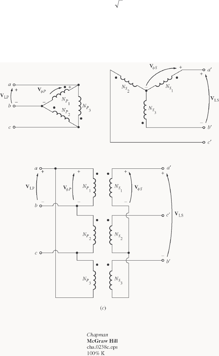
56
Assume that the phase voltages on the primary side are given by
°∠= 0
PA V
φ
V °−∠= 120
PB V
φ
V °∠= 120
PC V
φ
V
Then the phase voltages on the secondary side are given by
°∠=
′0
SA V
φ
V °−∠=
′120
SB V
φ
V °∠=
′120
SC V
φ
V
where aVV PS /
φφ
=. Since this is a Y-∆ transformer bank, the line voltage ab
V on the primary side is
°∠=°−∠−°∠=−= 3031200PPPBAab VVV
φφφ
VVV
and the voltage °∠=
′
=
′′ 0
SAba V
φ
VV . Note that the line voltage on the secondary side lags the line
voltage on the primary side by 30
°
.
2-21. Prove that the three-phase system of voltages on the secondary of the ∆-Y transformer shown in Figure 2-
38c lags the three-phase system of voltages on the primary of the transformer by 30°.
S
OLUTION The figure is reproduced below:
++
++
--
--
V
A
V
A
'
V
B
V
B
'
V
C
V
C
'
Assume that the phase voltages on the primary side are given by
°∠= 0
PA V
φ
V °−∠= 120
PB V
φ
V °∠= 120
PC V
φ
V
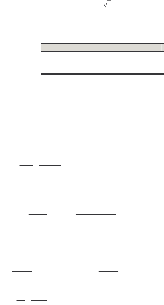
57
Then the phase voltages on the secondary side are given by
°∠=
′0
SA V
φ
V °−∠=
′120
SB V
φ
V °∠=
′120
SC V
φ
V
where aVV PS /
φφ
=. Since this is a ∆-Y transformer bank, the line voltage ab
V on the primary side is just
equal to °∠= 0
PA V
φ
V. The line voltage on the secondary side is given by
°−∠=°∠−°∠=−=
′′ 3031200PPPCAba VVV
φφφ
VVV
Note that the line voltage on the secondary side lags the line voltage on the primary side by 30
°
.
2-22. A single-phase 10-kVA 480/120-V transformer is to be used as an autotransformer tying a 600-V
distribution line to a 480-V load. When it is tested as a conventional transformer, the following values are
measured on the primary (480-V) side of the transformer:
Open-circuit test Short-circuit test
VOC = 480 V VSC = 10.0 V
IOC = 0.41 A ISC = 10.6 A
VOC = 38 W PSC = 26 W
(a) Find the per-unit equivalent circuit of this transformer when it is connected in the conventional manner.
What is the efficiency of the transformer at rated conditions and unity power factor? What is the
voltage regulation at those conditions?
(b) Sketch the transformer connections when it is used as a 600/480-V step-down autotransformer.
(c) What is the kilovoltampere rating of this transformer when it is used in the autotransformer connection?
(d) Answer the questions in (a) for the autotransformer connection.
S
OLUTION
(a) The base impedance of this transformer referred to the primary side is
()
()
22
base,
480 V 23.04
10 kVA
P
P
V
ZS
== =Ω
The open circuit test yields the values for the excitation branch (referred to the primary side):
,
,
0.41 A 0.000854 S
480 V
OC
EX
OC
I
YV
φ
φ
== =
()( )
11
38 W
cos cos 78.87
480 V 0.41 A
OC
OC OC
P
VI
θ
−−
=− =− =− °
0.000854 78.87 0.000165 0.000838
EX C M
YGjB j=− = ∠− °= −
1/ 6063
CC
RG==Ω
1/ 1193
MM
XB==Ω
The excitation branch elements can be expressed in per-unit as
6063 263 pu
23.04
C
RΩ
==
Ω 1193 51.8 pu
23.04
M
XΩ
==
Ω
The short circuit test yields the values for the series impedances (referred to the primary side):
10.0 V 0.943
10.6 A
SC
EQ
SC
V
ZI
== = Ω
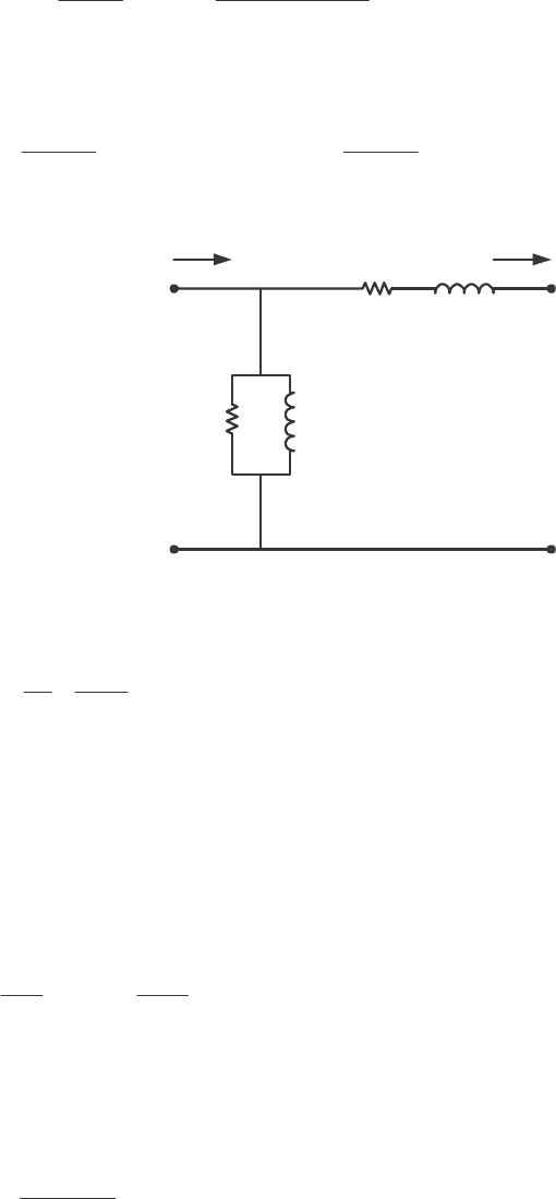
58
()()
11
26 W
cos cos 75.8
10.0 V 10.6 A
SC
SC SC
P
VI
θ
−−
== =°
0.943 75.8 0.231 0.915
EQ EQ EQ
ZRjX j=+ = ∠°= + Ω
The resulting per-unit impedances are
0.231 0.010 pu
23.04
EQ
RΩ
==
Ω 0.915 0.0397 pu
23.04
EQ
XΩ
==
Ω
The per-unit equivalent circuit is
+
-
V
S
V
P
I
S
+
-
I
P
R
C
jX
M
R
EQ
jX
EQ
0.010
j
0.0397
263
j
51.8
At rated conditions and unity power factor, the input power to this transformer would be IN
P = 1.0 pu.
The core losses (in resistor C
R) would be
()
2
2
core
1.0 0.00380 pu
263
C
V
PR
== =
The copper losses (in resistor EQ
R) would be
()( )
2
2
CU EQ 1.0 0.010 0.010 puPIR== =
The output power of the transformer would be
OUT OUT CU core 1.0 0.010 0.0038 0.986PPPP=−−=− − =
and the transformer efficiency would be
OUT
IN
0.986
100% 100% 98.6%
1.0
P
P
η
=× = × =
The output voltage of this transformer is
()( )
OUT IN EQ 1.0 1.0 0 0.01 0.0397 0.991 2.3Zj=− =−∠° + = ∠−°VVI
The voltage regulation of the transformer is
1.0 0.991
VR 100% 0.9%
0.991
−
=×=
(b) The autotransformer connection for 600/480 V stepdown operation is
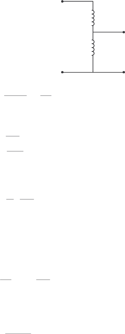
59
+
-
+
-
480 V
600 V
N
C
N
SE
V
SE
V
C
+
+
-
-
(c) When used as an autotransformer, the kVA rating of this transformer becomes:
()
SE
IO
SE
41
10 kVA 50 kVA
1
C
W
NN
SS
N
++
== =
(d) As an autotransformer, the per-unit series impedance EQ
Z is decreased by the reciprocal of the power
advantage, so the series impedance becomes
0.010 0.002 pu
5
EQ
R==
0.0397 0.00794 pu
5
EQ
X==
while the magnetization branch elements are basically unchanged. At rated conditions and unity power
factor, the input power to this transformer would be IN
P = 1.0 pu. The core losses (in resistor C
R) would
be
()
2
2
core
1.0 0.00380 pu
263
C
V
PR
== =
The copper losses (in resistor EQ
R) would be
()( )
2
2
CU EQ 1.0 0.002 0.002 puPIR== =
The output power of the transformer would be
OUT OUT CU core 1.0 0.002 0.0038 0.994PPPP=−−=− − =
and the transformer efficiency would be
OUT
IN
0.994
100% 100% 99.4%
1.0
P
P
η
=× = × =
The output voltage of this transformer is
()( )
OUT IN EQ 1.0 1.0 0 0.002 0.00794 0.998 0.5Zj=− =−∠° + = ∠−°VVI
The voltage regulation of the transformer is
1.0 0.998
VR 100% 0.2%
0.998
−
=×=
2-23. Figure P2-4 shows a power system consisting of a three-phase 480-V 60-Hz generator supplying two loads
through a transmission line with a pair of transformers at either end.
(a) Sketch the per-phase equivalent circuit of this power system.
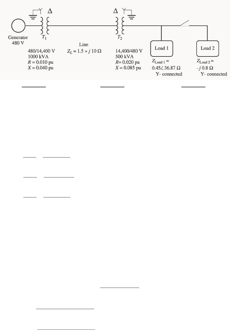
60
(b) With the switch opened, find the real power P, reactive power Q, and apparent power S supplied by the
generator. What is the power factor of the generator?
(c) With the switch closed, find the real power P, reactive power Q, and apparent power S supplied by the
generator. What is the power factor of the generator?
(d) What are the transmission losses (transformer plus transmission line losses) in this system with the
switch open? With the switch closed? What is the effect of adding Load 2 to the system?
Region 1 Region 2 Region 3
base1
S = 1000 kVA base2
S = 1000 kVA base3
S= 1000 kVA
base2,L
V= 480 V base2,L
V = 14,400 V base3,L
V = 480 V
S
OLUTION This problem can best be solved using the per-unit system of measurements. The power system
can be divided into three regions by the two transformers. If the per-unit base quantities in Region 1 are
chosen to be base1
S = 1000 kVA and base1,L
V = 480 V, then the base quantities in Regions 2 and 3 will be as
shown above. The base impedances of each region will be:
()
2
2
1
base1
base1
33 277 V 0.238
1000 kVA
V
ZS
φ
== = Ω
()
2
2
2
base2
base2
338314 V 207.4
1000 kVA
V
ZS
φ
== =Ω
()
2
2
3
base3
base3
33277 V 0.238
1000 kVA
V
ZS
φ
== =Ω
(a) To get the per-unit, per-phase equivalent circuit, we must convert each impedance in the system to
per-unit on the base of the region in which it is located. The impedance of transformer 1
T is already in per-
unit to the proper base, so we don’t have to do anything to it:
010.0
pu,1 =R
040.0
pu,1 =X
The impedance of transformer 2
T is already in per-unit, but it is per-unit to the base of transformer 2
T, so
it must be converted to the base of the power system.
()()
()()
2
base 1 base 2
pu on base 2 pu on base 1 2
base 2 base 1
( , , ) ( , , ) VS
RX Z RX Z
VS
= (2-60)
()( )
()( )
2
2,pu 2
8314 V 1000 kVA
0.020 0.040
8314 V 500 kVA
R==
()( )
()( )
2
2,pu 2
8314 V 1000 kVA
0.085 0.170
8314 V 500 kVA
X==
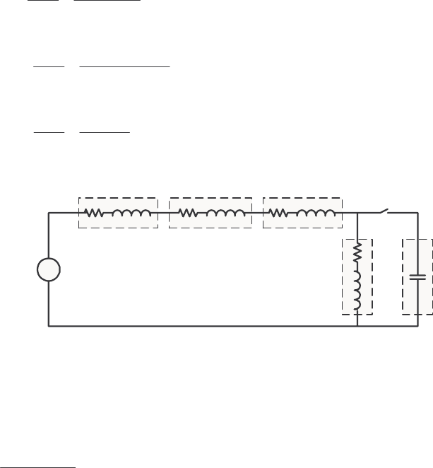
61
The per-unit impedance of the transmission line is
line
line,pu
base2
1.5 10 0.00723 0.0482
207.4
Zj
Zj
Z
+Ω
== = +
Ω
The per-unit impedance of Load 1 is
load1
load1,pu
base3
0.45 36.87 1.513 1.134
0.238
Z
Zj
Z
∠°Ω
== =+
Ω
The per-unit impedance of Load 2 is
load2
load2,pu
base3
0.8 3.36
0.238
Zj
Zj
Z
−Ω
== =−
Ω
The resulting per-unit, per-phase equivalent circuit is shown below:
+
-
1∠0°
T1T2
Line
L1L2
0.010 j0.040 0.00723 j0.0482 0.040 j0.170
1.513
j1.134 -j3.36
(b) With the switch opened, the equivalent impedance of this circuit is
EQ 0.010 0.040 0.00723 0.0482 0.040 0.170 1.513 1.134Zj j j j=+ + + ++ ++
EQ 1.5702 1.3922 2.099 41.6Zj=+ =∠°
The resulting current is
10 0.4765 41.6
2.099 41.6
∠°
==∠−°
∠°
I
The load voltage under these conditions would be
()()
Load,pu Load
0.4765 41.6 1.513 1.134 0.901 4.7Zj== ∠−°+ =∠−°VI
()( )
Load Load,pu base3 0.901 480 V 432 VVVV== =
The power supplied to the load is
()()
2
2
Load,pu Load 0.4765 1.513 0.344PIR== =
()( )
Load Load,pu base 0.344 1000 kVA 344 kWPPS== =
The power supplied by the generator is
()( )
,pu cos 1 0.4765 cos41.6 0.356
G
PVI
θ
== °=
()( )
,pu sin 1 0.4765 sin 41.6 0.316
G
QVI
θ
== °=
()( )
,pu 1 0.4765 0.4765
G
SVI== =
()( )
,pu base 0.356 1000 kVA 356 kW
GG
PPS== =
()( )
,pu base 0.316 1000 kVA 316 kVAR
GG
QQS== =
()( )
,pu base 0.4765 1000 kVA 476.5 kVA
GG
SSS== =
The power factor of the generator is

62
PF cos 41.6 0.748 lagging=°=
(c) With the switch closed, the equivalent impedance of this circuit is
()()
()()
EQ
1.513 1.134 3.36
0.010 0.040 0.00723 0.0482 0.040 0.170 1.513 1.134 3.36
jj
Zj j j jj
+−
=+ + + ++ + ++−
EQ 0.010 0.040 0.00788 0.0525 0.040 0.170 (2.358 0.109)Zj j j j=+++++++
EQ 2.415 0.367 2.443 8.65Zj=+ =∠°
The resulting current is
10 0.409 8.65
2.443 8.65
∠°
==∠−°
∠°
I
The load voltage under these conditions would be
()()
Load,pu Load
0.409 8.65 2.358 0.109 0.966 6.0Zj==∠−°+ =∠−°VI
()( )
Load Load,pu base3 0.966 480 V 464 VVVV== =
The power supplied to the two loads is the power supplied to the resistive component of the parallel
combination of the two loads: 2.358 pu.
()()
2
2
Load,pu Load 0.409 2.358 0.394PIR== =
()( )
Load Load,pu base 0.394 1000 kVA 394 kWPPS== =
The power supplied by the generator is
()( )
,pu cos 1 0.409 cos6.0 0.407
G
PVI
θ
== °=
()( )
,pu sin 1 0.409 sin 6.0 0.0428
G
QVI
θ
== °=
()( )
,pu 1 0.409 0.409
G
SVI== =
()( )
,pu base 0.407 1000 kVA 407 kW
GG
PPS== =
()( )
,pu base 0.0428 1000 kVA 42.8 kVAR
GG
QQS== =
()( )
,pu base 0.409 1000 kVA 409 kVA
GG
SSS== =
The power factor of the generator is
PF cos 6.0 0.995 lagging=°=
(d) The transmission losses with the switch open are:
()( )
2
2
line,pu line 0.4765 0.00723 0.00164PIR== =
()( )
line l ,pu base 0.00164 1000 kVA 1.64 kW
ine
PPS== =
The transmission losses with the switch closed are:
()( )
2
2
line,pu line 0.409 0.00723 0.00121PIR== =
()( )
line l ,pu base 0.00121 1000 kVA 1.21 kW
ine
PPS== =
Load 2 improved the power factor of the system, increasing the load voltage and the total power supplied to
the loads, while simultaneously decreasing the current in the transmission line and the transmission line
losses. This problem is a good example of the advantages of power factor correction in power systems.
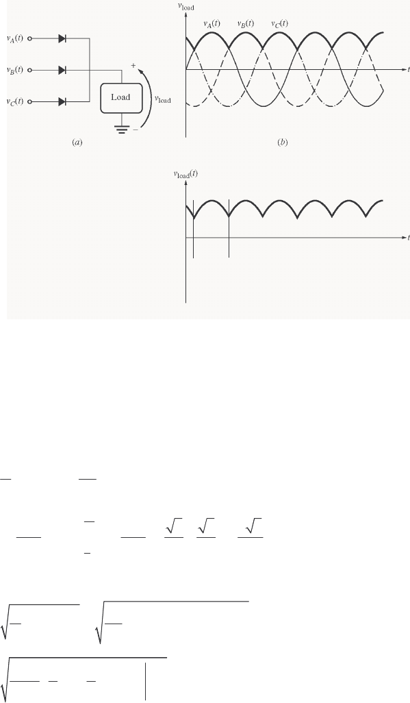
63
Chapter 3: Introduction to Power Electronics
3-1. Calculate the ripple factor of a three-phase half-wave rectifier circuit, both analytically and using
MATLAB.
S
OLUTION A three-phase half-wave rectifier and its output voltage are shown below
π
/6 5
π
/6
2
π
/3
()
sin
AM
vt V t
ω
=
() ( )
sin 2 / 3
BM
vt V t
ωπ
=−
() ( )
sin 2 / 3
CM
vt V t
ωπ
=+
S
OLUTION If we find the average and rms values over the interval from π/6 to 5π/6 (one period), these
values will be the same as the average and rms values of the entire waveform, and they can be used to
calculate the ripple factor. The average voltage is
()
5/6
/6
13
() sin
2
DC M
VvtdtVtdt
T
π
π
ωω
π
==
5
6
6
333333
cos 0.8270
22222
MM
DC MM
VV
Vt VV
π
π
ω
ππ π
=− =− − − = =
The rms voltage is
()
5/6
222
rms
/6
13
() sin
2M
VvtdtVtdt
T
π
π
ωω
π
==
5/6
2
rms
/
6
311
sin 2
22 4
M
V
Vtt
π
π
ωω
π
=−
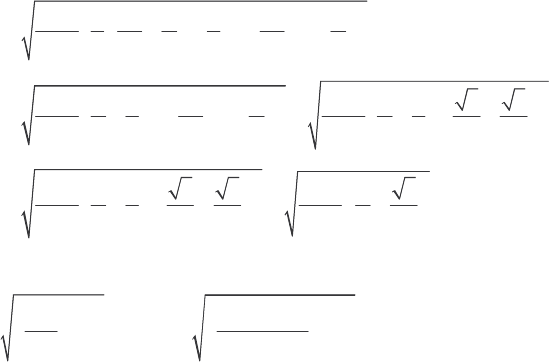
64
2
rms
315 15
sin sin
22664 3 3
M
V
V
ππ π π
π
=−−−
22
rms
315 3133
sin sin
234 3 3 23422
MM
VV
V
πππ π
ππ
=−−=−−−
22
rms
31333 3
0.8407
23422 234
MM
M
VV
VV
ππ
ππ
=−−−=+=
The resulting ripple factor is
22
rms
DC
0.8407
1 100% 1 100% 18.3%
0.8270
M
M
VV
rVV
=−×= −×=
The ripple can be calculated with MATLAB using the ripple function developed in the text. We must
right a new function halfwave3 to simulate the output of a three-phase half-wave rectifier. This output
is just the largest voltage of
()
tvA,
()
tvB, and
()
tvC at any particular time. The function is shown below:
function volts = halfwave3(wt)
% Function to simulate the output of a three-phase
% half-wave rectifier.
% wt = Phase in radians (=omega x time)
% Convert input to the range 0 <= wt < 2*pi
while wt >= 2*pi
wt = wt - 2*pi;
end
while wt < 0
wt = wt + 2*pi;
end
% Simulate the output of the rectifier.
a = sin(wt);
b = sin(wt - 2*pi/3);
c = sin(wt + 2*pi/3);
volts = max( [ a b c ] );
The function
ripple is reproduced below. It is identical to the one in the textbook.
function r = ripple(waveform)
% Function to calculate the ripple on an input waveform.
% Calculate the average value of the waveform
nvals = size(waveform,2);
temp = 0;
for ii = 1:nvals
temp = temp + waveform(ii);
end
average = temp/nvals;
% Calculate rms value of waveform
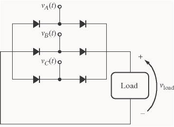
65
temp = 0;
for ii = 1:nvals
temp = temp + waveform(ii)^2;
end
rms = sqrt(temp/nvals);
% Calculate ripple factor
r = sqrt((rms / average)^2 - 1) * 100;
Finally, the test driver program is shown below.
% M-file: test_halfwave3.m
% M-file to calculate the ripple on the output of a
% three phase half-wave rectifier.
% First, generate the output of a three-phase half-wave
% rectifier
waveform = zeros(1,128);
for ii = 1:128
waveform(ii) = halfwave3(ii*pi/64);
end
% Now calculate the ripple factor
r = ripple(waveform);
% Print out the result
string = ['The ripple is ' num2str(r) '%.'];
disp(string);
When this program is executed, the results are
» test_halfwave3
The ripple is 18.2759%.
This answer agrees with the analytical solution above.
3-2. Calculate the ripple factor of a three-phase full-wave rectifier circuit, both analytically and using
MATLAB.
S
OLUTION A three-phase half-wave rectifier and its output voltage are shown below
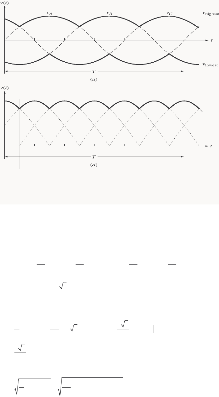
66
T
/12
()
sin
AM
vt V t
ω
=
() ( )
sin 2 / 3
BM
vt V t
ωπ
=−
() ( )
sin 2 / 3
CM
vt V t
ωπ
=+
S
OLUTION By symmetry, the rms voltage over the interval from 0 to T/12 will be the same as the rms
voltage over the whole interval. Over that interval, the output voltage is:
() () ()
22
sin sin
33
CB M M
vt vt vt V t V t
ππ
ωω
=−= +− −
()
22 22
sin cos cos sin sin cos cos sin
33 33
MM
vt V t t V t t
ππ ππ
ωω ωω
=+−−
()
2
2cos sin 3cos
3
M
vt V t t
π
ωω
==
Note that the period of the waveform is 2/T
πω
=, so T/12 is
/
6
πω
. The average voltage over the
interval from 0 to T/12 is
/6
/
6
0
0
16 63
() 3 cos sin
DC M M
Vvtdt VtdtVt
T
πω πω
ωωω
ππ
== =
33 1.6540
DC M M
VV V
π
==
The rms voltage is
/6
222
rms
0
16
() 3 cos
M
Vvtdt Vtdt
T
πω
ωω
π
==
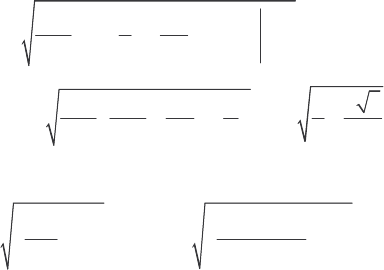
67
/
6
2
rms
0
18 1 1 sin 2
24
M
VVt t
πω
ωω
πω
=+
rms
18 1 3 9 3
sin 1.6554
12 4 3 2 4
MMM
VV V V
ωπ π
πωω π
=+=+=
The resulting ripple factor is
22
rms
DC
1.6554
1 100% 1 100% 4.2%
1.6540
M
M
VV
rVV
=−×= −×=
The ripple can be calculated with MATLAB using the ripple function developed in the text. We must
right a new function fullwave3 to simulate the output of a three-phase half-wave rectifier. This output
is just the largest voltage of
()
tvA,
()
tvB, and
()
tvC at any particular time. The function is shown below:
function volts = fullwave3(wt)
% Function to simulate the output of a three-phase
% full-wave rectifier.
% wt = Phase in radians (=omega x time)
% Convert input to the range 0 <= wt < 2*pi
while wt >= 2*pi
wt = wt - 2*pi;
end
while wt < 0
wt = wt + 2*pi;
end
% Simulate the output of the rectifier.
a = sin(wt);
b = sin(wt - 2*pi/3);
c = sin(wt + 2*pi/3);
volts = max( [ a b c ] ) - min( [ a b c ] );
The test driver program is shown below.
% M-file: test_fullwave3.m
% M-file to calculate the ripple on the output of a
% three phase full-wave rectifier.
% First, generate the output of a three-phase full-wave
% rectifier
waveform = zeros(1,128);
for ii = 1:128
waveform(ii) = fullwave3(ii*pi/64);
end
% Now calculate the ripple factor
r = ripple(waveform);
% Print out the result
string = ['The ripple is ' num2str(r) '%.'];
disp(string);
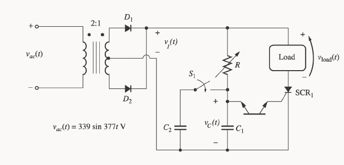
68
When this program is executed, the results are
» test_fullwave3
The ripple is 4.2017%.
This answer agrees with the analytical solution above.
3-3. Explain the operation of the circuit shown in Figure P3-1. What would happen in this circuit if switch S1
were closed?
S
OLUTION Diode D1 and D2 together with the transformer form a full-wave rectifier. Therefore, a voltage
oriented positive-to-negative as shown will be applied to the SCR and the control circuit on each half cycle.
(1) Initially, the SCR is an open circuit, since v1 < VBO for the SCR. Therefore, no current flows to the
load and vLOAD = 0.
(2) Voltage v1 is applied to the control circuit, charging capacitor C1 with time constant RC1.
(3) When vC > VBO for the DIAC, it conducts, supplying a gate current to the SCR.
(4) The gate current in the SCR lowers its breakover voltage, and the SCR fires. When the SCR fires,
current flows through the SCR and the load.
(5) The current flow continues until iD falls below IH for the SCR (at the end of the half cycle). The
process starts over in the next half cycle.
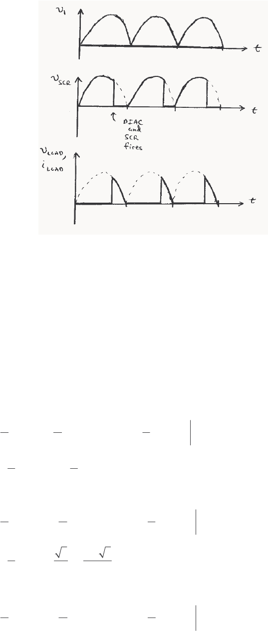
69
If switch S1 is shut, the charging time constant is increased, and the DIAC fires later in each half cycle.
Therefore, less power is supplied to the load.
3-4. What would the rms voltage on the load in the circuit in Figure P3-1 be if the firing angle of the SCR were
(a) 0°, (b) 30°, (c) 90°?
S
OLUTION The input voltage to the circuit of Figure P3-1 is
()
ttv
ω
sin339
ac =, where rad/s 377=
ω
Therefore, the voltage on the secondary of the transformer will be
()
ttv
ω
sin5.169
ac =
(a) The average voltage applied to the load will be the integral over the conducting portion of the half
cycle divided by π/ω, the period of a half cycle. For a firing angle of 0°, the average voltage will be
/
/
ave
0
00
11
() sin cos
T
MM
VvtdtVtdtVt
T
πω
πω
ωωω
ππ
== =−
[]
()( )
ave
12
1 1 0.637 169.5 V 108 V
MM
VV V
ππ
=− − − = = =
(b) For a firing angle of 30°, the average voltage will be
/
/
ave
/
6
/6 /6
11
() sin cos
T
MM
VvtdtVtdtVt
T
πω
πω
π
ππ
ωωω
ππ
== =−
()( )
ave
1323
1 0.594 169.5 V 101 V
22
MM
VV V
ππ
+
=− − − = = =
(c) For a firing angle of 90°, the average voltage will be
/
/
ave
/
2
/2 /2
11
() sin cos
T
MM
VvtdtVtdtVt
T
πω
πω
π
ππ
ωωω
ππ
== =−
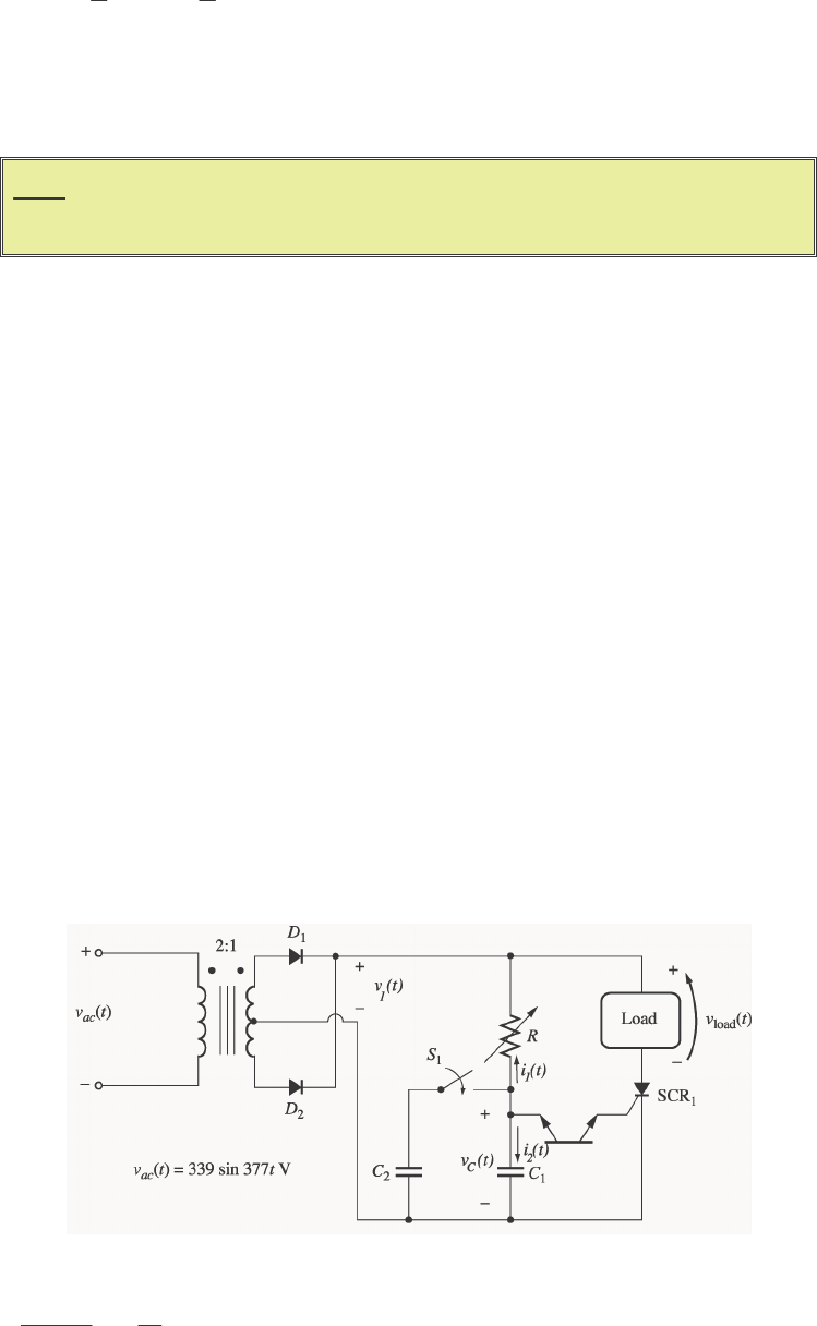
70
[]
()( )
ave
11
1 0.318 169.5 V 54 V
MM
VV V
ππ
=− − = = =
3-5. For the circuit in Figure P3-1, assume that VBO for the DIAC is 30 V, C1 is 1 µF, R is adjustable in the
range 1-20 kΩ, and that switch S1 is open. What is the firing angle of the circuit when R is 10 kΩ? What
is the rms voltage on the load under these conditions?
Note: Problem 3-5 is significantly harder for many students, since it involves solving
a differential equation with a forcing function. This problem should only be
assigned if the class has the mathematical sophistication to handle it.
S
OLUTION At the beginning of each half cycle, the voltages across the DIAC and the SCR will both be
smaller then their respective breakover voltages, so no current will flow to the load (except for the very tiny
current charging capacitor C), and vload(t) will be 0 volts. However, capacitor C charges up through
resistor R, and when the voltage vC(t) builds up to the breakover voltage of D1, the DIAC will start to
conduct. This current flows through the gate of SCR1, turning the SCR ON. When it turns ON, the
voltage across the SCR will drop to 0, and the full source voltage vS(t) will be applied to the load,
producing a current flow through the load. The SCR continues to conduct until the current through it falls
below IH, which happens at the very end of the half cycle.
Note that after D1 turns on, capacitor C discharges through it and the gate of the SCR. At the end of the
half cycle, the voltage on the capacitor is again essentially 0 volts, and the whole process is ready to start
over again at the beginning of the next half cycle.
To determine when the DIAC and the SCR fire in this circuit, we must determine when vC(t) exceeds VBO
for D1. This calculation is much harder than in the examples in the book, because in the previous problems
the source was a simple DC voltage source, while here the voltage source is sinusoidal. However, the
principles are identical.
(a) To determine when the SCR will turn ON, we must calculate the voltage vC(t), and then solve for the time
at which vC(t) exceeds VBO for D1. At the beginning of the half cycle, D1 and SCR1 are OFF, and the
voltage across the load is essentially 0, so the entire source voltage vS(t) is applied to the series RC circuit.
To determine the voltage vC(t) on the capacitor, we can write a Kirchhoff's Current Law equation at the
node above the capacitor and solve the resulting equation for vC(t).
0
21 =+ ii (since the DIAC is an open circuit at this time)
0
1=+
−
C
Cv
dt
d
C
R
vv

71
1
11 v
RC
v
RC
v
dt
d
CC =+
t
R
C
V
v
R
C
v
dt
dM
CC
ω
sin
1=+
The solution can be divided into two parts, a natural response and a forced response. The natural response
is the solution to the differential equation
10
CC
dvv
dt RC
+=
The solution to the natural response differential equation is
()
, e
t
RC
Cn
vtA
−
=
where the constant A must be determined from the initial conditions in the system. The forced response is
the steady-state solution to the equation
1sin
M
CC
dV
vv t
dt RC RC
ω
+=
It must have a form similar to the forcing function, so the solution will be of the form
(
)
,1 2
sin cos
Cf
vtB tB t
ωω
=+
where the constants 1
B and 2
B must be determined by substitution into the original equation. Solving for
1
B and 2
B yields:
()()
12 12
1
sin cos sin cos sin
M
dV
BtBt BtBt t
dt RC RC
ωω ωω ω
++ +=
()()
12 12
1
cos in sin cos sin
M
V
BtBst B tB t t
RC RC
ωωω ω ω ω ω
−+ +=
cosine equation:
12
10
BB
RC
ω
+= ⇒ 21
BRCB
ω
=−
sine equation:
21
1M
V
BB
RC RC
ω
−+ =
2
11
1
M
V
RC B B
RC RC
ω
+=
2
1
1
M
V
RC B
RC RC
ω
+=
222
1
1M
RC V
B
RC RC
ω
+=
Finally,
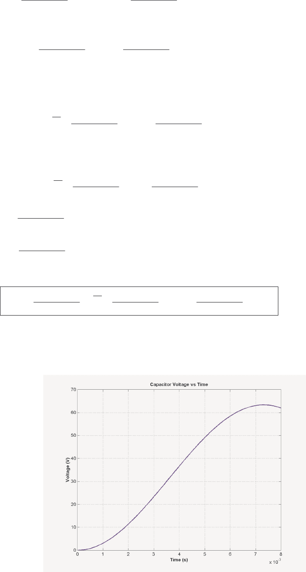
72
1222
1
M
V
BRC
ω
=+ and 2222
1
M
RC V
BRC
ω
ω
−
=+
Therefore, the forced solution to the equation is
()
,222 222
sin cos
11
MM
Cf
VRCV
vt t t
RC RC
ω
ωω
ωω
=−
++
and the total solution is
(
)
(
)
(
)
,,CCnCf
vt v t v t=+
()
222 222
sin cos
11
t
MM
RC
C
VRCV
vt Ae t t
RC RC
ω
ωω
ωω
−
=+ −
++
The initial condition for this problem is that the voltage on the capacitor is zero at the beginning of the half-
cycle:
()
0
222 222
0 sin 0 cos 00
11
MM
RC
C
VRCV
vAe RC RC
ω
ωω
−
=+ − =
++
22 2
0
1
M
RC V
ARC
ω
ω
−=
+
222
1
M
RC V
ARC
ω
ω
=+
Therefore, the voltage across the capacitor as a function of time before the DIAC fires is
()
222 222 222
sin cos
11 1
t
MM M
RC
C
RC V V RC V
vt e t t
RC RC RC
ωω
ωω
ωω ω
−
=+ −
++ +
If we substitute the known values for R, C,
ω
, and VM, this equation becomes
(
)
100
42 11.14 sin 42 cos
t
C
vt e t t
ωω
−
=+ −
This equation is plotted below:
It reaches a voltage of 30 V at a time of 3.50 ms. Since the frequency of the waveform is 60 Hz, the
waveform there are 360° in 1/60 s, and the firing angle α is
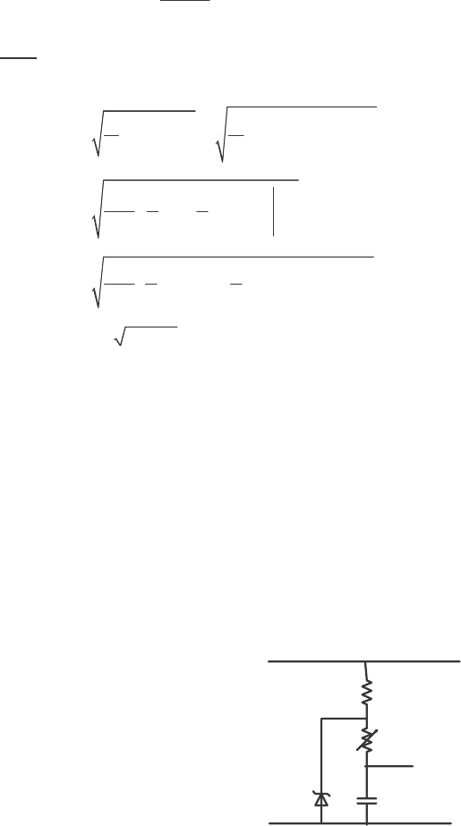
73
()
360
3.50 ms 75.6
1/60 s
α
°
==°
or 1.319 radians
Note: This problem could also have been solved using Laplace Transforms, if desired.
(b) The rms voltage applied to the load is
/
222
rms
1() sin
M
VvtdtVtdt
T
πω
α
ωω
π
==
/
2
rms
11
sin 2
24
M
V
Vtt
πω
α
ωω
π
=−
()()
2
rms
11
sin 2 sin 2
24
M
V
V
πα π α
π
=−−−
rms 0.3284 0.573 97.1 V
MM
VV V===
3-6. One problem with the circuit shown in Figure P3-1 is that it is very sensitive to variations in the input
voltage vt
ac (). For example, suppose the peak value of the input voltage were to decrease. Then the time
that it takes capacitor C1 to charge up to the breakover voltage of the DIAC will increase, and the SCR will
be triggered later in each half cycle. Therefore, the rms voltage supplied to the load will be reduced both by
the lower peak voltage and by the later firing. This same effect happens in the opposite direction if vt
ac ()
increases. How could this circuit be modified to reduce its sensitivity to variations in input voltage?
S
OLUTION If the voltage charging the capacitor could be made constant or nearly so, then the feedback
effect would be stopped and the circuit would be less sensitive to voltage variations. A common way to do
this is to use a zener diode that fires at a voltage greater than BO
V for the DIAC across the RC charging
circuit. This diode holds the voltage across the RC circuit constant, so that the capacitor charging time is
not much affected by changes in the power supply voltage.
v
C
R
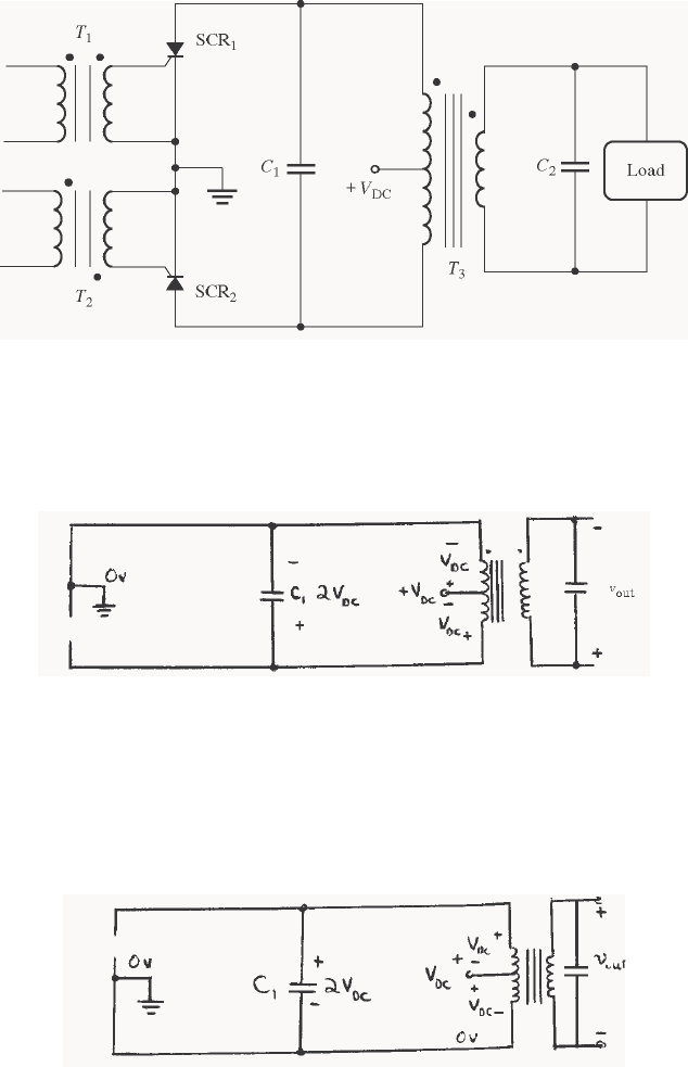
74
3-7. Explain the operation of the circuit shown in Figure P3-2, and sketch the output voltage from the circuit.
S
OLUTION This circuit is a single-phase voltage source inverter.
(1) Initially, suppose that both SCRs are OFF. Then the voltage on the transformer T3 will be 0, and
voltage VDC will be dropped across SCR1 and SCR2 as shown.
(2) Now, apply a pulse to transformer T1 that turns on SCR1. When that happens, the circuit looks like:
Since the top of the transformer is now grounded, a voltage VDC appears across the upper winding as
shown. This voltage induces a corresponding voltage on the lower half of the winding, charging capacitor
C1 up to a voltage of 2VDC, as shown.
Now, suppose that a pulse is applied to transformer T2. When that occurs, SCR2 becomes a short circuit,
and SCR1 is turned OFF by the reverse voltage applied to it by capacitor C1 (forced commutation). At that
time, the circuit looks like:
Now the voltages on the transformer are reversed, charging capacitor C1 up to a voltage of 2VDC in the
opposite direction. When SCR1 is triggered again, the voltage on C1 will turn SCR2 OFF.
The output voltage from this circuit would be roughly a square wave, except that capacitor C2 filters it
somewhat.
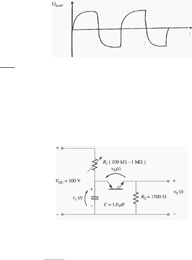
75
(
Note: The above discussion assumes that transformer T3 is never in either state long enough for it to
saturate.)
3-8. Figure P3-3 shows a relaxation oscillator with the following parameters:
R1=variable Ω= 1500
2
R
1.0 FC
µ
= V 100
DC =V
BO 30 VV= 0.5 mA
H
I=
(a) Sketch the voltages vt
C(), vt
D(), and vt
o() for this circuit.
(b) If R1 is currently set to 500 kΩ, calculate the period of this relaxation oscillator.
S
OLUTION
(a) The voltages vC(t), vD(t) and vo(t) are shown below. Note that vC(t) and vD(t) look the same during
the rising portion of the cycle. After the PNPN Diode triggers, the voltage across the capacitor decays with
time constant τ2 =
R1R2
R1 + R2
C, while the voltage across the diode drops immediately.
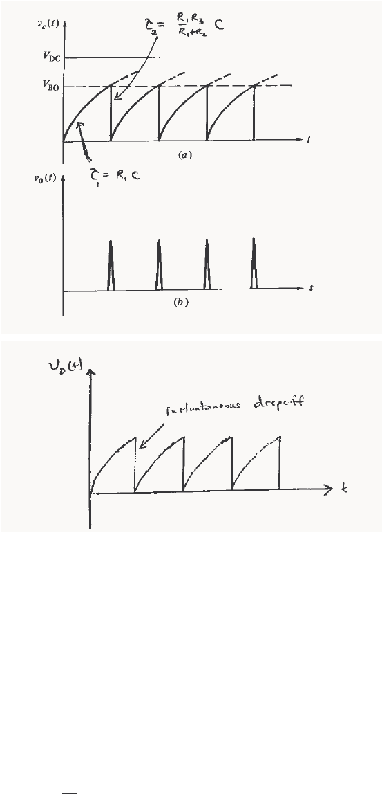
76
(b) When voltage is first applied to the circuit, the capacitor C charges with a time constant
τ
1 = R1 C =
(500 kΩ)(1.00 µF) = 0.50 s. The equation for the voltage on the capacitor as a function of time during the
charging portion of the cycle is
()
1
t
RC
C
vt ABe
−
=+
where A and B are constants depending upon the initial conditions in the circuit. Since vC(0) = 0 V and
vC(∞) = 100 V, it is possible to solve for A and B.
A = vC(∞) = 100 V
A + B = vC(0) = 0 V ⇒ B = -100 V
Therefore,
()
0.50
100 100 V
t
C
vt e
−
=−
The time at which the capacitor will reach breakover voltage is found by setting vC(t) = VBO and solving for
time t1:
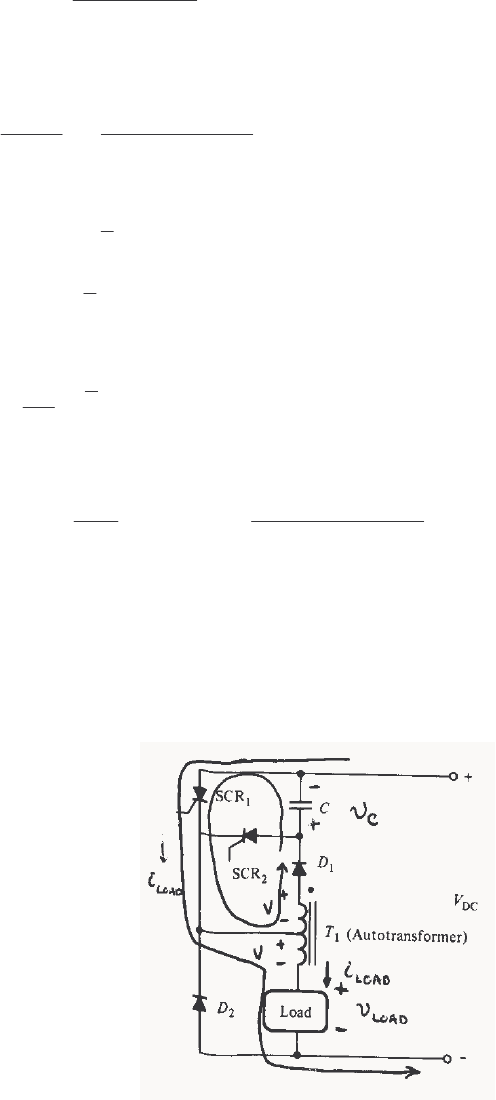
77
1
100 V 30 V
0.50 ln 178 ms
100 V
t−
=− =
Once the PNPN Diode fires, the capacitor discharges through the parallel combination of R1 and R2, so the
time constant for the discharge is
(
)
(
)
()
12
2
12
500 k 1.5 k 1.0 F 0.0015 s
500 k 1.5 k
RR C
RR
τµ
ΩΩ
== =
+Ω+Ω
The equation for the voltage on the capacitor during the discharge portion of the cycle is
()
2
t
C
vt ABe
τ
−
=+
()
2
BO
t
C
vt V e
τ
−
=
The current through the PNPN diode is given by
()
2
BO
2
t
D
V
it e
R
τ
−
=
If we ignore the continuing trickle of current from R1, the time at which iD(t) reaches IH is
()
(
)
(
)
2
22
BO
0.0005 A 1500
ln 0.0015 ln 5.5 ms
30 V
H
IR
tRC
V
Ω
=− =− =
Therefore, the period of the relaxation oscillator is T = 178 ms + 5.5 ms = 183.5 ms, and the frequency of
the relaxation oscillator is f = 1/T = 5.45 Hz.
3-9. In the circuit in Figure P3-4, T1 is an autotransformer with the tap exactly in the center of its winding.
Explain the operation of this circuit. Assuming that the load is inductive, sketch the voltage and current
applied to the load. What is the purpose of SCR2? What is the purpose of D2? (This chopper circuit
arrangement is known as a Jones circuit.)
S
OLUTION First, assume that SCR1 is triggered. When that happens, current will flow from the power
supply through SCR1 and the bottom portion of transformer T1 to the load. At that time, a voltage will be
applied to the bottom part of the transformer which is positive at the top of the winding with respect to the
bottom of the winding. This voltage will induce an equal voltage in the upper part of the autotransformer
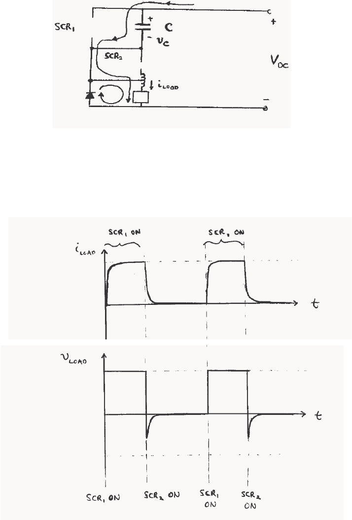
78
winding, forward biasing diode D1 and causing the current to flow up through capacitor C. This current
causes C to be charged with a voltage that is positive at its bottom with respect to its top. (This condition
is shown in the figure above.)
Now, assume that SCR2 is triggered. When SCR2 turns ON, capacitor C applies a reverse-biased voltage
to SCR1, shutting it off. Current then flow through the capacitor, SCR2, and the load as shown below.
This current charges C with a voltage of the opposite polarity, as shown.
SCR2 will cut off when the capacitor is fully charged. Alternately, it will be cut off by the voltage across
the capacitor if SCR1 is triggered before it would otherwise cut off.
In this circuit, SCR1 controls the power supplied to the load, while SCR2 controls when SCR1 will be
turned off. Diode D2 in this circuit is a free-wheeling diode, which allows the current in the load to
continue flowing for a short time after SCR1 turns off.
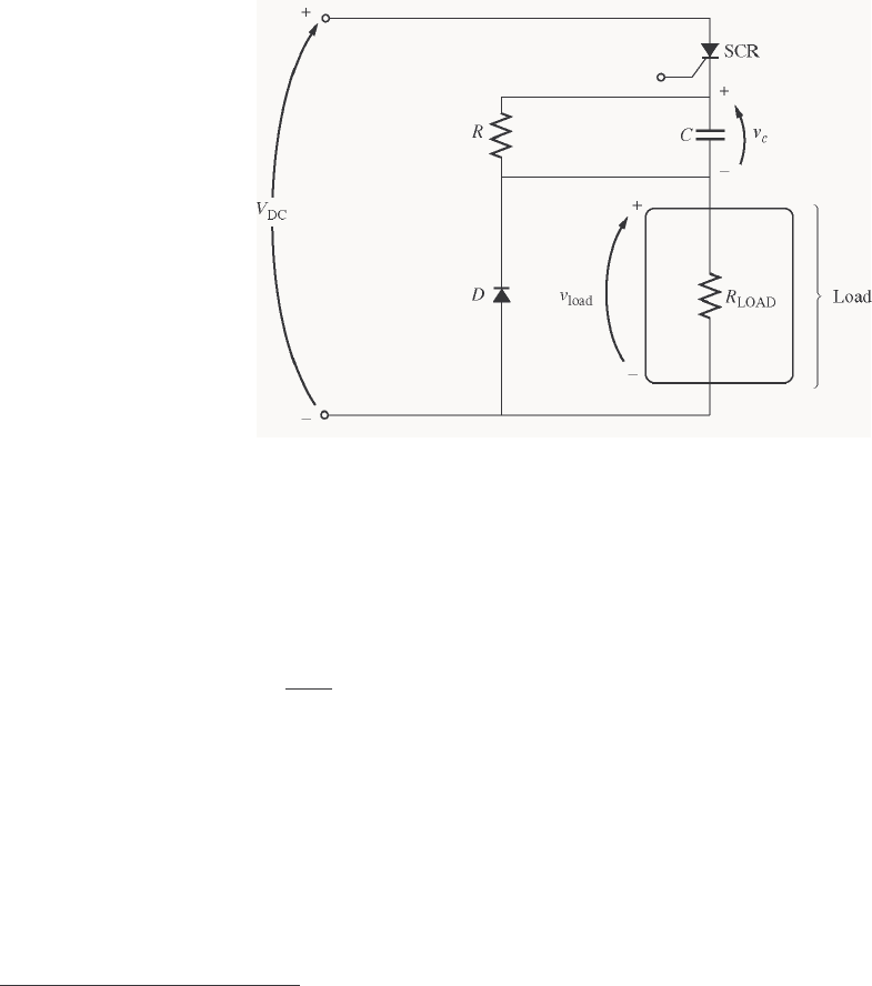
79
3-10. A series-capacitor forced commutation chopper circuit supplying a purely resistive load is shown in Figure
P3-5.
DC 120 VV= 20 kR=Ω
8 mA
H
I=2 LOAD 250 R=Ω
BO 200 VV= 150 FC
µ
=
(a) When SCR1is turned on, how long will it remain on? What causes it to turn off?
(b) When SCR1 turns off, how long will it be until the SCR can be turned on again? (Assume that three
time constants must pass before the capacitor is discharged.)
(c) What problem or problems do these calculations reveal about this simple series-capacitor forced
commutation chopper circuit?
(d) How can the problem(s) described in part (c) be eliminated?
Solution
(a) When the SCR is turned on, it will remain on until the current flowing through it drops below IH.
This happens when the capacitor charges up to a high enough voltage to decrease the current below IH. If
we ignore resistor R (because it is so much larger than RLOAD), the capacitor charges through resistor
RLOAD with a time constant
τ
LOAD = RLOADC = (250 Ω)(150
µ
F) = 0.0375 s. The equation for the voltage
on the capacitor as a function of time during the charging portion of the cycle is
()
LOAD
t
RC
C
vt ABe
−
=+
where A and B are constants depending upon the initial conditions in the circuit. Since vC(0) = 0 V and
vC(∞) = VDC, it is possible to solve for A and B.
A = vC(∞) = VDC
A + B = vC(0) = VDC ⇒ B = -VDC
Therefore,
2 The first printing of this book incorrectly stated that IH is 6 mA.
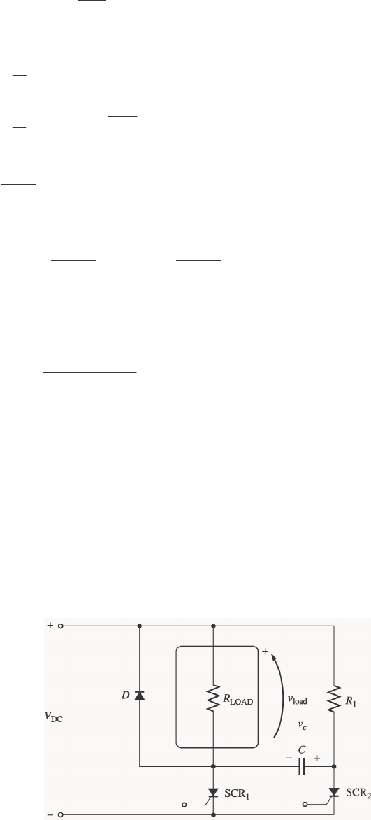
80
()
LOAD
DC DC V
t
RC
C
vt V V e
−
=−
The current through the capacitor is
() ()
CC
d
it C vt
dt
=
()
LOAD
DC DC
t
RC
C
d
it C V V e
dt
−
=−
()
LOAD
DC
LOAD
A
t
RC
C
V
it e
R
−
=
Solving for time yields
(
)
(
)
22
LOAD
DC DC
ln 0.0375 ln
CC
itR itR
tRC VV
=− =−
The current through the SCR consists of the current through resistor R plus the current through the
capacitor. The current through resistor R is 120 V / 20 kΩ = 6 mA, and the holding current of the SCR is
8 mA, so the SCR will turn off when the current through the capacitor drops to 2 mA. This occurs at time
(
)
(
)
2 mA 250
0.0375 ln 0.206 s
120 V
tΩ
=− =
(b) The SCR can be turned on again once the capacitor has discharged. The capacitor discharges
through resistor R. It can be considered to be completely discharged after three time constants. Since
τ
=
RC = (20 kΩ)(150
µ
F) = 3 s, the SCR will be ready to fire again after 9 s.
(c) In this circuit, the ON time of the SCR is much shorter than the reset time for the SCR, so power can
flow to the load only a very small fraction of the time. (This effect would be less exaggerated if the ratio of
R to RLOAD were smaller.)
(d) This problem can be eliminated by using one of the more complex series commutation circuits
described in Section 3-5. These more complex circuits provide special paths to quickly discharge the
capacitor so that the circuit can be fired again soon.
3-11. A parallel-capacitor forced commutation chopper circuit supplying a purely resistive load is shown in
Figure P3-6.
DC 120 VV= 120 kR=Ω
5 mA
H
I= load 250 R=Ω
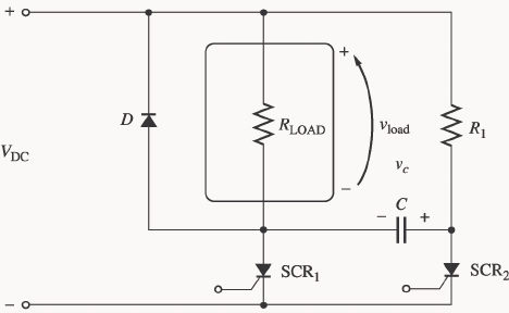
81
BO 250 VV= 15 FC
µ
=
(a) When SCR1 is turned on, how long will it remain on? What causes it to turn off?
(b) What is the earliest time that SCR1 can be turned off after it is turned on? (Assume that three time
constants must pass before the capacitor is charged.)
(c) When SCR1 turns off, how long will it be until the SCR can be turned on again?
(d) What problem or problems do these calculations reveal about this simple parallel-capacitor forced
commutation chopper circuit?
(e) How can the problem(s) describe in part (d) be eliminated?
S
OLUTION
(a) When SCR1 is turned on, it will remain on indefinitely until it is forced to turn off. When SCR1 is turned
on, capacitor C charges up to VDC volts with the polarity shown in the figure above. Once it is charged,
SCR1 can be turned off at any time by triggering SCR2. When SCR2 is triggered, the voltage across it
drops instantaneously to about 0 V, which forces the voltage at the anode of SCR1 to be -VDC volts, turning
SCR1 off. (Note that SCR2 will spontaneously turn off after the capacitor discharges, since VDC / R1 < IH
for SCR2.)
(b) If we assume that the capacitor must be fully charged before SCR1 can be forced to turn off, then the time
required would be the time to charge the capacitor. The capacitor charges through resistor R1, and the time
constant for the charging is
τ
= R1C = (20 kΩ)(15
µ
F) = 0.3 s. If we assume that it takes 3 time constants
to fully charge the capacitor, then the time until SCR1 can be turned off is 0.9 s.
(Note that this is not a very realistic assumption. In real life, it is possible to turn off SCR1 with less than a
full VDC volts across the capacitor.)
(c) SCR1 can be turned on again after the capacitor charges up and SCR2 turns off. The capacitor charges
through RLOAD, so the time constant for charging is
τ
= RLOADC = (250 Ω)(15
µ
F) = 0.00375 s
and SCR2 will turn off in a few milliseconds.
(d) In this circuit, once SCR1 fires, a substantial period of time must pass before the power to the load can be
turned off. If the power to the load must be turned on and off rapidly, this circuit could not do the job.
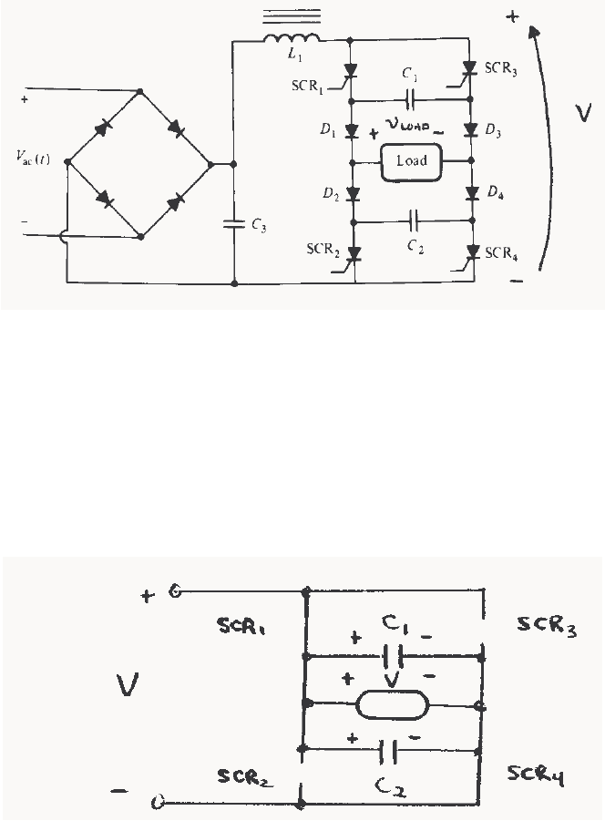
82
(e) This problem can be eliminated by using one of the more complex parallel commutation circuits described
in Section 3-5. These more complex circuits provide special paths to quickly charge the capacitor so that
the circuit can be turned off quickly after it is turned on.
3-12. Figure P3-7 shows a single-phase rectifier-inverter circuit. Explain how this circuit functions. What are
the purposes of C1 and C2? What controls the output frequency of the inverter?
S
OLUTION The last element in the filter of this rectifier circuit is an inductor, which keeps the current flow
out of the rectifier almost constant. Therefore, this circuit is a current source inverter. The rectifier and
filter together produce an approximately constant dc voltage and current across the two SCRs and diodes at
the right of the figure. The applied voltage is positive at the top of the figure with respect to the bottom of
the figure. To understand the behavior of the inverter portion of this circuit, we will step through its
operation.
(1) First, assume that SCR1 and SCR4 are triggered. Then the voltage V will appear across the load
positive-to-negative as shown in Figure (a). At the same time, capacitor C1 will charge to V volts through
diode D3, and capacitor C2 will charge to V volts through diode D2.
(a)
(2) Now, assume that SCR2 and SCR3 are triggered. At the instant they are triggered, the voltage across
capacitors C1 and C2 will reverse bias SCR1 and SCR4, turning them OFF. Then a voltage of V volts will
appear across the load positive-to-negative as shown in Figure (b). At the same time, capacitor C1 will
charge to V volts with the opposite polarity from before, and capacitor C2 will charge to V volts with the
opposite polarity from before.
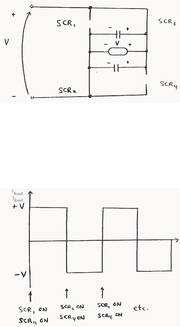
83
Figure (b)
(3) If SCR1 and SCR4 are now triggered again, the voltages across capacitors C1 and C2 will force
SCR2 and SCR3 to turn OFF. The cycle continues in this fashion.
Capacitors C1 and C2 are called commutating capacitors. Their purpose is to force one set of SCRs to turn
OFF when the other set turns ON.
The output frequency of this rectifier-inverter circuit is controlled by the rates at which the SCRs are
triggered. The resulting voltage and current waveforms (assuming a resistive load) are shown below.
3-13. A simple full-wave ac phase angle voltage controller is shown in Figure P3-8. The component values in
this circuit are:
R = 20 to 300 kΩ, currently set to 80 kΩ
C = 0.15
µ
F
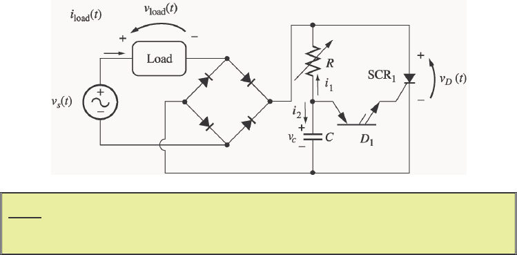
84
BO
V = 40 V (for PNPN Diode D1)
BO
V = 250 V (for SCR1)
( ) sin volts
sM
vt V t
ω
=
where
M
V = 169.7 V and
ω
= 377 rad/s
(a) At what phase angle do the PNPN diode and the SCR turn on?
(b) What is the rms voltage supplied to the load under these circumstances?
Note: Problem 3-13 is significantly harder for many students, since it involves
solving a differential equation with a forcing function. This problem should
only be assigned if the class has the mathematical sophistication to handle it.
S
OLUTION At the beginning of each half cycle, the voltages across the PNPN diode and the SCR will both be
smaller then their respective breakover voltages, so no current will flow to the load (except for the very tiny
current charging capacitor C), and vload(t) will be 0 volts. However, capacitor C charges up through
resistor R, and when the voltage vC(t) builds up to the breakover voltage of D1, the PNPN diode will start to
conduct. This current flows through the gate of SCR1, turning the SCR ON. When it turns ON, the
voltage across the SCR will drop to 0, and the full source voltage vS(t) will be applied to the load,
producing a current flow through the load. The SCR continues to conduct until the current through it falls
below IH, which happens at the very end of the half cycle.
Note that after D1 turns on, capacitor C discharges through it and the gate of the SCR. At the end of the
half cycle, the voltage on the capacitor is again essentially 0 volts, and the whole process is ready to start
over again at the beginning of the next half cycle.
To determine when the PNPN diode and the SCR fire in this circuit, we must determine when vC(t) exceeds
VBO for D1. This calculation is much harder than in the examples in the book, because in the previous
problems the source was a simple DC voltage source, while here the voltage source is sinusoidal. However,
the principles are identical.
(a) To determine when the SCR will turn ON, we must calculate the voltage vC(t), and then solve for the time
at which vC(t) exceeds VBO for D1. At the beginning of the half cycle, D1 and SCR1 are OFF, and the
voltage across the load is essentially 0, so the entire source voltage vS(t) is applied to the series RC circuit.
To determine the voltage vC(t) on the capacitor, we can write a Kirchhoff's Current Law equation at the
node above the capacitor and solve the resulting equation for vC(t).
12
0ii+= (since the PNPN diode is an open circuit at this time)

85
10
C
C
vv d
Cv
Rdt
−+=
1
11
CC
dvv v
dt RC RC
+=
1sin
M
CC
dV
vv t
dt RC RC
ω
+=
The solution can be divided into two parts, a natural response and a forced response. The natural response
is the solution to the equation
10
CC
dvv
dt RC
+=
The solution to the natural response equation is
()
, e
t
RC
Cn
vtA
−
=
where the constant A must be determined from the initial conditions in the system. The forced response is
the steady-state solution to the equation
1sin
M
CC
dV
vv t
dt RC RC
ω
+=
It must have a form similar to the forcing function, so the solution will be of the form
(
)
,1 2
sin cos
Cf
vtB tB t
ωω
=+
where the constants 1
B and 2
B must be determined by substitution into the original equation. Solving for
1
B and 2
B yields:
()()
12 12
1
sin cos sin cos sin
M
dV
BtBt BtBt t
dt RC RC
ωω ωω ω
++ +=
()()
12 12
1
cos in sin cos sin
M
V
BtBst B tB t t
RC RC
ωωω ω ω ω ω
−+ +=
cosine equation:
12
10BB
RC
ω
+= ⇒ 21
BRCB
ω
=−
sine equation:
21
1M
V
BB
RC RC
ω
−+ =
2
11
1
M
V
RC B B
RC RC
ω
+=
2
1
1
M
V
RC B
RC RC
ω
+=
222
1
1M
RC V
B
RC RC
ω
+=
Finally,

86
1222
1
M
V
BRC
ω
=+ and 2222
1
M
RC V
BRC
ω
ω
−
=+
Therefore, the forced solution to the equation is
()
,222 222
sin cos
11
MM
Cf
VRCV
vt t t
RC RC
ω
ωω
ωω
=−
++
and the total solution is
(
)
(
)
(
)
,,CCnCf
vt v t v t=+
()
222 222
sin cos
11
t
MM
RC
C
VRCV
vt Ae t t
RC RC
ω
ωω
ωω
−
=+ −
++
The initial condition for this problem is that the voltage on the capacitor is zero at the beginning of the half-
cycle:
()
0
222 222
0 sin 0 cos 00
11
MM
RC
C
VRCV
vAe RC RC
ω
ωω
−
=+ − =
++
22 2
0
1
M
RC V
ARC
ω
ω
−=
+
222
1
M
RC V
ARC
ω
ω
=+
Therefore, the voltage across the capacitor as a function of time before the PNPN diode fires is
()
222 222 222
sin cos
11 1
t
MM M
RC
C
RC V V RC V
vt e t t
RC RC RC
ωω
ωω
ωω ω
−
=+ −
++ +
If we substitute the known values for R, C, ω, and VM, this equation becomes
(
)
83.3
35.76 7.91 sin 35.76 cos
t
C
vt e t t
ωω
−
=+−
This equation is plotted below:
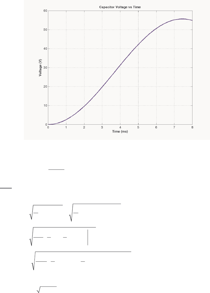
87
It reaches a voltage of 40 V at a time of 4.8 ms. Since the frequency of the waveform is 60 Hz, the
waveform there are 360° in 1/60 s, and the firing angle α is
()
360
4.8 ms 103.7
1/ 60 s
α
°
==°
or 1.810 radians
Note: This problem could also have been solved using Laplace Transforms, if desired.
(b) The rms voltage applied to the load is
/
222
rms
1() sin
M
VvtdtVtdt
T
πω
α
ωω
π
==
/
2
rms
11
sin 2
24
M
V
Vtt
πω
α
ωω
π
=−
()()
−−−=
απαπ
π
2sin2sin
4
1
2
1
2
rms
M
V
V
Since
α
= 1.180 radians, the rms voltage is
rms 0.1753 0.419 71.0 V
MM
VV V===
3-14. Figure P3-9 shows a three-phase full-wave rectifier circuit supplying power to a dc load. The circuit uses
SCRs instead of diodes as the rectifying elements.
(a) What will the load voltage and ripple be if each SCR is triggered as soon as it becomes forward biased?
At what phase angle should the SCRs be triggered in order to operate this way? Sketch or plot the
output voltage for this case.
(b) What will the rms load voltage and ripple be if each SCR is triggered at a phase angle of 90° (that is,
half way through the half-cycle in which it is forward biased)? Sketch or plot the output voltage for
this case.
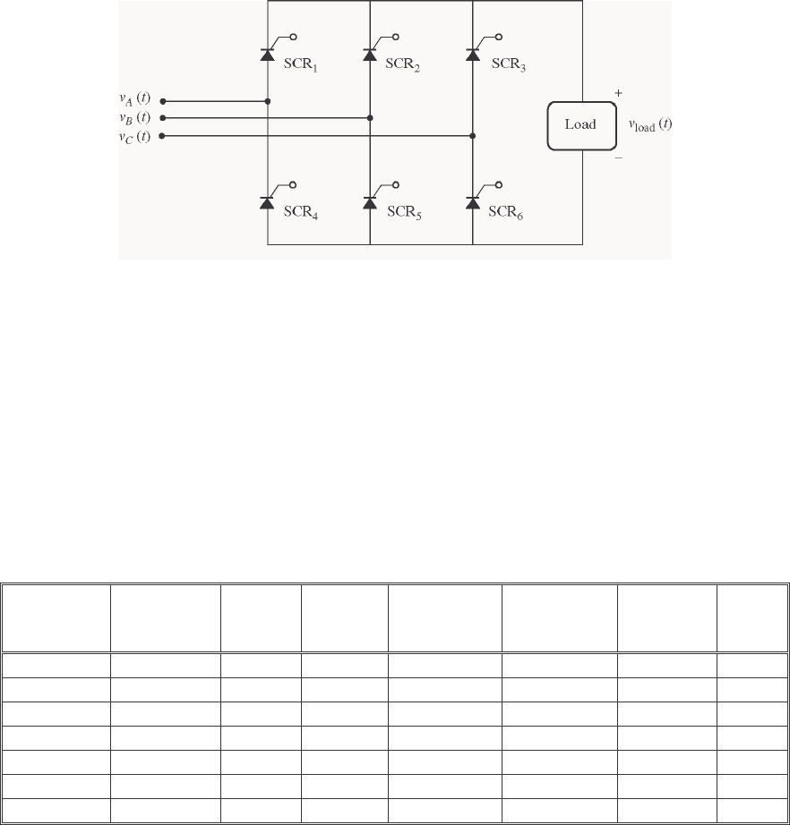
88
S
OLUTION Assume that the three voltages applied to this circuit are:
(
)
sin
AM
vt V t
ω
=
(
)
(
)
sin 2 / 3
BM
vt V t
ωπ
=−
(
)
(
)
sin 2 / 3
CM
vt V t
ωπ
=+
The period of the input waveforms is T, where 2/T
πω
=. For the purpose of the calculations in this
problem, we will assume that
ω
is 377 rad/s (60 Hz).
(a) The when the SCRs start to conduct as soon as they are forward biased, this circuit is just a three-
phase full-wave bridge, and the output voltage is identical to that in Problem 3-2. The sketch of output
voltage is reproduced below, and the ripple is 4.2%. The following table shows which SCRs must conduct
in what order to create the output voltage shown below. The times are expressed as multiples of the period
T of the input waveforms, and the firing angle is in degrees relative to time zero.
Start Time
(
ω
t)
Stop Time
(
ω
t)
Positive
Phase
Negative
Phase
Conducting
SCR
(Positive)
Conducting
SCR
(Negative)
Triggered
SCR
Firing
Angle
12/T− 12/T c b SCR3 SCR5 SCR5 -30°
12/T 12/3T a b SCR1 SCR5 SCR1 30°
12/3T 12/5T a c SCR1 SCR6 SCR6 90°
12/5T 12/7T b c SCR2 SCR6 SCR2 150°
12/7T 12/9T b a SCR2 SCR4 SCR4 210°
12/9T 12/11T c a SCR3 SCR4 SCR3 270°
12/11T 12/T c b SCR3 SCR5 SCR5 330°
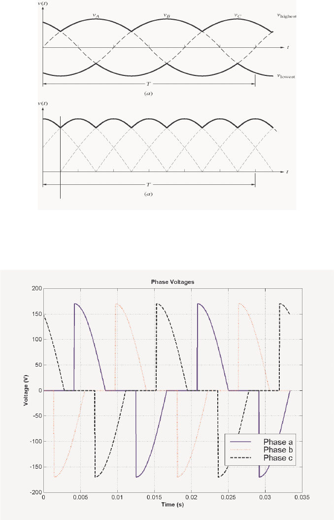
89
T
/12
(b) If each SCR is triggered halfway through the half-cycle during which it is forward biased, the
resulting phase a, b, and c voltages will be zero before the first half of each half-cycle, and the full
sinusoidal value for the second half of each half-cycle. These waveforms are shown below. (These plots
were created by the MATLAB program that appears later in this answer.)
and the resulting output voltage will be:
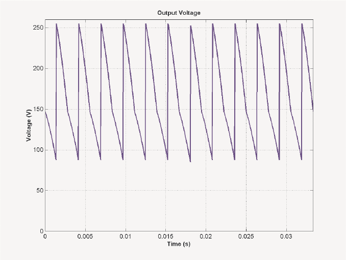
90
A MATLAB program to generate these waveforms and to calculate the ripple on the output waveform is
shown below. The first function biphase_controller.m generates a switched ac waveform. The
inputs to this function are the current phase angle in degrees, the offset angle of the waveform in degrees,
and the firing angle in degrees.
function volts = biphase_controller(wt,theta0,fire)
% Function to simulate the output of an ac phase
% angle controller that operates symmetrically on
% positive and negative half cycles. Assume a peak
% voltage VM = 120 * SQRT(2) = 170 V for convenience.
%
% wt = Current phase in degrees
% theta0 = Starting phase angle in degrees
% fire = Firing angle in degrees
% Degrees to radians conversion factor
deg2rad = pi / 180;
% Remove phase ambiguities: 0 <= wt < 360 deg
ang = wt + theta0;
while ang >= 360
ang = ang - 360;
end
while ang < 0
ang = ang + 360;
end
% Simulate the output of the phase angle controller.
if (ang >= fire & ang <= 180)
volts = 170 * sin(ang * deg2rad);
elseif (ang >= (fire+180) & ang <= 360)
volts = 170 * sin(ang * deg2rad);
else
91
volts = 0;
end
The main program below creates and plots the three-phase waveforms, calculates and plots the output
waveform, and determines the ripple in the output waveform.
% M-file: prob3_14b.m
% M-file to calculate and plot the three phase voltages
% when each SCR in a three-phase full-wave rectifier
% triggers at a phase angle of 90 degrees.
% Calculate the waveforms for times from 0 to 1/30 s
t = (0:1/21600:1/30);
deg = zeros(size(t));
rms = zeros(size(t));
va = zeros(size(t));
vb = zeros(size(t));
vc = zeros(size(t));
out = zeros(size(t));
for ii = 1:length(t)
% Get equivalent angle in degrees. Note that
% 1/60 s = 360 degrees for a 60 Hz waveform!
theta = 21600 * t(ii);
% Calculate the voltage in each phase at each
% angle.
va(ii) = biphase_controller(theta,0,90);
vb(ii) = biphase_controller(theta,-120,90);
vc(ii) = biphase_controller(theta,120,90);
end
% Calculate the output voltage of the rectifier
for ii = 1:length(t)
vals = [ va(ii) vb(ii) vc(ii) ];
out(ii) = max( vals ) - min( vals );
end
% Calculate and display the ripple
disp( ['The ripple is ' num2str(ripple(out))] );
% Plot the voltages versus time
figure(1)
plot(t,va,'b','Linewidth',2.0);
hold on;
plot(t,vb,'r:','Linewidth',2.0);
plot(t,vc,'k--','Linewidth',2.0);
title('\bfPhase Voltages');
xlabel('\bfTime (s)');
ylabel('\bfVoltage (V)');
grid on;
legend('Phase a','Phase b','Phase c');
hold off;
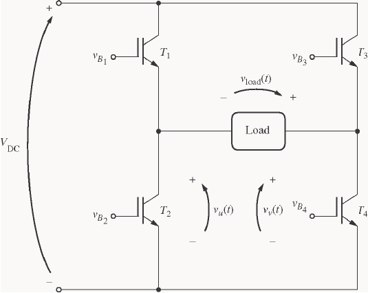
92
% Plot the output voltages versus time
figure(2)
plot(t,out,'b','Linewidth',2.0);
title('\bfOutput Voltage');
xlabel('\bfTime (s)');
ylabel('\bfVoltage (V)');
axis( [0 1/30 0 260]);
grid on;
hold off;
When this program is executed, the results are:
» prob_3_14b
The ripple is 30.9547
3-15. Write a MATLAB program that imitates the operation of the Pulse-Width Modulation circuit shown in
Figure 3-55, and answer the following questions.
(a) Assume that the comparison voltages vt
x()
and vt
y()
have peak amplitudes of 10 V and a frequency
of 500 Hz. Plot the output voltage when the input voltage is vt ft
in () sin=10 2π V, and f = 50 Hz.
(b) What does the spectrum of the output voltage look like? What could be done to reduce the harmonic
content of the output voltage?
(c) Now assume that the frequency of the comparison voltages is increased to 1000 Hz. Plot the output
voltage when the input voltage is vt ft
in () sin=10 2π V, and f = 50 Hz.
(d) What does the spectrum of the output voltage in (c) look like?
(e) What is the advantage of using a higher comparison frequency and more rapid switching in a PWM
modulator?
S
OLUTION The PWM circuit is shown below:
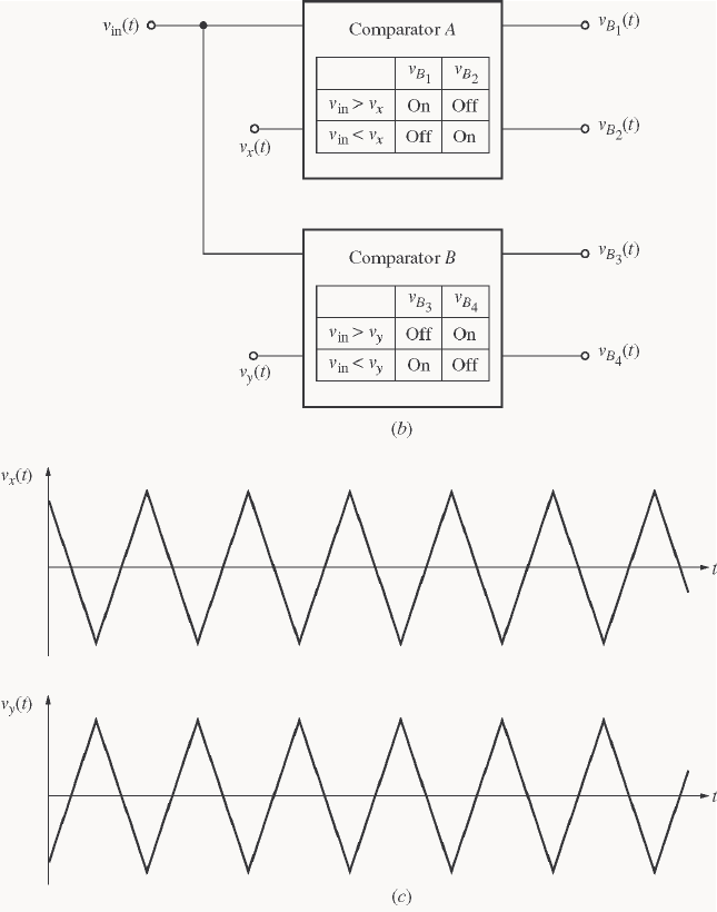
93
(a) To write a MATLAB simulator of this circuit, note that if in
v > x
v, then u
v = DC
V, and if in
v < x
v,
then u
v = 0. Similarly, if in
v > y
v, then v
v = 0, and if in
v < y
v, then v
v = DC
V. The output voltage is
then uv vvv −=
out . A MATLAB function that performs these calculations is shown below. (Note that
this function arbitrarily assumes that DC
V = 100 V. It would be easy to modify the function to use any
arbitrary dc voltage, if desired.)
function [vout,vu,vv] = vout(vin, vx, vy)
% Function to calculate the output voltage of a
% PWM modulator from the values of vin and the
% reference voltages vx and vy. This function
% arbitrarily assumes that VDC = 100 V.
%
% vin = Input voltage
% vx = x reference
% vy = y reference
% vout = Ouput voltage
% vu, vv = Components of output voltage
94
% fire = Firing angle in degrees
% vu
if ( vin > vx )
vu = 100;
else
vu = 0;
end
% vv
if ( vin >= vy )
vv = 0;
else
vv = 100;
end
% Caclulate vout
vout = vv - vu;
Now we need a MATLAB program to generate the input voltage
()
tvin and the reference voltages
()
tvx
and
()
tvy. After the voltages are generated, function vout will be used to calculate
()
tvout and the
frequency spectrum of
()
tvout . Finally, the program will plot
()
tvin ,
()
tvx and
()
tv y,
()
tvout , and the
spectrum of
()
tvout . (Note that in order to have a valid spectrum, we need to create several cycles of the
60 Hz output waveform, and we need to sample the data at a fairly high frequency. This problem creates 4
cycles of
()
tvout and samples all data at a 20,000 Hz rate.)
% M-file: prob3_15a.m
% M-file to calculate the output voltage from a PWM
% modulator with a 500 Hz reference frequency. Note
% that the only change between this program and that
% of part b is the frequency of the reference "fr".
% Sample the data at 20000 Hz to get enough information
% for spectral analysis. Declare arrays.
fs = 20000; % Sampling frequency (Hz)
t = (0:1/fs:4/15); % Time in seconds
vx = zeros(size(t)); % vx
vy = zeros(size(t)); % vy
vin = zeros(size(t)); % Driving signal
vu = zeros(size(t)); % vx
vv = zeros(size(t)); % vy
vout = zeros(size(t)); % Output signal
fr = 500; % Frequency of reference signal
T = 1/fr; % Period of refernce signal
% Calculate vx at fr = 500 Hz.
for ii = 1:length(t)
vx(ii) = vref(t(ii),T);
vy(ii) = - vx(ii);
end
% Calculate vin as a 50 Hz sine wave with a peak voltage of
95
% 10 V.
for ii = 1:length(t)
vin(ii) = 10 * sin(2*pi*50*t(ii));
end
% Now calculate vout
for ii = 1:length(t)
[vout(ii) vu(ii) vv(ii)] = vout(vin(ii), vx(ii), vy(ii));
end
% Plot the reference voltages vs time
figure(1)
plot(t,vx,'b','Linewidth',1.0);
hold on;
plot(t,vy,'k--','Linewidth',1.0);
title('\bfReference Voltages for fr = 500 Hz');
xlabel('\bfTime (s)');
ylabel('\bfVoltage (V)');
legend('vx','vy');
axis( [0 1/30 -10 10]);
hold off;
% Plot the input voltage vs time
figure(2)
plot(t,vin,'b','Linewidth',1.0);
title('\bfInput Voltage');
xlabel('\bfTime (s)');
ylabel('\bfVoltage (V)');
axis( [0 1/30 -10 10]);
% Plot the output voltages versus time
figure(3)
plot(t,vout,'b','Linewidth',1.0);
title('\bfOutput Voltage for fr = 500 Hz');
xlabel('\bfTime (s)');
ylabel('\bfVoltage (V)');
axis( [0 1/30 -120 120]);
% Now calculate the spectrum of the output voltage
spec = fft(vout);
% Calculate sampling frequency labels
len = length(t);
df = fs / len;
fstep = zeros(size(t));
for ii = 2:len/2
fstep(ii) = df * (ii-1);
fstep(len-ii+2) = -fstep(ii);
end
% Plot the spectrum
figure(4);
plot(fftshift(fstep),fftshift(abs(spec)));
title('\bfSpectrum of Output Voltage for fr = 500 Hz');
xlabel('\bfFrequency (Hz)');
ylabel('\bfAmplitude');
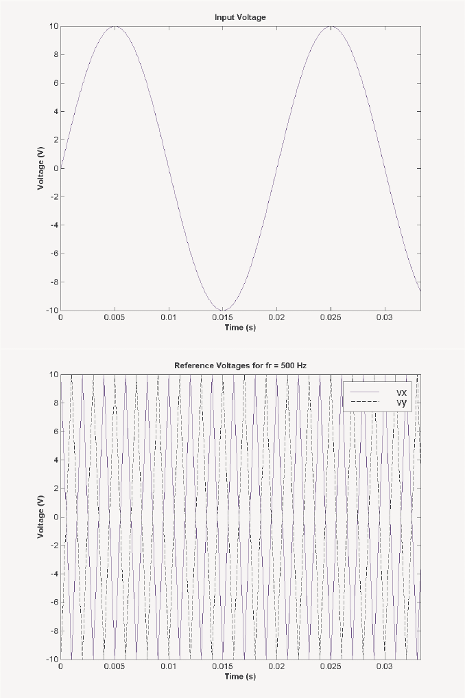
96
% Plot a closeup of the near spectrum
% (positive side only)
figure(5);
plot(fftshift(fstep),fftshift(abs(spec)));
title('\bfSpectrum of Output Voltage for fr = 500 Hz');
xlabel('\bfFrequency (Hz)');
ylabel('\bfAmplitude');
set(gca,'Xlim',[0 1000]);
When this program is executed, the input, reference, and output voltages are:
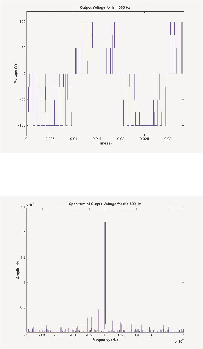
97
(b) The output spectrum of this PWM modulator is shown below. There are two plots here, one showing
the entire spectrum, and the other one showing the close-in frequencies (those under 1000 Hz), which will
have the most effect on machinery. Note that there is a sharp peak at 50 Hz, which is there desired
frequency, but there are also strong contaminating signals at about 850 Hz and 950 Hz. If necessary, these
components could be filtered out using a low-pass filter.
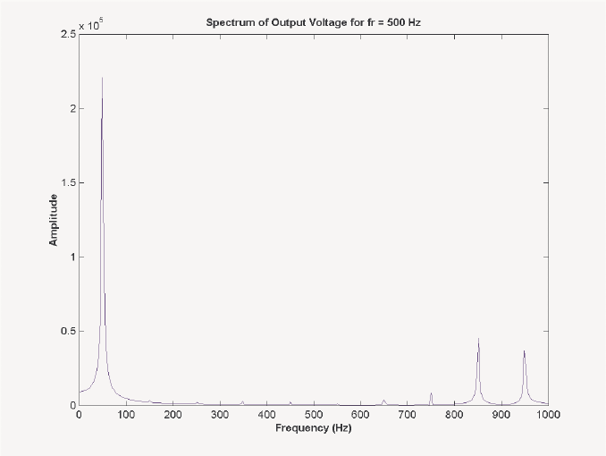
98
(c) A version of the program with 1000 Hz reference functions is shown below:
% M-file: prob3_15b.m
% M-file to calculate the output voltage from a PWM
% modulator with a 1000 Hz reference frequency. Note
% that the only change between this program and that
% of part a is the frequency of the reference "fr".
% Sample the data at 20000 Hz to get enough information
% for spectral analysis. Declare arrays.
fs = 20000; % Sampling frequency (Hz)
t = (0:1/fs:4/15); % Time in seconds
vx = zeros(size(t)); % vx
vy = zeros(size(t)); % vy
vin = zeros(size(t)); % Driving signal
vu = zeros(size(t)); % vx
vv = zeros(size(t)); % vy
vout = zeros(size(t)); % Output signal
fr = 1000; % Frequency of reference signal
T = 1/fr; % Period of refernce signal
% Calculate vx at 1000 Hz.
for ii = 1:length(t)
vx(ii) = vref(t(ii),T);
vy(ii) = - vx(ii);
end
% Calculate vin as a 50 Hz sine wave with a peak voltage of
% 10 V.
for ii = 1:length(t)
vin(ii) = 10 * sin(2*pi*50*t(ii));
end
99
% Now calculate vout
for ii = 1:length(t)
[vout(ii) vu(ii) vv(ii)] = vout(vin(ii), vx(ii), vy(ii));
end
% Plot the reference voltages vs time
figure(1)
plot(t,vx,'b','Linewidth',1.0);
hold on;
plot(t,vy,'k--','Linewidth',1.0);
title('\bfReference Voltages for fr = 1000 Hz');
xlabel('\bfTime (s)');
ylabel('\bfVoltage (V)');
legend('vx','vy');
axis( [0 1/30 -10 10]);
hold off;
% Plot the input voltage vs time
figure(2)
plot(t,vin,'b','Linewidth',1.0);
title('\bfInput Voltage');
xlabel('\bfTime (s)');
ylabel('\bfVoltage (V)');
axis( [0 1/30 -10 10]);
% Plot the output voltages versus time
figure(3)
plot(t,vout,'b','Linewidth',1.0);
title('\bfOutput Voltage for fr = 1000 Hz');
xlabel('\bfTime (s)');
ylabel('\bfVoltage (V)');
axis( [0 1/30 -120 120]);
% Now calculate the spectrum of the output voltage
spec = fft(vout);
% Calculate sampling frequency labels
len = length(t);
df = fs / len;
fstep = zeros(size(t));
for ii = 2:len/2
fstep(ii) = df * (ii-1);
fstep(len-ii+2) = -fstep(ii);
end
% Plot the spectrum
figure(4);
plot(fftshift(fstep),fftshift(abs(spec)));
title('\bfSpectrum of Output Voltage for fr = 1000 Hz');
xlabel('\bfFrequency (Hz)');
ylabel('\bfAmplitude');
% Plot a closeup of the near spectrum
% (positive side only)
figure(5);
plot(fftshift(fstep),fftshift(abs(spec)));
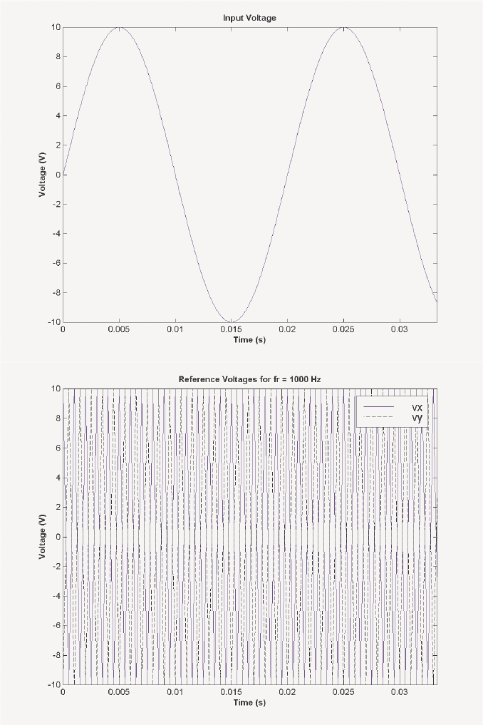
100
title('\bfSpectrum of Output Voltage for fr = 1000 Hz');
xlabel('\bfFrequency (Hz)');
ylabel('\bfAmplitude');
set(gca,'Xlim',[0 1000]);
When this program is executed, the input, reference, and output voltages are:
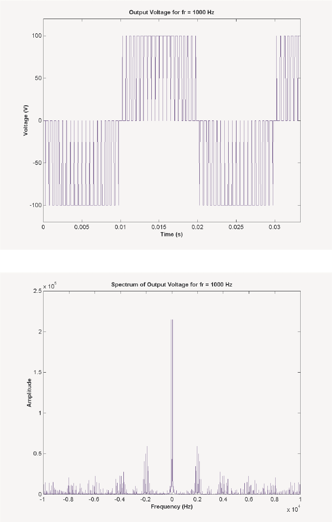
101
(d) The output spectrum of this PWM modulator is shown below.
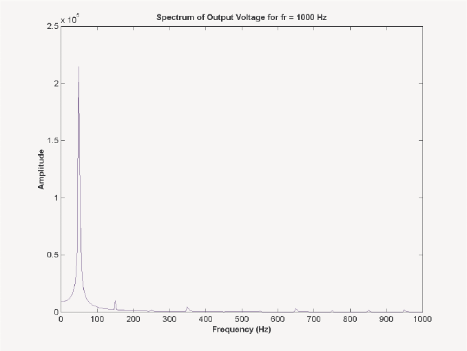
102
(e) Comparing the spectra in (b) and (d), we can see that the frequencies of the first large sidelobes
doubled from about 900 Hz to about 1800 Hz when the reference frequency was doubled. This increase in
sidelobe frequency has two major advantages: it makes the harmonics easier to filter, and it also makes it
less necessary to filter them at all. Since large machines have their own internal inductances, they form
natural low-pass filters. If the contaminating sidelobes are at high enough frequencies, they will never
affect the operation of the machine. Thus, it is a good idea to design PWM modulators with a high
frequency reference signal and rapid switching.
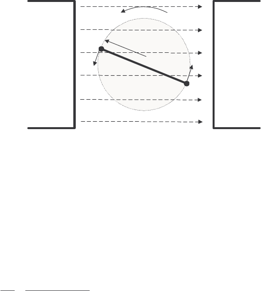
103
Chapter 4: AC Machinery Fundamentals
4-1. The simple loop is rotating in a uniform magnetic field shown in Figure 4-1 has the following
characteristics:
B=05. T to the right
r
=01.m
l=05. m
ω
= 103 rad/s
(a) Calculate the voltage et
tot ()induced in this rotating loop.
(b) Suppose that a 5 Ω resistor is connected as a load across the terminals of the loop. Calculate the
current that would flow through the resistor.
(c) Calculate the magnitude and direction of the induced torque on the loop for the conditions in (b).
(d) Calculate the electric power being generated by the loop for the conditions in (b).
(e) Calculate the mechanical power being consumed by the loop for the conditions in (b). How does
this number compare to the amount of electric power being generated by the loop?
ω
m
r
v
ab
v
cd
B
NS
B
is a uniform magnetic
field, aligned as shown.
a
b
c
d
S
OLUTION
(a) The induced voltage on a simple rotating loop is given by
(
)
ind 2 sin et rBl t
ω
=ω (4-8)
() ( )( )( )( )
ind 2 0.1 m 103 rad/s 0.5 T 0.5 m sin103et t=
()
ind 5.15 sin103 Vet t=
(b) If a 5 Ω resistor is connected as a load across the terminals of the loop, the current flow would be:
()
ind 5.15 sin 103 V 1.03 sin 103 A
5
et
it t
R
== =
Ω
(c) The induced torque would be:
()
ind 2 sin trilΒ
τθ
= (4-17)
() ( )( )( )( )
ind 2 0.1 m 1.03 sin A 0.5 m 0.5 T sin tt t
τωω
=
()
2
ind 0.0515 sin N m, counterclockwisett
τω
=⋅
(d) The instantaneous power generated by the loop is:

104
() ( )( )
2
ind 5.15 sin V 1.03 sin A 5.30 sin WPt e i t t t
ωω ω
== =
The average power generated by the loop is
2
ave
15.30 sin 2.65 W
T
Ptdt
T
ω
==
(e) The mechanical power being consumed by the loop is:
()
()
22
ind 0.0515 sin V 103 rad/s 5.30 sin WPt t
τω ω ω
== =
Note that the amount of mechanical power consumed by the loop is equal to the amount of electrical power
created by the loop. This machine is acting as a generator, converting mechanical power into electrical
power.
4-2. Develop a table showing the speed of magnetic field rotation in ac machines of 2, 4, 6, 8, 10, 12, and 14
poles operating at frequencies of 50, 60, and 400 Hz.
S
OLUTION The equation relating the speed of magnetic field rotation to the number of poles and electrical
frequency is
120 e
m
f
nP
=
The resulting table is
Number of Poles e
f = 50 Hz e
f = 60 Hz e
f = 400 Hz
2 3000 r/min 3600 r/min 24000 r/min
4 1500 r/min 1800 r/min 12000 r/min
6 1000 r/min 1200 r/min 8000 r/min
8 750 r/min 900 r/min 6000 r/min
10 600 r/min 720 r/min 4800 r/min
12 500 r/min 600 r/min 4000 r/min
14 428.6 r/min 514.3 r/min 3429 r/min
4-3. A three-phase four-pole winding is installed in 12 slots on a stator. There are 40 turns of wire in each slot
of the windings. All coils in each phase are connected in series, and the three phases are connected in ∆.
The flux per pole in the machine is 0.060 Wb, and the speed of rotation of the magnetic field is 1800 r/min.
(a) What is the frequency of the voltage produced in this winding?
(b) What are the resulting phase and terminal voltages of this stator?
S
OLUTION
(a) The frequency of the voltage produced in this winding is
()()
1800 r/min 4 poles 60 Hz
120 120
m
e
nP
f== =
(b) There are 12 slots on this stator, with 40 turns of wire per slot. Since this is a four-pole machine,
there are two sets of coils (4 slots) associated with each phase. The voltage in the coils in one pair of slots
is
()( )( )
2 2 40 t 0.060 Wb 60 Hz 640 V
AC
ENf
πφ π
== =
There are two sets of coils per phase, since this is a four-pole machine, and they are connected in series, so
the total phase voltage is
105
(
)
2 640 V 1280 VV
φ
==
Since the machine is ∆-connected, 1280 V
L
VV
φ
== .
4-4. A three-phase Y-connected 50-Hz two-pole synchronous machine has a stator with 2000 turns of wire per
phase. What rotor flux would be required to produce a terminal (line-to-line) voltage of 6 kV?
S
OLUTION The phase voltage of this machine should be
/
33464 V
L
VV
φ
== . The induced voltage per
phase in this machine (which is equal to
φ
V at no-load conditions) is given by the equation
2
AC
ENf
πφ
=
so
()()
3464 V 0.0078 Wb
2 2 2000 t 50 Hz
A
C
E
Nf
φππ
== =
4-5. Modify the MATLAB program in Example 4-1 by swapping the currents flowing in any two phases. What
happens to the resulting net magnetic field?
S
OLUTION This modification is very simple—just swap the currents supplied to two of the three phases.
% M-file: mag_field2.m
% M-file to calculate the net magetic field produced
% by a three-phase stator.
% Set up the basic conditions
bmax = 1; % Normalize bmax to 1
freq = 60; % 60 Hz
w = 2*pi*freq; % angluar velocity (rad/s)
% First, generate the three component magnetic fields
t = 0:1/6000:1/60;
Baa = sin(w*t) .* (cos(0) + j*sin(0));
Bbb = sin(w*t+2*pi/3) .* (cos(2*pi/3) + j*sin(2*pi/3));
Bcc = sin(w*t-2*pi/3) .* (cos(-2*pi/3) + j*sin(-2*pi/3));
% Calculate Bnet
Bnet = Baa + Bbb + Bcc;
% Calculate a circle representing the expected maximum
% value of Bnet
circle = 1.5 * (cos(w*t) + j*sin(w*t));
% Plot the magnitude and direction of the resulting magnetic
% fields. Note that Baa is black, Bbb is blue, Bcc is
% magneta, and Bnet is red.
for ii = 1:length(t)
% Plot the reference circle
plot(circle,'k');
hold on;
% Plot the four magnetic fields
plot([0 real(Baa(ii))],[0 imag(Baa(ii))],'k','LineWidth',2);
plot([0 real(Bbb(ii))],[0 imag(Bbb(ii))],'b','LineWidth',2);
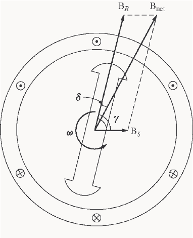
106
plot([0 real(Bcc(ii))],[0 imag(Bcc(ii))],'m','LineWidth',2);
plot([0 real(Bnet(ii))],[0 imag(Bnet(ii))],'r','LineWidth',3);
axis square;
axis([-2 2 -2 2]);
drawnow;
hold off;
end
When this program executes, the net magnetic field rotates clockwise, instead of counterclockwise.
4-6. If an ac machine has the rotor and stator magnetic fields shown in Figure P4-1, what is the direction of the
induced torque in the machine? Is the machine acting as a motor or generator?
S
OLUTION Since ind netR
k=×τBB
, the induced torque is clockwise, opposite the direction of motion. The
machine is acting as a generator.
4-7. The flux density distribution over the surface of a two-pole stator of radius r and length l is given by
()
cos
Mm
BB t=ω−α (4-37b)
Prove that the total flux under each pole face is
2M
rlB
φ
=
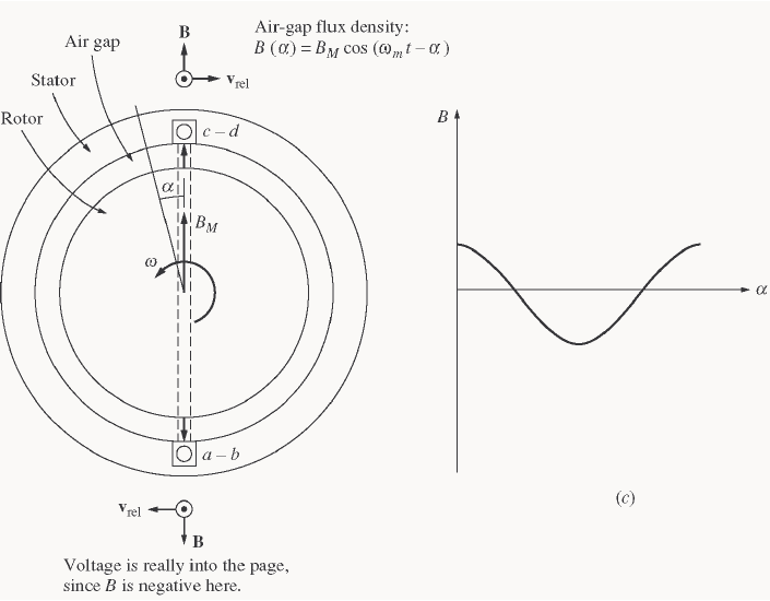
107
S
OLUTION The total flux under a pole face is given by the equation
d
φ
=⋅
BA
Under a pole face, the flux density B is always parallel to the vector dA, since the flux density is always
perpendicular to the surface of the rotor and stator in the air gap. Therefore,
BdA
φ
=
A differential area on the surface of a cylinder is given by the differential length along the cylinder (dl)
times the differential width around the radius of the cylinder (
θ
rd ).
()( )
dA dl rd
θ
= where r is the radius of the cylinder
Therefore, the flux under the pole face is
Bdl rd
φ
θ
=
Since r is constant and B is constant with respect to l, this equation reduces to
rl B d
φ
θ
=
Now,
()
cos cos
MM
BB t B
ωα θ
=−= (when we substitute t
θω α
=−), so
rl B d
φ
θ
=
[]
()
/2
/2
/2 /2
cos sin 1 1
MM M
rl B d rlB rlB
π
π
ππ
φθθθ
−−
===
2
M
rlB
φ
=

108
4-8. In the early days of ac motor development, machine designers had great difficulty controlling the core losses
(hysteresis and eddy currents) in machines. They had not yet developed steels with low hysteresis, and
were not making laminations as thin as the ones used today. To help control these losses, early ac motors
in the USA were run from a 25 Hz ac power supply, while lighting systems were run from a separate 60 Hz
ac power supply.
(a) Develop a table showing the speed of magnetic field rotation in ac machines of 2, 4, 6, 8, 10, 12, and
14 poles operating at 25 Hz. What was the fastest rotational speed available to these early motors?
(b) For a given motor operating at a constant flux density B, how would the core losses of the motor
running at 25 Hz compare to the core losses of the motor running at 60 Hz?
(c) Why did the early engineers provide a separate 60 Hz power system for lighting?
S
OLUTION
(a) The equation relating the speed of magnetic field rotation to the number of poles and electrical
frequency is
120 e
m
f
nP
=
The resulting table is
Number of Poles e
f = 25 Hz
2 1500 r/min
4 750 r/min
6 500 r/min
8 375 r/min
10 300 r/min
12 250 r/min
14 214.3 r/min
The highest possible rotational speed was 1500 r/min.
(b) Core losses scale according to the 1.5th power of the speed of rotation, so the ratio of the core losses
at 25 Hz to the core losses at 60 Hz (for a given machine) would be:
1.5
1500
ratio 0.269
3600
==
or 26.9%
(c) At 25 Hz, the light from incandescent lamps would visibly flicker in a very annoying way.

109
Chapter 5: Synchronous Generators
5-1. At a location in Europe, it is necessary to supply 300 kW of 60-Hz power. The only power sources
available operate at 50 Hz. It is decided to generate the power by means of a motor-generator set
consisting of a synchronous motor driving a synchronous generator. How many poles should each of the
two machines have in order to convert 50-Hz power to 60-Hz power?
S
OLUTION The speed of a synchronous machine is related to its frequency by the equation
120 e
m
f
nP
=
To make a 50 Hz and a 60 Hz machine have the same mechanical speed so that they can be coupled
together, we see that
()()
sync
12
120 50 Hz 120 60 Hz
nPP
==
2
1
612
510
P
P==
Therefore, a 10-pole synchronous motor must be coupled to a 12-pole synchronous generator to accomplish
this frequency conversion.
5-2. A 2300-V 1000-kVA 0.8-PF-lagging 60-Hz two-pole Y-connected synchronous generator has a
synchronous reactance of 1.1 Ω and an armature resistance of 0.15 Ω. At 60 Hz, its friction and windage
losses are 24 kW, and its core losses are 18 kW. The field circuit has a dc voltage of 200 V, and the
maximum IF is 10 A. The resistance of the field circuit is adjustable over the range from 20 to 200 Ω.
The OCC of this generator is shown in Figure P5-1.
(a) How much field current is required to make VT equal to 2300 V when the generator is running at no
load?
(b) What is the internal generated voltage of this machine at rated conditions?
(c) How much field current is required to make VT equal to 2300 V when the generator is running at rated
conditions?
(d) How much power and torque must the generator’s prime mover be capable of supplying?
(e) Construct a capability curve for this generator.
Note: An electronic version of this open circuit characteristic can be found in file
p51_occ.dat, which can be used with MATLAB programs. Column 1
contains field current in amps, and column 2 contains open-circuit terminal
voltage in volts.
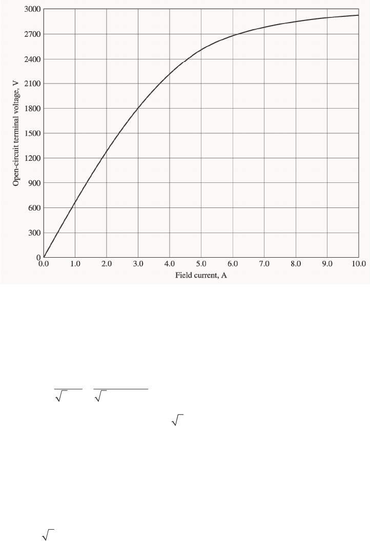
110
S
OLUTION
(a) If the no-load terminal voltage is 2300 V, the required field current can be read directly from the
open-circuit characteristic. It is 4.25 A.
(b) This generator is Y-connected, so AL II =. At rated conditions, the line and phase current in this
generator is
()
1000 kVA 251 A
3 3 2300 V
AL
L
P
II V
== = = at an angle of –36.87°
The phase voltage of this machine is
/
31328 V
T
VV
φ
==. The internal generated voltage of the machine
is
AAASA
RjX
φ
=+ +EV I I
()()()()
1328 0 0.15 251 36.87 A 1.1 251 36.87 A
Aj=∠°+ Ω∠− °+ Ω∠− °E
1537 7.4 V
A=∠°E
(c) The equivalent open-circuit terminal voltage corresponding to an A
E of 1537 volts is
()
,oc 3 1527 V 2662 V
T
V==
From the OCC, the required field current is 5.9 A.
(d) The input power to this generator is equal to the output power plus losses. The rated output power is
()()
OUT 1000 kVA 0.8 800 kWP==
(
)
(
)
2
2
CU 3 3 251 A 0.15 28.4 kW
AA
PIR== Ω=
F&W 24 kWP=

111
core 18 kWP=
stray (assumed 0)P=
IN OUT CU F&W core stray 870.4 kWPP PP P P=++++=
Therefore the prime mover must be capable of supplying 175 kW. Since the generator is a two-pole 60 Hz
machine, to must be turning at 3600 r/min. The required torque is
()
mN 465
r 1
rad 2
s 60
min 1
r/min 3600
kW 2.175
IN
APP ⋅=
==
π
ω
τ
m
P
(e) The rotor current limit of the capability curve would be drawn from an origin of
()
2
2
33 1328 V 4810 kVAR
1.1
S
V
QX
φ
=− =− =−
Ω
The radius of the rotor current limit is
()()
33 1328 V 1537 V 5567 kVA
1.1
A
E
S
VE
DX
φ
== =
Ω
The stator current limit is a circle at the origin of radius
(
)
(
)
3 3 1328 V 251 A 1000 kVA
A
SVI
φ
== =
A MATLAB program that plots this capability diagram is shown below:
% M-file: prob5_2.m
% M-file to display a capability curve for a
% synchronous generator.
% Calculate the waveforms for times from 0 to 1/30 s
Q = -4810;
DE = 5567;
S = 1000;
% Get points for stator current limit
theta = -95:1:95; % Angle in degrees
rad = theta * pi / 180; % Angle in radians
s_curve = S .* ( cos(rad) + j*sin(rad) );
% Get points for rotor current limit
orig = j*Q;
theta = 75:1:105; % Angle in degrees
rad = theta * pi / 180; % Angle in radians
r_curve = orig + DE .* ( cos(rad) + j*sin(rad) );
% Plot the capability diagram
figure(1);
plot(real(s_curve),imag(s_curve),'b','LineWidth',2.0);
hold on;
plot(real(r_curve),imag(r_curve),'r--','LineWidth',2.0);
% Add x and y axes
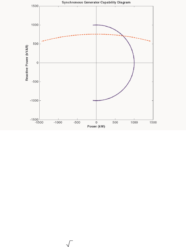
112
plot( [-1500 1500],[0 0],'k');
plot( [0,0],[-1500 1500],'k');
% Set titles and axes
title ('\bfSynchronous Generator Capability Diagram');
xlabel('\bfPower (kW)');
ylabel('\bfReactive Power (kVAR)');
axis( [ -1500 1500 -1500 1500] );
axis square;
hold off;
The resulting capability diagram is shown below:
5-3. Assume that the field current of the generator in Problem 5-2 has been adjusted to a value of 4.5 A.
(a) What will the terminal voltage of this generator be if it is connected to a ∆-connected load with an
impedance of 20 30 ∠°Ω
?
(b) Sketch the phasor diagram of this generator.
(c) What is the efficiency of the generator at these conditions?
(d) Now assume that another identical ∆-connected load is to be paralleled with the first one. What
happens to the phasor diagram for the generator?
(e) What is the new terminal voltage after the load has been added?
(f) What must be done to restore the terminal voltage to its original value?
S
OLUTION
(a) If the field current is 4.5 A, the open-circuit terminal voltage will be about 2385 V, and the phase
voltage in the generator will be 2385 / 3 1377 V=.
The load is ∆-connected with three impedances of 20 30 ∠°Ω. From the Y-∆ transform, this load is
equivalent to a Y-connected load with three impedances of 6.667 30 ∠°Ω
. The resulting per-phase
equivalent circuit is shown below:
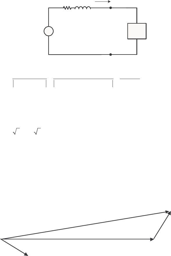
113
+
-
EA
0.15 Ωj1.1 Ω
6.667∠30°Z
+
-
V
φ
IA
The magnitude of the phase current flowing in this generator is
1377 V 1377 V 186 A
0.15 1.1 6.667 30 1.829
A
A
AS
E
IRjXZ j
== ==
++ ++ ∠° Ω
Therefore, the magnitude of the phase voltage is
()( )
186 A 6.667 1240 V
A
VIZ
φ
== Ω=
and the terminal voltage is
()
3 3 1240 V 2148 V
T
VV
φ
== =
(b) Armature current is 186 30 A
A=∠−°I, and the phase voltage is 1240 0 V
φ
=∠°V. Therefore, the
internal generated voltage is
AAASA
RjX
φ
=+ +EV I I
(
)
(
)
(
)
(
)
1240 0 0.15 186 30 A 1.1 186 30 A
Aj=∠°+ Ω∠−°+ Ω∠−°E
1377 6.8 V
A=∠°E
The resulting phasor diagram is shown below (not to scale):
I
= 186
∠
-30°
A
V
= 1240
∠
0° V
φ
E
= 1377
∠
6.8° V
A
θ
(c) The efficiency of the generator under these conditions 3can be found as follows:
(
)
(
)
(
)
OUT 3 cos 3 1240 V 186 A 0.8 554 kW
A
PVI
φ
θ
== =
()( )
2
2
CU 3 3 186 A 0.15 15.6 kW
AA
PIR== Ω=
F&W 24 kWP=
core 18 kWP=
stray (assumed 0)P=
IN OUT CU F&W core stray 612 kWPP PP P P=++++=
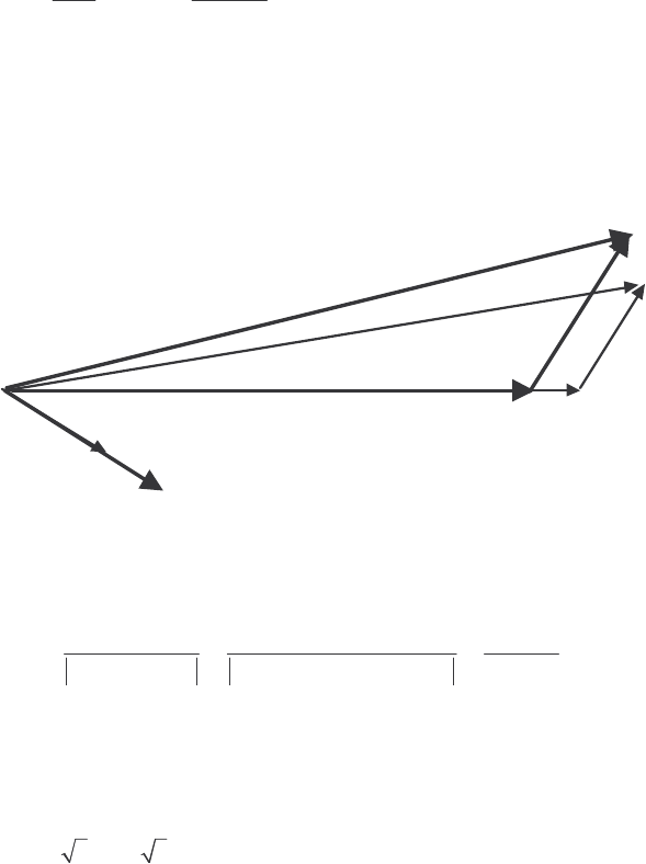
114
OUT
IN
554 kW
100% 100% 90.5%
612 kW
P
P
η
=× = × =
(d) When the new load is added, the total current flow increases at the same phase angle. Therefore,
SS
jX I increases in length at the same angle, while the magnitude of A
E must remain constant. Therefore,
A
E “swings” out along the arc of constant magnitude until the new SS
jX I fits exactly between
φ
V and
A
E.
I
= 186
∠
-30°
A
V
= 1240
∠
0° V
φ
θ
E
′
A
V
′
φ
I
′
A
E
= 1377
∠
6.8° V
A
(e) The new impedance per phase will be half of the old value, so 3.333 30 Z=∠°Ω. The magnitude of
the phase current flowing in this generator is
1377 V 1377 V 335 A
0.15 1.1 3.333 30 1.829
A
A
AS
E
IRjXZ j
== ==
++ ++ ∠°Ω
Therefore, the magnitude of the phase voltage is
()( )
335 A 3.333 1117 V
A
VIZ
φ
== Ω=
and the terminal voltage is
()
3 3 1117 V 1934 V
T
VV
φ
== =
(f) To restore the terminal voltage to its original value, increase the field current F
I.
5-4. Assume that the field current of the generator in Problem 5-2 is adjusted to achieve rated voltage (2300 V)
at full load conditions in each of the questions below.
(a) What is the efficiency of the generator at rated load?
(b) What is the voltage regulation of the generator if it is loaded to rated kilovoltamperes with 0.8-PF-
lagging loads?
(c) What is the voltage regulation of the generator if it is loaded to rated kilovoltamperes with 0.8-PF-
leading loads?
(d) What is the voltage regulation of the generator if it is loaded to rated kilovoltamperes with unity-power-
factor loads?
(e) Use MATLAB to plot the terminal voltage of the generator as a function of load for all three power
factors.
S
OLUTION

115
(a) This generator is Y-connected, so LA
II=. At rated conditions, the line and phase current in this
generator is
()
1000 kVA 251 A
3 3 2300 V
AL
L
P
II V
== = = at an angle of –36.87°
The phase voltage of this machine is
/
31328 V
T
VV
φ
==. The internal generated voltage of the machine
is
AAASA
RjX
φ
=+ +EV I I
(
)
(
)
(
)
(
)
1328 0 0.15 251 36.87 A 1.1 251 36.87 A
Aj=∠°+ Ω∠− °+ Ω∠− °E
1537 7.4 V
A=∠°E
The input power to this generator is equal to the output power plus losses. The rated output power is
()()
OUT 1000 kVA 0.8 800 kWP==
()( )
2
2
CU 3 3 251 A 0.15 28.4 kW
AA
PIR== Ω=
F&W 24 kWP=
core 18 kWP=
stray (assumed 0)P=
IN OUT CU F&W core stray 870.4 kWPP PP P P=++++=
OUT
IN
800 kW
100% 100% 91.9%
870.4 kW
P
P
η=× = × =
(b) If the generator is loaded to rated kVA with lagging loads, the phase voltage is 1328 0 V
φ=∠°Vand
the internal generated voltage is 1537 7.4 V
A
E=∠°. Therefore, the phase voltage at no-load would be
1537 0 VV
φ
=∠°. The voltage regulation would be:
1537 1328
VR 100% 15.7%
1328
−
=×=
(c) If the generator is loaded to rated kVA with leading loads, the phase voltage is 1328 0 V
φ=∠°Vand
the internal generated voltage is
AAASA
RjX
φ
=+ +EV I I
()( )()( )
1328 0 0.15 251 36.87 A 1.1 251 36.87 A
AjE=∠°+ Ω∠°+ Ω∠°
1217 11.5 V
A
E=∠°
The voltage regulation would be:
1217 1328
VR 100% 8.4%
1328
−
=×=−
(d) If the generator is loaded to rated kVA at unity power factor, the phase voltage is
1328 0 V
φ=∠°Vand the internal generated voltage is
AAASA
RjX
φ
=+ +EV I I
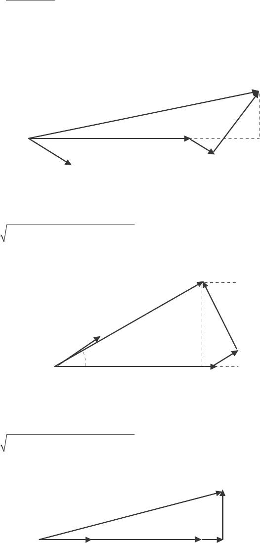
116
()()()()
1328 0 0.15 251 0 A 1.1 251 0 A
AjE=∠°+ Ω∠°+ Ω∠°
1393 11.4 V
A
E=∠°
The voltage regulation would be:
1393 1328
VR 100% 4.9%
1328
−
=×=
(e) For this problem, we will assume that the terminal voltage is adjusted to 2300 V at no load
conditions, and see what happens to the voltage as load increases at 0.8 lagging, unity, and 0.8 leading
power factors. Note that the maximum current will be 251 A in any case. A phasor diagram representing
the situation at lagging power factor is shown below:
I
A
V
φ
E
A
θ
δθ
θ
I
A
R
A
jX
S
I
A
By the Pythagorean Theorem,
()
()
22
2cos sin cos sin
AAASA SAAS
E V RI XI XI RI
φ
θθ θθ
=+ + + −
()
2
2cos sin cos sin
ASA AS AA SA
VEXI RI RI XI
φ
θθ θ θ
=− − − −
A phasor diagram representing the situation at leading power factor is shown below:
I
A
V
φ
E
A
θ
δθ
θ
I
A
R
A
jX
S
I
A
By the Pythagorean Theorem,
()
()
22
2cos sin cos sin
AAASA SAAS
E V RI XI XI RI
φ
θθ θθ
=+ − + +
()
2
2cos sin cos sin
ASA AS AA SA
VEXI RI RI XI
φ
θθ θ θ
=− + − +
A phasor diagram representing the situation at unity power factor is shown below:
I
A
V
φ
E
A
δ
I
A
R
A
jX
S
I
A
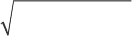
117
By the Pythagorean Theorem,
(
)
2
22
ASA
EV XI
φ
=+
()
2
2
ASA
VEXI
φ
=−
The MATLAB program is shown below takes advantage of this fact.
% M-file: prob5_4e.m
% M-file to calculate and plot the terminal voltage
% of a synchronous generator as a function of load
% for power factors of 0.8 lagging, 1.0, and 0.8 leading.
% Define values for this generator
EA = 1328; % Internal gen voltage
I = 0:2.51:251; % Current values (A)
R = 0.15; % R (ohms)
X = 1.10; % XS (ohms)
% Calculate the voltage for the lagging PF case
VP_lag = sqrt( EA^2 - (X.*I.*0.8 - R.*I.*0.6).^2 ) ...
- R.*I.*0.8 - X.*I.*0.6;
VT_lag = VP_lag .* sqrt(3);
% Calculate the voltage for the leading PF case
VP_lead = sqrt( EA^2 - (X.*I.*0.8 + R.*I.*0.6).^2 ) ...
- R.*I.*0.8 + X.*I.*0.6;
VT_lead = VP_lead .* sqrt(3);
% Calculate the voltage for the unity PF case
VP_unity = sqrt( EA^2 - (X.*I).^2 );
VT_unity = VP_unity .* sqrt(3);
% Plot the terminal voltage versus load
plot(I,abs(VT_lag),'b-','LineWidth',2.0);
hold on;
plot(I,abs(VT_unity),'k--','LineWidth',2.0);
plot(I,abs(VT_lead),'r-.','LineWidth',2.0);
title ('\bfTerminal Voltage Versus Load');
xlabel ('\bfLoad (A)');
ylabel ('\bfTerminal Voltage (V)');
legend('0.8 PF lagging','1.0 PF','0.8 PF leading');
axis([0 260 1500 2500]);
grid on;
hold off;
The resulting plot is shown below:
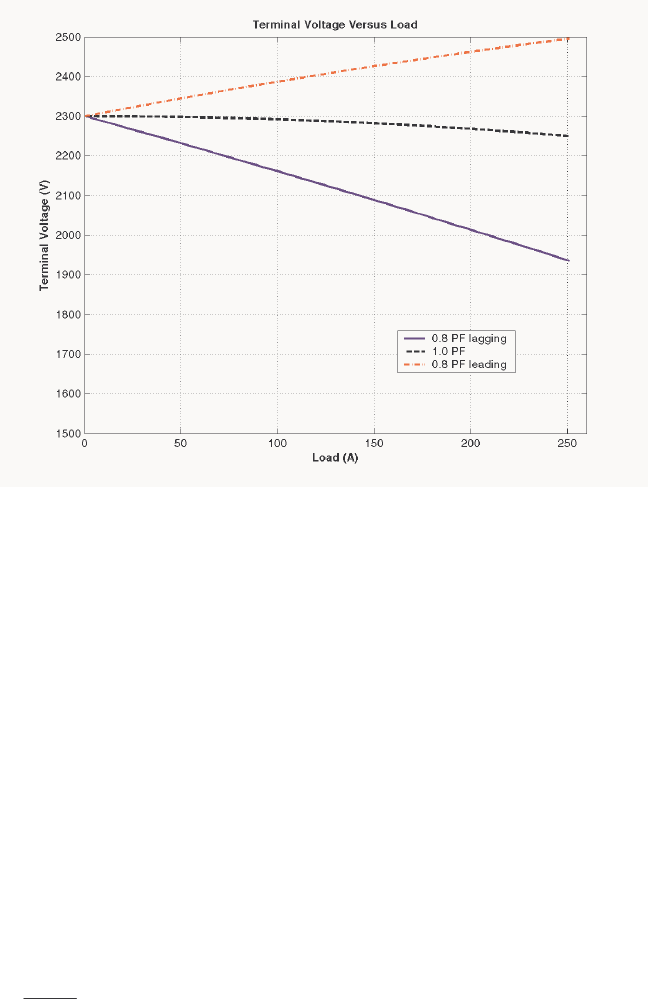
118
5-5. Assume that the field current of the generator in Problem 5-2 has been adjusted so that it supplies rated
voltage when loaded with rated current at unity power factor. (You may ignore the effects of A
R when
answering these questions.)
(a) What is the torque angle
δ
of the generator when supplying rated current at unity power factor?
(b) When this generator is running at full load with unity power factor, how close is it to the static stability
limit of the machine?
S
OLUTION
(a) The torque
δ
angle can be found by calculating A
E:
AAASA
RjX
φ
=+ +EV I I
()()()()
1328 0 0.15 251 0 A 1.1 251 0 A
AjE=∠°+ Ω∠°+ Ω∠°
1393 11.4 V
A
E=∠°
Thus the torque angle
δ
= 11.4°.
(b) The static stability limit occurs at °= 90
δ
. This generator is a very long way from that limit. If we
ignore the internal resistance of the generator, the output power will be given by
3sin
A
S
VE
PX
φ
δ
=
and the output power is proportional to sin
δ
. Since sin 11.4 0.198°= , and sin 90 1.00°= , the static
stability limit is about 5 times the current output power of the generator.
5-6. A 480-V 400-kVA 0.85-PF-lagging 50-Hz four-pole ∆-connected generator is driven by a 500-hp diesel
engine and is used as a standby or emergency generator. This machine can also be paralleled with the
normal power supply (a very large power system) if desired.
(a) What are the conditions required for paralleling the emergency generator with the existing power
system? What is the generator’s rate of shaft rotation after paralleling occurs?
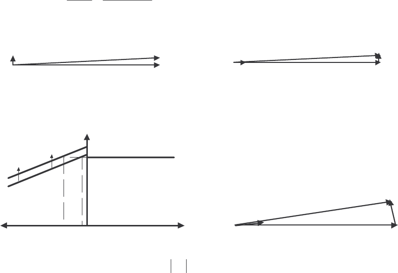
119
(b) If the generator is connected to the power system and is initially floating on the line, sketch the resulting
magnetic fields and phasor diagram.
(c) The governor setting on the diesel is now increased. Show both by means of house diagrams and by
means of phasor diagrams what happens to the generator. How much reactive power does the generator
supply now?
(d) With the diesel generator now supplying real power to the power system, what happens to the generator
as its field current is increased and decreased? Show this behavior both with phasor diagrams and with
house diagrams.
S
OLUTION
(a) To parallel this generator to the large power system, the required conditions are:
1. The generator must have the same voltage as the power system.
2. The
phase sequence of the oncoming generator must be the same as the phase sequence of the
power system.
3. The
frequency of the oncoming generator should be slightly higher than the frequency of the
running system.
4. The circuit breaker connecting the two systems together should be shut when the above conditions
are met and the generator is in phase with the power system.
After paralleling, the generator’s shaft will be rotating at
()
120 50 Hz
120 1500 r/min
4
e
m
f
nP
== =
(b) The magnetic field and phasor diagrams immediately after paralleling are shown below:
I
A
V
φ
E
A
jX
S
I
A
B
R
B
S
B
net
(c) When the governor setpoints on the generator are increased, the emergency generator begins to supply
more power to the loads, as shown below:
I
A
V
φ
E
A
jX
S
I
A
f
e
P
1
P
2
P
sys
P
G
Note that as the load increased with A
E constant, the generator began to consume a small amount of
reactive power.
(d) With the generator now supplying power to the system, an increase in field current increases the
reactive power supplied to the loads, and a decrease in field current decreases the reactive power supplied
to the loads.
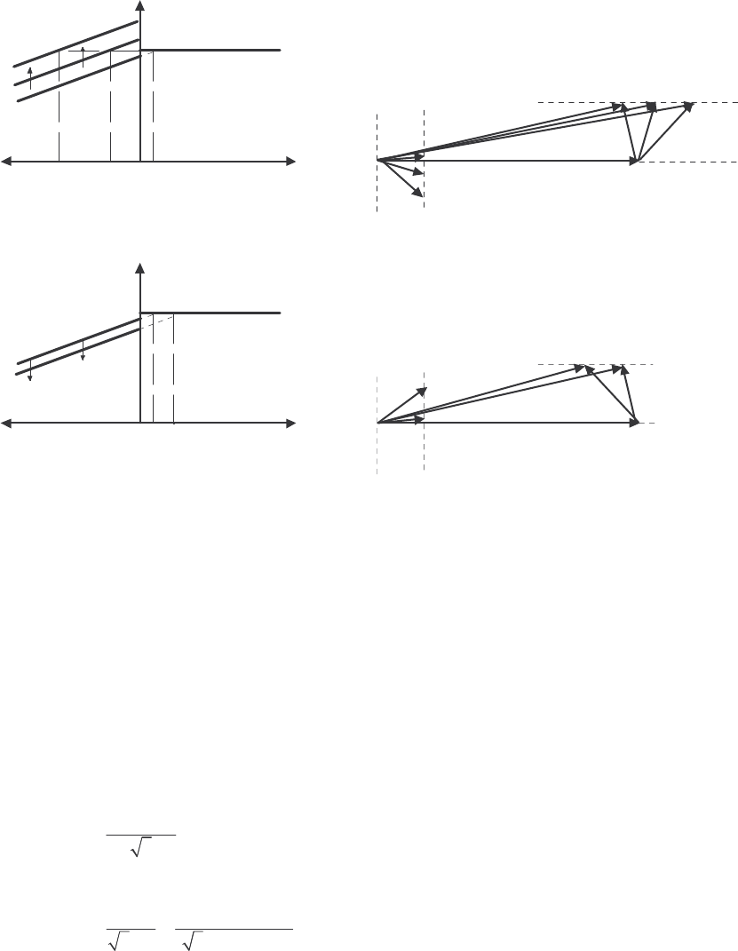
120
V
φ
E
A
1
jX
S
I
A
Q
sys
Q
G
Q
2
Q
1
Q
3
E
A
2
E
A
3
I
A
3
I
A
2
I
A
1
V
φ
E
A
1
jX
S
I
A
Q
sys
Q
G
Q
2
Q
1
E
A
2
I
A
2
I
A
1
V
T
V
T
5-7. A 13.8-kV 10-MVA 0.8-PF-lagging 60-Hz two-pole Y-connected steam-turbine generator has a
synchronous reactance of 12 Ω per phase and an armature resistance of 1.5 Ω per phase. This generator is
operating in parallel with a large power system (infinite bus).
(a) What is the magnitude of EA at rated conditions?
(b) What is the torque angle of the generator at rated conditions?
(c) If the field current is constant, what is the maximum power possible out of this generator? How much
reserve power or torque does this generator have at full load?
(d) At the absolute maximum power possible, how much reactive power will this generator be supplying or
consuming? Sketch the corresponding phasor diagram. (Assume IF is still unchanged.)
S
OLUTION
(a) The phase voltage of this generator at rated conditions is
13,800 V 7967 V
3
V
φ
==
The armature current per phase at rated conditions is
()
10,000,000 VA 418 A
3 3 13,800 V
A
T
S
IV
== =
Therefore, the internal generated voltage at rated conditions is
AAASA
RjXEV I I
φ
=+ +
()( )( )( )
7967 0 1.5 418 36.87 A 12.0 418 36.87 A
AjE=∠°+Ω∠− °+ Ω∠− °
12,040 17.6 V
A
E=∠°
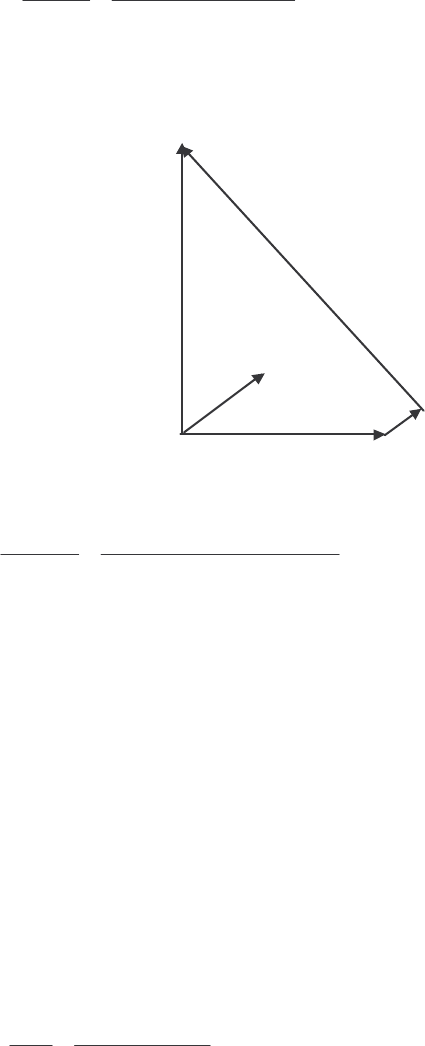
121
The magnitude of A
E is 12,040 V.
(b) The torque angle of the generator at rated conditions is
δ
= 17.6°.
(c) Ignoring A
R, the maximum output power of the generator is given by
()( )
MAX
3 3 7967 V 12,040 V 24.0 MW
12
A
S
VE
PX
φ
== =
Ω
The power at maximum load is 8 MW, so the maximum output power is three times the full load output
power.
(d) The phasor diagram at these conditions is shown below:
jX
S
I
A
V
φ
I
A
E
A
I
A
R
A
Under these conditions, the armature current is
12,040 90 V - 7967 0 V 1194 40.6 A
1.5 12.0
A
A
AS
RjX j
EV
I
φ
−∠° ∠°
== =∠°
++Ω
The reactive power produced by the generator at this point is
()()( )
3 sin 3 7967 V 1194 A sin 0 40.6 18.6 MVAR
A
QVI
φ
θ
== °−°=−
The generator is actually consuming reactive power at this time.
5-8. A 480-V, 100-kW, two-pole, three-phase, 60-Hz synchronous generator’s prime mover has a no-load speed
of 3630 r/min and a full-load speed of 3570 r/min. It is operating in parallel with a 480-V, 75-kW, four-
pole, 60-Hz synchronous generator whose prime mover has a no-load speed of 1800 r/min and a full-load
speed of 1785 r/min. The loads supplied by the two generators consist of 100 kW at 0.85 PF lagging.
(a) Calculate the speed droops of generator 1 and generator 2.
(b) Find the operating frequency of the power system.
(c) Find the power being supplied by each of the generators in this system.
(d) If VT is 460 V, what must the generator’s operators do to correct for the low terminal voltage?
S
OLUTION The no-load frequency of generator 1 corresponds to a frequency of
()()
nl1
3630 r/min 2
60.5 Hz
120 120
m
nP
f== =
The full-load frequency of generator 1 corresponds to a frequency of

122
()()
fl1
3570 r/min 2
59.5 Hz
120 120
m
nP
f== =
The no-load frequency of generator 2 corresponds to a frequency of
()()
nl2
1800 r/min 4
60.00 Hz
120 120
m
nP
f== =
The full-load frequency of generator 2 corresponds to a frequency of
()()
fl2
1785 r/min 4
59.50 Hz
120 120
m
nP
f== =
(a) The speed droop of generator 1 is given by
nl fl
1
fl
3630 r/min 3570 r/min
SD 100% 100% 1.68%
3570 r/min
nn
n
−−
=×= ×=
The speed droop of generator 2 is given by
nl fl
2
fl
1800 r/min 1785 r/min
SD 100% 100% 0.84%
1785 r/min
nn
n
−−
=×= ×=
(b) The power supplied by generator 1 is given by
()
1 1 nl1 sysP
Ps f f=−
and the power supplied by generator 1 is given by
()
2 2 nl2 sysP
Ps f f=−
The power curve’s slope for generator 1 is
1
nl fl
0.1 MW 0.1 MW/Hz
60.5 Hz 59.5 Hz
P
P
sff
== =
−−
The power curve’s slope for generator 1 is
2
nl fl
0.075 MW 0.150 MW/Hz
60.00 Hz 59.50 Hz
P
P
sff
== =
−−
The no-load frequency of generator 1 is 60.5 Hz and the no-load frequency of generator 2 is 60 Hz. The
total power that they must supply is 100 kW, so the system frequency can be found from the equations
LOAD 1 2
PPP=+
()()
LOAD 1 nl1 sys 2 nl2 sysPP
Psffsff=−+−
()
()
()
()
sys sys
100 kW 0.1 MW/Hz 60.5 Hz 0.15 MW/Hz 60.0 Hzff=−+ −
() ()
sys sys
100 kW 6050 kW 0.10 MW/Hz 9000 kW 0.15 MW/Hzff=− +−
()
sys
0.25 MW/Hz 6050 kW 9000 kW 100 kWf=+−
sys
14,950 kW 59.8 Hz
0.25 MW/Hz
f==
(c) The power supplied by generator 1 is

123
()
()( )
11nl1sys0.1 MW/Hz 60.5 Hz 59.8 Hz 70 kW
P
Ps f f=−= − =
The power supplied by generator 2 is
()
()( )
22nl2sys
0.15 MW/Hz 60.0 Hz 59.8 Hz 30 kW
P
Ps f f=−= − =
(d) If the terminal voltage is 460 V, the operators of the generators must increase the field currents on
both generators simultaneously. That action will increase the terminal voltages of the system without
changing the power sharing between the generators.
5-9. Three physically identical synchronous generators are operating in parallel. They are all rated for a full
load of 3 MW at 0.8 PF lagging. The no-load frequency of generator A is 61 Hz, and its speed droop is 3.4
percent. The no-load frequency of generator B is 61.5 Hz, and its speed droop is 3 percent. The no-load
frequency of generator C is 60.5 Hz, and its speed droop is 2.6 percent.
(a) If a total load consisting of 7 MW is being supplied by this power system, what will the system
frequency be and how will the power be shared among the three generators?
(b) Create a plot showing the power supplied by each generator as a function of the total power supplied to
all loads (you may use MATLAB to create this plot). At what load does one of the generators exceed
its ratings? Which generator exceeds its ratings first?
(c) Is this power sharing in (a) acceptable? Why or why not?
(d) What actions could an operator take to improve the real power sharing among these generators?
S
OLUTION
(a) Speed droop is defined as
nl fl nl fl
fl fl
SD 100% 100%
nn f f
nf
−−
=×=×
so nl
fl SD 1
100
f
f=
+
Thus, the full-load frequencies of generators A, B, and C are
nl,A
fl,A
A
61 Hz 59.0 Hz
SD 3.4
11
100 100
f
f===
++
nl,B
fl,B
B
61.5 Hz 59.71 Hz
SD 3.0
11
100 100
f
f===
++
nl,C
fl,C
C
60.5 Hz 58.97 Hz
SD 2.6
11
100 100
f
f===
++
and the slopes of the power-frequency curves are:
3 MW 1.5 MW/Hz
2 Hz
PA
S==
3 MW 1.676 MW/Hz
1.79 Hz
PB
S==
3 MW 1.961 MW/Hz
1.53 Hz
PC
S==

124
(a) The total load is 7 MW, so the system frequency is
()()()
LOAD nlA sys nlB sys nlC sysPA PB PC
P sffsffsff=−+−+−
(
)
()
(
)
()
(
)
()
sys sys sys
7 MW 1.5 61.0 1.676 61.5 1.961 60.5fff=−+ −+ −
sys sys sys
7 MW 91.5 1.5 103.07 1.676 118.64 1.961fff=−+− +−
sys
5.137 306.2f=
sys 59.61 Hzf=
The power supplied by each generator will be
()
()( )
nlA sys 1.5 MW/Hz 61.0 Hz 59.61 Hz 2.09 MW
APA
Psf f=−= − =
()
()( )
nlB sys 1.676 MW/Hz 61.5 Hz 59.61 Hz 3.17 MW
BPB
Psf f=−= − =
()
()( )
nlC sys 1.961 MW/Hz 60.5 Hz 59.61 Hz 1.74 MW
CPC
Ps f f=−= − =
(b) The equation in part (a) can be re-written slightly to express system frequency as a function of load.
()
()
()
()
()
()
LOAD sys sys sys
1.5 61.0 1.676 61.5 1.961 60.5Pf f f=−+ −+ −
LOAD sys sys sys
91.5 1.5 103.07 1.676 118.64 1.961Pf f f=− + − + −
sys LOAD
5.137 313.2fP=−
LOAD
sys
313.2
5.137
P
f−
=
A MATLAB program that uses this equation to determine the power sharing among the generators as a
function of load is shown below:
% M-file: prob5_9b.m
% M-file to calculate and plot the power sharing among
% three generators as a function of load.
% Define values for this generator
fnlA = 61.0; % No-load freq of Gen A
fnlB = 61.5; % No-load freq of Gen B
fnlC = 60.5; % No-load freq of Gen C
spA = 1.5; % Slope of Gen A (MW/Hz)
spB = 1.676; % Slope of Gen B (MW/Hz)
spC = 1.961; % Slope of Gen C (MW/Hz)
Pload = 0:0.05:10; % Load in MW
% Calculate the system frequency
fsys = (313.2 - Pload) ./ 5.137;
% Calculate the power of each generator
PA = spA .* ( fnlA - fsys);
PB = spB .* ( fnlB - fsys);
PC = spC .* ( fnlC - fsys);
% Plot the power sharing versus load
plot(Pload,PA,'b-','LineWidth',2.0);
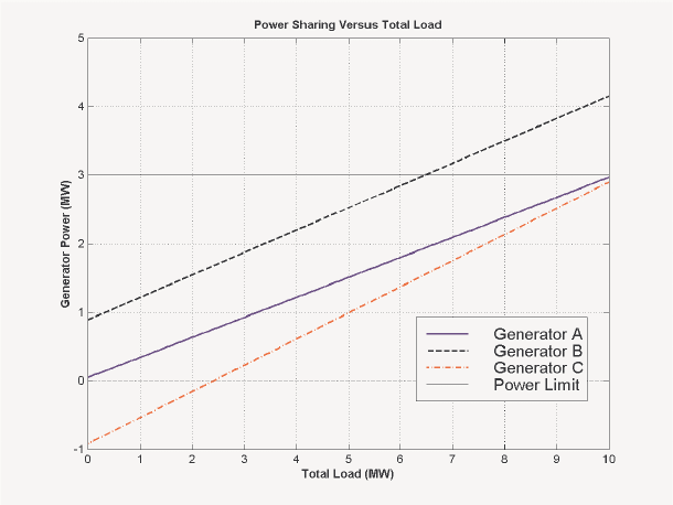
125
hold on;
plot(Pload,PB,'k--','LineWidth',2.0);
plot(Pload,PC,'r-.','LineWidth',2.0);
plot([0 10],[3 3],'k','LineWidth',1.0);
plot([0 10],[0 0],'k:');
title ('\bfPower Sharing Versus Total Load');
xlabel ('\bfTotal Load (MW)');
ylabel ('\bfGenerator Power (MW)');
legend('Generator A','Generator B','Generator C','Power Limit');
grid on;
hold off;
The resulting plot is shown below:
This plot reveals that there are power sharing problems both for high loads and for low loads. Generator B
is the first to exceed its ratings as load increases. Its rated power is reached at a total load of 6.45 MW.
On the other hand, Generator C gets into trouble as the total load is reduced. When the total load drops to
2.4 MW, the direction of power flow reverses in Generator C.
(c) The power sharing in (a) is not acceptable, because Generator 2 has exceeded its power limits.
(d) To improve the power sharing among the three generators in (a) without affecting the operating
frequency of the system, the operator should decrease the governor setpoints on Generator B while
simultaneously increasing them in Generators A and C.
5-10. A paper mill has installed three steam generators (boilers) to provide process steam and also to use some its
waste products as an energy source. Since there is extra capacity, the mill has installed three 5-MW
turbine generators to take advantage of the situation. Each generator is a 4160-V 6250-kVA 0.85-PF-
lagging two-pole Y-connected synchronous generator with a synchronous reactance of 0.75 Ω and an
armature resistance of 0.04 Ω. Generators 1 and 2 have a characteristic power-frequency slope sP of 2.5
MW/Hz, and generators 2 and 3 have a slope of 3 MW/Hz.
(a) If the no-load frequency of each of the three generators is adjusted to 61 Hz, how much power will the
three machines be supplying when actual system frequency is 60 Hz?
126
(b) What is the maximum power the three generators can supply in this condition without the ratings of one
of them being exceeded? At what frequency does this limit occur? How much power does each
generator supply at that point?
(c) What would have to be done to get all three generators to supply their rated real and reactive powers at
an overall operating frequency of 60 Hz?
(d) What would the internal generated voltages of the three generators be under this condition?
S
OLUTION
(a) If the system frequency is 60 Hz and the no-load frequencies of the generators are 61 Hz, then the
power supplied by the generators will be
()
()( )
11nl1sys2.5 MW/Hz 61 Hz 60 Hz 2.5 MW
P
Ps f f=−= −=
()
(
)
(
)
2 2 nl2 sys 2.5 MW/Hz 61 Hz 60 Hz 2.5 MW
P
Ps f f=−= −=
()
(
)
(
)
3 3 nl3 sys 3.0 MW/Hz 61 Hz 60 Hz 3.0 MW
P
Ps f f=−= −=
Therefore the total power supplied by the generators is 8 MW.
(b) The maximum power supplied by any one generator is (6250 kVA)(0.85) = 5.31 MW. Generator 3
will be the first machine to reach that limit. Generator 3 will supply this power at a frequency of
()
()
sys
5.31 MW 3.0 MW/Hz 61 Hz f=−
Hz23.59
sys =f
At this point the power supplied by Generators 1 and 2 is
()
()( )
12 1nl1sys 2.5 MW/Hz 61 Hz 59.23 Hz 4.425 MW
P
PPs f f== − = − =
The total power supplied by the generators at this condition is 14.16 MW.
(c) To get each of the generators to supply 5.31 MW at 60 Hz, the no-load frequencies of Generator 1
and Generator 2 would have to be adjusted to 62.12 Hz, and the no-load frequency of Generator 3 would
have to be adjusted to 61.77 Hz. The field currents of the three generators must then be adjusted to get
them supplying a power factor of 0.85 lagging. At that point, each generator will be supplying its rated
real and reactive power.
(d) Under the conditions of part (c), which are the rated conditions of the generators, the internal
generated voltage would be given by
AAASA
RjXEV I I
φ
=+ +
The phase voltage of the generators is 4160 V / 3 = 2402 V, and since the generators are Y-connected,
their rated current is
()
6250 kVA 867 A
3 3 4160 V
AL
T
S
II V
== = =
The power factor is 0.85 lagging, so 867 31.8 A
A
I=∠− °. Therefore,
AAASA
RjXEV I I
φ
=+ +
()()()()
2402 0 0.04 867 31.8 A 0.75 867 31.8 A
AjE=∠°+ Ω∠−°+ Ω∠−°
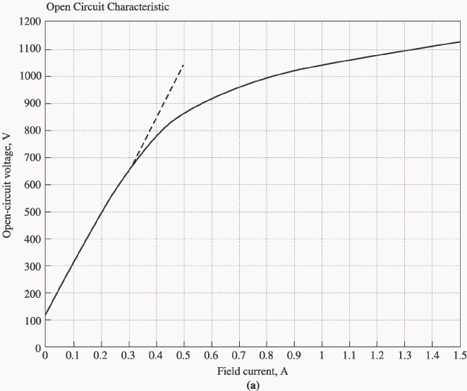
127
2825 10.9 V
A
E=∠°
Problems 5-11 to 5-21 refer to a two-pole Y-connected synchronous generator rated at 470 kVA, 480 V, 60 Hz,
and 0.85 PF lagging. Its armature resistance RA is 0.016 Ω. The core losses of this generator at rated conditions
are 7 kW, and the friction and windage losses are 8 kW. The open-circuit and short-circuit characteristics are
shown in Figure P5-2.
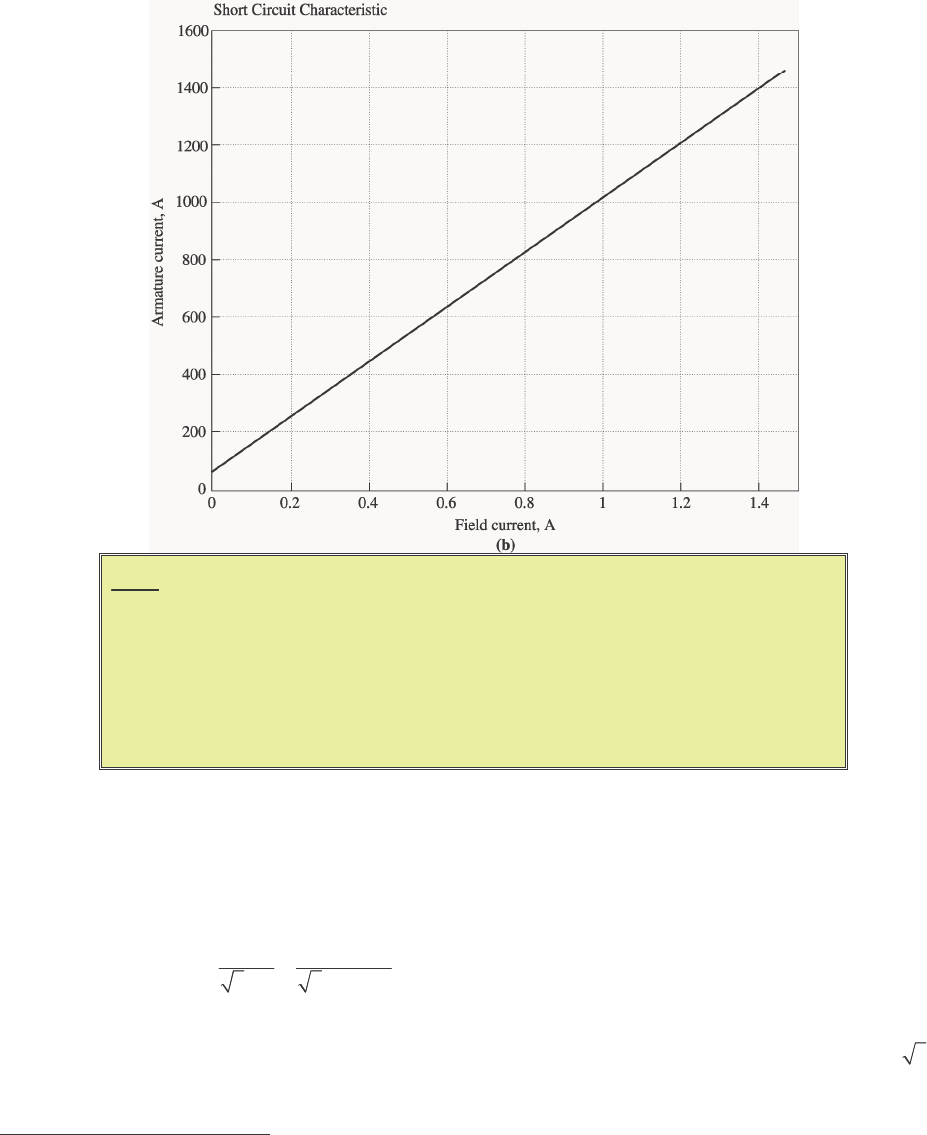
128
Note: An electronic version of the saturated open circuit characteristic can be found
in file p52_occ.dat, and an electronic version of the air-gap characteristic
can be found in file p52_ag_occ.dat. These files can be used with
MATLAB programs. Column 1 contains field current in amps, and column 2
contains open-circuit terminal voltage in volts. An electronic version of the
short circuit characteristic can be found in file p52_scc.dat. Column 1
contains field current in amps, and column 2 contains short-circuit terminal
current in amps.
5-11. (a) What is the saturated synchronous reactance of this generator at the rated conditions? (b) What is the
unsaturated synchronous reactance of this generator? (c) Plot the saturated synchronous reactance of this
generator as a function of load.
S
OLUTION
(a) The rated armature current for this generator is
()
470 kVA 565 A
3 3 480 V
AL
T
S
II V
== = =
The field current required to produce this much short-circuit current may be read from the SCC. It is 0.534
A3. The open circuit voltage at 0.532 A is 880 V4, so the open-circuit phase voltage (= A
E) is 880/ 3 =
508 V. The approximate saturated synchronous reactance S
X is
3 If you have MATLAB available, you can use the file p52_scc.dat and the interp1 function to look up this
value as shown below. Note that column 1 of p52_scc contains field current, and column 2 contains short-circuit
terminal current.
load p52_scc.dat
if = interp1(p52_scc(:,2),p52_scc(:,1),565)
if =

129
508 V 0.899
565 A
S
X==Ω
(b) The unsaturated synchronous reactance Su
X is the ratio of the air-gap line to the SCC. This is a
straight line, so we can determine its value by comparing the ratio of the air-gap voltage to the short-circuit
current at any given field current. For example, at F
I = 0.50 A, the air-gap line voltage is 1040 V, and the
SCC is 532 A.
()
1040 V / 3 1.13
532 A
Su
X==Ω
(c) This task can best be performed with MATLAB. The open-circuit characteristic is available in a file
called p52_occ.dat, and the short-circuit characteristic is available in a file called p52_scc.dat.
Each of these files are organized in two columns, where the first column is field current and the second
column is either open-circuit terminal voltage or short-circuit current. A program to read these files and
calculate and plot S
X is shown below.
% M-file: prob5_11c.m
% M-file to calculate and plot the saturated
% synchronous reactance of a synchronous
% generator.
% Load the open-circuit characteristic. It is in
% two columns, with the first column being field
% current and the second column being terminal
% voltage.
load p52.occ;
if_occ = p52(:,1);
vt_occ = p52(:,2);
% Load the short-circuit characteristic. It is in
% two columns, with the first column being field
% current and the second column being line current
% (= armature current)
load p52.scc;
if_scc = p52(:,1);
ia_scc = p52(:,2);
% Calculate Xs
if = 0.001:0.02:1; % Current steps
vt = interp1(if_occ,vt_occ,If); % Terminal voltage
ia = interp1(if_scc,ia_scc,If); % Current
Xs = (vt ./ sqrt(3)) ./ ia;
0.534
4 If you have MATLAB available, you can use the file p52_occ.dat and the interp1 function to look up this
value as shown below. Note that column 1 of p52_occ contains field current, and column 2 contains open-circuit
terminal voltage.
load p52_occ.dat
vt = interp1(p52_occ(:,1),p52_occ(:,2),0.534)
vt =
880.400
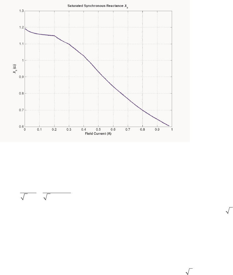
130
% Plot the synchronous reactance
figure(1)
plot(If,Xs,'LineWidth',2.0);
title ('\bfSaturated Synchronous Reactance \itX_{s} \rm');
xlabel ('\bfField Current (A)');
ylabel ('\bf\itX_{s} \rm\bf(\Omega)');
grid on;
The resulting plot is:
5-12. (a) What are the rated current and internal generated voltage of this generator? (b) What field current
does this generator require to operate at the rated voltage, current, and power factor?
S
OLUTION
(a) The rated line and armature current for this generator is
()
470 kVA 565 A
3 3 480 V
AL
T
S
II V
== = =
The power factor is 0.85 lagging, so 565.3 31.8 A
A
I=∠−°
. The rated phase voltage is V
φ
= 480 V / 3
= 277 V. The saturated synchronous reactance at rated conditions was found to be 0.450 Ω in the previous
problem. Therefore, the internal generated voltage is
AAASA
RjXEV I I
φ
=+ +
()( )()( )
277 0 0.016 565.3 31.8 A 0.899 565.3 31.8 A
Aj=∠°+ Ω ∠− °+ Ω ∠− °E
509 30.5 V
A
E=∠°
(b) This internal generated voltage corresponds to a no-load terminal voltage of
()
3509 = 881 V.
From the open-circuit characteristic, the required field current would be 0.535 A.
5-13. What is the voltage regulation of this generator at the rated current and power factor?
S
OLUTION The voltage regulation is

131
,nl ,fl
,fl
881 480
VR 100% 100% 83.5%
480
TT
T
VV
V
−−
=×=×=
5-14. If this generator is operating at the rated conditions and the load is suddenly removed, what will the
terminal voltage be?
S
OLUTION From the above calculations, T
V will be 881 V.
5-15. What are the electrical losses in this generator at rated conditions?
S
OLUTION The electrical losses are
()( )
2
2
CU 3 3 565 A 0.016 15.3 kW
AA
PIR== Ω=
5-16. If this machine is operating at rated conditions, what input torque must be applied to the shaft of this
generator? Express your answer both in newton-meters and in pound-feet.
S
OLUTION To get the applied torque, we must know the input power. The input power to this generator is
equal to the output power plus losses. The rated output power and the losses are
()()
OUT 470 kVA 0.85 400 kWP==
()( )
2
2
CU 3 3 565 A 0.016 15.3 kW
AA
PIR== Ω=
F&W 8 kWP=
core 7 kWP=
stray (assumed 0)P=
IN OUT CU F&W core stray 430.3 kWPP PP P P=++++=
Therefore, the applied torque is
()
IN
APP
430.3 kW 2280 N m
2 rad 1 min
1800 r/min 1 r 60 s
m
P
τπ
ω
== = ⋅
or
(
)
APP
7.04 430.3 kW
7.04 1680 lb ft
1800 r/min
m
P
n
τ
== =⋅
5-17. What is the torque angle
δ
of this generator at rated conditions?
S
OLUTION From the calculations in Problem 5-12,
δ
= 30.5°.
5-18. Assume that the generator field current is adjusted to supply 480 V under rated conditions. What is the
static stability limit of this generator? (Note: You may ignore A
R to make this calculation easier.) How
close is the full-load condition of this generator to the static stability limit?
S
OLUTION At rated conditions, 509 30.5 V
A=∠°E. Therefore, the static stability limit is
()()
MAX
3 3277 V 509 V 471 kW
0.899
A
S
VE
PX
φ
== =
Ω
The full-load rated power of this generator is reasonably close to the static stability limit. Normal
generators would have more margin than this.
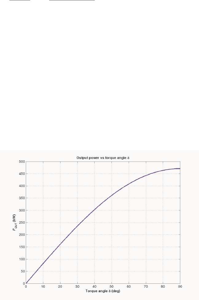
132
5-19. Assume that the generator field current is adjusted to supply 480 V under rated conditions. Plot the power
supplied by the generator as a function of the torque angle
δ
. (Note: You may ignore A
R to make this
calculation easier.)
S
OLUTION We will again ignore A
R to make this calculation easier. The power supplied by the generator is
()() ()
3 3 277 V 509 V
sin sin 471 kW sin
0.899
A
G
S
VE
PX
φ
δδδ
== =
Ω
The power supplied as a function of the torque angle
δ
may be plotted using a simple MATLAB program:
% M-file: prob5_19.m
% M-file to plot the power output of a
% synchronous generator as a function of
% the torque angle.
% Calculate Xs
delta = (0:1:90); % Torque angle (deg)
Pout = 561 .* sin(delta * pi/180); % Pout
% Plot the output power
figure(1)
plot(delta,Pout,'LineWidth',2.0);
title ('\bfOutput power vs torque angle \delta');
xlabel ('\bfTorque angle \delta (deg)');
ylabel ('\bf\itP_{OUT} \rm\bf(kW)');
grid on;
The resulting plot is:
5-20. Assume that the generator’s field current is adjusted so that the generator supplies rated voltage at the rated
load current and power factor. If the field current and the magnitude of the load current are held constant,
how will the terminal voltage change as the load power factor varies from 0.85 PF lagging to 0.85 PF
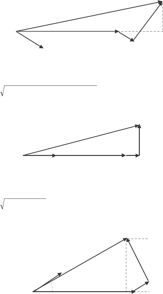
133
leading? Make a plot of the terminal voltage versus the impedance angle of the load being supplied by this
generator.
S
OLUTION If the field current is held constant, then the magnitude of A
E will be constant, although its
angle
δ
will vary. Also, the magnitude of the armature current is constant. Since we also know A
R, S
X,
and the current angle
θ
, we know enough to find the phase voltage
φ
V, and therefore the terminal voltage
T
V. At lagging power factors,
φ
V can be found from the following relationships:
I
A
V
φ
E
A
θ
δθ
θ
I
A
R
A
jX
S
I
A
By the Pythagorean Theorem,
()
()
222 sincossincos
θθθθ
φ
SAASASAAA IRIXIXIRVE −+++=
()
θθθθ
φ
sincossincos 22
ASAASAASA IXIRIRIXEV −−−−=
At unity power factor,
φ
V can be found from the following relationships:
I
A
V
φ
E
A
δ
I
A
R
A
jX
S
I
A
By the Pythagorean Theorem,
(
)
2
22
ASA
EV XI
φ
=+
()
22
ASA IXEV −=
φ
At leading power factors,
φ
V can be found from the following relationships:
I
A
V
φ
E
A
θ
δθ
θ
I
A
R
A
jX
S
I
A
By the Pythagorean Theorem,

134
()
()
222 sincossincos
θθθθ
φ
SAASASAAA IRIXIXIRVE ++−+=
()
θθθθ
φ
sincossincos 22
ASAASAASA IXIRIRIXEV +−+−=
If we examine these three cases, we can see that the only difference among them is the sign of the term
θ
sin . If
θ
is taken as positive for lagging power factors and negative for leading power factors (in other
words, if
θ
is the impedance angle), then all three cases can be represented by the single equation:
()
θθθθ
φ
sincossincos 22
ASAASAASA IXIRIRIXEV −−−−=
A MATLAB program that calculates terminal voltage as function of impedance angle is shown below:
% M-file: prob5_20.m
% M-file to calculate and plot the terminal voltage
% of a synchronous generator as a function of impedance
% angle as PF changes from 0.85 lagging to 0.85
% leading.
% Define values for this generator
EA = 509; % Internal gen voltage
I = 361; % Current (A)
R = 0.04; % R (ohms)
X = 0.695; % XS (ohms)
% Calculate impedance angle theta in degrees
theta = -31.8:0.318:31.8;
th = theta * pi/180; % In radians
% Calculate the phase voltage and terminal voltage
VP = sqrt( EA^2 - (X.*I.*cos(th) - R.*I.*sin(th)).^2 ) ...
- R.*I.*cos(th) - X.*I.*sin(th);
VT = VP .* sqrt(3);
% Plot the terminal voltage versus power factor
figure(1);
plot(theta,abs(VT),'b-','LineWidth',2.0);
title ('\bfTerminal Voltage Versus Impedance Angle');
xlabel ('\bfImpedance Angle (deg)');
ylabel ('\bfTerminal Voltage (V)');
%axis([0 260 300 540]);
grid on;
hold off;
The resulting plot of terminal voltage versus impedance angle (with field and armature currents held
constant) is shown below:
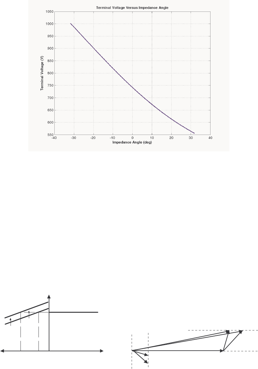
135
5-21. Assume that the generator is connected to a 480-V infinite bus, and that its field current has been adjusted
so that it is supplying rated power and power factor to the bus. You may ignore the armature resistance
A
R when answering the following questions.
(a) What would happen to the real and reactive power supplied by this generator if the field flux (and
therefore A
E) is reduced by 5%.
(b) Plot the real power supplied by this generator as a function of the flux
φ
as the flux is varied from 75%
to 100% of the flux at rated conditions.
(c) Plot the reactive power supplied by this generator as a function of the flux
φ
as the flux is varied from
75% to 100% of the flux at rated conditions.
(d) Plot the line current supplied by this generator as a function of the flux
φ
as the flux is varied from 75%
to 100% of the flux at rated conditions.
S
OLUTION
(a) If the field flux in increase by 5%, nothing would happen to the real power. The reactive power
supplied would increase as shown below.
V
φ
E
A
1
jX
S
I
A
Q
sys
Q
G
Q
2
Q
1
E
A
2
I
A
2
I
A
1
V
T
Q
∝
I
sin
θ
A
The reactive power
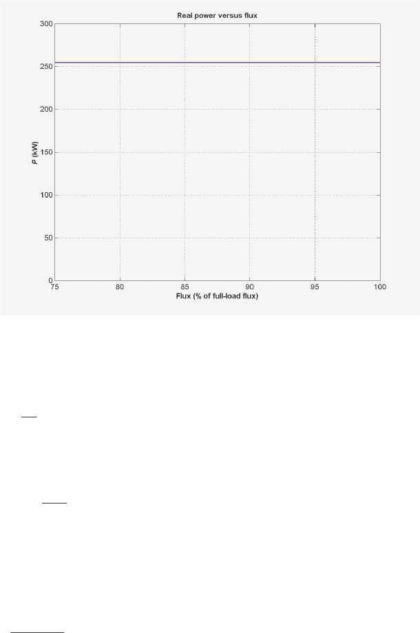
136
(b) If armature resistance is ignored, the power supplied to the bus will not change as flux is varied.
Therefore, the plot of real power versus flux is
(c) If armature resistance is ignored, the internal generated voltage A
E will increase as flux increases,
but the quantity
δ
sin
A
E will remain constant. Therefore, the voltage for any flux can be found from the
expression
Ar
r
AEE
=
φ
φ
and the angle
δ
for any A
E can be found from the expression
=−
r
A
Ar
E
E
δδ
sinsin 1
where
φ
is the flux in the machine, r
φ
is the flux at rated conditions, Ar
E is the magnitude of the internal
generated voltage at rated conditions, and r
δ
is the angle of the internal generated voltage at rated
conditions. From this information, we can calculate A
I for any given load from equation
S
A
AjX
φ
VE
I−
=
and the resulting reactive power from the equation
θ
φ
sin 3 A
IVQ =
where
θ
is the impedance angle, which is the negative of the current angle. Ignoring A
R, the internal
generated voltage at rated conditions is
ASA jX IVE +=
φ
()( )
277 0 0.899 565.3 31.8 A
Aj=∠°+ Ω ∠− °E
137
695 38.4 V
A=∠°E
so V 461=
Ar
E and °= 5.27
r
δ
. A MATLAB program that calculates the reactive power supplied
voltage as a function of flux is shown below:
% M-file: prob5_21c.m
% M-file to calculate and plot the reactive power
% supplied to an infinite bus as flux is varied from
% 75% to 100% of the flux at rated conditions.
% Define values for this generator
flux_ratio = 0.90:0.01:1.00; % Flux ratio
Ear = 695; % Ea at full flux
dr = 38.4 * pi/180; % Torque ang at full flux
Vp = 277; % Phase voltage
Xs = 0.899; % Xs (ohms)
% Calculate Ea for each flux
Ea = flux_ratio * Ear;
% Calculate delta for each flux
d = asin( Ear ./ Ea .* sin(dr));
% Calculate Ia for each flux
Ea = Ea .* ( cos(d) + j.*sin(d) );
Ia = ( Ea - Vp ) ./ (j*Xs);
% Calculate reactive power for each flux
theta = -atan2(imag(Ia),real(Ia));
Q = 3 .* Vp .* abs(Ia) .* sin(theta);
% Plot the power supplied versus flux
figure(1);
plot(flux_ratio,Q/1000,'b-','LineWidth',2.0);
title ('\bfReactive power versus flux');
xlabel ('\bfFlux (% of full-load flux)');
ylabel ('\bf\itQ\rm\bf (kVAR)');
grid on;
hold off;
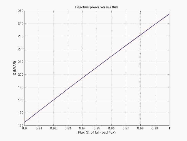
138
When this program is executed, the plot of reactive power versus flux is
(d) The program in part (c) of this program calculated A
I as a function of flux. A MATLAB program
that plots the magnitude of this current as a function of flux is shown below:
% M-file: prob5_21d.m
% M-file to calculate and plot the armature current
% supplied to an infinite bus as flux is varied from
% 75% to 100% of the flux at rated conditions.
% Define values for this generator
flux_ratio = 0.75:0.01:1.00; % Flux ratio
Ear = 695; % Ea at full flux
dr = 38.4 * pi/180; % Torque ang at full flux
Vp = 277; % Phase voltage
Xs = 0.899; % Xs (ohms)
% Calculate Ea for each flux
Ea = flux_ratio * Ear;
% Calculate delta for each flux
d = asin( Ear ./ Ea .* sin(dr));
% Calculate Ia for each flux
Ea = Ea .* ( cos(d) + j.*sin(d) );
Ia = ( Ea - Vp ) ./ (j*Xs);
% Plot the armature current versus flux
figure(1);
plot(flux_ratio,abs(Ia),'b-','LineWidth',2.0);
title ('\bfArmature current versus flux');
xlabel ('\bfFlux (% of full-load flux)');
ylabel ('\bf\itI_{A}\rm\bf (A)');
grid on;
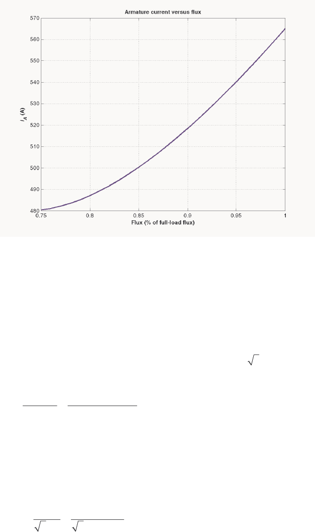
139
hold off;
When this program is executed, the plot of armature current versus flux is
5-22. A 100-MVA 12.5-kV 0.85-PF-lagging 50-Hz two-pole Y-connected synchronous generator has a per-unit
synchronous reactance of 1.1 and a per-unit armature resistance of 0.012.
(a) What are its synchronous reactance and armature resistance in ohms?
(b) What is the magnitude of the internal generated voltage EA at the rated conditions? What is its torque
angle
δ
at these conditions?
(c) Ignoring losses in this generator, what torque must be applied to its shaft by the prime mover at full
load?
S
OLUTION The base phase voltage of this generator is ,base 12,500/ 3 7217 VV
φ
==. Therefore, the base
impedance of the generator is
()
2
2
,base
base
base
3 37217 V 1.56
100,000,000 VA
V
ZS
φ
== =Ω
(a) The generator impedance in ohms are:
()( )
0.012 1.56 0.0187
A
R=Ω=Ω
()( )
1.1 1.56 1.716
S
X=Ω=Ω
(b) The rated armature current is
()
100 MVA 4619 A
3 3 12.5 kV
AL
T
S
II V
== = =
The power factor is 0.8 lagging, so 4619 36.87 A
A=∠− °I. Therefore, the internal generated voltage is
AAASA
RjX
φ
=+ +EV I I
140
()()()()
7217 0 0.0187 4619 36.87 A 1.716 4619 36.87 A
Aj=∠°+ Ω ∠− °+ Ω ∠− °E
13,590 27.6 V
A=∠°E
Therefore, the magnitude of the internal generated voltage A
E = 13,590 V, and the torque angle
δ
= 23°.
(c) Ignoring losses, the input power would equal the output power. Since
()( )
OUT 0.85 100 MVA 85 MWP==
and
()
sync
120 50 Hz
120 3000 r/min
2
e
f
nP
== =
the applied torque would be
()()()
app ind
85,000,000 W 270,000 N m
3000 r/min 2 rad/r 1 min/60 s
ττ π
== = ⋅
5-23. A three-phase Y-connected synchronous generator is rated 120 MVA, 13.2 kV, 0.8 PF lagging, and 60 Hz.
Its synchronous reactance is 0.9 Ω, and its resistance may be ignored.
(a) What is its voltage regulation?
(b) What would the voltage and apparent power rating of this generator be if it were operated at 50 Hz
with the same armature and field losses as it had at 60 Hz?
(c) What would the voltage regulation of the generator be at 50 Hz?
S
OLUTION
(a) The rated armature current is
()
120 MVA 5249 A
3 3 13.2 kV
AL
T
S
II V
== = =
The power factor is 0.8 lagging, so 5249 36.87 A
A=∠− °I. The phase voltage is 13.2 kV / 3 = 7621
V. Therefore, the internal generated voltage is
AAASA
RjX
φ
=+ +EV I I
()( )
7621 0 0.9 5249 36.87 A
Aj=∠°+ Ω ∠− °E
11,120 19.9 V
A=∠°E
The resulting voltage regulation is
11,120 7621
VR 100% 45.9%
7621
−
=×=
(b) If the generator is to be operated at 50 Hz with the same armature and field losses as at 60 Hz (so
that the windings do not overheat), then its armature and field currents must not change. Since the voltage
of the generator is directly proportional to the speed of the generator, the voltage rating (and hence the
apparent power rating) of the generator will be reduced by a factor of 5/6.
()
,rated
513.2 kV 11.0 kV
6
T
V==
()
rated
5120 MVA 100 MVA
6
S==

141
Also, the synchronous reactance will be reduced by a factor of 5/6.
()
50.9 0.75
6
S
X=Ω=Ω
(c) At 50 Hz rated conditions, the armature current would be
()
100 MVA 5247 A
3 3 11.0 kV
AL
T
S
II V
== = =
The power factor is 0.8 lagging, so 5247 36.87 A
A=∠− °I. The phase voltage is 11.0 kV / 3 = 6351
V. Therefore, the internal generated voltage is
AAASA
RjX
φ
=+ +EV I I
()( )
6351 0 0.75 5247 36.87 A
Aj=∠°+ Ω ∠− °E
9264 19.9 V
A=∠°E
The resulting voltage regulation is
9264 6351
VR 100% 45.9%
6351
−
=×=
Because voltage, apparent power, and synchronous reactance all scale linearly with frequency, the voltage
regulation at 50 Hz is the same as that at 60 Hz. Note that this is not quite true, if the armature resistance
A
R is included, since A
R does not scale with frequency in the same fashion as the other terms.
5-24. Two identical 600-kVA 480-V synchronous generators are connected in parallel to supply a load. The
prime movers of the two generators happen to have different speed droop characteristics. When the field
currents of the two generators are equal, one delivers 400 A at 0.9 PF lagging, while the other delivers 300
A at 0.72 PF lagging.
(a) What are the real power and the reactive power supplied by each generator to the load?
(b) What is the overall power factor of the load?
(c) In what direction must the field current on each generator be adjusted in order for them to operate at the
same power factor?
S
OLUTION
(a) The real and reactive powers are
()()()
13 cos 3 480 V 400 A 0.9 299 kW
TL
PVI
θ
== =
(
)
(
)
(
)
1
13 sin 3 480 V 400 A sin cos 0.9 145 kVAR
TL
QVI
θ
−
== =
(
)
(
)
(
)
23 cos 3 480 V 200 A 0.72 120 kW
TL
PVI
θ
== =
(
)
(
)
(
)
1
23 sin 3 480 V 200 A sin cos 0.72 115 kVAR
TL
QVI
θ
−
== =
(b) The overall power factor can be found from the total real and reactive power supplied to the load.
TOT 1 2 299 kW 120 kW 419 kWPPP=+= + =
TOT 1 2 145 kVAR 115 kVAR 260 kVARQQQ=+= + =
The overall power factor is

142
1TOT
TOT
PF cos tan 0.850 lagging
Q
P
−
==
(c) The field current of generator 1 should be increased, and the field current of generator 2 should be
simultaneously decreased.
5-25. A generating station for a power system consists of four 120-MVA 15-kV 0.85-PF-lagging synchronous
generators with identical speed droop characteristics operating in parallel. The governors on the
generators’ prime movers are adjusted to produce a 3-Hz drop from no load to full load. Three of these
generators are each supplying a steady 75 MW at a frequency of 60 Hz, while the fourth generator (called
the swing generator) handles all incremental load changes on the system while maintaining the system's
frequency at 60 Hz.
(a) At a given instant, the total system loads are 260 MW at a frequency of 60 Hz. What are the no-load
frequencies of each of the system’s generators?
(b) If the system load rises to 290 MW and the generator’s governor set points do not change, what will the
new system frequency be?
(c) To what frequency must the no-load frequency of the swing generator be adjusted in order to restore the
system frequency to 60 Hz?
(d) If the system is operating at the conditions described in part (c), what would happen if the swing
generator were tripped off the line (disconnected from the power line)?
S
OLUTION
(a) The full-load power of these generators is
()()
MW10285.0 MVA120 = and the droop from no-
load to full-load is 3 Hz. Therefore, the slope of the power-frequency curve for these four generators is
102 MW 34 MW/Hz
3 Hz
P
s==
If generators 1, 2, and 3 are supplying 75 MW each, then generator 4 must be supplying 35 MW. The no-
load frequency of the first three generators is
()
1 1 nl1 sysP
Ps f f=−
(
)
()
nl1
75 MW 34 MW/Hz 60 Hzf=−
nl1 62.21 Hzf=
The no-load frequency of the fourth generator is
()
4 4 nl4 sysP
Ps f f=−
()
()
nl1
35 MW 34 MW/Hz 60 Hzf=−
Hz03.61
nl1 =f
(b) The setpoints of generators 1, 2, 3, and 4 do not change, so the new system frequency will be
()()()()
LOAD 1 nl1 sys 2 nl2 sys 3 nl3 sys 4 nl4 sysPP P P
Psffsffsffsff=−+−+−+−
()
()
()
()
()
()
()
()
sys sys sys sys
290 MW 34 62.21 34 62.21 34 62.21 34 61.03ffff=−+−+−+−
sys
8.529 247.66 4 f=−

143
sys 59.78 Hzf=
(c) The governor setpoints of the swing generator must be increased until the system frequency rises back
to 60 Hz. At 60 Hz, the other three generators will be supplying 75 MW each, so the swing generator must
supply 290 MW – 3(75 MW) = 65 MW at 60 Hz. Therefore, the swing generator’s setpoints must be set
to
()
4 4 nl4 sysP
Ps f f=−
(
)
()
nl1
65 MW 34 MW/Hz 60 Hzf=−
nl1 61.91 Hzf=
(d) If the swing generator trips off the line, the other three generators would have to supply all 290 MW
of the load. Therefore, the system frequency will become
()()()
LOAD 1 nl1 sys 2 nl2 sys 3 nl3 sysPP P
P sff sff sff=−+−+−
(
)
()
(
)
()
(
)
()
sys sys sys
290 MW 34 62.21 34 62.21 34 62.21fff=−+−+−
sys
8.529 186.63 3 f=−
sys 59.37 Hzf=
Each generator will supply 96.7 MW to the loads.
5-26. Suppose that you were an engineer planning a new electric co-generation facility for a plant with excess
process steam. You have a choice of either two 10 MW turbine-generators or a single 20 MW turbine
generator. What would be the advantages and disadvantages of each choice?
S
OLUTION A single 20 MW generator will probably be cheaper and more efficient than two 10 MW
generators, but if the 20 MW generator goes down all 20 MW of generation would be lost at once. If two
10 MW generators are chosen, one of them could go down for maintenance and some power could still be
generated.
5-27. A 25-MVA three-phase 13.8-kV two-pole 60-Hz synchronous generator was tested by the open-circuit test,
and its air-gap voltage was extrapolated with the following results:
Open-circuit test
Field current, A 320 365 380 475 570
Line voltage, kV 13.0 13.8 14.1 15.2 16.0
Extrapolated air-gap voltage, kV 15.4 17.5 18.3 22.8 27.4
The short-circuit test was then performed with the following results:
Short-circuit test
Field current, A 320 365 380 475 570
Armature current, A 1040 1190 1240 1550 1885
The armature resistance is 0.24 Ω per phase.
(a) Find the unsaturated synchronous reactance of this generator in ohms per phase and in per-unit.
(b) Find the approximate saturated synchronous reactance XS at a field current of 380 A. Express the
answer both in ohms per phase and in per-unit.

144
(c) Find the approximate saturated synchronous reactance at a field current of 475 A. Express the answer
both in ohms per phase and in per-unit.
(d) Find the short-circuit ratio for this generator.
S
OLUTION
(a) The unsaturated synchronous reactance of this generator is the same at any field current, so we will
look at it at a field current of 380 A. The extrapolated air-gap voltage at this point is 18.3 kV, and the
short-circuit current is 1240 A. Since this generator is Y-connected, the phase voltage is
18.3 kV/ 3 10,566 V V
φ
==
and the armature current is 1240 A
A
I=. Therefore, the unsaturated
synchronous reactance is
10,566 V 8.52
1240 A
Su
X==Ω
The base impedance of this generator is
()
2
2
,base
base
base
3 3 7967 V 7.62
25,000,000 VA
V
ZS
φ
== =Ω
Therefore, the per-unit unsaturated synchronous reactance is
,pu
8.52 1.12
7.62
Su
XΩ
==
Ω
(b) The saturated synchronous reactance at a field current of 380 A can be found from the OCC and the
SCC. The OCC voltage at F
I = 380 A is 14.1 kV, and the short-circuit current is 1240 A. Since this
generator is Y-connected, the corresponding phase voltage is 14.1 kV/ 3 8141 V V
φ
== and the armature
current is 1240 A
A
I=. Therefore, the saturated synchronous reactance is
8141 V 6.57
1240 A
Su
X==Ω
and the per-unit unsaturated synchronous reactance is
,pu
6.57 0.862
7.62
Su
XΩ
==
Ω
(c) The saturated synchronous reactance at a field current of 475 A can be found from the OCC and the
SCC. The OCC voltage at F
I = 475 A is 15.2 kV, and the short-circuit current is 1550 A. Since this
generator is Y-connected, the corresponding phase voltage is 15.2 kV/ 3 8776 V V
φ
==
and the armature
current is 1550 A
A
I=. Therefore, the saturated synchronous reactance is
8776 V 5.66
1550 A
Su
X==Ω
and the per-unit unsaturated synchronous reactance is
,pu
5.66 0.743
7.62
Su
XΩ
==
Ω
(d) The rated voltage of this generator is 13.8 kV, which requires a field current of 365 A. The rated line
and armature current of this generator is
145
()
25 MVA 1046 A
3 13.8 kV
L
I==
The field current required to produce a short-circuit current of 10465 A is about 320 A. Therefore, the
short-circuit ratio of this generator is
365 A
SCR 1.14
320 A
==
5-28. A 20-MVA 12.2-kV 0.8-PF-lagging Y-connected synchronous generator has a negligible armature
resistance and a synchronous reactance of 1.1 per-unit. The generator is connected in parallel with a 60-Hz
12.2-kV infinite bus that is capable of supplying or consuming any amount of real or reactive power with
no change in frequency or terminal voltage.
(a) What is the synchronous reactance of the generator in ohms?
(b) What is the internal generated voltage EA of this generator under rated conditions?
(c) What is the armature current IA in this machine at rated conditions?
(d) Suppose that the generator is initially operating at rated conditions. If the internal generated voltage
EA is decreased by 5 percent, what will the new armature current IA be?
(e) Repeat part (d) for 10, 15, 20, and 25 percent reductions in EA.
(f) Plot the magnitude of the armature current IA as a function of EA. (You may wish to use MATLAB
to create this plot.)
S
OLUTION
(a) The rated phase voltage of this generator is 12.2 kV / 3 = 7044 V. The base impedance of this
generator is
()
2
2
,base
base
base
3 37044 V 7.44
20,000,000 VA
V
ZS
φ
== =Ω
Therefore,
0 (negligible)
A
R≈Ω
()( )
1.1 7.44 8.18
S
X=Ω=Ω
(b) The rated armature current is
()
20 MVA 946 A
3 3 12.2 kV
AL
T
S
II V
== = =
The power factor is 0.8 lagging, so 946 36.87 A
A=∠− °I. Therefore, the internal generated voltage is
AAASA
RjX
φ
=+ +EV I I
()( )
7044 0 8.18 946 36.87 A
Aj=∠°+ Ω∠− °E
13,230 27.9 V
A=∠°E
(c) From the above calculations, 946 36.87 A
A=∠− °I.
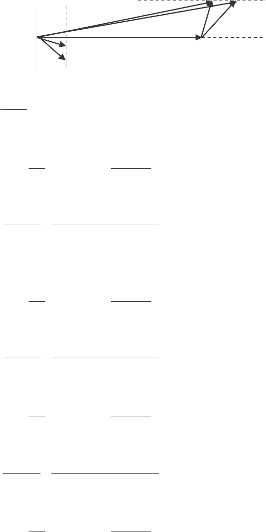
146
(d) If A
E is decreased by 5%, the armature current will change as shown below. Note that the infinite
bus will keep
φ
V and m
ω
constant. Also, since the prime mover hasn’t changed, the power supplied by the
generator will be constant.
V
φ
E
A
1
jX
S
I
A
E
A
2
I
A
2
I
A
1
Q
∝
I
sin
θ
A
3sin constant
A
S
VE
PX
φ
δ
==, so 11 2 2
sin sin
AA
EE
δδ
=
With a 5% decrease, 212,570 V
A
E=, and
11
1
22
2
13, 230 V
sin sin sin sin 27.9 29.5
12,570 V
A
A
E
E
δδ
−−
== °=°
Therefore, the new armature current is
212,570 29.5 7044 0 894 32.2 A
8.18
A
A
S
jX j
φ
−∠°− ∠°
== =∠−°
EV
I
(e) Repeating part (d):
With a
10% decrease, 211,907 V
A
E=, and
11
1
22
2
13, 230 V
sin sin sin sin 27.9 31.3
11,907 V
A
A
E
E
δδ
−−
== °=°
Therefore, the new armature current is
211, 907 31.3 7044 0 848 26.8 A
8.18
A
A
S
jX j
φ
−∠°− ∠°
== =∠−°
EV
I
With a
15% decrease, 211,246 V
A
E=, and
11
1
22
2
13, 230 V
sin sin sin sin 27.9 33.4
11,246 V
A
A
E
E
δδ
−−
== °=°
Therefore, the new armature current is
211,246 33.4 7044 0 809 20.7 A
8.18
A
A
S
jX j
φ
−∠°− ∠°
== =∠−°
EV
I
With a
20% decrease, 210,584 V
A
E=, and
11
1
22
2
13, 230 V
sin sin sin sin 27.9 35.8
10,584 V
A
A
E
E
δδ
−−
== °=°
Therefore, the new armature current is

147
210,584 35.8 7044 0 780 14.0 A
8.18
A
A
S
jX j
φ
−∠°− ∠°
== =∠−°
EV
I
With a
25% decrease, 29, 923 V
A
E=, and
11
1
22
2
13, 230 V
sin sin sin sin 27.9 38.6
9,923 V
A
A
E
E
δδ
−−
== °=°
Therefore, the new armature current is
29,923 38.6 7044 0 762 6.6 A
8.18
A
A
S
jX j
φ
−∠°− ∠°
== =∠−°
EV
I
(f) A MATLAB program to plot the magnitude of the armature current A
I as a function of A
E is shown
below.
% M-file: prob5_28f.m
% M-file to calculate and plot the armature current
% supplied to an infinite bus as Ea is varied.
% Define values for this generator
Ea = (0.65:0.01:1.00)*13230; % Ea
Vp = 7044; % Phase voltage
d1 = 27.9*pi/180; % torque angle at full Ea
Xs = 8.18; % Xs (ohms)
% Calculate delta for each Ea
d = asin( 13230 ./ Ea .* sin(d1));
% Calculate Ia for each flux
Ea = Ea .* ( cos(d) + j.*sin(d) );
Ia = ( Ea - Vp ) ./ (j*Xs);
% Plot the armature current versus Ea
figure(1);
plot(abs(Ea)/1000,abs(Ia),'b-','LineWidth',2.0);
title ('\bfArmature current versus \itE_{A}\rm');
xlabel ('\bf\itE_{A}\rm\bf (kV)');
ylabel ('\bf\itI_{A}\rm\bf (A)');
grid on;
hold off;
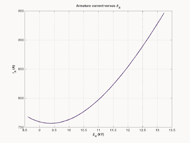
148
The resulting plot is shown below:
149
Chapter 6: Synchronous Motors
6-1. A 480-V, 60 Hz, four-pole synchronous motor draws 50 A from the line at unity power factor and full
load. Assuming that the motor is lossless, answer the following questions:
(a) What is the output torque of this motor? Express the answer both in newton-meters and in pound-feet.
(b) What must be done to change the power factor to 0.8 leading? Explain your answer, using phasor
diagrams.
(c) What will the magnitude of the line current be if the power factor is adjusted to 0.8 leading?
S
OLUTION
(a) If this motor is assumed lossless, then the input power is equal to the output power. The input power
to this motor is
()()()
IN 3 cos 3 480 V 50 A 1.0 41.6 kW
TL
PVI
θ
== =
The output torque would be
()
OUT
LOAD
41.6 kW 221 N m
1 min 2 rad
1800 r/min 60 s 1 r
m
P
τπ
ω
== = ⋅
In English units,
(
)
(
)
()
OUT
LOAD
7.04 41.6 kW
7.04 163 lb ft
1800 r/min
m
P
n
τ
== =⋅
(b) To change the motor’s power factor to 0.8 leading, its field current must be increased. Since the
power supplied to the load is independent of the field current level, an increase in field current increases
A
E while keeping the distance
δ
sin
A
E constant. This increase in A
E changes the angle of the current
A
I, eventually causing it to reach a power factor of 0.8 leading.
V
φ
E
A
1
jX
S
I
A
E
A
2
I
A
2
I
A
1
Q
∝
I
sin
θ
A
}
∝
P
}
∝
P
(c) The magnitude of the line current will be
()()
41.6 kW 62.5 A
3 PF 3 480 V 0.8
L
T
P
IV
== =
6-2. A 480-V, 60 Hz, 400-hp 0.8-PF-leading six-pole ∆-connected synchronous motor has a synchronous
reactance of 1.1 Ω and negligible armature resistance. Ignore its friction, windage, and core losses for the
purposes of this problem.
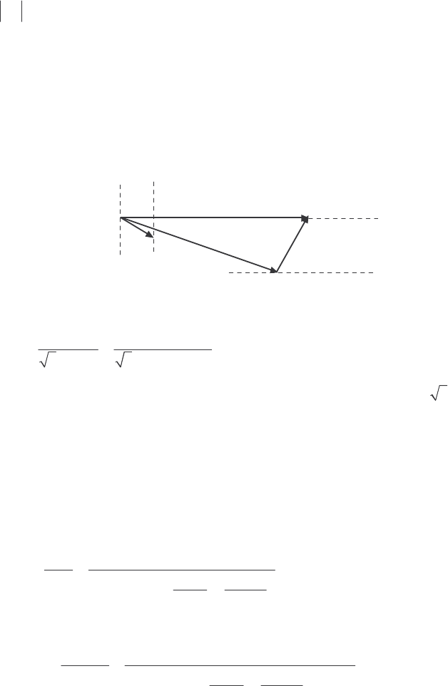
150
(a) If this motor is initially supplying 400 hp at 0.8 PF lagging, what are the magnitudes and angles of EA
and IA?
(b) How much torque is this motor producing? What is the torque angle
δ
? How near is this value to the
maximum possible induced torque of the motor for this field current setting?
(c) If EA is increased by 15 percent, what is the new magnitude of the armature current? What is the
motor’s new power factor?
(d) Calculate and plot the motor’s V-curve for this load condition.
S
OLUTION
(a) If losses are being ignored, the output power is equal to the input power, so the input power will be
()( )
IN 400 hp 746 W/hp 298.4 kWP==
This situation is shown in the phasor diagram below:
V
φ
E
A
jX
S
I
A
I
A
The line current flow under these circumstances is
()()
298.4 kW 449 A
3 PF 3 480 V 0.8
L
T
P
IV
== =
Because the motor is ∆-connected, the corresponding phase current is 449 / 3 259 A
A
I==
. The angle of
the current is
()
1
cos 0.80 36.87
−
−=−°, so 259 36.87 A
A=∠− °I. The internal generated voltage A
E is
ASA
jX
φ
=−EV I
()()( )
480 0 V 1.1 259 36.87 A 384 36.4 V
Aj=∠°− Ω ∠− °=∠−°E
(b) This motor has 6 poles and an electrical frequency of 60 Hz, so its rotation speed is m
n = 1200 r/min.
The induced torque is
()
OUT
ind
298.4 kW 2375 N m
1 min 2 rad
1200 r/min 60 s 1 r
m
P
τπ
ω
== = ⋅
The maximum possible induced torque for the motor at this field setting is
()()
() ()
ind,max
3 3 480 V 384 V 4000 N m
1 min 2 rad
1200 r/min 1.1
60 s 1 r
A
mS
VE
X
φ
τπ
ω
== =⋅
Ω
(c) If the magnitude of the internal generated voltage A
E is increased by 15%, the new torque angle can
be found from the fact that constantsin =∝ PEA
δ
.
()
21
1.15 1.15 384 V 441.6 V
AA
EE== =

151
()
11
1
21
2
384 V
sin sin sin sin 36.4 31.1
441.6 V
A
A
E
E
δδ
−−
== −°=−°
The new armature current is
2
2
480 0 V 441.6 31.1 V 227 24.1 A
1.1
A
A
S
jX j
φ
−∠° − ∠− °
== =∠−°
Ω
VE
I
The magnitude of the armature current is 227 A, and the power factor is cos (-24.1°) = 0.913 lagging.
(d) A MATLAB program to calculate and plot the motor’s V-curve is shown below:
% M-file: prob6_2d.m
% M-file create a plot of armature current versus Ea
% for the synchronous motor of Problem 6-2.
% Initialize values
Ea = (1:0.01:1.70)*384; % Magnitude of Ea volts
Ear = 384; % Reference Ea
deltar = -36.4 * pi/180; % Reference torque angle
Xs = 1.1; % Synchronous reactance
Vp = 480; % Phase voltage at 0 degrees
Ear = Ear * (cos(deltar) + j * sin(deltar));
% Calculate delta2
delta2 = asin ( abs(Ear) ./ abs(Ea) .* sin(deltar) );
% Calculate the phasor Ea
Ea = Ea .* (cos(delta2) + j .* sin(delta2));
% Calculate Ia
Ia = ( Vp - Ea ) / ( j * Xs);
% Plot the v-curve
figure(1);
plot(abs(Ea),abs(Ia),'b','Linewidth',2.0);
xlabel('\bf\itE_{A}\rm\bf (V)');
ylabel('\bf\itI_{A}\rm\bf (A)');
title ('\bfSynchronous Motor V-Curve');
grid on;
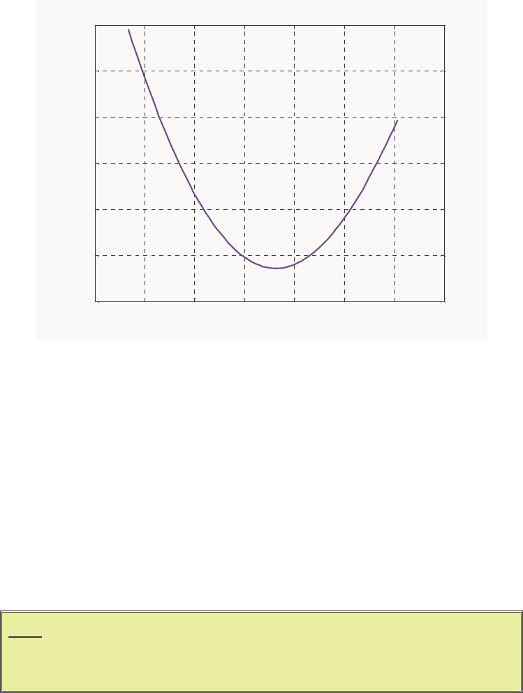
152
The resulting plot is shown below
350 400 450 500 550 600 650 700
200
210
220
230
240
250
260
E
A
(V)
I
A
(A)
Synchronous Motor V-Curve
6-3. A 2300-V 1000-hp 0.8-PF leading 60-Hz two-pole Y-connected synchronous motor has a synchronous
reactance of 2.8 Ω and an armature resistance of 0.4 Ω. At 60 Hz, its friction and windage losses are 24
kW, and its core losses are 18 kW. The field circuit has a dc voltage of 200 V, and the maximum IF is 10
A. The open-circuit characteristic of this motor is shown in Figure P6-1. Answer the following questions
about the motor, assuming that it is being supplied by an infinite bus.
(a) How much field current would be required to make this machine operate at unity power factor when
supplying full load?
(b) What is the motor’s efficiency at full load and unity power factor?
(c) If the field current were increased by 5 percent, what would the new value of the armature current be?
What would the new power factor be? How much reactive power is being consumed or supplied by the
motor?
(d) What is the maximum torque this machine is theoretically capable of supplying at unity power factor?
At 0.8 PF leading?
Note: An electronic version of this open circuit characteristic can be found in file
p61_occ.dat, which can be used with MATLAB programs. Column 1
contains field current in amps, and column 2 contains open-circuit terminal
voltage in volts.
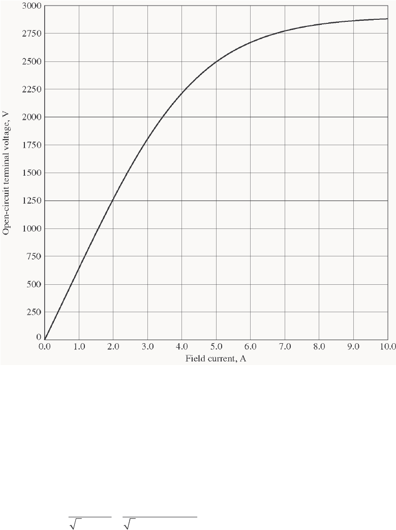
153
S
OLUTION
(a) At full load, the input power to the motor is
CUcoremechOUTIN PPPPP +++=
We can’t know the copper losses until the armature current is known, so we will find the input power and
armature current ignoring that term, and then correct the input power after we know it.
()( )
IN 1000 hp 746 W/hp 24 kW 18 kW 788 kWP=++=
Therefore, the line and phase current at unity power factor is
()()
788 kW 198 A
3 PF 3 2300 V 1.0
AL
T
P
II V
== = =
The copper losses due to a current of 198 A are
()()
2
2
CU 3 3 198 A 0.4 47.0 kW
AA
PIR== Ω=
Therefore, a better estimate of the input power at full load is
()( )
IN 1000 hp 746 W/hp 24 kW 18 kW 47 kW 835 kWP=+++=
and a better estimate of the line and phase current at unity power factor is
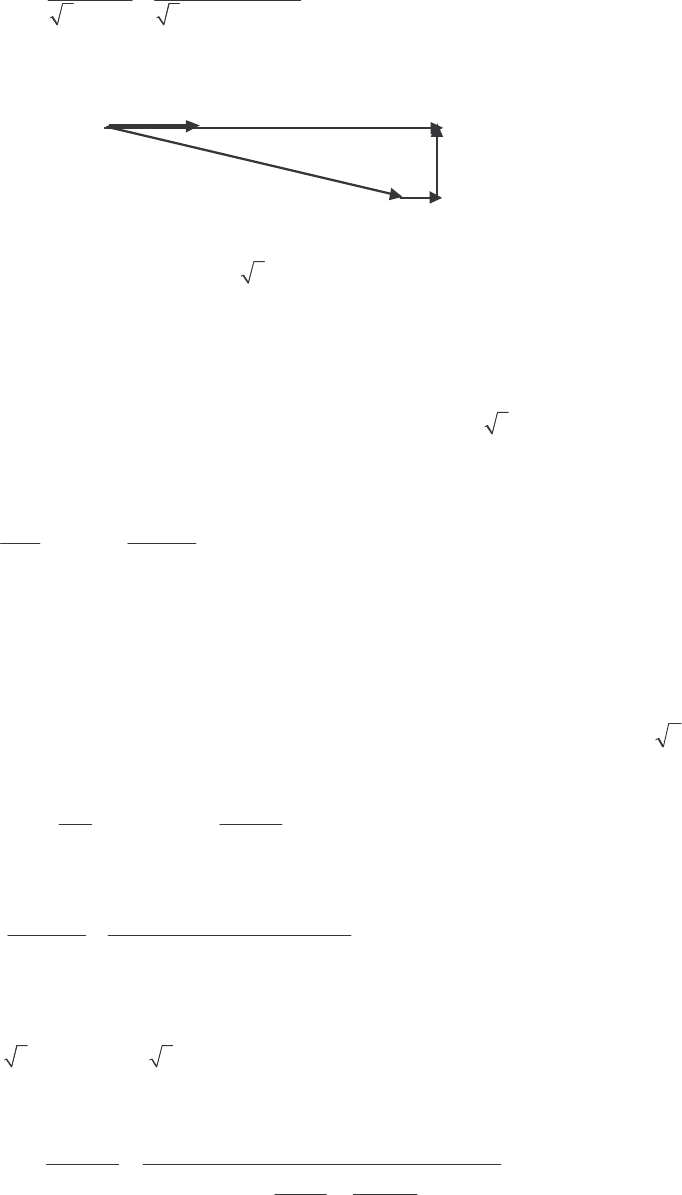
154
()()
835 kW 210 A
3 PF 3 2300 V 1.0
AL
T
P
II V
== = =
The phasor diagram of this motor operating a unity power factor is shown below:
jX
S
I
A
V
φ
I
A
E
A
I
A
R
A
The phase voltage of this motor is 2300 / 3 = 1328 V. The required internal generated voltage is
AAASA
RjX
φ
=− −EV I I
()( )()( )
1328 0 V 0.4 210 0 A 2.8 210 0 A
Aj=∠°−Ω∠°− Ω∠°E
1376 25.3 V
A=∠−°E
This internal generated voltage corresponds to a terminal voltage of
()
3 1376 2383 V=. This voltage
would require a field current of 4.6 A.
(b) The motor’s efficiency at full load and unity power factor is
OUT
IN
746 kW
100% 100% 89.3%
835 kW
P
P
η
=× = × =
(c) To solve this problem, we will temporarily ignore the effects of the armature resistance A
R. If A
R is
ignored, then
δ
sin
A
E is directly proportional to the power supplied by the motor. Since the power
supplied by the motor does not change when F
I is changed, this quantity will be a constant.
If the field current is increased by 5%, then the new field current will be 4.83 A, and the new value of
the open-circuit terminal voltage will be 2450 V. The new value of A
E will be 2450 V / 3 = 1415 V.
Therefore, the new torque angle
δ
will be
()
11
1
21
2
1376 V
sin sin sin sin 25.3 24.6
1415 V
A
A
E
E
δδ
−−
== −°=−°
Therefore, the new armature current will be
1328 0 V 1415 -25.3 V 214.5 3.5 A
0.4 2.8
A
A
AS
RjX j
φ
−∠° − ∠ °
== =∠°
++Ω
VE
I
The new current is about the same as before, but the phase angle has become positive. The new power
factor is cos 3.5° = 0.998 leading, and the reactive power supplied by the motor is
(
)
(
)
(
)
3 sin 3 2300 V 214.5 A sin 3.5 52.2 kVAR
TL
QVI
θ
== °=
(d) The maximum torque possible at unity power factor (ignoring the effects of A
R) is:
(
)
(
)
() ()
ind,max
3 3 1328 V 1376 V 5193 N m
1 min 2 rad
3600 r/min 2.8
60 s 1 r
A
mS
VE
X
φ
τπ
ω
== =⋅
Ω
155
If we are ignoring the resistance of the motor, then the input power would be 788 kW (note that copper
losses are ignored!). At a power factor of 0.8 leading, the current flow will be
()()
788 kW 247 A
3 PF 3 2300 V 0.8
AL
T
P
II V
== = =
so
247 36.87 A
A=∠ °I. The internal generated voltage at 0.8 PF leading (ignoring copper losses) is
AAASA
RjX
φ
=− −EV I I
()( )
1328 0 V 2.8 247 36.87 A
Aj=∠°− Ω ∠ °E
1829 17.6 V
A=∠−°E
Therefore, the maximum torque at a power factor of 0.8 leading is
(
)
(
)
() ()
ind,max
3 3 1328 V 1829 V 6093 N m
1 min 2 rad
3600 r/min 2.8
60 s 1 r
A
mS
VE
X
φ
τπ
ω
== =⋅
Ω
6-4. Plot the V-curves ( IA versus IF) for the synchronous motor of Problem 6-3 at no-load, half-load, and full-
load conditions. (Note that an electronic version of the open-circuit characteristics in Figure P6-1 is
available at the book’s Web site. It may simplify the calculations required by this problem. Also, you may
assume that A
R is negligible for this calculation.)
S
OLUTION The input power at no-load, half-load and full-load conditions is given below. Note that we are
assuming that A
R is negligible in each case.
IN,nl 24 kW 18 kW 42 kWP=+ =
()( )
IN,half 500 hp 746 W/hp 24 kW 18 kW 373 kWP=++=
()( )
IN,full 1000 hp 746 W/hp 24 kW 18 kW 788 kWP=++=
If the power factor is adjusted to unity, then armature currents will be
()()
,nl
42 kW 10.5 A
3 PF 3 2300 V 1.0
A
T
P
IV
== =
()()
,fl
373 kW 93.6 A
3 PF 3 2300 V 1.0
A
T
P
IV
== =
()()
,fl
788 kW 198 A
3 PF 3 2300 V 1.0
A
T
P
IV
== =
The corresponding internal generated voltages at unity power factor are:
ASA
jX
φ
=−EV I
(
)
(
)
,nl 1328 0 V 2.8 10.5 0 A 1328.3 1.27 V
Aj=∠°− Ω ∠°= ∠−°E
()( )
,half 1328 0 V 1.5 93.6 0 A 1354 11.2 V
Aj=∠°− Ω ∠°=∠−°E
(
)
(
)
,full 1328 0 V 2.8 198 0 A 1439 22.7 V
Aj=∠°− Ω∠°=∠−°E
These values of
A
E and
δ
at unity power factor can serve as reference points in calculating the
synchronous motor V-curves. The MATLAB program to solve this problem is shown below:
156
% M-file: prob6_4.m
% M-file create a plot of armature current versus field
% current for the synchronous motor of Problem 6-4 at
% no-load, half-load, and full-load.
% First, initialize the field current values (21 values
% in the range 3.8-5.8 A)
If = 2.5:0.1:8;
% Get the OCC
load p61_occ.dat;
if_values = p61_occ(:,1);
vt_values = p61_occ(:,2);
% Now initialize all other values
Xs = 1.5; % Synchronous reactance
Vp = 1328; % Phase voltage
% The following values of Ea and delta are for unity
% power factor. They will serve as reference values
% when calculating the V-curves.
d_nl = -1.27 * pi/180; % delta at no-load
d_half = -11.2 * pi/180; % delta at half-load
d_full = -22.7 * pi/180; % delta at full-load
Ea_nl = 1328.3; % Ea at no-load
Ea_half = 1354; % Ea at half-load
Ea_full = 1439; % Ea at full-load
%%%%%%%%%%%%%%%%%%%%%%%%%%%%%%%%%%%%%%%%%%%%%%%%%%%%%%
% Calculate the actual Ea corresponding to each level
% of field current
%%%%%%%%%%%%%%%%%%%%%%%%%%%%%%%%%%%%%%%%%%%%%%%%%%%%%%
Ea = interp1(if_values,vt_values,If) / sqrt(3);
%%%%%%%%%%%%%%%%%%%%%%%%%%%%%%%%%%%%%%%%%%%%%%%%%%%%%%
% Calculate the armature currents associated with
% each value of Ea for the no-load case.
%%%%%%%%%%%%%%%%%%%%%%%%%%%%%%%%%%%%%%%%%%%%%%%%%%%%%%
% First, calculate delta.
delta = asin ( Ea_nl ./ Ea .* sin(d_nl) );
% Calculate the phasor Ea
Ea2 = Ea .* (cos(delta) + j .* sin(delta));
% Now calculate Ia
Ia_nl = ( Vp - Ea2 ) / (j * Xs);
%%%%%%%%%%%%%%%%%%%%%%%%%%%%%%%%%%%%%%%%%%%%%%%%%%%%%%
% Calculate the armature currents associated with
% each value of Ea for the half-load case.
%%%%%%%%%%%%%%%%%%%%%%%%%%%%%%%%%%%%%%%%%%%%%%%%%%%%%%
% First, calculate delta.
delta = asin ( Ea_half ./ Ea .* sin(d_half) );
% Calculate the phasor Ea
Ea2 = Ea .* (cos(delta) + j .* sin(delta));
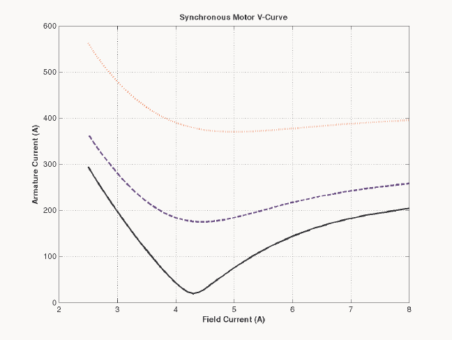
157
% Now calculate Ia
Ia_half = ( Vp - Ea2 ) / (j * Xs);
%%%%%%%%%%%%%%%%%%%%%%%%%%%%%%%%%%%%%%%%%%%%%%%%%%%%%%
% Calculate the armature currents associated with
% each value of Ea for the full-load case.
%%%%%%%%%%%%%%%%%%%%%%%%%%%%%%%%%%%%%%%%%%%%%%%%%%%%%%
% First, calculate delta.
delta = asin ( Ea_full ./ Ea .* sin(d_full) );
% Calculate the phasor Ea
Ea2 = Ea .* (cos(delta) + j .* sin(delta));
% Now calculate Ia
Ia_full = ( Vp - Ea2 ) / (j * Xs);
%%%%%%%%%%%%%%%%%%%%%%%%%%%%%%%%%%%%%%%%%%%%%%%%%%%%%%
% Plot the v-curves
%%%%%%%%%%%%%%%%%%%%%%%%%%%%%%%%%%%%%%%%%%%%%%%%%%%%%%
plot(If,abs(Ia_nl),'k-','Linewidth',2.0);
hold on;
plot(If,abs(Ia_half),'b--','Linewidth',2.0);
plot(If,abs(Ia_full),'r:','Linewidth',2.0);
xlabel('\bfField Current (A)');
ylabel('\bfArmature Current (A)');
title ('\bfSynchronous Motor V-Curve');
grid on;
The resulting plot is shown below. The flattening visible to the right of the V-curves is due to magnetic
saturation in the machine.
6-5. If a 60-Hz synchronous motor is to be operated at 50 Hz, will its synchronous reactance be the same as at
60 Hz, or will it change? (Hint: Think about the derivation of XS.)
158
S
OLUTION The synchronous reactance represents the effects of the armature reaction voltage stat
E and the
armature self-inductance. The armature reaction voltage is caused by the armature magnetic field S
B, and
the amount of voltage is directly proportional to the speed with which the magnetic field sweeps over the
stator surface. The higher the frequency, the faster S
B sweeps over the stator, and the higher the armature
reaction voltage stat
E is. Therefore, the armature reaction voltage is directly proportional to frequency.
Similarly, the reactance of the armature self-inductance is directly proportional to frequency, so the total
synchronous reactance XS is directly proportional to frequency. If the frequency is changed from 60 Hz to
50 Hz, the synchronous reactance will be decreased by a factor of 5/6.
6-6. A 480-V 100-kW 0.85-PF leading 50-Hz six-pole Y-connected synchronous motor has a synchronous
reactance of 1.5 Ω and a negligible armature resistance. The rotational losses are also to be ignored. This
motor is to be operated over a continuous range of speeds from 300 to 1000 r/min, where the speed changes
are to be accomplished by controlling the system frequency with a solid-state drive.
(a) Over what range must the input frequency be varied to provide this speed control range?
(b) How large is EA at the motor’s rated conditions?
(c) What is the maximum power the motor can produce at the rated conditions?
(d) What is the largest EA could be at 300 r/min?
(e) Assuming that the applied voltage Vφ is derated by the same amount as EA, what is the maximum
power the motor could supply at 300 r/min?
(f) How does the power capability of a synchronous motor relate to its speed?
S
OLUTION
(a) A speed of 300 r/min corresponds to a frequency of
(
)
(
)
300 r/min 6 15 Hz
120 120
m
e
nP
f== =
A speed of 1000 r/min corresponds to a frequency of
()()
1000 r/min 6 50 Hz
120 120
m
e
nP
f== =
The frequency must be controlled in the range 15 to 50 Hz.
(b) The armature current at rated conditions is
()()
100 kW 141.5 A
3 PF 3 480 V 0.85
AL
T
P
II V
== = =
so 141.5 31.8 A
A=∠°I. This machine is Y-connected, so the phase voltage is V
φ
= 480 / 3 = 277 V.
The internal generated voltage is
AAASA
RjX
φ
=− −EV I I
()( )
277 0 V 1.5 141.5 31.8 A
Aj=∠°− Ω ∠°E
429 24.9 V
A=∠− °E
So
A
E = 429 V at rated conditions.
(c) The maximum power that the motor can produce at rated speed with the value of A
E from part (b) is
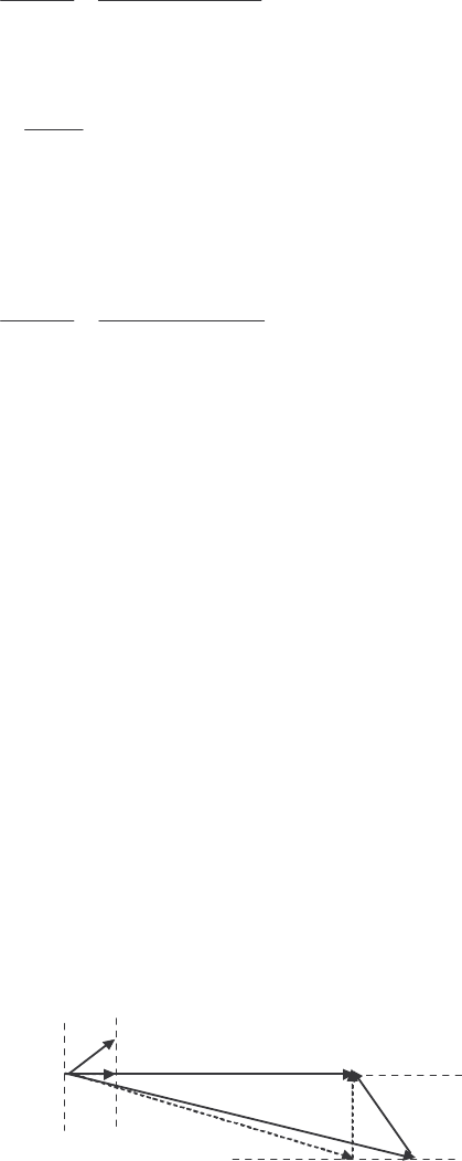
159
()()
max
3 3 277 V 429 V 238 kW
1.5
A
S
VE
PX
φ
== =
Ω
(d) Since A
E must be decreased linearly with frequency, the maximum value at 300 r/min would be
()
,300
15 Hz 429 V 129 V
50 Hz
A
E
==
(e) If the applied voltage
φ
V is derated by the same amount as A
E, then V
φ
= (15/50)(277) = 83.1 V.
Also, note that S
X = (15/50)(1.5 Ω) = 0.45 Ω. The maximum power that the motor could supply would
be
()()
max
3 3 83.1 V 129 V 71.5 kW
0.45
A
S
VE
PX
φ
== =
Ω
(f) As we can see by comparing the results of (c) and (e), the power-handling capability of the
synchronous motor varies linearly with the speed of the motor.
6-7. A 208-V Y-connected synchronous motor is drawing 40 A at unity power factor from a 208-V power
system. The field current flowing under these conditions is 2.7 A. Its synchronous reactance is 0.8 Ω.
Assume a linear open-circuit characteristic.
(a) Find the torque angle
δ
.
(b) How much field current would be required to make the motor operate at 0.8 PF leading?
(c) What is the new torque angle in part (b)?
S
OLUTION
(a) The phase voltage of this motor is V
φ
= 120 V, and the armature current is 40 0 A
A=∠°I.
Therefore, the internal generated voltage is
AAASA
RjX
φ
=− −EV I I
()( )
120 0 V 0.8 40 0 A
Aj=∠°− Ω ∠°E
124 14.9 V
A=∠− °E
The torque angle
δ
of this machine is –14.9°.
(b) A phasor diagram of the motor operating at a power factor of 0.78 leading is shown below.
V
φ
E
A
1
jX
S
I
A
E
A
2
I
A
2
I
A
1
}
∝
P
}
∝
P
Since the power supplied by the motor is constant, the quantity
θ
cos
A
I, which is directly proportional to
power, must be constant. Therefore,
()( )( )
20.8 40 A 1.00
A
I=

160
250 36.87 A
A=∠ °I
The internal generated voltage required to produce this current would be
222AAASA
RjX
φ
=− −EV I I
()( )
2120 0 V 0.8 50 36.87 A
Aj=∠°− Ω ∠ °E
2147.5 12.5 V
A=∠−°E
The internal generated voltage A
E is directly proportional to the field flux, and we have assumed in this
problem that the flux is directly proportional to the field current. Therefore, the required field current is
()
2
21
1
147 V 2.7 A 3.20 A
124 V
A
FF
A
E
II
E
== =
(c) The new torque angle
δ
of this machine is –12.5°.
6-8. A synchronous machine has a synchronous reactance of 2.0 Ω per phase and an armature resistance of 0.4
Ω per phase. If EA =460∠-8° V and
φ
V = 480∠0° V, is this machine a motor or a generator? How
much power P is this machine consuming from or supplying to the electrical system? How much reactive
power Q is this machine consuming from or supplying to the electrical system?
S
OLUTION This machine is a motor, consuming power from the power system, because A
E is lagging
φ
V.
It is also consuming reactive power, because cos
A
EV
φ
δ
<. The current flowing in this machine is
480 0 V 460 8 V 33.6 9.6 A
0.4 2.0
A
A
AS
RjX j
φ
−∠° − ∠−°
== =∠−°
++Ω
VE
I
Therefore the real power consumed by this motor is
()( )()
3 cos 3 480 V 33.6 A cos 9.6 47.7 kW
A
PVI
φ
θ
== °=
and the reactive power consumed by this motor is
()( )()
3 sin 3 480 V 33.6 A sin 9.6 8.07 kVAR
A
QVI
φ
θ
== °=
6-9. Figure P6-2 shows a synchronous motor phasor diagram for a motor operating at a leading power factor
with no RA. For this motor, the torque angle is given by
cos
tan = sin
SA
SA
XI
VXI
φ
θ
δθ
+
-1 cos
=tan sin
SA
SA
XI
VXI
φ
θ
δθ
+
Derive an equation for the torque angle of the synchronous motor if the armature resistance is included.
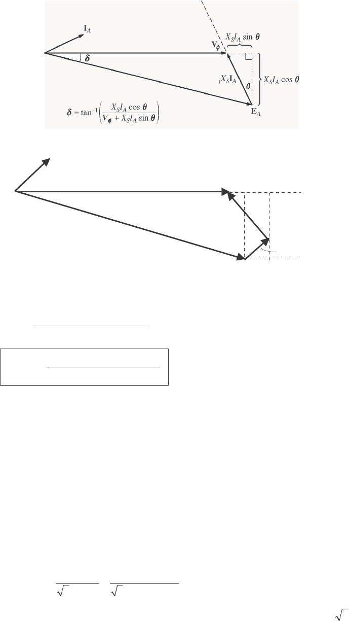
161
S
OLUTION The phasor diagram with the armature resistance considered is shown below.
jX
S
I
A
V
φ
I
A
E
A
I
A
R
A
I
A
R
A
cos
θ
θ
θ
θ
X
S
I
A
sin
θ
}
X
S
I
A
cos
θ
}
}
δ
Therefore,
cos sin
tan sin cos
SA AA
SA AA
XI RI
VXI RI
φ
θθ
δθθ
+
=+−
1cos sin
tan sin cos
SA AA
SA AA
XI RI
VXI RI
φ
θθ
δθθ
−
+
=
+−
6-10. A 480-V 375-kVA 0.8-PF-lagging Y-connected synchronous generator has a synchronous reactance of 0.4
Ω and a negligible armature resistance. This generator is supplying power to a 480-V 80-kW 0.8-PF-
leading Y-connected synchronous motor with a synchronous reactance of 1.1 Ω and a negligible armature
resistance. The synchronous generator is adjusted to have a terminal voltage of 480 V when the motor is
drawing the rated power at unity power factor.
(a) Calculate the magnitudes and angles of A
E for both machines.
(b) If the flux of the motor is increased by 10 percent, what happens to the terminal voltage of the power
system? What is its new value?
(c) What is the power factor of the motor after the increase in motor flux?
S
OLUTION
(a) The motor is operating at rated power and unity power factor, so the current flowing in the motor is
()()
,m ,m
80 kW 96.2 A
3 PF 3 480 V 1.0
AL
T
P
II V
== = =
so
,m 96.2 0 A
A=∠°I. This machine is Y-connected, so the phase voltage is V
φ
= 480 / 3 = 277 V. The
internal generated voltage of the motor is
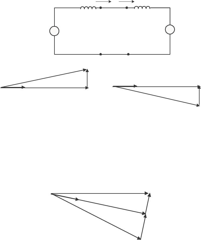
162
,m ,m ,mASA
jX
φ
=−EV I
()( )
,m 277 0 V 1.1 96.2 0 A
Aj=∠°− Ω ∠°E
,m 297 20.9 V
A=∠− °E
This same current comes from the generator, so the internal generated voltage of the generator is
,g ,g ,gASA
jX
φ
=+EV I
()( )
,g 277 0 V 0.4 96.2 0 A
Aj=∠°+ Ω ∠°E
,g 280 7.9 V
A=∠°E
+
-
E
A,g
j
0.4
Ω
+
-
V
φ
,m
I
A,g
+
-
I
A,m
E
A,m
j
1.1
Ω
+
-
V
φ
,g
I
A
jX
S,m
V
φ
I
A
E
A,m
jX
S,g
I
A
V
φ
I
A
E
A,g
Generator Motor
(b) The power supplied by the generator to the motor will be constant as the field current of the motor is
varied. The 10% increase in flux will raise the internal generated voltage of the motor to (1.1)(297 V) =
327 V.
To make finding the new conditions easier, we will make the angle of the phasor ,Ag
E the reference during
the following calculations. The resulting phasor diagram is shown below.
I
A
jX
S,m
V
φ
I
A
E
A
,
m
jX
S,g
I
A
E
A,g
δ
m
δ
g
Then by Kirchhoff’s Voltage Law,
,, ,,
()
Ag Am S g Sm A
jX X=+ +EE I

163
or ,,
,,
()
Ag Am
A
Sg Sm
jX X
−
=+
EE
I
Note that this combined phasor diagram looks just like the diagram of a synchronous motor, so we can
apply the power equation for synchronous motors to this system.
,,
,,
3sin
Ag Am
Sg Sm
EE
PXX
γ
=+
where
gm
γ
δδ
=+. From this equation,
()
()( )
()( )
,,
11
,,
1.5 80 kW
sin sin 25.9
3 3 280V 327 V
Sg Sm
Ag Am
XXP
EE
γ
−−
+Ω
== =°
Therefore,
,,
,,
280 0 V 327 25.9 V 95.7 5.7 A
() 1.5
Ag Am
A
Sg Sm
jX X j
−∠° − ∠− °
== =∠°
+Ω
EE
I
The phase voltage of the system would be
(
)
(
)
,,
280 0 V 0.4 95.7 5.7 A 286 7.6 V
Ag Sg A
jX j
φ
=− =∠°− Ω ∠°=∠−°VE I
If we make
φ
V the reference (as we usually do), these voltages and currents become:
,280 7.6 V
Ag =∠°E
286 0 V
φ
=∠°V
,327 18.3 V
Am =∠−°E
95.7 13.3 A
A=∠°I
The new terminal voltage is
()
3286 V 495 V
T
V==
, so the system voltage has increased.
(c) The power factor of the motor is now
()
PF cos 13.3 0.973 leading=−°= , since a current angle of
-18.3° implies an impedance angle of 18.3°.
Note: The reactive power in the motor is now
()( )( )
motor 3 sin 3 286 V 95.7 A sin 13.3 18.9 kVAR
A
QVI
φ
θ
== −°=−
The motor is now supplying 18.9 kVAR to the system. Note that an increase in machine flux has
increased the reactive power supplied by the motor and also raised the terminal voltage of the system.
This is consistent with what we learned about reactive power sharing in Chapter 5.
6-11. A 480-V, 100-kW, 50-Hz, four-pole, Y-connected synchronous motor has a rated power factor of 0.85
leading. At full load, the efficiency is 91 percent. The armature resistance is 0.08 Ω, and the synchronous
reactance is 1.0 Ω. Find the following quantities for this machine when it is operating at full load:
(a) Output torque
(b) Input power
(c) m
n
(d) A
E

164
(e) A
I
(f) conv
P
(g) mech core stray
PPP++
S
OLUTION
(a) Since this machine has 8 poles, it rotates at a speed of
(
)
120 50 Hz
120 1500 r/min
4
e
m
f
nP
== =
If the output power is 100 kW, the output torque is
()
()
out
load
m
100,000 W 637 N m
2 rad 1 min
1500 r/min 1 r 60 s
P
τπ
ω
== = ⋅
(b) The input power is
OUT
IN
100 kW 110 kW
0.91
P
P
η
== =
(c) The mechanical speed is
1500 r/min
m
n=
(d) The armature current is
()()
110 kW 156 A
3 PF 3 480 V 0.85
AL
T
P
II V
== = =
156 31.8 A
A=∠°I
Therefore,
A
E is
AAASA
RjX
φ
=− −EV I I
()()()()()
277 0 V 0.08 156 31.8 A 1.0 156 31.8 A
Aj=∠°− Ω∠°− Ω∠°E
375 21.8 V
A=∠− °E
(e) The magnitude of the armature current is 375 A.
(f) The power converted from electrical to mechanical form is given by the equation conv IN CU
PPP=−
()( )
2
2
CU 3 3 156 A 0.08 5.8 kW
AA
PIR== Ω=
conv IN CU 110 kW 5.8 kW 104.2 kWPPP=− = − =
(g) The mechanical, core, and stray losses are given by the equation
mech core stray conv OUT 104.2 kW 100 kW 4.2 kWPPPPP++=−= − =
6-12. The Y-connected synchronous motor whose nameplate is shown in Figure 6-21 has a per-unit synchronous
reactance of 0.90 and a per-unit resistance of 0.02.
(a) What is the rated input power of this motor?
(b) What is the magnitude of A
E at rated conditions?
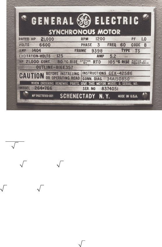
165
(c) If the input power of this motor is 10 MW, what is the maximum reactive power the motor can
simultaneously supply? Is it the armature current or the field current that limits the reactive power
output?
(d) How much power does the field circuit consume at the rated conditions?
(e) What is the efficiency of this motor at full load?
(f) What is the output torque of the motor at the rated conditions? Express the answer both in newton-
meters and in pound-feet.
S
OLUTION The base quantities for this motor are:
,base 6600 V
T
V=
,base
6600 V 3811 V
3
V
φ
==
,base ,base 1404 A
AL
II==
()()()
base rated 3 PF 3 6600 V 1404 A 1.0 16.05 MW
TL
SP VI== = =
(a) The rated input power of this motor is
()()()
IN 3 PF 3 6600 V 1404 A 1.0 16.05 MW
TL
PVI== =
(b) At rated conditions, 1.0 0 pu
φ
=∠°V and 1.0 0 pu
φ
=∠°I, so A
E is given in per-unit quantities as
AAASA
RjX
φ
=− −EV I I
()()( )()()
1 0 0.02 1.0 0 0.90 1 0
Aj=∠°− ∠°− ∠°E
1.33 42.6 pu
A=∠−°E
The base phase voltage of this motor is 6600 / 3= 3810 V, so A
E is
()()
1.33 42.6 3810 V 5067 42.6 V
A=∠−° =∠−°E
(c) From the capability diagram, we know that there are two possible constraints on the maximum
reactive power—the maximum stator current and the maximum rotor current. We will have to check each
one separately, and limit the reactive power to the lesser of the two limits.
The stator apparent power limit defines a maximum safe stator current. This limit is the same as the rated
input power for this motor, since the motor is rated at unity power factor. Therefore, the stator apparent

166
power limit is 16.05 MVA. If the input power is 10 MW, then the maximum reactive power that still
protects the stator current is
()()
22
22 16.05 MVA 10 MW 12.6 MVARQSP=−= − =
Now we must determine the rotor current limit. The per-unit power supplied to the motor is 10 MW /
16.05 MW = 0.623. The maximum A
E is 5067 V or 1.33 pu, so with A
E set to maximum and the motor
consuming 10 MW, the torque angle (ignoring armature resistance) is
()( )
()( )
11
0.90 0.623
sin sin 24.9
3 1.0 1.33
S
A
XP
VE
φ
δ
−−
== =°
At rated voltage and 10 MW of power supplied, the armature current will be
1 0 1.33 24.9 0.663 20.2 pu
0.90
A
A
AS
RjX j
φ
−∠°− ∠− °
== =∠°
+
VE
I
In actual amps, this current is
()( )
1404 A 0.663 20.2 931 20.2 A
A=∠°=∠°I
The reactive power supplied at the conditions of maximum A
E and 10 MW power is
()()()
3 sin 3 3811 V 931 A sin 20.2 3.68 MVAR
A
QVI
φ
θ
== °=
Therefore, the field current limit occurs before the stator current limit for these conditions, and the
maximum reactive power that the motor can supply is 3.68 MVAR under these conditions.
(d) At rated conditions, the field circuit consumes
()()
field 125 V 5.2 A 650 W
FF
PVI== =
(e) The efficiency of this motor at full load is
(
)
(
)
OUT
IN
21000 hp 746 W/hp
100% 100% 97.6%
16.05 MW
P
P
η
=× = × =
(f) The output torque in SI and English units is
()( )
()
OUT
load
21000 hp 746 W/hp 124,700 N m
1 min 2 rad
1200 r/min 60 s 1 r
m
P
τπ
ω
== = ⋅
()
()
load
5252 21000 hp
5252 91,910 lb ft
1200 r/min
m
P
n
τ
== = ⋅
6-13. A 440-V three-phase Y-connected synchronous motor has a synchronous reactance of 1.5 Ω per phase.
The field current has been adjusted so that the torque angle
δ
is 28° when the power supplied by the
generator is 90 kW.
(a) What is the magnitude of the internal generated voltage EA in this machine?
(b) What are the magnitude and angle of the armature current in the machine? What is the motor’s power
factor?
(c) If the field current remains constant, what is the absolute maximum power this motor could supply?
167
S
OLUTION
(a) The power supplied to the motor is 90 kW. This power is give by the equation
3sin
A
S
VE
PX
φ
δ
=
so the magnitude of A
E is
()( )
()
1.5 90 kW
377 V
3 sin 3 254 V sin 28
S
A
XP
EV
φ
δ
Ω
== =
°
(b) The armature current in this machine is given by
254 0 V 377 28 129 24 A
1.5
A
A
S
jX j
φ
−∠° − ∠− °
== =∠°
VE
I
The power factor of the motor is PF = cos 24º = 0.914 leading.
(c) The maximum power that the motor could supply at this field current
()()
max
33 254 V 377 V 191.5 kW
1.5
A
S
VE
PX
φ
== =
Ω
6-14. A 460-V, 200-kVA, 0.80-PF-leading, 400-Hz, six-pole, Y-connected synchronous motor has negligible
armature resistance and a synchronous reactance of 0.50 per unit. Ignore all losses.
(a) What is the speed of rotation of this motor?
(b) What is the output torque of this motor at the rated conditions?
(c) What is the internal generated voltage of this motor at the rated conditions?
(d) With the field current remaining at the value present in the motor in part (c), what is the maximum
possible output power from the machine?
S
OLUTION
(a) The speed of rotation of this motor is
()
sync
120 400 Hz
120 8000 r/min
6
e
f
nP
== =
(b) Since all losses are ignored,
()()
,rated ,rated rated PF 200 kVA 0.8 160 kW
IN OUT
PP S==×= =. The output
torque of this motor is
()
OUT
load
160 kW 191 N m
1 min 2 rad
8000 r/min 60 s 1 r
m
P
τπ
ω
== = ⋅
(c) The phase voltage of this motor is 460 V / 3 = 266 V. The rated armature current of this motor is
()()
160 kW 251 A
3 PF 3 460 V 0.80
AL
T
P
II V
== = =
Therefore, 251 36.87 A
A=∠ °I. The base impedance of this motor is
()
2
2
,base
base
base
33 266 V 1.06
200,000 VA
V
ZS
φ
== =Ω
168
so the actual synchronous reactance is
()()
0.50 pu 1.06 0.53
S
X=Ω=Ω. The internal generated voltage
of this machine at rated conditions is given by
ASA
jX
φ
=−EV I
()( )
266 0 V 0.53 251 36.87 A 362 17.1 V
Aj=∠°− Ω ∠ °=∠−°E
(d) The maximum power that the motor could supply at these conditions is
(
)
(
)
MAX
33 266 V 362 V 545 kW
0.53
A
S
VE
PX
φ
== =
Ω
6-15. A 100-hp 440-V 0.8-PF-leading ∆-connected synchronous motor has an armature resistance of 0.22 Ω and
a synchronous reactance of 3.0 Ω. Its efficiency at full load is 89 percent.
(a) What is the input power to the motor at rated conditions?
(b) What is the line current of the motor at rated conditions? What is the phase current of the motor at
rated conditions?
(c) What is the reactive power consumed by or supplied by the motor at rated conditions?
(d) What is the internal generated voltage EA of this motor at rated conditions?
(e) What are the stator copper losses in the motor at rated conditions?
(f) What is
P
conv at rated conditions?
(g) If EA is decreased by 10 percent, how much reactive power will be consumed by or supplied by the
motor?
S
OLUTION
(a) The input power to the motor at rated conditions is
()( )
OUT
IN
100 hp 746 W/hp 83.8 kW
0.89
P
P
η
== =
(b) The line current to the motor at rated conditions is
()()
83.8 kW 137 A
3 PF 3 440 V 0.8
L
T
P
IV
== =
The phase current to the motor at rated conditions is
137 A 79.4 A
33
L
I
I
φ
== =
(c) The reactive power supplied by this motor to the power system at rated conditions is
()( )
rated 3 sin 3 440 V 79.4 A sin36.87 62.9 kVAR
A
QVI
φ
θ
== °=
(d) The internal generated voltage at rated conditions is
AAASA
RjX
φ
=− −EV I I
()()()()
440 0 V 0.22 79.4 36.87 A 3.0 79.4 36.87 A
Aj=∠°−Ω∠°−Ω∠°E
603 19.5 V
A=∠−°E
(e) The stator copper losses at rated conditions are

169
()()
2
2
CU 3 3 79.4 A 0.22 4.16 kW
AA
PIR== Ω=
(f) conv
P at rated conditions is
conv IN CU 83.8 kW 4.16 kW 79.6 kWPPP=− = − =
(g) If A
E is decreased by 10%, the new value if A
E = (0.9)(603 V) = 543 V. To simplify this part of the
problem, we will ignore A
R. Then the quantity sin
A
E
δ
will be constant as A
E changes. Therefore,
()
11
1
21
2
603 V
sin sin sin sin 19.5 21.8
543 V
A
A
E
E
δδ
−−
==−°=−°
Therefore,
440 0 V 543 21.8 70.5 17.7 A
3.0
A
A
S
jX j
φ
−∠° − ∠− °
== =∠°
VE
I
and the reactive power supplied by the motor to the power system will be
()( )()
3 sin 3 440 V 70.5 A sin 17.7 28.3 kVAR
A
QVI
φ
θ
== °=
6-16. Answer the following questions about the machine of Problem 6-15.
(a) If A
E = 430∠13.5° V and φ
V = 440∠0° V, is this machine consuming real power from or supplying
real power to the power system? Is it consuming reactive power from or supplying reactive power to
the power system?
(b) Calculate the real power P and reactive power Q supplied or consumed by the machine under the
conditions in part (a). Is the machine operating within its ratings under these circumstances?
(c) If A
E = 470∠-12° V and φ
V = 440∠0° V, is this machine consuming real power from or supplying
real power to the power system? Is it consuming reactive power from or supplying reactive power to
the power system?
(d) Calculate the real power P and reactive power Q supplied or consumed by the machine under the
conditions in part (c). Is the machine operating within its ratings under these circumstances?
SOLUTION
(a) This machine is a generator supplying real power to the power system, because A
E is ahead of
φ
V.
It is consuming reactive power because cos
A
EV
φ
δ
<.
(b) This machine is acting as a generator, and the current flow in these conditions is
430 13.5 440 0 V 34.2 16.5 A
0.22 3.0
A
A
AS
RjX j
φ
−∠°−∠°
== =∠°
++
EV
I
The real power supplied by this machine is
()( )( )
3 cos 3 440 V 34.2 A cos 16.5 43.3 kW
A
PVI
φ
θ
== −°=
The reactive power supplied by this machine is
()( )( )
3 sin 3 440 V 34.2 A sin 16.5 12.8 kVAR
A
QVI
φ
θ
== −°=−

170
(c) This machine is a motor consuming real power from the power system, because A
E is behind
φ
V. It
is supplying reactive power because cos
A
EV
φ
δ
>.
(d) This machine is acting as a motor, and the current flow in these conditions is
440 0 V 470 12 33.1 15.6 A
0.22 3.0
A
A
AS
RjX j
φ
−∠° − ∠− °
== =∠°
++
VE
I
The real power consumed by this machine is
()()()
3 cos 3 440 V 33.1 A cos 15.6 42.1 kW
A
PVI
φ
θ
== °=
The reactive power supplied by this machine is
()()()
3 sin 3 440 V 33.1 A sin 15.6 11.7 kVAR
A
QVI
φ
θ
== °=+
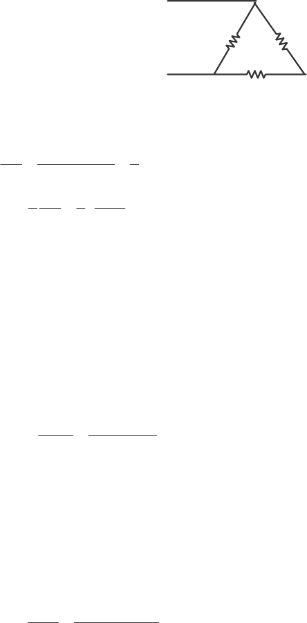
171
Chapter 7: Induction Motors
7-1. A dc test is performed on a 460-V ∆-connected 100-hp induction motor. If DC
V = 24 V and DC
I = 80 A,
what is the stator resistance 1
R? Why is this so?
S
OLUTION If this motor’s armature is connected in delta, then there will be two phases in parallel with one
phase between the lines tested.
R
1
R
1
R
1
V
DC
Therefore, the stator resistance 1
R will be
()
()
11 1
DC
1
DC 1 1 1
2
3
RR R
VR
IRRR
+
==
++
DC
1
DC
3324 V
0.45
2280 A
V
RI
== =Ω
7-2. A 220-V, three-phase, two-pole, 50-Hz induction motor is running at a slip of 5 percent. Find:
(a) The speed of the magnetic fields in revolutions per minute
(b) The speed of the rotor in revolutions per minute
(c) The slip speed of the rotor
(d) The rotor frequency in hertz
S
OLUTION
(a) The speed of the magnetic fields is
()
sync
120 50 Hz
120 3000 r/min
2
e
f
nP
== =
(b) The speed of the rotor is
() ( )( )
sync
1 1 0.05 3000 r/min 2850 r/min
m
nsn=− =− =
(c) The slip speed of the rotor is
()( )
slip sync 0.05 3000 r/min 150 r/minnsn== =
(d) The rotor frequency is
()()
slip 150 r/min 2 2.5 Hz
120 120
r
nP
f== =
7-3. Answer the questions in Problem 7-2 for a 480-V, three-phase, four-pole, 60-Hz induction motor running at
a slip of 0.035.
S
OLUTION
(a) The speed of the magnetic fields is

172
(
)
sync
120 60 Hz
120 1800 r/min
4
e
f
nP
== =
(b) The speed of the rotor is
() ( )( )
sync
1 1 0.035 1800 r/min 1737 r/min
m
nsn=− =− =
(c) The slip speed of the rotor is
()( )
slip sync 0.035 1800 r/min 63 r/minnsn== =
(d) The rotor frequency is
()()
slip 63 r/min 4 2.1 Hz
120 120
r
nP
f== =
7-4. A three-phase, 60-Hz induction motor runs at 890 r/min at no load and at 840 r/min at full load.
(a) How many poles does this motor have?
(b) What is the slip at rated load?
(c) What is the speed at one-quarter of the rated load?
(d) What is the rotor’s electrical frequency at one-quarter of the rated load?
SOLUTION
(a) This machine has 8 poles, which produces a synchronous speed of
()
sync
120 60 Hz
120 900 r/min
8
e
f
nP
== =
(b) The slip at rated load is
sync
sync
900 840
100% 100% 6.67%
900
m
nn
sn
−−
=×= ×=
(c) The motor is operating in the linear region of its torque-speed curve, so the slip at ¼ load will be
0.25(0.0667) 0.0167s==
The resulting speed is
() ( )( )
sync
1 1 0.0167 900 r/min 885 r/min
m
nsn=− =− =
(d) The electrical frequency at ¼ load is
()()
0.0167 60 Hz 1.00 Hz
re
fsf== =
7-5. A 50-kW, 440-V, 50-Hz, six-pole induction motor has a slip of 6 percent when operating at full-load
conditions. At full-load conditions, the friction and windage losses are 300 W, and the core losses are 600
W. Find the following values for full-load conditions:
(a) The shaft speed nm
(b) The output power in watts
(c) The load torque load
τ
in newton-meters
(d) The induced torque ind
τ
in newton-meters

173
(e) The rotor frequency in hertz
S
OLUTION
(a) The synchronous speed of this machine is
(
)
sync
120 50 Hz
120 1000 r/min
6
e
f
nP
== =
Therefore, the shaft speed is
(
)
(
)
(
)
sync
1 1 0.06 1000 r/min 940 r/min
m
nsn=− =− =
(b) The output power in watts is 50 kW (stated in the problem).
(c) The load torque is
()
OUT
load
50 kW 508 N m
2 rad 1 min
940 r/min 1 r 60 s
m
P
τπ
ω
== = ⋅
(d) The induced torque can be found as follows:
conv OUT F&W core misc 50 kW 300 W 600 W 0 W 50.9 kWPPPPP=+++= + + +=
()
conv
ind
50.9 kW 517 N m
2 rad 1 min
940 r/min 1 r 60 s
m
P
τπ
ω
== = ⋅
(e) The rotor frequency is
()( )
0.06 50 Hz 3.00 Hz
re
fsf== =
7-6. A three-phase, 60-Hz, four-pole induction motor runs at a no-load speed of 1790 r/min and a full-load
speed of 1720 r/min. Calculate the slip and the electrical frequency of the rotor at no-load and full-load
conditions. What is the speed regulation of this motor [Equation (4-68)]?
S
OLUTION The synchronous speed of this machine is 1800 r/min. The slip and electrical frequency at no-
load conditions is
sync nl
nl
sync
1800 1790
100% 100% 0.56%
1800
nn
sn
−−
=×= ×=
()()
,nl 0.0056 60 Hz 0.33 Hz
re
fsf== =
The slip and electrical frequency at full load conditions is
sync nl
fl
sync
1800 1720
100% 100% 4.44%
1800
nn
sn
−−
=×= ×=
()()
,fl 0.0444 60 Hz 2.67 Hz
re
fsf== =
The speed regulation is
nl fl
fl
1790 1720
SR 100% 100% 4.1%
1720
nn
n
−−
=×= ×=
7-7. A 208-V, two-pole, 60-Hz Y-connected wound-rotor induction motor is rated at 15 hp. Its equivalent
circuit components are
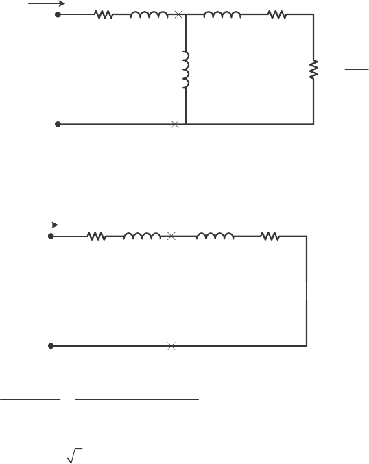
174
1
R = 0.200 Ω 2
R = 0.120 Ω M
X = 15.0 Ω
1
X = 0.410 Ω 2
X = 0.410 Ω
mech
P = 250 W misc
P ≈ 0 core
P = 180 W
For a slip of 0.05, find
(a) The line current L
I
(b) The stator copper losses SCL
P
(c) The air-gap power AG
P
(d) The power converted from electrical to mechanical form conv
P
(e) The induced torque ind
τ
(f) The load torque load
τ
(g) The overall machine efficiency
(h) The motor speed in revolutions per minute and radians per second
S
OLUTION The equivalent circuit of this induction motor is shown below:
0.20 Ωj0.41 Ω
+
-
V
φ
IAR1jX1R2
−
s
s
R1
2
jX2
jXM
0.120 Ωj0.41 Ω
j15 Ω
2.28 Ω
(a) The easiest way to find the line current (or armature current) is to get the equivalent impedance F
Z
of the rotor circuit in parallel with M
jX , and then calculate the current as the phase voltage divided by the
sum of the series impedances, as shown below.
0.20 Ωj0.41 Ω
+
-
V
φ
IAR1jX1RF
jXF
The equivalent impedance of the rotor circuit in parallel with M
jX is:
2
11
2.220 0.745 2.34 18.5
11 1 1
15 2.40 0.41
F
M
Zj
jX Z j j
== =+=∠°Ω
++
Ω+
The phase voltage is 208/ 3 = 120 V, so line current L
I is

175
11
120 0 V
0.20 0.41 2.22 0.745
LA
FF
V
IIRjXR jX j j
φ
∠°
== =
+++ Ω+ Ω+ Ω+ Ω
44.8 25.5 A
LA
II== ∠− °
(b) The stator copper losses are
()()
2
2
SCL 1
3 3 44.8 A 0.20 1205 W
A
PIR== Ω=
(c) The air gap power is 22
2
AG 2
33
AF
R
PI IR
s
==
(Note that
2
3AF
IR
is equal to 22
2
3R
Is, since the only resistance in the original rotor circuit was 2
/
Rs, and
the resistance in the Thevenin equivalent circuit is F
R. The power consumed by the Thevenin equivalent
circuit must be the same as the power consumed by the original circuit.)
()( )
2
22
2
AG 2
3 3 3 44.8 A 2.220 13.4 kW
AF
R
PI IR
s
=== Ω=
(d) The power converted from electrical to mechanical form is
() ( )( )
conv AG
1 1 0.05 13.4 kW 12.73 kWPsP=− =− =
(e) The induced torque in the motor is
()
AG
ind
sync
13.4 kW 35.5 N m
2 rad 1 min
3600 r/min 1 r 60 s
P
τπ
ω
== = ⋅
(f) The output power of this motor is
OUT conv mech core misc 12.73 kW 250 W 180 W 0 W 12.3 kWPPPPP=−−−= − − − =
The output speed is
() ( )( )
sync
1 1 0.05 3600 r/min 3420 r/min
m
nsn=− =− =
Therefore the load torque is
()
OUT
load
12.3 kW 34.3 N m
2 rad 1 min
3420 r/min 1 r 60 s
m
P
τπ
ω
== = ⋅
(g) The overall efficiency is
OUT OUT
IN
100% 100%
3cos
A
PP
PVI
φ
ηθ
=× = ×
()( )
12.3 kW 100% 84.5%
3 120 V 44.8 A cos25.5
η
=×=
°
(h) The motor speed in revolutions per minute is 3420 r/min. The motor speed in radians per second is
()
2 rad 1 min
3420 r/min 358 rad/s
1 r 60 s
m
π
ω
==
7-8. For the motor in Problem 7-7, what is the slip at the pullout torque? What is the pullout torque of this
motor?
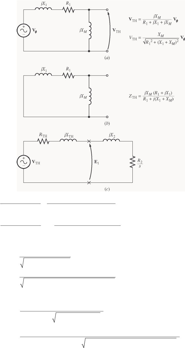
176
S
OLUTION The slip at pullout torque is found by calculating the Thevenin equivalent of the input circuit
from the rotor back to the power supply, and then using that with the rotor circuit model.
()
()
(
)
(
)
()
11
TH
11
15 0.20 0.41 0.1895 0.4016 0.444 64.7
0.20 0.41 15
M
M
jX R jX j j
Zj
RjXX j
+ΩΩ+Ω
== =+Ω=∠°Ω
++ Ω+ Ω+Ω
()
(
)
()
()
TH
11
15 120 0 V 116.8 0.7 V
0.22 0.43 15
M
M
j
jX
RjXX j
φ
Ω
== ∠°=∠°
++ Ω+ Ω+Ω
VV
The slip at pullout torque is
()
2
max 2
2
TH TH 2
R
s
RXX
=++
()( )
max 22
0.120 0.144
0.1895 0.4016 0.410
sΩ
==
Ω+ Ω+ Ω
The pullout torque of the motor is
()
2
TH
max 2
2
sync TH TH TH 2
3V
RRXX
τ
ω
=
2+++
()
() ()( )
2
max 22
3 116.8 V
377 rad/s 0.1895 0.1895 0.4016 0.410
τ
=
2Ω+Ω+Ω+Ω
177
max 53.1 N m
τ
=⋅
7-9. (a) Calculate and plot the torque-speed characteristic of the motor in Problem 7-7. (b) Calculate and plot
the output power versus speed curve of the motor in Problem 7-7.
S
OLUTION
(a) A MATLAB program to calculate the torque-speed characteristic is shown below.
% M-file: prob7_9a.m
% M-file create a plot of the torque-speed curve of the
% induction motor of Problem 7-7.
% First, initialize the values needed in this program.
r1 = 0.200; % Stator resistance
x1 = 0.410; % Stator reactance
r2 = 0.120; % Rotor resistance
x2 = 0.410; % Rotor reactance
xm = 15.0; % Magnetization branch reactance
v_phase = 208 / sqrt(3); % Phase voltage
n_sync = 3600; % Synchronous speed (r/min)
w_sync = 377; % Synchronous speed (rad/s)
% Calculate the Thevenin voltage and impedance from Equations
% 7-41a and 7-43.
v_th = v_phase * ( xm / sqrt(r1^2 + (x1 + xm)^2) );
z_th = ((j*xm) * (r1 + j*x1)) / (r1 + j*(x1 + xm));
r_th = real(z_th);
x_th = imag(z_th);
% Now calculate the torque-speed characteristic for many
% slips between 0 and 1. Note that the first slip value
% is set to 0.001 instead of exactly 0 to avoid divide-
% by-zero problems.
s = (0:1:50) / 50; % Slip
s(1) = 0.001;
nm = (1 - s) * n_sync; % Mechanical speed
% Calculate torque versus speed
for ii = 1:51
t_ind(ii) = (3 * v_th^2 * r2 / s(ii)) / ...
(w_sync * ((r_th + r2/s(ii))^2 + (x_th + x2)^2) );
end
% Plot the torque-speed curve
figure(1);
plot(nm,t_ind,'k-','LineWidth',2.0);
xlabel('\bf\itn_{m}');
ylabel('\bf\tau_{ind}');
title ('\bfInduction Motor Torque-Speed Characteristic');
grid on;
The resulting plot is shown below:
178
0500 1000 1500 2000 2500 3000 3500 4000
0
10
20
30
40
50
60
n
m
τ
ind
Induction Motor Torque-Speed Characteristic
(b) A MATLAB program to calculate the output-power versus speed curve is shown below.
% M-file: prob7_9b.m
% M-file create a plot of the output pwer versus speed
% curve of the induction motor of Problem 7-7.
% First, initialize the values needed in this program.
r1 = 0.200; % Stator resistance
x1 = 0.410; % Stator reactance
r2 = 0.120; % Rotor resistance
x2 = 0.410; % Rotor reactance
xm = 15.0; % Magnetization branch reactance
v_phase = 208 / sqrt(3); % Phase voltage
n_sync = 3600; % Synchronous speed (r/min)
w_sync = 377; % Synchronous speed (rad/s)
% Calculate the Thevenin voltage and impedance from Equations
% 7-41a and 7-43.
v_th = v_phase * ( xm / sqrt(r1^2 + (x1 + xm)^2) );
z_th = ((j*xm) * (r1 + j*x1)) / (r1 + j*(x1 + xm));
r_th = real(z_th);
x_th = imag(z_th);
% Now calculate the torque-speed characteristic for many
% slips between 0 and 1. Note that the first slip value
% is set to 0.001 instead of exactly 0 to avoid divide-
% by-zero problems.
s = (0:1:50) / 50; % Slip
s(1) = 0.001;
nm = (1 - s) * n_sync; % Mechanical speed (r/min)
wm = (1 - s) * w_sync; % Mechanical speed (rad/s)
% Calculate torque and output power versus speed
for ii = 1:51
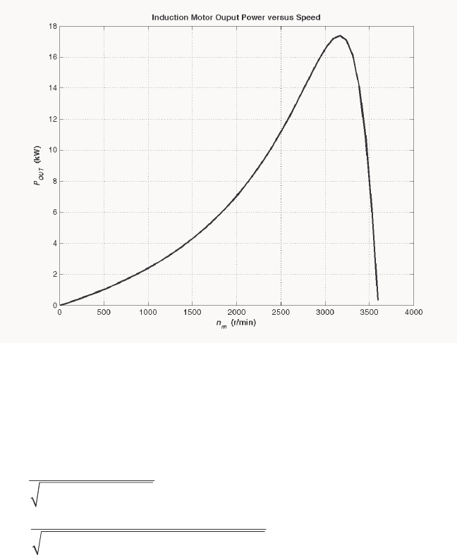
179
t_ind(ii) = (3 * v_th^2 * r2 / s(ii)) / ...
(w_sync * ((r_th + r2/s(ii))^2 + (x_th + x2)^2) );
p_out(ii) = t_ind(ii) * wm(ii);
end
% Plot the torque-speed curve
figure(1);
plot(nm,p_out/1000,'k-','LineWidth',2.0);
xlabel('\bf\itn_{m} \rm\bf(r/min)');
ylabel('\bf\itP_{OUT} \rm\bf(kW)');
title ('\bfInduction Motor Ouput Power versus Speed');
grid on;
The resulting plot is shown below:
7-10. For the motor of Problem 7-7, how much additional resistance (referred to the stator circuit) would it be
necessary to add to the rotor circuit to make the maximum torque occur at starting conditions (when the
shaft is not moving)? Plot the torque-speed characteristic of this motor with the additional resistance
inserted.
S
OLUTION To get the maximum torque at starting, the max
s must be 1.00. Therefore,
()
2
max 2
2
TH TH 2
R
s
RXX
=++
()( )
2
22
1.00
0.1895 0.4016 0.410
R
=Ω+ Ω+ Ω
20.833 R=Ω
Since the existing resistance is 0.120 Ω, an additional 0.713 Ω must be added to the rotor circuit. The
resulting torque-speed characteristic is:
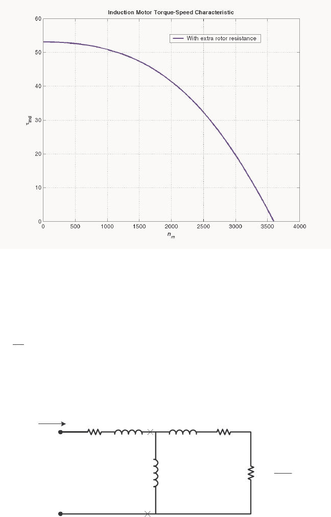
180
7-11. If the motor in Problem 7-7 is to be operated on a 50-Hz power system, what must be done to its supply
voltage? Why? What will the equivalent circuit component values be at 50 Hz? Answer the questions in
Problem 7-7 for operation at 50 Hz with a slip of 0.05 and the proper voltage for this machine.
S
OLUTION If the input frequency is decreased to 50 Hz, then the applied voltage must be decreased by 5/6
also. If this were not done, the flux in the motor would go into saturation, since
∫
=Tdtv
N
1
φ
and the period T would be increased. At 50 Hz, the resistances will be unchanged, but the reactances will
be reduced to 5/6 of their previous values. The equivalent circuit of the induction motor at 50 Hz is shown
below:
0.20 Ωj0.342 Ω
+
-
V
φ
IAR1jX1R2
−
s
s
R1
2
jX2
jXM
0.120 Ωj0.342 Ω
j12.5 Ω
2.28 Ω
(a) The easiest way to find the line current (or armature current) is to get the equivalent impedance F
Z
of the rotor circuit in parallel with M
jX , and then calculate the current as the phase voltage divided by the
sum of the series impedances, as shown below.
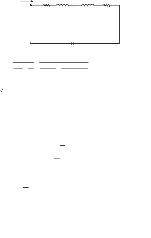
181
0.20 Ωj0.342 Ω
+
-
V
φ
IAR1jX1RF
jXF
The equivalent impedance of the rotor circuit in parallel with M
jX is:
2
11
2.197 0.744 2.32 18.7
11 1 1
12.5 2.40 0.342
F
M
Zj
jX Z j j
== =+=∠°Ω
++
Ω+
The line voltage must be derated by 5/6, so the new line voltage is 173.3 V
T
V=. The phase voltage is
173.3 / 3 = 100 V, so line current L
I is
11
100 0 V
0.20 0.342 2.197 0.744
LA
FF
V
IIRjXR jX j j
φ
∠°
== =
+++ Ω+Ω+Ω+Ω
38.0 24.4 A
LA
II== ∠− °
(b) The stator copper losses are
()( )
2
2
SCL 1
3 3 38 A 0.20 866 W
A
PIR== Ω=
(c) The air gap power is 22
2
AG 2
33
AF
R
PI IR
s
==
(Note that
2
3AF
IR
is equal to 22
2
3R
Is, since the only resistance in the original rotor circuit was 2
/
Rs, and
the resistance in the Thevenin equivalent circuit is F
R. The power consumed by the Thevenin equivalent
circuit must be the same as the power consumed by the original circuit.)
()( )
2
22
2
AG 2
3 3 3 38 A 2.197 9.52 kW
AF
R
PI IR
s
=== Ω=
(d) The power converted from electrical to mechanical form is
() ( )( )
conv AG
1 1 0.05 9.52 kW 9.04 kWPsP=− =− =
(e) The induced torque in the motor is
()
AG
ind
sync
9.52 kW 30.3 N m
2 rad 1 min
3000 r/min 1 r 60 s
P
τπ
ω
== = ⋅
(f) In the absence of better information, we will treat the mechanical and core losses as constant despite
the change in speed. This is not true, but we don’t have reason for a better guess. Therefore, the output
power of this motor is
OUT conv mech core misc 9.04 kW 250 W 180 W 0 W 8.61 kWPPPPP=−−−= − − − =
The output speed is
() ( )( )
sync
1 1 0.05 3000 r/min 2850 r/min
m
nsn=− =− =
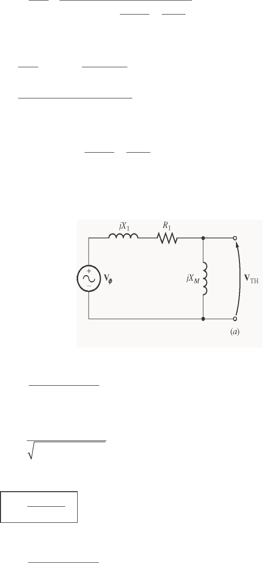
182
Therefore the load torque is
()
OUT
load
8.61 kW 28.8 N m
2 rad 1 min
2850 r/min 1 r 60 s
m
P
τπ
ω
== = ⋅
(g) The overall efficiency is
OUT OUT
IN
100% 100%
3cos
A
PP
PVI
φ
ηθ
=× = ×
()( )
8.61 kW 100% 82.9%
3 100 V 38.0 A cos 24.4
η
=×=
°
(h) The motor speed in revolutions per minute is 2850 r/min. The motor speed in radians per second is
()
2 rad 1 min
2850 r/min 298.5 rad/s
1 r 60 s
m
π
ω
==
7-12. Figure 7-18a shows a simple circuit consisting of a voltage source, a resistor, and two reactances. Find the
Thevenin equivalent voltage and impedance of this circuit at the terminals. Then derive the expressions for
the magnitude of VTH and for RTH given in Equations (7-41b) and (7-44).
S
OLUTION The Thevenin voltage of this circuit is
()
TH
11
M
M
jX
RjXX
φ
=++
VV
The magnitude of this voltage is
()
TH 2
2
11
M
M
X
VV
RXX
φ
=++
If 1M
XX>> , then
()()
22
2
11 1
MM
RXX XX++ ≈+ , so
TH
1
M
M
X
VV
XX
φ
≈+
The Thevenin impedance of this circuit is
()
()
11
TH
11
M
M
jX R jX
ZRjXX
+
=++
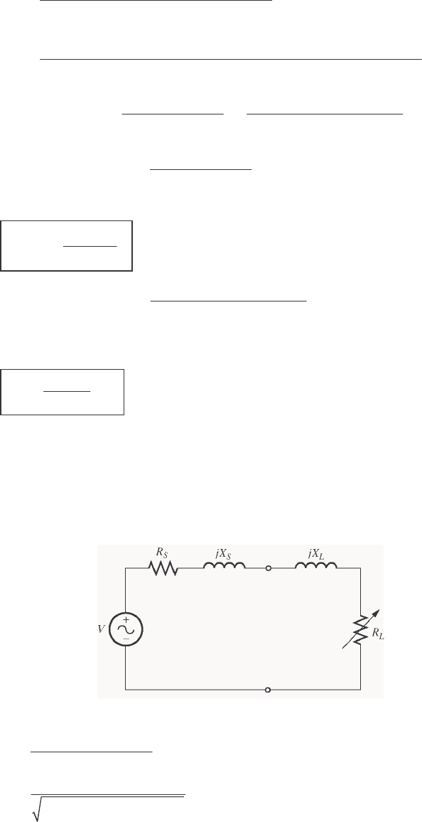
183
()( )
() ()
111 1
TH
11 11
MM
MM
jX R jX R j X X
ZRjXX RjXX
+−+
= ++ −+
()
222 2
11 11 1 1 1 1
TH 2
2
11
MMM MMM
M
RX X RX X RX j R X X X X X
ZRXX
−+++ ++
=++
() ()
2222
1 111
TH TH TH 22
22
11 11
MMMM
MM
RX R X X X XX
ZRjX j
RXX RXX
++
=+ = +
++ ++
The Thevenin resistance is
()
2
1
TH 2
2
11
M
M
RX
R
RXX
=++ . If 1M
XR>> , then
()()
22
2
11 1
MM
RXX XX++ ≈+ ,
so
2
TH 1
1
M
M
X
RR
XX
≈
+
The Thevenin reactance is
()
22 2
111
TH 2
2
11
MMM
M
RX X X XX
X
RXX
++
=++ .
If 1M
XR>> and 1M
XX>> then 22 2
111MMM
XX R X X X>> + and
()
222
11
MM
XX X R+≈>>
, so
2
1
TH 1
2
M
M
XX
XX
X
≈=
7-13. Figure P7-1 shows a simple circuit consisting of a voltage source, two resistors, and two reactances in
parallel with each other. If the resistor RL is allowed to vary but all the other components are constant, at
what value of RL will the maximum possible power be supplied to it? Prove your answer. (Hint: Derive
an expression for load power in terms of V, RS, XS, RL and XL and take the partial derivative of that
expression with respect to RL.) Use this result to derive the expression for the pullout torque [Equation (7-
54)].
S
OLUTION The current flowing in this circuit is given by the equation
L
SSLL
RjXRjX
=+++
V
I
()( )
22
L
SL S L
V
I
RR X X
=+++
The power supplied to the load is
184
()( )
2
2
22
L
LL
SL S L
VR
PIR
RR X X
==
+++
()( ) ()
()( )
22
22
2
22
2
SL S L L SL
LSL S L
RR X X VVR RR
P
RRR X X
+++ − +
∂
=
∂
+++
To find the point of maximum power supplied to the load, set / L
PR∂∂ = 0 and solve for L
R.
()( ) ()
22
22
20
SL S L L SL
RR X X VVR RR
+++ − +=
()( ) ()
22
2
SL S L LSL
RR X X RRR
+++ = +
()
2
22 2
222
SSLLSL SLL
RRRRXX RRR++++=+
()
2
22 2
2
SL SL L
RR XX R++ + =
()
2
22
SSLL
RXX R++ =
Therefore, for maximum power transfer, the load resistor should be
()
2
2
LS SL
RRXX=++
7-14. A 440-V 50-Hz two-pole Y-connected induction motor is rated at 75 kW. The equivalent circuit
parameters are
1
R = 0.075 Ω 2
R = 0.065 Ω M
X = 7.2 Ω
1
X = 0.17 Ω 2
X = 0.17 Ω
F&W
P = 1.0 kW misc
P = 150 W core
P = 1.1 kW
For a slip of 0.04, find
(a) The line current L
I
(b) The stator power factor
(c) The rotor power factor
(d) The stator copper losses SCL
P
(e) The air-gap power AG
P
(f) The power converted from electrical to mechanical form conv
P
(g) The induced torque ind
τ
(h) The load torque load
τ
(i) The overall machine efficiency
η
(j) The motor speed in revolutions per minute and radians per second
S
OLUTION The equivalent circuit of this induction motor is shown below:
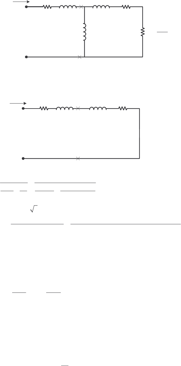
185
0.075 Ωj0.17 Ω
+
-
V
φ
IAR1jX1R2
−
s
s
R1
2
jX2
jXM
0.065 Ωj0.17 Ω
j7.2 Ω
1.56 Ω
(a) The easiest way to find the line current (or armature current) is to get the equivalent impedance F
Z
of the rotor circuit in parallel with M
jX , and then calculate the current as the phase voltage divided by the
sum of the series impedances, as shown below.
0.075 Ωj0.17 Ω
+
-
V
φ
IAR1jX1RF
jXF
The equivalent impedance of the rotor circuit in parallel with M
jX is:
2
11
1.539 0.364 1.58 13.2
11 1 1
7.2 1.625 0.17
F
M
Zj
jX Z j j
== =+=∠°Ω
++
Ω+
The phase voltage is 440/ 3 = 254 V, so line current L
I is
11
254 0 V
0.075 0.17 1.539 0.364
LA
FF
V
IIRjXR jX j j
φ
∠°
== =
+++ Ω+ Ω+ Ω+ Ω
149.4 18.3 A
LA
II== ∠− °
(b) The stator power factor is
()
PF cos 18.3 0.949 lagging=°=
(c) To find the rotor power factor, we must find the impedance angle of the rotor
11
2
2
0.17
tan tan 5.97
/1.625
R
X
Rs
θ
−−
===°
Therefore the rotor power factor is
PF cos5.97 0.995 lagging
R=°=
(d) The stator copper losses are
()()
2
2
SCL 1
3 3 149.4 A 0.075 1675 W
A
PIR== Ω=
(e) The air gap power is 22
2
AG 2
33
AF
R
PI IR
s
==

186
(Note that
2
3AF
IR
is equal to 22
2
3R
Is, since the only resistance in the original rotor circuit was 2
/
Rs
, and
the resistance in the Thevenin equivalent circuit is F
R. The power consumed by the Thevenin equivalent
circuit must be the same as the power consumed by the original circuit.)
()()
2
22
2
AG 2
3 3 3 149.4 A 1.539 103 kW
AF
R
PI IR
s
=== Ω=
(f) The power converted from electrical to mechanical form is
() ( )( )
conv AG
1 1 0.04 103 kW 98.9 kWPsP=− =− =
(g) The synchronous speed of this motor is
()
sync
120 50 Hz
120 3000 r/min
2
e
f
nP
== =
()
sync
2 rad 1 min
3000 r/min 314 rad/s
1 r 60 s
π
ω
==
Therefore the induced torque in the motor is
()
AG
ind
sync
103 kW 327.9 N m
2 rad 1 min
3000 r/min 1 r 60 s
P
τπ
ω
== = ⋅
(h) The output power of this motor is
OUT conv mech core misc 98.8 kW 1.0 kW 1.1 kW 150 W 96.6 kWPPPPP=−−−= − − − =
The output speed is
() ( )( )
sync
1 1 0.04 3000 r/min 2880 r/min
m
nsn=− =− =
Therefore the load torque is
()
OUT
load
98.8 kW 327.6 N m
2 rad 1 min
2880 r/min 1 r 60 s
m
P
τπ
ω
== = ⋅
(i) The overall efficiency is
OUT OUT
IN
100% 100%
3cos
A
PP
PVI
φ
ηθ
=× = ×
()( )()
96.6 kW 100% 89.4%
3 254 V 149.4 A cos 18.3
η
=×=
°
(j) The motor speed in revolutions per minute is 2880 r/min. The motor speed in radians per second is
()
2 rad 1 min
2880 r/min 301.6 rad/s
1 r 60 s
m
π
ω
==
7-15. For the motor in Problem 7-14, what is the pullout torque? What is the slip at the pullout torque? What is
the rotor speed at the pullout torque?
S
OLUTION The slip at pullout torque is found by calculating the Thevenin equivalent of the input circuit
from the rotor back to the power supply, and then using that with the rotor circuit model.
187
()
()
()( )
()
11
TH
11
7.2 0.075 0.17 0.0731 0.1662 0.182 66.3
0.075 0.17 7.2
M
M
jX R jX jj
Zj
RjXX j
+ΩΩ+Ω
== =+Ω=∠°Ω
++ Ω+ Ω+Ω
()
()
()
()
TH
11
7.2 254 0 V 248 0.06 V
0.075 0.17 7.2
M
M
j
jX
RjXX j
φ
Ω
== ∠°=∠°
++ Ω+ Ω+Ω
VV
The slip at pullout torque is
()
2
max 2
2
TH TH 2
R
s
RXX
=++
()( )
max 22
0.065 0.189
0.0731 0.1662 0.17
sΩ
==
Ω+ Ω+ Ω
The pullout torque of the motor is
()
+++2
=2
2TH
2
THTHsync
2
TH
max
3
XXRR
V
ω
τ
()
() ()( )
2
max 22
3248 V
314.2 rad/s 0.0731 0.0731 0.1662 0.17
τ
=
2Ω+Ω+Ω+Ω
max 704 N m
τ
=⋅
7-16. If the motor in Problem 7-14 is to be driven from a 440-V 60-Hz power supply, what will the pullout
torque be? What will the slip be at pullout?
S
OLUTION If this motor is driven from a 60 Hz source, the resistances will be unchanged and the reactances
will be increased by a ratio of 6/5. The resulting equivalent circuit is shown below.
0.075 Ωj0.204 Ω
+
-
V
φ
IAR1jX1R2
−
s
s
R1
2
jX2
jXM
0.065 Ωj0.204 Ω
j8.64 Ω
1.56 Ω
The slip at pullout torque is found by calculating the Thevenin equivalent of the input circuit from the rotor
back to the power supply, and then using that with the rotor circuit model.
()
()
()( )
()
11
TH
11
8.64 0.075 0.204 0.0731 0.1994 0.212 69.9
0.075 0.204 8.64
M
M
jX R jX j j
Zj
RjXX j
+ΩΩ+Ω
== =+Ω=∠°Ω
++ Ω+ Ω+Ω
()
()
()
()
TH
11
8.64 254 0 V 248 0.05 V
0.075 0.204 8.64
M
M
j
jX
RjXX j
φ
Ω
== ∠°=∠°
++ Ω+ Ω+Ω
VV
The slip at pullout torque is
()
2
max 2
2
TH TH 2
R
s
RXX
=++
188
()( )
max 22
0.065 0.159
0.0731 0.1994 0.204
sΩ
==
Ω+ Ω+ Ω
The synchronous speed of this motor is
()
sync
120 60 Hz
120 3600 r/min
2
e
f
nP
== =
()
sync
2 rad 1 min
3600 r/min 377 rad/s
1 r 60 s
π
ω
==
Therefore the pullout torque of the motor is
()
2
TH
max 2
2
sync TH TH TH 2
3V
RRXX
τ
ω
=
2+++
()
() ()( )
2
max 22
3248 V
377 rad/s 0.0731 0.0731 0.1994 0.204
τ
=
2Ω+Ω+Ω+Ω
max 507 N m
τ
=⋅
7-17. Plot the following quantities for the motor in Problem 7-14 as slip varies from 0% to 10%: (a) ind
τ
(b)
conv
P (c) out
P (d) Efficiency
η
. At what slip does out
P equal the rated power of the machine?
S
OLUTION This problem is ideally suited to solution with a MATLAB program. An appropriate program is
shown below. It follows the calculations performed for Problem 7-14, but repeats them at many values of
slip, and then plots the results. Note that it plots all the specified values versus m
n, which varies from
2700 to 3000 r/min, corresponding to a range of 0 to 10% slip.
% M-file: prob7_17.m
% M-file create a plot of the induced torque, power
% converted, power out, and efficiency of the induction
% motor of Problem 7-14 as a function of slip.
% First, initialize the values needed in this program.
r1 = 0.075; % Stator resistance
x1 = 0.170; % Stator reactance
r2 = 0.065; % Rotor resistance
x2 = 0.170; % Rotor reactance
xm = 7.2; % Magnetization branch reactance
v_phase = 440 / sqrt(3); % Phase voltage
n_sync = 3000; % Synchronous speed (r/min)
w_sync = 314.2; % Synchronous speed (rad/s)
p_mech = 1000; % Mechanical losses (W)
p_core = 1100; % Core losses (W)
p_misc = 150; % Miscellaneous losses (W)
% Calculate the Thevenin voltage and impedance from Equations
% 7-41a and 7-43.
v_th = v_phase * ( xm / sqrt(r1^2 + (x1 + xm)^2) );
z_th = ((j*xm) * (r1 + j*x1)) / (r1 + j*(x1 + xm));
r_th = real(z_th);
x_th = imag(z_th);
189
% Now calculate the torque-speed characteristic for many
% slips between 0 and 0.1. Note that the first slip value
% is set to 0.001 instead of exactly 0 to avoid divide-
% by-zero problems.
s = (0:0.001:0.1); % Slip
s(1) = 0.001;
nm = (1 - s) * n_sync; % Mechanical speed
wm = nm * 2*pi/60; % Mechanical speed
% Calculate torque, P_conv, P_out, and efficiency
% versus speed
for ii = 1:length(s)
% Induced torque
t_ind(ii) = (3 * v_th^2 * r2 / s(ii)) / ...
(w_sync * ((r_th + r2/s(ii))^2 + (x_th + x2)^2) );
% Power converted
p_conv(ii) = t_ind(ii) * wm(ii);
% Power output
p_out(ii) = p_conv(ii) - p_mech - p_core - p_misc;
% Power input
zf = 1 / ( 1/(j*xm) + 1/(r2/s(ii)+j*x2) );
ia = v_phase / ( r1 + j*x1 + zf );
p_in(ii) = 3 * v_phase * abs(ia) * cos(atan(imag(ia)/real(ia)));
% Efficiency
eff(ii) = p_out(ii) / p_in(ii) * 100;
end
% Plot the torque-speed curve
figure(1);
plot(nm,t_ind,'b-','LineWidth',2.0);
xlabel('\bf\itn_{m} \rm\bf(r/min)');
ylabel('\bf\tau_{ind} \rm\bf(N-m)');
title ('\bfInduced Torque versus Speed');
grid on;
% Plot power converted versus speed
figure(2);
plot(nm,p_conv/1000,'b-','LineWidth',2.0);
xlabel('\bf\itn_{m} \rm\bf(r/min)');
ylabel('\bf\itP\rm\bf_{conv} (kW)');
title ('\bfPower Converted versus Speed');
grid on;
% Plot output power versus speed
figure(3);
plot(nm,p_out/1000,'b-','LineWidth',2.0);
xlabel('\bf\itn_{m} \rm\bf(r/min)');
ylabel('\bf\itP\rm\bf_{out} (kW)');
title ('\bfOutput Power versus Speed');
axis([2700 3000 0 180]);
190
grid on;
% Plot the efficiency
figure(4);
plot(nm,eff,'b-','LineWidth',2.0);
xlabel('\bf\itn_{m} \rm\bf(r/min)');
ylabel('\bf\eta (%)');
title ('\bfEfficiency versus Speed');
grid on;
The four plots are shown below:
2700 2750 2800 2850 2900 2950 3000
0
100
200
300
400
500
600
700
n
m
(r/min)
τ
ind
(N-m)
Induced Torque versus Speed
191
This machine is rated at 75 kW. It produces an output power of 75 kW at 3.1% slip, or a speed of 2907
r/min.
7-18. A 208-V, 60 Hz, six-pole Y-connected 25-hp design class B induction motor is tested in the laboratory,
with the following results:
No load: 208 V, 22.0 A, 1200 W, 60 Hz
Locked rotor: 24.6 V, 64.5 A, 2200 W, 15 Hz
DC test: 13.5 V, 64 A
Find the equivalent circuit of this motor, and plot its torque-speed characteristic curve.
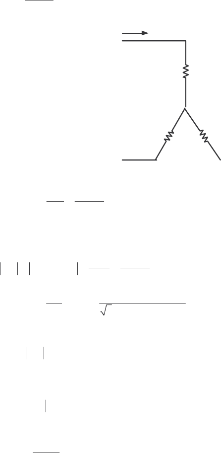
192
S
OLUTION From the DC test,
1
13.5 V
264 A
R= ⇒ 10.105 R=Ω
R
1
R
1
R
1
V
DC
+
-
I
DC
In the no-load test, the line voltage is 208 V, so the phase voltage is 120 V. Therefore,
1
,nl
120 V 5.455 @ 60 Hz
22.0 A
M
A
V
XX I
φ
+= = = Ω
In the locked-rotor test, the line voltage is 24.6 V, so the phase voltage is 14.2 V. From the locked-rotor
test at 15 Hz,
LR LR LR
,LR
14.2 V 0.2202
64.5 A
A
V
ZRjXI
φ
=+ = = = Ω
′′
()()
11
LR
LR
LR
2200 W
cos cos 36.82
3 24.6 V 64.5 A
P
S
θ
−−
== =°
′
Therefore,
()()
LR LR LR
cos 0.2202 cos 36.82 0.176 RZ
θ
==Ω°=Ω′
⇒ 12
0.176 RR+= Ω
⇒ 20.071 R=Ω
()()
LR LR LR
in 0.2202 sin 36.82 0.132 XZs
θ
==Ω°=Ω′′
At a frequency of 60 Hz,
LR LR
60 Hz 0.528
15 Hz
XX
==Ω
′
For a Design Class B motor, the split is 10.211 X=Ω and 20.317 X=Ω. Therefore,
5.455 0.211 5.244
M
X=Ω−Ω= Ω
The resulting equivalent circuit is shown below:
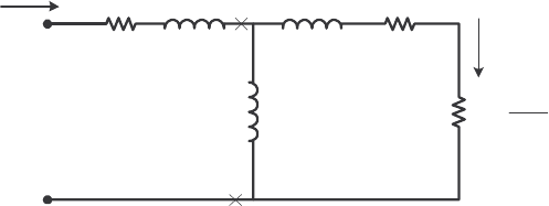
193
0.105
Ω
j
0.211
Ω
+
-
V
φ
I
A
R
1
jX
1
R
2
−
s
s
R1
2
jX
2
jX
M
0.071
Ω
j
0.317
Ω
j
5.244
Ω
I
2
A MATLAB program to calculate the torque-speed characteristic of this motor is shown below:
% M-file: prob7_18.m
% M-file create a plot of the torque-speed curve of the
% induction motor of Problem 7-18.
% First, initialize the values needed in this program.
r1 = 0.105; % Stator resistance
x1 = 0.211; % Stator reactance
r2 = 0.071; % Rotor resistance
x2 = 0.317; % Rotor reactance
xm = 5.244; % Magnetization branch reactance
v_phase = 208 / sqrt(3); % Phase voltage
n_sync = 1200; % Synchronous speed (r/min)
w_sync = 125.7; % Synchronous speed (rad/s)
% Calculate the Thevenin voltage and impedance from Equations
% 7-41a and 7-43.
v_th = v_phase * ( xm / sqrt(r1^2 + (x1 + xm)^2) );
z_th = ((j*xm) * (r1 + j*x1)) / (r1 + j*(x1 + xm));
r_th = real(z_th);
x_th = imag(z_th);
% Now calculate the torque-speed characteristic for many
% slips between 0 and 1. Note that the first slip value
% is set to 0.001 instead of exactly 0 to avoid divide-
% by-zero problems.
s = (0:1:50) / 50; % Slip
s(1) = 0.001;
nm = (1 - s) * n_sync; % Mechanical speed
% Calculate torque versus speed
for ii = 1:51
t_ind(ii) = (3 * v_th^2 * r2 / s(ii)) / ...
(w_sync * ((r_th + r2/s(ii))^2 + (x_th + x2)^2) );
end
% Plot the torque-speed curve
figure(1);
plot(nm,t_ind,'b-','LineWidth',2.0);
xlabel('\bf\itn_{m}');
ylabel('\bf\tau_{ind}');
title ('\bfInduction Motor Torque-Speed Characteristic');
grid on;
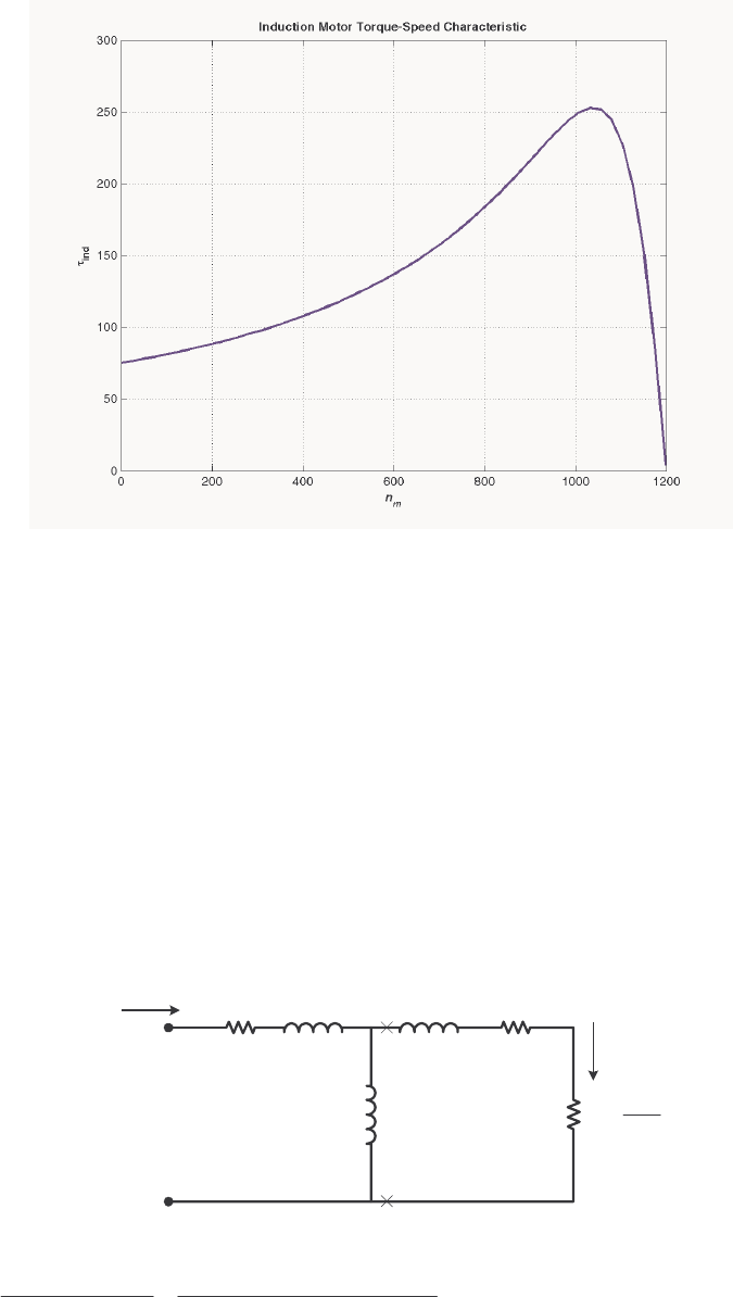
194
The resulting plot is shown below:
7-19. A 460-V, four-pole, 50-hp, 60-Hz, Y-connected three-phase induction motor develops its full-load induced
torque at 3.8 percent slip when operating at 60 Hz and 460 V. The per-phase circuit model impedances of
the motor are
1
R = 0.33 Ω M
X = 30 Ω
1
X = 0.42 Ω 2
X = 0.42 Ω
Mechanical, core, and stray losses may be neglected in this problem.
(a) Find the value of the rotor resistance 2
R.
(b) Find max
τ
, max
s, and the rotor speed at maximum torque for this motor.
(c) Find the starting torque of this motor.
(d) What code letter factor should be assigned to this motor?
S
OLUTION The equivalent circuit for this motor is
0.33 Ωj0.42 Ω
+
-
V
φ
IAR1jX1R2
−
s
s
R1
2
jX2
jXM
??? Ωj0.42 Ω
j30 Ω
I2
The Thevenin equivalent of the input circuit is:
()
()
()( )
()
11
TH
11
30 0.33 0.42 0.321 0.418 0.527 52.5
0.33 0.42 30
M
M
jX R jX j j
Zj
RjXX j
+ΩΩ+Ω
== =+Ω=∠°Ω
++ Ω+ Ω+Ω

195
()
()
()
()
TH
11
30 265.6 0 V 262 0.6 V
0.33 0.42 30
M
M
j
jX
RjXX j
φ
Ω
== ∠°=∠°
++ Ω+ Ω+Ω
VV
(a) If losses are neglected, the induced torque in a motor is equal to its load torque. At full load, the
output power of this motor is 50 hp and its slip is 3.8%, so the induced torque is
()( )
1 0.038 1800 r/min 1732 r/min
m
n=− =
()( )
()
ind load
50 hp 746 W/hp 205.7 N m
2 rad 1min
1732 r/min 1 r 60 s
ττ π
== = ⋅
The induced torque is given by the equation
()()
2
TH 2
ind 22
sync TH 2 TH 2
3/
/
VRs
RRs X X
τω
=
+++
Substituting known values and solving for 2
/
Rs yields
()
()
()
()
2
2
22
2
3262 V /
205.7 N m
188.5 rad/s 0.321 / 0.418 0.42
Rs
Rs
⋅=
+++
()
2
2
2
205,932 /
38,774
0.321 / 0.702
Rs
Rs
=
++
()
2
22
0.321 / 0.702 5.311 /Rs Rs
++=
()
2
22 2
0.103 0.642 / / 0.702 5.311 /Rs Rs Rs
+++=
2
22
4.669 0.702 0
RR
ss
−+=
20.156, 4.513
R
s
=
20.0059 , 0.172 R=ΩΩ
These two solutions represent two situations in which the torque-speed curve would go through this specific
torque-speed point. The two curves are plotted below. As you can see, only the 0.172 Ω solution is
realistic, since the 0.0059 Ω solution passes through this torque-speed point at an unstable location on the
back side of the torque-speed curve.
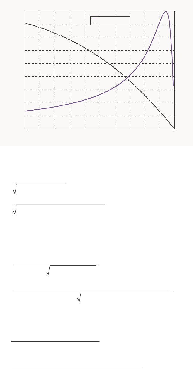
196
1600 1620 1640 1660 1680 1700 1720 1740 1760 1780 1800
0
50
100
150
200
250
300
350
400
450
n
m
τ
ind
Induction Motor Torque-Speed Characteristic
R2 = 0.0059 ohms
R2 = 0.172 ohms
(b) The slip at pullout torque can be found by calculating the Thevenin equivalent of the input circuit
from the rotor back to the power supply, and then using that with the rotor circuit model. The Thevenin
equivalent of the input circuit was calculate in part (a). The slip at pullout torque is
()
2
max 2
2
TH TH 2
R
s
RXX
=++
()( )
max 22
0.172 0.192
0.321 0.418 0.420
sΩ
==
Ω+ Ω+ Ω
The rotor speed a maximum torque is
()( )
pullout sync
(1 ) 1 0.192 1800 r/min 1454 r/minnsn=− =− =
and the pullout torque of the motor is
()
2
TH
max 2
2
sync TH TH TH 2
3V
RRXX
τ
ω
=
2+++
()
() ()( )
2
max 22
3262 V
188.5 rad/s 0.321 0.321 0.418 0.420
τ
=
2Ω+Ω+Ω+Ω
max 448 N m
τ
=⋅
(c) The starting torque of this motor is the torque at slip s = 1. It is
()()
2
TH 2
ind 22
sync TH 2 TH 2
3/
/
VRs
RRs X X
τω
=
+++
()( )
()( )( )
2
ind 22
3 262 V 0.172 199 N m
188.5 rad/s 0.321 0.172 0.418 0.420
τ
Ω
==⋅
+Ω+ +
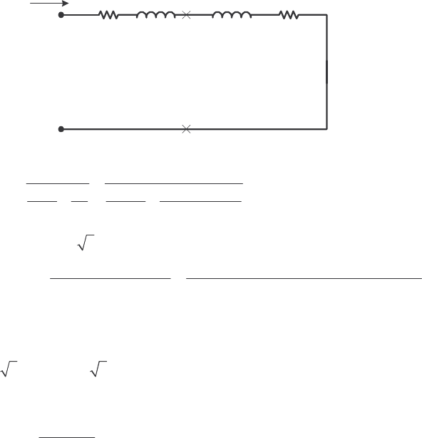
197
(d) To determine the starting code letter, we must find the locked-rotor kVA per horsepower, which is
equivalent to finding the starting kVA per horsepower. The easiest way to find the line current (or
armature current) at starting is to get the equivalent impedance F
Z
of the rotor circuit in parallel with
M
jX at starting conditions, and then calculate the starting current as the phase voltage divided by the sum
of the series impedances, as shown below.
0.33
Ω
j
0.42
Ω
+
-
V
φ
I
A,
start
R
1
jX
1
R
F
jX
F
The equivalent impedance of the rotor circuit in parallel with M
jX at starting conditions (s = 1.0) is:
,start
2
11
0.167 0.415 0.448 68.1
11 1 1
30 0.172 0.42
F
M
Zj
jX Z j j
== =+=∠°Ω
++
Ω+
The phase voltage is 460/ 3 = 266 V, so line current ,startL
I is
,start
11
266 0 V
0.33 0.42 0.167 0.415
LA
FF
RjXR jX j j
φ
∠°
== =
+++ Ω+ Ω+ Ω+ Ω
V
II
,start 274 59.2 A
LA
== ∠− °II
Therefore, the locked-rotor kVA of this motor is
()()
,rated
3 3 460 V 274 A 218 kVA
TL
SVI== =
and the kVA per horsepower is
218 kVA
kVA/hp 4.36 kVA/hp
50 hp
==
This motor would have starting code letter D, since letter D covers the range 4.00-4.50.
7-20. Answer the following questions about the motor in Problem 7-19.
(a) If this motor is started from a 460-V infinite bus, how much current will flow in the motor at starting?
(b) If transmission line with an impedance of 0.35 + j0.25 Ω per phase is used to connect the induction
motor to the infinite bus, what will the starting current of the motor be? What will the motor’s terminal
voltage be on starting?
(c) If an ideal 1.4:1 step-down autotransformer is connected between the transmission line and the motor,
what will the current be in the transmission line during starting? What will the voltage be at the motor
end of the transmission line during starting?
S
OLUTION
(a) The equivalent circuit of this induction motor is shown below:
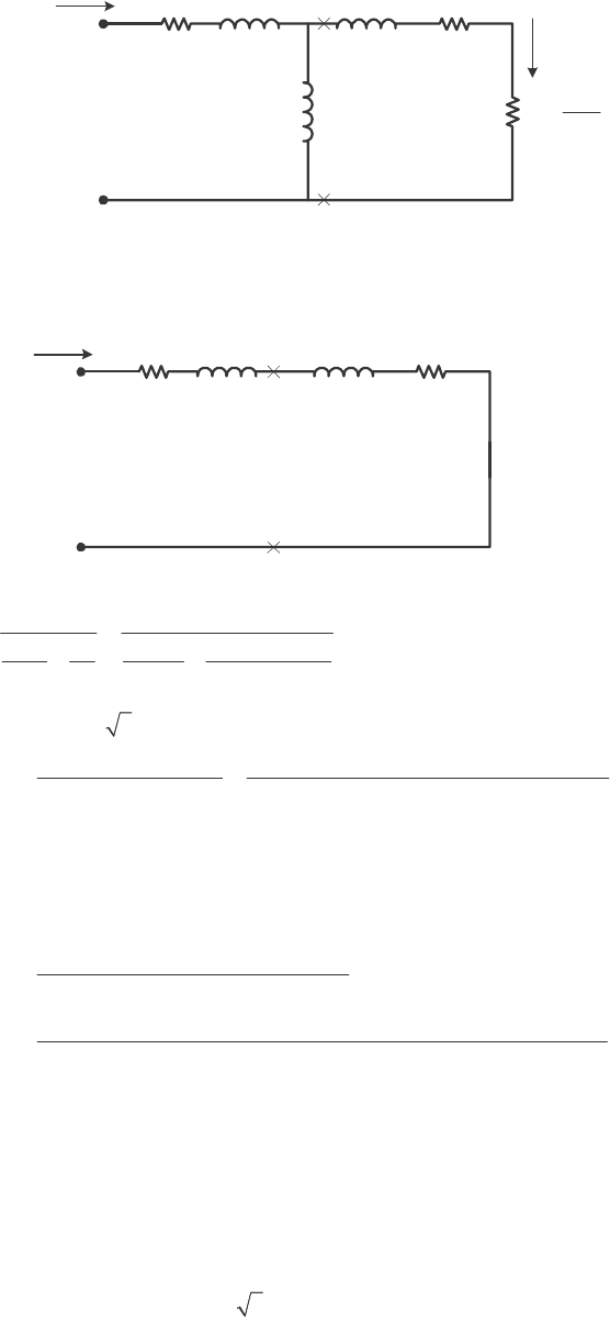
198
0.33 Ωj0.42 Ω
+
-
V
φ
IAR1jX1R2
−
s
s
R1
2
jX2
jXM
0.172 Ωj0.42 Ω
j30 Ω
I2
The easiest way to find the line current (or armature current) at starting is to get the equivalent impedance
F
Z of the rotor circuit in parallel with M
jX at starting conditions, and then calculate the starting current
as the phase voltage divided by the sum of the series impedances, as shown below.
0.33
Ω
j
0.42
Ω
+
-
V
φ
I
A
R
1
jX
1
R
F
jX
F
The equivalent impedance of the rotor circuit in parallel with M
jX at starting conditions (s = 1.0) is:
2
11
0.167 0.415 0.448 68.0
11 1 1
30 0.172 0.42
F
M
Zj
jX Z j j
== =+=∠°Ω
++
Ω+
The phase voltage is 460/ 3 = 266 V, so line current L
I is
11
266 0 V
0.33 0.42 0.167 0.415
LA
FF
RjXR jX j j
φ
∠°
== =
+++ Ω+ Ω+ Ω+ Ω
V
II
273 59.2 A
LA
== ∠− °II
(b) If a transmission line with an impedance of 0.35 + j0.25 Ω per phase is used to connect the induction
motor to the infinite bus, its impedance will be in series with the motor’s impedances, and the starting
current will be
,bus
line line 1 1
LA
FF
RjXRjXRjX
φ
== +++++
V
II
266 0 V
0.35 0.25 0.33 0.42 0.167 0.415
LA jj j
∠°
== Ω+ Ω+ Ω+ Ω+ Ω+ Ω
II
193.2 52.0 A
LA
== ∠− °II
The voltage at the terminals of the motor will be
()
11AFF
RjXR jX
φ
=+++VI
()( )
194.1 52.3 A 0.33 0.42 0.167 0.415 jj
φ
= ∠− ° Ω+ Ω+ Ω+ ΩV
187.7 7.2 V
φ
=∠°V
Therefore, the terminal voltage will be
()
3 187.7 V 325 V=. Note that the terminal voltage sagged by
about 30% during motor starting, which would be unacceptable.

199
(c) If an ideal 1.4:1 step-down autotransformer is connected between the transmission line and the motor,
the motor’s impedances will be referred across the transformer by the square of the turns ratio a = 1.4. The
referred impedances are
()
2
11
1.96 0.33 0.647 RaR== Ω= Ω
′
()
2
11
1.96 0.42 0.823 XaX== Ω= Ω′
()
21.96 0.167 0.327
FF
RaR== Ω= Ω
′
()
21.96 0.415 0.813
FF
XaX== Ω=Ω′
Therefore, the starting current referred to the primary side of the transformer will be
,bus
line line 1 1
LA
FF
RjXRjXRjX
φ
==′′ +++++
′′′ ′
V
II
266 0 V
0.35 0.25 0.647 0.823 0.327 0.813
LA jj j
∠°
==
′′ Ω + Ω+ Ω+ Ω + Ω+ Ω
II
115.4 54.9 A
LA
== ∠− °
′′
II
The voltage at the motor end of the transmission line would be the same as the referred voltage at the
terminals of the motor
()
11AFF
RjXR jX
φ
=+++′′′ ′′ ′VI
()( )
115.4 54.9 A 0.647 0.823 0.327 0.813 jj
φ
= ∠− ° Ω+ Ω + Ω+ ΩV
219.7 4.3 V
φ
=∠°V
Therefore, the line voltage at the motor end of the transmission line will be
(
)
3 219.7 V 380.5 V=. Note
that this voltage sagged by 17.3% during motor starting, which is less than the 30% sag with case of
across-the-line starting.
7-21. In this chapter, we learned that a step-down autotransformer could be used to reduce the starting current
drawn by an induction motor. While this technique works, an autotransformer is relatively expensive. A
much less expensive way to reduce the starting current is to use a device called Y-∆ starter. If an induction
motor is normally ∆-connected, it is possible to reduce its phase voltage Vφ (and hence its starting current)
by simply re-connecting the stator windings in Y during starting, and then restoring the connections to ∆
when the motor comes up to speed. Answer the following questions about this type of starter.
(a) How would the phase voltage at starting compare with the phase voltage under normal running
conditions?
(b) How would the starting current of the Y-connected motor compare to the starting current if the motor
remained in a ∆-connection during starting?
S
OLUTION
(a) The phase voltage at starting would be 1 / 3 = 57.7% of the phase voltage under normal running
conditions.
(b) Since the phase voltage decreases to 1 / 3 = 57.7% of the normal voltage, the starting phase current
will also decrease to 57.7% of the normal starting current. However, since the line current for the original
delta connection was 3 times the phase current, while the line current for the Y starter connection is
equal to its phase current, the line current is reduced by a factor of 3 in a Y-∆ starter.
For the
∆-connection: ,,
3
L
II
φ
∆∆
=
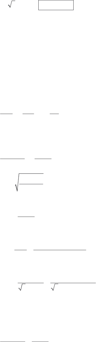
200
For the Y-connection: ,Y ,YL
II
φ
=
But
,,Y
3 II
φφ
∆=, so ,,Y
3
LL
II
∆=
7-22. A 460-V 100-hp four-pole ∆-connected 60-Hz three-phase induction motor has a full-load slip of 5 percent,
an efficiency of 92 percent, and a power factor of 0.87 lagging. At start-up, the motor develops 1.9 times
the full-load torque but draws 7.5 times the rated current at the rated voltage. This motor is to be started
with an autotransformer reduced voltage starter.
(a) What should the output voltage of the starter circuit be to reduce the starting torque until it equals the
rated torque of the motor?
(b) What will the motor starting current and the current drawn from the supply be at this voltage?
S
OLUTION
(a) The starting torque of an induction motor is proportional to the square of TH
V,
22
start2 TH2 2
start1 TH1 1
T
T
VV
VV
τ
τ
==
If a torque of 1.9 rated
τ
is produced by a voltage of 460 V, then a torque of 1.00 rated
τ
would be produced
by a voltage of
2
rated 2
rated
1.00
1.90 460 V
T
V
τ
τ
=
()
2
2
460 V 334 V
1.90
T
V==
(b) The motor starting current is directly proportional to the starting voltage, so
()()
()
2 1 1 rated rated
334 V 0.726 0.726 7.5 5.445
460 V
LLL
III II
=== =
The input power to this motor is
()( )
OUT
IN
100 hp 746 W/hp 81.1 kW
0.92
P
P
η
== =
The rated current is equal to
()
()()
IN
rated
81.1 kW 117 A
3 PF 3 460 V 0.87
T
P
IV
== =
Therefore, the motor starting current is
()( )
2 rated
5.445 5.445 117 A 637 A
L
II== =
The turns ratio of the autotransformer that produces this starting voltage is
460 V 1.377
334 V
SE C
C
NN
N
+==
so the current drawn from the supply will be
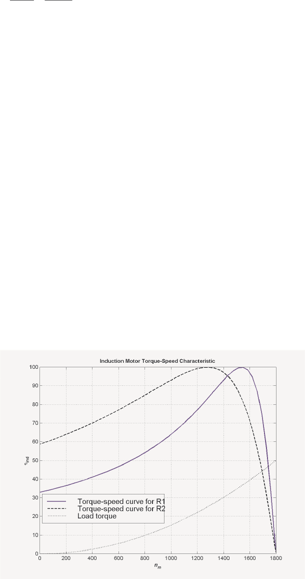
201
start
line
637 A 463 A
1.377 1.377
I
I== =
7-23. A wound-rotor induction motor is operating at rated voltage and frequency with its slip rings shorted and
with a load of about 25 percent of the rated value for the machine. If the rotor resistance of this machine is
doubled by inserting external resistors into the rotor circuit, explain what happens to the following:
(a) Slip s
(b) Motor speed nm
(c) The induced voltage in the rotor
(d) The rotor current
(e) ind
τ
(f) out
P
(g) RCL
P
(h) Overall efficiency
η
S
OLUTION
(a) The slip s will increase.
(b) The motor speed m
n will decrease.
(c) The induced voltage in the rotor will increase.
(d) The rotor current will increase.
(e) The induced torque will adjust to supply the load’s torque requirements at the new speed. This will
depend on the shape of the load’s torque-speed characteristic. For most loads, the induced torque will
decrease.
(f) The output power will generally decrease: OUT ind m
P
τω
=↓↓
(g) The rotor copper losses (including the external resistor) will increase.
202
(h) The overall efficiency
η
will decrease.
7-24. Answer the following questions about a 460-V ∆-connected two-pole 75-hp 60-Hz starting code letter E
induction motor:
(a) What is the maximum current starting current that this machine’s controller must be designed to
handle?
(b) If the controller is designed to switch the stator windings from a ∆ connection to a Y connection during
starting, what is the maximum starting current that the controller must be designed to handle?
(c) If a 1.25:1 step-down autotransformer starter is used during starting, what is the maximum starting
current that will be drawn from the line?
S
OLUTION
(a) Starting code letter E corresponds to a 4.50 – 5.00 kVA/hp, so the maximum starting kVA of this
motor is
()()
start 75 hp 5.00 375 kVAS==
Therefore,
()
start
375 kVA 471 A
3 3 460 V
T
S
IV
== =
(b) The line voltage will still be 460 V when the motor is switched to the Y-connection, but now the
phase voltage will be 460 / 3 = 266 V.
Before (in ∆):
()( )()( )
,
,
TH2TH2TH2TH2
460 V
V
IRRjX X RRjX X
φ
φ
∆
∆==
++ + ++ +
But the line current in a ∆ connection is 3 times the phase current, so
()( )()( )
,
,,
TH 2 TH 2 TH 2 TH 2
3797 V
3
L
V
II
RRjX X RRjX X
φ
φ
∆
∆∆
== =
++ + ++ +
After (in Y):
()( )()( )
,Y
,Y ,Y
TH 2 TH 2 TH 2 TH 2
265.6 V
L
V
II RRjX X RRjX X
φ
φ
== =
++ + ++ +
Therefore the line current will decrease by a factor of 3 when using this starter. The starting current with a
∆-Y starter is
start
471 A 157 A
3
I==
(c) A 1.25:1 step-down autotransformer reduces the phase voltage on the motor by a factor 0.8. This
reduces the phase current and line current in the motor (and on the secondary side of the transformer) by a
factor of 0.8. However, the current on the primary of the autotransformer will be reduced by another factor
of 0.8, so the total starting current drawn from the line will be 64% of its original value. Therefore, the
maximum starting current drawn from the line will be
()( )
start 0.64 471 A 301 AI==

203
7-25. When it is necessary to stop an induction motor very rapidly, many induction motor controllers reverse the
direction of rotation of the magnetic fields by switching any two stator leads. When the direction of
rotation of the magnetic fields is reversed, the motor develops an induced torque opposite to the current
direction of rotation, so it quickly stops and tries to start turning in the opposite direction. If power is
removed from the stator circuit at the moment when the rotor speed goes through zero, then the motor has
been stopped very rapidly. This technique for rapidly stopping an induction motor is called plugging. The
motor of Problem 7-19 is running at rated conditions and is to be stopped by plugging.
(a) What is the slip s before plugging?
(b) What is the frequency of the rotor before plugging?
(c) What is the induced torque ind
τ
before plugging?
(d) What is the slip s immediately after switching the stator leads?
(e) What is the frequency of the rotor immediately after switching the stator leads?
(f) What is the induced torque ind
τ
immediately after switching the stator leads?
S
OLUTION
(a) The slip before plugging is 0.038 (see Problem 7-19).
(b) The frequency of the rotor before plugging is
()( )
0.038 60 Hz 2.28 Hz
re
fsf== =
(c) The induced torque before plugging is 205.7 N⋅m in the direction of motion (see Problem 7-19).
(d) After switching stator leads, the synchronous speed becomes –1800 r/min, while the mechanical speed
initially remains 1732 r/min. Therefore, the slip becomes
sync
sync
1800 1732 1.962
1800
m
nn
sn
−−−
== =
−
(e) The frequency of the rotor after plugging is
()( )
1.962 60 Hz 117.72 Hz
re
fsf== =
(f) The induced torque immediately after switching the stator leads is
()()
2
TH 2
ind 22
sync TH 2 TH 2
3/
/
VRs
RRs X X
τω
=
+++
()( )
()( )( )
2
ind 22
3 262 V 0.172 /1.962
188.5 rad/s 0.321 0.172 /1.962 0.418 0.420
τ
Ω
=
+Ω + +
()( )
()( )( )
2
ind 22
3262 V 0.0877
188.5 rad/s 0.321 0.0877 0.418 0.420
τ
=
+++
ind 110 N m, opposite the direction of motion
τ
=⋅
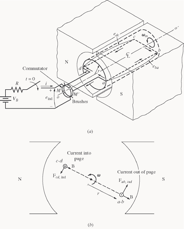
204
Chapter 8: DC Machinery Fundamentals
8-1. The following information is given about the simple rotating loop shown in Figure 8-6:
0.8 T B= 24 V
B
V=
0.5 ml= 0.4 R=Ω
0.125 mr= 250 rad/s
ω
=
(a) Is this machine operating as a motor or a generator? Explain.
(b) What is the current i flowing into or out of the machine? What is the power flowing into or out of the
machine?
(c) If the speed of the rotor were changed to 275 rad/s, what would happen to the current flow into or out
of the machine?
(d) If the speed of the rotor were changed to 225 rad/s, what would happen to the current flow into or out
of the machine?

205
(a) If the speed of rotation
ω
of the shaft is 500 rad/s, then the voltage induced in the rotating loop will be
ind 2erlB
ω
=
(
)
(
)
(
)
(
)
ind 2 0.125 m 0.5 m 0.8 T 250 rad/s 25 Ve==
Since the external battery voltage is only 24 V, this machine is operating as a generator, charging the
battery.
(b) The current flowing out of the machine is approximately
ind 25 V 24 V 2.5 A
0.4
B
eV
iR
−−
== =
Ω
(Note that this value is the current flowing while the loop is under the pole faces. When the loop goes
beyond the pole faces, ind
e will momentarily fall to 0 V, and the current flow will momentarily reverse.
Therefore, the average current flow over a complete cycle will be somewhat less than 2.5 A.)
(c) If the speed of the rotor were increased to 275 rad/s, the induced voltage of the loop would increase to
ind 2erlB
ω
=
(
)
(
)
(
)
(
)
ind 2 0.125 m 0.5 m 0.8 T 275 rad/s 27.5 Ve==
and the current flow out of the machine will increase to
ind 27.5 V 24 V 8.75 A
0.4
B
eV
iR
−−
== =
Ω
(d) If the speed of the rotor were decreased to 450 rad/s, the induced voltage of the loop would fall to
ind 2erlB
ω
=
()()()( )
ind 2 0.125 m 0.5 m 0.8 T 225 rad/s 22.5 Ve==
Here,
ind
e is less than B
V, so current flows into the loop and the machine is acting as a motor. The current
flow into the machine would be
ind 24 V - 22.5 V 3.75 A
0.4
B
Ve
iR
−
== =
Ω
8-2. Refer to the simple two-pole eight-coil machine shown in Figure P8-1. The following information is given
about this machine:
B=10. T in air gap
l=03. m (length of coil sides)
coils) of (radiusm 08.0=r
CCWr/min 1700=n
The resistance of each rotor coil is 0.04 Ω.
(a) Is the armature winding shown a progressive or retrogressive winding?
(b) How many current paths are there through the armature of this machine?
(c) What are the magnitude and the polarity of the voltage at the brushes in this machine?
(d) What is the armature resistance RA of this machine?
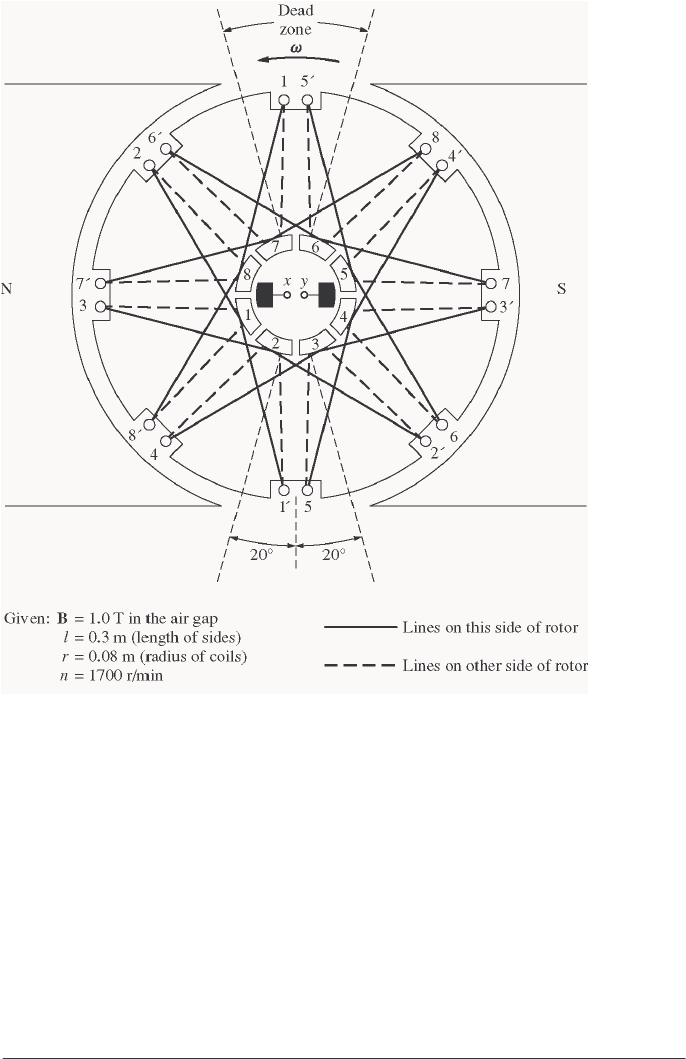
206
(e) If a 10 Ω resistor is connected to the terminals of this machine, how much current flows in the
machine? Consider the internal resistance of the machine in determining the current flow.
(f) What are the magnitude and the direction of the resulting induced torque?
(g) Assuming that the speed of rotation and magnetic flux density are constant, plot the terminal voltage of
this machine as a function of the current drawn from it.
S
OLUTION
(a) This winding is progressive, since the ends of each coil are connected to the commutator segments
ahead of the segments that the beginnings of the coils are connected to.
(b) There are two current paths in parallel through the armature of this machine (this is a simplex lap
winding).
(c) The voltage is positive at brush x with respect to brush y, since the voltage in the conductors is
positive out of the page under the North pole face and positive into the page under the South pole face.
(d) There are 8 coils on this machine in two parallel paths, with each coil having a resistance of 0.04 Ω.
Therefore, the total resistance A
R is
()()
0.04 0.04 0.04 0.04 0.04 0.04 0.04 0.04
0.04 0.04 0.04 0.04 0.04 0.04 0.04 0.04
A
RΩ+ Ω+ Ω+ Ω Ω+ Ω+ Ω+ Ω
=Ω+ Ω+ Ω+ Ω+ Ω+ Ω+ Ω+ Ω

207
0.08
A
R=Ω
(e) The voltage produced by this machine can be found from Equations 8-32 and 8-33:
A
Z
vBl Zr Bl
Eaa
ω
==
where Z is the number of conductors under the pole faces, since the ones between the poles have no voltage
in them. There are 16 conductors in this machine, and about 12 of them are under the pole faces at any
given time.
()
2 rad 1 min
1700 r/min 178 rad/s
1 r 60 s
π
ω
==
()()( )()()
12 cond 0.08 m 178 rad/s 1.0 T 0.3 m 25.6 V
2 current paths
A
Zr Bl
Ea
ω
== =
Therefore, the current flowing in the machine will be
load
25.6 V 2.54 A
0.08 10
A
A
A
E
IRR
== =
+Ω+Ω
(f) The induced torque is given by Equation 8-46:
( )()()()()
ind
12 cond 0.08 m 0.3 m 1.0 T 2.54 A
2 current paths
A
ZrlBI
a
τ
==
CW m,N 366.0
ind ⋅=
τ
(opposite to the direction of rotation)
8-3. Prove that the equation for the induced voltage of a single simple rotating loop
ind
2 e
φ
ω
π
= (8-6)
is just a special case of the general equation for induced voltage in a dc machine
A
EK
φ
ω
= (8-38)
S
OLUTION From Equation 8-38,
A
EK
φ
ω
=
where
2
Z
P
Ka
π
=
For the simple rotation loop,
Z = 2 (There are 2 conductors)
P = 2 (There are 2 poles)
a = 1 (There is one current path through the machine)
Therefore,
()()
()
2 2 2
22 1
ZP
Ka
ππ π
==
and Equation 8-38 reduces to Equation 8-6.
8-4. A dc machine has 8 poles and a rated current of 100 A. How much current will flow in each path at rated
conditions if the armature is (a) simplex lap-wound, (b) duplex lap-wound, (c) simplex wave-wound?
S
OLUTION

208
(a) Simplex lap-wound:
()()
18 8 pathsamP== =
Therefore, the current per path is
100 A 12.5 A
8
A
I
Ia
== =
(b) Duplex lap-wound:
()()
2 8 16 pathsamP== =
Therefore, the current per path is
100 A 6.25 A
16
A
I
Ia
== =
(c) Simplex wave-wound:
()()
2212 pathsam== =
Therefore, the current per path is
100 A 50 A
2
A
I
Ia
== =
8-5. How many parallel current paths will there be in the armature of a 12-pole machine if the armature is (a)
simplex lap-wound, (b) duplex wave-wound, (c) triplex lap-wound, (d) quadruplex wave-wound?
S
OLUTION
(a) Simplex lap-wound:
(1)(12) 12 pathsamP
== =
(b) Duplex wave-wound:
2 (2)(2) 4 pathsam== =
(c) Triplex lap-wound:
(3)(12) 36 pathsamP== =
(d) Quadruplex wave-wound:
2 (2)(4) 8 pathsam== =
8-6. The power converted from one form to another within a dc motor was given by
conv indAA m
PEI
τω
==
Use the equations for A
E and ind
τ
[Equations (8-38) and (8-49)] to prove that AA
EI = m
ωτ
ind ; that is,
prove that the electric power disappearing at the point of power conversion is exactly equal to the
mechanical power appearing at that point.
S
OLUTION
conv AA
PEI=
Substituting Equation (8-38) for A
E

209
()
conv A
PKI
φω
=
()
conv
A
PKI
φ
ω
=
But from Equation (8-49), ind
A
KI
τφ
=, so
conv ind
P
τω
=
8-7. An eight-pole, 25-kW, 120-V DC generator has a duplex lap-wound armature, which has 64 coils with 16
turns per coil. Its rated speed is 2400 r/min.
(a) How much flux per pole is required to produce the rated voltage in this generator at no-load conditions?
(b) What is the current per path in the armature of this generator at the rated load?
(c) What is the induced torque in this machine at the rated load?
(d) How many brushes must this motor have? How wide must each one be?
(e) If the resistance of this winding is 0.011 Ω per turn, what is the armature resistance A
R of this
machine?
S
OLUTION
(a)
2
A
ZP
EK a
φ
ωφω
π
==
In this machine, the number of current paths is
()()
28 16amP== =
The number of conductor is
()( )( )
64 coils 16 turns/coil 2 conductors/turn 2048Z==
The equation for induced voltage is
2
A
ZP
Ea
φ
ω
π
=
so the required flux is
()()
()
()
2048 cond 8 poles 2 rad 1 min
120 V 2400 r/min
2 16 paths 1 r 60 s
π
φ
π
=
120 V 40,960
φ
=
0.00293 Wb
φ
=
(b) At rated load, the current flow in the generator would be
25 kW 208 A
120 V
A
I==
There are a = m P = (2)(8) = 16 parallel current paths through the machine, so the current per path is
208 A 13 A
16
A
I
Ia
== =
(c) The induced torque in this machine at rated load is
ind 2A
ZP I
a
τφ
π
=
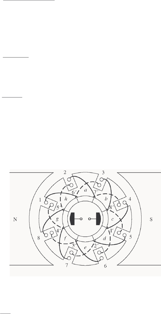
210
()()
()
()()
ind
2048 cond 8 poles 0.00293 Wb 208 A
216 paths
τπ
=
ind 99.3 N m
τ
=⋅
(d) This motor must have 8 brushes, since it is lap-wound and has 8 poles. Since it is duplex-wound,
each brush must be wide enough to stretch across 2 complete commutator segments.
(e) There are a total of 1024 turns on the armature of this machine, so the number of turns per path is
1024 turns 64 turns/path
16 paths
P
N==
The total resistance per path is
()( )
64 0.011 0.704
P
R=Ω=Ω. Since there are 16 parallel paths through
the machine, the armature resistance of the generator is
0.704 0.044
16 paths
A
RΩ
==Ω
8-8. Figure P8-2 shows a small two-pole dc motor with eight rotor coils and four turns per coil. The flux per
pole in this machine is 0.0125 Wb.
(a) If this motor is connected to a 12-V dc car battery, what will the no-load speed of the motor be?
(b) If the positive terminal of the battery is connected to the rightmost brush on the motor, which way will
it rotate?
(c) If this motor is loaded down so that it consumes 50 W from the battery, what will the induced torque of
the motor be? (Ignore any internal resistance in the motor.)
S
OLUTION
(a) At no load, TA
VEK
φ
ω
== . If K is known, then the speed of the motor can be found. The constant
K is given by
2
Z
P
Ka
π
=
On the average, about 6 of the 8 coils are under the pole faces at any given time, so the average number of
active conductors is
Z = (6 coils)(4 turns/coil)(2 conductors/turn) = 48 conductors

211
There are two poles and two current paths, so
()()
()
48 cond 2 poles 7.64
2 2 2 paths
ZP
Ka
ππ
== =
The speed is given by
()( )
12 V 125.6 rad/s
7.64 0.0125 Wb
A
E
K
ωφ
== =
()
1 r 60 s
125.6 rad/s 1200 r/min
2 rad 1 min
m
n
π
==
(b) If the positive terminal of the battery is connected to the rightmost brush, current will flow into the
page under the South pole face, producing a CW torque ⇒ CW rotation.
(c) If the motor consumes 50 W from the battery, the current flow is
50 W 4.17 A
12 V
B
P
IV
== =
Therefore, the induced torque will be
()( )( )
ind 7.64 0.0125 Wb 4.17 A 0.40 N m, CW
A
KI
τφ
== = ⋅
8-9. Refer to the machine winding shown in Figure P8-3.
(a) How many parallel current paths are there through this armature winding?
(b) Where should the brushes be located on this machine for proper commutation? How wide should they
be?
(c) What is the plex of this machine?
(d) If the voltage on any single conductor under the pole faces in this machine is e, what is the voltage at
the terminals of this machine?
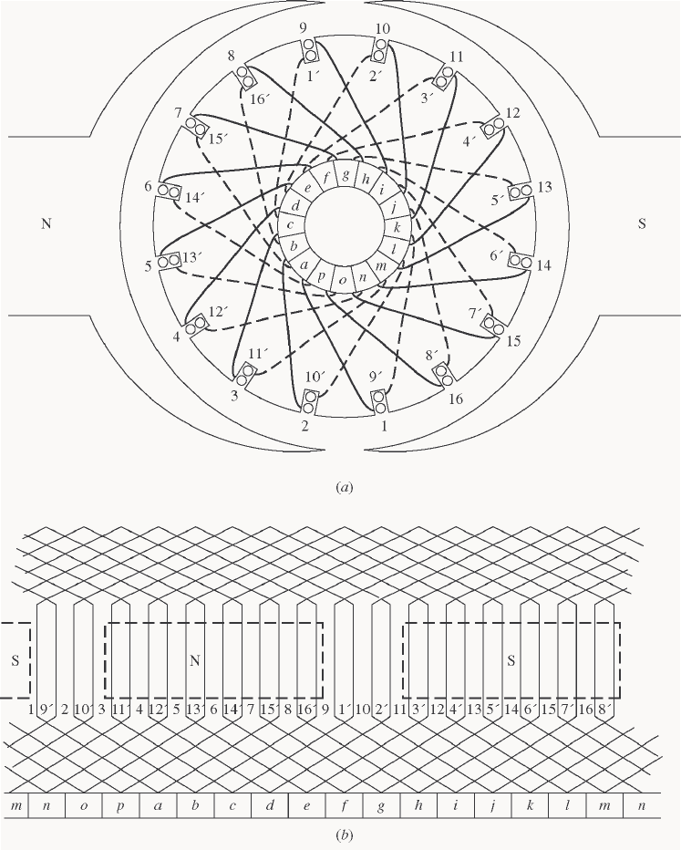
212
S
OLUTION
(a) This is a duplex, two-pole, lap winding, so there are 4 parallel current paths through the rotor.
(b) The brushes should be shorting out those windings lying between the two poles. At the time shown,
those windings are 1, 2, 9, and 10. Therefore, the brushes should be connected to short out commutator
segments b-c-d and j-k-l at the instant shown in the figure. Each brush should be two commutator
segments wide, since this is a duplex winding.
(c) Duplex (see above)
(d) There are 16 coils on the armature of this machine. Of that number, an average of 14 of them would
be under the pole faces at any one time. Therefore, there are 28 conductors divided among 4 parallel paths,
which produces 7 conductors per path. Therefore, TA VeE == 7 for no-load conditions.
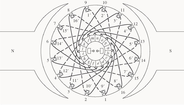
213
8-10. Describe in detail the winding of the machine shown in Figure P8-4. If a positive voltage is applied to the
brush under the North pole face, which way will this motor rotate?
S
OLUTION This is a 2-pole, retrogressive, lap winding. If a positive voltage is applied to the brush under
the North pole face, the rotor will rotate in a counterclockwise direction.
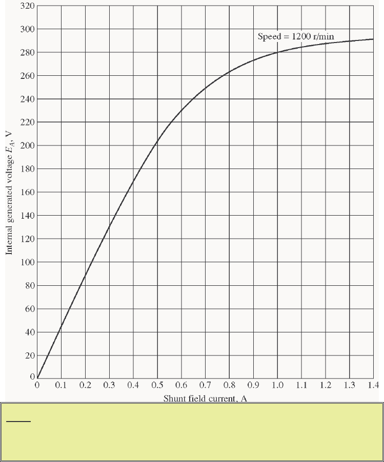
214
Chapter 9: DC Motors and Generators
Problems 9-1 to 9-12 refer to the following dc motor:
P
rated = 15 hp IL,rated = 55 A
VT = 240 V NF = 2700 turns per pole
nrated = 1200 r/min NSE = 27 turns per pole
RA = 0.40 Ω RF = 100 Ω
RS = 0.04 Ω Radj = 100 to 400 Ω
Rotational losses = 1800 W at full load. Magnetization curve as shown in Figure P9-1.
Note: An electronic version of this magnetization curve can be found in file
p91_mag.dat, which can be used with MATLAB programs. Column 1
contains field current in amps, and column 2 contains the internal generated
voltage EA in volts.
In Problems 9-1 through 9-7, assume that the motor described above can be connected in shunt. The equivalent
circuit of the shunt motor is shown in Figure P9-2.
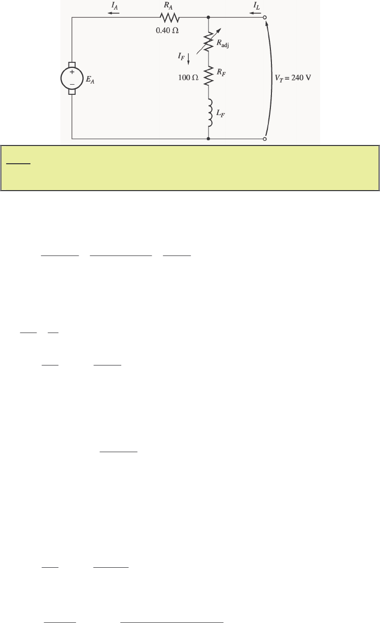
215
Note: Figure P9-2 shows incorrect values for RA and RF in the first printing of this
book. The correct values are given in the text, but shown incorrectly on the
figure. This will be corrected at the second printing.
9-1. If the resistor Radj is adjusted to 175 Ω what is the rotational speed of the motor at no-load conditions?
S
OLUTION At no-load conditions, 240 V
AT
EV== . The field current is given by
adj
240 V 240 V 0.873 A
175 100 250
T
F
F
V
IRR
== ==
+Ω+ΩΩ
From Figure P9-1, this field current would produce an internal generated voltage Ao
E of 271 V at a speed
o
n of 1200 r/min. Therefore, the speed n with a voltage A
E of 240 V would be
A
Ao o
En
En
=
()
240 V 1200 r/min 1063 r/min
271 V
A
o
Ao
E
nn
E
== =
9-2. Assuming no armature reaction, what is the speed of the motor at full load? What is the speed regulation of
the motor?
S
OLUTION At full load, the armature current is
adj
55 A 0.87 A 54.13 A
T
ALF L
F
V
IIIIRR
=−=− = − =
+
The internal generated voltage A
E is
()()
240 V 54.13 A 0.40 218.3 V
ATAA
EVIR=− = − Ω=
The field current is the same as before, and there is no armature reaction, so Ao
E is still 271 V at a speed
o
n of 1200 r/min. Therefore,
()
218.3 V 1200 r/min 967 r/min
271 V
A
o
Ao
E
nn
E
== =
The speed regulation is
nl fl
fl
1063 r/min 967 r/min
SR 100% 100% 9.9%
967 r/min
nn
n
−−
=×= ×=

216
9-3. If the motor is operating at full load and if its variable resistance adj
R is increased to 250 Ω, what is the
new speed of the motor? Compare the full-load speed of the motor with adj
R = 175 Ω to the full-load speed
with adj
R = 250 Ω. (Assume no armature reaction, as in the previous problem.)
S
OLUTION If adj
R is set to 250 Ω, the field current is now
adj
240 V 240 V 0.686 A
250 100 325
T
F
F
V
IRR
== ==
+Ω+ΩΩ
Since the motor is still at full load, A
E is still 218.3 V. From the magnetization curve (Figure P9-1), the
new field current F
I would produce a voltage Ao
E of 247 V at a speed o
n of 1200 r/min. Therefore,
()
218.3 V 1200 r/min 1061 r/min
247 V
A
o
Ao
E
nn
E
== =
Note that
adj
R has increased, and as a result the speed of the motor n increased.
9-4. Assume that the motor is operating at full load and that the variable resistor Radj is again 175 Ω. If the
armature reaction is 1200 A⋅turns at full load, what is the speed of the motor? How does it compare to the
result for Problem 9-2?
S
OLUTION The field current is again 0.87 A, and the motor is again at full load conditions. However, this
time there is an armature reaction of 1200 A⋅turns, and the effective field current is
*AR 1200 A turns
0.87 A 0.426 A
2700 turns
FF
F
II
N
⋅
=− = − =
From Figure P9-1, this field current would produce an internal generated voltage Ao
E of 181 V at a speed
o
n of 1200 r/min. The actual internal generated voltage A
E at these conditions is
()()
240 V 54.13 A 0.40 218.3 V
ATAA
EVIR=− = − Ω=
Therefore, the speed n with a voltage of 240 V would be
()
218.3 V 1200 r/min 1447 r/min
181 V
A
o
Ao
E
nn
E
== =
If all other conditions are the same, the motor with armature reaction runs at a higher speed than the motor
without armature reaction.
9-5. If Radj can be adjusted from 100 to 400 Ω, what are the maximum and minimum no-load speeds possible
with this motor?
S
OLUTION The minimum speed will occur when adj
R = 100 Ω, and the maximum speed will occur when
adj
R = 400 Ω. The field current when adj
R = 100 Ω is:
adj
240 V 240 V 1.20 A
100 100 200
T
F
F
V
IRR
== ==
+Ω+ΩΩ
From Figure P9-1, this field current would produce an internal generated voltage Ao
E of 287 V at a speed
o
n of 1200 r/min. Therefore, the speed n with a voltage of 240 V would be

217
A
Ao o
En
En
=
()
240 V 1200 r/min 1004 r/min
287 V
A
o
Ao
E
nn
E
== =
The field current when adj
R = 400 Ω is:
adj
240 V 240 V 0.480 A
400 100 500
T
F
F
V
IRR
== ==
+Ω+ΩΩ
From Figure P9-1, this field current would produce an internal generated voltage Ao
E of 199 V at a speed
o
n of 1200 r/min. Therefore, the speed n with a voltage of 240 V would be
A
Ao o
En
En
=
()
240 V 1200 r/min 1447 r/min
199 V
A
o
Ao
E
nn
E
== =
9-6. What is the starting current of this machine if it is started by connecting it directly to the power supply VT?
How does this starting current compare to the full-load current of the motor?
S
OLUTION The starting current of this machine (ignoring the small field current) is
,start
240 V 600 A
0.40
T
L
A
V
IR
== =
Ω
The rated current is 55 A, so the starting current is 10.9 times greater than the full-load current. This much
current is extremely likely to damage the motor.
9-7. Plot the torque-speed characteristic of this motor assuming no armature reaction, and again assuming a
full-load armature reaction of 1200 A⋅turns.
S
OLUTION This problem is best solved with MATLAB, since it involves calculating the torque-speed values
at many points. A MATLAB program to calculate and display both torque-speed characteristics is shown
below.
% M-file: prob9_7.m
% M-file to create a plot of the torque-speed curve of the
% the shunt dc motor with and without armature reaction.
% Get the magnetization curve. Note that this curve is
% defined for a speed of 1200 r/min.
load p91_mag.dat
if_values = p91_mag(:,1);
ea_values = p91_mag(:,2);
n_0 = 1200;
% First, initialize the values needed in this program.
v_t = 240; % Terminal voltage (V)
r_f = 100; % Field resistance (ohms)
r_adj = 175; % Adjustable resistance (ohms)
r_a = 0.40; % Armature resistance (ohms)
i_l = 0:1:55; % Line currents (A)
n_f = 2700; % Number of turns on field
218
f_ar0 = 1200; % Armature reaction @ 55 A (A-t/m)
% Calculate the armature current for each load.
i_a = i_l - v_t / (r_f + r_adj);
% Now calculate the internal generated voltage for
% each armature current.
e_a = v_t - i_a * r_a;
% Calculate the armature reaction MMF for each armature
% current.
f_ar = (i_a / 55) * f_ar0;
% Calculate the effective field current with and without
% armature reaction. Ther term i_f_ar is the field current
% with armature reaction, and the term i_f_noar is the
% field current without armature reaction.
i_f_ar = v_t / (r_f + r_adj) - f_ar / n_f;
i_f_noar = v_t / (r_f + r_adj);
% Calculate the resulting internal generated voltage at
% 1200 r/min by interpolating the motor's magnetization
% curve.
e_a0_ar = interp1(if_values,ea_values,i_f_ar);
e_a0_noar = interp1(if_values,ea_values,i_f_noar);
% Calculate the resulting speed from Equation (9-13).
n_ar = ( e_a ./ e_a0_ar ) * n_0;
n_noar = ( e_a ./ e_a0_noar ) * n_0;
% Calculate the induced torque corresponding to each
% speed from Equations (8-55) and (8-56).
t_ind_ar = e_a .* i_a ./ (n_ar * 2 * pi / 60);
t_ind_noar = e_a .* i_a ./ (n_noar * 2 * pi / 60);
% Plot the torque-speed curves
figure(1);
plot(t_ind_noar,n_noar,'b-','LineWidth',2.0);
hold on;
plot(t_ind_ar,n_ar,'k--','LineWidth',2.0);
xlabel('\bf\tau_{ind} (N-m)');
ylabel('\bf\itn_{m} \rm\bf(r/min)');
title ('\bfShunt DC Motor Torque-Speed Characteristic');
legend('No armature reaction','With armature reaction');
axis([ 0 125 800 1250]);
grid on;
hold off;
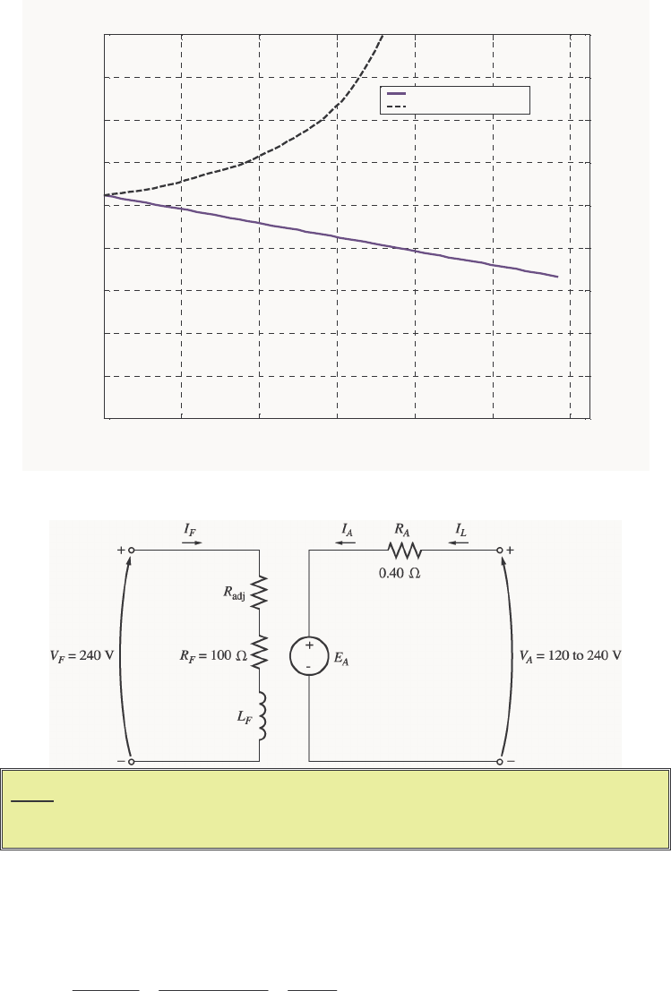
219
The resulting plot is shown below:
020 40 60 80 100 120
800
850
900
950
1000
1050
1100
1150
1200
1250
τ
ind
(N-m)
n
m
(r/min)
Shunt DC Motor Torque-Speed Characteristic
No armature reaction
With armature reaction
For Problems 9-8 and 9-9, the shunt dc motor is reconnected separately excited, as shown in Figure P9-3. It has a
fixed field voltage VF of 240 V and an armature voltage VA that can be varied from 120 to 240 V.
Note: Figure P9-3 shows incorrect values for RA and RF in the first printing of this
book. The correct values are given in the text, but shown incorrectly on the
figure. This will be corrected at the second printing.
9-8. What is the no-load speed of this separately excited motor when adj
R = 175 Ω and (a) A
V = 120 V, (b) A
V
= 180 V, (c) A
V = 240 V?
S
OLUTION At no-load conditions, AA
EV=. The field current is given by
adj
240 V 240 V 0.873 A
175 100 275
F
F
F
V
IRR
== ==
+Ω+ΩΩ
From Figure P9-1, this field current would produce an internal generated voltage Ao
E of 271 V at a speed
o
n of 1200 r/min. Therefore, the speed n with a voltage of 240 V would be

220
A
Ao o
En
En
=
A
o
Ao
E
nn
E
=
(a) If
A
V = 120 V, then A
E = 120 V, and
()
120 V 1200 r/min 531 r/min
271 V
n
==
(a) If
A
V = 180 V, then A
E = 180 V, and
()
180 V 1200 r/min 797 r/min
271 V
n
==
(a) If
A
V = 240 V, then A
E = 240 V, and
()
240 V 1200 r/min 1063 r/min
271 V
n
==
9-9. For the separately excited motor of Problem 9-8:
(a) What is the maximum no-load speed attainable by varying both A
V and adj
R?
(b) What is the minimum no-load speed attainable by varying both A
V and adj
R?
S
OLUTION
(a) The maximum speed will occur with the maximum A
V and the maximum adj
R. The field current
when adj
R = 400 Ω is:
adj
240 V 240 V 0.48 A
400 100 500
T
F
F
V
IRR
== ==
+Ω+ΩΩ
From Figure P9-1, this field current would produce an internal generated voltage Ao
E of 199 V at a speed
o
n of 1200 r/min. At no-load conditions, the maximum internal generated voltage AA
EV= = 240 V.
Therefore, the speed n with a voltage of 240 V would be
A
Ao o
En
En
=
()
240 V 1200 r/min 1447 r/min
199 V
A
o
Ao
E
nn
E
== =
(b) The minimum speed will occur with the minimum A
V and the minimum adj
R. The field current when
adj
R = 100 Ω is:
adj
240 V 240 V 1.2 A
100 100 200
T
F
F
V
IRR
== ==
+Ω+ΩΩ
From Figure P9-1, this field current would produce an internal generated voltage Ao
E of 287 V at a speed
o
n of 1200 r/min. At no-load conditions, the minimum internal generated voltage AA
EV= = 120 V.
Therefore, the speed n with a voltage of 120 V would be
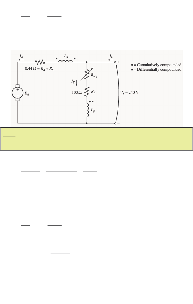
221
A
Ao o
En
En
=
()
120 V 1200 r/min 502 r/min
287 V
A
o
Ao
E
nn
E
== =
9-10. If the motor is connected cumulatively compounded as shown in Figure P9-4 and if Radj = 175 Ω, what is
its no-load speed? What is its full-load speed? What is its speed regulation? Calculate and plot the torque-
speed characteristic for this motor. (Neglect armature effects in this problem.)
Note: Figure P9-4 shows incorrect values for RA + RS and RF in the first printing of
this book. The correct values are given in the text, but shown incorrectly on
the figure. This will be corrected at the second printing.
S
OLUTION At no-load conditions, 240 V
AT
EV== . The field current is given by
adj
240 V 240 V 0.873 A
175 100 275
F
F
F
V
IRR
== ==
+Ω+ΩΩ
From Figure P9-1, this field current would produce an internal generated voltage Ao
E of 271 V at a speed
o
n of 1200 r/min. Therefore, the speed n with a voltage of 240 V would be
A
Ao o
En
En
=
()
240 V 1200 r/min 1063 r/min
271 V
A
o
Ao
E
nn
E
== =
At full load conditions, the armature current is
adj
55 A 0.87 A 54.13 A
T
ALF L
F
V
IIIIRR
=−=− = − =
+
The internal generated voltage A
E is
()
()()
240 V 54.13 A 0.44 216.2 V
ATAA S
EVIRR=− + = − Ω=
The equivalent field current is
()
*SE 27 turns
0.873 A 54.13 A 1.41 A
2700 turns
FF A
F
N
II I
N
=+ = + =

222
From Figure P9-1, this field current would produce an internal generated voltage Ao
E of 290 V at a speed
o
n of 1200 r/min. Therefore,
()
216.2 V 1200 r/min 895 r/min
290 V
A
o
Ao
E
nn
E
== =
The speed regulation is
nl fl
fl
1063 r/min 895 r/min
SR 100% 100% 18.8%
895 r/min
nn
n
−−
=×= ×=
The torque-speed characteristic can best be plotted with a MATLAB program. An appropriate program is
shown below.
% M-file: prob9_10.m
% M-file to create a plot of the torque-speed curve of the
% a cumulatively compounded dc motor without
% armature reaction.
% Get the magnetization curve. Note that this curve is
% defined for a speed of 1200 r/min.
load p91_mag.dat
if_values = p91_mag(:,1);
ea_values = p91_mag(:,2);
n_0 = 1200;
% First, initialize the values needed in this program.
v_t = 240; % Terminal voltage (V)
r_f = 100; % Field resistance (ohms)
r_adj = 175; % Adjustable resistance (ohms)
r_a = 0.44; % Armature + series resistance (ohms)
i_l = 0:55; % Line currents (A)
n_f = 2700; % Number of turns on shunt field
n_se = 27; % Number of turns on series field
% Calculate the armature current for each load.
i_a = i_l - v_t / (r_f + r_adj);
% Now calculate the internal generated voltage for
% each armature current.
e_a = v_t - i_a * r_a;
% Calculate the effective field current for each armature
% current.
i_f = v_t / (r_f + r_adj) + (n_se / n_f) * i_a;
% Calculate the resulting internal generated voltage at
% 1200 r/min by interpolating the motor's magnetization
% curve.
e_a0 = interp1(if_values,ea_values,i_f);
% Calculate the resulting speed from Equation (9-13).
n = ( e_a ./ e_a0 ) * n_0;
% Calculate the induced torque corresponding to each
% speed from Equations (8-55) and (8-56).
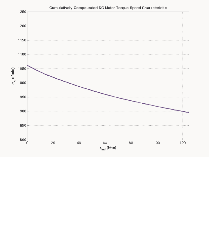
223
t_ind = e_a .* i_a ./ (n * 2 * pi / 60);
% Plot the torque-speed curves
figure(1);
plot(t_ind,n,'b-','LineWidth',2.0);
xlabel('\bf\tau_{ind} (N-m)');
ylabel('\bf\itn_{m} \rm\bf(r/min)');
title ('\bfCumulatively-Compounded DC Motor Torque-Speed
Characteristic');
axis([0 125 800 1250]);
grid on;
The resulting plot is shown below:
Compare this torque-speed curve to that of the shunt motor in Problem 9-7. (Both curves are plotted on the
same scale to facilitate comparison.)
9-11. The motor is connected cumulatively compounded and is operating at full load. What will the new speed of
the motor be if adj
R is increased to 250 Ω? How does the new speed compared to the full-load speed
calculated in Problem 9-10?
S
OLUTION If adj
R is increased to 250 Ω, the field current is given by
adj
240 V 240 V 0.686 A
250 100 350
T
F
F
V
IRR
== ==
+Ω+ΩΩ
At full load conditions, the armature current is
55 A 0.686 A 54.3 A
ALF
III=−= − =
The internal generated voltage A
E is
()
(
)
(
)
240 V 54.3 A 0.44 216.1 V
ATAA S
EVIRR=− + = − Ω=

224
The equivalent field current is
()
*SE 27 turns
0.686 A 54.3 A 1.23 A
2700 turns
FF A
F
N
II I
N
=+ = + =
From Figure P9-1, this field current would produce an internal generated voltage Ao
E of 288 V at a speed
o
n of 1200 r/min. Therefore,
()
216.1 V 1200 r/min 900 r/min
288 V
A
o
Ao
E
nn
E
== =
The new full-load speed is higher than the full-load speed in Problem 9-10.
9-12. The motor is now connected differentially compounded.
(a) If Radj = 175 Ω, what is the no-load speed of the motor?
(b) What is the motor’s speed when the armature current reaches 20 A? 40 A? 60 A?
(c) Calculate and plot the torque-speed characteristic curve of this motor.
S
OLUTION
(a) At no-load conditions, 240 V
AT
EV== . The field current is given by
adj
240 V 240 V 0.873 A
175 100 275
F
F
F
V
IRR
== ==
+Ω+ΩΩ
From Figure P9-1, this field current would produce an internal generated voltage Ao
E of 271 V at a speed
o
n of 1200 r/min. Therefore, the speed n with a voltage of 240 V would be
A
Ao o
En
En
=
()
240 V 1200 r/min 1063 r/min
271 V
A
o
Ao
E
nn
E
== =
(b) At
A
I = 20A, the internal generated voltage A
E is
()
()( )
240 V 20 A 0.44 231.2 V
ATAA S
EVIRR=− + = − Ω=
The equivalent field current is
()
*SE 27 turns
0.873 A 20 A 0.673 A
2700 turns
FF A
F
N
II I
N
=− = − =
From Figure P9-1, this field current would produce an internal generated voltage Ao
E of 245 V at a speed
o
n of 1200 r/min. Therefore,
()
231.2 V 1200 r/min 1132 r/min
245 V
A
o
Ao
E
nn
E
== =
At
A
I = 40A, the internal generated voltage A
E is
()
()( )
240 V 40 A 0.44 222.4 V
ATAA S
EVIRR=− + = − Ω=
The equivalent field current is

225
()
*SE 27 turns
0.873 A 40 A 0.473 A
2700 turns
FF A
F
N
II I
N
=− = − =
From Figure P9-1, this field current would produce an internal generated voltage Ao
E of 197 V at a speed
o
n of 1200 r/min. Therefore,
()
227.4 V 1200 r/min 1385 r/min
197 V
A
o
Ao
E
nn
E
== =
At
A
I = 60A, the internal generated voltage A
E is
()
()( )
240 V 60 A 0.44 213.6 V
ATAA S
EVIRR=− + = − Ω=
The equivalent field current is
()
*SE 27 turns
0.873 A 60 A 0.273 A
2700 turns
FF A
F
N
II I
N
=− = − =
From Figure P9-1, this field current would produce an internal generated voltage Ao
E of 121 V at a speed
o
n of 1200 r/min. Therefore,
()
213.6 V 1200 r/min 2118 r/min
121 V
A
o
Ao
E
nn
E
== =
(c) The torque-speed characteristic can best be plotted with a MATLAB program. An appropriate
program is shown below.
% M-file: prob9_12.m
% M-file to create a plot of the torque-speed curve of the
% a differentially compounded dc motor withwithout
% armature reaction.
% Get the magnetization curve. Note that this curve is
% defined for a speed of 1200 r/min.
load p91_mag.dat
if_values = p91_mag(:,1);
ea_values = p91_mag(:,2);
n_0 = 1200;
% First, initialize the values needed in this program.
v_t = 240; % Terminal voltage (V)
r_f = 100; % Field resistance (ohms)
r_adj = 175; % Adjustable resistance (ohms)
r_a = 0.44; % Armature + series resistance (ohms)
i_l = 0:50; % Line currents (A)
n_f = 2700; % Number of turns on shunt field
n_se = 27; % Number of turns on series field
% Calculate the armature current for each load.
i_a = i_l - v_t / (r_f + r_adj);
% Now calculate the internal generated voltage for
% each armature current.
e_a = v_t - i_a * r_a;
% Calculate the effective field current for each armature
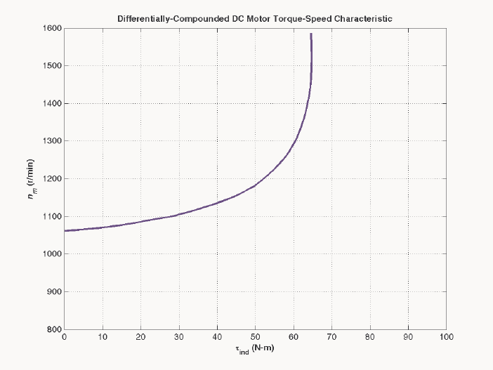
226
% current.
i_f = v_t / (r_f + r_adj) - (n_se / n_f) * i_a;
% Calculate the resulting internal generated voltage at
% 1200 r/min by interpolating the motor's magnetization
% curve.
e_a0 = interp1(if_values,ea_values,i_f);
% Calculate the resulting speed from Equation (9-13).
n = ( e_a ./ e_a0 ) * n_0;
% Calculate the induced torque corresponding to each
% speed from Equations (8-55) and (8-56).
t_ind = e_a .* i_a ./ (n * 2 * pi / 60);
% Plot the torque-speed curves
figure(1);
plot(t_ind,n,'b-','LineWidth',2.0);
xlabel('\bf\tau_{ind} (N-m)');
ylabel('\bf\itn_{m} \rm\bf(r/min)');
title ('\bfDifferentially-Compounded DC Motor Torque-Speed
Characteristic');
axis([0 100 800 1600]);
grid on;
The resulting plot is shown below:
Compare this torque-speed curve to that of the shunt motor in Problem 9-7 and the cumulatively-
compounded motor in Problem 9-10. (Note that this plot has a larger vertical scale to accommodate the
speed runaway of the differentially-compounded motor.)
9-13. A 7.5-hp 120-V series dc motor has an armature resistance of 0.2 Ω and a series field resistance of 0.16 Ω.
At full load, the current input is 58 A, and the rated speed is 1050 r/min. Its magnetization curve is shown
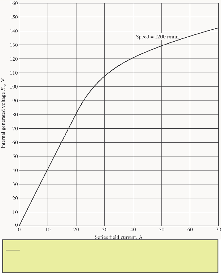
227
in Figure P9-5. The core losses are 200 W, and the mechanical losses are 240 W at full load. Assume that
the mechanical losses vary as the cube of the speed of the motor and that the core losses are constant.
Note: An electronic version of this magnetization curve can be found in file
p95_mag.dat, which can be used with MATLAB programs. Column 1
contains field current in amps, and column 2 contains the internal generated
voltage EA in volts.
(a) What is the efficiency of the motor at full load?
(b) What are the speed and efficiency of the motor if it is operating at an armature current of 35 A?
(c) Plot the torque-speed characteristic for this motor.
S
OLUTION
(a) The output power of this motor at full load is
()( )
OUT 7.5 hp 746 W/hp 5595 WP==
The input power is

228
()()
IN 120 V 58 A 6960 W
TL
PVI== =
Therefore the efficiency is
OUT
IN
5595 W
100% 100% 80.4%
6960 W
P
P
η
=× = × =
(b) If the armature current is 35 A, then the input power to the motor will be
()()
IN 120 V 35 A 4200 W
TL
PVI== =
The internal generated voltage at this condition is
()
()( )
2120 V 35 A 0.20 0.16 107.4 V
ATAAS
EVIRR=− + = − Ω+ Ω=
and the internal generated voltage at rated conditions is
()
()( )
1120 V 58 A 0.20 0.16 99.1 V
ATAAS
EVIRR=− + = − Ω+ Ω=
The final speed is given by the equation
,2 2
222
122,11
Ao
A
AAo
En
EK
EK En
φω
φω
==
since the ratio ,2 ,1
/
Ao Ao
EE is the same as the ratio 21
/
φ
φ
. Therefore, the final speed is
,1
2
21
1,2
Ao
A
AAo
E
E
nn
EE
=
From Figure P9-5, the internal generated voltage ,2Ao
E for a current of 35 A and a speed of o
n = 1200
r/min is ,2Ao
E = 115 V, and the internal generated voltage ,1Ao
E for a current of 58 A and a speed of o
n =
1200 r/min is ,1Ao
E = 134 V.
()
,1
2
21
1,2
107.4 V 134 V 1050 r/min 1326 r/min
99.1 V 115 V
Ao
A
AAo
E
E
nn
EE
== =
The power converted from electrical to mechanical form is
()()
conv 107.4 V 35 A 3759 W
AA
PEI== =
The core losses in the motor are 200 W, and the mechanical losses in the motor are 240 W at a speed of
1050 r/min. The mechanical losses in the motor scale proportionally to the cube of the rotational speedm
so the mechanical losses at 1326 r/min are
() ()
33
2
mech
1
1326 r/min
240 W 240 W 483 W
1050 r/min
n
Pn
== =
Therefore, the output power is
OUT conv mech core 3759 W 483 W 200 W 3076 WPPPP=−−= − − =
and the efficiency is
OUT
IN
3076 W
100% 100% 73.2%
4200 W
P
P
η
=× = × =
(c) A MATLAB program to plot the torque-speed characteristic of this motor is shown below:
229
% M-file: prob9_13.m
% M-file to create a plot of the torque-speed curve of the
% the series dc motor in Problem 9-13.
% Get the magnetization curve. Note that this curve is
% defined for a speed of 1200 r/min.
load p95_mag.dat
if_values = p95_mag(:,1);
ea_values = p95_mag(:,2);
n_0 = 1200;
% First, initialize the values needed in this program.
v_t = 120; % Terminal voltage (V)
r_a = 0.36; % Armature + field resistance (ohms)
i_a = 9:1:58; % Armature (line) currents (A)
% Calculate the internal generate voltage e_a.
e_a = v_t - i_a * r_a;
% Calculate the resulting internal generated voltage at
% 1200 r/min by interpolating the motor's magnetization
% curve. Note that the field current is the same as the
% armature current for this motor.
e_a0 = interp1(if_values,ea_values,i_a,'spline');
% Calculate the motor's speed, using the known fact that
% the motor runs at 1050 r/min at a current of 58 A. We
% know that
%
% Ea2 K' phi2 n2 Eao2 n2
% ----- = ------------ = ----------
% Ea1 K' phi1 n1 Eao1 n1
%
% Ea2 Eao1
% ==> n2 = ----- ------ n1
% Ea1 Eao2
%
% where Ea0 is the internal generated voltage at 1200 r/min
% for a given field current.
%
% Speed will be calculated by reference to full load speed
% and current.
n1 = 1050; % 1050 r/min at full load
Eao1 = interp1(if_values,ea_values,58,'spline');
Ea1 = v_t - 58 * r_a;
% Get speed
Eao2 = interp1(if_values,ea_values,i_a,'spline');
n = (e_a./Ea1) .* (Eao1 ./ Eao2) * n1;
% Calculate the induced torque corresponding to each
% speed from Equations (8-55) and (8-56).
t_ind = e_a .* i_a ./ (n * 2 * pi / 60);
% Plot the torque-speed curve
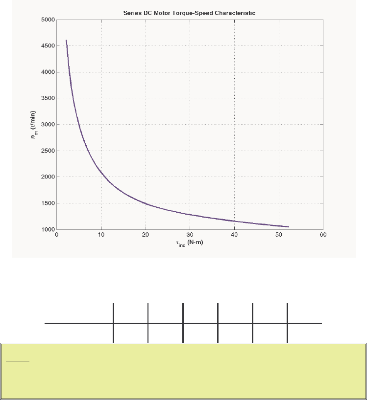
230
figure(1);
plot(t_ind,n,'b-','LineWidth',2.0);
hold on;
xlabel('\bf\tau_{ind} (N-m)');
ylabel('\bf\itn_{m} \rm\bf(r/min)');
title ('\bfSeries DC Motor Torque-Speed Characteristic');
grid on;
hold off;
The resulting torque-speed characteristic is shown below:
9-14. A 20-hp 240-V 76-A 900 r/min series motor has a field winding of 33 turns per pole. Its armature
resistance is 0.09 Ω, and its field resistance is 0.06 Ω. The magnetization curve expressed in terms of
magnetomotive force versus EA at 900 r/min is given by the following table:
EA, V 95 150 188 212 229 243
F, A turns⋅ 500 1000 1500 2000 2500 3000
Note: An electronic version of this magnetization curve can be found in file
prob9_14_mag.dat, which can be used with MATLAB programs. Column
1 contains magnetomotive force in ampere-turns, and column 2 contains the
internal generated voltage EA in volts.
Armature reaction is negligible in this machine.
(a) Compute the motor’s torque, speed, and output power at 33, 67, 100, and 133 percent of full-load
armature current. (Neglect rotational losses.)
(b) Plot the terminal characteristic of this machine.
S
OLUTION Note that this magnetization curve has been stored in a file called prob9_14_mag.dat. The
first column of the file is an array of mmf_values, and the second column is an array of ea_values.
These values are valid at a speed o
n = 900 r/min. Because the data in the file is relatively sparse, it is

231
important that interpolation be done using smooth curves, so be sure to specify the 'spline' option in
the MATLAB interp1 function:
load prob9_14_mag.dat;
mmf_values = prob9_14_mag(:,1);
ea_values = prob9_14_mag(:,2);
...
Eao = interp1(mmf_values,ea_values,mmf,'spline')
(a) Since full load corresponds to 76 A, this calculation must be performed for armature currents of 25.3
A, 50.7 A, 76 A, and 101.3 A.
If
A
I = 23.3 A, then
()
()( )
240 V 25.3 A 0.09 0.06 236.2 V
ATAA S
EVIRR=− + = − Ω+ Ω=
The magnetomotive force is
()()
33 turns 25.3 A 835 A turns
A
NI== = ⋅F, which produces a voltage Ao
E
of 134 V at o
n = 900 r/min. Therefore the speed of the motor at these conditions is
()
236.2 V 900 r/min 1586 r/min
134 V
A
o
Ao
E
nn
E
== =
The power converted from electrical to mechanical form is
()()
conv 236.2 V 25.3 A 5976 W
AA
PEI== =
Since the rotational losses are ignored, this is also the output power of the motor. The induced torque is
()
conv
ind
5976 W 36 N m
2 rad 1 min
1586 r/min 1 r 60 s
m
P
τπ
ω
== =⋅
If
A
I = 50.7 A, then
()
()( )
240 V 50.7 A 0.09 0.06 232.4 V
ATAA S
EVIRR=− + = − Ω+ Ω=
The magnetomotive force is
()()
33 turns 50.7 A 1672 A turns
A
NI== = ⋅F, which produces a voltage Ao
E
of 197 V at o
n = 900 r/min. Therefore the speed of the motor at these conditions is
()
232.4 V 900 r/min 1062 r/min
197 V
A
o
Ao
E
nn
E
== =
The power converted from electrical to mechanical form is
()()
conv 232.4 V 50.7 A 11,780 W
AA
PEI== =
Since the rotational losses are ignored, this is also the output power of the motor. The induced torque is
()
conv
ind
11,780 W 106 N m
2 rad 1 min
1062 r/min 1 r 60 s
m
P
τπ
ω
== = ⋅
If
A
I = 76 A, then
()
()( )
240 V 76 A 0.09 0.06 228.6 V
ATAA S
EVIRR=− + = − Ω+ Ω=

232
The magnetomotive force is
()()
33 turns 76 A 2508 A turns
A
NI== = ⋅F, which produces a voltage Ao
E
of 229 V at o
n = 900 r/min. Therefore the speed of the motor at these conditions is
()
228.6 V 900 r/min 899 r/min
229 V
A
o
Ao
E
nn
E
== =
The power converted from electrical to mechanical form is
()()
conv 228.6 V 76 A 17,370 W
AA
PEI== =
Since the rotational losses are ignored, this is also the output power of the motor. The induced torque is
()
conv
ind
17,370 W 185 N m
2 rad 1 min
899 r/min 1 r 60 s
m
P
τπ
ω
== = ⋅
If
A
I = 101.3 A, then
()
()( )
240 V 101.3 A 0.09 0.06 224.8 V
ATAA S
EVIRR=− + = − Ω+ Ω=
The magnetomotive force is
()()
33 turns 101.3 A 3343 A turns
A
NI== = ⋅F, which produces a voltage
Ao
E of 252 V at o
n = 900 r/min. Therefore the speed of the motor at these conditions is
()
224.8 V 900 r/min 803 r/min
252 V
A
o
Ao
E
nn
E
== =
The power converted from electrical to mechanical form is
()()
conv 224.8 V 101.3 A 22,770 W
AA
PEI== =
Since the rotational losses are ignored, this is also the output power of the motor. The induced torque is
()
conv
ind
22,770 W 271 N m
2 rad 1 min
803 r/min 1 r 60 s
m
P
τπ
ω
== = ⋅
(b) A MATLAB program to plot the torque-speed characteristic of this motor is shown below:
% M-file: series_ts_curve.m
% M-file to create a plot of the torque-speed curve of the
% the series dc motor in Problem 9-14.
% Get the magnetization curve. Note that this curve is
% defined for a speed of 900 r/min.
load prob9_14_mag.dat
mmf_values = prob9_14_mag(:,1);
ea_values = prob9_14_mag(:,2);
n_0 = 900;
% First, initialize the values needed in this program.
v_t = 240; % Terminal voltage (V)
r_a = 0.15; % Armature + field resistance (ohms)
i_a = 15:1:76; % Armature (line) currents (A)
n_s = 33; % Number of series turns on field
% Calculate the MMF for each load
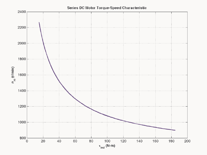
233
f = n_s * i_a;
% Calculate the internal generate voltage e_a.
e_a = v_t - i_a * r_a;
% Calculate the resulting internal generated voltage at
% 900 r/min by interpolating the motor's magnetization
% curve. Specify cubic spline interpolation to provide
% good results with this sparse magnetization curve.
e_a0 = interp1(mmf_values,ea_values,f,'spline');
% Calculate the motor's speed from Equation (9-13).
n = (e_a ./ e_a0) * n_0;
% Calculate the induced torque corresponding to each
% speed from Equations (8-55) and (8-56).
t_ind = e_a .* i_a ./ (n * 2 * pi / 60);
% Plot the torque-speed curve
figure(1);
plot(t_ind,n,'b-','LineWidth',2.0);
hold on;
xlabel('\bf\tau_{ind} (N-m)');
ylabel('\bf\itn_{m} \rm\bf(r/min)');
title ('\bfSeries DC Motor Torque-Speed Characteristic');
%axis([ 0 700 0 5000]);
grid on;
hold off;
The resulting torque-speed characteristic is shown below:
9-15. A 300-hp 440-V 560-A, 863 r/min shunt dc motor has been tested, and the following data were taken:
Blocked-rotor test:

234
VA=16 3. V exclusive of brushes VF=440 V
IA=500 A IF=886. A
No-load operation:
VA=16 3. V including brushes IF=876. A
IA=231. A r/min 863=n
What is this motor’s efficiency at the rated conditions? [Note: Assume that (1) the brush voltage drop is 2
V; (2) the core loss is to be determined at an armature voltage equal to the armature voltage under full load;
and (3) stray load losses are 1 percent of full load.]
S
OLUTION The armature resistance of this motor is
,br
,br
16.3 V 0.0326
500 A
A
A
A
V
RI
== = Ω
Under no-load conditions, the core and mechanical losses taken together (that is, the rotational losses) of
this motor are equal to the product of the internal generated voltage A
E and the armature current A
I, since
this is no output power from the motor at no-load conditions. Therefore, the rotational losses at rated speed
can be found as
()( )
brush 442 V 2 V 23.1 A 0.0326 439.2 V
AA AA
EVV IR=− − = − − Ω=
()()
rot conv 439.2 V 23.1 A 10.15 kW
AA
PP EI== = =
The input power to the motor at full load is
()()
IN 440 V 560 A 246.4 kW
TL
PVI== =
The output power from the motor at full load is
OUT IN CU rot brush stray
PPPPPP=−−− −
The copper losses are
()( )()( )
2
2
CU 560 A 0.0326 440 V 8.86 A 14.1 kW
AA FF
PIRVI=+= Ω+ =
The brush losses are
()( )
brush brush 2 V 560 A 1120 W
A
PVI== =
Therefore,
OUT IN CU rot brush stray
PPPPPP=−−− −
OUT 246.4 kW 14.1 kW 10.15 kW 1.12 kW 2.46 kW 218.6 kWP=−− −−=
The motor’s efficiency at full load is
OUT
IN
218.6 kW
100% 100% 88.7%
246.4 kW
P
P
η
=× = × =
Problems 9-16 to 9-19 refer to a 240-V 100-A dc motor which has both shunt and series windings. Its
characteristics are
RA = 0.14 Ω NF = 1500 turns
RS = 0.04 Ω NSE = 12 turns
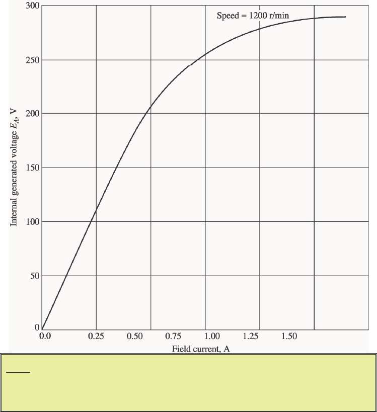
235
RF = 200 Ω nm = 1200 r/min
Radj = 0 to 300 Ω, currently set to 120 Ω
This motor has compensating windings and interpoles. The magnetization curve for this motor at 1200 r/min is
shown in Figure P9-6.
Note: An electronic version of this magnetization curve can be found in file
p96_mag.dat, which can be used with MATLAB programs. Column 1
contains field current in amps, and column 2 contains the internal generated
voltage EA in volts.
9-16. The motor described above is connected in shunt.
(a) What is the no-load speed of this motor when Radj = 120 Ω?
(b) What is its full-load speed?
(c) Under no-load conditions, what range of possible speeds can be achieved by adjusting Radj ?
S
OLUTION Note that this magnetization curve has been stored in a file called p96_mag.dat. The first
column of the file is an array of ia_values, and the second column is an array of ea_values. These
values are valid at a speed o
n = 1200 r/min. These values can be used with the MATLAB interp1
function to look up an internal generated voltage as follows:
load p96_mag.dat;

236
if_values = p96_mag(:,1);
ea_values = p96_mag(:,2);
...
Ea = interp1(if_values,ea_values,if,'spline')
(a) If adj
R = 120 Ω, the total field resistance is 320 Ω, and the resulting field current is
adj
240 V 0.75 A
200 120
T
F
F
V
IRR
== =
+Ω+Ω
This field current would produce a voltage Ao
E of 256 V at a speed of o
n = 1200 r/min. The actual A
E is
240 V, so the actual speed will be
()
240 V 1200 r/min 1125 r/min
256 V
A
o
Ao
E
nn
E
== =
(b) At full load, 100 A 0.75 A 99.25 A
ALF
III=−= − = , and
()()
240 V 99.25 A 0.14 226.1 V
ATAA
EVIR=− = − Ω=
Therefore, the speed at full load will be
()
226.1 V 1200 r/min 1060 r/min
256 V
A
o
Ao
E
nn
E
== =
(c) If
adj
R is maximum at no-load conditions, the total resistance is 500 Ω, and
adj
240 V 0.48 A
200 300
T
F
F
V
IRR
== =
+Ω+Ω
This field current would produce a voltage Ao
E of 200 V at a speed of o
n = 1200 r/min. The actual A
E is
240 V, so the actual speed will be
()
240 V 1200 r/min 1440 r/min
200 V
A
o
Ao
E
nn
E
== =
If
Radj is minimum at no-load conditions, the total resistance is 200 Ω, and
adj
240 V 1.2 A
200 0
T
F
F
V
IRR
== =
+Ω+Ω
This field current would produce a voltage Ao
E of 287 V at a speed of o
n = 1200 r/min. The actual A
E is
240 V, so the actual speed will be
()
240 V 1200 r/min 1004 r/min
287 V
A
o
Ao
E
nn
E
== =
9-17. This machine is now connected as a cumulatively compounded dc motor with adj
R = 120 Ω.
(a) What is the full-load speed of this motor?
(b) Plot the torque-speed characteristic for this motor.
(c) What is its speed regulation?
S
OLUTION

237
(a) At full load, 100 A 0.75 A 99.25 A
ALF
III=−= − = , and
()
(
)
(
)
240 V 99.25 A 0.14 0.05 221.1 V
ATAA S
EVIRR=− + = − Ω+ Ω=
The actual field current will be
adj
240 V 0.75 A
200 120
T
F
F
V
IRR
== =
+Ω+Ω
and the effective field current will be
()
*SE 12 turns
0.75 A 99.25 A 1.54 A
1500 turns
FF A
F
N
II I
N
=+=+ =
This field current would produce a voltage Ao
E of 290 V at a speed of o
n = 1200 r/min. The actual A
E
is 240 V, so the actual speed at full load will be
()
221.1 V 1200 r/min 915 r/min
290 V
A
o
Ao
E
nn
E
== =
(b) A MATLAB program to calculate the torque-speed characteristic of this motor is shown below:
% M-file: prob9_17.m
% M-file to create a plot of the torque-speed curve of the
% a cumulatively compounded dc motor.
% Get the magnetization curve.
load p96_mag.dat;
if_values = p96_mag(:,1);
ea_values = p96_mag(:,2);
n_0 = 1200;
% First, initialize the values needed in this program.
v_t = 240; % Terminal voltage (V)
r_f = 200; % Field resistance (ohms)
r_adj = 120; % Adjustable resistance (ohms)
r_a = 0.19; % Armature + series resistance (ohms)
i_l = 0:2:100; % Line currents (A)
n_f = 1500; % Number of turns on shunt field
n_se = 12; % Number of turns on series field
% Calculate the armature current for each load.
i_a = i_l - v_t / (r_f + r_adj);
% Now calculate the internal generated voltage for
% each armature current.
e_a = v_t - i_a * r_a;
% Calculate the effective field current for each armature
% current.
i_f = v_t / (r_f + r_adj) + (n_se / n_f) * i_a;
% Calculate the resulting internal generated voltage at
% 1800 r/min by interpolating the motor's magnetization
% curve.
e_a0 = interp1(if_values,ea_values,i_f);
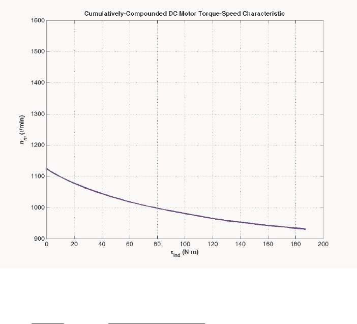
238
% Calculate the resulting speed from Equation (9-13).
n = ( e_a ./ e_a0 ) * n_0;
% Calculate the induced torque corresponding to each
% speed from Equations (8-55) and (8-56).
t_ind = e_a .* i_a ./ (n * 2 * pi / 60);
% Plot the torque-speed curves
figure(1);
plot(t_ind,n,'b-','LineWidth',2.0);
xlabel('\bf\tau_{ind} (N-m)');
ylabel('\bf\itn_{m} \rm\bf(r/min)');
title ('\bfCumulatively-Compounded DC Motor Torque-Speed
Characteristic');
axis([0 200 900 1600]);
grid on;
The resulting torque-speed characteristic is shown below:
(c) The no-load speed of this machine is the same as the no-load speed of the corresponding shunt dc
motor with adj
R = 120 Ω, which is 1125 r/min. The speed regulation of this motor is thus
nl fl
fl
1125 r/min - 915 r/min
SR 100% 100% 23.0%
915 r/min
nn
n
−
=×= ×=
9-18. The motor is reconnected differentially compounded with adj
R = 120 Ω. Derive the shape of its torque-
speed characteristic.
S
OLUTION A MATLAB program to calculate the torque-speed characteristic of this motor is shown below:
% M-file: prob9_18.m
% M-file to create a plot of the torque-speed curve of the
239
% a differentially compounded dc motor.
% Get the magnetization curve.
load p96_mag.dat;
if_values = p96_mag(:,1);
ea_values = p96_mag(:,2);
n_0 = 1200;
% First, initialize the values needed in this program.
v_t = 240; % Terminal voltage (V)
r_f = 200; % Field resistance (ohms)
r_adj = 120; % Adjustable resistance (ohms)
r_a = 0.19; % Armature + series resistance (ohms)
i_l = 0:2:40; % Line currents (A)
n_f = 1500; % Number of turns on shunt field
n_se = 12; % Number of turns on series field
% Calculate the armature current for each load.
i_a = i_l - v_t / (r_f + r_adj);
% Now calculate the internal generated voltage for
% each armature current.
e_a = v_t - i_a * r_a;
% Calculate the effective field current for each armature
% current.
i_f = v_t / (r_f + r_adj) - (n_se / n_f) * i_a;
% Calculate the resulting internal generated voltage at
% 1800 r/min by interpolating the motor's magnetization
% curve.
e_a0 = interp1(if_values,ea_values,i_f);
% Calculate the resulting speed from Equation (9-13).
n = ( e_a ./ e_a0 ) * n_0;
% Calculate the induced torque corresponding to each
% speed from Equations (8-55) and (8-56).
t_ind = e_a .* i_a ./ (n * 2 * pi / 60);
% Plot the torque-speed curves
figure(1);
plot(t_ind,n,'b-','LineWidth',2.0);
xlabel('\bf\tau_{ind} (N-m)');
ylabel('\bf\itn_{m} \rm\bf(r/min)');
title ('\bfDifferentially-Compounded DC Motor Torque-Speed
Characteristic');
axis([0 200 900 1600]);
grid on;
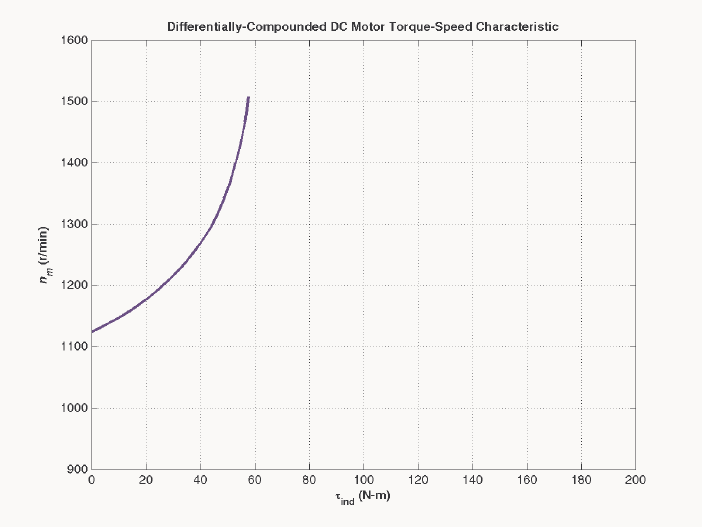
240
The resulting torque-speed characteristic is shown below:
This curve is plotted on the same scale as the torque-speed curve in Problem 6-17. Compare the two
curves.
9-19. A series motor is now constructed from this machine by leaving the shunt field out entirely. Derive the
torque-speed characteristic of the resulting motor.
S
OLUTION This motor will have extremely high speeds, since there are only a few series turns, and the flux
in the motor will be very small. A MATLAB program to calculate the torque-speed characteristic of this
motor is shown below:
% M-file: prob9_19.m
% M-file to create a plot of the torque-speed curve of the
% a series dc motor. This motor was formed by removing
% the shunt field from the cumulatively-compounded machine
% if Problem 9-17.
% Get the magnetization curve.
load p96_mag.dat;
if_values = p96_mag(:,1);
ea_values = p96_mag(:,2);
n_0 = 1200;
% First, initialize the values needed in this program.
v_t = 240; % Terminal voltage (V)
r_a = 0.19; % Armature + series resistance (ohms)
i_l = 20:1:45; % Line currents (A)
n_f = 1500; % Number of turns on shunt field
n_se = 12; % Number of turns on series field
% Calculate the armature current for each load.
i_a = i_l;
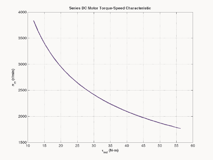
241
% Now calculate the internal generated voltage for
% each armature current.
e_a = v_t - i_a * r_a;
% Calculate the effective field current for each armature
% current. (Note that the magnetization curve is defined
% in terms of shunt field current, so we will have to
% translate the series field current into an equivalent
% shunt field current.
i_f = (n_se / n_f) * i_a;
% Calculate the resulting internal generated voltage at
% 1800 r/min by interpolating the motor's magnetization
% curve.
e_a0 = interp1(if_values,ea_values,i_f);
% Calculate the resulting speed from Equation (9-13).
n = ( e_a ./ e_a0 ) * n_0;
% Calculate the induced torque corresponding to each
% speed from Equations (8-55) and (8-56).
t_ind = e_a .* i_a ./ (n * 2 * pi / 60);
% Plot the torque-speed curves
figure(1);
plot(t_ind,n,'b-','LineWidth',2.0);
xlabel('\bf\tau_{ind} (N-m)');
ylabel('\bf\itn_{m} \rm\bf(r/min)');
title ('\bfSeries DC Motor Torque-Speed Characteristic');
grid on;
The resulting torque-speed characteristic is shown below:

242
The extreme speeds in this characteristic are due to the very light flux in the machine. To make a practical
series motor out of this machine, it would be necessary to include 20 to 30 series turns instead of 12.
9-20. An automatic starter circuit is to be designed for a shunt motor rated at 15 hp, 240 V, and 60 A. The
armature resistance of the motor is 0.15 Ω, and the shunt field resistance is 40 Ω. The motor is to start
with no more than 250 percent of its rated armature current, and as soon as the current falls to rated value,
a starting resistor stage is to be cut out. How many stages of starting resistance are needed, and how big
should each one be?
S
OLUTION The rated line current of this motor is 60 A, and the rated armature current is ALF
III=− = 60
A – 6 A = 54 A. The maximum desired starting current is (2.5)(54 A) = 135 A. Therefore, the total initial
starting resistance must be
start,1
240 V 1.778
135 A
A
RR+= = Ω
start,1 1.778 0.15 1.628 R=Ω−Ω=Ω
The current will fall to rated value when A
E rises to
()()
240 V 1.778 54 A 144 V
A
E=−Ω =
At that time, we want to cut out enough resistance to get the current back up to 135 A. Therefore,
start,2
240 V 144 V 0.711
135 A
A
RR −
+= =Ω
start,2 0.711 0.15 0.561 R=Ω−Ω=Ω
With this resistance in the circuit, the current will fall to rated value when A
E rises to
(
)
(
)
240 V 0.711 54 A 201.6 V
A
E=−Ω =
At that time, we want to cut out enough resistance to get the current back up to 185 A. Therefore,
start,3
240 V 201.6 V 0.284
135 A
A
RR −
+= = Ω
start,3 0.284 0.15 0.134 R=Ω−Ω=Ω
With this resistance in the circuit, the current will fall to rated value when A
E rises to
()()
240 V 0.284 54 A 224.7 V
A
E=−Ω =
If the resistance is cut out when A
E reaches 228,6 V, the resulting current is
240 V 224.7 V 102 A 135 A
0.15
A
I−
==<
Ω,
so there are only three stages of starting resistance. The three stages of starting resistance can be found
from the resistance in the circuit at each state during starting.
start,1 1 2 3 1.628 RRRR=++= Ω
start,2 2 3 0.561 RRR=+= Ω
start,3 3 0.134 RR== Ω
Therefore, the starting resistances are
11.067 R=Ω
20.427 R=Ω
30.134 R=Ω

243
9-21. A 15-hp 120-V 1800 r/min shunt dc motor has a full-load armature current of 60 A when operating at rated
conditions. The armature resistance of the motor is A
R = 0.15 Ω, and the field resistance F
R is 80 Ω.
The adjustable resistance in the field circuit adj
R may be varied over the range from 0 to 200 Ω and is
currently set to 90 Ω. Armature reaction may be ignored in this machine. The magnetization curve for this
motor, taken at a speed of 1800 r/min, is given in tabular form below:
EA, V 5 78 95 112 118 126
IF, A 0.00 0.80 1.00 1.28 1.44 2.88
Note: An electronic version of this magnetization curve can be found in file
prob9_21_mag.dat, which can be used with MATLAB programs. Column
1 contains field current in amps, and column 2 contains the internal generated
voltage EA in volts.
(a) What is the speed of this motor when it is running at the rated conditions specified above?
(b) The output power from the motor is 7.5 hp at rated conditions. What is the output torque of the motor?
(c) What are the copper losses and rotational losses in the motor at full load (ignore stray losses)?
(d) What is the efficiency of the motor at full load?
(e) If the motor is now unloaded with no changes in terminal voltage or Radj , what is the no-load speed of
the motor?
(f) Suppose that the motor is running at the no-load conditions described in part (e). What would happen
to the motor if its field circuit were to open? Ignoring armature reaction, what would the final steady-
state speed of the motor be under those conditions?
(g) What range of no-load speeds is possible in this motor, given the range of field resistance adjustments
available with adj
R?
S
OLUTION
(a) If adj
R = 90 Ω, the total field resistance is 170 Ω, and the resulting field current is
adj
230 V 1.35 A
90 80
T
F
F
V
IRR
== =
+Ω+Ω
This field current would produce a voltage Ao
E of 221 V at a speed of o
n = 1800 r/min. The actual A
E is
(
)
(
)
230 V 60 A 0.15 221 V
ATAA
EVIR=− = − Ω=
so the actual speed will be
()
221 V 1800 r/min 1800 r/min
221 V
A
o
Ao
E
nn
E
== =
(b) The output power is 7.5 hp and the output speed is 1800 r/min at rated conditions, therefore, the
torque is
()( )
()
out
out
15 hp 746 W/hp 59.4 N m
2 rad 1 min
1800 r/min 1 r 60 s
m
P
τπ
ω
== = ⋅
(c) The copper losses are

244
(
)
(
)
(
)
(
)
2
2
CU 60 A 0.15 230 V 1.35 A 851 W
AA FF
PIRVI=+= Ω+ =
The power converted from electrical to mechanical form is
()()
conv 221 V 60 A 13,260 W
AA
PEI== =
The output power is
()( )
OUT 15 hp 746 W/hp 11,190 WP==
Therefore, the rotational losses are
rot conv OUT 13,260 W 11,190 W 2070 WPP P=−= − =
(d) The input power to this motor is
()
()( )
IN 230 V 60 A 1.35 A 14,100 W
TA F
PVII=+= + =
Therefore, the efficiency is
OUT
IN
11,190 W
100% 100% 79.4%
14,100 W
P
P
η
=× = × =
(e) The no-load A
E will be 230 V, so the no-load speed will be
()
230 V 1800 r/min 1873 r/min
221 V
A
o
Ao
E
nn
E
== =
(f) If the field circuit opens, the field current would go to zero ⇒
φ
drops to res
φ
⇒ A
E↓ ⇒ A
I↑⇒
ind
τ
↑ ⇒ n↑ to a very high speed. If F
I = 0 A, Ao
E = 8.5 V at 1800 r/min, so
()
230 V 1800 r/min 48,700 r/min
8.5 V
A
o
Ao
E
nn
E
== =
(In reality, the motor speed would be limited by rotational losses, or else the motor will destroy itself first.)
(g) The maximum value of adj
R = 200 Ω, so
adj
230 V 0.821 A
200 80
T
F
F
V
IRR
== =
+Ω+Ω
This field current would produce a voltage Ao
E of 153 V at a speed of o
n = 1800 r/min. The actual A
E is
230 V, so the actual speed will be
()
230 V 1800 r/min 2706 r/min
153 V
A
o
Ao
E
nn
E
== =
The minimum value of adj
R = 0 Ω, so
adj
230 V 2.875 A
0 80
T
F
F
V
IRR
== =
+Ω+Ω
This field current would produce a voltage Ao
E of about 242 V at a speed of o
n = 1800 r/min. The actual
A
E is 230 V, so the actual speed will be
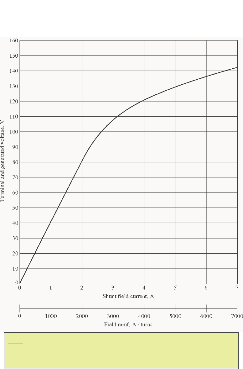
245
()
230 V 1800 r/min 1711 r/min
242 V
A
o
Ao
E
nn
E
== =
9-22. The magnetization curve for a separately excited dc generator is shown in Figure P9-7. The generator is
rated at 6 kW, 120 V, 50 A, and 1800 r/min and is shown in Figure P9-8. Its field circuit is rated at 5A.
The following data are known about the machine:
Note: An electronic version of this magnetization curve can be found in file
p97_mag.dat, which can be used with MATLAB programs. Column 1
contains field current in amps, and column 2 contains the internal generated
voltage EA in volts.
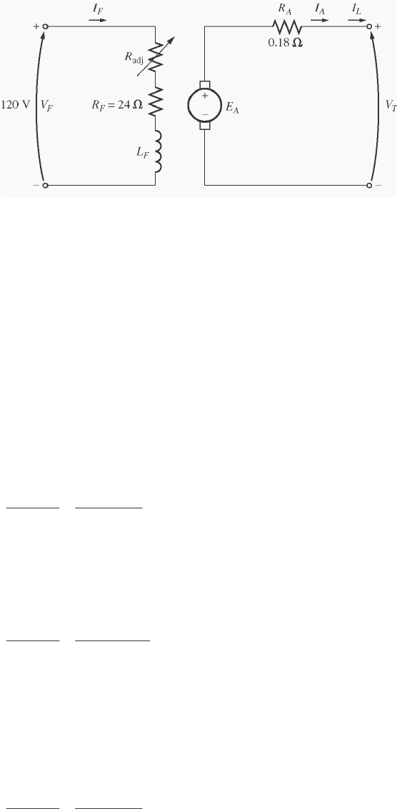
246
0.18
A
R=Ω 120 V
F
V=
adj 0 to 30 R=Ω 24
F
R=Ω
1000 turns per pole
F
N=
Answer the following questions about this generator, assuming no armature reaction.
(a) If this generator is operating at no load, what is the range of voltage adjustments that can be achieved
by changing Radj ?
(b) If the field rheostat is allowed to vary from 0 to 30 Ω and the generator’s speed is allowed to vary from
1500 to 2000 r/min, what are the maximum and minimum no-load voltages in the generator?
S
OLUTION
(a) If the generator is operating with no load at 1800 r/min, then the terminal voltage will equal the
internal generated voltage A
E. The maximum possible field current occurs when adj
R = 0 Ω. The current
is
,max
adj
120 V 5 A
24 0
F
F
F
V
IRR
== =
+Ω+Ω
From the magnetization curve, the voltage Ao
E at 1800 r/min is 129 V. Since the actual speed is 1800
r/min, the maximum no-load voltage is 129 V.
The minimum possible field current occurs when adj
R = 30 Ω. The current is
,max
adj
120 V 2.22 A
24 30
F
F
F
V
IRR
== =
+Ω+Ω
From the magnetization curve, the voltage Ao
E at 1800 r/min is 87.4 V. Since the actual speed is 1800
r/min, the minimum no-load voltage is 87 V.
(b) The maximum voltage will occur at the highest current and speed, and the minimum voltage will
occur at the lowest current and speed. The maximum possible field current occurs when adj
R = 0 Ω. The
current is
,max
adj
120 V 5 A
24 0
F
F
F
V
IRR
== =
+Ω+Ω
From the magnetization curve, the voltage Ao
E at 1800 r/min is 129 V. Since the actual speed is 2000
r/min, the maximum no-load voltage is

247
A
Ao o
En
En
=
()
2000 r/min 129 V 143 V
1800 r/min
AAo
o
n
EE
n
== =
The minimum possible field current occurs when adj
R = 30 Ω. The current is
,max
adj
120 V 2.22 A
24 30
F
F
F
V
IRR
== =
+Ω+Ω
From the magnetization curve, the voltage Ao
E at 1800 r/min is 87.4 V. Since the actual speed is 1500
r/min, the maximum no-load voltage is
A
Ao o
En
En
=
()
1500 r/min 87.4 V 72.8 V
1800 r/min
AAo
o
n
EE
n
== =
9-23. If the armature current of the generator in Problem 9-22 is 50 A, the speed of the generator is 1700 r/min,
and the terminal voltage is 106 V, how much field current must be flowing in the generator?
S
OLUTION The internal generated voltage of this generator is
(
)
(
)
106 V 50 A 0.18 115 V
ATAA
EVIR=+ = + Ω=
at a speed of 1700 r/min. This corresponds to an Ao
E at 1800 r/min of
A
Ao o
En
En
=
()
1800 r/min 115 V 121.8 V
1700 r/min
o
Ao A
n
EE
n
== =
From the magnetization curve, this value of Ao
E requires a field current of 4.2 A.
9-24. Assuming that the generator in Problem 9-22 has an armature reaction at full load equivalent to 400
A⋅turns of magnetomotive force, what will the terminal voltage of the generator be when F
I = 5 A, m
n =
1700 r/min, and A
I = 50 A?
S
OLUTION When F
I is 5 A and the armature current is 50 A, the magnetomotive force in the generator is
(
)
(
)
net AR 1000 turns 5 A 400 A turns 4600 A turns
F
NI=−= − ⋅ = ⋅FF
or
*
net
/
4600 A turns / 1000 turns 4.6 A
FF
IN==⋅ =F
The equivalent internal generated voltage Ao
E of the generator at 1800 r/min would be 126 V. The actual
voltage at 1700 r/min would be
()
1700 r/min 126 V 119 V
1800 r/min
AAo
o
n
EE
n
== =
Therefore, the terminal voltage would be
(
)
(
)
119 V 50 A 0.18 110 V
TAAA
VEIR=− = − Ω=
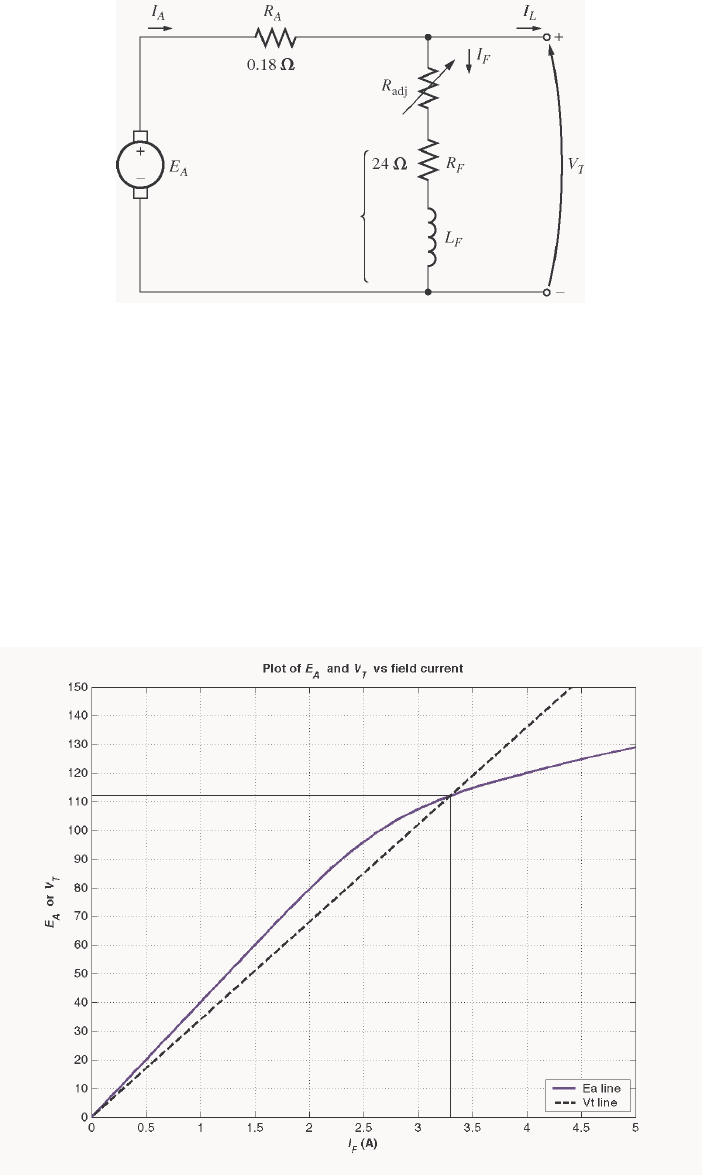
248
9-25. The machine in Problem 9-22 is reconnected as a shunt generator and is shown in Figure P9-9. The shunt
field resistor Radj is adjusted to 10 Ω, and the generator’s speed is 1800 r/min.
(a) What is the no-load terminal voltage of the generator?
(b) Assuming no armature reaction, what is the terminal voltage of the generator with an armature current
of 20 A? 40 A?
(c) Assuming an armature reaction equal to 200 A⋅turns at full load, what is the terminal voltage of the
generator with an armature current of 20 A? 40 A?
(d) Calculate and plot the terminal characteristics of this generator with and without armature reaction.
S
OLUTION
(a) The total field resistance of this generator is 34 Ω, and the no-load terminal voltage can be found
from the intersection of the resistance line with the magnetization curve for this generator. The
magnetization curve and the field resistance line are plotted below. As you can see, they intersect at a
terminal voltage of 112 V.
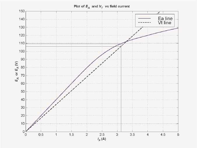
249
(b) At an armature current of 20 A, the internal voltage drop in the armature resistance is
()( )
V 6.3 0.18 A 20 =Ω . As shown in the figure below, there is a difference of 3.6 V between A
E and
T
V at a terminal voltage of about 106 V.
A MATLAB program to locate the position where the triangle exactly fits between the A
E and T
V lines is
shown below. This program created the plot shown above. Note that there are actually two places where
the difference between the A
E and T
V lines is 3.6 volts, but the low-voltage one of them is unstable. The
code shown in bold face below prevents the program from reporting that first (unstable) point.
% M-file: prob9_25b.m
% M-file to create a plot of the magnetization curve and the
% field current curve of a shunt dc generator, determining
% the point where the difference between them is 3.6 V.
% Get the magnetization curve. This file contains the
% three variables if_values, ea_values, and n_0.
clear all
load p97_mag.dat;
if_values = p97_mag(:,1);
ea_values = p97_mag(:,2);
n_0 = 1800;
% First, initialize the values needed in this program.
r_f = 24; % Field resistance (ohms)
r_adj = 10; % Adjustable resistance (ohms)
r_a = 0.19; % Armature + series resistance (ohms)
i_f = 0:0.02:6; % Field current (A)
n = 1800; % Generator speed (r/min)
% Calculate Ea versus If
Ea = interp1(if_values,ea_values,i_f);
250
% Calculate Vt versus If
Vt = (r_f + r_adj) * i_f;
% Find the point where the difference between the two
% lines is 3.6 V. This will be the point where the line
% line "Ea - Vt - 3.6" goes negative. That will be a
% close enough estimate of Vt.
diff = Ea - Vt - 3.6;
% This code prevents us from reporting the first (unstable)
% location satisfying the criterion.
was_pos = 0;
for ii = 1:length(i_f);
if diff(ii) > 0
was_pos = 1;
end
if ( diff(ii) < 0 & was_pos == 1 )
break;
end;
end;
% We have the intersection. Tell user.
disp (['Ea = ' num2str(Ea(ii)) ' V']);
disp (['Vt = ' num2str(Vt(ii)) ' V']);
disp (['If = ' num2str(i_f(ii)) ' A']);
% Plot the curves
figure(1);
plot(i_f,Ea,'b-','LineWidth',2.0);
hold on;
plot(i_f,Vt,'k--','LineWidth',2.0);
% Plot intersections
plot([i_f(ii) i_f(ii)], [0 Ea(ii)], 'k-');
plot([0 i_f(ii)], [Vt(ii) Vt(ii)],'k-');
plot([0 i_f(ii)], [Ea(ii) Ea(ii)],'k-');
xlabel('\bf\itI_{F} \rm\bf(A)');
ylabel('\bf\itE_{A} \rm\bf or \itV_{T}');
title ('\bfPlot of \itE_{A} \rm\bf and \itV_{T} \rm\bf vs field
current');
axis ([0 5 0 150]);
set(gca,'YTick',[0 10 20 30 40 50 60 70 80 90 100 110 120 130 140
150]')
set(gca,'XTick',[0 0.5 1.0 1.5 2.0 2.5 3.0 3.5 4.0 4.5 5.0]')
legend ('Ea line','Vt line',4);
hold off;
grid on;
At an armature current of 40 A, the internal voltage drop in the armature resistance is
()( )
V 2.7 0.18 A 40 =Ω . As shown in the figure below, there is a difference of 7.2 V between A
E and
T
V at a terminal voltage of about 98 V.
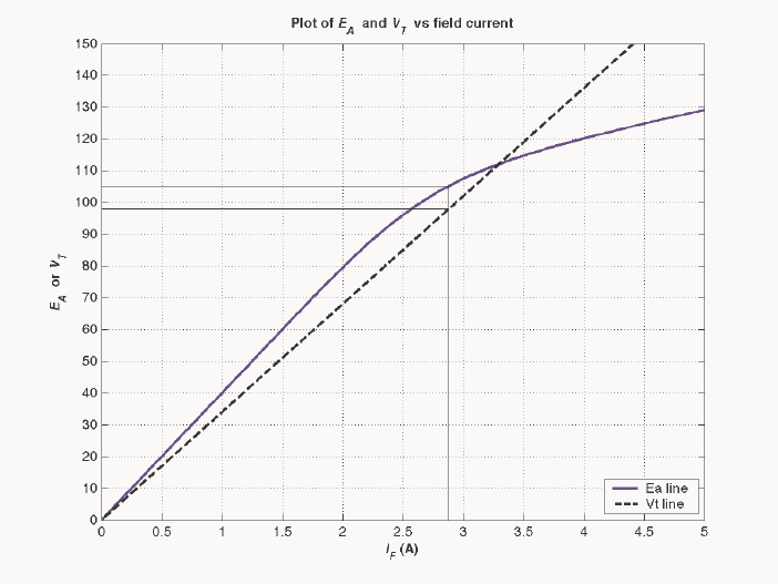
251
(c) The rated current of this generated is 50 A, so 20 A is 40% of full load. If the full load armature
reaction is 200 A⋅turns, and if the armature reaction is assumed to change linearly with armature current,
then the armature reaction will be 80 A⋅turns. The figure below shows that a triangle consisting of 3.6 V
and (80 A⋅turns)/(1000 turns) = 0.08 A fits exactly between the A
E and T
V lines at a terminal voltage of
103 V.
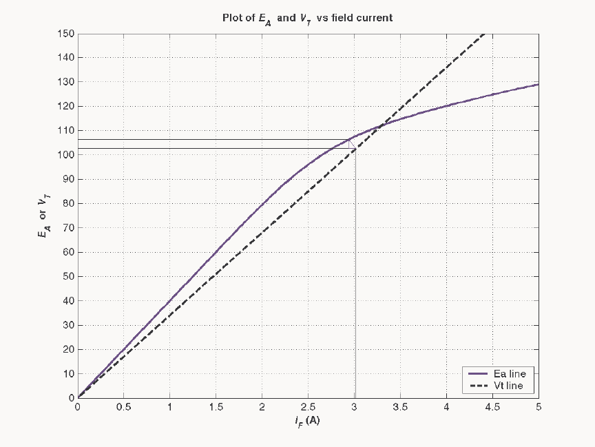
252
The rated current of this generated is 50 A, so 40 A is 80% of full load. If the full load armature reaction
is 200 A⋅turns, and if the armature reaction is assumed to change linearly with armature current, then the
armature reaction will be 160 A⋅turns. There is no point where a triangle consisting of 3.6 V and (80
A⋅turns)/(1000 turns) = 0.16 A fits exactly between the A
E and T
V lines, so this is not a stable operating
condition.
(c) A MATLAB program to calculate the terminal characteristic of this generator without armature
reaction is shown below:
% M-file: prob9_25d.m
% M-file to calculate the terminal characteristic of a shunt
% dc generator without armature reaction.
% Get the magnetization curve. This file contains the
% three variables if_values, ea_values, and n_0.
load p97_mag.dat;
if_values = p97_mag(:,1);
ea_values = p97_mag(:,2);
n_0 = 1800;
% First, initialize the values needed in this program.
r_f = 24; % Field resistance (ohms)
r_adj = 10; % Adjustable resistance (ohms)
r_a = 0.18; % Armature + series resistance (ohms)
i_f = 0:0.005:6; % Field current (A)
n = 1800; % Generator speed (r/min)
253
% Calculate Ea versus If
Ea = interp1(if_values,ea_values,i_f);
% Calculate Vt versus If
Vt = (r_f + r_adj) * i_f;
% Find the point where the difference between the two
% lines is exactly equal to i_a*r_a. This will be the
% point where the line line "Ea - Vt - i_a*r_a" goes
% negative.
i_a = 0:1:50;
for jj = 1:length(i_a)
% Get the voltage difference
diff = Ea - Vt - i_a(jj)*r_a;
% This code prevents us from reporting the first (unstable)
% location satisfying the criterion.
was_pos = 0;
for ii = 1:length(i_f);
if diff(ii) > 0
was_pos = 1;
end
if ( diff(ii) < 0 & was_pos == 1 )
break;
end;
end;
% Save terminal voltage at this point
v_t(jj) = Vt(ii);
i_l(jj) = i_a(jj) - v_t(jj) / ( r_f + r_adj);
end;
% Plot the terminal characteristic
figure(1);
plot(i_l,v_t,'b-','LineWidth',2.0);
xlabel('\bf\itI_{L} \rm\bf(A)');
ylabel('\bf\itV_{T} \rm\bf(V)');
title ('\bfTerminal Characteristic of a Shunt DC Generator');
hold off;
axis( [ 0 50 0 120]);
grid on;
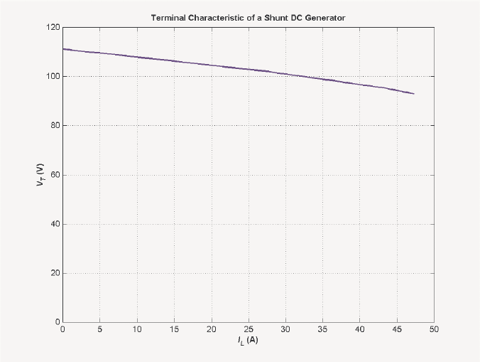
254
The resulting terminal characteristic is shown below:
A MATLAB program to calculate the terminal characteristic of this generator with armature reaction is
shown below:
% M-file: prob9_25d2.m
% M-file to calculate the terminal characteristic of a shunt
% dc generator with armature reaction.
% Get the magnetization curve. This file contains the
% three variables if_values, ea_values, and n_0.
clear all
load p97_mag.dat;
if_values = p97_mag(:,1);
ea_values = p97_mag(:,2);
n_0 = 1800;
% First, initialize the values needed in this program.
r_f = 24; % Field resistance (ohms)
r_adj = 10; % Adjustable resistance (ohms)
r_a = 0.18; % Armature + series resistance (ohms)
i_f = 0:0.005:6; % Field current (A)
n = 1800; % Generator speed (r/min)
n_f = 1000; % Number of field turns
% Calculate Ea versus If
Ea = interp1(if_values,ea_values,i_f);
% Calculate Vt versus If
Vt = (r_f + r_adj) * i_f;
% Find the point where the difference between the Ea
% armature reaction line and the Vt line is exactly
% equal to i_a*r_a. This will be the point where
255
% the line "Ea_ar - Vt - i_a*r_a" goes negative.
i_a = 0:1:37;
for jj = 1:length(i_a)
% Calculate the equivalent field current due to armature
% reaction.
i_ar = (i_a(jj) / 50) * 200 / n_f;
% Calculate the Ea values modified by armature reaction
Ea_ar = interp1(if_values,ea_values,i_f - i_ar);
% Get the voltage difference
diff = Ea_ar - Vt - i_a(jj)*r_a;
% This code prevents us from reporting the first (unstable)
% location satisfying the criterion.
was_pos = 0;
for ii = 1:length(i_f);
if diff(ii) > 0
was_pos = 1;
end
if ( diff(ii) < 0 & was_pos == 1 )
break;
end;
end;
% Save terminal voltage at this point
v_t(jj) = Vt(ii);
i_l(jj) = i_a(jj) - v_t(jj) / ( r_f + r_adj);
end;
% Plot the terminal characteristic
figure(1);
plot(i_l,v_t,'b-','LineWidth',2.0);
xlabel('\bf\itI_{L} \rm\bf(A)');
ylabel('\bf\itV_{T} \rm\bf(V)');
title ('\bfTerminal Characteristic of a Shunt DC Generator w/AR');
hold off;
axis([ 0 50 0 120]);
grid on;
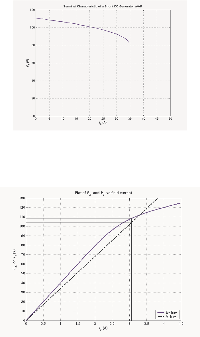
256
The resulting terminal characteristic is shown below:
9-26. If the machine in Problem 9-25 is running at 1800 r/min with a field resistance Radj = 10 Ω and an
armature current of 25 A, what will the resulting terminal voltage be? If the field resistor decreases to 5 Ω
while the armature current remains 25 A, what will the new terminal voltage be? (Assume no armature
reaction.)
S
OLUTION If A
I = 25 A, then
(
)
(
)
25 A 0.18
AA
IR =Ω
= 4.5 V. The point where the distance between the
A
E and T
V curves is exactly 4.5 V corresponds to a terminal voltage of 104 V, as shown below.
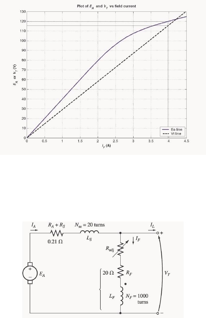
257
If
Radj decreases to 5 Ω, the total field resistance becomes 29 Ω, and the terminal voltage line gets
shallower. The new point where the distance between the A
E and T
V curves is exactly 4.5 V corresponds
to a terminal voltage of 115 V, as shown below.
Note that decreasing the field resistance of the shunt generator increases the terminal voltage.
9-27. A 120-V 50-A cumulatively compounded dc generator has the following characteristics:
0.21
AS
RR+= Ω
1000 turns
F
N=
20
F
R=Ω
SE 20 turnsN=
adj 0 to 30 , set to 10 R=Ω Ω
1800 r/min
m
n=
The machine has the magnetization curve shown in Figure P9-7. Its equivalent circuit is shown in Figure
P9-10. Answer the following questions about this machine, assuming no armature reaction.
(a) If the generator is operating at no load, what is its terminal voltage?
(b) If the generator has an armature current of 20 A, what is its terminal voltage?
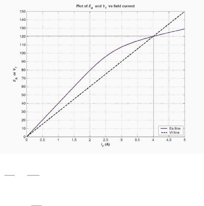
258
(c) If the generator has an armature current of 40 A, what is its terminal voltage'?
(d) Calculate and plot the terminal characteristic of this machine.
S
OLUTION
(a) The total field resistance of this generator is 30 Ω, and the no-load terminal voltage can be found
from the intersection of the resistance line with the magnetization curve for this generator. The
magnetization curve and the field resistance line are plotted below. As you can see, they intersect at a
terminal voltage of 121 V.
(b) If the armature current is 20 A, then the effective field current contribution from the armature current
()
SE 20 20 A 0.4 A
1000
A
F
NI
N==
and the
()
AA S
IR R+ voltage drop is
()
(
)
(
)
20 A 0.21 4.2 V
AA S
IR R+= Ω= . The location where the
triangle formed by SE
A
F
NI
N and AA
IR exactly fits between the A
E and T
V lines corresponds to a terminal
voltage of 120 V, as shown below.
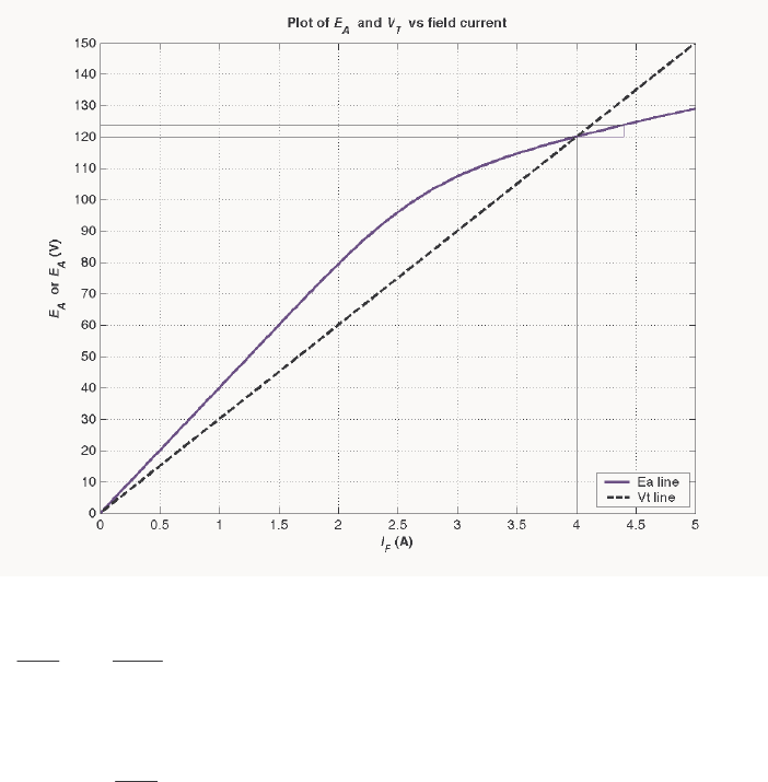
259
(c) If the armature current is 40 A, then the effective field current contribution from the armature current
()
A 6.0A 40
1000
15
SE ==
A
F
I
N
N
and the
()
SAA RRI + voltage drop is
()()()
V 8 20.0 A 80 =Ω=+ SAA RRI . The location where the
triangle formed by A
F
I
N
NSE and AA RI exactly fits between the A
E and T
V lines corresponds to a terminal
voltage of 116 V, as shown below.
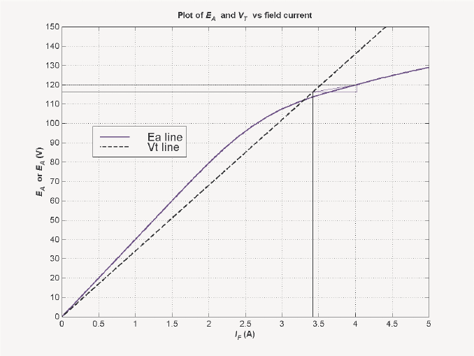
260
A MATLAB program to locate the position where the triangle exactly fits between the A
E and T
V lines is
shown below. This program created the plot shown above.
% M-file: prob9_27b.m
% M-file to create a plot of the magnetization curve and the
% field current curve of a cumulatively-compounded dc generator
% when the armature current is 20 A.
% Get the magnetization curve. This file contains the
% three variables if_values, ea_values, and n_0.
clear all
load p97_mag.dat;
if_values = p97_mag(:,1);
ea_values = p97_mag(:,2);
n_0 = 1800;
% First, initialize the values needed in this program.
r_f = 20; % Field resistance (ohms)
r_adj = 10; % Adjustable resistance (ohms)
r_a = 0.21; % Armature + series resistance (ohms)
i_f = 0:0.02:6; % Field current (A)
n = 1800; % Generator speed (r/min)
n_f = 1000; % Shunt field turns
n_se = 20; % Series field turns
% Calculate Ea versus If
Ea = interp1(if_values,ea_values,i_f);
% Calculate Vt versus If
Vt = (r_f + r_adj) * i_f;
% Calculate the Ea values modified by mmf due to the
% armature current
261
i_a = 20;
Ea_a = interp1(if_values,ea_values,i_f + i_a * n_se/n_f);
% Find the point where the difference between the
% enhanced Ea line and the Vt line is 4 V. This will
% be the point where the line "Ea_a - Vt - 4" goes
% negative.
diff = Ea_a - Vt - 4;
% This code prevents us from reporting the first (unstable)
% location satisfying the criterion.
was_pos = 0;
for ii = 1:length(i_f);
if diff(ii) > 0
was_pos = 1;
end
if ( diff(ii) < 0 & was_pos == 1 )
break;
end;
end;
% We have the intersection. Tell user.
disp (['Ea_a = ' num2str(Ea_a(ii)) ' V']);
disp (['Ea = ' num2str(Ea(ii)) ' V']);
disp (['Vt = ' num2str(Vt(ii)) ' V']);
disp (['If = ' num2str(i_f(ii)) ' A']);
disp (['If_a = ' num2str(i_f(ii)+ i_a * n_se/n_f) ' A']);
% Plot the curves
figure(1);
plot(i_f,Ea,'b-','LineWidth',2.0);
hold on;
plot(i_f,Vt,'k--','LineWidth',2.0);
% Plot intersections
plot([i_f(ii) i_f(ii)], [0 Vt(ii)], 'k-');
plot([0 i_f(ii)], [Vt(ii) Vt(ii)],'k-');
plot([0 i_f(ii)+i_a*n_se/n_f], [Ea_a(ii) Ea_a(ii)],'k-');
% Plot compounding triangle
plot([i_f(ii) i_f(ii)+i_a*n_se/n_f],[Vt(ii) Vt(ii)],'b-');
plot([i_f(ii) i_f(ii)+i_a*n_se/n_f],[Vt(ii) Ea_a(ii)],'b-');
plot([i_f(ii)+i_a*n_se/n_f i_f(ii)+i_a*n_se/n_f],[Vt(ii)
Ea_a(ii)],'b-');
xlabel('\bf\itI_{F} \rm\bf(A)');
ylabel('\bf\itE_{A} \rm\bf or \itE_{A} \rm\bf(V)');
title ('\bfPlot of \itE_{A} \rm\bf and \itV_{T} \rm\bf vs field
current');
axis ([0 5 0 150]);
set(gca,'YTick',[0 10 20 30 40 50 60 70 80 90 100 110 120 130 140
150]')
set(gca,'XTick',[0 0.5 1.0 1.5 2.0 2.5 3.0 3.5 4.0 4.5 5.0]')
legend ('Ea line','Vt line',4);
hold off;
grid on;
262
(d) A MATLAB program to calculate and plot the terminal characteristic of this generator is shown
below.
% M-file: prob9_27d.m
% M-file to calculate the terminal characteristic of a
% cumulatively compounded dc generator without armature
% reaction.
% Get the magnetization curve. This file contains the
% three variables if_values, ea_values, and n_0.
clear all
load p97_mag.dat;
if_values = p97_mag(:,1);
ea_values = p97_mag(:,2);
n_0 = 1800;
% First, initialize the values needed in this program.
r_f = 20; % Field resistance (ohms)
r_adj = 10; % Adjustable resistance (ohms)
r_a = 0.21; % Armature + series resistance (ohms)
i_f = 0:0.02:6; % Field current (A)
n = 1800; % Generator speed (r/min)
n_f = 1000; % Shunt field turns
n_se = 20; % Series field turns
% Calculate Ea versus If
Ea = interp1(if_values,ea_values,i_f);
% Calculate Vt versus If
Vt = (r_f + r_adj) * i_f;
% Find the point where the difference between the two
% lines is exactly equal to i_a*r_a. This will be the
% point where the line line "Ea - Vt - i_a*r_a" goes
% negative.
i_a = 0:1:50;
for jj = 1:length(i_a)
% Calculate the Ea values modified by mmf due to the
% armature current
Ea_a = interp1(if_values,ea_values,i_f + i_a(jj)*n_se/n_f);
% Get the voltage difference
diff = Ea_a - Vt - i_a(jj)*r_a;
% This code prevents us from reporting the first (unstable)
% location satisfying the criterion.
was_pos = 0;
for ii = 1:length(i_f);
if diff(ii) > 0
was_pos = 1;
end
if ( diff(ii) < 0 & was_pos == 1 )
break;
end;
end;
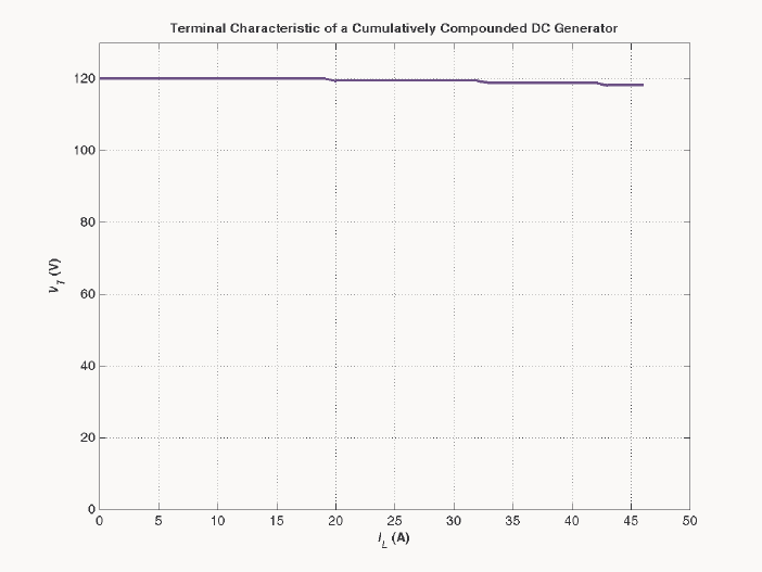
263
% Save terminal voltage at this point
v_t(jj) = Vt(ii);
i_l(jj) = i_a(jj) - v_t(jj) / ( r_f + r_adj);
end;
% Plot the terminal characteristic
figure(1);
plot(i_l,v_t,'b-','LineWidth',2.0);
xlabel('\bf\itI_{L} \rm\bf(A)');
ylabel('\bf\itV_{T} \rm\bf(V)');
string = ['\bfTerminal Characteristic of a Cumulatively ' ...
'Compounded DC Generator'];
title (string);
hold off;
axis([ 0 50 0 130]);
grid on;
The resulting terminal characteristic is shown below. Compare it to the terminal characteristics of the
shunt dc generators in Problem 9-25 (d).
9-28. If the machine described in Problem 9-27 is reconnected as a differentially compounded dc generator, what
will its terminal characteristic look like? Derive it in the same fashion as in Problem 9-27.
S
OLUTION A MATLAB program to calculate and plot the terminal characteristic of this generator is shown
below.
% M-file: prob9_28.m
% M-file to calculate the terminal characteristic of a
% differentially compounded dc generator without armature
% reaction.
% Get the magnetization curve. This file contains the
264
% three variables if_values, ea_values, and n_0.
clear all
load p97_mag.dat;
if_values = p97_mag(:,1);
ea_values = p97_mag(:,2);
n_0 = 1800;
% First, initialize the values needed in this program.
r_f = 20; % Field resistance (ohms)
r_adj = 10; % Adjustable resistance (ohms)
r_a = 0.21; % Armature + series resistance (ohms)
i_f = 0:0.02:6; % Field current (A)
n = 1800; % Generator speed (r/min)
n_f = 1000; % Shunt field turns
n_se = 20; % Series field turns
% Calculate Ea versus If
Ea = interp1(if_values,ea_values,i_f);
% Calculate Vt versus If
Vt = (r_f + r_adj) * i_f;
% Find the point where the difference between the two
% lines is exactly equal to i_a*r_a. This will be the
% point where the line line "Ea - Vt - i_a*r_a" goes
% negative.
i_a = 0:1:26;
for jj = 1:length(i_a)
% Calculate the Ea values modified by mmf due to the
% armature current
Ea_a = interp1(if_values,ea_values,i_f - i_a(jj)*n_se/n_f);
% Get the voltage difference
diff = Ea_a - Vt - i_a(jj)*r_a;
% This code prevents us from reporting the first (unstable)
% location satisfying the criterion.
was_pos = 0;
for ii = 1:length(i_f);
if diff(ii) > 0
was_pos = 1;
end
if ( diff(ii) < 0 & was_pos == 1 )
break;
end;
end;
% Save terminal voltage at this point
v_t(jj) = Vt(ii);
i_l(jj) = i_a(jj) - v_t(jj) / ( r_f + r_adj);
end;
% Plot the terminal characteristic
figure(1);
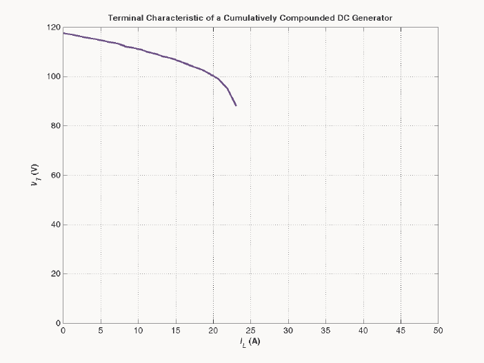
265
plot(i_l,v_t,'b-','LineWidth',2.0);
xlabel('\bf\itI_{L} \rm\bf(A)');
ylabel('\bf\itV_{T} \rm\bf(V)');
string = ['\bfTerminal Characteristic of a Cumulatively ' ...
'Compounded DC Generator'];
title (string);
hold off;
axis([ 0 50 0 120]);
grid on;
The resulting terminal characteristic is shown below. Compare it to the terminal characteristics of the
cumulatively compounded dc generator in Problem 9-28 and the shunt dc generators in Problem 9-25 (d).
9-29. A cumulatively compounded dc generator is operating properly as a flat-compounded dc generator. The
machine is then shut down, and its shunt field connections are reversed.
(a) If this generator is turned in the same direction as before, will an output voltage be built up at its
terminals? Why or why not?
(b) Will the voltage build up for rotation in the opposite direction? Why or why not?
(c) For the direction of rotation in which a voltage builds up, will the generator be cumulatively or
differentially compounded?
S
OLUTION
(a) The output voltage will not build up, because the residual flux now induces a voltage in the opposite
direction, which causes a field current to flow that tends to further reduce the residual flux.
(b) If the motor rotates in the opposite direction, the voltage will build up, because the reversal in voltage
due to the change in direction of rotation causes the voltage to produce a field current that increases the
residual flux, starting a positive feedback chain.
(c) The generator will now be differentially compounded.
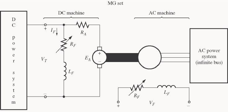
266
9-30. A three-phase synchronous machine is mechanically connected to a shunt dc machine, forming a motor-
generator set, as shown in Figure P9-11. The dc machine is connected to a dc power system supplying a
constant 240 V, and the ac machine is connected to a 480-V 60-Hz infinite bus.
The dc machine has four poles and is rated at 50 kW and 240 V. It has a per-unit armature resistance of
0.04. The ac machine has four poles and is Y-connected. It is rated at 50 kVA, 480 V, and 0.8 PF, and its
saturated synchronous reactance is 2.0 Ω per phase.
All losses except the dc machine’s armature resistance may be neglected in this problem. Assume that the
magnetization curves of both machines are linear.
(a) Initially, the ac machine is supplying 50 kVA at 0.8 PF lagging to the ac power system.
1. How much power is being supplied to the dc motor from the dc power system?
2. How large is the internal generated voltage A
E of the dc machine?
3. How large is the internal generated voltage A
E of the ac machine?
(b) The field current in the ac machine is now increased by 5 percent. What effect does this change have
on the real power supplied by the motor-generator set? On the reactive power supplied by the motor-
generator set? Calculate the real and reactive power supplied or consumed by the ac machine under
these conditions. Sketch the ac machine’s phasor diagram before and after the change in field current.
(c) Starting from the conditions in part (b), the field current in the dc machine is now decreased by 1
percent. What effect does this change have on the real power supplied by the motor-generator set? On
the reactive power supplied by the motor-generator set? Calculate the real and reactive power supplied
or consumed by the ac machine under these conditions. Sketch the ac machine’s phasor diagram before
and after the change in the dc machine’s field current.
(d) From the above results, answer the following questions:
1. How can the real power flow through an ac-dc motor-generator set be controlled?
2. How can the reactive power supplied or consumed by the ac machine be controlled without
affecting the real power flow?
S
OLUTION
(a) The power supplied by the ac machine to the ac power system is
()()
AC cos 50 kVA 0.8 40 kWPS
θ
== =
267
and the reactive power supplied by the ac machine to the ac power system is
() ()
1
AC sin 50 kVA sin cos 0.8 30 kvarQS
θ
−
== =
The power out of the dc motor is thus 40 kW. This is also the power converted from electrical to
mechanical form in the dc machine, since all other losses are neglected. Therefore,
()
conv 40 kW
AA T A A A
PEIVIRI==− =
240 kW 0
TA A A
VI I R−− =
The base resistance of the dc machine is
()
2
2
,base
base,dc
base
230 V 1.058
50 kW
T
V
RP
== =Ω
Therefore, the actual armature resistance is
()( )
0.04 1.058 0.0423
A
R=Ω=Ω
Continuing to solve the equation for conv
P, we get
2
0.0423 230 40,000 0
AA
II−+ =
2
5434.8 945180 0
AA
II−+=
179.9 A
A
I=
and
A
E = 222.4 V.
Therefore, the power into the dc machine is 41.38 kW
TA
VI =, while the power converted from electrical
to mechanical form (which is equal to the output power) is
()()
222.4 V 179.9 A 40 kW
AA
EI ==. The
internal generated voltage A
E of the dc machine is 222.4 V.
The armature current in the ac machine is
()
50 kVA 60.1 A
3 3 480 V
A
S
IV
φ
== =
60.1 36.87 A
A=∠− °I
Therefore, the internal generated voltage A
E of the ac machine is
ASA
jX
φ
=+EV I
()( )
277 0 V 2.0 60.1 36.87 A 362 15.4 V
Aj=∠°+ Ω ∠− °=∠°E
(b) When the field current of the ac machine is increased by 5%, it has no effect on the real power
supplied by the motor-generator set. This fact is true because P
τω
=, and the speed is constant (since the
MG set is tied to an infinite bus). With the speed unchanged, the dc machine’s torque is unchanged, so the
total power supplied to the ac machine’s shaft is unchanged.
If the field current is increased by 5% and the OCC of the ac machine is linear, A
E increases to
(
)
(
)
1.05 262 V 380 V
A
E==′
The new torque angle
δ
can be found from the fact that since the terminal voltage and power of the ac
machine are constant, the quantity sin
A
E
δ
must be constant.
268
sin sin
AA
EE
δδ
=′′
11
362 V
sin sin sin sin15.4 14.7
380 V
A
A
E
E
δδ
−−
== °=°
′
′
Therefore, the armature current will be
380 14.7 V 277 0 V 66.1 43.2 A
2.0
A
A
S
jX j
φ
−∠°−∠°
== =∠−°
Ω
EV
I
The resulting reactive power is
(
)
(
)
3 sin 3 480 V 66.1 A sin 43.2 37.6 kvar
TL
QVI
θ
== °=
The reactive power supplied to the ac power system will be 37.6 kvar, compared to 30 kvar before the ac
machine field current was increased. The phasor diagram illustrating this change is shown below.
V
φ
E
A
1
jX
S
I
A
E
A
2
I
A
2
I
A
1
(c) If the dc field current is decreased by 1%, the dc machine’s flux will decrease by 1%. The internal
generated voltage in the dc machine is given by the equation
A
EK
φ
ω
=, and
ω
is held constant by the
infinite bus attached to the ac machine. Therefore, A
E on the dc machine will decrease to (0.99)(222.4 V)
= 220.2 V. The resulting armature current is
,dc
230 V 220.2 V 231.7 A
0.0423
TA
A
A
VE
IR
−−
== =
Ω
The power into the dc motor is now (230 V)(231.7 A) = 53.3 kW, and the power converted from electrical
to mechanical form in the dc machine is (220.2 V)(231.7 A) = 51 kW. This is also the output power of the
dc machine, the input power of the ac machine, and the output power of the ac machine, since losses are
being neglected.
The torque angle of the ac machine now can be found from the equation
ac
3sin
A
S
VE
PX
φ
δ
=
()()
()()
11
ac 51 kW 2.0
sin sin 18.9
3 3 277 V 380 V
S
A
PX
VE
φ
δ
−− Ω
== =°
The new
A
E of this machine is thus 380 18.9 V∠°, and the resulting armature current is
380 18.9 V 277 0 V 74.0 33.8 A
2.0
A
A
S
jX j
φ
−∠°−∠°
== =∠−°
Ω
EV
I
The real and reactive powers are now
(
)
(
)
3 cos 3 480 V 74.0 A cos 33.8 51 kW
TL
PVI
θ
== °=
(
)
(
)
3 sin 3 480 V 74.0 A sin 33.8 34.2 kvar
TL
QVI
θ
== °=
269
The phasor diagram of the ac machine before and after the change in dc machine field current is shown
below.
V
φ
E
A
1
jX
S
I
A
E
A
2
I
A
2
I
A
1
(d) The real power flow through an ac-dc motor-generator set can be controlled by adjusting the field
current of the dc machine. (Note that changes in power flow also have some effect on the reactive power of
the ac machine: in this problem, Q dropped from 35 kvar to 30 kvar when the real power flow was
adjusted.)
The reactive power flow in the ac machine of the MG set can be adjusted by adjusting the ac machine’s
field current. This adjustment has basically no effect on the real power flow through the MG set.
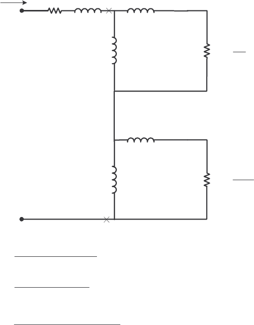
270
Chapter 10: Single-Phase and Special-Purpose Motors
10-1. A 120-V, 1/3-hp 60-Hz, four-pole, split-phase induction motor has the following impedances:
1
R = 1.80 Ω 1
X = 2.40 Ω M
X = 60 Ω
2
R = 2.50 Ω 2
X = 2.40 Ω
At a slip of 0.05, the motor’s rotational losses are 51 W. The rotational losses may be assumed constant
over the normal operating range of the motor. If the slip is 0.05, find the following quantities for this
motor:
(a) Input power
(b) Air-gap power
(c) P
conv
(d) P
out
(e) ind
τ
(f) load
τ
(g) Overall motor efficiency
(h) Stator power factor
S
OLUTION The equivalent circuit of the motor is shown below
1.8 Ωj2.4 Ω
+
-
V
I1R1jX1
s
R2
5.0
j0.5X2
j0.5XM
j1.20 Ω
j30 Ω
s
R
−2
5.0 2
jX2
j1.20 Ω
j0.5XM
j30 Ω
{
{
{
{
Forward
Reverse
0.5ZB
0.5ZF
()()
22
22
/
/
M
F
M
Rs jX jX
ZR s jX jX
+
=++
(
)
(
)
50 2.40 60 28.15 24.87
50 2.40 60
F
jj
Zj
jj
+
==+Ω
++
()
()
()
22
22
/2
/2
M
B
M
R s jX jX
ZR s jX jX
=−+ +

271
()()
1.282 2.40 60 1.185 2.332
1.282 2.40 60
B
jj
Zj
jj
+
==+Ω
++
(a) The input current is
1
11
I0.5 0.5
FB
RjX Z Z
=++ +
V
()( )( )
1
120 0 V
I5.2344.2 A
1.80 2.40 0.5 28.15 24.87 0.5 1.185 2.332jj j
∠°
==∠−°
++ + + +
()( )
IN cos 120 V 5.23 A cos 44.2 450 WPVI
θ
== °=
(b) The air-gap power is
()
()()
2
2
AG, 1 0.5 5.23 A 14.1 386 W
FF
PIR== Ω=
()
()( )
2
2
AG, 1 0.5 5.23 A 0.592 16.2 W
BB
PIR== Ω=
AG AG, AG, 386 W 14.8 W 371 W
FB
PP P=−= − =
(c) The power converted from electrical to mechanical form is
() ( )( )
conv, AG,
1 1 0.05 386 W 367 W
FF
PsP=− =− =
() ( )( )
conv, AG,
1 1 0.05 16.2 W 15.4 W
BB
PsP=− =− =
conv conv, conv, 367 W 15.4 W 352 W
FB
PP P=−= − =
(d) The output power is
OUT conv rot 352 W 51 W 301 WPPP=−= − =
(e) The induced torque is
()
AG
ind
sync
371 W 1.97 N m
2 rad 1 min
1800 r/min 1 r 60 s
P
τπ
ω
== = ⋅
(f) The load torque is
()( )
OUT
load
301 W 1.68 N m
2 rad 1 min
0.95 1800 r/min 1 r 60 s
m
P
τπ
ω
== = ⋅
(g) The overall efficiency is
OUT
IN
301 W
100% 100% 66.9%
450 W
P
P
η
=× = × =
(h) The stator power factor is
PF cos 44.2 0.713 lagging
=°=
10-2. Repeat Problem 10-1 for a rotor slip of 0.025.
()()
22
22
/
/
M
F
M
Rs jX jX
ZR s jX jX
+
=++
()()
100 2.40 60 28.91 43.83
1002.4060
F
jj
Zj
jj
+
==+Ω
++

272
()
()
()
22
22
/2
/2
M
B
M
R s jX jX
ZR s jX jX
=−+ +
()()
1.282 2.40 60 1.170 2.331
1.282 2.40 60
B
jj
Zj
jj
+
==+Ω
++
(a) The input current is
1
11
I0.5 0.5
FB
RjX Z Z
=++ +
V
()( )( )
1
120 0 V
I4.0359.0 A
1.80 2.40 0.5 25.91 43.83 0.5 1.170 2.331jj j
∠°
==∠−°
++ + + +
()( )
IN cos 120 V 4.03 A cos 59.0 249 WPVI
θ
== °=
(b) The air-gap power is
()
(
)
(
)
2
2
AG, 1 0.5 4.03 A 12.96 210.5 W
FF
PIR== Ω=
()
(
)
(
)
2
2
AG, 1 0.5 4.03 A 0.585 9.5 W
BB
PIR== Ω=
AG AG, AG, 210.5 W 9.5 W 201 W
FB
PP P=−= − =
(c) The power converted from electrical to mechanical form is
(
)
(
)
(
)
conv, AG,
1 1 0.025 210.5 W 205 W
FF
PsP=− =− =
() ( )( )
conv, AG,
1 1 0.025 9.5 W 9.3 W
BB
PsP=− =− =
conv conv, conv, 205 W 9.3 W 196 W
FB
PP P=−= − =
(d) The output power is
OUT conv rot 205 W 51 W 154 WPPP=−= − =
(e) The induced torque is
()
AG
ind
sync
210.5 W 1.12 N m
2 rad 1 min
1800 r/min 1 r 60 s
P
τπ
ω
== = ⋅
(f) The load torque is
()( )
OUT
load
154 W 0.84 N m
2 rad 1 min
0.975 1800 r/min 1 r 60 s
m
P
τπ
ω
== = ⋅
(g) The overall efficiency is
OUT
IN
154 W
100% 100% 61.8%
249 W
P
P
η
=× = × =
(h) The stator power factor is
PF cos 59.0 0.515 lagging
=°=
10-3. Suppose that the motor in Problem 10-1 is started and the auxiliary winding fails open while the rotor is
accelerating through 400 r/min. How much induced torque will the motor be able to produce on its main

273
winding alone? Assuming that the rotational losses are still 51 W, will this motor continue accelerating or
will it slow down again? Prove your answer.
S
OLUTION At a speed of 400 r/min, the slip is
1800 r/min 400 r/min 0.778
1800 r/min
s−
==
()()
22
22
/
/
M
F
M
Rs jX jX
ZR s jX jX
+
=++
()()
100 2.40 60 2.96 2.46
1002.4060
F
jj
Zj
jj
+
==+Ω
++
()
()
()
22
22
/2
/2
M
B
M
R s jX jX
ZR s jX jX
=−+ +
()()
1.282 2.40 60 1.90 2.37
1.282 2.40 60
B
jj
Zj
jj
+
==+Ω
++
The input current is
1
11
I0.5 0.5
FB
RjX Z Z
=++ +
V
()()()
1
120 0 V
I 18.73 48.7 A
1.80 2.40 0.5 2.96 2.46 0.5 1.90 2.37jjj
∠°
==∠−°
++ ++ +
The air-gap power is
()
()()
2
2
AG, 1 0.5 18.73 A 1.48 519.2 W
FF
PIR== Ω=
()
()()
2
2
AG, 1 0.5 18.73 A 0.945 331.5 W
BB
PIR== Ω=
AG AG, AG, 519.2 W 331.5 W 188 W
FB
PP P=−= − =
The power converted from electrical to mechanical form is
() ( )( )
conv, AG,
1 1 0.778 519.2 W 115.2 W
FF
PsP=− =− =
()()()
conv, AG,
1 1 0.778 331.5 W 73.6 W
BB
PsP=− =− =
conv conv, conv, 115.2 W 73.6 W 41.6 W
FB
PP P=−= − =
The induced torque is
()
AG
ind
sync
188 W 1.00 N m
2 rad 1 min
1800 r/min 1 r 60 s
P
τπ
ω
== = ⋅
Assuming that the rotational losses are still 51 W, this motor is not producing enough torque to keep
accelerating. conv
P is 41.6 W, while the rotational losses are 51 W, so there is not enough power to make
up the rotational losses. The motor will slow down5.
10-4. Use MATLAB to calculate and plot the torque-speed characteristic of the motor in Problem 10-1, ignoring
the starting winding.
5 Note that in the real world, rotational losses decrease with decreased shaft speed. Therefore, the losses will really
be less than 51 W, and this motor might just be able to keep on accelerating slowly—it is a close thing either way.
274
S
OLUTION This problem is best solved with MATLAB, since it involves calculating the torque-speed values
at many points. A MATLAB program to calculate and display both torque-speed characteristics is shown
below. Note that this program shows the torque-speed curve for both positive and negative directions of
rotation. Also, note that we had to avoid calculating the slip at exactly 0 or 2, since those numbers would
produce divide-by-zero errors in F
Z
and B
Z
respectively.
% M-file: torque_speed_curve3.m
% M-file create a plot of the torque-speed curve of the
% single-phase induction motor of Problem 10-4.
% First, initialize the values needed in this program.
r1 = 1.80; % Stator resistance
x1 = 2.40; % Stator reactance
r2 = 2.50; % Rotor resistance
x2 = 2.40; % Rotor reactance
xm = 60; % Magnetization branch reactance
v = 120; % Single-Phase voltage
n_sync = 1800; % Synchronous speed (r/min)
w_sync = 188.5; % Synchronous speed (rad/s)
% Specify slip ranges to plot
s = 0:0.01:2.0;
% Offset slips at 0 and 2 slightly to avoid divide by zero errors
s(1) = 0.0001;
s(201) = 1.9999;
% Get the corresponding speeds in rpm
nm = ( 1 - s) * n_sync;
% Caclulate Zf and Zb as a function of slip
zf = (r2 ./ s + j*x2) * (j*xm) ./ (r2 ./ s + j*x2 + j*xm);
zb = (r2 ./(2-s) + j*x2) * (j*xm) ./ (r2 ./(2-s) + j*x2 + j*xm);
% Calculate the current flowing at each slip
i1 = v ./ ( r1 + j*x1 + zf + zb);
% Calculate the air-gap power
p_ag_f = abs(i1).^2 .* 0.5 .* real(zf);
p_ag_b = abs(i1).^2 .* 0.5 .* real(zb);
p_ag = p_ag_f - p_ag_b;
% Calculate torque in N-m.
t_ind = p_ag ./ w_sync;
% Plot the torque-speed curve
figure(1)
plot(nm,t_ind,'Color','b','LineWidth',2.0);
xlabel('\itn_{m} \rm(r/min)');
ylabel('\tau_{ind} \rm(N-m)');
title ('Single Phase Induction motor torque-speed
characteristic','FontSize',12);
grid on;
hold off;
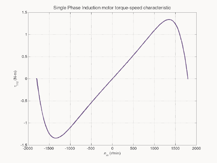
275
The resulting torque-speed characteristic is shown below:
10-5. A 220-V, 1.5-hp 50-Hz, two-pole, capacitor-start induction motor has the following main-winding
impedances:
1
R = 1.40 Ω 1
X = 2.01 Ω M
X = 105 Ω
2
R = 1.50 Ω 2
X = 2.01 Ω
At a slip of 0.05, the motor’s rotational losses are 291 W. The rotational losses may be assumed constant
over the normal operating range of the motor. Find the following quantities for this motor at 5 percent slip:
(a) Stator current
(b) Stator power factor
(c) Input power
(d) AG
P
(e) P
conv
(f) out
P
(g) ind
τ
(h) load
τ
(i) Efficiency
S
OLUTION The equivalent circuit of the motor is shown below
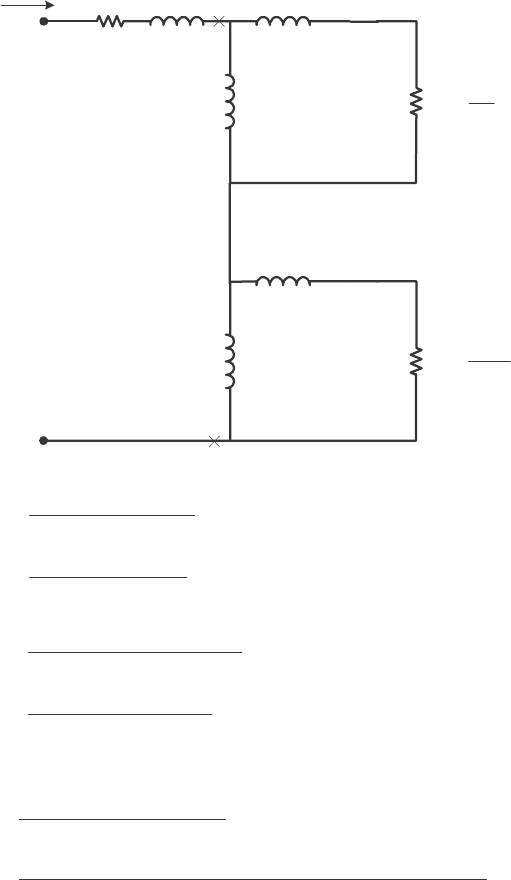
276
1.4 Ωj1.9 Ω
+
-
V = 220∠0° V
I1R1jX1
s
R2
5.0
j0.5X2
j0.5XM
j1.90 Ω
j30 Ω
s
R
−2
5.0 2
jX2
j1.90 Ω
j0.5XM
j100 Ω
{
{
{
{
Forward
Reverse
0.5ZB
0.5ZF
()()
22
22
/
/
M
F
M
Rs jX jX
ZR s jX jX
+
=++
()()
30 1.90 100 26.59 9.69
30 1.90 100
F
jj
Zj
jj
+
==+Ω
++
()
()
()
22
22
/2
/2
M
B
M
R s jX jX
ZR s jX jX
=−+ +
()()
0.769 1.90 100 0.741 1.870
0.769 1.90 100
B
jj
Zj
jj
+
==+Ω
++
(a) The input stator current is
1
11
I0.5 0.5
FB
RjX Z Z
=++ +
V
()( )( )
1
220 0 V
I 13.0 27.0 A
1.40 1.90 0.5 26.59 9.69 0.5 0.741 1.870jjj
∠°
==∠−°
++ ++ +
(b) The stator power factor is
PF cos 27 0.891 lagging
=°=
(c) The input power is
()()
IN cos 220 V 13.0 A cos 27 2548 WPVI
θ
== °=
(d) The air-gap power is
()
()( )
2
2
AG, 1 0.5 13.0 A 13.29 2246 W
FF
PIR== Ω=
()
()( )
2
2
AG, 1 0.5 13.0 A 0.370 62.5 W
BB
PIR== Ω=
AG AG, AG, 2246 W 62.5 W 2184 W
FB
PP P=−= − =

277
(e) The power converted from electrical to mechanical form is
() ( )( )
conv, AG,
1 1 0.05 2246 W 2134 W
FF
PsP=− =− =
() ( )( )
conv, AG,
1 1 0.05 62.5 W 59 W
BB
PsP=− =− =
conv conv, conv, 2134 W 59 W 2075 W
FB
PP P=−= −=
(f) The output power is
OUT conv rot 2134 W 291 W 1843 WPPP=−= − =
(g) The induced torque is
()
AG
ind
sync
2184 W 6.95 N m
2 rad 1 min
3000 r/min 1 r 60 s
P
τπ
ω
== = ⋅
(h) The load torque is
()( )
OUT
load
1843 W 6.18 N m
2 rad 1 min
0.95 3000 r/min 1 r 60 s
m
P
τπ
ω
== = ⋅
(i) The overall efficiency is
OUT
IN
1843 W
100% 100% 72.3%
2548 W
P
P
η
=× = × =
10-6. Find the induced torque in the motor in Problem 10-5 if it is operating at 5 percent slip and its terminal
voltage is (a) 190 V, (b) 208 V, (c) 230 V.
()()
22
22
/
/
M
F
M
Rs jX jX
ZR s jX jX
+
=++
()()
30 1.90 100 26.59 9.69
30 1.90 100
F
jj
Zj
jj
+
==+Ω
++
()
()
()
22
22
/2
/2
M
B
M
R s jX jX
ZR s jX jX
=−+ +
()()
0.769 1.90 100 0.741 1.870
0.769 1.90 100
B
jj
Zj
jj
+
==+Ω
++
(a) If T
V = 190∠0° V,
1
11
I0.5 0.5
FB
RjX Z Z
=++ +
V
()( )( )
1
190 0 V
I 11.2 27.0 A
1.40 1.90 0.5 26.59 9.69 0.5 0.741 1.870jjj
∠°
==∠−°
++ ++ +
()
()( )
2
2
AG, 1 0.5 11.2 A 13.29 1667 W
FF
PIR== Ω=
()
()( )
2
2
AG, 1 0.5 11.2 A 0.370 46.4 W
BB
PIR== Ω=
AG AG, AG, 1667 W 46.4 W 1621 W
FB
PP P=−= − =

278
()
AG
ind
sync
1621 W 5.16 N m
2 rad 1 min
3000 r/min 1 r 60 s
P
τπ
ω
== = ⋅
(b) If T
V = 208∠0° V,
1
11
I0.5 0.5
FB
RjX Z Z
=++ +
V
()( )( )
1
208 0 V
I12.327.0 A
1.40 1.90 0.5 26.59 9.69 0.5 0.741 1.870jjj
∠°
==∠−°
++ ++ +
()
()( )
2
2
AG, 1 0.5 12.3 A 13.29 2010 W
FF
PIR== Ω=
()
()( )
2
2
AG, 1 0.5 12.3 A 0.370 56 W
BB
PIR== Ω=
AG AG, AG, 2010 W 56 W 1954 W
FB
PP P=−= − =
()
AG
ind
sync
1954 W 6.22 N m
2 rad 1 min
3000 r/min 1 r 60 s
P
τπ
ω
== = ⋅
(c) If T
V = 230∠0° V,
1
11
I0.5 0.5
FB
RjX Z Z
=++ +
V
()( )( )
1
230 0 V
I 13.6 27.0 A
1.40 1.90 0.5 26.59 9.69 0.5 0.741 1.870jjj
∠°
==∠−°
++ ++ +
()
()( )
2
2
AG, 1 0.5 13.6 A 13.29 2458 W
FF
PIR== Ω=
()
()( )
2
2
AG, 1 0.5 13.6 A 0.370 68 W
BB
PIR== Ω=
AG AG, AG, 2458 W 68 W 2390 W
FB
PP P=−= − =
()
AG
ind
sync
2390 W 7.61 N m
2 rad 1 min
3000 r/min 1 r 60 s
P
τπ
ω
== = ⋅
Note that the induced torque is proportional to the square of the terminal voltage.
10-7. What type of motor would you select to perform each of the following jobs? Why?
(a) Vacuum cleaner (b) Refrigerator
(c) Air conditioner compressor (d) Air conditioner fan
(e) Variable-speed sewing machine (f) Clock
(g) Electric drill
S
OLUTION
(a) Universal motor—for its high torque
(b) Capacitor start or Capacitor start and run—For its high starting torque and relatively constant
speed at a wide variety of loads
(c) Same as (b) above

279
(d) Split-phase—Fans are low-starting-torque applications, and a split-phase motor is appropriate
(e) Universal Motor—Direction and speed are easy to control with solid-state drives
(f) Hysteresis motor—for its easy starting and operation at sync
n. A reluctance motor would also do
nicely.
(g) Universal Motor—for easy speed control with solid-state drives, plus high torque under loaded
conditions.
10-8. For a particular application, a three-phase stepper motor must be capable of stepping in 10° increments.
How many poles must it have?
S
OLUTION From Equation (10-18), the relationship between mechanical angle and electrical angle in a
three-phase stepper motor is
2
me
P
θθ
=
so 60
2 2 12 poles
10
e
m
P
θ
θ
°
== =
°
10-9. How many pulses per second must be supplied to the control unit of the motor in Problem 10-7 to achieve a
rotational speed of 600 r/min?
S
OLUTION From Equation (10-20),
pulses
1
3
m
nn
P
=
so
()( )
pulses 3 3 12 poles 600 r/min 21,600 pulses/min 360 pulses/s
m
nPn== = =
10-10. Construct a table showing step size versus number of poles for three-phase and four-phase stepper motors.
S
OLUTION For 3-phase stepper motors, °= 60
e
θ
, and for 4-phase stepper motors, °= 45
e
θ
. Therefore,
Number of poles Mechanical Step Size
3-phase ( 60
e
θ
=°) 4-phase ( 45
e
θ
=°)
2 60° 45°
4 30° 22.5°
6 20° 15°
8 15° 11.25°
10 12° 9
°
12 10° 7.5°
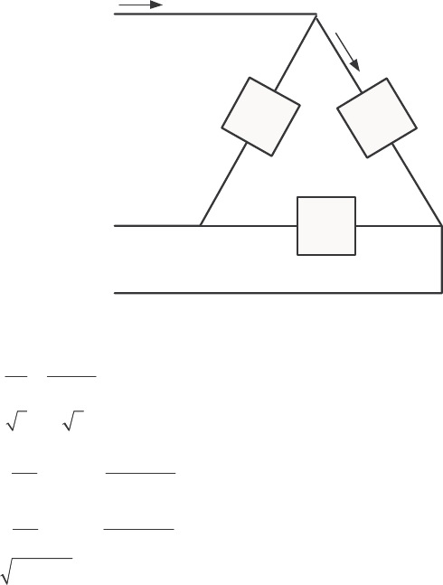
280
Appendix A: Review of Three-Phase Circuits
A-1. Three impedances of 4 + j3 Ω are ∆-connected and tied to a three-phase 208-V power line. Find Iφ, IL,
P, Q, S, and the power factor of this load.
S
OLUTION
Z
φ
Z
φ
Z
φ
+
-
240 V
I
L
I
φ
Ω+= 43 jZ
φ
Here, 208 V
L
VV
φ
== , and 4 3 5 36.87 Zj
φ
=+ Ω=∠ °Ω, so
208 V 41.6 A
5
V
IZ
φ
φ
φ
== =
Ω
()
3 3 41.6 A 72.05 A
L
II
φ
== =
()
2
2208 V
3 cos 3 cos 36.87 20.77 kW
5
V
PZ
φ
θ
== °=
Ω
()
2
2208 V
3 sin 3 sin 36.87 15.58 kvar
5
V
QZ
φ
θ
== °=
Ω
22
25.96 kVASPQ=+=
PF cos 0.8 lagging
θ
==
A-2. Figure PA-1 shows a three-phase power system with two loads. The ∆-connected generator is producing a
line voltage of 480 V, and the line impedance is 0.09 + j0.16 Ω. Load 1 is Y-connected, with a phase
impedance of 2.5∠36.87° Ω and load 2 is ∆-connected, with a phase impedance of 5∠-20° Ω.
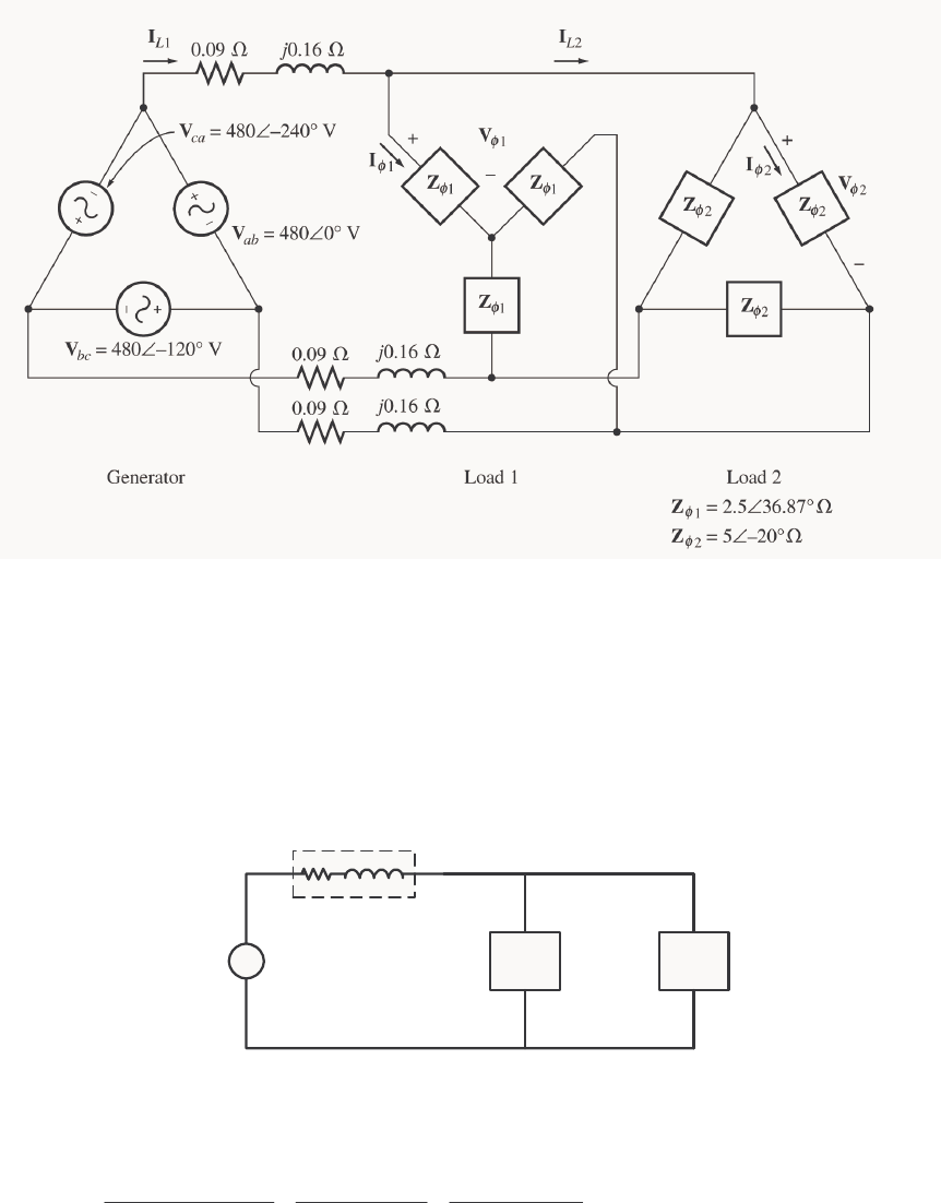
281
(a) What is the line voltage of the two loads?
(b) What is the voltage drop on the transmission lines?
(c) Find the real and reactive powers supplied to each load.
(d) Find the real and reactive power losses in the transmission line.
(e) Find the real power, reactive power, and power factor supplied by the generator.
S
OLUTION To solve this problem, first convert the two deltas to equivalent wyes, and get the per-phase
equivalent circuit.
+
-
277
∠
0° V
Line
0.090
Ω
j
0.16
Ω
1
φ
Z2
φ
Z
Ω°∠= 87.365.2
1
φ
Z
Ω°−∠= 2067.1
2
φ
Z
load,
φ
V
+
-
(a) The phase voltage of the equivalent Y-loads can be found by nodal analysis.
,load ,load ,load
277 0 V 0
0.09 0.16 2.5 36.87 1.67 20 j
φφφ
−∠°
++=
+Ω ∠°Ω∠−°Ω
VVV
()
(
)
()()
,load ,load ,load
5.443 60.6 277 0 V 0.4 36.87 0.6 20 0
φφφ
∠− ° −∠°+∠− ° +∠° =VVV
()
,load
5.955 53.34 1508 60.6
φ
∠− ° = ∠− °V
,load 253.2 7.3 V
φ
=∠−°V

282
Therefore, the line voltage at the loads is 3 439 V
L
VV
φ
=.
(b) The voltage drop in the transmission lines is
line ,gen ,load 277 0 V 253.2 -7.3 41.3 52 V
φφ
∆=−=∠°−∠°=∠°VV V
(c) The real and reactive power of each load is
()
2
2
1
253.2 V
3 cos 3 cos 36.87 61.6 kW
2.5
V
PZ
φ
θ
== °=
Ω
()
2
2
1
253.2 V
3 sin 3 sin 36.87 46.2 kvar
2.5
V
QZ
φ
θ
== °=
Ω
()
()
2
2
2
253.2 V
3 cos 3 cos -20 108.4 kW
1.67
V
PZ
φ
θ
== °=
Ω
()
()
2
2
2
253.2 V
3 sin 3 sin -20 39.5 kvar
1.67
V
QZ
φ
θ
== °=−
Ω
(d) The line current is
line
line
line
41.3 52 V 225 8.6 A
0.09 0.16 Zj
∆∠°
== =∠−°
+Ω
V
I
Therefore, the loses in the transmission line are
()( )
2
2
line line line
3 3 225 A 0.09 13.7 kWPIR== Ω=
()( )
2
2
line line line
3 3 225 A 0.16 24.3 kvarQIX== Ω=
(e) The real and reactive power supplied by the generator is
gen line 1 2 13.7 kW 61.6 kW 108.4 kW 183.7 kWPPPP=++= + + =
gen line 1 2 24.3 kvar 46.2 kvar 39.5 kvar 31 kvarQQQQ=++= + − =
The power factor of the generator is
gen
-1 1
gen
31 kvar
PF cos tan cos tan 0.986 lagging
183.7 kW
Q
P
−
== =
A-3. Figure PA-2 shows a one-line diagram of a simple power system containing a single 480 V generator and
three loads. Assume that the transmission lines in this power system are lossless, and answer the following
questions.
(a) Assume that Load 1 is Y-connected. What are the phase voltage and currents in that load?
(b) Assume that Load 2 is ∆-connected. What are the phase voltage and currents in that load?
(c) What real, reactive, and apparent power does the generator supply when the switch is open?
(d) What is the total line current L
I when the switch is open?
(e) What real, reactive, and apparent power does the generator supply when the switch is closed?
(f) What is the total line current L
I when the switch is closed?
(g) How does the total line current L
I compare to the sum of the three individual currents 123
III++? If
they are not equal, why not?
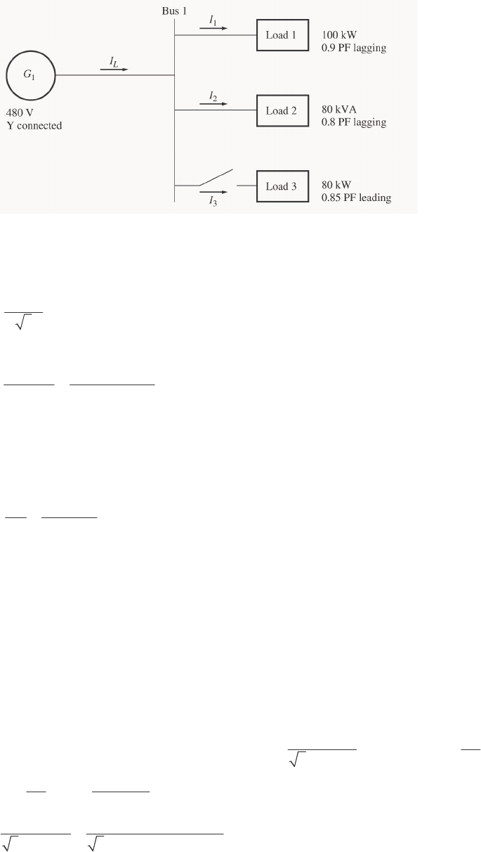
283
S
OLUTION Since the transmission lines are lossless in this power system, the full voltage generated by 1
G
will be present at each of the loads.
(a) Since this load is Y-connected, the phase voltage is
1
480 V 277 V
3
V
φ
==
The phase current can be derived from the equation 3cosPVI
φφ
θ
= as follows:
()()
1
100 kW 133.7 A
3 cos 3 277 V 0.9
P
IV
φ
φ
θ
== =
(b) Since this load is ∆-connected, the phase voltage is
2480 VV
φ
=
The phase current can be derived from the equation 3SVI
φ
φ
= as follows:
()
2
80 kVA 55.56 A
3 3 480 V
S
IV
φ
φ
== =
(c) The real and reactive power supplied by the generator when the switch is open is just the sum of the
real and reactive powers of Loads 1 and 2.
1100 kWP=
(
)
(
)
(
)
1
1tan tan cos PF 100 kW tan 25.84 48.4 kvarQP P
θ
−
== = °=
(
)
(
)
2cos 80 kVA 0.8 64 kWPS
θ
== =
(
)
(
)
2sin 80 kVA 0.6 48 kvarQS
θ
== =
12
100 kW 64 kW 164 kW
G
PPP=+= + =
12
48.4 kvar 48 kvar 96.4 kvar
G
QQQ=+= + =
(d) The line current when the switch is open is given by 3 cos
L
L
P
IV
θ
=, where 1
tan G
G
Q
P
θ
−
=.
11
96.4 kvar
tan tan 30.45
164 kW
G
G
Q
P
θ
−−
== =°
()()
164 kW 228.8 A
3 cos 3 480 V cos 30.45
L
L
P
IV
θ
== =
°
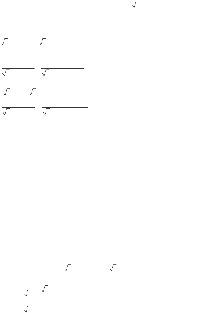
284
(e) The real and reactive power supplied by the generator when the switch is closed is just the sum of the
real and reactive powers of Loads 1, 2, and 3. The powers of Loads 1 and 2 have already been calculated.
The real and reactive power of Load 3 are:
380 kWP=
(
)
(
)
(
)
1
3tan tan cos PF 80 kW tan 31.79 49.6 kvarQP P
θ
−
== =
12 3
100 kW 64 kW 80 kW 244 kW
G
PPPP=++= + + =
123
48.4 kvar 48 kvar 49.6 kvar 46.8 kvar
G
QQQQ=++= + − =
(f) The line current when the switch is closed is given by 3 cos
L
L
P
IV
θ
=, where 1
tan G
G
Q
P
θ
−
=.
11
46.8 kvar
tan tan 10.86
244 kW
G
G
Q
P
θ
−−
== =°
()()
244 kW 298.8 A
3 cos 3 480 V cos 10.86
L
L
P
IV
θ
== =
°
(g) The total line current from the generator is 298.8 A. The line currents to each individual load are:
()()
1
1
1
100 kW 133.6 A
3 cos 3 480 V 0.9
L
L
P
IV
θ
== =
()
2
2
80 kVA 96.2 A
3 3 480 V
L
L
S
IV
== =
()()
3
3
3
80 kW 113.2 A
3 cos 3 480 V 0.85
L
L
P
IV
θ
== =
The sum of the three individual line currents is 343 A, while the current supplied by the generator is 298.8
A. These values are not the same, because the three loads have different impedance angles. Essentially,
Load 3 is supplying some of the reactive power being consumed by Loads 1 and 2, so that it does not have
to come from the generator.
A-4. Prove that the line voltage of a Y-connected generator with an acb phase sequence lags the corresponding
phase voltage by 30°. Draw a phasor diagram showing the phase and line voltages for this generator.
S
OLUTION If the generator has an acb phase sequence, then the three phase voltages will be
0
an V
φ
=∠°V
240
bn V
φ
=∠− °V
120
cn V
φ
=∠− °V
The relationship between line voltage and phase voltage is derived below. By Kirchhoff’s voltage law, the
line-to-line voltage ab
V is given by
ab a b
=−VVV
0 240
ab VV
φφ
=∠°− ∠− °V
1333
2222
ab VVjVVjV
φ
φφφφ
=−− + = −
V
31
322
ab Vj
φ
=−
V
330
ab V
φ
=∠−°V
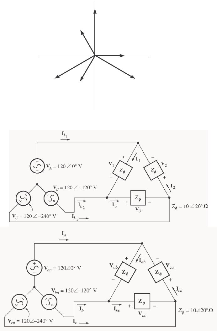
285
Thus the line voltage lags the corresponding phase voltage by 30°. The phasor diagram for this connection
is shown below.
Van
Vbn
Vcn
Vab
Vbc
A-5. Find the magnitudes and angles of each line and phase voltage and current on the load shown in Figure P2-
3.
S
OLUTION Note that because this load is ∆-connected, the line and phase voltages are identical.
120 0 V 120 120 V 208 30 V
ab an bn --=−=∠° ∠ °=∠°VVV
120 120 V 120 240 V 208 90 V
bc bn cn -- -=−=∠−° ∠ °=∠°VVV
120 240 V 120 0 V 208 150 V
ca cn an -=−=∠−° ∠°=∠°VVV
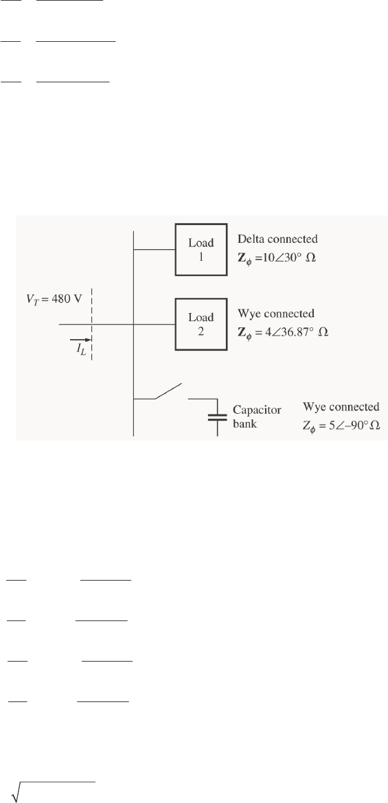
286
208 30 V 20.8 10 A
10 20
ab
ab Z
φ
∠°
== =∠°
∠°Ω
V
I
208 90 V 20.8 110 A
10 20
bc
bc Z
φ
∠− °
== =∠−°
∠°Ω
V
I
208 150 V 20.8 130 A
10 20
ca
ca Z
φ
∠°
== =∠°
∠°Ω
V
I
20.8 10 A 20.8 130 A 36 20 A
aabca --=−= ∠° ∠°=∠°II I
20.8 110 A 20.8 10 A 36 140 A
bbcab --=−= ∠−° ∠°=∠ °II I
20.8 130 A 20.8 -110 A 36 100 A
ccabc -=−= ∠° ∠ °=∠°II I
A-6. Figure PA-4 shows a small 480-V distribution system. Assume that the lines in the system have zero
impedance.
(a) If the switch shown is open, find the real, reactive, and apparent powers in the system. Find the total
current supplied to the distribution system by the utility.
(b) Repeat part (a) with the switch closed. What happened to the total current supplied? Why?
S
OLUTION
(a) With the switch open, the power supplied to each load is
()
kW 86.9530 cos
10
V 804
3cos3
2
2
1=°
Ω
==
θ
φ
Z
V
P
()
2
2
1
480 V
3 sin 3 sin 30 34.56 kvar
10
V
QZ
φ
θ
== °=
Ω
()
kW 04.4636.87 cos
4
V 277
3cos3
2
2
2=°
Ω
==
θ
φ
Z
V
P
()
2
2
2
277 V
3 sin 3 sin 36.87 34.53 kvar
4
V
QZ
φ
θ
== °=
Ω
kW 105.9 kW 46.04 kW 86.59
21TOT =+=+= PPP
TOT 1 2 34.56 kvar 34.53 kvar 69.09 kvarQQQ=+= + =
The apparent power supplied by the utility is
22
TOT TOT TOT 126.4 kVASPQ=+=
The power factor supplied by the utility is
287
-1 1
TOT
TOT
69.09 kvar
PF cos tan cos tan 0.838 lagging
105.9 kW
Q
P
−
== =
The current supplied by the utility is
()()
TOT 105.9 kW 152 A
3 PF 3 480 V 0.838
L
T
P
IV
== =
(b) With the switch closed, 3
P is added to the circuit. The real and reactive power of 3
P is
()
()
kW 090 cos
5
V 277
3cos3
2
2
3=°
Ω
== -
Z
V
P
θ
φ
()()
2
2
3
277 V
3 sin 3 sin 90 46.06 kvar
5
V
P-
Z
φ
θ
== °=−
Ω
TOT 1 2 3 59.86 kW 46.04 kW 0 kW 105.9 kWPPPP=++= + + =
TOT 1 2 3 34.56 kvar 34.53 kvar 46.06 kvar 23.03 kvarQQQQ=++= + − =
The apparent power supplied by the utility is
22
TOT TOT TOT 108.4 kVASPQ=+=
The power factor supplied by the utility is
-1 1
TOT
TOT
23.03 kVAR
PF cos tan cos tan 0.977 lagging
105.9 kW
Q
P
−
== =
The current supplied by the utility is
()()
TOT 105.9 kW 130.4 A
3 PF 3 480 V 0.977
L
T
P
IV
== =
(c) The total current supplied by the power system drops when the switch is closed because the capacitor
bank is supplying some of the reactive power being consumed by loads 1 and 2.

288
Appendix B: Coil Pitch and Distributed Windings
B-1. A 2-slot three-phase stator armature is wound for two-pole operation. If fractional-pitch windings are to be
used, what is the best possible choice for winding pitch if it is desired to eliminate the fifth-harmonic
component of voltage?
S
OLUTION The pitch factor of a winding is given by Equation (B-19):
2
sin
υ
ρ
=
p
k
To eliminate the fifth harmonic, we want to select
ρ
so that 0
2
5
sin =
ρ
. This implies that
()
n 180
2
5°=
ρ
, where n = 0, 1, 2, 3, …
or
()
... ,144 ,72
5
1802°°=
°
=n
ρ
These are acceptable pitches to eliminate the fifth harmonic. Expressed as fractions of full pitch, these
pitches are 2/5, 4/5, 6/5, etc. Since the desire is to have the maximum possible fundamental voltage, the
best choice for coil pitch would be 4/5 or 6/5. The closest that we can approach to a 4/5 pitch in a 24-slot
winding is 10/12 pitch, so that is the pitch that we would use.
At 10/12 pitch,
966.0
2
150
sin =
°
=
p
k for the fundamental frequency
()( )
259.0
2
150 5
sin =
°
=
p
k for the fifth harmonic
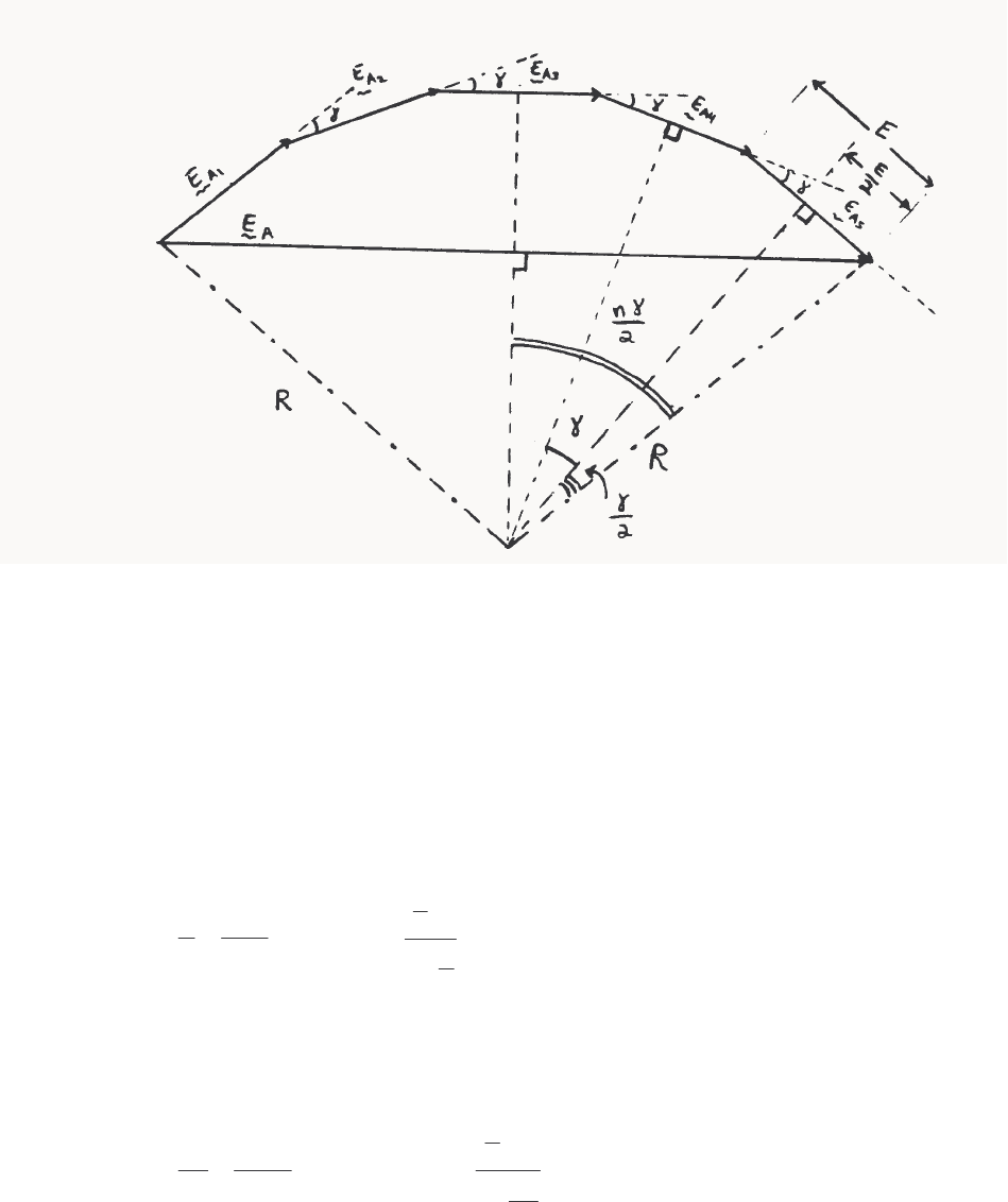
289
B-2. Derive the relationship for the winding distribution factor kd in Equation B-22.
S
OLUTION The above illustration shows the case of 5 slots per phase, but the results are general. If there
are 5 slots per phase, each with voltage Ai
E, where the phase angle of each voltage increases by γ° from
slot to slot, then the total voltage in the phase will be
AnAAAAAA EEEEEEE ++++++= ...
54321
The resulting voltage A
E can be found from geometrical considerations. These “n” phases, when
drawn end-to-end, form equally-spaced chords on a circle of radius R. If a line is drawn from the center of
a chord to the origin of the circle, it forma a right triangle with the radius at the end of the chord (see
voltage 5A
E above). The hypotenuse of this right triangle is R, its opposite side is 2/E, and its smaller
angle is 2/
γ
. Therefore,
R
E2/
2
sin =
γ
⇒
2
sin
2
1
γ
E
R= (1)
The total voltage A
E also forms a chord on the circle, and dropping a line from the center of that chord to
the origin forms a right triangle. For this triangle, the hypotenuse is R, the opposite side is 2/
A
E, and the
angle is 2/
γ
n. Therefore,
R
En A2/
2
sin =
γ
⇒
2
sin
2
1
γ
n
E
R
A
= (2)
Combining (1) and (2) yields

290
2
sin
2
1
2
sin
2
1
γγ
n
EE A
=
2
sin
2
sin
γ
γ
n
E
EA=
Finally,
2
sin
2
sin
γ
γ
n
n
nE
E
kA
d==
since
d
k is defined as the ratio of the total voltage produced to the sum of the magnitudes of each
component voltage.
B-3. A three-phase four-pole synchronous machine has 96 stator slots. The slots contain a double-layer winding
(two coils per slot) with four turns per coil. The coil pitch is 19/24.
(a) Find the slot and coil pitch in electrical degrees.
(b) Find the pitch, distribution, and winding factors for this machine.
(c) How well will this winding suppress third, fifth, seventh, ninth, and eleventh harmonics? Be sure to
consider the effects of both coil pitch and winding distribution in your answer.
S
OLUTION
(a) The coil pitch is 19/24 or 142.5°. Note that these are electrical degrees. Since this is a 4-pole
machine, the coil pitch would be 71.25 mechanical degrees.
There are 96 slots on this stator, so the slot pitch is 360°/96 = 3.75 mechanical degrees or 7.5 electrical
degrees.
(b) The pitch factor of this winding is
947.0
2
5.142
sin
2
sin =
°
==
ρ
p
k
The distribution factor is
2
sin
2
sin
γ
γ
n
n
kd=
The electrical angle γ between slots is 7.5°, and each phase group occupies 8 adjacent slots. Therefore, the
distribution factor is
291
()( )
956.0
2
15
sin 8
2
158
sin
2
sin
2
sin
=
°
°
==
γ
γ
n
n
kd
The winding factor is
()()
905.00.956 947.0 === dpw kkk
B-4. A three-phase four-pole winding of the double-layer type is to be installed on a 48-slot stator. The pitch of
the stator windings is 5/6, and there are 10 turns per coil in the windings. All coils in each phase are
connected in series, and the three phases are connected in ∆. The flux per pole in the machine is 0.054 Wb,
and the speed of rotation of the magnetic field is 1800 r/min.
(a) What is the pitch factor of this winding?
(b) What is the distribution factor of this winding?
(c) What is the frequency of the voltage produced in this winding?
(d) What are the resulting phase and terminal voltages of this stator?
S
OLUTION
(a) The pitch factor of this winding is
966.0
2
150
sin
2
sin =
°
==
ρ
p
k
(b) The coils in each phase group of this machine cover 4 slots, and the slot pitch is 360/48 = 7.5
mechanical degrees or 15 electrical degrees. Therefore, the distribution factor is
()( )
958.0
2
15
sin 4
2
15 4
sin
2
sin
2
sin
=
°
°
==
γ
γ
n
n
kd
(c) The frequency of the voltage produces by this winding is
()()
Hz60
120
poles 4r/min 1800
120 === Pn
fm
e
(d) There are 48 slots on this stator, with two coils sides in each slot. Therefore, there are 48 coils on the
machine. They are divided into 12 phase groups, so there are 4 coils per phase. There are 10 turns per
coil, so there are 40 turns per phase group. The voltage in one phase group is
( )()()( )( )
V 533 Hz60 Wb 0.054 0.958 0.966 turns4022 ===
πφπ
edpPG fkkNE
There are two phase groups per phase, connected in series (this is a 4-pole machine), so the total phase
voltage is V 10662== G
EV
φ
. Since the machine is ∆-connected,
V 1066==
φ
VVT
B-5. A three-phase Y-connected six-pole synchronous generator has six slots per pole on its stator winding. The
winding itself is a chorded (fractional-pitch) double-layer winding with eight turns per coil. The
distribution factor kd = 0.956, and the pitch factor kp = 0.981. The flux in the generator is 0.02 Wb per
292
pole, and the speed of rotation is 1200 r/min. What is the line voltage produced by this generator at these
conditions?
S
OLUTION There are 6 slots per pole × 6 poles = 36 slots on the stator of this machine. Therefore, there are
36 coils on the machine, or 12 coils per phase. The electrical frequency produced by this winding is
()()
Hz60
120
poles 6r/min 1200
120 === Pn
fm
e
The phase voltage is
()()()( )()
V 480 Hz60 Wb 0.02 0.956 0.981 turns9622 ===
πφπ
φ
edpP fkkNV
Therefore, the line voltage is
V 8313==
φ
VVL
B-6. A three-phase Y-connected 50-Hz two-pole synchronous machine has a stator with 18 slots. Its coils form
a double-layer chorded winding (two coils per slot), and each coil has 60 turns. The pitch of the stator coils
is 8/9.
(a) What rotor flux would be required to produce a terminal (line-to-line) voltage of 6 kV?
(b) How effective are coils of this pitch at reducing the fifth-harmonic component of voltage? The seventh-
harmonic component of voltage?
S
OLUTION
(a) The pitch of this winding is 8/9 = 160°, so the pitch factor is
985.0
2
160
sin =
°
=
p
k
The phase groups in this machine cover three slots each, and the slot pitch is 20 mechanical or 20 electrical
degrees. Thus the distribution factor is
()( )
960.0
2
20
sin 3
2
20 3
sin
2
sin
2
sin
=
°
°
==
γ
γ
n
n
kd
The phase voltage of this machine will be
()( )()()()
Hz50 0.960 0.985 l turns/coi60 coils 622
φπφπ
φ
== edpP fkkNV
φ
φ
75621=V
The desired phase voltage is 6 kV / 3= 3464 V, so
Wb 046.0
75621
V 3464 ==
φ
(b) The
fifth harmonic:
()( )
643.0
2
160 5
sin =
°
=
p
k
The
seventh harmonic:
()( )
342.0
2
160 7
sin −=
°
=
p
k

293
Since the fundamental voltage is reduced by 0.985, the fifth and seventh harmonics are suppressed relative
to the fundamental by the fractions:
5
th: 653.0
985.0
643.0 =
7
th: 347.0
985.0
342.0 =
In other words, the 5th harmonic is suppressed by 34.7% relative to the fundamental, and the 7th harmonic is
suppressed by 65.3% relative to the fundamental frequency.
B-7. What coil pitch could be used to completely eliminate the seventh-harmonic component of voltage in ac
machine armature (stator)? What is the minimum number of slots needed on an eight-pole winding to
exactly achieve this pitch? What would this pitch do to the fifth-harmonic component of voltage?
S
OLUTION To totally eliminate the seventh harmonic of voltage in an ac machine armature, the pitch factor
for that harmonic must be zero.
2
7
sin0
ρ
==
p
k
⇒
()
n 180
2
7°=
ρ
, n = 0, 1, 2, …
()
7
1802n°
=
ρ
In order to maximize the fundamental voltage while canceling out the seventh harmonic, we pick the value
of n that makes
ρ
as nearly 180° as possible. If n = 3, then
ρ
= 154.3°, and the pitch factor for the
fundamental frequency would be
975.0
2
3.154
sin =
°
=
p
k
This pitch corresponds to a ratio of 6/7. For a two-pole machine, a ratio of 6/7 could be implemented with
a total of 14 slots. If that ratio is desired in an 8-pole machine, then 56 slots would be needed.
The fifth harmonic would be suppressed by this winding as follows:
()( )
434.0
2
3.154 5
sin =
°
=
p
k
B-8. A 13.8-kV Y-connected 60-Hz 12-pole three-phase synchronous generator has 180 stator slots with a
double-layer winding and eight turns per coil. The coil pitch on the stator is 12 slots. The conductors from
all phase belts (or groups) in a given phase are connected in series.
(a) What flux per pole would be required to give a no-load terminal (line) voltage of 13.8 kV?
(b) What is this machine’s winding factor kw?
S
OLUTION
(a) The stator pitch is 12/15 = 4/5, so °= 144
ρ
, and
951.0
2
144
sin =
°
=
p
k
294
Each phase belt consists of (180 slots)/(12 poles)(6) = 2.5 slots per phase group. The slot pitch is 2
mechanical degrees or 24 electrical degrees. The corresponding distribution factor is
()( )
962.0
2
24
sin .52
2
24 5.2
sin
2
sin
2
sin
=
°
°
==
γ
γ
n
n
kd
Since there are 60 coils in each phase and 8 turns per coil, all connected in series, there are 480 turns per
phase. The resulting voltage is
()()()()
Hz60 0.962 0.951 turns48022
φπφπ
φ
== edpP fkkNV
061,117
φ
φ
=V
The phase voltage of this generator must be V 79673 / kV 8.13 =, so the flux must be
Wb 068.0
117,061
V 9677==
φ
(b) The machine’s winding factor is
()()
915.00.962 0.951 === dpw kkk
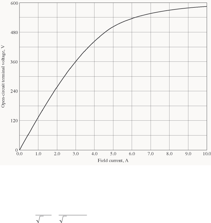
295
Appendix C: Salient Pole Theory of Synchronous Machines
C-1. A 480-V 200-kVA 0.8-PF-lagging 60-Hz four-pole Y-connected synchronous generator has a direct-axis
reactance of 0.25 Ω, a quadrature-axis reactance of 0.18 Ω, and an armature resistance of 0.03 Ω.
Friction, windage, and stray losses may be assumed negligible. The generator’s open-circuit characteristic
is given by Figure P5-1.
(a) How much field current is required to make VT equal to 480 V when the generator is running at no
load?
(b) What is the internal generated voltage of this machine when it is operating at rated conditions? How
does this value of EA compare to that of Problem 5-2b?
(c) What fraction of this generator’s full-load power is due to the reluctance torque of the rotor?
S
OLUTION
(a) If the no-load terminal voltage is 480 V, the required field current can be read directly from the open-
circuit characteristic. It is 4.55 A.
(b) At rated conditions, the line and phase current in this generator is
()
A 6.240
V 4803
kVA 200
3 ====
L
LA V
P
II at an angle of –36.87°
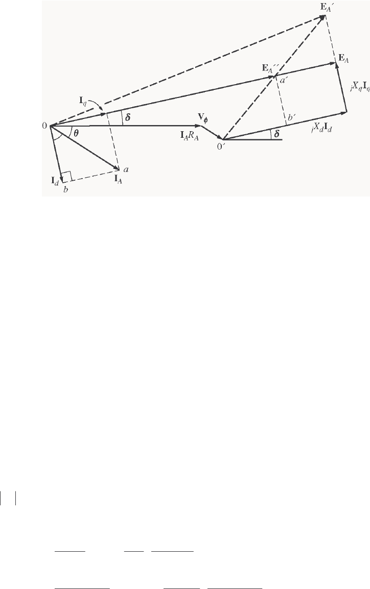
296
′′ = + +EV I I
AAAqA
RjX
φ
()()()()
A 87.366.240 18.0A 87.366.240 03.00277 °−∠Ω+°−∠Ω+°∠=
′′ j
A
E
V 61.5310 °∠=
′′
A
E
Therefore, the torque angle
δ
is 5.61°. The direct-axis current is
()
°−∠+= 90 sin
δδθ
Ad II
()()
°−∠°= 4.84 48.42sinA 6.240
d
I
A 4.84 5.162 °−∠=
d
I
The quadrature-axis current is
()
δδθ
∠+= cos
Aq II
()()
°∠°= 61.5 48.42cosA 6.240
q
I
A 61.5 4.177 °∠=
q
I
Therefore, the internal generated voltage of the machine is
qqddAAA jXjXRIIIVE +++=
φ
()( )()( )()( )
°∠+°−∠+°−∠+°∠= 61.54.17718.04.845.16225.087.366.24003.00277 jj
A
E
V 61.5322 °∠=
A
E
A
E is approximately the same magnitude here as in Problem 5-2b, but the angle is about 2.2° different.
(c) The power supplied by this machine is given by the equation
PVE
X
VX X
XX
A
d
dq
dq
=+
−
33
2
2
φφ
δδ sin sin 2
()() ()
()()
°
−
+°5= 1.221 sin
18.025.0
18.025.0
2
2773
.61 sin
25.0
32227732
P
kW 139.4kW 8.34kW 6.104
=
+
=
P
The cylindrical rotor term is 104.6 kW, and the reluctance term is 34.8 kW, so the reluctance torque
accounts for about 25% of the power in this generator.
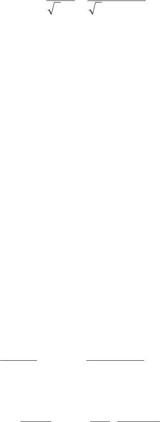
297
C-2. A 14-pole Y-connected three-phase water-turbine-driven generator is rated at 120 MVA, 13.2 kV, 0.8 PF
lagging, and 60 Hz. Its direct-axis reactance is 0.62 Ω and its quadrature- axis reactance is 0.40 Ω. All
rotational losses may be neglected.
(a) What internal generated voltage would be required for this generator to operate at the rated conditions?
(b) What is the voltage regulation of this generator at the rated conditions?
(c) Sketch the power-versus-torque-angle curve for this generator. At what angle δ is the power of the
generator maximum?
(d) How does the maximum power out of this generator compare to the maximum power available if it
were of cylindrical rotor construction?
S
OLUTION
(a) At rated conditions, the line and phase current in this generator is
()
A 5249
kV 2.133
MVA120
3 ====
L
LA V
P
II at an angle of –36.87°
′′ =+ +
EV I I
AAAqA
RjX
φ
()( )
A 87.365249 40.0007621 °−∠Ω++°∠=
′′ j
A
E
V 7.109038 °∠=
′′
A
E
Therefore, the torque angle
δ
is 10.7°. The direct-axis current is
()
°−∠+= 90 sin
δδθ
Ad II
()()
°−∠°= 3.79 57.47sinA 2495
d
I
A 3.79 3874 °−∠=
d
I
The quadrature-axis current is
()
δδθ
∠+= cos
Aq II
()()
°∠°= 7.10 57.47cosA 2495
q
I
A 7.10 3541 °∠=
q
I
Therefore, the internal generated voltage of the machine is
qqddAAA jXjXRIIIVE +++=
φ
()( )()( )
°∠+°−∠++°∠= 7.103541 40.03.793874 62.0007621 jj
A
E
V 7.109890 °∠=
A
E
(b) The voltage regulation of this generator is
%8.29%100
7621
76219890
%100
fl
flnl =×
−
=×
−
V
VV
(c) The power supplied by this machine is given by the equation
PVE
X
VX X
XX
A
d
dq
dq
=+
−
33
2
2
φφ
δδ sin sin 2
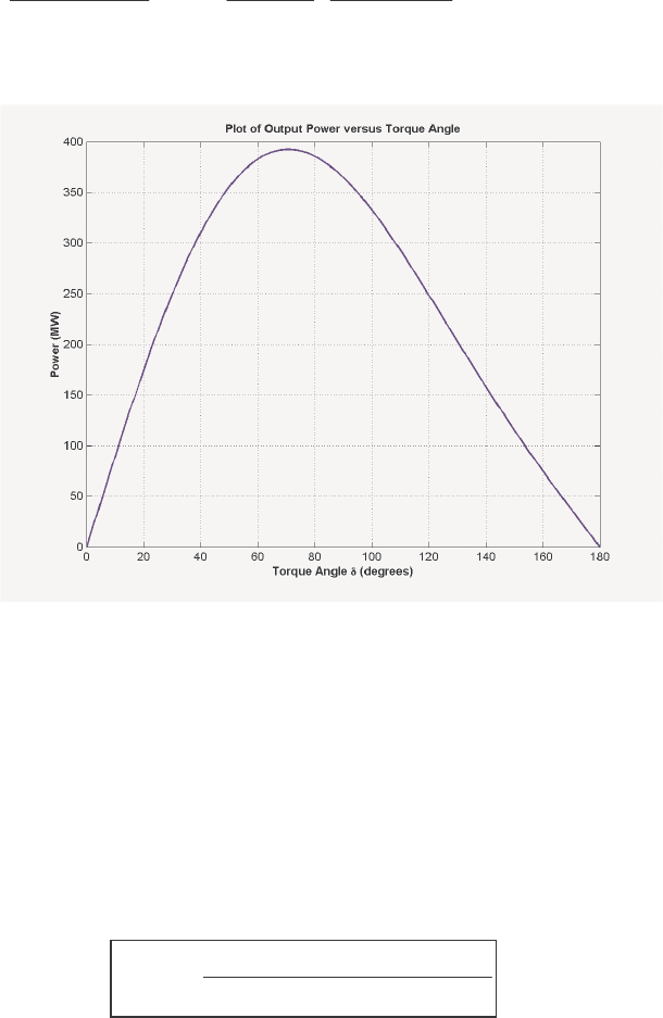
298
()() ()
()()
δδ
2 sin
40.0 62.0
40.062.0
2
76213
sin
62.0
9890762132
−
+=P
MW2 sin 3.77 sin 7.364
δ
δ
+=P
A plot of power supplied as a function of torque angle is shown below:
The peak power occurs at an angle of 70.6°, and the maximum power that the generator can supply is
392.4 MW.
(d) If this generator were non-salient, MAX
P would occur when
δ
= 90°, and MAX
P would be 364.7 MW.
Therefore, the salient-pole generator has a higher maximum power than an equivalent non-salint pole
generator.
C-3. Suppose that a salient-pole machine is to be used as a motor.
(a) Sketch the phasor diagram of a salient-pole synchronous machine used as a motor.
(b) Write the equations describing the voltages and currents in this motor.
(c) Prove that the torque angle δ between EA and Vφ on this motor is given by
δθθ
θθ
φ
=+
tan cos - sin
sin + cos
-1 IX IR
VIX IR
Aq AA
Aq AA
S
OLUTION
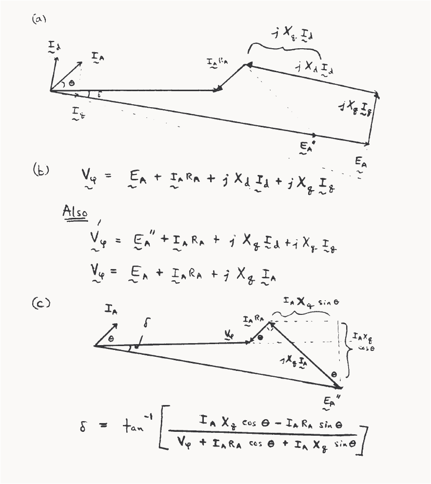
299

300
C-4. If the machine in Problem C-1 is running as a motor at the rated conditions, what is the maximum torque
that can be drawn from its shaft without it slipping poles when the field current is zero?
S
OLUTION When the field current is zero, A
E = 0, so
−
=
δ
φ
2 sin
2
32
qd
qd
XX
XXV
P
()
()()
kW 2 sin2 sin
18.025.0
18.025.0
2
27732
δδ
179=
−
=P
At °= 45
δ
, 179 kW can be drawn from the motor.
301
Appendix D: Errata for Electric Machinery Fundamentals 4/e
(Current at 10 January 2004)
Please note that some or all of the following errata may be corrected in future reprints of the
book, so they may not appear in your copy of the text. PDF pages with these corrections are attached to
this appendix; please provide them to your students.
1. Page 56, Problem 1-6, there are 400 turns of wire on the coil, as shown on Figure P1-3. The body of
the problem incorrectly states that there are 300 turns.
2. Page 56, Problem 1-7, there are 400 turns of wire on the left-hand coil, and 300 turns on the right-
hand coil, as shown on Figure P1-4. The body of the problem is incorrect.
3. Page 62, Problem 1-19, should state: “Figure P1-14 shows a simple single-phase ac power system
with three loads. The voltage source is 120 0 V=∠°V, and the three loads are …”
4. Page 64, Problem 1-22, should state: “If the bar runs off into a region where the flux density falls to
0.30 T… ”. Also, the load should be 10 N, not 20.
5. Page 147, Problem 2-10, should state that the transformer bank is Y-∆, not ∆-Y.
6. Page 226, Problem 3-10, the holding current H
I should be 8 mA.
7. Page 342, Figure p5-2, the generator for Problems 5-11 through 5-21, the OCC and SCC curves are
in error. The correct curves are given below. Note that the voltage scale and current scales were
both off by a factor of 2.
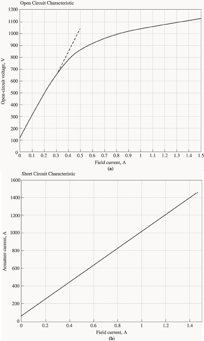
302
8. Page 344, Problem 5-28, the voltage of the infinite bus is 12.2 kV.
9. Page 377, Problem 6-11, the armature resistance is 0.08 Ω, and the synchronous reactance is 1.0 Ω.
10. Page 470, Problem 7-20 (a), the holding the infinite bus is 460-V.
303
11. Page 623, Figure P9-2 and Figure P9-3, 0.40
A
R=Ω and 100
F
R=Ω. Values are stated correctly
in the text but shown incorrectly on the figure.
12. Page 624, Figure P9-4, 0.44
AS
RR+= Ω and 100
F
R=Ω. Values are stated correctly in the text
but shown incorrectly on the figure.
13. Page 627, Problem 9-21, adj
R is currently set to 90 Ω. Also, the magnetization curve is taken at 1800
r/min.
14. Page 627, Problem 9-22, A
R is 0.18 Ω.
15. Page 630, Figure P9-10, 0.21
AS
RR+= Ω
SE
N is 20 turns. Values are stated correctly in the text
but shown incorrectly on the figure.
16. Page 680, Problem 10-6, refers to Problem 10-5 instead of Problem 10-4.
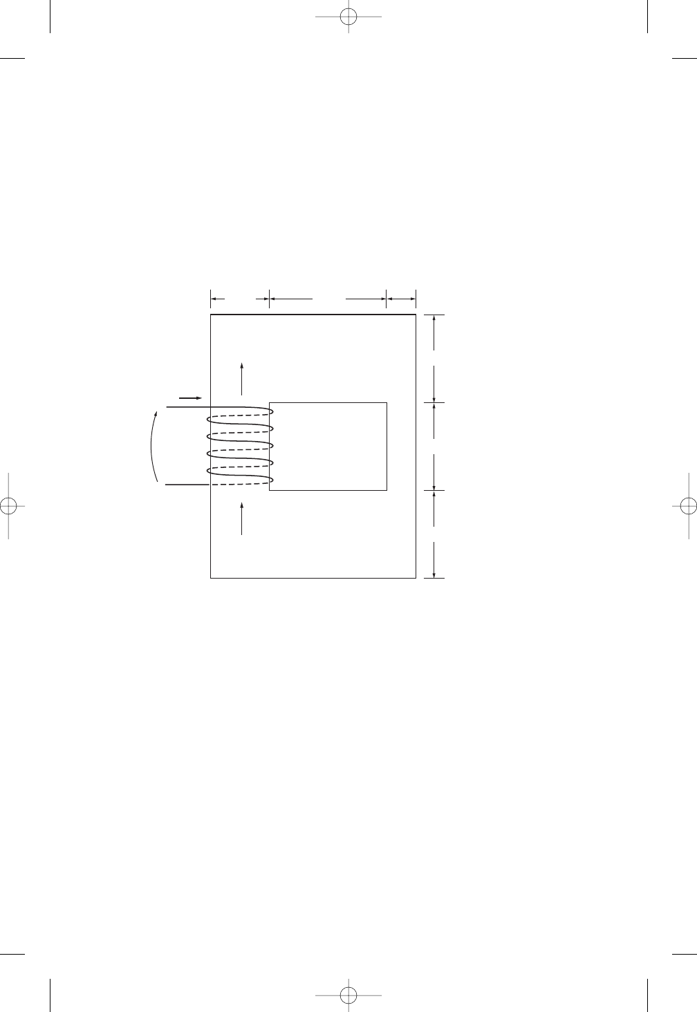
56 ELECTRIC MACHINERY FUNDAMENTALS
1–4. A motor is supplying 60 N • m of torque to its load. If the motor’s shaft is turning at
1800 r/min, what is the mechanical power supplied to the load in watts? In horse-
power?
1–5. A ferromagnetic core is shown in Figure P1–2. The depth of the core is 5 cm. The
other dimensions of the core are as shown in the figure. Find the value of the current
that will produce a flux of 0.005 Wb. With this current, what is the flux density at
the top of the core? What is the flux density at the right side of the core? Assume
that the relative permeability of the core is 1000.
1–6. A ferromagnetic core with a relative permeability of 1500 is shown in Figure P1–3.
The dimensions are as shown in the diagram, and the depth of the core is 7 cm. The
air gaps on the left and right sides of the core are 0.070 and 0.050 cm, respectively.
Because of fringing effects, the effective area of the air gaps is 5 percent larger than
their physical size. If there are 400 turns in the coil wrapped around the center leg
of the core and if the current in the coil is 1.0 A, what is the flux in each of the left,
center, and right legs of the core? What is the flux density in each air gap?
1–7. A two-legged core is shown in Figure P1–4. The winding on the left leg of the core
(N1) has 400 turns, and the winding on the right (N2) has 300 turns. The coils are
wound in the directions shown in the figure. If the dimensions are as shown, then
what flux would be produced by currents i10.5 A and i20.75 A? Assume
r
1000 and constant.
1–8. A core with three legs is shown in Figure P1–5. Its depth is 5 cm, and there are 200
turns on the leftmost leg. The relative permeability of the core can be assumed to be
1500 and constant. What flux exists in each of the three legs of the core? What is the
flux density in each of the legs? Assume a 4 percent increase in the effective area of
the air gap due to fringing effects.
15 cm
5 cm
20 cm10 cm
i
400 turns
Core depth 5 cm
φ
φ
15 cm
15 cm
+
–
FIGURE P1–2
The core of Problems 1–5 and 1–16.
cha65239_ch01.qxd 10/16/2003 9:54 AM Page 56
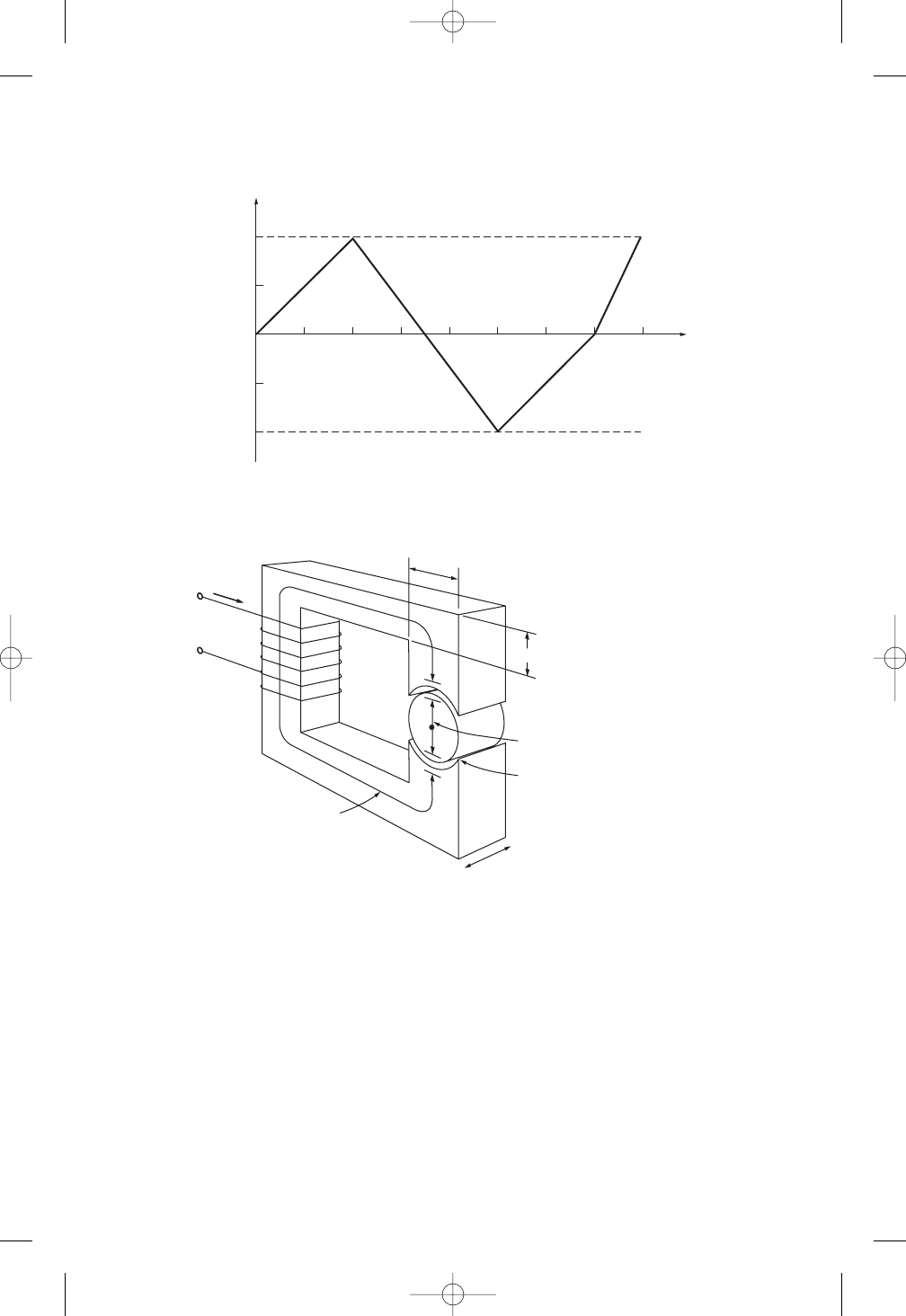
62 ELECTRIC MACHINERY FUNDAMENTALS
(d) Calculate the reactive power consumed or supplied by this load. Does the load
consume reactive power from the source or supply it to the source?
1–19. Figure P1–14 shows a simple single-phase ac power system with three loads. The
voltage source is V = 120∠0° V, and the impedances of the three loads are
Z1530° Z2545° Z3590°
Answer the following questions about this power system.
(a) Assume that the switch shown in the figure is open, and calculate the current I,
the power factor, and the real, reactive, and apparent power being supplied by
the load.
N turns
l
c
= 48 cm
l
r
= 4 cm
4 cm
Depth = 4 cm
4 cm
4 cm
l
g
= 0.05 cm
i
N = ?
FIGURE P1–13
The core of Problem 1–17.
t (ms)
12345678
0
φ
(Wb)
0.010
0.005
–0.005
–0.010
FIGURE P1–12
Plot of flux
as a function of time for Problem 1–16.
cha65239_ch01.qxd 10/23/2003 9:22 AM Page 62

64 ELECTRIC MACHINERY FUNDAMENTALS
(a) If this bar has a load of 10 N attached to it opposite to the direction of motion,
what is the steady-state speed of the bar?
(b) If the bar runs off into a region where the flux density falls to 0.30 T, what hap-
pens to the bar? What is its final steady-state speed?
(c) Suppose VBis now decreased to 80 V with everything else remaining as in
part b. What is the new steady-state speed of the bar?
(d) From the results for parts band c, what are two methods of controlling the
speed of a linear machine (or a real dc motor)?
REFERENCES
1. Alexander, Charles K., and Matthew N. O. Sadiku: Fundamentals of Electric Circuits, McGraw-
Hill, 2000.
2. Beer, F., and E. Johnston, Jr.: Vector Mechanics for Engineers: Dynamics, 6th ed., McGraw-Hill,
New York, 1997.
3. Hayt, William H.: Engineering Electromagnetics, 5th ed., McGraw-Hill, New York, 1989.
4. Mulligan, J. F.: Introductory College Physics, 2nd ed., McGraw-Hill, New York, 1991.
5. Sears, Francis W., Mark W. Zemansky, and Hugh D. Young: University Physics, Addison-Wesley,
Reading, Mass., 1982.
cha65239_ch01.qxd 10/16/2003 9:54 AM Page 64

TRANSFORMERS 147
2–8. A 200-MVA, 15/200-kV single-phase power transformer has a per-unit resistance of
1.2 percent and a per-unit reactance of 5 percent (data taken from the transformer’s
nameplate). The magnetizing impedance is j80 per unit.
(a) Find the equivalent circuit referred to the low-voltage side of this transformer.
(b) Calculate the voltage regulation of this transformer for a full-load current at
power factor of 0.8 lagging.
(c) Assume that the primary voltage of this transformer is a constant 15 kV, and
plot the secondary voltage as a function of load current for currents from no
load to full load. Repeat this process for power factors of 0.8 lagging, 1.0, and
0.8 leading.
2–9. A three-phase transformer bank is to handle 600 kVA and have a 34.5/13.8-kV volt-
age ratio. Find the rating of each individual transformer in the bank (high voltage,
low voltage, turns ratio, and apparent power) if the transformer bank is connected to
(a) Y–Y, ( b) Y–, (c) –Y, ( d) –, (e) open , (f) open Y–open .
2–10. A 13,800/480-V three-phase Y--connected transformer bank consists of three
identical 100-kVA 7967/480-V transformers. It is supplied with power directly from
a large constant-voltage bus. In the short-circuit test, the recorded values on the
high-voltage side for one of these transformers are
VSC 560 V ISC 12.6 A PSC 3300 W
(a) If this bank delivers a rated load at 0.85 PF lagging and rated voltage, what is
the line-to-line voltage on the high-voltage side of the transformer bank?
(b) What is the voltage regulation under these conditions?
(c) Assume that the primary voltage of this transformer is a constant 13.8 kV, and
plot the secondary voltage as a function of load current for currents from no-
load to full-load. Repeat this process for power factors of 0.85 lagging, 1.0, and
0.85 leading.
(d) Plot the voltage regulation of this transformer as a function of load current for
currents from no-load to full-load. Repeat this process for power factors of 0.85
lagging, 1.0, and 0.85 leading.
2–11. A 100,000-kVA, 230/115-kV –three-phase power transformer has a resistance of
0.02 pu and a reactance of 0.055 pu. The excitation branch elements are RC110 pu
and XM20 pu.
(a) If this transformer supplies a load of 80 MVA at 0.85 PF lagging, draw the pha-
sor diagram of one phase of the transformer.
(b) What is the voltage regulation of the transformer bank under these conditions?
(c) Sketch the equivalent circuit referred to the low-voltage side of one phase of this
transformer. Calculate all the transformer impedances referred to the low-voltage
side.
2–12. An autotransformer is used to connect a 13.2-kV distribution line to a 13.8-kV dis-
tribution line. It must be capable of handling 2000 kVA. There are three phases, con-
nected Y–Y with their neutrals solidly grounded.
(a) What must the NC/NSE turns ratio be to accomplish this connection?
(b) How much apparent power must the windings of each autotransformer handle?
(c) If one of the autotransformers were reconnected as an ordinary transformer,
what would its ratings be?
2–13. Two phases of a 13.8-kV three-phase distribution line serve a remote rural road (the
neutral is also available). A farmer along the road has a 480-V feeder supplying
cha65239_ch02.qxd 10/16/2003 12:20 PM Page 147
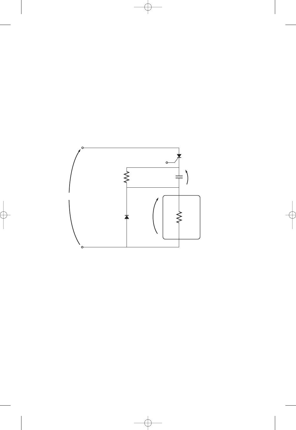
226 ELECTRIC MACHINERY FUNDAMENTALS
3–10. A series-capacitor forced commutation chopper circuit supplying a purely resistive
load is shown in Figure P3–5.
(a) When SCR1 is turned on, how long will it remain on? What causes it to turn off?
(b) When SCR1 turns off, how long will it be until the SCR can be turned on again?
(Assume that 3 time constants must pass before the capacitor is discharged.)
(c) What problem or problems do these calculations reveal about this simple series-
capacitor forced-commutation chopper circuit?
(d) How can the problem(s) described in part cbe eliminated?
3–11. A parallel-capacitor forced-commutation chopper circuit supplying a purely resis-
tive load is shown in Figure P3–6.
(a) When SCR1is turned on, how long will it remain on? What causes it to turn off?
(b) What is the earliest time that SCR1can be turned off after it is turned on?
(Assume that 3 time constants must pass before the capacitor is charged.)
(c) When SCR1turns off, how long will it be until the SCR can be turned on again?
(d) What problem or problems do these calculations reveal about this simple parallel-
capacitor forced-commutation chopper circuit?
(e) How can the problem(s) described in part dbe eliminated?
3–12. Figure P3–7 shows a single-phase rectifier-inverter circuit. Explain how this circuit
functions. What are the purposes of C1and C2? What controls the output frequency
of the inverter?
VDC 120 V
IH5 mA
VBO 250 V
R120 k
Rload 250
C15
F
VDC 120 V
IH
8 mA
VBO 200 V
R120 k
Rload 250
C 150
F
+
–
+
–
+
–
V
DC
R1
R
LOAD
C
D
SCR
Load
v
load
v
c
FIGURE P3–5
The simple series-capacitor forced-commutation circuit of Problem 3–10.
cha65239_ch03.qxd 10/30/2003 1:15 PM Page 226
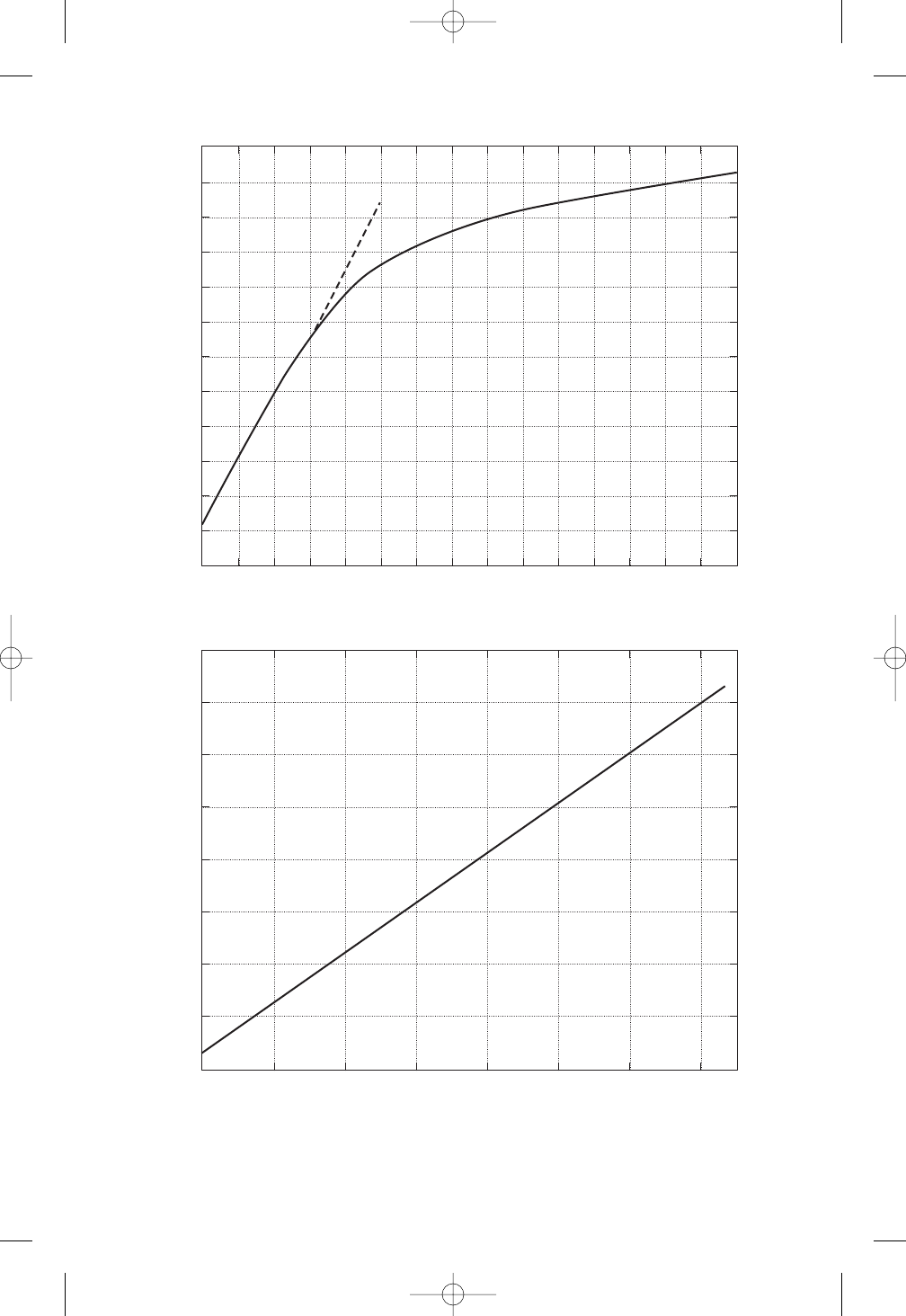
342
0 0.1
Open-circuit voltage, V
Field current, A
1200
1100
1000
900
800
700
600
500
400
300
200
100
00.2 0.3 0.4 0.5 0.6 0.7 0.8 0.9 1 1.1 1.2 1.3 1.4 1.5
(a)
0
Armature current, A
Field current, A
1600
1400
1200
1000
800
600
400
200
00.2 0.4 0.6 0.8 1 1.2 1.4
(b)
Open Circuit Characteristic
Short Circuit Characteristic
FIGURE P5–2
(a) Open-circuit characteristic curve for the generator in Problems 5–11 to 5–21. (b) Short-circuit
characteristic curve for the generator in Problems 5–11 to 5–21.
cha65239_ch05.qxd 11/5/2003 2:14 PM Page 342

344 ELECTRIC MACHINERY FUNDAMENTALS
5–27. A 25-MVA, three-phase, 13.8-kV, two-pole, 60-Hz Y-connected synchronous gen-
erator was tested by the open-circuit test, and its air-gap voltage was extrapolated
with the following results:
Open-circuit test
Field current, A 320 365 380 475 570
Line voltage, kV 13.0 13.8 14.1 15.2 16.0
Extrapolated air-gap voltage, kV 15.4 17.5 18.3 22.8 27.4
The short-circuit test was then performed with the following results:
Short-circuit test
Field current, A 320 365 380 475 570
Armature current, A 1040 1190 1240 1550 1885
The armature resistance is 0.24 per phase.
(a) Find the unsaturated synchronous reactance of this generator in ohms per phase
and per unit.
(b) Find the approximate saturated synchronous reactance XSat a field current of
380 A. Express the answer both in ohms per phase and per unit.
(c) Find the approximate saturated synchronous reactance at a field current of
475 A. Express the answer both in ohms per phase and in per-unit.
(d) Find the short-circuit ratio for this generator.
5–28. A 20-MVA, 12.2-kV, 0.8-PF-lagging, Y-connected synchronous generator has a neg-
ligible armature resistance and a synchronous reactance of 1.1 per unit. The gener-
ator is connected in parallel with a 60-Hz, 12.2-kV infinite bus that is capable of sup-
plying or consuming any amount of real or reactive power with no change in
frequency or terminal voltage.
(a) What is the synchronous reactance of the generator in ohms?
(b) What is the internal generated voltage EAof this generator under rated conditions?
(c) What is the armature current IAin this machine at rated conditions?
(d) Suppose that the generator is initially operating at rated conditions. If the inter-
nal generated voltage EAis decreased by 5 percent, what will the new armature
current IAbe?
(e) Repeat part dfor 10, 15, 20, and 25 percent reductions in EA.
(f) Plot the magnitude of the armature current IAas a function of EA. (You may wish
to use MATLAB to create this plot.)
cha65239_ch05.qxd 11/5/2003 2:14 PM Page 344
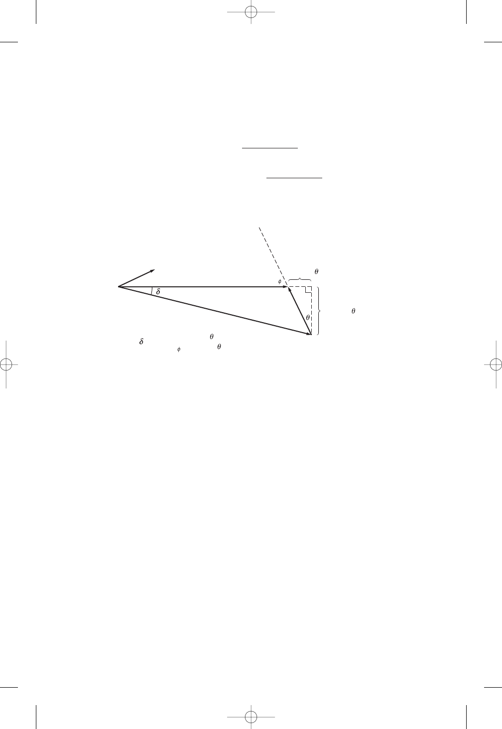
SYNCHRONOUS MOTORS 377
6–9. Figure P6–2 shows a synchronous motor phasor diagram for a motor operating at a
leading power factor with no RA. For this motor, the torque angle is given by
Derive an equation for the torque angle of the synchronous motor if the armature re-
sistance is included.
6–10. A 480-V, 375-kVA, 0.8-PF-lagging, Y-connected synchronous generator has a syn-
chronous reactance of 0.4 and a negligible armature resistance. This generator is
supplying power to a 480-V, 80-kW, 0.8-PF-leading, Y-connected synchronous mo-
tor with a synchronous reactance of 1.1 and a negligible armature resistance. The
synchronous generator is adjusted to have a terminal voltage of 480 V when the mo-
tor is drawing the rated power at unity power factor.
(a) Calculate the magnitudes and angles of EAfor both machines.
(b) If the flux of the motor is increased by 10 percent, what happens to the termi-
nal voltage of the power system? What is its new value?
(c) What is the power factor of the motor after the increase in motor flux?
6–11. A 480-V, 100-kW, 50-Hz, four-pole, Y-connected synchronous motor has a rated
power factor of 0.85 leading. At full load, the efficiency is 91 percent. The armature
resistance is 0.08 , and the synchronous reactance is 1.0 . Find the following
quantities for this machine when it is operating at full load:
(a) Output torque
(b) Input power
(c)nm
(d)EA
(e)|IA|
(f)P
conv
(g)P
mech P
core P
stray
tan1
(
XSIA cos
V
XSIA sin
)
tan
XSIA cos
V
XSIA sin
= tan
–1
(
(
V
E
A
I
A
j
X
S
I
A
X
S
I
A
cos
X
S
I
A
sin
X
S
I
A
cos
––—————–
V + X
S
I
A
sin
FIGURE P6–2
Phasor diagram of a motor at a leading power factor.
cha65239_ch06.qxd 11/5/2003 2:35 PM Page 377

470 ELECTRIC MACHINERY FUNDAMENTALS
(a) The line current IL
(b) The stator power factor
(c) The rotor power factor
(d) The stator copper losses PSCL
(e) The air-gap power PAG
(f) The power converted from electrical to mechanical form Pconv
(g) The induced torque
ind
(h) The load torque
load
(i) The overall machine efficiency
(j) The motor speed in revolutions per minute and radians per second
7–15. For the motor in Problem 7–14, what is the pullout torque? What is the slip at the
pullout torque? What is the rotor speed at the pullout torque?
7–16. If the motor in Problem 7–14 is to be driven from a 440-V, 60-Hz power supply,
what will the pullout torque be? What will the slip be at pullout?
7–17. Plot the following quantities for the motor in Problem 7–14 as slip varies from 0 to
10 percent: (a)
ind; (b) Pconv; (c) Pout; (d) efficiency
. At what slip does Pout equal
the rated power of the machine?
7–18. A 208-V, 60 Hz six-pole, Y-connected, 25-hp design class B induction motor is
tested in the laboratory, with the following results:
No load: 208 V, 22.0 A, 1200 W, 60 Hz
Locked rotor: 24.6 V, 64.5 A, 2200 W, 15 Hz
DC test: 13.5 V, 64 A
Find the equivalent circuit of this motor, and plot its torque–speed characteristic
curve.
7–19. A 460-V, four-pole, 50-hp, 60-Hz, Y-connected, three-phase induction motor devel-
ops its full-load induced torque at 3.8 percent slip when operating at 60 Hz and 460
V. The per-phase circuit model impedances of the motor are
R10.33 XM30
X10.42 X20.42
Mechanical, core, and stray losses may be neglected in this problem.
(a) Find the value of the rotor resistance R2.
(b) Find
max, smax, and the rotor speed at maximum torque for this motor.
(c) Find the starting torque of this motor.
(d) What code letter factor should be assigned to this motor?
7–20. Answer the following questions about the motor in Problem 7–19.
(a) If this motor is started from a 460-V infinite bus, how much current will flow in
the motor at starting?
(b) If transmission line with an impedance of 0.35 j0.25 per phase is used to
connect the induction motor to the infinite bus, what will the starting current of
the motor be? What will the motor’s terminal voltage be on starting?
(c) If an ideal 1.4:1 step-down autotransformer is connected between the transmis-
sion line and the motor, what will the current be in the transmission line during
starting? What will the voltage be at the motor end of the transmission line dur-
ing starting?
cha65239_ch07.qxd 11/5/2003 3:02 PM Page 470
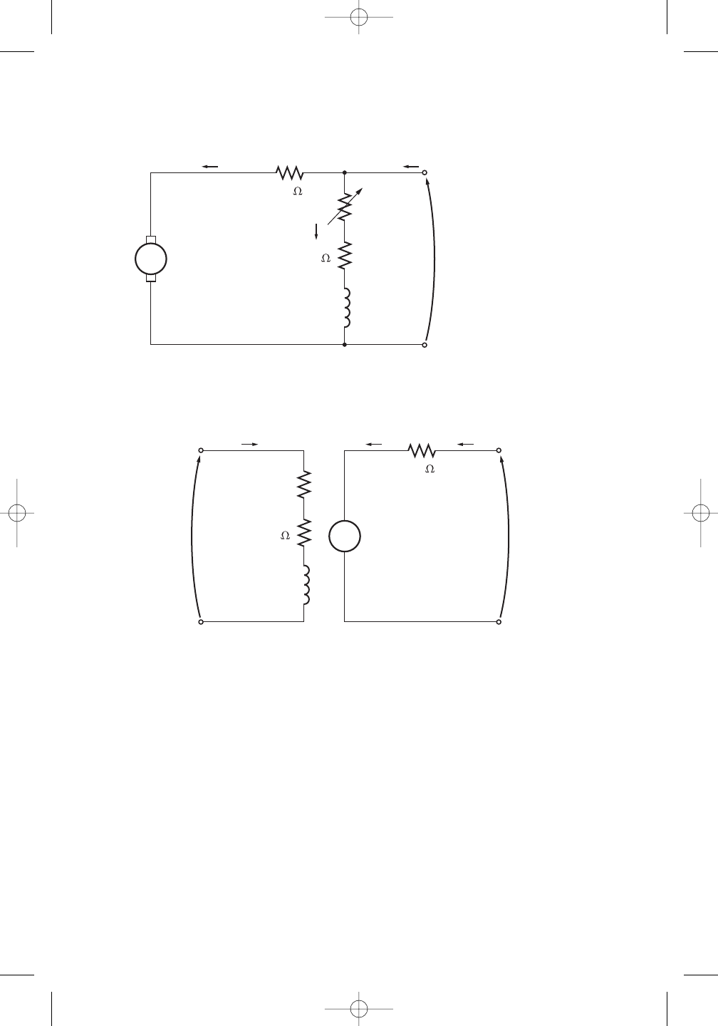
DC MOTORS AND GENERATORS 623
9–10. If the motor is connected cumulatively compounded as shown in Figure P9–4 and if
Radj 175 , what is its no-load speed? What is its full-load speed? What is its
speed regulation? Calculate and plot the torque–speed characteristic for this motor.
(Neglect armature effects in this problem.)
9–11. The motor is connected cumulatively compounded and is operating at full load.
What will the new speed of the motor be if Radj is increased to 250 ? How does the
new speed compare to the full-load speed calculated in Problem 9–10?
9–12. The motor is now connected differentially compounded.
(a) If Radj 175 , what is the no-load speed of the motor?
(b) What is the motor’s speed when the armature current reaches 20A? 40 A? 60 A?
(c) Calculate and plot the torque–speed characteristic curve of this motor.
9–13. A 7.5-hp, 120-V series dc motor has an armature resistance of 0.2 and a series field
resistance of 0.16 . At full load, the current input is 58 A, and the rated speed is
RA
EA
VT = 240 V
100
+
–
IF
IL
IA
LF
RF
Radj
0.40
FIGURE P9–2
The equivalent circuit of the shunt motor in Problems 9–1 to 9–7.
R
A
E
A
V
F
= 240 V V
A
= 120 to 240 V
+
–
I
L
I
F
I
A
+
–
+
–
R
F
= 100
L
F
R
adj
0.40
FIGURE P9–3
The equivalent circuit of the separately excited motor in Problems 9–8 and 9–9.
cha65239_ch09.qxd 11/14/03 10:10 AM Page 623
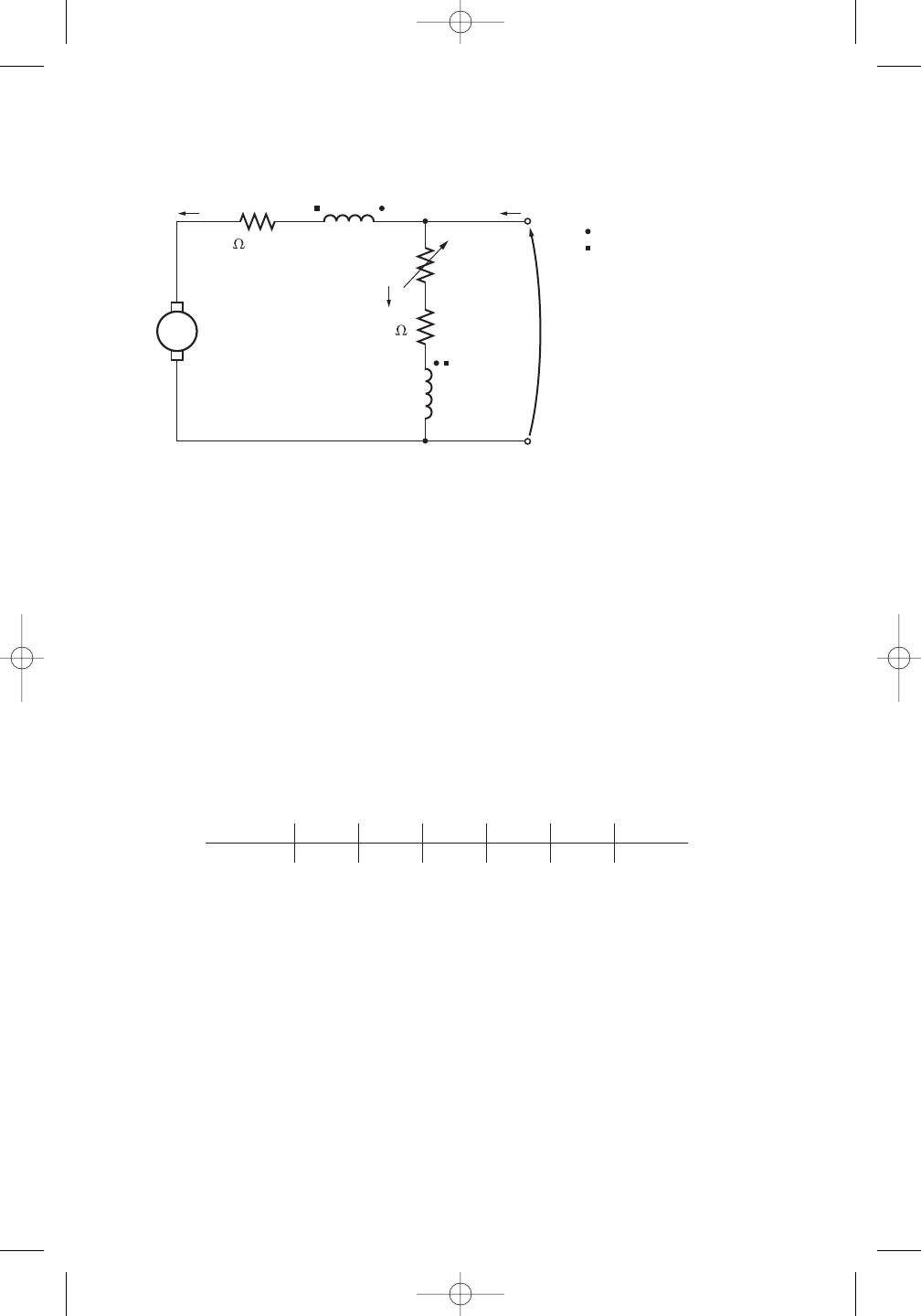
624 ELECTRIC MACHINERY FUNDAMENTALS
1050 r/min. Its magnetization curve is shown in Figure P9–5. The core losses are 200
W, and the mechanical losses are 240 W at full load. Assume that the mechanical
losses vary as the cube of the speed of the motor and that the core losses are constant.
(a) What is the efficiency of the motor at full load?
(b) What are the speed and efficiency of the motor if it is operating at an armature
current of 35 A?
(c) Plot the torque–speed characteristic for this motor.
9–14. A 20-hp, 240-V, 76-A, 900 r/min series motor has a field winding of 33 turns per
pole. Its armature resistance is 0.09 , and its field resistance is 0.06 . The mag-
netization curve expressed in terms of magnetomotive force versus EAat 900 r/min
is given by the following table:
EA, V 95 150 188 212 229 243
, A • turns 500 1000 1500 2000 2500 3000
Armature reaction is negligible in this machine.
(a) Compute the motor’s torque, speed, and output power at 33, 67, 100, and 133
percent of full-load armature current. (Neglect rotational losses.)
(b) Plot the torque–speed characteristic of this machine.
9–15. A 300-hp, 440-V, 560-A, 863 r/min shunt dc motor has been tested, and the follow-
ing data were taken:
Blocked-rotor test:
VA16.3 V exclusive of brushes VF440 V
IA500 A IF8.86 A
No-load operation:
VA16.3 V including brushes IF8.76 A
IA23.1 A n863 r/min
E
A
V
T
= 240 V
= Cumulatively compounded
= Differentially compounded
= R
A
+ R
S
100
+
–
I
F
I
L
I
A
L
F
R
F
L
S
R
adj
+
–
0.44
FIGURE P9–4
The equivalent circuit of the compounded motor in Problems 9–10 to 9–12.
cha65239_ch09.qxd 11/14/03 10:10 AM Page 624
DC MOTORS AND GENERATORS 627
9–19. A series motor is now constructed from this machine by leaving the shunt field out
entirely. Derive the torque–speed characteristic of the resulting motor.
9–20. An automatic starter circuit is to be designed for a shunt motor rated at 15 hp, 240
V, and 60 A. The armature resistance of the motor is 0.15 , and the shunt field re-
sistance is 40 . The motor is to start with no more than 250 percent of its rated ar-
mature current, and as soon as the current falls to rated value, a starting resistor
stage is to be cut out. How many stages of starting resistance are needed, and how
big should each one be?
9–21. A 15-hp, 230-V, 1800 r/min shunt dc motor has a full-load armature current of 60 A
when operating at rated conditions. The armature resistance of the motor is RA
0.15 , and the field resistance RFis 80 .The adjustable resistance in the field cir-
cuit Radj
may be varied over the range from 0 to 200 and is currently set to 90 .
Armature reaction may be ignored in this machine. The magnetization curve for this
motor, taken at a speed of 1800 r/min, is given in tabular form below:
EA, V 8.5 150 180 215 226 242
IF, A 0.00 0.80 1.00 1.28 1.44 2.88
(a) What is the speed of this motor when it is running at the rated conditions spec-
ified above?
(b) The output power from the motor is 7.5 hp at rated conditions. What is the out-
put torque of the motor?
(c) What are the copper losses and rotational losses in the motor at full load (ignore
stray losses)?
(d) What is the efficiency of the motor at full load?
(e) If the motor is now unloaded with no changes in terminal voltage or Radj, what
is the no-load speed of the motor?
(f) Suppose that the motor is running at the no-load conditions described in part e.
What would happen to the motor if its field circuit were to open? Ignoring ar-
mature reaction, what would the final steady-state speed of the motor be under
those conditions?
(g) What range of no-load speeds is possible in this motor, given the range of field
resistance adjustments available with Radj?
9–22. The magnetization curve for a separately excited dc generator is shown in Figure
P9–7. The generator is rated at 6 kW, 120 V, 50 A, and 1800 r/min and is shown in
Figure P9–8. Its field circuit is rated at 5A. The following data are known about the
machine:
RA
0.18 VF
120 V
Radj 0 to 30 RF24
NF1000 turns per pole
Answer the following questions about this generator, assuming no armature reaction.
(a) If this generator is operating at no load, what is the range of voltage adjustments
that can be achieved by changing Radj?
(b) If the field rheostat is allowed to vary from 0 to 30 and the generator’s speed
is allowed to vary from 1500 to 2000 r/min, what are the maximum and mini-
mum no-load voltages in the generator?
cha65239_ch09.qxd 11/14/03 10:10 AM Page 627
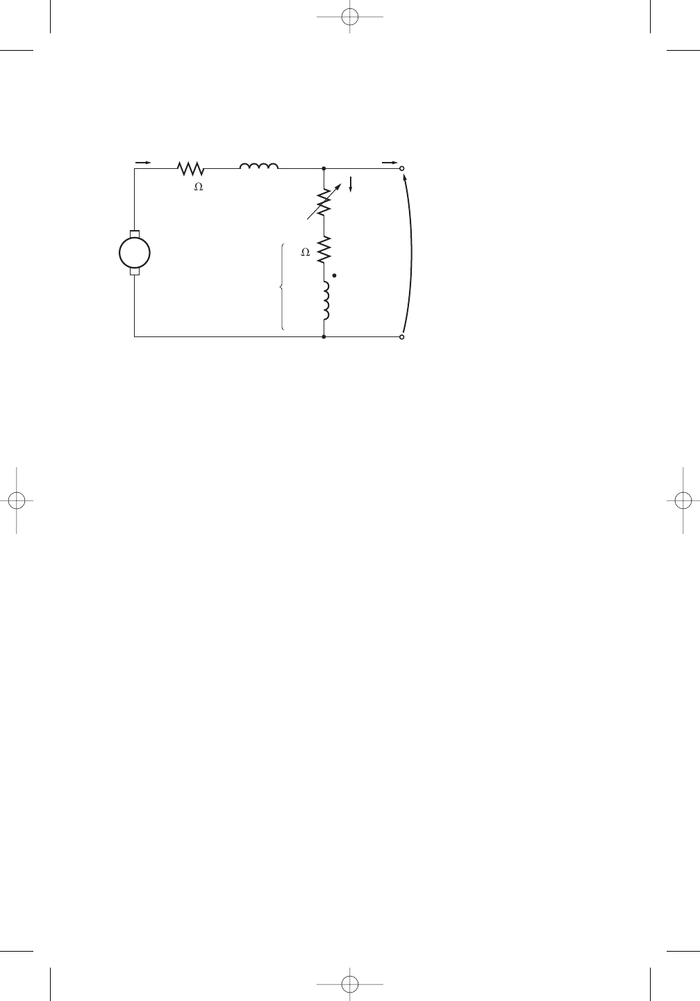
630 ELECTRIC MACHINERY FUNDAMENTALS
The machine has the magnetization curve shown in Figure P9–7. Its equivalent cir-
cuit is shown in Figure P9–10. Answer the following questions about this machine,
assuming no armature reaction.
(a) If the generator is operating at no load, what is its terminal voltage?
(b) If the generator has an armature current of 20 A, what is its terminal voltage?
(c) If the generator has an armature current of 40 A, what is its terminal voltage?
(d) Calculate and plot the terminal characteristic of this machine.
9–28. If the machine described in Problem 9–27 is reconnected as a differentially com-
pounded dc generator, what will its terminal characteristic look like? Derive it in the
same fashion as in Problem 9–27.
9–29. A cumulatively compounded dc generator is operating properly as a flat-
compounded dc generator. The machine is then shut down, and its shunt field con-
nections are reversed.
(a) If this generator is turned in the same direction as before, will an output voltage
be built up at its terminals? Why or why not?
(b) Will the voltage build up for rotation in the opposite direction? Why or why
not?
(c) For the direction of rotation in which a voltage builds up, will the generator be
cumulatively or differentially compounded?
9–30. A three-phase synchronous machine is mechanically connected to a shunt dc ma-
chine, forming a motor–generator set, as shown in Figure P9–11. The dc machine is
connected to a dc power system supplying a constant 240 V, and the ac machine is
connected to a 480-V, 60-Hz infinite bus.
The dc machine has four poles and is rated at 50 kW and 240 V. It has a per-unit
armature resistance of 0.04. The ac machine has four poles and is Y-connected. It is
rated at 50 kVA, 480 V, and 0.8 PF, and its saturated synchronous reactance is 2.0
per phase.
All losses except the dc machine’s armature resistance may be neglected in this
problem. Assume that the magnetization curves of both machines are linear.
(a) Initially, the ac machine is supplying 50 kVA at 0.8 PF lagging to the ac power
system.
RA + RS
Nse = 20 turns
EAVT
20
+
–
IF
IL
IA
LFNF = 1000
turns
RF
LS
Radj
+
–
0.21
FIGURE P9–10
The compounded dc generator in Problems 9–27 and 9–28.
cha65239_ch09.qxd 11/14/03 10:10 AM Page 630

680 ELECTRIC MACHINERY FUNDAMENTALS
(f) Pout
(g)
ind
(h)
load
(i) Efficiency
10–6. Find the induced torque in the motor in Problem 10–5 if it is operating at 5 percent
slip and its terminal voltage is (a) 190 V, (b) 208 V, (c) 230 V.
10–7. What type of motor would you select to perform each of the following jobs? Why?
(a) Vacuum cleaner
(b) Refrigerator
(c) Air conditioner compressor
(d) Air conditioner fan
(e) Variable-speed sewing machine
(f) Clock
(g) Electric drill
10–8. For a particular application, a three-phase stepper motor must be capable of step-
ping in 10°increments. How many poles must it have?
10–9. How many pulses per second must be supplied to the control unit of the motor in
Problem 10–8 to achieve a rotational speed of 600 r/min?
10–10. Construct a table showing step size versus number of poles for three-phase and
four-phase stepper motors.
REFERENCES
1. Fitzgerald, A. E., and C. Kingsley, Jr. Electric Machinery. New York: McGraw-Hill, 1952.
2. National Electrical Manufacturers Association. Motors and Generators, Publication No. MG1-
1993. Washington, D.C.: NEMA, 1993.
3. Veinott, G. C. Fractional and Subfractional Horsepower Electric Motors. New York: McGraw-
Hill, 1970.
4. Werninck, E. H. (ed.). Electric Motor Handbook. London: McGraw-Hill, 1978.
cha65239_ch10.qxd 11/14/03 12:41 PM Page 680
