Integral Sleeve Hitch Dimension Drawings (AM31668) As Of 20081016 Drawings(AM31668)
User Manual: Integral Sleeve Hitch Dimension Drawings (AM31668) as of 20081016 WFMFiles.com
Open the PDF directly: View PDF ![]() .
.
Page Count: 9
Dimension drawings to fabricate an Integral Sleeve Hitch
John Deere Part Number: AM31668
Dimensions references prepared by: Richard Chuckry
Drawings prepared by: Kenneth Dortch
Reviewed and edited by: Kent Ortman
2007
This Sleeve Hitch will fit John Deere 120, 140, 300, 312, 314, 316 Kohler and 317 Lawn and Garden tractors and
gear driven 110 and 112 1968 -1974 and 200, 208, 210, 212, 214 and 216 from 1975-1987 Lawn and Garden tractors.
Legend
Machining required. Refer to schedule on sheet 9 of 9 for more information.
A Addendum No. Description: Date Issued:
1 Dimension changes to side mounting panel.
Refer to Sleeve Hitch drawings. 03/20/07
2 Refer to Lift Link drawings. Additional
information provided for Lift Link angle. 10/16/08
Material required. Refer to schedule on sheet 9 of 9 for more information.
M1
Drawing Addenda or changes and modifications to the drawings.
These drawings are provided as a service to all who would like to fabricate such items. However, ALL contents herein should be clarified before fabrication as to accuracy by the FABRICATOR.
The names shown on these documents CANNOT be held responsible for fabrication malfunctions of ANY kind due to drawing inaccuracies.
Integral Sleeve Hitch
Sheet 2 of 9
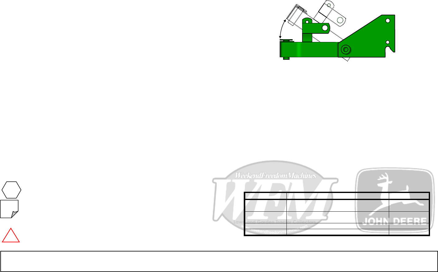
Side View @ Mounting Plate 2 Required
1 3/4”
1
1
M1
Note: It is entirely up to the
fabricator on how the Sleeve
Hitch will be attached to the
tractor. The hole shown will
accommodate both bolt on and
a weld on Spring Latch to the
side of the side mounting plate.
6 1/2”
2 1/4”
6 1/2”
8 1/2”
CL
CL
CL
CL
1 1/8”
1 1/8” 1 1/8”
B
CL
CL
CL
11/16”
CL
1 1/8”
CL
CL
13/16”
7/8”
3 1/2”
15/16”
1 3/16”
C
1
1
A
D
CL
CL
CL
CL
5/8” 5 7/8”
Do NOT Scale – not to scale
These drawings are for reference ONLY and are
NOT to be scaled as to the actual size.
Integral Sleeve Hitch
Sheet 3 of 9
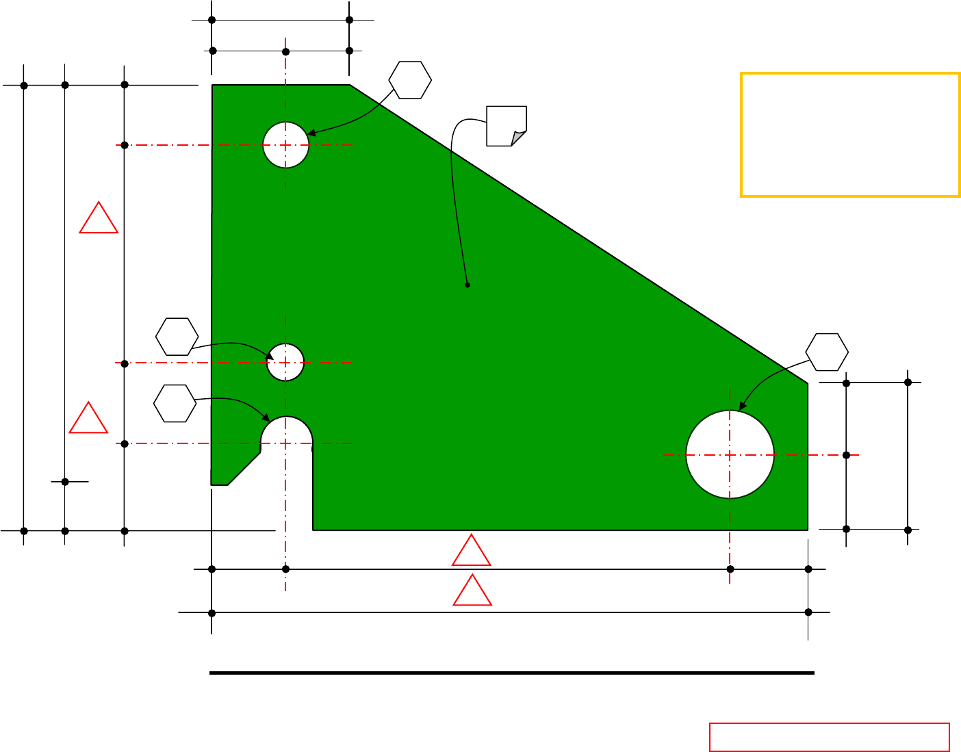
Side View @ Lift Link tab - A 1 Required
Do NOT Scale – not to scale
4 1/4”
1/4”
Weld to top rail on both sides
M2
Weld to top rail on both sides CL
CL 1 1/2”
Bottom edge
M4
Top edge
3/4”
CL
3 1/2”
3/4”
1”
1 3/4”
E
CL
2 1/4”
Bottom edge
3/4”
3/8”
3/4”
CL
CL
1 1/2”
M4
M3
F
3/4”
Side View @ Lift Link tab - B 1 Required
Do NOT Scale – not to scale
These drawings are for reference ONLY and are
NOT to be scaled as to the actual size.
Integral Sleeve Hitch
Sheet of 9 These drawings are for reference ONLY
NOT to be scaled as to the actual size.
4
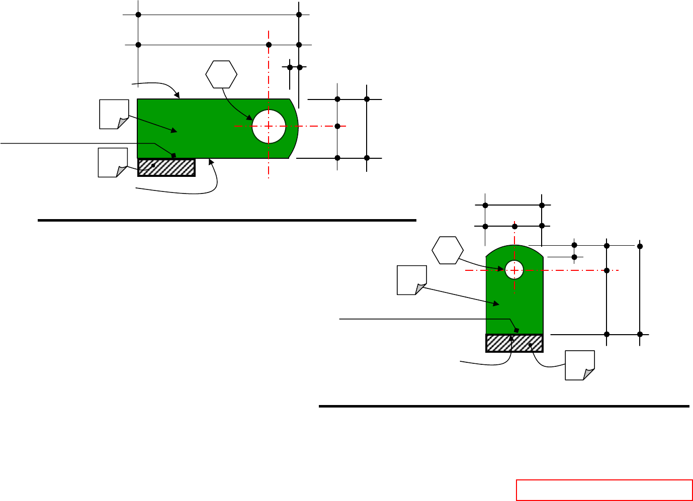
Bottom View @ Hitch Frame Structure 1 Required
Weld to mounting plate
M1
M1
M2
5/8” x 1 1/2”
Stabilizer bolts w/
lock down nut
Weld to side rail both sides @ each end
10 1/2”
13 5/8”
5 1/4”
2 13/16”
1 7/32” 1 7/32”
6
”
1 1/4”
5 1/2”
3 3/4”
CL CL
CL CL
CL
CL
CL
CL
CL CL
CL
CL
CL
CL Mounting plates
Lift Link Tab A above
Weld to inside of rail on both sides
M5
CL
EQ. EQ.
M4 M7
G
Note: Dimensions as
indicated are taken from
centerline of metal.
6 1/2”
B
B
Refer to detail on Sheet 2 of 9 M6
Allow space between
materials for swivel
movement.
Do NOT Scale – not to scale and are
Integral Sleeve Hitch
Sheet of 9 5
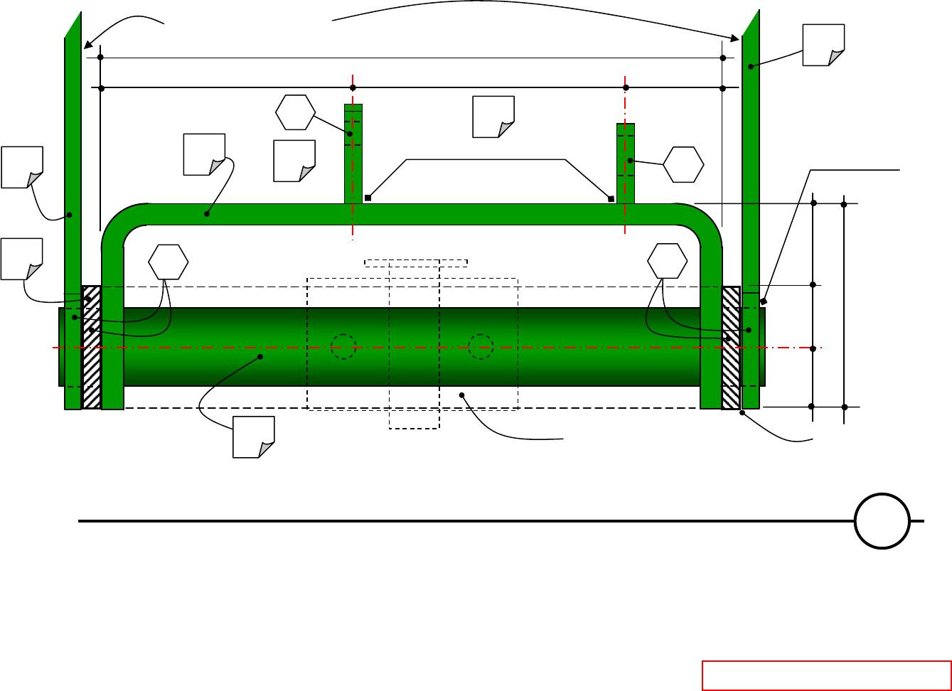
Plan (Top) View @ Hitch Frame Structure
These drawings are for reference ONLY and are
NOT to be scaled as to the actual size.
Weld to mounting plate
10 1/2”
13 5/8”
5 1/4”
1 7/32” 1 7/32”
6”
1 1/4”
5 1/2”
3 3/4”
CL
Mounting plates
6 1/2”
Weld to side rail on both sides
Lift Link Tab B Lift Link Tab A
Weld to top rail on both sides
G
A
CL
CL
CL
CL
CL
CL CL
CL CL
CL
CL
M5
M2
M1
Note: Dimensions as
indicated are taken from
centerline of metal.
CL
M1
B
E
B
EQ. EQ.
CL
2 13/16”
5/8” x 1 1/2”
Stabilizer bolts w/
lock down nut
Refer to Sheet 7 of 9 for Stabilizer details
F
M3
M4
CL
Refer to detail on Sheet 2 of 9
M6
Allow space between
materials for swivel
movement.
Do NOT Scale – not to scale
Integral Sleeve Hitch
Sheet 6 of 9
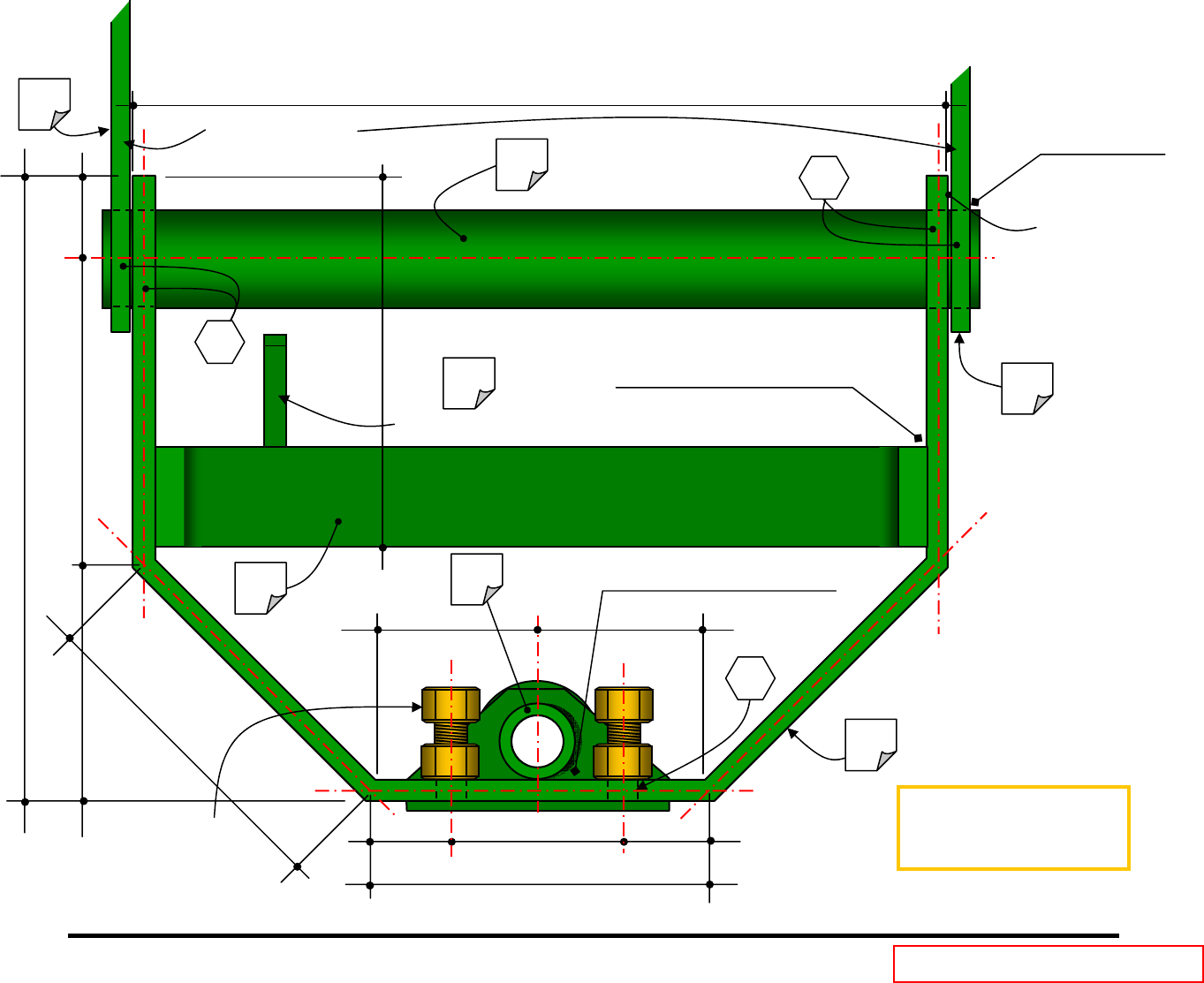
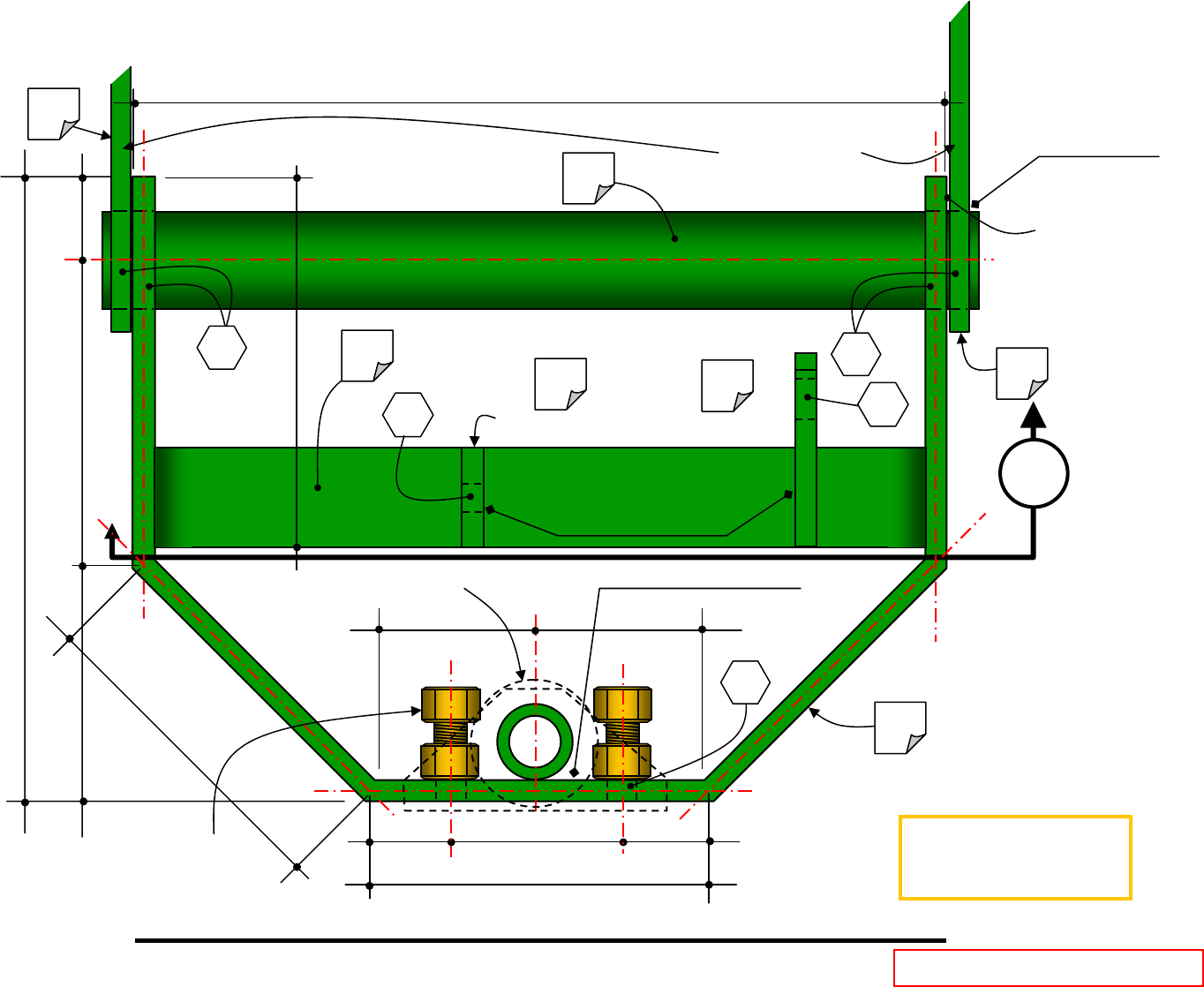
M1
Mounting plates beyond
Lift Link Tab B
Lift Link Tab A
4 1/2”
1 1/4”
1 1/4” 2”
2”
5 3/4”
12 3/4”
5”
CL
CL
CL
CL CL
M1
CL
M6 Refer to Sheet 7 of 9 for Stabilizer
and Hitch Pin Sleeve details
B B
M5
Weld to top rail on both sides
Refer to details on Sheet 2 of 9
F
E
M3
M2
M4 Weld to mounting plate
Allow space between
materials for swivel
movement.
Cross Section @ Hitch Frame Structure A
Do NOT Scale – not to scale
These drawings are for reference ONLY and are
NOT to be scaled as to the actual size.
Integral Sleeve Hitch
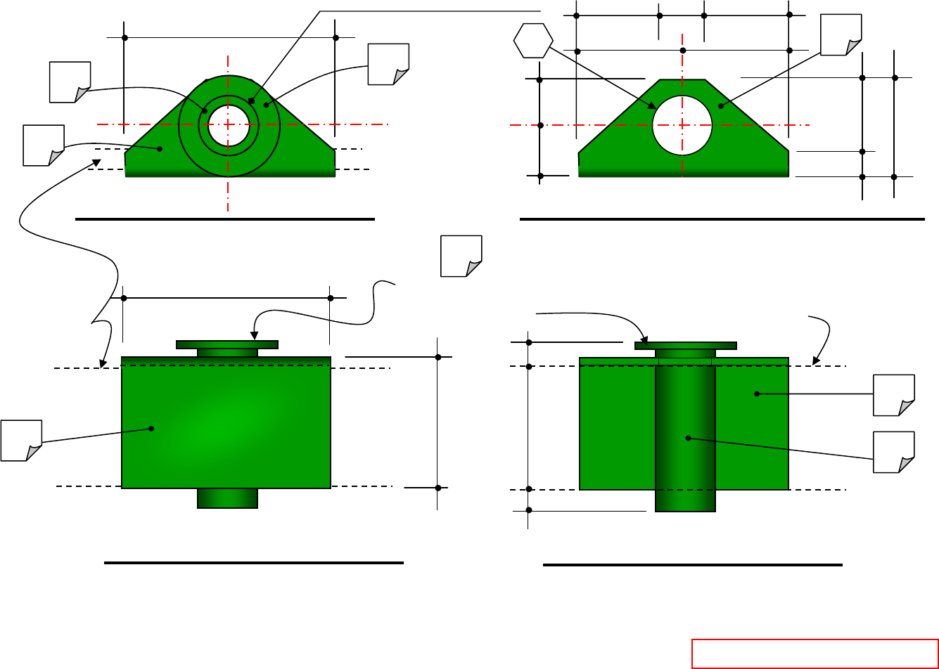
Sheet 7 of 9
Stabilizer Plate and Hitch Pin Sleeve
M8
M7
Weld washer to pipe @ top edge
2 1/8”
4”
Line of hitch frame rails Line of hitch frame rails
2 5/8”
2 1/2”
3/8”
Plan View 1 Req.
Do NOT Scale – not to scale
CL
CL
CL EQ.
EQ.
1 9/16”
1 9/16” 7/8”
H
Plan View @ Stabilizer Plate
3/8” 1 3/4”
1” 1 1/8”
M8
3/8”
2” diameter washer with a 1”
hole at the center welded to the
top of the hitch pin sleeve.
CL
CL
M7 M9
4”
M8
CL
M8
Do NOT Scale – not to scale
M9
Front View Back View
Do NOT Scale – not to scale Do NOT Scale – not to scale
These drawings are for reference ONLY and are
NOT to be scaled as to the actual size.
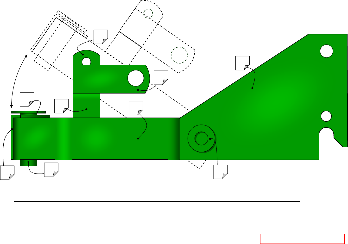
Integral Sleeve Hitch
Sheet 8 of 9
M7
M8
M9
M5
M4
M3
M2
M1
M6
Right Side View @ Integral Sleeve Hitch
Do NOT Scale – not to scale
These drawings are for reference ONLY and are
NOT to be scaled as to the actual size.

Integral Sleeve Hitch
Sheet 9 of 9 These drawings are for reference ONLY and are
NOT to be scaled as to the actual size.
Material Requirements
Item: Quantity: Thickness: Size: Comments:
2 1/4” 6 1/2” x 8 1/2” Drill for holes “A”, “B”, “C”, and possible “D”. Ease all perimeter edges to reduce
sharp material cut edges. Refer to Sheet 2 of 9.
1 3/8” 1 3/4’ x 4 1/4” Drill for hole “E”. Round off one side of narrow edge. Refer to detail on Sheet 3 of
9. This is Tab designation A.
1 3/8” 1 1/2” x 2 1/4” Drill for hole “F”. Round off one side of narrow edge. Refer to detail on Sheet 3 of
9. This is Tab designation B
1 1/2” 1 1/2” Bend two upright verticals to equal 4 1/2” high. Refer to Sheet 6 of 9 for bar
configuration.
1 3/8” 2 1/2” x 30 3/4” Drill for hole “B” at both ends and hole “G”. The length dimensions are given at
the centerline of the thickness side of the bar. Allow for some length as the metal
bends into the sharp required. Refer to Sheets 4, 5, 6, and 8 for details.
1 5/16” 1 5/16” x 14 1/2” This is the pivot pipe. The side walls of the pipe are 5/16” thick. Weld the side
mounting panels on the outside to hold the pipe in place and allow the Hitch
Frame Structure to pivot freely. Refer to Sheets 4, 5, 6, and 8 for details.
1 3/16” 1” x 3 1/4” This is the hitch pin sleeve. The side walls of the sleeve are 3/16” th. and it has a
5/8” dia. hole in the center. Needs to be welded to the Hitch Frame Structure with
a 3/8” overhang to the top and bottom. Refer to Sheet 7 of 9 for details.
1 1/8” 2 1/8” x 2 5/8” x 4” The Stabilizer Plate is an angle. Drill for Hole “H”. Refer to Sheet 7 of 9 for details.
1 1/8” 2” diameter This is the washer that is to be welded to the top of the hitch pin sleeve. Refer to
Sheet 7 of 9 for details
Hole Machining Requirements
Item: Quantity: Size: Comments:
2 5/8” I.D. These holes are to allow the hitch to be bolted on to the tractor or the fabricator can weld a spring
latch to the outside of the plate.
4 1 5/16” I.D. This is to allow the swivel rod to go through the hitch frame rail and the outside of the mounting
plates.
2 3/4” I.D. Notch as shown to mount on tractor bushings.
2 17/32” I.D. These holes are for the use of a 43C and/or a 54C center blade. These holes can be added at the
discretion of the fabricator.
1 5/8” I.D. For Lift Link tab A
1 3/8” I.D. For Lift Link tab B
2 9/16” I.D. Tapped threaded holes to receive 5/8-20 course thread Stabilizer bolts.
1 1 1/8” I.D. Hole should allow the Stabilizer Plate to move freely to insure that the Stabilizer Plate can be used.
A
B
C
D
E
F
G
H
M1
M2
M3
M4
M5
M6
M7
M8
M9
