Iot Workshop Manual Io T
User Manual:
Open the PDF directly: View PDF ![]() .
.
Page Count: 33

SVIT IoT CLUB
IOT WORKSHOP
MANUAL
Compiled By:
Prof. Abhijith H V
Assistant Professor
Dept. of ISE
SVIT, Bengaluru – 64
Department of Information Science and Engineering
&
Department of Computer Science and Engineering
Sai Vidya Institute of Technology
Rajanukunte, Bengaluru – 560064
2018-2019

IoT Workshop
SVIT IoT Club P a g e | 1
Software installation procedure
1) Download and install Arduino IDE from the below link
https://www.arduino.cc/en/Main/Software
(select windows installer)
2) Download and install ch340G driver from below link
https://www.arduined.eu/ch340g-converter-windows-7-driver-download/
(It will be zip format unzip to folder then go to ch340g folder then run setup)
3) Download and install cp210x driver from below link
https://www.silabs.com/products/development-tools/software/usb-to-uart-bridge-
vcp-drivers
(select Download VCP (5.3 MB) (Default))
(It will be zip format unzip to folder then run cp210xVCPInstaller_x86)
4) Download firebase Arduino library zip file from below link
https://github.com/FirebaseExtended/firebase-arduino
To download click clone or download button and then download zip
To install:
Open Arduino IDE installed in step 1
Select sketch -> include library -> Add .Zip Library -> select downloaded firebase-
arduino-master.zip from downloaded folder and press open
5) Download Arduino Json library zip file from below link
https://github.com/bblanchon/ArduinoJson
To download click clone or download button and then download zip
To install:
Open Arduino IDE installed in step 1
Select sketch -> include library -> Add .Zip Library -> select downloaded
ArduinoJson-master.zip from downloaded folder and press open
6) Download Arduino Json library zip file from below link
https://github.com/adafruit/Adafruit_MQTT_Library
To download click clone or download button and then download zip
To install:
Open Arduino IDE installed in step 1
Select sketch -> include library -> Add .Zip Library -> select downloaded adafruit-
mMQTT-Library-master.zip from downloaded folder and press open
7) Installing ESP8266
Open Arduino IDE installed in step 1
Go to files and click on the preference in the Arduino IDE

IoT Workshop
SVIT IoT Club P a g e | 3
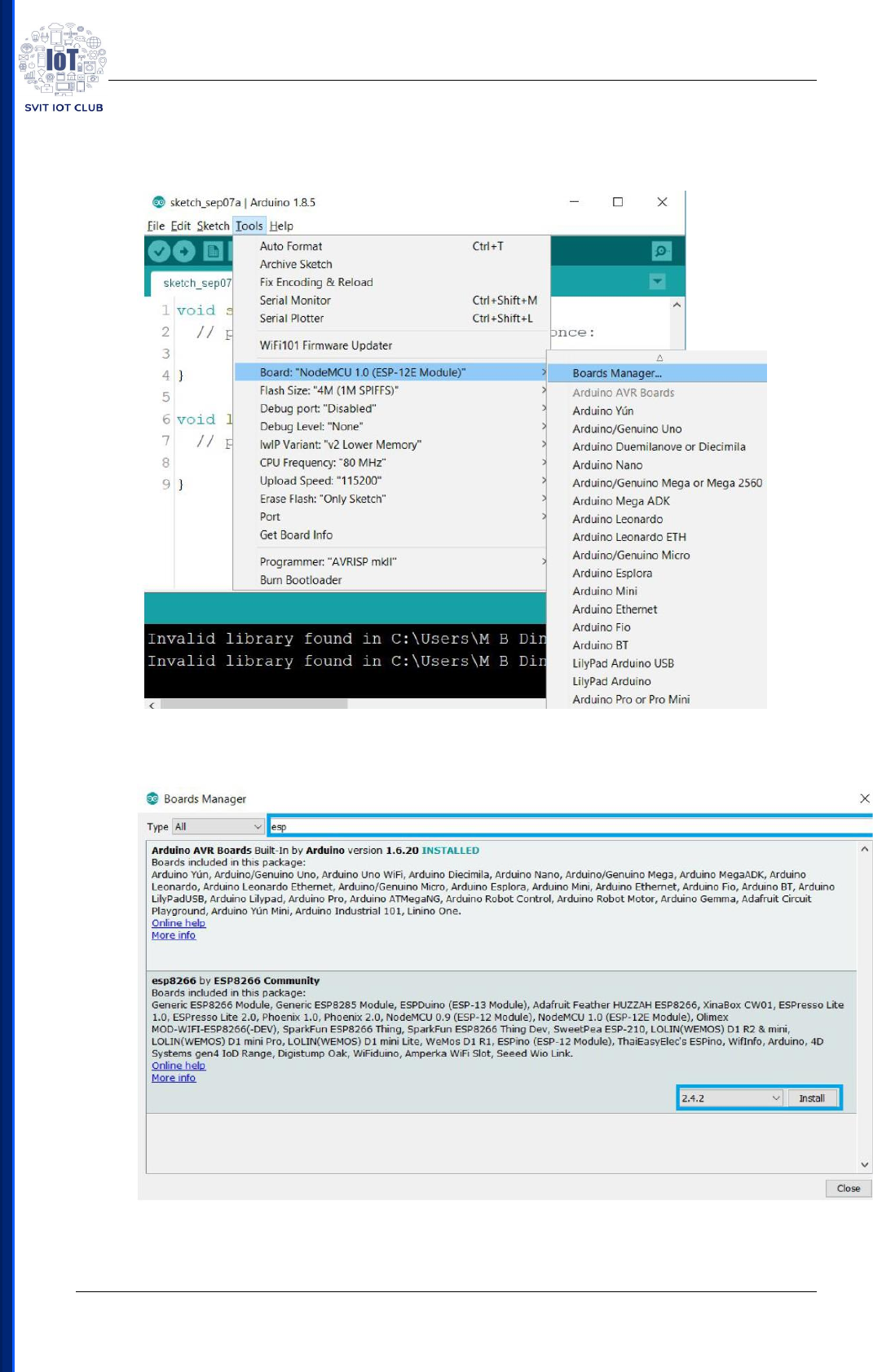
After completing the above steps, go to Tools > board, and then
select board Manager.
Type Esp8266 in the Search bar then Select esp8266 by ESp8266
Community and install it.
It should take several minutes for downloading and installing
the Esp8266 Board managers. After installation close the Board Manager.

IoT Workshop
SVIT IoT Club P a g e | 4
Following Android Apps has to be installed in android phone
1) Bluetooth Terminal
2) Google Assistant
3) QR Code Scanner
4) IFTTT
IoT Workshop
SVIT IoT Club P a g e | 5
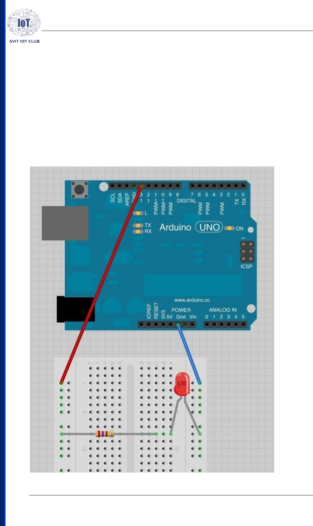
Experiment 1:
Blinking LED
Components Required:
• Arduino Uno
• Breadboard (Optional)
• 2 wires (Optional)
• LED (Optional)
• 220 ohm resistor (Optional)
Circuit Sketch:

IoT Workshop
SVIT IoT Club P a g e | 6
Source Code:
// the setup function runs once when you press reset or power the board
void setup() {
// initialize digital pin LED_BUILTIN as an output.
pinMode(LED_BUILTIN, OUTPUT);
}
// the loop function runs over and over again forever
void loop() {
digitalWrite(LED_BUILTIN, HIGH); // turn the LED on (HIGH is the voltage level)
delay(1000); // wait for a second
digitalWrite(LED_BUILTIN, LOW); // turn the LED off by making the voltage LOW
delay(1000); // wait for a second
}
IoT Workshop
SVIT IoT Club P a g e | 7
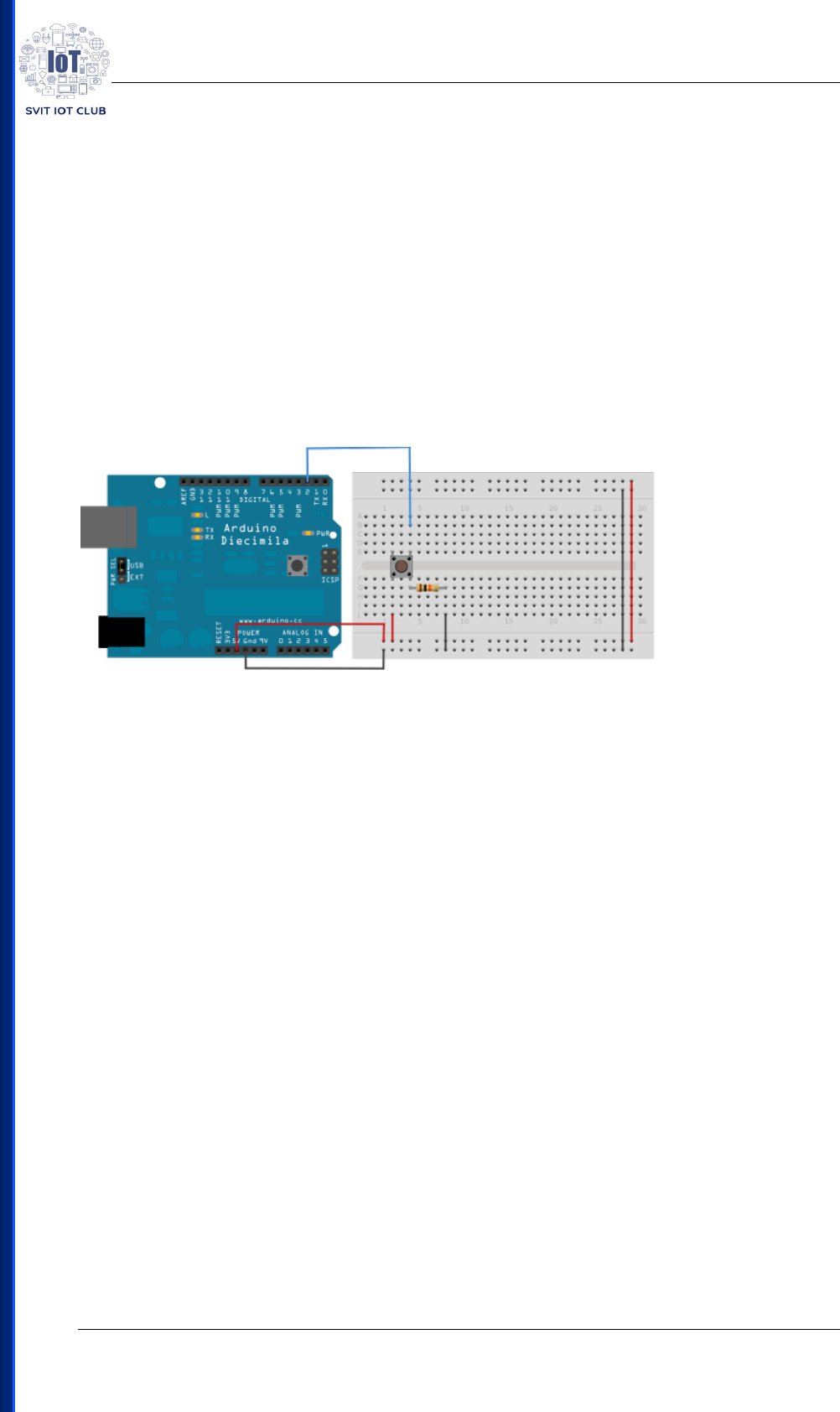
Experiment 2:
Controlling LED Using Switch Button
Components Required:
• Arduino Uno
• Momentary button or Switch
• 10K ohm resistor
• hook-up wires
• breadboard
Circuit Sketch:
Source Code:
// constants won't change. They're used here to set pin numbers:
const int buttonPin = 2; // the number of the pushbutton pin
const int ledPin = 13; // the number of the LED pin
// variables will change:
int buttonState = 0; // variable for reading the pushbutton status
void setup() {
// initialize the LED pin as an output:
pinMode(ledPin, OUTPUT);
// initialize the pushbutton pin as an input:
pinMode(buttonPin, INPUT);
}

IoT Workshop
SVIT IoT Club P a g e | 8
void loop() {
// read the state of the pushbutton value:
buttonState = digitalRead(buttonPin);
// check if the pushbutton is pressed. If it is, the buttonState is HIGH:
if (buttonState == HIGH) {
// turn LED on:
digitalWrite(ledPin, HIGH);
} else {
// turn LED off:
digitalWrite(ledPin, LOW);
}
}

IoT Workshop
SVIT IoT Club P a g e | 9
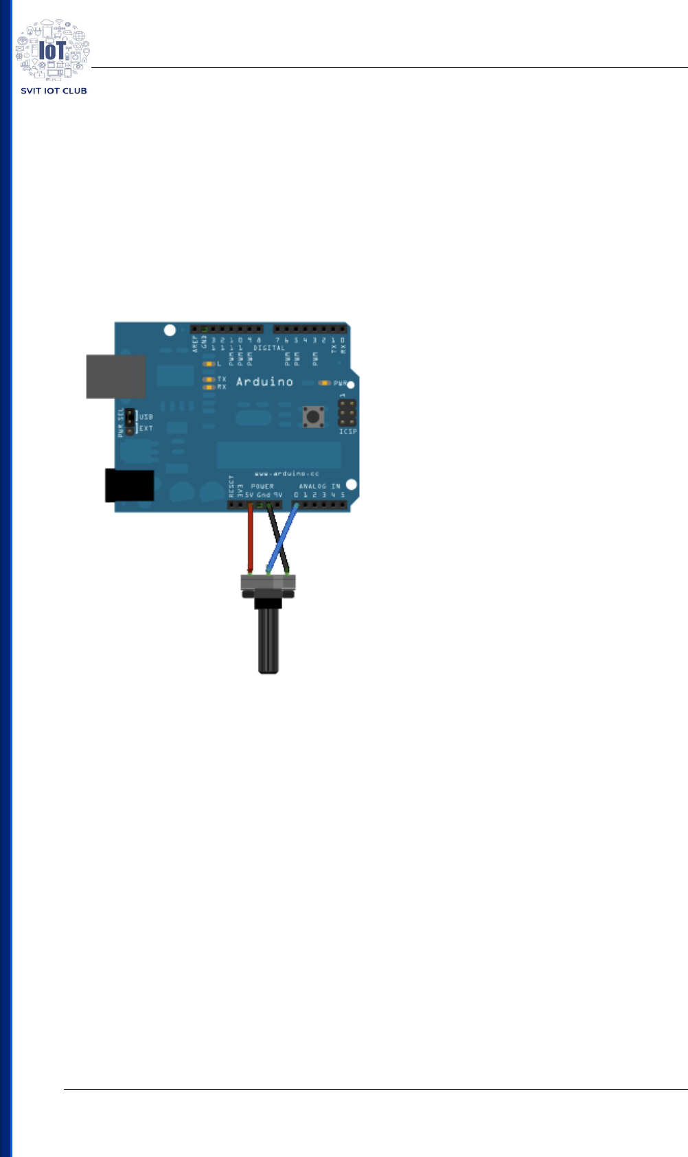
Experiment 3:
Analog Read Serial
Components Required:
• Arduino Uno
• 10k ohm Potentiometer
Circuit Sketch:
Source Code:
// the setup routine runs once when you press reset:
void setup() {
// initialize serial communication at 9600 bits per second:
Serial.begin(9600);
}
// the loop routine runs over and over again forever:
void loop() {
// read the input on analog pin 0:
int sensorValue = analogRead(A0);

IoT Workshop
SVIT IoT Club P a g e | 10
// print out the value you read:
Serial.println(sensorValue);
delay(1); // delay in between reads for stability
}
IoT Workshop
SVIT IoT Club P a g e | 11
Experiment 4:
Controlling LED using Potentiometer
Components Required:
• Arduino Uno
• 10k ohm Potentiometer
Circuit Sketch:
Source Code:
int POT = A0; //Intialize pin A1 for LDR
int LD_2= 13; // Intialize pin 9(LD2) as analog for the LED
int potValue = 0; // Initialize ldrValue to 0
int ledValue = 0; // Initialize ledValue to 0
void setup()
{
Serial.begin(9600); //Baud rate for serial communication
}
void loop()
{

IoT Workshop
SVIT IoT Club P a g e | 12
potValue = analogRead(POT); // Read present analog input from POT
ledValue = map(potValue, 0, 1023, 0, 255);/*change the analog out
value to control LED
brightness*/
analogWrite(LD_2, ledValue);// write analog value to output pin
Serial.print("sensor = "); // print values
Serial.print(potValue);
Serial.print("\t output = ");
Serial.println(ledValue);
delay(2); // Read after every 2 milliSeconds
}
IoT Workshop
SVIT IoT Club P a g e | 13
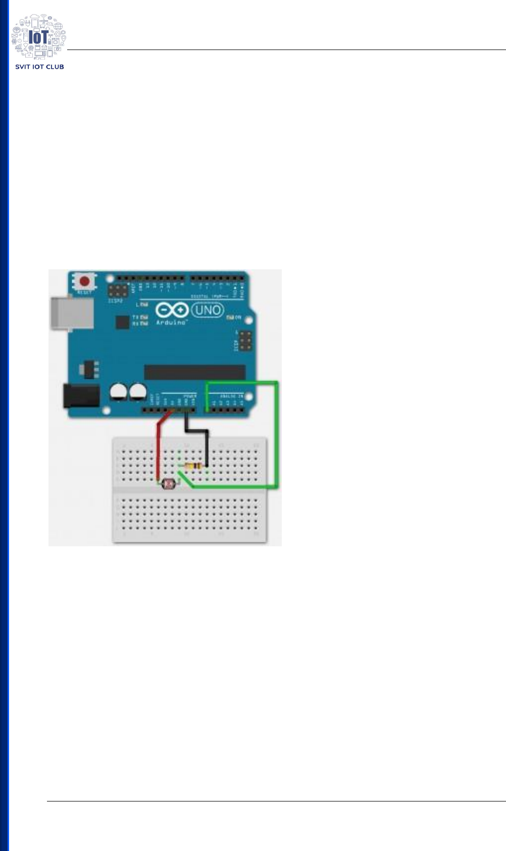
Experiment 5:
Controlling LED using LDR
Components Required:
• Arduino Uno
• Breadboard
• Wires
• 100K ohm resistor
• LDR (Photoresistor)
Circuit Sketch:
Source Code:
#include <SoftwareSerial.h>
int sensorPin = A0; // select the input pin for the LDR
int sensorValue = 0; // variable to store the value coming from the sensor
int led = 13;
void setup() { // declare the ledPin as an OUTPUT:
pinMode(led, OUTPUT);
Serial.begin(9600);
}

IoT Workshop
SVIT IoT Club P a g e | 14
void loop()
{
sensorValue = analogRead(sensorPin);
Serial.println(sensorValue);
if (sensorValue < 100)
{
Serial.println("LED light on");
digitalWrite(led,HIGH);
delay(1000);
}
digitalWrite(led,LOW);
delay(sensorValue);
}
IoT Workshop
SVIT IoT Club P a g e | 15
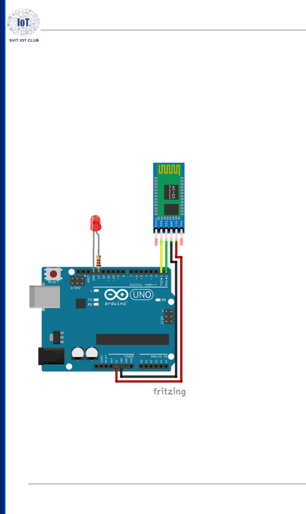
Experiment 6:
Controlling LED using Bluetooth from Android Phone
Components Required:
• Arduino Uno
• HC-05 Bluetooth module
• Jumper wires
• 220 Ohm Resistor
• LED
Circuit Sketch:
Source Code:
#include <SoftwareSerial.h> // To define software Serial
int LD_1=13; //Intialize pin D8 for LED (LD1)
int incoming=0; //Initialize incoming data to 0
SoftwareSerial svit(3, 2);//Set software serial(RX,TX) pins

IoT Workshop
SVIT IoT Club P a g e | 16
void setup()
{
pinMode(LD_1,OUTPUT); //To configure LED a output pin
Serial.begin(9600); // Baud rate for serial communication
svit.begin(9600); /*Baud rate for software serial communication*/
}
void loop()
{
if (svit.available()>0) /*check if any incoming data from software serial pins */
{
incoming=svit.read();/*read if any incoming data from software serial pins */
svit.println(incoming);/*print incoming data in serial monitor*/
if(incoming=='1') // check if incoming number is digit 1
{
digitalWrite(LD_1,HIGH); // set LED as high
}
if(incoming=='2') // check if incoming number is digit 2
{
digitalWrite(LD_1,LOW); // set LED as low
}
}
}
IoT Workshop
SVIT IoT Club P a g e | 17
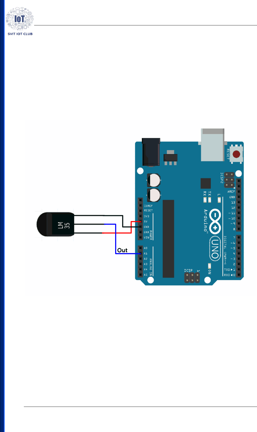
Experiment 7:
Temperature Measurement using LM35
Components Required:
• Arduino Uno
• Jumper Wires
• LM35 Temperature sensor
Circuit Sketch:
Source Code:
int val;
int tempPin = A1;
void setup()
{
Serial.begin(9600);
}
void loop()

IoT Workshop
SVIT IoT Club P a g e | 18
{
val = analogRead(tempPin);
float mv = val*4.833;
float cel = mv/10;
float farh = (cel*9)/5 + 32;
Serial.print("TEMPRATURE = ");
Serial.print(cel);
Serial.print("*C");
Serial.println();
delay(1000);
Serial.print("TEMPRATURE = ");
Serial.print(farh);
Serial.print("*F");
Serial.println();
}

IoT Workshop
SVIT IoT Club P a g e | 19
Experiment 8:
LED Blinking using NodeMCU
Components Required:
NodeMCU
Source Code:
#define LED D0 // Led in NodeMCU at pin GPIO16 (D0).
void setup() {
pinMode(LED, OUTPUT); // LED pin as output.
}
void loop() {
digitalWrite(LED, HIGH);// turn the LED off.(Note that LOW is the voltage level but
actually
//the LED is on; this is because it is acive low on the ESP8266.
delay(1000); // wait for 1 second.
digitalWrite(LED, LOW); // turn the LED on.
delay(1000); // wait for 1 second.
}
IoT Workshop
SVIT IoT Club P a g e | 20
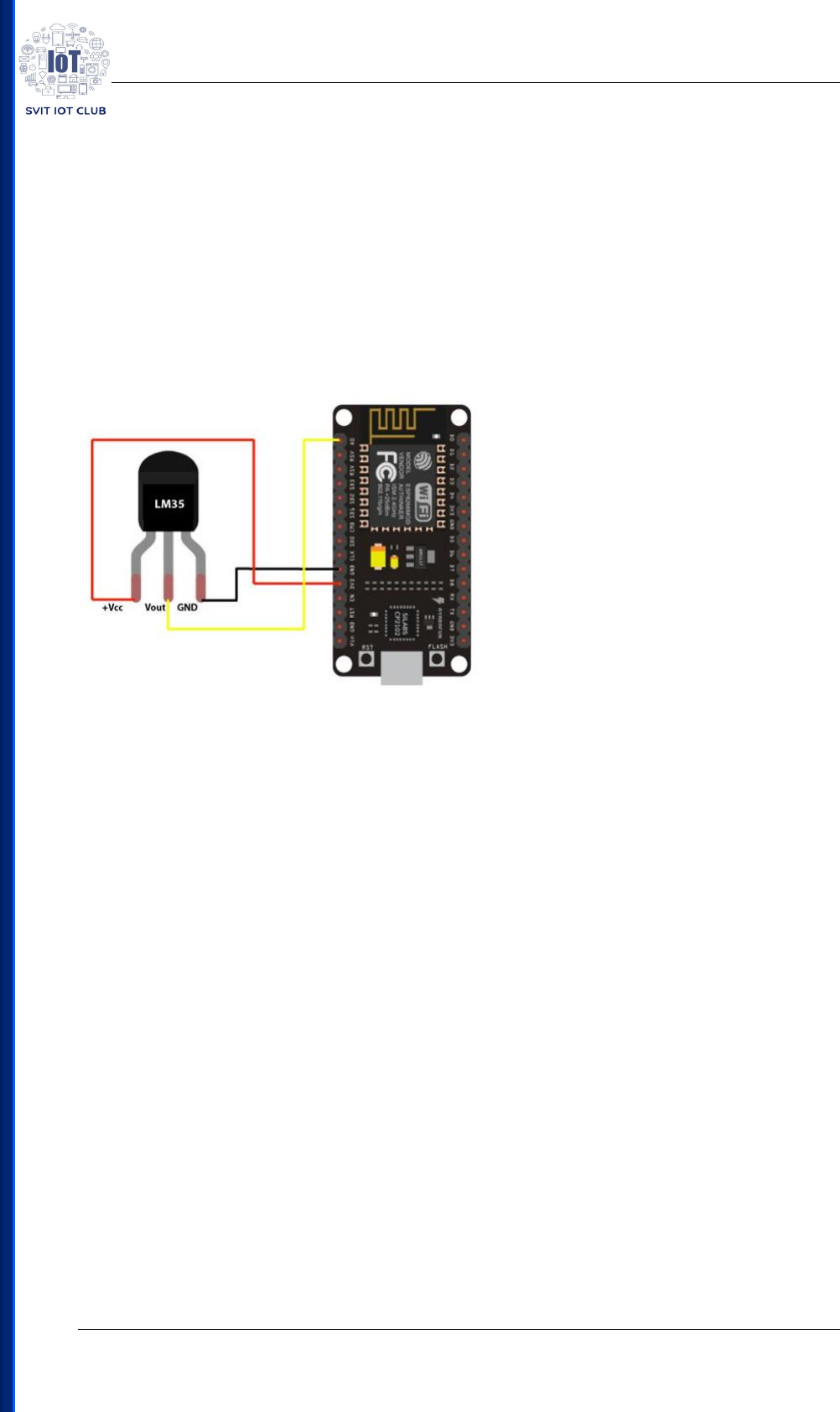
Experiment 9:
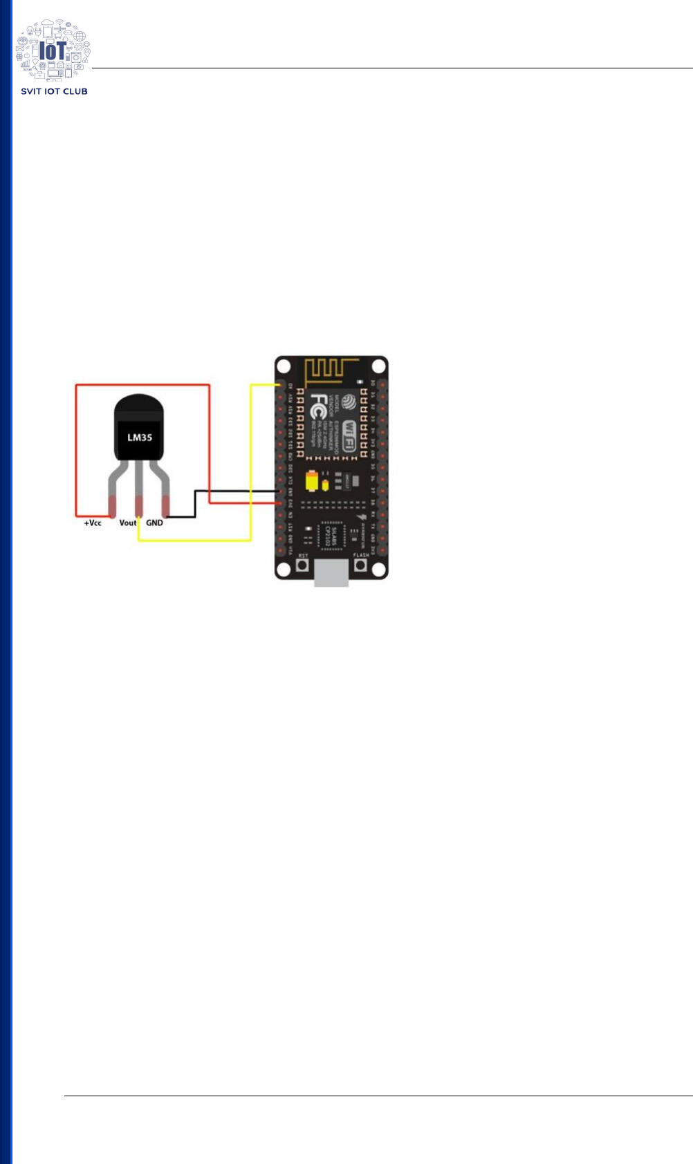
Temperature Sensing using NodeMCU
Components Required:
• NodeMCU
• LM35 Temperature Sensor
• Jumper Wires
Circuit Sketch:
Source Code:
// initializes or defines the output pin of the LM35 temperature sensor
int outputpin= A0;
//this sets the ground pin to LOW and the input voltage pin to high
void setup() {
Serial.begin(9600);
}
void loop() //main loop
{
int analogValue = analogRead(outputpin);
float millivolts = (analogValue/1024.0) * 3300; //3300 is the voltage provided by NodeMCU
float celsius = millivolts/10;
Serial.print("in DegreeC= ");

IoT Workshop
SVIT IoT Club P a g e | 21
Serial.println(celsius);
//---------- Here is the calculation for Fahrenheit ----------//
float fahrenheit = ((celsius * 9)/5 + 32);
Serial.print(" in Farenheit= ");
Serial.println(fahrenheit);
delay(1000);
}

IoT Workshop
SVIT IoT Club P a g e | 22
Experiment 10:
Controlling LED using Firebase
Components Required:
• NodeMCU
• DB creation using Firebase
Source Code:
#include <ESP8266WiFi.h>
#include <FirebaseArduino.h>
// Set these to run example.
#define FIREBASE_HOST "iot-workshop-85c3b.firebaseio.com"
#define FIREBASE_AUTH "qsE4HGf4VU26TJ3HmrjSjLVXdyD0VJrfbDU9fe0Q"
#define WIFI_SSID "AndroidAP"
#define WIFI_PASSWORD "abhi1234"
void setup() {
Serial.begin(9600);
// connect to wifi.
WiFi.begin(WIFI_SSID, WIFI_PASSWORD);
Serial.print("connecting");
while (WiFi.status() != WL_CONNECTED) {
Serial.print(".");
delay(500);
}
Serial.println();
Serial.print("connected: ");
Serial.println(WiFi.localIP());
Firebase.begin(FIREBASE_HOST, FIREBASE_AUTH);
pinMode(D0,OUTPUT);
}

IoT Workshop
SVIT IoT Club P a g e | 23
int n = 0;
void loop() {
int b = Firebase.getInt("Led");
if(b == 1)
{
digitalWrite(D0, HIGH);
}
else
{
digitalWrite(D0, LOW);
}
delay(1000);
}
IoT Workshop
SVIT IoT Club P a g e | 24
Experiment 11:
Sending Temperature to Firebase
Components Required:
• NodeMCU
• LM35 Temperature Sensor
• Jumper Wires
• DB in Firebase
Circuit Sketch:
Source Code:
#include <ESP8266WiFi.h>
#include <FirebaseArduino.h>
// Set these to run example.
#define FIREBASE_HOST "iot-workshop-85c3b.firebaseio.com"
#define FIREBASE_AUTH "qsE4HGf4VU26TJ3HmrjSjLVXdyD0VJrfbDU9fe0Q"
#define WIFI_SSID "AndroidAP"
#define WIFI_PASSWORD "abhi1234"
void setup() {
Serial.begin(9600);

IoT Workshop
SVIT IoT Club P a g e | 25
// connect to wifi.
WiFi.begin(WIFI_SSID, WIFI_PASSWORD);
Serial.print("connecting");
while (WiFi.status() != WL_CONNECTED) {
Serial.print(".");
delay(500);
}
Serial.println();
Serial.print("connected: ");
Serial.println(WiFi.localIP());
Firebase.begin(FIREBASE_HOST, FIREBASE_AUTH);
}
int n = 0;
void loop() {
int a = analogRead(A0);
float mv= a*2.932;
float cel = mv/10;
Serial.print("Tempearature:");
Serial.println(cel);
Firebase.setFloat("Temperature",cel);
delay(1000);
}
IoT Workshop
SVIT IoT Club P a g e | 26
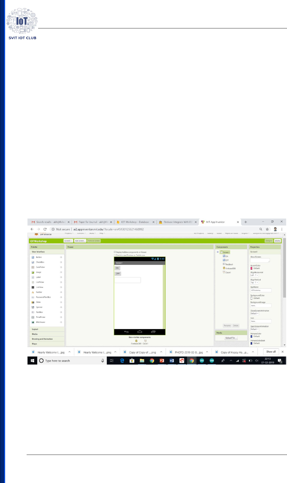
Experiment 12 & 13:
Demonstration of LED and Temperature Sensor through
Firebase and Android App created using MIT App Inventor2
Components Required:
• NodeMCU
• LM35 Temperature Sensor
• Jumper Wires
• DB in Firebase
• Android Phone
Circuit Sketch:
Same as Experiment 10 and 11
Source Code:
Same as Experiment 10 and 11

IoT Workshop
SVIT IoT Club P a g e | 27

IoT Workshop
SVIT IoT Club P a g e | 28
Experiment 14:
LED Control using Google Assistant
Components Required:
• NodeMCU
• DB in Adafruit
• Android Phone with Google Assistant, IFTTT
Circuit Sketch:
Same as Experiment 10 and 11
Source Code:
#include <ESP8266WiFi.h>
#include "Adafruit_MQTT.h"
#include "Adafruit_MQTT_Client.h"
#define WIFI_SSID "HTC Portable Hotspot"
#define WIFI_PASS "f22298aeca91"
#define MQTT_SERV "io.adafruit.com"
#define MQTT_PORT 1883
#define MQTT_NAME "abhijithhv"
#define MQTT_PASS "6c0f0ecd1735413aaf4ec5c04a489e12"
//Set up MQTT and WiFi clients
WiFiClient client;
Adafruit_MQTT_Client mqtt(&client, MQTT_SERV, MQTT_PORT, MQTT_NAME,
MQTT_PASS);
//Set up the feed you're subscribing to
Adafruit_MQTT_Subscribe onoff = Adafruit_MQTT_Subscribe(&mqtt, MQTT_NAME
"/f/Led");

IoT Workshop
SVIT IoT Club P a g e | 29
void setup()
{
Serial.begin(9600);
//Connect to WiFi
Serial.print("\n\nConnecting Wifi... ");
WiFi.begin(WIFI_SSID, WIFI_PASS);
while (WiFi.status() != WL_CONNECTED)
{
delay(500);
}
Serial.println("OK!");
//Subscribe to the onoff feed
mqtt.subscribe(&onoff);
pinMode(D0, OUTPUT);
digitalWrite(D0, HIGH);
}
void loop()
{
MQTT_connect();
//Read from our subscription queue until we run out, or
//wait up to 5 seconds for subscription to update
Adafruit_MQTT_Subscribe * subscription;
while ((subscription = mqtt.readSubscription(5000)))

IoT Workshop
SVIT IoT Club P a g e | 30
{
//If we're in here, a subscription updated...
if (subscription == &onoff)
{
//Print the new value to the serial monitor
Serial.print("onoff: ");
Serial.println((char*) onoff.lastread);
//If the new value is "ON", turn the light on.
//Otherwise, turn it off.
if (!strcmp((char*) onoff.lastread, "1"))
{
//Active low logic
digitalWrite(D0, LOW);
}
else
{
digitalWrite(D0, HIGH);
}
}
}
// ping the server to keep the mqtt connection alive
if (!mqtt.ping())
{
mqtt.disconnect();
}
}

IoT Workshop
SVIT IoT Club P a g e | 31
/***************************************************
Adafruit MQTT Library ESP8266 Example
Must use ESP8266 Arduino from:
https://github.com/esp8266/Arduino
Works great with Adafruit's Huzzah ESP board & Feather
----> https://www.adafruit.com/product/2471
----> https://www.adafruit.com/products/2821
Adafruit invests time and resources providing this open source code,
please support Adafruit and open-source hardware by purchasing
products from Adafruit!
Written by Tony DiCola for Adafruit Industries.
MIT license, all text above must be included in any redistribution
****************************************************/
void MQTT_connect()
{
int8_t ret;
// Stop if already connected.
if (mqtt.connected())
{
return;
}
Serial.print("Connecting to MQTT... ");

IoT Workshop
SVIT IoT Club P a g e | 32
uint8_t retries = 3;
while ((ret = mqtt.connect()) != 0) // connect will return 0 for connected
{
Serial.println(mqtt.connectErrorString(ret));
Serial.println("Retrying MQTT connection in 5 seconds...");
mqtt.disconnect();
delay(5000); // wait 5 seconds
retries--;
if (retries == 0)
{
// basically die and wait for WDT to reset me
while (1);
}
}
Serial.println("MQTT Connected!");
}
