JDY 40 English Manual
JDY-40_English_manual
User Manual:
Open the PDF directly: View PDF ![]() .
.
Page Count: 8
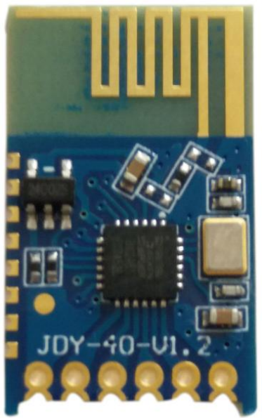
JDY-40 wireless serial port module
Brief function introduction
JDY-40 is developed by 2.4G technology, with a distance of 120 meters. It uses serial
communication interface, which is simple and quick to use. You can apply JDY-40 to
products only needs to know the knowledge of serial port.
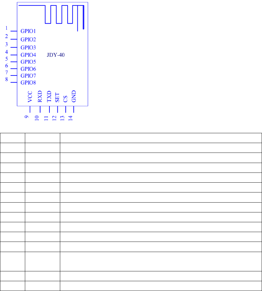
JDY-40 pin definition
Pin function description
Pin
Pin Names
Function
1
GPIO1
Input/output IO, which can be configured by AT+CLSS
2
GPIO2
Input/output IO, which can be configured by AT+CLSS
3
GPIO3
Input/output IO, which can be configured by AT+CLSS
4
GPIO4
Input/output IO, which can be configured by AT+CLSS
5
GPIO5
Input/output IO, which can be configured by AT+CLSS
6
GPIO6
Input/output IO, which can be configured by AT+CLSS
7
GPIO7
Input/output IO, which can be configured by AT+CLSS
8
GPIO8
Input/output IO, which can be configured by AT+CLSS
9
VCC
Power Supply(2.2V–3.6V)
10
RXD
Serial port input pin
11
TXD
Serial port output pin
12
SET
AT command switching pin (low level AT instruction, high level
transparent transmission)
13
CS
CS chip select pin (low level of awaken, high level of sleep)
14
GND
Power Ground
Application scene
1:2.4G panel switch
2:2.4G remote controller
3:2.4G transparent transmission
4:Mobile phone one-to-many control
5:IO switching control
6:2.4Gtoys
7:Application of intelligent home control
Technical parameter
Model
JDY-40
Operating frequency range
2.4G
Transmit power
MAX 12db
Working temperature
-40℃ - 80℃
Reception sensitivity
-97db
Transmission distance
120meters
TX current
40mA
RX current
24mA
Sleep current
5uA
Communication interface
Standard TTL serial port
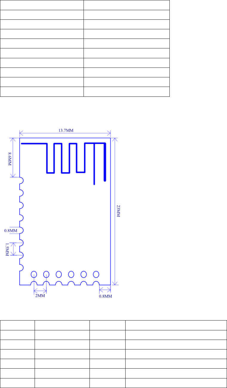
Dimensional drawing
Default configuration
Sequence
Function
Parameter
instructions
1
Baud rate
9600
AT+BAUD
2
Wireless ID
8899
AT+RFID8899
3
Device ID
1122
AT+DVID1122
4
Channel
001
AT+RFC001
5
Transmit power
12db
AT+POWE9
6
Device type
A0
AT+CLSSA0

AT instruction set
Sequence
instructions
Effect
Default
1
AT+BAUD
Baud rate
9600
2
AT+RFID
Wireless ID
8899
3
AT+DVID
Device ID
1122
4
AT+RFC
Channel(128 Channels)
001
5
AT+POWE
Transmit power
+10db
6
AT+CLSS
Type
A0
AT instruction instructions
In particular, the JDY-40 module sends the AT instruction need to end the symbol \r\n
Setting / query - baud rate
Instruction
Response
Parameter
AT+BAUD<Param>
OK
Param(1-7)
1:1200
2:2400
3:4800
4:9600
5:14400
6:19200
Default Value: 4
AT+BAUD
+BAUD=<Param>
RFID Setting / query - RFID
Instruction
Response
Parameter
AT+RFID<Param>
OK
Param(0000-FFFF)
Default Value:8899
AT+RFID
+BAUD=<Param>
Setting / query - DVID
Instruction
Response
Parameter
AT+DVID<Param>
OK
Param(0000-FFFF)
Default Value:8899
AT+DVID
+BAUD=<Param>
RFC Setting / query - RFC
Instruction
Response
Parameter
AT+RFC<Param>
OK
Param(001-128)
Default Value:001
AT+RFC
+RFC=<Param>

POWE Setting / query - POWE
Instruction
Response
Parameter
AT+POWE<Param>
OK
Param(0-9)
0:-25db
1:-15db
2:-5db
3:0db
4:+3db
5:+6db
6:+9db
7:+10db
8:+10db
9:+12db
AT+POWE
+POWE=<Param>
Setting / query – CLSS type
Instruction
Response
Parameter
AT+CLSS<Param>
OK
Param
A0: Serial port transparent
transmission(Transceiver)
C0: Remote controller or IO key
indicator light(Transmitting terminal)
C1: remote controller or IO key
without indicator light (Transmitting
terminal)
C2:IO is low level at normal level,
high level after receiving signal and
low level after delay 30mS
C3:IO is high level at normal level,
low level after receiving signal and
high level after delay 30mS
C4:IO is low level at normal level,
receives pressed signal of high level
and receives lift signal low level
C5: The IO level is reversed when
IO receives the pressed signal.
Default Value:A0
AT+CLSS
+CLSS=<Param>
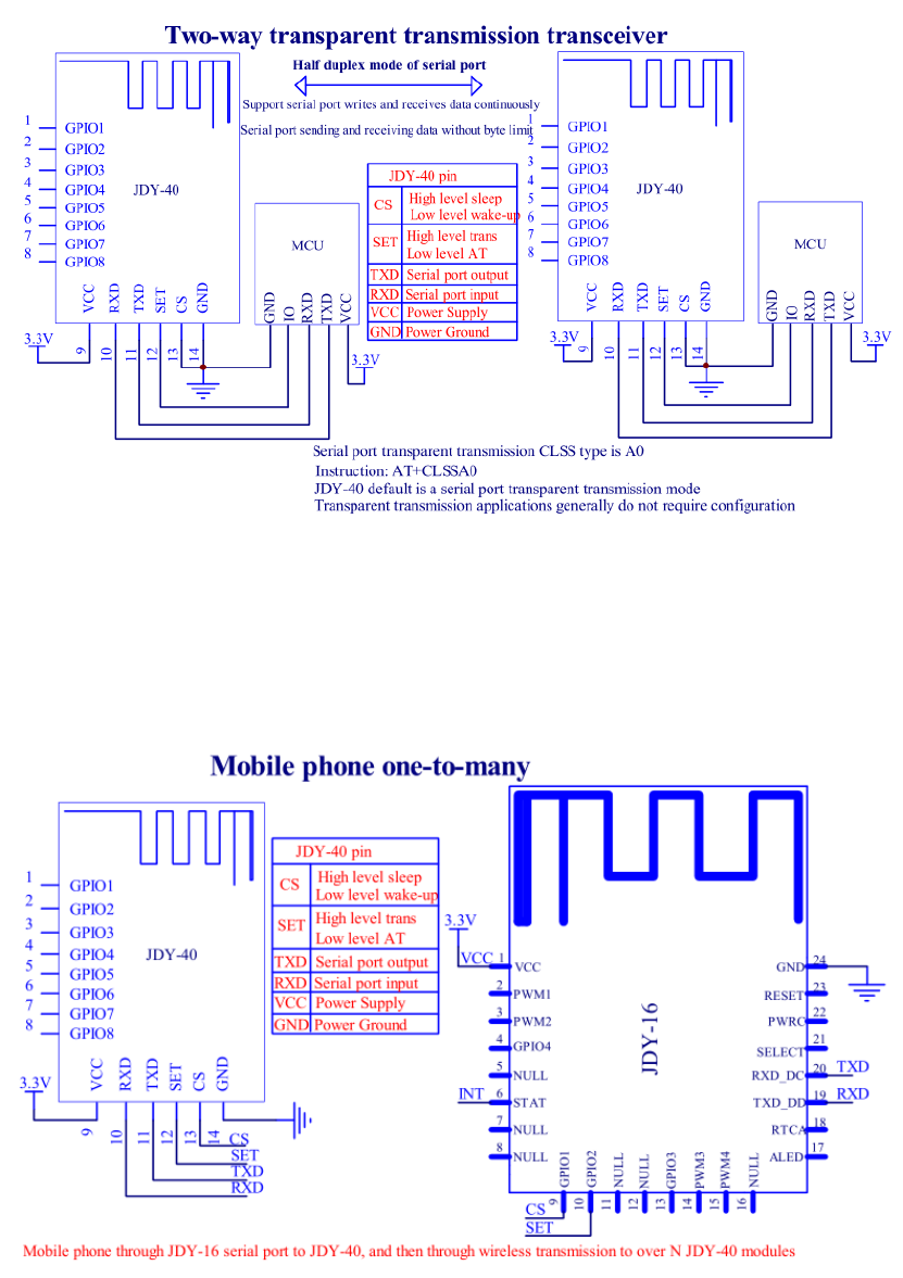
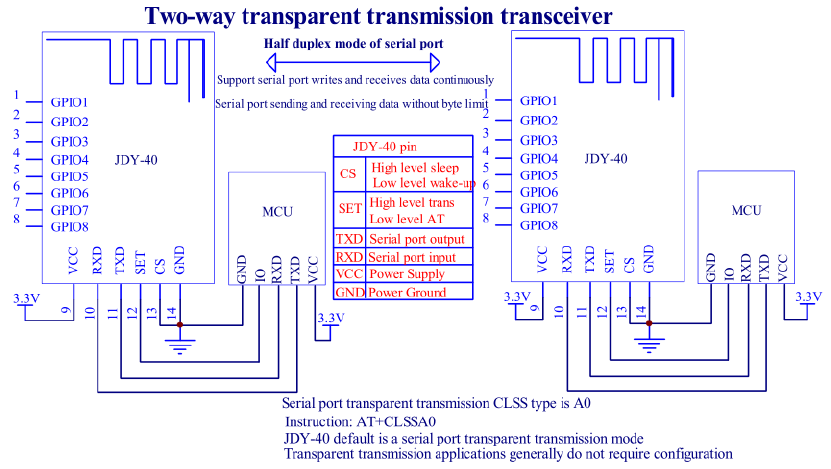
JDY-40 application wiring diagram
Serial port transparent transmission application circuit diagram
It can be applied to MCU and MCU wireless serial port transparent transmission,
instrument and electronic toys.
Mobile phone one-to-many control
It can be applied to mobile phone one-to-many control, mobile phone one-to-many
transparent transmission, mobile phone one-to-many application of intelligent
furniture control.
Switching control 1

It can be applied to: the 2.4G remote controller with 8 IO can be applied to the remote
control key and support the low function, two 7th batteries can be used for at least one
year, application of low power consumption switch panel in intelligent home, and 2.4G toy
application.
Switching control 2
It can be applied to: the 2.4G remote controller with 7 IO can be applied to the remote
control key and support the low function, two 7th batteries can be used for at least one
year, application of low power consumption switch panel in intelligent home, and 2.4G toy
application.
Switching control 3
It can be applied to: the 2.4G remote controller with 8 IO can be applied to the remote
control key and support the low function, two 7th batteries can be used for at least one
year, application of low power consumption switch panel in intelligent home, and 2.4G toy
application.
