1298 JLG 600 Service Manual
User Manual: JLG 600 Service Manual
Open the PDF directly: View PDF ![]() .
.
Page Count: 328 [warning: Documents this large are best viewed by clicking the View PDF Link!]
- Section A. Introduction - Maintenance Safety Precautions
- Section 1. Specifications
- Section 2. General
- Section 3. Chassis & Turntable
- 3.1 Tires & Wheels
- 3.2 Torque Hub
- Oil Information
- Roll and Leak Testing
- Tightening and Torquing Bolts
- Main Disassembly
- Output Carrier Disassembly
- Input Carrier Disassembly
- Hub-Spindle Disassembly
- Spindle-Brake Disassembly
- Cover Disassembly
- Cover Assembly
- Input Carrier Assembly
- Spindle - Brake Assembly
- Hub-Spindle Assembly
- Output Planet Gear Assembly
- Main Assembly
- Integral Brake Check
- 3.3 Free Wheeling Option
- 3.4 Drive Motor
- 3.5 Oscillating Axle Bleed Procedure and Lockout Test
- 3.6 Steer Adjustments
- 3.7 Swing Drive
- 3.8 Swing Bearing
- 3.9 Rotary Coupling
- 3.10 Generator
- 3.11 Deutz D2.9 L4 Engine
- 3.12 Deutz D2011 Engine
- 3.13 Spark Arrester Cleaning Instructions
- 3.14 Glow Plugs
- 3.15 Deutz EMR 2
- 3.16 Bio Fuel in Deutz Engines
- 3.17 GM Engine General Maintenance
- 3.18 GM Engine Dual Fuel System
- Fuel Filter
- Direct Electronic Pressure Regulator (DEPR)
- Air Fuel Mixer
- Electronic Throttle Control (ETC)
- Electric Lock Off
- Engine Control Module (ECM)
- Heated Exhaust Gas Oxygen Sensor
- Gasoline Multi Point Fuel Injection System (MPFI)
- Gasoline Fuel Pump
- Gasoline Pressure And Temperature Sensor Manifold
- Fuel Filter
- Fuel Injector Rail
- Fuel Injector
- 3.19 GM Engine Fuel System Repair
- Propane Fuel System Pressure Relief
- Propane Fuel System Leak Test
- Propane Fuel Filter Replacement
- Direct Electronic Pressure Regulator (DEPR) Maintenance And Inspection
- Check/Drain Oil Build-Up In 2-Stage Vaporizer
- Air Fuel Mixer/Throttle Control Device Maintenance And Inspection
- Exhaust System And Catalytic Converter Inspection And Maintenance
- Temperature Manifold Absolute Pressure (TMAP) Sensor
- Throttle Body (ETC) Replacement
- Mixer Replacement
- Electronic Pressure Regulator (EPR) Replacement
- Regulator Replacement
- Coolant Hose Replacement
- Vapor Hose Replacement
- Engine Control Module Replacement
- Heated Exhaust Gas Oxygen Sensor Replacement
- 3.20 GM Engine LPG Fuel System Diagnosis
- Section 4. Boom & Platform
- 4.1 Boom Systems
- 4.2 Wear Pads
- 4.3 Boom Disassembly/Assembly & Cable Replacement
- 4.4 Wire Rope
- 4.5 Wire Rope Tensioning Adjustment
- 4.6 Articulating Jib Boom
- 4.7 Limit Switches and Cam Valve Adjustment
- 4.8 Boom Cleanliness Guidelines
- 4.9 Rotary Actuator
- 4.10 Foot Switch Adjustment
- 4.11 Platform
- 4.12 Powertrack Maintenance
- Section 5. Hydraulics
- 5.1 O-Ring Lubrication
- 5.2 Cylinders - Theory of Operation
- 5.3 Cylinder Checking Procedure
- 5.4 Cylinder Removal and Installation
- 5.5 Cylinder Repair
- Disassembly
- Cylinder Locations
- Main Lift Cylinder
- Cleaning and Inspection
- Assembly
- Master Cylinder
- Cleaning and Inspection
- Assembly
- Telescope Cylinder
- Cleaning and Inspection
- Assembly
- Platform Level (Slave) Cylinder
- Cleaning and Inspection
- Assembly
- Jib Lift Cylinder (SJ Only)
- Cleaning and Inspection
- Assembly
- Steer Cylinder
- Cleaning and Inspection
- Assembly
- Axle Lockout Cylinder
- 5.6 Hydraulic Pump (Gear)
- 5.7 Variable Pump
- 5.8 Hydraulic Component Start-Up
- 5.9 Pressure Setting Procedures
- Section 6. JLG Control System
- Section 7. Basic Electrical Information & Schematics
Service and Maintenance Manual
Model
600S
660SJ
S/N 0300171769
to Present
P/N - 3121298
February 26, 2014
INTRODUCTION
3121298 – JLG Lift – A-1
SECTION A. INTRODUCTION - MAINTENANCE SAFETY PRECAUTIONS
A GENERAL
This section contains the general safety precautions which
must be observed during maintenance of the aerial platform.
It is of utmost importance that maintenance personnel pay
strict attention to these warnings and precautions to avoid
possible injury to themselves or others, or damage to the
equipment. A maintenance program must be followed to
ensure that the machine is safe to operate.
MODIFICATION OR ALTERATION OF AN AERIAL WORK PLATFORM SHALL BE
MADE ONLY WITH WRITTEN PERMISSION FROM THE MANUFACTURER.
The specific precautions to be observed during maintenance
are inserted at the appropriate point in the manual. These pre-
cautions are, for the most part, those that apply when servic-
ing hydraulic and larger machine component parts.
Your safety, and that of others, is the first consideration when
engaging in the maintenance of equipment. Always be con-
scious of weight. Never attempt to move heavy parts without
the aid of a mechanical device. Do not allow heavy objects to
rest in an unstable position. When raising a portion of the
equipment, ensure that adequate support is provided.
SINCE THE MACHINE MANUFACTURER HAS NO DIRECT CONTROL OVER THE
FIELD INSPECTION AND MAINTENANCE, SAFETY IN THIS AREA RESPONSIBIL-
ITY OF THE OWNER/OPERATOR.
BHYDRAULIC SYSTEM SAFETY
It should be noted that the machines hydraulic systems oper-
ate at extremely high potentially dangerous pressures. Every
effort should be made to relieve any system pressure prior to
disconnecting or removing any portion of the system.
C MAINTENANCE
FAILURE TO COMPLY WITH SAFETY PRECAUTIONS LISTED IN THIS SECTION
COULD RESULT IN MACHINE DAMAGE, PERSONNEL INJURY OR DEATH AND IS A
SAFETY VIOLATION.
• ENSURE REPLACEMENT PARTS OR COMPONENTS ARE
IDENTICAL OR EQUIVALENT TO ORIGINAL PARTS OR
COMPONENTS.
• NO SMOKING IS MANDATORY. NEVER REFUEL DURING ELEC-
TRICAL STORMS. ENSURE THAT FUEL CAP IS CLOSED AND
SECURE AT ALL OTHER TIMES.
• REMOVE ALL RINGS, WATCHES AND JEWELRY WHEN PER-
FORMING ANY MAINTENANCE.
• DO NOT WEAR LONG HAIR UNRESTRAINED, OR LOOSE-FIT-
TING CLOTHING AND NECKTIES WHICH ARE APT TO BECOME
CAUGHT ON OR ENTANGLED IN EQUIPMENT.
• OBSERVE AND OBEY ALL WARNINGS AND CAUTIONS ON
MACHINE AND IN SERVICE MANUAL.
• KEEP OIL, GREASE, WATER, ETC. WIPED FROM STANDING
SURFACES AND HAND HOLDS.
• USE CAUTION WHEN CHECKING A HOT, PRESSURIZED COOL-
ANT SYSTEM.
• NEVER WORK UNDER AN ELEVATED BOOM UNTIL BOOM HAS
BEEN SAFELY RESTRAINED FROM ANY MOVEMENT BY
BLOCKING OR OVERHEAD SLING, OR BOOM SAFETY PROP
HAS BEEN ENGAGED.
• BEFORE MAKING ADJUSTMENTS, LUBRICATING OR PER-
FORMING ANY OTHER MAINTENANCE, SHUT OFF ALL
POWER CONTROLS.
• BATTERY SHOULD ALWAYS BE DISCONNECTEDDURING
REPLACEMENT OF ELECTRICAL COMPONENTS.
• KEEP ALL SUPPORT EQUIPMENT AND ATTACHMENTS
STOWED IN THEIR PROPER PLACE.
• USE ONLY APPROVED, NONFLAMMABLE CLEANING SOL-
VENTS.

INTRODUCTION
A-2 – JLG Lift – 3121298
REVISON LOG
Original Issue - August 7, 2013
Revised - October 10, 2013
Revised - November 25, 2013
Revised - February 26, 2014

3121298 – JLG Lift – i
TABLE OF CONTENTS
SECTION NO. TITLE PAGE NO.
SECTION A - INTRODUCTION - MAINTENANCE SAFETY PRECAUTIONS
A General . . . . . . . . . . . . . . . . . . . . . . . . . . . . . . . . . . . . . . . . . . . . . . . . . . . . . . . . . . . . . . . . . . . . . . . . . . . . . . . . . . . . . . . . . . . . A-1
B Hydraulic System Safety . . . . . . . . . . . . . . . . . . . . . . . . . . . . . . . . . . . . . . . . . . . . . . . . . . . . . . . . . . . . . . . . . . . . . . . . . . . . A-1
C Maintenance. . . . . . . . . . . . . . . . . . . . . . . . . . . . . . . . . . . . . . . . . . . . . . . . . . . . . . . . . . . . . . . . . . . . . . . . . . . . . . . . . . . . . . . A-1
SECTION 1 - SPECIFICATIONS
1.1 Operating Specifications . . . . . . . . . . . . . . . . . . . . . . . . . . . . . . . . . . . . . . . . . . . . . . . . . . . . . . . . . . . . . . . . . . . . . . . . . . . 1-1
1.2 Dimensional Data . . . . . . . . . . . . . . . . . . . . . . . . . . . . . . . . . . . . . . . . . . . . . . . . . . . . . . . . . . . . . . . . . . . . . . . . . . . . . . . . . . 1-1
1.3 Capacities . . . . . . . . . . . . . . . . . . . . . . . . . . . . . . . . . . . . . . . . . . . . . . . . . . . . . . . . . . . . . . . . . . . . . . . . . . . . . . . . . . . . . . . . . 1-2
1.4 Tires . . . . . . . . . . . . . . . . . . . . . . . . . . . . . . . . . . . . . . . . . . . . . . . . . . . . . . . . . . . . . . . . . . . . . . . . . . . . . . . . . . . . . . . . . . . . . . . 1-2
1.5 Engine Data. . . . . . . . . . . . . . . . . . . . . . . . . . . . . . . . . . . . . . . . . . . . . . . . . . . . . . . . . . . . . . . . . . . . . . . . . . . . . . . . . . . . . . . . 1-2
1.6 Function Speeds . . . . . . . . . . . . . . . . . . . . . . . . . . . . . . . . . . . . . . . . . . . . . . . . . . . . . . . . . . . . . . . . . . . . . . . . . . . . . . . . . . . 1-3
Machine Orientation When Doing Speed Tests . . . . . . . . . . . . . . . . . . . . . . . . . . . . . . . . . . . . . . . . . . . . . . . . . 1-3
Test Notes . . . . . . . . . . . . . . . . . . . . . . . . . . . . . . . . . . . . . . . . . . . . . . . . . . . . . . . . . . . . . . . . . . . . . . . . . . . . . . . . . . . . 1-3
1.7 Torque Requirements . . . . . . . . . . . . . . . . . . . . . . . . . . . . . . . . . . . . . . . . . . . . . . . . . . . . . . . . . . . . . . . . . . . . . . . . . . . . . . 1-3
1.8 Hydraulic Oil . . . . . . . . . . . . . . . . . . . . . . . . . . . . . . . . . . . . . . . . . . . . . . . . . . . . . . . . . . . . . . . . . . . . . . . . . . . . . . . . . . . . . . . 1-4
1.9 Major Component Weights. . . . . . . . . . . . . . . . . . . . . . . . . . . . . . . . . . . . . . . . . . . . . . . . . . . . . . . . . . . . . . . . . . . . . . . . . 1-5
1.10 Operator Maintenance . . . . . . . . . . . . . . . . . . . . . . . . . . . . . . . . . . . . . . . . . . . . . . . . . . . . . . . . . . . . . . . . . . . . . . . . . . . . . 1-6
SECTION 2 - GENERAL
2.1 Machine Preparation, Inspection, and Maintenance . . . . . . . . . . . . . . . . . . . . . . . . . . . . . . . . . . . . . . . . . . . . . . . . . 2-1
General . . . . . . . . . . . . . . . . . . . . . . . . . . . . . . . . . . . . . . . . . . . . . . . . . . . . . . . . . . . . . . . . . . . . . . . . . . . . . . . . . . . . . . . 2-1
Preparation, Inspection, and Maintenance . . . . . . . . . . . . . . . . . . . . . . . . . . . . . . . . . . . . . . . . . . . . . . . . . . . . . 2-1
Pre-Start Inspection . . . . . . . . . . . . . . . . . . . . . . . . . . . . . . . . . . . . . . . . . . . . . . . . . . . . . . . . . . . . . . . . . . . . . . . . . . . 2-1
Pre-Delivery Inspection and Frequent Inspection. . . . . . . . . . . . . . . . . . . . . . . . . . . . . . . . . . . . . . . . . . . . . . . 2-1
Annual Machine Inspection. . . . . . . . . . . . . . . . . . . . . . . . . . . . . . . . . . . . . . . . . . . . . . . . . . . . . . . . . . . . . . . . . . . . 2-1
Preventive Maintenance. . . . . . . . . . . . . . . . . . . . . . . . . . . . . . . . . . . . . . . . . . . . . . . . . . . . . . . . . . . . . . . . . . . . . . . 2-1
2.2 Service and Guidelines . . . . . . . . . . . . . . . . . . . . . . . . . . . . . . . . . . . . . . . . . . . . . . . . . . . . . . . . . . . . . . . . . . . . . . . . . . . . . 2-2
General . . . . . . . . . . . . . . . . . . . . . . . . . . . . . . . . . . . . . . . . . . . . . . . . . . . . . . . . . . . . . . . . . . . . . . . . . . . . . . . . . . . . . . . 2-2
Safety and Workmanship . . . . . . . . . . . . . . . . . . . . . . . . . . . . . . . . . . . . . . . . . . . . . . . . . . . . . . . . . . . . . . . . . . . . . . 2-2
Cleanliness. . . . . . . . . . . . . . . . . . . . . . . . . . . . . . . . . . . . . . . . . . . . . . . . . . . . . . . . . . . . . . . . . . . . . . . . . . . . . . . . . . . . 2-2
Components Removal and Installation. . . . . . . . . . . . . . . . . . . . . . . . . . . . . . . . . . . . . . . . . . . . . . . . . . . . . . . . . 2-2
Component Disassembly and Reassembly . . . . . . . . . . . . . . . . . . . . . . . . . . . . . . . . . . . . . . . . . . . . . . . . . . . . . 2-3
Pressure-Fit Parts. . . . . . . . . . . . . . . . . . . . . . . . . . . . . . . . . . . . . . . . . . . . . . . . . . . . . . . . . . . . . . . . . . . . . . . . . . . . . . 2-3
Bearings . . . . . . . . . . . . . . . . . . . . . . . . . . . . . . . . . . . . . . . . . . . . . . . . . . . . . . . . . . . . . . . . . . . . . . . . . . . . . . . . . . . . . . 2-3
Gaskets . . . . . . . . . . . . . . . . . . . . . . . . . . . . . . . . . . . . . . . . . . . . . . . . . . . . . . . . . . . . . . . . . . . . . . . . . . . . . . . . . . . . . . . 2-3
Bolt Usage and Torque Application . . . . . . . . . . . . . . . . . . . . . . . . . . . . . . . . . . . . . . . . . . . . . . . . . . . . . . . . . . . . 2-3
Hydraulic Lines and Electrical Wiring. . . . . . . . . . . . . . . . . . . . . . . . . . . . . . . . . . . . . . . . . . . . . . . . . . . . . . . . . . . 2-3
Hydraulic System. . . . . . . . . . . . . . . . . . . . . . . . . . . . . . . . . . . . . . . . . . . . . . . . . . . . . . . . . . . . . . . . . . . . . . . . . . . . . . 2-3
Lubrication . . . . . . . . . . . . . . . . . . . . . . . . . . . . . . . . . . . . . . . . . . . . . . . . . . . . . . . . . . . . . . . . . . . . . . . . . . . . . . . . . . . 2-3
Battery. . . . . . . . . . . . . . . . . . . . . . . . . . . . . . . . . . . . . . . . . . . . . . . . . . . . . . . . . . . . . . . . . . . . . . . . . . . . . . . . . . . . . . . . 2-3
Lubrication and Servicing . . . . . . . . . . . . . . . . . . . . . . . . . . . . . . . . . . . . . . . . . . . . . . . . . . . . . . . . . . . . . . . . . . . . . 2-3
2.3 Lubrication and Information. . . . . . . . . . . . . . . . . . . . . . . . . . . . . . . . . . . . . . . . . . . . . . . . . . . . . . . . . . . . . . . . . . . . . . . . 2-4
Hydraulic System. . . . . . . . . . . . . . . . . . . . . . . . . . . . . . . . . . . . . . . . . . . . . . . . . . . . . . . . . . . . . . . . . . . . . . . . . . . . . . 2-4
Hydraulic Oil . . . . . . . . . . . . . . . . . . . . . . . . . . . . . . . . . . . . . . . . . . . . . . . . . . . . . . . . . . . . . . . . . . . . . . . . . . . . . . . . . . 2-4
Changing Hydraulic Oil. . . . . . . . . . . . . . . . . . . . . . . . . . . . . . . . . . . . . . . . . . . . . . . . . . . . . . . . . . . . . . . . . . . . . . . . 2-4
Lubrication Specifications . . . . . . . . . . . . . . . . . . . . . . . . . . . . . . . . . . . . . . . . . . . . . . . . . . . . . . . . . . . . . . . . . . . . . 2-4
2.4 Cylinder Drift Test . . . . . . . . . . . . . . . . . . . . . . . . . . . . . . . . . . . . . . . . . . . . . . . . . . . . . . . . . . . . . . . . . . . . . . . . . . . . . . . . . . 2-4
Platform Drift . . . . . . . . . . . . . . . . . . . . . . . . . . . . . . . . . . . . . . . . . . . . . . . . . . . . . . . . . . . . . . . . . . . . . . . . . . . . . . . . . 2-4
Cylinder Drift. . . . . . . . . . . . . . . . . . . . . . . . . . . . . . . . . . . . . . . . . . . . . . . . . . . . . . . . . . . . . . . . . . . . . . . . . . . . . . . . . . 2-4
2.5 Pins and Composite Bearing Repair Guidelines . . . . . . . . . . . . . . . . . . . . . . . . . . . . . . . . . . . . . . . . . . . . . . . . . . . . . . 2-5
2.6 Welding on JLG Equipment. . . . . . . . . . . . . . . . . . . . . . . . . . . . . . . . . . . . . . . . . . . . . . . . . . . . . . . . . . . . . . . . . . . . . . . . . 2-5
Do the Following When Welding on JLG Equipment: . . . . . . . . . . . . . . . . . . . . . . . . . . . . . . . . . . . . . . . . . . . 2-5
Do NOT Do the Following When Welding on JLG Equipment: . . . . . . . . . . . . . . . . . . . . . . . . . . . . . . . . . . . 2-5

ii – JLG Lift – 3121298
TABLE OF CONTENTS
SECTION NO. TITLE PAGE NO.
SECTION 3 - CHASSIS & TURNTABLE
3.1 Tires & Wheels. . . . . . . . . . . . . . . . . . . . . . . . . . . . . . . . . . . . . . . . . . . . . . . . . . . . . . . . . . . . . . . . . . . . . . . . . . . . . . . . . . . . . . 3-1
Tire Inflation. . . . . . . . . . . . . . . . . . . . . . . . . . . . . . . . . . . . . . . . . . . . . . . . . . . . . . . . . . . . . . . . . . . . . . . . . . . . . . . . . . 3-1
Tire Damage . . . . . . . . . . . . . . . . . . . . . . . . . . . . . . . . . . . . . . . . . . . . . . . . . . . . . . . . . . . . . . . . . . . . . . . . . . . . . . . . . 3-1
Tire Replacement. . . . . . . . . . . . . . . . . . . . . . . . . . . . . . . . . . . . . . . . . . . . . . . . . . . . . . . . . . . . . . . . . . . . . . . . . . . . . 3-1
Wheel Replacement . . . . . . . . . . . . . . . . . . . . . . . . . . . . . . . . . . . . . . . . . . . . . . . . . . . . . . . . . . . . . . . . . . . . . . . . . . 3-1
Wheel Installation . . . . . . . . . . . . . . . . . . . . . . . . . . . . . . . . . . . . . . . . . . . . . . . . . . . . . . . . . . . . . . . . . . . . . . . . . . . . 3-1
3.2 Torque Hub . . . . . . . . . . . . . . . . . . . . . . . . . . . . . . . . . . . . . . . . . . . . . . . . . . . . . . . . . . . . . . . . . . . . . . . . . . . . . . . . . . . . . . . . 3-2
Oil Information . . . . . . . . . . . . . . . . . . . . . . . . . . . . . . . . . . . . . . . . . . . . . . . . . . . . . . . . . . . . . . . . . . . . . . . . . . . . . . . 3-2
Roll and Leak Testing . . . . . . . . . . . . . . . . . . . . . . . . . . . . . . . . . . . . . . . . . . . . . . . . . . . . . . . . . . . . . . . . . . . . . . . . . 3-2
Tightening and Torquing Bolts. . . . . . . . . . . . . . . . . . . . . . . . . . . . . . . . . . . . . . . . . . . . . . . . . . . . . . . . . . . . . . . . 3-2
Main Disassembly . . . . . . . . . . . . . . . . . . . . . . . . . . . . . . . . . . . . . . . . . . . . . . . . . . . . . . . . . . . . . . . . . . . . . . . . . . . . 3-4
Output Carrier Disassembly . . . . . . . . . . . . . . . . . . . . . . . . . . . . . . . . . . . . . . . . . . . . . . . . . . . . . . . . . . . . . . . . . . . 3-5
Input Carrier Disassembly. . . . . . . . . . . . . . . . . . . . . . . . . . . . . . . . . . . . . . . . . . . . . . . . . . . . . . . . . . . . . . . . . . . . . 3-5
Hub-Spindle Disassembly. . . . . . . . . . . . . . . . . . . . . . . . . . . . . . . . . . . . . . . . . . . . . . . . . . . . . . . . . . . . . . . . . . . . . 3-6
Spindle-Brake Disassembly . . . . . . . . . . . . . . . . . . . . . . . . . . . . . . . . . . . . . . . . . . . . . . . . . . . . . . . . . . . . . . . . . . . 3-7
Cover Disassembly . . . . . . . . . . . . . . . . . . . . . . . . . . . . . . . . . . . . . . . . . . . . . . . . . . . . . . . . . . . . . . . . . . . . . . . . . . . 3-8
Cover Assembly . . . . . . . . . . . . . . . . . . . . . . . . . . . . . . . . . . . . . . . . . . . . . . . . . . . . . . . . . . . . . . . . . . . . . . . . . . . . . . 3-8
Input Carrier Assembly . . . . . . . . . . . . . . . . . . . . . . . . . . . . . . . . . . . . . . . . . . . . . . . . . . . . . . . . . . . . . . . . . . . . . . . 3-9
Spindle - Brake Assembly . . . . . . . . . . . . . . . . . . . . . . . . . . . . . . . . . . . . . . . . . . . . . . . . . . . . . . . . . . . . . . . . . . . . . 3-10
Hub-Spindle Assembly . . . . . . . . . . . . . . . . . . . . . . . . . . . . . . . . . . . . . . . . . . . . . . . . . . . . . . . . . . . . . . . . . . . . . . . 3-11
Output Planet Gear Assembly. . . . . . . . . . . . . . . . . . . . . . . . . . . . . . . . . . . . . . . . . . . . . . . . . . . . . . . . . . . . . . . . . 3-12
Main Assembly . . . . . . . . . . . . . . . . . . . . . . . . . . . . . . . . . . . . . . . . . . . . . . . . . . . . . . . . . . . . . . . . . . . . . . . . . . . . . . . 3-13
Integral Brake Check. . . . . . . . . . . . . . . . . . . . . . . . . . . . . . . . . . . . . . . . . . . . . . . . . . . . . . . . . . . . . . . . . . . . . . . . . . 3-13
3.3 Free Wheeling Option . . . . . . . . . . . . . . . . . . . . . . . . . . . . . . . . . . . . . . . . . . . . . . . . . . . . . . . . . . . . . . . . . . . . . . . . . . . . . . 3-17
Disengage Drive Motors & Brakes for Towing, etc. (Free Wheel) . . . . . . . . . . . . . . . . . . . . . . . . . . . . . . . . 3-17
Engage Drive Motors & Brakes (Normal Operation) . . . . . . . . . . . . . . . . . . . . . . . . . . . . . . . . . . . . . . . . . . . . 3-17
3.4 Drive Motor . . . . . . . . . . . . . . . . . . . . . . . . . . . . . . . . . . . . . . . . . . . . . . . . . . . . . . . . . . . . . . . . . . . . . . . . . . . . . . . . . . . . . . . . 3-17
Description. . . . . . . . . . . . . . . . . . . . . . . . . . . . . . . . . . . . . . . . . . . . . . . . . . . . . . . . . . . . . . . . . . . . . . . . . . . . . . . . . . . 3-17
Shaft Seal Replacement. . . . . . . . . . . . . . . . . . . . . . . . . . . . . . . . . . . . . . . . . . . . . . . . . . . . . . . . . . . . . . . . . . . . . . . 3-18
Loop Flushing Valve . . . . . . . . . . . . . . . . . . . . . . . . . . . . . . . . . . . . . . . . . . . . . . . . . . . . . . . . . . . . . . . . . . . . . . . . . . 3-19
Troubleshooting . . . . . . . . . . . . . . . . . . . . . . . . . . . . . . . . . . . . . . . . . . . . . . . . . . . . . . . . . . . . . . . . . . . . . . . . . . . . . 3-20
Disassembly. . . . . . . . . . . . . . . . . . . . . . . . . . . . . . . . . . . . . . . . . . . . . . . . . . . . . . . . . . . . . . . . . . . . . . . . . . . . . . . . . . 3-21
Inspection. . . . . . . . . . . . . . . . . . . . . . . . . . . . . . . . . . . . . . . . . . . . . . . . . . . . . . . . . . . . . . . . . . . . . . . . . . . . . . . . . . . . 3-25
Assembly . . . . . . . . . . . . . . . . . . . . . . . . . . . . . . . . . . . . . . . . . . . . . . . . . . . . . . . . . . . . . . . . . . . . . . . . . . . . . . . . . . . . 3-27
Initial Start-up Procedures . . . . . . . . . . . . . . . . . . . . . . . . . . . . . . . . . . . . . . . . . . . . . . . . . . . . . . . . . . . . . . . . . . . . 3-32
3.5 Oscillating Axle Bleed Procedure and Lockout Test . . . . . . . . . . . . . . . . . . . . . . . . . . . . . . . . . . . . . . . . . . . . . . . . . . 3-32
Lockout Cylinder Bleeding . . . . . . . . . . . . . . . . . . . . . . . . . . . . . . . . . . . . . . . . . . . . . . . . . . . . . . . . . . . . . . . . . . . . 3-32
Oscillating Axle Lockout Test. . . . . . . . . . . . . . . . . . . . . . . . . . . . . . . . . . . . . . . . . . . . . . . . . . . . . . . . . . . . . . . . . . 3-33
3.6 Steer Adjustments. . . . . . . . . . . . . . . . . . . . . . . . . . . . . . . . . . . . . . . . . . . . . . . . . . . . . . . . . . . . . . . . . . . . . . . . . . . . . . . . . . 3-33
3.7 Swing Drive . . . . . . . . . . . . . . . . . . . . . . . . . . . . . . . . . . . . . . . . . . . . . . . . . . . . . . . . . . . . . . . . . . . . . . . . . . . . . . . . . . . . . . . . 3-34
Gear Backlash . . . . . . . . . . . . . . . . . . . . . . . . . . . . . . . . . . . . . . . . . . . . . . . . . . . . . . . . . . . . . . . . . . . . . . . . . . . . . . . . 3-36
Swing Drive Lubrication . . . . . . . . . . . . . . . . . . . . . . . . . . . . . . . . . . . . . . . . . . . . . . . . . . . . . . . . . . . . . . . . . . . . . . 3-36
Motor Control Valve Disassembly . . . . . . . . . . . . . . . . . . . . . . . . . . . . . . . . . . . . . . . . . . . . . . . . . . . . . . . . . . . . . 3-37
Motor and Brake Disassembly. . . . . . . . . . . . . . . . . . . . . . . . . . . . . . . . . . . . . . . . . . . . . . . . . . . . . . . . . . . . . . . . . 3-37
Main Disassembly . . . . . . . . . . . . . . . . . . . . . . . . . . . . . . . . . . . . . . . . . . . . . . . . . . . . . . . . . . . . . . . . . . . . . . . . . . . . 3-38
Hub-Shaft Disassembly . . . . . . . . . . . . . . . . . . . . . . . . . . . . . . . . . . . . . . . . . . . . . . . . . . . . . . . . . . . . . . . . . . . . . . . 3-38
Carrier Disassembly. . . . . . . . . . . . . . . . . . . . . . . . . . . . . . . . . . . . . . . . . . . . . . . . . . . . . . . . . . . . . . . . . . . . . . . . . . . 3-39
Hub-Shaft Subassembly . . . . . . . . . . . . . . . . . . . . . . . . . . . . . . . . . . . . . . . . . . . . . . . . . . . . . . . . . . . . . . . . . . . . . . 3-40
Carrier Subassembly. . . . . . . . . . . . . . . . . . . . . . . . . . . . . . . . . . . . . . . . . . . . . . . . . . . . . . . . . . . . . . . . . . . . . . . . . . 3-41
Main Assembly . . . . . . . . . . . . . . . . . . . . . . . . . . . . . . . . . . . . . . . . . . . . . . . . . . . . . . . . . . . . . . . . . . . . . . . . . . . . . . . 3-42
Motor and Brake Assembly . . . . . . . . . . . . . . . . . . . . . . . . . . . . . . . . . . . . . . . . . . . . . . . . . . . . . . . . . . . . . . . . . . . 3-43
Motor Control Valve Assembly . . . . . . . . . . . . . . . . . . . . . . . . . . . . . . . . . . . . . . . . . . . . . . . . . . . . . . . . . . . . . . . . 3-43

3121298 – JLG Lift – iii
TABLE OF CONTENTS
SECTION NO. TITLE PAGE NO.
3.8 Swing Bearing . . . . . . . . . . . . . . . . . . . . . . . . . . . . . . . . . . . . . . . . . . . . . . . . . . . . . . . . . . . . . . . . . . . . . . . . . . . . . . . . . . . . . 3-44
Turntable Bearing Mounting Bolt Condition Check . . . . . . . . . . . . . . . . . . . . . . . . . . . . . . . . . . . . . . . . . . . . . 3-44
Wear Tolerance . . . . . . . . . . . . . . . . . . . . . . . . . . . . . . . . . . . . . . . . . . . . . . . . . . . . . . . . . . . . . . . . . . . . . . . . . . . . . . . 3-44
Swing Bearing Replacement . . . . . . . . . . . . . . . . . . . . . . . . . . . . . . . . . . . . . . . . . . . . . . . . . . . . . . . . . . . . . . . . . . . 3-46
Swing Bearing Torque Values. . . . . . . . . . . . . . . . . . . . . . . . . . . . . . . . . . . . . . . . . . . . . . . . . . . . . . . . . . . . . . . . . . 3-47
3.9 Rotary Coupling. . . . . . . . . . . . . . . . . . . . . . . . . . . . . . . . . . . . . . . . . . . . . . . . . . . . . . . . . . . . . . . . . . . . . . . . . . . . . . . . . . . . 3-48
3.10 Generator. . . . . . . . . . . . . . . . . . . . . . . . . . . . . . . . . . . . . . . . . . . . . . . . . . . . . . . . . . . . . . . . . . . . . . . . . . . . . . . . . . . . . . . . . . 3-52
Every 250 hours . . . . . . . . . . . . . . . . . . . . . . . . . . . . . . . . . . . . . . . . . . . . . . . . . . . . . . . . . . . . . . . . . . . . . . . . . . . . . . . 3-52
Every 500 hours . . . . . . . . . . . . . . . . . . . . . . . . . . . . . . . . . . . . . . . . . . . . . . . . . . . . . . . . . . . . . . . . . . . . . . . . . . . . . . . 3-52
Overload Protection. . . . . . . . . . . . . . . . . . . . . . . . . . . . . . . . . . . . . . . . . . . . . . . . . . . . . . . . . . . . . . . . . . . . . . . . . . . 3-53
Inspecting Brushes, Replacing Brushes, and Cleaning Slip Rings. . . . . . . . . . . . . . . . . . . . . . . . . . . . . . . . . 3-53
3.11 Deutz D2.9 L4 Engine . . . . . . . . . . . . . . . . . . . . . . . . . . . . . . . . . . . . . . . . . . . . . . . . . . . . . . . . . . . . . . . . . . . . . . . . . . . . . . 3-55
Check Oil Level. . . . . . . . . . . . . . . . . . . . . . . . . . . . . . . . . . . . . . . . . . . . . . . . . . . . . . . . . . . . . . . . . . . . . . . . . . . . . . . . 3-57
Change Engine Oil . . . . . . . . . . . . . . . . . . . . . . . . . . . . . . . . . . . . . . . . . . . . . . . . . . . . . . . . . . . . . . . . . . . . . . . . . . . . 3-57
Change Oil Filter . . . . . . . . . . . . . . . . . . . . . . . . . . . . . . . . . . . . . . . . . . . . . . . . . . . . . . . . . . . . . . . . . . . . . . . . . . . . . . 3-58
Change Fuel Filters. . . . . . . . . . . . . . . . . . . . . . . . . . . . . . . . . . . . . . . . . . . . . . . . . . . . . . . . . . . . . . . . . . . . . . . . . . . . 3-58
3.12 Deutz D2011 Engine . . . . . . . . . . . . . . . . . . . . . . . . . . . . . . . . . . . . . . . . . . . . . . . . . . . . . . . . . . . . . . . . . . . . . . . . . . . . . . . 3-59
Checking Oil Level . . . . . . . . . . . . . . . . . . . . . . . . . . . . . . . . . . . . . . . . . . . . . . . . . . . . . . . . . . . . . . . . . . . . . . . . . . . . 3-61
Changing Engine Oil . . . . . . . . . . . . . . . . . . . . . . . . . . . . . . . . . . . . . . . . . . . . . . . . . . . . . . . . . . . . . . . . . . . . . . . . . . 3-61
Changing Oil Filter . . . . . . . . . . . . . . . . . . . . . . . . . . . . . . . . . . . . . . . . . . . . . . . . . . . . . . . . . . . . . . . . . . . . . . . . . . . . 3-62
Replace Fuel Filter. . . . . . . . . . . . . . . . . . . . . . . . . . . . . . . . . . . . . . . . . . . . . . . . . . . . . . . . . . . . . . . . . . . . . . . . . . . . . 3-62
Clean Fuel Strainer . . . . . . . . . . . . . . . . . . . . . . . . . . . . . . . . . . . . . . . . . . . . . . . . . . . . . . . . . . . . . . . . . . . . . . . . . . . . 3-63
3.13 Spark Arrester Cleaning Instructions . . . . . . . . . . . . . . . . . . . . . . . . . . . . . . . . . . . . . . . . . . . . . . . . . . . . . . . . . . . . . . . . 3-63
3.14 Glow Plugs. . . . . . . . . . . . . . . . . . . . . . . . . . . . . . . . . . . . . . . . . . . . . . . . . . . . . . . . . . . . . . . . . . . . . . . . . . . . . . . . . . . . . . . . . 3-63
3.15 Deutz EMR 2 . . . . . . . . . . . . . . . . . . . . . . . . . . . . . . . . . . . . . . . . . . . . . . . . . . . . . . . . . . . . . . . . . . . . . . . . . . . . . . . . . . . . . . . 3-64
3.16 Bio Fuel in Deutz Engines. . . . . . . . . . . . . . . . . . . . . . . . . . . . . . . . . . . . . . . . . . . . . . . . . . . . . . . . . . . . . . . . . . . . . . . . . . . 3-76
General . . . . . . . . . . . . . . . . . . . . . . . . . . . . . . . . . . . . . . . . . . . . . . . . . . . . . . . . . . . . . . . . . . . . . . . . . . . . . . . . . . . . . . . 3-76
Bio Fuel . . . . . . . . . . . . . . . . . . . . . . . . . . . . . . . . . . . . . . . . . . . . . . . . . . . . . . . . . . . . . . . . . . . . . . . . . . . . . . . . . . . . . . . 3-76
Biological Contamination In Fuels . . . . . . . . . . . . . . . . . . . . . . . . . . . . . . . . . . . . . . . . . . . . . . . . . . . . . . . . . . . . . 3-77
3.17 GM Engine General Maintenance . . . . . . . . . . . . . . . . . . . . . . . . . . . . . . . . . . . . . . . . . . . . . . . . . . . . . . . . . . . . . . . . . . . 3-78
Drive Belt Maintenance. . . . . . . . . . . . . . . . . . . . . . . . . . . . . . . . . . . . . . . . . . . . . . . . . . . . . . . . . . . . . . . . . . . . . . . . 3-78
Engine Electrical System Maintenance . . . . . . . . . . . . . . . . . . . . . . . . . . . . . . . . . . . . . . . . . . . . . . . . . . . . . . . . . 3-78
Checking/Filling Engine Oil Level . . . . . . . . . . . . . . . . . . . . . . . . . . . . . . . . . . . . . . . . . . . . . . . . . . . . . . . . . . . . . . 3-78
Changing Engine Oil . . . . . . . . . . . . . . . . . . . . . . . . . . . . . . . . . . . . . . . . . . . . . . . . . . . . . . . . . . . . . . . . . . . . . . . . . . 3-79
Coolant Fill Procedure - Dual Fuel Engine . . . . . . . . . . . . . . . . . . . . . . . . . . . . . . . . . . . . . . . . . . . . . . . . . . . . . . 3-79
3.18 GM Engine Dual Fuel System . . . . . . . . . . . . . . . . . . . . . . . . . . . . . . . . . . . . . . . . . . . . . . . . . . . . . . . . . . . . . . . . . . . . . . . 3-80
Fuel Filter . . . . . . . . . . . . . . . . . . . . . . . . . . . . . . . . . . . . . . . . . . . . . . . . . . . . . . . . . . . . . . . . . . . . . . . . . . . . . . . . . . . . . 3-80
Direct Electronic Pressure Regulator (DEPR) . . . . . . . . . . . . . . . . . . . . . . . . . . . . . . . . . . . . . . . . . . . . . . . . . . . . 3-82
Air Fuel Mixer . . . . . . . . . . . . . . . . . . . . . . . . . . . . . . . . . . . . . . . . . . . . . . . . . . . . . . . . . . . . . . . . . . . . . . . . . . . . . . . . . 3-82
Electronic Throttle Control (ETC) . . . . . . . . . . . . . . . . . . . . . . . . . . . . . . . . . . . . . . . . . . . . . . . . . . . . . . . . . . . . . . . 3-83
Electric Lock Off . . . . . . . . . . . . . . . . . . . . . . . . . . . . . . . . . . . . . . . . . . . . . . . . . . . . . . . . . . . . . . . . . . . . . . . . . . . . . . . 3-83
Engine Control Module (ECM) . . . . . . . . . . . . . . . . . . . . . . . . . . . . . . . . . . . . . . . . . . . . . . . . . . . . . . . . . . . . . . . . . 3-83
Heated Exhaust Gas Oxygen Sensor. . . . . . . . . . . . . . . . . . . . . . . . . . . . . . . . . . . . . . . . . . . . . . . . . . . . . . . . . . . . 3-84
Gasoline Multi Point Fuel Injection System (MPFI) . . . . . . . . . . . . . . . . . . . . . . . . . . . . . . . . . . . . . . . . . . . . . . 3-84
Gasoline Fuel Pump . . . . . . . . . . . . . . . . . . . . . . . . . . . . . . . . . . . . . . . . . . . . . . . . . . . . . . . . . . . . . . . . . . . . . . . . . . . 3-84
Gasoline Pressure And Temperature Sensor Manifold . . . . . . . . . . . . . . . . . . . . . . . . . . . . . . . . . . . . . . . . . . 3-84
Fuel Filter . . . . . . . . . . . . . . . . . . . . . . . . . . . . . . . . . . . . . . . . . . . . . . . . . . . . . . . . . . . . . . . . . . . . . . . . . . . . . . . . . . . . . 3-85
Fuel Injector Rail . . . . . . . . . . . . . . . . . . . . . . . . . . . . . . . . . . . . . . . . . . . . . . . . . . . . . . . . . . . . . . . . . . . . . . . . . . . . . . 3-85
Fuel Injector . . . . . . . . . . . . . . . . . . . . . . . . . . . . . . . . . . . . . . . . . . . . . . . . . . . . . . . . . . . . . . . . . . . . . . . . . . . . . . . . . . 3-85
3.19 GM Engine Fuel System Repair . . . . . . . . . . . . . . . . . . . . . . . . . . . . . . . . . . . . . . . . . . . . . . . . . . . . . . . . . . . . . . . . . . . . . 3-85
Propane Fuel System Pressure Relief . . . . . . . . . . . . . . . . . . . . . . . . . . . . . . . . . . . . . . . . . . . . . . . . . . . . . . . . . . . 3-85
Propane Fuel System Leak Test . . . . . . . . . . . . . . . . . . . . . . . . . . . . . . . . . . . . . . . . . . . . . . . . . . . . . . . . . . . . . . . . 3-85
Propane Fuel Filter Replacement . . . . . . . . . . . . . . . . . . . . . . . . . . . . . . . . . . . . . . . . . . . . . . . . . . . . . . . . . . . . . . 3-86
Direct Electronic Pressure Regulator (DEPR) Maintenance And Inspection . . . . . . . . . . . . . . . . . . . . . . . 3-86
Check/Drain Oil Build-Up In 2-Stage Vaporizer . . . . . . . . . . . . . . . . . . . . . . . . . . . . . . . . . . . . . . . . . . . . . . . . . 3-87
Air Fuel Mixer/Throttle Control Device Maintenance And Inspection . . . . . . . . . . . . . . . . . . . . . . . . . . . . 3-87
Exhaust System And Catalytic Converter Inspection And Maintenance . . . . . . . . . . . . . . . . . . . . . . . . . . 3-88
Temperature Manifold Absolute Pressure (TMAP) Sensor . . . . . . . . . . . . . . . . . . . . . . . . . . . . . . . . . . . . . . . 3-88

iv – JLG Lift – 3121298
TABLE OF CONTENTS
SECTION NO. TITLE PAGE NO.
Throttle Body (ETC) Replacement . . . . . . . . . . . . . . . . . . . . . . . . . . . . . . . . . . . . . . . . . . . . . . . . . . . . . . . . . . . . . 3-88
Mixer Replacement . . . . . . . . . . . . . . . . . . . . . . . . . . . . . . . . . . . . . . . . . . . . . . . . . . . . . . . . . . . . . . . . . . . . . . . . . . . 3-88
Electronic Pressure Regulator (EPR) Replacement. . . . . . . . . . . . . . . . . . . . . . . . . . . . . . . . . . . . . . . . . . . . . . 3-89
Regulator Replacement. . . . . . . . . . . . . . . . . . . . . . . . . . . . . . . . . . . . . . . . . . . . . . . . . . . . . . . . . . . . . . . . . . . . . . . 3-89
Coolant Hose Replacement . . . . . . . . . . . . . . . . . . . . . . . . . . . . . . . . . . . . . . . . . . . . . . . . . . . . . . . . . . . . . . . . . . . 3-89
Vapor Hose Replacement . . . . . . . . . . . . . . . . . . . . . . . . . . . . . . . . . . . . . . . . . . . . . . . . . . . . . . . . . . . . . . . . . . . . 3-89
Engine Control Module Replacement . . . . . . . . . . . . . . . . . . . . . . . . . . . . . . . . . . . . . . . . . . . . . . . . . . . . . . . . . 3-90
Heated Exhaust Gas Oxygen Sensor Replacement . . . . . . . . . . . . . . . . . . . . . . . . . . . . . . . . . . . . . . . . . . . . . 3-90
3.20 GM Engine LPG Fuel System Diagnosis . . . . . . . . . . . . . . . . . . . . . . . . . . . . . . . . . . . . . . . . . . . . . . . . . . . . . . . . . . . . . . 3-91
Fuel System Description . . . . . . . . . . . . . . . . . . . . . . . . . . . . . . . . . . . . . . . . . . . . . . . . . . . . . . . . . . . . . . . . . . . . . . 3-91
Diagnostic Aids. . . . . . . . . . . . . . . . . . . . . . . . . . . . . . . . . . . . . . . . . . . . . . . . . . . . . . . . . . . . . . . . . . . . . . . . . . . . . . . 3-91
SECTION 4 - BOOM & PLATFORM
4.1 Boom Systems . . . . . . . . . . . . . . . . . . . . . . . . . . . . . . . . . . . . . . . . . . . . . . . . . . . . . . . . . . . . . . . . . . . . . . . . . . . . . . . . . . . . . 4-1
Removal . . . . . . . . . . . . . . . . . . . . . . . . . . . . . . . . . . . . . . . . . . . . . . . . . . . . . . . . . . . . . . . . . . . . . . . . . . . . . . . . . . . . . 4-1
4.2 Wear Pads. . . . . . . . . . . . . . . . . . . . . . . . . . . . . . . . . . . . . . . . . . . . . . . . . . . . . . . . . . . . . . . . . . . . . . . . . . . . . . . . . . . . . . . . . . 4-2
4.3 Boom Disassembly/Assembly & Cable Replacement . . . . . . . . . . . . . . . . . . . . . . . . . . . . . . . . . . . . . . . . . . . . . . . . . 4-3
Boom Section Disassembly . . . . . . . . . . . . . . . . . . . . . . . . . . . . . . . . . . . . . . . . . . . . . . . . . . . . . . . . . . . . . . . . . . . 4-3
4.4 Wire Rope . . . . . . . . . . . . . . . . . . . . . . . . . . . . . . . . . . . . . . . . . . . . . . . . . . . . . . . . . . . . . . . . . . . . . . . . . . . . . . . . . . . . . . . . . . 4-4
Inspection. . . . . . . . . . . . . . . . . . . . . . . . . . . . . . . . . . . . . . . . . . . . . . . . . . . . . . . . . . . . . . . . . . . . . . . . . . . . . . . . . . . . 4-4
Three Month Inspection . . . . . . . . . . . . . . . . . . . . . . . . . . . . . . . . . . . . . . . . . . . . . . . . . . . . . . . . . . . . . . . . . . . . . . 4-4
Eight Year Inspection . . . . . . . . . . . . . . . . . . . . . . . . . . . . . . . . . . . . . . . . . . . . . . . . . . . . . . . . . . . . . . . . . . . . . . . . . 4-4
Replacement Criteria . . . . . . . . . . . . . . . . . . . . . . . . . . . . . . . . . . . . . . . . . . . . . . . . . . . . . . . . . . . . . . . . . . . . . . . . . 4-4
4.5 Wire Rope Tensioning Adjustment . . . . . . . . . . . . . . . . . . . . . . . . . . . . . . . . . . . . . . . . . . . . . . . . . . . . . . . . . . . . . . . . . . 4-5
Wire Rope Tensioning Procedure . . . . . . . . . . . . . . . . . . . . . . . . . . . . . . . . . . . . . . . . . . . . . . . . . . . . . . . . . . . . . 4-5
Inspection. . . . . . . . . . . . . . . . . . . . . . . . . . . . . . . . . . . . . . . . . . . . . . . . . . . . . . . . . . . . . . . . . . . . . . . . . . . . . . . . . . . . 4-9
Assembly . . . . . . . . . . . . . . . . . . . . . . . . . . . . . . . . . . . . . . . . . . . . . . . . . . . . . . . . . . . . . . . . . . . . . . . . . . . . . . . . . . . . 4-10
Installation . . . . . . . . . . . . . . . . . . . . . . . . . . . . . . . . . . . . . . . . . . . . . . . . . . . . . . . . . . . . . . . . . . . . . . . . . . . . . . . . . . . 4-13
4.6 Articulating Jib Boom. . . . . . . . . . . . . . . . . . . . . . . . . . . . . . . . . . . . . . . . . . . . . . . . . . . . . . . . . . . . . . . . . . . . . . . . . . . . . . . 4-14
Removal . . . . . . . . . . . . . . . . . . . . . . . . . . . . . . . . . . . . . . . . . . . . . . . . . . . . . . . . . . . . . . . . . . . . . . . . . . . . . . . . . . . . . 4-14
Disassembly. . . . . . . . . . . . . . . . . . . . . . . . . . . . . . . . . . . . . . . . . . . . . . . . . . . . . . . . . . . . . . . . . . . . . . . . . . . . . . . . . . 4-14
Inspection. . . . . . . . . . . . . . . . . . . . . . . . . . . . . . . . . . . . . . . . . . . . . . . . . . . . . . . . . . . . . . . . . . . . . . . . . . . . . . . . . . . . 4-14
Assembly . . . . . . . . . . . . . . . . . . . . . . . . . . . . . . . . . . . . . . . . . . . . . . . . . . . . . . . . . . . . . . . . . . . . . . . . . . . . . . . . . . . . 4-15
4.7 Limit Switches and Cam Valve Adjustment . . . . . . . . . . . . . . . . . . . . . . . . . . . . . . . . . . . . . . . . . . . . . . . . . . . . . . . . . . 4-15
4.8 Boom Cleanliness Guidelines . . . . . . . . . . . . . . . . . . . . . . . . . . . . . . . . . . . . . . . . . . . . . . . . . . . . . . . . . . . . . . . . . . . . . . . 4-15
4.9 Rotary Actuator . . . . . . . . . . . . . . . . . . . . . . . . . . . . . . . . . . . . . . . . . . . . . . . . . . . . . . . . . . . . . . . . . . . . . . . . . . . . . . . . . . . . 4-18
Theory of Operation . . . . . . . . . . . . . . . . . . . . . . . . . . . . . . . . . . . . . . . . . . . . . . . . . . . . . . . . . . . . . . . . . . . . . . . . . . 4-18
Required Tools . . . . . . . . . . . . . . . . . . . . . . . . . . . . . . . . . . . . . . . . . . . . . . . . . . . . . . . . . . . . . . . . . . . . . . . . . . . . . . . 4-18
Disassembly. . . . . . . . . . . . . . . . . . . . . . . . . . . . . . . . . . . . . . . . . . . . . . . . . . . . . . . . . . . . . . . . . . . . . . . . . . . . . . . . . . 4-21
Inspection. . . . . . . . . . . . . . . . . . . . . . . . . . . . . . . . . . . . . . . . . . . . . . . . . . . . . . . . . . . . . . . . . . . . . . . . . . . . . . . . . . . . 4-25
Assembly . . . . . . . . . . . . . . . . . . . . . . . . . . . . . . . . . . . . . . . . . . . . . . . . . . . . . . . . . . . . . . . . . . . . . . . . . . . . . . . . . . . . 4-26
Installing Counterbalance Valve. . . . . . . . . . . . . . . . . . . . . . . . . . . . . . . . . . . . . . . . . . . . . . . . . . . . . . . . . . . . . . . 4-30
Testing Actuator. . . . . . . . . . . . . . . . . . . . . . . . . . . . . . . . . . . . . . . . . . . . . . . . . . . . . . . . . . . . . . . . . . . . . . . . . . . . . . 4-31
Testing Actuator for Internal LeakS. . . . . . . . . . . . . . . . . . . . . . . . . . . . . . . . . . . . . . . . . . . . . . . . . . . . . . . . . . . . 4-31
Installation and Bleeding . . . . . . . . . . . . . . . . . . . . . . . . . . . . . . . . . . . . . . . . . . . . . . . . . . . . . . . . . . . . . . . . . . . . . 4-31
Troubleshooting . . . . . . . . . . . . . . . . . . . . . . . . . . . . . . . . . . . . . . . . . . . . . . . . . . . . . . . . . . . . . . . . . . . . . . . . . . . . . 4-32
4.10 Foot Switch Adjustment . . . . . . . . . . . . . . . . . . . . . . . . . . . . . . . . . . . . . . . . . . . . . . . . . . . . . . . . . . . . . . . . . . . . . . . . . . . . 4-33
4.11 Platform . . . . . . . . . . . . . . . . . . . . . . . . . . . . . . . . . . . . . . . . . . . . . . . . . . . . . . . . . . . . . . . . . . . . . . . . . . . . . . . . . . . . . . . . . . . 4-33
Platform Support Torque Settings. . . . . . . . . . . . . . . . . . . . . . . . . . . . . . . . . . . . . . . . . . . . . . . . . . . . . . . . . . . . . 4-33
Replace Platform Sections . . . . . . . . . . . . . . . . . . . . . . . . . . . . . . . . . . . . . . . . . . . . . . . . . . . . . . . . . . . . . . . . . . . . 4-33
4.12 Powertrack Maintenance . . . . . . . . . . . . . . . . . . . . . . . . . . . . . . . . . . . . . . . . . . . . . . . . . . . . . . . . . . . . . . . . . . . . . . . . . . . 4-34
Remove Link . . . . . . . . . . . . . . . . . . . . . . . . . . . . . . . . . . . . . . . . . . . . . . . . . . . . . . . . . . . . . . . . . . . . . . . . . . . . . . . . . 4-34
Install New Link . . . . . . . . . . . . . . . . . . . . . . . . . . . . . . . . . . . . . . . . . . . . . . . . . . . . . . . . . . . . . . . . . . . . . . . . . . . . . . 4-37
Replace Fixed End Brackets . . . . . . . . . . . . . . . . . . . . . . . . . . . . . . . . . . . . . . . . . . . . . . . . . . . . . . . . . . . . . . . . . . . 4-40
Replace Moving End Brackets . . . . . . . . . . . . . . . . . . . . . . . . . . . . . . . . . . . . . . . . . . . . . . . . . . . . . . . . . . . . . . . . . 4-41

3121298 – JLG Lift – v
TABLE OF CONTENTS
SECTION NO. TITLE PAGE NO.
SECTION 5 - HYDRAULICS
5.1 O-Ring Lubrication . . . . . . . . . . . . . . . . . . . . . . . . . . . . . . . . . . . . . . . . . . . . . . . . . . . . . . . . . . . . . . . . . . . . . . . . . . . . . . . . . 5-1
Cup and Brush . . . . . . . . . . . . . . . . . . . . . . . . . . . . . . . . . . . . . . . . . . . . . . . . . . . . . . . . . . . . . . . . . . . . . . . . . . . . . . . . 5-1
Dip . . . . . . . . . . . . . . . . . . . . . . . . . . . . . . . . . . . . . . . . . . . . . . . . . . . . . . . . . . . . . . . . . . . . . . . . . . . . . . . . . . . . . . . . . . . 5-2
Spray . . . . . . . . . . . . . . . . . . . . . . . . . . . . . . . . . . . . . . . . . . . . . . . . . . . . . . . . . . . . . . . . . . . . . . . . . . . . . . . . . . . . . . . . . 5-2
Brush-On . . . . . . . . . . . . . . . . . . . . . . . . . . . . . . . . . . . . . . . . . . . . . . . . . . . . . . . . . . . . . . . . . . . . . . . . . . . . . . . . . . . . . 5-2
5.2 Cylinders - Theory of Operation. . . . . . . . . . . . . . . . . . . . . . . . . . . . . . . . . . . . . . . . . . . . . . . . . . . . . . . . . . . . . . . . . . . . . 5-3
Systems With Double Acting Cylinders. . . . . . . . . . . . . . . . . . . . . . . . . . . . . . . . . . . . . . . . . . . . . . . . . . . . . . . . . 5-3
Systems With Holding Valves . . . . . . . . . . . . . . . . . . . . . . . . . . . . . . . . . . . . . . . . . . . . . . . . . . . . . . . . . . . . . . . . . . 5-3
5.3 Cylinder Checking Procedure . . . . . . . . . . . . . . . . . . . . . . . . . . . . . . . . . . . . . . . . . . . . . . . . . . . . . . . . . . . . . . . . . . . . . . . 5-3
Cylinders Without Counterbalance Valves - Master Cylinder and Steer Cylinder. . . . . . . . . . . . . . . . . . 5-3
Cylinders With Single Counterbalance Valve . . . . . . . . . . . . . . . . . . . . . . . . . . . . . . . . . . . . . . . . . . . . . . . . . . . 5-4
Cylinders With Dual Counterbalance Valves . . . . . . . . . . . . . . . . . . . . . . . . . . . . . . . . . . . . . . . . . . . . . . . . . . . . 5-4
5.4 Cylinder Removal and Installation . . . . . . . . . . . . . . . . . . . . . . . . . . . . . . . . . . . . . . . . . . . . . . . . . . . . . . . . . . . . . . . . . . 5-5
Main Boom Telescope Cylinder Removal . . . . . . . . . . . . . . . . . . . . . . . . . . . . . . . . . . . . . . . . . . . . . . . . . . . . . . . 5-5
Main Boom Telescope Cylinder Installation . . . . . . . . . . . . . . . . . . . . . . . . . . . . . . . . . . . . . . . . . . . . . . . . . . . . 5-5
Main Boom Lift Cylinder Removal. . . . . . . . . . . . . . . . . . . . . . . . . . . . . . . . . . . . . . . . . . . . . . . . . . . . . . . . . . . . . . 5-6
Main Boom Lift Cylinder Installation . . . . . . . . . . . . . . . . . . . . . . . . . . . . . . . . . . . . . . . . . . . . . . . . . . . . . . . . . . . 5-6
5.5 Cylinder Repair. . . . . . . . . . . . . . . . . . . . . . . . . . . . . . . . . . . . . . . . . . . . . . . . . . . . . . . . . . . . . . . . . . . . . . . . . . . . . . . . . . . . . 5-6
Disassembly . . . . . . . . . . . . . . . . . . . . . . . . . . . . . . . . . . . . . . . . . . . . . . . . . . . . . . . . . . . . . . . . . . . . . . . . . . . . . . . . . . 5-6
Cylinder Locations . . . . . . . . . . . . . . . . . . . . . . . . . . . . . . . . . . . . . . . . . . . . . . . . . . . . . . . . . . . . . . . . . . . . . . . . . . . . 5-7
Main Lift Cylinder . . . . . . . . . . . . . . . . . . . . . . . . . . . . . . . . . . . . . . . . . . . . . . . . . . . . . . . . . . . . . . . . . . . . . . . . . . . . . 5-8
Cleaning and Inspection. . . . . . . . . . . . . . . . . . . . . . . . . . . . . . . . . . . . . . . . . . . . . . . . . . . . . . . . . . . . . . . . . . . . . . . 5-10
Assembly . . . . . . . . . . . . . . . . . . . . . . . . . . . . . . . . . . . . . . . . . . . . . . . . . . . . . . . . . . . . . . . . . . . . . . . . . . . . . . . . . . . . . 5-11
Master Cylinder . . . . . . . . . . . . . . . . . . . . . . . . . . . . . . . . . . . . . . . . . . . . . . . . . . . . . . . . . . . . . . . . . . . . . . . . . . . . . . . 5-13
Cleaning and Inspection. . . . . . . . . . . . . . . . . . . . . . . . . . . . . . . . . . . . . . . . . . . . . . . . . . . . . . . . . . . . . . . . . . . . . . . 5-15
Assembly . . . . . . . . . . . . . . . . . . . . . . . . . . . . . . . . . . . . . . . . . . . . . . . . . . . . . . . . . . . . . . . . . . . . . . . . . . . . . . . . . . . . . 5-16
Telescope Cylinder . . . . . . . . . . . . . . . . . . . . . . . . . . . . . . . . . . . . . . . . . . . . . . . . . . . . . . . . . . . . . . . . . . . . . . . . . . . . 5-18
Cleaning and Inspection. . . . . . . . . . . . . . . . . . . . . . . . . . . . . . . . . . . . . . . . . . . . . . . . . . . . . . . . . . . . . . . . . . . . . . . 5-20
Assembly . . . . . . . . . . . . . . . . . . . . . . . . . . . . . . . . . . . . . . . . . . . . . . . . . . . . . . . . . . . . . . . . . . . . . . . . . . . . . . . . . . . . . 5-21
Platform Level (Slave) Cylinder. . . . . . . . . . . . . . . . . . . . . . . . . . . . . . . . . . . . . . . . . . . . . . . . . . . . . . . . . . . . . . . . . 5-23
Cleaning and Inspection. . . . . . . . . . . . . . . . . . . . . . . . . . . . . . . . . . . . . . . . . . . . . . . . . . . . . . . . . . . . . . . . . . . . . . . 5-25
Assembly . . . . . . . . . . . . . . . . . . . . . . . . . . . . . . . . . . . . . . . . . . . . . . . . . . . . . . . . . . . . . . . . . . . . . . . . . . . . . . . . . . . . . 5-26
Jib Lift Cylinder (SJ Only) . . . . . . . . . . . . . . . . . . . . . . . . . . . . . . . . . . . . . . . . . . . . . . . . . . . . . . . . . . . . . . . . . . . . . . 5-28
Cleaning and Inspection. . . . . . . . . . . . . . . . . . . . . . . . . . . . . . . . . . . . . . . . . . . . . . . . . . . . . . . . . . . . . . . . . . . . . . . 5-30
Assembly . . . . . . . . . . . . . . . . . . . . . . . . . . . . . . . . . . . . . . . . . . . . . . . . . . . . . . . . . . . . . . . . . . . . . . . . . . . . . . . . . . . . . 5-31
Steer Cylinder. . . . . . . . . . . . . . . . . . . . . . . . . . . . . . . . . . . . . . . . . . . . . . . . . . . . . . . . . . . . . . . . . . . . . . . . . . . . . . . . . 5-33
Cleaning and Inspection. . . . . . . . . . . . . . . . . . . . . . . . . . . . . . . . . . . . . . . . . . . . . . . . . . . . . . . . . . . . . . . . . . . . . . . 5-35
Assembly . . . . . . . . . . . . . . . . . . . . . . . . . . . . . . . . . . . . . . . . . . . . . . . . . . . . . . . . . . . . . . . . . . . . . . . . . . . . . . . . . . . . . 5-36
Axle Lockout Cylinder . . . . . . . . . . . . . . . . . . . . . . . . . . . . . . . . . . . . . . . . . . . . . . . . . . . . . . . . . . . . . . . . . . . . . . . . . 5-37
5.6 Hydraulic Pump (Gear) . . . . . . . . . . . . . . . . . . . . . . . . . . . . . . . . . . . . . . . . . . . . . . . . . . . . . . . . . . . . . . . . . . . . . . . . . . . . . 5-39
Disassembly . . . . . . . . . . . . . . . . . . . . . . . . . . . . . . . . . . . . . . . . . . . . . . . . . . . . . . . . . . . . . . . . . . . . . . . . . . . . . . . . . . 5-39
Inspect Parts For Wear. . . . . . . . . . . . . . . . . . . . . . . . . . . . . . . . . . . . . . . . . . . . . . . . . . . . . . . . . . . . . . . . . . . . . . . . . 5-41
General Information. . . . . . . . . . . . . . . . . . . . . . . . . . . . . . . . . . . . . . . . . . . . . . . . . . . . . . . . . . . . . . . . . . . . . . . . . . . 5-42
Reverse Shaft Rotation of Pump . . . . . . . . . . . . . . . . . . . . . . . . . . . . . . . . . . . . . . . . . . . . . . . . . . . . . . . . . . . . . . . 5-42
Assembly . . . . . . . . . . . . . . . . . . . . . . . . . . . . . . . . . . . . . . . . . . . . . . . . . . . . . . . . . . . . . . . . . . . . . . . . . . . . . . . . . . . . . 5-42
Placing Pump Back Into Service. . . . . . . . . . . . . . . . . . . . . . . . . . . . . . . . . . . . . . . . . . . . . . . . . . . . . . . . . . . . . . . . 5-45
5.7 Variable Pump . . . . . . . . . . . . . . . . . . . . . . . . . . . . . . . . . . . . . . . . . . . . . . . . . . . . . . . . . . . . . . . . . . . . . . . . . . . . . . . . . . . . . 5-45
Ports and Pressure Gauges . . . . . . . . . . . . . . . . . . . . . . . . . . . . . . . . . . . . . . . . . . . . . . . . . . . . . . . . . . . . . . . . . . . . 5-45
NFPE Control. . . . . . . . . . . . . . . . . . . . . . . . . . . . . . . . . . . . . . . . . . . . . . . . . . . . . . . . . . . . . . . . . . . . . . . . . . . . . . . . . . 5-45
Remove and Install FNR and NFPE Modules . . . . . . . . . . . . . . . . . . . . . . . . . . . . . . . . . . . . . . . . . . . . . . . . . . . . 5-46
Remove and Install FNR and NFPE Control Orifices . . . . . . . . . . . . . . . . . . . . . . . . . . . . . . . . . . . . . . . . . . . . . 5-46
Charge Relief Valve. . . . . . . . . . . . . . . . . . . . . . . . . . . . . . . . . . . . . . . . . . . . . . . . . . . . . . . . . . . . . . . . . . . . . . . . . . . . 5-46
Shaft Seal and Shaft Replacement . . . . . . . . . . . . . . . . . . . . . . . . . . . . . . . . . . . . . . . . . . . . . . . . . . . . . . . . . . . . . 5-49
Hydraulic Pump W/Hayes Pump Drive Coupling Lubrication. . . . . . . . . . . . . . . . . . . . . . . . . . . . . . . . . . . . 5-50
Charge Pump . . . . . . . . . . . . . . . . . . . . . . . . . . . . . . . . . . . . . . . . . . . . . . . . . . . . . . . . . . . . . . . . . . . . . . . . . . . . . . . . . 5-51

vi – JLG Lift – 3121298
TABLE OF CONTENTS
SECTION NO. TITLE PAGE NO.
5.8 Hydraulic Component Start-Up . . . . . . . . . . . . . . . . . . . . . . . . . . . . . . . . . . . . . . . . . . . . . . . . . . . . . . . . . . . . . . . . . . . . . 5-52
5.9 Pressure Setting Procedures . . . . . . . . . . . . . . . . . . . . . . . . . . . . . . . . . . . . . . . . . . . . . . . . . . . . . . . . . . . . . . . . . . . . . . . . 5-53
Main Relief, Steer, Swing, and Lift Down . . . . . . . . . . . . . . . . . . . . . . . . . . . . . . . . . . . . . . . . . . . . . . . . . . . . . . . 5-53
Platform Level. . . . . . . . . . . . . . . . . . . . . . . . . . . . . . . . . . . . . . . . . . . . . . . . . . . . . . . . . . . . . . . . . . . . . . . . . . . . . . . . 5-53
Articulating Jib Boom (If Equipped) . . . . . . . . . . . . . . . . . . . . . . . . . . . . . . . . . . . . . . . . . . . . . . . . . . . . . . . . . . . 5-53
4 Wheel Steer (If Equipped) . . . . . . . . . . . . . . . . . . . . . . . . . . . . . . . . . . . . . . . . . . . . . . . . . . . . . . . . . . . . . . . . . . . 5-53
SECTION 6 - JLG CONTROL SYSTEM
6.1 Introduction. . . . . . . . . . . . . . . . . . . . . . . . . . . . . . . . . . . . . . . . . . . . . . . . . . . . . . . . . . . . . . . . . . . . . . . . . . . . . . . . . . . . . . . . 6-1
Connect JLG Control System Analyzer. . . . . . . . . . . . . . . . . . . . . . . . . . . . . . . . . . . . . . . . . . . . . . . . . . . . . . . . . 6-3
Using Analyzer . . . . . . . . . . . . . . . . . . . . . . . . . . . . . . . . . . . . . . . . . . . . . . . . . . . . . . . . . . . . . . . . . . . . . . . . . . . . . . . 6-3
Changing Access Level . . . . . . . . . . . . . . . . . . . . . . . . . . . . . . . . . . . . . . . . . . . . . . . . . . . . . . . . . . . . . . . . . . . . . . . 6-4
Adjust Parameters . . . . . . . . . . . . . . . . . . . . . . . . . . . . . . . . . . . . . . . . . . . . . . . . . . . . . . . . . . . . . . . . . . . . . . . . . . . . 6-5
Machine Setup . . . . . . . . . . . . . . . . . . . . . . . . . . . . . . . . . . . . . . . . . . . . . . . . . . . . . . . . . . . . . . . . . . . . . . . . . . . . . . . 6-6
Level Vehicle Description . . . . . . . . . . . . . . . . . . . . . . . . . . . . . . . . . . . . . . . . . . . . . . . . . . . . . . . . . . . . . . . . . . . . . 6-6
6.2 Machine Personality Settings . . . . . . . . . . . . . . . . . . . . . . . . . . . . . . . . . . . . . . . . . . . . . . . . . . . . . . . . . . . . . . . . . . . . . . . 6-15
6.3 Machine Orientation When Setting Function Speeds . . . . . . . . . . . . . . . . . . . . . . . . . . . . . . . . . . . . . . . . . . . . . . . . 6-37
Test Notes. . . . . . . . . . . . . . . . . . . . . . . . . . . . . . . . . . . . . . . . . . . . . . . . . . . . . . . . . . . . . . . . . . . . . . . . . . . . . . . . . . . . 6-38
6.4 CANbus Communications . . . . . . . . . . . . . . . . . . . . . . . . . . . . . . . . . . . . . . . . . . . . . . . . . . . . . . . . . . . . . . . . . . . . . . . . . . 6-38
SECTION 7 - BASIC ELECTRICAL INFORMATION & SCHEMATICS
7.1 General . . . . . . . . . . . . . . . . . . . . . . . . . . . . . . . . . . . . . . . . . . . . . . . . . . . . . . . . . . . . . . . . . . . . . . . . . . . . . . . . . . . . . . . . . . . . 7-1
7.2 Multimeter Basics . . . . . . . . . . . . . . . . . . . . . . . . . . . . . . . . . . . . . . . . . . . . . . . . . . . . . . . . . . . . . . . . . . . . . . . . . . . . . . . . . . 7-1
Grounding . . . . . . . . . . . . . . . . . . . . . . . . . . . . . . . . . . . . . . . . . . . . . . . . . . . . . . . . . . . . . . . . . . . . . . . . . . . . . . . . . . . 7-1
Backprobing . . . . . . . . . . . . . . . . . . . . . . . . . . . . . . . . . . . . . . . . . . . . . . . . . . . . . . . . . . . . . . . . . . . . . . . . . . . . . . . . . 7-1
Min/Max . . . . . . . . . . . . . . . . . . . . . . . . . . . . . . . . . . . . . . . . . . . . . . . . . . . . . . . . . . . . . . . . . . . . . . . . . . . . . . . . . . . . . 7-1
Polarity . . . . . . . . . . . . . . . . . . . . . . . . . . . . . . . . . . . . . . . . . . . . . . . . . . . . . . . . . . . . . . . . . . . . . . . . . . . . . . . . . . . . . . 7-1
Scale . . . . . . . . . . . . . . . . . . . . . . . . . . . . . . . . . . . . . . . . . . . . . . . . . . . . . . . . . . . . . . . . . . . . . . . . . . . . . . . . . . . . . . . . . 7-1
Voltage Measurement . . . . . . . . . . . . . . . . . . . . . . . . . . . . . . . . . . . . . . . . . . . . . . . . . . . . . . . . . . . . . . . . . . . . . . . . 7-1
Resistance Measurement . . . . . . . . . . . . . . . . . . . . . . . . . . . . . . . . . . . . . . . . . . . . . . . . . . . . . . . . . . . . . . . . . . . . . 7-2
Continuity Measurement . . . . . . . . . . . . . . . . . . . . . . . . . . . . . . . . . . . . . . . . . . . . . . . . . . . . . . . . . . . . . . . . . . . . . 7-2
Current Measurement . . . . . . . . . . . . . . . . . . . . . . . . . . . . . . . . . . . . . . . . . . . . . . . . . . . . . . . . . . . . . . . . . . . . . . . . 7-3
7.3 Applying Silicone Dielectric Compound to Electrical Connections . . . . . . . . . . . . . . . . . . . . . . . . . . . . . . . . . . . . 7-3
Dielectric Grease Application . . . . . . . . . . . . . . . . . . . . . . . . . . . . . . . . . . . . . . . . . . . . . . . . . . . . . . . . . . . . . . . . . 7-4
Deutsch HD, DT, DTM, DRC Series . . . . . . . . . . . . . . . . . . . . . . . . . . . . . . . . . . . . . . . . . . . . . . . . . . . . . . . . . . . . . 7-4
AMP Seal . . . . . . . . . . . . . . . . . . . . . . . . . . . . . . . . . . . . . . . . . . . . . . . . . . . . . . . . . . . . . . . . . . . . . . . . . . . . . . . . . . . . . 7-4
AMP Mate-N-Lok . . . . . . . . . . . . . . . . . . . . . . . . . . . . . . . . . . . . . . . . . . . . . . . . . . . . . . . . . . . . . . . . . . . . . . . . . . . . . 7-5
DIN Connectors . . . . . . . . . . . . . . . . . . . . . . . . . . . . . . . . . . . . . . . . . . . . . . . . . . . . . . . . . . . . . . . . . . . . . . . . . . . . . . 7-5
Exclusions. . . . . . . . . . . . . . . . . . . . . . . . . . . . . . . . . . . . . . . . . . . . . . . . . . . . . . . . . . . . . . . . . . . . . . . . . . . . . . . . . . . . 7-5
7.4 AMP Connector . . . . . . . . . . . . . . . . . . . . . . . . . . . . . . . . . . . . . . . . . . . . . . . . . . . . . . . . . . . . . . . . . . . . . . . . . . . . . . . . . . . . 7-6
Contact Assembly . . . . . . . . . . . . . . . . . . . . . . . . . . . . . . . . . . . . . . . . . . . . . . . . . . . . . . . . . . . . . . . . . . . . . . . . . . . . 7-6
Connector Assembly . . . . . . . . . . . . . . . . . . . . . . . . . . . . . . . . . . . . . . . . . . . . . . . . . . . . . . . . . . . . . . . . . . . . . . . . . 7-6
Disassembly. . . . . . . . . . . . . . . . . . . . . . . . . . . . . . . . . . . . . . . . . . . . . . . . . . . . . . . . . . . . . . . . . . . . . . . . . . . . . . . . . . 7-7
Wedge Lock . . . . . . . . . . . . . . . . . . . . . . . . . . . . . . . . . . . . . . . . . . . . . . . . . . . . . . . . . . . . . . . . . . . . . . . . . . . . . . . . . . 7-7
Service - Voltage Reading . . . . . . . . . . . . . . . . . . . . . . . . . . . . . . . . . . . . . . . . . . . . . . . . . . . . . . . . . . . . . . . . . . . . . 7-7
7.5 Deutsch Connectors . . . . . . . . . . . . . . . . . . . . . . . . . . . . . . . . . . . . . . . . . . . . . . . . . . . . . . . . . . . . . . . . . . . . . . . . . . . . . . . . 7-8
DT/DTP Series Assembly . . . . . . . . . . . . . . . . . . . . . . . . . . . . . . . . . . . . . . . . . . . . . . . . . . . . . . . . . . . . . . . . . . . . . . 7-8
DT/DTP Series Disassembly . . . . . . . . . . . . . . . . . . . . . . . . . . . . . . . . . . . . . . . . . . . . . . . . . . . . . . . . . . . . . . . . . . . 7-8
HD30/HDP20 Series Assembly . . . . . . . . . . . . . . . . . . . . . . . . . . . . . . . . . . . . . . . . . . . . . . . . . . . . . . . . . . . . . . . . 7-9
HD30/HDP20 Series Disassembly. . . . . . . . . . . . . . . . . . . . . . . . . . . . . . . . . . . . . . . . . . . . . . . . . . . . . . . . . . . . . . 7-9

3121298 – JLG Lift – vii
LIST OF FIGURES
FIGURE NO. TITLE PAGE NO.
1-1. Operator Maintenance and Lubrication . . . . . . . . . . . . . . . . . . . . . . . . . . . . . . . . . . . . . . . . . . . . . . . . . . . . . . . . . . . . . 1-6
1-2. Torque Chart (SAE Fasteners - Sheet 1 of 7). . . . . . . . . . . . . . . . . . . . . . . . . . . . . . . . . . . . . . . . . . . . . . . . . . . . . . . . . . 1-11
1-3. Torque Chart (SAE Fasteners - Sheet 2 of 7). . . . . . . . . . . . . . . . . . . . . . . . . . . . . . . . . . . . . . . . . . . . . . . . . . . . . . . . . . 1-12
1-4. Torque Chart (SAE Fasteners - Sheet 3 of 7). . . . . . . . . . . . . . . . . . . . . . . . . . . . . . . . . . . . . . . . . . . . . . . . . . . . . . . . . . 1-13
1-5. Torque Chart (SAE Fasteners - Sheet 4 of 7). . . . . . . . . . . . . . . . . . . . . . . . . . . . . . . . . . . . . . . . . . . . . . . . . . . . . . . . . . 1-14
1-6. Torque Chart (METRIC Fasteners - Sheet 5 of 7) . . . . . . . . . . . . . . . . . . . . . . . . . . . . . . . . . . . . . . . . . . . . . . . . . . . . . . 1-15
1-7. Torque Chart (METRIC Fasteners - Sheet 6 of 7) . . . . . . . . . . . . . . . . . . . . . . . . . . . . . . . . . . . . . . . . . . . . . . . . . . . . . . 1-16
1-8. Torque Chart (METRIC Fasteners - Sheet 7 of 7) . . . . . . . . . . . . . . . . . . . . . . . . . . . . . . . . . . . . . . . . . . . . . . . . . . . . . . 1-17
2-1. Deutz Engine and Hydraulic Operating Temperature Specifications. . . . . . . . . . . . . . . . . . . . . . . . . . . . . . . . . . 2-9
2-2. GM Engine and Hydraulic Operating Temperature Specifications . . . . . . . . . . . . . . . . . . . . . . . . . . . . . . . . . . . . 2-10
3-1. Wheel Lug Nut Tightening Sequence . . . . . . . . . . . . . . . . . . . . . . . . . . . . . . . . . . . . . . . . . . . . . . . . . . . . . . . . . . . . . . . 3-1
3-2. Bolt Tightening Sequence . . . . . . . . . . . . . . . . . . . . . . . . . . . . . . . . . . . . . . . . . . . . . . . . . . . . . . . . . . . . . . . . . . . . . . . . . . 3-2
3-3. Torque Hub . . . . . . . . . . . . . . . . . . . . . . . . . . . . . . . . . . . . . . . . . . . . . . . . . . . . . . . . . . . . . . . . . . . . . . . . . . . . . . . . . . . . . . . . 3-3
3-4. Torque Hub Main Disassembly . . . . . . . . . . . . . . . . . . . . . . . . . . . . . . . . . . . . . . . . . . . . . . . . . . . . . . . . . . . . . . . . . . . . . 3-4
3-5. Output Carrier Disassembly . . . . . . . . . . . . . . . . . . . . . . . . . . . . . . . . . . . . . . . . . . . . . . . . . . . . . . . . . . . . . . . . . . . . . . . . 3-5
3-6. Input Carrier Disassembly . . . . . . . . . . . . . . . . . . . . . . . . . . . . . . . . . . . . . . . . . . . . . . . . . . . . . . . . . . . . . . . . . . . . . . . . . . 3-5
3-7. Hub Spindle Disassembly. . . . . . . . . . . . . . . . . . . . . . . . . . . . . . . . . . . . . . . . . . . . . . . . . . . . . . . . . . . . . . . . . . . . . . . . . . . 3-6
3-8. Spindle Brake Disassembly . . . . . . . . . . . . . . . . . . . . . . . . . . . . . . . . . . . . . . . . . . . . . . . . . . . . . . . . . . . . . . . . . . . . . . . . . 3-7
3-9. Torque Hub Cover . . . . . . . . . . . . . . . . . . . . . . . . . . . . . . . . . . . . . . . . . . . . . . . . . . . . . . . . . . . . . . . . . . . . . . . . . . . . . . . . . 3-8
3-10. Input Carrier Assembly . . . . . . . . . . . . . . . . . . . . . . . . . . . . . . . . . . . . . . . . . . . . . . . . . . . . . . . . . . . . . . . . . . . . . . . . . . . . . 3-9
3-11. Spindle-Brake Assembly. . . . . . . . . . . . . . . . . . . . . . . . . . . . . . . . . . . . . . . . . . . . . . . . . . . . . . . . . . . . . . . . . . . . . . . . . . . . 3-10
3-12. Hub Spindle Assembly . . . . . . . . . . . . . . . . . . . . . . . . . . . . . . . . . . . . . . . . . . . . . . . . . . . . . . . . . . . . . . . . . . . . . . . . . . . . . 3-11
3-13. Output Planet Gear Assembly . . . . . . . . . . . . . . . . . . . . . . . . . . . . . . . . . . . . . . . . . . . . . . . . . . . . . . . . . . . . . . . . . . . . . . 3-12
3-14. Main Assembly. . . . . . . . . . . . . . . . . . . . . . . . . . . . . . . . . . . . . . . . . . . . . . . . . . . . . . . . . . . . . . . . . . . . . . . . . . . . . . . . . . . . . 3-13
3-15. Hub Assembly . . . . . . . . . . . . . . . . . . . . . . . . . . . . . . . . . . . . . . . . . . . . . . . . . . . . . . . . . . . . . . . . . . . . . . . . . . . . . . . . . . . . . 3-14
3-16. Bearing Cup Pressing Tool. . . . . . . . . . . . . . . . . . . . . . . . . . . . . . . . . . . . . . . . . . . . . . . . . . . . . . . . . . . . . . . . . . . . . . . . . . 3-15
3-17. Seal Pressing Tool . . . . . . . . . . . . . . . . . . . . . . . . . . . . . . . . . . . . . . . . . . . . . . . . . . . . . . . . . . . . . . . . . . . . . . . . . . . . . . . . . . 3-15
3-18. Bearing Cup Pressing Tool. . . . . . . . . . . . . . . . . . . . . . . . . . . . . . . . . . . . . . . . . . . . . . . . . . . . . . . . . . . . . . . . . . . . . . . . . . 3-16
3-19. Drift Pin for Lining Up Thrust Washers with Output Planet Gear . . . . . . . . . . . . . . . . . . . . . . . . . . . . . . . . . . . . . . 3-16
3-20. Disengaging Drive Hubs. . . . . . . . . . . . . . . . . . . . . . . . . . . . . . . . . . . . . . . . . . . . . . . . . . . . . . . . . . . . . . . . . . . . . . . . . . . . 3-17
3-21. Drive Motor Cross Section . . . . . . . . . . . . . . . . . . . . . . . . . . . . . . . . . . . . . . . . . . . . . . . . . . . . . . . . . . . . . . . . . . . . . . . . . . 3-17
3-22. Removing Shaft Seal . . . . . . . . . . . . . . . . . . . . . . . . . . . . . . . . . . . . . . . . . . . . . . . . . . . . . . . . . . . . . . . . . . . . . . . . . . . . . . . 3-18
3-23. Loop Flushing Spool . . . . . . . . . . . . . . . . . . . . . . . . . . . . . . . . . . . . . . . . . . . . . . . . . . . . . . . . . . . . . . . . . . . . . . . . . . . . . . . 3-19
3-24. Loop Flushing Spool . . . . . . . . . . . . . . . . . . . . . . . . . . . . . . . . . . . . . . . . . . . . . . . . . . . . . . . . . . . . . . . . . . . . . . . . . . . . . . . 3-21
3-25. Plugs, Fittings, and Speed Sensor . . . . . . . . . . . . . . . . . . . . . . . . . . . . . . . . . . . . . . . . . . . . . . . . . . . . . . . . . . . . . . . . . . . 3-21
3-26. End Cap . . . . . . . . . . . . . . . . . . . . . . . . . . . . . . . . . . . . . . . . . . . . . . . . . . . . . . . . . . . . . . . . . . . . . . . . . . . . . . . . . . . . . . . . . . . 3-22
3-27. Valve Plate & Rear Shaft Bearing . . . . . . . . . . . . . . . . . . . . . . . . . . . . . . . . . . . . . . . . . . . . . . . . . . . . . . . . . . . . . . . . . . . . 3-22
3-28. Cylinder Kit . . . . . . . . . . . . . . . . . . . . . . . . . . . . . . . . . . . . . . . . . . . . . . . . . . . . . . . . . . . . . . . . . . . . . . . . . . . . . . . . . . . . . . . . 3-23
3-29. Shaft Seal . . . . . . . . . . . . . . . . . . . . . . . . . . . . . . . . . . . . . . . . . . . . . . . . . . . . . . . . . . . . . . . . . . . . . . . . . . . . . . . . . . . . . . . . . . 3-23
3-30. Shaft & Front Bearing. . . . . . . . . . . . . . . . . . . . . . . . . . . . . . . . . . . . . . . . . . . . . . . . . . . . . . . . . . . . . . . . . . . . . . . . . . . . . . . 3-24
3-31. Swash Plate & Servo Piston . . . . . . . . . . . . . . . . . . . . . . . . . . . . . . . . . . . . . . . . . . . . . . . . . . . . . . . . . . . . . . . . . . . . . . . . . 3-24
3-32. Cylinder Kit Disassembly . . . . . . . . . . . . . . . . . . . . . . . . . . . . . . . . . . . . . . . . . . . . . . . . . . . . . . . . . . . . . . . . . . . . . . . . . . . 3-25
3-33. Servo Piston . . . . . . . . . . . . . . . . . . . . . . . . . . . . . . . . . . . . . . . . . . . . . . . . . . . . . . . . . . . . . . . . . . . . . . . . . . . . . . . . . . . . . . . 3-27
3-34. Swash Plate and Journal Bearing. . . . . . . . . . . . . . . . . . . . . . . . . . . . . . . . . . . . . . . . . . . . . . . . . . . . . . . . . . . . . . . . . . . . 3-28
3-35. Shaft and Front Bearing . . . . . . . . . . . . . . . . . . . . . . . . . . . . . . . . . . . . . . . . . . . . . . . . . . . . . . . . . . . . . . . . . . . . . . . . . . . . 3-29
3-36. Cylinder Kit Installation. . . . . . . . . . . . . . . . . . . . . . . . . . . . . . . . . . . . . . . . . . . . . . . . . . . . . . . . . . . . . . . . . . . . . . . . . . . . . 3-29
3-37. Servo Spring and Minimum Angle Stop . . . . . . . . . . . . . . . . . . . . . . . . . . . . . . . . . . . . . . . . . . . . . . . . . . . . . . . . . . . . . 3-29
3-38. Valve Plate and Rear Bearing . . . . . . . . . . . . . . . . . . . . . . . . . . . . . . . . . . . . . . . . . . . . . . . . . . . . . . . . . . . . . . . . . . . . . . . 3-30
3-39. End Cap . . . . . . . . . . . . . . . . . . . . . . . . . . . . . . . . . . . . . . . . . . . . . . . . . . . . . . . . . . . . . . . . . . . . . . . . . . . . . . . . . . . . . . . . . . . 3-30
3-40. Shaft Seal . . . . . . . . . . . . . . . . . . . . . . . . . . . . . . . . . . . . . . . . . . . . . . . . . . . . . . . . . . . . . . . . . . . . . . . . . . . . . . . . . . . . . . . . . . 3-31
3-41. Plugs and Fittings Installation . . . . . . . . . . . . . . . . . . . . . . . . . . . . . . . . . . . . . . . . . . . . . . . . . . . . . . . . . . . . . . . . . . . . . . 3-31
3-42. Loop Flushing Spool . . . . . . . . . . . . . . . . . . . . . . . . . . . . . . . . . . . . . . . . . . . . . . . . . . . . . . . . . . . . . . . . . . . . . . . . . . . . . . . 3-31
3-43. Bleeder Valve Location . . . . . . . . . . . . . . . . . . . . . . . . . . . . . . . . . . . . . . . . . . . . . . . . . . . . . . . . . . . . . . . . . . . . . . . . . . . . . 3-32
3-44. Steer Adjustments . . . . . . . . . . . . . . . . . . . . . . . . . . . . . . . . . . . . . . . . . . . . . . . . . . . . . . . . . . . . . . . . . . . . . . . . . . . . . . . . . 3-33
3-45. Swing Drive Assembly. . . . . . . . . . . . . . . . . . . . . . . . . . . . . . . . . . . . . . . . . . . . . . . . . . . . . . . . . . . . . . . . . . . . . . . . . . . . . . 3-34
3-46. Swing Motor and Brake Assembly . . . . . . . . . . . . . . . . . . . . . . . . . . . . . . . . . . . . . . . . . . . . . . . . . . . . . . . . . . . . . . . . . . 3-35
3-47. Swing Drive Shim Placement . . . . . . . . . . . . . . . . . . . . . . . . . . . . . . . . . . . . . . . . . . . . . . . . . . . . . . . . . . . . . . . . . . . . . . . 3-36
3-48. Swing Drive Pivot and Mounting Bolts . . . . . . . . . . . . . . . . . . . . . . . . . . . . . . . . . . . . . . . . . . . . . . . . . . . . . . . . . . . . . . 3-36
3-49. Swing Drive Jam Nut and Mounting Bolt . . . . . . . . . . . . . . . . . . . . . . . . . . . . . . . . . . . . . . . . . . . . . . . . . . . . . . . . . . . . 3-36
3-50. Swing Drive Lubrication . . . . . . . . . . . . . . . . . . . . . . . . . . . . . . . . . . . . . . . . . . . . . . . . . . . . . . . . . . . . . . . . . . . . . . . . . . . . 3-36

viii – JLG Lift – 3121298
LIST OF FIGURES
FIGURE NO. TITLE PAGE NO.
3-51. Main Control Valve Disassembly . . . . . . . . . . . . . . . . . . . . . . . . . . . . . . . . . . . . . . . . . . . . . . . . . . . . . . . . . . . . . . . . . . . . 3-37
3-52. Motor and Brake Disassembly. . . . . . . . . . . . . . . . . . . . . . . . . . . . . . . . . . . . . . . . . . . . . . . . . . . . . . . . . . . . . . . . . . . . . . . 3-37
3-53. Main Disassembly . . . . . . . . . . . . . . . . . . . . . . . . . . . . . . . . . . . . . . . . . . . . . . . . . . . . . . . . . . . . . . . . . . . . . . . . . . . . . . . . . . 3-38
3-54. Hub-Shaft Disassembly . . . . . . . . . . . . . . . . . . . . . . . . . . . . . . . . . . . . . . . . . . . . . . . . . . . . . . . . . . . . . . . . . . . . . . . . . . . . . 3-38
3-55. Carrier Disassembly . . . . . . . . . . . . . . . . . . . . . . . . . . . . . . . . . . . . . . . . . . . . . . . . . . . . . . . . . . . . . . . . . . . . . . . . . . . . . . . . 3-39
3-56. Hub-Shaft Subassembly . . . . . . . . . . . . . . . . . . . . . . . . . . . . . . . . . . . . . . . . . . . . . . . . . . . . . . . . . . . . . . . . . . . . . . . . . . . . 3-40
3-57. Carrier Subassembly. . . . . . . . . . . . . . . . . . . . . . . . . . . . . . . . . . . . . . . . . . . . . . . . . . . . . . . . . . . . . . . . . . . . . . . . . . . . . . . . 3-41
3-58. Main Assembly . . . . . . . . . . . . . . . . . . . . . . . . . . . . . . . . . . . . . . . . . . . . . . . . . . . . . . . . . . . . . . . . . . . . . . . . . . . . . . . . . . . . . 3-42
3-59. Motor and Brake Assembly . . . . . . . . . . . . . . . . . . . . . . . . . . . . . . . . . . . . . . . . . . . . . . . . . . . . . . . . . . . . . . . . . . . . . . . . . 3-43
3-60. Motor Control Valve Assembly . . . . . . . . . . . . . . . . . . . . . . . . . . . . . . . . . . . . . . . . . . . . . . . . . . . . . . . . . . . . . . . . . . . . . . 3-43
3-61. Swing Bearing Bolt Feeler Gauge Check . . . . . . . . . . . . . . . . . . . . . . . . . . . . . . . . . . . . . . . . . . . . . . . . . . . . . . . . . . . . . 3-44
3-62. Swing Bearing Tolerance Measuring Point. . . . . . . . . . . . . . . . . . . . . . . . . . . . . . . . . . . . . . . . . . . . . . . . . . . . . . . . . . . 3-44
3-63. Swing Bearing Tolerance Measurement Location & Boom Placement. . . . . . . . . . . . . . . . . . . . . . . . . . . . . . . . . 3-45
3-64. Swing Bearing Torque Sequence. . . . . . . . . . . . . . . . . . . . . . . . . . . . . . . . . . . . . . . . . . . . . . . . . . . . . . . . . . . . . . . . . . . . 3-47
3-65. Rotary Coupling - Sheet 1 of 2. . . . . . . . . . . . . . . . . . . . . . . . . . . . . . . . . . . . . . . . . . . . . . . . . . . . . . . . . . . . . . . . . . . . . . . 3-48
3-66. Rotary Coupling - Sheet 2 of 2. . . . . . . . . . . . . . . . . . . . . . . . . . . . . . . . . . . . . . . . . . . . . . . . . . . . . . . . . . . . . . . . . . . . . . . 3-49
3-67. Rotary Coupling Port Location - 2WS . . . . . . . . . . . . . . . . . . . . . . . . . . . . . . . . . . . . . . . . . . . . . . . . . . . . . . . . . . . . . . . . 3-50
3-68. Rotary Coupling Port Location - 4WS . . . . . . . . . . . . . . . . . . . . . . . . . . . . . . . . . . . . . . . . . . . . . . . . . . . . . . . . . . . . . . . . 3-51
3-69. Generator Belt Tension . . . . . . . . . . . . . . . . . . . . . . . . . . . . . . . . . . . . . . . . . . . . . . . . . . . . . . . . . . . . . . . . . . . . . . . . . . . . . 3-52
3-70. Generator Brushes and Slip Rings . . . . . . . . . . . . . . . . . . . . . . . . . . . . . . . . . . . . . . . . . . . . . . . . . . . . . . . . . . . . . . . . . . . 3-52
3-71. Generator Cleaning. . . . . . . . . . . . . . . . . . . . . . . . . . . . . . . . . . . . . . . . . . . . . . . . . . . . . . . . . . . . . . . . . . . . . . . . . . . . . . . . . 3-52
3-72. Generator Circuit Breaker Location. . . . . . . . . . . . . . . . . . . . . . . . . . . . . . . . . . . . . . . . . . . . . . . . . . . . . . . . . . . . . . . . . . 3-53
3-73. Inspecting Generator Brushes, Replacing Brushes, and Cleaning Slip Rings . . . . . . . . . . . . . . . . . . . . . . . . . . . 3-54
3-74. Deutz D2.9 L4 Engine Installation - Sheet 1 of 2 . . . . . . . . . . . . . . . . . . . . . . . . . . . . . . . . . . . . . . . . . . . . . . . . . . . . . . 3-55
3-75. Deutz D2.9 L4 Engine Installation - Sheet 2 of 2 . . . . . . . . . . . . . . . . . . . . . . . . . . . . . . . . . . . . . . . . . . . . . . . . . . . . . . 3-56
3-76. Deutz 2.9 T4F Dipstick Markings . . . . . . . . . . . . . . . . . . . . . . . . . . . . . . . . . . . . . . . . . . . . . . . . . . . . . . . . . . . . . . . . . . . . 3-57
3-77. Engine Oil Viscosity. . . . . . . . . . . . . . . . . . . . . . . . . . . . . . . . . . . . . . . . . . . . . . . . . . . . . . . . . . . . . . . . . . . . . . . . . . . . . . . . . 3-57
3-78. Deutz D2011 Engine Installation - Sheet 1 of 2. . . . . . . . . . . . . . . . . . . . . . . . . . . . . . . . . . . . . . . . . . . . . . . . . . . . . . . 3-59
3-79. Deutz D2011 Engine Installation - Sheet 2 of 2. . . . . . . . . . . . . . . . . . . . . . . . . . . . . . . . . . . . . . . . . . . . . . . . . . . . . . . 3-60
3-80. Deutz Dipstick Markings . . . . . . . . . . . . . . . . . . . . . . . . . . . . . . . . . . . . . . . . . . . . . . . . . . . . . . . . . . . . . . . . . . . . . . . . . . . . 3-61
3-81. Engine Oil Viscosity. . . . . . . . . . . . . . . . . . . . . . . . . . . . . . . . . . . . . . . . . . . . . . . . . . . . . . . . . . . . . . . . . . . . . . . . . . . . . . . . . 3-61
3-82. EMR 2 Engine Side Equipment . . . . . . . . . . . . . . . . . . . . . . . . . . . . . . . . . . . . . . . . . . . . . . . . . . . . . . . . . . . . . . . . . . . . . . 3-64
3-83. Deutz EMR 2 Troubleshooting Flow Chart . . . . . . . . . . . . . . . . . . . . . . . . . . . . . . . . . . . . . . . . . . . . . . . . . . . . . . . . . . . 3-65
3-84. Deutz EMR 2 Vehicle Side Connection Diagram . . . . . . . . . . . . . . . . . . . . . . . . . . . . . . . . . . . . . . . . . . . . . . . . . . . . . . 3-66
3-85. Deutz EMR 2 Engine Side Connection Diagram - Sheet 1 of 2. . . . . . . . . . . . . . . . . . . . . . . . . . . . . . . . . . . . . . . . . 3-67
3-86. Deutz EMR 2 Engine Side Connection Diagram - Sheet 2 of 2. . . . . . . . . . . . . . . . . . . . . . . . . . . . . . . . . . . . . . . . . 3-68
3-87. EMR 2 Engine Plug Pin Identification . . . . . . . . . . . . . . . . . . . . . . . . . . . . . . . . . . . . . . . . . . . . . . . . . . . . . . . . . . . . . . . . 3-69
3-88. EMR 2 Vehicle Plug Pin Identification. . . . . . . . . . . . . . . . . . . . . . . . . . . . . . . . . . . . . . . . . . . . . . . . . . . . . . . . . . . . . . . . 3-70
3-89. EMR2 Fault Codes - Sheet 1 of 5. . . . . . . . . . . . . . . . . . . . . . . . . . . . . . . . . . . . . . . . . . . . . . . . . . . . . . . . . . . . . . . . . . . . . 3-71
3-90. EMR2 Fault Codes - Sheet 2 of 5. . . . . . . . . . . . . . . . . . . . . . . . . . . . . . . . . . . . . . . . . . . . . . . . . . . . . . . . . . . . . . . . . . . . . 3-72
3-91. EMR2 Fault Codes - Sheet 3 of 5. . . . . . . . . . . . . . . . . . . . . . . . . . . . . . . . . . . . . . . . . . . . . . . . . . . . . . . . . . . . . . . . . . . . . 3-73
3-92. EMR2 Fault Codes - Sheet 4 of 5. . . . . . . . . . . . . . . . . . . . . . . . . . . . . . . . . . . . . . . . . . . . . . . . . . . . . . . . . . . . . . . . . . . . . 3-74
3-93. EMR2 Fault Codes - Sheet 5 of 5. . . . . . . . . . . . . . . . . . . . . . . . . . . . . . . . . . . . . . . . . . . . . . . . . . . . . . . . . . . . . . . . . . . . . 3-75
3-94. GM Engine Oil Dip Stick. . . . . . . . . . . . . . . . . . . . . . . . . . . . . . . . . . . . . . . . . . . . . . . . . . . . . . . . . . . . . . . . . . . . . . . . . . . . . 3-78
3-95. GM 3.0 Dual Fuel System Components . . . . . . . . . . . . . . . . . . . . . . . . . . . . . . . . . . . . . . . . . . . . . . . . . . . . . . . . . . . . . . 3-81
3-96. Direct Electronic Pressure Regulator. . . . . . . . . . . . . . . . . . . . . . . . . . . . . . . . . . . . . . . . . . . . . . . . . . . . . . . . . . . . . . . . . 3-82
3-97. Air Fuel Mixer . . . . . . . . . . . . . . . . . . . . . . . . . . . . . . . . . . . . . . . . . . . . . . . . . . . . . . . . . . . . . . . . . . . . . . . . . . . . . . . . . . . . . . 3-82
3-98. ELectronic Throttle Control Device . . . . . . . . . . . . . . . . . . . . . . . . . . . . . . . . . . . . . . . . . . . . . . . . . . . . . . . . . . . . . . . . . . 3-83
3-99. Electric Lock Off Assembly . . . . . . . . . . . . . . . . . . . . . . . . . . . . . . . . . . . . . . . . . . . . . . . . . . . . . . . . . . . . . . . . . . . . . . . . . . 3-83
3-100. ECM Assembly . . . . . . . . . . . . . . . . . . . . . . . . . . . . . . . . . . . . . . . . . . . . . . . . . . . . . . . . . . . . . . . . . . . . . . . . . . . . . . . . . . . . . 3-83
3-101. ECM Input-Output Diagram. . . . . . . . . . . . . . . . . . . . . . . . . . . . . . . . . . . . . . . . . . . . . . . . . . . . . . . . . . . . . . . . . . . . . . . . . 3-83
3-102. Heated Exhaust Gas Oxygen Sensor (HEGO) . . . . . . . . . . . . . . . . . . . . . . . . . . . . . . . . . . . . . . . . . . . . . . . . . . . . . . . . . 3-84
3-103. Gasoline Fuel Pressure and Temperature Manifold Assembly . . . . . . . . . . . . . . . . . . . . . . . . . . . . . . . . . . . . . . . . 3-84
3-104. Filter Lock Assembly. . . . . . . . . . . . . . . . . . . . . . . . . . . . . . . . . . . . . . . . . . . . . . . . . . . . . . . . . . . . . . . . . . . . . . . . . . . . . . . . 3-86
3-105. DEPR. . . . . . . . . . . . . . . . . . . . . . . . . . . . . . . . . . . . . . . . . . . . . . . . . . . . . . . . . . . . . . . . . . . . . . . . . . . . . . . . . . . . . . . . . . . . . . . 3-91
4-1. Location of Components - Platform Support. . . . . . . . . . . . . . . . . . . . . . . . . . . . . . . . . . . . . . . . . . . . . . . . . . . . . . . . . 4-1
4-2. Rotator and Leveling Cylinder Locations . . . . . . . . . . . . . . . . . . . . . . . . . . . . . . . . . . . . . . . . . . . . . . . . . . . . . . . . . . . . 4-1
4-3. Boom Powertrack Components . . . . . . . . . . . . . . . . . . . . . . . . . . . . . . . . . . . . . . . . . . . . . . . . . . . . . . . . . . . . . . . . . . . . . 4-2
4-4. Location and Thickness of Wear Pads . . . . . . . . . . . . . . . . . . . . . . . . . . . . . . . . . . . . . . . . . . . . . . . . . . . . . . . . . . . . . . . 4-2
4-5. Clamping Wire Ropes. . . . . . . . . . . . . . . . . . . . . . . . . . . . . . . . . . . . . . . . . . . . . . . . . . . . . . . . . . . . . . . . . . . . . . . . . . . . . . . 4-3

3121298 – JLG Lift – ix
LIST OF FIGURES
FIGURE NO. TITLE PAGE NO.
4-6. Proximity Switch Assembly Disassembly . . . . . . . . . . . . . . . . . . . . . . . . . . . . . . . . . . . . . . . . . . . . . . . . . . . . . . . . . . . . 4-3
4-7. Wire Rope Wire Breaks . . . . . . . . . . . . . . . . . . . . . . . . . . . . . . . . . . . . . . . . . . . . . . . . . . . . . . . . . . . . . . . . . . . . . . . . . . . . . 4-4
4-8. Wire Rope Kink. . . . . . . . . . . . . . . . . . . . . . . . . . . . . . . . . . . . . . . . . . . . . . . . . . . . . . . . . . . . . . . . . . . . . . . . . . . . . . . . . . . . . 4-4
4-9. Sheave Groove Wear . . . . . . . . . . . . . . . . . . . . . . . . . . . . . . . . . . . . . . . . . . . . . . . . . . . . . . . . . . . . . . . . . . . . . . . . . . . . . . . 4-4
4-10. Dimensions of Boom Sections . . . . . . . . . . . . . . . . . . . . . . . . . . . . . . . . . . . . . . . . . . . . . . . . . . . . . . . . . . . . . . . . . . . . . . 4-5
4-11. Clamping Wire Ropes . . . . . . . . . . . . . . . . . . . . . . . . . . . . . . . . . . . . . . . . . . . . . . . . . . . . . . . . . . . . . . . . . . . . . . . . . . . . . . 4-5
4-12. Boom Assembly Cutaway - Sheet 1 of 3 . . . . . . . . . . . . . . . . . . . . . . . . . . . . . . . . . . . . . . . . . . . . . . . . . . . . . . . . . . . . . 4-6
4-13. Boom Assembly Cutaway - Sheet 2 of 3 . . . . . . . . . . . . . . . . . . . . . . . . . . . . . . . . . . . . . . . . . . . . . . . . . . . . . . . . . . . . . 4-7
4-14. Boom Assembly Cutaway - Sheet 3 of 3 . . . . . . . . . . . . . . . . . . . . . . . . . . . . . . . . . . . . . . . . . . . . . . . . . . . . . . . . . . . . . 4-8
4-15. Disassembly of Sheave Assembly . . . . . . . . . . . . . . . . . . . . . . . . . . . . . . . . . . . . . . . . . . . . . . . . . . . . . . . . . . . . . . . . . . . 4-8
4-16. Wire Rope Routing Disassembly . . . . . . . . . . . . . . . . . . . . . . . . . . . . . . . . . . . . . . . . . . . . . . . . . . . . . . . . . . . . . . . . . . . . 4-9
4-17. Dimension of Sheaves When New . . . . . . . . . . . . . . . . . . . . . . . . . . . . . . . . . . . . . . . . . . . . . . . . . . . . . . . . . . . . . . . . . . 4-9
4-18. Routing Installation of Retract Wire Ropes . . . . . . . . . . . . . . . . . . . . . . . . . . . . . . . . . . . . . . . . . . . . . . . . . . . . . . . . . . 4-10
4-19. Boom Powertrack Installation . . . . . . . . . . . . . . . . . . . . . . . . . . . . . . . . . . . . . . . . . . . . . . . . . . . . . . . . . . . . . . . . . . . . . . 4-11
4-20. Proximity Switch Installation . . . . . . . . . . . . . . . . . . . . . . . . . . . . . . . . . . . . . . . . . . . . . . . . . . . . . . . . . . . . . . . . . . . . . . . 4-12
4-21. Boom Powertrack Assembly . . . . . . . . . . . . . . . . . . . . . . . . . . . . . . . . . . . . . . . . . . . . . . . . . . . . . . . . . . . . . . . . . . . . . . . . 4-13
4-22. Articulating Jib Boom Components. . . . . . . . . . . . . . . . . . . . . . . . . . . . . . . . . . . . . . . . . . . . . . . . . . . . . . . . . . . . . . . . . 4-14
4-23. Horizontal Limit and Dual Capacity Limit Switches Adjustments . . . . . . . . . . . . . . . . . . . . . . . . . . . . . . . . . . . . . 4-16
4-24. Transport Switch Adjustments - CE Machines Only . . . . . . . . . . . . . . . . . . . . . . . . . . . . . . . . . . . . . . . . . . . . . . . . . . 4-17
4-25. Rotary Actuator - Exploded View. . . . . . . . . . . . . . . . . . . . . . . . . . . . . . . . . . . . . . . . . . . . . . . . . . . . . . . . . . . . . . . . . . . . 4-19
4-26. Rotary Actuator - Assembly Drawing. . . . . . . . . . . . . . . . . . . . . . . . . . . . . . . . . . . . . . . . . . . . . . . . . . . . . . . . . . . . . . . . 4-20
4-27. Rotator Counterbalance Valve . . . . . . . . . . . . . . . . . . . . . . . . . . . . . . . . . . . . . . . . . . . . . . . . . . . . . . . . . . . . . . . . . . . . . . 4-30
4-28. Actuator Bleed Ports . . . . . . . . . . . . . . . . . . . . . . . . . . . . . . . . . . . . . . . . . . . . . . . . . . . . . . . . . . . . . . . . . . . . . . . . . . . . . . . 4-31
4-29. Foot Switch Adjustment. . . . . . . . . . . . . . . . . . . . . . . . . . . . . . . . . . . . . . . . . . . . . . . . . . . . . . . . . . . . . . . . . . . . . . . . . . . . 4-33
4-30. Platform Support Torque Values . . . . . . . . . . . . . . . . . . . . . . . . . . . . . . . . . . . . . . . . . . . . . . . . . . . . . . . . . . . . . . . . . . . . 4-33
4-31. Platform Section Replacement. . . . . . . . . . . . . . . . . . . . . . . . . . . . . . . . . . . . . . . . . . . . . . . . . . . . . . . . . . . . . . . . . . . . . . 4-33
5-1. Boom Positioning and Support, Cylinder Repair . . . . . . . . . . . . . . . . . . . . . . . . . . . . . . . . . . . . . . . . . . . . . . . . . . . . . 5-3
5-2. Hydraulic Cylinder Locations . . . . . . . . . . . . . . . . . . . . . . . . . . . . . . . . . . . . . . . . . . . . . . . . . . . . . . . . . . . . . . . . . . . . . . . 5-7
5-3. Cylinder Barrel Support. . . . . . . . . . . . . . . . . . . . . . . . . . . . . . . . . . . . . . . . . . . . . . . . . . . . . . . . . . . . . . . . . . . . . . . . . . . . . 5-8
5-4. Marking Cylinder for Alignment . . . . . . . . . . . . . . . . . . . . . . . . . . . . . . . . . . . . . . . . . . . . . . . . . . . . . . . . . . . . . . . . . . . . 5-8
5-5. Cylinder Rod Support . . . . . . . . . . . . . . . . . . . . . . . . . . . . . . . . . . . . . . . . . . . . . . . . . . . . . . . . . . . . . . . . . . . . . . . . . . . . . . 5-8
5-6. Main Lift Cylinder Assembly . . . . . . . . . . . . . . . . . . . . . . . . . . . . . . . . . . . . . . . . . . . . . . . . . . . . . . . . . . . . . . . . . . . . . . . . 5-9
5-7. Tapered Bushing Removal. . . . . . . . . . . . . . . . . . . . . . . . . . . . . . . . . . . . . . . . . . . . . . . . . . . . . . . . . . . . . . . . . . . . . . . . . . 5-10
5-8. Composite Bushing Installation. . . . . . . . . . . . . . . . . . . . . . . . . . . . . . . . . . . . . . . . . . . . . . . . . . . . . . . . . . . . . . . . . . . . . 5-10
5-9. Rod Seal Installation. . . . . . . . . . . . . . . . . . . . . . . . . . . . . . . . . . . . . . . . . . . . . . . . . . . . . . . . . . . . . . . . . . . . . . . . . . . . . . . . 5-11
5-10. Poly-Pak Piston Seal Installation . . . . . . . . . . . . . . . . . . . . . . . . . . . . . . . . . . . . . . . . . . . . . . . . . . . . . . . . . . . . . . . . . . . . 5-11
5-11. Wiper Seal Installation. . . . . . . . . . . . . . . . . . . . . . . . . . . . . . . . . . . . . . . . . . . . . . . . . . . . . . . . . . . . . . . . . . . . . . . . . . . . . . 5-11
5-12. Head Seal Kit Installation . . . . . . . . . . . . . . . . . . . . . . . . . . . . . . . . . . . . . . . . . . . . . . . . . . . . . . . . . . . . . . . . . . . . . . . . . . . 5-11
5-13. Piston Seal Kit Installation . . . . . . . . . . . . . . . . . . . . . . . . . . . . . . . . . . . . . . . . . . . . . . . . . . . . . . . . . . . . . . . . . . . . . . . . . . 5-12
5-14. Tapered Bushing Installation . . . . . . . . . . . . . . . . . . . . . . . . . . . . . . . . . . . . . . . . . . . . . . . . . . . . . . . . . . . . . . . . . . . . . . . 5-12
5-15. Rod Assembly Installation . . . . . . . . . . . . . . . . . . . . . . . . . . . . . . . . . . . . . . . . . . . . . . . . . . . . . . . . . . . . . . . . . . . . . . . . . . 5-12
5-16. Cylinder Barrel Support. . . . . . . . . . . . . . . . . . . . . . . . . . . . . . . . . . . . . . . . . . . . . . . . . . . . . . . . . . . . . . . . . . . . . . . . . . . . . 5-13
5-17. Marking Cylinder for Alignment . . . . . . . . . . . . . . . . . . . . . . . . . . . . . . . . . . . . . . . . . . . . . . . . . . . . . . . . . . . . . . . . . . . . 5-13
5-18. Cylinder Rod Support . . . . . . . . . . . . . . . . . . . . . . . . . . . . . . . . . . . . . . . . . . . . . . . . . . . . . . . . . . . . . . . . . . . . . . . . . . . . . . 5-13
5-19. Master Cylinder Assembly . . . . . . . . . . . . . . . . . . . . . . . . . . . . . . . . . . . . . . . . . . . . . . . . . . . . . . . . . . . . . . . . . . . . . . . . . . 5-14
5-20. Tapered Bushing Removal. . . . . . . . . . . . . . . . . . . . . . . . . . . . . . . . . . . . . . . . . . . . . . . . . . . . . . . . . . . . . . . . . . . . . . . . . . 5-15
5-21. Composite Bushing Installation. . . . . . . . . . . . . . . . . . . . . . . . . . . . . . . . . . . . . . . . . . . . . . . . . . . . . . . . . . . . . . . . . . . . . 5-15
5-22. Rod Seal Installation. . . . . . . . . . . . . . . . . . . . . . . . . . . . . . . . . . . . . . . . . . . . . . . . . . . . . . . . . . . . . . . . . . . . . . . . . . . . . . . . 5-16
5-23. Poly-Pak Piston Seal Installation . . . . . . . . . . . . . . . . . . . . . . . . . . . . . . . . . . . . . . . . . . . . . . . . . . . . . . . . . . . . . . . . . . . . 5-16
5-24. Wiper Seal Installation. . . . . . . . . . . . . . . . . . . . . . . . . . . . . . . . . . . . . . . . . . . . . . . . . . . . . . . . . . . . . . . . . . . . . . . . . . . . . . 5-16
5-25. Head Seal Kit Installation . . . . . . . . . . . . . . . . . . . . . . . . . . . . . . . . . . . . . . . . . . . . . . . . . . . . . . . . . . . . . . . . . . . . . . . . . . . 5-16
5-26. Piston Seal Kit Installation . . . . . . . . . . . . . . . . . . . . . . . . . . . . . . . . . . . . . . . . . . . . . . . . . . . . . . . . . . . . . . . . . . . . . . . . . . 5-17
5-27. Tapered Bushing Installation . . . . . . . . . . . . . . . . . . . . . . . . . . . . . . . . . . . . . . . . . . . . . . . . . . . . . . . . . . . . . . . . . . . . . . . 5-17
5-28. Rod Assembly Installation . . . . . . . . . . . . . . . . . . . . . . . . . . . . . . . . . . . . . . . . . . . . . . . . . . . . . . . . . . . . . . . . . . . . . . . . . . 5-17
5-29. Cylinder Barrel Support. . . . . . . . . . . . . . . . . . . . . . . . . . . . . . . . . . . . . . . . . . . . . . . . . . . . . . . . . . . . . . . . . . . . . . . . . . . . . 5-18
5-30. Marking Cylinder for Alignment . . . . . . . . . . . . . . . . . . . . . . . . . . . . . . . . . . . . . . . . . . . . . . . . . . . . . . . . . . . . . . . . . . . . 5-18
5-31. Cylinder Rod Support . . . . . . . . . . . . . . . . . . . . . . . . . . . . . . . . . . . . . . . . . . . . . . . . . . . . . . . . . . . . . . . . . . . . . . . . . . . . . . 5-18
5-32. Telescope Cylinder Assembly. . . . . . . . . . . . . . . . . . . . . . . . . . . . . . . . . . . . . . . . . . . . . . . . . . . . . . . . . . . . . . . . . . . . . . . 5-19
5-33. Tapered Bushing Removal. . . . . . . . . . . . . . . . . . . . . . . . . . . . . . . . . . . . . . . . . . . . . . . . . . . . . . . . . . . . . . . . . . . . . . . . . . 5-20
5-34. Composite Bushing Installation. . . . . . . . . . . . . . . . . . . . . . . . . . . . . . . . . . . . . . . . . . . . . . . . . . . . . . . . . . . . . . . . . . . . . 5-20

x– JLG Lift – 3121298
LIST OF FIGURES
FIGURE NO. TITLE PAGE NO.
5-35. Rod Seal Installation . . . . . . . . . . . . . . . . . . . . . . . . . . . . . . . . . . . . . . . . . . . . . . . . . . . . . . . . . . . . . . . . . . . . . . . . . . . . . . . . 5-21
5-36. Poly-Pak Piston Seal Installation. . . . . . . . . . . . . . . . . . . . . . . . . . . . . . . . . . . . . . . . . . . . . . . . . . . . . . . . . . . . . . . . . . . . . 5-21
5-37. Wiper Seal Installation . . . . . . . . . . . . . . . . . . . . . . . . . . . . . . . . . . . . . . . . . . . . . . . . . . . . . . . . . . . . . . . . . . . . . . . . . . . . . . 5-21
5-38. Head Seal Kit Installation . . . . . . . . . . . . . . . . . . . . . . . . . . . . . . . . . . . . . . . . . . . . . . . . . . . . . . . . . . . . . . . . . . . . . . . . . . . 5-21
5-39. Piston Seal Kit Installation. . . . . . . . . . . . . . . . . . . . . . . . . . . . . . . . . . . . . . . . . . . . . . . . . . . . . . . . . . . . . . . . . . . . . . . . . . . 5-22
5-40. Tapered Bushing Installation. . . . . . . . . . . . . . . . . . . . . . . . . . . . . . . . . . . . . . . . . . . . . . . . . . . . . . . . . . . . . . . . . . . . . . . . 5-22
5-41. Rod Assembly Installation . . . . . . . . . . . . . . . . . . . . . . . . . . . . . . . . . . . . . . . . . . . . . . . . . . . . . . . . . . . . . . . . . . . . . . . . . . 5-22
5-42. Cylinder Barrel Support . . . . . . . . . . . . . . . . . . . . . . . . . . . . . . . . . . . . . . . . . . . . . . . . . . . . . . . . . . . . . . . . . . . . . . . . . . . . . 5-23
5-43. Marking Cylinder for Alignment. . . . . . . . . . . . . . . . . . . . . . . . . . . . . . . . . . . . . . . . . . . . . . . . . . . . . . . . . . . . . . . . . . . . . 5-23
5-44. Cylinder Rod Support. . . . . . . . . . . . . . . . . . . . . . . . . . . . . . . . . . . . . . . . . . . . . . . . . . . . . . . . . . . . . . . . . . . . . . . . . . . . . . . 5-23
5-45. Platform Level (Slave) Cylinder Assembly. . . . . . . . . . . . . . . . . . . . . . . . . . . . . . . . . . . . . . . . . . . . . . . . . . . . . . . . . . . . 5-24
5-46. Tapered Bushing Removal . . . . . . . . . . . . . . . . . . . . . . . . . . . . . . . . . . . . . . . . . . . . . . . . . . . . . . . . . . . . . . . . . . . . . . . . . . 5-25
5-47. Composite Bushing Installation . . . . . . . . . . . . . . . . . . . . . . . . . . . . . . . . . . . . . . . . . . . . . . . . . . . . . . . . . . . . . . . . . . . . . 5-25
5-48. Rod Seal Installation . . . . . . . . . . . . . . . . . . . . . . . . . . . . . . . . . . . . . . . . . . . . . . . . . . . . . . . . . . . . . . . . . . . . . . . . . . . . . . . . 5-26
5-49. Poly-Pak Piston Seal Installation. . . . . . . . . . . . . . . . . . . . . . . . . . . . . . . . . . . . . . . . . . . . . . . . . . . . . . . . . . . . . . . . . . . . . 5-26
5-50. Wiper Seal Installation . . . . . . . . . . . . . . . . . . . . . . . . . . . . . . . . . . . . . . . . . . . . . . . . . . . . . . . . . . . . . . . . . . . . . . . . . . . . . . 5-26
5-51. Head Seal Kit Installation . . . . . . . . . . . . . . . . . . . . . . . . . . . . . . . . . . . . . . . . . . . . . . . . . . . . . . . . . . . . . . . . . . . . . . . . . . . 5-26
5-52. Piston Seal Kit Installation. . . . . . . . . . . . . . . . . . . . . . . . . . . . . . . . . . . . . . . . . . . . . . . . . . . . . . . . . . . . . . . . . . . . . . . . . . . 5-27
5-53. Tapered Bushing Installation. . . . . . . . . . . . . . . . . . . . . . . . . . . . . . . . . . . . . . . . . . . . . . . . . . . . . . . . . . . . . . . . . . . . . . . . 5-27
5-54. Rod Assembly Installation . . . . . . . . . . . . . . . . . . . . . . . . . . . . . . . . . . . . . . . . . . . . . . . . . . . . . . . . . . . . . . . . . . . . . . . . . . 5-27
5-55. Cylinder Barrel Support . . . . . . . . . . . . . . . . . . . . . . . . . . . . . . . . . . . . . . . . . . . . . . . . . . . . . . . . . . . . . . . . . . . . . . . . . . . . . 5-28
5-56. Marking Cylinder for Alignment. . . . . . . . . . . . . . . . . . . . . . . . . . . . . . . . . . . . . . . . . . . . . . . . . . . . . . . . . . . . . . . . . . . . . 5-28
5-57. Cylinder Rod Support. . . . . . . . . . . . . . . . . . . . . . . . . . . . . . . . . . . . . . . . . . . . . . . . . . . . . . . . . . . . . . . . . . . . . . . . . . . . . . . 5-28
5-58. Jib Lift Cylinder Assembly(600SJ). . . . . . . . . . . . . . . . . . . . . . . . . . . . . . . . . . . . . . . . . . . . . . . . . . . . . . . . . . . . . . . . . . . . 5-29
5-59. Tapered Bushing Removal . . . . . . . . . . . . . . . . . . . . . . . . . . . . . . . . . . . . . . . . . . . . . . . . . . . . . . . . . . . . . . . . . . . . . . . . . . 5-30
5-60. Composite Bushing Installation . . . . . . . . . . . . . . . . . . . . . . . . . . . . . . . . . . . . . . . . . . . . . . . . . . . . . . . . . . . . . . . . . . . . . 5-30
5-61. Rod Seal Installation . . . . . . . . . . . . . . . . . . . . . . . . . . . . . . . . . . . . . . . . . . . . . . . . . . . . . . . . . . . . . . . . . . . . . . . . . . . . . . . . 5-31
5-62. Poly-Pak Piston Seal Installation. . . . . . . . . . . . . . . . . . . . . . . . . . . . . . . . . . . . . . . . . . . . . . . . . . . . . . . . . . . . . . . . . . . . . 5-31
5-63. Wiper Seal Installation . . . . . . . . . . . . . . . . . . . . . . . . . . . . . . . . . . . . . . . . . . . . . . . . . . . . . . . . . . . . . . . . . . . . . . . . . . . . . . 5-31
5-64. Head Seal Kit Installation . . . . . . . . . . . . . . . . . . . . . . . . . . . . . . . . . . . . . . . . . . . . . . . . . . . . . . . . . . . . . . . . . . . . . . . . . . . 5-31
5-65. Piston Seal Kit Installation. . . . . . . . . . . . . . . . . . . . . . . . . . . . . . . . . . . . . . . . . . . . . . . . . . . . . . . . . . . . . . . . . . . . . . . . . . . 5-32
5-66. Tapered Bushing Installation. . . . . . . . . . . . . . . . . . . . . . . . . . . . . . . . . . . . . . . . . . . . . . . . . . . . . . . . . . . . . . . . . . . . . . . . 5-32
5-67. Rod Assembly Installation . . . . . . . . . . . . . . . . . . . . . . . . . . . . . . . . . . . . . . . . . . . . . . . . . . . . . . . . . . . . . . . . . . . . . . . . . . 5-32
5-68. Cylinder Barrel Support . . . . . . . . . . . . . . . . . . . . . . . . . . . . . . . . . . . . . . . . . . . . . . . . . . . . . . . . . . . . . . . . . . . . . . . . . . . . . 5-33
5-69. Removing Spanner Nut . . . . . . . . . . . . . . . . . . . . . . . . . . . . . . . . . . . . . . . . . . . . . . . . . . . . . . . . . . . . . . . . . . . . . . . . . . . . . 5-33
5-70. Cylinder Rod Support. . . . . . . . . . . . . . . . . . . . . . . . . . . . . . . . . . . . . . . . . . . . . . . . . . . . . . . . . . . . . . . . . . . . . . . . . . . . . . . 5-33
5-71. Steer Cylinder Assembly . . . . . . . . . . . . . . . . . . . . . . . . . . . . . . . . . . . . . . . . . . . . . . . . . . . . . . . . . . . . . . . . . . . . . . . . . . . . 5-34
5-72. Piston Seal and Wear Ring . . . . . . . . . . . . . . . . . . . . . . . . . . . . . . . . . . . . . . . . . . . . . . . . . . . . . . . . . . . . . . . . . . . . . . . . . . 5-35
5-73. Cylinder Head Disassembly . . . . . . . . . . . . . . . . . . . . . . . . . . . . . . . . . . . . . . . . . . . . . . . . . . . . . . . . . . . . . . . . . . . . . . . . . 5-35
5-74. Composite Bushing Installation . . . . . . . . . . . . . . . . . . . . . . . . . . . . . . . . . . . . . . . . . . . . . . . . . . . . . . . . . . . . . . . . . . . . . 5-35
5-75. Cylinder Head Assembly . . . . . . . . . . . . . . . . . . . . . . . . . . . . . . . . . . . . . . . . . . . . . . . . . . . . . . . . . . . . . . . . . . . . . . . . . . . . 5-36
5-76. Piston Seal and Wear Ring . . . . . . . . . . . . . . . . . . . . . . . . . . . . . . . . . . . . . . . . . . . . . . . . . . . . . . . . . . . . . . . . . . . . . . . . . . 5-36
5-77. Spanner Nut Torque . . . . . . . . . . . . . . . . . . . . . . . . . . . . . . . . . . . . . . . . . . . . . . . . . . . . . . . . . . . . . . . . . . . . . . . . . . . . . . . . 5-36
5-78. Axle Lockout Cylinder . . . . . . . . . . . . . . . . . . . . . . . . . . . . . . . . . . . . . . . . . . . . . . . . . . . . . . . . . . . . . . . . . . . . . . . . . . . . . . 5-38
5-79. Shim Adjustable Charge Relief Valve Components. . . . . . . . . . . . . . . . . . . . . . . . . . . . . . . . . . . . . . . . . . . . . . . . . . . 5-46
5-80. Gauge Port Locations. . . . . . . . . . . . . . . . . . . . . . . . . . . . . . . . . . . . . . . . . . . . . . . . . . . . . . . . . . . . . . . . . . . . . . . . . . . . . . . 5-47
5-81. Plugs/Fittings Size & Torque . . . . . . . . . . . . . . . . . . . . . . . . . . . . . . . . . . . . . . . . . . . . . . . . . . . . . . . . . . . . . . . . . . . . . . . . 5-48
5-82. Screw Adjustable Charge Relief Valve Components. . . . . . . . . . . . . . . . . . . . . . . . . . . . . . . . . . . . . . . . . . . . . . . . . . 5-49
5-83. Shaft Seal Components . . . . . . . . . . . . . . . . . . . . . . . . . . . . . . . . . . . . . . . . . . . . . . . . . . . . . . . . . . . . . . . . . . . . . . . . . . . . . 5-49
5-84. Installation of Shaft Seal . . . . . . . . . . . . . . . . . . . . . . . . . . . . . . . . . . . . . . . . . . . . . . . . . . . . . . . . . . . . . . . . . . . . . . . . . . . . 5-49
5-85. Shaft Components . . . . . . . . . . . . . . . . . . . . . . . . . . . . . . . . . . . . . . . . . . . . . . . . . . . . . . . . . . . . . . . . . . . . . . . . . . . . . . . . . 5-50
5-86. Charge Pump Components . . . . . . . . . . . . . . . . . . . . . . . . . . . . . . . . . . . . . . . . . . . . . . . . . . . . . . . . . . . . . . . . . . . . . . . . . 5-51
5-87. Articulating Jib Boom Pressure Adjustment . . . . . . . . . . . . . . . . . . . . . . . . . . . . . . . . . . . . . . . . . . . . . . . . . . . . . . . . . 5-53
5-88. Main Control Valve - Sheet 1 of 2. . . . . . . . . . . . . . . . . . . . . . . . . . . . . . . . . . . . . . . . . . . . . . . . . . . . . . . . . . . . . . . . . . . . 5-54
5-89. Main Control Valve - Sheet 1 of 2. . . . . . . . . . . . . . . . . . . . . . . . . . . . . . . . . . . . . . . . . . . . . . . . . . . . . . . . . . . . . . . . . . . . 5-55
5-90. Location of Components - Main Control Valve . . . . . . . . . . . . . . . . . . . . . . . . . . . . . . . . . . . . . . . . . . . . . . . . . . . . . . . 5-56
6-1. Hand-Held Analyzer (WANALYZER Controls and Display Similar) . . . . . . . . . . . . . . . . . . . . . . . . . . . . . . . . . . . . . 6-1
6-2. Controller Block Diagram . . . . . . . . . . . . . . . . . . . . . . . . . . . . . . . . . . . . . . . . . . . . . . . . . . . . . . . . . . . . . . . . . . . . . . . . . . . 6-2
6-3. Analyzer Platform Connector . . . . . . . . . . . . . . . . . . . . . . . . . . . . . . . . . . . . . . . . . . . . . . . . . . . . . . . . . . . . . . . . . . . . . . . 6-3
6-4. Analyzer Ground Control Box Connector . . . . . . . . . . . . . . . . . . . . . . . . . . . . . . . . . . . . . . . . . . . . . . . . . . . . . . . . . . . . 6-3

3121298 – JLG Lift – xi
LIST OF FIGURES
FIGURE NO. TITLE PAGE NO.
6-5. Analyzer Software Version 6.8 - Sheet 1 of 6 . . . . . . . . . . . . . . . . . . . . . . . . . . . . . . . . . . . . . . . . . . . . . . . . . . . . . . . . . 6-9
6-6. Analyzer Software Version 6.8 - Sheet 2 of 6 . . . . . . . . . . . . . . . . . . . . . . . . . . . . . . . . . . . . . . . . . . . . . . . . . . . . . . . . . 6-10
6-7. Analyzer Software Version 6.8 - Sheet 3 of 6 . . . . . . . . . . . . . . . . . . . . . . . . . . . . . . . . . . . . . . . . . . . . . . . . . . . . . . . . . 6-11
6-8. Analyzer Software Version 6.8 - Sheet 4 of 6 . . . . . . . . . . . . . . . . . . . . . . . . . . . . . . . . . . . . . . . . . . . . . . . . . . . . . . . . . 6-12
6-9. Analyzer Software Version 6.8 - Sheet 5 of 6 . . . . . . . . . . . . . . . . . . . . . . . . . . . . . . . . . . . . . . . . . . . . . . . . . . . . . . . . . 6-13
6-10. Analyzer Software Version 6.8 - Sheet 6 of 6 . . . . . . . . . . . . . . . . . . . . . . . . . . . . . . . . . . . . . . . . . . . . . . . . . . . . . . . . . 6-14
6-11. Control Module Locations . . . . . . . . . . . . . . . . . . . . . . . . . . . . . . . . . . . . . . . . . . . . . . . . . . . . . . . . . . . . . . . . . . . . . . . . . . 6-48
6-12. Ground Control Module Pin Connections 1 of 3 . . . . . . . . . . . . . . . . . . . . . . . . . . . . . . . . . . . . . . . . . . . . . . . . . . . . . 6-49
6-13. Ground Control Module Pin Connections 2 of 3 . . . . . . . . . . . . . . . . . . . . . . . . . . . . . . . . . . . . . . . . . . . . . . . . . . . . . 6-50
6-14. Ground Control Module Pin Connections 3 of 3 . . . . . . . . . . . . . . . . . . . . . . . . . . . . . . . . . . . . . . . . . . . . . . . . . . . . . 6-51
6-15. Platform Control Module Pin Connections 1 of 2 . . . . . . . . . . . . . . . . . . . . . . . . . . . . . . . . . . . . . . . . . . . . . . . . . . . . 6-52
6-16. Platform Control Module Pin Connections 2 of 2 . . . . . . . . . . . . . . . . . . . . . . . . . . . . . . . . . . . . . . . . . . . . . . . . . . . . 6-53
7-1. Voltage Measurement (DC) . . . . . . . . . . . . . . . . . . . . . . . . . . . . . . . . . . . . . . . . . . . . . . . . . . . . . . . . . . . . . . . . . . . . . . . . . 7-1
7-2. Resistance Measurement . . . . . . . . . . . . . . . . . . . . . . . . . . . . . . . . . . . . . . . . . . . . . . . . . . . . . . . . . . . . . . . . . . . . . . . . . . . 7-2
7-3. Continuity Measurement . . . . . . . . . . . . . . . . . . . . . . . . . . . . . . . . . . . . . . . . . . . . . . . . . . . . . . . . . . . . . . . . . . . . . . . . . . . 7-2
7-4. Current Measurement (DC) . . . . . . . . . . . . . . . . . . . . . . . . . . . . . . . . . . . . . . . . . . . . . . . . . . . . . . . . . . . . . . . . . . . . . . . . . 7-3
7-5. Applying Dielectric Grease . . . . . . . . . . . . . . . . . . . . . . . . . . . . . . . . . . . . . . . . . . . . . . . . . . . . . . . . . . . . . . . . . . . . . . . . . 7-4
7-6. Deutsch Connector . . . . . . . . . . . . . . . . . . . . . . . . . . . . . . . . . . . . . . . . . . . . . . . . . . . . . . . . . . . . . . . . . . . . . . . . . . . . . . . . 7-4
7-7. Dielectric Grease On Female Contacts . . . . . . . . . . . . . . . . . . . . . . . . . . . . . . . . . . . . . . . . . . . . . . . . . . . . . . . . . . . . . . 7-4
7-8. Seal Plugs. . . . . . . . . . . . . . . . . . . . . . . . . . . . . . . . . . . . . . . . . . . . . . . . . . . . . . . . . . . . . . . . . . . . . . . . . . . . . . . . . . . . . . . . . . 7-4
7-9. AMP Mate-N-Lok Connector . . . . . . . . . . . . . . . . . . . . . . . . . . . . . . . . . . . . . . . . . . . . . . . . . . . . . . . . . . . . . . . . . . . . . . . . 7-5
7-10. DIN Connector . . . . . . . . . . . . . . . . . . . . . . . . . . . . . . . . . . . . . . . . . . . . . . . . . . . . . . . . . . . . . . . . . . . . . . . . . . . . . . . . . . . . . 7-5
7-11. Brad Harrison/Phoenix Connectors . . . . . . . . . . . . . . . . . . . . . . . . . . . . . . . . . . . . . . . . . . . . . . . . . . . . . . . . . . . . . . . . . 7-5
7-12. AMP Junior Timer . . . . . . . . . . . . . . . . . . . . . . . . . . . . . . . . . . . . . . . . . . . . . . . . . . . . . . . . . . . . . . . . . . . . . . . . . . . . . . . . . . 7-5
7-13. AMP Connector . . . . . . . . . . . . . . . . . . . . . . . . . . . . . . . . . . . . . . . . . . . . . . . . . . . . . . . . . . . . . . . . . . . . . . . . . . . . . . . . . . . . 7-6
7-14. AMP Contact Assembly. . . . . . . . . . . . . . . . . . . . . . . . . . . . . . . . . . . . . . . . . . . . . . . . . . . . . . . . . . . . . . . . . . . . . . . . . . . . . 7-6
7-15. AMP Connector Assembly . . . . . . . . . . . . . . . . . . . . . . . . . . . . . . . . . . . . . . . . . . . . . . . . . . . . . . . . . . . . . . . . . . . . . . . . . . 7-6
7-16. AMP Contact Installation . . . . . . . . . . . . . . . . . . . . . . . . . . . . . . . . . . . . . . . . . . . . . . . . . . . . . . . . . . . . . . . . . . . . . . . . . . . 7-6
7-17. Close Wedge Lock. . . . . . . . . . . . . . . . . . . . . . . . . . . . . . . . . . . . . . . . . . . . . . . . . . . . . . . . . . . . . . . . . . . . . . . . . . . . . . . . . . 7-7
7-18. Seating Wedge Lock . . . . . . . . . . . . . . . . . . . . . . . . . . . . . . . . . . . . . . . . . . . . . . . . . . . . . . . . . . . . . . . . . . . . . . . . . . . . . . . 7-7
7-19. AMP Connector Disassembly . . . . . . . . . . . . . . . . . . . . . . . . . . . . . . . . . . . . . . . . . . . . . . . . . . . . . . . . . . . . . . . . . . . . . . . 7-7
7-20. DT/DTP Contact Installation . . . . . . . . . . . . . . . . . . . . . . . . . . . . . . . . . . . . . . . . . . . . . . . . . . . . . . . . . . . . . . . . . . . . . . . . 7-8
7-21. DT/DTP Contact Removal. . . . . . . . . . . . . . . . . . . . . . . . . . . . . . . . . . . . . . . . . . . . . . . . . . . . . . . . . . . . . . . . . . . . . . . . . . . 7-8
7-22. HD/HDP Contact Installation . . . . . . . . . . . . . . . . . . . . . . . . . . . . . . . . . . . . . . . . . . . . . . . . . . . . . . . . . . . . . . . . . . . . . . . 7-9
7-23. HD/HDP Locking Contacts Into Position. . . . . . . . . . . . . . . . . . . . . . . . . . . . . . . . . . . . . . . . . . . . . . . . . . . . . . . . . . . . . 7-9
7-24. HD/HDP Contact Removal . . . . . . . . . . . . . . . . . . . . . . . . . . . . . . . . . . . . . . . . . . . . . . . . . . . . . . . . . . . . . . . . . . . . . . . . . . 7-9
7-25. HD/HDP Unlocking Contacts . . . . . . . . . . . . . . . . . . . . . . . . . . . . . . . . . . . . . . . . . . . . . . . . . . . . . . . . . . . . . . . . . . . . . . . 7-9
7-26. Electrical Components 1 of 2 . . . . . . . . . . . . . . . . . . . . . . . . . . . . . . . . . . . . . . . . . . . . . . . . . . . . . . . . . . . . . . . . . . . . . . . 7-10
7-27. Electrical Components 2 of 2 . . . . . . . . . . . . . . . . . . . . . . . . . . . . . . . . . . . . . . . . . . . . . . . . . . . . . . . . . . . . . . . . . . . . . . . 7-11
7-28. Platform and Ground Control Electrical Schematic - 1 of 2 . . . . . . . . . . . . . . . . . . . . . . . . . . . . . . . . . . . . . . . . . . . 7-12
7-29. Platform and Ground Control Electrical Schematic - 2 of 2 . . . . . . . . . . . . . . . . . . . . . . . . . . . . . . . . . . . . . . . . . . . 7-13
7-30. Generator Wiring Schematic 1 of 2. . . . . . . . . . . . . . . . . . . . . . . . . . . . . . . . . . . . . . . . . . . . . . . . . . . . . . . . . . . . . . . . . . 7-14
7-31. Generator Wiring Schematic 2 of 2. . . . . . . . . . . . . . . . . . . . . . . . . . . . . . . . . . . . . . . . . . . . . . . . . . . . . . . . . . . . . . . . . . 7-15
7-32. Deutz Engine Harness Electrical Schematic. . . . . . . . . . . . . . . . . . . . . . . . . . . . . . . . . . . . . . . . . . . . . . . . . . . . . . . . . . 7-16
7-33. GM/PSI Engine Harness Electrical Schematic . . . . . . . . . . . . . . . . . . . . . . . . . . . . . . . . . . . . . . . . . . . . . . . . . . . . . . . . 7-17
7-34. Deutz Tier 4 Final Engine Harness Electrical Schematic . . . . . . . . . . . . . . . . . . . . . . . . . . . . . . . . . . . . . . . . . . . . . . 7-18
7-35. Deutz Tier 4 Final Engine Harness Electrical Schematic . . . . . . . . . . . . . . . . . . . . . . . . . . . . . . . . . . . . . . . . . . . . . . 7-19
7-36. Hydraulic Schematic . . . . . . . . . . . . . . . . . . . . . . . . . . . . . . . . . . . . . . . . . . . . . . . . . . . . . . . . . . . . . . . . . . . . . . . . . . . . . . . 7-20
7-37. Hydraulic Schematic . . . . . . . . . . . . . . . . . . . . . . . . . . . . . . . . . . . . . . . . . . . . . . . . . . . . . . . . . . . . . . . . . . . . . . . . . . . . . . . 7-21
7-38. Hydraulic Schematic 2-Wheel Drive - 1 of 2. . . . . . . . . . . . . . . . . . . . . . . . . . . . . . . . . . . . . . . . . . . . . . . . . . . . . . . . . . 7-22
7-39. Hydraulic Schematic 2-Wheel Drive - 2 of 2. . . . . . . . . . . . . . . . . . . . . . . . . . . . . . . . . . . . . . . . . . . . . . . . . . . . . . . . . . 7-23
7-40. Hydraulic Schematic 4-Wheel Drive - 1 of 2. . . . . . . . . . . . . . . . . . . . . . . . . . . . . . . . . . . . . . . . . . . . . . . . . . . . . . . . . . 7-24
7-41. Hydraulic Schematic 4-Wheel Drive - 2 of 2. . . . . . . . . . . . . . . . . . . . . . . . . . . . . . . . . . . . . . . . . . . . . . . . . . . . . . . . . . 7-25

xii – JLG Lift – 3121298
LIST OF TABLES
TABLE NO. TITLE PAGE NO.
1-1 Operating Specifications. . . . . . . . . . . . . . . . . . . . . . . . . . . . . . . . . . . . . . . . . . . . . . . . . . . . . . . . .1-1
1-2 Dimensional Data . . . . . . . . . . . . . . . . . . . . . . . . . . . . . . . . . . . . . . . . . . . . . . . . . . . . . . . . . . . . . .1-1
1-3 Capacities . . . . . . . . . . . . . . . . . . . . . . . . . . . . . . . . . . . . . . . . . . . . . . . . . . . . . . . . . . . . . . . . . . . .1-2
1-4 Tire Specifications . . . . . . . . . . . . . . . . . . . . . . . . . . . . . . . . . . . . . . . . . . . . . . . . . . . . . . . . . . . . . .1-2
1-5 Deutz TD 2.9 Specifications . . . . . . . . . . . . . . . . . . . . . . . . . . . . . . . . . . . . . . . . . . . . . . . . . . . . . .1-2
1-6 Deutz D2011L04 . . . . . . . . . . . . . . . . . . . . . . . . . . . . . . . . . . . . . . . . . . . . . . . . . . . . . . . . . . . . . . .1-2
1-7 GM 3.0L . . . . . . . . . . . . . . . . . . . . . . . . . . . . . . . . . . . . . . . . . . . . . . . . . . . . . . . . . . . . . . . . . . . . . .1-2
1-8 Function Speeds (In Seconds) . . . . . . . . . . . . . . . . . . . . . . . . . . . . . . . . . . . . . . . . . . . . . . . . . . . .1-3
1-9 Torque Requirements . . . . . . . . . . . . . . . . . . . . . . . . . . . . . . . . . . . . . . . . . . . . . . . . . . . . . . . . . . .1-3
1-10 Hydraulic Oil . . . . . . . . . . . . . . . . . . . . . . . . . . . . . . . . . . . . . . . . . . . . . . . . . . . . . . . . . . . . . . . . . .1-4
1-11 Mobilfluid 424 . . . . . . . . . . . . . . . . . . . . . . . . . . . . . . . . . . . . . . . . . . . . . . . . . . . . . . . . . . . . . . . . . 1-4
1-12 Mobil DTE 13M . . . . . . . . . . . . . . . . . . . . . . . . . . . . . . . . . . . . . . . . . . . . . . . . . . . . . . . . . . . . . . . .1-4
1-13 UCon Hydrolube HP-5046 . . . . . . . . . . . . . . . . . . . . . . . . . . . . . . . . . . . . . . . . . . . . . . . . . . . . . . .1-4
1-14 Mobil EAL H 46 . . . . . . . . . . . . . . . . . . . . . . . . . . . . . . . . . . . . . . . . . . . . . . . . . . . . . . . . . . . . . . . .1-5
1-15 Exxon Univis HVI 26 . . . . . . . . . . . . . . . . . . . . . . . . . . . . . . . . . . . . . . . . . . . . . . . . . . . . . . . . . . . .1-5
1-16 Component Weights . . . . . . . . . . . . . . . . . . . . . . . . . . . . . . . . . . . . . . . . . . . . . . . . . . . . . . . . . . . .1-5
1-17 Lubrication Specifications. . . . . . . . . . . . . . . . . . . . . . . . . . . . . . . . . . . . . . . . . . . . . . . . . . . . . . . .1-6
2-1 Inspection and Maintenance. . . . . . . . . . . . . . . . . . . . . . . . . . . . . . . . . . . . . . . . . . . . . . . . . . . . . .2-2
2-2 Cylinder Drift . . . . . . . . . . . . . . . . . . . . . . . . . . . . . . . . . . . . . . . . . . . . . . . . . . . . . . . . . . . . . . . . . .2-4
2-3 Inspection and Preventive Maintenance Schedule . . . . . . . . . . . . . . . . . . . . . . . . . . . . . . . . . . . .2-6
3-1 Wheel Torque Chart . . . . . . . . . . . . . . . . . . . . . . . . . . . . . . . . . . . . . . . . . . . . . . . . . . . . . . . . . . . .3-2
3-2 Torque Hub Brake Release Pressure . . . . . . . . . . . . . . . . . . . . . . . . . . . . . . . . . . . . . . . . . . . . . . .3-13
3-3 Excessive Noise and/or Vibration . . . . . . . . . . . . . . . . . . . . . . . . . . . . . . . . . . . . . . . . . . . . . . . . . .3-20
3-4 System Operating Hot. . . . . . . . . . . . . . . . . . . . . . . . . . . . . . . . . . . . . . . . . . . . . . . . . . . . . . . . . . .3-20
3-5 Won’t Shift or Slow to Start . . . . . . . . . . . . . . . . . . . . . . . . . . . . . . . . . . . . . . . . . . . . . . . . . . . . . . .3-20
3-6 Displacement Identifiers . . . . . . . . . . . . . . . . . . . . . . . . . . . . . . . . . . . . . . . . . . . . . . . . . . . . . . . . .3-23
3-7 Slipper Foot Thickness & End Play . . . . . . . . . . . . . . . . . . . . . . . . . . . . . . . . . . . . . . . . . . . . . . . .3-25
3-8 Cylinder Block Measurements . . . . . . . . . . . . . . . . . . . . . . . . . . . . . . . . . . . . . . . . . . . . . . . . . . . .3-26
3-9 Coupling Port Information Table - 2WS . . . . . . . . . . . . . . . . . . . . . . . . . . . . . . . . . . . . . . . . . . . . .3-52
3-10 Coupling Port Information Table - 4WS . . . . . . . . . . . . . . . . . . . . . . . . . . . . . . . . . . . . . . . . . . . . .3-52
3-11 LP Fuel System Diagnosis . . . . . . . . . . . . . . . . . . . . . . . . . . . . . . . . . . . . . . . . . . . . . . . . . . . . . . .3-92
3-12 Symptom Diagnosis . . . . . . . . . . . . . . . . . . . . . . . . . . . . . . . . . . . . . . . . . . . . . . . . . . . . . . . . . . . .3-94
3-13 DTC to SPN/FMI Cross Reference Chart . . . . . . . . . . . . . . . . . . . . . . . . . . . . . . . . . . . . . . . . . . . .3-102
4-1 Troubleshooting . . . . . . . . . . . . . . . . . . . . . . . . . . . . . . . . . . . . . . . . . . . . . . . . . . . . . . . . . . . . . . .4-32
5-1 Hydraulic Pump Bolt Torque Chart. . . . . . . . . . . . . . . . . . . . . . . . . . . . . . . . . . . . . . . . . . . . . . . . .5-44
5-2 Recommended Gauge Size . . . . . . . . . . . . . . . . . . . . . . . . . . . . . . . . . . . . . . . . . . . . . . . . . . . . . .5-45
6-1 Analyzer Abbreviations . . . . . . . . . . . . . . . . . . . . . . . . . . . . . . . . . . . . . . . . . . . . . . . . . . . . . . . . . .6-7
6-2 Personality Ranges/Defaults . . . . . . . . . . . . . . . . . . . . . . . . . . . . . . . . . . . . . . . . . . . . . . . . . . . . . .6-15
6-3 Help Fault Codes, Displayed Faults, and Descriptions . . . . . . . . . . . . . . . . . . . . . . . . . . . . . . . . .6-18
6-4 Help Message/Fault Listing. . . . . . . . . . . . . . . . . . . . . . . . . . . . . . . . . . . . . . . . . . . . . . . . . . . . . . .6-27
6-5 Machine Configuration Programming Information . . . . . . . . . . . . . . . . . . . . . . . . . . . . . . . . . . . . .6-33
6-6 Fault Code List . . . . . . . . . . . . . . . . . . . . . . . . . . . . . . . . . . . . . . . . . . . . . . . . . . . . . . . . . . . . . . . .6-39
SECTION 1 - SPECIFICATIONS
3121298 – JLG Lift – 1-1
SECTION 1. SPECIFICATIONS
1.1 OPERATING SPECIFICATIONS 1.2 DIMENSIONAL DATA
Table 1-1. Operating Specifications
Ground Bearing Pressure
600S
660SJ
67 psi (4.7 kg/cm2)
75 psi (5.3 kg/cm2)
Maximum Drive Speed 4.25 MPH (6.8 Km/hr.)
Electrical System 12VDC
Gross Machine Weight
(Approximate)
600S - 2WS
600S - 4WS
660SJ - 2WD
660SJ - 4WS
21,425 lbs. (9718 kg)
21,800 lbs. (9888 kg)
26,275 lbs. (11918 kg)
25,910 lbs. (12088 kg)
Ground Bearing Pressure
600S
660SJ
67 psi (4.7 kg/cm2)
75 psi (5.3 kg/cm2)
Maximum Drive Speed 4.25 MPH (6.8 Km/hr.)
Electrical System 12VDC
Table 1-2. Dimensional Data
Machine Height (Stowed) 8 ft. 5 in. (2.57 m)
Machine Length (Stowed)
60 0S
660SJ
28 ft. 4.6 in. (8.65 m)
35ft. 8 in. (10.88 m)
Machine Width (by tire size)
39x15 - 22.5
15x19.5 tire (non-marking)
41/18LLx22.5X625 (turf)
97 in. (2.46 m)
98 in. (2.49 m)
100 in. (2.54 m)
Wheelbase 8 ft. 1 in. (2.46 m)
Ground Clearance 12 in. (0.3 m)
Platform Height
600S
660SJ
60 ft. 3 in. (18.36 m)
66 ft. 8 in. (20.32 m)
Horizontal Reach
600S
660SJ
49 ft. 6 in. (15.08 m)
56 ft. 9 in. (17.30 m)
Tail Swing 3 ft. 9 in. (1.14 m)
Capacity (Unrestricted) 500 lbs (227 kg)
SECTION 1 - SPECIFICATIONS
1-2 – JLG Lift – 3121298
1.3 CAPACITIES
1.4 TIRES
1.5 ENGINE DATA
Table 1-3. Capacities
Fuel Tank 40 Gallons (151 L)
Hydraulic Oil Tank 32 Gallons (98.4 L)
Hydraulic System (Including Tank) 40 Gallons (121 L)
Torque Hub, Drive*17 ounces (0.5 L)
Engine Crankcase
Deutz D2011L04
GM
11 quarts (10.5 L)
4.5 qts. (4.25 L) w/Filter
*Fill torque hubs half (1/2) full of lubricant.
Table 1-4. Tire Specifications
Size 39 x 15-22.5
Load Range G
Ply Rating 14
Foam Fill (Optional) Foam/Crumb
Diameter 38.5
Width 15.5
Rim Size 11.75 x 22.5
Tire & Wheel Weight 128T, 262FF,
Max Tire Load 16,000 lb (7257 kg) @ 95 psi (6.5 bar)
Size 15 x 19.5 Non-Marking
Load Range G
Ply Rating 14
Foam Fill Foam/Crumb
Diameter 40
Width 15.3
Rim Size 11.75 x 19.5
Tire & Wheel Weight 585 lb
Max Tire Load 20,000 lb @ 95 psi (6.5 bar)
Size 41/18LL x 22.5 Turf/Sand
Load Range H
Ply Rating 16
Foam Fill Soft
Diameter 41
Width 18.4
Rim Size 14 x 22.5
Tire & Wheel Weight 724 lb (329 kg)
Max Tire Load 15,500 lb @ 70 psi/5 bar
Table 1-5. Deutz TD 2.9 Specifications
Fuel Ultra Low Sulfur Diesel (15 ppm)
Output 67 hp (50 kW)
Torque 173 ft.lbs. (234 Nm) @ 1800rpm
Oil Capacity (Crankcase) 2.4 gal (8.9 L) w/Filter
Cooling System 3.3 gal (12.5 L)
Low RPM 1200 ±50 rpm
High RPM 2600±50 rpm
Alternator 95 Amp
Fuel Consumption 0.65 GPH (2.48 lph)
Table 1-6. Deutz D2011L04
Fuel Diesel
Oil Capacity
Coo lin g Sys te m
Cra nkc as e
To ta l Cap ac ity
5 Quarts (4.5 L)
11 Quarts (10.5 L) w/Filter
16 Quarts (15 L)
Idle RPM 1000
Low RPM 1800
High RPM 2500
Alternator 60 Am p, b elt dr ive
Battery 950 Cold Cranking Amps, 205
Minutes Reserve Capacity, 12
VDC
Fuel Consumption 0.65 GPH (2.46 lph)
Horsepower 49
Table 1-7. GM 3.0L
Fuel Gasoline or Gasoline/LP Gas
No. of Cylinders 4
BHP
Ga sol in e
LP
83 hp @ 3000 rpm
75 hp @ 3000 rpm
Bore 4.0 in. (101.6 mm)
Stroke 3.6 in. (91.44 mm)
Displacement 181 cu.in. (3.0 L, 2966 cc)
Oil Capacity w/filter 4.5 qts. (4.25 L)
Minimum Oil Pressure
at id le
Ho t
6 psi (0.4 Bar) @ 1000 rpm
18 psi (1.2 Bar) @ 2000 rpm
Compression Ratio 9.2:1
Firing Order 1-3-4-2
Max. RPM 2800
Fuel Consumption N/A
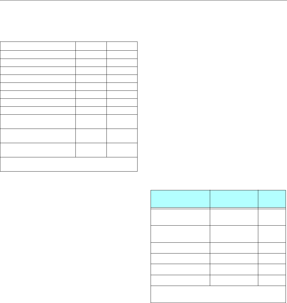
SECTION 1 - SPECIFICATIONS
3121298 – JLG Lift – 1-3
1.6 FUNCTION SPEEDS
Machine Orientation When Doing Speed Tests
Lift: Boom retracted. Telescope retracted. Lift up, record time,
Lift down, record time.
Swing: Boom at full elevation. Telescope retracted. Swing
turntable off center and stop. Swing opposite direction and
start test when centered. This eliminates controller ramp up
and ramp down affecting times.
Telescope: Boom at full elevation; Telescope retracted; Tele-
scope out, record time. Telescope In, record time.
Drive: Test to be done on a smooth level surface. Set Drive
Select Switch to 2WD High Engine. Start approximately 25 ft
(7.62 m) from starting point so unit is at maximum speed
when starting test. Record results for a 200 ft. (60.96 m) course.
Drive forward, record time. Drive reverse, record time.
Drive (Above Horizontal): Test should be done on a smooth
level surface. Set Drive Select Switch to 2WD High Engine.
Select Platform Speed Knob out of creep speed. This verifies
switches are working when boom is above horizontal. Results
should be recorded for a 50 ft course. Drive forward, record
time. Drive reverse, record time.
Platform Rotate: Platform level and completely rotated one
direction. Rotate opposite direction, record time. Rotate other
direction, record time.
Jib: Platform level and centered with boom. Start with Jib
down. Jib up, record time. Jib down, record time.
Test Notes
1. Start stop watch with function, not with controller or
switch.
2. Drive test results reflect 12x16.5 or 33/1550x16.5 air or
foam-filled tires.
3. All speed tests are run from platform. Speeds do not
reflect ground control operation.
4. Platform speed knob control must be at full speed
(turned clockwise completely).
5. Test with oil temperature above 100° F (38° C). Function
speeds vary if hydraulic oil is cold and thick.
6. Some flow control functions may not work with speed
knob clicked into creep position.
1.7 TORQUE REQUIREMENTS
Table 1-8. Function Speeds (In Seconds)
Function 600S 600SJ
Lift Up 46 - 60 46 -60
Lift Down 33 - 43 33 - 43
Swing Right & Left* 79 - 101 79 - 101
Telescope In 25 - 33 25 - 33
Telescope Out 50 - 67 50 - 67
Platform Rotate Right & Left** 16 - 25 25-32
Jib Up N/A 22 - 34
Jib Down N/A 16 - 26
Drive (2WD & 4WD GM Engine) 30-34
(4.25 MPH)
30-34
(4.25 MPH)
Drive (2WD & 4WD Deutz Engines) 34-38
(4.02 MPH)
34-38
(4.02 MPH)
Drive above Horizontal
(50 ft.)
46-54
(0.68 MPH)
46-54
(0.68 MPH)
*Max 10% Difference Between Left & Right
**Max 15% Difference Between Left & Right
Table 1-9. Torque Requirements
Description Torque Value (Dry) Interval
Hours
Bearing To Chassis 190 ft. lbs.
(258 Nm)
50/600*
B ea ri n g To Tur nt ab l e 190 ft. lbs.
(258 Nm)
50/600*
Wire Rope 15 ft. lbs (20 Nm) 150
Wheel Lugs 170 ft. lbs (231 Nm) 150
Engine Mounting Bolts 165 ft. lbs. (231 Nm) A/R
Engine Manifold Mounting Bolts 30 ft. lbs. (42 Nm) A/R
*Check swing bearing bolts after first 50 hours of operation and every 600 hours thereafter.
(See Swing Bearing in Section 3.)
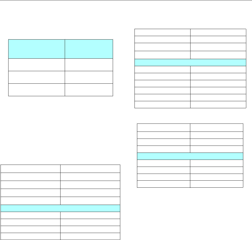
SECTION 1 - SPECIFICATIONS
1-4 – JLG Lift – 3121298
1.8 HYDRAULIC OIL
NOTE: Hydraulic oils require anti-wear qualities at least API Ser-
vice Classification GL-3, and sufficient chemical stability
for mobile hydraulic system service.
NOTE: Aside from JLG recommendations, it is not advisable to
mix oils of different brands or types. They may not contain
required additives or be of comparable viscosities. If
hydraulic oil other than Mobil 424 is desired, contact JLG
Industries for proper recommendations.
Table 1-11. Mobilfluid 424
SAE Grade 10W30
Gravity, API 29.0
Density, Lb/Gal. 60°F 7.35
Pour Point, Max -46°F (-43°C)
Flash Point, Min. 442°F (228°C)
Viscosity
Brookfield, cP at -18°C 2700
at 40° C 55 cSt
at 100° C 9.3 cSt
Viscosity Index 152
Table 1-10. Hydraulic Oil
Hydraulic System
Operating
Temperature Range
S.A.E. Viscosity
Grade
+0° to + 180° F
(-18° to +83° C)
10W
+0° to + 210° F
(-18° to +99° C)
10W-20, 10W30
+50° to + 210° F
(+10° to +99° C
20W-20
Table 1-12. Mobil DTE 13M
ISO Viscosity Grade #32
Specific Gravity 0.877
Pour Point, Max -40°F (-40°C)
Flash Point, Min. 330°F (166°C)
Viscosity
at 40° C 33cSt
at 100° C 6.6 cSt
at 100° F 169 SUS
at 210° F 48 SUS
cp at -20° F 6,200
Viscosity Index 140
Table 1-13. UCon Hydrolube HP-5046
Type Synthetic Biodegradable
Specific Gravity 1.082
Pour Point, Max -58°F (-50°C)
pH 9.1
Viscosity
at 0° C (32° F) 340 cSt (1600SUS)
at 40° C (104° F) 46 cSt (215SUS)
at 65° C (150° F) 22 cSt (106SUS)
Viscosity Index 170
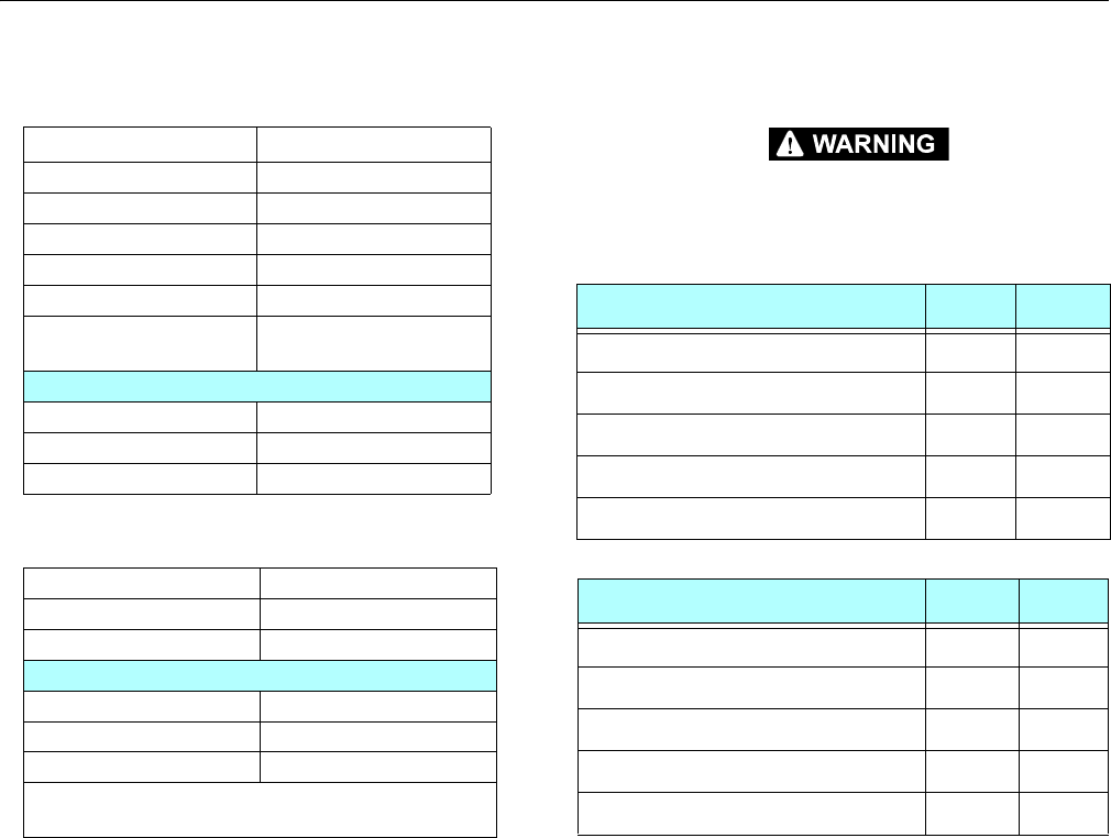
SECTION 1 - SPECIFICATIONS
3121298 – JLG Lift – 1-5
1.9 MAJOR COMPONENT WEIGHTS
DO NOT REPLACE ITEMS CRITICAL TO STABILITY WITH ITEMS OF DIFFERENT
WEIGHT OR SPECIFICATION (FOR EXAMPLE: BATTERIES, FILLED TIRES, PLAT-
FORM) DO NOT MODIFY UNIT IN ANY WAY TO AFFECT STABILITY.
Table 1-14. Mobil EAL H 46
Type Synthetic Biodegradable
ISO Viscosity Grade 46
Specific Gravity .910
Pour Point -44°F (-42°C)
Flash Point 500°F (260°C)
Operating Temp. 0 to 180°F (-17 to 162°C)
Weight 7.64 lb. per gal.
(0.9 kg per liter)
Viscosity
at 40° C 45 cSt
at 100° C 8.0 cSt
Viscosity Index 153
Table 1-15. Exxon Univis HVI 26
Specific Gravity 32.1
Pour Point -76°F (-60°C)
Flash Point 217°F (103°C)
Viscosity
at 40° C 25.8 cSt
at 100° C 9.3 cSt
Viscosity Index 376
NOTE: ExxonMobil recommends checking oil viscosity
yearly.
Table 1-16. Component Weights
600S Components LBS. KG.
Tire and Wheel (Ballasted Only) 15 - 19.5 253 115
Engine - Deutz 534 242
Counterweight 2900 1315
Platform - 6 ft. (1.83 M) 205 93
Platform - 8 ft. (2.44 M) 230 105
600SJ Components LBS. KG.
Tire and Wheel (Ballasted Only) 15 - 19.5 253 115
Engine - Deutz 534 242
Counterweight 4650 2109
Platform - 6 ft. (1.83 M) 205 93
Platform - 8 ft. (2.44 M) 230 105
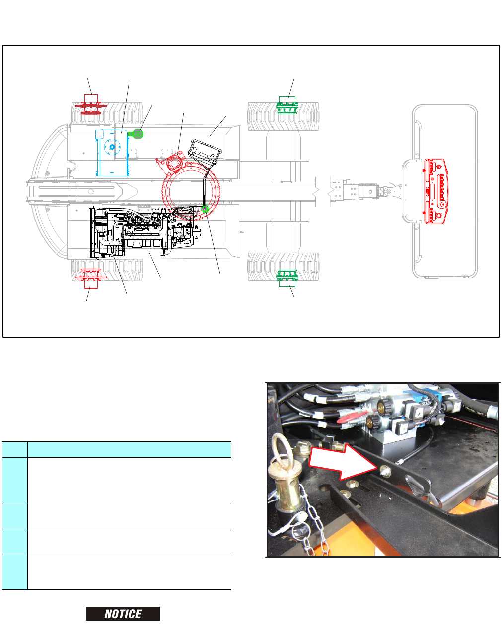
SECTION 1 - SPECIFICATIONS
1-6 – JLG Lift – 3121298
Figure 1-1. Operator Maintenance and Lubrication
1.10 OPERATOR MAINTENANCE
NOTE: The following numbers correspond to those in Figure 1-1.,
Operator Maintenance and Lubrication.
LUBRICATION INTERVALS ARE BASED ON MACHINE OPERATION UNDER NOR-
MAL CONDITIONS. FOR MACHINES USED IN MULTI-SHIFT OPERATIONS AND/
OR EXPOSED TO HOSTILE ENVIRONMENTS OR CONDITIONS, LUBRICATION
FREQUENCIES MUST BE INCREASED ACCORDINGLY.
1. Swing Bearing
Lube Point(s) - 1 Grease Fittings
Capacity - A/R
Lube - MPG
Interval - Every 3 months or 150 hrs of operation
Comments - Remote Access. Apply grease and rotate
in 90 degree intervals until bearing is completely
lubricated.
Table 1-17. Lubrication Specifications.
KEY SPECIFICATIONS
MPG Multipurpose Grease having a minimum dripping
point of 350° F (177° C). Excellent water resistance and
adhesive qualities, and being of extreme pressure type.
(Timken OK 40 pounds minimum.)
EPGL Extreme Pressure Gear Lube (oil) meeting API service
classification GL-5 or MIL-Spec MIL-L-2105
HO Hydraulic Oil. API service classification GL-3, e.g. Mobil-
fluid 424
EO Engine (crankcase) Oil. Gas - API SF, SH, SG class, MIL-L-
2104. Diesel - API CC/CD class, MIL-L-2104B/MIL-L-
2104C
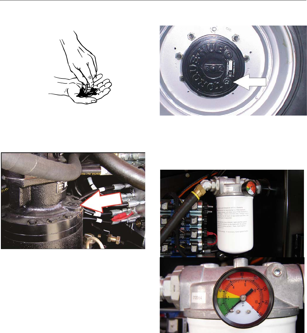
SECTION 1 - SPECIFICATIONS
3121298 – JLG Lift – 1-7
2. Wheel Bearings (If equipped)
Lube Point(s) - Repack
Capacity - A/R
Lube - MPG
Interval - Every 2 years or 1200 hours of operation
3. Swing Drive Hub
4. Lube Point(s) - Level/Fill Plug
Capacity - 43 oz. (1.3 L)
Lube - 90w80 Gear Oil
Interval - Check level every 3 months or 150 hrs of
operation; change every 2 years or 1200 hours of
operation
5. Wheel Drive Hub
Lube Point(s) - Level/Fill Plug
Capacity - 17 oz. (1/2 Full)
Lube - EPGL
Interval - Check level every 3 months or 150 hrs of
operation; change every 2 years or 1200 hours of
operation
6. Hydraulic Return Filter
Interval - Change after first 50 hrs. and every 6 months
or 300 hrs. thereafter or as shown by Condition Indica-
tor.
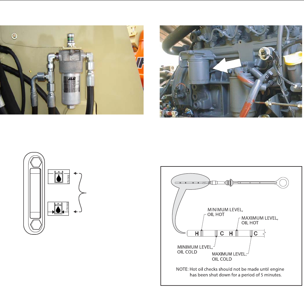
SECTION 1 - SPECIFICATIONS
1-8 – JLG Lift – 3121298
7. Hydraulic Charge Filter
Interval - Change after first 50 hrs. and every 6 months
or 300 hrs. thereafter, or as shown by Condition Indi-
cator.
8. Hydraulic TankLube Point(s) - Fill Cap
Capacity - 26 gal. Tank; 40 gal. System
Lube - HO
Interval - Check Level daily; Change every 2 years or
1200 hours of operation
9. Oil Change w/Filter - Deutz D2011
Lube Point(s) - Fill Cap/Spin-on Element
Capacity - 11 Quarts Crankcase; 5 Quarts Cooler
Lube - EO
Interval - Every Year or 1200 hours of operation
Comments - Check level daily/Change in accordance
with engine manual..
NORMAL OPERATING
RANGE WITH BOOM
IN STOWED POSITION
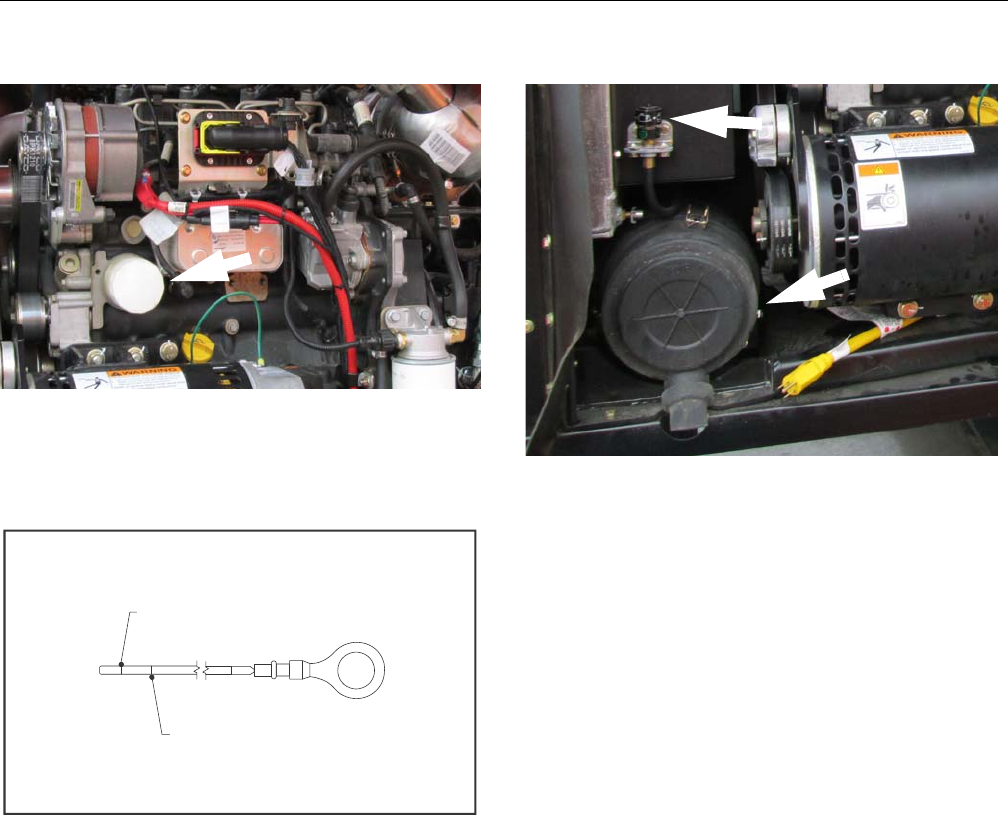
SECTION 1 - SPECIFICATIONS
3121298 – JLG Lift – 1-9
10. Oil Change w/Filter - Deutz D2.9
Lube Point(s) - Fill Cap/Spin-on Element
Capacity - 8.45 Qt (8 L) Crankcase and Filter
Interval - Every Year or 600 hours of operation
Comments - Check level daily/Change in accordance
with engine manual..
11. Air Filter - Deutz D2.9
Lube Point(s) - Replaceable Element
Interval - Every 6 months or 300 hours of operation or
as shown by condition indicator
MINIMUM OIL
LEVEL
MAXIMUM OIL
LEVEL
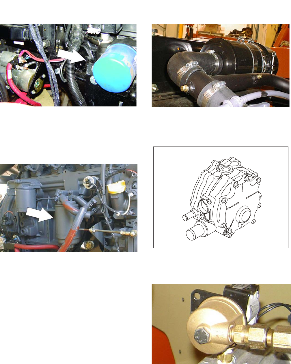
SECTION 1 - SPECIFICATIONS
1-10 – JLG Lift – 3121298
12. Oil Change w/Filter - GM
Lube Point(s) - Fill Cap/Spin-on Element
(JLG P/N 7027965)
Capacity - 4.5 qt. (4.25 L) w/filter
Lube - EO
Interval - 3 Months or 150 hours of operation
Comments - Check level daily/Change in accordance
with engine manual.
13. Fuel Filter - Deutz
Lube Point(s) - Replaceable Element
Interval - Every Year or 600 hours of operation
14. Fuel Filter (Gasoline) - GM
Lube Point(s) - Replaceable Element
Interval - Every 6 months or 300 hours of operation
15. Air Filter
Lube Point(s) - Replaceable Element
Interval - Every 6 months or 300 hours of operation or
as indicated by the condition indicator
16. 2-Stage Vaporizer (LP only)
Interval - 3 Months or 150 hours of operation, or
whenever fuel is contaminated.
Comments - Drain oil build up or contamination.
17. Fuel Filter (Propane) - GM Engine
Interval - 3 Months or 150 hours of operation
Comments - Replace filter.
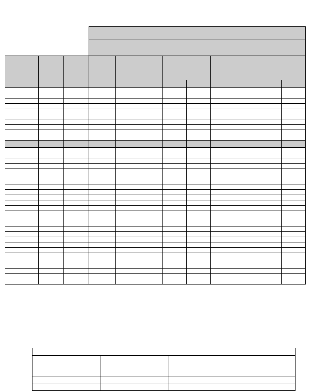
SECTION 1 - SPECIFICATIONS
3121298 – JLG Lift – 1-11
Figure 1-2. Torque Chart (SAE Fasteners - Sheet 1 of 7)
REFERENCE JLG ANEROBIC THREAD LOCKING COMPOUND
JLG P/N Loctite® P/N ND Industries P/N
Description
0100011 242
TM
Vibra-TITE
TM
121 Medium Strength (Blue)
0100019 271
TM
Vibra-TITE
TM
140 High Strength (Red)
0100071 262
TM
Vibra-TITE
TM
131 Medium - High Strength (Red)
Size TPI Bolt Dia Tensile
Stress Area Clamp Load
In Sq In LB IN-LB [N.m] IN-LB [N.m] IN-LB [N.m] IN-LB [N.m]
4 40 0.1120 0.00604 380 8 0.9 6 0.7
48 0.1120 0.00661 420 9 1.0 7 0.8
6 32 0.1380 0.00909 580 16 1.8 12 1.4
40 0.1380 0.01015 610 18 2.0 13 1.5
8 32 0.1640 0.01400 900 30 3.4 22 2.5
36 0.1640 0.01474 940 31 3.5 23 2.6
10 24 0.1900 0.01750 1120 43 4.8 32 3.5
32 0.1900 0.02000 1285 49 5.5 36 4
1/4 20 0.2500 0.0318 2020 96 10.8 75 9 105 12
28 0.2500 0.0364 2320 120 13.5 86 10 135 15
In Sq In LB FT-LB [N.m] FT-LB [N.m] FT-LB [N.m] FT-LB [N.m]
5/16 18 0.3125 0.0524 3340 17 23 13 18 19 26 16 22
24 0.3125 0.0580 3700 19 26 14 19 21 29 17 23
3/8 16 0.3750 0.0775 4940 30 41 23 31 35 48 28 38
24 0.3750 0.0878 5600 35 47 25 34 40 54 32 43
7/16 14 0.4375 0.1063 6800 50 68 35 47 55 75 45 61
20 0.4375 0.1187 7550 55 75 40 54 60 82 50 68
1/2 13 0.5000 0.1419 9050 75 102 55 75 85 116 68 92
20 0.5000 0.1599 10700 90 122 65 88 100 136 80 108
9/16 12 0.5625 0.1820 11600 110 149 80 108 120 163 98 133
18 0.5625 0.2030 12950 120 163 90 122 135 184 109 148
5/8 11 0.6250 0.2260 14400 150 203 110 149 165 224 135 183
18 0.6250 0.2560 16300 170 230 130 176 190 258 153 207
3/4 10 0.7500 0.3340 21300 260 353 200 271 285 388 240 325
16 0.7500 0.3730 23800 300 407 220 298 330 449 268 363
7/8 9 0.8750 0.4620 29400 430 583 320 434 475 646 386 523
14 0.8750 0.5090 32400 470 637 350 475 520 707 425 576
1 8 1.0000 0.6060 38600 640 868 480 651 675 918 579 785
12 1.0000 0.6630 42200 700 949 530 719 735 1000 633 858
1 1/8 7 1.1250 0.7630 42300 800 1085 600 813 840 1142 714 968
12 1.1250 0.8560 47500 880 1193 660 895 925 1258 802 1087
1 1/4 7 1.2500 0.9690 53800 1120 1518 840 1139 1175 1598 1009 1368
12 1.2500 1.0730 59600 1240 1681 920 1247 1300 1768 1118 1516
1 3/8 6 1.3750 1.1550 64100 1460 1979 1100 1491 1525 2074 1322 1792
12 1.3750 1.3150 73000 1680 2278 1260 1708 1750 2380 1506 2042
1 1/2 6 1.5000 1.4050 78000 1940 2630 1460 1979 2025 2754 1755 2379
12 1.5000 1.5800 87700 2200 2983 1640 2224 2300 3128 1974 2676
NO. 5000059 REV. J
Values for Zinc Yellow Chromate Fasteners (Ref 4150707)
SAE GRADE 5 BOLTS & GRADE 2 NUTS
Torque
(Dry)
Torque
(Loctite® 262
TM
or Vibra-
TITE
TM
131)
Torque
Lubricated
Torque
(Loctite® 242
TM
or 271
TM
OR Vibra-TITE
TM
111 or
140)
3. * ASSEMBLY USES HARDENED WASHER
NOTES: 1. THESE TORQUE VALUES DO NOT APPLY TO CADMIUM PLATED FASTENERS
2. ALL TORQUE VALUES ARE STATIC TORQUE MEASURED PER STANDARD AUDIT METHODS TOLERANCE = ±10%
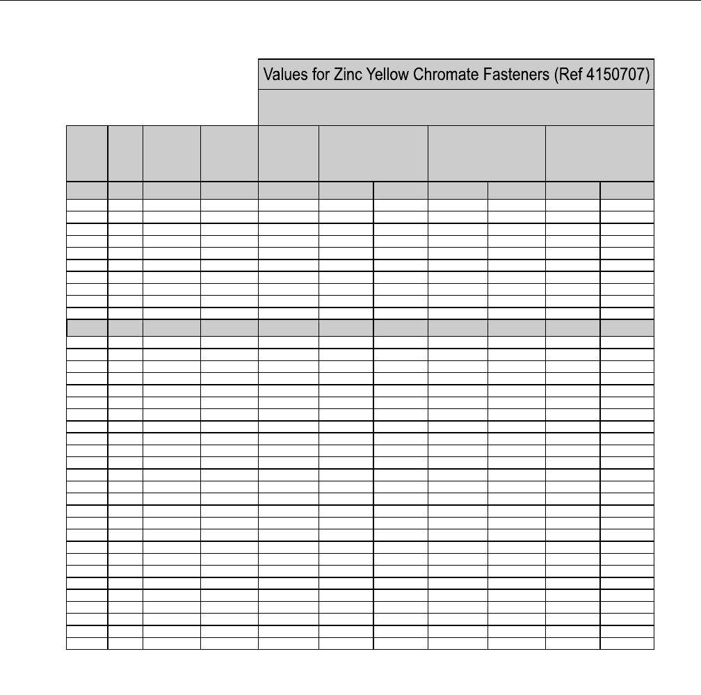
SECTION 1 - SPECIFICATIONS
1-12 – JLG Lift – 3121298
Figure 1-3. Torque Chart (SAE Fasteners - Sheet 2 of 7)
Size TPI Bolt Dia Tensile
Stress Area Clamp Load
In Sq In
4 40 0.1120 0.00604
48 0.1120 0.00661
6 32 0.1380 0.00909
40 0.1380 0.01015
8 32 0.1640 0.01400
36 0.1640 0.01474
10 24 0.1900 0.01750
32 0.1900 0.02000
1/4 20 0.2500 0.0318
28 0.2500 0.0364
In Sq In
5/16 18 0.3125 0.0524
24 0.3125 0.0580
3/8 16 0.3750 0.0775
24 0.3750 0.0878
7/16 14 0.4375 0.1063
20 0.4375 0.1187
1/2 13 0.5000 0.1419
20 0.5000 0.1599
9/16 12 0.5625 0.1820
18 0.5625 0.2030
5/8 11 0.6250 0.2260
18 0.6250 0.2560
3/4 10 0.7500 0.3340
16 0.7500 0.3730
7/8 9 0.8750 0.4620
14 0.8750 0.5090
1 8 1.0000 0.6060
12 1.0000 0.6630
1 1/8 7 1.1250 0.7630
12 1.1250 0.8560
1 1/4 7 1.2500 0.9690
12 1.2500 1.0730
1 3/8 6 1.3750 1.1550
12 1.3750 1.3150
1 1/2 6 1.5000 1.4050
12 1.5000 1.5800
NO. 5000059 REV. J
3. * ASSEMBLY USES HARDENED WASHER
NOTES: 1. THESE TORQUE VALUES DO NOT APPLY TO CADMIUM PLATED FASTENERS
2. ALL TORQUE VALUES ARE STATIC TORQUE MEASURED PER STANDARD AUDIT METHODS TOLERANCE = ±10%
LB IN-LB [N.m] IN-LB [N.m] IN-LB [N.m]
1320 43 5
1580 60 7
1800 68 8
2860 143 16 129 15
3280 164 19 148 17
LB FT-LB [N.m] FT-LB [N.m] FT-LB [N.m
4720 25 35 20 25 20 25
5220 25 35 25 35 20 25
7000456040 553550
7900 50 70 45 60 35 50
9550 70 95 65 90 50 70
10700 80 110 70 95 60 80
12750 105 145 95 130 80 110
14400 120 165 110 150 90 120
16400 155 210 140 190 115 155
18250 170 230 155 210 130 175
20350 210 285 190 260 160 220
23000 240 325 215 290 180 245
30100 375 510 340 460 280 380
33600 420 570 380 515 315 430
41600 605 825 545 740 455 620
45800 670 910 600 815 500 680
51500 860 1170 770 1045 645 875
59700 995 1355 895 1215 745 1015
68700 1290 1755 1160 1580 965 1310
77000 1445 1965 1300 1770 1085 1475
87200 1815 2470 1635 2225 1365 1855
96600 2015 2740 1810 2460 1510 2055
104000 2385 3245 2145 2915 1785 2430
118100 2705 3680 2435 3310 2030 2760
126500 3165 4305 2845 3870 2370 3225
142200 3555 4835 3200 4350 2665 3625
Torque
(Loctite® 242
TM
or 271
TM
OR Vibra-TITE
TM
111 or
140) K=.18
Torque
(Loctite® 262
TM
or Vibra-
TITE
TM
131)
K=0.15
SAE GRADE 8 (HEX HD) BOLTS & GRADE 8 NUTS*
Torque
(Dry or Loctite® 263)
K= 0.20
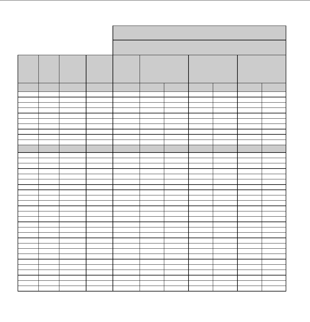
SECTION 1 - SPECIFICATIONS
3121298 – JLG Lift – 1-13
Figure 1-4. Torque Chart (SAE Fasteners - Sheet 3 of 7)
Size TPI Bolt Dia Tensile
Stress Area
Clamp Load
See Note 4
In Sq In LB IN-LB [N.m] IN-LB [N.m] IN-LB [N.m]
4 40 0.1120 0.00604
48 0.1120 0.00661
6 32 0.1380 0.00909
40 0.1380 0.01015
8 32 0.1640 0.01400
36 0.1640 0.01474
10 24 0.1900 0.01750
32 0.1900 0.02000
1/4 20 0.2500 0.0318 2860 122 14 114 13
28 0.2500 0.0364 3280 139 16 131 15
In Sq In LB FT-LB [N.m] FT-LB [N.m] FT-LB [N.m]
5/16 18 0.3125 0.0524 4720 20 25 20 25 20 25
24 0.3125 0.0580 5220 25 35 20 25 20 25
3/8 16 0.3750 0.0775 7000 35 50 35 50 35 50
24 0.3750 0.0878 7900 40 55 40 55 35 50
7/16 14 0.4375 0.1063 9550 60 80 55 75 50 70
20 0.4375 0.1187 10700 65 90 60 80 60 80
1/2 13 0.5000 0.1419 12750 90 120 85 115 80 110
20 0.5000 0.1599 14400 100 135 95 130 90 120
9/16 12 0.5625 0.1820 16400 130 175 125 170 115 155
18 0.5625 0.2030 18250 145 195 135 185 130 175
5/8 11 0.6250 0.2260 20350 180 245 170 230 160 220
18 0.6250 0.2560 23000 205 280 190 260 180 245
3/4 10 0.7500 0.3340 30100 320 435 300 410 280 380
16 0.7500 0.3730 33600 355 485 335 455 315 430
7/8 9 0.8750 0.4620 41600 515 700 485 660 455 620
14 0.8750 0.5090 45800 570 775 535 730 500 680
1 8 1.0000 0.6060 51500 730 995 685 930 645 875
12 1.0000 0.6630 59700 845 1150 795 1080 745 1015
1 1/8 7 1.1250 0.7630 68700 1095 1490 1030 1400 965 1310
12 1.1250 0.8560 77000 1225 1665 1155 1570 1085 1475
1 1/4 7 1.2500 0.9690 87200 1545 2100 1455 1980 1365 1855
12 1.2500 1.0730 96600 1710 2325 1610 2190 1510 2055
1 3/8 6 1.3750 1.1550 104000 2025 2755 1905 2590 1785 2430
12 1.3750 1.3150 118100 2300 3130 2165 2945 2030 2760
1 1/2 6 1.5000 1.4050 126500 2690 3660 2530 3440 2370 3225
12 1.5000 1.5800 142200 3020 4105 2845 3870 2665 3625
NO. 5000059 REV. J
4. CLAMP LOAD LISTED FOR SHCS IS SAME AS GRADE 8 OR CLASS 10.9 AND DOES NOT REPRESENT FULL STRENGTH
CAPABILITY OF SHCS. IF HIGHER LOAD IS REQUIRED, ADDITIONAL TESTING IS REQUIRED.
SOCKET HEAD CAP SCREWS
Magni Coating (Ref 4150701)*
Torque
(Dry) K = .17
Torque
(Loctite® 242
TM
or 271
TM
OR Vibra-TITE
TM
111 or
140 OR Precoat 85®
K=0.16
Torque
(Loctite® 262
TM
or Vibra-TITE
TM
131)
K=0.15
2. ALL TORQUE VALUES ARE STATIC TORQUE MEASURED PER STANDARD AUDIT METHODS TOLERANCE = ±10%
NOTES: 1. THESE TORQUE VALUES DO NOT APPLY TO CADMIUM PLATED FASTENERS
*3. ASSEMBLY USES HARDENED WASHER OR FASTENER IS PLACED AGAINST PLATED STEEL OR RAW ALUMINUM
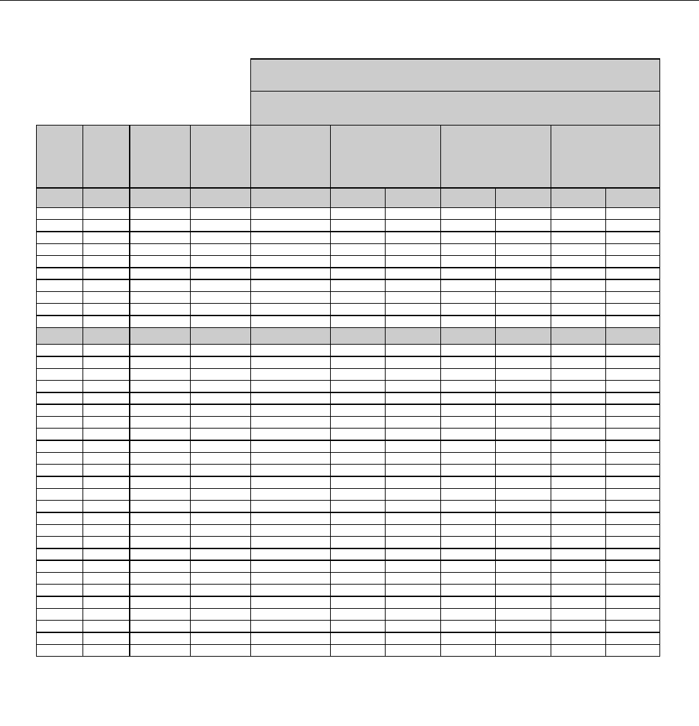
SECTION 1 - SPECIFICATIONS
1-14 – JLG Lift – 3121298
Figure 1-5. Torque Chart (SAE Fasteners - Sheet 4 of 7)
Size TPI Bolt Dia Tensile
Stress Area
Clamp Load
See Note 4
In Sq In LB IN-LB [N.m] IN-LB [N.m] IN-LB [N.m]
4 40 0.1120 0.00604
48 0.1120 0.00661
6 32 0.1380 0.00909
40 0.1380 0.01015
8 32 0.1640 0.01400
36 0.1640 0.01474
10 24 0.1900 0.01750
32 0.1900 0.02000
1/4 20 0.2500 0.0318 2860 143 16 129 15
28 0.2500 0.0364 3280 164 19 148 17
In Sq In LB FT-LB [N.m] FT-LB [N.m] FT-LB [N.m]
5/16 18 0.3125 0.0524 4720 25 35 20 25 20 25
24 0.3125 0.0580 5220 25 35 25 35 20 25
3/8 16 0.3750 0.0775 7000 45 60 40 55 35 50
24 0.3750 0.0878 7900 50 70 45 60 35 50
7/16 14 0.4375 0.1063 9550 70 95 65 90 50 70
20 0.4375 0.1187 10700 80 110 70 95 60 80
1/2 13 0.5000 0.1419 12750 105 145 95 130 80 110
20 0.5000 0.1599 14400 120 165 110 150 90 120
9/16 12 0.5625 0.1820 16400 155 210 140 190 115 155
18 0.5625 0.2030 18250 170 230 155 210 130 175
5/8 11 0.6250 0.2260 20350 210 285 190 260 160 220
18 0.6250 0.2560 23000 240 325 215 290 180 245
3/4 10 0.7500 0.3340 30100 375 510 340 460 280 380
16 0.7500 0.3730 33600 420 570 380 515 315 430
7/8 9 0.8750 0.4620 41600 605 825 545 740 455 620
14 0.8750 0.5090 45800 670 910 600 815 500 680
1 8 1.0000 0.6060 51500 860 1170 775 1055 645 875
12 1.0000 0.6630 59700 995 1355 895 1215 745 1015
1 1/8 7 1.1250 0.7630 68700 1290 1755 1160 1580 965 1310
12 1.1250 0.8560 77000 1445 1965 1300 1770 1085 1475
1 1/4 7 1.2500 0.9690 87200 1815 2470 1635 2225 1365 1855
12 1.2500 1.0730 96600 2015 2740 1810 2460 1510 2055
1 3/8 6 1.3750 1.1550 104000 2385 3245 2145 2915 1785 2430
12 1.3750 1.3150 118100 2705 3680 2435 3310 2030 2760
1 1/2 6 1.5000 1.4050 126500 3165 4305 2845 3870 2370 3225
12 1.5000 1.5800 142200 3555 4835 3200 4350 2665 3625
NO. 5000059 REV. J
4. CLAMP LOAD LISTED FOR SHCS IS SAME AS GRADE 8 OR CLASS 10.9 AND DOES NOT REPRESENT FULL STRENGTH
CAPABILITY OF SHCS. IF HIGHER LOAD IS REQUIRED, ADDITIONAL TESTING IS REQUIRED.
SOCKET HEAD CAP SCREWS
Torque
(Dry)
K = .20
Torque
(Loctite® 242
TM
or 271
TM
OR Vibra-TITE
TM
111 or
140 OR Precoat 85®
K=0.18
Zinc Yellow Chromate Fasteners (Ref 4150707)*
2. ALL TORQUE VALUES ARE STATIC TORQUE MEASURED PER STANDARD AUDIT METHODS TOLERANCE = ±10%
NOTES: 1. THESE TORQUE VALUES DO NOT APPLY TO CADMIUM PLATED FASTENERS
*3. ASSEMBLY USES HARDENED WASHER OR FASTENER IS PLACED AGAINST PLATED STEEL OR RAW ALUMINUM
Torque
(Loctite® 262
TM
or Vibra-TITE
TM
131)
K=0.15
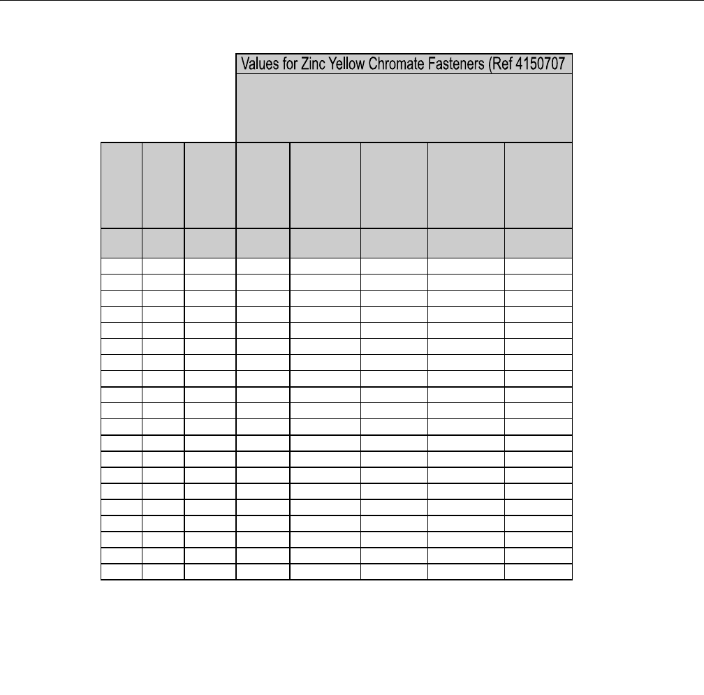
SECTION 1 - SPECIFICATIONS
3121298 – JLG Lift – 1-15
Figure 1-6. Torque Chart (METRIC Fasteners - Sheet 5 of 7)
Size PITCH
Tensile
Stress
Area
Clamp
Load
Torque
(Dry or Loctite®
263
TM
)
Torque
(Lub)
Torque
(Loctite® 262
TM
OR Vibra-
TITE
TM
131)
Torque
(Loctite®
242
TM
or 271
TM
OR Vibra-
TITE
TM
111 or
140)
Sq mm KN [N.m] [N.m] [N.m] [N.m]
3 0.5 5.03 2.19 1.3 1.0 1.2 1.4
3.5 0.6 6.78 2.95 2.1 1.6 1.9 2.3
4 0.7 8.78 3.82 3.1 2.3 2.8 3.4
5 0.8 14.20 6.18 6.2 4.6 5.6 6.8
6 1 20.10 8.74 11 7.9 9.4 12
7 1 28.90 12.6 18 13 16 19
8 1.25 36.60 15.9 26 19 23 28
10 1.5 58.00 25.2 50 38 45 55
12 1.75 84.30 36.7 88 66 79 97
14 2 115 50.0 140 105 126 154
16 2 157 68.3 219 164 197 241
18 2.5 192 83.5 301 226 271 331
20 2.5 245 106.5 426 320 383 469
22 2.5 303 132.0 581 436 523 639
24 3 353 153.5 737 553 663 811
27 3 459 199.5 1080 810 970 1130
30 3.5 561 244.0 1460 1100 1320 1530
33 3.5 694 302.0 1990 1490 1790 2090
36 4 817 355.5 2560 1920 2300 2690
42 4.5 1120 487.0 4090 3070 3680 4290
4. CLAMP LOAD LISTED FOR SHCS IS SAME AS GRADE 8 OR CLASS 10.9 AND DOES NOT
REPRESENT FULL STRENGTH CAPABILITY OF SHCS. IF HIGHER LOAD IS REQUIRED,
ADDITIONAL TESTING IS REQUIRED.
*3. ASSEMBLY USES HARDENED WASHER OR FASTENER IS PLACED AGAINST PLATED
STEEL OR RAW ALUMINUM
CLASS 8.8 METRIC BOLTS
CLASS 8 METRIC NUTS
NOTES: 1. THESE TORQUE VALUES DO NOT APPLY TO CADMIUM PLATED FASTENERS
2. ALL TORQUE VALUES ARE STATIC TORQUE MEASURED PER STANDARD AUDIT
METHODS TOLERANCE = ±10%
NO. 5000059 REV. J
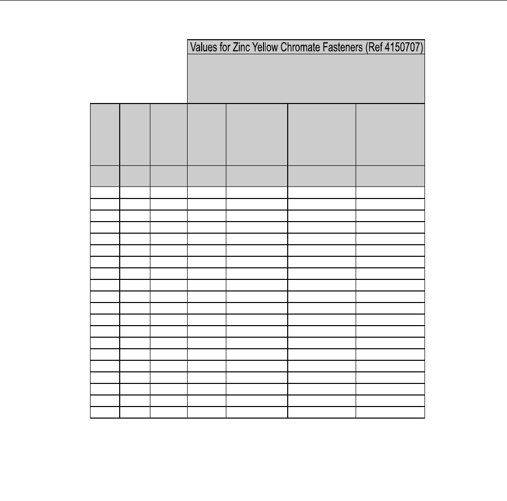
SECTION 1 - SPECIFICATIONS
1-16 – JLG Lift – 3121298
Figure 1-7. Torque Chart (METRIC Fasteners - Sheet 6 of 7)
Size PITCH
Tensile
Stress
Area
Clamp
Load
Torque
(Dry or Loctite®
263
TM
)
K = 0.20
Torque
(Lub OR Loctite®
242
TM
or 271
TM
OR
Vibra-TITE
TM
111 or
140)
K= 0.18
Torque
(Loctite® 262
TM
OR
Vibra-TITE
TM
131)
K=0.15
Sq mm KN [N.m] [N.m] [N.m]
3 0.5 5.03 3.13
3.5 0.6 6.78 4.22
4 0.7 8.78 5.47
5 0.8 14.20 8.85
6 1 20.10 12.5
7 1 28.90 18.0 25.2 22.7 18.9
8 1.25 36.60 22.8 36.5 32.8 27.4
10 1.5 58.00 36.1 70 65 55
12 1.75 84.30 52.5 125 115 95
14 2 115 71.6 200 180 150
16 2 157 97.8 315 280 235
18 2.5 192 119.5 430 385 325
20 2.5 245 152.5 610 550 460
22 2.5 303 189.0 830 750 625
24 3 353 222.0 1065 960 800
27 3 459 286.0 1545 1390 1160
30 3.5 561 349.5 2095 1885 1575
33 3.5 694 432.5 2855 2570 2140
36 4 817 509.0 3665 3300 2750
42 4.5 1120 698.0 5865 5275 4395
CLASS 10.9 METRIC BOLTS
CLASS 10 METRIC NUTS
CLASS 12.9 SOCKET HEAD CAP SCREWS M3 - M5*
4. CLAMP LOAD LISTED FOR SHCS IS SAME AS GRADE 8 OR CLASS 10.9 AND DOES NOT
REPRESENT FULL STRENGTH CAPABILITY OF SHCS. IF HIGHER LOAD IS REQUIRED,
ADDITIONAL TESTING IS REQUIRED.
*3. ASSEMBLY USES HARDENED WASHER OR FASTENER IS PLACED AGAINST PLATED
STEEL OR RAW ALUMINUM
NOTES: 1. THESE TORQUE VALUES DO NOT APPLY TO CADMIUM PLATED FASTENERS
2. ALL TORQUE VALUES ARE STATIC TORQUE MEASURED PER STANDARD AUDIT
METHODS TOLERANCE = ±10%
NO. 5000059 REV. J
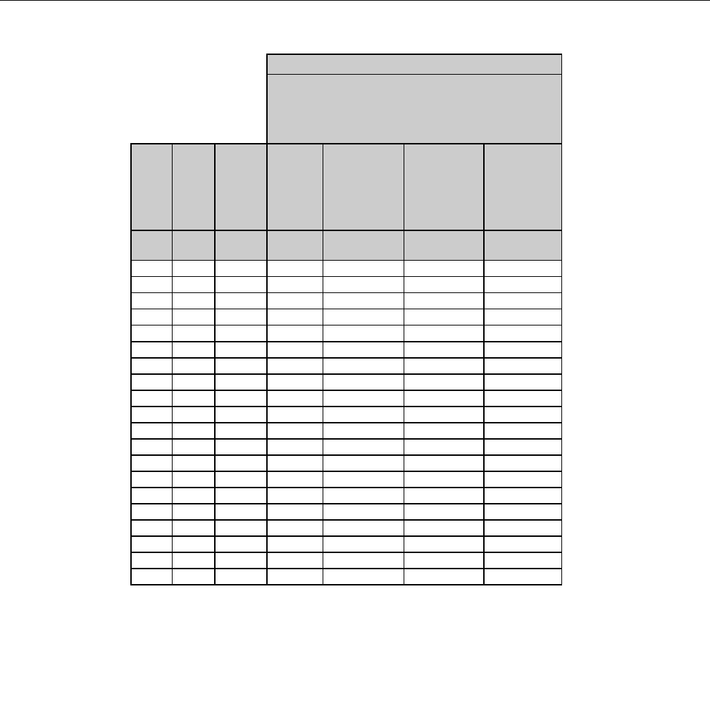
SECTION 1 - SPECIFICATIONS
3121298 – JLG Lift – 1-17
Figure 1-8. Torque Chart (METRIC Fasteners - Sheet 7 of 7)
Size PITCH
Tensile
Stress
Area
Clamp Load
See Note 4
Torque
(Dry or Loctite®
263
TM
)
K = .17
Torque
(Lub OR Loctite®
242
TM
or 271
TM
OR Vibra-TITE
TM
111 or 140)
K = .16
Torque
(Loctite® 262
TM
OR Vibra-TITE
TM
131)
K = .15
Sq mm kN [N.m] [N.m] [N.m]
30.55.03
3.5 0.6 6.78
40.78.78
50.814.20
6120.1012.5 13 12 11
7128.9018.0 21 20 19
8 1.25 36.60 22.8 31 29 27
10 1.5 58.00 36.1 61 58 54
12 1.75 84.30 52.5 105 100 95
14 2 115 71.6 170 160 150
16 2 157 97.8 265 250 235
18 2.5 192 119.5 365 345 325
20 2.5 245 152.5 520 490 460
22 2.5 303 189.0 705 665 625
24 3 353 220.0 900 845 790
27 3 459 286.0 1315 1235 1160
30 3.5 561 349.5 1780 1680 1575
33 3.5 694 432.5 2425 2285 2140
36 4 817 509.0 3115 2930 2750
42 4.5 1120 698.0 4985 4690 4395
CLASS 12.9 SOCKET HEAD CAP SCREWS
M6 AND ABOVE*
4. CLAMP LOAD LISTED FOR SHCS IS SAME AS GRADE 8 OR CLASS 10.9 AND DOES NOT
REPRESENT FULL STRENGTH CAPABILITY OF SHCS. IF HIGHER LOAD IS REQUIRED,
ADDITIONAL TESTING IS REQUIRED.
*3. ASSEMBLY USES HARDENED WASHER OR FASTENER IS PLACED AGAINST PLATED
STEEL OR RAW ALUMINUM
NOTES: 1. THESE TORQUE VALUES DO NOT APPLY TO CADMIUM PLATED FASTENERS
2. ALL TORQUE VALUES ARE STATIC TORQUE MEASURED PER STANDARD AUDIT
METHODS TOLERANCE = ±10%
NO. 5000059 REV. J
Magni Coating (Ref 4150701)*

SECTION 1 - SPECIFICATIONS
1-18 – JLG Lift – 3121298
NOTES:

SECTION 2 - GENERAL
3121298 – JLG Lift – 2-1
SECTION 2. GENERAL
2.1 MACHINE PREPARATION, INSPECTION, AND
MAINTENANCE
General
This section provides information needed by personnel
responsible to place machine in operation readiness and
maintain its safe operating condition. For maximum service
life and safe operation, ensure all necessary inspections and
maintenance have been completed before placing machine in
service.
Preparation, Inspection, and Maintenance
It is important to establish and conform to a comprehensive
inspection and preventive maintenance program. The follow-
ing table outlines periodic machine inspections and mainte-
nance recommended by JLG Industries, Inc. Consult your
national, regional, or local regulations for further requirements
for aerial work platforms. Frequency of inspections and main-
tenance must be increased as environment, severity and fre-
quency of usage requires.
Pre-Start Inspection
It is the User’s or Operator’s primary responsibility to perform a
Pre-Start Inspection of the machine before use daily or at each
change of operator. Reference the Operator’s and Safety Man-
ual for Pre-Start Inspection procedures. The Operator and
Safety Manual must be read and understood in its entirety
before performing the Pre-Start Inspection.
Pre-Delivery Inspection and Frequent Inspection
The Pre-Delivery Inspection and Frequent Inspection shall be
performed by a qualified JLG equipment mechanic. JLG Indus-
tries, Inc. recognizes a qualified JLG equipment mechanic as a
person who, by possession of a recognized degree, certificate,
extensive knowledge, training, or experience, has successfully
demonstrated the ability and proficiency to service, repair, and
maintain the subject JLG product model.
The Pre-Delivery Inspection and Frequent Inspection proce-
dures are performed in the same manner, but at different
times. The Pre-Delivery Inspection shall be performed prior to
each sale, lease, or rental delivery. The Frequent Inspection
shall be accomplished for each machine in service for 3
months or 150 hours (whichever comes first); out of service for
a period of more than 3 months; or when purchased used. Fre-
quency of this inspection must be increased as environment,
severity and frequency of usage requires.
Reference the JLG Pre-Delivery and Frequent Inspection Form
and Inspection and Preventive Maintenance Schedule for
items requiring inspection. Reference appropriate areas of this
manual for servicing and maintenance procedures.
Annual Machine Inspection
The Annual Machine Inspection must be performed on an
annual basis, no later than thirteen (13) months from the date
of the prior Annual Machine Inspection. JLG Industries recom-
mends this task be performed by a Factory-Trained Service
Technician. JLG Industries, Inc. recognizes a Factory-Trained
Service Technician as a person who has successfully com-
pleted the JLG Service Training School for the subject JLG
product model. Reference the machine Service and Mainte-
nance Manual and appropriate JLG inspection form for perfor-
mance of this inspection.
Reference the JLG Annual Machine Inspection Form and
Inspection and Preventive Maintenance Schedule for items
requiring inspection. Reference appropriate areas of this man-
ual for servicing and maintenance procedures.
For the purpose of receiving safety-related bulletins, it is
important that JLG Industries, Inc. has updated ownership
information for each machine. When performing each Annual
Machine Inspection, notify JLG Industries, Inc. of current
machine ownership.
Preventive Maintenance
In conjunction with specified inspections, maintenance shall
be performed by a qualified JLG equipment mechanic. JLG
Industries, Inc. recognizes a qualified JLG equipment
mechanic as a person who, by possession of a recognized
degree, certificate, extensive knowledge, training, or experi-
ence, has successfully demonstrated the ability and profi-
ciency to service, repair, and maintain the subject JLG product
model.
Reference the Preventive Maintenance Schedule and appro-
priate areas of this manual for servicing and maintenance pro-
cedures. Frequency of service and maintenance must be
increased as environment, severity and frequency of usage
requires.

SECTION 2 - GENERAL
2-2 – JLG Lift – 3121298
2.2 SERVICE AND GUIDELINES
General
Following information is provided to assist you in using servic-
ing and maintenance procedures in this manual.
Safety and Workmanship
Your safety, and that of others, is the first consideration in
maintenance of equipment. Always be conscious of weight.
Never attempt to move heavy parts without aid of a mechani-
cal device. Do not allow heavy objects to rest in an unstable
position. Ensure adequate support is provided when raising a
portion of the equipment.
Cleanliness
1. The most important single item in preserving the long
service life of a machine is to keep dirt and contamina-
tion out of vital components. Shields, covers, seals, and
filters are provided to keep air, fuel, and oil supplies
clean; however, these items must be maintained on a
schedule to function properly.
2. Any time air, fuel, or oil lines are disconnected, clean
adjacent areas as well as the openings and fittings them-
selves. As soon as a line or component is disconnected,
cap or cover all openings to prevent contamination.
3. Clean and inspect all parts during servicing or mainte-
nance. Ensure all passages and openings are unob-
structed. Cover all parts to keep them clean. Make sure
all parts are clean before they are installed. New parts
should remain in their containers until ready to be used.
Components Removal and Installation
1. Use adjustable lifting devices, whenever possible, if
mechanical assistance is required. All slings (chains,
cables, etc.) should be parallel to each other and as near
perpendicular as possible to top of part being lifted.
2. Should it be necessary to remove a component on an
angle, keep in mind the capacity of an eyebolt or similar
bracket lessens, as the angle between the supporting
structure and component becomes less than 90
degrees.
3. If a part resists removal, check to see if all nuts, bolts,
cables, brackets, wiring, etc., have been removed and no
adjacent parts are interfering.
Table 2-1. Inspection and Maintenance
Type Frequency Primary
Responsibility
Service
Qualification Reference
Pre-Start Inspection Prior to use each day; or
at each Operator change.
User or Operator User or Operator Operation and Safety Manual
Pre-Delivery Inspection Prior to each sale, lease, or
rental delivery.
Owner, Dealer, or User Qualified JLG Mechanic Service and Maintenance Manual
and applicable JLG inspection form.
Frequent Inspection In service for 3 months or 150 hours, whichever
comes first; or
out of service for a period of more than 3 months; or
purchased used.
Owner, Dealer, or User Qualified JLG Mechanic Service and Maintenance Manual
and applicable JLG inspection form.
Annual Machine Inspec-
tion
Annually, no later than 13 months from date of
prior inspection.
Owner, Dealer, or User Factory-Trained Service
Technician
(Recommended)
Service and Maintenance Manual
and applicable JLG inspection form.
Preventive
Maintenance
At intervals as specified in Service and Mainte-
nance Manual.
Owner, Dealer, or User Qualified JLG Mechanic Service and Maintenance Manual

SECTION 2 - GENERAL
3121298 – JLG Lift – 2-3
Component Disassembly and Reassembly
Complete procedural steps in sequence when disassembling
or reassembling a component. Do not partially disassemble or
assemble one part, then start on another. Always recheck your
work to ensure nothing is overlooked. Do not make any
adjustments, other than those recommended, without obtain-
ing proper approval.
Pressure-Fit Parts
When assembling pressure-fit parts, use a molybdenum disul-
fide base compound or equivalent to lubricate the mating sur-
face.
Bearings
1. When a bearing is removed, cover it to keep out dirt and
abrasives. Clean bearings in nonflammable cleaning sol-
vent and allow to drip dry. Compressed air can be used,
but do not spin the bearing.
2. Discard bearings if races and balls (or rollers) are pitted,
scored, or burned.
3. If bearing is found to be serviceable, apply a light coat of
oil and wrap it in clean (waxed) paper. Do not unwrap
reusable or new bearings until ready to install.
4. Lubricate new or used serviceable bearings before
installation. Apply pressure to the outer race when
pressing a bearing into a retainer or bore. Apply pres-
sure to the inner race If bearing is installed on a shaft.
Gaskets
Check holes in gaskets align with openings in mating parts. If
it is necessary to hand-fabricate a gasket, use gasket material
or stock of equivalent material and thickness. Be sure to cut
holes in the correct location. Blank gaskets can cause serious
system damage.
Bolt Usage and Torque Application
SELF LOCKING FASTENERS, SUCH AS NYLON INSERT AND THREAD DEFORMING
LOCKNUTS, ARE NOT INTENDED TO BE REINSTALLED AFTER REMOVAL.
1. Always use new replacement hardware when installing
locking fasteners. Use bolts of proper length. A bolt
which is too long will bottom before the head is tight
against its related part. If a bolt is too short, there will
not be enough thread area to engage and hold the part
properly. When replacing bolts, use only those having
the same specifications of the original, or one which is
equivalent.
2. Unless specific torque requirements are given within the
text, use standard torque values on heat-treated bolts,
studs, and steel nuts, in accordance with recommended
shop practices. (See Torque Chart in Section 1.)
Hydraulic Lines and Electrical Wiring
Clearly mark or tag hydraulic lines and electrical wiring, and
their receptacles, when disconnecting or removing them from
the unit. This ensures correct reinstallation.
Hydraulic System
1. Keep the system clean. If evidence of metal or rubber
particles are found in the hydraulic system, drain and
flush the entire system.
2. Disassemble and reassemble parts on clean work sur-
face. Clean all metal parts with non-flammable cleaning
solvent. Lubricate components as needed to aid assem-
bly.
Lubrication
Service applicable components with the amount, type, and
grade of lubricant recommended in this manual at the speci-
fied intervals. When recommended lubricants are not avail-
able, consult your local supplier for an equivalent that meets
or exceeds the specifications listed.
Battery
Clean battery using a non-metallic brush and a solution of
baking soda and water. Rinse with clean water. After cleaning,
thoroughly dry battery and coat terminals with an anti corro-
sion compound.
Lubrication and Servicing
Components and assemblies requiring lubrication and servic-
ing are shown in the Lubrication Chart in Section 1.
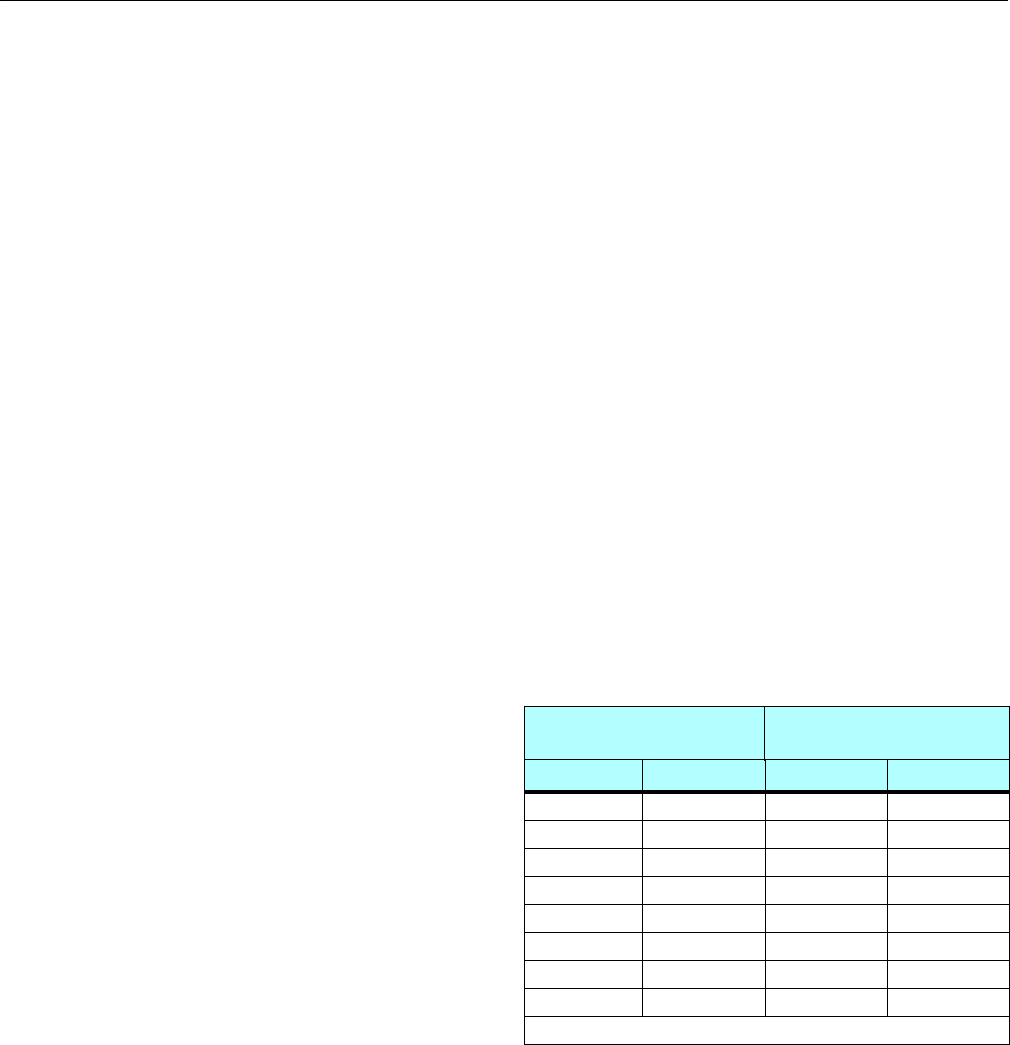
SECTION 2 - GENERAL
2-4 – JLG Lift – 3121298
2.3 LUBRICATION AND INFORMATION
Hydraulic System
1. The primary enemy of a hydraulic system is contamina-
tion. Contaminants can enter the system by using inade-
quate hydraulic oil; allowing moisture, grease, filings,
sealing components, sand, etc., to enter when perform-
ing maintenance; or allowing the pump to cavitate due
to insufficient system warm-up or leaks in pump supply
(suction) lines.
2. Design and manufacturing tolerances of component
working parts are very close. The smallest amount of dirt
or other contamination entering a system can cause
wear or damage to components and faulty operation.
Take every precaution to keep hydraulic oil clean -
including reserve oil in storage. Check, clean, and
replace hydraulic system filters as at intervals specified
in the Lubrication Chart in Section 1. Always examine fil-
ters for metal particles.
3. Cloudy oils indicate high moisture content which per-
mits organic growth and causes oxidation or corrosion.
If this condition occurs, the system must be drained,
flushed, and refilled with clean oil.
4. It is not advisable to mix oils of different brands or types.
They may not contain required additives or be of com-
parable viscosities. Good grade mineral oils, with viscos-
ities suited to ambient temperatures in which the
machine is operating, are recommended for use.
NOTE: Metal particles may appear in oil or filters of new machines
due to wear-in of meshing components.
Hydraulic Oil
1. Refer to Section 1 for viscosity ranges.
Changing Hydraulic Oil
1. Filter elements must be changed after the first 50 hours
of operation and every 300 hours (unless specified oth-
erwise) thereafter. If it is necessary to change the oil, use
only those oils meeting or exceeding specifications in
this manual. If unable to obtain the same type of oil sup-
plied with the machine, consult local supplier for assis-
tance in selecting the proper equivalent. Avoid mixing
petroleum and synthetic base oils.
2. Keep hydraulic oil clean. If oil must be poured from orig-
inal container into another, clean all possible contami-
nants from the service container. Always clean filter
mesh element and replace cartridge any time system oil
is changed.
3. While the unit is shut down, a good preventive mainte-
nance measure is to make a thorough inspection of all
hydraulic components, lines, fittings, etc., as well as a
functional check of each system, before placing
machine back in service.
Lubrication Specifications
Specified lubricants, as recommended by component manu-
facturers, are always the best choice. However, multi-purpose
greases usually have qualities which meet a variety of single
purpose grease requirements. Should questions arise regard-
ing use of greases in maintenance stock, consult your local
supplier for evaluation. Refer to Section 1 for an explanation of
lubricant key designations in the Lubrication Chart.
2.4 CYLINDER DRIFT TEST
Measure maximum acceptable cylinder drift using the follow-
ing methods.
Platform Drift
Measure platform drift to ground. Lower booms (if equipped)
slightly elevated, main boom fully extended with rated load in
platform and power off. Maximum allowable drift is 2 inches (5
cm) in 10 minutes. If machine does not pass this test, proceed
with the following.
Cylinder Drift
Measure drift at cylinder rod with a calibrated dial indicator.
Cylinder oil must be at stabilized ambient temperature.
Cylinder must have normal platform load applied.
Cylinder is acceptable if it passes this test.
Table 2-2. Cylinder Drift
Cylinder Bore Diameter Max. Acceptable Drift
in 10 Minutes*
inches mm inches mm
376.2 0.026 0.66
3.5 89 0.019 0.48
4101.6 0.015 0.38
5127 0.009 0.22
6152.4 0.006 0.15
7177.8 0.005 0.13
8203.2 0.0038 0.10
9228.6 0.0030 0.08
*Based on 6 drops per minute cylinder leakage.

SECTION 2 - GENERAL
3121298 – JLG Lift – 2-5
2.5 PINS AND COMPOSITE BEARING REPAIR
GUIDELINES
Filament wound bearings.
1. Pinned joints should be disassembled and inspected if
the following occurs:
a. Excessive sloppiness in joints.
b. Noise originating from joint during operation.
2. Filament wound bearings should be replaced if any of
the following is observed:
a. Frayed or separated fibers on the liner surface.
b. Cracked or damaged liner backing.
c. Bearings that have moved or spun in their housing.
d. Debris embedded in liner surface.
3. Pins should be replaced if any of the following is
observed (Clean pin before inspection):
a. Detectable bearing area wear.
b. Flaking, peeling, scoring, or scratches on pin surface.
c. Rusting of pin in bearing area.
4. Re-assembly of pinned joints using filament wound
bearings:
a. Blow out housing using compressed air to remove
all dirt and debris. Bearings and bearing housings
must be free of all contamination.
b. Clean bearings and pins with solvent to remove all
grease and oil.
NOTE: Filament wound bearings are a dry joint and should not be
lubricated unless otherwise instructed (i.e. sheave pins).
c. Inspect pin to ensure it is free of burrs, nicks, and
scratches which can damage bearing during instal-
lation and operation.
2.6 WELDING ON JLG EQUIPMENT
NOTE: This instruction applies to repairs, or modifications to the
machine and to welding performed from the machine on
an external structure, or component,
Do the Following When Welding on JLG Equipment:
• Disconnect battery.
• Disconnect moment pin connection (where fitted)
• Ground only to structure being welded.
Do NOT Do the Following When Welding on JLG
Equipment:
FAILURE TO COMPLY WITH THESE INSTRUCTIONS MAY RESULT IN COMPO-
NENT DAMAGE (I.E. ELECTRONIC MODULES, SWING BEARING, COLLECTOR
RING, BOOM WIRE ROPES ETC.
• Do NOT ground on frame and weld on any other area than
chassis.
• Do NOT ground on turntable and weld on any other area
than turntable.
• Do NOT ground on platform/support and weld on any
other area than platform/support.
• Do NOT ground on a specific boom section and weld on
any other area than that specific boom section.
• Do NOT allow pins, wear pads, wire ropes, bearings, gear-
ing, seals, valves, electrical wiring, or hoses to be between
grounding position and welded area.

SECTION 2 - GENERAL
2-6 – JLG Lift – 3121298
Table 2-3. Inspection and Preventive Maintenance Schedule
AREA
INTERVAL
Weekly
Preventive
Maintenance
Monthly
Preventive
Maintenance
Pre-Delivery2
or Frequent3
Inspection
Annual4
(Yearly)
Inspection
Every 2
Years
Boom Assembly
Boom Weldments 1,2,4 1,2,4
Hose/Cable Carrier Installations 1,2,9,12 1,2,9,12
Pivot Pins and Pin Retainers 1,2 1,2
Sheaves, Sheave Pins 1,2 1,2
Bearings 1,2 1,2
Wear Pads 1,2 1,2
Covers or Shields 1,2 1,2
Extend/Retract Chain or Cable Systems 1,2,3 1,2,3
Boom Assembly 14
Platform Assembly
Platform 1,2
Railing 11,2
Gate 5 1 1,5
Floor 11,2
Rotator 9,5 15
Lanyard Anchorage Point 1,2,10 1,2,10
Turntable Assembly
Swing Bearing 1,2,14 1,2,3,13,14
Oil Coupling 9
Swing Drive System 11 11
Turntable Lock 1,2,5 1,2,5
Hood, Hood Props, Hood Latches 51,2,5
Chassis Assembly
Tires 16,17 16,17,18 16,17,18
Wheel Nuts/Bolts 15 15 15
Wheel Bearings 14,24
Oscillating Axle/Lockout Cylinder Systems 5,8
Extendable Axle Systems 5,8 5,8
Steer Components
Spindle Thrust Bearing/Washers 1,2
Drive Hubs 11 11

SECTION 2 - GENERAL
3121298 – JLG Lift – 2-7
Functions/Controls
Platform Controls 5 6 6
Ground Controls 5 6 6
Function Control Locks, Guards, or Detents 1,5 5 5
Footswitch 5 5
Emergency Stop Switches (Ground & Platform) 5 5
Function Limit or Cutout Switch Systems 5 5
Drive Brakes 5
Swing Brakes 5
Auxiliary Power 5 5
Power System
Engine Idle, Throttle, and RPM 3 3
Engine Fluids (Oil, Coolant, Fuel) 9,11 11 11
Air/Fuel Filter 1,7 7 7
Exhaust System 1,9 9 9
Batteries 1,9 19
Battery Fluid 11 11 11
Battery Charger 5 5
Fuel Reservoir, Cap, and Breather 2 1,5 1,5
Hydraulic/Electric System
Hydraulic Pumps 1,9 1,2,9
Hydraulic Cylinders 1,9,7 2 1,2,9 1,2,9
Cylinder Attachment Pins and Pin Retainers 1,9 1,2 1,2
Hydraulic Hoses, Lines, and Fittings 1,9 12 1,2,9,12 1,2,9,12
Hydraulic Reservoir, Cap, and Breather 1,9 2 1,5 1,5 24
Hydraulic Filter 1,9 7 7
Hydraulic Fluid 7,11 7,11
Electrical Connections 120 20
Instruments, Gauges, Switches, Lights, Horn 15,23
General
Operation and Safety Manuals in Storage Box 21 21
ANSI and AEM Manuals/Handbooks Installed (ANSI Mar-
kets Only)
21
Capacity Decals Installed, Secure, Legible 21 21
All Decals/Placards Installed, Secure, Legible 21 21
Table 2-3. Inspection and Preventive Maintenance Schedule
AREA
INTERVAL
Weekly
Preventive
Maintenance
Monthly
Preventive
Maintenance
Pre-Delivery2
or Frequent3
Inspection
Annual4
(Yearly)
Inspection
Every 2
Years
SECTION 2 - GENERAL
2-8 – JLG Lift – 3121298
Annual Machine Inspection Due 21
No Unauthorized Modifications or Additions 21 21
All Relevant Safety Publications Incorporated 21 21
General Structural Condition and Welds 2,4 2,4
All Fasteners, Pins, Shields, and Covers 1,2 1,2
Grease and Lubricate to Specifications 22 22
Function Test of All Systems 21 21, 22
Paint and Appearance 7 7
Stamp Inspection Date on Frame 22
Notify JLG of Machine Ownership 22
Footnotes:
1 Pr io r to us e e ac h d ay; or at eac h O pe ra tor ch an ge
2 Pr io r to ea ch sa le , le as e, or del iv er y
3 In service for 3 months or 150 Hours; or Out of service for 3 months or more; or Purchased used
4 An nu al ly, n o l ate r t ha n 1 3 m ont hs fro m t he dat e o f t he pr io r in sp ec ti on
Performance Codes:
1 - Check for proper and secure installation
2 - Visual inspection for damage, cracks, distortion or excessive wear
3 - Check for proper adjustment
4 - Check for cracked or broken welds
5 - Operates Properly
6 - Returns to neutral or "off" position when released
7 - Clean and free of debris
8 - Interlocks function properly
9 - Check for signs of leakage
10 - Decals installed and legible
11 - Check for proper fluid level
12 - Check for chafing and proper routing
13 - Check for proper tolerances
14 - Properly lubricated
15 - Torqued to proper specification
16 - No gouges, excessive wear, or cords showing
17 - Properly inflated and seated around rim
18 - Proper and authorized components
19 - Fully charged
20 - No loose connections, corrosion, or abrasions
21 - Verify
22 - Perform
23 - Sealed Properly
24 - Drain, Clean, Refill
Table 2-3. Inspection and Preventive Maintenance Schedule
AREA
INTERVAL
Weekly
Preventive
Maintenance
Monthly
Preventive
Maintenance
Pre-Delivery2
or Frequent3
Inspection
Annual4
(Yearly)
Inspection
Every 2
Years
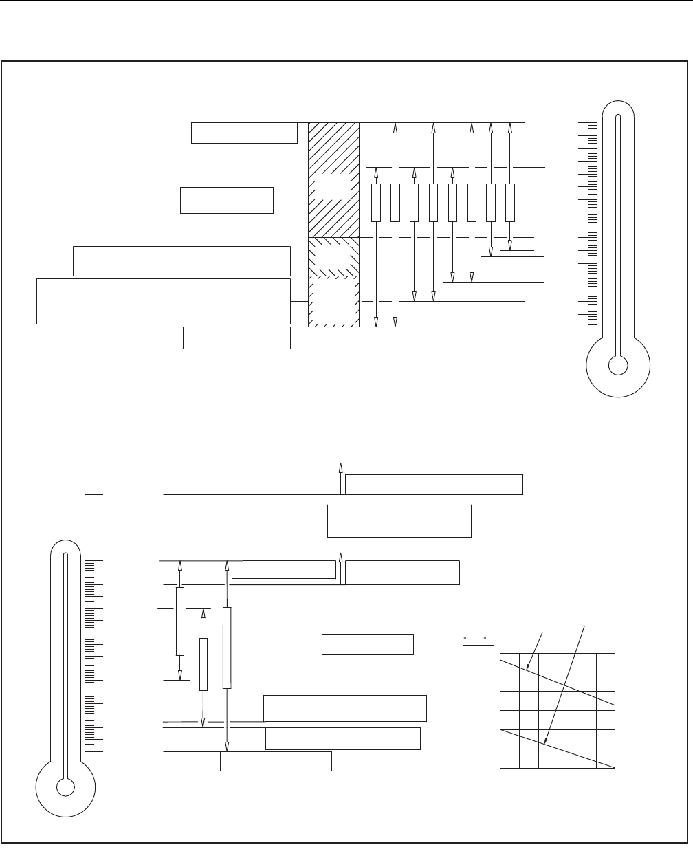
SECTION 2 - GENERAL
3121298 – JLG Lift – 2-9
Figure 2-1. Deutz Engine and Hydraulic Operating Temperature Specifications
!"
!"!
!
!"
!!
#
!
$!
%!%
#!
"#
!"
!!
!
&
!#!
$
!"!
&'
&
!'
&
%"%
&
''
'&
%
!
"#
"""$%
"& "
'"$'(
)
)
)
)
*"!"
$%
4150548 E
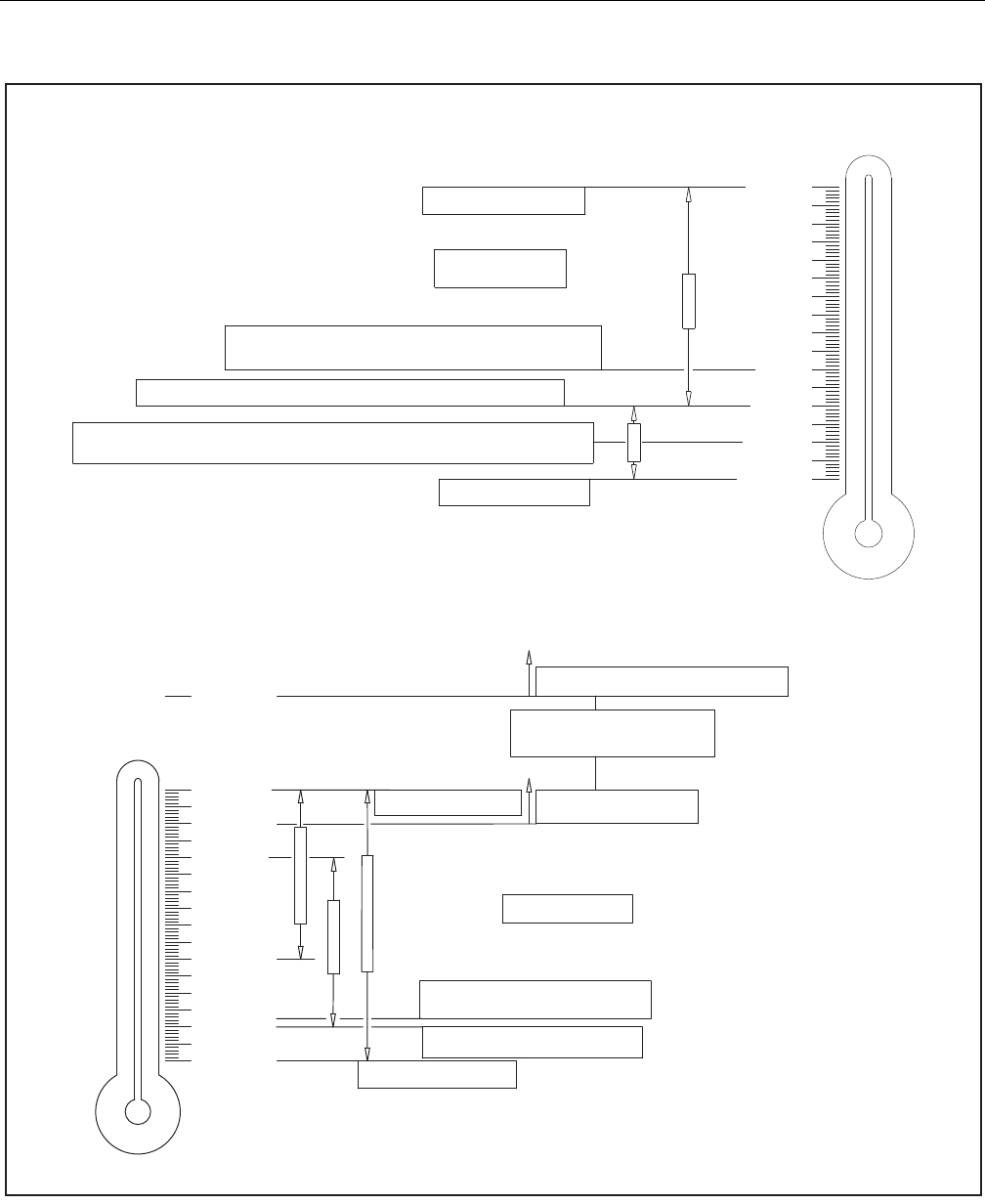
SECTION 2 - GENERAL
2-10 – JLG Lift – 3121298
Figure 2-2. GM Engine and Hydraulic Operating Temperature Specifications
!
!"
!!
#
!
$!
%!%
#!
"#
!"
!!
!
&
! "
&'
&
!'
&
""##
"
&
''
'&
%
!
"
"
$"
"
"
!
!
!"
!
!#
!
!$
!
!
% !
& !&
$ !
# !$
" !
!#
!
!"
"
%
""%
%&"
%"%
4150548 E
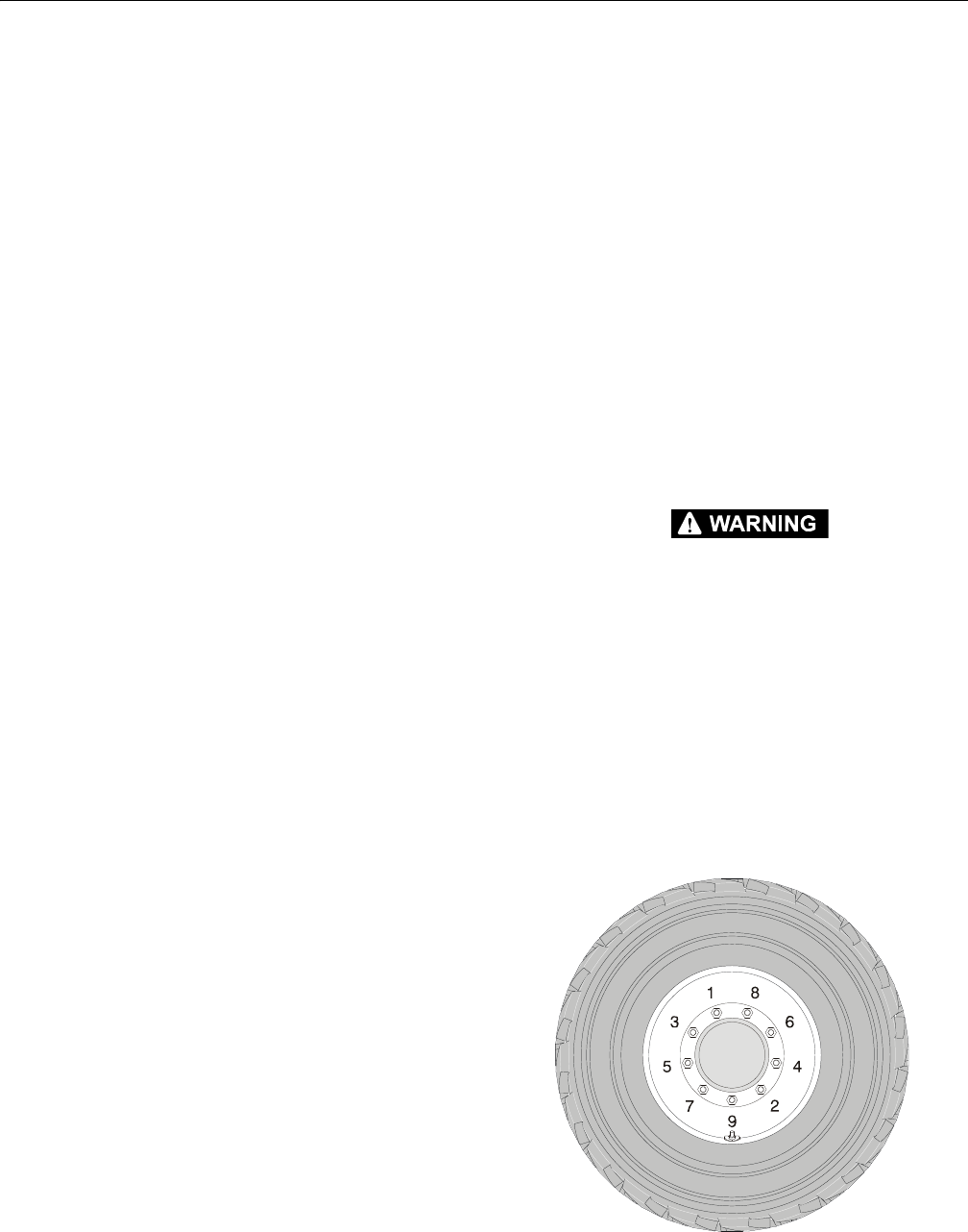
SECTION 3 - CHASSIS & TURNTABLE
3121298 – JLG Lift – 3-1
SECTION 3. CHASSIS & TURNTABLE
3.1 TIRES & WHEELS
Tire Inflation
Pneumatic tire air pressure must be equal to air pressure sten-
ciled on side of JLG product or rim decal for safe and proper
machine operation.
Tire Damage
PNEUMATIC TIRES
JLG Industries, Inc. recommends when any cut, rip, or tear is
discovered that exposes sidewall or tread area cords in the tire,
measures must be taken to remove the JLG product from ser-
vice immediately. Arrangements must be made for replace-
ment of the tire or tire assembly.
POLYURETHANE FOAM FILLED TIRES
JLG Industries, Inc. recommends when any of the following are
discovered, measures must be taken to remove the JLG prod-
uct from service immediately and arrangements made for
replacement of tire or tire assembly:
• Smooth, even cut through cord plies which exceeds
3" (7.5 cm) in total length.
• Tears or rips (ragged edges) in cord plies which
exceeds 1" (2.5 cm) in any direction.
• Punctures which exceed 1" in diameter.
• Damage to bead area cords.
NOTE: If a tire is damaged but within above criteria, it must be
inspected daily to ensure damage does not exceed allow-
able criteria.
Tire Replacement
JLG recommends a replacement tire be the same size, ply, and
brand as originally installed on the machine. Please refer to the
JLG Parts Manual for part number of approved tires for a par-
ticular machine model. If not using a JLG approved replace-
ment tire, we recommend replacement tires have the
following characteristics:
• Equal or greater ply/load rating and size of original
• Tire tread contact width equal or greater than original
• Wheel diameter, width, and offset dimensions equal to the
original
• Approved for the application by the tire manufacturer
(including inflation pressure and maximum tire load)
Unless specifically approved by JLG Industries Inc. do not
replace a foam filled or ballast filled tire assembly with a pneu-
matic tire. When selecting and installing a replacement tire,
ensure all tires are inflated to pressure recommended by JLG.
Due to size variations between tire brands, both tires on the
same axle should be identical.
Wheel Replacement
Rims installed on each product model are designed for stabil-
ity requirements which consist of track width, tire pressure,
and load capacity. Size changes such as rim width, center
piece location, larger or smaller diameter, etc., without written
factory recommendations, may result in unsafe stability condi-
tions.
Wheel Installation
WHEEL NUTS MUST BE INSTALLED AND MAINTAINED AT PROPER TORQUE TO
PREVENT LOOSE WHEELS, BROKEN STUDS, AND DANGEROUS SEPARATION OF
WHEEL FROM AXLE. USE ONLY NUTS MATCHED TO CONE ANGLE OF WHEEL.
Tighten lug nuts to proper torque to prevent wheels from
coming loose. Use a torque wrench to tighten fasteners. If you
do not have a torque wrench, tighten fasteners with a lug
wrench, then immediately have a service garage or dealer
tighten lug nuts to proper torque.
Over-tightening will break studs or permanently deform
mounting stud holes in wheels.
1. Start all nuts by hand to prevent cross threading. DO
NOT use a lubricant on threads or nuts.
2. Tighten nuts in the following sequence:
Figure 3-1. Wheel Lug Nut Tightening Sequence
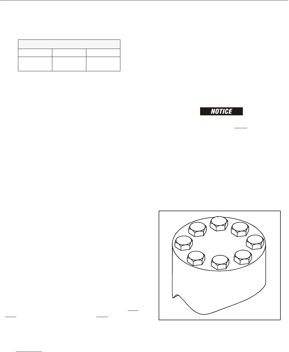
SECTION 3 - CHASSIS & TURNTABLE
3-2 – JLG Lift – 3121298
3. Torque to specifications shown in Table 3-1 below.
4. Torque wheel nuts after first 50 hours of operation and
after each wheel removal. Check torque every 3 months
or 150 hours of operation.
3.2 TORQUE HUB
Oil Information
1. 1. TYPE – EP90
Use EP90 for normal applications. For applications where
lubricant must meet special requirements, the O.E.M can
recommend a suitable substitute.
2. OIL TEMPERATURE
Continuous – 160° F (70° C) Intermittent – 200° F (95° C).
3. OIL CHANGE
Initial – After 50 hours or 50,000 revolutions of opera-
tion. Subsequent – After 1000 hours or (1) year, which-
ever comes first.
NOTE: Higher temperatures make it necessary to change oil more
frequently.
4. OIL FILL LEVEL AND VOLUME
Unit mounted horizontal – half full. (See Diagram A.)
Approximate volume - 17 oz. (0.5 1tr).
Roll and Leak Testing
Always roll and leak test Torque-Hubs after assembly to make
sure that the unit’s gears and sealants are working properly.
The following information briefly outlines what to look for
when performing these tests.
ROLL TEST
The roll test determines if the unit’s gears rotate freely and
properly. You should be able to rotate gears by applying a con-
stant force to the roll checker. If you feel more drag in gears
only at certain points, gears are not rolling freely. Examine
them for improper installation or defects.
Some gear packages roll with more difficulty than others. Do
not be concerned if gears seem to roll hard as long as they roll
with consistency.
LEAK TEST
The purpose of a leak test is to make sure unit is air tight. You
can tell if your unit has a leak if pressure gauge test reading
starts to fall once you have pressurized the unit.
Leaks usually occur at the main seal or wherever O-rings or
gaskets are located. You can usually detect location of a leak by
brushing a soap and water solution around main seal and
where O-rings or gaskets meet unit exterior, then checking for
air bubbles. Replace part immediately if you detect a leak in a
seal, O-ring, or gasket.
Tightening and Torquing Bolts
USE EXTREME CARE WHEN USING AN AIR IMPACT WRENCH. DO NOT TIGHTEN
BOLTS BEYOND THEIR TORQUE SPECIFICATION. NEVER USE AN IMPACT
WRENCH TO TIGHTEN SHOULDER BOLTS. TIGHTEN ALL SHOULDER BOLTS BY
HAND.
1. Tighten (but do not torque) bolt ”A” until snug.
2. Go to opposite side of bolt circle and tighten bolt ”B”
until equally snug.
3. Continue around bolt circle and tighten remaining bolts.
4. Use a torque wrench to apply specified torque to bolt ”A”.
5. Continue around bolt circle and apply equal torque to
remaining bolts.
Figure 3-2. Bolt Tightening Sequence
Table 3-1. Wheel Torque Chart
TORQUE SEQUENCE
1st Stage 2nd Stage 3rd Stage
40 ft-lb
(55 Nm)
100 ft-lb
(130 Nm)
170 ft-lb
(255 Nm)
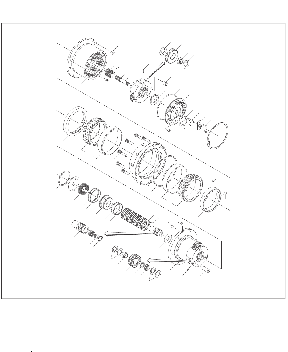
SECTION 3 - CHASSIS & TURNTABLE
3121298 – JLG Lift – 3-3
Figure 3-3. Torque Hub
3B
3F
3C
3B
19
11
20
59
1E
4G
3E
2
17
6A
6E
6D
6B
6C
6G
15
16
6F
1B
1C
1H
1D
18
1C
1F
1G
1G
8C
8B
8L
8E
8D
8A
8F
8H
8K
8J
12
21
7
1L
1M
1K
4B
4C
4F
4D
4C
4B
4H
1A
4G
4E
3A
2780269
1A. Spindle
1B. Seal
1C. Bearing
1D. Housing
1E. Ring Gear
1F. Bearing Nut
1G. Setscrew
1H. Wheel Stud
1K. Retaining Ring
1L. Spring
1M. Thrustwasher
2. Thr us t wa sh er
3A. Carrier
3B. Thrustwasher
3C. Needle Bearing
3E. Planet Shaft
3F. Planet Gear
4B. Thrustwasher
4C. Needle Bearing
4D. Thrust Spacer
4E. Planet Shaft
4F. Planet Gear
4G. Roll Pin
4H. Thrustwasher
5. Re ta in in g R in g
6A. Cover Plate
6B. Disengage Cap
6C. Bolt
6D. Dowel Pin
6E. O-Ring
6F. Pipe Plug
6G. Retaining Ring
7. Co upl in g
8A. Brake Piston
8B. Pressure Plate
8C. Retaining Ring
8D. O-Ring
8E. Back-up Ring
8F. O-Ring
8H. Back-up Ring
8J. Brake Rotor
8K. Brake Stator
8L. Brake Spring
9. In pu t S ha ft
11. Sun Gear
12. Plug
15. I.D. Plate
16. Drive Screw
17. O-Ring
18. O-Ring
19. Countersunk Screw
20. Retaining Ring
21. Plug
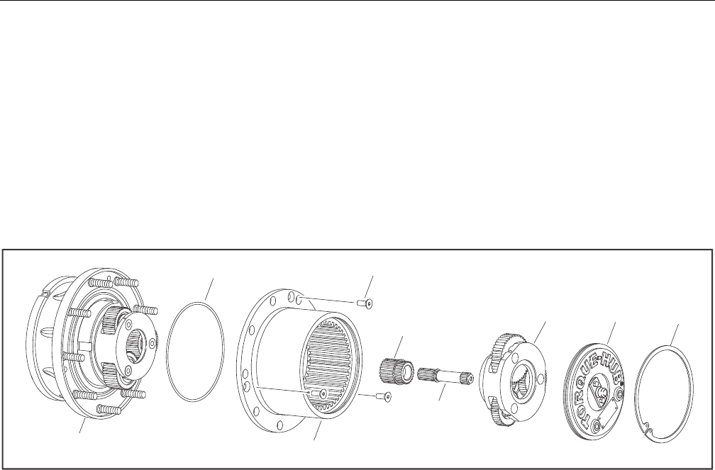
SECTION 3 - CHASSIS & TURNTABLE
3-4 – JLG Lift – 3121298
Main Disassembly
1. Perform Roll Check, Leak Check, and Brake Check if
applicable before disassembly.
2. Drain oil from unit. Note condition and volume of oil.
3. Remove Retaining Ring (6G) by prying open end of
Retaining Ring out of groove in Ring Gear (1E) with a
screwdriver. Grasp loose end with pliers and pull out
Retaining Ring.
4. Remove Cover Subassembly (6).
NOTE: Carefully pressurize unit with air to pop cover off.
5. Remove Input Carrier Subassembly (3).
6. Remove Input Shaft (9).
7. Remove Second Stage Sun Gear (11).
8. Loosen and remove three Flat Head Bolts (19) that retain
Ring Gear (1E) to Housing (1G).
9. Lift Ring Gear (1E) off Housing (1D).
10. Remove O-ring (18) from Housing (1D.
Figure 3-4. Torque Hub Main Disassembly
1D 1E
9
11
19
18
366A
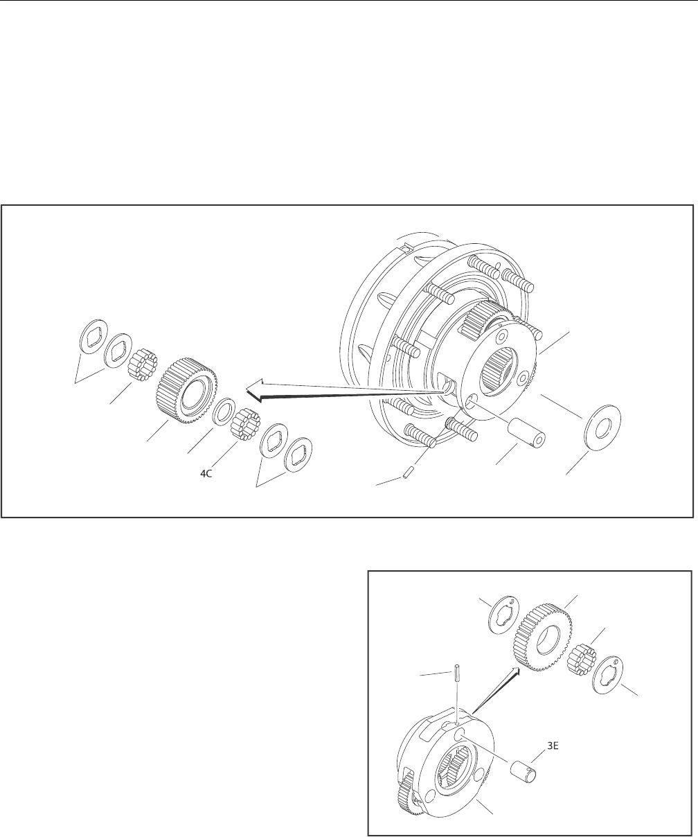
SECTION 3 - CHASSIS & TURNTABLE
3121298 – JLG Lift – 3-5
Output Carrier Disassembly
1. Use a 1/8” diameter punch to drive Roll Pin (4G) in Planet
Shaft (4E) until it bottoms against Spindle (1A).
2. Grasp Roll Pin (4G) with needle nosed pliers or a hooked
tool and pull Planet Shaft (4E) out of Spindle (1A).
3. Drive Roll Pin (4G) out of Planet Shaft (4E). Discard roll
pin.
4. Slide Planet Gear Subassembly (4) out of Spindle (1A).
Do not drop Needle Bearings (4C).
5. Remove four Thrust Washers (4B), 28 Needle Rollers (4C),
and Thrust Spacer (4D) from Second Stage Planet Gear
(4F).
6. Repeat Steps 12-15 for remaining Planet Gears (4F).
7. Remove Thrust Washer (4H) from Spindle (1A) counter-
bore.
Figure 3-5. Output Carrier Disassembly
Input Carrier Disassembly
1. Using a 1/8” diameter punch, drive Roll Pin (4G) in Planet
Shaft (3E) until it bottoms against Carrier (3A).
2. Using a soft face hammer, tap Planet Shaft (3E) out of
Carrier (3A).
3. Using a 1/8” diameter punch, drive Roll Pin (4G) out of
Planet Shaft (3E). Discard roll pin.
4. Slide Planet Gear (3F) and two Thrust Washers (3B) out
of Carrier (3A).
5. Remove 14 needle Bearings (3C) from bore of Planet
Gear (3F).
6. Repeat steps 1 through 5 for remaining planet gears.
Figure 3-6. Input Carrier Disassembly
4H
4B
4C
4F
4D
4B 4G
4E
1A
3B 3F
3C
3B
4G
3A
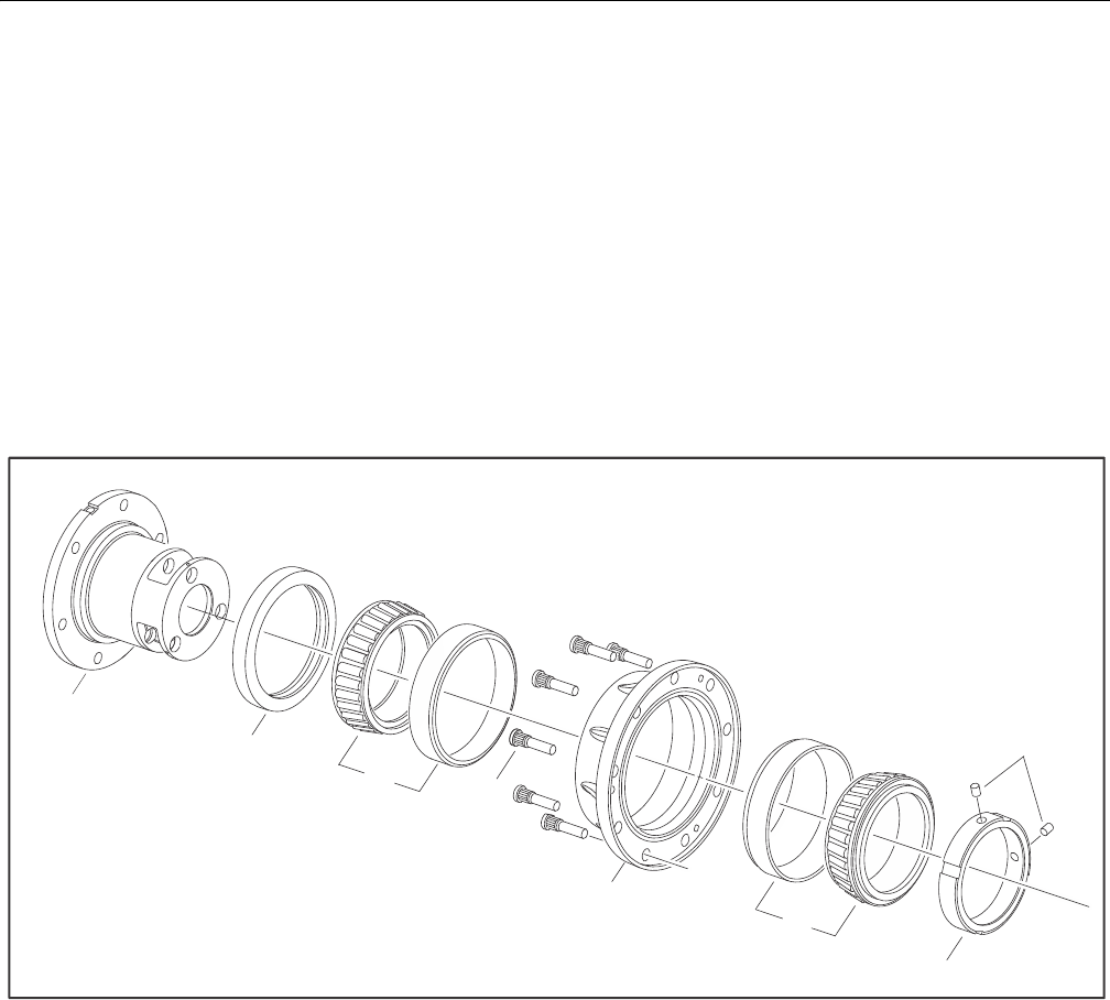
SECTION 3 - CHASSIS & TURNTABLE
3-6 – JLG Lift – 3121298
Hub-Spindle Disassembly
1. Place unit on bench with Spindle (1A) end down.
2. Remove 2 Set Screws (1G) and Bearing Nut (1F) using T-
206569.
NOTE: Holes in Bearing Nut (1F) for Set Screws (1G) are staked for
retention of Set Screws (1G). Clean holes before removing
Set Screws.
3. Remove “A” position Bearing Cone (1C) from Bearing
Cup (1C) in Hub (1D).
4. While supporting unit on Hub (1D) flange, press Spindle
(1A) out of Hub (1D).
5. Lift Hub (1D) off of Spindle (1A). Remove Boot Seal (1Q)
from Hub (1D) if applicable.
6. If necessary, press nine Studs (1H) out of Hub (1D).
Locate Hub (1D) on Seal (1B) end.
7. Remove Seal (1B) from Hub (1D). Discard seal.
8. Remove “B” position Bearing Cone (1C) from Bearing
Cup (1C) in Hub (1D).
9. Remove “B” position Bearing Cone (1C) from Hub (1D).
10. Using a soft steel rod, knock both Bearing Cups (1C) out
of Hub (1D).
Figure 3-7. Hub Spindle Disassembly
1A
1B
1C 1H
1D
1C
1F
1G
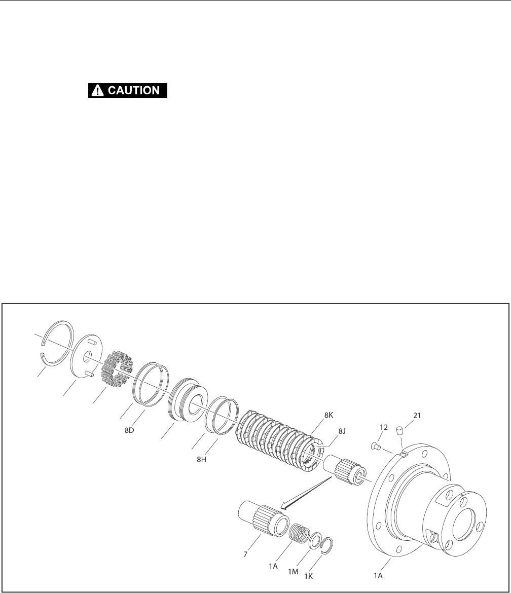
SECTION 3 - CHASSIS & TURNTABLE
3121298 – JLG Lift – 3-7
Spindle-Brake Disassembly
NOTE: Units with integral Input Brake (8) only.
COMPRESSED SPRINGS CAN FLY OUT AND CAUSE SEVERE EYE DAMAGE OR
OTHER INJURIES. WEAR EYE PROTECTION WHEN PERFORMING THESE PROCE-
DURES.
1. Install two 1/4"-20 x 5/8" Flat Head Cap Screws (22)
through Pressure Plate (8B) into Piston (8A). Tighten
incrementally until spring force is taken off Retaining
Ring (8C).
NOTE: Flat Head Cap Screws (22) are for transit and service only
and are removed before shipping new units. They are
included in most brake repair kits.
2. Using retaining ring pliers, remove Retaining Ring (8C)
from groove in Spindle (1A).
3. Back Flat Head Cap Screws (22) incrementally out of Pis-
ton (8A) until spring force is relieved from Pressure Plate
(8B). Remove Flat Head Cap Screws (22) and Pressure
Plate (8B) from brake cavity in Spindle (1A).
4. Remove Compression Springs (8L) from Piston (8A).
5. Using an air hose, slowly and carefully pressurize brake
port in Spindle (1A) until Piston (8A) comes out of piston
bore of Spindle (1A). Pull Piston (8A) out of Spindle (1A)
by hand.
6. Remove Backup Rings (8E and 8H) and O-rings (8D and
8F) from grooves in Piston (8A).
7. Remove Rotors (8J) and Stators (8K) from brake cavity in
Spindle (1A).
8. Remove Coupling Subassembly (7) from brake cavity in
Spindle (1A).
9. Remove Retaining Ring (1K) from internal groove using
appropriate tool.
10. Remove Spacer (1M) and Spring (1L) from bore of Cou-
pling (7).
11. Remove Plastic Plug (12) and Pipe Plug (21) from Spindle
(1A) if applicable.
Figure 3-8. Spindle Brake Disassembly
8C
8B
8L
8E
8A
8F
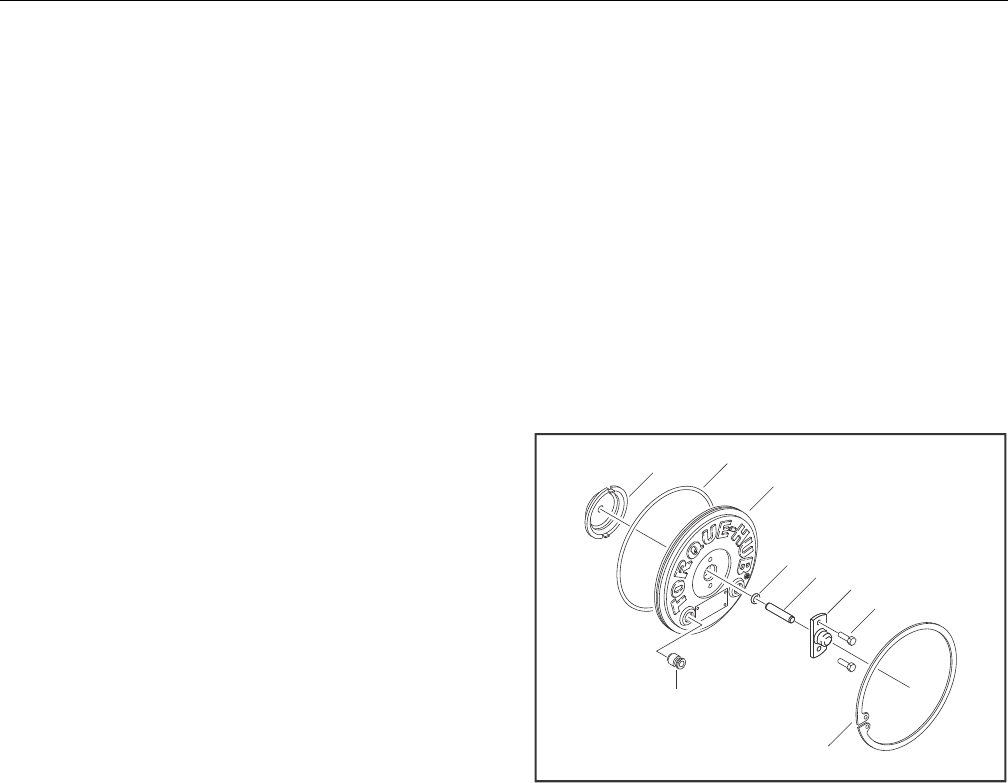
SECTION 3 - CHASSIS & TURNTABLE
3-8 – JLG Lift – 3121298
Cover Disassembly
1. Remove O-Ring (17) from groove in Cover (6A).
2. Remove Thrust Washer (2) from Cover (6A) pockets.
3. Unscrew two Hex Head Bolts (6C) and remove Disen-
gage Cap (6B) from Cover (6A).
4. Pull Disengage Rod (6D) out from Cover (6A).
5. Use appropriate tool to remove O-ring (6E) from internal
groove in Cover (6A).
6. Remove two O-Ring Pipe Plugs (6F) from Cover (6A).
Cover Assembly
1. Grease O-Ring (6E) and insert in internal groove in Cover
(6A).
2. Assemble Disengage Cap (6B) on Cover (6A) using two
Hex Head Bolts (6C). Torque bolts to 70-80 in-lbs.
3. Insert Disengage Rod (6D) in hole in Cover (6A) until it
touches inside of Disengage Cap (6B).
NOTE: Disengage Rod can be inserted either end first.
4. Grease face of Thrust Washer (2) and place in Cover (6A).
Make sure tangs on washer seat into pockets in cover.
5. Install O-Ring Pipe Plugs (6F) in Cover (6A). Plugs should
be hand tight.
Figure 3-9. Torque Hub Cover
217
6A
6E 6D 6B
6C
6G
6F
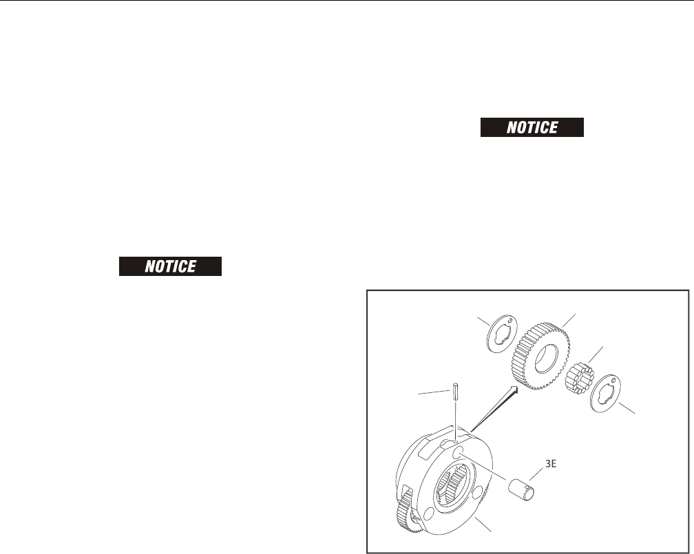
SECTION 3 - CHASSIS & TURNTABLE
3121298 – JLG Lift – 3-9
Input Carrier Assembly
1. Apply a liberal coat of grease to bore of one Input Planet
Gear (3F).
2. Line inside of Planet Gear (3F) with 14 Needle Rollers
(3C).
NOTE: The last roller installed must be installed end wise. That is,
the end of the last roller must be placed in between ends of
the two rollers which form the space, and then slid, parallel
to the other rollers, into place.
3. Set Carrier (3A) in an upright position.
INSERT END OF PLANET SHAFT THAT DOES NOT HAVE ROLL PIN HOLE IN CAR-
RIER FIRST.
4. Insert a Planet Shaft (3E) in planet shaft hole in end of
Carrier (3A) opposite splined end.
5. Place one Thrust Washer (3B) on end of Planet Shaft (3E).
Make sure the flat faces towards inside of carrier and
make sure button fits in the pocket on inside of Carrier
(3A) towards the OD.
6. Following the thrust washer, place Planet Gear (3F) with
needle rollers, on Planet Shaft (3E).
7. Following the planet gear, place one more Thrust
Washer (3B) onto Planet Shaft (3E). Align Thrust Washer
(3B) in same manner described in Step 5.
8. Now insert Planet Shaft (3E) through opposite planet
shaft hole on Carrier (3A). Use an alignment punch or
similar tool to align roll pin holes on Carrier (3A) and
Planet Shaft (3E).
DO NOT TO HIT PLANET GEARS (3F) WHEN DRIVING IN ROLL PINS (4G).
9. Drive Roll Pin (4G) down into aligned roll pin holes. Pin
should be flush with flat of carrier.
10. Repeat Steps 1-9 for installation of two remaining Planet
Gears (3F).
NOTE: Some grease may need to be applied to Thrust Washers
(3B) to hold them in place while installing planet gears.
Figure 3-10. Input Carrier Assembly
3B 3F
3C
3B
4G
3A
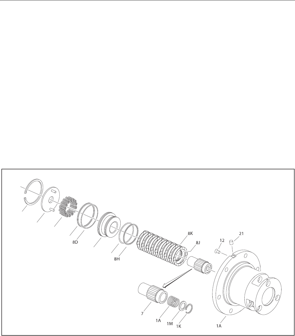
SECTION 3 - CHASSIS & TURNTABLE
3-10 – JLG Lift – 3121298
Spindle - Brake Assembly
1. Place Spindle (1A) with flange side up.
2. Place Stator (8K) in Spindle (1A) scallop cuts.
3. Place Rotor (8J) on top of Stator (8K).
4. Repeat steps 2 & 3 until there are a total of 9 Stators (8K)
and 8 Rotors (8J) installed.
5. Place Piston (8A) with smaller O.D. end facing up. Grease
two O-Rings and two Backup Rings.
6. Install large Backup Ring (8E) in large-diameter groove at
bottom of Piston (8A).
7. Install large O-Ring (8D) in large-diameter groove at bot-
tom of Piston (8A), on top of large Backup Ring (8E).
8. Install small O-Ring (8F) in small-diameter groove near
top of Piston (8A). Make sure O-Ring is seated on the
bottom of the groove.
9. Install small Backup Ring (8H) in small-diameter groove
near top of Piston (8A), on top of small O-Ring (8F).
10. Insert Piston (8A) in Spindle (1A) until it contacts Stator
(8K).
11. Insert appropriate number of Springs (8L), based on
assembly print, into Piston (8A)counterbore.
12. Place Spring (1L) in Coupling (7) counterbore. Place Pres-
sure plate (1M) on top of Spring (1L).
13. Use appropriate tool to install Retaining Ring (1K) in
retaining ring groove in coupling (7) counterbore.
14. Insert Coupling subassembly (7) through Rotors (8J).
15. Place Pressure Plate (8B) on top of Springs (8L).
16. Use two ¼ -20 x 0.625 Flat Head Cap Screws (22) by bolt-
ing Pressure Plate (8B) and Piston (8A) together or some
other appropriate tools to install Retaining Ring on top
of Pressure Plate (8B) until Retaining Ring (8C) is seated.
NOTE: Remove two screws from units when done or brake will not
function.
17. Install Pipe Plug (21) if applicable.
Figure 3-11. Spindle-Brake Assembly
8C
8B
8L
8E
8A
8F
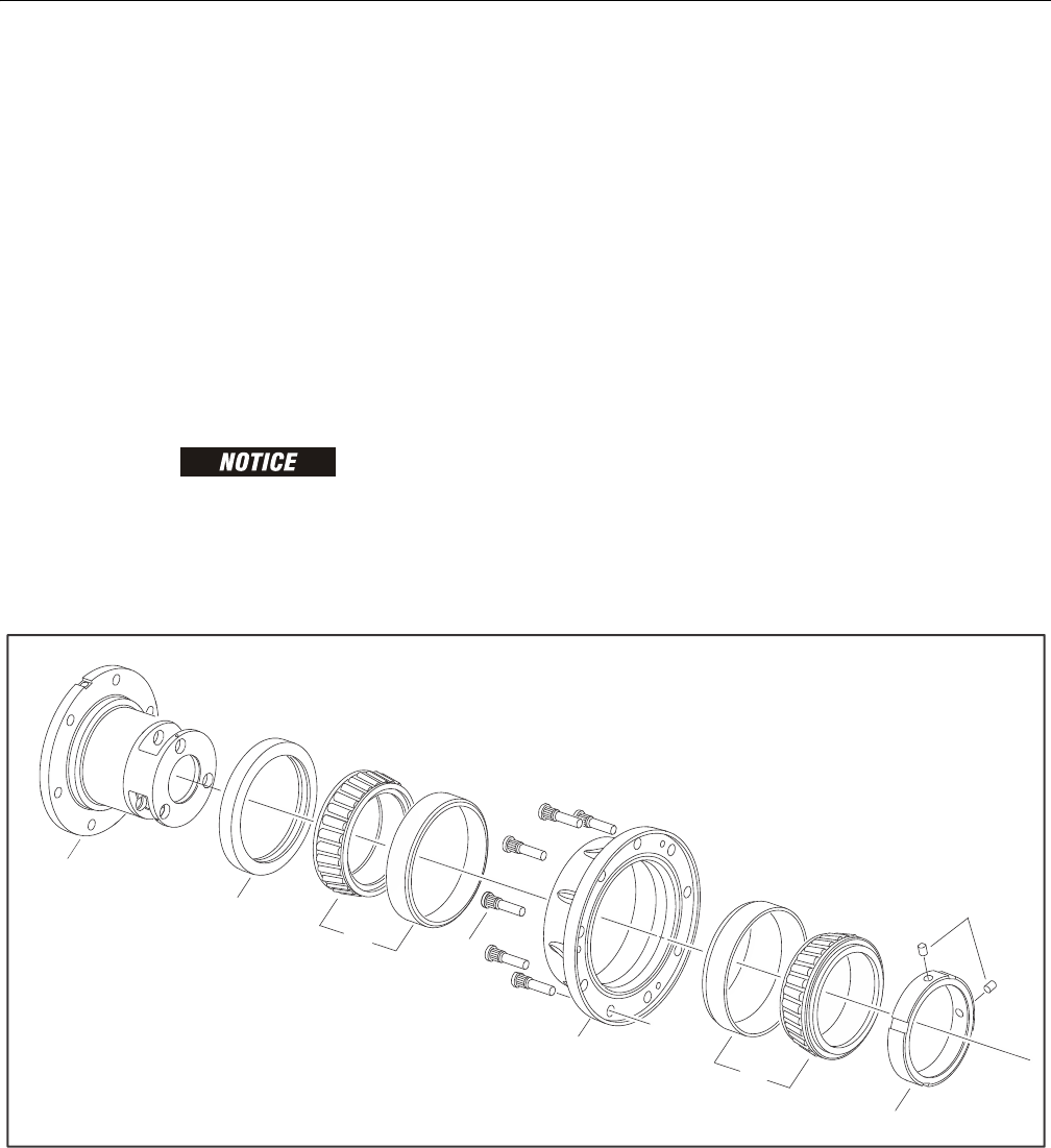
SECTION 3 - CHASSIS & TURNTABLE
3121298 – JLG Lift – 3-11
Hub-Spindle Assembly
NOTE: Spray a light film of oil on all component parts during
assembly. Spray a generous amount of oil on bearings dur-
ing installation.
1. Press Bearing Cup of part (1C), position "A", into Hub
using T-158422 pressing tool.
2. Turn hub over and press Bearing Cup of part (1C), posi-
tion "B", into hub using T-158422 pressing tool.(T).
3. Place Bearing Cone of part (1C), into Bearing Cup of part
(1C), position "B".
4. Grease Seal (1B) lip and press seal into Hub (1D) using
appropriate tool until seal is flush with end of hub.(T).
DO NOT USE EXCESSIVELY HIGH PRESSURE TO PRESS IN STUDS OR HUB MAY
CRACK.
5. Place Hub (1D) into pressing base. Press nine Studs (1H)
in Hub.
6. Set Spindle assembly (1A) on bench with flange down.
Turn Hub (1D) over and lower onto Spindle (5). Install
boot (21) if applicable.
7. Install Bearing Cone of part (1C) in Bearing Cup, position
"A".
8. Apply Loctite 243 or equivalent on Bearing Nut (1F)
thread. Screw Nut (1F) on top of Bearing Cone of part
(1C). Leave 0.003-0.005 inches end play to check initial
rolling torque with unit tied down. Torque Bearing Nut
(1F) until rolling torque is 40 - 50 in-lb (4.5 - 5.6 Nm)
greater than initial rolling torque. Using tool T-206569
for Bearing Nut.
NOTE: Final torque is initial rolling torque plus 40-50 in-lb E.g., if
initial rolling torque is 30 in-lb, final rolling torque is
between 70-80 in-lb. Be sure to rotate hub as torque is
applied to properly seat bearing. Be sure torque wrench is
tangent to the Hub (1D) OD.
9. Install two Set Screws (1G) in Bearing Nut (1F) threaded
holes. Make sure Set Screw is driven in spindle thread.
Tighten set screws to damage thread and stake edge of
nut around Set Screws (1G) so nut will not loosen.
Figure 3-12. Hub Spindle Assembly
1A
1B
1C 1H
1D
1C
1F
1G
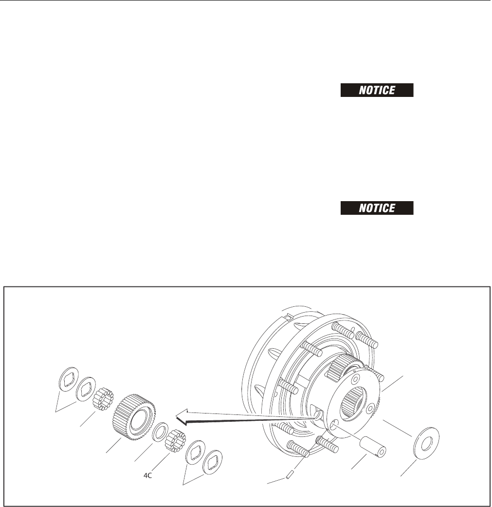
SECTION 3 - CHASSIS & TURNTABLE
3-12 – JLG Lift – 3121298
Output Planet Gear Assembly
1. Apply a liberal coat of grease to the bore of one Output
Planet Gear (4F).
2. Line inside of Planet Gear (4F) with 14 Needle Rollers
(4C).
NOTE: Last roller installed must be installed end wise. That is, the
end of the last roller must be placed in between the ends of
the two rollers which form the space, and then slid, parallel
to the other rollers, into place.
3. Place Spacer (4D) in bore of Output Planet (4F).
4. Repeat Step 2 to put in second roll of Needle Rollers (4C).
5. Apply grease to hold two Thrust Washers (4B) together
and on Output Planet Gear (4F) counterbore. Repeat on
other side.
6. Repeat Steps 1-5 for remaining Output Planet Gears (4F).
7. Place Thrust Washer (4H) in counterbore of Spindle (1A).
8. Place Planet Gear Subassembly (4) in Spindle (1A)
through gap between two Studs (1H). Align planet gear
bore with one of the planet shaft holes on spindle (1A)
assembly using special tool T-209919.
INSERT END OF PLANET SHAFT THAT DOES NOT HAVE ROLL PIN HOLE IN SPIN-
DLE FIRST.
9. Insert Planet Shaft (4E) in Spindle (1A) through first set of
Thrust Washers (4B), Planet gear, and second set of
Washers (4B).
10. Use an alignment punch or similar tool to align roll pin
holes on Spindle (1A) and Planet Shaft (4E).
DO NOT HIT PLANET GEARS (4F) WHEN DRIVING IN ROLL PINS (4G).
11. Drive new Roll Pin (4G) in aligned roll pin holes. Pin
should be flush with OD of spindle.
12. Repeat Steps (11-14) for remaining Planet Gears (4F).
Figure 3-13. Output Planet Gear Assembly
4H
4B
4C
4F
4D
4B 4G
4E
1A
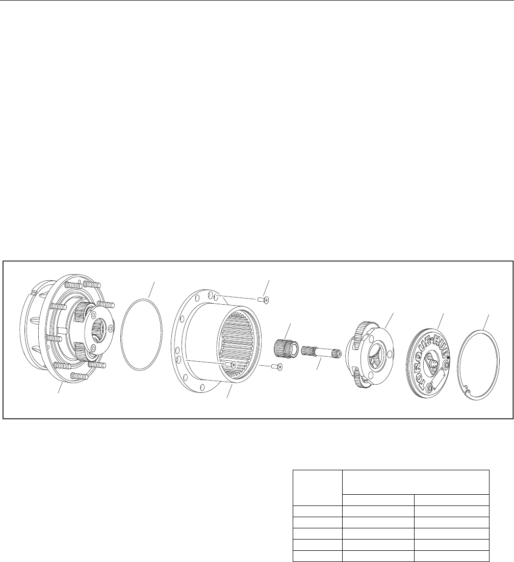
SECTION 3 - CHASSIS & TURNTABLE
3121298 – JLG Lift – 3-13
Main Assembly
NOTE: Coat all components with a generous amount of lubricant
oil as they are being assembled.
1. Place Hub-Spindle Subassembly on bench.
2. Grease O-Ring (18) and place it in groove of Hub (1D).
3. Place Ring Gear (1E) on Hub (1D). Align three shipping
Cap Screw Holes on Hub (1D) and Ring Gear (1E).
4. Install three shipping Cap Screws (19) in ring gear and
hub. Torque to 15-20 ft-lb.
5. Place External Retaining Ring (5) over 13T spline to the
retaining groove on Input Shaft (9).
NOTE: For ratio 48:1, assemble Output Sun Gear (11) over Input
Shaft (9) first, then install External Retaining Ring (5).
6. Using appropriate tool to install Retaining Ring (20) in
groove on Output Sun (11).
7. Place Input Shaft (9) spline end into mesh with Internal
Coupling (7) splines.
8. With modified spline end facing up, place Output Gear
(11) in mesh with planet gears from Hub-Spindle Subas-
sembly.
9. Place Input Carrier Subassembly (3) on Output Sun Gear
(11) splines.
10. Grease O-Ring (17) and insert in groove in Cover Subas-
sembly (6).
11. Install Cover Subassembly (6) in Ring Gear (1E) counter-
bore and install Retaining Ring (6G) in groove in Ring
Gear (1E).
12. Check disconnect, roll and air check unit, leak check
brake, and record release pressure.
Figure 3-14. Main Assembly
Integral Brake Check
1. Using appropriate fittings, connect hydraulic line from
hand pump to brake port.
2. Check brake is set by trying to rotate Input Shaft (9). This
can be accomplished by installing an appropriate tool
(any tool that can locate on splines of Input Coupling (7),
such as a mating splined shaft) into Input Coupling
(7).Bleed brake.
3. Increase hydraulic pressure gradually while trying to
rotate input until brake just starts to release. Note this
pressure. Make sure pressure falls into appropriate range
in Table 3-2.
Table 3-2. Torque Hub Brake Release Pressure
4. Increase pressure to 1,000 psi and hold for 30 seconds to
check for leaks. Repair leaks if necessary.
NOTE: Make sure brake re-engages when pressure is released.
NOTE: When done, make sure Input Coupling (7) is centered in
Spindle (1A) to make installation of motor possible without
release of brake.
1D 1E
9
11
19
18
36
6A
BRAKE
CODE
JUST RELEASE
PRESSURE RANGE
PSI BAR
A200-260 13.7-17.9
B170-220 11.7-15.1
C140-185 9.6-12.7
D130-155 8.9-10.6
E115-145 7.9-9.9
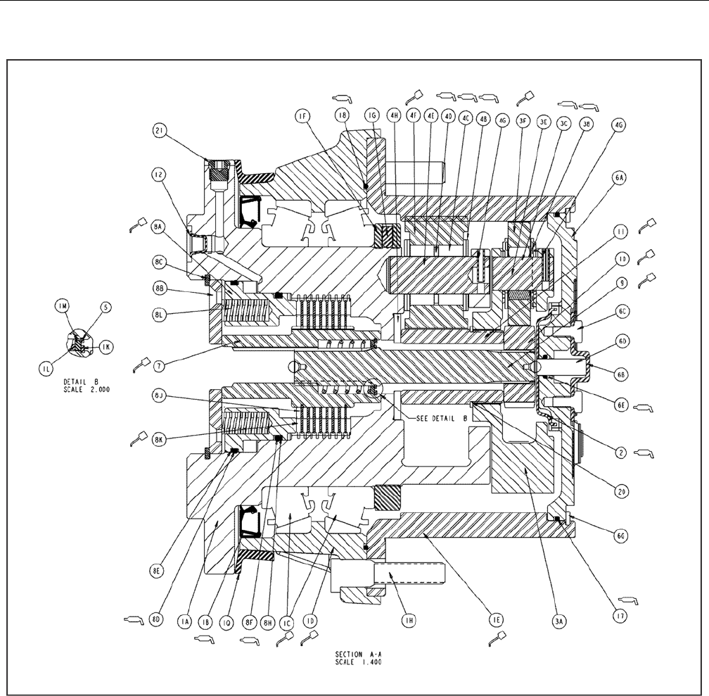
SECTION 3 - CHASSIS & TURNTABLE
3-14 – JLG Lift – 3121298
Figure 3-15. Hub Assembly
1A. Spindle
1B. Lip Seal
1C. Tapered Bearing
1D. Housing
1E. Ring Gear
1F. Bearing Nut
1G. Setscrew
1H. Stud
1K. Retaining Ring
1L. Spring
1M. Thrust Washer
1Q. Seal Boot
2. T hr us t S pac er
3A. Carrier
3B. Thrust Washer
3C. Needle Bearing
3E. Planet Shaft
3F. Planet Gear
4B. Thrust Washer
4C. Needle Bearing
4D. Thrust Spacer
4E. Planet Shaft
4F. Planet Gear
4G. Roll Pin
4H. Thrust Washer
5. R et ai ni ng Ri ng
6A. Cover
6B. Disengage Cap
6C. Bolt
6D. Dowel Pin
6E. O-Ring
6F. Pipe Plug
6G. Retaining Ring
7. C ou pli ng
8A. Brake Piston
8B. Pressure Plate
8C. Retaining Ring
8D. O-Ring
8E. Backup Ring
8F. O-Ring
8H. Backup Ring
8J. Brake Rotor
8K. Brake Stator
8L. Spring
9. I np ut Sh af t
10. Sun Gear
11. Sun Gear
12. Plastic Plug
15. ID Plate
16. Drive Screw
17. O-Ring
18. O-Ring
19. Bolt
20. Retaining Ring
21. O-Ring Plug
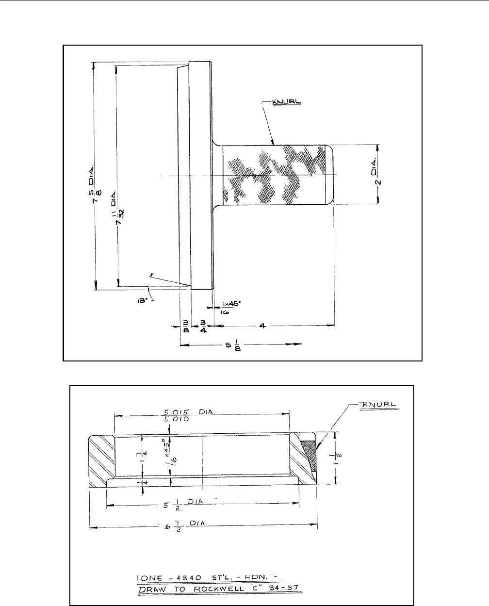
SECTION 3 - CHASSIS & TURNTABLE
3121298 – JLG Lift – 3-15
Figure 3-16. Bearing Cup Pressing Tool
Figure 3-17. Seal Pressing Tool
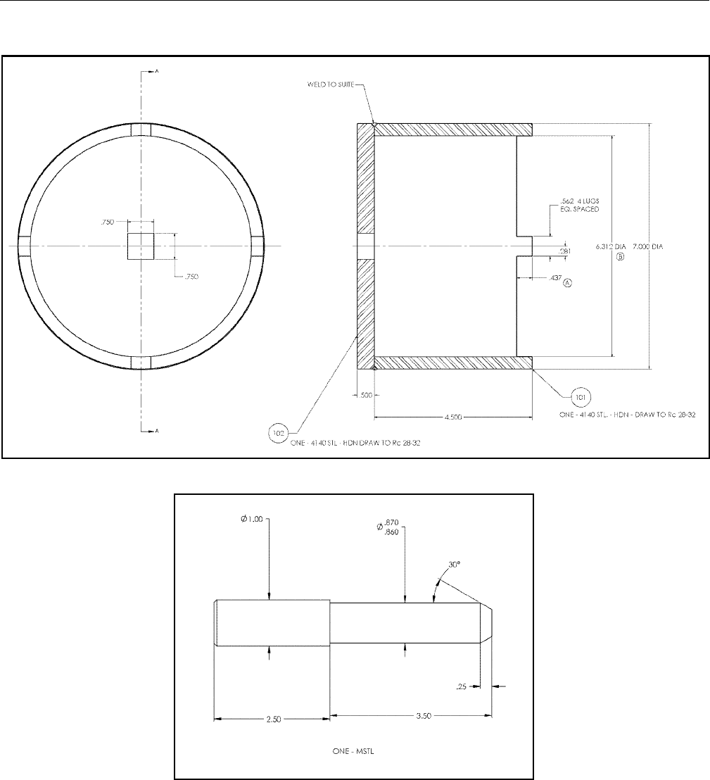
SECTION 3 - CHASSIS & TURNTABLE
3-16 – JLG Lift – 3121298
Figure 3-18. Bearing Cup Pressing Tool
Figure 3-19. Drift Pin for Lining Up Thrust Washers with Output Planet Gear
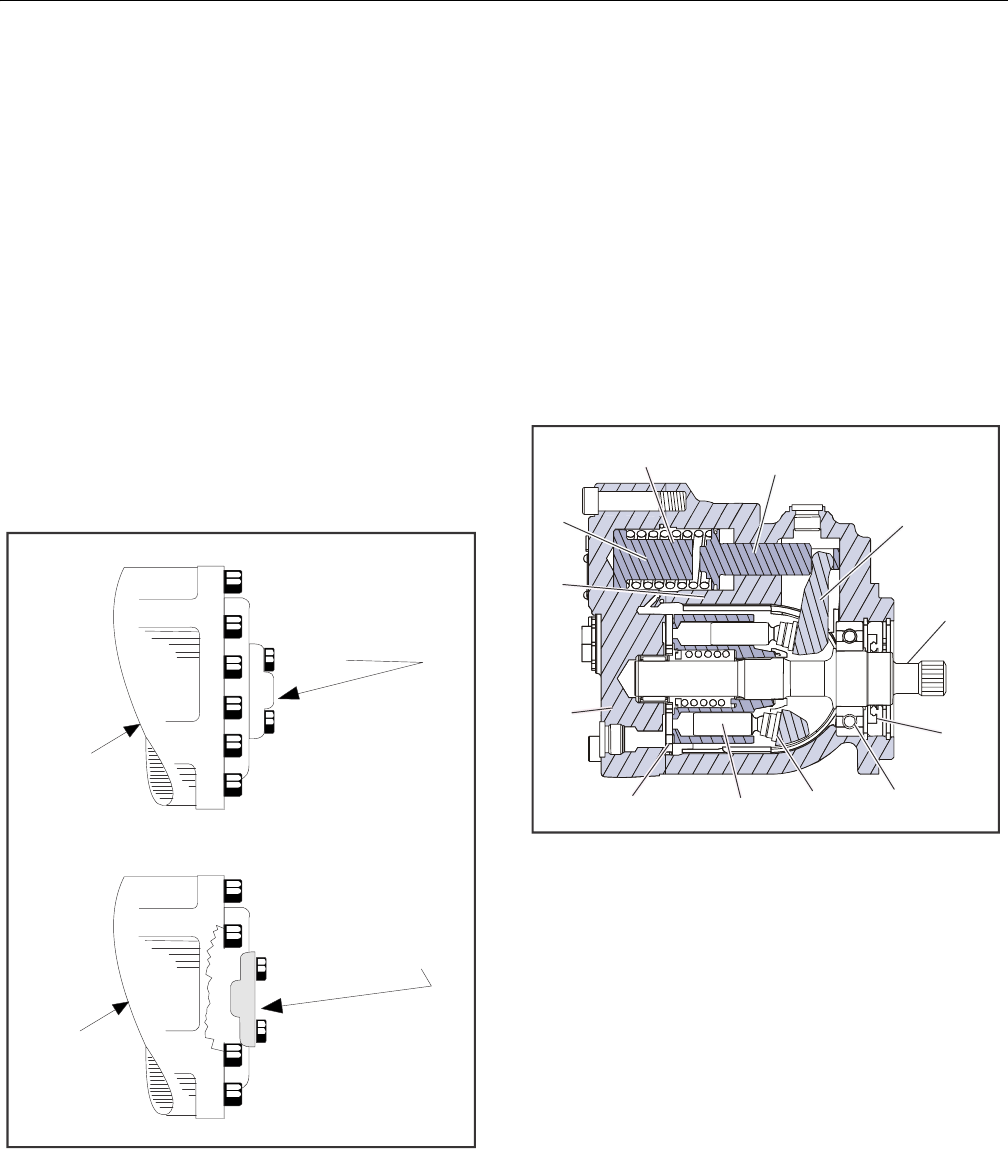
SECTION 3 - CHASSIS & TURNTABLE
3121298 – JLG Lift – 3-17
3.3 FREE WHEELING OPTION
Disengage Drive Motors & Brakes for Towing, etc.
(Free Wheel)
1. Chock wheels securely if not on flat level surface.
2. Disconnect both drive hubs by inverting disconnect
caps in center of hubs.
3. If equipped, move steer/tow selector valve to float (tow)
position by pulling valve knob out.
Engage Drive Motors & Brakes (Normal Operation)
1. If equipped, move steer/tow valve to steer position by
pushing valve knob in.
2. Connect both drive hubs by inverting disconnect cap in
center of hub.
3. Remove chocks from wheels as required.
Figure 3-20. Disengaging Drive Hubs
3.4 DRIVE MOTOR
Description
Drive motors are low to medium power, two-position axial pis-
ton motors incorporating an integral servo piston. They are
designed for operation in open and closed circuit applications.
The standard control is a direct acting single line hydraulic
control. The integral servo piston controls motor displace-
ment.
Motors are spring biased to maximum displacement and
hydraulically shifted to minimum displacement. Minimum and
maximum displacement can be set with fixed internal stops.
The large diameter servo piston allows smooth acceleration
and deceleration with relatively large circuit orificing.
Figure 3-21. Drive Motor Cross Section
DISCONNECT
CAP
DISCONNECT CAP
(REVERSED)
DRIVE
HUB
DRIVE
HUB
Drive Hub Engaged
Drive Hub Disengaged
1. Bias Spring
2. Servo Piston
3. Swashplate
4. Output Shaft
5. Shaft Seal
6. Bearing
7. Slipper
8. Piston
9. Valve Plate
10. End Cap
11. Cylinder Block
12. Minimum Angle Stop
12
3
4
5
6
7
8
9
10
11
12
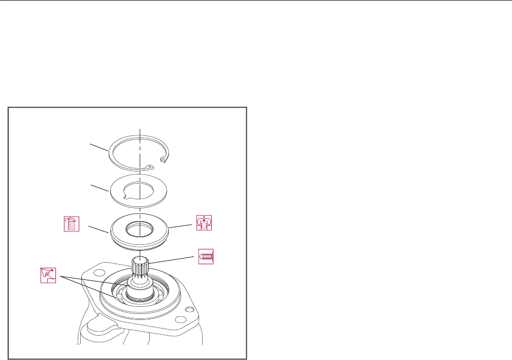
SECTION 3 - CHASSIS & TURNTABLE
3-18 – JLG Lift – 3121298
Shaft Seal Replacement
REMOVAL
1. Remove snap ring (1) retaining shaft seal, and support
washer.
Figure 3-22. Removing Shaft Seal
2. Remove support washer (2).
3. Carefully pry out shaft seal (3).
NOTE: To avoid damaging shaft during removal, install a large
sheet metal screw in chuck of a slide hammer. Drive screw
in seal surface and use slide hammer to pull seal.
4. Discard seal.
INSPECTION
Inspect new seal, motor housing seal bore, and sealing area on
shaft for rust, wear, and contamination. Polish shaft and clean
housing if necessary.
INSTALLATION
1. Cover shaft splines with an installation sleeve to protect
shaft seal during installation.
2. Install new shaft seal with cupped side facing motor.
Press seal into housing until it bottoms out. Press evenly
to avoid binding and damaging the seal.
3. Install seal support washer.
4. Install snap ring.
5. Remove installation sleeve.
1. Snap Ring
2. Support Washer
3. Shaft Seal
1
2
3
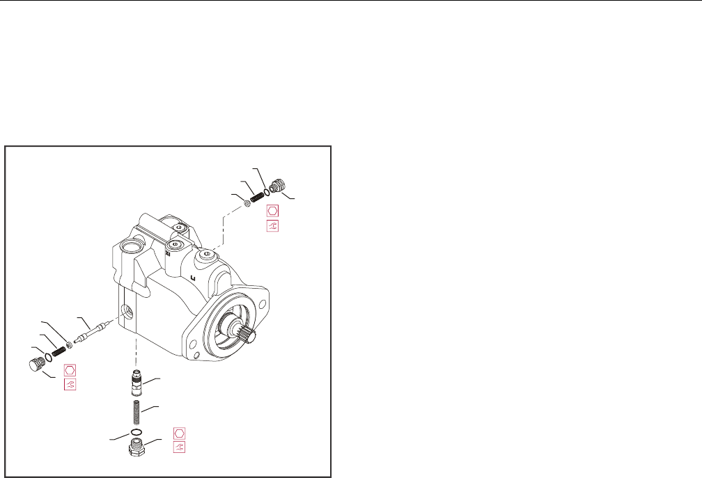
SECTION 3 - CHASSIS & TURNTABLE
3121298 – JLG Lift – 3-19
Loop Flushing Valve
REMOVAL
1. Using a 11/16 in internal hex wrench remove plug (1)
and (2).
Figure 3-23. Loop Flushing Spool
2. Using a 1/4 in hex wrench remove plug (3).
3. Remove O-rings (4, 5, and 6).
4. Using pliers, remove centering springs (7, 8, and 9).
5. Remove spring retaining washers (10 and 11).
6. Remove shift spool (12).
7. Remove orifice poppet (13).
INSPECTION
Inspect new O-rings and the sealing area for rust, wear, or con-
tamination. Check springs and poppet for wear.
INSTALLATION
1. Install orifice poppet (13).
2. Install shift spool (12).
3. Install spring retaining washers on springs (10 and 11).
4. Carefully install centering springs (7, 8, and 9).
5. Install new O-rings (6, 4, and 5).
6. Using a 1/4 in hex wrench torque plug (3) to 20 ft. lbs.
(27 Nm).
7. Using a 11/16 in internal hex, torque plugs (2 and 1) to
27 ft.lbs. (37 Nm).
1. Plug
2. Plug
3. Plug
4. O-ring
5. O-ring
6. O-ring
7. Spring
8. Spring
9. Spring
10. Washer
11. Washer
12. Shift Spool
13. Orifice Poppet
2
6
9
11
1
4
8
10 12
53
7
13
(37 Nm)
27 ft-lb
11/16 in
(37 Nm)
27 ft-lb
11/16 in
20 ft-lb (27 Nm)
5/8 in

SECTION 3 - CHASSIS & TURNTABLE
3-20 – JLG Lift – 3121298
Troubleshooting
Table 3-3. Excessive Noise and/or Vibration
Item Description Action
Check oil level in reservoir and oil
supply to motor.
Insufficient hydraulic fluid could lead to cavitation that would cause sys-
tem noise.
Fill reservoir to proper level. Ensure oil supply to motor is adequate and
lines are unobstructed.
Check for air in system. Air trapped in system lines or motor could result in cavitation that would
cause system noise.
Ensure all system lines and components are purged of air.
Inspect output shaft couplings. A loose or incorrect shaft coupling will produce vibrations that could result
in system noise.
En su re co rr ec t c ou pl ing is us ed an d t hat it fi ts pro pe rl y o n s haf t.
Inspect output shaft alignment. Misaligned shafts create excessive frictional vibration that could result in
system noise.
Ensure shafts are properly aligned.
Hydraulic oil viscosity above limits. Viscosity above acceptable limits will result in cavitation that would lead
to system noise.
Replace hydraulic oil with appropriate fluid for operating conditions.
Table 3-4. System Operating Hot
Item Description Action
Check oil level in reservoir and oil
supply to pump.
Insufficient amount of hydraulic fluid will not meet system cooling
demands.
Fill reservoir to proper level.
Inspect heat exchanger, (if
equipped).
If heat exchanger fails, or becomes obstructed, it may not meet system
cooling demands.
Ensure heat exchanger is receiving adequate air flow and is in good operat-
ing condition. Repair or replace as necessary.
Check system relief valves. If a system relief valve becomes unseated for an extended period of time or
fails for any other reason, system could become overheated.
Repair or replace any malfunctioning relief valves as applicable and verify
loads on machine are not excessive.
Table 3-5. Won’t Shift or Slow to Start
Item Description Action
Check signal line to servo control
port.
Obstructed or restricted flow through servo control signal lines could
result in slow shift or no shift motor conditions.
Ensure signal lines are not obstructed or restricted and signal pressure is
adequate to shift motor.
Check correct supply and drain ori-
fices are properly installed and not
obstructed.
Supply and drain orifices determine motor shift. The smaller the orifice,
the longer the time it takes to shift the motor. Obstruction also increases
shift times.
Ensure proper control orifices are installed in motor and not obstructed.
Clean or replace as necessary.
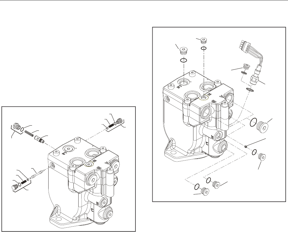
SECTION 3 - CHASSIS & TURNTABLE
3121298 – JLG Lift – 3-21
Disassembly
NOTE: Removal of endcap voids warranty.
During assembly, coat all moving parts with a film of clean
hydraulic oil. This ensures parts will be lubricated during
start-up.
Replace all O-Rings and gaskets.
It is recommended that all O-rings be replaced. Lightly
lubricate all O-rings with clean petroleum jelly prior to
assembly.
Figure 3-24. Loop Flushing Spool
1. Using a 11/16 in wrench remove plug (1) and (2).
2. Using a 5/8 in hex wrench remove plug (3).
3. Remove O-rings (4, 5, and 6).
4. Using pliers, remove centering springs (7, 8, and 9).
5. Remove spring retaining washers (10 and 11).
6. Remove shift spool (12).
7. Remove orifice poppet (13).
Figure 3-25. Plugs, Fittings, and Speed Sensor
8. Remove all fittings from unit. Discard any O-rings on fit-
tings.
9. Using an 11/16 inch hex wrench, loosen speed sensor
lock nut (14) if equipped. Remove speed sensor using a
Vi inch hex wrench. Units without speed sensor have an
O-ring plug (15) installed in that location; remove it with
a Va inch internal hex wrench.
10. Using a 1/4 inch internal hex wrench, remove control
line plugs (16, 17). Discard O-rings. Using a 3 mm hex
wrench, remove cavity plug (18, if equipped with two-
line control) from X2 cavity.
11. Using a 5/16 inch internal hex wrench, remove drain
plugs (19, 20). Discard O-rings.
12. Using a 9/16 inch internal hex wrench, remove work
port plugs (21, if equipped with axial ports). Discard O-
rings.
1. Plug
2. Plug
3. Plug
4. O-ring
5. O-ring
6. O-ring
7. Spring
8. Spring
9. Spring
10. Washer
11. Washer
12. Shift Spool
13. Orifice Poppet
5
3
7
13
2
6
9
11
1
4
8
10 12
14. Lock Nut
15. O-ring Plug
16. Control Line Plug
17. Control Line Plug
18. Cavity Plug
19. Drain Plug
20. Drain Plug
21. Work Port Plug
15
20
16
16
19
17
18
21
14
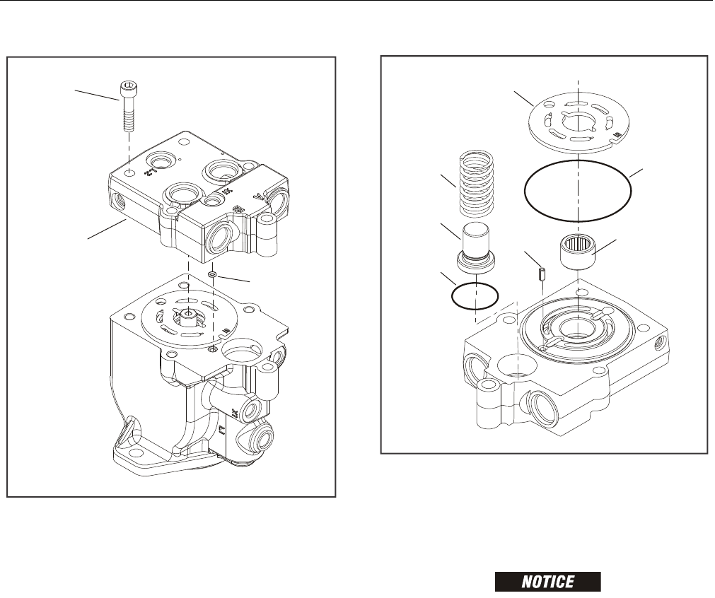
SECTION 3 - CHASSIS & TURNTABLE
3-22 – JLG Lift – 3121298
Figure 3-26. End Cap
13. Using an 8 mm internal hex wrench, remove endcap
screws (22).
14. Remove endcap (23). Remove O-ring (24) from housing
or endcap. When endcap screws are removed, pressure
from servo spring will cause endcap to bind on shaft.
Press down on portion of endcap covering servo piston
and hold endcap level while removing.
Figure 3-27. Valve Plate & Rear Shaft Bearing
DO NOT SCRATCH VALVE PLATE SURFACE. DO NOT DRIVE BEARING PAST REAR
SHAFT JOURNAL. BEARING MAY BECOME TRAPPED ON SHAFT AND DAMAGED.
15. Remove valve plate (25) and timing pin (26) from end-
cap. Each displacement has a unique valve plate. For
identification, the last two digits of the valve plate part
number are stamped on its surface.
16. Remove and discard O-rings (27, 28).
17. Remove rear shaft bearing (29) from endcap with a bear-
ing puller. Bearing may be difficult to remove with a
puller. Try this as an alternative: Pack bearing cavity with
heavy grease. After shaft is removed, insert it into bear-
ing cavity and tap splined end lightly with a soft mallet.
Grease will force the bearing out. Remove minimum
angle stop (29) and servo spring (30) from housing.
24
22
23
22. Screw
23. End Cap
24. O-ring
26
28
29
30
29
27
25
25. Valve Plate
26. End Cap
27. O-ring
28. O-ring
29. Angle Stop
30. Servo Spring
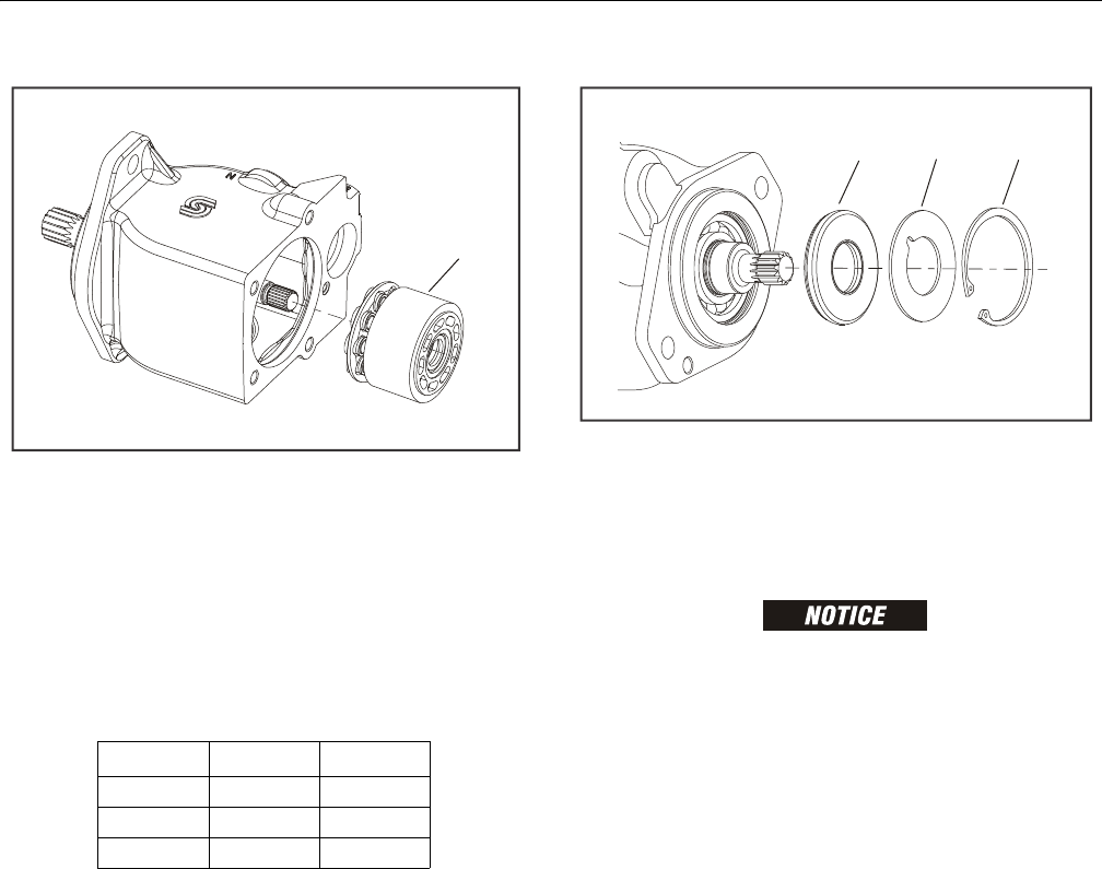
SECTION 3 - CHASSIS & TURNTABLE
3121298 – JLG Lift – 3-23
Figure 3-28. Cylinder Kit
18. Turn housing on its side and remove cylinder kit assem-
bly (31). Set assembly aside. Do not to scratch running
surface.
NOTE: Grooves on surface of cylinder kit identify its displacement:
Figure 3-29. Shaft Seal
TO AVOID DAMAGING SHAFT DURING SEAL REMOVAL, INSTALL A LARGE
SHEET METAL SCREW IN CHUCK OF SLIDE HAMMER. DRIVE SCREW INTO SEAL
SURFACE AND USE SLIDE HAMMER TO PULL SEAL.
1. Turn housing over and remove snap ring (32) retaining
shaft seal and support washer. Remove support washer
(33) and carefully pry out shaft seal (34). Discard seal.
Table 3-6. Displacement Identifiers
# of Grooves Frame L Frame K
125 38
230 45
335 - -
31. Cylinder Kit Assembly
31
34
33
32
32. Snap Ring
33. Support Washer
34. Shaft Seal
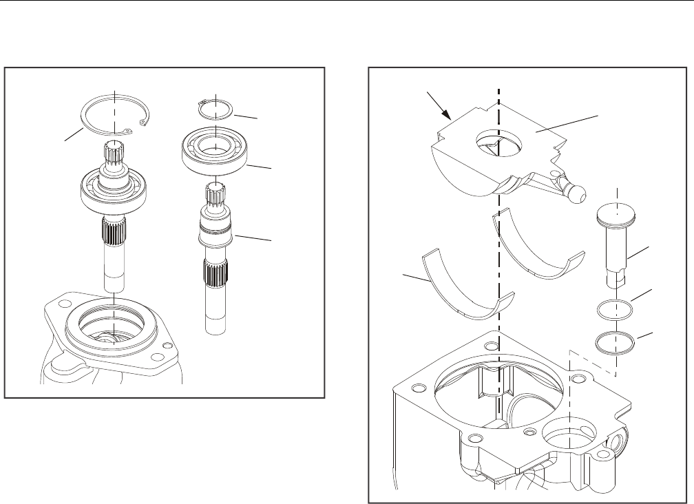
SECTION 3 - CHASSIS & TURNTABLE
3-24 – JLG Lift – 3121298
.
Figure 3-30. Shaft & Front Bearing
2. Remove inner snap ring (35) and shaft/bearing assembly.
3. Remove snap-ring (36) retaining shaft front bearing. Pull
bearing (37) off shaft (38).
Figure 3-31. Swash Plate & Servo Piston
4. Turn housing over and remove swashplate (39) by lifting
on end opposite servo lever.
5. Remove servo piston (40). Remove piston seal (41) and
O-ring (42) from servo piston. Discard seal and O-ring.
6. Remove journal bearings (43) from housing. Note loca-
tion and orientation of each bearing for reassembly.
35. Inner Snap Ring
36. Snap Ring
37. Bearing
38. Shaft
38
37
36
35
39. Swashplate
40. Servo Piston
41. Piston Seal
42. O-ring
43. Journal Bearings
41
42
40
Lift Here
39
43
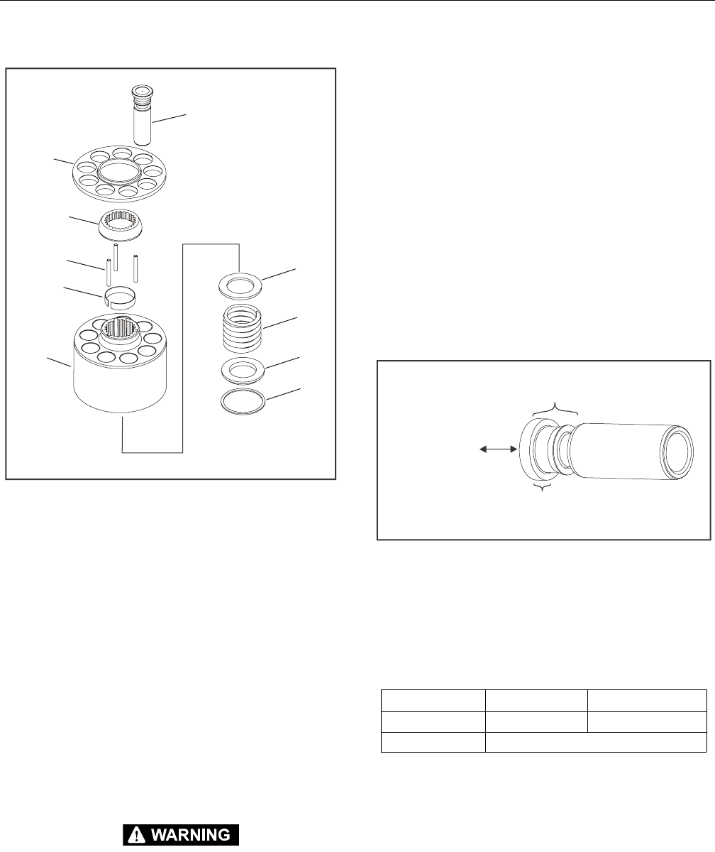
SECTION 3 - CHASSIS & TURNTABLE
3121298 – JLG Lift – 3-25
Figure 3-32. Cylinder Kit Disassembly
7. Remove pistons (44) and slipper retainer (45) from cylin-
der block (46).
NOTE: Pistons are not selectively fitted. However, units with high
hourly usage may develop wear patterns. Number pistons
and bores for reassembly if they are to be reused.
8. Remove ball guide (47), hold-down pins (48), and retain-
ing ring (49) from cylinder block.
NOTE: Most repairs do not require block spring removal. Perform
this procedure only if you suspect problems with the block
spring.
RISK OF PERSONAL INJURY: COMPRESSING THE BLOCK SPRING REQUIRES
FORCE OF ABOUT 80 TO 90 LBF (350 TO 400 N). USE A PRESS SUFFICIENT TO
MAINTAIN THIS FORCE WITH REASONABLE EFFORT. ENSURE THE SPRING IS
SECURE BEFORE ATTEMPTING TO REMOVE THE SPIRAL RETAINING RING.
RELEASE THE PRESSURE SLOWLY AFTER THE RETAINING RING IS REMOVED.
9. Turn block over. Using a press, apply pressure on block
spring washer (50) to compress block spring. Compress
spring enough to safely remove spiral retaining ring
(51). While maintaining pressure, unwind spiral retaining
ring (51). Carefully release pressure and remove outer
block spring washer (50), block spring (52), and inner
block spring washer (53) from cylinder block.
Inspection
After disassembly, wash all parts (including end-cap and hous-
ing) thoroughly with clean solvent and allow to air dry. Blow
out oil passages in housing and endcap with compressed air.
Conduct inspection in a clean area and keep all parts free from
contamination. Clean and dry parts again after any rework or
resurfacing.
PISTON
Inspect pistons for damage and discoloration. Discolored pis-
tons may indicate excessive heat; do not reuse.
SLIPPERS
Inspect slipper running surfaces. Replace piston assemblies
with scored or excessively rounded slipper edges. Measure
slipper foot thickness. Replace piston assemblies with exces-
sively worn slippers. Check slipper axial end-play. Replace pis-
ton assemblies with excessive end-play.
44. Piston
45. Slipper Retainer
46. Cylinder Block
47. Ball Guide
48. Holddown Pins
49. Retaining Ring
50. Block Spring Washer
51. Spiral Retaining Ring
52. Block Spring
53. Inner Block Spring Washer
51
50
52
53
46
49
48
47
45
44
Table 3-7. Slipper Foot Thickness & End Play
Measurement L Frame K Frame
Slipper Foot Thickness 2.71 mm (0.11 in.) 4.07 mm (0.16 in.)
Piston/Slipper End Play 0.15 mm (0.006 in.)
Slipper
Maximum End Play
Minimum Slipper Foot Thickness
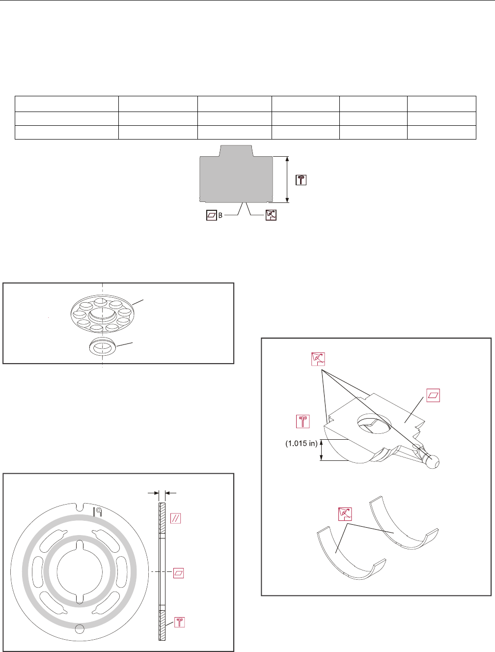
SECTION 3 - CHASSIS & TURNTABLE
3-26 – JLG Lift – 3121298
CYLINDER BLOCK
Measure cylinder block height. Replace blocks worn beyond minimum height specification. Inspect cylinder block running surface.
Replace or resurface worn or scratched blocks. Blocks may be resurfaced to specifications shown in the drawing, provided resurfacing
will not reduce block height below minimum specification. Table 3-8, Cylinder Block Measurements.
BALL GUIDE AND SLIPPER RETAINER
Inspect ball guide and slipper retainer for damage, discolor-
ation, or excessive wear. A discolored ball guide or slipper
retainer indicates excessive heat. Do not reuse.
VALVE PLATE
Valve Plate condition is critical to efficiency of the motor.
Inspect valve plate surfaces carefully for excessive wear,
grooves, or scratches. Replace or resurface grooved or
scratched valve plates. Measure valve plate thickness and
replace if worn beyond minimum specification. Valve plates
may be resurfaced, provided resurfacing will not reduce thick-
ness below minimum specification.
SWASHPLATE AND JOURNAL BEARINGS
Inspect running face, servo ball-joint, and swashplate journal
surfaces for damage or excessive wear. Some material transfer
may appear on these surfaces and is acceptable if surface con-
dition meets specifications shown. Measure swashplate thick-
ness from journals running face. Replace swashplate if
damaged or worn beyond minimum specification. Replace
swashplate if difference in thickness from one side to the other
exceeds specification.
Inspect journal bearings for damage or excessive wear.
Replace journal bearings if scratched, warped, or excessively
worn. Polymer wear layer must be smooth and intact.
A
Table 3-8. Cylinder Block Measurements
Measurement L25 L30 L35 K38 K45
Minimum Cylinder Block Height (A) 50.8 (2.00) 50.8 (2.00) 50.8 (2.00) 54.4 (2.14) 54.4 (2.14)
Cylinder Block Surface Flatness 0.002 (0.0000079) 0.002 (0.0000079) 0.002 (0.0000079) 0.002 (0.0000079) 0.002 (0.0000079)
Slipper Retainer
Ball Guide
3.83 mm (0.151 in) Min
0.025 mm
(0.001 in)
0.0076 mm
(0.00030 in)
Convex Max
LV
25.8 mm
24.6 mm
(0.969 in)
KV
Thickness equality side to side:
0.05 mm (0.002 in)
0.0025 mm
(0.0001 in)
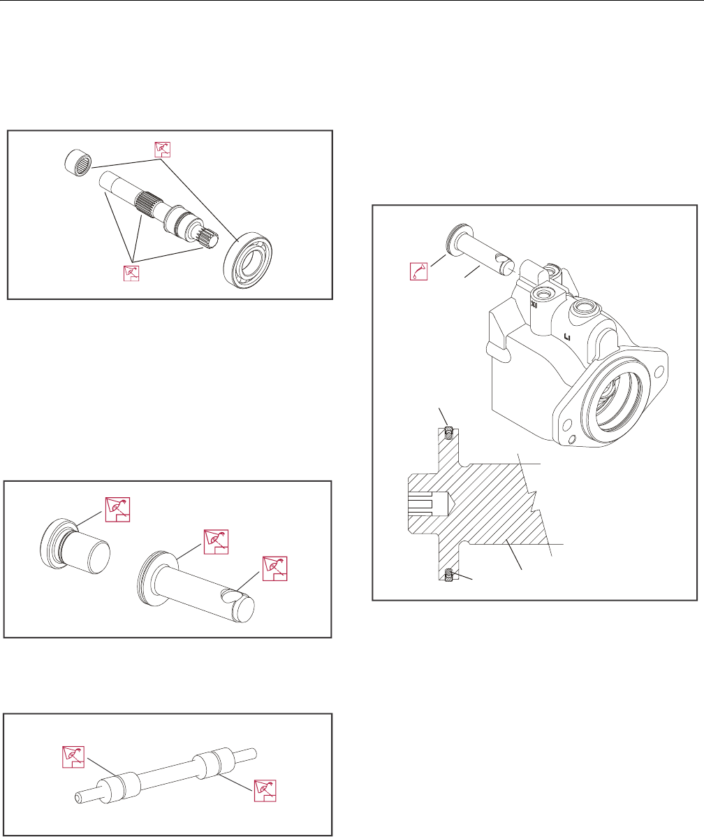
SECTION 3 - CHASSIS & TURNTABLE
3121298 – JLG Lift – 3-27
SHAFT BEARINGS
Inspect bearings for excessive wear or contamination. Rotate
bearings while feeling for uneven movement. Bearings should
spin smoothly and freely. Replace bearings that appear worn
or do not rotate smoothly.
SHAFT
Inspect motor shaft for damage or excessive wear on output
and block splines. Inspect bearing surfaces and sealing sur-
face. Replace shafts with damaged or excessively worn splines,
bearing surfaces, or sealing surfaces.
SERVO PISTON AND MINIMUM ANGLE STOP
Inspect minimum angle stop, servo piston head, and servo pis-
ton ball-socket for damage or excessive wear. Replace as
required.
LOOP FLUSHING SPOOL
Inspect loop flushing spool for cracks or damage. Replace as
required.
Assembly
1. Install new O-ring (1) and piston seal (2) to servo piston
(3). Install piston seal over O-ring.
NOTE: Installing piston seal stretches it, making it difficult to
install servo piston in its bore. Allow 30 minutes for seal to
relax after installation. To speed up seal relaxation, com-
press seal by installing piston head in end-cap servo cavity
and let it stand for at least five minutes.
Figure 3-33. Servo Piston
2. After piston seal has relaxed, lubricate and install servo
piston in housing bore. Align piston with ball socket fac-
ing inside of housing.
1. O-ring
2. Piston Seal
3. Servo Piston
2
13
3
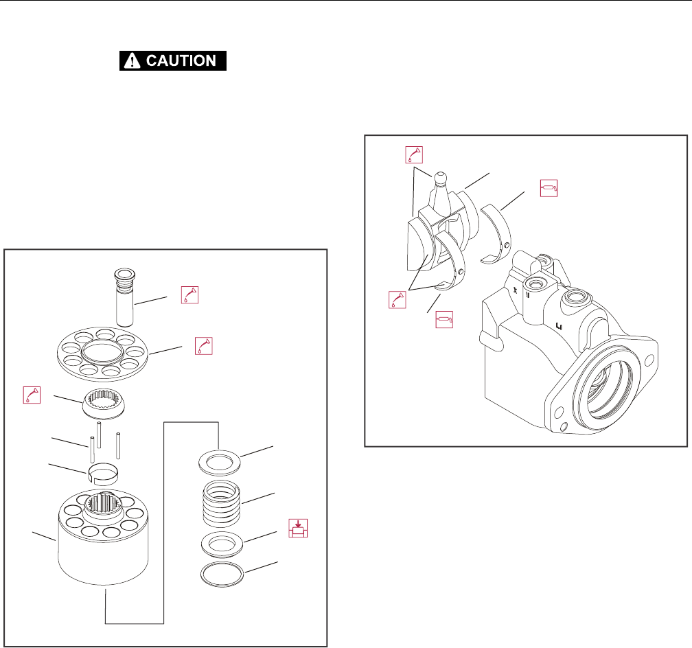
SECTION 3 - CHASSIS & TURNTABLE
3-28 – JLG Lift – 3121298
RISK OF PERSONAL INJURY: COMPRESSING THE BLOCK SPRING REQUIRES
ABOUT 80 TO 90 LBF (350 TO 400 N) OF FORCE. USE A PRESS SUFFICIENT TO
MAINTAIN THIS FORCE WITH REASONABLE EFFORT. ENSURE SPRING IS
SECURE BEFORE ATTEMPTING TO INSTALL THE SPIRAL RETAINING RING.
RELEASE PRESSURE SLOWLY AFTER RETAINING RING IS INSTALLED.
3. Install inner block spring washer (4), block spring (5), and
outer washer (6) in cylinder block (6A). Using a press,
compress block spring enough to expose retaining ring
groove. Wind spiral retaining ring (7) in cylinder block
groove.
4. Turn block over and install retaining ring (8), hold-down
pins (9), and ball guide (10) to cylinder block.
5. Install pistons (11) to slipper retainer (12). Install piston/
retainer assembly in cylinder block. Ensure concave sur-
face of retainer seats on ball guide. If reusing pistons,
install them in original block bores. Lubricate pistons,
slippers, retainer, and ball guide before assembly. Set
cylinder kit aside on a clean surface until needed.
6. Install journal bearings (13) in housing seats. Use assem-
bly grease to keep bearings seated during assembly.
Ensure locating nubs drop into seat cavities. If reusing
bearings, install in original location and orientation.
Lubricate journal bearings.
Figure 3-34. Swash Plate and Journal Bearing
7. Install swashplate (14) in housing. Tilt swashplate and
guide servo lever ball into its socket in the servo piston
rod. Ensure swashplate seats into journal bearings and
moves freely. Lubricate running surface of swashplate.
4. Block Spring Washer
5. Block Spring
6. Outer Washer
6A. Cylinder Block
7. Spiral Retaining Ring
8. Retaining Ring
9. Holddown Pins
10. Ball Guide
11. Piston
12. Slipper Retainer
7
6
5
4
6A
8
9
10
12
11
13. Journal Bearings
14. Swash Plate
14
13
13
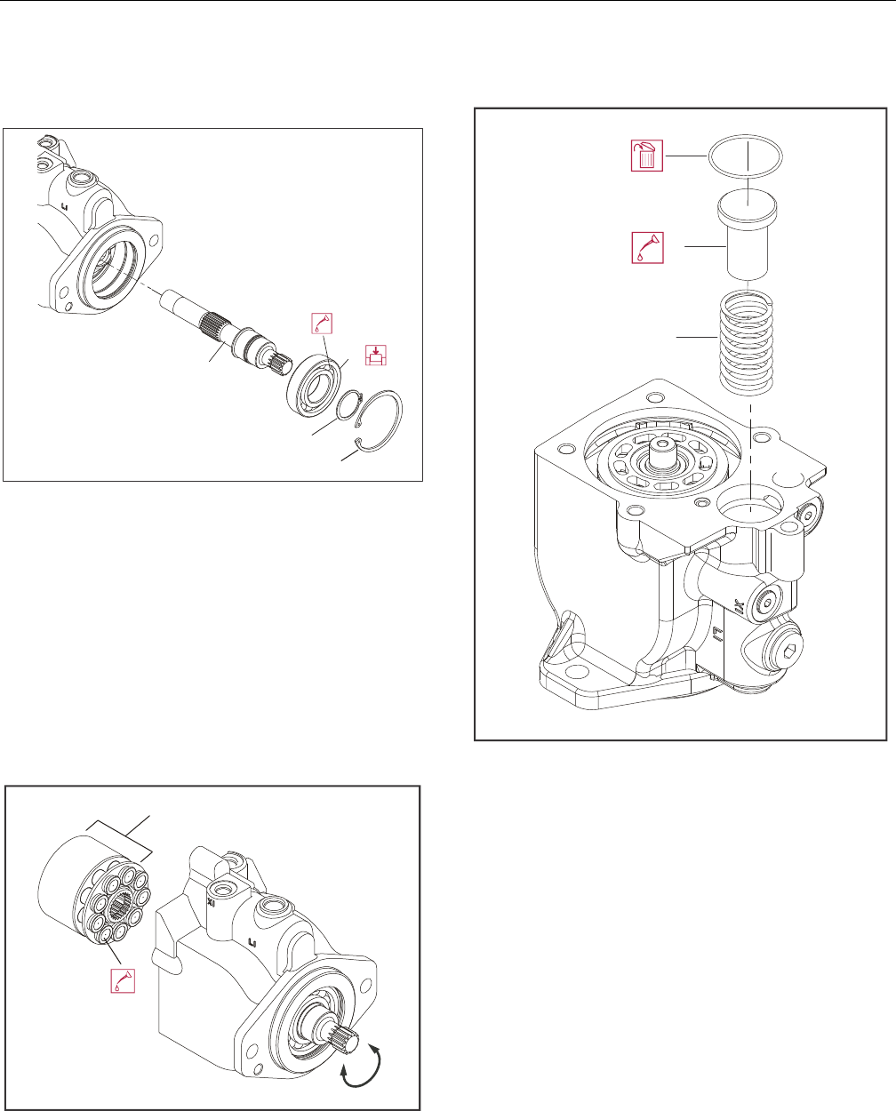
SECTION 3 - CHASSIS & TURNTABLE
3121298 – JLG Lift – 3-29
8. Press front shaft bearing (15) on shaft (16). Press bearing
on shaft with lettering facing out. Lubricate bearing roll-
ers. Install snap-ring (17) on shaft.
Figure 3-35. Shaft and Front Bearing
9. While holding swashplate in place, turn housing on its
side. Install the install shaft/bearing assembly into hous-
ing from flange end. Install snap-ring (18).
10. Verify swashplate and bearings are properly seated.
Install cylinder kit (19) on shaft. Install with slippers fac-
ing swashplate. Rock the shaft to align block splines and
slide cylinder kit into place. Orient motor with shaft
pointing downward and verify cylinder kit, swashplate,
journal bearings, and servo piston are properly installed.
Figure 3-36. Cylinder Kit Installation
11. Lubricate and install servo spring (20) and minimum
angle stop (21) in housing bore.
Figure 3-37. Servo Spring and Minimum Angle Stop
15. Front Shaft Bearing
16. Shaft
17. Snap Ring
18. Snap Ring
19. Cylinder Kit
16
15
17
18
19
20. Servo Spring
21. Minimum Angle Stop
20
21
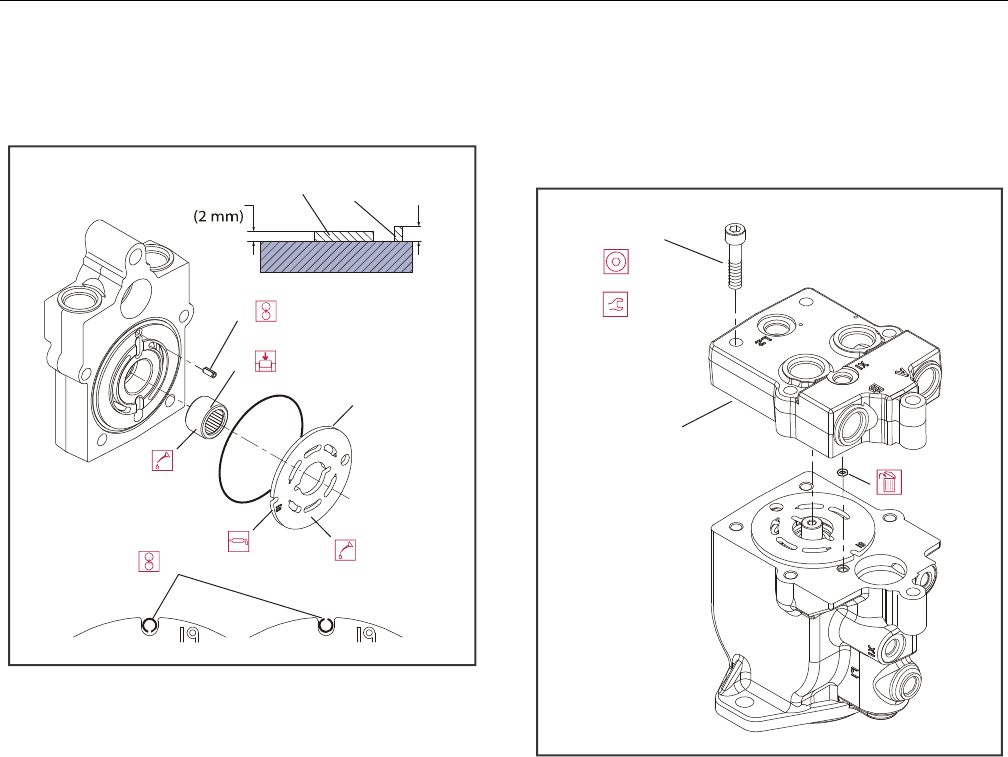
SECTION 3 - CHASSIS & TURNTABLE
3-30 – JLG Lift – 3121298
12. Press rear shaft bearing (22) in endcap. Install bearing
with letters facing out. Press until bearing surface is 0.08
±0.01 in (2 ±0.25 mm) above endcap surface.
Figure 3-38. Valve Plate and Rear Bearing
13. Install timing pin (23) into its bore in the endcap. Install
pin with groove facing toward or away from shaft. Press
pin until end protrudes 0.12 ±0.01 in (3 ±0.25 mm)
above endcap surface.
14. Install valve plate (24) on endcap. Install valve plate with
yellow surface toward cylinder block. Align slot in valve
plate with timing pin. Apply a liberal coat of assembly
grease to endcap side of valve plate to keep it in place
during installation.
15. Install endcap (25) on housing with endcap screws (26).
Ensure endcap will properly seat to housing without
interference. Improper assembly of internal components
may prevent endcap from seating properly. Ensure O-
rings seat properly when installing endcap.
Figure 3-39. End Cap
16. Using an 8 mm internal hex wrench, tighten endcap
screws. Tighten screws in opposite corners slowly and
evenly to compress the servo spring and properly seat
the endcap. Torque endcap screws 35-45 ft-lb (47-61
Nm).
17. Before installing shaft seal, ensure shaft turns smoothly
with less than 120 in-lb (13.5 Nm) of force. If shaft does
not turn smoothly within specified maximum force, dis-
assemble and check unit.
22. Rear Shaft Bearing
23. Timing Pin
24. Valve Plate
23
23
22
24
(3 mm)
0.12 in
0.08 in 23
22
25. End Cap
26. Screw
26
25
8 mm
(47-61 Nm)
35-45 ft-lbs
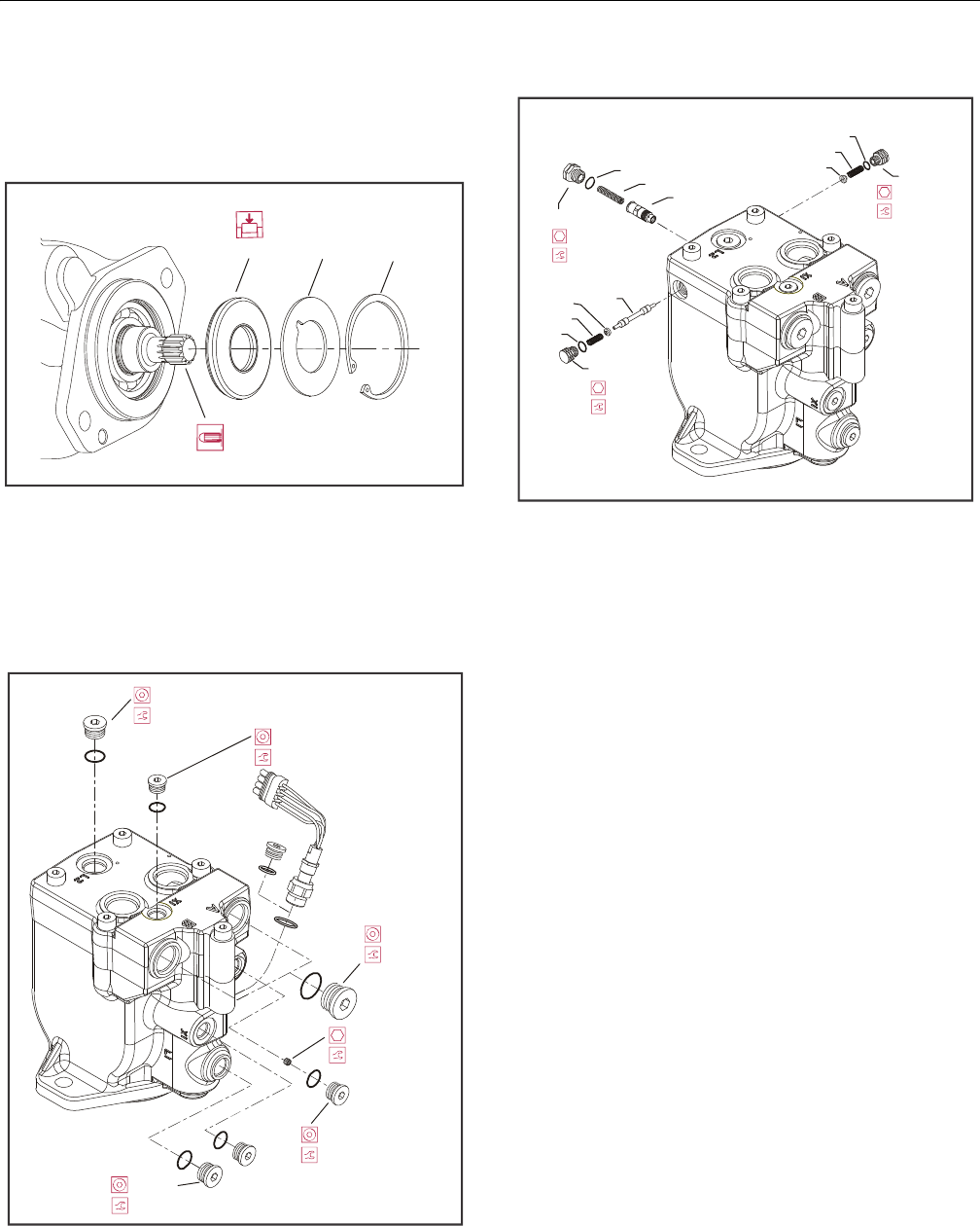
SECTION 3 - CHASSIS & TURNTABLE
3121298 – JLG Lift – 3-31
18. Cover shaft splines with an installation sleeve. Install a
new shaft seal (27) with cup side facing motor. Press seal
in housing until it bottoms out. Press evenly to avoid
binding and damaging seal. Install seal support washer
(28) and snap ring (29).
Figure 3-40. Shaft Seal
19. Install remaining plugs and fittings to housing. Refer to
drawing below for wrench sizes and installation torques.
Figure 3-41. Plugs and Fittings Installation
20. Install orifice poppet (30).
Figure 3-42. Loop Flushing Spool
21. Install shift spool (31).
22. Install spring retaining washers on springs (32 and 33).
23. Carefully install centering springs (34, 35, and 36).
24. Install new O-rings (37, 38, and 39).
25. Using a 5/8 in wrench torque plug (40) to 20 ft-lb (27
Nm).
26. Using a 11/16 in wrench, torque plugs (41 and 42) to 27
ft-lb (37 Nm).
27. Shaft Seal
28. Seal Support Washer
29. Snap Ring
27 28 29
1/4 in
(45 Nm)
33 ft-lb
5/16 in
(85 Nm)
63 ft-lb
5/16 in
(85 Nm) 63 ft-lb
1/4 in
(45 Nm)
33 ft-lb
9/16 in
(170 Nm)
125 ft-lb
3 mm
(2 - 3 Nm)
1.5 - 2.5 ft-lb
30. Orifice Poppet
31. Shift Spool
32. Spring
33. Spring
34. Spring
35. Spring
36. Spring
37. O-ring
38. O-ring
39. O-ring
40. Plug
41. Plug
42. Plug
39
40
34 30
41
37
36
33
42
38
35
32 31
(27 Nm)
20 ft-lb
5/8 in
(37 Nm)
(37 Nm)
27 ft-lb
27 ft-lb
11/16 in
11/16 in
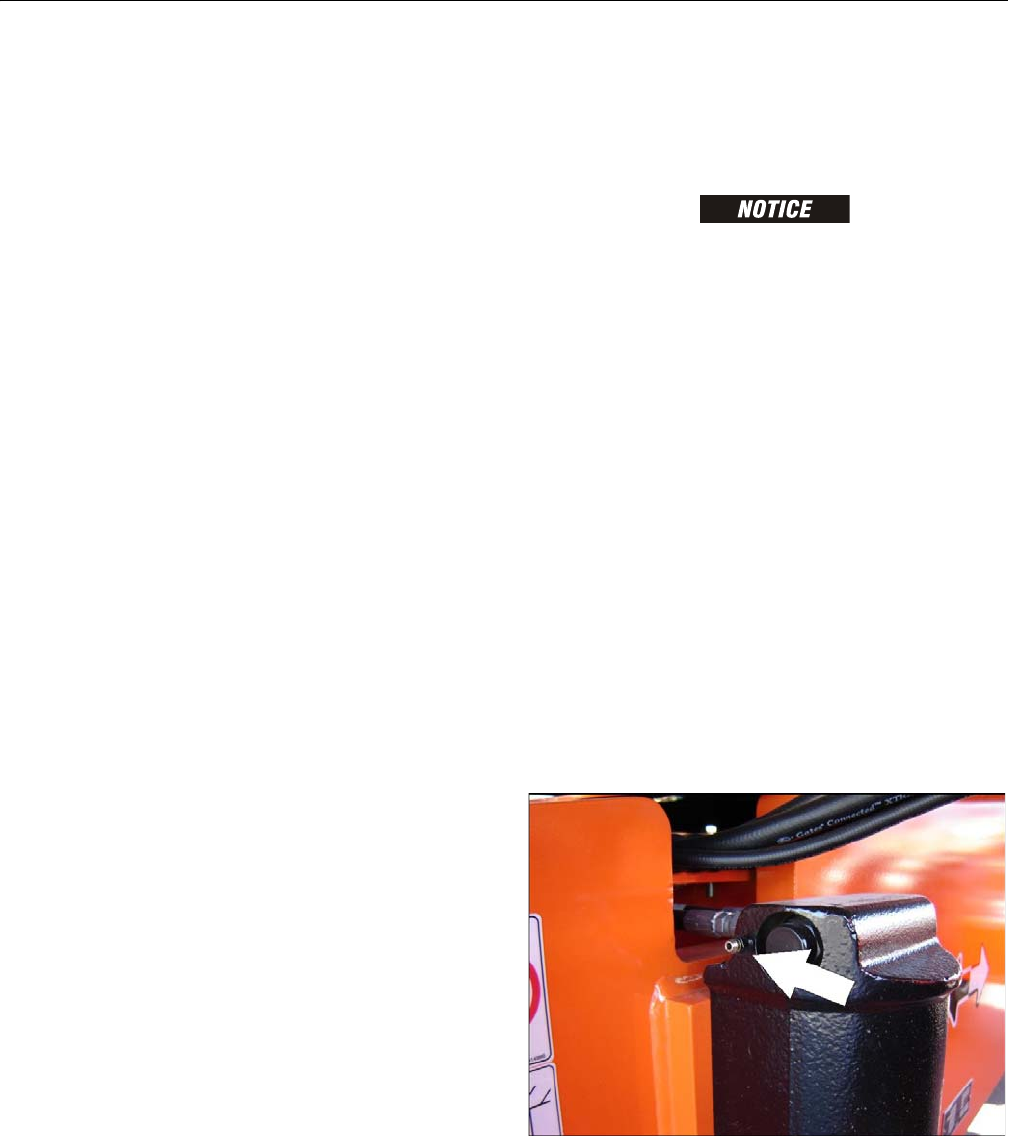
SECTION 3 - CHASSIS & TURNTABLE
3-32 – JLG Lift – 3121298
Initial Start-up Procedures
Follow this procedure when starting-up a new motor or when
installing a motor that has been removed.
Prior to installing the motor, inspect for damage incurred dur-
ing shipping. Make certain all system components (reservoir,
hoses, valves, fittings, heat exchanger, etc.) are clean prior to
filling with fluid.
1. Fill reservoir with recommended hydraulic fluid. Always
filter fluid through a 10 micron filter when pouring into
the reservoir. Never reuse hydraulic fluid.
2. Fill inlet line leading from pump to reservoir. Check inlet
line for properly tightened fittings and be certain it is
free of restrictions and air leaks.
3. Fill pump and motor housing with clean hydraulic fluid.
Pour filtered oil directly in upper most case drain port.
4. To ensure pump and motor stay filled with oil, install
case drain lines in upper most case drain ports.
5. Install a 0 to 500 psi (0 to 35 bar) gauge in charge pres-
sure gauge port of pump to monitor system pressure
during start up.
6. Watching pressure gauge and run engine at lowest pos-
sible speed until system pressure builds to normal levels
(minimum 160 psi [11 bar]). Once system pressure is
established, increase to full operating speed. If system
pressure is not maintained, shut down engine, deter-
mine cause, and take corrective action.
7. Operate hydraulic system for at least fifteen minutes
under light load conditions.
8. Check and adjust control settings as necessary after
installation.
9. Shut down engine and remove pressure gauge. Replace
plug at charge pressure gauge port.
10. Check fluid level in reservoir. Add clean filtered fluid if
necessary. Motor is now ready for operation.
3.5 OSCILLATING AXLE BLEED PROCEDURE AND
LOCKOUT TEST
Lockout Cylinder Bleeding
ENSURE MACHINE IS ON A LEVEL SURFACE, REAR WHEELS ARE BLOCKED, AND
BRAKE WIRE IS DISCONNECTED. ENSURE PLATFORM IS FULLY LOWERED AND
BOOM IS CENTERED OVER REAR AXLE BEFORE STARTING BLEED PROCEDURE.
1. Park machine on a level surface and block rear wheels.
2. Center boom over rear axle to make sure oscillation
valve in rotary coupling is activated.
3. Place suitable container under flow divider mounted on
inside of frame to catch hydraulic fluid.
4. Remove Port 11 tee fitting from flow divider. Cap fitting
and plug hose.
5. Place suitable containers under each lockout cylinder to
catch hydraulic fluid.
6. Have helper start engine from platform. Turn function
control knob speed fully counter-clockwise to Turtle
position to set drive creep mode. Activate Low Drive In
Reverse creep mode.
7. Open bleeder screw on one lockout cylinder.
NOTE: Open bleeder valve enough to get a fast stream of oil. A fast
stream of oil will exhaust air from hose and lockout cylin-
der better than a slow stream.
Figure 3-43. Bleeder Valve Location
8. Close bleeder valve when no more air in hydraulic oil.
9. Repeat on opposite lockout cylinder.
10. Shut down engine.
11. Reconnect hose and tee fitting to Port 11 on flow
divider.
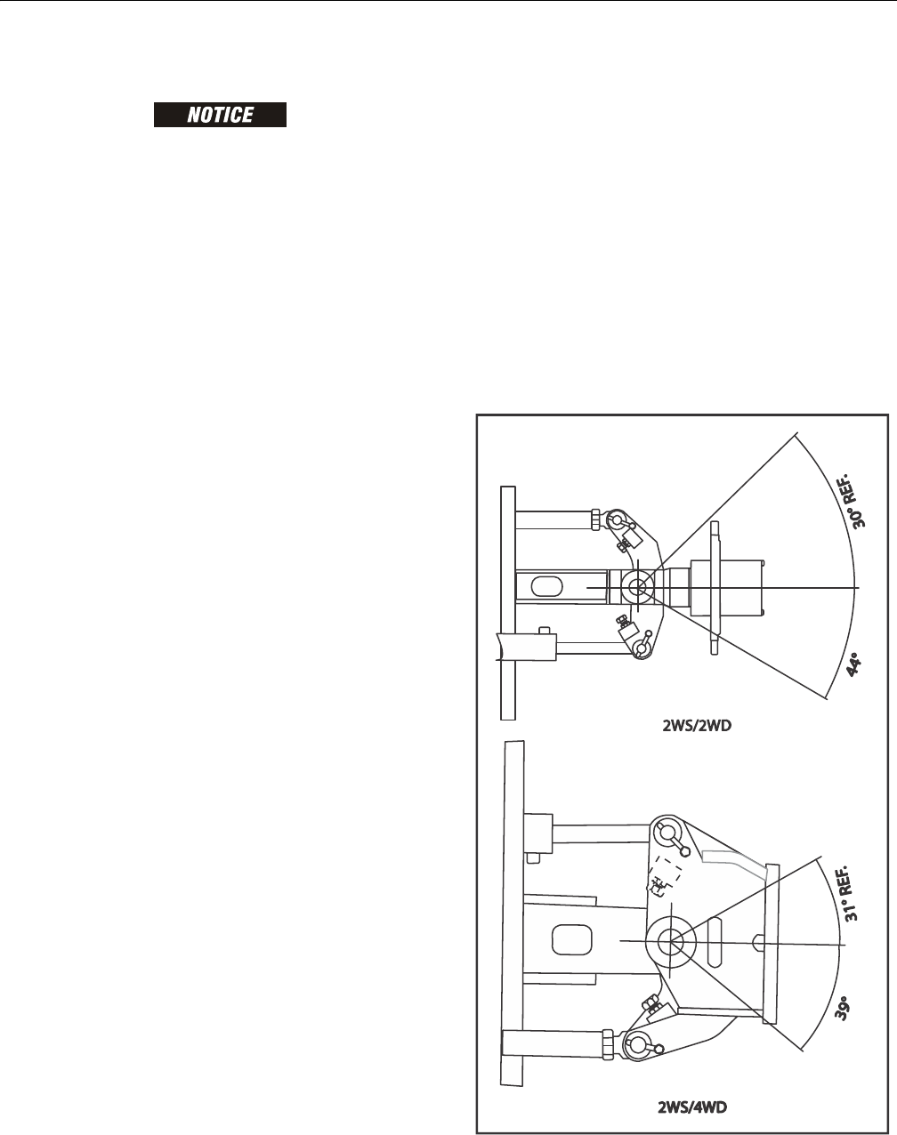
SECTION 3 - CHASSIS & TURNTABLE
3121298 – JLG Lift – 3-33
Oscillating Axle Lockout Test
LOCKOUT SYSTEM TEST MUST BE PERFORMED QUARTERLY, ANY TIME A SYS-
TEM COMPONENT IS REPLACED, OR WHEN IMPROPER SYSTEM OPERATION IS
SUSPECTED.
NOTE: Ensure boom is fully retracted, lowered, and centered
between drive wheels before starting lockout cylinder test.
1. Place a 6 inch (15.2 cm) high block with ascension ramp
in front of left front wheel.
2. From platform control station, activate machine hydrau-
lic system.
3. Place FUNCTION SPEED CONTROL and DRIVE SPEED/
TORQUE SELECT control switches to their respective
LOW positions.
4. Place DRIVE control lever to FORWARD position and
carefully drive machine up ascension ramp until left
front wheel is on top of block.
5. Carefully activate SWING control lever and position
boom over right side of machine.
6. With boom over right side of machine, place DRIVE con-
trol lever to REVERSE. Drive machine off block and ramp.
7. Have an assistant check if left front wheel remains
locked in position off of ground.
8. Carefully activate SWING control lever and return boom
to stowed position (centered between drive wheels).
When boom reaches center, stowed position, lockout
cylinders should release and allow wheel to rest on
ground. It may be necessary activate DRIVE to release
cylinders.
9. Place 6 inch (15.2 cm) high block with ascension ramp in
front of right front wheel.
10. Place DRIVE control lever to FORWARD and carefully
drive machine up ascension ramp until right front wheel
is on top of block.
11. Carefully activate SWING control lever and position
boom over left side of machine.
12. With boom over left side of machine, place DRIVE con-
trol lever to REVERSE. Drive machine off block and ramp.
13. Have an assistant check if right front wheel remains
locked in position off of ground.
14. Carefully activate SWING control lever and return boom
to stowed position (centered between drive wheels).
When boom reaches center, stowed position, lockout
cylinders should release and allow wheel to rest on
ground. It may be necessary activate DRIVE to release
cylinders.
15. If lockout cylinders do not function properly, have quali-
fied personnel correct malfunction before further opera-
tion.
3.6 STEER ADJUSTMENTS
NOTE: 2 Wheel Steering/2 Wheel Drive: Spindles do not stop on
cylinder stroke. Adjust steering stops as follows: Adjust item
#1 to achieve 44° inside turn angles. Steer full left and
adjust RH item #2 to contact axle. Steer full right and adjust
LH item #2 to contact axle.
2 Wheel Steering/Four Wheel Drive: Spindles do not stop
on cylinder stroke. Adjust steering stops as follows: Adjust
item #1 to achieve 39° inside turn angles. Steer full left and
adjust RH item #2 to contact axle. Steer full right and adjust
LH item #2 to contact axle.
Figure 3-44. Steer Adjustments
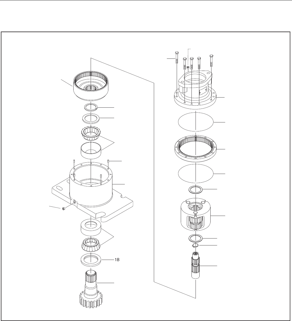
SECTION 3 - CHASSIS & TURNTABLE
3-34 – JLG Lift – 3121298
3.7 SWING DRIVE
Figure 3-45. Swing Drive Assembly
2
1I
1H
1E
1G
1J
13
1C
1A
12
20
6
5A
4
5
11
3
11
44
8
1A. Output Shaft
1B. Lip Seal
1C. Bearing
1E. Bearing
1G. Housing
1H. Thrust Washer
1I. Retaining Ring
1J. Pipe Plug
2. I nt ern al Ge ar
3. Carrier Assembly
4. Ring Gear
5. O-Ring
5A. O-Ring
6. Br ake Ho us in g
8. Su n G ea r
11. Thrust Washer
12. Bolt
13. Dowel Pin
20. Pipe Plug
44. Internal Retaining Ring
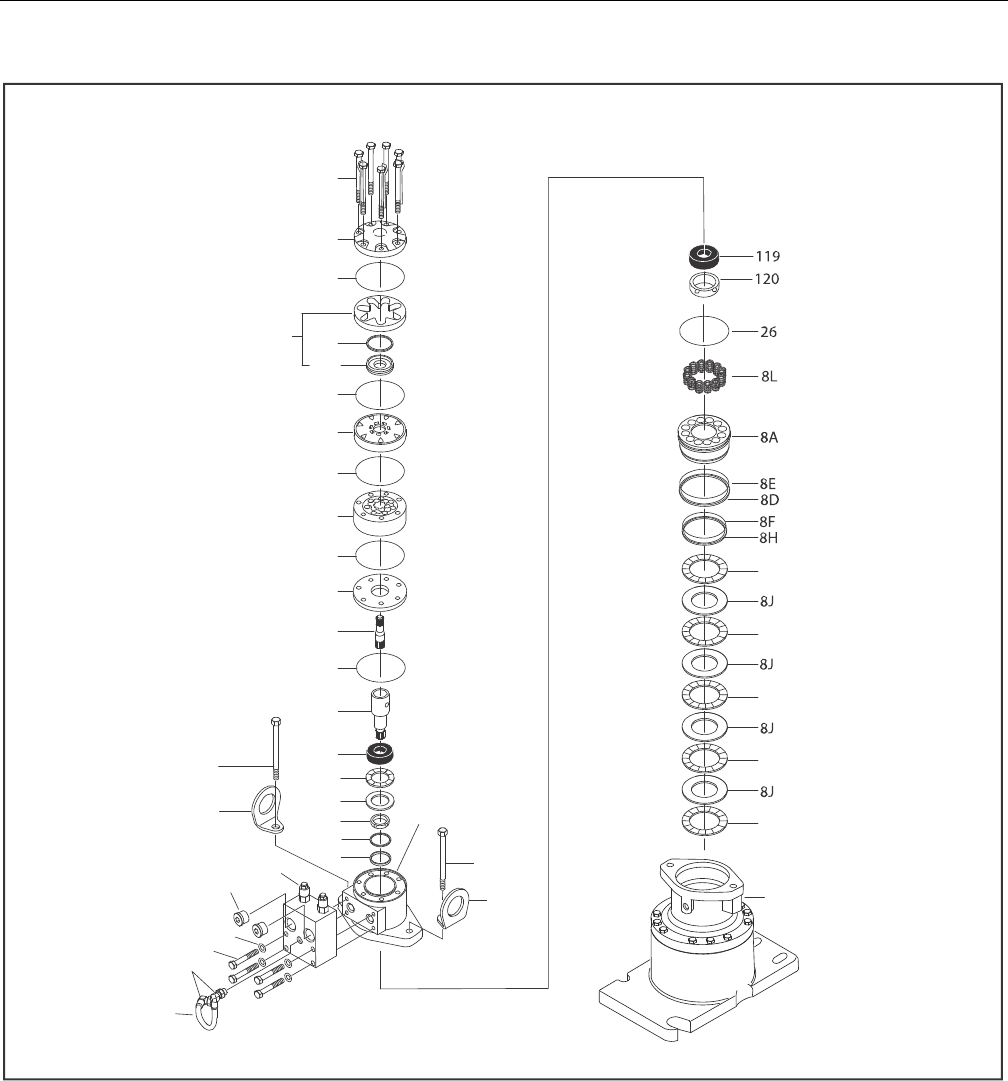
SECTION 3 - CHASSIS & TURNTABLE
3121298 – JLG Lift – 3-35
Figure 3-46. Swing Motor and Brake Assembly
101
102
104
105
103
106
107
104
109
108
110
112
104
104
104
113
115
114
116
125
117
29
28
32
23
22
30
29
28
118
21
35
6
8K
8K
8K
8K
8K
6. Brake Housing
8A. Piston
8D. O-Ring
8E.Back-Up Ring
8F. O-Ring
8H. Back-up Ring
8J. Rotor Disc
8K. Stator Disc
8L. Spring
21. Bolt
22. Lockwasher
23. Pipe Plug
26. O-Ring
28. Lifting Lug
29. Bolt
30. Elbow
35. Tube
101. Bolt
102. End Cover
103. Commutator Seal
104. Ring Seal
105. Commutator and Ring Assy
106. Ring
107. Manifold
108. Rotor Set
109. Wear Plate
110. Drive Link
112. Coupling Shaft
113. Inner Bearing
114. Thrust Washer
115. Thrust Bearing
116. Inner Seal
117. Back-up Washer
118. Housing
119. Outer Bearing
120. Seal
125. Back-up Washer
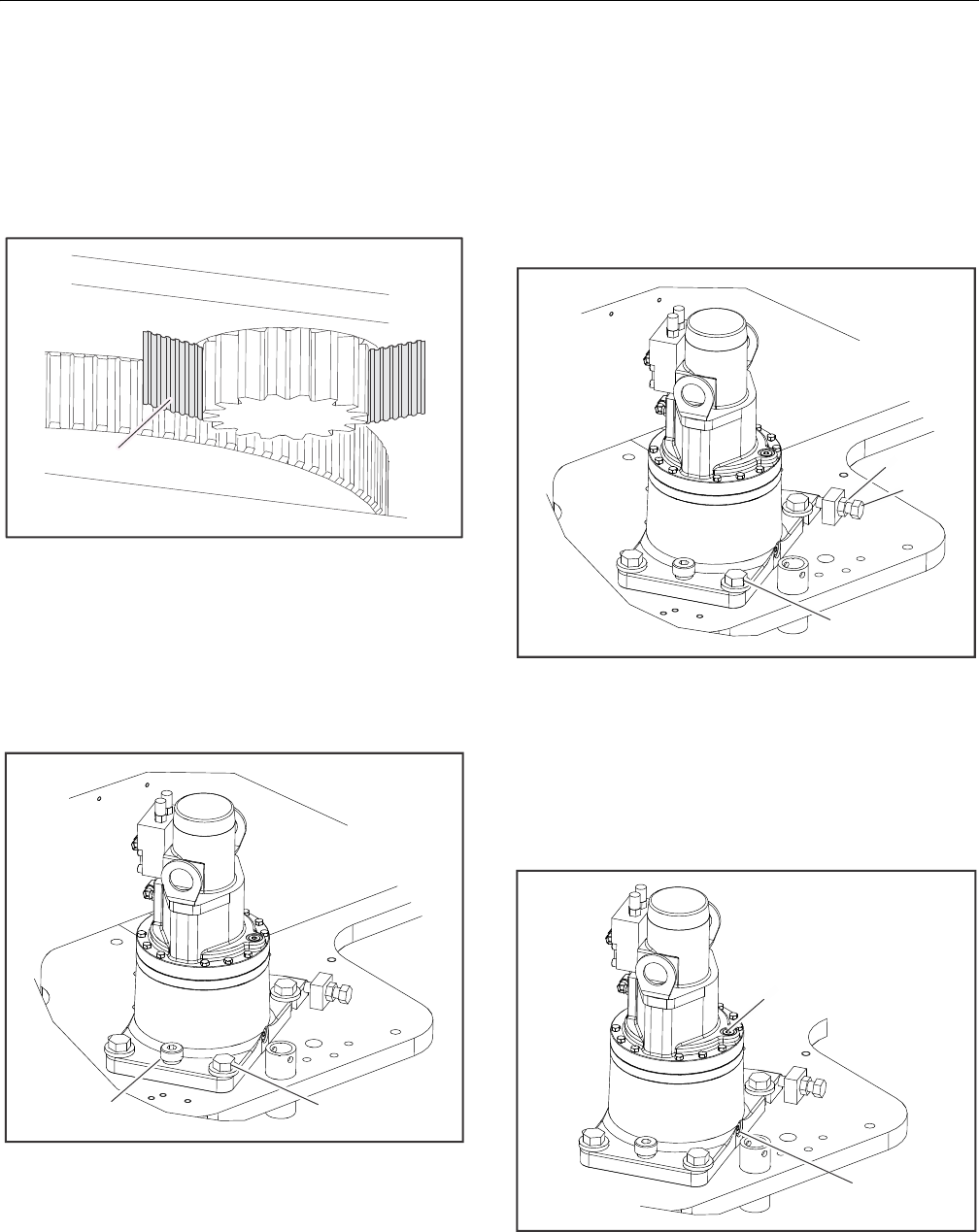
SECTION 3 - CHASSIS & TURNTABLE
3-36 – JLG Lift – 3121298
Gear Backlash
Set backlash to .010 - .015 in (0.254 to 0.381mm).
1. Insert shim (JLG P/N 4071009) between pinion and bear-
ing on the bearing high spot. The bearing high spot
should be stamped with an "X" on the surface below the
teeth and marked with yellow paint in the tooth space.
Figure 3-47. Swing Drive Shim Placement
2. Apply JLG Thread locking compound P/N 0100019 to
pivot bolt. Torque pivot bolt to 205 ft-lb (280 Nm).
3. Remove turntable lock pin.
4. Apply JLG Thread locking compound P/N 0100019 to
four mounting bolts. Torque mounting bolts to 30 ft-lb
(40 Nm).
Figure 3-48. Swing Drive Pivot and Mounting Bolts
5. Loosen jam nut.
6. Tighten jack bolt until pinion is snug against shim and
bearing, then loosen jack bolt.
7. Apply JLG Thread locking compound P/N 0100019 to
jack bolt threads. Torque jack bolt to 50 ft-lb (68 Nm).
8. Tighten jam nut.
9. Torque four mounting bolts to 340 ft-lb (461 Nm).
Figure 3-49. Swing Drive Jam Nut and Mounting Bolt
10. Remove and discard swing drive shim.
Swing Drive Lubrication
Fill Swing Drive Gearbox with 43 oz (1.27L) 90w80 gear oil with
EP additives. Oil should cover the ring gear. Torque pipe plug
23 - 24 ft-lb (31 - 32.5 Nm).
Figure 3-50. Swing Drive Lubrication
Shim
Pivot Bolt Mounting Bolt
Jack Bolt
Mounting Bolt
Jam Nut
Drain Plug
Fill Plug
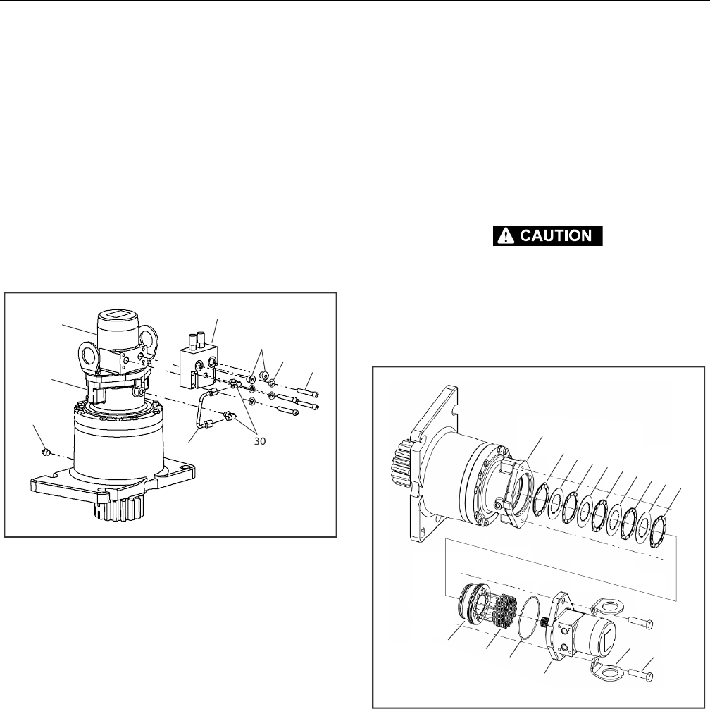
SECTION 3 - CHASSIS & TURNTABLE
3121298 – JLG Lift – 3-37
Motor Control Valve Disassembly
1. Place unit on bench with motor end up.
2. Remove Drain Plug (1P) and drain oil from gearbox.
3. Remove Hydraulic Tubing Assembly (35).
4. Loosen jam nuts on Elbow Fittings (30). Remove fittings
from Brake (6) and Motor Control Valve (32).
5. Remove O-ring Plugs (23) from Motor Control Valve (32).
6. Remove four bolts (21), washers (22), and Motor Control
Valve (32) from Motor (31).
7. Reinstall Drain Plug (1P). Torque to 23 - 24 ft-lb (31 - 32.5
Nm).
Figure 3-51. Main Control Valve Disassembly
Motor and Brake Disassembly
1. With unit resting on bench with Motor (31) end up,
remove Hex Bolts (29) and Lift Lugs (28) from Motor (31).
2. Pull Motor (31) straight up and remove Motor (31) from
Brake Housing (6).
3. Remove O-ring (26) between Motor (31) and Brake
Housing (6).
4. Remove Springs (8L) from piston.
PISTON (8A) MAY MOVE QUICKLY. WEAR EYE PROTECTION.
5. Apply less than 50 psi air to brake port to remove Brake
Piston (8A).
6. Remove Rotors (8J) and Stators (8K) from Brake Housing
(6).
Figure 3-52. Motor and Brake Disassembly
31
1P
35
32
23
22
21
6
6
8K
8J
8L
8K 8K
8K
8J
8K
8J
8J
8A
26
31
28
29
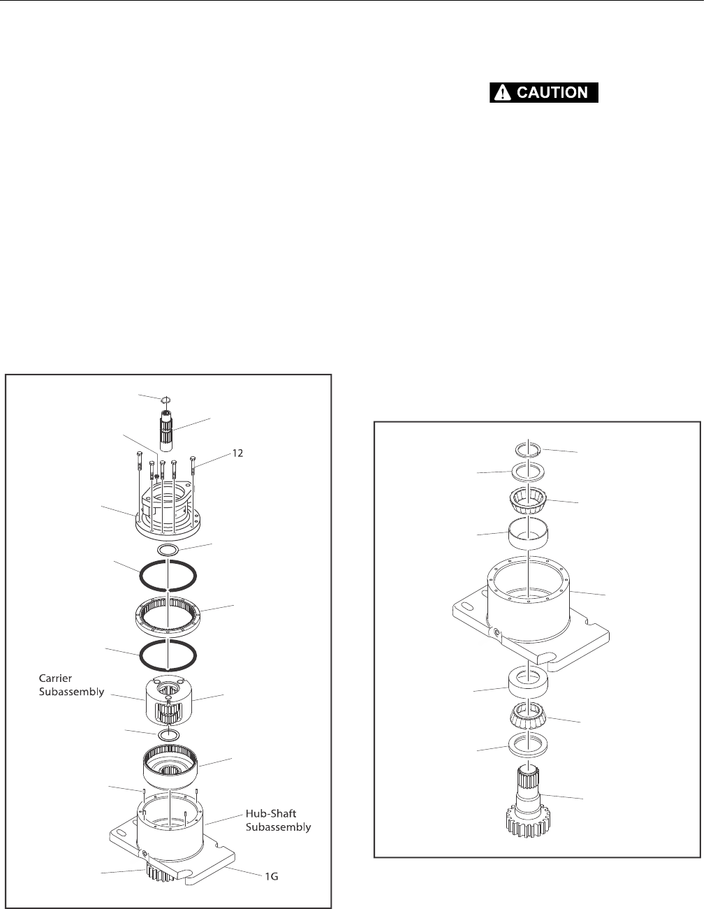
SECTION 3 - CHASSIS & TURNTABLE
3-38 – JLG Lift – 3121298
Main Disassembly
1. Remove Sun Gear (8) with Retaining Ring (44) inside.
2. With unit resting on Output Shaft (Pinion) (1A), remove
Bolts (12) from Brake Housing (6).
3. Remove Brake Housing (6) from main assembly.
4. Remove O-ring (5A) from Brake Housing (6) and Ring
Gear (4).
5. Remove Thrust Washer (11) from Brake Housing (6) and
Carrier Subassembly.
6. Remove Ring Gear (4) from Housing (1G).
7. Remove O-ring (5) from Ring Gear (4) and Housing (1G).
8. Remove Carrier Subassembly.
9. Remove Thrust Washer (11) between Carrier Subassem-
bly and Internal Gear (2).
10. Remove Internal Gear (2).
Figure 3-53. Main Disassembly
Hub-Shaft Disassembly
WEAR EYE PROTECTION DURING THIS PROCEDURE.
11. Using retaining ring pliers, remove and discard Retaining
Ring (11) from groove in Output Shaft (1A).
12. Remove Thrust Washer (1H).
13. Support Housing (1G) on Output Shaft (1A) end. Press
Output Shaft (1A) out of Housing (IG).
NOTE: Lip Seal (1B) will be pressed out of Housing (1G) by Bearing
Cone(1D) during this step.
14. Remove Bearing Cone (IE) from Housing (IG).
15. Use a bearing puller to remove Bearing Cone (1D) from
Shaft (1A). Bearing Cups (1C & 1F) will remain in Housing
(1G).
NOTE: If bearing replacement is necessary, Bearing Cups (1C & 1F)
can be removed with a slide hammer puller or driven out
with a punch.
Figure 3-54. Hub-Shaft Disassembly
44
8
20
6
11
5A
4
5
3F
11
2
13
1A
1A
1B
1D
1C
1G
1F
1E
1H
1I
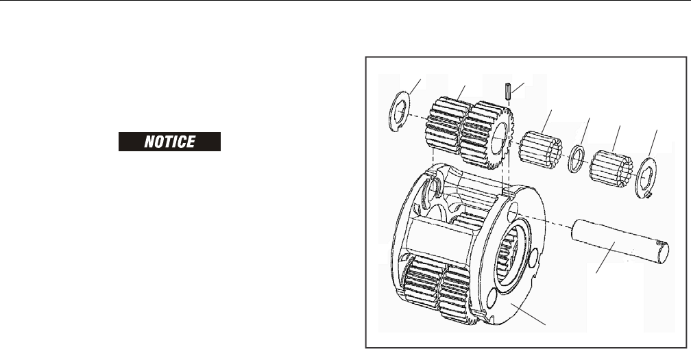
SECTION 3 - CHASSIS & TURNTABLE
3121298 – JLG Lift – 3-39
Carrier Disassembly
1. Using a 3/16" punch drive Roll Pin (3G) holding Planet
Shaft (3E) in Carrier (3A) in Planet Shaft (3E) until it bot-
toms.
MAKE SURE ROLL PIN HAS BOTTOMED OR CARRIER MAY BE DAMAGED WHEN
PLANET SHAFT IS REMOVED.
2. Remove Planet Shaft (3E) from Carrier (3A). Use a small
punch to remove Roll Pin (3G) from Planet Shaft (3E).
3. Slide Planet Gear (3F) and two Thrust Washers (3B) out
of Carrier (3A).
4. Remove both rows of Needle Bearings (3C) and Spacer
(3D) from bore of Planet Gear (3F).
5. Repeat Steps 1 thru 4 for remaining Cluster Gears (3F).
Figure 3-55. Carrier Disassembly
3B
3B
3C
3D
3C
3F
3G
3E
3A
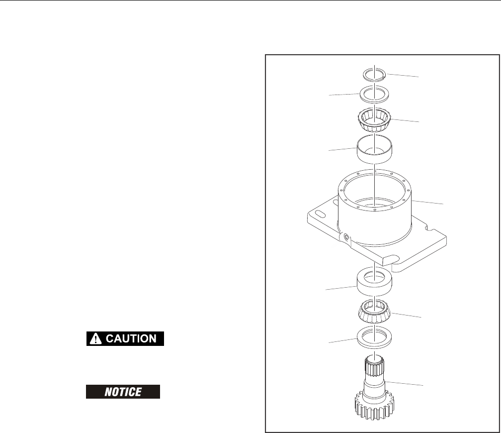
SECTION 3 - CHASSIS & TURNTABLE
3-40 – JLG Lift – 3121298
Hub-Shaft Subassembly
1. Press Bearing Cup (1C) in Housing (1G). Make sure cup
starts square with bore of Hub (1G).
2. Place Bearing Cone (1D) in Bearing Cup (1C) in Housing
(1G).
3. Apply grease to rubber portion of Seal (1B). Press or tap
Seal (1B) with smooth face up, in counterbore of Hous-
ing (1G) until it is flush with Housing (1G) face bore.
4. Invert Hub (1G) and press Bearing Cup (1E) in counter-
bore of Housing (1G).
5. Carefully lower Housing (1G) on Output Shaft (1A) until
Bearing Cone (1D) contacts Output Shaft (1A).
6. Press on small end of Bearing Cone (1D), being careful
not to contact the bearing cage, until Bearing Cone (1D)
seats on Output Shaft (1A) shoulder.
7. Start Bearing Cone (1F) on Output Shaft (1A).
8. Press or tap Bearing Cone (1F) on Output Shaft (1A) until
it is just seated in Bearing Cup (1E), while rotating the
Housing (1G).
9. Install Bearing Spacer (1H) on Output Shaft (1A) against
Bearing Cone (1F).
RINGS UNDER TENSION CAN FLY OUT AND CAUSE SERIOUS INJURY. WEAR EYE
PROTECTION WHEN INSTALLING RINGS.
NEVER REUSE A RETAINING RING IN REBUILD OR REPAIR.
10. Install new Retaining Ring (1I) in groove of Output Shaft
(1A).
11. Tap Retaining Ring (1I) with a soft metal punch to ensure
it is completely seated in groove of Output Shaft (1A).
Figure 3-56. Hub-Shaft Subassembly
12. Reinstall Drain Plug if not already installed (1P from Fig.
3-45). Torque to 23 - 24 ft-lb (31 - 32 Nm).
1A
1B
1D
1C
1G
1F
1E
1H
1I
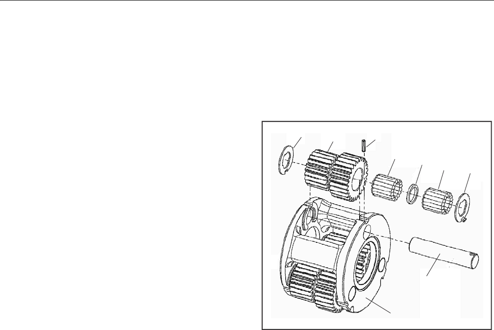
SECTION 3 - CHASSIS & TURNTABLE
3121298 – JLG Lift – 3-41
Carrier Subassembly
1. Apply a liberal coat of grease to bore of Cluster Gear
(3F). This holds Needle Rollers (3C) in place during
assembly.
2. Install first row of Needle Rollers (3C) in bore of Cluster
Gear (3F).
3. Insert Spacer (3D) in bore of Cluster Gear (3F) on top of
Needle Rollers (3C).
4. Place second row of Needle Rollers (3C) in bore of Clus-
ter Gear (3F) against Spacer(3D).
5. Place Carrier (3A) with one roll pin hole straight up.
6. Start Planet Shaft (3E) through hole in Carrier (3A). Using
ample grease to hold it in position, slide one Thrust
Washer (3B) over Planet Shaft (3E) with tang resting in
cast slot of Carrier (3A).
7. With large end of Cluster Gear (3F) facing roll pin hole in
Carrier, place Cluster Gear in position in Carrier (3A).
Push Planet Shaft (3E) through Cluster Gear (3F) without
going all the way through.
8. Slide second Thrust Washer (3B) between Cluster Gear
(3F) and Carrier (3A) with washer tang located in cast
slot of Carrier (3A). Finish sliding Planet Shaft (3E)
through Thrust Washer (3B) into Carrier (3A).
9. Position non-chamfered side on Planet Shaft (3E) Roll
Pin hole in line with hole in Carrier (3A) using a 1/8 inch
diameter punch.
10. Use a 3/16" punch to align two roll pin holes. Drive roll
pin (3G) through Carrier (3A) and into Planet Shaft (3E)
until Roll Pin (3G) is flush with bottom of cast slot in Car-
rier (3A) outside diameter at Thrust Washer (3B) tang.
Use a 1/4" pin punch to make sure roll pin (3G) is flush in
slot.
11. Repeat Steps 1 thru 10 for remaining Cluster Gears (3F).
Figure 3-57. Carrier Subassembly
3B
3B
3C
3D
3C
3F
3G
3E
3A
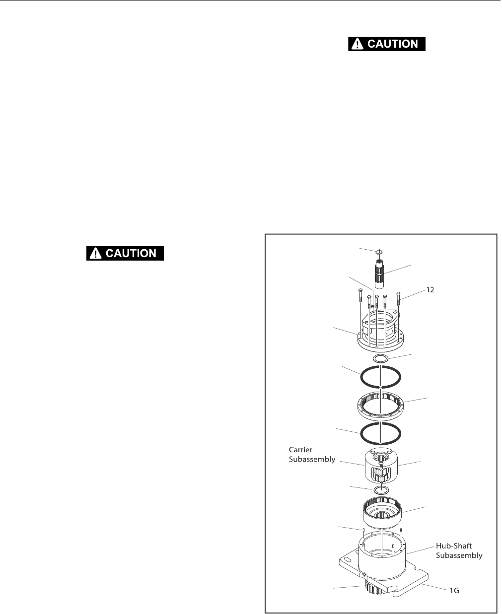
SECTION 3 - CHASSIS & TURNTABLE
3-42 – JLG Lift – 3121298
Main Assembly
1. With Hub Shaft Subassembly resting on Shaft (1A) install
Internal Gear (2). The spline of Internal Gear (2) bore will
mesh with spline of Output Shaft (1A). This will be a tight
fit.
2. Inspect location of Internal Gear (2) on Output Shaft
(1A). A portion of Output Shaft (1A) should protrude
through Internal Gear (2) bore.
3. Install 4 Dowel Pins (13) into counter bore holes in Hub
(1G).
4. Install Thrust Washer (11) in counter bore of Carrier Sub-
assembly (Small Cluster-Gear end) Use grease to hold in
place.
5. Place O-ring (5) into Hub counter-bore. Use grease to
hold O-ring in place.
SHARP EDGES OF COUNTER-BORE CAN CAUSE SERIOUS INJURY. BE CAREFUL
WHEN SEATING O-RING.
6. Place Carrier Subassembly on bench with large end of
Cluster Gears (3F) facing up with one at 12 o’clock posi-
tion. Find punch marked tooth on each gear at large end
and locate at 12 o'clock (straight up) from each planet
pin. Marked tooth will be located just under Carrier on
upper two gears. Check timing through slots in carrier.
(See Carrier Subassembly)
7. With longer shoulder side of Ring Gear (4) facing down,
place Ring Gear (4) over (into mesh with) cluster gears
(3F). Be sure cluster gear timing marks (punch marks)
remain in correct location during Ring Gear (4) installa-
tion. Ring Gear (4) side with an "X" or punch mark
stamped on it should be up.
8. While holding Ring Gear (4) and Cluster Gears (3F) in
mesh, place small end of Cluster Gears (3F) into mesh
with Internal Gear (2). On Ring Gear (4), locate hole
marked "X" or punch marked over one of the marked
counter-bored holes (Step 5) in Hub (1G). Check timing
through slots in carrier. Rotate carrier in assembly to
check freedom of rotation.
NOTE: If gears do not mesh easily or Carrier Assembly does not
rotate freely, remove Carrier and Ring Gear. Check Cluster
Gear timing.
9. Install Thrust Washer (11) in counter bore on face of car-
rier. Use grease to hold in place.
10. Place O-ring (5A) into counter bore of Brake Housing (6).
Use grease to hold O-Ring in place.
SHARP EDGES OF COUNTER-BORE CAN CAUSE SERIOUS INJURY. BE CAREFUL
WHEN SEATING O-RING.
11. Install Brake Housing (6). Align Pipe Plug hole (20) with
those in the Hub (1G).
12. Install Bolts (12) through Brake Housing (6) into Hub
(1G). Torque to 23 - 27 ft-lb (31-36 Nm).
13. With gearbox standing on pinion end, fill gearbox with
43 oz of ISO VG150 / VG220 gear oil.
14. Install Retaining Ring (44) in groove of Sun Gear (8).
15. Install Sun Gear (8) into mesh with Planet Gears (3F).
16. Install Pipe Plug (20) in Cover (6). Torque to 23 to 24 ft-lb
(31 - 32 Nm).
Figure 3-58. Main Assembly
44
8
20
6
11
5A
4
5
3F
11
2
13
1A
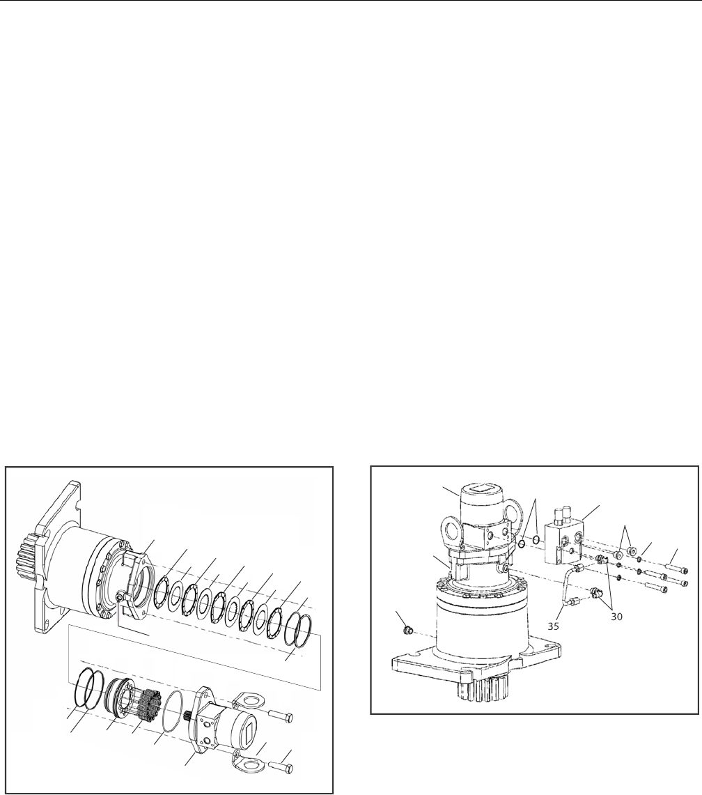
SECTION 3 - CHASSIS & TURNTABLE
3121298 – JLG Lift – 3-43
Motor and Brake Assembly
1. Insert Stator (8K) (O.D. lobes) in bore of Brake Housing
(6). Alternate Rotors (8J) (I.D. splines) and Stators, ending
with a Stator (8K).
2. Grease O-rings (8F) & (8D) and Back-up rings (8H) & (8E).
Place them in their respective grooves in Brake Housing
(6) and Piston (8A). Make sure Back-up rings are correctly
positioned.
3. Apply grease sparingly to Piston O.D. (8A) and bore of
Brake Housing (6). Insert Piston (8A) in Brake Housing
(6). Do not damage O-rings.
4. Install Springs (8L) in Piston (8A) spring pockets.
5. Test brake and perform roll test. Remove Brake Test
Plate.
6. Install O-ring (26) on pilot of Motor (31). Use grease to
keep O-ring in place.
7. Place Motor (31) in Brake pilot and line up holes. Check
timing sheet.
8. Assemble Lift Lugs (28) on Hex Bolts (29). Assemble Hex
Bolts (29) with Lift Lugs (28) through Motor (31) and
Brake (6) against Motor flange. Torque to 80-100 ft-lb
(108-135 Nm).
Figure 3-59. Motor and Brake Assembly
Motor Control Valve Assembly
1. Lay assembly down with motor ports facing up. Remove
two plastic plugs in the motor ports. Do not to lose O-
ring in each port. Assemble Motor control Valve (32) on
Motor (31) with Bolt (21) and Lock Washers (22). Torque
Bolts (21) to 23-27 ft-lb (31-36 Nm).
NOTE: Align holes in control valve with motor ports.
2. Install Elbow Fittings (30) in Brake (6). Do not tighten
jam nuts.
3. Install Elbow Fittings (30) in Motor Control Valve (32). Do
not tighten jam nuts.
4. Assemble Tube (35) in Elbow Fittings (30). Torque jam
nuts to 13-15 ft-lb (17-20 Nm).
5. Install one O-ring Plug (23) in Motor Control Valve (32).
Torque to 30-31 ft-lb (40-42 Nm).
6. Pressure test brake, tube, and control valve connections
by applying 3000 psi (207 bar) pressure to open port in
Motor Control Valve (32) and holding for one minute.
Check for leaks at control-valve-motor interface and
tube connections. Release pressure and install remain-
ing O-ring Plug (23) in Motor Control Valve (32). Torque
to 30-31 ft-lb (40-42 Nm).
Figure 3-60. Motor Control Valve Assembly
68K
8J 8K
8K
8K
8K
8J 8J 8J 8H
8F
8D
8E 8A 8L 26
31
28 29
Brake Port
31
6
1P
32
23
22
21
O-Ring
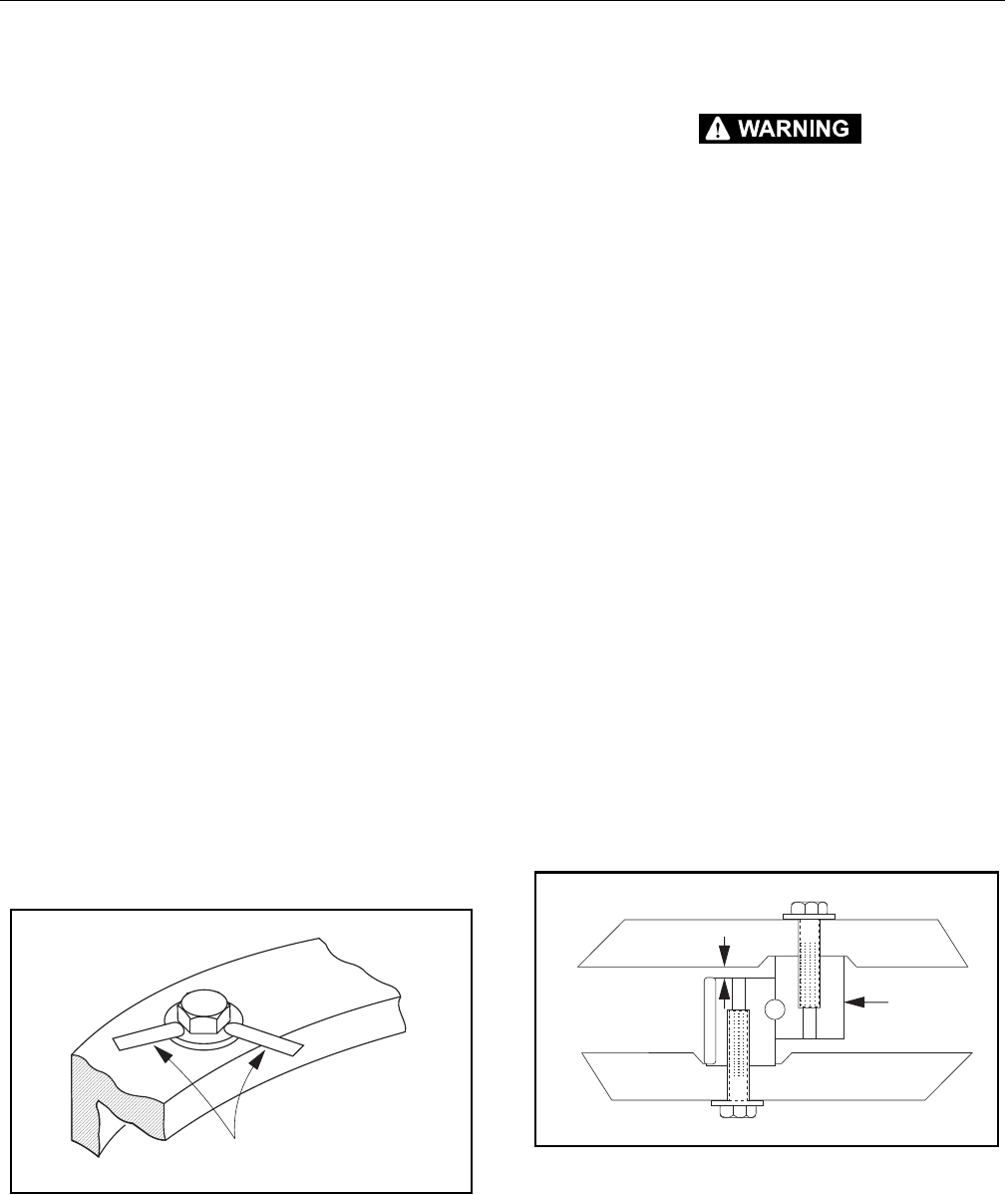
SECTION 3 - CHASSIS & TURNTABLE
3-44 – JLG Lift – 3121298
3.8 SWING BEARING
Turntable Bearing Mounting Bolt Condition Check
NOTE: This check is designed to replace existing bearing bolt
torque checks on JLG Lifts in service. This check must be
performed after first 50 hours of machine operation and
every 600 hours of machine operation thereafter. If any
bolts are missing or loose, replace missing or loose bolts
with new bolts and torque to value specified in torque
chart after lubricating bolt threads with loctite #271. After
replacing and retorquing bolt or bolts, recheck all bolts for
looseness.
1. Check frame to bearing. Attach bolts as follows:
a. Elevate fully retracted boom to 70° (full elevation).
b. Try and insert a 0.0015" feeler gauge between bolt
head and hardened washer at position shown in Fig-
ure 3-61.
c. Make sure 0.0015" feeler gauge will not fit under
bolt head to bolt shank.
d. Swing turntable 90° and check some selected bolts
at new position.
e. Continue rotating turntable at 90° intervals until a
sampling of bolts are checked in all quadrants.
2. Check turntable to bearing. Attach bolts as follows:
a. Elevate fully retracted boom to 70° (full elevation).
b. try and insert a 0.0015" feeler gauge between bolt
head and hardened washer at positions shown in
Figure 3-61.
c. Lower boom to horizontal and fully extend boom.
d. Try and insert the 0.0015" feeler gauge between bolt
head and hardened washer at position shown in Fig-
ure 3-61.
Figure 3-61. Swing Bearing Bolt Feeler Gauge Check
Wear Tolerance
SWING BEARING IS ONE OF THE MOST CRITICAL POINTS ON AN AERIAL LIFT. IT
IS HERE STRESSES OF LIFTING ARE CONCENTRATED, AT CENTER OF ROTATION.
BECAUSE OF THIS, PROPER MAINTENANCE OF SWING BEARING BOLTS IS A
MUST FOR SAFE OPERATION.
1. From underside of machine, at rear center, with boom
fully elevated and fully retracted, as shown in Figure 3-
63., Swing Bearing Tolerance Measurement Location &
Boom Placement A, using a magnetic base dial indicator,
measure and record distance between swing bearing
and turntable as shown in Figure 3-62., Swing Bearing
Tolerance Measuring Point.
2. At the same point, with boom horizontal and fully
extended, and tower boom fully elevated as shown in -
Swing Bearing Tolerance Boom Placement B, using a
magnetic base dial indicator, measure and record dis-
tance between swing bearing and turntable as shown in
Figure 3-62., Swing Bearing Tolerance Measuring Point.
3. If difference is greater than 0.079 in. (2.00 mm), replace
swing bearing.
4. If difference is less than 0.079 in. (2.00 mm) and any of
the following conditions exist:
a. Metal particles in grease.
b. Increased drive power required.
c. Noise.
d. Rough rotation.
5. Remove, disassemble, and inspect bearing. If bearing
inspection shows no defects, reassemble and return to
service.
Figure 3-62. Swing Bearing Tolerance Measuring Point
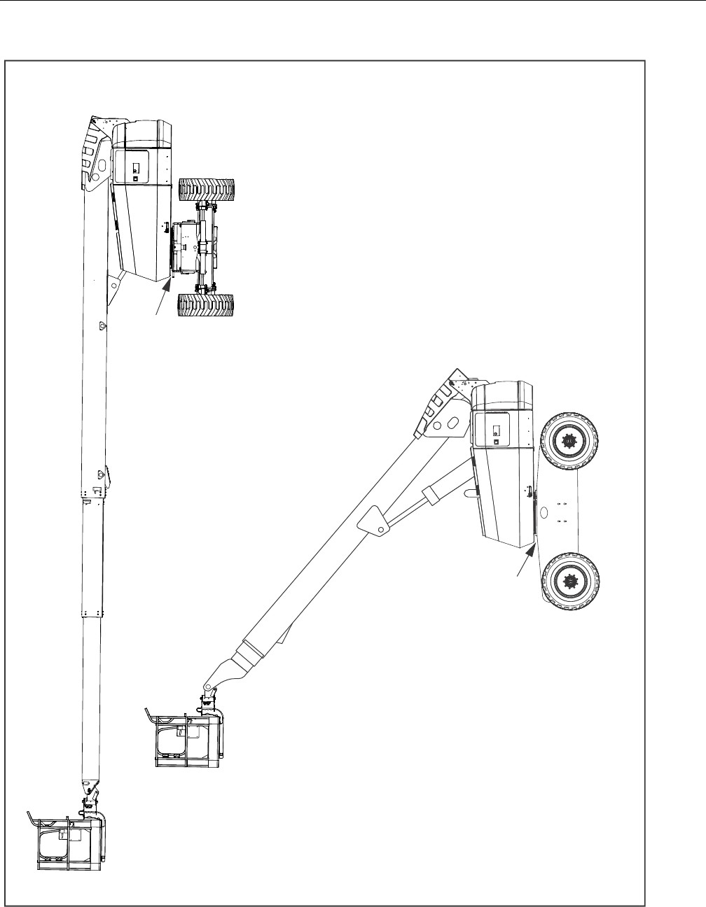
SECTION 3 - CHASSIS & TURNTABLE
3121298 – JLG Lift – 3-45
Measuring Point
Measuring Point
a. Boom fully elevated and fully retracted.
b. Boom horizontal and fully extended.
Figure 3-63. Swing Bearing Tolerance Measurement Location & Boom Placement

SECTION 3 - CHASSIS & TURNTABLE
3-46 – JLG Lift – 3121298
Swing Bearing Replacement
REMOVAL
1. Operate boom from Ground Control station to provide
access to frame opening or rotary coupling.
NEVER WORK BENEATH THE BOOM WITHOUT FIRST ENGAGING BOOM SAFETY
PROP OR PROVIDING ADEQUATE OVERHEAD SLING SUPPORT AND/OR BLOCK-
ING.
2. Attach an adequate support sling to boom and draw all
slack from sling. Prop or block boom if feasible.
3. From inside turntable, remove mounting hardware
attaching rotary coupling retaining yoke brackets to
turntable.
HYDRAULIC LINES AND PORTS SHOULD BE CAPPED IMMEDIATELY AFTER DIS-
CONNECTING LINES TO AVOID THE ENTRY OF CONTAMINANTS INTO THE SYS-
TEM.
4. Tag and disconnect hydraulic lines from fittings on top
of rotary coupling. Use a suitable container to retain any
residual hydraulic fluid. Immediately cap lines and ports.
5. Attach suitable overhead lifting equipment to base of
turntable weldment.
6. Use a suitable tool to scribe a line on swing bearing
inner race an underside of turntable. This will aid in
aligning bearing upon installation. Remove bolts and
washers which attach turntable to bearing inner race.
Discard bolts.
7. Use lifting equipment to carefully lift complete turntable
assembly from bearing. Ensure no damage occurs to
turntable, bearing, or frame-mounted components.
8. Carefully place turntable on a suitably supported trestle.
9. Use a suitable tool to scribe a line on outer swing bear-
ing race and frame. This line will aid in aligning bearing
upon installation. Remove bolts and washers which
attach outer race of bearing to frame. Discard bolts. Use
suitable lifting equipment to remove bearing from
frame, then move bearing to a clean, suitably supported
work area.
INSTALLATION
1. Using suitable lifting equipment, carefully lower swing
bearing in position on frame. Ensure scribed line of outer
bearing race aligns with scribed line on frame. If a new
swing bearing is used, ensure filler plug fitting is 90°
from fore and aft center line of frame.
JLG INDUSTRIES RECOMMENDS ALL REMOVED BEARING BOLTS BE DISCARDED
AND REPLACED WITH NEW BOLTS. SINCE THE SWING BEARING IS THE ONLY
STRUCTURAL LINK BETWEEN THE FRAME AND TURNTABLE, IT IS IMPERATIVE
SUCH REPLACEMENT HARDWARE MEETS JLG SPECIFICATIONS. USE OF GENU-
INE JLG HARDWARE IS HIGHLY RECOMMENDED.
CHECK TORQUE SETTING ACCURACY OF TOOL IF COMPRESSED AIR OR ELECTRI-
CALLY OPERATED IMPACT WRENCH IS USED TO TIGHTEN BEARING ATTACH-
MENT BOLTS.
2. Refer to Torque Sequence diagram as shown in Figure 3-
64., Swing Bearing Torque Sequence. Clean residue off
new bearing bolts and apply a light coating of Thread
Locking Compound JLG P/N 0100019. Install bolts and
washers through frame and outer bearing race. Torque
bolts to 190 ft-lb (258 Nm). Remove lifting equipment
from bearing.
3. Using suitable lifting equipment, carefully position turn-
table assembly above machine frame.
4. Carefully lower turntable onto swing bearing. Ensure
scribed line of inner bearing race aligns with scribed line
on turntable. If a new swing bearing is used, ensure filler
plug fitting is 90° fore and aft center line of turntable.
5. Clean residue off new bearing bolts and apply a light
coating of Thread Locking Compound JLG P/N 0100019.
Install bolts and washers through turntable and bearing
inner race.
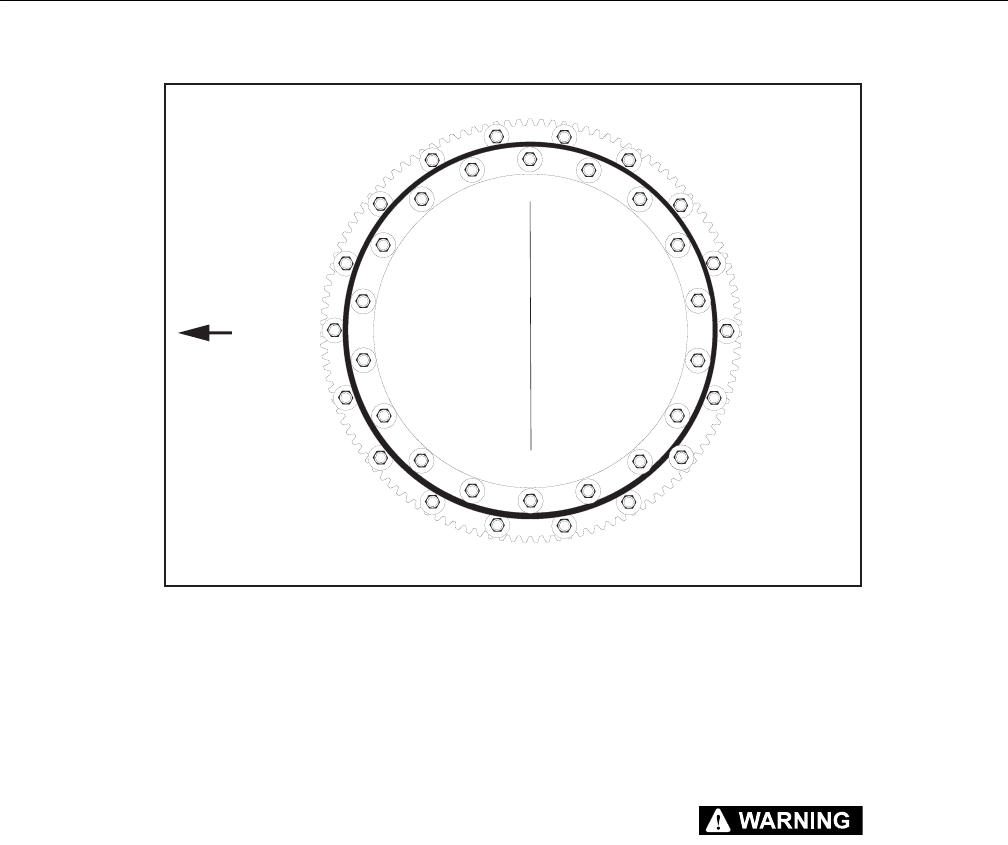
SECTION 3 - CHASSIS & TURNTABLE
3121298 – JLG Lift – 3-47
6. Following Torque Sequence diagram shown in Figure 3-
64., Swing Bearing Torque Sequence, torque bolts to 190
ft-lb (258 Nm) w/Loctite.
7. Remove lifting equipment.
8. Install rotary coupling retaining yoke brackets. Apply a
light coating of Thread Locking Compound, JLG P/N
0100011 to attaching bolts. Secure yoke to turntable
with mounting hardware.
9. Connect hydraulic lines to rotary coupling as tagged
prior to removal.
10. At ground control station, use boom lift control to lower
boom to stowed position.
11. Using all applicable safety precautions, activate hydrau-
lic system and check swing system for proper and safe
operation.
Swing Bearing Torque Values
1. Outer Race - 190 ft-lb (258 Nm) w/Loctite.
2. Inner Race - 190 ft-lb (258 Nm) w/Loctite.
3. See Figure 3-64. Swing Bearing Torque Sequence.
CHECK OR MISSING OR LOOSE INNER AND OUTER SWING BEARING BOLTS
AFTER FIRST 50 HOURS OF OPERATION AND EVERY 600 HOURS THEREAFTER.
Figure 3-64. Swing Bearing Torque Sequence
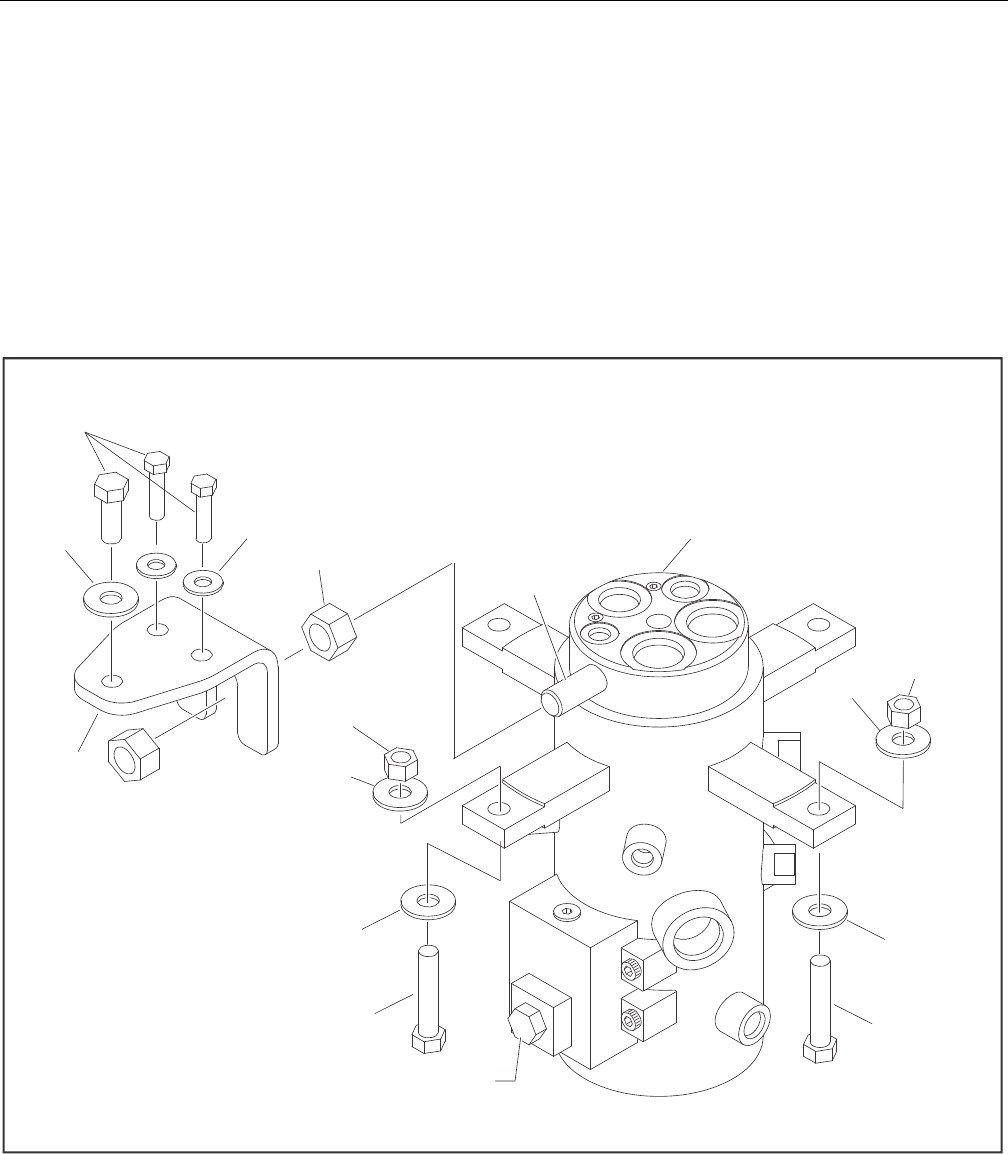
SECTION 3 - CHASSIS & TURNTABLE
3-48 – JLG Lift – 3121298
3.9 ROTARY COUPLING
Use the following procedure to install the seal kit.
1. If not already removed, remove axle oscillation valve
from cylinder barrel. The valve spool protrudes into the
barrel and will damage spool and seals if left in place.
2. Remove snap ring (12) from end.
3. Remove thrust ring (13) from same end.
4. Remove center body (10) from housing (11).
5. Cut off old seals (14,15,17,18).
6. Assemble lip seals (14) in direction shown in Figure 3-66.,
Rotary Coupling - Sheet 2 of 2.
7. Reassemble O-ring (18).
8. Heat cap seals (17) in hydraulic oil for 5 minutes at 300° F
(149° C).
9. Assemble cap seals over O-rings
10. Reinsert center body in housing (lube with hydraulic oil).
11. Replace thrust ring and snap ring.
Figure 3-65. Rotary Coupling - Sheet 1 of 2
1. R ot ar y Cou pl in g
2. Tor que Lug
3. Lo ckn ut
4. Fl at Wa sh er
5. B ol t
6. N ut
7. B ra cke t
4
3
4
5
5
3
4
1
4
2
Detail A
7
6
44
5
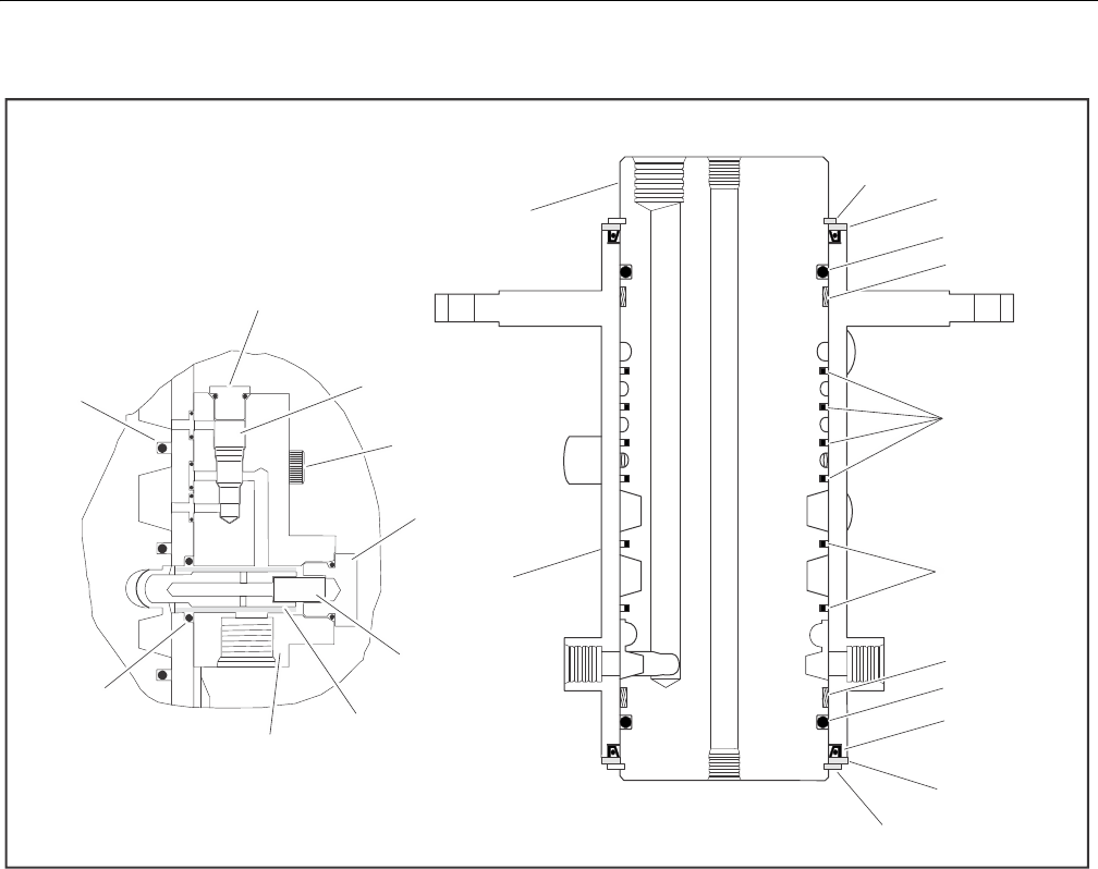
SECTION 3 - CHASSIS & TURNTABLE
3121298 – JLG Lift – 3-49
Figure 3-66. Rotary Coupling - Sheet 2 of 2
1. O -ri ng
2. P lu g
3. C he ck Va lve
4. S cr ew
5. P lu g
6. Sp ri ng
7. Va lve B lo ck Pl un ge r
8. Va lve B lo ck
9. O -ri ng
10. Body
11. Housing
12. Retaining Ring
13. Ring
14. Oil Seal
15. O-ring
16. Bearing
17. Cap Seal
18. O-ring
2
3
4
5
6
7
8
9
DETAIL A
1
13
12
14
15
16
17, 18
17, 18
16
15
13
12
10
11
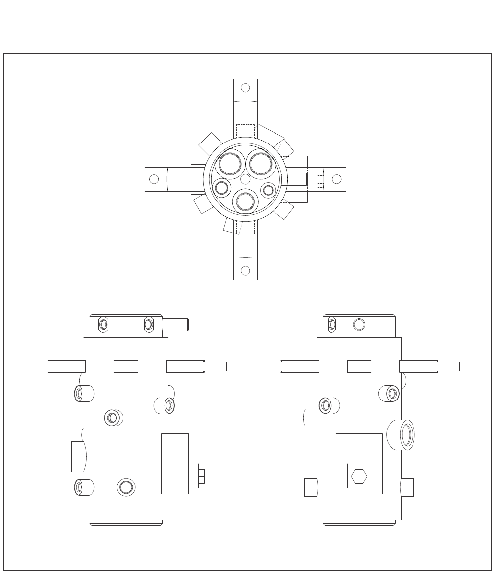
SECTION 3 - CHASSIS & TURNTABLE
3-50 – JLG Lift – 3121298
Figure 3-67. Rotary Coupling Port Location - 2WS
3
4
1
22
3
4
6
77
3
1
2
3
4
5
77
1,5
75
2
3
7
4
2,7
6
56
1
7
2
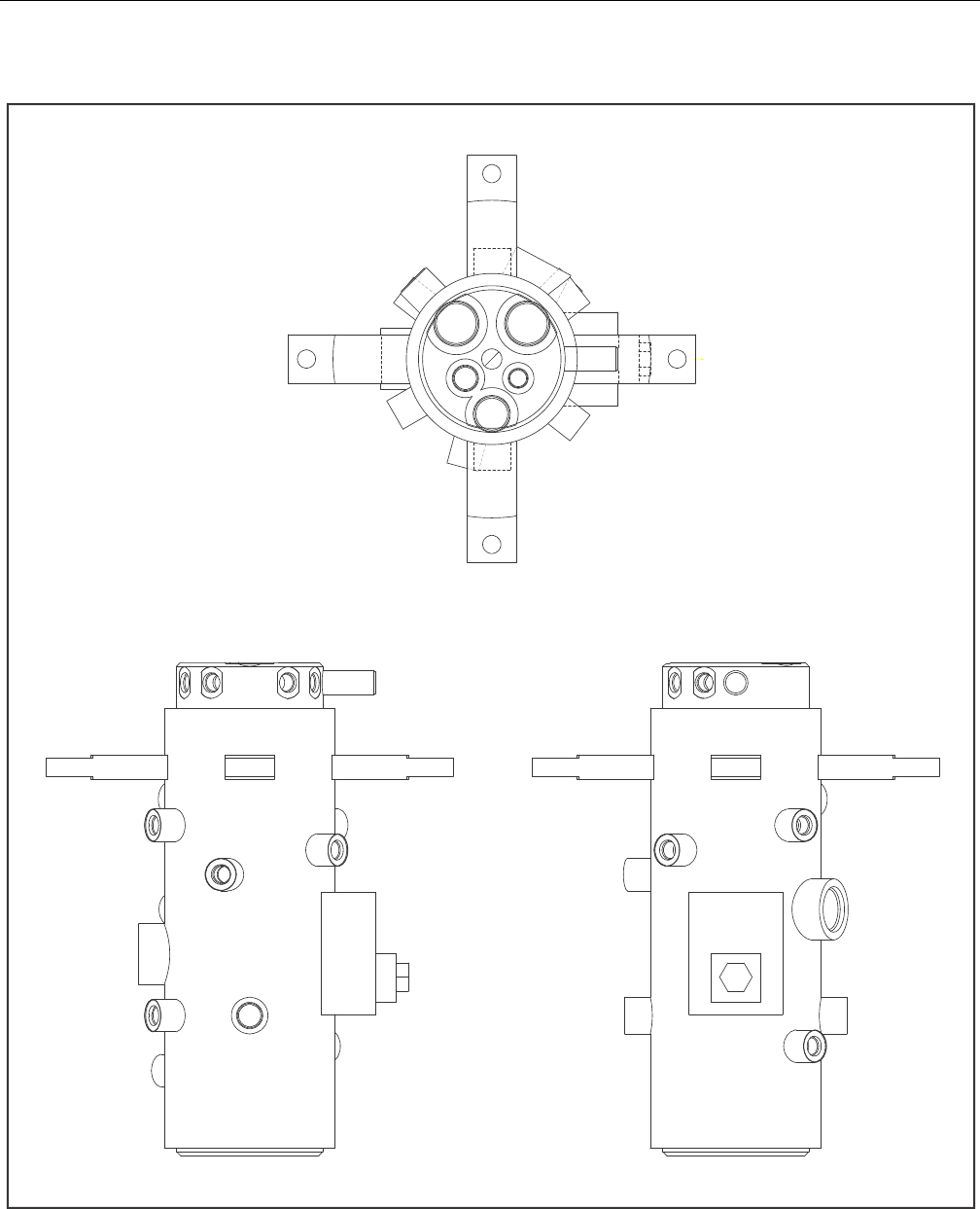
SECTION 3 - CHASSIS & TURNTABLE
3121298 – JLG Lift – 3-51
Figure 3-68. Rotary Coupling Port Location - 4WS
1,5,9
75
2,8
3
7
4
2,7
6
56
1
7
2
3
4
1
22
3
4
6
77
8
9
983
1
2
3
4
5
77
8
8
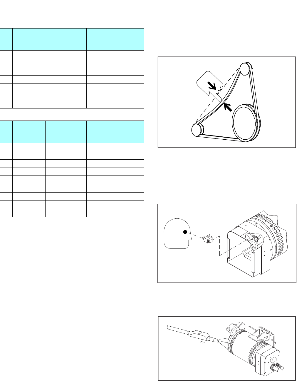
SECTION 3 - CHASSIS & TURNTABLE
3-52 – JLG Lift – 3121298
3.10 GENERATOR
Every 250 hours
Check drive belt tension every 250 hours of operation,.
Figure 3-69. Generator Belt Tension
Every 500 hours
Service generator brushes and slip rings every 500 hours of
operation. Hostile environments may require more frequent
service.
Figure 3-70. Generator Brushes and Slip Rings
Blow out inside of generator every 500 hours of service. If
operating in a hostile environment, clean monthly.
Figure 3-71. Generator Cleaning
Table 3-9. Coupling Port Information Table - 2WS
Port
No. Outlet Port
Size Description
Operating
Pressure
PSI (Bar)
Proof
Pressure
PSI (Bar)
1 1 -8 Brake 450 (31) 675 (47)
2 2 -6 2 Speed 4500 (310) 6750 (465)
3 1 -6 Steer 2500 (172) 3750 (259)
4 1 -6 Steer 2500 (172) 3750 (259)
5 2 -6, -16 Drive Reverse 4500 (310) 6750 (465)
6 1 -16 Drive Forward 4500 (310) 6750 (465)
7 3 -8, -6 Case Drain 250 (17) 375 (26)
Table 3-10. Coupling Port Information Table - 4WS
Port
No. Outlet Port
Size Description
Operating
Pressure
PSI (Bar)
Proof
Pressure
PSI (Bar)
1 1 -8 Brake 450 (31) 675 (47)
2 2 -6 2 Speed 4500 (310) 6750 (465)
3 1 -6 Steer 2500 (172) 3750 (259)
4 1 -6 Steer 2500 (172) 3750 (259)
5 2 -6, -16 Drive Reverse 4500 (310) 6750 (465)
6 1 -16 Drive Forward 4500 (310) 6750 (465)
7 3 -8, -6 Case Drain 250 (17) 375 (26)
8 1 -6 Steer 2500 (172) 3750 (259)
9 1 -6 Steer 2500 (172) 3750 (259)
1/2 in.
(13 mm)
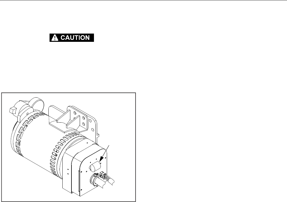
SECTION 3 - CHASSIS & TURNTABLE
3121298 – JLG Lift – 3-53
Overload Protection
STOP ENGINE WHENEVER CHECKING OR INSPECTING CIRCUIT BREAKER.
The circuit breaker protects generator windings from over-
load. Generator output stops if circuit breaker opens.
If circuit breaker continues to open, check for faulty equip-
ment connected to platform receptacles.
Figure 3-72. Generator Circuit Breaker Location
Inspecting Brushes, Replacing Brushes, and
Cleaning Slip Rings
Refer to Figure 3-73., Inspecting Generator Brushes, Replacing
Brushes, and Cleaning Slip Rings.
INSPECTING BRUSH POSITION
Inspect brush alignment with slip rings. View alignment
through air vents in stator barrel. Brushes must ride com-
pletely on slip rings.
INSPECTING BRUSHES
1. Remove end panel. Inspect wires.
2. Remove brush holder assembly. Pull brushes from hold-
ers.
3. Replace brushes if damaged, or if brush is at or near min-
imum length.
CLEANING SLIP RINGS
1. Visually inspect the slip rings. Under normal use, the
rings turn dark brown.
2. If slip rings are corroded or their surface is uneven,
remove belt to turn shaft by hand for cleaning.
3. Clean rings with 220 grit emery paper. Remove as little
material as possible. If rings are deeply pitted and do not
clean up, consult generator factory service.
4. Reinstall belt, brush holder assembly, and end panel.
Circuit
Breaker
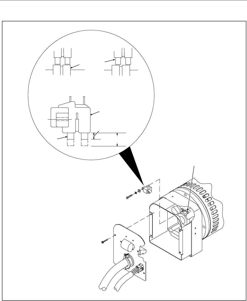
SECTION 3 - CHASSIS & TURNTABLE
3-54 – JLG Lift – 3121298
Figure 3-73. Inspecting Generator Brushes, Replacing Brushes, and Cleaning Slip Rings
1
1/4 in (6 mm)
27/16 in - 1/2 in
(11 - 12 mm ) New
3
2
3
Unacceptable
Brush Position on Slip Rings
Acceptable
Note: Brushes must ride completely on slip rings.
or Less - Replace
1. Brush Holder Assembly
2. Brushes
3. Slip Rings
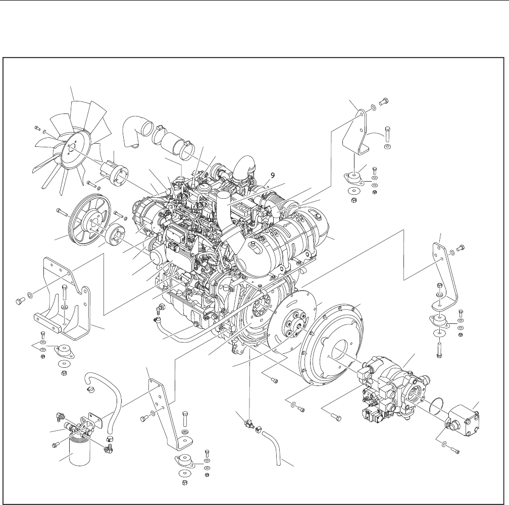
SECTION 3 - CHASSIS & TURNTABLE
3121298 – JLG Lift – 3-55
3.11 DEUTZ D2.9 L4 ENGINE
Figure 3-74. Deutz D2.9 L4 Engine Installation - Sheet 1 of 2
1. Fan
2. Adapter
3. Drive Belt
4. Water Pump
5. Fuel Injector
6. Thermostat
7. Oil Fill Cap
8. Temperature Sender
9. Turbocharger
10. Exhaust Pipe
11. Spark Arrester
12. Pressure Sensor
13. Front Engine Mount
14. Motor Mount
15. Shuttle Valve
16. Catalytic Converter/Muffler
17. Rear Engine Mount
18. Coupling
19. Pump Adapter Plate
20. Pump Assembly
21. Gear Pump Assembly
22. Oil Drain Hose
23. Oil Drain Valve
24. Pump Coupler
25. Flywheel
26. Fuel Filter
27. Pressure Sensor
28. Rear Engine Mount
29. Oil Pan Drain Plug
30. Front Engine/Generator Mount
31. Oil Fill Cap
32. Oil Cooler
33. Oil Filter
34. Belt Tensioner
35. Plug
36. Alternator
37. Adapter
38. Pulley
27
26
30
28
1
8
1
9
2
4
25
2
3
2
2
1
0
,
1
1
2
1
2
0
38
1
28
7
3
4
6
5
31
29
32
33
34
35
36
37
1
2
1
5
1
6
1
7
1
3
1
4
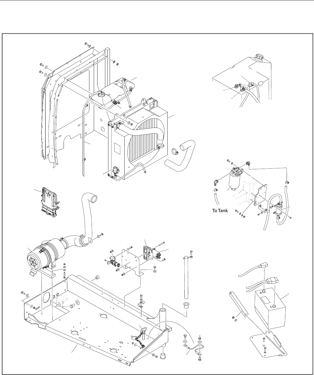
SECTION 3 - CHASSIS & TURNTABLE
3-56 – JLG Lift – 3121298
Figure 3-75. Deutz D2.9 L4 Engine Installation - Sheet 2 of 2
1. Coolant Recovery Tank
2. Radiator Assembly
3. Air Filter Service Indicator
4. Coolant Overflow Hose
5. Coolant Level Sensor
6. Fuel Pump
7. Fuel Pre-Filter
8. Battery
9. Power Module Relay
10. Relay
11. Lanyard
12. Hitch Pin
13. Engine Tray
14. Air Filter Assembly
15. Engine Control Unit (ECU)
Return
Supply
Vent
T
o
E
n
g
i
n
e
6
1
2
1
1
15
13
14
7
10
9
8
2
4
3
1
5
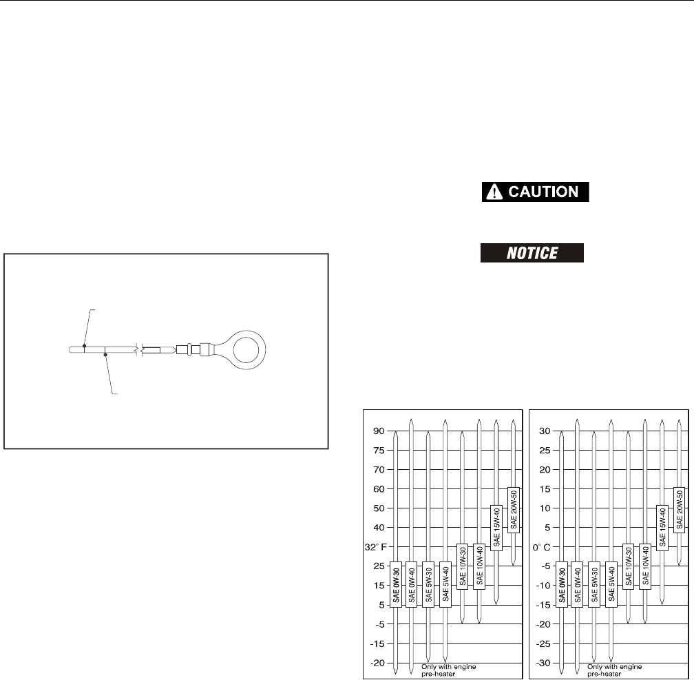
SECTION 3 - CHASSIS & TURNTABLE
3121298 – JLG Lift – 3-57
NOTE: Refer to engine manufacturer’s manual for detailed oper-
ating and maintenance instructions.
Check Oil Level
1. Make sure machine and engine are level and switch
engine OFF before checking oil level.
2. Remove oil dipstick and wipe with clean cloth.
3. Insert dipstick to the stop and remove again.
4. Check oil level. Top oil level as shown in figure below
with an approved grade and type of oil outlined in
engine manufacturer’s operator’s manual.
Figure 3-76. Deutz 2.9 T4F Dipstick Markings
5. Replace dipstick until fully seated.
Change Engine Oil
1. Allow engine to warm up. Engine oil should reach
approximately 176° F (80° C).
2. Make sure machine and engine are level and switch off
engine.
3. Place oil tray under engine.
HOT ENGINE OIL CAN CAUSE BURNS. AVOID CONTACT WITH HOT OIL WHEN
DRAINING.
COLLECT USED OIL IN A CONTAINER SUITABLE FOR DISPOSAL OR RECYCLING.
DISPOSE OF USED ENGINE OIL IN ACCORDANCE WITH ENVIRONMENTAL REGU-
LATIONS.
4. Open oil drain valve and drain oil.
5. Close oil drain valve.
6. Pour in new engine oil. Refer to Section 1 for capacity
and Figure 3-81., Engine Oil Viscosity.
Figure 3-77. Engine Oil Viscosity
MINIMUM OIL
LEVEL
MAXIMUM OIL
LEVEL
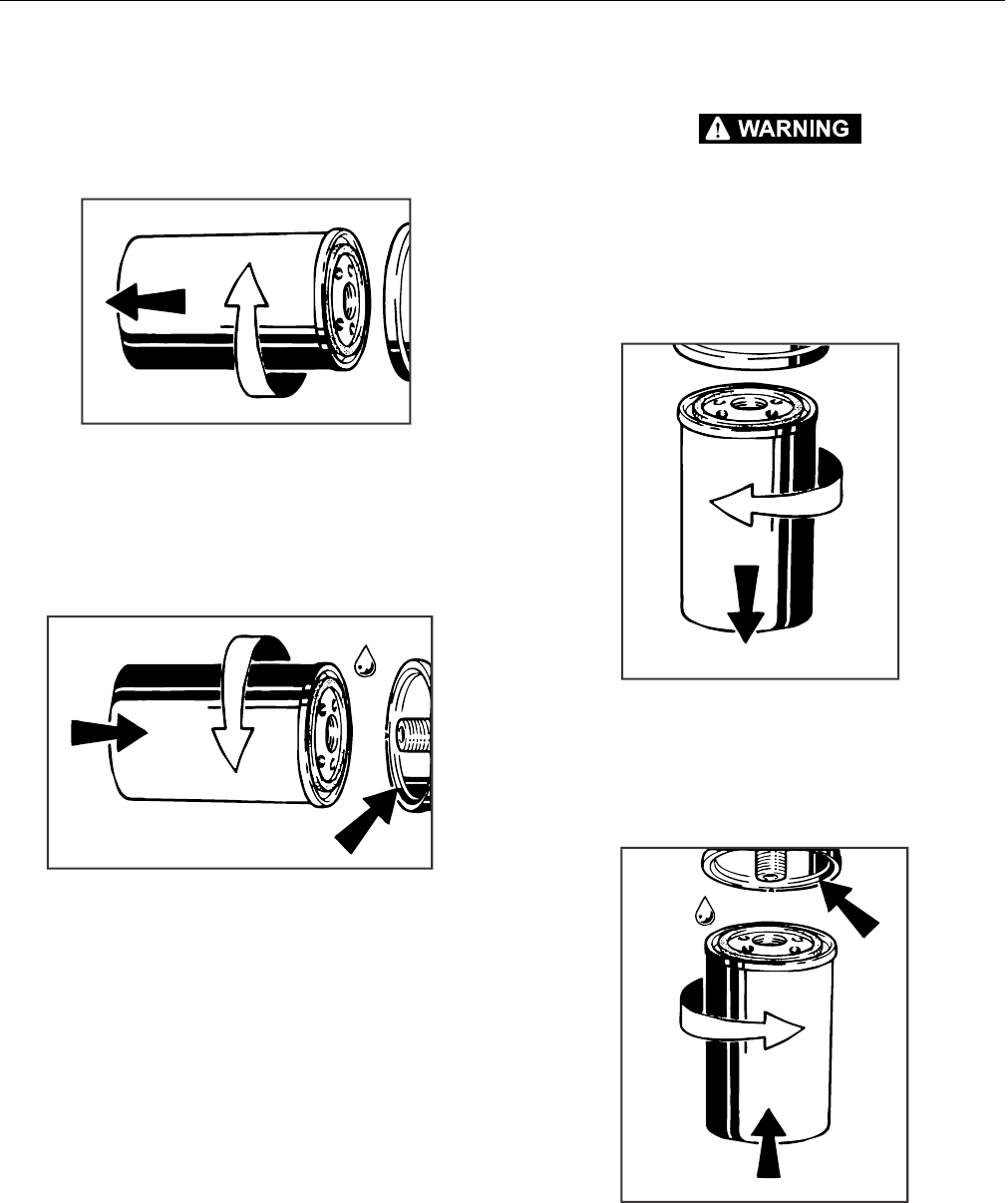
SECTION 3 - CHASSIS & TURNTABLE
3-58 – JLG Lift – 3121298
Change Oil Filter
1. Wipe area around filter to clean any dirt from area.
2. Using a suitable oil filter removal tool, loosen lube oil fil-
ter cartridge and spin off.
3. Catch any escaping oil.
4. Clean any dirt from filter carrier sealing surface.
5. Lightly coat new oil filter rubber gasket with clean oil
6. Screw in new filter by hand until gasket is flush.
7. Hand-tighten filter another half-turn.
8. Check oil level.
9. Check oil pressure.
10. Check oil filter cartridge for leaks.
Change Fuel Filters
FUEL IS FLAMMABLE AND CAN CAUSE DEATH OR SERIOUS INJURY. MAKE SURE
NO OPEN FLAMES OR SPARKS ARE IN THE AREA WHEN WORKING ON FUEL SYS-
TEM. DO NOT SMOKE WHEN WORKING ON FUEL SYSTEM.
1. Wipe area around filter to clean any dirt from area.
2. Disconnect water sensor connector (Pre-filter Only).
3. Remove fuel filter cartridge. Catch any escaping fuel.
4. Clean dirt from filter carrier sealing surface.
5. Apply light film of oil or diesel fuel to rubber gasket of
new filter cartridge.
6. Screw in new filter by hand until gasket is flush. Hand-
tighten filter another half-turn.
7. Connect water sensor connector (Pre-filter Only).
8. Open fuel shut-off valve.
9. Check for leaks.
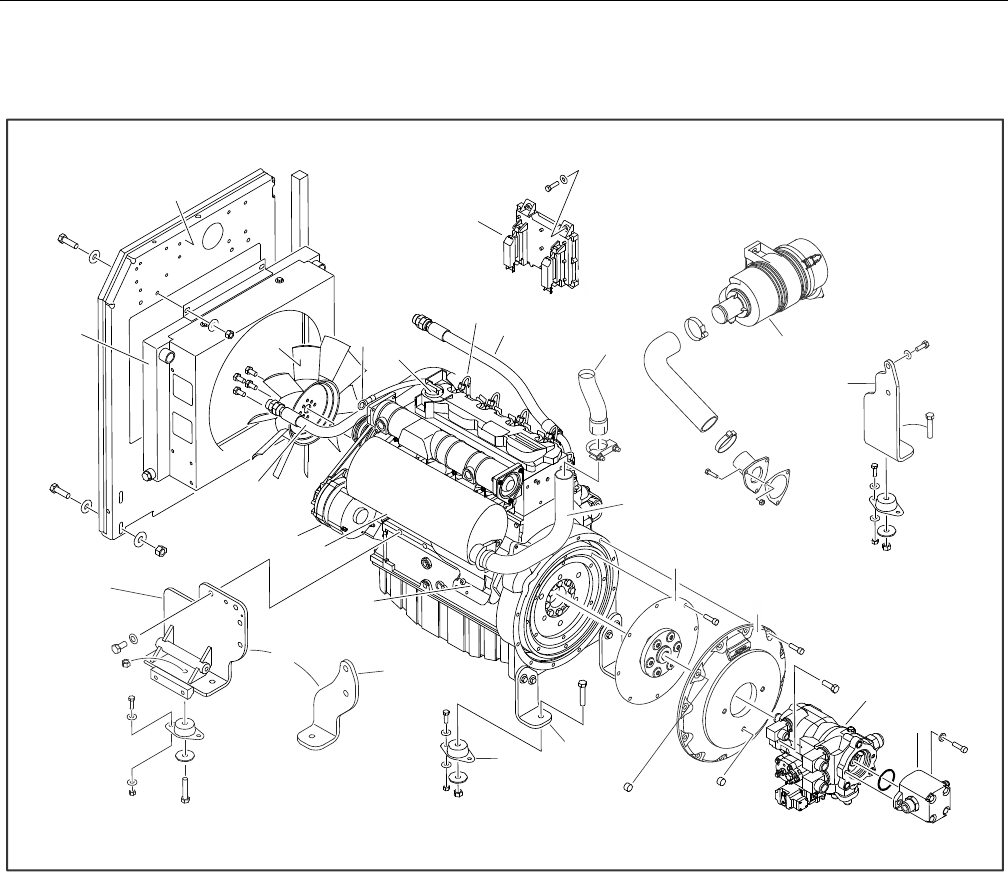
SECTION 3 - CHASSIS & TURNTABLE
3121298 – JLG Lift – 3-59
3.12 DEUTZ D2011 ENGINE
Figure 3-78. Deutz D2011 Engine Installation - Sheet 1 of 2
1. Radiator Mounting Plate
2. Fan
3. Dipstick
4. Oil Filler Cap
5. Control Module
6. Fuel Injector
7. Oil Cooler Hose
8. Exhaust Pipe Extension
9. Air Cleaner
10. Right Rear Engine Mounting Plate
11. Exhaust Pipe
12. Coupling
13. Pump Adapter Plate
14. Piston Pump
15. Gear Pump
16. Left Rear Engine Mounting Plate
17. Engine Mount
18. Left Front Engine Support
19. Left Front Engine/Generator Support
20. Starter
21. Muffler
22. Alternator
23. Radiator Hose
24. Radiator
24
1
2
2
3
2
2
2
1
2
0
3
4
6
7
5
9
1
0
17
8
1
1
1
2
1
3
1
4
1
5
OR
19
18
1
6
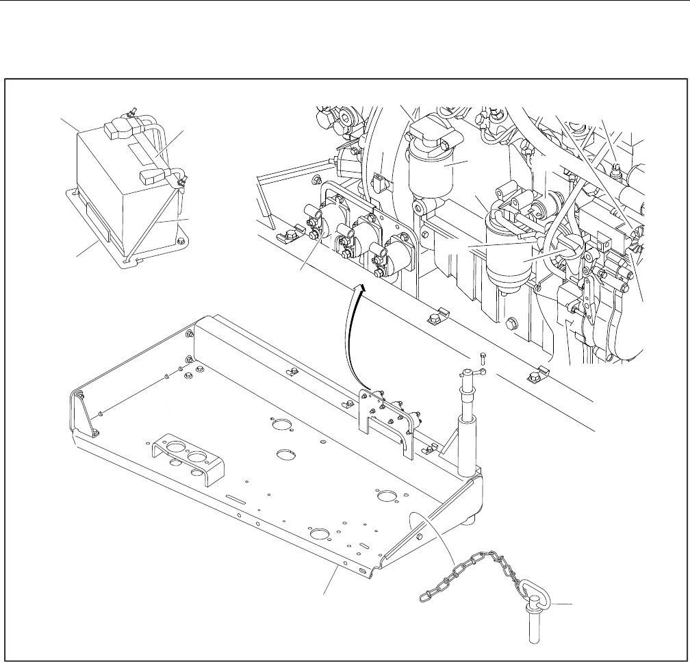
SECTION 3 - CHASSIS & TURNTABLE
3-60 – JLG Lift – 3121298
Figure 3-79. Deutz D2011 Engine Installation - Sheet 2 of 2
1. Battery
2. Battery Hold-Down
3. J-Bolt
4. Battery Hold-Down Plate
5. Temperature Sensor
6. Oil Filter
7. Fuel Filter
8. Oil Pressure Sensor
9. Throttle Actuator
10. Temperature Sensor
11. Starter
12. Oil Lube Pump
13. Oil Filler Cap
14. Fuel Supply Pump
15. Relay
16. Speed Sensor
17. Hitch Pin
18. Engine Tray
4
12
3
6
7
1
3
1
1
9
1
0
1
6
1
4
8
5
1
2
1
7
1
8
15
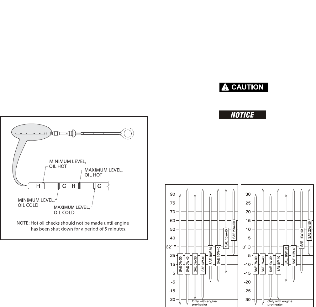
SECTION 3 - CHASSIS & TURNTABLE
3121298 – JLG Lift – 3-61
NOTE: Refer to engine manufacturer’s manual for detailed oper-
ating and maintenance instructions.
Checking Oil Level
1. Make sure machine and engine are level and switch
engine OFF before checking oil level.
2. Remove oil dipstick and wipe with clean cloth.
3. Insert dipstick to the stop and remove again.
4. Check oil level. Top oil level as shown in figure below
with an approved grade and type of oil outlined in
engine manufacturer’s operator’s manual.
Figure 3-80. Deutz Dipstick Markings
5. Replace dipstick until fully seated.
Changing Engine Oil
1. Allow engine to warm up. Engine oil should reach
approximately 176° F (80° C).
2. Make sure machine and engine are level and switch off
engine.
3. Place oil tray under engine.
HOT ENGINE OIL CAN CAUSE BURNS. AVOID CONTACT WITH HOT OIL WHEN
DRAINING.
COLLECT USED OIL IN A CONTAINER SUITABLE FOR DISPOSAL OR RECYCLING.
DISPOSE OF USED ENGINE OIL IN ACCORDANCE WITH ENVIRONMENTAL REGU-
LATIONS.
4. Open oil drain valve and drain oil.
5. Close oil drain valve.
6. Pour in new engine oil. Refer to Section 1 for capacity
and Figure 3-81., Engine Oil Viscosity.
Figure 3-81. Engine Oil Viscosity
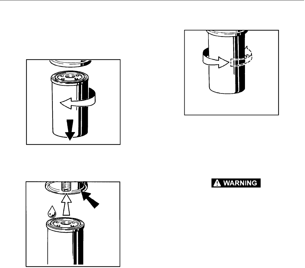
SECTION 3 - CHASSIS & TURNTABLE
3-62 – JLG Lift – 3121298
Changing Oil Filter
1. Wipe area around filter to clean any dirt from area.
2. Using a suitable oil filter removal tool, loosen lube oil fil-
ter cartridge and spin off.
3. Catch any escaping oil.
4. Clean any dirt from filter carrier sealing surface.
5. Lightly coat new oil filter rubber gasket with clean oil.
6. Screw in new filter by hand until gasket is flush.
7. Hand-tighten filter another half-turn.
8. Check oil level.
9. Check oil pressure.
10. Check oil filter cartridge for leaks.
Replace Fuel Filter
FUEL IS FLAMMABLE AND CAN CAUSE DEATH OR SERIOUS INJURY. MAKE SURE
NO OPEN FLAMES OR SPARKS ARE IN THE AREA WHEN WORKING ON FUEL SYS-
TEM. DO NOT SMOKE WHEN WORKING ON FUEL SYSTEM.
1. Wipe area around filter to clean any dirt from area.
2. Remove fuel filter cartridge. Catch any escaping fuel.
3. Clean dirt from filter carrier sealing surface.
4. Apply light film of oil or diesel fuel to rubber gasket of
new filter cartridge.
5. Screw in new filter by hand until gasket is flush. Hand-
tighten filter another half-turn.
6. Open fuel shut-off valve.
7. Check for leaks.
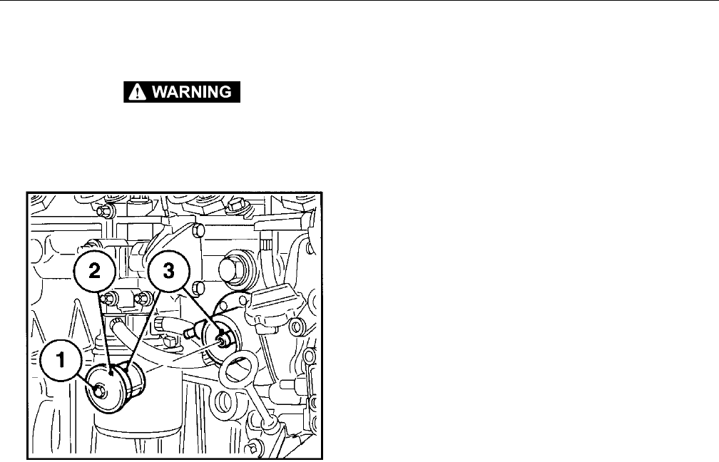
SECTION 3 - CHASSIS & TURNTABLE
3121298 – JLG Lift – 3-63
Clean Fuel Strainer
FUEL IS FLAMMABLE AND CAN CAUSE DEATH OR SERIOUS INJURY. MAKE SURE
NO OPEN FLAMES OR SPARKS ARE IN THE AREA WHEN WORKING ON FUEL
SYSTEM. DO NOT SMOKE WHEN WORKING ON FUEL SYSTEM.
1. Unscrew hexagonal nut (1).
2. Remove fuel strainer cover (2).
3. Clean fuel strainer with diesel fuel and replace as
needed.
4. Place seal (3) in position.
5. Install fuel strainer cover (2). Tighten screw (1).
6. Check for leaks.
3.13 SPARK ARRESTER CLEANING INSTRUCTIONS
1. Remove cleanout plug in bottom of spark arrester (muf-
fler).
2. Without causing deformation (or any type of damage to
spark arrester) repeatedly tap on arrester near cleanout
plug. This may be enough to begin spark trap drainage.
3. An industrial vacuum cleaner can do a complete job at
this point.
a. Or, IN A SAFE AREA, start engine. Alternate between
low idle and high idle for two to three minutes.
b. Or, operate engine as required by application for
two to three minutes.
4. Install cleanout plug.
3.14 GLOW PLUGS
If glow plug option is enabled in the JLG Control System, glow
plug and indicator lamp will be energized when Power/Emer-
gency Stop switch is pulled on if ambient air temperature is
less than 50° F (10° C) and engine coolant temperature is less
than 140° F (60° C).
This determination occurs one second after the Power/Emer-
gency Stop switch has been pulled on. Lamp and glow plugs
remain energized for period of time specified by setting in the
JLG Control System. Engine start is disabled during this period.
On Deutz engines, glow plugs continue (post glow) after
engine has started three times the machine digit setting.
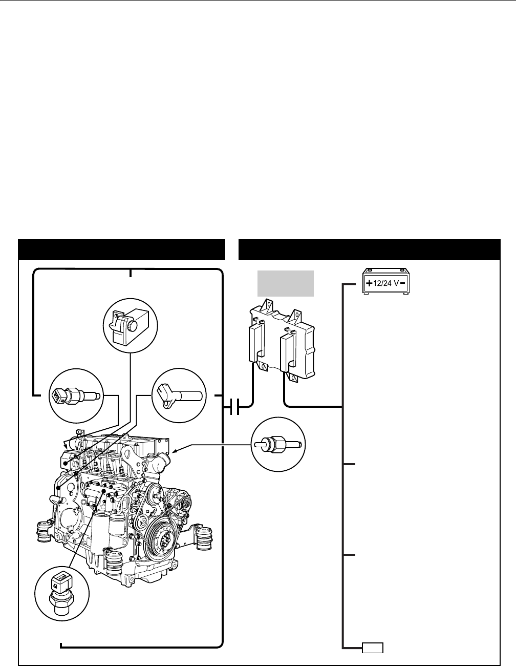
SECTION 3 - CHASSIS & TURNTABLE
3-64 – JLG Lift – 3121298
3.15 DEUTZ EMR 2
The EMR2 consists of sensors, control unit, and actuator.
Engine-side controls and the JLG Control System are con-
nected by separate cable harnesses to the EMR control unit.
Sensors attached to the engine provide control unit electron-
ics with all relevant physical parameters In accordance with
information of the current engine conditions and precondi-
tions (throttle position etc.), the EMR2 controls an actuator
that operates the control rod of the injection pump and thus
doses the fuel quantity in accordance with the performance
requirements.
Exact position of the regulating rod is reported back and, if
necessary, is corrected, by means of the control rod travel sen-
sor, situated together with the rotation magnets in a housing
of the actuator.
The EMR2 is equipped with safety devices and measures in the
hardware and software to ensure emergency running (Limp
home) functions. In order to switch the engine off, the EMR2 is
switched in a de-energized fashion over the ignition switch. A
strong spring in the actuator presses the control rod in the de-
energized condition into the zero position. As a redundancy
measure, an additional solenoid serves for switching off and
this, independently of the actuator, also moves the control rod
in the de-energized condition into the zero position.
After programming over the ISO9141 interface, the EMR2 pos-
sesses a motor-specific data set which is permanently assigned
to the engine. Included in this are the various application cases
as well as the customer’s wishes regarding a particular scope
of function.
Each EMR2 module is matched by serial number to the engine.
Modules cannot be swapped between engines.
Figure 3-82. EMR 2 Engine Side Equipment
!" #!$% &'!( !()#*!+ ,-!" #!$% &'!(
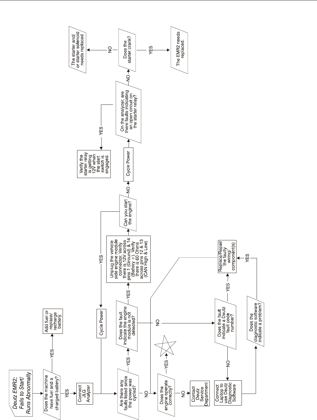
SECTION 3 - CHASSIS & TURNTABLE
3121298 – JLG Lift – 3-65
Figure 3-83. Deutz EMR 2 Troubleshooting Flow Chart
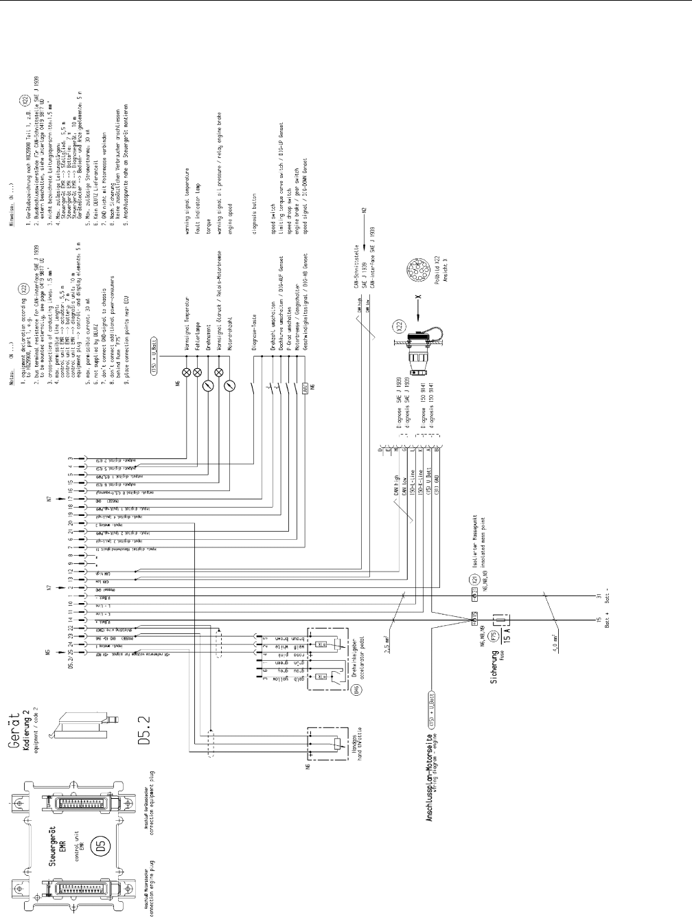
SECTION 3 - CHASSIS & TURNTABLE
3-66 – JLG Lift – 3121298
Figure 3-84. Deutz EMR 2 Vehicle Side Connection Diagram
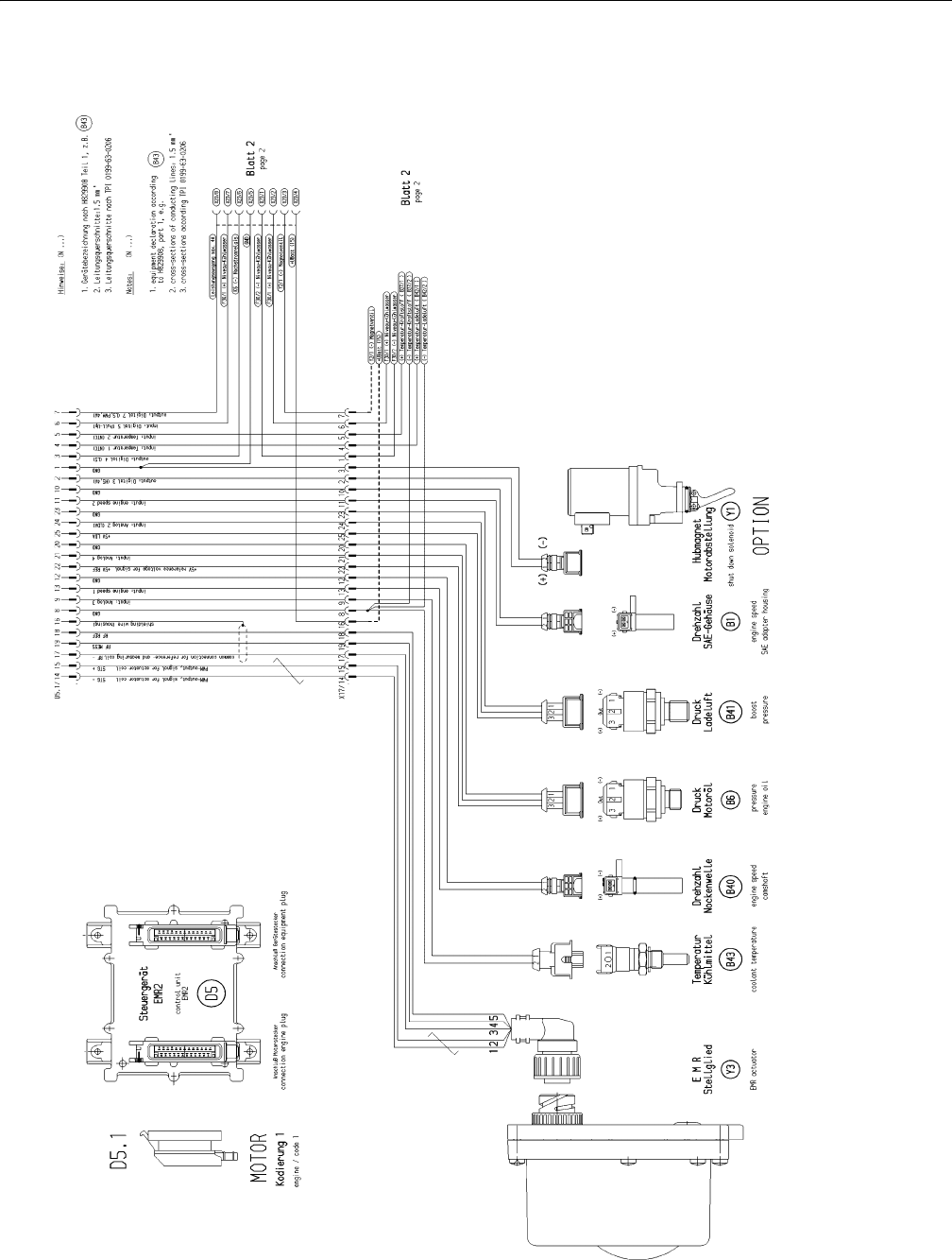
SECTION 3 - CHASSIS & TURNTABLE
3121298 – JLG Lift – 3-67
Figure 3-85. Deutz EMR 2 Engine Side Connection Diagram - Sheet 1 of 2
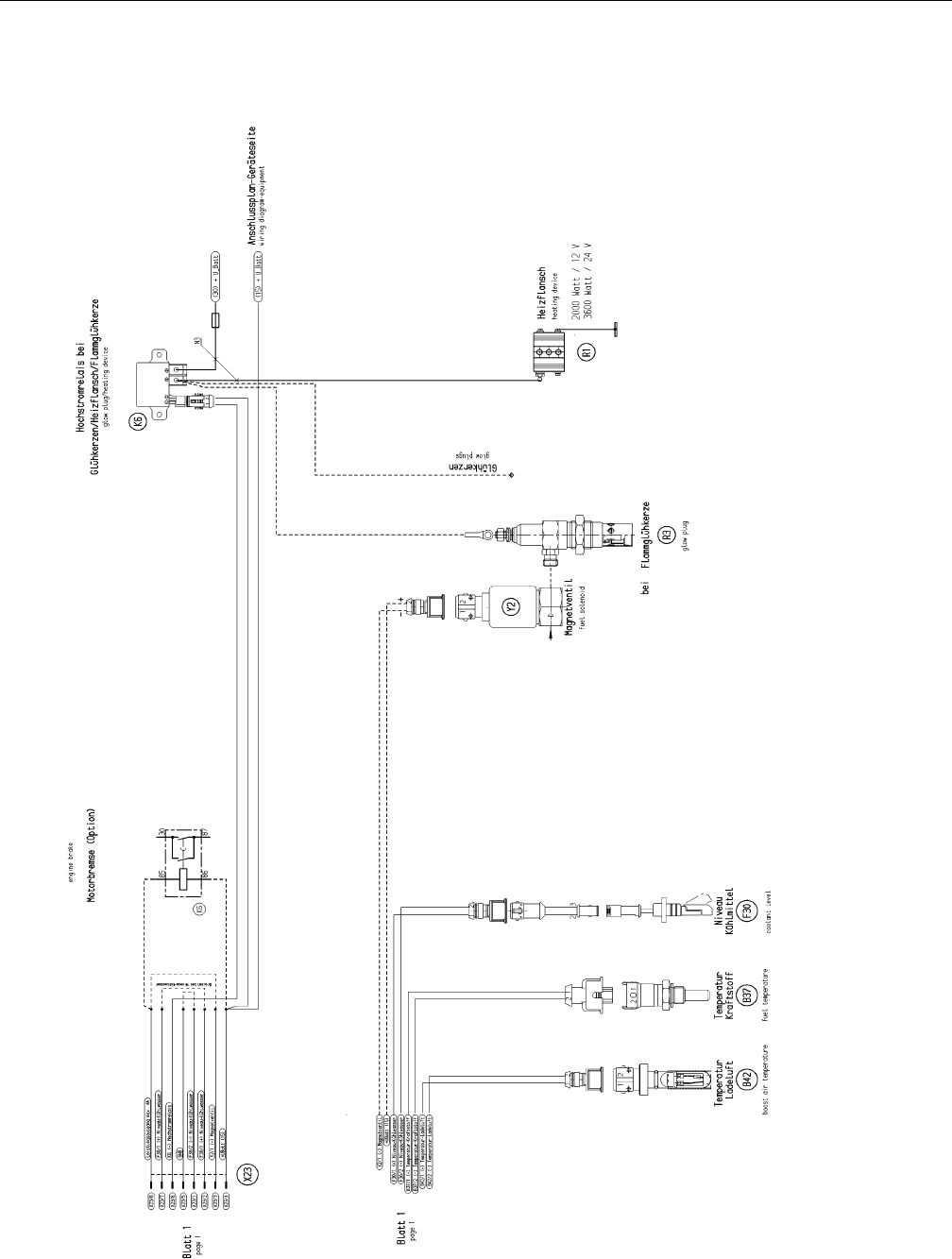
SECTION 3 - CHASSIS & TURNTABLE
3-68 – JLG Lift – 3121298
Figure 3-86. Deutz EMR 2 Engine Side Connection Diagram - Sheet 2 of 2
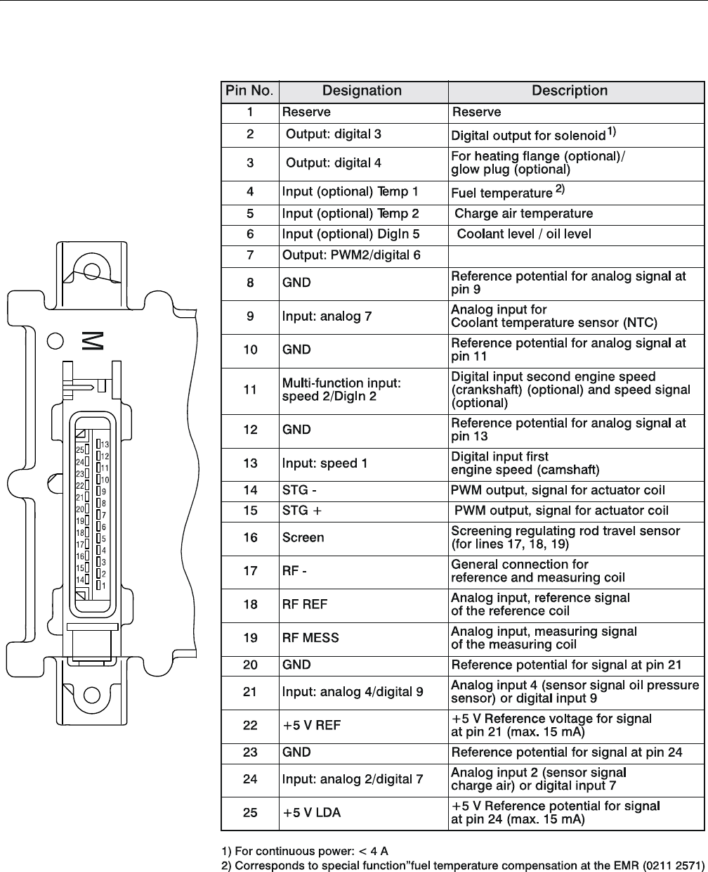
SECTION 3 - CHASSIS & TURNTABLE
3121298 – JLG Lift – 3-69
Figure 3-87. EMR 2 Engine Plug Pin Identification
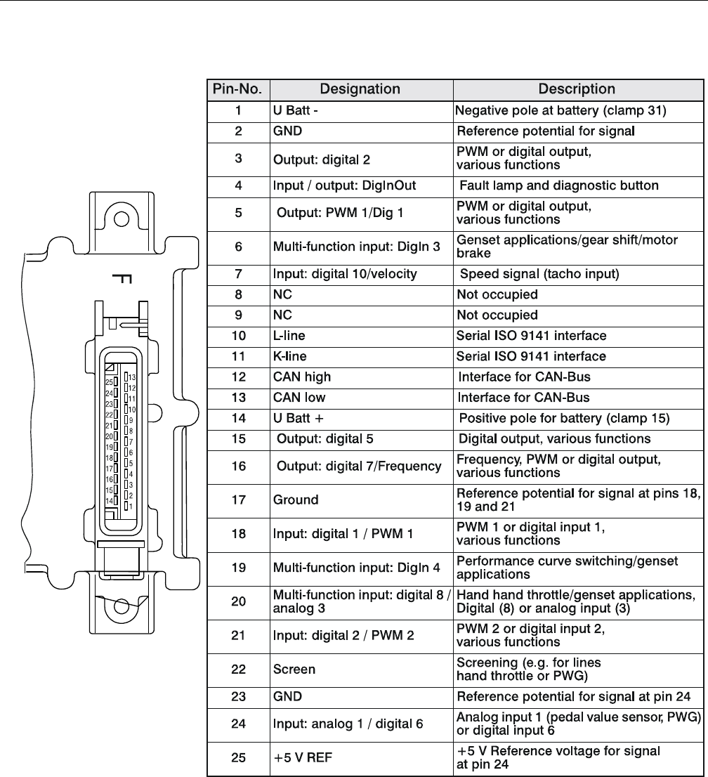
SECTION 3 - CHASSIS & TURNTABLE
3-70 – JLG Lift – 3121298
Figure 3-88. EMR 2 Vehicle Plug Pin Identification
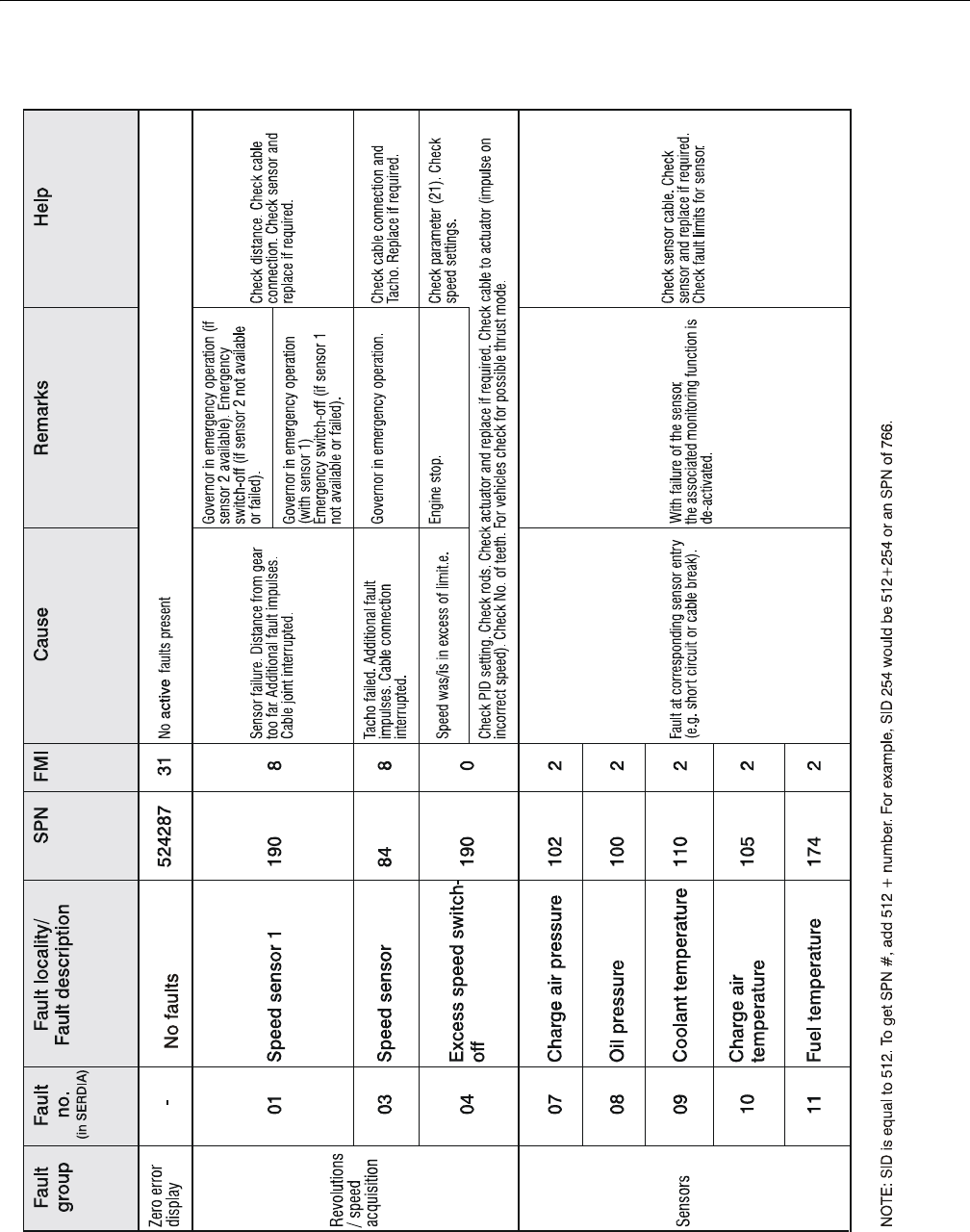
SECTION 3 - CHASSIS & TURNTABLE
3121298 – JLG Lift – 3-71
Figure 3-89. EMR2 Fault Codes - Sheet 1 of 5
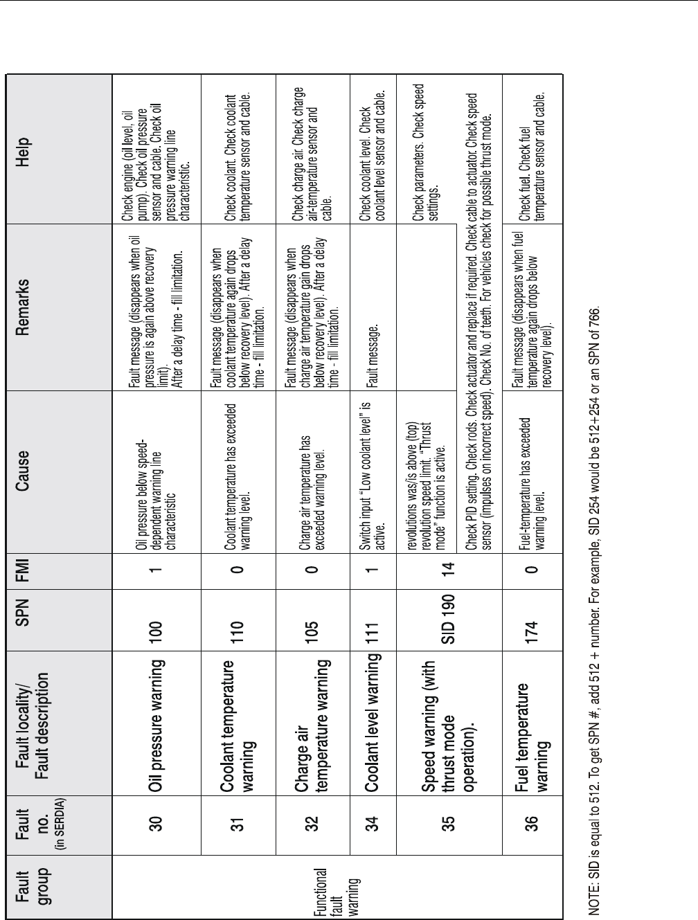
SECTION 3 - CHASSIS & TURNTABLE
3-72 – JLG Lift – 3121298
Figure 3-90. EMR2 Fault Codes - Sheet 2 of 5
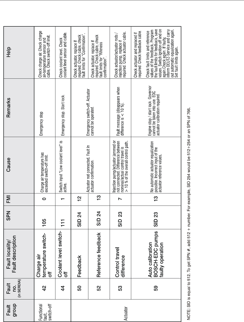
SECTION 3 - CHASSIS & TURNTABLE
3121298 – JLG Lift – 3-73
Figure 3-91. EMR2 Fault Codes - Sheet 3 of 5
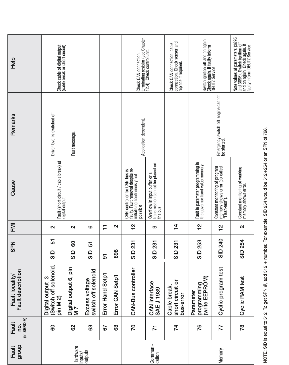
SECTION 3 - CHASSIS & TURNTABLE
3-74 – JLG Lift – 3121298
Figure 3-92. EMR2 Fault Codes - Sheet 4 of 5
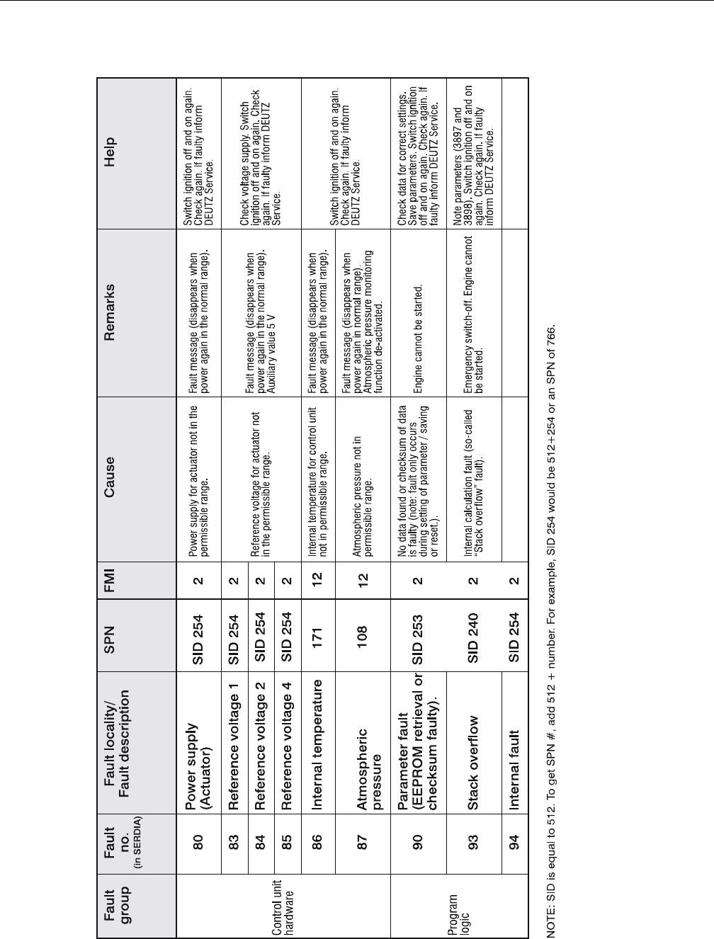
SECTION 3 - CHASSIS & TURNTABLE
3121298 – JLG Lift – 3-75
Figure 3-93. EMR2 Fault Codes - Sheet 5 of 5

SECTION 3 - CHASSIS & TURNTABLE
3-76 – JLG Lift – 3121298
3.16 BIO FUEL IN DEUTZ ENGINES
General
Use of bio fuels is permitted for the compact engines made by
DEUTZ.
Distillate fuels with residue oil percentages or mixed fuels may
not be used in DEUTZ compact engines.
DEUTZ vehicle engines are designed for diesel fuels in accor-
dance with EN 590 with a cetane number of at least 51. DEUTZ
engines for mobile machinery are designed for a cetane num-
ber of at least 45. When using fuels of a low cetane number, dis-
turbing white smoke and ignition misfires are to be expected
under some circumstances.
A cetane number of at least 40 is permissible for the US market,
therefore special engine models have been developed to
avoid starting difficulties, extreme white smoke or increased
hydrocarbon emissions (EPA specification - US EPA REGULA-
TIONS FOR LARGE NONROAD COMPRESSION-IGNITION
ENGINES).
If white smoke is unacceptable when using a very low cetane
number, use of ignition improvers is to be recommended as a
later remedial measure.
Certification measurements for compliance with legal emission
limits are carried out with test fuels prescribed by law. These
correspond to diesel fuels in accordance with EN 590 and
ASTM D 975. No emission values are guaranteed with other
fuels described. It is the obligation of the owner to check per-
mission for use of fuels in accordance with regional regula-
tions.
Bio Fuel
PERMITTED BIO-DIESEL FUELS
Originally only rape seed oil methylester (RME) was sold as a
bio-diesel fuel in Europe but fatty acid methylester (FAME)
based on other oils have come onto the market increasingly in
recent years. However, with the latter there is a risk that the limit
values of EN 14214 are not kept in the field. Anyone who uses
bio-diesel fuel in DEUTZ engines must therefore choose his
supplier very carefully and have him guarantee compliance
with the EN 14214 limit values. Since experience has shown
that rape seed oil methylester (RME) exceeds the limit values
less often that other esters, it is expressly recommended to use
only rape seed oil methyester. DEUTZ customers in Germany
can additionally ensure the quality by buying bio-diesel fuel
with an AGQM certificate (Arbeitsgemeinschaft Qualitäts-Man-
agement Biodiesel e.V.).
The use of US bio-diesel based on soy oil methylester is only
permissible in mixtures with diesel fuel with a bio-diesel part of
a max. 20 weight-%. The US bio-diesel used for the mixture must
comply with the ASTM D6751-07a (B100) standard.
APPROVED ENGINES
912, 913, 914, 1011, 2011, 1012, 2012, 1013, 2013, 413 and 513
series are approved for bio-diesel from year of manufacture
1993 under compliance with basic conditions specified below.
BASIC CONDITIONS TO BE OBSERVED
• A power loss of 5-9% in relation to diesel fuel in accordance
with EN 590 is possible due to the lower heating value.
Blocking of fuel injector is not allowed.
• Lubricating oil quality must correspond to TR 0199-99-
3002. Lubricating oil change interval must be halved in
relation to operation with diesel fuel in accordance with EN
590.
• Standstills of longer than 4 to 6 weeks must be avoided with
bio-diesel. Otherwise, engine must be started and stopped
with diesel fuel.
• Bio-diesels can be mixed with normal diesel fuel but basic
conditions described in this subsection apply for mixtures.
Mixtures with up to 5% (m/m) bio-diesel (B5) which have
recently been on sale at European fuel stations are
excepted. These fuels must be treated like normal diesel
fuels because EN 590 expressly permits adding up to 5%
(m/m) bio-diesel in accordance with EN 14214.
• Approximately 30-50 hours after changing from diesel fuel to
bio-diesel, the fuel filter should be changed as a preventive
measure to avoid a drop in performance due to clogged fuel
filters. Deposited fuel ageing products are dissolved by bio-
diesel and transported into the fuel filter. They should not
be changed immediately, but after 30 to 50 hours because
that is the time it takes for most dirt to be dissolved.
PLANT OIL
PURE PLANT OILS (E.G. RAPE SEED OIL, SOY OIL, PALM OIL) ARE NOT CLASSIFIED AS
BIO-DIESEL AND EXHIBIT PROBLEMATICAL PROPERTIES FOR DIESEL ENGINE OPER-
ATION (STRONG TENDENCY TO COKE, RISK OF PISTON SEIZURE, EXTREMELY HIGH
VISCOSITY, AND POOR EVAPORATION BEHAVIOR).
The conversion of DEUTZ engines to rape seed oil fuel opera-
tion with conversion kits and modified tanks systems of various
manufacturers is not allowed and leads to loss of warranty
rights.

SECTION 3 - CHASSIS & TURNTABLE
3121298 – JLG Lift – 3-77
Biological Contamination In Fuels
SYMPTOMS
The following symptoms may indicate a fuel tank is contami-
nated by micro-organisms:
• Internal tank corrosion,
• Filter blockage and associated loss of power due to gel-like
deposits on the fuel filter (especially after long standstills)
CAUSE
Micro-organisms (bacteria, yeasts, funguses) can form bio-
sludge under unfavorable conditions (favoured particularly by
heat and water).
Penetration by water is usually caused by condensation of water
in the air. Water does not dissolve in fuel so penetrating water
collects at bottom of the tank. Bacteria and funguses grow in the
watery phase, at phase boundary to the fuel phase, from which
they draw their nutrition. There is an increased risk especially
with bio-diesel (FAME).
PREVENTIVE MEASURES
• Keep storage tank clean. Perform regular cleaning of the
tank by specialist companies
• Installation of fuel pre-filters with water traps, especially in
countries with frequently fluctuating fuel qualities and high
percentage of water.
If the fuel system and storage tank have already been attacked
by micro-organisms. Biocide must be dosed according to the
manufacturer's specifications.
• Avoid direct exposure of the storage tank to sunlight
• Use smaller storage tanks with corresponding low dwell
times of the stored fuel
FUEL ADDITIVES
The use of fuel additives is not permitted. The flow improvers
mentioned above are an exception. Use of unsuitable additives
will result in loss of warranty.
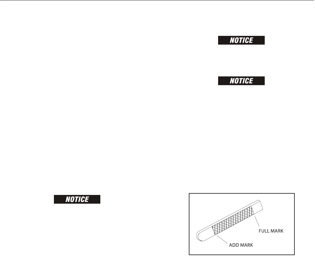
SECTION 3 - CHASSIS & TURNTABLE
3-78 – JLG Lift – 3121298
3.17 GM ENGINE GENERAL MAINTENANCE
Drive Belt Maintenance
The serpentine drive belt utilizes a spring loaded tensioner
which keeps the belt properly adjusted. The drive belt is an
integral part of the cooling and charging systems and should
be inspected frequently.
When inspecting belts check for:
• Cracks or breaks
• Chunking of the belt
•Splits
• Material hanging from belt
•Glazing and hardening
• Damaged or improperly aligned pulleys
• Improperly performing tensioner
Check belt tensioner by pressing down on the midway point of
the longest stretch between pulleys. The belt should not
depress beyond 1/2 inch (13mm). If depression is more than
allowable, adjust tension.
ENGINE MANUFACTURER DOES NOT RECOMMEND USE OF "BELT DRESSING"
OR "ANTI SLIPPING AGENTS" ON DRIVE BELT.
Engine Electrical System Maintenance
The engine electrical system incorporates computers and
microprocessors to control engine ignition, fuel control, and
emissions. Periodic inspection of electrical wiring is necessary
due to sensitivity of computers to good electrical connections.
When inspecting the electrical system use the following:
• Check and clean battery terminal connections and ensure
connections are tight
• Check battery for any cracks or damage to case
• Check Positive and Negative battery cables for corrosion
build up, or rubbing and chafing. Check connections on
chassis are tight.
• Check entire engine wire harness for rubbing chafing, cuts
or damaged connections. Repair as needed.
• Check all wire harness connectors to ensure they are fully
seated and locked.
• Check ignition coil and spark plug cables for hardening,
cracking, chafing, separation, split boot covers, and fit
• Replace spark plugs at the proper intervals as prescribed in
the engine manufacturer’s manual
• Make sure all electrical components are fitted securely.
• Check ground and platform control stations to ensure all
warning indicator lights are functioning.
Checking/Filling Engine Oil Level
AN OVERFILLED CRANKCASE (OIL LEVEL OVER THE SPECIFIED FULL MARK) CAN
CAUSE AN OIL LEAK, FLUCTUATION OR DROP IN OIL PRESSURE, AND ROCKER
ARM "CLATTER".
CARE MUST BE TAKEN WHEN CHECKING ENGINE OIL LEVEL. OIL LEVEL MUST
BE MAINTAINED BETWEEN "ADD" MARK AND "FULL" MARK ON DIPSTICK.
To ensure you are not getting a false reading, make sure the
following steps are taken before checking oil level.
1. Stop engine if in use.
2. Allow sufficient time (approximately 5 minutes) for oil to
drain back into oil pan.
3. Remove dipstick. Wipe with a clean cloth or paper towel
and reinstall. Push dipstick all the way in dipstick tube.
4. Remove dipstick and note oil level.
5. Oil level must be between "FULL" and "ADD" marks.
Figure 3-94. GM Engine Oil Dip Stick
6. If oil level is below "ADD" mark, proceed to Step 7 and 8
and reinstall dipstick in dipstick tube.
7. Remove oil filter cap from valve rocker arm cover.
8. Add required amount of oil to bring level up to, but not
over, "FULL" mark on dipstick.
9. Reinstall oil fill cap to valve rocker cover and wipe away
any excess oil.
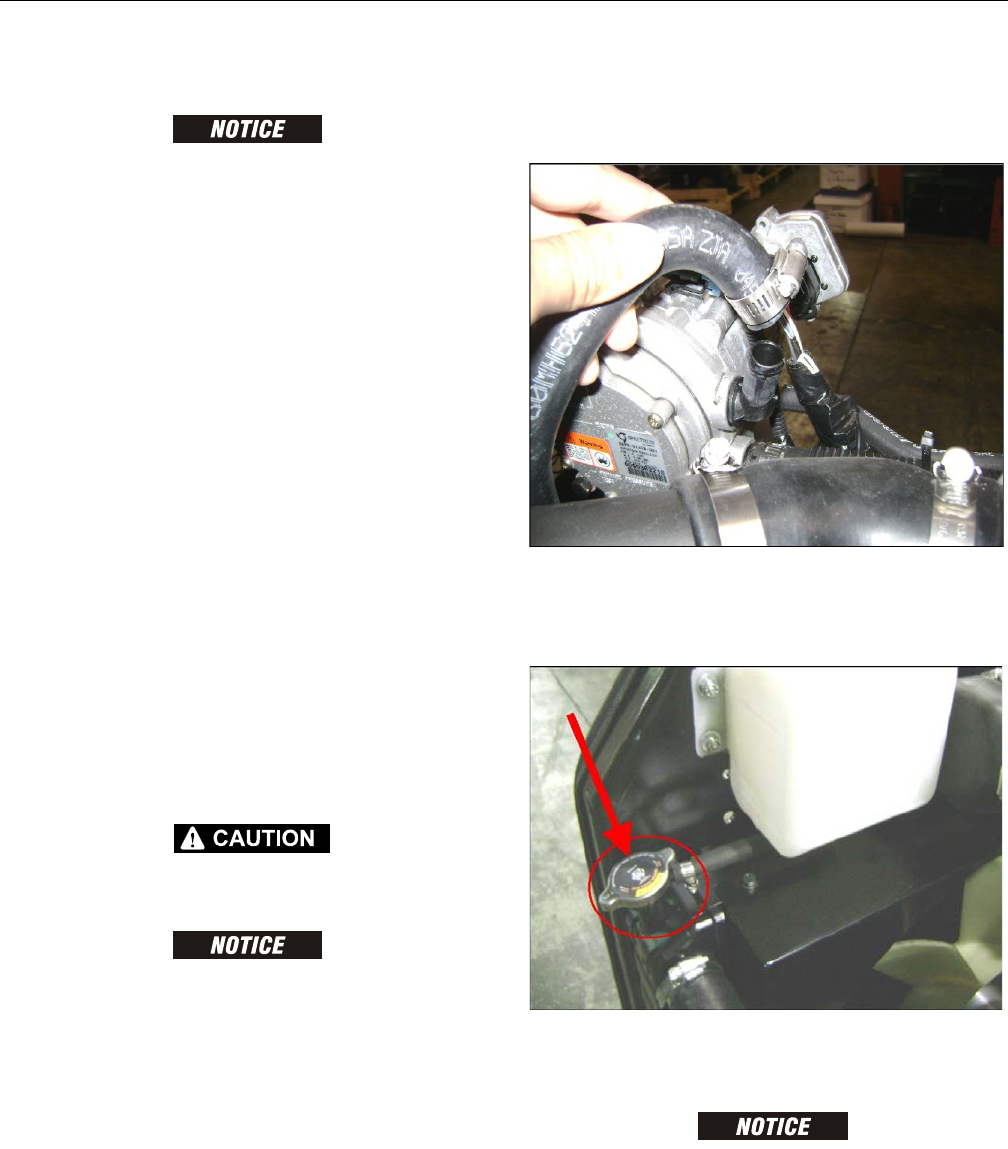
SECTION 3 - CHASSIS & TURNTABLE
3121298 – JLG Lift – 3-79
Changing Engine Oil
ALWAYS CHANGE OIL FILTER WHEN CHANGING OIL. CHANGE OIL WHEN
ENGINE IS WARM FROM OPERATION. OILS WILL FLOW FREELY AND CARRY
AWAY MORE IMPURITIES.
To change oil use the following steps:
1. Start engine and run until it reaches normal operating
temperature.
2. Stop engine.
3. Remove drain plug and allow oil to drain.
4. Remove and discard oil filter and sealing ring.
5. Coat sealing ring on new filter with clean engine oil and
wipe engine filter mounting surface to remove contami-
nation. Tighten filter securely (follow filter manufactur-
ers instructions). Do not over tighten.
6. Check sealing ring on drain plug for damage. Replace if
necessary. Pipe plug and oil pan sealing surface with a
clean rag. Reinstall plug. Do not over tighten.
7. Fill crankcase with oil.
8. Start engine and check for oil leaks.
9. Stop engine and check oil level is at "FULL".
10. Dispose of oil and filter in a safe manner as required by
local regulations.
Coolant Fill Procedure - Dual Fuel Engine
HOT ENGINE AND COMPONENTS CAN CAUSE SEVERE BURNS. MAKE SURE
ENGINE IS COOL BEFORE PERFORMING MAINTENANCE.
DAMAGE TO ENGINE CAN OCCUR IF NOT PROPERLY FILLED WITH COOLANT.
LPG FUELED ENGINES ARE MOST PRONE TO CREATING AN AIR LOCK DURING A
COOLANT FILL OPERATION DUE TO ELECTRONIC PRESSURE REGULATOR (EPR)
BEING THE HIGHEST POINT IN THE COOLING SYSTEM. AN EPR THAT APPEARS
TO HAVE FROST FORMING ON IT IS A SIGN THE ENGINE COOLING SYSTEM CON-
TAINS AIR. APPEARANCE AND TEMPERATURE OF THE EPR SHOULD BE MONI-
TORED DURING COOLANT FILL OPERATION. A WARM EPR IS AN INDICATION
THAT THE COOLING SYSTEM IS PROPERLY FILLED AND FUNCTIONING.
1. Loosen worm gear clamp on coolant line running to EPR
as shown below. Remove hose from EPR. Place a rag
under hose to prevent coolant from running onto
engine/machine.
2. Remove radiator cap. Fill radiator with coolant until
coolant starts to appear from previously removed hose
at the EPR. Reinstall hose back on EPR and continue to
fill radiator with coolant.
3. With radiator cap still removed, start engine and run
until thermostat opens at 170° F (77° C), which can be
checked using the JLG handheld analyzer.
WHILE ENGINE IS RUNNING, AIR AND/OR STEAM MAY BE PRESENT COMING
FROM THE RADIATOR. THIS IS NORMAL.
4. Run engine for five minutes after it has reached operat-
ing temperature. Shut off engine and continue to step 5.
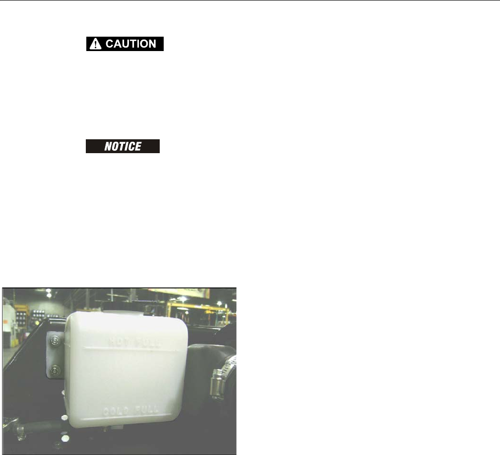
SECTION 3 - CHASSIS & TURNTABLE
3-80 – JLG Lift – 3121298
WITH ENGINE RUNNING OR WHEN SHUTTING OFF ENGINE, SOME HEATED
COOLANT MAY SPILL OUT DUE TO AIR "BURPING" OUT OF THE SYSTEM WITH
RADIATOR CAP OFF.
5. Verify the two coolant hoses on the EPR are warm. If they
are not warm repeat step 3 and 4, otherwise continue to
step 6.
A PROPERLY PURGED COOLING SYSTEM WILL YIELD A WARM UPPER RADIA-
TOR HOSE AND A WARM EPR HOSE. IF UPPER RADIATOR AND EPR HOSES ARE
NOT WARM TO THE TOUCH AFTER ENGINE HAS RUN FOR 5-8 MINUTES AFTER
REACHING OPERATING TEMPERATURE, THE SYSTEM MAY STILL CONTAIN AIR.
IT MAY BE NECESSARY TO REPEAT ABOVE STEPS.
6. Fill radiator with coolant as needed and install radiator
cap.
7. Remove coolant recovery bottle cap and fill to just
below HOT FULL line. Reinstall cap.
3.18 GM ENGINE DUAL FUEL SYSTEM
The fuel system installed on this engine is designed to meet
mobile engine emission standards applicable for 2010 and
later model years. The Dual Fuel system allows the vehicle to
operate on gasoline or LPG by positioning a selector switch in
the operator's platform. When the operator places the selector
switch in gasoline mode, the gasoline fuel pump is energized.
In gasoline mode the LPG fuel lock-off is isolated and will not
energize. In addition, the gasoline injector circuit is enabled
and injector pulses are provided to each injector. ECM calibra-
tion for gasoline is also enabled.
When LPG mode is selected the Low Pressure LPG lock-off is
energized and fuel from the LPG tank flows to the Electronic
Pressure Regulator (EPR). The EPR receives an electronic signal
to position the secondary lever for start or run positions. When
the engine begins to crank, the mixer air valve will rise and fuel
begins flowing to engine. During this mode the gasoline fuel
pump is isolated and is not activated.
Primary components of the gasoline dual fuel system are the
gasoline tank, electric fuel pump and filter, fuel supply line,
injector rail and injectors and the fuel pressure regulator.
Primary components of the LPG dual fuel system are the LPG
fuel tank, in-fuel filter, LPG Low Pressure lock-off, Electronic
Pressure Regulator (EPR) and the fuel mixer module. The LPG
fuel system operates at pressures which range from 14.0
inches (355.60 mm) of water column up to 312 psi (21.5 BAR).
Components shared by both systems include the Electronic
Throttle Control and ECM. The ECM contains a dual calibration;
one controls the gasoline fuel system during gasoline opera-
tion and one controls the LPG fuel system during LPG opera-
tion.
Fuel Filter
Propane fuel, like all other motor fuels, is subject to contamina-
tion from outside sources. Refueling and removal of the tank
from the equipment can contaminate the fuel system. It is nec-
essary to filter fuel before it enters fuel system components
downstream of the tank.
An in-line fuel filter is installed in the fuel system to remove
fuel contamination. The in-line filter is replaceable as a unit
only. Filter maintenance is critical to proper operation of the
fuel system and should be replaced as listed in Section 1. More
frequent replacement of the filter may be necessary in severe
operating conditions.
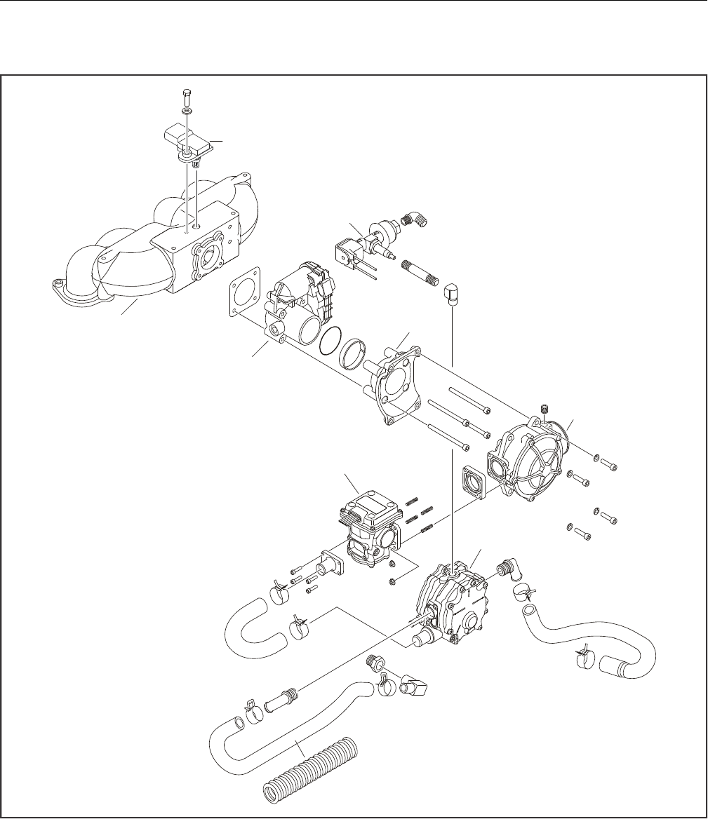
SECTION 3 - CHASSIS & TURNTABLE
3121298 – JLG Lift – 3-81
Figure 3-95. GM 3.0 Dual Fuel System Components
1. T-MAP Sensor
2. Lock-Off Valve
3. Mixer
4. Adapter
5. Regulator
6. Direct Electronic Pressure Regulator (DEPR)
7. Throttle Body
8. Intake Manifold
2
7
3
4
6
5
1
8
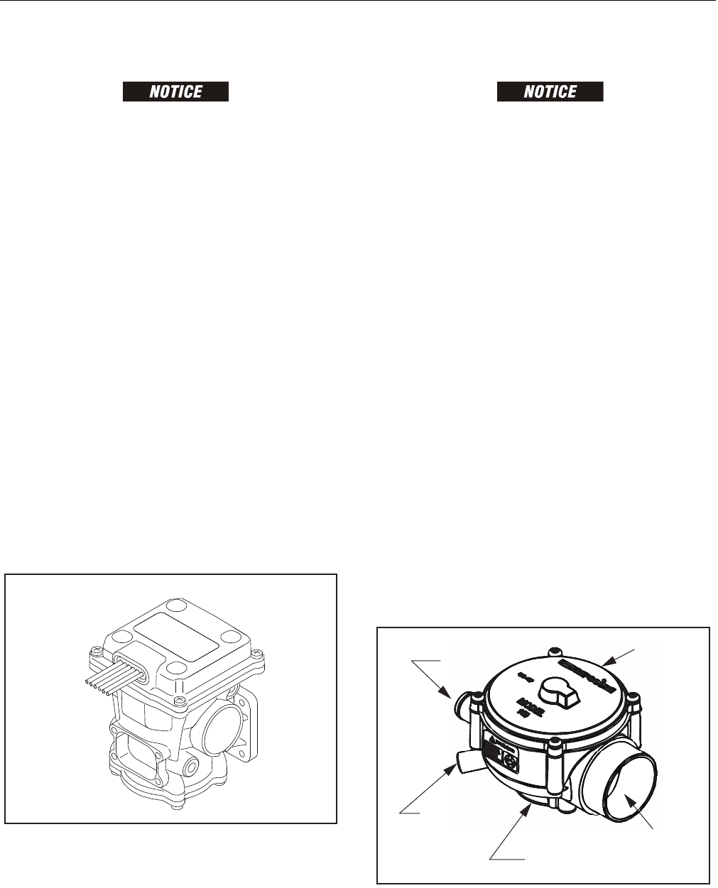
SECTION 3 - CHASSIS & TURNTABLE
3-82 – JLG Lift – 3121298
Direct Electronic Pressure Regulator (DEPR)
THE DEPR IS AN EMISSION CONTROL DEVICE AND SHOULD ONLY BE SERVICED
BY QUALIFIED TECHNICIANS.
The ECI engine management system uses the DEPR to control
fuel delivery for precise fuel metering needed for optimum
combustion, fuel economy, and transient response.
The DEPR is a single-stage microprocessor based electrome-
chanical fuel pressure regulator that incorporates a high
speed/fast acting actuator. It communicates with the Engine
Control Module (ECM) over a Controller Area Network (CAN)
link, receiving fuel pressure commands and broadcasting
DEPR operating parameters back to the ECM.
The DEPR can regulate fuel pressure from -18 to +13 inches of
water column above the Mixer air inlet pressure, providing suf-
ficient control authority to stall an engine either rich or lean.
When the DEPR receives an output pressure command from
the ECM, the valve is internally driven to attain targeted fuel
pressure, the DEPR then closes the loop internally using a built
in fuel pressure sensor to maintain target fuel pressure/fuel
flow rate, until another external command from the ECM is
received (intervals < 10 ms).
The DEPR has an integral fuel temperature sensor that is used
by the ECM to correct for variations in fuel density. This pro-
vides an extremely accurate method for open loop fuel con-
trol. Then with the addition of the pre- and post-cat oxygen
sensors, the pressure command transmitted form the ECM can
be further adjusted using closed loop feedback.
Figure 3-96. Direct Electronic Pressure Regulator
Air Fuel Mixer
THE AIR/FUEL MIXER IS AN EMISSION CONTROL DEVICE. COMPONENTS INSIDE
THE MIXER ARE SPECIFICALLY CALIBRATED TO MEET THE ENGINE’S EMISSIONS
REQUIREMENTS AND SHOULD NEVER BE DISASSEMBLED OR REBUILT. IF THE
MIXER FAILS TO FUNCTION CORRECTLY, REPLACE WITH AN OEM REPLACE-
MENT PART.
The air valve mixer is a self-contained air-fuel metering device.
The mixer is an air valve design, utilizing a relatively constant
pressure drop to draw fuel into the mixer from cranking
speeds to full load.
The mixer is mounted in the air stream ahead of the throttle
control device. When the engine begins to crank it draws in air
with the air valve covering the inlet, and negative pressure
begins to build. This negative pressure signal is communicated
to the top of the air valve chamber through vacuum ports in
the air valve assembly. A pressure/force imbalance begins to
build across the air valve diaphragm between the air valve vac-
uum chamber and the atmospheric pressure below the dia-
phragm.
The vacuum being created is referred to as Air Valve Vacuum
(AVV). As the air valve vacuum reaches the imbalance point,
the air valve begins to lift against the air valve spring. The
amount of AVV generated is a direct result of throttle position.
At low engine speed the air valve vacuum and the air valve
position is low, creating a small venturi for the fuel to flow. As
engine speed increases, AVV increases and the air valve is lifted
higher creating a much larger venturi. Air valve vacuum is
communicated from the mixer venturi to the IEPR via the fuel
supply hose.
Figure 3-97. Air Fuel Mixer
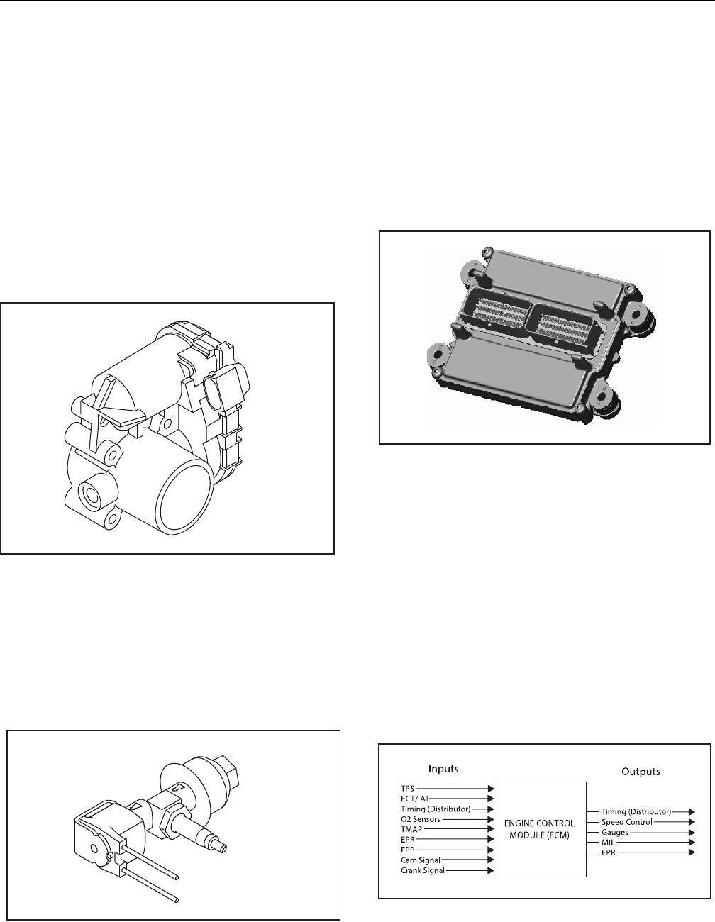
SECTION 3 - CHASSIS & TURNTABLE
3121298 – JLG Lift – 3-83
Electronic Throttle Control (ETC)
The Electronic Throttle Control device or "Throttle Body
Assembly" is connected to the intake manifold of the engine.
The electronic throttle control device utilizes an electric motor
connected to the throttle shaft.
When the engine is running, electrical signals are sent from
equipment controls to the engine ECM. The ECM then sends
an electrical signal to the motor on the electronic throttle con-
trol to increase or decrease the angle of the throttle blade thus
increasing or decreasing the air/fuel flow to the engine.
Two internal Throttle Position Sensors (TPS) provide throttle
shaft and blade position output signals to the ECM. TPS infor-
mation is used by the ECM to correct speed and load control,
as well as emission control.
Figure 3-98. ELectronic Throttle Control Device
Electric Lock Off
The Electric Lock Off device is an integrated assembly consist-
ing of a 12 volt solenoid and normally closed valve. When
energized, the solenoid opens the valve and allows propane
fuel to flow through the device. The valve opens during
engine cranking and run cycles. Lock Off supply voltage is con-
trolled by the Engine Control Module (ECM).
Figure 3-99. Electric Lock Off Assembly
Engine Control Module (ECM)
NOTE: The ECM may also be referred to as the Engine Control Unit
(ECU) in some applications.
To obtain maximum effect from the catalyst and accurate con-
trol of air fuel ratio, the emission certified engine is equipped
with an onboard computer or Engine Control Module (ECM).
The ECM is a 32 bit controller which receives input data from
sensors fitted to the engine and fuel system and then outputs
various signals to control engine operation.
Figure 3-100. ECM Assembly
One specific function of the controller is to maintain "closed
loop fuel control". Closed loop fuel control is accomplished
when the exhaust gas oxygen sensor (HEGO) mounted in the
exhaust system sends a voltage signal to the controller. The
controller calculates corrections for the air fuel ratio. and out-
puts signals to the DEPR to correct the amount of fuel supplied
to the mixer. At the same time the ECM may correct throttle
blade position to correct engine speed and load.
The controller also performs fuel system diagnostic functions
and notifies the operator of malfunctions by turning on a Mal-
function Indicator Light (MIL) mounted in the Ground Control
Station and Platform Control Station. System malfunctions are
identified by a Diagnostic Code number. In addition to notify-
ing the operator of the system malfunction, the controller also
stores information about the malfunction in its memory.
Figure 3-101. ECM Input-Output Diagram
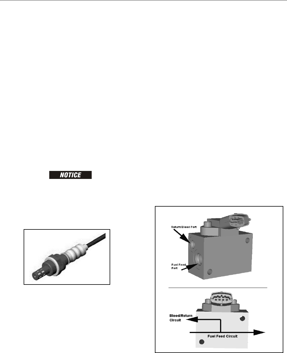
SECTION 3 - CHASSIS & TURNTABLE
3-84 – JLG Lift – 3121298
Heated Exhaust Gas Oxygen Sensor
There are two Heated Exhaust Gas Oxygen Sensors (HEGO).
The first HEGO is mounted in the exhaust system downstream
of the engine. It is used to measure the amount of oxygen
present in the exhaust stream and communicate that to the
ECM via an electrical signal. The amount of oxygen present in
the exhaust stream indicates whether the fuel/air ratio is too
rich or too lean. If the HEGO sensor signal indicates exhaust
stream is too rich, the ECM will decrease or lean the fuel mix-
ture during engine operation. If mixture is too lean the ECM
will richen the mixture. The ECM continuously monitors the
HEGO sensor output. If a rich or lean condition is present for an
extended period of time, and the ECM cannot correct the con-
dition, the ECM sets a diagnostic code and turns on the MIL
light in control box.
The second HEGO is mounted in the exhaust system after the
muffler. It measures the amount of oxygen in the exhaust sys-
tem after the catalyst treatment has been completed in the
muffler. If the ECM detects that the catalytic action in the muf-
fler is not sufficient and fuel correction cannot correct the mal-
function the MIL light is illuminated in the control box and a
DTC code will stored in the computer.
THE HEATED EXHAUST GAS OXYGEN SENSOR IS AN EMISSION CONTROL
DEVICE. IF THE HEGO FAILS TO OPERATE, REPLACE IT WITH AN OEM REPLACE-
MENT PART. THE HEGO SENSOR IS SENSITIVE TO SILICONE OR SILICONE BASED
PRODUCTS AND CAN BECOME CONTAMINATED. AVOID USING SILICONE SEAL-
ERS OR HOSES TREATED WITH SILICONE LUBRICANTS IN THE AIR STREAM OR
FUEL LINES.
Gasoline Multi Point Fuel Injection System (MPFI)
The primary components of the Gasoline Multi Point Fuel
Injection (MPFI) fuel system are the fuel tank, electric fuel
pump, fuel pressure and temperature sensor manifold, fuel fil-
ter, and fuel rail.
Gasoline Fuel Pump
Gasoline is stored as a liquid in the fuel tank and in drawn into
the fuel system by an electric fuel pump. The fuel pump
receives a signal from the ECM to prime the fuel system for
approximately two seconds before start. Priming the fuel sys-
tem provides for a quicker start when engine begins to crank.
Gasoline Pressure And Temperature Sensor
Manifold
This engine is equipped with a fuel injector rail that does not
have a pressure regulator or a return circuit to the fuel tank.
Fuel pressure for this engine is regulated by the engine’s ECM.
The ECM receive fuel pressure and temperature feedback from
the gasoline fuel sensor manifold and uses this information to
control the ground side of the fuel pump. Fuel pressure is regu-
lated by the ECM pulse width modulating (PWM) the fuel
pump. The fuel pressure and temperature sensor manifold has
a return or "bleed" circuit that connects back to the fuel tank.
This circuit is used to bleed off any vapor that develops in the
line and return a small amount of fuel to the tank.
Fuel comes from the fuel tank and passes through the fuel
pump. Fuel exits the fuel pump, passes through the filter and
then enters the fuel pressure and temperature manifold
assembly. Fuel flows through the feed circuit and is delivered
to the fuel injector rail. Fuel that enters the bleed circuits
through the bypass valve in the manifold is returned to the
fuel tank.
Figure 3-102. Heated Exhaust Gas Oxygen Sensor
Figure 3-103. Gasoline Fuel Pressure and Temperature
Manifold Assembly

SECTION 3 - CHASSIS & TURNTABLE
3121298 – JLG Lift – 3-85
Fuel Filter
After fuel is drawn into the fuel pump, the fuel flows through
the gasoline fuel filter. The fuel filter traps small particles as
fuel passes through the filter to remove debris and prevents
fuel pressure and temperature manifold and fuel injectors
from becoming damaged. Fuel filter maintenance is required
as shown in Section 1.
Fuel Injector Rail
Fuel flows from the fuel pressure and temperature manifold
assembly to the fuel rails where fuel is delivered to the fuel
injectors. The fuel rail also contains a Schrader valve which is
used to test regulated pressure of the fuel system.
Fuel Injector
The fuel supply is maintained on the top of the injector from
the injector rail. The injector is fed a "pulse" signal through the
wire harness which causes the injector to open. During regular
operating conditions the ECM controls the opening and dura-
tion of opening of the injector. During lower RPM operation
the injector signals or "pulses" are less frequent then when the
engine is operating at higher RPMs. The engine has been cali-
brated to deliver the precise amount of fuel for optimum per-
formance and emission control.
3.19 GM ENGINE FUEL SYSTEM REPAIR
Propane Fuel System Pressure Relief
THE PROPANE FUEL SYSTEM OPERATES AT PRESSURES UP TO 312 PSI (21.5
BAR). TO MINIMIZE THE RISK OF FIRE AND PERSONAL INJURY, RELIEVE THE
PROPANE FUEL SYSTEM PRESSURE (WHERE APPLICABLE) BEFORE SERVICING
THE PROPANE FUEL SYSTEM COMPONENTS.
To relieve propane fuel system pressure:
1. Close manual shut-off valve on propane fuel tank.
2. Start and run vehicle until engine stalls.
3. Turn ignition switch OFF.
RESIDUAL VAPOR PRESSURE WILL BE PRESENT IN THE FUEL SYSTEM. ENSURE
WORK AREA IS WELL VENTILATED BEFORE DISCONNECTING ANY FUEL LINE.
Propane Fuel System Leak Test
PROPANE IS HIGHLY FLAMMABLE AND CAN EASILY IGNITE AND CAUSE BURNS
AND SERIOUS INJURIES. NEVER USE AN OPEN FLAME OF ANY TYPE TO CHECK
FOR PROPANE FUEL SYSTEM LEAKS.
Always inspect propane fuel system for leaks after performing
service. Check for leaks at fittings of the serviced or replaced
component. Use a commercially available liquid leak detector
or an electronic leak detector. When using both methods, use
electronic leak detector first to avoid contamination by liquid
leak detector.
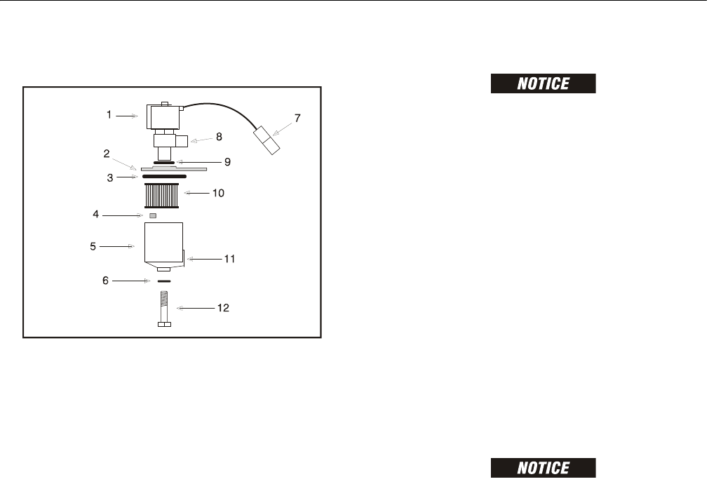
SECTION 3 - CHASSIS & TURNTABLE
3-86 – JLG Lift – 3121298
Propane Fuel Filter Replacement
REMOVAL
1. Relieve propane fuel system pressure. Refer to Propane
Fuel System Pressure Relief.
2. Disconnect the negative battery cable.
3. Slowly loosen the filter housing retaining bolt and
remove it.
4. Pull filter housing from electric lock off assembly.
5. Locate and remove filter magnet.
6. Remove the filter from housing.
7. Remove and discard housing seal.
8. Remove and discard retaining bolt seal.
9. Remove and discard mounting plate to lock off O-ring
seal.
INSTALLATION
REINSTALL FILTER MAGNET IN HOUSING BEFORE INSTALLING NEW SEAL.
1. Install mounting plate to lock off O-ring seal.
2. Install retaining bolt seal.
3. Install housing seal.
4. Drop magnet in bottom of filter housing.
5. Install filter in housing.
6. Install retaining bolt in filter housing.
7. Install filter up to bottom of electric lock off.
8. Tighten filter retaining bolt to 106 in-lb (12 Nm).
9. Open manual shut-off valve. Start vehicle and leak check
propane fuel system at each serviced fitting. Refer to
Propane Fuel System Leak Test.
Direct Electronic Pressure Regulator (DEPR)
Maintenance And Inspection
Refer to Figure 3-95. GM 3.0 Dual Fuel System Components.
DEPR COMPONENTS ARE SPECIFICALLY DESIGNED AND CALIBRATED TO MEET
FUEL SYSTEM REQUIREMENTS OF THE EMISSION CERTIFIED ENGINE. IF THE
DEPR FAILS TO OPERATE OR DEVELOPS A LEAK, IT SHOULD BE REPAIRED OR
REPLACED WITH OEM RECOMMENDED REPLACEMENT PARTS.
1. Check for any fuel leaks at inlet and outlet fittings.
2. Check for any fuel leaks in DEPR body.
3. Check inlet and outlet fittings of coolant supply lines for
water leaks if applicable.
4. Check DEPR is securely mounted and mounting bolts are
tight.
5. Check DEPR for external damage.
6. Check DEPR electrical connections are seated and
locked.
1. Electric Lock Off Solenoid
2. Mounting Plate
3. Housing Seal
4. Filter Magnet
5. Filter Housing
6. Seal
7. Electrical Connector
8. Fuel Outlet
9. O-ring
10. Filter
11. Fuel Inlet
12. Retaining Bolt
Figure 3-104. Filter Lock Assembly
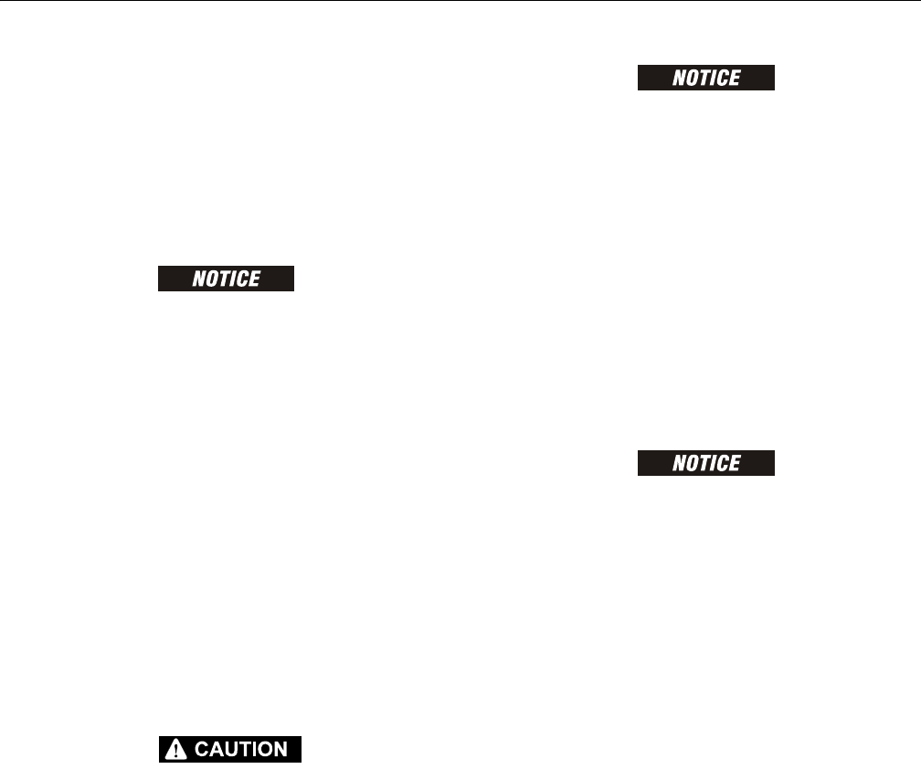
SECTION 3 - CHASSIS & TURNTABLE
3121298 – JLG Lift – 3-87
Check/Drain Oil Build-Up In 2-Stage Vaporizer
Refer to Figure 3-95. GM 3.0 Dual Fuel System Components.
During normal operation for LPG engines oil or “heavy ends”
may build inside the Vaporizer secondary chamber. These oil
and heavy ends may be a result of poor fuel quality, fuel con-
tamination, or regional variation of the fuel make up. A signifi-
cant build up of oil can affect performance of the secondary
diaphragm response.
FAILURE TO FOLLOW THIS RECOMMENDATION MAY BE USED TO DENY A WAR-
RANTY CLAIM.
Drain oil periodically to maintain emission warranty. More fre-
quent draining of the Vaporizer Regulator is recommended
where substandard fuel may be a problem. Drain Vaporizer
Regulator at every engine oil change if contaminated or sub-
standard fuel is suspected or known to be have been used
with the emission compliant fuel system.
NOTE: Draining regulator when engine is warm will help oils to
flow freely from the regulator.
1. Move equipment well ventilated area and ensure no
external ignition sources are present.
2. Start engine.
3. With engine running, close manual valve.
4. When engine runs out of fuel and stops, turn key OFF.
5. Disconnect negative battery cable.
A SMALL AMOUNT OF FUEL MAY STILL BE PRESENT IN THE FUEL LINE. USE
GLOVES TO PREVENT BURNS AND WEAR PROPER EYE PROTECTION.
NOTE: If fuel continues to flow from connections when loosened,
check manual valve is fully closed.
6. Loosen hose clamps at inlet and outlet hoses. Remove
hoses.
7. Remove regulator mounting bolts.
8. Place a small receptacle in the engine compartment.
9. Rotate regulator to 90° so outlet fitting is pointing down
into receptacle. Drain regulator.
10. Inspect secondary chamber for any large dried particles
and remove.
11. Remove receptacle and reinstall regulator retaining
bolts. Torque to specifications.
12. Reinstall fuel hoses. Reconnect any other hoses
removed during this procedure.
13. Slowly open manual service valve.
FUEL CYLINDER MANUAL VALVE CONTAINS AN “EXCESS FLOW CHECK VALVE”.
OPEN MANUAL VALVE SLOWLY TO PREVENT ACTIVATING THE “EXCESS FLOW
CHECK VALVE.”
14. Check for leaks at the inlet and outlet fittings using a
soapy solution or an electronic leak detector.
15. Check coolant line connections for leaks.
16. Start engine. Recheck regulator for leaks.
17. Dispose of any drained material in safe and proper man-
ner according to applicable regulations.
Air Fuel Mixer/Throttle Control Device Maintenance
And Inspection
Refer to Figure 3-95. GM 3.0 Dual Fuel System Components.
AIR FUEL MIXER COMPONENTS HAVE BEEN SPECIFICALLY DESIGNED AND CAL-
IBRATED TO MEET FUEL SYSTEM REQUIREMENTS OF THE EMISSION CERTIFIED
ENGINE. THE MIXER SHOULD NOT BE DISASSEMBLED OR REBUILT. IF MIXER
FAILS TO OPERATE OR DEVELOPS A LEAK, IT SHOULD BE REPLACED WITH OEM
RECOMMENDED REPLACEMENT PARTS.
1. Check for leaks at the inlet fitting.
2. Inspect fuel inlet hose for cracking, splitting, or chaffing.
Replace if any of these condition exist.
3. Ensure mixer is securely mounted and not leaking vac-
uum at the mounting gasket or surface.
4. Inspect air inlet hose connection and clamp. Inspect
inlet hose for cracking, splitting, or chafing. Replace if
any of these conditions exist.
5. Inspect air cleaner element.
6. Check fuel lines for cracking, splitting, or chafing.
Replace if any of these conditions exist.
7. Check for leaks at the throttle body and intake manifold.

SECTION 3 - CHASSIS & TURNTABLE
3-88 – JLG Lift – 3121298
Exhaust System And Catalytic Converter Inspection
And Maintenance
EXHAUST SYSTEM ON THIS EMISSION CERTIFIED ENGINE CONTAINS A HEATED
EXHAUST GAS OXYGEN SENSOR (HEGO) WHICH PROVIDES FEEDBACK TO THE
ECM ON AMOUNT OF OXYGEN PRESENT IN THE EXHAUST STREAM AFTER COM-
BUSTION. OXYGEN IN THE EXHAUST STREAM IS MEASURED IN VOLTAGE AND
SENT TO THE ECM. THE ECM THEN MAKES CORRECTIONS TO THE FUEL AIR
RATIO TO ENSURE PROPER FUEL CHARGE AND OPTIMUM CATALYTIC PERFOR-
MANCE. EXHAUST CONNECTIONS MUST REMAIN SECURE AND AIR TIGHT.
THE HEGO SENSOR IS SENSITIVE TO SILICONE BASED PRODUCTS. DO NOT USE
SILICONE SPRAYS OR HOSES WHICH ARE ASSEMBLED USING SILICONE LUBRI-
CANTS. SILICONE CONTAMINATION CAN CAUSE SEVERE DAMAGE TO THE
HEGO.
1. Check exhaust manifold at cylinder head for leaks and all
retaining bolts and shields (if used) are in place.
2. Check manifold to exhaust pipe fasteners are tight and
there are no exhaust leaks. Repair if necessary.
3. Inspect HEGO electrical connector is seated and locked.
Check wires for cracking, splits, chafing or “burn
through.” Repair if necessary.
4. Check exhaust pipe extension connector for leaks.
Tighten if necessary.
5. Check catalyst muffler is securely mounted. Check for
leaks at inlet and outlet.
Temperature Manifold Absolute Pressure (TMAP)
Sensor
Refer to Figure 3-95. GM 3.0 Dual Fuel System Components.
REMOVAL
1. Disconnect TMAP (402) electrical connector.
2. Remove retaining bolt (403), washer (404), and TMAP
(402).
INSTALLATION
NOTE: Apply a small amount of O-ring lubricant before installa-
tion.
1. Install TMAP (402). Secure with washer (404) and bolt
(403).
2. Torque retaining bolt to 62 in-lb (7 Nm).
3. Start vehicle and check for proper operation.
Throttle Body (ETC) Replacement
Refer to Figure 3-95. GM 3.0 Dual Fuel System Components.
REMOVAL
1. Disconnect negative battery cable.
2. Remove Mixer (See “Mixer Replacement” on page 88).
3. Disconnect TMAP electrical connector.
4. Disconnect electronic throttle control connector.
5. Remove bolts (208), adapter (204), and throttle body
(201) from manifold.
6. Remove spacer (205).
7. Remove and discard gasket (202) and O-ring (203).
INSTALLATION
NOTE: Lightly lubricate O-ring.
1. Install O-ring (203) and spacer (205) on throttle body
(201).
2. Align new gasket (202) and throttle body on manifold.
3. Slide adapter (204) on throttle body and secure with four
bolts (208).
4. Reinstall Mixer (See “Mixer Replacement” on page 88).
Mixer Replacement
Refer to Figure 3-95. GM 3.0 Dual Fuel System Components.
REMOVAL
1. Remove EPR. (See Electronic Pressure Regulator Replace-
ment on next page).
2. Remove Air Intake hose from Mixer.
3. Remove four bolts (206) and washers (207) securing
mixer (104) to adapter (204). Remove Mixer.
INSTALLATION
COVER THROTTLE BODY ADAPTER OPENING TO PREVENT DEBRIS FROM
ENTERING ENGINE.
1. Install Mixer (104) to Adapter (204). Secure with four
washers (207) and bolts (206). Torque to 80 in-lb (9 Nm)
2. Install EPR (See Electronic Pressure Regulator Replace-
ment on next page).
3. Reinstall Air Intake Hose.
4. Start engine and leak check all fittings and connections.

SECTION 3 - CHASSIS & TURNTABLE
3121298 – JLG Lift – 3-89
Electronic Pressure Regulator (EPR) Replacement
REMOVAL
Refer to Figure 3-95. GM 3.0 Dual Fuel System Components.
1. Unplug EPR (102) electrical connector.
2. Remove hoses from EPR.
3. Remove four flange nuts (107) and EPR from Mixer (104).
4. If new EPR is being installed, remove and retain hose
adapter (103) and four bolts (105).
INSTALLATION
1. If new EPR is being installed, install adapter (103) and
four bolts (105) to EPR.
2. Install EPR (102) on Mixer (104). Secure with four flange
nuts (107).
3. Reattach all hoses.
4. Start engine and leak check all fittings and connections.
Regulator Replacement
Refer to Figure 3-95. GM 3.0 Dual Fuel System Components.
REMOVAL
1. Disconnect and remove Lock-Off Valve (12) from Regula-
tor (16).
2. Remove hoses from regulator.
3. Remove regulator from engine.
INSTALLATION
1. Install Regulator (16) on engine.
2. Install hoses on regulator.
3. Install Lock-Off Valve (12) to Regulator. Reconnect Lock-
Off Valve.
4. Start engine and leak check all fittings and connections.
Coolant Hose Replacement
REMOVAL
1. Drain coolant.
2. Using hose clamp pliers, disconnect both hose clamps
on each hose.
3. Remove hose from fittings.
INSTALLATION
NOTE: Use hose material and lengths specified by JLG.
1. Install hose clamps to each hose and set clamp back on
each hose to make installation easier.
2. Fit hose to fittings.
3. Secure by positioning each of the clamps.
Vapor Hose Replacement
REMOVAL
1. Disconnect both hose clamps using hose clamp pliers.
2. Remove vapor hose from each fitting.
INSTALLATION
VAPOR SUPPLY HOSE IS SPECIFICALLY DESIGNED FOR THIS EQUIPMENT. DO
NOT USE HOSE MATERIAL OR LENGTH OTHER THAN JLG SPECIFIED PARTS.
1. Install hose clamps and set back on each hose.
2. Reinstall vapor hose to each fitting.
3. Reset clamps.
4. Start engine and check for leaks.

SECTION 3 - CHASSIS & TURNTABLE
3-90 – JLG Lift – 3121298
Engine Control Module Replacement
REMOVAL
1. Disconnect Negative battery cable.
2. Remove controller from mounting bracket.
3. Push connector lock back to unlock connector.
4. Unplug and remove controller.
INSTALLATION
CONTROLLER IS CALIBRATED FOR EACH ENGINE. VERIFY YOU HAVE CORRECT
CONTROLLER.
1. Plug connector into controller.
2. Push lock into place.
3. Mount controller into mounting bracket.
4. Reconnect the battery cable.
5. Start engine.
6. Check and clear any DTC codes.
7. Verify engine is in closed loop and no warning lights are
illuminated.
Heated Exhaust Gas Oxygen Sensor Replacement
REMOVAL
1. Disconnect negative (-) battery cable.
2. Disconnect O2 sensor electrical connector.
3. Using an O2 Sensor socket, remove and discard Sensor.
INSTALLATION
LUBRICATE O2 SENSOR THREADS WITH ANTI-SEIZE COMPOUND GM P/N
5613695 OR EQUIVALENT BEFORE INSTALLATION. DO NOT GET COMPOUND
ON SENSOR TIP.
1. Install O2 sensor. Tighten to 30 lb-ft (41 Nm).
2. Start engine.
3. Check and clear any DTC codes.
4. Verify engine is in closed loop and no warning lights are
illuminated.
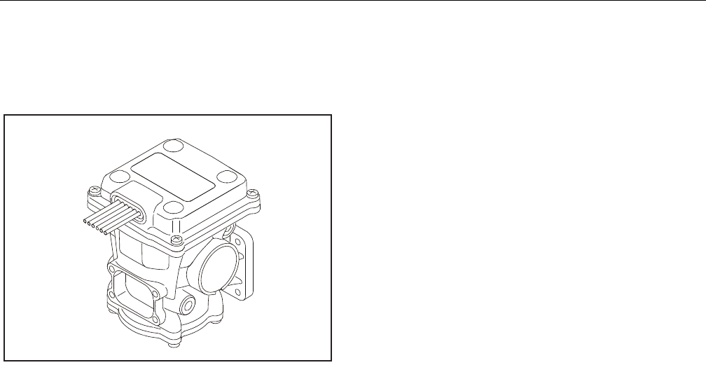
SECTION 3 - CHASSIS & TURNTABLE
3121298 – JLG Lift – 3-91
3.20 GM ENGINE LPG FUEL SYSTEM DIAGNOSIS
Fuel System Description
Figure 3-105. DEPR
The Engine Control Module (ECM) receives information from
various engine sensors to control the Direct Electronic Pres-
sure Regulator (DEPR) and lock-off Valve.
The lock-off Valve solenoid prevents fuel flow unless the
engine is cranking or running.
At Key ON, the DEPR valve receives a two (2) second prime
pulse from the ECM, allowing time for the fuel to flow through
the fuel filter and fuel lines to the DEPR.
Fuel travels from the lock-off to the light duty 2- stage regula-
tor into the DEPR.
Engine cranking generates vacuum which provided lift for the
mixer air valve and is commonly referred to as air valve vac-
uum. Once in the mixer, fuel is combined with air and drawn
into the engine for combustion.
Diagnostic Aids
This procedure is intended to diagnose a vehicle operating on
LPG. If vehicle will not continue to run on LPG, refer to Hard
Start for preliminary checks.
NOTE: Before proceeding with this procedure, verify vehicle has a
sufficient quantity of fuel and that liquid fuel is being deliv-
ered to the LPR. Ensure the LPG tank manual shut off valve
is fully opened and excess flow valve has not been acti-
vated.
Tools Required:
• 7/16 Open end wrench (for test port plugs)
• DVOM (GM J 39200, Fluke 88 or equivalent).
• 12 volt test light
Diagnostic Scan Tool
• Diagnostic Display tool.
Pressure Gauges
•IMPCO ITK-2 Test kit
• Water Column Gauge / Manometer (GM 7333-6 or equiva-
lent).
• 0-10 PSI Gauge
Test Description
Numbers below refer to step numbers on the diagnostic table.
5. This step determines if the LPR requires replacement
6. This step determines if the problems are in the mechanical
side of the Pressure Regulator or the Electronic Voice Coil
10. This step determines if the Mixer requires replacement
14. This step determines if the Lock Off requires replacement
17. This step determines if the Fuel Filter requires replacement.

SECTION 3 - CHASSIS & TURNTABLE
3-92 – JLG Lift – 3121298
Table 3-11. LP Fuel System Diagnosis
STEP ACTION VALUE(S) YES NO
1Were you referred to this procedure by a DTC diagnostic chart? - - Go to Ste p 3 G o t o S tep 2
2Perform the On Board Diagnostic (OBD) System Check.
Are any DTCs present in the ECM?
- - Go t o t h e
applicable DTC Table
Go to Ste p 3
3Verify that the LPG fuel tank has a minimum of 1/4 tank of fuel, that the manual valve is open
and the tank quick connect is fully engaged
Does the vehicle have fuel?
- - Go to Ste p 4 - -
41. Connect a water column gauge or a manometer to the secondary test port of the low pressure
regulator (LPR).
2. Start the engine and allow it to reach operating temperature.
Does the engine start and run?
- - Go to Ste p 5 G o t o S tep 8
5With the engine idling, observe the pressure reading for the LPR secondary pressure.
Does the fuel pressure fluctuate rhythmically OUTSIDE the specified range?
-1.0" to
-2.0" w.c
G o to Ste p 2 5 Go to Ste p 6
61. Disconnect the EPR electrical connectors. NOTE: This action will cause a DTC to be set by the
ECM
2. With the engine idling observe the pressure reading on the secondary test port.
Is the fuel pressure WITHIN the specified range?
-1.0" to
-2.0" w.c
Go to Fuel Control System
Diagnosis
Go to Ste p 7
71. Inspect the air intake stream between the mixer assembly and the throttle body for leaks.
2. Inspect the fuel hose connection between the LPR and mixer assembly for damage or leak-
age.
3. Inspect any vacuum hoses for leaks
Was a problem found and corrected?
- - G o to St ep 26 Go to Ste p 2 2
81. Connect a water column gauge or a manometer to the secondary test port of the low pressure
regulator (LPR).
2. Crank the engine and observe the pressure reading for the LPR secondary pressure.
D oe s th e f ue l p res su re i nd ic ate a va cu um is p re se nt ?
- - G o to St ep 12 G o to St ep 9
91. Remove Air induction hose to the mixer
2. Observe the air valve for movement while the engine is cranking. Note: Movement of the air
valve will be minimal at cranking speeds.
D oe s th e a ir va lve mov e w he n th e en gi ne is cr an ked ?
- - G o to St ep 11 Go to Ste p 1 0
10 1. Inspect the air intake stream to the mixer assembly and the throttle body for vacuum leaks.
2. Inspect the vacuum hoses from the mixer for proper connection and condition.
Was a problem found and repaired?
- - G o to St ep 26 Go to Ste p 2 4
11 Inspect the fuel hose connection between the LPR and the mixer assembly for damage or leak-
age.
Was a problem found and repaired?
- - G o to St ep 26 Go to Ste p 1 2
12 1. Connect a 0-10 psi gauge to the primary test port of the low pressure regulator (LPR).
2. Crank the engine and observe the pressure reading for the LPR primary pressure.
Is the fuel pressure ABOVE the specified value?
1- 3 PSI G o to St ep 22 Go to St ep 1 3
13 1. Turn OFF the ignition.
2. Disconnect the LPL connector.
3. Install a test light between the pins of the LPL connector.
4. Crank the engine. The test light should illuminate.
Does the test light illuminate?
- - G o to St ep 14 Go to Ste p 1 6
14 Using a DVOM, check the resistance of the low pressure lock-off (LPL).
Is the resistance within the specified range?
12W - 16WG o to Ste p 15 Go to Ste p 2 3

SECTION 3 - CHASSIS & TURNTABLE
3121298 – JLG Lift – 3-93
15 1. Turn the ignition OFF.
2. Close the manual shut-off valve on the LPG tank.
CAUTION: When disconnecting LPG fuel lines, liquid LPG may be present. Perform this step in a
well ventilated area.
3. Loosen the fuel inlet hose fitting at the inlet of the LPL.
Was fuel present when the fitting was loosened?
- - Go to Step 23 Go to Step 17
16 1. Turn OFF the ignition.
2. Connect the test light to chassis ground and probe pin A of the LPL connector.
3. Crank the engine. The test light should illuminate.
Does the test light illuminate?
- - Go to Step 20 Go to Step 21
17 1. Remove the LPG fuel filter / LPL.
2. Remove the filter from the LPL.
3. Empty the contents of the inlet side of the LPG fuel filter onto a clean surface.
4. Inspect the contents of the LPG fuel filter for an excessive amount of foreign material or
water. If necessary, locate and repair the source of contamination.
5. Verify the LPG fuel filter is not restricted or plugged.
Was a problem found?
- - Go to Step 19 Go to Step 18
18 The fuel supply system or hoses are plugged or restricted, locate and repair the problem.
Is the action complete?
- - Go to Step 26 - -
19 Replace the fuel filter. Refer to Fuel Filter Replacement.
Is th e a ct io n c om pl ete ?
- - Go to Step 26 - -
20 Repair the open in the lock-off ground circuit.
Is the action complete?
- - Go to Step 26 - -
21 Repair the open in the lock-off power circuit.
Is the action complete?
- - Go to Step 26 - -
22 Replace the low pressure regulator (LPR). Refer to Low Pressure Regulator Replacement.
Is the action complete?
- - Go to Step 26 - -
23 Replace the lock-off. Refer to Lock-off Replacement.
Is the action complete?
- - Go to Step 26 - -
24 Replace the mixer assembly. Refer to Fuel Mixer Replacement.
Is th e a ct io n c om pl ete ?
- - Go to Step 26 - -
25 The fuel supply system is operating normally, if a failure of the control solenoids is suspected.
Refer to Fuel Control System Diagnosis.
1. Install the test plug in the LPR secondary chamber.
2. If yo u we re s en t to th is rou ti ne by ano th er di ag no stic ch ar t, re turn to th e pr ev io us dia gn os ti c
procedure.
Is the action complete?
- - System OK - -
26 1. Disconnect all test equipment
2. Install the primary and secondary test port plugs.
3. Start the engine.
4. Using SNOOP or equivalent, leak check the test port plugs.
Is the action complete?
- - System OK - -
Table 3-11. LP Fuel System Diagnosis
STEP ACTION VALUE(S) YES NO

SECTION 3 - CHASSIS & TURNTABLE
3-94 – JLG Lift – 3121298
Table 3-12. Symptom Diagnosis
Checks Action
Important Preliminary Checks
Before Using This Section Before using this section, you should have performed On Board Diagnostic Check and determined that:
1. The Control Module and MIL (Malfunction Indicator Lamp) are operating correctly.
2. There are no Diagnostic Trouble Codes (DTCs) stored, or a DTC exists but without a MIL.
Several of the following symptom procedures call for a careful visual and physical check. The visual and physical checks are very important. The
checks can lead to correcting a problem without further checks that may save valuable time.
LPG Fuel System Check 1. Verify the customer complaint.
2. Locate the correct symptom table.
3. Check the items indicated under that symptom.
4. Operate the vehicle under the conditions the symptom occurs. Verify HEGO switching between lean and rich.
IMPORTANT! Normal HEGO switching indicates the LPG fuel system is in closed loop and operating correctly at that time.
Visual and Physical Checks Check all ECM system fuses and circuit breakers.
Check the ECM ground for being clean, tight and in its proper location.
Check the vacuum hoses for splits, kinks and proper connections.
Check thoroughly for any type of leak or restriction.
Check for air leaks at all the mounting areas of the intake manifold sealing surfaces.
Check for proper installation of the mixer module assembly.
Check for air leaks at the mixer assembly.
Check the ignition wires for the following conditions:
- Cra ck in g
- Ha rd ne ss
- Pro pe r ro ut in g
- Car bo n t rac ki ng
Check the wiring for the following items:
- Pro pe r con ne ct io ns , pi nc he s o r c ut s.
The following symptom tables contain groups of possible causes for each symptom. The order of these procedures is not important. If the scan
tool readings do not indicate the problems, then proceed in a logical order, easiest to check or most likely to cause first.
Intermittent
DEFINITION: The problem may or may not turn ON the Malfunction Indicator Lamp (MIL) or store a Diagnostic Trouble Code (DTC).
Preliminary Checks Refer to Important Preliminary Checks.
Do not use the DTC tables. If a fault is an intermittent, the use of the DTC tables may result in the replacement of good parts.
Faulty Electrical Connections or Wiring Faulty electrical connections or wiring can cause most intermittent problems.
Check the suspected circuit for the following conditions:
- Fau lt y fus e o r c irc u it b re ake r
- Co nn ec to rs po or ly mat ed
- Terminals not fully seated in the connector (backed out)
- Terminals not properly formed or damaged
- Term in al to w ir es p oo rl y c on nec t ed
- Terminal tension insufficient.
Carefully remove all the connector terminals in the problem circuit in order to ensure the proper contact tension. If necessary, replace all the
connector terminals in the problem circuit in order to ensure the proper contact tension.
Checking for poor terminal to wire connections requires removing the terminal from the connector body.
Operational Test If a visual and physical check does not locate the cause of the problem, drive the vehicle with a scan tool. When the problem occurs, an abnormal
voltage or scan reading indicates the problem may be in that circuit.

SECTION 3 - CHASSIS & TURNTABLE
3121298 – JLG Lift – 3-95
Intermittent Malfunction Indicator Lamp
(MIL)
The following components can cause intermittent MIL and no DTC(s):
A defective relay, Control Module driven solenoid, or a switch that can cause electrical system interference. Normally, the problem will occur
when the faulty component is operating.
The improper installation of electrical devices, such as lights, 2-way radios, electric motors, etc.
The ignition secondary voltage shorted to a ground.
The Malfunction Indicator Lamp (MIL) circuit or the Diagnostic Test Terminal intermittently shorted to ground.
The Control Module grounds.
Loss of DTC Memory To check for the loss of the DTC Memory:
1. Disconnect the TMAP sensor.
2. Idle the engine until the Malfunction Indicator Lamp illuminates.
The ECM should store a TMAP DTC. The TMAP DTC should remain in the memory when the ignition is turned OFF. If the TMAP DTC does not store
and remain, the ECM is faulty
Additional Checks
No Start
DEFINITION: The engine cranks OKbut does not start.
Preliminary Checks Refer to Important Preliminary Checks.
Control Module Checks If a scan tool is available:
Check for proper communication with both the ECM
Check the fuse in the ECM battery power circuit. Refer to Engine Controls Schematics.
Check battery power, ignition power and ground circuits to the ECM. Refer to Engine Control Schematics. Verify voltage and/or continuity for
each circuit.
Sensor Checks Check the TMAP sensor.
Check the Magnetic pickup sensor (RPM).
Fuel System Checks Important: A closed LPG manual fuel shut off valve will create a no start condition.
Check for air intake system leakage between the mixer and the throttle body.
Verify proper operation of the low pressure lock-off solenoids.
Check the fuel system pressures. Refer to the LPG Fuel System Diagnosis.
Check for proper mixer air valve operation.
Ignition System Checks Note: LPG being a gaseous fuel requires higher secondary ignition system voltages for the equivalent gasoline operating conditions.
Check for the proper ignition voltage output with J 26792 or the equivalent.
Verify that the spark plugs are correct for use with LPG (R42LTS)
Check the spark plugs for the following conditions:
- We t p lu gs
- C ra ck s
- We ar
- I mp ro per ga p
- Burned electrodes
- Heavy deposits
Check for bare or shorted ignition wires.
Check for loose ignition coil connections at the coil.
Engine Mechanical Checks Important: The LPG Fuel system works on a fumigation principle of fuel introduction and is more sensitive to intake manifold leakage than
the gasoline fuel supply system.
Check for the following:
- Va cu um le ak s
- Im pr ope r v al ve t im in g
- Lo w co mp res si on
- B ent pu sh rod s
- Wo rn roc ke r ar ms
- Br oke n o r we ak va lve sp ri ngs
- Wo rn ca ms ha ft lo be s.
Table 3-12. Symptom Diagnosis
Checks Action

SECTION 3 - CHASSIS & TURNTABLE
3-96 – JLG Lift – 3121298
Exhaust System Checks Ch ec k t he e xh au st sy ste m f or a p oss ib le res tr ic ti on :
- Inspect the exhaust system for damaged or collapsed pipes
- Inspect the muffler for signs of heat distress or for possible internal failure.
Check for possible plugged catalytic converter. Refer to Restricted Exhaust System Diagnosis
Hard Start
DEFINITION: The engine cranks OK, but does not start for a long time. The engine does eventually run, or may start but immediately dies.
Preliminary Checks Refer to Important Preliminary Checks.
Make sure the vehicle's operator is using the correct starting procedure.
Sensor Checks Check the Engine Coolant Temperature sensor with the scan tool. Compare the engine coolant temperature with the ambient air temperature
on a cold engine. IF the coolant temperature reading is more than 5 degrees greater or less than the ambient air temperature on a cold engine,
check for high resistance in the coolant sensor circuit. Refer to DTC 111
Check the Crankshaft Position (CKP) sensor.
Check the Throttle position (TPS) sensor.
Fuel System Checks I mp or ta nt : A clo se d L PG ma nu al fu el sh ut off v al ve w il l c rea te a n e xt en de d c ran k O R n o s tar t co nd it ion .
Verify the excess flow valve in the LPG manual shut-off valve is not tripped.
Check mixer module assembly for proper installation and leakage.
Verify proper operation of the low pressure lock-off solenoids.
Verify proper operation of the EPR
Check for air intake system leakage between the mixer and the throttle body.
Check the fuel system pressures. Refer to the Fuel System Diagnosis.
Ignition System Checks Note: LPG being a gaseous fuel requires higher secondary ignition system voltages for the equivalent gasoline operating conditions.
Check for the proper ignition voltage output with J 26792 or the equivalent.
Verify that the spark plugs are correct for use with LPG (R42LTS)
Check the spark plugs for the following conditions:
- We t pl ug s
- Cra ck s
- We ar
- Improper gap
- Burned electrodes
- Heavy deposits
Check for bare or shorted ignition wires.
Check for moisture in the distributor cap if applicable.
Check for loose ignition coil connections.
Important:
1. If the engine starts but then immediately stalls, Check the Crankshaft Position (CKP).
2. Check for improper gap, debris or faulty connections.
Engine Mechanical Checks Important: The LPG Fuel system works on a fumigation principle of fuel introduction and is more sensitive to intake manifold leakage than the
gasoline fuel supply system.
Check for the following:
- Va cu um l ea ks
- I mpr op er val ve t im in g
- Lo w co mp res si on
- B ent pu sh ro ds
- Wor n r ock er ar ms
- B roke n o r we ak va lve sp ri ng s
- Wor n c am sh af t l obe s.
Check the intake and exhaust manifolds for casting flash.
Exhaust System Checks Check the exhaust system for a possible restriction:
- Inspect the exhaust system for damaged or collapsed pipes
- Inspect the muffler for signs of heat distress or for possible internal failure.
Check for possible plugged catalytic converter. Refer to Restricted Exhaust System Diagnosis or Exhaust System in the GM Base Engine Service
Manual
Table 3-12. Symptom Diagnosis
Checks Action

SECTION 3 - CHASSIS & TURNTABLE
3121298 – JLG Lift – 3-97
Additional Checks
Cuts Out, Misses
DEFINITION: A surging or jerking that follows engine speed, usually more pronounced as the engine load increases which is not normally felt above 1500 RPM. The exhaust has a steady spit-
ting sound at idle, low speed, or hard acceleration for the fuel starvation that can cause the engine to cut-out.
Preliminary Checks Refer to Important Preliminary Checks.
Ignition System Checks Start the engine.
Wet down the secondary ignition system with water from a spray bottle, and look/listen for arcing or misfiring as you apply water.
Check for proper ignition output voltage with spark tester J 26792.
Check for a cylinder misfire.
Verify that the spark plugs are correct for use with LPG (R42LTS)
Remove the spark plugs in these cylinders and check for the following conditions:
Insulation cracks
Wear
Improper gap
Burned electrodes
Heavy deposits
Visually/Physically inspect the secondary ignition for the following:
Ignition wires for arcing, cross-firing and proper routing
Ignition coils for cracks or carbon tracking
Engine Mechanical Checks Perform a cylinder compression check.
Check the engine for the following:
- Im pr ope r v al ve t im in g
- B ent pu sh rod s
- Wo rn roc ke r a rm s
- Wo rn ca ms ha ft lo be s.
- Br oke n o r we ak va lve sp ri ngs .
Check the intake and exhaust manifold passages for casting flash.
Fuel System Checks Check the fuel system - plugged fuel filter, low fuel pressure, etc. Refer to LPG Fuel System Diagnosis.
Check the condition of the wiring to the low pressure lock-off solenoid.
Additional Check Check for Electromagnetic Interference (EMI).
EMI on the reference circuit can cause a missing condition.
Monitoring the engine RPM with a scan tool can detect an EMI.
A sudden increase in the RPM with little change in the actual engine RPM, indicates EMI is present.
If the problem exists, check the routing of the secondary wires and the ground circuit.
Hesitation, Sag, Stumble
DEFINITION: The vehicle has a momentary lack of response when depressing the accelerator. The condition can occur at any vehicle speed. The condition may cause the engine to stall if it's
severe enough.
Preliminary Checks Refer to Important Preliminary Checks.
Fuel System Checks Check the fuel pressure. Refer to LPG Fuel System Diagnosis.
Check for low fuel pressure during a moderate or full throttle acceleration. If the fuel pressure drops below specification, there is possibly a
faulty low pressure regulator or a restriction in the fuel system.
Check the Manifold Absolute Pressure (MAP) sensor response and accuracy.
Check LPL electrical connection
Check the mixer air valve for sticking or binding.
Check the mixer module assembly for proper installation and leakage.
Check the EPR electrical connections.
Table 3-12. Symptom Diagnosis
Checks Action

SECTION 3 - CHASSIS & TURNTABLE
3-98 – JLG Lift – 3121298
Ignition System Checks Note: LPG being a gaseous fuel requires higher secondary ignition system voltages for the equivalent gasoline operating conditions. If a prob-
lem is reported on LPG and not gasoline, do not discount the possibility of a LPG only ignition system failure and test the system accordingly.
Check for the proper ignition voltage output with J 26792 or the equivalent.
Verify that the spark plugs are correct for use with LPG (R42LTS)
Check for faulty spark plug wires
Check for fouled spark plugs.
Additional Check Check for manifold vacuum or air induction system leaks
Check the generator output voltage.
Backfire
DEFINITION: The fuel ignites in the intake manifold, or in the exhaust system, making a loud popping noise.
Preliminary Check Refer to Important Preliminary Checks.
Ignition System Checks Important! LPG, being a gaseous fuel, requires higher secondary ignition system voltages for the equivalent gasoline operat-
ing conditions. The ignition system must be maintained in peak condition to prevent backfire.
Check for the proper ignition coil output voltage using the spark tester J26792 or the equivalent.
Check the spark plug wires by connecting an ohmmeter to the ends of each wire in question. If the meter reads over 30,000 ohms, replace the
wires.
Check the connection at each ignition coil.
Check for deteriorated spark plug wire insulation.
Check the spark plugs. The correct spark plugs for LPG are (R42LTS)
Remove the plugs and inspect them for the following conditions:
- We t pl ug s
- Cra ck s
- We ar
- Improper gap
- Burned electrodes
- Heavy deposits
Engine Mechanical Check Important! The LPG Fuel system works on a fumigation principle of fuel introduction and is more sensitive to intake manifold leakage than a
gasoline fuel supply system.
Check the engine for the following:
- Im pro pe r va lv e ti mi ng
- En gin e c om pre ss io n
- Ma ni fol d v ac uu m le ak s
- Int ak e m ani fo ld ga ske ts
- Stic ki ng or le aki ng va lve s
- Ex ha ust sy st em le aka ge
Check the intake and exhaust system for casting flash or other restrictions.
Fuel System Checks Perform a fuel system diagnosis. Refer to LPG Fuel System Diagnosis.
Lack of Power, Sluggishness, or Sponginess
DE FI NI TI ON : Th e e ng in e de li ver s le ss th an exp ec te d p owe r. The re is lit tl e o r n o i nc rea se in sp ee d wh en pa r ti all y a pp ly in g t he accelerator pedal.
Preliminary Checks Refer to Important Preliminary Checks.
Refer to the LPG Fuel system OBD System Check
Compare the customer's vehicle with a similar unit. Make sure the customer has an actual problem. Do not compare the power output of the
vehicle operating on LPG to a vehicle operating on gasoline as the fuels do have different drive feel characteristics
Remove the air filter and check for dirt or restriction.
Check the vehicle transmission Refer to the OEM transmission diagnostics.
Table 3-12. Symptom Diagnosis
Checks Action

SECTION 3 - CHASSIS & TURNTABLE
3121298 – JLG Lift – 3-99
Fuel System Checks Check for a restricted fuel filter, contaminated fuel, or improper fuel pressure. Refer to LPG Fuel System Diagnosis.
Check for the proper ignition output voltage with the spark tester J 26792 or the equivalent.
Check for proper installation of the mixer module assembly.
Check all air inlet ducts for condition and proper installation.
Check for fuel leaks between the LPR and the mixer.
Verify that the LPG tank manual shut-off valve is fully open.
Verify that liquid fuel (not vapor) is being delivered to the LPR.
Sensor Checks Check the Heated Exhaust Gas Oxygen Sensor (HEGO) for contamination and performance. Check for proper operation of the MAP sensor.
Check for proper operation of the TPS sensor.
Exhaust System Checks Check the exhaust system for a possible restriction:
- Inspect the exhaust system for damaged or collapsed pipes
- Inspect the muffler for signs of heat distress or for possible internal failure.
- Check for possible plugged catalytic converter.
Engine Mechanical Check Check the engine for the following:
Engine compression
Valve timing
Improper or worn camshaft. Refer to Engine Mechanical in the Service Manual.
Additional Check Check the ECM grounds for being clean, tight, and in their proper locations.
Check the generator output voltage.
If all procedures have been completed and no malfunction has been found, review and inspect the following items:
Visually and physically, inspect all electrical connections within the suspected circuit and/or systems.
Check the scan tool data.
Poor Fuel Economy
DEFINITION: Fuel economy, as measured by refueling records, is noticeably lower than expected. Also, the economy is noticeably lower than it was on this vehicle at one time, as previously
shown by an by refueling records.
Preliminary Checks Refer to Important Preliminary Checks.
Check the air cleaner element (filter) for dirt or being plugged.
Visually (Physically) check the vacuum hoses for splits, kinks, and proper connections.
Check the operators driving habits for the following items:
- Is th ere exc es si ve i dl in g o r s top an d g o d rivi ng ?
- Ar e t he t ir es a t t he co rre ct ai r p res su re?
- Ar e ex ces si ve ly h ea vy lo ad s b ei ng ca rri ed ?
- Is th ei r o fte n r ap id acc el er at io n?
Suggest to the owner to fill the fuel tank and to recheck the fuel economy.
Suggest that a different operator use the equipment and record the results.
Fuel System Checks Check the LPR fuel pressure. Refer to LPG Fuel System Diagnosis.
Check the fuel system for leakage.
Sensor Checks Check the Temperature Manifold Absolute Pressure (TMAP) sensor.
Ignition System Checks Verify that the spark plugs are correct for use with LPG (R42LTS)
Check the spark plugs. Remove the plugs and inspect them for the following conditions:
- We t p lu gs
- C ra ck s
- We ar
- I mp ro per ga p
- Burned electrodes
- Heavy deposits
Check the ignition wires for the following items:
- C ra ck ing
- H ar dn ess
- Proper connections
Cooling System Checks Check the engine thermostat for always being open or for the wrong heat range
Table 3-12. Symptom Diagnosis
Checks Action

SECTION 3 - CHASSIS & TURNTABLE
3-100 – JLG Lift – 3121298
Additional Check Check the transmission shift pattern. Refer to the OEM Transmission Controls section the Service Manual.
Check for dragging brakes.
Rough, Unstable, or Incorrect Idle, Stalling
DEFINITION: The engine runs unevenly at idle. If severe enough, the engine or vehicle may shake. The engine idle speed may vary in RPM. Either condition may be severe enough to stall the
engine.
Preliminary Check Refer to Important Preliminary Checks.
Sensor Checks Check for silicon contamination from fuel or improperly used sealant. The sensor will have a white powdery coating. The sensor w il l re su lt in a
high but false signal voltage (rich exhaust indication). The ECM will reduce the amount of fuel delivered to the engine causing a severe drive-
ability problem.
Check the Heated Exhaust Gas Oxygen Sensor (HEGO) performance:
Check the Temperature Manifold Absolute Pressure (TMAP) sensor response and accuracy.
Fuel System Checks Check for rich or lean symptom that causes the condition. Drive the vehicle at the speed of the complaint. Monitoring the oxygen sensors will
help identify the problem.
Check for a sticking mixer air valve.
Verify proper operation of the EPR.
Perform a cylinder compression test. Refer to Engine Mechanical in the Service Manual.
Check the LPR fuel pressure. Refer to the LPG Fuel System Diagnosis.
Check mixer module assembly for proper installation and connection.
Ignition System Checks Check for the proper ignition output voltage using the spark tester J26792 or the equivalent.
Verify that the spark plugs are correct for use with LPG (R42LTS)
Check the spark plugs. Remove the plugs and inspect them for the following conditions:
- We t pl ug s
- Cra ck s
- We ar
- Improper gap
- Burned electrodes
- Bl ist ere d i ns ul ato rs
- Heavy deposits
Ch ec k t he sp ark pl ug wi res by co nne c ti ng a n o hm me ter to th e e nd s of each wire in question. If the meter reads over 30,000 ohms, replace the
wires.
Additional Checks Important: The LPG Fuel system works on a fumigation principle of fuel introduction and is more sensitive to intake manifold leakage than
the gasoline fuel supply system.
Check for vacuum leaks. Vacuum leaks can cause a higher than normal idle and low throttle angle control command.
Check the ECM grounds for being clean, tight, and in their proper locations.
Check the battery cables and ground straps. They should be clean and secure. Erratic voltage may cause all sensor readings to be skewed
resulting in poor idle quality.
Engine Mechanical Check C hec k t he en gi ne for th e f ol low in g:
- Bro ke n mo to r m oun ts
- Im pro pe r va lve t im in g
- Lo w c om pre ss io n
- Be nt pus hr od s
- Wo rn ro cke r a rm s
- Bro ke n or we ak val ve s pr in gs
- Wo rn c ams ha ft lo be s
Surges/Chuggles
DEFINITION: The engine has a power variation under a steady throttle or cruise. The vehicle feels as if it speeds up and slows d own wi th no ch an ge i n t he ac cel er ato r p ed al.
Preliminary Checks Refer to Important Preliminary Checks.
Sensor Checks Check Heated Exhaust Gas Oxygen Sensor (HEGO) performance.
Table 3-12. Symptom Diagnosis
Checks Action

SECTION 3 - CHASSIS & TURNTABLE
3121298 – JLG Lift – 3-101
Fuel System Checks Check for Rich or Lean symptom that causes the condition. Drive the vehicle at the speed of the complaint. Monitoring the oxygen sensors will
help identify the problem.
Check the fuel pressure while the condition exists. Refer to LPG Fuel System Diagnosis.
Verify proper fuel control solenoid operation.
Verify that the LPG manual shut-off valve is fully open.
Check the in-line fuel filter for restrictions.
Ignition System Checks Check for the proper ignition output voltage using the spark tester J26792 or the equivalent.
Verify that the spark plugs are correct for use with LPG (R42LTS)
Check the spark plugs. Remove the plugs and inspect them for the following conditions:
- We t p lu gs
- C ra ck s
- We ar
- I mp ro per ga p
- Burned electrodes
- Heavy deposits
- C he ck th e C ran ks ha ft Po si ti on (C KP ) s en sor.
Additional Check Check the ECM grounds for being clean, tight, and in their proper locations.
Check the generator output voltage.
Check the vacuum hoses for kinks or leaks.
Check Transmission
Table 3-12. Symptom Diagnosis
Checks Action

SECTION 3 - CHASSIS & TURNTABLE
3-102 – JLG Lift – 3121298
Table 3-13. DTC to SPN/FMI Cross Reference Chart
DTC Description SPN Code FMI Code
16 Crank Never Synced at Start 636 8
91 Fuel Pump Low Voltage 94 4
92 Fuel Pump High Voltage 94 3
107 MAP Low Voltage 106 4
108 MAP High Pressure 106 16
111 IAT Higher Than Expected 1 105 15
112 IAT Low Voltage 105 4
113 IAT High Voltage 105 3
116 ECT Higher Than Expected 1 110 15
117 ECT Low Voltage 110 4
118 ECT High Voltage 110 3
121 TPS 1 Lower Than TPS 2 51 1
122 TPS 1 Signal Voltage Low 51 4
123 TPS 1 Signal Voltage High 51 3
127 IAT Higher Than Expected 2 105 0
129 BP Low Pressure 108 1
134 EGO 1 Open/Inactive 724 10
154 EGO 2 Open/Inactive 520208 10
171 Adaptive Learn High Gasoline 520200 0
172 Adaptive Learn Low Gasoline 520200 1
182 Fue l Te mp Ga sol in e Lo w Vol ta ge 174 4
183 Fue l Te mp Ga so lin e H ig h Vol ta ge 174 3
187 Fuel Temp LPG Low Voltage 520240 4
188 Fuel Temp LPG High Voltage 520240 3
217 ECT Higher Than Expected 2 110 0
219 Max Govern Speed Override 515 15
221 TPS 2 Signal Voltage Low 51 0
222 TPS 2 Signal Low Voltage 520251 4
223 TPS 2 Signal High Voltage 520251 3
261 Injector Driver 1 Open 651 5
262 Injector Driver 1 Shorted 651 6
264 Injector Driver 2 Open 652 5
265 Injector Driver 2 Shorted 652 6
267 Injector Driver 3 Open 653 5
268 Injector Driver 3 Shorted 653 6
270 Injector Driver 4 Open 654 5
271 Injector Driver 4 Shorted 654 6
336 Crank Sync Noise 636 2
337 Crank Loss 636 4
341 Cam Sync Noise 723 2
342 Cam Sensor Loss 723 4
420 Gasoline Cat Monitor 520211 10
524 Oil Pressure Low 100 1

SECTION 3 - CHASSIS & TURNTABLE
3121298 – JLG Lift – 3-103
562 System Voltage Low 168 17
563 System Voltage High 168 15
601 Flash Checksum Invalid 628 13
604 RAM Failure 630 12
606 COP Failure 629 31
642 External 5V Reference Low 1079 4
643 External 5V Reference High 1079 3
685 Power Relay Open 1485 5
686 Power Relay Shor ted 1485 4
687 Power Relay Shor t to Power 1485 3
1111 Fuel Rev Limit 515 16
1112 Spark Rev Limit 515 0
1151 Closed Loop Multiplier High LPG 520206 0
1152 Closed Loop Multiplier Low LPG 520206 1
1155 Closed Loop Multiplier High Gasoline 520204 0
1156 Closed Loop Multiplier Low Gasoline 520204 1
1161 Adaptive Learn High LPG 520202 0
1162 Adaptive Learn Low LPG 520202 1
1165 LPG Cat Monitor 520213 10
1171 LPG Pressure Higher Than Expected 520260 0
1172 LPG Pressure Lower Than Expected 520260 1
1173 EPR Comm Lost 520260 31
1174 EPR Voltage Supply High 520260 3
1175 EPR Voltage Supply Low 520260 4
1176 EPR Internal Actuator Fault 520260 12
1177 EPR Internal Circuitry Fault 520260 12
1178 EPR Internal Comm Fault 520260 12
1612 RTI 1 loss 629 31
1613 RTI 2 Loss 629 31
1614 RTI 3 Loss 629 31
1615 A/D Loss 629 31
1616 Invalid Interrupt 629 31
1625 Shutdown Request 1384 31
1626 CAN Tx Failure 639 12
1627 CAN Rx Failure 639 12
1628 CAN Address Conflict Failure 639 13
1629 Loss of TSC 1 639 31
2111 Unable to Reach Lower TPS 51 7
2112 Un ab le to R ea ch Hi gh er TPS 51
2135 TPS 1/2 Simultaneous Voltages 51 31
2229 BP Pressure High 108 0
Table 3-13. DTC to SPN/FMI Cross Reference Chart
DTC Description SPN Code FMI Code

SECTION 3 - CHASSIS & TURNTABLE
3-104 – JLG Lift – 3121298
NOTES:
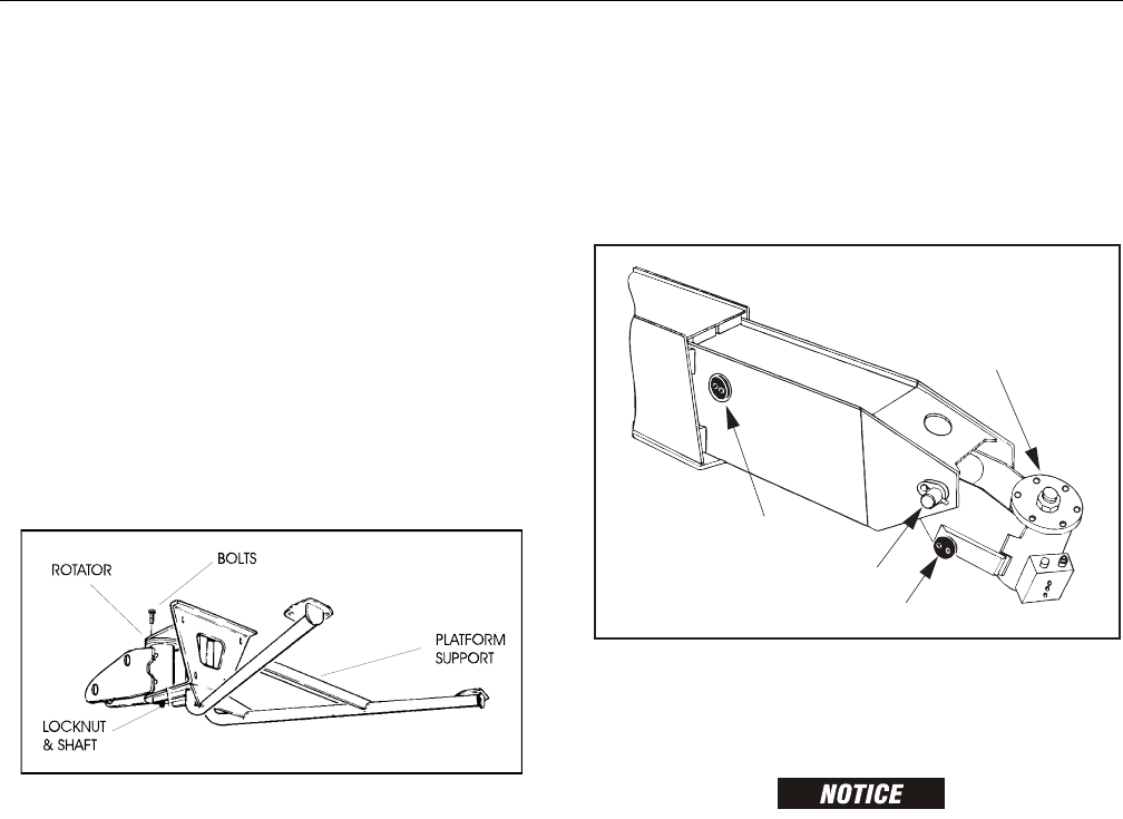
SECTION 4 - BOOM & PLATFORM
3121298 – JLG Lift – 4-1
SECTION 4. BOOM & PLATFORM
4.1 BOOM SYSTEMS
Removal
1. Remove platform/support as follows:
a. Disconnect electrical cable from control console.
b. Remove eight bolts securing platform to platform
support and remove the platform.
c. Using an overhead crane or suitable lifting device,
strap support platform support.
d. Remove six bolts and locknuts securing support to
rotator.
e. Using a suitable brass drift and hammer, remove
rotator shaft, then remove support from rotator.
Figure 4-1. Location of Components - Platform Support
2. Remove rotator and slave level cylinder from fly boom
as follows:
a. Tag and disconnect hydraulic lines to rotator. Use
suitable container for residual hydraulic fluid. Cap
hydraulic lines and ports.
b. Remove hardware from pin #1. Remove pin #1 from
fly boom with a suitable brass drift and hammer.
c. Support rotator. Remove hardware from pin #2.
Remove pin #2 from fly boom with a suitable brass
drift and hammer. Remove rotator.
d. Telescope fly section out approximately 20 inches
(50.8 cm) to access slave leveling cylinder.
e. Support slave cylinder. Remove hardware from pin
#3. Remove pin #3 from fly boom with a suitable
brass drift and hammer.
f. Tag and disconnect hydraulic lines to slave leveling
cylinder. Use a suitable container for residual
hydraulic fluid. Cap hydraulic lines and ports.
Remove slave cylinder.
Figure 4-2. Rotator and Leveling Cylinder Locations
3. Remove powertrack from boom as follows:
a. Disconnect wiring harness from ground control box.
HYDRAULIC LINES AND PORTS SHOULD BE CAPPED IMMEDIATELY AFTER DIS-
CONNECTING LINES TO AVOID ENTRY OF CONTAMINANTS INTO SYSTEM.
b. Tag and disconnect hydraulic lines from boom to
control valve. Use a suitable container for residual
hydraulic fluid. Cap hydraulic lines and ports.
c. Disconnect dual capacity indicator limit switch from
side of boom section.
d. Remove hydraulic lines and electrical cables from
powertrack.
e. Using a suitable lifting equipment, adequately sup-
port powertrack weight along entire length.
f. Remove bolts #1 securing push tube on fly boom
section.
g. Remove bolts #2 securing push tube on mid boom
section.
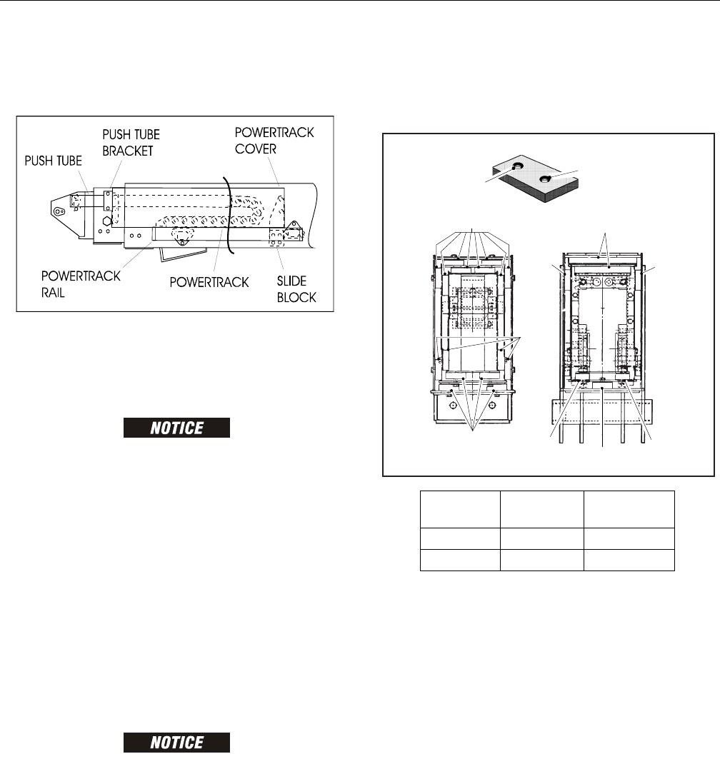
SECTION 4 - BOOM & PLATFORM
4-2 – JLG Lift – 3121298
h. With powertrack support and using all applicable
safety precautions, remove bolts #3 and #4 securing
rail to the base boom section. Remove powertrack
from boom section.
Figure 4-3. Boom Powertrack Components
4. Remove boom assembly from machine as follows:
a. Using suitable lifting equipment, adequately sup-
port boom assembly weight along entire length.
CAP HYDRAULIC LINES AND PORTS IMMEDIATELY AFTER DISCONNECTING
LINES TO PREVENT ENTRY OF CONTAMINANTS INTO SYSTEM.
b. Tag and disconnect hydraulic lines from telescope
cylinder. Use a suitable container for residual
hydraulic fluid. Cap hydraulic lines and ports.
c. Remove hardware securing lift cylinder rod end to
base boom section.
d. Using a suitable brass drift and hammer, remove lift
cylinder pin from base boom.
e. Remove hardware securing master cylinder rod end
to base boom section.
f. Using a suitable brass drift and hammer, remove the
master cylinder pin from the base boom.
g. Remove hardware securing push bar to turntable
upright.
WHEN REMOVING PIN FROM PUSHBAR DO NOT DROP PUSHBAR ON WIRE
ROPE ADJUSTMENT THREADS. FAILURE TO DO SO WILL DAMAGE THREADS.
h. Using a suitable brass drift and hammer, remove
push bar pin from turntable upright.
i. Remove hardware securing boom pivot pin to turn-
table upright.
j. Using a suitable brass drift and hammer, remove
pivot pin from turntable upright.
k. Using all applicable safety precautions, carefully lift
boom assembly clear of turntable and lower to
ground or suitably supported work surface.
4.2 WEAR PADS
Wear pads are made of polyethylene. Pads move on polyureth-
ene painted surfaces. No paint is removed and no lubrication
is applied.
Figure 4-4. Location and Thickness of Wear Pads
1. Shim wear pads to within 1/32 inch (.79 mm) tolerance
between wear pad and adjacent surface.
2. Replace wear pads when worn within 1/16 inch (1.59
mm) and 1/8 inch (3.18 mm) - B, C, D of threaded insert.
See Location and Thickness Of Wear Pads.
3. Bolt length must be changed when adjusting wear pads
and removing or adding shims.
a. Longer bolts must be used when adding shims to
ensure proper thread engagement in insert.
b. Shorter bolts must be used when shims are
removed so bolt does not protrude from insert and
contact boom surface.
!
"
#"
PAD
THICKNESS
OF NEW PAD
REPLACE WHEN
WORN TO:
A 5/8" 9/16"
B, C, D 3/4" 5/8"
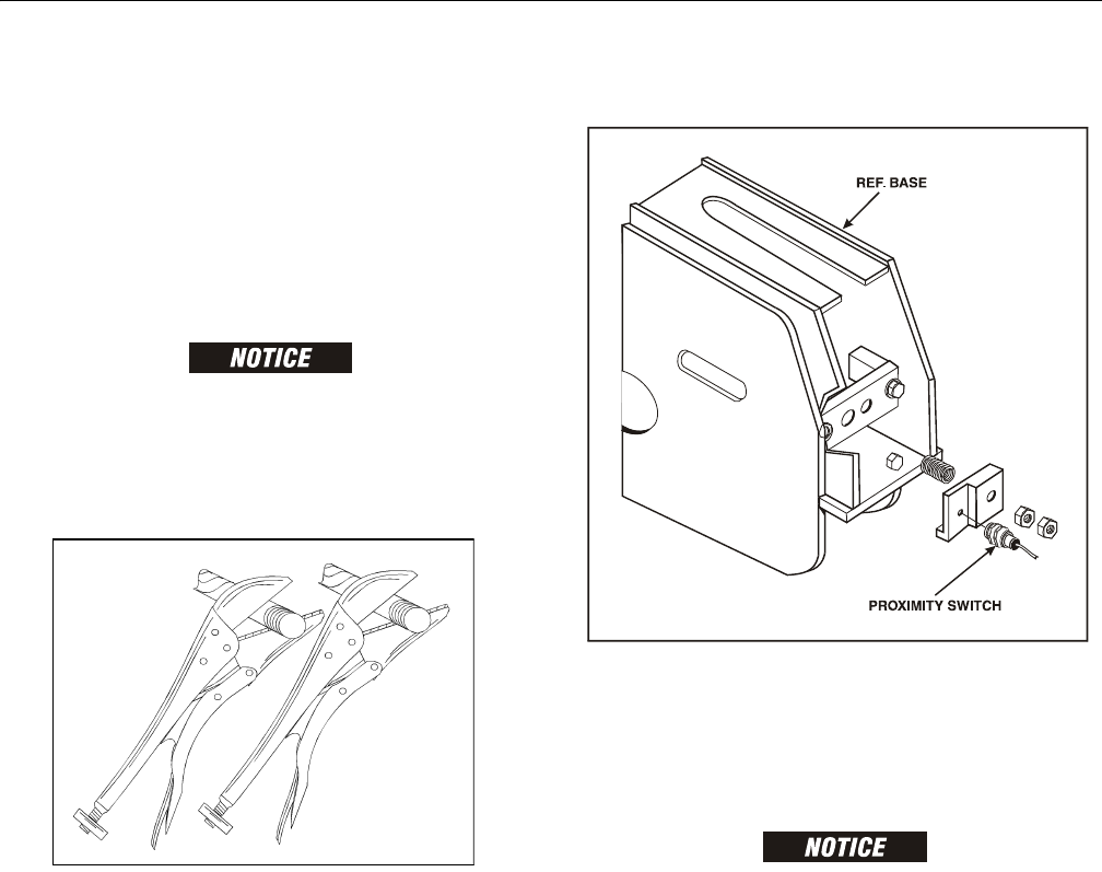
SECTION 4 - BOOM & PLATFORM
3121298 – JLG Lift – 4-3
4.3 BOOM DISASSEMBLY/ASSEMBLY & CABLE
REPLACEMENT
Boom Section Disassembly
1. Remove hardware securing push bar to aft end of tele-
scope cylinder. Remove pin from cylinder.
2. Remove hardware securing cover plate on bottom front
of base boom section.
DO NOT ALLOW WIRE ROPE TO ROTATE. THIS MAY DAMAGE THE WIRE ROPE.
3. Clamp both threaded ends of wire rope to prevent rota-
tion. Note: Do not clamp on threads. Remove jam nuts
and nuts which secure wire rope adjustments to bottom
front of base boom section.
Figure 4-5. Clamping Wire Ropes
NOTE: CE specification machines go to Step 4. All other machines
go to Step 5.
4. Remove spring mounting plate, spring, and proximity
switch from aft end of base section.
Figure 4-6. Proximity Switch Assembly Disassembly
5. Remove hardware securing wire rope adjustment block
to aft end of base boom section and remove block.
6. Remove hardware securing telescope cylinder to aft end
of mid boom section.
WHEN REMOVING TELESCOPE CYLINDER FROM BOOM, IT MAY BE NECESSARY
TO TURN CYLINDER SLIGHTLY TO CLEAR ASSEMBLIES MOUNTED IN BOOM.
MOVE CYLINDER SLOWLY OUT OF POSITION. DAMAGE TO COMPONENTS MAY
RESULT FROM FORCIBLE IMPACT WITH ASSEMBLIES.
7. Remove bolts securing wire rope attach bar to top of fly
boom section.
8. Pull telescope cylinder and wire ropes partially from aft
end of base boom section. Secure cylinder with a suit-
able sling and lifting device at center of gravity.
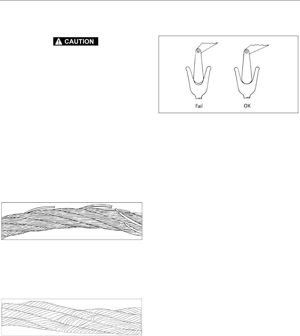
SECTION 4 - BOOM & PLATFORM
4-4 – JLG Lift – 3121298
4.4 WIRE ROPE
WIRE ROPE CAN HAVE SHARP EDGES AND CAUSE SERIOUS INJURY. NEVER
HANDLE WIRE ROPE WITH BARE HANDS.
Each day before using machine:
1. Raise main boom approximately horizontal.
2. Extend and retract the boom sections.
3. Check for delayed movement of fly section which indi-
cates loose wire ropes.
Inspection
NOTE: Pictures in this paragraph are samples to show rope
replacement criteria.
1. Inspect ropes for broken wires, particularly valley wire
breaks and breaks at end terminations.
NOTE: Flexing a wire rope can often expose broken wires hidden
in valleys between strands.
Figure 4-7. Wire Rope Wire Breaks
2. Inspect ropes for corrosion.
3. Inspect ropes for kinks or abuse.
NOTE: A kink is caused by pulling down a loop in a slack line dur-
ing improper handling, installation, or operation.
Figure 4-8. Wire Rope Kink
4. Inspect sheaves for condition of bearings/pins. (See
Dimension Of Sheaves for proper dimension.)Inspect
sheaves for condition of flanges. (See Dimension Of
Sheaves for proper dimension.)
5. Inspect sheaves with a groove wearout gauge for exces-
sive wear.
NOTE: Check groove so that it may be clearly seen if gauge con-
tour matches sheave groove contour.
Figure 4-9. Sheave Groove Wear
7. Ropes passing inspection should be lubricated with wire
rope lubricant before reassembly.
Three Month Inspection
1. Remove boom covers and visually (with flashlight)
inspect the ropes for rust, broken wires, frays, abuse, or
any signs of abnormalities.
2. Check wire rope tension by deflecting wire ropes by
hand. Properly tensioned ropes should have little or no
movement.
Eight Year Inspection
1. Mandatory wire rope and sheave replacement.
Additional inspection required if:
a. Machine is exposed to hostile environment or con-
ditions.
b. Erratic boom operation or unusual noise exists.
c. Machine is idle for an extended period.
d. Boom is overloaded or sustained a shock load.
e. Boom exposed to electrical arc. Wires may be fused
internally.
Replacement Criteria
NOTE: Sheaves and wire rope must be replaced as sets.
1. Rusted or corroded wire ropes.
2. Kinked, “bird caged”, or crushed ropes.
3. Ropes at end of adjustment range.
4. Sheaves failing wearout gage inspection.
5. Ropes with 6 total broken wires in one rope lay, 3 in one
strand in one rope lay, 1 valley break, or 1 break at any
end termination.
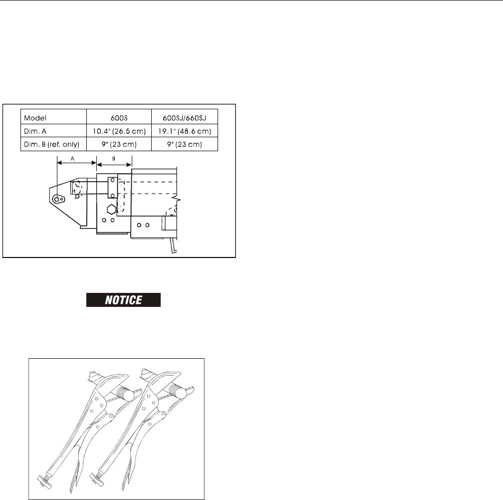
SECTION 4 - BOOM & PLATFORM
3121298 – JLG Lift – 4-5
4.5 WIRE ROPE TENSIONING ADJUSTMENT
Wire Rope Tensioning Procedure
1. Position boom in fully down and retracted position.
Figure 4-10. Dimensions of Boom Sections
DO NOT CLAMP ON THREADS OR THREADS MAY BE DAMAGED.
DO NOT ALLOW WIRE ROPE TO ROTATE OR WIRE ROPE MAY BE DAMAGED.
CLAMP THREADED ENDS OF WIRE ROPE TO PREVENT ROTATION.
Figure 4-11. Clamping Wire Ropes
2. Install adjusting nuts (or remove nylon collar locknuts if
re-adjusting) to both retract and extend wire ropes.
3. Torque retract adjusting nuts (platform end) to 15 ft-lb
(20 Nm) alternating between the two wire ropes and
keeping approximately the same amount of thread
beyond the adjusting nut.
4. Repeat torque procedure in step #4 to extend wire ropes
(turntable end).
5. Extend boom 2 - 3 feet using telescope function. Repeat
step #4.
6. Retract boom 1 - 2 feet using telescope function. Do not
bottom out telescope cylinder. Repeat step #5.
7. Extend boom approximately 2 - 3 feet again and check
torque on retract wire ropes.
8. Retract boom without bottoming out telescope cylin-
der. Check torque on extend wire ropes.
NOTE: Step #8 and #9 may need to be repeated to equalize the
torque on all 4 wire ropes.
9. After all wire ropes are properly torqued, install nylon
collar locknuts. Remove all clamping devices and install
all covers and guards. Check boom for proper function.
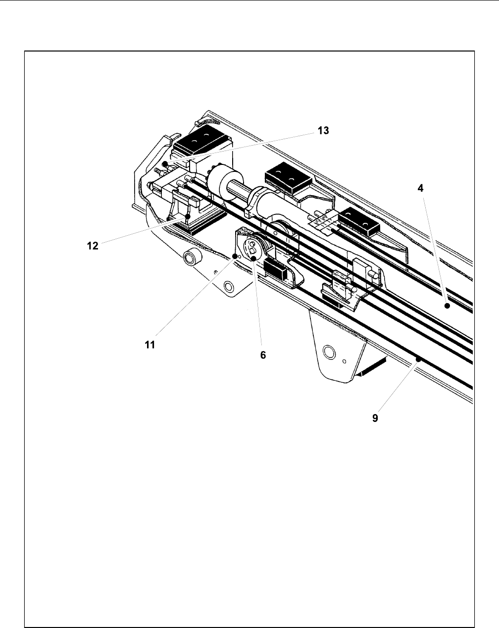
SECTION 4 - BOOM & PLATFORM
4-6 – JLG Lift – 3121298
Figure 4-12. Boom Assembly Cutaway - Sheet 1 of 3
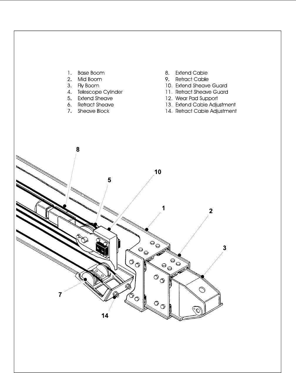
SECTION 4 - BOOM & PLATFORM
3121298 – JLG Lift – 4-7
Figure 4-13. Boom Assembly Cutaway - Sheet 2 of 3
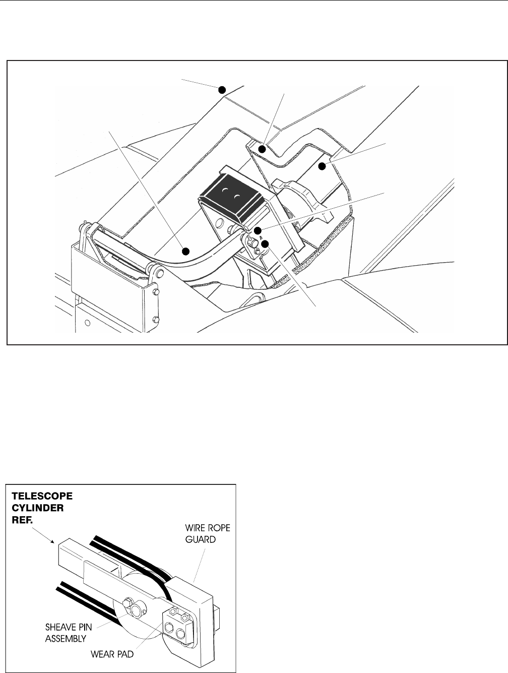
SECTION 4 - BOOM & PLATFORM
4-8 – JLG Lift – 3121298
Figure 4-14. Boom Assembly Cutaway - Sheet 3 of 3
10. Carefully remove telescope cylinder and sheave assem-
bly. Place telescope cylinder on a suitable trestle.
a. Remove hardware from wear pads. Remove wear
pads from cylinder.
b. Remove hardware from wire rope guard. Remove
guard from cylinder.
c. Remove hardware from sheave pin. Remove pin and
sheave from cylinder.
Figure 4-15. Disassembly of Sheave Assembly
11. Remove hardware securing wear pads to front of base
boom section. Remove wear pads from top, sides, and
bottom of base boom section.
12. Using an overhead crane or suitable lifting device,
remove mid and fly boom sections from base section.
Note: When removing mid and fly boom sections from
base boom section, retract wire rope must be dragged
along with boom sections.
13. Remove hardware which secures wear pads to aft end of
mid boom section. Remove wear pads from top, sides,
and bottom of mid boom section.
14. Remove hardware which secures sheave guards and
sheave assemblies to mid boom section. Remove sheave
assemblies from mid boom section.
15. Remove hardware which secures wear pads to front of
mid boom section. Remove wear pads from top, sides,
and bottom of the mid boom section.
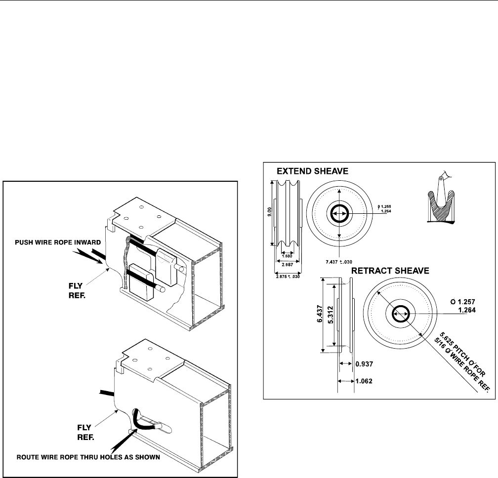
SECTION 4 - BOOM & PLATFORM
3121298 – JLG Lift – 4-9
16. Remove fly boom section from mid section using an
overhead crane or suitable lifting device.
NOTE: When removing fly boom section from mid boom section,
retract wire rope must be dragged along with fly boom sec-
tion.
17. Remove hardware which secures wear pads to aft end of
fly boom section. Remove wear pads from top, sides,
and bottom of fly boom section.
18. When removing wire rope from fly boom section, push
cable into fly boom. Route wire rope back through holes
in side of fly boom section.
Figure 4-16. Wire Rope Routing Disassembly
Inspection
NOTE: Refer to guidelines established in Section 2 - General when
inspecting pins and bearings.
1. Inspect all sheaves (extend and retract wire ropes and
telescope cylinder) for excessive groove wear, burrs, or
other damage. Replace sheaves as necessary.
NOTE: Use a groove gauge to check size, contour, and amount of
wear. Replace sheave if worn as shown in the following
drawing.
Figure 4-17. Dimension of Sheaves When New
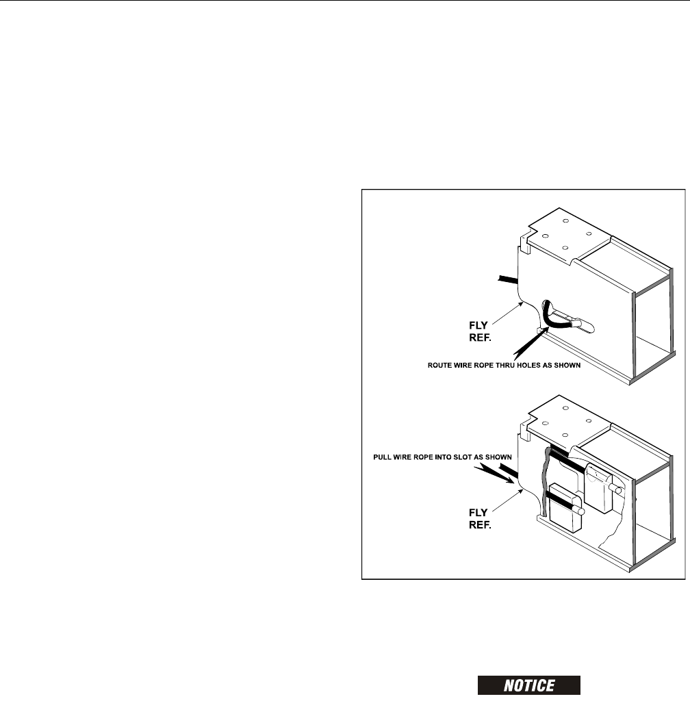
SECTION 4 - BOOM & PLATFORM
4-10 – JLG Lift – 3121298
2. Inspect extend and retract wire rope sheave bearings for
wear, scoring or other damage, and ovality.
3. Inspect extend wire rope and retract wire rope sheave
pins for scoring, tapering and ovality. Replace pins as
necessary.
4. Inspect telescope cylinder sheave pin for scoring, taper-
ing and ovality. Replace pins as necessary.
5. Inspect boom pivot pin for wear, scoring, tapering and
ovality, or other damage. Replace pins as necessary.
6. Inspect telescope cylinder attach point for scoring,
tapering and ovality. Replace pins as necessary.
7. Inspect upper lift cylinder attach pin for wear, scoring,
tapering and ovality, or other damage. Ensure pin sur-
faces are protected prior to installation. Replace pins as
necessary.
8. Inspect inner diameter of boom pivot bushing for scor-
ing, distortion, wear, or other damage. Replace bearing
as necessary.
9. Inspect all wear pads for excessive wear or other dam-
age. Replace pads when worn to within 1/8 inch (3.2
mm) of threaded insert.
10. Inspect extend and retract wire rope attach point com-
ponents for cracks, stretching, distortion, or other dam-
age. Replace components as necessary.
11. Inspect all threaded components for damage such as
stretching, thread deformation, or twisting. Replace as
necessary.
12. Inspect structural units of boom assembly for bending,
cracking, separation of welds, or other damage. Replace
boom sections as necessary.
Assembly
NOTE: Install same number and thickness of shims removed dur-
ing disassembly when installing fly section wear pads.
1. Measure inside dimensions of base and mid sections to
determine number of shims required for proper lift.
2. Measure inside dimensions of mid section to determine
number of shims required for proper lift.
3. Install side, top, and bottom wear pads to aft end of fly
section. Shim evenly to inside measurements of mid sec-
tion.
4. Install retract wire ropes in aft end of fly section. Route
wire ropes through holes in side of fly boom section and
pull into slot.
Figure 4-18. Routing Installation of Retract Wire Ropes
5. Install side, top, and bottom wear pads to aft end of mid
section. Shim evenly to mid section inside measure-
ments.
WHEN ASSEMBLING BOOM SECTIONS, ENSURE BOOM SLIDING TRAJECTORIES
ARE CLEAR OF CHAINS, TOOLS, AND OTHER OBSTRUCTIONS.
6. Shim insides of boom sections for a total of 1/16 inch
(0.062) clearance (if action is centered, there will be 1/32
inch clearance on each side).
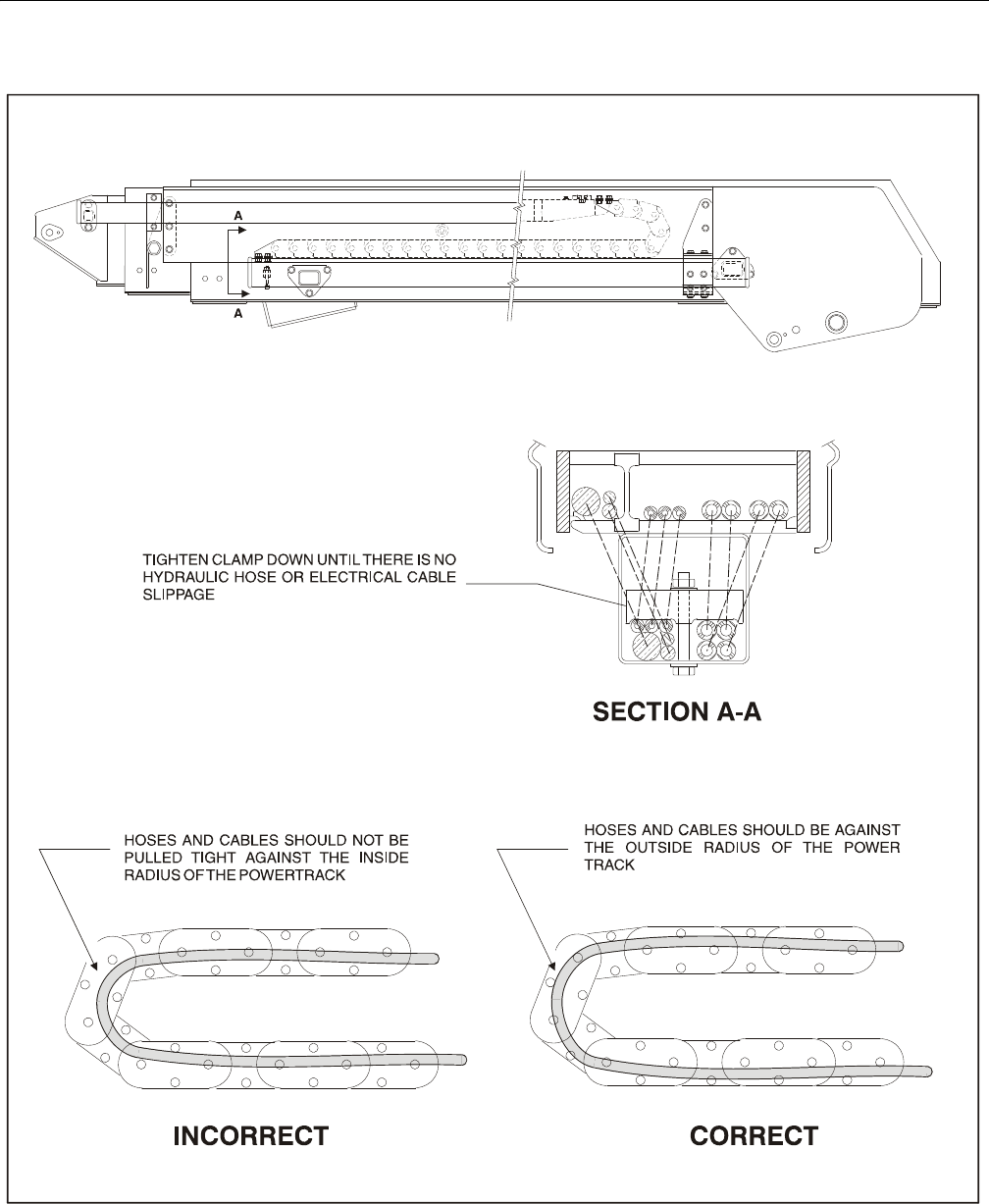
SECTION 4 - BOOM & PLATFORM
3121298 – JLG Lift – 4-11
Figure 4-19. Boom Powertrack Installation
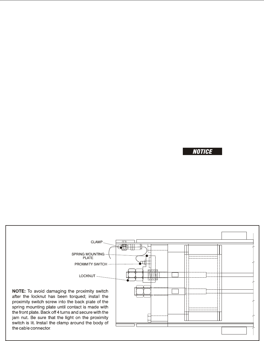
SECTION 4 - BOOM & PLATFORM
4-12 – JLG Lift – 3121298
7. Slide fly boom section into mid boom section. Shim
boom, if necessary, for a total of 1/16 inch (0.062) clear-
ance.
8. Install wear pads in forward position of the mid boom
section. Shim boom, if necessary, for a total of 2/10 inch
(0.20) clearance.
9. Properly position retraction wire rope sheaves assem-
blies at aft end of mid boom section. Ensure all sheave-
to-mounting block attachment holes align. Install
sheave pins and secure them with mounting hardware.
Position retract wire ropes onto sheaves.
10. Install sheave guards to aft end of mid boom section
and secure with mounting hardware.
11. Slide mid boom section into base boom section. Allow
retraction wire ropes to trail between bottom surfaces
of boom sections. Shim boom, if necessary, for a total of
1/16 inch (0.062) clearance.
12. Install wear pads into the forward position of base boom
section. Shim boom, if necessary, for a total of 2/10 inch
(0.20) clearance.
13. Install sheave block to bottom of base boom section
and adjust block so that retract wire ropes do not come
into contact with boom surfaces.
14. Install wire rope threaded ends thru attachment holes in
bottom of base boom section. Loosely install nuts and
jam nuts on threaded ends of wire ropes.
15. Align telescope cylinder barrel-to-sheave attachment
point. Install extend sheave pin through telescope cylin-
der barrel and sheave assembly; secure pin with mount-
ing hardware.
16. Route extend wire ropes around extend sheave and
secure wire ropes to the telescope cylinder.
17. Install extend wire rope mounting blocks to threaded
ends of wire ropes. Loosely install nuts and jam nuts on
threaded ends of wire ropes.
NOTE: Do not twist or cross wire ropes during installation.
NOTE: For non CE specification machines, skip step 18 and pro-
ceed to step 19.
18. Install extend wire rope mounting blocks, proximity
mounting plate and spring to threaded ends of wire
ropes. Loosely install nuts and jam nuts on threaded
ends of wire ropes. Refer to Figure 4-20., Proximity
Switch Installation.
19. Secure sling and lifting device at telescope cylinder’s
approximate center of gravity, and lift cylinder to aft end
of boom assembly.
WHEN INSERTING TELESCOPE CYLINDER IN BOOM, IT MAY BE NECESSARY TO
TURN CYLINDER SLIGHTLY TO CLEAR ASSEMBLIES MOUNTED IN BOOM. CARE
MUST BE TAKEN TO MOVE CYLINDER SLOWLY INTO POSITION. DAMAGE TO
COMPONENTS MAY RESULT FROM FORCIBLE IMPACT WITH ASSEMBLIES.
20. Align cylinder with slots at aft end of mid boom section,
then secure cylinder with mounting hardware.
21. Align holes in aft end of fly boom section with holes in
wire rope mounting block. Secure with mounting hard-
ware.
Figure 4-20. Proximity Switch Installation
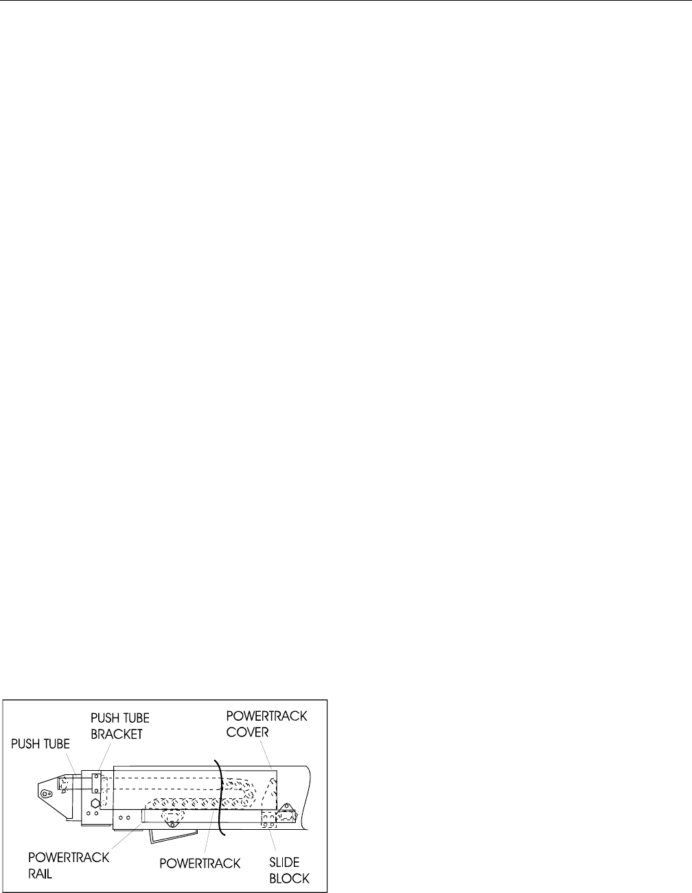
SECTION 4 - BOOM & PLATFORM
3121298 – JLG Lift – 4-13
22. Align holes in aft end of mid boom section with holes in
wire rope mounting block. Secure with mounting hard-
ware.
NOTE: Boom wire ropes must be torqued after installation of
boom assembly.
23. Align holes in rod end of telescope cylinder with holes in
push bar. Install push bar pin and secure with mounting
hardware.
23. Install hydraulic lines and electrical cables, and harness-
ing powertrack components as follows:
a. Align holes in powertrack rail with attachment holes
in side of base boom section. Secure rail with
mounting hardware.
b. Install powertrack to rail with mounting hardware.
c. Attach push tube bracket to side of mid boom sec-
tion with mounting hardware.
NOTE: Do not over tighten attach bolt on push tube bracket. It
should pivot freely.
d. Install slide block and wear pads to powertrack rail
with mounting hardware.
e. Install powertrack to push tube with mounting
hardware.
f. Carefully feed hoses and electrical cables through
aft end of powertrack rail, powertrack, and push
tube.
g. Ensure all hoses and cables are properly routed
through powertrack rail, powertrack, and push tube.
Tighten or install all clamping or securing apparatus
to hoses or cables, as necessary.
h. Install powertrack cover and push tube rods with
mounting hardware.
Figure 4-21. Boom Powertrack Assembly
Installation
1. Using a suitable lifting device, position boom assembly
on turntable so pivot holes in both boom and turntable
are aligned.
2. Install boom pivot pin. Ensure location of hole in pin is
aligned with attach point on turntable.
3. If necessary, gently tap pin into position with soft
headed mallet. Secure pin mounting hardware.
4. Align push bar pivot hole with pivot holes in turntable.
Install push bar pivot pin, Ensure location of hole in pin
is aligned with attach point on turntable.
5. If necessary, gently tap pin into position with soft
headed mallet. Secure pin mounting hardware.
6. Connect all wiring to ground control box.
7. Connect all hydraulic lines running along side of boom
assembly.
8. Using all applicable safety precautions, operate lifting
device to position boom lift cylinder so holes in cylinder
rod end and boom structure are aligned. Insert lift cylin-
der pin. Ensure location of hole in pin is aligned with
attach point on boom.
9. Align holes in boom structure with hole in master cylin-
der. Insert master cylinder pin. Ensuring hole in pin is
aligned with attach point on boom.
10. Adjust retract and extend cables to proper torque. Refer
to paragraph 2-6, boom cable torque procedures.
11. Using all applicable safety precautions, operate machine
systems and raise and extend boom fully. Note exten-
sion cycle performance.
12. Retract and lower boom. Note retraction cycle perfor-
mance.
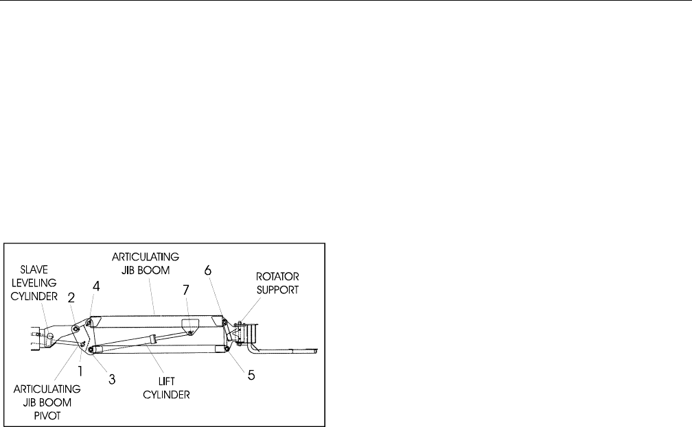
SECTION 4 - BOOM & PLATFORM
4-14 – JLG Lift – 3121298
4.6 ARTICULATING JIB BOOM
Removal
1. For platform/support removal see platform/support
removal diagram. See Section 4-1., Location of Compo-
nents - Platform Support.
2. Position articulating jib boom level with ground.
3. Remove mounting hardware from slave leveling cylin-
der pin #1. Using a suitable brass drift and hammer,
remove cylinder pin from articulating jib boom.
Figure 4-22. Articulating Jib Boom Components
4. Remove mounting hardware from articulating jib boom
pivot pin #2. Using a suitable brass drift and hammer,
remove pivot pin from boom assembly.
Disassembly
1. Remove mounting hardware from articulating jib boom
pivot pins #3 and #4. Using a suitable brass drift and
hammer, remove the pins from articulating jib boom
pivot weldment.
2. Remove mounting hardware from rotator support pins
#5 and #6. Using a suitable brass drift and hammer,
remove pins from rotator support.
3. Remove mounting hardware from lift cylinder pin #7.
Using a suitable brass drift and hammer, remove the cyl-
inder pin from articulating jib boom.
Inspection
NOTE: Refer to Section 2 - General, when inspecting pins and
bearings.
1. Inspect articulating fly boom pivot pin for wear, scoring,
tapering and ovality, or other damage. Replace pins as
necessary.
2. Inspect articulating fly boom pivot attach points for
scoring, tapering and ovality, or other damage. Replace
pins as necessary.
3. Inspect inner diameter of articulating fly boom pivot
bearings for scoring, distortion, wear, or other damage.
Replace bearings as necessary.
4. Inspect lift cylinder attach pin for wear, scoring, tapering
and ovality, or other damage. Ensure pin surfaces are
protected prior to installation. Replace pins as neces-
sary.
5. Inspect inner diameter of rotator attach point bearings
for scoring, distortion, wear, or other damage. Replace
bearing as necessary.
6. Inspect all threaded components for damage such as
stretching, thread deformation, or twisting. Replace as
necessary.
7. Inspect structural units of articulating jib boom assem-
bly for bending, cracking, separation of welds, or other
damage. Replace boom sections as necessary.

SECTION 4 - BOOM & PLATFORM
3121298 – JLG Lift – 4-15
Assembly
NOTE: For location of components See Section 4-22., Articulating
Jib Boom Components.
1. Align lift cylinder with attach holes in articulating jib
boom. Using a soft head mallet, install cylinder pin #7
into articulating jib boom and secure with mounting
hardware.
2. Align rotator support with attach hole in articulating jib
boom. Using a soft head mallet, install rotator support
pin #6 into articulating jib boom and secure with
mounting hardware.
3. Align bottom tubes with attach holes in rotator support.
Using a soft head mallet, install rotator support pin #5
into articulating jib boom and secure with mounting
hardware.
4. Align articulating jib boom with attach hole in articulat-
ing jib boom pivot weldment. Using a soft head mallet,
install rotator support pin #4 into articulating jib boom
and secure with mounting hardware.
5. Align bottom tubes with attach holes in articulating jib
boom pivot weldment. Using a soft head mallet, install
rotator support pin #3 into articulating jib boom pivot
weldment. Secure with mounting hardware.
6. Align articulating jib boom pivot weldment with attach
holes in fly boom assembly. Using a soft head mallet,
install pivot pin #2 into fly boom assembly. Secure with
mounting hardware.
7. Align slave leveling cylinder with attach holes in articu-
lating jib boom pivot weldment. Using a soft head mal-
let, install slave leveling cylinder pin #1 into articulating
jib boom pivot weldment. Secure with mounting hard-
ware.
4.7 LIMIT SWITCHES AND CAM VALVE ADJUSTMENT
Adjust switches and cam valve as shown in Figure 4-23., Hori-
zontal Limit and Dual Capacity Limit Switches Adjustments
and Figure 4-24., Transport Switch Adjustments - CE Machines
Only.
4.8 BOOM CLEANLINESS GUIDELINES
The following are guidelines for internal boom cleanliness for
machines used in excessively dirty environments.
1. JLG recommends use of JLG Hostile Environment Pack-
age to keep internal portions of a boom cleaner and
help prevent dirt and debris from entering the boom.
This package reduces the amount of contamination
which can enter the boom, but does not eliminate the
need for more frequent inspections and maintenance
when used in these types of environments.
2. JLG recommends you follow all guidelines for servicing
your equipment in accordance with instruction in the
JLG Service & Maintenance Manual for your machine.
Periodic maintenance and inspection is vital to proper
operation of the machine. Frequency of service and
maintenance must be increased as environment, sever-
ity, and frequency of usage requires.
3. Debris and contamination inside the boom can cause
premature failure of components and should be
removed. Methods to remove debris should always be
done using all applicable safety precautions outlined in
the JLG Operation & Safety Manual and the JLG Service
& Maintenance Manuals.
4. The first attempt to remove debris from inside the boom
must be to utilize pressurized air to blow the debris
toward the nearest exiting point from the boom. Make
sure that all debris is removed before operating the
machine.
5. If pressurized air cannot dislodge debris, then water
with mild solvents applied with a pressure washer can
be used. Wash debris toward the nearest exiting point
from the boom. Make sure all debris is removed, no
“puddling” of water has occurred, and boom internal
components are dry before operating machine. Make
sure you comply with all federal and local laws for dis-
posing of wash water and debris.
6. If pressurized air or washing boom does not dislodge
and remove debris, disassemble boom following
instructions outlined in the JLG Service & Maintenance
Manual to remove debris.
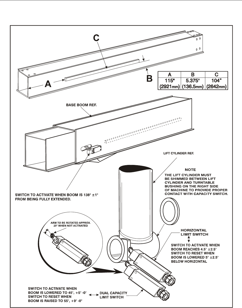
SECTION 4 - BOOM & PLATFORM
4-16 – JLG Lift – 3121298
Figure 4-23. Horizontal Limit and Dual Capacity Limit Switches Adjustments
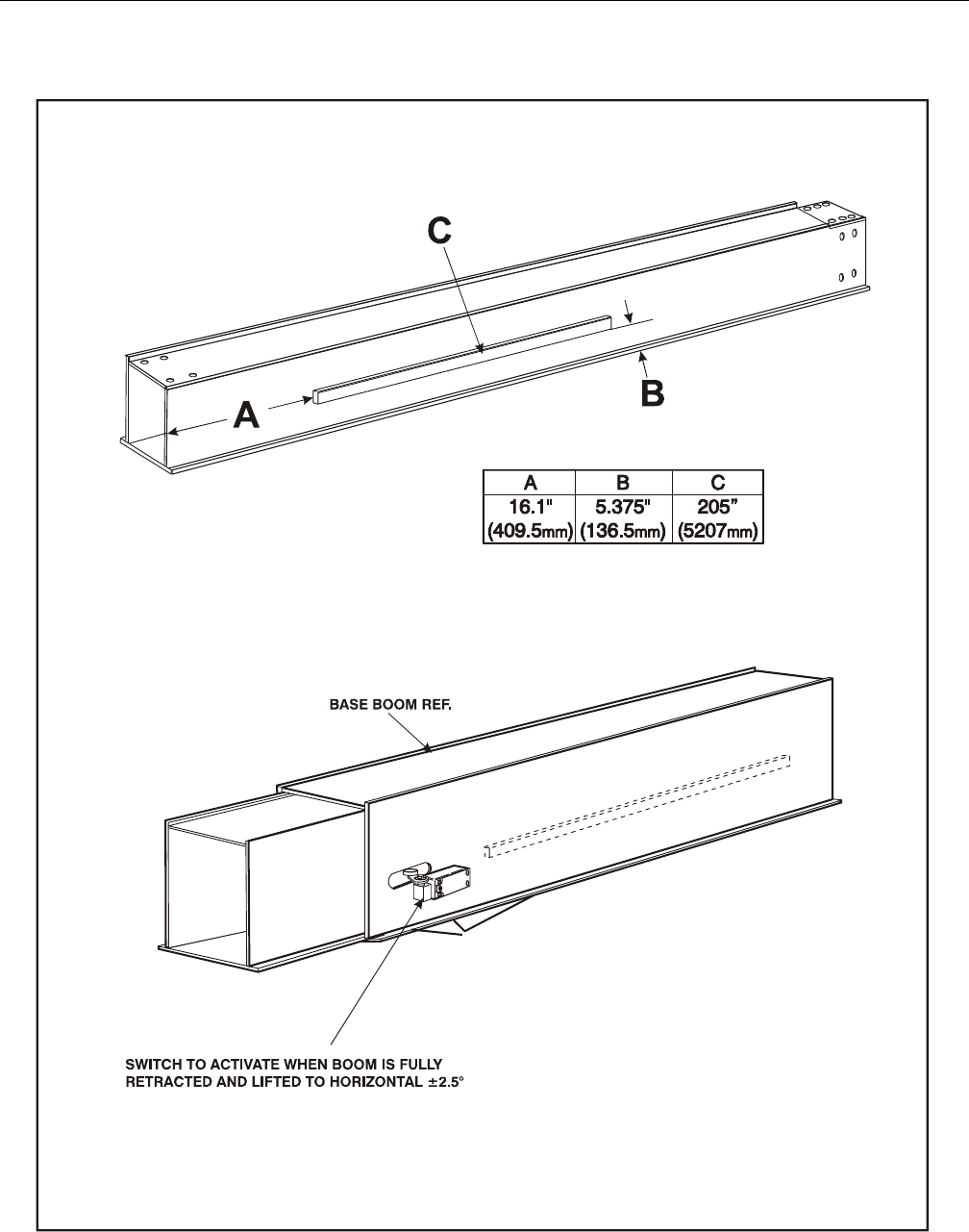
SECTION 4 - BOOM & PLATFORM
3121298 – JLG Lift – 4-17
Figure 4-24. Transport Switch Adjustments - CE Machines Only
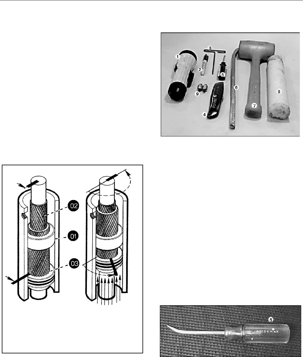
SECTION 4 - BOOM & PLATFORM
4-18 – JLG Lift – 3121298
4.9 ROTARY ACTUATOR
Theory of Operation
The L20 Series rotary actuator is a simple mechanism that uses
the sliding spline operating concept to convert linear piston
motion into powerful shaft rotation.
Each actuator is composed of a housing with integrated gear
teeth (01) and only two moving parts: the central shaft with
integrated bearing tube and mounting flange (02), and the
annular piston sleeve (03). Helical spline teeth machined on
the shaft engage matching splines on the piston inside diame-
ter. The piston outside diameter carries a second set of oppo-
site direction splines which engage with matching splines in
the housing.
As hydraulic pressure is applied, piston is displaced axially
within the housing - similar to operation of a hydraulic cylin-
der - while splines cause shaft to rotate. When control valve is
closed, oil is trapped inside the actuator, preventing piston
movement and locking the shaft in position. The shaft is sup-
ported radially by the large upper radial bearing and lower
radial bearing. Axially, the shaft is separated from the housing
by upper and lower thrust washers. End cap is adjusted for
axial clearance and locked in position by set screws or pins.
Required Tools
1. Flashlight - Examine timing marks, component failure,
and overall condition.
2. Felt Marker - Match mark timing marks and outline trou-
bled areas.
3. Allen wrench - Remove port plugs and set screws.
4. Box knife - removal of seals.
5. Seal tool - assembly and disassembly of seals and wear
guides.
6. Pry bar - End cap removal and manual rotation of shaft.
7. Rubber mallet- Removal and installation of shaft and
piston sleeve assembly.
8. Nylon drift - Piston sleeve installation.
9. End cap dowel pins - removal and installation of end cap
(sold with Helac seal kit).
The seal tool is a customized standard flat head screwdriver. To
make this tool, heat flat end with a torch. Secure heated end of
screwdriver in a vice and bend to a slight radius. Once radius is
achieved, round off all sharp edges using a grinder. There may
be some slight modifications for your personal preference.
Bars indicate starting positions
of piston and shaft. Arrows indi-
cate direction they will rotate.
The housing with integral ring
gear remains stationary.
As fluid pressure is applied, the
piston is displaced axially while
helical gearing causes the piston
and shaft to rotate simultane-
ously. The double helix design
compounds rotation: shaft rota-
tion is about twice of the piston.
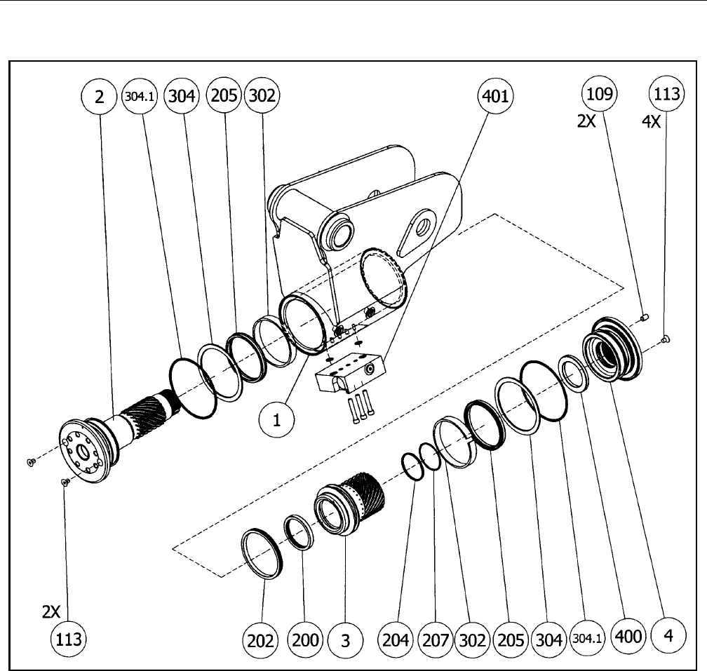
SECTION 4 - BOOM & PLATFORM
3121298 – JLG Lift – 4-19
PARTS
1. Housing
2. S ha ft
3. P is to n Sl ee ve
4. E nd Cap
HARDWARE
103.1. Screw
103.2 . Washer
106.1. Port Plug
106.2. Port Plug
109 . L oc k Pi n
113 . C ap sc re w
SEALS
200 . T- Se al
202 . T- Se al
204 . O -ri ng
205 . C up Se al
207 . B ac ku p R in g
304.1. Wiper Seal
BEARINGS
302. Wear Guide
304. Thrust Washer
ACCESSORIES
40 0. Sto p Tub e
420.1 Bushing
420.2 Bushing
421.1 Bushing
Figure 4-25. Rotary Actuator - Exploded View
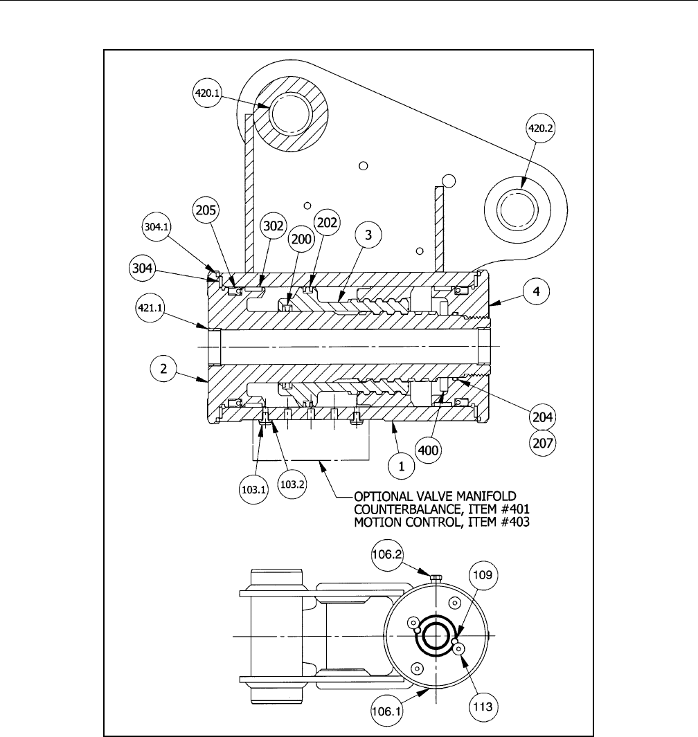
SECTION 4 - BOOM & PLATFORM
4-20 – JLG Lift – 3121298
PARTS
1. Ho us in g
2. Sh af t
3. Pi sto n S le eve
4. En d Ca p
HARDWARE
103.1. Screw
103.2 . Washer
106.1. Port Plug
106.2. Port Plug
109 . L oc k Pi n
113 . C ap sc rew
SEALS
20 0. T- Se al
20 2. T- Se al
20 4. O- ri ng
20 5. Cup S eal
20 7. Bac ku p R in g
304.1. Wiper Seal
BEARINGS
302. Wear Guide
304. Thrust Washer
ACCESSORIES
40 0. St op Tub e
420.1 Bushing
420.2 Bushing
421.1 Bushing
Figure 4-26. Rotary Actuator - Assembly Drawing
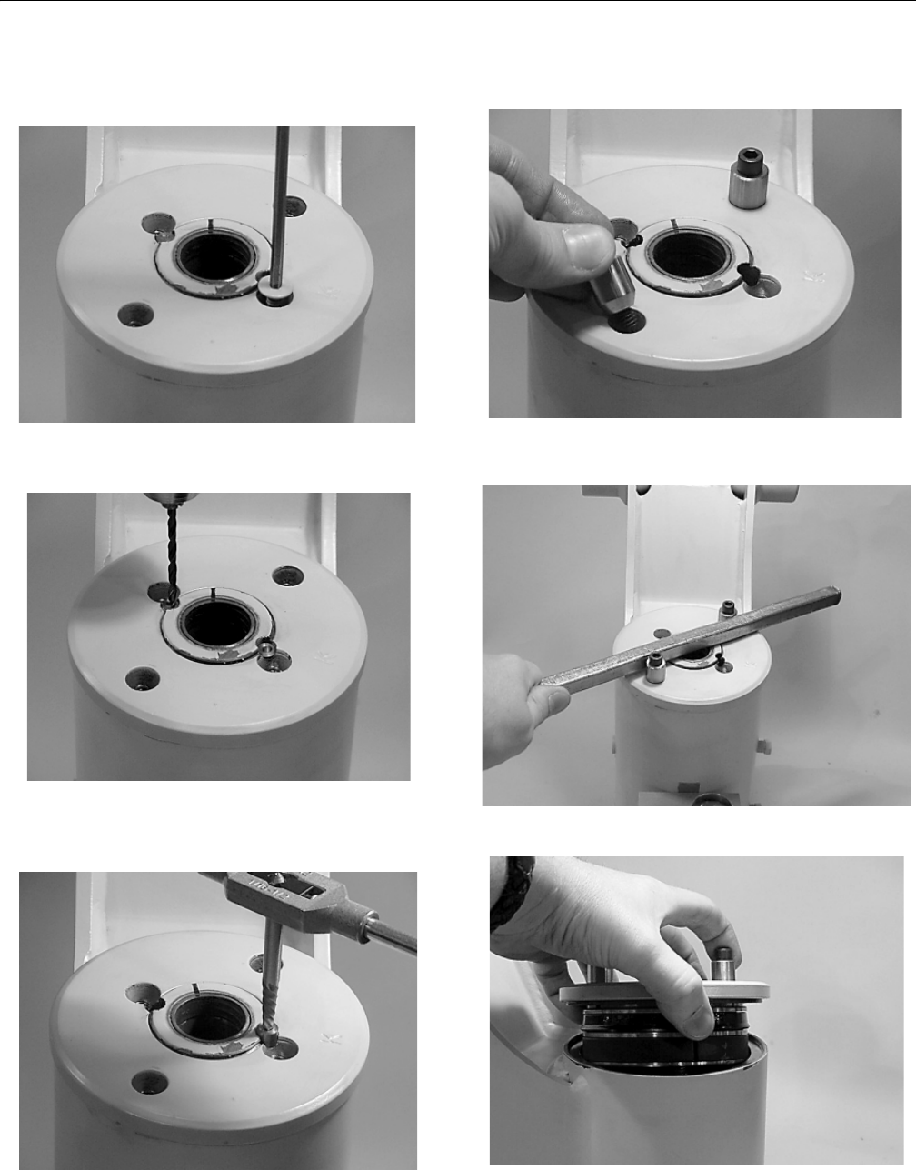
SECTION 4 - BOOM & PLATFORM
3121298 – JLG Lift – 4-21
Disassembly
1. Remove capscrews (113) over end cap lock pins (109).
2. Using a 1/8” (3.18mm) drill bit, drill a hole in center of
each lock pin approximately 3/16" (4.76mm) deep.
3. Remove lock pins using an ”Easy Out” (Size #2 shown. If
pin will not come out, use 5/16" drill bit 1/2" (12.7mm)
deep to drill out entire pin.
4. Remove end cap (4) using tools provided with Helac seal
kit.
5. Using a metal bar or similar tool, unscrew end cap (4) by
turning it counter clockwise.
6. Remove end cap (4) and set aside for later inspection.
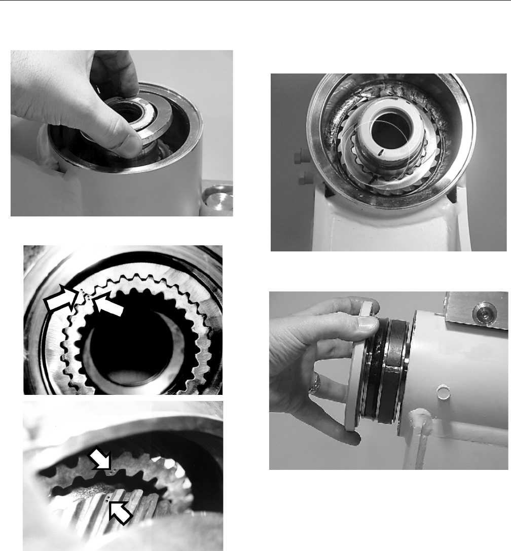
SECTION 4 - BOOM & PLATFORM
4-22 – JLG Lift – 3121298
7. Remove stop tube if installed.
8. Actuator has timing marks for proper engagement.
9. Before removing shaft, (2), use a felt marker to clearly
indicate timing marks between shaft and piston. This
simplifies timing during assembly.
10. Remove shaft (2). It may be necessary to strike threaded
end of shaft with a rubber mallet.
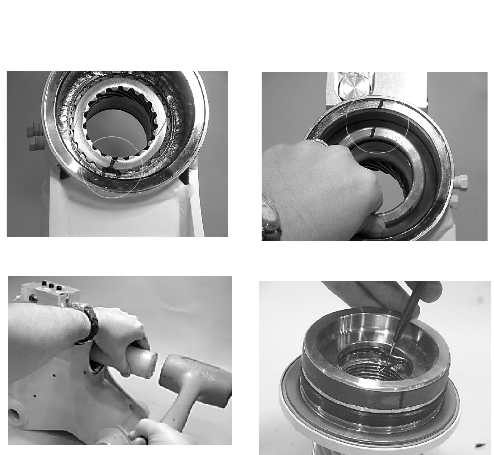
SECTION 4 - BOOM & PLATFORM
3121298 – JLG Lift – 4-23
11. Before removing piston (3), mark housing (1) ring gear in
relation to piston O.D. gear. There should be timing
marks on housing (1) ring gear, piston (3), and shaft (2).
12. To remove piston (3), use a rubber mallet and plastic
mandrel so piston is not damaged.
13. At the point when piston gear teeth come out of
engagement with housing gear teeth, mark piston and
housing with a marker as shown.
14. Remove O-ring (204) and backup ring (207) from end
cap (4) and set aside for inspection.
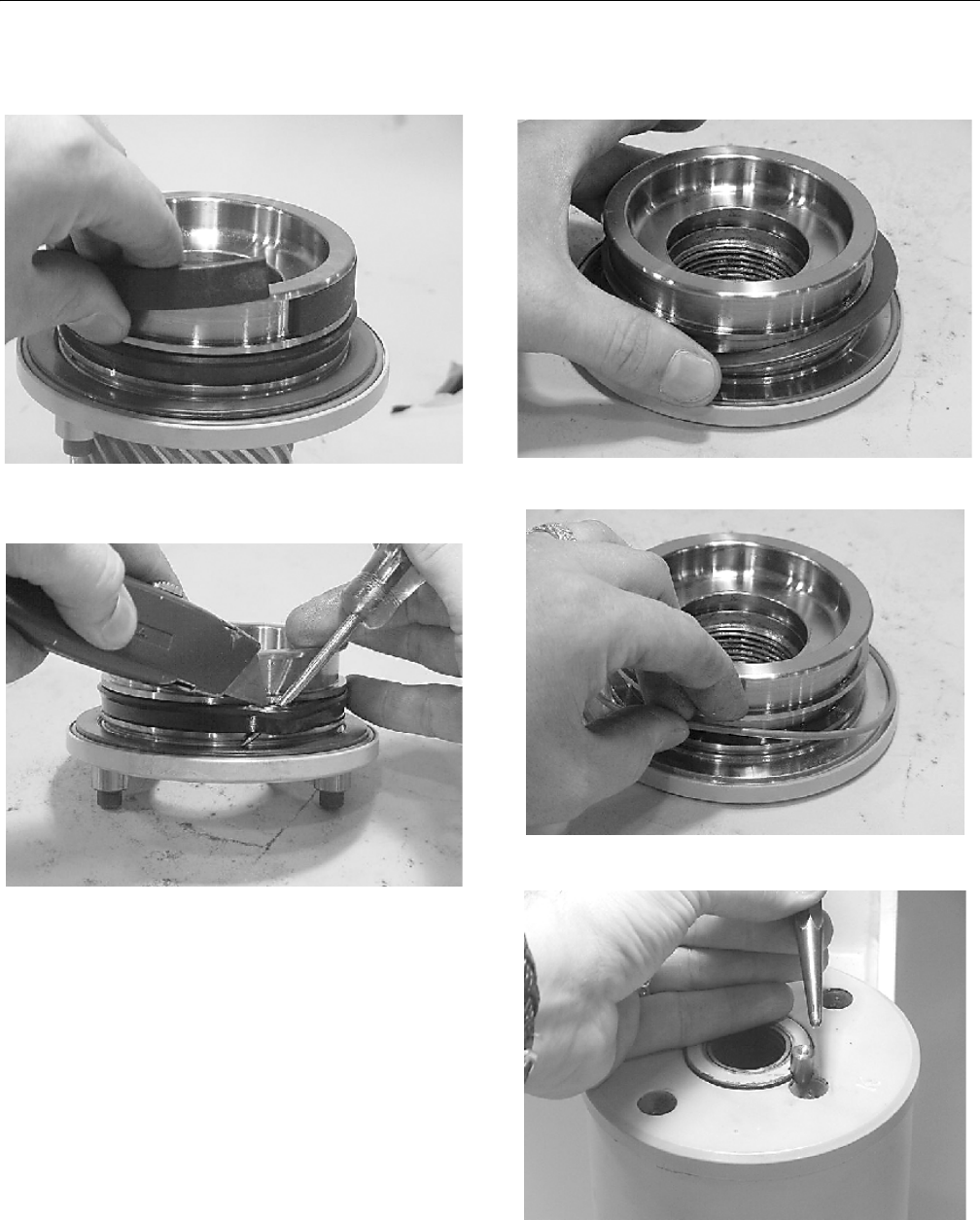
SECTION 4 - BOOM & PLATFORM
4-24 – JLG Lift – 3121298
15. Remove wear guides (302) from end cap (4) and shaft
(2).
16. To remove main pressure seals (205), cut them with a
sharp razor blade. Do not to damage seal groove.
17. Remove thrust washers (304) from end cap (4) and shaft
(2).
18. Remove wiper seal (304.1) from end cap (4) and shaft (2).
19. Remove piston O.D. seal (202).
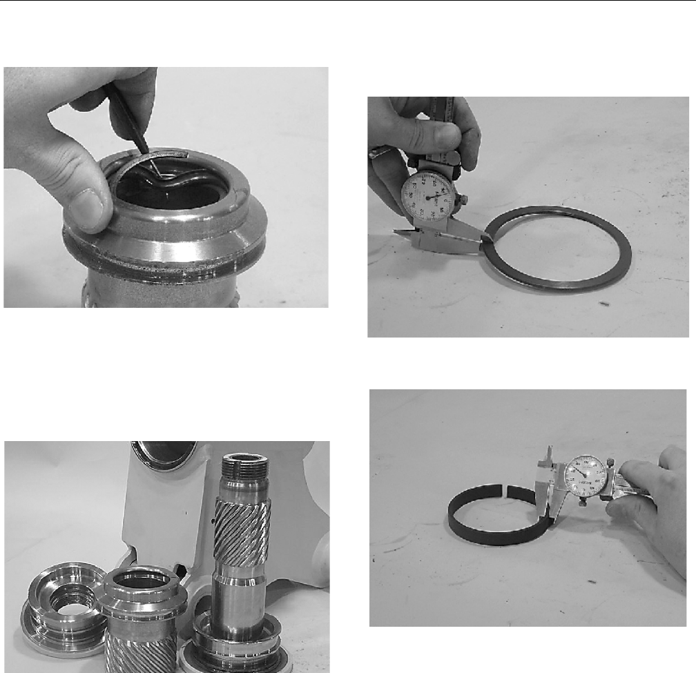
SECTION 4 - BOOM & PLATFORM
3121298 – JLG Lift – 4-25
20. Remove piston I.D. seal (200).
Inspection
1. Clean all parts in a solvent tank and dry with com-
pressed air before inspecting. Carefully inspect all criti-
cal areas for any surface finish abnormalities: Seal
grooves, bearing grooves, thrust surfaces, rod surface,
housing bore, and gear teeth.
2. Inspect thrust washers (304) for rough or worn edges
and surfaces. Measure thickness is within specifications
(Not less than 0.092” or 2.34 mm).
3. Inspect wear guide condition and measure thickness
(not less than 0.123” or 3.12 mm).
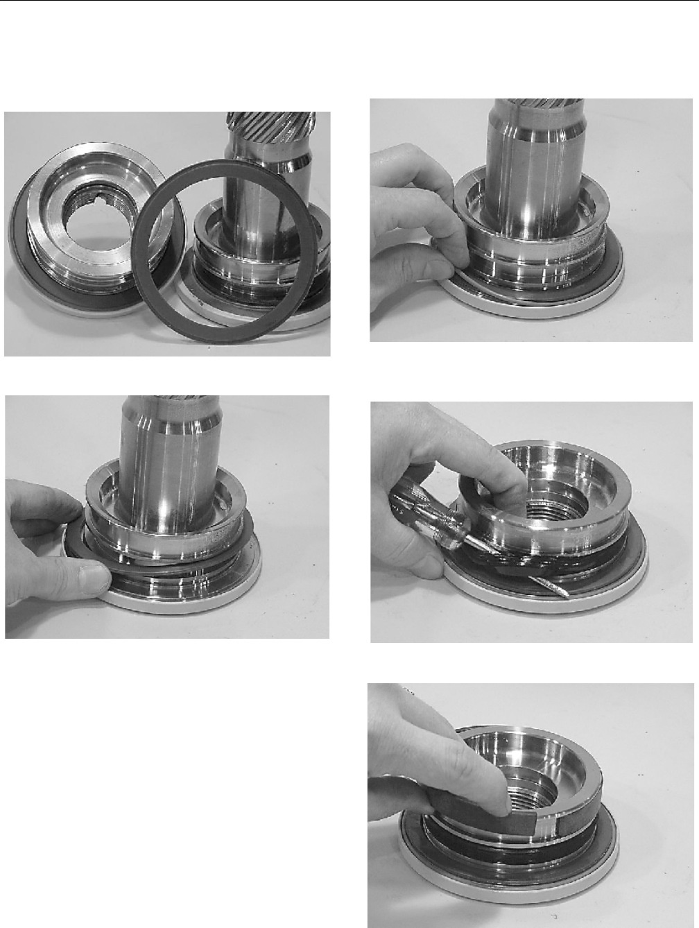
SECTION 4 - BOOM & PLATFORM
4-26 – JLG Lift – 3121298
Assembly
1. Gather all components and tools to one location. Use
cut away drawing to reference seal orientations.
2. Install thrust washer (304) on shaft (2) and end cap (4).
3. Install wiper seal (304.1/green 0-ring) in groove on shaft
(2) and end cap (4) - around outside edge of thrust
washer (304).
4. Use a seal tool install main pressure seal (205) on shaft
(2) and end cap (4). Use seal tool in a circular motion.
5. Install wear guide (302) on end cap (4) and shaft (2).
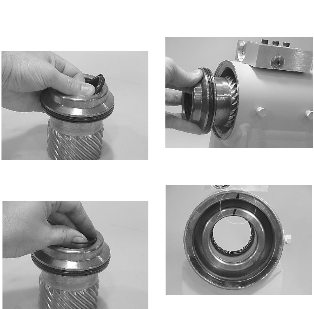
SECTION 4 - BOOM & PLATFORM
3121298 – JLG Lift – 4-27
6. Install inner T-seal (200) in piston (3) using a circular
motion. Install outer T-seal (202) by stretching it around
the groove in a circular motion. Each T-seal has two
back-up rings (see drawing for orientation).
7. Beginning with inner seal (200) insert one end of b/u
ring in lower groove and feed the rest in using a circular
motion. Make sure wedged ends overlap correctly.
Repeat for outer seal (202).
8. Insert piston (3) in housing (1) as shown, until outer pis-
ton seal (202) touches inside housing bore.
9. Looking from angle shown, rotate piston (3) until marks
you put on piston and housing (1) during disassembly
line up as shown. Using a rubber mallet, tap piston in
housing to point where gear teeth meet.
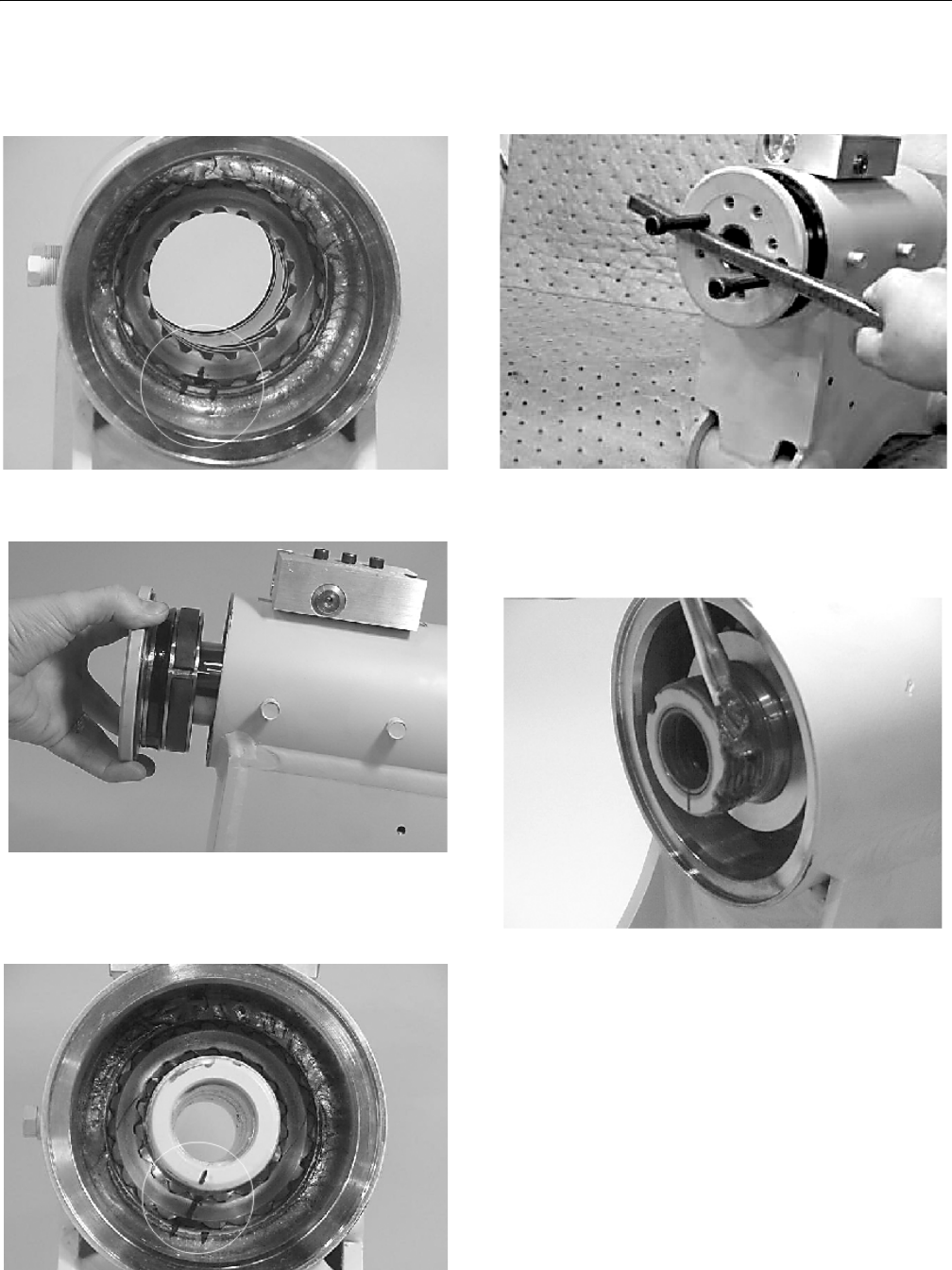
SECTION 4 - BOOM & PLATFORM
4-28 – JLG Lift – 3121298
10. Looking from opposite end of housing (1) when timing
marks line up, tap piston (3) in until gear teeth mesh
together. Tap piston in housing until it bottoms out.
11. Install shaft (2) in piston (3). Do not damage seals. Do
not engage piston gear teeth.
12. Looking from view shown, use existing timing marks to
line up gear teeth on shaft (2) with gear teeth on inside
of piston (3). Tap flange end of shaft with rubber mallet
until gear teeth engage.
13. Install 2 bolts in threaded holes in flange. Using a bar,
rotate shaft clockwise until wear guides are seated in
housing bore.
14. Install stop tube on shaft end. Stop tube is an available
option to limit actuator rotation.
15. Coat threads on end of shaft with anti-seize grease to
prevent galling.
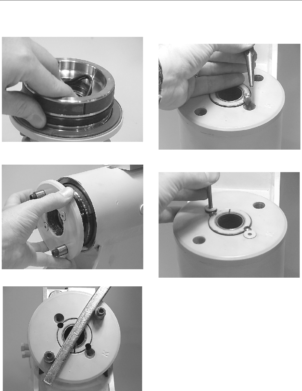
SECTION 4 - BOOM & PLATFORM
3121298 – JLG Lift – 4-29
16. Install 0-ring (204) and back-up ring (207) in inner seal
groove on end cap (4).
17. Thread end cap (4) on shaft (2) end. Ensure wear guide
stays in place on end cap as it is threaded in housing (1).
18. Tighten end cap (4). Ensure holes for lock pins line up.
19. Place lock pins (109) provided in Helac seal kit in holes
with dimple side up. Using a punch, tap lock pins to bot-
tom of hole.
20. Insert set screws (113) over lock pins. Tighten to 25 in-lb
(2.825 Nm).
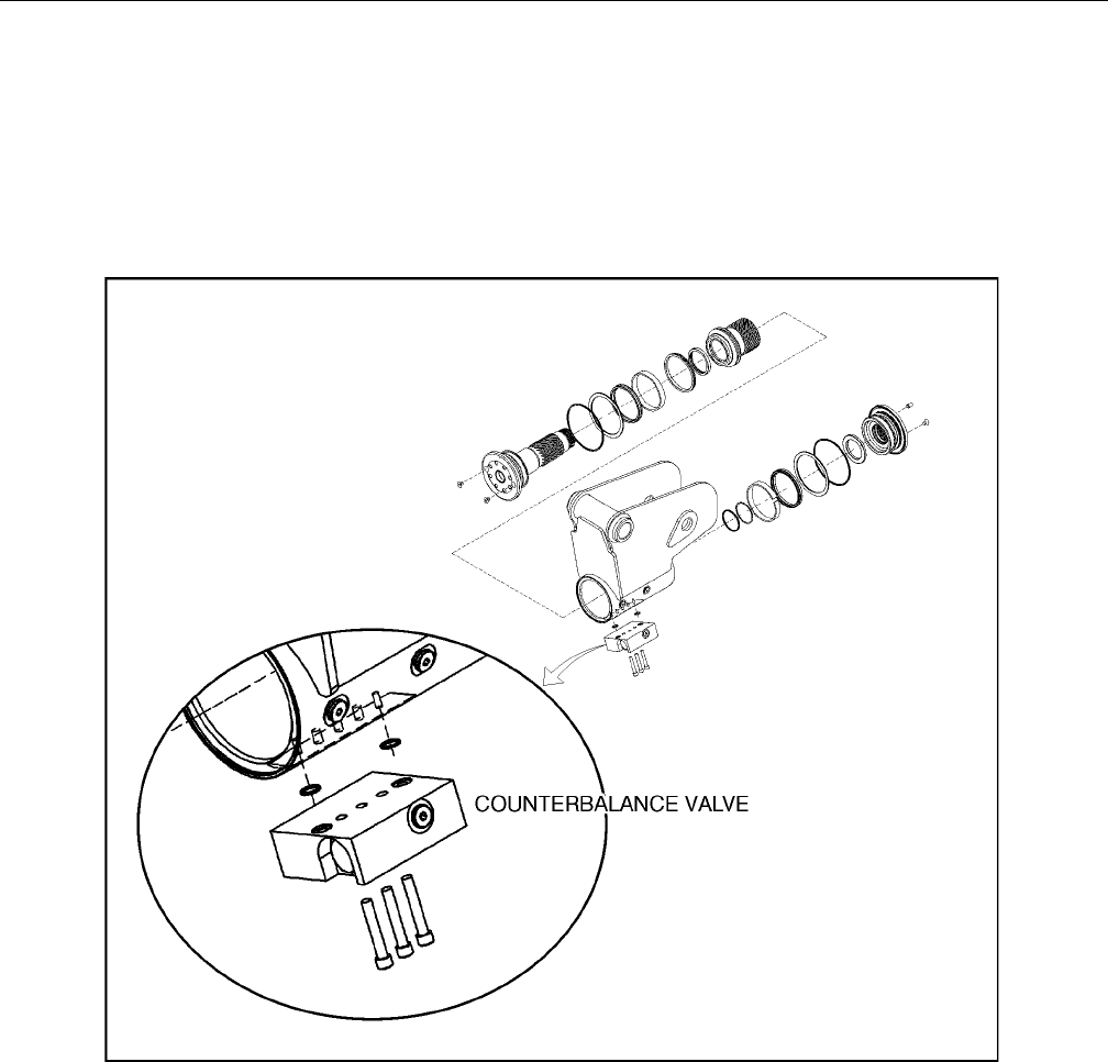
SECTION 4 - BOOM & PLATFORM
4-30 – JLG Lift – 3121298
Installing Counterbalance Valve
Refer to Figure 4-27., Rotator Counterbalance Valve.
1. Make sure surface of actuator is clean and free of any
contamination and debris, including old Loctite.
2. Make sure new valve has the O-rings in counterbores of
valve to seal it to the actuator housing.
3. Bolts that come with valve are Grade 8 bolts. Install new
bolts with a new valve. Apply Loctite #242 to shanks of
the three bolts at time of installation.
4. Torque 1/4-inch bolts 110-120 in-lb (12.4-13.5 Nm). Do
not torque over 125 in-lb (14.1 Nm). Torque 5/16-inch
bolts to 140 in-lb (15.8 Nm). Do not torque over 145 in-lb
(16.3 Nm).
Figure 4-27. Rotator Counterbalance Valve
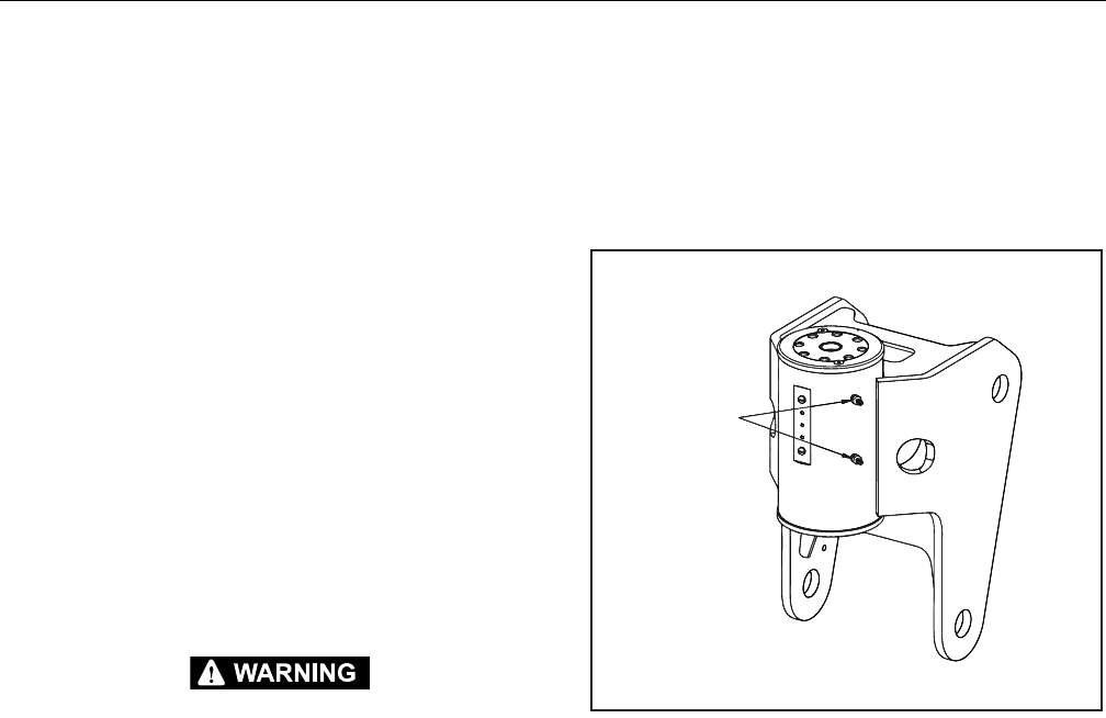
SECTION 4 - BOOM & PLATFORM
3121298 – JLG Lift – 4-31
Testing Actuator
If equipment is available, test actuator on a hydraulic test
bench. Breakaway pressure — the pressure at which the shaft
begins to rotate — should be approximately 400 psi (28 bar).
Cycle actuator at least 25 times at 3000 psi (210 bar) pressure.
After 25 rotations, increase pressure to 4500 psi (315 bar).
Check for leaks and cracks. Perform test again at end of rota-
tion in the opposite direction.
Testing Actuator for Internal LeakS
If actuator is equipped with a counterbalance valve, plug valve
ports, connect hydraulic lines to housing ports. Bleed all air
from actuator (see Installation and Bleeding). Rotate shaft to
end of rotation at 3000 psi (210 bar) and maintain pressure.
Remove hydraulic line from non-pressurized side.
Continuous oil flow from open housing port indicates internal
leakage across the piston. Replace line and rotate shaft to end
of rotation in opposite direction. Repeat test procedure out-
lined above for other port. If there is an internal leak, disassem-
ble, inspect, and repair.
Installation and Bleeding
AFTER INSTALLING ACTUATOR, IT IS IMPORTANT THAT ALL SAFETY DEVICES
SUCH AS TIE RODS OR SAFETY CABLES ARE PROPERLY REATTACHED.
To purge air from hydraulic lines, connect them together to
create a closed loop and pump hydraulic fluid through them.
Review hydraulic schematic to determine which hydraulic
lines to connect. The linear feet and inside diameter of hydrau-
lic supply lines together with pump capacity determine
amount of pumping time required to fully purge the hydraulic
system.
Bleeding may be necessary if excessive backlash is exhibited
after actuator is connected to hydraulic system. The following
steps are recommended when a minimum of two gal (8L) is
purged.
1. Connect a 3/16" inside diameter x 5/16" outside diame-
ter x 5 foot clear, vinyl drain tube to each of the two
bleed nipples. Secure with hose clamps. Place vinyl
tubes in a clean 5-gallon container to collect purged oil.
2. Oil can be returned to reservoir after procedure is com-
pleted.
Figure 4-28. Actuator Bleed Ports
3. With an operator in the platform, open both bleed nip-
ples 1/4 turn. Hydraulically rotate platform to end of
rotation (clockwise or counterclockwise), and maintain
hydraulic pressure. Oil with small air bubbles will be
seen flowing through the tubes. Allow 1/2 gallon of fluid
to be purged from actuator.
4. Keep fittings open and rotate platform in opposite
direction to end position. Maintain hydraulic pressure
until an additional 1/4 gallon of fluid is pumped into the
container.
5. Repeat steps 2 & 3. After last 1/2 gallon is purged, close
both bleed nipples before rotating away from end posi-
tion.

SECTION 4 - BOOM & PLATFORM
4-32 – JLG Lift – 3121298
Troubleshooting
Table 4-1. Troubleshooting
Problem Cause Solution
1. Shaft rotates slowly or not at all a. In su ff ic ie nt t orq ue ou tp ut
b. Low ra te o f f lu id fl ow
c. Control or counterbalance valve has internal leak
d. Piston and/or shaft seal leak
e. Corrosion build-up on the thrust surfaces
f. Swollen seals and composite bearings caused by incom-
patible hydraulic fluid
a. Verify correct operating pressure. Do not exceed OEM’s
pressure specifications. Load may be above maximum
capacity of the actuator.
b. Inspect ports for obstructions and hydraulic lines for
restrictions and leaks.
c. Disconnect hydraulic lines and bypass valve. Leave valve
ports open and operate actuator through housing ports (do
not exceed OEM’s operating pressure). Valve must be
replaced if a steady flow of fluid is seen coming from valve
ports.
d. Remove plug and housing’s valve ports. Operate actuator
through housing ports. Conduct internal leakage test.
e. Rebuild actuator. Remove all rust then polish. Replace-
ment parts may be needed.
f. Rebuild actuator. Use fluid compatible with all seals and
bearings.
2. Operation is erratic or not responsive a. Ai r i n ac t uat or a. Purge air from actuator. See bleeding procedures.
3. Shaft will not fully rotate a. Twisted or chipped gear teeth
b. Port fittings are obstructing the piston
a . Ch ec k f or ge ar b in di ng. Ac tu ato r m ay not be ab le to b e
rebuilt and may need to be replaced. Damage could be a
result of overload or shock.
b. C he ck th re ad le ng th of por t fi tt in gs. Fit tin gs sh ou ld dur -
ing stroke not reach inside housing bore.
4. Selected position cannot be maintained a. Control or counterbalance valve has internal leak
b. Piston and/or shaft seal leak
c. Ai r i n ac t uat or
a. Disconnect hydraulic lines and bypass valve. Leave valve
ports open and operate actuator through housing ports (do
not exceed OEM’s operating pressure). Valve must be
replaced if a steady flow of fluid is seen coming from valve
ports.
b. Remove plug and housing’s valve ports. Operate actuator
through housing ports. Conduct internal leakage test.
c. Purge air from actuator. See bleeding procedures
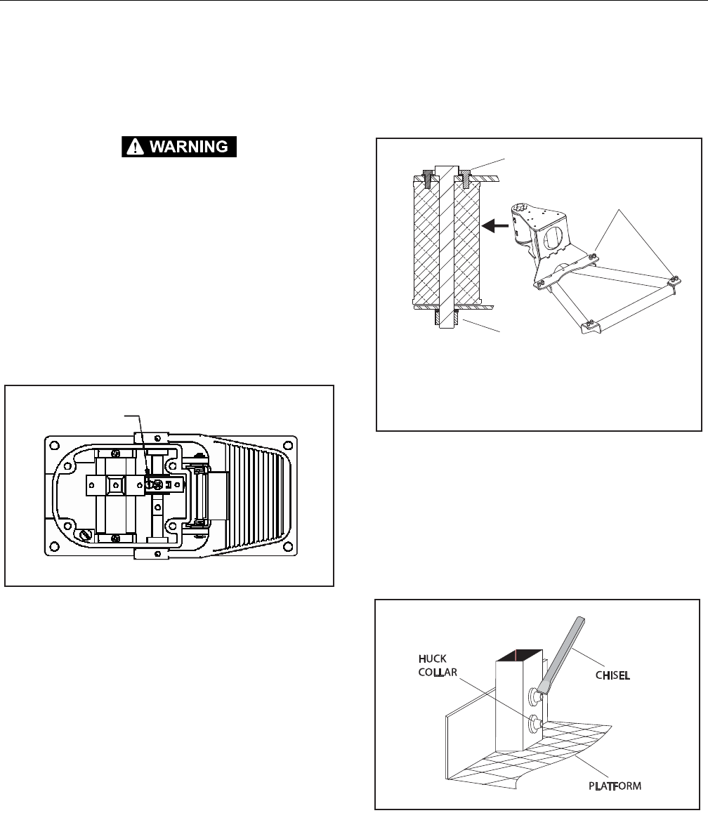
SECTION 4 - BOOM & PLATFORM
3121298 – JLG Lift – 4-33
4.10 FOOT SWITCH ADJUSTMENT
Adjust foot switch to operate functions when pedal is at center
of travel. Adjust if switch operates within last 1/2 in. (6.35 mm)
of top or bottom travel.
ELECTRIC SHOCK OR UNCONTROLLED MACHINE MOVEMENT CAN CAUSE
DEATH OR SERIOUS INJURY. DISCONNECT INPUT POWER BEFORE PERFORM-
ING INSTALLATION OR MAINTENANCE.
NOTE: For models with two switches, both switches can be inde-
pendently adjusted.
1. Remove four socket head cap screws and cover from
foot switch assembly.
2. To increase travel before switch is activated, turn Adjust-
ment Screw clockwise.
3. To decrease travel before switch is activated, turn
Adjustment Screw counter-clockwise.
Figure 4-29. Foot Switch Adjustment
4. Install cover and secure with four socket head caps
crews. Torque to 18-22 in-lb (2-3 Nm).
4.11 PLATFORM
Platform Support Torque Settings
NOTE: If any rotator bolts are replaced, re-torque all rotator bolts.
Figure 4-30. Platform Support Torque Values
Replace Platform Sections
The platform is made up of five sections: floor, right side, left
side, back (console box mounting.), and gate. Sections are
secured with Huck magna grip fastener and collars.
1. Support Huck collar with a suitable support.
2. Using a hammer and chisel, remove collar from fastener.
Figure 4-31. Platform Section Replacement
3. Replace Huck fasteners with 1/4 x 20 NC x 2 1/4" grade 5
bolts, flat washers, and locknuts when installing new
section of platform.
4. Replace rivets with 1/4 x 20 NC x 2 “grade 5 bolts, flat
washers, and locknuts when installing a new gate to
platform.
!
!
"#$%&"'()*
&&
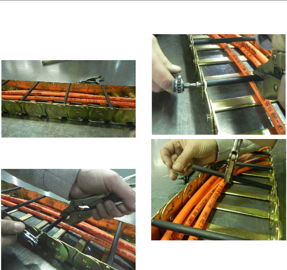
SECTION 4 - BOOM & PLATFORM
4-34 – JLG Lift – 3121298
4.12 POWERTRACK MAINTENANCE
Remove Link
NOTE: Hoses shown in powertrack are for example only. Actual
hose and cable arrangements are different.
1. Clamp bar and poly roller tightly so they do not spin
when removing screw. With a small ¼” ratchet and a T-
20 Torx bit, remove 8-32 x 0.500 screw from one side.
2. Repeat step 1 and remove screw from other side of
track. Remove bar/poly roller from powertrack.
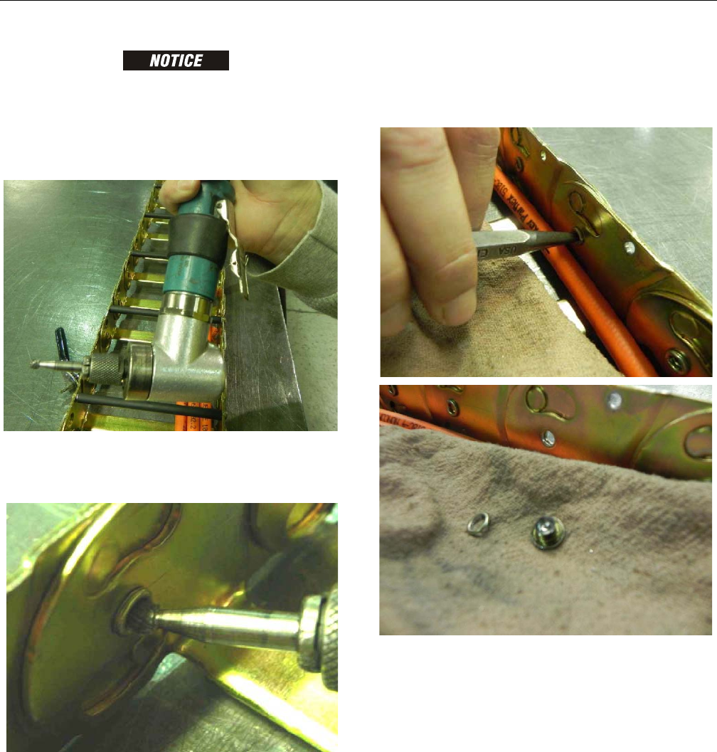
SECTION 4 - BOOM & PLATFORM
3121298 – JLG Lift – 4-35
REPOSITION CABLES/HOSES. KEEP COVERED DURING GRINDING TO PREVENT
DAMAGE.
3. To remove a link, rivets holding links together must be
removed. Use a right-angle pneumatic die grinder with
a ¼” ball double cut bur attachment.
4. insert tool into rolled over end of rivet. Grind out middle
of rivet until rolled over part of rivet falls off. Repeat for
all rivets to be removed.
5. After grinding it may be necessary to use a center punch
with a hammer to remove rivet.
NOTE: It may be necessary to loosen fixed end brackets from
machine to move track section enough to disconnect links.
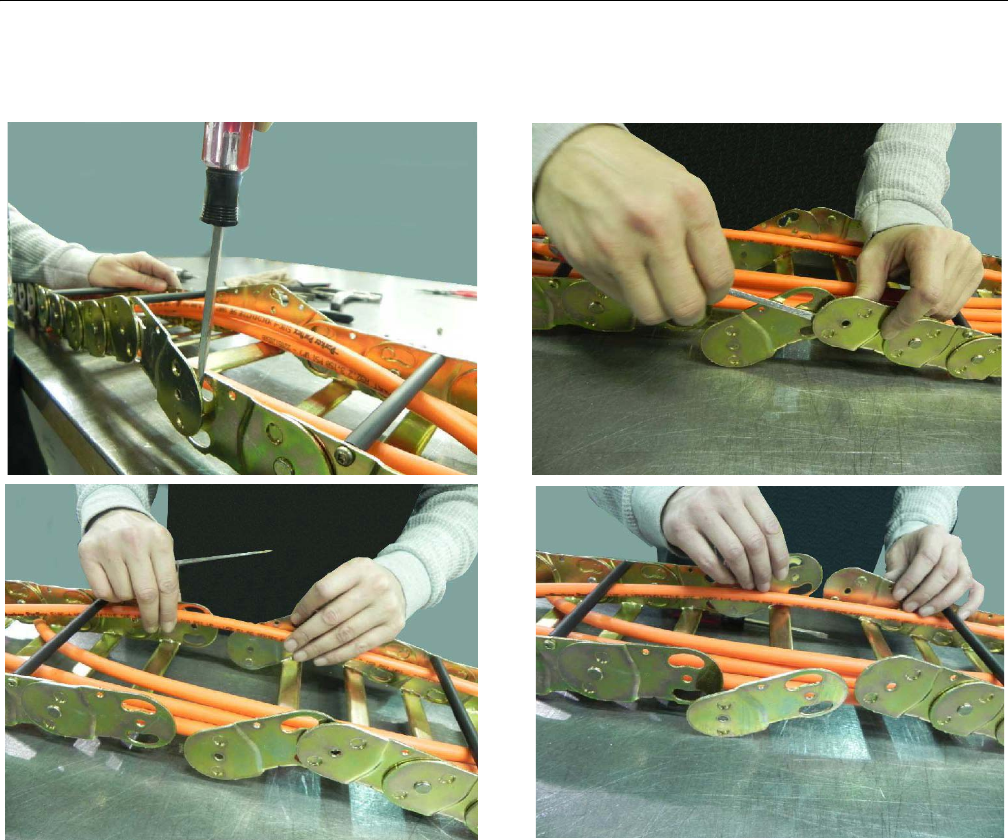
SECTION 4 - BOOM & PLATFORM
4-36 – JLG Lift – 3121298
6. Insert flat head screwdriver between links. Twist and pull
links apart.
7. Remove link from other section of powertrack using
screwdriver.
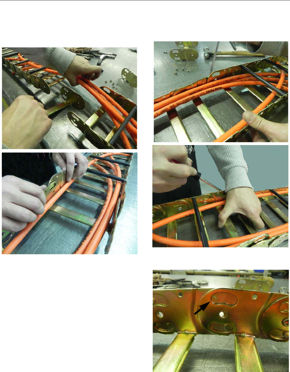
SECTION 4 - BOOM & PLATFORM
3121298 – JLG Lift – 4-37
Install New Link
1. Squeeze cut-out end of new link into half-shear (female)
end of track section.
2. Spread half-shear (female) end of new link and slide cut-
out end of track section into it. Use screwdriver if neces-
sary.
3. Round half-shears will not fit properly in cut-outs after
new link is installed .
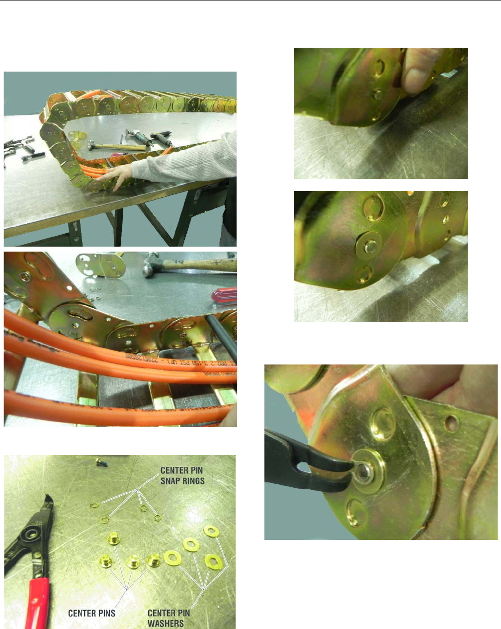
SECTION 4 - BOOM & PLATFORM
4-38 – JLG Lift – 3121298
4. Pull moving end over track so new connection is posi-
tioned in curve of powertrack. Round half-shears will
rotate into cut-outs.
5. Parts shown below connect new link to powertrack.
6. Push pin through center hole. Slide washer on pin.
7. Install snap ring in groove on pin. Repeat pin installation
steps for all center holes with rivets removed.
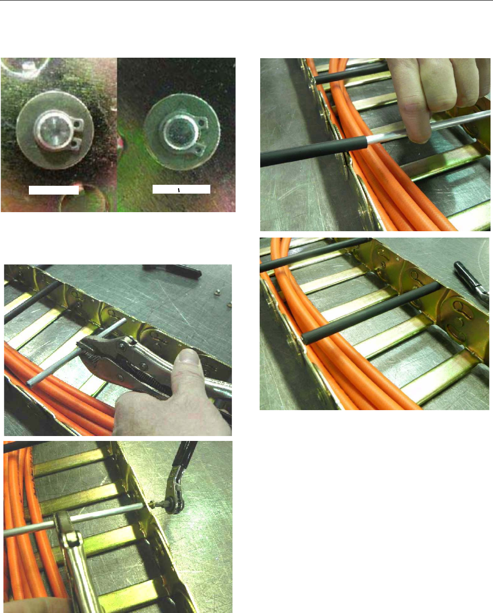
SECTION 4 - BOOM & PLATFORM
3121298 – JLG Lift – 4-39
NOTE: Make sure snap rings are seated in pin groove and closed
properly.
1. Install new 8-32 x 0.500 self-threading Torx head screw
in end of new aluminum round bar. Torque to 18-20 in-
lb (2-2.25 Nm).
2. Pull up on other end of round bar. Slide new poly roller
on bar.
Correct Incorrect
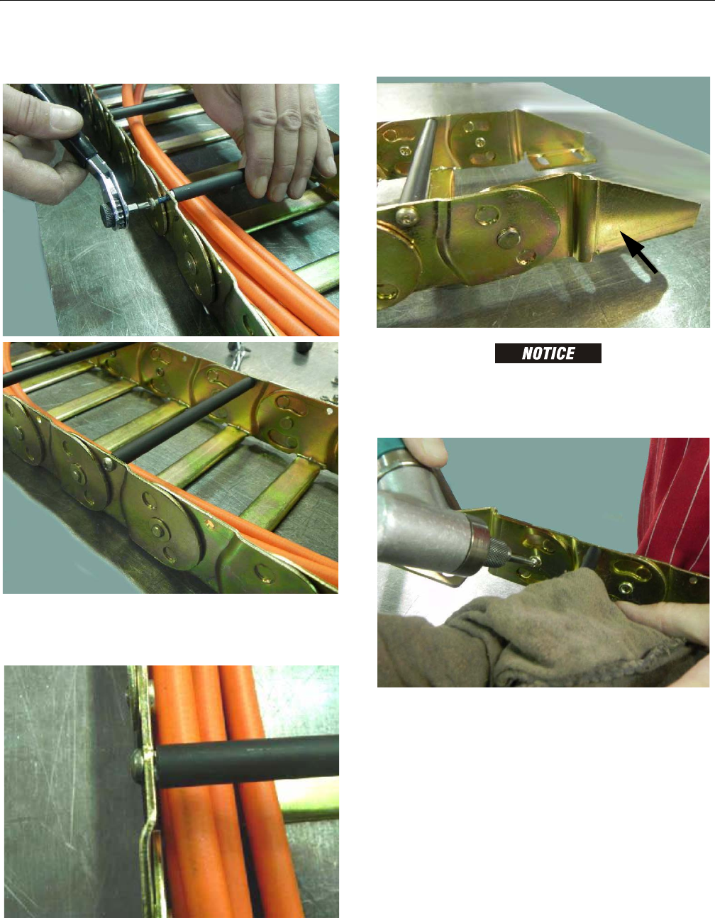
SECTION 4 - BOOM & PLATFORM
4-40 – JLG Lift – 3121298
3. Install new 8-32 x 0.500 self threading screw on other
side. Torque to 18-20 in-lb (2-2.25 Nm).
NOTE: When tightening screws make sure screw head is seated
against link with no space in between link and underside of
screw head.
Replace Fixed End Brackets
REPOSITION CABLES/HOSES. KEEP COVERED DURING GRINDING TO PREVENT
DAMAGE.
1. Remove rivets as shown in link removal instructions..
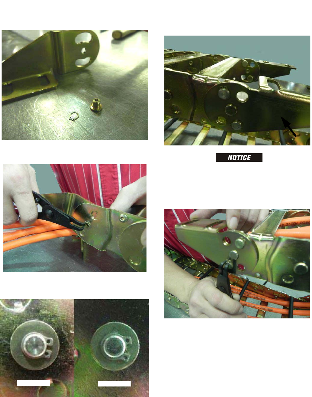
SECTION 4 - BOOM & PLATFORM
3121298 – JLG Lift – 4-41
2. Parts used: Bracket Center Pin and Center Pin Snap Ring.
3. Take new bracket and install bracket center pin and
snap ring. Repeat on other bracket if replacing it.
NOTE: Ensure snap rings are seated in pin groove and closed
properly.
Replace Moving End Brackets
REPOSITION CABLES AND HOSES. KEEP COVERED DURING GRINDING TO PRE-
VENT DAMAGE.
1. Remove existing pins and center rivet. Remove rivet as
shown in link removal instructions on page 4-20. Repeat
on other bracket if replaced.
Correct Incorrect
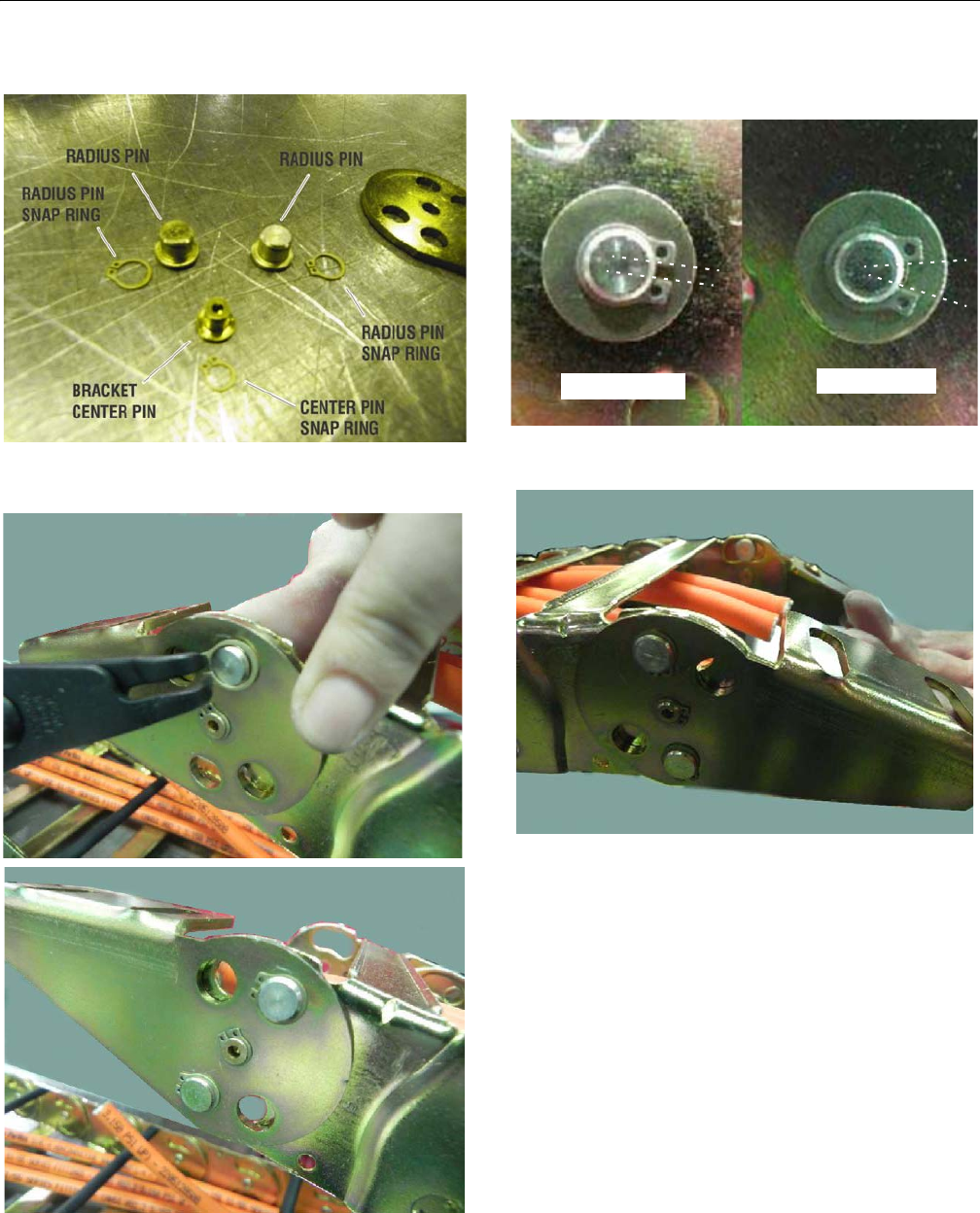
SECTION 4 - BOOM & PLATFORM
4-42 – JLG Lift – 3121298
2. Install center pin with snap ring in new bracket.
3. Install radius pins and snap rings in original locations.
Repeat with other moving end if replaced.
NOTE: Ensure snap rings are seated in pin groove and closed
properly.
1. Make sure both brackets rotate correctly.
Incorrect
Correct
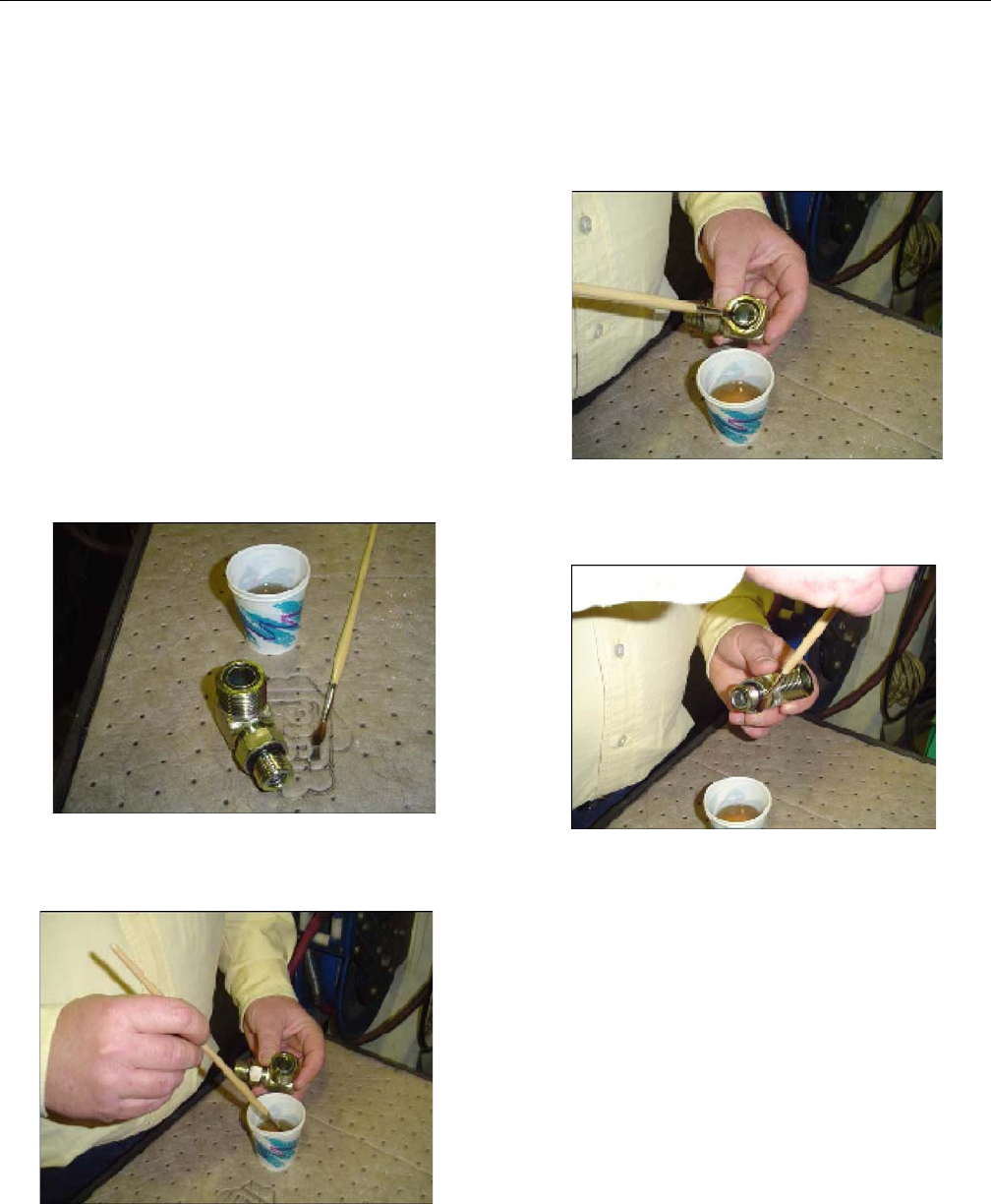
SECTION 5 - HYDRAULICS
3121298 – JLG Lift – 5-1
SECTION 5. HYDRAULICS
5.1 O-RING LUBRICATION
When assembling connectors, all fittings with O-rings must be
lubricated with hydraulic oil before assembly. There are four
methods of lubricating O-rings:
1. Cup and Brush
2. Dip
3. Spray
4. Brush-On
Cup and Brush
Tools needed:
• Small container for hydraulic oil
• Small paint brush
1. Hold fitting in one hand and dip brush into container
with other hand. Remove excess hydraulic oil from
brush so an even film of oil is applied to O-ring.
2. Hold fitting over hydraulic oil container and brush an
even film of oil around entire O-ring in fitting. Make sure
O-ring is completely saturated.
3. Turn fitting over and repeat previous step to O-ring on
other side of fitting. Make sure entire O-ring is coated
with hydraulic oil.
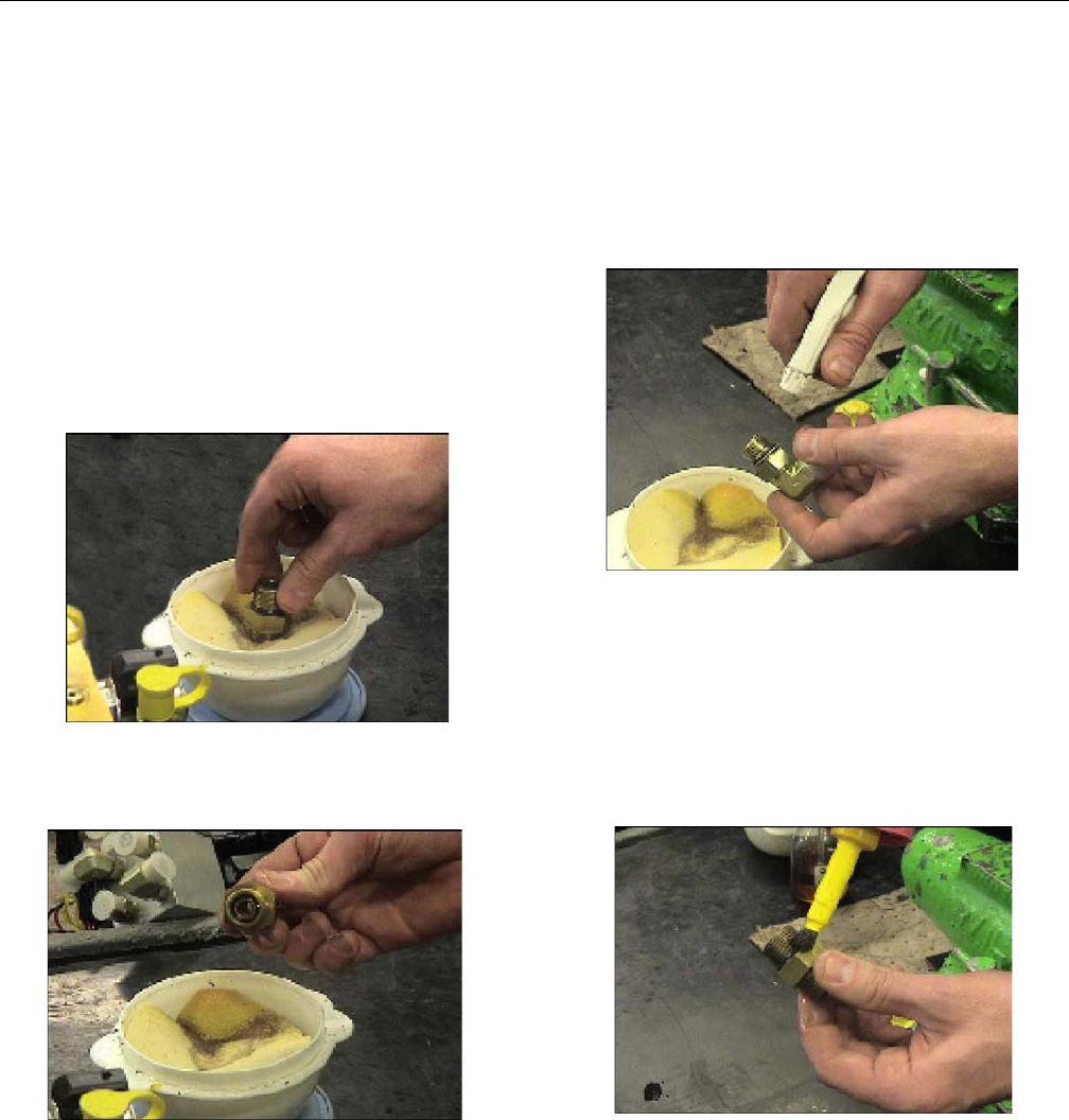
SECTION 5 - HYDRAULICS
5-2 – JLG Lift – 3121298
Dip
NOTE: This method works best with Face Seal O-rings, but will
work for all O-ring fitting types.
Tools needed:
• Small leak proof container
• Sponge cut to fit inside container
• Small amount of hydraulic oil to saturate sponge.
1. Place sponge inside container and add hydraulic oil to
sponge until fully saturated.
2. Dip fitting into sponge using firm pressure.
3. After lifting fitting, a small droplet should form and drip
from bottom of fitting. This indicates an even coating of
oil.
NOTE: O-ring boss-type fittings require more pressure to immerse
more of fitting into saturated sponge. This also causes
more oil to be dispersed from sponge.
Spray
This method requires a pump or trigger spray bottle.
1. Fill spray bottle with hydraulic oil.
2. Hold fitting over suitable catch can.
3. Spray entire O-ring surface with medium coat of oil.
Brush-On
This method requires a sealed bottle brush.
1. Fill bottle with hydraulic oil.
2. Using slight pressure to body of spray bottle, invert bot-
tle so brush end faces down.
3. Brush an even coat of hydraulic oil on entire O-ring.
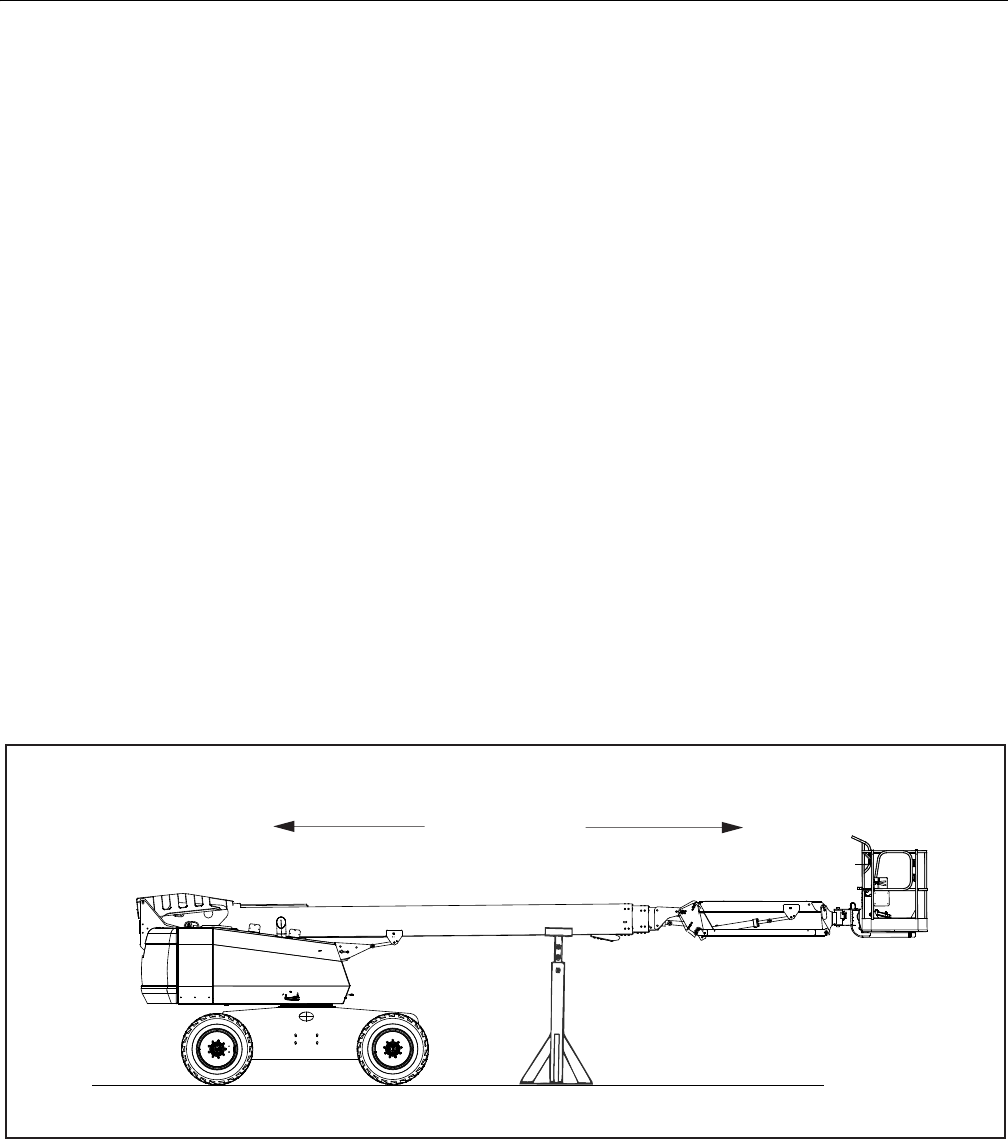
SECTION 5 - HYDRAULICS
3121298 – JLG Lift – 5-3
5.2 CYLINDERS - THEORY OF OPERATION
Systems With Double Acting Cylinders
Systems with double acting cylinders are the Slave Level, Mas-
ter Level, Lift, Telescope, Articulating Jib Boom Lift, Axle Lock-
out, and Steer. A double acting cylinder is one that requires oil
flow to operate the cylinder rod in both directions. Directing
oil (by actuating the corresponding control valve to piston
side of cylinder) forces the piston to travel toward the rod end
of the barrel, extending the cylinder rod (piston attached to
rod). When oil flow is stopped, movement of rod stops. By
directing oil to the rod side of the cylinder, the piston is forced
in the opposite direction and the cylinder rod retracts.
Systems With Holding Valves
Holding valves are used in the Lift, Telescope, Lockout, Slave
Level, and Articulating Jib Boom Lift circuits to prevent retrac-
tion of the cylinder rod should a hydraulic line rupture or a
leak develop between the cylinder and its control valve.
5.3 CYLINDER CHECKING PROCEDURE
NOTE: Cylinder check must be performed anytime a system com-
ponent is replaced or when improper system operation is
suspected.
Cylinders Without Counterbalance Valves - Master
Cylinder and Steer Cylinder
1. Using all applicable safety precautions, activate engine
and fully extend cylinder to be checked. Shut down
engine.
2. Carefully disconnect hydraulic hoses from retract port of
cylinder. There will be some initial weeping of hydraulic
fluid which can be caught in a suitable container. After
initial discharge, there should be no further drainage
from the retract port.
3. Activate engine and extend cylinder.
4. If cylinder retract port leakage is less than 6-8 drops per
minute, carefully reconnect hose to port and retract cyl-
inder. If leakage continues at a rate of 6-8 drops per min-
ute or more, repair cylinder.
5. With cylinder fully retracted, shut down engine and
carefully disconnect hydraulic hose from cylinder
extend port.
6. Activate engine and retract cylinder. Check extend port
for leakage.
7. If extend port leakage is less than 6-8 drops per minute,
carefully reconnect hose to extend port, then activate
cylinder through one complete cycle and check for
leaks. If leakage continues at a rate of 6-8 drops per min-
ute or more, repair cylinder.
Figure 5-1. Boom Positioning and Support, Cylinder Repair

SECTION 5 - HYDRAULICS
5-4 – JLG Lift – 3121298
Cylinders With Single Counterbalance Valve
(Upper Lift Cylinder)
OPERATE ALL FUNCTIONS FROM GROUND CONTROL STATION ONLY.
1. Using all applicable safety precautions, activate hydrau-
lic system.
WHEN WORKING ON MAIN LIFT CYLINDER, RAISE BOOM TO HORIZONTAL AND
PLACE A BOOM PROP APPROXIMATELY 1 INCH (2.54 CM) BELOW THE MAIN
BOOM. DO NOT WORK ON CYLINDER WITHOUT A SUITABLE PROP IN PLACE.
2. Shut down hydraulic system and allow machine to sit for
10-15 minutes. If machine is equipped with proportional
control valves, turn IGNITION SWITCH to ON, move con-
trol switch or lever for applicable cylinder in each direc-
tion, then turn IGNITION SWITCH to OFF. If machine is
equipped with hydraulic control valves, move control
lever for applicable cylinder in each direction. This is
done to relieve hydraulic line pressure. Carefully remove
hydraulic hoses from appropriate cylinder port block.
3. There will be initial weeping of hydraulic fluid, which
can be caught in a suitable container. After initial dis-
charge, there should be no further leakage from the
ports. If leakage continues at a rate of 6-8 drops per min-
ute or more, counterbalance valve is defective and must
be replaced.
4. To check piston seals, carefully remove counterbalance
valve from the retract port. After initial discharge, there
should be no further leakage from the ports. If leakage
occurs at a rate of 6-8 drops per minute or more, piston
seals are defective and must be replaced.
5. If no repairs are necessary or when repairs have been
made, replace counterbalance valve and connect
hydraulic hoses to cylinder port block.
6. If used, remove lifting device from upright or remove
prop from below main boom. Activate hydraulic system
and run cylinder through one complete cycle to check
for leaks.
Cylinders With Dual Counterbalance Valves
(Articulating Jib Boom Lift, and Slave), Slave Level, Lower Lift,
Upright level, Main Telescope and Tower Telescope)
OPERATE ALL FUNCTIONS FROM GROUND CONTROL STATION ONLY.
1. Using all applicable safety precautions, activate hydrau-
lic system.
IF WORKING ON TOWER BOOM LIFT CYLINDER, RAISE TOWER BOOM HALF-
WAY, FULLY ELEVATE MAIN BOOM WITH TELESCOPE CYLINDER FULLY
RETRACTED. ATTACH AN OVERHEAD CRANE TO THE UPRIGHT FOR SUPPORT,
LEAVING APPROXIMATELY 1 INCH (2.54 CM) OF SLACK IN CHAIN OR SLING FOR
TEST PURPOSES. IF WORKING ON THE UPRIGHT LEVEL, RAISE TOWER BOOM
HALFWAY, THEN RAISE MAIN BOOM TO HORIZONTAL AND POSITION A SUIT-
ABLE BOOM PROP APPROXIMATELY 1 INCH (2.54 CM) BELOW MAIN BOOM. IF
WORKING ON PLATFORM LEVEL CYLINDER, STROKE PLATFORM LEVEL CYLIN-
DER FORWARD UNTIL PLATFORM SITS AT A 45 DEGREES ANGLE.
2. Shut down hydraulic system and allow machine to sit for
10-15 minutes. If machine is equipped with proportional
control valves, turn IGNITION SWITCH to ON, move con-
trol switch or lever for applicable cylinder in each direc-
tion, then turn IGNITION SWITCH to OFF. If machine is
equipped with hydraulic control valves, move control
lever for applicable cylinder in each direction. This is
done to relieve hydraulic line pressure. Carefully remove
hydraulic hoses from appropriate cylinder port block.
3. There will be initial weeping of hydraulic fluid, which
can be caught in a suitable container. After initial dis-
charge, there should be no further leakage from the
ports. If leakage continues at a rate of 6-8 drops per min-
ute or more, counterbalance valve is defective and must
be replaced.
4. To check piston seals, carefully remove the counterbal-
ance valve from the retract port. After initial discharge,
there should be no further leakage from the ports. If
leakage occurs at a rate of 6-8 drops per minute or more,
the piston seals are defective and must be replaced.
5. If no repairs are necessary or when repairs have been
made, replace counterbalance valve and carefully con-
nect hydraulic hoses to cylinder port block.
6. Remove lifting device from upright or remove prop from
below main boom. Activate hydraulic system and run
cylinder through one complete cycle to check for leaks.

SECTION 5 - HYDRAULICS
3121298 – JLG Lift – 5-5
5.4 CYLINDER REMOVAL AND INSTALLATION
Main Boom Telescope Cylinder Removal
1. Place machine on a flat and level surface, with main
boom in the horizontal position.
2. Shut down engine. Support main boom basket end with
a prop. (See Figure 5-1., Boom Positioning and Support,
Cylinder Repair).
CAP HYDRAULIC LINES AND PORTS IMMEDIATELY AFTER DISCONNECTING
LINES TO PREVENT ENTRY OF CONTAMINANTS INTO THE SYSTEM.
3. Tag and disconnect hydraulic lines to telescope cylinder.
Use a suitable container to retain residual hydraulic fluid.
Cap hydraulic lines and ports.
4. Remove hardware securing cover plate on bottom of
base boom section and remove cover.
DO NOT ALLOW CABLE TO ROTATE. THIS MAY DAMAGE THE CABLE.
5. Clamp both threaded ends of cable to prevent rotation.
Note: Do not clamp on threads. Remove jam nuts and
loosen adjustment nuts so there is slack in the cables.
(See Section 4 - Boom & Platform).
6. Remove hardware securing push bar to turntable and
telescope cylinder.
7. Using a suitable brass drift, carefully drive push bar pins
from telescope cylinder rod and turntable.
8. Remove hardware securing cable adjustment block to
aft end of the base boom section and remove block.
9. Remove hardware securing telescope cylinder to aft end
of mid boom section.
WHEN REMOVING TELESCOPE CYLINDER FROM BOOM, IT MAY BE NECESSARY
AT SOME POINT TO TURN CYLINDER SLIGHTLY IN ORDER TO CLEAR ASSEM-
BLIES MOUNTED IN THE BOOM. MOVE CYLINDER SLOWLY INTO POSITION OR
DAMAGE TO COMPONENTS MAY RESULT FROM FORCIBLE IMPACT WITH THESE
ASSEMBLIES.
10. Remove bolts securing cable attach bar to top of fly
boom section.
11. Pull telescope cylinder and cables partially from aft end
of base boom section. Secure cylinder with a suitable
sling and lifting device at center of gravity.
12. Carefully remove telescope cylinder and sheave assem-
bly. Place telescope cylinder on a suitable trestle.
Main Boom Telescope Cylinder Installation
1. Route extend cables around extend sheave and secure
cables to the telescope cylinder.
2. Install extend cables mounting blocks to threaded ends
of cables. Loosely install nuts and jam nuts on threaded
end of cables.
DO NOT TO TWIST OR CROSS CABLES DURING INSTALLATION.
3. Secure sling and lifting device at telescope cylinder’s
center of gravity. Lift cylinder to aft end of boom assem-
bly.
4. Install extend cable mounting blocks to threaded ends
of cables. Loosely install nuts and jam nuts on threaded
ends of cables.
WHEN INSERTING TELESCOPE CYLINDER INTO BOOM, IT MAY BE NECESSARY
TO TURN CYLINDER SLIGHTLY TO CLEAR ASSEMBLIES MOUNTED IN THE
BOOM. MOVE CYLINDER SLOWLY INTO POSITION OR DAMAGE TO COMPO-
NENTS MAY RESULT FROM FORCIBLE IMPACT WITH THESE ASSEMBLIES.
5. Carefully install telescope cylinder barrel end support
into slots in mid boom and secure with blocks and bolts.
Use Loctite #242 on bolts.
6. Align holes in aft end of fly boom section with holes in
cable mounting block. Secure with mounting hardware.
7. Align holes in aft end of base boom section with holes in
cable mounting block. Secure with mounting hardware.
8. Remove cylinder port plugs and hydraulic line caps. Cor-
rectly attach lines to cylinder ports.
9. Align holes in rod end of telescope cylinder with holes in
push bar. Install push bar pin and secure with mounting
hardware.
10. Align holes in push bar with holes in turntable. Install
push bar pin and secure with mounting hardware.
NOTE: Boom cables must be torqued after telescope cylin-
der installation. (See Section 4.1, Boom Rope Torqu-
ing Procedures)

SECTION 5 - HYDRAULICS
5-6 – JLG Lift – 3121298
Main Boom Lift Cylinder Removal
1. Place machine on a flat and level surface. Start engine
and place main boom in horizontal position. Shut down
engine and prop boom. (See Figure 5-1., Boom Position-
ing and Support, Cylinder Repair)
2. Remove hardware retaining cylinder rod attach pin to
boom. Using a suitable brass drift, drive out cylinder rod
pin.
3. Using auxiliary power, retract the lift cylinder rod com-
pletely.
4. Disconnect, cap and tag the main boom lift cylinder
hydraulic lines and ports.
5. Remove barrel end attach pin retaining hardware. Using
a suitable brass drift drive out the barrel end attach pin
from the turntable.
6. Remove the cylinder from the turntable and place in a
suitable work area.
Main Boom Lift Cylinder Installation
1. Install lift cylinder in place using suitable slings or sup-
ports, aligning attach pin mounting holes on the turnta-
ble.
2. Using a suitable drift, drive barrel end attach pin
through mounting holes in lift cylinder and turntable.
Secure in place with pin retaining hardware.
3. Remove cylinder port plugs and hydraulic line caps and
correctly attach lines to cylinder ports.
4. Using auxiliary power, extend cylinder rod until attach
pin hole aligns with those in the boom. Using a suitable
soft mallet, drive cylinder rod attach pin through the
boom and lift cylinder. Secure pin in place with attach-
ing hardware.
5. Remove boom prop and overhead crane. Activate
hydraulic system.
6. Using all applicable safety precautions, operate boom
functions. Check for correct operation and hydraulic
leaks. Secure as necessary.
7. Check fluid level of hydraulic tank. Adjust as necessary.
5.5 CYLINDER REPAIR
NOTE: Following are general procedures that apply to all cylin-
ders on this machine. Procedures that apply to a specific
cylinder are noted.
Disassembly
CYLINDER DISASSEMBLYSHOULD BE PERFORMED ON A CLEAN WORK SURFACE
IN A DIRT FREE WORK AREA TO PREVENT CONTAMINATION.
1. Connect a suitable auxiliary hydraulic power source to
cylinder port block fitting.
DO NOT FULLY EXTEND CYLINDER TO END OF STROKE. RETRACT CYLINDER
SLIGHTLY TO AVOID TRAPPING PRESSURE.
2. Operate hydraulic power source and extend the cylin-
der. Shut down and disconnect power source. Ade-
quately support cylinder rod, if applicable.
3. If applicable, remove cartridge-type holding valve and
fittings from cylinder port block. Discard O-rings.
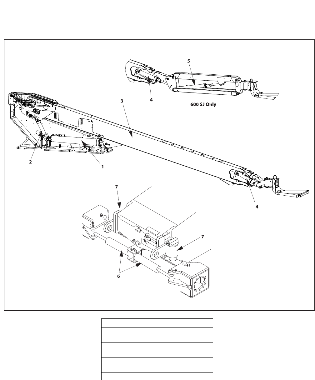
SECTION 5 - HYDRAULICS
3121298 – JLG Lift – 5-7
Cylinder Locations
Item Cylinder
1Main Lift
2Master
3 Telescope
4 Slave (Platform Level)
5Jib Lift
6 Steer
7 Axle Lockout
Figure 5-2. Hydraulic Cylinder Locations
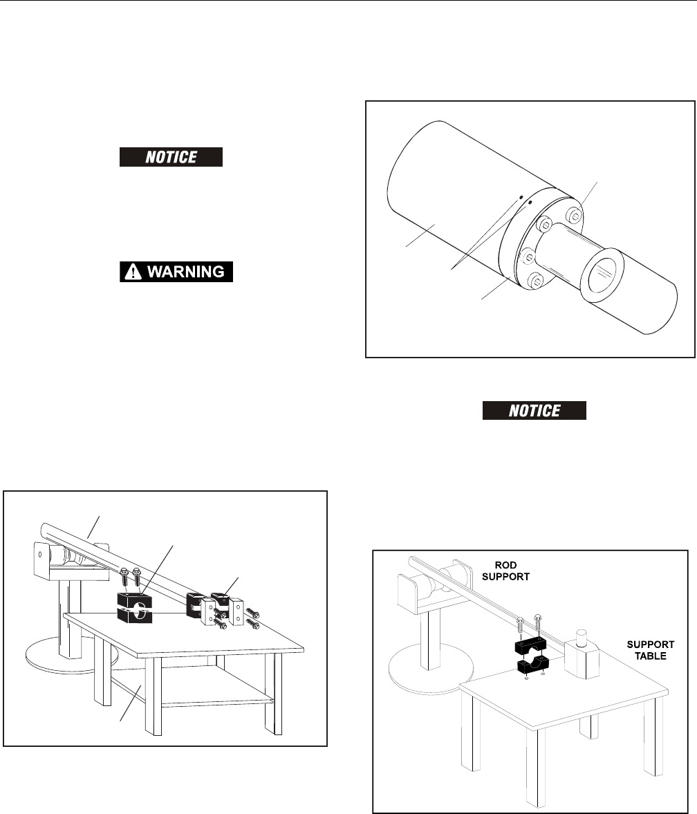
SECTION 5 - HYDRAULICS
5-8 – JLG Lift – 3121298
Main Lift Cylinder
DISASSEMBLY
NOTE: Refer to Figure 5-6.
CONTAMINATION MAY DAMAGE EQUIPMENT. DISASSEMBLE CYLINDER ON A
CLEAN WORK SURFACE IN A DIRT FREE WORK AREA.
1. Connect a suitable auxiliary hydraulic power source to
cylinder port block fitting.
DO NOT FULLY EXTEND CYLINDER TO THE END OF STROKE. RETRACT CYLINDER
SLIGHTLY TO AVOID TRAPPING PRESSURE.
2. Operate hydraulic power source and extend cylinder.
Shut down and disconnect power source. Adequately
support cylinder rod, if applicable.
3. If applicable, remove cartridge-type counterbalance
valve and fittings from cylinder port block. Discard O-
rings.
4. Place cylinder barrel in a suitable holding fixture. Tap
around outside of cylinder head retainer with a suitable
hammer to break thread-locking compound.
Figure 5-3. Cylinder Barrel Support
5. Mark cylinder head (1) and barrel (2) with center punch
marks (3) for later realignment. Remove eight cylinder
head cap screws (4).
Figure 5-4. Marking Cylinder for Alignment
PULLING ROD OFF-CENTER CAN DAMAGE PISTON AND CYLINDER BARREL SURFACES.
USE EXTREME CARE WHEN REMOVING CYLINDER ROD, HEAD, AND PISTON.
6. Clamp barrel securely. Pull rod assembly and cylinder
head from barrel.
7. Protect cylinder rod from damage and clamp in a vise or
holding fixture as close to piston as possible.
Figure 5-5. Cylinder Rod Support
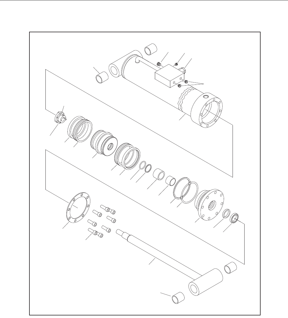
SECTION 5 - HYDRAULICS
3121298 – JLG Lift – 5-9
1. Barrel
1a. Composite Bushing
2. Rod
2a. Composite Bushing
3. Head
4. Piston
5. Tapered Bushing
6. Spacer
7. Cartridge Valve
8. O-Ring Plug
9. 5/16"-11x2 Bolt
10. O-Ring Plug
11. Lock Ring
12. Hydrolock Seal
13. O-Ring
14. Back-Up Ring
15. Wear Ring
16. O-Ring
17. Back-Up Ring
18. Rod Seal
19. Wiper
20. Locking Compound
21. Locking Primer
22. Ring Washer
23. Not Used
24. Socket Head Screw
25. O-Ring Plug
Figure 5-6. Main Lift Cylinder Assembly

SECTION 5 - HYDRAULICS
5-10 – JLG Lift – 3121298
8. Using suitable protection, clamp cylinder rod in a vise or
similar holding fixture as close to piston as possible.
9. Loosen and remove nut attaching piston to rod. Remove
piston.
10. Loosen and remove cap screw(s), if applicable, attaching
tapered bushing to piston.
11. Insert cap screw(s) in threaded holes in outer piece of
tapered bushing. Progressively tighten cap screw(s) until
bushing is loose on piston.
12. Remove tapered bushing from piston.
13. Screw piston counter-clockwise by hand and remove
from cylinder rod.
Figure 5-7. Tapered Bushing Removal
14. Remove and discard piston O-rings, seal rings, and
backup rings.
15. Remove piston spacer, if applicable, from rod.
16. Remove rod from holding fixture. Remove cylinder head
gland and retainer plate, if applicable. Discard O-rings,
back-up rings, rod seals, and wiper seals.
Cleaning and Inspection
1. Clean parts thoroughly with approved cleaning solvent.
2. Inspect cylinder rod for scoring, tapering, ovality, or
other damage. If necessary, dress rod with Scotch Brite
or equivalent. Replace rod if necessary.
3. Inspect threaded portion of rod for excessive damage.
Dress threads as necessary.
4. Inspect inner surface of cylinder barrel tube for scoring
or other damage. Check inside diameter for tapering or
ovality. Replace if necessary.
5. Inspect threaded portion of barrel for damage. Dress
threads as necessary.
6. Inspect piston surface for damage, scoring, or distortion.
Dress piston surface or replace piston as necessary.
7. Inspect threaded portion of piston for damage. Dress
threads as necessary.
8. Inspect seal and O-ring grooves in piston for burrs and
sharp edges. Dress surfaces as necessary.
9. Inspect cylinder head inside diameter for scoring or
other damage, and for ovality and tapering. Replace as
necessary.
10. Inspect threaded portion of head for damage. Dress
threads as necessary.
11. Inspect seal and O-ring grooves in head for burrs and
sharp edges. Dress applicable surfaces as necessary.
12. Inspect cylinder head outside diameter for scoring,
damage, ovality, and tapering. Replace as necessary.
13. If applicable, inspect rod and barrel bearings for signs of
correct excessive wear or damage. Replace as necessary.
a. Thoroughly clean hole, (steel bushing) of burrs, dirt
etc. to facilitate bearing installation.
b. Inspect steel bushing for wear or other damage. If
steel bushing is worn or damaged, rod/barrel must
be replaced.
c. Lubricate inside of the steel bushing with WD40
prior to bearing installation.
NOTE: Lubrication is not required with nickel plated pins and
bearings. Install pin in composite bushing dry.
d. Press composite bushing into barrel or rod bushing
with correct size arbor.
Figure 5-8. Composite Bushing Installation
14. Inspect travel limiting collar or spacer for burrs and
sharp edges. If necessary, dress inside diameter surface
with Scotch Brite or equivalent.
15. If applicable, inspect port block fittings and holding
valve. Replace as necessary.
16. Inspect oil ports for blockage or presence of dirt or other
foreign material. Repair as necessary.
17. If applicable, inspect piston rings for cracks or other
damage. Replace as necessary.

SECTION 5 - HYDRAULICS
3121298 – JLG Lift – 5-11
Assembly
NOTE: Use proper cylinder seal kit for cylinder assembly. See your
JLG Parts Manual.
Apply a light film of hydraulic oil to all components before
assembly.
1. Use seal tool to install new rod seal into applicable cylin-
der head gland groove.
Figure 5-9. Rod Seal Installation
IMPROPER SEAL INSTALLATION CAN CAUSE CYLINDER LEAKS AND IMPROPER
CYLINDER OPERATION. ENSURE ‘POLY-PAK’ PISTON SEALS ARE PROPERLY
INSTALLED. REFER TO WIPER SEAL INSTALLATION FOR CORRECT SEAL ORIEN-
TATION.
2. Use a soft mallet to tap new wiper seal into applicable
cylinder head gland groove. Install new wear ring in
applicable cylinder head gland groove.
Figure 5-10. Poly-Pak Piston Seal Installation
Figure 5-11. Wiper Seal Installation
3. Place new O-ring and back-up seal in applicable outside
diameter groove of cylinder head.
Figure 5-12. Head Seal Kit Installation
4. Install washer ring on rod. Carefully install head gland
on rod. Do not damage or dislodge wiper and rod seals.
Push head along rod to rod end, as applicable.
5. Carefully slide piston spacer on rod.
NOTE: Upper telescope cylinder piston has an O-ring installed
inside spacer.

SECTION 5 - HYDRAULICS
5-12 – JLG Lift – 3121298
6. If applicable, place new O-ring and back-up rings in
inner piston diameter groove.
Figure 5-13. Piston Seal Kit Installation
7. Using suitable protection, clamp cylinder rod in a vise or
similar holding fixture as close to piston as possible.
8. Carefully thread piston on cylinder rod hand tight,
Ensure O-ring and back-up rings are not damaged or
dislodged.
NOTE: Piston and mating end of rod must be free of oil when
installing tapered bushing.
9. Thread piston onto rod until it aligns with spacer end
and install tapered bushing.
NOTE: Apply LOCTITE #242 or equivalent to tapered bushing bolts
when rebuilding master, slave, lift, and telescope cylinders.
10. Install bolts in tapered bushing using loctite #242
Figure 5-14. Tapered Bushing Installation
11. Remove cylinder rod from holding fixture.
12. Place new guide locks and seals in applicable outside
diameter grooves of cylinder piston. (See Figure 2-28.
Piston Seal Kit Installation.)
13. Position cylinder barrel in a suitable holding fixture.
INSERTING ROD OFF-CENTER CAN DAMAGE PISTON AND CYLINDER BARREL
SURFACES. USE EXTREME CARE WHEN INSTALLING CYLINDER ROD, HEAD,
AND PISTON.
14. Clamp barrel clamped securely and support rod. Insert
piston end into barrel cylinder. Do not damage or dis-
lodge piston loading O-ring and seal ring.
15. Continue pushing rod into barrel until cylinder head
gland can be inserted into barrel cylinder.
16. Secure cylinder head gland using washer ring and
socket head bolts.
Figure 5-15. Rod Assembly Installation

SECTION 5 - HYDRAULICS
3121298 – JLG Lift – 5-13
Master Cylinder
DISASSEMBLY
NOTE: Refer to Figure 5-19. Master Cylinder.
CONTAMINATION MAY DAMAGE EQUIPMENT. DISASSEMBLE CYLINDER ON A
CLEAN WORK SURFACE IN A DIRT FREE WORK AREA.
1. Connect a suitable auxiliary hydraulic power source to
cylinder port block fitting.
DO NOT FULLY EXTEND CYLINDER TO THE END OF STROKE. RETRACT CYLINDER
SLIGHTLY TO AVOID TRAPPING PRESSURE.
2. Operate hydraulic power source and extend cylinder.
Shut down and disconnect power source. Adequately
support cylinder rod, if applicable.
3. If applicable, remove cartridge-type counterbalance
valve and fittings from cylinder port block. Discard O-
rings.
4. Place cylinder barrel in a suitable holding fixture. Tap
around outside of cylinder head retainer with a suitable
hammer to break thread-locking compound.
Figure 5-16. Cylinder Barrel Support
5. Mark cylinder head (1) and barrel (2) with center punch
marks (3) for later realignment. Remove eight cylinder
head cap screws (4).
Figure 5-17. Marking Cylinder for Alignment
PULLING ROD OFF-CENTER CAN DAMAGE PISTON AND CYLINDER BARREL SURFACES.
USE EXTREME CARE WHEN REMOVING CYLINDER ROD, HEAD, AND PISTON.
6. Clamp barrel securely. Pull rod assembly and cylinder
head from barrel.
7. Protect cylinder rod from damage and clamp in a vise or
holding fixture as close to piston as possible.
Figure 5-18. Cylinder Rod Support
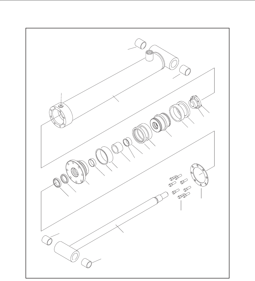
SECTION 5 - HYDRAULICS
5-14 – JLG Lift – 3121298
1. Barrel
1a. Composite Bushing
2. Rod
2a. Composite Bushing
3. Piston
4. Head
5. Tapered Bushing
6. Spacer
7. Capscrew
8. Ring Washer
9. Locking Compound
10. Locking Primer
11. Seal
12. Lock Ring
13. O-Ring
14. Back-Up Ring
15. Wear Ring
16. O-Ring
17. Back-Up Ring
18. Rod Seal
19. Wiper
20. Not Used
21. Capscrew
Figure 5-19. Master Cylinder Assembly

SECTION 5 - HYDRAULICS
3121298 – JLG Lift – 5-15
8. Using suitable protection, clamp cylinder rod in a vise or
similar holding fixture as close to piston as possible.
9. Loosen and remove nut attaching piston to rod. Remove
piston.
10. Loosen and remove cap screw(s), if applicable, attaching
tapered bushing to piston.
11. Insert cap screw(s) in threaded holes in outer piece of
tapered bushing. Progressively tighten cap screw(s) until
bushing is loose on piston.
12. Remove tapered bushing from piston.
13. Screw piston counter-clockwise by hand and remove
from cylinder rod.
Figure 5-20. Tapered Bushing Removal
14. Remove and discard piston O-rings, seal rings, and
backup rings.
15. Remove piston spacer, if applicable, from rod.
16. Remove rod from holding fixture. Remove cylinder head
gland and retainer plate, if applicable. Discard O-rings,
back-up rings, rod seals, and wiper seals.
Cleaning and Inspection
1. Clean parts thoroughly with approved cleaning solvent.
2. Inspect cylinder rod for scoring, tapering, ovality, or
other damage. If necessary, dress rod with Scotch Brite
or equivalent. Replace rod if necessary.
3. Inspect threaded portion of rod for excessive damage.
Dress threads as necessary.
4. Inspect inner surface of cylinder barrel tube for scoring
or other damage. Check inside diameter for tapering or
ovality. Replace if necessary.
5. Inspect threaded portion of barrel for damage. Dress
threads as necessary.
6. Inspect piston surface for damage, scoring, or distortion.
Dress piston surface or replace piston as necessary.
7. Inspect threaded portion of piston for damage. Dress
threads as necessary.
8. Inspect seal and O-ring grooves in piston for burrs and
sharp edges. Dress surfaces as necessary.
9. Inspect cylinder head inside diameter for scoring or
other damage, and for ovality and tapering. Replace as
necessary.
10. Inspect threaded portion of head for damage. Dress
threads as necessary.
11. Inspect seal and O-ring grooves in head for burrs and
sharp edges. Dress applicable surfaces as necessary.
12. Inspect cylinder head outside diameter for scoring,
damage, ovality, and tapering. Replace as necessary.
13. If applicable, inspect rod and barrel bearings for signs of
correct excessive wear or damage. Replace as necessary.
a. Thoroughly clean hole, (steel bushing) of burrs, dirt
etc. to facilitate bearing installation.
b. Inspect steel bushing for wear or other damage. If
steel bushing is worn or damaged, rod/barrel must
be replaced.
c. Lubricate inside of the steel bushing with WD40
prior to bearing installation.
NOTE: Lubrication is not required with nickel plated pins and
bearings. Install pin in composite bushing dry.
d. Press composite bushing into barrel or rod bushing
with correct size arbor.
Figure 5-21. Composite Bushing Installation
14. Inspect travel limiting collar or spacer for burrs and
sharp edges. If necessary, dress inside diameter surface
with Scotch Brite or equivalent.
15. If applicable, inspect port block fittings and holding
valve. Replace as necessary.
16. Inspect oil ports for blockage or presence of dirt or other
foreign material. Repair as necessary.
17. If applicable, inspect piston rings for cracks or other
damage. Replace as necessary.

SECTION 5 - HYDRAULICS
5-16 – JLG Lift – 3121298
Assembly
NOTE: Use proper cylinder seal kit for cylinder assembly. See your
JLG Parts Manual.
Apply a light film of hydraulic oil to all components before
assembly.
1. Use seal tool to install new rod seal into applicable cylin-
der head gland groove.
Figure 5-22. Rod Seal Installation
IMPROPER SEAL INSTALLATION CAN CAUSE CYLINDER LEAKS AND IMPROPER
CYLINDER OPERATION. ENSURE ‘POLY-PAK’ PISTON SEALS ARE PROPERLY
INSTALLED. REFER TO WIPER SEAL INSTALLATION FOR CORRECT SEAL ORIEN-
TATION.
2. Use a soft mallet to tap new wiper seal into applicable
cylinder head gland groove. Install new wear ring in
applicable cylinder head gland groove.
Figure 5-23. Poly-Pak Piston Seal Installation
Figure 5-24. Wiper Seal Installation
3. Place new O-ring and back-up seal in applicable outside
diameter groove of cylinder head.
Figure 5-25. Head Seal Kit Installation
4. Install washer ring on rod. Carefully install head gland
on rod. Do not damage or dislodge wiper and rod seals.
Push head along rod to rod end, as applicable.
5. Carefully slide piston spacer on rod.
NOTE: Upper telescope cylinder piston has an O-ring installed
inside spacer.

SECTION 5 - HYDRAULICS
3121298 – JLG Lift – 5-17
6. If applicable, place new O-ring and back-up rings in
inner piston diameter groove.
Figure 5-26. Piston Seal Kit Installation
7. Using suitable protection, clamp cylinder rod in a vise or
similar holding fixture as close to piston as possible.
8. Carefully thread piston on cylinder rod hand tight,
Ensure O-ring and back-up rings are not damaged or
dislodged.
NOTE: Piston and mating end of rod must be free of oil when
installing tapered bushing.
9. Thread piston onto rod until it aligns with spacer end
and install tapered bushing.
NOTE: Apply LOCTITE #242 or equivalent to tapered bushing bolts
when rebuilding master, slave, lift, and telescope cylinders.
10. Install bolts in tapered bushing using loctite #242
Figure 5-27. Tapered Bushing Installation
11. Remove cylinder rod from holding fixture.
12. Place new guide locks and seals in applicable outside
diameter grooves of cylinder piston. (See Figure 2-28.
Piston Seal Kit Installation.)
13. Position cylinder barrel in a suitable holding fixture.
INSERTING ROD OFF-CENTER CAN DAMAGE PISTON AND CYLINDER BARREL
SURFACES. USE EXTREME CARE WHEN INSTALLING CYLINDER ROD, HEAD,
AND PISTON.
14. Clamp barrel clamped securely and support rod. Insert
piston end into barrel cylinder. Do not damage or dis-
lodge piston loading O-ring and seal ring.
15. Continue pushing rod into barrel until cylinder head
gland can be inserted into barrel cylinder.
16. Secure cylinder head gland using washer ring and
socket head bolts.
Figure 5-28. Rod Assembly Installation
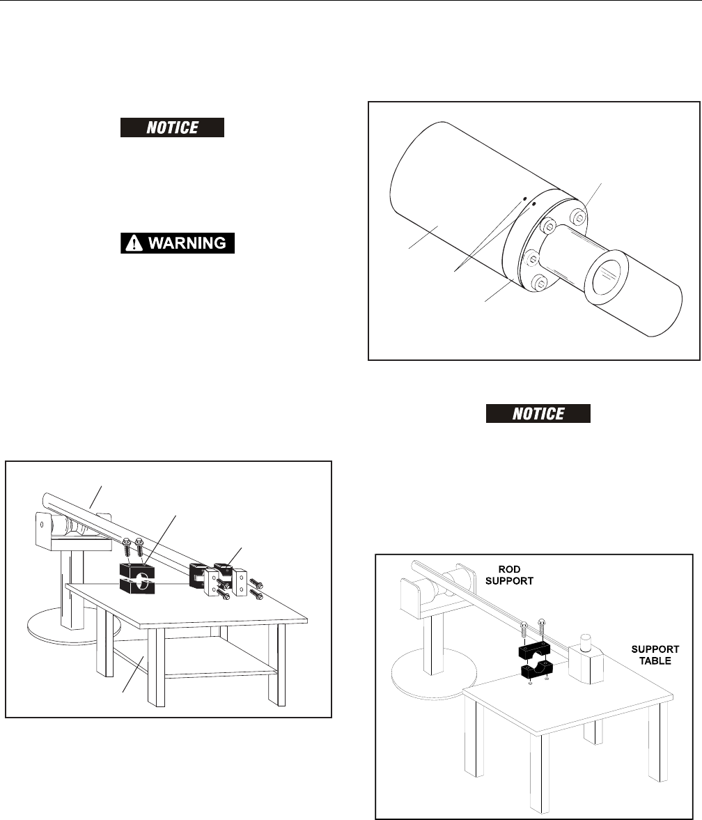
SECTION 5 - HYDRAULICS
5-18 – JLG Lift – 3121298
Telescope Cylinder
DISASSEMBLY
CONTAMINATION MAY DAMAGE EQUIPMENT. DISASSEMBLE CYLINDER ON A
CLEAN WORK SURFACE IN A DIRT FREE WORK AREA.
1. Connect a suitable auxiliary hydraulic power source to
cylinder port block fitting.
DO NOT FULLY EXTEND CYLINDER TO THE END OF STROKE. RETRACT CYLINDER
SLIGHTLY TO AVOID TRAPPING PRESSURE.
2. Operate hydraulic power source and extend cylinder.
Shut down and disconnect power source. Adequately
support cylinder rod, if applicable.
3. If applicable, remove cartridge-type counterbalance
valve and fittings from cylinder port block. Discard O-
rings.
4. Place cylinder barrel in a suitable holding fixture. Tap
around outside of cylinder head retainer with a suitable
hammer to break thread-locking compound.
Figure 5-29. Cylinder Barrel Support
5. Mark cylinder head (1) and barrel (2) with center punch
marks (3) for later realignment. Remove eight cylinder
head cap screws (4).
Figure 5-30. Marking Cylinder for Alignment
PULLING ROD OFF-CENTER CAN DAMAGE PISTON AND CYLINDER BARREL SURFACES.
USE EXTREME CARE WHEN REMOVING CYLINDER ROD, HEAD, AND PISTON.
6. Clamp barrel securely. Pull rod assembly and cylinder
head from barrel.
7. Protect cylinder rod from damage and clamp in a vise or
holding fixture as close to piston as possible.
Figure 5-31. Cylinder Rod Support
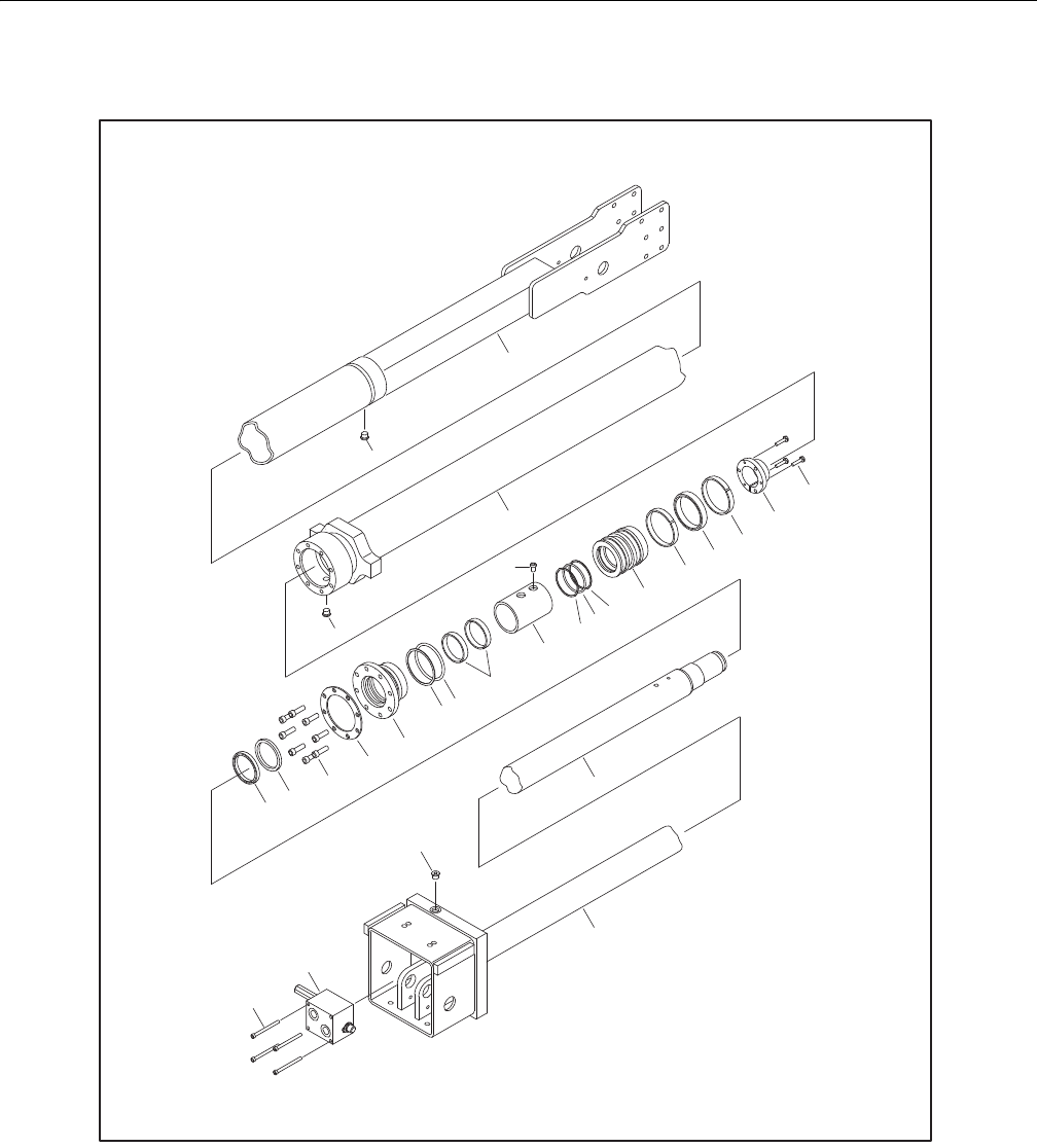
SECTION 5 - HYDRAULICS
3121298 – JLG Lift – 5-19
1. Barrel
2. Rod
3. Head
4. Piston
5. Tapered Bushing
6. Spacer
7. Valve Assembly
8. O-Ring Plug
9. Capscrew
10. Ring Washer
11. Capscrew
12. Capscrew
13. Wiper
14. Rod Seal
15. O-Ring
16. Back-Up Ring
17. Wear Ring
18. O-Ring
19. Back-Up Ring
20. T-Seal
21. Wear Ring
22. Locking Compound
23. Locking primer
24. Not Used
25. Bolt
Figure 5-32. Telescope Cylinder Assembly
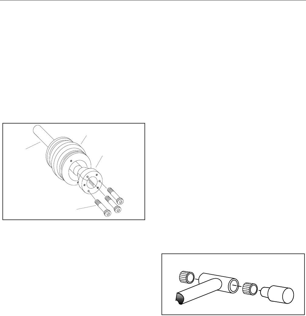
SECTION 5 - HYDRAULICS
5-20 – JLG Lift – 3121298
8. Using suitable protection, clamp cylinder rod in a vise or
similar holding fixture as close to piston as possible.
9. Loosen and remove nut attaching piston to rod. Remove
piston.
10. Loosen and remove cap screw(s), if applicable, attaching
tapered bushing to piston.
11. Insert cap screw(s) in threaded holes in outer piece of
tapered bushing. Progressively tighten cap screw(s) until
bushing is loose on piston.
12. Remove tapered bushing from piston.
13. Screw piston counter-clockwise by hand and remove
from cylinder rod.
Figure 5-33. Tapered Bushing Removal
14. Remove and discard piston O-rings, seal rings, and
backup rings.
15. Remove piston spacer, if applicable, from rod.
16. Remove rod from holding fixture. Remove cylinder head
gland and retainer plate, if applicable. Discard O-rings,
back-up rings, rod seals, and wiper seals.
Cleaning and Inspection
1. Clean parts thoroughly with approved cleaning solvent.
2. Inspect cylinder rod for scoring, tapering, ovality, or
other damage. If necessary, dress rod with Scotch Brite
or equivalent. Replace rod if necessary.
3. Inspect threaded portion of rod for excessive damage.
Dress threads as necessary.
4. Inspect inner surface of cylinder barrel tube for scoring
or other damage. Check inside diameter for tapering or
ovality. Replace if necessary.
5. Inspect threaded portion of barrel for damage. Dress
threads as necessary.
6. Inspect piston surface for damage, scoring, or distortion.
Dress piston surface or replace piston as necessary.
7. Inspect threaded portion of piston for damage. Dress
threads as necessary.
8. Inspect seal and O-ring grooves in piston for burrs and
sharp edges. Dress surfaces as necessary.
9. Inspect cylinder head inside diameter for scoring or
other damage, and for ovality and tapering. Replace as
necessary.
10. Inspect threaded portion of head for damage. Dress
threads as necessary.
11. Inspect seal and O-ring grooves in head for burrs and
sharp edges. Dress applicable surfaces as necessary.
12. Inspect cylinder head outside diameter for scoring,
damage, ovality, and tapering. Replace as necessary.
13. If applicable, inspect rod and barrel bearings for signs of
correct excessive wear or damage. Replace as necessary.
a. Thoroughly clean hole, (steel bushing) of burrs, dirt
etc. to facilitate bearing installation.
b. Inspect steel bushing for wear or other damage. If
steel bushing is worn or damaged, rod/barrel must
be replaced.
c. Lubricate inside of the steel bushing with WD40
prior to bearing installation.
NOTE: Lubrication is not required with nickel plated pins and
bearings. Install pin in composite bushing dry.
d. Press composite bushing into barrel or rod bushing
with correct size arbor.
Figure 5-34. Composite Bushing Installation
14. Inspect travel limiting collar or spacer for burrs and
sharp edges. If necessary, dress inside diameter surface
with Scotch Brite or equivalent.
15. If applicable, inspect port block fittings and holding
valve. Replace as necessary.
16. Inspect oil ports for blockage or presence of dirt or other
foreign material. Repair as necessary.
17. If applicable, inspect piston rings for cracks or other
damage. Replace as necessary.

SECTION 5 - HYDRAULICS
3121298 – JLG Lift – 5-21
Assembly
NOTE: Use proper cylinder seal kit for cylinder assembly. See your
JLG Parts Manual.
Apply a light film of hydraulic oil to all components before
assembly.
1. Use seal tool to install new rod seal into applicable cylin-
der head gland groove.
Figure 5-35. Rod Seal Installation
IMPROPER SEAL INSTALLATION CAN CAUSE CYLINDER LEAKS AND IMPROPER
CYLINDER OPERATION. ENSURE ‘POLY-PAK’ PISTON SEALS ARE PROPERLY
INSTALLED. REFER TO WIPER SEAL INSTALLATION FOR CORRECT SEAL ORIEN-
TATION.
2. Use a soft mallet to tap new wiper seal into applicable
cylinder head gland groove. Install new wear ring in
applicable cylinder head gland groove.
Figure 5-36. Poly-Pak Piston Seal Installation
Figure 5-37. Wiper Seal Installation
3. Place new O-ring and back-up seal in applicable outside
diameter groove of cylinder head.
Figure 5-38. Head Seal Kit Installation
4. Install washer ring on rod. Carefully install head gland
on rod. Do not damage or dislodge wiper and rod seals.
Push head along rod to rod end, as applicable.
5. Carefully slide piston spacer on rod.
NOTE: Upper telescope cylinder piston has an O-ring installed
inside spacer.
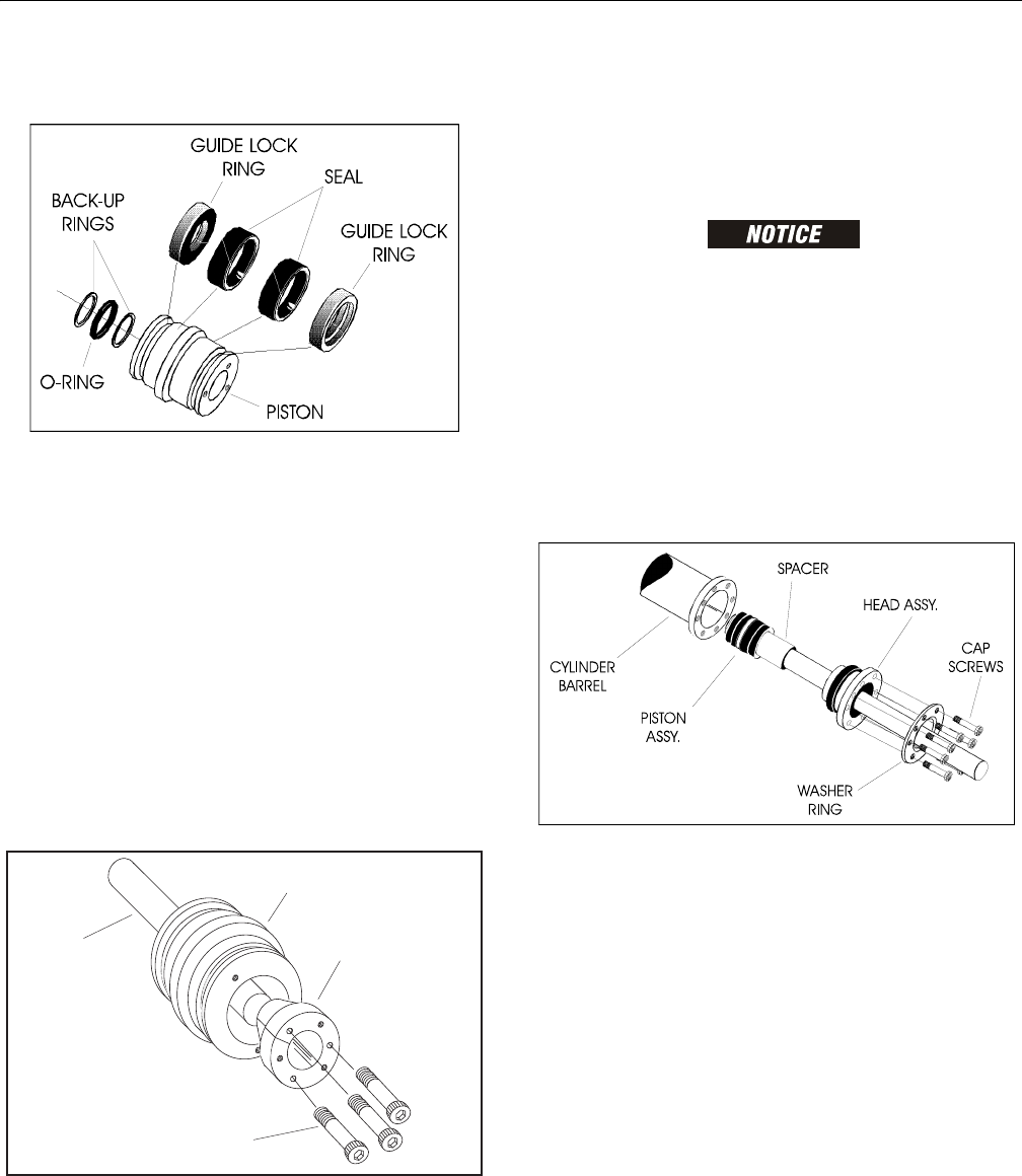
SECTION 5 - HYDRAULICS
5-22 – JLG Lift – 3121298
6. If applicable, place new O-ring and back-up rings in
inner piston diameter groove.
Figure 5-39. Piston Seal Kit Installation
7. Using suitable protection, clamp cylinder rod in a vise or
similar holding fixture as close to piston as possible.
8. Carefully thread piston on cylinder rod hand tight,
Ensure O-ring and back-up rings are not damaged or
dislodged.
NOTE: Piston and mating end of rod must be free of oil when
installing tapered bushing.
9. Thread piston onto rod until it aligns with spacer end
and install tapered bushing.
NOTE: Apply LOCTITE #242 or equivalent to tapered bushing bolts
when rebuilding master, slave, lift, and telescope cylinders.
10. Install bolts in tapered bushing using loctite #242
Figure 5-40. Tapered Bushing Installation
11. Remove cylinder rod from holding fixture.
12. Place new guide locks and seals in applicable outside
diameter grooves of cylinder piston. (See Figure 2-28.
Piston Seal Kit Installation.)
13. Position cylinder barrel in a suitable holding fixture.
INSERTING ROD OFF-CENTER CAN DAMAGE PISTON AND CYLINDER BARREL
SURFACES. USE EXTREME CARE WHEN INSTALLING CYLINDER ROD, HEAD,
AND PISTON.
14. Clamp barrel clamped securely and support rod. Insert
piston end into barrel cylinder. Do not damage or dis-
lodge piston loading O-ring and seal ring.
15. Continue pushing rod into barrel until cylinder head
gland can be inserted into barrel cylinder.
16. Secure cylinder head gland using washer ring and
socket head bolts.
Figure 5-41. Rod Assembly Installation
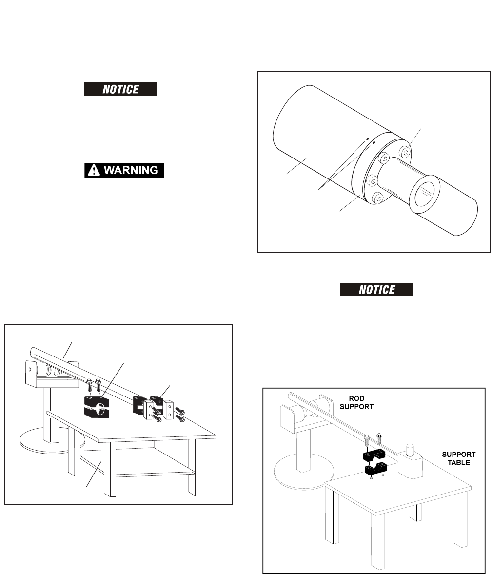
SECTION 5 - HYDRAULICS
3121298 – JLG Lift – 5-23
Platform Level (Slave) Cylinder
DISASSEMBLY
CONTAMINATION MAY DAMAGE EQUIPMENT. DISASSEMBLE CYLINDER ON A
CLEAN WORK SURFACE IN A DIRT FREE WORK AREA.
1. Connect a suitable auxiliary hydraulic power source to
cylinder port block fitting.
DO NOT FULLY EXTEND CYLINDER TO THE END OF STROKE. RETRACT CYLINDER
SLIGHTLY TO AVOID TRAPPING PRESSURE.
2. Operate hydraulic power source and extend cylinder.
Shut down and disconnect power source. Adequately
support cylinder rod, if applicable.
3. If applicable, remove cartridge-type counterbalance
valve and fittings from cylinder port block. Discard O-
rings.
4. Place cylinder barrel in a suitable holding fixture. Tap
around outside of cylinder head retainer with a suitable
hammer to break thread-locking compound.
Figure 5-42. Cylinder Barrel Support
5. Mark cylinder head (1) and barrel (2) with center punch
marks (3) for later realignment. Remove eight cylinder
head cap screws (4).
Figure 5-43. Marking Cylinder for Alignment
PULLING ROD OFF-CENTER CAN DAMAGE PISTON AND CYLINDER BARREL SURFACES.
USE EXTREME CARE WHEN REMOVING CYLINDER ROD, HEAD, AND PISTON.
6. Clamp barrel securely. Pull rod assembly and cylinder
head from barrel.
7. Protect cylinder rod from damage and clamp in a vise or
holding fixture as close to piston as possible.
Figure 5-44. Cylinder Rod Support
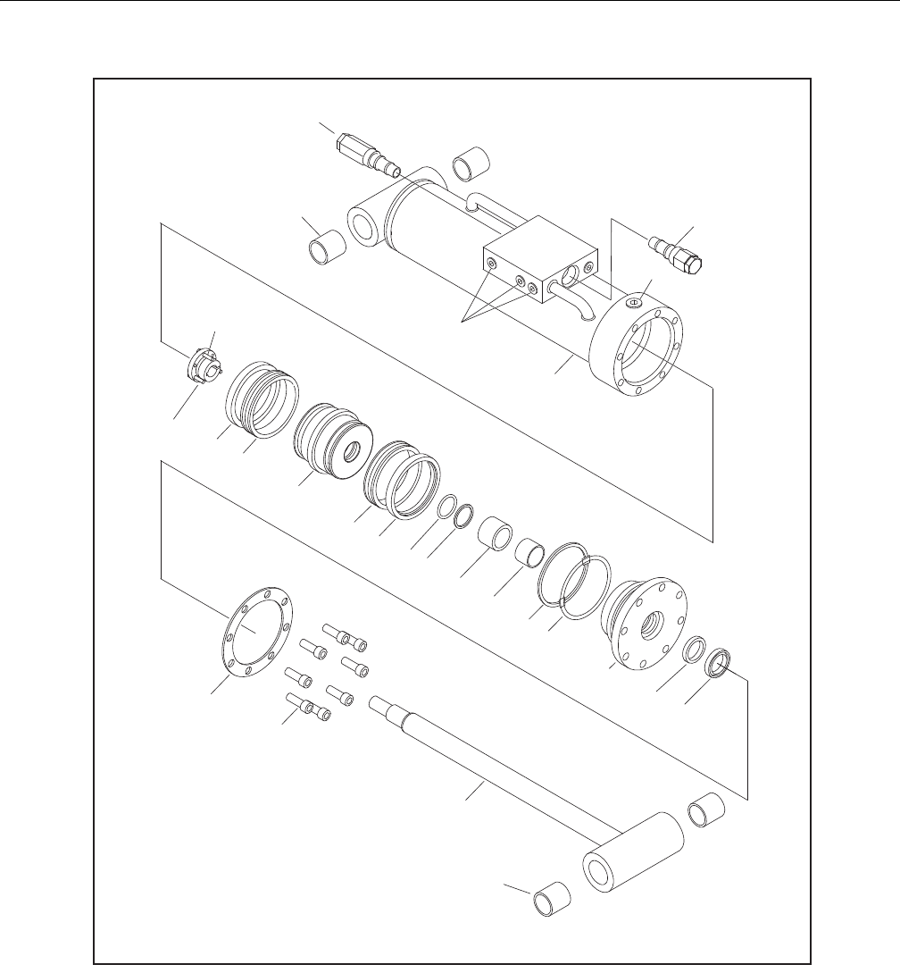
SECTION 5 - HYDRAULICS
5-24 – JLG Lift – 3121298
1. Barrel
1a. Composite Bushing
2. Rod
2a. Composite Bushing
3. Piston
4. Head
5. Tapered Bushing
6. Spacer
7. Cartridge Valve
8. O-Ring Plug
9. Capscrew
10. Ring Washer
11. Locking Compound
12. Locking Primer
13. Seal
14. Ring Lock
15. O-Ring
16. Back-Up Ring
17. Wear Ring
18. O-Ring
19. Back-Up Ring
20. Rod Seal
21. Wiper
22. Not Used
23. Cartridge Valve
24. O-Ring Plug
25. Bolt
Figure 5-45. Platform Level (Slave) Cylinder Assembly

SECTION 5 - HYDRAULICS
3121298 – JLG Lift – 5-25
8. Using suitable protection, clamp cylinder rod in a vise or
similar holding fixture as close to piston as possible.
9. Loosen and remove nut attaching piston to rod. Remove
piston.
10. Loosen and remove cap screw(s), if applicable, attaching
tapered bushing to piston.
11. Insert cap screw(s) in threaded holes in outer piece of
tapered bushing. Progressively tighten cap screw(s) until
bushing is loose on piston.
12. Remove tapered bushing from piston.
13. Screw piston counter-clockwise by hand and remove
from cylinder rod.
Figure 5-46. Tapered Bushing Removal
14. Remove and discard piston O-rings, seal rings, and
backup rings.
15. Remove piston spacer, if applicable, from rod.
16. Remove rod from holding fixture. Remove cylinder head
gland and retainer plate, if applicable. Discard O-rings,
back-up rings, rod seals, and wiper seals.
Cleaning and Inspection
1. Clean parts thoroughly with approved cleaning solvent.
2. Inspect cylinder rod for scoring, tapering, ovality, or
other damage. If necessary, dress rod with Scotch Brite
or equivalent. Replace rod if necessary.
3. Inspect threaded portion of rod for excessive damage.
Dress threads as necessary.
4. Inspect inner surface of cylinder barrel tube for scoring
or other damage. Check inside diameter for tapering or
ovality. Replace if necessary.
5. Inspect threaded portion of barrel for damage. Dress
threads as necessary.
6. Inspect piston surface for damage, scoring, or distortion.
Dress piston surface or replace piston as necessary.
7. Inspect threaded portion of piston for damage. Dress
threads as necessary.
8. Inspect seal and O-ring grooves in piston for burrs and
sharp edges. Dress surfaces as necessary.
9. Inspect cylinder head inside diameter for scoring or
other damage, and for ovality and tapering. Replace as
necessary.
10. Inspect threaded portion of head for damage. Dress
threads as necessary.
11. Inspect seal and O-ring grooves in head for burrs and
sharp edges. Dress applicable surfaces as necessary.
12. Inspect cylinder head outside diameter for scoring,
damage, ovality, and tapering. Replace as necessary.
13. If applicable, inspect rod and barrel bearings for signs of
correct excessive wear or damage. Replace as necessary.
a. Thoroughly clean hole, (steel bushing) of burrs, dirt
etc. to facilitate bearing installation.
b. Inspect steel bushing for wear or other damage. If
steel bushing is worn or damaged, rod/barrel must
be replaced.
c. Lubricate inside of the steel bushing with WD40
prior to bearing installation.
NOTE: Lubrication is not required with nickel plated pins and
bearings. Install pin in composite bushing dry.
d. Press composite bushing into barrel or rod bushing
with correct size arbor.
Figure 5-47. Composite Bushing Installation
14. Inspect travel limiting collar or spacer for burrs and
sharp edges. If necessary, dress inside diameter surface
with Scotch Brite or equivalent.
15. If applicable, inspect port block fittings and holding
valve. Replace as necessary.
16. Inspect oil ports for blockage or presence of dirt or other
foreign material. Repair as necessary.
17. If applicable, inspect piston rings for cracks or other
damage. Replace as necessary.
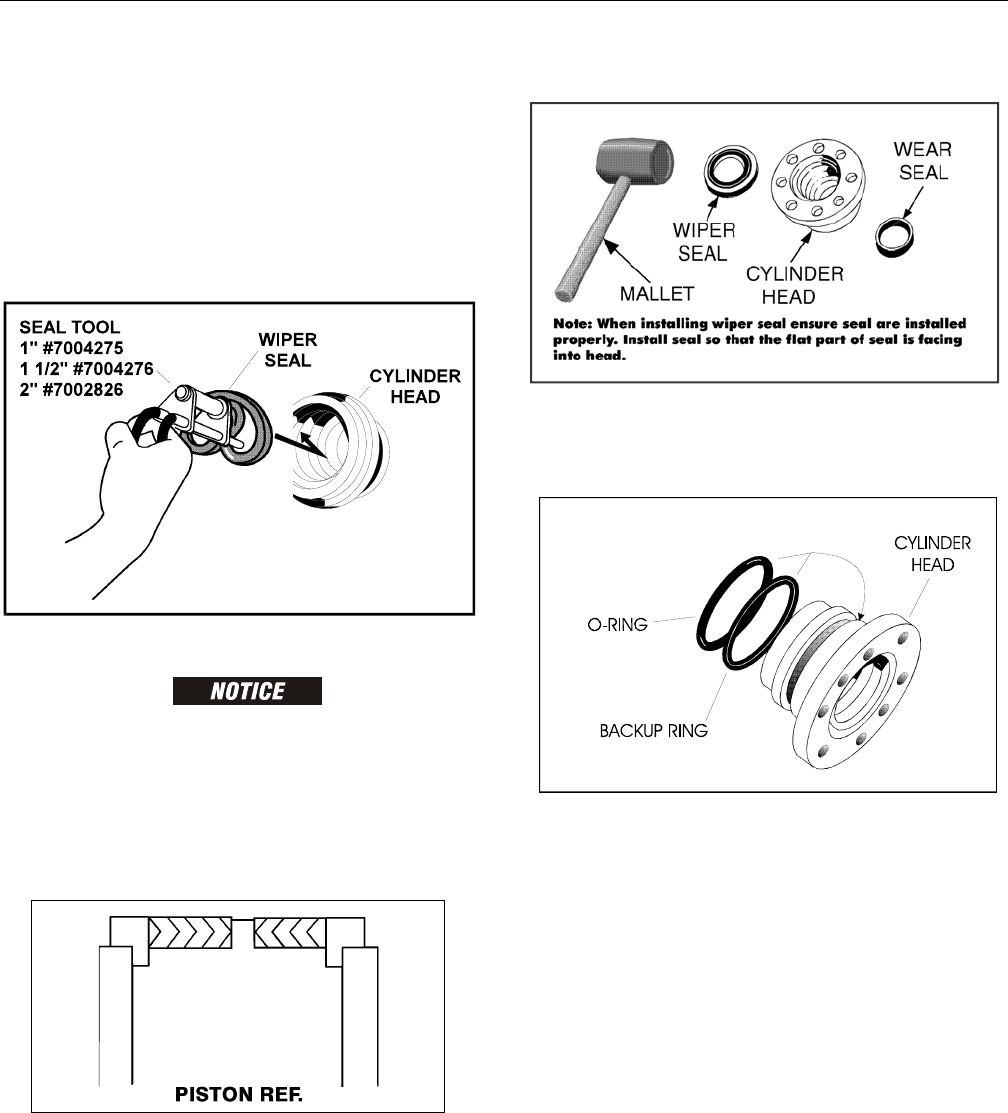
SECTION 5 - HYDRAULICS
5-26 – JLG Lift – 3121298
Assembly
NOTE: Use proper cylinder seal kit for cylinder assembly. See your
JLG Parts Manual.
Apply a light film of hydraulic oil to all components before
assembly.
1. Use seal tool to install new rod seal into applicable cylin-
der head gland groove.
Figure 5-48. Rod Seal Installation
IMPROPER SEAL INSTALLATION CAN CAUSE CYLINDER LEAKS AND IMPROPER
CYLINDER OPERATION. ENSURE ‘POLY-PAK’ PISTON SEALS ARE PROPERLY
INSTALLED. REFER TO WIPER SEAL INSTALLATION FOR CORRECT SEAL ORIEN-
TATION.
2. Use a soft mallet to tap new wiper seal into applicable
cylinder head gland groove. Install new wear ring in
applicable cylinder head gland groove.
Figure 5-49. Poly-Pak Piston Seal Installation
Figure 5-50. Wiper Seal Installation
3. Place new O-ring and back-up seal in applicable outside
diameter groove of cylinder head.
Figure 5-51. Head Seal Kit Installation
4. Install washer ring on rod. Carefully install head gland
on rod. Do not damage or dislodge wiper and rod seals.
Push head along rod to rod end, as applicable.
5. Carefully slide piston spacer on rod.
NOTE: Upper telescope cylinder piston has an O-ring installed
inside spacer.

SECTION 5 - HYDRAULICS
3121298 – JLG Lift – 5-27
6. If applicable, place new O-ring and back-up rings in
inner piston diameter groove.
Figure 5-52. Piston Seal Kit Installation
7. Using suitable protection, clamp cylinder rod in a vise or
similar holding fixture as close to piston as possible.
8. Carefully thread piston on cylinder rod hand tight,
Ensure O-ring and back-up rings are not damaged or
dislodged.
NOTE: Piston and mating end of rod must be free of oil when
installing tapered bushing.
9. Thread piston onto rod until it aligns with spacer end
and install tapered bushing.
NOTE: Apply LOCTITE #242 or equivalent to tapered bushing bolts
when rebuilding master, slave, lift, and telescope cylinders.
10. Install bolts in tapered bushing using loctite #242
Figure 5-53. Tapered Bushing Installation
11. Remove cylinder rod from holding fixture.
12. Place new guide locks and seals in applicable outside
diameter grooves of cylinder piston. (See Figure 2-28.
Piston Seal Kit Installation.)
13. Position cylinder barrel in a suitable holding fixture.
INSERTING ROD OFF-CENTER CAN DAMAGE PISTON AND CYLINDER BARREL
SURFACES. USE EXTREME CARE WHEN INSTALLING CYLINDER ROD, HEAD,
AND PISTON.
14. Clamp barrel clamped securely and support rod. Insert
piston end into barrel cylinder. Do not damage or dis-
lodge piston loading O-ring and seal ring.
15. Continue pushing rod into barrel until cylinder head
gland can be inserted into barrel cylinder.
16. Secure cylinder head gland using washer ring and
socket head bolts.
Figure 5-54. Rod Assembly Installation

SECTION 5 - HYDRAULICS
5-28 – JLG Lift – 3121298
Jib Lift Cylinder (SJ Only)
DISASSEMBLY
CCONTAMINATION MAY DAMAGE EQUIPMENT. DISASSEMBLE CYLINDER ON A
CLEAN WORK SURFACE IN A DIRT FREE WORK AREA.
1. Connect a suitable auxiliary hydraulic power source to
cylinder port block fitting.
DO NOT FULLY EXTEND CYLINDER TO THE END OF STROKE. RETRACT CYLINDER
SLIGHTLY TO AVOID TRAPPING PRESSURE.
2. Operate hydraulic power source and extend cylinder.
Shut down and disconnect power source. Adequately
support cylinder rod, if applicable.
3. If applicable, remove cartridge-type counterbalance
valve and fittings from cylinder port block. Discard O-
rings.
4. Place cylinder barrel in a suitable holding fixture. Tap
around outside of cylinder head retainer with a suitable
hammer to break thread-locking compound.
Figure 5-55. Cylinder Barrel Support
5. Mark cylinder head (1) and barrel (2) with center punch
marks (3) for later realignment. Remove eight cylinder
head cap screws (4).
Figure 5-56. Marking Cylinder for Alignment
PULLING ROD OFF-CENTER CAN DAMAGE PISTON AND CYLINDER BARREL SURFACES.
USE EXTREME CARE WHEN REMOVING CYLINDER ROD, HEAD, AND PISTON.
6. Clamp barrel securely. Pull rod assembly and cylinder
head from barrel.
7. Protect cylinder rod from damage and clamp in a vise or
holding fixture as close to piston as possible.
Figure 5-57. Cylinder Rod Support
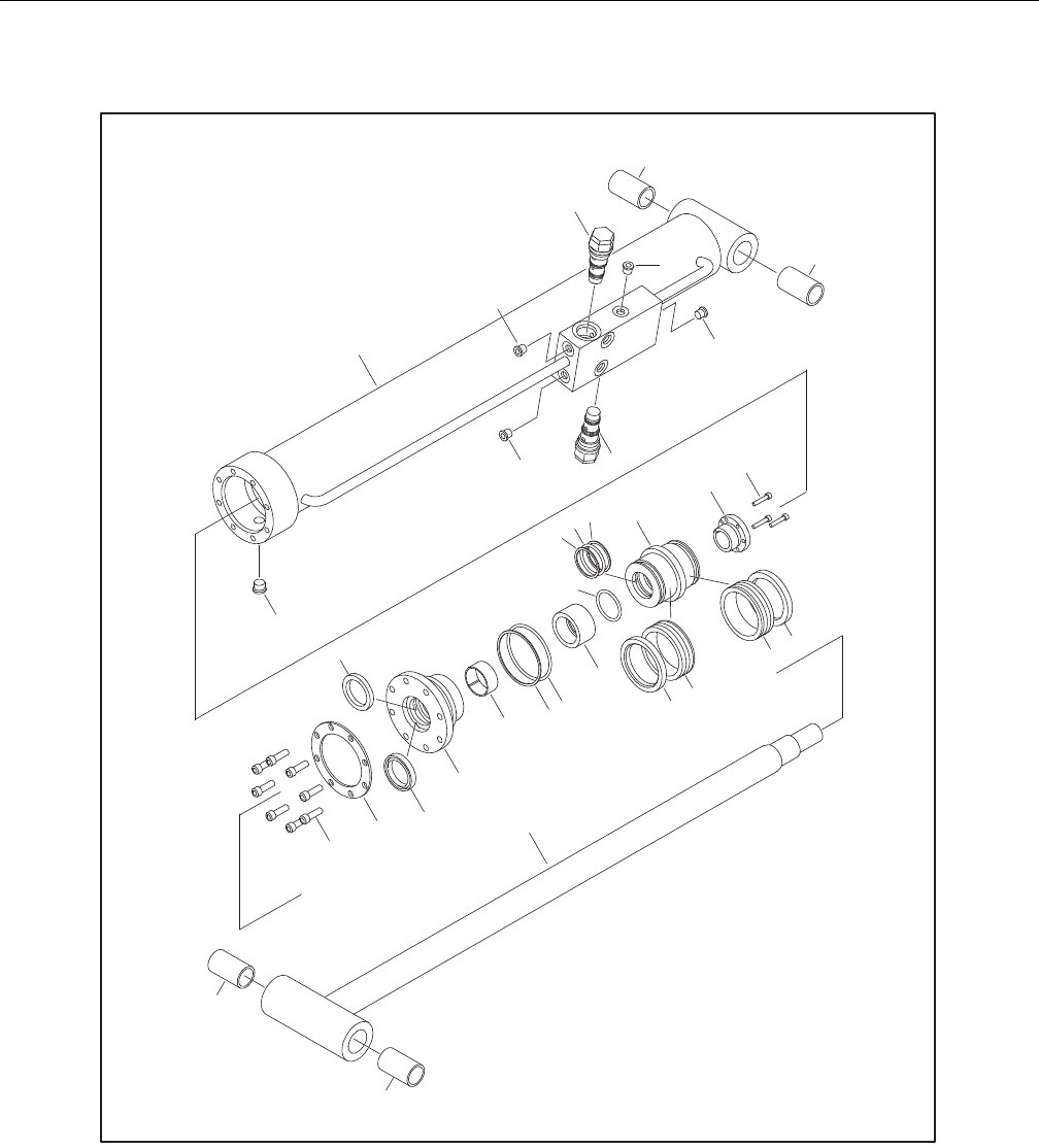
SECTION 5 - HYDRAULICS
3121298 – JLG Lift – 5-29
1. Barrel
1a. Bushing
2. Head
3. Ring Washer
4. Capscrew
5. Rod
5a. Bushing
6. Cartridge Valve
7. Not Used
8. O-Ring Plug
9. O-Ring Plug
10. Piston
11. Tapered Bushing
12. Spacer
13. Not Used
14. Seal
15. Lock Ring
16. O-Ring
17. Back-Up Ring
18. Rod Seal
19. Wiper
20. Wear Ring
21. Wiper
22. Wear Ring
23. Locking Compound
24. Locking Primer
25. Not Used
26. Bolt
Figure 5-58. Jib Lift Cylinder Assembly(600SJ)

SECTION 5 - HYDRAULICS
5-30 – JLG Lift – 3121298
8. Using suitable protection, clamp cylinder rod in a vise or
similar holding fixture as close to piston as possible.
9. Loosen and remove nut attaching piston to rod. Remove
piston.
10. Loosen and remove cap screw(s), if applicable, attaching
tapered bushing to piston.
11. Insert cap screw(s) in threaded holes in outer piece of
tapered bushing. Progressively tighten cap screw(s) until
bushing is loose on piston.
12. Remove tapered bushing from piston.
13. Screw piston counter-clockwise by hand and remove
from cylinder rod.
Figure 5-59. Tapered Bushing Removal
14. Remove and discard piston O-rings, seal rings, and
backup rings.
15. Remove piston spacer, if applicable, from rod.
16. Remove rod from holding fixture. Remove cylinder head
gland and retainer plate, if applicable. Discard O-rings,
back-up rings, rod seals, and wiper seals.
Cleaning and Inspection
1. Clean parts thoroughly with approved cleaning solvent.
2. Inspect cylinder rod for scoring, tapering, ovality, or
other damage. If necessary, dress rod with Scotch Brite
or equivalent. Replace rod if necessary.
3. Inspect threaded portion of rod for excessive damage.
Dress threads as necessary.
4. Inspect inner surface of cylinder barrel tube for scoring
or other damage. Check inside diameter for tapering or
ovality. Replace if necessary.
5. Inspect threaded portion of barrel for damage. Dress
threads as necessary.
6. Inspect piston surface for damage, scoring, or distortion.
Dress piston surface or replace piston as necessary.
7. Inspect threaded portion of piston for damage. Dress
threads as necessary.
8. Inspect seal and O-ring grooves in piston for burrs and
sharp edges. Dress surfaces as necessary.
9. Inspect cylinder head inside diameter for scoring or
other damage, and for ovality and tapering. Replace as
necessary.
10. Inspect threaded portion of head for damage. Dress
threads as necessary.
11. Inspect seal and O-ring grooves in head for burrs and
sharp edges. Dress applicable surfaces as necessary.
12. Inspect cylinder head outside diameter for scoring,
damage, ovality, and tapering. Replace as necessary.
13. If applicable, inspect rod and barrel bearings for signs of
correct excessive wear or damage. Replace as necessary.
a. Thoroughly clean hole, (steel bushing) of burrs, dirt
etc. to facilitate bearing installation.
b. Inspect steel bushing for wear or other damage. If
steel bushing is worn or damaged, rod/barrel must
be replaced.
c. Lubricate inside of the steel bushing with WD40
prior to bearing installation.
NOTE: Lubrication is not required with nickel plated pins and
bearings. Install pin in composite bushing dry.
d. Press composite bushing into barrel or rod bushing
with correct size arbor.
Figure 5-60. Composite Bushing Installation
14. Inspect travel limiting collar or spacer for burrs and
sharp edges. If necessary, dress inside diameter surface
with Scotch Brite or equivalent.
15. If applicable, inspect port block fittings and holding
valve. Replace as necessary.
16. Inspect oil ports for blockage or presence of dirt or other
foreign material. Repair as necessary.
17. If applicable, inspect piston rings for cracks or other
damage. Replace as necessary.

SECTION 5 - HYDRAULICS
3121298 – JLG Lift – 5-31
Assembly
NOTE: Use proper cylinder seal kit for cylinder assembly. See your
JLG Parts Manual.
Apply a light film of hydraulic oil to all components before
assembly.
1. Use seal tool to install new rod seal into applicable cylin-
der head gland groove.
Figure 5-61. Rod Seal Installation
IMPROPER SEAL INSTALLATION CAN CAUSE CYLINDER LEAKS AND IMPROPER
CYLINDER OPERATION. ENSURE ‘POLY-PAK’ PISTON SEALS ARE PROPERLY
INSTALLED. REFER TO WIPER SEAL INSTALLATION FOR CORRECT SEAL ORIEN-
TATION.
2. Use a soft mallet to tap new wiper seal into applicable
cylinder head gland groove. Install new wear ring in
applicable cylinder head gland groove.
Figure 5-62. Poly-Pak Piston Seal Installation
Figure 5-63. Wiper Seal Installation
3. Place new O-ring and back-up seal in applicable outside
diameter groove of cylinder head.
Figure 5-64. Head Seal Kit Installation
4. Install washer ring on rod. Carefully install head gland
on rod. Do not damage or dislodge wiper and rod seals.
Push head along rod to rod end, as applicable.
5. Carefully slide piston spacer on rod.
NOTE: Upper telescope cylinder piston has an O-ring installed
inside spacer.

SECTION 5 - HYDRAULICS
5-32 – JLG Lift – 3121298
6. If applicable, place new O-ring and back-up rings in
inner piston diameter groove.
Figure 5-65. Piston Seal Kit Installation
7. Using suitable protection, clamp cylinder rod in a vise or
similar holding fixture as close to piston as possible.
8. Carefully thread piston on cylinder rod hand tight,
Ensure O-ring and back-up rings are not damaged or
dislodged.
NOTE: Piston and mating end of rod must be free of oil when
installing tapered bushing.
9. Thread piston onto rod until it aligns with spacer end
and install tapered bushing.
NOTE: Apply LOCTITE #242 or equivalent to tapered bushing bolts
when rebuilding master, slave, lift, and telescope cylinders.
10. Install bolts in tapered bushing using loctite #242
Figure 5-66. Tapered Bushing Installation
11. Remove cylinder rod from holding fixture.
12. Place new guide locks and seals in applicable outside
diameter grooves of cylinder piston. (See Figure 2-28.
Piston Seal Kit Installation.)
13. Position cylinder barrel in a suitable holding fixture.
INSERTING ROD OFF-CENTER CAN DAMAGE PISTON AND CYLINDER BARREL
SURFACES. USE EXTREME CARE WHEN INSTALLING CYLINDER ROD, HEAD,
AND PISTON.
14. Clamp barrel clamped securely and support rod. Insert
piston end into barrel cylinder. Do not damage or dis-
lodge piston loading O-ring and seal ring.
15. Continue pushing rod into barrel until cylinder head
gland can be inserted into barrel cylinder.
16. Secure cylinder head gland using washer ring and
socket head bolts.
Figure 5-67. Rod Assembly Installation
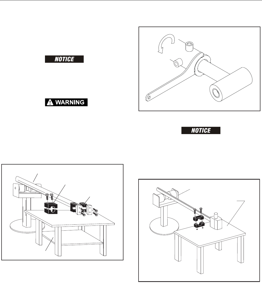
SECTION 5 - HYDRAULICS
3121298 – JLG Lift – 5-33
Steer Cylinder
DISASSEMBLY
NOTE: Refer to Figure 5-71.
CONTAMINATION MAY DAMAGE EQUIPMENT. DISASSEMBLE CYLINDER ON A
CLEAN WORK SURFACE IN A DIRT FREE WORK AREA.
1. Connect a suitable auxiliary hydraulic power source to
cylinder port block fitting.
DO NOT FULLY EXTEND CYLINDER TO THE END OF STROKE. RETRACT CYLINDER
SLIGHTLY TO AVOID TRAPPING PRESSURE.
2. Operate hydraulic power source and extend cylinder.
Shut down and disconnect power source. Adequately
support cylinder rod, if applicable.
3. Place cylinder barrel in a suitable holding fixture. Tap
around outside of cylinder head retainer with a suitable
hammer to break thread-locking compound.
Figure 5-68. Cylinder Barrel Support
4. Remove burrs and contamination from cylinder before
disassembly.
5. Unscrew Spanner Nut (13) with hook spanner.
Figure 5-69. Removing Spanner Nut
PULLING ROD OFF-CENTER CAN DAMAGE PISTON AND CYLINDER BARREL
SURFACES. USE EXTREME CARE WHEN REMOVING CYLINDER ROD AND PIS-
TON.
6. Clamp barrel securely. Apply pressure to rod pulling
device and carefully withdraw complete rod assembly
from cylinder barrel.
Figure 5-70. Cylinder Rod Support
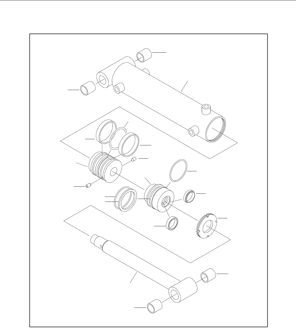
SECTION 5 - HYDRAULICS
5-34 – JLG Lift – 3121298
1. Piston
2. Seal
3. O-Ring
4. Setscrew
5. Barrel
6. Rod
7. Head
8. O-Ring
9. Back-Up Ring
10. Seal
11. O-Ring
12. Wiper
13. Spanner Nut
14. Composite Bushing
Figure 5-71. Steer Cylinder Assembly
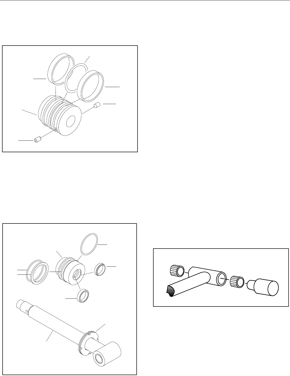
SECTION 5 - HYDRAULICS
3121298 – JLG Lift – 5-35
7. Remove two Seals (2) and O-Ring (3) from Piston (1).
8. Loosen two Setscrews (4) in Piston (1). Unscrew and
remove Piston (1) from Rod (6) with strap wrench.
Figure 5-72. Piston Seal and Wear Ring
9. Remove Cylinder Head (7) from Rod (6).
10. Remove O-Ring (11), O-Ring (9), and Backup Ring (8)
from Cylinder Head (7).
11. Remove Wiper (12) and Rod Seal (10). Do not damage
cylinder head groove.
12. Remove Spanner Nut (13) from Rod (6).
Figure 5-73. Cylinder Head Disassembly
Cleaning and Inspection
1. Clean all parts in an approved cleaning solvent.
2. Inspect cylinder rod for scoring, tapering, ovality, or
other damage. If necessary, dress rod with Scotch Brite™
or equivalent. Replace rod if necessary.
3. Inspect inner surface of cylinder barrel tube for scoring,
tapering, ovality, or other damage. Replace if necessary.
4. Inspect threaded portion of barrel for damage. Dress
threads as necessary.
5. Inspect piston surface for damage and scoring and for
distortion. Inspect seal and O-ring grooves in piston for
burrs and sharp edges. Dress piston surfaces or replace
rod assembly as necessary.
6. Inspect rod bushings for excessive wear or damage.
Replace as necessary.
a. Thoroughly clean rod bushing of burrs, dirt, etc.
b. Inspect rod bushing for wear or other damage. If rod
bushing is worn or damaged, rod must be replaced.
c. Lubricate inside of rod bushing with WD40 before
installing composite bushing.
d. Press composite bushing in rod bushing using cor-
rect size arbor.
NOTE: Pin is installed in composite bushing dry. Lubrication is not
required with nickel plated pins and bearings.
Figure 5-74. Composite Bushing Installation
7. Inspect cylinder head inside diameter for scoring, taper-
ing, ovality, or other damage. Replace as necessary.
8. Inspect threads, and seal and O-Ring grooves in head for
burrs, sharp edges, and other damage. Dress surfaces as
necessary.
9. Inspect oil ports for blockage or contamination. Repair
as necessary.
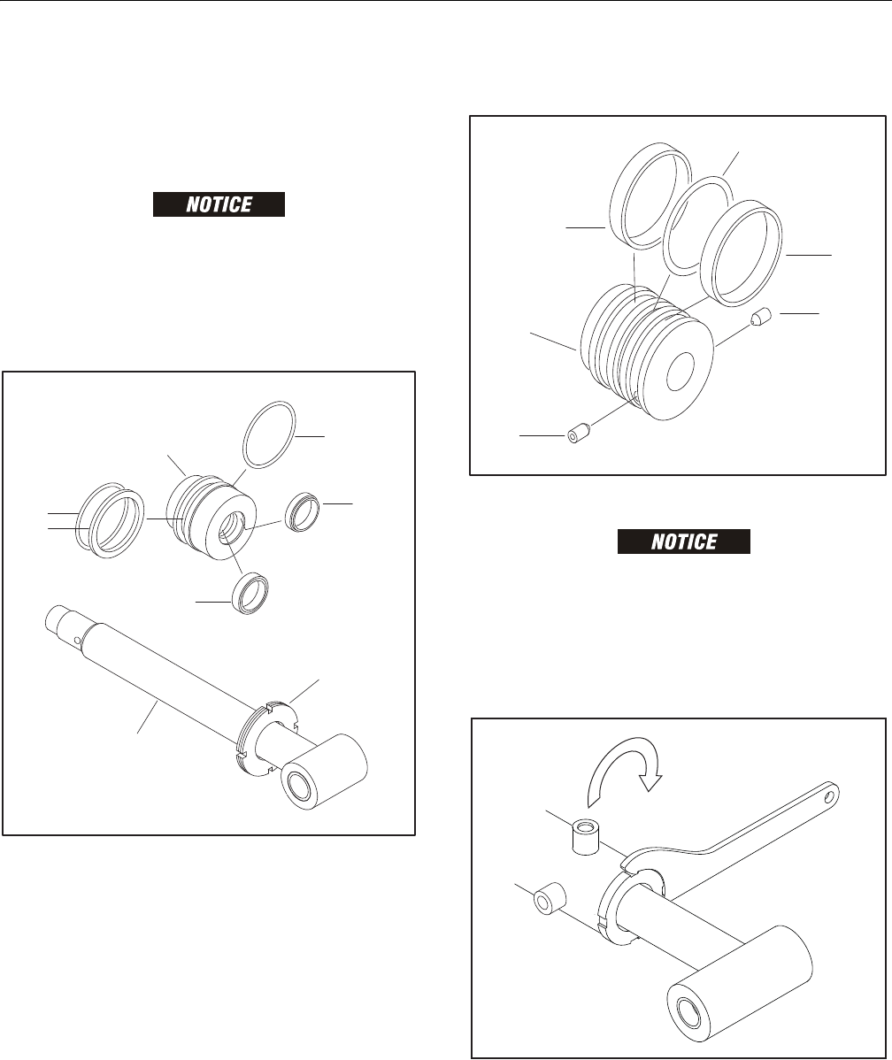
SECTION 5 - HYDRAULICS
5-36 – JLG Lift – 3121298
Assembly
NOTE: Apply a light film of hydraulic oil to all components before
assembly.
1. Position cylinder barrel in a suitable holding fixture.
IMPROPER SEAL INSTALLATION CAN CAUSE CYLINDER LEAKS AND IMPROPER
CYLINDER OPERATION.
2. Install Spanner Nut (3) on Rod (6).
3. Install Rod Seal (5) and Wiper () in Cylinder Head (3).
4. Install O-Ring (7), Backup Ring (8), and O-Ring (9).
Figure 5-75. Cylinder Head Assembly
5. Install wear ring (11) in piston groove.
6. Install seal (10) in piston groove.
Figure 5-76. Piston Seal and Wear Ring
INSERTING ROD OFF-CENTER CAN DAMAGE PISTON AND CYLINDER BARREL
SURFACES. USE EXTREME CARE INSTALLING CYLINDER ROD AND PISTON.
7. Insert Rod Assembly in Barrel (1).
8. Apply Locking Primer and Loctite 242 (or equivalent) to
threads of Spanner Nut (3). Tighten spanner nut (3) with
hook spanner to 57-63 ft-lb (77-85 Nm).
Figure 5-77. Spanner Nut Torque

SECTION 5 - HYDRAULICS
3121298 – JLG Lift – 5-37
Axle Lockout Cylinder
NOTE: Refer to Figure 5-78., Axle Lockout Cylinder.
DISASSEMBLY
CONTAMINATION MAY DAMAGE EQUIPMENT. DISASSEMBLE CYLINDER ON A
CLEAN WORK SURFACE IN A DIRT FREE WORK AREA.
PISTON CAN FALL OUT OF HOUSING AND CAUSE INJURY OR DAMAGE TO
EQUIPMENT. BE CAREFUL WHEN REMOVING AXLE CYLINDER. OPENING BLEED
VALVE CAN CAUSE PISTON TO FALL OUT OF HOUSING.
1. Open bleed valve (8). Rotate piston (2) and remove from
housing (1).
2. Remove wiper (6). Do not scratch housing bore.
3. Remove two wear rings (5) and rod seal (7) from grooves
in piston bore. Do not scratch housing bore.
4. Remove check valve (9), if required.
5. Inspect bore and piston for scoring, pitting, or excessive
wear.
6. Remove minor surface blemishes with wet 2000-grit
sandpaper. Pitting requires replacement of housing or
piston.
7. Clean all parts with approved solvent and dry with com-
pressed air.
ASSEMBLY
Refer to Figure 5-78., Axle Lockout Cylinder.
1. Install two new wear rings (5) and rod seal (7) in piston
bore grooves. Make sure they are not twisted.
2. Install new wiper (6) in housing.
3. Lubricate piston bore with clean hydraulic fluid.
INSERTING PISTON OFF-CENTER CAN DAMAGE PISTON AND PISTON BORE
SURFACES. USE EXTREME CARE WHEN INSTALLING PISTON.
4. Install piston (2) in bore and push to top of bore.
5. Install check valve (9). Torque to 25 - 27 ft-lb (33 - 36 Nm).
6. Bleed system.
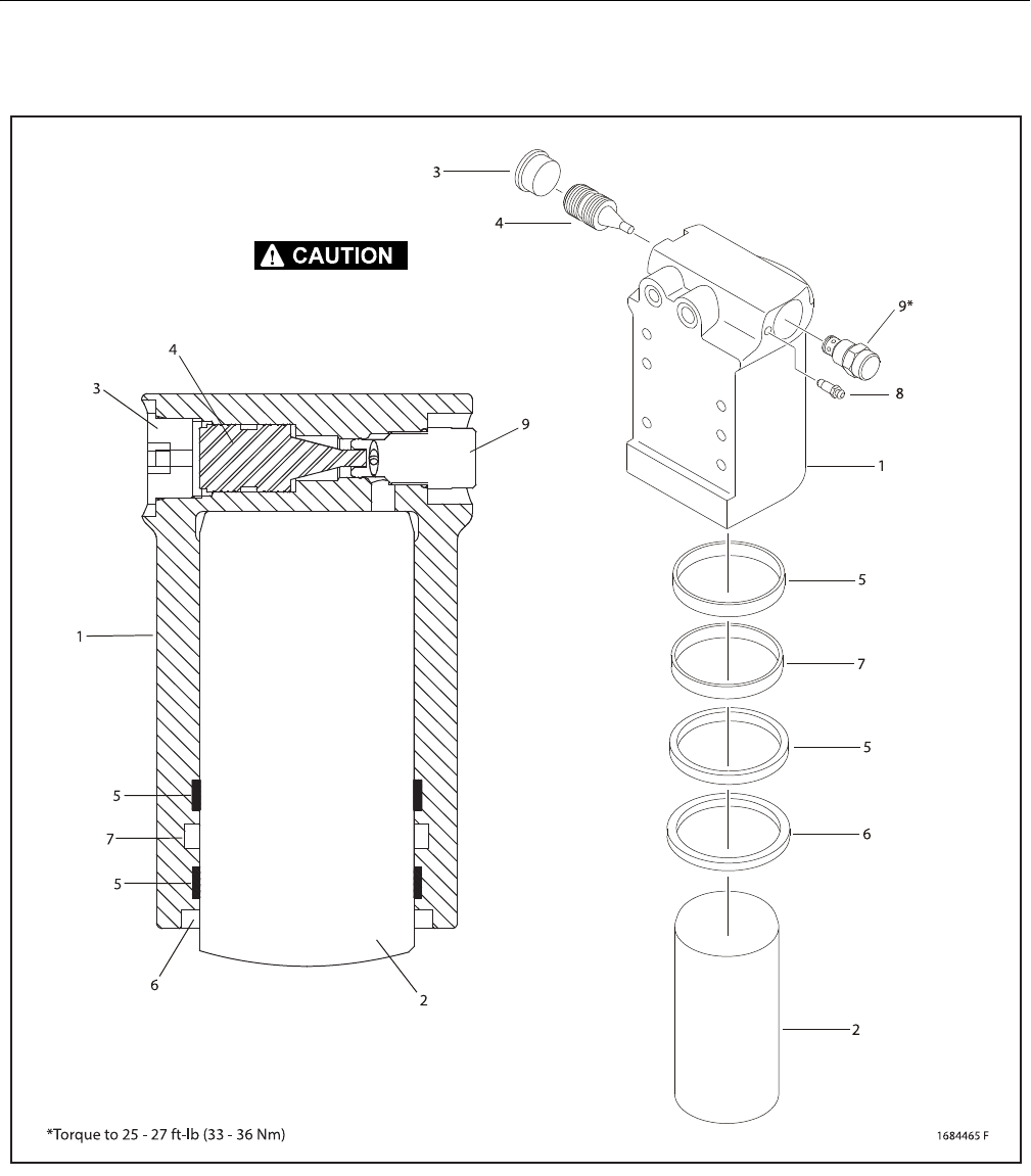
SECTION 5 - HYDRAULICS
5-38 – JLG Lift – 3121298
1. Barrel
2. Rod
3. Plug
4. Pilot Piston
5. Wear Ring
6. Wiper
7. Rod Seal
8. Bleeder
9. Cartridge Valve
Figure 5-78. Axle Lockout Cylinder
FALLING PARTS CAN CAUSE INJURY AND EQUIPMENT DAMAGE. CYLINDER
ROD CAN FALL OUT WHEN BLEEDER VALVE IS OPENED.
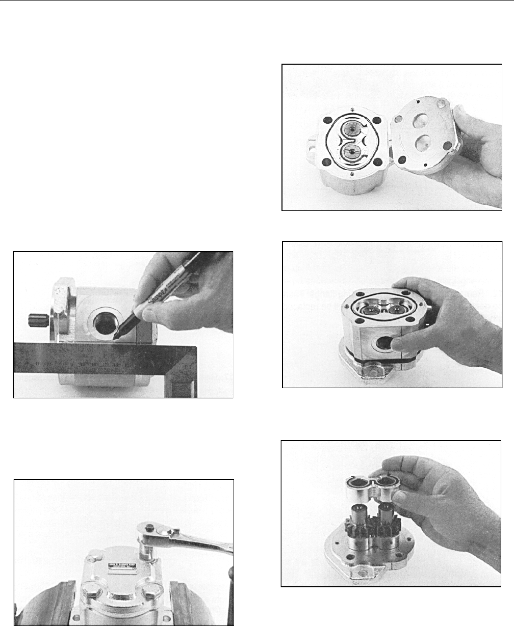
SECTION 5 - HYDRAULICS
3121298 – JLG Lift – 5-39
5.6 HYDRAULIC PUMP (GEAR)
Disassembly
NOTE: The following general instructions also apply to multiple
section gear pumps. The only extra parts are the coupling
between drive shafts and center distance plate which
divides the two pump sections. This repair procedure also
applies to ”W” series Gear Motors.
1. Always work in a clean work area when repairing
hydraulic products. Plug ports and wash exterior of
pump with approved cleaning solvent.
2. Remove port plugs and drain oil from pump.
3. Use a permanent marker pen to mark a line across
mounting flange, gear housing and end cover. This will
assure proper reassembly and rotation of pump.
4. Remove key from drive shaft if applicable.
5. Clamp mounting flange in a protected jaw vise with
pump shaft facing down.
6. Loosen four metric hex head bolts.
7. Remove pump from vise and place on clean work bench.
Remove four hex head bolts and spacers if applicable.
8. Lift and remove end cover.
9. Carefully remove gear housing and place on work
bench. Make sure rear bearing block remains on drive
and idler shafts.
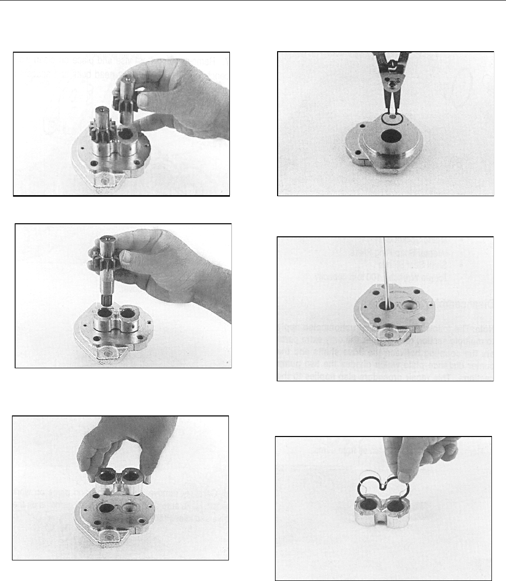
SECTION 5 - HYDRAULICS
5-40 – JLG Lift – 3121298
10. Remove rear bearing block from drive and idler shafts.
11. Remove idler shaft from bearing block.
12. Remove drive shaft from mounting flange.
NOTE: Shaft seal will be replaced.
13. Remove front bearing block.
14. Turn mounting flange over, with shaft seal up. Remove
retaining ring with snap ring pliers.
15. Remove oil seal from mounting flange. Do not mar or
scratch seal bore.
16. Remove dowel pins from gear housing. Do not lose pins.
17. Remove and discard seals from both bearing blocks.
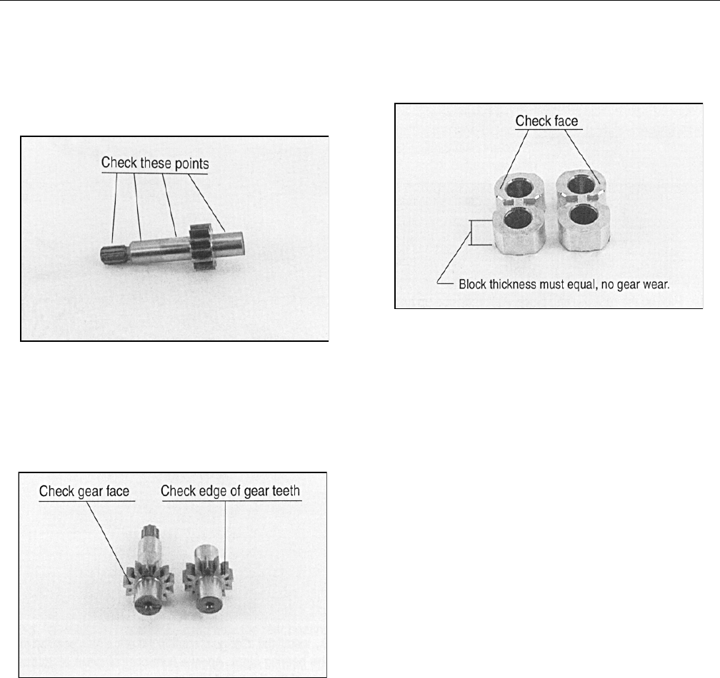
SECTION 5 - HYDRAULICS
3121298 – JLG Lift – 5-41
Inspect Parts For Wear
1. Clean and dry all parts thoroughly before inspection. It
is not necessary to inspect seals. They will be placed as
new items.
2. Check drive shaft spine for twisted or broken teeth,
check keyed drive shaft for broken or chipped keyway.
No marks or grooves on shaft in seal area, some discolor-
ation of shaft is allowable.
3. Inspect drive gear shaft and idler gear shafts at bearing
points and seal area for rough surfaces and excessive wear.
4. Inspect gear face for scoring or excessive wear. If face
edge of gear teeth are sharp, they will mill into the bear-
ing blocks. If wear has occurred, parts are unusable.
5. Inspect bearing blocks for excessive wear or scoring on
surfaces in contact with gears. Inspect bearings for
excessive wear or scoring.
6. Inspect area inside gear housing. A clean ”wipe” on
inside surface of intake side is normal. There should not
be excessive wear, deep scratches, or gouges.
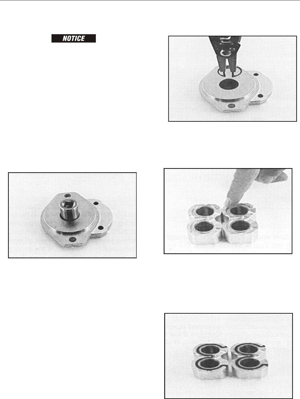
SECTION 5 - HYDRAULICS
5-42 – JLG Lift – 3121298
General Information
FAILURE TO PROPERLY ASSEMBLE THIS PUMP WILL RESULT WITH LITTLE OR
NO FLOW AT RATED PRESSURE. RELATIONSHIP OF MOUNTING FLANGE, BEAR-
ING BLOCKS, AND GEAR HOUSING MUST BE CORRECT.
Reverse Shaft Rotation of Pump
NOTE: Pump is not bi-rotational. Use the following procedure if
shaft rotation direction is changed.
Reverse shaft rotation of ”W” series gear pump by rotating, as
a group, two bearing blocks and gear housing 180° in relation-
ship to remaining parts of pump. This places pressure port
opposite from original position.
Assembly
NOTE: Install new seals when reassembling pump or motor. Go to
page 8 for kit part numbers for W-600, W-900, and W-1500
pumps and motors.
1. Install new shaft seal in mounting flange with part num-
ber side facing out. Press seal into seal bore until seal
reaches bottom of bore. Use uniform pressure to pre-
vent seal misalignment or damage.
2. Install retaining ring in groove in seal bore of mounting
flange.
3. Place front and back bearing blocks on a clean surface
with E-seal grooves facing up. Apply a light coating of
petroleum jelly in the grooves. Coat E-seal and backup
with petroleum jelly. This helps keep seals in place dur-
ing reassembly
4. Place E-seals, flat side out, into grooves in both bearing
blocks. Carefully place backup ring, flat side out, in
groove made by E-seal and groove in bearing block.
(Note: W900 series pump - In center of backup ring and E-
seal there is a notch. Make sure notches line up so backup
ring will set flush with E-seal). Backup ring in W1500
pump is symmetrical.
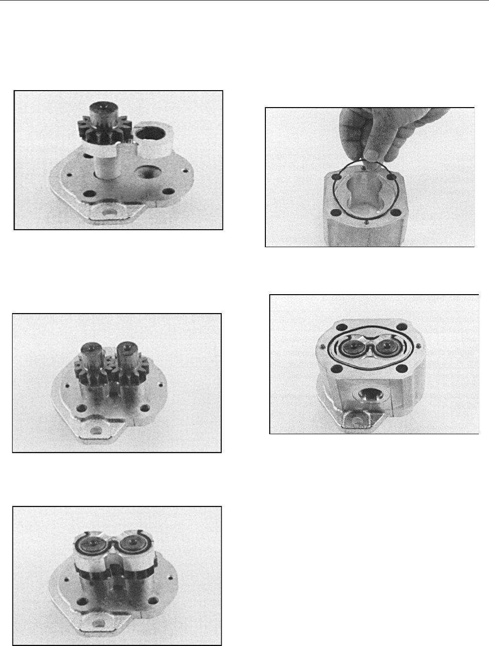
SECTION 5 - HYDRAULICS
3121298 – JLG Lift – 5-43
5. Place mounting flange, with shaft seal side down, on a
clean flat surface.
6. Apply a light coating of petroleum jelly to exposed face
of front bearing block.
7. Insert drive end of drive shaft through bearing block
with seal side down and open side of E-seal pointing to
intake side of pump.
8. Install seal sleeve over drive shaft. Carefully slide drive
shaft through shaft seal. Remove seal sleeve from shaft.
9. Install idler gear shaft in remaining position in bearing
block. Apply a light coat of clean oil to face of drive and
idler gears.
10. Place rear bearing block over drive and idler gear shafts
with seal side up and open end of E-seal
facing intake side of pump.
11. Install two dowel pins in mounting flange holes or two
long dowel pins through gear housing if pump is a mul-
tiple section pump.
12. Apply a light coating of petroleum jelly in grooves on
both sides of gear housing. Coat new O-rings and install
in grooves.
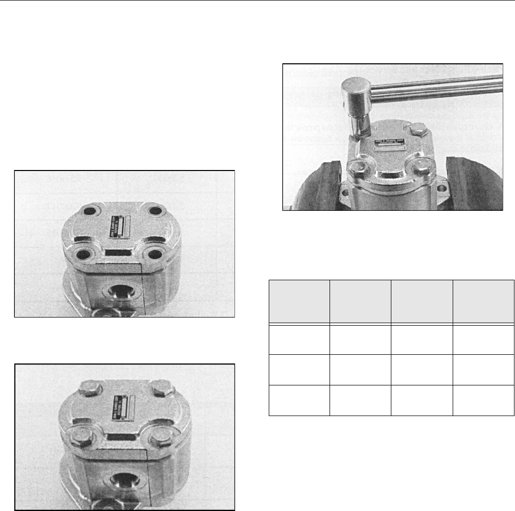
SECTION 5 - HYDRAULICS
5-44 – JLG Lift – 3121298
13. Gently slide gear housing over rear bearing block
assembly. Slide housing down until it engages dowel
pins. Press firmly in place with hands, do not force or use
any tool. Check intake port in housing is on same side as
open end of E-seal, and marked lines on mounting
flange and gear housing are aligned.
NOTE: Rear bearing block surface should be slightly below gear
housing face. If bearing block is higher than rear face of
gear housing, E-seal or O-ring have shifted out of groove.
Remove gear housing and check for proper seal installa-
tion.
14. Install two remaining dowel pins in rear of gear housing,
if applicable. Place end cover over back of pump.
15. Install four spacers (if applicable) and hex head bolts
through bolt holes in end cover. Hand tighten.
16. Place mounting flange of pump in protected jawed vise
and alternately torque bolts to torque chart specifica-
tions. All torque figures are for ”dry torque” bolts.
17. Remove pump from vise.
18. Place a small amount of clean oil in pump inlet and
rotate drive shaft away from inlet one revolution. If drive
shaft binds, disassemble pump and check for assembly
problems. Reassemble pump.
Table 5-1.Hydraulic Pump Bolt Torque Chart
Pump Series Thread Size
Torque Values,
Black Oxide
End Cover
Torque Values,
Zinc Plated End
Cover
W-600 M 8 x 1.25 18-21 ft.lb.
24-30 Nm
16-18 ft.lb.
21.7-24.4 Nm
W-900 M 10 x 1.5 50-55 ft.lb.
68-75 Nm
38-43 ft.lb.
51.5-58.3 Nm
W-1500 M 12 x 1.75 80-85 ft.lb.
108-115 Nm
68-73 ft.lb.
92.2-99 Nm

SECTION 5 - HYDRAULICS
3121298 – JLG Lift – 5-45
Placing Pump Back Into Service
1. If shop test stand is available, use the following proce-
dure for testing rebuilt pumps:
a. Mount pump on test stand. Make sure proper level
of clean oil is available in reservoir. Check suction
line for leaks and obstructions.
b. Start pump and run for three minutes at zero pres-
sure.
c. Intermittently load pump to 500 P.S.I. for three min-
utes.
d. Intermittently load pump to 1000 P.S.I. for three
minutes.
e. Intermittently load pump to 2000 P.S.I. for three
minutes.
f. Remove pump from test stand and check for free-
ness of drive shaft. Check pump for signs of external
leakage.
2. If shop test stand is not available, use the following proce-
dure for testing rebuilt pumps:
a. For engine driven pumps, mount pump on equip-
ment and run pump at 1/2 engine speed at zero
pressure for three minutes.
b. Operate control valve and build pressure intermit-
tently for three minutes.
c. Increase engine speed to full throttle and build
pressure intermittently for three minutes.
d. Stop engine and check pump for external leaks.
5.7 VARIABLE PUMP
Ports and Pressure Gauges
Proper servicing of pumps and motors requires pressure mea-
sured and monitored at various hydraulic circuit points. The
Series 42 pump has several locations at which to take these
measurements. The following outlines show gauge port loca-
tions, and gauge and fitting size for each port.
NFPE Control
The 3-position FNR control, and electric and hydraulic non-
feedback proportional (NFPE and NFPH) controls are non-
feedback type controls. FNR and NFPE controls consist of
pump housing mounted modules. Hydraulic input for NFPH is
received through ports on top of pump [9/16–18 SAE O-ring
fitting].
Non-feedback controls are factory set. Control modules can be
removed to clean ports and change O-rings.
FNR and NFPE orifice plugs are located inside the servo piston
covers. NFPH orifice plugs are located in the NFPH ports. Ori-
fice plugs may be cleaned or replaced.
Table 5-2. Recommended Gauge Size
Gauge
Port
Name
Pressure
Measured
Recommended Gauge
Size Fitting
PSI Bar
M1 & M2 System
Pressure
Ports A & B
10000 600 9/16-18 ORF
M3 Charge 1000 60 3/4-16 ORF
M4 & M5 Servo 1000 60 9/16-18 ORF
L1 & L2 Case 500 35 1-1/16-12 ORF
SCharge Pump
Inlet Vacuum
30 in. Hg Vac. 11-1/16-12 ORF
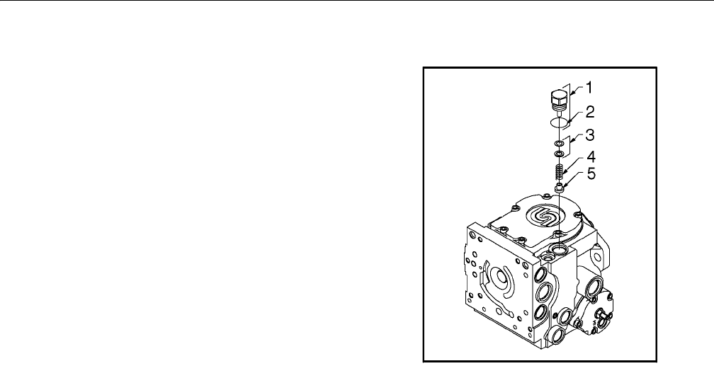
SECTION 5 - HYDRAULICS
5-46 – JLG Lift – 3121298
Remove and Install FNR and NFPE Modules
1. Clean pump and module housings.
2. Remove four screws retaining module to pump housing (4
mm Int. Hex). Remove module from housing.
3. Remove O-rings from the control ports. Examine ports
for cleanliness.
4. Clean sealing surfaces.
5. Replace locator pin.
6. Install new O-rings.
7. Replace screws. Torque to 3.5 - 4.5 ft-lb (4.7-6.1 Nm).
Remove and Install FNR and NFPE Control Orifices
NOTE: Future models may contain an orifice plate between mod-
ule and pump housing. This will take the place of the orifice
plugs beneath the servo piston cover.
1. Remove servo piston cover.
2. Remove orifice plug (1/8" Int. Hex).
3. Examine orifice and port for cleanliness.
4. Install orifice plug. Torque to 1.5 - 2.5 ft-lb (2.0-3.4 Nm).
Charge Relief Valve
Charge relief valve may be removed for cleaning and installa-
tion of new O-rings. Pressure setting may be changed for dif-
ferent charge flows depending on charge pump size and
pump speed.
Factory setting is set relative to case pressure at 1800 rpm.
Actual charge pressure varies at different speeds.
SHIM ADJUSTABLE STYLE
1. Remove shim adjustable charge relief valve plug (1" Hex)
from pump housing. Remove O-ring from plug.
2. Remove spring and poppet from housing.
3. Do not alter shims which may be installed between
spring and valve plug, or interchange parts with another
valve. Inspect poppet and mating seat in housing for
damage or foreign material.
4. If desired, change charge relief valve setting. An approx-
imate rule of thumb is 4 bar / 1.25 mm (58 psi / 0.050 in).
Effective setting will vary.
To confirm charge relief valve setting, measure charge
pressure (port M3) with pump in stroke. Charge pressure
should level off when relief setting is reached.
1. Plug
2. O-Ring
3. Shims
4. Spring T-Seal
5. Poppet
Figure 5-79. Shim Adjustable Charge Relief Valve
Components
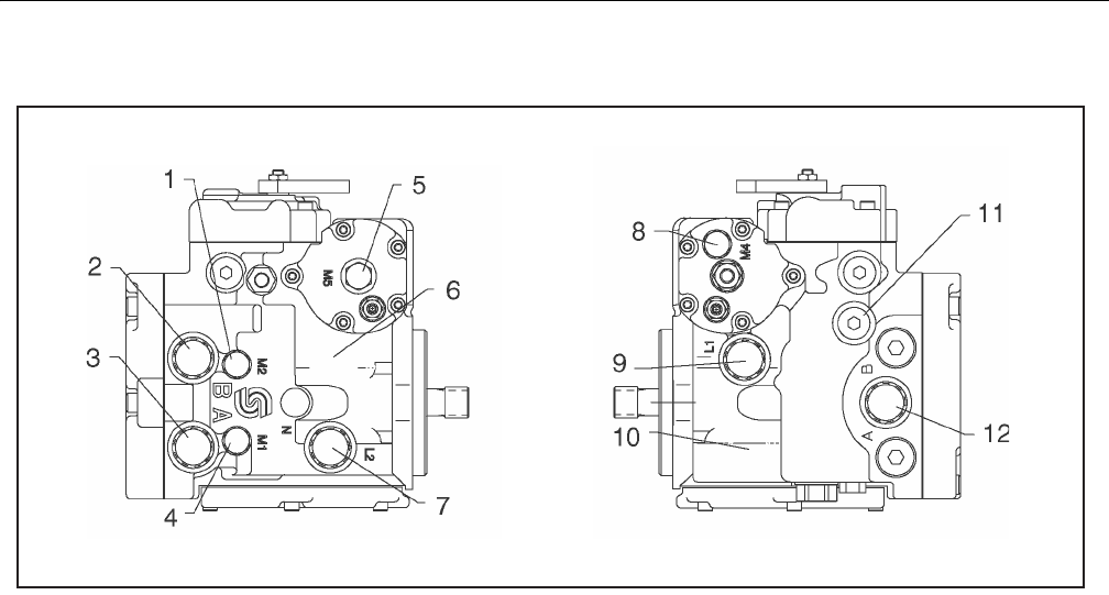
SECTION 5 - HYDRAULICS
3121298 – JLG Lift – 5-47
Figure 5-80. Gauge Port Locations
1. System Pressure Gauge Port M2 7. Case Drain Port L2
2. System Pressure Port B 8. Servo Pressure Gauge Port L4
3. System Pressure Port A 9. Case Drain Port L1
4. System Pressure Gauge Port M1 10. Case Drain Port L1 (non-feedback)
5. Servo Pressure Gauge Port M5 11. Charge Pressure Gauge
6. Case Drain Port L2 (non-feedback) 12. Charge Pump Inlet Port S
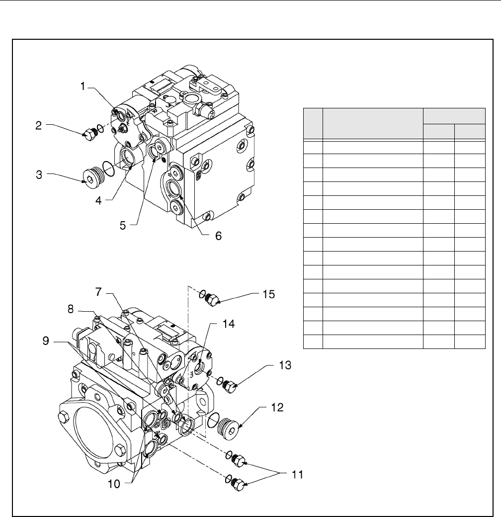
SECTION 5 - HYDRAULICS
5-48 – JLG Lift – 3121298
Figure 5-81. Plugs/Fittings Size & Torque
#Plug/
Fitting
Torque
lb. ft. Nm
1 Servo Gauge Port M4 N/A N/A
2 11/16 20-35 27-47
39/16 70-100 95-135
4 Case Drain Port L1 N/A N/A
5 Charge Pressure Gauge M3 N/A N/A
6 Charge Pump Inlet Port S 85 115
7 Case Drain Port L2 N/A N/A
8Port N N/A N/A
9 System Gauge M1 & M2 N/A N/A
10 System Ports A&B 85 115
11 11/16 20-35 27-47
12 9/16 70-100 95-135
13 11/16 20-35 27-47
14 Servo Gauge M5 N/A N/A
15 11/16 20-35 27-47
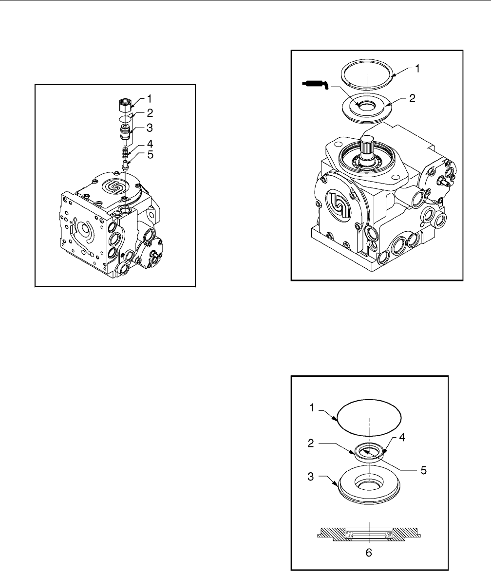
SECTION 5 - HYDRAULICS
3121298 – JLG Lift – 5-49
5. Install new O-ring on valve plug. Reinstall poppet,
spring, and plug (with shims and O-ring) into pump
housing. Torque to 40-100 ft-lb (55-135 Nm).
SCREW ADJUSTABLE STYLE
1. Mark plug, lock nut, and housing to maintain original
adjustment before removing screw adjustable relief valve
plug. Loosen lock nut (1-1/16" Hex) and remove plug (8
mm Int. Hex). Remove O-ring from plug.
2. Remove spring and poppet from housing.
3. Inspect poppet and mating seat in housing for damage
or foreign material.
4. Install new O-ring on valve plug. Reinstall poppet and
spring. Reinstall plug and lock nut. Torque to 34 - 42 ft-lb
(47-57 Nm), aligning marks made at disassembly.
5. Check and adjust charge pressure if necessary. For screw
adjustable “anti-stall” charge relief valves, an approxi-
mate rule of thumb is 2.8 bar/quarter turn (40 psi/quar-
ter turn).
6. Measure charge pressure (port M3) with pump in stroke.
Charge pressure should level off when relief setting is
reached.
Shaft Seal and Shaft Replacement
A lip type shaft seal is used in Series 42 pumps. Seal and shaft
can be replaced without major unit disassembly. Replacement
generally requires removing pump from machine.
1. L oc k Nu t
2. O -R in g
3. P lu g
4. S pr in g T- Se al
5. Po pp et
Figure 5-82. Screw Adjustable Charge Relief Valve
Components
1. Re ta in in g R in g 2. S ea l Ca rr ie r A ss em bly
Figure 5-83. Shaft Seal Components
1. O -R ing
2. S eal
3. S eal Ca rr ie r
4. Sealant may be used on outside diameter
5. Inside Lip (face down)
6. Pre ss Se al to Bo tto m o f S ea l C arri er
Figure 5-84. Installation of Shaft Seal
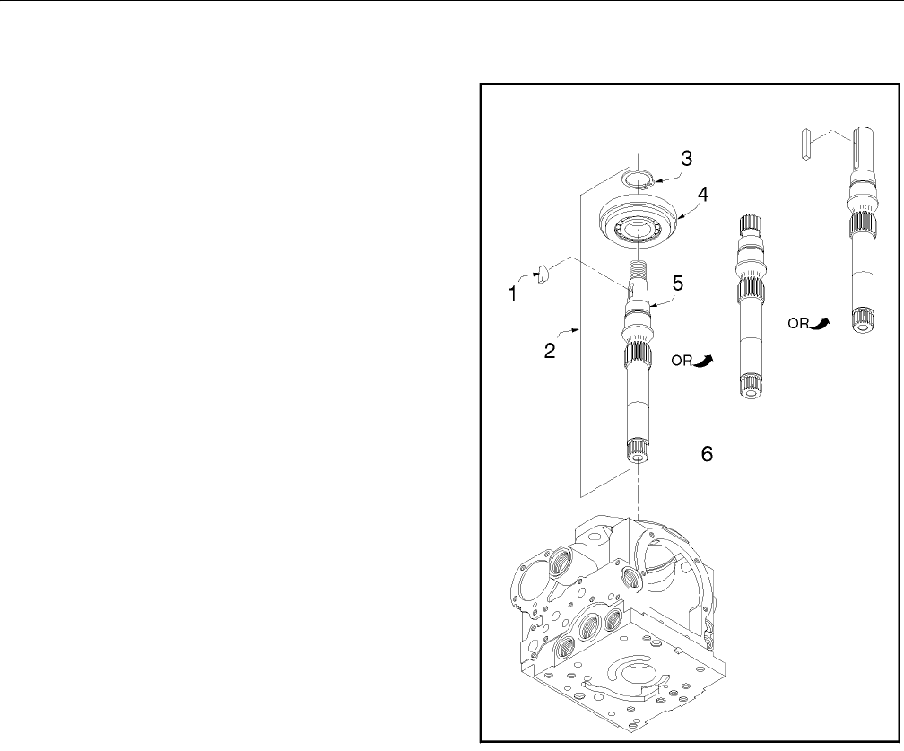
SECTION 5 - HYDRAULICS
5-50 – JLG Lift – 3121298
1. Position pump with shaft facing up.
NOTE: If unit is positioned horizontally when shaft is removed, cyl-
inder block could move out of place, making shaft installa-
tion difficult.
2. Remove retaining ring from housing.
3. Pull out seal carrier assembly.
4. Remove O-ring from seal carrier. To install a new shaft
only, go to step 8.
5. Place seal carrier in an arbor press with shaft bearing
side down and press out old seal. An appropriately sized
pipe spacer or socket wrench can be used as a press
tool. Seal is not reusable.
6. Inspect seal carrier and new seal for damage. Inspect
sealing area on shaft for rust, wear, or contamination.
Polish sealing area on shaft if necessary.
7. Press new seal in shaft bearing side of seal carrier. Seal
lip must face outside of pump. Do not damage seal. Out-
side diameter of seal may be coated with a sealant (e.g.
Loctite High Performance Sealant #59231) before instal-
lation. This helps prevent leaks caused by damage to
seal bore in seal carrier. If shaft is not being replaced go
to step 11.
8. Remove shaft and roller bearing assembly from pump or
motor.
9. Remove retaining ring from roller bearing assembly with
snap ring pliers. Remove roller bearing assembly.
10. Place roller bearing assembly on new shaft and secure
with retaining ring.
11. Wrap spline or key end of shaft with thin plastic to pre-
vent damage to seal lip during installation. Lubricate
inside diameter of shaft seal with petroleum jelly.
12. Place O-ring on shaft bearing and lubricate with petro-
leum jelly.
13. Slide seal carrier assembly over shaft and into housing
bore. Press against O-ring. Hold inward pressure against
shaft to compress cylinder block spring while pressing seal
carrier into place.
14. Install retaining ring.
Hydraulic Pump W/Hayes Pump Drive Coupling
Lubrication
Coat pump and drive coupling splines with Lithium Soap
Base Grease (TEXACO CODE 1912 OR EQUIVALENT)
whenever pump or pump drive coupling is removed. Cou-
pling is greased prior to assembly.
1. Ke y
2. Sh af t A ss em bl y
3. Re ta in ing R in g
4. Ro ll er Be ar in g
5. Sh af t
Figure 5-85. Shaft Components
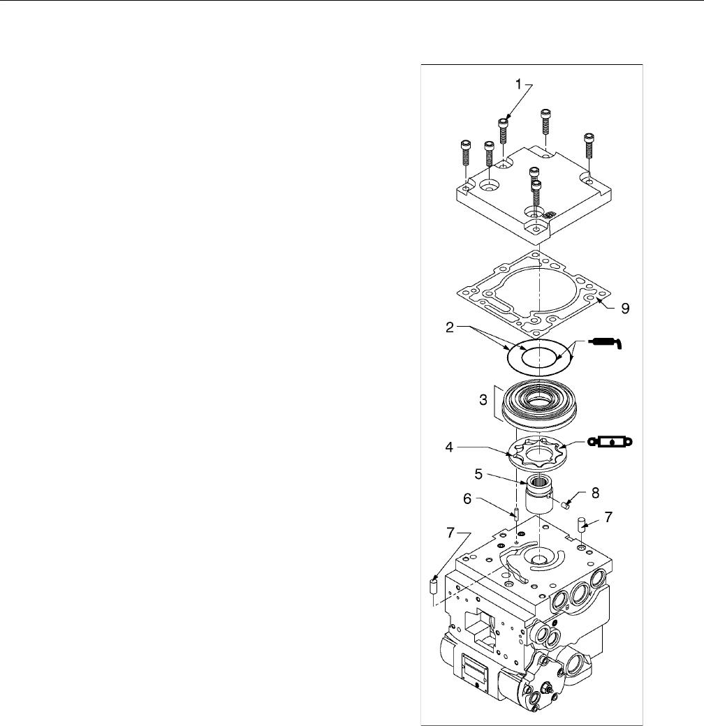
SECTION 5 - HYDRAULICS
3121298 – JLG Lift – 5-51
Charge Pump
NOTE: Disassemble charge pump to inspect and clean, or change
auxiliary shaft drive coupling.
1. Remove auxiliary pump if necessary.
2. Remove screws retaining charge pump cover to pump
housing (Torx T). Seven screws are used with “no pad” or
SAE “A” auxiliary mounting pad charge pump cover, and
six screws are used with SAE “B” auxiliary mounting pad
charge pump cover. Remove charge pump cover, gas-
ket, and cover locating pins.
3. Remove gerotor cover assembly from charge pump
cover or back of pump housing. Remove gerotor cover
O-rings. Two O-rings are used on gerotor cover of all
pumps.
4. Remove gerotor assembly from gerotor cover or pump
housing.
5. Remove gerotor drive pin and drive coupling. Remove
gerotor cover locating pin from pump housing.
6. Inspect each part if they are to be reused. If either gerotor
assembly parts needs to be replaced, they must both be
replaced. Always replace O-rings and charge pump cover
gasket. Inspect journal bearing in gerotor cover for exces-
sive wear.
7. Lubricate gerotor assembly with clean hydraulic oil
before assembly.
8. Install gerotor drive pin into hole in drive coupling.
Apply grease or petroleum jelly to keep in place.
9. Install drive coupling on pump shaft with smaller out-
side diameter facing away from shaft.
10. Install gerotor assembly onto coupling.
11. Install gerotor cover locating pin into pump housing.
Install gerotor cover assembly over gerotor. Locating pin
must engage slot in gerotor cover.
NOTE: Charge pump rotation is determined by location of gerotor
recess and pressure balance hole in gerotor cover. Different
gerotor covers are used for clockwise and counterclockwise
rotation pumps.
12. Install new pressure balance O-rings to gerotor cover
and retain with petroleum jelly or grease.
13. Install charge pump cover locating pins and new charge
pump cover gasket.
14. Install charge pump cover. Cover must engage gerotor
cover and locating pins. Install charge pump cover
screws. Torque evenly to 26 - 32 ft-lb (36-43 Nm).
15. Reinstall auxiliary pump if necessary.
Figure 5-86. Charge Pump Components
1. Cover Retaining Screw 6. Gerotor Cover Locating Pin
2. O-Ring 7. Charge Pump Cover
Locating Pin
3. Gerotor Cover
4. Gerotor Assembly 8. Gerotor Drive Pin
5. Drive Coupling 9. Gasket
SECTION 5 - HYDRAULICS
5-52 – JLG Lift – 3121298
5.8 HYDRAULIC COMPONENT START-UP
The goal at hydrostatic system start up is to preserve the
designed life span of the system. Use the following start-up
procedure when a new pump or motor is installed or a system
is restarted after a pump or motor has been removed and rein-
stalled.
THE FOLLOWING PROCEDURE MAY REQUIRE MACHINE TO BE DISABLED
(WHEELS RAISED OFF THE GROUND, WORK FUNCTIONS DISCONNECTED, ETC.)
WHILE PERFORMING PROCEDURE. TO PREVENT INJURY. TAKE NECESSARY
SAFETY PRECAUTIONS BEFORE MOVING VEHICLE/MACHINE.
Inspect pumps or motors for damage that may have been
incurred during shipping and handling before installation.
Make sure all system components (reservoir, hoses, valves, fit-
tings, heat exchanger, etc.) are clean before filling with fluid.
Fill reservoir with recommended hydraulic fluid. This fluid
should be passed through a 10 micron (nominal, no bypass)
filter before entering reservoir. Using contaminated fluid can
damage components and may cause unexpected vehicle/
machine movement.
INSPECT ALL PUMPS OR MOTORS FOR DAMAGE AND CONTAMINATION IF ANY
PUMP OR MOTOR IS REPLACED DUE TO INTERNAL DAMAGE. FLUSH AND
REPLACE ALL HYDRAULIC SYSTEM FLUID OR DAMAGE TO ENTIRE SYSTEM MAY
RESULT.
Inlet line from reservoir to pump must be filled prior to start-
up. Check inlet line for properly tightened fittings, restrictions,
and air leaks.
NOTE: Reservoir is usually above pump inlet. Pressure head cre-
ated by higher oil level helps keep inlet pressures within
acceptable range and prevent high vacuum levels. How-
ever, air may be trapped due to hose routing or low reser-
voir locations. Bleed air by loosening hose at fitting closest
to pump. When oil begins to flow, line is full and air has
been purged. Tighten fitting to specified torque. If tank
needs to be pressurized to start oil flow, take a vacuum
reading at pump inlet during operation to verify pump is
not trying to draw an inlet vacuum higher than its capabil-
ity.
Fill pump and motor housing with clean hydraulic fluid before
start up. Fill housing by pouring filtered oil in upper case drain
port.
NOTE: Use highest possible case drain port. This ensures housing con-
tains as much oil as possible and offers the greatest amount of
lubrication to internal components.
NOTE: It may be easier to fill housing before installing the case drain
line. Component (especially motor) location may prevent case
drain port access after installation.
NOTE: Oil used to fill component housing must be clean. Store fill
container properly to prevent contamination.
Install 1000 psi (60 bar) pressure gauge in charge pressure
gauge port to monitor charge pressure during start-up.
It is recommended external control input signal, (electrical
connections for EDC), be disconnected at pump control until
after initial start-up. This ensures pump remains in its neutral
position.
DO NOT START ENGINE UNLESS PUMP IS IN NEUTRAL POSITION (0° SWASH-
PLATE ANGLE). TAKE PRECAUTIONS TO PREVENT MACHINE MOVEMENT IN
CASE PUMP IS ACTUATED DURING INITIAL START-UP.
”Jog” or slowly rotate engine until charge pressure starts to
rise. Start engine and run at lowest possible RPM until charge
pressure is established. Excess air should be bled from system
lines as close to motors as possible.
NOTE: With engine on low idle loosen, do not remove, system lines
at motor(s). Continue to run engine at low idle and tighten
system lines as soon as oil is observed to leak from them.
When oil is observed to ”leak” at motor, line is full and air is
purged. Tighten system hoses to specified torque.
Once charge pressure is established, increase speed to normal
operating RPM. Charge pressure should be as indicated in the
pump model code. If charge pressure is inadequate, shut
down and determine cause.
INADEQUATE CHARGE PRESSURE WILL AFFECT OPERATOR'S ABILITY TO CON-
TROL MACHINE.
Shut down engine and connect external control input signal.
Reconnect machine function(s), if disconnected earlier. Start
engine, checking pump remains in neutral. With engine at nor-
mal operating RPM, slowly check forward and reverse machine
operation.
Charge pressure may slightly decrease during forward or
reverse operation. Continue to cycle slowly between forward
and reverse for at least five minutes.
Shut down engine, remove gauges, and plug ports. Check res-
ervoir level and add filtered fluid if needed.
Machine is ready for operation.
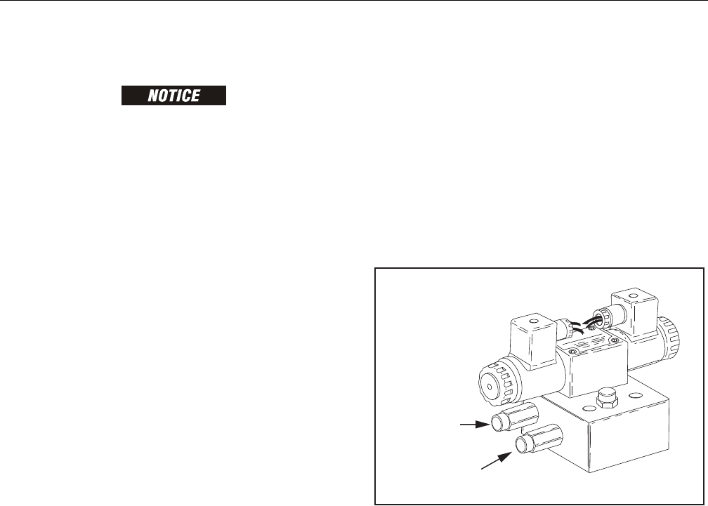
SECTION 5 - HYDRAULICS
3121298 – JLG Lift – 5-53
5.9 PRESSURE SETTING PROCEDURES
COLD TEMPERATURES HAVE A SIGNIFICANT IMPACT ON PRESSURE READINGS.
JLG INDUSTRIES, INC. RECOMMENDS OPERATING THE MACHINE UNTIL THE
HYDRAULIC SYSTEM HAS WARMED TO NORMAL OPERATING TEMPERATURES
PRIOR TO CHECKING PRESSURES. JLG ALSO RECOMMENDS USING A CALI-
BRATED GAUGE. PRESSURE READINGS ARE ACCEPTABLE IF WITHIN +/- 5% OF
SPECIFIED PRESSURES.
Main Relief, Steer, Swing, and Lift Down
1. Install pressure gauge at quick disconnect on port MP
on main valve.
2. With aid of an assistant, activate telescope in.
3. Monitor pressure gauge and adjust main relief valve to
3000 PSI (206.85 Bar).
4. With the aid of an assistant, activate steer left.
5. Monitoring pressure gauge and adjust steer left relief
valve to 1800 PSI (124.1 Bar).
6. With aid of an assistant, activate steer right.
7. Monitor pressure gauge and adjust steer right relief
valve to 1800 PSI (124.1 Bar).
8. With aid of an assistant, activate swing left or right.
9. Monitor pressure gauge and adjust swing relief valve to
1700 PSI (117.2 Bar).
10. With aid of an assistant, activate lift down.
11. Monitoring pressure gauge and adjust lift down relief
valve to 1500 PSI (103.4 Bar).
Platform Level
1. Install pressure gauge at quick disconnect on port M3
on main valve.
2. With aid of an assistant, activate platform level forward.
3. While monitoring pressure gauge, adjust platform level
relief to 2800 PSI (193.06 Bar).
4. Install pressure gauge at quick disconnect on port M4
on main valve.
5. With aid of an assistant, activate platform level back-
ward.
6. Monitor pressure gauge and adjust platform level relief
valve to 1800 PSI (124.11 Bar).
Articulating Jib Boom (If Equipped)
1. Install pressure gauge at quick disconnect on articulat-
ing valve.
2. With aid of an assistant, activate articulating jib up.
3. Monitor pressure gauge and adjust articulating jib up
relief valve to 1500 PSI (103 Bar).
4. With aid of an assistant, activate articulating jib down.
5. Monitor pressure gauge and adjust activate articulating
jib down relief valve to 1200 PSI (83 Bar).
Figure 5-87. Articulating Jib Boom Pressure Adjustment
4 Wheel Steer (If Equipped)
1. Activate "2 wheel steer" at platform console using
steer select switch.
2. Install pressure gauge in port MP on main control valve.
3. With aid of an assistant, activate steer left and right.
Adjust front steer relief valve to 2500 PSI (172.4 Bar).
This pressure only affects the front axle.
4. Activate “crab” or “coordinated” steer at platform
console using steer select switch
5. Disconnect wire DIN connectors on front steer valve
at main control valve block. When steer is activated
only rear steer will work.
6. Install pressure gauge in port MP on main control valve.
7. With aid of an assistant, activate steer left and right.
Adjust rear steer relief valve to 2500 PSI (172.4 Bar).
2500 PSI (172.4 Bar) at valve bank will give 2000PSI
(137.9 Bar) at cylinders.
8. Reconnect front steer DIN connectors at valve bank.
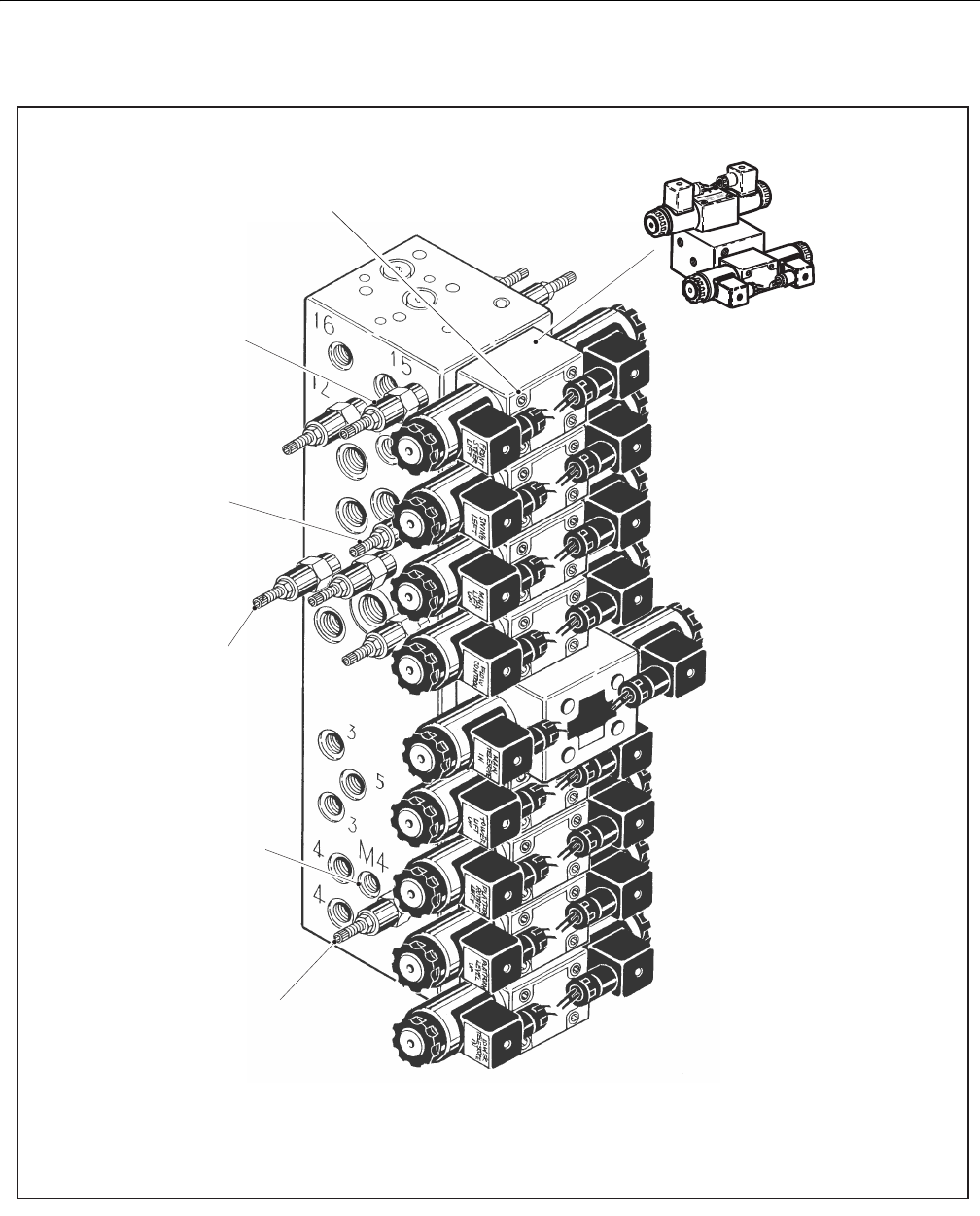
SECTION 5 - HYDRAULICS
5-54 – JLG Lift – 3121298
Figure 5-88. Main Control Valve - Sheet 1 of 2
!
"
#$%&'(#)
!"#
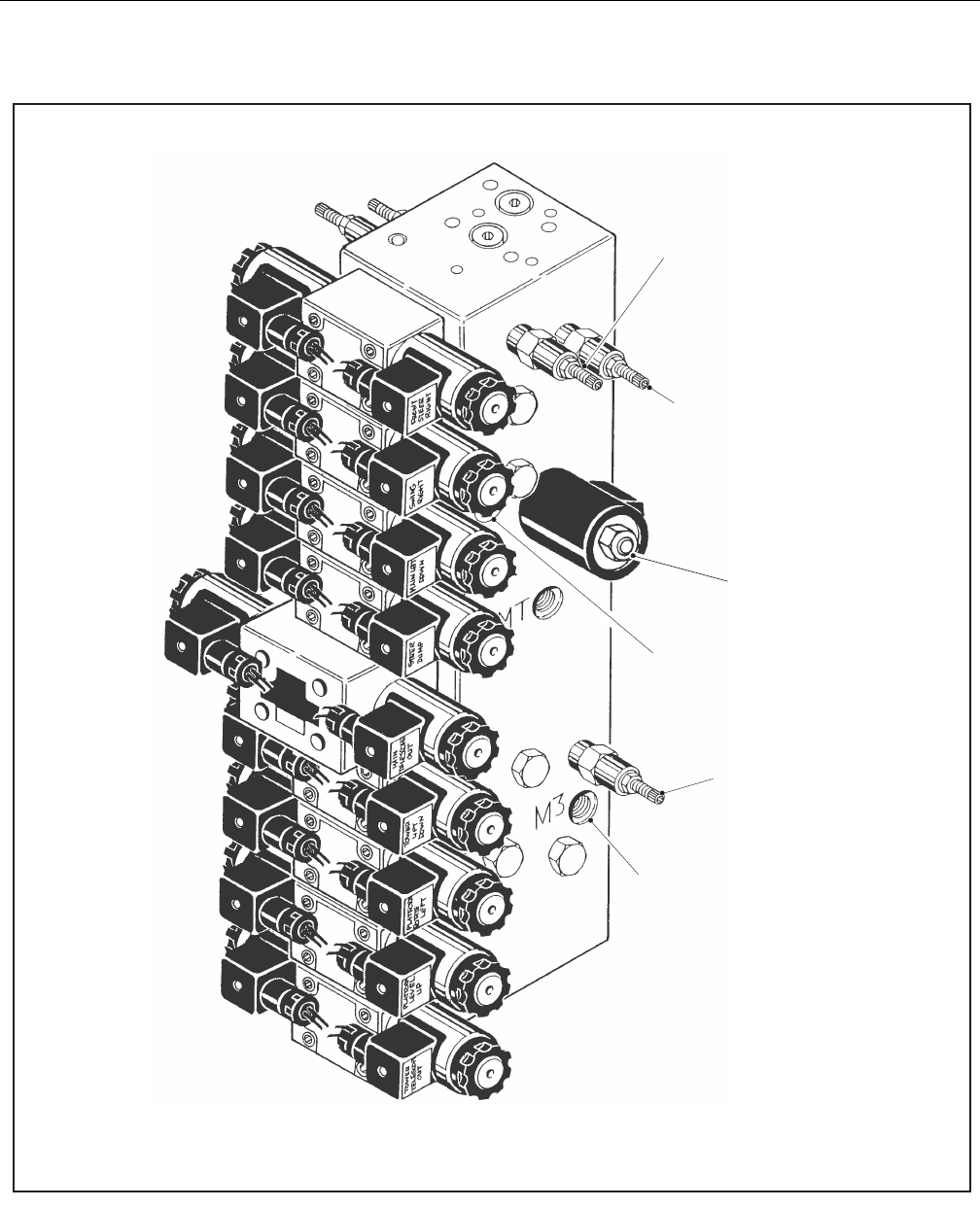
SECTION 5 - HYDRAULICS
3121298 – JLG Lift – 5-55
Figure 5-89. Main Control Valve - Sheet 1 of 2
!
"#
$%&'()*'+'$,'-
!"#
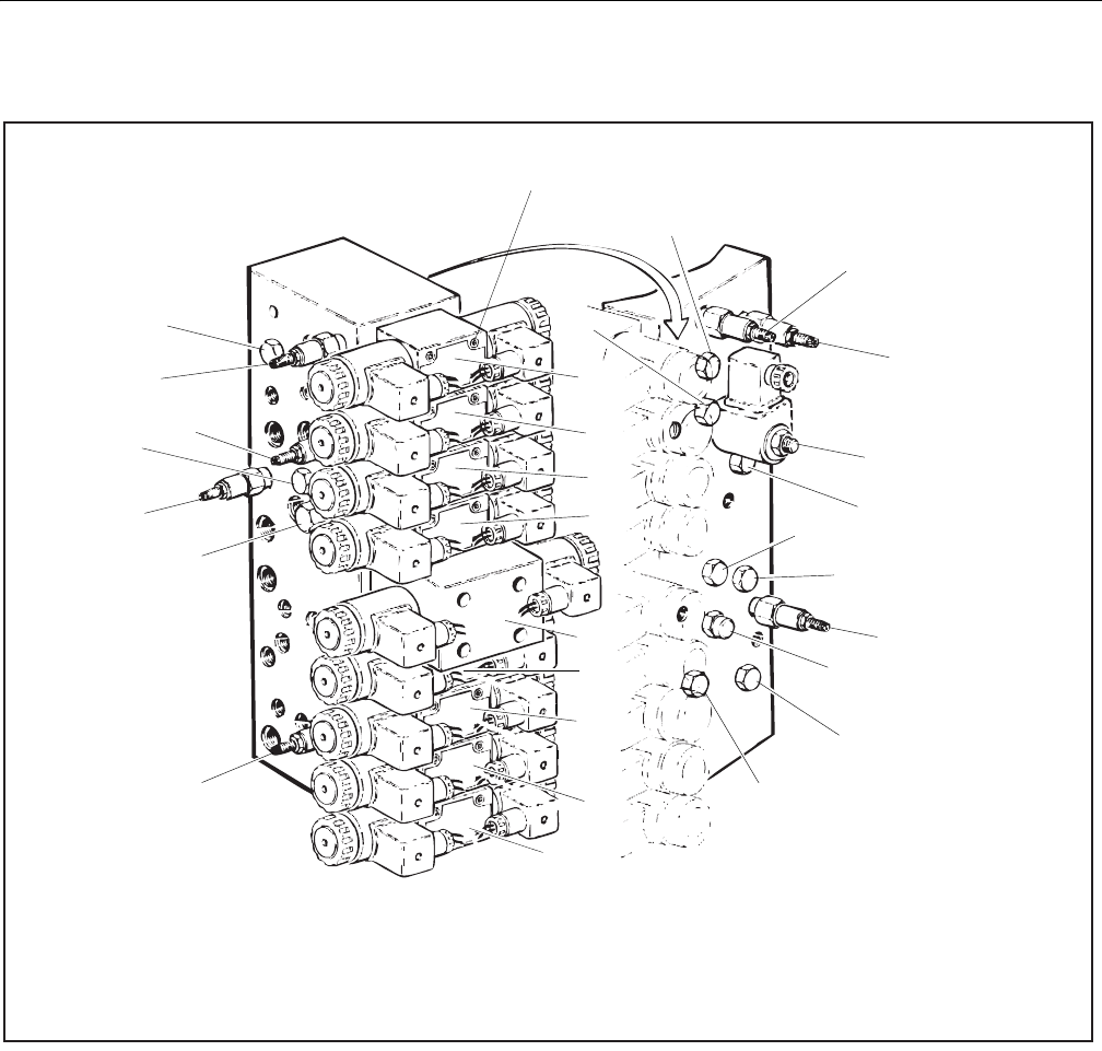
SECTION 5 - HYDRAULICS
5-56 – JLG Lift – 3121298
Figure 5-90. Location of Components - Main Control Valve
1.
!
" !#$ %!
&" '(% $
%!)*+, !
1. Solenoid Operated 2-Way valve 10. Directional Control Valve (Platform Rotator) 19. Directional Control Valve (Upper Lift)
2. Pressure Control Load Sense Cartridge 11. Directional Control Valve (Upper Telescope) 20. Directional Control Valve (Swing)
3. Direct Operated Relief Valve (Main Relief) 12. Directional Control Valve (Flow Control) 21. Direct Operated Relief Valve
4. Directional Control Valve (Platform Level) 13. Load Shuttle Valve 22. Directional Control Valve (Steer)
5. Pilot Operated Check Valve 14. Load Shuttle Valve 23. Direct Operated Relief Valve
6. Pilot Operated Check Valve 15. Load Shuttle Valve 24. Direct Operated Relief Valve
7. Direct Operated Relief Valve 16. Load Shuttle Valve 25. Directional Control Valve (Lower Telescope)
8. Direct Operated Relief Valve 17. Load Shuttle Valve 26. Directional Control Valve (Lower Lift)
9. Pressure Compensated Flow Control (Fixed 0.2 GPM) 18. Direct Operated Relief Valve 27. Check Valve
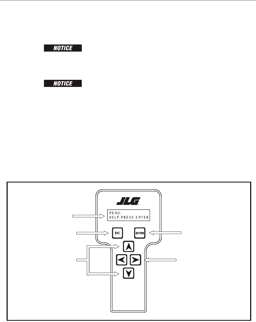
SECTION 6 - JLG CONTROL SYSTEM
3121298 – JLG Lift – 6-1
SECTION 6. JLG CONTROL SYSTEM
6.1 INTRODUCTION
WHEN INSTALLING A NEW GROUND MODULE CONTROLLER IT IS NECESSARY
TO PROGRAM THE CONTROLLER FOR PROPER MACHINE CONFIGURATION,
INCLUDING OPTIONS.
AVOID PRESSURE-WASHING ELECTRICAL/ELECTRONIC COMPONENTS. IF
PRESSURE-WASHING IS USED TO WASH AREAS CONTAINING ELECTRICAL/
ELECTRONIC COMPONENTS, JLG INDUSTRIES, INC. RECOMMENDS A MAXIMUM
PRESSURE OF 750 PSI (52 BAR) AT A MINIMUM DISTANCE OF 12 INCHES (30.5
CM) FROM THESE COMPONENTS. IF ELECTRICAL/ELECTRONIC COMPONENTS
ARE SPRAYED, SPRAYING MUST NOT BE DIRECT AND FOR BRIEF TIME PERI-
ODS TO AVOID HEAVY SATURATION.
The JLG designed Control System is a 12 volt based motor con-
trol unit installed on the boom lift.
The JLG Control System has reduced the need for exposed ter-
minal strips, diodes and trimpots and provides simplicity in
viewing and adjusting the various personality settings for
smooth control of: acceleration, deceleration, creep, min
speed, and max.-speed for all boom, drive, and steering func-
tions.
Upper lift, swing, and drive are controlled by individual joy-
sticks. Steering is controlled by a rocker switch built in the top
of the drive joystick. To activate Drive, Lift, and Swing; pull up
the slide lock on the joystick and move the handle in the
desired direction.
The control system provides voltage output to the valves and
pump, as programmed, for smooth operation and maximum
cycle time. Ground control speeds for all boom functions can
also be programmed in the control system.
The JLG Control System controller has a built in LED to indicate
any faults. The system stores recent faults which may be
accessed for troubleshooting. Optional equipment includes a
soft touch system, head and tail lights, and ground alarm.
These options may be added later but must be programmed
into the control system when installed.
The Control System may be accessed with a custom designed,
direct connect hand held analyzer or wireless adapter using an
app on your Android or iPhone/iPad device. The analyzer or
wireless output displays two lines of information at a time, by
scrolling through the program.
Each module has a label with JLG part number and a serial number
containing a date code.
Figure 6-1. Hand-Held Analyzer (WANALYZER Controls and Display Similar)
! "#
$%
#!
! "#
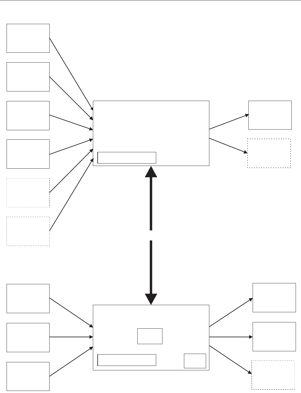
SECTION 6 - JLG CONTROL SYSTEM
6-2 – JLG Lift – 3121298
Figure 6-2. Controller Block Diagram
!"
#!"
$#
%&#'
&"(
)*
#
+,
$
-./0
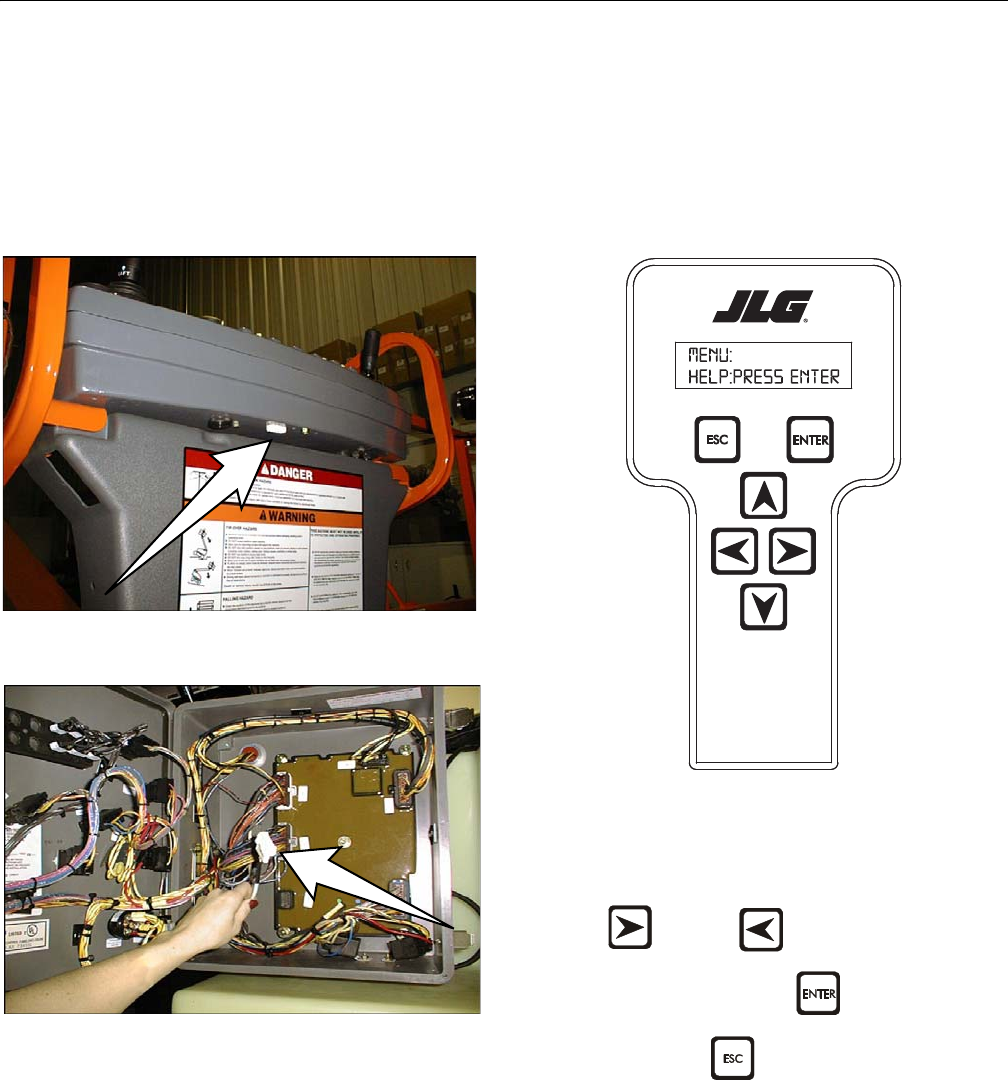
SECTION 6 - JLG CONTROL SYSTEM
3121298 – JLG Lift – 6-3
Connect JLG Control System Analyzer
1. Connect four pin end of cable supplied with hand-held
or wireless analyzer to controller module on platform
box or at controller module inside ground control box.
Connect other end of cable to analyzer.
NOTE: Cable has a keyed four pin connector at each end. It cannot
be connected backwards.
Figure 6-3. Analyzer Platform Connector
Figure 6-4. Analyzer Ground Control Box Connector
NOTE: Follow instructions provided with Wireless Analyzer (WAN-
ALYZER) kit. JLG Analyzer application must be downloaded
and installed to your smartphone or tablet device.
Using Analyzer
1. Power up Control System by turning lower key to plat-
form or ground position and pulling both emergency
stop buttons out.
Analyzer displays the following with machine power on and
analyzer connected properly:
MENU:
HELP:PRESS ENTER
Move between top level menu items using
RIGHT and LEFT arrow keys. To select a dis-
played menu item, press ENTER . To cancel a selected
menu item press ESC . Scroll using right and left arrow
keys to select a different menu item.
Top level menus:
HELP
DIAGNOSTICS
SYSTEM TEST
ACCESS LEVEL
PERSONALITIES
MACHINE SETUP
CALIBRATIONS (view only)
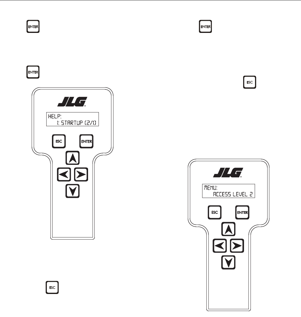
SECTION 6 - JLG CONTROL SYSTEM
6-4 – JLG Lift – 3121298
If ENTER is selected at the HELP: PRESS ENTER display,
and a fault is present, the analyzer display scrolls the fault
across the screen. If no fault is detected, the display shows:
HELP: EVERYTHING OK. If powered up at the ground station,
the display shows: GROUND OK.
If ENTER is pressed again, display shows the following:
LOGGED HELP
1: POWER CYCLE (0/0)
Analyzer displays last system fault if any are present. Use right
and left arrow keys to scroll through fault logs and view last 25
faults. Press ESC two times to return to MENU screen.
POWER CYCLE (0/0) indicates a power up.
When a top level menu is selected, a new set of menu items
may be offered: for example:
DRIVE
BOOM
SYSTEM
DATALOG
VERSIONS
Pressing ENTER with any of the above displayed menus,
displays additional sub-menus within the selected menu. In
some cases, such as DRIVE, the next level is the parameter or
information to be changed. Refer to the flow chart for what
menus are available within the top level menus. You may only
view the personality settings for selected menus while in
access level 2. Remember, you may always cancel a selected
menu item by pressing the ESCAPE key.
Changing Access Level
When analyzer is first connected, you will be in access level 2
which enables you to only view most settings which cannot be
changed until you enter a password to advance to a lower
level. This ensures that a setting cannot be accidentally
altered. To change access level, the correct password must be
entered. To enter password, scroll to ACCESS LEVEL menu. For
example:
ACCESS LEVEL:
CODE 00000
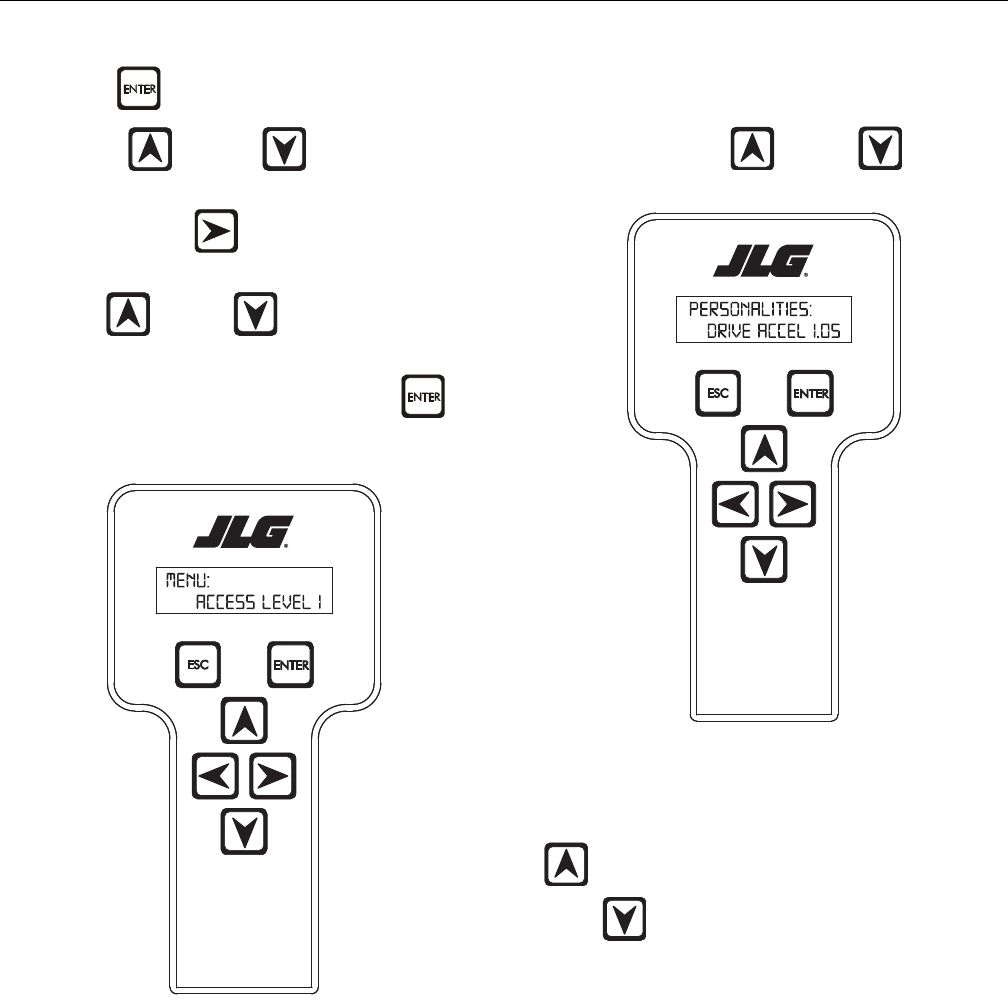
SECTION 6 - JLG CONTROL SYSTEM
3121298 – JLG Lift – 6-5
Press ENTER to select the ACCESS LEVEL menu.
Using the UP or DOWN arrow keys, enter first
digit of the password, 3.
Then using the RIGHT arrow key, position cursor right
one space to enter the second digit of the password.
Use the UP or DOWN arrow key to enter the sec-
ond digit of the password which is 33271.
When correct password is displayed, press ENTER . The
access level displays the following if password was entered
correctly:
MENU:
ACCESS LEVEL 1
Repeat above steps if correct access level is not displayed or
you can not adjust personality settings.
Adjust Parameters
Once you have gained access to level 1, and a personality item
is selected, press the UP or DOWN arrow keys to
adjust its value, for example:
DRIVE:
ACCEL 1.0S
There will be a minimum and maximum for the value to
ensure efficient operation. The Value will not increase if the UP
arrow is pressed at maximum value or decrease if the
DOWN arrow is pressed at minimum value for any per-
sonality. If value does not change when pressing up and down
arrows, check access level is at access level 1.
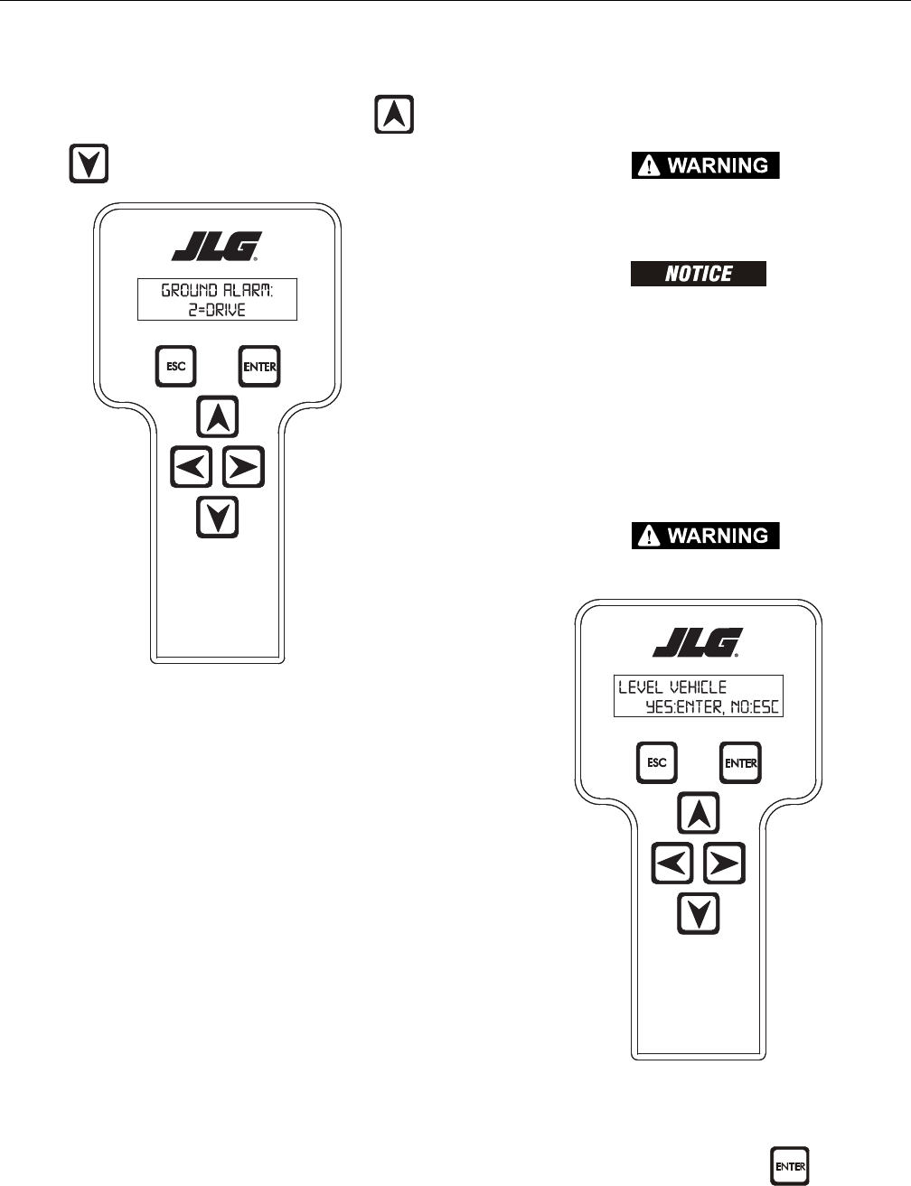
SECTION 6 - JLG CONTROL SYSTEM
6-6 – JLG Lift – 3121298
Machine Setup
When a machine digit item is selected, press UP or
DOWN arrow keys to adjust its value, for example:
GROUND ALARM:
2 = DRIVE
The effect of the machine digit value is displayed along with
its value. The above display would be selected if the machine
was equipped with a ground alarm and you wanted it to
sound when driving. There are certain settings allowed to
install optional features or select the machine model.
When selection the machine model to match the size of the
machine, the personality settings will all default to the factory
recommended setting.
NOTE: Refer to Personality Ranges/Defaults for the recommended
factory settings.
NOTE: Password 33271 allows access to level 1 to change
machine personality settings.
There is a setting that JLG strongly recommends that you do
not change. This setting is so noted below:
ELEVATION CUTBACK
CHANGING ELEVATION CUTBACK SETTING MAY ADVERSELY AFFECT PERFOR-
MANCE OF YOUR MACHINE.
AVOID PRESSURE-WASHING ELECTRICAL/ELECTRONIC COMPONENTS. IF
PRESSURE-WASHING IS USED TO WASH AREAS CONTAINING ELECTRICAL/
ELECTRONIC COMPONENTS, JLG INDUSTRIES INC. RECOMMENDS A MAXIMUM
PRESSURE OF 750 PSI (52 BAR) AT A MINIMUM DISTANCE OF 12 INCHES
(30.5CM) FROM THESE COMPONENTS. IF ELECTRICAL/ELECTRONIC COMPO-
NENTS ARE SPRAYED, SPRAYING MUST NOT BE DIRECT AND FOR BRIEF TIME
PERIODS TO AVOID HEAVY SATURATION.
Level Vehicle Description
DO NOT LEVEL VEHICLE EXCEPT ON A LEVEL SURFACE.
LEVEL VEHICLE
YES:ENTER, NO:ESC
Not available at password level 2. ENTER confirms vehi-
cle is current.

SECTION 6 - JLG CONTROL SYSTEM
3121298 – JLG Lift – 6-7
Table 6-1. Analyzer Abbreviations
ABBREVIATION MEANING
ACCEL ACCELERATE
ACT ACTIVE
A/D ANALOG DIGITAL CONVERTER COUNT
AMB. AMBIENT
ANG ANGLE
AUX AUXILIARY
BCS BOOM CONTROL SYSTEM
BM BOOM LENGTH ANGLE MODULE
BLAM BOOM LENGTH ANGLE MODULE
BR BROKEN
BSK BASKET
CAL CALIBRATION
CL CLOSED
CM CHASSIS MODULE
CNTL CONTROL
CNTRL CONTROL
C/O CUT OUT
CONT(S) CONTRACTOR(S)
COOR COORDINATED
CRK PT CRACK POINT
CRP CREEP
CUT CUTOUT
CYL CYLINDER
DECEL DECELERATE
DDOWN
DN DOWN
DWN DOWN
DEG. DEGREE
DOS DRIVE ORIENTATION SYSTEM
DRV DRIVE
EERROR
E&T ELEVATED & TILTED
ELEV ELEVATION
ENG ENGINE
EXT EXTEND
FFRONT
FL FLOW
FNT FRONT
FOR FORWARD
FWD FORWARD
FSW FOOT SWITCH
FUNC FUNCTION
G GROUND
GND GROUND
GRN GREEN
GM GROUND MODULE
HHOURS
HW HARDWARE
HWFS HARDWARE FAILSAFE
IIN or CURRENT
JOY JOYSTICK
LLEFT
LB POUND
LEN LENGTH
LIM LIMIT
LT LEFT
LVL LEVEL
MMINUTES
MIN MINIMUM
MAX MAXIMUM
MMAIN
MN MAIN
NO NO RM AL LY O PEN or NO
NC NORMALLY CLOSED
OOUT
O/C OPEN CIRCUIT
OP OPEN
O/R OVERRIDE or OUTRIGGER
O//R OVERRIDE
OSC OSCILLATING
OVRD OVERRIDE
PPLATFORM
PPRESSURE
PCV PROPORTIONAL CONTROL VALVE
PLAT PLATFORM
PLT PLATFORM
PM PLATFORM MODULE
POT POTENTIOMETER
PRES PRESSURE
PRS PRESSURE
PT POINT
RREAR or RIGHT
REV REVERSE or REVISION
RET RETRACT
ROT. ROTATE
RT RIGHT
Table 6-1. Analyzer Abbreviations
ABBREVIATION MEANING

SECTION 6 - JLG CONTROL SYSTEM
6-8 – JLG Lift – 3121298
S/C SHORT CIRCUIT
SEL SELECTOR
SN SERIAL NUMBER
SPD SPEED
STOW STOWED
STOWD STOWED
SW SWITCH or SOFTWARE
TELE TELESCOPE
TEMP TEMPERATURE
TORQ. TORQUE
TRN TRANSPORT
T/T TURNTABLE
TTOWER
TURNTBL TURNTABLE
TWR TOWER
UUPPER or UP
VVOLT
VER VERSION
VLV VALVE
WIT WITNESS
YEL YELLOW
Table 6-1. Analyzer Abbreviations
ABBREVIATION MEANING
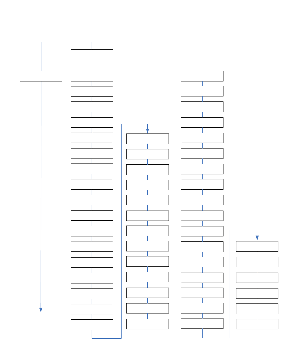
SECTION 6 - JLG CONTROL SYSTEM
3121298 – JLG Lift – 6-9
Figure 6-5. Analyzer Software Version 6.8 - Sheet 1 of 6
MENU:
HELP:PRESS ENTER
HELP: (001)
EVERYTHING OK
LOG:(xxx)
x:xxxxxxxxxxx
MENU:
DIAGNOSTICS
TO
DIAGNOSTICS:
ENGINE
TO
MENU:
SYSTEM TEST
DIAGNOSTICS:
DRIVE/STEER
JOYSTICK DRIVE:
FORWARD XXX%
JOYSTICK STEER:
LEFT XXX%
DRIVE OUTPUT:
FORWARD XXX%
DRIVE FORWARD:
COMMANDED:XXXXMA
DRIVE REVERSE:
COMMANDED:XXXXMA
DRIVE OUTPUT:
ACTUAL: XXXXMA
STEER OUTPUT:
LEFT XXX%
LEFT TRACK
OUTPUT: FWD XXX%
LEFT TRACK FWD
COMMANDED:XXXXMA
LEFT TRACK REV
COMMANDED:XXXXMA
LEFT TRACK
ACTUAL: XXXXMA
RIGHT TRACK
OUTPUT: FWD XXX%
RIGHT TRACK FWD
COMMANDED:XXXXMA
RIGHT TRACK REV
COMMANDED:XXXXMA
RIGHT TRACK
ACTUAL: XXXXMA
STEER TYPE:
NORMAL
BRAKES STATUS:
LOCKED
CREEP:
SWITCH: CLOSED
CREEP MODE:
OFF
2-SPEED:
SWITCH: OPEN
2-SPEED VALVE
OUTPUT: OFF
HIGH ENGINE
SWITCH: OPEN
DRIVE MODE:
MID ENGINE
DRV. ORIENTATION
FEATURE:DISABLED
DRV. ORIENTATION
SWITCH: OPEN
DRV. ORIENTATION
OVERRIDE: OPEN
DRV. ORIENTATION
STATUS:CONFIRMED
DRIVE CONTROL:
NORMAL
CRIBBING MODE:
DISABLED
DIAGNOSTICS:
BOOM FUNCTIONS
JOYSTICK LIFT:
MAIN UP XXX%
LIFT OUTPUT:
MAIN UP XXX%
LIFT UP
COMMANDED:XXXXMA
LIFT DOWN
COMMANDED:XXXXMA
LIFT OUTPUT
ACTUAL:XXXXMA
JOYSTICK SWING:
LEFT XXX%
SWING OUTPUT:
LEFT XXX%
SWING LEFT
COMMANDED:XXXXMA
SWING RIGHT
COMMANDED:XXXXMA
SWING OUTPUT
ACTUAL:XXXXMA
PLATFORM LEVEL:
UP XXX%
PLATFORM ROTATE:
LEFT XXX%
MAIN TELESCOPE:
IN XXX%
TOWER TELESCOPE:
IN XXX%
TOWER LIFT:
UP XXX%
JIB LIFT:
UP XXX%
FLOW VALVE
COMMANDED:XXXXMA
FLOW VALVE
ACTUAL:XXXXMA
PLATFORM CONTROL
VALVE: OFF
FUNCTION SPEED:
PUMP POT XXX%
CREEP
SWITCH: CLOSED
CREEP MODE:
OFF
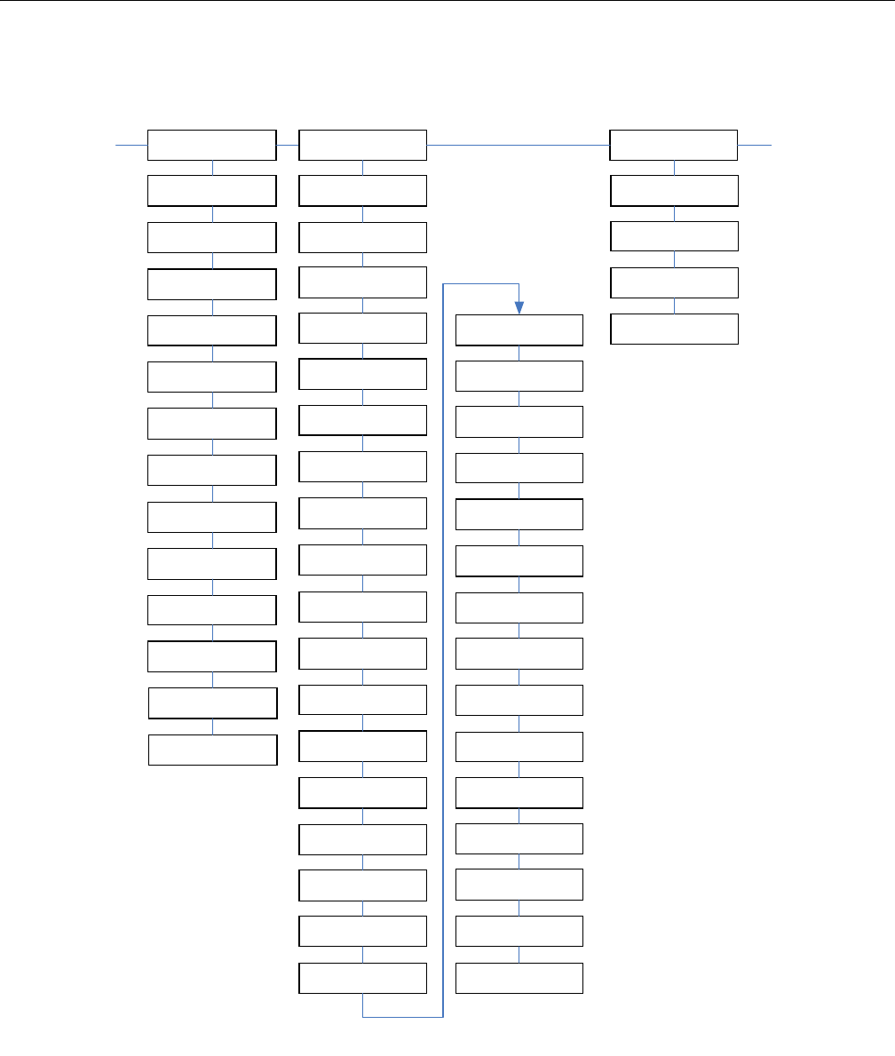
SECTION 6 - JLG CONTROL SYSTEM
6-10 – JLG Lift – 3121298
Figure 6-6. Analyzer Software Version 6.8 - Sheet 2 of 6
From
DIAGNOSTICS:
BOOM FUNCTIONS
TO
DIAGNOSTICS:
LOAD
DIAGNOSTICS:
ENGINE
START SEQUENCE:
NOT ACTIVE
BATTERY VOLTAGE:
XX.XV
COOLANT
TEMPERATURE:XXXF
ELECTRIC FAN
OUTPUT: OFF
ELECTRIC FUEL
PUMP OUTPUT: OFF
ENGINE OIL
PRESSURE:XXX PSI
FUEL SELECTION
SWITCH: GAS
FUEL SELECTION
STATUS: GAS
AMBIENT
TEMPERATURE:XXXF
FUEL LEVEL
SENSOR: OK
STARTER
CRANK TIME: XX S
ENGINE SPEED
ACTUAL: XXXX RPM
ENGINE SPEED
TARGET: XXXX RPM
DIAGNOSTICS:
SYSTEM
GROUND MODULE:
BATTERY: XX.XV
PLATFORM MODULE:
BATTERY: XX.XV
AMBIENT
TEMPERATURE:XXXF
PLATFORM SELECT
KEYSWITCH: OPEN
GROUND SELECT
KEYSWITCH: OPEN
STATION CONTROL:
GROUND
FOOTSWITCH INPUT
GROUND: OPEN
FOOTSWITCH INPUT
PLATFORM: OPEN
TRANSPORT
SWITCHES: OPEN
TRANSPORT MODE:
OUT OF TRANSPORT
END OF STROKE
PROXIMITY:CLOSED
TOWER LIFT
PROXIMITY:CLOSED
TOWER TELESCOPE
PROXIMITY:CLOSED
TOWER POSITION:
RETRACTED
CABLE BREAK
SWITCH: CLOSED
CREEP
SWITCH: CLOSED
CREEP MODE:
OFF
CHASSIS TILT:
XX.X DEGREES
CHASSIS TILT
X-AXIS: XX.X
CHASSIS TILT
Y-AXIS: XX.X
AUXILIARY POWER
SWITCH: OPEN
HORN
SWITCH: OPEN
RETURN HYDRAULIC
FILTER: OPEN
CHARGE PUMP
FILTER: OPEN
SOFT TOUCH LIMIT
SWITCH: OPEN
STOUCH OR SKYGRD
RELAYS: OPEN
ST/SG OVERRIDE
OVERRIDE: OPEN
GENSET.WELDER
SWITCH: OPEN
LIGHTS
SWITCH: OPEN
PLATFORM TILT1
ANGLE: XX.X
PLATFORM TILT2
ANGLE: XX.X
PLATFORM TILT1
VOLTAGE: XX MV
PLATFORM TILT2
VOLTAGE: XX MV
DIAGNOSTICS:
UMS
CHASSIS TILT
ANGLE: XX.X
UMS TO TURNTABLE
ANGLE: XX.X
UMS INCLINATION
ANGLE: XX.X
UMS STATUS:
NORMAL
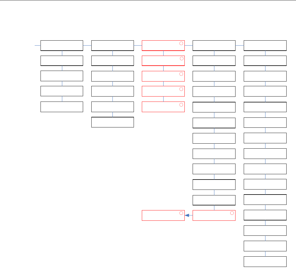
SECTION 6 - JLG CONTROL SYSTEM
3121298 – JLG Lift – 6-11
Figure 6-7. Analyzer Software Version 6.8 - Sheet 3 of 6
CALIBRATION DATA
LOAD 500LB:
CALIBRATION DATA
PLATFORM UP:
FROM
DIAGNOSTICS:
UMS
DIAGNOSTICS:
LOAD
CAPACITY LENGTH
SWITCH: CLOSED
CAPACITY ANGLE
SWITCH: CLOSED
PERCENT OF MAX
LOAD: XXX%
PLATFORM LOAD
STATE: OK
DIAGNOSTICS:
CAN STATISTICS
CAN STATISTICS
RX/SEC: X
CAN STATISTICS
TX/SEC: X
CAN STATISTICS
BUS OFF: X
CAN STATISTICS
PASSIVE: X
CAN STATISTICS
MSG ERROR: XXXX
DIAGNOSTICS:
CALIBRATION DATA
1
CALIBRATION DATA
LOAD ZERO:
1
1
1
CALIBRATION DATA
PLATFORM DN:
1
DIAGNOSTICS:
DATALOG
DATALOG:
ON: XXXh XXm
DATALOG:
ENGINE: XXXh XXm
DATALOG:
DRIVE: XXXh XXm
DATALOG:
LIFT: XXXh XXm
DATALOG:
SWING: XXXh XXm
DATALOG:
TELE: XXXh XXm
DATALOG:
MAX TEMP: XXXF
DATALOG:
MIN TEMP: XXXF
DATALOG:
MAX VOLTS: XX.XV
DATALOG:
RENTAL: XXXh XXm
DATALOG:
ERASE RENTAL?
1
CLEAR RENTAL:
YES:ENTER,NO:ESC
1
DIAGNOSTICS:
VERSIONS
GROUND MODULE
SOFTWARE: XX.XX
GROUND MODULE
COST. DATA:XX.XX
GROUND MODULE
HARDWARE: REV XX
GROUND MODULE
S/N: XXXXXX
PLATFORM MODULE
SOFTWARE: XX.XX
PLATFORM MODULE
HARDWARE: REV XX
PLATFORM MODULE
S/N: XXXXXX
PROPULSION MOD
SOFTWARE: XX.XX
TCU MODULE
SOFTWARE: XX.XX
TCU MODULE
HARDWARE: REV XX
TCU MODULE
S/N: XXXXXX
GATEWAY MODULE
SOFTWARE: XX.XX
GATEWAY MODULE
HARDWARE: REV XX
ANALYZER:
ANALYZER XX.XX
1
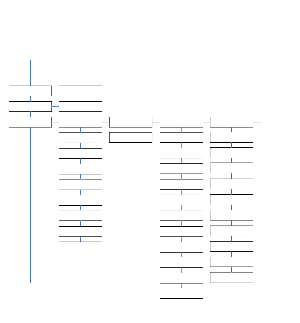
SECTION 6 - JLG CONTROL SYSTEM
6-12 – JLG Lift – 3121298
Figure 6-8. Analyzer Software Version 6.8 - Sheet 4 of 6
FROM
MENU:
DIAGNOSTICS
TO
PERSONALITIES:
MAIN LIFT
MENU:
SYSTEM TEST
SYSTEM TEST:
ACTIVATE?
MENU:
ACCESS LEVEL
ACCESS LEVEL:
CODE XXXXXX
MENU:
PERSONALITIES
PERSONALITIES:
DRIVE
DRIVE:
ACCEL X.XS
DRIVE:
DECEL X.XS
DRIVE:
MIN FORWARD XXX%
DRIVE:
MAX FORWARD XXX%
DRIVE:
MIN REVERSE XXX%
DRIVE:
MAX REVERSE XXX%
DRIVE:
ELEV. MAX XXX%
DRIVE:
CREEP MAX XXX%
PERSONALITIES:
STEER
STEER:
MAX SPEED XXX%
PERSONALITIES:
LEFT TRACK
LEFT TRACK:
ACCEL X.XS
LEFT TRACK:
DECEL X.XS
LEFT TRACK:
MIN FORWARD XXX%
LEFT TRACK:
MAX FORWARD XXX%
LEFT TRACK:
MIN REVERSE XXX%
LEFT TRACK:
MAX REVERSE XXX%
LEFT TRACK:
ELEV F MAX XXX%
LEFT TRACK:
ELEV R MAX XXX%
LEFT TRACK:
CREEP F MAX XXX%
LEFT TRACK:
CREEP R MAX XXX%
TRACK COUNTER
ROTATE MAX XXX%
TO
MENU:
MACHINE SETUP
PERSONALITIES:
RIGHT TRACK
RIGHT TRACK:
ACCEL X.XS
RIGHT TRACK:
DECEL X.XS
RIGHT TRACK:
MIN FORWARD XXX%
RIGHT TRACK:
MAX FORWARD XXX%
RIGHT TRACK:
MIN REVERSE XXX%
RIGHT TRACK:
MAX REVERSE XXX%
RIGHT TRACK:
ELEV F MAX XXX%
RIGHT TRACK:
ELEV R MAX XXX%
RIGHT TRACK:
CREEP F MAX XXX%
RIGHT TRACK:
CREEP R MAX XXX%
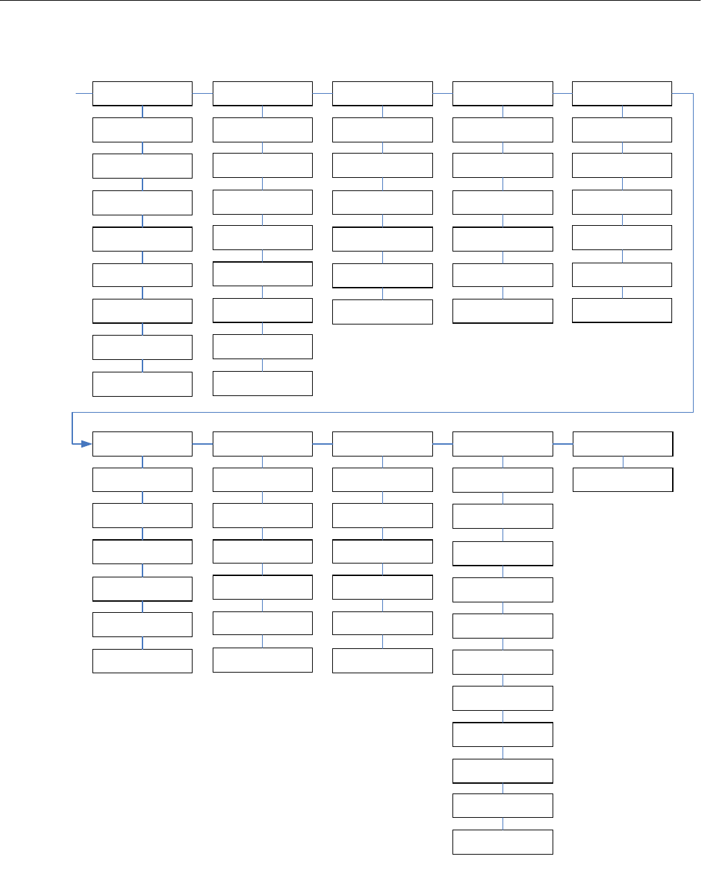
SECTION 6 - JLG CONTROL SYSTEM
3121298 – JLG Lift – 6-13
Figure 6-9. Analyzer Software Version 6.8 - Sheet 5 of 6
FROM
PERSONALITIES:
RIGHT TRACK
PERSONALITIES:
MAIN LIFT
MAIN LIFT:
ACCEL X.XS
MAIN LIFT:
DECEL X.XS
MAIN LIFT:
MIN UP XXX%
MAIN LIFT:
MAX UP XXX%
MAIN LIFT:
CREEP UP XXX%
MAIN LIFT:
MIN DOWN XXX%
MAIN LIFT:
MAX DOWN XXX%
MAIN LIFT:
CREEP DOWN XXX%
PERSONALITIES:
SWING
SWING:
ACCEL X.XS
SWING:
DECEL X.XS
SWING:
MIN LEFT XXX%
SWING:
MAX LEFT XXX%
SWING:
CREEP LEFT XXX%
SWING:
MIN RIGHT XXX%
SWING:
MAX RIGHT XXX%
SWING:
CREEP RIGHT XXX%
PERSONALITIES:
TOWER LIFT
TOWER LIFT:
ACCEL X.XS
TOWER LIFT:
DECEL X.XS
TOWER LIFT:
MIN UP XXX%
TOWER LIFT:
MAX UP XXX%
TOWER LIFT:
MIN DOWN XXX%
TOWER LIFT:
MAX DOWN XXX%
PERSONALITIES:
MAIN TELESCOPE
MAIN TELESCOPE:
ACCEL X.XS
MAIN TELESCOPE:
DECEL X.XS
MAIN TELESCOPE:
MIN IN XXX%
MAIN TELESCOPE:
MAX IN XXX%
MAIN TELESCOPE:
MIN OUT XXX%
MAIN TELESCOPE:
MAX OUT XXX%
PERSONALITIES:
TOWER TELESCOPE
TOWER TELESCOPE:
ACCEL X.XS
TOWER TELESCOPE:
DECEL X.XS
TOWER TELESCOPE:
MIN IN XXX%
TOWER TELESCOPE:
MAX IN XXX%
TOWER TELESCOPE:
MIN OUT XXX%
TOWER TELESCOPE:
MAX OUT XXX%
PERSONALITIES:
PLATFORM LEVEL
PLATFORM LEVEL:
ACCEL X.XS
PLATFORM LEVEL:
DECEL X.XS
PLATFORM LEVEL:
MIN IN XXX%
PLATFORM LEVEL:
MAX IN XXX%
PLATFORM LEVEL:
MIN OUT XXX%
PLATFORM LEVEL:
MAX OUT XXX%
PERSONALITIES:
PLATFORM ROTATE
PLATFORM ROTATE:
ACCEL X.XS
PLATFORM ROTATE:
DECEL X.XS
PLATFORM ROTATE:
MIN LEFT XXX%
PLATFORM ROTATE:
MAX LEFT XXX%
PLATFORM ROTATE:
MIN RIGHT XXX%
PLATFORM ROTATE:
MAX RIGHT XXX%
PERSONALITIES:
JIB LIFT
JIB LIFT:
ACCEL X.XS
JIB LIFT:
DECEL X.XS
JIB LIFT:
MIN UP XXX%
JIB LIFT:
MAX UP XXX%
JIB LIFT:
MIN DOWN XXX%
JIB LIFT:
MAX DOWN XXX%
PERSONALITIES:
GROUND MODE
GROUND MODE:
MAIN UP: XXX%
GROUND MODE:
MAIN DOWN: XXX%
GROUND MODE:
SWING: XXX%
GROUND MODE:
PLT LEVEL: XXX%
GROUND MODE:
PLT ROTATE: XXX%
GROUND MODE:
MAIN TELE: XXX%
GROUND MODE:
TOWER TELE: XXX%
GROUND MODE:
TOWER UP: XXX%
GROUND MODE:
TOWER DOWN: XXX%
GROUND MODE:
JIB LIFT: XXX%
GROUND MODE:
JIB SWING: XXX%
PERSONALITIES:
GEN SET/WELDER
GEN SET/WELDER:
ENGINE XXXX RPM
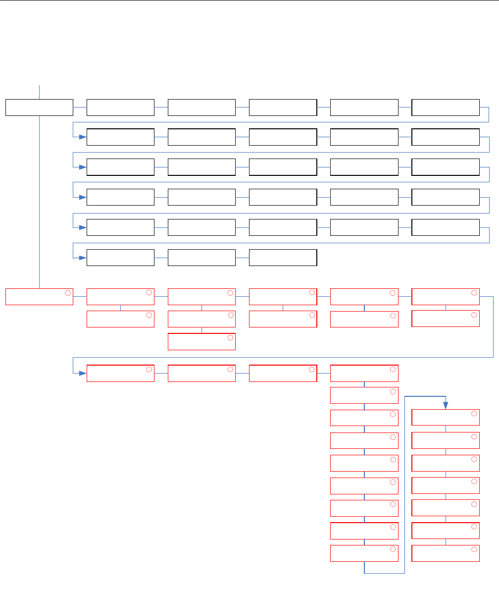
SECTION 6 - JLG CONTROL SYSTEM
6-14 – JLG Lift – 3121298
Figure 6-10. Analyzer Software Version 6.8 - Sheet 6 of 6
FROM
MENU:
PERSONALITIES
MENU:
MACHINE SETUP
MODEL NUMBER:
600S
MARKET:
CE
ENGINE:
PERKINS ECM
FLYWHEEL TEETH:
133 TEETH
GLOW PLUG:
IN-CYLINDER
STARTER LOCKOUT:
DISABLED
ENGINE SHUTDOWN:
ENABLED
TILT:
5 DEGREES
JIB:
NO
4 WHEEL STEER:
NO
STOUCH/SKYGUARD:
NO
GEN SET/WELDER:
NO
GEN SET CUTOUT:
MOTION ENABLED
H & T LIGHTS:
NO
CABLE SWITCH:
NO
LOAD SYSTEM:
NO
LOAD SENSOR:
4 UNDER PLATFORM
FUNCTION CUTOUT:
NO
GROUND ALARM:
MOTION
DRIVE:
4WD
TEMPERATURE:
FAHRENHEIT
LEVELING MODE:
ALL FUNCTIONS
DRIVE CONTROL:
ENHANCED
BOOM CONTROL:
NORMAL
CLEARSKY:
NO
CRIBBING OPTION:
NO
FUEL TANK SIZE:
31 GALLON
ALARM / HORN:
SEPARATE
MENU:
CALIBRATIONS
1 CALIBRATIONS:
TILT SENSOR
1 CALIBRATIONS:
UMS SENSOR
1 CALIBRATIONS:
FORD ENGINE
1 CALIBRATIONS:
LOAD SENSOR
1 CALIBRATIONS:
DEUTZ SETUP
1
CALIBRATIONS:
PLAT. LEVELING
1 CALIBRATIONS:
LEVEL UP CRKPT
1 CALIBRATIONS:
LEVEL DOWN CRKPT
1 CALIBRATIONS:
PROP MODULE
1
TILT SENSOR:
CALIBRATE?
1 UMS SENSOR:
CALIBRATE?
1
UMS SENSOR:
RAW: XX.X
1
FORD ENGINE:
DISABLE RS-485?
1 LOAD SENSOR:
CALIBRATE?
1 DEUTZ SETUP
SETUP X
1
PROP MODULE:
J1-7 MIN: XXX
1
PROP MODULE:
J1-7 MAX: XXX
1
PROP MODULE:
J1-8 MIN: XXX
1
PROP MODULE:
J1-8 MAX: XXX
1
PROP MODULE:
J1-9 MIN: XXX
1
PROP MODULE:
J1-9 MAX: XXX
1
PROP MODULE:
J1-10 MIN: XXX
1
PROP MODULE:
J1-10 MAX: XXX
1
PROP MODULE:
DEADBAND: XXXXX
1
PROP MODULE:
FF NUM: XXXXX
1
PROP MODULE:
FF DEN: XXXXX
1
PROP MODULE:
I NUM: XXXXX
1
PROP MODULE:
I DEN: XXXXX
1
PROP MODULE:
NEG ERR: XXXXX
1
PROP MODULE:
GAIN FLAG: XXXXX
1

SECTION 6 - JLG CONTROL SYSTEM
3121298 – JLG Lift – 6-15
6.2 MACHINE PERSONALITY SETTINGS NOTE: Personality settings can be adjusted within the adjustment
range for optimum machine performance.
Table 6-2. Personality Ranges/Defaults
FUNCTION PERSONALITY RANGE DEFAULTS - 600S
DRIVE ACCELeration 0.1s to 5.0s 2.0
DECELeration 0.1s to 3.0s 2.0
Forward MINimum speed 0 to 35% 4
Forward MAXimum speed 0 to 100% 35
REVerse MINimum speed 0 to 35% 4
REVerse MAXimum speed 0 to 100% 35
ELEVATED MAXimum speed 0 to 50% 15
CREEP MAXimum speed 0 to 50% 25
Engine RPM 800 to 2900 1800
TOWER LIFT ACCELeration 0.1 to 5.0 N/A
DECELeration 0.1 to 3.0 N/A
MlNimum UP speed 0 to 60% N/A
MAXimum UP speed 0 to 100% N/A
MINimum DOWN speed 0 to 60% N/A
MAXimum DOWN speed 0 to 100% N/A
Engine RPM 800 to 2900 N/A
UPPER LIFT ACCELeration 0.1 to 5.0 2.0
DECELeration 0.1 to 3.0 0.7
MlNimum UP speed 0 to 60% 40
MAXimum UP speed 0 to 100% 80
CREEP Maximum UP speed 0 to 65% 55
MINimum DOWN speed 0 to 60% 40
MAXimum DOWN speed 0 to 100% 70
CREEP maximum DOWN speed 0 to 75% 55
Engine RPM 800 to 2900 1800

SECTION 6 - JLG CONTROL SYSTEM
6-16 – JLG Lift – 3121298
SWING ACCELeration 0.1 to 5.0s 2.0
DECELeration 0.1 to 3.0s 1.8
MINimum LEFT speed 0 to 50% 30
MAXimum LEFT speed 0 to 100% 65
CREEP maximum LEFT speed 0 to 65% 45
MINimum RIGHT speed 0 to 50% 30
MAXimum RIGHT speed 0 to 100% 65
CREEP maximum RIGHT speed 0 to 65% 45
Engine RPM 800 to 2900 1400
TELESCOPE UPPER ACCELeration 0.1 to 5.0 3.5
DECELeration 0.1 to 3.0 0.8
MINimum IN speed 0 to 65% 45
MAXimum IN speed 0 to 100% 75
MINimum OUT speed 0 to 65% 45
MAXimum OUT speed 0 to 100% 70
Engine RPM 800 to 2900 1800
TELESCOPE TOWER ACCELeration 0.1 to 5.0 N/A
DECELeration 0.1 to 3.0 N/A
MINimum IN speed 0 to 65% N/A
MAXimum IN speed 0 to 100% N/A
MINimum OUT speed 0 to 65% N/A
MAXimum OUT speed 0 to 100% N/A
Engine RPM 800 to 2900 N/A
BASKET LEVEL ACCELeration 0.1 to 5.0 2.5
DECELeration 0.1 to 3.0 0.5
MINimum UP speed 0 to 65% 48
MAXimum UP speed 0 to 100% 52
MlNimum DOWN speed 0 to 65% 45
MAXimum DOWN speed 0 to 100% 50
Engine RPM 800 to 2900 1500
Table 6-2. Personality Ranges/Defaults
FUNCTION PERSONALITY RANGE DEFAULTS - 600S

SECTION 6 - JLG CONTROL SYSTEM
3121298 – JLG Lift – 6-17
BASKET ROTATE ACCELeration 0.1 to 5.0 1.8
DECELeration 0.1 to 3.0 0.7
MlNimum LEFT speed 0 to 65% 46
MAXimum LEFT speed 0 to 100% 50
MINimum RIGHT speed 0 to 65% 46
MAXimum RIGHT speed 0 to 100% 50
Engine RPM 800 to 2900 1500
JIB LIFT ACCELeration 0.1 to 5.0 5.0
DECELeration 0.1 to 3.0 1.0
MINimum UP speed 0 to 65% 46
MAXimum UP speed 0 to 100% 52
MINimum DOWN speed 0 to 65% 45
MAXimum DOWN speed 0 to 100% 52
Engine RPM 800 to 2900 1800
STEER MAXimum speed 0 to 100% 100
Engine RPM 800 to 2900 1800
GROUND MODE Tower LIFT UP speed 0 to 100% N/A
Tower LIFT DOWN speed 0 to 100% N/A
Upper LIFT UP 0 to 100% 60
Upper LIFT DOWN 0 to 100% 60
SWING speed 0 to 100% 60
Upper TELEscope speed 0 to 100% 70
Tower TELEscope speed 0 to 100% N/A
BASKET ROTATE speed 0 to 100% 50
BASKET LEVEL speed 0 to 100% 50
JIB LIFT speed 0 to 100% 50
NOTE: Personality settings can be adjusted anywhere within the adjustment range for optimum machine performance.
4150365B
Table 6-2. Personality Ranges/Defaults
FUNCTION PERSONALITY RANGE DEFAULTS - 600S

SECTION 6 - JLG CONTROL SYSTEM
6-18 – JLG Lift – 3121298
Table 6-3. Help Fault Codes, Displayed Faults, and Descriptions
Fault Flash
Code
Communicated (Displayed on
Analyzer) Fault Description Priority
None No flash code is indicated for the following help messages. They are intended to
hint at a possible problem if vehicle is not behaving as expected.
1
EVERYTHING OK The “normal” help message in platform mode
GROUND MODE OK The “normal” help message in ground mode
FSW OPEN A drive or boom function has been selected but footswitch is open.
RUNNING AT CREEP – CREEP
SWITCH OPEN
All function speeds are limited to creep because creep switch is open.
RUNNING AT CREEP – TILTED
AND ABOVE ELEVATION
All boom function speeds are limited to creep because vehicle is tilted and
above elevation.
RUNNING AT CUTBACK – ABOVE
ELEVATION
Drive speed is limited to “ELEVATED MAX” because vehicle is above elevation.
TI LT S EN SO R OU T O F RA NG E The tilt sensor has indicated a tilt angle greater than 19 degrees for more than 4
seconds. Not reported during 2 second power-up.
LOAD SENSOR READING UNDER
WEIGHT
The loa d s en sor is re ad in g 20 % o r mo re un der th e calib rate d z er o p oi nt . T his
fault may occur if platform is resting on the ground. Not reported during 2 sec-
ond power-up.
1/1 Flash code 1/1 indicates a “sleep” mode.
NOT REQUIRED
2/1 Flash code 2/1 indicates problems with footswitch. 2
FSW FAULTY The two footswitch inputs have read the same state for more than one second.
KEYSWITCH FAULTY Both platform and ground modes are selected simultaneously
2/2 Flash code 2/2 indicates problems with drive & steer selection. Except where
noted, these faults are not reported during 2 second power-up sequence.
3
DRIVE LOCKED – JOYSTICK
MOVED BEFORE FOOTSWITCH
Drive was selected before and during footswitch closure. Can be reported dur-
ing power-up sequence.
FSW INTERLOCK TRIPPED Footswitch was closed for seven seconds with no function selected. Can be
reported during power-up sequence.
STEER LOCKED – SELECTED
BEFORE FOOTSWITCH
Steer was selected before and during footswitch closure.
STEER SWITCHES FAULTY Both steer switches are active together.
DRIVE / STEER WITH NO QPROX This fault only occurs with inductive joysticks. It occurs if the joystick is moved
out of the neutral position with no Qprox sensors active.
D/S JOY. QPROX BAD These faults only occur with inductive joysticks. They indicate that the Q-Prox
sensor is reading above 3.18 volts.
D/S JOY. OUT OF RANGE LOW Resistive joysticks: These faults do not occur.
Inductive joysticks: The trigger points for these faults are dependent on the
centertap voltage reading. These faults will be triggered when the voltage is
less than the centertap voltage minus half the center tap voltage minus 0.3
volts. If the centertap is at the high end of the range, these faults will be trig-
gered below 1.05 volts. If the centertap is at the low end of the range, these
faults will be triggered below 0.79 volts.

SECTION 6 - JLG CONTROL SYSTEM
3121298 – JLG Lift – 6-19
D/S JOY. OUT OF RANGE HIGH Resistive joysticks: These faults do not occur if the Vref voltage is below 8.1 volts.
If Vref is above 7.7 volts, Vref is operating out of tolerance or a short to battery
has occurred.
Inductive joysticks: The trigger points for these faults are dependent on the
centertap voltage reading. These faults will be triggered when the voltage is
more than the centertap voltage plus half the centertap voltage plus 0.3 volts. If
the centertap is at the high end of the range, these faults will be triggered above
4.35 volts. If the centertap is at the low end of the range, these faults will be trig-
gered above 3.8 volts.
D/S JOY. CENTER TAP BAD Resistive joysticks: These faults occur when the center tap voltage is not
between 3.08 volts and 3.83 volts. Due to resistor tolerances there is a +/-.1 volt
range around these values where the fault may be indicated.
Inductive joysticks: These faults occur when the center tap voltage is not
between 2.18 volts and 2.70 volts. Due to resistor tolerances there is a +/-.1 volt
range around these values where the fault may be indicated.
WAITING FOR FSW TO BE OPEN Footswitch was closed when platform mode was selected. Can be reported
during power-up sequence.
2/3 Flash code 2/3 indicates problems with boom function selection. 3
LIFT/SWING LOCKED – JOYSTICK
MOVED BEFORE FOOTSWITCH
Platform upper lift or swing was selected before and during footswitch closure.
PUMP SWITCHES FAULTY –
CHECK DIAGNOSTICS/BOOM
A boom function (lower lift, telescope, basket level, basket rotate, jib) has both
directions selected together.
PUMP SWITCHES LOCKED –
SELECTED BEFORE FOOTSWITCH
A platform boom function (lower lift, telescope, basket level, basket rotate, jib)
was selected before key switch or footswitch closure.
PUMP SWITCHES LOCKED –
SELECTED BEFORE AUX POWER
A ground boom function (lower lift, telescope, basket level, basket rotate, jib)
was selected before aux power.
LIFT / SWING WITH NO QPROX This fault only occurs with inductive joysticks. It occurs if the joystick is moved
out of the neutral position with no Qprox sensors active.
l/S JOY. QPROX BAD These faults only occur with inductive joysticks. They indicate the Q-Prox sensor
is reading above 3.18 volts.
l/S JOY. OUT OF RANGE LOW Resistive joysticks: These faults do not occur.
Inductive joysticks: The trigger points for these faults are dependent on the
centertap voltage reading. These faults will be triggered when voltage is less
than centertap voltage minus half the center tap voltage minus 0.3 volts. If cen-
tertap is at high end of the range, these faults will be triggered below 1.05 volts.
If centertap is at low end of the range, these faults will be triggered below 0.79
volts.
l/S JOY. OUT OF RANGE HIGH Resistive joysticks: These faults do not occur if Vref voltage is below 8.1 volts. If
Vref is above 7.7 volts, Vref is operating out of tolerance or a short to battery has
occurred.
Inductive joysticks: The trigger points for these faults are dependent on the
centertap voltage reading. These faults will be triggered when voltage is more
than centertap voltage plus half the centertap voltage plus 0.3 volts. If center-
tap is at hi gh end of the ra ng e, th ese faul ts w il l be tr igg ered abo ve 4 .35 vo lt s. I f
centertap is at low end of the range, these faults will be triggered above 3.8
volts.
Table 6-3. Help Fault Codes, Displayed Faults, and Descriptions
Fault Flash
Code
Communicated (Displayed on
Analyzer) Fault Description Priority

SECTION 6 - JLG CONTROL SYSTEM
6-20 – JLG Lift – 3121298
l/S JOY. CENTER TAP BAD Resistive joysticks: These faults occur when center tap voltage is not between
3.08 volts and 3.83 volts. Due to resistor tolerances there is a +/-.1 volt range
around these values where the fault may be indicated.
Inductive joysticks: These faults occur when center tap voltage is not between
2.18 volts and 2.70 volts. Due to resistor tolerances there is a +/-.1 volt range
around these values where the fault may be indicated.
PUMP SWITCHES LOCKED –
SELECTED BEFORE START
SWTICH
This fault occurs when a hydraulic function switch is closed before start switch is
closed.
FOOTSWITCH SELECTED BEFORE
START
User attempted to start machine with footswitch engaged.
2/4 Flash code 2/4 indicates steering digital inputs are faulty.
NOT REQUIRED
2/5 Flash code 2/5 indicates a function is prevented due to a cutout. 4
BOOM PREVENTED – DRIVE
SELECTED
A boom function is selected while a drive function is selected and drive cutout is
configured to prevent simultaneous drive & boom operation.
DRIVE PREVENTED – ABOVE
ELEVATION
Drive is selected while above elevation and drive cutout is configured to pre-
vent drive.
DRIVE PREVENTED – BOOM
SELECTED
Drive is selected while a boom function is selected and drive cutout is config-
ured to prevent simultaneous drive & boom operation.
DRIVE PREVENTED – TILTED &
ABOVE ELEVATION
Drive is selected while tilted and above elevation and tilt is configured to cutout
drive.
MODEL CHANGED – HYDRAU-
LICS SUSPENDED – CYCLE EMS
User changed model number using the analyzer. User must cycle power before
hydraulics system will be active again.
11
2/7 Flash code 2/7 indicates accelerator input is faulty.
NOT REQUIRED
2/8 Flash code 2/8 indicates a problem with a hydraulic filter. Not reported during 2
second power-up.
5
RETURN FILTER BYPASSED Hydraulic return filter clogged
CHARG E P UM P FI LTE R BY PAS SED Charge pump filter clogged
3/1 Flash code 3/1 indicates a contactor did not close when energized.
NOT REQUIRED
3/2 Flash code 3/2 indicates a contactor did not open when energized.
NOT REQUIRED
3/3 Flash code 3/3 indicates a driver problem. All driver faults are detected in a simi-
lar manner. Open circuit faults are detected when analog feedback reads too
hi gh an d the out put is co mm and ed off. S ho rt to gro und is det ec ted wh en a na -
log feedback reads low and the output is commanded on. Short to battery is
detected when analog feedback reads Vbat and the output is commanded off.
Not reported during 2 second power-up.
6
ALTERNATOR/ECM POWER
SHORT TO GROUND
HOUR METER SHORT TO
GROUND
HOUR METER SHORT TO
BATTERY
HORN SHORT TO GROUND
HORN OPEN CIRCUIT
Table 6-3. Help Fault Codes, Displayed Faults, and Descriptions
Fault Flash
Code
Communicated (Displayed on
Analyzer) Fault Description Priority

SECTION 6 - JLG CONTROL SYSTEM
3121298 – JLG Lift – 6-21
HORN SHORT TO BATTERY
AUX POWER SHORT TO GROUND
AUX POWER OPEN CIRCUIT
AUX POWER SHORT TO
BATTERY
GLOW PLUG SHORT TO GROUND
GLOW PLUG OPEN CIRCUIT
GLOW PLUG SHORT TO
BATTERY
LP LOCK SHORT TO GROUND
LP LOCK OPEN CIRCUIT
LP LO CK S HO RT TO BAT TER Y
LP START ASSIST SHORT TO
GROUND
LP START ASSIST OPEN
CIRCUIT
LP START ASSIST SHORT TO BAT-
TERY
MAIN DUMP SHORT TO GROUND
MAI N DU MP OP EN CIR CUIT
MAIN DUMP SHORT TO
BATTERY
PARKING BRAKE SHORT TO
GROUND
PARKING BRAKE OPEN
CIRCUIT
PARKING BRAKE SHORT TO BAT-
TERY
START SOLENOID SHORT TO
GROUND
START SOLENOID OPEN
CIRCUIT
START SOLENOID SHORT TO BAT-
TERY
STEER DUMP SHORT TO
GROUND
STEER DUMP OPEN CIRCUIT
STEER DUMP SHORT TO
BATTERY
TWO SPEED SHORT TO GROUND
TWO SPEED OPEN CIRCUIT
TWO SPEED SHORT TO
BATTERY
GROUND ALARM SHORT TO
GROUND
Table 6-3. Help Fault Codes, Displayed Faults, and Descriptions
Fault Flash
Code
Communicated (Displayed on
Analyzer) Fault Description Priority

SECTION 6 - JLG CONTROL SYSTEM
6-22 – JLG Lift – 3121298
GROUND ALARM OPEN
CIRCUIT
GROUND ALARM SHORT TO
BATTERY
GENERATOR SHORT TO GROUND
GENERATOR OPEN CIRCUIT
GENERATOR SHORT TO
BATTERY
WELDER SHORT TO GROUND
WELDER OPEN CIRCUIT
WELDER SHORT TO BATTERY
HEAD TAIL LIGHT SHORT TO
GROUND
HEAD TAIL LIGHT OPEN
CIRCUIT
HEAD TAIL LIGHT SHORT TO
BATTERY
BASKET UP OVERRIDE SHORT TO
GROUND
Only occurs on machines with electronic leveling systems.
BASKET UP OVERRIDE OPEN
CIRCUIT
Only occurs on machines with electronic leveling systems.
BASKET UP OVERRIDE SHORT TO
BATTERY
Only occurs on machines with electronic leveling systems.
BA SK ET U P SH OR T TO G RO UN D
BASKET UP OPEN CIRCUIT
BASKET UP SHORT TO
BATTERY
BASKET DOWN SHORT TO
GROUND
BASKET DOWN OPEN
CIRCUIT
BASKET DOWN SHORT TO BAT-
TERY
BASKET DOWN OVERRIDE
SHORT TO GROUND
Only occurs on machines with electronic leveling systems.
BASKET DOWN OVERRIDE OPEN
CIRCUIT
Only occurs on machines with electronic leveling systems.
BASKET DOWN OVERRIDE
SHORT TO BATTERY
Only occurs on machines with electronic leveling systems.
BASKET LEFT OPEN CIRCUIT
BASKET LEFT SHORT TO
BATTERY
BASKET LEFT SHORT TO
GROUND
BASKET RIGHT SHORT TO
GROUND
Table 6-3. Help Fault Codes, Displayed Faults, and Descriptions
Fault Flash
Code
Communicated (Displayed on
Analyzer) Fault Description Priority

SECTION 6 - JLG CONTROL SYSTEM
3121298 – JLG Lift – 6-23
BASKET RIGHT OPEN CIRCUIT
BASKET RIGHT SHORT TO
BATTERY
JIB UP SHORT TO GROUND
JIB UP OPEN CIRCUIT
JIB UP SHORT TO BATTERY
JIB DOWN SHORT TO GROUND
JIB DOWN OPEN CIRCUIT
JIB DOWN SHORT TO
BATTERY
JIB LEFT SHORT TO GROUND
JIB LEFT OPEN CIRCUIT
JIB LEFT SHORT TO BATTERY
JIB RIGHT SHORT TO GROUND
JIB RIGHT OPEN CIRCUIT
JIB RIGHT SHORT TO BATTERY
TOWER UP SHORT TO GROUND
TOWER UP OPEN CIRCUIT
TOWER UP SHORT TO
BATTERY
TOWER DOWN SHORT TO
GROUND
TOWER DOWN OPEN CIRCUIT
TOWER DOWN SHORT TO BAT-
TERY
TOWER IN SHORT TO GROUND
TOWER IN OPEN CIRCUIT
TOWER IN SHORT TO
BATTERY
TOWER OUT SHORT TO GROUND
TOWER OUT OPEN CIRCUIT
TOWER OUT SHORT TO
BATTERY
UPPER IN SHORT TO GROUND
UPPER IN OPEN CIRCUIT
UPPER IN SHORT TO BATTERY
UPPER OUT SHORT TO GROUND
UPPER OUT OPEN CIRCUIT
UPPER OUT SHORT TO
BATTERY
LIFT UP DUMP SHORT TO
GROUND
LIFT UP DUMP OPEN CIRCUIT
Table 6-3. Help Fault Codes, Displayed Faults, and Descriptions
Fault Flash
Code
Communicated (Displayed on
Analyzer) Fault Description Priority

SECTION 6 - JLG CONTROL SYSTEM
6-24 – JLG Lift – 3121298
LIFT UP DUMP SHORT TO
BATTERY
LIFT DOWN HOLDING SHORT TO
GROUND
LIFT DOWN HOLDING OPEN CIR-
CUIT
LIFT DOWN SHORT TO BATTERY
HOUR METER OPEN CIRCUIT This fault cannot be detected during normal operation. It may be reported dur-
ing self test.
FORD ECM POWER OPEN
CIRCUIT
This fault cannot be detected during normal operation. It may be reported dur-
ing self test.
FORD ECM POWER SHORT TO
BATTERY
This fault cannot be detected during normal operation. It may be reported dur-
ing self test.
3/4 Flash code 3/4 indicates a driver problem on a platform valve block valve driver.
All driver faults are detected in a similar manner. Open circuit faults are detected
when analog feedback reads too high and the output is commanded off. Short
to ground is detected when analog feedback reads low and the output is com-
manded on. Short to battery is detected when analog feedback reads Vbat and
the output is commanded off. Not reported during 2 second power-up.
6
BASKET UP SHORT TO
BATTERY
BA SK ET U P SH OR T TO G RO UN D
BASKET UP OPEN CIRCUIT
BASKET UP SHORT TO
BATTERY OR OPEN CIRCUIT
Only occurs on machines with electronic basket leveling
BASKET DOWN SHORT TO BAT-
TERY
BASKET DOWN SHORT TO
GROUND
BASKET DOWN OPEN
CIRCUIT
BASKET DOWN SHORT TO BAT-
TERY OR OPEN CIRCUIT
Only occurs on machines with electronic basket leveling.
BASKET LEFT SHORT TO
BATTERY
BASKER LEFT SHORT TO
GROUND
BASKET LEFT OPEN CIRCUIT
BASKET RIGHT SHORT TO BAT-
TERY
BASKET RIGHT SHORT TO
GROUND
BASKET RIGHT OPEN CIRCUIT
JIB UP SHORT TO BATTERY
JIB UP SHORT TO GROUND
JIB UP OPEN CIRCUIT
Table 6-3. Help Fault Codes, Displayed Faults, and Descriptions
Fault Flash
Code
Communicated (Displayed on
Analyzer) Fault Description Priority

SECTION 6 - JLG CONTROL SYSTEM
3121298 – JLG Lift – 6-25
JIB DOWN SHORT TO
BATTERY
JIB DOWN SHORT TO GROUND
JIB DOWN OPEN CIRCUIT
JIB LEFT SHORT TO BATTERY
JIB LEFT SHORT TO GROUND
JIB LEFT OPEN CIRCUIT
JIB RIGHT SHORT TO BATTERY
JIB RIGHT SHORT TO GROUND
JIB RIGHT OPEN CIRCUIT
PLATFORM CONTROL VALVE
SHORT TO BATTERY
Only occurs on machines with electronic basket leveling
PLATFORM CONTROL VALVE
SHORT TO GROUND
Only occurs on machines with electronic basket leveling
PLATFORM CONTROL VALVE
OPEN CIRCUIT
Only occurs on machines with electronic basket leveling
3/5 Flash code 3/5 indicates a brake pressure problem.
NOT REQUIRED
4/2 Flash code 4/2 indicates engine is over temperature. NOT REQUIRED
4/3 Flash code 4/3 indicates problems with the engine. Except where noted, these
faults are not reported during 2 second power-up sequence.
9
HIGH ENGINE TEMP Occurs when engine temperature is above 117° Celsius for Ford engines, and
above 130° Celsius for Deutz engines.
AIR FILTER BYPASSED Air filter clogged
NO ALTERNATOR OUTPUT Engine has been running for 15 seconds or more and battery voltage is still
below 12.5 volts.
LOW OIL PRESSURE If a Deutz engine is installed, oil pressure is below 8 PSI and the engine has been
running for at least 10 seconds. If a Ford engine is installed, the Ford ECM has
reported a low oil pressure fault.
OIL PRESSURE SHORT TO
BATTERY
If a Deutz engine is installed, this indicates oil pressure sensor is reading above
6.6 volts.
OIL PRESSURE SHORT TO
GROUND
If a Deutz engine is installed, this indicates oil pressure sensor is reading below
0.1 volts for more than 5 seconds. This fault is not detected during crank.
COOLANT TEMPERATURE
SHORT TO GROUND
If a De ut z en gi ne is ins ta lle d, th is indicates coolant temperature is reading
below 0.1 volts.
FORD FAULT CODE ## All Ford fault codes except 63 are simply passed through from the FORD ECM.
They only occur if a Ford engine is selected in machine configuration digits. Can
be reported during power-up sequence.
FORD FAULT CODE UNKNOWN An unrecognized Ford ECM fault code has been received. Can be reported dur-
ing power-up sequence.
485 COMMUNICATIONS LOST This fault only occurs with a Ford engine. It occurs when no responses are
received from the ECM for 2.5 seconds. Can be reported during power-up
sequence.
FUEL SENSOR SHORT TO
BATTERY
Indicates fuel sensor is reading above 4.3 volts.
Table 6-3. Help Fault Codes, Displayed Faults, and Descriptions
Fault Flash
Code
Communicated (Displayed on
Analyzer) Fault Description Priority

SECTION 6 - JLG CONTROL SYSTEM
6-26 – JLG Lift – 3121298
FUEL SENSOR SHORT TO
GROUND
Indicates fuel sensor is reading below 0.2 volts.
4/4 Flash code 4/4 indicates problems with the battery supply. Not reported during
2 second power-up.
7
BATTERY LOW Battery voltage is below 11V for more than 5 seconds. This fault is not detected
during crank. This is a warning – controller does not shut down.
BATTERY TOO HIGH –
SYSTEM SHUT DOWN
Battery voltage is above 16V. EMS recycle required.
BATTERY TOO LOW –
SYSTEM SHUT DOWN
Battery voltage is below 9V.
5/5 Flash code 5/5 indicates problems with vehicle engine RPM or the encoder. Not
reported during 2 second power-up.
8
SPEED SENSOR READING
INVALID SPEED
This fault is detected with diesel engines only. The RPM pickup is indicating a
speed that greater than 4000 RPM or approximately 8875 Hz.
SPEED INPUT LOST This fault is detected with diesel engines only. It occurs if there is no RPM
detected and the oil pressure input is reading above 8 PSI for more than three
seconds. This is probably due to wiring problems at the ground module or a
faulty speed sensor.
6/6 Flash code 6/6 indicates problems with the CAN bus. 10
CAN BUS FAILURE: Ground module or platform module is not receiving CAN messages. This is
probably due to wiring problems between the platform and ground modules.
7/7 Flash code 7/7 indicates problems with a motor.
NOT REQUIRED
9/9 Flash code 9/9 indicates problems with the controller. 11
PLATFORM MODULE
SOFTWARE UPDATE REQUIRED
Platform module code is too old to support the EIM or BPE load sensor and the
machine is configured to use one of these two sensors. The PM code must be
updated to a newer version.
HIGH RESOLUTION A2D
FAILURE –INTERRUPT LOST
The ADS1213 chip in the platform module has stopped asserting its interrupt
(DRDY) line for some reason. An EMS cycle is required.
HIGH RESOLUTION A2D
FAILURE-REINIT LIMIT
The ADS1213 has needed to be reset 3 or more times.
PLATFORM MODULE FAILURE:
HWFS CODE 1
Platform module V(Low) FET has failed
GROUND MODULE FAILURE:
HWFS CODE 1
Ground module V(Low) FET has failed
GROUND SENSOR REF
VOLTAGE OUT OF RANGE
These faults occur when the seven volt reference voltage used for joysticks, sen-
sors, etc. goes out of range. Not reported during 2 second power-up.
PLATFORM SENSOR REF VOLT-
AGE OUT OF RANGE
These faults occur when the seven volt reference voltage used for the joysticks,
sensors, etc. goes out of range. Not reported during 2 second power-up.
EEPROM FAILURE – CHECK ALL
SETTINGS
A critical failure occurred with the EEPROM. Personalities, machine configura-
tion digits, etc. may be reset to default values and should be checked.
CHASSIS TILT SENSOR NOT GAIN
CALIBRATED
Indicates that chassis tilt sensor calibration information has been lost. Machine
will indicate it is tilted at all times. This calibration data is programmed into the
unit at the factory.
CHASSIS TILT SENSOR GAIN OUT
OF RANGE
Indicates chassis tilt sensor calibration is corrupted.
Table 6-3. Help Fault Codes, Displayed Faults, and Descriptions
Fault Flash
Code
Communicated (Displayed on
Analyzer) Fault Description Priority

SECTION 6 - JLG CONTROL SYSTEM
3121298 – JLG Lift – 6-27
Table 6-4. Help Message/Fault Listing
HELP MESSAGE FAULT FAULT REMOVAL
OK 00CLEARS WHEN FAULT IS REMOVED
DRIVING AT CREEP - TILTED 00CLEARS WHEN FAULT IS REMOVED
FSW OPEN 00CLEARS WHEN FAULT IS REMOVED
RUNNING AT CREEP - CREEP SWITCH OPEN 00CLEARS WHEN FAULT IS REMOVED
RUNNING AT CREEP - TILTED AND ABOVE ELEVATION 00CLEARS WHEN FAULT IS REMOVED
RUNNING AT CUTBACK - ABOVE ELEVATION 00CLEARS WHEN FAULT IS REMOVED
TILT SENSOR OUT OF RANGE 00CLEARS WHEN FAULT IS REMOVED
LOAD SENSOR READING UNDER WEIGHT 00CLEARS WHEN FAULT IS REMOVED
FSW FAULTY 21REQUIRES EMS TO BE RECYCLED TO CLEAR FAULT
KEYSWITCH FAULTY 21CLEARS WHEN FAULT IS REMOVED
DRIVE LOCKED - JOYSTICK MOVED BEFORE FOOTSWITCH 22CLEARS WHEN FAULT IS REMOVED
FSW INTERLOCK TRIPPED 22CLEARS WHEN FAULT IS REMOVED
STEER LOCKED - SELECTED BEFORE FOOTSWITCH 22CLEARS WHEN FAULT IS REMOVED
STEER SWITCHES FAULTY 22CLEARS WHEN FAULT IS REMOVED
D/S JOY. QPROX BAD 22CLEARS WHEN FAULT IS REMOVED
L/S JOY. QPROX BAD 23CLEARS WHEN FAULT IS REMOVED
D/S JOY. OUT OF RANGE LOW 22CLEARS WHEN FAULT IS REMOVED
D/S JOY. OUT OF RANGE HIGH 22CLEARS WHEN FAULT IS REMOVED
L/S JOY. OUT OF RANGE LOW 23CLEARS WHEN FAULT IS REMOVED
L/S JOY. OUT OF RANGE HIGH 23CLEARS WHEN FAULT IS REMOVED
D/S JOY. CENTER TAP BAD 22CLEARS WHEN FAULT IS REMOVED
L/S JOY. CENTER TAP BAD 23CLEARS WHEN FAULT IS REMOVED
WAITING FOR FSW TO BE OPEN 22CLEARS WHEN FAULT IS REMOVED
PUMP POT FAULTY 23CLEARS WHEN FAULT IS REMOVED
PUMP SWITCHES FAULTY - CHECK DIAGNOSTICS/BOOM 23CLEARS WHEN FAULT IS REMOVED
PUMP SWITCHES LOCKED - SELECTED BEFORE FOOTSWITCH 23CLEARS WHEN FAULT IS REMOVED
PUMP SWITCHES LOCKED - SELECTED BEFORE START SWITCH 23CLEARS WHEN FAULT IS REMOVED
FOOTSWITCH SELECTED BEFORE START 23CLEARS WHEN FAULT IS REMOVED
BOOM PREVENTED - DRIVE SELECTED 25CLEARS WHEN FAULT IS REMOVED
DRIVE PREVENTED - ABOVE ELEVATION 25CLEARS WHEN FAULT IS REMOVED
DRIVE PREVENTED - TILTED & ABOVE ELEVATION 25CLEARS WHEN FAULT IS REMOVED
DRIVE PREVENTED - BOOM SELECTED 25CLEARS WHEN FAULT IS REMOVED

SECTION 6 - JLG CONTROL SYSTEM
6-28 – JLG Lift – 3121298
FORD ECM POWER SHORT TO GROUND 33REQUIRES EMS TO BE RECYCLED TO CLEAR FAULT
HORN SHORT TO GROUND 33REQUIRES EMS TO BE RECYCLED TO CLEAR FAULT
HORN OPEN CIRCUIT 33REQUIRES EMS TO BE RECYCLED TO CLEAR FAULT
HORN SHORT TO BATTERY 33REQUIRES EMS TO BE RECYCLED TO CLEAR FAULT
AUX POWER SHORT TO GROUND 33REQUIRES EMS TO BE RECYCLED TO CLEAR FAULT
AUX POWER OPEN CIRCUIT 33REQUIRES EMS TO BE RECYCLED TO CLEAR FAULT
AUX POWER SHORT TO BATTERY 33REQUIRES EMS TO BE RECYCLED TO CLEAR FAULT
GLOW PLUG SHORT TO GROUND 33REQUIRES EMS TO BE RECYCLED TO CLEAR FAULT
GLOW PLUG OPEN CIRCUIT 33REQUIRES EMS TO BE RECYCLED TO CLEAR FAULT
GLOW PLUG SHORT TO BATTERY 33REQUIRES EMS TO BE RECYCLED TO CLEAR FAULT
LP LOCK SHORT TO GROUND 33REQUIRES EMS TO BE RECYCLED TO CLEAR FAULT
LP LOCK OPEN CIRCUIT 33REQUIRES EMS TO BE RECYCLED TO CLEAR FAULT
LP LOCK SHORT TO BATTERY 33REQUIRES EMS TO BE RECYCLED TO CLEAR FAULT
LP START ASSIST SHORT TO GROUND 33REQUIRES EMS TO BE RECYCLED TO CLEAR FAULT
LP START ASSIST OPEN CIRCUIT 33REQUIRES EMS TO BE RECYCLED TO CLEAR FAULT
LP START ASSIST SHORT TO BATTERY 33REQUIRES EMS TO BE RECYCLED TO CLEAR FAULT
MAIN DUMP SHORT TO GROUND 33REQUIRES EMS TO BE RECYCLED TO CLEAR FAULT
MAIN DUMP OPEN CIRCUIT 33REQUIRES EMS TO BE RECYCLED TO CLEAR FAULT
MAI N DU MP SH ORT TO B AT TERY 33REQUIRES EMS TO BE RECYCLED TO CLEAR FAULT
PARKING BRAKE SHORT TO GROUND 33REQUIRES EMS TO BE RECYCLED TO CLEAR FAULT
PARKING BRAKE OPEN CIRCUIT 33REQUIRES EMS TO BE RECYCLED TO CLEAR FAULT
PARKING BRAKE SHORT TO BATTERY 33REQUIRES EMS TO BE RECYCLED TO CLEAR FAULT
START SOLENOID SHORT TO GROUND 33REQUIRES EMS TO BE RECYCLED TO CLEAR FAULT
START SOLENOID OPEN CIRCUIT 33REQUIRES EMS TO BE RECYCLED TO CLEAR FAULT
START SOLENOID SHORT TO BATTERY 33REQUIRES EMS TO BE RECYCLED TO CLEAR FAULT
STEER DUMP SHORT TO GROUND 33REQUIRES EMS TO BE RECYCLED TO CLEAR FAULT
STEER DUMP OPEN CIRCUIT 33REQUIRES EMS TO BE RECYCLED TO CLEAR FAULT
STEER DUMP SHORT TO BATTERY 33REQUIRES EMS TO BE RECYCLED TO CLEAR FAULT
TWO SPEED SHORT TO GROUND 33REQUIRES EMS TO BE RECYCLED TO CLEAR FAULT
TWO SPEED OPEN CIRCUIT 33REQUIRES EMS TO BE RECYCLED TO CLEAR FAULT
TWO SPEED SHORT TO BATTERY 33REQUIRES EMS TO BE RECYCLED TO CLEAR FAULT
ALARM SHORT TO GROUND 33REQUIRES EMS TO BE RECYCLED TO CLEAR FAULT
ALARM OPEN CIRCUIT 33REQUIRES EMS TO BE RECYCLED TO CLEAR FAULT
Table 6-4. Help Message/Fault Listing
HELP MESSAGE FAULT FAULT REMOVAL

SECTION 6 - JLG CONTROL SYSTEM
3121298 – JLG Lift – 6-29
ALARM SHORT TO BATTERY 33REQUIRES EMS TO BE RECYCLED TO CLEAR FAULT
GENERATOR SHORT TO GROUND 33REQUIRES EMS TO BE RECYCLED TO CLEAR FAULT
GENERATOR OPEN CIRCUIT 33REQUIRES EMS TO BE RECYCLED TO CLEAR FAULT
GENERATOR SHORT TO BATTERY 33REQUIRES EMS TO BE RECYCLED TO CLEAR FAULT
HEAD TAIL LIGHT SHORT TO GROUND 33REQUIRES EMS TO BE RECYCLED TO CLEAR FAULT
HEAD TAIL LIGHT OPEN CIRCUIT 33REQUIRES EMS TO BE RECYCLED TO CLEAR FAULT
HEAD TAIL LIGHT SHORT TO BATTERY 33REQUIRES EMS TO BE RECYCLED TO CLEAR FAULT
HOUR METER SHORT TO GROUND 33REQUIRES EMS TO BE RECYCLED TO CLEAR FAULT
HOUR METER SHORT TO BATTERY 33REQUIRES EMS TO BE RECYCLED TO CLEAR FAULT
BASKET UP SHORT TO GROUND 33REQUIRES EMS TO BE RECYCLED TO CLEAR FAULT
BASKET UP OPEN CIRCUIT 33REQUIRES EMS TO BE RECYCLED TO CLEAR FAULT
BASKET UP SHORT TO BATTERY 33REQUIRES EMS TO BE RECYCLED TO CLEAR FAULT
BASKET DOWN SHORT TO GROUND 33REQUIRES EMS TO BE RECYCLED TO CLEAR FAULT
BASKET DOWN OPEN CIRCUIT 33REQUIRES EMS TO BE RECYCLED TO CLEAR FAULT
BASKET DOWN SHORT TO BATTERY 33REQUIRES EMS TO BE RECYCLED TO CLEAR FAULT
BASKET LEFT SHORT TO GROUND 33REQUIRES EMS TO BE RECYCLED TO CLEAR FAULT
BASKET LEFT OPEN CIRCUIT 33REQUIRES EMS TO BE RECYCLED TO CLEAR FAULT
BASKET LEFT SHORT TO BATTERY 33REQUIRES EMS TO BE RECYCLED TO CLEAR FAULT
BASKET RIGHT SHORT TO GROUND 33REQUIRES EMS TO BE RECYCLED TO CLEAR FAULT
BASKET RIGHT OPEN CIRCUIT 33REQUIRES EMS TO BE RECYCLED TO CLEAR FAULT
BASKET RIGHT SHORT TO BATTERY 33REQUIRES EMS TO BE RECYCLED TO CLEAR FAULT
JIB UP SHORT TO GROUND 33REQUIRES EMS TO BE RECYCLED TO CLEAR FAULT
JIB UP OPEN CIRCUIT 33REQUIRES EMS TO BE RECYCLED TO CLEAR FAULT
JIB UP SHORT TO BATTERY 33REQUIRES EMS TO BE RECYCLED TO CLEAR FAULT
JIB DOWN SHORT TO GROUND 33REQUIRES EMS TO BE RECYCLED TO CLEAR FAULT
JIB DOWN OPEN CIRCUIT 33REQUIRES EMS TO BE RECYCLED TO CLEAR FAULT
JIB DOWN SHORT TO BATTERY 33REQUIRES EMS TO BE RECYCLED TO CLEAR FAULT
JIB LEFT SHORT TO GROUND 33REQUIRES EMS TO BE RECYCLED TO CLEAR FAULT
JIB LEFT OPEN CIRCUIT 33REQUIRES EMS TO BE RECYCLED TO CLEAR FAULT
JIB LEFT SHORT TO BATTERY 33REQUIRES EMS TO BE RECYCLED TO CLEAR FAULT
JIB RIGHT SHORT TO GROUND 33REQUIRES EMS TO BE RECYCLED TO CLEAR FAULT
JIB RIGHT OPEN CIRCUIT 33REQUIRES EMS TO BE RECYCLED TO CLEAR FAULT
JIB RIGHT SHORT TO BATTERY 33REQUIRES EMS TO BE RECYCLED TO CLEAR FAULT
Table 6-4. Help Message/Fault Listing
HELP MESSAGE FAULT FAULT REMOVAL

SECTION 6 - JLG CONTROL SYSTEM
6-30 – JLG Lift – 3121298
TOWER UP SHORT TO GROUND 33REQUIRES EMS TO BE RECYCLED TO CLEAR FAULT
TOWER UP OPEN CIRCUIT 33REQUIRES EMS TO BE RECYCLED TO CLEAR FAULT
TOWER UP SHORT TO BATTERY 33REQUIRES EMS TO BE RECYCLED TO CLEAR FAULT
TOWER DOWN SHORT TO GROUND 33REQUIRES EMS TO BE RECYCLED TO CLEAR FAULT
TOWER DOWN OPEN CIRCUIT 33REQUIRES EMS TO BE RECYCLED TO CLEAR FAULT
TOWER DOWN SHORT TO BATTERY 33REQUIRES EMS TO BE RECYCLED TO CLEAR FAULT
TOWER IN SHORT TO GROUND 33REQUIRES EMS TO BE RECYCLED TO CLEAR FAULT
TOWER IN OPEN CIRCUIT 33REQUIRES EMS TO BE RECYCLED TO CLEAR FAULT
TOWER IN SHORT TO BATTERY 33REQUIRES EMS TO BE RECYCLED TO CLEAR FAULT
TOWER OUT SHORT TO GROUND 33REQUIRES EMS TO BE RECYCLED TO CLEAR FAULT
TOWER OUT OPEN CIRCUIT 33REQUIRES EMS TO BE RECYCLED TO CLEAR FAULT
TOWER OUT SHORT TO BATTERY 33REQUIRES EMS TO BE RECYCLED TO CLEAR FAULT
UPPER IN SHORT TO GROUND 33REQUIRES EMS TO BE RECYCLED TO CLEAR FAULT
UPPER IN OPEN CIRCUIT 33REQUIRES EMS TO BE RECYCLED TO CLEAR FAULT
UPPER IN SHORT TO BATTERY 33REQUIRES EMS TO BE RECYCLED TO CLEAR FAULT
UPPER OUT SHORT TO GROUND 33REQUIRES EMS TO BE RECYCLED TO CLEAR FAULT
UPPER OUT OPEN CIRCUIT 33REQUIRES EMS TO BE RECYCLED TO CLEAR FAULT
UPPER OUT SHORT TO BATTERY 33REQUIRES EMS TO BE RECYCLED TO CLEAR FAULT
FUEL SENSOR SHORT TO BATTERY 33CLEARS WHEN FAULT IS REMOVED
FUEL SENSOR SHORT TO GROUND 33CLEARS WHEN FAULT IS REMOVED
OIL PRESSURE SHORT TO BATTERY 43CLEARS WHEN FAULT IS REMOVED
OIL PRESSURE SHORT TO GROUND 43CLEARS WHEN FAULT IS REMOVED
COOLANT TEMPERATURE SHORT TO GROUND 43CLEARS WHEN FAULT IS REMOVED
FORD FAULT CODE 12 43CLEARS WHEN FAULT IS REMOVED
FORD FAULT CODE 13 43CLEARS WHEN FAULT IS REMOVED
FORD FAULT CODE 14 43CLEARS WHEN FAULT IS REMOVED
FORD FAULT CODE 15 43CLEARS WHEN FAULT IS REMOVED
FORD FAULT CODE 21 43CLEARS WHEN FAULT IS REMOVED
FORD FAULT CODE 22 43CLEARS WHEN FAULT IS REMOVED
FORD FAULT CODE 23 43CLEARS WHEN FAULT IS REMOVED
FORD FAULT CODE 24 43CLEARS WHEN FAULT IS REMOVED
FORD FAULT CODE 25 43CLEARS WHEN FAULT IS REMOVED
FORD FAULT CODE 26 43CLEARS WHEN FAULT IS REMOVED
Table 6-4. Help Message/Fault Listing
HELP MESSAGE FAULT FAULT REMOVAL

SECTION 6 - JLG CONTROL SYSTEM
3121298 – JLG Lift – 6-31
FORD FAULT CODE 31 43CLEARS WHEN FAULT IS REMOVED
FORD FAULT CODE 32 43CLEARS WHEN FAULT IS REMOVED
FORD FAULT CODE 33 43CLEARS WHEN FAULT IS REMOVED
FORD FAULT CODE 34 43CLEARS WHEN FAULT IS REMOVED
FORD FAULT CODE 35 43CLEARS WHEN FAULT IS REMOVED
FORD FAULT CODE 36 43CLEARS WHEN FAULT IS REMOVED
FORD FAULT CODE 41 43CLEARS WHEN FAULT IS REMOVED
FORD FAULT CODE 42 43CLEARS WHEN FAULT IS REMOVED
FORD FAULT CODE 43 43CLEARS WHEN FAULT IS REMOVED
FORD FAULT CODE 44 43CLEARS WHEN FAULT IS REMOVED
FORD FAULT CODE 45 43CLEARS WHEN FAULT IS REMOVED
FORD FAULT CODE 46 43CLEARS WHEN FAULT IS REMOVED
FORD FAULT CODE 51 43CLEARS WHEN FAULT IS REMOVED
FORD FAULT CODE 52 43CLEARS WHEN FAULT IS REMOVED
FORD FAULT CODE 53 43CLEARS WHEN FAULT IS REMOVED
FORD FAULT CODE 54 43CLEARS WHEN FAULT IS REMOVED
FORD FAULT CODE 55 43CLEARS WHEN FAULT IS REMOVED
FORD FAULT CODE 56 43CLEARS WHEN FAULT IS REMOVED
FORD FAULT CODE 57 43CLEARS WHEN FAULT IS REMOVED
FORD FAULT CODE 61 43CLEARS WHEN FAULT IS REMOVED
FORD FAULT CODE 62 43CLEARS WHEN FAULT IS REMOVED
FORD FAULT CODE 63 43CLEARS WHEN FAULT IS REMOVED
FORD FAULT CODE 64 43CLEARS WHEN FAULT IS REMOVED
FORD FAULT CODE UNKNOWN 43CLEARS WHEN FAULT IS REMOVED
RETURN FILTER BYPASSED 28CLEARS WHEN FAULT IS REMOVED
CHARGE PUMP FILTER BYPASSED 28CLEARS WHEN FAULT IS REMOVED
BATTERY LOW 44CLEARS WHEN FAULT IS REMOVED
BATTERY TOO HIGH - SYSTEM SHUT DOWN 44REQUIRES EMS TO BE RECYCLED TO CLEAR FAULT
BATTERY TOO LOW - SYSTEM SHUT DOWN 44CLEARS WHEN FAULT IS REMOVED
SPEED SENSOR READING INVALID SPEED 55CLEARS WHEN FAULT IS REMOVED
SPEED INPUT LOST 55CLEARS WHEN FAULT IS REMOVED
ENGINE TEMP HIGH 43CLEARS WHEN FAULT IS REMOVED
AIR FILTER BYPASSED 43CLEARS WHEN FAULT IS REMOVED
Table 6-4. Help Message/Fault Listing
HELP MESSAGE FAULT FAULT REMOVAL

SECTION 6 - JLG CONTROL SYSTEM
6-32 – JLG Lift – 3121298
NO ALTERNATOR OUTPUT 43CLEARS WHEN FAULT IS REMOVED
OIL PRESSURE LOW 43CLEARS WHEN FAULT IS REMOVED
485 COMMUNICATIONS LOST 43CLEARS WHEN FAULT IS REMOVED
CAN BUS FAILURE 66CLEARS WHEN FAULT IS REMOVED
LOAD SENSOR NOT CALIBRATED 99CLEARS WHEN FAULT IS REMOVED
TILT SENSOR NOT CALIBRATED 99CLEARS WHEN FAULT IS REMOVED
EEPROM FAILURE - CHECK ALL SETTINGS 99REQUIRES EMS TO BE RECYCLED TO CLEAR FAULT
PLATFORM MODULE FAILURE: HWFS CODE 1 99CLEARS WHEN FAULT IS REMOVED
GROUND MODULE FAILURE: HWFS CODE 1 99CLEARS WHEN FAULT IS REMOVED
Table 6-4. Help Message/Fault Listing
HELP MESSAGE FAULT FAULT REMOVAL

SECTION 6 - JLG CONTROL SYSTEM
3121298 – JLG Lift – 6-33
Table 6-5. Machine Configuration Programming Information
Configuration Digit Number Description Default
Number
NOTE: Machine configuration must be completed before any personality settings can be changed. Changing personality set-
tings first and then changing the model number of the machine configuration will cause personality settings to return to
default
MODEL NUMBER:
1
0
4
No Model
600S
0
1
MARKET:
2
0
1
2
3
4
5
ANSI USA
ANSI EXPORT
CSA
CE
AUSTRALIA
JAPAN
0
ENGINE:
3
8
9
12
13
DEUTZ F4 TIER1: Deutz BF4M1011 Diesel (Tier 1)
DEUTZ F4 TIER2: Deutz BF4M2011 Diesel (Tier 2)
DEUTZ ECM: Engine Control Module
CAT Engine
14
FLYWHEEL TEETH:
4
0
1
133 TEETH: 133 flywheel teeth.
110 TEETH: 110 flywheel teeth.
1
GLOW PLUG:
5
0
1
2
NO GLOW PLUGS: No glow plugs installed.
AIR INTAKE: Glow plugs installed in the air intake on the manifold.
IN-CYLINDER: Glow plugs installed in each cylinder.
2
STARTER LOCKOUT:
6
0
1
DISABLED: Automatic pre-glow time determined by ambient air tempera-
ture; engine start can be attempted at any time during pre-glow.
ENABLED: Automatic pre-glow time determined by ambient air tempera-
ture; engine start is NOT permitted until pre-glow is finished.
0
ENGINE SHUT-
DOWN:
7
0
1
DISABLED: No engine shutdown.
ENABLED: Shutdown engine when coolant temperature is greater than
110°C or oil pressure is less than 8 PSI.
1
SECTION 6 - JLG CONTROL SYSTEM
6-34 – JLG Lift – 3121298
TILT:
8
1
2
3
4
5
5 DEGREES: Reduces the maximum speed of all boom functions to creep
when tilted more than 5 degrees and above elevation; also reduces drive
speed to creep.
4 DEGREES: Reduces the maximum speed of all boom functions to creep
when tilted more than 4 degrees and above elevation; also reduces drive
speed to creep.
3 DEGREES: Reduces the maximum speed of all boom functions to creep
when tilted more than 3 degrees and above elevation; also reduces drive
speed to creep.
4 DEGREES + CUT: Reduces the maximum speed of all boom functions to
creep when tilted more than 4 degrees and above elevation; also disallows
tower lift up, tower telescope out, drive, main telescope out and main lift up.
3 DEGREES + CUT: Reduces the maximum speed of all boom functions to
creep when tilted more than 3 degrees and above elevation; also disallows
tower lift up, tower telescope out, drive, main telescope out and main lift up.
1
Note: Any of the selections above will light the tilt lamp when a tilted condition occurs and will sound the platform alarm when
the machine is also above elevation.
JIB:
9
0
1
NO: No Jib installed.
YES: Jib installed which has up and down movements only.
0
4 WHEEL STEER:
10
0
1
NO: No four-wheel steer installed.
YES: Four wheel steer installed
0
STOUCH/SKY-
GUARD:
11
0
1
2
3
NO: No soft touch or SkyGuard system installed.
SOFT TOUCH: Soft touch only installed.
SKYGUARD: SkyGuard only installed.
BOTH (CUTOUT) - Soft touch and SkyGuard installed.
0
GEN SET/WELDER:
12
0
1
NO: No generator installed.
BE LT DR IV E: Bel t dr iv en se tup
0
GEN SET CUTOUT:
13*
0
1
MOTION ENABLED: Motion enabled when generator is ON.
MOTION CUTOUT: Motion cutout in platform mode only.
0
* Only visible if Gen Set / Welder Menu selection is not 0.
Table 6-5. Machine Configuration Programming Information
Configuration Digit Number Description Default
Number

SECTION 6 - JLG CONTROL SYSTEM
3121298 – JLG Lift – 6-35
H & T LIGHTS:
14
0
1
NO: No head and tail lights installed.
YES: Head and tail lights installed.
0
CABLE SWITCH:
15*
0
1
NO: No broken cable switch installed.
YES: Broken cable switch installed.
0
* Certain market selections will alter default setting.
LOAD SYSTEM:
16*
0
1
2
3
4
NO: No load sensor installed.
WA RN O NLY: Fun cti ons in cr ee p, o ve rl oad la mp lit , p latfor m al ar m be ep s (5
sec ON, 2 sec OFF).
CUTOUT PLATFORM: All functions cutout, overload lamp lit, platform alarm
beeps (5 sec ON, 2 sec OFF).
CUTOUT ALL: All functions cutout, flash overload light (500mS on, 500mS
off ), platform alarm beeps (5 sec ON, 2 sec OFF).
SPECIAL 1: Functions in creep, overload lamp lit, disables main telescope out
& main lift up, platform alarm beeps (5 sec ON, 2 sec OFF).
0
* Only visible under certain market selections.
* Certain market selections will limit load system options or alter default setting.
LOAD SENSOR:
17*
0
1
1 ON ROTATOR: Use the on-board load sensor for all models except those
which use the Leveling Platform Module.
4 UNDER PLATFORM: Use the EIM for load sensing.
1
* Only visible under certain market selections.
* Certain market selections will limit load system options or alter default setting.
Table 6-5. Machine Configuration Programming Information
Configuration Digit Number Description Default
Number

SECTION 6 - JLG CONTROL SYSTEM
6-36 – JLG Lift – 3121298
FUNCTION CUT-
OUT:
18*
0
1
2
3
NO: No drive cutout.
BOOM CUTOUT: Boom function cutout while driving above elevation.
DRIVE CUTOUT: Drive cutout above elevation.
DRIVE CUT E&T: Drive cutout above elevation and tilted.
0
* Only visible under certain market selections.
* Certain market selections will limit function cutout options or alter default setting.
GROUND ALARM:
19*
0
1
2
3
NO: No ground alarm installed.
DRIVE: Travel alarm sounds when the drive function is active (Option).
DESCE NT: De sce nt al ar m so un ds w he n l if t d ow n i s ac tive (O pt io n).
MOTION: Motion alarm sounds when any function is active (Option).
3
* Certain market selections will alter default setting.
DRIVE:
20*
0
1
2
4 WD: Four wheel drive.
2WD: Two wheel drive.
2WD W/2-SPEED: Two wheel drive with two-speed valve.
0
* Only visible under certain market selections.
DISPLAY UNITS:
21*
0
1
IMPERIAL: DEG F, PSI, LBS
METRIC: DEG C, KPA, KGS.
0
* Certain market selections will alter default setting.
LEVELING MODE:
22*
0
1
ALL: Platform level with all functions.
LEVEL LIFT /TELESCOPE: Platform level on lift and telescope only.
0
* Only visible on 800S models.
DRIVE CONTROL:
23
0
1
2
NORMAL: Drive coils are energized from the Ground Module.
PROPULSION: Drive coils are energized from the Propulsion Module.
ENHANCED: Drive coils are energized from the Ground Module and the
ground side of the drive coils are brought back to current feedback returns.
2
BOOM CONTROL:
24
0
1
NORMAL: Boom control coils are energized from the Ground Module.
ENHANCED: Boom control coils are energized from the Ground Module and
the ground side of the drive coils are brought back to current feedback
returns.
0
Table 6-5. Machine Configuration Programming Information
Configuration Digit Number Description Default
Number

SECTION 6 - JLG CONTROL SYSTEM
3121298 – JLG Lift – 6-37
6.3 MACHINE ORIENTATION WHEN SETTING
FUNCTION SPEEDS
LIFT UP: from platform control, lowest elevation up to maxi-
mum elevation, boom retracted, jib retracted.
LIFT DOWN: from platform control, maximum elevation down
to minimum elevation, boom retracted, jib retracted.
JIB LIFT UP: from platform control, lowest jib elevation up to
maximum jib elevation, boom retracted, jib retracted.
JIB LIFT DOWN: from platform control, maximum jib elevation
down to minimum jib elevation, boom retracted, jib retracted.
SWING RIGHT(Max): 360°, from platform control, boom
approximately 45° elevation, boom retracted, jib retracted.
SWING LEFT(Max): 360°, from platform control, boom
approximately 45° elevation, boom retracted, jib retracted.
TELESCOPE OUT: from platform control, boom 20°, 500 lb
(226 kg) capacity selected.
TELESCOPE IN: from platform control, boom 20°, 500 lb (226
kg) capacity selected.
JIB TELESCOPE IN: from platform control, boom horizontal, jib
horizontal, 500 lb (226 kg) capacity selected.
JIB TELESCOPE OUT: from platform control, boom horizontal,
jib horizontal, 500 lb (226 kg) capacity selected.
DRIVE FORWARD (Max): high speed - low torque setting,
drive 200 ft (61 m) front wheels to front wheels. Timed after
machine has obtained maximum speed.
DRIVE REVERSE (Max): high speed - low torque setting, drive
200 ft (61 m) front wheels to front wheels Timed after machine
has obtained maximum speed.
DRIVE FORWARD (Creep Max): high torque - low speed set-
ting, platform speed knob at full creep
DRIVE REVERSE (Creep Max): high torque - low speed set-
ting, platform speed knob at full creep
DRIVE FORWARD (Elevated Max - Boom Beyond Trans-
port): high speed - low torque setting, platform speed knob
out of creep, Lift boom above transport, drive forward 50 ft (15
m).
DRIVE REVERSE (Elevated Max - Boom Beyond Transport):
high speed - low torque setting, platform speed knob out of
creep, Lift boom above transport, drive backward 50 ft (15 m).
CLEARSKY:
25
0
1
NO: ClearSky Telematics system not installed.
YES: ClearSky Telematics system installed.
0
CRIBBING OPTION:
26
0
1
NO: Cribbing Option is disabled.
YES: Cribbing Option is enabled.
0
FUEL TANK SIZE:
27
0
1
31 Gallon tank.
52 Gallon tank.
0
ALARM/HORN:
28
0
1
SEPERATE: Separate alarm and horn.
COMBINED: combination alarm/horn.
0
4150364 F
Table 6-5. Machine Configuration Programming Information
Configuration Digit Number Description Default
Number

SECTION 6 - JLG CONTROL SYSTEM
6-38 – JLG Lift – 3121298
Test Notes
1. Personality settings can be adjusted anywhere within
the adjustment range for optimum machine perfor-
mance.
2. Stop watch should start when function is activated - not
controller or switch.
3. Unless noted, measure function speeds from platform.
4. Platform speed knob must be at full speed (fully clock-
wise).
5. Perform all tests with oil temperature above 100° F (38°
C).
6.4 CANBUS COMMUNICATIONS
CANbus: CAN (Control Area Network) is a two wire differential
serial link between the Platform and Ground Modules provid-
ing bi-directional communications.
Two-wire: One wire (red) is driven high (5v) and the other low
(black) (0v) to send a signal. Both wires ”float” (2.5v) when no
signal is being sent.
Differential: Any electrical line noise can affect the high or the
low wires but never both, so communications is not corrupted.
Serial Link: Messages are being sent bit by bit along the wires;
the high bus speed allow all modules to be constantly
updated around 20 times per second. Typical traffic is 300 -
500 messages per second.
A complete CANbus circuit is approximately 60 ohms, which
can be verified at the ”T” fitting inside the ground station. Indi-
vidual circuits are approximately 120 ohms.
The GROUND MODULE (UGM) is the master system controller.
Most functions are dispatched and coordinated from this
module. The PLATFORM MODULE handles sub-tasks. All char-
acterized information (values) are stored in the ground mod-
ule (i.e., Personalities or Calibrations).
Interlocks: Any device that sends an electrical input. (For an
example a limit switch, proximity switch, etc;)
Platform Level: The GROUND MODULE stores default values
and handles interlocks. The PLATFORM MODULE reads sensors
mounted on the platform assembly and controls Level Up /
Down valves to maintain setpoint sent from the GROUND
MODULE.
Steer: The GROUND MODULE stores crack points, and sends
desired drive direction, steering mode, and axle extend/retract
commands. The PLATFORM MODULE reports steering switch
position to the GROUND MODULE.
Drive: The GROUND MODULE stores crack points and sends
commands for each drive pump. (Command is computed from
drive joystick input, interlocks, wheel angle, etc).
Lift, Tele, & Swing: The GROUND MODULE stores default val-
ues, and handles interlocks and calibration information. Lift,
Telescope, and Swing commands depend on interlocks
through out the machine. Boom angle, length, and swing are
controlled by the GROUND MODULE

SECTION 6 - JLG CONTROL SYSTEM
3121298 – JLG Lift – 6-39
.
Table 6-6. Fault Code List
DTC Text
001 EVERYTHING OK
0010 RUNNING AT CUTBACK - OUT OF TRANSPORT POSITION
0011 FSW OPEN
0012 RUNNING AT CREEP - CREEP SWITCH OPEN
0013 RUNNING AT CREEP - TILTED AND ABOVE ELEVATION
0014 CHASSIS TILT SENSOR OUT OF RANGE
0030 RUNNING AT CREEP - PLATFORM STOWED
0031 FUEL LEVEL LOW - ENGINE SHUTDOWN
211 POWER CYCLE
212 KEYSWITCH FAULTY
213 FSW FAULTY
224 FUNCTION PROBLEM - STEER LEFT PERMANENTLY SELECTED
225 FUNCTION PROBLEM - STEER RIGHT PERMANENTLY SELECTED
227 STEER SWITCHES FAULTY
2211 FSW INTERLOCK TRIPPED
2212 DRIVE LOCKED - JOYSTICK MOVED BEFORE FOOTSWITCH
2213 STEER LOCKED - SELECTED BEFORE FOOTSWITCH
2216 D/S JOY. OUT OF RANGE HIGH
2217 D/S JOY. CENTER TAP BAD
2219 L/S JOY. OUT OF RANGE HIGH
2220 L/S JOY. CENTER TAP BAD
2221 LIFT/SWING LOCKED - JOYSTICK MOVED BEFORE FOOTSWITCH
2222 WAITING FOR FSW TO BE OPEN
2223 FUNCTION SWITCHES LOCKED - SELECTED BEFORE ENABLE
2224 FOOTSWITCH SELECTED BEFORE START
2247 FUNCTION PROBLEM - PLATFORM ROTATE LEFT PERMANENTLY SELECTED
2248 FUNCTION PROBLEM - PLATFORM ROTATE RIGHT PERMANENTLY SELECTED
2249 FUNCTION PROBLEM - JIB LIFT UP PERMANENTLY SELECTED
2250 FUNCTION PROBLEM - JIB LIFT DOWN PERMANENTLY SELECTED
2251 FUNCTION PROBLEM - TELESCOPE IN PERMANENTLY SELECTED
2252 FUNCTION PROBLEM - TELESCOPE OUT PERMANENTLY SELECTED
2257 FUNCTION PROBLEM - TOWER LIFT UP PERMANENTLY SELECTED
2258 FUNCTION PROBLEM - TOWER LIFT DOWN PERMANENTLY SELECTED
2262 FUNCTION PROBLEM - PLATFORM LEVEL UP PERMANENTLY SELECTED
2263 FUNCTION PROBLEM - PLATFORM LEVEL DOWN PERMANENTLY SELECTED
234 FUNCTION SWITCHES FAULTY - CHECK DIAGNOSTICS/BOOM
235 FUNCTION SWITCHES LOCKED - SELECTED BEFORE AUX POWER
236 FUNCTION SWITCHES LOCKED - SELECTED BEFORE START SWITCH
237 START SWITCH LOCKED - SELECTED BEFORE KEYSWITCH
2310 FUNCTION PROBLEM - GROUND ENABLE PERMANENTLY SELECTED
2370 FUNCTION PROBLEM - JIB LIFT UP PERMANENTLY SELECTED

SECTION 6 - JLG CONTROL SYSTEM
6-40 – JLG Lift – 3121298
2371 FUNCTION PROBLEM - JIB LIFT DOWN PERMANENTLY SELECTED
2372 FUNCTION PROBLEM - SWING LEFT PERMANENTLY SELECTED
2373 FUNCTION PROBLEM - SWING RIGHT PERMANENTLY SELECTED
23104 BOOM TRANSPORT SWITCH DISAGREEMENT
23105 FUNCTION PROBLEM - TOWER LIFT UP PERMANENTLY SELECTED
23106 FUNCTION PROBLEM - TOWER LIFT DOWN PERMANENTLY SELECTED
23107 FUNCTION PROBLEM - LIFT UP PERMANENTLY SELECTED
23108 FUNCTION PROBLEM - LIFT DOWN PERMANENTLY SELECTED
23109 FUNCTION PROBLEM - TELESCOPE IN PERMANENTLY SELECTED
23110 FUNCTION PROBLEM - TELESCOPE OUT PERMANENTLY SELECTED
23111 FUNCTION PROBLEM - PLATFORM LEVEL UP PERMANENTLY SELECTED
23112 FUNCTION PROBLEM - PLATFORM LEVEL DOWN PERMANENTLY SELECTED
23113 FUNCTION PROBLEM - PLATFORM ROTATE LEFT PERMANENTLY SELECTED
23114 FUNCTION PROBLEM - PLATFORM ROTATE RIGHT PERMANENTLY SELECTED
259 MODEL CHANGED - HYDRAULICS SUSPENDED - CYCLE EMS
2513 GENERATOR MOTION CUTOUT ACTIVE
2514 BOOM PREVENTED - DRIVE SELECTED
2516 DRIVE PREVENTED - ABOVE ELEVATION
2517 DRIVE PREVENTED - TILTED & ABOVE ELEVATION
2518 DRIVE PREVENTED - BOOM SELECTED
331 BRAKE - SHORT TO BATTERY
332 BRAKE - OPEN CIRCUIT
334 LIFT UP VALVE - OPEN CIRCUIT
335 LIFT DOWN VALVE - SHORT TO BATTERY
336 LIFT DOWN VALVE - OPEN CIRCUIT
3311 GROUND ALARM - SHORT TO BATTERY
3352 LP LOCK - SHORT TO GROUND
3353 LP LOCK - OPEN CIRCUIT
3354 LP LOCK - SHORT TO BATTERY
3355 LP START ASSIST - SHORT TO GROUND
3356 LP START ASSIST - OPEN CIRCUIT
3357 LP START ASSIST - SHORT TO BATTERY
3358 MAIN DUMP VALVE - SHORT TO GROUND
3359 MAIN DUMP VALVE - OPEN CIRCUIT
3360 MAIN DUMP VALVE - SHORT TO BATTERY
3361 BRAKE - SHORT TO GROUND
3362 START SOLENOID - SHORT TO GROUND
3363 START SOLENOID - OPEN CIRCUIT
3364 START SOLENOID - SHORT TO BATTERY
3365 STEER DUMP VALVE - SHORT TO GROUND
3366 STEER DUMP VALVE - OPEN CIRCUIT
3367 STEER DUMP VALVE - SHORT TO BATTERY
3373 GEN SET/WELDER - SHORT TO GROUND
Table 6-6. Fault Code List
DTC Text

SECTION 6 - JLG CONTROL SYSTEM
3121298 – JLG Lift – 6-41
3374 GEN SET/WELDER - OPEN CIRCUIT
3375 GEN SET/WELDER - SHORT TO BATTERY
3376 HEAD TAIL LIGHT - SHORT TO GROUND
3377 HEAD TAIL LIGHT - OPEN CIRCUIT
3378 HEAD TAIL LIGHT - SHORT TO BATTERY
3379 HOUR METER - SHORT TO GROUND
3382 PLATFORM LEVEL UP VALVE - SHORT TO GROUND
3383 PLATFORM LEVEL UP VALVE - OPEN CIRCUIT
3384 PLATFORM LEVEL UP VALVE - SHORT TO BATTERY
3388 PLATFORM LEVEL DOWN VALVE - SHORT TO GROUND
3389 PLATFORM LEVEL DOWN VALVE - OPEN CIRCUIT
3390 PLATFORM LEVEL DOWN VALVE - SHORT TO BATTERY
3394 PLATFORM ROTATE LEFT VALVE - SHORT TO GROUND
3395 PLATFORM ROTATE LEFT VALVE - OPEN CIRCUIT
3396 PLATFORM ROTATE LEFT VALVE - SHORT TO BATTERY
3397 PLATFORM ROTATE RIGHT VALVE - SHORT TO GROUND
3398 PLATFORM ROTATE RIGHT VALVE - OPEN CIRCUIT
3399 PLATFORM ROTATE RIGHT VALVE - SHORT TO BATTERY
33100 JIB LIFT UP VALVE - SHORT TO GROUND
33101 JIB LIFT UP VALVE - OPEN CIRCUIT
33102 JIB LIFT UP VALVE - SHORT TO BATTERY
33103 JIB LIFT DOWN VALVE - SHORT TO GROUND
33104 JIB LIFT DOWN VALVE - OPEN CIRCUIT
33105 JIB LIFT DOWN VALVE - SHORT TO BATTERY
33106 TOWER LIFT UP VALVE - SHORT TO GROUND
33107 TOWER LIFT UP VALVE - OPEN CIRCUIT
33109 TOWER LIFT DOWN VALVE - SHORT TO GROUND
33110 TOWER LIFT DOWN VALVE - OPEN CIRCUIT
33118 SWING RIGHT VALVE - SHORT TO GROUND
33119 SWING RIGHT VALVE - OPEN CIRCUIT
33120 TELESCOPE IN VALVE - SHORT TO BATTERY
33122 SWING LEFT VALVE - SHORT TO GROUND
33123 TELESCOPE OUT VALVE - SHORT TO BATTERY
33130 THROTTLE ACTUATOR - SHORT TO GROUND
33131 THROTTLE ACTUATOR - OPEN CIRCUIT
33132 THROTTLE ACTUATOR - SHORT TO BATTERY
33182 LIFT VALVES - SHORT TO BATTERY
33186 TELESCOPE OUT VALVE - OPEN CIRCUIT
33188 TELESCOPE OUT VALVE - SHORT TO GROUND
33189 TELESCOPE IN VALVE - OPEN CIRCUIT
33190 TELESCOPE IN VALVE - SHORT TO GROUND
33279 GLOWPLUG - OPEN CIRCUIT
33280 GLOWPLUG - SHORT TO BATTERY
Table 6-6. Fault Code List
DTC Text

SECTION 6 - JLG CONTROL SYSTEM
6-42 – JLG Lift – 3121298
33281 GLOWPLUG - SHORT TO GROUND
33287 LIFT - CURRENT FEEDBACK READING TOO LOW
33295 SWING LEFT VALVE - OPEN CIRCUIT
33314 FLOW CONTROL VALVE - OPEN CIRCUIT
33315 FLOW CONTROL VALVE - SHORT TO BATTERY
33316 FLOW CONTROL VALVE - SHORT TO GROUND
33317 DRIVE FORWARD VALVE - OPEN CIRCUIT
33318 DRIVE FORWARD VALVE - SHORT TO BATTERY
33319 DRIVE FORWARD VALVE - SHORT TO GROUND
33320 DRIVE REVERSE VALVE - OPEN CIRCUIT
33322 DRIVE REVERSE VALVE - SHORT TO GROUND
33331 DRIVE - CURRENT FEEDBACK READING TOO LOW
33406 LIFT UP VALVE - SHORT TO GROUND
33410 DRIVE - CURRENT FEEDBACK READING LOST
33412 SWING VALVES - SHORT TO BATTERY
33413 TOWER LIFT - CURRENT FEEDBACK READING TOO LOW
33414 SWING - CURRENT FEEDBACK READING TOO LOW
33415 FLOW CONTROL VALVE - CURRENT FEEDBACK READING TOO LOW
33416 TOWER LIFT - CURRENT FEEDBACK READING LOST
33417 LIFT - CURRENT FEEDBACK READING LOST
33418 SWING - CURRENT FEEDBACK READING LOST
33419 FLOW CONTROL VALVE - CURRENT FEEDBACK READING LOST
33420 TRACTION LOCK VALVE - SHORT TO BATTERY
33421 TRACTION LOCK VALVE - OPEN CIRCUIT
33422 TRACTION LOCK VALVE - SHORT TO GROUND
33423 OSCILLATING AXLE VALVES - SHORT TO BATTERY
33424 OSCILLATING AXLE VALVES - SHORT TO GROUND
33425 TOWER LIFT VALVES - SHORT TO BATTERY
342 PLATFORM LEVEL UP VALVE - SHORT TO BATTERY
343 PLATFORM LEVEL UP VALVE - SHORT TO GROUND
345 PLATFORM LEVEL DOWN VALVE - OPEN CIRCUIT
346 PLATFORM LEVEL DOWN VALVE - SHORT TO BATTERY
347 PLATFORM LEVEL DOWN VALVE - SHORT TO GROUND
349 PLATFORM ROTATE LEFT VALVE - OPEN CIRCUIT
3410 PLATFORM ROTATE LEFT VALVE - SHORT TO BATTERY
3411 PLATFORM ROTATE LEFT VALVE - SHORT TO GROUND
3412 PLATFORM ROTATE RIGHT VALVE - OPEN CIRCUIT
3413 PLATFORM ROTATE RIGHT VALVE - SHORT TO BATTERY
3414 PLATFORM ROTATE RIGHT VALVE - SHORT TO GROUND
3415 JIB LIFT UP VALVE - OPEN CIRCUIT
3416 JIB LIFT UP VALVE - SHORT TO BATTERY
3417 JIB LIFT UP VALVE - SHORT TO GROUND
3418 JIB LIFT DOWN VALVE - OPEN CIRCUIT
Table 6-6. Fault Code List
DTC Text

SECTION 6 - JLG CONTROL SYSTEM
3121298 – JLG Lift – 6-43
3419 JIB LIFT DOWN VALVE - SHORT TO BATTERY
3420 JIB LIFT DOWN VALVE - SHORT TO GROUND
431 FUEL SENSOR - SHORT TO BATTERY
432 FUEL SENSOR - SHORT TO GROUND
433 OIL PRESSURE - SHORT TO BATTERY
434 OIL PRESSURE - SHORT TO GROUND
435 COOLANT TEMPERATURE - SHORT TO GROUND
437 ENGINE TROUBLE CODE
438 HIGH ENGINE TEMP
4310 NO ALTERNATOR OUTPUT
4311 LOW OIL PRESSURE
4313 THROTTLE ACTUATOR FAILURE
4314 WRONG ENGINE SELECTED - ECM DETECTED
4322 LOSS OF ENGINE SPEED SENSOR
4323 SPEED SENSOR READING INVALID SPEED
4326 FUEL ACTUATOR - SHORT TO GROUND
4327 FUEL ACTUATOR - OPEN CIRCUIT
4328 FUEL ACTUATOR - SHORT TO BATTERY
4329 FUEL ACTUATOR - CURRENT FEEDBACK READING TOO LOW
4330 FUEL ACTUATOR - CURRENT FEEDBACK READING LOST
441 BATTERY VOLTAGE TOO LOW - SYSTEM SHUTDOWN
442 BATTERY VOLTAGE TOO HIGH - SYSTEM SHUTDOWN
443 LSS BATTERY VOLTAGE TOO HIGH
444 LSS BATTERY VOLTAGE TOO LOW
445 BATTERY VOLTAGE LOW
662 CANBUS FAILURE - PLATFORM MODULE
663 CANBUS FAILURE - LOAD SENSING SYSTEM MODULE
666 CANBUS FAILURE - ENGINE CONTROLLER
6613 CANBUS FAILURE - EXCESSIVE CANBUS ERRORS
6622 CANBUS FAILURE - TCU MODULE
6629 CANBUS FAILURE - TELEMATICS CANBUS LOADING TOO HIGH
681 REMOTE CONTRACT MANAGEMENT OVERRIDE - ALL FUNCTIONS IN CREEP
813 CHASSIS TILT SENSOR NOT CALIBRATED
814 CHASSIS TILT SENSOR OUT OF RANGE
815 CHASSIS TILT SENSOR DISAGREEMENT
821 LSS CELL #1 ERROR
822 LSS CELL #2 ERROR
823 LSS CELL #3 ERROR
824 LSS CELL #4 ERROR
825 LSS HAS NOT BEEN CALIBRATED
826 RUNNING AT CREEP - PLATFORM OVERLOADED
827 DRIVE & BOOM PREVENTED - PLATFORM OVERLOADED
828 LIFT UP & TELE OUT PREVENTED - PLATFORM OVERLOADED
Table 6-6. Fault Code List
DTC Text

SECTION 6 - JLG CONTROL SYSTEM
6-44 – JLG Lift – 3121298
8211 LSS READING UNDER WEIGHT
8639 FRONT LEFT STEER VALVE - OPEN CIRCUIT
8640 FRONT LEFT STEER VALVE - SHORT TO BATTERY
8641 FRONT LEFT STEER VALVE - SHORT TO GROUND
8642 FRONT RIGHT STEER VALVE - OPEN CIRCUIT
8643 FRONT RIGHT STEER VALVE - SHORT TO BATTERY
8644 FRONT RIGHT STEER VALVE - SHORT TO GROUND
8669 OSCILLATING AXLE SWITCH DISAGREEMENT
991 LSS WATCHDOG RESET
992 LSS EEPROM ERROR
993 LSS INTERNAL ERROR - PIN EXCITATION
994 LSS INTERNAL ERROR - DRDY MISSING FROM A/D
998 EEPROM FAILURE - CHECK ALL SETTINGS
9910 FUNCTIONS LOCKED OUT - PLATFORM MODULE SOFTWARE VERSION
IMPROPER
9911 FUNCTIONS LOCKED OUT - LSS MODULE SOFTWARE VERSION IMPROPER
9915 CHASSIS TILT SENSOR NOT GAIN CALIBRATED
9919 GROUND SENSOR REF VOLTAGE OUT OF RANGE
9920 PLATFORM SENSOR REF VOLTAGE OUT OF RANGE
9921 GROUND MODULE FAILURE - HIGH SIDE DRIVER CUTOUT FAULTY
9922 PLATFORM MODULE FAILURE - HWFS CODE 1
9924 FUNCTIONS LOCKED OUT - MACHINE NOT CONFIGURED
9927 GROUND MODULE CONSTANT DATA UPDATE REQUIRED
9944 CURRENT FEEDBACK GAINS OUT OF RANGE
9945 CURRENT FEEDBACK CALIBRATION CHECKSUM INCORRECT
9949 MACHINE CONFIGURATION OUT OF RANGE - CHECK ALL SETTINGS
9977 LSS CORRUPT EEPROM
9979 FUNCTIONS LOCKED OUT - GROUND MODULE SOFTWARE VERSION IMPROPER
9986 GROUND MODULE VLOW FET FAILURE
Table 6-6. Fault Code List
DTC Text
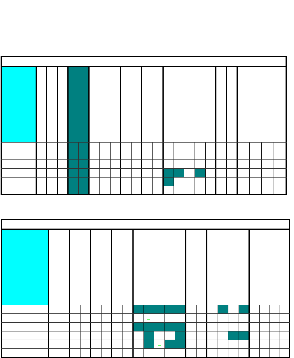
SECTION 6 - JLG CONTROL SYSTEM
3121298 – JLG Lift – 6-45
600S
MODEL NUMBER
MARKET
ENGINE
FLYWHEEL TEETH
GLOW PLUG
STARTER LOCKOUT
ENGINE SHUTDOWN
TILT
JIB
4 WHEEL STEER
STOUCH/SKYGUARD
ANSI USA 4 0 12 010 1 2 0 1 0 1 1 23450 0 0 1 2 3
ANSI EXPORT 4 1 12 010 1 2 0 1 0 1 1 23450 0 0 1 2 3
CSA 4 2 12 010 1 2 0 1 0 1 1 23450 0 0 1 2 3
CE 4 3 12 010 1 2 0 1 0 1X X 3X 5 0 0 0 1 2 3
AUSTRALIA 4 4 12 010 1 2 0 1 0 1XX3X 5 0 0 0 1 2 3
JAPAN 4 5 12 010 1 2 0 1 0 1 1 23450 0 0 1 2 3
600S
GEN SET / WELDER
GEN SET CUTOUT
HEAD & TAIL LIGHTS
CABLE BREAK SWITCH
LOAD SYSTEM
LOAD SENSOR
FUNCTION CUTOUT
GROUND ALARM
ANSI USA 010101010X X X X 0 1 0 X 2 X 0 1 2 3
ANSI EXPORT 010101010 1 23401 0 1 2 3 0 1 2 3
CSA 010101010X X X X 0 1 0 1 2 3 0 1 2 3
CE 010101 0 10 X 23 X 0 101X X 0 1 2 3
AUSTRALIA 010101 0 1 0 X2X X 0 1 0 1 2 3 0 1 2 3
JAPAN 01010101 0 123401 0 1 2 3 0 1 2 3
NOTE: Bold Italic Numbers indicate the default setting. Plain text indicates another available selection. Bold, Italic underlined num-
bers indicate the default when the option is factory installed.
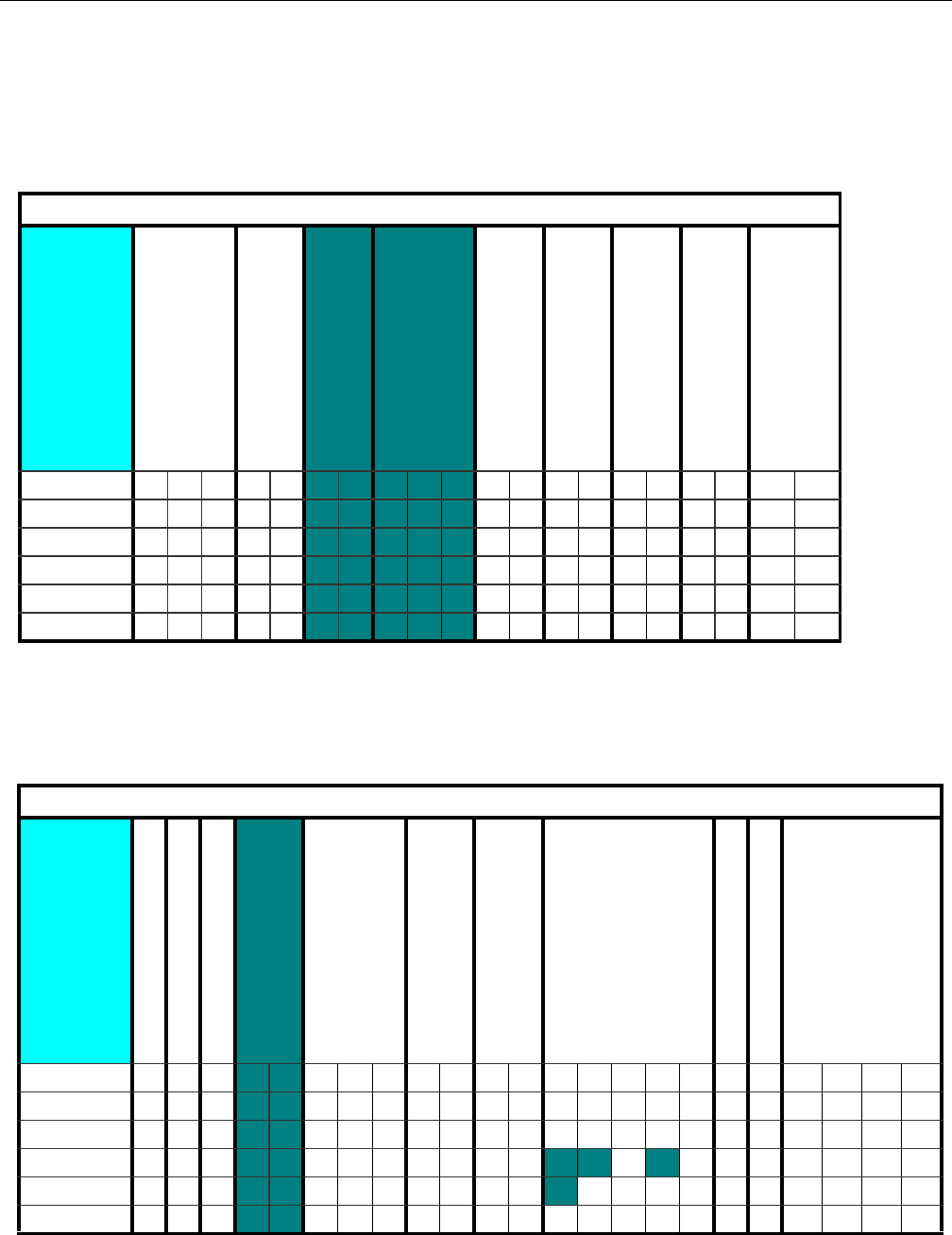
SECTION 6 - JLG CONTROL SYSTEM
6-46 – JLG Lift – 3121298
600S
DRIVE TYPE
DISPLAY UNITS
LEVELING MODE
DRIVE CONTROL
BOOM CONTROL
CLEARSKY
CRIBBING OP
FUEL TANK SIZE
ALARM/HORN
ANSI USA 01 2 010101 2 0101010101
ANSI EXPORT 01 2 010101 2 0101010101
CSA 012010101 2 0101010101
CE 012010101 2 0101010101
AUSTRALIA 012010101 2 0101010101
JAPAN 012010101 2 0101010101
NOTE: Bold Italic Numbers indicate the default setting. Plain text indicates another available selection. Bold, Italic underlined num-
bers indicate the default when the option is factory installed.
NOTE: Bold Italic Numbers indicate the default setting. Plain text indicates another available selection. Bold, Italic underlined num-
bers indicate the default when the option is factory installed.
600SJ
MODEL NUMBER
MARKET
ENGINE
FLYWHEEL TEETH
GLOW PLUG
STARTER LOCKOUT
ENGINE SHUTDOWN
TILT
JIB
4 WHEEL STEER
STOUCH/SKYGUARD
ANSI USA 4 0 12 010 1 2 0 1 0 1 1 23451 0 0 1 2 3
ANSI EXPORT 4 1 12 010 1 2 0 1 0 1 1 23451 0 0 1 2 3
CSA 4 2 12 010 1 2 0 1 0 1 1 23451 0 0 1 2 3
CE 4 3 12 010 1 2 0 1 0 1X X 3X 5 1 0 0 1 2 3
AUSTRALIA 4 4 12 010 1 2 0 1 0 1XX3X 5 1 0 0 1 2 3
JAPAN 4 5 12 010 1 2 0 1 0 1123451 0 0 1 2 3
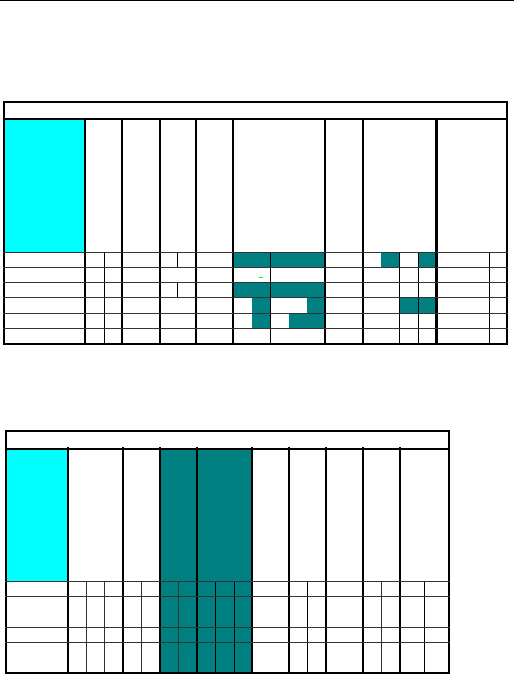
SECTION 6 - JLG CONTROL SYSTEM
3121298 – JLG Lift – 6-47
600SJ
GEN SET / WELDER
GEN SET CUTOUT
HEAD & TAIL LIGHTS
CABLE BREAK SWITCH
LOAD SYSTEM
LOAD SENSOR
FUNCTION CUTOUT
GROUND ALARM
ANSI USA 010101010XXXX01 0 X 2 X 0 1 2 3
ANSI EXPORT 010101010 1 23401 0 1 2 3 0 1 2 3
CSA 010101010XXXX01 0 1 2 3 0 1 2 3
CE 010101 0 10 X 23 X 0 101X X 0 1 2 3
AUSTRALIA 010101 0 1 0 X2X X 0 1 0 1 2 3 0 1 2 3
JAPAN 01010101 0 123401 0 1 2 3 0 1 2 3
NOTE: Bold Italic Numbers indicate the default setting. Plain text indicates another available selection. Bold, Italic underlined numbers
indicate the default when the option is factory installed.
NOTE: Bold Italic Numbers indicate the default setting. Plain text indicates another available selection. Bold, Italic underlined numbers
indicate the default when the option is factory installed.
600SJ
DRIVE TYPE
DISPLAY UNITS
LEVELING MODE
DRIVE CONTROL
BOOM CONTROL
CLEARSKY
CRIBBING OP
FUEL TANK SIZE
ALARM/HORN
ANSI USA 01 2 010101 2 0101010101
ANSI EXPORT 01 2 010101 2 0101010101
CSA 01201 0 101 2 0101010101
CE 01201 0 101 2 0101010101
AUSTRALIA 01201 0 101 2 0101010101
JAPAN 01201 0 101 2 0101010101
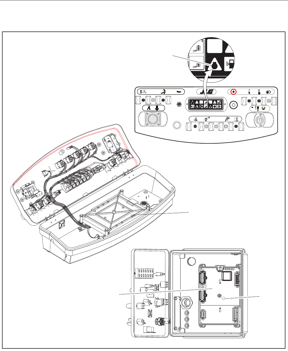
SECTION 6 - JLG CONTROL SYSTEM
6-48 – JLG Lift – 3121298
Figure 6-11. Control Module Locations
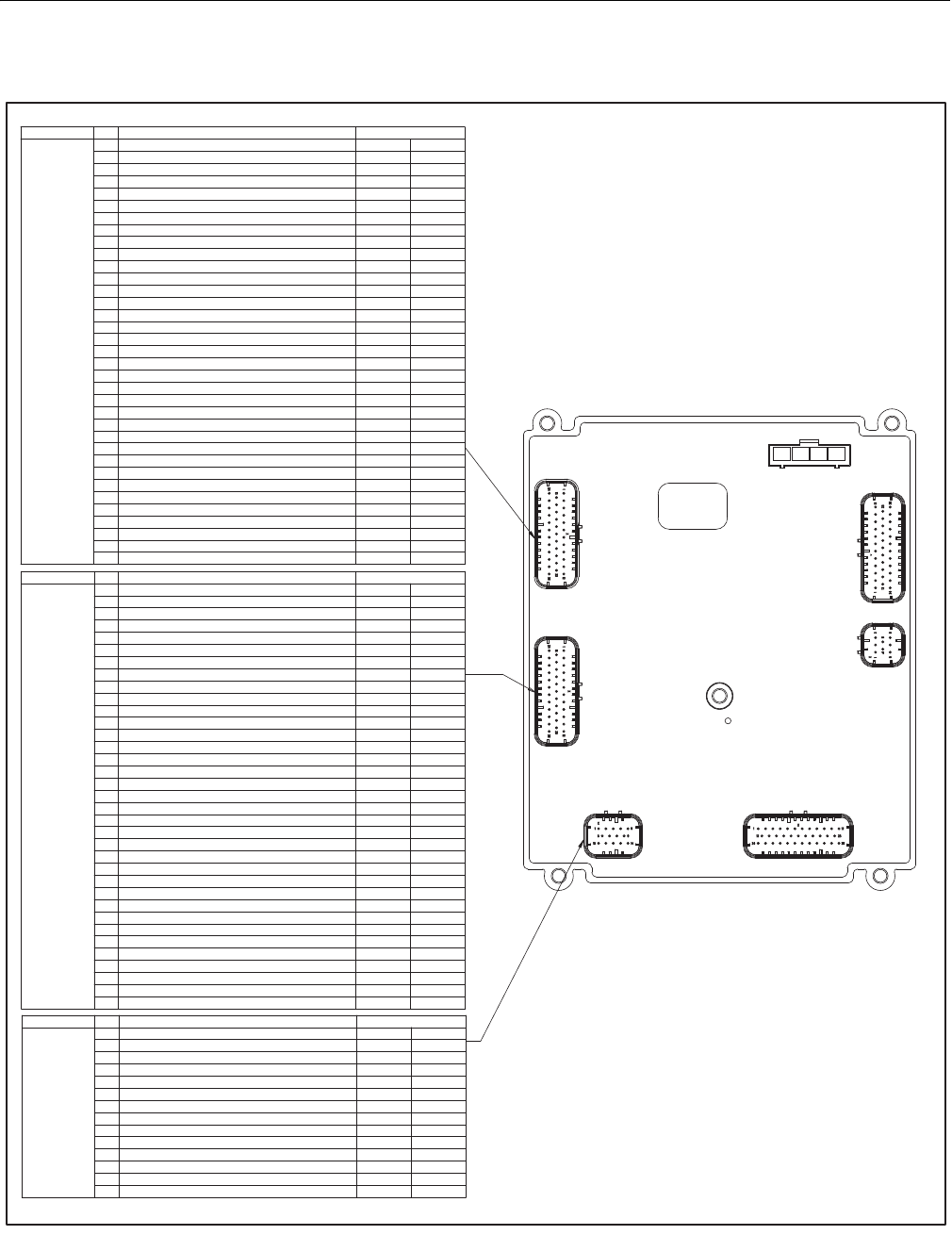
SECTION 6 - JLG CONTROL SYSTEM
3121298 – JLG Lift – 6-49
Figure 6-12. Ground Control Module Pin Connections 1 of 3
!
"#### !
$!%&'(! !
) ! !
* ! !
+!%&'%# !
,'&!% !
- ! !
. ! !
/0&1& #! !
##! !
" ( # !
$ 20!
)3
*##
+#! 4 0
, ! !
- ! !
. ! !
"/"5#!%% !
" 3205## !
"" 20!
"$ 2'%% !
")! & &
"*#5)-* # &
"+#5)-*(# &
", ! !
"-06( %
".06#5"$"1#
$/06#5"$"1#
$ 06 ! !
$" 1 !
$$ #5)-* ! !
$)205## !
$*! !
"
#! 3%% !
" !
$(##! !
)3##! !
*3% #! !
+ ! !
,3%!(#! !
-'%# !
.! !
/3#! !
3 #! !
" 2 #! !
$ 3! 3%% !
) ! !
*(# #! !
+3# #! !
, ! !
- ! !
.'(! !
"/! !
" 3#! !
"" 3!(#! !
"$ 2!(#! !
") 205## !
"* %##
"+!&20!
",3 !
"- ! !
". ! !
$/ ! !
$ (%% !
$" (!(#! !
$$ ( #! !
$)#(#! !
$*#(#! !
$
27
!%&' !2' !
"' !2' !
$ ! !
)#( !2' !
*! !
+( !2' !
,20% %2
- 3### !
.22#( !
/! !
! !
" ! %
$ !
) !2' !
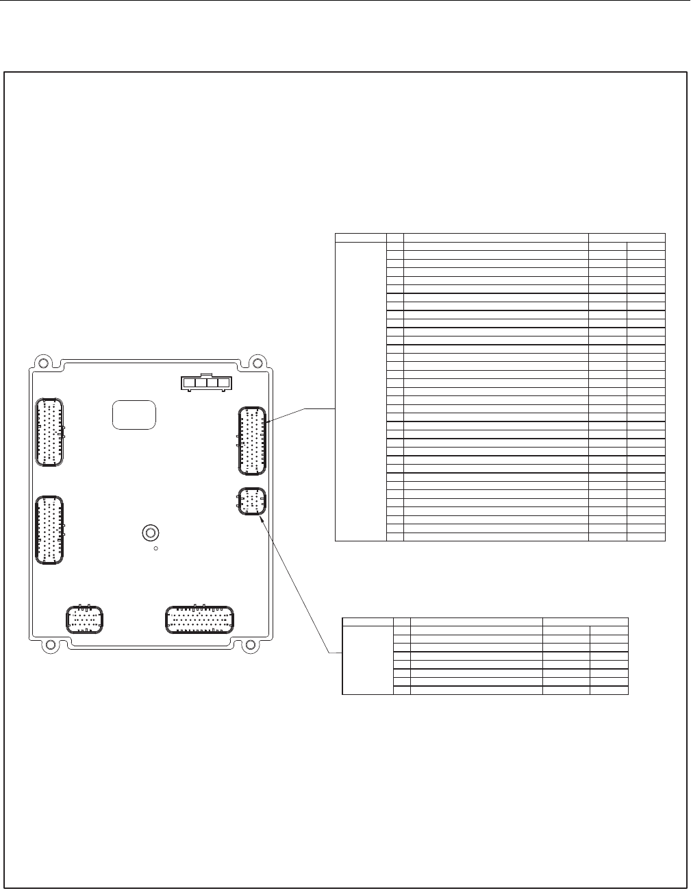
SECTION 6 - JLG CONTROL SYSTEM
6-50 – JLG Lift – 3121298
Figure 6-13. Ground Control Module Pin Connections 2 of 3
!"#" "$%
&!!"#" "$%
'#%$!!!"#" "$%
(")$# *"+ $# "$%
,-,. .# %%
/$"$ "0
")$#+ *"+ $# "$%
1$$$!$# "$%
2#%$!#%$!"$%
3#%$!#%$!"$%
"$0%$ *"+ !"#" "$%
& 4$ *"+ !"#" "$%
' $+"#+ " "0
(#%$!!* !"#" "$%
, *"+ !"#" "$%
/-,. .# %%
$"$ "0
1$ +"!#%$!"$%
2#%$!#%$!"$%
&3$$$!$# "$%
& * 5"")133$)!"."$"$ !"#" "$%
&& *"5"")133$)!"#" "$%
&' #%$!%$"$$." !"#" "$%
&($* " "0
&,#%$!#%$!"$%
&/-,. .# %%
& -,. .# %%
&1#%$!#%$!"$%
&2).# .%%
'3).# .%%
' ).# .%%
'& ).# .%%
'' ).# .%%
'().#% "$!% .%%
',$#5"")133 $)!"."$"$ !"#" "$%
&
$$$!6%$) "$%
&$$$!6%$) "$%
'$&+"#+" " "0
($&*" " "0
,$& +"!" #%$!"$%
/$&"$ "0
$&"$ "0
1$$$!!"#" "$%
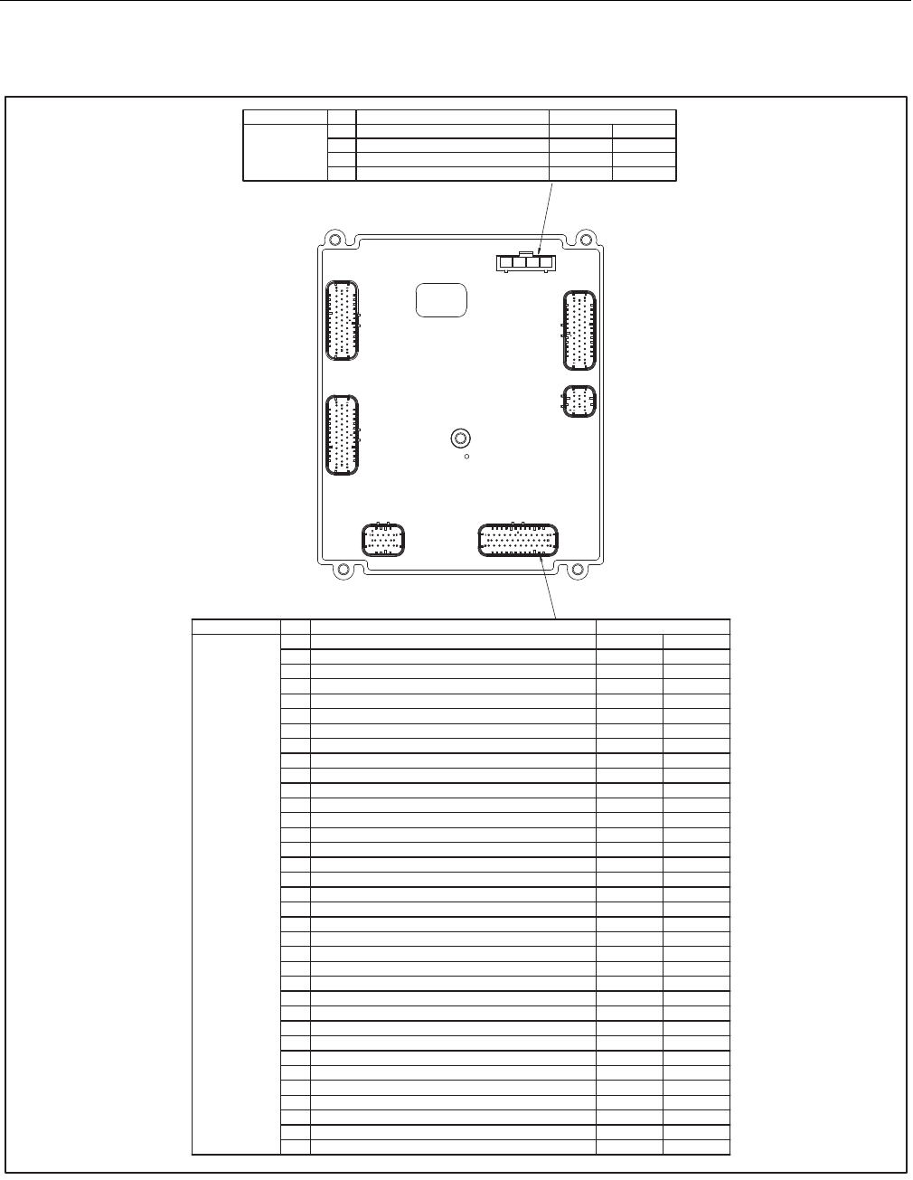
SECTION 6 - JLG CONTROL SYSTEM
3121298 – JLG Lift – 6-51
Figure 6-14. Ground Control Module Pin Connections 3 of 3
!" !"
#$! %& '"
( !"&! !" '"
)$!&! %&
)
!''" " & '"'&! ' '&
#*++&&',& ' '&
( $ '"'&! ' '&
)" '"-&! ' '& '"
*&!%$" ' '& '"
.&!!& ' '& '"
/&'"-'" ' '& '"
' ' '& '"
0' ' '& '"
+ $!' ' '& '"
$!-'" ' '& '"
# 1!! ' '&
( !!"'!,2&--& ' '&
)&!%!&'"'&! ' '&
*&"'"'"'&! ' '&
. &3''&!,$!4"'""& ' '& '"
/ &!% ' '& '"
&!!&!' 1 ' '& '"
0 ' ' '& '"
#+ '!' 1 ' '& '"
# $!'$" ' '& '"
## $!- ' '& '"
#( &'"' ' '& '"
#)&!,%& %&
#*&!,%& !""&!-" %&
#. &!,$4"1&! '" '"'&! ' '&
#/ 1&! '!,2&--& ' '&
# " '"1' 1&"!&!'"'&! ' '&
#0 " '"$'!--!'"'&! ' '&
(+ &'"- ' '& '"
( & !" !" '"
(# !" !" '"
(( &'"'$" ' '& '"
()-$'" ' '& '"
(*-$'" !' 1 ' '& '"
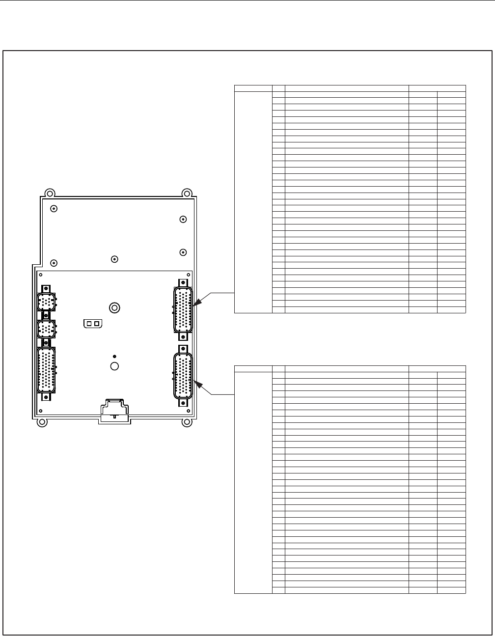
SECTION 6 - JLG CONTROL SYSTEM
6-52 – JLG Lift – 3121298
Figure 6-15. Platform Control Module Pin Connections 1 of 2
!
" !
#$ !
%$ !
&'!$ !
('!$ !
)!'! * !
+!'! !
,!'- !
. !'- !
/ !
" / !
# $''
% $! !
& !0!1 !
( !/$$ !
) !$$ !
+ $* /!1 -!
,
!
". !
" !
"" -!$1$'!!/ !
"# !
"% !
"& !
"( !
") $-!-* * !
"+ 2' !
", $*- !
#. *!3! * !
# * !
#" ' !
## !4$ !
#% $''-! 5) -!
#& $'' !
"
!
" !
#/!1-! *$ !
%-!$1$'-$* *$ !
& !'
(*!$$$! !'
)!/! !'
+-*$1$'$$$! !'
,$! !'
. /6!/! !'
!'-!! !'
" &../!!1! !'
# .../!!1! !'
% -!$1$'! !'
& !! !'
( $* ! !'
) ! ! !'
+ !'
, -$!/! !'
". *! !'
" ! !'
"" 3%-! !'
"# #3%-! !'
"% 3"-! !'
"& -!$
"(
!!17
!!
") !!17
"+ !!170 !
", !!170 !
#. /!1-! /!1 -!
# /!1-! /!1 -!
#" /!1-! /!1 -!
## /!1-! /!1 -!
#% $* /!1 -!
#& -! !'
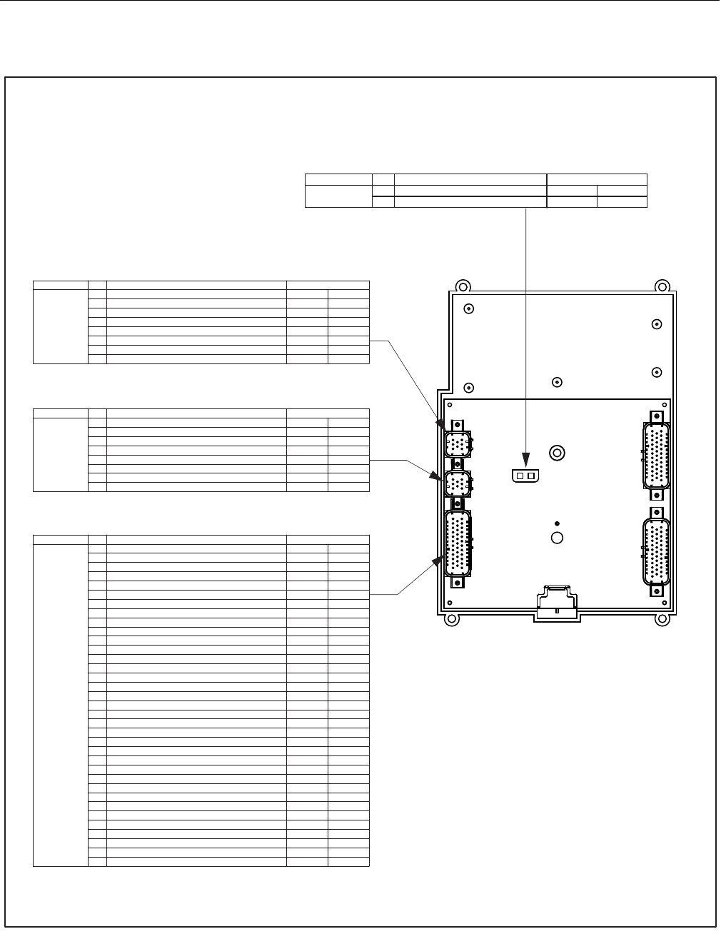
SECTION 6 - JLG CONTROL SYSTEM
3121298 – JLG Lift – 6-53
Figure 6-16. Platform Control Module Pin Connections 2 of 2
! "
#
$ %&'(
""! "
!) ""!
*!) ""!
+)",$"! )",( !- !
.!)", !- !
/" 0"")", !- !
#
),"")",
!- !
)",)"! ""! "
1!)"! ""! "
2 3#! 3#!
!" !! "
!" !! "
*
!! "
+
"
. !! 3#!
/ ! "
#" 0"")", ,)""! "
),"")", ,)""! "
1 !!!!
2 !! "
""!
""!
* "
+ "
. ""!
/ ""!
# ""!
""!
1 "
*2 ! ""!
* !,", ""!
* !)," ""!
** ""!
*+
""!
*. "
/
$ %&'(
"4)-)"0)-! )- !
"! ""! "
*")"! ""! "
+))"! ""! "
.) ""! "
/)", ""! "
#"4)-)"0 "
"
.
$&&%(
4)"-)"0)-! )- !
"! ""! "
*")"! ""! "
+)")"! ""! "
.)"! ""! "
/ ""! "
#"4)"-)"0 "
"

SECTION 6 - JLG CONTROL SYSTEM
6-54 – JLG Lift – 3121298
NOTES:
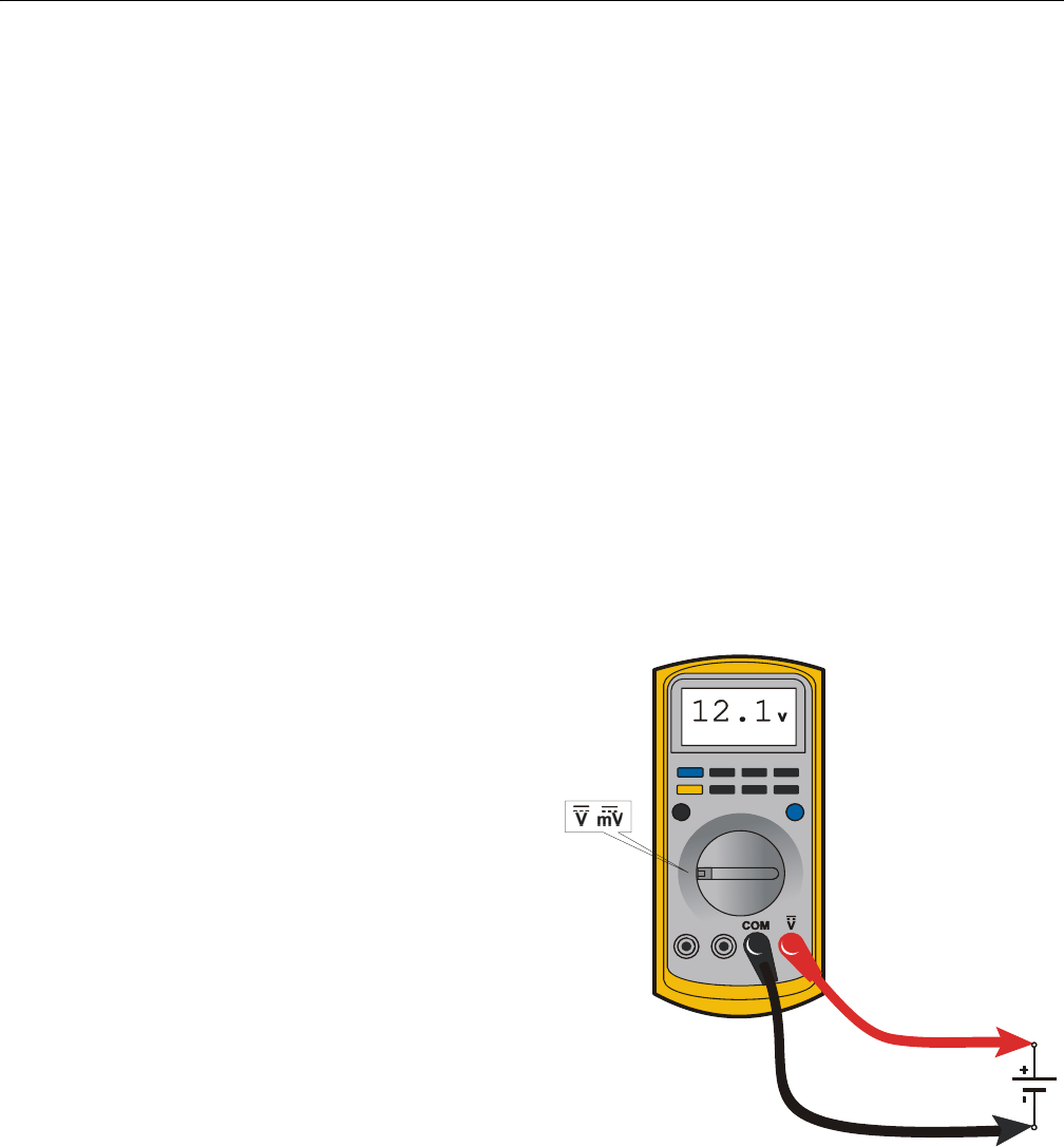
SECTION 7 - BASIC ELECTRICAL INFORMATION & SCHEMATICS
3121298 – JLG Lift – 7-1
SECTION 7. BASIC ELECTRICAL INFORMATION & SCHEMATICS
7.1 GENERAL
This section contains basic electrical information and sche-
matics for locating and correcting most electrical problems. If
a problem develops which is not presented in this section or
corrected by listed corrective actions, obtain technically quali-
fied guidance before proceeding with any additional mainte-
nance.
NOTE: Some procedures/connectors shown in this section may
not apply to all models.
7.2 MULTIMETER BASICS
A wide variety of multimeters or Volt Ohm Meters (VOM) can
be used for troubleshooting your equipment. This section
shows diagrams of a common, digital VOM configured for sev-
eral different circuit measurements. Instructions for your VOM
may vary. Please consult the meter operator’s manual for more
information.
Grounding
"Grounding the meter" means to take the black lead (which is
connected to the COM (common) or negative port) and touch
it to a good path to the negative side of the Voltage source.
Backprobing
To "backprobe" means to take the measurement by accessing
a connector’s contact on the same side as the wires, the back
of the connector. Readings can be done while maintaining cir-
cuit continuity this way. If the connector is the sealed type,
great care must be taken to avoid damaging the seal around
the wire. It is best to use probes or probe tips specifically
designed for this technique, especially on sealed connectors.
Whenever possible insert probes into the side of the connec-
tor such that the test also checks both terminals of the con-
nection. It is possible to inspect a connection within a closed
connector by backprobing both sides of a connector terminal
and measuring resistance. Do this after giving each wire a gen-
tle pull to ensure the wires are still attached to the contact and
contacts are seated in the connector.
Min/Max
"Min/Max" recording feature of some meters can help when
taking measurements of intermittent conditions while alone.
For example, you can read voltage applied to a solenoid when
it is only operational while a switch, far from the solenoid and
meter, is held down.
Polarity
Getting a negative Voltage or current reading when expecting
a positive reading frequently means the leads are reversed.
Check what reading is expected, location of the signal and
leads are correctly connected to the device under test. Also
check the lead on the "COM" port goes to the ground or nega-
tive side of the signal and lead on the other port goes to the
positive side of the signal.
Scale
M = Mega = 1,000,000 * (Displayed Number)
k = kilo = 1,000 * (Displayed Number)
m = milli = (Displayed Number) / 1,000
μ = micro = (Displayed Number) / 1,000,000
Example: 1.2 k = 1200
Example: 50 mA = 0.05 A
Voltage Measurement
• If meter is not auto ranging, set it to the correct range
(See multimeter’s operation manual)
• Use firm contact with meter leads
Figure 7-1. Voltage Measurement (DC)
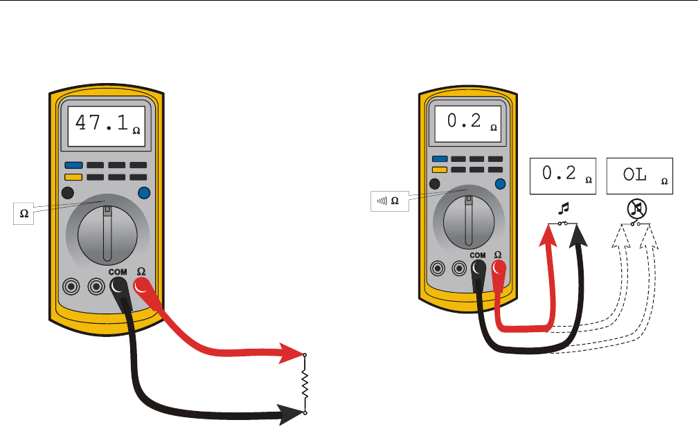
SECTION 7 - BASIC ELECTRICAL INFORMATION & SCHEMATICS
7-2 – JLG Lift – 3121298
Resistance Measurement
• First test meter and leads by touching leads together.
Resistance should read a short circuit (very low resis-
tance)
• Circuit power must be turned OFF before testing resis-
tance
• Disconnect component from circuit before testing
• If meter is not auto ranging, set it to the correct range
(See multimeter’s operation manual)
• Use firm contact with meter leads
Continuity Measurement
• Some meters require a separate button press to enable
audible continuity testing
• Circuit power must be turned OFF before testing conti-
nuity
• Disconnect component from circuit before testing
• Use firm contact with meter leads
• First test meter and leads by touching leads together.
Meter should produce an audible alarm, indicating
continuity
Figure 7-2. Resistance Measurement
Figure 7-3. Continuity Measurement
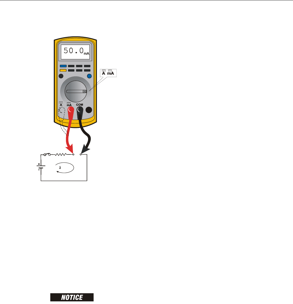
SECTION 7 - BASIC ELECTRICAL INFORMATION & SCHEMATICS
3121298 – JLG Lift – 7-3
Current Measurement
• Set up meter for expected current range
• Be sure to connect meter leads to correct jacks for
selected current range
• If meter is not auto ranging, set it to correct range (See
multi meter’s operation manual)
• Use firm contact with meter leads
7.3 APPLYING SILICONE DIELECTRIC COMPOUND
TO ELECTRICAL CONNECTIONS
NOTE: This section is not applicable for battery terminals.
JLG P/N 0100048 DIELECTRIC GREASE (NOVAGARD G661) IS THE ONLY MATE-
RIAL APPROVED FOR USE AS A DIELECTRIC GREASE.
NOTE: Do NOT apply dielectric grease to the following connec-
tions:
• Main Boom Rotary sensor connections (on Celesco Sensor),
• LSS Modules connections,
• Deutz EMR 2 ECM connection.
Silicone Dielectric Compound must be used on all electrical
connections except for those mentioned above for the follow-
ing reasons:
• To prevent oxidation at mechanical joint between male
and female pins.
• To prevent electrical malfunction caused by low level con-
ductivity between pins when wet.
Use the following procedure to apply Silicone Dielectric Com-
pound to the electrical connectors. This procedure applies to
all plug connections not enclosed in a box. Silicone grease
should not be applied to connectors with external seals.
1. To prevent oxidation, silicone grease must be packed
completely around male and female pins on the inside
of the connector prior to assembly. This is most easily
achieved by using a syringe.
NOTE: Over a period of time, oxidation increases electrical resis-
tance at the connection, eventually causing circuit failure.
2. To prevent shorting, silicone grease must be packed
around each wire where they enter the outside of the
connector housing. Also, silicone grease must be
applied at the joint where the male and female connec-
tors come together. Any other joints (around strain
reliefs, etc.) where water could enter the connector
should also be sealed.
NOTE: This condition is especially common when machines are
pressure washed since the washing solution is much more
conductive than water.
3. Anderson connectors for battery boxes and battery
chargers should have silicone grease applied to contacts
only.
NOTE: Curing-type sealants can also be used to prevent shorting
and would be less messy, but make future pin removal diffi-
cult.
When applied to electrical connections, dielectric grease helps
prevent corrosion of electrical contacts and improper conduc-
tivity between contacts from moisture intrusion. Open and
sealed connectors benefit from application of dielectric
grease.
Dielectric grease shall be applied to all electrical connectors at
the time of connection (except those noted under Exclusions).
Figure 7-4. Current Measurement (DC)
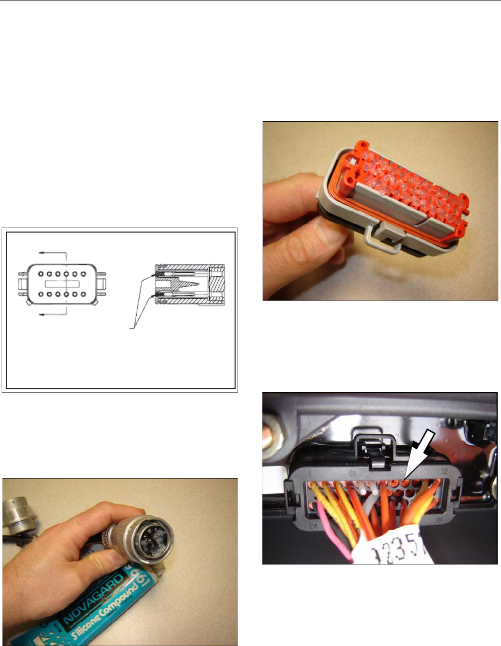
SECTION 7 - BASIC ELECTRICAL INFORMATION & SCHEMATICS
7-4 – JLG Lift – 3121298
Dielectric Grease Application
Before following these instructions, refer to excluded connec-
tor types (See Exclusions below).
1. Use dielectric grease in a tube for larger connection
points or apply with a syringe for small connectors.
2. Apply dielectric grease to the female contact (fill it
approximately ½ full; see example below)
3. Leave a thin layer of dielectric grease on connector face.
4. Assemble connector system immediately to prevent
moisture or dust contamination
5. Pierce one of the unused wire seals before assembly if
the connector system tends to trap air (i.e. AMP Seal)
and then install a seal plug.
Figure 7-5. Applying Dielectric Grease
Deutsch HD, DT, DTM, DRC Series
The Deutsch connector system is commonly used for harsh
environments. Follow installation instructions.
Figure 7-6. Deutsch Connector
AMP Seal
The AMP Seal connector system is used on Control ADE Plat-
form and Ground Modules.
Apply dielectric grease to the female contact. If trapped air
prevents connector from latching, pierce one of the unused
wire seals.
Figure 7-7. Dielectric Grease On Female Contacts
After assembly, install a seal plug (JLG #4460905) to keep out
moisture. Seal plugs may also be installed by the wire harness
manufacturer if an unused wire seal was damaged during
assembly.
Figure 7-8. Seal Plugs
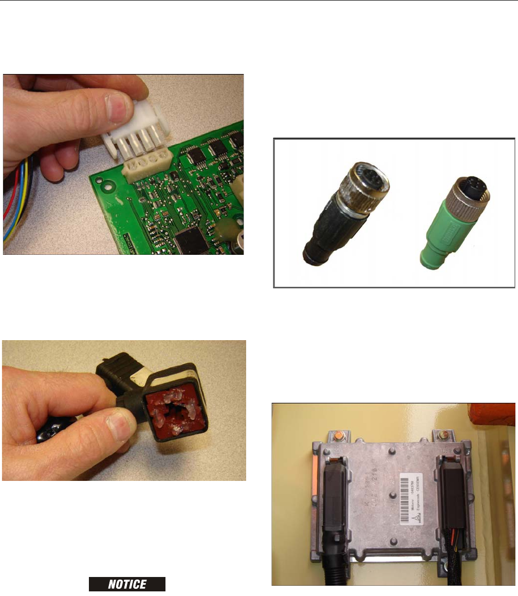
SECTION 7 - BASIC ELECTRICAL INFORMATION & SCHEMATICS
3121298 – JLG Lift – 7-5
AMP Mate-N-Lok
Follow manufacturer installation instructions.
Figure 7-9. AMP Mate-N-Lok Connector
DIN Connectors
This connector is typically used on hydraulic valves. Follow
manufacturer installation instructions.
Figure 7-10. DIN Connector
Exclusions
Some connectors do not require or may be permanently dam-
aged by application of dielectric grease. Dielectric grease may
not be required in properly sealed enclosures.
DO NOT USE DIELECTRIC GREASE ON BRAD HARRISON/PHOENIX CONTACT
M12 OR AMP JUNIOR TIMER CONNECTORS. LOW-FORCE CONTACTS CANNOT
DISPLACE DIELECTRIC GREASE AND CREATE ELECTRICAL CONTACT.
BRAD HARRISON/PHOENIX CONTACT M12
This connector uses gold contact material to resist corrosion
and an O-ring seal for moisture integrity. Low-force contacts
cannot displace dielectric grease to achieve electrical contact.
Once contaminated, replacement of female contacts is
required. The JLG Load Sensing System and 1250AJP Rotary
Angle Sensors are examples of components with the M12 con-
nector system.
Figure 7-11. Brad Harrison/Phoenix Connectors
AMP JUNIOR TIMER
This type of connector uses back-seals to keep out moisture.
Low-force contacts cannot displace dielectric grease and cre-
ate electrical contact. Use solvents (i.e. contact cleaner or min-
eral spirits) to remove dielectric grease. The Deutz EMR2
engine control module uses this connector.
Figure 7-12. AMP Junior Timer
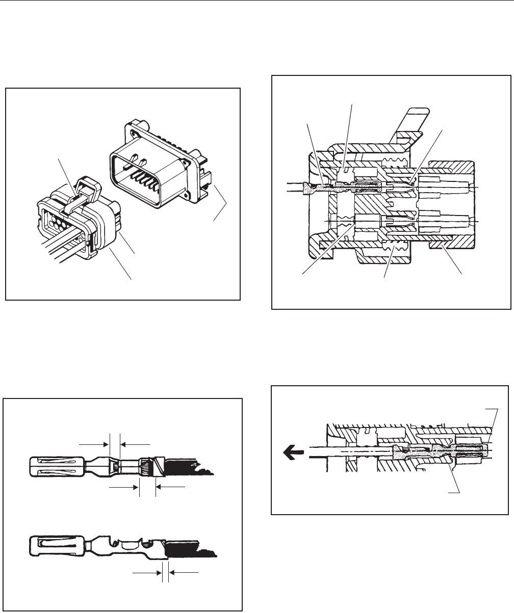
SECTION 7 - BASIC ELECTRICAL INFORMATION & SCHEMATICS
7-6 – JLG Lift – 3121298
7.4 AMP CONNECTOR
Plug and header assembly colors are mechanically keyed to
mate only with identical colors.
Figure 7-13. AMP Connector
Contact Assembly
1. Strip wire and install in crimp end of connector as
shown in Figure 7-14.
2. Crimp connector. Do not damage cutoff tab.
Figure 7-14. AMP Contact Assembly
Connector Assembly
1. Check wedge lock is in the open, or as-shipped, position.
Figure 7-15. AMP Connector Assembly
2. Push contact straight into circuit cavity as far as it will go.
3. Pull on contact wire with a force of 1 - 2 lb to be sure
retention fingers are holding contact.
Figure 7-16. AMP Contact Installation
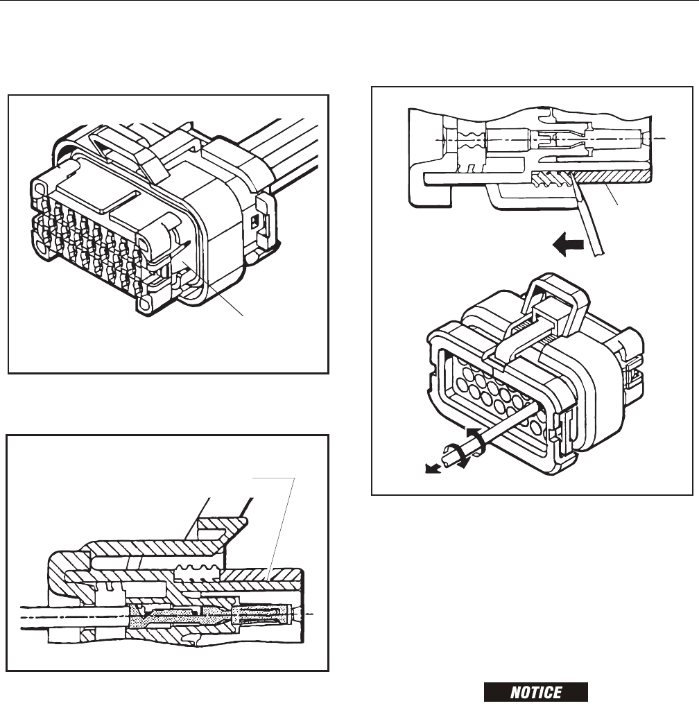
SECTION 7 - BASIC ELECTRICAL INFORMATION & SCHEMATICS
3121298 – JLG Lift – 7-7
4. After all contacts are inserted, close wedge lock to its
locked position. Release locking latches by squeezing
them inward.
Figure 7-17. Close Wedge Lock
5. Slide wedge lock in housing until flush with housing.
Figure 7-18. Seating Wedge Lock
Disassembly
1. Insert a 4.8 mm (3/16") wide screwdriver blade between
mating seal and one of red wedge lock tabs.
2. Pry wedge lock open.
3. While rotating wire back and forth over a half turn (1/4
turn in each direction), gently pull wire until contact is
removed.
NOTE: Wedge lock should never be removed from housing for
insertion or removal of contacts.
Figure 7-19. AMP Connector Disassembly
Wedge Lock
The wedge lock has slotted openings in the forward, or mating
end. These slots accommodate circuit testing in the field by
using a flat probe such as a pocket knife. DO NOT use a sharp
point such as an ice pick.
Service - Voltage Reading
HOLES IN WIRE INSULATION CAN LET IN MOISTURE AND CAUSE SYSTEM FAIL-
URE. DO NOT PIERCE WIRE INSULATION TO TAKE VOLTAGE READINGS.
It has been common practice in electrical troubleshooting to
probe wires by piercing insulation with a sharp point. This
practice should be discouraged when dealing with an
AMPSEAL plug assembly or any other sealed connector sys-
tem. Resulting pinholes in the insulation allows moisture to
enter by traveling along wire strands and could result in sys-
tem failure.
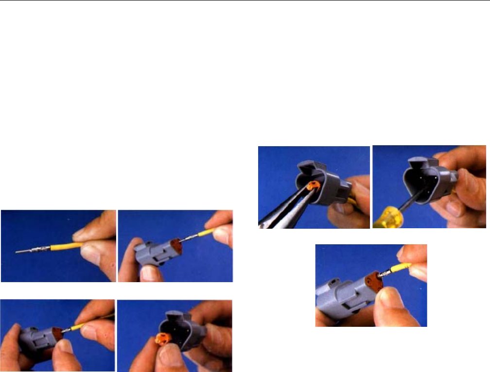
SECTION 7 - BASIC ELECTRICAL INFORMATION & SCHEMATICS
7-8 – JLG Lift – 3121298
7.5 DEUTSCH CONNECTORS
DT/DTP Series Assembly
1. Grasp crimped contact (1) about 25mm behind contact
barrel.
2. Hold connector with rear grommet (2) facing you.
3. Push contact straight into connector grommet (3) until a
click is felt. A slight tug confirms it is locked in place.
4. Once all contacts are in place, insert wedgelock (4) with
arrow pointing toward exterior locking mechanism. The
wedgelock will snap into place. Rectangular wedges are
not oriented. They may go in either way.
NOTE: Receptacle shown - use same procedure for plug.
Figure 7-20. DT/DTP Contact Installation
DT/DTP Series Disassembly
1. Remove wedgelock (1) using needle-nose pliers or a
hook shaped wire to pull wedge straight out.
2. To remove contacts, gently pull wire backwards at the
same time releasing the locking finger (2) by moving it
away from contact with a screwdriver.
3. Hold rear seal (3) in place. Removing contact may dis-
place seal.
Figure 7-21. DT/DTP Contact Removal
12
34
12
3
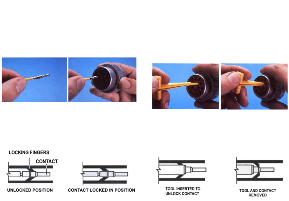
SECTION 7 - BASIC ELECTRICAL INFORMATION & SCHEMATICS
3121298 – JLG Lift – 7-9
HD30/HDP20 Series Assembly
1. Grasp contact (1) about 25mm behind contact crimp
barrel.
2. Hold connector with rear grommet (2) facing you.
Figure 7-22. HD/HDP Contact Installation
3. Push contact straight into connector grommet until a
positive stop is felt. A slight tug will confirm it is locked
in place.
Figure 7-23. HD/HDP Locking Contacts Into Position
NOTE: Insert sealing plugs in unused wire cavities for full environ-
mental sealing.
HD30/HDP20 Series Disassembly
1. With rear insert toward you, snap appropriate size
extractor tool (1) over wire of contact to be removed.
2. Push tool in the insert cavity (2) until it engages contact
and resistance is felt.
Figure 7-24. HD/HDP Contact Removal
3. Pull contact-wire assembly out of connector
NOTE: Do Not twist or insert tool at an angle.
Figure 7-25. HD/HDP Unlocking Contacts
12
12
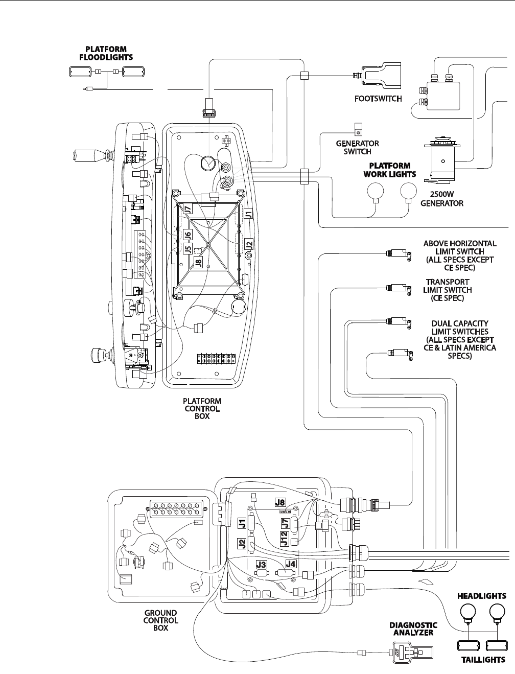
SECTION 7 - BASIC ELECTRICAL INFORMATION & SCHEMATICS
7-10 – JLG Lift – 3121298
Figure 7-26. Electrical Components 1 of 2
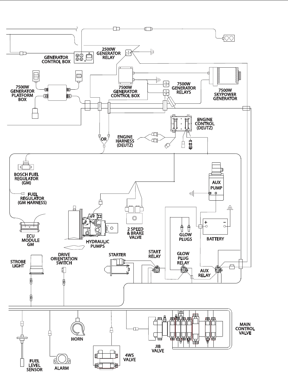
SECTION 7 - BASIC ELECTRICAL INFORMATION & SCHEMATICS
3121298 – JLG Lift – 7-11
Figure 7-27. Electrical Components 2 of 2
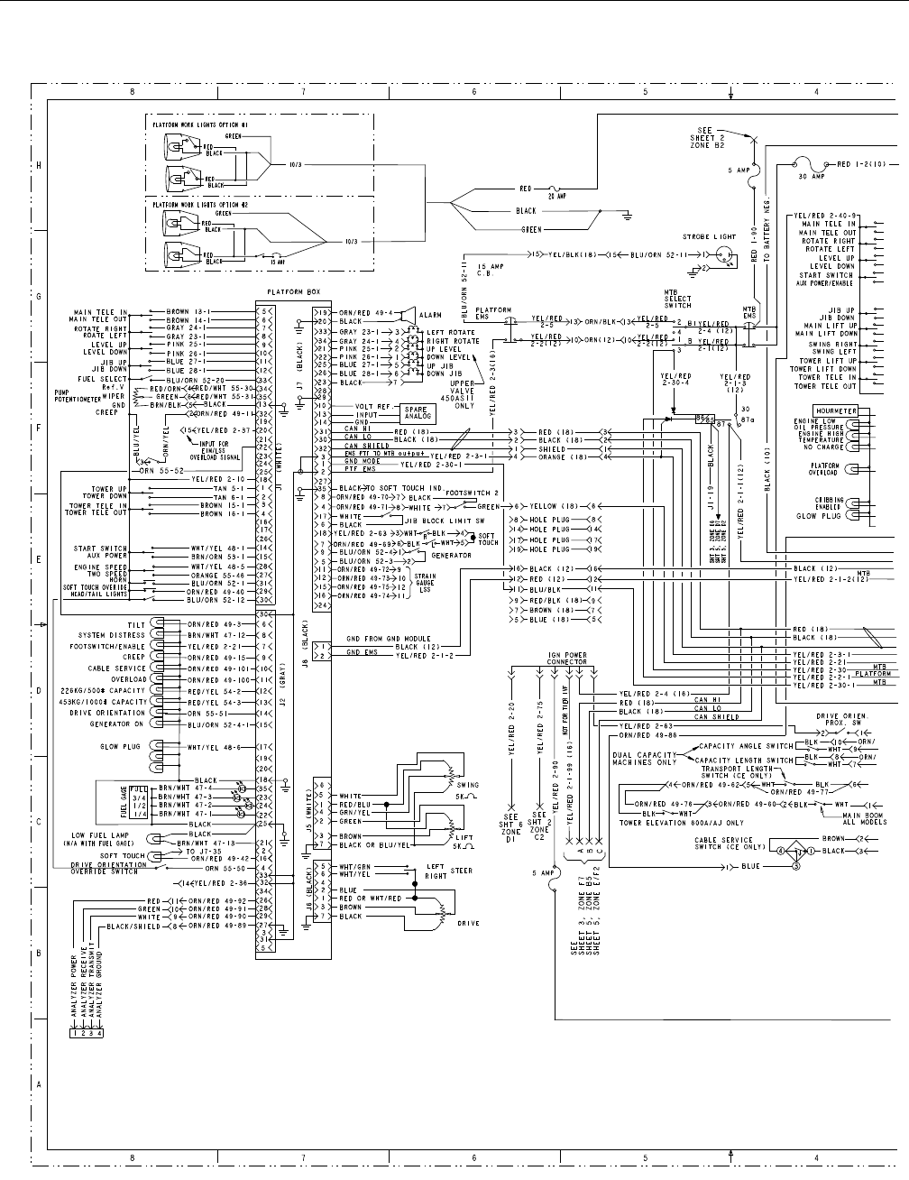
SECTION 7 - BASIC ELECTRICAL INFORMATION & SCHEMATICS
7-12 – JLG Lift – 3121298
Figure 7-28. Platform and Ground Control Electrical Schematic - 1 of 2
1001110345D - Sheet 2
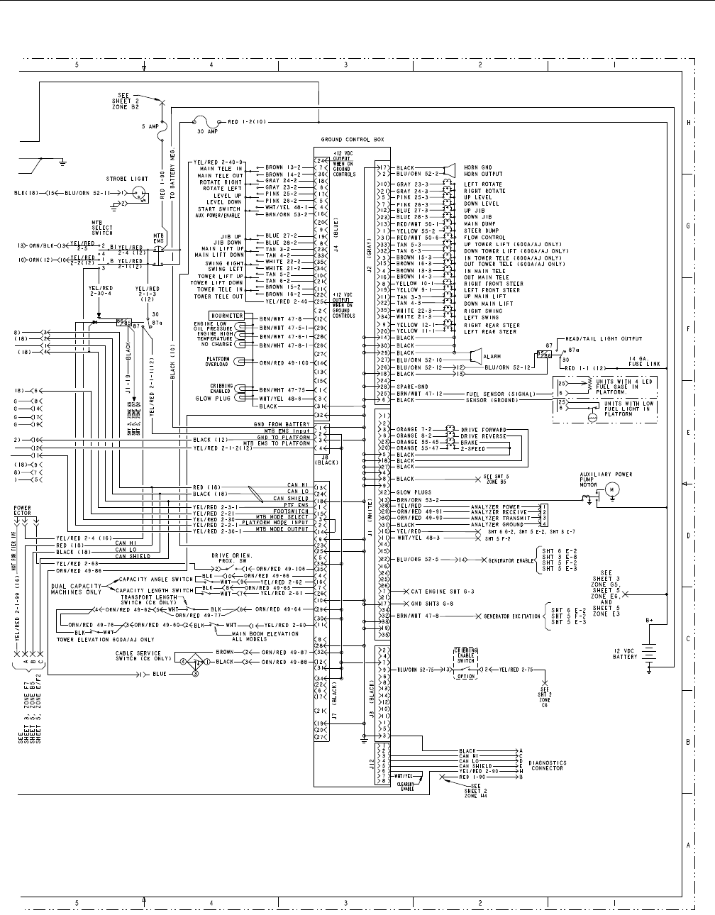
SECTION 7 - BASIC ELECTRICAL INFORMATION & SCHEMATICS
3121298 – JLG Lift – 7-13
Figure 7-29. Platform and Ground Control Electrical Schematic - 2 of 2
1001110345D - Sheet 2
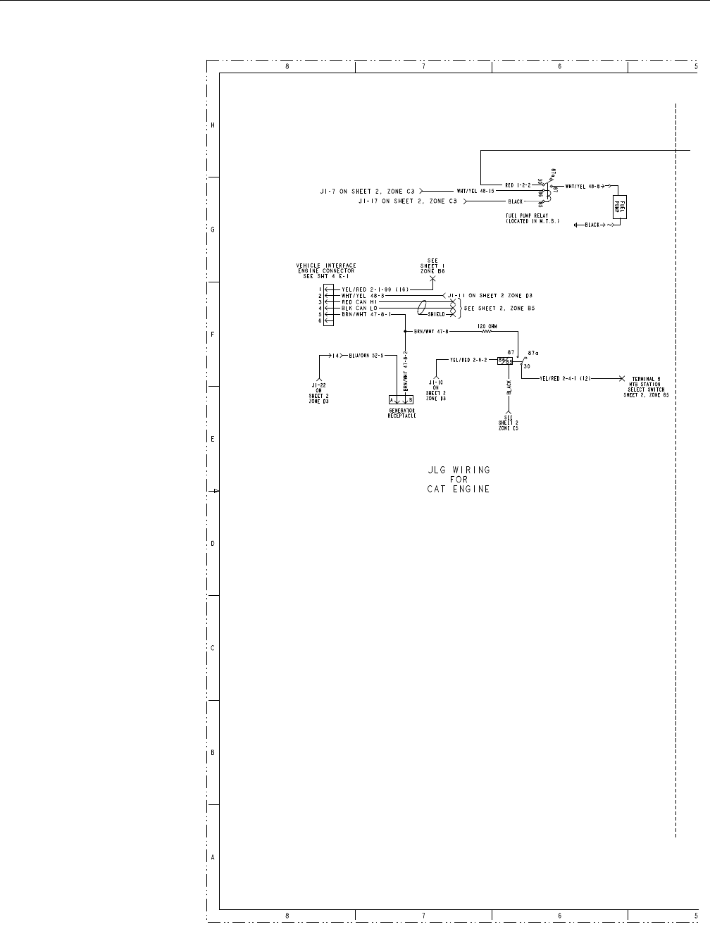
SECTION 7 - BASIC ELECTRICAL INFORMATION & SCHEMATICS
7-14 – JLG Lift – 3121298
Figure 7-30. Generator Wiring Schematic 1 of 2
1001110345D - Sheet 3
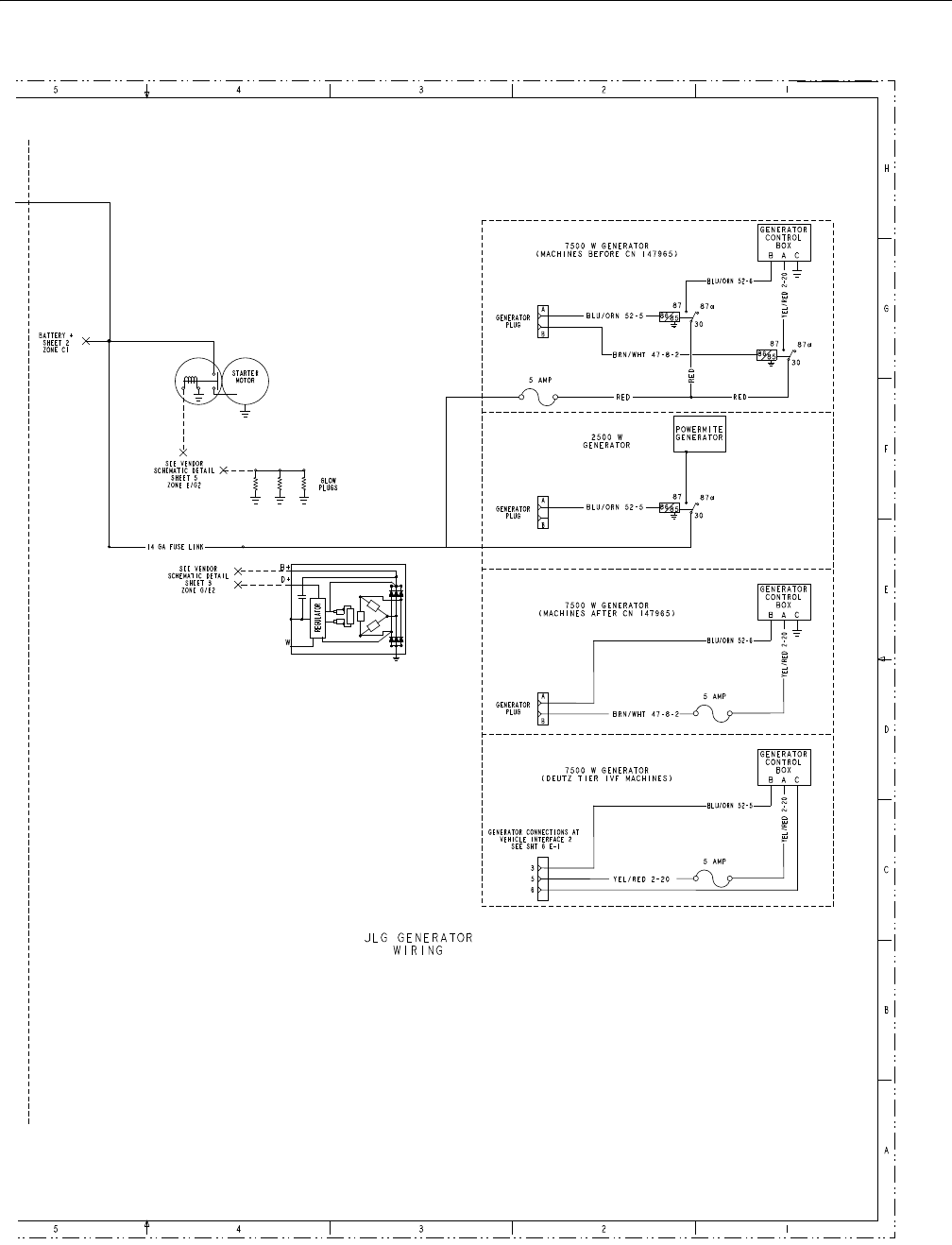
SECTION 7 - BASIC ELECTRICAL INFORMATION & SCHEMATICS
3121298 – JLG Lift – 7-15
Figure 7-31. Generator Wiring Schematic 2 of 2
1001110345D - Sheet 3
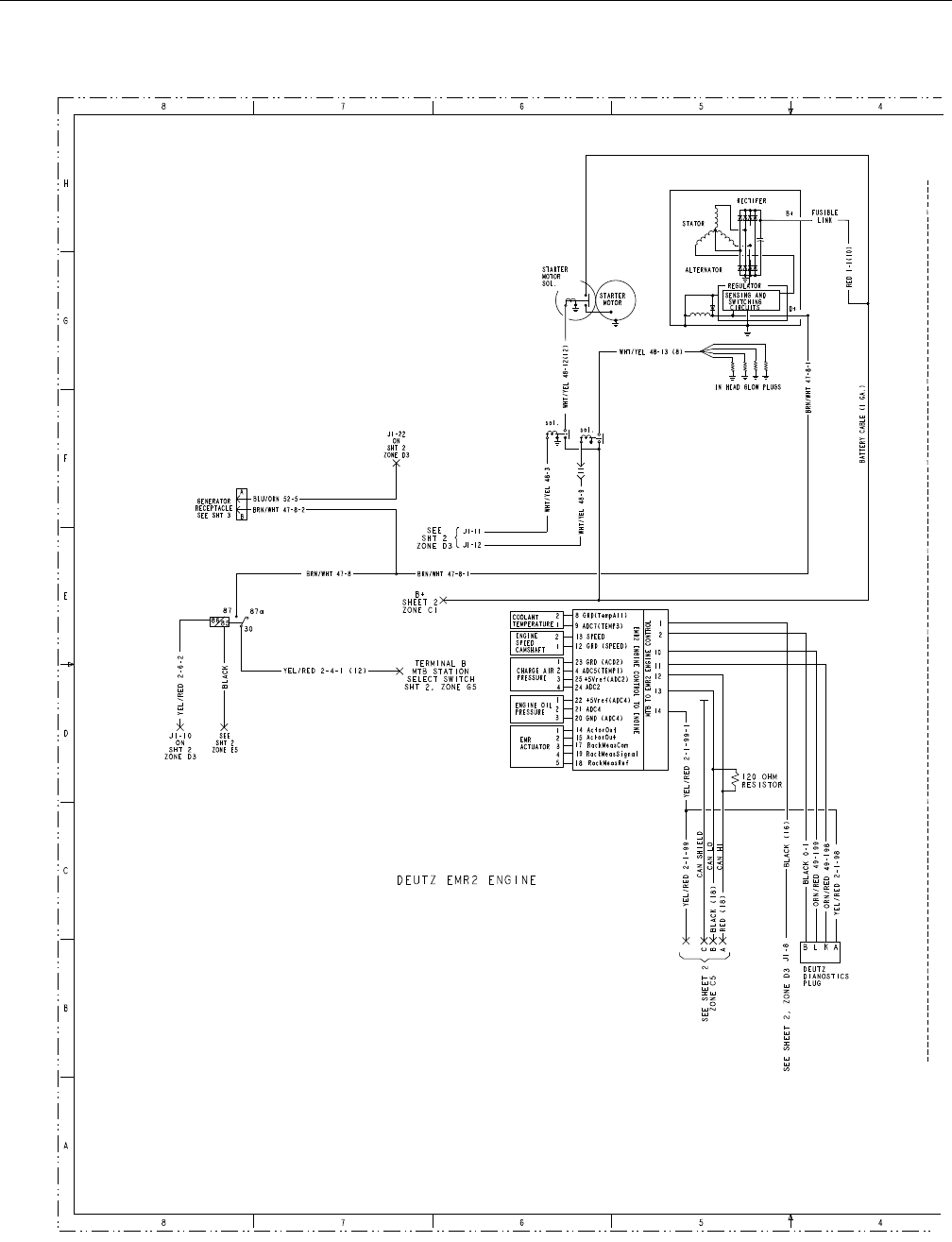
SECTION 7 - BASIC ELECTRICAL INFORMATION & SCHEMATICS
7-16 – JLG Lift – 3121298
Figure 7-32. Deutz Engine Harness Electrical Schematic
1001110345D - Sheet 5
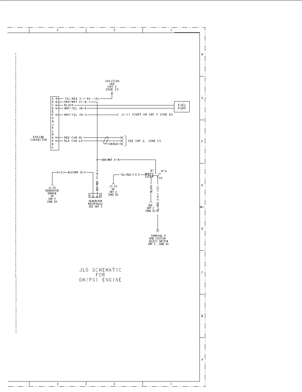
SECTION 7 - BASIC ELECTRICAL INFORMATION & SCHEMATICS
3121298 – JLG Lift – 7-17
Figure 7-33. GM/PSI Engine Harness Electrical Schematic
1001110345D - Sheet 5
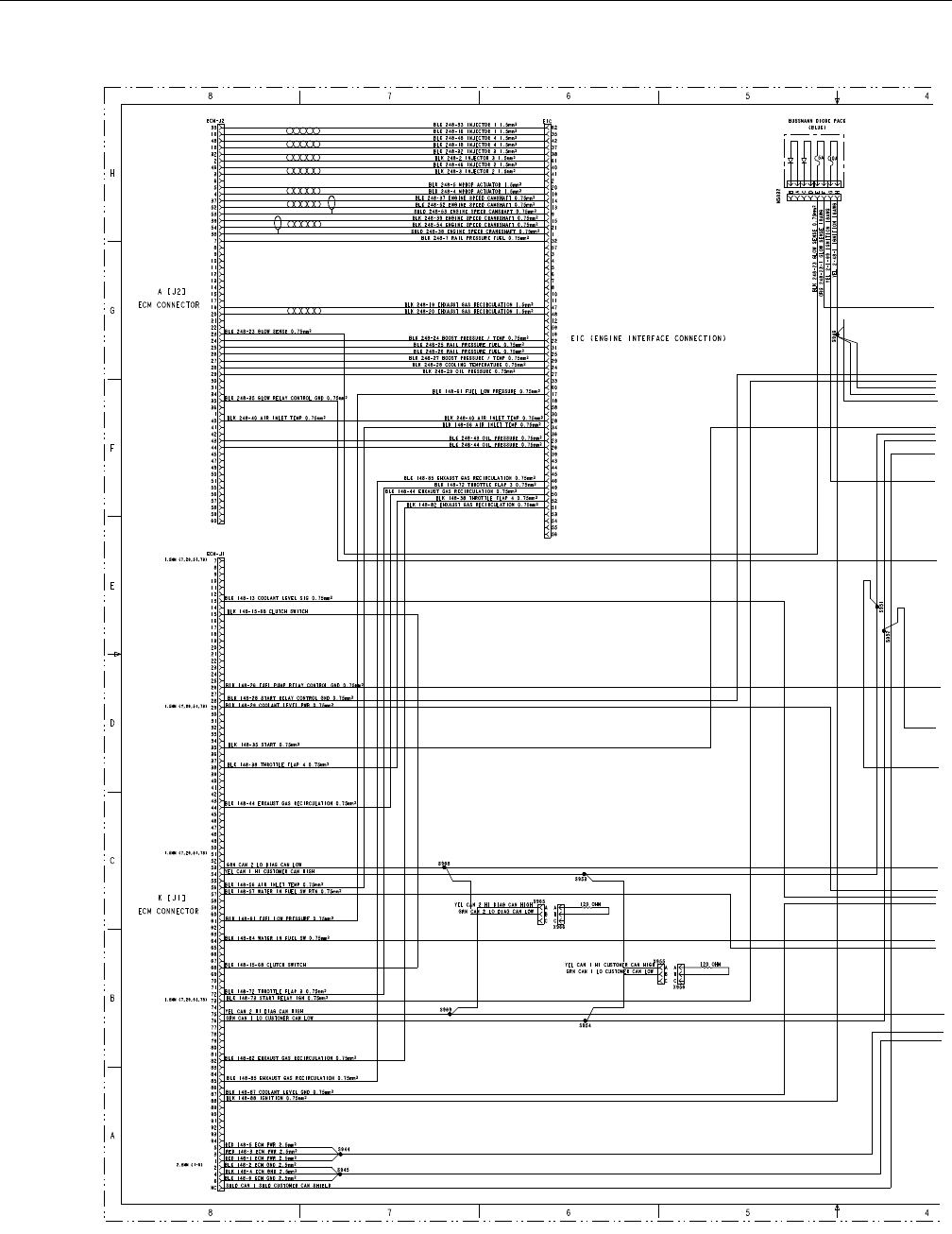
SECTION 7 - BASIC ELECTRICAL INFORMATION & SCHEMATICS
7-18 – JLG Lift – 3121298
Figure 7-34. Deutz Tier 4 Final Engine Harness Electrical Schematic
1001110345D - Sheet 6
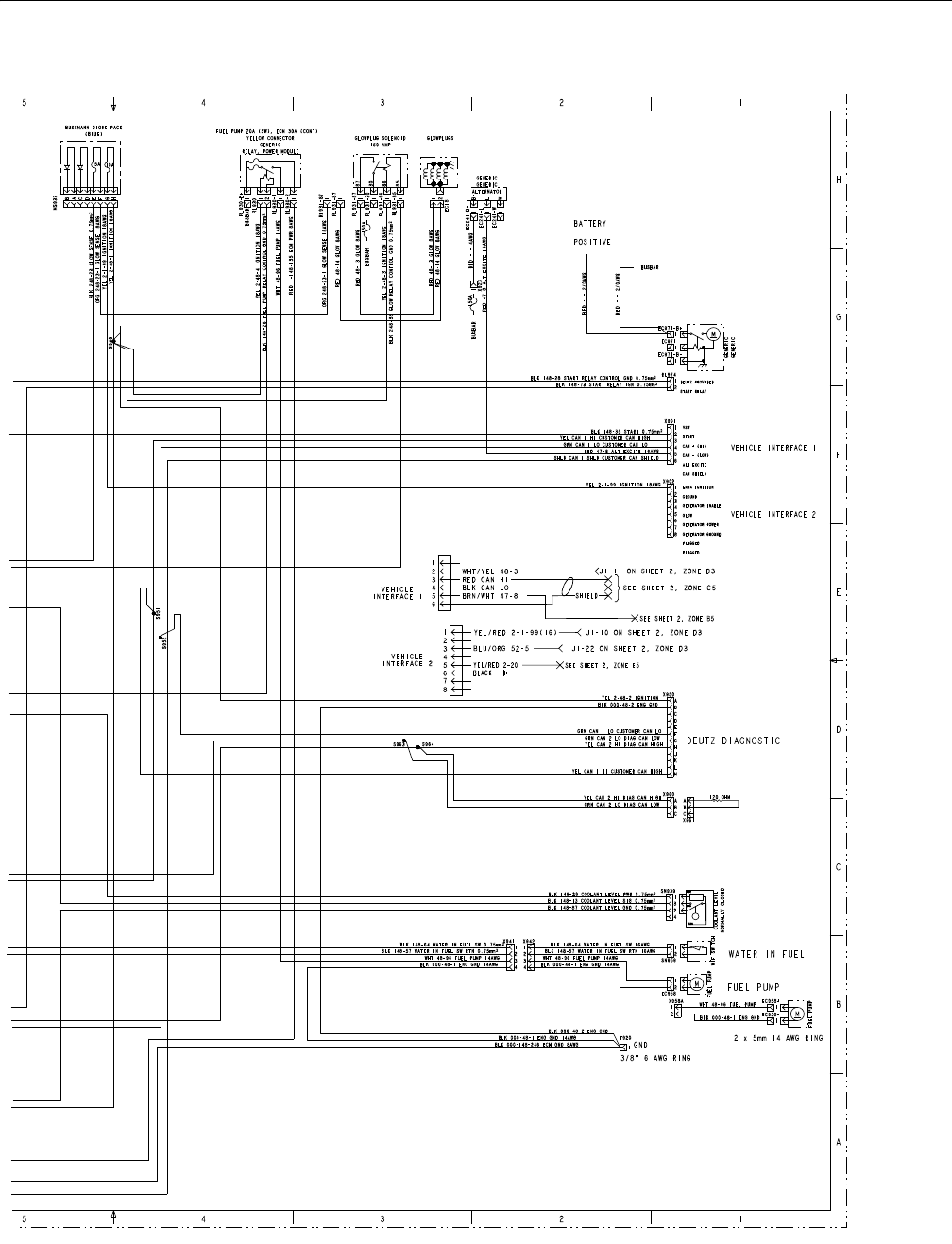
SECTION 7 - BASIC ELECTRICAL INFORMATION & SCHEMATICS
3121298 – JLG Lift – 7-19
Figure 7-35. Deutz Tier 4 Final Engine Harness Electrical Schematic
1001110345D - Sheet 6
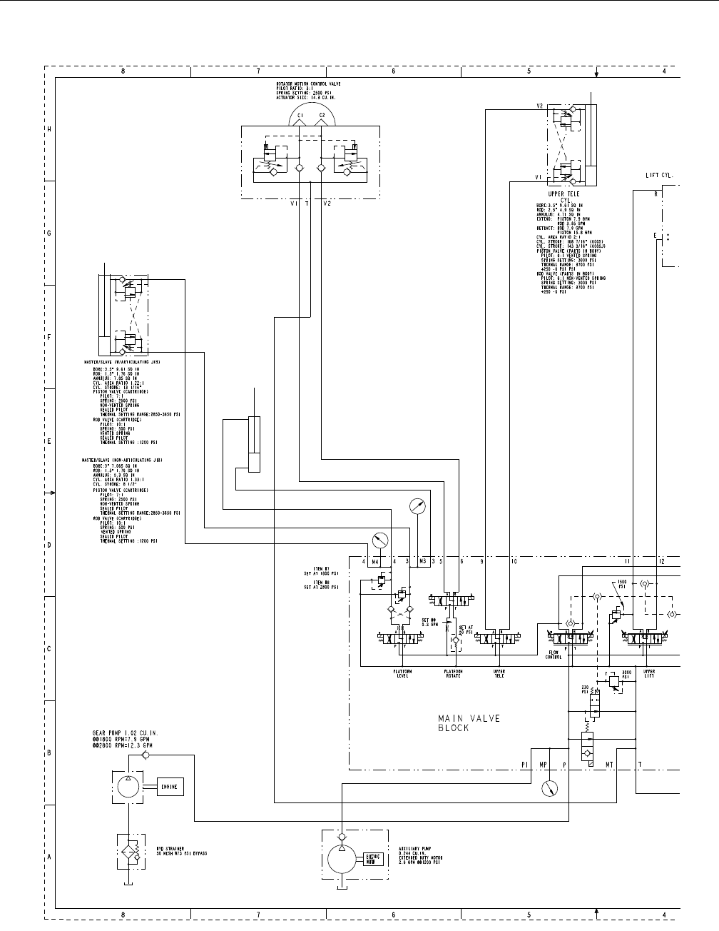
SECTION 7 - BASIC ELECTRICAL INFORMATION & SCHEMATICS
7-20 – JLG Lift – 3121298
Figure 7-36. Hydraulic Schematic
2792605D - Sheet 1
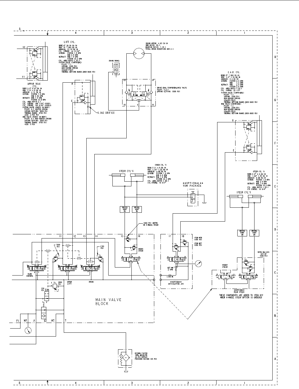
SECTION 7 - BASIC ELECTRICAL INFORMATION & SCHEMATICS
3121298 – JLG Lift – 7-21
Figure 7-37. Hydraulic Schematic
2792605D - Sheet 1
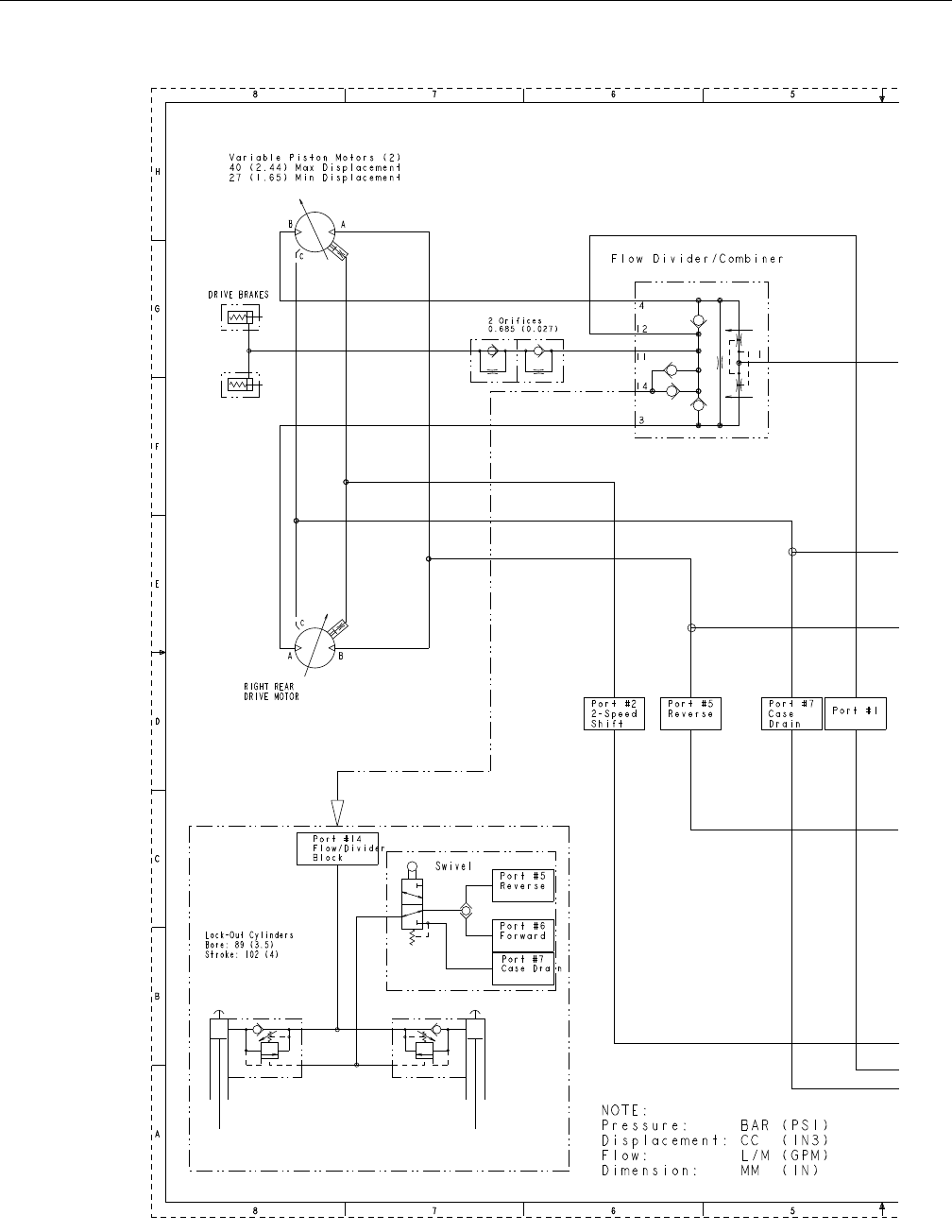
SECTION 7 - BASIC ELECTRICAL INFORMATION & SCHEMATICS
7-22 – JLG Lift – 3121298
Figure 7-38. Hydraulic Schematic 2-Wheel Drive - 1 of 2
2792605D - Sheet 3
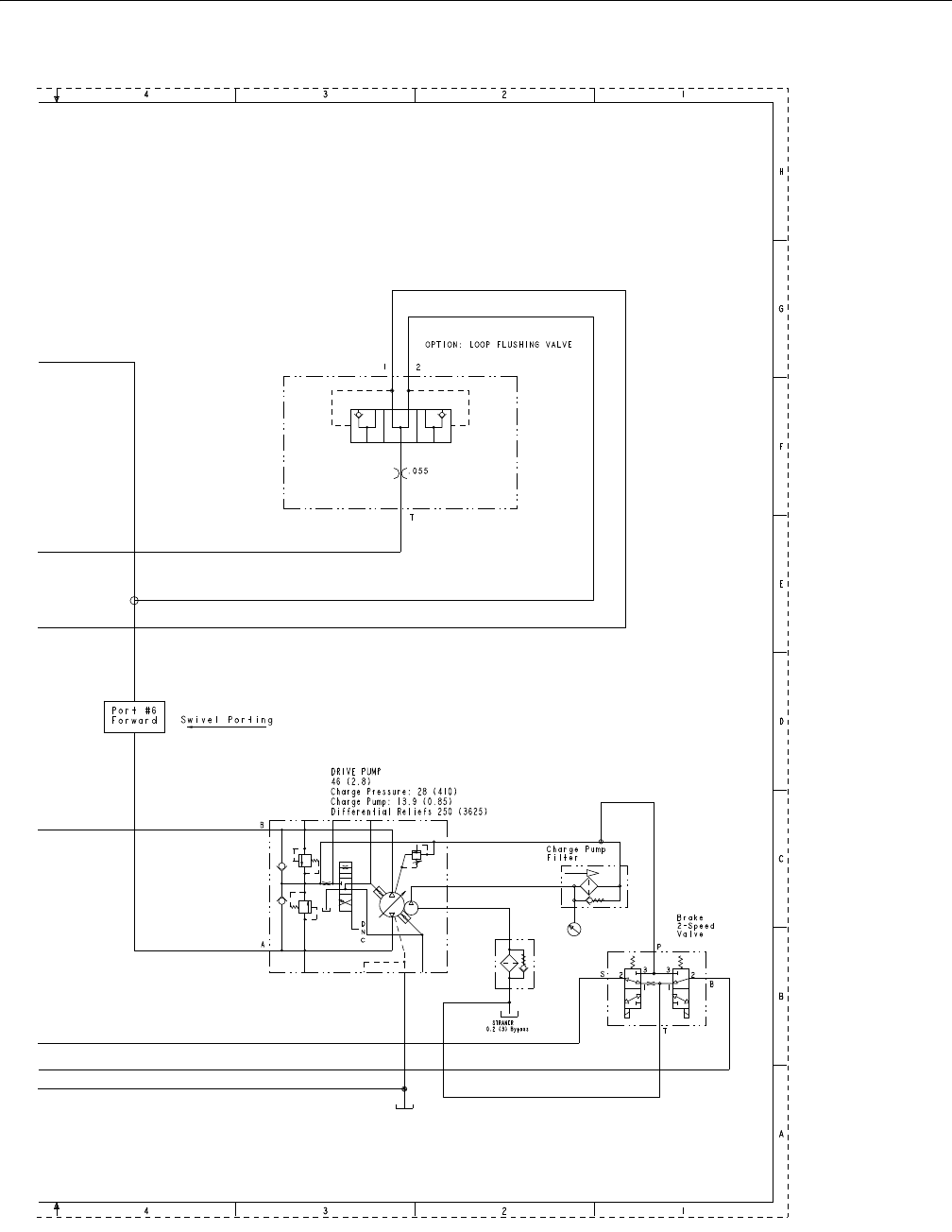
SECTION 7 - BASIC ELECTRICAL INFORMATION & SCHEMATICS
3121298 – JLG Lift – 7-23
Figure 7-39. Hydraulic Schematic 2-Wheel Drive - 2 of 2
2792605D - Sheet 3
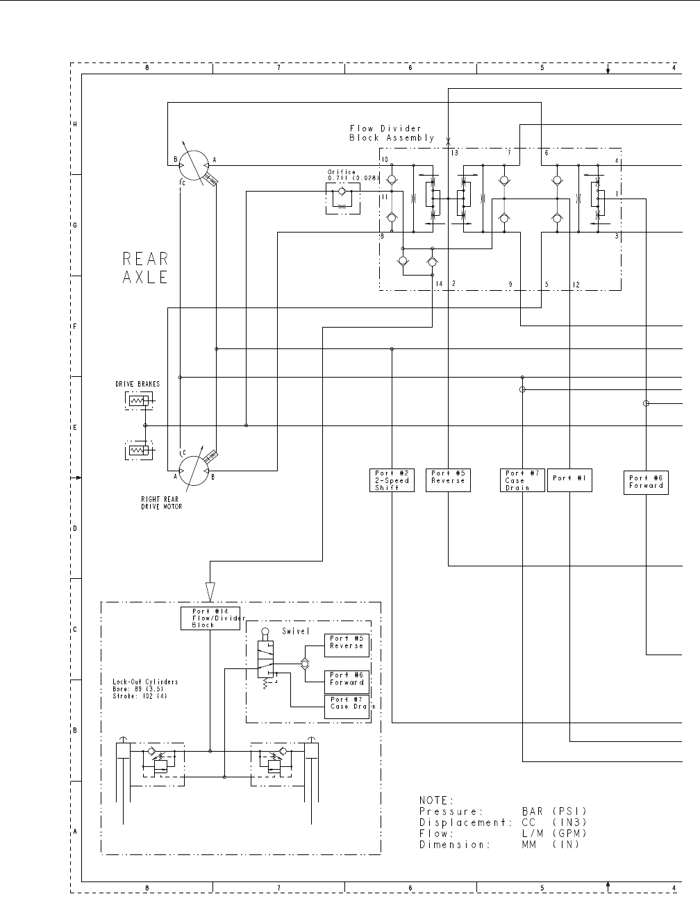
SECTION 7 - BASIC ELECTRICAL INFORMATION & SCHEMATICS
7-24 – JLG Lift – 3121298
Figure 7-40. Hydraulic Schematic 4-Wheel Drive - 1 of 2
2792605D - Sheet 4
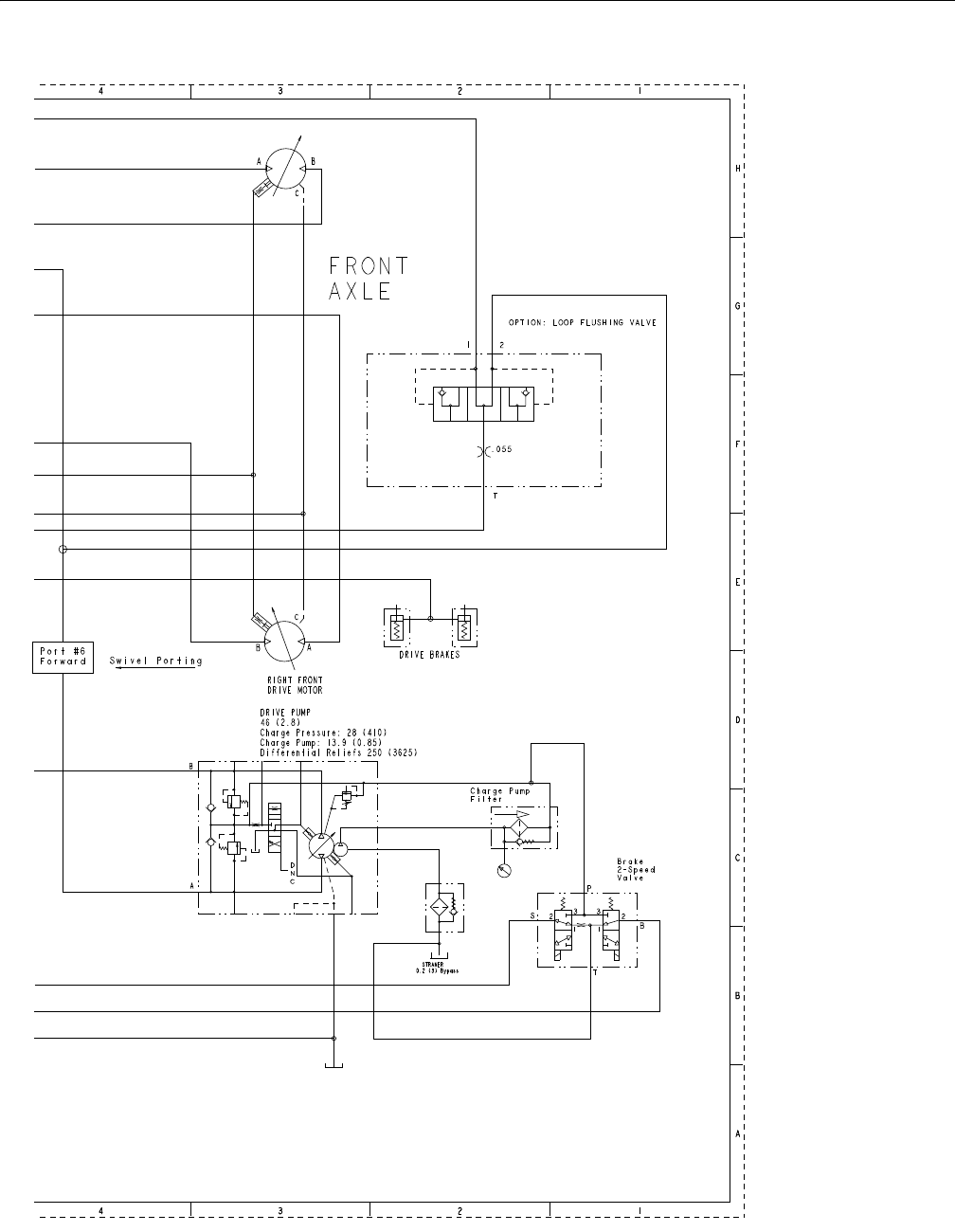
SECTION 7 - BASIC ELECTRICAL INFORMATION & SCHEMATICS
3121298 – JLG Lift – 7-25
Figure 7-41. Hydraulic Schematic 4-Wheel Drive - 2 of 2
2792605D - Sheet 4

SECTION 7 - BASIC ELECTRICAL INFORMATION & SCHEMATICS
7-26 – JLG Lift – 3121298
NOTES:

Corporate Office
JLG Industries, Inc.
1 JLG Drive
McConnellsburg PA. 17233-9533
USA
(717) 485-5161
(717) 485-6417
JLG Worldwide Locations
JLG Industries (Australia)
P.O. Box 5119
11 Bolwarra Road
Port Macquarie
N.S.W. 2444
Australia
+61 2 65 811111
+61 2 65813058
JLG Latino Americana Ltda.
Rua Eng. Carlos Stevenson,
80-Suite 71
13092-310 Campinas-SP
Brazil
+55 19 3295 0407
+55 19 3295 1025
JLG Industries (UK) Ltd
Bentley House
Bentley Avenue
Middleton
Greater Manchester
M24 2GP - England
+44 (0)161 654 1000
+44 (0)161 654 1001
JLG France SAS
Z.I. de Baulieu
47400 Fauillet
France
+33 (0)5 53 88 31 70
+33 (0)5 53 88 31 79
JLG Deutschland GmbH
Max-Planck-Str. 21
D - 27721 Ritterhude - Ihlpohl
Germany
+49 (0)421 69 350 20
+49 (0)421 69 350 45
JLG Equipment Services Ltd.
Rm 1107 Landmark North
39 Lung Sum Avenue
Sheung Shui N. T.
Hong Kong
(852) 2639 5783
(852) 2639 5797
JLG Industries (Italia) s.r.l.
Via Po. 22
20010 Pregnana Milanese - MI
Italy
+39 029 359 5210
+39 029 359 5845
Oshkosh-JLG Singapore
Technology Equipment Pte Ltd
29 Tuas Ave 4,
Jurong Industrial Estate
Singapore, 639379
+65-6591 9030
+65-6591 9031
Plataformas Elevadoras
JLG Iberica, S.L.
Trapadella, 2
P.I. Castellbisbal Sur
08755 Castellbisbal, Barcelona
Spain
+34 93 772 4700
+34 93 771 1762
JLG Sverige AB
Enkopingsvagen 150
Box 704
SE - 176 27 Jarfalla
Sweden
+46 (0)850 659 500
+46 (0)850 659 534
www.jlg.com
