Joyce_History_of_the_AN_UYK 20_Sep76 Joyce History Of The AN UYK 20 Sep76
Joyce_History_of_the_AN_UYK-20_Sep76 Joyce_History_of_the_AN_UYK-20_Sep76
User Manual: Joyce_History_of_the_AN_UYK-20_Sep76
Open the PDF directly: View PDF ![]() .
.
Page Count: 123 [warning: Documents this large are best viewed by clicking the View PDF Link!]
- 000
- 001
- 002
- 003
- 004
- 005
- 006
- 007
- 008
- 009
- 010
- 011
- 012
- 013
- 014
- 015
- 016
- 017
- 018
- 019
- 020
- 021
- 022
- 023
- 024
- 025
- 026
- 027
- 028
- 029
- 030
- 031
- 032
- 033
- 034
- 035
- 036
- 037
- 038
- 039
- 040
- 041
- 042
- 043
- 044
- 045
- 046
- 047
- 048
- 049
- 050
- 051
- 052
- 053
- 054
- 055
- 056
- 057
- 058
- 059
- 060
- 061
- 062
- 063
- 064
- 065
- 066
- 067
- 068
- 069
- 070
- 071
- 072
- 073
- 074
- 075
- 076
- 077
- 078
- 079
- 080
- 081
- 082
- 083
- 084
- 085
- 086
- 087
- 088
- 089
- 090
- 091
- 092
- 093
- 094
- 095
- 096
- 097
- 098
- 099
- 100
- 101
- 102
- 103
- 104
- 105
- 106
- 107
- 108
- 109
- 110
- 111
- 112
- 113
- 114
- 115
- 116
- 117
- 118
- 119
- 120
- 121
- 122
HISTORY
OF
THE
AN/UYK-20(V)
DATA
PROCESSING
SYSTEM
ACQUISITION
AND
ITS
IMPACT
ON
TACTICAL
SYSTEMS
DEVELOPMENT
Robert
Richardson
Joyce
NPS-36Jo7609
1
NAVAL
POSTGRADUATE
SCHOOL
Monterey,
California
THESIS
HISTORY
OF
THE
~~/UYK-20(V)
DATA
PROCESSING
SYSTEM
ACQUISITION
Al'lD ITS
IMPACT
ON
TACTICAL
SYS~EMS
DEVELOPMENT
Robert
Richardson
Joyce
September
1976
Thesis
Advisors:
S.
Jauregui
&
E.
Zabrycki
Approved
for
public
release;
distribution
unli:nited
Prepared
for:
Naval
Electronic
Systems
Command
(E4E-107)
Washington,
D.C.
20360
T 1 7
hn
q 9
· UNCLASSIFIED
SECURITY
CL.ASSIFICATION
OF
THIS
~A.GE
(ft
..
Del.
Knl.,.d)
R!PORT
DOCUMENTATION
PAGE
READ
INSTRUCTIONS
BEFORE
COMPLETING
FORM
T.
~E~ORT
NUM.ER
2.
GOVT
ACCESSION
NO
1.
RECI~IENT'S
CAT
AL.OG
NUMSER
NPS-36Jo76091
••
TITL.E
(
..
d
Subtlt'.)
HISTORY
OF
THE
AN/UYK-20(V)
DATA
PROCESSING
SYST&~
ACQUISITION
AND
ITS
IMPACT
ON
TACTICAL
SYSTEMS
DEVELOPIIIlENT
7.
AUTHOR(.)
Robert
Richardson
Joyce
Naval
Postgraduate
School
Monterey,
California
93940
'I.
CONTROLL.ING
OFFICE
NAME
AND
ADDRESS
Naval
Electronic
Systems
Command(~4E-
Washington,
D.C.
20360 107)
Naval
Postgraduate
School
Monterey,
California
93940
16.
OISTRI.uTIOH
STATEMENT
(01
th,.
Report)
5.
TV~F'
Q.F-"'~PORT
•
~£RIOO
COVERED
Master's
Thesis;
(September
1976)-
••
~ERFORMING
ORG.
REPORT
NU.UER
'0.
~ROGRAM
ELEMENT,
PROJECT,
TASI(
AREA'
WORK
UNIT
NUM.ERS
12.
REPORT
OATE
September
1976
13.
NUM.ER
OF
~AGES
122
11.
IECURITY
CL.ASS.
(01
tlu.
~r1J
Unclassified
1S..
DECL.ASSIfI'ICATIONI
DOWNGIIUDING
SCHEDUL.E
Approved
for
public
release;
distribution
unlimited.
17.
OISTRI_UTIOH
STATEMENT
(01
tit.
".tree,
..
'end
'ft
.'00.30,
II
d,II.,
..
, IPo.I RefHWf)
18.
SUPPL.
EMENTARV
HOTES
't.
KEY
WORDS
(C«ttlnu.
on
,
...
.,
•••
'de
II
n.c
•••
~
end
ldentl",
bJ"
IJ'oclr
nu.tIJ.,)
Minicomputer
Standard
Data
Processing
System
Tactical
Digital
System
In
1972
the
Chief
of
Naval
~aterial
perceived
a
prolif-
eration
of
small
computer
types
in
the
Navy
inventory.
To
stem
that
prollferstlcn
:l
3t3.G.iar·d.~lniccffi;uter
W3.S
;:rocured,
to
be
used
in
all
current
and
future
tactical
systems
requir-
ing
a
small
digital
processor.
That
standard
was
designated
the
AN/UYK-20(V)
Data
Processing
System.
Lack
of
dedicated
DO
I
~~=~1
1A73
ED'TION
0"
I
NOV
81
IS
O.SOL.ETE
(Page
1)
SIN
0102-014-
6601
I
UNCLASSIFIED
SECURITY
CLASSIfI'ICATION
OF
TMIS
..
AGE
(""'"
D.,
••
I'I'erMJ
Unclas
s
ified
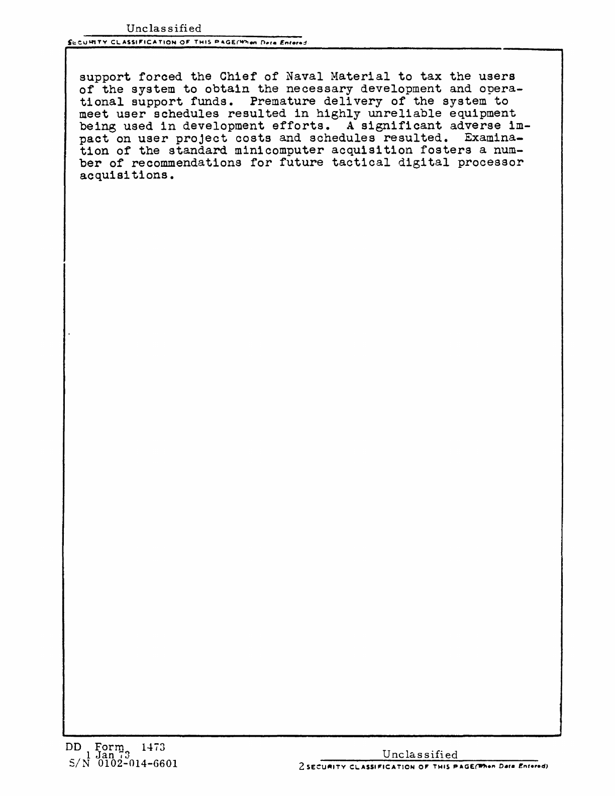
support
forced
the
Chief
of
Naval
Material
to
tax the
users
of
the
system
to
obtain
the
necessary
development
and
opera-
tional
support
funds.
Premature
delivery
of
the
system
to
meet
user
schedules
resulted
in
highly
unreliable
equipment
being
used
in
development
efforts.
A
significant
adverse
im-
pact
on
user
project
costs
and
schedules
resulted.
Examina-
tion
of
the
standard
minicomputer
acquisition
fosters
a num-
ber
of
recommendations
for
future
tactical
digital
processor
acquisitions.
DO
Form
1473
1
Jan
73
SIN
0102-014-6601
Unclassified
ABSTRACT
In
1972
the
Chief
of
Naval
Material
perceived
a
proliferation
of
small
computer
types
in
the
Navy
inventory.
To
stem
that
proliferation
a
standard
minicomputer
was
procured,
to
be
used
in
all
current
and
future
tactical
systems
requiring
a
small
digital
processor.
That
standard
was
designated
the
AN/UY
K-20
(V)
Da
ta
processing
System.
Lack
of
dedicated
appropriated
funds
for
procurement
and
support
forced
the
Chief
of
Naval
Material
to
tax
the
users
of
the
system
to
obtain
the
necessary
development
and
operational
support
funds.
Premature
delivery
of
the
system
to
meet
user
schedules
resulted
in
highly
unreliable
equipment
being
used
in
development
efforts.
A
significant
adverse
impact
on
user
project
costs
and
schedules
resulted.
Examination
of
the
standard
minicomputer
acquisition
fosters
a
number
of
recommendations
for
future
tactical
digital
processor
acquisitions.
4
TABLE
OF
CONTENTS
..
GLOSSARy..........
••••••••••
••••••••••
•..•
•••••••.
•.••••
8
ACKNOWLEDGEMENT
••••••••••••••••••••••••...•••••••.•••••.
11
I.
INTRODUCTION
••••••••••••••••••••••.•••••••.•.••••
12
A.
THESIS
OBJECTIVE.............................
12
B.
METHODOLOGy
••••••••••••••••••..•••••••.•.••••
13
II.
IDENTIFICATION
OF
THE
NEED
FOR
A
STANDARD
MINICOMPUTER
•••••••••••••••••••••••••••••••••••••.••••••
14
A.
DEFINITION
OF
A
MINICOMPUTER.................
16
B.
DEFINITION
AND
IMPLICATIONS
OF
A "STANDARDII..
17
C.
THE
RANGE
OF
CAPABILITIES
NEEDED
•••••••••••••
20
1.
Packaging
••
'.
• • •
•• •• ••
••
•
••
• • •
••
• •
••
•
.••
.•
21
2.
Reliability
and
Maintainability
••••••••••
22
3.
Architecture.............................
23
4.
Input/Output
••••••••••••••••••••••.••••.•
25
5 •
In
t
er
r up t
s.
. • • •
••
• • • • • • • • • • • • • . • • • • • . • • • • 27
6.
Control/Maintenance
Panel
••••••••••••••••
27
7.
Software.
• • • • • •
••
• • • •
••
•
.•
• • •
••
•• ••
•
••
•
.•
28
D.
CAPABILITIES
3F
EXISTING
NAVY
COMPUTERS
TO
MEET
THE
SPECIFICATIONS......................................
28
1.
CP-642B
.•••••••••••••••••••••••.•••••••••
30
2.
AN/UYK-15(V)
•••••••..•••••.•••.•..•••••••
30
3.
CP-890...................................
31
4.
AN/UYK-12(V)
••••••••••••••••••....•••••••
31
III.
DEVELOPMENT
AND PRODUCTION HISTORy
••.••.•••••••••
3~
IV.
EVALUATION
OF
THE
SySTEM.........................
54
A.
PRODUCT
B.
COMPARISON
OF
SPECIFICATION
AND
FINAL
• . . . • . . . . . . . . . . . • . • . . . . . . . . . . . . . . . . .
54
COMPARISON
OF
AN/UYK-20
DPS
WITH
THE
"OFF-THE-SHELF"
MINICOMPUrER
STATE-OF-THE-ART
••••••...•.
1972
57
57
1.
Architecture
•••••..•••..•••••••••••.••.•.
5
2.
Main
Memory
••••••••••••••••••••••••••••••
60
3.
Instruction
Set..........................
61
4 • I n p u
t/
0 u t
put.
• • • • • • • • • • • • • • • • • • • • • • • • • • • • 6 3
5.
Interrupt
Structure......................
64
6.
Construction..
• • • • •
••
• • • • • • • • • • • • • • • • • •
••
64
7.
Support
Software.........................
66
c. IMPACT OF
AN/UYK-20
DPS
ON
DEVELOPMENT OF USER
SySTEMS.............
•••••••••••••••••••••••••••.••••••••
67
1.
Establishment
of
AN/UYK-20
as
a
Standard.
68
2.
Hardware/Firmware
Capabilities
•••••••••••
70
3.
Availability
of
Support
Software
•••••••••
73
4.
Support
Software
capabilities
••••••••••••
76
5.
Availability
of
Peripherals
••••••••••••••
77
6.
Hardware
and
Software
Reliability
and
. "
b'l"
Ma~nta~na
~
~ty
••••••••••••••••••••••••••••••••
0
•••••••••
78
,7.
Lack
of
Dedicated
Appropriated
Funds
to
Su
pport
the
AN/UYK
-20
DPS...............................
80
V. SUMMARY, CONCLUSIONS
AND
RECOMMENDATIONS
•••••••••
82
Appendix
A:
AN/OYK-7
SYSTEM
DESCRIPTION................
88
Appendix
B:
Appendix
C:
Appendix
D:
Appendix
E:
Appendix
F:
Appendix
G:
Appendix
H:
Appendix
I:
STANDARD MINICOMPUTER
SPECIFICATIONS
•••••••
90
CP-642B
SYSTEM
DESCRIPTION.................
92
AN/OYK-15
(V) SYSTEM
DESCRIPTION............
94
CP-890
SYSTEM
DESCRIPTION
••••••••••••••••••
96
AN/UYK-12
(V)
SYSTEM
DESCRIPTION
••••••••••••
98
DESCRIPTION
OF
SYSTEM SOFTWARE
•••••••••••••
100
AN/OYK-20
(1)
DPS
DESCRIPTION
•••••••••••••••
105
BASIC
AN/UYK-20
HARDWARE
CONFIGURATION AND
OPTIONS.
• • • •
••
• • • • • • • • • •
••
• • • • • • • • • • • • • • • • • • • • • • • • • • • •
••
107
Appendix
J:
Appendix
K:
Appendix
L:
Appendix
M:
ROLM
1602
SYSTEK
DESCRIPTION...............
109
HP2100A
SYSTEM
DESCRIPTION
•••••••••••••••••
111
DEC
PDP-ll/45
SYSTEM
DESCRIPTION.........
••
113
VARIAN-73
SYSTEM
DESCRIPTION
•••••••••••••••
115
LIST
OF REFERENCES
••••••••••••••••••••••••••••••••••••••
117
INITIAL
DISTRIBUTION
LIST
................................
119
LIST
OF
FIGURES.........................................
7
6
LIST
OF
FIGURES
1.
Naval
Material
Command
Organization
•••••••••••••••••
33
2.
AN/UYK-20
(V)
System
Users
•••••••••••••••••••••••••••
34
3.
Naval
Electronic
Systems
Command
Organization
•••••••
53
7
GLOSSARY
AADC
-
All
Applications
Digital
Computer
ADD
-
Alphanumeric
Display
Device
ADP
-
Automatic
Data
Processing
APE
-
Advanced
Production
Engineering
Model
- a
militarized
prototype
CDC
-
control
Data
corporation
CMTU
-
Cartridge
Magnetic
Tape
Unit
CNM
-
Chief
of
Naval
Material
CNO
-
Chief
of
Naval
Operations
COMNAVELEX
-
Commander,
Naval
Electronic
Systems
Command
CVTSC
-
Carrier
Tactical
Systems
Center
DCAS
-
Defense
Contract
Administration
Service
DEC
-
Digital
Equipment
:orporation
DMA
-
Direct
Memory
Access
DPS
-
Data
processing
System
DRG
-
Design
Review
Group
ESA
-
Externally
Specified
Addressing
FCDSSA -
Fleet
Combat
Direction
Systems
Software
Activity
FDM
-
Functional
Demonstration
Model
a
non-militariz~d
prototype
GFCS
-Gun
Fire
Control
System
GFE
-
Government
Furnished
Equipment
IBM
-'
International
Business
Machines
Corporation
ILS
-
Integrated
Logistics
Support
I/O
-
Input/Output
IOC -
Input/Output
Controller
ISADC -
Interim
Standard
Airborne
Digital
Computer
LSI
-
Large
Scale
Integration
MATHPAC
-
Plug-in
module
of
floating-point,
~rigonometric
and
hyperbolic
functions
implemented
in
microcode
8
MICROGROWTH
-
Plug-in
module
of
user
specified
microprograms
MOS
-
Metal
Oxide
Semiconductor
MSI
-Medium
Scale
Integration
MTBF
-Mean Time
Between
Failures
MTTR
-Mean Time To
Repair
NAFI
-
Naval
Avionics
Facility,
Indianapolis
NAVAIR
-
Naval
Air
Systems
Command
NAVELEX
-
Naval
Electronic
Systems
Command
HAVMACS
-
Naval
Message
Address
Communications
System
NAVHAT
-
Naval
Material
:ommand
HAVORD
-
Naval
Ordnance
Systems
Command
combined
with
NAVSHIPS
to
form
NAVSEA
NAVSEA
-
Naval
Sea
Systems
Command -
formed
by
combining
NAVORD
and
NAVSHIPS
NAVSEC
-
Naval
Systems
Engineering
Center
NAVSHIPS
-
Naval
Ships
Systems
Command
combined
with
HAVORD
to
form
NAVSEA
NELC
-
Naval
Electronics
Laboratory
Center
NESEC
-
Naval
Electronic
Systems
Engineering
Center
NTDS
-
Naval
Tactical
Data
System
OMB
-
Office
of
Management
and
Budget
O&MN
-
Operations
and
Maintenance
Navy
Appropriation
OPEVAL
-
Operational
Evaluation
OSD
-
Office
of
the
Secretary
of
Defense
QA
-
Quality
Assurance
RAM
-Random
Access
Memory
RDT&EN
-
Research,
Development,
Test
and
Evaluation
Navy
Appropriation
REiSON
-
Reconnaissance
Electronic
Warfare
Systems
Office
Navy
RFP
-
Request
for
Proposals
ROM
-
Read-Only-Memory
SECDEF
-
Secretary
of
Defense
SSA
-
Source
Selection
Authority
SSAC
-
Source
Selection
Advisory
Council
SSEB
-
Source
Selection
Evaluation
Board
9
TADSO
-
Tactical
Digital
systems
Office
of
the
Naval
Material
Command
TADSTAND
-
Tactical
Digital
Standard
TALOS
-
long-range,
surface-to-air
missile
TARTAR
-
short-range,
surface-to-air
missile
TECHEVAL
-
Technical
Evaluation
TERRIER -
intermediate-range,
surface-to-air
missile
TTL -
Transistor-Transistor
Logic
UNIVAC
-
UNIVAC
Defense
Systems
Division
of
Sperry-Rand
corporation
WCS
-
writable
Control
Store
10
ACKNOWLEDGEMENT
I
wish
to
thank
the
many
personnel
of
Navy
activities
and
private
contractor
firms
who
took
time
out
from
their
busy
schedules
to
answer
my
questions.
Thanks
also
to
my
two
thesis
advisors,
Professor
stephen
Jauregui
and
LCDR
Edward
Zabrycki,
who
waited
patiently
for
the
thesis
to
emerge
from
my
research.
Finally,
special
thanks
go
to
the
Commander,
Naval
Electronic
Systems
Command
(PME-107)
who
provided
funds
to
make
this
thesis
possible
and
to
my
wife,
Ann,
who
relieved
me
of
many
family
obligations
juring
the
final
crunch.
11
A.
THESIS
OBJECTIVE
In
1972
the
Navy
began
procurement
of
a
small
digital
computer
which
was
to
be
a
standard
minicomputer
for
tactical
system
applications.
That
standard
minicomputer
was
later
designated
the
AN/UYK-20(V)
Data
Processing
System.
The
acquisition
strategy
employed
and
the
resulting
events
of
the
first
three
years
of
production
caused
great
concern
among
project
m~nagers
who
were
required
to
use
the
standard
minicomputer.
At
least
one
user
project
manager
believed
that
~n
objective
look
at
the
standard
minicomputer
acquisition
was
necessary
to
prevent
recurrence
of
those
events
which
adversely
impacted
on
the
development
of
tactical
systems.
It
is
the
objective
of
this
thesis
to
examine
the
standard
minicomputer
acquisition
process,
to
ev~luate
the
system
in
light
of
user
needs
and
1972
state-of-the-art,
to
identify
those
events
which
contributed
to
the
adverse
impact
of
the
standard
minicomputer
on
development
efforts,
and
to
offer
some
recommendations
for
future
acquisitions
of
standard
tactical
digital
processors.
B.
METHODOLOGY
12
In
order
to
obtain
information
about
minicomputers
in
general
and
the
AN/UYK-20(V)
Data
Processing
System
in
particular,
a
literature
search
was
conducted.
references
are
listed
at
the
end
of
the
thesis.
Pertinent
To
obtain
a
complete
and
objective
picture
of
the
acquisition
process
it
was
then
necessary
to
contact
personnel
at
all
levels
in
user
pr~ject
organizations
and
also
personnel
in
the
standard
minicomputer
project
organization.
The
following
types
of
activities
were
contacted
to
obtain
information:
* Navy
field
activities
checkout,
delivery
responsible
for
assembly,
and
maintenance
of
tactical
systems
hardware
~nd
software.
* Navy
laboratories
-
responsible
for
certain
aspects
of
tactical
system
development
and
testing.
*
Private
contractors
responsible
for
hardware
and
software
development
of
tactical
systems
under
contract
to
Navy
project
offices.
* Navy
project
offices
-
responsible
for
management
of
the
acquisition
of
tactical
systems
utilizing
UYK-20
as
a
system
component.
Additional
information
was
obtained
by
attending
two
AN/UYK-20
User's
Group
meetings.
A
minimal
amount
of
laboratory
experience
was
gained
on
the
UYK-20
itself.
13
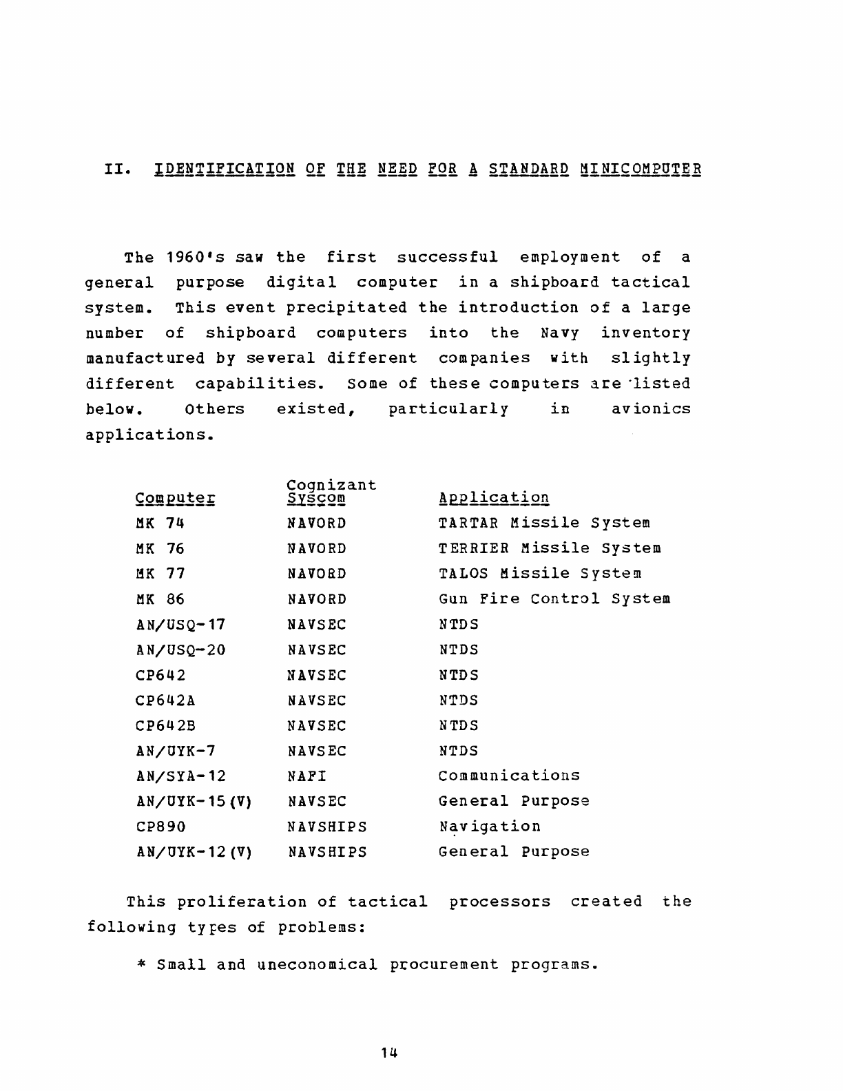
The
1960's
saw
the
first
successful
employment
of
a
general
purpose
digital
computer
in
a
shipboard
tactical
system.
This
event
precipitated
the
introduction
of
a
large
number
of
shipboard
computers
into
the
Navy
inventory
manufactured
by
several
different
companies
with
slightly
different
capabilities.
Some
of
these
computers
are
"listed
below.
Others
existed,
particularly
in
avionics
applications.
~Q!llput~£
MK
74
MK
76
MK
77
MK
86
AN/U5Q-17
AN/USQ-20
CP642
CP642A
CP642B
AN/OYK-7
AN/SYA-12
AN/UYK-15
(V)
CP890
AN/UYK-12
(V)
Cognizant
~§~2!!!
NAVORD
NAVORD
NAVORD
NAVORD
NAVSEC
NAVSEC
NAVSEC
NAVSEC
NAVSEC
NAVSEC
NAFI
NAVSEC
NAVSHIPS
NAVSBIPS
!E.21!cat
i211
TARTAR
Missile
System
TERRIER
Missile
System
TALOS
Missile
System
Gun
Fire
Control
System
NTDS
NTDS
NTDS
NTDS
NTDS
NTDS
Communications
General
Purpose
N~vigation
General
Purpose
This
proliferation
of
tactical
processors
created
the
following
tYFes
of
problems:
*
Small
and
uneconomical
procurement
programs.
14
*
Untenable
naterial
and
logistics
support
posture.
*
Increased
scope
of
personnel
training
requirements.
*
System
interface
and
integration
problems.
*
Software
incompatibility.
*
Proliferation
of
support
software.
Recognition
of
these
problems
prompted
the
Chief
of
Naval
Operations
(eNO)
to
direct
the
Chief
of
Naval
Material
(CNM)
to
develop
a
standard
general
purpose
computer
for
shipboard
and
shore
applications.
In
August
1971,
CNM
created
the
Tactical
Digital
Systems
Offi~e
(TADSO)
1MAT-09Y)
to
carryout
this
directive.
Figure
1
shows
the
position
of
TADSO
in
the
NAVMAT
organization
as
of
January
1975.
The
chart
illustrates
that
the
Director
of
TADSO
was
in
an
influential
postition,
reporting
directly
to
the
Vice
Chief
of
Naval
Material.
MAT-09Y
has
traditionally
been
a
Rear
Admiral.
CNM,
by
reference
1,
described
the
scope
of
TADSO
efforts:
11(1)
Inter-and
intra-
platform
compatibility
of
all
tactical
digital
systems
and
equipment.
(2)
Standardization
of
tactical
digital
eguipment
and
associated
software.
(3)
Configuration
and
interface
management
of
tactical
dig
ital
equipment
and
soft
ware.
"
On
3
November
1971
TADSO
published
its
first
Tactical
Digital
Standard
(TADSTAND
1)
[Ref.
2]
which
established
the
AN/UYK-7
processor
as
the
standard
computer
for
shipboard
applications
and
the
CMS-2
high-level
language
as
the
standard
high-level
language
to
be
employed
in
the
production
of
operational
programs
for
tactical
data
systems.
TADSTAND
1
also
provided
that
a
request
for
deviation
from
these
standards
could
be
initiated
to
TADSO
if
it
was
thought
to
be
in
the
best
interests
of
the
Navy
to
15
use
either
another
Navy
computer
or
a
computer
not
presently
in
the
Navy
inventory.
In
response
to
TADSfAND 1
some
requests
to
deviate
from
the
UYK-7
standard
were
received.
The
most
significant
justification
given
was
that
the
UYK-7
was
too
large
and
expensive
($720,000
average
cost)
for
the
intended
application.
(See
App.
A
for
a
description
of
the
UYK-7
computer.)
out
of
this
identified
need
for
a
smaller
computer
grew
the
AN/UYK-20(V)
Data
Processing
System
(DPS),
the
Navy
standard
m~nicomputer.
It
is
the
purpose
of
this
chapter
to
establish
the
meaning
and
implications
of
the
terms
"minicompu
terl1
and
"standard",
to
identify
the
capabilities
needed
within
the
Navy
in
a
standard
minicomputer
system,
and
to
establish
whether
or
not
these
capabilities
could
be
met
by
a
small
computer
existing
in
the
Navy
inventory
in
1972.
A.
DEFINITION
OF
A MINICOMPUTER
Commercially
available
computers
in
1972
formed
almost
a
continuous
spectrum
in
size,
power
and
capabilities.
Naturally,
it
is
is
difficult
to
separate
the
minicomputer
from
larger
or
smaller
types.
The
possibility
of
a
small
computer
with
useful
capabilities
and
memory
capacity
grew
with
tha
development
of
hybrid
and
integrated
circuits
in
the
mid-1960's.
In
1970
medium-
and
large-scale
integration
was
introduced,
allowing
even
more
capability
to
be
designed
into
a
small
package.
hardware
decade.
designed
At
the
same
time
these
advancements
were
reducing
costs
at
the
rate
of
an
order
of
magnitude
?er
The
advent
of
mini-peripherals
specifically
for
use
with
minicomputers
was
the
final
addition
to
complete,
low-cost
mini-systems.
At
that
time,
as
was
still
true
in
1976,
software
was
the
predomin~nt
cost
of
such
systems.
16
C.
weitzman
[Ref.
11]
defined
the
minicomputer
as
an
8-
to
18-
bit
word
size
machine
with
memory
size
from
1K
to
32K
words.
costs
range
from
$4,000
to
$100,000.
The
minicomputer
is
generally
catagorized
as
having
limited
accuracy,
low
speed
for
double-precision
arithmetic
operation.s
and
no
floating-point
hardware.
By
1972,
however,
many
minicomputers
had
multiple
Input/Ou
t
put'
(I/O)
access
features
and
microprogrammable
central
processors
allowing
extensive
instruction
repertoires
with
firmware
implementation
of
floating-point
and
special
mathmatical
functions.
A
more
detailed
discussion
of
the
minicomputer
technology
of
the
early
1970's
may
be
found
in
Chapter
IV,
section
B.
B. DEFINITION
AND
IMPLICATIONS
OF
A "STANDARD"
A
"standard"
could
be
defined
as
a
specific
entity
which
will
be
used
in
every
application
where
an
entity
of
that
general
description
is
required.
The
contents
of
the
several
TADSTANDS
published
by
TADSO
imply
the
following
Navy
policy
concerning
a
"standard":
The
entity
identified
as
a
"standard"
will
be
used
in
all
developing
and
future
tactical
digital
system
applications
except
where
deviation
is
specifically
provided
for,
requested
and
approved.
References
3
through
9
are
the
standards
promulgated
by
TADSO
as
of
May
1976.
Tne
impact
of
such
standards
in
user
system
design
will
be
discussed
in
Chapt.
IV.
The
implications
of
establishing
standards
are
summarized
in
the
following
paragraphs.
Standardization
allows
realization
of
the
economies
of
large
scale
production.
For
example,
as
of
~ay
1976,
824
AN/UYK-20
Data
Processing
Systems
had
been
ordered
and
637
17
units
delivered.
At
that
time
there
were
107
programs
using
the
system.[Fig.2]
At
the
outset
of
the
UYK-20
acquisition
the
estimated
production
run
was
in
excess
of
4500
units.
This
volume
is
over
an
oeder
of
magnitude
greater
than
any
one
program
would
require
in
an
independent
processor
acquisition.
Clearly,
the
economies
of
scale
would
be
realized
with
such
a
program.
Although
it
is
impossible
to
quantify
the
actual
savings
realized
by
using
UYK-20
in
any
particula.r
project,
the
economies
of
scale
are
demonstrated
in
the
volume
order
prices
for
an
AN/UYK-20(V)
DPS
basic
configuration
in
fiscal
year
1974:
Quantity
-
50
at
$25,966
each
Quantity
-
100
at
$24,735
each
Quantity
-
150
at
$24,324
each
It
is
also
interesting
tJ
note
that
the
Fiscal
Year
(FY)
1976
order
price
for
a
similar
$25,000
each,
approximately
the
same
despite
inflation.
configuration
as
the
FY
is
about
74
price
Standardization
realizes
cost
savings
in
material
support.
One
project
manager
estimated
that
the
cost
of
introducing
one
new
part
into
the
Navy
Supply
System
at
SPCC
is
about
$1500.
It
has
also
been
estimated
th~t
the
Navy
realizes
$20,000
to
$40,000
per
year
in
Integrated
Logistic
Support
(ILS)
cost
savings
through
a
standardized
system
like
UYK-20.
standardization
avoids
duplication
of
suppoct
software
costs.
A
project
manager
estimated
a
savings
of
$2,000,000
to
$4,000,000
per
year
in
software
maintainance
costs
for
a
project
using
a
standard
computer.
Standardization
reduces
the
scope
of
required
maintenance
training.
The
Chief
of
Naval
Technical
Training
emphasized
this
fact
in
a
letter
to
the
Director
of
TADSO,
pointing
out
that
it
was
becoming
increasingly
difficult
to
fill
technical
traininj
billets,
and
that
standardization
18
programs
like
AN/UYK-7
help
alleviate
this
problem.(Ref.10]
It
is
estimated
that
about
$409,000
per
year
savings
in
technical
training
costs
is
realized
through
the
existence
of
UYK-20.
standardization
can
required
for
operator
reduce
the
personnel.
amount
of
training
Lack
of
standardization
may
mean
that
as
an
operator
is
transferred
from
one
command
to
another
he
must
be
sent
back
to
school
to
learn
new
equipment.
such
an
occurrence
has
a
direct
impact
on
fleet
readiness
and
personnel
training
costs.
As
an
example,
the
REWSON
program
faces
this
problem
because
some
of
its
shore
installations
utilize
DEC
PDP-11
computers
while
the
associated
shipboard
installations
employ
AN/UYK-20
Data
Processing
Systems.
Standardization
saves
the
repetitive
acquisition
costs
of
procurements
of
unique
systems.
These
costs
include
the
recurring
costs
for
ILS,
software
maintenance,
etc.
and
also
the
one-time
development
costs.
As
an
example,
the
OYK-20
acquisition
required
$1.3
million
in
Research
&
Development
funding
for
militarization
of
commercial
hardware,
support
software,
documentation,
etc.
Despite
these
strong
arguments
in
favor
of
standardization,
there
is
much
resistance
to
any
standardization
program.
Mr.
Howard
Gantzler,
Deputy
Assistant
secretary
of
Defense
(Installations
&
Logistics),
recognized
that
attitude
when
he
stated
at
a
seminar
given
at
the
Naval
Postgraduate
School
in
January
1976,
"Everybody
is
in
favor
of
it
[standardization],
but
nobody
wants
to
adopt
someone
else'S
standards."
Rear
Admiral
E. B.
Fowler,
Vice
Commander
of
the
Naval
Electronics
systems
COmmand
identified
another
drawback
of
standardization
in
an
address
to
the
Naval
Postgraduate
School
chapter
of
the
IEEE
in
April
1976.
19
lIyou
have
to
standardize.
You
canlt
afford
not
to
do
so.
But
you
must
also
get
a
firm
grip
on
the
half-life
of
the
thing
you
are
standardizing...
AN/OYK-20
was
thought
at
first
to
be
a
five
year
investment.
We
are
currently
reprocurring,
and
it
looks
like
ten
to
fifteen
years.
The
CP-6~2Bls
[CP-642B
computer
(UNIVAC
1212).
See
Chapt.
II,
Sect.
D.]
have
been
~round
for
sixteen
to
seventeen
years,
and
we
put
them
on
the
Nimitz,
the
newest
capital
ship.
This
is
a
systems
engineering
problem."
In
that
statement
Admiral
Fowler
suggests
that
once
a
standard
is
established,
it
may
be
used
for
many
more
years
than
anticipated
unless
a
firm
policy
for
replacement
is
adopted
at
the
outset.
Understandably,
the
majo~ity
of
opposition
to
standardization
was
found
by
this
author
in
the
technical
community,
which
standardized
components
not
tasks
required.
must
desi9n
specifically
C.
THE
RANGE
OF
CAPABILITIES
NEEDED
systems
using
tailored
to
the
In
January
1972,
a
Design
Review
Group
(DRG)
was
convened
by
TADSO
to
translate
the
requirements
of
the
Navy
for
a
minicomputer
system
into
a
specification
which
could
be
used
as
the
basis
for
competitive
bidding.
It
is
significant
to
note
that
the
intent
was
not
to
fill
the
entire
range
of
size
and
power
below
the
UYK-7,
but
only
to
fill
the
identified
current
and
future
needs.
Thus,
from
the
outset
the
success
of
OYK-20
depended
on
accurate
prediction
of
those
needs
by
the
DRG.
The
composition
of
the
DRG
was
most
important,
and
it
is
interesting
to
note
the
commands
represented:
Naval
Ordnance
Systems
Command
(ORD-532),
Naval
Ships
systems
Command
(SHIPS-03524),
Naval
Air
Systems
Command
(AIR-5333F),
Naval
Ships
3ngineering
20
center
(SEC-6178D
and
SEC-6172),
H. Q.
Marine
Corps
(Code
AAM-4),
Fleet
Combat
Direction
System
Support
Activities
pacific
and
Atlantic,
and
Naval
Weapons
Laboratory
Dahlgren.
The
Naval
Ordnance
Systems
Command
and
the
Naval
Ships
systems
Command
have
since
been
combined
into
one
command
designated
the
Naval
Sea
Systems
Command (NAVSEA).
Thus
all
the
commands
responsible
for
systems
aevelopment
were
well
represented.
In
order
to
save
time
and
development
costs,
TADSO
had
conceived
an
"off-the-shelf"
procurement.
That
was
an
important
decision,
which
implied
that
the
intent
was
to
procure
a
market-tested
computer
system
which
would
only
need
to
be
militarized.
Since
the
computer
was
to
be
general
purpose
~nd
serve
a
wide
range
of
diverse
applications,
a
modular
building
block
approach
was
conceived.
A
basic
configuration
was
to
be
specified
and
plug-in
modules
provided
so
that
the
user
could
increase
the
size
and
power
of
the
processo~
up
to
his
individual
needs.
Add-on
modules
were
to
be
individually
priced
so
that
the
user
only
paid
for
the
capability
ne
needed.
The
following
p~ragraphs
summarize
the
range
of
capabilities
which
TADSO
and
the
DRG
foresaw
would
be
needed
to
meet
Navy
systems
requirements
of
1972
and
about
five
years
into
the
future~
The
computer
would
be
required
to
meet
military
specification
MIL-E-16400
for
shipboard,
groundbased,
and
submarine
electronic
systems.
This
decision
precluded
airborne
applications
of
the
computer,
which
would
have
required
the
more
stringent
and
expensive
MIL-E-5400
specification,
but
would
have
expanded
the
applications
and
thus
the
volume
of
production.
The
reason
behind
that
decision
was
the
intention
to
produce
an
interim
standard
shipboard
computer
to
be
eventually
replaced
by
the
All-Applications
Digital
Computer
(AADC)
which
was
then
21
"
under
development
by
the
Naval
Air
Systems
Command (NAVAIR).
The
AADC
never
materialized,
and
as
of
1975
the
AADC
project
had
been
redirected
to
produce
an
Interim
Standard
Airborne
Digital
Computer
(ISADC).
Out
of
the
ISADC
project
came
the
AN/AYK-14
computer
in
1976.
The
computer
was
to
be
packaged
in
one
enclosure
of
maximum
dimensions
26
inches
high,
24
inches
deep,
and
width
suitable
for
mounting
in
a
standard
19-inch
rack.
Maximum
power
consum~tion
was
to
be
one
kilowatt.
To
achieve
the
desired
building
block
capability,
the
following
units
were
to
be
strictly
plug-in
with
no
other
hardware
changes
necessary~to
install:
memory
modules
of
8K-words
per
module,
I/O
channels
in
groups
of
two
if
serial
and
in
groups
of
four
if
parallel,
real-time
clock,
general
registers,
and
microprogrammable
control
memory.
In
accordance
with
MIL-E-16400,
modular
construction
was
specified.
All
assemblies
with
a
cost
of
$200
or
less
would
be
throw-away
components.
only
those
assemblies
where
it
was.
determined
that
repair
would
be
more
cost-effective
than
throw-away/replacement
would
be
designated
as
repairable
modules.
It
was
further
specified
that
repairs
would
be
performed
by
the
contractor,
a
factor
which
had
a
later
impact
on
the
repairable
turn-around
time.
The
maximum
configuration
of
the
computer
was
to
have
a Mean
Time
Between
Failures
(MTBF)
of
2000
hours,
a
Mean
Time
to
Repair
(MTTR)
of
15
minutes
and
a Maximum
Time
to
Repair
of
12D
minutes.
The
MTBF
specified
was
a
figure
which
had
been
used
on
previous
military
computer
specifications.
As
far
as
the
author
of
this
thesis
could
determine,
the
basis
for
citing
the
2000
hour
figure
was
historical
rather
than
the
result
of
calculation.
The
computer
was
to
be
logically
and
electrically
designed
to
facilitate
the
isolation
of
malfunctioning
modules
through
diagnostic
programming.
The
diagnostic
22
program
was
to
isolate
93%
of
recurring
(non-intermittent)
active
logic
element
failures
to
not
more
than
three
printed
circuit
card
modules.
3.
Architectur~
The
computer
was
to
employ
third
generation
technology
with
the
use
of
medium-scale
integration.
Perhaps
the
most
significant
architectucal
requirement
was
th~t
the
processor
was
to
be
microprogram
mabIe.
The
rationale
for
requiring
this
capability
was
the
possibility
of
a
more
powerful
macro-instruction
set
and
the
flexibility
to
modify
or
add
to
the
macro-instruction
set
by
simply
modifying
the
contents
of
control
memory.
An
additional
requirement
was
therefore
for
at
least
500
words
(16-bit)
of
user
growth
capacity
in
the
control
memory.
Other
required
architecture
length
at
least
16-bits
including
sign
attributes
were:
word
but
not
including
parity,
random
access
non-volatile
memory
with
a
separate
high
speed
memory
desireaole
but
not
cequired,
main
memory
read-restore
cycle
time
less
than
1.2
microseconds,
asynchronous
timing
with
at
least
one
level
of
memory
fetch
instruction
overlap
to
cceate
an
effective
memory
cycle
time
of
less
than
one
microsec~nd,
minimum
storage
capacity
of
8K-words
expandable
to
at
least
65K-words
(directly
addressable)
in
8K-word
increments,
a minimum
of
four
general
registers
expandable
to
sixteen.
It
was
significant
that
no
requirement
was
made
for
a
capability
to.
expand
memory
capacity
beyond
65K-words.
Also
significant
was
the
absence
of
requirements
for
parity
checking,
memory
write
protection
or
executive
mode
with
privileged
instructions.
The
question
of
parity
checking
was
a much
discussed
attribute.
Those
in
favor
cited
the
need
to
identify
hardware
errors,
particularly
in
memory
accesses,
when
attempting
to
debug
software.
In
addition,
arguments
were
23
made
in
favor
of
identifying
errors
when
executing
operational
programs
to
prevent
miscalculations
of
target
information,
misrouting
of
data
(particularly
in
message
handling
systems),
mishandling
of
classified
information,
etc.
The
arguments
against
parity
pointed
to
the
significant
cost
in
real
estate
(extra
bits
and
about
10%
more
logic)
and
extra
memory
bits
per
word.
It
was
argued
that
parity
error
detection
had
little
value
in
modern
digital
equipment
since
this
attribute
was
designed
to
detect
single
bit
failures
rather
than
catastrophic
logic
failures
affect~ng
whole
blocks
of
addresses;
the
latter
type
of
failure
characterized
the
type
of
failure
most
often
encountered
in
modern
equipment.
Operationally
it
was
thought
undesireable
to
interrupt
processing
of
critical
targ'et-~data
to
process
pari
ty
errors
in
a comba t
si
tuation.
In
the
end
the
cost
considerations
prevailed.
Although
the
question
of
~emory
protection
was
not
discussed
to
the
same
extent
as
me~ory
parity
checking,
similar
cost
and
real
estate
savings
could
be
realized
by
not
including
a
hardware
memory
protection
feature
in
the
design.
The
macro-instruction
set
specified
pLovided
for
single
and
double
word
addition,
subtraction,
multiplication~
division,
logical
operations,
shifts,
jumps,
and
a
programmable
stop.
In
a
non-dual-state
machine
the
programmable
stop
would
be
non-privileged,
making
it
a
controversial
attribute.
Only
load,
add,
subtract
and
store
byte
operations
were
specified,
and
no
bit
manipulation
instructions
were
required.
It
is
significant
that
all
operations
specified
were
arithmetic
(recognizing
the
most
significant
bit
of
a
word
as
the
sign)
so
that
no
capability
for
full
16-bit
data
manipUlation
was
required.
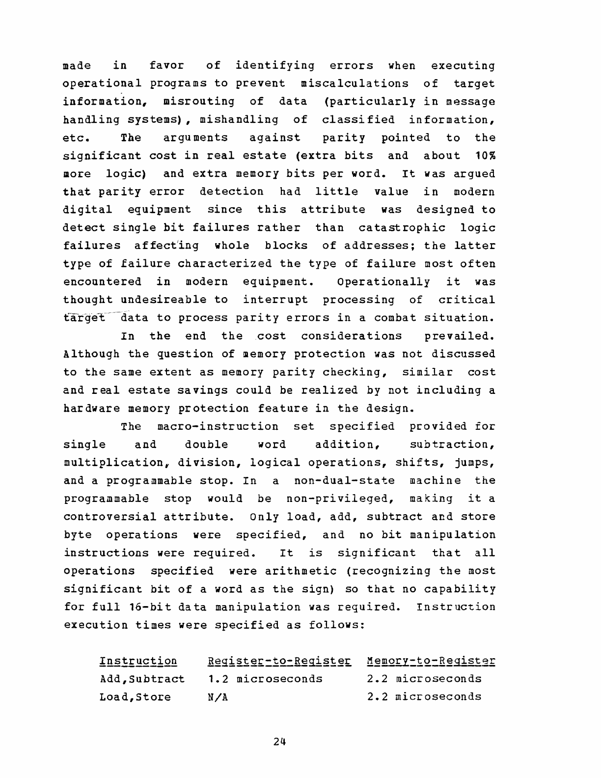
Instruction
execution
times
were
specified
as
follows:
!~tr1!£ti.QQ
Add,Subtract
Load,Store
Regist~£=~2=Regi§i~£
~~mory-to-Register
1.2
microseconds
2.2
microseconds
N/A
2.2
microseconds
24
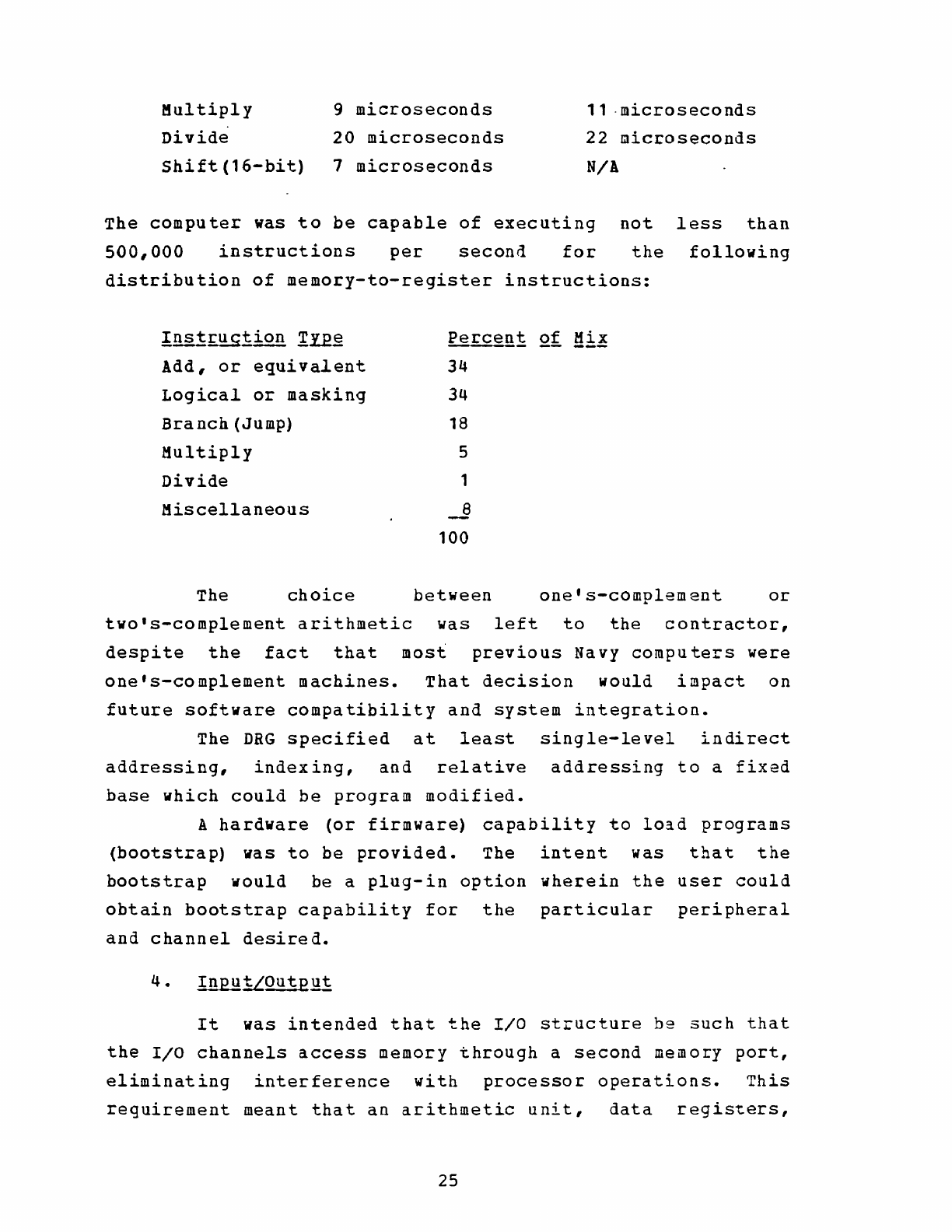
Multiply
9
microseconds
Divide
20
microseconds
11 .
microseconds
22
microseconds
Shift(16-bit)
1
microseconds
N/!
The
computer
was
to
be
capable
of
executing
500,000
instructions
per
second
for
not
less
than
the
following
distribution
of
memory-to-register
instructions:
!!l2~r.~~ion
!.ll~
Add,
or
equivalent
Logical
or
masking
Branch
(Jump)
Multiply
Divide
Miscellaneous
Pe~:!:
Qt
Hi!
34
34
18
5
1
~
100
The
choice
between
one's-complement
or
tvo's-complement
arithmetic
was
left
to
the
contractor,
despite
the
fact
that
most
previous
Navy
computers
were
one's-complement
machines.
That
decision
would
impact
on
future
software
compatibility
and
system
integration.
The
DRG
specified
at
least
single-level
indirect
addressing,
indexing,
and
relative
addressing
to
a
fixed
base
which
could
be
program
modified.
A
hardware
(or
firmware)
capability
to
lo~d
programs
(bootstrap)
was
to
be
provided.
The
intent
was
that
the
bootstrap
would
be
a
plug-in
option
wherein
the
user
could
obtain
bootstrap
capability
for
the
particular
peripheral
and
channel
desired.
It
was
intended
that
the
110
structure
be
such
that
the
I/O
channels
access
memory
through
a
second
memory
port,
eliminating
interference
with
processor
operations.
This
requirement
meant
that
an
arithmetic
unit,
data
registers,
25
etc.
were
required
for
each
channel
to
perform
buffer
control
functions,
address
calculations,
interrupt
control,
etc.
In
order
to
save
on
real
estate,
the
channels
(a
total
of
sixteen)
were
to
be
grouped
in
increments
of
not
more
than
four
channels
for
parallel
mode,
or
two
channels
for
serial
mode.
Only
one
aider
and
set
of
data
registers
plus
control
circuitry
would
be
required
per
four
channel
group.
This
requirement,
while
saving
circuitry
and
cost
placed
several
significant
restrictions
on
possible
I/O
configurations:
*
For
parallel
mode
data
transfe~,
each
four
channel
group
was
constrained
to
one
type
of
interface.
*
Serial
and
parallel
channels
could
not
be
mixed
within
a
group.
*
Double
word
(32-bit)
transfers,
such
as
necessary
for
interfacing
with
UYK-7,
would
require
one
channel
from
each
of
two
adjacent
groups,
thus
forcing
eight
channels
to
be
of
the
same
type
of
interface.
(This
requirement
stems
from
the
need
for
separate
processing
circuitry
for
the
upper
and
lower
16-bits
of
32-hit
parallel
transfers.)
Direct
Memory
Access
(DMA)
was
desired
but
not
required.
Thus,
a
provision
for
direct
memory
ac~ess
by
a
high
speed
mass
storage
device
(such
as
a
disk)
could
somewhat
compensate
for
the
lack
of
provision
for
expansion
of
main
memory
beyond
65K-words.
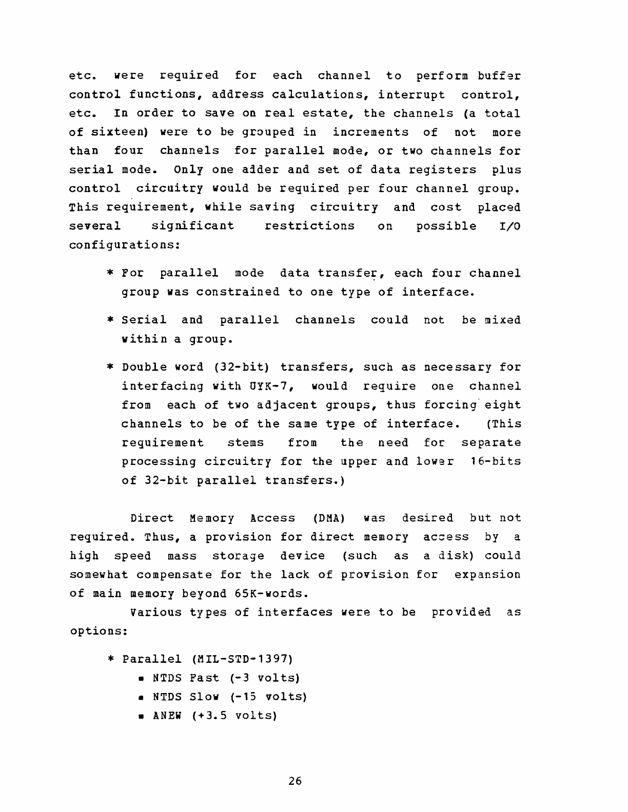
Various
types
of
interfaces
were
to
be
provided
as
options:
*
Parallel
(MIL-STD-1397)
•
NTDS
Past
(-3
volts)
•
NTDS
Slow
(-15
volts)
•
ANEW
(+3.5
volts)
26
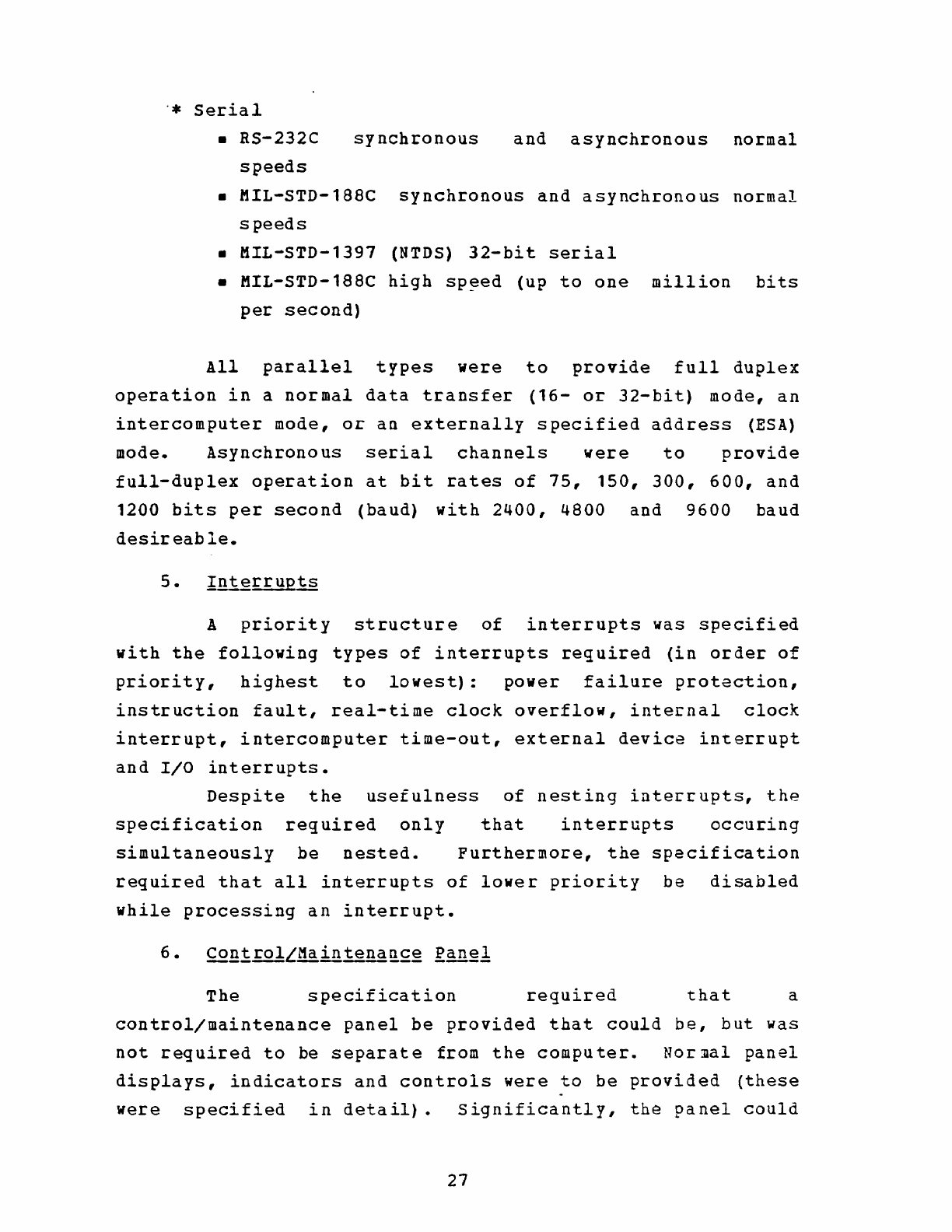
.•
Serial
•
RS-232C
synchronous
and
asynchronous
normal
speeds
•
MIL-STD-188C
synchronous
and
asynchronous
normal
speeds
•
MIL-STD-1397
(NTDS)
32-bit
serial
•
MIL-STD-188C
high
sp~ed
(up
to
one
million
bits
per
second)
All
parallel
types
were
to
provide
full
duplex
operation
in
a
normal
data
transfer
(16-
or
32-bit)
mode,
an
intercomputer
mode,
or
an
externally
specified
address
(ESA)
mode.
Asynchronous
serial
channels
were
to
provide
full-duplex
operation
at
bit
rates
of
75,
150,
300,
600,
and
1200
bits
per
second
(baud)
with
2400,
4800
and
9600
baud
desir
eab
Ie.
A
priority
structure
of
interrupts
was
specified
with
the
following
types
of
interrupts
required
(in
order
of
priority,
highest
to
lowest):
power
failure
protection,
instruction
fault,
real-time
clock
overflow,
inte~nal
clock
interrupt,
intercomputer
time-out,
external
device
interrupt
and
I/O
interrupts.
Despite
the
usefulness
of
nesting
interrupts,
the
specification
required
only
that
interrupts
occuring
simultaneously
be
nested.
Furthermore,
the
specification
required
that
all
interrupts
of
lower
priority
be
disabled
while
processing
an
interrupt.
The
specification
required
that
a
control/maintenance
panel
be
provided
that
could
be,
but
was
not
required
to
be
separate
from
the
computer.
Nor~al
panel
displays,
indicators
and
controls
were
to
be
provided
(these
were
specified
in
detail).
significantly,
the
panel
could
27
be
configured
to
display
only
one
register
at
a
time,
or
more,
as
the
manufacturer
wished.
It
is
significant
that
the
question
of
software
was
not
addressed
in
the
~pecification
generated
by
the
DRG.
In
the
Request-for-Proposals
(RFP)
only
an
assembler
was
required.
Ap~endix
B
summarizes
the
specifications
for
the
standard
minicomputer
system
as
determined
by
TADSO
and
the
DRG.
D.
CAPABILITIES
OF
EXISrING
NAVY
COMPUTERS
TO
MEET
THE
SPECI
FIC
ATIO
NS
It
is
valid
to
investigate
whether
the
perceived
present
and
future
needs
of
the
Navy
for
a
minicomputer,
as
defined
by
the
DRG,
could
be
met
by
an
existing
general
purpose
small
computer
in
the
Navy
inventory.
If
so,
this
computer
could
be
designated
a
standard
just
as
the
AN/OYK-7
had
been
a
year
before.
The
sections
below
discuss
the
pertinent
features
of
some
of
those
Navy
computers
which
woqld
have
been
most
likely
to
fill
the
need
for
a
standard
minicomputer.
Appendices
C
through
F
summarize
the
characteristics
of
those
computers.
Comparing
the
standard
minicomputer
specification
wi~h
the
existing
computers
reveals
that
none
met
the
specification
completely,
although
two
were
good
candidates
with
certain
exceptions.
The
AN/OYK-15
(V)
lacked
microprogramming
and
relative
addressing,
but
was
otherwise
acceptable.
It
had
additional
features
such
as
memory
parity
checking,
memory
write
protection
and
multi-ported
memory
banks
to
further
recommend
it.
The
AN/OYK-12(V)
also
lacked
microprogramming
and
did
not
meet
all
required
instruction
28
execution
speeds
or
memory
capacity,
but
had
an
extensive
support
software
package
to
recommend
it.
The
existence
of
UYK-12
and
UYK-15
brings
the
decision
to
specify
a
microprogrammed
processor
under
close
scrutiny.
As
discussed
in
the
previous
section,
the
advantages
of
microprogrammability
are
an
expanded
macro-instruction
set,
ability
to
implement
high
speed
floating-point,
mathematical
and
trigonometric
functions
as
needed,
and
flexibility
to
add
high-speed
user
macros
to
facilitate
real-time
processing.
The
disadvantages
were
best
summarized
in
enclosure
(1)
of
a
letter
to
TADSO
from
the
/Naval
Air
Systems
Command
(AIR-5333),
"The
latter
deficiency
(the
requirement
for
micro-programmability],
while
being
technically
feasible,
leads
to
unusual
hardware
and
software
configuration
management
problems.
NAVAIR
believes
that
a
requirement
for
micro-programmability
has
not
been
demonstrated
and
will
serve
only
to
eliminate
qualified
vendors.
lie
Ref.
13]
NAVAIR's
comments
about
configuration
management
refer
to
the
potential
user
capability
to
modify
the
macro-instruction
set.
It
must
be
pointed
out
that
configuration
control
can
be
maintained
by
requiring
that
all
modifications
to
the
macro-instruction
set
he
upward
compatible
with
the
basic
set.
The
foregoing
comments
not-withstanding,
microprogrammability
remained
a
requirement,
and
none
of
the
existing
Navy
computers
could
meet
the
specification.
It
is
also
interesting
to
note
that
a
majority
of
the
computers
in
the
Navy
inventory
were
manufactured
by
the
UNIVAC
Defense
Systems
Division
of
Sperry
Rand
Corporation
(UNIVAC).
Th9
Rolm
Corporation
manufactured
AN/UYK-12(V)
is
an
exception,
and
there
were
others.
Comparison
of
the
standard
minicomputer
specification
with
the
UNIVAC
manufactured
29
computers
reveals
that
the
DRG
was
probably
influenced
by
the
UNIVAC
design
philosophy
in
producing
their
specification.
For
instance,
the
UYK-12
I/O
structure,
which
was
not
in
accordance
with
the
specification,
was
simply
another
method
of
accomplishing
the
same
end.
It
is
the
opinion
of
this
author
that
the
use
in
the
RFP
of
the
detailed
technical
specification
produced
by
the
DRG
rather
than
a
performance
specification,
probably
excluded
some
candidate
minicomputers
from
the
competition.
This
computer,
a
militarized
version
of
the
UNIVAC
1212,
was
an
upward
compatible
follow-on
to
the
U5Q-20/CP-642/CP-642A
family.
Designed
specifically
for
use
in
the
Navy
Tactical
Data
System
(NTDS),
its
architecture
optimized
processing
of
large
quantities
of
complex
data
where
heavy
I/O
comunication
was
required.
with
reference
to
App.
C
it
can
be
seen
that
although
CP-6~2B
was a
minicomputer
in
capabilities,
it
was
a
physically
larger
unit
than
desired.
Its
size
and
slow
speed
are
a
result
of
its
second
generation
architecture.
Lack
of
serial
I/O
capability,
lack
of
interrupts
and
limited
memory
were
other
factors
which
made
this
computer
unacceptable.
Appendix
C
profiles
the
CP-642B.
2.
ANLQYK-15J!l
The
shortcomings
of
this
computer,
a
militarized
UNIVAC
1616,
have
been
previously
discussed.
Additional
desireable
features
incorporated
in
the
AN/UYK-15(V)
include
optional
additional
general
registers
up
to
64,
memory
parity
checking
and
a
priority
structured,
multi-ported
memory.
This
latter
feature
incorporates
a
priority
multiplexer
which
provides
four
access
ports
for
each
16K-word
memory
bank.
Combined
with
separate
IOC's
for
each
group
of
four
I/O
channels,
this
feature
allows
simultaneous
access
to
different
memory
banks
by
the
CPU
and
various
30
IOC's,
thus
improving
throughput.
Appendix
D
profiles
the
AN/UYK- 15
(V)
•
Commercially
designated
the
UNIVAC
1289,
this
computer
was
designed
for
navigation
system
applications.
Although
of
second
generation
technology,
it
featured
reasonable
speed.
It
failed
in
a
number
of
ways
to
meet
the
standard
minicomputer
specification,
but
it
had
some
capabilities
not
required,
but
desireable:
dual
states
(program
and
executivet,
programmable
memory
read/write
protection,
memory
parity
checking,
and
floating-point
hardware.
Appendix
E
profiles
the
CP-890.
4.
ANLQYK-12
tit
That
computer
was
designed
from
the
ground
up
as
a
militarized
Data
General
NOVA
with
a
military
application
I/O
structure
added.
Designated
the
Rolm
1601,
it
was
completely
upward
compatible
with
the
NOVA
and
could
thus
run
all
software
developed
for
that
popular
minicomputer.
The
I/O
structure
was
basically
a
single
I/O
bus
with
the
facility
to
address
61
different
devices.
Each
device
could
independently
interrupt
the
processor
according
to
a
predetermined
priority.
The
computer
could
be
configured
with
up
to
16
110
interfaces
and
15
backpanel
connectors.
An
extensive
package
of
well-tested
and
well-documented
support
software
was
available.
Included
were
cross-assemblers
and
cross-compilers
so
that
programs
for
the
UYK-15
could
be
assembled
or
compiled
on
a
larger
machine.
That
feature
recognized
the
constraints
on
using
a
minicomputer
for
program
development.
In
this
chapter
the
meaning
and
implications
of
a
standard
minicomputer
have
been
established.
The
Navy
requirements
for
a
minicomputer
system
in
1972
were
discussed,
and
it
was
concluded
that
no
existing
small
31
computer
in
the
Navy
inventory
could
meet
those
requirements.
In
Chapt.
III
the
history
of
the
standard
minicomputer
acquisition
project
will
be
discussed.
32
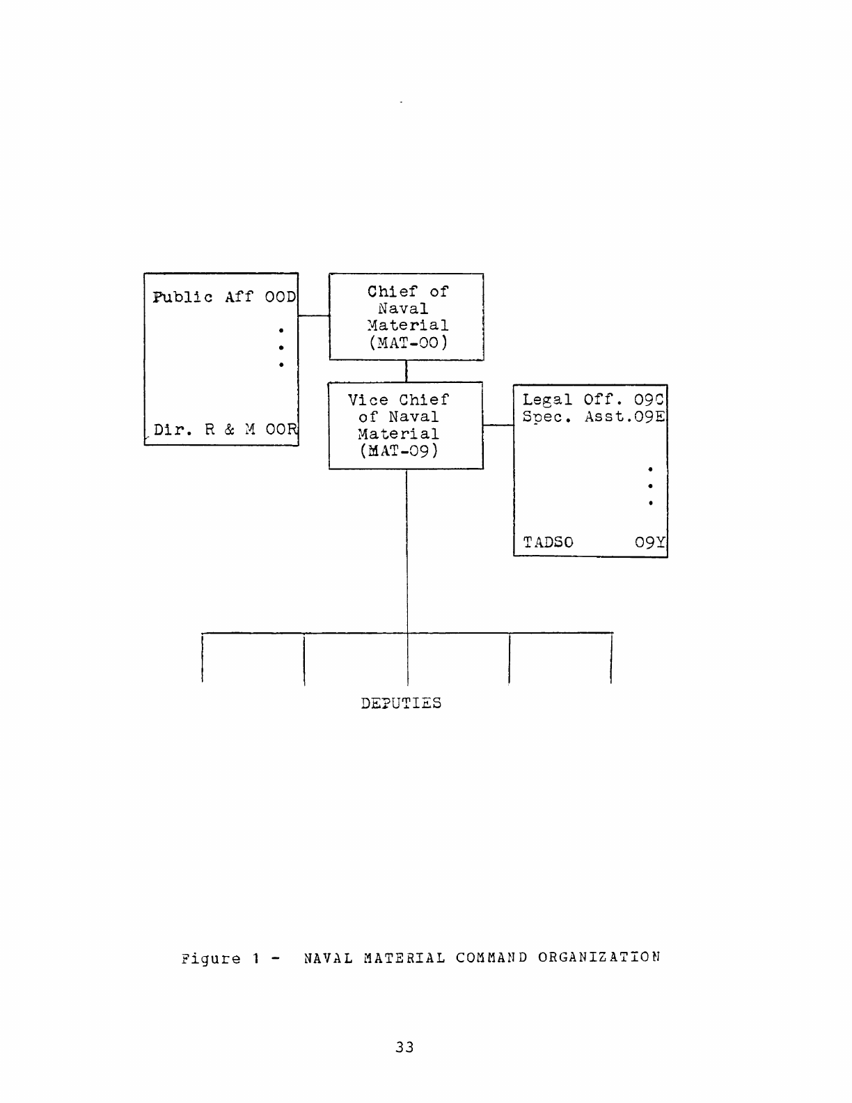
Public
Aff
OOD
Chief
of
Naval
-
•
:v1a
terial
•
(MAT-OO)
•
Vice
Chief
Legal
Off.
0ge
R &
~-1
OaR
of
Naval
Spec.
Asst.09E
Dir.
Ma
terial
f---
(MAT-09 ) •
•
•
TADSO
09Y
DE:?UTIES
Figure
1 -
NAVAL
MATERIAL
COMMAND
ORGANIZATION
33
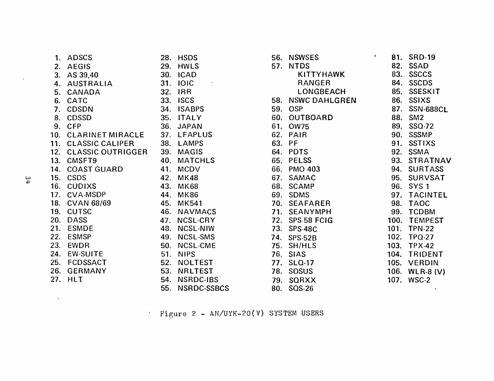
1. ADSCS 28. HSDS 56. NSWSES 81. SRD-19
2. AEGIS 29. HWLS 57.
NTDS
. 82. SSAD
3. AS 39,40 30.
ICAD
KITTYHAWK
83.
SSCCS
4.
AUSTRALIA
31.
IOIC
RANGER
84. SSCDS
5.
CANADA
32.
IRR
LONGBEACH
85. SSESKIT
6.
CATC 33. ISCS 58. NSWC
DAHLGREN
86. SSIXS
7. COSON 34. ISABPS 59.
OSP
87. SSN-688CL
8.
COSSO
35.
ITALY
60.
OUTBOARD
88. SM2
9. CFP 36.
JAPAN
61. OW75 89. SSO-72
10.
CLARINET
MIRACLE
37.
LFAPLUS
62.
PAIR
90.
SSSMP
11. CLASSIC
CALIPER
38. LAMPS 63.
PF
91. SSTIXS
12. CLASSIC
OUTRIGGER
39.
MAGIS
64. POTS 92. SSMA
13. CMSFT9 40.
MATCHLS
65. PELSS 93.
STRATNAV
14. COAST
GUARD
41.
MCDV
66.
PMO
403
94. SURTASS
Lv 15.
CSOS
42.
MK48
67.
SAMAC
95.
SURVSAT
~
16.
CUDIXS
43.
MK68
68. SCAMP 96. SYS 1
17. CVA-MSOP 44.
MK86
69. SOMS 97.
TACINTEL
18.
CVAN
68/69
45.
MK541
70.
SEAFARER
98.
TAOC
19. CUTSC 46.
NAVMACS
71. SEA
NYMPH
99. TCDBM
20. OASS 47. NCSL-CRY 72. SPS-58 FCIG 100. TEMPEST
21. ESMDE 43. NCSL-NIW 73. SPS-48C 101. TPN-22
22.
ESMSP
49. NCSL-SMS 74. SPS-52B 102. TPO-27
23. EWDR 50. NCSL-CME 75.
SH/HLS
103. TPX-42
24. EW-SUITE 51. NIPS 76. SIAS 104.
TRIDENT
25. FCDSSACT 52.
NOLTEST
77. SLO-17 105.
VERDIN
26.
GERMANY
53.
NRLTEST
78. SOSUS 106. WLR-8
(V)
27. HLT. 54. NSRDC-IBS 79.
SORXX
107. WSC-2
55. NSRDC-SSBCS 80. SOS-26
Figure
2 - AN/UYK-20(V)
SYSTEM
USERS
The
events
leading
to
the
publication
of
a
specification
for
a
standard
minicomputer
have
been
detailed'
in
the
previous
chapter.
This
chapter
will
relate
the
history
of
the
AN/UYK-20(V)
acquisition
from
specification
to
mid-year
1976.
Much
of
the
information
on
events
leading
to
the
contract
award
in
May
1973
was
derived
from
a
research
paper
by
Captain
J.
S.
Sansone
(Ref.
14],
who
was
the
Project
and
contracting
officer
for
the
standard
minicomputer
procurement.
In
June
1972
the
preliminary
specification
for
the
standard
minicomputer
was
distributed
for
final
review.
By
that
time
TADSO
was
well
established
and
had
issued
six
TADSTANDS
acquisition
on
a
variety
of
strategy
called
subjects.
[Refs.
for
militarization
2-8
]
The
of
a
commercial
system
requiring
a minimum
of
system
development
to
meet
the
DRG
specification.
It
was
estimated
that
about
$1.8
million
in
Research,
Development,
Test
and
Evaluation
Navy
(RDT&EN)
appropriated
funds
would
be
necessary
to
cover
costs
of
design
and
development,
militarization,
Government
Furnished
Equipment
(GFE),
environmental
and
celiability
testing,
TEMPEST
testing,
Integrated
Logisti~s
Support
plans,
development
of
technical
manuals,
other
data
requirements,
and
support
software
development.
In
late
August
1972
CNM
advised
eNO's
Director
of
Research,
Development,
Test
and
Evaluation
(OP-098)
of
the
existance
of
the
standard
minicomputer
specification,
and
the
need
for
prompt
approval
to
preclude
further
proliferation
of
commercial
minicomputers
in
the
Navy
inventory.
OP-098
was
also
informed
that
the
necessary
$1.8
million
in
RDT&EN
funds
could
be
obtained
by
reprogramming
Fiscal
Year
1973
funds
from
sub-allocations
to
the
various
35
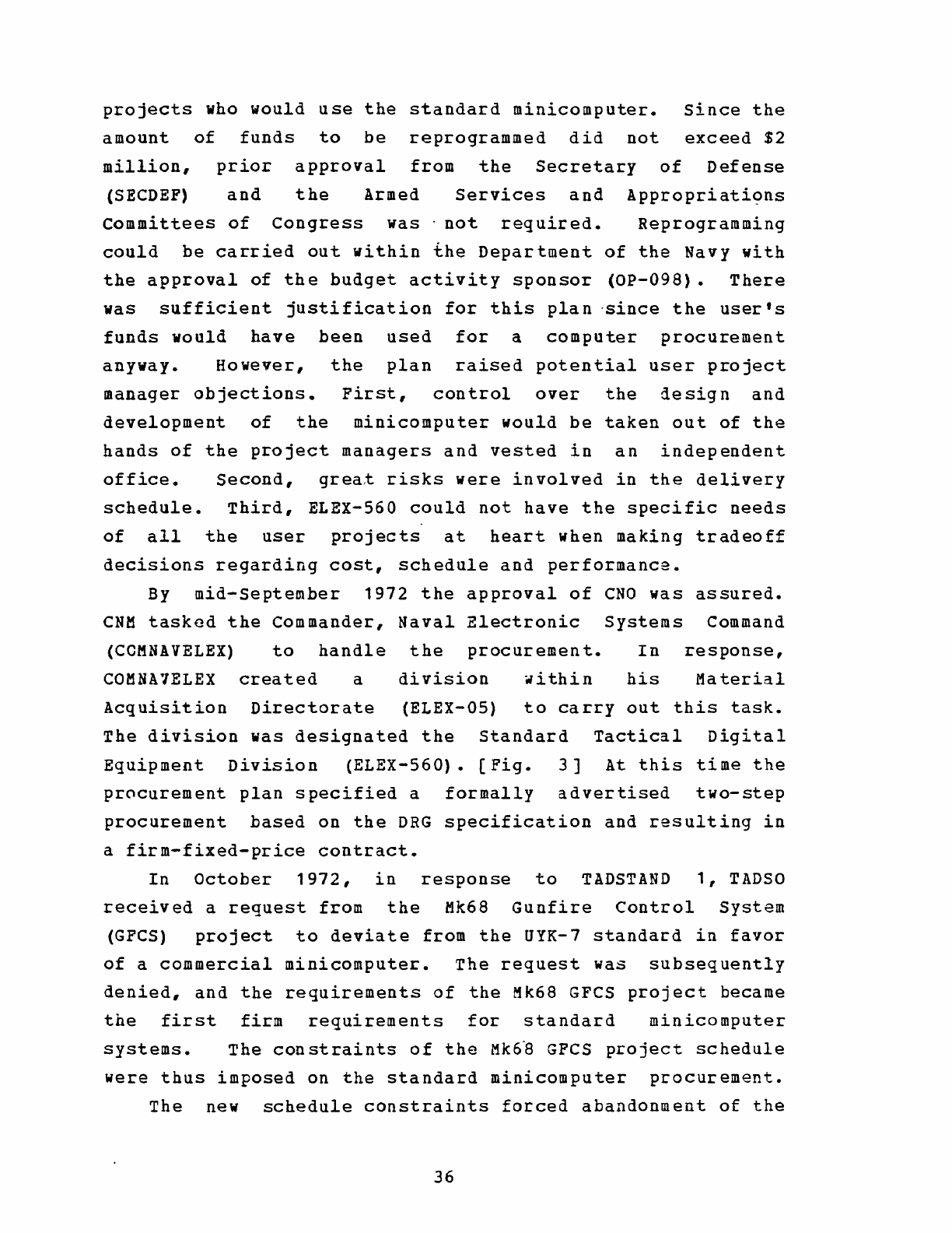
projects
who
would
use
the
standard
minicomputer.
since
the
amount
of
funds
to
be
reprogrammed
did
not
exceed
$2
million,
prior
approval
from
the
Secretary
of
Defense
(SECDEF)
and
the
Armed
Services
and
Appropriati9ns
committees
of
Congress
was·
not
required.
Reprogramming
could
be
carried
out
within
the
Department
of
the
Navy
with
the
approval
of
the
budget
activity
sponsor
(OP-098).
There
was
sufficient
justification
for
this
plan
-since
the
user's
funds
would
have
been
used
for
a
computer
procurement
anyway.
However,
the
plan
raised
potential
user
project
manager
objections.
First,
control
over
the
design
and
development
of
the
minicomputer
would
be
taken
out
of
the
hands
of
the
project
managers
and
vested
in
an
independent
office.
Second,
grea~
risks
were
involved
in
the
delivery
schedule.
Third,
ELEX-S60
could
not
have
the
specific
needs
of
all
the
user
projects
at
heart
when
making
tradeoff
decisions
regarding
cost,
schedule
and
performance.
By
mid-September
1972
the
approval
of
CNO
was
assured.
CNM
taskod
the
Commander,
Naval
Electronic
Systems
Command
(CCMNAVELEX)
to
handle
the
procurement.
In
response,
COMNA1ELEX
created
a
division
~ithin
his
Material
Acquisition
Directorate
(ELEX-OS)
to
carry
out
this
task.
The
division
was
designated
the
Standard
Tactical
Digital
Equipment
Division
(ELEX-S60).
[Fig.
3]
At
this
time
the
pr0curement
plan
specified
a
formally
advertised
two-step
procurement
based
on
the
DRG
specification
and
resulting
in
a
firm-fixed-price
contract.
In
October
1972,
in
response
to
TADSTAND
1,
TADSO
received
a
request
from
the
Mk68
Gunfire
Control
System
(GFCS)
project
to
deviate
from
the
UYK-7
standard
in
favor
of
a
commercial
minicomputer.
The
request
was
subsequently
denied,
and
the
requirements
of
the
Mk68
GFCS
project
became
the
first
firm
requirements
for
standard
minicomputer
systems.
The
constraints
of
the
Mk6~
GFCS
project
schedule
were
thus
imposed
on
the
standard
minicomputer
procurement.
The
new
schedule
constraints
forced
abandonment
of
the
36
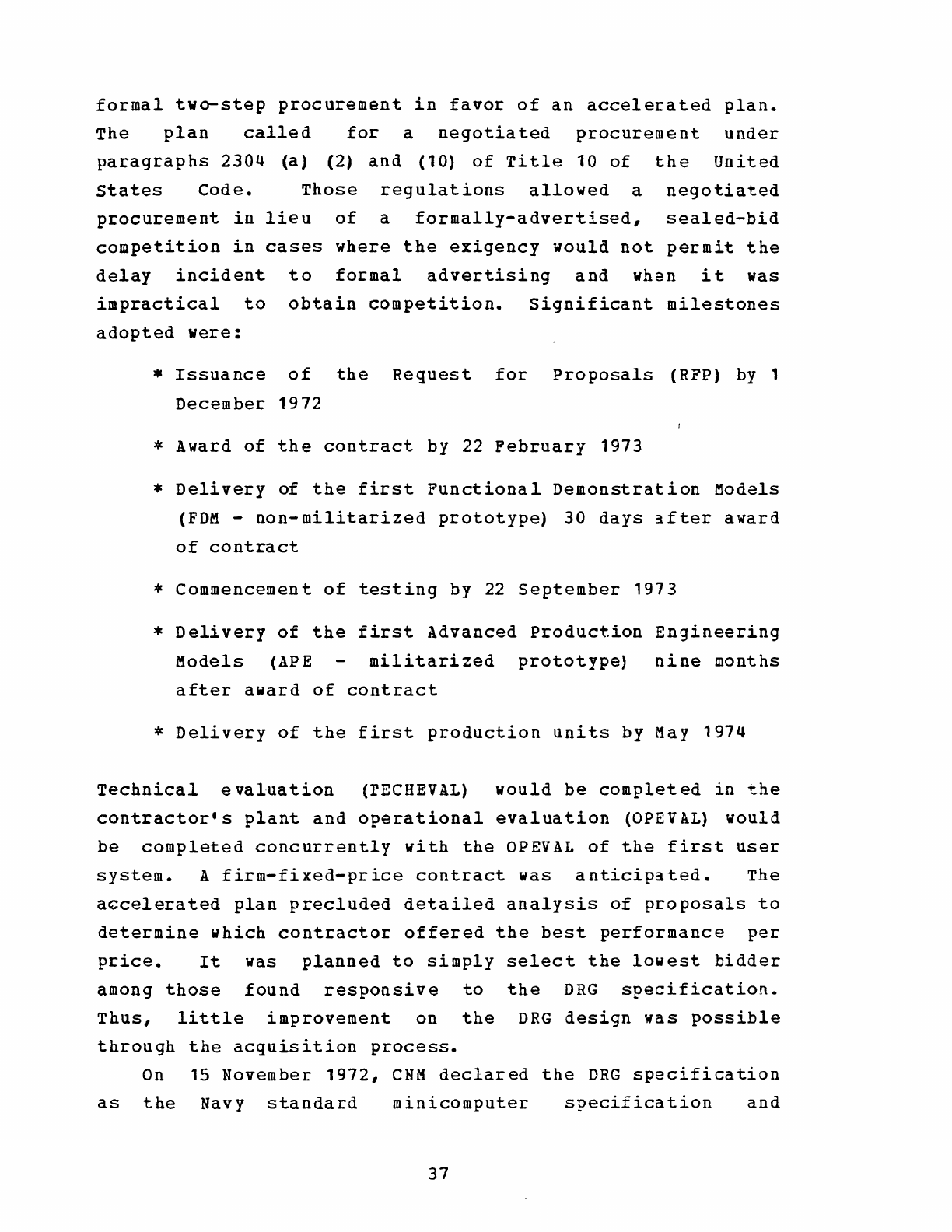
formal
two-step
procurement
in
favor
of
an
accelerated
plan.
The
plan
called
for
a
negotiated
procurement
under
paragraphs
2304
(a)
(2)
and
(10)
of
Title
10
of
the
United
states
Code.
Those
regulations
allowed
a
negotiated
procurement
in
lieu
of
a
formally-advertised,
sealed-bid
competition
in
cases
where
the
exigency
would
not
permit
the
delay
incident
to
formal
advertising
and
when
it
was
impractical
to
obtain
competition.
Significant
milestones
adopted
were:
*
Issuance
of
the
Request
for
Proposals
(RPP)
by
1
December
1972
*
Award
of
the
contract
by
22
Pebruary
1973
*
Delivery
of
the
first
Functional
Demonstration
Models
(FDM
-
non-militarized
prototype)
30
days
after
award
of
contract
*
Commencement
of
testing
by
22
September
1973
*
Delivery
of
the
first
Advanced
Production
Engineering
Models
(APE
militarized
prototype)
nine
months
after
award
of
contract
*
Delivery
of
the
first
production
units
by
May
1974
Technical
evaluation
(rECHEVAL)
would
be
completed
in
the
contractor's
plant
and
operational
evaluation
(OPEVAL)
would
be
completed
concurrently
with
the
OPEVAL
of
the
first
user
system.
A
firm-fixed-price
contract
was
anticipated.
The
accelerated
plan
precluded
detailed
analysis
of
proposals
to
determine
which
contractor
offered
the
best
performance
per
price.
It
was
planned
to
simply
select
the
lowest
bidder
among
those
found
responsive
to
the
DRG
specification.
Thus,
little
improvement
on
the
DRG
design
was
possible
through
the
acquisition
process.
On
15
November
1972,
CNM
declared
the
DRG
specification
as
the
Navy
standard
minicomputer
specification
and
37
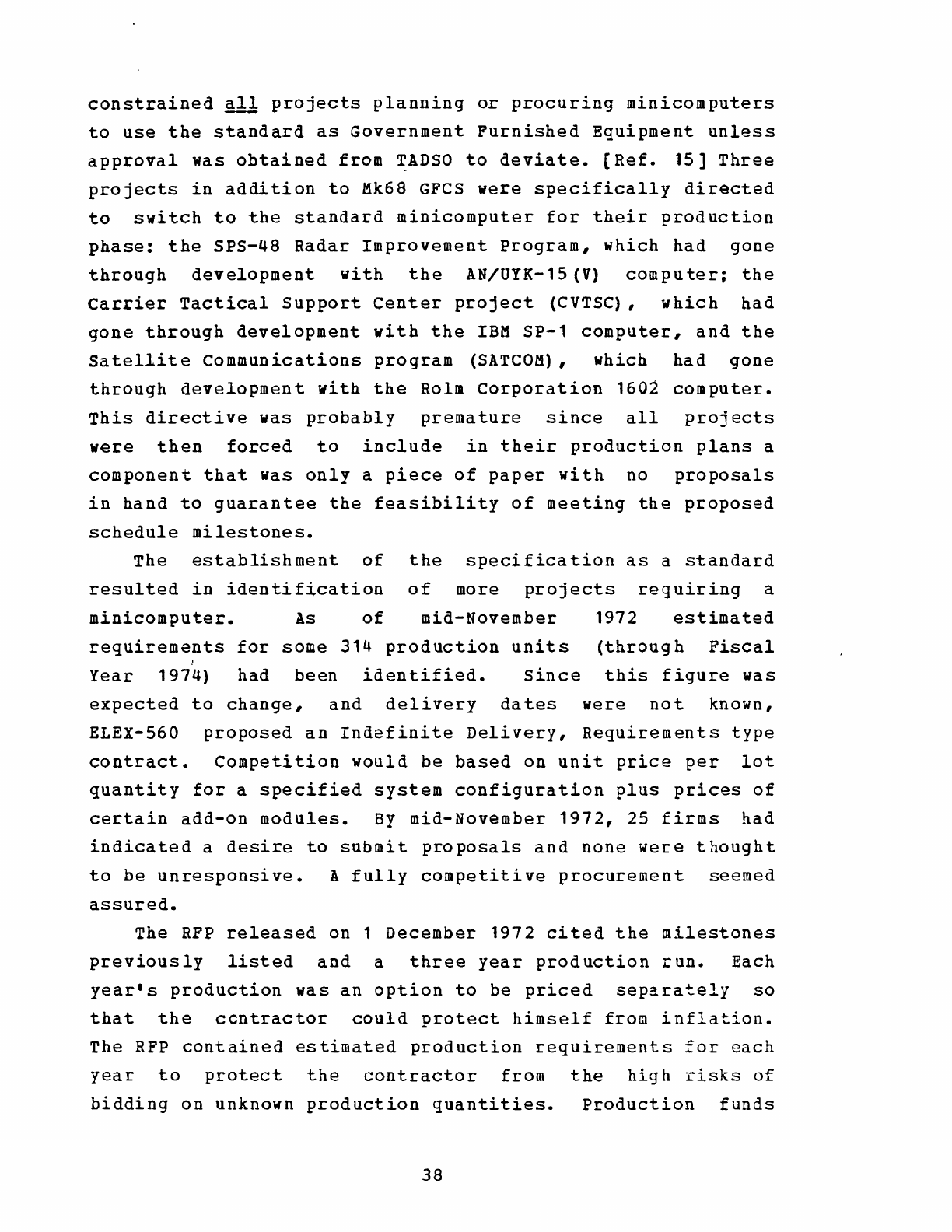
constrained
all
projects
planning
or
procuring
minicomputers
to
use
the
standard
as
Government
Furnished
Equipment
unless
approval
was
obtained
from
TADSO
to
deviate.
[Ref.
15]
Three
projects
in
addition
to
Mk68
GFCS
were
specifically
directed
to
switch
to
the
standard
minicomputer
for
their
production
phase:
the
SPS-48
Radar
Improvement
Program,
which
had
gone
through
development
with
the
AN/UYK-15
(V)
computer;
the
Carrier
Tactical
Support
center
project
(CVTSC),
which
had
gone
through
development
with
the
IBM
SP-1
computer,
and
the
Satellite
Communications
program
(SATCOM),
which
had
gone
through
development
with
the
Rolm
Corporation
1602
computer.
This
directive
was
probably
premature
since
all
projects
were
then
forced
to
include
in
their
production
plans
a
component
that
was
only
a
piece
of
paper
with
no
proposals
in
hand
to
guarantee
the
feasibility
of
meeting
the
proposed
schedule
milestones.
The
establishment
of
the
specification
as
a
standard
resulted
in
identification
of
more
projects
requiring
a
minicomputer.
As
of
mid-November
1972
estimated
requirements
for
some
314
production
units
(through
Fiscal
I
Year
1974)
had
been
identified.
Since
this
figure
was
expected
to
change,
and
delivery
dates
were
not
known,
ELEX-560
proposed
an
Indefinite
Delivery,
Requirements
type
contract.
Competition
would
be
based
on
unit
price
per
lot
quantity
for
a
specified
system
configuration
plus
prices
of
certain
add-on
modules.
By
mid-November
1972,
25
firms
had
indicated
a
desire
to
submit
proposals
and
none
were
thought
to
be
unresponsive.
A
fully
competitive
procurement
seemed
assured.
The
RFP
released
on
1
December
1972
cited
the
milestones
previously
listed
and
a
three
year
production
run.
Each
year's
production
was
an
option
to
be
priced
separately
so
that
the
ccntractor
could
protect
himself
from
inflation.
The
RFP
contained
estimated
production
requirements
for
each
year
to
protect
the
contractor
from
the
high
risks
of
bidding
on
unknown
production
quantities.
Production
funds
38
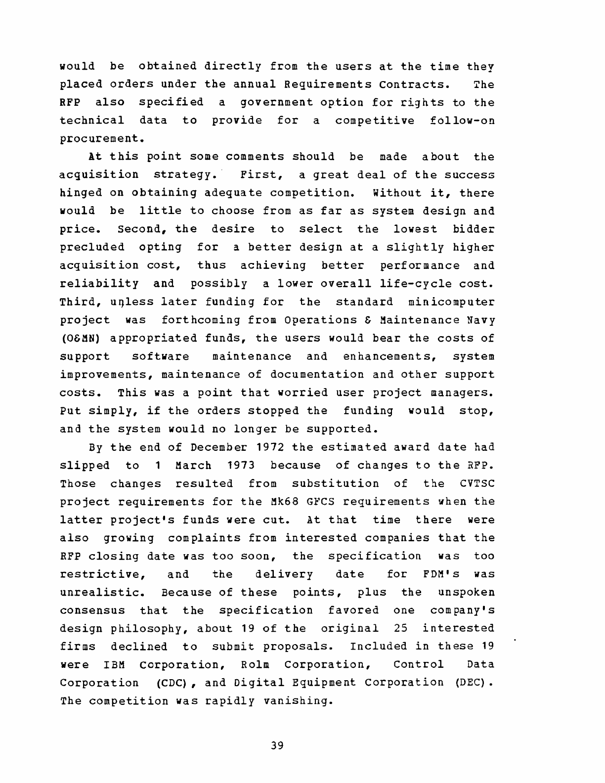
would
be
obtained
directly
from
the
users
at
the
time
they
placed
orders
under
the
annual
Requirements
contracts.
~he
RFP
also
specified
a
government
option
for
rights
to
the
technical
data
to
provide
for
a
competitive
follow-on
procurement.
At
this
point
some
comments
should
be
made
about
the
acquisition
strategy.'
First,
a
great
deal
of
the
success
hinged
on
obtaining
adequate
competition.
without
it,
there
would
be
little
to
choose
from
as
far
as
system
design
and
price.
Second,
the
desire
to
select
the
lowest
bidde~
precluded
opting
for
a
better
design
at
a
slightly
higher
acquisition
cost,
thus
achieving
better
performance
and
reliability
and
possibly
a
lower
overall
life-cycle
cost.
Third,
uqless
later
funding
for
the
standard
minicomputer
project
was
forthcoming
from
Operations
&
Maintenance
Navy
(O&MN)
appropriated
funds,
the
users
would
bear
the
costs
of
support
software
maintenance
and
enhancements,
system
improvements,
maintenance
of
documentation
and
other
support
costs.
This
was a
point
that
worried
user
project
managers.
Put
simply,
if
the
orders
stopped
the
funding
would
stop,
and
the
system
would
no
longer
be
supported.
By
the
end
of
December
1972
the
estimated
award
date
had
slipped
to
1
March
1973
because
of
changes
to
the
RFP.
Those
changes
resulted
from
substitution
of
the
CVTSC
project
requirements
for
the
Mk68
GFCS
requirements
when
the
latter
project's
funds
were
cut.
At
that
time
there
were
also
growing
complaints
from
interested
companies
that
the
RFP
closing
date
was
too
soon,
the
specification
was
too
restrictive,
and
the
delivery
date
for
FDM's
was
unrealistic.
Because
of
these
points,
plus
the
unspoken
consensus
that
the
specification
favored
one
company's
design
philosophy,
about
19
of
the
original
25
interested
firms
declined
to
submit
proposals.
Included
in
these
19
were
IBM
corporation,
Rolm
corporation,
control
Data
Corporation
(CDC),
and
Digital
Equipment
corporation
(DEC).
The
competition
was
rapidly
vanishing.
39
The
options
open
to
the
Navy
at
this
point
were
as
follows:
*
Maintain
the
schedule
despite
the
high
probability
of
a
sole-source
procurement.
*
Slip
user
project
schedules
in
order
to
extend
the
proposal
due
date
and
gain
more
competition.
*
Cancel
the
RPP
and
restructure
the
procurement
as
a
development
effort.
The
decision
was
to
slip
the
closing
date
for
receipt
of
proposals
to
2
April
1973
and
extend
the
date
for
delivery
of
FDM's
to
120
days
after
date
of
contract.
Since
this
schedule
might
not
meet
some
potential
user
schedules,
a
risk
of
losing
some
firm
requirements
had
been
accepted.
During
the
month
of
February
1973
two
formal
prot~sts
on
the
RFP
were
filed
with
the
Government
Accounting
Office
(GAO)
•
The
first,
from
Control
Data
Corporation,
was
satisfied
by
the
extension
of
the
due
date
for
proposals.
The
second,
from
UNIVAC,
objected
to
the
extension
on
the
grounds
that
the
company
had
spent
considerable
effort
and
funds
to
meet
the
original
dates.
An
important
point
brought
out
in
this
latter
protest
was
that
no
firm
had
a
computer
that
would
meet
the
specification
completely,
and
that
substantial
design
and
development
effort
were
necessary
in
all
cases.
~AO
subsequently
determined
that
no
violation
of
procurement
law
had
occurred,
and
UNIVAC's
protest
was
denied.
Although
not
required
for
a
procureme~t
of
such
low
estimated
dollar
value
($1.8
million),
a
Source
selection
Authority
(SSA),
Source
Selection
Advisory
Council
(SSAC),
and
Source
Selection
Evaluation
Board
(SSEB)
~ere
designated.
The
SSEB
consisted
of
the
DRG
plus
representatives
of
NAVELEX,
the
Marine
Corps
and
TADSO.
The
SSAC
consisted
of
representatives
of
NAVELEX
and
rADSO
with
40
expertise
in
support,
etc.
consel:lt
of
CNM.
management
systems,
cost
analysis,
logistic
The
5SA
was
COMNAVELEX
with
the
advice
and
On
2
April
1973
proposals
were
-received
from
O~IVAC,
CDC,
General
Electric
and
Raytheon.
The
S5EB
proceeded
to
evaluate
the
proposals
~!i~2Y!
knQ~lg~~
£1
Eri£g~
and
found
all
firms
to
be
responsive
to
the
DRG
specification.
The
S5AC
determined
that
adequate
price
competition
existed.
A
pre-award
survey
was
conducted
at
each
plant
during
the
week
of
16
to
20
April
1973.
All
offerers
were
found
to
be
technically
and
financially
responsible
and
responsive
in
accordance
with
Armed
Services
Procurement
Regulation
(ASPR)
1-903.
contract
award
was
made
to
the
low
bidder,
UNtVAC,
on
27
April
1973.
The
contract
included
all
hardware
requirements
plus
an
assembler
for
a
firm-fixed-price
of
$673,000.
Soon
after
contract
award,
user
requirements
for
additional
support
software
in
addition
to
the
assembler
were
identified.
To
meet
this
need,
sole-source
contracts
were
let
to
UNIVAC
for
two
self-hosted
systems.
The
first,
designated
'Level
I,
was
released
in
November
1973.
The
second,
designated
Level
II,
was
released
in
J
anllary
1974.(App.
G]
NAVELEX
also
contracted
with
UNIVAC
at
that
time
to
develop
two
other
support
software
packages:
a
standard
real-time
executive
later
designated
SDEX-20,
which
was
to
provide
users
with
basic
software
modules
upon
which
to
build
their
operational
programs;
and
a
compiler
for
the
Navy
standard
high-level
language
(CMS-2),
which
would
generate
machine
code
for
the
OYK-20.
This
high-level
language
for
the
UYK-20
was
designated
CMS-2M
and
was
to
be
a
subset
of
the
CMS-2
language.
These
additional
contracts
were
funded
from
the
balance
remaining
of
$1.3
million
in
RDT&EN
funds
reprogrammed
for
the
UYK-
20
acquisition.
In
May
1973
TADSO
revised
'rADSTAND
1
to
designa
te
the
UYK-20
as
the
Navy
standard
digital
processor
for
those
applications
requiring
a
minicomputer.
(Ref.
3]
As
expected,
41
this
action
generated
a
few
requests
for
deviation
from
that
standard.
Most
were
turned
down.
The
Submarine
Integrated
Radio
Room (IRR)
project,
which
was
developing
with
the
CDC
MPP
computer
and
the
AN/UYK-15
(V)
,
had
a
request
to
deviate
denied
on
the
basis
that
the
UYK-20
was
upward
compatible
with
the
UYK-15.
Very
few
requests
for
deviation
were
granted.
The
VERDIN
retrofit
project
was
granted
a
waiver
due
to
size
problems
in
retrofitting
equipment
into
a
submarine,
and
the
riecessity
for
compatibility
with
existing
equipments.
The
SEA
SCOUT
project
was
granted
a
waiver
since
two
systems
were
already
deployed
with
the
AN/UYK-12
(V)
,
urgent
requirements
existed
for
four
more
systems,
and
no
more
than
a
total
of
six
systems
were
to
be
acquired.
The
BULLSEYE
project
was
granted
a
waiver
to
use
the
DEC
PDP-11
computer
as
its
shore-site
cryptologic
processor.
Justification
for
that
waiver
was
that
the
PDp·l1
was
currently
in
use
at
shore
sites,
associated
engineers
and
support
systems
were
available,
and
shipboard
use
was
not
anticipated.
On
27
March
1974
the
UYK-20
received
service
approval.
A
major
milestone
in
any
program,
this
event
also
had
a
profound
impact
on
the
funding
of
the
project.
Once
service
approval
was
received,
the
activities
of
ELEX-560
could
no
longer
be
supported
with
RDT&EN
funds.
Since
no
Operations
&
Kaintenance
Navy
(O&MN)
funds
were
available
to
support
the
project,
NAVELEX
was
forced
to
assess
users
of
the
system
for
system
suppoct
in
the
following
manner.
The
UYK-20
contract
was
a
Requirements,
Indefinite
Delivery
contract
which
allowed
the
users
to
purchase
systems
and
components
by
transmitting
a
DD
Form
1155
(Order
for
Supplies
or
Services)
to
ELEX-560
with
an
order
form
attached.
The
user's
funds
were
obligated
via
the
DD
Form
1155,
and
the
order
form
provided
a
detailed
description
of
the
equipment
and
software
requested.
The
user
obligated
funds
according
to
a
published
price
list.
These
published
prices
included
a
surcharge
over
the
fixed
prices
in
the
42
contract;
it
was
this
surcharge
which
was
used
to
fund
ELEX-560
support
activities.
Occasionally
users
would
require
new
system
components
(e.g.
bootstraps,
I/O
interfaces,
and/or
peripheral
handler
software
routines
for
a
unique
peripheral
device).
Naturally
the
requesting
user
had
to
provide
funds
for
the
development
of
his
unique
requirement.
This
was
accomplished
by
submitting
a
DD
Form
1149
(Requisition
and
Invoice/Shipping
Document)
to
ELEX-560
with
a
description
of
the
needed
material.
ELEX-560
would
use
the
authority
transmitted
by
the
DD
Form
1149
to
obligate
the
user's
funds
on
a
sole-source
Time
and
Materials
type
contract
with
UNIVAC
for
the
development
effort.
Accounting
for
the
surcharge
and
the
myriad
of
appropriation
budget
activities
cited
by
the
users
was
an
elaborate
task.
Frequent
liason
with
ordering
acti
vi
ties
was
necessary
to
insure
that
surcharges
were
"p3.id"
out
of
appropriation
catagories
which
could
be
properly
used
by
ELEX-560.
For
the
most
part
O&MN
funds
were
required
to
fund
project
tasks.
The
surcharge
system
concerned
user
project
managers.
Primary
objections
were
(1)
the
necessity
to
pay
prices
above
t
he
fixed
prices
on
the
contract,
and
(2)
the
realization
that
if
no
orders
were
received
the
funding
support
for
the
project
would
dry
up.
Each
year
NAVELEX
requested
sufficient
O&MN
funding
to
support
the
project,
but
those
funds
were
never
forthcoming.
Project
personnel
believed
that
the
project
requirements
were
cut
from
the
Navy
budget
submission
by
the
Office
of
the
Secretary
of
Defense
(OSD)
or
the
Office
of
Management
and
Budget
(OMB).
In
September
1974
the
first
issue
of
"The
Standard
n
was
pUblished.
This
dccument
vas,
as
stated
in
its
header,
Ita
bi-monthly
newsletter
published
to
inform
AN/UYK-20
users
of
current
status
and
new
developments
that
involve
the
AN/UYK-20
(V)
computer
and
its
support
software."
"The
Standard"
iias
a
step
toward
solving
the
communications
43
.>roblem
that
plagues
all
bureaucratic
organizations.
About
that
same
time
the
idea
of
a
formal
user's
)rganization
vas
conceived,
and
in
November
1974
the
first
IN/UYK-20
User's
Group
m~etitig
was
held
at-
the
Naval
~lectronics
Laboratory
Center
(NELC)
in
San
Diego.
The
neeting
attracted
some
200
persons
from
government
and
?rivate
industry.
By
mid-1976
the
AN/UYK-20
User's
Group
las
meeting
semi-annually
in
the
Spring
and
Fall
and
boasted
i
membership
of
close
to
300
persons.
Each
meeting
provided
i
forum
for
ELEX-560
to
transmit
further
information
to
the
lsers,
but
more
importantly
for
the
users
to
present
ideas
in
briefings
and
present~tions
which
would
benefit
other
asers.
The
meetings
also
provided
an
opportunity
for
users
~nd
project
cffice
personnel
to
meet
face
to
face
and
iiscuss
problems.
At
the
November
1976
User's
Group
meeting
at
the
Naval
Postgraduate
School
in
Monterey,
the
Fleet
Combat
Direction
Systems
Support
Activity
(FCDSSA)
San
Diego
announced
the
release
of
a
compiler
for
the
UYK-20
computer.
This
compiler,
designated
CMS-2Y(20),
operated
under
the
SHARE/7
operating
system
on
the
AN/UYK-7
computer.
The
compiler
was
designed
to
provide
versatile
program
development
capability,
since
it
utilized
the
powerful
programming
aids
available
under
SHARE/7.
(App.
G]
By
late-1974
the
first
UYK-20
computers
had
been
received
and
were
in
use
in
the
development
of
tactical
systems.
Many
hardware
failures
were
encountered
in
these
early
computers.
The
hardware
problems
were
compounded
by
the
fact
that
the
diagnostic
program
package
for
the
UYK-20
was
not
available
to
users
until
November
1974.
Users
were
dependent
on
UNIVAC
field
engineers
to
perform
corrective
maintenance.
Errors
were
also
encountered
in
the
support
software
and
in
the
documentation
for
both
h~rdware
and
software.
In
general
these
problems
were
discovered
and
solved
through
trial
and
error,
but
with
large
expenditures
of
user
time
and
funds.
44
The
types
of
problems
most
often
encountered
during
the
early
period
in
late-1974
were:
Memory
Array
Board
failures,
Memory
Control
Board
failures,
broken
or
bent
connection
pins
on
printed
circuit
(PC)
cards,
defective
power
supplies,
PC
cards
not
seated
properly,
and
software
documentation
which
either
contained
erroneous
descriptions
of
software
capabilities
or
neglected
to
mention
capabilities
that
existed.
The
contractor,
who
was
responsible
for
correcting
many
of
the
problems,
submitted
Engineering
Change
Proposals
(ECP's)
to
NAVELEX
to
correct
deficiencies.
Because
of
a
clause
in
the
contract
which
required
all
production
units
to
he
identical,
a
retrofit
was
necessary
to
incorporate
the
approved
Engineering
Changes
into
production
units
already
in
the
field.
UYK-20
serial
number
350,
which
came
off
the
production
line
in
December
1975,
became
the
baseline
unit
for
the
first
retrofit.
All
349
previous
production
units
were
affected
in
varying
degrees.
RetLofit
I
consisted
of
minor
changes
such
as
replacement
of
screws,
mountings,
and
fittings,
and
major
changes
such
as
replacement
of
power
supplies
in
serial/numbers
1
through
12,
replacement
of
PC
cards
which
had
been
redesigned,
and
modifications
to
existing
cards.
The
retrofit
was
performed
in
the
field
by
UNIVAC
engineers
during
the
period
from
January
1975
to
September
1976.
Despite
the
discovery
and
correction
of
many
deficiencies,
by
mid-1975
the
frequency
of
failures
in
production
units
signified
that
a
Leliability
problem
did
exist.
Perhaps
the
best
data
base
attesting
to
the
suspected
reliability
problems
came
from
the
Naval
Electronics
Systems
Engineering
Center
(NESEC)
at
San
Diego.
This
activity
was
tasked
with
assembly
and
checkout
of
the
Navy
Message
Address
Communications
system
(NAVMACS),
which
was
one
of
the
first
systems
using
UYK-20
to
reach
the
fleet.
During
the
period
late-1974
to
mid-1975,
NESEC
San
Diego
reported
that
a
high
percentage
of
production
units
were
received
inoperative
due
to
faulty
PC
cards
and
45
assembly
modules.
Spares
received
were
making
trouble-shooting
with
the
diagnostic
difficult.
(Trouble-shooting
procedures
diagnostic
rcutines
depended
on
substituting
and
PC
cards
for
suspected
defective
parts.)
also
defective,
programs
utilizing
very
the
spare
modules
Some
failures
were
intermittant,
making
them
extremely
difficult
to
diagnose.
Records
at
NESEC
San
Diego
indicate
that
during
the
period
late-1974
to
mid-1975
many
modules
were
experiencing
60~
to
70%
failure
rates.
Particular
problem
areas
were
power
supplies,
Memory
Array
Boards,
seating
of
I/O
cards,
and
overheating
in
hot
weather.
It
was
found
that
over
a
significant
period
of
operation,
however,
the
failure
rate
would
be
substantially
decreased,
indicating
that
a
"burn-in"
period
increased
reliability.
In
response
to
the
reports
from
NESEC
San
Diego,
personnel
from
UNIVAC
visited
that
activity
and
verified
the
need
to
upgrade
reliability.
In
June
and
July
of
1975
UNIVAC
voluntarily
shut
down
the
production
line
in
Clearwater,
Florida
to
investigate
the
possibility
of
severe
Quality
Assurance
(QA)
problems.
Over
the
ensuing
months
the
contractor
took
the
following
action
to
up-grade
UYK-20
quality:
*
Personnel
Improvements
•
Established
QA
as
an
independent
organization.
•
Transferred
added
QA
technical
and
management
capability
from
the
main
plant
in
st.
Paul,
Minnisota
to
the
UYK-20
production
plant
in
Clearwater.
•
Hired
additional
quality
engineers
and
inspectors.
•
Added
a
program
QA
man
in
Clearwater.
•
Transferred
final
testing
to
Manufacturing
in
order
to
remove
schedule
concerns
and
increase
QA
focus.
46
*
Documentation
and
Procedures
•
Reviewed
and
updated
all
inspection
and
test
procedures.
•
Established
formal
procedures
for
resolving
Defense
Contract
Administration
Service
(DCAS)
and
UNIVAC
quality
concerns
and
for
implementing
corrective
actions.
•
Reviewed
and
improved
assembly
processes.
•
Added
automatic
equipment.
•
Introduced
new
material
handling
containers
for
PC
cards.
•
Developed
new
fixtures
for
holding
memory
arrays
during
assembly.
*
Training
and
Motivation
•
Hired
a
full-time
trainer.
•
Established
a
dedicated
training
room.
•
Instituted
training
programs
for
manufacturing
and
inspection
personnel.
•
Establis~ed
certification
criteria
and
recertification
time
periods
for
all
key
skills.
*
Management
Reviews
•
Increased
local
aUdits.
•
Established
formal
defect
trend
reviews
with
manufacturing
and
QA.
•
Implemented
corrective
action
follow-up
on
key
defects.
•
strengthened
and
increased
management
aUdits.
After
the
June
to
July
shutdown
and
the
SUbsequent
quality
imFrovement
program,
UNIVAC
experienced
a
66%
improvement
in
acceptance
tests
at
the
Clearwater
plant.
These
improvements
were
felt
by
the
users
in
late-1975
when
a
high
percentage
of
computers
received
from
the
factory
(were
in
operational
condition.
47
In
late-1974,
in
response
to
user
demands,
Univac
developed
a
User's
Handbook
for
the
AN/UYK-20(V) DPS.
This
handbook
was
written
primarily
for
operational
program
development
programmers
and
contained
a
description
of
the
hardware
and
detailed
descriptions
of
support
software.
The
handbook
was
first
released
in
early-1975
and
by
mid-1976
had
undergone
four
major
revisions
to
correct
numerous
errors
and
incorporate
new
software
systems.
Early
in
1975
SDEX-20
(the
standard
Real-Time
Executive)
and
the
CMS-2M
compiler
were
released.
Since
eMS-2M
was
a
subset
of
the
CMS-2
standard
high-level
language,
it
became
a
standard
also.
UYK-20
users
were
required
to
write
their
operational
programs
in
that
language.
A
few
projects
had
begun
development
using
other
languages,
predominantly
FORTRAN,
and
were
unwilling
to
rewrite.
Their
objections
cited
schedule
impact,
increased
development
cost
and
the
high
risk
associated
with
using
an
untested
compiler.
TADSO
held
a
firm
line,
and
most
projects
still
in
~evelopment
were
forced
to
switch
to
eMS-2M.
Up
to
the
beginning
of
1975
no
peripheral
devices
existed
which
were
specifically
meant
for
use
in
Navy
tactical
systems.
It
was
rapidly
becoming
apparent
that
proliferation
of
diverse
peripheral
equipments
was
also
a
problem.
By
May
1975,
76
unique
peripheral
devices
were
in
use
with
the
UYK-20
computer.
In
February
and
March
of
1975
two
contracts
were
let
for
peripheral
devices
which
were
destined
to
become
standards
for
use
in
Navy
systems:
* A
contract
with
QUANTEX,
Peripherals
Division
of
North
Atlantic
Industries
Incorporated
for
a
Cartridge
Magnetic
Tape
unit
(CMTU)
which
was
eventually
designated
AN/USH-26
(V)
•
* A
contract
with
UNIVAC·
for
an
Alphanumeric
Display
Device
(ADD),
which
vas
eventually
designated
AN/USQ-69
(V)
•
48
The
acquisition
strategy
for
these
peripheral
units
was
identical
to
that
utilized
in
the
standard
minicomputer
procurement.
Requirements,
Indefinite
Delivery,
firm-fixed-price
contracts
were
awarded
to
the
low
bidders
among
those
contractors
found
responsible
and
responsive
to
the
RFP.
The
first
standard
peripheral
production
units
were
sched~led
to
be
delivered
in
october
1976.
As a
result
of
its
diversification
into
peripneral
eguipments
and
other
areas,_
at
the
beginning
of
Fiscal
Year
1976
ELEX-S60
was
redesignated
the
Automatic
Data
Processing
(ADP)
Systems
Division
(ELEX-S70).
With
the
redesignation
came
increased
scope
of
responsibilities
including:
*
Tactical
ADP
hardware
development.
*
Tactical
ADP
software
development.
*
Tactical
ADP
display
systems
development.
In
September
and
October
of
1915
the
Disk
File
Manager
software
and
Machine
Independent
System
Generator
software
packages
were
released.
[App.
G]
In
November
1975,
at
the
AN/UYK-20
User's
Group
meeting,
it
was
announced
that
a
User's
Group
Software
Directory
would
be
published
quarterly
by
the
Publications
Chairman
of
the
User's
Group.
This
directory
was
designed
to
inform
users
of
the
availability
of
operational
and
support
software
developed
by
other
users.
Although
the
=oncept
was
good,
by
May
1976
there
were
no
suppliers
of
information
on
their
software,
although
there
were
many
requests
for
the
directory_
Also
announced
at
the
November
1975
meeting
was
an
AN/UYK-20
Test,
Analyse
and
Fix
(TAAF)
program.
This
program,
Dahlgren,
to
be
carried
out
at
the
Naval
Weapons
center
at
was
designed
to
accomplish
the
following
objectives:
*
Perform
a
Navy
conducted
AN/UYK-20
reliability
test
49
to:
•
Ensure
recently
retrofitted
impr~ved
UYK-20
operation.
field
changes
•
Detect
any
additional
changes
demonstrate
a
2000
hour
MTBF.
required
to
*
Establish
a UYK-20
field
data
collection
program.
The
test
setup
was
to
consist
of
four
machines
variously
configured
to
excercise
all
hardware
options.
A
total
of
12,000
hours
of
operation
under
steady-state
temperature,
voltage
and
frequency
conditions
was
planned.
Two
of
the
machines
were
to
be
subjected
to
a
total
of
600
hours
of
vibration
testing.
In
May
1976
the
results
of
the
TAAF
program
were
reported
to
the
User's
Group
assembled"
at
the
Naval
Underwater
Systems
Center
in
New
Londoa:
*
Corrective
Action
Items
Identified
• Memory
Array
Board
fabrication
popped
resistors
and
cracked
cores.
•
The
master
clock
was
overloaded.
•
Miscellaneous
logic
gates
were
overloaded.
• A
certain
type
of
Read-Only-Memory
(ROM)
was
defective
and
should
be
replaced.
*
Corrective
Action
items
Installed
•
An
Engineering
overload.
Change
to
eliminate
clock
•
Increased
QA
inspection
of
Memory
Array
Boards
'and
Power
Supplies.
*
Observations
•
No
£Q!ponen~
reliability
problems
were
detected.
•
Reliability
agreed
closely
with
available
field
data.
•
Failures
were
due
to
fabrication
techniques,
design
problems
and
~~1
component
failure.
50
The
data
gathered
d~ring
the
TAAF
program
shoved
that
MTBF
during
the
first
4000
hours
of
operation
on
the
four
machines
remained
low
at
about
500
to
600
hours.
After
4000
hours
a
steady
improvement
occurred
so
at
the
completion
of
testing
(12,000
hours)
the
MTBF
was
about
1500
hours.
The
results
of
these
formal
tests
essentially
confirmed
what
had
been
suspected
by
users
a
year
and
a
half
previously
-
that
memory
boards
and
power
supplies
were
a
major
cause
of
failures,
and
that
a
signi~icant
"burn-in"
period
was
necessary
for
reliable
operation.
By
the
end
of
1975
many
design
deficiencies
had
been
corrected
through
Engineering
Changes.
The
contractor
had
also
requested
waivers
on
certain
deficiencies
which
he
thought
too
rare
to
warrant
attention.
ELEX-570
approved
two
of
those
requests
for
deviation
from
the
design
specifications:
circuit
bLeaker
trip
under
shock
test,
and
Electromagnetic
Interference
(specifically
magnetic
radiation)
test
results.
All
other
requests
had
been
refused,
but
by
the
end
of
1975
the
contractor
had
failed
to
correct
three
deficiencies:
*
The
NTDS
serial
I/O
interface
was
experiencing
signal
reflections
when
cable
lengths
of
150
to
225
feet
were
used.
*
Under
certain
conditions
the
condition
code
was
not
set
properly
during
double
precision
subtract
operations.
*
Under
certain
conditions
Floating
Point
Add/Subtract
oFerations
resulted
in
errors.
As
a
result,
the
government
stopped
accepting
production
units
from
December
1975
to
February
1976.
This
firm
action
caused
the
contractor
to
submit
ECP's
to
correct
the
three
deficiencies.
Computer
serial
number
550,
which
was
pLoduced
in
51
February
1976,
became
the
base-line
for
a
second
retrofit.
Retrofit
II
implemented
the
Engin@.ering
Changes
to
correct
the
three
design
deficiencies
listed
above
plus
six
others.
(About
90
Engineering
Change
Proposals
had
been
submitted
by
that
time.)
Naturally,
the
two
shutdowns
put
UYK-20
production
behind
schedule.
At
the
User's
Group
meeting
in
May,
1976
it
was
reported
that
824
units
had
been
ordered,
but
only
637
delivered.
At
the
same
User's
Group
meeting
ELEX-S70
reported
the
establishment
of
an
AN/UYK-20
Support
Software
Repository.
The.
purpose
of
the
repository
was
to
collect
and
distribute
as
required
to
D.
S.
Government
UYK-20
users,
software
developed
by
other
U.
S.
Government
users.
This
effort
was
designed
to
reduce
software
development
redundancy
and
thus
reduce
development
costs.
Also
reported
to
the
User's
Group
was
the
impending
release
of
a new
technical
manual,
the
first
majo~
revision
of
this
document.
This
chapter
has
related
the
growing
pains
of
a
computer
system
from
development
tprough
initial
production.
Many
of
the
problems
were
to
be
expected
in
such
a
project.
The
unfortunate
part
of
the
UYK-20
history
was
that
throughout
this
growth
Feriod
users
were
dependent
on
the
computer
as
a
component
in
tactical
systems
under
development.
The
early
unreliability
of
this
component
compounded
the
problems
encountered
in
developing
those
systems.
The
next
chapter
will
discuss
the
impact
of
the
UYK-20
computer
on
user
systems
during
this
period
of
growth.
52
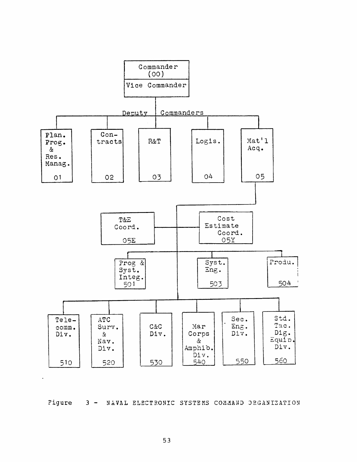
Commander
(00)
Vice
Commander
DeDutv Commanders
I t f I
Plan.
Con-
Prog.
tracts
R&T
Logis.
Mat'l
& Acq.
Res.
Manag.
01
02
03 04
05
T&E
Cost
Coord.
Estimate
Coord.
05E 05Y
I I I
I
?rog
&
Syst.
Prod.u.
Syst.
Eng.
Integ.
501 503 504
{ I t t
Tele-
ATe
Sec.
Std.
comm.
Surv.
C&C
YIar
Eng.
Tac.
Div.
&
Div.
Corps
Div.
Dig.
Nav.
&
~q1:lip.
Div.
Amphib.
Div.
Div.
510 520 530
C;40
550 560
Figure
3 -
N~VAL
ELECTRONIC
SYSTEMS
COM~AND
JRGANIZATION
53
The
previous
chapters
have
been
historical
in
nature,
relating
the
events
which
~arked
the
development
and
initial
production
run
of
the
standard
minicomputer.
It
is
the
purpose
of
this
chapter
to
evaluate
the
system
itself
and
the
impact
of
UYK-20's
growing
pains
on
the
development
of
those
systems
which
used
it
as
a
system
component.
A.
COMPARISON
OF
SPECIFICATION
AND
FINAL
PRODUCT
Chapter
II,
section
C
and
Appendix
B
d~scussed
the
specification
upon
which
the
AN/UYK-20
DPS
acquisition
was
based.
To
complete
the
historical
picture
presented
in
previous
chapters,
it
is
necessary
to
briefly
discuss
the
actual
product
which
resulted
from
the
standard
minicomputer
acquisition.
For
ease
of
comparison,
App.
H
summarizes
the
characteristics
of
UYK-20
as
it
existed
at
mid-year
1976.
Appendix
B
summarizes
the
DRG's
specification.
Appendix
I
lists
the
basic
hardware
configuration
and
options
available.
Appendix
G
describes
the
system
support
software.
References
16
and
17
provide
further
d=tails.
By
comparing
Apps.
Band
H
it
can
be
seen
that
the
OYK-20
system
met
or
exceeded
the
specification
in
all
major
areas
except
reliability
and
maintainability.
As
discussed
in
the
previcus
chapter,
MTBF
to
2000
hours
has
never
been
demonstrated.
No
empirical
data
on
MTTR
was
available.
It
must
be
remember9d
that
MTTR
included
localization
of
the
problem,
checkout.
correction,
alignment
and
calibration,
and
system
It
could
be
p~stulated
that
meeting
an
MTTR
of
15
minutes
presumed
that
the
diagnostic
programs
were
ready
to
load
(via
magnetic
tape
or
paper
tape),
that
the
technician
54
was
familiar
with
the
diagnostic
procedures
published
in
the
Technical
Manual,
and
that
a
complete
spares
kit
was
available.
If
the
trouble
was
isolated
to
a
module
which
was
missing
from
the
spares
kit,
the
MTTR
would
necessarily
include
time
to
procure
the
part.
The
UYK-20
represented
improvement
over
the
specification
in
the
areas
of
speed,
number
of
general
registers,
inst"ruction
repertoir,
weight
and
power
consumption.
Weaknesses
were
in
the
memory
addressing
scheme
and
interrupt
structure.
Some
weaknesses
in
the
I/O
structure
were
discussed.
in
Chapt.
II.
In
addition,
the
central
Processor
(CP)
and
the
liD
Controller
(IO:)
ended
up
sharing
the
same
memory
port,
with
the
IOC
having
priority
over
the
CP.
An
optional
Direct
Memory
Access
(OMA)
channel
was
provided,
which
accessed
memory
through
a
second
memory
port.
This
minimized
interference
between
the
CP/IOC
and
the
OM!
device,
but
the
~ddition
of
the
OMA
capability
added
about
65
nanoseconds
to
the
memory
cycle
time.
An
additional
drawback
was
that
the
CP
/IOC
had
priority
over
the
OMA
in
accessing
any
particular
memory
bank.
Since
many
accesses
are
sequential,
.
the
CP
could
lock-out
the
DMA
device
from
memory.
Although
it
was
not
mentioned
in
the
documentation,
a
jumper
connection
on
a
pc
card
could
be
modified
to
give
the
CP/IOC
and
OMA
memory
ports
equal
priority.
There
was
no
provision
to
expand
main
memory
beyond
65K-words.
Although
multi-level
indirect
addressing
was
possible,
the
procedure
for
implementation
was
awkward
and
involved
setting
indirect
control
bits
in
a
status
register
and
storing
information
in
an
Indirect
Word.
Sixty-four
page
registers
existed
so
that
m~in
memory
CQuld
be
divided
into
64
blocks
of
1,024
words
each.
No
memory
protection
existed,
however,
~hich
was
necessary
to
prevent
inadvertant
access
to
pages
in
memory
by
unauthorized
programs.
!lso
missing
was
a
provision
for
a
55
privileged
state
(i.e.
a
se~
of
pri7ileged
instructions
which
could
be
reserved
for
use
by a
designated
ezecuti7e
program.
The
lack
of
those
latter
tvo
capa=ilities
prevented
the
efficient
i~ple~entation
of
program
s-apping
algorithms
for
multi-progra~ming
applications.
T~e
usefulness
of
the
page
registers
was
thus
limited.
The
interrupt
structure
weakness
primarily
in701ve1
t~e
inability
to
nest
interrupts.
If
an
interrupt
from
one
class
was
interrupted
by
an
interrupt
from
anothe=
hig~er
priority
class
(there
vere
three
classes),
the
lo-e=
priority
interrupt
would
be
saved
while
the
~igher
p=iority
interrupt
was
processed.
Eowever,
only
one
s~o=age
ar~a
fo=
saving
status
registers,
prograo
registers
ani
~eal-ti~e
clock
existed
per
interrup~
class.
If
an
i~ter=u?t
pre-empted
another
interrupt
of
~he
same
class,
tne
sa~e
storage
area
would
be
~eused
and
the
?rev~ous
?rogra~
s~a~~s
would
be
lost
forev~r.
The
instruction
reper~oir
-as
ex~ensi7e,
reflectin;
~~e
capabilities
of
microprogra~me1
cont=ol.
Ins~~~=~ic~s
.e~e
incorporated
fro~
the
AN/UYK-15(V)
i~st~uction
se~
~o
ma~~
the
UYK-20
upward
com~atible
with
t~at
~achine.
!1~~o~0t
not
required
by
the
specification,
si;ni£ica~t
caFability
for
floating-point,
~athe~atical
and
t~igo~o~etri~
f~nCtio~s
existed
in
an
optior.al
~o1ule
of
mic=oFrog~a~
rQ~ti~es
designated
the
~ATH?AC.
Also
available
as
an
oF~i~~
-as
512
words
of
user
specified
mic=oprogram
=o~ti~es,
~es~;~a~9d
the
Microgrowth.
By
1976
there
vas
available
an
ex~ensi7e
set
J:
5~??O=~
software
[App.
G],
but
it
~ust
be
remembered
t~a~
~he
fi=s~
systems
only
had
an
assembler
software
was
developed
over
~3e
e~suing
rest
Significant
also
~as
the
fact
~hat
M~3?
was
mach
verse
in
the
early
~onths
than
the
1500
hou=s
de~ons~=a~ed
i~
1;76.
This
section
has
briefly
com?arei
~he
!5/1!l-2G
:?S
~~~~
tbe
DRG's
s?ecifica~ioc.
!~
general
=o=~
ca?ajili~!
eX~5te~
in
the
final
prod~ct
~ha~
was
originally
req~es~ec,
.~~~
56
some
important
exceptions.
Ensuing
discussions
will
compare
the
UYK-20
with
the
"off-the-shelf"
state-of-the-art
in
minicomputer
design
in
late-1972/early-1973.
The
discussions
will
provide
further
insight
into
the
true
capabilities
of
the
AN/UYK-20
DPS.
B.
COMPARISON
OF
AN/UYK-20
DPS
WITH
THE
1972
"OFF-THE-SHELF"
MINICOiiPUTER STATE-OF-THE-ART
It
has
been
stated
previously
that
the
standard
minicomputer
specification
may
have
been
too
restrictive.
If
given
the
funding
constraints,
the
acquisition
strategy
had
embodied
design-to-cost
concepts,
for
example,
so
that
the
proposals
could
work
toward
the
best
system
for
the
money
guided
by
a
performance
specification,
the
final
product
may
have
looked
much
different.
It
would
be
difficult
to
postulate
the
cost
of
militarizing
any
particular
commercially
marketed
computer
system.
It
is
beyond
the
scope
of
this
thesis
to
predict
what
the
proposals
would
have
been,
given
the
development
funds
and
production
prices
eventually
realized.
This
se~tion
will,
however,
discuss
the
technical
possibilities
available
in
late-1972
and
early-1973.
The
intent
is
to
consider
that
state-of-art
which
was
through
development
and
into
production
about
the
time
of
the
standard
minicomputer
Request
for
proposals
(RFP).
The
assumption
is,
as
previously
stated,
that
the
Navy
wanted
to
minimize
time
and
development
effort
and
so
would
look
for
a
system
which
was
ready
for
market.
The
discussions
will
also
provide
a
further
means
of
evaluating
the
AN/UYK-20
DPS.
For
information,
four
minicomputers
representing
the
1972
technology
are
profiled
in
Apps.
J
through
M.
Certainly
the
microprogrammed
processor
was
the
most
57
common
architecture
in
1972
minicomputers.
examples,
only
the
Digital
Equipment
Corporation
Of
the
four
PDP-11/45
was
not
microprogrammed.
Microprogramming-
permitted
a
reasonably
powerful
instruction
repertoir
while
minimizing
size
and
electrical
power
consumption.
Basically
two
types
of
microprogramming
were
used.
Horizontal
microprogramming
utilized
a
long
micro-instruction
word
where
each
bit
controlled
a
specific
register-transfer
function.
The
Varian
73
with
a
64-bit
micro-instruction
word
was
a
good
example
of
that
design
concept.
The
Rolm
1602
with
a
32-bit
micro-instruction
word
was
a
border
line
case.
Vertical
microprogramming
utilized
shorter
micro-instruction
words
which
required
some
hardware
decoding
in
the
control
process.
The
Hewlett
Packard
2100A
with
a
24-bit
micro-instruction
word
and
the
UYK-20
with
a
16-bit
microinstruction
word
are
examples
of
vertical
microprogramming.
The
tradeoff
between
the
two
types
was
more
.high-speed
memory
and
simpler
hardware
logic
for
'\
horizontal
versus
less
memory
but
more
complex
logic
in
the
case
of
vertical.
A
convenient
capability
in'
a
microprogrammed
processor
resulted
from
the
use
of
writable
Control
store
(WCS)
memory
in
place
of
Read-Only-Memory
(ROM).
WCS
memory
allowed
the
user
to
alter
the
microprograms
or
add
his
own
routines
with
the
same
ease
encountered
in
storing
programs
in
Random
Access
Memory
(RAM).
By
contrast,
many
ROM
designs
involved
methods
of
program
storage
which
were
unalterable.
Some
minicomputers
allowed
a
mixture
of
ROM
and
WCS
in
the
control
memory.
This
feature
was
totally
lacking
in
UYK-20,
even
in
the
User
Microgrowth
section,
which
had
to
be
factory
produced.
To
circumvent
this
problem,
FCDSSA
San
Diego
developed
a
device
called
GENRAM
which
plugged
into
the
User
Microgrowth
module
slot
of
the
UYK-20.
This
device,
along
with
a
microcode
assembler,
facilitated
development
and
test
of
microprogram
routines
for
the
UYK-20.
By
contrast,
the
DEC
PDP-l1/45
achieved
a
powerful
58
instruction
set
through
hardware
implemented
logic.
To
do
SO
DEC
sacrificed
size
:lnd
power
consumption.
By
using
high-speed
bipolar
logic
and
Large-Seale-Integration,
DEC
achieved
much
faster
instruction
execution
speeds
than
possible
with
a
microprogrammed
architecture.
For
example,
an
Add
instructi~n
required
only
0.3
usee
contrasted
with
0.75
usee
for
the
same
operation
in
UYK-20
or
1.96
usee
in
HP2100A.
Another
architecture
feature
available
on
minicomputers
in
1972
was
register
"push-pop"
stacks.
Th~
PDP-11/45
had
an
extensive
stack
manipulation
capability,
but
it
was
also
available
in
a
more
limited
way
on
smaller
machines
like
the
Rolm
1502.
A
"push-pop"
stack
was
a
group
of
registers
configured
so
that
if
a
value
was
stored
in
the
top
registe~,
all
previously
stored
values
were
automatically
"pushed"
down
to
the
register
"below".
If
the
stack
was
referenced
by
an
instruction,
the
"top"
value
"popped"
off
and
all
values
previously
stored
moved
"up".
Actually
the
stack
was
implemented
through
the
use
of
a
stack
pointer
register
which
always
pointed
to
the
"top"
register
on
the
stack.
rhis
was
a
last-in-first-out
sort
of
operation.
stacks
were
useful
for
storing
data
that
would
be
used
in
a
preset
order,
such
as
nesting
interrupts
where
the
last
machine
state
(values
of
the
program
counter,
status
registers
and
other
important
data)
were
"pushed"
onto
the
stack,
to
be
"popped"
off
when
the
last
interrupt
finished
processing.
The
UYK-20
had
no
stack
cap~bility.
Another
architecture
attribute
was
useful
particularly
where
programs
had
to
be
swapped
on
and
off
a
mass
storage
device
as
in
a
multi-programming
environment.
That
attribute
was
a
Privileged
State.
Basically,
a
set
of
instructions
was
provided
which
could
only
be
executed
while
in
that
special
state.
Instructions
which
stopped
program
execution,
altered
memory
assignments
of
programs,
altered
memory
protection,
etc.
would
be
part
of
a
privileged
instruction
set.
Combined
with
features
like
memory
protect
59
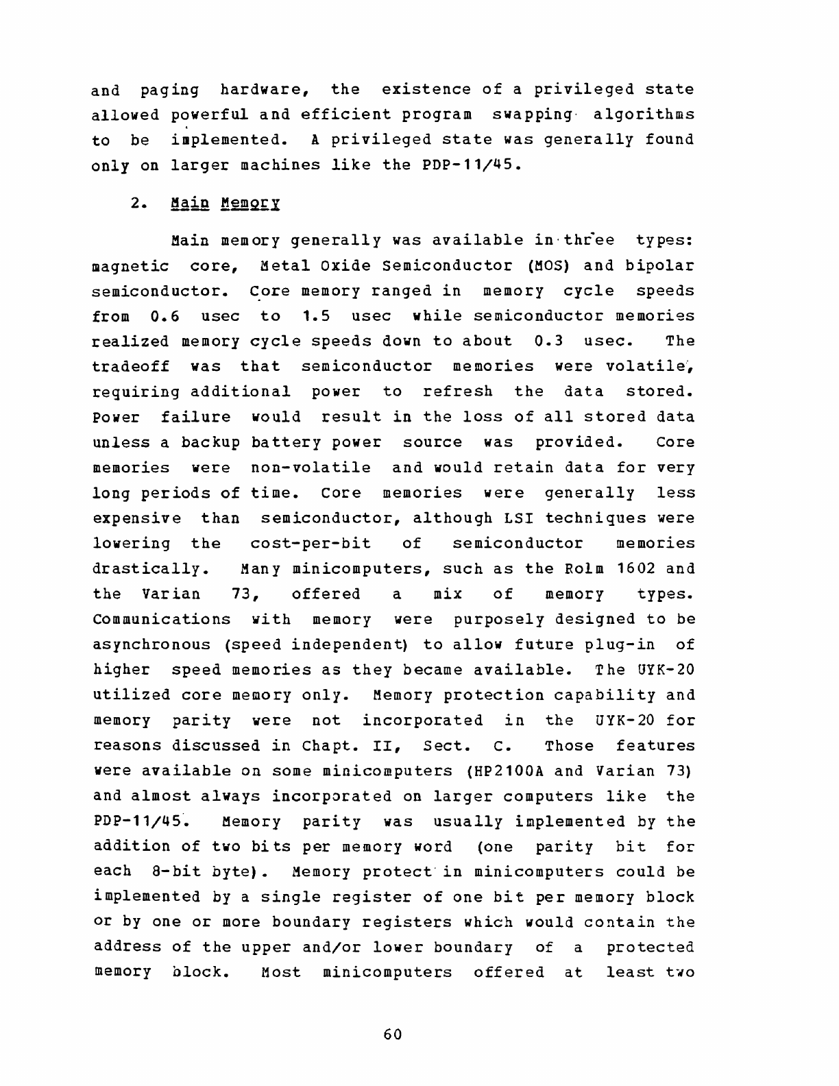
and
paging
hardware,
the
existence
of
a
privileged
state
allowed
powerful
and
efficient
program
swapping'
algorithms
to
be
implemented.
A
privileged
state
was
generally
found
only
on
larger
machines
like
the
PDP-l1/45.
Main
memory
generally
was
available
in'thcee
types:
magnetic
core,
Metal
Oxide
Semiconductor
(MOS)
and
bipolar
semiconductor.
~ore
memory
ranged
in
memory
cycle
speeds
from
0.6
usec
to
1.5
usec
while
semiconductor
memories
realized
memory
cycle
speeds
down
to
about
0.3
usec.
The
tradeoff
was
that
semiconductor
memories
were
volatile~
requiring
additional
power
to
refresh
the
data
stored.
Power
failure
would
result
in
the
loss
of
all
stored
data
unless
a
backup
battery
power
source
was
provided.
Core
memories
were
non-volatile
and
would
retain
data
for
very
long
periods
of
time.
Core
memories
were
generally
less
expensive
than
semiconductor,
although
LSI
techniques
were
lowering
the
cost-per-bit
of
semiconductor
memories
drastically.
Many
minicomputers,
such
as
the
Rolm
1602
and
the
Varian
73,
offered
a
mix
of
memory
types.
Communications
with
memory
were
purposely
designed
to
be
asynchronous
(speed
independent)
to
allow
future
plug-in
of
higher
speed
memories
as
they
became
available.
The
UYK-20
utilized
core
memory
only.
Memory
protection
capability
and
memory
parity
were
not
incorporated
in
the
UYK-20
for
reasons
discussed
in
Chapt.
II,
Sect.
C.
Those
features
were
available
on
some
minicomputers
(HP2100A
and
Varian
73)
and
almost
always
incorporated
on
larger
computers
like
the
PDP-l1/45~
Memory
parity
was
usually
implemented
by
the
addition
of
two
bits
per
memory
word
(one
parity
bit
for
each
a-bit
byte).
Memory
protect'in
minicomputers
could
be
implemented
by
a
single
register
of
one
bit
per
memory
block
or
by
one
or
more
boundary
registers
which
would
contain
the
address
of
the
upper
and/or
lower
boundary
of
a
protected
memory
alock.
Most
minicomputers
offered
at
least
t.o
60
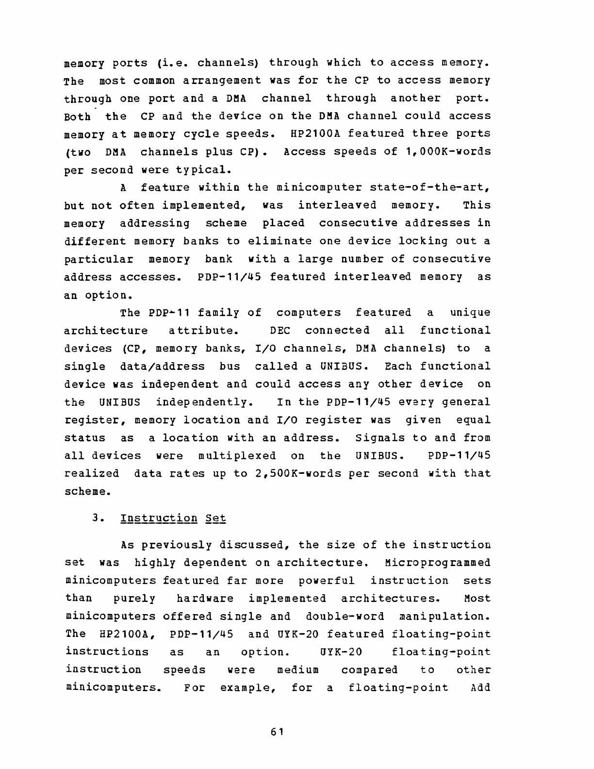
memory
ports
(i.e.
channels)
through
which
to
access
memory.
The
most
common
arrangement
was
for
the
CP
to
access
memory
through
one
port
and
a
DMA
channel
through
another
port.
Both
the
CP
and
the
device
on
the
OMA
channel
could
access
memory
at
memory
cycle
speeds.
HP2100A
featured
three
ports
(two
DMA
channels
plus
CP).
Access
speeds
of
1,OOOK-words
per
second
were
typical.
A
feature
within
the
minicomputer
state-of-the-art,
but
not
often
implemented,
was
interleaved
memory.
This
memory
addressing
scheme
placed
consecutive
addresses
in
different
memory
banks
to
eliminate
one
device
locking
out
a
particular
memory
bank
with
a
large
number
of
consecutive
address
accesses.
PDP-l1/45
featured
interleaved
memory
as
an
option.
The
PDP-ll
family
of
computers
featured
a
unique
architecture
attribute.
DEC
connected
all
functional
devices
(CP,
memory
banks,
I/O
channels,
DM!
channels)
to
a
single
data/address
bus
called
a UNIBUS.
Each
functional
device
was
independent
and
could
access
any
other
device
on
the
UNIBUS
independently.
In
the
PDP-11/Q5
every
general
register,
memory
location
and
I/O
register
was
given
equal
status
as
a
location
with
an
address.
Signals
to
and
from
all
devices
were
multiplexed
on
the
UNIBUS.
PDP-11/45
realized
data
rates
up
to
2,SOOK-words
per
second
with
that
scheme.
As
previously
discussed,
the
size
of
the
instruction
set
was
highly
dependent
on
architecture.
Microprogrammed
minicomputers
featured
far
more
powerful
instruction
sets
than
purely
hardware
implemented
architectures.
Most
minicomputers
offered
single
and
double-word
manipulation.
The
HP2100A,
PDP-11/45
and
UYK-20
featured
floating-point
instructions
as
an
option.
UYK-20
floating-point
instruction
speeds
were
medium
compared
to
other
minicomputers.
For
example,
for
a
floating-point
Add
61
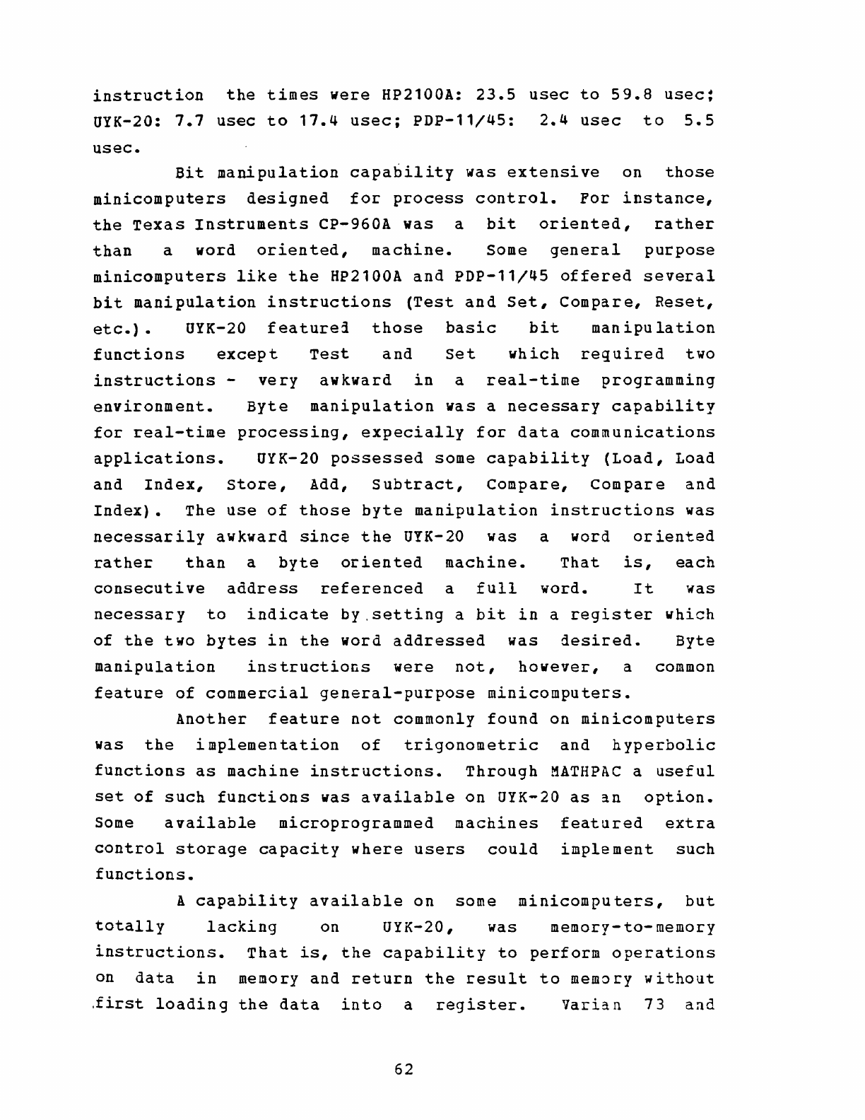
instruction
the
times
were
HP2100A:
23.5
usee
to
59.8
usec:
UYK-20:
7.7
usec
to
17.4
usec;
PDP-11/45:
2.4
usec
to
5.5
usec.
Bit
manipulation
capability
was
extensive
on
those
minicomputers
designed
for
process
control.
For
instance,
the
Texas
Instruments
CP-960A
was
a
bit
oriented,
rather
than
a
word
oriented,
machine.
Some
general
purpose
minicomputers
like
the
HP2100A
and
PDP-11/45
offered
several
bit
manipulation
instructions
(Test
and
Set,
Compare,
Reset,
etc.)
• UYK-20
featurea
those
basic
bit
manipulation
functions
except
Test
and
set
which
required
two
instructions
environment.
very
awkward
in
a
real-time
programming
Byte
manipulation
was
a
necessary
capability
for
real-time
processing,
expecially
for
data
communications
applications.
UYK-20
possessed
some
capability
(Load,
Load
and
Index,
store,
Add,
Subtract,
Compare,
Compare
and
Index).
The
use
of
those
byte
manipulation
instructions
was
necessarily
awkward
since
the
UYK-20
was
a
word
oriented
rather
than
a
byte
oriented
machine.
That
is,
each
consecutive
address
referenced
a
full
word.
It
was
necessary
to
indicate
by.setting
a
bit
in
a
register
which
of
the
two
bytes
in
the
word
addressed
was
desired.
Byte
manipulation
instructions
were
not,
however,
a common
feature
of
commercial
general-purpose
minicomputers.
Another
feature
not
commonly
found
on
minicomputers
was
the
implementation
of
trigonometric
and
hyperbolic
functions
as
machine
instructions.
Through
MATHPAC
a
useful
set
of
such
functions
was
available
on
UYK-20
as
~n
option.
Some
available
microprogrammed
machines
featured
extra
control
storage
capacity
where
users
could
implement
such
functions.
A
capability
available
on
some
minicomputers,
but
totally
lacking
on
UYK-20,
was
memory-to-memory
instructions.
That
is,
the
capability
to
perform
operations
on
data
in
memory
and
return
the
result
to
memory
without
.first
loading
the
data
into
a
register.
Varian
73
and
62
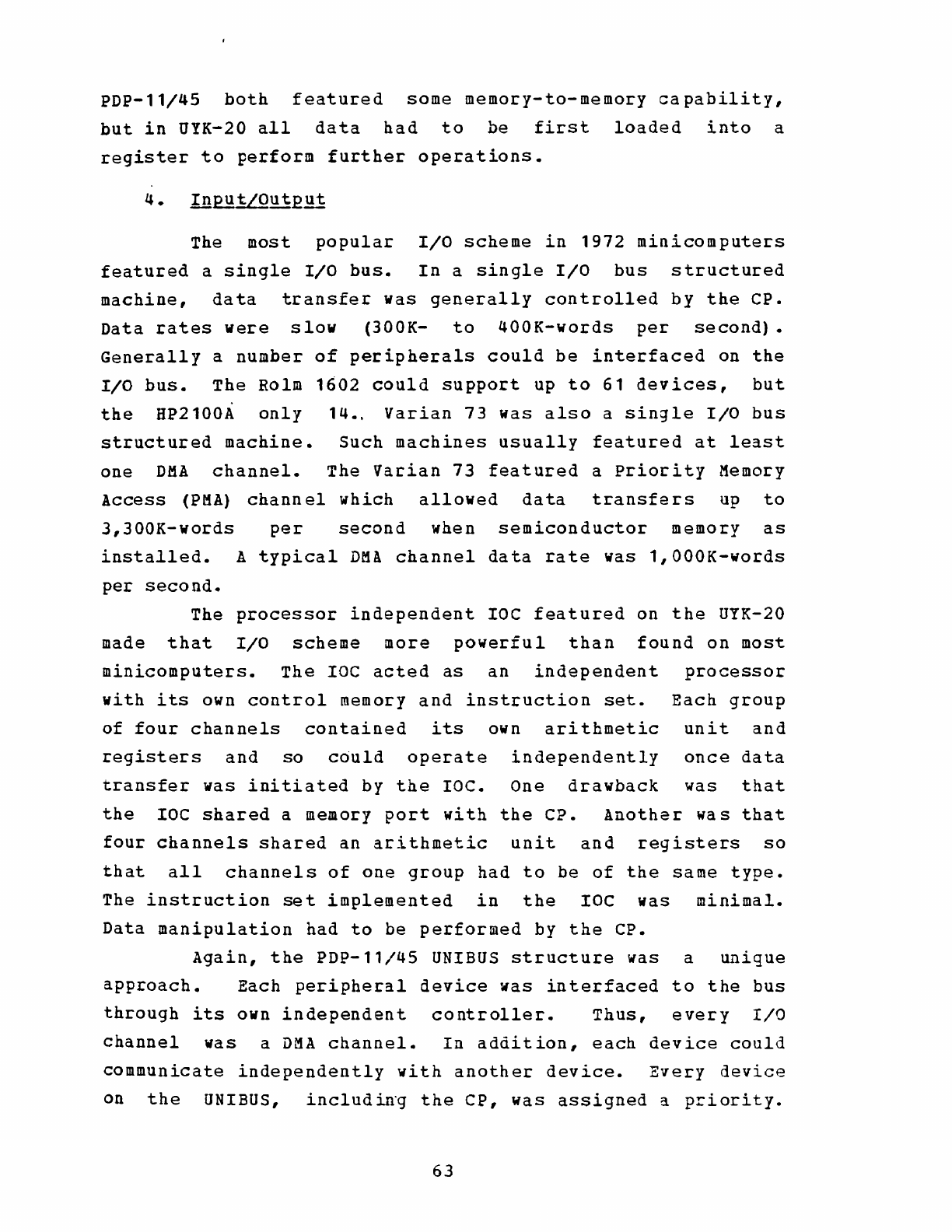
PDP-11/45
both
featured
some
memory-to-memory
capability,
but
in
UYK-20
all
data
had
to
be
first
loaded
into
a
register
to
perform
further
operations.
The
most
popular
I/O
scheme
in
1972
minicomputers
featured
a
single
I/O
bus.
In
a
single
I/O
bus
structured
machine,
data
transfer
was
generally
controlled
by
the
CP.
Data
rates
were
slow
(300K-
to
400K-words
per
second).
Generally
a
number
of
peripherals
could
be
interfaced
on
the
I/O
bus.
The
Rolm
1602
could
support
up
to
61
devices,
but
the
HP2100A
only
14.,
Varian
73
was
also
a
single
I/O
bus
structured
machine.
Such
machines
usually
featured
at
least
one
DM!
channel.
The
Varian
73
featured
a
priority
Memory
Access
(PM!)
channel
which
allowed
data
transfers
up
to
3,300K-words
per
second
when
semiconductor
memory
as
installed.
A
typical
DMA
channel
data
rate
was
l,OOOK-words
per
second.
The
processor
independent
IOC
featured
on
the
UYK-20
made
that
I/O
scheme
more
powerful
than
found
on
most
minicomputers.
The
IOC
acted
as
an
independent
processor
with
its
own
control
memory
and
instruction
set.
Each
group
of
four
channels
contained
its
own
arithmetic
unit
and
registers
and
so
could
operate
independently
once
data
transfer
was
initiated
by
the
roc.
One
drawback
was
that
the
IOC
shared
a memory
port
with
the
CP.
Another
was
that
four
channels
shared
an
arithmetic
unit
and
registers
so
that
all
channels
of
one
group
had
to
be
of
the
same
type.
The
instruction
set
implemented
in
the
IOC
was
minimal.
Data
manipulation
had
to
be
performed
by
the
CP.
Again,
the
PDP-11/45
UNIBUS
structure
was a
unique
approach.
Each
peripheral
device
was
interfaced
to
the
bus
through
its
own
independent
controller.
Thus,
every
I/O
channel
was
a
DMA
channel.
In
addition,
each
device
could
communicate
independently
with
another
device.
Every
device
on
the
UNIBUS,
includin'g
the
CP,
was
assigned
3.
priority.
63
Communications
were
handled
according
to
priority
by
a
UNIBUS
Priority
Arbitration
unit.
By
that
system,
liD
transfers
were
handled
indentically
to
memory
accesses.
Thus,
every
instruction
implemented
on
the
PDP-11/45
could
be
used
in
an
I/O
program
to
manipulate
data.
Some
1972
minicomputers
featured
a
priority
interrupt
structure.
As
previously
discussed,
minicomputers
with
stack
architecture
generally
featured
multi-level
interrupt
nesting
capability.
On
other
machines
nesting
was
accomplished
by
providin;
storage
area
for
machine
status
for
each
interrupt
line.
Two
methods
of
handling
interrupts
were
common.
The
first
involved
branching
to
a
specific
memory word
assigned
to
the
interrupt,
~hich
contained
the
address
of
the
interrupt
service
routine.
The
second
allowed
a
direct
branch
to
the
interrupt
service
routine.
The
latter
method
was
faster,
but
required
more
hardware
logic.
UYK-20
implemented
the
former
scheme.
On
UYK-20,
as
previously
discussed,
only
three
storage
areas
were
provided
to
store
machine
status
(one
per
interrupt
class)
so
that
nesting
capability
was
severely
limited.
The
term
"modular
construction"
had
different
connotations
with
different
manufacturers.
The
most
common
scheme
featured
a
simple
backpanel
which
provided
only
power
lines,
data
and
address
buses,
etc.,
which
were
common
to
all
printed
circuit
(PC)
card
modules.
All
PC
cards
were
the
same
size
and
could
be
plugged
into
any
slot.
Circuits
on
a
particular
PC
card
related
to
functional
~a~agories,
there
being
one
PC
card
for
the
CP,
one
for
memory
control
circuits,
one
for
each
memory
bank,
and
one
for
each
IIO
device
interface.
HP2100A,
Rolm
1602
and
Varian
73
we~e
configured
in
that
manner.
The
PDP-11/45
also
was
similarly
configured,
although
backpanel
wiring
was
more
complex
due
to
the
UNIBUS
structure.
PC
cards
were
generally
large
and
were
structuraliy
reinforced
for
strength.
UYK-20
featured
an
entirely
different
approach.
PC
card
modules
were
utilized,
but
cards
were
small
and
were
hardware
type
oriented
rather
than
functionally
oriented
•
.
For
instance,
control
memory
and
associated
circuitry
accupied
four
PC
cards,
the
master
clock
occupied
another,
interrupt
storage
anothe~,
and
each
general
register
set
(two
sets
of
16
registers
each)
occupied
a
card.
The
UYK-20
scheme
facilitated
the
installation
of
plug-in
options
that
were
available
[App.
I],
but
created
a
complicated
wiring
situation
on
the
backpanel
and
greatly
increased
the
number
of
different
types
of
PC
cards
utilized.
The
maintenance
plan
where
a
majority
of
the
PC
cards
were
"throw-away"
modules
(i.e.
those
cards
could
be
discarded
wheL
found
to
be
defective)
also
depended
on
that
scheme.
Naturally,
a
PC
card
containing
an
entire
processor
would
be
too
expensive
to
discard.
The
repairable
PC
cards
in
the
UYK-20
were
those
few
that
were
large
and
functionally
oriented
-Memory
Array
Boards,
Memory
Control
Boards
and
I/O
Interface
cards.
Those
generally
were
inadequately
reinforced,
tended
to
bend,
and
were
extremely
difficult
to
remove
and
install.
Interestingly,
the
Rolm
1602
featured
large
functionally
oriented
cards
and
met
all
military
specification
requirements
including
shock
and
vibration
testing.
That
computer
was
s~rvice
app~oved
and
designated
AN/UYK-19
(V)
•
A
significant
achievement
by Rolm
in
the
1602
design
was
a
demonstrated
MTBF
of
-11,000
hours.
Since
the
UYK-20
experienced
significant
reliability
problems,
it
would
be
informative
to
investigate
the
differences
in
those
two
computers.
It
is
beyond
the
scope
of
this
thesis
to
present
a
detailed
analysis
of
the
impact
of
the
design
and
construction
of
the
two
machines
on
their
demonstrated
reliability.
Some
major
points
can
be
made,
however.
The
logic
design
itself
was
a
contributor
to
UYK-20's
65
r~liability
problems.
For
example,
the
TAAP
program
conducted
at
Naval
Weapons
Center
Dahlgren
revealed
that
the
master
clock
and
certain
logic
gates
in
the
UYK-20
were
overloaded.
A
user
reported
that
the
MIL-STD-188C
'asynchronous,
serial
I/O
interface
card
was
defective
in
that
the
channel
would
interrupt
on
both
leading
and
trailing
edges
of
an
interrupt
signal
pulse.
rhose
were
basic
logi~
design
problems
and
would
directly
contribute
to
module
failures.
Construction
and
reinforcement
of
larger
PC
cards
was
inadequate
in
UYK-20.
With
frequent
handling
such
cards
suffered
broken
components,
jumper
wires,
printed
circuit
runs
and
connection
pins.
All
such
occurrences
created
circuit
failures
which
lowered
MTBF.
In
a
complex
backpanel
wiring
situation,
lack
of
adequate
quality
assurance
measures
could
allow
wiring
errors
to
pass
unnoticed.
such
errors
could
appear
as
circuit
failures
under
troubleshooting
procedures
utilizing
diagnostic
software.
Over
the
three
years
after
contract
award,
UNIVAC
had
corrected
many
of
those
sorts
of
problems.
Yet
the
MTBF
had
risen
to
only
1500
hours.
The
reason
for
that
may
lie
in
the
selection
and
integration
of
components.
rhe
ability
for
a
manufacturer
to
control
the
quality
of
components
used
in
producing
computers
would
directly
impact
on
reliability.
In
producing
the
1602,
Rolm
corporation
had
that
control.
Most
components
in
UYK-20
were
procured
under
military
specifications
(with
the
exception
of
integrated
circuits).
such
components
must
be
procured
from
a
Qualified
Parts
List
(QPL)
vendor
under
military
specification
control.
In
that
situation
UNIVAC
had
no
control
over
component
quality.
Hardware
engineers
interviewed
generally
agreed
that
many
components
procured
under
military
specifications
probably
exhibited
MTBF's
in
the
hundreds
of
hours.
It
is
beyond
the
scope
of
this
thesis
to
present
a
detailed
analysis
of
the
available
minicomputer
support
66
software
in
1972.
availability,
however.
Some
comments
can
As
indicated
in
Apps.
be
made
about
J
through
M,
commercial
minicomputers
generally
featured
a
complete
set
of
software.
In
most
cases
a
minicomputer
was
upward
compatible
with
earlier
models,
so
that
each
inherited
a
package
of
well
tested
and
fully
documented
support
software.
New
soft~are
modules
could
be
added
at
leisure
to
take
advantage
of
the
added
capabilities
of
the
more
advanced
machine.
Host
software
engineers
interviewed
agreed
that
adequate
operational
testing
was
difficult
to
achiev~.
Complete
debug
of
a
software
module
depended
on
extensive
use
in
the
field.
Naturally,
any
software
package
inherited
from
a
market-tested
computer
had
that
advantage.
The
/UYK-20
computer
did
not
have
that
advantage.
Although
upward
compatible
with
the
AN/UYK-15(V)
[App.
D],
that
machine
did
not
possess
a
complete
package
of
support
software
and
had
not
had
extensive
use.
Support
software
for
UYK-20 was
developed
during
the
three
years
following
contract
award.
As
of
mid-1976
the
CMS-2M
compiler
and
SDEX-20
real-time
executive
were
still
in
the
"user
debug"
stage.
All
software
was
still
receiving
enhancements
to
upgrade
capability
as
funds
became
available.
The
foregoing
material
in
this
thesis
has
discussed
the
events
which
occurred
in
the
AN/UYK-20
DPS
acquisition
history
and
the
technical
advantages
and
drawbacks
of
the
system.
The
final
section
in
this
chapter
will
discuss
the
impact
of
those
events,
advantages
and
disadvantages
on
the
users
and
their
tactical
system
development
efforts.
c.
IMPACT
OF
AN/UYK-20
DPS
ON
DEVELOPMENT
OF
USER
SYSTEMS
The
events
of
the
three
years
after
contract
award,
which
have
been
referred
to
a
"growing
pains",
had
a
significant
impact
on
the
efforts
of
users
to
develop
67
tactical
systems
utilizing
UYK-20
as
a
system
component.
This
section
will
discuss
the
various
ways
which
that
system
component
aided
or
complicated
those
development
efforts
during
the
period
mid-1973
to
mid-1976.
The
implications
of
establishing
a
"standard"
system
component
were
discussed
in
Chapt.
II,
Sect.
B.
For
those
programs
well
into
development
with
another
minicomputer
and
lor
programming
language,
the
impact
on
~cquisition
cost
and
schedule
to
switch
to
UYK-20
was
significant.
One
project
reported
a
two
year
schedule
slip
and
software
costs
of
$350,000
to
$400,000
to
reprogram
for
the
UYK-20.
Since
that
system
involved
primarily
data-handling,
only
limited
processing
power
and
core
memory
capacity
were
needed.
A
lower
cost
processor
with
4K-words
of
memory
and
unit
cost
of
$15,000
was
replaced
by
a
minimum
configuration
UYK-20
with
8K-words
of
memory
and
unit
cost
of
$24,OQO.
Another
project
reported
a
four
to
five
month
slip
and
$400,000
to
$500,000
cost
to
reprogram
with
eMS-2M,
the
standard
high-level
language.
The
trade-off
for
those
projects
was
to
lower
life-cycle
costs
through
savings
in
I1S
costs,
training
costs,
etc.
as
previously
discussed.
Unfortunately,
the
immediate
concern
was
always
initial
acquisition
cost,
schedule,
and
performance.
While
life-cycle
cost
was
given
lip-service,
a
project's
success
was
ultimately
measured
by
success
in
those
three
areas.
Thus,
imposition
of
the
standard
on
a
system
well
into
development
impacted
directly
on
the
measure
of
the
project's
success.
Because
of
the
necessity
to
identify
firm
requirements
for
UYK-20
production
units,
and
to
obtain
O&MN
funds
through
the
surcharge
scheme,
NAVELEX
was
forced
to
require
those
projects
to
switch
to
UYK-20.
The
technical
drawback
of
adopting
a
standard
was
that
the
UYK-20
might
not
be
specifically
suited
for
a
68
particular
applica
tion.
An
example
might
be
an
engine
monitoring
and
control
system
where
a
powerful
bit
manipulation
capability
was
needed.
That
project
would
be
required
to
use
UYK-20
regardJ..ess
of
the
minimal
bit
manipulation
capability.
Interestingly,
no
project
personnel
found
the
UYK-20
totally
unsuited
for
their
application.
It
has
been
reported
that
as
of
mid-1976
over
100
projects
were
utilizing
UYK-20.
Tasks
included
the
following
diverse
sorts
of
requirements:
*
Message
Processing
Systems
•
Low
memory
capacity
(8K-
to
16K-words)
•
Low
computing
power
•
High
I/O
capacity
(12
to
16
channels)
•
High
data
rates
*
Navigational
Systems
• Medium memory
capacity
(16K-
to
32K-words)
•
32-bit
(double
word)
I/O
transfer
•
32-bit
data
manipulation
•
Floating-point
trigonometric
and
hyperbolic
functions
•
High
accuracy
(up
to
24-bits
per
data
word
preferred)
• Low
I/O
capacity
(4
to
8
channels)
*
Signal
Analysis
Systems
•
Large
storage
capacity
(65K-words
of
memory
plus
high-speed
mass
storage
device
(disk)
on
D~A
channel
•
Multi-programming
capability
•
Powerful
mathematical
capability
•
High
throughput
(instruction
execution
rate)
•
High
I/O
data
rates
•
High
IIO
capacity
(8
to
16
channels)
*
Target
Tracking
and
Fire
Control
Systems
•
32K-
to
65K-words
of
storage
capacity
69
•
12
to
16
I/O
channels
•
Mass
storage
device
(disk)
on
OMA
channel
•
Floating-point
and
trigonometric
functions
•
High
throughput
(instruction
execution
rate)
•
Special
user
functions
implemented
through
Microgrowth
It
vas
a
significant
accomplishment,
and
spoke
well
for
the
DRG
specification,
that
UYK-20
was
able
to
handle
those
and
many
other
diverse
tasks.
The
conclusion
w~s
that
few
projects
were
severely
impacted
by
imposition
of
a
standard
minicomputer.
Unfortunately,
that
statement
could
not
be
made
about
UYK-20,
the
compater
that
became
the
standard.
2.
Hardware/Firmware
~~~biliti~2
Users
generally
found
the
UYK-20
architecture
powerful
enough
for
their
needs.
Local
Jumps,
Lo~d
Multiple
and
store
Multiple
instructions
not
common
on
minicomputers
were
very
useful.
The
availability
of
32
general
registers
was a
powerful
programming
aid.
IIO
structure
was
versatile
and
powerful
with
the
processor
independent
IOC.
Certain
attributes
caused
some
inconvenience,
however.
The
awkward
byte
addressing
scheme
discussed
in
the
previous
section
would
add
an
additional
instruction
to
byte
manipulation
operations
in
order
to
set
the
upper/lower
byte
indicator.
Execution
time
for
the
byte
operation
would
be
incr~ased
about
50%
and
program
storage
requirements
doubled.
One
solution
was
to
write
self-modifying
code,
to
modify
the
byte
manipulation
instructions
"on-the-fly".
This
created
programs
which
were
very
hard
to
debug.
Also,
such
code
was
non-reentrant;
i.e.
it
could
not
be
reused
without
reloading
the
original
program
from
~n
external
device,
and
it
could
not
be
shared
in
a
IDulti-programming
environment.
Lack
of
memory-to-memory
instructions
added
Load
and
70
store
instructions
to
those
operations
because
of
the
need
to
put
the
data
in
registers.
About
1.5
usec
was
added
to
the
execution
time
for
memory-to-memory
operations,
and
program
storage
requirements
were
tripled.
Lack
of
a
Test
and
set
instruction
(that
operation
required
two
instructions
in
UYK-20)
could
cause
major
problems.
If
an
interrupt
occurred
between
the
two
instructions,
which
changed
the
value
that
was
being
tested,
then
the
test
already
performed
was
invalid.
The
routine
executing
the
Test
and
Set
instructions
would
not
be
aware
of
the
change
and
would
proceed
on
the
basis
of
the
original
test
results
when
the
interrupt
finished
processing.
The
solution
was
to
lockout
interrupts
before
executing
the
Test
and
Set
instructions
and
to
restore
interrupts
after
completing
the
Test
and
set.
That
solution
added
two
to
four
instructions
and
3.3
to
4.8
usec
to
a
Test
and
set
operation.
There
were
no
absolute
compare
instructions
in
UYK-20. When
comparing
two
words,
the
most
significant
bit
would
always
be
considered
the
sign.
To
compare
a
16-bit
absolute
word
a
double-word
operation
was
needed.
Time
and
storage
requirements
were
thus
again
added
to
the
user
program.
The
sum
total
of
those
sorts
of
deficiencies
significantly
decreased
throughput
and
increased
storage
requirements.
The
solution
was
to
implement
the
missing
capabilities
in
the
User
Microgrowth
area
of
control
memory.
Such
a
development
effort
had
to
be
user
funded,
however.
As
an
example,
one
activity
received
a
quotation
of
$50,000
to
implement
four
instructions
in
Microgrowth:
*
Increment
and
Store
Memory
*
Literal
Add
to
Memory
* Add
to
Memory
*
Literal
store
to
Memory
71
In
addition,
an
extra
$1,000
was
added
to
the
price
of
each
production
unit.
Many
projects
preferred
to
suffer
the
inconvenience
rather
than
pay
the
price.
For
those
systems
with
large
storage
requirements
and
a
large
number
of
tasks
which
could
be
performed
simultaneously,
the
lack
of
proper
tools
to
implement
multi-programming
was
a
serious
drawback.
Although
page
registers
existed,
there
was
no
privileged
instructions
or
memory
protection
with
which
to
implement
sophisticated
page
swapping
algorithms.
The
alternatives
reguired
more
time
and
tied
up
valuable
storage
space,
both
expensive
commodities
in
time-critical,
real-time
applications.
The
storage
capacity
problem
could
~ave
been
relieved
in
some
cases
if
a
provision
to
exp~nd
memory
beyond
65K-words
had
existed.
Alternatives
involved
adding
additional
UYK-20's
to
the
system,
which
was
expensive
if
the
additional
processing
power
was
not
also
needed,
or
adding
a
mass
storage
device
on
the
DMA
channel,
which
would
often
not
meet
speed
requirements.
To
solve
the
dilemma
in
one
case,
a
semiconductor
memory
disk
emulator
was
conceived
which
would
interface
to
the
computer
through
the
DMA
channel.
Ability
to
utilize
semiconductor
memory
in
place
of
core
memory
would
have
alleviated
some
similar
problems
if
that
capability
had
existed.
A
capacity
problem
also
plagued
some
projects
in
the
I/O
area.
Although
the
processor
independent
IOC
provided
powerful
I/O
capabilities,
only
16
channels
were
available,
with
the
type
configuration
constraints
previously
discussed.
To
get
more
capacity
required
multiplexing
on
a
channel,
which
sloved
down
th
data
rate,
or
adding
more
UYK-20's
to
the
system.
Certain
IIO
configurations
would
have
benefited
from
complete
independence
of
the
two
sides
of
a
duplex
channel.
However,
both
sides
shared
registers
and
could
not
be
cleared
independently.
Several
users
stated
the
need
to
write
extra
routines
to
pLevent
losing
data
on
one
side
if
72
the
need
arose
to
clear
the
other
side
of
a
channel.
A
characteristic
of
serial,
synchronous
interface
channels
was
that
the
first
few
characters
transmitted
were
"garbage"
due
to
the
need
to
establish
synchronization.
This
situation
could
not
be
tolerated
on
a
radio
(RF)
data
channel
where
good
data
would
be
lost.
The
solution
was
to
alter
the
RF
Data
Channel
hardware.
A common
complaint
from
development
progr~mmers
was
the
inadequacy
of
the
Maintenance
Panel
for
software
debugging.
Lack
of
I/O
status
indicators
and
multiple-register
displays
were
cited
as
drawbacks.
The
maintenance
panel
had
too
much
capability
for
hardware
troubleshooting,
but
not
enough
for
program
debug.
A
solution
would
have
been
to
reduce
the
capability
of
the
maintenance
panel
and
provide
a
plug-in
software
debug
panel.
The
lack
of
I/O
status
indicators
was a
serious
problem
since,
with
the
laC
independent
of
the
processor,
there
was
no
way
to
determine
if
an
I/O
transfer
was
actually
taking
place
after
it
was
initiated.
Lack
of
interrupt
nesting
capability
was
a
major
concern
to
development
programmers.
Care
had
to
be
exercised
so
that
multiple
interrupts
occuring
in
one
class
would
not
store
over
the
original
machine
status,
thus
preventing
a
return
to
the
interrupted
routine.
The
solution
was
usually
to
lock-out
other
inte~~upts,
which
virtually
nullified
the
priority
interrupt
capability.
Real-time
programs
were
generally
interrupt
driven,
thus,
loss
of
priority
interrupt
capability
was
a
serious
drawback.
The
awkwardness
of
using
the
indirect
addressing
capability
caused
some
programmers
to
abandon
its
use
in
favor
of
direct
addressing
with
indexing.
The
support
software
for
the
AN/UYK-20
DPS
was
slow
in
coming.
Those
programs
in
development
in
late-1973,
73
which
were
forced
to
switch
to
UYK-20,
had
only
a
limited
capability
assembler.
As
a
result,
many
created
their
own
program
development
capability.
Doing
that
added
to
the
time
and
cost
of
a
system
since
operational
program
development
would
cease
while
programmers
wrote
monitors,
assemblers,
editors,
debug
routines,
etc.
As
an
example,
the
cost
of
developing
an
assembler
was
$5,000
to
$100,000
depending
on
its
capability.
It
was
cheaper
and
faster
to
write
your
own,
however,
than
to
wait
for
the
Level
I
and
Level
II
systems
to
be
released
and
debugged.
The
late
delivery
of
eMS-2M
(early-1975)
caused
two-fold
problems.
Many
early
operational
programs
for
UYK-20
had
to
be
written
in
assembly
language.
Since
it
took
the
same
time
fOL
a
programmer
to
code
one
line
of
assembly
language
as
to
code
one
line
of
a
high-level
language
(with
a
ratio
of
about
six
assembly
language
instructions
to
one
high-level
language
instruction),
the
cost
was
significant.
Those
projects
which
electad
to
sta~t
development
with
another
high-level
language
(usually
FORTRAN)
faced
the
prospect
of
reprogramming
in
eMS-2M when
that
compiler
became
available.
The
whole
question
of
program
development
facilities
for
a
minicomputer
is
worth
some
discussion.
It
wa5
generally
not
possible
to
configure
a
small
computer
for
efficient
program
development.
Level
II
operating
System,
which
was
self-hosted
on
the
UYK-20,
could
SUPPOLt
only
one
programmer
at
a
time.
Although
both
interactive
and
ba~ch
modes
were
provided,
compile
times
were
slow
and
debug
facilities
were
minimal.
What
was
generally
needed
was a
larger
computer
~ith
a
time-sharing
monitor
so
that
several
programmers
could
work
simultaneously.
An
ideal
system
would
feature
cross-assemblers
and
compilers
to
generate
object
code
for
the
small
computer.
Adequate
memory,
disk
storage
and
a
number
of
program
development
aids
such
as
a
text
editor,
debug
utilities,
data
conversion
routines,
etc.
would
be
a
necessity.
A
program
to
emulata
th9
s~all
74
computer
would
be
useful
operati~nal
software.
for
initial
debugging
of
A
few
activities
which
were
to
do
extensive
program
development
for
the
UYK-20
did
create
such
systems.
The
Electromagnetic
Systems
Laboratory
in
Sunnyvale
set
up
a
time-sharing
system
on
a
Hewlett
Packard
3000
computer.
The
system
featured
a
direct
link
to
a UYK-20
computer
via
a
special
intercomputer
I/J
channel.
Source
code
generated
on
the
HP3000
could
be
loaded
directly
into
the
UYK-20
for
assembly
or
compiling.
The
Autonetics
Division
of
North
American
Rockwell
set
up
a
similar
system
based
on
a
PDP-11/45
computer.
FCDSSA
San
Diego
developed
the
CMS-2Y(20)
compiler
for
use
on
an
AN/UYK-7
computer
under
the
SHARE/7
time-sharing
system
as
an
aid
to
their
software
development
and
maintenance
efforts.
Such
systems
were
understandably
costly
to
set
up.
In
addition,
the
hardware
and
as~ociated
software
to
interface
the
system
directly
to
a UYK-20
had
to
be
developed
in-house.
The
project
sponsoring
the
davelopment
had
to
provide
the
funds.
The
dilemma
facing
the
projact
manager
was
whether
it
was
more
cost
effective
to
fund
a
program
development
facility
or
to
provide
a
self-hosted
system
for
the
UYK-20
and
suffer
the
inefficiencies.
As
an
example,
the
price
of
a
self-hosted
system
with
Level
II
and
CMS-2M
would
be
about
$150,000
including
peripherals.
At
the
other
end
of
the
price
spectrum,
the
UYK-7
hosted
system
would
cost
about
$800,000.
Commercial
systems
would
be
priced
in
between
depending
on
capability.
To
provide
program
development
facilities
and
save
projects
the
cost
of
support
software
and
peripherals,
a
System
Design
Laboratory
(SDL)
was
conceived
by
the
Naval
Electronics
Laboratory
Center.
That
was
a
commercial
computer
based
time-sharing
system
with
cross-assemblers,
compilers
and
an
emulator
for
UYK-20.
The
system
could
be
accessed
via
the
ARPANET, a
commercial
network
linked
by
leased
telephone
75
nationwide
computer
lines.
Anticipated
drawbacks
of
that
scheme
were
possible
demand
beyond
the
system
capacity,
and
the
fact
that
classified
programs
could
not
be
developed
on
the
system.
In
fact,
the
major~ty
of
projects
depended
on
the
self-hosted
system.
The
non-availability
of
a
well-tested,
complete,
self-hosted
program
development
system
at
the
outset
impacted
significantly
on
both
cost
and
schedule
of
projects.
It
is
beyond
the
scope
of
this
thesis
to
present
a
detailed
analysis
of
the
impact
of
support
software
capabilities
on
program
development.
However,
certain
points
brought
out
by
development
programmers
are
worth
some
discussion.
A
dynamic
debug
capability
was
needed
under
Level
II.
As
of
mid-1916
the
development
of
this
capability
was
planned,
but
funds
were
not
available.
Dynamic
debug
capability
would
allow
programmers
to
perform
an~lysis
on
an
executing
program
without
inte~fering
with
its
execution.
CMS-2M
listings
of
source
code
and
object
code
were
not
produced
side-by-side,
making
cross-referencing
awkward
and
time
consuming.
CMS-2M
depended
on
the
trigonometric
and
hyperbolic
functions
provided
through
MATHPAC.
Accuracy
provided
was
insufficient
in
some
applications.
The
large
variety
of
useful
functions
and
routines
developed
for
a
well-used
language
like
FORTRAN
were
not
available
with
CMS-2M.
Because
that
language
anticipated
restricted
usage,
such
a
library
of
routines
would
never
be
created,
forcing
the
development
programmer
to
write
his
own
routines
when
needed.
In
recognition
of
this
problem,
the
User's
Group
Software
Directory
and
the
software
Repository
mentioned
in
Chapter
III
were
an
attempt
to
prevent
redundant
development
of
such
routines.
eMS-2M
was
not
an
optimizing
compiler.
Because
many
operational
programs
are
time-critical
and
have
large
16
storage
requirements,
it
would
have
been
useful
to
have
an
optimizing
version
of
the
eMS-2M
compiler
to
mini~ize
use
of
those
assets.
Like
any
general
purpose
real-time
executive,
SDEX-20
required
too
much
core
and
system
overhead
(time
spent
in
executing
the
executive
software)
to
be
widely
useful.
Those
applications
with
time-critical
routines
and
large
storage
requirements
were
forced
to
write
their
own
,
real-time
mcnitors.
By
writing
an
executive
in-house
it
could
be
optimized
for
the
particular
application,
thus
minimizing
storage
and
overhead.
Many
programmers
felt
that
a
general
purpose
real-time
executive
would
be
useful
if
the
source
code
were
available
to
programmers
as
a
reference
to
aid
in
writing
their
own.
The
low
usage.
of
SDEX-
20
raised
the
question
of
the
cost-effectiveness
of
supplying
that
type
of
support
software.
The
peripherals
problem
is
actually
divided
into
two
catagories:
peripherals
for
program
development,
and
peripherals
for
tactical
systems.
Up
to
mid-1976
no
standard
militar
ized
peripherals
were
available
for
purchase,
except
keyboard/printers
and
paper
tape
reader/punches
which
had
been
in
existance
for
several
years.
Those
units
were
generally
too
large
for
a
minicomputer
installation.
Even
with
the
introduction
of
the
Alphanumeric
Display
Device
(ADD)
and
the
Cartridge
Magnetic
Tape
Unit
(CMTU)
in
mid-1976,
important
peripherals
were
still
lacking,
such
as
a
magnetic
tape
unit
(reel-to-reel),
a
disk
storage
device,
and
a
graphics
display
terminal.
Projects
were
forced
to
fund
militarizaiori
of
their
own
pe~ipherals,
which
created
the
same
sort
of
proliferation
problem
encountared
with
minicomputers
in
the
early
1970·s.
During
the
early
production
period
in
late-1973,
only
UNIVAC
peripherals
could
be
interfaced
with
the
UYK-20
77
for
program
development.
Those
peripherals
were
generally
too
large
and
expensive
for
a
minicomputer
system,
so
projects
began
acquiring
their
own.
costs
of
procuring
peripheral~
included
development
of
device
software
modules
to
interface
with
the
UYK-20
operating
systems.
The
acquisition
of
peripherals
to
be
used
for
program
development
was
costly,
especially
since
those
peripherals
would
in
general
not
be
used
in
the
tactical
system
itself.
Projects
were
wise
to
retain
a UYK-20
s1stem
with
peripherals
configured
for
program
development
to
be
provided
as
Government
Furnished
Equipment
(GFE)
for
future
development
efforts.
6 •
JI.2f:g!!ll~
MaiBtai!l~iliiY
The
acute
quality
and
reliability
problems
experienced
in
the
AN/UYK-20
DPS
were
reported
in
Chapter
III.
It
was
those
problems
that
had
the
most
profound
impact
on
user
development
efforts.
The
programs
developing
in
mid-to-late-1973
were
forced
to
use
Functional
Demonstration
Models
(FDM's)
and
Advanced
Production
Engineering
Models
(APE's)
in
order
to
meet
develoFment
schedules.
That
hardware
was
essentially
not
ready
for
release.
The
numerous
deficiencies
and
failures
caused
significant
down
time.
Projects
were
forced
to
purchase
two
computers
and
cannabilize
one
to
keep
the
other
running.
Early
production
units
had
similar
problems.
Software
debugging
on
faulty
hardware
was
a
difficult
and
time-consuming
task.
One
activity
reported
expending
three
man-months
of
labor
trying
to
debug
a
program
when
the
problem
was
actually
in
the
interrupt
hardware.
Efforts
to
troubleshoot
faulty
hardware
were
hampered
by
faulty
spares
in
the
spare
parts
kits.
The
kits
were
expensive
($13,000
each)
so
that
project
man~gers
were
unwilling
to
purchase
sufficient
numbers.
Project
personnel
estimated
that
one
spares
kit
per
computer
was
necessary
to
78
ensure
parts
availability.
Memory
Array
Boards,
which
experienced
very
high
failure
rates,
were
repairable
modules
and
were
not
included
in
the
spares
kits.
Since
the
time
to
ship
the
repairable
modules
back
to
UNIVAC
for
repair
and
return
was
running
six
to
eight
weeks,
activities
were
forced
to
purchase
extra
Memory
Array
Boards
(at
$1,300
each)
to
minimize
down
time.
It
was
more
timely
and
cost
effective
for
some
activities,
like
NESEC
San
Diego,'
to
do
their
own
hardware
trouble-shooting
and
repair,
rather
than
call
in
UNIVAC
engineers.
The
diagnostic
software
and
documentation
was
not
well
suited
to
this
effort.
The
diagnostic
routines
could
isolate
circuit
board
failures,
but
not
design
problems
which
plagued
the
earlier
machines.
Activities
turned
to
logic
circuit
diagrams,
but
found
that
those
also
contained
errors.
It
was
difficult
to
maintain
accurate
up-to-date
files
of
logic
circuit
diagrams
since
no
formal
system
existed
for
procuring
them.
Early
releases
of
the
support
software
had
many
errors.
User
activities
attempting
to
debug
the
software
were
hampered
by
inadequate
and
erroneous
documentation.
Source
code
was
not
available
initially
to
aid
in
their
efforts.
After
repeated
demands
the
source
code
for
the
operating
systems
was
made
available,
but
code
for
the
compilers
was
withheld
as
a
matter
of
proprietary
information.
Most
software
engineers
interviewed
expressed
the
opinion
that
the
support
software
source
code,
including
compilers,
should
be
purchased
outright
by
the
Navy
so
that
it
could
be
made
available
to
users.
That
was
especially
true
when
the
support
software
contained
so
many
errors
and
the
documentation
was
inadequate.
In
many
cases
programmers
had
to
resort
to
the
source
code
to
determine
the
details
of
system
software
operation.
One
activity
reported
that
it
was
once
forced
to
reprogram
to
take
advant~ge
of
an
assembler
capability
which
was
not
mentioned
in
the
documentation.
A
basic
problem
with
software
documentation
79
was
that
no
detailed
discussions
of
software
philosophy
were
presented.
Adding
the
problems
in
the
software
on
top
of
problems
in
the
hardware
made
an
extremely
difficult
situation
for
programmers
attempting
to
debug
operational
software.
7.
Lack
of
~di£g.~~g
!EI!rQ£ri~!.~~
FU!lds
!Q
§.!!£.EQ!:!
1he
AN/UYK-2
C
DP§
It
is
significant
that
a
majority
of
problems
were
corrected
when
usage
was
sufficient
to
isolate
those
problems.
Given
time
the
support
software
became
available.
Given
time
the
standard
peripherals
would
be
available.
If
NAVELEX
could
have
waited
until
the
system
was
adequately
tested
before
release,
much
of
the
inconvenience
caused
to
users
would
have
been
eliminated.
The
reason
that
NAVELEX
could
not
wait
was
lack
of
funding.
It
was
necessary
to
identify
specific
requirements
for
production
units
and
to
receive
orders
for
the
system
in
order
to
get
the
surcharge
that
paid
for
project
support.
NAVELEX
was
thus
forced
to
require
the
use
of
the
system
before
it
was
ready.
An
obvious
solution
was
to
wait
until
funding
for
the
entire
acquisition
cycle
was
reasonably
assured
(another
year
at
best).
Then
wait
until
the
system
was
complete,
including
software
and
testing,
before
releasing
it
(another
two
to
three
years).
Of
course,
a
three
to
four
year
delay
would
have
brought
proliferation
of
minicomputer
types
in
the
Navy
inventory
to
an
unacceptable
level.
Some
of
that
delay
might
have
been
saved
by
purchasing
a
"market-tested"
computer
system,
then
militarizing
it.
At
least
the
reliable
commercial
equivalent
would
have
been
available
for
use
in
development
until
the
militarized
version
was
available.
Certainly
computer
systems
existed
which
could
meet
Navy
performance
requirements.
The
lack
of
dedicated
funds
has
thus
been
identified
as
the
prime-mover
in
many
events
in
the
history
of
the
AN/UYK-20
DPS
acquisition.
The
final
chapter
will
summarize
80
and
present
some
recommendations
which
might
prove
useful
in
future
tactical
processor
acquisitions.
81
In
1972,
when
proliferation
of
minicomputer
types
in
the
Navy
inventory
was
perceived
to
be
a
significant
problem,
the
Tactical
Digital
systems
Office
(TADSO)
of
the
Naval
Material
Command
(NAVMAT)
conceived
the
procurement
of
a
standard
minicomputer.
Use
of
that
minicomputer
was
required
in
all
tactical
systems
requiring
a
small
computer
unless
sufficien~
justification
was
given
to
use
a
different
computer.
Although
no
funds
had
been
appropriated
for
such
a
procurement,
NAVMAT,
with
the
approval
of
the
Chief
of
Naval
Operations
(CNO)
I
proceeded
to
initiate
the
procurement
action
by
reprogramming
a
minimum
of
Research,
Development,
Test
and
Evaluation
Navy
(RDT&EN)
appropriated
funds
from
anticipated
user
projects.
A
Design
Review
Group
(DRG)
was
convened,
and
a
fairly
restrictive
technical
specification
was
drawn
up.
With
the
exception
of
an
assembler,
support
software
requirements
were
missing
entirely
from
the
specification.
At
that
point
the
Navy
was
procuring
one-half
of
a
minicomputer
system
with
no
funds
appropriated
for
future
support.
The
necessity
to
get
support
funds
forced
NAVMAT
to
require
projects
still
in
their
ievelopment
phase
to
include
the
standard
minicomputer
immediately
in
their
program
and
to
assess
a
surcharge
on
purchases
of
standard
minicomputer
hardware
and
software.
The
contract
award
went
to
the
lowest
bidder,
UNIVAC
Defense
Systems
Division
of
Sperry-Rand
Corpor~tion.
The
DRG
specification
appeared
to
be
influenced
by
the
UNIVAC
design
philosophy,
owing
to
the
large
number
of
UNIVAC
computers
in
the
Navy
inventory.
Although
the
original
acquisition
strategy
intended
that
the
minicomputer
system
be
a
militarized
off-the-shelf
82
commercial
system,
UNIVAC
won
the
competition
with
a new
design
that
had
never
been
in
production
and
was
not
upward
compatible
with
any
veIl-established
family
of
computers.
In
order
to
meet
user
project
development
schedules,
the
first
Functional
Development
Models
(FDM)
(non-militarized
prototypes)
were
delivered
within
120
days
aftec
contract
award
and
the
first
Advanced
Production
Engineering
Models
(APE)
(militarized
prototypes)
within
nine
months
after
contract
award.
Although
the
hardware
design
held
the
potential
for
FDM's,
APE's
tested
and
good
capabilities
in
a
minicomputer,
the
and
early
production
units
were
inadequately
debugged.
Reliability
was
very
low
and
maintainability
suffeced
from
inadequate
diagnostic
programs,
poor
documentation,
faulty
spares,
and
excessive
turnaround
time
on
repairable
modules.
Initially
software
was
non-existent;
when
raleased
it
was
inadequately
tested
and
debugged.
User
efforts
to
use
the
software
were
hampered
by
poor
documentation.
Thus,
lack
of
dedicated
funding
forced
users
to
utilize
the
standard
minicomputer
as
a
system
component
before
it
was
ready.
The
result
was
significant
labor
costs
to
cope
with
the
problems
and
increased
risks
in
the
development
of
operational
programs.
It
was
mid-1976,
three
years
after
contract
award,
before
the
system
was
sufficiently
reliable
and
possessed
adequate
support
software
to
be
considered
a
viable
system
component
in
a
developing
tactical
system.
It
must
be
recognized
that
follow-on
standard
tactical
digital
processors
may
not
be
minicomputers.
Perhaps
the
design
will
be
a
distributed
microprocessor
system
or
some
architecture
not
yet
conceived.
The
rapid
advance
in
the
state-of-the-art
of
digital
processors
makes
the
possibilities
endless.
The
events
connected
with
the
standard
minicomputer
acquisition
do
foster,
however,
some
conclusions
and
recommendations
pertinent
to
future
acquisitions
of
tactical
digital
processors,
regardless
of
83
architectural
philosophy.
1 •
The
life-cycle
cost
and
logistics
support.
considerations
make
adoption
of
standards
necessary.
2.
The
decision
as
to
how
often
to
reprocure
a
standard
involves
a
tradeoff
-between
two
alternatives:'
(1)
reprocuring
rapidly
enough
to
keep
up
with
advances
in
the
state-of-the-art,
and
(2)
producing
a
particular
standard
long
enough
to
maximize
the
economic
benefit
of
large-scale
production.
The
tolerance
of
tactical
system
development
engineers
for
using
an
"old
fl
standard
must
also
be
taken
into
account.
That
decision
must
be
made
on
the
basis
of
factors
such
as
availability
of
funds
and
how
well
the
current
standard
is
performing
at
the
time.
3.
The
primary
goal
of
the
standard
minicomputer
acquisition
strategy
was
to
stem
the
proliferation
of
minicomputer
types
in
the
Navy
inventory.
That
goal
vas
accomplished
at
the
expense
of
significant
adverse
impact
on
the
costs
and
schedule
of
user
projects.
It
is
this
author's
opinion
that
the
"cost"
of
the
adver:se
impact
outweighed'
the
benefit
of
minimizing
proliferation.
It
should
be
the
primary
goal
of
future
tactical
digital
processor
acquisitions
to
deliver
a
highly
reliable
system
complete
with
support
software
and
accurate
documentation.
That
would
be
simply
applying
current
systems
engineering
management
a~d
Integrated
Logistics
Support
policies.
4.
The
standard
minicomputer
procurement
was
totally
dependent
on
user
projects
for
both
development
and
operational
suppo;rt
funding.
That
fact
was
the
underlying
reason
why
projects
were
forced
to
use
the
system
before
it
was
ready,
accounting
for:
most
of
the
events
which
impacted
adversely
on
those
user
projects.
The
availability
of
both
RDT&EN
and
O&MN
funding
for
a
standard
tactical
digital
84
processor
acquisition
should
be
reasonably
assured
prior
to
contract
award.
Based
on
experience
with
the
standard
minicomputer
acquisition,
contract
award
should
be
planned
for
two
to
three
years
prior
to
required
delivery
of
the
militarized
version
to
the
fleet.
5.
Since
it
would
be
desirable
to
minimize
the
time
between
contract
award
and
delivery
to
the
fleet,
the
acquisition
strategy
should
strongly
consider
procurement
of
an
off-the-shelf,
market-tested
system
which
exhibits
a
strong
heritage
from
a
successful
family
of
processors.
Availability
of
software
should
be
a
major
consideration.
It
is
this
author's
opinion
that
the
strong
competition
in
the
digital
equipment
industry
assures
that
new
commercial
systems
push
the
state-of-the-art
while
at
the
same
time
exhibiting
reliable
hardware
and
software
performance.
The
strategy
just
suggested
should
thus
suffer
minimal
risk
of
early
obsolescence.
This
strategy
would
also
insure
the
immediate
availability
of
FDM's
for
use
in
development.
6.
Award
of
contract
in
the
standard
minicomputer
procurement
was
based
on
two
factors,
(1)
technical
responsiveness
and
(2)
lowest
price
proposal.
Such
a
strategy
precludes
consideration
of
which
proposal
presents
the
best
reliability
and
performance
for
the
price.
Future
acquisition
strategies
should
require
a
fully
negotiated
procurement
based
on
a
performance
specification.
Such
a
strategy
would
give
the
Source
Selection
Evaluation
Board
the
flexibility
to
consider
both
design
and
price.
proposals
offering
market-tested
systems
could
be
weighted
heavily
since
such
systems
have
usage
data
to
prove
reliability
and
performance.
7.
Despite
the
fact
that
a
pre-award
survey
found
all
companies
submitting
proposals
to
be
responsive,
the
winner
experienced
immediate
and
severe
quality
assurance
proble~s.
85
T~ose
QA
problems
had
a
profound
impact
on
user
development
efforts.
Future
pre-award
surveys
should
firmly
establish
the
potential
contractors'
abilities
to
produce
a
reliable
product.
Careful
evaluation
of
quality
control
standards
should
be
made
to
assure
that
those
standards
will
insure
delivery
of
a
reliable
product.
8.
The
Requirements,
Indefinite
Delivery
contract
awarded
in
the
standard
minicomputer
acquisition
was
well-suited
as
a
production
contract
and
should
be
utilized
in
future
procurements
of
standard
equipment.
9.
The
imposition
of
military
specifications
on
a
commercial
design
creates
some
risk
in
the
development
area.
Future
acquisition
strategy
should
consider
awarding
a
cost
type
development
contract
for
the
militarization
effort.
Funds
permitting,
the
award
of
such
a
contract
to
several
companies
would
permit
a
"fly-off",
ensuring
competition
for
the
production
contract.
10.
As
tactical
digital
processors
become
smaller
due
to
advances
in
Large
Scale
Integration
techniques,
the
need
for
non-self-hosted
program
development
facilities
becomes
more
important.
Future
acquisitions
of
tactical
digital
processors
should
consider
award
of
a
separate
fixed-price
contract
for
a
program
development
system
to
support
the
standard
digital
processor.
Certain
digital
equipment
companies
specialize
in
design,
integration,
and
production
of
such
specialized
systems
from
off-the-shelf
components,
so
that
adequate
competition
should
exist
fo~
such
a
procurement.
11.
The
maintenance
and
control
panels
on
the
AN/UYK-20
computer
did
not
provide
adequate
capabilities
for
software
test
and
debug.
Future
systems
should
include
a
plug-in
software
debug
console
to
provide
this
capability.
86
12.
A
generalized
real-time
executive
may
occupy
too
much
core,
and
require
too
much
~ystem
overhead
to
be
widely
useful
in
a
tactical
system
environmen
t.
such
software
could
be
better
optimized
in
designs
tailored
for
the
specific
application.
Future
acquisitions
should
not
include
a
standard
real-time
executive
with
the
support
software,
but
should
provide
some
means
(such
as
the
software
Repository)
by
which
projects
are
made
aware
of
such
software
developed
by
other
users.
13.
software
development
engineers
interviewed
stated
that
source
cod~
for
the
various
support
software,
including
assemblers
and
compilers,
was
a
useful
tool
to
aid
in
debugging
operational
programs.
Knowledge
of
the
source
code
would
allow
the
developer
to
determine
the
exact
operation
of
the
software
and
the
philosophy
behind
its
design.
Future
acquisition
strategies
should
include
outright
purchase
of
the
data
rights
to
all
software
as
well
as
hardware
so
that
source
code
may
be
supplied
to
users~
87
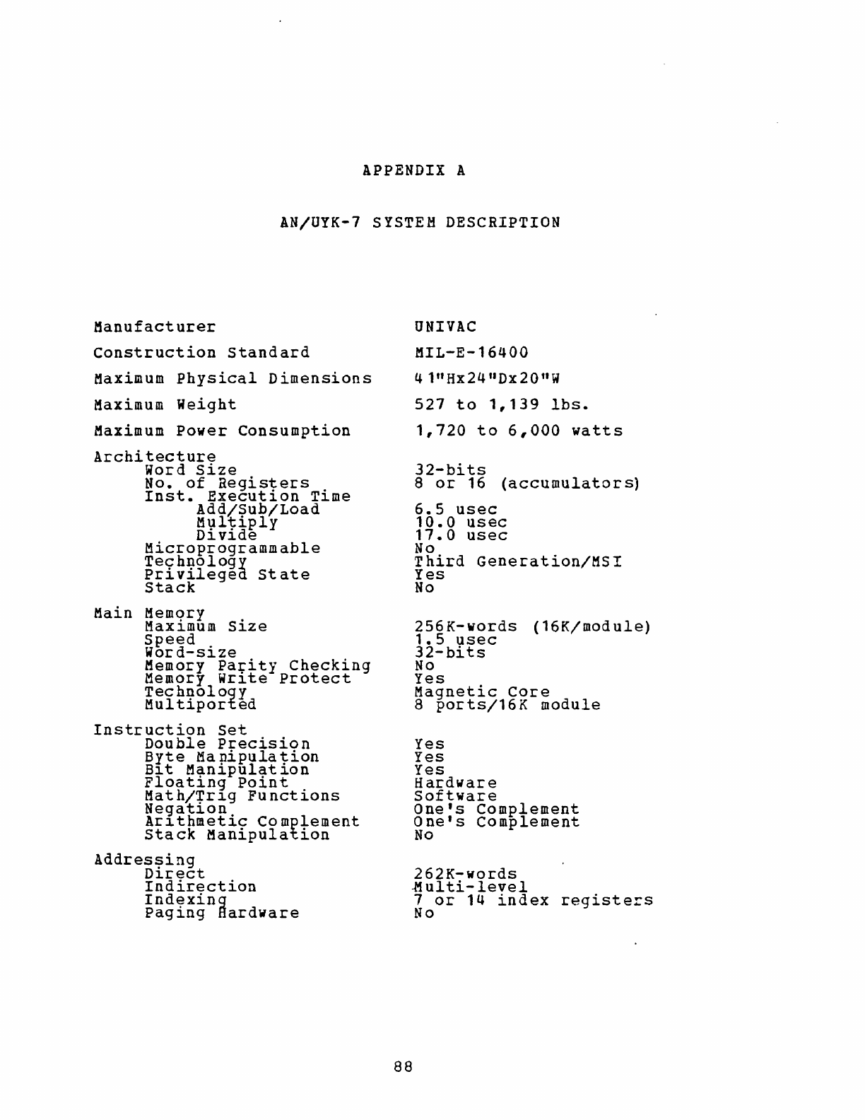
APPENDIX
A
AN/UYK-7
SYSTEM
DESCRIPTION
Manufacturer
Construction
standard
Maximum
Physical
Dimensions
Maximum
Weight
Maximum
Power
Consumption
Architecture
Word
Size
No.
of
Registers
Inst.
Execution
Time
Add/Sub/Load
Ml;lltiply
Dl.
vl.de
Microprogrammable
Technology
Privilegea
State
Stack
Main Memqry .
Maxl.mum
Sl.ze
Speed
Wor
d-size
Memory
Pa~ity
Checking
Memory Wrl.te
Protect
Technology
Multiported
Instruction
Set
Double
Precision
Byte
Ma
nipula
tion
Bl.t
Manipulation
Floating
Point
Math/+rl.g
Functions
Neqatl.on
Arl.thmetic
Complement
Stack
Manipulation
Addres~ing
D~rect
Indirection
Indexing
Paging
Hardware
UNIVAC
MIL-E-16400
41"Hx24
I1 Dx20"W
527
to
1,139
Ibs.
1,720
to
6,000
watts
32-bits
8
or
16
(accumulators)
6.5
usec
10.0
usec
17.0
usec
No
Third
Generation/MSI
Yes
No
256K-words
(16K/module)
1.5
usec
32-
bits
No
Yes
Magnetic
Core
8
ports/16K
module
Yes
Yes
Yes
Hardware
Software
One's
Complement
One's
Complement
No
262K-words
-M
ul
ti-level
1
or
14
index
registers
No
88
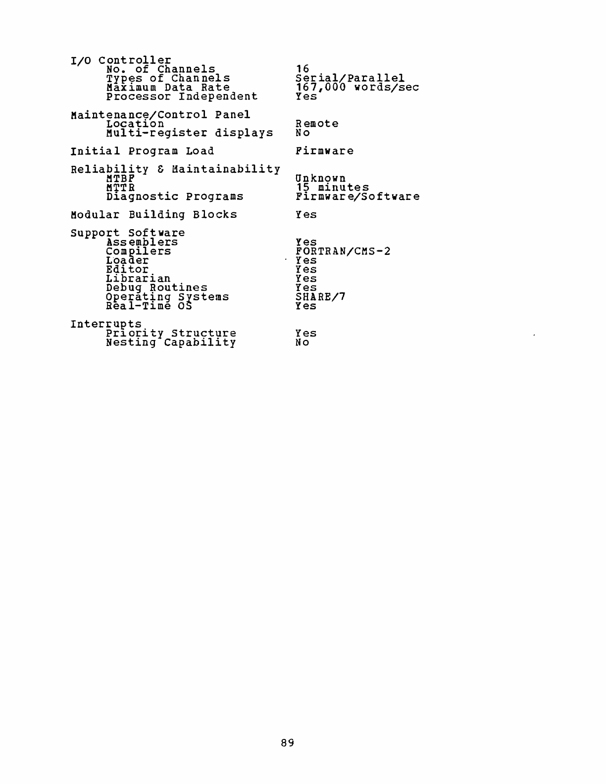
I/O
controller
No.
of
Channels
Typ~s
of
Channels
Max~mum
Data
Rate
Processor
Independent
Maintenanc~/Control
Panel
Locat~on
Multi-register
displays
Initial
Program
Load
Reliability
&
Maintainability
MTBP
fiTTR
Diagnostic
Programs
Modular
Building
Blocks
support
Software
Assemblers
Compilers
L'oader
Editor
Librarian
Debug
Routines
Operat~ng
systems
Real-T~me
as
Interrupts
Pr~ority
Structure
Nesting
Capability
89
16
Serial/Parallel
167,000
words/sec
Yes
Remote
No
Firmware
Unknown
15
minutes
Firmware/Software
Yes
Yes
FORTRAN/CMS-2
Yes
Yes
Yes
Yes
SHARE/7
Yes
Yes
No
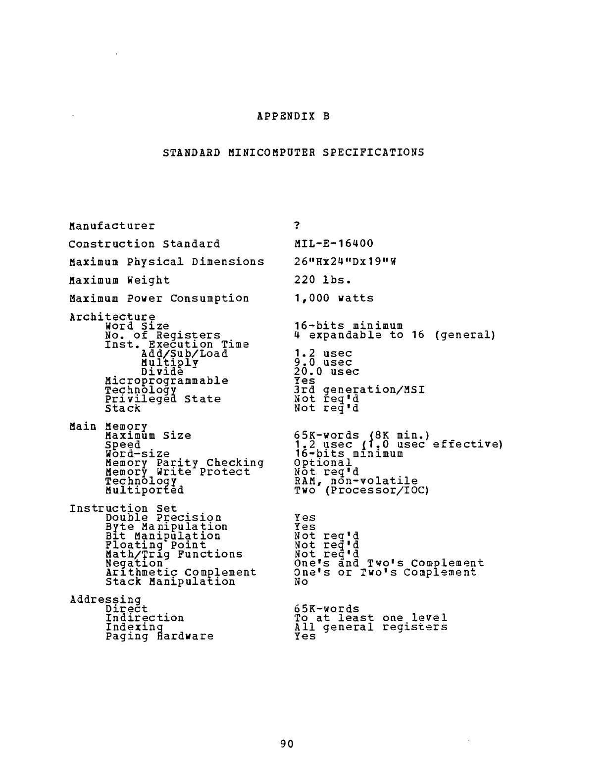
APPENDIX B
STANDARD
MINICOMPUTER
SPECIFICATIONS
Manufacturer
Construction
Standard
Maximum
Physical
Dimensions
Maximum
Weight
Maximum
Power
Consumption
Architecture
Word
Size
No.
of
Registers
Inst.
Execution
Time
Add/Sub/Load
Multiplv
Divide
-
Microprogrammable
Technology
Privileged
State
Stack
Main
Mem9ry .
Maxl.mum
Sl.ze
speed
Word-size
Memory
Pa~ity
Checking
Memory
Wr~te
Protect
Technology
Multiported
Instruction
Set
Double
Precision
Byte
Manipulation
Bl.t
Manipulation
Floating
Point
Math/~rl.g
Functions
Negatl.on
Arl.thmetic
Complement
Stack
Manipulation
Addres~ing
D~rect
Indirection
Indexing
Paging
Hardware
90
?
MIL-E-16400
26"Hx24
t1
Dx19
I1 W
220
lbs.
1,000
watts
16-bits
minimum
4
expandable
to
16
(general)
1.2
usec
9.0
usec
20.0
usee
Yes
3rd
generation/MSI
Not
regld
Not
regld
65K-words
(8K
min.)
1.2
usec
{f.O
usec
effective)
16-bits
m~nimum
Optional
Not
reqld
RAM,
non-volatile
Two
(Processor/I
~C)
Yes
Yes
Not
req'd
Not
regld
Not
req'd
Onels
and
Twols
Com·plement
Onels
or
lWOIS
Complement
No
65K-words
To
at
least
one
level
All
general
registers
Yes
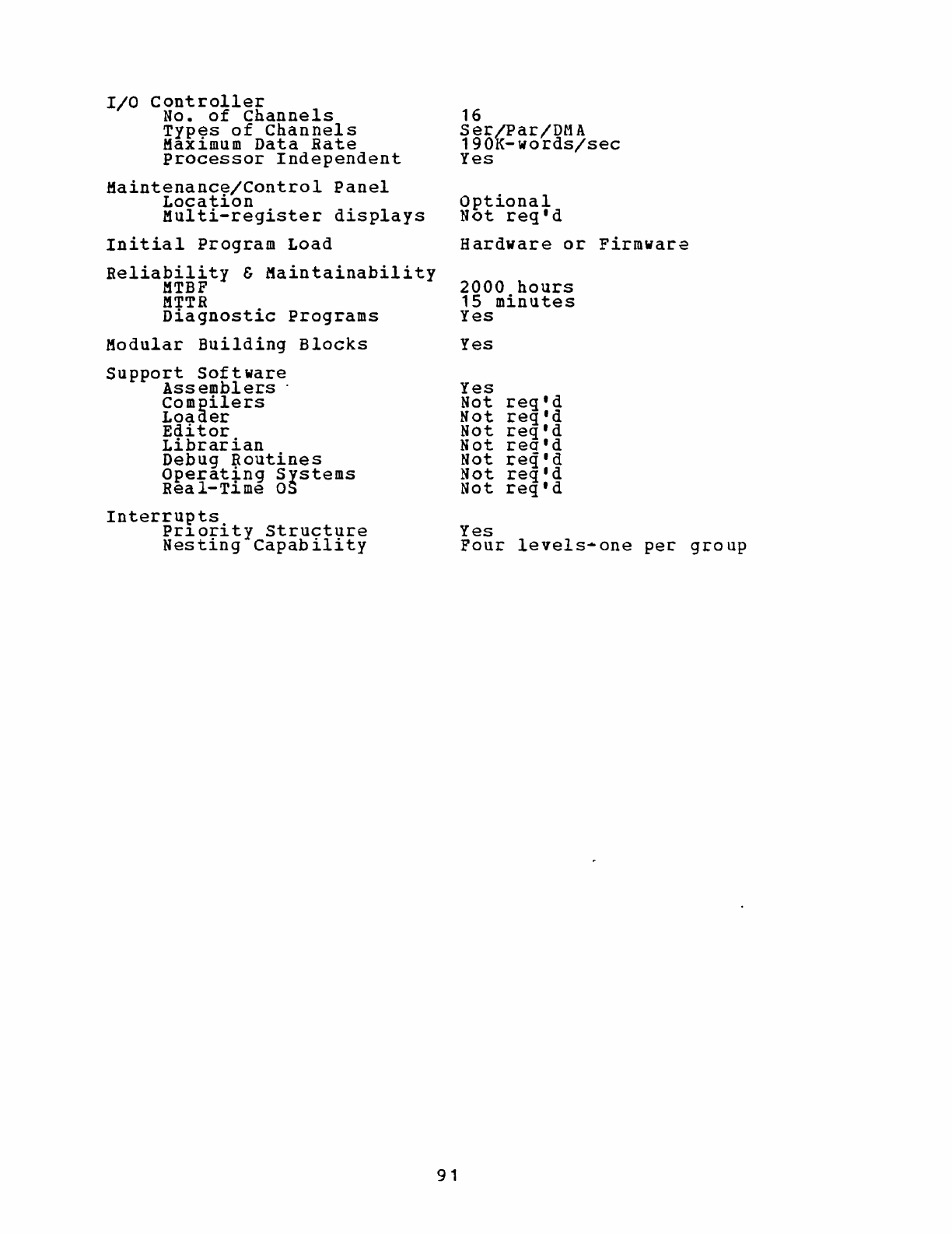
I/O
controller
No.
of
Channels
Typ~s
of
Channels
Max~mum
Data
Rate
Processor
Independent
Maintenance/Control
Panel
Location
Multi-register
displays
Initial
Program
Load
Beliability
&
Maintainability
MTBF
MTTR
Diagnostic
Programs
Modular
Building
Blocks
Support
Software
Ass
embl
ers
.
Compilers
Loader
Editor
Librarian
Debug
~outines
Operat~ng
Systems
Real-T~me
as
Interrupts
Pr~ority
structure
Nesting
Capability
91
16
Ser/Par/DMA
190K-words/sec
Yes
Optional
Not
req'd
Hardware
or
Firmwar~
2000
hours
15
minutes
Yes
Yes
Yes
Not
req'd
Not
req'd
Not
req'd
Not
req1d
Not
req'd
Not
regld
Not
req'd
Yes
Four
levels-one
per
group
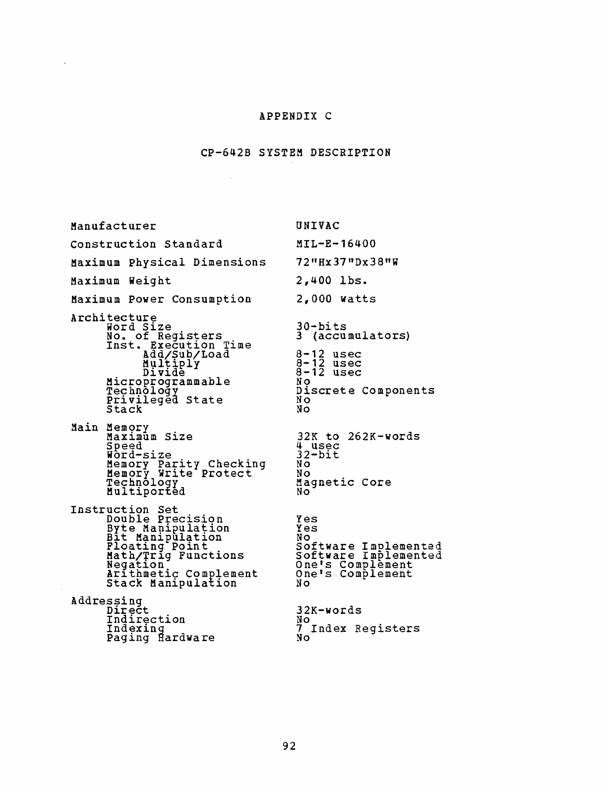
APPENDIX C
CP-642B
SYSTEM
DESCRIPTION
Manufacturer
Construction
Standard
Maximum
Physical
Dimensions
Maximum
Weight
Maximum
Power
Consumption
Architecture
Word
Size
No.
of
Registers
.
Inst.
Execut10n
T1me
Add/Sub/Load
M\;ll1:iply
D1v1de
Microprogrammable
Technology
privilegea
State
Stack
Main
Mem9ry .
MaX1IDum
S1ze
Speed
Word-size
Memory
Parity
Checking
Memory
write
protect
Technology
Multiported
Instruction
Set
Double
Precision
Byte
Ma~ipulation
B~t
Man~pulat10n
Floating
Poin
t
Math/+r~g
Functions
Negat10n
Ar1thmetic
Complement
Stack
Manipulation
Addres~ing
D1rect
Indirection
Indexing
Pag
ing
Hardva
re
92
UNIVAC
MIL-E-16400
72"Hx37
nDx38"W
2,400
lbs.
2,000
watts
30-hi
ts
3
(accumulators)
8-12
usec
8-12
usec
8-12
usec
No
Discrete
Components
No
No
32K
to
262K-words
4
usec
32-bit
No
No
Magnetic
Core
No
Yes
Yes
No
Software
Implemented
Software
Implemented
One's
Complement
One's
Complement
No
32K-words
No
7
Index
Registers
No
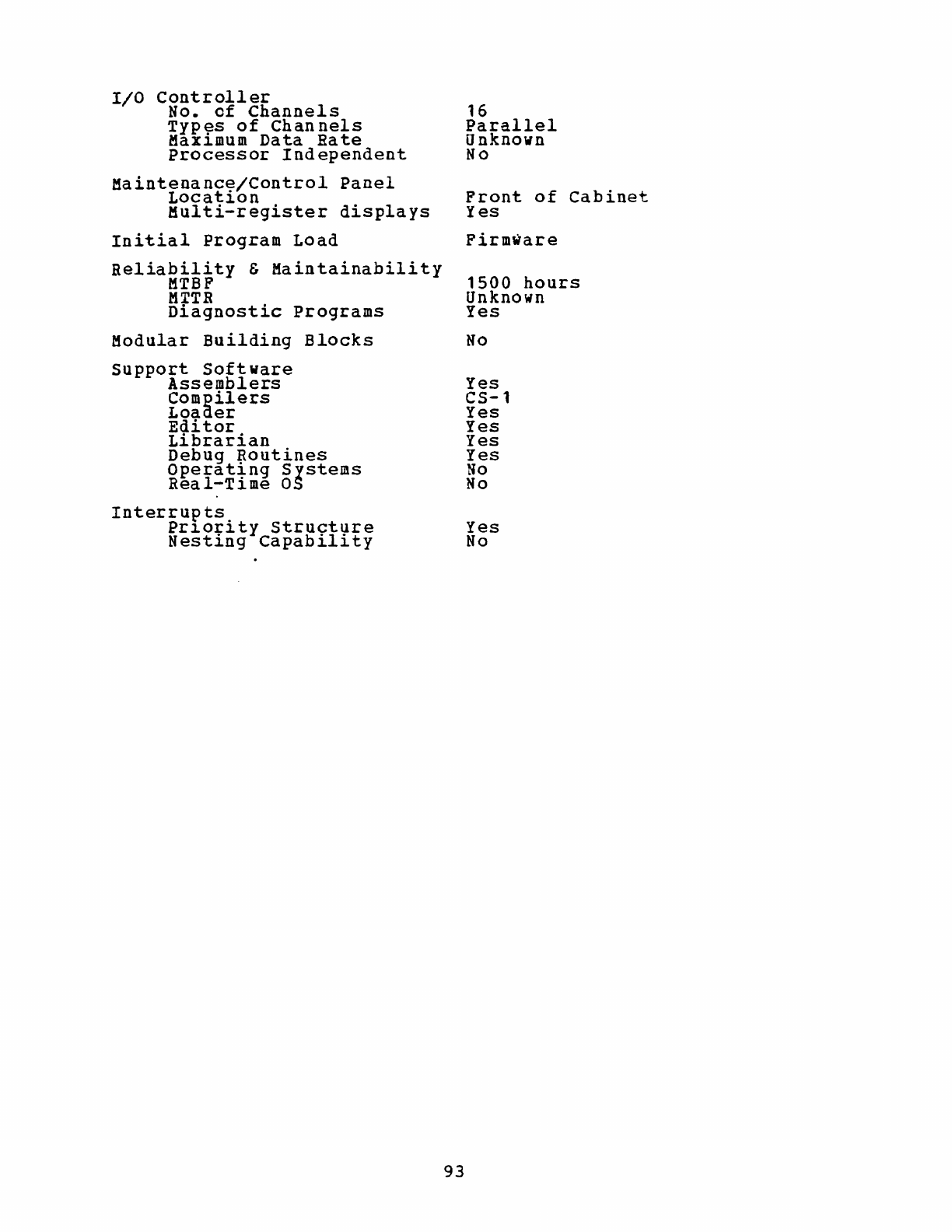
I/O
Controller
No.
of
Channels
Typ~s
of
Channels
Max~mum
Data
Rate
Processor
Independent
Maintenance/Control
Panel
Location
Multi-register
displays
Initial
Program
Load
Reliability
&
Maintainability
liTBF
MTTR
Diagnostic
Programs
Modular
Building
Blocks
support
Software
Assemblers
Compilers
Loaaer
Editor
Librarian
Debug
~outines
Operat~ng
Systems
Real-Time
as
Interrup
ts.
Pr~or~ty
structure
Nesting
Capability
93
16
Parallel
Unknown
No
Front
of
Cabinet
Yes
Firmware
1500
hours
Unknown
Yes
No
Yes
CS-1
Yes
Yes
Yes
Yes
No
No
Yes
No
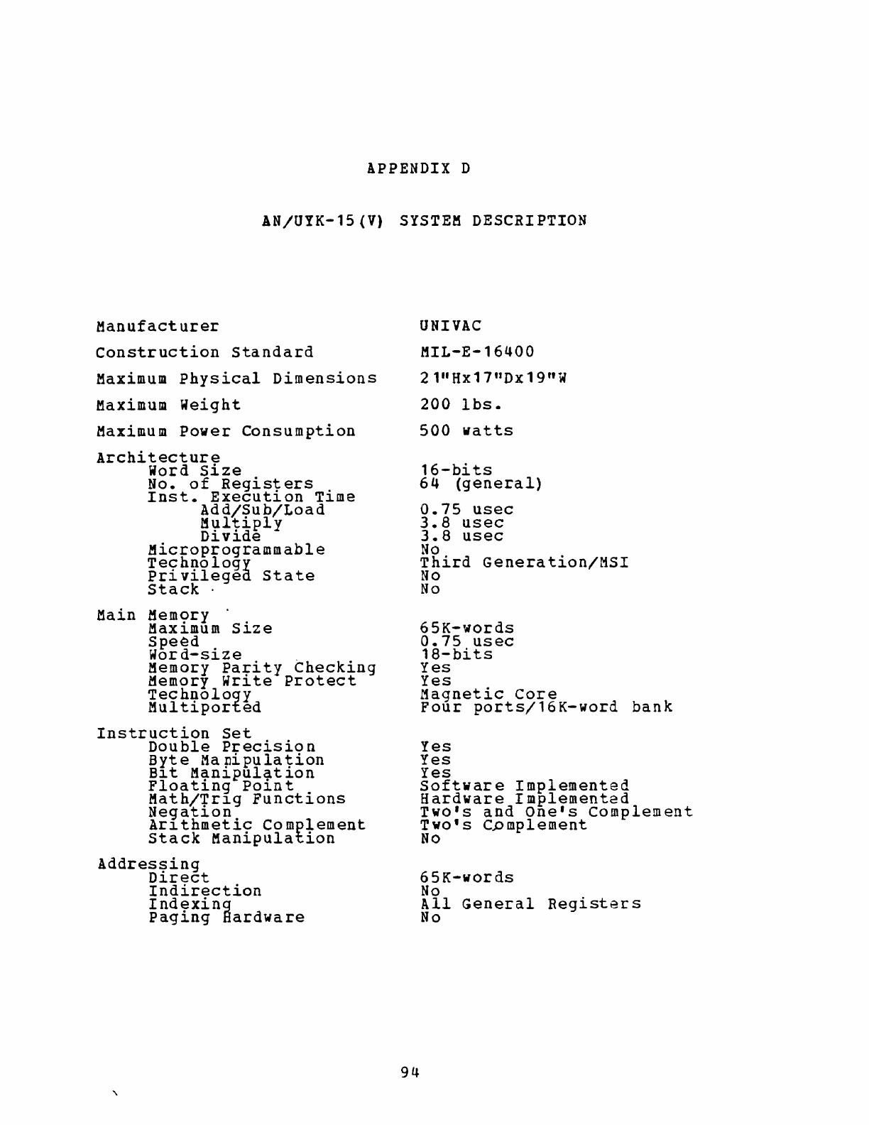
APPENDIX
D
AN/UYK-15
(V)
SYSTEM
DESCRIPTION
Manufacturer
Construction
Standard
Maximum
Physical
Dimensions
Maximum
Weight
Maximum
Power
Consumption
Architecture
Word
Size
No.
of
Registers
.
Inst.
Execut~on
T~me
Add/Sub/Load
M\lltiply
D~v~de
Microprogrammable
Technology
Privilegea
State
Stack·
Main Mem9ry .
Max~mum
S~ze
Speed
Word-size
Memory
Pa~ity
Checking
Memory
Wr~te
Protect
Technology
Multiported
Instruction
Set
Double
Precisio
n
Byte
Manipulation
B~t
Manipulation
Floating
Point
Math/+r~g
Functions
Negat~on
Ar~thmetic
Complement
Stack
Manipulation
Addres!?ing
D~rect
Indirection
Indexing
Paging
Hardware
94
UNIVAC
MIL-E-16400
21"Hx17"Dx19"W
200
lbs.
500
watts
16-bits
64
(general)
0.75
usec
3.8
usec
3.8
usec
No
Third
Generation/MSI
No
No
65K-words
0.75
usec
18-bits
Yes
Yes
Magnetic
Core
Four
ports/16K-word
bank
Yes
Yes
Yes
Software
Implemented
Hardware
Implemented
Two's
and
One's
Complement
Two's
C..omplement
No
65K-words
No
All
General
Registers
No

I/O
Controller
No.
of
Channels
Typ~s
of
Channels
Max~mum
Data
Rate
Processor
Independent
Maintenance/Control
Panel
Location
Multi-register
displays
Initial
Program
Load
Reliability
&
Maintainability
MTBF
M+TR
.
D~agnost~c
Programs
Modular
Building
Blocks
support
Soft
ware
Assemblers
Compilers
Loaijer
Editor
Librarian
Debug
Routines
Operat~ng
Systems
Real-T~me
OS
Interrupts
Pr~ority
structure
Nesting
Capability
95
16
Ser/Par
190K-words/sec
Yes
Front
of
Cabinet
No
Firmware
2000
hours
15
minutes
Firmware/Software
Yes
Yes
Unknown
Yes
Unknown
Unknown
Unknown
Unknown
Unknown
Yes
Four
levels-one
per
class
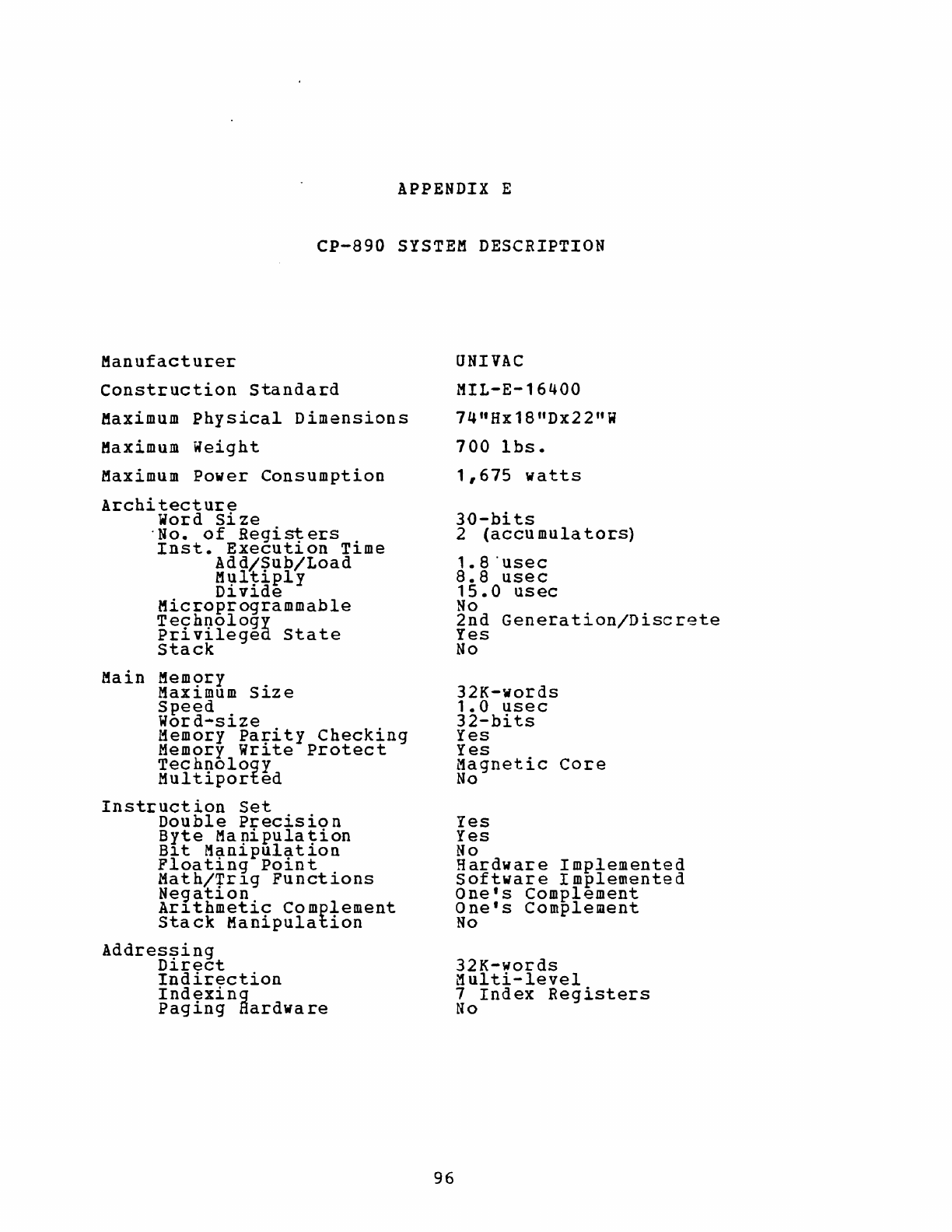
APPENDIX E
CP-890
SYSTEM
DESCRIPTION
Manufacturer
Construction
Standard
Maximum
Physical
Dimensions
Maximum
Weight
Maximum
Power
Consumption
Architecture
Word
Size
'No.
of
Regist
ers
.
Inst.
Execut~on
T1me
Add/Sub/Load
M':lltiply
D~v~de
Microprogrammable
Technology
Privilegea
State
Stack
Main
Mem<?ry
.
MaX1mum
S~ze
Speed
Word-size
Memory
Parity
Checking
Memory
write
Protect
Technology
Multiported
Instruction
set
Double
Precision
Byte
Ma
pipula
t-ion
B~t
Man~pulat~on
Floating
Point
Math/+r1g
Functions
Ne9at~on
Ar~thmetic
Complement
Stack
Manipulation
Addres~ing
D~rect
Indirection
Indexing
Paging
Hardware
96
UNIVAC
MIL-E-16400
74"HxlS"Dx22"W
700
Ibs.
1,675
watts
30-bits
2
(accu
mula
tors)
1.S'usec
8.8
usee
15.0
usee
No
2nd
Generation/Discrete
Yes
No
32K-words
1.0
usec
32-bits
Yes
Yes
Magnetic
Core
No
Yes
Yes
No
Hardware
Implemented
software
Implemented
One's
Complement
One's
Complement
No
32K-words
L1ulti-level
7
Index
Registers
No
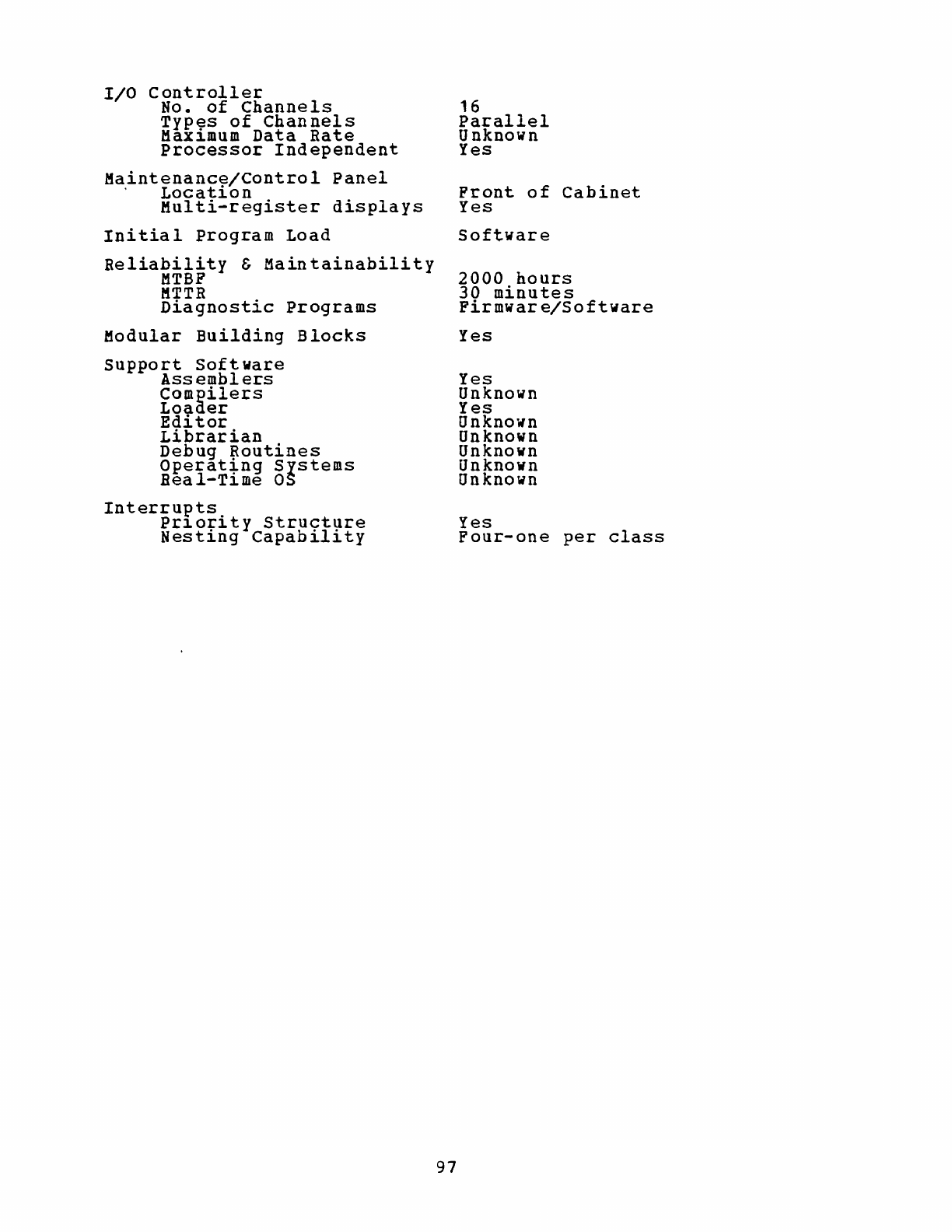
I/O
controller
No.
of
Channels
Types
of
Channels
Maximum
Data
Rate
Processor
Independent
Maintenanc~/control
Panel
.
Locat~on
Multi-register
displays
Initial
Program
Load
Reliability
&
Maintainability
MTBF
KTTR
Diagnostic
Programs
Modular
Building
Blocks
support
Software
Assemblers
Compilers
Loader
Editor
Librarian
Debug
Routines
Operat~ng
Systems
Beal-T~me
OS
Interrupts
Pr~ority
Structure
Nesting
Capability
97
16
Parallel
Unknown
Yes
Front
of
Cabinet
Yes
Software
2000
hours
30
minutes
Firmware/Software
Yes
Yes
Unknown
Yes
Unknown
Unknown
Unknown
Unknown
Unknown
Yes
Four-one
per
class
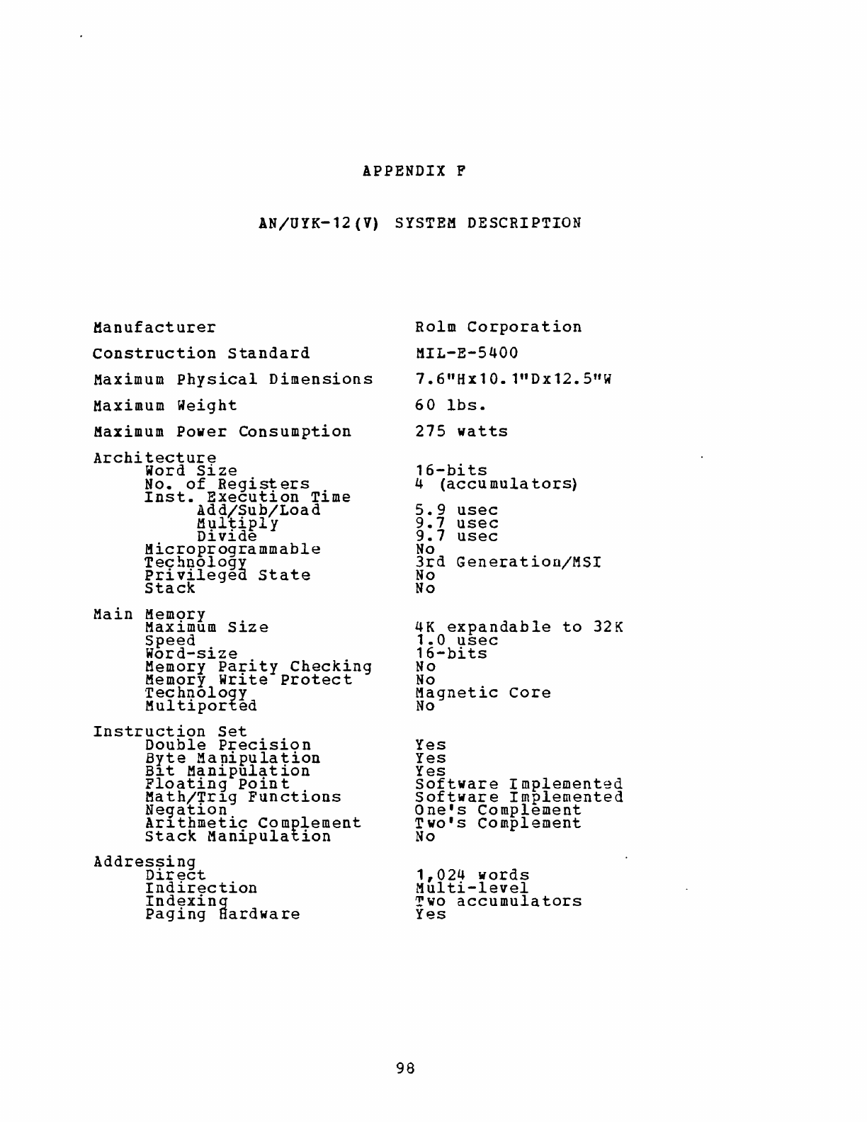
APPENDIX
P
AN/UYK-12
(V)
SYSTEM
DESCRIPTION
Manufacturer
Construction
Standard
Maximum
Physical
Dimensions
Maximum
Weight
Maximum
Power
Consumption
Architecture
Word
Size
No.
of
Registers
Inst.
Execution
Time
Add/Sub/Load
M\).ltiply
Dl.vl.de
Microprogrammable
Technology
privilegea.
State
Stack
Main
MemQry
.
Maxl.mum
Sl.ze
Speed
Word-size
Memory
pa~ity
Checking
Memory Wrl.te
Protect
Technology
Multiported
Instruction
Set
Double
Precision
Byte
Manipulation
Bl.t
Manipulation
Floating
Poin
t
Math/1rl.g
Functions
Negatl.on
Arl.thmetic
Complement
Stack
Manipulation
Addressing
Direct
Indirection
Indexing
Paging
Hardware
98
Rolm
Corporation
MIL-E-5400
7.6
I
Hxl0.l"Dx12.5"w
60
Ibs.
275
watts
16-bits
4
(accu
mula
tors)
5.9
usec
9.7
usec
9.7
usec
No
3rd
Generation/MSI
No
No
4K
expandable
to
32K
1.0
usec
16-bits
No
No
Magnetic
Core
No
Yes
Yes
Yes
Software
Implemented
Software
Implemented
One's
Complement
Two's
Complement
No
1,024
words
Multi-level
Two
accumulators
Yes

I/O
Controller
No.
of
Channels
Typ~s
of
Channels
MaX1mum
Data
Rate
Processor
Independent
Maintenanc~/Control
Panel
Locat10n
Multi-register
displays
Initial
program
Load
Reliability
&
Maintainability
MTBF
MTTR
Diagnostic
Programs
Modular
Building
Blocks
Support
software
Assemblers
Compilers
Loader
Editor
Librarian
Debug
~outines
Operat~ng
Systems
Real-T1me
as
Interrupts.
Pr10r1ty
structure
Nesting
Capability
99
61
devices
on
I/O
bus
Ser/par
600K-words/sec
Yes
Attached
or
Remote
No
Firmware
11,000
hours
28.6
minutes
Software
For
memory
&
I/O
Yes
FORTRAN/BASIC/ALGOL
Yes
Yes
Yes
Yes
Batch/Disk
Disk
Yes
Yes
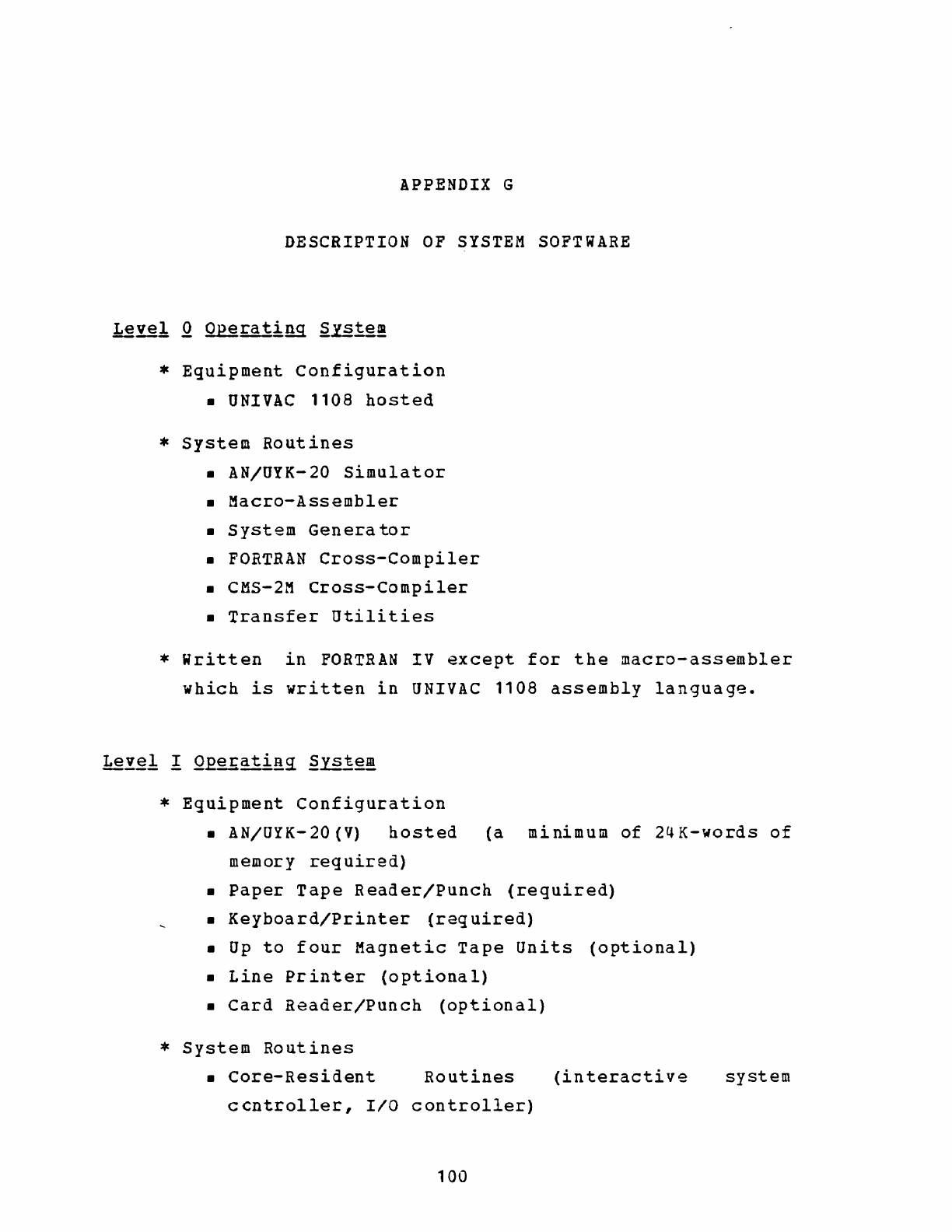
APPENDIX
G
DESCRIPTION
OF
SYSTEM
SOFTWARE
*
Equipment
Configuration
•
UNIVAC
1108
hosted
*
System
Routines
• AN/UYK-20
Simulator
•
Macro-Assembler
•
System
Generator
•
FORTRAN
Cross-Compiler
• eMS-2M
Cross-Compiler
•
Transfer
Utilities
*
written
in
FORTRAN
IV
except
for
the
macro-assembler
which
is
written
in
UNIVAC
1108
assembly
language.
*
Equipment
Configuration
• AN/UYK-20(V)
hosted
(a
minimum
of
24K-words
of
memory
required)
•
Paper
Tape
Reader/Punch
(required)
•
Keyboard/Printer
(required)
•
Up
to
four
Magnetic
Tape
units
(optional)
•
Line
Printer
(optional)
•
Card
Reader/Punch
(optional)
*
System
Routines
•
Core-Resident
Routines
(interactive
system
ccntroller,
IIO
controller)
100
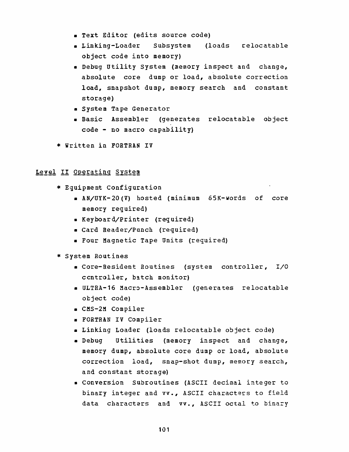
•
Text
Editor
(edits
source
code)
•
Linking-Loader
Subsystem
(loads
celocatable
object
code
into
memory)
•
Debug
utility
System
(memory
inspect
and
change,
absolute
core
dump
or
load,
absolute
correction
load,
snapshot
dump,
memory
search
and
constant
storage)
•
System
Tape
Generator
•
Basic
Assembler
(generates
relocatable
object
code
-
no
macro
capability)
*
Written
in
FORTRAN
IV
*
Equipment
Configuration
• AN/UYK-20(V)
hosted
(minimum
65K-words
of
core
memory
required)
•
Keyboard/printer
(required)
•
Card
Reader/Punch
(required)
•
Four
Magnetic
Tape
Units
(required)
*
System
Routines
•
Core-Resident
Routines
(system
controller,
I/O
ccntroller,
b~tch
monitor)
• ULTRA-16
Macr~-Assembler
(generates
relocatable
object
code)
•
CMS-2M
Compiler
•
FORTRAN
IV
Compiler
•
Linking
Loader-
(loads
relocatable
object
code)
•
Debug
utilities
(memory
inspect
and
change,
memory
dump,
absolute
core
dump
or
load,
absolute
correction
load,
snap-shot
dump,
memory
search,
and
constant
storage)
•
Conversion
Subroutines
(ASCII
decimal
integer
to
binary
integec
and
vv.,
ASCII
characte~s
to
field
data
characters
and
vv.,
ASCII
octal
to
bina=y
101
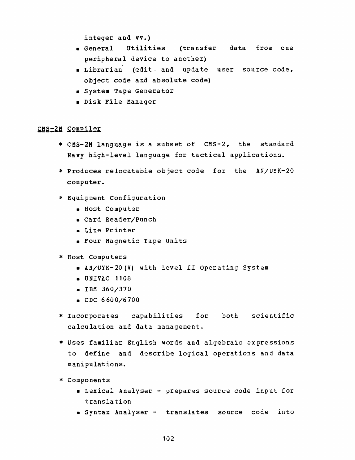
integer
and
vv.)
•
General
utilities
(transfer
peripheral
device
to
another)
data
from
one
•
Librarian
(edit·
and
update
user
source
code,
object
code
and
absolute
code)
•
System
Tape
Generator
•
Disk
File
Manager
*
CMS-2M
language
is
a
subset
of
CMS-2,
the
standard
Navy
high-level
language
for
tactical
applications.
*
Produces
relocatable
object
code
for
the
AN/UYK-20
computer.
*
Equipment
Configuration
•
Host
Computer
•
Card
Reader/Punch
•
Line
Printer
•
Four
Magnetic
Tape
Units
*
Host
Computers
• AN/UYK-20(V)
with
Level
II
operating
System
•
UNIVAC
1108
•
IBM
360/370
•
CDC
6600/6700
*
Incorporates
capabilities
for
calculation
and
data
management.
both
scientific
*
Uses
familiar
English
words
and
algebraic
expressions
to
define
and
describe
logical
operations
and
data
manipulations.
*
Components
•
Lexical
Analyser
-
prepares
source
code
input
for
translation
•
Syntax
Analyser
-
translates
source
code
into
102
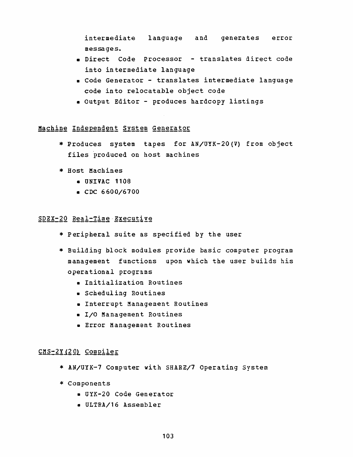
intermediate
language
and
generates
error
messages.
•
Direct
Code
Processor
-
translates
direct
code
into
intermediate
language
•
Code
Generator
-
translates
intermediate
language
code
into
relocatable
object
code
•
Output
Editor
-
produces
hardcopy
listings
*
Produces
system
tapes
for
AN/UYK-20(V)
from
object
files
~roduced
on
host
machines
*
Host
Machines
•
UNIVAC
1108
• CDC
6600/6700
*
Peripheral
suite
as
specified
by
the
user
*
Building
block
modules
provide
basic
computer
program
management
functions
upon
which
the
user
builds
his
operational
programs
•
Initialization
Routines
•
Scheduling
Routines
•
Interrupt
Management
Routines
•
I/O
Management
Routines
•
Error
Management
Routines
* AN/UYK-7
Computer
with
SHARE/7
Operating
System
*
Components
• UYK-20
Code
Generator
• ULTRA/16
Assembler
103
• UYK-7
hosted
Loader
• UYK-20
Simulator/Debug
Tool
*
Features
•
Interfaces
with
CMS-2Y(7)
code
editing
•
Extensive
optimization
Librarian
for
source
•
Produces
side-by-side
source
code/object
code
listings
104
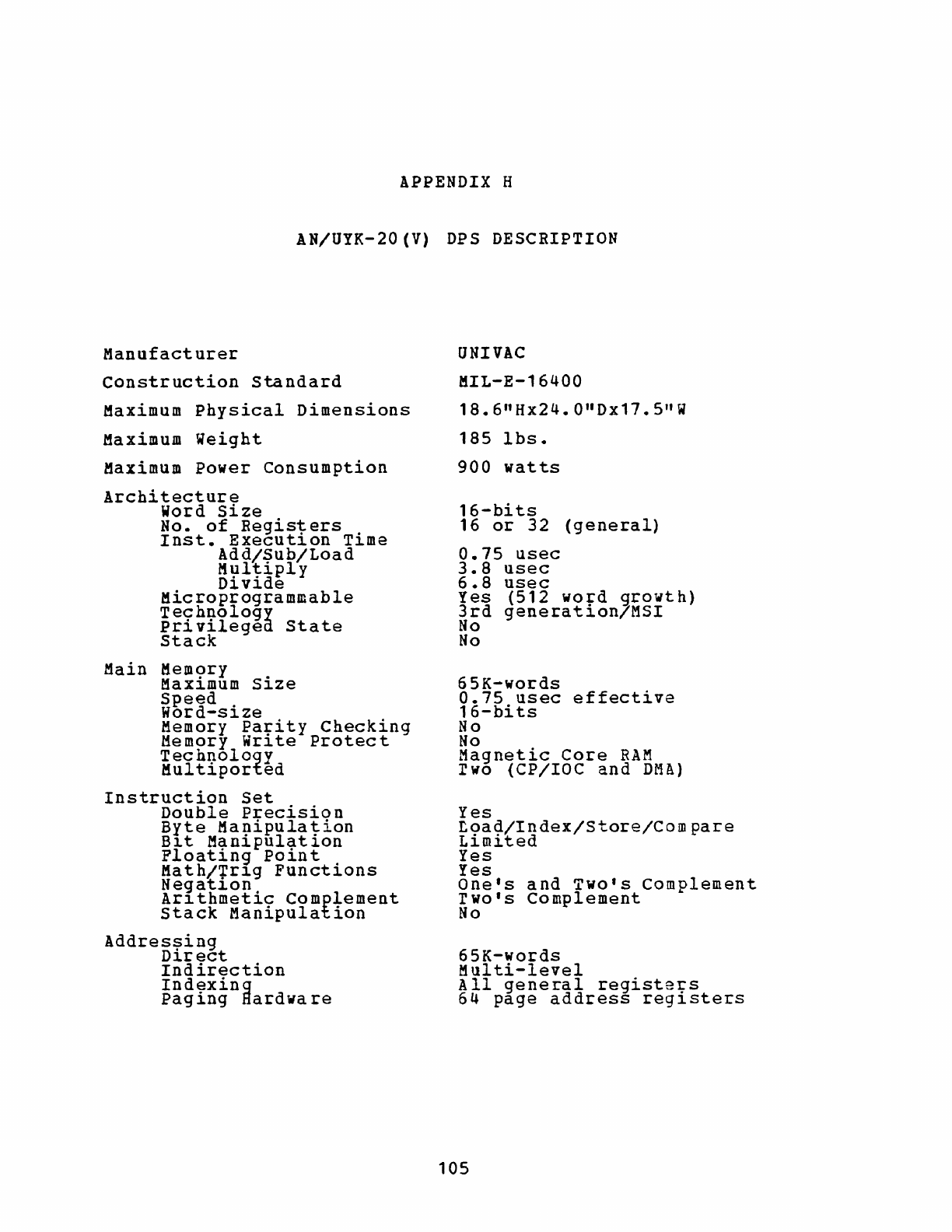
APPENDIX H
AN/UYK-20(V)
DPS DESCRIPTION
Manufacturer
Construction
standard
Maximum
Physical
Dimensions
Maximum
Weight
Maximum
Power
Consumption
Architecture
Word
Size
No.
of
Registers
.
Inst.
Execut10n
T~me
Add/Sub/Load
M~lt-iply
D1v1de
Microprogrammable
Technology
privileged
State
Stack
Main
Mem9ry .
MaX1mum
S1ze
Speed
Word-size
Memory
Pa~ity
Checking
Memory
Wr1te
Protect
Technology
Multiported
Instruction
Set
Double
Precision
Byte
Ma~ipulat-ion
B~t
Man1pulat~on
Ploating
Pain
t
Math/~r1g
Functions
Negat~on
Ar1thmetic
Complement
Stack
Manipulation
Addres!?ing
D1rect
Indirection
Indexing
Pag
ing
Hard
wa
re
UNIVAC
MIL-E-16400
18.6
I1
Hx24.0"Dx17.5"W
185
lbs.
900
watts
16-bits
16
or
32
(general)
0.75
usec
3.8
usec
6.8
usec
Yes
(512
wo+d
growth)
3rd
generat10nlMSI
No
No
65K-words
0.75
usec
effective
16-bits
No
No
Magnetic
Core
RAM
rwo
(CP/IOC
and
DM!)
Yes
L9a~/Index/Store/Compare
Ll.m~ted
Yes
Yes
One's
and
Two's
Complement
r
wo'
s
Complement
No
65K-words
Multi-level
All
general
registers
64
page
address
registers
105
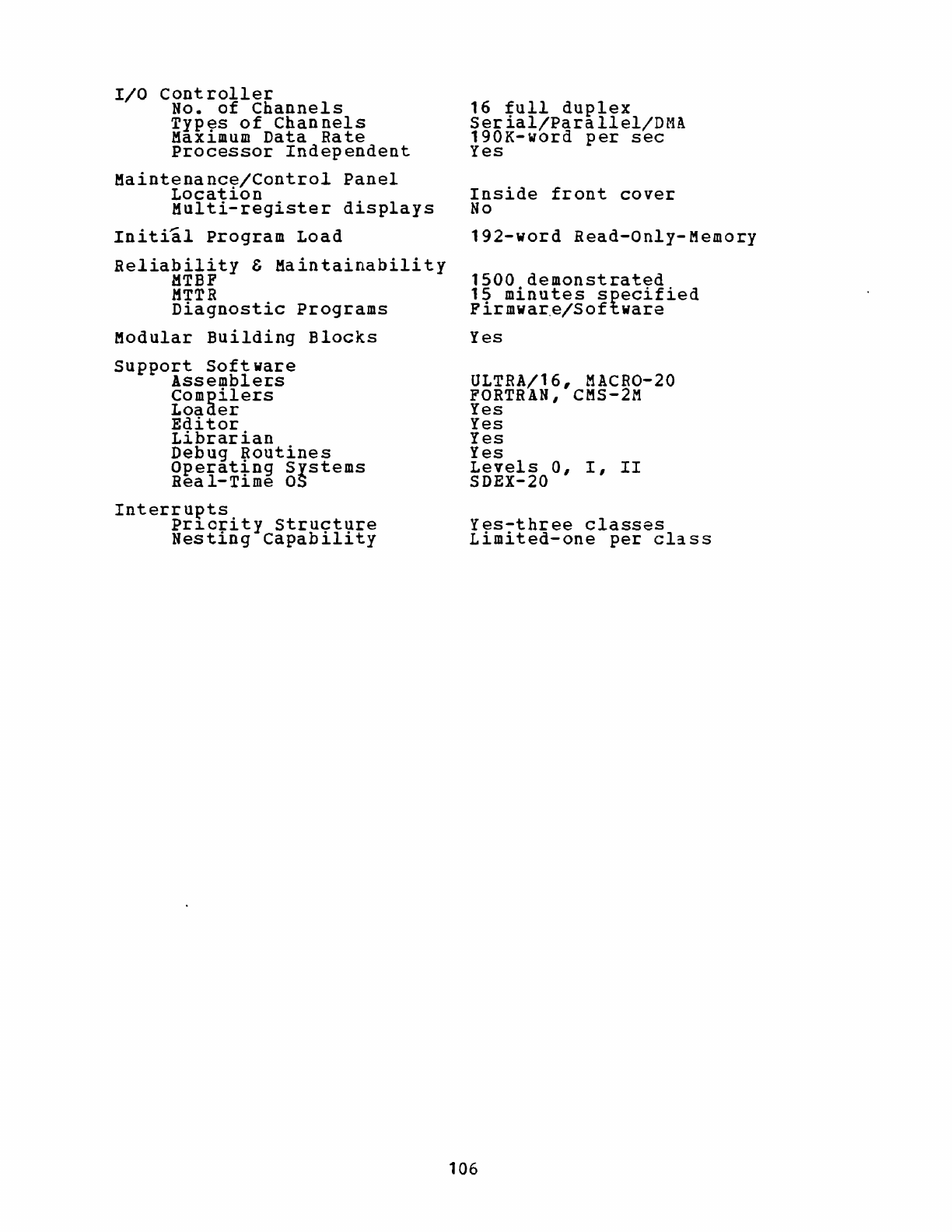
I/O
Controller
No.
of
Channels
Types
of
Channels
Maximum
Data
Rate
Processor
Independent
Maintenanc~/Control
Panel
Locatl.on
Multi-register
displays
Initial
Program
Load
Reliability
&
Maintainability
MTBF
MTTR
Diagnostic
Programs
Modular
Building
Blocks
support
Software
Assemblers
Compilers
Loader
Editor
Librarian
Debug
~outines
Operat+ng
Systems
Rea
l-Tl.me
OS
Interrupts
Prl.ority
Structure
Nesting
Capability
16
full
duplex
Serial/Parallel/DMA
190K-word
per
sec
Yes
Inside
front
cover
No
192-word
Read-Only-Memory
1500
demonstrated
15
minutes
specified
F
irmwar.e/Software
Yes
ULTRA/16,
MACRO-20
FORTRAN, eMS-2M
Yes
Yes
Yes
Yes
Levels
0,
I,
II
SDEX-20
Yes-three
classes
Limited-one
per
cl~ss
106
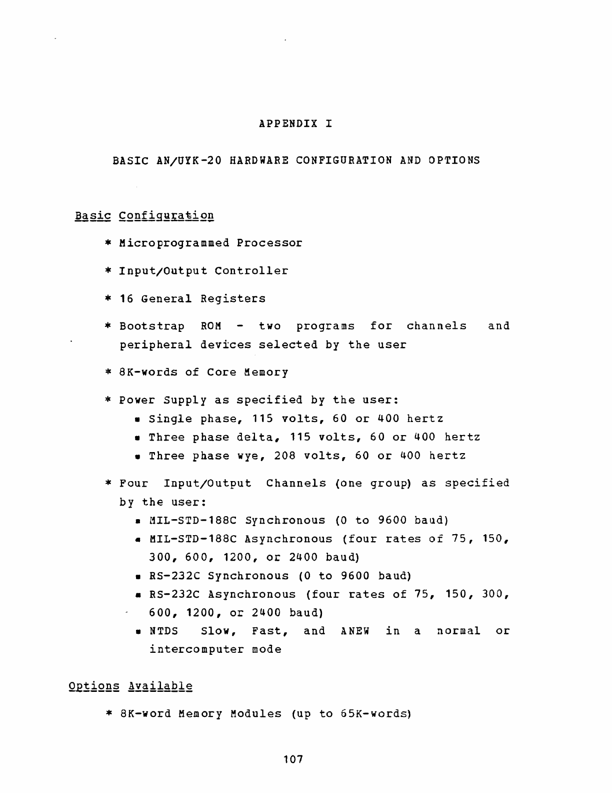
APPENDIX I
BASIC AN/UYK-20
HARDWARE
CONFIGURATION
AND
OPTIONS
*
Microprogrammed
Processor
*
Input/Output
Controller
*
16
General
Registers
*
Bootstrap
ROM
two
programs
for
channels
and
peripheral
devices
selected
by
the
user
*
8K-words
of
Core
Memory
*
Power
Supply
as
specified
by
the
user:
•
Single
phase,
115
volts,
60
or
400
hertz
•
Three
phase
delta,
115
volts,
60
or
400
hertz
•
Three
phase
wye,
208
volts,
60
or
400
hertz
*
Four
Input/Output
Channels
(one
group)
as
specified
by
the
user:
•
MIL-STD-188C
Synchronous
(0
to
9600
baud)
•
MIL-STD-188C
Asynchronous
(four
rates
of
75,
150,
300,
600,
1200,
or
2400
baud)
•
RS-232C
Synchronous
(0
to
9600
baud)
•
RS-232C
Asynchronous
(four
rates
of
75,
150,
300,
600,
1200,
or
2400
baud)
•
NTDS
Slow,
Fast,
and
ANEW
in
a
normal
or
intercomputer
mode
*
8K-word
Memory
Modules
(up
to
65K-words)
107
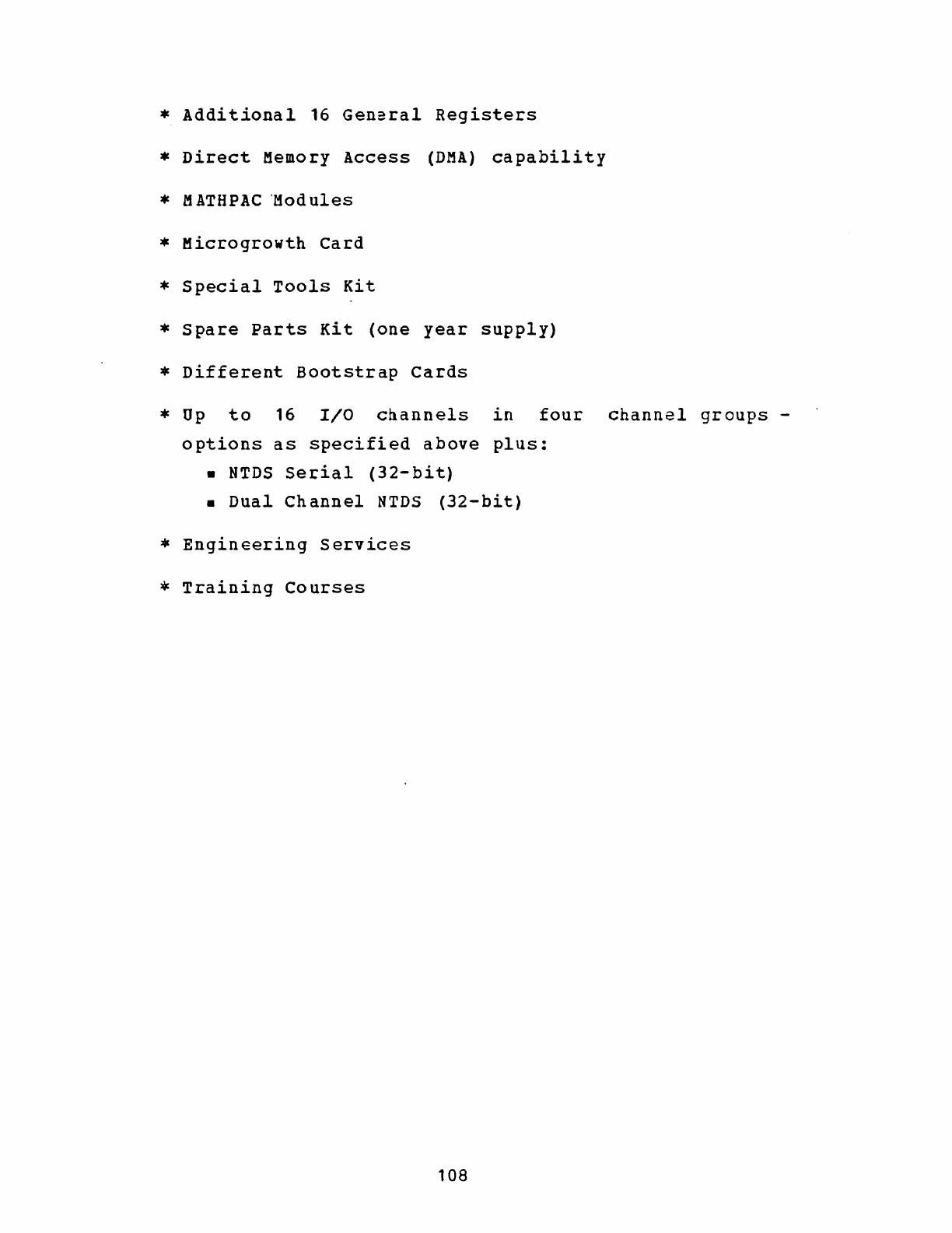
*
Additional
16
General
Registers
*
Direct
Memory
Access
(DMA)
capability
*
MATBPAC
'Modules
*
Microgrowth
Card
*
Special
Tools
Kit
*
Spare
Parts
Kit
(one
year
supply)
*
Different
Bootstrap
Cards
*
Up
to
16
I/O
cnannels
in
four
channel
groups
-
options
as
specified
above
plus:
•
NTDS
Serial
(32-bit)
•
Dual
Channel
NTDS
(32-bit)
*
Engineering
Services
*
Training
Courses
108
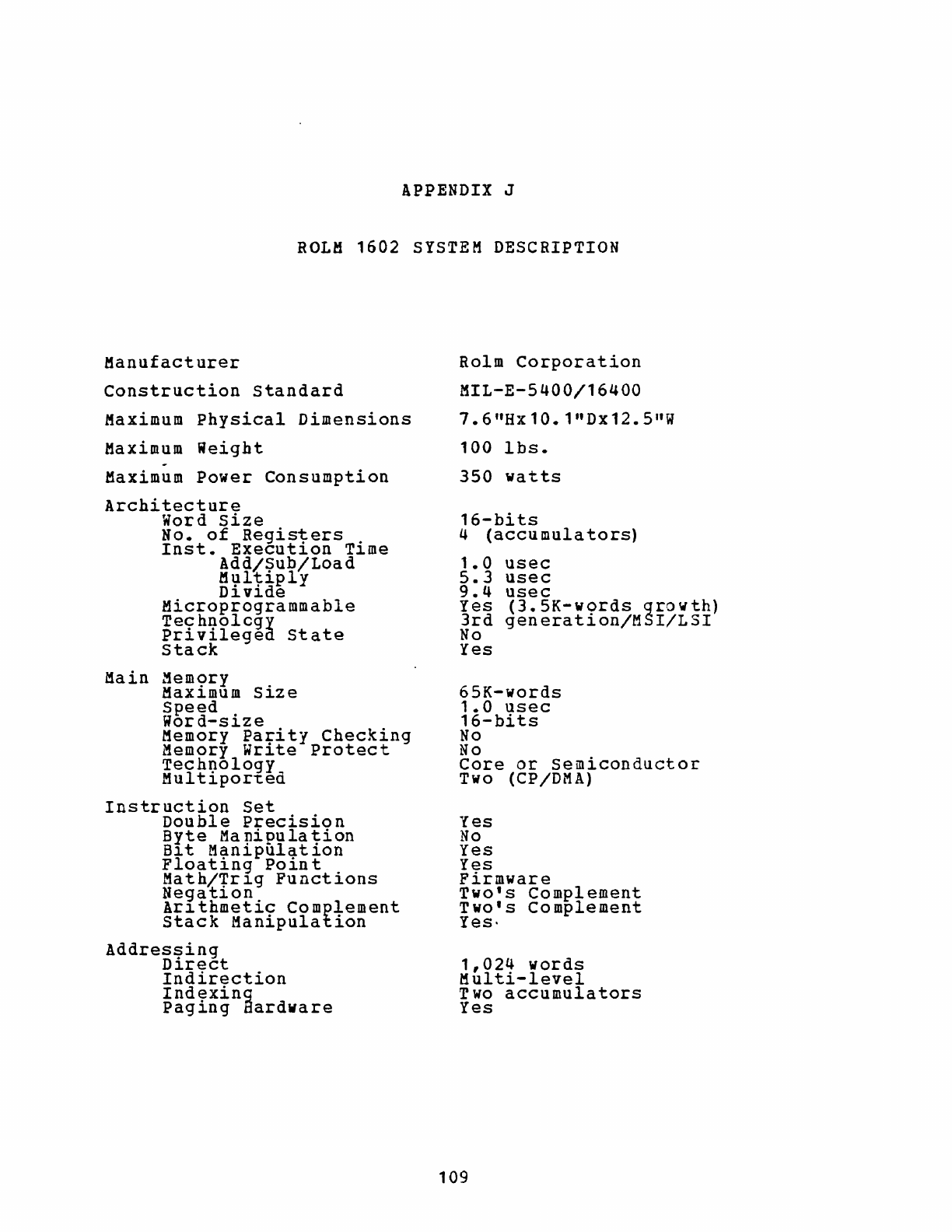
APPENDIX J
ROLH
1602
SYSTEM DESCRIPTION
Manufacturer
Construction
Standard
Maximum
Physical
Dimensions
Maximum
Weight
-
Maximum
Power
Consumption
Architecture
Word
size
No.
of
Registers
.
Inst.
Execut~on
T1me
Add/Sub/Load
Multiply
Divide
Microprogrammable
Technolcgy
Privilegea
State
Stack
Main
Mem<;>ry
.
MaX1mum
S1ze
Speed
Word-size
Memory
Pa+ity
Checking
Memory
Wr1te
Protect
Technology
Mul
tiported
Instruction
Set
Double
Precision
Byte
Ma
nipula
tion
81
t
Manipulation
Floating
Poin
t
Math/+r1g
Functions
Negat10n
Ar1thmetic
Complement
Stack
Manipulation
Addressing
Direct
Indirection
Indexing
Paging
Hardware
Rolm
Corporation
MIL-E-5400/16400
7.6"Hx10.1nDx12.5"W
100
lbs.
350
watts
16-bits
4
(accumulators)
1
.0
5.3
9.4
Yes
3rd
No
Yes
usec
usec
usec
(3.5K-words
growth)
generation/MSI/LSI
65K-words
1.0
usec
16-bits
No
No
Core
or
Semiconductor
Two (CP
/DMA)
Yes
No
Yes
Yes
Firmware
Two's
Complement
Two's
Complement
Yes-
1,024
words
Multi-level
Two
accumulators
Yes
109
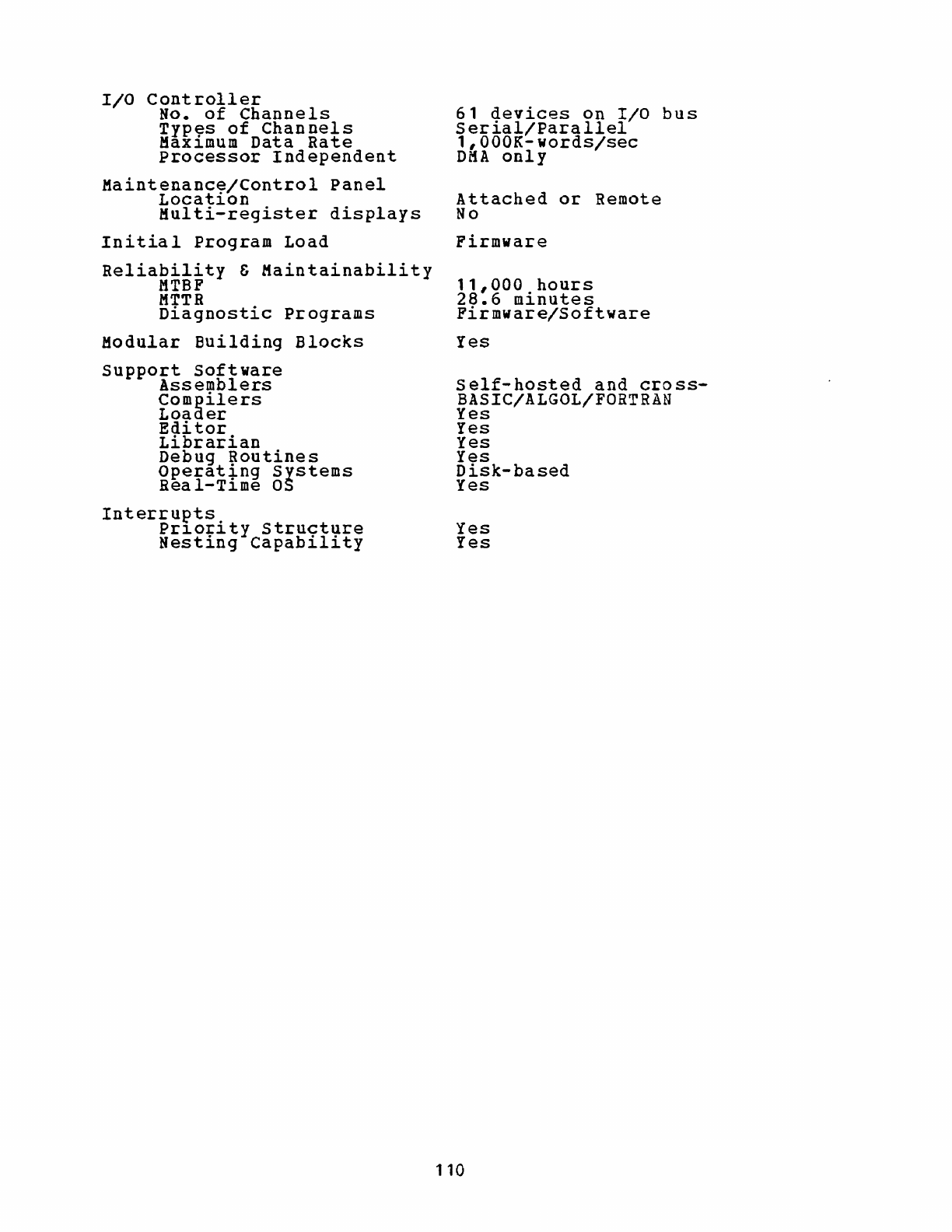
I/O
Controller
No.
of
Channels
Types
of
Channels
Maximum
Data
Rate
Processor
Independent
Maintenance/Control
Panel
Location
Multi-register
displays
Initial
Program
Load
Reliability
&
Maintainability
MTBF
MTTR
Diagnostic
Programs
Modular
Building
Blocks
Support
Software
Assemblers
Compilers
Loader
Editor
Librarian
Debug
Routines
Operat~ng
Systems
Real-Tl.me
OS
Interrupts.
Prl.orl.ty
Structure
Nesting
Capability
61
devices
on
I/O
bus
Serial/Parallel
1,000K-words/sec
DMA
only
Attached
or
Remote
No
Firmware
11,000
hours
28.6
minutes
Firmware/Software
Yes
Self-hosted
and
cross-
BASIC/ALGOL/FORTRAN
Yes
Yes
Yes
Yes
Disk-based
Yes
Yes
Yes
110
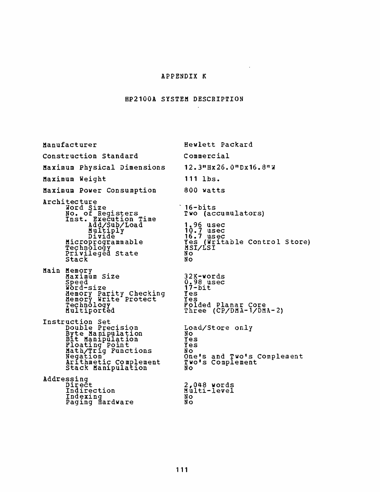
APPENDIX K
HP2100A
SYSTEM
DESCRIPTION
Manufacturer
Construction
standard
Maximum
Physical
Dimensions
Maximum
Weight
Maximum
Power
Consumption
Architecture
Word
Size
No.
of
Registers
.
Inst.
Execut~on
T~me
Add/Sub/Load
M':1
l
tiply
D~v~de
Microprogrammable
Technology
Privileged
State
Stack
Main
Mem9ry .
Max~mum
Sl.ze
Speed
Word-size
Memory
Pa~ity
Checking
Memory
Wr~te
Protect
Technoloqy
Multiported
Instruction
Set
Double
Precision
Byte
Manipulation
B~t
Manipulation
Floating
Point
Math/+rl.g
Functions
Negat~on
Arl.thmetic
Complement
Stack
Manipulation
Addres!?ing
Dl.rect
Indirection
Indexing
Paging
Hardware
Hewlett
Packard
Commercial
12.3"Hx26.0"Dx16.8"W
111
lbs.
800
watts
~
16-bits
Two
(accumulators)
1.96
usec
10.7
usec
16.7
usec
Yes
(Writable
Control
store)
MSI/LSI
No
No
32K-words
0.98
usec
17-bit
Yes
Yes
Folded
Planar
Core
Three
(CP/DMA-l/DMA-2)
Load/Store
only
No
Yes
Yes
No
One's
and
Two's
Complement
Two's
Complement
No
2,048
words
Multi-level
No
No
111
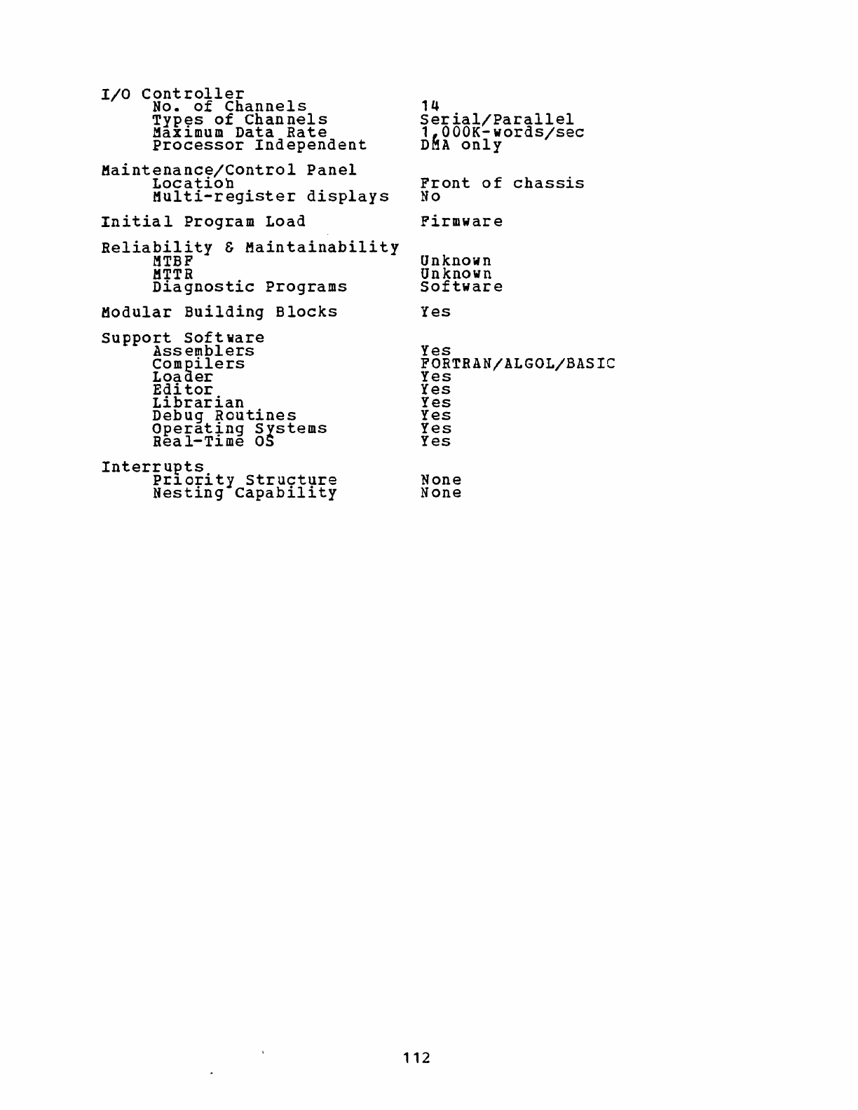
I/O
Controller
No.
of
Channels
Typ~s
of
Channels
MaX1mum
Data
Rate
Processor
Independent
Maintenance/Control
Panel
Location
Multi-register
displays
Initial
Program
Load
Reliability
&
Maintainability
MTBF
MTTR
Diagnostic
Programs
Modular
Building
Blocks
Support
Software
Assemblers
Compilers
Loader
Edi
tor
Librarian
Debug
Routines
Operat~ng
Systems
Real-T1me
as
Interrupts
pr10rity
structure
Nesting
capability
14
Serial/Parallel
1~OOOK-words/sec
D~A
only
Front
of
chassis
No
Firmware
Unknown
Unknown
Software
Yes
Yes
FORTRAN/ALGOL/BASIC
Yes
Yes
Yes
Yes
Yes
Yes
None
None
112
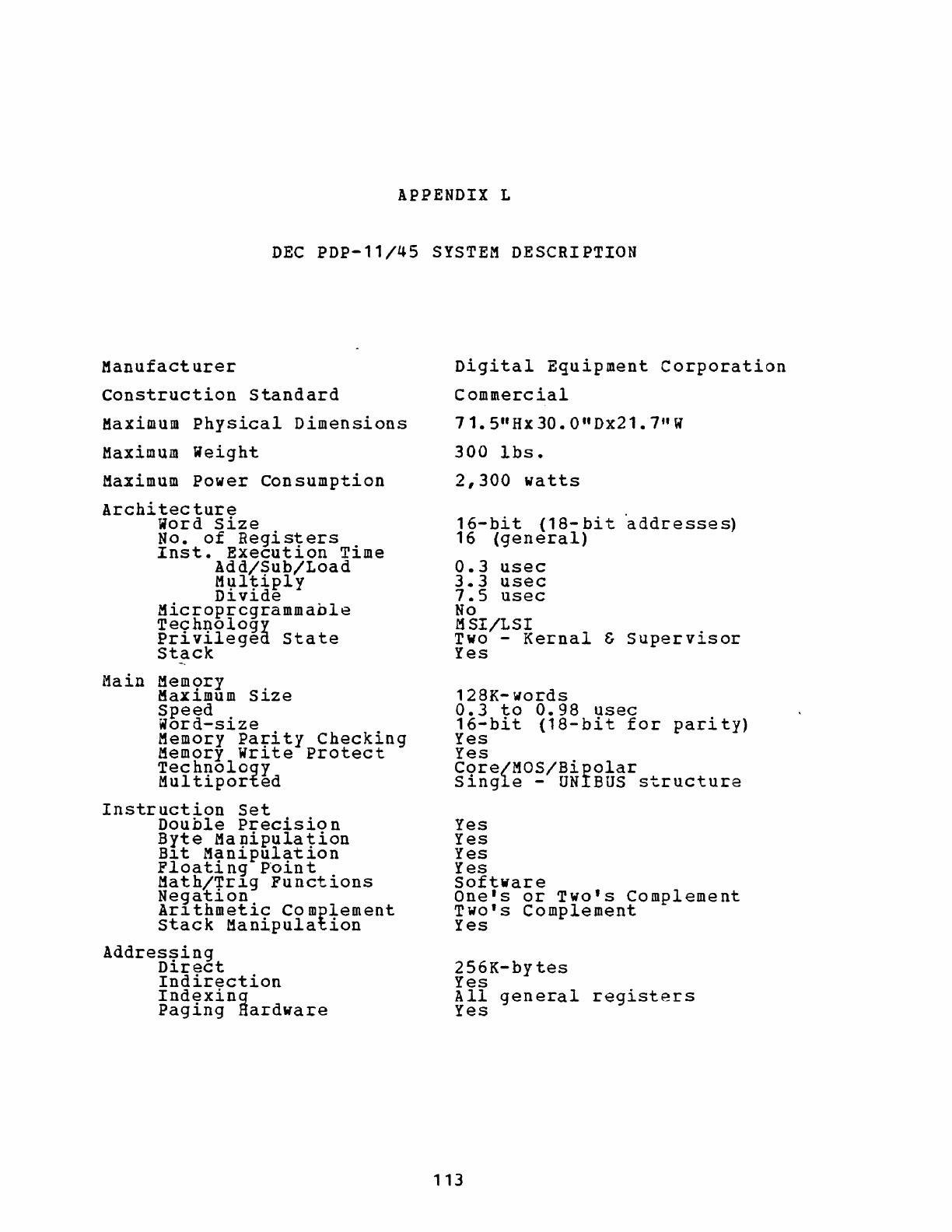
APPENDIX
L
DEC
PDP-l1/45
SYSTEM
DESCRIPTION
Manufacturer
Construction
Standard
Maximum
Physical
Dimensions
Maximum
Weight
Maximum
Power
Consumption
Archi
tec
ture
Word
Size
No.
of
Regis~ers
.
Inst.
Execut10n
T1me
Add/Sub/Load
M':lltiply
D1v1de
Microprcgrammable
Technology
Privileged
state
Stack
Main
Mem<;>ry
.
MaX1mum
S1ze
Speed
Word-size
Memory
Pa~ity
Checking
Memory
Wr1te
Protect
Technology
Multiported
Instruction
set
Double
Precisio
n
Byte
Manipulation
B1t
Manipulation
Floati
ng P"oin t
Math/~r~g
Functions
Negat10n
Ar1thmetic
Complement
Stack
Manipulation
Addres~ing
D1rect
Indirection
Indexing
Paging
Hardware
Digital
Equipment
Corporation
Commercial
71.
5"
Hx
30.
0
II
Dx21.
7"
W
300
Ibs.
2,300
watts
16-bit
(la-bit
'addresses)
16
(general)
0.3
usee
3.3
usec
7.5
usec
No
MSI/LSI
Two
-
Kernal
&
Supervisor
Yes
128K-
words
0.3
to
0.98
usee
16-bit
(18-bit
for
parity)
Yes
Yes
Core/MOS/Bipolar
Single
-
UNIBUS
structure
Yes
Yes
Yes
Yes
Software
One's
or
Two's
Complement
Two's
Complement
Yes
256K-bytes
Yes
All
general
registers
Yes
113
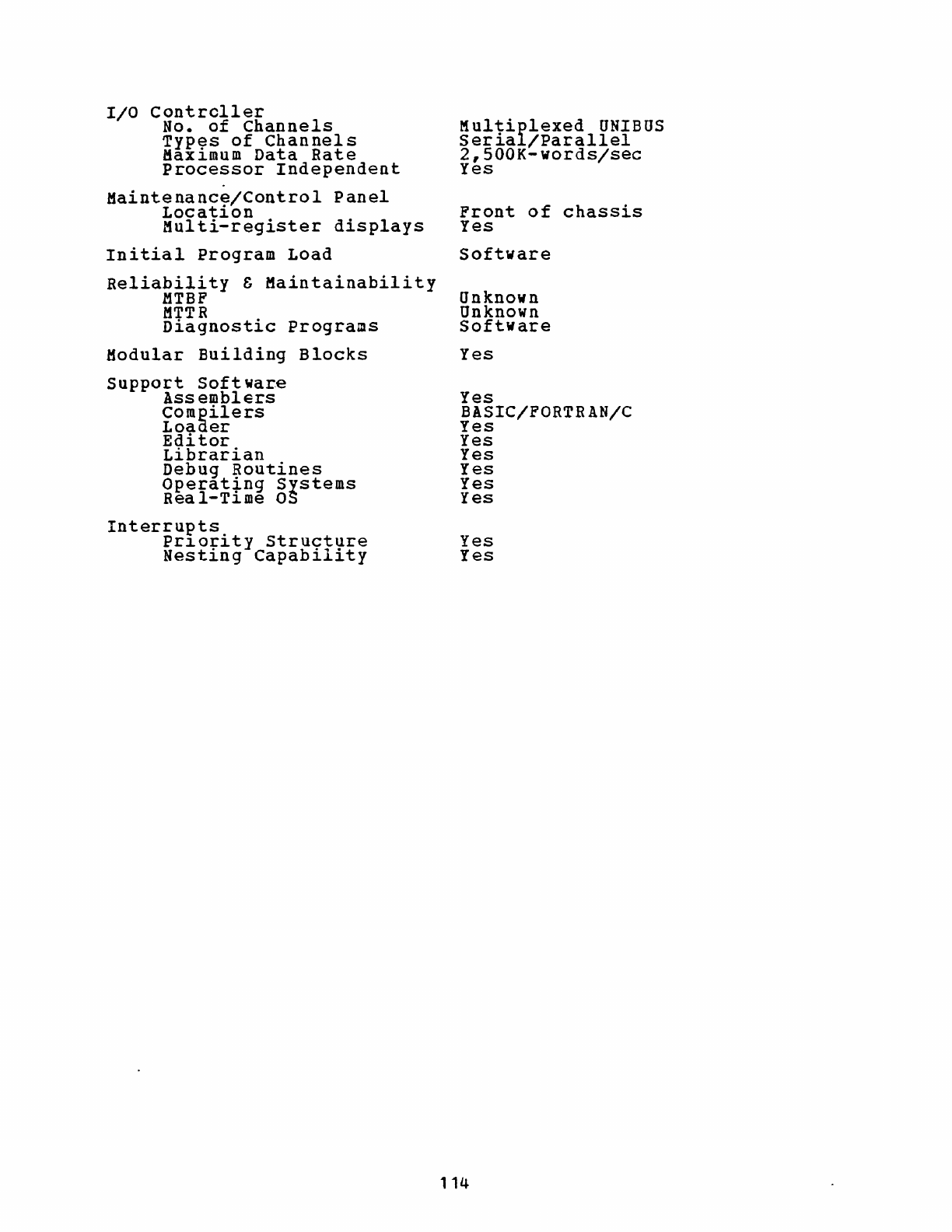
I/O
Controller
No.
of
Channels
Types
of
Channels
Maximum
Data
Rate
Processor
Independent
Maintenance/Control
Panel
Location
Multi-register
displays
Initial
Program
Load
Reliability
&
Maintainability
MTBF
MTTR
Diagnostic
Programs
Modular
Building
Blocks
Support
Softwar.e
Assemblers
Compilers
Loaaer
Editor
Librarian
Debug
Routines
Operat~ng
Systems
Rea
l-T~me
as
Interrupts.
Pr~or~ty
structure
Nesting
Capability
Multiplexed
UNIBUS
Serial/Parallel
2,500K-words/sec
Yes
Front
of
chassis
Yes
Software
Unknown
Unknown
Software
Yes
Yes
BASIC/FORTRAN/C
Yes
Yes
Yes
Yes
Yes
Yes
Yes
Yes
114
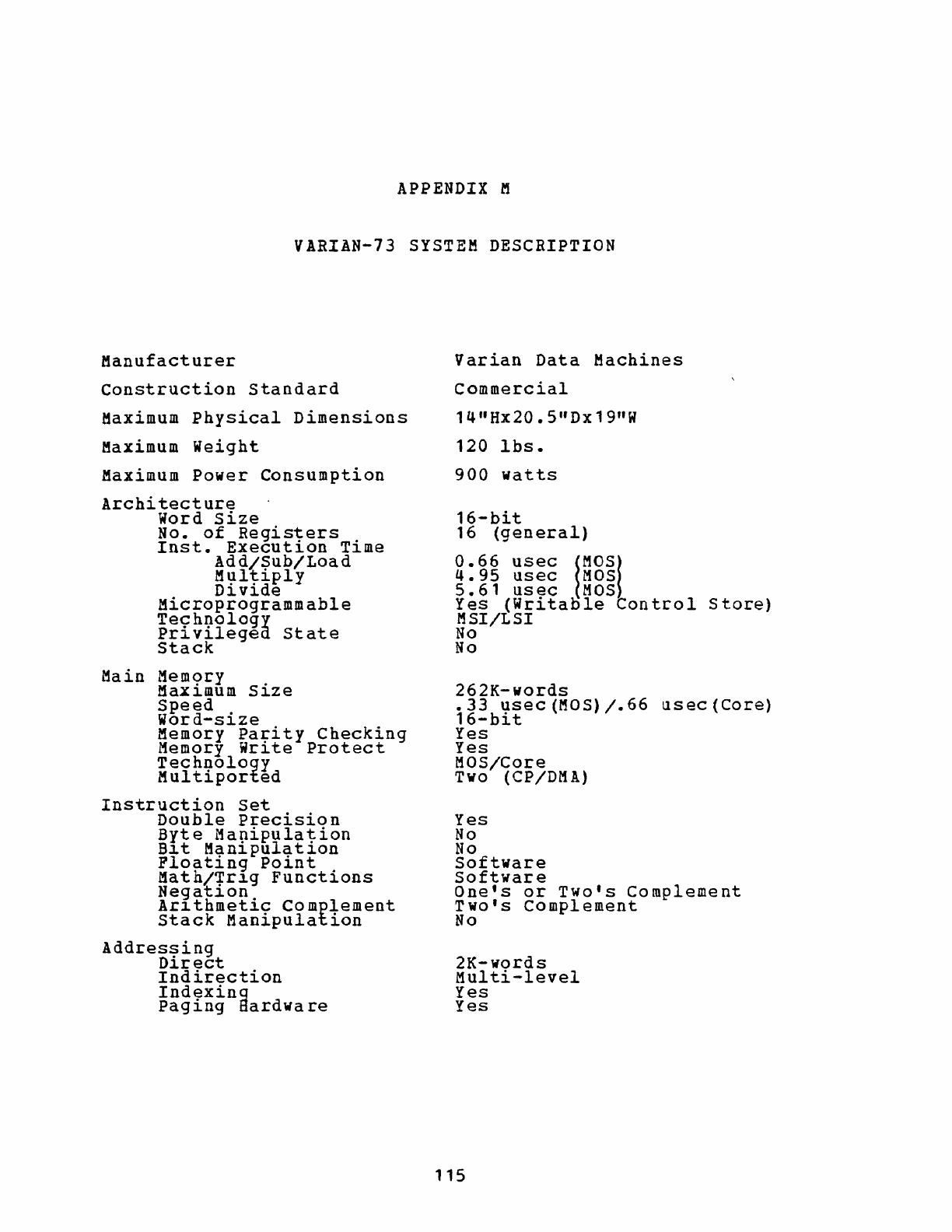
APPENDIX M
VARIAN-73
SYSTEM
DESCRIPTION
Manufacturer
Construction
Standard
Maximum
Physical
Dimensions
Maximum
Weight
Maximum
Power
Consumption
Architecture
Word
Size
No.
of
Registers
lnst.
Execution
Time
Add/Sub/Load
Ml;1ltiply
D~v~de
Microprogrammable
Technology
Privileged
state
Stack
Main
Mem9ry .
Max~mum
S~ze
Speed
Word-size
Memory
Parity
Checking
Memory
Write
Protect
Technology
Multiported
Instruction
Set
Double
Precision
Byte
Ma~ipulation
B~t
Man~pulat~on
Ploating
Point
Math/+r1g
Functions
Negat~on
Ar~thmetic
Complement
Stack
Manipulation
Addressing
Direct
Indirection
Indexing
paging
8ardwa
re
Varian
Data
Machines
Commercial
14
n
Hx20.5"Dx19"W
120
lbs.
900
watts
16-bit
16
(general)
0.66
usec
!MOSI
4.95
usec
MOS
5.61
usec
MOS
Yes
(Writaole
Conteol
Store)
MSI/LSI
No
No
262K-words
.33
usec(MOS)/.66
usec(Core)
16-bit
Yes
Yes
MaS/Core
Two (CP/DMA)
Yes
No
No
Software
Software
One's
or
Two's
Complement
Two's
Complement
No
2K-words
Multi-level
Yes
Yes
115
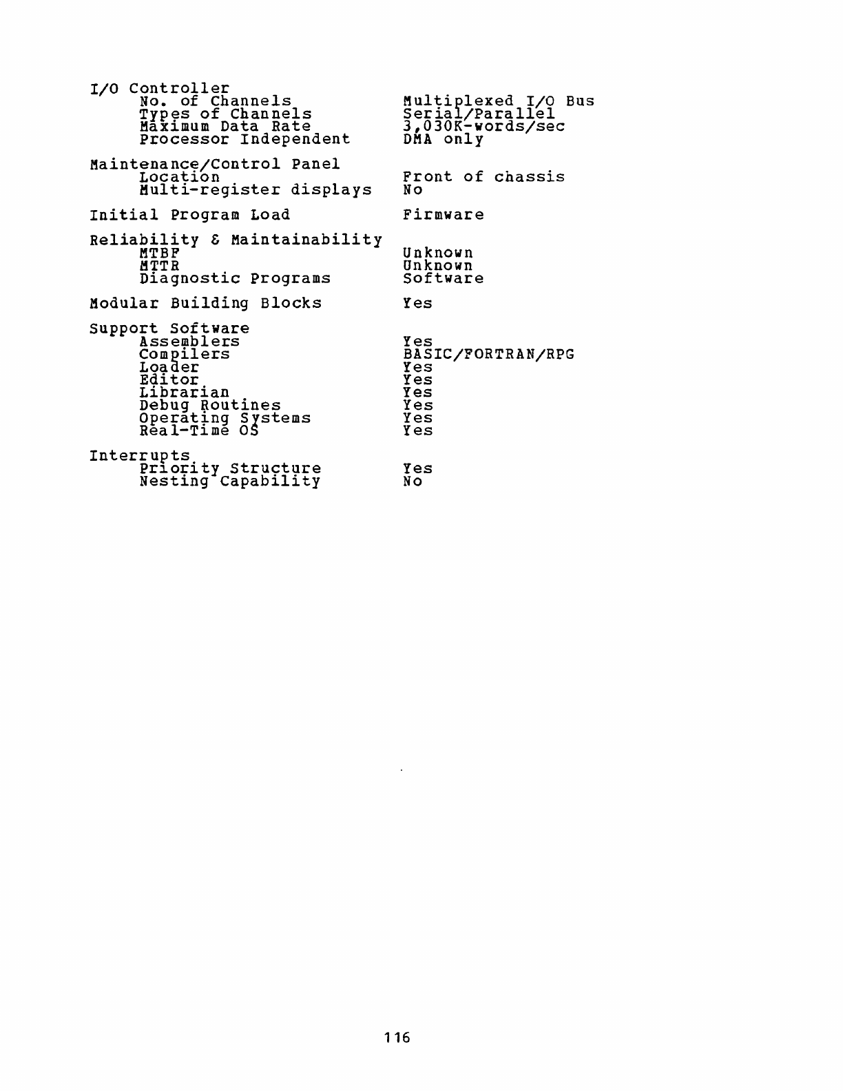
I/O
Controller
No.
of
Channels
Types
of
Channels
Maximum
Data
Rate
Processor
Independent
Maintenance/Control
Panel
Location
Multi-register
displays
Initial
Program
Load
Reliability
&
Maintainability
MTBP
MTTR
Diagnostic
Programs
Modular
Building
Blocks
support
Software
Assemblers
Compilers
Loaner
Editor
Librarian
Debug
Routines
Operat~ng
Systems
Real-Tl.me
OS
Interrupts
pr~ority
structure
Nesting
Capability
Multiplexed
I/O
Bus
Serial/Parallel
3,030K-words/sec
OMA
only
Front
of
chassis
No
Firmware
Unknown
Onknown
Software
Yes
Yes
BASIC/FORTRAN/RPG
Yes
Yes
Yes
Yes
Yes
Yes
Yes
No
116
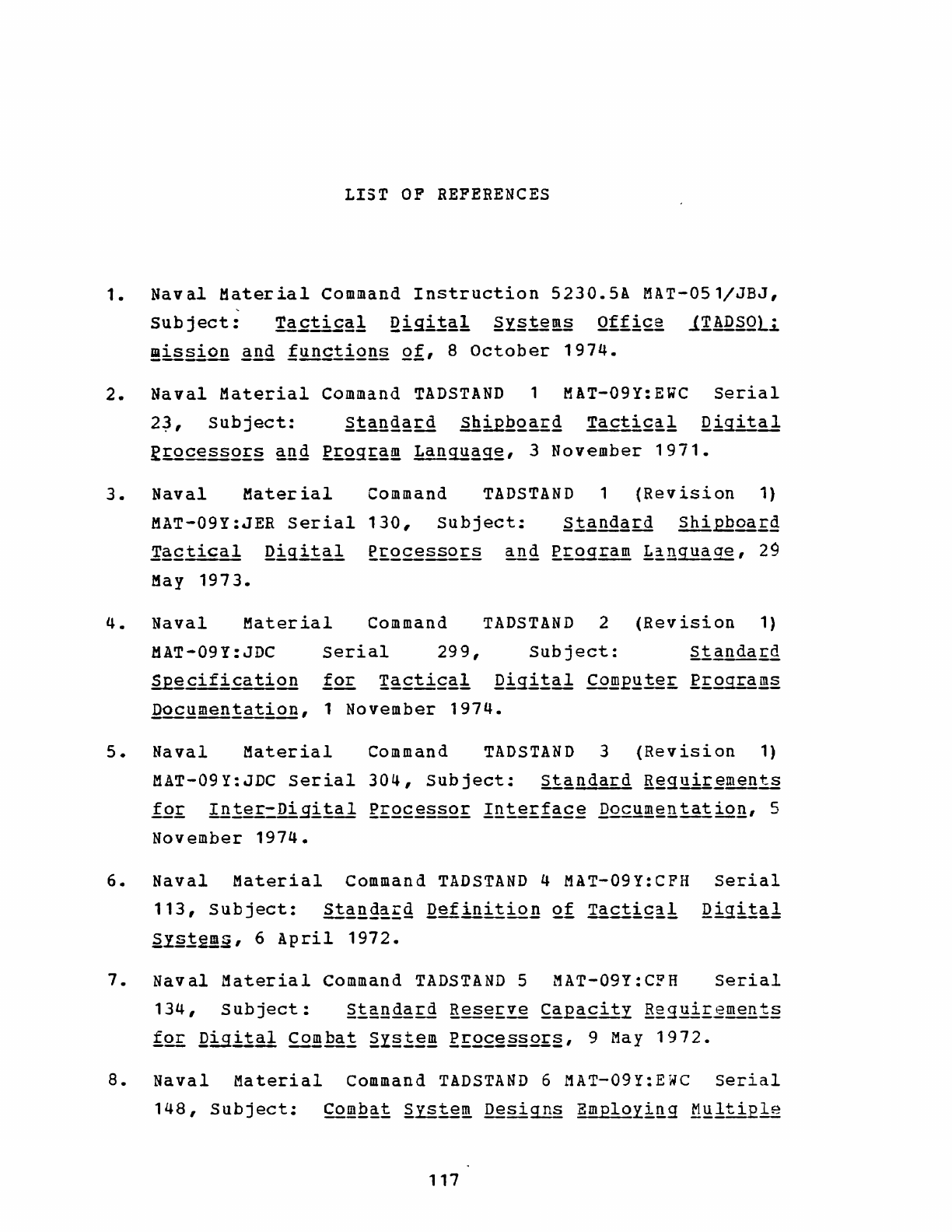
LIST
OF REFERENCES
1.
Naval
Material
Command
Instruction
5230.5A
MAT-051/JBJ,
Subject:
Ta£ti£~!
Qigi!g!
~y§te~
QtfiQg
l!ADS
O
li
!!is§i2!!
gnd
fY..!!£tiQns
QI,
8
October
1974.
2.
Naval
Material
Command
TADSTAND
1 MAT-09Y:EWC
Serial
2~,
Subject:
3.
Naval
Material
Command
TADSTAND
1
(Revision
1)
MAT-09Y:JER
Serial
130,
Subject:
~tand~rd
Shi£Boa££
.£2:£tical
~igital
~£Q.£~~Q£§
~g
f.£Qg~
~!ngua~,
29
May
1973.
4.
Naval
Material
Command
TADSTAND
2
(Revision
1)
MAT-09Y:JDC
Serial
299,
Subject:
~§cif~cation
12£
!g£ti£~b
Qocymen!atiQB,
1
November
1974.
5.
Naval
Material
Command
TADSTAND
3
(Revision
1)
MAT-09Y:JDC
Serial
304,
Subject:
standard
R~guir~~ts
!Q~
Inter-DiEital
R£Q£~§§Q.£
!gte£!~£~
~~~lltation,
5
November
1974.
6.
Naval
Material
Command
TADSTAND
4 MAT-09Y:CFH
Serial
113,
Subject:
ll~!!g~Eg
Qefinitiol!
Qf
Ta£!!£a!.
Qigitgl
~y~!~~,
6
April
1972.
7.
Naval
Material
Command
TADSTAND
5 MAT-09Y:CFH
Serial
134,
Subject:
2!£!!dard
R~~£ve
~gEacity
Regui£~~!l!§
~Q£
~igital
£2~ba!
~I§1~~
gE2£§§§2£§,
9
May
1972.
8.
Naval
Material
Command
TADSTAND
6 MAT-09Y:EWC
Serial
148,
Subject:
CO!Q~!
2Y§~~~
Desi~§
Employ!~g
~~1tiEle
117
Al!LUYK-l
PrQ£~£2'
5
June
1972.
9.
Naval
Material
Command
TADSTAND
7 MAT-09Y:HLW
Serial
207,
Subject:
~!~gsrd
Digital
Di2~lal
£Q!!..§21~,
25
July
1974.
10.
Chief
of
Naval
Technical
Training
letter
Code
314:JW
Serial
173,
Subject:
~at~
~!:oc~ssing
~@iE~nt
~tanda~dizatiQn,
5
June
1974.
11.
Weitzman,
C.
l1in!£Q!!ID!~~f:
~I§~~~
~!!:.!!ctur~L
Im~!~~~ll!atiQQ
~~g
lEE1!£ation,
Prentice-Hall
Inc.,
1974.
12~
Naval
Electronics
Systems
Command
Contract
Specification
ELEX-C-135,
Title:
£ompu!~£L
Qigital
Dai~L
£Q~ba~
~Y§te~,
27
November
1972.
13.
Naval
Air
Systems
Command
letter
AIR-5333F3:ATS
Serial
unknown,
Subject:
~~~gsrd
~in!=UYli
Digital
R£Q£g§§Q!:,
1
December
1972.
14.
Sansone,
J.
S.,
Ih~
l!S!Y~§
§.ianda£,g,
!~ctic2!
!1!!!i-Digi!~!
Pr~§Q.!:
JANLQYK-2QlY1J..
PrQ.£~!:~nt:
A
ttQg~!
for
~uty!:~
Acguisit!Q!!§,
Research
Paper,
Industrial
college
of
the
Armed
Forces,
Washington,
D.
e.,
1974.
15.
Chief
of
Naval
Material
letter
MAT-09Y:JER
Serial
217,
Subject:
§.tand~!:g
~i!!i=Q!li
Qigi!~1
PrQ~2§§Q£,
15
November
1972.
-
16.
Department
of
the
Navy
.Technical
Manual
NAVELEX
0967-LP-598-1000,
Q~ts
Proc~~sirrg
~~!
AN/UYK-2QlYL'
v.
1-6,
1976.
17.
Department
of
the
Navy
Handbook
NAVELEX
0967-LP-598-2000,
Q~g£~§
li~!!gboQk
!liLYYK-2Q1YL
Compu~~f
SUE..EQ!:!
Soft~£~,
v.
I-IV,
Systems,
April
1976.
118
Sperry-UNIVAC
Defense
INITIAL
DISTRIBUTION
LIST
1.
Defense
Documentation
Center
Cameron
station
Alexandria,
Virginia
22314
2.
Library,
Code
0212
Naval
postgraduate
School
Monterey,
California
93940
3.
Department
Chairman,
Code
62
Department
of
Electrical
Engineering
Naval
postgraduate
School
Monterey,
California
93940
4.
Department
Chairman,
Code
54
Department
of
Administrative
Sciences
Naval
Postgraduate
School
Monterey,
California
93940
5.
Dean
of
Research,
Code
023
Naval
postgraduate
School
Monterey,
California
93940
6.
Assoc.
Professor
S.
Jauregui,
Code
62Ja
Department
of
Electrical
Engineering
Naval
Postgraduate
School
Monterey,
California
93940
7.
LCDR
E.
Zabrycki,
Code
54Zx
Department
of
Administrative
Sciences
Naval
Postgraduate
School
Monterey,
California
93940
119
No.
Copies
2
2
2
2
1
10
1
8.
LCDR
Robert
R.
Joyce,
USN
3987
Hischier
Court
Napa,
California
94558
9.
Commander,
Naval
Security
Group
Command
Naval
security
Group
Headquarters
3801
Nebraska
Ave.,
N.W.
Washington,
D.C.
20390
ATTN:
CDR
H.
Shoemaker,
G82
LCDR
F.
Cleary
10.
Commanding
Officer
Naval
Electronic
Systems
Security
Engineering
Center
Naval
Security
station
Nebraska
Ave.,
N.W.
Washington,
D.C.
20390
ATTN:
Mr.
D.
Webster
11.
Commander,
Naval
Electronic
Systems
Command
Naval
Electronic
Systems
Command
Headquarters
ELEX-01
Washington,
D.C.
20360
ATTN:
RADM
G.
Smith
12.
Commander,
Naval
Electronic
Systems
Command
Naval
Electronic
Systems
Command
Headquarters
PME-107
Washington,
D.C.
20360
ATTN:
CAPT
H.
Leavitt
Mr.
R.
Materazza
LCDR
R.
Todaro
Mr.
P.
Lowell
13.
Commander,
Naval
Electronic
Systems
Command
Naval
Electronic
systems
command
Headquarters
PME-106
Washington,
D.C.
20360
120
1
2
1
1
4
1
ATTN:
CAPT
J.
Pope
14.
Commander,
Naval
Electronic
Systems
Command
Naval
Electronic
Systems
Command
Headquarters
ELEX-570
Washington,
D.C.
20360
ATTN:
CAPT
C.
Hager
15.
Chief
of
Naval
Material
Naval
Material
Command
Headquarters
NMAT-09Y
Washington,
D.C.
20360
ATTN:
CAPT
Reiher
16.
Commander
w
Naval
Electronics
Laboratory
Center
San
Diego,
California
92152
ATTN:
Mr.
R.
Eyres
Mr. B.
Burris
17.
Director
National
Security
Agency
Group
W
Ft.
George
G.
Meade,
Maryland
20755
ATTN: Mr.
J.
Boone
18.
Electromagnetic
Systems
Laboratories,
Inc.
495
Java
Drive
Sunnyvale,
California
94086
ATTN: Mr.
B.
Barr
19.
Sanders
Associates
95
Canal
Street
Nashua,
New
Hampshire
03060
ATTN:
Mr.
W.
Zandi
20.
Naval
Communications
station,
Rota
NAVSECGRU
Department
FPO,
New
York
09540
ATTN:
CDR
R.
Shields
121
1
1
2
1
1
1
1
21.
Commanding
Officer
Fleet
Combat
Direction
System
support
Activity
San
Diego,
California
92147
ATTN:
LCDR
J.
Roudebush
Mr.
V.
Khosharian
22.
Commanding
Officer
Naval
Electronic
Systems
Engineering
Center
P.O.
Box
80337
4297
Pacific
Highway
San
Diego,
California
92138
ATTN:
Mr.
C.
Benson
122
2
1
