KB9VBR J Pole Antenna Sheet 440
User Manual: J 440
Open the PDF directly: View PDF ![]() .
.
Page Count: 2

The modern J-Pole is derived from an antenna
called the end-fed Zep. Itʼs similar in design to
the end-fed antennas of the 1930ʼs; most
notably the antennas used on the Zeppelin
dirigibles. Of course the Zeps used on dirigibles
where long wire HF antennas that trailed out
the rear of the cabin. The modern J-Pole
antenna is much shorter and optimized for VHF
and UHF communication.
The J-Pole antenna can be best described as a
½ wave section over a ¼ wave vertical with a ¼
wave matching stub. The 2 quarter wave
sections at the base of the antenna run parallel
to each other. The current in the one section will
be out of phase of the other, keeping that
section of the antenna from radiating. The
remaining half wave section will radiate
extremely well since there is no counteracting
field to keep it from radiating.
As a half wave antenna, the J-Pole doesnʼt
need any radials or a ground plane to work.
Average gain with a 2 meter J-Pole is about 3
db. Many like to compare the gain and antenna
pattern to that of a Ringo Ranger. The biggest
advantage of the J-Pole is that it is at DC
ground, so it can be mounted just about
anywhere and still work. No special grounding
or a groundplane is necessary for operation.
KB9VBR J-Pole antennas are built with the
highest quality materials and individually tested
for optimum performance. If you have any
questions about your antenna, or have a
special request, please let me know. I am more
than willing to help you out.
KB9VBR
J-Pole Antennas
Affordable antennas with
superior performance.
• Solid copper construction, Durable
in the harshest of environments
• SO-239 connector soldered on at
point of lowest SWR for band
• Low SWR. 1.2:1 or less at 146
MHz for the 2 meter J-Pole.
• Efficient radiator. 3db of gain when
compared to a 1/4 wave
groundplane antenna.
• 11 inch mounting stub for easy
installation. 6 meter model has 18
inch stub.
•Can be painted to blend into the
environment.
©2011 Michael Martens • All rights reserved
Order more J-Pole Antennas
The Original 2 meter J-Pole
Our most popular seller. This antenna has
outstanding performance on 2 meters and loads up
quite well on 70 centimeters. Overall length is 69
inches with an 11 inch mounting stub.
The Breakaway 2 meter J-Pole
The 2 meter J-Pole with a two piece design. Now the
antenna will fit in the trunk of your car. Carry it with
you for fast emergency communications deployment.
The 6 meter J-Pole
A monster of an antenna measuring in at 13.5 feet.
Excellent performance, hit repeaters 40 mile away
with only 5 watts. The 6 meter J features a two piece
design for shipping and easy storage.
The 222 MHz J-Pole
Its difficult to find quality antennas for the 222 MHz
band. This antenna will get you on the air with great
signal reports. Overall length is 49 inches with an 11
inch mounting stub.
The 440 MHz J-Pole
440 MHz single band dedicated antenna. Short,
lightweight, and always more gain than a 1/4 wave
groundplane; only 30 inches overall with 11 inch
mounting stub.
Other antennas (see website for details)
153 MHz Public Safety / MURS Antenna
155 MHz Marine band / Public Safety Antenna
162 MHz Railroad / NOAA Weather Antenna
462-467 MHz GMRS band Antenna
118-127 MHz Airband Antenna
87-108 MHz Low Power FM band Antenna
To Order, Contact:
Michael Martens, KB9VBR
1228 Arthur St
Wausau, WI 54403
(715)845-4218
kb9vbr@yahoo.com
Order online at: www.jpole-antenna.com
J-Pole antennas are balanced antennas. Since you
will be connecting a balanced antenna to an
unbalanced feedline, you may need to construct a
balun to decouple the coax from the antenna.
Doing so will increase the antennaʼs performance.
Making the balun is easy, just take 5 loops of coax
and loop them into a 6 inch diameter bundle.
Secure the bundle with cable ties. The balun
should be positioned about a foot away from the
feedpoint.
Mount the J-Pole on a mast with at least 2 hose
clamps or U-Bolts. The mounting section of this
antenna is 11 inches long, that should be plenty of
length to clamp the antenna onto a mast. The J-
Pole is at DC ground, that means you can clamp it
directly to a metal mast or support structure without
affecting its performance. Just make sure that the
mounting mast does not extend above the T
connector. Seal the PL-259 connector with high
quality electrical or Coax Seal.
As the antenna is exposed to the elements, the
bright copper finish will slowly oxidize and create a
lovely dark patina. This oxidation does not affect
the antennaʼs performance.
The copper J-Pole is extremely durable. I have one
installed at home that has gone through several
winters without any problems. These antennas can
also be mounted on a mast and jammed into the
ground for an emergency station. Local ARES
groups could work with emergency government to
place J-Poles on the roofs of fire stations and
shelter locations. These antennas require no
maintenance and are inexpensive enough that they
can be installed everywhere.
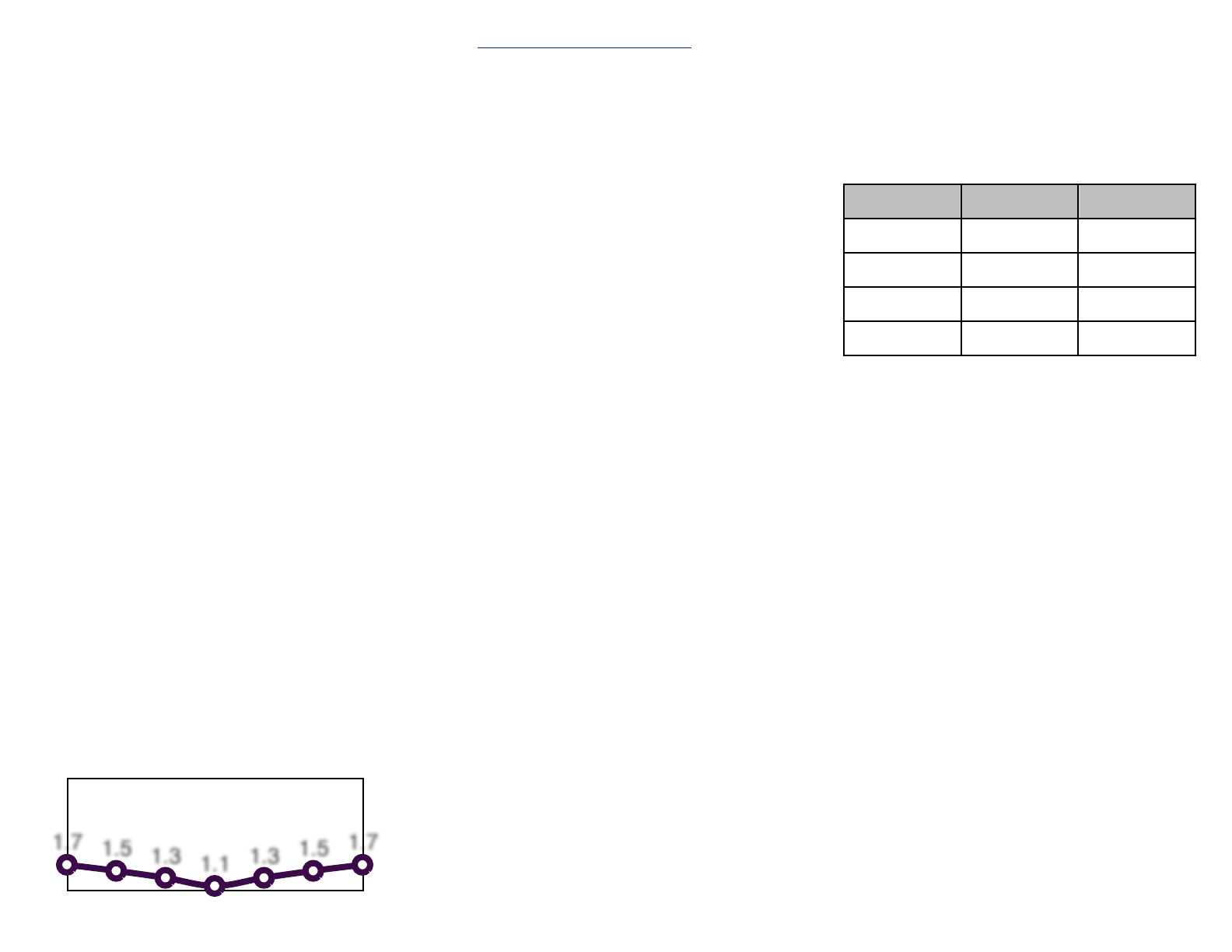
143 144 145 146 147 148 149
1.7
1.5
1.3
1.1
1.3
1.5
1.7
2 Meter J-Pole SWR Chart 144-148MHz
Go to www.jpole-antenna.com/FAQ for more
antenna questions and answers.
What are the all copper J-Pole antennas
constructed with?
My J-Pole antennas are constructed out of Type M
solid copper pipe for the ultimate in durability and
weather resistance. All joints are soldered with rosin
core solder. An SO-239 connector is soldered onto
the antenna at the point of lowest SWR.
How do your two meter J-Poles perform on the
440 MHz band?
The two meter J-Pole is tuned for maximum
efficiency at the 2 meter band where the SWR is
1.2:1 or less at 146 MHz. It is a pretty good
performer on the UHF band where the SWR is 1.5:1
– 2.0:1 between 445-450Mhz. This is still within the
range of what modern radios can handle.
Can the antenna be painted?
You may paint the antenna with nonmetallic paint to
protect it and help it blend into the surroundings. If
you want to keep the antenna looking shiny and new
on the tower, you can also paint it with a clear
lacquer or nonmetallic enamel paint.
How to I connect your antennas to my hand held
portable radio?
While the J-Pole antennas are designed to be base
station antennas, they will all work very well with your
HT or hand held radio. The antennas have an
So-239 connector on them, and I recommend using
coax cable with Pl-259 connectors to connect the
antenna to the radio. You will need an adaptor to
connect the standard coax with Pl-259 connectors to
your portable radio. Radio Shack does sell an BNC
to SO-239 adaptor and an SMA to SO-239 adaptor.
How much power will a J-Pole antenna handle
Typically, the 2 meter all copper J-Pole antenna will
handle 250 watts or more of power. Copper is a very
efficient conductor and will tolerate and dissipate
heat energy very well.
What type of coax should I use?
Coax size is dependent on a couple of factors,
most notably the length of your run and the
frequency of your antenna. VHF and UHF signals
are more prone to attenuation in the coax, so a low
loss cable should be selected.
Feedline loss in DB per 100 feet:
Cable
146 MHz
446 Mhz
RG-58
6.5
12.2
RG-8X
4.7
8.6
RG-8U
2.3
4.7
9913/LMR400
1.6
2.9
A loss of 3 db will cut your power in half. A six db
loss will cut your power into 1/4. I recommend
RG-8 if your cable run is over 50 feet and RG-8X if
it is less than 50 feet. You shouldnʼt use RG-58 for
VHF/UHF unless it is a very short run (less than 15
feet.). GMRS J-Pole users should only use RG-8
for short runs and Belden 9913 for longer runs.
The SWR is really high on my antenna. What
should I check?
Here are a few things you can check if your SWR
is high.
• Check the coax, make sure there are no
problems associated with it. The connectors
should be well soldered or crimped without any
shorts and there should be be any apparent
kinks in the cable.
• Check the mounting location, nearby buildings
will affect the SWR. Keep structures at least six
feet away from the antenna, or make sure the
antenna is above the structure.
• Make a balun to keep RF from coming back
down the coax. Make a coil of about 5 loops of
coax with a coil diameter of about 6 inches. This
coil should be located about a foot away from
the feedpoint of the antenna. Secure the coil
with cable ties or electrical tape.
• Inspect the antenna itself. Is the solder loose or
cracked at the feedpoint. If it is, let me know.
