Unknown KEI_196 KEI 196
User Manual: KEI_196
Open the PDF directly: View PDF ![]() .
.
Page Count: 160 [warning: Documents this large are best viewed by clicking the View PDF Link!]

WARRANTY
Keithley Instruments, Inc. warrants this product to be free from defects in material and tiorkmanship for a period of 1 year from date of
shipment.
Keithley Instruments, Inc. warrants the following items for90 days from the date of shipment: probes, cables, rechargeable batteries,
diskettes, and documentation.
During the warranty period, we will, at OUT option, either repair or replace any product that proves to be defective.~~ :
To exercise this warranty, write or call your local Keithley representative, or contact Keithley headquarters in Ct&e.land, Ohio. YOU will
be given Prompt assistance and return instruciions. Send the product, transport&~ prepaid, to the indicated service facility. Repairs
will be made and the product returned, transportation prepaid. Repaired or replaced products are warranted for the balance of the origi-
nal warranty period, or at least PO days.
LIMITATION OF WARRANTY
This warranty does not apply to defects resulting from product modification without Keithley’s express written consent, or misuse of
any product or part. This warranty also does not apply to fuses,~software, non-rechargeable batteries, damage from battery leakage,~or
problems arising~55Zi-i ncmii~l wear or failure to follow instructions.
THIS WARRANTY IS IN LIEU OF ALL OTtiERWARRANTIES, EXPRESSED OR IMPLIED, INCLUDING ANY IMPLIED
WARRANTY OF MERCHANTABILITY OR FITNESS FOR A PARTICULAR USE. THE REMEDIES PRO\IIDED HEREIN ARE
BUYER’S SOLE AND EXCLUSIVE REMEDIES.
NEITHER KEITHLEY INSTRUMENTS, INC. NOR ANY OF ITS EMPLOYEES SHALL BE LIABLE FOR ANY DIRECT, JNDI-
RECT, SPECIAL, INCIDENTALOR CONsE:QUENTIAL DAMAGES ARISING OUT OF THE USE OF ITS JNSTRIJM.ENTS AND
SOFTWARE EVEN IF KEITHLEY INSTRUMENTS, INC., HAS BEEN ADVISED IN ADVANCE OF THE POSSIBILITY OF
SUCH DAMAGES. SUCH EXCLUDED DAMAGES SHALL INCLUDE, BUT ARE NOT LIMITED To: COSTS OFT REMOVAL
AND INSTALLATION, Lossm SUSTAINED As THE RESULT OF IN3URY TO ANY PERSON, OR DAMAGETO PROPERTY.

Safety Precautions
The following safety precautions should be observed befoE
using this product and any associated inshvmentation. Al-
though some instruments and accessories would normally be
used with non-hazardousvoltages, therearesituatio~iis where
hazardous conditions may be present
This product is intended for use by qualiied personnel who
iecognize shock hazards and are familiar with the safety pre-
cautions required to avoid possible injury. Read the operating
information carefully before using the product.
Exercise extreme caution when a shock hazard is present. Le-
thal voittige may be present on cable connector jacks or test
f?xtures. The American National Standards Instih~te (ANSI)
states that a shock hazard exists when voltage levels greater
than 30V RMS, 42.4V peak, or 60VDC are present. A good
safety practice is to expect that hazardous voltage is present
in any unknown circuit before measuring.
Before operating an inskutient, make sure the line cord is
connected to a properly grounded power receptacle. Inspect
the connecting cables, test leads, and jumpers for possible
wear, cracks, or breaks before each use.
For maximum safety, do not touch the product, test cables, or
any other instruments while power is applied to the circuit
under test. ALWAYS remove power from the entire test sys-
tern and discharge any capacitors before: connecting or dis-
connecting cables or jumpers, installing or removing
switching cards, or making internal changes, such as install-
ing or removing jumpers.
Do not touch any object that could provide a current path to
the common side of the circuit under test or power lie
(earth) ground. Always make measurements with dry hands
while standing on a ~JY, insulated surface capable of with-
standing the voltage being measured.
Do not exceed the maximum signal levels of the instruments
and accessories, as defined in the specifications and operating
inform&ion, and a~ shown on the instrument or test fixture
rear panel, or switchiig card.
Do not connect switching cards directly to unlimited power
circuits. They are intended to be used with impedance limit-
ed sources. NEVER cbnnect switching cards directly to AC
tin. When connecting sources to switching cards, install
$~~tive devices to lit fault current and voltage to the
card.
When fuses are used in a product, replace with same type and
rating for continued protection against fire hazard.
Chassis connections must only be used as shield connections
for measuring circuits, NOT as safety earth ground connec-
tions.
If you are using a test fxtwe, keep the lid closed while power
is applied to the device under test. Safe operation requires the
u.s$of a lid interlock.
Ifa @saew ispresenton~hetest tixhm?,connectit tbsafety
earth ground using #18 AWG or larger wire.
The $ symbol on an instrument or accessory indicates that
1oOOV or more may be present on the terminals. Refer to the
product manual for detailed operahlng information.
Instrumentation and accessories should not be connected to
humans.
Maintenance should be performed by qualified service per-
sonnel. Before perfo&ng any maintenance, disconnect the
line cord~and all test cables.
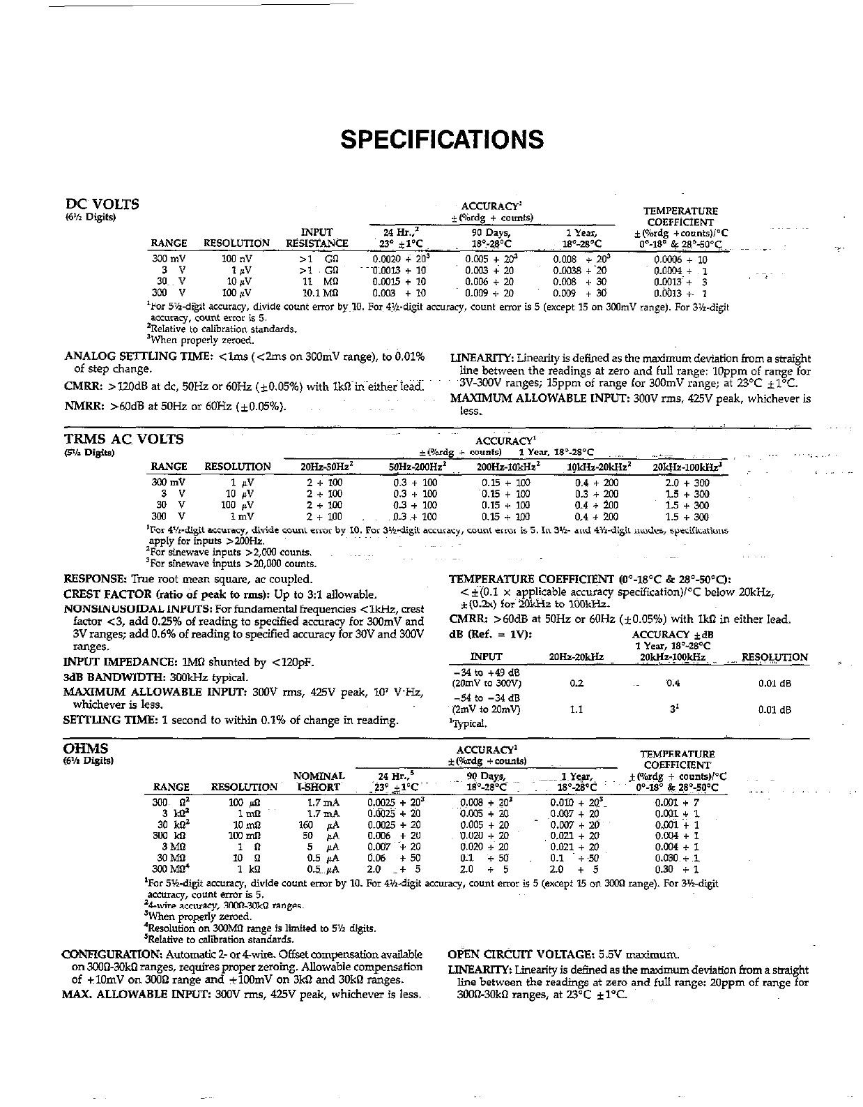
SPECIFICATIONS
DC~ VOLTS
6% Digits,
ANALOG SETTLING TIME: <lm.s (<2ms on 300mV range), to 0.01%
of step change. LINEARI’IY Linearity is defined as the timurn deviation from a straight
line between the readings at zero and full range: 1Oppm of range for
CMRR: >lZOdB at dc, MHz or 6OHz (iO.O5%) with lkQ in either lead. ~3V-3ooV ranges; 15ppm of range for 3OOmV range; at 23OC il°C.
NMRR: >M)dB at50Hz or60Hz (iO.0546). ~~ MAXIMUM ALLOWABLE INPUT: 300V rms. 425” peak, whichever is
less.
RESPONSE: Tiue root mean square, ac coupled.
CREST FACTOR (ratio of peak to rms)z Up to 3:l allowable.
NONSINUSOIDAL INPUTS: For fundamental frequencies < -, mest
factor ~3, add 0.25% of reading to specified accuracy for 3oomV and
3V ranges; add 0.6% of reading to specified accuracy for 30V and 3fXlV
ranges.
INPUT IMPEDANCE: lMlI shunted bv <12OoF.
3dBBANDWIDTHz 3WkHzfypical. ’ ’
MAXIMUM ALLOWABLE INPUT: 3oOV -, 425” peak, 10’ VHz,
whichever is less.
SETTLING TIME: 1 second to within 0.1% of change in reading.
TBMF’ERATURE COEFFICI@‘JT (0=18”C & 28Y?,*C):
< i(O.l x app!icable accuracy specification)K below 2OkHz,
f(0.2.x) for 2okHz to 1ook?iz.
CMRR: >6OdB at 5OHz or 6OHz (*0.05%) with IkR in either lead.
dB (Ref. = 1”): .4CC”RAcY *a
1 Year, IP-WC
INPUT *OHa-~0gz ?OW-?c! -. P??LUnoN
WNETGURATION: Automatic 2- or&,ire. Offset compensationavai!ab~e OBN CIRCUIT VOLTAGE: 5.5V maxinwm.
on 3wiXOkO ranges, requires proper zeroing. Allowable compensation
of ilOmV on 3OilQ range and ilWmV on 3ktl and 3OkO ranges. JJNEARIlY Linetity is defined as the madmum deviation from a &might
MAX, ALLOWABLE INPIJZ 3wV rms, 425V peak, whichever is less. line between the readings at zero and full range: 20ppm of range for
SCO@3OkO ranges, at 23°C iYC.
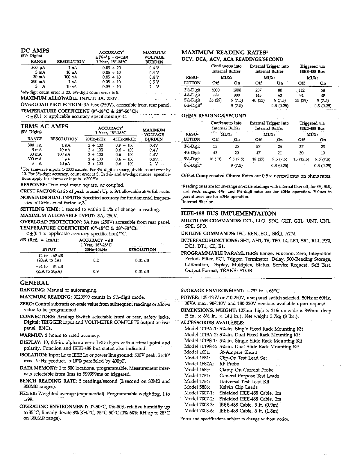
3mA 10 n.4 0.05 + 10
3iE 1ooP.A
1d 0.05 0.05 + +~ 10 10
3 A 10 K.4 0.09 + 10 * v
‘4wigit count error is 20. 3K-digit CO”“t error is 5.
MAXIMUMALLOWABLHINPUT: 3A, 250”.
OVERLOAD PROTECTION: 3A fuse (25OV), accessible from reii~ panel.
TEMPERATURE COEFFICIENT (O”-18’C & 2S”-500C):
c iCO.1 x applicable accumw svecification)PC. ~~~
1 For Sinewave inputs >x.m EOuntS. For 4Vdigit accuracy, divide cou*t error by
10. .%3lidigit accuracy, count errOI b 5. Jn 3vl- and 4K.digit modes, specifica-
ti‘J”d apply for stnew.we inputs ,200Hz.
RESPONSE: True mot mean square, ac coupled.
CREST FACTOR (ratio of peak to rms): Up to 3:l allowable at % full scale.
NONSINUSOIDAL INPUTS: Spe&d accwacy for fundamental fquen-
ctes <lkJ&, CI& factor <3.
SEmING TIME: 1 second to within 0.1% of change in reading.
MAXIMUM ALLOWABLE INPUT: 3A, 250V.
OVERLOAD PROTECTION: 3A fuse (UOV) accessibl&fiom rear panel.
TEMPERATURE COEFFICIENT (O’-18’C & 28%d”Qi~ ~’
< f(O.l x applicable accuracy specification)i°C.
dB (Ref. = ImA): ‘4CC”RAcY *a
1 Year, 1S%B’C
INPUT 2oH51okHz RE8OLuTION ~~~~
-34 to +69 dB
(ZOJ4.4 to 3.4) 0.2 0.01 dB
-54 to -34 dB
@!A to 20PA) 0.9 0.01 dB
tiAXIMUM READING RAT&
DCV, DCA, ACV, ACA READINGS/SECOND
conttn”ovs into Extemal Rigger into Triggered via
Internal Buffer I”temd Buffer IEEE488 Bus
IEEE-488 BUS IMPLEMENTATION
MULTILINE COMMANDS: DCL, LLO, SDC, GET, GTL; UNT, UNL,
.~- SPE, SPD.
UNILINE COMMANDS: IFC, REN,~EOI, SKQ, ATN.
INTERFACE FUNCTIONS: SHl. AHl, T6, TBO, L4, LEO, SRl, RLl, ?PO,
DCI. DTl, CO, El.
PROGRAMMABLE PARAMETERS: Range, Function, zero, Integration
Period, Filter. EOI. Trigger, Terminator, Delay, ?OO-Reading storage,
Calibration. Display, Multiplex, Status, Service Request, Self Test,
Output Format. TRANSLATOR.
GENERAL
RANGING: Manual or autoranging.
MAXIMUM READING: 3029999 counts in 6%.digit mode.
ZERO: Control subtract: on-scale value from subseqtient readings or allows
value to be prog&nmed.
CONNECTORS: Analog: Switch selectable front or rear, safety j&s.
Digital: TRIGGER input tid VOLTMETER COMPLETE &put on iear
panel, BNCs.
WARMUP: 2 hours to rated accuracy.
DISPLAY: 10, 0.5-in. alphanumeric LED digits with decimal point and
polarity. Function and IEEE-488 bus status also indicated.
ISOLATION: Input Lo to IEEE Lo orpower line ground: 5oOVpeak. 5~xlC+
max. VI+ product. >lO’D paralleled by 4OOpF.
DATA MEMORY: 1 to 500 locations, programmable. Measurement inter-
vals selectable from lms to 999999,&s or triggered.
BENCH READING RATE: 5 readings/second (2lsecond on 30M8 and
3COMtl ranges).
FILTER: Weighted average (exponential). Programmable weighting, 1 to
l/99.
OPERATING ENVIRONMENT: O”-500$ 0%.80% relative humidity up
to 35T; linearly derate 3% RH/“C, 35’C-5Ci’C (0%.60% RH up to 28OC
on 3oOMB range).
STORAGE ENVIRONMENT: -25” to +65OC.
POWER: 105.125V or 210.UOV, rex panel switch selected, 5OHz or 6OHz,
30VA max. YO-1lOV and 18022OV versions available upon request.
DIMENSIONS, WEIGHT: l27mm high x 216mm wide x 359mm deep
(5 in. x 8% in. x 14% in.). Net weight 3.7kg (8 Ibs.).
ACCBSSORIES AVAILABLE:
Model lOlYA-1: 5%.in. Single Fixed Rack Mounting Kit
Model lOlYA-2: 5’%-in. Dual Fixed Rack Mounting Kit
Model 10195-1: 5’%-in. Single Slide Rack Mounting Kit
Model 10195-2: 5X-b,. Dual Slide Rack Mounting Kit
Model 1651: 5&Ampere Shunt
Model 1681: Clip-On Test Lead Set
Model 168s RFPmbe
Model 1685: Clamp-On Current Pmbe
Model 1751: General Purpose Test Leads
Model 1754: Universal Test Lead Kit
Model 5806: Kelvin clip Leads
Model 7W7-I: Shielded IEEE-488 Cable, lm
Model 7007-2: Shielded IEEE-488 Cable, 20,
Model 7008.3: IEEE-488 Cable, 3 ft. (O.Ym)
Model 7008-6: IEEE488 Cable, 6 ft. (1.8m)
Prices and specifications Subject to change without notice.
TABLE OF CONTENT!3
SECTION l-GENERAL INFORMATION
1.1 INTRODUCTION. ........................................................................... l-1 ..
1.2 FEAI-URES ...... .;. ................ ;~:~.~ .... .;.e:.;. .. .;. ....................................... .~.-.~:.: l-l
1.3 WARRANTY INFORMATION ................................................................. l-1
1.4 MANUAL ADDENDA .......... ; .............................................................. l-l
1.5~ SAFETY SYMBOLS AND TFRMS ............................................................... l-l
:p7 SPECIFICATIONS ............................................................................ l-2
INSPECTION .............................................. . .................................... l-2
1.8 USING THE MODEL 196 MANUAL .......................................................... l-2
1.9 GE’JTMG STARED ............................. .; ......................... ..~~...._~. ..~..: .. .;. ....... 1-2
1.10 ACCESSORIES .................... .~: .~.~;~.~..~;~..~~.~;-;;~.‘;~.~. .~;~; ;:~.~.
.... : .... .;~;; .~~.-.: . :~.-;~; : .~: ;~. ........ l-3
SECTION 2-BASIC DMM OPERATIONS
2.1
2.2
2.2.1
2.2.2
2.2.3
2.2.4
2.3
23.1
2.3.2
2.33~
2.3.4
2.4
2.4.1
2.4.2
2.4.3
2.5
2.6
2.6.1
2.6.2
2.6.3
2.6.4
2.65
2.6;6
2.6.7
2.68
2.6.9
2.6.10
2.6.u.
2.7
27.1
2.7.2
2.7.3
2.%4
2.75
2.7.6
2.7.7
2.7.8
2.7.9
INTRODUCTION ........................................................................... 2-l
POWER UP PROCEDURES ......... _._.~ .............................. ..I.. ....................... 2-l
Line rower ................................................... : ................................. 2-1
Power-Up sequence. ............................................................................ 2-l
Factory Default Conditions ................................................................. 2-l
User Programmed Conditions ................................................................. 2-2
FRONT PANEL FAMILIARIZATION .......................................................... 2-2
DisplayandIndicators ...................................................................... 2-2
controls.. ........................................................................................ 2-2
~1nputTermine.k ............................................................................. 2-4
Calibration Enable Switch ................................................................... 2-4
REAR PANEL FAMILIARIZATION ....................................................... __
.... 2-5
Controls ................................................................................... 2-5
Connectors and Terminals .................................................................... 2-5
Fuses.. ..... _. ....... . ............................................................................. Z-6
ERROR DISPLAY MESSAGES. ..~.;Z:..; ..................... ~...~;. ... . .;...:~;.=;
...... ........ ;~~;~;::~ 2-6.
BASIC MEASUREMENTS ..................................................................... 2-6
WarmUpPeriod ........................................................................... 2-7
Zero.........................~............~.~.......~ ......................................... 2-7
Filter ....................................................................................... 2-8
DCVolta eMeasurements..
H ... ~.~~..~...=_
................. ..: . ..*-. ....................... .~. .... 2-9 ~~~
.Low-Leve Measurement Coiisiderations ..................................................... 2-10
Resistan& Measurements ................................................................... 2-11
TRMS ACVoltageMeasurements ........................................................... 2-12
Current Measurements (DC or TRMS~~AC)
.... ;. ........... .I ............................... 2-13
dBMeasurements ......................................................................... 2-13
:TRMS Considerations ...................................................................... 2-15
~~dBApplications ....................... .: ................ :.~
.......... :..~: .............. . ........ 2-17
FRONT PANEL PROGRAMS ................................................................... 2-17
Program 0 (Menu) ........................................................................ 2-18
Program2(Resolution) .................................................................... 2-18
Program4(MX+B)~. ........................................................................... 2-18
Program5~/LO/Pass).....................; .............................................. 2-19
Program 6 (Multiplexer, Auto/CAL) .......................................................... 2-20
Program30(Save)..................~.....~ .................................................. 2-20
Program 31 (IEEE Address). .......................................................................... ~2-21
Program 32 (Lie Frequency) ....................................................... _. ........... 2-21
Program 33 (Diagnostic). ..................................................................... 2-22
i
2.7.10 Program 34 (MX+B Pammeters) ............................................ ., ..... _~. ... _ _ .... 2-22
2.7.11 Program 35 (HI/LO Limits) .............................. ., ...... ., ............................ 2-22
2.%x? Program36(Calibration) ................................................................... 2-23
27.13 mgram 37 (Reset) .................. ., .... __. ................. -. ............................ 2-23
2.7.14 Programn ................................................................................ 2-24
2.7.15 Program ZERO.. .............. .: .~;:.~.~.
.............................. .I. .. . ... I~.~:.-. .......... .l~. 2-24
2.7.16 Program FILTER ................. ..~.._~~
................................................... .._. 2-24
2.7x7 Program dB ................................. _,_,_ ............................................ 2-25
2.8 FRONT PANEL TRIGGERING ................................................................. 2-25
2.8.1 One-ShotTrigge~ring.. ........ I.~...;..~ .................. .;..... T . ..I. ............................. 2-25
2.8.2 Triggering Readings Into Data Store. ..................... ., .... __ ............................. ., .. Z-25
2.9 EXTEEWAL TRIGGERING ........................................... _. ........................ 2-26
2.9.1 ExternalTrigger.. .......................................................................... 2-26
2.9.2 Voltmeter Complete ................... .~._ .. .._. ............. ___~. ........................ ._ .... 2-26
2.9.3 ~Trigering Example.. ...................................................................... 2-27
SECTION 3-IEEE-488 PROGRAMMING
3.1
3.2
3.3
3.4
3.5 ~~~,
3.6
3.6.1
3.6.2
3.7
3.7.1
3.%2
3.8
3.8.1
3.8.2
3.8.3
3.8.4
3.8.5
3.8.6
3.8.7
3.8.8
3.9 ~
3.9.1
3.9.2
3.9.3~
3.9.4
3.9.5
3.9.6
3.9.7
3.9.8
3.9.9
3.9.10
3.9.11
3.9.32
3.9.13
3.9.14
3.9.15
3.9.16
3.9.17
3.9.18
ii
INTRODUCTION.. ........................................................ ................... 3-l
A SHORTCUT TO IEEE-488 OPERATION ........................................................ 3-l
BUS CONNECTIONS.. ................... . . ..~.~_~..~_ ............................................ 3-4
INTERFACE FUNCTION CODES .............................................................. 3-5
PRJMARY ADDRESS SELECTION ...................................... _ ........... _ ......... 3-6
CONTROLLER PRO% RAMMING ........ _. ................................................... ~3-6
Controller Handler Softwae .................................................................. 3-7
BASIC Interface Programming Statements. .................................................... 3-7
FRONT PANEL ASPECTS OF IEEE-488 OPERATION .......................................... __ __ ,3-7
FrontPanelErrorMessages.. ... ~;.;~.~..:...:~~ ... . ....................... ~..~..~...~;.~ .............. . 57
IEEE-488 Status Indicators and LOCAL Key .................................... .~I. .... ._ ....... 3-10
GENERAL BUS COMMAND PROGRAMMIN G ................................................ 3-n
REN (Remote Enable) ..................................................................... ., . 3-ll
IFC (Tnterface Clear) ....................... __ _., ............................................. 3Xl
LLO (LocalLockout).......................................................~ ................ 3-11
GTL(GoToLocal). ........................................................................ 3-12
DCL(Devi?e Clear) ........................................................................ 3-12
~SDC t Selective De& Clear), .................. 1. _.~. .... -. ........... ._ .......................... 3-13
GET Group Execute Trigger) .................................. -~.~. ........ t. ................. 3-n
Se&d Polling (SPE,SPD). .1.. ................ .-;. ........ .: .................................... 3-13
DEVICE-DEPENDENT COMMAND PRWWNG ............................. _..:. . ;, .... .,
.... 3-14
Execute(x). ................................................. .._. ........................... 3-17
Fur&on (F) ................ ; .............................................................. 3-17
Range(R). ...................... .._ ...................................................... 3-18
zero(Z). ......................................................... ..- ....................... 3-18
Filter(P).......................~~............................................................3- .
Rate (S). ........ .;. ......................................................................... 3-19
Trigger Mode Q ............................................................................ 3-20
Reading Mode (B) ............................. __ .......................................... 3-20
Data Store Interval (Q) and Size (I) 3-20
Value (V) and Calibration (C) ..........................................................
............................................................... 3-22
Default Conditions (L) .............................................................. .~: .... : 3-23
DataFormat(G). .... . ............. ;~:. ............... :I;.....; .:. ........................ 3-23
SRQ Mask (M) and Serial Poll Byte Format .................................................. 3-24
EOI and Bus Hold-off Modes (K) ................................................................ 3-26
Terminator(Y) .............. ~..~..~...~...l~.~ _. ........ _ ..........................................
status (u) ................................................................................... :I!
Auto/Cal Multiplex (A). .................................................................... 3-29
Delay (W) .................................................................................... 331
3.9.19 ~Sem&~). ................................................... .._. . .._. . .- ................. 331
3.9.20 whit Button (H) ...................................................................... ~...~.~.~__ .. 3-31
3.9.21 Display (D) ............................................................................... 332
3.9.22 lntemalFilter(N) ......................................................................... 3-33
3.10 TRANSLATOR SOFIWARE .................................................. ._. .... -~
......... 3-33
3.10.1 Translator Format. ............................................................. _.,_~ .,
. .,
....... ~3-34 ...
3.10.2 WildCard($). ............................................... . . c____. ... .._ .... .............. 335
3.10.3 NEW and OLD ................. .;~,..~..~.~.
...................... I. ... ,:~. ......................... 3-35~
3.108 Combining Translator Words .............. . .................. _ .............. .,_ ................ 3-35
3.10.5 Combining Translator Words With Keithley IEEE-488 Commands .............................. 3-36
3.10.6 Executing Translator Words and Keithley IEEE Commands .................................... 3-36
3.10.7 SAVE.. ..................... ~;~.~...~v ................................ 1;:. .......... ;.~. .... ;...;. 3-37
3.10.8 ~LIST ......................... _.~.
...... . ......................... .: ........................ 3-37
3.10.9 FORGET ............. :.I; ....... .._ ..................... ..~ ................................... 3-37
3.11 BUS DKC.4 TRANSMISSION TIMES .......................................................... 3-37
SECTION 4-PERFORMANCE VERIFICATION
4.1
4.2
4.3
4.4
4.5
4.5.1
4.5.2
4.5.3
4.5.4
4.5.5
INTRODUCTION .............................................................................. 41
ENVIRONMENTAL CONDITIONS ............................ _. .. _. .................................. 4-1
INITIAL CONDITIONS. ..... - _*_..._..__._ ................ ~.~_~. ................... ..-- ...... ..-- ... 41
RECOMMENDEDTESTEQUIPMENT.. ................................ . ......... . ............... 41
VERIFICAXION PROCEDURES. ................................................................. 42
DC Volts Verification ........................................ __ __ _._ ___ __
...................... 4-2
TRMS AC Volts Verification ...... ..~.~......................~...I..~...........~.......~ .......... 4-2
Ohms Verification ......... ..~.._~:. ............ . ._ ......... . .m .,._ ...... ~.;;. ..... ;..~; ..:. .. .~..; ... 4-3
DCCurrentVerification.. .... ;I;. ....... ;~ ................ ~:
..... ~...~.;~;. ...... .~;~.~.-;.-;.......;. 4-4
TRMS AC Current Verification .............................. ~_-_. ............... ................ 4-5
SECTION 5-PRINCIPLES OF OPERATION
5.1
5.2
5.3
5.3.1
5.3.2
5.3.3
5.3.4
5.4
5.5
5.6
5.61
5.6.2
5.7
INTRODUCTION ........... .___ ~.~_~.~.~._.
........................................................ 5-l
OVERALL FUNCTIONAL DESCRIPTION ........................................................... 5-l
ANALOG CIRCUITRY.. ............................................ . .......... _:~ ................. 5-l
Input Signal Conditioning. .................... .~.~.~~-.
. .~; _. ................................ ; ........... 5-l
Multiplexer ................................................................................. 5-4
~+2.1V Reference Source ........... ............. . .................... -. .... ~~~.~~:.~~. ................. 5-7
Input Buffer Amplifier ......................................................... .: ............ ....
A/D CONVERTER ............... .._..~~.~_~_..................................~......_....._~ ... .55
CONTROL CIRCUITRY ....................................................................... 5-8
DIGITAL CIRCUITRY
Microcomputer. ........................................................................................................................................................ ;
Display Circuitry ................ ..~._.......................~....................~ ........... 5-9
POWER SUPPLIES .................... ..~.~...._..~ ............................................. 5-9
SECTION B-MAINTENANCE
6.1
6.2
6.3
6.3.1
6.3.2
6.4
6.4.1
6.4.2
INTRODUCTION .............................................................................. 6-l
LINE VOITAGE SELECTION ..................................................................
FUSE REPLACEMENT .................................................... ..~~.~...~..-*~~ ....
Line Fuses
.................................................................................. 6-l
CurrentFuse ....................... .
................
..,
... ____.: ......... . .._ ..
__:.: -;~
CALIBRKION ..... ........
.._....................~ .................. I,;;...;..;;.~....;.~~~:
...................
RecommendedCalibrationEquipment
Environmental Conditions. ....................... ..................
.) .................................................................................
.~_. 2;;
iii
6.4.3
6.4.4
6.4.5
6.4.6
6.4.7
t%
6.4.10
6.4.11
6.4.72
6.5
6.6
6.7
6.7.1
6.7.2
67.3
6.7.4
6.7.5
6.7.6
Warn-UpPeriod.. ............ ..I... ... I......,: ..:. .... ..:.~:..:...~ ..; ........... . ............. 6-3
CALENABLE Switch.. ................. ........................................................ 6-3
Front Panel Calibration ............... _.-. ...... .,
..... _. ....................................... 6-3
IEEE-488Bus~CaIibration.. .............. _ ....................... .._. __.__ _..................., .. ~.~6-4
Calibration Sequence .... ! ........ ,.._._
.. :&.-. _. ...... ‘~-. ,_. ... .~_ ............................. __ . _ .. ,6,-4
DC V&s CaI’b 1 *alon.. t’ ............................ .._ .......................................... 6-5
Resistance Calibration. .......... .I .... _, ....................................................... 6-6
TRMS~ACVtiltsCalibration.. ................... ;~. .._ .. :.:~:.~ ... . ............................... 6-7
DC Current Calibration ............. _. . __ ......... ... ._. ..................................... ., . 6-9
TRMS AC Currefit Calibration ................................................................ 6-10
DISASSEMBLYINSi-RUCTIONS .......... ~...__._ . ,........I_ .......... ............................... 6-11
SPECIAL HANDLING OF STATIC-SENSI’?IVE DEVICES ........ _I...~ ............ ~&lZ
TROUBLESHOOTING ............. .~I,~_.
.................... .~:. - ..l..: .......... : ......
... ., ......................... ., ... 6-12
Recommended Test Equipment ......... -., .. ..I. ................ ._,_ _~. .,..__.
...................... 6-14
Power Up Self Test .................. .-~- ._.~_._. .......... ._~.~.~.~.~.~.~. ., . ___., . ., ...................... 6-14
Program 33 - Self Diagnostic Program ................ ._ ....... . _, ............... __. ............. 6-14
Power Supplies ................... .~.~_.__-. ..... .___“.,_. ............. _. ......................... 6-15
Signal COnditioning Check .-. .. .:.:~~.
....... .~-.:~. ....... _. ....... ._. ........................ _. .. 6-15
Digital and Display Circuitry Checks ........................................................ 6-15
SECTION 74iEPLACEABLE PAFITS
7.1 INTRODUCTION...~.~..~:~...;..;~..~.~..; .._.....I.... _......_......................_.._......_ _.. 7-1
Z2 PARTS UST..............................................~....................~..~......-.... 7-1
z3 ORDFRINGINFORMATION ..,................,. _.._ __........... ~-~ . . . . ~~.-- _..... ~-...1.~...~...-~~1~3~
%4 FACTORY SERVICE . . . . . . . . ;..;.;....;...;;~-__.~.~-;; ._.. ~..__ . . . . . . . . . . . . . . I_ . . . . . . . . f . . . _ . . . . . . . . . . . . ;rl
7.5 SCHEMp;TIC DIAGRAMS ps;rrj: COMPG&T LOC&TIOti DRAWINGS . . . . : .~ .~. ; _ _ . . .~. __ . 7-l
APPENDIX A
ASCII CHARACTER CODES AND IEEE-488 MULTILINE INTERFACE COMMAND MESSAGES.. 1. A-1~
APPENDIX B
IBM PC/XT and MODEL 8573A PROGRAMMING . _ _. . . . . . _. . . _ _ _ _. _. . _ . _ __. . . k-1
APPENDIX C
CONTROLLER PROGRAMS. .‘, . .‘:. . ., . . . ::. .~. . __ . . . _ . .~. . . . _ . . . . . . , . . . . . :. . . _. . C-l
APPENDIX D
IEEE-488 BUS OVERVIEW . . . . ._ . . . . . . . . . . . . . . . . _ . . . _ . , . _ . . _ __ _. . . _ . . . . . . _ . _ _. D-l
iv
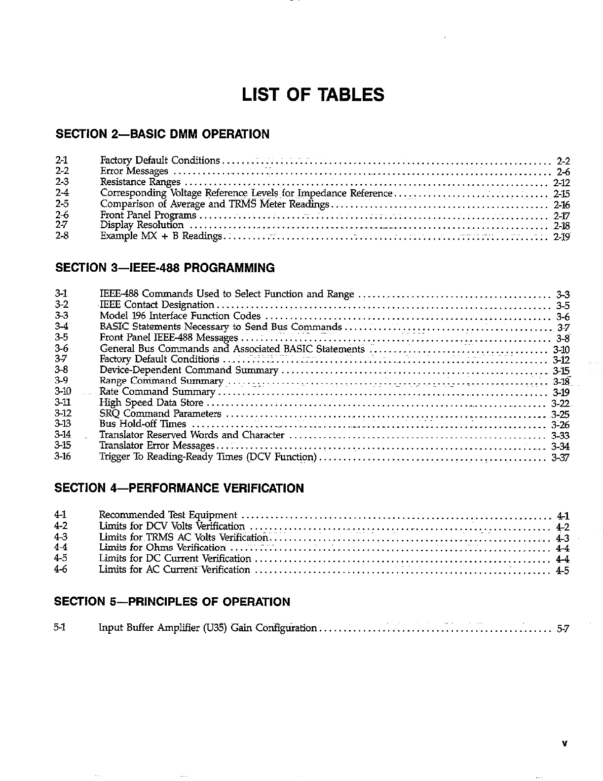
LIST OF TABLES
SECTION 2-BASIC DMM OPERATION
2-l
2-2
23
Et
2-6
2-7
2-8
Factory Default Conditions ...... .~I. :. . : .; ... :~.
................................................. 2-2
ErrorMessages .......... ..~.......;-.....................,......................; .............. 2-6
ResistanceRanges.. ............................ . ............................................ 2-12
Corresponding Voltage +ferenceJev$@for Impedance !7eference. ..................... .: ...... ;~. ..... 2-15
Comparison of Average and TRMS Meter Readings ............................................. 2-16
FrontPanelPrograms.. ...... ~.:. .... . ..... :z.:. ... ~.:. ... .z.:..~ .:. ................. :.~. .......... 2-l7
Display Resolution ........................... ............. .,
.. .__ .... _
............................. 2-18
ExampleMX+BReadings.:. ...... .:~. ............... . ....... . ............. ~;;.;;~;;. ... i...;;. 2-19~
SECTION 3-IEEE-488 PROGRAMMING
3-l
3-2
3-3
3-4
3-5
3-6
3-7
3-8
3-9
3-10
3-ll
3-12
3-13
3-14
3-35
3-16
IEEE-488 Commands Used to Select Function and Range ........................................ 3-3
~lEEE Contact Designation. .............................. i ...................................... 35
Model 196 Interface Function Codes ............................................ _. ... _. ........ 3-6
BASIC Statements Necessary to Send Bus Commands ............................... 1.. ........... 3-7
FrontPanelIEEE488Messages.. .. I...; ........ :I............... l............ .................. 3-8~
General Bus Commands and Associated BASIC Statements ;~.
................. .~;. ............... 3-10
FactoryDefaultConditiotis ....... ~~;I.~;.~~...;.;.~~; ....... ;;...~.J:.:..~..: ... . .... -..I~;~.~ 1.. ............ 3-12
Device-Dependent Command Summary ............................................ ._ .......... 3-E
Range Co~andSummary...~..,,:. ...................... :r:..~-..~.~ ~..~i: ..%.
..... ........... -.!L. 3-l$
Rate Command Summary ........................................ _
... _
.. _
................ _
...... 3-19
High Speed Data Store .......................................................................... 3-22
SRQ Command Parameters .................................................. _. .......... _
. __ 3-25
Bus Hold-off Ties ............................................ ._. ....... .~.~.:. ...... :. ............ __ 3-26
Translator Reserved Words and Chxacter .................................... _
................ 3-33
Translator Error Messages ... z .................................................................... 3-34
Trigger To Reading-Ready Times (DCV Funct&~n) ............................................... 3-37
SECTION 4-PERFORMANCE VERIFICATION
41
4-2
22
45
46
RecommendedTest Equipment ................................................................ 41
Limits for DCV Volts Verification ................................................................ 42
LimitsforTRMSACVoltsVerifibation.. ........ . ....... MY..;
..................................... i-3
Limits for Ohms Verification ... .:~. ;~.~.~. ....... ;...~ .................... .:. ...................... 4-4
Limits for DC Current Verification ............................................................. 4-4
Limits for AC CurretifVerification ....................... t.. .... ~.I; ...................... . ........ 4-5
SECTION 5-PRINCIPLES OF OPERATION
5-1 Input Buffer Amplifier (U35) Gain Co*gt&ation . . . . . . ‘. . . . . .‘; i . . . . ~ . . . . . _~. _ . _ . 5-7
V
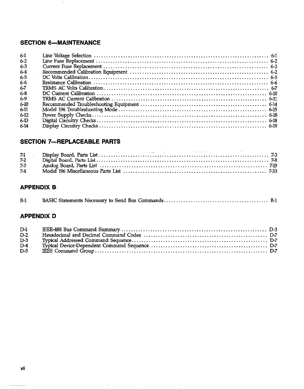
SECTION 6-MAINTENANCE
6-l
6-2
6-3
6-4
6-5
6-6
6-7
6-8
6-9
6-J.0
6-12
6-12
6-13
6-14
LineVoltage Selection ............ ..L ......................................................... 6-l
LineFuseReplacement ....................................................................... 6-2
Current~Fuse Replacement ................................... _. ....... __. ...................... 6-2
Recommended Calibration Equipment .......................................................... 6-2
DCVoltsCalibration......................~.....- .............................................. 6-5
ResistanceCalibration ........................................................................ 6-6
TRMS AC Volts Calibration. ................. _, .. _._ ............................................... 6-7
DC Current Calibration ............ .~..................... ....................................... 6-10
TRMS AC Currefit calibration ....................................... _. ......................... 6-11
Recommended Troubleshooting Equipment .................................................... 6-14
Model I.96 Troubleshooting Mode .............................................................. 6-15
Power Stipply Checks. ................................................ _ ............ _
..... ., .. ., ., 6-18
Digital Circuitry Checks. ........................................................................ 6-18
Display Circuitry Checks ..................... ., .. __ ............. _. ............................ 6-19
SECTION 7-REPLACEABLE PAFKS
7-1 Display Board, Parts List.. . . . . . . . . . . , . . . . _ _ .-. .: . _ . _ :. . . . _:. . . . . _. . . . . . :. . . . .‘. . ._ _. 7-3
7-2 DigitalBoard,PartsList........................-~.............................................. 7-S
7-3 AnalogBoard,Parts List . . . . . . . . . . . . . . . . . . . . ..~.............................................. 719
7-4 Model196MiscellaneousParts List . . . . . . . . . . . . . . . . . . . . . . . . . . . . . . . . .._........................ 7-33
APPENDIX B
B-1 BASIC Statements Necessary to Send Btis Co mmands........................................... B-1
APPENDIX D
D-l lEEE488Bus Command So ............................................................ D-3
D-2 Hexadecimal and Decimal Command Codes ................................................... D-7
D-3 Typical Addressed Command Sequence. ............................................. _
.......... D-7
;; Typical Device-Dependent Commiind Sequence .. ;~. ................... .; ..... . .. .;~..~ ............ D-7
IBEE Co mmaid Group ................ _ ..... ; .................................... ., ....... ., .... D-7
Vi
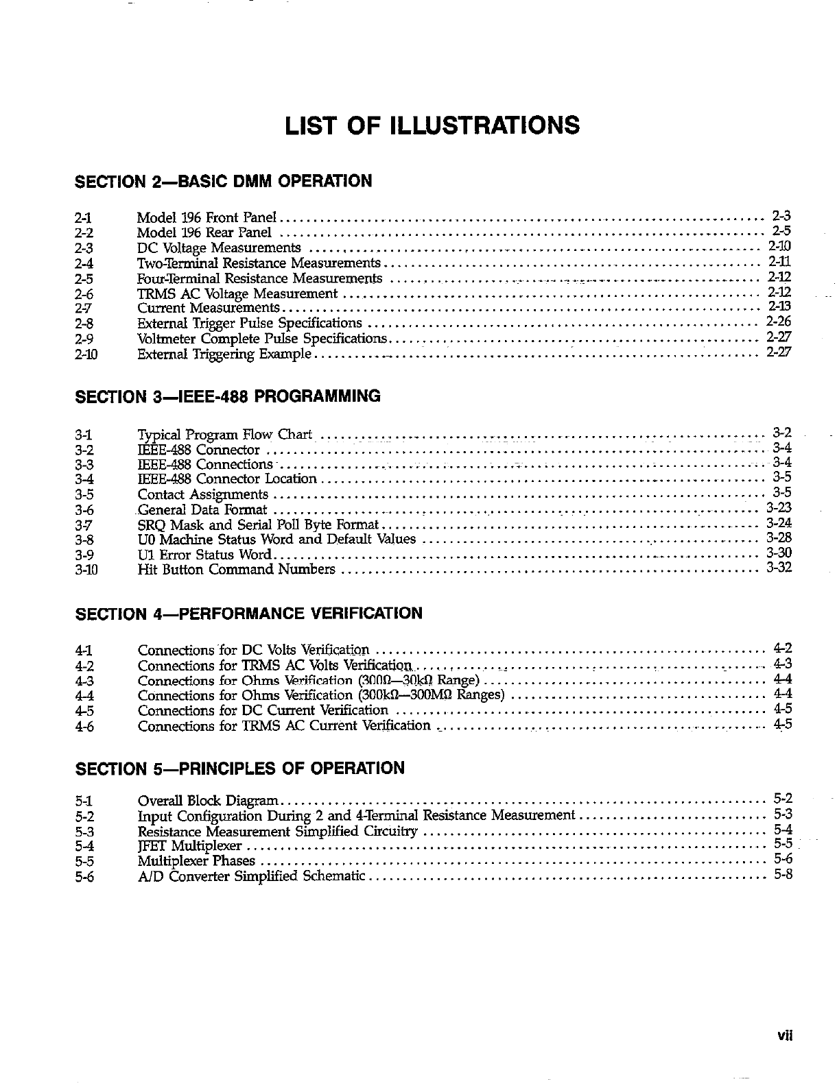
LIST OF ILLUSTRATIONS
SECTION 2-BASIC DMM OPERATION
2-l
2-2
2-3
2-4
2-5
2-6
2-7
2-8
2-9
2-10
Model196FrontPanel................................................~.......~.......~- ....... 2-3
Model 196 Rear Panel ............................................................. .._ ........ 2-5
DCVoltageMeasurements ........................... ..~....~.....-...............~.-...~- ... 2-10
Two-Terminal Resistance Measurements ................................................. .,
...... 2-11
Four-Terminal Resistance Measurements ........................ .~.- .. . _~_.~_ _,_
..... _,__
...... _
. .~_.
... 2-p
TRMSACVoltageMeasuremement
Current Measurements. .................................................................................................................................... $E
External Trigger Pulse Specifications .......................................................... 2-26
Voltmeter Complete Pulse Specifications
External Triggering Example ..................................... I
...................................... .,
......... .._..............._ ................. i;g
SECTION 3-IEEE-466 PROGRAMMING
3-l
3-2
2
3-5
3-6
37
3-8
3-9
3-10
TypicalProgramFlo~ Chart.. ~.y.:~I.T ._ ~.~--.~:~.~.~. r
IEEE-488 Connector .. ................ ....... .................... ................................ ........
..- ........................ -.:-~. :;4j
.....
IEEE-488Connections~. ................................... ~.:.~ ..;
....................... ;:
....... .
............................ . .
IEEE-488 Connector Location ... .................
..*........~ ;;.~:3:
...
Contact Assignments ......................................................................... 3-5
~Generd Data Format ........................ _
...................................................... 3-23
SRQMask and Serial Poll Byte Fo~at.........................................~.....-...-..- . 3-24
UO Machine Status Word and Default V&es
Ul Error Status Word .... .... ........ ............................................................................................................. i;;:
Hit Button Command Numbers .............................................................. 3-32
SECTION 4-PERFORMANCE VERIFICATION
41
42
43
E
4-6
Conmctions ‘for DC Volts Verification .......................................................... 42
CoMectionsforTRMSACVoltsVeriCication~ ..... . ...... _:. ......... ..!. ....... . ................... 43
Connections for Ohms Verification (300%#$! Range) ............... _. ......................... 44
Connections for Ohms Verification (3OOkn--3OOMQ Ranges) ...................................... 44
Connections for DC Current Verification ........................................................ 45
Connections for TRMS AC Cur&t Verification ._.
.................................................... 4-5
SECTION &PRINCIPLES OF OPERATION
5-l
5-2
5-3
S-4
5-5
5-6
Overall Block Diagram. ....................................................................... 5-2
Input Configuration During 2 and 4Terminal Resistance Measurement. ........................... 5-3
Resistance Measurement Simplified Circi&y ................................................... 5-4
JFET Multiplexer ......................................................................................................... .,
Multiplexer Phases ............................................... ;:
A/D Converter Simplified Schematic ........................................................... 5-8
Vii
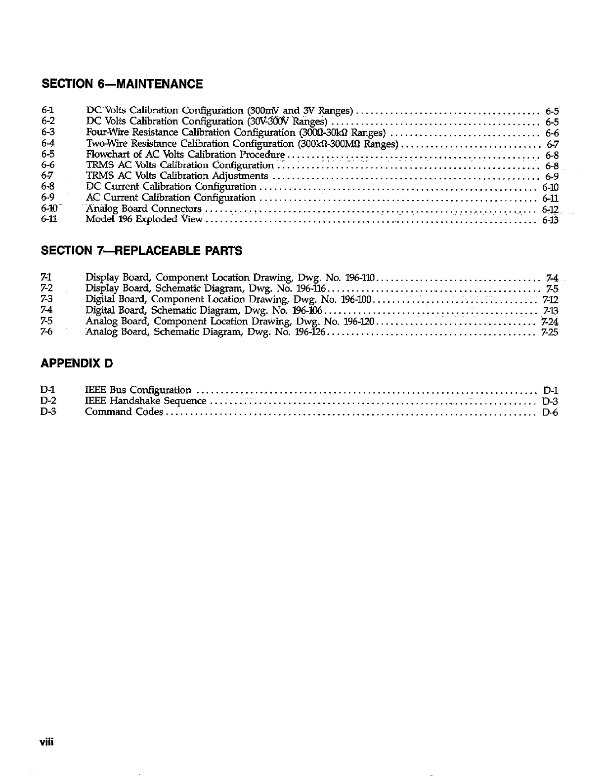
SECTION 6-MAINTENANCE
DC Volts Calibration Confii&on (300mV ani ,y @nges) ...................................... 6-5
DC Volts Calibration Confi~atio~ (3OV-300V Ranges) ........................................... 6-5
Four-Wire Resistance Calibration Configuration (3000-3OkQ Ranges) ............................... 6-6
Two-Wire Resistance Calibration Configuration (300kO3OOMQ Ranges). ............................ 6-7
Flowchart of AC Volts Calibration Procedure .................................................... 6-8
TRMS AC Volts Calibration Configuration :.I .. ; .................................................. 1. ... 6-8
TRMS~ AC Volts Calibration Adjustments ....................................................... 6-9
DC Current Calibration Configuration., ....................................................... 6-10
ACCurrent CalibrationConfiguration ......................................................... 6-U.
Analog Board Conne~ors~. .......... (. ......................................... .~.-i.. .............. 6-12~
Model196ExplodedViav .................................................................... 6-l3
SECTION 7-REPLACEABLE PARTS
7-1
7-2
7-3
z
7-6
Display Board, Comporient Location Drawing, Dwg. No. 196-110. .................................. ~7-4
Display Board, Schematic Diagram, Dwg. No. 196.XL6
.............................................. 7-5
Digital Board, Component Location Drawing, Dwg. No. 196-100 .................... ;. .. ; . ~; ; ....... ; . 7-12
Digital Board, Schematic Diagram, Dwg. No. 196-106. ............................... ‘.‘~.
......... : .. 7-13
Analog Board, Component Location Drawing, Dwg. No. 196.120 .................................. 7-24
Analog Board, Schematic Diagram, Dwg. No. 196-126 ........................................... 7-25
APPENDIX D
D-l
D-2
D-3
tEEEBusCon@ration ...................................................................... D-l
IEEE Handshake Sequence ....... ;Y;~;
.............................................. .;. ............. D-3
CommandCodes ............................................................................ D-6
viii
SECTION 1
GENERAL INFORMATION
1.1 INTRODU~ION 1.3 WARRANTY INFORMATION
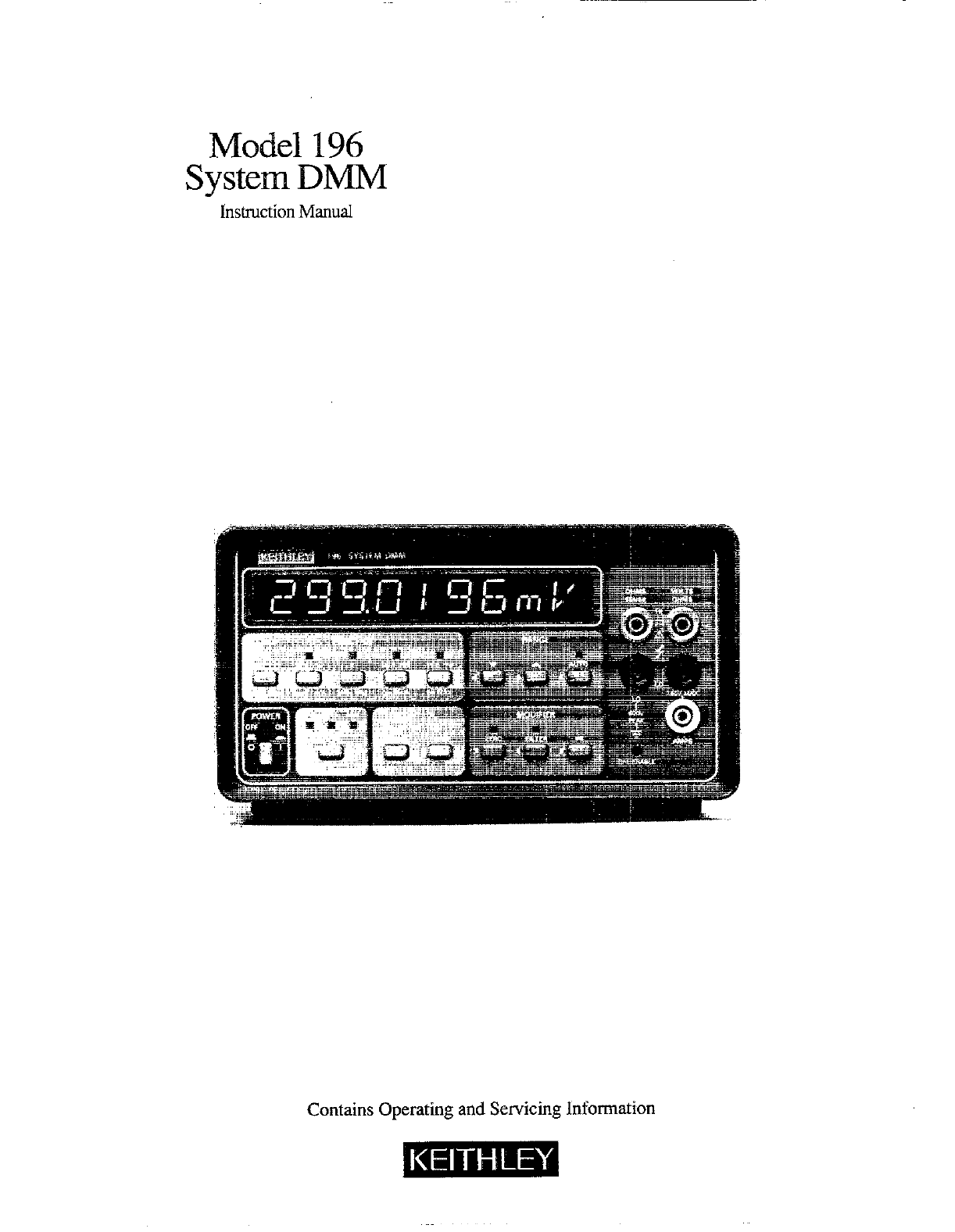
The Keithley Model 196 System DMM is a five function
autoranging~ digital multimeter. At 6% digit resolution, the
LED display can display ~*3,@0,1lOO coo@s. The ran@ of
this analog-to-digital (A/D) converter is greater t+q the nor:
mal *l,999,999&tit~AAID converter used in many 6% &St
DMMs. The built-in IEEE-488~ interface makes the instru-
ment fully programmable over the IEEE-488 bus. The Model
196 can make the following basic measurements:
1. DC voltage measurements from lOOnV to 3OOV.
2. Resistance measurements from lOOpI tb’3OOM62.
3. TRMS AC voltage measurements from 1pV to 300V.
4. DC current me&urements from lnA to 3A.
5. TRMS AC current measurements from lnA to 3A.
Warranty information may be found on the inside front
cover of this manual. Should it become necessary to exq
c@e the warranty, contact your Keithley represent&e or
the ~factory to determine the proper course of action.
Keithley Instruments maintains service facilities in the
United States, United Kingdom and throughout Europe.
Information concerning the application, operation or ser-
vice of your instrument may be directed to the applications
engineer at any of these locations. Check the inside front
cover for addresses.
1.4 MANUAL ADDENDA
In addition to the above~ mentioned measurement
capabilities, the Model 196 can make:AC dB voltage and
current measurements.
Information concerning improvements or changes to the
instrument which occur after the printing of this manual
will be found on an addendum sheet included with the
manual. Be sure to review these changes before attempt-
ing to operate or service the instrument.
1.2 FEATURES 1.5 SAFETY SYMBOLS AND TERMS
Some important Model 196 features include:
l 10 Character Alphanumeric Display-Easy to read 14seg-
ment LEDs used for readings and front panel messages.
*High Speed Measurement Rate-l000 readings per
second.
l Zero-Used to cancel offsets or establish baselines. A zero
value can be programmed from the front panel or over
the IEEE-488 bus.
l Filter-The weighted average digital filter can be set from
the front panel or over the bus.
l Data Store-Can stoti tip to 500 readings and is accessl%le
only over the bus.
l Digital Calibration-The instrument may be digitally
calibrated from either the front panel or over the bus.
l User Programmable Default Condition&&y inshument
measurement configuration can be established as the
power-up default conditions.
l Translator Softwze-User defined words (stored in non-
volatile memory) can be used to replace standard com-
mand strings over the IEEE-488 bus.
l Offset Compensated Ohms-Used to correct for small er-
ror voltages in the measurement circuit.
The following safety symbols and terms are used in this
manual or found on the Model 196.
The A symbol on the instrument denotes that the user
should refer tom the -operating instruction iq this manual.
The I/y on the instrument denotes that a potential of
300V or more may be present on the terminal(s). Standard
safety practices should be observed when such dangerous
levels are encomitered.
The WARNING used in this manual explains dangers that
could result in personal injury or death.
The CAUTION used in this manual explains hazards that
could damage the instrument:
1.6 SPECIFICATIONS
Detailed Model 196 specifications may be found preceding
the 7hble of Contents oft &is manual. ~. ~~~~
l-l
1.7 INSPECTION
The Model 196 System DMM was carefully inspected, both
electrically and mechanically before shipment. After un-
packing all items from the shipping carton, check for any
obvious signs of physical damage that may have occurred
during transit. Report any damage to the shipping~agent.
Retain and use the original packing materials in case reship-
ment is necessary. The following items are shipped with
every Model 196 order:
Model 196 System DMM
Model 196 Instruction Manual
Safety Test Leads (Model 3751)
Additional accessories as ordered.
Jf an additional instruction manual is required, order the
manual package (Keithley Part Number 196-901-00). The
manual package includes an instruction manual and any
applicable addenda.
1.8 USING THE MODEL 196 MANUAL
This manual contains information necessrny for operating
and servicing the Model 196 System DMM. The informa-
tion is divided into the following sections:
l Section 1 contains general information about the Model
396 includiig that necessary to inspect the instrument and
get it operating as quickly as possl%le.
l Section 2 contains detailed operating information on
using the front panel controls and programs, making con-
nections and basic measuring techniques for each of the
available measuring functions.
l Section 3 contains the information necessary to connect
the Model 196 to the IEEE488 bus and program operating
modes and functions from a controller.
l Se&on 4 contains performance verification procedures
for the instrument. This information will be helpful if you
wish to verify that the instrument is operating in com-
pliance with its stated specifications.
l Section 5 contains a description of operating theory.
Analog, digital, power supply, and IEEE-488 interface
operation is included.
0 Section 6 contains information for servicing the instru-
ment. This section includes information on fuse replace-
ment, line voltage selection, calibration and
troubleshooting.
l Section 7 contains replaceable parts information.
1.9 GETTING STARTED
The Model 196 System DMM is a highly sophisticated in-
strument with many capabilities. To get the instrument up
&id running quickly use the following procedure. For com-
plete information on operating the Model 196 consult the
appropriate section of this manual.
Power up
1. Plug the line cord intom~the rear anel power jack and
plug the other end of the cordpinto an appropriate,
grounded power source. See paragraph 2.2.1 for more
complete information.
2. Press in the POWER switch to apply power to the in-
shument. The instrument will power up in the 3CW DC
*ange.
Making Measurements
‘L Connect safety~shrouded testy leads to the front panel
VOLTS H.I and LO input terminals. Make sore the IN-
PUT switch on the rear panel is in the in (FRONT)
position.
2. To make a voltage measurement, simply connect the in-
put leads to a DC voltage source (up to 3OOV) and take
the reading from the display.
3. To change to a different measuring function, simply
press the desired function button. For -pie, to
measure resistance, press the OHMS button.
Using Front P.&e1 Programs
Program selection is accomplished by pressing the PRGM
button followed by the button(s) eat corresponds to the
program number or name. For example, to select Program
31 (IEEE), press the PRGM button and then the 3 and 1
buttons. ‘Ihble 2-7 lists and briefly describes the available
front panel programs. Once a program is selected the
following general rules will apply:
1. A displayed program condition can be entered by press-
i”p the ENTER button.
2. Program conditions that prompt the user with a flashing
digit can be modified using the data buttons (0 through
9 and i).
3. Programs that contain alternate conditions can be
displayed by pressing one ofthe range buttons. Each
press of one of these buttons toggles the display between
the two available conditions.
1-2
GENERAL INFORMATION
4. A program will be executed when the ENTER button is
pressed.
5. A program can be exited at any time and thus not ey-
ecuted, by pressing the PRGM button.
Paragraph 2.7 provides the detailed information for using
the front panel programs.
1.10 ACCESSORIES
The following accessories are available to enhance the
Model l96s, capabilities.
Models lOl9A and 1019s Rack Mounting Kits-The Model
~1019A is a stationary rack mounting kit with two front
panels provided to enable either single or dual side-by-side
mounting of the Model 196 or other similar Wthley in-
struments. The Model 10195 is a similar rack mounting kit
with a sliding mount configuration.
Model X301 Temperature Probe-The Model 1301 is a rUg-
ged low cost temperature probe designed to allow temper-
ature measurements from -55 to I5O’C.
Model 16008 High Voltage Probe-The Model 16008 extends
DMM measurements to 40kV.
Model 165150Ampere Current Shunt-The Model 1651 is
an external 0.00161 +J% 4terminal shunt, which permits
current measurements from 0 to 50A AC or DC.
Model l&31 Clip-On Test Lead Set-The Model l68l’con
tains two leads, 1.2m (4 ft.) long terminated with banana
plugs and spring action clip probes.
Model 1682A RF Probe-The Model 1682A permits voltage
measurements from lOOkHa to 25OMHz. AC to DC transfer
accuracy is *ldB from lOOkFIr to 25OhJH.z at IV, peak
responding, calibrated in RMS of a sine wave.
Model 1685 Clamp-On AC Probe-The Model 1685
measures AC current by clamping on to a single conduc-
tor. Interruption of the circuit is unnecessary. The Model
1685 detects currents by sensing the chsnglng magnetic field
produced by the current~flow.
Model I751 Safety Test Leads-Finger gu$.s and shrouded
banana plugs help minimize the chance of making contact
with live circuitry.
Model 1754 Universal Test Lead Kit--The Model 1754 is a
12 piece test lead kit, with interchangeable plug-in ac-
cessories. Included in the kit is one set of test leads (l-red,
l-black), two spade lugs, two standard b-a plugs, two
phone tips (0.06 DIA.), two hooks and miniature alligator
clips (with boots).
Model 5804 Test Lead Set-The Model 5804, used for
4terminal measurements, includes: two test probes with
spring-loaded plunger clip adapters to fit test probes, two
spring-loaded plunger test clips with in-line banana jacks,
and four solid copper alligator clips with insulator boots.
Model 5805 Kelvin Probes-The Model 5805 includes two
spring-loaded Kelvin test probes (one red, one black), with
48-inch banana plug cable assemblies. A set of eight re-
placement contacts for the Model 5805 Kelvin test probes
is also available (Keithley PIN CS-551).
Model 5806 Kelvin Clip Lead Set-The Model 5806 includes
~two I+in clip test lead assemblies with banana plug ter-
mination (one red, one black). A set of eight replacement
rubber bands for the lviode1~5806 is also available (Keithkey
PIN GA-22).
Model 7087 IEEE-&3 Shielded Cables-The Model 7007 con-
nects the Model 196 to the IEEE-488 bus using shielded
cables to reduce electromagnetic interference (EMI). The
Model 7Ow-1 is one meter in length and has a EMI shield-
ed IEEE-488 connector at: each end. The Model 7007-2 is
identical to the Model 7007-1, but is two meters in length.
Model 7088 IEEE488 Cables-The Model 7008~connects the
Model 196 to the IEEE-488 bus. The Model 7008-3 is D.9m
(3 ft.) in length and has a~standard IEEE488 connector at
each end. The Model 7008-6 cable is identical to the Model
7008-3, but~is 1.8m (6 ft.) in length.
Model 8573A IEEE488 Interface--The Model 8573A is an
IEEE1188 standard interface designed to interface the IBM
PC or XT computers to Keithley instrumentation over the
~IEEE-488 bus. The interface system contains two distinc-
tive parts an interface board containing logic~ to perform
the necessary hardware functions and the handler software
(supplied on disk) to perform the required control func-
tions. These two important facets of the Model 857ZA join
together to give the IBM advanced capabilities over
lXE-488 interfaceable instrumentation.
l-311-4
SECTION 2
BASIC DMM OPERATION
2.1 INTRODUCTION
Operation of the Model 196 can be divided into two general
categories: front panel operation and IEEE-488 bus~opera-
tion. This section contains information necesssay to use the
instrument from the front panel. Theses functions can also
be programmed over the lEFE-488 bus, as described in Sec-
tion 3.
2.2 POWER UP PROCEDURE
2.2.1 Line Power
Use the following procedure to connect the Model 196 to
line power and power up the instrument.
1. Check that the instrument is set to correspond to the
available line power. When the instrument leaves the fac-
tov, the internally selected line voltage is marked on the
rear panel. Ranges are 105W25V or 2kW!5OV 5016OHz
AC. If the line voltage setting of the instrument needs
to be changed, refer to Section 6, paragraph 6.2 for the
procedure. If the line frequency setting of the instrument
needs to be checked and/or changed, utilize front panel
Program 32 (see paragraph 2.7.8) after the instrument
completes the power up sequence.
2. Connect the female end of the power cord to the AC
receptacle on the rear panel of the instrument.~ Connect
the other end of the cord to a grounded AC outlet.
WARNING
The Model 196 is equipped with a 3-wire power
cord that contains a separate ground wire and
is designed to be used with grounded outlets,
When proper connections are made, instrument
chassis is connected to power line ground.
Failure to use a gmunded outlet may result in
personal injury or death because of electric
shock.
CAUTION
Be sure that the power line voltage agrees with
the indicated range on the rear panel of the in-
strument. Failure to obsenre this precaution
may result in instrument damage.
2.2.2 Power Up Sequence
The instrument can be turned on by pressing in the front
panel POWER switch. The switch will be at the inner most
position when the instrument is turned on. Upon ower
up, the instrument will do a number of tests on itse 9 Tests
are performed on memory (ROM, RAM and ETROM). If
RAM or ROM fails, the instrument will lo& up. If ETROM
FAILS, the message ‘TINCAL!’ will be displayed. See para-
graph 67.2 for a complete description of the power up self
test and recommendations to resolve failures.
2.2.3 Default Conditions
Default conditions can be defined as setup conditions that
the instrument will return to when a particular feature or
command is asserted. The Model 196 will return to either
factory default conditions or user saved default conditions.
Factory Default Conditions
Ate the factory, the Model 196 is set up so that the instru-
ment is configured to certain setup conditions on the
initial power up. These factory default conditions are listed
in Tables 2-l and 37 (located in Section 3). If alternate setup
conditions are saved (see User Saved Default Conditions),
the instrument can be returned to the factory default con-
ditions by running Program 37 (Reset). To retain the fac-
tory default condihons as power-up default conditions, run
Program 30 (Save} immediately after executing kograrn 37
(Reset).
Sending device-dependent comman d I.0 over the IEEE-488
bus is equivalent to running Program 37 (Reset) and then
Program 30 (Save).
2-l
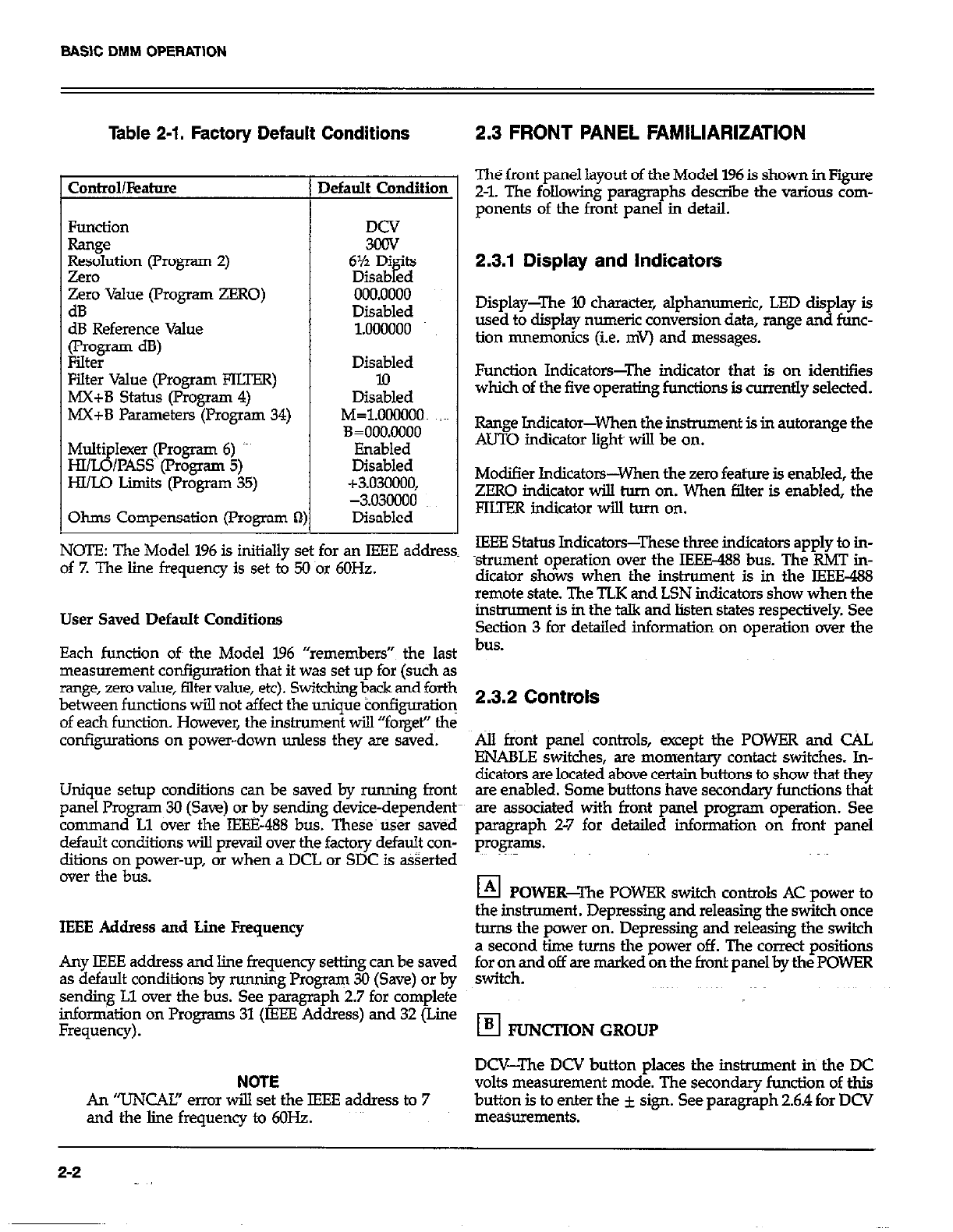
Table 2-1. Factory Default Conditions
Control/kahw
Zero value (rrogram ZERO)
dB
dB Reference Value
(program dB)
Filter
Filter Value (Program FILTER)
MX+B Status (Program 4)
MX+B Parameters (Program 34)
Multi
HI/ LB lexer (Program 6) ‘-’
/l’ASS~~(l’rogrsm 5)
HI/Lo Limits (Program 35)
Ohms Compensation (Program R
1)
kfault Condition
DCV
3cQV
6% Di ‘ts
Diiabgd
000.0000
Disabled
1.000000
Disabled
lo
Disabled
M=1.0OWOO~ ;~~
3=000.0000
Enabled
Disabled
+3.030000,
-3.o3clooo
Disabled
2.3 FRONT PANEL FAMILIARIZATION
The front panel layout of the Model 196 is shown in Fiie
Z-l. The following paragraphs describe the various com-
ponents of the front panel in detail.
2.3.1 Display and Indicators
Display-The 10 character, alphanumeric, LED display is
used to display numeric conversion data, range and func-
tion mnemonics (i.e. mv) and messages.
Function Indicators-The indicator that is on identifies
which of the five operating functions is currently selected.
Rsnge Jndicator-When the instrument is in autorange the
AUTO indicator light will be on.
Modifier Indicators-When the zero feature is enabled, the
ZERO indicator will torn on. When filter is enabled, the
FKTER indicator will turn on.
NOTE: The Model 196 is initially set for an IEEE address IEEE Status Indicators-These three indicators apply to in-
of 7. The line frequency is set to 50 nor 6OHz. strument operation over the IEEE-488 bus. The RMT in-
dicator shows when the instrument is in the IEEE-488
remote state. The TLK and LSN indicators show when the
User Saved Default Conditions
Each function oft the Model 196 “remembers”~ the last
measurement configuration that it was set up for (such as
range, zero value, filter value, et+ Switching back and forth
between functions will not affect the unique tonfiguratioq
of each function. However, the instrument will “forget” the
configurations on power-down unless they are saved.
Unique setup conditions can be saved by running front
panel Program 30 (Save) or by sending device-dependent
command Ll aver the IEBE-488 bus. These~tiser saved
default conditions will prevsjl over the factory default con-
ditions on power-up, or when a DCL or SDC is asserted
over the bus.
IEEE Address and Lie Frequency
Any IEEE address and line frequency setting can be saved
as default conditions by running Program 30 (Save) or by
sending Ll over the bus. See paragraph 2.7 for complete
information on Programs 31 (IEEE Address) and 32 (Line
Frequency).
NOTE
An ‘TJNCAI!’ error will set the IEEE address to 7
and the line frequency to 6OHz.
instrument is in the talk and listen states respectively. See
Section 3 for detailed information on oueration over the
bus.
2.3.2 Controls
.&lI front panel co&ols, except the POWER and C%L
ENABLE switches, are momentary contact switches. In-
dicaton are located above certain buttons to show that they
are enabled. Some buttons have secondary functions that
are associated with front panel program operation. See
paragraph 2-7 for detailed information on front panel
prOg.3lllS.
El POWER-The POWER switch controls AC power to
the insbxment . Depressing and releasing the switch once
tams the power on. Depressing and releasing the switch
a second time turns the power off. The correct positions
footi\and off are marked on the front panel by the POWER
El FUNCTION GROUP
DCV-The DCV button places the instrument in the DC
volts measurement mode. The secondary function of this
button is to enter the i sign. See paragraph 2.6.4 for DCV
measurements.
2-2
BASIC DMM OPERATION
El
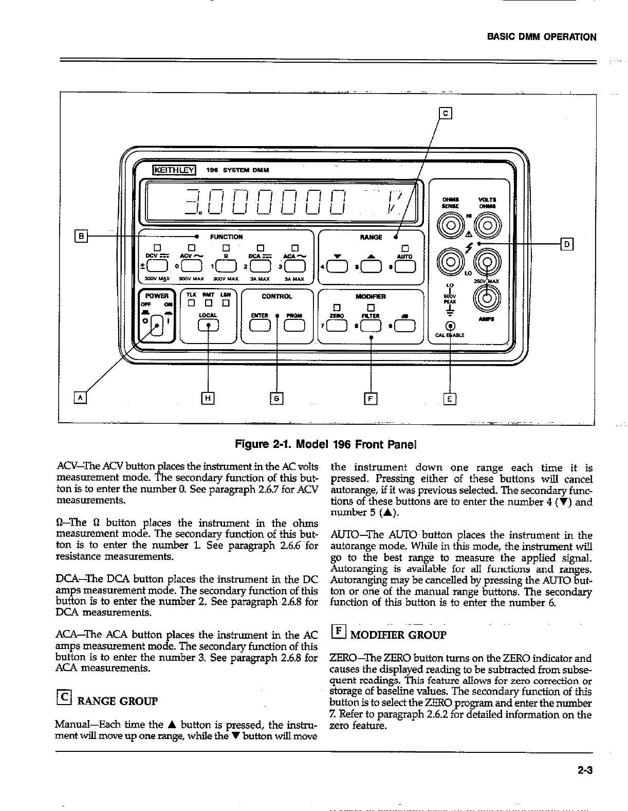
Figure 2-1. Model 196 Front Panel
ACV-The ACV button places the instrument in the AC volts
measurement mode. The secondary function of this but-
ton is to enter the number 0. See paragraph 26.7 for ACV
measurements.
&The fl button places the instrument in the ohms
measurement mode. The secondary function of this but-
ton is to enter the number 1. See paragraph 2.6.6~for
resistance measurements.
DCA-The DCA button places the instrument in the DC
amps measurement mode. The secondary function of this
button is to enter the number 2. See paragraph 26.8 for
DC4 measurements.
ACA-The ACA button places the instrument in the AC
amps measurement mode. The secondary function of this
button is to enter the number 3. See paragraph 2.6.8 for
ACA measurements.
!zl RANGE GROUP
Manual-Each time the A button is pressed, the instru-
ment will move up one range, while the V button will move
the instrument down one range each time its is
pressed. Pressing either of these buttons will cancel
autorange, if it was previous selected. The secondary func-
tions of these buttons are tom enter the number 4 (V) and
number 5 (A).
AUTO-The AUTO button places the instrument in the
autorange mode. While in this mode, the instrument will
go to the best range to measure the applied signal.
Autoranging is available for all functions and ranges.
Autoranging may be cancelled by pressing the AUTO but-
ton or one of the manual range buttons. The secondary
function of this button is to enter the number 6.
ZERO-The ZERO button turns on the ZERO indicator and
causes the displayed reading to be subtracted from subse-
quent readings. This feature allows for zero correction or
storage of baseline values. The secondary function of this
button is to select the ZERO program and enter the number
Z Refer to paragraph 2.62 for detailed information on the
zero feature.
2-3
SAS\C DMM OPERATION
FIUER-The FIWER button turns on the FIUEl7 indicator
and causes the instrument to start weighted averaging (1
to l/99) fhe readings. The factory default weighted average
is l/10, but may be changed using the PIITER program (see
paragraph 2.7.16). See paragraph 2.6.3 for filter operation.
Selectin the PILTEK rogiam is one of the secondary func-
tionsof&isbutton.&eothersecondaryfunctionisto~nter
the number 8.
dB-The dB button places the inshument~~in the dB
measurement mode and may be used with the ACV and
ACA functions. Under factory default conditions, measure-
ments are referenced to 1V or lmA. However, the dB pro-
gram may be used to change the referqce @ell. ‘JTh$ seconY
day function of this button is to select the dB program and
enter the number 9. See paragriph 2.6.9 for dB measure-
ments.
El CONTROL GROUP
PRGM-This button is used tom enter the fronts panel pro-
gram mode.
ENTER-This button is used to enter program parameters.
This button will also trigger a reading when the instruments
is in a one-shot trigger mode.
El LQCA&When the instrument is in the IEEE-488
remote state (RM’I indicator on), the LOCAL button will
return the instrument to front panel operation. However,
if local lockout (LLO) was asserted over the IEEE-488 bus,
the LOCAL button will be inoperative. See Section 3 for
informa$on on operating the instnunent-over the IEEE488
bus.
2.3.3 Input Terminals q
The ~input terminals are intended to be used with safety
shrouded test leads to help minimize the possibility of con-
tact with live cikuits. Note that the terminals sre duplicated
sideways on the rear panel and that the INPUT switch (also
located on the rear panel) determines which set of termin&
is Bctive.
VOLTS 0HMS~i-J.I akd LQ-l’he VOLTS OHMS Hl atid LO
terminals are used for making DC volts, AC volts and two-
wire resistance measurements.
AMPS and LO-The AMPS and LO terminals are used for
making DC current and AC cUrrent measurem&s.
OHMS SENSE HI and LO--The OHMS SENSE HI and LO
terminals are used with the VOJXS OHMS HI and LO ter-
minals to make four-wire resistance measurements.
2.3.4 Calibration Enable Switch q
Calibration of the Model 196 can only be done if the CAL
ENABLE switch is in the enable position. See paragraph
6.4 for details.
2-4

BASIC DMM OPERATION
2.4 REAR PANEL FAMILIARIZATION 2.4.2 Connectors and Terminals
The reax panel of the Model 196 is shown in Figure 2-2. ~~~ pJ AC Receptacle-Power is applied through the supplied
power cord to the 3-terminal AC receptacle. Note that the
selected supply voltage is marked on the rear panel near
2.4.1 Controls the line voltage switch.
ra T TkTc TIC%TTA,-C -t-L:- a.r.2~L -A,-~ the hment El Input Terminals-The rear panel input terminals per-
form the same functions as the front panel input terminals.
Iable lme voltage. see paragrapn 6.2 for the pro-
set this switch. Paragraph 2.3.3 contains the description of the input
terminals.
L4 mu IEEE-488 Car
INPUT-The INPUT switch connects the instrument mector-This connector is used to con-
to either the front panel input terminals or the rear panel nect the ins,e nt to the IEEE-483 bus. IEEE interface
input terminals. This switch operates in same manner as functions ym -rl-l
x5 14,&ed below the connector.
the power switch. The front panel input terminals are
selected when the switch is in the “in’ position and the q
EXTERNAL TRIGGER Input-This BNC~connector is
rear panel input terminals are selected when the switch is used to apply pulses to trigger the Model 196 to take one
in the “0uV position. or more readings, depending on the selected trigger mode.
Figure 2-2. Model 196 Rear Panel
2-5
BASIC DMf.4 OPERATION
I3 VOITMFXER COMPLETE Output-T% BNC output
connector provides a TTLcompatible negative-going pulse
when the Model 196 has completed a reading. It is useful
for triggering other inshumentation.
2.4.3. Fuses
El LINE FUSE-The line fuse provides protection for the
AC power line input. Refer to paragraph 6.3.1 for the line
fuse replacement procedure.
El CURRENT FUSkhe 3A current fuse provides pro-
tection for the current measurement circoits of the instru-
ment. Refer to paragraph 63.2 for the cwr$nt fuse replace-
ment procedure.
2.5 ERROR DISPLAY MESSAGES
Table 2-2 lists and explains the various display messages
assodated with incorrect front panel operation of the Model
196.
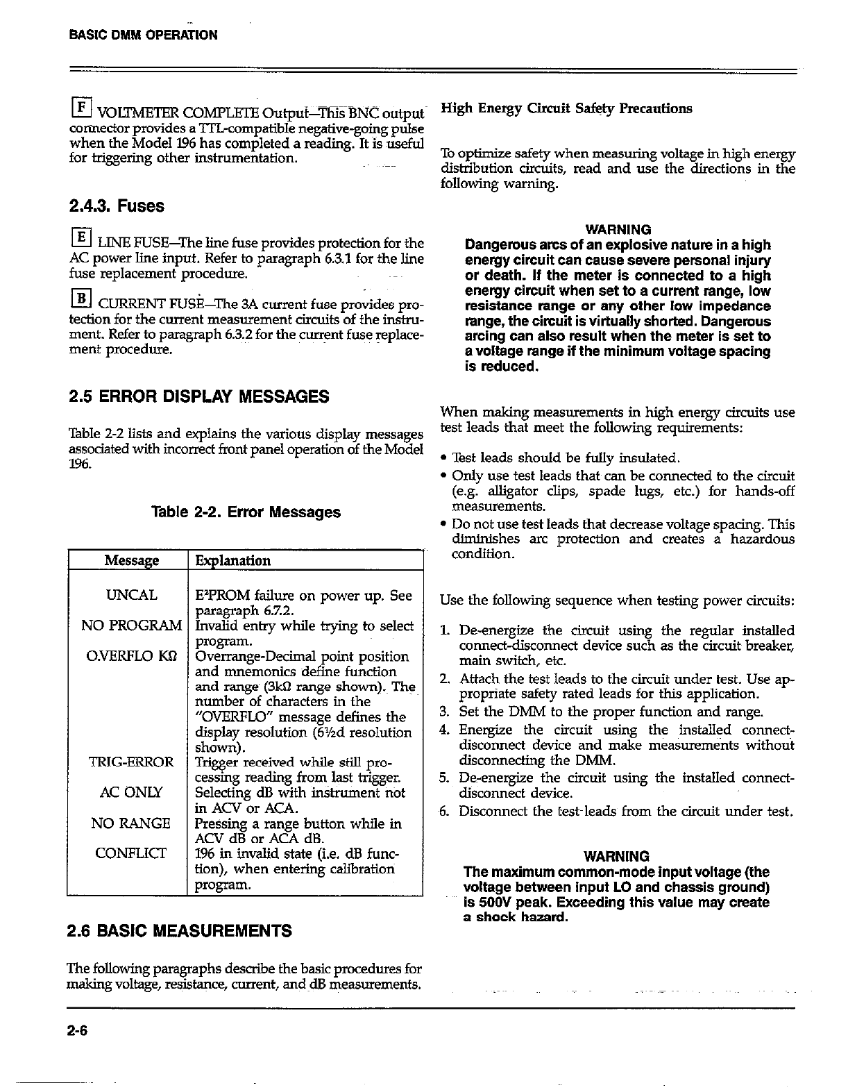
Table 2-2. Error Messages
Message
UNCAL
NO PROGRAM
O.VERFLO KQ
TRIG-ERROR
AC ONLY
NO RANGE
CONFLICI
Explanation
EIPROM failure on power up. See
paragraph 6.7.2.
Invalid entry while trying to select
program.
Overrange-Decimal point position
and mnemonics define function
and range (3kfl range shown).~ Th:
number of characters in the
“OVERFLO” message defines the
display resolution (6Yzd resolution
shown).
Trigger received while still pro-
cessing reading from last trigger.
Selecting dB with in&ument fitit
in ACV or ACA.
Pressing a range button while in
ACV dB or ACA dB.
196 in invalid state (i.e. dB func-
tion), when entering calibratioti
p*ogram.
2.6 BASIC MEASUREMENTS
The following paragraphs describe the basic pwxdures for
making voltage, resJs@~ce, current, and~dB measurements.
To optimize safety when measuring voltage in high energy
distribution circuits, read and use the directions in the
following warning.
WARNING
Dangerous arcs of an explosive nature in a high
energy circuit can cause severe personal injury
or death. If the meter is connected to a high
energy circuit when set to a current range, low
resistance range or any other low impedance
range, the circuit is virtually shorted. Dangerous
arcing can also result when the meter is set to
a voltage range if the minimum voltage spacing
is reduced.
When making measurements in high energy circuits use
test leads that meet the follcwing requirements:
l Test leads should be folly insulated.
l Only use test leads that can be connected to the circuit
(e.~,jz~~~~.clips, spade lugs, etc.) for hands-off
l Do not use test leads that decrease voltage spacing. This
diminishes arc protection and creates a hazardous
condition.
Use the following sequence when testing power circuits:
1. De-energize the circuit using the regular installed
connect-disconnect device such as the circuit breaker,
main switch, etc.
2. Attach the test leads to the circuit under test. Use ap-
propriate safety rated lead~s for this application.
3. Set the DMM to the proper function and range.
4. Energize the circuit using the installed connect-
disconnect device and make measurenwnts without
disconnecting the DMM.
5. De-energize the circuit using the installed connect-
disconnect device.
6. Disconnect the test~leads from the circuit under test.
WARNING
The maximum common-mode input voltage (the
voltage between inout LO and chassis around)
is 506J peak. Exceeding this value may create
s shock hazard.
2-6
BASIC DMM OPERATION
2.6.1 Warm Up Period
The Model 196 is usable immediately when it is first turned
on. However, the instrument must be allowed to warm up
for at least~ two hours to achieve rated accuracy.
2.6.2 Zero
The zero feature serves as a means of baseline suppression
by aIlowing a stored offset value to be subtracted from
subsequent readings. When the ZERO button is pressed,
the instrument takes the currently displayed reading as a
baseline value. All subsequent readings represent~the dif-
ference between the applied signal level and the ~stored
baseline.
A baseline level can be established for any or all measure-
ment functions and is remembered by each function. For
example, a 1OV baseline can be established on DCV, a 5V
baseline can be established on ACV and a 1Okll baseline
can be established on OHMS. Theses levels will snot be
cancelled by switching back and forth between functioti.
Once a baseline is established for a measurement function,
that stored level will be the same regardless of what range
the Model 196 is on. For example, if 1V is established
as the baseline on the 3V range, then the baseline will also
be 1V on the 30V through 30lV ranges. A aem baseline level
canbeaslaigeasfullrange. ~~
NOTE
The followirg discussion on dynamic range is
based on a display resolution of 6% digits. At 5’/zd
resolution, the number of counts would be reduced
by a factor of 10. At 4Yzd resolution, counts would
be reduced by a factor of 100 and 3%d resolution
would reduce counts by a factor of 1000.
By design, the dynamic measurement range of the Model
196, at 6%-d@ resolution, is M)60000 counts.1 With zero
disabled, the displayed reading range of the instrument is
*303ooOO counts. With zero enabled, the Model 196 has
the capability to-display ~606OCOO counts. This increased
display range ensures that the dynamic measurement range
of the instrument is not reduced when using a zero baseline
value. The following two examples will use the maximum
allowable zero values (3030000 counts and -3030008
counts) to show that dynamic measurement range wilI not
be reduced. It is important to note that the increased display
range does not increase the maximum allowable input level
to the instrument. For example, on the 3V range, the Model
196 will always overrange when more than k3.03V is con-
nected to the input.
Example l-The instrument is set to the 3V DC range and
a maximum -3.03OOOOV is established as the zero value.
When -3.03OOOOV is connected to the input of the Model
196, the display will read O.OMlOOClV. When +3.03OCEOV is
co.nnected to the input, the display will read +60600ooV.
Thus, the dynamic measurement range of the Model 196
is OV to 6.06V, which is 6060000 counts.
Example 2-Ihe instrument is still set to the 3V DC range,
but a maximum +3.03oOOOV ia the zero level. When
+3.03oO~CGV is connected to the input of the Model 196, the
display will read O.O@XtOOV When Y3.0~ is connected
to the input, the display will read -6.06OOOCV. Thus the
dynamic measurements range of the instrument is -6.06V
to OV, which is still 6060000 counts.
Zero Correction-The Model 196 must be properly zeroed
when using the 3OOmV DC or the 3OOB range in order to
achieve rated accuracy specifications. To use ZERO for zero
correction, perform the following steps:
z
2.
3.
4.
5.
Disable zero, if presently enabled, by pressing the
ZERO button. The ZERO indicator will turn off.
Select the 3oOmV DC or the 30022 range.
Connect the test leads to the input of the Model 196 and
short them together. If four-wire resistance
measurements are to be made, connect and short all four
leads together. Allow any thermals to stabilize.
Note: At5% and 6%~digit resolution, low level measure-
ment techniques need to be employed. Use Kelvin test
leads or shielded test leads. See paragraph 2.6.5 for low
level measurement considerations.
Press the ZERO button. The display will read zero.
Remove the short and connect thetest leads to the signal
or resistance to be measured.
Note: Test lead, resistance is also~ compensated for when
zeroing the 3OO’J range with the above procedure.
Baseline Levels-Baseline values can be established by
either applying baseline levels to the instrument or by set-
ting baseline values with the front panel ZERO program.
paragraph 27’15 contains the complete procedure for using
the ZERO program. To establish a baseline level by apply-
ing a level to the Model 196, perform the following steps:
1. Disable zero, if presently enabled, by pressing the ZERO
button. The ZERO indicator will turn off.
2. Sele&a function and range that is appropriate for the
anticipated measurement.
3. Chnect the desired baseline level to the input -of the
Model 196 and note that level on the display
2.7
BASIC DMM OPERATION
4. Press the ZERO button. The display will zero and the
ZERO indicator will be enabled. The previously
displayed reading will be the stored baseline. The rero
baseline value will also be stored in Program ZERO,
replacing the previous zero value.
WARNING
With ZERO enabled, a hazardous voltage
baseline level (rt4OV or more), not displayed,
may be present on the input terminals. If not
sure what is applied to the input, assume that
a hazardous voltage is present.
5. Disconnect the stored signal from the input and connect
the signal to be measured in its place. Subsequent~
readings will be the difference between the stored value
and the applied ‘signal.
Notes:
1. Disablmg zero cancels the zero baseline value on that
selected function. However, since the zero value is
automatically stored in Program ZERO, the zero baseline
value can be retrieved by using the program as long as
the ZERO button is not ~again pressed (see paragraph
2.Xi5 for details). Pressing the ZERO button, thus enabl-
ing zero, will wipe out the previous baseline value in Pro-
gram ZERO. Baselines established on other functions are
not affected.
2. To store a new baseline on a selected function, zero must
first be disabled and then enabled again. The new value
will be stored with the first triggered conversion. The
baseline value wi.lI also be stored as~the zero value in
Program ZERO, cancelling the previously stored value.
3. Setting the range lower than the suppressed value wi.lI
overrange the display; the instrument will display the
overrange message under theses conditions.
4. When the ZERO button is pressed to enable zero, the
ZERO indicator light will blink until an on scale reading
is available to use as a zero level.
2.6.3 Filter
The Model 196 incorporates two filters; a digital filter con-
trolled from either the front panel or over the IEEE-438 bus,
and an internal filter controlled exclusively from over the
bus.
Digital Filter-The Model 196 utilizes a digital filter to at-
tenuate excess noise present on input signals. This filter
is a weighted average type.
The factory default filter weighting is l/l@ but can be
changed to a weighting from 1 (l/l) to-1199 with the use
of the FILTER program. While in the program, the Model
196 will only display the denominator of the filter
Weighting. For example, if the current filter weighting is l/lo,
the FILTER program will display it as the value l0. Thus,
filter value as usecl in this discussion refers to the values
displayed by the Model 196 when in the FILTER program.
A falter value can be set for any or all measurement func-
tions and is remembered by each function. For example,
a filter value of 20 can be set for DCV and a filter value of
53 can be set~for ACV These filter values will not be can-
celled by switching back and forth between functions.
An advantage of using the filter is to stabilize the reading
-of a noisy input level. A consideration of filter usage is that
the larger the weighting, the longer the response time of
the display. Perform the following procedure to use the
filter:
1. If it is desired to cb.eck and/or change the filter value,
utilize Program FIITER as explained in paragraph 27.16.
2. Press the FILTER button. The FILm indicator will turn
on.
Notes:
1. When the filter is enabled, readings will be filtered before
being displayed. See Digital Filter Theory.
2. Pressing the FILIER button a second time will disable
the filter.
3. After a reading is triggered (continuous or one-shot), the
FIITER indicator light will blink for three time constants.
A time constant is measured in readings. The number
of readings in one time constant is equal to the filter
value. For example, for a filter value of IO, one time con-
stant~ is equal to 10 readings and three time constants
would be equal to 30 readings. The blinking duration will
be shorter in the 3%d mode since that has the fastest
reading rate.
4. In a continuous trigger mode, a reading that is outside
the filter window wiIl cause the FILTER indicator to blink
for one time constant.
Digital Filter Theory-The mathematical representation of
the weighted average digital Elter is as follows:
(new reading -AVG(t-I))
AVG(t) = AVG(t-1) + F
2-6
BASIC DMM OPERATION
where,
AVG(t) = displayed average
AVG(t-1) = old displayed average
F = weighting factor (filter value)
As with any filter, the Model 196 digital filter will affect
reading response time. The step response for this fiker~is
of the form:
step response = l-K’“+”
Where,
“K” is a constant based on the filter weighting~ factor
The step occurs when n=O. n=l is the first ream after
the step, n=2 is the second reading, etc.
Therefore:
step response = l- ( )
l- Y- a+1
F
Example:
F=10
n=5
Five readings sfter the step occurs, the display will be at
47% of the step change. After 10 readings (n=lO), the
display will be at 168% and after 20 readings, the display
wiU be at ~88%. The more the readings, the closer the
display will be to the step change.
To speed the response to large step changes, the Model 196
digital filter employs a “windo+ around the displayed
average. As long as new readings are within this window,
the displayed value is based on the weighted avemge equa-
tion. If a new reading is outside of this window, the
displayed value will be the new reading, and weighted
averaging WilI start from this point. The step response was
one reding to tbis change. The window in the Model 196
filter is lO,OoO counts for 6Yzd resolution, 1000 counts for
5Yzd, 7.00~ counts for 4Yzd and 10 counts for 31/2d.
Internal Filter-In addition to the front panel digital filter,
an inter& running avenge digita~fiher & -cd when msk-
ing high ~oh$ion and high sensitivity rriek+reme$k qe
enable&able status of the filter is controlled over the IEEE
bus. However, under factory default conditions, the in&~-
ment powers up with the filter enabled. When enabled,
this filtering only occurs when the instniment is in the 5Yz
OI blh-digit resolution niode.
Notes:
1. The front panel FILTER indicator light does not turn on
when the internal filter is activated. The indicator is only
used with the front~panel digital filter.
2. Contding the internal filter (on/off) over the IEEE bus
is explained in paragraph 3.9.22.
3. In a one-shot trigger mode, the Model 196 will not out-
put a reading until both filters have settled. Three time
constants are used to allow the filters to settle. A time
constant is measured in readings. The number of
readings in one time constant is equal to the filter value.
For example, for a filter value of lo,, three time constants
would be equal to 30 readings. If both the internal filter
and the front panel filter are in use, the time constant
is the sum of both filter values.
4. Filter windows for the internal filter function in the same
manner as the windows for the front panel filter.
However, the window sizes of the internal filter are much
bnaller than the front panel filter window sizes.
2.6.4 DC Voltage Measurements
The Model 196 can be.~ used tom make DC voltage
measurements in the range oft-*XlOnV to k3OOV. Use the
following procedure to make DC voltage measurements.
1. Select the DC volts fundion by pressing the DCV button.
2. Select a range consistent with the expected voltage or use
autorange.
3. Select the front or rear panel input terminals with the
INPUT switch.
NOTE
The 3oOmV DC range requires zero to be set in
order to achieve rated accuracy. The zero correc-
tion procedure can be found in paragraph 2.6.2.
2-9
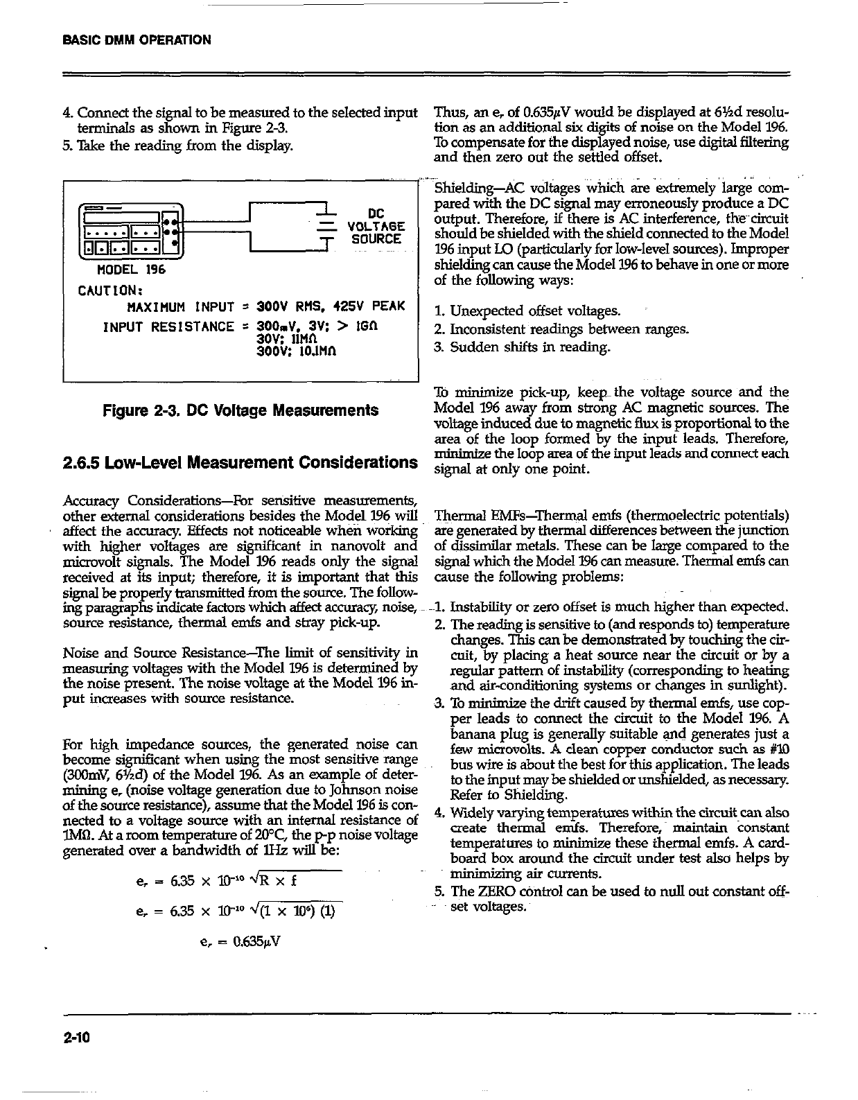
BASIC DMM OPERATION
4. Connect the signal to be measured to the selected input Thus, an e, of 0.635pV would be displayed at 6Yzd resolu-
terminals as shown in Figure 2-3. lion as an additional six diaits of noise on the Model 196.
5. T&e the reading from the display To compensate for the dispgyed noise, use digital filtering
and then zero out the settled offset.
CAUTION:
MAXIFIUM INPUT = 300V RtlS. 425V PEAK
INPUT RESISTANCE = WJdiM:;Vs > IGIl
300G: 10.llln
Figure 2-3. DC Voltage Measurements
..~ .,
Shielding-AC voltages ‘Which &e extremely k&i corn-
pared with the DC signal may erroneously produce a DC
output. Therefore, if there is AC interference, the~~circuit
should be shielded with the shield connected to the Model
196 input Lo (particularly for low-level sources). Impropw
shielding can cause the Model 1% to behave in one or more
of the following ways:
1. Unexpected offset voltages.
2. Inconsistent readings between ranges.
3. Sudden shifts in reading.
To minimjze pick-up, keep-the voltage source and the
Model 196 away from strong AC magnetic sources. The
voltage induced due to magnetic flux is proportional to the
area of the loop formed by the input leads. Therefore,
m minimize the loop area of the input leads and connect each
2.6.6 Low-Level Measurement Considerations signd at ody one point.
Accuracy Considerations-For sensitive measurements,
other external considerations besides the Model I.96 will
affect the accumcy. Effects not noticeable wheti working
with higher voltages sre significant in nanovolt and
microvolt signals. The Model 196 reads only the signal
received at its input; therefore, it is important that tb.is
signal be properly bansmitted from the source. The follow-
ing paragraphs indicate factors which affect accuracy noise,
source resistance, thermal emfs and stray pick-up.
Noise and Source Resistance-The limit of sensitivity in
measuring voltages with the Model 196 is determined by
the noise present. The noise voltage at the Model 1% in-
put increases with sauce resistance.
For high impedance sources, the generated ~noise can
become significant when using the most sensitive mnge
(3COmV, 6Yzd) of the Model 196. As an -pie of deter-
mining e, (noise voltage generation due to Johnson noise
of the somce resistance), assume that the Model 196 is con-
nected to a voltage source with an internal resistance of
lM0. At a mom temperature of 20°C, the p-p noise Voltage
generated over a bandwidth of lHz will be:
e, = 635xXP’~Rxf
e, = 6.35 x lP d/(1 x W) (1)
e, = 0.635fiV
T&rmal EMFs-Thermal emfs (thermoelectric potentials)
are generated by thermal differences between the junction
of dissimilar metals. These can be large compared to the
signal which the Model 196 can measure. Thermal emfs can
cause the following problems:
-1. Instability or zero offset is much higher than expected.
2. The reading is sensitive to (and responds to) temperature
changes. This can be demonstrated by touching the cir-
cuit, by placing a heat source near the circuit or by a
regular pattern of instability (corresponding to heating
and air-conditioning systems or changes in sunlight).
3. To minim&e the drift caused by thermal emfs, use cop-
per leads to connect the circuit to the Model 196. A
4.
banana plug is generally suitable and generates just a
few microvolts. A clean copper conductor such ss #lO
bus wire is about the best for this application. The leads
to the input may be shielded or unshielded, as necessary.
Refer to Shielding.
Widely varying temperatwes within the circuit can also
create thermal ends. Therefor& maintain Constant
temperatures to minimize these thermal ends. A card-
board box around the circuit under test also helps by
minimking air currents.
5. The ZERO cOntro1 can be used to null out constant off-
set voltages.
2-10
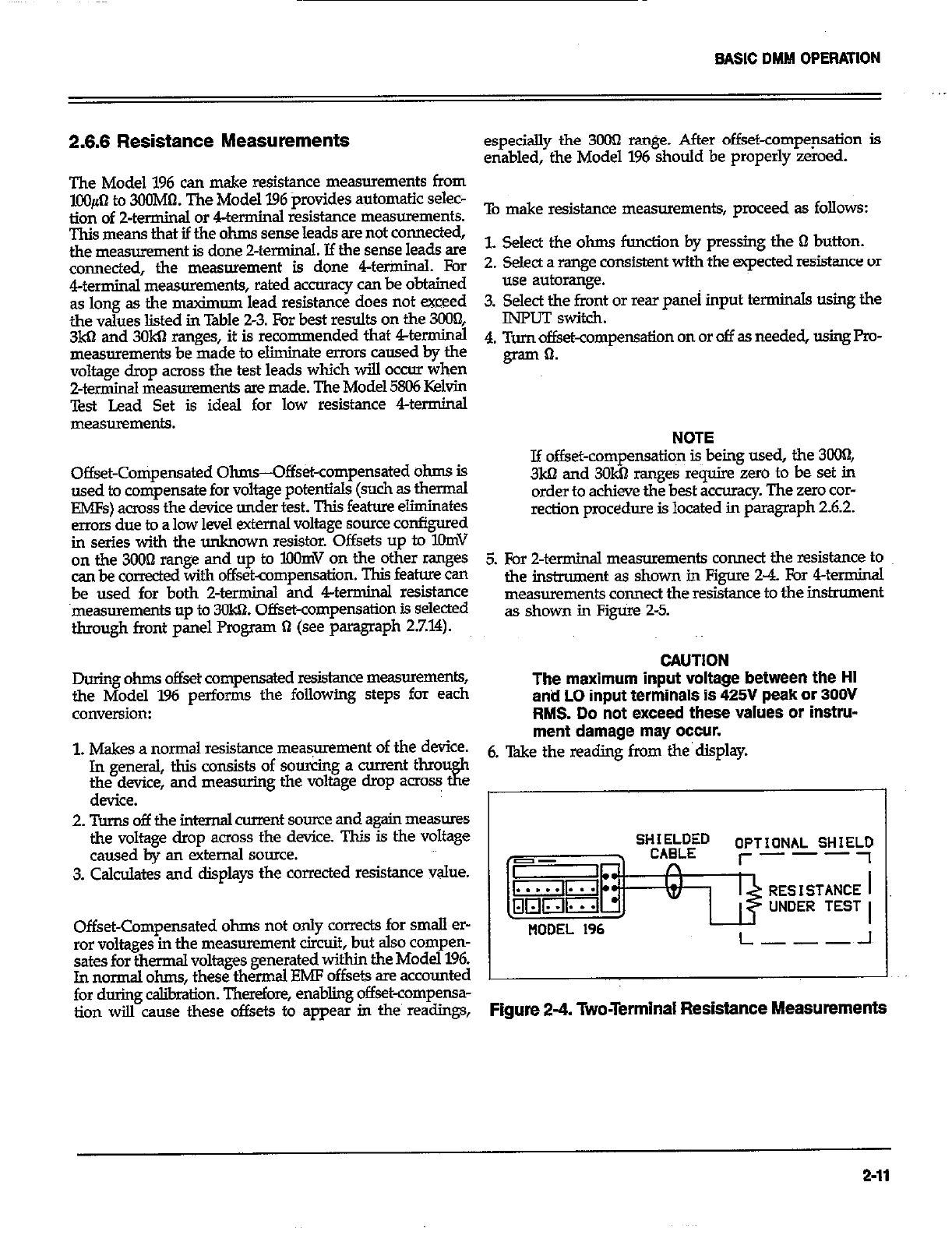
BASIC DMM OPERATION
2.6.6 Resistance Measurements
The Model 196 can make resistance measurements from
lOO#-l to 3CGMtI. The Model 196 provides automatic selec-
tion of 2-terminal or 4terminal resistance measurements.
This means that if the ohms sense leads are not connected,
the measurement is done Zterminal. If the sense leads are
connected, the measurement is done 4terininaI. For
4terminal measurements, rated accuracy can be obtained
as long as the msximum lead resistance does not exceed
the values listed in Table 2-3. For best results on the 3008
3kQ and 3OkQ ranges, it is recommended that 4terminal
measurements be made to eliminate errors caused by the
voltage drop across the test leads which will occur when
2-terminal measurements are made. The Model 5806 Kelvin
Test Lead Set is ideal for low resistance 4terminal
Offset-Compensated Ohms-Offs&-compensated ohms is
used to compensate for voltage potentials (such as thermal
EMFs) across the device under test. This feature eliminates
errors due to a low level external voltage source configured
in series with the unknown resistor. Offsets up to KhnV
on the 3OOn range and up to BlOmV on the other ranges
can be corrected with offset-compensation. This feature can
be used for both 2-terminal and 4terminal resistance
measurements up to 30k61. Offset-compensation is selected
through front panel Program !I (see paragraph 27.14).
especially the 3000 range. After offset-compep.sation is
enabled, the Model 1% should be properly zeroed.
To make resistance measurements, proceed as follows:
L Select the ohms function by pressing the Q button.
2. Select a range consistent with the expected resistance or
use autorange.
3. Select the f&t or rear panei input terminals using the
INPUT switch.
4. Turn offset-compensation on or off as needed, using Pm-
gram 0.
NOTE
If offset-compensatio~n is being used, the 3ooI1,
3ka and 3OkQ ranges require zero to be set in
order to achieve the best accuracy. The zero car-
rection procedure is located in paragraph 2.6.2.
5. For 2-terminal measurements connect the resistance to
the instnunent as shown in Figs 2-4. For 4terminal
measurements connect the resistance to the instrument
as shown in F&ire 2-5.
CAUTlON
During ohms offset compensated resistance measurements,
the Model 196 performs the following steps for each The maximum input voltage between the HI
anti LO input terminals is 425V peak or 300V
conversion: RMS. Do not exceed these values or instru-
1. Makes a normal resistance meaS,mment of the device. ment damage may occur.
In general, this consists of sourcing a current thmu 6. Take the reading from the’display.
the device, and measuring the voltage dmp acro~ tfz
device.
2. Turns off the internal -nt source and again measures
the voltage drop across the device. This is the voltage
caused by an external source.
3. Calculates and displays the corrected resistance value. SHKEf~D
n OPTIONAL SHIEY
I- ---
w UNDER TEST
Offset-Compensated ohms not only cowxts for small er-
ror voltages in the measurement circuit, but also compen-
sates for thermal voltages generated withim the Model 196.
In normal ohms, these thermal EMF offsets are accounted
NODEL 196 L---~-I
for during c&ration. Therefore, enabling offset-compensa-
tion wilI cause these offsets to appear in the’ readings, Figure 2-4. Two-Terminal Resistance Measurements
2-11
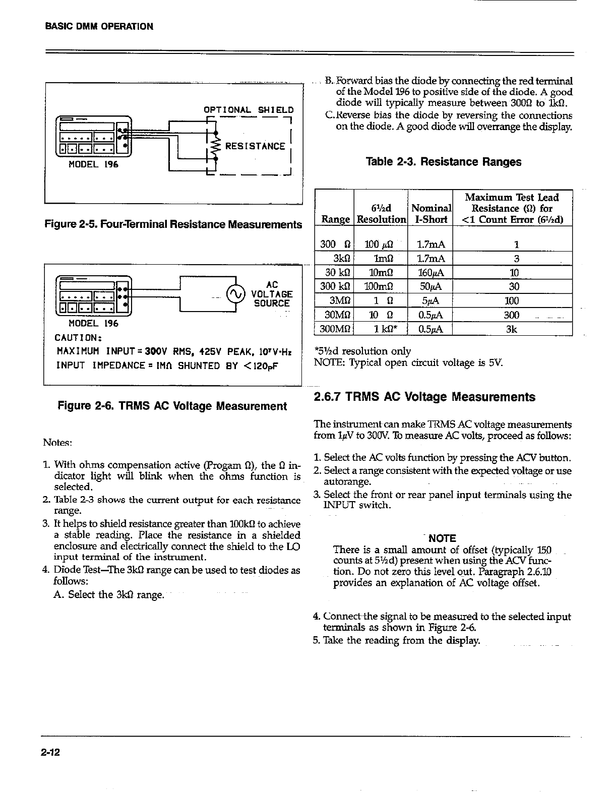
BASIC DMM OPERATION
OPTIONAL SHIELO
-~~- -
MODEL 196
B.&rward bias the diode by connecting the red terminal
of the Model 196 to positive side of the diode. A good
diode will typically measure between 3OOn to IkQ.
C.Reverse bias the diode by reversing the connections
on the diode. A good diode will overrange the display.
Table 2-3. Resistance Ranges
Maximum Test Lead
6%d Nominal Resistance (Q) for
Figure 2-5. Four-Terminal Resistance Measurements Range 1 Resolutim I-Short 1 -3 Count Error (Wzd)
I I I
MODEL 196
CAUTION:
MAX I MUM INPUT = 300V RMS, 425V PEAK. 1O’V.H.
INPUT IMPEDANCE = 1Hf-1 SHUNTED BY < 120pF
Figure 2-6. TRMS AC Voltage Measurement
Notes:
*5%d resolution only
NOTE: Typical open circuit voltage is 5V.
2.6.7 TRMS AC Voltage Measurements
The instrument can make TRMS AC voltage measurements
from l$I to 3OOV. To measwe AC volts, proceed as follows:
1. With ohms compensation active (Progam a), the 61 in- 1. Select the AC volts function by pressing the ACV button.
dicator light will blink when the ohms function is 2. Select a range con$stent with the expeqed voltage or use
selected. autorange.
2. Table 2-3 shows the current output for each resistance 3. Select the front or rear panel input terminals using the
range. INPUT switch.
3. It helps to shield resistance greater than IOOkQ to achieve
a stable reading. Place the resistance in a shielded
enclosure and electrically connect the shield to the LQ
input terminal of the instrument.
4. Diode Test-The 3kQ range can be used to test diodes as
MlOWS:
A. Select the 3kO range.
NOTE
There is a small amount of offset (typically 150
counts at 5%d) present when using the ACV func-
tion. Do not zero this level o-ut. Paragraph 2.6.10
provides an explanation of AC voltage offset.
4. Connecbthe signal to be measured to the selected input
terminals as shown in Figure 2-6.
5. Take the reading from the display.
2-12
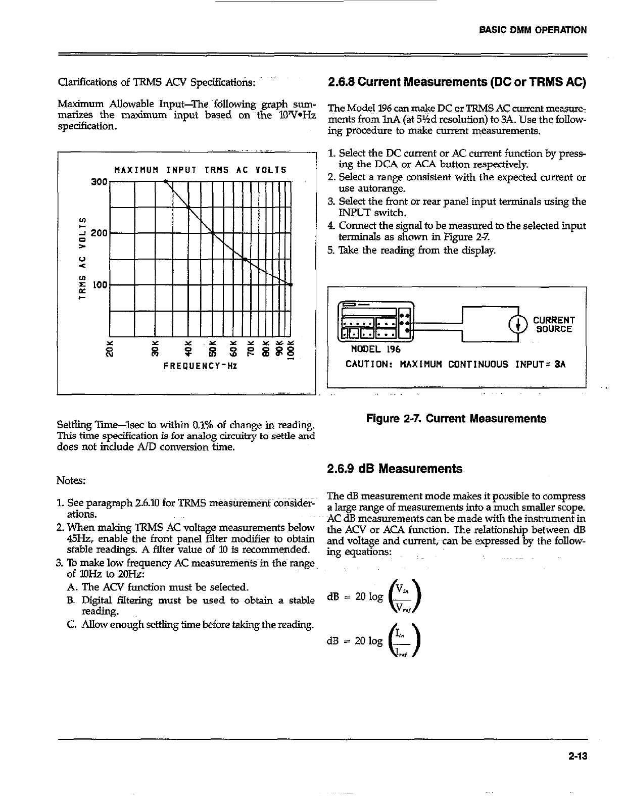
BASIC DMM OPERATION
Clarifications of TRMS ACV Spedfications: ” 2.8.8 Current Measurements (DC or TRMS AC)
Msximum Allowable Input-The following graph sum-
marizes the maximum input based on ~the lWV*Hz
specification.
The Model 196 can m&e DC or TRW AC current measure:
ments from lnA (at 5Yrd resolution) to 34. Use the follow-
ing procedure to make current measurements.
MAXIIIUH INPUT TRt4S AC VOLTS I
FREOUENCY-HZ CAUTION: MAXIMUM CONTINUOUS INPUT=3A
1. Select the DC current or AC current function by press-
ing the DCA or ACA button respectively.
2. Select a range consistent with the expected current or
use autorange.
3. Select the front or rear panel input terminals using the
INPUT switch.
4. Connect the signal to be measured to the selected input
terminals as shown in Figure 2-7.
5. Take the reading from the display.
~. .- _ ._..
I I
Settling Time-lsec to within 0.1% of change in reading.
This the specification is for analog circuitry to settle and
does not in&de AID conversion time.
Figure 2-7. Current Measurements
Notes: 2.8.9 dB Measurements
1. See paragraph 26.10 for TRMS measurement conSid&
&iOllS.
2. When making TRMS AC voltage measurements below
45Hz, enable the front panel filter modifier to obtain
stable readings. A filter value of 10 is recommended.
3. To make low frequency AC mea%uenients in the range
of lOHz to 2oH.z:
A. The ACV function must be selected.
B. Digital filtering must be used to obtain a stable
reading.
C. Allow enough settling time before taking the reading.
The dB measurement mode makes it pocisible to compress
a large range of~measurements into a much smaller scope.
AC dB measurements can be made with the instrument in
the ACV or AC4 function. The relationship between dB
and voltage and currentxan be expressed by the follow-
mg equations:
dB = 20 log .%
0 V
w
2-13
At the factory the instrument is set up to be a dBV meter
when ACV dB is selected. dBV is defined as deciiels above
or below a 1V reference. The instrument will read OdB when
1V is applied to the input. The 1V reference is the factory
default reference. With ACA dS selected, the factory default
reference is lmA. The inskument will read OdB when lmA
is applied to the input.
Reference levels other than 1V and ImA can be established.
There are two methods that can be used to establish a dB
reference. One method is to use the zero feature. This
simply consists of applying a signal to the instrument and
pressing the ZERO button. That suppressed level& the dB
reference (OdB point). The alternate method is to utilize the
front panel dB program and enter the desired reference
value. An advantage of using the dB program is that-a
source is not needed to establish a reference.
The following procedure explains how to use the zero
feature to establish a reference:
1. Apply a voltage or current signal, that is to be used~as
the dB reference, to the input of the Model 196.
2. Press the ZERO button. The ZERO indicator will turn
on and the display will zero. The reference i?now
whatever the applied signal is.
3. Disconnect the signal from the instrument.
Program dB allows the user to check or change the dB
reference of the instrument. The recommended progmm-
mable voltage reference range is from lOpV to 9.99999v The
recommended programmabie current reference range is
from lOnA to 9.99999mA. Paragraph 27.77 contains the in-
formation needed for using the dB program.
AC dB Measurements-Perform the following steps to
make dB measurements:
l. Select the ACV or ACA function.
2. Select the front or rear panel input terminals with the
INPUT switch.
3. Check and/or change the dB reference as previously
explained.
4. Connect the signal to be measured to the inputs of the
Model 196.
5. ktite,the dB measurement mode by pressing the dB
6. Take the dB reading from the display.
WARNING
With dB enabled, a hazardous voltage baseline
level (~40V or more), not displayed, may be pre-
sent on the input terminals. If not sure what is
applied to the input, assume that a hazardous
voltage is present.
dBm MeasurementiBm is defined as decibels above or
below a lmW reference. dB~ measurements can be made in
terms of impedance rather than voltage or current. Because
the instrument ~cannof directly establish impedance
referenws, a v&age reference must be calculated and
established for a particular impedance reference. Use the
following equation to calculate the voltage refenznce need-
ed for a particular impedance reference:
For OdBm, V,., = JlmW l Z.,,
Example: Calculate the voltage reference needed to make
dBm measurements referenced to Mx)fi.
For OdBm, V,+ = ~O&lOlW :, 6OOQ ..,
3 46
= .77456v
Once the necessary voltage reference is known. it canbe
established in the Model 196 with the.dB program. Subse-
quent dBm readings will be referenced to the correspond-
in impedance reference. Table 2-4 lists the voltage
2
I erences needed for some commonly used impedance
references.
dBW Measurements-dBW is defined as decibels above or
below a 1W reference. dBW measurements are made in the
same manner as dBm measurements; that is, calculate the
voltage reference for a particular impedance and set the in-
strument to it with the dB program. The only difference
between dBm and dBW is the reference point; ZmW vs 1W.
The following equation can be used to ca&Jate the voltage
reference:
For OdBW, V,, = dlW*Z,,
2-14
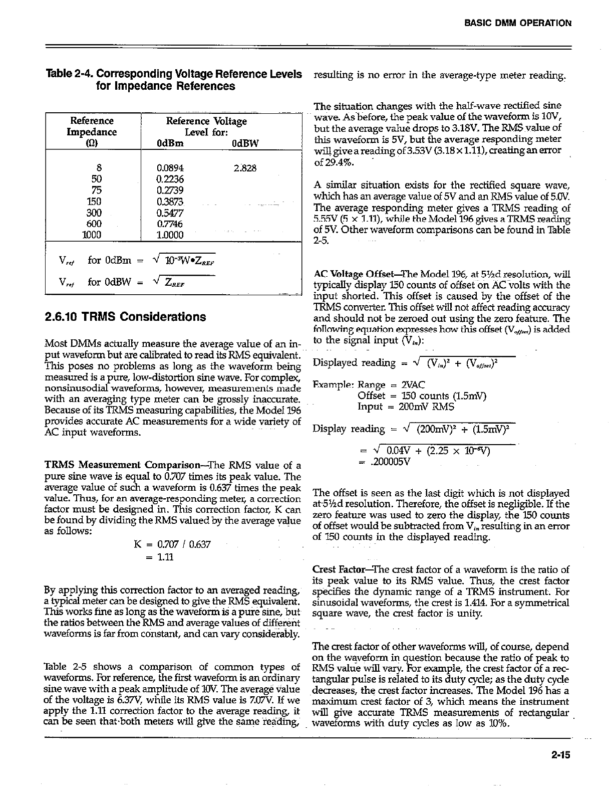
Table 2-4. Corresponding Voltage Reference Levels
for Impedance References resulting is no error in the average-type meter reading,
Reference Reference
Impedance Impedance
(0 (0
8
50
75
150
300
600
1000
Reference Voltage
Level for:
OdBm OdBW
0.0894 2;828
0.2236
0.2739
0.3873
0.5477
0.7746
1.0000
V
,f for OdBm = -J lO?V*Z,
V
,*t for OdBW = 4 ZR,
2.6.10 TRMS Considerations
The situation changes with the half-wave rectified sine
wave. As before, the peak value of the waveform is IOV,
but the average value drops to 3.18V. The R&E value of
this waveform is 5V, but the average responding meter
wiUgiveareadingof35 (3.18xl.l~),~ealingan MOT
of29.4%.
A similar situation exists for the rectified square wave,
which has an average value of 5V and an RMS value of 5.CW.
The average responding meter gives a TRMS reading of
5.55V (5 x Lll), while the Model 196 gives a TRMS reading
of 5V. Other waveform comparisons can be found in Table
2-5.
AC Voltage Offset-The Model 196, at 5%d resolution, will
typically display 150 counts of offset on AC volts with the
input shorted. This offset is caused by the offset of the
TRMS converter. This offset will not affect reading accuracy
and should not be zeroed out using the zero feature. The
following equation expresses how this offset (V,,) is added
Most DMMs actually measure the average value of an in- to the signal input (V,.):
put waveform but are calibrated to read its RMS equivalent.
This poses no problems as long as the waveform being Disp1ayed reading = ’ @‘I=)’ + ‘V,,,)
measured is a pure, low-distortion sine wave. For complex,
nonsinusodial waveforms, however, measurements made Example: Range = 2VAC
with an averaging type meter can be grossly insccurafe. Offset = I.50 counts (1.5mV)
Because of its TRMS measuring capabilities, the Model 196 Input = ZOOmV RMS
provides accurate AC measurements for a wide variety of
AC input waveforms. Display reading = 4 (2OOmV)’ + (1.5mV)
Lz J 0.04v + (2.25 x 10-v)
TRMS Measurement Comparison-The RMS value of a = .200005V
pure sine wave is equal to 0.707 times its peak value. The
average value of such a waveform is 0.637 times the peak
value. Thus, for an average-responding meter, a correction The offset is seen as the last digit which is not displayed
factor must be designed in. This correction factor, K can at5%d resolution. Therefore, the offset is negligible. If the
be found by dividing the RMS valued by the average vsjue zero feature was used to zero the display, the I50 counts
as follows: of offset would be subtracted from Vj. resulting in an error
K = 0.707 / 0.637 of 150 counts in the displayed reading.
= 1.11 Crest Factor-The crest factor of a waveform is the ratio of
By applying this correction factor to an weraged reading, its peak value to its RMS value. Thus, the crest factor
a typical meter can be designed to give the RMS equivalent. specifies the dynamic range of a TRMS instrument; For
This works fine as long as the waveform is a pure sine, butt sinusoidal waveforms, the crest is 1.414. For a symmetrical
the ratios between the RMS and average values of different square wave, the a& factor is unity
waveforms is far from constant, and can vary considerably. The crest factor of other waveforms will, of course, depend
Table 2-5 shows a comparison of common types of on the waveform in question because the ratio of peak to
waveforms. For reference, the first waveform is an ordinary RMS value will vsrj~ For example, the crest factor of a rec-
sine wave with a peak amplitude of 1OV The average value tang&u pulse is related to its duty cycle; as the duty cycle
of the voltage is 6.37V while its RMS value is ZO7V Jf we ~decreases, the crest factor increases. The Model 196 has a
apply the 1.11 correction factor to the average reading, its maximum crest factor of 3, which means the instrument
can be seen thatboth meters will give the same reading, will give accurate TRMS measurements of rectangular
waveforms with duty cycles as low as 10%.
2-15
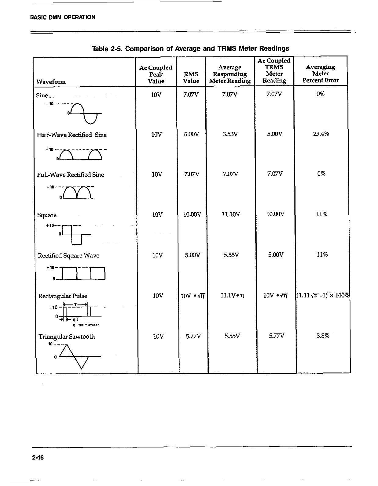
BASIC DMM OPERATION
Table 2-5. Comparison of Average and TRMS Meter Readings
Yaveform
iine
+,p------
0
0
la&Wave Rectied Sine
Ul-Wave Rectified Sine
;quare
+10-- --
0
?I- ~~~
Rectified Square Wave
Triangular Sawtooth
ic Coupled
Peak
Value
IOV
1ov
1ov
1ov
1ov
IOV
1ov
RMS
Value
7.07v
5.OOV
7.07v
lO.ow
5.cOv
,ov l fi
5.77v
Average
Responding
4&r Reading
7.07V
3.53v
7.07v
ll.lOV
5.55v
ll.lV* q
5.55v
,c Coupled
TRMS
Meter
Reading
7.07V
5.oov
7.07v
lO.ooV
5.OOV
1ov l fi
5.77v
Averaging
Meter
Percent Error
0%
29.4%
0%
11%
11%
:.11fi-I) x 100
3.6%
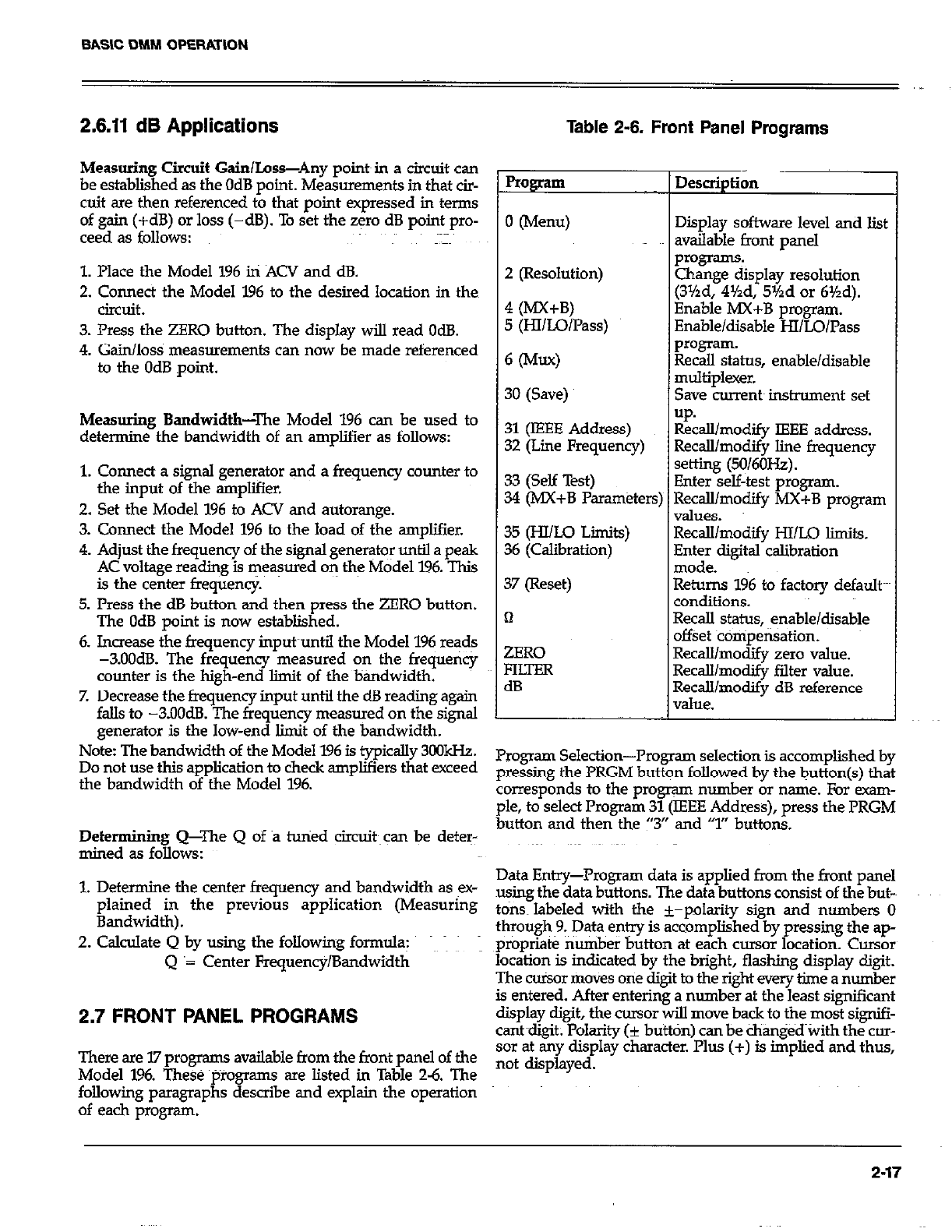
BASIC DMM OPERATION
2.6.11 dB Applications
Measuring Circuit Gain/Loss-Any poimin a circuit can
be established as the OdB point. Measurements in that cir-
cuit are then referenced to that point expressed in terms
of gain (+dB) or loss (-dB). To set the zero dB point pro-
ceed as follows:
1. Place the Model 196 in ACV and dB.
2. Connect the Model 196 to the desired location in then
circuit.
3. Press the ZERO button. The display will read OdB.
4. Gain/loss measurements can now be made referenced
to the OdB point.
Measuring Bandwidth-The Model 196 can be used to
determine the bandwidth of an amplifier as follows:
1. Connect a signal generator and a frequency counter to
the input of the amplifier.
2. Set the Model 196 to ACV and autorange.
3. Comect the Model 196 to the load of the amplifier.
4. Adjust the frequency of the signsI generator until a peak
AC voltage reading is measured on the Model 196. This
is the center frequency.
5. Press the dB button and then press the ZERO button.
The OdB point is now established.
6. Increase the frequency input~until the Model 196 reads
-3.OOdB. The frequency measured on the frequency
counter is the high-end Emit of the bandwidth.
7. Decrease the frequency input until the dB reading again
falls to -3.OOdB. The frequency measured on the signal
generator is the low-end limit of the bandwidth.
Note: The bandwidth of the Model 196 is typically 3oOkHz.
Do not use this application to check amplifiers that exceed
the bandwidth of the Model 196.
Determining Q-The Q of B tuned circuit~can be deter-
mined as follows:
Table 2-6. Front Panel Programs
Program Description
I
0 (Menu) Display software level and list
available front panel
2 (Resolution)
4 (MX+B)
5 (HlILo/Pass)
Programs
Change display resolution
(3Yzd, 4%d, 5%d or 6%d).
Enable MX+B program.
Enable/disable HI/LO/Pass
6 W-9 ~ ~%lsaskus, enable/disable
3O(Save) ~ multiplexer.
Save currem instrmnent set
up.
31 (IEEE Address) Recall/modify IEEE address.
32 (Line Frequency) Recall/modify line frequency
33 (Self Test) setting (50/6OHz).
34 (MX+B Parameters; Enter self-test program.
Recall/modify MX+B program
values.
3.5 (HI/Lo Liits) Recalllmodify HI/LO limits.
36 (Calibration) Enter digital calibration
mode.
37 (Reset) Returns 196 to factory default
conditions.
n Recall status, enable/disable
offset ~comoensation.
ZERO
FluER
dB
Recall/modify zero value.
RecaWmocbfy falter value.
Recall/modify dB reference
value.
Program Selection--Program selection is accomplished by
pressing the PRGM button followed by the button(s) that
corresponds to the program number or name. For exam-
ple, to select Program 31 (IEEE Address), press the PRGM
button and then the “3” and ‘7” buttons.
1. Determine the center frequency and bandwidth as ex- Data Entry--Program data is applied from the front panel
plained in the previous application (Measuring using the data buttons. The data buttons consist of the but-~
t ons~ labeled with the +-oolaritv sipn and numbers 0
Bandwidth).
2. Calculate Q by using the following formula: through~9.~ Data entry is &bmpl&hed”by pressing the ap-
propriate number button at each cursor location. Cursor
Q ‘= Center Frequency/Bandwidth location is indicated by the bright, flashing display digit.
The cu%or moves one digit to the right every time a number
is entered. After entering a number at the least significant
2.7 FRONT PANEL PROGRAMS display digit, the cursor will move back to the most signifi-
cantdiait; Polarity fi button) can be changed with the cm-
There are I.7 programs available from the front panel of the sor at &y display character.‘I’lus (+) is &plied and thus,
Model 196. These ~tiroamms are Listed in Table 26. The not displayed,
following paragraphs describe and explain the operation
of each program.
2-17
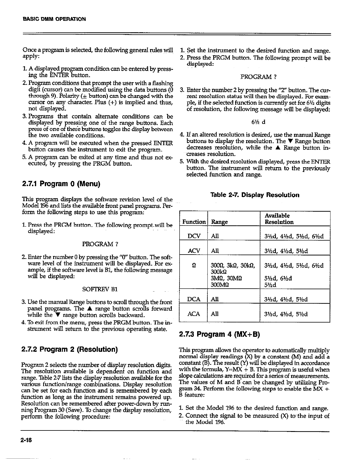
Once a program is selected, the following general Mes wiu
=PPlY:
1. A displayed program condition can be entered by press-
im the ENTER button.
2. P&gram conditions that prompt the user with a flashing
digit (cursor) can be modified using the data buttons (0
through 9). Polarity (i button) can be changed with the
msor on any character. Plus (+) is implied and thus,
not displayed.
3. Program.5 that contain alternate conditions can be
display:d by pressing one of the range buttons. Each
press of one of these buttons toggles the display between
the two available conditions.
4. A program will be executed when the pressed ENTER
button causes the instrument to exit the program.
5. A program can be exited at any time and thus not ex-
ecuted, by pressing the PRGM button.
2.7.1 Program 0 (Menu)
This program displays the software revision levels of the
Model 196 and lists the available front panel progr-. Per-
form the following steps to use this program:
1. Press the PRGM button. The following prompt-will be
displayed:
PROGRAM ?
2. Enter the number 0 by pressing the “0” button. The soft-
ware level of the instrument will be displayed, For ex-
ample, if the software level is Bl, the following message
will be displayed:
SOFTREV 81
3. Use the manual Range buttons to scroll through the front
panel programs. The A range button scmlls forward
while the y range button scrolls backward.
4 To exit from the menu, press the PRGM button. The in-
strument will retnrn to the previous operating state.
2.7.2 Program 2 (Resolution)
Program 2 selects the number of display resolution digits.
The resolution available is dependent on function and
range. Table 2-7 lists the display resolution availabie for the
various function/range combinations. Display resolution
can be set for each function and is remembered by each
function as long as the instrument remains powered up.
Resolution can be remembered after power-down by run-
ning Program 30 (Save). To change the display resolution,
perform the following procedure:
1.~ Set the in+ument to the desired fun@iqn and range.
2. Press the PRGM button. The following prompt will be
displayed:
PROGRAM ?
3. Enter the number 2 by pressing the “2” button. The cur-
rent resolution status will then be displayed. For exam-
ple, if the selected function is currently set for 6% digits
of resolution, the following message v+l be displayed:
6% d
4. If an altered resolution is desired, use the manual Range
buttons to display the resolution. The V Range button
decreases resolution, while the A Range but&n in-
creases resolution.
5. With the desired resolution displayed, press the ENTER
button. The instrument will return to the previously
selected function and range.
Table 2-7. Display Resolution
Function Range
DCV All
ACV AU
Available
Resolution
31/2d, 4%d, 5Hd, 61hd
3%d, 4%d, 5%d
DCA IAll ( 3%d, 4%d, 5Yzd
I I
I AcA I- 3%d, 4Hd, Shd I
2.7.3 Program 4 (MX+B)
This program allow3 the operator to automatically multiply
normal display readings (X) by a constant (M) and add a
constant (B). The result (Y) will be &played in accordance
with the formula, Y=MX + B. This program is useful when
slope calculations are required for a series of measurements.
The values of M and B can be char& by utilizing Pro-
gram 34. Perform the following steps to enable the MX t
B feature:
1. Set the Model 196 to the desired function and range.
2. Connect the signal to be measured (x) tvthe input of
the Model 196.
2-16
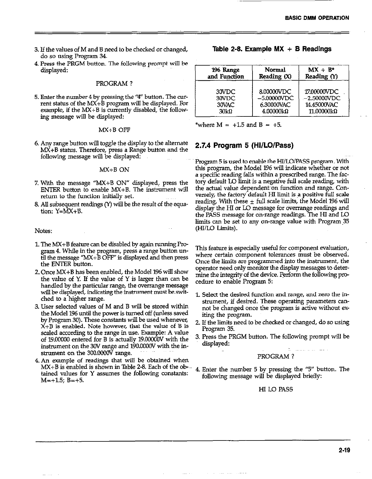
BASIC DMM OPERATION
,,
3. If the values of M and B need to be checked or changed,
do so using Program 34.
4. Press the PRGM button. The following prompt will be
displayed:
PROGRAM ?
5. Enter the number 4 by pressing the “4” button. The cur-
rent status of the MX+B program will be displayed. For
example, if the MX+B is currently disabled, the follow-
ing message will be displayed:
MX+B OFF
6. Any range button will to&e the display to the alternate
MX+B status. Therefore, press a Range button and the
following message will be displayed:
MX+B ON
7. With the message “MX+B ON” displayed, press the
ENTER button to enable MX+B. The ins&rnent will
return to the function initially set.
8. AU subsequent readings cr) wiJ.l be the result of the equa-
tion: Y=MX+B.
Notes:
1. The hIX+B feature can be disabled by again running Pro-
gram 4. While in the progxwn, press a range button un-
til the message “MX+B OFF” is displayed and then press
the ENTER button.
2. Once h4X+B has been enabled, the Model 196 will show
the value of Y. If the value of Y is larger than can be
handled by the particular range, the overrange message
will be displayed, indicating the instrument must beswit-
ched to a higher range.
3. User selected values of M and B will be stored within
the Model 196 until the power is turned off (unless saved
by Program 30). These constants will be used whenever,
X+B is enabled. Note however, that the value of B is
scaled according to the range in use. Example: A value
of 19.00000 entered for B is actually 19.0000OV with the
instrument on the 30V range and 19O.OOOOV with the in-
strument on the 3OO.oMxxT range.
4.An example of readings that will be obtained when
MX+B is enabled is shown in Table 2-8. Each of the ob-
tained values for Y assumes the following constants:
M=+1.5; B=+5.
Table 2-8. Example MX + B Readings
lzooomc
~-2.5OOOOvDc
14.4500OVAC
11.00000kQ
*where M = +1.5 and B = +5.
2.7.4 Program 5 (HI/LO/Pass)
Program 5 is used to enable the HI/LO/PASS program. With
this program, the Model 196 will indicate whether or not
a specific reading falls within a prescribed range. The fac-
tory defa&L.Q limit is a negative full scale reading, with
the actual value depende~ntron function and range. Con-
versely, the factory’default y limit is a positive full scale
reading. With these f full scale limits, the Model 196 will
display the HI or Lo message for overrange readings and
the PASS message for oh-range readings. The HI and LO
limits can be set to any on-range value with Program.35
(HI/Lo Limits).
This feature is especially useful for component evaluation,
where certain component tolerances must be observed.
Once the limits are programmed into~ the instrument, the
operator need only monitor the display messages to deter-
mine the integrity of the device. perform the following pro-
ceduIe to enable Program 5:
1. Select the desired function and range, and zero the in-
shument, if desired. These operating parameters can-
not be changed once the program is active without ex-
iting the program.
2. If the limits need to be checked or changed, do so using
Program 35.
3. Press the PRGM button. The following prompt will be
displayed:
PROGRAM ?
4. Enter the number 5 by pressing the “5” button. The
following message will be displayed briefly:
HI LO PAS5
2-19
BASIC DMM OPERATION
5. At this point, the instrument will run the program. No
numeric readings wilI be displayed. Instead, one of the
following messages will be displayed:
A. If the measured value is less than the low limit, the
following message will be displayed:
Lo
B. If the measured value is greater than the Mgh limit,
the following message will be displayed:
HI
C. If the measured value falls within the high and low
limits, the following message will be displayed:
PASS
6. To disable the program, press the function button that
has the indicator light on. This will disable the~prZ@am
without changing the measurement parameters (i.e.
function, range, etc.) of the instrument.
Notes: ~~~~ ~~~ >)
1. L&its can be set using Program 35 with or without Pro-
gram 5 enabled.
2. User selectable values of L and H will be stored within
the Model 196 until the power is turned off (unless saved
by Program 30). These constants will be used whenever
HI/LO/PASS is enabled. Note however, that the value of
L and H are scaled according to the range in use.
3. Pressing any ofthe front panel controls, &cept dB (unless
in AC), ENTER, and LOCAL, will disable the program
and select the feature associated with that button.
2.7.5 Program 6 (Multiplexer, Auto/Cal)
The multiplexer autoical routines may be defeated by run-~
ning Program 6. Using the Model 196 with the auto zerokal
defeated increases measurement speed and is useful for
making high impedance DC voltage measurements which
can be affected by the input multiplexing. Perform the
following steps to run this program: -.
1. Press the PRGM button. The following prompt will be
displayed:
PROGRAM ?
2. Enter the number 6 by pressing the “6”button. The cur-
rent multiplexer status will then be displayed. For exam-
ple, if the multiplexer is on, the following message~~*
be displayed: ~;~
MUX ON
3. If the alternate multiplexer status is desired, press one
of the range buttons. The alternate status will be
displayed as follows:
MUX OFF
4. To enter the displayed multiplexer status, press the
VENTER button. The instrument will return to the
previous operating state.
NOTE
with the auto/Cal multiplexer disabled, the internal
zero and calibration are affected by changing the
nominal inout level. esneciallv on ohms and the
3OOVDC range. WheneGer the’applied input level
changes, press the selected function button to per-
form an auto/Cal routine, otherwise substantial
errors will result. Zero and calibration may also be
affected by time. Thus, it is recommended that the
selected function button be pressed periodically.
2.7.6 Program 3O~(Save)
Program 30 saves current instrument conditions set up by
the user. These user programmed conditions will then
replace the previously saved default conditions on power
up. Also, an SDC or DCL asserted over the IEEE-488 bus
will return the instrument to these saved conditions.
The following instrument operating parameters are saved
by this program:
Function
Range
Resolution
Zero status (on/off) and value
Filter status (on/off) and value
ACdB status (on/off) and reference value
IEEE ~address ~.~
Line frequency setting
MX+B status (on/off) and values
HI&O limits
Ohms compensation status (on/off)
Perform the following procedure to use the save program:
1.~ Seth up the instrument as desired or~run Program 37
(Reset) to return the instrument to the factory default
conditions.
2-20
BASIC DMM OPERATION
2. Press the PRGM button. The following prompt will be
displayed: 3. Ifit is desired to retain the displayed status value, proceed
to~step 4. To change the status value, enter the address
number (0 to 30).
PROGRAM ? 4. With a valid status disulaved, mess the ENTER button.
3. Enter the number 30 by pressin the “3” and “0” but-
tons. The following message & be displayed briefly:
The instrument will %rn to the previously defined
,stam
SAVE
4. The following message will then be displayed:
ENTBR?
Notes:
1. If an invalid number is entered, the instrument wiIl exit
zrn@t$ program with the IEEE primary address being
5. To save the instrument set up conditions, press the 2.To change the default address of the instrument, select
ENTER button. The following message v$k~displayed the desired IEEE address using this program and then
L..z^cL.. Program 30 (or Ll over the IEEE bus) to save it. Cvchng
BNTBRBD
power, Program 37 (Reset), or an SDC, DCL or Lb sen?
over the bus will not have any affect on the new default
address.
6. The instrument wi!.l return to the conditions set up in 3. If the JEBE address is changed but not saved:
step 1 and will now power up to those conditions. A. 2 cl&power will return the insmument to the default
B .
B. Program 37 (Reset), or an SDC or DCL sent over the
Notes: bus wiB not have any affect on the current address.
1. TO exit the program without changing the previous C. Sending LO over the bus will not change the current
default conditions, press any front panel button except IEEE address, and will save that address as the power
the ENTBR button. The instrument will return to the up default address.
operating states set up in step 1. 4, An /mCAfJ’ error d default the IEEE address to 7 and
2. To return the instmment to the factory power up default the line frequency setting to 6OHz.
conditions, use Program 37 (Reset) and save the condi-
tions using Program 30. ~~ 2,7.8 Program 32 (Lht? Frequency)
3. When using this program, make sure that the rest~of the
instrument is in the desired operating state. The Model I.96 does not automatically detect the power line
frequency upon power up.~~This program aLlows the user
2.7.7 Program 31 (IEEE Address) to check the line frequency set
to select the alternate fmquenc$K&%e&Z%Z~~~
Program 31 allow? the user to check and/or modify the ad- to either 5OH.z or 6oHz. Perform the folloxjng steps to check
dress of the IEEE&B interface. The interface can be set to and/or change the line frequencysetting of the yodel 196.
address from 0 to 30 Detailed information on
!!Zo%g%ps to use this program:
bus rs prowded m Section 3. Perform the 1. Press the PRGM button. The following prompt will be
displayed.
PROGRAM ?
1. Press the PRGM button. The following prompt will be
displayeyed: 2. Enter the number 32 by pressing the “3” and “2” but-
tons. The current line frequency setting will then be
PROGRAM ? displayed. J.f the instrument is currently set to 6OH.2, the
2. Enter the number 31 by pressing the “3” and “1” but- following message @I be displayed:
tons. The IEEE address value will be displayed. Exam- PRBQ=6OHz
pie: If the current primary address of the instrument is
7, the following message will :be displayed:
07 IE
2-21
BASIC DMM OPERATION
3. If the displayed frequency setting matches the available
line frequency, proceed to step 4. If the alternative line
frequency setting is needed, press one of the Range but-
tons. The display will toggle to the alternate frequency
setting as shown:
FREQ=5OHz
4. With the correct frequency setting displayed, press the
FJITER button. The instrument will return to the pre-
vious operating state.
Notes:
1. To change the default line frequency setting of the ins&~-
ment, select the desired setting using this prog;&% and
then Program 30 (or Ll over the IFEE bus) to save it. Cycl-
ing power, Program 37 (Reset), or an SDC, DCL or I.0
sent over the bus will not have any affect on the new
default setting.
2. If the line frequency setting is changed but not saved:
A. Cycling power, x~r sending an SDC~or DCL over the
bus will return the instrument to the default.s&&.
8. Program 37 (Reset) will not have any affect on the cur-
rent setting.
C. Sending Lo over the bus will not change the current
line frequency setting, and will save that setting as
the default setting.
3. An “UNCAE’ error will default the IEEE address to 7 and
the line frequency setting to 6OHz.
2.7.9 Program 33 (Diagnostic)
Program 33 is a diagnostic program designed to switch on
tious switching PET’s, relays and logic levels to allow sig-
nal tracing through the instrument. Also, tests on the dis-
play and memcry are performed. Refer to paragraph 6.7.3 in
the maintenance section to use this program to troubleshoot
the instrument.
2.7.10 Program 34 (MX+B Parameters)
This prqpm allows the operator to check/change the M
and B values for the MX+B feature (Program 4) of the
Model 196. The factory
lBOOOOO and the value of i. ower up default value of M is
1s OOOOCKX. To check/change the
values of M and B, proceed as follows:
1. Press the PRGM button. The following prompt will be
displayed:
PRO&AM ?
2. Enter the number 31 by pressing the “3” and ‘+I” buttons.
The current value of M will now be diip1ayed.X thefac-
tory default value is the current value of M, then the
following message will be-displayed:
l.OLlONO M
3. If it is desired to retain the displayed M value, proceed
to step 4. If it is desired to modify the M value, do so
causing the data buttons. Note that valid M values are in
the range of -9.999999 to +9.999999.
4. With a M value displayed, press the ENTER button.
5. The ctit%t~B value will now be displayed. If the factory
defualt~value is the current B value, the following
message will be displayed:
0000.000 B
Decimal point~position is determined by the mnge that
the instrument was on when t&s program was selected.
6. If it is desired to retain the displayed B value, proceed
to step Z If it is desired to modify the value of M, do
so usin
fmm f % the data keys. Notes that the B value range is
.ooolxlo-~ to i9999.999 (in&ding zero).
7. With a valid B value displayed, press the ENTER but-
ton. The instrument will return to the previously defm-
ed state of operation.
Notes:
1. User se&ted &&s of M and B will be~st&ed &thin
the Model 196 until the power is turnedoff (unless saved
by Program 30). These constants will be used whenever
MX+B is enabled. Note however, that the value of B is
scaled according to the range in use. Example: A value
of 19.00000 entered for B is actually 19.O0XOV with the
instrument on the 3OV range and 19O.OOC0V with the in-
strument in the 300V range.
2. The user can set the values for M and B as the power
up default values by running Program 30.
2.7.11 Program 35 (Hi/LO Limits)
Program 35 is used to set the high and low limits for t&
HI/LO/PASS program (l’rogram 5). The fa~ctory default
limits are +303X03 counts (Hl limit) and -3030300 counts
(LO limit). The actual value of the limits is dependent on
the range. For example, the factory default HI limit on the
3V ran e is 3.03OOoW, while the factory default HI limit ori
the3c8 range 1s 30.3ooo(N. Perform the following procedure
to~set HI and Lo limits:
2-22
BASIC DMM OPERATION
1. Place the Model 196 in the function and range that the
HI/LO/PASS program (Program 5) will be used.
2. Press the PRGM button. The folIowing prompt will be
displayed:
PROGRAM ?
3. Enter the number 35 by pressing the “3” and “5” but-
tons. The current LO limit wiII be displayed. For exam-
ple, if the I.0 limit is the factory default value, the follow-
ing message will be displayed:
-303.0000 Lo
Decimal point position is determined by the range that
the instrumentwas on when this program was selected.
4. If it is desired to retain the dis
to step 5. Otherwise, modify t
K
layed LO limit, proceed
e &splayed value using
the data buttons. The IO limit must be in the range of
-3030000 to +3030000 counts.
5. With the desired LO lit displayed, press the ENTFR
button. The current HI limit will be~dis la ed. For ex-
ample, if the LO lit is the factory d &I? a t value, the
following message will be displayed:
303.0000 HI
Decimal point position is determined by the ran e that
the instrument was on when this program was se e&d.
H
6. If it is desired to retain the displayed HI limit, proceed
to step 7. Otherwise, modify the displayed value using
the data buttons. The HI limit must be in the~range of
-3030000 to +3030ooo counts.
7. With the desired HI limit displayed, press the ENTER
button. The instrument will return to the previous
operating state.
Notes:
1. Userselected limits wiil be stored in the Model.196 until
power is turned off (unless saved by Program 30). These
constants will be used whenever Program 5
@I/IAX?~SS) is enabled.
2. Limits set by the user will become the power up default
limits by running Program 30 (Save).
3. Entering an invalid value will result with the instrument
using the power up default limit.
2.7.12 Program 36 (Calibration)
The user can easiIy perform front panel digital calibration
by applying accurate calibration signals using Program 36.
The calibration signals can be either prompted default
values or numbers entered from the front panel. Paragraph
6.4.5 descriis the basic steps for using this program, while
paragraphs 6.4.7 through 6.4.12 provide the complete front
panel calibration procedure.
2.7.13 Program 37 (Reset)
Program 37 resets instrument set up parameters back to fac-
tory default conditions. The factory default conditions are
listed in Tables 2-l and 3-T’. Perform the following steps to
run this program.
1. Press the PRGM button. The following prompt will be
displayed:
PROGRAM ?
2. Enter the number 37 by pressing the “3” and “7” but-
tons. The following message will be displayed briefly:
RESET
3. The following promptwill then be displayed:
4. Press the ENTER button. The following message will be
displayed briefly and the instrument~will return to the
factory default conditions.
ENTERED
Notes:
1. Prwgram 37 (Reset) can be aborted by pressing any front
panel button, except the ENTER button, when the
prompt “ENTER?” is displayed. The instrument will
return to the previous operating state.
2. Once the instrument is reset to the factory default con-
ditions with this program, Program 30 must be run if
it is desired to have the factory default conditions on
subsequent power ups.
3. Program 37 (Reset) will have no aifect on the current ISEE
address and line frequency setting.
2-23
SASIC DMM OPERATION
2.7.14 Program L!
The ohms offset compensation program is used to compen-
sate for voltage potentials (such as thermal EMFs) across
the resistance to be measured. This feat&s can be used for
both 2-terminal and 4-terminal resistor measurements up
to 3OkR. Additional information on ohms offset compen-
sation can be found in paragraph 2.6.6. Perform the follow-
ing steps to use the ohms offset compensatron program:
1. Press the PRGM button. The following prompt wilJ be
displayed:
PROGRAM ?
2. Press the Q button. The current status of ohms compen-
sation wiIl be dis
is currently disa
E layed. For example, if compensation
displayed: led, the following messages will bee
COMPOFF
3. If the alternate status is desired ,gressoneoftheRange
buttons. The alternate status will e displayed as fo!.lows:
COME’ ON
4 With the desired compensation status displayed, press
the ENTER button.
A. If ohms offset compensation was enabled, the instru-
ment will be placed in the ohms function with the
0 indicator light flashing.
B. If ohms offset compensation was disabled, the insnu-
ment will return to the previous 0
the ohms function is selected, K .’
eraling state. When
t
will not flash. e B mdrcator light
Notes:
1. The lT iridicator~light reveals the status of ohms offset
compensation. With the ohms function selected, a
flashing 0 light indicates that compensation is enabled,
and conversely, a non-flashing Q light indicates that com-
pensation is disabled.
2. The status of ohms offset compensation can be saved as
a power up default condition by running Program 30.
2.7.15 Program ZERO
Program ZERO allows the user to check or modify the,,zero
value. A complete explanation of the zero modifier can be
found in paragraph 2.6.2. Once a zero v&e is set on a
measurement function, that zero level is the same on all
the ranges. Example: If 1V DC is set to the zero value of
the 3V DC range, the zero value in the program wiil be
displayed as 1.000000. On the 30V DC range the zero value
will still be 1V DC, but will be expressed as 01.00000 in the
program.
Perform the following procedure to implement Program
ZERO.
1. Press the PRGM button. The following prompt will be
displayed:
PROGRAM ?
2. Press the ZERO button. The current zero value will then
be displayed. Example: If the instrument is on the 3OV
DC range and the current zero value is +3V DC the
following message will be displayed:
03.00000 z -~
3. If it is desired to retain the displayed zero value, press
the ENTER button. The instrument will return to the
previous operating state with the zero modifier enabled.
The displayed reading will reflect the entered zero value.
4. To modifythe zero value, enter the new value and press
the ENTER button. The instrument will return to the
previously defined state with the zero modifier enabled
using the newly entered zero value.
Note: The factory default power up zero value is OCKKICO.
If it is desired to have a different zero value displayed
on power up, modify the zero value using Program
ZERO followed by Program 30 to save it.
2.7.16 Program FILTER
Program FILTER allows the user to modjfy~ the weighting
of the digital filter. Valid filter values are from 1 to 99. More
information concerning the filter can be found in paragraph
2.6.3.
Perform the following steps to check and/or modify the
filter value.
1. Select the desired function.
2. Press the PRGM button. The following prompt will be
displayed:
PROGRAM ?
2-24
BASIC DMM OPERATION
3. Press the FIITER button. The current filter value will then
be displayed. Example: If the filter value is 5, the follow-
ing message wilI be displayed:
05 F
4. If it is desired to retain the displayed filter value, pro-
ceed to step 5. If it is desired to modify the filtervalue,
do so using the data buttons.
5. With the desired filter value displayed, press the ENTER
button. The instrument will return to the previously
defined state when the filter is enabled.
6. To check or change the filter value of another function,
select the function and repeat steps 2 through 5.
Notes:
l.The factory default power up filter value is 10. If it is
desired to have a different filter value on power up,
change the filter value using Program FILTER followed
by Program 30 to save it.
2. Entering a filter value of 00 wilI default the filter value
back to the previous value and return the instrum~ent~to
the previously defined state with the filter disabled.
2.7.17 Program dB
Program dB allowsthe user to check and/or modify~the dB
reference. The programmable voltage reference can be up
to 9999999V and the
be up to 9.99Y999mA. ?I
rogr-able current references can
et&d information on dB messure-
ments is provided in paragraph 2.6.9. Perform the follow-
ing steps to use this program:
1. Press the PRGM button. The following promptwiIl be
displayed:
PROGRAM ?
2. Press the dB button. The current reference level will be
displayed. Example: If the reference is 1V or lmA, the
following message wilI be displayed:
1.oocmoodB
3. Modify, if desired, the dB reference level and press the
ENTER button. The recommended reference mnge is
lo/# to 9.999999V and l!lnA to 9999999mA. The ins&u-~
ment wilI return to the previously defined state.
ENTERED
Note: The factory default power up voltage reference is
1.OOOOOOV with the instrument in ACV and 1M)OOOOmA
with ACA selected. If it is desired, to have a~ different
referencepn power up, modify the reference using Pro-
gram dB followed by Program 30 to save it.
2.8 FRONT PANEL TRIGGERING
With the instrument properly configured over the IEEE-488
bus, readings can be triggered from the front panel using
the ENTER button. The following paragraphs provide
general procedures for one-shot front panel triggering and
front panel triggering into data store.
NOTE
The procedures in this section require IEEE-488 bus
programming. Refer to Section 3 particukxly
paragraphs 3.9.7 (Triggering) and 3.9.9 (Data Store)
fx$t& on progrsmming the instrument over the
On power up, the instrument is in the continuous trigger
mode with the conversion rate determined by the internal
time base. To lace the instrument in a state where each
press of the Ed OR button wilI trigger one reading, per-
XJTE
form the following general procedure:
1. ~Place the instrument in the desired function and range.
2. mace the instrument in “one-shot on external trigger” by
sending ‘I7 over the IEEE-488 bus.
3. Press the LOCAL button to return control to the front
pill-d.
4. Each press of the ENTER button will trigger one reading.
2.8.2 Triggering Readings into Data Store
The front panel ENTER button can be used to trigger
reading into data store. In the one-shot trigger mode, each
ress of the ENTERbutton wilI store one readin
E lf in the
uffer In the continuous trigger mode, the ENTE button
will start the storage process at the rate that was programm-
ed over the IEEE-488 bus. Performthe following general
procedure to trigger readings into data store from the front
panel:
1. Place the instrument in the desired function and range.
2. place the instrument in the appropriate trigger mode:
A. To store one reading in the buffer after each press of
the ENTER button, send T7 (one-shot on external trig-
ger) over the bus.
B. To store a series of readings in the buffer after the
ENTER button is pressed, send~T6~(continuous on CC-
ternal trigger) over the bus.
2-25
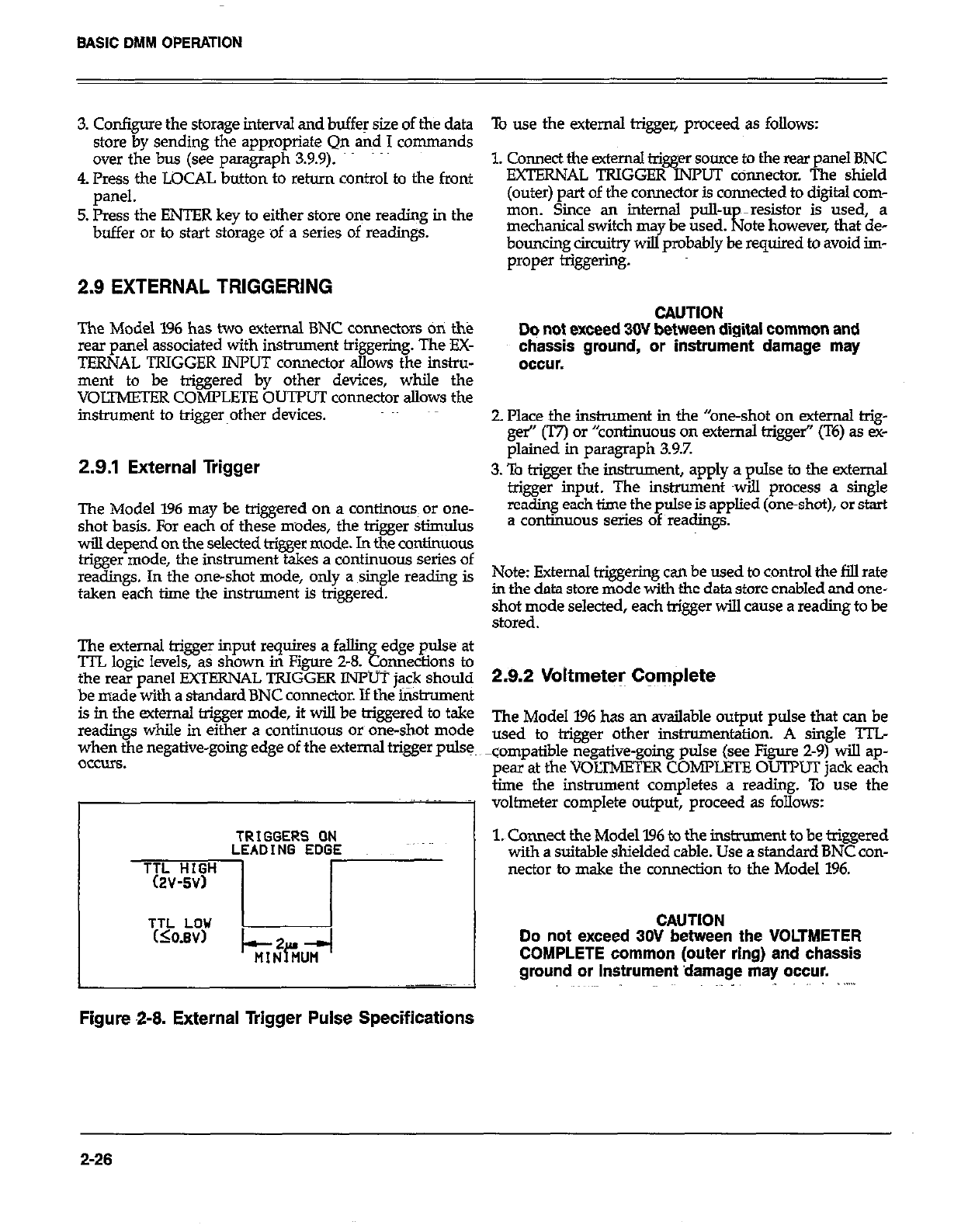
3. Configure the storage interval and buffer size of the data
store by sending the appropriate Qn and I commands
over the bus (see paragraph 3.9.9).
4. Press the LOCAL button to return control to the front
panel.
5. Press the ENTER key to either store one reading in the
buffer or to start storage of a series of readings.
2.9 EXTERNAL TRIGGERING
The Model 1% has two external BNC connectors on the
rear panel associated with instrument triggerinp. The EX-
TERNAL TRIGGER IiWUT connector allows the instru-
ment to be triggered by other devices, while the
VOLTMETER COMPLETE OUTPUT connector allows the
instrument to triggerother devices.
2.9.1 External Trigger
The Model 196 may be triggered on a continous~ or one-
shot basis. For each of these modes, the trigger stimulus
will depend on the selected trigger mode. In the continuous
trigger mode, the instrument takes a continuous series of
readings. In the one-shot mode, only a single reading is
taken each time the instrument is triggered.
The external trigger input requires a fallin
‘ITL logic levels, as shown in Figure 2-8. edge pulse at
Ebb omaections to
the rear nanel !?XTERNAL TRIGGER INPUT iack should
be made with a standard BNC connector. If thei&rument
is in the external trigger mode, it will be triggered to take
readings while in either a continuous or one-shot mode
when the negative-going edge of the external trigger pulse,
OCCUIS.
TRIGGERS ON
LEADING EDGE
Figure 2-8. External Trigger Pulse Specifications
To use the external trigger, proceed as follows:
1. Connect the external trigger soum to the rear panel BNC
EXTERNAL TRIGGER INPUT ccinnector. The shield
(outer) part of the connector is connected to digital com-
mon. Since an internal pull-u ~re.?.istor is used, a
mechanical switch ma be used.
bcmncing circuitry wiEyprobably l! required to avoid im-
ate however that de-
proper &&e&g.
CAUTION
Dq not exceed 30V between digital common and
chassis ground, or instrument damage may
occur.
2. Place the instrument in the “one-shot on external trig-
ger” (T7) or “continuous on external trigger’ (T6) as ex-
plained in paragraph 3.9.7.
3. To trigger the instrument, apply a pulse to the external
trigger input. The instrument twill process a single
reading each time the pulse is applied (one-shot), or start
a continuous series of readings.
Note: External triggering can be used to control the fill rate
in the data store mode with the data store enabled and one-
shot mode selected, each trigger will cause a reading to be
stored.
2.9.2 Voltmeter Complete
The Model 196 has an available output pulse that can be
used to trigger other instrumentaticm. A single TTL
compatible negative-going pulse (see Figure 2-9) will ap-
pear at the VOLTMETER COMPLETE OUTPUT jack each
time the instrument completes a reading. To use the
voltmeter complete output, proceed as follows:
1. Cmnect the Model 196 to the instrument to be triggered
with a suitable shielded cable. Use a standard BNC con-
nector to make the connection to the Model 196.
CAUTION
Do not exceed 30V between the VOLTMETER
COMPLETE common (outer ring) and chassis
ground or instrument damage may occur.
2-26
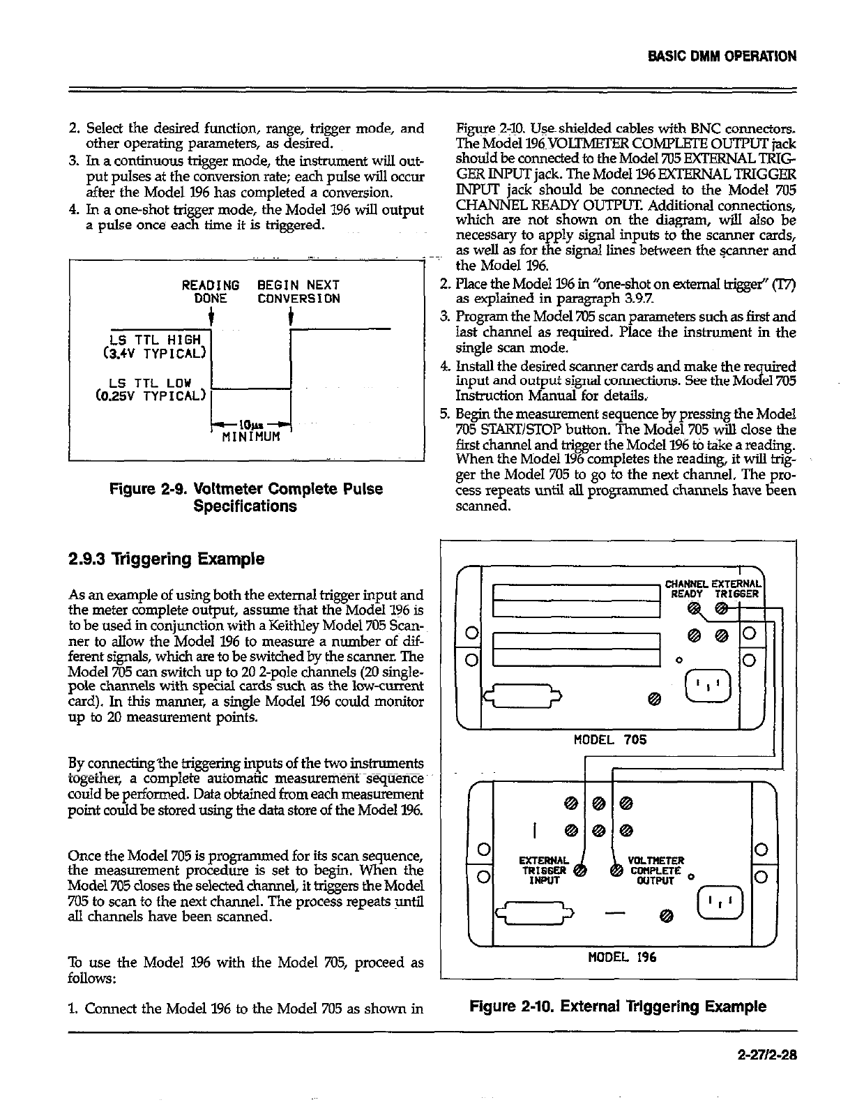
BASIC DMM OPERATION
2. Select the desired function, range, trigger mode, and
other operating parseters, as desired.
3. In a continuous trigger mode, the ins@unent will out-
put pulses at the conversion rate; each pulse will occur
after the Model I% has completed a conversion.
4. In a one-shot trigger mode, the Model 196 will output
a pulse once each time it is higgered.
REA?&JG BEGIN NEXT
CONVERSION
Figure 2$X Uses shielded cables with BNC connectors.
The Model 196~YOLTMETER coMrmouTr~jack
should be connected to the Model 705 EXTERNAL TRIG
GER INPUT jack. The Model 196 EXTEXNALTRIGGEE
INPUT jack should be connected to the Model 7Ki
CHANNEL READY OUTPUT. Additional connections,
which are not shown on the diagram, will also be
necessary to apply signal inputs to the scanner cards,
~~~
1’
as well as for the signal lines between the wanner and
the Model 196.
2. Place the Model 196 in “one-shot on external trigge~” 0
as explained in paragraph 3.9.7.
3. Program the Model 705 scan parameters such as first and
last channel as required. Place the instrument in the
single scan mode.
LS TTL LOU 1
(025V TYPICAL) 1
I I
Figure 2-9. Voltmeter Complete Pulse
4. lnstdl the desired scanner cards and make the re uired
input and output signal connections. See the MO
i el705
Instruction Manual for details.,
5. Begin the measurement sequence by pressing the Model
705 START/STOP button. The Model 705 will close the
first channel and trigger the Model 196 t0 t&e a reading.
When the Model 196 completes the reading, it will hig-
ger the Model 705 to go to the next channel. The pro-
cess repeats until all programmed channels have been
Specifications scanned.
2.9.3 Triggering Example
As an example of using both the external trigger input and
the meter complete output, assume that the Model 196 is
to be used in conjunction with a Keithley Model 705 Scan-
ner to allow the Model 196 to measure a number of dif-
ferent signals, which are to be switched by the scanner. The
Model 705 can switch up to 20 2-pole channels (20 single-
pole channels with special cards such as the low-current
card). In this manner, a single Model 196 could monitor
up to 20 measurement points.
By connecting’the triggering inputs of the two instruments
L__..,- ~~~
cogerner, a complete automatic measurement sequence”
could be performed. Data obtained from each measurement
point could be stored using the data store of the Model 196.
Once the Model 705 is programmed for its scan sequence,
the measurement procedure is set to begin. When the
Model 705 closes the selected channel, it triggers the Model
705 to scan to the next channel. The process repeats until
all channels have been scanned.
\I I /I
MOOEL 705 I
(I II
MODEL 196
To use the Model 1% with the Model 705, proceed as
follows:
1. Connect the Model 196 to the Model 705 as shown in Figure 2-10. External Triggering Example
2-271248
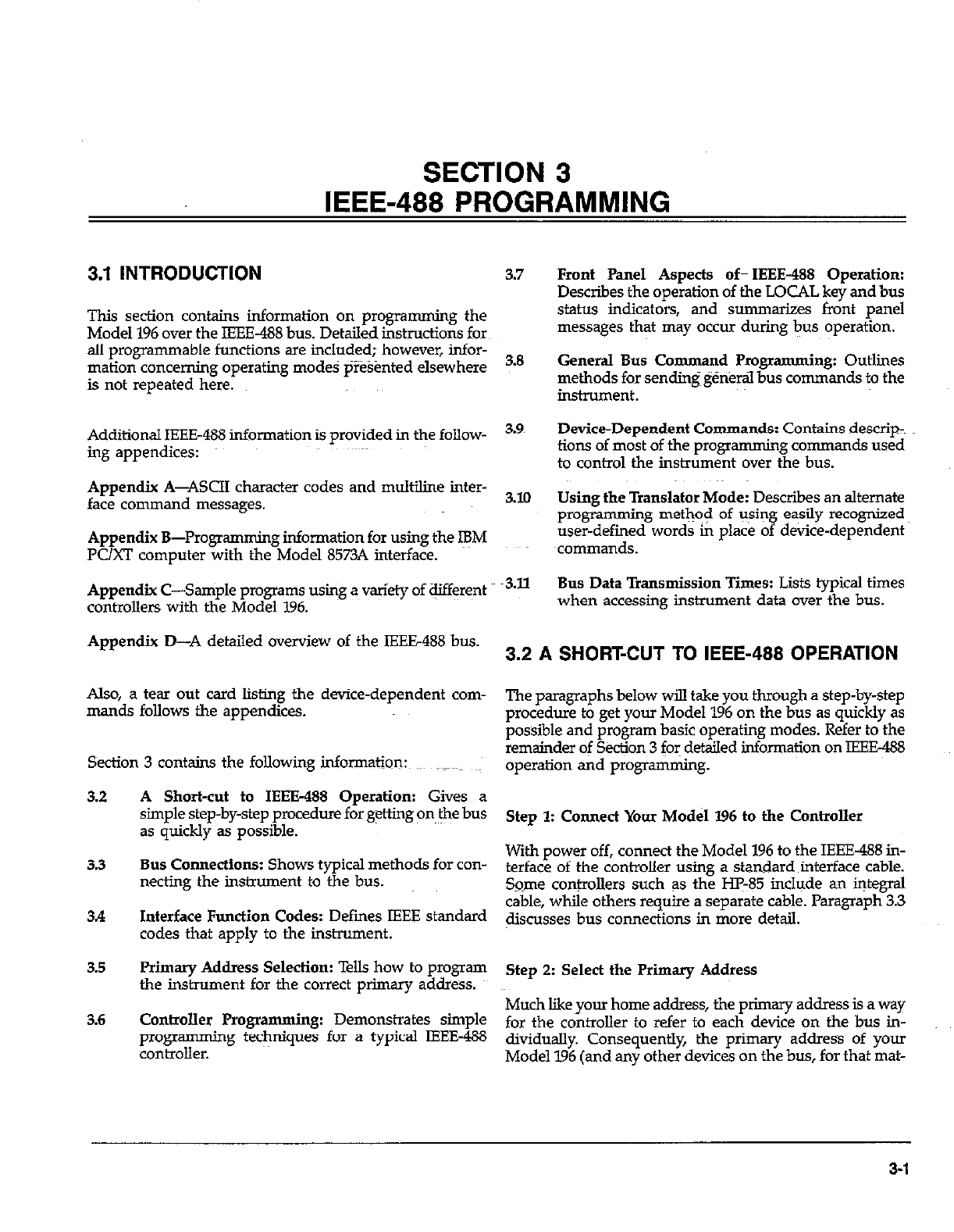
SECTION 3
IEEE-488 PROGRAMMING
3.1 INTRODUCTION 3.7
This section contains information on programming the
Model 196 over the IEEE-488 bus. Detailedinstructions fork
all programmable functions are included; however, infor-
mation concerning operating modes presented elsewhere
is not repeated here.
3.8
Additional IEEE-488 information is provided in the follow-
ing appendices:
Appendix A-ASCII character codes and multiline inter-
face command messages.
Appendix B-Progmmning information for using the FM
PC/XT computer with the Model 8573A interface.
Appendix C-Saniple programs using a variety of ef!rent
controllers with the Model 196.
3.9~
3.10
3.11
Appendix D-A detailed overview of the IEEE488 bus. 3.2 A SHORT-CUT TO IEEE-488 OPERATION
Also, a tear out card listing the device-dependent com-
mands follows the appendices.
S&ion 3 contains the following infonnation:~ ~_~~~ ~:
The paragraphs below will take you through a step-by-step
procedure to get your Model 196 on the bus as quickly as
possible and program basic operating modes. Refer to the
remainder of S&ion 3 for detailed information on IEEE-488
operation and programming.
3.2 A Short-cut to IEEE-488 Operation: Gives a
simple step-by-step procedure for g+ng on the bus
as quickly as possible. Step 1: Connect Your Model I96 to the Controller
3.3 Bus Connections: Shows typical methods for con-
necting the instrument to the bus.
34 Interface Function Codes: Defies IEEE standard
codes that apply to the instrument.
With power off, connect the Model 196 to the IEEE-488 in-
terface of the controller using a standard interface cable.
Some controllers such as the HI-85 include an integral
cable, while others require a separate cable. Paragraph 3.3
discusses bus connections in more detail.
3.5 Primary Address Selection: Tells how to program
the instrument for the correct primary address. Step 2: Select the Primary Address
3.6 Controller Programming: Demonstrates simple
programming techniques for a typical IEEE-488
controller.
Much like your home address, the primary address is a way
for the controller to refer to each device on the bus in-
dividually. Consequently, the primary addres~s of your
Model 196 (and any other devices on the bus, for that mat-
Front Panel Aspects of- IEEE-488 Operation:
Describes the operation of the LOCAL key and bus
status indicators, and summarizes front panel
messages that may occur during bus operation.
General Bus Command Programming: Outlines
methods for sendingg&&al bus commands to the
instrument.
Device-Dependent Commands: Contains descrip-~
tions of most of the programmjng commands used
to control the instrument over the bus.
Using the Translator Mode: Describes an alternate
Prow naming method of using easily recognized
user-defined words in place of device-dependent
xommands.
Bus Data Transmission Times: Lists typical times
when accessing instrument data over the bus.
3-l
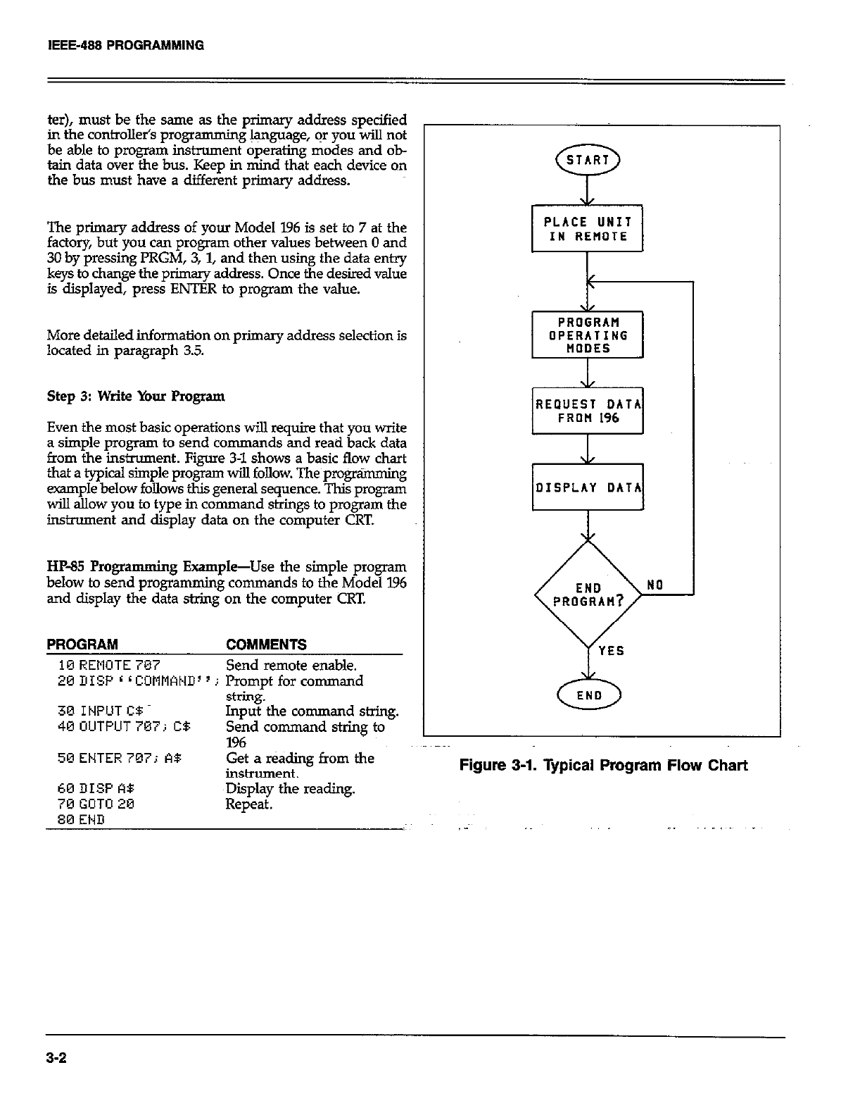
IEEE-488 PROGRAMMING
ter), must be the same as the primary address specified
in the controlletis programming language, or you will not
be able to program instrument operating modes and ob-
tain data over the bus. Keep in mind that each device on
the bus must have a different primary address.
The primary address of your Model 196 is set to 7 at the
factory, but you can program other values between 0 and
30 by pressing PRGM, 3, 1, and then using the data en*
keys to change the primary address. Once the desired value
is displayed, press ENTER to program the value.
More detailed information on primary address selection is
located in paragraph 3.5.
Step 3: Write Your Program
Even the most basic operations will require that you write
a simple program to send commands and read back data
from the instrument. Figure 3-l shows a basic flow chart
that a typical simple program will follow. The programming
example below follows this general sequence. This program
will allow you to type in command strings to program the
instrument and display data on the computer CRT.
HP85 Progra mming Example-Use the simple program
below to send programming commands to the Model 196
and display the data string on the computer CRT.
PROGRAM COMMENTS
10 REMOTE 707 Send remote enable.
26 DISP L L COMMAND’ ’ j Prompt for command
30 INPUT CB
40 UUTPUT707; CB
string.
Input the command string.
Send command string to
196
50ENTER707; A$ Get a r&ding from the
inshument.
OPERATING
REQUEST DATA
0
END
60 DISP A8
70 GOTO 20
80 END
~Diiplay the reading.
Repeat.
3-2
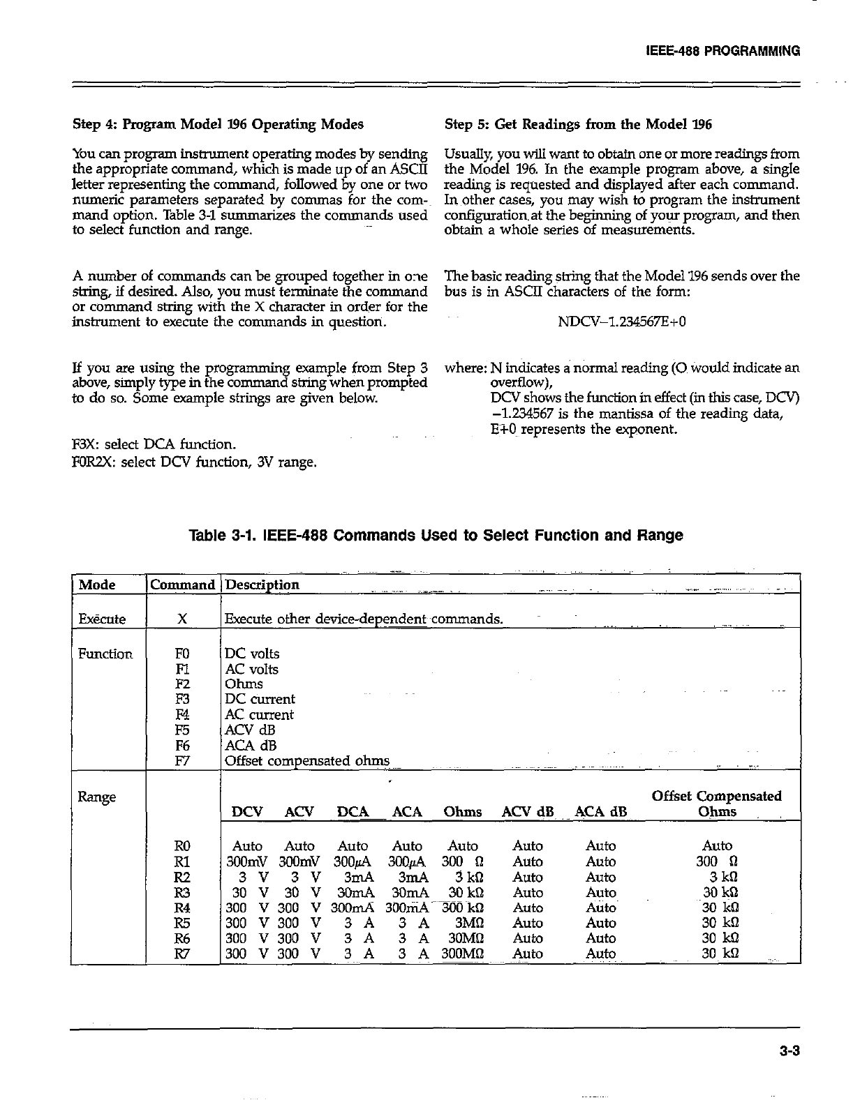
Step 4: Pmgram Model I.96 Operating Modes Step 5: Get Readings from the Model I96
You can program instrument operating modes by sending Usually, you will want to obtain one or more readings from
the appropriate command, which is made up of an ASCII
letter representing the command, followed by one or two the Model 196. In the example program abcwe, a single
reading is requested and displayed after each command.
numeric parameters separated by commas for the corn-~ In other cases, you may wish to program the instrument
mand option. Table 3-l summarizes the commands used configuration& the beginning of your program, and then
to select function and range. obtain a whole series of measurements.
A number of commands can be grouped together in one The basic reading string that the Model 196 sends over the
string, if desired. Also, you must terminate the command bus is in ASCII characters of the form:
or command string with the X character in order for the
instrument to execute the commands in question. NDCV-l234567E+O
If you are using the programming example from Step 3 where: N indicates a normal reading (0 tiould indicate an
above, simply type in the command string when prompted overflow),
to do so. Some example strings are given below. DCV shows the function in effect (in this case, DCV)
-1.234567 is the mantissa of the reading data,
E?-0~ represents the exponent.
F3X: select DCA function.
FORZX: select DCV function, 3V range.
Table 3-1. IEEE-488 Commands Used to Select Function and Range
:ommand I
X
FO
Fl
E
E
F6
F7
RO
E
R3
R4
R5
Execute other device-dep$w~commands.
DC volts
AC volts
ohms
DC current
AC current
ACV dB
ACA dB
Offset compensated ohm.~~-
Offset Compensated
WY Aa’ ~~!lF!K ACA Ohms ACV dB, &CA dB Ohms
Auto Auto Auto Auto Auto Auto Auto Auto
300mV 3oOmV 3OOfi 300~2% 300 0 Auto Auto 300 I-i
3v 3v 3mA 3mA 3k0 Auto Auto 3kt-l
30 V 30 V 3OmA 30mA 30 kQ Auto Auto 3Ok’2
300 v 300 v 3oomA 3ooti-TLiO~kQ Auto A&o 30 lit-l
300 V 300 V 3 A 3 A 3Mfl Auto Auto 30 kfl
300 V 300 V 3 A 3 A 3OM!l Auto Auto 30 kQ
300 V 300 V 3 A 3 A 3OOMfl Auto Auto 30, kQ
3-3
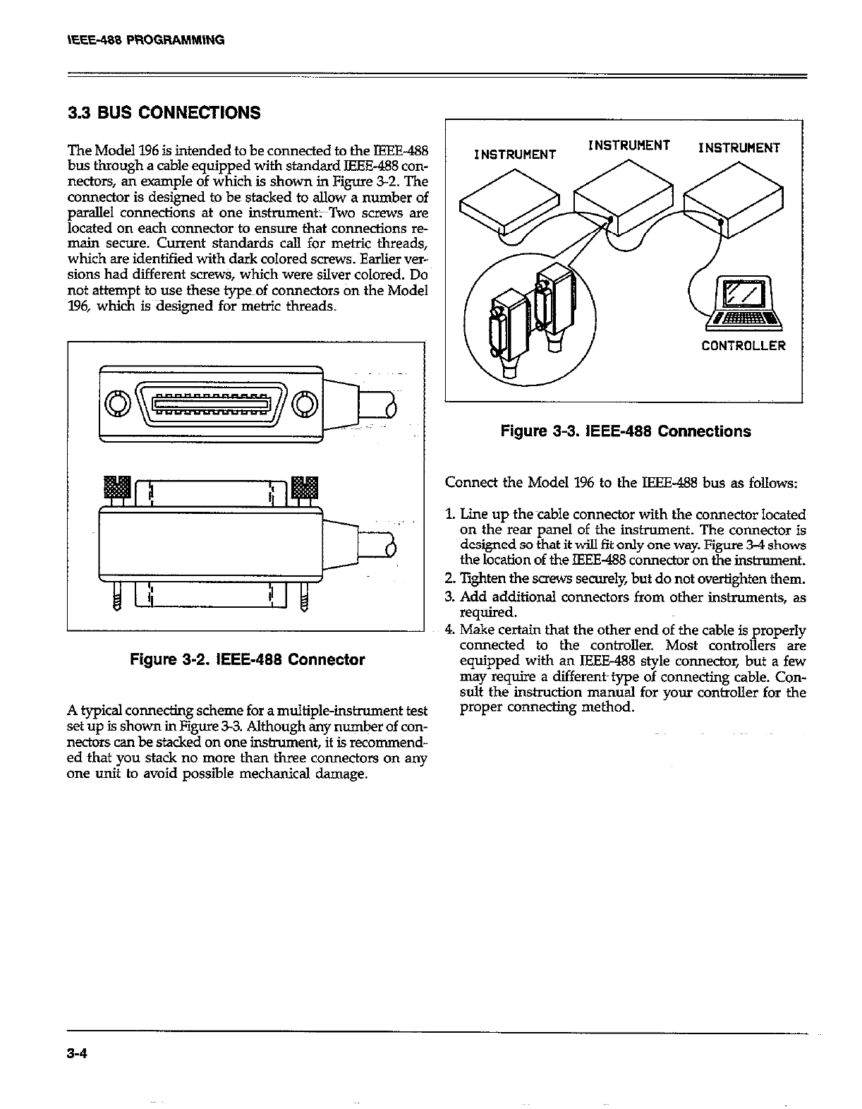
3.3 BUS CONNECTIONS
The Model 196 is intended to be connected to the IEEE-488
bus through a cable equipped with standard IEEE-488 con-
nectors, an example of which is shown in Figure 3-2. The
connector is designed to be stacked to allow a number of
parallel connections at one instrument;~~Two screws are
located on each connector to ensure that connections re-
main secure. Current standards call for metric threads,
which are identified with dark colored screws. Earlier ver-
sions had different screw& which were silver colored. Do
not attempt to use these type~~of connectors tin the Model
196, which is~aesigned for metric threads.
Figure 3-2. IEEE-488 Connector
INSTRWENT INSTRUMENT
CONTROLLER
Figure 3-3. IEEE-488 Connections
Connect the Model 196 to the IEEE-488 bus as follows:
1. Lime up thecable connector with the connector located
on the rear panel of the instrument. The connector is
designed so that it will fit only one way. Figure 3-4 shows
the location of the IEEE-488 connector on the instrument.
2. lighten the saew securely, but do not overtighten them.
3. Add additional connectors from other instruments, as
required.
4. Make certain that the other end of the cable is properly
connected to the controller. Most controllers are
equipped with an IEEE-488 style connector, but a few
may require a different~ type of connecting cable. Con-
sult the instruction manual for your controller for the
. . _..
A typical connecting scheme for a multiple-instrument test
set up is shown in Figure 33. Although any number of con-
nectors can be stacked on one instrument, it is recommend-
ed that you stack no more than three connectors on any
one unit to avoid possible mechanical damage.
proper connectmg metnoa.
3-4
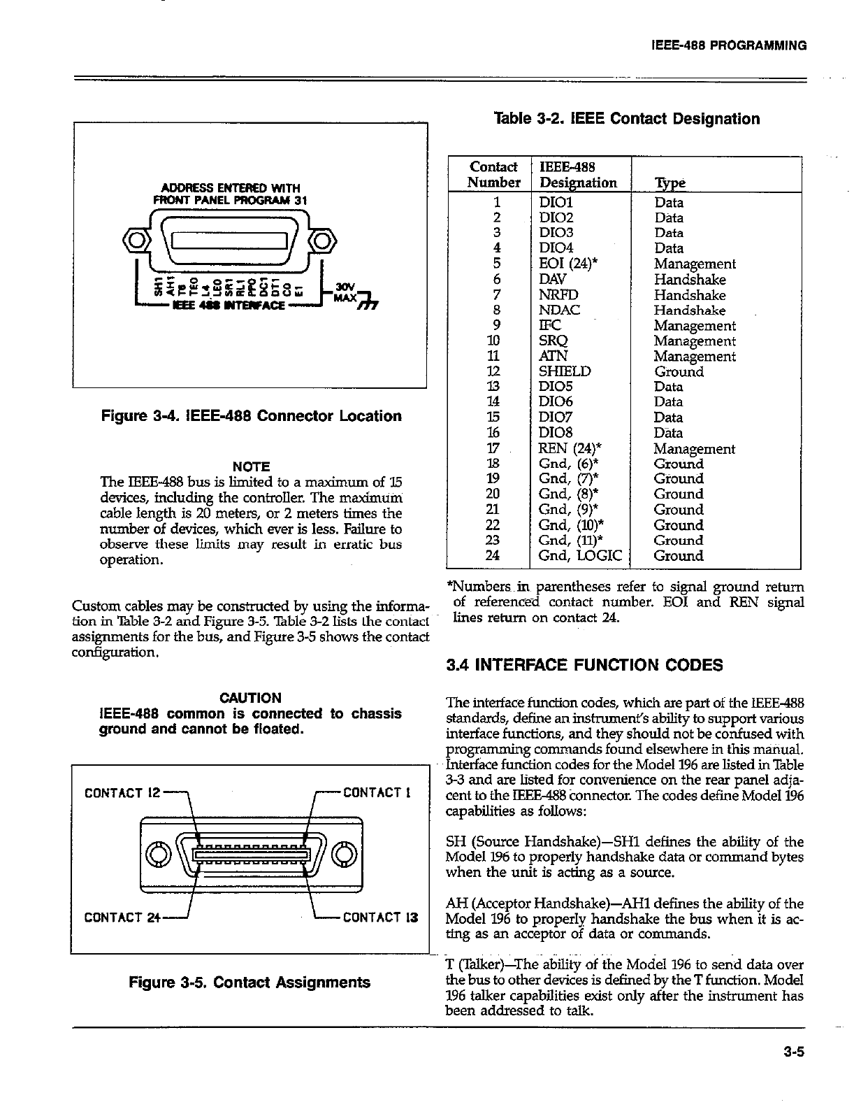
IEEE-488 PROGRAMMING
ADDRES3ENTEREDWiTH
FRONT PANEL PROGRAM 31
FIgure 3-4. IEEE-488 Connector Location
NOTE
The FEE-488 bus is limited to a maximum of 35
devices, incluiing the controller. The maximum
cable length is 20 meters, or 2 meters times the
number of devices, which ever is less. Failure to
observe these limits may result in erratic bus
operation.
Table 3-2. IEEE Contact Designation
contact IEEE-488
Number Designation
1 DIOl
; D102
D103
4 DI04
7 N-RFD
i NDAC
lo
11 ATN
tz SHIELD
DI05
14 D106
E D107
DI08
17
l8
19
20 Gnd, (8)*
ii Gnd, (9)
Gnd, (lo)*
23 Gnd, (ll)*
24 Gnd. LOGIC
Tyge
Data
Data
Data
Data
Management
Handshake
Handshake
Handshake
Management
Management
Management
Ground
Data
Data
Data
Data
Management
Ground
Giounii
Ground
Ground
Ground
Ground
Ground
*Numbersin parentheses refer to signal ground rehrn
Custom cables may be constructed by using the informa- of reference-d contact number. EOI and REN signal
fiOn in Table 3-2 and Figure 3-5. Bble 3-2 Ii& the COntad lines return On contact 24.
assignments for the bus, and Figure 3-5 shows the contact
3.4 INTERFACE FUNCTION CODES
CAUTION
IEEE-488 common is connected to chassis
ground and cannot be floated.
CONTACT 12
-7 r CONTACT I
t I J
I \
CONTACT 241 L CONTACT 13
Figure 3-5. Contact Assignments
The interface function codes, which are part of the IEEE-488
standards, define an instmment’s ability to support various
interface functions, and they should not be confused with
programming commands found elsewhere in this manual.
Interface function codes for the Model 196 are listed in Table
3-3 and are listed for convenience on the rear panel adja-
cent to the IEEE488 connector. The codes define Model 196
capabilities as follows:
SH (Source Handshake)-SHl defines the ability of the
Model 196 to properly handshake data or command bytes
when the unit is acting as a source.
AH (Acceptor Handshake&AH1 defines the ability of the
Model 196 to properly handshake the bus when it is ac-
ting as an acceptor of data or commands.
T (Talker)-The ability of the Model 196 to send data over
the bus to other devices is defined by the T function. Model
196 talker capabilities exist only after the instrument has
been addressed to talk.
3-5
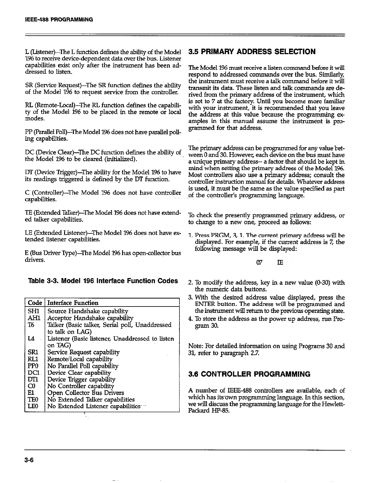
L (Listener)-‘he L function defines the ability of the Model
196 to receive device-dependent data over the bus. Listener
capabilities exist only after the instrument has been ad-
dressed to listen.
SR (Service Request)--The SR function defies the ability
of the Model 196 to request services from the controller.
RL (Remote-Local)-The RL function defies the capabili-
gofe;vz Model 196 to be placed in the remote or local
PP (Parallel Poll)-I’he Model 196 does not have parallel poll-
ing capabilities.
DC (Device Clear)-The DC function defines the ability of
the Model 196 to be cleared (iitialized).
DT (Device Trigger)-The ability for the Model 196 to have
its readings triggered is defined by the DT function.
C (Controller)-The Model 196 does not have controller
capabilities.
TE (Extended Talker)-The Model 196 does not have extend-
ed talker capabilities.
LE (Extended Listener)-The Model 196 does not have SC-
tended listener capabilities.
E (Bus Driver Type)-The Model 196 has open-colle$or bus
drivers.
Table 3-3. Model 196 Interface Function Codes
Interface Function
Source Handshake cauabilitv
Acceptor Handshake capab&y
Talker (Basic talker, Serial poll, Unaddressed
to talk on LAG)
Listener (Basic listener, Unaddressed to listen
on TAG)
Service Request capability
Remote/Local capability
No Parallel Poll capability
Device Clear capability
Device Trigger capability
No Controller capability
Open Collector Bus Drivers
No Extended Talker capabilities
No Extended Listener capabilities-
3.5 PRIMARY ADDRESS SELECTION
The Model 196 must receive a listen cornman dbeforeitwill
respond to addressed co mmands over the bus. Similarly,
the instrument must receive a talk co mmand before it will
transmit its data. These listen and talk commands are de-
rived from the primary address of the instrument, which
is set to 7 at the factory. Until you become more familiar
with your instrument, it is recommended that you leave
the address at this value because the programming I+
amples in this manual assume the instrument is p10-
grammed for that address.
The primary address can be programmed for any value bet-
ween 0 and 30. However, each device on the bus must have
a unique primary address-- a factor that should be kept in
mind when setting the primary address of the Model 796.
Most controllers also use a primary address; consult the
controller instruction manual for details. Whatever address
is used, it must be the same as the value specified as part
of the controll& programming language.
To check the presently programmed primary address, or
to change to a new one, proceed as follows:
1. Press PRGM, 3,l. The current primary address will be
displayed. For example, if the current address is 7, the
following message will be displayed:
07 IE
2. To modify the address, key in a new value (O-30) with
the numeric data buttons.
3. With the desired address value displayed, press the
ENTER button. The address will be programmed and
the instrument wiU return to the previous operating state.
4. To store the address as the power up address, run Pro-
gram 30.
Note: For detailed information on using Programs 30 and
31, refer to paragraph 2.7.
3.6 CONTROLLER PROGRAMMING
A number of IEEE-188 controllers are available, each of
which has its-own programming language. In th$ section,
we will discuss the programming language for the Hewlett-
Packard W-85.
3-6
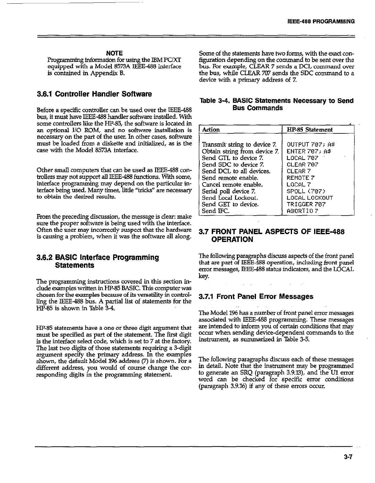
IEEE-488 PROGFlAMMlNG
NOTE
p=w amming information for using the IBM PC/XT
equipped with a Model 8573A IEEE-488 interface
is contained in Appendix 8.
3.6.1 Controller Handler Software
Before a specific controller can be used over the IEEE-488
bus, it must have IEEE-488 handler software installed. With
some controllers like the HP-85, the software is located in
an optional I/O ROM, and no software installation is
necessary on the part of the user. In other cases, software
must be loaded tioom a diskette and initialized, as is the
case with the Model 8573A interface.
Other small computers that can be used as IEEE-488 con-
trollers may not support all IEEE488 functions. With some,
interface pro* amming may depend on the particulsx in-
terface being used. Many times, little “tricks” are necessary
to obtain the desired results.
From the preceding discussion, the message is clear: make
sure the proper software is being used with the interface.
Often the user may incorrectly suspect that the hardware
is causing a problem, when it was the software all along.
3.6.2 BASIC Interface Programming
Statements
The progmmmin g instructions covered @ this section in-
clude examples written in HP-85 BASIC. This computer was
chosen for the examples because of its versatility in control-
ling the IEEE-488 bus. A partial list of statements for the
HP-85 is shown in Table 3-4.
HP-85 statements have a one or three digit argument~that
must be specified as part of the statement. The first digit
is the interface select code, which is set to 7 at the factory.
The last two digits of those statements requiring a 3-digit
argument specify the primary address. k the examples
shown, the default Model 196 address (7) is shown. For a
different address, you would of course change the cor-
responding digits in the programming statement.
Some~of the statements have two forms, with the exact con-
figuration depending on the command to be sent over the
bus. For example, CLEAR 7 sends a DCL command over
the bus, while CLEAR 707 sends the SDC command to a
device with a primary address of 7.
Table 3-4. BASIC Statements Necessary to Send
Bus Commands
Action 1 HP-85 Statement
I
Transmits string to device 7. OUTPUT707; A$
Obtain string from device Z ENTER707; A$
Send GTL to device Z LUCAL 707
Send SDC to device Z CLEAR 7’37
Send DCL to all devices. CLEhR 7
Send remote enable. REMOTE 7
Cancel remote enable. LrJCAL 7
Serial poll device Z SPOLL<707>
Send Local Lockout. LOCAL LOCKUUT
Send GET to device. TRIGGER787
Send IFC. ABURTIO 7
3.7 FRONT PANEL ASPECTS OF IEEE-488
OPERATION
The following paragraphs discuss aspects of the front panel
that are part of IEEE488 operation, including front panel
error messages, IEEE-488 status indicators, and the LOCAL
key.
3.7.1 Front Panel Error Messages
The Model 196 has a number of front panel error messages The Model 196 has a number of front panel error messages
associated with IEEE-488 programming. These messages associated with IEEE-488 programming. These messages
are intended to inform you of certain conditions that may are intended to inform you of certain conditions that may
occur when sendine device-deuendent commands to the occur when sendine device-deuendent commands to the
I
instrument, as summarized in Table 3-5.
The following paragraphs discuss each of these messages
in detail. Note that the instrument may be programmed
to generate an SRQ (paragraph 3.9.X3), and the Ul error
word can be checked for specific error conditions
(paragraph 3.9.16) if any of these errors occur.
3-7
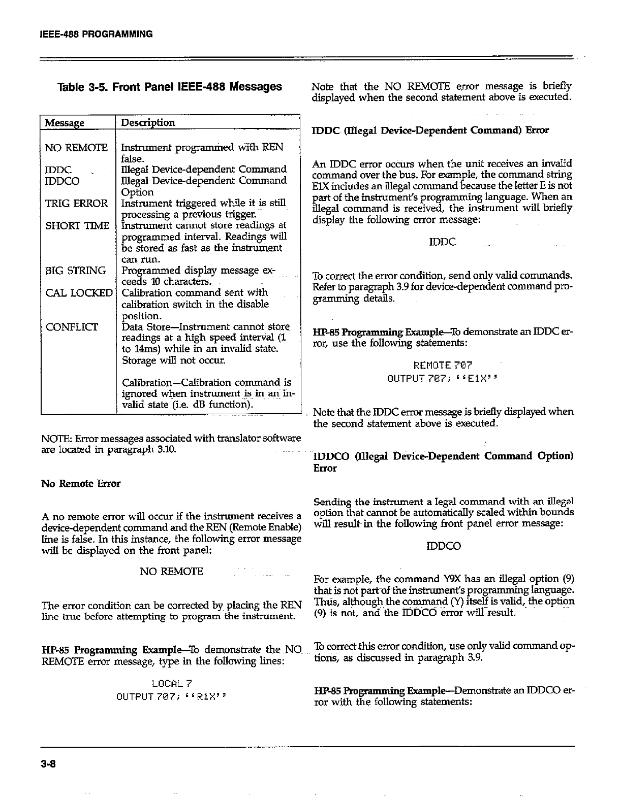
IEEE-488 PROGRAMMlNG
Table 3-5. Front Panel IEEE-488 Messages
NO REMOTE Instrument programkd Wifh REN
false.
IDDC Uegal Device-dependent Command
IDDCO Illegal Device-dependent Command
Option
TRIG ERROR Instrument triggered while it is still
urocessinc a urevious triczer.
SHORT TIME &xume~t c&-mot Store G&dings at
programmed interval. Readings will
be stored as fast as the instrument
can run.
BIG STRING Programmed display message ex-
ceeds 10 characters.
CAL LOCKED Calibration command sent with
calibration switch in the disable
position.
CONFLICT Data Store-Instrument cannot store
readmgs at a high speed interval (1
to 14ms) while in an invalid state.
Storage will not occur.
I
Calibration-Calibration com&tid is
ignored when instrument is~ in a+ in-
valid state (i.e. dB function).
Note that the NO REMOTE Errol message is briefly
displayed when the second statement above is executed.
IDDC ilIIega.I Device-Dependent Command) Error
An IDDC error ocCtis when the unit receives an invalid
command over the bus. For -pie, the command string
EIX includes an illegal command because the letter E is not
part of the inshwmenl% programming language. When an
illegal command is received, the instrument will briefly
display the following enor message:
IDDC
To correct the error condition, send only valid commands.
Refer to paragraph 3.9 for device-dependent command pm-
gmmming details.
HP-85Rog? amming Fxampl~To demonstrate an IDDC er-
ror, use the following statements:
REMOTE 707
OUTPIJT 707; * ‘ElXI ’
Note that the IDDC error message is briefly displayed when
the second statement above is executed.
NOTE: Error messages associated with translator software
are located in paragraph 3.10. IDDCO (Illegal b&ice-Dependent Cmnman d Option)
Error
No Remote Error
Sending the instrument a legal command with an illegal
A no remote error will occur if the instrument receives a option that cannot be automatically scaled within bounds
device-dependent command and the REN (Remote Enable) will result in the following front panel error message:
line is false. In this instance, the following error message
will be displayed on the front panel: IDDCO
NO REMOTE For example, the command WX has an iIlegal option (9)
that is not paruf ~the instrument’s programming language.
The error condition can be corrected by placing the REN Thus, aleough~ the cq$rna$ (Y) itseg is valid, the option
line true before attempting to ~program the instrument. (9) is not, and the IDDCO err01 will result.
HP-85 Programming Example--To demonstrate the NQ To correct this error condition, use only valid command op-
REMOT!Z error message, type in &e following lines: lions, as discussed in paragraph 3.9.
LOCAL i
OUTPUT 707i L ( RiX’ ’ HP-85 Pm gmmming Example-Demonstrate an IDDCO er-
ror with the following statements:
3-8

IEEE-488 PROGRAMMlNG
REMOTE 707
OUTPUT 797; r r Y9X’ ’
Note that the IDDCO error message is briefly displayed
when the second statement above is executed.
Trigger Ovemm Error
A trigger overrun error occurs when the instrument receives
a trigger while still processing a reading from a previous
trigger. Note that orily the overrun triggers are ignored.
These overrun triggers will not affect the instrument ex-
cept to generate the message below. When a trigger over-
run occurs, the foLIowing front panel message will be
displayed for approximately one second:
TRIG ERROR
HP-85 Pro
gramming Example-To demonstrate~~~a trigger
overrun error, enter the following statements into the W-85
keyboard:
REMOTE 707
OUTPUT 707; 6 ‘ T3X’ ’
TRIGGERi07iZTRIGGER707
Note that the trigger overrun message is displayed after the
END LINE key is pressed a third time.
Big String Error
A big string error occurs when trying to &splay a message
(using the ED command) that exceeds 10 characters. Blank
display digits used in the message count~as characters. The
invalid message is ignored and the following message is
displayed briefly when a big string error occurs:
BIG STRING
HP-85 Progr amming Example-Enter the following state:
ments into the computer to demonstrate a big string qror:
REMOTE 707
OIUTPUT 707; r r DH0U@ARECYOU?X~ ’
When END LINE is pressed the second time the big string
error will occur because the message is made up oft I2
characters.
Cd Locked Error
A cal locked error occurs when trying to calibrate the in-
strument over the bus with the front panel calibration
switch in the disable position. Calibration commands will
be ignored and the following message will be displayed
briefly:
CAL LOCKED
Short Time Error
A short time error occurs when the instrument cannot store
readings in the data store at the programmed interval (Q
tiriunand). However, the instrument will continue to store
readings as fast as its can run. The following message is
displayed briefly when a short time error occurs:
SHORT TIME
HP-85 Pm gramming Example--To demonstrate a short time
error, enter the following statements into the computer:
REMOTE 707
OUTPUT707;~rQ100F2T2X”
TRIGGER707
When END LINE is pressed the thiid time, the instrument
wiU start storing readings in the buffer. However, since the
instroment cannot make resistance measurements (FZ) at
the selected interval (QlOO), short period errors will occur.
Conflict Error
A conflict error occurs when trying to store readings at a
high speed interval (lms to 14ms) while the instrument is
in an invalid state. After sending a command string that~
contains the interval command(Q), the following message
is displayed briefly when a conflid error occurs:
CONFLICI
The entire command string will be ignored and the data
store will not start.
Mid instrument states for high speed data storage are listed
in Table 3-U
3-9
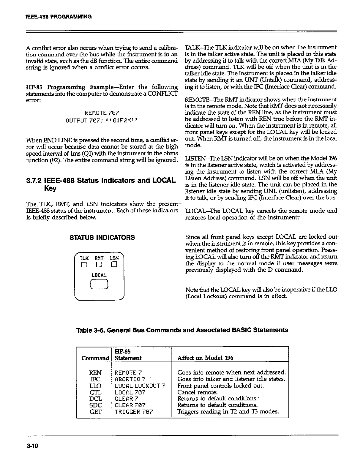
A conflict error also occurs when trying to send a calibra-
tion command over the bus while the instrument is in an
invalid state, such as the dB function. The entire command
string is ignored when a conflict error occurs.
HP-85 Programming Example-Enter the following
statements into the computer to demons&ate a CONFLXT
error:
REMOTE 707
OIJTPUT 707; r L QlWX s
When END LINE is pressed the second time, a conflict er-
ror will occur because data cannot be stored at the high
speed interval of lms (Ql) with the instrument in the ohms
function (F2). The entire command string will be ignored.
3.7.2 IEEE-488 Status indicators and LOCAL
Key
The TLK, RMT, and LSN indicators show the present
IEEE-488 status of the instrument. Each of these indicators
is briefly described below.
STATUS INDICATORS
T‘K RHT LSN
El 0 Cl
LOCAL
0
TALK-The TLK indicator will be on when the instrument
is in the talker active state. The unit is placed in thii state
by addressing it to talk with the correct MTA (My Talk Ad-
dress) command. TLK will be off when the unit is in the
talker idle state. The instrument is placed in the talker idle
state by sending it-an UNT (Untalk) ~command, address-
ing it to~listen, or with the IFC (Interface Clear) command.
REMOTE-The RMT indicator shows when the instrument
is in the remote mode. Note that RMT does not necessarily
indicate the state of the REN line, as the instrument must
be addressed to listen with REN true before the RMT in-
dicator will turn on. When the instrument is in remote, all
front panel keys except for the LOCAL key will be locked
out. When RMT is turned off, the instrument is in the local
mode.
LISTEN-The LSN indicator will be on when the Model 196
is in the listener active state, which is activated by address-
ing the instrument to listen with the correct MLA (My
Listen Address) command. LSN will be off when the unit
is in the listener idle state. The unit can be placed in the
listener idle state by sending UNL (*ten), addressing
it to talk, or by sending JFC (Interface Clear) over the bus.
LOCAJJYhe LOCAL key cancels the remote mode and
restores local operation of the instrument;
Since all front panel keys except LOCAL are locked outs
when the instrument is in remote, thii key provides a con-
venient method of restoring front panel operation. Press-
ing LOCAL will also hum off the RMT indicator and return
the display to the~normal mode if user messages were
previously displayed with the D command.
Note that the LOCAL key will also be inoperative if the LLO
(Local Lockout) command is in effect.
HP-85
Statement Affect on Model 196
I
REMOTE 7
ABORT10 7
LOCALLOCKOUT
LOCAL 707
CLEAR 7
CLEAR 707
TRIGGER707
Goes into remote when next addressed.
Goes into talker and listener idle states.
Front panel controls locked out.
Cancel remote.
Returns to default conditions.’
Returns to default conditions.
Trigsem reading in T2 and T3 modes.
3-10
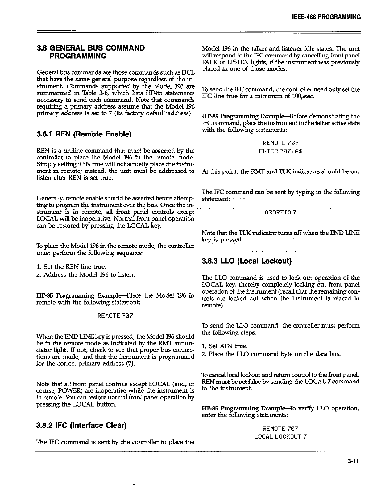
3.8 GENERAL BUS COMMAND
PROGRAMMING
General bus commands are those commands such as DCL
that have the same general purpose regardless of the in-
strument. Cbmmands supported by the Model 196 are
summarized in Table 3-6, which lists HP-85 statements
necessary to send each command. Note that commands
requiring a primary address assume that~ the Model 196
primary address is set to 7 (its factory default~addr&s).
3.8.1 REN (Rem’ote Enable)
REN is a uniline command that must be asserted by the
controller to place the Model 196 in the remote mode.
Simply setting REN true will not actually place the in&u-
ment in remote; instead, the units must be addressed to
listen after REN is set true.
Generdly, remote enable should be asserted before attemp-
ting to program the instrument over the bus. Once the in-
strument is in r¬e, all front panel controls except
LOCAL will be inoperative. Normal front panel operation
can be restored by pressing the LOCAL key.
To place the Model 196 in the remote mode, the controller
must perform the following sequence:
1. Set the REN line true.
2. Address the Model 196 to listen.
HP-35 Programming Example-Place the Model 196 in
remote with the following statement:
REMOTE 787
When the END LINE key is pressed, the Model 196 should
be in the remote mode as indicated by the RMT annun-
ciator light. If not, check to see that proper bus connec-
tions are made, and that the instrument is programmed
for the correct primary address (7).
Note that all front panel controls except~LOCAL (and, of
course, POWER) are inoperative while the instrument is
in remote. You can restore normal front panel operation by
pressing the LOCAL button.
3.8.2 IFC (Interface Clear)
The IFC command is sent by the controller to place the
Model 196 in the talker and listener idle states; The unit
wilI respond to the IFC comman d by cancelling front panel
TALK or LISTEN lights, if the instrument was previously
placed in one of those modes.
To send the IFC co nunand, the controller need only set the
EC line true for a minimum of 100pec.
HP-85 Pmgrammi ng Example-Before demonstrating the
LFC command, place the instrument in the talker active state
with the following statements:
REMOTE 707
ENTER 707; A$
At this point, the RMT and TLK indicators should be on.
The lFC command can be sent by typing in the following
statement:
FlEORTIU 7
Note that the TLK indicator hnns off when the Eb!D LINE
key is presse-d.
3.8.3 LLO (Local Lockout)
The LLQ co nunand is used to lock out operation of the
LOCAL key, thereby completely locking outs front panel
operation of the instrument (recall that the remaining con-
trols are locked out when the instrument is placed in
remote).
To send the LLO comniand, the controller must perform
the following steps:
1. Set .4lN tie.
2. Place the LLQ command byte on the data bus.
To cancel local lockout and return control to the front panel,
REN must be set false by sending the LOCAL 7 command
to the instrument.
HP-85 Progr amming Example-To verify LLO operation,
enter the following statements:
REMOTE 707
LOCALLOCKOUT
3-11
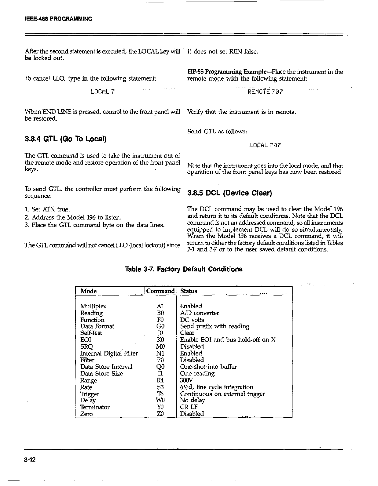
After the second statement is executed, the LOCAL key will it does not set RBN false.
be locked out.
To cancel LLO, type in the following statement:
LOCAL 7
HP-85 Programming Example-Place the instrument in the
remote modes with the following statement:
REMott 707
When END LINE is pressed, control to the front panel will Verify that the instrument is in remote.
be restored.
3.8.4 GTL (Go To Local) Send GTL as follows:
LOCAL 7M7
The GTL command is used to take the instrument out of
the remote mode and restore operation of the front panel
keys. Note that the instrument goes into the local mode, and that~
operation of the front panel keys has now been restored.
TO setid GTL, the controller must perform the following
sequence: 3.8.5 DCL (Device Clear)
1. Set KIN true. The DCL co rmnand may be used to clear the Model 196
2. Address the Model 196 to listen. and return it to its default conditions. Note~that the DCL
3. Place the GTL command byte on the data lines. command is riot an addressed command, so ail instruments
equipped to implement DCL will do so simultaneously.
When the Model 196 receives a DCL c
ommand, it-will
TheGTLco nunand wi!.l not cancel LLO (local lockout) since r&urn to either the factory default conditions listed in Tables
2-l and 3-7 or to the user saved default conditions.
Table 3-7. Factory Default Conditions
Mode 1 Command
I
Multiplex
Reading
Function
Data Format
Selflrest
EOI
SRQ
Internal Digital Filter
Filter
Data Store Interval
Data Store Size
R=w
Rate
Al
BO
JO
Kil
MO
Nl
status
Enabled
A/D converter
DC volts
Send prefix with reading
Clear
Enable EOI and bus hold-off on X
Disabled
Enabled
Disabled
One-shot~into buffer
One reading
3ocN
6%d, line cycle integration
Continuous on external trigger
No delay
CR LF
l&a&d
3-12
IEEE-488 PROGRAMMING
To send the DCL command, the controller must perform
the following steps:
1. Set ATN true.
2. Place the DCL conuixmd byte on the data bus.
Notes:
1. DCL will return the instrument to the default line fre-
quency setting.
2. DCL will not have any affect on the -nt IEEE address:
HP-85 Programming Example-Place the unit in an operat-
ing mode that is not a default xondition. Now enter the
following statement into the I-Jl’-85 keyboard:
CLEAR 7
When the END LJN!? key is pressed, the inslnnnent w
to the default conditions.
3.8.6 SDC (Selective Device Clear)
The SDC command is an addressed command that per-
forms essentially the same function as the DCL command.
However, since each device must be individuslly address-
ed, the SDC command provides a method to clear only a
single, selected instrument instead of clearing all in-
struments simultaneous1 as is the case with DCL. When
the Model 196 receives t
it
e SDC command, it will return
to either the factory default conditions listed in Tables 3-7
and 2-1 or to the user saved default conditions.
To transmit the SDC command, the controller must per-
form the following steps:
1. Set ATN true.
2. Address the Model 196 to listen.
3. Place the SDC command byte-on the data bus.
Notes:
1. SDC will return the instrument to the default line fre-
quency setting.
2. SDC will not have any affect on the current IEEE address.
HP-85 Programming Example-Using several front~panel
controls, alter instrument states from the default wnfigura-
tion. Send SDC with ~the following statement:
CLEQR 707
When the above statement is executed, the instrument
retums to the default configuration.
3.8.7 GET (Group Execute Trigger)
GET may be used to initiate a Model 196 measurement se-
quence if the instrument is placed in the appropriate trig-
ger mode (see paragraph 3.9). Once triggered, the i&u-
ment~~will perform the measurement sequence in accord-
ance with previously selected rate and sample parameters.
To send GET, the controller must perform the following
sequence:
1. set !irN low.
2. Address the Model 196 to listen.
3. Place the GET command byte on the data bus.
HP-85 Programming Example--Type in the following
statements to place the instrument in the correct trigger
mode for purposes of this demonstration:
REMOTE~707
OCITFILIT 707; L * T3X’ ’
Now trigger the measurement sequence by sending GET
with the following statement:
TRIGGER707
When the END LINE key is pressed, the measurement se-
quence will be triggered.
3.8.8 Serial Polling (SPE,SPD)
The serial polling sequence is used to obtain the Model 196
serial poll byte. The serial poll byte contains important in-
formation about internal functions, as desoibed in
paragraph 3.9.13. The serial polling sequence can also be
used by the controller to determine which instxument on
the bus has asserted SRQ (Service Request).
F~,rial polling sequence is generally conducted as
1. The controller sets KiW true.
2. The controller then places the Sl’E (Serial Poll Enable)
command byte on the data bus. At this paint;~~all active
devices are in the serial poll enabled mode and waiting
to be addressed.
3-13
IEEE-488 PROGRAMMING
3. The Model 196 is then addressed to talk.
4. The controller sets Al-N false.
5. The instrument places its serial poll byte on the data bus
to be read by the controller.
6. The controller then sets ATN true and places the SPD
(Serial Poll Disable) command byte on the data bus to
end the serial polling sequence.
Once instruments are in the serial poll mode, steps 3
through 5 above can be repeated by sending the correct talk
address for each instrument.
HP-85 Programming Example-The HP-85 SPOLL state-
ment automatically performs the sequence justmdescn%ed.
TO demonstrate serial polling, type in the following
statements:
AEllOTE 707
S= SPOIL (797)
DISP s
When the above statements are executed, the Model 196
is serial polled, and the decimal value of the serial poll byte
is displayed on the computer CRT.
3.9 DEVICE-DEPENDENT COMMAND
PROGRAMMING
IEEE-488 device-dependent commands are used with the
Model 196 to control various operating modes such as func-
tion, range, trigger mode and data format. Each command
is made up of a single ASCII letter followed by a number
representing an option of that command. For example, a
command to control the measuring function is programmed
by sending an ASCII “F” followed by a number represent-
ing the function option. The IEEE-488 bus actuall treats
these commands as data in that ATN is false when ;I e com-
mands are transmitted.
A number of commands may be grouped together in one
s&in .
AS cl3 A command strin is usually terminated with an
“Y character, whx 3-l tells the instrument to execute
the command string. Cornman ds sent without the execute
character will not be executed at that time, but they will
be retained within an internal command buffer for execu-
tion at the time the X character is received. If any errors
occur, the instnunent will displa a
error messages and generates an J8
R propriate front panel
If programmed todo
so.
Commands that affect instrument operation will trigger a
reading when the command is executed. These-bus com-
mands affect the Model 196 much like the front panel con-
trols. Note that commands are not necessarily executed in
the order received; instead, they will be executed in
alphabetical order. Thus to force a particular command se-
quence, you would follow each command with the execute
character(X), as in the example string, Upcnx, which will
reset the instrument to factory default conditions and then
select the ohms function.
Device-dependent comman ds can be sent either one at a
time, or in groups of sweral commands within a single
string. Some examples of valid command strings include:
FOX-Single command string.
FOKlPOROX-Multiple command string.
T6 X-Spaces &e ignored.
Typical invalid command strings include:
ElX-Invalid command, as E is ndt one of the instrument
commands.
=X-Invalid co nunand option because 15 is not an option
of the F command.
If an illegal COmIMn d @DC), illegal command option
(IDDCO), is sent, or if a command string is sent with REN
false, the string will be ignored.
Device-dependent commands that control the Model 196
are listed in lkble 3-8. These commands are covered in detail
in the following paragraphs. The associated programming
scamples show how to send the commands with the HP-%
NOTE
Programming examples assume that the Model
196 is at its factory default- value of 7.
In order to send a device-dependent-command, the con-
troller must perform the following steps:
1. Set MN true.
2. Address the Model 196 to listen.
3. set MN false.
4. Send the command string over the bus one byte at a
time.
3-14
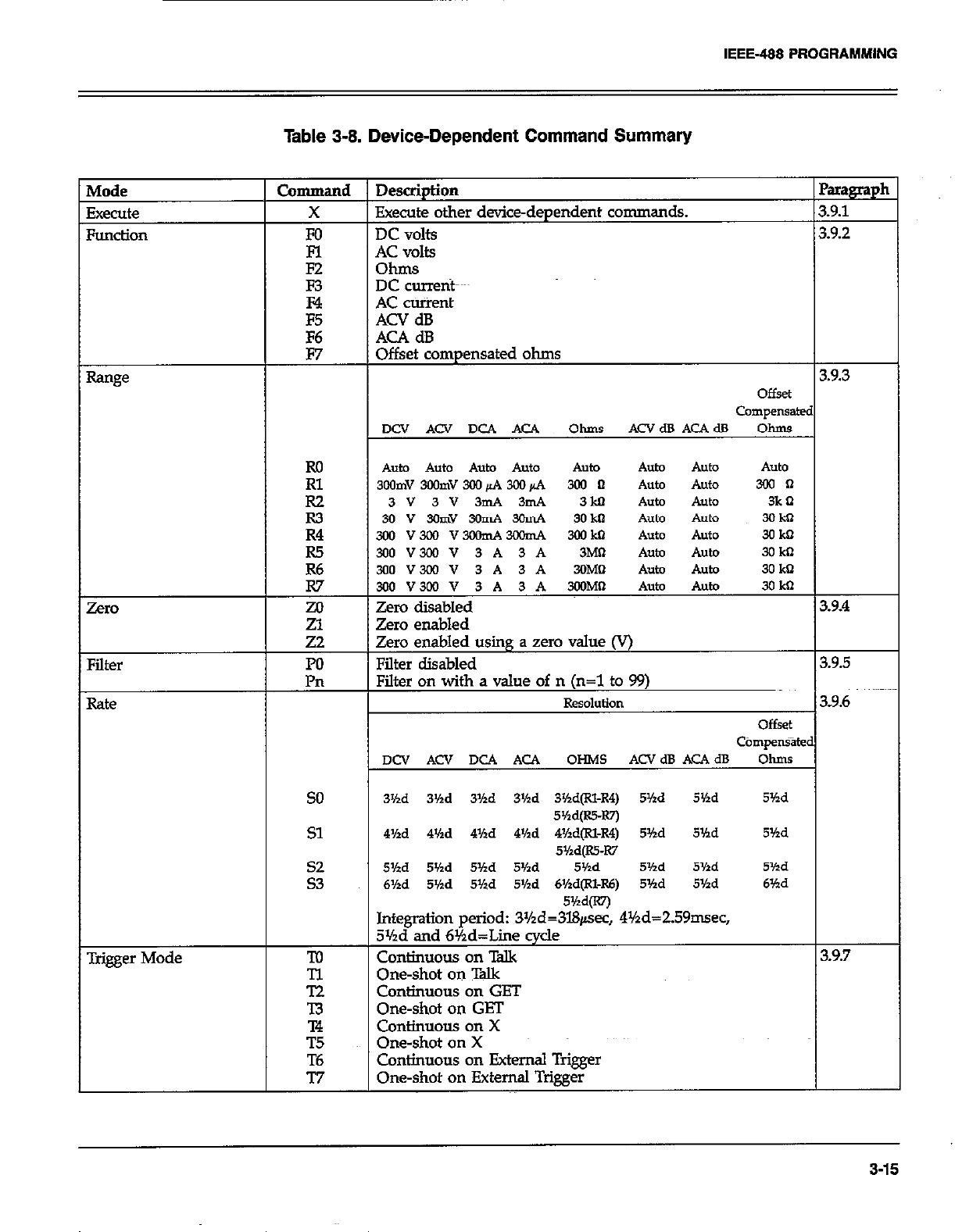
IEEE-488 PROGRAMMING
Table 3-8. Device-Dependent Command Summery
Auto Auto Auto Auto
3wmv390mv300&4m+4 3ol n hto 300 n
3v3v3mA3mA 3M
3ov3GmY3onA3GmA 3okn
hfger Mode
so 3’hd 3’/ld 3’hd 3Md 3%d(Rl-4) 5’hd 5’hd 5’hd
5w=-Rn
Sl 4Hd 4’hd 4%d 4Md 4%d@l-R4) 5Md 5’hd 5’hd
5’/zd@S-I(7
::
5Vtd 5’hd 5Hd 5Hd 5’hd 5’hd 5%d 5Yzd
6Hd 5’hd 5’hd 5Md 6Hd(Rl-R6) 5Md 5Yzd 6’hd
5Md(R7j
Integration period: 3Yzd=3l&sec, 4%d=ZS9nwec,
3%d and 6%d=Liie cycle
To Cmtinuous on Talk 3.9.7
E One-shot on Talk
Continuous on GET
-I3 One-shot on GET
T4 Continuous on X
T.5 One-shot on X
T6 Continuous on External Trigger
77 One-shot on External Trigger
3-15
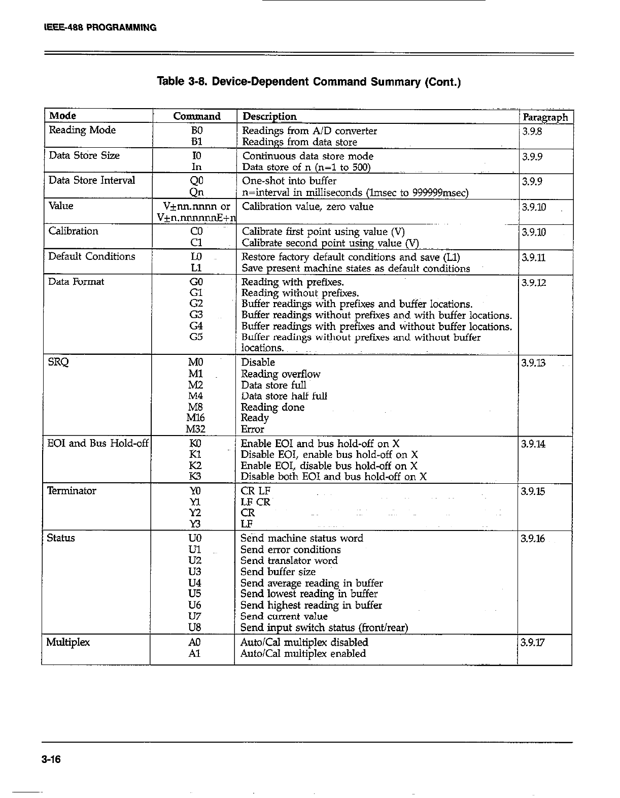
IEEE-488 PROGRAMM,ING
Table 3-8. Device-Dependent Command Summary (Cont.)
Mode Command
Reading Mode BO
Data Store Size
Data Store Interval
Value
Calibration
Default Conditions
Data Format
SRQ
EOI and Bus Hold-of;
Terminator
SthLS
Multiplex
In
QO
Qn
Vjnn.nnnn 01
V+n.nnmqnE+
2
Lo
Ll
:;
G2
2
G5
MO
Ml
E
M32
E
E
m
Yl
Y2
n
uo
ii
u3
U4
u5
U6
E
A0
Al
Description
Readings from A/D converter Readings from A/D converter
Readings from data store Readings from data store
Continuous data store mode Continuous data store mode
Parag
3.9.8 3.9.8
3.9.9 3.9.9
Data store of no (n=l to 500)
One-shot into buffer
n=intend in milliseconds (lmsec to 999999msec)
Calibration value, zero value
3.9.9
3.9.10
Calibrate first point using value (V)
Calibrate second point using value (V)~
Restore factory default conditions and save (Ll)
Save present machine states as default conditions
Readings with prefixes.
Reading without~ prefixes.
Buffer readitlgs with prefixes and buff& locations.
Buffer readings without prefues and with buffer locations.
Buffer readings with prefixes and without buffer locations.
Buffer read&s without orefues and without buffer
3.9.10
s9.11
3.9.12
locations. “~~
Disable
Reading overflow
Data store full
1 3.9.13
Data store half full
Reading done
Ready
Error
Enable EOI and bus hold-off on X
Disable EOI, enable bus hold-off on X
Enable EOI,, disable bus hold-off on X
Disable both EOI and bus hold-off on X
CR LF
4F_CR~
CK
LF
3.9.14
3.9.15
Send machine status word
Send error conditions
Send translator word
Send buffer size
3.9.16
Send average reading in buffer
Send lowest reading in buffer
Send highest reading in buffer
Send current value
Send input switch status (front/rear)
Auto/Cal multiplex disabled
Auto/Cal multiplex enabled 3.9.17
3-16
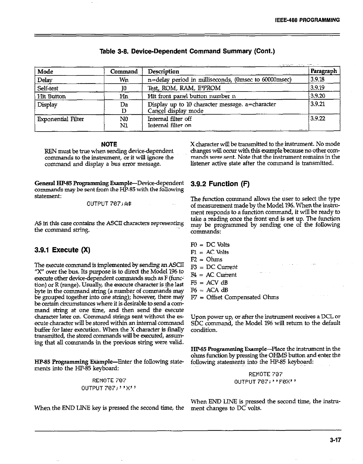
IEEE-488 PROGRAMMING
Table 3-8. Device-Dependent Command Summary (Cont.)
Mode
Delay
self-test
Hit Button
Display
Exponential Filter
Command Desqiption Paragraph
wn n=delay period in milliseconds, (Omsec to 6OOOOqsec) 3.9.18
JO Te&ROM, RAM, E’PROM 3.9.19
I-h Hit front panel button munber n 3.920
Da Display up to 10 character message. a=character 3.9.21
D Cq@ display mode
E. Internal filter off 3.9.22
Internal filter on ; ,.
NOTE X character will be transmitted to the instrument. No mode
REN must be true when sending device-dep~+nt changes will OCCUI withH~$ example because no other com-
commands to the instrument, or it will ignore the man& were sent. Note that the instrument remains in the
command and display a bus error message. listener active state after the command is transmitted.
General HP-85 Pmgramming Example-Device-dependent
commands may be sent from the HP-85 with the following
statement:
OUTf’UT707;AB
A!$ in this case contains the ASCII characters representing
the command string.
3.9.1 Execute (X)
The execute command is implemented by sending an ASCn
“X” over the bus. Its purpose is to direct the Model 196 to
execute other device-dependent commands such as F (func-
tion) or R (range). Usually, the execute character is the last
byte in the comrn+nd.string (a r+mber of commands may
k FTC! together mto one strmg); bowever, there may
amumstmces where it is desrable to send a com-
mand string at one time, and then send the execute
character later on. Command strings sent without the ex-
ecute character will be stored within an internal command
buffer for later execution. When the X character is finally
transmitted, the stored comman ds will be executed, assmn-
ing that alI commands in the previous string were valid.
HP-85 Pmgramming E%%nple-Enter the following state-
ments into the HZ-85 keyboard:
REMOTE 707
UUTPUT~707;“X”
When the END LINE key is pressed the second time, the
3.9.2 Function (F)
The function command allows the user to select the type
of measurement made by the Model 196. When the instru-
ment responds to a function command, it will be ready to
take a reading once the front-end is set u
P The function
may be programmed by sending one o the following
commsrlds:
FO = DC Volts
Fl = AC Volts
FZ=Ohms
F3 = DC Current
F4 = AC Client
F5 = ACV dB
F6 = AC4 dB
F7 = Offset Compensated Ohms
Upon power up, or after the instrument receives a DCL or
SDC command, the Model 196 will return to the default
condition.
HP-85 Programming Example-Place the instrument in the
ohms function by pressing the OHMS button and enter the
following statements into the HP-85 keybq%d:
REMOTE 707
OUTPUT707i”F0X”
When END LINZ is pressed the second time, the instru-
ment changes to DC volts.
3-17
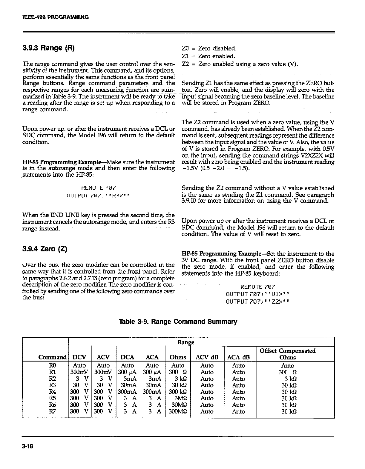
\EEE-488 PROGRAMMING
3.9.3 Range (R)
The range command gives the user control over the sen-
sitivity of the instrument. This command, and its options,
erform essentialI the same functions as the front anel
kge buttons. &nge commands parameters an$ the
respective ranges for each measurings functjon are~sum_
marized in Table 3-9. The instrument wiil be ready to take
a reading after the range is set up when responding to a
range command.
Upon power up, or after the instrument receives a DCL or
SDC co mmand, the Model 196 will return to the default
condition.
HP-35 Programming Example-Make sure the instrument
is in the autorange mode and then enter the following
,statements into the HP-85:
REMOTE 707
OUTPUT 707; ’ ‘R3X’ 9
ZO = Zero disabled.
Zl = Zero enabled.
22 F Zero enabled using a zero value (V).
Sending Zl has the same effect as pressing the ZERO but-
ton. Zero will enable, and the display will zero with the
mput signal becoming the zero baseline level. The baseline
wih be stored in Program ZERO.
The 22 command is used when a zero value, using the V
command, has already been established. When the 22 com-
mand is sent, subsequent readings represent the difference
between the input signal and the value of V. Also, the value
of V is stored in Program ZERO. For example, with 0.5V
on the in ut,
result WI Ii sending the command strings V2XZ2X will
zero being enabled and the instrument reading
-1.5v (0.5 -2.0 = -1.5).
Sending the 22 comman d without a V value established
is the same as sending the Zl command. See paragraph
3.9.10 for more information on using the V command.
When the END LINE key is pressed the second time, the
instrument cancels the autorange mode, and enters the R3 Upon power up or after the instrument receives a DCL or
range instead. SDC command, the Model 196 %ill return to the default
condition. The value of V will reset to zero.
3.9.4 Zero (if) HP-85 Programming Example-Set the instruments to the
Over the bus, the zero modifier can be controlled in the 3V DC range. With the front panel ZERO button disable
th
same way that it is controlled from the front panel. Refer e zero mode, if enabled, and enter the following
stat ements into the HP-85 kevbosrd:
to paragraphs 2.6.2 and 2.7.15 Qro
description of the zero modifier. TE rogram) for a complete
e zero modifier is con-
trolled by sending one of the folkowing zero comman dsover REMOTE 707
. . . OUTPUT707;‘1111Xy’
the bUS: OUTPUT 707; ’ ‘ZZX’ 3
Table 3-9. Range Command Summary
I Range Offset Compensated
Command DCV ACV DCA ACA Ohms ACV dB ACA dB Ohms
Ro Auto Auto Auto Auto Auto Auto Auto Auto
Rl 3oomv 3oOnN 300 /LA 300 @A 300 0 Auto Auto 300 0
E 3i :: 3: :: 322 3;s 30 3kil m Auto Auto Auto Auto 30 3kS kD
R4 300 v 300 v 3oomA 3oomA 300 kbl AU&J Auto 30 kQ
3-18
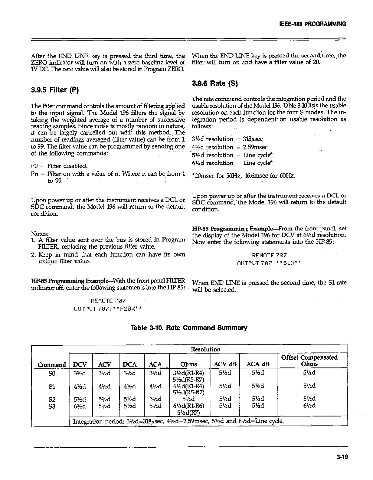
IEEE-488 PROGRAMMING
After the END LINE key is pressed the third time, the
ZERO indicator will turn on with a zero baseline level of
1V DC. The zero value will also be stored in Pmgram ZERO.
3.9.5 Filter (P)
The filter command controls the amount of filtering applied
to the input signal. The Model 196 filters the signal by
taking the weighted average of a number of suicessive
reading samples. Since noise is mostly random in nature,
it can be largely cancelled out with this method.~The
number of readings averaged (filter value) can be from 1
to 99. The filter value can be programmed by sending one
of the following commands:
PO = Filter disabled.
Pn = Filter on with a value of n. Where n can be from 1
to 99.
Upon power up or after the instrument receives a DCL or
SDC command, the Model I96 will return to the default
condition.
Notes:
1. A filter value sent over the bus is stored in Program
FIUER, replacing the previous filter value.
2. Keep in mind that each function can have its own
unique filter value.
Ew85Rogr amming BxamphGWnh the front panel FKFER
indicator off, enter the following statements into the HF-85:
REMOTE 707
OlJTPUT707;“PZOX”
When the END LINE key is pressed the second-&ne,,the
falter will turn on and have a filter value of 20.
3.9.6 Rate (S)
The rate command controls the integration period and the
usable resolution of the Model 196. lhble 3-10 lists the usable
resolution on each function for the four S modes. The in-
tegration period is dependent-on usable resolution as
follows:
3Yzd resolution = 3l8psec
4Md resolution = 259msec
5Yzd resolution = Line cycle*
6Yzd resolution = Lime cycle*
“20msec for 5OH2, l6.6msec for 6OHz.
Upon power up or after the instrument receives a DCL or
SDC command, the Model 196 will return to the default
condition.
HP-85 Programming Example-From the front panel, Seth
the display of the Model 1% for DCV at 6Yzd resolution.
Now enter the following statements into the HP-85
REMOTE 707
OUTPUT707;“S1X3’
When END LINE is pressed the second time, the Sl rate
will be selected.
Table 3-10. Rate Command Summary
Command
so
Sl
zi
DCV
3Yzd
4Yzd
5Yzd
6%d
Integt
ACV
3%d
4Yzd
5%d
5%d [
Id:
m peril
DC4
3Yzd
4Yzd
5Yzd
5Yzd
ACA
3Yzd
4Yzd
5Yzd
5r/zd
L
LCV dB
5Yzd AC4 dB
5%d
5Yzd 5Yzd 5Yzd
5Yzd 5Yzd 5Yzd
5Yzd 5Yzd 6Yzd
,.v. .
bd=259msec, 5Y’a ana bYza=Lme cycle.
,~~
3.19
IEEE-488 PROGRAMMING
3.9.7 Trigger Mode (T)
Triggering provides a stimulus to begin a reading conver-
sion within the instrument. Triggering may be done in two
basic ways: in a continuous mode, a single trigger com-
mand is used to start a continuous series of readings; in
a one-shot trigger mode, a separate trigger stimulus is re-
quired to start each conversion. The Model 196 @eight
trigger commands as follows:
TO = Continuous on Talk
Tl~ = One-shot on Talk
T2 ~= Continuous on GET
I3 = One-shot on GET
T4 = Continuous on X
T5 = One-shot on X
T6 = Continuous on External Trigger
T7 = One-shot on External Trigger ~ ~~~~~
The trigger modes are paired according to the type of
stimulus that is used to trigger the instrument. In the ‘IO
and~Tl niddes, t+iggering is performed by addressing the
Model 196 to talk. In the T2 arid T3 modes, the IEEE-488
multiline GET command performs the trigger function. The
instrument execute (X) character provides the triggeT
stimulus in the T4 and T5 modes. External trigger pulses
provide the trigger $imuhrs in the T6 ,and T7 modes.
Upon power up or after the instmment receives a DCL or
SDC cbmmtid, the Model 196 will return to the default
condition.
NOTE
With the instrument in the T6 and T7 trigger
modes, the front panel ENTER button can be us-
ed to trigger readings. See paragraph 2.8 fqor details.
HP-85 Pmgmmming Exampl+Place the instrument in the
one-shot on talk mode with the following statements:
REMOTE 707
OLlTPUT707j~“Tl:x:”
One reading can now be triggered and the resulting da@
obtained with the following statements:
ENTER 787; A4:
DISP A$
In this example, the ENTER statement addresses the Model
196 to talk, ate which point a single reading is triggered.
When the reading has been processed, it is sent out over
to the bus to the computer, which then displays the result.
3.9.8 Reading Mode (B)
The reading mode command parameters allow the selec-
tion of the source of data that is transmitted over the
IEEE-488 bus. Through this comman d, the user has a choice
of data from the A/Dmv%ter (normal DMM readings)
or the buffer (data store).~The reading mode commands are
as follows:
BO = A/D converter readings
Bl = Data Store readings
Upon power up or after the instrument receives a DCL or
SDC command, the Model 196 wiIl return to the default
condition.
When in BO, normal A/D reading+ will be sent~. In a con-
tinuous trigger mode, readings will be updated ate the con-
version rate. The Bl command is used to access readings
from the buffer. When the Bl command is sent, subsequent
readings will be taken from consecutive buffer locations
beginning with the first memory location (001). Once all
readings have been requested, the unit will cycle back and
begin again.
HP-85 Programming Example-Enter the following
statements into the computer to send a reading over the
bus and display it on the computer CRT.
REMOTE 707
OUTPUT 707~; ’ ’ EnXI ’
ENTER 707 i A$
DISP A9
The second statement above sets the instrument to the AID
converter reading mode. The third and fourth statements
acquire the reading and display it~~on the CRT.
3.9.9 Data Store Interval (Q) and Size (I)
The data store is controlled by the interval command (Q).
and the size command (I).
3-20
IEEE-488 PROGRAMMING
J.nterval
With the Q comman d, the user can select the interval that
the instrument will store readings or select the one-shot
mode. In one-shot, one reading will be stored each time
the instrument is triggered. The Q cmnman d is in the
following form:
QO=Oneshot into buffer.
Qn=Set storage interval in millisec (lmsec to 999999tiec).
To use the data store in the one-shot mode (QO), the in-
strument must be in a one-shot trigger mode (cc n, T5
or T7). In the QOTl mode, one reading will be stored each
lime the instrument is addressed to talk. In the QClI3 mode,
each GET co mmand will cause one reading &q be store&
ln the QOT5 mode, each instrument execute character (X)
will cause a reading to be stored. Fmally, in the Qm mode,
each external trigger pulse will cause a r&ling to be stored.
If the instrument is in a continuous trigger mode (To, T2,
T4 or T6), any IDDC error will occur.
NOTE
With the instrument in the T7 trigger mode, the
front uanel ENTER button can be used to manuallv
store’readings into the buffer. Each press of thk
ENTER button wilI store one reading in t&e buffer.
See paragraph 2.8 for details.
To store readings at a selected interval (Qn), the instrument
must be in a continuous trigger mode f,lU, T2, X, T6). &en
the selected trigger occurs, the storage process will
commence.
NOTE
With the instrument in the T6 trigger mode, the
front panel ENTER button can be used to start a
series of readings to be stored in the buffer. The
storage interval and buffer size are determined by
the Qn and I co mmands respectively. See
paragraph 2.8 fork details.
siie
The size of the data store can be controlled by one of the
following I commands.
IO=Continuous storage mode.
In=Set data store size to n (1 to 500).
In the continuous data storage mode (IO), storage will not
stop after the buffer is filled (500 readings), but will pro-
ceed back to~the first memory location and start oven&kg
data. V+h the Innn command, the storage process will stop
when the defined number of readings have been stored.
In this case the buffer is cdnsidered to be fuli.’
Notes:
1. When the Q or I co
mmand is sent, ‘c---i’ will be
displayed until the first trigger occurs.
2. The data store can be disabled by sendine: the F com-
mand. Storage will again resume’when &appropriate
trigger occurs.
The instrument must be in a valid operating state (see
%ble 3-11) in order to use the high speed data store
capabilities. The high speed intervals are lmsec through
lknsec. The instrument display will blank while the in-
strument is storing readings at high speed. If the ins&u-
ment~ is not in a valid operating state for high speed
storage, a conflict error will be displayed briefly and
storage will not occur.
The short time error message indicates that the in&u-
mentcannot store readings at the programmed interval
rate. Instead, readings will be stored as fast as the in-
strument can run.
With S2 or 53 asserted, the fastest valid storage interval
(I) is 3lmsec and 35msec respectively. A shorter inter-
val will result in a short time error when the storage pm-
c&s is started. Readings will be stored as fast as the in-
strument can run.
Either during or after the storage process, readings may
be recalled by using the Bl command as described in
the previous paragraph. Also, the highest, lowest and
average reading in a full buffer can be recalled by send-
ing the ,appropriate U commands. See paragraph 3.9.16
for information on using the U commands.~
Upon power up or after the instrument receives a DCL of
SDC command, the Model 196 will return to the defaults
condition.
~Hp-85 Programming Example-Enter the program below
to enable data store operation and obtain and display 100
readings on the computer CRT:
3-21
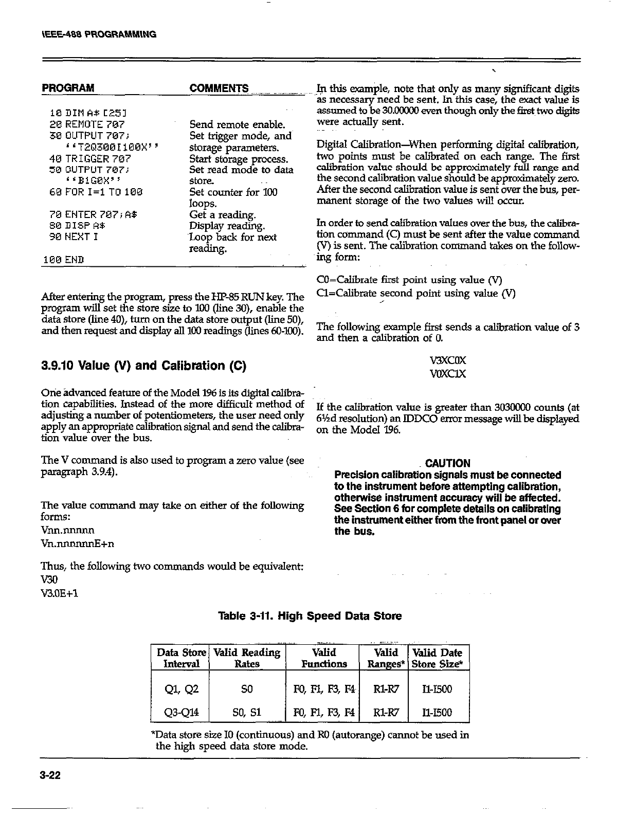
PROGRAM COMMENT3 _.__.. _-_-. .~
10DItlA8C25l
20 REMOTE 70.7 Send remote enable.
30 OUTPUT 707; Set trigger mode, and
‘1T2~3001100X” storage parameters.
40TRIGGER707 Start storage process.
50 OUTPUT 707: Set read mode to data
s ‘BiGBX” StOK?.
60FORI=lTO100 Set counter for 100
loops.
70ENTER707iR8 Get a reading.
00 DISPA$ Display reading.
30 NEXT I toop back for next
reading.
100 END
After entering the program, press the HP-85 RUN key. The
program will set the store size to IOO (line 30), enable the
data store (line 4O), turn on the data store output (line 50),
and then request and display all 100 readings (lines 6O-l.OO).
3.9.10 Value (V) and Calibration (C)
Otie ;Idvanced feature of the Model 196 is its digital c&bra-
tion capabilities. Instead of the more difficult method of
adjusting a number of potentiometers, the user need only
apply an appropriate calibration signal and send the caliira-
tion value over the bus.
The V command is also used to program a zero value (see
paragraph 3.9.4).
Fhy command may take on either of the following
VM.mlNm
Vn.nnnnnnE+n
Thus, the following two comman ds would be equivalent:
WI
V3.OE+l
,.$ @is example, note that only as many significant digits
as necessary need be sent. In this case, the exact value is
assumed to be 3OMxxx) even though only the first two digits
were adually sent.
Digital Calibration-When performing digital c&ration,
two points must be caliiated on each range. The first
caliiation value should be approtiately full range and
the second calibration value should be approximately zero.
After the second calibration value is sent over the bus, per-
manent storage of the two values will occur.
In order to send calibration values over the btxs, the caliia-
tion command (C) must be sent after the value command
(V) is sent. The calibration command takes on the follow-
mg form:
cO=Calibrate first point using value (V)
Cl=Calibrate second point using value Iv)
,
The following example first sends a caliiration value of 3
and then a calibration of 0.
WXCOX
VOXCIX
If the calibration value is greater than 3030000 counts (at
61Ad resolution) an lDDC0 error message will be displayed
on the Model 196.
CAUTION
Precision calibration signals must be connected
to the instrument before attempting calibration,
otherwise instrument accuracy will be affected.
See Section 6 for complete details on calibrating
the instrument either from the front panel or over
the bus.
Table 3-11. High Speed Data store
. . .~.
Data Store Valid Reading Valid Valid Valid Date
Interval Rate FundiOnS Ranges* Store Site*
QL Q2 so FO, FYL F3, F4 Rl-R7 Il-I500
Q3-Q14 so, Sl FO, F-l, F3, M Rl-R7 Il-I500
*Data store size IO (continuous) and Ro (autorange) cannot be used in
the high speed data store mode.
3-22
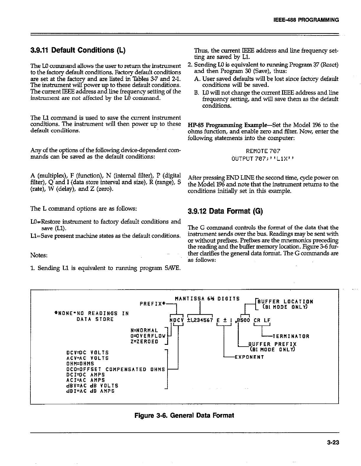
IEEE-488 PROGRAMMING
3.9.11 Default Conditions (L) Thus, the current IEEE address and line frequency set-
ting are saved by IJ.
The LO cotiand allows the user to return the instrument 2. Sending Ill is equivalent to running Program 37 (Reset)
to the factory default conditions. Factory default conditions and then Program 30 (Save), thus:
are set at the factory and are listed in Tables 3-7 and 2-l.
The imtmment wiIl power up to these default conditions. A. User saved defaults will be lost since fact&y default
conditions will be saved.
The current IEEE address and line frequency setting of the
instrument are not affected by the M command. B. M will not change the current IEEE address and line
frequency setting, and will save them as the default
conditions.
The Ll command is used to save the current instrument
conditiO116. The ir!StrUment wiu then power up t0 these
default conditions. ~&&j fiogmmming E-@-&t the Model 196 to the
ohms function, and enable zero and filter. Now, enter the
following statements into the computer:
Any of the options of the following device-dependent com- REMOTE 787
mar& can be saved as the default conditions: CIUTPIJT~~~;“L~X”
A (multiplex), F (function), N (internal filter), P (digital
filter), Q ad 1 (data Store h-ttemd and Sue), R (ra%d, s After pressing END LINE the second time, cycle power on
(rate), W (delay), and Z (zero). the Model 196 and note that the hmment retins to the
conditions initially set in this example.
The L command options are as follows: 3.9.12 Data Format (G)
L&Restore instrument to factory default conditions and
save (Ll). The G comman d controls the format of the data that the
Ll=Save present machine states as the default conditions. instrument sends over the bus. Readings may be sent with
or without prefixes. Prefixes are the mnemonics preceding
the reading and the buffer memory location. Figure 3-6 fur-
Notes: ther clarifies the general data format. The G comniands are
as follows:
1. Sending Ll is equivalent to running program SAVE.
+NONE’NO READINGS IN
DATA STORE
pREFIx~~A~~“~A ‘: D’G”s~~~~~R,,~O~~~~~~N
NDCV +I.234567 E + 1 .ESOO CR LF
DCV=OC VOLTS
ACV=AC VOLTS
1 L7”;;;;g!yR
EXPONENT
OHH=OHMS
OCO=OFFSET COMPENSATED OHNS
DCI=DC AMPS
ACI=AC ANPS
dBV=AC dB VOLTS
dBI=AC dB AMPS
Figure 3-6. General Data Format
3-23
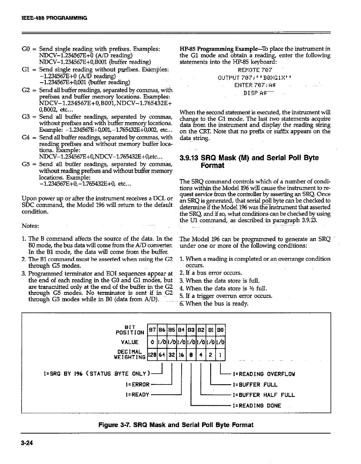
IEEE-408 PROGRAMMlNG
GO = Send single reading with prefixes. Examples:
NDCV-1.234567E+D (A/D reading)
NDCV-1234567E+O,BOOl (buffer reading)
Gl = Send single reading without pwfixes. Etim$es:
-1234567E+O (A/D reading)
-1234567E+0,001 (buffer reading)
G2 = Send alI buffer readings, separated by co-s, with
prefixes and buffer memory locations. Examples:
NDCV-l.Z34567E+O,BOOl,NDCV-1.765432E+
O,BOO2, etc.. .
G3 = Send aII buffer readings, separated by commas,
without prefixes and with buffer memory locations.
Example: -1.2X!WE+O,IX?~-1.765432E+O,M?2, etc...
G4 = Send alI buffer readings, separated by commas, with
reading prefixes and without~ memory buff&r loca-
tions. Example:
NDCV-1.234567E+O,NDCV-1.765432E+O,etc...
G5 = Send all buffer readings, separated by co-s,
without reading prefixes and without buffer memory
locations. Example:
-1234567E+O,-1.765+0, etc...
Upon power up or after the instrument receives a DCL or
SDC ~command, the Model 196 will return to the default
CO*diti0*.
Notes:
HP-85 Progr
amming Example-To place the instrument in
the Gl mode and @@n a reading, enter the following
statements into the m-85 keyboard:
REMOTE787
When the second statement is exerted, the instrument wilI
than
data fr
e to the Gl mode. The last two statements acquire
om the instiment and display the reading string
on the CRT. Note that no prefii or suffix appears on the
da@ string.
3.9.13 SRQ Mask (M) and Serial Poll Byte
Format
The SRQ command controls which of a number of condi-
tions within the Model 196 wiU cause the instrument to re-
quest service from the controller by asserting an SRQ. Once
an SRQ is generated, that serial p* byte can be checked to
determine if the Model 1% was the instrument that asserted
the SRQ and if so, what conditions can be checked by using
the Ul command, as described in paragraph 3.9.33.
1. The B command affects the source of the data. In the
BO mode, the bus data wiIl come from the A/D converter. The Model 196 can be programmed to generate an SRQ
In the Bl mode, the data wiIl come from the buff& under one or more of the following cqncjitions:
2. The Bl command must be asserted when using the G2 1. When a reading is completed or an overrange condition
through G5 modes. oaxrs.
3. Pro~ammed terminator and EOI sequences appear at 2. If a bus error occurs.
the&d of each reading in the GO and Gl mddes, but 3.~ When the data store is full.
are transmitted only at the end of the buffer in the G2
through G5 modes. No terminator is sent if in G2 4, men the data store is yz full.
through G5 modes while in BO (data from A/D). ~‘~ ~~~
5. If a trigger overrun error occurs.
6;~When the bus is ready.
BIT
POSITION
VALUE
DECIMAL
WEIGHTING
I=SRQ BY 196 (STATUS BYTE ONLY) I=READING OVERFLOW
I=ERRDR I= BUFFER FULL
I-READY l=BUFFER HALF FULL
I’READING DONE
Figure 3-7. SRQ Mask and Serial Poll Byte Format
3-24
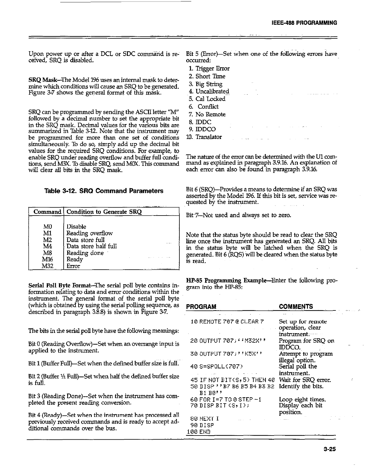
IEEE-488 PROGRAMMING
Upon power up or after a DCL or SDC co~%id is re-
ceived, SRQ is disabled.
SRQ Mask--The Model 196 uses an internal mask to deter-
mine which conditions will cause an SRQ to be generated.
Figure 3-7 shows the general format of this mask.
SRQ can be programmed by sending the ASCII letter “M”
followed by a decimal number tom set the appropriate bit
in the SRQ mask. Decimal values for the various bits are
summarized in Table 3-12. Note that the instrument may
be programmed for more than one set of conditions
simultaneously. To do so, simply add up the decimal bit
values for the required SRQ conditions. For example, to
enable SRQ under reading overflow and buffer full condi-
tions, send M3X. To disable SRQ, send MOX. This command
wi!.l clear all bits in the SRQ mask.
Table 3-12. SRQ Command Parameters
Command ( Cond#qn to Generate SRQ
I
MO Disable
Ml Reading overflow
iii Data store full
Data store half full
ibE3 Reading done
Ready
M32 Error .-~~
Serial Poll Byte Format-The serial poll byte contains in-
formation relating to data and error conditions with@ the
instrument. The general format of the serial poll byte
(which is obtained by using the serial polling sequence, as
described in paragraph 3.88) is shown k Figure 3-7.
The bits in the serial poll byte have the following meanings:
Bit 0 (Reading Overtlow)-Set when an overrange input is
applied to the inshument.
Bit 1 (Buffer Full)-Set when the defied buffer size is full.
Bit 2 (Buffer Yz Full)-Set when half the defined buffer size
isfoll.
Bit~3 (l%adirg Done)-Set when the instrument has com-
pleted the present reading conversion.
Bit 4 (Ready)-Set when the instrument has processed all
previously received commands and is ready to accept ad-
ditional commands over the bus.
Bit 5 (Error)-Set when one of the following errors have
occurred:
1. Trigger Error
2. Short Tie
3. Big String
4. UncaGxated
5. Cal Locked
6. Conflict
7. No Remote
8. IDDC
9. IDDCO .~~
10. Translator _
The nature of the error can be determined with the Ul com-
mand asexplained in paragmph 3.9.16. An explanation of
each error can also be found in paragraph 3.9.X
Bit 6 [SRQ)-Provides a means to determine if an SRQ Was
asserted by the Model 196. Jf this bit is set, service was re-
quested by the instrument.
Bit-7-Not used and always set to zero.
Note that the status byte should be read to clear the SRQ
line once the instroment~has generated an SRQ. All bits
in the status kyte will be latched when the SRQ is
generated. Bit 6 (RQS) will be cleared when the status byte
is read.
I-IF-85 Programming Example-Enter the following pro-
gram into the m-85:
PROGRAM COMMENTS
10 REMUTE 797 @ CLEAR 7 Set up for remote
operation, clear
instrument;~~~
20 UIJTPUT 707; r r M32X’ y Promm for SRQ on
Ipwo.
30 OIJTPLIT 7M7; 8 ‘KSX’ ’ Attempt to program
40 S=SFOLL<707:) ille@bptioti. -
Serml poll the
insbxment.
~~IF~OTEIT(SIS)THEN~~ WaitforSRQemor.
50 DISF “B7 B6 B5 E4 B3 BZ Identify the bits.
El RQ”
60 FOR I=7 TOM STEF~-1
~BDISFEIT<SII).:
80 NEXT I
90 I!ISF
l&3 END
Loop eight times.
Displav each bit
po&i&.
._
3-25
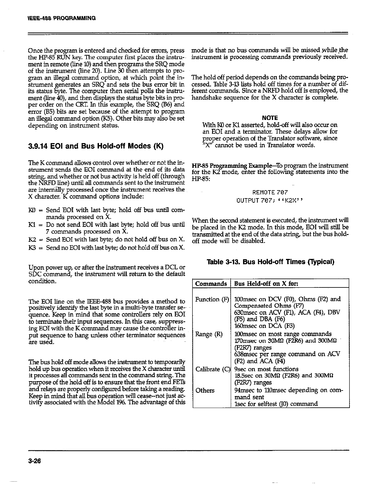
Once the program is entered and checked for errors, press
the HP-85 RUN key. The computer first places the instru-
ment in remote (line lo) and then programs the SRQ mode
of the instrument (line 20). Line 30 then attempts to pro-
gram an illegal command option, at which point the in-
strument generates an SRQ and sets the bus error bit in
its status byte. The computer then serial polls the instru-
ment (line 4O), and then displays the status byte bits in pro-
per order on the CRT. In this example, the SRQ (B6) and
error (85) bits are set because of the attempt to program
an illegal command option (K5). Other bits may also be set
depending on instrument status.
3.9.14 EOI and Bus Hold-off Modes (K)
mode is that no bus commands will be missed whilethe
instrument is processing commands previously received.
The hold off period depends on the commands beingpro-
cessed. Table 343 lists hold off times for a number of dif-
ferent commands. Since a NRFD hold off is employed, the
handshake sequence for the X character is complete.
NOiE
With KD or Kl asserted, hold-off will also occur on
an EOI and a terminator. These delays allow for
proper operation of the Translator software, since
“X” cannot be used in Translator words.
The K command allows control over whether or not the in-
strument~sends the EOI command at the end of its data HP-85 Programming Example-To program the instrument
&in and whether or not bus activity is held off (through for the K2
the&FDline)untilallcommandssenttotheinstrUment Hp-85’
mode, enter the followmg statemats into the
are inteniay processed once~the instrument receives the
X chamter. K command options include:
KO = Send EOI with last byte; hold off bus until com-
FiEMOTE 707
‘OUTPUT 797 i r r KZX ’
mands processed on X.
Kl = Do not send EOI with last byte; hold off bus until When the second statement is executed, the instrument will
7 commands processed on X. be placed in the K2 mode. In this mode, EOI will still be
K2 = Send EOI with last byte; do not hold off bus on X. transmitted at the end of the data string, but the bus hold-
off mode w$l be disabled.
K3 = Send no EOI with last byte; do not hold off bus on X.
Upon power up, or after the instrument receives a DCL or
SDC co
mmand, the instrument will return to the default
condition.
The EOI line on the IEEE-488 bus provides a method to
positively identify the last byte in a multi-byte transfer se-
quence. Keep in mind that some controllers 1~4y on EOI
to terminate their input sequences. In this case, suppress-
ing EOI with the K command may cause the contr@er in-
put sequence to hang unless other terminator sequences
are used.
The bus hold off mode allows the instrument to temporarily
hold up bus operation when it receives the X character until
it processes all co mmands sent in the command string. The
purpose of the hold off is to ensure that the front end FETs
and relays are properly configured before taking a reading.
Keep in mind that all bus o
tivity associated with the hf eration will cease--not just ac-
ode1 196. The advantage of this
Table 3-13. Bus Hold-off Times (Typical)
Commands
Function (F]
Range CR)
Calibrate (C
Others
Bus Held-off on X for:
1OOmsec on DCV (FO), Ohms (F2) and
Compensated Ohms (F7)
63Omsec on ACV (Fl), ACA (F4), DBV
(F5) and DBA (F6)
16Omsec on DC4 (F3)
lOOmsec on most range conunands
l7Omsec on 3OM0 (F2R6) and 34OMQ
(Fuv) ranges
638msec per range comman donACV
(F’4 and Aa 0
9sec on most functions
IBSsec on 3OM0 (E?R6) and 3WMll
0 ranges
94msec to llOmsec depending on com-
mand sent
lsec for selftest (JO) command
3-26
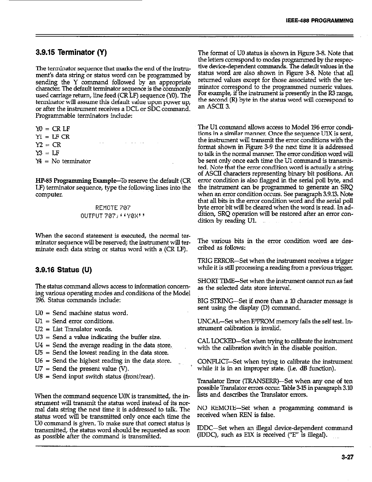
IEEE-488 PROGRAMMING
3.9.15 Terminator (Y)
The terminator sequence that~marks the end of the instm-
merit’s data string or status word can be programmed by
sending the Y command followed by an appropriate
character. The default terminator sequence is the commonly
used carriage return, line feed (CR LF) sequence (YO). The
terminator will assume this default value upon power up,
or after the inshxment receives a DCL or SDC command.
Programmable terminators include:
YO=CRLF
Yl=LFCR
M=CR
Y3 = LF
Y4 = No terminator
HP-85 Progr amming Example--To reserve the default (CR
LF) terminator sequence, type the following lines into the
computer.
REMOTE 707
OLITFUT 767j r i YBX ’
When the second statement is executed, the normal ter-
minator sequence will be reserved; the instrument will ter-
minate each data string or status word~with a (CR LF).
3.9.16 Status (U)
The status command allows access to information con&m-
ing various operating modes and conditions of the Model
196. Status commands include:
LJO = Send machine status word.
Ul = Send error conditions.
UZ = List Translator words.
U3 = Send a value indicating the buffer size.
U4 = Send the average reading in the data stores.
U5 = Send the lowest reading in the data store.
U6 = Send the highest readiig in the data store.
U7 = Send the present value (V).
U8 = Send input switch status (front/rear).
When the command sequence UOX is transmitted, the in-
strument will transmit the status word instead of its nor-
mal data string the next time it is addressed to talk. The
status word will be transmitted only once each time the
UO command is given. To make sure that correct status i+
transmitted, the status word should be requested as soon
as possible after the con-man d is transmitted.
The format of UO status is shown in Figure 3-8. Note that
the letters correspond to modes programmed by the respec-
tive device-dependent comman de.. The default values in the
status word are also shown in Figure 3-8. Note that all
returned values accept for those associated with the ter-
minator correspond to the programmed numeric values.
For example, if the instrument is presently in the R3 range,
the second (R) byte in the status word wiJ.l correspond to
an ASCII 3.
The Ul command allows access to Model ‘I.96 error condi-
tions in a similar manner. Once the sequence UlX is sent,
the instrument will transmit the error conditions with the
format shown in Figure 3-9 the next time it is addressed
to talk in the normal manner. The error condition word will
be sent only once each time the Ul command is transmit-
ted. Note that the error condition word is a&ally a string
of ASCII characters representing binary bit positions. An
error condition is also flagged in the serial poll byte, and
the instrument can be programmed to generate an SRQ
when an enur condition OCCUIS. See paragraph 3.9.13. Note
that all bits in the error condition word and the serial poll
b e error bit~will be cleared when the word is read. In ad-
d? hon, SRQ~ op%r&ion will be restored after an error con-
ditionby reading Ul.
The various bits in the error condition word are des-
aibed as follows:
TRIG ERROR-Set when the instrument receives a trigger
while it is still processing a reading from a previous trigger.
SHORT TIME-Set when the instrument cannot run as fast
as the selected data store interval.
BIG STRING-Set if more than a 10 character message is
sent using the display (D) command.
UNCAL-Set when EVROM memory fails the self test. In-
strument calibration is invalid.
CAL LQCKED-Set when t@ng to &irate the instrmnent
with the calibration switch in the disable position.
CONFLICT-Set when trying to calibrate the instrument
while it is in an improper state. (i.e. dB function).
Translator Error (TRANSERR)-Set when any one of ten
possible Translator enors occur. Table 3-15 in pmagraph 3.10
lists and describes the Translator errors.
NO REMOTE-Set when a progamming command is
received when REN is false.
IDDC-Set when an illegal device-dependent command
(IDDC), such as ElX is received (“El’ is illegal).
3-27
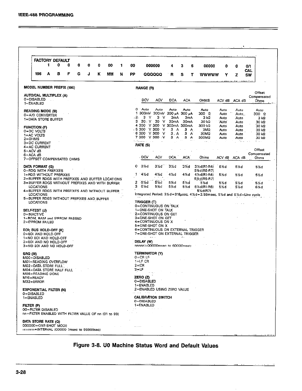
IEEE-408 PROG!%tblMlNG
,, :
FACTORY DEFAULT
1 0 0 0 0 0 00 1 00 000000 4 3 6 00000 0 0 011
CAL
196 A B F 0 J K MM N PP QQQQQQ R S T WWWWW Y Z SW
MODEL NUMBER PREFIX (196) RANGE (R,
A”To,oAL MWTIPLEX (A, OffSet
O=OIS*sl.ED Dcv *cv DCA COmpenSated
AU OHMS
l=ENAsLEo ACVdS ~.KAdS O)I,?s
Re*DING MODE (B,
O=AJD CONVERTER
l=DATA STORE SUFFER
FUNCTION (0
o=oc “OUS
,=*c VOLTS
2=OHMS
3=x CURRENT
&-AC CURRENT
SELFTEST (.I)
O=INACTI”E
l=ROM. RAM and E’PROM PASSED
2=E*PROM FAILED
EXPONENTIAL FILTER (i-4) Z=ENPISLED USING ZERO VALUE
O=OISASLED
,=EN*BLED cALIBRATlON SWITOH
“=“lSARI F”
Figure 3-8. 00 Machine Status Word and Default Values
~_____ .,, ~,.,”
3-28
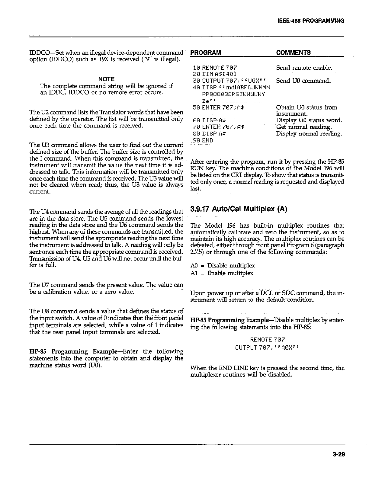
IEEE-488 PROGRAMMING
IDDCO--Set when an illegal device-dependent command
option (IDDCO) such as T9X is received (“9” is illegal).
NOTE
The corn lete command string will be ignored if
an IDD P , JDDCO or no remote error occurs.
The U2 command lists the Translator words that have been
defined by the. operator. The list will be transmittedonly
once each time fhe command is received.
The U3 command allows the user to find out the current
defined size of the buffer. The buffer Size iFZ&olled by
the I command. When this command is transmitted, fhe
instrument will transmit the value the next time~it is ad-
dressed to talk. This information will be transnxi&d only
once each time the command is received. The U3 value will
not be cleared when read; thus, the U3. value is always
current.
The U4 command sends the average of all the readings that
are in the data store. The U5 conun~nd sends the lowest
reading in the data store and the U6 command sends the
highest. When any of these co mmands are transmit@$fhe
instrument will send the appropriate reading the next time
the instrurnent~is addressed to talk. A reading will only be
sent-once each time the appropriate command is received.
~gyni&on of U4, U5 and U6 will not occur until the buf-
The U7 command sends the present value. The value can
be a calibration value, or a zero value.
The US command sends a value that defines~ the status of
the input switch. A value of 0 indicates that the~front pariel
input terminals are selected, while a value of ~1 indicates
that the rear panel input terminals are selected.
HP-85 Progamming Example-Enter the following
statements into the computer to obtain and display the
machine status word (UO).
PROGRAM COMMENTS
10 REMOTE 707
xi DIM ABC401 Send remote enable.
30 UIUTPUT 7U7 ( L UBY’ y
, I Send UO command.
40 DISP * ~mdlHBFGJKtltlN
PPQ~!aaP~RSTWWWl,lWY
Z%‘” ~~~~~~~~~~ ~~~
50 EHTER~TWT; At: obtin uo stibls from
instrument.
60 UISF-‘-A5 Display UO status word.
7U ENTER 707; RB ~Get n&mal reading.
:m III% A$ Display normal reading.
30 END
After eni+ng the program, run it by pressing the HP85
RUN key. The machine conditions of the Model 196 will
be listed on the CRT display. To show that status is &ansn&
ted only once, a normal reading is requested and displayed
last.
3.9.17 Auto/Cal Multiplex (A)
The Model 196 has built-in multiplex routines that
automatically calibrate and zero the instrument, so as to
maintajn its high accura
defeated, either through x The multiplex routines can be
ant panel Program 6 (paragraph
2.25) or through one of the following comma$.s:
A0 = Disable multiplex
Al = Enable multiplex
Upon power up or after a DCL or SDC command, the in-
strument will return to the default-condition.
HP-85 Programming Example-Disable multiplex by enter-
ing the following statements into the I-E-85:
REMOTE 707
OUTFUT 707; “AOXx 5
When the END LINE key is pressed the second time, the
multiplexer routines will be disabled.
3-29
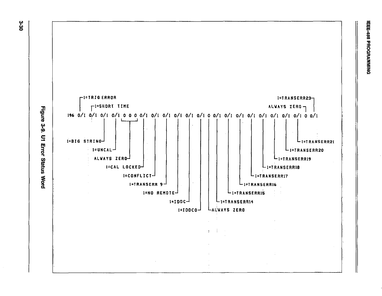
l=lRIG ERROR
rl=SHORT TIME
196 d/l k/l O/I O/i 0 0 0 O/l O/I O/I
I=CAL LOCKED’
J
I=CDNFLICT
I-TRANSERR 9
O/I O/I D/l
I-ND REMOTEA
I--IDDC
‘i
l=IrJOCO
0 D/l O/I
I=lRANSERR23
ALUAYS ZERO, 1
O/I O/I O/I O/I O/I D/l ;, Oil
I=TRANSERRPI
I=TRAMSERR20
I-TRANSERRIS
1 LI=TRANSERR17
l:TRANSERR16
1
LI=TRANSERRIk ~
l=TRANSERRl4
AlhAYS ZERO
IEEE-488 PROGRAMMING
3.9.18 Delay (IV)
The delay command controls the time interval that occurs
horn the point the inslrument is triggered until it begins
integration of the input signal. This feature is useful in
situations where a specific time period must transpire to
allcw an input signal to settle before measurement. Dur-
ing the delay period, the inputs multiplexing FETs ar@
switched on so the inshument is set to begin integration
upon conclusion of the programmed delay period. A delay
period can be programmed using the following command:
wn
Here, n represents the delay value in milliseconds. The
range of programmable delay values is from Omsec to
600Oflmsec.
Examples: For a delay of 0.002sec send W2X.
For a delay of 30.05sec send W3005OX.
For a delay of 60sec send W6OOOOX.
Upon power up or after receivin a DCL or SDC commtidj
the instrument will return to t
a e default condition.
HP-85 Pmgr amming Example--To program a 25Omsec delay
period into the instrument, enter the following statements
into the computer:
REMOTE 707
OUTPUT 707; I’WZ5OX”
After the END LINE key is pressed the second time, the
instrument will wait for 25Omsec after each triggered con-
version before executing the next coversion period.
3.9.19 Self-Test (J)
The J command causes the instrument to perform tests it
automaticsJly performs upon power up. When the self-test
command is given, the Model 196 perfor?ns the following
tests:
1. ROM Test
2.RAMTest
3. EIPROM Test
J command parameters include:
JO = Perform self-test.
Ifthe self-test is successful, the J byte in the UO status word
will be set to 1. If E’PROM fails, the message ‘VNCAL!’
will be displayed and the J b te in the Ul status word will
be set to 2. Ati EzPROM f a3 ore is also flagged~in thg Ul
status word. If ROM and RAM fails, the instrument will
lock up.
recomme&tions to resolve a failure.
See paragra h 6.7.2 for more information on these tests and
HP-85 Programming Example-Enter the following
statements into the computer to perform the Model 196
self-test:
REMOTE 707
OUTPUT 707.: ’ s JOX” ’
When the END LINE key is pressed the second time, the
instrument erforms the self-test. If sUCcessful, the self-test
byte (J) in tK e UO~status word will be set to 1.
3.9.20 Hit Button (H)
The hit button command allows the user to emulate vir-
tually any front panel control sequence. Through the use
of-the H command, the front panel programs may be
entered through commands given over the bus. The H com-
mand is sent by sending the ASCII letter followed by a
number representing a front panel control. These control
numbers are shown in Figure 340.
E@ples:
H3x-Selects the ACA function.
HOX-Selects the ACV function.
HP-85 Programming Example-Enter the following
statements into the computer to place the instrument in the
ohms function:
REMOTE 707
OUTPUT707j”HiX”
When the END LINEkey is pressed the second time, the
instrument is placed in the ohms function.
3-31
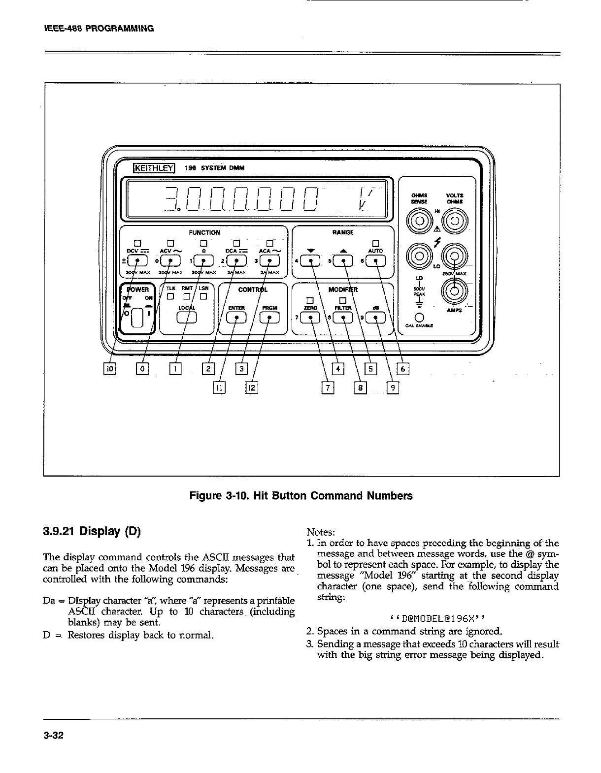
Figure 3-10. Hit Button Command Numbers
3.9.21 Display (D) Notes:
1. In order to have spaces preceding the beginning oft the
The display command controls the ASCII messages that message and between message words, use the @ sym-
can be placed onto the Model 196 display. Messages are bol to represent~each space. For example, to-display the
controlled with the following commands: message “Model 196” starting at--the seconds display
character (one space), send the following command
Da = DIsolav character “sT’, where “a” reoresents a orint~ble string:
A&II’ character. tip to 10 chkacters (&&ding
blanks) may be sent. c d D@tlODEL@i=c5V’ 5
, .a
D =~ Restores display back to normal. 2. Spaces in a command string are ignored.
3. Sending a message that exceeds 10 characters will results
with the big string error message being @splayed.
3-32
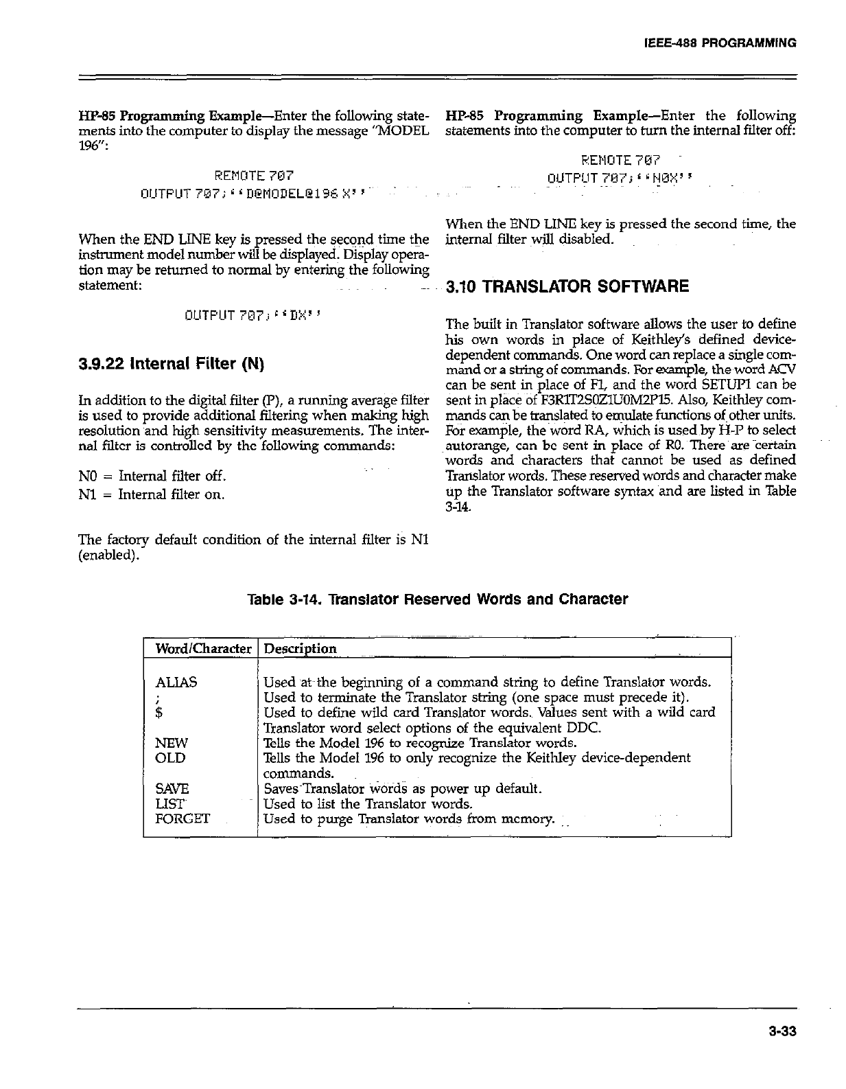
IEEE-488 PROGRAMMING
HP-85 Programmi ng Example-Enter the following state- HP-65 Programming Example-Enter the following
ments into the computer to display the message “MODEL statements into the computer to turn the internal filter off:
196”: HEMITE 707
REMOTE 707 UUTPIUT 797; 6 G HMX 5
WTFUT 7073 r r DWlOIIELCi96 X3 ’ : -
When the END LINE key is pressed the second time, the
When the END LINE key is pressed the sec+d time the internal filter will disabled.
instrument model number will be displayed: Display opera-
tion may be returned to normal by entering the following
statement: 3.10 TRANSLATOR SOFTWARE
OUTPUT 767; 6 6 I!:+~ ’ The built in Translator software allows the user to define
his own words in place of Keithley’s defined device-
3.9.22 internal Filter (N) dependent commands. One word can replace a single com-
mand or a string of commands. For example, the,word ACV
can be sent in place of Fl, and the word SETUP1 can be
In addition to the digital filter (P), a running average filter sent in place of F3R1T2S~ZllJOMZFl5. Also, Keithley corn-
is used to provide additional filtering when making high mands can be translated to emulate functions of other units.
resolution and high sensitivity measurements. The inter- For exam$e, the~word RA, which is used by H-P to select
ml filter is controlled by the following commands: ~autorange, can be sent in place of RO. There are Yertain
words and characters that cannot be used as defined
NO = Internal filter off. Translator words. These reserved words and character make
Nl = Internal filter on. ;!4;he Translator software syntax and are listed in Table
The factory default condition of the internal filter is Nl
(enabled).
Table 3-14. Translator Reserved Words and Character
Word/Character Description
I
ALIAS
$
SAVE
LET
FORGET
Used at~the beginning of a command string to define Translator words.
Used to terminate the Translator string (one space must precede it).
Used to define wild card Translator words. Values sent with a wild card
Translator word select options of the equivalent DDC.
Tells the Model 196 to recognize Translator words.
Tells the Model 196 to only recognize the Keithley device-dependent
commands.
Saves~Translator Words as power up default.
Used to list the Translator words.
Used to purge Translator words from memory.
3-33
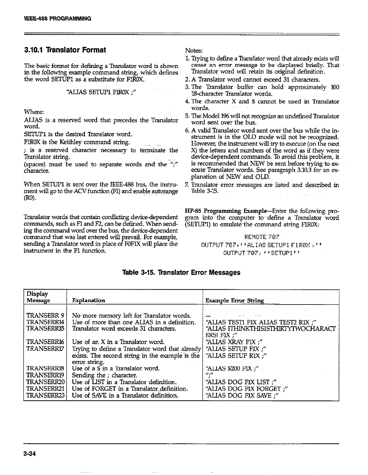
3.10.1 Translator Format Notes:
1. Trying to define a Translator word that already exists will
The basic format for defining a Translator word is shown cause an error message to be displayed briefly. Thatk
in the following example command St&g, whi&d&ines Translator word will retain its original definition.
the word SEZIJR as a substitute for FlROX. 2. A.Translatoi word cannoi exceed 31 characters.
‘ALIAS sETuPl FlROX ;” 3. The Translator buffer can hold approximately 100
B-character Translator words.
4. The character X and $ cannot be used in Translator
Where: words.
ALIAS is a reserved word that precedes the Translator 5. The Model 196 will not recognize an undefined Translator
word. word sent over the bus.
SETUPl is the desired Translator word. 6. A valid Translator word sent over the bus while the in-
FlROX is the Keithley command string. strument is in the OLD mode will not be recognized.
However, the instrument will try to execute (on the next
; is a reserved character necessary to tetiate the
Tran%lahx stig. X) the letters and numbers of the word as if they were
device-dependent commaqds.~ To avoid this problem, it
(spaces) must be used to separate words and the “;” is recommended that NEW be sent before trying to ex-
character. ecu@Translator words. See paragraph 3.10.3 for an ex-
planation oft NEW and OLD.
When SETUFl is sent over the IEEE-488 bus, the in&u-
ment will go to the ACV function (Fl) and enable autorange 7. Translator error messages are listed and described in
Table 3-7.5.
Translator words that contain conflicting device-dependents HP-85 Programming Example-Enter the following pro-
command.?., such as Fl and F2, can be defined. When send- &ati into the c&i@uter &define a Translator word
ing the comma d word over the bus, the device-dependent (SETUPI) to emulate-the command string FIROX:
command that was last entered will prevail. For example, REMOTE 7M7
sending a Translator word in place of FOFYX will place the C~UTPLlT767r’LALIASSETlJPiFlROXi’~
instrument in the Fl function. UUTFUT707; ‘rSETUP1’!
Table 3-15. Translator Error Messages
Display
Message Explanation Example Error String
TRANSERR 9 No more memory left for Translator words. -
TRANSERR14 Use of more than one ALIAS in a definition. “ALIAS TESTI l?lX ALIAS TEST2 RLX ;‘I
TRANSERRl5 Translator word exceeds 31 characters. ‘RUAS ITwNKTHIs1sTHIRpITw OCHARACT
ERS! FIX ;I’
TRANSERRl6 Use of an X in a Translator word. “ALIAS XRAY FIX ;”
TRANSFERl7 Trying to define a Translator word ~&at alre@y “ALIAS SETUl? FIX ;”
exists. The second string in the example is the “ALJAS SETUP RlX ;”
error shing.
TRANSERRB Use of a $ in a Translator word. ‘ALIAS $200 FCC;”
TRANSERRl9 Sending the ; character. n.,,
TRANSERR20 Use of LIST in a Translator definition. kIAS DOG FlX LIST ;”
TRANSERR21 Use of FORGET in a Translator_definition. “ALIAS DOG FJX FORGET ;”
TRANSEKQ.3 Use of SAVE in a Translator definition. ‘NJAS DOG FIX SAVE ;”
3-34
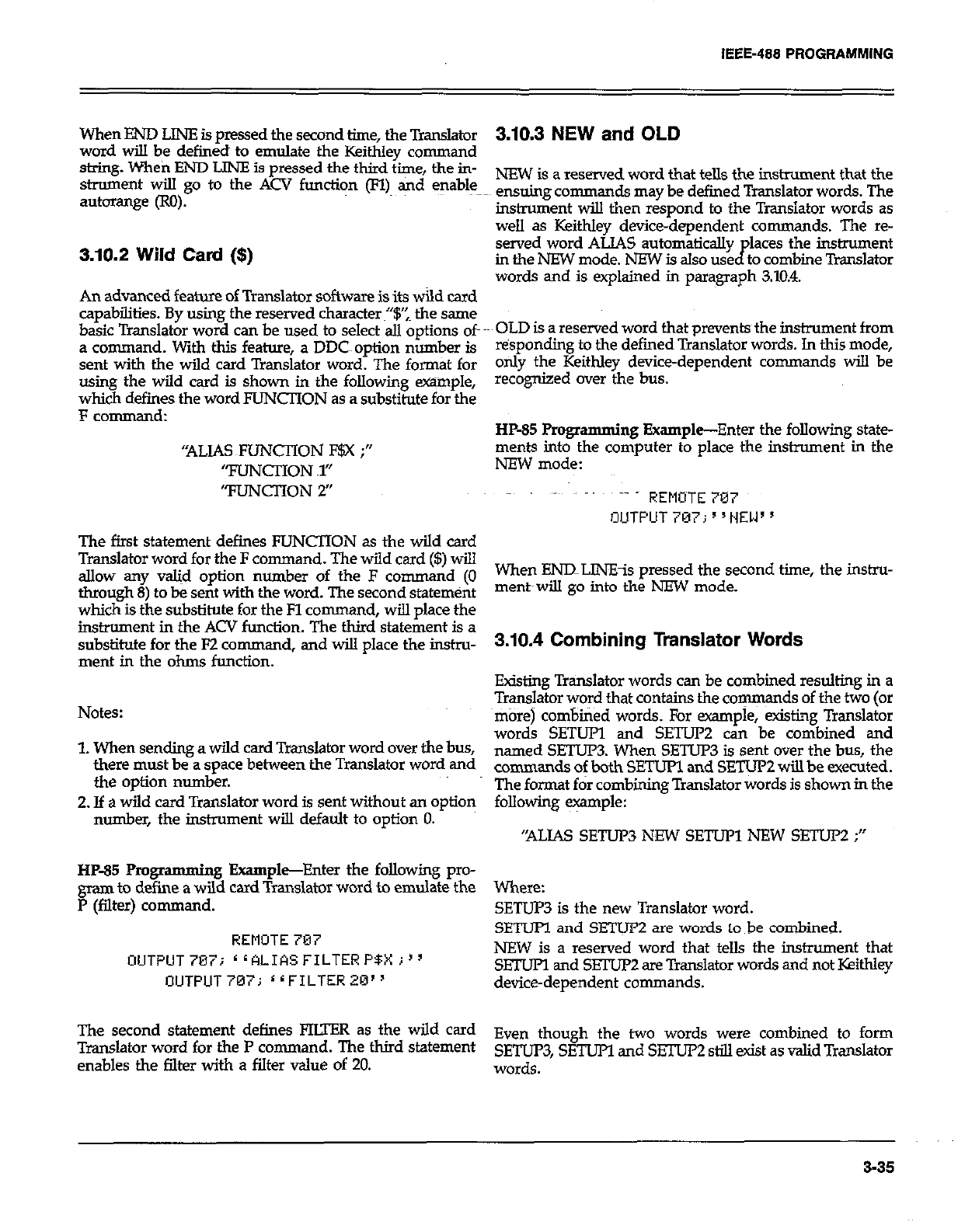
IEEE-488 PROGAAMMlNG
When END LlNE is pressed the second time, the Translator
word will be defined to emulate the Keithley command
string. When END LlNE is pressed the third time, the in-
strument will go to the ACV function (n) and enable
autorange (RO).
3.10.2 Wild Card ($)
An advanced feature of Translator software is its wild card
capabilities. By using the reserved character~“$‘: the same
basic Translator word can beg used to select all options of
a command. With this feature, a DDC~ option number is
sent with the wild card Translator word. The format for
using the wild card is shown in the following wple,
which defines the word FUNCTION as a substitute for the
F command:
“ALIAS FUNCTION F$X ;”
“FLlNCl-ION ~1”
“FUNCTION 2’
The first statement defines FUNCTION as the wild card
Translator word for the F command. The wild card ($) will
allow any w&d option number of the F command (0
through 8) to be sent with the word. The second statemtint
which is the substifute for the Fl command, will place the
instrument in the ACV function. The third statement is a
substitute for the F2 command, and will place the instru-
ment in the ohms function.
Notes:
1. When sending a wild card Translator word over the bus,
there must be a space between the Translator word and
the option number.
2. If a wild card Translator word is sent without an option
number, the instrument will default to option 0.
HP-85 Pmgramming Example-Enter the following pro-
gram to define a wild card Translator word to emulate the
P (filter) command.
REMOTE 707
OUTPUT7Bij rrALIASFILTERP$Xj”
OUTPUT707; 11FILTER20”
The second statement defines FIUER as the wild card
Translator word for the P comman d. The third statement
enables the filter with a filter value of 20.
3.10.3 NEW and OLD
NEW is a reserved word that tells the instrument that the
ensuing commands may be defined Translator words. The
instrument will then respond to the Transistor words as
well as Keithley device-dependent comman ds. The re-
served word ALIAS automatically places the instrument
in the NEW mode. NEW is also used to combine Translator
words and is explained in paragraph 3.10.4.
OLD is a reserved word that preventsthe instrument from
tisponding to the defined Translator words. In this mode,
only the Keithley device-dependent commands will be
recognized cwer the bus.
HP-85 Programming Example-Enter the following state-
ments into the computer to place the instrument in the
NEW mode:
~- REMOTE 707
OUTPUT 7137; s ‘HEW ’
When ENlILINEis pressed the second time, the instru-
ment~wiu go into the NEW mode.
3.10.4 Combining Translator Words
Existing Translator words can be combined resulting in a
Translator word that contains the cow ds of the two (or
more) combined words. For example, exist&~ Translator
words SETUP and SETU2 can be combined and
named SETUPB When SETUP3 is sent over the bus, the
commands of both SETUP1 and SETUP2 will be executed.
The f-t fir combining Translator words is shown in the
following e+nple:
“ALIAS SETUP3 NEW SETUP1 NEW SETUP2 ;”
Where:
SETUP3 is the new Translator word.
SETUPl and SETUP2 are words to be combined.
NEW is a reserved word that tells the instrument that
SETUFl and SETUP2 are Translator words and not Keithky
device-dependent commands.
Even though the two words were combined to form
SETUP3, SETUPI and SETUI’2 still exist as valid Translator
words.
3-35
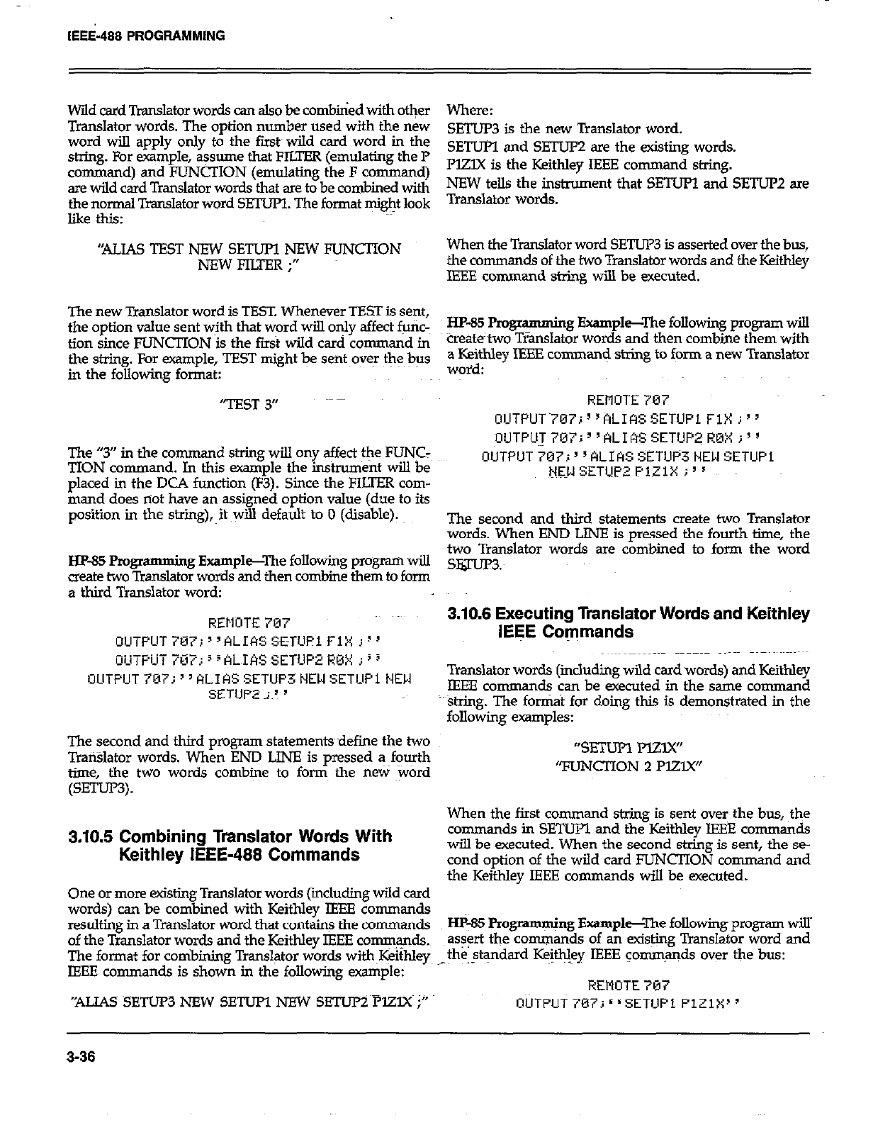
IEEi-488 PROGRAMMING
Wild card Translator words can also be combbied with other
Translator words. The option number used with the new
word will apply only to the fir& wild card word in the
string. For example, assume that FILTER (emulating the P
command) and FUNCTION (emulating the F command)
are wild card Translator words that are to be combined with
the normal Translator word SETUPl. The format might look
like this:
“ALIAS TEST NEW SETUPl NEW FUNCTION
NEWFIU’ER;”
The new Translator word is TEST. Whenever TEST is sent,
the option value sent with that word will only affect futic-
tion since FUNCTION is the first wild card command in
the string. For example, TEST might be sent~oyq the bus
in the following format:
‘TEST 3”
The “3” in the command string will ony affect the FUNC:
TION command. In this example the instrument will be
placed in the DCA function (F3). Since the FILTER com-
mand does not have an assigned option value (due to its
position in the s’xing), it will default to 0 (disable).
HP-85 Progr
amming Example--The following program will
create two Translator words and then combine them to form
a third Translator word:
REllnTE 707
OUTPUT707i”ALIASSETUPlFlX I)’
_._ _-
The second and third propam statementsdefine the two
TraiBlator words. When END LINE is pressed a fourth
time, the two words combine to form the new word
(SETur3).
3.10.5 Combining Translator Words With
Keithley IEEE-488 Commands
One or more existing Translator words (iicluding wild card
words) can be combined with Keithley IEEE commands
resulting in a Translator word that contain! the commands
of the Translator words and the Keithley IEEE comqqds.
The format for cotibirdng Translator words with~I+ithley
IEEE commands is shown in the following example:
“ALIAS SETUP3 NEW SETUPI NFW SETUi=Y~PlZlX i”
Where:
SETUP3 is the new Translator word.
SETUl?l and SETUP2 are the existing words.
PlZlX is the Keithley IEEE command string.
NEW tells the instrument that SETUPl and SETUP2 are
Translator words.
When the Translator word SETUP3 is asserted over the bus,
the commands of the two Translator words and the Keithley
IEEE command string will be executed.
HP-85 FYogr amming Example-The following program will
tieate’two TIanslator words and then combine them with
a Keithley IEEE cornman< string to form a new Translator
woid:
REMOTE 707
OlJTPUT~707i”ALIkSSETUPl FiX i”
OUTPU~707i1’ALIASSETUP~R0Xi”
OUTPlJT707;“ALIASSETUP3t4EWSETUPi
N3l SETUP2 PlZlX i”
The second and third statements create two Translator
words. When END LINE is pressed the fourth time, the
two Translator words are combined to form the word
slguP3:
3.10.8 Executing Translator Words and Keithley
IEEE Commands
Translator words (includmg wild card words) and Keithley
IEEE commands can be executed in the same command
string. The fortit for doing this is demonstrated in the
following examples:
“SETUR Mzy(”
TlJNCIlON 2 PEW
When the first command string is sent over the bus, the
commands in SETUPl and the Keithley IEEE commands
will be executed. When the second string is sent, the se-
cond option of the wild card FUNCTION command and
the Keithley IEEE commands will be executed.
Hp-85 Programming Example--The following program will’
as+ the commands of an existing Translator word and
the,$+dard Keifhley IEEE commands over the bus:
;
REMOTE 707
3-36
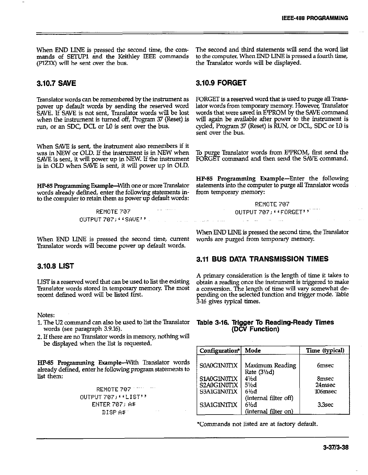
When END LINE is pressed the second time, the corn- The second and third statements will send the word list
man& of SETUP1 and the Keithky IEEE comman ds to the computer. When END LINE is pressed a fourth time,
(FElX) will be sent over the bus. the Translator words will be displayed.
3.10.7 SAVE 3.10.9 FORGET
Translator words can be remembered by the instrument as FORGET is a reserved word that is used to purge all Trans-
power up default words by sending the reserved word
SAVE. If SAK is not Sent, Translator words will be lost lator words from temporary memory. However, Trarislator
when the instrument is turned off; Program 37 (Reset) is words that were saved in ElPROM by the SAVE command
will again Je ~qailable after power to the instrument is
run, or an SDC, DCL or M is sent over the bti. cycled, Program 37 (Reset) is RUN, or DCL, SDC or Ul is
sent over the bus.
When SAVE is sent, the instrument also remembers if it
was in NEW or OLD. Jf the instrument is in NEW when
SAVE is sent, it ~wiu power up in NEW. If the instrument
is in OLD when SAVE is sent, it will power up in OLD.
HP-85 Pmgr
amming Example--with one or more Translator
words already defined, enter the following statements in-
to the computer to retain them as power up default words:
REMOTE 787
OUTPUT707;*LSA’JE”
When END LINE is pressed the second time, current
Translator words will become power up default words.
3.10.8 LIST
LIST is a reserved word that can be used to lit the existing
Translator words stored in temporary memory. The most
recent defined word will be listed first.
To u e Translator words from EY’ROM, first send the
FO iis G T comnd and then send the SAVE command.
HP-85 Programming Example-Enter the following
statements into the computer to purge all Translator words
from temporary memory:
REMOTE 707
OUTPIJT 707; * r FORGET’ p
When ENDLINE is pressed the second time, the Translator
words are purged from temporq memory.
3.11 BUS DATA TRANSMISSION TIMES
A primary consideration isthe length of time it takes to
obtain a reading once the instrument is triggered to make
a conversion. The length of time will vary somewhat de-
pending on the selected function and higer mode. Table
3-16 give-s typical times.
Notes:
1. The UZ command can also be used to list the Translator Table a-16. Trigger To Reading-Ready Times
(DCV Function)
words (see paragraph 3.9.16).
2. If there are no Translator words in memory, nothing will
be displayed when the list is requested.
HP-85 Programming Example--With Trtilator words
already defined, enter he following program statements to
list them:
REMUTE7CI7 ~~~
OlJTPUTiEVi‘~LIST’~
ENTE~R 707; A5
DISP A$
Configuratioa
SOAOGlNOTIX
SL4OGlNOTlX
S2AOGlNOTlX
S3AlGlNOTlX
S3AlGlNlTlX
Mode
Maximum Reading
Rate (3%d)
4Md
5Yzd
6Yzd
(internal filter off)
6%d
(internal filter on)
Tie (typical)
6msec
Smec
24msec
106msec
3.3sec
“Commands not listed are at factory default.
3-3713-38
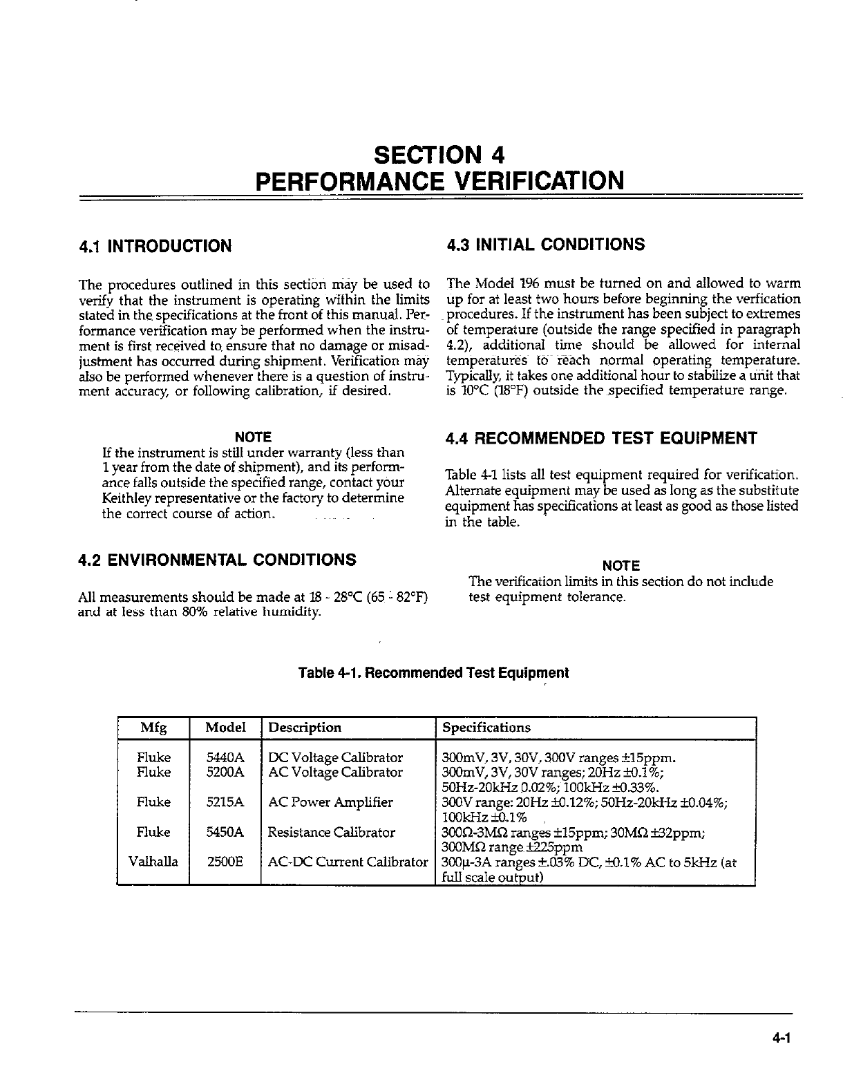
SECTION 4
PERFORMANCE VERIFICATION
4.1 INTRODUCTION 4.3 INITIAL CONDITIONS
The procedures outlined in this section may be used to
verify that the instrument is operating wifhin the limits
stated in the specifications at the front of this manual. Per-
formance verification may be performed when the instru-
ment is first received to ensure that no damage or misad-
justment has occurred during shipment. Verification may
also be performed whenever there is a question of instru-
ment accuracy, or following calibration, if desired.
The Model 196 must be turned on and allowed to warm
up for at least two hours before beginning the verfication
procedures. If the instrument has been subject to extremes
of temperature (outside the range specified in paragraph
4.2), additional time should be allowed for internal
temperatmes~ to reach normal operating temperature.
Typically, it takes one additional hour to stabilize a unit that
is 10°C (18°F) outside the specified temperature range.
NOTE
If the instrument is still under warranty (less than
1 year from the date of shioment). and its oerfonn-
, I.
ante falls outside the specified range, contact your
Keithley representative or the factory to determine
the correct course of action.
4.2 ENVIRONMENTAL CONDITIONS
All measurements should be made at 18 - 28’C (65~ 182°F)
and at less than 80% relative humidity.
4.4 RECOMMENDED TEST EQUIPMENT
Table 4-l lists all test equipment required for verification.
Alternate equipment may be used as long as the substitute
equipment has specifications at least as good as those listed
in the table.
NOTE
The verification limits in this section do not include
test equipment tolerance.
Table 4-l. Recommended Test Equipment
Description I Specifications
DC Voltage Calibrator
AC Voltage Calibrator
AC Power Amplifier
300mV, 3V, 3OV, 3OOV ranges *15ppm.
3OOmV, 3V, 30V ranges; 2OHz H.l%;
50Hz-20kHz 9.02%; 1OOkHz M.33%.
3OOV range: 2OHz B3.12%; 5OHz-2OkHr M.04%;
lookHz~.1%
3COQ-3MQ ranges il5ppm; 30MQ i32ppm;
300MR ranee~B25nnm
Resistance Calibrator
AC-DC Current Calibrator 300~~3A n&es +..d3’% DC, +o.l% AC to 5kHz (at
full scale output)
4-I
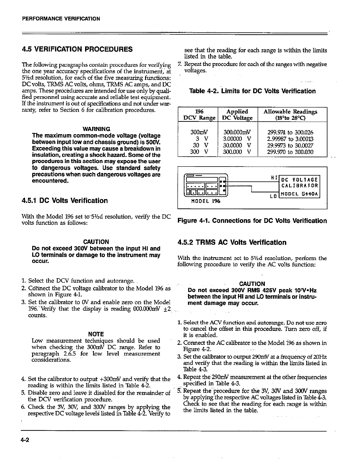
PERFORMANCE VERIFICATION
4.5 VERIFICATION PROCEDURES
The following paragraphs contain procedures for verifying
the one year accuracy specifications of the instniment,~ at
5%d resolutiofi, for each of the five mea&@ fticiions:
DC volts, TRMS AC volts, ohms, TRMS AC amps,~ and DC
amps. These procedures are intended for use only by quali-
fied personnel using accurate and reliable test equipment.
If the instrument is out of specifications and not under war-
ranty, refer to Section 6 for calibration procedur+
WARNING
The maximum common-mode voltage (voltage
between inout low and chassis aroundt is 5OOV.
Exceeding this value may cause-a breakdown in
insulatlon, creating a shock hazard. Some of the
procedures in this-section may expose the user
to dangerous voltages. Use standard safety
precautions when such dangerous voltages are
encountered.
see that~ the reading for each range is within the limits
listed in the table.
7. Repeat the procedure for each of the mnges with negative
voltages.
Table 4-2. Limits for DC Volta Verification
196 Applied Allowable Readings
DCV Range DC Voltage (wto 28T)
1 I I
300mV 3OO.OOOmV 299.974 to 300.026
3 v 3.00000 TV 2.99987 to 3.00013
30 v 30.0000 v 29.9973 to 30.0027
300 v 300.000 v 299.970 to 300.030
4.5.1 DC Volts Verification
With the Model 196 set tom5Yzd resolution, verify the DC
volts function as follows: Figure 4-1. Connections for DC Volts Verification
CAUTION
Do not exceed 300V between the input HI and
LO terminals or damage to the instrument may
occur.
4.5.2 TRMS AC Volts Verification
With the instrument set to 5%d resolution, perform the
following procedure to verify the AC volts function:
1. Select the DCV function and autorange.
2. Cdiinect the DC voltage calibrator to the Model ‘I96 as
shown in Figure 41.
3. Set the calibrator to OV and enable zero on the Model
19fYVerify that the display is reading OOO.OOOmV ~2~
counts.
NOTE
Low measurement techniques should be used
when checking the 3oOmV DC range. Refer to
paragraph 2.6.5 for low level measurement
considerations.
4. Set the calibrator to output +3OOmV and verify that the
reading is within the limits listed in Table 4-Z.
5. Disable zero and leave it disabIed for the remainder of
the DCV verification procedure.
6. Check the 3V, 3W, and 3OOV ranges by applying the
respective DC voltage levels listed in Table 42. VeqJo
CAUTION
Do not exceed 3OOV RMS 425V peak lOV*Hr
between the input HI and LO terminals or instru-
ment damage may occur.
1. Select the ACV function and &orange. Do not use zero
to cancel the offset in this procedure. Turn zero off, if
it is enabled.
2. Connect the AC calibrator to the Model 196 as shown in
Figure 4-2.
3. Set the calibrator to output 29OmV at a frequency of 2OHz
and verify that the reading is within the liits listed in
Table 4-3.
4. Repeat the 290mV measurement at the other frequencies
specified in Table 43.
5. Repeat the~piocedure for the 3V, 30V and 300V ranges
by applying the respective AC voltages listed in Table 4X%.
Check to see that the reading for each range is within
the limits listed in the table.
4-2
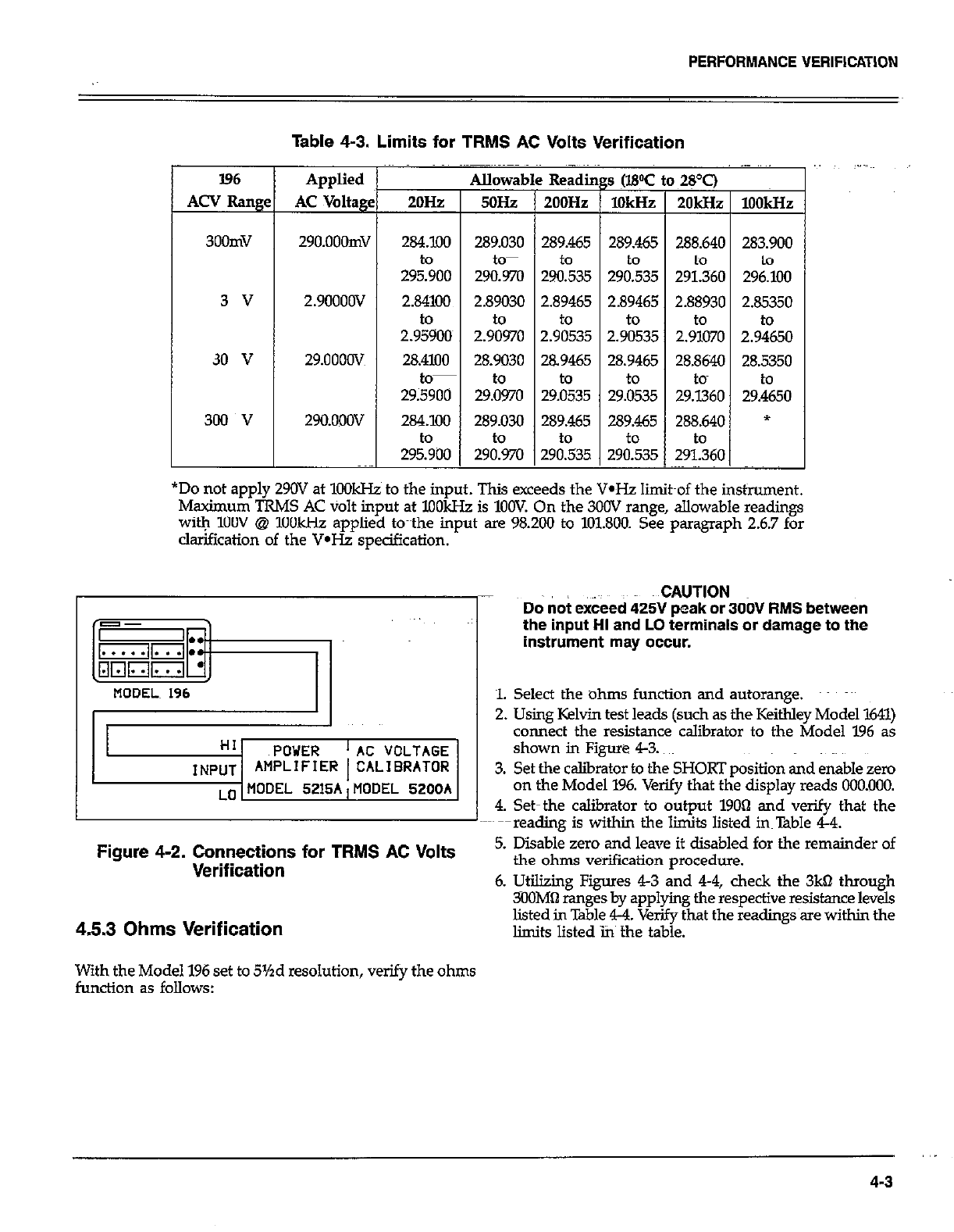
PERFORMANCE VERIFICATION
Table 4-3. Limits for TRMS AC Volts Verification
I96
ACV Rang
300mV
3 v
30 v
300 v
Applied
AC Voltagg
29O.OOOmV
2.9OOOOV
29.oooov
29O.ooOV
I Allowat
2OH~zP 5oHz
284.100 289.030
29soo to-
290.970
2.84100 2.89030
to to
2.95900~ 2.90970
28.4100
=
28.9030
to-
29;5900 29&o
284.100 289.030
to to
295.900 290.970
-
289.465 289.465 288.640 283.900
to
Z&35 29&35 291.360 29&Xl
12.89465 1 2.89465 1 2.88930 I 2.85350 I
2.9:35 2.9%35 2.9%0 2.9+&O
28.9465 28.9465 28.8640 28.5350
I to I to I tom I to I
29.0535 29.0535 29.1360 29.4650
*Do not apply 290V at 1OOkHz to the input. This exceeds the V-Hz limit~of the instrument.
Maximum TRMS AC volt input at XlOkHz is 1OOV On the 300V range, allowable readings
witYq 1OOV @ 1OOkHz applied to~~the input are 98.200 to 101.800. See paragraph 2.6.7 for
clarification of the V*Hz specification.
HI POWER ‘AC VOLTAGE
INPUT AMPLIFIER 1 CALIBRATOR
LO MODEL 5215A,MODEL 5200A
Figure 4-2. Connections for TRMS AC Volts
Verification
4.5.3 Ohms Verification
With the Model 196 set to 5%d resolution, verify the ohms
function as follows:
..CAUT!ON
Do not exceed 425V peak or 3OOV RMS between
the input HI and LO terminals or damage to the
instrument may occur.
1. Select the ohms function and autorange. ~~~
2. Using Kelvin test leads (such as the Keithley Model 1611)
connect the resistance calibrator to the Model 196 as
shown in Figure 43.
3. Set the caliirator to the SHORT position and enable zero
on the Model 196. Verify that the display reads 000.000.
4. Set-the calibrator to output 19OQ and verify that the
~--reading is within the limits listed instable 44.
5. Disable zero and leave it disabled for the remainder of
the ohms verification procedure.
6. Utilizing Figures 43 and 44, check the 3kQ through
XlOMa ranges by applying the respective resistance levels
listed in Table 4-4. Verify that the readings~are within the
limits listed ins the table.
,.
4-3

PERFORMANCE VERIFICATION
Table 4-4. Limits for Ohms Verification
I
196 Ran e
300 n
3kQ
30 kfl
300 kQ
3Ml-J
3OMQ
3OOMQ
set up
Figure 4-3
Figure 4-3
Figure 43
Figure 4-4
Figure 4-4
Figure 44
Figure 4-4
Applied
Resistance
190.000 61
1.90000 kQ
19.0000 k61
190.000 kdl
1.9OoOOMQ
19.OOOOMfl
lOO.OOOMQ
OUTPUT HI
=SENSE HI RESIST~ANCE
CALIBRATOR
tiODEL 196 SENSE LO tiODEL StSOA
OUTPUT LO’
Figure 4-3. Connections for Ohms Verification
(300n--3OkQ Range)
OUTPUT HI
MODEL 196 CABLE
RESISTANCE
CALIBRATOR
MODEL 5450A
OUTPUT LO
Figure 4-4. Connections for Ohms Verification
(300kQ-300MO Ranges)
Plowable Readings
(WC to 28T)
189979 to 190.021
1.89985 to I.90015
18.9985~ to 19.OGl5
X39.958 to 190.042
1.89958 to 1.90042
18.9808~ to 19.0192
97.998 to 102.002
~4.5.4 DC Current Verification
With the instrument set to 5%d resolution, verify the DC
current function as follows:
CAUTION
Do not exceed 3A to the AMPS and LO input ter-
minals or the rear panel current fuse will blow.
1. Select the DC4 function and autorange.
2. Conned~the DC current calibration source to the Model
196 as shown in Figure 45.
3. Set the calibration source to output +3OOfi and verify
that the reading is within the liits listed in Table 45.
4. Repeat the procedure for the 3mA,3OmA, 3OOmA and
3A ranges by applying the respective DC current levels
listed in Table 45. Check to see that the reading for each
range is within the limits listed in the table.
5. Repeat the procedure for each of the ranges with
negative current levels.
Table 4-5. Limits for DC Current Verification
l96 Range
300 PA
3m.4
3om.4
3oomA
3A
Applied
DC Current
300.000 pA
3.ooooonL4
3o.ocKlonL4
300.000!&4
3.OOOOO A
299.710 to 300.290
2.99840 to 3.00160
29.9840 to 30.0160
299.84Oto 300.160
2.99720 to 3.00280
4-4
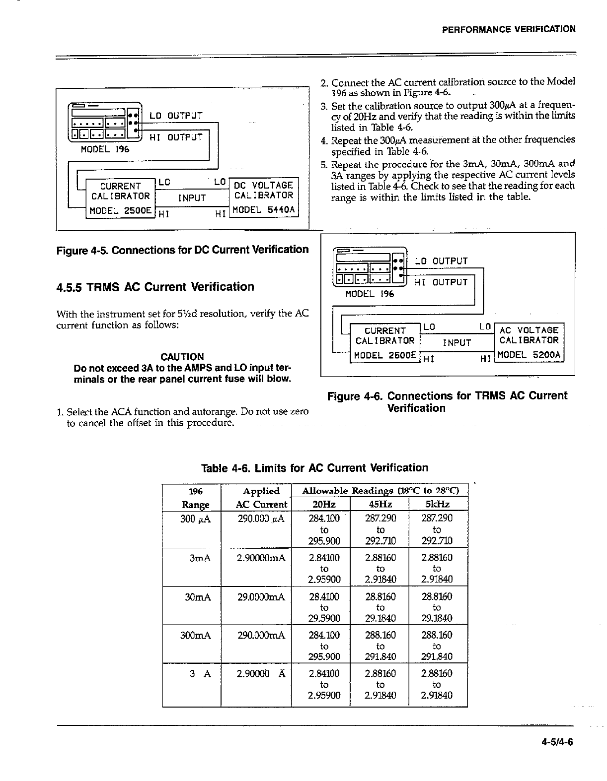
L CURRENT Lo Lo DC VOLTAGE
CALIBRATOR INPUT CALIBRATOR
MODEL 2500E ,,, T MODEL 5440A
PERFORMANCE VERIFICATION
2. Connect the AC current calibratiori source to the Model
196 as shown in Figure 4-6.
3. Set the calibration source to output 3006 at a frequen-
cy of 20Hz and verify that the reading is within the limits
listed in Table 4-6.
4. Repeat the 3OOd measurement at the other frequencies
specified in Table 4-6.
5. Repeat the procedure for the 3mA, 3Om.4, 3OOmA and
3A ranges by applying the respective AC current levels
listed in Table 4-6. Check to see that the reading for each
range is within the limits listed in the table.
Figure 4-5. Connections for DC Current Verification
4.55 TRMS AC Current Verification
With the instrument set for 5%d resolution, verify the AC
current function as follows:
CAUTION
Do not exceed 3A to the AMPS and LO input ter-
minals or the rear panel current fuse will blow.
i
n
-I
c
L CURRENT Lo Lo AC VOLTAGE
CALIBRATOR INPUT CALIBRATOR
MODEL XOOE HI 7 MODEL 5200A
Figure 4-6. Connections for TRMS AC Current
1. Select the ACA function and autorange. Do not use zero Verification
to cancel the offset in this procedure.
Table 4-6. Limits for AC Current Verification
4-514-6
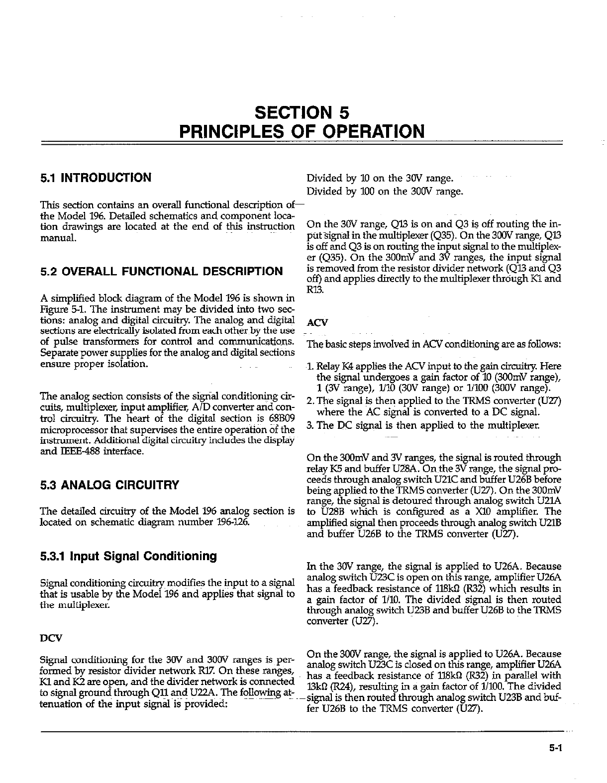
SECTION 5
PRINCIPLES OF OPERATION
5.1 INTRODUCTION
This section contains an overall functional desaiption of
the Model 196. Detailed schematics and component loca-
tion drawings are located at the end of $s instr@on
manual.
5.2 OVERALL FUNCTIONAL DESCRIPTION
A simplified block diagram of the Model 196 is shown in
Figure 5-1. The instrument may be divided into two sec-
tions: analog and digital circuitry. The analog and digital
sections are electrically isolated from each other by the use
of pulse transformers for control and communications.
Separate~power supplies for the analog and digital secfiotis
ensure proper isolation.
The analog section consists of the signal condition&g cir-
cuits, multiplexer, input amplifier, A/D converter and con-
trol circuitry. The heart of the digital sectioq is 6FBO9
microprocessor that supervises the entire operation of the
instrument. Additional digital circuitry includes the diipl<~
and IEEE-488 interface.
5.3 ANALOG CIRCUITRY
The detailed circuitry of the Model 196 analog section is
located on schematic diagram number 196-126.
5.3.1 Input Signal Conditioning
Signal conditioning circui~~modjfie~ the input to a signal
that is usable by the Model 196 and applies that signal to
the multiplexer.
DCV
Signal conditioning fork the 30V and 300V ranges is per-
formed by resistor divider network Rl7. On these ranges,
Kl and K2 are open, and the divider network is connected
to signal ground through Qll vd U22A. The following at-
tenuation of the input signal is provided:
Divided by 10 on the 30V range.
Divided by I.00 on the 300V range.
On the 30V range, Ql3 is on and 43 is off routing the in-
put %ignaJ in the multiplexer (Q35). On the 3OOV range, 413
is off and Q3 is on routing the input signal to the multiplex-
er (Q35). On the 3OOmV and 3V ranges, the input signal
is removed from the resistor divider network (Ql.3 and Q3
off) and applies directly to the multiplexer thrdugh Kl and
RI?.
ACV
The basic steps involved in ACV conditioning are as follows:
1. Relay K4 applies the ACV input to the gain circuitry. Here
the signal undergoes a gain factor of 10 (3OOmV range),
1 (3V range), I.00 (30V range) or WIIO (300V range).
2. The signal is then applied to the TRMS converter (U27)
where the AC si& is converted to a DC signal.
3. The DC signal is then applied to the multiplexer.
On the 3OOmV and 3V ranges, the signal is routed through
relay K5 and buffer U28A. On the 3V range, the signal pro-
ceeds through analog switch LJZlC and buffer U26B before
being applied to the TRMS converter (U27). On the 3OOmV
range, the signal is detoured through analog switch UZlA
to UZSB which is configured as a Xl0 amplifier. The
amplified signal then proceeds through analog switch UZlB
and buffer U26B to the TRMS converter (U27).
J.n the 30V range, the signal is applied to U26A. Because
analog~switch U23C is open on this range, amplifier U26A
has a feedback resistance of 1lBkO (R32) which results in
a gain factor of 1110. The divided signal is then routed
through analog switch U23B and buffer IJ26B to the TRMS
converter (WY).
On the 300V range, the signal is applied to U26A. Because
analog switch U23C is closed on this range, amplifier U26A
has a feedback resistance of 118kn (l732) in parallel with
l3kn (RZ4), resulting in a gain factor qf 1/lIlO. The divided
~signal is then routed through analog switch U23B and buf-
fer U26B to the TRMS converter (U27).
5-l
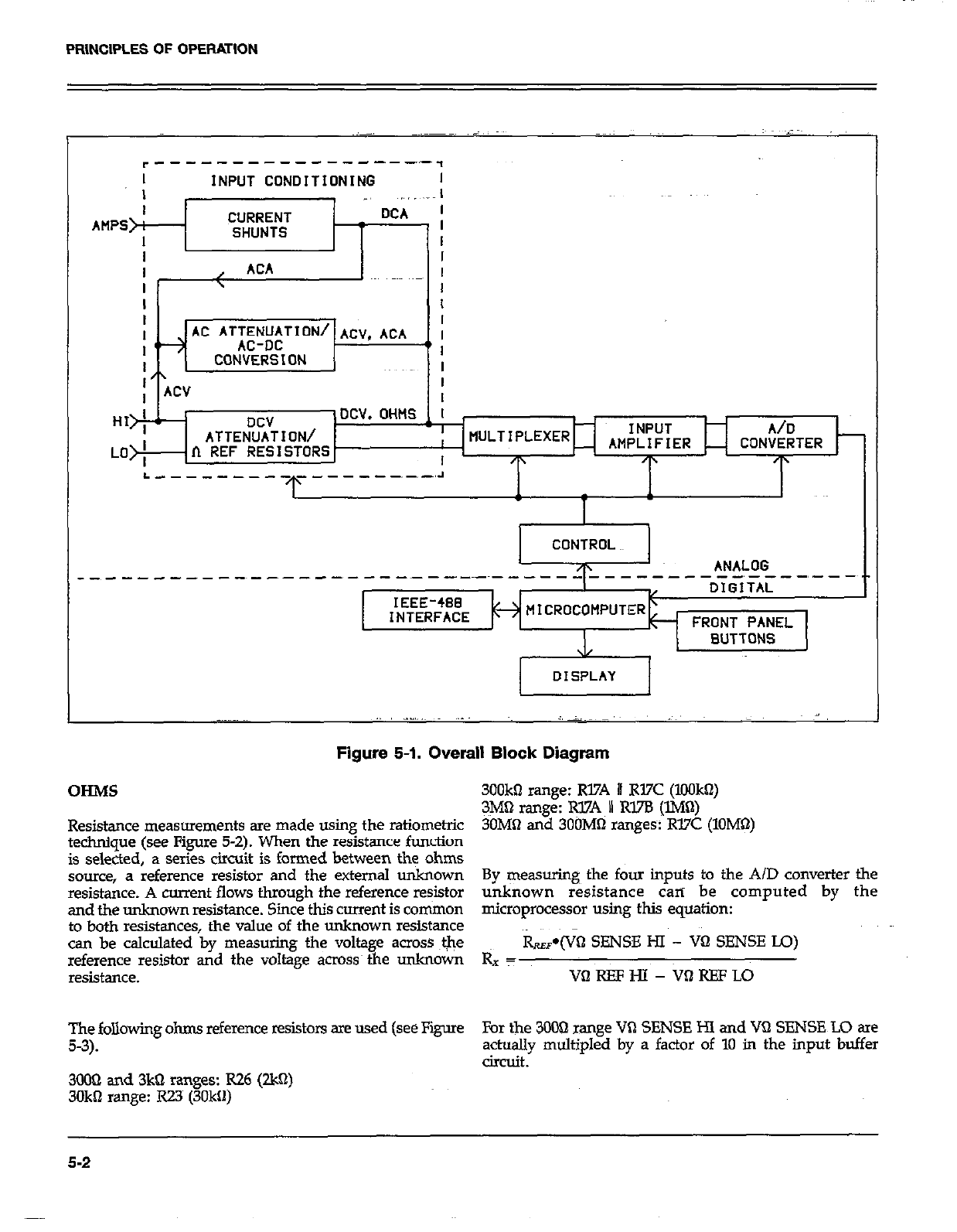
PRINCIPLES OF OPERATION
I INPUT CONOITIONlNG I
DCV
ATTENUATION/
n REF RESISTORS
INPUT A/D
AMPLIFIER CONVERTER
+ /p
ANALOG
.----------~---__-- ---_----,---
DIGITAL
INTERFACE FRONT PANEL
BUTTONS
DISPLAY
Figure 5-l. Overall Block Diagram
OHMS 300kQ range: R17A I R17C (IOOkQ)
3M61 range: @7A II Rl7B (lMQ)
Resistance measurements are made using the ratiometric 30MlI and 3OOMQ ranges R37C (1OMQ)
technique (see Figure 5-Z). When the resistance function
is selected, a series circuit is formed between the ohms
source, a reference resistor and the external unknown By ~easwing the four inputs to the A/D converter the
resistance. A cant flows through the reference resistor unknown resistance can be computed by the
and the unknown resistance. Since this current is common microprocessor using this equation:
to both resistances, the value of the unknown resistance
can be calculated by measuring the voltage across ale i=‘.&(Vtl SENSE HI - VQ SENSE IQ)
reference resistor and the voltage across~the unknown Rx T
resistance. vnREFHl- VlaREFLO
The following ohms reference resistors are used (see Figure For the 3OOQ orange VQ SENSE HI and VQ SENSE LO are
5-3). a&ally multipled by a factor of 10 in the input buffer
circuit.
3OOQ and 3kQ ranges: R26 (2W)
3OkQ range: RZ3~ (3Okfl)
5-2
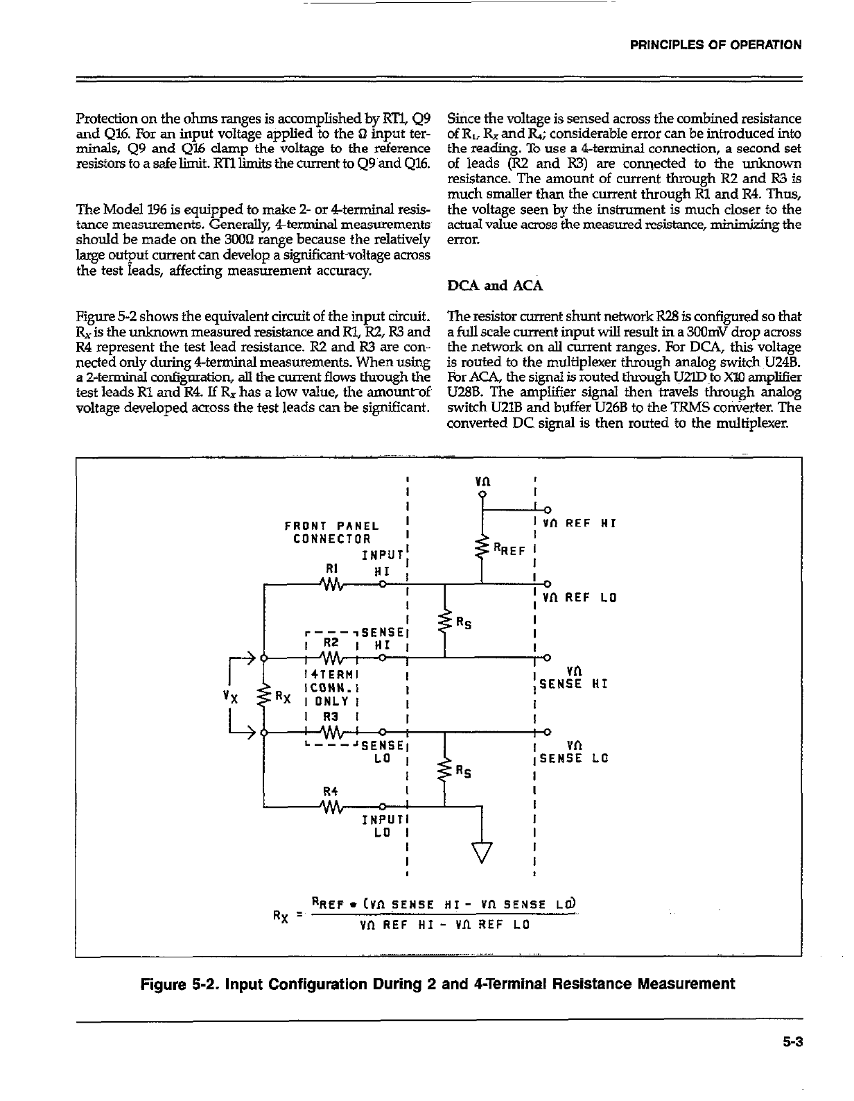
PRINCIPLES OF OPERATION
Protection on the ohms ranges is accomplished by RTl, Q9 Since the voltage is sensed across the combined resistance
and Ql6. For an input voltage applied to the Q input ter- of R,, Rx and Q; considerable error can be introduced into
minals, Q9 and Ql6 clamp the voltage to the reference the reading. To use a 4-terminal connection, a second set
resistors toasafelimit.RTllimitsthecumnttoQ9amdQ16. of leads (R2 and R3) are connected to the unknown
resistance. The amount of current through R2 and R3 is
much smaller than the current through Rl and R4. Thus,
The Model 196 is equipped to make Z- or 4.-terminal resis- the voltage seen by the instrument is much closer to the
tance measurements. Generally 4-terminal measurements actoal value across the measured resistance, minimizing the
should be made on the 3003 range because the relatively error.
large output current can develop a significantvoltage across
the test leads, affecting measurement accuracy. DCA and ACA
Figure 5-2 shows the equivalent circuit of the input circuit. The resistor current shunt network R28 is configured so that
Rx is the unknown measured resistance and Rl, R2, R3 and a full scale current input will result in a 3oOmV drop across
R4 represent the test lead resistance. R2 and R3 are con- the network on all current ranges. For DCA, this voltage
netted only during 4-terminal measurements. When using
a 2-terminal configuration, all the current flows through the is routed to the multiplexer through analog switch U24B.
For ACA, the signal is routed through lJ2m~o Xl0 ampliser
test leads Rl and R4. If Rx has a low value, the amountof~ U28B. The amplifier signal then travels through analog
voltage developed across the test leads can be significant. switch U2lB and buffer U26B to the TRMS ConVerter. The
converted DC signal is then routed to the multiplexer.
FRONT PANEL ; 1 in REF HI
CONNECTOR I
INPUT; RREF l
RI “,’ I I
Jv& I
I
I ; Vn REF LO
I
r----SENSE1 RS I
I
I
I0 vn
iSENSE HI
I
I R3 I I I
ME c i 0
L---JSENSEl vn
LO I iSENSE LO
I Rs I
R4 I I
ALL I I
INPUTI I
LO I I
RX = RREF. cvn TENSE HI - vn SENSE Ed)
vn REF HI - vn REF ~0
Figure 5-2. Input Configuration During 2 and 4-Terminal Resistance Measurement
5-3
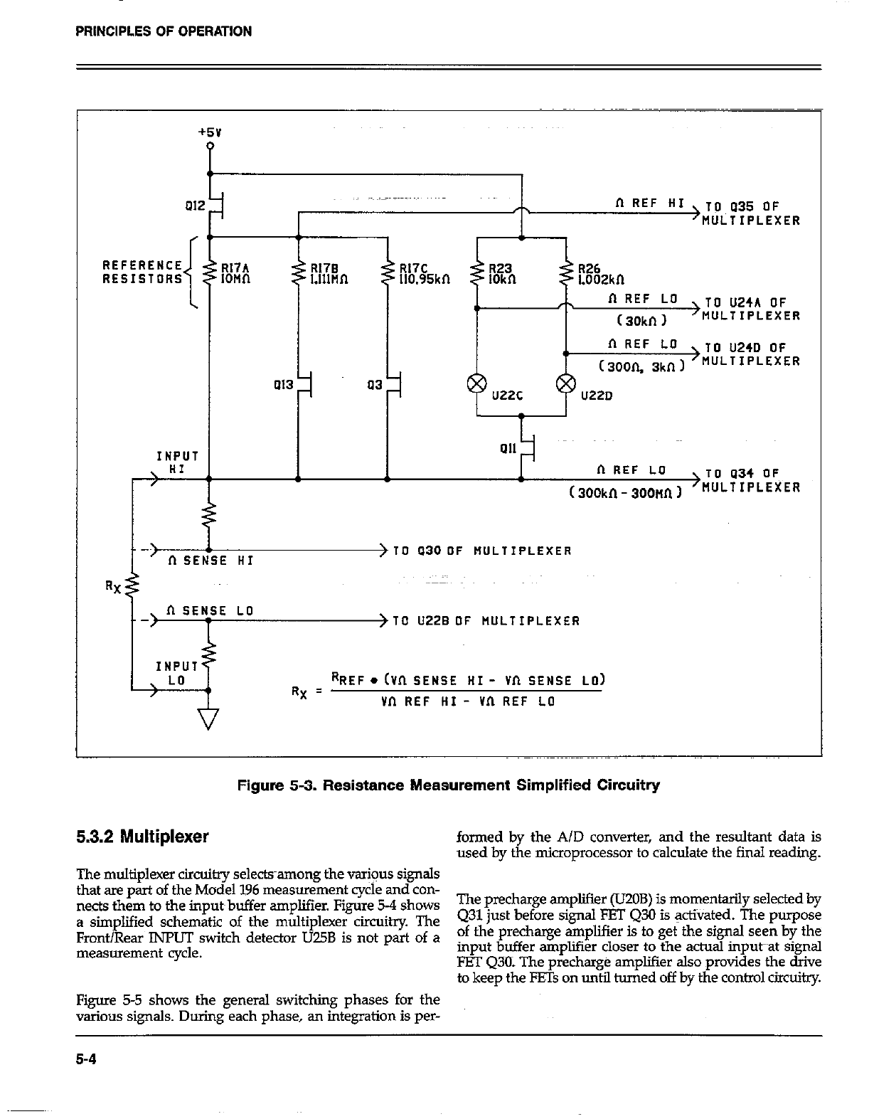
PRINCIPLES OF OPERATION
01;
REFERENCE
RESISTORS
INPUT
n REF HI >V~U35 OF
MULTIPLEXER
R17A R17B R17C
IOMfl R26
Llllnn 110.95kn Loozkn
n REF LO
4) ( 30kn 1
>TO U24A OF
MULTIPLEXER
n REF LO
, TO U240 OF
(3oon. 3kn I >WJ‘TIPLEXER
a13 a3 u220
ai1
n REF LO TO a34 OFT
(300kn - soonn I >wJLTIPLEXER
E HI > TO a30 OF tlULTIPLEXER
RX
\ II SENSE LO
/ >TO U22B OF RULTIPLEXER
INPUT
\ LO
/ RREF. (Vn SENSE HI - Vn SENSE LO)
RX = vn REF HI - vn REF LO
Figure 5-3. Resistance Measurement Simplified Circuitry
5.3.2 Multiplexer formed by the A/D converter, and the resultant data is
used by the microprocessor to calculate the fiial reading.
The multiplexer circuitry selectsamong the var+us signals
that xe part of the Model 196 measurement cycle and con-
nects them to the input~buffer amplifier. Figure 5-4 shows The precharge amplifier (UZOB) is momentarily selected by
a simplified schematic of the multiplexer circuitry The Q31 just before signal FET 430 is activated. The purpose
Front/Rear INPUT switch detector TJ75B is not part of a of the precharge amplifier is to get the signal seen by the
_
measurement cycle. mput buffer amplifier closer to the actual input~~at signal
FET Q30: The precharge ampliier also provides the drive
to keep the FE% on until turned off by the control circuitry.
Figure 5-5 shows the general switching phases for the
various signals. During each phase, an integration is per-
5-4
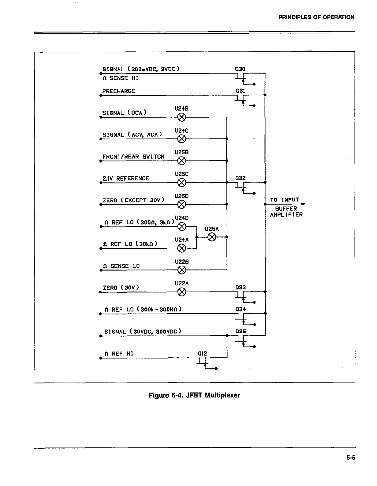
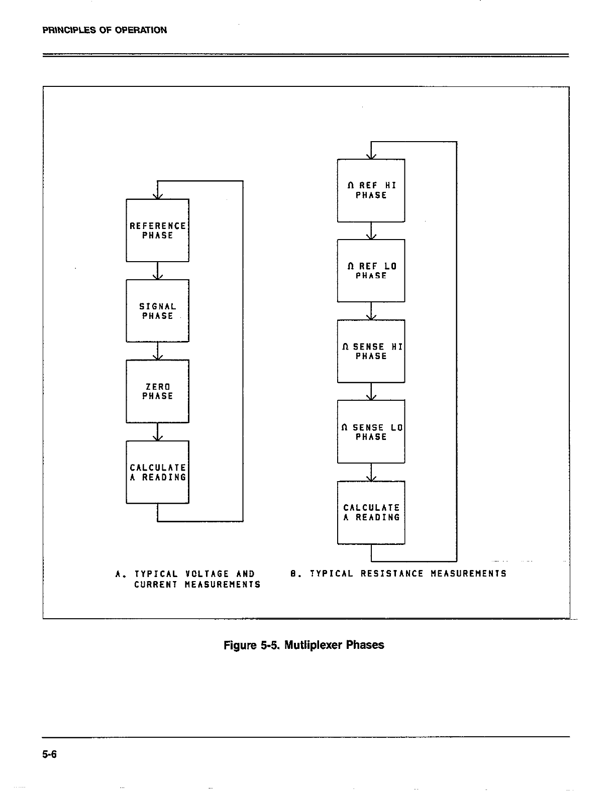
PFilNClPLES OF OPERATION
REFERENCE REFERENCE
PHASE PHASE
L L
SIGNAL SIGNAL
PHASE PHASE
J/ J/
ZERO ZERO
PHASE PHASE
J/ J/
CALCULATE CALCULATE
A READING A READING
II REF HI
PHASE
XL xl/
fT REF LO fT REF LO
PHASE PHASE
.L .L
II SENSE HI II SENSE HI
PHASE PHASE
XL XL
II SENSE LO II SENSE LO
PHASE PHASE
\1 \1
CALCULATE CALCULATE
A READING A READING
A. TYPICAL YDLTAGE AND A. TYPICAL YOLTAGE AND 8. TYPICAL RESISTANCE MEASUREMENTS 8. TYPICAL RESISTANCE MEASUREMENTS
CURRENT HEASUREflENlS CURRENT HEASUREflENlS
Figure 5-5. hlutliplexer Phases
5-6
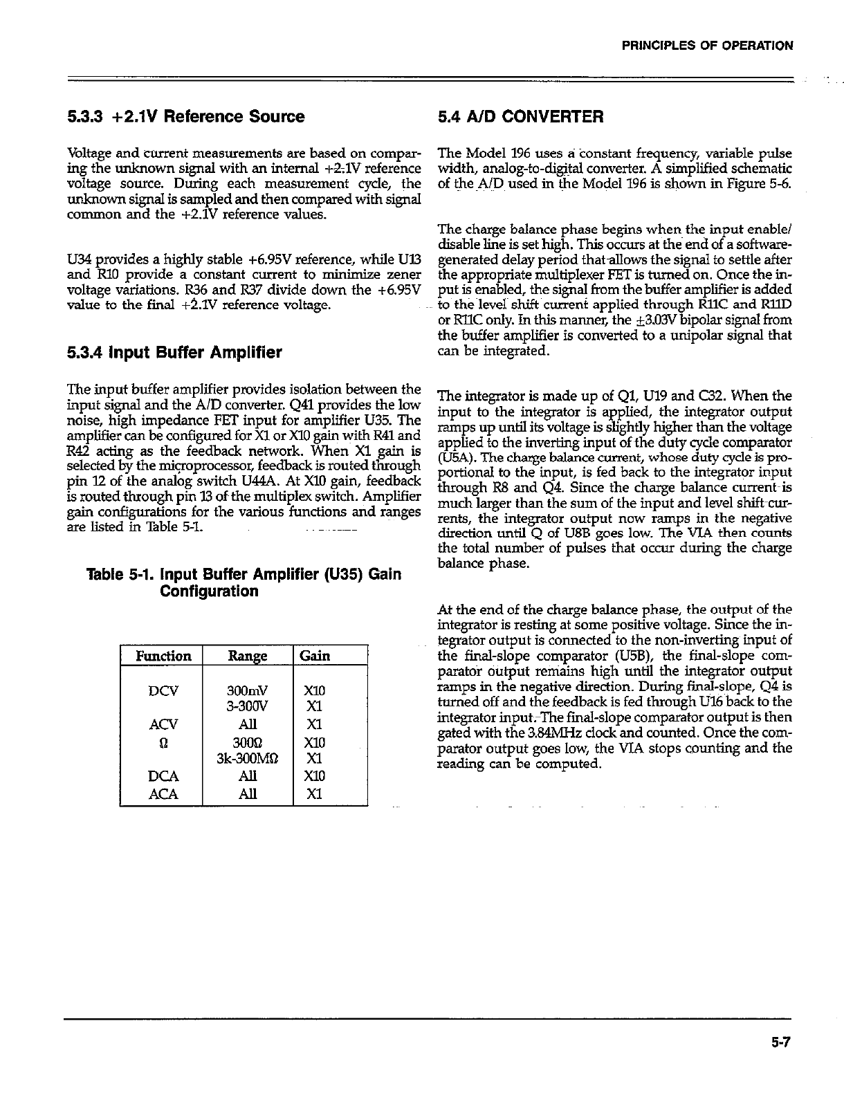
PRINCIPLES OF OPERATION
5.3.3 +2.1V Reference Source 5.4 AID CONVERTER
Voltage and current measurements are based on compar-
ing the unknown signal with an internal +&lV reference
voltage source. During each measurement cycle, the
unknown signal is sampled and then compared with signal
common and the +2.1V reference values.
U34 provides a highly stable +6.95V reference, while Ul3
and RlO provide a constant current to minimize zener
voltage variations. R36 and R37 divide down the +6.95V
value to the final +t.lV reference voltage.
5.3.4 input Buffer Amplifier
The input buf The input buffer amplifier provides isolation between the
input signal ana tne x/u converter. u41 pro\ input signal and the A/D converter. 441 provides the low The integrator is made up of Ql, Ul9 and C32. When the
noise, high impedance FET input for amplif noise, high impedance FET input for amplifier U35. The input to the integrator is applied, the integrator output
amplifier can be configured for Xl or X10 gain amplifier can be configured for Xl or X10 gain with R41 and ramps up until its voltage is slightly higher than the voltage
R42 acting as the feedback network. Whel R42 acting as the feedback network. When Xl gain is applied to the inverting input of ~the duty cycle comparator
selected by the mipprocessor, feedback is 101 selected by the mipprocessor, feedback is routed through (U5A). The charge balance current, whose duty cycle is pro-~
pin 12 of the analog switch U44A. At Xl0 ga pin 12 of the analog switch U44A. At Xl0 gain, feedback portional to the input, is fed back to the integrator input
is routed through pin I3 of~the multiplex switc is routed through pin I3 of~the multiplex switch. Amplifier through R8 and Q4. Since the charge balance current-is
gain configurations for the various function gain configurations for the various functions tid ranges much larger than the sum of the input and level shift-cur-
are listed in Table 5-l. are listed in Table 5-l. rents, the integrator output now ramps in the negative
direction until 0 of LJ8B eoes low. The VJA then counts
The Model 196 uses a tionstant~ frequency, variable pulse
width, analog-to-dig@ converter. A simplified schematic
of t~he ~A@ used in &he Model 196 is shown in Figure 5-6.
The charge balance phase begins when~ the input enable/
disable line is set high. This occurs at the end of a software-
generated delay period thatallows the signal to settle after
the appropriate multiplexer FET is turned on. Once the in-
put + Fabled, the sign+ from the buffer amplifier is added
to the level shift current applied through RllC and RllD
or RllC only. In this manner, the i3.03V bipolar signal from
the buffer amplifier is converted to a unipolar signal that
can be integrated.
the total numb& of oul& that occur during the charze
Table 5-1. Input Buffer Amplifier (U35) Gain balance phase. *
Range
3oomv
3-300V
All
3k-E&*
All
All
;ain
==I
At the end of the charge balance phase, the output of the
integrator is resting at some positive voltage. Since the in-
tegrator output is connected to the non-inverting~ input of
the final-slope comparator (U5B), the final-slope corn-
par&o+ output remains high until the integrator output
ramps in the negative direction. During fin@-slope, Q4 is
huned off and the feedback is fed through U16 back to the
integrator input;The fmal-slope comparator output is then
gated with the 3.84MH.z clock and counted. Once the com-
parator output goes low, the VJA stops counting and the
reading can be computed.
5-7
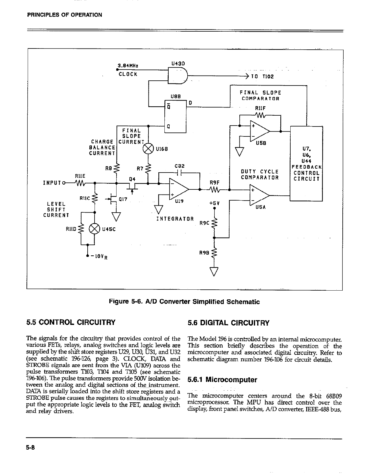
PRINCIPLES OF OPERATION
., ..,
3.84NHz U43D
CLOCK > IO 1102
lJ88 FINAL SLOPE
-0 COMPARATOR
-ii RllF
CURRENT U7.
W
us4
FEEDBACK
DUTY CYCLE CONTROL
COMPARATOR CIRCUIT
Figure 5-6. AID Converter Simplified Schematic
5.5 CONTROL CIRCUITRY 5.6 DIGITAL CIRCUITRY
The signals for the circuitry that provides control of the
” arious FETs, relays, analog switches and logic levels are
supplied by the shift store registers U.29, U30, U31, and U32
(see schematic 196-126, page 3). CLOCK, DATA and
!ZROBE signals are sent from the VIA (U109) across the
pulse transformers T103, T104 and TlO5 (see ~schematic
196-106). The pulse transformers provide 5OOV isolation be-
tween the analog and dig&J sqtions of~tlw~nstrument.
DKIYA is serially loaded into the shift store registers and a
STROBE pulse causes the registers to simultaneously~~ut-
put the appropriate logic levels to the FET, analog switch
and relay drivers.
The Model 196 is controlled by an internal microcomputer.
This section briefly desoibes the operation of the
microcomputer and associated digital circuitry. Refer to
schematic diagram number 196-106 ftir circuit details.
5.6.1 Microcomputer
The microcomputer centers around the 8-bit 68809
microprocessor. The MPU has direct control over the
display, front panel switches, AID converter, IEEE488 bus,
5-8
PRINCIPLES OF OPERATION
as welI as the VOLTMETER COMPLETE Output and the
FXTERNAL TRIGGER Input. Timing for the micro-
processor is accomplished by the use of X01; an SMH!z
crystal. Internally, this frequency is divided~ down by four
to obtain a bus operating frequency ofZMHz.
Instrument operation software is stored in EPROMs U105
and U106. The revision level of this software is displayed
by Program 0 (Menu). Calibration constants, Translator
words and instrument set up conditions ati ~stti*d in
E*I’ROM (UlO8). Ul!l7 is the RAM. Partial address decoding
is use~d in this system. The function selected is d&en-n%
ed by the state of All, Al2, Al?, Al4 and Al5 address lines.
These address lines determine which is selected by the
decoders (U101). Only one device WOM, RAM, VIA, etc)
will have access to the data bus at any one time.
The heart of the IEEE-488 circuiixy is the GPIBA (Ull2). The
GPIBA is capable of performing aII IEEE talker-listener pro-
tocols. The bidirectional data lies DON through D7 permit
the transfer of data between the microprocessor and the
GPISA. The transceivers Ull3 and Ull4 are used to drive
the output. Data is buffered by Ull3 and U114 and iS
transmitted to the bus via connector Jl5.
5.6.2 Display Circuitry
The display information is sent through display latches UllO
and Ulll. Upon each display update, new segment~infor-
mation is presented to the display latches and a clock pulse
is sent on l”. The clock pulse to U4 and U5 (see schematic
196-116) shifts a digit enable bit to the next digit to be
enabled. Every 10 times the display is updated, a digit
enable it is generated at PA1 and goes to the data input of
the shift register. Ul28 through Ul.31 are the drivers for the
LED segments of the display digits tid the LED indicators.
5.7 POWER SUPPLIES
The main power supplies of the Model 196 are located on
sheet 1 of 2 of schematic drawing number 196-106. Fuse FlOl
is the line fuse which is accessible from the rear panel. 5102
is the POWER ON/OFF switch and SlOl selects ll5V or
230V operation by placing the transformer primary wind-
ings in parallel or series. The power transformer, TlOl, has
three secondary windings; one for the +5V digital supply,
one for the +5V analog supply and one for the kl5V analog
supply. CRlOl, CR102 and CR103 provide fullwave rectifica-
tion for the three supplies, while VRlOl through VR104 pro-
vide the regulation.
5-9/5-10
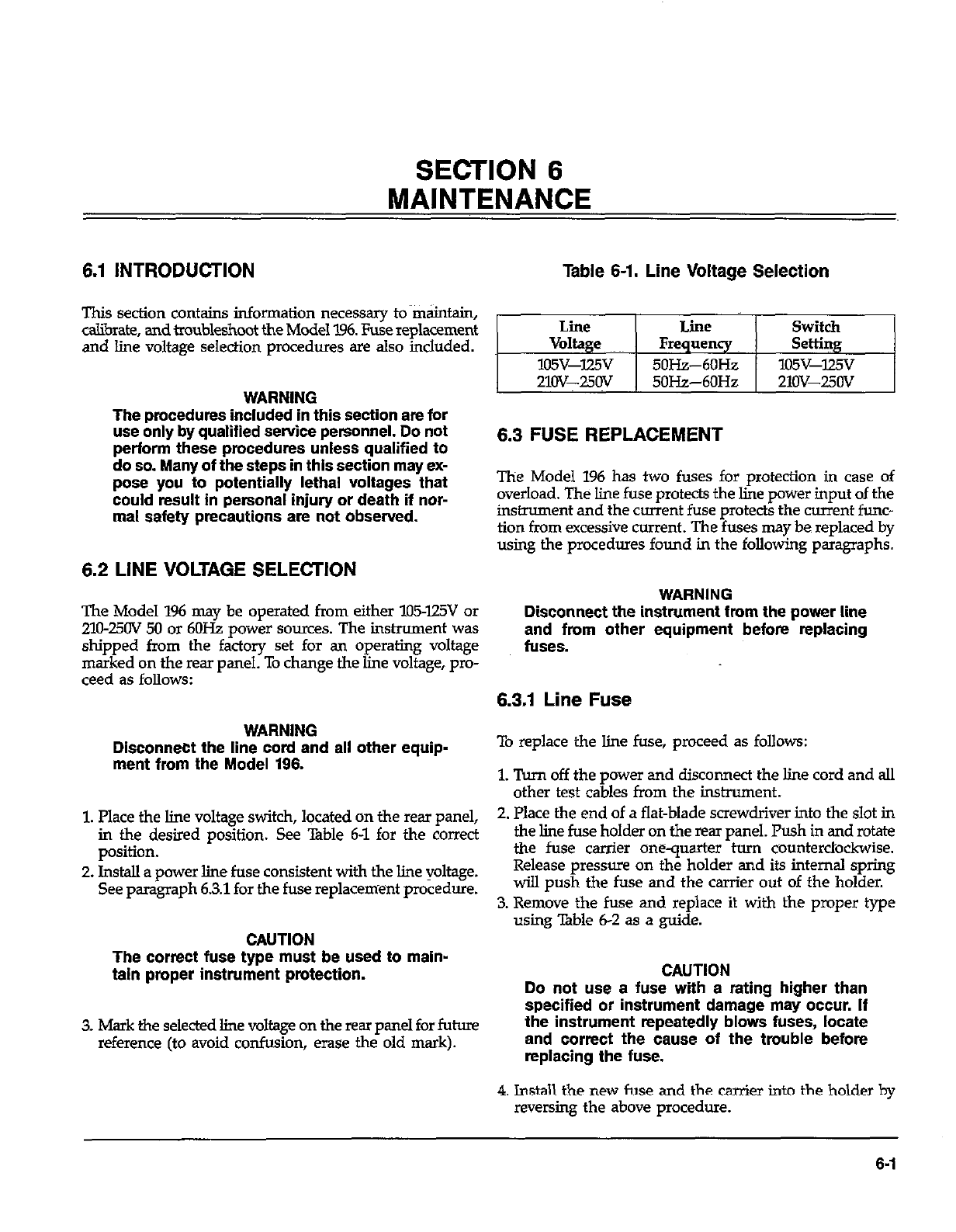
SECTION 6
MAINTENANCE
6.1 INTRODUCTION Table 6-1. Line Voltage Selection
This section contains information necessary to maintain,
calibrate, and troubleshoot the Model 196. Fuse replacement
and line voltage selection procedures are also included.
WARNING
The procedures included in this section are for
use onlv bv aualiffed service oersonnel. Do not
perform the& procedures unless qualified to
do so. Many of the steps in this section may ex-
pose you to potentially lethal voltages that
could result in personal injury or death if nor-
mal safety precautions are not observed.
6.2 LINE VOLTAGE SELECTION
The Model 196 may be operated from either lll5-l25V or
210~25OV 50 or 6OHz power sources. The instrument was
shipped from the factory set for an operating voltage
marked on the rear panel. To change the line voltage, pro-
ceed as follows:
WARNING
Disconnect the line cord and all other equip-
ment from the Model 196.
1. Place the line voltage switch, located on the rear panel,
in the desired position. See Table 6-l for the correct
position.
2. Install a power line fuse consistent with the line voltage.
See paragraph 6.3.1 for the fuse replacement procedure.
CAUTION
The correct fuse type must be used to main-
taln proper instrument protection.
3. Mark the selected line voltage on the rear panel for future
reference (to avoid confusion, erase the old mark).
Line Line Switch
Voltage Frequency Setting
105v-lzv 5OHz--6OHz lO5v-lz5v
21Ov-25Ov 50Hz-6OHz 21ov-25Ov
6.3 FUSE REPLACEMENT
The Model 196 has two fuses for protection in case of
overload. The line fuse protects the line power input of the
instrument and the current fuse protects the current func-
tion from excessive current. The fuses may be replaced by
using the procedures found in the following paragraphs.
WARNING
Disconnect the instrument fmm the power line
and from other equipment before replacing
fuses.
6.3.1 Line Fuse
To replace the line fuse, proceed as follows:
1. Turn off the power and disconnect the line cord and all
other test cables from the instrument.
2. Place the end of a flat-blade screwdriver into the slot in
the line fuse holder on the rear panel. Push in and rotate
the fuse carrier onequarter turn counterclockwise.
Release pressure on the holder and its internal spring
will push the fuse and the carrier out of the holder.
3. Remove the fuse and replace it with the proper type
using Table 6-2 as a guide.
CAUTION
Do not use a fuse with a rating higher than
specified or instrument damage may occur. If
the instrument repeatedly blows fuses, locate
and correct the cause of the trouble before
replacfng the fuse.
4. Install the new fuse and the carrier into the holder by
reversing the above procedure.
6-l
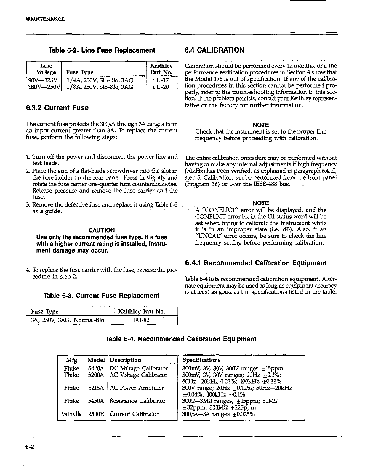
MAINTENANCE
Table 6-2. Line Fuse Replacement 6.4 CALIBRATION
I Line I I Keithlev
Voltage 1 Fuse %e ~~~~~ I p=cY6
9OV-125V 1/4A, 25OV, Slo-Blo, 3AG Fu-I7
18OV-250V 1 /SA. 250V. Slo-Blo. 3AG m-20
6.3.2 Current Fuse
Calibration should be performed every 12 months, or if the
performance verification procedures in Section 4 show that
the Model 196 is out of specification. If any of the calibra-
tion procedures in this section cannot be performed pro-
perly, refer to the troubleshooting information in this sec-
tion. If the problem persists, contact your Keithley represen-
tative or the factory for further informatxon.
The current fuse protects the 3CQA through 3A ranges from NOTE
an input current greater than 3A. To replace the current
fuse, perform the following steps: Check that the instrument is set to the proper line
frequency before proceeding with calibration.
1. Tuin off the power and disconnect the power line and
test leads. ~~ entjre &brafion procedure may be performed without
having to make any internal adjustments if high frequency
2. Place the end of a flat-blade screwdriver into the slot in
the fuse holder on the rear panel. Press in slightly and (701612) has been verified, as explained in paragraph 6.4.10,
step 5. Calibration can be performed from the front panel
rotate the fuse carrier onequarter turn counterclockwise. (Program 36) or over the IEEE-488 bus.
Release pressure and remove the fuse carrier and the
fuse.
3. Remove the defective fuse and replace it~using Table 6-3
as a guide.
CAUTION
Use only the recommended fuse type. If a fuse
with s higher current rating is installed, instru-
ment damage may occur.
NOTE
A ~“CONFLICT” error will be displayed, and the
CONFLfCT error bit in <he Ul status word will be
set when trying to calibrate the instrument while
it is in an improper state (i.e. dB). Also, ifan
“UNCAK’ error occurs, be sure to check the line
frequency setting before performing calibration.
6.4.1 Recommended Calibration Equipment
4. To replace the fuse carrier with the fuse, reverse the pro-
cedure in step 2. Table 6-4 lists recommended calibration equipment. Alter-
nate equipment may be used as long as eqGp&ent accurxy
Table 6-3. Current Fuse Replacement is at least as good as the specifications listed in the table.
Fuse Type / Keithley Part No.
3A, 25OV, 3AG,~Normal-Blo / Fu-82
M
=I
Fluke
Fluke
Table 6-4. Recommended Calibration Equipment
Description
DC Voltage Calibrator -’
AC Voltage Calibrator
AC Power Amplifier
Current Calibrator
.,. ,~ ,~ ~, ._I~~ ~,,
Specification9
3Oomv, 3v, 3w, 3oov ranges *l5ppm
3oomv, 3v, 3ov ranges; 20% *0.10/o;
50&-2Old-h 0.02%; lO4lkHz -10.33%
300V range; 2OHz fO.l2%; 5OH.z-2OkHz
*0.049/o; lookHz fO.l%
3OOiL3MO ranges; fl5ppm; 30MQ
k32ppm; 3OOMfi +225ppm
3OOfi-3A ranges *0.025%
6-2
6.4.2 Environmental Conditions
Calibration should be performed under laboratory condi-
tions having an ambient temperature of 23°C +YC and a
relative humidity of less than 70%.
6.4.3 Warm-Up Period
Turn on the instrument power and allow it to warm up for
at least two hours before beginning the calibration pro-
cedure. If the instrument has been subjected to extremes
of ttimperahue or humidity, allow at least one additional
hour for the instrument to stabilize before beginning the
calibration procedure.
6.4.4 CAL ENABLE Switch
A switch, accessible from the front panel, disables or
enables front panel and IEEE-488 bus calibration. When the
switch is in the DISABLE position, calibration cannot be
performed. The following message will be briefly displayed
when attempting to enter the caliiration program while the
switch is disabled:
CAL LOCKED
Calibration can only be accomplished with the calibration
switch in the ENABLE position.
The switch operates in the same manner as the power
switch and is accessed from the front panel with a small
bladed screwdriver. In the “out” positioti, klibration is
disabled and in the “in” position, calibration is enabled.
6.4.5 Front Panel Calibration
The following information provides the basic procedure for
calibrating the instrument from the fro&panel. A detailed
calibration procedure is located in paragraph 6.4.7.
1. Place the calibration switch to the ENABLE position
to enable calibration. The switch is accessed from the
front panel of the instrument.
2. Select the function and range to be calibrated (DCV,
Am, 61, DC4 or ACA).
3. Select the front panel calibration program as follows:
A. lkss the PRGM button. The following message will
be displayed:
PROGRAM ?
B. Enter Program 36 by pressing the 3 and 6 buttons.
The following message will be displayed briefly:
CAL=
C. The defaukcalibration point, which is a high end
reading for the selected range and function, will now
be displayed. Pororpxample, if the 3V DC range was
selected in step 2, the following calibration point will
be displayed:
3.oooow VW
4. If a different calibration point is to be used, enter the
new value using the data buttons (0 through 9). Each
press of a data button displays the number at the cur-
sor location (identified by the bright flashing digit), and
moves the -or to the n&digit. Jf the cursor is moved
past the least significant-digit, it-will move back to the
most~sigtiicant digit.
5. Comieti the calibration signal to the instrument.
6. Preis the ENTER button. The following message will
be displayed for several seconds:
WORKING
Z The low end calibration point will now be displayed.
For the 3VDC range, the following calibration point will
be displayed:
0.000000 VDC
Note: Calibration can be aborted with either the first
or second calibration point~prompt displayed by press-
ing the PRGM button. The instrument will leave the
calibration program without changing the previous
calibration constants.
8. If a calibration point other than the one displayed is toes
be used, then change the display to the desired value
as explained in step 4.
9. Set the level of the caliiration signal to agree with the
displayed calibration point;~
10. Press the ENTER button. The following message will
be displayed for several seconds:
WORKING
11. The two calibration points will be stored in EYROM and
the instrument will now exit the &i&ration program.
Select the next range and fundion to be calibrated and
repeat steps 3 through 10.
NOTEz If the calibration sources has a~ offset; Set the
calibration points to agree with the actual output of the
source. For example, if the source has a l$I DC offset
on the 300mV DC range, set the calibration points for
3CO.OOlOmV and 000.0010mV.
6-3
6.4.6 IEEE-468 Bus Calibration
IEEE-488 bus calibration is performed in a manner similar
to front panel calibration, except that calibration constants
are transmitted over the bus instead of being entered from
the front panel. By combining appropriate IEEE-488 com-
patible caliiation equipment with a suitable test program,
calibration of the Model 196 could be performed on an
automated basis. Refer to Section 3 for complete informa-
tion on using the IEEE-488 bus. The following information
provides the basic procedure for calibrating the ins-ent
over the IEEE-488 bus. The detailed calibration procedure
starts with paragraph 68.7.
Use the following basic procedure when calibrating the
Model 196 over the IEEE488 bus:
1. Place the csliiration switch to the ENABLE position. The
switch is accessed from the front panel of the Model 196.
2. Program the desired range and function over the bus.
For example, to select the 3OOV DC range, send FOR4X.~
3. The high end of the range is calibrated first. Apply a full
range (or near full range) calibration signal to the input
of the instnnnent. For example, for the 3oOV DC range,
apply 3OOV DC to the instrument.
4. Send the required calibration value preceded by the V
command letter and followed by the CO calibration com-
mand. For example to calibrate the 3OOV DC range at the
300V calibration point, send V3OOXCOX. ~~~~
NOTE: Calibration can be aborted at this time by sen-
ding an SDC or DCL comman d over the bti.~TheC&bra-
tion constant sent in step 4 will not be stored in E’PROM.
5. The low end of the range is calibrated next, Apply a zero
(or near zero) csliiration signal to the input of the in-
strument; For example, for the 3OOV DC range apply OV
to the instrument.
6. Send the appropriate calibration cornman ds for the sec-
ond calibration point. For example, to calibrate the zero
calibration point of the 3OOV DC range send VOXUX.
Note that Cl is used for the second calibration point.
7. Storage of the two calibration points into E%‘RqM
automatically occurs when the second calibration com-
mand is sent.
8. Repeat steps 1-7 for the remaining ranges and functions.
HP-85 Progr amming Example-The following simple pro-
gram demonstrates how to calibrate the Model I.96 over the
bus. The program assumes that the instruments primary
address is ate Z
PROGRAM COMMENTS
10 REMIX&7~07
20FOR I=OTOi
30 MSF ’ ’ RPPLY CAL1
BRkTION SIGML 9
46DISF”ENTERCALI
ERATIDN
COMMAND3 ’
50 INPUT A9
60OUTPUT707;A$
70ENTER70iiBB
SODISPB5
90 NEXT~I
100 EMD
Send remote enable.
Set program for one loop.
Prompts for calibration
signal.
Prompt for command.
Input command string from
keyboard.
Send command string to
7.96.
Get a reading.
Display reading.
Loop back one time.
‘lb run the program, press the HP-85 RUN key. At~the first
set of prompts, apply a fuJl range (or near full range) caliira-
tion signal to the instrument, type in the corresponding
calibration co mmand and press the return key. The com-
puter CRT will then display the calibration value. At the
second set of prompts, apply a zero (or near zero) caliir-
tion signal tc-~the~ inshu~~nt, type in the corresponding
calibration command and press the return key. The com-
puter will display the calibration value and store both
calibration constants into EY’ROM.
6.4.7 Calibration Sequence
C&irate the Model 196 in the order presented in the
following paragraphs. The basic sequence is:
1. DC Volts calibration
2. Ohms calibration
3. AC Volts calibration
4. DC Current calibration
5. AC Corrent~calibration
6-4
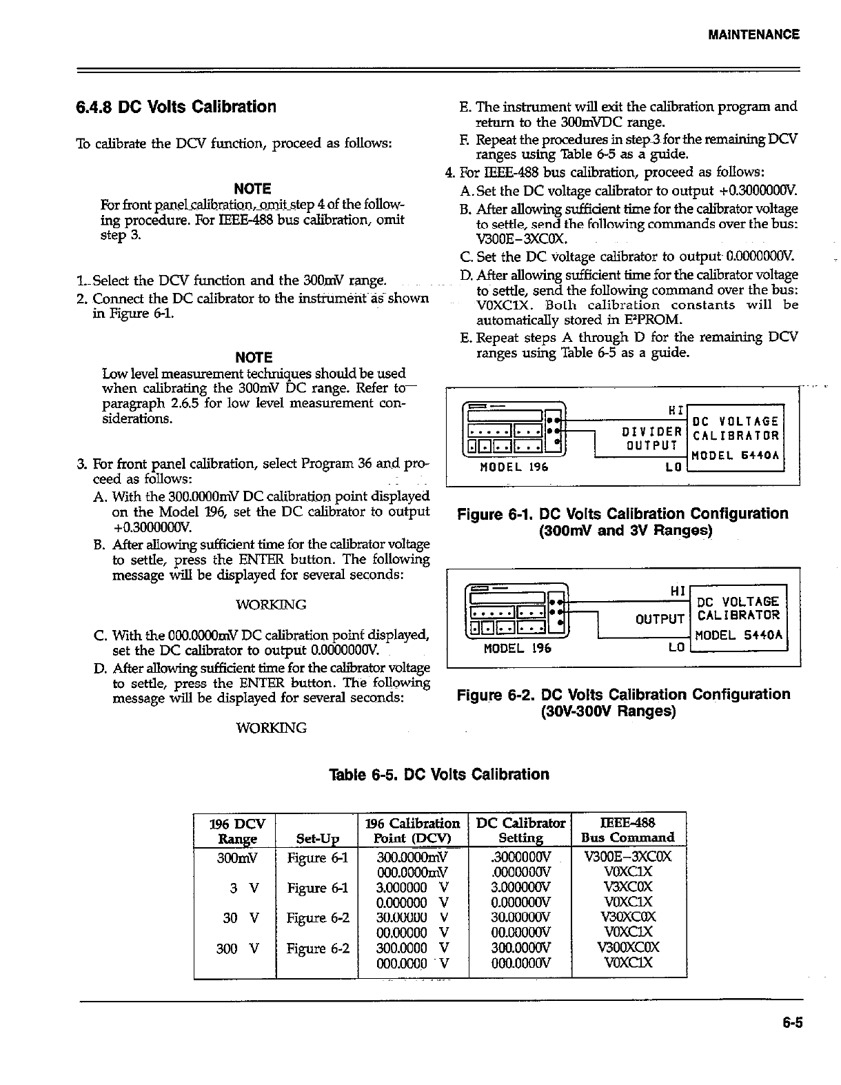
6.4.8 DC Volts Calibration
To calibrate the DCV function, proceed as follows:
NOTE
For front panelcalibration,omitstep 4 of the follow-
ing procedure. For IEH3-488 bus calibration, omit
step 3.
l.Select the DCV function and the 3OOmV range.
2. Connect the DC calibrator to the instrument as shown
in Figure 6-l.
NOTE NOTE
Low level measurement techniques should be used Low level measurement techniques should be used
when calibrating the 3OOmV DC range. Refer to- when calibrating the 3OOmV DC range. Refer to-
paragraph 2.6.5 for low level measurement con- paragraph 2.6.5 for low level measurement con-
siderations. siderations.
3. For front panel calibration, select Program 36 and pro-
ceed as follows:
A. With the 3OO.OOOOmV DC calibration point displayed
on the Model 196, set the DC calibrator to output
+0.30000oov.
B. After allowing sufficient time for the calibrator voltage
to settle, press the ENTER button. The following
message will be displayed for several seconds:
WORKING
C. With the OONlOOOmV DC calibration poinf displayed,
set the DC caliiator to output O.OOOOOOOV.
E. The instrument will exit the calibration progrsm and
return to the 3OOmWC range.
E Repeat the procedures in step~3 for the remaining DCV
ranges using Table 6-5 as a guide.
4. For IEEE488 bus calibration, proceed as follows:
A.Set the DC voltage calibrator to output +030000OOV.
B. After allowing sufficient time for the caliirator voltage
to settle, send the following commands over the bus:
V300E-3XCOX.
C. Set the DC voltage calibrator to outputs O.OOOOOOOV.
D. After allowing sufficient time for the calibrator voltage
to~settle, send the following comman d over the bus:
VOXClX. Both calibration constants will be
automatically stored in EzPROM.
E. Repeat steps A through D for the remaining DCV
ranges using Table 6-5 as a guide.
Figure 6-1. DC Volts Calibration Configuration
(300mV and 3V Ranges)
D. After allowing sufficient time-for the caliirator voltage 1
to settle, press the ENTER button. The following
message will be displayed for several seconds: Figure 6-2. DC Volts Calibration Configuration
(3OW3OOV Ranges)
WORKING
Table 6-5. DC Volts Calibration
Set-Up
Figure 6-l
Figure 6-l
Figure 6-2
Figure 6-2
IEEE&8
Bus Command
VJBOE-3XCOX
voxclx
v3xcox
voxclx
V3OXCOX
voxclx
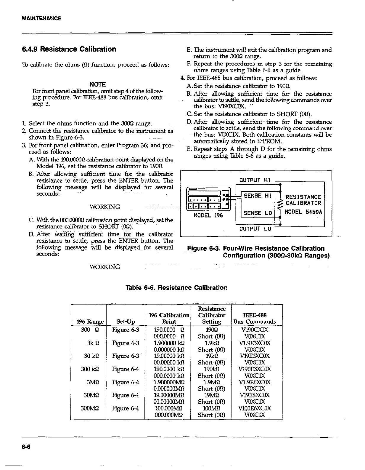
6.4.9 Resistance Calibration E. The instrument will exit the calibration program and
return to the 30061 range.
To calibrate the ohms (Q) function, proceed as follows: F. Repeat the procedures in step 3 for the remaining
ohms ranges using Table 6-6 as a guide.
NOTE
For front panel calibration, omit step 4 of the follow-
ing procedure. For IEEE-488 bus calibration, omits
step 3.
4. For IEEE-488bus calibration, proceed& follows:
A. Set the resistance calibrator to 19Ohl.
B. After allowing sufficient time for the resistance
calibrator to settle, send the following commands over
the bus: Vl9OXCOX.
C. Set the resistance calibrator to SHORT (00).
1. Select the ohms function and the 300Q range.
2. Connect the resistance calibrator to the instrument as
shown in Figure 6-3.
3. For front panel calibration, enter Program 36; and pro-
teed as follows:
A. With the 190.00003 calibration uoint disulaved on the
D. After sIlowing sufficienttthne for the resistance
caliirator to settle, send the following command over tle, send the following command over
the bus: VOXClX. Both calibration constants will be
X. Both calibration constants will be
~lautomatically stored in ElPROM. tored in ElPROM.
E. Repeat steps A through D for the remaining ohms through D for the remaining ohms
ranges using Table 6-6 as a guide. able 6-6 as a guide.
Model 196, set the resistancecalibrato~ to 1900.
B. After allowing sufficient uptime for the c&&or
resistance to settle, press the ENTER button. The
following message will be displayed for several
seconds: RESISTANCE
WORKING CALIBRATOR
tlODEL 5450A
C with the OCQoooOR calibration point displayed, set the
resistance calibrator to SHORT (On). I
D. After waiting sufficient time for the calibrators
resistance to settle, press the ENTER button. The
following message will be displayed for several Figure 6-3. Four-Wire Resistance Calibration
Configuration (300&30kQ Ranges)
WORKING
396 Rang< Set-Up
300 n Figure 6-3
3k B Figure 63
30 kll Figure 6-3
300 kB Figure 63
3M1-2 Figure 6-4
3OMhl Figure 6-4
3OOMQ Figure 6-4
Table 6-6. Resistance Calibration
196 ~calibratiot
Point
190.0000 n
000.0000 n
1.900000 k0
O.OCGLXIO khl
l%OOoOO kS
00.00000 kB
l9O.OOL?4 kQ
000.0000 kO
1.9ilOCOOMR
O.OOOBOOMS
19.oOOOOM~
OO.OOOCOMD
lOO.OOOM62
OOO.OOOMO
1 Resistance
Calibrator
Setting
19OQ
Short (OS)
1.9kB
Short (OR)
19kbl
Short (On)
19OkS
Short (OR)
1.9MQ
Short (Obt)
19MB
Short (On)
100MR
Short (OS)
IEEE-488
Ius Commands
vl9oCxox
voxclx
v1.9E3xcox
voxclx
v19E3xcOx
VOXClX
Vl90E3XCOX
voxclx
Vl.9E6XCOX
voxclx
Vl9E6XCOX
voxclx
Vlo0E6XCOx
voxclx
6-6
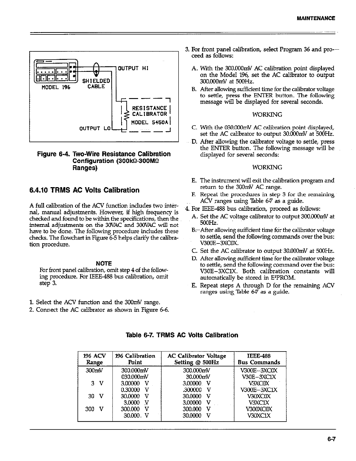
MAINTENANCE
OUTPUT
MODEL 196 CABLE
HI
Ik---7
OUTPUT LO ---
Figure 6-4. Two-Wire Resistance Calibration
Configuration (300kS300Mhl
Ranges)
3. For front panel calibration, select Program 36 and pro---
teed as follows:
A. With the 3OO.OOOmV AC calibration point displayed
on the Model 196,~ set the AC calibrator to output
3OO.Ouomv at 5ooHz.
B. After allowing sufikient time for the caliiator voltage
to settle, press the ENTER button. The following
message will be displayed for several seconds.
WORKING
C. With the 03O.OOOmV AC calibration point displayed,
set the AC calibrator to output 3O.OOOmV at 5OOHz.
ED. After allowing the calibrator voltage to settle, press
the ENTER button. The following message will be
displayed for several seconds:
WORKING
A full caliiration of the ACV function includes two inter-
nal, manual adjustments. However, if high frequency is
checked and found tobe within the specifications, then the
internal adjustments on the 30VAC and 3GOVAC will not
have to be done. The following procedure includes these
checks. The flowchart in Figure 6-5 helps clarify the calibra-
tion procedure.
E. The instrument will exit the calibration program and
return to the 3GOmV AC range.
F. Repeat the procedures in step 3 for the remaining
ACV ranges using Table 6-7 as a guide.
~4. For IEEE-488 bus calibration, proceed as follows:
A. Set the AC voltage calibrator to output 3OG.OGQmV at
5ooHz.
6.4.10 TRMS AC Volts Calibration
NOTE
For front panel calibration, omit step 4 of the follow-
ing procedure. For IEEE-488 bus calibration, omit
step 3.
BrAfter allowing sufficient time for the calibrator voltage
to settle, send the following commands over the bus:
V3OOE-3XCOX.
C. Set the AC calibrator to outputs 3O.OOOmV at 5OOHz.
D. After allowing sufficient time for the calibrator voltage
to settle, send the following command over the bus:
V30E-3XClX. Both calibration constants will
automatically be stored in FPROM.
E. Repeat steps A through D for the remaining ACV
ranges using~ Table 6-7 as a guide.
1. Select the ACV function and the 300mV range.
2. Connect the AC calibrator as shown in Figure 6-6.
Table 6-7. TRMS AC Volts Calibration
l96 ACV I996 Calibration AC Calibrator Voltage
Range Point Setting @ 5ooHz
3GGmV 3GO.OOOmV 3GG.OWmV
03O.OoOmV 3o.oOOmv
3 v 3.00000 v 3.OOWO~ v
0.30000 v .3ocaoo v
30 v 30.0000 v 30.0000 v
3.0000 v
I
?iooooo v
300 v 300.000 V 300.000 v
30.000m v 30.0000 v
IEEE-488
Bus Commands
VJOOE-3XCOX
V3OE-3XClX
v3xcGx
KKK&3XClX
v3GxcGx
v3xclX
v3oGxcGx
v3oxclx
6-7
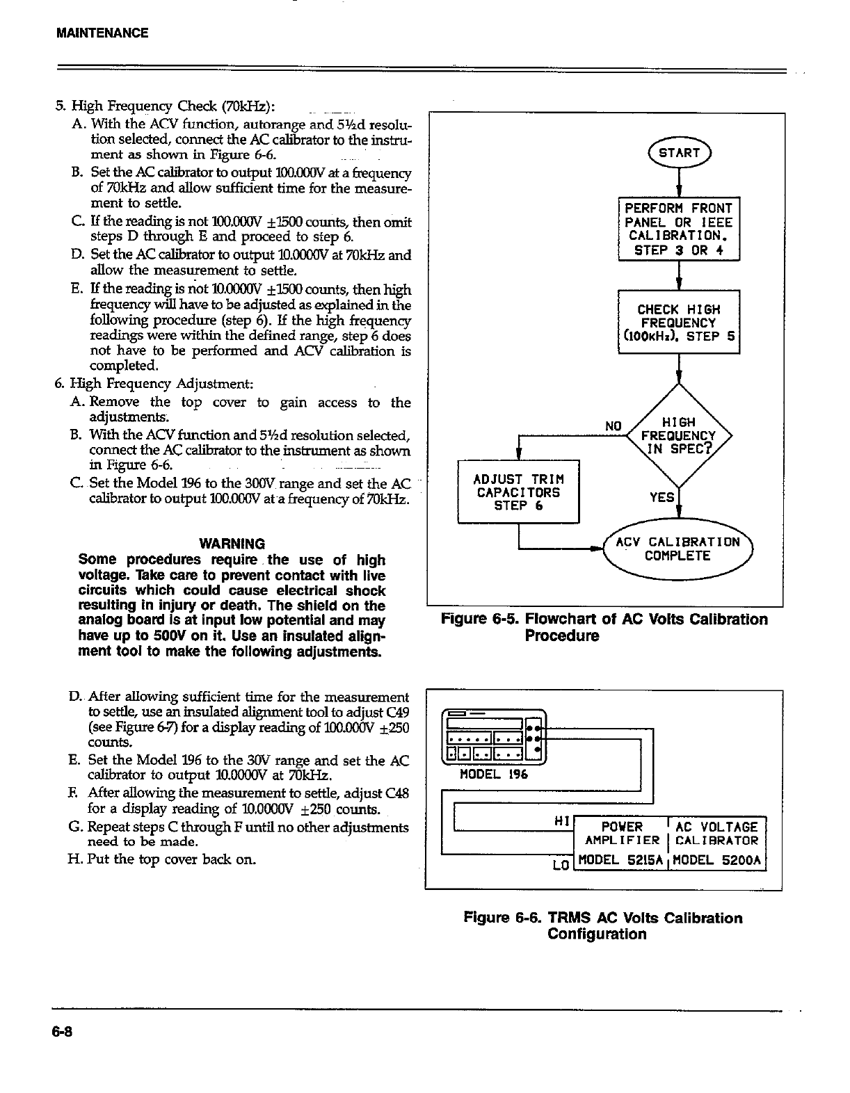
MAINTENANCE
5. High Fmquency Check (7OkHZ):
A. With the ACV function, autorange and 5%d resolu-
tion selected, connect the AC calibrator to the instru-
ment as shown in Figure 6-6.
B. Set the AC caliirator to output XXXCW at a frequency
of 70kHz and allow sufficient time for the measure-
ment to settle.
C. If the reading is not 1oo.oooV fl500 counts, then omit
steps D through E and proceed to step 6.
D. Set the AC calibmtor to output M.OOilOV at 7OkI-k and
allow the measurement to settle.
E. If the reading is not lO.KKHN fl500 counts, then high
frequency will have to be adjusted as explained in the
following procedure (step 6). If the high frequency
readings were within the defined range, step 6 does
not have to be performed and ACV calibration is
completed.
6. High Frequency Adjustment:
A. Remove the top cover to gain access to the
adjustments;
B. With the ACV function and 5%d resolution selected,
connect the AC calibrator to the instrument as shown
in Figure 6-6.
C Set the Model 196 to the 300V range and set the AC
calibrator to output lOO.OWV &a frequency of 7OkHz.
WARNING
Some procedures require. the use of high
voltage. Take cam to prevent contact with live
circuits which could cause electrical shock
resulting in injury or death. The shield on the
analog board Is at input low potential and may
have up to 5OOV on it. Use an insulated align-
ment tool to make the following adjustments.
START
P
PERFORM FRONT
PANEL OR IEEE
CALIBRATION.
STEP 3 OR 4
I
CHECK HIGH CHECK HIGH
FREQUENCY FREQUENCY
(IOOKHI). STEP 5 (IOOKHI). STEP 5
ADJUST TRIM ADJUST TRIM
CAPACITORS CAPACITORS
STEP 6 STEP 6
Figure 6-6. Flowchart of AC Volts Calibration
Procedure
D.~ After allowing sufficient time for the measurement 1
to settle, use &insulated alignment tool to adjust C49
(see Figure 62’) for a display reading of loolMw ~50
COUd.9.
E. Set the Model 196 to the 3OV range and set the AC
caJ.ibrator to output l!mGoGv at 7GkI-k
E After allowing the measurement to settle, adjust C48
for a display reading of lO.OoooV f250 counts.
G. Repeat steps C through F until no other adjustments
need to be made.
H. Put the top cover back on.
HI POWER
AMPLIFIER AC VOLTAGE
CALIBRATOR
MODEL 5200A
Figure 6-6. TRMS AC Volts Calibration
Configuration
6-6
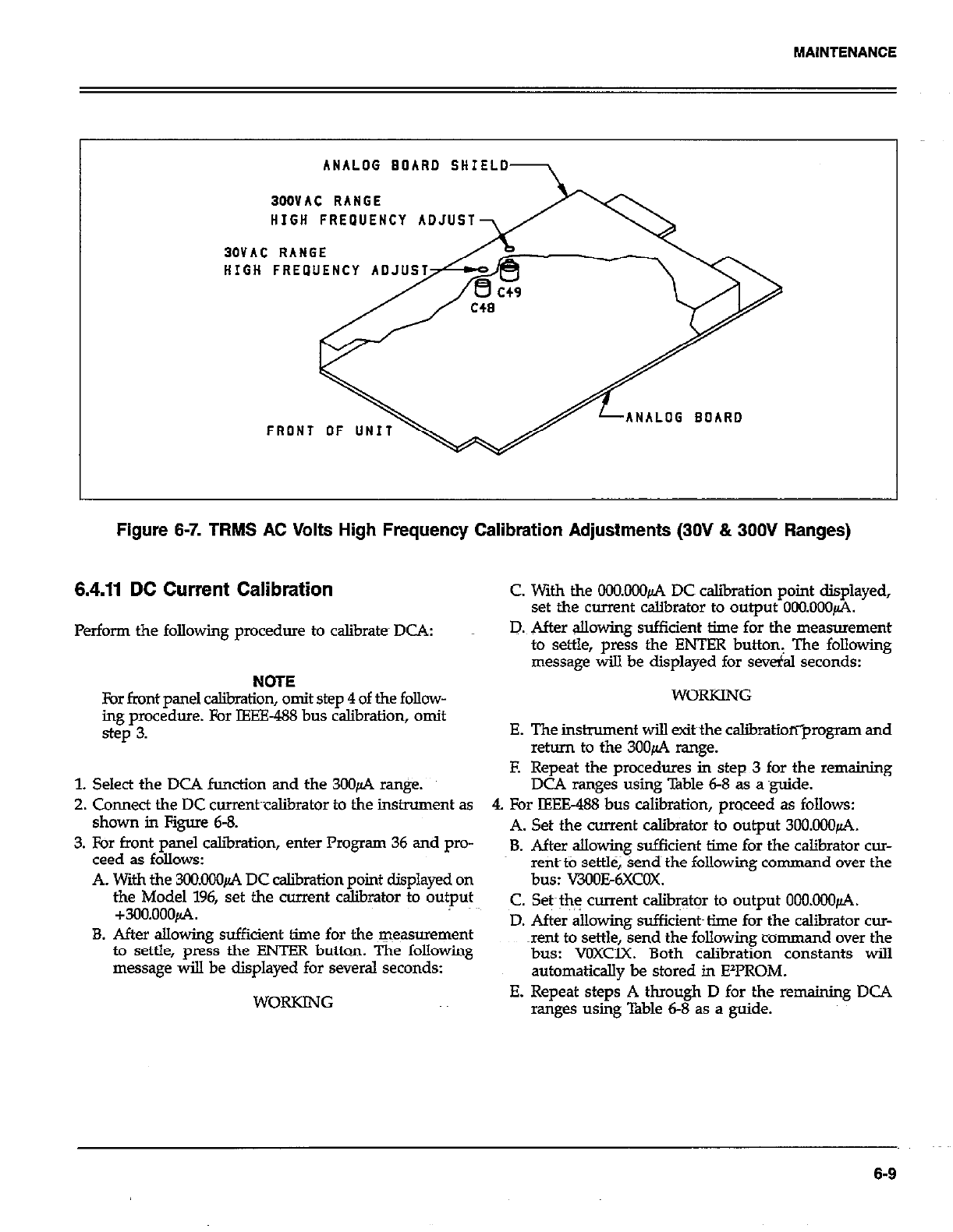
MAlNTENANCE
ANALOG BOARD SHIELD
BODVAC RANGE
HIGH FREPUENCY ADJUST
30VAC RANGE
ANALOG BOARD
Figure 6-7. TRMS AC Volts High Frequency Calibration Adjustments (30V & 300V Ranges)
6.4.11 DC Current Calibration C With the OCO.000~ DC caliiation point displayed,
set the current calibrator to output 000.000~.
Perform the following procedure to calibrate DCA:
NOTE
For front panel calibration, omit step 4 of the follow-
ing procedure. For IEEE-488 bus calibration, omit
step 3.
1. Select the DCA function and the 30&4 ranpe.
2. Cmnect the DC cwrent~cslibrator to the instrument as
shown in Figure 6-8.
3. For front panel c&ration, enter Program 36 and pro-
ceed as follows:
A. With the 304ICKKl~ DC calibration point displayed on
the Model 196, set the current calibrator to output
+300.000&4.
B. After allowing sufficient time for the ~~easmwnent
to settle, press the ENTER button. The following
message will be displayed for several seconds:
D. After allowing sufficient time for the measurement
to settle, press the Eh!TER button, The following
message will be displayed for several seconds:
WORKING
E. The instrument will exit the calibratioriprogram and
return to the 3OOfi range.
E Repeat the procedures in step 3 for the remaining
DCA ranges using Table 6-8 as a guide.
4. For IEEE-488 bus calibration, proceed as follows:
A. Set the current w&i&or to output 3OO.ooO~.
B. After allowing sufficient time for the calibrator cur-
rent~tb settle, sends the following command over the
bus: V3OOE6XCOX.
C. Set~th$ current calib+n to output 0OO.000~.
D. After allowing sufficient~ time for the calibrator cur-
xnt to settle, send the following command over the
bus: VOXClX. Both calibration constants will
automatically be stored in EzPROM.
E. Repeat steps A through D for the remaining DC4
ranges using ‘i%ble 6-8 as a guide.
6-9
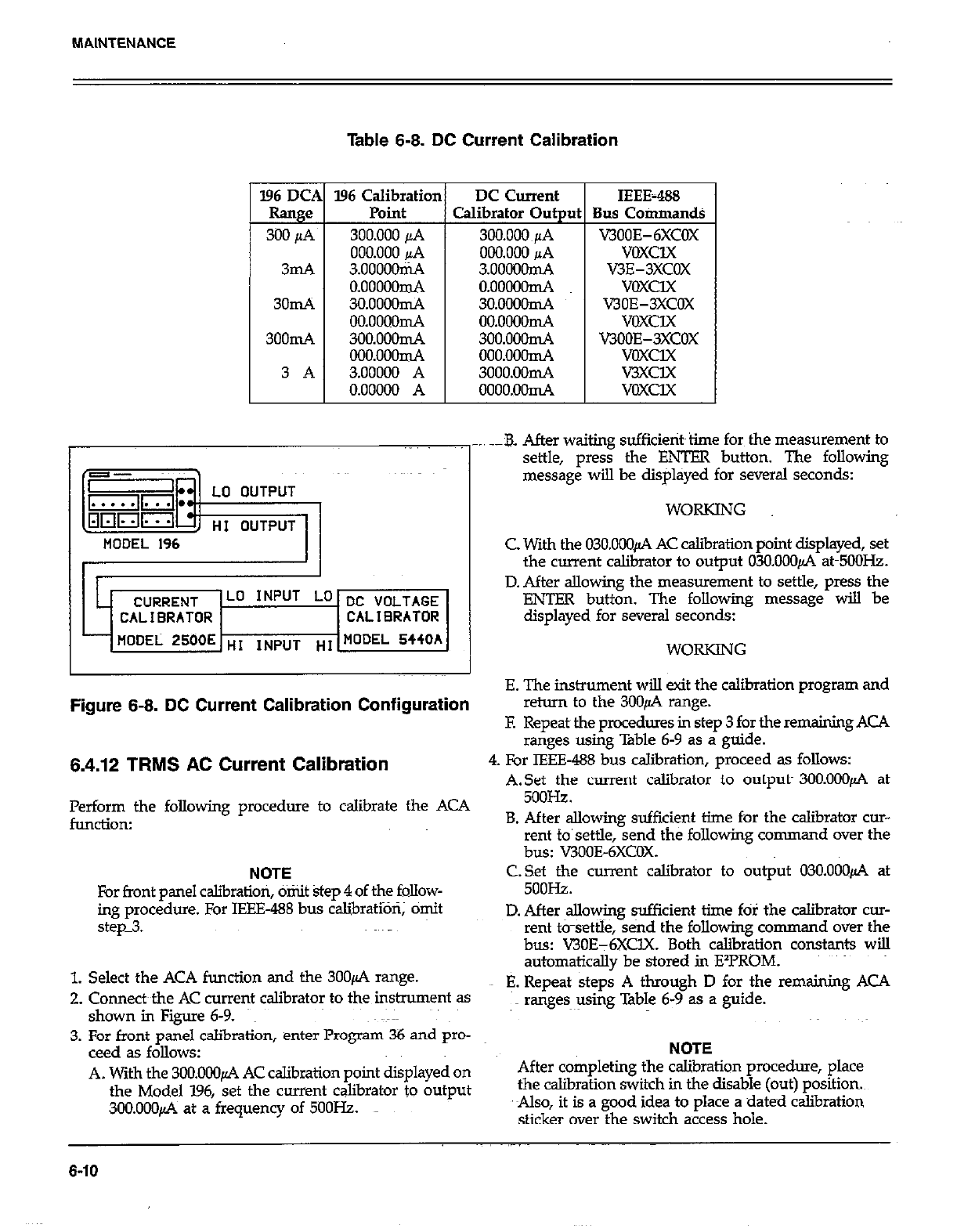
MAINTENANCE
Table 6-8. DC Current Calibration
l96 Calibratior
Point
300.000 jL4
000.000 &4
3.oooooni4
o.ooooomA
3o.ooooIn4
00.0000n-A
3OO.ooonL4
ooo.ooonL4
3.00000 A
0.00000 A
DC Current
Calibrator Out ut
300.000~~1A
000.000 JIA
3.ooOOom4
.
0.00000d
3o.OOaomA
oo.oooonL4
3oo.ooonL4
000.000d
3ooo.ooIm4
oooo.oom4
IEEE-P&3
Bus Commands
V300E-6XcOX
voxclx
V3E-3XCOX
voxclx
V30E-3XCOX
VOXClX
KJOOE-3XCOX
voxclx
V3XCl.X
voxux
_. .-B. After waiting sufficietit~time for the measurement to
settle, press the ENTER button. The following
message will be displayed for several seconds:
WORKING
MODEL 196 C. With the 03O.ooOfi AC calibration point displayed, set
the current calibrator to output 030.000~ atm5OOHz.
Lo INPUT Lo DC VOLTAGE
CALIBRATOR CALl0RATOR
- flODEL 2500E HI ,NPUT “I MODEL 5440h
D. After allowing the measurement to settle, press the
ENTER button. The following message will be
displayed for several seconds:
WORKING
E. The instrument will exit the calibration program and
Figure 6-8. DC Current Calibration Configuration
6.4.12 TRMS AC Current Calibration
Perform the following procedure to calibrate the ACA
funcdon:
NOTE
For front panel cslibratiori, omit step 4 of the follow-
ing procedure. For IEEE-488 bus calibratioti; omit
step_3.
1. Select the ACA function and the 3OOfi range.
2. Connects the AC current calibrator to the instrument as
shown in Figure 6-9.
3. For front panel calibration, enter Program 36 and pro-
ceed as follows:
A. With the 3OO.OOOfi AC calibration point displayed on
the Model 196, set the current calibrator to output
300.000~ at a frequency of 5OOHz.
return to the 3UO+ range.
F. Repeat the procedures in step 3 for the remaining ACA
ranges using Table 6-9 as a guide.
4. For IEEE-488 bus calibration, proceed as follows:
A.Set the current calibrator to output- 3OO.OOOfi at
5ooHz.
B. After allowing sufficient time for the calibrator cur-
rent to’settle, send the following command over the
bus: V300E-6XCOX.
C.Set the current calibrator to output 03O.OOOfi at
5ooHz.
D. After allowing sufficient time fOl the calibrator CUT-
rent t&settle, &nd the following cornman d over the
bus: V30E-6XClX. Both calibration constants will
automatically be stored in E*l?ROM.
E. Repeat steps A through D for the remaining ACA
ranges using Table 6-9 as a guide.
NOTE
After completing the calibration procedure, place
the csliiration switch in the disable (out) position
Also, it is a good idea to place a dated calibration
sticker over the switch access hole.
6-10
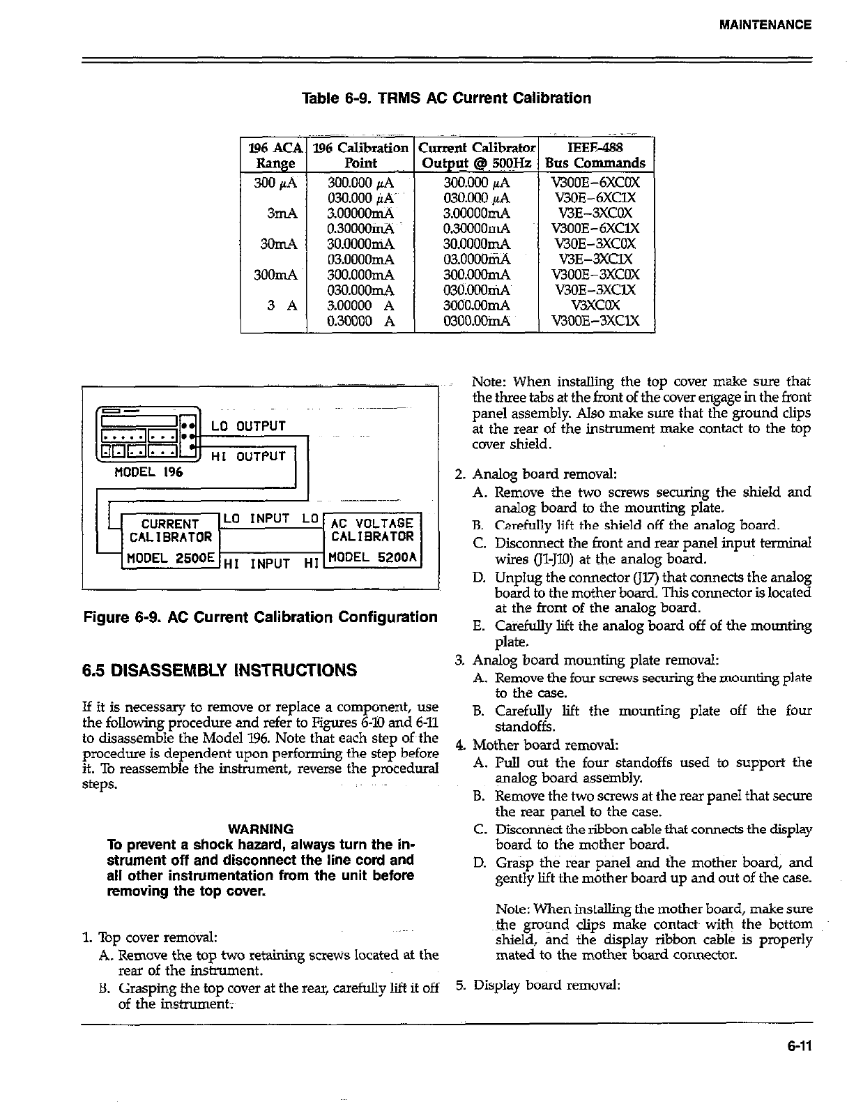
MAINTENANCE
Table 6-9. TRMS AC Current Calibration
,; _ ~.~
196 ACA 196 Calibration Current Calibrator IEEE488
Range Point Out@ @~ 5@IHz Bus Commands
300&i 3OO.ooopA 300.000 pA v3ooE-6xcOX
030.000 PA’ 03o.DoopA v3OE-6XClX
3mA 3ooooomA 3.ooooomA V3E-3XCOX
0.30OOOclA 03000mA v300E-6XclX
3omA 3o.oOOomA 3o.oooomA V3OE-3XCOX
03.0000mA 03.0000IiL4 V3E-3XClX
3OOmA 3oo.ooomA 3oo.ooomA V300E-3XCOX
o3o.ooom4 030.000n4 V3OE-3XClX
V3XCOX
0.30000 A 03oo.OOidi WOOE-3XClX
Note: When installing the top cover make sure that
the three tabs at the front of the cover engage in the front
panel assembly. Also make sure that the ground clips
at the rear of the inshument make contact to the top
cover shield.
2. Analog board removal:
C. Disconnect the front and rear panel input terminal
wires (Il-JlO) at the analog board.
D. Unplug the connector (JV) that connects the analog
board to the mother board. This connector is located
Figure 6-9. AC Current Calibration Configuration
6.5 DISASSEMBLY INSTRUCTIONS
If it is necessary to remove or replace a component, use
the following procedure and refer to Figures 6-10 and 6-11
to disassemble the Model 196. Note that each step of~the
procedure is dependent upon performing the step before
it. To reassemble the instrument, reverse the procedural
steps.
WARNING
To prevent a shock hazard, always turn the in-
strument off and disconnect the line cord and
all other instrumentation from the unit before
removing the top cover.
1. Top cover removal:
A. Remove the top two retaining screws located at the
rear of the instrument.
B. Grasping the top cover at the rear, carefully lift it off
of the instrument;
at the front of the analog board.
E. Cakefully lift the analog board off of the mounting
plate.
3. Analog board mounting plate removal:
A. Remove the four screws securing the mounting plate
to the case.
B. Carefully lift the mounting plate off the four
standoffs.
4. Mother board removal:
A. Pull out the four standoffs used to support the
gmlog board assembly.
B. Remove the two screws at the rear panel that secure
the rear panel to the case.
C. Dikonnkt the ribbon cable that connects the display
board to the mother board.
D. Grasp the rear panel and the mother board, and
gently lift the mother board up and out of the case.
Note: When installing the mother board, make sure
&e ground clips make contacts with the bottom
shield, and the display ribbon cable is properly
mated to the mother board connector.
5. Display board removal:
6-11
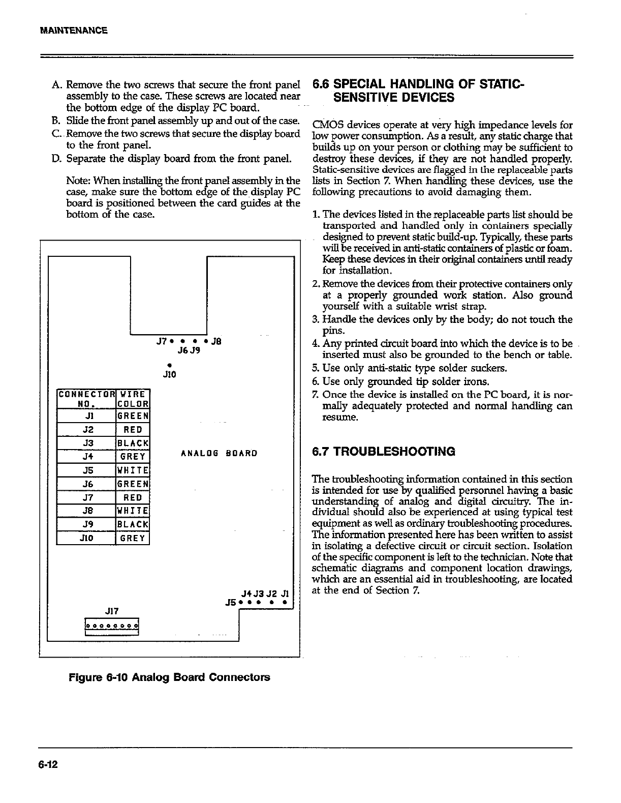
A. Remove the two screws that secure the front panel
assembly to the case. These screws are locate~d near
the bottom edge of the display PC board.
B. Slide the fmnt panel assembly up and out of the case.
C. Remove the two screws that secure the display board
to the front panel.
D. Separate the display board from the front panel.
Note When MtalXng the front panel assembly in the
case, make sure the bottom edge of the~display PC
board is positioned between the card guide-s at the
bottom of the case.
57. l l l JB
J6 J9
I
JiO
ANALOG BOARD
J4J3 52 Jl
Js... . .
J17
6.6 SPECIAL HANDLING OF STATIC-
SENSITIVE DEVICES
CMOS devices operate at very high impedance levels for
low power consumption. As a result, any static charge that
builds up on your person or clothing may be sufficient to
destroy these devices, if they are not handled properly.
Static-sensitive devices are flagged in the replaceable parts
lists in Section Z When handling these devices, use the
following precautions to avoid damaging them.
1. The devices listed in the replaceable parts list should be
transported and handled only in containers specially
designed to prevent static build-up. Typically, these parts
will be received in anti-static containers of plastic or foam.
Keep these devices in their original containers until ready
for installation.
2. Remove the devices from their protective containers only
at a properly grounded work station. Also ground
yourself with a suitable wrist strap.
3. Handle the devices only by the body; do not touch the
pins.
4. Any printed circuit board into which the device is to be
inserted must also be grounded to the bench or table.
5. Use only anti-static type solder suckers.
6. Use only grounded tip solder irons.
7. Once the device is installed on the PC board, it is nor-
mally adequately protected and normal handling can
resume.
6.7 TROUBLESHOOTING
The troubleshooting information contained in this section
is intended for use by qualified personnel having a basic
understanding of analog and digital circuitry. The in-
dividual should also be experienced at using typical test
equipment as well as ordinary troubleshooting procedures.
The information presented here has been written to assist
in isolating a defective circuit or circuit section. Isolation
of the specific component is left to the technician. Note that
schematic diagrams and component location drayings,
which are an essential aid in troubleshooting, are located
at the end of Section 7.
Figure 6-10 Analog Board Connectors
6-12
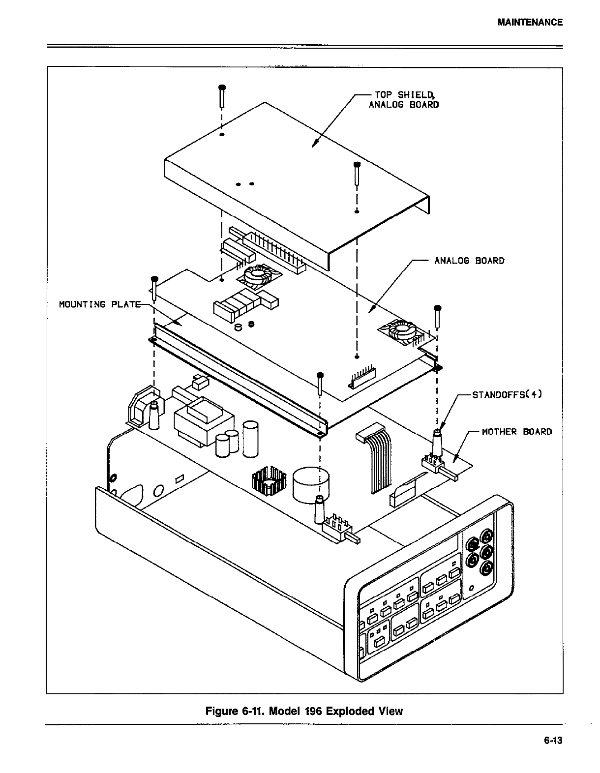

6.7.1 Recommended Test Equipment
Success in troubleshooting complex equipment like the
Model 1% depends not only on the skill of the technician,
but relies on the use of accurate, reliable test equipment.
Table 6-10 lists the equipment recommended for trouble-
shooting the Model 196. Other equipment such as logic
analyzers and capacitance meters could also be helpful,
especially in difficult situations.
6.7.2 Power Up Self Test
Upon power up, the instrument will do a number of tests
on itself. Tests are performed on memory (ROM, RAM and
E’FROM). Whenever one of the memory tests fails, the in-
skument will lock up and must be repaired. If all the tests
pass, then the current IEEE address and software revision
level of the inskument will be displayed. Immediately after
turning on the Model 196, the foll+ng sequence will take
place:
1. A digital check will be performed on the ROM circuitry.
If the test fails, the instrument will lock up with the
following message displayed:
0000000000
Replacing U105 and U106 may resolve the problem.
2. If the ROM test passes, a digital self-test will then be per-
fotied on the RAM circuitry. If the RAM test fails, the
instrument will lock up with the following error message
displayed:
AAAAAAAAAA
Replacing UKV may resolve the problem.
3. Finally, the E’PROM circuitry where the calibration con-
stants, IEEE address and line frequency settings are
stored will be checked. Jf this test fails, the following
message displayed:
UNCIAL
Pressing any front panel momentary button will return
the instrument to normal operation however, a complete
calibration will have to be performed, and the IEEE ad-
clress and line frequency setting should be checked. If
the test still fails after calibration, try replacing U108
before recaliirating the instrument again.
4. The instrument will then go to the power up default
function.
6.7.3 Program 33 - Self Diagnostic Program
This front panel program performs a display testand the
same memory tests performed upon power up. Also in-
cluded is a troubleshooting test mode, that is designed to
switch on various switching FETs and relays to allow signal
tracing through the instrument. Perform the following pro-
cedure to utilize Program 33:
1. press tl~e PRGM button and then the 3 and 3 buttons.
First is the display test. Segments of the c&play
characters will be sequentially displayed for a short
period of time. The front panel LEDs will also be on dur-
ing this test. This test allows the operator to note in-
operative display segments or LEDs. Self test-on the
ROM, RAM, and E2PROM ~III then be performed. These
are the same tests run on power up and are explained
in detail in paragraph 6.7.2.
- -_ -___._
Five function DMM with 0.1% basic DCV accuracy, 1OM
input impedance
-I-
Power supply and DC voltage checks;
analog signal tracing conti+ty, logic
levels.
Dual-trace, triggered sweep oscilloscope, DC to 5OMH.z Digital and analog waveform checks.
Digital frequency counter Checking clock frequencies.
Table 6-10. Recommended Troubleshooting Equipment
6-14
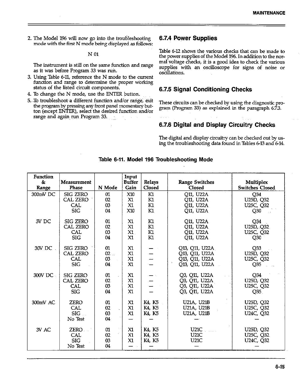
2. The Model 196 wiIl now go into the trouHesh+ing
mode with the first N mode being displayed as follows:
N 01
The instrument is still on the same function and mnge
as it was before Program 33 was ruti.
3. Using Table 6-11, reference the N mode to the current
function and range to determine the proper warking
status of the listed circuit components.
4. To change the N mode, use the ENTER button.
5.X0 troubleshoota different~ function tidlor ra@$e; exit
the program by pressing any front panel momentary but-
ton (except ENTER), select the desired function and/or
range and again run Program 33.
6.7.4 Power Supplies
Table 6-12 shows the various checks that can be made to
the power supplies of the Model 196. In addition to the nor-
mal voltage checks, it is a good~idea to check the various
supplies with an oscilloscope for signs of noise or
oscillations.
6.7.5 Signal Conditioning Checks
These circuits can be checked by using the diagnostic pro-
gram (Program 33) as explained in the paragraph 6.7.3.
6.7.6 Digital and Display Circuitry Checks
The digital and display circuitry can be checked out by us-
ing the troubleshooting data found in Tables 6-13 and 6-14.
Table 6-11. Model 196 Troubleshooting Mode
Function Input
& Measurement Buffer Relays Range Switches Multiplex
Range Phase N Mode Gain Closed Closed Switches Closed
300mV DC SIG ZERO 01 X10 Kl
CAL ZERO 02 Xl Kl :z ~~ U25::Q32
CAL 03 Xl Kl Qll: U22A LJUC, 432
SIG 04 X10 Kl Qll, U22A 430 ~~
3VDC SIG ZERO 01
CAL ZERO zz ;t :; QII, U22A 434
Q% Uzw U25D,mQ32
CAL Xl z QX U22A UUC,. 432
SIG 04 Xl Q% IJ~A 430
30VDC SIG ZERO kc g 1 Q13, QlL UZZJ. 433
CAL ZERO Q13, QlL IJZ.ZA U25D, 432
CAL z: Xl - 4% QU LJZL’. UUC, Q32
SIG Xl - Ql3, QU, U22A 435
300X7 DC SIG ZERO 01 Xl - Q3, QJ.L U22A Q34
CAL ZERO xl - Q3, QQ U22A~
CAL :z U25D; 432
Xl - Q3, QlL IJZA U25C, Q32
SIG 04 Xl - Q3, Qll, UZA 435
300mV AC ZERO ol Xl K4, K5 U2lA, U21B U25D, Q32
CAL 02 Xl K% K5 U2lA, U21B U25C, 432
SIG 03 Xl K4 ~5 u2L4, u2lB U24C, Q32
No Test 04 - - - -
3V AC ZERO ol ;: K4, K5 U21C ~~~~ U25D, 432
CAL W KS u21c
SIG ii u25c, Q32
Xl K4, K5 u21c U24C, 432
No Test 04 -~ - -
6-16
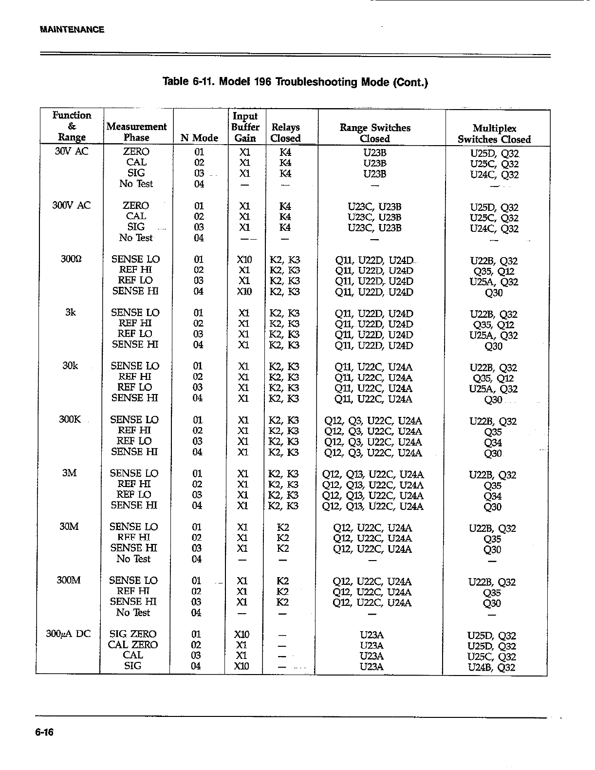
Table 6-11. Model 196 Troubleshooting Mode (Cont.)
CAL
SIG
No Test
N Mode
01
02
03
04
Input
Buffer
Gain
;i
Xl
I -
300V AC ZERO ii 2 Ei U23C, U23B
CAL U23C, U23B
SIG 03 Xl K4 U23C, U23B
No Test 04 -~ - -
3OOcl SENSE LO In x10 K2, K3 Qll, U22D, U24Dm
iI% it : E% Qll, U22D, U24D
Qll, U22D, U24D
SENSE HI 04 xl0 K2: K3 Qll, U22D, U24D
3k SENSE Lo
REFHl
REFLO
SENSE HI
30k SENSE LO
EE
SENSE HI
3OOK SENSE Lo
REFHI
REFU3
SENSE HI
3M SENSE LO
REFHI
SEE%
3ilM SENSE LO
SE%E%
No Test
300M SENSE Lo
SE%E%
No Test
3OOfi DC SIG ZERO
CAL ZERO
CAL
SIG
- I -
xl
Xl
xl
-
x10
xl
Xl
Xl0
K2
E
-
-
-
-~
-
Qll, U22D, U24D
Qll, ~U22D, U24D
Qll, U22D, U24D
Qll, U22D, U24D
U22B, 432
4% Q=
U25A, 432
430
Qll, U22C, U24A U22B, 432
Q~ll, U22C, U244 Q35, 412
Qll, U22C, U24A U2W, 432
Qll, U22C, U24A Q30
Ql2,43, U22C, U24A
QZQ3, U22C, U24A
Ql2, 43, U22C, U24A
Ql.2, Q3, U22C, U24A
U22B, 432
Q35
g
412,413, U22C, U24A
QELQl.3, U22C, U24A
412, Ql3, U22C, U24A
Ql2, QU, U22C, U24A
U22B, 432
g
Ql2, U22.C, U244
Ql2, U22C, U24A
412, U22C, U24.4
-
U22B, 432
435
430
Et
U23A
U23A
-
Multiplex
Switches Closed
U25D, 432~
U25C, 432
U24C, 432
-~
U25D, 432
UUC, 432
U24C, Q32
-
U22B, 432
435, 412
U25A, Q32
43
U22B, 432
8;
-
u25D, Q32
U25D, 432
U25C, 432
U24B. 032
6-16

MAlNTENANCE
Table 6-11. Model 196 Troubleshooting Mode (Cont.)
Function
&
Range
3mA DC
3OmA DC
3OOmA DC
3A DC
3OOfi AC
3mAAC
3OmA AC
3COmA AC
3AAc
Measuremen
P&E
SIG ZERO
CAL ZERO
CAL
SIG
SIG ZERO
CAL ZERO
CAL
SIG
SIG ZERO
CAL ZERO
CAL
SIG
SIG ZERO
CAL ZERO
CAL
SIG
ZERO
CAL
SIG
No Test
ZERO
CAL
SIG
No Test
ZERO
CAL
SIG
No Test
ZERO
CAL
SIG
No Test
ZERO
CAL
SIG
No Test
N &lo&
01
02
E
01
02
03
04
01~
02
ii
01
02
03
04
01
02
ii
i;
03
04
ii
03
04
01
:z
04
01
z.i
04
IllpUl
3uffe
Gain
xl0
;;
Xl0
x10
Xl
El
Xl0
;;
x10
x10
xl
Xl
x10
xl
Xl
Xl
Xl
;;
-
z;
Xl
-
is
Xl
-
Xl
z
-
-
-
-
-
-
-
- ~~
-
-
-
-
-
-
-
-
-
-
-
-
-
-
-
-
-
-
-
-
-
-
-
-
-
-
Range Switches
Closed
g? :.E
Q29: 436
42% 436
4% Q37 UUD, 432
428, Q37 UUD, 432
Q% 437 U25C, Q32
Q28, Q37 U24B, 432
U25D, 432
U2!5D, 432
U2.K Q32
UZ4B, 432
Q39, Q@
Q39, Q40
g; g::
UUD, Q32
U25D, 432
UUC, 432
U24B, Q32
u23A, u2lD, u2lB U25D, 432
U23A, U21D, U21B U25C, Q32
U23A, U2lD, U21B U24C, 432
- -
429, 436, U2lD, U21B
Q29, Q36, U21D, U21B
429, Q36, UUD, U2lB
-
Q28,437, U2lD, U2lB
Q28, Q37, U21D, U2lB
428, ~437, UZlD, U2lB
-
226, 438, U21D, U21B U25D, 432
226, Q38, U21D, U21B UWC, 432
326, 438, U2lD, U2lB U24C, 432
-
239, 440, U21D, U21B U25D, Q32
239, 440, UZlD, U21B U25C, Q32
239, 440, U219 UZlB U24C, 432
-
Multiplex
Switches Closed
U2SD, 432
U25D, 432
U25C, 432
U24B, 432
U25D, 432
UUC, 432
U24C, 432
-
UUD, 432
U25C, 432
U24C, Q32
-
6-17

Table 6-12. Power Supply Checks
Step ItemlCotipdnent Required Condition Remarks
1 SlOl Line Switch
2 FlOl Line Fuse Set to 115~ Or 23OV as required. Lie voltage selection
Check for~contimity. Remove fuse to check
3 Line Power Plugged intd live receptacle;
4 power on.
+5V Digital Supply VRllll, pin ~3 +5v, i5% Referenced to digital common
5 +5v Analog Supply VRlO2, pin 3 +5v, *5%
6 +l5V Analog Supplies VR103, pin 3; +lW, -UV, f0.75V Reference to analog common
vRlo4, pin 3 Referenced to analog common
Table 6-13. Digital Circuitry Checks
Step 1 Item/Component
1 U105, U106, U107, U108 ~.~
2~~
3
4
5
6
7
8
9
10
11
iL
14
UlO9, pin 2 (PAO)
UlO9, pin 3 (PAl)
u109, pin 6.(PA4)
UlO9, pin 7 (I?A5)
U109, pin 8 (TA6)
UXl9, pin 9 @?47)
ulO9, pin 19
Ul20, pin 6
u43, pin l3
UlO9, pins 12 through 16
u104, pin 3
um4, pin 37
ull2, pin 9
I.5 Ull2, pin 19
16 UK!, pin 18
I7 Ull2, pin28
I8 Ull2, pins 28 @TN), 24 (NDAC),
25 (NRFD), 26 (DAV), and the data
lines
Required Condition
Pass RAM, ROM tid E’I’ROM
self-test on power up.
TTL level pulses~ every lmsec
lTL level pulses every l5msec
Switch data (+5V or OV)
Switch data (+5V or OV)
Switch data (+5V or OV)
Switch data (+5V or OV)
Variable pulse train (OV to +5V)
Variable pulse train (OV to +5V)
Variable pulse train (OV to +5V)
Variable pulse train (OV to +5V)
lk.Hz pulses
+5V, *5%
+5V siznal pulsed OV to +5V
every GnseC
+5v (Logic “1”)
2MHz square wave at OV to +5V
Should go false (+5V) when
command is sent
Refer to Figure D-2 for required
conditions
Remarks
Display wilI lock if failure
occurs-
VIA clock
Data
Data input to VIA
Data input to VIA
Data input to VIA
Data input to VIA
VII Data Line
Data output
Output-of-A/D converter
Analog data to VL4
lRQ line
Reset line
lNTline
RESET lie
ClOCk
ATN line
Handshake sequence
6-16
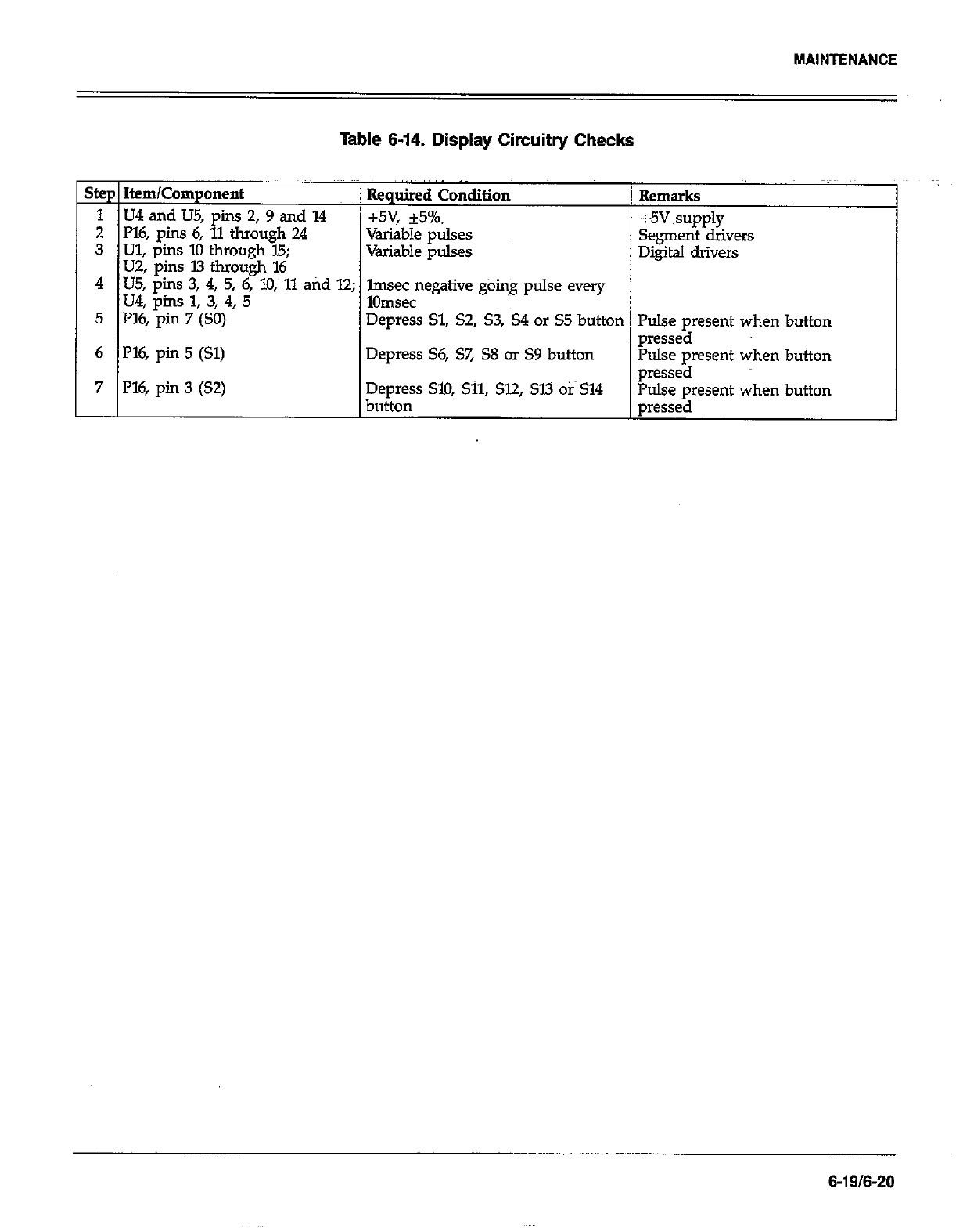
MAINTENANCE
Table 6-14. Display Circuitry Checks
Step Item/Component Required Condition Rema “~
irks
1 U4 and US, pins 2,9 and 14 +5v, *5%. +5v
2 Pl6, pins 6, 11 through 24
3 Ul, pins 10 through 15;
Variable pulses supply
Variable pulses Segment drivers
U2, pins 13 through 16 Digital drivers
4 US, pins 3, 4, 5, 6, lo, 11 atid 12;
u4, pins 1, 3, 4? 5 lmsec negative going pulse every
1Omsec
5 I%, pin 7 (SO) Depress Sl, S2, S3, S4 or S5 button Pulse present when
6 l’l6, pin 5 (Sl) pressed
Depress S6, S7, S8 or S9 button Pulse pment when
7 P16, pin 3 (S2) Depress SlO, Sll, 512, SW Otis 514 pressed
button Pulse present when
pressed
button
button
button
6-19/6-20
SECTION 7
REPLACEABLE PARTS
7.1 INTRODUCTION 1. Instrument Model Number
2. Insrument Serial Number
This section contains replacement parts information, corn- 3. parts Description
ponent location drawings and schematic @agrams for the
Model 196. 4. Circuit Designation (if applicable)
5. Keithley Part Number
7.2 PARTS LIST
Parts are listed alphanumerically in order of their circuit
designations. Table 7-1 contains parts list information for
the display board. Table 7-2 contains parts list info~ati~n
for the digital board. Table 7-3 contains parts list informa-
tion for the anal0
f board. Table 7-4 contains a miscel-
laneous parts list or the Model 196.
Devices that are static-sensitive are flagged in the p&s lists
descriptions with the abbreviation SSD. Special handling
of these devices is explained in paragraph 6.6.
7.3 ORDERING INFORMATION
To place an order, or to obtain information concerning
replacement parts, contact your Keith@ representative or
the factory. See inside front cover for addresses. When
ordering include the following information:
If an additional instruction manual is required, order the
manual package (Keithley PartNumber 196-901-00). The
manual package contains an instruction manual and any
applicable addenda.
7.4 FACTORY SERVICE
If the instrument is to be returned to the facto y for ser-
vice, please complete the service form which follows this
section and return it with the instrument.
7.5 SCHEMATIC DIAGRAMS AND
COMPONENT LOCATION DRAWINGS
Schematic diagrams and component location drawings
follow the appropriate replaceable parts list for that par-
ticular board.
7-117-2
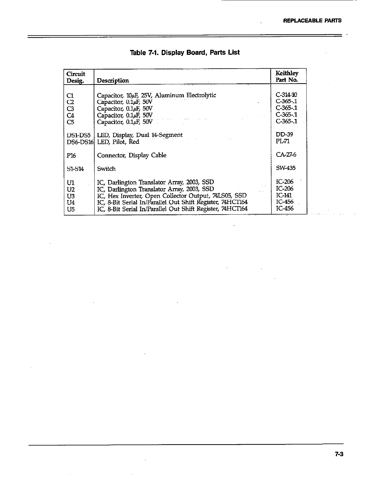
REPLACEABLE PARTS
Table 7-1. Display Board, Parts List
Circuit
Desig. Description
z Capacitor, lO@, 29, Al*um Elect@Ytic
Capacitor, O.lfl, SW
E Capacitor, o&z, SW
Capacitor, O.l& v
c5 capacitor, 0.1/s, 5Ov ~~
DSl-DS5 LED, Display, Dual !?+gment
DS6-DS16 LED, Pilot, Red
I’l6 Connector, Display Cable
51-514 switch
Ul IC, Darlington Translator Amy, 2003, SSD
is IC, Darlington Translator Array, 2003, SSD
IC, Hex Inverter, Open Collector Output; 74LSO5, SSD
E IC, 8-Bit Serial InPamlMQut Shift Register, 74HCIl64
IC, 8-Bit Serial In/Padlel Out Shift Register, 74HCIl64
Keithley
Part No.
c-31410
C-365-A
C-365-S
C-365-.1
C-365-.1
DD-39
PL7l
CA-%6
SW-435
IC-206
IC-206
IC-141
IC-456
K-456
7-3
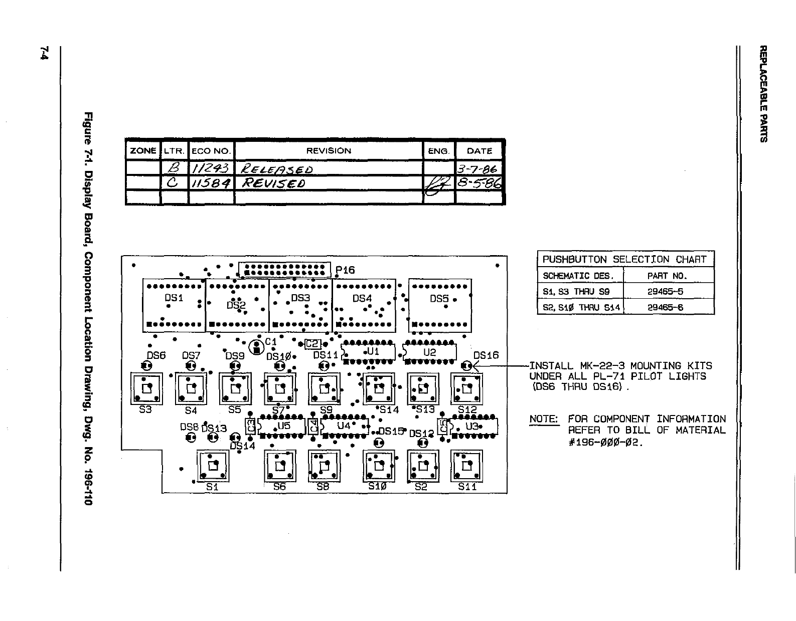
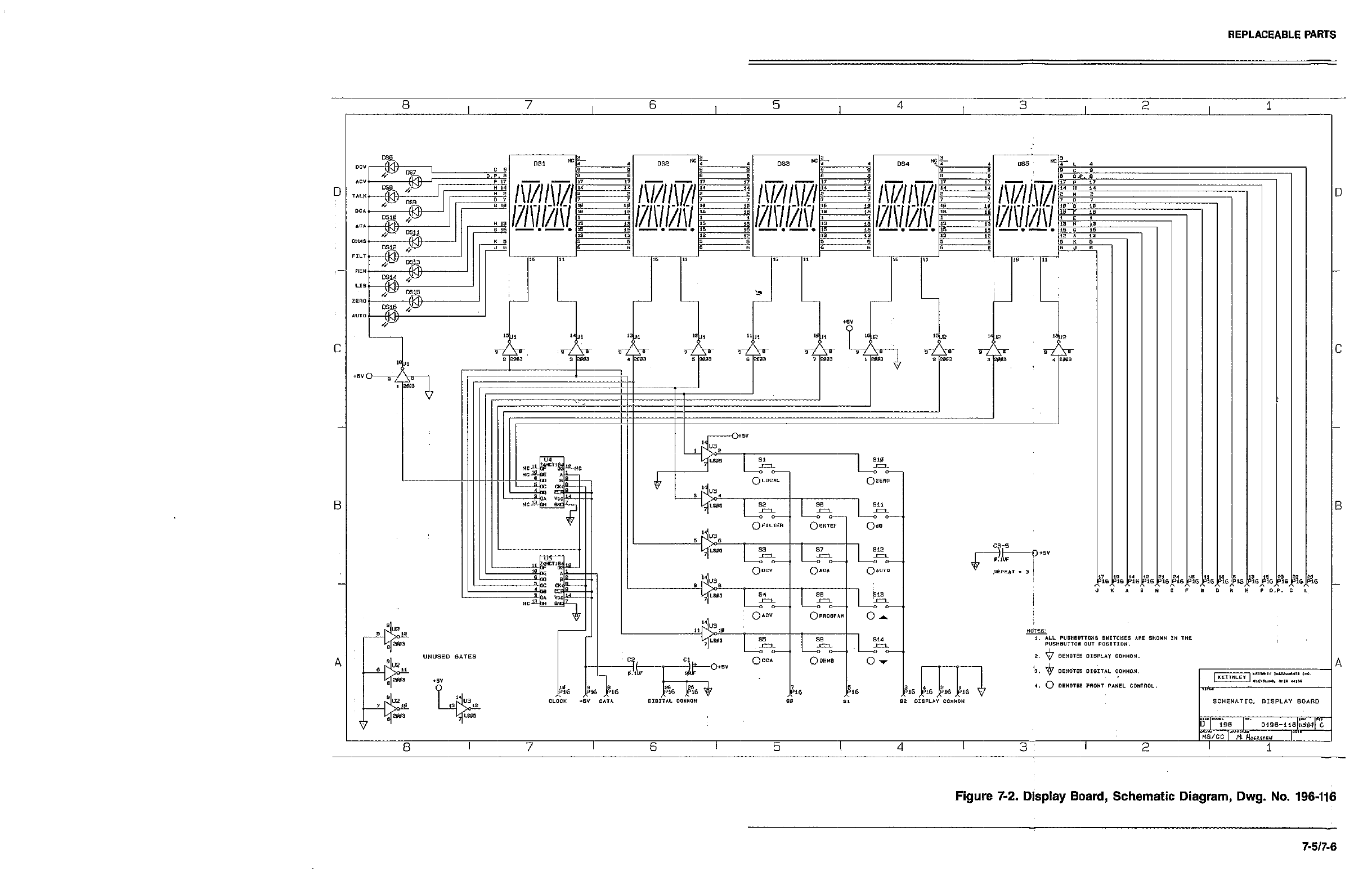
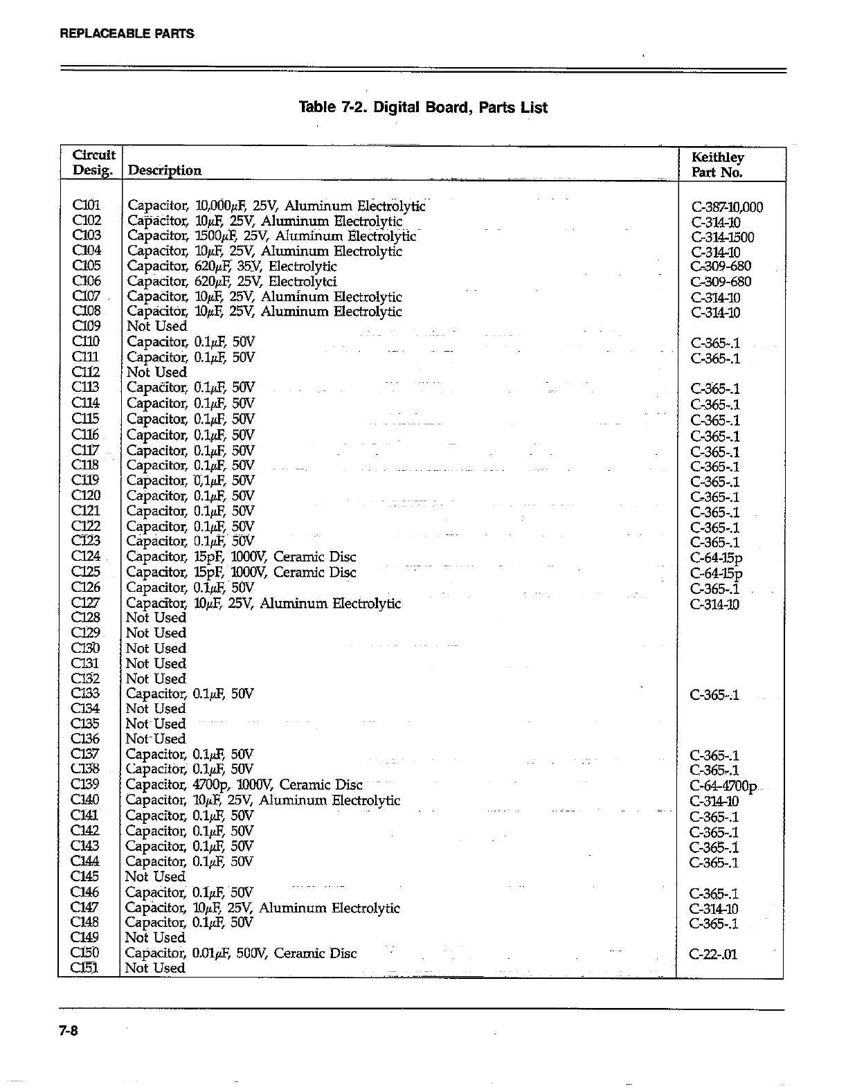
REPLACEABLE PARTS
Table 7-2. Digital Board, Parts List
circuit
Desig.
Cl01
Cl02
a03
Cl04
Cl05
CiO6
cl07
cl08
a09
cllo
%
z
E.z
Cll7
Cl%
al9
cl20
cm
g
u24
cl25
Cl26
EE3
cm
CEO
%
cJ33
Cl34
Cl35
Cl36
Cl37
Cl38
cl39
Cl40
~~~
Cl43
cm
Cl45
Cl46
Cl47
cm
cl49
cl50
CEi
DescSption
Capacitor, lO,OOOpF, WV, Aluminum Ek&lyti~
C+kitor, lo& 25V, Aluminum Electrolytic
Capacitor, l500& 25V, Alumhm Elect++&
Capacitor, lo& 25Y Aluminum Electrolytic
Cap@or, 62O/cE; 35Y, Electrolytic
Capacitor, 62Ofi 25V, Electrolytci
Capacitor, lo& 25V, Aluminum Electrolytic
capacitor, l&F, WV, Aluminum Electrolytic
Not Used
Capacitor, o&F, 5ov
Capacitor, 0.19, 5OV
Not Used
CapaZtor, O&F, 50V ~~
Capacitor, O.&S, 5OV
Capacitor, O.l& SW
Capacitor, O&F, 5OV
Capacitor, IJ.l& 50V
Capacitor, O.&F, 5OV
Capacitor, iJl& 50V
Capacitor, O.l& 50V
Capacitor, o.ifl, 50V
Capacitor, O.lfl, SW
Cap&itor, O.l/LF,, 5W
Capacitor, l5pF, lO+JW, Ceramic Disc
Capacitor, l5pF, MOOV,~ Ceramic Diic
capacitor, o&z, 5w
Capacitoz lO& WV, Aluminum Electrolytic
Not Used
Not Used
Not Used
Not Used
Not Used
Capacitor, O.l& 5OV
Mot Used
Vot~Used
YotmUsed
Capacitor, O.l& 50V
zapacitor; o&F, SW
Capacitor, 47OOp,~ lOCW, Ceramic Disc
Capacitor, lo@, 25V, Aluminum Electrolytic
Zapacitor, O.l@, 5OV
Zapacitor, O.l@, 50V
Z+acitor, O&F, SW
Zapacitor, O.l@F, 50V
Vat Used
Zapacitor; O.lpF, 5W
Spkitor, X&E 25V, Aluminum Electrolytic
z3pacitor, O.l& SW
Uoi Used
~+%itOr, O.Olp.F, 5OOV, Ceramic Disc
.
Keitbley
Part No.
C-38%10,000
c-314-10
c-314-1500
c-314-10
C-309-680
C-309-680
c-314-10
c-314-10
C-365-.1
C-365-J
C-365-.1
C-365-.1
C-365-.1
C-365-.1
C-365-.1
c-365-.1
C-365-.1
C-365-.1
C-365-.1
C-64~l5p
c-64-15p
C-365-.1
c-314-10
C-365-J
C-365-.1
c-64-47oop~~
c-31w
C-365-.1
C-365-.1
C-365-.1
C-365-.1
C-365-.1
c-314-10
c-365-s
C-22-.01
7-8
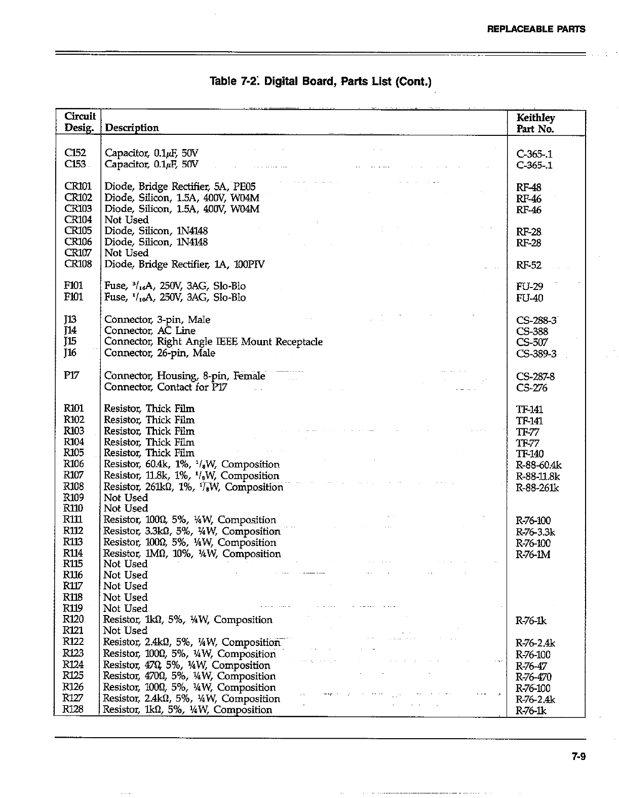
REPLACEABLE PARTS
Table 7-21 Digital Board, Parts List (Cont.)
Circuit
De&g. Description Keithley
Part No.
cl52 Capacitor, o&F, 50v
cl.53 capacitor, o&F, 50v
CRlOl Diode, Bridge Rectifier, SA, ~rE05
CR102 Diode, Silicon, 1.5A, 4OOV, WO4M
CR103 Diode, Silicon, 1.5A, 4OOV, WO4M
CR104 Not Used
CR105 Diode, Silicon, lN4148
CR106 Diode, Silicon, lN4148
CR107 Not Used
CR108 Diode, Bridge Rectifier, L4, lOOPlV
FlOl Fuse, V,6A, 25a: 3AG, Slo-Blo
FM1 Fuse, ‘I,&, 25OV, 3AG, Slo-Blo
E Connector, 3-pin, Male
Connector, AC Line
;z Connector, Right Angle IEEE Mount Receptacle
Connector, 26-pm, Male
m7 Connector, Hotising, 8-pin, Female
Connector, Contact for lV
Rl!Jl Resistor, Thick Film
R102 Resistor, Thick Film
R103 Resistor, Thick Film
Rlo4 Resistor, Thick Film
Rlo5 Resistor, Thick Film
R106 Resistor, 60.4k, l%, ‘leW, Composition
R107 Resistor, llSk, l%, ‘/,W, Composition
R108
R109 Resistor, 26lkQ l%, ‘&W, Composition
Not Used
RlM Not Used
Rlll Resistor, 1o(M2, 596, XW, Composition
RllZ
Rll3 Resistor, 3.3k0, 5%, %W, Composition
Rll4 Resistor, 1004 5%, VrW, Composition
Resistor, lM0, lo%, XW, Composition
FE Not Used
Not Used
Rll.7 Not Used
Rll8 Not Used
Rll9 Not Used
RI20 Resistor, lkfl, 5%, v4W, CornpositiOn
RI21 Not Used
rim Resistor, 2&n, 5%, ‘hW, CompositibT
E Resistor, lOOQ, 596, Yaw, Compositioti
Resistor, 47Q 596, y4W, Composition _
Rl25
R126 Resistor, 4700, 5%, XW, Composition
RlW Resistor, lOOQ 5%, YPW, Composition
Resistor, 2.4kfl, 5%, +bW, Composition .--I
RI.28 Resistor, lk0, 596, ‘/aW, Coxnposition
c-365-.1
Q&.1
RF-48
RF-46
RF-46
RF-28~
RF-28
RF-52~
Fu-29
FU-40
CS-288-3~
CS-388
CS-507
CS-389-3
CS-287-8
CS-276
n-141
w-141
v-77
Tl-77
TF-140
R-88-60&
R-88-11.8k
R-88-261k
R-76-100
R-763.3k
R-76-100
R-7&l&4
R-76I.k
R-76-2&
R-76-100
R-76-47
R-76-470
R-76X0
R-76-2&
R-76-Xx
7-9
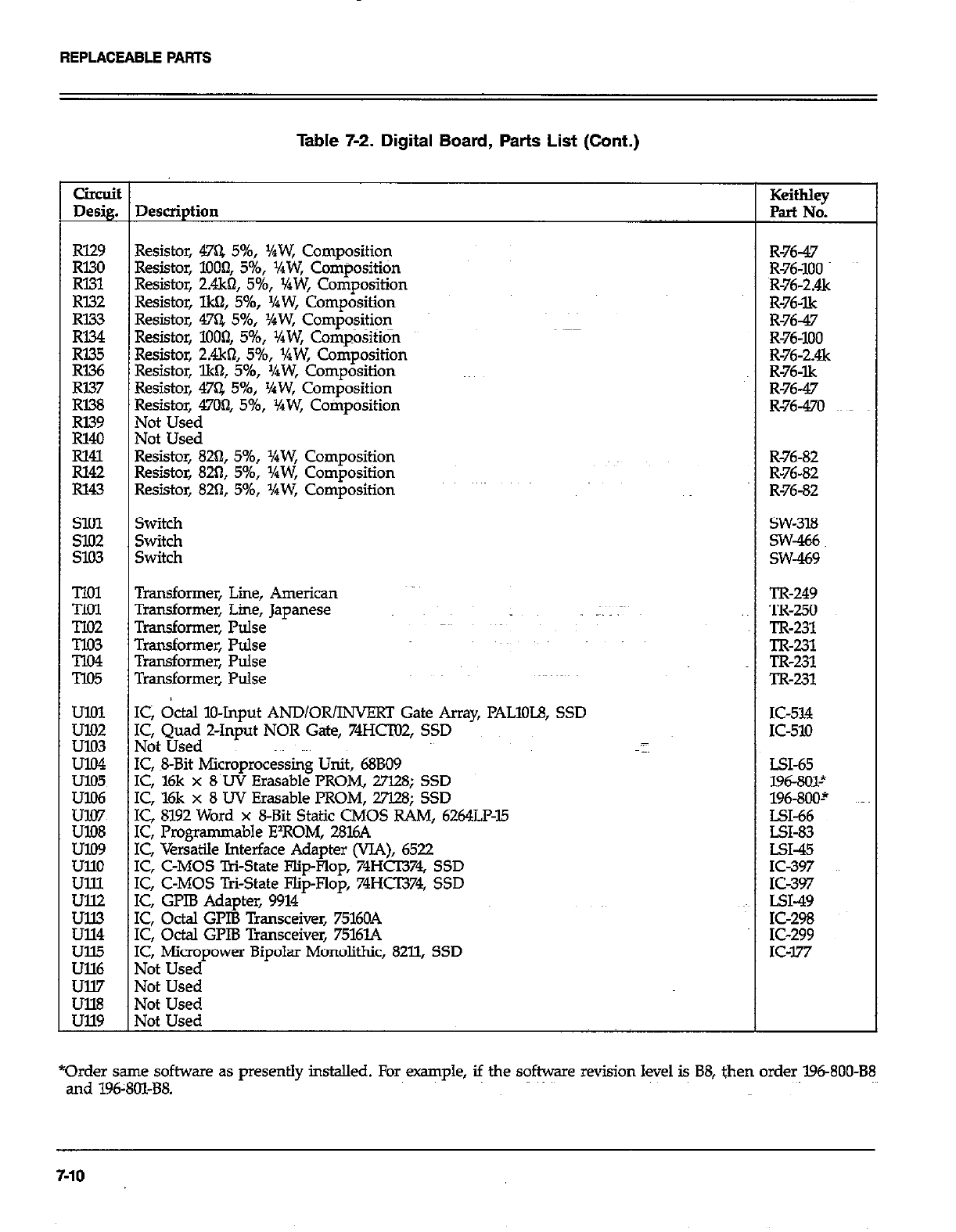
REPLACEABLE PAATS
Table 7-2. Digital Board, Parts List (Cont.)
CiIcuit
Desig. Description Keithky
Part No.
Rl29 Resistor, 47Q 5%, ‘IPW, Composition R-76-47
Rl30
Rl31 Resistor, 1000, 596, VaW, Composititin R-76-100
Resistor, 2.4k61, 5%, VaW, Composition R-76-2&
RI32 Resistor, lkQ, 5%, ‘/aW, Composition R-76-lk
i%i Resistor, 47% 5%, ‘/rW, Composition R-76-47
Resistor, lOOf& 5%, XW, Cotiposition R-76-100
R335 R-76-2&
RI36 Resistor, 2.4k62, 5%, v4W, Composition
Resistor, lk61, 546, ‘/aW, Composition R-76-lk
RI37 Resistor, 47Q 596, YiW, Composition R-76-47
RI38 Resistor, 4704 5%, I/qW, Cotiposition R-76-470
E Not Used
Not Used
% Resistor, 82Q, 5%, XW, Composition R-76-82
Resistor, 82tl, 5%, XW, Composition R-76-82
R143 Resistor, 820, 5%, ‘/rW, Composition R-76-82
SlOl Switch SW-318
s102 Switch SW-466
9.03 Switch SW-439
Tlol Transformer, Line, American TR-249
TIol Transformer, Lime, Japanese .~ lx-250
TIO2 Transformer, Pulse TR-231
E Transformer, Pulse TR-231
Transformer, Pulse TR-231
T105 Transformer, Pulse TR-231
Kz IC, &al IO-Input AND/OR/INVERT Gate Army, PALlOL8, SSD IC-514
u103 I&QI~~~ Z-Input NOR Gate, 74HcTo2, SSD K-510
U104 IC, ~8Bit Microprocessing Unit, 68BO9 LSI-65
ulO5 IC, l6k x 8’UV Erasable PROM, 27128; SSD 196-801~
Ez IC, ‘l6k x 8 UV Erasable PROM, 27l.28; SSD 196-800-’
IC, 8192 Word x 8-Bit Static CMOS RAM, 6264LF-15 LX-66
EE IC, Progfamma ble E’ROM, 2816A LSI-83
IC, Versatile Interface Adapter (VJA), 6522 LSI-45
ullo IC, C-MOS T&State Flip-Flop, 74HCI374, SSD IC-397
Ulll IC, C-MOS Tri-State Flip-Flop, 74HCT374, SSD IC-397
:Ei IC, GPIB Adapter, 9914 ~~~ LSI-49
IC, Octal GLIB Transceiver, 75160A IC-298
ul14 IC, Octal GPIB Transceiver, 7516L4 IC-299
Ull5 IC, Micropower Bipolar Monolithic, 8211, SSD IC-177
Ull6 Not Used
Ull7 Not Used
~~ Not Used
Not Used
*Order same software as presently installed. For example, if the software revision level is B8, then order 19680088
and 196:801-B8.
7-10
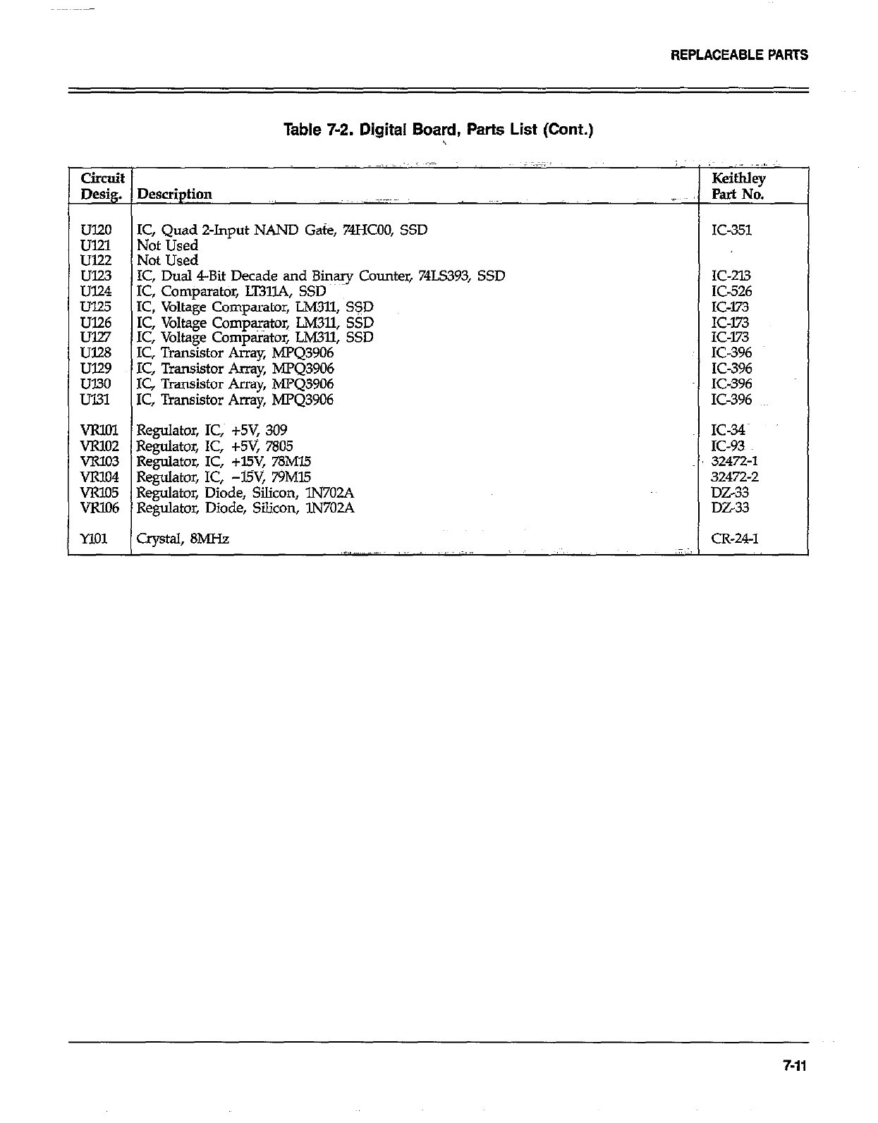
REPLACEABLEPARTS
Table 7-2. Digital Board, Parts List (Cont.)
circoit KeithIey
Desig. Description ~, Part No.
~~
UT20 IC, Quad 2-Input NAND Gate, 74HcO0, SSD
ul21 Not Used
Ul22 Not Used
E IC, Dual 4-Bit Decade and Binary Counter, 74LS393, SSD
IC, Comparatbr, LT31lA, SSD
Ul25 IC, Voltage Comparator, LM311, SSD
% IC, Voltage Comparator, LM311, SSD
IC, Voltage Comparator, LM311, SSD
U128 IC, Transistor Array, MPQ3906
ul29 IC, Transistor Array, hPQ3906
UT30 IC Transistor Array, MPQ3906
Ul31 IC, Transistor Array, MPQ3906
VRlOI Regulator, IC,~ +5V, 309
VRlO2 Regulator, IC, +5V, 7805
VR103 Regulator, IC, +l5V, 78Ml.5
VR104 Regulator, IC, -WV, 79Ml5
VRlO5 Regulator, Diode, Silicon, lN702A
VRlO6 Regulator, Diode, Silicon, lN702A
MO1 Crystal, 8MHz ~,I”-.-.-~~ _ _~~ .~...
IC-351
IC-213
IC-526
IC-173
:::Fz
IC-396
IC-396
IC396
IC-396
::g
32472-l
32472-2
DZ33
DZ33
CR-24-l
7-11
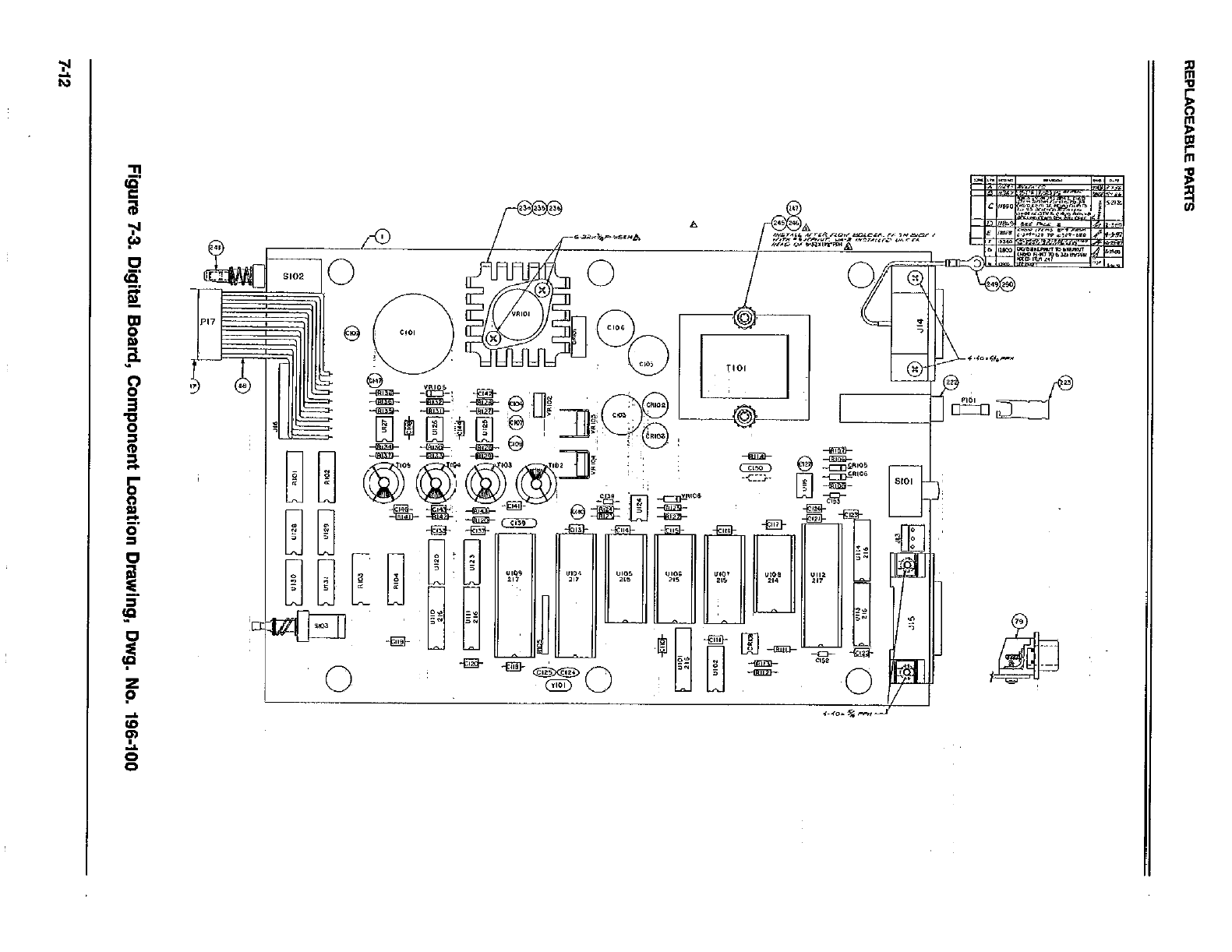
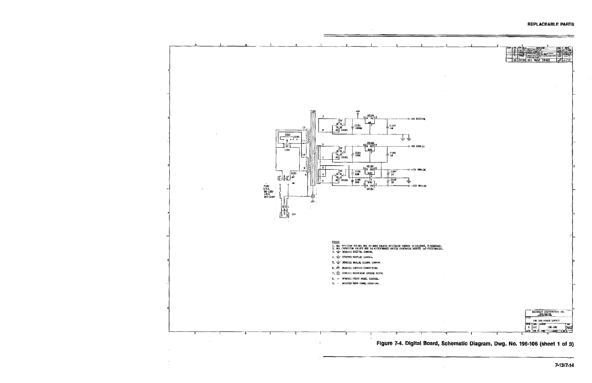
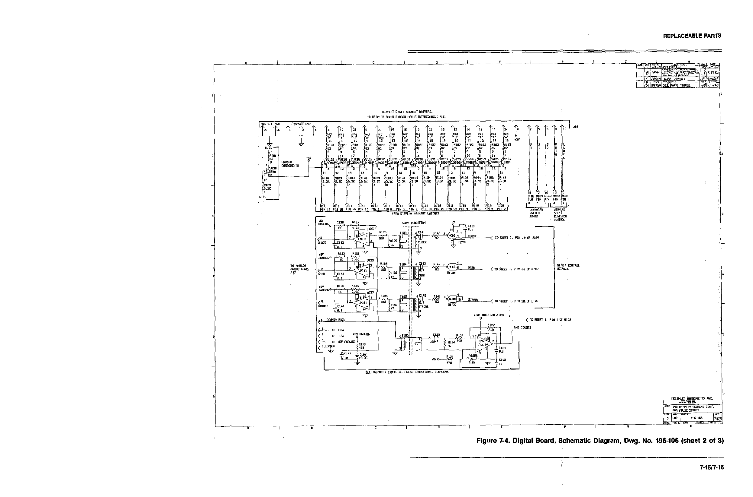
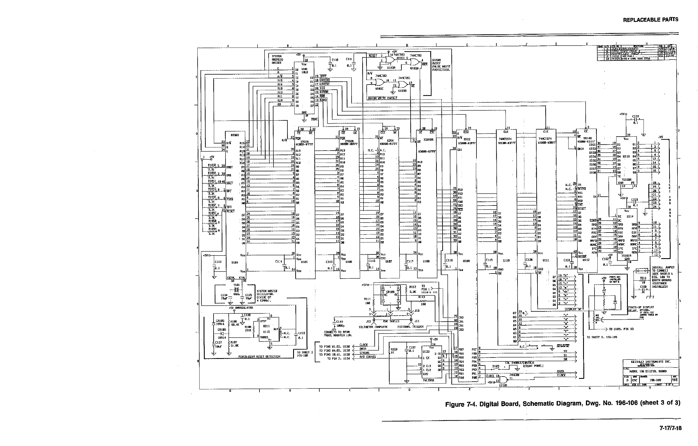
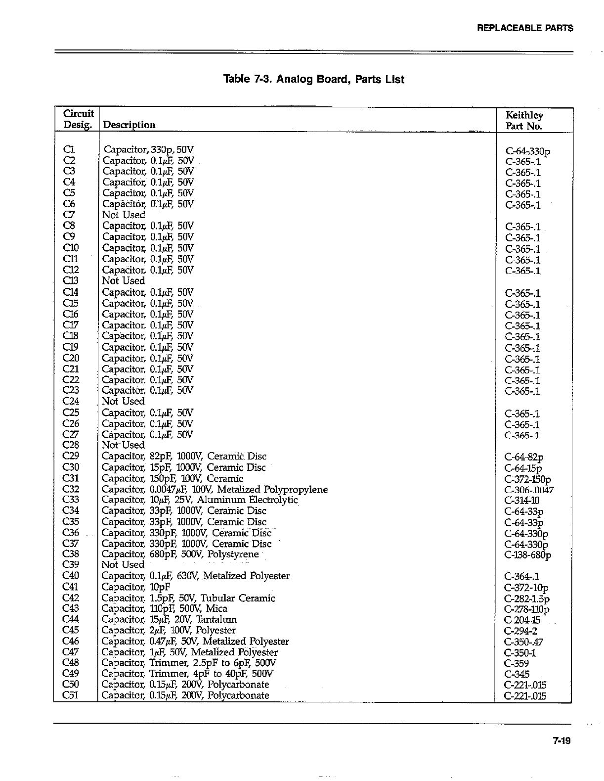
REPLACEABLEPAFITS
Table 7-3. Analog Board, Parts List
Circuit
Desig. Description Keithley
Part No.
I
2
c3
C4
c5
C6
Ei
EL
Cl1
E
Cl4
cl5
z
C24
c25
0.6
C43
C44
C45
C46
C47
C48
c49
z:
Capacitor, 33Op, 50V
Capacitor, O&F, 50V
Capacitor, O$F, 50V
Capacifor,~ 0.$X 50V
Capacitor, O.l& 50V
Capak, O.l& 50V
Not Used
Capacitw O&F, 50V
Capacitor, O.l& 50V
Capacitor, O.lpF, 50V
capacitor, O.lfAF, 5ov
capacitor, O.&F, 5ov
Not Used
capacitor, O.lfLF, 5w
Gpacitor, O.l& 50V
capacitor, O.l& 5OV
Capacitor, O&F, 5OV
CapBcitor, O.i$, 50V
Capacitor, 0.18 50V
Capacitor, O&F, SOV
Capacitor, O.&F, 50V
Capacitor, O&F, 50V
Capacitor, O.l& 50V
Not Used
Capacitor, O.&Z, 50V
Camcitor. O.luE 50V
Capacitor,
Not-Used
Capacitor,
Capacitor,
Capacitor,
Capacitor,
Capacitor,
Capacitor,
Capacitor,
Capacitor,
Capacitor,
Capacitor,
Not Used
Capacitor,
Capacitor,
capacitor,
Cauacitor,
o.i& 50~
c-365-.1
C-365-A
C-365-.1
82pF, lOOW, Ceranik Disc
l5pF, lOOW, Ceramic Disc C-64-82~
I50pE low, Ceramic C-64J5p
0.0047& IOW, Metaliied Polypropylene C-372-150~
C-306-.0047
lo& 25V, Aluminum Electrolytic c-314-10
33pF, loOW, Cerainic Disc
33pF, lOOW, Ceramic Disc C-64-33~
330pF, ‘IOOW, C&amic Disc C-64-33~
330pF, lOOOV, CeramkDisc C-64-330~
680pF, 5OOV, Polystyrene c-64-330p
c-us-68Op
O&F, 63W, ~Metalized Polyester
lopF
15pF, 5OV, Tubular Ceramic
llOuE 5OoV Mica
c-364-.1
C-372-10~
C-282-1.5~
c-278~llop
c-204-15
C-2942
c-350-m
c-350-1
c-359
c-345
c-22s.ow
c-221-.015
ca&2itor, l5$, -2OV, Tantalum
Capacitor, +F, lOOV, Polyester
Capacitor, 0.47@, 5OV, Metalized Polyester
Cqjacitor, l& 5OV, Metalized l%lyester
Capacitor, Trimmer, 2.5pF to 6pF, 500V
Capacitor, Trimmer, 4pF to 4OpF, 500V
Capacitor, O.&F, ZCiOV, Polycarbonate
Capacitor, O.W@, ZOW, Polycarbonate
ca33op
C-3657.1
C-365-S
C-365.1
C-365-A
c-365-.1
C-365-.1
c-365-.1
C-365-.1
C-365.1
C-365-.1
C-365-.1
C-365-.1
C-365-.1
C-365-.1
C-365-.1
C-365-.1
C-365-.1
C-365-A
c-365-.1
c-365-.3
7-19
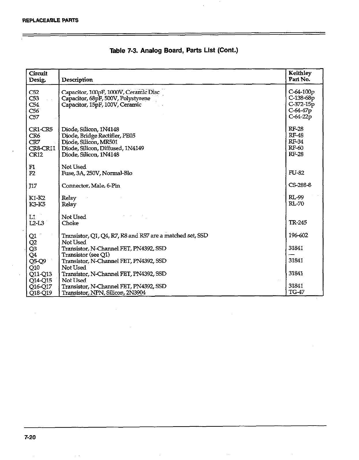
REPLACEABLEPARTS
Table 7-3. Analog Board, Parts List (Cont.)
circuit Keithley
Desig. DfStipti0ll Part No.
c52 Capacitor, lOOpF, lOGOV, Ceramic @SC c&4-loop
c53 Capacitor, 68pF, 5OOV, Polystyrene C-138-68~
CL54 Capacitor, 15pF, lOOV, Ceramic C-372-15~
c56~ t-a-47p
c57 c-64-22p
CRl-CR5 Diode, Silicon, lN4148 RF-28
GE Diode, Bridge Rectifier, I%05 RF-48
Diode, Silicon, MR501 m-34
CR&CR11 Diode, Silicon, Diffused, lN4149 RF-60
CR12 Diode, Silicon, lN4148 RI-28
Fl Not Used
F2 Fuse, 3A, UOV, Normal-B10 FU-82
117 Connector, Male, 6-Pin C5288-8
Kl-IO Relay RL-99
K?rK5 Relay RL-70
LI Not Used
L2-L.3 Choke TR-245
g Transistor, Ql, Q4, R7, R8 and R57 are a matched set, SSD 196-602
Not Used
z Transistor, N-Channel EET, l’N4392, SSD 31841
Transistor (see Ql) -
:cF Transistor, N-Channel FET, PN4392, SSD 31841
Not Used
Qll-Ql3 Transistor, N-Channel ET, PN4392, SSD 31841
Q14-Ql5 Not Used
Transistor, N-Channel FET, PN4392, SSD 31841
Transistor, NPN, Silicon, 2N3904 TG-47
7-20
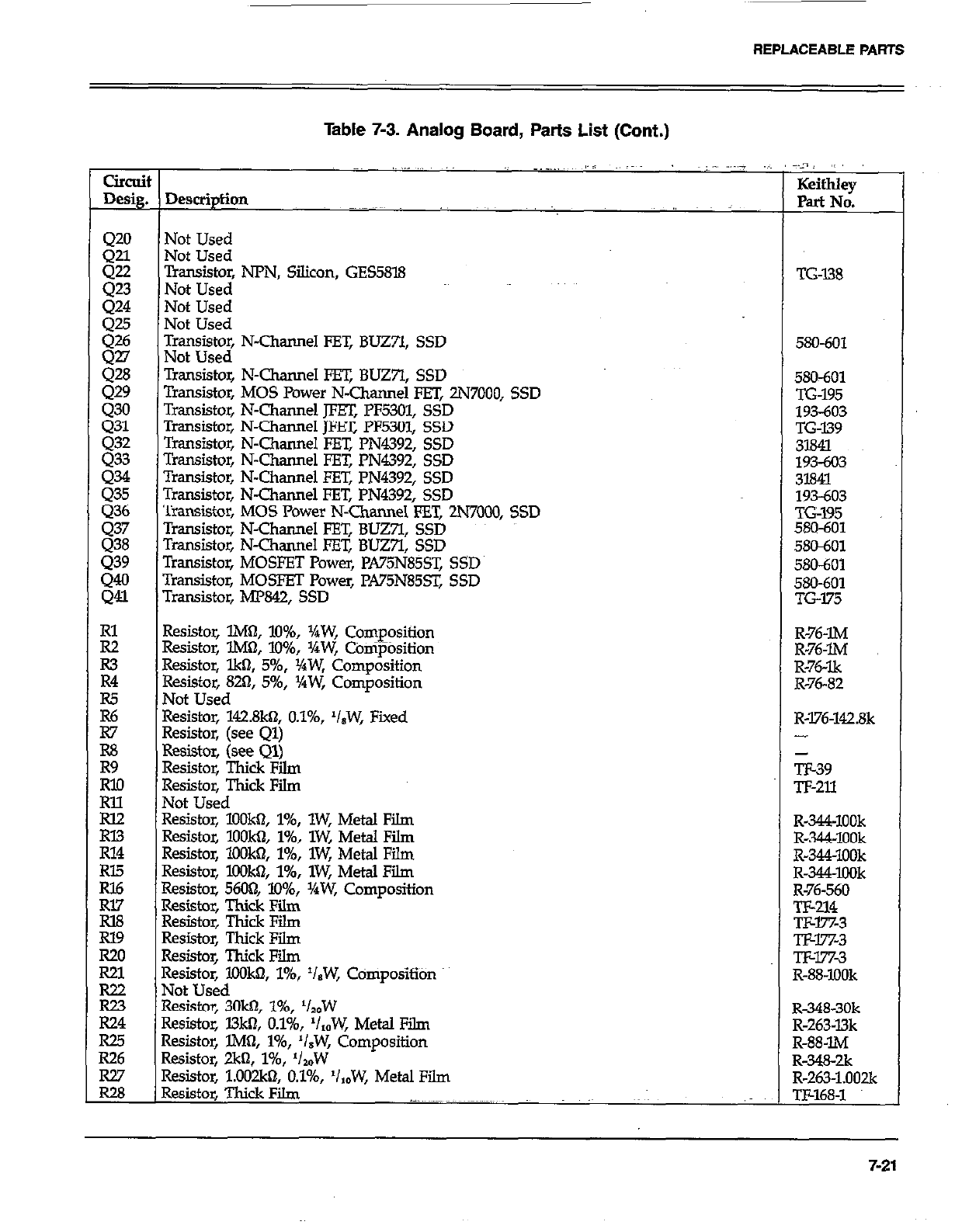
REPLACEABLE PARTS
Table 7-3. Analog Board, Parts List (Cont.)
clrcui
Desig.
420
Q21
gi
424
:Fi
gli
429
430
431
432
Q33
:.z.t
gi
439
::
E
R3
R4
iz
R7
R8
Eo
E
RX.?
R14
Rl5
RI6
Rl7
la8
Rl9
R20
R21
R22
E
R25
R26
Ei
~,., _.,,, I, AL.; ,,,__
Not Used
Not Used
;oWo~ NPN, Silicon, GES5818
Not Used
Not Used
l$s~s~~ N-Channel FET, BLJZYI, SSD
Transistor, N-Channel FET, BUZ7l, SSD
Transistor, MOS Power N-Channel FET, 2N7000, SSD
Transistor, N-Channel JFET, PF5301, SSD
Transistor, N-Channel m PF5301, SSD
Transistor, N-Channel FET, PN4392, SSD
Transistor, N-Channel FET, PN4392, SSD
Transistor, N-Channel En: PN4392, SSD
Transistor, N-Channel FET, PN4392, SSD
Transistor, MOS Power N-Channel FET, 2N7000, SSD
Transistor, N-Channel FET, BUZ;I, SSD
Transistor, N-Channel FET, BUZ7l, SSD
Transistor, MOSFET Power, PA75N85ST, SSD
Tmnsistor, MOSFET Power, PA75N85sT, SSD
Transistor, MP842, SSD
Resistor, lMtI, lo%, j/4W, Composition
Resistor, lM& lo%, XW, COnipOsition
Resistor, lkfl, 5%, VaW, Composition
Resistor, 820, 5%, YrW, Composition
Not Used
Resistor, 142.8kn, O.l%, ‘IsW, Fixed
Resistor, (see Ql)
Resistor, (see Ql)
Resistor, Thick Fii
Resistor, Thick Film
Not Used
Resistor, lOOkn, l%, lW, Metal Film
Resistor, lOOk& l%, lW, Metal Film
Resistor, lOOkiI, l%, lW, Metal Film
Resistor, lOOk& l%, lW, Metal Film
Resistor, 5600, 10%, YrW, Composition
Resistor, Thick Film
Resistor, Thick Film
Resistor, Thick Film
Resistor, Thick Film
Resistor, KKJW, l%, ‘IBW, CdmpositiOn
Not Used
Resistor, 3Okbl, l%, ‘lzdW
Resistor, l3ktI, O.l%, ‘/,,W, Metal Film
Resistor, lM& l%, ‘/.W, Composition
Resistor, 2kfl, 146, ‘/,W
Resistor, l.O02kt?, O.l%, ‘IzbW, Metal Film
Resistor, Thick Film .-.. ~~~._.~~~ ~~~.~.~~~~
:.-n~ ,~
KeithIey
Pat No.
TG-I38
580-601
580&Y
TG-195
193603
TG-139
3l84l
193-603
31841
193-603
TG195
580-601
580601
SKI-601
580-601
TG175
R-76-IM
R-76-m
R-76-lk
R-76-82
R-176-142.8k
-
TE39
Tl-211
R-344-1OOk
R-344~1OOk
R-344~lOOk
R-344XlOk
R-76-560
TF-214
Txw%3
TJ&l%3
Tlw7x3
R-88-IOOk
R-348-30k
R-263~l3k
R-88-IM
R-?&K&
R-263-1.002k
TF-168-l
7-21
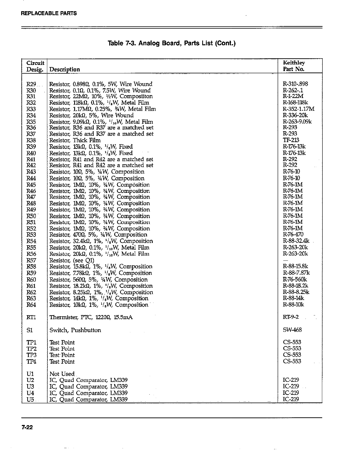
REPLACEABLEPARTS
Table 7-3. Analog Board, Parts List (Cont.)
Circuit Keithley
Desig. Description Part No.
R29~~~ Resistor, 0.8984 O.l%, SW, Wire Wound R-310-.898
R30 Resistor, 0.161, O.l%, %5W, Wire Wound R-262-A
R31 Resistoz 22M0, lo%, %W, Composiiton R-l-22M
R32 Resistor, ll8kn, O.l%, ‘I,W, Metal Film R-168-118k
R33 Resistor, l.E’M~, 0.2596, 3/W, Metal Film R-352.1.17M
R34 Resistor, ZOkn, 5%, Wiie Wound R-336-20k
R35~ Resistor, 9.09kfI, O.l%, ‘I,,W, Metal Fii R-263-9.09k
E Resistor, R36 and R37 are a matched set R-293
Resistor, R36 and R37 are a matched set R-293
zi Resistor, Thick Film TF-213
Resistor, l3k0, O.l%, ‘isW, Fiied R-l76-l3k
R40 Resistor, L3khl, O.l%, ‘isW, Fixed R-176~l3k
R41 Resistor, R41 and R42 are a matched set R-292
Ei Resistor, R41 and R42 are a matched set R-292
Resistor, XX& 5%,~ ~XW, Composition R-76-10
R44 Resistor, 104 5%, XW, Composition R-76-10
R45 Resistor, lMa, lo%, l/aW, CornpOsition R-76~lM
R46 Resistor, lM0, lo%, XW, Composition R-76-IM
R47 Resistor, lM& lo%, %W, Composition R-76~lM
R48 Resistor, lM6t, lo%, VaW, Composition R-76-lM
R49 Resistor, lMn, lo%, Yaw, Composition R-76-w
g Resistor, l.M!?, lo%, %W, Composition R-76-lM
Resistor, lMbl, lo%, Yaw, Composition R-76-m
E: Resistor, lMf& 1096, ‘/rW, Composition R-76-lM
Resistor, 470& 5%, XW, Composition R-76-470
R54 Resistor, 32&o, l%, ‘/,W, Composition R-88-32&
R55 Resistor, 2Ok0, O.l%, ‘/,,W, Metal Film R-263-20k
E; Resistor, 2Ok0, O.l%, ‘/,OW, Metal Film R-263-20k
Resistor, (see Ql)
R58 Resistor, l5.8k0, l%, ‘I,W, Composition R-88-l5.8k
R59 Resistor, 7.78k0, l%, ‘/,W, Composition R-88-7.87k
R60 Resistor, 5604 5%, XW, Composition R-76-560k
R61 Resistor, l8.2kn, I%, ‘/,W, Composition R-88-lK2k
i-2: Resistor, 8.25k3, 1%, .‘/,W, Comptisition R-88-8.25k
Resistor, 14k0, l%, ‘I&W, Composition R-88-1&
R64 Resistor, lDk$?, l%, V,W, Composition R-88-1Ok
RTl Thermister, PTC, 12200, l5.5mA RT-9-2 ~~~
Sl Switch, Pushbutton SW-468
TPl Test Point cs-553
TP2 Test Point cs-553
GE Test~Point cs-553
Test Point CS-553
Ul Not Used
E IC, squad Comparator, LM339 IC-219
IC, Quad Comparator, LM339 IC-219
u4 IC, Quad Comparator, LM339 IC-219
UC IC, Quad Comparator, LM339 IC-219
7-22
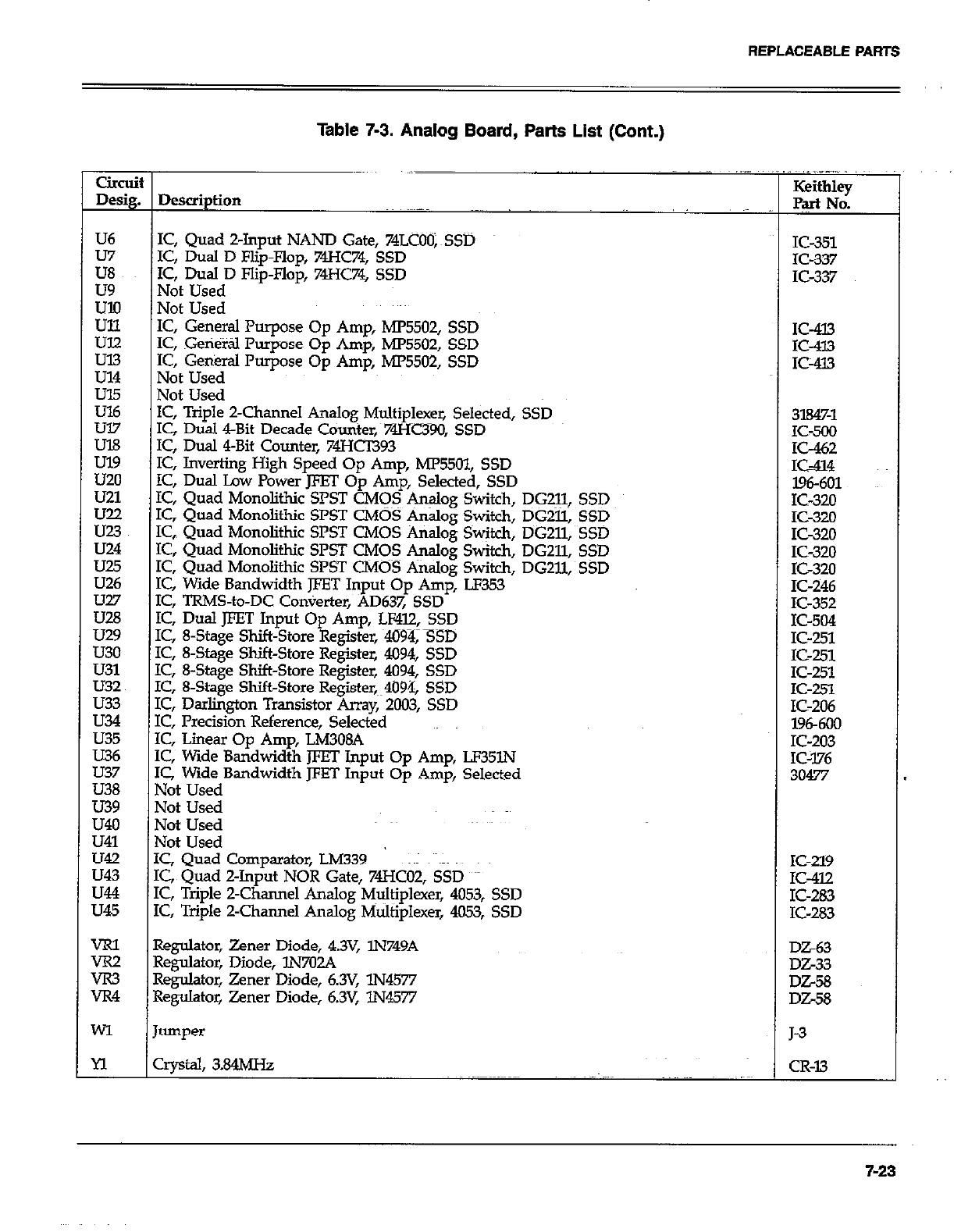
REPLACEABLE PARTS
Table 7-3. Analog Board, Parts List (Cont.)
U6
u7
E
us?
:ii
u21
K.~
U24
u28
U29
u30
u31
U32
LJ33
LJ34
LJ35
LJ36
LJ37
U38
u39
L&o
u41
u42
LJ43
LJ44
35
t Dewiption
I IC, Quad Z-Input NAND Gate, 74LCOO;~SSD
IC, Dual D Flip-Flop, 74HC74, SSD
1’2, Dual D Flip-Flop, 74HC74, SSD
Not Used
Not Used
IC, General Purpose Op Amp, MP5502, SSD
IC, Geti&tl Pumose 00 Arm MP5502. SSD
IC, Genkral Purpose Op Am;, MP5502; SSD
Not Used
Not Used
IC, Triple Z-Channel Analog Multiplexer, Selected, SSD
IC Dtial &Bit Decade Counter. 74Hc390. SSD
IC; Dual 4-Bit Counter, 74Hb93
IC, Inverting High Speed Op Amp, ME5Ol, SSD
IC, Dual Lav Power JFET Op Amp, Selected, SSD
IC, Quad Monolithic SPST CMOS &+og Switch, DG211,
IC, Quad Monolithic SPST CMOS Analog Switch, DGZll,
IC, Quad Monolithic SPST CMOS Analog Switch, DGZll,
IC, Quad Monolithic SPST C&IOS Analog Switch, DG211,
IC, Quad Monolithic SPST CMOS Analog Switch, DG211,
IC, Wide Bandwidth JFET Input Op Amp, LF353
IC, TRMS-to-DC Converter, AD637, SSD
IC, Dual JFET Input Op Amp, LF4l2, SSD
IC, 8-Stage Shift-Store Register, 4094, SSD
IC, 8-Stage Shift-Store Register, 4094, SSD
IC, 8-Stage Shift-Store Register, 4094, SSD
IC, 8-Stage Shift-Store Register,~~4094, SSD
IC, Darlington Transistor Array, 2003, SSD
IC, Precision Reference, Selected
IC, Linear Op Amp, LM308A
IC, Wide Bandwidth JFET Input Op Amp, LP35lN
IC, Wide Bandwidth JFET Input Op Amp, Selected
Not Used
Not Used
Not Used
Not Used
IC, Quad Comparator, LM339 ~~I alms
IC, Quad Z-Input NOR Gate, 74HcO2, SSD
IC, Triple Z-Channel Analog Multiplexer, 4053, SSD
IC, Triple 2-Charmel Analog Multiplexer, 4053, SSD
SSD
SSD
SSD
SSD
SSD
IC-351
IC-337
K-337
IC-413
K-433
IC-413
3l84%1
1C-500
x-462
IS-414
196601
1 IC-320
K-320
K-320
K-320
K-320
K-246
E-352
IC-504
IC-251
IC-251
IC-251
IC-251
IC-206
l96-600
IC-203
IC-376
30477
IC-219
IC-412
IC-283
IC-283
VRl Regulator, Zener Diode, 4.3V, lN749A
ix2 Regulator, Diode, lN702A --__
rR3 Regulator, Zener Diode, 6.3V, lN4577 DZ-58
JR4 Regulator, Zener Diode, 6.3V, lN4577 DiX8
MI Jumper J-3
n crystal, 3.84MHz CR-13
7-23
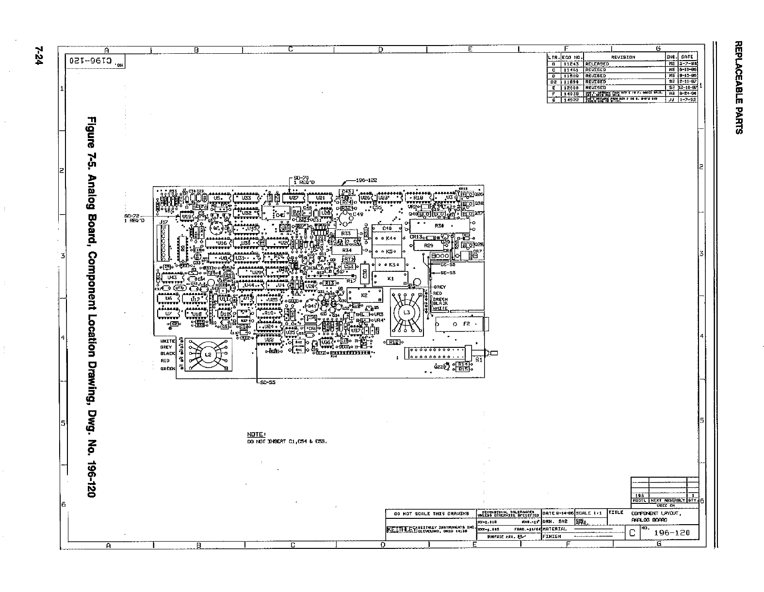
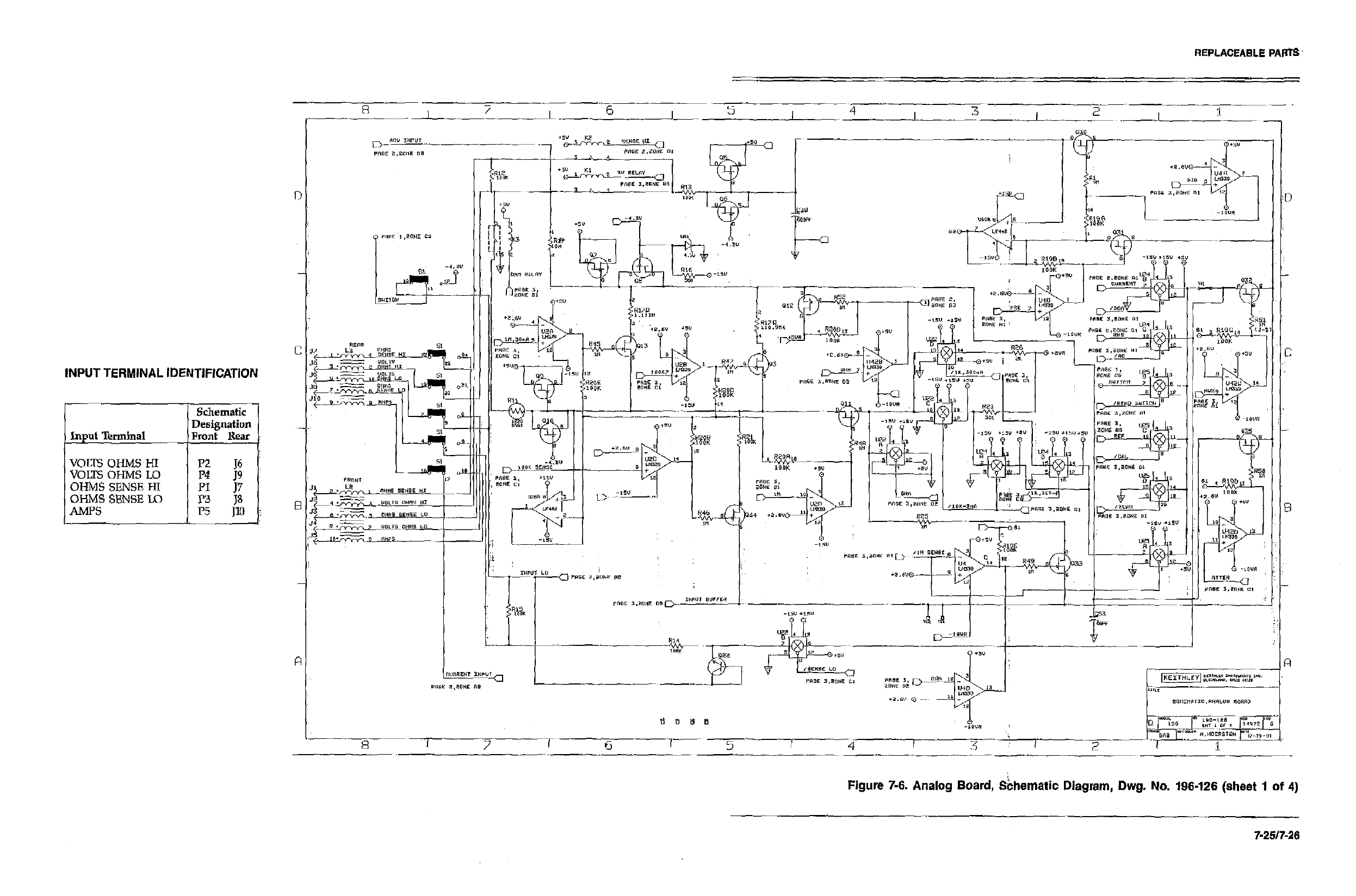
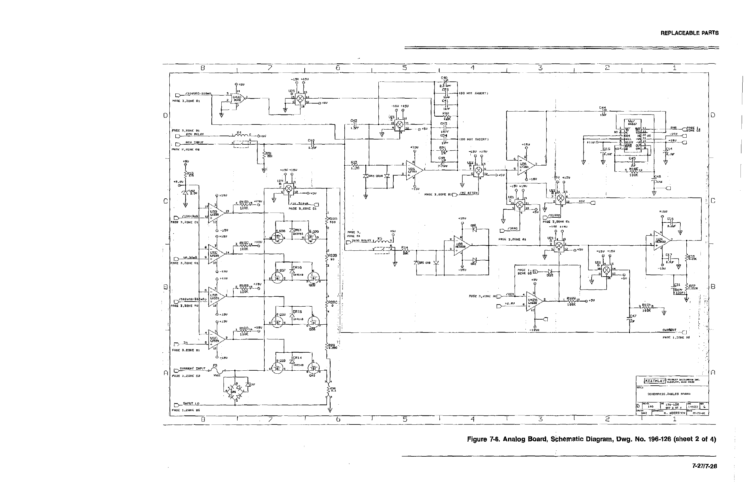
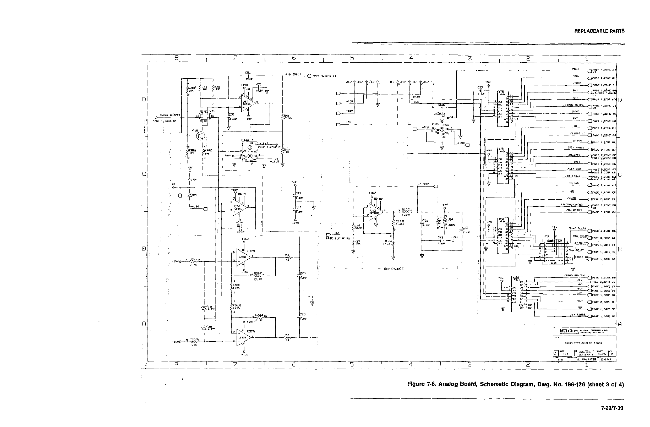
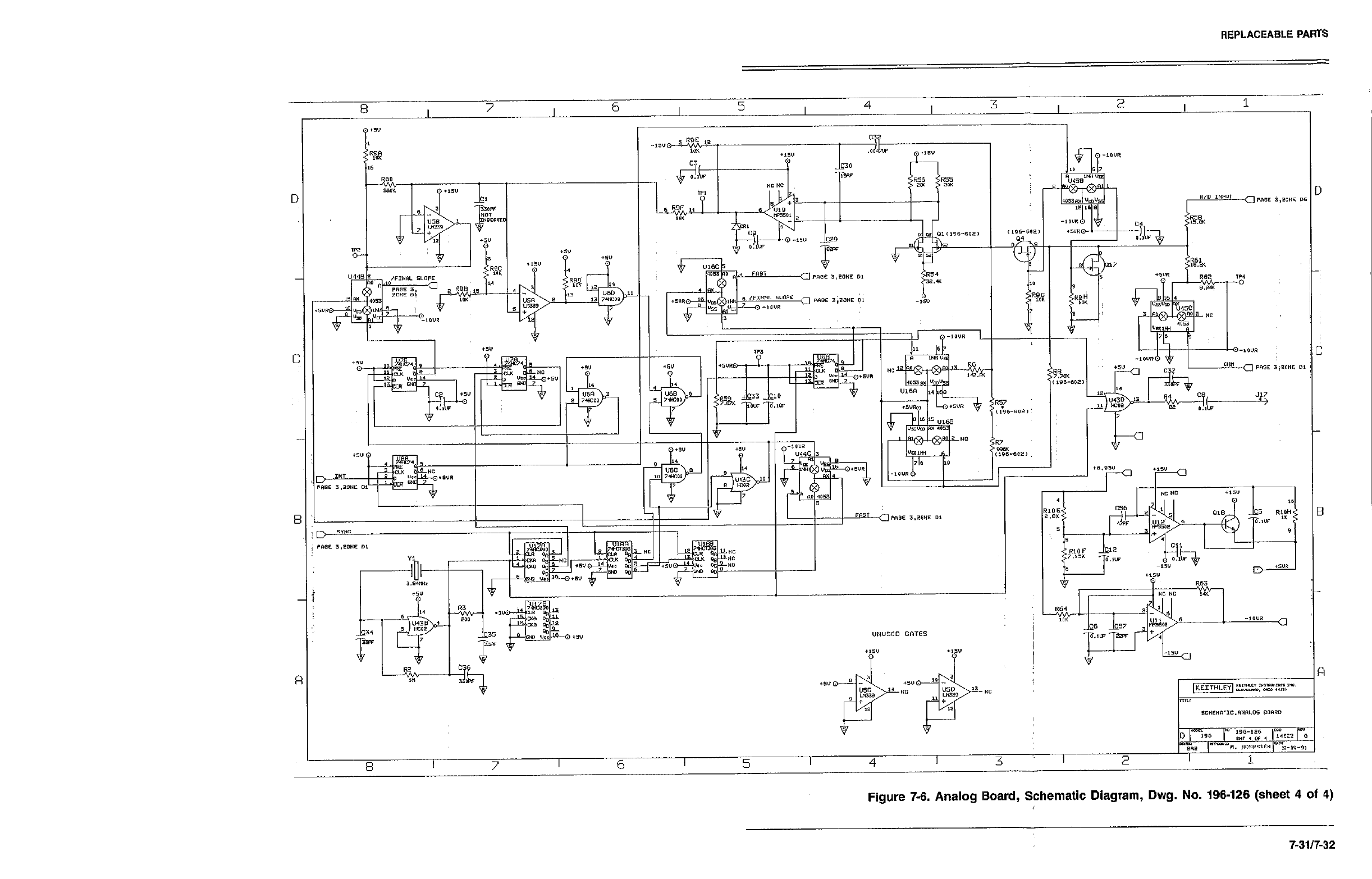
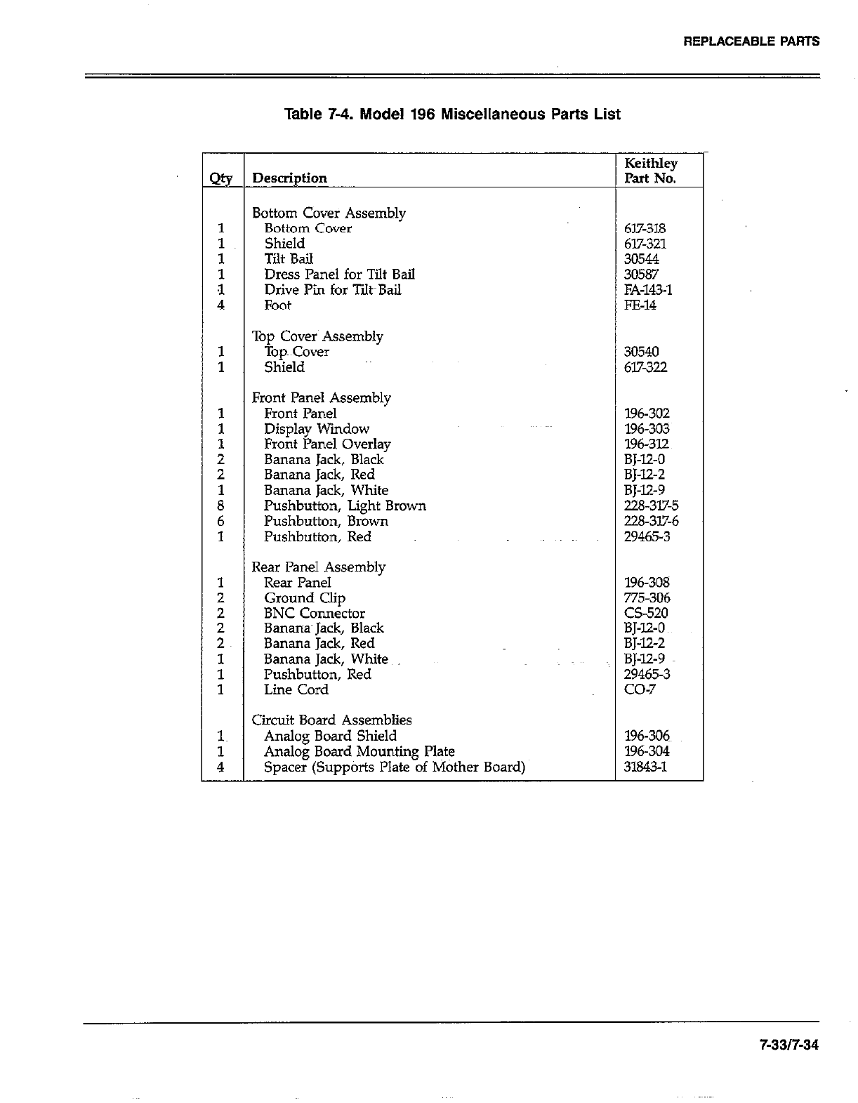
REPLACEABLE PARTS
-
2%
1
:
t
4
1
1
1
1
1
2
2
i
6
1
1
;
2
2~
1
1
1
1~
i
-
Table 7-4. Model 196 Miscellaneous Parts List
Description
3ottom Cover Assembly
Bottom Cover
Shield
Tilt Bail
Dress Panel for Tilt Bail
Drive Pi for Tilt~Bail
Foot
Tou Cover Assemblv
-iOP~ Cover ’ 30540
Shield 617-322
?ront Panel Assembly
Front Panel
Display Window
Front Panel Overlay
Banana Jack, Black
Banana Jack, Red
Banana Jack, White
Pushbutton, Light Brown
Pushbutton, Brown
Pushbutton, Red
7e.w Panel Assembly
Rear Panel
Ground Clip
BNC Connector
Bananas Jack, Black
Banana Jack, Red
Banana Jack, White
Pushbutton, Red
Line Cord
Xrcuit Board Assemblies
Analog Board Shield
Analog Board Mounting Plate
Spacer (Supports Plate of Mother Board)
Keithley
Part No.
617-318
617-321
30544
30587
FA-143-l
FE-14
196-302
196-303
196-312
BJ-12-O
BJ-12-2
BJ-12-9
228-317-5
228-317-6
29465-3
196-308
775-306
CS-520
BJ-12-O
BJ-X2-2
BJ-12-9
29465-3
co-7
196-306
196-304
31843-l
7-an-34
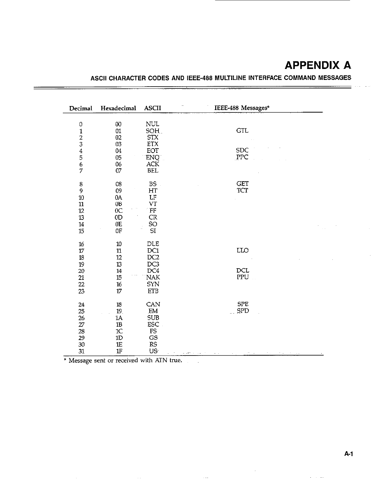
APPENDIX A
ASCII CHARACTER CODES AND IEEE-488 MULTILINE INTERFACE COMMAND MESSAGES
Decimal Hexadecimal ASCII IEEE-488 Messages*
0 00
1 01
2 02
3 4 ifi
5
6 z:
7 07
; 08
09
10 OA
11 OB
iii oc
OD
ii OE
OF
16 10
17 11
18 12
19 13
20 14
21 15
22 16
23 17
24 18
25
26 18
1c
29 1D
30 lE
NUL
SQH~~ GTL
EOT SDC
~PPC
BS
H-r
LF
VT
E
so
SI
DLE
DC1
DC2
DC3
DC4
~NAK
SYN
ETB
CAN
EM
SUB
ESC
FS
GS
RS
GET
TCT
LX0
DCL
IWJ
X=‘E
SPD
31 IF USA .i~.
* Message sent or received with ATN true.
A-l
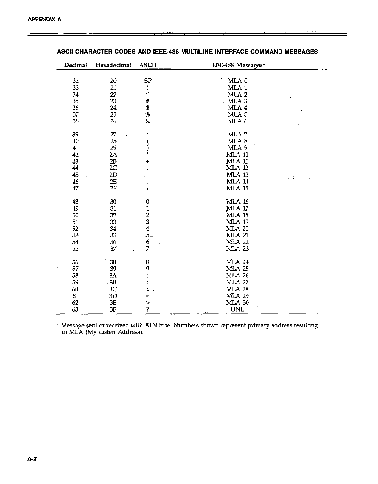
APPEND\X A
ASCII CHARACTER CODES AND IEEE-488 MULTILINE INTERFACE COMMAND MESSAGES
Decimal Hexadecimal ASCII IEEE488 Messages*
32 20
33
34 z
35 23
36 24
25
26
39 27
4.0 28
ii 29
2A
43 28
44 2c
E 2D
2E
47 2F
48 30
49 31
50 32
51 33
Ei 34
35
54
55 :;
SP
!,
n
#
$
%
&
MLAO
.MLAl
ML‘52
MLA 3
MLA4
MLA 5~
MLA6
MLA 7
MLA 8
MLA9
MLA 10
MLA 11
MLAl2
MLA 13
~MiA 14
MLA 15
MLA 16
MLA 17
MLA 18
MLA 19
MLA 20
MLA 21
MLA 22
MLAW
56 38
57 39
58
59 2
60 3c
61 3D a
62 3E >
63 3F ? UNL
MLA~24
MLA 25
ML.4 26
MLA2.7
MLA 28
MLA 29
~MLA 30
* Message sent or received with KIN true.~Numbers shown represent primary address resulting
in ML4 (My Listen Address).
A-2
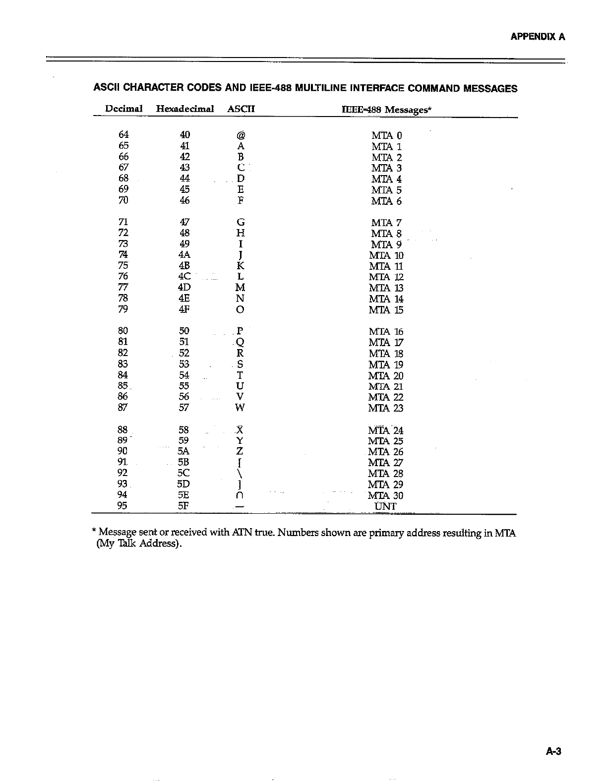
APPENDIX A
ASCII CHARACTER CODES AND IEEE-488 MULTILINE INTERFACE COMMAND MESSAGES
Decimal Hexadecimal ASCII IEEE=488 Messages*
40
41
:
it
46
47
:
4.4
4E
4c
4D
4E
4F
50
51
52
53
54
55
56
57
58
59
5A
5B
5c
5D
5E
@
A
:
D
z
G
H
I
S
T
U
z
x MT.4 24
MTA6
Es’
MTA9
MTA 10
ilK%i
MTAl3
MT.4 14
ml5
MIX 16
MTN.7
MT.418
MT.4 19
MTA 20
Mm 21
EE
tEz
MT.427
MTA 28
MT4 29
MT4 30
95 5F UNT
* Message sent or received with ATN true. Numbers shown are primary address resulting in MTA
(My Xlk Address).
A-3
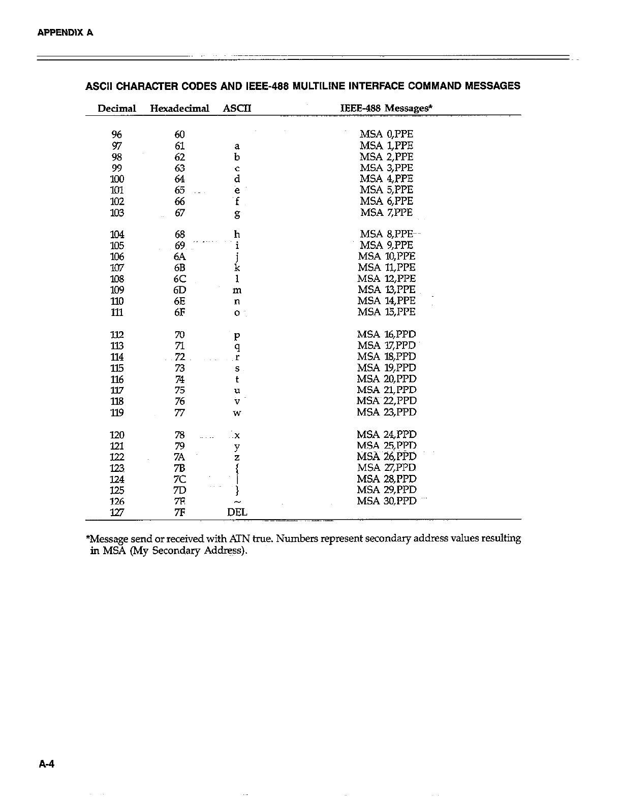
APPENDIX A
ASCII CHARACTER CODES AND IEEE-488 MULTILINE INTERFACE COMMAND MESSAGES
Decimal Hexadecimal ASCII IEEE-488 Messages*
96 60
97
98
99
ii: 65
102 66
103 67
lo4 68
E 69 ~” -~
6A
107 68
lO8 6C
lo9 6D
110 6E
111 6F
ll.2 70
n
~72
115 73
116 74
ll.7 75
1X3 76
119 77
h
i
k
MSA 0,PPE
MSA 1,l’l’E
MSA 2,PPE
MSA 3;PpE
MSA 4,PPE
MSA 5,PPE
MSA 6,IT’E
MSA 7,l’l’E
MSA S,PPE-
MSA 9,PPE
MSA 10,l’l’E
MSA 11,PPE
MSA l2,l’PE
MSA l3;PPE
MSA 14,l’PE :
MSA l5,I’PE
MSA l6,PPD
MSA lX’I?D
MSA 18,l’l’D
MSA 19,PPD
MSA 20,Pl’D
MSA 21.l’PD
MS?% 22,iTD
MSA 23,ppD
MSA 24J’PD
MSA 25,PrD
MSAi6,PPD
MSA 27,PPD
124 7c MSA 28,PPD
125 7D MSA 29,PPD
126 7E MSA 30,I’l’D
127 7F IJEL
*Message send or received with ATN hue. Numbers represent secondary address values resulting
in MSA (My Secondary Address).
A-4
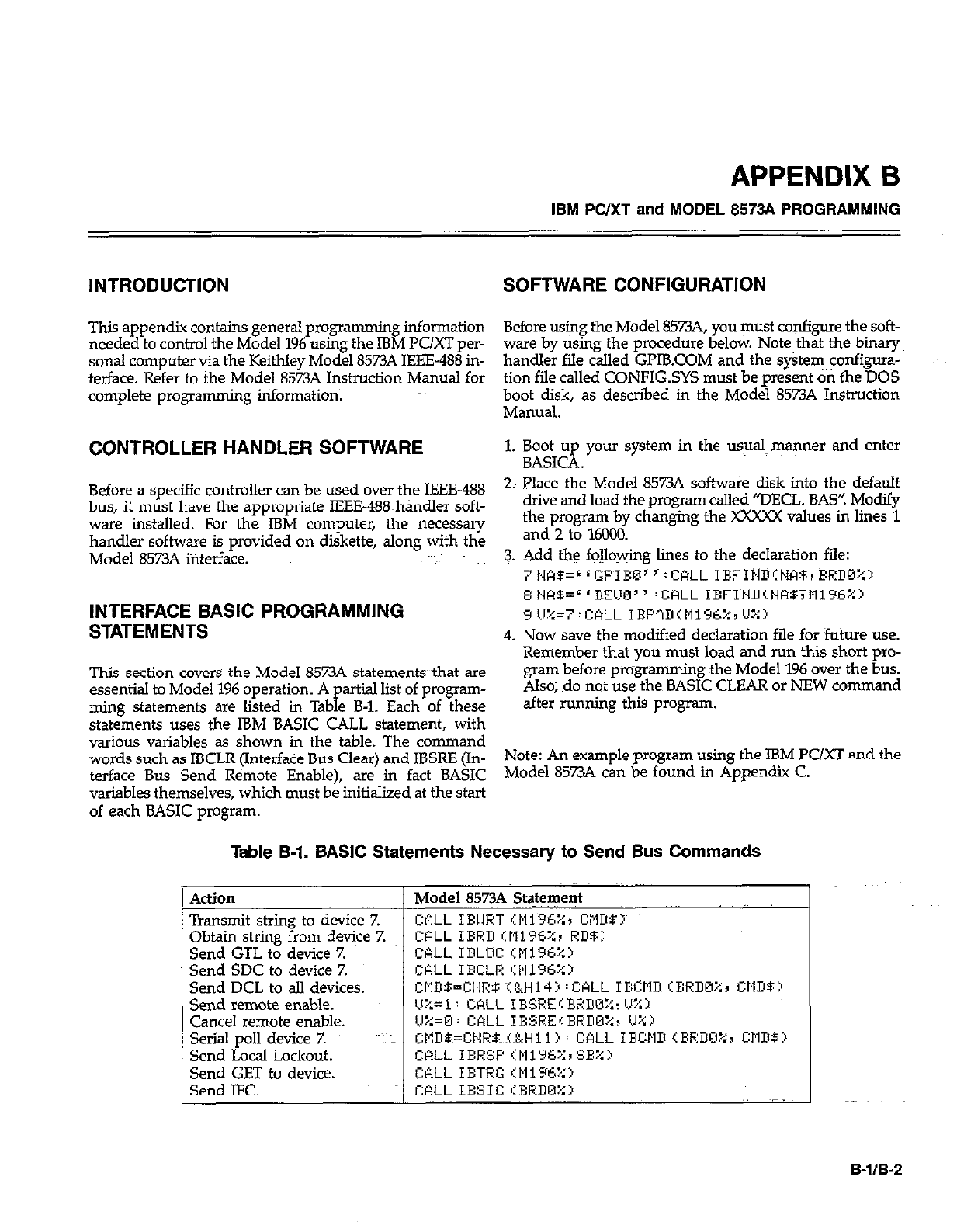
APPENDIX 6
IBM PC/XT and MODEL 8573A PROGRAMMING
INTRODUCTION SOFTWARE CONFIGURATION
This appendix contains general programming information Before~using the Model 8573A, you mustconfigure the soft-
needed to control the Model 196 using the IBM PUG per- ware by using the procedure below. Note that the binary
sonal computer via the Keithley Model 8573A IEEE-488 in- handler fde called Gl’lB.COM and the system ~onfigura-
terface. Refer to the Model 8573A Instruction Manual for tion file called CONFIG.SYS must be present on the DOS
complete programming information; booty disk, as described in the Model 8573A Instruction
Mamlal.
CONTROLLER HANDLER SOFTWARE 1. Boot up your system in the usual manner and enter
BASICA. ~~~
Before a specific tiontroller can be used over the IEEE-488
bus, it must have the appropriate IEEE-488~handler soft-
ware installed. For the IBM computer, the necessary
handler software is provided on diskette, along with the
Model 85734 interface.
INTERFACE BASIC PROGRAMMING
STATEMENTS
This section covers the Model 8573A statements that are
essential to Model 196 operation. A partial list of program-
ming statements are listed in Table B-l. Each of these
statements uses the IBM BASIC CALL statement, with
various variables as shown in the table. The command
words such as IBCLR (Interface Bus Clear) and IBSRE (In-
terface Bus Send Remote Enable), are in fact BASIC
variables themselves, which must be initialized at the start
of each BASIC program.
2; Place the Model 8573A software disk into~ the default
drive and load the program called “DECL. BAS’! Modify
the program by changing the XXXXX values in lines 1
and 2 to l6Ci30.
3. Add the fojlowing lines to the declaration file:
: #*EL i Gp~IBMI 5~ : CALL IEFIN~IN178~,~XHDU%j
8 t.tcI$=L ‘DEW3 ’ CALL IXFI~HD~NW~Mi96%:~
9 II%=7:mLL IEPfmItli96%rU:+~>
4. Now save the modified declaration file for future use.
Remember that you must load and nm this short pro-
gram before programming the Model 196 over the bus.
Also; do not use the BASIC~CLEAR or NEW command
after running this program.
Note: An example program using the IBM PC/XT and the
Model 8573A can be found in Appendix C.
Table B-l. BASIC Statements Necessary to Send Bus Commands
ActlOll
Transmit string to device Z
Obtain string from device Z
Send GTL to device Z
Send SDC to device 7.
Send DCL to all devices.
Send remote enable.
Cancel remote enable.
Serial poll device 7.
Send Local Lockout.
Send GET to device.
Send LFC.
Model 8573A &+ame+
CALL IBl.tRT ‘:Eii%::r CMDBI~
B-IIB-2
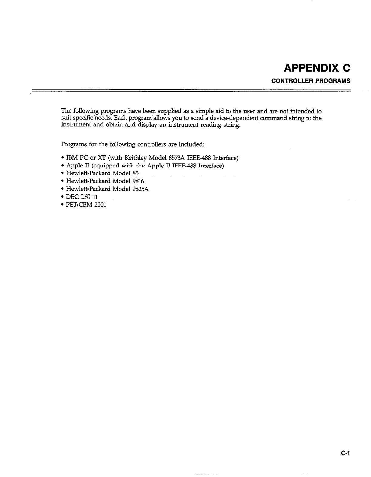
APPENDIX C
CONTROLLER PROGRAMS
The following programs have been supplied as a simple aid to the user and are not intended to
suit specific needs. Each progrm~allows you to send a device-dependent command string to the
instrument and obtain and display an instrument reading string.
Programs for the following controllers are iqcluded:
l IBM PC or XT (with Keithley Model 8573A IEEE-488 Interface)
l Apple II (equipped with the Apple II IEEE-488 Interface)
l Hewlett-Packard Model 85
l Hewlett-Packard Model 9816
l HewlettJ’ackxd Model 9825A
. DEC LSI 11
. l’ET/CBM 2001
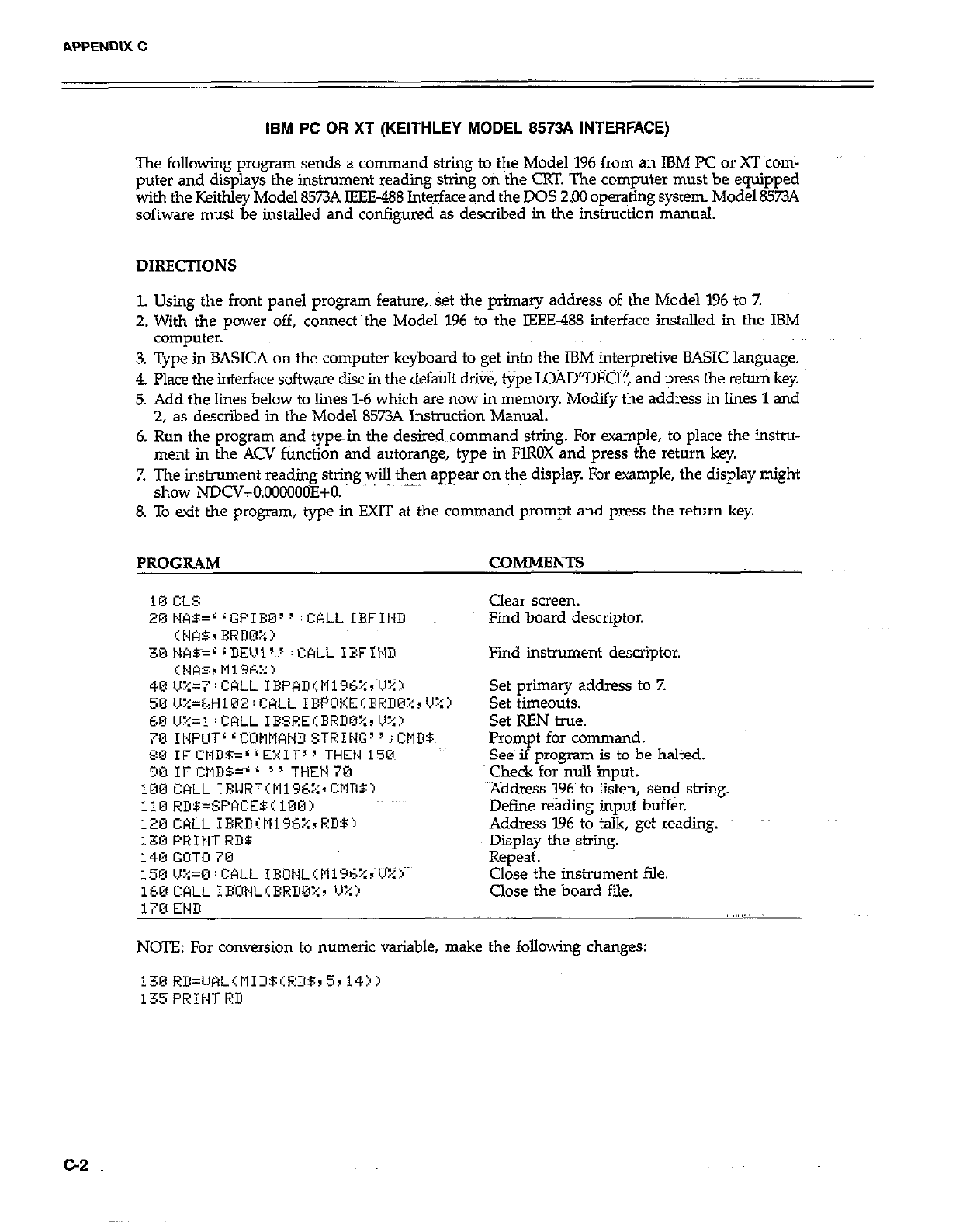
APPENDIX C
IBM PC OR XT (KEITHLEY MODEL 8573A INTERFACE)
The following program sends a command string to the Model 196 from an IBM PC or XT corn-
puter and displays the instrument reading string on the CRT. The computer must be equipped
with the Keithley Model 8573A IEEE-488 Int&ace and the DOS 2.00 oper+ing system. Model 8573A
software must be installed and configured as described in the instruction manual.
DIRECTIONS
1. Using the front panel program feature, set the primary address of the Model 196 to 7.
2. With the power off, connea~the Model 196 to the IEEE-488 interface installed in the IBM
computer.
3. Type in BASICA on the computer keyboard to get into the IBM interpretive BASICS language.
4. Place the interface software disc in the default drive, type LOAD”DECI?, and press the return key.
5. Add the lines below to lines l-6 which are now in memory. Modify the address in lines 1 and
2, as descried in the Model 8573A Instruction Manual.
6. Run the program and typein the desired~~command sting. For example, to place the instru-
ment in the ACV function and autoiawe, tvue in FlROX and press the return kev.
I. I_
7. The instrument reading string will then appear on the display. l&r example, the display might
show NDCV+O.OOOOO(IE+O.
8. To exit the program, type in EXIT at the command prompt and press the return key.
PROGRAM CwMENTs
Clear screen.
Find board descriptor.
Find instrument descriptor.
Set primary address to 7.
Set timeouts.
Set REN true.
Prompt for command.
Se& if program is to be halted.
check for null input.
YAddress 196~ to listen, send string.
Defme reading input buffer.
Address 196 to talk, get reading.
Display the string.
Repeat.
Close the instrument file.
Close the board file.
NOTE: For conversion to numeric variable, make the following changes:
130 RD=VHL,~tlIDBiRDB~5~ 14jj
135PRINTRD
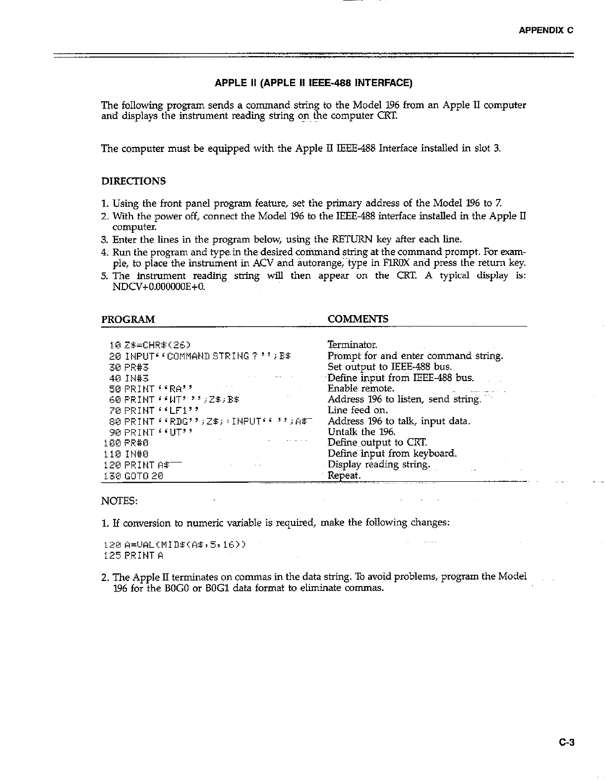
APPENDIX C
APPLE II (APPLE II IEEE-488 INTERFACE)
The following program sends a command string to the Model 196 from an Apple II computer
and displays the instrument reading string on the computer CRT.
The computer must be equipped with the Apple II IEEE-488 Interface installed in slot 3.
DIRECTIONS
1. Using the front panel program feature, set the primary address of the Model 196 to 7.
2. With the po-wer off, connect the Model 196 to the IEEE-488 interface installed in the Apple II
computer.
3. Enter then lines in the program below, using the RETURN key after each line.
4. Run the program and typein the desired cotimand string at the command prompt. For exam-
ple, to place the instrument in ACV and autorange; ~tipe in FlROX and press the return key.
5. The instrument reading string will then appear on the CRT A typical display is:
NDCV+O.OOOOOOE+O.
PROGRAM COMMENTS
Terminator.
Prompt for and enter command string.
Set output to IEEE488 bus.
4E1 It4#3 ~Define hput froti~ IEEE-488 bus.
50 PI?1 NT r L RA’ ’ Enable remote.
60 PRINT ‘ r MT7 ’ I i ZB.; ES: Address 196 to listen, send string. map
7@FRINT rrLFi” Line feed on.
~~F’RIt~T~~RDG’~;2$j:It~FCITrr “illlBm Address 196 to talk, input data.
90 PRINT <<UT” Untalk the 196.
100 PR#O Defiie~output to CRT.
ii9 IH#U Defines input from keyboard.
120 PRINT f%- Display reading string.
130 GUTl2Ei Repeat.
NOTES:
1. If conversion to numeric variable iS required, make the following changes:
2. The Apple II terminates on commas in the data string. To avoid problems, program the Model
196 for the BOG0 or BOG1 data format to eliminate commas.
c-3
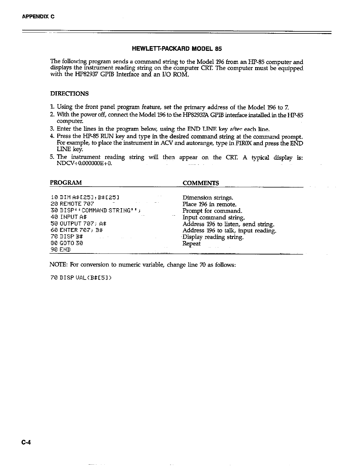
HEWLETFPACKARD MODEL 85
The following program sends a command string to the Model 196 from an HP-85 computer and
displays the instrument reading string on the computer CRT. The computer must be equipped
with the HP82937 GPIB Interface and an I/O ROM.
DIRECTIONS
1. Using the front panel program feature, set the primary address of the Model 196 to Z
2. with the power off, connect the Model 796 to the HP82937A GPIB interface installed in the HP85
computer.
3. Enter the lines in the program below, using the END LINE key after each line.
4. Press the HP-85 RUN key and type in the desired command string at the command prompt.
For example, to place the instrument in ACV and autorange, type in FlROX and press the END
LINE kev.
5. The instrument reading string wi!.l then appear on the CW. A typical display is:
NDCV+O.OOOoOOE+O.
PROGRAM COMMENTS
10 DIM WL251, BBC251
20 REMOTE 707
30DISPL’COMMCINDSTRIt~G~‘j
Dimension strings.
Place 196 in remote.
Promot for command.
40 IWUT A8
50 OUTPUT 707; A5 Input’command shing.
C0 ENTER 707; B9 Address 196 to listen, send string.
70 DISP BO: Address I.96 to talk, input reading.
~Display reading string.
80 GOTU 30
90 END Repeat
NOTE: For conversion to numeric variable, change line 70 as follows:
c-4
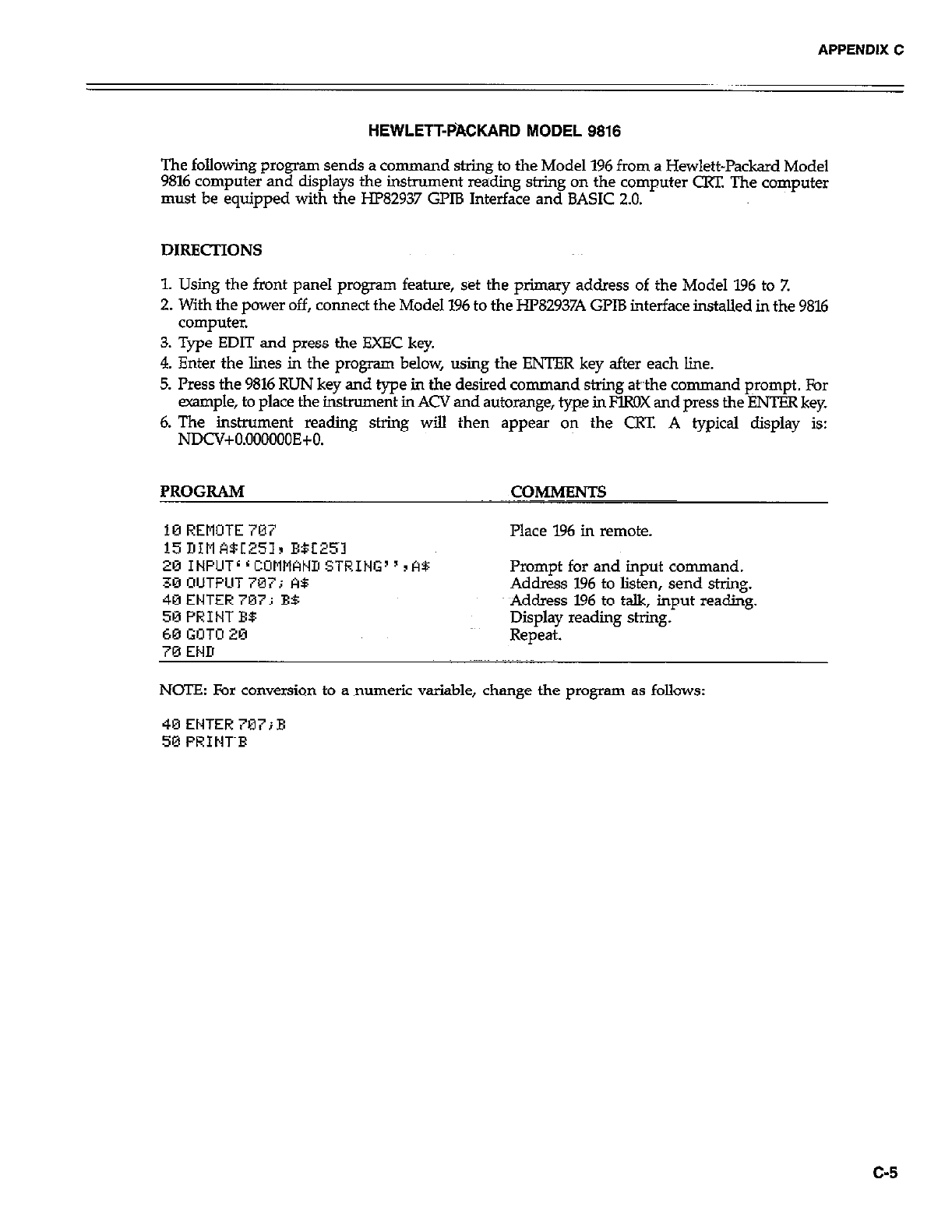
APPENDIX C
HEWLETT-PACKARD MODEL 9818
The following p~ogrm sends a command string to the Model 196 from a Hewlett-Packard Model
9816 computer and displays the instrument readiig string on the computer CRT. The computer
must be equipped with the HP82937 GPlB Interface and BASIC 2.0.
DIRECTIONS
1. Using the front panel program feature, set the primary address of the Model 196 to Z
2. With the power off, connect the Model 196 to the HP82937A GPIB interface installed in the 9816
computer.
3. Type EDIT and press the EXEC key.
4. Enter the lines in the program below, using the ENTER key after each line.
5. Press the 9816 RUN key and type in the desired command string &the command prompt. For
example, to place the instrument in ACV and autorange, type in FlROX and press the ENTER key.
6. The inshument reading string will then appear on the CRT. A typical display is:
NDCV+O.OOOOOOE+O.
PROGRAM COMMENTS
10 REMOTE707 Place 196 in remote.
15 DIM A5[251r E5E25~1
201NPUTLrCOMNANIISTRING”rA5:
30 OUTPUT 707; A5
40ENTER707i BB
50 PRINT E$
60 GOT0 20
70 END
Prompt for and input command.
Address 196 to listen, send string.
Address 196 to talk, input reading.
Display reading string.
Repeat.
NCYE: For conversion to a numeric variable, change the program as follows:
40ENTER707;E
50 PRINT~F
c-5
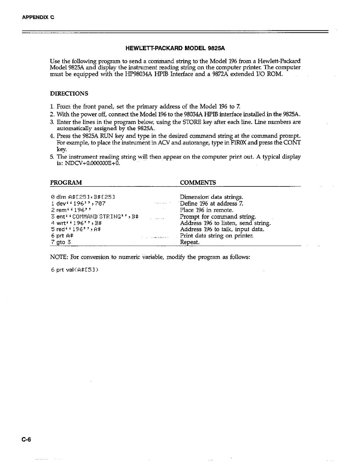
APPENDIX C
HEWLETT-PACKARD MODEL 9825A
Use the following program to send a conirixand string to-the Model 196 from a Hewlett-Packard
Model 9825A and display the instrument reading string on the computer printer. The computer
must be equipped with the HP98034A HPlB Interface and a 98724 extended I/O ROM.
1. Fr%%ri the front panel, set the primary address of the Model 196 to 7.
2. With the power off, connect the Model 196 to the 98034A HPlB interface installed in the 9825A.
3. Enter the lines in the program below, using the STORE key after each line. Line numbers are
automatically assigned by the 9825A.
4. Press the 9825A RUN key and typein the desired command string at the command prompt.
For example, to place the instrument~in ACV and autorange, type in FlROX and press the CONT
key.
5. The instrument reading string will then~appear on the computer print out. A typical display
is: NDCV+O.OOOOOOE+O.
PROGRAM COMMENTS
Dimension data strings.
~Defiie 196 at address 7.
Place 196 in remote.
Prompt for command string.
Address 196 to listen, send string.
Address 196 to talk, input data.
Print data string on printer.
Repeat.
NOTE: For conversion to numeric Variable, modify the program as follows:
6 prt valIABC51)
C-8
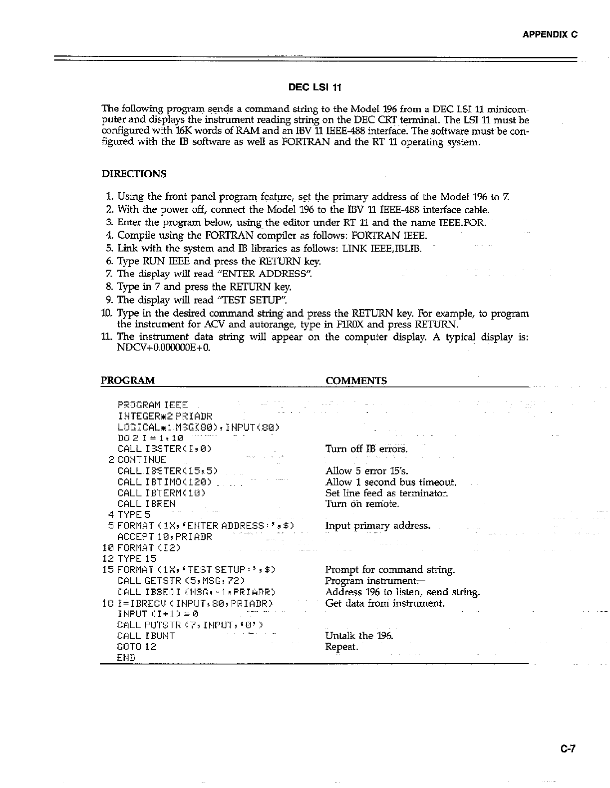
APPENDIX C
DEC LSI 11
The following program sgnds a command string to the Model 196 from a DEC LSI ll minicom-
puter and displays the instrument reading string on the DEC CRT~t$nnin& The LSI 11 must be
configured with l6K words of RAM and an IBV 11 IEEE-488 interface. The software must~be con-
figured with the IB software as welI as FORTRAN and the RT 11 operating system.
DIRECTIONS
1. Using the front panel program feature, set the primary address of the Model 196 to 7.
2. With the power off, connect the Model 196 to the IBV 11 IEEE-488 interface cable.
3. Enter the program below, using the editor under RT 11 and the name IEEEFOR.
4. Compile using the FORTRAN compiler as folIows: FORTRAN IEEE.
5. Link with the system and IB libraries as follows: LINK IEEE,IBLIB.
6. Type RUN IEEE and press the RETURN key.
Z The display will read “ENTER ADDRESS”.
8. Type in 7 and press the RETURN key.
9. The display wiIl read “TEST SETUP’:
10. Type in the desired command string and press the RETURN key. For example, to program
the instrument for ACV and autorange, type in FlROX and press REZTURN.
11. The instrument data string will appear on the computer display. A typical display is:
NDCV+O.OOOOOOE+O.
PROGRAM
CkLL IESTER’I,B>
2 CONTINUE
CRLL IBSTER115rS:n
WLL IBTIM~O~:120~
CALLIETERM<lO>
CtiLL IRREN
4 T’iPE 5
5 FORWT < 1X, r ENTER ADDRESS : ’ 3 BZ’
ACCEPT 10sPRIADR
10 FURMAT <12:)
12 TYPE 15
i5FORMATr.iX~LTE!~TSETUP:‘~5:~
CALL GETSTR (53 NSG, 72)
CALL IESEOI IMfG, -1sPRIADHj
1E: I=IEREC!J (INPCIT, 80, PRIADR:l
INPCIT II+13 =0
CALL PIJTSTR 177 INPUT, 80’ >
CQLL IBUNT
GOT0 12
END
- COMMENTS
Turn off IB etiors.
Allow 5 error 15’s.
Allow 1 second bus timeout.
Set line feed as terminator.
Turn Ofi remote.
Input primary address.
Prompt for command string.
Frogran instruments
Address 196 to listen, send string.
Get data from instrument.
Untalk the 196.
Repeat.
G7
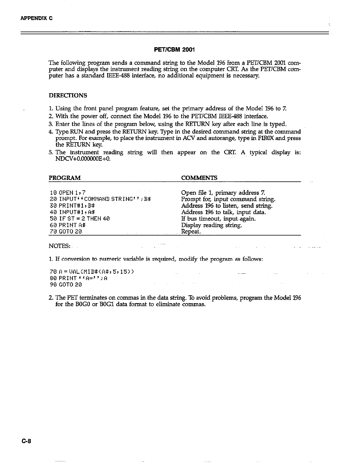
PETICBM 2001
The following program sends a co mmand string to the Model 196~ from a l%T/CBM 2001 com-
puter and displays the instrument reading string on the computer CRT. As the PB UCBM corn-
puter has a standard IEEE-488 interface, no additional equipment is necessary.
DIRECTIONS
1. Using the front panel program feature, set the primary address of the Model 196 to Z
2. With the power off, connect the Model 196 to the PETlCBM IEEE-488 interface.
3. Enter the lines of the program below, using the RETURN key after each line is typed.
4. TypeRUN and press the RETURN key. Type in the desired command string at the command
prompt. For erample, to place the instrument in ACV and autorange, types in FlROX and press
the RETURN key.
5. The instrument reading string will then appear on the CRT. A typical display is:
NDCV+O.OOOOOOE+O.
PROGRAM COMMENTS
18OPEN ir7
20 INPUT’ r CCMliWD STRING’ F ;EB
30 PRINT#lrE$
40 INPLlT#i I A$
59 IF ST=2 THEN 40
60 PRINT A$
70 GOTO 20
NOES:
Open file 1, primary address Z
Prompt for, input command string.
Address 196 to listen, send string.
Address 196 to talk, input data.
If bus timeout, input~~~again.
Epldl reading string.
P
1. If conversion to numeric variable is required, modify the program as follows:
2. The PET terminates on commas in the data string. To avoid problems, program the Model 196
for the BOG0 or BOG1 data format to eliminate commas.
G8
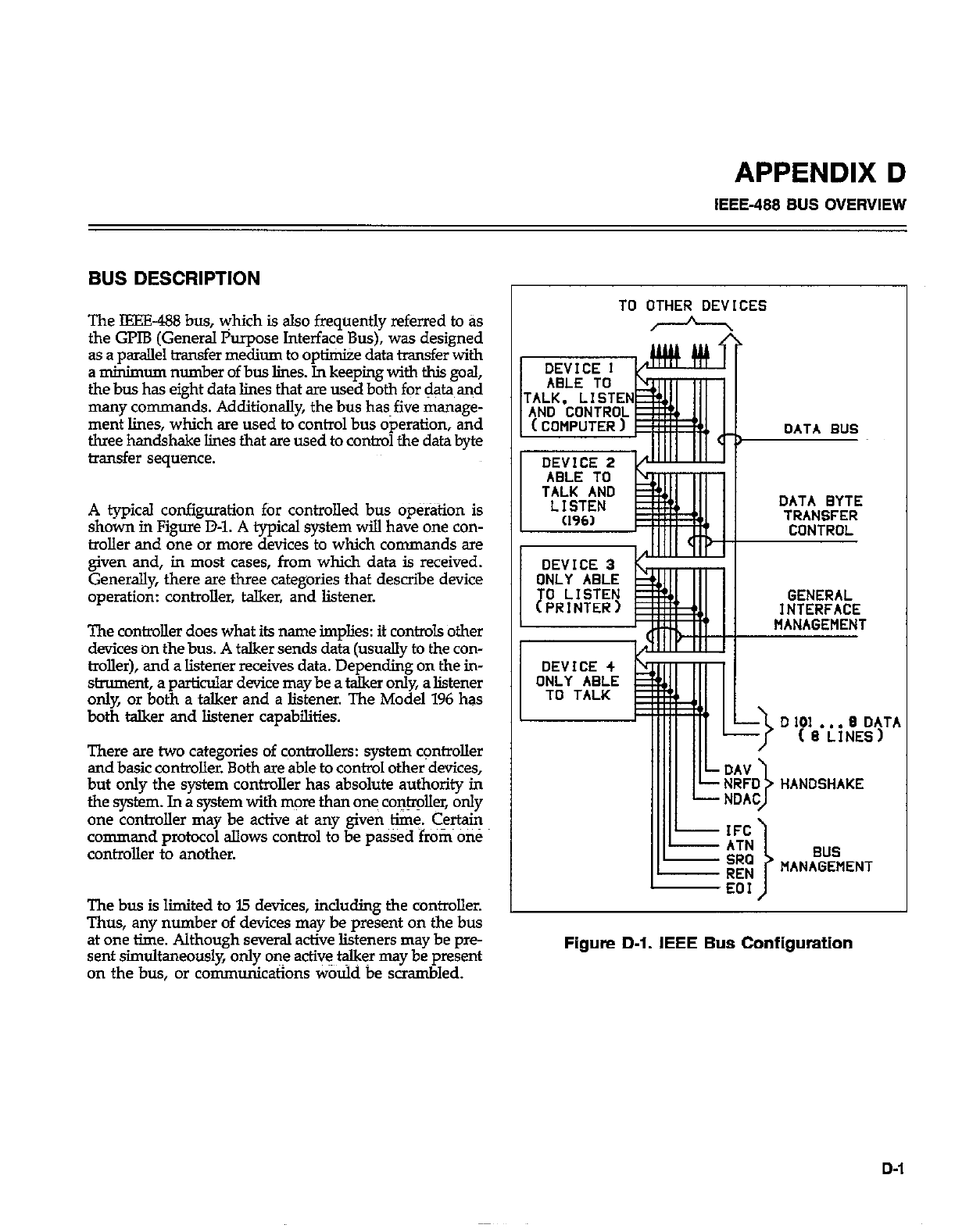
APPENDIX D
IEEE-488 BUS OVERVIEW
BUS DESCRIPTION
The IEEE-488 bus, yhich is also frequently referred to as
the GPIB (General Purpose Interface Bus), was designed
as a parallel transfer medium to optimize data transfer with
a minimum number of bus lines. In keeping with this goal,
the bus has eight data lines that are used both for data and
many commands. Additionally, the bus has~five manage-
ment lines, which are used to control bus operation, and
three handshake lines that are used to control the data byte
transfer sequence.
A typical configuration for controlled bus op&tion is
shown in Figure D-l. A typical system will have one con-
troller and one or more devices to which commands are
given and, in most cases, from which data is received.
Generally, there are three categories that describe device
operation: controller, talker, and listener.
The controller does what its name implies: it con&cJ.s other
devices on the bus. A talker sends data (usually to the con-
troller), and a listener receives data. Depending on the in-
strument, a particular device may be a talker only, a listener
only, or both a talker and a listener. The Model 196 has
both talker and listener capabilities.
There are two categories of controllers: system c+rolIer
and basic controller. Both are able to control other devices,
but only the system controller has absolute authority in
the system. In a system with more than ones co&r&r, only
one controller may be active at any given time. Certain
command protocol allows control to be pa&d from OS
controller to another.
The bus is limited to I5 devices, including the controller.
Thus, any number of devices may be present on the bus
at one time. Although several active listeners may be pre-
sent simultaneously, only one act& t$kFr may be present
on the bus, or communications would be scrambled.
TO OTHER DEVICES
h
, \
MANAGEMENT
Figure D-l. IEEE Bus Configuration
D-1
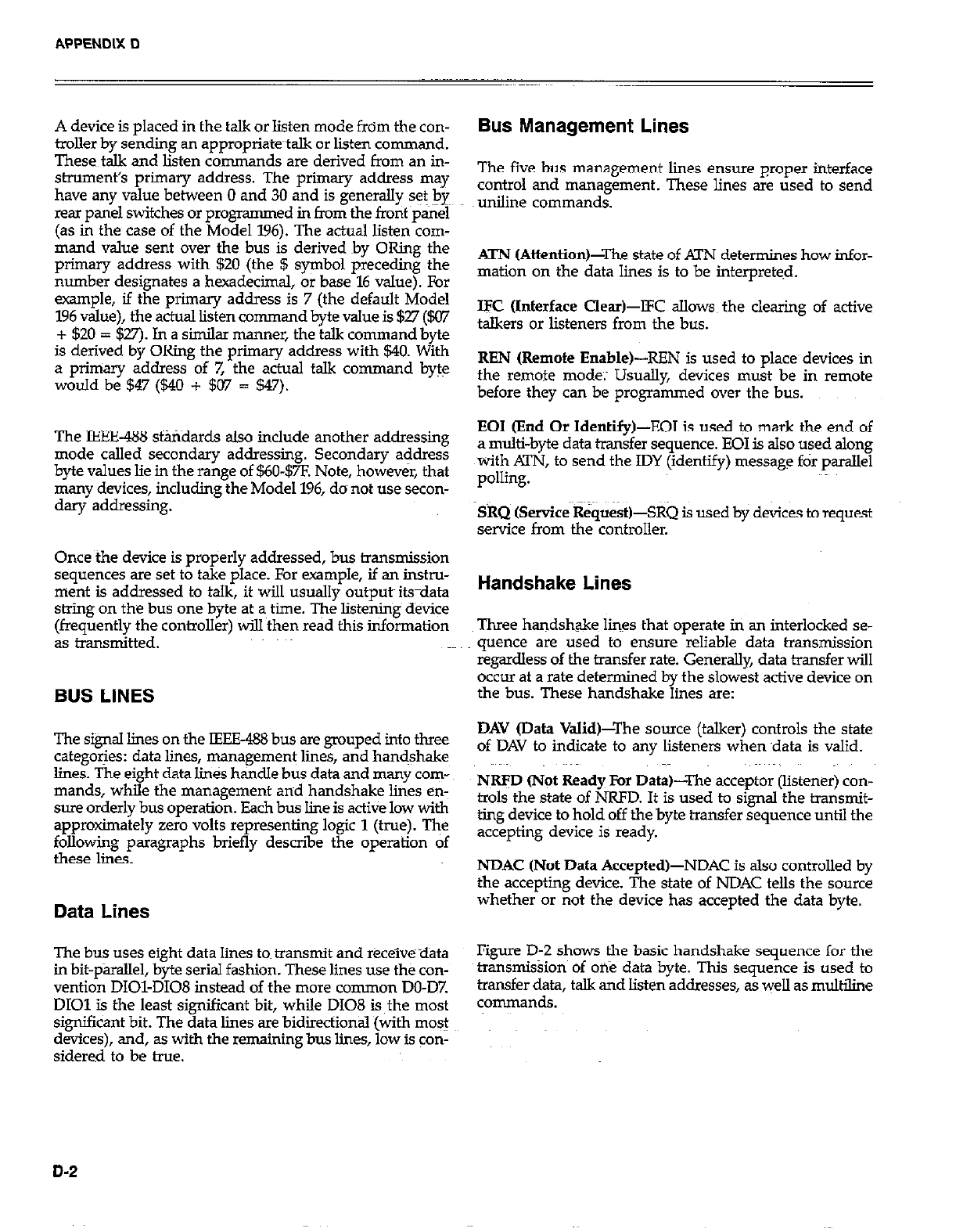
A device is placed in the talk or listen mode from the con-
troller by sending an appropriatetalk or listen command.
These talk and listen commands are derived from an in-
strument’s primary address. The primary address may
have any value between 0 and 30 and is generally set bye
rear panel switches or programmed in from the front ~pairel
(as in the case of the Model 196). The actual listen com-
mand value sent over the bus is derived by ORing the
primary address with $20 (the $ symbol preceding the
number designates a hexadecimal, or base 16 value). For
example, if the primary address is 7 (the default Model
196 value), the actual listen command byte value is $27 ($07
+ 520 = $27). In a similar manner, the talk command byte
is derived by ORing the primary address with 540. With
a priniaty address of 7, the actual talk command byte
would be 547 (540 + 507 = 547).
The IEEE-438 standards also include another addressing
mode called secondary addressing. Secondary address
byte values lie in the range of $60-$7F. Note, however, that
many devices, including the Model 196, do not use secon-
dary addressing.
Once the device is properly addressed, bus transmission
sequences are set to take place. For example, if an instru-
ment is addressed to talk, it will usually outputs its-data
string on the bus one byte at a~ time. The listening device
(frequently the controller) will then read this information
as transmitted.
BUS LINES
The signal lines on the IEEE488 bus are grouped into three
categories: data lines, management lines, and handshake
lines. The eight data lines handle bus data and many com-
mands, while the management and handshake lines en-
sure orderly bus operation. Each bus line is active low with
approximately zero volts representing logic 1 (true). The
following paragraphs briefly describe the operation of
these lines.
Data Lines
The bus uses eight data lines tom transmit and receive ~data
in bit-parallel, byte serial fashion. These lines use the con-
vention DIOI-DI08 instead of the more common DO-D7
DIOl is the least significant bit, while D108 is the most
significant bit. The data lines are bidirectional (with most
devices), and, as with the remaining bus lines, low is con-
sidered to be true.
Bus Management Lines
The five bus management limes ensure proper interface
control and management. These lines are used to send
uniline commands.
ATN (Attention)-The state of ATN determines how infor-
mation on the data lines is to be interpreted.
IK (Interface Clear)-lFC allow the clearing of active
talkers or listeners from the bus.
REN (Remote Enable)-REN is used to places devices in
the remote mode; Usually, devices must be in remote
before they can be programmed over the bus.
EOI (End Or Identify)-EOI is used to mark the end of
a multi-byte data transfer sequence. EOI is also used along
with !XN, to send the IDY (identify) message for parallel
polling.
SRQ (Service RequestGSRQ is used by devices to request
service from the controller.
Handshake Lines
Three handshake lines that operate in an interlocked se-
quence are used to ensure reliable data transmission
regardless of the transfer rate. GeneraLly, data transfer will
occur at a rate determined by the slowest active device on
the bus. These handshake lines are:
DAV (Data ValidPThe source (talker) controls the state
of DAV to indicate to any listeners when ~data is valid.
NRFD Orot Ready For Data)-The acceptor (listener) con-
trols the state of NRFD. It is used to signal the transmit-
ting device to hold off the byte transfer sequence until the
accepting device is ready.
NDAC (Not Data Accepted)-NDAC is also controlled by
the accepting device. The state of NDAC tells the source
whether or not the device has accepted the data byte.
Figure D-2 shows the basic handshake sequence for the
transmission of one data byte. This sequence is used to
transfer data, talk and listen addresses, as well as multiline
commands.
D-2
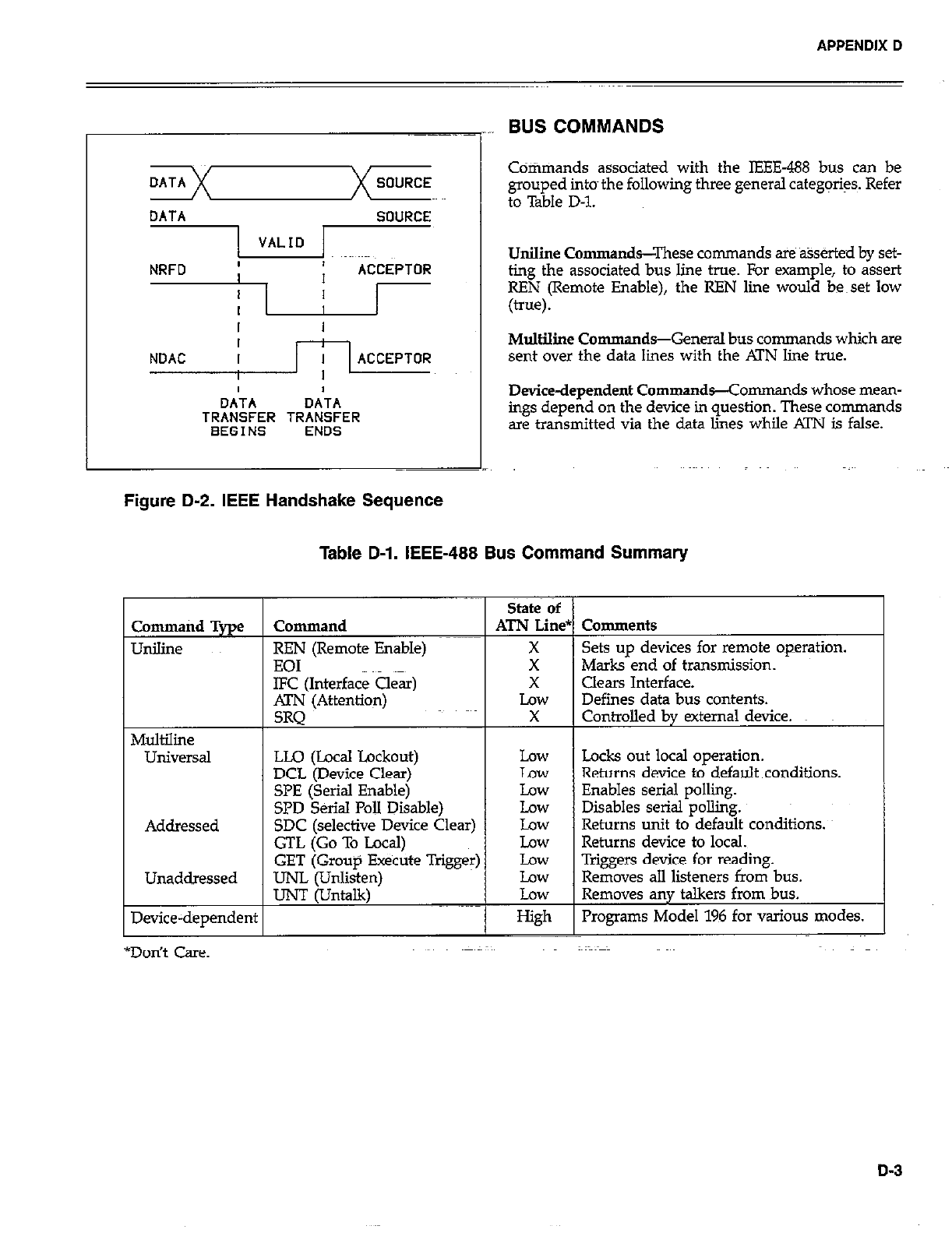
APPENDIX D
DATA SOURCE
DATA SOURCE
II
I I
I
NDAC I ACCEPTOR
I
OA’TA DATA
TRANSFER TRANSFER
BEGINS ENDS
Figure D-2. IEEE Handshake Sequence
BUS COMMANDS
Cdtimands associated with the IEEE-488 bus can be
grouped into~ the following three general categ@s. Refer
to Table D-l.
UniIine Commands--These commands are %serted by set-
ting the associated bus line true. For example, to assert
REN (Remote Enable), the REN line would be~set low
(true).
Multiline Commands-General bus commands which are
sent over the data lines with the Al’N line true.
Device-dependent Commands-Comman ds whose mean-
ings depend on the device in question. These commands
are transmitted via the data lies while ATN is false.
Table D-l. IEEE-488 Bus Command Summary
State of
Command Type Command ATN Line* Comments
Unilille REN (Remote Enable) X Sets up devices for remote operation.
EOI X Marks end of transmission.
IFC (Interface a4 X clears Interface.
ATN (Attention) Low Defines data bus contents.
SRQ X Controlled by external device.
Multiline
UlliVersal LLQ (Local Lockout) Low Locks out local operation.
DCL (Device Clear) Law Returns device to default conditions.
SPE (Serial Enable) Law Enables serial polling.
SPD Serial PoII Disable) Low Disables serial polliig.
Addressed SDC (selective Device Clear) Low Returns unit to default conditions.
GTL (Go To Local) Low Returns device to local.
GET (Group Execute Trigger) Low Triggers device for rea$ing.
Unaddressed UNL (Unlisten) Low Removes all listeners from bus.
IJNT (Untalk) Low Removes any talkers from bus.
Device-dependent High Programs Model 196 for tious modes.
*Don’t Care.
D-3
Uniline Commands
The five uniline commands include REN, EOI, lFC, Al’N,
and SRQ. Each comman d is associated with a dedicated
bus lie, which is set low to assert the command in
question.
REN (Remote Enable&EN is asserted by the controller
to set up instruments on the bus for remote operation.
When REN is true, devices will be removed from the local
mode. Depending on device configuration, ail front panel
controls except the LOCAL button (if the device is so
equipped) may be locked out when REN is true. General-
ly REN should be asserted before attempting to program
instruments over fhe bus.
EOI (End or Identify)-EOI may be asserted either by the
controller or by external devices to identify the last byte,
in a multi-byte transfer sequence, allowing data words of
various lengths to be transmitted.
IFC (Interface Clear)-IFC is asserted by the controller to
clear the interface and return all devices to the talker and
listener idle states.
ATN (Attention)-The controller asserts KIN while sen-
ding addresses or multiline commands.
SRQ (Service Request)-SRQ is asserted by a device on
the bus when it requires service from the controller.~
Universal Multiline Commands
Universal multiline commands are those uxnmands that
required no addressing as part of the command sequence.
Ail devices equipped to implement these commands will
do so simultaneously when the commands are transmit-
ted. As with all multiline commands, these commands are
transmitted with ATN true.
LI.0 (LncaI Lockout)-LLO is Sent to instruments to lock
out front panel or local operation of the instrument.
DCL (Device Clear)-DCL is used to return instruments
to some default state. Usually, devices return to their
power-up conditions.
SPE (Serial Poll Enable)-SPE is the first step in the serial
polling sequence, which is used to determine which device
on the bus is requesting service.
SPD (Serial Poll Disable)-SPD is used by the controller
to remove all devices on the bus from the serial poll mode
and is generally the last command in the serial polling
sequence.
Addressed Multiline Commands
Addressed multiliie conunan ds are those commands that
must be preceded by an appropriate listen address before
the instrument will respond to the command in question.
Note that only the addressed device will respond to the
command. Both the command and the address preceding
it ilIe sent with .KlYJ true.
SDC (Selective Device Clear)-The SDC command per-
forma essentially fhe same function as DCL except that on-
ly the addressed device responds. Generally, instruments
return to their power-up default conditions when respon-
ding to SDC.
GTL (Go To Local)-GTL is used to remove instruments
from~the remote mode and place them in local. With many
instruments, GTL may also n?store operation of front panel
controls if previously locked out.
GET (Group Execute Trigger)-GET is used to bigger
devices to perform a specific action that will depend on
device con@uration (for ~ple, perform a measurement
sequence). Although GET is an addressed command,
many devices may respond to GET without addressing.
Address Commands
Addressed co remands include two primary command
groups, and a secondary address group. ATN is true when
these conman ds are asserted. These commands include:
LAG (Listen Address Group)-These listen commands are
derived from an instrument’s primary address and are
used to address devices to listen. The actual command byte
is obtained by ORing the primary address with $20.
TAG (TaIk Address Group)-The talk co-nds~ are de-
rived from the plimary address by ORing the address with
$40. Tdk commands are used to address devices to talk.
SCG (Secondary Command Group)-Commands in this
group provide additional addressing capabilities. Many
devices (icluding the Model 196) do not use thes~e
commands.
D-4
APPENDIX D
Unaddress Commands
The two unaddress~commands are used by the controller
to remove any talkers or listeners from the bus. ATN is true
when these commands are asserted.
UNL Wnlis&n)-Listeners are placed in the listener idle
state by UNL.
UNT @Jntalk)-Any previously commanded talkers will
be placed in the talker idle state by LINT.
Device-Dependent Commands
The purpose of device-dependent commands will depend
on instrument configuration. Generally, these commands
are sent as one or more ASCII characters that command
the device to perform a specific action. For example, the
command string ROX is used to control the measurements
mnge of the Model 196.
The IEEE-488 bus treats these commands as data in thatch
ATN is false when the commands are transmitted.
Command Codes
Command codes for the various commands that use the
data lines are s-tied in Figure D-3. Hexadecimal and
and decimal values for the various commands are listed
in Table D-2.
D-5
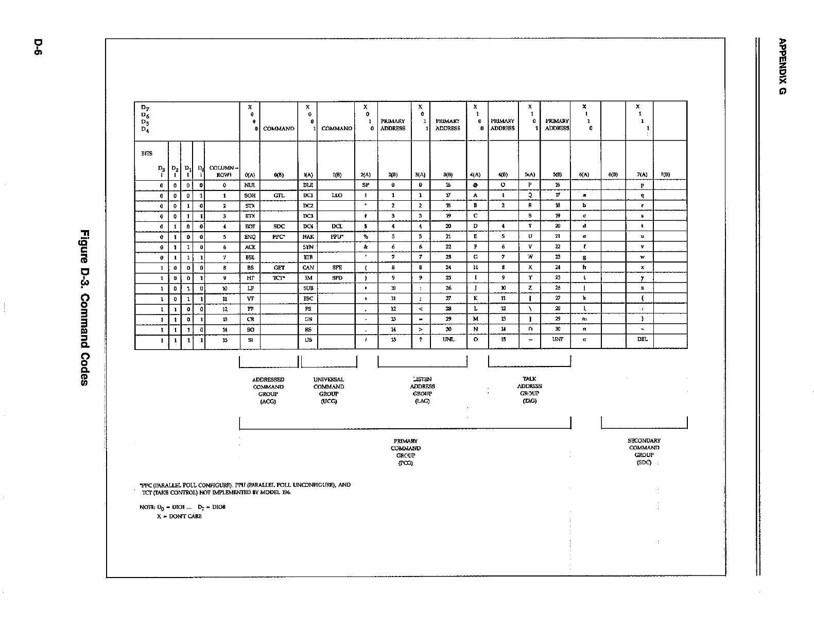
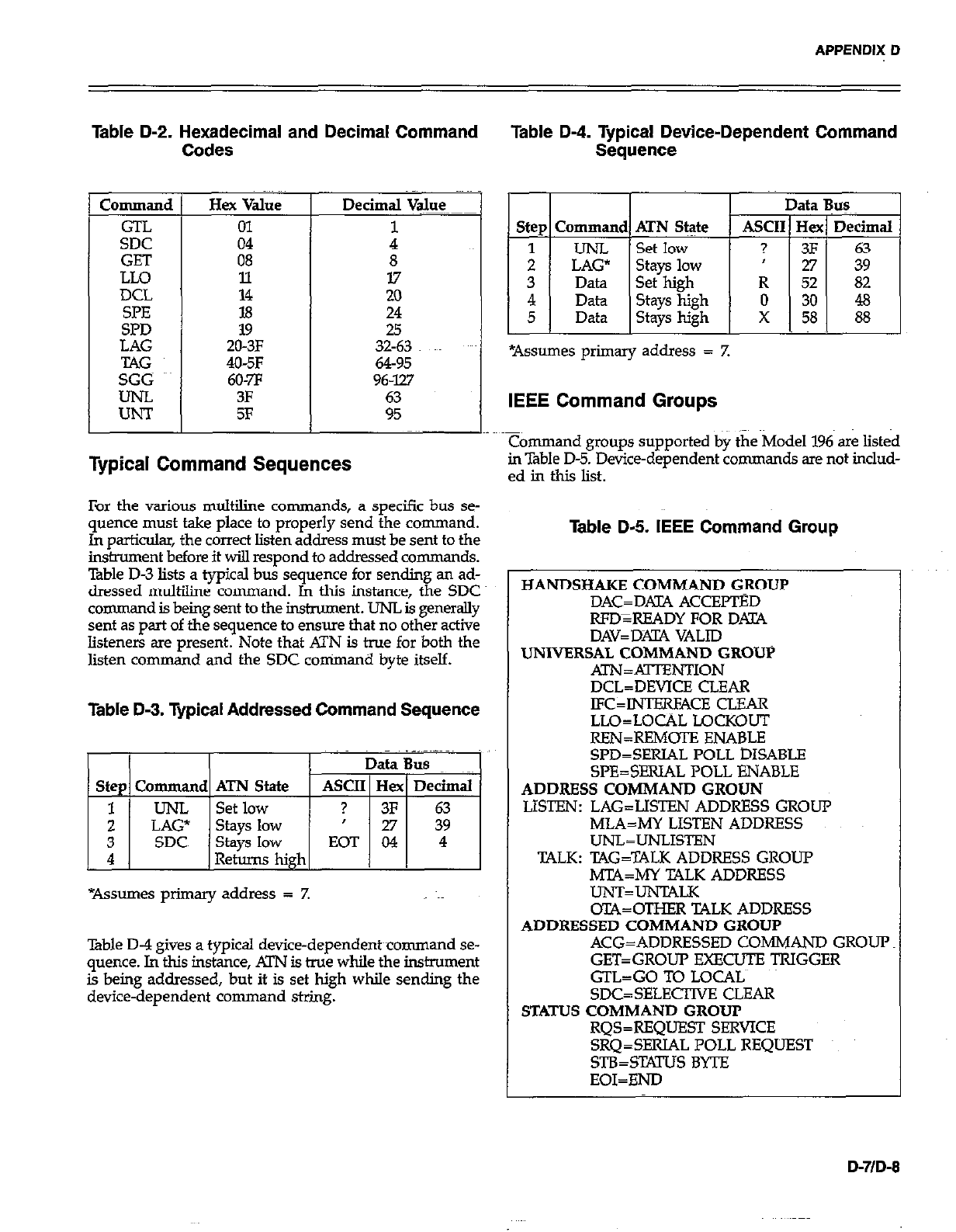
APPENDIX D
Table D-2. Hexadecimal and Decimal Command
Codes
Command
GTL
SDC
GET
LLO
DCL
SpE
SPD
Hex Value
01
04
08
11
14
18
19
ZO-3F
406F
60-7F
3F
5F
8
17
20
24
25
32-63
64-95
96-W
Typical Command Sequences
For the various multiline commands, a specific bus se-
quence must take place to properly send the command.
In particular, the correct listen address must be sent to the
insment before it wiJ.l respond to addressed commands.
Table D-3 lists a typical bus sequence for sending an ad-
dressed m&line command. In this instance, the SDC
command is being sent to the instrument. UNL is generally
sent as part of the sequence to ensure that no other active
listeners are present. Note that ATN is true for both the
listen command and the SDC conimand byte itself.
Table D-3. Typical Addressed Command Sequence
St&s low EOT 04 4
4 Retqw high I I
*Assumes primary address = Z
%ble D-4 gives a typical device-dependent~command se-
quence. In this instance, XI’N is true while the instrument
is being addressed, but it is set high while sending the
device-dependent command string.
Table D-4. Tvaical Device-Dependent Command
Sequence .
I I I I
Step Command ATN Stz$e ASCI
1 I UNL ISetlow I ?
IEEE Command Groups
Command groups supported by the Model 196 are listed
in Table D-5. Device-dependent commands are not includ-
ed in this list.
Table D-5. IEEE Command Group
HANDSHAKE COMMAND GROUP
DAC=DAZlX ACCEFTED
WD=READYFORD.UA
DAV=DXlA VALID
UNIVERSAL COMMAND GROUP
ATN=xKl-I’ENTION
DCL=DEVICE CLEAR
JFC=INTERFACE CLEAR
LLO=LOCAL LQCKOUT
REN=RFMOTE ENABLE
~PD=~~~ALIJOLLD~~AB~
SPE=SERIAL POLL ENABLE
ADDRESS COMMAND GROUN
LISTEN: LAG=LISTEN ADDRESS GROUP
MLA=MY LISTEN ADDRESS
UNL=UNLISTEN
TALK: TAG=TALK ADDRESS GROUP
M’C4=MY TALK ADDRESS
UNT=UNTALK
oTA=OTHER TALK ADDRESS
ADDRESSED COMMAND GROUP
ACG=ADDRESSED COMMAND GROUP
GET=GROUP EXECUTE TRIGGER
GTL=GO TO LOCALS
SDC=SELEClWE CLEAR
STATUS COMMAND GROUP
RQS=REQUEST SERVICE
SRQ=SERIAL POLL REQUEST
STB=SWS BYTE
EOI=END
D-7/D-8
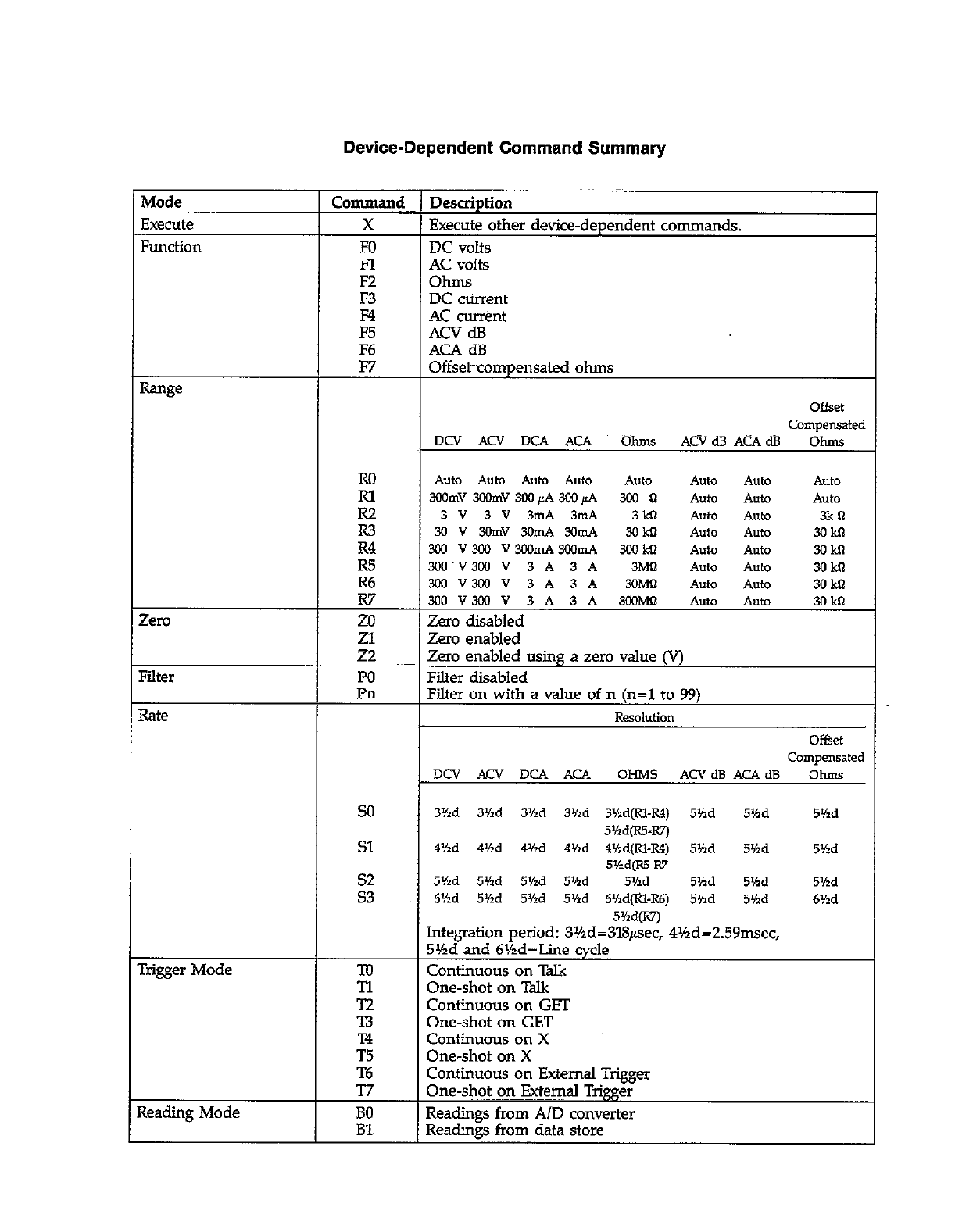
Auto Auto Auto Auto AlltO AlltO AUtO Auto
300mV3CGmV3WpA3CGpA 300 II Auto AUtO Auto
3v3v3mA3m4 3kn Auto AUtO 3kll
3ov3omv3omA3amA 3okn Auto Auto 3okn
3&l v3al vmmA3mmA 300 ktl Auto Auto 3okn
Zero disabled
3Yid 3%d 3Hd 3’hd 3Md(R1-R4) 5Yzd 5Hd 5Yzd
5Md(R5-W)
41hd 4’hd 4%d 444d 4Hd(RI-R4) 5Yzd Shd 5%d
5%d(R55-R7
5%d 5Vtd 5’hd 5Yzd 5Y2d 5’hd 5Kd 5Md
6Hd 5Yxd 5Md 5Vld 6Kd@l-R6) 5Yzd 5’hd 6Yzd
ontmuous on
One-shot on Talk
Continuous on GET
One-shot on GET
Continuous on X
One-shot on X
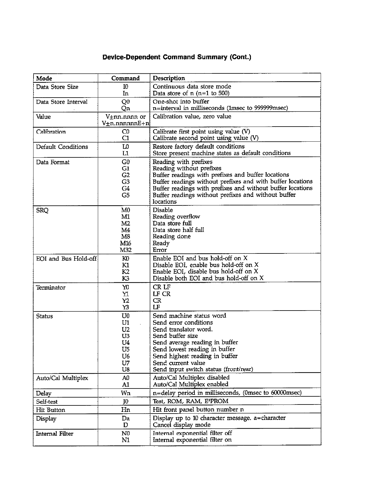
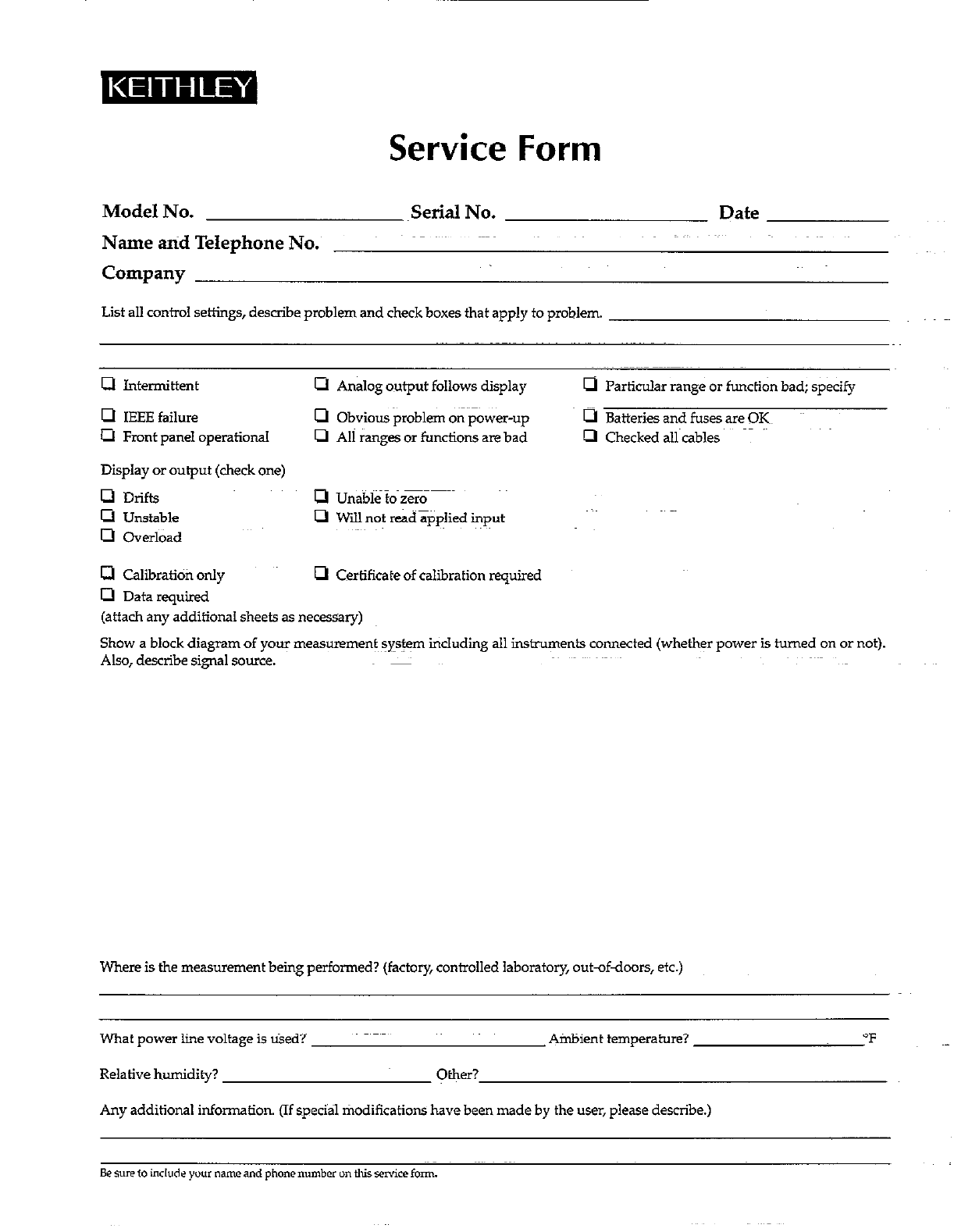
Service Form
Model No. .Serial No.
Name atid Telephone No.
Company
List all control settings, describe problem and check boxes that apply to problem.
Date
Cl Intermittent
0 IEEE failure
a Front panel operational
Display or output (clwk one)
0 Drifts
m Unstable
0 Overi&d
0 Calibratiofi only
0 Data required
a Analog output follows display a Particular range or function bad; specify
0 Obvious problem on power-up 0 Batteries and fuses are OK~
m All ranges or functions are bad 0 Checked all cables
(attach any additional sheets as necessary)
Show a block diagram of your measurements :ystem including all instruments connected (whether power is turned on or not).
Also, describe signal source.
Where is the measurement being performed? (factory, controlled laboratory, outdfdoors, etc.)
What power line voltage is tied?~ Ambient temperature?
Relative humidity? Other?
Any additional information. (If special tiodifications have been made by the user, please describe.)
“F
