TABLE OF CONTENTS KEYTEK/KEYTEK CE MASTER SYSTEM USERS KEYTEK
User Manual: KEYTEK/KEYTEK CE MASTER SYSTEM USERS
Open the PDF directly: View PDF ![]() .
.
Page Count: 108 [warning: Documents this large are best viewed by clicking the View PDF Link!]
- Immunity Tester
- Operations Manual
- Operations Manual
- Product Safety
- Surge Testing Guidelines
- Safety Concerns During Surge Testing
- Inappropriate Uses
- Description
- Installation
- Assembly Instructions
- Cabling and Interconnections
- Physical Environment
- Operating limits
- Storage limits
- Test Area Considerations and Site Preparation
- Special Considerations for Surge Testing
- Special Considerations for EFT Testing
- Special Considerations for ESD Testing
- Special Considerations for Pulsed Magnetic Field and Power-Frequency Magnetic Field Testing
- Handling, Transportation, Storage
- This page left blank intentionally.
- Introduction
- Running Tests
- Overview of the software
- Basic Operations
- CEWare in Detail
- Screens and Organization
- Menu, Toolbar, and Status Bar
- Maintenance
- Troubleshooting

CEMASTER
®
Immunity Tester
Operations Manual

CEMASTER
®
Immunity Tester
Operations Manual
MA-95-016-005-00 REV D
Copyright 1997-2001 Thermo KeyTek
All Rights Reserved
Thermo KeyTek
One Lowell Research Center
Lowell, MA 01852-4345
Phone: 978-275-0800
Fax: 978-275-0850
E-mail: customer_service@thermokeytek.com
©Thermo KeyTek 1997-2001 All rights reserved
The copyright protection afforded to Thermo KeyTek includes all forms of media
material and information including, without limitation, the software*, generated icons
and logos etc. and all associated documentation. This operating manual and associated
software contained within may not be duplicated in any way without the express
permission of Thermo KeyTek.
Printable products of the software such as test reports and graphs, and associated files
of the same, are the property of the purchaser and may be subject to their own
copyright restrictions.
*The CEMASTER software described in this manual may be copied by, strictly for the
use of, the purchaser in accordance with the furnished license agreement.
™ Trademark Credits
CEMASTER is a registered trademark of Thermo KeyTek
IBM is a registered trademark of International Business Machines Corporation. Microsoft
Windows and MS-DOS are registered trademarks of Microsoft Corporation.
Notice
In no event will Thermo KeyTek be liable for any damages, consequential, incidental or
indirect (including loss of business profits, business interruption, loss of business
information, and the like) arising out of the use or inability to use the hardware or
software supplied.
The author and publisher of the operating manual make no warranty of any kind,
expressed or implied, with regard to the instructions and suggestions contained within.
The author and publisher of this operating manual shall not be liable in any event of
incidental or consequential damages in connection with, or arising out of, the furnishing,
undertaking or use while following verbal or written instructions and suggestions in any
interpretation of its contents.
Thermo KeyTek products undergo continuous development and the company reserves
the right to change their specifications without obligation or prior notification.
Thermo KeyTek One Lowell Research Center Lowell, MA 01852-4345 USA Tel: 978-275-0800
Fax: 978-275-0850 http://www.thermokeytek.com
Amendment History
Issue Date Author Amendment
1997 1997 JHB First issue.
3-3-99 3-3-99 JHB unknown
A 2-1-00 JBC Added Manual part number,formatted manual
to standards including copyright page,
Amendment history page, and cover
B 05-02-01 MDP Removed TVL logo and other references per
ECO-150-00
C 05-02-01 MDP Reformat to Thermo KeyTek standards and
changed company name From: KeyTek to
Thermo KeyTek per ECO-010-01
D 10-01-01 MDP Add Appendix A per ECO-185-01
TABLE OF CONTENTS
OVERVIEW
PRODUCT SAFETY 1
SURGE TESTING GUIDELINES 3
SAFETY CONCERNS DURING SURGE TESTING 4
INAPPROPRIATE USES 5
DESCRIPTION 6
INSTALLATION 7
Assembly Instructions 7
Cabling and Interconnections 7
Electrical Supply Requirements 9
Physical Environment 11
Test Area Considerations and Site Preparation 12
Special Considerations for Surge Testing 12
Special Considerations for EFT Testing 13
Special Considerations for ESD Testing 16
Special Considerations for Magnetic Field Testing 16
Handling, Transportation, Storage 17
OPERATION
INTRODUCTION 19
User Interface 21
Programming the%'/#56'4 from the Front Panel 22
Map of Front Panel Menu Structure 28
Programming the %'/#56'4from a Personal Computer 31
RUNNING TESTS 32
STANDARDS OVERVIEW 32
TEST PROCEDURES AND REPORTS 33
IEC 1000-4-2 -- ESD Testing 35
IEC 1000-4-4 -- EFT Testing 41
IEC 1000-4-5 -- SURGE Testing 47
IEC 1000-4-8 -- POWER-FREQUENCY MAGNETIC FIELD Testing 55
IEC 1000-4-9 -- PULSED MAGNETIC FIELD Testing 58
IEC 1000-4-11 -- POWER QUALITY FAILURE Testing 62

%'9#4'
SOFTWARE OVERVIEW 67
BASIC OPERATIONS 68
SCREENS AND ORGANIZATION 71
Main Screen 72
New Sequence Definition Screen 76
New Custom Sequence Wizard Screen 77
Sequence Editor Screen 82
The Run Screen 83
MENU, TOOLBAR, AND STATUS BAR 85
MenuBar 85
Toolbar 91
Status Bar 92
MAINTENANCE AND TROUBLESHOOTING
MAINTENANCE 95
Service and Maintenance Issues 95
Annual Calibration 95
Factory Inspection and Refurbishment 95
Updating Firmware 95
Upgrading Hardware Options 95
Decommission Issues 95
TROUBLESHOOTING 96
System Menu 96
Troubleshooting Guide 98
Error Messages 99
The information on IEC requirements -- figures and diagrams, tables and data, and test levels -- are
accurate as of the date of printing of this manual. However, the IEC and EN documents are subject
to review and change. The information in this manual is intended as a guideline only.

CEMASTER System 1
Product Safety
The following safety instructions have been included in compliance with safety standard
regulations. Please read them carefully.
• Read Instructions -- Read all safety and operating instructions before operating the
instrument.
• Retain Instructions -- Retain all safety and operating instructions for future reference.
• Heed Warnings - Adhere to all warnings on the instrument and in the operating instructions.
• Follow Instructions -- Follow all operating and use instructions.
• Water and Moisture -- Do not use the instrument near water.
• Carts and Stands -- Use the instrument only with a cart or stand that is recommended or
included as part of the %'/CUVGT system by the manufacturer.
• Wall or Ceiling Mounting -- Do not mount the instrument on a wall or ceiling.
• Ventilation -- The instrument should be situated so that its location or position does not
interfere with its proper ventilation. Do not install in a cabinet or other situation that may
impede the flow of air through the ventilation openings.
• Heat -- The instrument should be situated away from heat sources such as heat registers or
other instruments which produce heat.
• Power Sources -- Connect the instrument only to the type of power source described in the
operating instructions or as marked on the instrument.
• Grounding or Polarization -- Take precautions to insure that the grounding of the
instrument is not defeated. Operate only with grounded power cord.
• Power Cord Protection -- Place power supply cords so that they are not likely to be walked
on or pinched by items placed on them or against them. Pay particular attention to cords at
plugs, convenience receptacles, and the point where they enter and exit the instrument. The
cordsets used should be the right-angle cordsets supplied with the unit, to prevent damage to
the cordsets when moving the%'/CUVGT.
• Cleaning -- Clean the instrument only as recommended by the manufacturer.
• Non-Use Periods -- Unplug the power cords of the instrument when it will be left unused for
a long period of time.

CEMASTER System 2
• Lifting and Carrying -- When moving or installing a %'/#56'4follow the instructions
given in the Installation section of this manual. Moving a %'/#56'4 requires two persons.
• Object and Liquid Entry -- Take care that objects do not fall and that liquids are not spilled
into the enclosure through openings.
• Defects and Abnormal Stress -- Whenever it is likely that the normal operation has been
impaired, make the equipment inoperable and secure it against further operation. Normal
operation is likely to be impaired if, for example, the instrument:
Shows visible damage.
Fails to perform the intended function.
Has been subject to prolonged storage under unfavorable conditions.
Has been subjected to severe transport stresses.
• Damage Requiring Service -- The instrument should be serviced by qualified service
personnel when:
The power supply cord or the plug has been damaged.
Objects have fallen or liquid has been spilled into the instrument.
The instrument has been exposed to rain.
The instrument does not appear to operate normally or exhibits a marked change in
performance.
The instrument has been dropped, or the enclosure has been damaged.
• Sitting or Climbing -- Do not sit or climb upon the instrument or use it as a step or ladder.

CEMASTER System 3
Surge Testing Guidelines
• DO NOT WORK ALONE.
• Do not use the equipment in conditions other than reasonable laboratory conditions.
There should be no condensing humidity or water standing on the floor or work surfaces;
there shouldn’t be significant dust or other contamination.
• Ensure that NO ONE is touching the equipment under test (EUT) during the test or
immediately after the test until AC power to the EUT has been turned off.
• Ensure that there is a barrier to act as protection in case the equipment under test
explodes. This may happen due to power-follow1 after a failure. The barrier should be
interlocked to prevent surging and to disconnect all AC if the barrier is removed.
• The equipment under test must be surrounded by sufficient insulating material to
withstand twice the surge voltage. Consider distance to the floor or table and walls if air
is the insulating material.
• Ensure that the proper supply mains voltages are applied to both Thermo KeyTek
equipment and to the equipment under test, and that the AC branch circuit is capable of
supplying the current.
• The ground (protective earth), neutral and phase lines of the AC supply to the equipment
under test supply must be connected properly. Do not defeat the protective earth
connection.
• The ground (protective earth), neutral and phase lines of the AC supply to the Thermo
KeyTek equipment must be connected properly. Do not defeat the protective earth
connection.
• When surging a powered EUT, the mains supply to the equipment under test must be
capable of handling the potential AC fault current (e.g. do not use a UPS to power the
EUT).
• Never surge an AC mains line other than through the EUT output connector and the
%'/#56'4internal filter.
• Use only equipment which is designed to be safe for the test being performed.
• Do not test in a potentially explosive atmosphere (e.g. gas fumes).
• Never use equipment that is operating in a strange manner, or that shows clear indication
of abuse.
• If probes are in use, be sure they are differential probes which have no ground connection
to the surged ground or to the equipment under test.
1 Power-follow is a condition where the Surge event causes a low-impedance path which full mains current may then flow
through. One example of this is a gas-tube arrestor, which maintains a high impedance until a surge event switches it to a low-
mpedance state; the low-impedance state is maintained until the mains voltage drops below a critical threshold. Similar effects
can be seen due to electrical arcs or exploded components.

CEMASTER System 4
Safety Concerns During Surge Testing
Surge testing is hazardous. The equipment under test (EUT) can ignite, possibly explosively.
Noxious, toxic and sometimes fatal fumes can be generated by the burning equipment.
Accumulated gases may ignite explosively (i.e., flashover).
In an environment where surge testing takes place, it is absolutely crucial that these minimum
safety precautions be taken:
• Surge testing should be performed only by properly trained test personnel who are
experienced in conducting such test, or be observed and supervised by such experienced
personnel. No person subject to heart or neurological conditions should be allowed to
conduct surge tests. Persons with pacemakers should not be allowed in or near the area
where testing is conducted.
• Never leave a procedure or a test setup unattended.
• All personnel working in the area must be shielded with appropriate eye protection, body
protection and electrical protection. They should not be allowed to work in a direct line
of a possible explosion of the equipment under test.
• The test area should be a clear and unobstructed environment dedicated to such tests.
• The test area should be equipped with ventilating hoods and blowers to remove gases that
may be caused by exploding or burning components.
• The test area should have nonflammable walls and floors plus shielding to contain
exploding parts and flames.
• There must be fire extinguishers certified for use in electrical and chemical fires readily
available at the test site. DO NOT USE WATER TO EXTINGUISH AN
ELECTRICAL FIRE.
• All flammable materials and debris must be outside the test area, and the area must be
well marked, preferably by physical barriers, to prevent accidental intervention by non-
test personnel while a test is in progress.

CEMASTER System 5
Inappropriate Uses
The unit must be kept within the environmental limits of the operating requirements. This
includes not using the %'/#56'4 in condensing humidity.
The unit must not be operated by wearers of electronic life-support equipment. Personnel
with pace-makers, heart problems, nervous disorders, and similar problems should not be
allowed to operate the %'/#56'4 or be present during ESD testing.
The ESD probe is capable of giving an unpleasant shock -- it is not intended for use as a
shock prod, "cattle prod", or as any device designed to shock people or animals.
There are no User Serviceable parts inside; do not remove covers.

CEMASTER System 6
Description
The %'/#56'4 is a single-box test system for those in need of the CE Mark. The
%'/#56'4performs 6 different immunity tests, in accordance with European Norm
requirements and the controlling, Basic EMC immunity standards of:
• IEC 1000-4-2 ESD
• IEC 1000-4-4 EFT
• IEC 1000-4-5 Surge
• IEC 1000-4-8 Power Frequency Magnetic Field
• IEC 1000-4-9 Pulse Magnetic Field
• IEC 1000-4-11 Dip and Interrupt
The %'/#56'4is the only combination EMC immunity tester that includes built in dip and
interrupt, internal IEC 1000-4-8 capability, computer-controlled ESD tester and simplified,
predefined test routines. The CEMASTER is also the only EMC immunity tester that customers
configure to meet their own testing needs.
Because of the %'/#56'4's custom configurability, growing companies are now able to
afford in-house compliance testing and larger manufacturers may purchase multiple units for
various departments. The %'/#56'4 is a perfect solution for test houses seeking to
complement their high-end test systems and offer their customers on-site testing capabilities as
an additional service. As a user-friendly, portable immunity tester, the %'/#56'4 is the ideal
solution for rental companies.

CEMASTER System 7
Installation
Assembly Instructions
%'/#56'4Assembly
The %'/#56'4 requires two people for unpacking. Check the packaging materials and
follow any special unpacking instructions shipped with your unit. The %'/#56'4comes
fully assembled.
Save all shipping materials (shipping boxes, foam pieces, bags, and special instructions) for
possible future shipments. The original shipping materials must be used whenever the
%'/#56'4 is returned for calibration or service.
Carefully check all shipping materials for accessories which may be packaged with the
%'/#56'4.
Computer Assembly
If your system includes a computer: Unpack the computer and accessories. Verify that the
voltage settings of computer and monitor match your mains voltage.
Cabling and Interconnections
The %'/#56'4has two AC Mains cordsets which plug into the rear of the unit. One, the
Systems Power input, powers the circuitry of the %'/#56'4. The second, the EUT Power
input, powers the front panel mains connector and the Equipment Under Test. The cordsets
used should be the right-angle cordsets supplied with the unit to prevent damage to the
cordsets when moving the %'/#56'4.
The FiberCom option connects the %'/#56'4 to an external computer running the
%'/#56'4 application software under Windows 3.x or Windows-95. The FiberCom
option (CM-SW) includes a small module, the FC-11, a short RS-232 cable with a 9-pin D-
shell connector, and a fiberoptic cable with a duplex modular connector. The RS-232
connector connects to your computer. The fiberoptic cable connects to the %'/#56'4
front panel; this connector is polarized and can only be inserted in one orientation: with the
small tab on the connector facing right. Do not force the connector. The FiberCom option
derives power from the RS-232 port of the computer -- no external power source is required.2
The optional ESD probe connector attaches to the front panel. This connector is polarized
and can only be inserted in one orientation: align the flat of the connector plug with the flat of
the front panel opening. Do not force the connector.
Direct Current Power to EUT
2 Some computers use a low-power RS-232 driver with a reduced drive voltage. If the FiberCom fails to work with a
computer, an external supply should be used [Thermo KeyTek part #02-701-695-00 (USA) and 62-050-415-00
(European)].

CEMASTER System 8
The CEMASTER can accept a Direct Current (DC) power source at the EUT input and
provide it to the EUT output. When connecting to DC it is important to note the assignment
of EUT inlet and outlet connectors.
EUT Mains Inlet, Panel Wiring
The IEC Inlet connector is wired,
L1 left, L2 right, PE center.
EUT Mains Outlet, Panel Wiring
Regardless of nationality, the outlet is always
wired, L2 left, L1 right, PE center.
For DC use L1 and L2 should be used for voltages or voltage and return; the PE connection
should be used for return only.
Interlock connector
The optional interlock allows the user to connect a remote switch which, when open, removes all
AC and high-voltage from the %'/#56'4 front panel outlets, and disables the ESD head.
A spare interlock connector is provided in the accessories kit for the %'/#56'4. To use this
connector, wire your cable from the connector TIP and RING contacts, and provide a simple
switch or contact closure at the other end of the cable.
• The interlock operates from an internal, +5V, 20mA, logic level signal. Do not connect the
interlock to a power source.
• Use a cable with voltage rating of twice the voltage rating of your EUT.
• Route the interlock cable away from the EUT output and the EUT.
• DO NOT connect the interlock within the EUT, or to circuitry tied to the EUT.
Capacitive Cable Clamp Cable
A 1 meter long stereo phono plug cable and a 1 meter NH-coaxial cable are provided with the
CM-CCL, and CM-CCLC options. The coax cable is screwed onto the CEMASTER coax
output, and to either end of the CM-CCL or CM-CCLC cable clamps. The unused coaxial
connector on the opposite end of the cable clamp should be left unterminated, or can be used
with an optional, coaxial probe to monitor the delivered voltage.
The CM-CCLC cable clamp includes an interlocked safety cover. By connecting the stereo
phono plug cable between CEMASTER and either end of the cable clamp, the CEMASTER will

CEMASTER System 9
operate only if the cover of the cable clamp is properly seated. The unused interlock jack on the
opposite end of the cable clamp can be used to wire to additional interlock switches.
Magnetic Coil Connections
A CEMASTER-to-coil cable is provided with the CM-HCOIL option. The CEMASTER-end of
the cable is plugged into the front-panel safety sockets. The coil end of the cable plugs into the
sockets on the coil.
Other Cables
The %'/#56'4 accessories kit includes safety socket connectors and an interlock connector
which the user may use to fabricate special test cables. When fabricating cables, always use wire
rated for twice the peak, pulse voltage present during testing.
Electrical Supply Requirements
The %'/#56'4 will automatically configure for your AC Mains voltage, choosing one of
two voltage ranges:
100 - 120 Vac, 50/60 Hz
220 - 240 Vac, 50/60 Hz
The AC power source for the EUT must have adequate capacity for full power-follow3 in the
event that testing causes an equipment failure. Using a supply without sufficient capacity may
result in a failure being masked.
Acceptable power sources include:
• A dedicated branch circuit
• The dedicated output of a motor-generator (MG) set.
• The output of a properly installed isolation transformer.
Use of the %'/#56'4 with Ground-Fault Interrupters (GFI)
Problems may result when using the CEMASTER on AC mains protected by Ground-Fault
Interrupters (GFIs). Surging the EUT, with a coupling mode to PE (L1-PE, L2-PE, or
L1&L2-PE) will cause the GFI to trip, causing an unexpected loss of AC power to the EUT.
The problem is due to the coupling network mandated by IEC 1000-4-5; this network
connects the surge generator to the AC mains during the surge pulse, and creates a short pulse
of mains current in PE, tripping the GFI. This problem only occurs during Surge events with
a PE coupling mode selected.
3 Power-follow is a condition where the Surge event causes a low-impedance path which full mains current may then
flow through. One example of this is a gas-tube arrestor, which maintains a high impedance until a surge event
switches it to a low-impedance state; the low-impedance state is maintained until the mains voltage drops below a
critical threshold. Similar effects can be seen due to electrical arcs or exploded components.
CEMASTER System 10
There are two solutions to this problem:
• The first solution is to power the EUT from a source that does not have a GFI device
installed. This solution may not be practical in some locations due to building codes or safety
regulations.
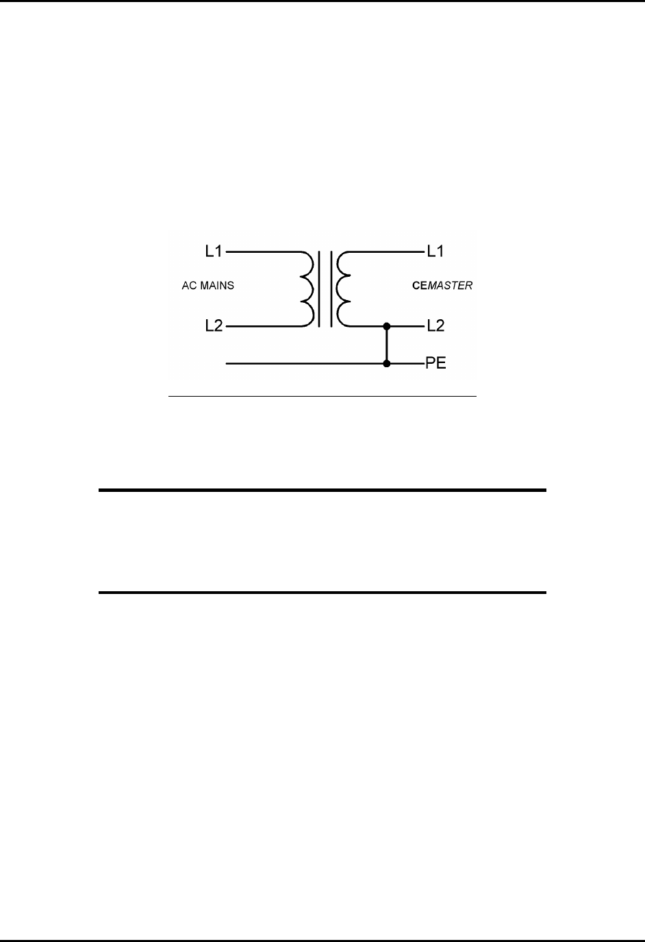
• The second solution is to install an isolation transformer between the AC mains and
%'/#56'4. The isolation transformer should be rated for -- at least -- 1920VA for
120VAC mains, or 3840VA for 220/240VAC mains. The transformer should be wired as
diagrammed below.
Proper Connection of an Isolation Transformer
Note that L2 - Neutral - is bonded back to PE at the output of the transformer
Note
A solid-state regulated line source such as an uninterruptable
power supply (UPS) or a power frequency amplifier will generally
not have the instantaneous capacity or full power-follow required
for Surge and PQF testing, and therefore should not be used as the
AC power source for any equipment being tested.

CEMASTER System 11
Physical Environment
%'/#56'4 systems are intended for operation in a laboratory environment, protected from
excess dust, humidity, and temperature.
• No condensing humidity or standing water on the floor or work surfaces.
• No significant dust or other contamination.
Operating limits
Temperature: 15 - 40° C
Humidity: 10 - 85%, non-condensing
Altitude: 10,000 feet max.
Storage limits
Temperature: 0 - 60° C
Humidity: 10 - 90%, non-condensing
Altitude: 10,000 feet max.
Note:
If your %'/#56'4 system has been subjected to temperatures or humidity outside of the
normal operating limits for a period exceeding four hours, place the %'/#56'4 in an
environment of the proper temperature and humidity, and allow the %'/#56'4 to stabilize in
that environment for a period of 24 hours; during stabilization, the unit should be unpacked, but
not powered nor operating.
The %'/#56'4 CM-ESD option may require as much as 48 hours stabilization time if the
period outside the humidity limits exceeds four hours.

CEMASTER System 12
Test Area Considerations and Site Preparation
Conduct pulsed EMI testing under sound laboratory conditions. Verify the following:
• No condensing humidity or standing water on the floor or work surfaces
• No significant dust or other contaminants
• Clear and unobstructed vision
• Adequate ventilation, including ventilating hoods and blowers to remove gases
• Nonflammable walls and floors
• Barriers surrounding the EUT to contain exploding parts and flames
• Appropriate fire extinguishers for electrical and chemical fires. DO NOT USE WATER
TO EXTINGUISH AN ELECTRICAL FIRE.
• No flammable materials or debris inside the test area. The area must be well marked,
preferably by physical barriers
• Keep unauthorized personnel out of the area during testing
Allow at least six inches clearance from the wall or other equipment on both sides of the
instrument for proper air flow. The system must be mounted on a level surface.
For EFT testing the %'/#56'4 should be mounted on the floor, on the ground reference
plane. For other testing, the %'/#56'4 may be placed on a table that can support the
weight of the unit. It may also be placed on a sturdy cart. However, since the unit is heavy,
make certain that the instrument and cart combination is stable, and cannot be easily tipped -
particularly if the wheels strike a bump on the floor such as the edge of a rug, a pebble or a
small piece of hardware.
Special Considerations for Surge Testing
Pulsed-EMI testing is best done in an area cleared of obstructions. Clearly mark the
boundaries of the area.
There is the possibility that the surge may flash over to circuits or metal objects not directly
under test, and that components in the equipment being tested may explode or ignite under
the stress of the surge test. Whenever possible, enclose the equipment under test within a
fireproof and explosion-proof barrier having insulation capable of withstanding at least twice
the maximum surge voltage.
Never allow direct line-of-site view of components that may explode or ignite. If visual
observation is required, use a robust transparent barrier of suitable thickness for protection.
Pulsed-EMI testing should only be carried out by fully trained personnel who are informed of
the hazards of such testing, and who have full control over all of the test equipment in the
area.
CEMASTER System 13
Special Considerations for EFT Testing
Note
While the possibility of component destruction is less of a
concern during EFT testing, it should not be ignored.
EFT testing involves the use of very high frequency pulses. For this reason the testing standards
specify the use of a ground reference plane in the area where EFT testing is performed. In
addition, the standards specify the minimum and maximum spacings among the various
equipment present in the test area.
This device complies with the requirements of the EMC Directive,
89/336/EEC, as stated in the declaration of Conformity. However, EFT
test pulses are by nature an interference test and can therefore create a
possible source of disturbance to other electronic equipment that is not
intended for test. This device should be used in an environment free of
other equipment that could be affected by these emissions, or in a shielded
room.
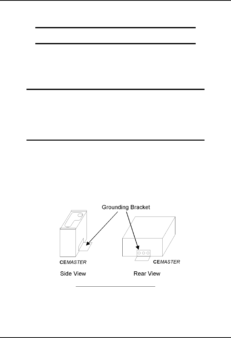
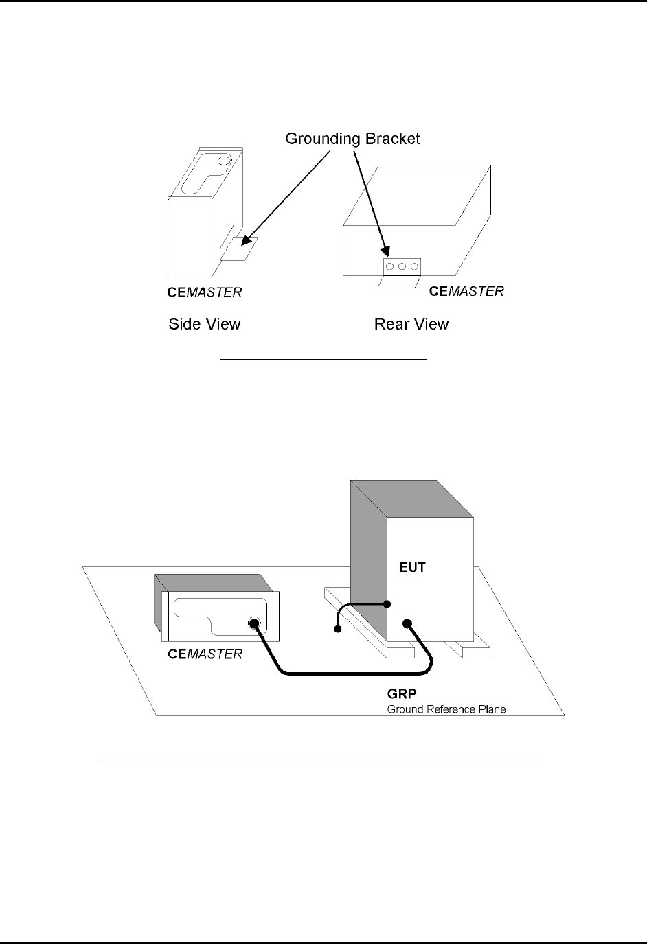
The floor of the test area is to be covered with copper or aluminum with a minimum thickness of
0.01 inch, which must be bonded to building Protective Earth (PE) ground. In addition, the
cabinet of the %'/#56'4must be directly tied to the ground reference plane. Provision for a
mounting bracket is made on the rear and bottom of the %'/#56'4and the bracket and
screws are provided.
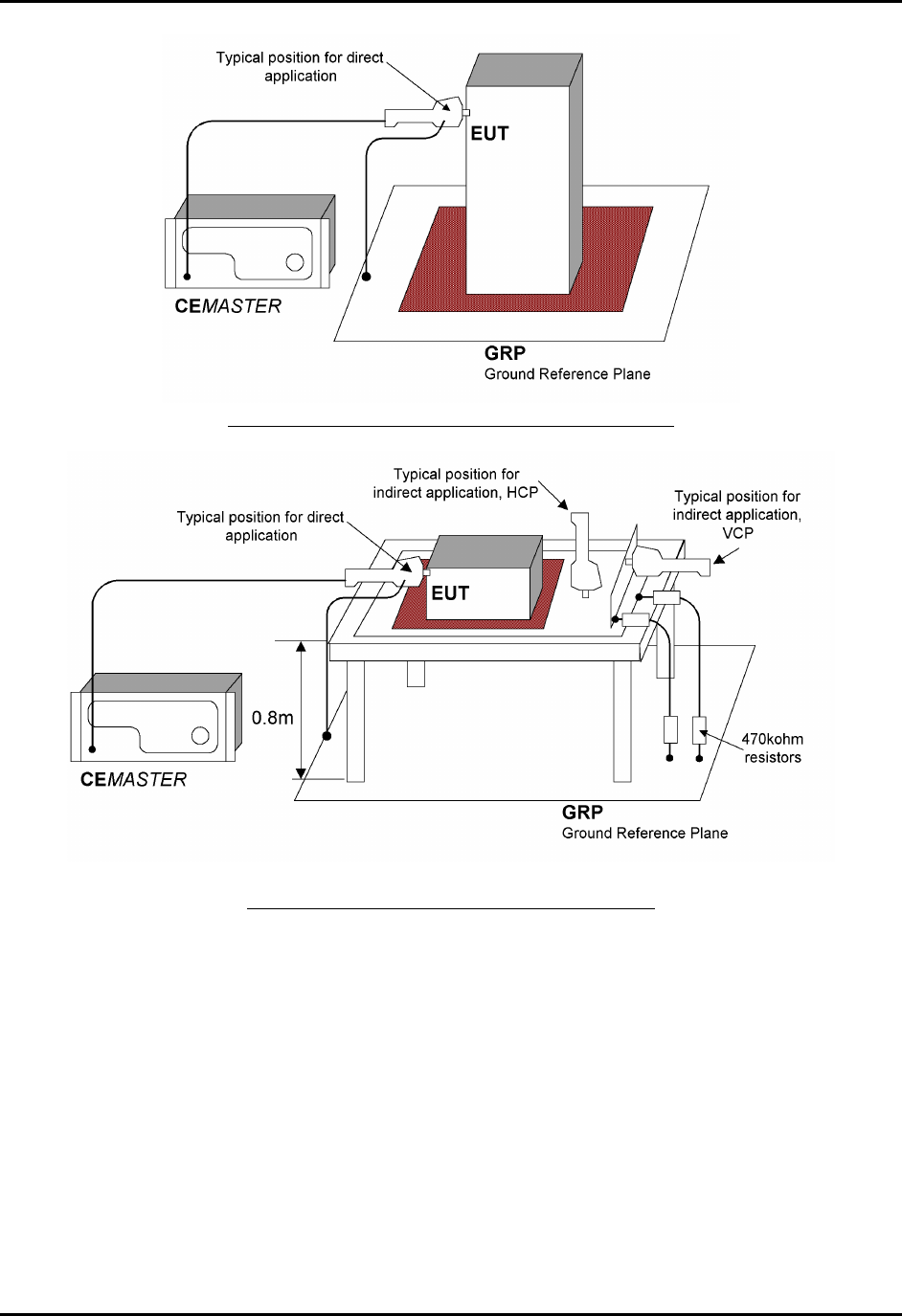
EFT Grounding Bracket Location
CEMASTER System 14
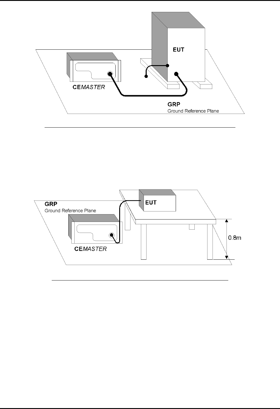
EFT Connection to Equipment Under Test for Floor-standing EUT
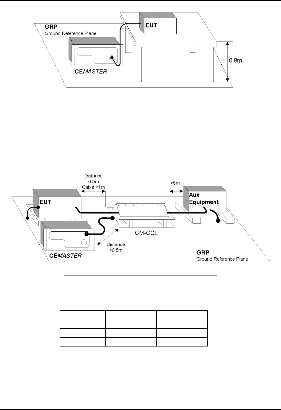
When used with table-top equipment, the equipment should be placed on an insulating table of
0.8 meters height.
EFT Connection to Equipment Under Test for Table-top EUT
CEMASTER System 15
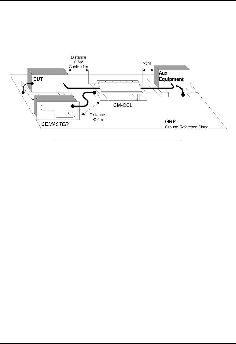
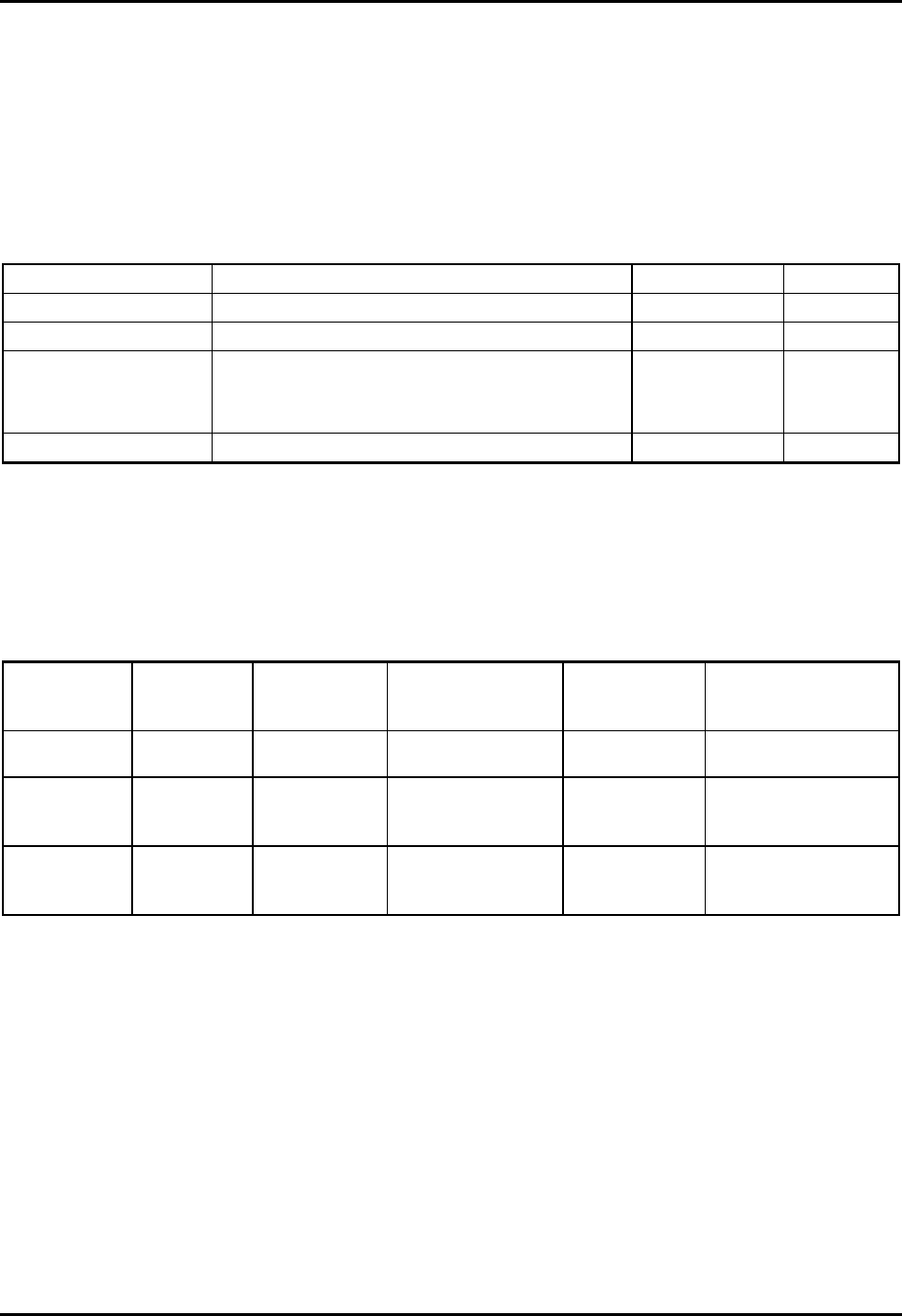
Data and signal cables are tested using the EFT Capacitive Coupling Clamp (CM-CCL). When
performing these tests, the EUT and any auxiliary equipment should be powered from the
%'/#56'4 EUT output, to provide isolation between the test setup and building power mains.
The minimum spacing required between the clamp and the equipment in the test area is shown in
the figure below.
Use of the Capacitive Cable Coupler for EFT Testing

CEMASTER System 16
Special Considerations for ESD Testing
ESD testing involves the use of high-voltage, fast-rising pulses. For this reason the testing
standards specify the use of a ground reference plane in the area where ESD testing is performed.
This device complies with the requirements of the EMC Directive,
89/336/EEC, as stated in the declaration of Conformity. However, ESD
test pulses are by nature an interference test and can therefore create a
possible source of disturbance to other electronic equipment that is not
intended for test. This device should be used in an environment free of
other equipment that could be affected by these emissions, or in a shielded
room.
IEC 1000-4-2 requires the use of a ground plane which must be bonded to building Protective
Earth (PE) ground. The minimum size of the ground plane is 1 m2, the exact size depending on
the dimensions of the EUT; the ground plane shall extend beyond the EUT by at least 0.5 m on
all sides. The ground plane shall be sheet copper or aluminum of 0.25 mm minimum thickness,
or 0.65 mm minimum thickness if another metal is used.
For ESD testing, the %'/#56'4need not be connected to the ground plane.
The EUT shall be positioned at least 1 m from walls and any metallic structures.
For table-top equipment, a non-conducting table 0.8 m high is placed on the ground plane. A
ground plane (HCP) 1.6 m by 0.8 m will be put on the table, and the EUT and any cables shall be
placed on an insulating support 0.5mm thick placed on top of the HCP. The HCP shall connect to
the ground reference plane with a resistive cable with two, 470,000 ohm resistors, one resistor at
each end of the cable.
Special Considerations for Pulsed Magnetic Field and Power-Frequency
Magnetic Field Testing
IEC 1000-4-8 and IEC 1000-4-9 require the use of a ground plane which must be bonded to
building Protective Earth (PE) ground. The minimum size of the ground plane is 1 m2, the exact
size depending on the dimensions of the EUT; the ground plane shall extend beyond the EUT by
at least 0.5 m on all sides. The ground plane shall be sheet copper or aluminum of 0.25 mm
minimum thickness, or 0.65 mm minimum thickness if another metal is used.
For Magnetic Field testing, the %'/#56'4 need not be connected to the ground plane.
The EUT is placed on the ground reference plane, on an insulating support 0.1 meter thick.
The coil and EUT shall be positioned at least 1 meter from walls and metallic objects.

CEMASTER System 17
Handling, Transportation, Storage
Save all shipping materials (shipping boxes, foam pieces, bags, and special instructions) for
possible future shipments.
The %'/#56'4 requires two people for unpacking. Follow the instructions in the
INSTALLATION section of this manual and any special instructions shipped with the unit.
Issues related to transportation of %'/#56'4 models are identical to those for installation;
the weight of the unit requires that two people help in packing and movement. When packing
the unit for transportation the original shipping materials should be used, or new materials of
equivalent strength and durability.
An optional transport case -- CM-CASE -- is available for the unit.
For long storage intervals, unplug the power cords of the instrument and cover the instrument
to protect from dust and liquid spills.

CEMASTER System 18
This page left blank intentionally.
CEMASTER System 19
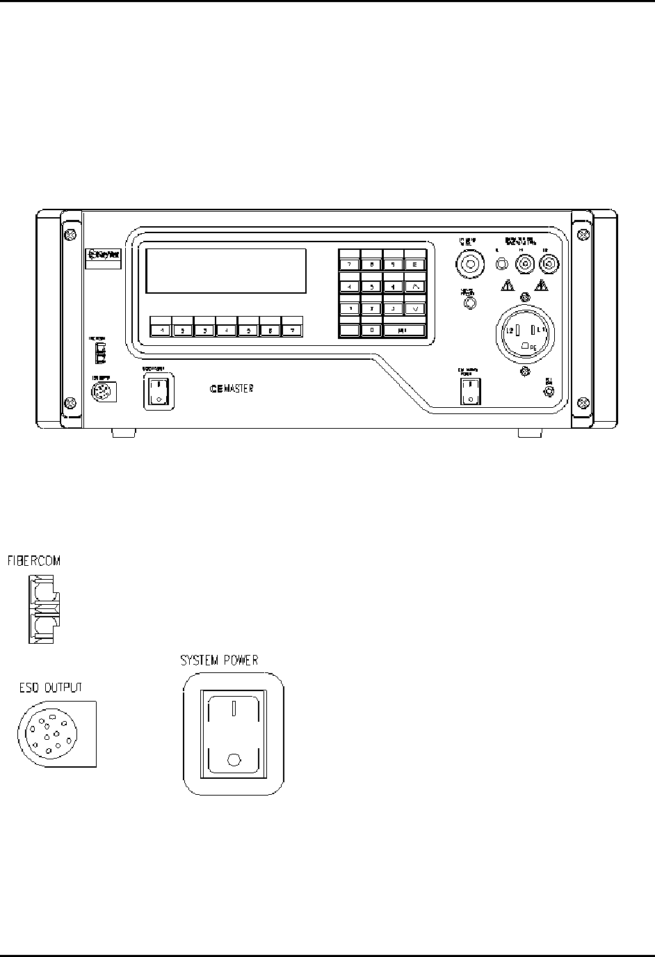
Introduction
All features of the %'/#56'4, and all connections to the Equipment Under Test, are made
from the front panel of the %'/#56'4. The front panel controls and features are broken into
three major groups: the System Interconnections, the Equipment Under Test Connections, and
the User Interface.
CEMASTER System Interconnections -- ESD and Computer Interface
On the left, bottom side of the %'/#56'4front
panel are connectors for the FiberCom serial port,
the ESD test probe, and the power switch for the
%'/#56'4Note that both connectors are
polarized. On the FiberCom connector the small
tab on the connector faces right. On the ESD
probe connector, align the flat of the connector
plug with the flat of the front panel opening. Do
not force the connectors.
CEMASTER System 20
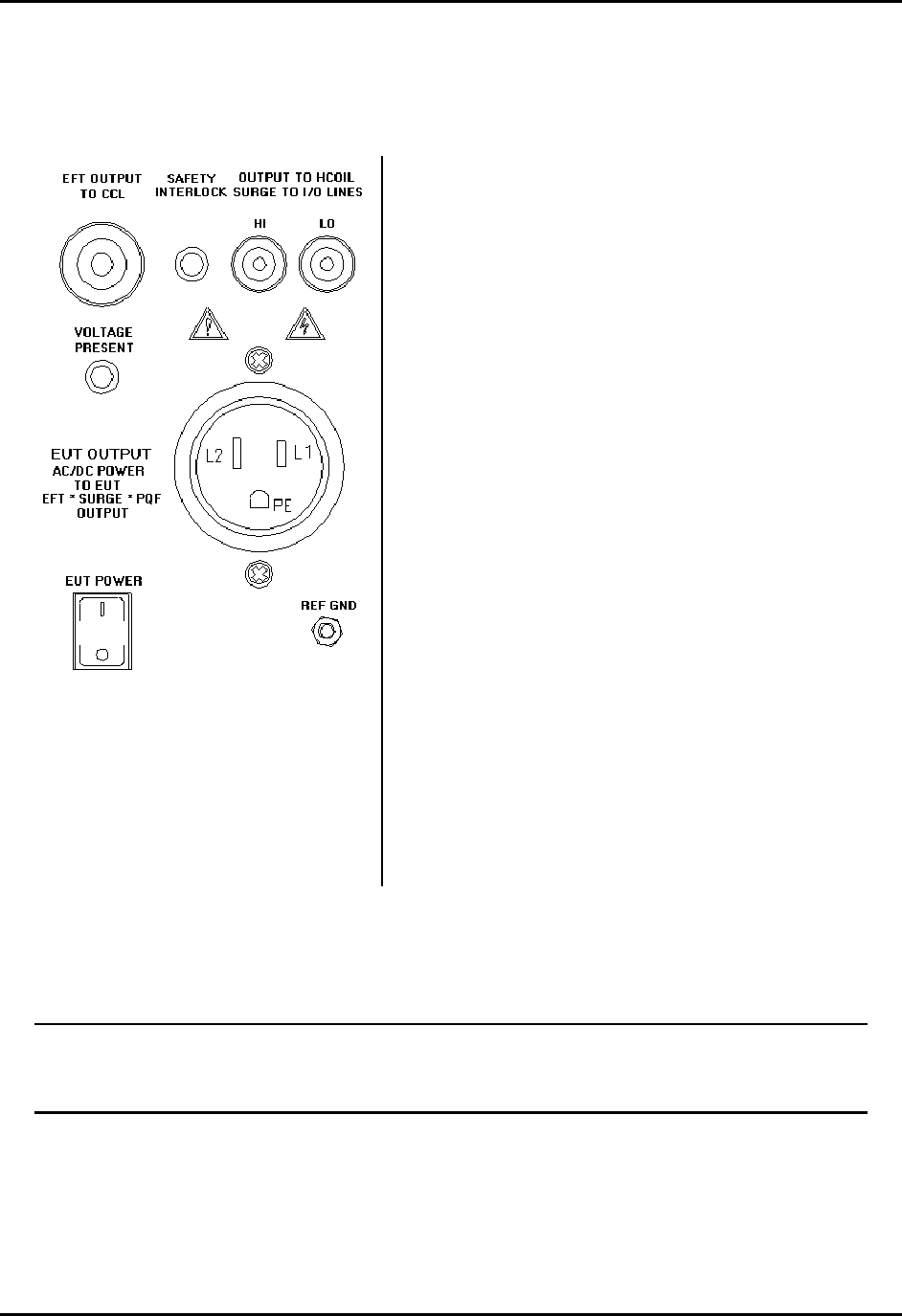
Connections to the Equipment Under Test
On the top, right side of the %'/#56'4 front panel are the connections to the Equipment
Under Test. These include:
The EFT output coax, at upper left, connects to the
Capacitive Cable Clamp and is used for waveform
verification.
The Safety Interlock connector allows the user to
connect a remote switch which, when open, removes
all AC and high-voltage from the %'/#56'4front
panel outlets, and disables the ESD head.
The Safety socket outputs, at upper right, couple surge
pulses to the magnetic coil, communication lines, and
can be used for component testing. These sockets also
provide power frequency magnetic field output to a
test coil.
The EUT Power connector provides AC Mains to the
Equipment Under Test.
The EUT Power switch energizes the EUT Power
connector.
The Voltage Present LED is lit when the AC Mains
outlet is energized or when high voltage is present.
The Reference Ground Connector is a chassis
connection provided for waveform verification of the
EFT waveform; it is not used during normal testing.
For safety, a positive, operator-action is required to energize the EUT; i.e. if the EUT
power switch is ON when the CEMASTER is first turned on, the switch must be toggled
OFF and then ON to energize the EUT Power connector.
CEMASTER System 21
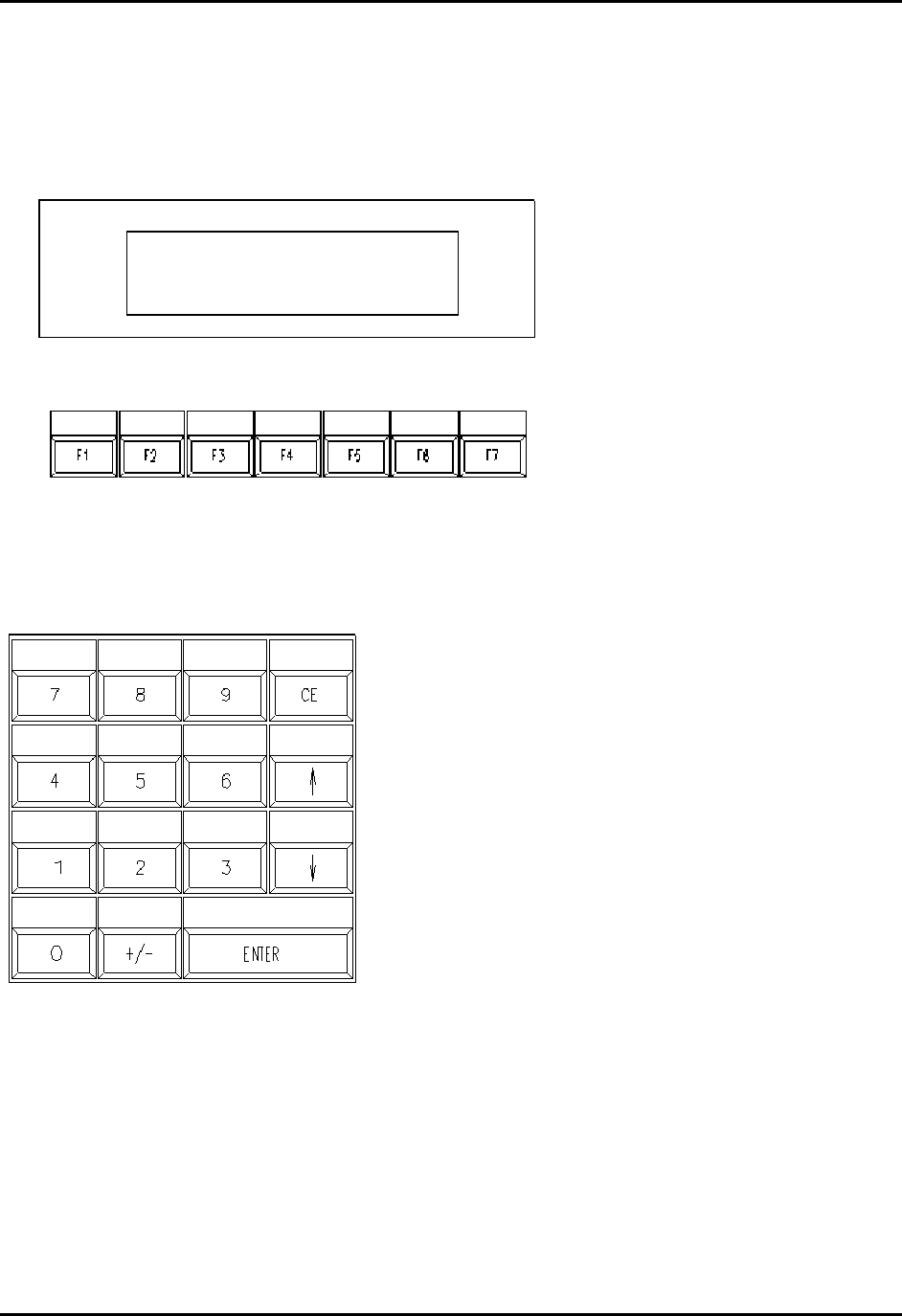
User Interface
When purchased with the CM-FP option, the %'/#56'4 front panel includes a liquid crystal
display with seven function keys, and a 15-key keypad to the right of the display.
The liquid crystal display
and seven function keys
provide quick user input.
The function keys are
mapped to the bottom line
of the display. Pressing a
function key executes that
command.
Typical commands are
EXIT (go back one menu),
RUN, and scroll through
menu selections.
The numeric keypad is used to select menu items and
enter numeric data into edit fields. The keys are
defined as follows:
0 thru 9 enter numeric data or select menu items
+/- change polarity
CE Clear Entry; erase a numeric field
ENTER accept the current input or menu item
scroll through selection list boxes, and
increment or decrement numeric fields
LCD Display

CEMASTER System 22
Programming the CEMASTER from the Front Panel
When purchased with the CM-FP option, the front panel display shows status and the display and
keypad allow convenient programming of the %'/#56'4 via screen menus. Programming is
intuitive and easy. There are four basic menu types.
The Main Menu is the 'top' menu; this is the menu seen after the %'/#56'4initializes, and
this is the menu returned to after exiting all lower menus. The Main Menu allows selecting the
test type to perform: Surge, EFT, ESD, etc. You select a test type either by moving a highlight
bar down the screen using the arrow function keys, then pressing ENTER, or by pressing the
number key associated with the test type.
MAIN EUT OFF
1. EFT/B 5. PQF
2. Surge 6. Pulse Magnetic
3. Power Frequency 7. Calibration
4. ESD 8. System Setup
↑ ↓
The Main Menu shows all possible options, however, you can only select an option if it is
installed in the %'/#56'4system. Attempting to select an option which is not installed will
display an error message that the option is not available.
After selecting a test type, a Test Menu opens. The Test Menu offers a user-defined option, and
usually one or more pre-programmed tests to speed setup and testing per European Norms. The
user-defined option gives access and control of every test parameter; this is the most powerful
option, and allows engineering and debugging tests of EUT. The pre-programmed tests are a fast
way to perform certification testing to European Norms, as most parameters default to the proper
values and cannot be changed -- by locking these parameters the user can be certain that the tests
are performed according to the European Norms, and performed the same way every time. Many
pre-programmed tests perform a sequence of tests; for example, at several voltage levels, at
several mains synchronizations, and in several coupling modes. As with the Main Menu, you
select a test either by moving a highlight bar down the screen using the arrow function keys, then
pressing ENTER, or by pressing the number key associated with the test.
SURGE: TESTS EUT OFF
1. User defined 6. Class 3 Fast
2. Pre-Qual A 7. Class 1 Full
3. Pre-Qual B 8. Class 2 Full
4. Class 1 Fast 9. Class 3 Full
5. Class 2 Fast
↑ ↓ EXIT
CEMASTER System 23
After selecting either the User-Defined test option, or a pre-programmed test, a Parameter
Definition Menu opens. The Parameter Definition Menu has edit fields, for waveform,
voltage, etc. To change a field you first move the highlight bar to that field, using the function
keys. After selecting a field there are different editing steps, depending on the type of field.
• List fields have a limited number of specific values. An example is the line synch field
which can accept "L1" or "RAND". With a list field selected, the value is changed by
using the keypad arrow keys to scroll through the options.
• Numeric fields are edited by typing a value at the keypad. The keypad input fills the
available field from right to left (If the field allows a decimal place, such as "##.##" and
thus a value between 0 and 99.99, to enter a value of 10, press "1", "0", "0", "0"). Press
"+/-" after the number to make it negative. Press ENTER or move the highlight bar to
another field to accept the value; the value must be accepted before a test can be run.
• Some fields combine Numeric and List fields. When selected, the keypad arrow keys
change the list portion (L1,RND) and the keypad number keys replace the numeric value.
When all entries have been made and accepted the test can be started by pressing the F1 key --
the RUN function key. To exit this menu without starting a test, press the F7 key -- the EXIT
function key.
SURGE: USER DEF EUT OFF
Waveform .......... 12 Ohm
Voltage ........... +2000 V
Output:Coupling ... MAINS:L1,L2/PE
Phase Sync:Angle .. L1:180 deg
Number of Tests ... 500
Time Between Tests 60 s
RUN ↑ ↓ EXIT
When a pre-programmed test has been selected, many parameters assume default values and
cannot be changed by the user; these fields cannot be selected or highlighted. The fields for these
parameters are replaced with the an AUTO symbol.
SURGE: PREQUAL A EUT OFF
Waveform ..........
Voltage ...........
Output:Coupling ...
Phase Sync:Angle ..
Number of Tests ...
Time Between Tests 60 s
RUN ↑ ↓ EXIT
When a test is running, a RUN Menu is displayed. The RUN Menu shows the test type (Surge,
EFT, etc.) and the EUT status (EUT ON, EUT OFF) on the top line of the display. The right side
of the display shows the test parameters you programmed: waveform, voltage, coupling mode,
line synch, number of tests, and time remaining in this test step (For example, the Surge Run
Menu will display the test steps -- or test states -- on the STATUS line of CHARGING, FIRING,
A
UTO
A
UTO
A
UTO
A
UTO
A
UTO

CEMASTER System 24
and WAITING. During each of these states, the time remaining field will count down and display
the time remaining in that state.). Some tests, such as ESD, will not display time remaining as the
time remaining depends on how the operator uses the ESD probe.
The left side of the display shows status; from top to bottom this is; Status (of test: charging,
running, etc.), Time (secs remaining in this test; if this test is one of a sequence this is the time
for the individual test and not the time for the entire sequence), Test (the present test in a
sequence, or test n of total tests), and Comm (or communications status: local, remote).
SURGE: RUN EUT OFF
12 Ohm
Status: Charging +2000 V
Time: 37s MAINS:L1,L2/PE
Test: 1/90 L1:180 deg
Comm: Local 3
60 s
STOP PAUSE
In the RUN Menu, the STOP function key -- the F1 key -- terminates a test immediately and
returns to the Parameter Definition Menu. The PAUSE function key -- the F3 key -- causes a
temporary suspension of the test. Once a test has paused, press the F3 key a second time to
resume the test (not all tests can be paused and restarted; if critical timing makes this impossible,
the system will treat a pause as a stop, and the test must be restarted from the beginning). Pause
is useful for checking EUT status.
Selections 7 and 8 of the Main Menu -- Calibration and System Menus -- do not run tests, but
perform special functions. The Calibration Menu allows calibration of the CEMASTER by a
Thermo KeyTek authorized service representative. The System Menu provides troubleshooting
and diagnostic tools to the user, and provides access to run-time options.
For more information on the Calibration and System Menus see the TROUBLESHOOTING
chapter.

CEMASTER System 25
STATUS: INITIALIZING EUT OFF
Hazardous voltages and emissions are
present by design when this equipment is
operating. Take safety precautions at
all times.
<PRESS ANY KEY TO CONTINUE>
At power-up a standard message screen is
shown while the system initializes and
performs self-tests.
Press any key to show the Main Menu screen
below.
MAIN EUT OFF
1. EFT/B 5. PQF
2. Surge 6. Pulse Magnetic
3. Power Frequency 7. Calibration
4. ESD 8. System Setup
↑ ↓
The Main Menu allows selecting a test type;
move the highlight bar using the arrow
function keys and press ENTER, or press the
number key associated with the test type. As
example, press 2 to open the Surge menu.
SURGE: TESTS EUT OFF
1. User defined 6. Class 3 Fast
2. Pre-Qual A 7. Class 1 Full
3. Pre-Qual B 8. Class 2 Full
4. Class 1 Fast 9. Class 3 Full
5. Class 2 Fast
↑ ↓ EXIT
The Test Menu offers pre-defined tests to
speed setup and a user defined mode for
control of every parameter. Press 1 to open
the user defined menu.
The EXIT function key moves back one menu
level.
SURGE: USER DEF EUT OFF
Waveform .......... 12 Ohm
Voltage ........... +2000 V
Output:Coupling ... MAINS:L1,L2/PE
Phase Sync:Angle .. L1:180 deg
Number of Tests ... 500
Time Between Tests 60 s
RUN ↑ ↓ EXIT
Parameter Definition Menus have edit fields,
for waveform, voltage, etc. Move the high-
light bar using the function keys to select a
field. Edit a field by typing in a number, or
use the keypad arrow keys to scroll through a
list of options. The RUN function key starts
the test.
.
SURGE: RUN EUT OFF
12 Ohm
Status: Charging +2000 V
Time: 37s MAINS:L1,L2/PE
Test: 1/90 L1:180 deg
Comm: Local 3
60 s
STOP PAUSE
The RUN Menu identifies the test and shows
status. The screen shows test parameters, and
EUT status (ON,OFF), unit status (charging,
waiting, firing), test status (time remaining,
and test 1 of 90), and communications status
(Local, remote). Stop and Pause keys end the
test or causes a temporary hold.
Front Panel Screens showing the Initializing screen and Four Menu Types

CEMASTER System 26
SURGE: USER DEF EUT OFF
Waveform .......... 12 Ohm
Voltage ........... +2000 V
Output:Coupling ... MAINS:L1,L2/PE
Phase Sync:Angle .. L1:180 deg
Number of Tests ... 500
Time Between Tests 60 s
RUN ↑ ↓ EXIT
SURGE: USER DEF EUT OFF
Waveform .......... 12 Ohm
Voltage ........... +2000 V
Output:Coupling ... MAINS:L1,L2/PE
Phase Sync:Angle .. L1:180 deg
Number of Tests ... 500
Time Between Tests 60 s
RUN ↑ ↓ EXIT
Editing Functions Within the Parameter Definition Menus
EUT status shows the front
panel outlet is ON or OFF
The Status bar indicates
the active test menu;
Surge
The RUN / STOP
function key starts or
stops tests
The arrow function
keys select a field to
edit
The EXIT function key
moves to the previous
menu
The bottom line of
text maps to the
seven function keys
List fields are selected by the function keys and
edited using the keypad arrow keys to scroll
through the options.
Numeric fields are selected by the function keys
and edited by typing a value at the keypad.
Press ENTER to accept the value.
Some fields combine Numeric and
List fields. When selected, the
keypad arrow keys change the list
portion (L1,RND) and the keypad
number keys replace the numeric
value.
CEMASTER System 27
SURGE: RUN EUT ON
12 Ohm
Status: Charging +2000 V
Time: 37s MAINS:L1,L2/PE
Test: 1/90 L1:180 deg
Comm: Local 3
60 s
STOP PAUSE
Definition of the Run Screen Menu
EUT status shows the front
panel outlet is ON or OFF
The Status bar indicates
the active test; Surge,
and the menu; RUN.
The STOP -F1- function
key halts the test
The PAUSE -F3- function
key pauses the test. Press
F3 again to resume
The right column shows pro-
grammed test parameters:
waveform, voltage, coupling
mode, line synch, number of
tests, and time between tests
(or length of test).
The left column shows test
information:
Status (charging, running, etc.)
Time (secs left in this test step)
Comm (local, remote)
Test (test n of total tests)
CEMASTER System 28
Map of Front Panel Menu Structure
The next two pages show the structure of the front panel menus.
Selection Flow, from Main Menu through Test Menu, Parameter Definition Menu, and Run
Menu
VALUE is set to 125V
VALUE is set to 0, then 90, then 270
VALUE may be edited by user
VALUE is set to 60, but may be edited.
Indicates a sequence of tests; first test 12-ohm, 250V; second
test 2-ohm, 125V
Legend, Map Of Front-Panel Menus

CEMASTER System 29
Map of Front-Panel Menus, Page 1 of 2
CEMASTER System 30
Map of Front-Panel Menus, Page 2 of 2

CEMASTER System 31
Programming the CEMASTER from a Personal Computer
When purchased with the CM-SW option, the %'/#56'4may be programmed and controlled
from a Personal Computer (PC) running Windows.
The PC software gives full access to all the features and capabilities of the %'/#56'4,
including running a single test, running a pre-defined test sequence, and running diagnostics.
In addition, the PC software adds a number of useful features:
• Create tests and easily edit them.
• Chain tests into a test sequence. A test sequence can be constructed from a single test
type (e.g. Surge) or can combine test types (e.g. do one Surge test followed by one
EFT test, etc.).
• Store and recall tests and test sequences to disk.
• Print or file text descriptions of tests and test sequences (for inclusion in reports).
• Log test -- print or file what tests are executed.
Full instructions for the software are described in the %'9CTG section.

CEMASTER System 32
Running Tests
STANDARDS OVERVIEW
The European Union’s EMC Directive requires that electronic and electrical products be tested
for immunity to both man-made and natural phenomena and to insure that products do not emit
unintentional signals that may interfere with the continued, reliable operation of other products.
Compliance with the EMC Directive requires that products be tested in accordance with
European Norms, or ENs, issued by CENELEC. These ENs are not developed by CENELEC but
are IEC and CISPR standards redesignated as ENs.
There are three types of EMC Publications:
• Product EMC Standards
• Product Family Standards (including Generic Standards)
• Basic EMC Publications
Product EMC Standards relate to a particular type of product, system or installation for which
specific conditions must be considered. Product EMC Standards include:
• Resistance Welding equipment
• Measuring Relays and Protection equipment
Product Standards have priority over Product Family and Generic Standards; however, where no
Product Standard or Product Family Standard exists for a particular product, the relevant Generic
Standard will apply.
Product Family Standards apply to products of a particular category such as:
• Household appliances and portable tools
• ITE (Information Technology Equipment)
• Audio, video, audio-visual and entertainment lighting control apparatus for
professional use
Product Family Standards have priority over Generic Standards; however, where no Product
Family EMC Standard exists for a particular product family, the relevant Generic Standard will
apply.
Generic EMC Standards are a special type of Product Family Standard which apply to products
operating in a particular environment for which no dedicated Product or Product Family Standard
exists. They specify a set of essential requirements, test procedures and generalized performance
criteria applicable to products or systems operating in this environment.

CEMASTER System 33
The Generic EMC Standards include: EN 50082-1, EN 50082-2, EN 50081-1, and EN 50081-2
which cover immunity and emissions testing for commercial, residential and light industrial
environments, as well as for industrial environments.
Basic EMC Publications may be standards or technical reports which, by definition, are NOT
dedicated to specific product families, products, systems or installations. They may concern:
• Terminology
• Descriptions of electromagnetic phenomena
• Specification of compatibility levels (NOT compliance levels)
• General requirements for the limitation of emissions
• Recommendations for test levels for immunity
• Measurement techniques
• Descriptions and classification of the environment
Basic EMC Publications include Basic EMC standards such as the IEC 1000-4-X Series, CISPR
22, CISPR 11, and others
TEST REQUIREMENTS
The Basic EMC Publications (IEC 1000-4-2, IEC 1000-4-4, etc.) set the waveforms, test
environment, and measurement techniques. The CEMASTER was designed to meet the
requirements of these publications.
Test levels are set by the Generic EMC Standards and Product Family Standards. The
preprogrammed tests stored in the CEMASTER are designed to meet the test levels of:
• EN 50082-1 Generic Immunity, Residential, commercial, and light industrial
• EN 50082-2 Generic Immunity, Industrial
WRITING A TEST PROCEDURE AND THE TEST REPORT
Before starting testing, you should create a test procedure. This should identify which European
Norms or other test requirements you are testing to. This should include the test levels, polarities,
and number of tests.
Most of the remainder of a test procedure is set by the Basic EMC Publications (IEC 1000-4-2,
IEC 1000-4-4, etc.) which define the test setup and environmental limits, in detail.
The test procedure should also describe how the EUT is setup and connected to test equipment
and ancillary equipment. If the EUT involves software, a description of which software and
software revisions should be included.

CEMASTER System 34
An important part of both the test procedure and the test report is to establish how the EUT is
exercised during the test. Most test procedures recommend that the EUT be operated in "the most
sensitive mode". Preliminary testing will usually be required to determine what the most
sensitive mode of operation is, which may vary with configuration, software, and operations
performed.
Finally, the test procedure should consider what level of disturbances of operation is allowed.
Ideally the EUT should operate through testing without disturbance, however there may be
disturbance which are considered acceptable, in that they do not result in damage. As example,
the following are four levels of system disturbance:
• Normal performance within specification limits;
• Temporary degradation or loss of function which is self-recoverable;
• Temporary degradation or loss of function which is requires operator intervention or system
reset;
• Degradation or loss of function which is not recoverable due to damage to equipment or
components or loss of data.
In no case is it acceptable that the equipment become dangerous or unsafe as a result of testing.
The test report should present all of the information of the test procedure, report the test results,
and give explanation of the results, as required. For acceptance tests, the test report is a required
result of testing.
The remainder of this section covers the basic EMC publications in detail; explains the
waveforms and testing requirements; and explains how to use the %'/#56'4to meet the
requirements of the Basic EMC Publications.
The information on IEC requirements -- figures and diagrams, tables and data, and
test levels -- are accurate as of the date of printing of this manual. However, the
IEC and EN documents are subject to review and change. The information in this
manual is intended as a guideline only.
CEMASTER System 35
IEC 1000-4-2 -- ESD Testing
What is Electrostatic Discharge (ESD) Testing?
These tests relate to equipment, systems, sub-systems, and peripherals which may be involved in
static electricity discharges (either from persons or adjacent equipment), owing to environmental
and installation conditions, such as relative low humidity, use of low-conductivity (artificial
fiber) carpets, vinyl garments, etc.
Two different types of tests can be performed with the ESD head - Contact or Air. Contact
discharges are tests in which a sharp metal ESD tip physically touches the EUT. This method is
regarded as the most repeatable method, and is the only acceptable method for waveform
verification and calibration. Air discharges are tests in which a rounded ESD tip is quickly thrust
toward the EUT until an ESD event occurs by "leaping" from the ESD tip to the EUT through the
air. This method does not yield as repeatable results, but can be used if a contact discharge
cannot be performed for some reason or another.
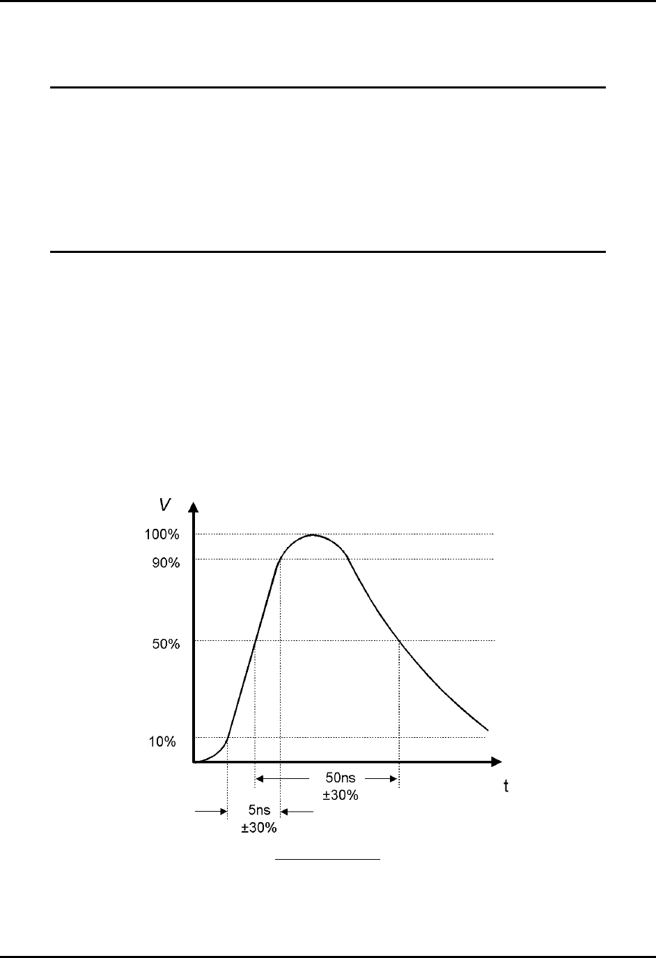
The ESD waveform is characterized by the current in Contact-mode discharge, as defined in the
figure and table below:
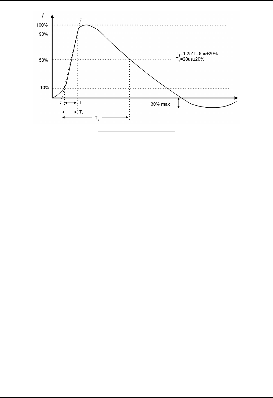
Typical ESD Current Waveform
Level Set Voltage Peak Current (± 10%) Current (±30%) at 30nS Current (±30%) at 60nS
1 2 kV 7.5A 4 2
2 4 kV 15 A 8 4
3 6 kV 22.5 A 12 6
4 8 kV 30 A 16 8
Waveform Parameters for ESD Pulse

CEMASTER System 36
General Guidelines for Testing
Place the air-discharge or contact-mode output tip into the ESD probe output tip receptacle.
The TPA-2 probe tip is used for air discharge.
The rounded tip of this probe prevents corona
(which reduces applied voltage) and ensures
most consistent results.
The TPC-3 probe tip is used for contact
discharge. The sharp point of this tip will
penetrate surface oxidation and -- where
necessary -- paint.
Connect the ESD probe to the %'/#56'4using the 8-pin DIN cable. Connect the discharge
return cable from the ESD probe to ground (an indicator on the ESD probe will light if the
discharge return cable is not connected to the ESD probe). The bargraph indicator on the ESD
probe is intended as a rough guide to the actual test voltage, and can serve in many applications
as a pulse -- discharge -- indicator. The bargraph display is not calibrated, and can be affected by
high humidity; for precise readings of probe tip voltage or periodic calibrations, Thermo
KeyTek's DCA-2, high-voltage divider should be used.
The ESD probe can be operated in manual triggering mode -- normal -- or automatic triggering
mode -- tripod. Normal triggering is intended for handheld applications; in normal mode the
probe will fire once for each time the probe button is pressed if the repetition is set to one, or fire
continuously at 1pps or 20pps while the button is depressed if the repetition is set higher. Tripod
triggering mode is intended for tripod operation; in this mode the probe will start triggering when
the probe button is pressed and released and operation continues until either: the test ends, the
operator ends the test by pressing the STOP -- F1 function -- key, or the probe button is pressed a
second time.
For safety, in all modes of operation, the operator must select a program and press run from the
%'/#56'4 front panel or application software, THEN press the probe button to start the test.
For Contact discharges the TPC-3 contact tip should physically touch the EUT. For Air
discharge the rounded, TPA-2 tip is thrust toward the EUT at a constant rate until an ESD event
occurs by "leaping" from the ESD tip to the EUT through the air. The probe is then pulled back -
away from the EUT - in preparation for the next test. Some practice is required to obtain
consistent results with air discharge.
Certification testing per European Norms uses 1pps for compliance testing. Use 20 pulses per
second mode for quick scans to determine the most sensitive areas; then switch to 1pps for
compliance testing. In 20 pps mode the pulse-detection and pulse counting features of the
%'/#56'4are disabled -- after the first pulse event, the ESD probe will free-run at 20pps
whether or not there is a discharge.

CEMASTER System 37
Testing Requirements per IEC 1000-4-2
Testing to IEC 1000-4-2 has the following requirements:
• Testing takes place in climatic conditions as follows:
Ambient temperature: 15 °C to 35 °C
Relative Humidity: 30 % to 60 %
Atmospheric Pressure: 86 kPa (860 mbar) to 106 kPa (1060 mbar)
• A ground reference plane (GRP) is required.
• The EUT shall be positioned at least 1 m from walls and any metallic structures.
• Positioning of power and signal cables shall be representative of good installation practice.
• The EUT shall be connected to the grounding system, representative of good installation
practice; no additional earthing connections are allowed.
• The discharge return cable should, where possible, be placed off the ground reference plane,
and should not come closer than 0.2 m to other conductive parts of the test setup.
• Vertical Coupling Planes (VCP) and Horizontal Coupling Planes (HCP) may be used for
indirect application of the ESD pulse. These planes shall be constructed from the same
material and thickness as the ground plane, and should be connected to the ground plane by a
cable with two, 470,000 ohm resistors, one resistor at each end of the cable.
• For table-top equipment, a non-conducting table 0.8 m high is placed on the ground plane. A
ground plane (HCP) 1.6 m by 0.8 m will be put on the table, and the EUT and any cables
shall be placed on an insulating support 0.5mm thick placed on top of the HCP. The HCP
shall connect to the ground reference plane with a resistive cable as in the previous
paragraph.
IEC 1000-4-2 requires the use of a ground plane which must be bonded to building Protective
Earth (PE) ground. The minimum size of the ground plane is 1 m2, the exact size depending on
the dimensions of the EUT; the ground plane shall extend beyond the EUT by at least 0.5 m on
all sides. The ground plane shall be sheet copper or aluminum of 0.25 mm minimum thickness,
or 0.65 mm minimum thickness if another metal is used.
For Floor-standing EUT the EUT is placed on a non-conducting mat of 0.1 mm minimum
thickness placed on the ground plane. ESD testing may be direct -- applied to the EUT -- or
indirect -- applied to the ground plane or to a vertical plane bonded to the ground plane.
CEMASTER System 38
Typical ESD Test Setup for Floor-standing EUT
Typical ESD Test Setup for Table-Top EUT
During testing, the EUT is operated in a normal fashion. Compliance testing is typically
performed with the EUT continually operating in the most sensitive mode, as determined by
preliminary testing.
Pulses are applied to points and surfaces which are accessible to personnel during normal usage.
The voltage is increased from the minimum to the selected test level, in order to determine the
threshold of failure (if any). The final test level is set by the product specification and the test
class. The test is applied with single discharges, at preselected points. At least ten discharges of
the most sensitive polarity shall be applied, and a rest interval of at least one second is
recommended (or longer, as required to verify continued operation of the EUT).
CEMASTER System 39
The %'/#56'4 supports 1000-4-2 testing to class 3 in Air-discharge mode and class 2 in
contact discharge mode. The following table lists the test capabilities of the ESD hardware:
User-defined ESD Tests
The user-defined test option allows individual control of all test parameters required for ESD
testing; this allows testing at different levels, modes, and repetition rates. The test parameters are:
Surge Test Parameter Range/Units
Voltage [-8800...-250, +250...+8800] V; resolution: 5 V
Tip Air or Contact
Mode Normal or Tripod
Repetition Rate [1pps, 20pps]
Number of Pulses [1 . . . 999]
Preprogrammed IEC Standard ESD Test Sequences
Two preprogrammed test sequences are stored in the %'/#56'4for rapid testing to the IEC
standards.
There are two tests mandated by the specifications - a 4 kV contact discharge and an 8 kV air
discharge. Repetition is set for 1 pps and polarity is set by the user to the most sensitive polarity.
The user can select mode -- normal or tripod -- and the number of pulses.
The table below shows these two tests:
Class
Peak Voltage
kV
Contact Air
1 2 2
2 4 4
3 N/A 8
Tests Voltage, kV Number of
Discharges
Repetition, pps
Contact 4 10 positive,
10 negative
1
Air 8 10 positive,
10 negative
1

CEMASTER System 40
Waveform Verification
IEC 1000-4-2 requires that the ESD output be verified periodically. Verification requires an ESD
target (Thermo KeyTek CTC-3), a target plane (Thermo KeyTek TP-1), and an oscilloscope of
1GHz minimum bandwidth. The ESD probe with contact-mode tip is placed on a tripod, the
%'/#56'4set to TRIPOD mode, 1pps.
The rise time, peak amplitude, and amplitude at 30 ns and 60 ns should be monitored and
recorded and checked against the figure and table at the start of this section.
Performing ESD calibration is not trivial. The high-speed oscilloscope is expensive; the
extremely fast risetime and high-bandwidth required by specification can require that a
dedicated test site be built, with Faraday-shields for the oscilloscope, and EMI damping
materials on floors and walls to reduce reflections.
Thermo KeyTek offers a calibration service for all equipment, including the ESD probe.
Contact factory for details.
CEMASTER System 41
IEC 1000-4-4 -- EFT Testing
For safety reasons, the precautions taken during EFT testing should be the same as
for Surge testing -- read and follow the guidelines of the Safety Concerns During
Surge Testing section, Page 4.
It is important that the Equipment Under Test be properly connected -- read and
follow the guidelines of the Test Area Considerations and Site Preparation
section and of the Special Considerations for EFT Testing section, Page 12, as
well as the Testing Requirements per IEC 1000-4-4 section which follows.
What is Electrical Fast Transients (Burst) Testing?
The electrical fast transient test consists of a burst of fast transients, coupled into power supply,
control and signal ports of electrical and electronic equipment. The significant characteristics of
the test are very high amplitude, the short rise time, the high repetition rate, and the low energy of
the transients.
The test is intended to demonstrate the immunity of electrical and electronic equipment when
subjected to types of transient disturbances such as those originating from switching transients
(interruption of unsuppressed inductive loads, relay contact bounce, etc.).
EFT Waveform

CEMASTER System 42
General Guidelines for Testing
The EFT test voltage is referenced to the chassis of the %'/#56'4The EFT waveform is
coupled into the EUT via the AC Mains and the mains coupler built into the %'/#56'4, or via
signal lines (or both). An optional Capacitive Cable Clamp is available for coupling to signal
lines or to power lines where the CEMASTER internal coupler cannot be used.
When applied to the EUT Mains, the EFT voltage is applied between ground -- the Ground
Reference Plane (GRP) -- and each of the power supply terminals and between the GRP and the
protective earth of the EUT.
Power-line -- Mains -- testing is performed by plugging the EUT into the %'/#56'4 EUT
outlet, establishing the EUT in a normal operating mode, and applying the EFT waveform to,
first the line (L1), then neutral (L2), then PE.
Data-line testing starts with the EUT and auxiliary equipment plugged into the %'/#56'4
EUT outlet -- to prevent EFT waveforms from contaminating the AC Mains -- and couples the
EFT waveform from the CLAMP outlet to a Capacitive Cable Clamp where the waveform is
coupled into the signal lines. The Capacitive Cable Clamp should be adjusted to fit snugly about
the cables to be tested.
Testing Requirements per IEC 1000-4-4
Testing to IEC 1000-4-4 has the following requirements:
• Testing takes place in climatic conditions as follows:
Ambient temperature: 15 °C to 35 °C
Relative Humidity: 25 % to 75 %
Atmospheric Pressure: 86 kPa (860 mbar) to 106 kPa (1060 mbar)
• A ground reference plane (GRP) is required.
• The EUT shall be positioned at least 0.5 m from walls and any metallic structures.
• The EUT shall be connected to the grounding system, representative of good installation
practice; no additional earthing connections are allowed.
• Positioning of power and signal cables shall be representative of good installation practice,
EXCEPT:
• The length of signal and power cables shall be 1 meter or less
• If the length of signal or power cable exceeds 1 meter, the excess length shall be
gathered into a flat coil with a diameter of 0.4 m and situated at a height of 0.1 m
above the GRP.
IEC 1000-4-4 requires the use of a ground plane which must be bonded to building Protective
Earth (PE) ground. The minimum size of the ground plane is 1 m2, the exact size depending on
the dimensions of the EUT and %'/#56'4; the ground plane shall extend beyond the EUT
and %'/#56'4 by at least 0.1 m on all sides. The ground plane shall be sheet copper or
CEMASTER System 43
aluminum of 0.25 mm minimum thickness, or 0.65 mm minimum thickness if another metal is
used.
The cabinet of the CEMASTER must be directly tied to the ground reference plane. Provision
for a mounting bracket is made on the rear of the CEMASTER and the bracket and screws are
provided.
Location of Grounding Bracket
For floor mounted equipment, the EUT shall be placed on the GRP and shall be insulated from
the GRP by an insulating support 0.1 meter ± 0.01 meter thick.
For table-top equipment, the EUT should be placed on a table of height 0.8 meter ± 0.08 meter
above the GRP.
EFT Connection to Equipment Under Test for Floor-standing EUT
CEMASTER System 44
EFT Connection to Equipment Under Test for Table-top EUT
Data and signal cables are tested using the EFT Capacitive Coupling Clamp (CM-CCL). When
performing these tests, the EUT and any auxiliary equipment should be powered from the
%'/#56'4EUT output, to provide isolation between the test setup and building power mains.
The minimum spacing required between the clamp and the equipment in the test area is shown in
the figure below (Note: if the Auxiliary equipment is not considered part of the EUT, the
separation distance is 5 meters as shown. If the Auxiliary equipment is considered part of the
EUT, the separation drops to 1 meter).
Use of the Capacitive Cable Coupler for EFT Testing
The voltage test levels to be applied vary with the test class, and are listed below:
Test Level Peak Voltage Frequency
Class 1 500V 5kHz
Class 2 1.0kV 5kHz
Class 3 2.0kV 5kHz
The level used in testing depends on the European Norm (EN) chosen to test against. As
example, EN50082-1 (for Residential, commercial, and light industry) specifies a test level of
1000 volts. The EFT voltage is applied for one minute, for each test.
CEMASTER System 45
User Defined EFT Test
The user-defined test option allows individual control of all test parameters required in EFT
testing; this allows testing at different levels, modes, and repetition rates.
On being triggered by pressing the “start” key, a user defined test produces a series of output
events with the parameters defined below:
Parameter Range Resolution Accuracy
Voltage -250V ... -2500V, 250V ... 2500V 1V +/- 10%
Burst Frequency 2.5 ... 100kHz in 0.5kHz steps +/- 20%
Output Coupling Clamp, Mains [Mains modes, L1, L2, PE,
L1&L2, L2&PE, L1&PE, or L1&L2&PE
All outputs with respect to Groundplane]
Test Duration 1...999 seconds 1 second
Preprogrammed EFT Test Sequences
Three preprogrammed test sequences are stored in the %'/#56'4 for rapid testing to the IEC
standards. These test sequences are designed to satisfy the requirements of EN50082-1 and
EN50082-2.
Test
Sequence
Peak
Voltage
Frequency Port Coupling
Mode
Mains only
Number of Bursts
Class 1 500V 5kHz Mains or Clamp PE to
groundplane.
200 (1 minute) per
polarity
Class 2 1.0kV 5kHz Mains or Clamp L1, L2, and PE
in sequence
200 (1 minute) per
polarity and coupling
mode
Class 3 2.0kV 5kHz Mains or Clamp L1, L2, and PE
in sequence
200 (1 minute) per
polarity and coupling
mode
All tests are run twice: once in each polarity.
CEMASTER System 46
Waveform Verification
IEC 1000-4-4 requires that the EFT output be verified periodically. For verification, the output of
the generator is connected to an oscilloscope through a 50-ohm, high-voltage coaxial attenuator.
The rise time, duration, and repetition rate of the impulses within one burst should be monitored
and recorded.
The bandwidth of oscilloscope and attenuator must exceed 400MHz. For digital oscilloscopes a
sampling rate exceeding 1GSa/s is recommended. The attenuator must have a voltage rating of
1250V minimum.
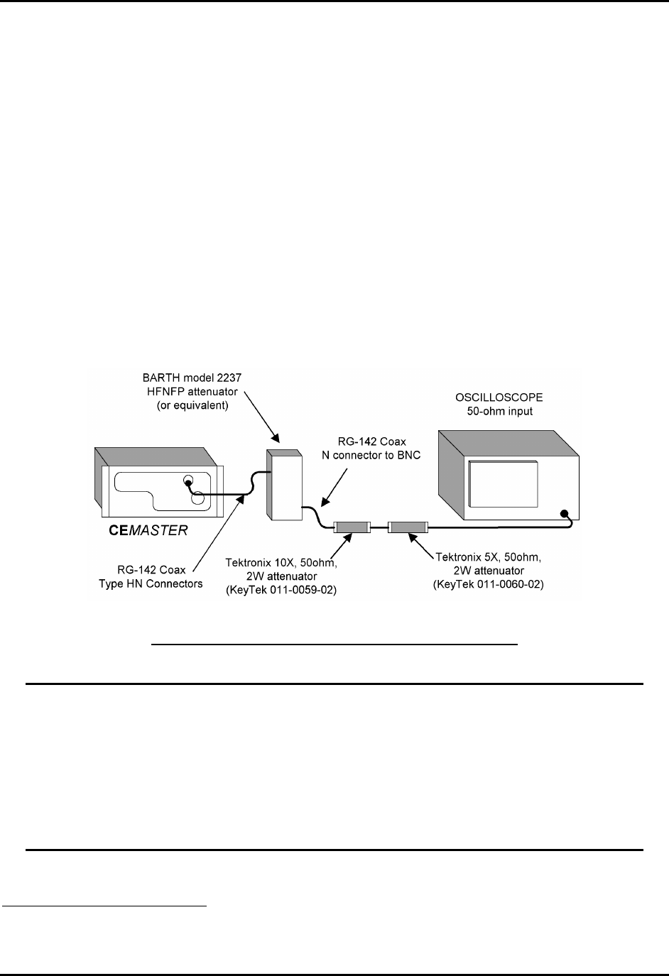
The test setup shown below is usable for Waveform Verification. The BARTH Model
2237HFNFP attenuator4 has sufficient voltage and power rating to connect directly to the
%'/#56'4 output. The Tektronix5 attenuators drop the voltage to within the range of typical
oscilloscope inputs. The circuit below provides a total attenuation of 1000:1.
Recommended Test Setup for Waveform Verification
The circuit above is for measurement of the EFT waveform at the HN-coax connector;
this circuit is not rated for use across the AC Mains outlet. Connecting this circuit
across the AC Mains with Mains voltage present will result in damage of the
attenuator.
If measuring EFT waveform at the AC Mains outlet: Check that the EUT switch is off
and no AC is applied to the EUT Mains Inlet before connecting the attenuator; make the
measurement and remove the attenuator immediately.
4 Barth Electronics, Inc., 1300 Wyoming St., Boulder City, NV 89005 USA
5 Tektronix, Inc., P.O. Box 1000, Wilsonville, OR 97070-1000 USA
CEMASTER System 47
IEC 1000-4-5 -- SURGE Testing
Surge testing is hazardous -- read and follow the guidelines of the Safety
Concerns During Surge Testing section, Page 4.
It is important that the Equipment Under Test be properly connected -- read and
follow the guidelines of the Test Area Considerations and Site Preparation
section and of the Special Considerations for Surge Testing section, Page 11.
What is Surge Testing?
Surge testing is the application of unidirectional surges to the Equipment Under Test to model
those caused in the real world by overvoltages from switching and lightning transients.
Surges occur on the AC power mains as a result of switching operations in the power grid and
from nearby lightning strikes, either directly to the power distribution system or to nearby
ground. Radiated coupling of surges into I/O lines can also occur.
Electronic products are tested for Surge immunity to insure their continued reliable operation if
subjected to realistic levels of surge voltages.
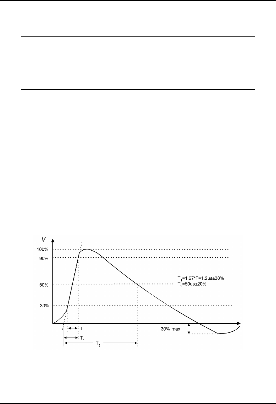
The waveform used for IEC testing is the 1.2/50 µs open circuit voltage (8/20 µs short circuit
current) combination wave. This waveform is separately characterized by the open circuit voltage
and short circuit current.
Open-Circuit Surge Voltage
CEMASTER System 48
Short-Circuit Surge Current
General Guidelines for Testing
Surge testing is very useful to determine breakdown of components when subjected to a high-
voltage impulse. Surge testing can be performed on AC or DC power Mains, communications
lines, and components.
The %'/#56'4 includes a built-in coupler which can place surges on AC or DC Mains for
application to the EUT. The angle of application onto the AC Mains waveform can be precisely
controlled; application at 90° and 270° cause the surge to add to the peak line voltage for worst-
case voltage; application at other angles can be used to find sensitive components -- such as
diodes, SCRs, or solid-state switches -- which are most sensitive at the time they turn on or off.
The %'/#56'4 also has front panel, safety socket connections to apply surges to the magnetic
field test coil (CM-HCOIL) or for component testing. The CM-I/OCD optional accessory
provides convenient coupling of surges onto data and I/O lines.
When surging a DC Mains or the EUT with no mains applied, the Line Coupling Phase Angle
selection must be set to ‘RND’ -- random -- as the test will be unable to synchronize to a DC
mains and will not run.
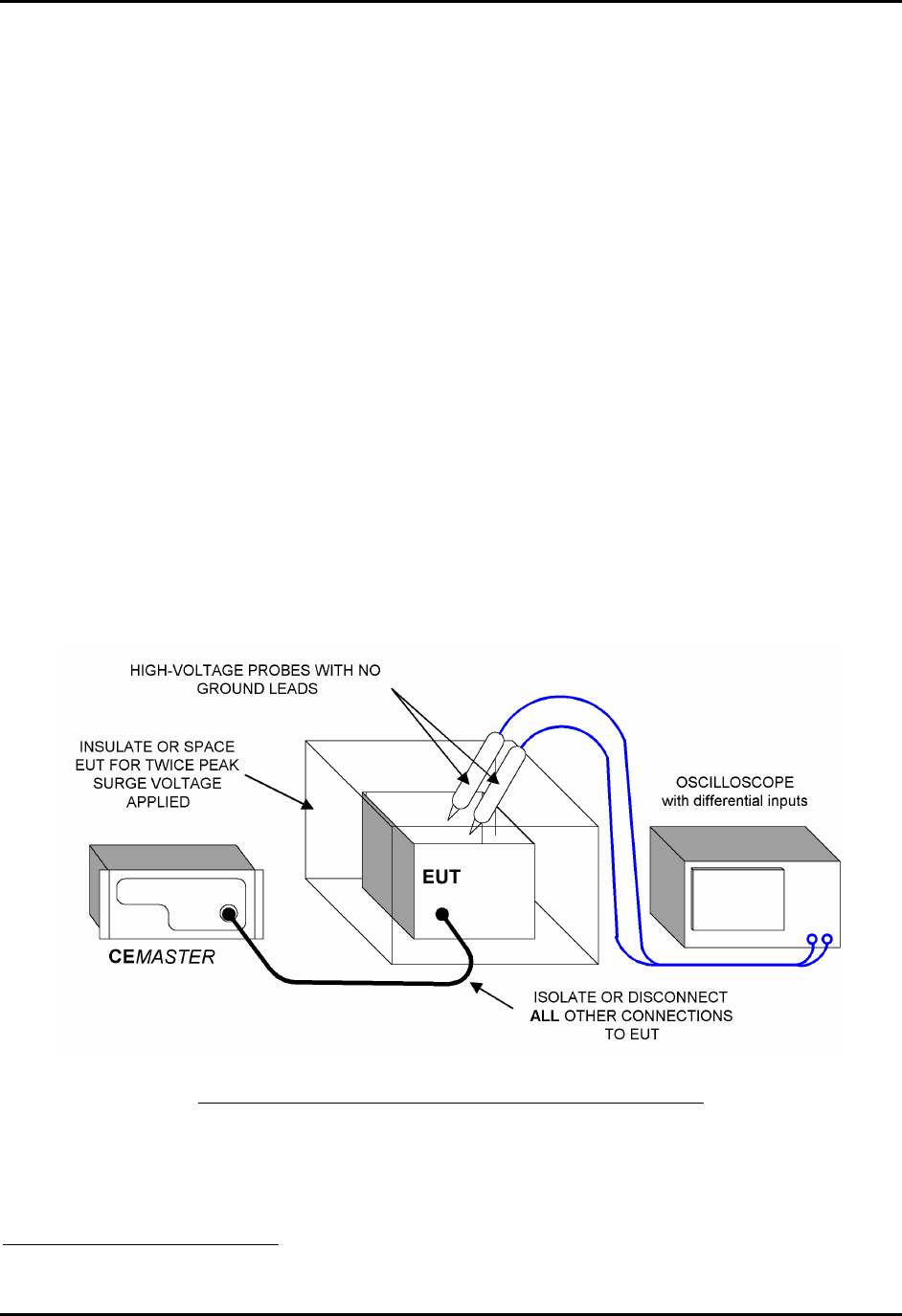
CEMASTER System 49
Probing the EUT during Surge testing should be attempted only by experienced test engineers.
When connecting probes to the EUT, follow these guidelines:
• Use balanced, differential, high-voltage probes rated for the surge voltage (such as the
Thermo KeyTek PK1001D probe set). Most oscilloscope probes are rate for 600Vac or less
and should NOT be used in Surge testing.
• Current should be measured with a non-contact, high-bandwidth current transformer (a
Pearson6 model 110 current transformer, or equivalent).
• Do not connect probe grounds to the EUT! This will create a path for Surge and fault
currents which can endanger the operator and test equipment.
• Do not defeat protective grounding or earthing of the oscilloscope or other test
instrument.
• If connecting a voltmeter or other high-impedance test equipment to the EUT, carefully check
the common-mode voltage rating of the equipment. This is the voltage rating of both probes
above the instrument ground. Surge testing will typically exceed the common-mode voltage
rating of most Mains-powered equipment, and can exceed the rating of battery-powered
equipment. Use of an instrument above its common-mode voltage rating may result in
improper operation or damage.
Connection of Probes to the EUT during Surge Testing
6 Pearson Electronics, Inc., 1860 Embarcadero Rd., Palo Alto, CA 94303 USA
CEMASTER System 50
Testing Requirements per IEC 1000-4-5
The Basic EMC Standards for Surge define the methods of generating consistently reproducible
surge voltages for test purposes. They specify generator and coupler/decoupler design and
performance in sufficient detail to produce correlatable results between test sites. These are
issues which are controlled by the design of the CEMASTER and need not be considered by the
operator or user.
While the Basic EMC Standard specifies how to perform Surge testing, the Generic, Product and
Product Family Standards specify the test levels and pass/fail performance criteria. IEC 1000-4-5
also includes a climatic specification, as follows:
• Testing takes place in climatic conditions as follows:
Ambient temperature: 15 °C to 35 °C
Relative Humidity: 10 % to 75 %
Atmospheric Pressure: 86 kPa (860 mbar) to 106 kPa (1060 mbar)
Note that other values may be specified in the test specification. The EUT should be
operated within its intended climatic conditions.
The test level, polarity, and source impedance are set by the European Norms (EN), as a function
of use and exposure class (See the Class Definition Table and Test Levels Table, below). The
%'/#56'4 is capable of testing to Classes 0, 1, 2, and 3 test levels.
The general test requirements, per IEC 1000-4-5 are as follows:
Output polarity Both positive and negative
Output (source) impedance For power supply (AC or DC), line to line surges: 2 Ω
For power supply (AC or DC), line to earth surges: 12 Ω
For direct coupling to communication lines: 40 Ω
(2 or 12 Ω selected from CEMASTER, and additional,
external resistance added)
Number of tests At least five positive and five negative tests at each test level
Repetition rate Maximum: 1 surge per minute
Mains Synchronization 0° or 180°, 90°, and 270°
CEMASTER System 51
Class definitions
Class 0 Well-protected electrical environment, often within a special room.
Class 1 Partly protected electrical environment.
Class 2 Electrical environment where the cables are well separated, even at short runs.
Class 3 Electrical environment where cables run in parallel.
Class 4 Electrical environment where the interconnections are running as outdoor cables
along with power cables, and cables are used for both electronic and electric
circuits.
Class 5 Electrical environment for electronic equipment connected to tele-
communication cables and overhead power lines in a non-densely populated
area.
Class x Special conditions specified in the product specification.
Voltage Test Levels vs. Class
Test levels (kV)
Clas
s
Power supply
Coupling
Mode
Unbalanced datalines,
LDB
Coupling mode
Balanced datalines
Coupling mode
SDB, DB1)
Coupling mode
Line
to line
Line
to
earth
Line to line Line to
earth
Line to
line
Line to
earth
Line to
line
Line to
earth
0 NA NA NA NA NA NA NA NA
1 NA 0.5 NA 0.5 NA 0.5 NA NA
2 0.5 1.0 0.5 1.0 NA 1.0 NA 0.5
3 1.0 2.0 1.0 2.0 3) NA 2.0 3) NA NA
4 2.0 4.0 3) 2.0 4.0 3) NA 2.0 3) NA NA
5 2) 2) 2.0 4.0 3) NA 4.0 3) NA NA
x
1) Limited distance, special configuration, special layout, 10 m to max. 30 m: no test is
advised at interconnection cables up to 10 m, only class 2 is applicable.
2) Depends on the class of the local power supply system.
3) Normally tested with primary protection.
Explanation:
DB = data bus (data line) SDB = short-distance bus
LDB = long-distance bus NA = not applicable
CEMASTER System 52
User Defined Surge Test
The User Defined menu allows individual control of all test parameters required in surge testing;
this allows testing at different levels, modes, and repetition rates.
A User defined Surge Test is controlled by a set of test parameters and results in a surge event, or
number of surge events, whose parameters are defined in the table below.
Surge Test Parameter Range/Units
Waveform Auto, 2, 12 Ω Output Impedance (source impedance)
For Waveform = “Auto”: If the Output is MAINS and the Line Coupling is PE, then
the Output Impedance is 12Ω; otherwise the Output Impedance is 2Ω.
Surge Voltage [-2500..+2500] V; resolution: 1 V
Output Direct (safety sockets), MAINS (EUT output receptacle)
Line Coupling For Output = Direct : [N/A]
For Output = MAINS: (Surge HIGH/Surge LOW) = [L1/L2, L1/PE, L2/PE, (L1 and L2)/PE]
Line Coupling Phase
Angle
For Output = Direct : [not applicable]
For Output = MAINS: [Random, 0..360 °]; resolution: 1°
Random is required when surging a DC Mains, or when surging the EUT outlet with no
EUT power applied.
Interval Between Tests [Min, (15..999) s]; resolution: 1 s
For Interval Between Tests = “Min”: the interval between tests will be the minimum
time required to charge the circuit to the required Surge Voltage. If a number is entered
which is less than the minimum time required to charge the circuit to the required Surge
Voltage, the time will be replaced with the minimum time.
Number of Tests [1..999]
When the operator presses the START key, the system will execute the specified
number of Charge and Surge cycles; the surge will occur automatically every Interval
Between Tests, preceded by an audible warning.
Preprogrammed IEC Standard Surge Test Sequences
Each of the preprogrammed tests is a set of sequentially executed tests where most parameter
values are predefined. Preprogrammed tests are based on the IEC Installation Class definitions.
There are eight pre-stored IEC Standard test sequences.
“Pre-Qualification” test sequences offer test levels below the Class 1 test level. These tests are
useful for tracking down problems in units which fail to meet the Class 1 test levels.
“Fast” test sequences perform tests to one and only one Class level, while “Full” test sequences
follow the directions of IEC 1000-4-5, testing to a Class test level and all Classes below that
level. A “Full” test sequence is required to certify equipment. A “Fast” test sequence allow
quickly tracking down problems; e.g. if a unit always passes Class 1 only to fail Class 2, the Fast
test can test only the Class 2 level.
CEMASTER System 53
After selecting a preprogrammed test you have the options of selecting Line Coupling, and
Interval between tests.
To meet the specifications of IEC 1000-4-5 the Interval between tests should be 60 seconds (the
default) or greater. Use a larger interval, if needed, to verify operation of the EUT between
pulses. While you can use a shorter interval to speed pre-qualification testing, note that the surge
event can cause stress to the EUT; applying surges at too fast a rate may be overly stressful and
could result in damage to the EUT. The time to complete column in the following table assumes
the default Interval between tests is used.
When Line Coupling is set to MAINS, the %'/#56'4 cycles through each line coupling
mode: L1-to-L2, L1-to-PE , and L2-to-PE.
When surging a DC Mains or the EUT with no mains applied, the Line Coupling Phase Angle
selection must be set to ‘RND’ --random -- as the test will be unable to synchronize to a DC
mains and will not run.
Surge Voltage Time to Complete (hrs:min)
Test L1-to-L2 L1-to-PE & L2-to-PE Direct Coupling Mains Coupling
Pre-Qualification A NT 125 00:10 01:00
Pre-Qualification B 125 250 00:10 01:30
Class 1 Fast 250* 500 00:10 01:30
Class 2 Fast 500 1000 00:10 01:30
Class 3 Fast 1000 2000 00:10 01:30
Class 1 Full
Step 1
Step 2
Step 3
no test
125
250
500
00:30
04:30
Class 2 Full
Step 1
Step 2
Step 3
125
250
500
250
500
1000
00:30
04:30
Class 3 Full
Step 1
Step 2
Step 3
250
500
1000
500
1000
2000
00:30
04:30
All tests perform 5 surges with negative polarity, 5 surges with positive polarity, at three line synchronizations
(0°, 90°, and 270°). For Line Coupling = “DIRECT”, the Surge Voltage will be the same as for line to earth
coupling (L1-to-PE & L2-to-PE) and no line synchronization is used. The 2-oh, waveform is used for Line-to-
line testing; the 12-ohm waveform is used for line-to-PE testing.
* not required for Class 1 test (see Class 1 Full test)

CEMASTER System 54
Waveform Verification
IEC 1000-4-5 requires that the simulator output be verified periodically. High voltage differential
surge probes are required for verifying the open-circuit voltage, and a suitable current
transformer is required for verification of the short-circuit current. A digital or storage
oscilloscope with 100MHz bandwidth is sufficient for measuring the surge voltage and current
waveforms and peaks.
The probes are connected across the lines to be verified (e.g. L1 and L2), the %'/#56'4 is
programmed to apply a pulse to these lines, and the signal is captured by the oscilloscope. The
peak value, rise, and duration is measured and calculated and compared to the waveforms at the
beginning of this section.
When measuring current at the EUT outlet, the EUT outlet must be switched off and the EUT
Mains power cord should be removed from the inlet for safety. When measuring voltage across
the EUT output, the AC Mains should be switched off and the line synchronization set to
RANDOM; this simplifies measurements, as the Surge Voltage waveform will not be
superimposed on the Mains waveform.

CEMASTER System 55
IEC 1000-4-8
POWER-FREQUENCY MAGNETIC FIELD Testing
What is Power Frequency Magnetic Field Testing?
Electronic products are often subjected to magnetic fields at AC mains frequencies. These fields
are frequently produced in the vicinity of power transformers and can cause problems with
CRT’s, Hall effect sensors, and other electronic products having a sensitivity to magnetic fields.
Electronic Products are tested for immunity to power frequency magnetic fields to insure their
continued reliable operation when placed in service.
General Guidelines for Testing
The test magnetic field is applied by the immersion method to the EUT; in this method the EUT
is placed in the center of an induction coil.
The induction coil is characterized by a test volume, and an Induction Coil Factor; the coil factor
is the ratio between the magnetic field strength generated by an induction coil and the current
value required to obtain that field strength. For a standard coil, the coil factor is determined by
the manufacturer of the coil, and can be verified by laboratory measurements before carrying out
the tests.
The %'/#56'4operates as a current-controlled device -- it outputs a sinusoidal output
current. The maximum Magnetic Field Strength available in a test is dependent upon the
Induction Coil Factor of the Induction Coil, as the Magnetic Field Strength is the product of the
Surge Current and the Induction Coil Factor.
The %'/#56'4 can source 5 amperes; this is sufficient to drive a coil with a coil-factor of 0.8
to 4 A/m. With lesser coil factors, the current will increase, and this may cause distortion of the
sinusoidal current. When the programmed magnetic field strength, divided by the coil factor,
exceeds 5 amperes, the current should be checked for indications of distortion.
The size and shape of the induction coil may vary, but one standard coil is the one-meter square
coil available from Thermo KeyTek as CM-HCOIL. This coil is capable of providing a constant
field-strength over a volume of 0.6 by 0.6 by 0.5 meter; for EUT larger than this, a larger coil
will be required. The Coil Factor for this coil is 0.87.
Since the Equipment Under Test may show sensitivity to the direction of magnetic field, the coil
or EUT is typically rotated to apply the field in three orthogonal directions.
The unit of magnetic field measurement is A/m. In free-space, 1 A/m is equivalent to 1.26 micro-
Teslas or 0.0126 Gauss.
CEMASTER System 56
Example of the three Orthogonal Axes for Magnetic Field Testing
Testing Requirements per IEC 1000-4-8
Testing to IEC 1000-4-8 has the following requirements:
• Testing takes place in climatic conditions as follows:
Ambient temperature: 15 °C to 35 °C
Relative Humidity: 25 % to 75 %
Atmospheric Pressure: 86 kPa (860 mbar) to 106 kPa (1060 mbar)
• A ground reference plane (GRP) is required.
• The EUT shall be connected to the grounding system, representative of good installation
practice.
• Positioning of power and signal cables shall be representative of good installation practice.
• A back-filter, to prevent possible interference with other equipment, is optional in IEC 1000-
4-8, although required in the Pulsed Magnetic Field testing. The %'/#56'4EUT output
may be used as a mains back-filter if desired.
IEC 1000-4-8 requires the use of a ground plane which must be bonded to building Protective
Earth (PE) ground. The minimum size of the ground plane is 1 m2, the exact size depending on
the dimensions of the EUT; the ground plane shall extend beyond the EUT by at least 0.5 m on
all sides. The ground plane shall be sheet copper or aluminum of 0.25 mm minimum thickness,
or 0.65 mm minimum thickness if another metal is used.
The EUT is placed on the ground reference plane, on an insulating support 0.1 meter thick. The
EUT is operated normally and the magnetic field is applied. The coil is rotated twice and the test
is repeated.
IEC 1000-4-8 requires that one terminal of the test generator be attached to the ground reference
plane; the %'/#56'4does this internally. You should not make an external connection
between coil and ground reference plane.
User Defined Power Frequency Magnetic Field Test
The User Defined menu allows individual control of all test parameters required in Power
Frequency Magnetic Field Immunity Testing; this allows testing at different levels, frequencies,
and durations.

CEMASTER System 57
A User-defined test is controlled by a the parameters in the table below:
Test Parameter Range/Units
Coil Factor 0.65...1
Field Strength 0...4 A/m, in steps of 0.25 A/m
Line Frequency 50Hz, 60Hz
Duration 1...9999 seconds
Preprogrammed IEC Standard PFMF Immunity Test Sequences
There are no preprogrammed tests for Power Frequency Magnetic Field Immunity Testing.
Waveform Verification
IEC 1000-4-8 requires that the simulator output be verified periodically. This is to ensure that the
EUT is being tested at the proper test level. Waveform Verification takes place with the same
setup as for EUT testing, but with the EUT removed.
Verification requires a magnetic-field strength meter. Thermo KeyTek offers a magnetic-field
strength meter , CM-HMON, for use in Verification.
The %'/#56'4 is set for the desired field strength. The magnetic-field strength meter is
placed in the center of the coil and oriented to achieve a maximum reading. The reading of the
field meter is compared to the desired field-strength, and the coil factor adjusted accordingly:
lower if the measured field strength is too low, higher if the measured field strength is too high.
The measurement and adjustment may be repeated until the measured field strength is within
acceptable tolerances of the desired field strength.

CEMASTER System 58
IEC 1000-4-9
PULSED MAGNETIC FIELD Testing
What is PULSED MAGNETIC FIELD Testing?
Pulse Magnetic fields are produced as a result of a large current impulse through a conductor.
An example is lightning current flowing through a grounding conductor at a power sub-station.
Pulse magnetic fields can also occur in heavy industrial areas where very large current impulses
are used in a manufacturing process.
Electronic products are tested for immunity pulse magnetic fields to insure their continued
reliable operation when placed in service in a very harsh environment.
General Guidelines for Testing
The test magnetic field is applied by the immersion method to the EUT; in this method the EUT
is placed in the center of an induction coil.
The induction coil is characterized by a test volume, and an Induction Coil Factor; the coil factor
is the ratio between the magnetic field strength generated by an induction coil and the current
value required to obtain that field strength. For standard dimension coil, the coil factor is
determined by the manufacturer of the coil, and can be verified by laboratory measurements
before carrying out the tests.
The %'/#56'4 operates as a current-controlled device -- it outputs a current pulse. The
maximum Magnetic Field Strength available in a test is dependent upon the Induction Coil
Factor of the Induction Coil, as the Magnetic Field Strength is the product of the Surge Current
and the Induction Coil Factor.
The size and shape of the induction coil may vary, but one standard coil is the one-meter square
coil available from Thermo KeyTek as CM-HCOIL. This coil is capable of providing a constant
field-strength over a volume of 0.6 by 0.6 by 0.5 meter; for EUT larger than this, a larger coil
will be required. The Coil Factor for this coil is 0.87.
Since the Equipment Under Test may show sensitivity to the direction of magnetic field, the coil
or EUT is typically rotated to apply the field in three orthogonal directions.
The unit of magnetic field measurement is A/m. In free-space, 1 A/m is equivalent to 1.26 micro-
Teslas or 0.0126 Gauss.
CEMASTER System 59
Example of the three Orthogonal Axes for Magnetic Field Testing
Testing Requirements per IEC 1000-4-9
Testing to IEC 1000-4-9 has the following requirements:
• Testing takes place in climatic conditions as follows:
Ambient temperature: 15 °C to 35 °C
Relative Humidity: 25 % to 75 %
Atmospheric Pressure: 86 kPa (860 mbar) to 106 kPa (1060 mbar)
• A ground reference plane (GRP) is required.
• The EUT shall be connected to the grounding system, representative of good installation
practice.
• The coil and EUT shall be positioned at least 1 meter from walls and metallic objects.
• A back-filter is required to prevent possible interference with other equipment. The
CEMASTER EUT output may be used as a mains back-filter, or a Line-impedance-
stabilization-network (LISN) may be substituted. The user may have to provide additional
backfilters for signal and communication lines (if any).
• Positioning of power and signal cables shall be representative of good installation practice,
with the following notes:
• Communication lines shall be maintained at a height of 0.1 meter above the GRP.
• Backfilters on communication lines -- if used -- shall be at least one meter from the
EUT.
IEC 1000-4-9 requires the use of a ground plane which must be bonded to building Protective
Earth (PE) ground. The minimum size of the ground plane is 1 m2, the exact size depending on
the dimensions of the EUT; the ground plane shall extend beyond the EUT by at least 0.5 m on
all sides. The ground plane shall be sheet copper or aluminum of 0.25 mm minimum thickness,
or 0.65 mm minimum thickness if another metal is used.
The EUT is placed on the ground reference plane, on an insulating support 0.1 meter thick. The
EUT cabinet is connected to the ground plane via the EUT earth terminal (if any). The EUT is
operated in a normal fashion and pulses are applied. The coil is rotated twice and the test is
repeated.
IEC 1000-4-9 requires that one terminal of the test generator be attached to the ground reference
plane; the CEMASTER does this internally. You should not make an external connection
between coil and ground reference plane.
CEMASTER System 60
User Defined Pulsed Magnetic Field Immunity Test
The User Defined menu allows individual control of all test parameters required in Pulsed
Magnetic Field Immunity Testing; this allows testing at different levels, number of pulses, and
time between tests.
A User-defined test is controlled by a the parameters in the table below:
PMF Test Parameter Range/Units
Coil Factor [0.5..1.0]; resolution: 0.01
Magnetic Field Strength [-800..+800] A/m
The Magnetic Field Strength is dependent upon the Coil Factor selected, as Magnetic
Field Strength is the product of the Surge Current and the Coil Factor. The above
range assumes a coil factor of 0.87; the actual Magnetic Field Strength will be less for
lower coil factors.
Time Between Tests [15..999 s]; resolution: 1 s
The lower limit is dependent on Magnetic Field Strength; its value will be higher at
higher Magnetic Field Strength, reaching a maximum of 30 s at 800 A/m. If a number
is entered which is less than the minimum time required to charge the circuit to the
required Surge Voltage, the time will be replaced with the minimum time.
Number of Tests [1..999]
When the operator presses the START key, the system will execute the specified
number of Charge and Surge cycles; the surge will occur automatically every Interval
Between Tests, preceded by an audible warning.
Preprogrammed IEC Standard Pulsed Magnetic Field Immunity
Test Sequences
Each of the preprogrammed tests is a set of sequentially executed tests where most parameter
values are predefined. Preprogrammed tests are based on the IEC Installation Class definitions.
There are two pre-stored IEC Standard test sequences, which test to different magnetic field
strengths. The only adjustment the user can make is to the time between tests.
Class 3 Test: This test sets the magnetic field strength to 100 A/m and programs 5 pulses.
Class 4 Test: This test sets the magnetic field strength to 300 A/m and programs 5 pulses.

CEMASTER System 61
Waveform Verification
IEC 1000-4-9 requires that the simulator output be verified periodically, to ensure that the EUT
is being tested at the proper test level. Waveform Verification takes place with the same setup as
for EUT testing, but with the EUT removed.
Calibration requires a digital or storage oscilloscope with 100MHz bandwidth, a magnetic-field
strength meter, and an inductive current probe and true-rms voltmeter capable of measuring 10
amperes peak with bandwidth exceeding 100Hz (the oscilloscope may be substituted for the
voltmeter). Thermo KeyTek offers a magnetic-field strength meter , CM-HMON, for use in
Verification. A Pearson7 model 110 current transformer (or equivalent) may be used as the
current probe.
The current probe is placed over one of the coil leads. The %'/#56'4 is set for Power
Frequency Magnetic Field testing, and programmed for a field strength of three A/m. The
magnetic-field strength meter is placed in the center of the coil and oriented to achieve a
maximum. This reading is recorded. The rms-reading of the current is recorded. The ratio of
magnetic field to current is calculated and recorded.
The %'/#56'4 is set for Pulsed Magnetic Field testing, and programmed for the proper field
strength specified by the test level. A pulse is programmed and the peak current recorded via the
oscilloscope. The ratio of magnetic-field to current -- calculated in the prior step -- is multiplied
by the peak current -- measured in this step -- to obtain the actual magnetic field applied during
test. This result is compared to the test level, and the coil factor adjusted accordingly: lower if the
measured field strength is too low, higher if the measured field strength is too high. The
measurement and adjustment may be repeated until the measured field strength is within
acceptable tolerances of the desired field strength.
Alternatively, a peak reading magnetic field meter of bandwidth greater than 10MHz may be
used. In this case the magnetic field may be measured directly (the current need not be
measured).
The current waveform obtained in Pulsed Magnetic Field Testing is identical to that
obtained in Surge testing. IEC 1000-4-9 refers to the wave as a 6.4x16uS wave; this is the
result of a difference in definition of risetimes and duration. Per IEC 1000-4-9, the
risetime is simply the time from 10% to 90% with no multiplier. The duration is simply
the time from 50% of rise to 50% of fall.
7 Pearson Electronics, Inc., 1860 Embarcadero Rd., Palo Alto, CA 94303 USA

CEMASTER System 62
IEC 1000-4-11
POWER QUALITY FAILURE Testing
What is Power Quality Failure Testing?
Dips and interrupts can occur on the AC power mains as a result of a fault in the distribution
system such as an open circuit breaker or a sudden large load being turned on in the immediate
vicinity. A power distribution system fault can cause a switch in the distribution grid to open and
close a number of times, resulting in multiple interrupts to electrical and electronic equipment.
Electronic products are tested for immunity to dips and interrupts to insure their continued
reliable operation if subjected to dips and/or interrupts on the AC power mains.
General Guidelines for Testing
The EUT is connected to the EUT outlet and powered. The EUT is allowed time to stabilize, and
then a dip or interrupt is applied to the EUT. The duration and level of the dip is set by the test
requirements.
Testing Requirements per IEC 1000-4-11
Testing to IEC 1000-4-11 has the following requirements:
• Testing takes place in climatic conditions as follows:
Ambient temperature: 15 °C to 35 °C
Relative Humidity: 25 % to 75 %
Atmospheric Pressure: 86 kPa (860 mbar) to 106 kPa (1060 mbar)
Or other values of climatic conditions as given in the product specifications.
IEC 1000-4-11 requires the generator be capable of supplying peak inrush currents of 500A for
220V to 240V mains, and 250A for 100V to 120V mains. The %'/#56'4is designed to meet
these levels, however -- due to building wiring capabilities -- the site where the %'/#56'4 is
being used may not meet the requirement.
The peak inrush current should be measured at the test site, using the circuit and method
described in the Waveform Verification section.
If the %'/#56'4plus test site meets the inrush current requirement (500A peak for 220V to
240V mains, or 250A for 100V to 120V mains), it is not necessary to measure the EUT peak
inrush current.
If the CEMASTER plus test site does not meet the inrush current requirement, the test can still
be performed as long as the EUT peak inrush current is less than the peak inrush current of the
%'/#56'4 plus test site. In this case, it is necessary to measure the EUT peak inrush current.
CEMASTER System 63
The circuit and method for measuring EUT peak inrush current is described in the Waveform
Verification section.
User Defined PQF Test
The User Defined menu allows individual control of all test parameters required in PQF Testing;
this allows testing at different levels, phase angles, number of tests, and time between tests.
A User-defined test is controlled by a the parameters in the table below:
PQF Test Parameter Range/Units
Test Level [0% (open circuit), 0% (short circuit), 40%, 70%]
Test Level is the level of voltage during a test, as % of line voltage. The line
voltage level before and after a test is the Default/Standby Test Level = 100%
Starting Angle [0..360] ° of the line voltage waveform; resolution: 1°
Starting Phase Angle is the phase angle at which the dip or interruption begins
Test Duration Units [cyc, sec], cyc is periods (cycles) of the Mains and sec is time in seconds
Test Duration If Test Duration Units = “cyc”: [0.1..3000.0] ; in the periods (cycles) of the line
voltage waveform
If Test Duration Units = “sec”: [0.01..60.00] s; where s is time in seconds
Test Duration is the duration of the dip or interruption, in either waveform periods
or seconds
Time Between Tests [10..999] s; resolution: 1 s
Number of Tests [1..999]
Preprogrammed IEC Standard PQF Test Sequences
Each is made up of a set of sequentially executed tests. The individual tests are similar to user
defined PQF tests, except that all parameter values are predefined; none are changeable.
There are five Preprogrammed IEC Standard test sequences:
Test Sequence Name Test Level Test Duration
0% Open / 5 s 0% (open circuit) 5.00 s
0% Short / 5 s 0% (short circuit) 5.00 s
40% / 0.10 s 40% 0.10 s
70% / 0.01 s 70% 0.01 s
Combination see right • Perform one IEC Standard “70%/0.01 s” test sequence
• Perform one IEC Standard “40%/0.10 s” test sequence
• Perform one IEC Standard “0% Short/5 s” test sequence
• Perform one IEC Standard “0% Open/5 s” test sequence

CEMASTER System 64
Each sequence has the following, common characteristics:
• Default/Standby Test Level = 100%
• Starting Phase Angle = 0° (and also 180° for Test Duration < 0.02 s)
• Interval Between Tests = 10 s
• Number of Tests = “N/A”
Each of the IEC Standard test sequences, except “Combination”, is performed at the Test Level
and using the Test Duration defined in the table above, as follows:
• Start at the Default/Standby Test Level
• Switch to the Test Level at Starting Phase Angle = 0°, and maintain for Test Duration
• Switch to the Default/Standby Test Level, and maintain for Interval Between Tests
• Switch to the Test Level at Starting Phase Angle = 0°, and maintain for Test Duration
• Switch to the Default/Standby Test Level, and maintain for Interval Between Tests
• Switch to the Test Level at Starting Phase Angle = 0°and maintain for Test Duration
• Switch to the Default/Standby Test Level
• If Test Duration is less than 0.02 s, then, in addition to the above:
• Wait for Interval Between Tests
• Switch to the Test Level at Starting Phase Angle = 180°, and maintain for Test Duration
• Switch to the Default/Standby Test Level, and maintain for Interval Between Tests
• Switch to the Test Level at Starting Phase Angle = 180°, and maintain for Test Duration
• Switch to the Default/Standby Test Level, and maintain for Interval Between Tests
• Switch to the Test Level at Starting Phase Angle = 180°, and maintain for Test Duration
• Switch to the Default/Standby Test Level, and maintain for Interval Between Tests
• Do not allow a new test sequence to start until Interval Between Tests has elapsed
End of test sequence
Other Preprogrammed Test Sequences -- Line Qualification
See Waveform Verification Section

CEMASTER System 65
Waveform Verification
IEC 1000-4-11 requires that the simulator output be verified periodically. For Dip & Interrupt
test simulators, it is necessary to verify the voltage transition levels, transition times to 100%,
and the inrush current capability. Most modern oscilloscopes are capable of observing the voltage
levels and transition times. Transition times are measured with a 100-ohm, 600-watt load. For
verifying the inrush current, a bridge rectifier, suitably rated 1700uF capacitor, and appropriate
current transformer (Pearson8 model 110 or equivalent) are required.
The Line Qualify test sequences meet the IEC 1000-4-11: 1994 standard for qualifying the “Test
generator peak inrush current drive capability". These test sequences require the use of a standard
line qualification test load, “an uncharged capacitor whose value is 1700 µF in series with a
suitable rectifier” (from IEC 1000-4-11: 1994, Clause 6.1.2). The two preprogrammed test
sequences for verifying the peak inrush drive current capability of the test generator are:
Line Qualify 90°
Line Qualify 270°
Common characteristics of the “Line Qualify” test sequences are:
• Default/Standby Test Level = 0% (open circuit)
• Test Level = 100%
• Test Duration = 10 periods
• Interval Between Tests = 120 s (user selectable)
• Number of Tests = 1 (user selectable)
And the “Line Qualify” test sequence consists of the following steps:
Start at Default/Standby Test Level (open circuit)
Switch to Test Level at the Starting Phase Angle defined by the test sequence name
Maintain Test Level for Test Duration
Switch to Default/Standby Test Level (open circuit)
End test
Warning!
The Line Qualification Load will draw significant current; it should be plugged into the EUT
outlet only when no voltage is present -- EUT switch OFF. DO NOT plug the Line Qualification
Load into a live outlet as an arc may result which might damage the outlet.
The charged capacitor requires a time to discharge after each test. The time allowed should
exceed 7 time constants (seven times value-resistor {in ohms} times value-capacitor {in farads}).
Failure to allow sufficient time to discharge may give invalid readings. Allow the Line
Qualification Load to discharge -- EUT switch OFF -- before handling.
8 Pearson Electronics, Inc., 1860 Embarcadero Rd., Palo Alto, CA 94303 USA
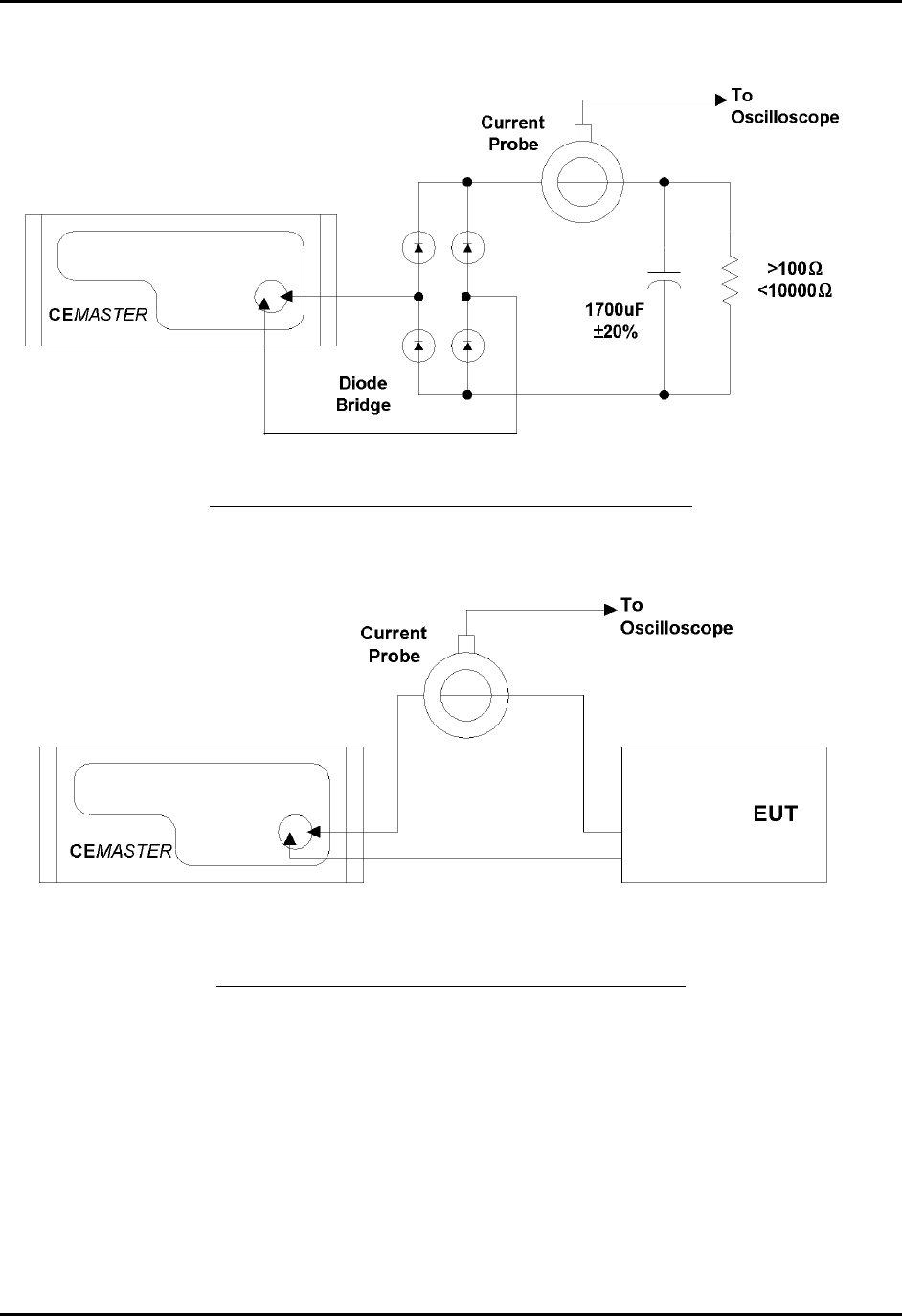
CEMASTER System 66
Line Qualification Test Setup -- Mains Peak Current
Line Qualification Test Setup -- EUT Peak Current

CEMASTER System 67
%'/#56'4 %'9CTG
Overview of the software
%'9CTGis the %'/#56'4ŏs PC control software. It provides full access to all the features
and capabilities available from the %'/#56'4 front panel, including running a single test and
running a pre-defined test sequence.
In addition, %'9CTG adds a number of useful features. It allows a user to:
• Create tests and easily edit them.
• Chain test sequences together. Multiple test sequences can then combine test types
(e.g. do one or more Surge tests followed by one or more EFT tests, etc.).
• Store and recall tests and test sequences to disk.
• Log tests-- print or file a list of the tests which are executed.
• Develop tests off-line, and run in a simulation mode.
A Help file for the %'/#56'4%'9CTG is provided with the software which can be opened by
clicking Help|Contents on the menu bar. It provides complete operating instructions for the
program; using the Help file while experimenting with the program is the recommended method
for learning the software. These written instructions are largely duplicated in the Help file.
The CM-SW option, available as a purchased %'/#56'4 option, includes the %'9CTG
program. It may be used on a Personal Computer (PC) running either Windows 3.1 or
Windows95. The computer must have at least 16MB of RAM and a 80486/66MHz or faster
processor. Screen transitions are slower on 486 processors, thus Pentium computers are
recommended. %'9CTG is designed for an 800x600 display driver. Some drivers require
selection of ‘small fonts’ on the Windows 95 display settings. You should select such a driver (or
one with greater resolution) in your Windows configuration. On a driver with a smaller display,
scrolling is necessary to see the entire application screen.
The CM-SW option includes an RS-232 to optical converter (the FC-11), a short RS-232 cable
with a 9-pin D-shell connector, and a fiber optic cable with a duplex modular connector. The
RS-232 connector connects to a Com port on your computer. The fiber optic cable connects to
the %'/#56'4 front panel; this connector is polarized and can only be inserted in one
orientation: with the small tab on the connector facing right. Do not force the connector. The
FiberCom option derives power from the RS-232 port of the computer -- no external power
source is required.
%'9CTGversion 2.0 (and higher) also supports '/%2TQ and has some additional controls.
References to EMCPro and hardware selection in this chapter apply to that %'9CTG version
only. %'9CTGconfiguration for %'/#56'4or '/%2TQ is automatic when a tester is
connected

CEMASTER System 68
Basic Operations
The following steps will take you through major operating modes of the program and will
acquaint you with the screens. Refer to the next section for full description of all the controls
and displays on the screens. These steps can be run in simulation mode or with a %'/#56'4
connected. If the %'/#56'4 is connected and powered on, the application will send
commands to it by default.
Starting the Program
• Start the %'/#56'4 by powering it on and pressing a key to move beyond the warning
screen.
• Start the %'9CTGprogram by double-clicking on the ICON in the %'/#56'4 group on
Windows 3.1, or running the program from the Start menu (PROGRAMS | %'/#56'4
Software | %'9CTG) on Windows95.
Defining a Test
• Click on one of the New Sequence buttons at the left of the Main Screen to create a new test.
• Select "User-defined" from the box on the New Sequence Definition screen. The other items
on that screen are defaults (the same ones as on the %'/#56'4front panel) and can be left
alone or changed, as you wish.
• Click "OK" on the Custom Sequence Wizard screen to accept the Wizard defaults. This screen
allows you to create several tests of the same type quickly.
• Click "OK" on the Sequence Editor Screen to accept the test sequence. This screen allows you
to manually edit the order of the tests or the test parameters.
• Back on the Main Screen, you now have one sequence defined and shown in the grid. You can
return to the Sequence Editor at any time by double-clicking on the row or row number of the
sequence you wish to edit.
• On the Menu bar at the top of the screen, select FILE | SAVE if you want to save your sample
test.
Running a Test
• Click on the RUN button to start the test. The grids on the Run Screen, and the Status Block at
the lower right, will show the status of the executing tests.

CEMASTER System 69
• Hit the ABORT button to return to the Main Screen. After test completion, a notice is
displayed, and return to the Main Screen is automatic on acknowledgment of the notice.
• Exit the application by choosing FILE | EXIT from the main application menu.
Additional Operating Notes
• Remote mode. While the PC %'9CTG program controls the %'/#56'4, the normal idle
screen contains a "Comm: Remote; Status: Idle" indication if no test is running. When a test is
active, a Run Screen (the same as from front panel control) will be shown on the front panel
display. If the EXIT button on the front panel is pressed when in "Remote Idle," the
%'/#56'4 will no longer be controlled by the PC. This is not recommended. Termination of
tests and remote control from the %'9CTG menu is preferable. (ESD test operation is a special
case; see the next item.)
• ESD operation. The ESD test function is designed for maximum control at the ESD head.
%'/#56'4operation puts the unit in a "Test Run" state, where it will stay until the user hits
EXIT on the front panel. The same front-panel control is in place when running from %'9CTG.
Leave the ESD run state by hitting EXIT on the front panel when all ESD pulsing is done. You
may also select ABORT from %'9CTG, but this will terminate the entire sequence.
If your %'/CUVGT does not have a front panel, the ABORT from %'9CTG is the only
mechanism for stopping an ESD test. For this reason, putting an ESD test in a sequence with
other test types is not recommended in that configuration.
During ESD tests, the user may perform more tests than are defined in the sequence definition;
for this reason, the %'9CTG screen may show tests executed greater than the total tests, such as
"140 of 100" pulses.
• Mouse operations. If running Windows 3.1 with the "snap-to" option enabled on the mouse
driver (see the Mouse driver selections on the Windows Control Panel), the mouse cursor may
jump when the mouse button is pressed. Turn off "snap-to," if it is enabled. Not all mouse
drivers support “snap-to.”
• Editing pre-programmed surge tests. Some of the pre-programmed surge tests (pre-
qualification and Level 1) include voltages which are below the normal limit for surge user-
defined tests. These tests will run as pre-programmed tests, but not as user-defined tests. If you
edit these pre-programmed tests and attempt to run without changing the voltages, %'9CTG will
report errors at each voltage below the normal limit. If these low-voltage, pre-programmed tests
are edited, be certain to remove or change all the voltages below the 200V limit.
• Test timing counts. The test count displayed on the %'9CTGscreen is a combination of
values from %'9CTG timing and firmware timing. It may sometimes change quickly, faster than

CEMASTER System 70
a normal clock, or lag the front panel count, due to communication delays. The test is being
executed by the firmware, and the front panel has the most current information for each test.
Only %'9CTG supports user-defined sequences and combinations of sequences; that timing
information is summarized in the Sequence List Status block, as described in other sections of
the manual.
CEWare Support of '/%2TQ and CEMaster differences
The standard test sequences supported on %'/CUVGT and '/%2TQ are not identical.
This is largely due to the higher voltages and additional test types of the '/%2TQ. While
CEWare version 2.0 supports both products, there are certain incompatibilities when
using these standard sequences.
Using CEMaster standard sequences with the EMCPro
Most standard sequences created in CEWare for use on the %'/CUVGT can also be used
on the '/%2TQ. The exceptions are those containing at least one of the following Surge
(1.2/50) sequences:
PreQual A
PreQual B
Class 1 Fast
Class 1Full (formerly called Class 1 Complete)
Class 2Full (formerly called Class 1 Complete)
While neither of the %'/CUVGT prequalification sequences are available on the '/%2TQ,
the Class 1 Fast sequence is the same as the '/%2TQ sequence Class 1 Complete, and
therefore a direct substitution can be made. Note, however, that the new suite will not
run on a %'/CUVGT. Also note that the %'/CUVGT Class 1 Complete and Class 2
Complete sequences are not the same as those sequences with the same names on the
'/%2TQ.
Using EMCPro standard sequences with the CEMaster
Many standard sequences created in CEWare for use on the '/%2TQ can also be used on
the %'/CUVGT. The exceptions are those containing at least one of the following
sequences:
EFT Class 4
HPulse Class 5
Surge (1.2/50) Class 1 Full
Surge (1.2/50) Class 2 Full
Surge (1.2/50) Class 4 Fast
Surge (1.2/50) Class 4 Full
Surge (10/700), all sequences
Surge (Ring), all sequences
Note that the '/%2TQ Class 1 Full and Class 2 Full sequences are not the same as those
sequences with the same names on the %'/CUVGT. However the '/%2TQ Surge(1.2/50)

CEMASTER System 71
Class 1 Full sequence is the same as the %'/CUVGT sequence Surge (1.2/50) Class 1
Fast, and therefore a direct substitution can be made. Note, though, that the new suite
will not run on an '/%2TQ.
Changing Program Settings
Program settings - defaults - affecting communications, data logging, and user-defined messages,
may be changed from the menu bar; the setup option. See the `Menu, Toolbar, and Status Bar’
section for more detail.
• Viewing, editing, and printing test reports outside %'9CTG. Test logs may also be
viewed, edited, and printed using a word processor. The following document format controls are
appropriate for MicroSoft Word. Equivalent margin and font selections are likely to be necessary
from other word processors.
1. Start MS Word and select the text log file you wish to print from FILE
• OPEN.
2. Select all of the text in the document
3. Select FORMAT - FONT
• Select Font = Courier New, MS LineDraw, or Lucida Console
• Select Font Style = Regular
• Select Size = 10
• Select OK
4. Select FILE - PAGE SETUP
• Set Margins Left = 0.9"
• Right = 0.9"
• Top = 1.0"
• Bottom = 1.0"
• Select OK
5. If you wish to Print, select FILE - PRINT
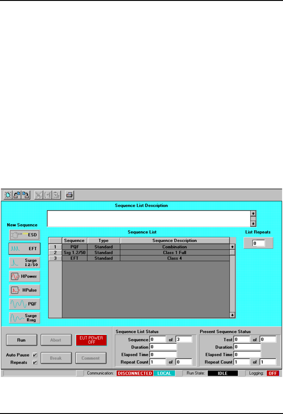
CEMASTER System 72
%'9CTGin Detail
Screens and Organization
%'9CTG uses five screens to create, edit, and run tests. The material on the screens is described
in the following sections. This information is also contained in the Help file.
Main Screen -- The overview screen; used to create and run tests.
New Sequence Definition Screen -- Used to define a test sequence, selecting pre-programmed
or custom (user-defined) tests.
New Custom Sequence Wizard Screen -- If a User Defined test sequence is selected, the
Custom Sequence Wizard will help define the sequence of tests.
Sequence Editor Screen -- Used to modify a test sequence.
Run Screen -- Shows Test Status information while tests are running.
Main Screen

CEMASTER System 73
Main Screen
The Main Screen is the screen you use to create tests, load or save tests, and run tests.
To create a new test, click on one of the seven test buttons, left-center on the screen. To load an
existing test, click on the Toolbar or Menubar at the top of the screen. To Run a test click on the
RUN button at the bottom left of the screen. The following sections describe the information and
the controls on the Main Screen.
Toolbar
The toolbar at the top of the screen supports some system-level operations. It is described in
detail in the section on Menu, Toolbar, and Status Bar, which appear on several screens.
Test Status Block
When on the Run Screen, the Test Status Block shows which test is currently executing, and
shows duration and elapsed times. While displayed on the Main Screen, this block is updated
when a test sequence is selected or deselected on the Sequence List grid. It is described in detail
in the section on the Run Screen.
Test Control Block
The test control block has control buttons to start, stop, and control tests.
• RUN Button -- The Run button starts the Test. Once the test is running, the Run button
becomes the Pause button.
• PAUSE Button (Only enabled on Run Screen) -- Click the Pause button to temporarily
halt the test.
• RESUME Button (Only on Run Screen, when in Paused state) -- Click to resume a
paused test.
• ABORT Button -- The Abort button Halts the test.
• BREAK Button -- The Break button 'breaks' out of loops.
When you click the Break button, if the Present Sequence Status has a repeat count
greater than one, it drops to one. Any test presently executing continues to completion,
but at completion the present test ends.
If the Sequence List Status has a repeat count greater than one, it drops to one. Any test
presently executing continues to completion, but at completion the present test ends; at
completion of all tests in the present sequence, the present sequence ends.

CEMASTER System 74
• COMMENT Button -- The Comment button allows definition of a user comment while
tests are running. The comment can then be inserted into the log file at any instance the
user chooses by selecting the OK button on the comment entry window.
• AUTO PAUSE/REPEATS Checkboxes -- Enable steps and defined sequence repeats.
When checked, Auto Pause will enable any pauses defined in the Sequence Editor. At
each pause the operator must click the OK button on a Windows prompt box to continue
the test. When un-checked, any pauses defined in the Sequence Editor are ignored. When
checked, Repeats will allow any repeats defined in the Sequence Editor and in the main
menu. When un-checked, any repeats are ignored; each test and sequence will execute
exactly one time. (This is the mechanism for single-stepping, used in coordination with
the Pause column on the Sequence Editing screen.)
• EUT POWER STATUS Button -- The EUT Power status button shows the EUT status.
The EUT power may be turned off from the computer by clicking this button. When off,
the EUT Power can only be turned on from the %'/#56'4, by turning the EUT switch
ON, or toggling OFF and ON.
Sequence List Grid
The Sequence List Grid shows which test sequences have been defined (or loaded with the
current file). The grid allows editing the sequence during the definition and editing phases. A
yellow highlight bar identifies the test to be edited when using CUT, COPY, and PASTE.
• To Edit a Test Sequence: Double-click on the gray, numbered, row-header cell to the
left of the test you want to edit, or anwhere in the row of that test. The Sequence editor
will open.
• To Add a Test Sequence to the end of the sequence list: Deselect any selected Test
Sequences by clicking the button in the upper-left corner of the grid. Then, click a test
type button.
• To Insert a Test Sequence: Click the gray numbered cell to the left of the test you want
to insert the new sequence in front of. Then select a test type by clicking a test type
button.
• To Delete a Test Sequence: Click the gray numbered cell to the left of the test you
want to delete. Then click the Cut button from the toolbar.
• To Move a Test Sequence: Click the gray numbered cell to the left of the test you want
to move. Click the Cut button from the toolbar to remove this test. Click the gray
numbered cell to the left of the test you want to insert the cut sequence in front of. Then
click the paste button from the toolbar to insert the test.

CEMASTER System 75
Test Type Controls
These 6 buttons at the left of the Main Screen select a test type to create. There are 8 different
immunity tests available, in accordance with European Norm requirements and the controlling,
basic EMC immunity standards of:
IEC 1000-4-2 ESD
IEC 1000-4-4 EFT
IEC 1000-4-5 Combination and Telcom Wave Surge
IEC 1000-4-8 Power Frequency Magnetic Field
IEC 1000-4-9 Pulse Magnetic Field
IEC 1000-4-11 Dip and Interrupt
The tests available on your system will depend on the options installed in your %'/#56'4. If
a test is not available, the corresponding test button will be grayed out, and cannot be selected.
The legend on the last button will depend on the surge option installed in the system.
Repeat Control
The repeat control sets how many times the sequence shown in the Sequence List grid is
executed. Click this control and enter a number.
Test Description
If a test is loaded from a file, the description box will contain the text description filed with the
test. If a new test is created, enter a description of the test in the description box for inclusion in
reports and logfiles, and to be saved with the test.
Tool Bar
The toolbar holds icons for common tasks, allowing you to select that task with a single mouse-
click. See the section below on the Menu, Toolbar, and Status Bar.
• File Icons -- The file icons create a new test sequence, load an existing test sequence,
or save the current test sequence. If you attempt to create a new sequence or load an
existing sequence, you will be prompted to save any existing work.
• Edit Icons -- The CUT, COPY, and PASTE icons allow you to edit the test sequence
grid. These icons are also found in the Sequence Editor.
• The Printer icon will print the test sequence.
Starting a Run

CEMASTER System 76
When you wish to execute the presently defined sequence list, select the Run button in the Test
Control area. A Windows message box will appear to inform you if you are doing a
Local/Simulation run. If you are about to do a Remote run (connected to a %'/#56'4) no
warning is given.
If Logging is enabled, a Run-Time Logging Information screen will appear where you will see
the header information that will appear in the log report(s) and can edit this information/
You may edit the 60 character log report header line or the 40 character operator name. There is a
60 character field for a description of the equipment under test and a text entry field where you
can make any comments regarding the run before you begin. The comment will appear after the
header on the first page of the log text report.
Enter up to 8 characters for the file name for either or both of the log report types selected. This
must be a valid 8 character DOS filename. The file paths and extensions are shown for reference
only and are not editable in this window.
Run-Time Logging Information Screen

CEMASTER System 77
New Sequence Definition Screen
New Sequence Definition Screen
The New Sequence Definition Screen is opened when you create a new test by clicking on one of
the test type buttons from the Main screen.
The list box to the left of the screen shows sequences that you can choose. The User Defined
sequence gives you the most control of the test, allowing you to define all of the Sequence
Defaults shown on the right side of the screen. The other options shown -- which vary by test
type -- are test sequences which the %'/#56'4 has stored and available. These sequences
speed set-up and execution of commonly performed IEC test sequences by setting and locking
many of the defaults -- the locked defaults will be grayed, and cannot be selected. The standard
test sequences for each test type are described in the %'/#56'4 manual.
To continue, click one of the sequences shown. If the Sequence Defaults to the right of the screen
are enabled, you can select one or more of the Defaults. Finally, click OK.
CEMASTER System 78
New Custom Sequence Wizard Screen
New Custom Sequence Wizard Screen
The New Custom Sequence Wizard screen quickly creates test sequences. The Wizard is run
automatically whenever you select a User Defined Sequence in the New Sequence Definition
Screen. The Wizard allows you to create lists of one or more parameters, then forms all
combinations of these parameters to quickly create a large number of tests. When you click OK,
the Wizard closes and the Sequence Editor opens for fine editing of test parameters.
To use the Wizard, select one of the radio button options at the bottom left of the screen, or click
within any parameter definition box to the right of the screen. The defaults in the combo boxes
are those you selected from the New Sequence Definition Screen. Make a parameter selection,
then click the Insert button (to the left of the parameter definition boxes) to copy the selection
into the list box. You can change list boxes using the radio buttons below the list box, and edit
the list box using the CUT, COPY, and PASTE buttons above the list box.
CEMASTER System 79
As example, if you click Voltages, and insert 250V, 500V, and 1000V, then click Output and
select L1-L2 and L1-PE, when you exit the Wizard, the Wizard will create six tests:
L1-L2 at 250V
L1-L2 at 500V
L1-L2 at 1000V
L1-PE at 250V
L1-PE at 500V
L1-PE at 1000V
If you want to create a User-Defined test sequence with a single test, simply click the OK button
to exit the Wizard and open the Sequence Editor.
Sequence Editor
The Sequence Editor is opened after selecting a test sequence from the New Sequence Definition
Screen, or by double-clicking an existing test from the test grid of the Main Screen. The
sequence editor gives you fine control over what tests are performed and all options. If you wish
to execute a predefined test with no changes, you should simply click on the OK button. If you
make any changes in a predefined test, the test will be re-defined as a User Defined test.
Sequence Editor Screen

CEMASTER System 80
Sequence Description Grid
The Sequence Description Grid shows which tests have been defined in a sequence.. It supports
the editing process on the Sequence Editing Screen as well as allowing the data to be changed in
any individual cell. Basic test editing is allowed on any test in the grid. Text cells can be
changed by selecting a cell, deleting the current entry, and typing the new one. Cells that support
a list of legal values have a standard Windows drop-down list controlled by the drop-down
button at the right of the cell. Open the list and select a new valve to change it. Additional
editing controls that affect more than one cell are also supported and are described in more detail
below.
• PAUSE or PAUSE AND DISPLAY MESSAGE Control
The PAUSE column of this grid allows single-stepping or automatic stopping at any test
in the sequence. Check the box in the row of the test where you wish to pause. (The
pause will occur before the test executes.) Make sure that the Auto Pause box is checked,
on the Main Screen, before the test starts. The PAUSE box for all tests in a sequence
may be set with the technique described in this section for changing an entire column.
To set or reset the PAUSE box, use a single left button click of the mouse to select the
PAUSE cell then use single left button clicks to set or reset the check-box in the cell. A
message can be displayed during a PAUSE - see the Message Selection section.
A yellow highlight bar identifies the test to be edited when using CUT, COPY, and PASTE,
which act on entire test rows.
• To Delete a Test Sequence
Click the gray, numbered cell to the left of the test you want to delete. The entire row will
highlight. Then click the CUT button from the toolbar.
• To Move a Test Sequence
Click the gray, numbered cell to the left of the test you want to move. Click the CUT
button above the grid to remove this test. Click the gray numbered cell to the left of the
test that will follow the moved test. Then click the PASTE button from the toolbar to
insert the test.
• To Copy a Test Step
Click the gray, numbered box to the left of the test you want to copy; the entire row will
highlight. Click the COPY button.
• To Paste a Test Step

CEMASTER System 81
After a Cut or Copy operation, click the gray, numbered box to the left of the test you
want to insert in front of; the entire row will highlight. Click the PASTE button. NOTE:
To select a block of rows, hold [Shift] key when left-clicking; to select multiple single
rows, hold [Cntrl] key when left-clicking.
The Sequence Editor allows several special editing operations in addition to the normal Cut and
Paste Operations. These operations take place over all or part of a column. This can change many
tests with a single editing step.
• To change an entire column
Click one cell within the column you want to change. Then, click the gray column header
at the top of the grid. All cells in the column will be highlighted.
Press ENTER. The cell you highlighted will open for editing. Select a new value and
press ENTER (if this is a numeric cell, type in a new value and press ENTER; if this is a
check box, press ENTER to toggle).
All cells in the column -- and thus all tests within this sequence -- will take on the new
value you entered.
• To change all entries in a range within a column
Click the first cell in the range within the column you want to change. Then, hold down
the shift key and click the last cell in the range you want to change. All cells between the
first and last cells will be highlighted.
Press ENTER. The last cell you highlighted will open for editing. Select a new value and
press ENTER (if this is a numeric cell, type in a new value and press ENTER; if this is a
check box, press ENTER to toggle).
All cells in the range will take on the new value you entered.
When you change a column, other columns may change as a result. These changes will
always be 'legal' -- that is, the test will run with the resulting change, and you will not get
an error. But the changes may not be uniform. Check the other columns to be sure the
tests will run the way you want them to.
Keyboard Editing
The grid can be edited using the keyboard cursor keys, Tab, and ENTER. Press Tab until the
grid is selected -- the highlighted cell within the grid will have a dotted selection-box drawn
inside it. Use the cursor keys to select a cell to edit. Press ENTER to open the cell. If the cell is
CEMASTER System 82
a drop-down box, use the cursors to select an option. If the cell is numeric, type in a new value.
Press ENTER to accept the change.
Message Selection Grid
To assign a message to be displayed during a run-time pause, double-click the left mouse button
on the desired PAUSE cell. This will bring up the Message Selection window where a single 80-
character message may be selected from 200 available messages.
Message Selection Screen
Use the right scroll bar to scroll through the 200 messages or enter a specific message number in
the Go To… edit box then click the Go To… button.
Select the desired message by clicking on the message number button to the right of the message,
then click OK.
Message Selection Screen, with message selected
CEMASTER System 83
When OK is selected, the Message Selection Window closes, and the message number is pasted
in the PAUSE cell of the Sequence Editor Grid.
ESD: Sequence Editor Screen
To remove a message from being displayed during pause, double-click the left mouse button on
the desired PAUSE cell. This will bring up the Message Selection window where the selected
message will be displayed highlighted.
Deselect the message by clicking on the upper left corner button on the Message Selection grid,
then click OK.
NOTE: The Message Selection grid does allow editing of message text but does not allow Cut,
Copy and Paste operations.
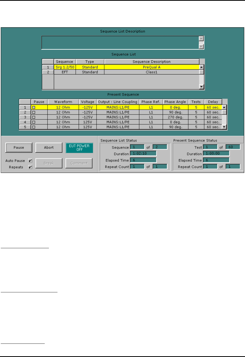
CEMASTER System 84
The Run Screen
The Run Screen
The Run Screen is displayed while tests are executing. A Present Sequence grid control is added
to the screen, along with the Sequence List grid control. Together they describe the current set of
tests being run.
Sequence List Grid
This list of sequences is the same as shown on the Main Screen, and shows the presently defined
set of test sequences. A yellow highlight bar indicates the test sequence that is presently
executing.
Present Sequence Grid
The Present Sequence Grid is displayed when running tests. The grid shows all the parameters of
the present test sequence, which consists of one or more tests. It is essentially the same
information presented on the Sequence Edit screen. A horizontal highlight bar across the grid
identifies which test of the sequence is running.
Test Status Block

CEMASTER System 85
The Test Status Block at the lower right of the Run Screen shows which test is currently
executing, test duration, and elapsed times. It contains two display areas: one for the Sequence
List, and one for Present Sequence -- the one that is currently executing. The two sets of data are
similar: the Sequence List Status summarizes statistics for the entire set of sequences, and the
current sequence within that list; the Present Sequence summarizes information about the
current test within the present sequence.
• Sequence List Status
Sequence -- The sequence that is running, out of the total number of sequences.
Duration -- The duration shown is the estimated time required to complete the entire
sequence, excluding time for pauses. The time format is hours:minutes:seconds.
Elapsed Time -- The elapsed time is the total time from the start of the test to the present
time.
Repeat Count -- These fields show the present loop count, and the total list count for the
sequence. The total reflects the value from the List Repeats field on the Main
Screen.
• Present Sequence Status
Test -- These fields identify which test is running out of the total number of tests in the
present sequence.
Duration -- The duration shown is the estimated time required to complete the Present
Test Sequence. The time format is hours:minutes:seconds.
Elapsed Time -- The elapsed time is the total time from the start of the present sequence
to the present time.
Repeat Count -- These fields show the present loop count, and the total list count for the
sequence. The total reflects the value from the Sequence Editor, Sequence Repeats
field.
Test Control Block
This set of buttons is the same as on the Main Screen and is described in that section. Buttons
may be enabled or not, depending on the state of the system and the software.
Menu, Toolbar, and Status Bar
These areas appear on both the Main and Run Screens.
Menubar
The menu bar performs actions, sets options and preferences, and accesses the help file. The
menu options are described below.

CEMASTER System 86
Menubar Selections
File Menu
The File menu supports loading and saving of test files, and exit from the application. The
default extension used for test sequence files is .SEQ.
• File | New
Delete any present tests and prepare for creating a new test. If you have tests defined and
have not saved them you will be prompted to save the tests before continuing.
• File | Open
Load an existing test file. The File Common-Dialog box will open, allowing you to click
on a file to load. If you have tests defined and have not saved them you will be prompted
to save the tests before continuing.
• File | Save, Save As
The Save command will save the present test to a disk file. If the test was loaded from
disk, the test will be written to the same file. If the test is a new test, you will be prompted
for a path and filename to use in saving the test.
The Save As command will prompt you for a path and filename to use in saving the test.
Use this command to create file copies of tests, or new tests based on the old ones that
you have edited.
• File | Print Sequence, Print Log, Print Setup
The Print Sequence command will print the present Sequence List.
The Print Setup command controls the printer, selecting which printer is used, which font
is used, and paper orientation. Print Log will allow the user to select and print a Log file.
• File | File Select
This section holds the last four files you opened / saved. You can quickly load a prior file
by clicking one of these selections or typing the corresponding number
• File | Exit
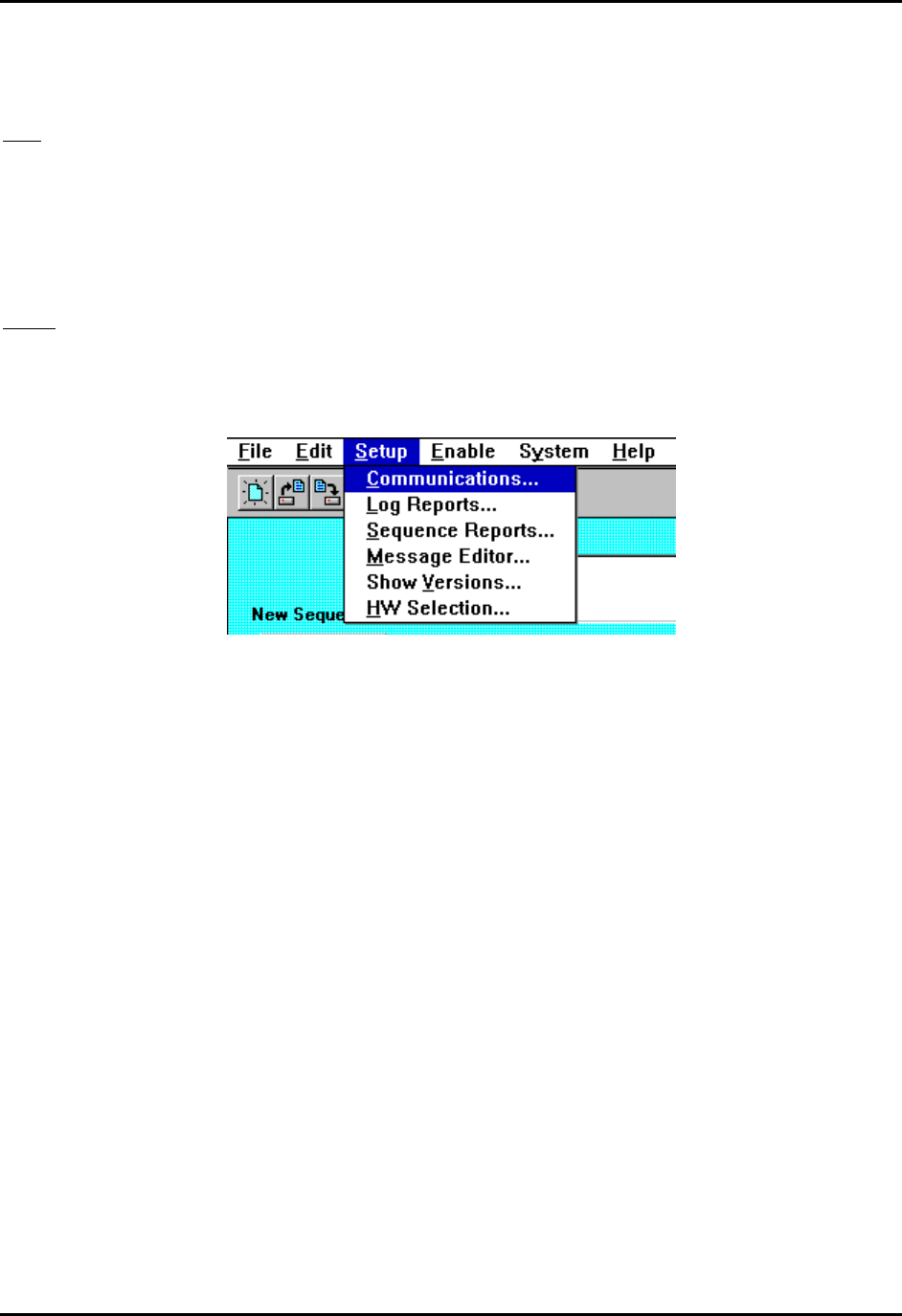
CEMASTER System 87
This selection exits from the application.
Edit
The Edit menu allows keyboard selection of the CUT, COPY, and PASTE selections that are
also accessible from the Toolbar. In addition, there is a DELETE selection which does a
destructive cut of selected data.
Setup
The Setup menu is where the user may select and set parameters for run time operation or report
generation. The items on the setup menu are:
Setup menu
• Communications
The user may select the COM port to set up communications with a C'/CUVGT.
%'9CTG allows selections (COM1 - COM4) and automatically detects which ports are
available on the system. The default selection is COM1. Other communication
parameters, although shown, are fixed.
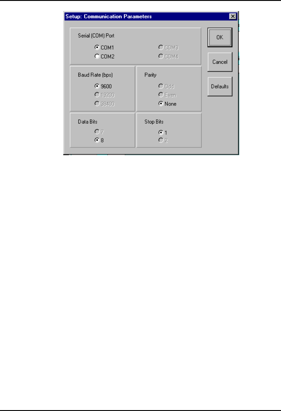
CEMASTER System 88
Communication Parameters Screen
• Log Reports
Log Reports allows the user to select the type of logging reports they which to produce:
Text Reports or Export Reports. For each type of report, you may define your own file
extension and path or you may accept the defaults (you will be asked to enter a log report
file name at run time). The file extension must be a (up to) 3 character valid DOS file
extension. The path must be a valid DOS path of up to 60 characters in length.
You may also define your own header line that will appear as the first line in the header
of all Log reports. A default report header is supplied. You may enter a new report header
of up to 60 characters.
A 40 character field is supplied where you may enter an operator name that will also
appear on the Log reports.
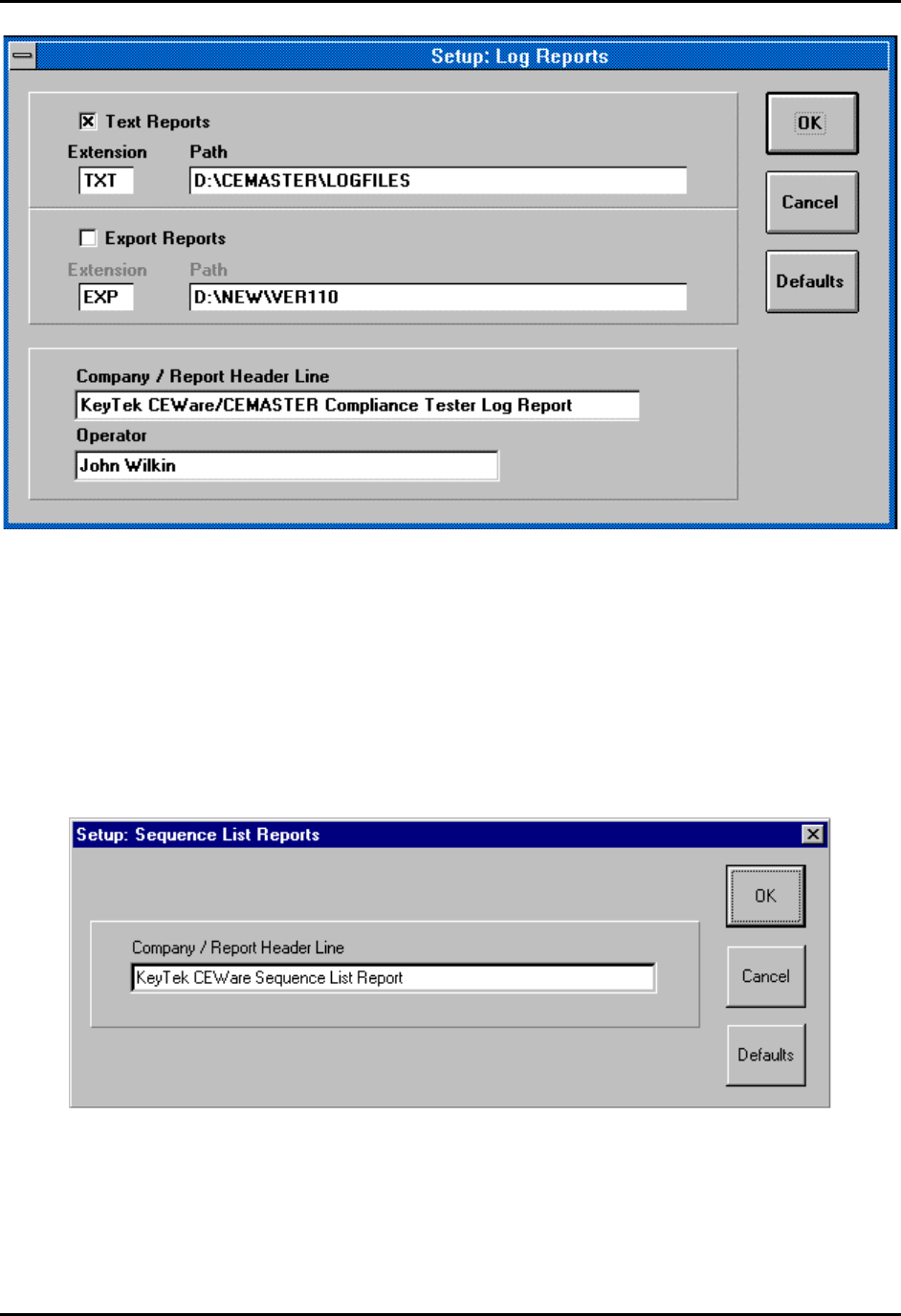
CEMASTER System 89
Log Reports Screen
• Sequence Reports
Sequence Reports allows the user to define his own header line that will appear as the
first line in the header of all Sequence List reports. All other data for the Sequence List
report is fixed. A default report header is supplied. You may enter a new report header of
up to 60 characters.
Sequence list Reports Screen
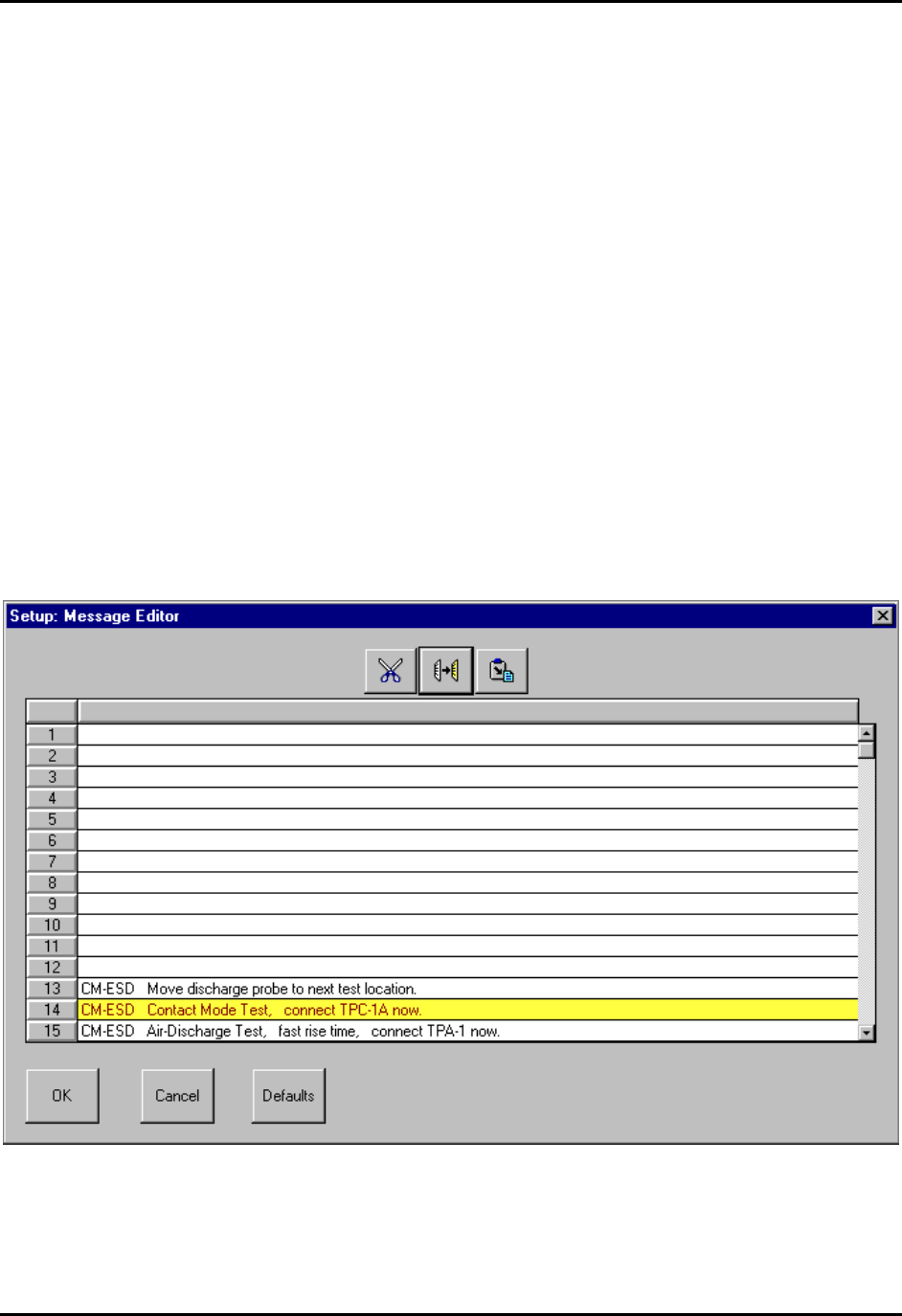
CEMASTER System 90
• Message Editor
The Message Editor allows you to define up to 200 messages that may later be attached to
Auto-Pause controls on the test edit screens for display to an operator at run time. Use the
scroll bar control on the right side of the message grid to scroll through the 200 messages.
Each message may be up to 80 characters (maximum) in length. A set of default messages
is supplied for use with several optional components available for use with the
%'/#56'4. These default messages may be redefined if you desire.
To define a message, click within a message cell to highlight it (green highlight), then
click a second time to enter “edit mode” for the cell. Enter the desired message text then
press Enter.
To select messages for CUT, COPY, and PASTE operations, click the message number
cells on the left side of the message grid. This will highlight the message in yellow.
Multiple messages may be selected by holding the Ctrl key while clicking, or a block of
messages may be selected by holding the Shift key while clicking after the first message
in the block has been selected.
To deselect all messages, click the button in the upper left corner of the message grid.
Message Editor Screen
• Show Versions
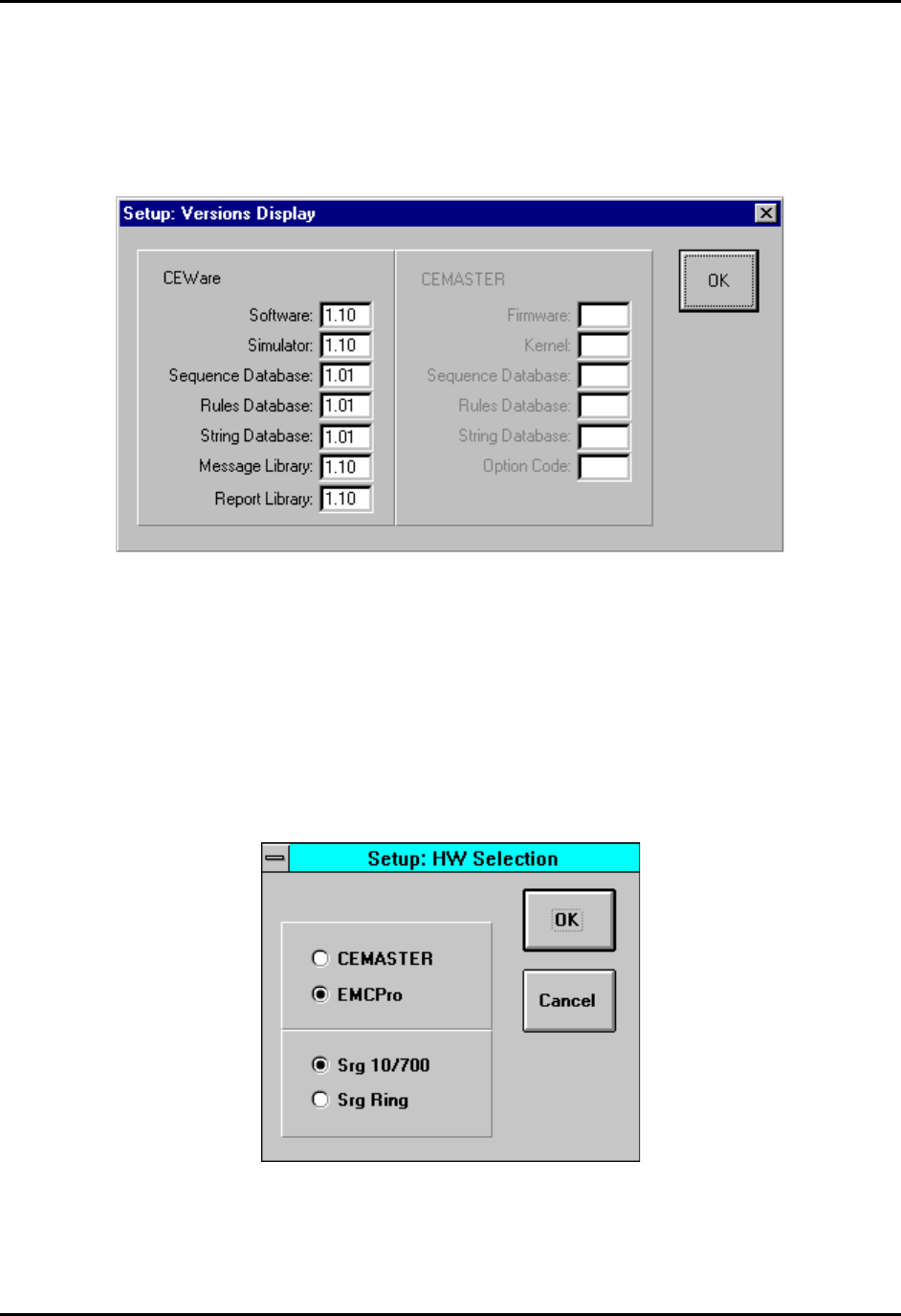
CEMASTER System 91
Show Versions is a display of the version number of the %'9CTG application, plus the
version of all major software components the %'9CTG application uses. When
communicating remotely with a %'/#56'4, the firmware version plus the version of
all major firmware components of the %'/#56'4 is also shown.
Versions Display Screen
• HW Selection
This selection is necessary only when running %'9CTG in local mode (with simulated
hardware). The menu supports selection of test hardware type (%'/CUVGT or '/%2TQ) and also
of a second surge type (10/700 Telecom wave or Ring wave) if '/%2TQis selected. Selection
of this configuration information is automatic in ‘Remote’ mode, with hardware connected.
HW Selection Screen

CEMASTER System 92
Enable
There are two selections under Enable: Remote Communications and Logging. Both of these
selections are ON/OFF selections that are indicated by a check mark when they are ON and no
check mark when they are OFF.
• Remote Communications
This selection turns ON or OFF the remote (PC-based) control of the %'/CUVGT by the
%'9CTG application. The selection is disabled if the communications cannot be
established with a %'/CUVGT: (communications cable not connected or %'/CUVGT
power is OFF). When communication with a %'/CUVGT is established, this selection is
enabled and %'9CTG will automatically try to turn remote control ON.
The status of communications is shown on the Status Bar at the bottom of the %'9CTG
screen. When communication is not established the first item next to the
“Communication:” label says DISCONNECTED. When communication is established,
the label says CONNECTED.
When remote control to a %'/#56'4 is enabled successfully (Remote
Communications ON), the second item next to the “Communication:” label says
REMOTE. When remote control is disabled (Remote Communications OFF), the item
says LOCAL.
• Logging
This selection turns ON or OFF the logging feature for producing run time log reports. At
least one of the two Log report types must have been enabled in Setup | Log Reports to
enable logging or an error message will appear when you try to enable it. Logging may
only be set ON or OFF when the Main Screen is visible: Logging may not be turned ON
or OFF once a run is started.
The status of Logging is also shown on the Status Bar at the bottom of the %'9CTG
screen. When Logging is not enabled the item next to the “Logging:” label says OFF.
When Logging is enabled, the item says ON.
System
These are debugging and field service functions that do not need to be accessed by the user for
any normal operation.
CEMASTER System 93
Help
The Help menu brings up the Help file and shows the About box.
Toolbar
Toolbar
The toolbar holds icons for common tasks, allowing you to select that task with a single mouse-
click.
• File Icons -- The file icons create a new test sequence, load an existing test sequence,
or save the current test sequence. If you attempt to create a new sequence or load an
existing sequence, you will be prompted to save any existing work.
• Edit Icons -- The CUT, COPY, and PASTE icons allow you to edit the test sequence
grid. These icons are also found in the Sequence Editor.
• The Printer icon will print the present sequence list, i.e. it is the same as the File Print
Sequence selection on the menu bar.
Status Bar
The status bar at the bottom of the screen gives a quick synopsis of the CEMASTER and test
status. In some cases, the status bar will be replaced with help prompts. It contains the following
information.
System Status Bar

CEMASTER System 94
Communication
• DISCONNECTED/CONNECTED
Indicates if a %'/#56'4 has been detected (CONNECTED) or not
(DISCONNECTED).
• LOCAL/REMOTE
When communications with the %'/#56'4 are established, this indicates whether
control is from the front panel (LOCAL) or from the PC (REMOTE). The program will
automatically go Remote; select from the menu bar (EnableRemote Communications)
to change to simulation mode when a %'/#56'4 is connected and powered on.
Run State
Shows the operating state of the %'/#56'4
• CHARGING - generating high voltage.
• WAITING - between active test states, waiting for the next.
• FIRING - generating an output
• IDLE - no tests are running.
• RUNNING - generating a continuous test state (EFT, ESD, or PFMF).
Logging
Indicates if run time test information is being written to disk (ON) or not (OFF).

CEMASTER System 95
Maintenance
Service and Maintenance Issues
There are no user serviceable parts within the %'/#56'4. Service is solely by Thermo
KeyTek-trained, authorized technicians.
Annual Calibration
Periodic calibration of the %'/#56'4 is required. The recommended calibration interval is
dependent on use. If periodic waveform verification is performed, calibration need be
performed only if the waveform verification fails; if periodic waveform verification is not
performed the recommended calibration interval is one year. Factory calibration is available;
consult factory for terms and conditions.
Factory Inspection and Refurbishment
Factory Inspection and Refurbishment is available. Consult factory for terms and conditions.
Updating Firmware
There may be periodic updates of the %'/#56'4firmware or application software. Each
update is provided with instructions for installation and use. An update of the %'/#56'4
firmware requires the CM-SW option be installed. If this option is not installed a Thermo
KeyTek authorized service representative is required to upgrade the firmware in the field.
If you have questions about what is the latest versions of firmware, contact Customer Service.
The latest firmware revisions are also listed on the Thermo Voltek web page, at:
http://www.thermovoltek.com
Upgrading Hardware Options
Most hardware options can be added in the field by a Thermo KeyTek authorized service
representative. Consult factory for terms and conditions.
Decommission Issues
There are no special issues in decommissioning %'/#56'4 equipment.

CEMASTER System 96
Troubleshooting
This section aids in finding and solving any problems you may experience. As a first step, the
%'/#56'4includes diagnostic tools, accessed through the System Menu, and described
below.
System Menu
The System Menu gives access to several useful functions to aid in troubleshooting.
SYSTEM SETUP EUT OFF
1. Parameters
2. Access Code
3. Diagnostics
4. Versions
↑ ↓ EXIT
The System menu selects special system
operations; move the highlight bar using
the arrow function keys and press ENTER,
or press the number key associated with the
sub-menu.
The Parameters Menu offers control of a number of system parameters, allowing customization
of the %'/#56'4system. Check the menu for options available in your system; possible
options are: control of the beeper; default coil factor to use; etc.
The Access Code Menu is not available at this time. In the future, this menu will allow locking
features of the %'/#56'4system -- preventing unauthorized use.
The Versions Menu shows internal revisions for the code and databases used by the
%'/#56'4. This information is important and should be checked whenever contacting
Customer Service.
VERSIONS EUT OFF
Firmware ...... Vx.xx
Kernel ...... Vx.xx
Sequence Database .... Vx.xx Sep 24, 96
Rule Database .... Vx.xx 16:15
String Database .... Vx.xx
Option Code .... AA
EXIT
The Version Menu shows a Build date and
time, five arguments with revisions, and a
code indicating the installed options.

CEMASTER System 97
The Diagnostics Menu performs a quick check of basic %'/#56'4 functions, and can often
localize a problem and allow a field service repair rather than a factory repair.
DIAGNOSTICS:TESTS EUT OFF
1. Line Sync 1 5. ESD
2. Line Sync 2 6. RELAY
3. High Volt
4. Coil
↑ ↓ EXIT
The DIAGNOSTICS: TESTS menu
selects special system operations; move the
highlight bar using the arrow function keys
and press ENTER, or press the number key
associated with the test.
Before running any diagnostic, remove all connections from the front panel EUT connector, the
coaxial connector, and the safety socket connectors.
To use the diagnostic tests, follow the requirements from the list below, choose a test, and follow
any on-screen directions. If the test halts, record any message displayed and report the message to
Customer Service.
The basic functions tested are listed below:
1. Line Sync 1 -- General Purpose check of Mains circuitry. Checks that Mains contactor is
operational, thermal breaker is operational, basic wiring OK, and line sync is operational.
Requires: EUT Mains present, EUT Switch ON, no EUT connected, no interlock fault.
2. Line Sync 2 -- Checks PQF circuitry. Checks PQF transformer and contactors are
operational, PQF switches are operational, and Aux line sync circuit is operational.
Requires: EUT Mains present, EUT Switch ON, no EUT connected, no interlock fault.
3. High Volt -- Checks high-voltage supply, energy storage capacitors, and discharge circuitry
4. Coil -- Checks power frequency magnetic field circuitry.
Requires: no front-panel connections, no EUT AC present, no interlock fault.
5. ESD -- Checks ESD head interface circuitry.
Requires: an ESD head, no interlock fault.
6. RELAY -- Checks all internal relays and switching circuits.
Requires: EUT Mains present, EUT switch ON, no EUT connected, no interlock fault.

CEMASTER System 98
Troubleshooting Guide
In the event of a problem with the %'/#56'4, please follow the following procedure.
• Verify that you have properly selected all test parameters.
• Check that the %'/#56'4 is properly connected to the AC Mains.
• Check that the EUT is properly connected to the %'/#56'4.
• Check all interconnections for loose connections.
• Try cycling power to the EUT and the %'/#56'4.
• Run Diagnostics tests from the System Menu.
• Contact Customer Service for guidance.

CEMASTER System 99
Error Messages
The following are possible error messages, their causes, and possible solutions.
No AC Phase Reference Detected
Check EUT Power switch and EUT
power
The Surge parameters specify line sync, and no
AC mains was detected for synchronization.
To surge without AC mains present: Change
the line sync setting from “L1” to “RND” -
random.
To surge with AC mains: Check that EUT
power cord is plugged in, EUT power is
present, and the %'/#56'4EUT switch is
on; check that EUT ON is shown on the front
panel display.
AC Required At Mains Output
Check EUT Power switch and EUT
power
During a PQF test, AC was not present (PQF
requires AC to be present).
Check that EUT power cord is plugged in,
EUT power is present, and the %'/#56'4
EUT switch is on; check that EUT ON is
shown on the front panel display.
ESD Simulator Not Connected An ESD test is selected, and no ESD simulator
head was attached.
Attach an ESD head; check that the cable is
properly connected (remove ground-return
cable; if the ground-return indicator does not
light on the head, there is a poor connection).
Interlock Open Fault
EFT Interlock
This fault indicates a problem in the EFT
subsystem and requires factory service. Consult
the factory for further information.
Interlock Open Fault
Power PCB Interlock
This fault indicates a problem with an internal
subsystem and requires factory service. Consult
the factory for further information.
Interlock Open Fault
External Interlock
The external interlock is open, forcing the
%'/#56'4 into a safe state.
If a cable is in the interlock connector, remove
it and check that the fault goes away. Repair
any break in the external interlock circuit.

CEMASTER System 100
Mains Fault: Disconnect and check EUT
If fault recurs contact Thermo KeyTek
Service
During a PQF test a high-current was detected,
possibly due to a short in the EUT.
Disconnect the EUT and check it for possible
shorts line-to-line or line-to-chassis. Retest.
Test with a second EUT if possible.
If this message persists factory service is
required. Consult Customer Service for detail.
Unspecified Fault
#<fault number>
Record the fault number and retry the failed
test. If this fault persists, report it to Customer
Service.
Timeout on Remote Control: Check PC
Application and Connection
The %'/#56'4 while running under control
of a PC, lost communications with the PC. For
safety, a loss of communications halts all tests.
Check connections between the %'/#56'4
and the PC, and check that the PC application
is running.
CEMASTER System 101
Filing a Problem Report
When reporting a problem to Thermo KeyTek Customer Service, please include the serial
number and model number from the rear panel of the %'/#56'4 (and serial number of the
ESD probe or other accessories, if applicable).
If your CEMASTER is operational, access the SYSTEM menu, VERSIONS screen and copy all
the information shown to include in your trouble report.
VERSIONS EUT OFF
Firmware ...... Vx.xx
Kernel ...... Vx.xx
Sequence Database .... Vx.xx Sep 24, 96
Rule Database .... Vx.xx 16:15
String Database .... Vx.xx
Option Code .... AA
EXIT
The Version Menu shows a Build date and
time, five arguments with revisions, and a
code indicating the installed options.
Mail, Fax, or phone your problem report to:
Customer Service
Thermo KeyTek
One Lowell Research Center
Lowell, MA 01852-4345 USA
Voice: 978-275-0800 FAX: 978-275-0850
http://www.thermokeytek.com
or your local, authorized service representative.

CEMASTER System A-1
Appendix A
Multi-Contacts Accessories
To our customers using the ECAT System with 6mm socket jumpers, adapters, patch cords
and for all others ECAT, EMCPro and CEMASTER Systems using 4mm safety jacks:
To obtain parts please refer to the Multi-Contact electronic catalog at
MC USA
U.S Headquarters
5560 Skylane Blvd.
Santa Rosa, CA 95403
http://www.multi-contact-usa.com
