PDF2 KF850z Bi Amp Kit INSTR Rev B ENG
Bi-Amp Crossover Retro Kit KF850z KF850z_bi-amp_kit_INSTR_revB_ENG
User Manual:
Open the PDF directly: View PDF ![]() .
.
Page Count: 4
Instructions/Installation KF850z
Bi-Amp Crossover Retro Kit
DESCRIPTION:
This KF850z Bi-Amp Crossover Retro Kit is used for converting the KF850z Loudspeaker to bi-amp capability
and can only be used on a KF850 that was originally manufactured as a KF850z. It cannot be used on a KF850
originally manufactured as a KF850E that was upgraded to a KF850z.
Warning: Installation should only be done by an
experienced technician. Improper installation may
result in damage to the equipment, injury or death.
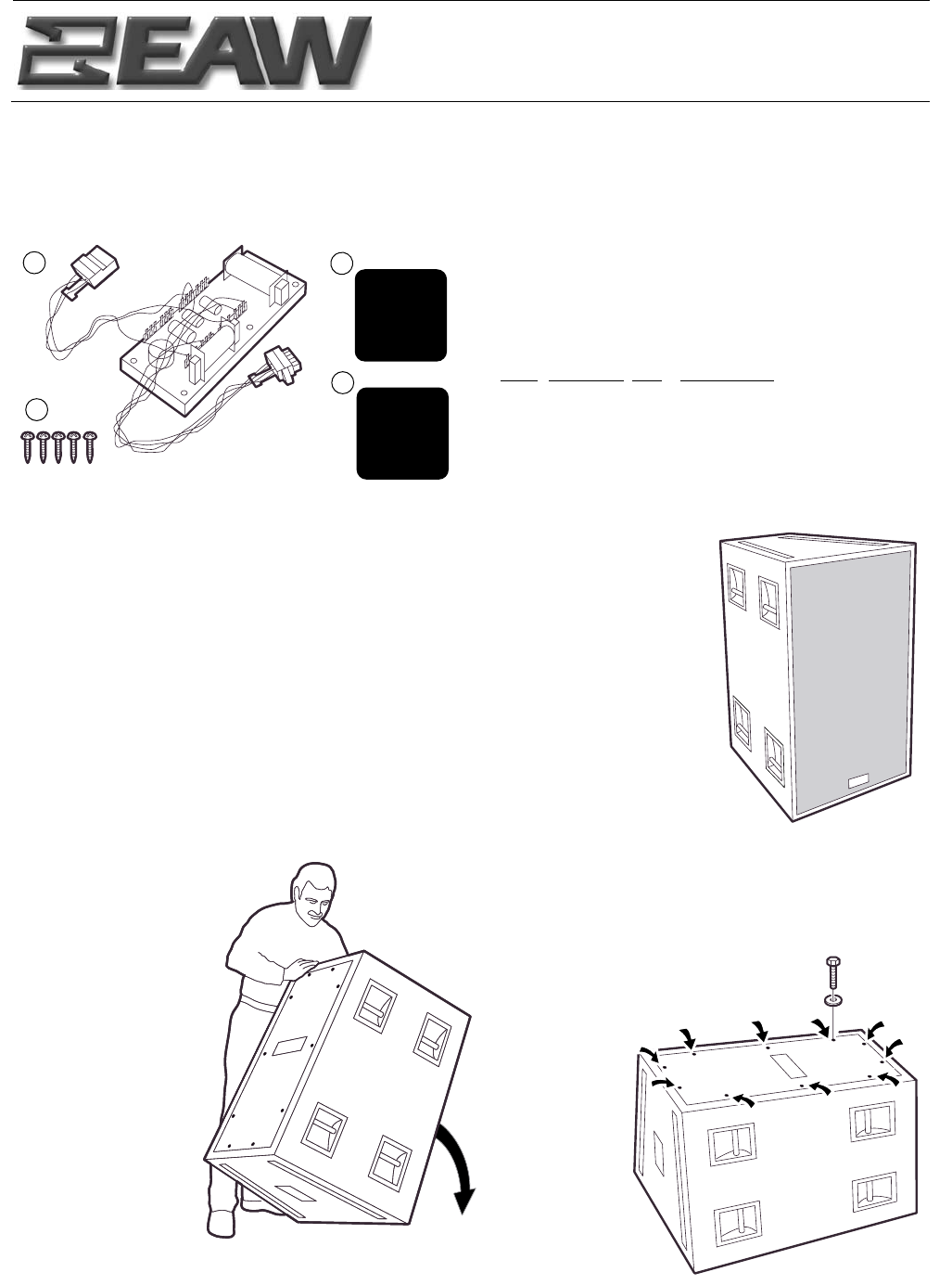
KF850z Bi-Amp Crossover Retro Kit Parts List,
EAW P/N 0007951:
Item EAW P/N Qty Description
A 0007523 1 Bi-Amp Crossover
B 102087 5 Wood Screw #8 x 1 Lg PH
C 0007748 1 Sticker/AP6/Bi-Amp
D 0007749 1 Sticker/NL8/Bi-Amp
E 0007952 1 Instructions (this sheet)
OVERVIEW
KF850z Bi-Amp Crossover Kit installation requires the technician to:
1. Lay the enclosure down onto its front.
2. Remove the rear access panel.
3. Flip the panel over and rest it on the enclosure’s back.
4. Position the new crossover board on the inside of the access panel.
5. Screw the new crossover board to the access panel.
6. Unplug the existing wiring.
7. Connect the new crossover board.
8. Remove two existing wires.
9. Reattach the rear access panel.
10. Attach the appropriate sticker to the input label.
11. Return the enclosure onto its standing position.
INSTRUCTIONS
B
A
PIN 1--...NC
PIN 1+...NC
PIN 2--...LF--
PIN 2+...LF+
PIN 3--...MF/HF--
PIN 3+...MF/HF+
PIN 4--...NC
PIN 4+...NC
D
C
PIN 1...LF--
PIN 2...LF+
PIN 3...MF/HF--
PIN 4...MF/HF+
PIN 5...NC
PIN 6...NC
KF850z
Loudspeaker
1. Insure your work area
is clear of objects that can
damage the enclosure’s
steel grill then set
the enclosure onto
its front.
2. Remove the 10 hex head
bolts and washers that attach
the rear access panel. Do not
discard this hardware.
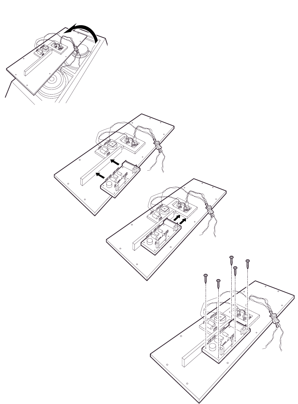
3. Carefully lift and turn over the access panel, not damaging
the internal wiring, and rest it on the back of the enclosure.
5. With it tight against
the stiffener and input backer,
screw the bi-amp crossover board
in this position with the 5 supplied
wood screws.
4. Orient the
bi-amp crossover
board so its large
inductor is toward the
input and the smaller
inductor away from the
wooden stiffener.
Position the bi-amp
crossover board tight
against the stiffener
and the wooden
input backer.
NOTE: The illustrations for Steps 3 through 8 are as viewed from the bottom of the enclosure.
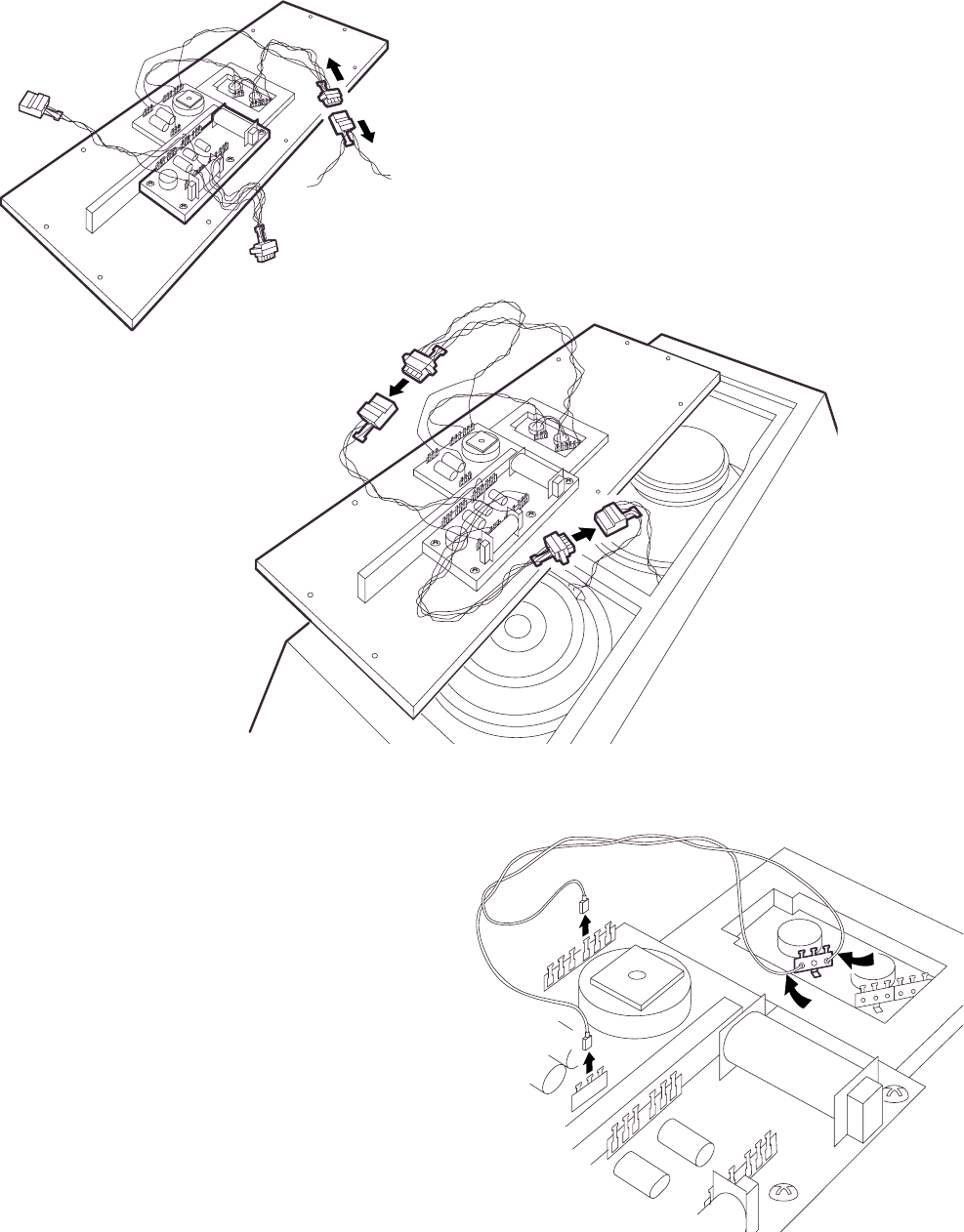
6. Unplug the inline connector between the access
panel and the drivers.
8. Cut the red and black wires soldered to
the 3-pin connector on the input. Unplug
the other ends from the terminal strips on
the existing crossover board. You may dis-
card these wires.
7. Connect the male connector
from the access panel to the
female connector from the
bi-amp crossover board.
Connect the female connector
from the drivers to the male
connector from the bi-amp
crossover board.
Ensure all connectors
are fully mated.
If you have any questions about installing the KF850z Bi-Amp Crossover Board, please contact the EAW Application
Support Group for assistance:
EAW ASG Tel 800-992-5013 (USA only)
One Main Street Tel 508-234-6158
Whitinsville, MA 01588 USA Fax 508-234-3776
E-mail asg @eaw.com
The Laws of Physics | The Art of Listening
EAW is the worldwide technological and market leader in the design and manufacture of high-performance, professional loudspeaker systems.
P/N 0007952 (B) 6NOV03
Thank you for purchasing
EAW products
11. Return the enclosure to its upright position.
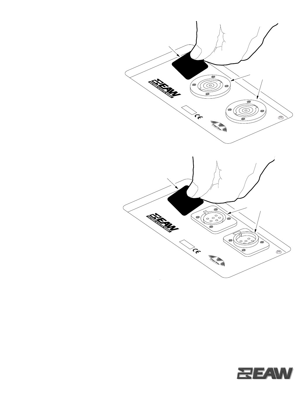
10. The pin-out code on the existing input label
must be replaced with a new sticker with the bi-
amp code. If the input has two NL8 connectors
(shown above), cover the pin-out code with sticker
P/N 0007749.
If the input has two AP6 connectors (shown right),
cover the pin-out code with sicker P/N 0007748.
PIN 1
PIN 1
PIN 2
PIN 2
PIN 3
PIN 3
LOW
LOW
MID
MID
HIGH
HIGH
...
...
...
...
...
...
--
+
--
+
--
+
--
+
--
+
--
+
WHITINSVILLE, MA USA
S/N
KF850zR
PIN 1...LF--
PIN 2...LF+
PIN 3...MF/HF--
PIN 4...MF/HF+
PIN 5...NC
PIN 6...NC
CANNON
CANNON
AP6 CONNECTORS
PIN-OUT STICKER
EAW P/N 0007748
PIN 1
PIN 1
PIN 2
PIN 2
PIN 3
PIN 3
LOW
LOW
MID
MID
HIGH
HIGH
...
...
...
...
...
...
--
+
--
+
--
+
--
+
--
+
--
+
NEUTRIK
NL 8 MPR
NEUTRIK
NL 8 MPR
WHITINSVILLE,MA USA
S/N
KF850zR
PIN 1--...NC
PIN 1+...NC
PIN 2--...LF--
PIN 2+...LF+
PIN 3--...MF/HF--
PIN 3+...MF/HF+
PIN 4--...NC
PIN 4+...NC
NL8 CONNECTORS
PIN-OUT STICKER
EAW P/N 0007749
9. Reposition the access panel onto the back
of the enclosure making sure internal wiring is
not pinched. Reinstall and tighten the 10 hex
head bolts and washers removed in step 2.
