001 KPHR432K90.etc KPHR432K90
User Manual: KPHR432K90
Open the PDF directly: View PDF ![]() .
.
Page Count: 364 [warning: Documents this large are best viewed by clicking the View PDF Link!]
- COVER
- SAFETY
- SELF DIAGNOSIS FUNCTION
- DISASSEMBLY
- 2-1. REAR BOARD REMOVAL
- 2-2. CHASSIS ASSY REMOVAL
- 2-3. SERVICE POSITION
- 2-4. H2 BOARD REMOVAL
- 2-5. H1 BOARD REMOVAL (HR532N90)
- 2-6. H1 BOARD REMOVAL (EXCEPT HR532N90)
- 2-7. H3 BOARD REMOVAL (HR432K90)
- 2-8. H3 BOARD REMOVAL (EXCEPT HR432K90)
- 2-9. MIRROR COVER REMOVAL
- 2-10. BEZNET ASSY REMOVAL
- 2-11. H4 BOARD (EXCEPT HW572K90) AND S BOARD REMOVAL
- 2-12. AD BOARD AND B BOARD REMOVAL
- 2-13. F BOARD (EXCEPT HR532N90) AND G BOARD REMOVAL
- 2-14. A BOARD, D BOARD AND U BOARD REMOVAL
- 2-15. PICTURE TUBE REMOVAL
- 2-16. HIGH-VOLTAGE CABLE INSTALLATION AND REMOVAL
- SET-UP ADJUSTMENTS
- 3-1. SCREEN VOLTAGE ADJUSTMENT (COARSE ADJUSTMENT)
- 3-2. SCREEN (G2) ADJUSTMENT (FINE ADJUSTMENT)
- 3-3. DEFLECTION YOKE TILT ADJUSTMENT
- 3-4. FOCUS LENS ADJUSTMENT
- 3-5. FOCUS VR ADJUSTMENT
- 3-6. 2-POLE MAGNET ADJUSTMENT
- 3-7. CENTERING MAGNET ADJUSTMENT
- 3-8. 4-POLE MAGNET ADJUSTMENT
- 3-9. DEFOCUS ADJUSTMENT (BLUE)
- 3-10.ELECTRICAL ADJUSTMENT BY REMOTE COMMANDER
- 3-11. REGISTRATION ADJUSTMENT
- 3-12. AUTO CONVERGENCE OFFSET
- 3-13. AUTO REGISTRATION ERROR CODE LIST
- CIRCUIT ADJUSTMENTS
- SAFETY RELATED ADJUSTMENTS
- DIAGRAMS
- 6-1. BLOCK DIAGRAM (1) (EXCEPT HW572K90)
- 6-2. CIRCUIT BOARDS LOCATION
- 6-3. SCHEMATIC DIAGRAMS
- A(1/9) BOARD CIRCUIT
- A(2/9) BOARD CIRCUIT
- A(3/9) BOARD CIRCUIT
- A(4/9) BOARD CIRCUIT
- A(5/9) BOARD CIRCUIT
- A(6/9) BOARD CIRCUIT
- A(7/9) BOARD CIRCUIT
- A(8/9) BOARD CIRCUIT
- A(9/9) BOARD CIRCUIT
- AD(1/2) BOARD CIRCUIT
- AD(2/2) BOARD CIRCUIT
- B(1/4) BOARD CIRCUIT
- B(2/4) BOARD CIRCUIT
- B(3/4) BOARD CIRCUIT
- B(4/4) BOARD CIRCUIT
- CB, CR, CG BOARD CIRCUIT
- D(1/3) BOARD CIRCUIT
- D(2/3) BOARD CIRCUIT
- D(3/3) BOARD CIRCUIT
- G(1/2) BOARD CIRCUIT
- G(2/2) BOARD CIRCUIT
- H1, H2, H3, H4 BOARD CIRCUIT
- S BOARD CIRCUIT
- U(1/3) BOARD CIRCUIT
- U(2/3) BOARD CIRCUIT
- U(3/3) BOARD CIRCUIT
- U(1/3) BOARD CIRCUIT
- U(2/3) BOARD CIRCUIT
- U(3/3) BOARD CIRCUIT
- V BOARD CIRCUIT
- 6-4. PRINTED WIRING BOARDS
- 6-5. WAVEFORMS
- 6-6. IC BLOCK DIAGRAMS
- 6-7. SEMICONDUCTORS
- EXPLODED VIEWS
- ELECTRICAL PARTS LIST
- 4085459E1.pdf
- Contents
- Important Safeguards
- Introducing the Sony Projection TV
- Installing and Connecting the Projection TV
- Contents
- Inserting Batteries into the Remote Control
- Carrying Your Projection TV
- Installing the Projection TV
- Connector Types
- Projection TV Controls and Connectors
- Basic Connections (Connecting Cable TV or Antenna)
- Connecting a VCR and Cable
- Connecting a VCR and Cable Box
- Connecting Two VCRs for Tape Editing
- Connecting an Audio Receiver
- Connecting a DVD Player with Component Video Connectors
- Connecting a DVD Player with A/V Connectors
- Connecting a Digital TV Receiver
- Connecting a Camcorder
- Connecting an AV Receiver
- Using the CONTROL S Feature
- Setting Up the Projection TV Automatically
- Adjusting the Convergence Automatically – FLASH FOCUS™ –
- Using the Features
- Using the Menus
- Other Information
- Contents
- 4085459F1.pdf
- Contents
- Important Safeguards
- Introducing the Sony Projection TV
- Installing and Connecting the Projection TV
- Contents
- Inserting Batteries into the Remote Control
- Carrying Your Projection TV
- Installing the Projection TV
- Connector Types
- Projection TV Controls and Connectors
- Basic Connections (Connecting Cable TV or Antenna)
- Connecting a VCR and Cable
- Connecting a VCR and Cable Box
- Connecting Two VCRs for Tape Editing
- Connecting a Satellite Receiver
- Connecting a Satellite Receiver with a VCR
- Connecting an Audio Receiver
- Connecting a DVD Player with Component Video Connectors
- Connecting a DVD Player with A/V Connectors
- Connecting a Digital TV Receiver
- Connecting a Camcorder
- Connecting an AV Receiver
- Using the CONTROL S Feature
- Setting Up the Projection TV Automatically
- Adjusting the Convergence Automatically – FLASH FOCUS™ –
- Using the Features
- Using the Menus
- Other Information
- Contents
- 4085753E1.pdf
- Contents
- Important Safeguards
- Introducing the Sony Projection TV
- Installing and Connecting the Projection TV
- Contents
- Inserting Batteries into the Remote Control
- Carrying Your Projection TV
- Installing the Projection TV
- Connector Types
- Projection TV Controls and Connectors
- Basic Connections (Connecting Cable TV or Antenna)
- Connecting a VCR and Cable
- Connecting a VCR and Cable Box
- Connecting Two VCRs for Tape Editing
- Connecting an Audio Receiver
- Connecting a DVD Player with Component Video Connectors
- Connecting a DVD Player with A/V Connectors
- Connecting a Digital TV Receiver
- Connecting a Camcorder
- Connecting an AV Receiver
- Using the CONTROL S Feature
- Setting Up the Projection TV Automatically
- Adjusting the Convergence Automatically – FLASH FOCUS™ –
- Using the Features
- Using the Menus
- Other Information
- Contents
CHASSIS
SERVICE MANUAL
MODEL COMMANDER DEST. CHASSIS NO.
–––––– –––––––––––– ––––– ––––––––––– MODEL COMMANDER DEST. CHASSIS NO.
–––––– –––––––––––– ––––– –––––––––––
RA-6
KP-HR432K90 RM-Y909K Korean SCC-P73B-A
KP-HR532K90 RM-Y909K Korean SCC-P73A-A
KP-HR532N90 RM-Y908 Taiwan SCC-P74A-A
KP-HW572K90RM-Y909K Korean SCC-P73C-A
PROJECTION TV
RM-Y908/Y909K KP-HR432K90/HR532K90/HR532N90 KP-HW572K90

– 2 –
KP-HR432K90/HR532K90/HR532N90/HW572K90
RM-Y909KRM-Y908RM-Y909K RM-Y909K
Specifications
Projection System 3 picture tubes, 3 lenses, horizontal in-line system
Picture Tube 7-inch high-brightness monochrome tubes (6.3 raster size), with optical
coupling and liquid cooling system
Projection Lenses High performance, large
diameter hybrid lens F1.1
Antenna 75 ohm external terminal for VHF/UHF
Television System NTSC, American TV Standard
Screen Size (measured diagonally) 43 inches (KP-HR432N90)
53 inches (KP-HR532K90/HR532N90)
57 inches (KP-HW572K90)
Channel Coverage
VHF 2-13
UHF 14-69
CATV 1-125
Power Requirements 110 V AC, 60 Hz (KP-HR532N90)
220 V AC, 60 Hz (KP-HR432K90/HR532K90/HW572K90)
Number of Inputs/Outputs
Video (IN) 4 1 Vp-p, 75 ohms unbalanced, sync negative
S Video (IN) 3 Y: 1 Vp-p, 75 ohms unbalanced, sync negative
C: 0.286 Vp-p (Burst signal), 75 ohms
Audio (IN) 6 500 mVrms (100% modulation)
Impedance: 47 kiloohms
AUDIO (VAR/FIX) 1 500 mVrms at the maximum volume setting
(Variable)
500 mVrms (Fixed)
Impedance (output): 2 kiloohms
TV Out 1 Video: 1 Vp-p 75 ohms unbalanced, Sync
negative
Audio: 500 mVrms (100% modulation)
Impedance (output): 1 kiloohms
CONTROL S (IN/OUT) 1 Minijacks
Component Video Input 2 (Y, PB, PR) Y: 1.0 Vp-p, 75 ohms unbalanced, sync
negative
PB: 0.7 Vp-p, 75 ohms
PR: 0.7 Vp-p, 75 ohms
RF Inputs 2
Converter 1
Speaker Output 20 W x 2
Dimensions (W x H x D) 966 x 1,072 x 570 mm (KP-HR432K90)
1,180 x 1,430 x 626 mm (KP-HR532K90)
1,180 x 1,417 x 632 mm (KP-HR532N90)
1,326 x 1,377 x 690 mm (KP-HW572K90)
Mass 56 kg (KP-HR432K90)
71 kg (KP-HR532K90)
71.2 kg (KP-HR532N90)
89 kg (KP-HW572K90)
Power Consumption
In Use 280 W (KP-HR532N90)
230 W (KP-HR432K90/HR532K90/HW572K90)
In Standby 1 W (KP-HR532N90)
1.2 W (KP-HR432K90/HR532K90/HW572K90)
Supplied Accessories
Remote Control RM-Y908 (KP-HR532N90)
RM-Y909K (KP-HR432K90/HR532K90/HW572K90)
AA (R6) Batteries 2 supplied for remote control
Design and specifications are subject to change without notice.
– 3 –
KP-HR432K90/HR532K90/HR532N90/HW572K90
RM-Y909KRM-Y908RM-Y909K RM-Y909K
(CAUTION)
SHORT CIRCUIT THE ANODE OF THE PICTURE TUBE AND THE
ANODE CAP TO THE METAL CHASSIS, CRT SHIELD, OR CAR-
BON PAINTED ON THE CRT, AFTER REMOVING THE ANODE.
WARNING!!
AN ISOLATION TRANSFORMER SHOULD BE USED DURING
ANY SERVICE TO AVOID POSSIBLE SHOCK HAZARD, BE-
CAUSE OF LIVE CHASSIS.
THE CHASSIS OF THIS RECElVER IS DIRECTLY CONNECTED
TO THE AC POWER LINE.
SAFETY-RELATED COMPONENT WARNING!!
COMPONENTS IDENTIFIED BY SHADING AND MARK ! ON
THE SCHEMATIC DIAGRAMS, EXPLODED VIEWS AND IN THE
PARTS LIST ARE CRITICAL TO SAFE OPERATION. REPLACE
THESECOMPONENTS WITH SONY PARTS WHOSE PART NUM-
BERS APPEAR AS SHOWN IN THIS MANUAL OR IN SUPPLE-
MENTS PUBLISHED BY SONY. CIRCUIT ADJUSTMENTS THAT
ARE CRITICAL TO SAFEOPERATION ARE IDENTIFIED IN THIS
MANUAL. FOLLOW THESE PROCEDURES WHENEVER CRITI-
CAL COMPONENTS ARE REPLACED OR IMPROPER OPERA-
TION IS SUSPECTED.
– 4 –
KP-HR432K90/HR532K90/HR532N90/HW572K90
RM-Y909KRM-Y908RM-Y909K RM-Y909K
TABLE OF CONTENTS
Section Title Page
–––––– –––– –––– Section Title Page
–––––– –––– ––––
1. SELF DIAGNOSIS FUNCTION ............................. 5
2. DISASSEMBLY
2-1. REAR BOARD REMOVAL ....................................... 8
2-2. CHASSIS ASSY REMOVAL ..................................... 8
2-3. SERVICE POSITION ................................................. 8
2-4. H2 BOARD REMOVAL ............................................. 8
2-5. H1 BOARD REMOVAL (HR532N90) ....................... 9
2-6. H1 BOARD REMOVAL (EXCEPT HR532N90) ....... 9
2-7. H3 BOARD REMOVAL (HR432K90) ....................... 9
2-8. H3 BOARD REMOVAL(EXCEPT HR432K90) ........ 9
2-9. MIRROR COVER REMOVAL ................................... 9
2-10. BEZNET ASSY REMOVAL .................................... 10
2-11. H4 BOARD (EXCEPT HW572K90) AND
S BOARD REMOVAL .............................................. 10
2-12. AD BOARD AND B BOARD REMOVAL .............. 10
2-13. F BOARD (EXCEPT HR532N90) AND
G BOARD REMOVAL ............................................... 9
2-14. A BOARD, D BOARD AND
U BOARD REMOVAL ............................................. 11
2-15. PICTURE TUBE REMOVAL ................................... 11
2-16. HIGH-VOLTAGE CABLE INSTALLATION AND
REMOVAL ................................................................ 11
3. SET-UP ADJUSTMENTS
3-1. SCREEN VOLTAGE ADJUSTMENT
(COARSE ADJUSTMENT) ..................................... 12
3-2. SCREEN (G2) ADJUSTMENT
(FINE ADJUSTMENT) ............................................ 12
3-3. DEFLECTION YOKE TILT ADJUSTMENT .......... 12
3-4. FOCUS LENS ADJUSTMENT ............................... 12
3-5. FOCUS VR ADJUSTMENT..................................... 13
3-6. 2-POLE MAGNET ADJUSTMENT ........................ 13
3-7. CENTERING MAGNET ADJUSTMENT ............... 13
3-8. 4-POLE MAGNET ADJUSTMENT ........................ 13
3-9. DEFOCUS ADJUSTMENT (BLUE) ....................... 13
3-10. ELECTRICAL ADJUSTMENT BY REMOTE
COMMANDER ........................................................ 14
3-11. REGISTRATION ADJUSTMENT ........................... 27
3-12. AUTO CONVERGENCE OFFSET.......................... 31
3-13. AUTO REGISTRATION ERROR CODE LIST ....... 31
4. CIRCUIT ADJUSTMENTS
4-1. P & P SUB CONTRAST
ADJUSTMENT (VIDEO) (SCON) .......................... 33
4-2. P & P SUB CONTRAST
ADJUSTMENT (RF) (SCON).................................. 33
4-3. P & P SUB-HUE AND
SUB-COLOR ADJUSTMENT (SHUE, SCOL) ...... 33
4-4. P & P SUB-HUE AND
SUB-COLOR ADJUSTMENT (SHUE, SCOL) ....... 33
4-5. BLUE OFFSET ADJUSTMENT(HW572K90)........ 34
5. SAFETY RELATED ADJUSTMENTS
5-1. HV REGULATION CIRCUIT CHECK AND
ADJUSTMENT......................................................... 35
5-2. HV HOLD DOWN CIRCUIT OPERATION
CHECK AND ADJUSTMENT ................................. 35
5-3. +B MAX VOLTAGE CONFIRMATION .................. 35
5-4. +B OVP CONFIRMATION ...................................... 35
6. DIAGRAMS
6-1. BLOCK DIAGRAM (1)............................................ 36
BLOCK DIAGRAM (2)............................................ 37
BLOCK DIAGRAM (3)............................................ 38
BLOCK DIAGRAM (4)............................................ 39
BLOCK DIAGRAM (5)............................................ 40
BLOCK DIAGRAM (6)............................................ 41
BLOCK DIAGRAM (7)............................................ 42
BLOCK DIAGRAM (8)............................................ 43
BLOCK DIAGRAM (9)............................................ 44
BLOCK DIAGRAM (10).......................................... 45
BLOCK DIAGRAM (11).......................................... 46
BLOCK DIAGRAM (12).......................................... 47
BLOCK DIAGRAM (13).......................................... 48
6-2. CIRCUIT BOARDS LOCATION ................................. 49
6-3. SCHEMATIC DIAGRAMS........................................... 49
6-4. PRINTED WIRING BOARDS...................................... 82
6-5. WAVEFORMS ............................................................... 97
6-6. IC BLOCK DIAGRAMS ............................................... 99
6-7. SEMICONDUCTORS ................................................. 103
7. EXPLODED VIEWS
7-1. COVER (KP-HR432K90) ....................................... 104
7-2. COVER (KP-HR532K90/HR532N90) ................... 105
7-3. COVER (KP-HW572K90) ...................................... 106
7-4. CHASSIS (KP-HR432K90) .................................... 107
7-5. CHASSIS (KP-HR532K90/HR532N90) ................ 108
7-6. CHASSIS (KP-HW572K90) ................................... 109
7-7. PICTURE TUBE ..................................................... 110
8. ELECTRICAL PARTS LIST .............................. 111
– 5 –
KP-HR432K90/HR532K90/HR532N90/HW572K90
RM-Y909KRM-Y908RM-Y909K RM-Y909K
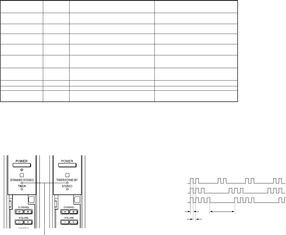
3. Blinking count display of STAND BY indicator
1. Summary of Self-Diagnosis Function
• This device includes a self-diagnosis function.
• In case of abnormalities, the STAND BY indicator automatically blinks. It is possible to predict the abnormality location by the
number of blinks. The Instruction Manual describes blinking of the /STAND BY indicator.
• If the symptom is not reproduced sometimes in case of a malfunction, there is recording of whether a malfunction was generated
or not. Operate the remote command to confirm the matter on the screen and to predict the location of the abnormality.
2. Diagnosis Items and Prediction of Malfunction Location
• When a malfunction occurs the STAND BY indicator only blinks for one of the following diagnosis items. In case of two or
more malfunctions, the item which first occurred blinks. If the malfunctions occurred simultaneously, the item with the lower
blink count blinks first.
• The screen display displays the results regarding all the diagnosis items listed below. The display “ 0 ” means that no malfunc-
tions occurred.
SECTION 1
SELF DIAGNOSIS FUNCTION
Note1: If a +B overcurrent is detected, stoppage of the vertical deflection is detected simultaneously. The sympton that is diagnosed first by the microcontroller is displayed on screen.
Note 2: Refer to Screen (G2) Adjustment in Section 3-1, 2 of this manual.
Note 3: If STANDBY indicator blinks six (6) times, unplug the unit and wait 10 minutes before performing the adjustment.
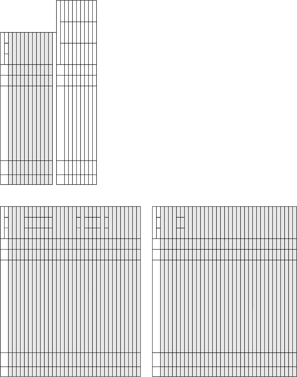
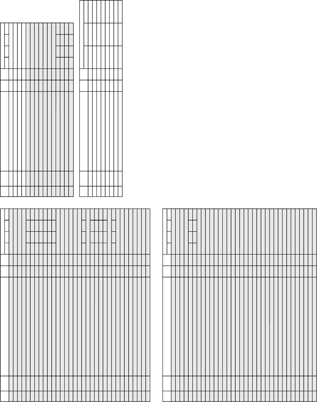
Deteced symptoms
Diagnosis Item No. of times
STANDBY
indicator blinks Probable Cause Location
7 timesHorizontal deflection stopped • Q8035, 8038 is shorted. (D board)
8 timesHigh voltage error • T8005 is faulty. (D board)
0Power does not turn on •Power cord is not plugged in.
• Fuse is burned out (F6001) (G board)
• Power does not come on.
• No power is supplied to the unit.
• AC power supply is faulty.
2 times
+B overcurrent (OCP)
(See Note 1) • H. OUT (Q8024) is shorted. (D board)
• +B PWM (Q8035, 8038) is shorted. (D board) • Power does not come on.
• Load on power line is shorted.
3 times+B overvoltage (OVP) • IC501 is faulty (G board)
• IC5002 is faulty (G board) • Has entered standby mode.
4 timesVertical deflection stopped • +- 15V is not supplied. (D board)
• IC8003 is faulty. (A board)
• Has entered standby state after horizontal raster.
• Vertical deflection pulse is stopped.
• Power line is shorted or power supply is stopped.
5 times
White balance failure
(Not balanced)
• Video out (IC7101, 7201, 7301) is faulty. (CR, CG, CB board)
•CRT drive (IC309) is faulty. (A board)
•G2 is improperly adjusted. (See Note 2)
• No raster is generated.
• CRT cathode current detection reference pulse output is small.
6 times
LOW B OCP/OVP
(Overcurrent/over voltage)
(See Note 3)
• +5 line is overloaded. (A, B boards)
• +5 line is shorted. (A, B boards) • No picture
• No picture
Audio error 9 times
• +- 19V line is shorted. (A, B boards)
• IC708 is faulty. (A board)
• PS701 or PS702 is opened. (A board) • No sound
Lamp OFF :
3.0 seconds
Lamp ON : 0.3 seconds
Lamp OFF : 0.3 seconds
Release of STAND BY indicator blinking.
•The STAND BY indicator blinking display is released by turning OFF the power switch
on the TV main unit or removing the plug from the power.
* One blink is not used for self-diagnosis.
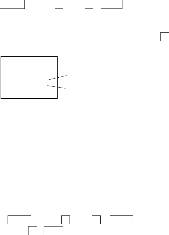
•EXAMPLE
<Diagnosis Items> <Number of Blinks>
• +B overcurrent 2 times
• +B overvoltage 3 times
• Vertical deflection stop 4 times
< FRONT PANEL >
(EXEPT HR532N90) (HR532N90)
STAND BY indicator
– 6 –
KP-HR432K90/HR532K90/HR532N90/HW572K90
RM-Y909KRM-Y908RM-Y909K RM-Y909K
4. Self-diagnosis screen displays
•In cases of malfunctions where it is not possible to determine the symptom such as when the power goes off occasionally or when
the screen disappears occasionally, there is a screen display on whether the malfunction occurred or not in the past (and whether
the detection circuit operated or not) in order to allow confirmation.
<Screen Display Method>
•Quickly press the remote command button in the following order from the standby state.
5. Self-Diagnosis Screen Display
•The results display is not automatically cleared. In case of repairs and after repairs, check the self-diagnosis screen and be sure
to return the results display to “ 0 ”.
•If the results display is not returned to “ 0 ” it will not be possible to judge a new malfunction after completing repairs.
<Method of Clearing Results Display>
<Method of Ending Self Diagnosis Screen>
•When ending the self-diagnosis screen completely, turn the power switch OFF on the remote commander or the main unit.
˘
Be aware that this differs from the method of
entering the service mode (volume + ).
DISPLAY b Channel 5 b VOL – b POWER
SELF DIAGNOSIS
2 : +B OCP N/A
3 : +B OVP N/A
4 : V STOP 0
5 : AKB 1
10 : WDT 24
Numeral “0” means that no fault
was detected.
Numeral “1” means a fault was detected
one time or more
Self-diagnosis screen display
1. Power off (Set to the standby mode)
2. DISPLAY b Channel 5 b VOL + b POWER (Service Mode)
3. Channel 8 b ENTER (Test reset = Factory preset condition)
– 7 –
KP-HR432K90/HR532K90/HR532N90/HW572K90
RM-Y909KRM-Y908RM-Y909K RM-Y909K
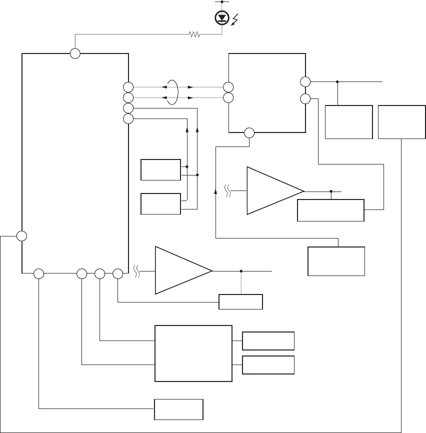
6. Self-diagnosis function operation
OCP Low B and +B line detect DET SHORT, and shut-down POWER ON RELAY.
Reset by turning power on/off.
In case of +B is loaded approx. 1.5A or more, microcomputer detects it via IC5005
OVP In case of +B becomes approx. 150V or more, POWER ON RELAY shuts down and microcomputer detects it via IC5005.
Reset by turning power on/off just the same as OCP.
Low B Occurs when set +5V is out
V Stop In case of V Drive disappeared, Q8001 detecs it and shut-down POWER ON RELAY. Microcomputer detects it and makes LED
blinking.
AKB IK detection. Makes LED blinking in case of microcomputer doesn’t detect IK returns of IC309 (CXA2150AQ) 20 seconds or
more.
H Stop In case of H DRIVE is disappeared, Q378 detects it and shut-down POWER ON RELAY shuts down.
Microcomputer receives H Stop data from Q378 and makes LED blinking.
HV Stop In case of HV becomes 33KV or more. IC8006 detects it and shut-down
POWER ON RELAY. Microcomputer makes LED blinking.
Audio In case of DC component overlaps the output of Audio Amp., POWER ON RELAY shuts down.
Microcomputer detects it and makes LED blinking.
Self-diagnosis block diagram
49
53
43 244544
31
28
29
25
58
35
34
5. AKB
5. AKB
4. V STOP
3. OVP
2. OCP
6. LOW B
8. HV.STOP
9. Audio
IC704
MAIN-CPU
IC309
CXA2150AQ
Y/C JUNGLE
D9101
TIMER/STANDBY
R765
IC702
EEPROM
IC703
EEPROM
Q714
+5V DETECT
Q378
H PULSE
Detector
IC8006
HV Detector
Q8001
V Pulse Detector
IC5005
OVP Buffer
OCP Buffer
C Board
DC Detect
IC8003
V Drive
IC708
6. H STOP
BUS 26
30
OVP DETECT
OCP DETECT
Audio AMP

– 8 –
KP-HR432K90/HR532K90/HR532N90/HW572K90
RM-Y909KRM-Y908RM-Y909K RM-Y909K
SECTION 2
DISASSEMBLY
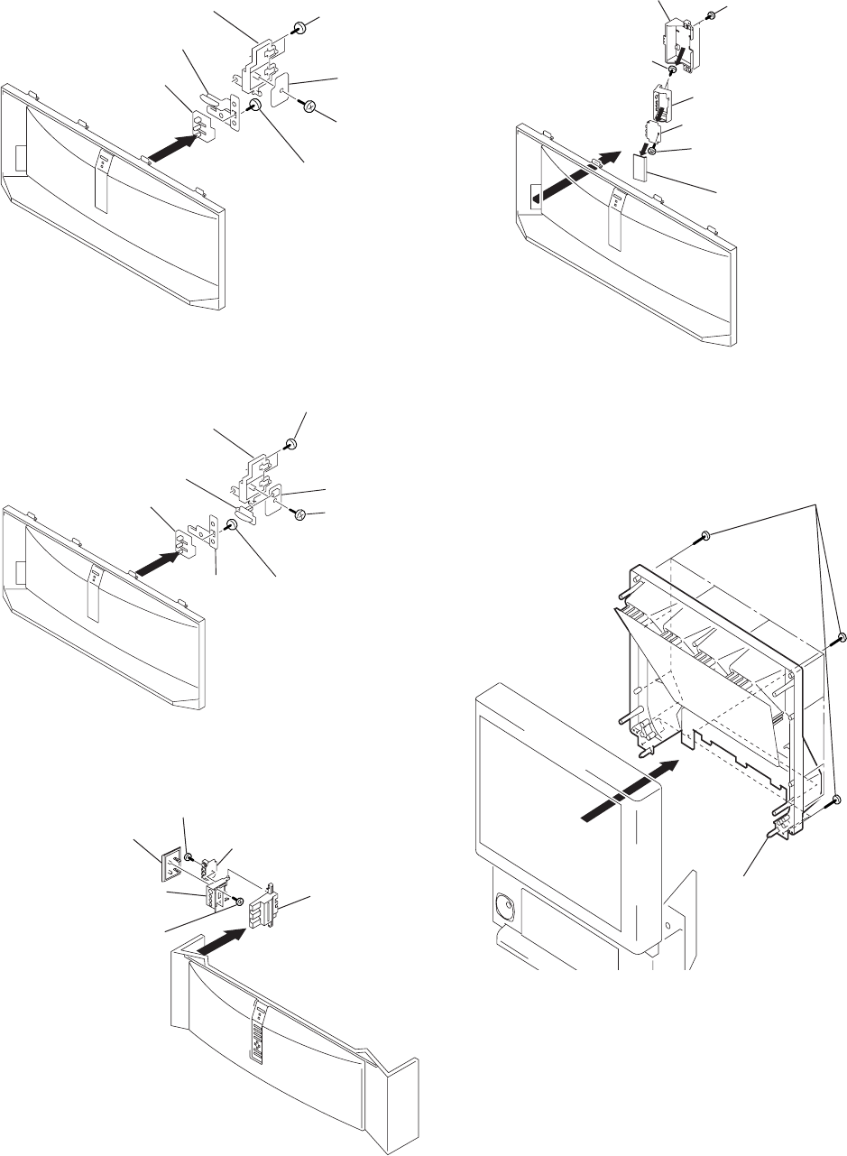
2-1. REAR BOARD REMOVAL 2-3. SERVICE POSITION
2-2. CHASSIS ASSY REMOVAL
2-4. H2 BOARD REMOVAL
2 Rear board
1 Nine screws,
tapping, hexagon head
2 Chassis assy
1 Three screws,
tapping, hexagon head
1 Disconnect CN17, 18, 19
on A board.
From V boards CN9001.
(The extension cable is not
supplied because of the
countermeasure for radiation.)
D board
CN17, 18, 19
A board
2 Covers
Cut them off with a plier or the like
from chassis assembly in case of
checking printed circuit boards.
After checking, turn over the covers
and secure them with screws.
Screws
(+BVTP3x12)
Chassis assembly
2 Screw,
tapping,
hexagon
head
2 Screw,
tapping,
hexagon
head
3 Six screws
(+BVTP4x12(HR432K90))
(+BVTP4x16
(Except HR432K90))
1 Cap,
speaker
grille
1 Cap,
speaker
grille
4 H2 board
5 Button, multi
Except HR432K90
– 9 –
KP-HR432K90/HR532K90/HR532N90/HW572K90
RM-Y909KRM-Y908RM-Y909K RM-Y909K
2-5. H1 BOARD REMOVAL (HR532N90)
1 Two screws
(+BVTP4x16)
3 Screw
(+BVTP4x16)
4 H1 board
6 Button, power
2 Bracket H1
5 Screw
(+BVTP4x16)
7 Guide, LED
2-9. MIRROR COVER REMOVAL
2 Mirror cover
1 Twenty three screws,
+BVTP4x16
2-8. H3 BOARD REMOVAL (EXCEPT HR432K90)
1 Screws
(+BVTP4x16)
2 Holder, front teminal
4 Bracket, H3
6 Screw
(+BVTP3x12)
3 Two screws
(+BVTP3x12)
5 Door, front terminal
7 H3 board
2-6. H1 BOARD REMOVAL (EXCEPT HR532N90)
1 Two screws
(+BVTP4x12
(HR432K90))
(+BVTP4x16
(Except HR432K90))
3 Screw
(+BVTP3x12
(HR432K90))
(+BVTP4x16
(Except HR432K90)
4 H1 board
5 Button, power
7 Button,
power
2 Bracket H1
6 Screw
(+BVTP4x12
(HR432K90))
(+BVTP4x16
(Except HR432K90)
8 Guide, LED
2-7. H3 BOARD REMOVAL (HR432K90)
2 Holder, side teminal
4 Bracket, H3
6 Screw
(+BVTP4x16)
3 Two screws
(+BVTP4x16)
5 Door, side terminal 7 H3 board
1
– 10 –
KP-HR432K90/HR532K90/HR532N90/HW572K90
RM-Y909KRM-Y908RM-Y909K RM-Y909K
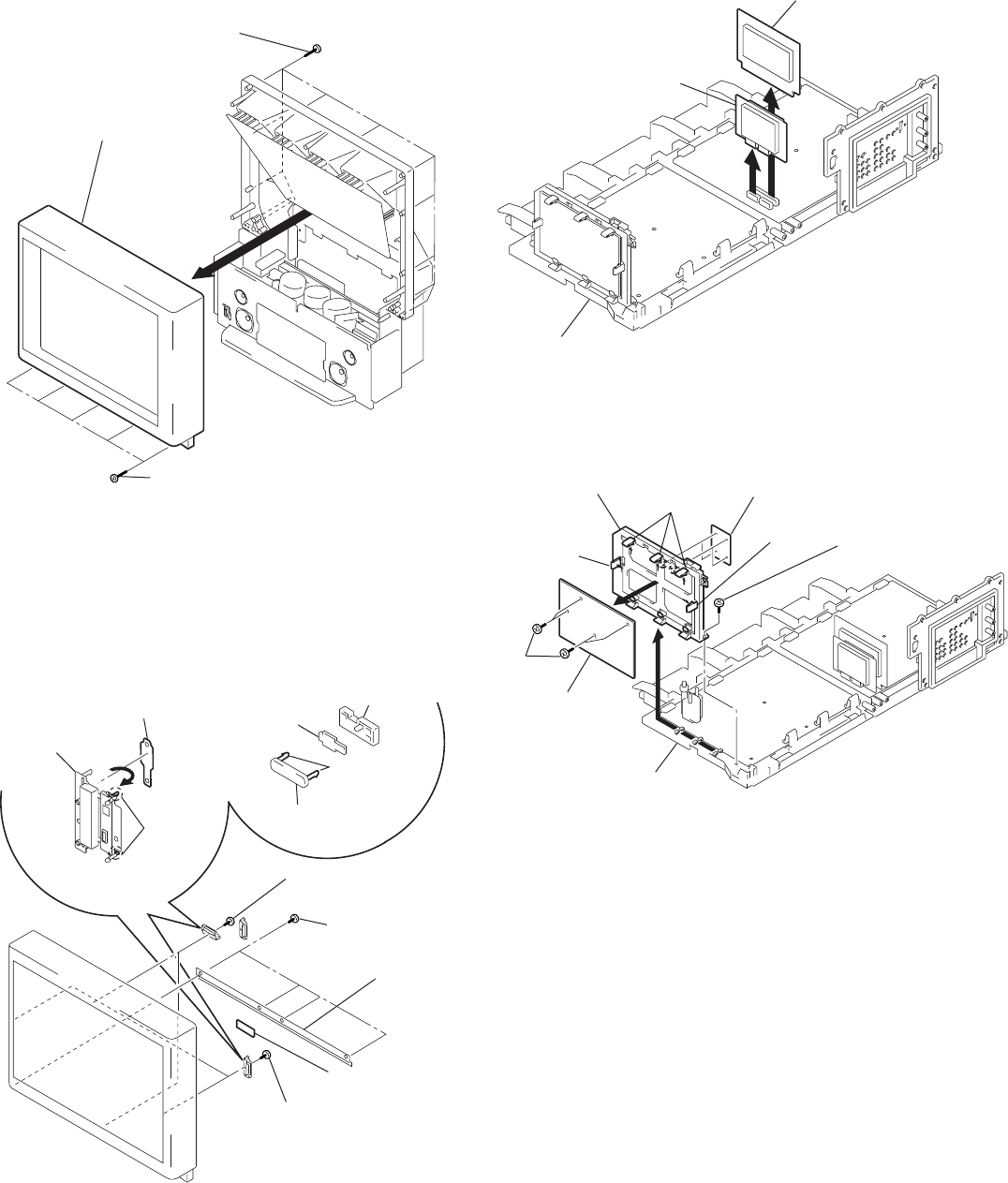
2-12. AD BOARD AND B BOARD REMOVAL
1 B board
1 AD board
Main bracket
2-11. H4 BOARD (EXCEPT HW572K90)
AND S BOARD REMOVAL
3 H4 board
2 L screen holder
6 Claws
8 S board 8 S board
7
Sensor
bracket
Sensor
bracket (B)
4 Two screws
(+BVTP 4x12)
1 Four screws
(+BVTP 4x12)
5 Two screws
(+BVTP 4x12)
7 Sensor bracket (A)
6
Two claws
• HW572K90 • Except HW572K90
2-13. F BOARD (EXCEPT HR532N90) AND
G BOARD REMOVAL
5 G board
3 Bracket G
2 Claws
2 Claw
2 Claw
Main bracket
6 F board
4 Four screws
(+BVTP3x12)
1 screw
(+BVTP4x12)
3 Beznet assy
2 Screws,
+BVTP4x16
1 Screws,
tapping, hexagon head
2-10. BEZNET ASSY REMOVAL
– 11 –
KP-HR432K90/HR532K90/HR532N90/HW572K90
RM-Y909KRM-Y908RM-Y909K RM-Y909K
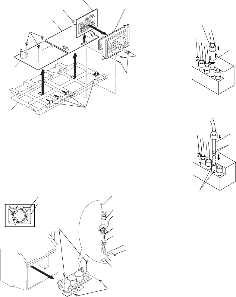
2-16. HIGH-VOLTAGE CABLE INSTALLATION
AND REMOVAL
(1) Removal
1 Rubber cap
2 HV cable
turn 90°
1 HV cable
Gutter
Hook
(2) Installation
2-14. A BOARD, D BOARD AND U BOARD REMOVAL
6 D board
6 A board
2 Terminal board
5 Claws
Main bracket
3 U board
1 Two screws,
tapping, hexagon head
4 Screws
(+BVTP3x12)
4 Six screws
(+BVTP3x12)
1 Five screws
(+BVTP3x12)
8 Two screws
(+BVTP3x12)
!™ Four screws
(+BVTP 4x16)
!£ Picture tube
Picture tube
0 Deflection yoke
3
7 Neck assy
6 CR board
9 V board
5 Lens
Lens 4 Four screws,
(+BVTP 4x16)
1 Two screws,
(4x20) , head tapping,
2 Four screws,
(4x20) , head
tapping,
2-15. PICTURE TUBE REMOVAL
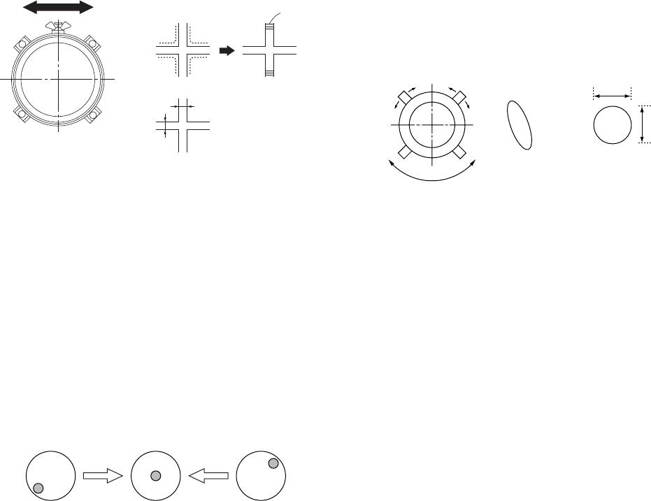
CAUTION: Removing the arrow-marked
screws is strictly prohibited.
If removed, it may cause liquid spill.
– 12 –
KP-HR432K90/HR532K90/HR532N90/HW572K90
RM-Y909KRM-Y908RM-Y909K RM-Y909K
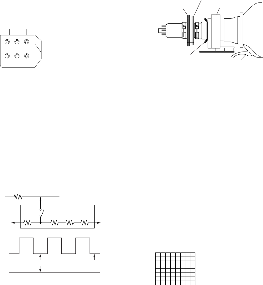
2-pole magnet
4-pole magnet
Deflection yoke
Anode cap
Centering magnet
3-1. SCREEN VOLTAGE ADJUSTMENT
(COARSE ADJUSTMENT)
1. Receive the Monoscope signal.
2. Set 50% BRIGHTNESS and minimum PICTURE.
3. Turn the red VR on the FOCUS block all the way to the left
and then gradually turn it to the right until the point where you
can see the retrace line.
4. Next gradually turn it to the left to the position where the
retrace line disappears.
R G B
SCREEN
R G B
FOCUS
FOCUS block Fig. 3-1
SECTION 3
SET-UP ADJUSTMENTS
170 ± 0.5V
G2 JIG
TO CG BOARD
TP7201
(200V)
GND
3k 5.6k 5.6k 5.6k
SW
K
GND
pedestal level
All resistors are 3W type
Fig. 3-2
3-2. SCREEN (G2) ADJUSTMENT
(FINE ADJUSTMENT)
Fine Mode is recommended to set screen controls to their optimal
condition. It is necessary to build the simple jig, illustrated below,
using 3-watt resistors. Please note, that if the proper voltage is not
obtained with their listed values, resistors, then please increase or
decrease one of the values in the resistor network to obtain the
correct voltage.
1. Select VIDEO1 mode without signals.
2. Connect G2 JIG.
3. SW on JIG.
4. Connect an oscilloscope to the TP7101(KR), TP7202(KG) and
TP7301(KB) of CR board, CG board and CB board.
5. Adjust R, G and B screen voltage to 170 ± 0.5V with screen
VR on the Focus block.
3-3. DEFLECTION YOKE TILT ADJUSTMENT
1. Connect the color bar generator monoscope pattern to Video 1
input.
2. Cover the both red and blue picture lenses with the lens caps
to show only the green color.
3. Loosen the deflection yoke set screw and align the tilt of the
Deflection Yoke so that the bars at the center of the
monoscope pattern are horizontal.
4. After aligning the deflection yoke, fasten it securely to the
funnel-shaped portion (neck) of the CRT.
5. The tilt of the deflection yoke for red is aligned in the mode
Cover the both green and blue picture lenses with the lens caps
and the tilt of the deflection yoke for blue is aligned with in
Fig. 3-3
3-4. FOCUS LENS ADJUSTMENT
In this adjustment, use the remote commander in the
service mode.
For details of the usage of the service mode and the remote
commander, please refer the item 3-9. ELECTRICAL
ADJUSTMENT BY REMOTE COMMANDER.
1. Loosen the lens screw.
2. Cover the both red and blue picture lenses with the lens caps
to show only the green color.
3. Turn the green lens to adjust to the optimum focus point with
the crosshatch signal.
4. Tighten the lens screw.
5. Cover the both green and blue picture lenses with the lens caps
to show only the red color.
6. Adjust red CRT lens just the same as green.
7. Cover the both green and red picture lenses with the lens caps
to show only the blue color.
8. Adjust blue CRT lens just the same as green.
9. After adjusting the items 3-5. Focus VR Adjustment, 3-6. 2-Pole
Magnet Adjustment and 3-7. 4-Pole Magnet Adjustment,
adjust again to the optimum focus point.
*: Every time you press 6, the test signal changes to
“crosshatch+video signal” - “crossbatch+borderline(black)”
- “crosshach(black)” - “dots(black)” - off.
Note: Instead of items 2, 5 and 7, you can cut off the unnecessary
color beams by controlling the service mode 2150P-2 1
RGBS.
Fig. 3-4
Test signal
the mode Cover the both green and red picture lenses with the
lens caps is aligned the same as was done for green.
Note: Instead of items 2 and 5, you can cut off the unnecessary
color beams by controlling the service mode CXA2150P-2 0
RGBS.
– 13 –
KP-HR432K90/HR532K90/HR532N90/HW572K90
RM-Y909KRM-Y908RM-Y909K RM-Y909K
3-7. CENTERING MAGNET ADJUSTMENT
1. Set the picture mode to “Pro”.
2. Receive the monoscope signal.
3. Cover the both red and blue picture lenses with the lens caps
to show only the green color.
4. Adjust the green centering magnet to put the center of the
monoscope signal to the center of the screen.
5. Adjust the red centering magnet in the same way.
6. Adjust the blue centering magnet in the same way.
Note: Instead of item 2 you can cut off the unnecessary color
beams by controlling the service mode 2150P-2 1 RGBS.
3-8. 4-POLE MAGNET ADJUSTMENT
1. Set the picture mode to“Pro” and picture to MAX.
2. Receive the Dot signal.
3. Cover the both red and blue picture lenses with the lens caps
to show only the green color.
4. Turn the green focus VR on the focus block to the right and set
the spot will become smaller.
5. Adjust the 4-Pole Magnet so that the spot becomes round for
green and red.
6. Adjust blue spot to an oval shape X:Y=1:1.4 - 1.5.
Note: Instead of item 2 you can cut off the unnecessary color
beams by controlling the service mode 2150P-2 1 RGBS.
3-9. DEFOCUS ADJUSTMENT (BLUE)
Note: Please adjust the blue dot to be slightly larger than red and
green dots. This adjustment provides a more pleasing picture
to the customer.
1. Select the picture mode to “Pro”.
2. Receive the Dot signal.
3. Cover the both red md green picture lenses with the lens caps
to show only the blue color.
4. Turn the blue focus VR on the focus block to right to make the
round dot elipical.
5. Check flare with high luminace signal, make sure flare is
minimal while dot shape is elipical.
6. Set generdtor to all white signal and check uniformity.
Note: Instead of item 3 you can cut off the unnecessary color
beams by controlling the service mode 2150P-2 1 RGBS.
Fig. 3-7
Fig. 3-8
/
x
y
x : y = 1:1.4
˜
1.5 (BIue)
x : y = 1:1 (Green, Red)
Use the center dot
3-5. FOCUS VR ADJUSTMENT
1. Set generator to crosshatch.
2. Cover the both red and blue picture lenses with the lens caps
to show only the green color.
3. Turn the green focus VR on the focus block to adjust to the
optimum focus point with the crosshatch signal.
4. Cover the both green and blue picture lenses with the lens caps
to show only the red color.
5. Turn the red focus VR on the focus block to adjust to the
optimum focus point with the crosshatch signal.
6. Cover the both green and red picture lenses with the lens caps
to show only the blue color.
7. Turn the blue focus VR on the focus block to adjust to the
optimum focus point with the crosshatch signal.
8. After adjusting the items 3-4. Focus Lens Adjustment, 3-6. 2-
Pole Magnet Adjustment and 3-7. 4-Pole Magnet Adjustment,
adjust again to the optimum focus point.
Note: Instead of items 2, 4 and 6, you can cut off the unnecessary
color beams by controlling the service mode 2150P-2 1
RGBS.
A
B
Lens
Minimize both A and B.
Center of crosshatch
Scanning line visible.
3-6. 2-POLE MAGNET ADJUSTMENT
1. Set the picture mode to“Pro” and picture to MAX.
2. Receive the Dot signal.
3. Cover the both red and blue picture lenses with the lens caps
to show only the green color.
4. Turn the green focus VR on the focus block to the left and set
to overfocus to enlarge the spot.
5. Adjust 2-pole magnet so that the bright spot should be
centered.
6. Align the green focus VR and set for just (precise) focus.
7. Perform the same alignment for red and blue.
Note: Instead of item 2 you can cut off the unnecessary color
beams by controlling the service mode 2150P-2 1 RGBS.
Fig. 3-6
Fig. 3-5
– 14 –
KP-HR432K90/HR532K90/HR532N90/HW572K90
RM-Y909KRM-Y908RM-Y909K RM-Y909K
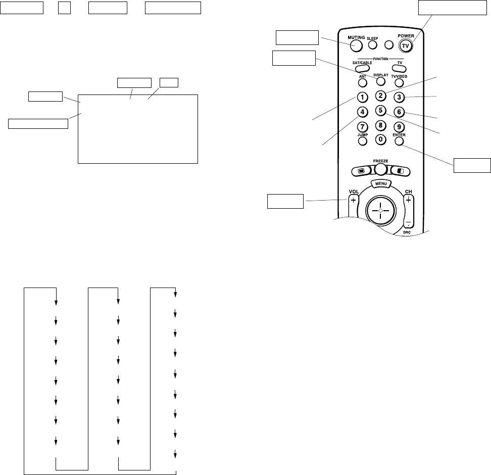
3-10.ELECTRICAL ADJUSTMENT BY REMOTE
COMMANDER
3. The SCREEN displays the item being adjusted.
4. Press 1 or 4 on the Remote Commander to select the
adjustment item.
5. Press 3 or 6 on the Remote Commander to change the data.
6. Press 2 or 5 on the Remote Commander to select the
category.
Every time you press 2(Category up), Service mode changes
in the order as shown below.
2. MEMORY WRITE CONFIRMATION METHOD
1. After adjustment, turn power off with the remote commander.
2. Turn power on and set to Service Mode.
3. Call the adjusted items again and confirm they were adjusted.
By using Remote Commander (RM-Y908/Y909K),all circuit
adjustments can be made.
NOTE : Test Equipment Required.
1. Pattern Generator (with component outputs)
2. Frequency counter
3. Digital multimeter
4. Audio oscillator
1. METHOD OF SETTING THE SERVICE ADJUSTMENT MODE
SERVICE MODE PROCEDURE
1. Standby mode. (Power off)
2. DISPLAY n 5 n VOL (+) n TV POWER
on the Remote Commander.
(Press each button within a second.)
SERVICE MODE ADJUSTMENT
3. ADJUSTING BUTTONS AND INDICATOR
3D-COMB
2103-1
2103-2
2150P-1
2150P-2
2150P-3
2150D-1
2150D-2
2150D-3
2151
AP
TRUS
OP
ID
DLBY
MID2
ID-1
2150P-4 MID1
CCD
PJE
SNNR
OSD
MID3
MID5
7. If you want to recover the latest values press - then [ENTER] to
read the memory.
8. Press [MUTING] then [ENTER] to write into memory.
9. Turn power off.
Note: Press 8 then [ENTER] on the Remote Commander to initialize
or turn set off and on to exit.
RM-Y908/Y909K
Note : When the PJE mode is activated, which displays an inter-
nally generated signal, several buttons on the remote
commander will have different functions than listed above.
Therefore, when in the PJE mode, refer to page 28 for
button functions.
MUTING
DISPLAY
Adjustment item up
ENTER
Data
WSL : XXX
0 0
3D-COMB
NRMD
F / A FLAG : XXXXXXXX
CBA FLAG : XXXXXXXX
SERVICE
TV
Item NO.
Adjustment Item
Category
Adjustment item down
VOL (+)
TV POWER ON
Category up
Data up
Data down
Category down
– 15 –
KP-HR432K90/HR532K90/HR532N90/HW572K90
RM-Y909KRM-Y908RM-Y909K RM-Y909K
4. SERVICE MODE LIST
3D-COMB uPD64082 ( ) :HW572K90
Reg.No & Name FUNCTION
UHF/VHF & Cvideo Svideo Note: * shows common data.
Standard Non-standard Standard Non-standard
0 NRMD Operation mode setting 0133
1 YAPS Y-output correction 3*
2 CLKS System clock setting 1*
UHF/VHF & Cvideo Svideo
Standard Non-standard Standard Non-standard
3 NSDS Selection for standard/non-standard signal processing 0000
4 MSS Selection for inter-frame/inter-line processing 0*
5 KILS Killer processing selection 1*
UHF/VHF CV/SV
6 CDL C-signal phase with respect to the Y-signal 33
NRMD=0 NRMD=1 NRMD=2 NRMD=3
7 DYCO DY detection coring level (Y motion detection coring) 2222
8 DYGA DY detection gain (Y motion detection gain) 10 10 10 10
9 DCCO DC detection coring level (C motion detection coring) 5555
10 DCGA DC detection gain ( C motion detection gain) 5555
11 YNRL Frame recursive YNR nonlinear filter limit level 1*
12 CNRL Frame recursive CNR nonlinear filter limit level 1*
UHF/VHF Video1-4 Video5&6
13 VTRH Hysteresis for Hsysnc non-standard signal detection 111
14 VTRR Sensitivity for Hsysnc non-standard signal detection 111
15 LDSR Sensitivity for frame non-standard signal detection 222
VM=off VM=Low VM=Mid VM=High
16 VAPG V-aperture compensation gain 0000
17 VAPI V-aperture compensation convergence point 0000
SNNR=0 SNNR=1 SNNR=2 SNNR=3
18 YPET Y peaking filter (BPF) center frequency 30000
19 YPFG Y peaking filter (BPF) gain 9 (8)0123
SNNR=0 SNNR=1 SNNR=2 SNNR=3
20 YHCO Y output high frequency component coring 0111 Note: YHCO & YHCG are defined directly by SNNR data.
21 YHCG Y output high frequency component coring gain 1111
22 HSSL Hsync slice level 12 *
23 VSSL Vsync slice level 8 *
24 ADCL ADC clock delay 3 *
NRMD=0 NRMD=1 NRMD=2 NRMD=3
25 D2GA Moving detection gain 4444
26 KILR Killer detection reference 3*
3D-COMB uPD64082
Reg.No & Name FUNCTION
27 OP Option: Selection of comb filter&recursive n.reduction types. 1*
UHF/VHF CVideo1 SVideo1 CVideo2 SVideo2 CVideo3 SVideo3 CVideo4
28 NR1 Noise reduction on/off 00101010
29 NR2 SNNR control on/off 0*
30 WSL Noise level detection level data 0-255 Read Data
31 HPLL H-PLL filter 1 *
32 BPLL Burst PLL filter 1 *
33 FSCF Burst extraction gain 0*
34 PLLF PLL loop gain 1 *
UHF/VHF Video1-4 Video5&6
35 CC3N Selection if a line-comb filter C separation filter characteristic 000
36 HDP Fine adjustment of the system H-phase 5*
37 BGPS Internal 4*
38 BGPW 10 *
39 TEST Test bit (0:Normal mode 1:Test mode) * forbidden setting 0*
40 WSC Amount of noise detection coring 1*
UHF/VHF & Video1-4 Video5&6
41 LIND DRC-M line-doubling setting for non-standard signals UHF/VHF&Video1-4 02
42 PFGO (YPFG offset at GR on) * Not used 3*
SNNR=0 SNNR=1 SNNR=2 SNNR=3
#16 VAPG 0000
Note: •shaded items are fixed. There is no need to change data. Others are different a little
in the sets individually. Basically, there is no need to change data, too.
– 16 –
KP-HR432K90/HR532K90/HR532N90/HW572K90
RM-Y909KRM-Y908RM-Y909K RM-Y909K
NTSC-YCT (Chroma Decoder) CXA2103-1 (Main) ( ) :HW572K90
Reg.No & Name FUNCTION
UV & Video YCbCr-480i
P&P Left P&P Left
(M)-DRC (M)-DRC
0 YLEV Y-Out gain 34 40
1 CLEV Cb&Cr-Out gain 27 46
UHF/VHF Video
2 SCON Sub contrast ADJ (7) ADJ (7)
3 SCOL Sub color ADJ (7) ADJ (7)
4 SHUE Sub hue ADJ (7) ADJ (7)
5 YDLY Y/C delay time 0 0
UHF/VHF Cvideo Svideo YCbCr480i SNNR=0 SNNR=1 SNNR=2 SNNR=3
6 SHAP Sharpness 6 (5)4440123
7 SHF0 Sharpness f0 selector 3333
8 PREO Sharpness pre/over-shoot ratio 3000
9 BPF0 Chroma band filter f0 setting 3000
10 BPFQ Chroma band filter Q setting 0333
11 BPSW Chroma bnad filter on/off 1000
12 TRAP Y block chroma trap filter on/off 0000
13 LPF Y Cb Cr-Output LPF on/off 1111
UHF/VHF Video YCbCr
14 AFCG AFC Loop gain (PLL between Hsync & HVCO) 100
15 CDMD V countdown system mode selector 333
16 SSMD H&Vsync slide level setting 000
17 HMSK Masking of macrovision signal on/off 111
18 HALI H automatic adjustment on/off 000
19 PPHA H TIM phase adjustment video 777
UV & Video YCbCr-480i
P&P Left P&P Left
(M)-DRC (M)-DRC
20 CBOF 34 34
21 CROF 32 32
P&P & Favorite P&P & Favorite
Single Picture UBLK-0 UBLK-1 UBLK-2 UBLK-3 UBLK-4 UBLK-5 UBLK-6 UBLK-7
22 ATPD Auto-pedestal Inflection Point P&P & Favorite UBLK=0 011211232
23 DCTR DC Transmission Ratio P&P & Favorite UBLK=0 021122223
NTSC-YCT (Chroma Decoder) CXA2103-2 (Sub) ( ) :HW572K90
Reg.No & Name FUNCTION
UV & Video
P&P Right P&P Right
(S) (S)-DRC
0 YLEV Y-Out gain 34 38
1 CLEV Cb&Cr-Out gain 27 31
UHF/VHF Video
2 SCON Sub contrast ADJ (7) ADJ (7)
3 SCOL Sub color ADJ (7) ADJ (7)
4 SHUE Sub hue ADJ (7) ADJ (7)
5 YDLY Y/C delay time 0 0
UHF/VHF Cvideo Svideo SNNR=0 SNNR=1 SNNR=2 SNNR=3
6 SHAP Sharpness 444 0123
7 SHF0 Sharpness f0 selector 333
8 PREO Sharpness pre/over-shoot ratio 3 (0) 0 0
9 BPF0 Chroma band filter f0 setting 000
10 BPFQ Chroma band filter Q setting 000
11 BPSW Chroma bnad filter on/off 000
12 TRAP Y block chroma trap filter on/off 000
13 LPF Y Cb Cr-Output LPF on/off 000
UHF/VHF Video
14 AFCG AFC Loop gain (PLL between Hsync & HVCO) 1 0 Note: Reg.No 14 to 19 are the same data as CXA2103-1. (the same NVM address)
15 CDMD V countdown system mode selector 33
16 SSMD H&Vsync slide level setting 00
17 HMSK Masking of macrovision signal on/off 11
18 HALI H automatic adjustment on/off 00
19 PPHA H TIM phase adjustment video 77
UV & Video YCbCr-480i
P&P Right P&P Right
(S)-DRC (S)-DRC
20 CBOF 32 32
21 CROF 31 31
P&P & Favorite P&P & Favorite
Single Picture UBLK-0 UBLK-1 UBLK-2 UBLK-3 UBLK-4 UBLK-5 UBLK-6 UBLK-7
22 ATPD Auto-pedestal Inflection Point P&P & Favorite UBLK=0 011211232
23 DCTR DC Transmission Ratio P&P & Favorite UBLK=0 021122223
Note: Reg.No 22 and 23 are the same data as CXA2103-1. (the same NVM address)
– 17 –
KP-HR432K90/HR532K90/HR532N90/HW572K90
RM-Y909KRM-Y908RM-Y909K RM-Y909K
CRT Driver CXA2150P-1 (Picture Controls:P1) ( ) :HW572K90
Reg.No & Name FUNCTION
UHF/VHF CV SV YCbCr480i YCbCr480P YCbCr1080i P&P
0 SBOT Offset for SBRT 0 000000
1 YOF Y OFFSET: DC-offset for Y signal 0000000
2 CBOF CB OFFSET: DC-offset for Cb signal 35 35 35 37 40 31 35
3 CROF CR OFFSET: DC-offset for Cr signal 36 36 36 39 41 31 36
4 SBRT SUB BRT: Sub Bright ADJ (24) *
5 RDRV R DRIVE: R output drive ADJ (31) *
6 GDRV G DRIVE: G output drive 41 (31) *
7 BDRV B DRIVE: B output drive ADJ (31) *
8 RCUT R CUTOFF: R output cutoff ADJ (31) *
9 GCUT G CUTOFF: G output cutoff 31 (63) *
10 BCUT B CUTOFF: B output cutoff ADJ (31) *
Vivid (Cool) Std (Neutral) Movie (Warm) Pro
11 WBSW WB SW 0 (no memory) 0 (no memory) 0 (no memory) 0 (no memory)
12 SBOF Offset for SBRT 63 63 (no memory) 63 63 (no memory)
13 RDOF Offset for RDRV 63 63 (no memory) 66 (65) 63 (no memory)
14 GDOF Offset for GDRV 63 63 (no memory) 63 63 (no memory)
15 BDOF Offset for BDRV 68 (66) 63 (no memory) 56 (54) 63 (no memory)
16 RCOF Offset for RCUT 63 (62) 63 (no memory) 64 (63) 63 (no memory)
17 GCOF Offset for GCUT 63 63 (no memory) 63 63 (no memory)
18 BCOF Offset for BCUT 64 (67) 63 (no memory) 63 (62) 63 (no memory)
CRT Driver CXA2150P-2 (Picture Controls:P2)
Reg.No & Name FUNCTION
0 ALBK PIC ON 1*
1 RGBS R ON/G ON/B ON : R/G/B outputs on/off 7*
2 BLKB BLK BTM: RGB output bottom limit level (Black level) 3*
3 LIML PLIMIT LEV: Threshold level for excessively high inputs 0*
4 PABL P ABL: DC-level in RGB output detection for PEAK ABL 15 *
5 SABL S ABL: S ABL gain 0*
6 AGNG AGING W/AGING B: AGING W/AGING B modes on/off 0*
7 AKBO AKBOFF: Automatic/Manual = Cut off setting 0*
UHF/VHF V1 _ 4
YCbCr480i YCbCr480P YCbCr1080i P&P
8 SYPH SYNC PHASE: Hsync delay with respect to Video (100%H-period) 00000
9 CLPH CLP PHASE: Internal clamp pulse phase (100%H-period) 33333
10 CLGA CLP GATE: Switch for the gated internal clamp pulse with Hsync 00000
11 JAXS JAXIS: color axis switch 0*
12 BLKO BLKO: Blanking switch 0*
CRT Driver CXA2150P-3 (Picture Controls:P3) (Part1) ( ) :HW572K90
Reg.No & Name FUNCTION Vivid
UHF/VHF CV SV YCbCr480i YCbCr480P YCbCr1080i P&P
0 SYSM SYSTEM: Signal bandwidth setting 1111122
1 UVML VM LEV: VM OUT level 3332233
2 VMMO System Micro pin#40 1111110
3 VMCR VM COR: VM OUT coring level 0001133
4 VMLM VM LMT: VM OUT limit level 3333333
5 VMF0 VM F0: VM f0 2 2 2 2222
6 VMDL VM DLY:VM OUT phase (defined by phase difference from R OUT) 2 (1)22221 (0)1
7 SHOF Offset for USHP=SHOF x 4 0 2 (1) 3 (2) 3 3 3
8 SHF0 SHP F0: Sharpness circuit f0 1111101
9 PROV PRE/OVER: Y signal pre/over-shoot ratio 1 (0) 0 0 0 (3) 2 (3) 0 (3) 0 (3)
10 F1LV SHP F1: Sharpness for higher f0 (4.2/5.6Mhz @NORMAL mode) 3 (0) 3 (0) 0 1 3 3
11 CDSP SHP CD: Sharpness in part of high color saturation 3333333
12 LTLV LTI LEV: Luminance transient improvement (LTI) 3333333
13 LTMD LTI MODE: LTI mode setting 0 (1) 0 (1)
2 (1)
3 (0)
0 (1) 0 (1) 0 1 (0) 1
14 CTLV CTI LEV: Chrominance transient improvement (CTI) 0000000
15 CTMD CTI MODE: CTI mode setting 0000000
16 UBOF Offset for UBRT (Picture clarity adjustment) 0 0 0 13 (0) 13 (7) 9 9 (7)
17 UCOF Offset for UCOL=UCOF x 2 (Picutre clarity adjustment) 3333302
18 UHOF Offset for UHUE (Picutre clarity adjustment) 0000000
19 MIDE MID enhancement setting 31515711
– 18 –
KP-HR432K90/HR532K90/HR532N90/HW572K90
RM-Y909KRM-Y908RM-Y909K RM-Y909K
CRT Driver CXA2150P-3 (Picture Controls:P3) (Part2) ( ) :HW572K90
Reg.No & Name FUNCTION Standard Movie Pro
UHF CV SV YCbCr YCbCr YCbCr P&P UHF CV SV YCbCr YCbCr YCbCr P&P UHF CV SV YCbCr YCbCr YCbCr P&P
VHF 480i 480P 1080i VHF 480i 480P 1080i VHF 480i 480P 1080i
#0 SYSM 111112211111221111122
#1 UVML 222223 (2)311111110000000
#2 VMMO 111111100000000000000
#3 VMCR 0113311111333333333
#4 VMLM 333333333333333333333
#5 VMF0 222222222222222222222
#6 VMDL 2222112 (1)2222112222211
#7 SHOF 1 1 (0) 1 (0) 2 (0) 23311111110000000
#8 SHF0 111111111111111111111
#9 PROV 0000033332233333 (2)3 3 (2)2
#10 F1LV 01333 (0)3 (0)3 (0) 3 (0)3 (0)3 (0)1233 1233
#11 CDSP 333333300000000000000
#12 LTLV 222222200000000000000
#13 LTMD 11111
11111
1 (0) 1111111 (0)1111111 (0)1
#14 CTLV 000000000000000000000
#15 CTMD 000000000000000000000
#16 UBOF 97
7 (10)7 (10)7 (10)7 (10)7 (10)7 (10)7 (10)7777777
#17 UCOF
00 (1)
2 (0)
1 (0)
3 (0)
0 (3)
3 (0) 3 (0)
77777
0000000000000000
#18 UHOF 000000000000000000000
#19 MIDE 2 14 14 6 10
--
113135 9
--
012124 8
--
CRT Driver CXA2150P-3 (Picture Controls:P3) (Part3)
Reg.No & Name FUNCTION
SNNR=0 SNNR=1 SNNR=2 SNNR=3
#1 UVML 0 0 0 0
#3 VMCR 0 +1 +2 +3
#10 F1LV 0 -1 -2 -3
#11 CDSP 0 0 0 0
#12 LTLV 0 0 0 0
#14 CTLV 0 0 0 0
#19 MIDE 0 0 0 0
CRT Driver CXA2150P-4 (Picture Controls:P4) ( ) :HW572K90
Reg.No & Name FUNCTION Vivid Standard Movie Pro
0 UPIC PICTURE: Picture 63 44 31 31
1 UBRT BRIGHT: Brightness 26 31 31 31
2 UCOL COLOR: 31 31 31 31
3 UHUE HUE:Hu 31 31 31 31
4 USHP SHARPNESS: Sharpness 32 40 31 31
5 UTMP Color Temperature (0:Warm 1:Neutral 2:Cool) 2101
6 UDCL DCOL: D 2200
UHF/VHF V1-4
YCbCr480i YCbCr480P YCbCr1080i P&P
7 AXIS COL AXIS: color matrix setting 00000
Picture Mode Vivid
UHF/VHF V1-4
YCbCr480i YCbCr480P YCbCr1080i P&P
8 UGAM GAMMA/GAMMA L: RGB output GAMMA correction setting 5 4 4 5 (1) 5
9 AGAM GAMMA/GAMMA L (AV Pro user control) - Void Data -
UGAM-0 UGAM-1 UGAM-2 UGAM-3 UGAM-4 UGAM-5 UGAM-6 UGAM-7
10 GSBO Offset for SBRT 0 0 0 0 0 0 0 0
11 GCCO Offset for UCOL 00000000
12 GHUO Offset for UHUE 0 0 000000
Picture Mode Vivid
UHF/VHF V1-4
YCbCr480i YCbCr480P YCbCr1080i P&P
13 UBLK Item#15-18 pack F1 data controls 7 (6)6664
14 ABLK (Av Pro user control) - Void Data
-
UBLK0 UBLK1 UBLK2 UBLK3 UBLK4 UBLK5 UBLK6 UBLK7
15 DCTR DC TRAN: Y signal DC transmission 111233 (2)33
16 DPIC DPIC LEV: Y signal AUTO PEDESTAL level 01211212
17 DSBO Offset for SBRT 7 7 7 7 7 7 7 7
18 ABLM ABL MODE: ABL mode 00000011
Full Vcomp 1 & 2
19 ABLT ABL TH: ABL current detection Vth contro 015
20 EPOF Offset for UPIC=EPOF x (UPIC/63) (for power save) - Void Data
21 SPOF Offset for UPIC=SPOF x (UPIC/64) - Data Not used 15 << Only available at Vcomp 1 & 2.
UHF/VHF V1-4
YCbCr480i YCbCr480P YCbCr1080i P&P
22 SCON SUB CONTRAST: SUB PICTURE 12 (8) 9 (8) 9 (8) 8 (7) 8 (7)
23 CLOF Offset for UCOL 9 9 9 9 9
24 HUOF Offset for UHUE 55555
25 IDSW Not used
Full Vcomp1 Vcomp2
26* DATA* Display of vertical compression modes. 012
Note: Full : 4:3*EXCEPT HW572K90
Vcomp1 : 480p/960i, 16:9
Vcomp2 : 1080i, 16:9
– 19 –
KP-HR432K90/HR532K90/HR532N90/HW572K90
RM-Y909KRM-Y908RM-Y909K RM-Y909K
CRT Driver CXA2150P-4 (Picture Controls:P4) ( ) :HW572K90
Reg.No & Name FUNCTION
SNNR SNNR SNNR SNNR
=0 =1 =2 =3
#4 USHP 0134
Picture Mode : Standard Picture Mode : Movie Picture Mode : Pro
UHF YCbCr YCbCr YCbCr P&P UHF YCbCr YCbCr YCbCr P&P UHF YCbCr YCbCr YCbCr P&P
VHF 480i 480P 1080i VHF 480i 480P 1080i VHF 480i 480P 1080i
V1 _ 4 V1 _ 4 V1 _ 4
#8 UGAM 222110000000000
Picture Mode : Standard Picture Mode : Movie Picture Mode : Pro
UHF YCbCr YCbCr YCbCr P&P UHF YCbCr YCbCr YCbCr P&P UHF YCbCr YCbCr YCbCr P&P
VHF 480i 480P 1080i VHF 480i 480P 1080i VHF 480i 480P 1080i
V1 _ 4 V1 _ 4 V1 _ 4
#13 UBLK 3 33332 (1)0 (1)0 (1)0 (1)0 (1)2 (0)0000
CRT Driver CXA2150D-1 (Deflection Controls:D1)
Reg.No & Name FUNCTION
Full Zoom WideZoom
0 VPOS V POSITION: Vertical position (V DRV signal DC bias)
1 VSIZ V SIZE: Vertical size (V DRV signal gain) ADJ (50)
7
ADJ (27)
2 VSZO V SIZE OFFSET 0
3 VLIN V LINEARITY: Vertical linearity
4 VSCO S CORRECTION: Vertical S-correction 9999
5 VCEN VSAW0 DCH/VSAW0 DCL: Vertical center adjustment 31
6 VPIN VSAW0 AMP: Vertical PIN adjustment 15
7 NSCO VSAW1 DC: Rotation 7
8 HTPZ VSAW1 AMP: Horizontal trapezoid 15
9 ZOOM ZOOM SW: Zoom switch 00
10 APSW ASP SW: Aspect switch 0
11 ASPT V ASPECT: Aspect ratio 0
12 SCRL V SCROLL: Vertical scroll 29
0
0
29
0
0
29
13 UVLN UP VLIN: Upper vertical linearty 00
14 LVLN LO VLIN: lower vertical linearty 0
1
0
44
29
0
0
1
0
22
29
5
50
1080i
ADJ (27)
CRT Driver CXA2150D-2 (Deflection Controls:D2)
Reg.No & Name FUNCTION
Full/Normal Zoom WideZoom
0 HCNT HC PARA DC: Horizontal center
1 HPOS H POSTION: Horizontal position 25
19
2 HSIZ H SIZE: Horisontal size ADJ(35) ADJ(35)
3 SLIN MP PARA DC: Horizontal S-correction ADJ(3) ADJ(3)
4 MPIN MP PARA AMP: Horizontal middle pin 00
5 PIN PIN AMP: Horizontal pin 10 10
6 PIN0 7777
7 UCP UP CPIN: Upper corner pin 31 31
8 LCP LO CPIN: Lower corner pin 31 31
9 UXCG UP UCG: Upper extra corner pin gain 00
10 LXCG LO UCG: Lower extra corner pin gain 00
11 UXCP UP UCP: Upper extra corner pin position 22
12 LXCP LO UCP: Lower extra corner pin position 22
13 XCPP UC POL: Extra corner pin polarity 00
14 PPHA PIN PHASE: Pin phase
15 VANG AFC ANGLE: AFC angle
31
31
33
48
16 LANG HC PARA PHASE: Linearity angle
17 VBOW AFC BOW: AFC bow 31
18 LBOW HC PARA AMP: Linearity bow
19 CPY1 Copy function 1: (Set CPY1=1, then press MUTE+Enter) * Not used
1080i
0
Normal
HW572K90
HW572K90 EXCEPT HW572K90
EXCEPT HW572K90
Full Vcomp1 Vcomp2
ADJ (50)
ADJ (35)
ADJ (31)
0
5
8
31
15 15
7
15
00
010
44 32 28
29 29 29
00
00
Full Vcomp1 Vcomp2
19 19
25
3
7
10
7
31
31
0
0
2
2
0
31
31
31 33
31
39 63
0
– 20 –
KP-HR432K90/HR532K90/HR532N90/HW572K90
RM-Y909KRM-Y908RM-Y909K RM-Y909K
Audio Processor (AP) BH3868FS
Reg.No & Name FUNCTION
0 SVOL Volume:Offset for Volume
1 SBAL Balance Offset for Balance
2 SBAS Bass:Offset for Bass
3 STRE Treble:Offset for Treble
4 BBLP BBE low pass filter
5 BBHP BBE high pass filter
6 SREF Surround effect
7 AGC Auto gain control
8 BBE BBE on/off
TruSurround (TRUS) NJM2180
Reg.No & Name FUNCTION
1 TSMD Trusurround effect selection 2
DLBY NJM1106 (HW572K90)
Reg.No & Name FUNCTION
0 DBMD 0
1 SCH 0
2 ADSW 0
3 CECH 0
4 DELY 7
5 SSEL 0
0 ATT 0
HW572K90
0
7
10
7
0
2
11
0
0
0
7
7
7
0
2
11
0
0
EXCEPT HW572K90
CRT Driver CXA2150D-3 (Deflection Controls:D3)
Reg.No & Name FUNCTION
0 HBLK HBLK SW: Horizontal blanking switch
1 LBLK LEFT BLK: Left blanking
2 RBLK RIGHT BLK: Right blanking
3 VBLK VBLK SW: Vertical blanking switch
4 TBLK UP BLK: Top blanking
5 BBLK LO BLK: Bottom blanking
6 VCMP V COMP: Vertical compensation
7 HCMP H COMP: Horizontal compensation
8 ACMP AFC COMP: AFC compensation
9 PCMP PIN COMP: Pin compensation
10 AFCM AFC MODE: AFC compensation
11 VFRQ V FREQ: Vertical frequency
12 VON V ON: Vertical drive on
13 JUMP JMP SW: Reference pulse jump switch
14 VDJP VDRV SW: Vertical drive switch
15 VDST RST SW: Vertical drive start switch
16 EWDC EW DC: Pin DC level shift
17 AKBT AKBTIM: AKB timing
Component I/F & Sync Separation CXA2151
Reg.No & Name FUNCTION
480i 480P 1080i 720P
15.75khz 31.50khz 33.75khz 45khz
0 MTRX MAT OUT 0011
1 GAIN GAIN SEL 0
2 CBGN CBGAIN 9
3 VTC V TC 1
4 HWID H WIDTH 1
Video5 Video6 Sub
5 HSEP HSEP SEL 000
6 TEST TEST 0
7 FRGB 0
8 HMSK Hsync masking in vertical retrace
Full Zoom WideZoom1080i
5656
2525
100
15 15 154
15 15 155
0
15
15
0000
000
000
000
32
111
000
1
0
9
1
0
9999
1080i ELSE
10
Normal
1
1
0
0
0
1
1
0
0
Full Vcomp1 Vcomp2
1
56 56
25 25
11
EXCEPT HW572K90HW572K90
EXCEPT HW572K90HW572K90
15 14 12
15 15 13
033
00
00
00
32
1
1
01
111
000
00
999
480i 480P 1080i 720P
15.75khz 31.50khz 33.75khz 45khz
0011
0
9
1
1
Video5 Video6 Sub
000
0
0
Full Vcomp1 Vcomp2
10
– 21 –
KP-HR432K90/HR532K90/HR532N90/HW572K90
RM-Y909KRM-Y908RM-Y909K RM-Y909K
MID-1 (Display Data : Output) (EXCEPT HW572K90)
Reg.No & Name FUNCTION
(A) Display Data (Only One) (for 4:3)
0 DHPH H active display area phase 110
1 DVPH V active display area phase 20
2 DHAR H active display area size 240
3 DVAR V active display area size 135
4 DHPW display H pulse width 55
5 DVPW display V pulse width 5
22 DPSW display PLL switch 1 (fixed)
23 MDL model select (16:9/4:3) 1
(B) Misc. Common Data Data
6 DYCD display output Y-C delay correction 2
7 DYSD display output YS signal delay select 1
(C) Favorite / Other Favorite Others
8 MDHP main display picture H position 90
10 MDHS main display picture H size 160 240
(D) Single (Input Signal Format) / Favorite Single 480i/480P Single 720P Favorite
9 MDVP main display picture V position 30 30 27
11 MDVS main display picture V size 120 120 81
(E) Index / Others Index Others
12 MLHP multi picture mode H position 32 36
13 MLVP multi picture mode V position 47 31
(F) Favorite Favorite
14 SDHS sub display picture H position 171
15 SDVS sub display picture V position 27
(G) Favorite Favorite
16 SDHS sub display picture H size 59
17 SDVS sub display picture V size 29
(H) PinP Position (Not Used)
18 PDHP (PinP Large mode H position)
-
19 PDVS (PinP Large mode V position)
-
(I) PinP Size (Not Used)
20 PDHS (PinP Large mode H size)
-
21 PDVS (PinP Large mode V size)
-
(J) Single / Others Single Others
24 BCOL Background Y level 05
MID-1 (Display Data : Output)(HW572K90)
Reg.No & Name FUNCTION
(A) Display Data (Only One)
0 DHPH H active display area phase 110
1 DVPH V active display area phase 20
2 DHAR H active display area size 240
3 DVAR V active display area size 135
4 DHPW display H pulse width 55
5 DVPW display V pulse width 5
22 DPSW display PLL switch 1 (fixed)
23 MDL model select (16:9/4:3) 0
(B) Misc. Common Data Data
6 DYCD display output Y-C delay correction 2
7 DYSD display output YS signal delay select 1
(C) Favorite / Other Favorite Others
8 MDHP main display picture H position 90
10 MDHS main display picture H size 149 240
(D) Single (Input Signal Format) / Favorite Single 480i/480P Single 720P Favorite
9 MDVP main display picture V position 30 30 20
11 MDVS main display picture V size 120 120 97
(E) Index / Others Index Others
12 MLHP multi picture mode H position 36 36
13 MLVP multi picture mode V position 31 31
(F) Favorite Favorite
14 SDHS sub display picture H position 166
15 SDVS sub display picture V position 20
(G) Favorite Favorite
16 SDHS sub display picture H size 44
17 SDVS sub display picture V size 29
(H) PinP Position (Not Used)
18 PDHP (PinP Large mode H position)
-
19 PDVS (PinP Large mode V position)
-
(I) PinP Size (Not Used)
20 PDHS (PinP Large mode H size)
-
21 PDVS (PinP Large mode V size)
-
(J) Single / Others Single Others
24 BCOL Background Y level 55
Normal
154
162
– 22 –
KP-HR432K90/HR532K90/HR532N90/HW572K90
RM-Y909KRM-Y908RM-Y909K RM-Y909K
MID-2 (Active Data for DRC : INPUT)(EXCEPT HW572K90)
Reg.No & Name FUNCTION
(A) MID Mode, Wide mode, Input Signal Format Single
RF, Video, YC YPbPr
0 DRHP DRC H active area position 111 110
1 DRHS DRC H active area size 178 178
2 DRVP DRC V active area position 37 37
3 DRVS DRC V active area size 120 120
Twin, Favorite Memo
RF, Video, YC YPbPr RF, Video, YC YPbPr
0 DRHP DRC H active area position 132 131 142 141
1 DRHS DRC H active area size 166 166 162 162
2 DRVP DRC V active area position 54 54 58 58
3 DRVS DRC V active area size 112 112 110 110
Index Twin-Right Index-Small
RF, Video, YC YPbPr RF, Video, YC RF
0 DRHP DRC H active area position 139 138 138 143
1 DRHS DRC H active area size 164 164 166 162
2 DRVP DRC V active area position 50 50 54 54
3 DRVS DRC V active area size 114 114 112 112
MID-2 (Active Data for DRC : INPUT)(HW572K90)
Reg.No & Name FUNCTION
(A) MID Mode, Wide mode, Input Signal Format Single(Normal)
RF, Video, YC YPbPr
0 DRHP DRC H active area position 142 141
1 DRHS DRC H active area size 162 162
2 DRVP DRC V active area position 37 37
3 DRVS DRC V active area size 120 120
Single(Other)
RF, Video, YC YPbPr
111 110
178 178
37 37
120 120
Twin, Favorite Memo
RF, Video, YC YPbPr RF, Video, YC YPbPr
0 DRHP DRC H active area position 132 131 142 141
1 DRHS DRC H active area size 166 166 162 162
2 DRVP DRC V active area position 54 54 58 58
3 DRVS DRC V active area size 112 112 110 110
Index Twin-Right Index-Small
RF, Video, YC YPbPr RF, Video, YC RF
0 DRHP DRC H active area position 139 138 138 143
1 DRHS DRC H active area size 164 164 166 162
2 DRVP DRC V active area position 50 50 54 54
3 DRVS DRC V active area size 114 114 112 112
– 23 –
KP-HR432K90/HR532K90/HR532N90/HW572K90
RM-Y909KRM-Y908RM-Y909K RM-Y909K
MID-3 (Active Data for A/D (VDO) : INPUT)
Reg.No & Name FUNCTION
(A) MID mode, Wide mode, Input Signal Format Single
480P 720P YPbPr No Signal
0 VDHP VDO H active area position 109 95 205
1 VDHS VDO H active area pixel size 166 108 226
2 VDVE VDO V active area even position 37 24 37
3 VDVS VDO V active area line size 120 180 56
Twin, Favorite Twin-Right
480P 1080i 720P YPbPr No Signal RF, Video, S-Video
0 VDHP VDO H active area position 128 94 111 179 197
1 VDHS VDO H active area pixel size 155 150 99 199 215
2 VDVE VDO V active area even position 53 37 50 24 26
3 VDVS VDO V active area line size 112 126 168 56 56
Memo
480P 1080i 720P YPbPr No Signal
0 VDHP VDO H active area position 136 102 115 179
1 VDHS VDO H active area pixel size 152 147 98 199
2 VDVE VDO V active area even position 57 44 58 24
3 VDVS VDO V active area line size 110 123 164 56
Index Index-Small
480P 1080i 720P YPbPr No Signal RF
0 VDHP VDO H active area position 132 99 112 166 204
1 VDHS VDO H active area pixel size 154 149 99 187 211
2 VDVE VDO V active area even position 51 34 48 24 26
3 VDVS VDO V active area line size 113 128 169 56 56
(B) Input Signal Format
RF, Video, S-Video, YPbPr 480i 480P 1080i 720P
4 VDVO VDO V active area line size 0 000
5 VCPO VDO V active area odd position 95 70 40 40
6 VCWD VDO clamp pulse output timing 3 333
7 VYCD VDO clamp pulse width 0 000
8 VSTP VDO PLL phase ditect stop line count
-
119 160 146
9 VSTT VDO PLL phase ditect start line count
-
400
10 VHSC VDO H sync cycle 130
---
MID-5 (Picture Data) (A) Enhance Table Data Setting ( ) :HW572K90
0 P-OP Table select 01234567
1 MHLY Main H LPF Y Coefficient select 11111111
2 MHLC Main H LPF C Coefficient select 33333333
3 MVLY Main V LPF Y Coefficient select 00000000
4 MVLC Main V LPF C Coefficient select 00000000
5 MHYR Main H Enhance. Y Coreing level 0 (1)0 (1)1 (2)10001
6 MHYL Main H Enhance. Y Clip level 11111111
7 MHYE Main H Enhance. Y Enhancement level 77337735
8 MHYO Main H Enhance. Y Coefficient select 11111111
9 MHCR Main H Enhance. C Coreing level 00000000
10 MHCL Main H Enhance. C Clip level 11111111
11 MHCE Main H Enhance. C Enhancement level 00000000
12 MHCO Main H Enhance. C Coefficient select 11111111
13 MVYR Main V Enhance. Y Coreing level 00220022
14 MVYL Main V Enhance. Y Clip level 11111111
15 MVYE Main V Enhance. Y Enhancement level 00250025
16 MVCR Main V Enhance. C Coreing level 00000000
17 MVCL Main V Enhance. C Clip level 11111111
18 MVCE Main V Enhance. C Enhancement level 00000000
0 P-OP Table select 8 9 10 11 12 13 14 15
1 MHLY Main H LPF Y Coefficient select 00001111
2 MHLC Main H LPF C Coefficient select 33333333
3 MVLY Main V LPF Y Coefficient select 00000000
4 MVLC Main V LPF C Coefficient select 00000000
5 MHYR Main H Enhance. Y Coreing level 00010001
6 MHYL Main H Enhance. Y Clip level 11111111
7 MHYE Main H Enhance. Y Enhancement level 77357733
8 MHYO Main H Enhance. Y Coefficient select 11111111
9 MHCR Main H Enhance. C Coreing level 00000000
10 MHCL Main H Enhance. C Clip level 11111111
11 MHCE Main H Enhance. C Enhancement level 00000000
12 MHCO Main H Enhance. C Coefficient select 11111111
13 MVYR Main V Enhance. Y Coreing level 00220022
14 MVYL Main V Enhance. Y Clip level 11111111
15 MVYE Main V Enhance. Y Enhancement level 00250025
16 MVCR Main V Enhance. C Coreing level 00000000
17 MVCL Main V Enhance. C Clip level 11111111
18 MVCE Main V Enhance. C Enhancement level 00000000
* No.19
-
No.36 data is all “0” not to use.
– 24 –
KP-HR432K90/HR532K90/HR532N90/HW572K90
RM-Y909KRM-Y908RM-Y909K RM-Y909K
On-Screen Display (OSD)
Reg.No & Name FUNCTION
0 HPOS OSD horizontal position 14
1 HPOF Horizontal position for Favorite mode 37
2 VPOS OSD vertical position 4
3 VPOT Vertical position for P&P (Twin) mode 40
SNNR
Reg.No & Name FUNCTION
0 SNNR SNNR data setting 0123
1 SNFX Selection of SNNR data setting 0
2 WSLT Noise level detection data thresholds for SNNR data (read data) 0 -30 31 -62 63 -126 127 -255
SNNR Settings based on WSL Data
SNNR=0/1/2/3 0123
SNNR data is used for the (-) offset setting.
3 CPFG Related to 3D-COMB (upD64802) / #19 YPFG settings 0123
4 CPFT Related to 3D-COMB (upD64802) / #18 YPFT settings 0000
SNNR data is used for the direct setting.
5 CCOR Related to 3D-COMB (upD64802) / #20 VHCO settings 0111
6 CHCG Related to 3D-COMB (upD64802) / #21 VHCG settings 1111
7 CAPG Related to 3D-COMB (upD64802) / #16 VAPG settings 0000
8 3SHP Related to CXA2103 / #6 SHAP settings 0123
9 MIDD Related to CXA2150P-3 / #19 MIDE settings 0000
10 5SHP Related to CXA2150P-4 / #4 USHP settings 0134
SNNR data is used for the (-) offset setting.
11 5YF1 Related to CXA2150P-3 / #10 F1LV settings 0123
12 5CDS Related to CXA2150P-3 / #11 CDSP settings 0000
13 5LTI Related to CXA2150P-3 / #12 LTLV settings 0000
14 5CTI Related to CXA2150P-3 / #14 CTLV settings 0000
15 5VML Related to CXA2150P-3 / #1 UVML settings 0000
16 5VMC Related to CXA2150P-3 / #3 VMCR settings 0123
SNNR data is used for the (+) offset setting.
ID-1 Detection
Reg.No & Name FUNCTION
0 XJGL XJGLK: Setting for memorizing or not the ID-1 detection status 0
1 LNJI LNJI: Setting for the multi/single-line ID-1 detection 0
Closed Caption Display & Parental Control (CCD&VCHIP)
Reg.No & Name FUNCTION
0 HPRM Horizontal position of CCD (Main) 49
1 HPRS Horizontal position of CCD (Sub) 49
2 RND OSD rounding control 1
3 CCDI Interruption control 3
4 CRIP CRI count & parity count 4
5 CRIT Charge/Discharge timing control for slice voltage level 0
6 CHMK Horizontal mask width 42
7 FPOL Field polarity selection 1
8 LANG 0
9 DATA Swwitch for CCD service/test data 0
10 VCHIP Selection of Vchip controls 1
OPTIONS
Reg.No & Name FUNCTION
0 DLY1 Power-On to RLY timing = DLY1 x 50ms 2
1 DLY2 Power-On Mute timing = DLY2 x 50ms 12
2 DLY3 Relay-On to start Bus communication 12
3 AGC 255
4 PCMX 63
5 BRMX 63
6* RAMW* 0
ID
Reg.No & Name FUNCTION
0 ID0 Selection of OSD languages & color system *1
1 ID1 Selection of composite & s-video inputs 127
2 ID2 Selection of audio-related controls 239
3 ID3 Selection of basic system settings 66
4 ID4 Selection of basic system settings 203
5 ID5 Selection of advanced system settings 177
6 ID6 Selection of sub picture related sesttings 54
7 ID7 Selection of some reserved settings 24
*HW572K90
*1 HR432K90, HR532K90, HW572K90:217
HR532N90:89
– 25 –
KP-HR432K90/HR532K90/HR532N90/HW572K90
RM-Y909KRM-Y908RM-Y909K RM-Y909K
PJ Engine (EXCEPT HW572K90)
ITEM ITEM Contents min max init (4:3)
No. Name Normal V.Comp HD
0 FDIS Switch of display for fine adjustment data 01
-
1 COPY Service copy adjustment 01
-
2 ALCP Service all copy adjustment 01
-
3 OSDH Osd horizontal position of PJED service menu 1 255 22
4 OSDV Osd vertical position of PJED service menu 1 255 100 100 100
5 FVSL Start position of fine adjustment 015011
6 FVSP Start line of fine adjustment 0 255 3 25 73
7 V1DL Value of V1 delay 0 255 1 1 1
8 V1CU Value of V1 count up 0 4095 454 337 292
9 V1OH Value of V1 offset upper data 0 255 5 134 185
10 V1OL Value of V1 offset lower data 0 255 0 0 0
11 OEVP Odd/Even select position 0 4095 1056
12 COHP Horizontal phase for rough adjustment 0 4095 0
13 34CS Start center clamp position of H3 and H4 pulse 031 14
14 34CW Width center clamp position of H3 and H4 pulse 031 0
15 FIHP Horizontal phase for fine adjustment 0 4095 1082
16 TPHP Horizontal phase for test pattern 0 4095 66
17 TPVP Vertical phase for test pattern 0 255 55 53 17
18 DFHP Horizontal phase for dynamic focus 0 4095 270
19 DFHG Value of horizontal parabola wave for dynamic focus -128 127 -65 -65 -65
20 DFVG Value of vertical parabola wave for dynamic focus -128 127 -90 -90 -90
21 DFDC Value of center for dynamic focus -128 127 127 127 127
22 DFV1 Value of V1 saw wave for dynamic focus -128 127 -50 -50 -50
23 SDHP Compensation of horizontal phase for shading 0 4095 444
24 SDH1 Value of horizontal saw wave for dynamic focus -128 127 63 127 127
25 RVCS Start position of Red vertical clamp 031 0
26 RVCW Width of Red vertical clamp 031 0
27 GVCS Start position of Green vertical clamp 031 0
28 GVCW Width of Green vertical clamp 031 0
29 BVCS Start position of Blue vertical clamp 031 0
30 BVCW Width of Blue vertical clamp 031 0
31 RHCS Start position of Red horizontal clamp 031 0
32 RHCW Width of Red horizontal clamp 031 0
PJ Engine (EXCEPT HW572K90)
ITEM ITEM Contents min
max init (4:3)
No. Name Normal V.Comp HD
33 GHCS Start position of Green horizontal clamp 031 0
34 GHCW Width of Green horizontal clamp 031 0
35 BHCS Start position of Blue horizontal clamp 031 0
36 BHCW Width of Blue horizontal clamp 031 0
37 BDVU Vartical positioni for boder line 1 0 2047 23 1 1
38 BDVL Vartical positioni for boder line 2 0 2047 905 935 1079
39 BDHL Horizontal position for boder line 1 0 2047 148
40 BDHR Horizontal position for boder line 2 0 2047 1262
41 HBLD Horizontal phase for output of H.Blank out 0 4095 0
42 HBLW Width for output of H.Blank out 0 4095 0
43 PWM2 PWM2 output width setting of Regi IC 0 4095 43:500 53:345
44 COGV Green vertical center offset data for Auto Regi. -128 127
-
45 CORV Red vertical center offset data for Auto Regi. -128 127
-
46 COBV Blue vertical center offset data for Auto Regi. -128 127
-
47 COGH Green horizontal center offset data for Auto Regi. -128 127
-
48 CORH Red horizontal center offset data for Auto Regi. -128 127
-
49 COBH Blue horizontal center offset data for Auto Regi. -128 127
-
50 SOGV Green vertical skew offset data for Auto Regi. -128 127
-
51 SORV Red vertical skew offset data for Auto Regi. -128 127
-
52 SOBV Blue vertical skew offset data for Auto Regi. -128 127
-
53 SOGH Green horizontal skew offset data for Auto Regi. -128 127
-
54 SORH Red horizontal skew offset data for Auto Regi. -128 127
-
55 SOBH Blue horizontal skew offset data for Auto Regi. -128 127
-
56 ZOGH Green horizontal size offset data for Auto Regi. -128 127
-
57 ZORH Red horizontal size offset data for Auto Regi. -128 127
-
58 ZOBH Blue horizontal size offset data for Auto Regi. -128 127
-
59 LOGH Green horizontal linearity offset data for Auto Regi. -128 127
-
60 LORH Red horizontal linearity offset data for Auto Regi. -128 127
-
61 LOBH Blue horizontal linearity offset data for Auto Regi. -128 127
-
62 ERR Auto Regi. Error code 0
--
63 ADTM A/D data input timing of Auto Regi. 0 127 43:144 53:144
64 VUP Auto Regi. Pattern Upper vertical position 0 2047 43:50 53:50
65 VUPM Auto Regi. Pattern Upper middle vertical position 0 2047 0
66 VMID Auto Regi. Pattern Middle vertical position 0 2047 43:515 53:515
PJ Engine (EXCEPT HW572K90)
ITEM ITEM Contents min
max init (4:3)
No. Name
Normal V.Comp HD
67 VLOM Auto Regi. Pattern Lower middle vertical position 0 2047 0
68 VLOW Auto Regi. Pattern Lower vertical position 0 2047 43:975 53:975
69 HLB Auto Regi. Pattern left horizontal position 0 4095 43:90 53:90
70 HLBM Auto Regi. Pattern left middle horizontal position 0 4095 0
71 HMID Auto Regi. Pattern middle horizontal position 0 4095 43:655 53:655
72 HRIM Auto Regi. Pattern right middle horizontal position 0 4095 0
73 HRIV Auto Regi. Pattern right horizontal position 0 4095 43:1220 53:1220
74 SFTF Switch of shift fast 01 0
75 ACTL Acount timer counter lower byte 0
-
0
76 ACTH Acount timer counter upper byte 0
-
0
77 SLSW Auto Regi adjustment item select 0 3 43:3 53:3
min
max 4:3
Green Blue Red
78 CENT -512 511 ADJ +35, +20
79 SKEW -512 511 ADJ 0, 0 ADJ 0, 0 ADJ 0, 0
80 SIZE -512 511 ADJ -100, -75
ADJ +35, +20
ADJ -100, -75
ADJ +35, +20
ADJ -100, -75
81 LIN -512 511 ADJ 0, 0 ADJ -410, 0 ADJ 410, 0
82 KEY -512 511 ADJ x, 0 ADJ x, -120 ADJ x, 120
83 PIN -512 511 ADJ 0, 320 ADJ 0, 300 ADJ 0, 300
84 MLIN -512 511 ADJ 0, x ADJ 145, x ADJ -145, x
85 MSIZ -512 511 ADJ 0, x ADJ 100, x ADJ 100, x
Note: 4:3 has Normal, V.Comp, HD separately
– 26 –
KP-HR432K90/HR532K90/HR532N90/HW572K90
RM-Y909KRM-Y908RM-Y909K RM-Y909K
PJ Engine (HW572K90)
ITEM ITEM Contents min max init (16:9)
No. Name Normal Zoom W Zoom HD
0 FDIS Switch of display for fine adjustment data 01
-
1 COPY Service copy adjustment 01
-
2 ALCP Service all copy adjustment 01
-
3 OSDH Osd horizontal position of PJED service menu 1 255 22
4 OSDV Osd vertical position of PJED service menu 1 255 100 120 100 60
5 FVSL Start position of fine adjustment 0 15 0 14 15 0
6 FVSP Start line of fine adjustment 02553 212553
7 V1DL Value of V1 delay 0 255 1 139 60 1
8 V1CU Value of V1 count up 0 4095 454 598 506 387
9 V1OH Value of V1 offset upper data 0 255 5 5 5 79
10 V1OL Value of V1 offset lower data 02550000
11 OEVP Odd/Even select position 0 4095 1056
12 COHP Horizontal phase for rough adjustment 0 4095 0
13 34CS Start center clamp position of H3 and H4 pulse 031 14
14 34CW Width center clamp position of H3 and H4 pulse 031 0
15 FIHP Horizontal phase for fine adjustment 0 4095 1104
16 TPHP Horizontal phase for test pattern 0 4095 69
17 TPVP Vertical phase for test pattern 0 255 55 111 79 15
18 DFHP Horizontal phase for dynamic focus 0 4095 250
19 DFHG Value of horizontal parabola wave for dynamic focus -128 127 -70 -70 -70 -70
20 DFVG Value of vertical parabola wave for dynamic focus -128 127 -50 -50 -50 -50
21 DFDC Value of center for dynamic focus -128 127 127 127 127 127
22 DFV1 Value of V1 saw wave for dynamic focus -128 127 -50 -50 -50 -50
23 SDHP Compensation of horizontal phase for shading 0 4095 422
24 SDH1 Value of horizontal saw wave for dynamic focus -128 127 127 127 127 127
25 RVCS Start position of Red vertical clamp 031 0
26 RVCW Width of Red vertical clamp 031 0
27 GVCS Start position of Green vertical clamp 031 0
28 GVCW Width of Green vertical clamp 031 0
29 BVCS Start position of Blue vertical clamp 031 0
30 BVCW Width of Blue vertical clamp 031 0
31 RHCS Start position of Red horizontal clamp 031 0
32 RHCW Width of Red horizontal clamp 031 0
PJ Engine (HW572K90)
ITEM ITEM Contents min
max init (16:9)
No. Name Normal Zoom W Zoom HD
33 GHCS Start position of Green horizontal clamp 031 0
34 GHCW Width of Green horizontal clamp 031 0
35 BHCS Start position of Blue horizontal clamp 031 0
36 BHCW Width of Blue horizontal clamp 031 0
37 BDVU Vartical positioni for boder line 1 0 2047 28 21 12 49
38 BDVL Vartical positioni for boder line 2 0 2047 900 683 820 1039
39 BDHL Horizontal position for boder line 1 0 2047 148
40 BDHR Horizontal position for boder line 2 0 2047 1262
41 HBLD Horizontal phase for output of H.Blank out 0 4095 0
42 HBLW Width for output of H.Blank out 0 4095 0
43 PWM2 PWM2 output width setting of Regi IC 0 4095 730
44 COGV Green vertical center offset data for Auto Regi. -128 127
-
45 CORV Red vertical center offset data for Auto Regi. -128 127
-
46 COBV Blue vertical center offset data for Auto Regi. -128 127
-
47 COGH Green horizontal center offset data for Auto Regi. -128 127
-
48 CORH Red horizontal center offset data for Auto Regi. -128 127
-
49 COBH Blue horizontal center offset data for Auto Regi. -128 127
-
50 SOGV Green vertical skew offset data for Auto Regi. -128 127
-
51 SORV Red vertical skew offset data for Auto Regi. -128 127
-
52 SOBV Blue vertical skew offset data for Auto Regi. -128 127
-
53 SOGH Green horizontal skew offset data for Auto Regi. -128 127
-
54 SORH Red horizontal skew offset data for Auto Regi. -128 127
-
55 SOBH Blue horizontal skew offset data for Auto Regi. -128 127
-
56 ZOGH Green horizontal size offset data for Auto Regi. -128 127
-
57 ZORH Red horizontal size offset data for Auto Regi. -128 127
-
58 ZOBH Blue horizontal size offset data for Auto Regi. -128 127
-
59 LOGH Green horizontal linearity offset data for Auto Regi. -128 127
-
60 LORH Red horizontal linearity offset data for Auto Regi. -128 127
-
61 LOBH Blue horizontal linearity offset data for Auto Regi. -128 127
-
62 ERR Auto Regi. Error code 0
--
63 ADTM A/D data input timing of Auto Regi. 0 127 144
64 VUP Auto Regi. Pattern Upper vertical position 0 2047 50
65 VUPM Auto Regi. Pattern Upper middle vertical position 0 2047 0
66 VMID Auto Regi. Pattern Middle vertical position 0 2047 512
PJ Engine (HW572K90)
ITEM ITEM Contents min max init (16:9)
No. Name Normal Zoom W Zoom HD
67 VLOM Auto Regi. Pattern Lower middle vertical position 0 2047 0
68 VLOW Auto Regi. Pattern Lower vertical position 0 2047 975
69 HLB Auto Regi. Pattern left horizontal position 0 4095 90
70 HLBM Auto Regi. Pattern left middle horizontal position 0 4095 0
71 HMID Auto Regi. Pattern middle horizontal position 0 4095 655
72 HRIM Auto Regi. Pattern right middle horizontal position 0 4095 0
73 HRIV Auto Regi. Pattern right horizontal position 0 4095 1215
74 SFTF Switch of shift fast 01 0
75 ACTL Acount timer counter lower byte 0
-
0
76 ACTH Acount timer counter upper byte 0
-
0
77 SLSW Auto Regi adjustment item select 03 0
78 VB2S 0 1023
79 VB2W 0 1023
80 VB3S 0 1023
81 VB3W 0 1023
min max 16:9
Green Blue Red
82 CENT -512 511 ADJ 35, 20 ADJ 35, 20 ADJ 35, 20
83 SKEW -512 511 ADJ 0, 0 ADJ 0, 0 ADJ 0, 0
84 SIZE -512 511 ADJ -100, -75 ADJ -100, -75 ADJ -100, -75
85 LIN -512 511 ADJ 0, 0 ADJ -425, 0 ADJ 425, 0
86 KEY -512 511 ADJ x, -20 ADJ x, -120 ADJ x, 120
87 PIN -512 511 ADJ 0, 320 ADJ 0, 350 ADJ 0, 350
88 MLIN -512 511 ADJ 0, x ADJ 150, x ADJ -150, x
89 MSIZ -512 511 ADJ -100, x ADJ -100, x ADJ -100, x
16:9 has Normal, Zoom, W Zoom, HD separately
0000
49 106 68 9
521 464 502 561
42 49 61 1
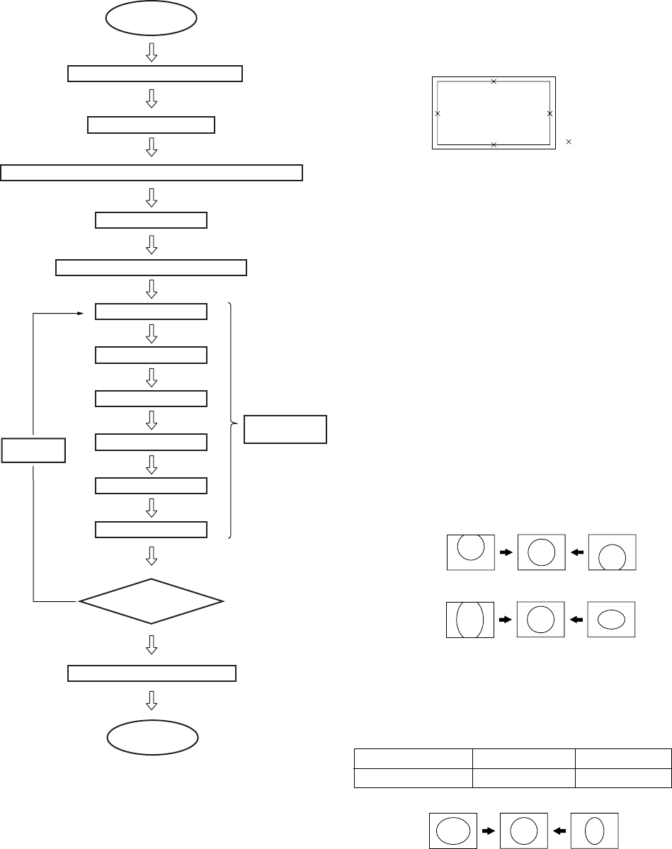
– 27 –
KP-HR432K90/HR532K90/HR532N90/HW572K90
RM-Y909KRM-Y908RM-Y909K RM-Y909K
1) Set NTSC Full mode.
2) Enter the Service mode, and select “PJE”.
Note : When you replaced printed circuit boards or devices or
CRTs, and when correction is drastically necessary, press
“7” + “ENTER” buttons to initialize the data in the Pro-
jector Engine mode.
Press “MUTING” + “ENTER” buttons on the com-
mander to write the data.
3-11-2. Main Deflection Adjustment
Note : Before this adjustment, input the data of PJE item No. 78-
85, (See page 25 or 26).
1. Place the caps on the red and blue lenses so that only the
green color is displayed.
2. Enter the monoscope signal and set to NTSC Full mode .
3. Enter the Service mode, and select “2150D-1” .
4. Adjust “0 VPOS” and “1 VSIZ” so that the picture is dis-
played in the center of screen.
5. Adjust “2 VSZO” for 1080i vertical size adjustment.
6. Select “2150D-2” and adjust “2 H-Size” so that the picture
size is within the specification.
3-11. REGISTRATION ADJUSTMENT 3-11-1. Setup for Adjustment
1. Marking
1) At the 4 insides of the screen, locate the middle. Use a tape
measure to identify the middle.
2. Data Setting
: middle
Change the
display mode
* When the NTSC Full mode
adjustment has finished,
copy its data to the next dispiay mode
at the first time only and be sure to
adjust in the order given.
¥ ADJUSTING FLOW
START
Turn on the power and wait for 10 minutes.
Set to the NTSC Full mode
Check the deflection yokes, the centering magnets, 2 pole/4 pole magnets
Set to the service mode.
MAIN DEFLECTION ADJUSTMENT (Green)
Green coarse adjustment
Green fine adjustment
Red coarse adjustment
Red fine adjustment
Blue fine adjustment
Blue coarse adjustment
Memorize the FLASH FOCUS offset data
End
Another display mode?
SUB DEFLECTION
ADJUSTMENT
ALLCOPY* Yes
No
(Item 3-10-2)
(Item 3-10-4)
7. Copy the dada of NTSC Full mode to the other display mode
and adjust in the other mode as the occasion demands.
2 H-Size
0 VPOS
1 V-Size
SPEC Overscan Spec. = 9%
Input Signal H SIZE V SIZE
Monoscope 15.6 ± 0.2 sq. 11.5 ± 0.2 sq.
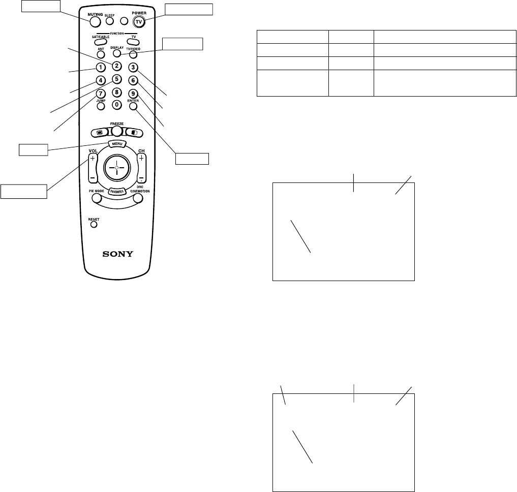
– 28 –
KP-HR432K90/HR532K90/HR532N90/HW572K90
RM-Y909KRM-Y908RM-Y909K RM-Y909K
2. Operation Method for Coarse Adjustment
1) Enter the Service mode, and select “PJE”.
2) Press “1” or “4” button on the commander to select the
item, and use the joystick to change the data.
3) Select “GRN CENT” . When BLU or RED is displayed,
press “3” button on the commander to change the adjust-
ment color in the order of GRN c BLU c RED.
4) In the GRN, BLU, or RED mode,move v, Vdirection the
joystick can change the data in vertical direction, or b, B
direction in horizontal direction.
5) Before returning to the Service mode, press “MUTING”
+“ENTER” buttons on the commander to write the data.
(Omission of this operation causes the set data to be returned
to the data before adjustment)
PJE 00 00
FDIS
Adjustment Item
Item No. Data
v, Bdirection:Data up
V, b direction:Data down
GRN 000 000
CENT
Adjustment Item
Data (H) Data (V)
Color
b: Data (H) up
B: Data (H) down
v: Data (V) up
V: Data (V) down
Commander Function
Buttons Mode Description
- + ENTER READ Writes data to NVM.
MUTING+ENTER WRITE Reads data from NVM.
7 + ENTER PJE Service data initialization. Not stored.
INITIAL (Be sure not to use usually)
Joystick
3-11-3. Operation Method for Projector Engine
Mode
1. Functions of Keys on Commander
• 1: Changes adjustment item. (item No. moves up)
: Marker moves clockwise from center to out-
side. (in fine adjustment mode)
• 4: Changes adjustment item.
(item No. moves down)
: Marker moves counterclockwise from outside
to center. (in fine adjustment mode)
• 2: Changes adjustment category.
(category No. moves up)
• 5: Changes adjustment category.
(category No. moves down)
• Joystick : Changes data value. (up or down)
: Marker moves up, down, or to the left or right.
(in fine adjustment mode)
• 3: Changes adjustment color.
GRN c BLU c RED
• 6: Displays or changes internal test signals.
: crosshatch + external signal c crosshatch +bor-
derline c crosshatch only c dot only c off
• 9: Switches adjustment mode.
Coarse adjustment mode c fine adjustment
mode
Color change
Internal test signal
Mode select
(Fine or Coarse)
Adjustment item
up
Adjustment item
down
Category up
Category down
RM-Y908/909K
Copy PAL data
to NTSC
TV POWER
VOLUME +
DISPLAY
Initialize data
(Not stored)
data up/down
MUTING
ENTER
MENU
• Press joy :Switches marker moving method.
stick (in fine adjustment mode)
joystick (v, V, b, B) keys c 1 and 4 buttons
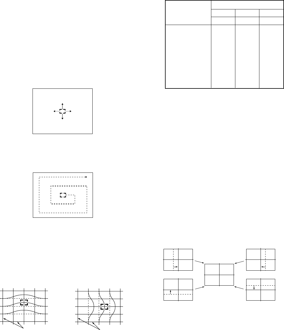
– 29 –
KP-HR432K90/HR532K90/HR532N90/HW572K90
RM-Y909KRM-Y908RM-Y909K RM-Y909K
3-11-4. PJE Adjustment
(Sub Deflection Adjustment)
Push the joystick
to v
Push the joystick
to V
Push the joystick
to B
Push the joystick
to b
•GRN CENT (horizontally/vertically)
<Adjustment for NTSC Full Mode>
•The adjustment should be done in the numerical order
given.
1. Green Adjustment
1) Place the caps on the red and blue lenses so that only the
green color is displayed.
2) Enter the monoscope signal to set.
3) Select the PJE mode.
4) Press “6” button on the commander to display internal test
signal (crosshatch).
5) Select “GRN CENT”, and adjust so that the picture coincide
in the center of screen.
Adjustment Type
Adjustment Item GRN RED BLU
H / V H / V H / V
CENT a / aa / aa / a
SKEW a / aa / aa / a
SIZE a / aa / aa / a
LIN a / aa / aa / a
KEY – / a– / a– / a
PIN a / aa / aa / a
MLIN a / –a / –a / –
MSIZ a / –a / –a / –
Adjustment a : Yes – : No
3. Operation Method for Fine Adjustment
1) Select the PJE mode.
2) Select FDIS so that the data at each position can be displayed
in the fine adjustment mode, and set the data to “01”.
3) Press “9” button on the commander, and the fine adjust-
ment mode will be active where a green marker appears in
the center of screen (in the case of GRN mode).
4) Press joystick, and the marker color will be switched be-
tween green (GRN mode) and white alternately.
5) Use “1” or “4” button on the commander, or the joystick
to move the marker to the position to be adjusted, where fine
adjustment can be made.
•When marker color is white.
(in this case, fine adjustment is disabled)
Operating the joystick can move the marker
up, down, or to the left or right freely.
•When marker color is green. (GRN mode)
1: moves the marker clockwise from center to outside.
4: moves the marker counterclockwise from outside to center.
•Fine adjustment can be made on the basis of marker
position using v, V, b, B directiom of the joystick.
6) Press “9” button on the commander to return to the coarse
adjustment mode.
CROSSHATCH
Move joystick v direction
Move joystick B direction
CROSSHATCH
Note: If the value of over the limit value, adjust these in the fine
adjustment .
Coarse Data Limit Valune.
Cent H 35±170 V 20±170, Size H-75max, Lin H Blu
-425min, H Red 425max.
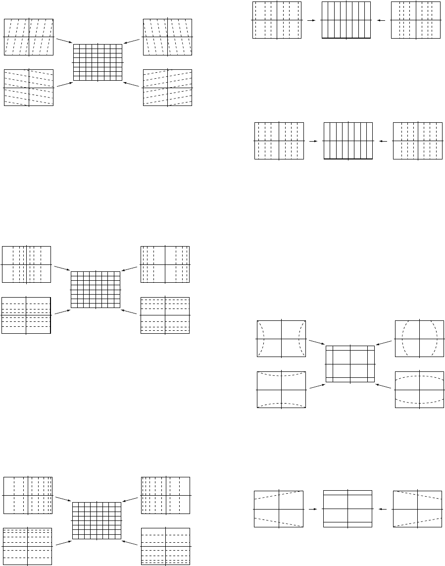
– 30 –
KP-HR432K90/HR532K90/HR532N90/HW572K90
RM-Y909KRM-Y908RM-Y909K RM-Y909K
•GRN MLIN (horizontally)
11) Select “GRN MLIN”, and correct the sizes of the horizontal
line at the center of the screen are symmetrical left and right.
10) Select “GRN MSIZ”, and correct the space intervals for the
horizontal section of the screen are equal.
•GRN MSIZ (horizontally)
Push the joystick
to B
Push the joystick
to b
Push the joystick
to B
Push the joystick
to b
7) Select “GRN SKEW”, and correct the tilt of horizontal lines
and vertical lines.
8) Select “GRN SIZE”, and adjust so that each distance from
center to left end and to right end is equal. Adjust so that
each distance from center to top and to bottom is equal.
•GRN SIZE (horizontally/vertically)
9) Select “GRN LIN”, and adjust so that each space at the right
end and at the left end of screen is equal. Adjust so that each
space at the top and at the bottom of screen is equal.
•GRN LIN (horizontally/vertically)
Push the joystick
to v
Push the joystick
to V
Push the joystick
to B
Push the joystick
to b
Push the joystick
to v
Push the joystick
to V
Push the joystick
to B
Push the joystick
to b
Push the joystick
to B
Push the joystick
to b
Push the joystick
to v
Push the joystick
to V
Note: The SIZE and LIN, MSIZ and MLIN adjustments are
affected each other.
So adjust these mutually if necessary.
Push the joystick
to v
Push the joystick
to B
Push the joystick
to b
Push the joystick
to V
12) Select “GRN PIN”, and adjust so that right and left vertical
lines on the screen become straight. Adjust so that upper and
lower horizontal lines on the screen become straight.
•GRN PIN (horizontally/vertically)
13) Select “GRN KEY”, and adjust so that upper and lower hori-
zontal lines on the screen become parallel.
•GRN KEY (vertically)
Push the joystick
to v
Push the joystick
to V
Note: The VPINand KEY adjustments are affected each other.
So adjust these mutually if necessary.
•GRN SKEW (horizontally/vertically)
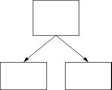
– 31 –
KP-HR432K90/HR532K90/HR532N90/HW572K90
RM-Y909KRM-Y908RM-Y909K RM-Y909K
<Copy All Registration Data to Other modes>
1. Make sure that the adjustment for NTSC Full mode finished
and the data have already been written.
2. Select the PJE mode.
3. Select ALCP and set the data to “01”, and press
“MUTING”+“ENTER” buttons on the commander.
4. The data of NTSC Full mode are copied to all other modes.
5. Check in the other mode and adjust as the occasion demands.
Be sure to write data in each mode.
2. Red Adjustment
1) Place a cap on the blue lens so that green and red colors are
displayed.
2) Press “3” button on the commander to select RED mode.
3) Adjust the following items so that red lines overlap with
green lines.
•RED CENT (horizontally/vertically)
•RED SKEW (horizontally/vertically)
•RED SIZE (horizontally/vertically)
•RED LIN (horizontally/vertically)
•RED MSIZ (horizontally)
•RED MLIN (horizontally)
•RED PIN (horizontally/vertically)
•RED KEY (vertically)
4) Press “9” button on the commander to enter the fine adjust-
ment mode.
5) Make fine adjustment so that horizontal lines and vertical
lines overlap with green lines.
6) Press “9” button on the commander to return to the coarse
adjustment mode.
3. Blue Adjustment
1) All colors are displayed.
2) Press “3” button on the commander to select BLU mode.
3) Hereinafter, use same manner as that of red adjustment to
adjust so that the blue lines overlap with green and red lines.
4. Registration Data Writing
1) After each adjustment of green, blue, and red for the NTSC
Full mode finished, press “MUTING”+ “ENTER” buttons
on the commander to write registration data to the NVM.
14) Press “9” button on the commander to enter the fine adjust-
ment mode.
15) Make fine adjustment so that horizontal lines and vertical
lines become straight.
16) Press “9” button on the commander to return to the coarse
adjustment mode.
NTSC
VCOMP
NTSC
Full
HD
(1080i Full)
Copy Registration Data.
3-12. AUTO CONVERGENCE OFFSET
This adjustment must be performed after the registration adjust-
ment was made or after readjustment was made by any reason.
1. Darken the periphery of this set.
2. Enter the monoscope signal to set the NTSC Full mode.
3. Select the PJE mode.
4. Press “FLASH FOCUS” button on the front panel of the set.
(The offset value is now automatically stored)
5. Select “ ERR” of PJE mode.
Confirm ERR is “00”. If ERR is not “00”, recheck. (Refer to 3-
12.)
6. Exit the service mode.
3-13. AUTO REGISTRATION ERROR CODE LIST
If an error code is displayed after the set has been fully adjusted, cor-
rectly, plese check the following items : position, tilt and sizing. If
either of these adjustments are off, even slightli, the auto registration
pattern will not hit the four sensors properly. This occurs when the
internal generator patterns is being flashed on the screen for the sen-
sor to read. Therefore, auto registration (called auto convergence)
cannot operate properly causing an error code to be displayed. In or-
der for this function to operate properly, correct position, tilt and size
must be adjusted properly.
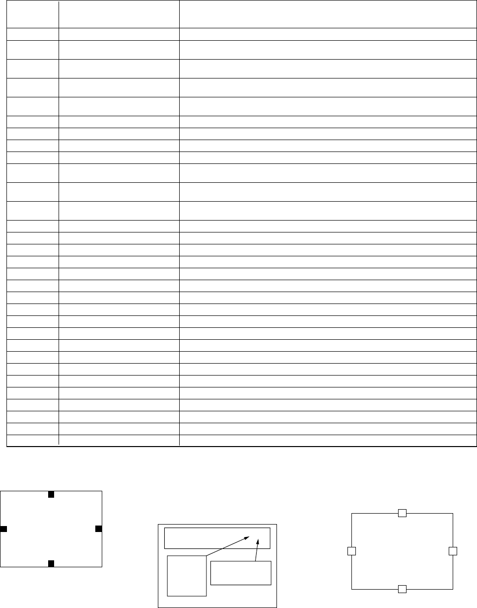
– 32 –
KP-HR432K90/HR532K90/HR532N90/HW572K90
RM-Y909KRM-Y908RM-Y909K RM-Y909K
ERROR CODE LIST
ERROR DESCRIPTION REMEDY
CODE
00 No Error
10 Sensor 0 low output Check sensor 0, connection/wiring, circuit, and pattern position
(Is pattern over sensor ?) Adjust “64 VUP” if necessary.
11 Sensor 1 low output Check sensor 1, connection/wiring, circuit, and pattern position
(Is pattern over sensor ?) Adjust “69 HLB” if necessary.
12 Sensor 2 low output Check sensor 2, connection/wiring, circuit, and pattern position
(Is pattern over sensor ?) Adjust “73 HRIV” if necessary.
13 Sensor 3 low output Check sensor 3, connection/wiring, circuit, and pattern position
(Is pattern over sensor ?) Adjust “68 VLOW” if necessary.
20 Sensor 0 high output Check sensor 0 and circuit.
21 Sensor 1 high output Check sensor 1 and circuit.
22 Sensor 2 high output Check sensor 2 and circuit.
23 Sensor 3 high output Check sensor 3 and circuit.
30 V CENT or SKEW adjustment Check “66 VMID” data and check registration condition.
loop overflow
31 H CENT or SKEW adjustment Check “71 HMID” data and check registration condition.
loop overflow
32 H LIN or SIZE adjustment Check “71 HMID” data and check registration condition.
loop overflow
40 V CENT regi data overflow Check “66 VMID” data and confirm V CENT data (all mode) is not near 511.
41 H CENT regi data overflow Check “71 HMID” data and confirm H CENT data (all mode) is not near 511.
42 V SKEW regi data overflow Check “66 VMID” data and confirm V SKEW data (all mode) is not near 511.
43 H SKEW regi data overflow Check “71 HMID” data and confirm H SKEW data (all mode) is not near 511.
44 H LIN regi data overflow Check “71 HMID” data and confirm H CENT data (all mode) is not near 511.
45 H SIZE regi data overflow Check “71 HMID” data and confirm H CENT data (all mode) is not near 511.
50 V CENT regi data overdrow Check “66 VMID” data and confirm V CENT data (all mode) is not near –512.
51 H CENT regi data overdrow Check “71 HMID” data and confirm H CENT data (all mode) is not near –512.
52 V SKEW regi data overdrow Check “66 VMID” data and confirm V SKEW data (all mode) is not near –512.
53 H SKEW regi data overdrow Check “71 HMID” data and confirm H SKEW data (all mode) is not near –512.
54 H LIN regi data overdrow Check “71 HMID” data and confirm H CENT data (all mode) is not near –512.
55 H SIZE regi data overdrow Check “71 HMID” data and confirm H CENT data (all mode) is not near –512.
60 H or V CENT offset overflow Check “71 HMID” data and check “66 VMID” data.
61 H or V SKEW offset overflow Check SKEW adjustment.
62 H SIZE or LIN offset overflow Check “71 HMID” data, check “66 VMID” data and check SIZE and LIN adjustment.
70 H or V CENT offset overdrow Check “71 HMID” data and check “66 VMID” data.
71 H or V SKEW offset overdrow Check SKEW adjustment.
72 H SIZE or LIN offset overdrow Check “69 HLB” data, check “73 HRIV” data and check SIZE and LIN adjustment.
80 SIZE limit error Check that H SIZE is negative and not near zero.
0 : UPPER SENSOR
1 : LEFT SENSOR
2 : RIGHT SENSOR
3 : LOWER SENSOR
SCREEN
0
3
12
[SENSOR POSITION]
PJE 62 213
ERR
Color:
0=Green
1=Red
2=Blue
0-Green
1-Red
2-Blue
Example: Blue low Level Sensor 3
ERROR EXAMPLE
AUTO REGI ERROR CODE FORMAT
Error Code:
(See Error List)
Error codes in normal (customer) mode are not
displayed. You must enter PJED service mode to
see to the error code.
ERROR G
LO LEVEL S3
SENSOR POSITIONS
1 2
0
3
When executing flash focus in service mode, the
error will be displayed in text format (see below).
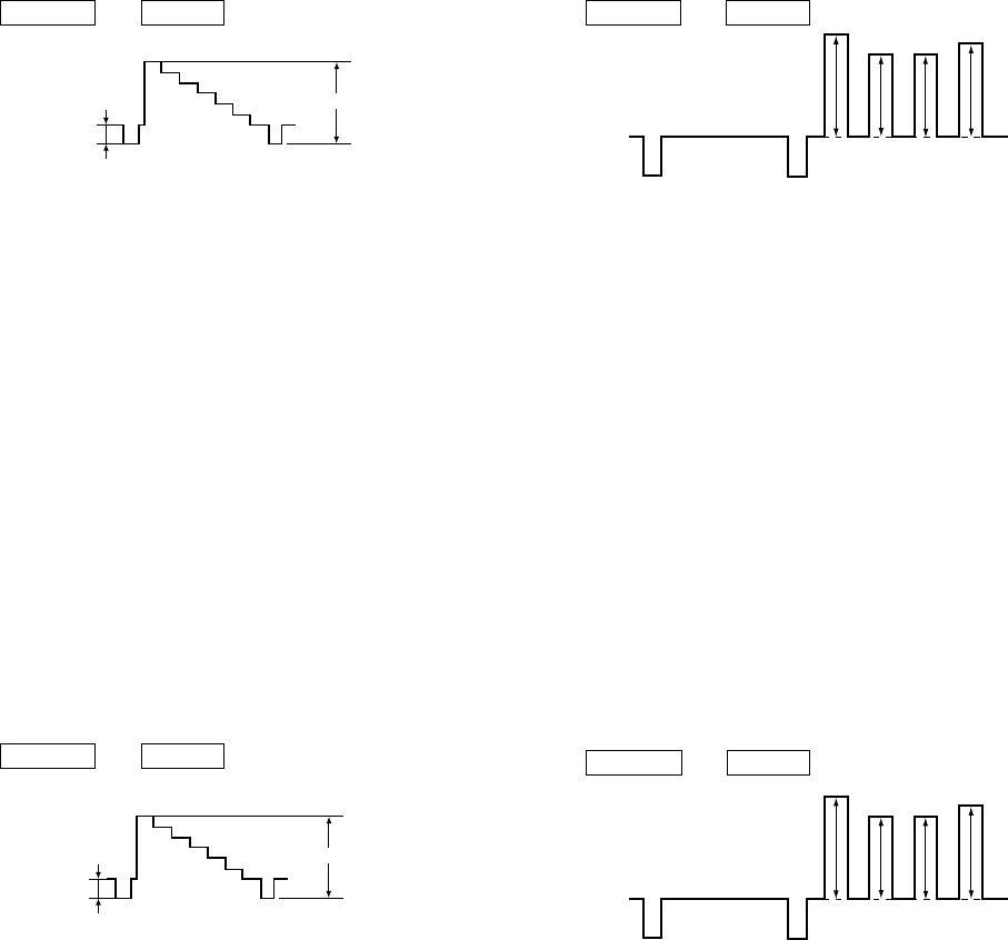
– 33 –
KP-HR432K90/HR532K90/HR532N90/HW572K90
RM-Y909KRM-Y908RM-Y909K RM-Y909K
4-2. P & P SUB CONTRAST ADJUSTMENT (RF)
(SCON) ( ):HW572K90
1. Receive the signal.
TV terminal (main) : Color-bar (white-75%, No
setup)
VIDEO terminal (sub) : Color-bar (white-75%, No
setup)
2. VIDEO MODE : Pro
PICTURE : maximum
COLOR : minimum
RGB Signal : off
3. Set to P & P mode, and set to service mode.
4. Connect an oscilloscope between the check point and ground.
Check points : CN5 pin 6 (G)
(A Board)
5. Select “ 2103-1-02 ”(Main scon), and adjust so that the wave-
form level of VWB is 2.00 (1.67) ± 0.04Vp-p.
6. Select “ 2103-2-02 ”(Sub scon), and adjust so that the wave-
form level of VWB is 2.00 (1.67) ± 0.04Vp-p.
7. Write the data into memory.
MUTING n ENTER
Fig. 4-2
White
VR1
VR1-VR2=VR
VR2
Pedestal
SECTION 4
CIRCUIT ADJUSTMENTS
4-1. P & P SUB CONTRAST ADJUSTMENT
(VIDEO) (SCON) ( ):HW572K90
1. Receive the signal.
TV terminal (sub) : Color-bar (white-75%, No
setup)
VIDEO terminal (main) : Color-bar (white-75%, No
setup)
2. VIDEO MODE : Pro
PICTURE : maximum
COLOR : minimum
RGB Signal : off
3. Set to P & P mode, and set to service mode.
4. Connect an oscilloscope between the check point and ground.
Check points : CN5 pin 6 (G)
(A Board)
5. Select “ 2103-1-02 ”(Main scon), and adjust so that the wave-
form level of VWB is 2.00 (1.67) ± 0.04Vp-p.
6. Select “ 2103-2-02 ”(Sub scon), and adjust so that the wave-
form level of VWB is 2.00 (1.67) ± 0.04Vp-p.
7. Write the data into memory.
MUTING n ENTER
Fig. 4-1
White
VR1
VR1-VR2=VR
VR2
Pedestal
4-3.
P & P SUB-HUE AND SUB-COLOR ADJUSTMENT
(SHUE, SCOL)
1. Receive the signal.
TV terminal (sub) : Color-bar (white-75%, No
setup)
VIDEO terminal (main) : Color-bar (white-75%, No
setup)
2. VIDEO MODE : Pro
PICTURE : maximum
COLOR : center
RGB Signal : on
3. Set to P & P mode, set to service mode.
4. Connect an oscilloscope between pin 7 (B) of CN5 (A board)
connecter and ground.
5. Select “ 2103-1-03 SCOL, -04 SHUE ”(Main), and adjust
them to have VB1 VB4 and VB2 VB3 in the waveform
levels.
6. Select “ 2103-2-03 SCOL, -04 SHUE ”(Sub), and adjust them
to have VB1 VB4 and VB2 VB3 in the waveform levels.
7. Write the data into memory.
MUTING n ENTER
Fig. 4-3
VB1 VB2 VB3 VB4
<
=
<
=
<
=
<
=
4-4.
P & P SUB-HUE AND SUB-COLOR ADJUSTMENT
(SHUE, SCOL)
1. Receive the signal.
TV terminal (main) : Color-bar (white-75%, No
setup)
VIDEO terminal (sub) : Color-bar (white-75%, No
setup)
2. VIDEO MODE : Pro
PICTURE : maximum
COLOR : center
RGB Signal : on
3. Set to P & P mode, set to service mode.
4. Connect an oscilloscope between pin 7 (B) of CN5 (A board)
connecter and ground.
5. Select “ 2103-1-03 SCOL, -04 SHUE ”(Main), and adjust
them to have VB1 VB4 and VB2 VB3 in the waveform
levels.
6. Select “ 2103-2-03 SCOL, -04 SHUE ”(Sub), and adjust them
to have VB1 VB4 and VB2 VB3 in the waveform levels.
7. Write the data into memory.
MUTING n ENTER
Fig. 4-4
VB1 VB2 VB3 VB4
<
=
<
=
<
=
<
=
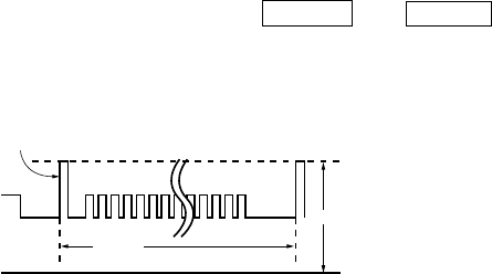
– 34 –
KP-HR432K90/HR532K90/HR532N90/HW572K90
RM-Y909KRM-Y908RM-Y909K RM-Y909K
4-5. BLUE OFFSET ADJUSTMENT (HW572K90)
1. Receive the all black (1080i, component) signal with VIDEO 5
input, and set VIDEO MODE to pro and PICTURE to maximum.
2. Connect an oscilloscope between CN5 pin 7 (B) on the A board
and ground.
3. Set in the service mode and select the category “ 2150D-2 ”.
4. Adjust “ 3 SLIN ” so that the waveform level is 2.20 ± 0.05Vp-p.
5. After adjustment finished, press “ MUTING ” +“ ENTER ”
buttons on the commander to write the data to the NVM.
6. Receive the RF signal and change the wide to mode to “ Wide
Zoom ” copy the same data to “ 3 SLIN ”.
Reference Pulse
2.20±0.05 Vp-p
GND
16.7ms
Fig. 4-5
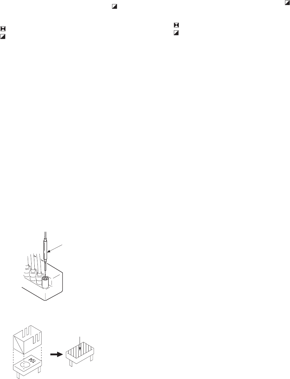
– 35 –
KP-HR432K90/HR532K90/HR532N90/HW572K90
RM-Y909KRM-Y908RM-Y909K RM-Y909K
5-2. HV HOLD DOWN CIRCUIT OPERATION
CHECK AND ADJUSTMENT
When replacing the following components marked with on
the schematic diagram always check hold-down voltage and if
necessary re-adjust.
: VR8002
: C8054, C8086, C8088, C8100, C8104,
C8118, C8123, C8124
D8019, D8020, D8022, D8028, D8036
FB8001
IC8008
Q8035, Q8038
R8035, R8043, R8159, R8166, R8171,
R8196, R8201
T8004 (LOT), T8005 (FBT)
HV block, D board
OPERATION CHECK
1. Receive the dot signal.
2. Set PIC MIN/BRT MIN.
3. Confirm that the voltage between cathode of D8038(JW171)
and GND is more than 23.0V DC.
4. Using an external DC Power supply, apply the voltage shown
below between cathode of D8038(JW171) on “D” and GND,
then confirm that the HV-Prot circuit works.(Raster disap-
pears.)
Apply DC voltage: Less than 29.05V DC.
HV HOLD-DOWN ADJUSTMENT
1. Connect a HV static voltmeter to the unconnected plug of the high-
voltage block.
2. Power on the set.
3. Connet an externel 10kΩ VR at CN8015 and adjust this VR so that
the high voltoge is 34.50kV.
4. Adjust VR8002 to the point that the HV-Prot circuit works (Raster
disappears) at 34.50 ± 0.50kV reading on the static voltmeter.
5. After adjustment, put the VR cover on VR8002 and apply sufficient
amount of epoxy resin around VR8002 as the same manner for
VR8001.
[ G BOARD]
5-3. +B MAX VOLTAGE CONFIRMATION
The following adjustments should always be performed
when replacing IC501, R5032.
1. Supply 130VAC to variable autotransformer.
2. Receive dot signal pattern and set the PICTURE and
BRIGHTNESS settings to their minimum.
3. Confirm the voltage of TP +B 135V is less than 137.0Vdc.
4. If step 4 not satisfied , replace IC501 and repeat above steps.
5-4. +B OVP CONFIRMATION
1. Add to low voltage power supply between to TP. 5001 and
ground.
2. Supply 120VAC to variable autotransformer.
3. Power on the Set and receive dot signal pattern.
4. Set the PICTURE and BRIGHTNESS settings.
5. Check the OVP is activated.
Operate :less than 2.50V
SECTION 5
SAFETY RELATED ADJUSTMENTS
[ D BOARD]
5-1. HV REGULATION CIRCUIT CHECK AND
ADJUSTMENT
When replacing the following components marked with on the
schematic diagram always check HV regulation, and if neces-
sary re-adjust.
: VR8001
: C8079, C8083, C8090, C8129, D8013, D8015
D8038, D8043
IC8006
Q8021, R8055, R8099, R8102, R8128, R8129,
R8131, R8139, R8140, R8142, R8153, R8163,
R8223, R8230
T8004 (LOT), T8005 (FBT)
HV block, D board
OPERATION CHECK
1. Receive the all white signal.
2. Set PIC MAX/BRT CENT.
3. Confirm that the voltage between CN8015 1 PIN and GND
is less than 7.80VDC.
HV REGULATION ADJUSTMENT
1. Connect a HV static voltmeter to the unconnected plug of the high-
voltage block.
2. Power on the set.
3. Repeat steps 1 and 2 as above.
4. Confirm that the static voltmeter reading is 31.0 ± 0.4V.
5. If not, adjust with VR8001 to the specified value.
6. After adjustment, put the VR cover on VR8001 as shown below and
apply sufficient amount of epoxy resin around VR8001.
Fig. 4-1
Remove the cap off from
the unused terminal and
connect a static voltmeter
there.
VR8001
epoxy resin
Fig. 4-2
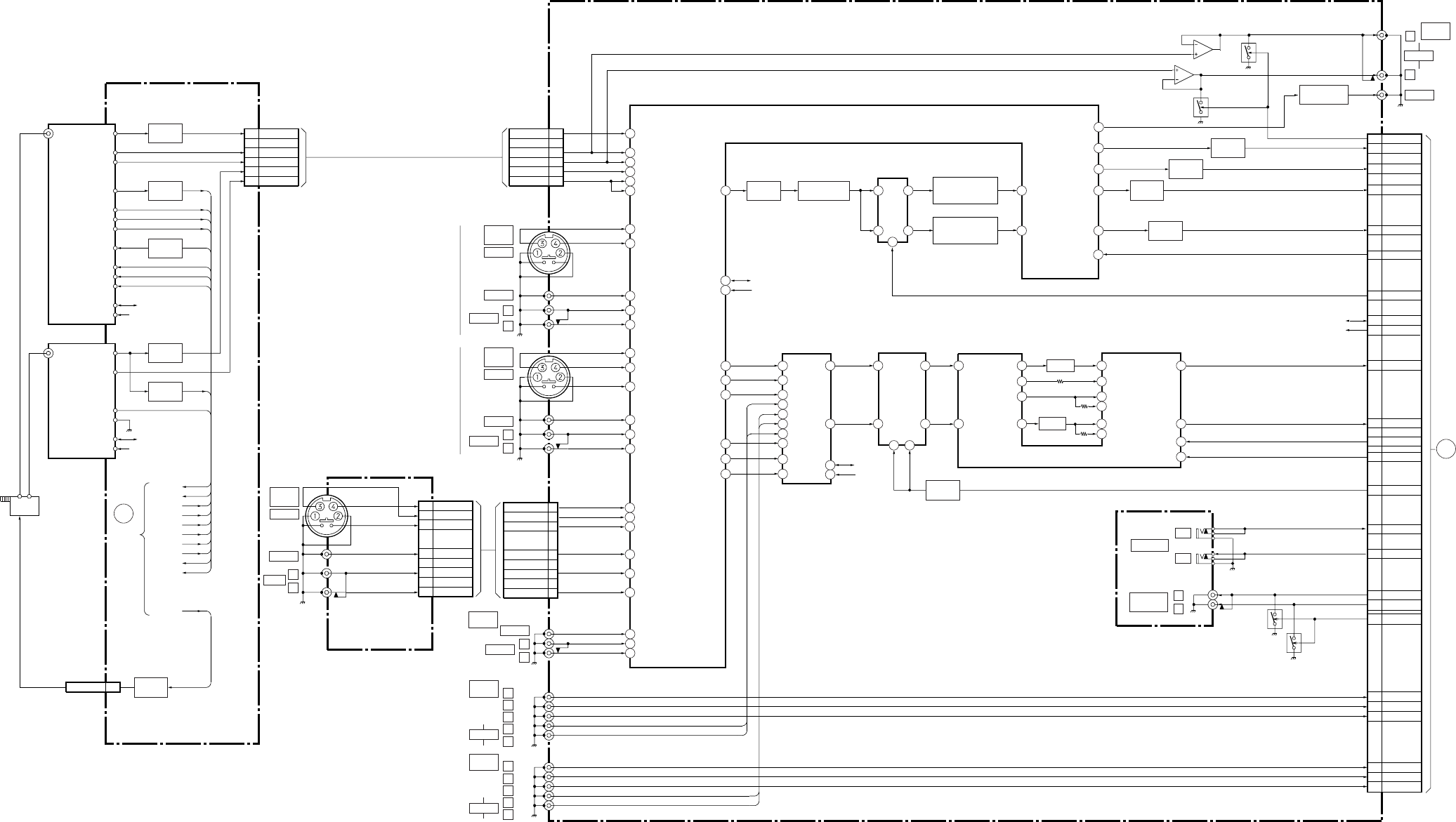
– 36 –
KP-HR432K90/HR532K90/HR532N90/HW572K90
RM-Y909KRM-Y908RM-Y909K RM-Y909K
SECTION 6
DIAGRAMS
6-1. BLOCK DIAGRAM (1) (EXCEPT HW572K90)
63
62
64
8
9
11
17
19
15
16
18
24
26
28
22
23
25
60
59
61
44
41
47
53
43
52
38
40
54
45
4
5
6
10
11
18
19
23
24
25
3
5
7
1
2
4
32
31
BUFFER
Q8, 27 BUFFER
Q2008
BUFFER
Q2009
AMP
Q2015
AMP
Q2013
SWITCH
Q2301
AMP
Q2016
B. P. F.
Q2022, FL2001
B. P. F.
Q2017, 2020, 2025,
2027, FL2002
B. P. F.
Q2017, 2020, 2025,
2027, FL2002
H. SEP
Q21
BUFFER
Q2, 14
H. SEP
Q7
AGC
Q22
C1
A1
A3
C3
C4
C1
A1
A3
C3
C4
1SW2 ANT SW M
MAIN TU V
MAIN TU L
MAIN TU R
SUB TU V
SUB TU L/R
MAIN TU V
MAIN TU L
MAIN TU R
SUB TU V
SUB TU L/R
RF MAIN-V
Y-IN 1
C-IN 1
V-IN 1
L-IN 1
R-IN 1
Y-IN 3
C-IN 3
SSW-IN 3
V-IN 3
L-IN 3
R-IN 3
DEC-V
DEC-L
DEC-R
RF MAIN-L
RF MAIN-R
S-V
SUB-L
SUB-R
IC2004
A/V SWITCH
IC2003
CN6 CN2001(1/2)
CN701
TU2
MAIN TUNER
TU1
SUB TUNER
MAIN Y/V OUT
MAIN C OUT
SUB Y IN
SUB C IN
SUB Y OUT
SUB C OUT
SUB V OUT
MAIN L OUT
SUB L OUT
MONITOR L OUT
MONITOR R OUT
SUB R OUT
MAIN R OUT
Y-IN 2
C-IN 2
SSW-IN 2
V-IN 2
L-IN 2
R-IN 2
SDA
SCL
DAT1
CLK1
DET OUT2
DET OUT
DET OUT
DE-EM OUT
AFT OUT
MUTE
RF AGC
SDA
SCL
SDA
SCL
STUH
AFT2
SDA
SCL
SDA
SCL
MODE
F MONO
MUTE
AFT OUT
ST LED
BIL LED
L OUT
R OUT
A26
A29
C29
A20
LINE MUTE
COMP V OUT
MN C OUT
SUB Y OUT
Q2007
Q2029
Q2005
J2001
Q2006
CN9302 CN2002
5
67
2
31
J2004
BUFFER
Q2012, 2026
VIDEO 1
IN
S VIDEO
VIDEO
AUDIO
L
R
J2005
VIDEO 3
IN
S VIDEO
VIDEO
AUDIO
AUDIO
VIDEO 5
IN
L
Y
PB
PR
R
L
R
VIDEO
AUDIO L
R
TO
A
BOARD
SYSTEM
CONTROL
BLOCK
ANT
SW
MTU H
AFT1
ST-1
BIL-1
MOD-1
AGC
MONO-1
TU MUTE
STU H
AFT2
MTU H
AFT1
ST-1
BIL-1
AGC
MOD-1
MONO-1
TU MUTE
ANT SW M
SWITCH
Q712
6
8
5
10
3
1
V2-Y IN
V2-C IN
V2-SSW IN
V2-V IN
V2-L IN
V2-R IN
V2-Y IN
V2-C IN
V2-SSW IN
V2-V IN
V2-L IN
V2-R IN
CN2001
(2/2)
6
8
5
10
3
1
VIDEO
MONITOR
OUT
AUDIO
L
R
J2007
AUDIO OUT
(VAR/FIX)
L
R
J2006
AUDIO
VIDEO 6
IN Y
PB
PR
R
L
A
(1/5)(TUNER)
U
(VIDEO/AUDIO IN/OUT) (EXCEPT HW572K90)
H3
(LINE IN 2)
A
TO A BOARD
CN6
DAT1
CLK1
VIDEO 4
IN
1
32
7
4
25
49
51
56
58
MULTI-V IN 10
IC2007
COMB FILTER
L1
L2
L3
L5
L6
R6
R5
R3
R2
R1
12
L OUT 1
13
1
4
2
3
22
23
R OUT 1
L OUT
R OUT
21
15
FIL 1 OUT
19
SPACE OUT
17
CENTER OUT
FIL 2 OUT
12
11
LCH OUT
3
MODE1
2
MODE2
RCH OUT
20
14
18
16
28
27
S-SDA
13 5
S-SCL
L IN
R IN
LCH IN
RCH IN
FIL 1 IN
SPACE IN
CENTER IN
26 CE IN
FIL 2 IN
13 FIL 2 IN 2
LSW RSW
FILTER
FILTER
MONITOR V OUT
IC2304
ATT SWITCH IC2305
TRUSURROUND PROCESSOR
IC2001
AUDIO SELECT
C20 SUB C OUT
A31 PS-V
C31 FSC
C18 S-ATT
A24 CONT-S IN
C23 CONT-S OUT
C10 AUDIO L
C25 DAT1
C27 CLK1
A11 AUDIO R
A22 S-MODE 1
C22 S-MODE 2
A6 VARI L
C6 VARI R
A28 A MUTE
A15 D1-Y
C16 D1-CB
A17 D1-CR
C12 D2-Y
A13 D2-CB
C14 D2-CR
J9301
VIDEO 2
IN
S VIDEO
VIDEO
AUDIO L
R
J2002
J2003
CONTROL S
IN
OUT
DAT1
CLK1
10
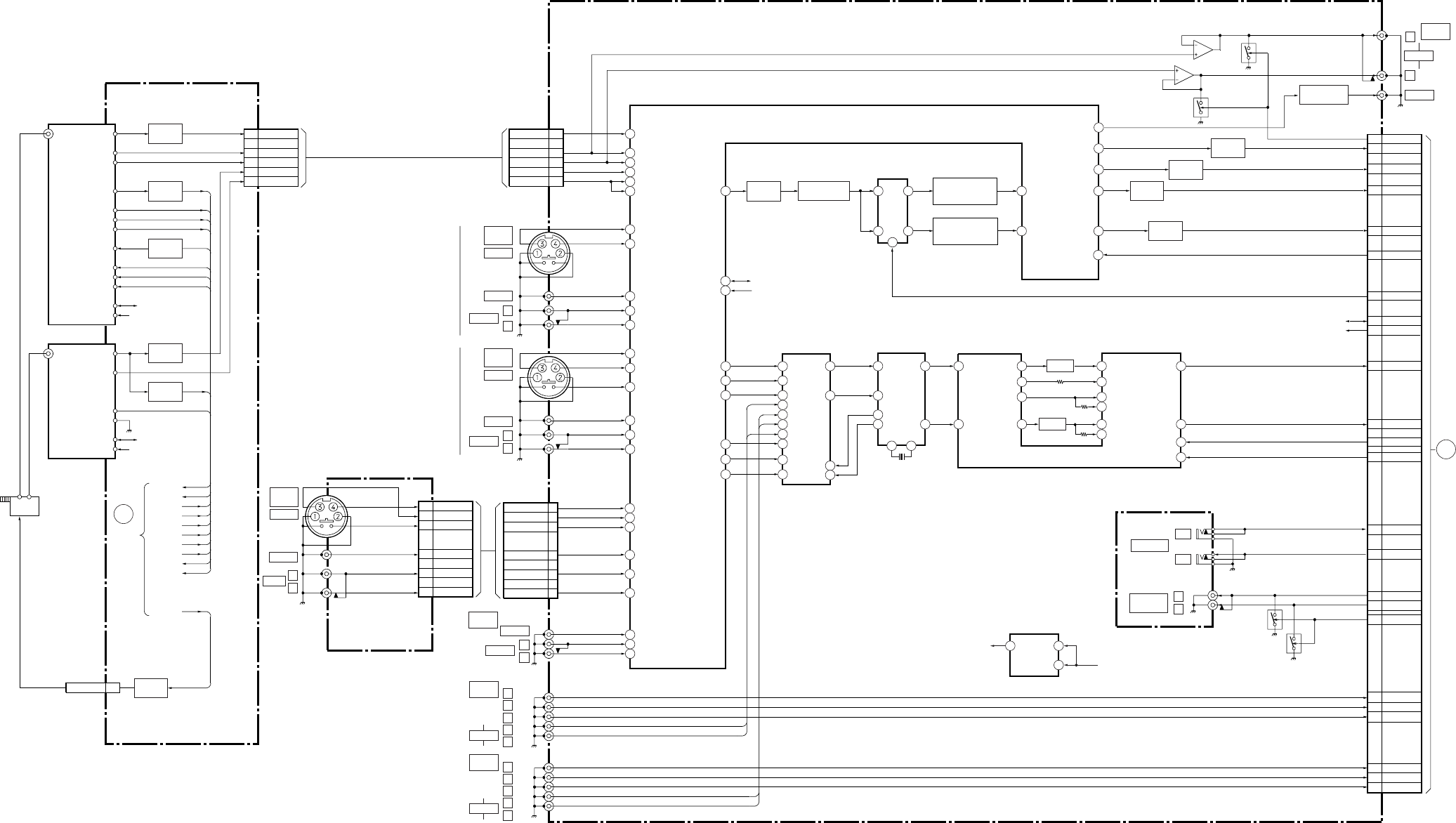
– 37 –
KP-HR432K90/HR532K90/HR532N90/HW572K90
RM-Y909KRM-Y908RM-Y909K RM-Y909K
BLOCK DIAGRAM (2) (HW572K90)
63
62
64
8
9
11
17
19
15
16
18
24
26
28
22
23
25
60
59
61
44
41
47
53
43
52
38
40
54
45
4
5
6
10
11
18
19
23
24
25
3
5
7
1
2
4
32
31
BUFFER
Q8, 27 BUFFER
Q2008
BUFFER
Q2009
AMP
Q2015
AMP
Q2013
AMP
Q2016
B. P. F.
Q2022, FL2001
B. P. F.
Q2017, 2020, 2025,
2027, FL2002
B. P. F.
Q2017, 2020, 2025,
2027, FL2002
H. SEP
Q21
BUFFER
Q2, 14
H. SEP
Q7
AGC
Q22
C1
A1
A3
C3
C4
C1
A1
A3
C3
C4
1SW2 ANT SW M
MAIN TU V
MAIN TU L
MAIN TU R
SUB TU V
SUB TU L/R
MAIN TU V
MAIN TU L
MAIN TU R
SUB TU V
SUB TU L/R
RF MAIN-V
Y-IN 1
C-IN 1
V-IN 1
L-IN 1
R-IN 1
Y-IN 3
C-IN 3
SSW-IN 3
V-IN 3
L-IN 3
R-IN 3
DEC-V
DEC-L
DEC-R
RF MAIN-L
RF MAIN-R
S-V
SUB-L
SUB-R
IC2004
A/V SWITCH
IC2003
CN6 CN2001(1/2)
CN701
TU2
MAIN TUNER
TU1
SUB TUNER
MAIN Y/V OUT
MAIN C OUT
SUB Y IN
SUB C IN
SUB Y OUT
SUB C OUT
SUB V OUT
MAIN L OUT
SUB L OUT
MONITOR L OUT
MONITOR R OUT
SUB R OUT
MAIN R OUT
Y-IN 2
C-IN 2
SSW-IN 2
V-IN 2
L-IN 2
R-IN 2
SDA
SCL
DAT1
CLK1
+12V
DET OUT2
DET OUT
DET OUT
DE-EM OUT
AFT OUT
MUTE
RF AGC
SDA
SCL
SDA
SCL
STUH
AFT2
SDA
SCL
SDA
SCL
MODE
F MONO
MUTE
AFT OUT
ST LED
BIL LED
L OUT
R OUT
A26
A29
C29
A20
LINE MUTE
COMP V OUT
MN C OUT
SUB Y OUT
Q2007
Q2029
Q2005
J2001
Q2006
CN9302 CN2002
5
67
2
31
J2004
BUFFER
Q2012, 2026
VIDEO 1
IN
S VIDEO
VIDEO
AUDIO
L
R
J2005
VIDEO 3
IN
S VIDEO
VIDEO
AUDIO
AUDIO
VIDEO 5
IN
L
Y
PB
PR
R
L
R
VIDEO
AUDIO L
R
TO
A
BOARD
SYSTEM
CONTROL
BLOCK
ANT
SW
MTU H
AFT1
ST-1
BIL-1
MOD-1
AGC
MONO-1
TU MUTE
STU H
AFT2
MTU H
AFT1
ST-1
BIL-1
AGC
MOD-1
MONO-1
TU MUTE
ANT SW M
SWITCH
Q712
6
8
5
10
3
1
V2-Y IN
V2-C IN
V2-SSW IN
V2-V IN
V2-L IN
V2-R IN
V2-Y IN
V2-C IN
V2-SSW IN
V2-V IN
V2-L IN
V2-R IN
CN2001
(2/2)
6
8
5
10
3
1
VIDEO
MONITOR
OUT
AUDIO
L
R
J2007
AUDIO OUT
(VAR/FIX)
L
R
J2006
AUDIO
VIDEO 6
IN Y
PB
PR
R
L
A(1/5)(TUNER)
U(VIDEO/AUDIO IN/OUT) (HW572K90)
H3
(LINE IN 2)
A
TO A BOARD
CN6
VIDEO 4
IN
1
32
7
4
25
49
51
56
58
MULTI-V IN 10
IC2007
COMB FILTER
L1
L2
L3
L5
L6
R6
R5
R3
R2
R1
12
L OUT 1 72
17
42
43
22
23
L OUT
R OUT
21
15
FIL 1 OUT
19
SPACE OUT
17
CENTER OUT
FIL 2 OUT
12
11
LCH OUT
3
MODE1
2
MODE2
RCH OUT
20
14
18
16
28
27
S-SDA
19 20
S-SCL
L IN
SCLK
16 SDAT
13 73
R OUT 1 R IN
LCH IN
RCH IN
FIL 1 IN
SPACE IN
CENTER IN
26 CE IN
FIL 2 IN
13 FIL 2 IN 2
CLK2 CLK1
V INV OUT+10V
CONTROL
FILTER
FILTER
MONITOR V OUT
IC2301
PROLOGIC DECODE
4 5
1
IC2302
+10V REG
IC2305
TRUSURROUND PROCESSOR
IC2001
AUDIO SELECT
C20 SUB C OUT
A31 PS-V
C31 FSC
A24 CONT-S IN
C23 CONT-S OUT
C10 AUDIO L
C25 DAT1
C27 CLK1
A11 AUDIO R
A22 S-MODE 1
C22 S-MODE 2
A6 VARI L
C6 VARI R
A28 A MUTE
A15 D1-Y
C16 D1-CB
A17 D1-CR
C12 D2-Y
A13 D2-CB
C14 D2-CR
J9301
VIDEO 2
IN
S VIDEO
VIDEO
AUDIO L
R
J2002
J2003
X2301
4MHZ
CONTROL S
IN
OUT
DAT1
CLK1
10
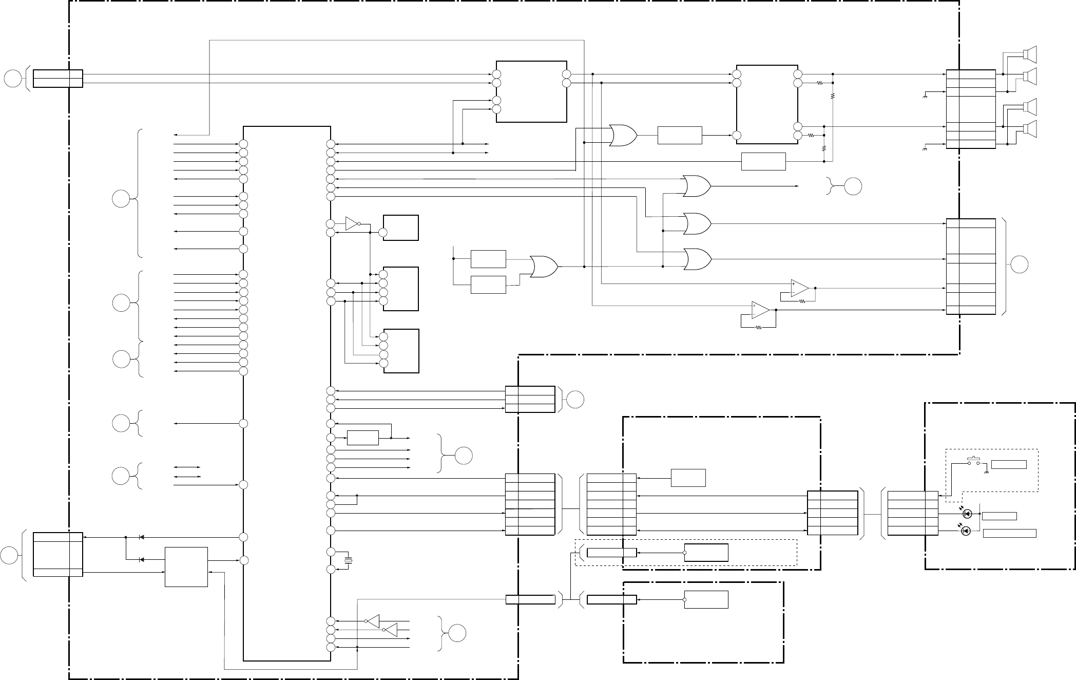
– 38 –
KP-HR432K90/HR532K90/HR532N90/HW572K90
RM-Y909KRM-Y908RM-Y909K RM-Y909K
BLOCK DIAGRAM (3)
23
25
92
93
83
63
85
58
4
55
42
52
40
81
80
51
82
34
21
53
97
95
41
88
31
28
24
65
66
79
30
12
13
15
33
94
46
48
49
45
44
72
SUB H-IN
MAIN H-IN
SUB AFT
MAIN AFT
FMONO
MAIN BIL
MAIN ST
MAAIN MOD2
AGC
ANT SW M
MID BUSY
X SW
VM LEVEL
SD/GR-RST
S-ATT
BUFEER
Q701
DAT1
/BINT
YUVMT
IC704
SYSTEM CONTROL
IC703
NVM
IC701
RESET
28
5
17
18
IN1
IN2
SCL
SDA
IC711
D/A CONVERTER
DAT1
CLK1
AUDIO PROT
SP MUTE
21
12
L OUT1
R OUT2
7
11
5
IN(L)
IN(R)
MUTE
IC708
L,R AMP
4
8
2
10
OUT(L)
IN-(L)
OUT(R)
IN-(R)
AUDIO MUTE
LINE MUTE
8
5
$A0
DAT
XTAL
XTAL
4RST
YM
OVP
OCP
MAIN RLY
C10
A11
AUDIO L
AUDIO R
CN6 (1/3)
CN6 (2/3)
TO A
BOARD
I/O CONV
BLOCK
STUH
MTUH
AFT2
AFT1
MONO-1
SAP LED
ST -1
MOD-1
AGC
ANT SW M
MID BUSY
X SW
VM LEVEL
S-MODE1
S-MODE2
3D-RST
S-ATT
DAT1
CLK1
/BINT
CONTROL
SWITCHES
S9201-9212 POWER
S9101
HR532N90
STEREO
X701
+11V
L/R MUTE
Q717,718
PROTECT
Q722,723,725
OFF MUTE
Q402
ON MUTE
Q401
1
2
3
4
CN705
LINE MUTE
A MUTE
C6 VARIL
A6 VARIR
CN6 (3/3)
8
7
4
OVP
OCP
RELAY
CN7
2OUT
SIRCS
CN9401
3
4
2
1
3
4
2
1
KEY1
POWER
STEREO LED
KEY1
POWER
STEREO LED
STBY-TIMER LED
CN9 CN9202
IC707(1/2)
3
21
IC707(2/2)
5
67
STBY +5V
D1201
REMOTE SENSOR
(EXCEPT HW572K90)
A(2/5)(AUDIO, SYSTEM CONTROL)
H2
(CONTROL SWITCHES)
H4
(REMOTE SENSOR)
H1
(POWER SWITCH)
(1/2)
A
TO U
BOARD
CN2001
A
TO U
BOARD
CN2001
GTO G
BOARD
CN5001
ATO U
BOARD
CN2001
TU MUTE
54 PROT MUT
PROT MUTE
78 YUV SW
YUV SW
74 BLOCK S
BLOCK S
73 BLOCK M
BLOCK M
39 #V-COMP
V COMP
29
47
CKK0
WP
6
7
CLK
WP
8
5
VCC
DAT
6
7
CLK
WP
IC702
NVM
50
67
POWER MUTE
DAT0
RESET
NVM RST
DAT1
CLK1
A28
A26
SIRCS
CN16
IC9401
3
2
1
POWER
STEREO-LED
STBY-TIMER-LED
CN9101
3
2
1
POWER
STEREO-LED
STBY-TIMER-LED
CN9201
D1201
STANDBY/TIMER
CLK1
9
HV PROTHV PRPT
TO A
BOARD
VIDEO
BLOCK 5
90
7
SIG-H
SIG-V
MID BINT
SIRCS
OSD H
OSD V
ND-B-INT
IR IN
7TO A
BOARD
VIDEO
BLOCK
CONT-S
I/F
Q702-706
Q708-710
CONT-S OUT
CONT-S IN
D708
D709
87 /BINT
C23
A24
2
2OUT
SIRCS
CN9102
REMOTE SENSOR
HW572K90
IC9101
19
YS
OSD R
OSD G
OSD B
KEY1
MPWR
MPWRN
STEREO-LED
STBY TIMER LED
22
OSD-YS
OSD-R
OSD-B
OSD-G
32 1TO A
BOARD
VIDEO
BLOCK
STBY-TIMER-LED
Q715 Q733
L.E.
SP(R)
R.E.
SP(L)
P MUTE 7TO A
BOARD
VIDEO
BLOCK
TO A
BOARD
VIDEO
BLOCK 6
TO A
BOARD
TUNER
BLOCK 10
TO A
BOARD
VIDEO
BLOCK 8
Q707
D704
D713
D711
D712
Q707
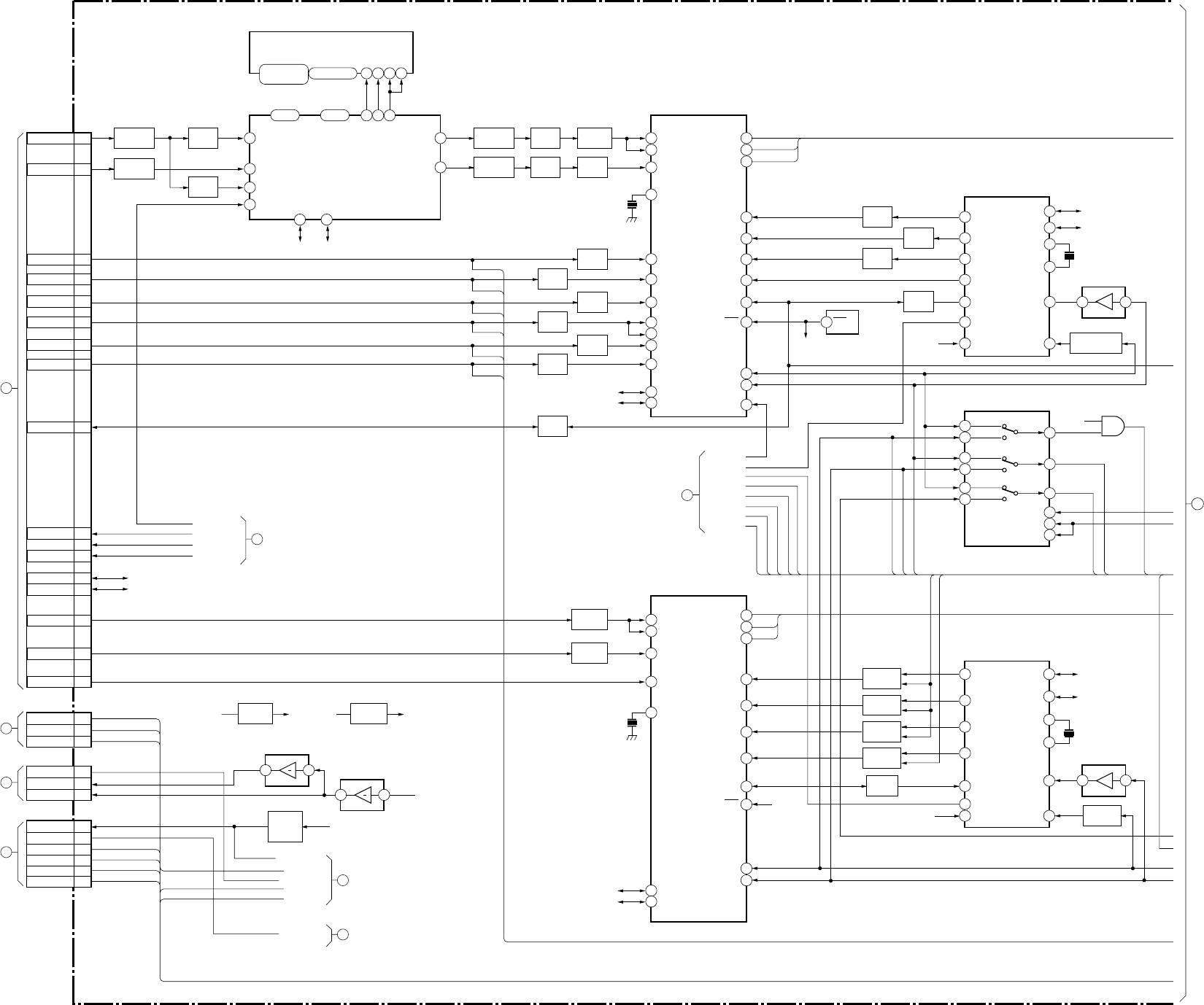
– 39 –
KP-HR432K90/HR532K90/HR532N90/HW572K90
RM-Y909KRM-Y908RM-Y909K RM-Y909K
BLOCK DIAGRAM (4)
88
11 12 10
13 27 28
28-13 9-2,99
16-19,22-26
2-5,7-10
31-34,36-39
BUFFER
Q5
76
57
60 59
BUFFER
Q3,4,6
B.P.F
FL7,Q2016
96
4684
8
22
23
24
25
BUFFER
Q302,303
33
BUFFER
Q323
46
8
BUFFER
Q311,312
48
44
41
3
4
1 2
BUFFER
Q308,310
35
BUFFER
Q321
38
BUFFER
Q317
34
BUFFER
Q322
37
16
BUFFER
Q318
39
BUFFER
Q316
3
4
BUFFER
Q358
BUFFER
Q24,26
B.P.F
FL5,Q13,17
B.P.F
FL7,Q2016
4883
41
BUFFER
Q305
32
BUFFER
Q314
25
22
23
24
32
MIX
Q340,368
MIX
Q340,368
26 33
MIX
Q335,363
27 34
MIX
Q336,361
21 36
MIX
Q380,381
122
48
50
11
12
8
7
BUFFER
Q320
931
20
15
9
27 34
BUFFER
Q319
26 33
BUFFER
Q315
132
BUFFER
Q317
9 4
20
15
28
21 36
11
48
50
8
7
12
31
9
WAVE SHAPE
Q306,304
BUFFER
Q23,25
B.P.F
FL4,Q12,18
+9V REG
IC2
+3.3V REG
IC2
1 2
7 6
8
TO
A BOARD
SYSTEM
BLOCK
3
TO
A BOARD
I/V CONV
BLOCK
5
TO
A BOARD
SYSYTEM
BLOCK
6
TO
A BOARD
SYSTEM
BLOCK
29
3D-RST
S-ATT
S-,ODE1
S-MODE2
YUV SW
BLOCK-M
BLOCK-S
PROT MUTE
MID BUSY
X SW
VM LEVEL
V COMP
PROT MUTE
MID BUSY
X SW
VM LEVEL
V COMP
MN C OUT
COMP V OUT
CN6(1/2)
A29
C29
A17
A13
C31
3
5
7
D1-CR
D2-CB
C12
D2-Y
A15
D1-Y
C16
D1-CB
C14
D2-CR
A31
PS-V
C18
S-ATT
C22
S-MODE2
A22
S-MODE1
C25
DAT1
A20
SUB Y
C20
SUB C
C27
CLK1
DAT1
CLH1
FSC
A
TO
U BOARD
CN2001
F
TO
D BOARD
CN8006
E
TO
D BOARD
CN8004
D
TO
D BOARD
CN8002
V-DRV(+)
CN14
V-DRV(–)
VP
2
4
2
H_CENT
CN3
DF_V
DF
1
2
4
REGI_MUTE
CN2
HV_PROT
ABL
6
8
HP
PIN(E-W)
10
H_DRV
IO0-IO16 A0-A8
WE
AYI AYO
ACOI
ACI
CSI
SDA
SCL
RS+B
MIO0
I
MIO15
MA0
I
MA8
CE
LCAS
UCAS
IC4 4MBEDO
MWE
MCE
MCAS
Y-IN YOUT
CBOUT
CROUT
EXT R
EXT G
EXT B
YSYM
MONOUT
RST
HT1M
VT1M
YUV SW
Y1-IN
C-IN
XTAL
Y-IN
CB-IN
CR-IN
EXT-Y
YB-IN
EXT-CB
EXT-CR
SDA
SCL
X303
3.58MHz
DAT 1
CLK 1
Y-M
CB-M
CR-M
Y-IN YOUT
CBOUT
CROUT
EXT R
EXT G
EXT B
YSYM
MONOUT
RST RST
HTIM
VTIM
Y1-IN
C-IN
FSC
XTAL
SDA
SCL
Y-M
CB-M
CR-M
+11V
+11V
D FOCUS
REGI MUTE
HP IN
H CENT
H SAW
V SHIFT
HP IN
H SAW
V SHIFT
HV PROT
HV PROT
ABL
V DRIVE+
V DRIVE–
VP
HP IN
PIN(E-W)
H DRIVE
+9V +6V +3.3V
IC3(1/2)
DF FILTER
IC3(2/2)
DF FILTER
INITIAL
MUTE
Q11,28
7 6
RST
SDA
SCL
XTL
EXTL
VP
HP
R
G
B
YS
VIN
PBO
REAET
SDA
SCL
XTL
EXTL
VP
HP
R
G
B
YS
VIN
PBO
RESET
IC304
SUB-CCD V-CHIP
DAT1
CLK1
X304
12MHz
IC311(2/2)
11
10
14
4
15
9
13
3
5
12
1
2
HD-M
HD-S
VD-M
VD-S
M2103
M2151
V
VD-02
VD-03
IC307
DRC_SYNC_SEL
S-HD
S-VD
VD1
HD3
VD2
HD2
SUBG
VD3
SUB YS
IC6
3D COMB FILTER
HH DET
IC301
YCT-SUB
DAT1
CLK1
IC303
YCT-MAIN
RST IC310
RESET
IC302
MAIN-CCD V-CHIP
RST
X302
12MHz
DAT1
CLK1
IC311(1/2)
IC312
+5V 1
27
X301
3.58MHz
DTA1 CLK1
D1-Y
D1-CB
D1-CR
D2-Y
D2-CB
D2-CR
RST
A
(3/5) (YCT)
1
TO/FROM
BLOCK DIARAM(5)
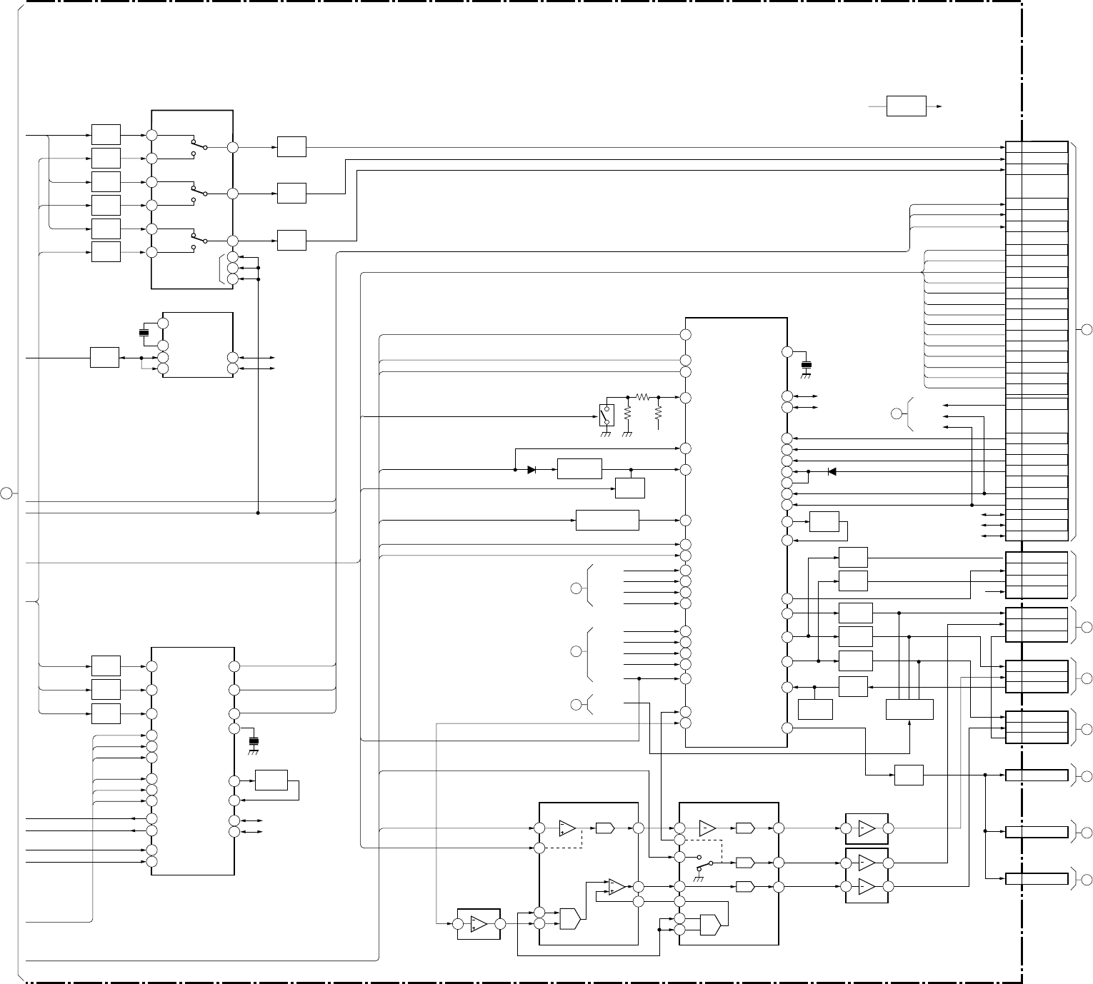
– 40 –
KP-HR432K90/HR532K90/HR532N90/HW572K90
RM-Y909KRM-Y908RM-Y909K RM-Y909K
BLOCK DIAGRAM (5)
3
6
7
10
9
10
9
11
12
13
BUFFER
Q341
BUFFER
Q332
2
BUFFER
Q333
1
27
26
25
20
20
16
31
2
3
13
BUFFER
Q334
35
34
33
1
5
12
43
42
41
22
23
4
5
+3.3V REG
IC8
39
30
29
6
5
4
2
10
9
8
7
35
54
43
6 7
28
27
30
921
21
6
2
3
18
8
912
25
6
2 1
7
BUFFER
Q373
20
21
22
13
12
28
42
MUTE
Q369
INV.BUFFER
Q378,379
LINIT
Q309,313,349,352
BUFFER
Q345
BUFFER
Q348
BUFFER
Q331,343
BUFFER
Q347,354
BUFFER
Q351,357
BUFFER
Q353
LIMITER
Q355,356
BUFFER
Q367
MUTE
Q342,346,350
R-R
R-G
R-B
R-YS
OSD-R
OSD-G
OSD-B
OSD-YS
VP
P MUTE
Q374 26
DAT1
CLK1
15
4
14
30
BUFFER
Q344
B
TO
B BOARD
CN3203
FOR CHECK
7
TO
A BOARD
SYSTEM
BLOCK
1
TO
A BOARD
SYSTEM
BLOCK
2
TO
A BOARD
I/V CONV
BLOCK
3
TO
A BOARD
SYSTEM
BLOCK
CN13
I
TO
CR BOARD
CN7102
H
TO
CG BOARD
CN7202
G
TO
CB BOARD
CN7302
L
TO
V BOARD
CN9001
K
TO
V BOARD
CN9001
J
TO
V BOARD
CN9001
CB
C22
CR
C21
SEL Y OUT
A19
SEL Y
SEL CB
SEL CR
VP
MID BUSY
SUB G
SUB YS
XSW
VD3
HD3
SWL2
SEL1
HD2
VD2
S-HD
S-VD
VD1
SEL CB OUT
C16
SEL CR OUT
A17
SUB G
C28
MID BUSY
C27
TH CONT
A30
SUB YS
A29
MID VD
A12
MID HD
A14
DRC SEL2
C14
DRC SEL1
C11
HD
A9
MID BINT
C29
MID BINT
SIG H
SIG V
VD
C9
S-HD
C24
S-VD
C25
VD1
C14
MID Y
A6
MID CR
A4
MID CB
C5
MID YS
C3
MID VS
C1
MID HS
A1
DAT1
C31
CLK
A32
RST
DAT1
CLK
RST C18
VP
A32
Y
C20
CN5(1/2)
SCP
5
B
7
SIRCS
3
G
6
CN704
RS
1
IK
4
R
3
CN703
GS
1
IK
4
G
3
CN702
BS
1
IK
4
B
3
CN19
M
4
CN18
VM
4
CN17
VM
4
IN3_3
S-Y
S-CB
S-CR
IN3_2
IN3_1
IN1_3
IN1_2
IN1_1
IN3_H
DAT1
CLK1
IN3_V
IN2_3
IN2_2
IN2_1
SELHOUT
SELVOUT
SELYOUT
SELYOUT
SELCROUT
EXTCLK/
XTAL
YG-IN
SDA
SCL
YG-OUT
D1-Y
D1-CB
D1-CR
D2-Y
D2-CB
D2-CR
X305
4MHz
X307
2.7MHz
IC306
COMPONENT-I/F
SEL Y
SEL CB
SEL CR
IC706
SHADING
IC705
SHADING
BUFFER
Q325
BUFFER
Q328
BUFFER
Q329
BUFFER
Q326
BUFFER
Q329
BUFFER
Q327
BUFFER
Q339
BUFFER
Q337
BUFFER
Q338
Y-M
Y-S
CB-M
CB-S
CR-M
CR-S
Y-M
Y-O
CB-O
CR-O
M/S
Y-S
CB-M
CB-S
CR-M
CR-S
XI
XO
DAT1
CLK1
VSIN
VDIN
SDA
SCL
IC305
YCT-SEL
IC308
ID-1 DECODER
SEL2
HP IN
VM LEVEL
V DRIVE+
V DRIVE–
V SHIFT
PROT MUTE
ABL
VP
ABL
H SAW
V COMP
PIN(E-W)
H DRIVE
SEL1
2 1
IC709(1/2)
SHADING AMP
21
24
7
G
R
B
X306
14.318MHz
Y
CB
CR
IC309
YC3
37
53
52
15
33
25
34
56
64
47
40
27
63
62
58
14
VCOMP
V_DRV+
V_DRV–
VM_MOD
HP_IN
HPROT
ABL_IN
EW_DRV
H_DRV
R2_IN
G2_IN
B2_IN
YSYM2
R1_IN
G1_IN
B1_IN
YSYM1
VPROT
VTIM
HC_PARA
CERA
DA
SCL
Y_IN
CB_IN
CR_IN
YF_OFF
DPDT_OFF
HS_IN
VS_IN
VBIAS
VREG5
SCP
R_OUT
G_OUT
B_OUT
IJ IN
VM_OUT
+5V
+3.3V+6V
IC709(2/2)
IC710
SHADING AMP
D318
D321
A
(4/5) (VIDEO)
1
TO/FROM
BLOCK DIARAM(4)
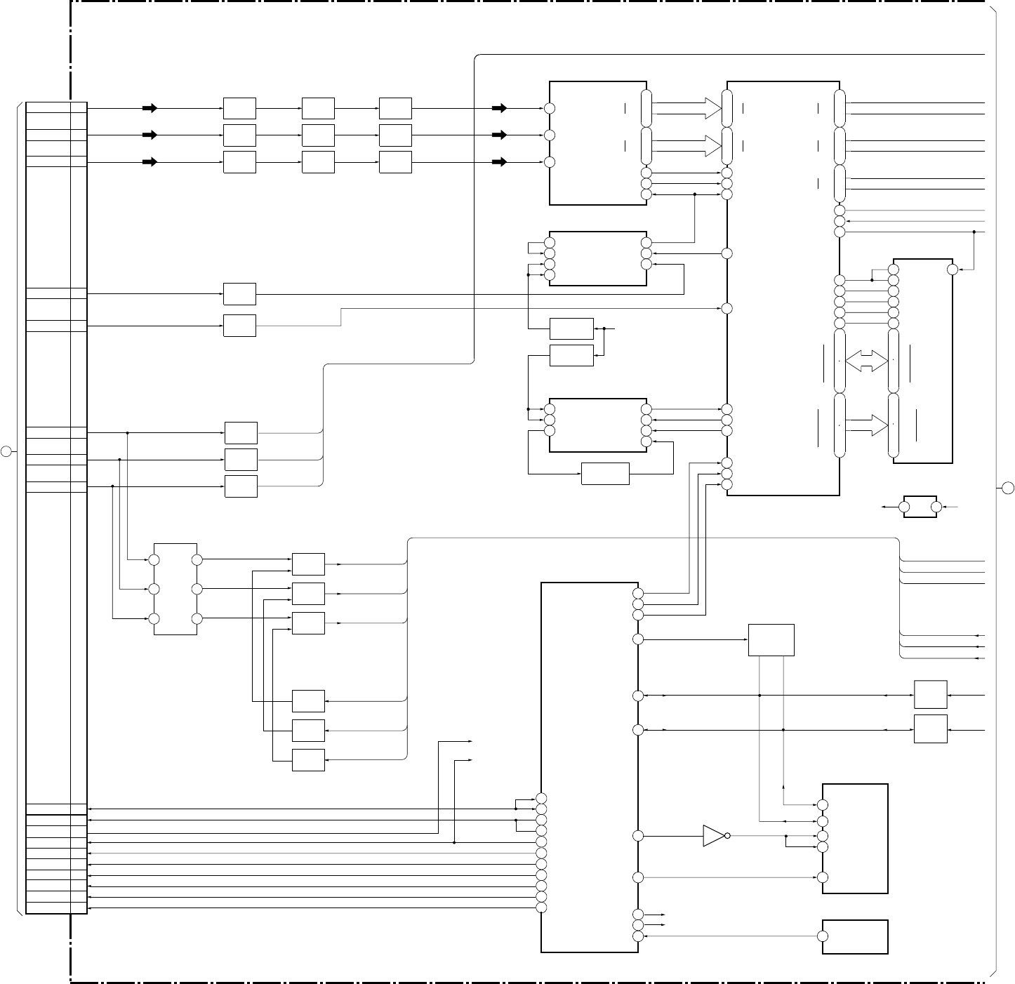
– 41 –
KP-HR432K90/HR532K90/HR532N90/HW572K90
RM-Y909KRM-Y908RM-Y909K RM-Y909K
Y
CB
CR
Y-CL
CB-CL
CR-CL
100
102
117
7
8
9
10
11
156
157
161
160
162
95
96
97
-
-
-
-
20
13
32
25
49
46
42
35
DYO2
DYO9
DRO2
DRO9
DBO2
DBO9
V9O
HD2
C54O
DOM
XCAS
XRAS
XWE
XCS
DQ0
DQ15
ADDR0
ADDR11
DIY0
DIY7
DIC7
DIC0
CLP
ADHD
W13I
WPLLHD
IVD
C54I
RPLLHD
HREF
GAME
13
6
24
17
55
56
58
63
31
50
D(A)1
D(B)8
D(B)1
VIN(C)
VIN(A)
XSYNC
CLK
EXTCLP
VIN(B)
1
3
4
5
6
12
14
13
4
5
6
12
LOGIC VDD
VCO OUT
FINA
FINB
PFD OUT
VCO VDD
VCO IN
LOGIC VDD VCO OUT
FINA
FINB
PFD OUT
VCO IN
14
+5V
-
-
-
-
2
12
39
49
19
24
27
32
DQ0
LDQM
WE
CAS
RAS
CS
ADDR0
DQ15
UDOM
ADDR11
35
36
14
15
16
17
18
CLK
I
O
+2.5V +3.3V
-
-
-
-
-
-
-
6
8
3
5
7
4
214
79
511
FL3003
100
2
3
1
99
96
98
C2
DRC-PXI
DRC-LINE-W
65
D0 95
C0 97
32
NVM-RST
CLK
DAT
AA
WP
RESET
33
NVM-WP
64
OSD-HSYNC
63
OSD-VSYNC
45
RST
DRC-INSEL
D2
TH CONT
DRC SEL2
C1
57 B-INT
D1
122
129
133
140
147
154
174
181
164
171
DRCDCLK
XDRCHS
XDRCVS
CB0-7
CR0-7
Y0-7
61 VSTILL0
59
69
PXI
Y0-7
C0-7
D(A)8
VDD
+3.3V REG.
Q3301
VCO LIMIT
Q3305
REG
Q3302
BUFFER
Q3307
BUFFER
Q3311
BUFFER
Q3309
LPF
(7.2MHz)
LPF
(3.6MHz)
LPF
(3.6MHz)
BUFFER
Q3306
BUFFER
Q3310
BUFFER
Q3308
BUFFER
Q3304
BUFFER
Q3303
BUFFER
Q3005
BUFFER
Q3006
BUFFER
Q3007
MIX
Q3408
MIX
Q3406
MIX
Q3405
BUFFER
Q3403
BUFFER
Q3407
BUFFER
Q3409
BIAS
SWITCH
Q3089,3090
B
HD
VP(V-FBP)
CB
Y
CR
CN3203(1/2)
C20
C22
A21
A9
VD C9
SEL Y OUT A19
SEL CB OUT C16
SEL CR OUT
TO
A BOARD
CN13
A17
DAT1 C31
CLK1 C37
TH CONT(X-SW) A30
DRC SEL2 C14
DRC SEL1 C11
MID BUSY C27
SUB G C28
SUB YS A29
MID BINT C29
A32
R-Y
B-Y
Y
R-Y
B-Y
Y
66 OSD-YS
69 G
S-HD
S-VD
53 SUB-BUSY
9O_DRC_CD_SEL
10
55 VP-MAON
TH-Y
TH-CB
TH-CR
Y
CB
CR
Y-CL
CB-CL
CR-CL
LEVEL
SHIFT
Q3404
LEVEL
SHIFT
Q3402
B
(1/2) (DRC-MF)
IC3304
3-CH 8 BIT A/D CONVERTER IC3303
DRC-MF
IC3305
WRITE PLL
IC3301
16M-SDRAM
IC3302
+1.8V REG
IC3306
READ PLL
IC3089
NVM
Q3091
IC3090
MID...COM
IC3091
RESET
2
TO/FROM
BLOCK DIARAM(7)
BLOCK DIAGRAM (6)
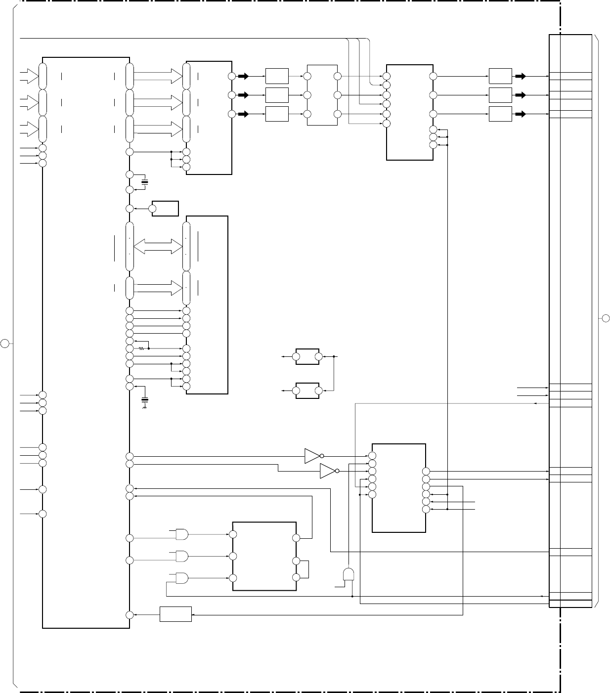
– 42 –
KP-HR432K90/HR532K90/HR532N90/HW572K90
RM-Y909KRM-Y908RM-Y909K RM-Y909K
BLOCK DIAGRAM (7)
X3402
X3402
74.175824MHz
17.2672MHz
42
44
46
214
511
79
I
O
I
O
+2.5V +3.3V
+2.5V
13
20
3
10
23
30
51
44
71
62
61
52
R2
R9
G2
G9
B2
B9
RCK
BCK
RESET
GCK
RO
GO
BO
31
32
33
41
31
29
21
20
11
9
10
37
DSPY0
DSPY7
DSPCR0
DSPCR7
DSPCB0
DSPCB7
DRCYIN0
DRCYIN7
DRCCRIN0
DRCCRIN7
DRCCBIN0
DRCCBIN7
XDRCVS
XDRCHS
DRCDCLK
135
137
140
141
142
143
144
146
147
76
72
73
74
194
215
79
88
91
199
DSPCLK
DXT1OUT
DXT1IN
XRESET
SDDAT0
D0-D15
A0-A12
SDDAT31
SDADR12
SDCS
SDRAS
SDCAS
SDWE
SDCLKIN
SDCLK
SDCKE
SDDQM1
SDDQM0
DXT2IN
XDSPHS
XDSPVS
XDSPYS
VDOPLLHLD
VDOCLKIN
XVDOHS
196
202
IICSDA
ANYGIN
ANYCBIN
ANYCRIN
210
208
168 VDOYCLVL
169 VDOCBCLVL
170
93
IICSCL
94
VDOCRCLVL
17
18
19
20
67
68
28
59
16
71
13
74
85
31
42
22
27
60
66
DQ0
2
CKE
CLK
DQM2
DQM3
DQM0
DQM1
4
CY
DRC SEL2
TF CONT
CX
aY
aX aO
CO
A
CO
5
13
12
bY
1
bX
PFD
INHIBIT
FIN B
FIN A
VCO OUT
VCO IN
PFD OUT
2
3
15
14
4
11
B10
C9
MID VDS
MID HD
MID Y
MID CB
MID CR
MID HS
MID VS
CN3203(2/2)
-
-
-
-
-
-
-
-
-
-
-
-
-
--
--
-
BUFFER
Q3401
FL3401
1
16
8
11
3
14 5
2
7
12
96
157
148
167
158
119
99
120
134
Y0-7
CR0-7
CB0-7
HS
VS
DQ31
A0
A12
CS
CAS
RAS
WE
SDADR0
A6
A4
C5
A1
S-HD
C24
S-VD
C25
VD1
A15
C1
A14
MID YS
C3
A12
BUFFER
Q3410
BUFFER
Q3415
BUFFER
Q3414
BUFFER
Q3411
BUFFER
Q3413
BUFFER
Q3412
B
B
TO
A BOARD
CN13
R-Y
B-Y
Y
R-Y
B-Y
Y
93
12
6
1
24
+5V
+5V
+5V
+5V
5
201
XVDOVS
1
24
7
1
2
4
1
24
Y3I Y OUT
TEX3I
V3I
VBX3I
U3I
UEX3I
V OUT
U OUT
CONT
CONT
CONT
(2/2) (DRC PROCESS,MULTI IMAGE DRIVER)
S-HD
S-VD
IC3410
D/A CONVERTOR
IC3403 IC3402
64M-SDRAM
IC3408
IMAGE DRIVER
IC3411(2/2)
IC3411(1/2)
IC3406
IC3404
WRITE PLL
IC3407
IC3405 IC3412
IC3403
+2.5V REG
IC3409
+2.5V REG
IC3413
SYNC SWITCH
IC3414
SELECTOR
2
TO/FROM
BLOCK DIARAM(6)
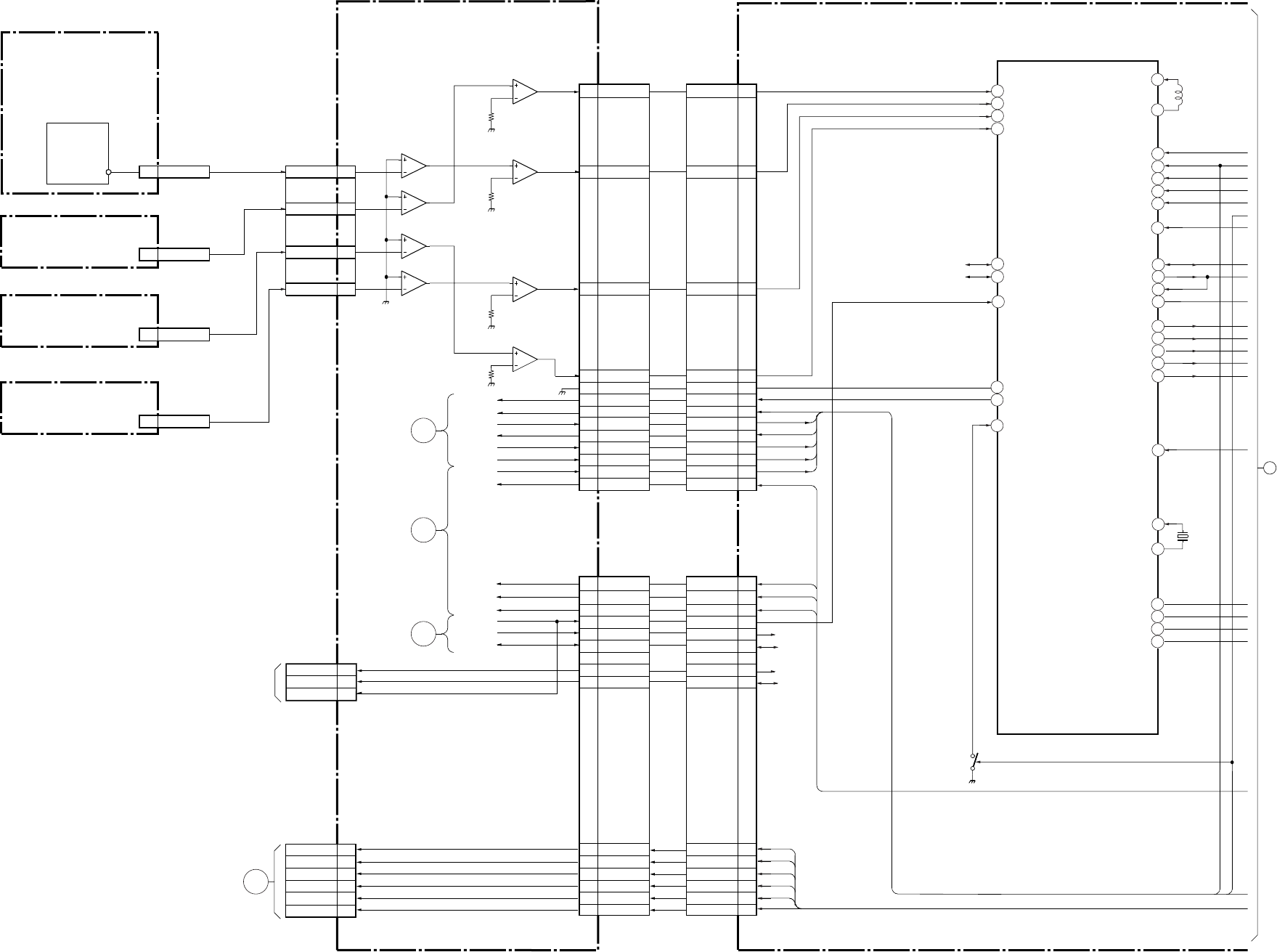
– 43 –
KP-HR432K90/HR532K90/HR532N90/HW572K90
RM-Y909KRM-Y908RM-Y909K RM-Y909K
BLOCK DIAGRAM (8)
18
7
26
27
28
49
47
50
48
44
9
12
36
32
33
34
11
6
46
60
61
62
59
55
8
39
17
16
15
4
IC1606
PJED-CPU
OR
OB
OG
O YS
I EXLC
38
OXLC
I EXODD
RESET
I OSC
O OSC
VBLK
DREG SCL
O DREG SDA
I DREG SDA
O I2C RST
O DREGI RST
O DREGI MUTE
O NAM
64
WRITE PROT O RAMCLR
O NVM STOP
MAIN SCL
SEN UI
SEN LE
SEN R
SEN LO
MAIN SDA
I BINT
I VP
52
OVSHIFT
53
OHSHIFT
I HP
I DREG OVF
I DREG BSY
I DREG ACK
LEFT
UPPER
LOWER
RIGHT
S3001
SENSOR
CN3001 CN10
CN12
(X/X) CN1601
HP
VP
11
7
6
5
7
6
5
1
2
3
1
2
3
7
6
5
7
6
5
1
2
3
1
2
3
3
5
7
SENSOR LEFT
UPPER
LOWER
RIGHT
SCLCK
SDAT
X1601
12MHz
IC11
IC11
IC7
Q1603
IC5
IC10
IC10
(I/V CONV.)
A(5/5)
S(SENSOR)
S(SENSOR)
S(SENSOR)
S(SENSOR)
RH
RV
GH
GV
BH
BV
8
7
5
4
2
1
C
TO G
BOARD
CN651
SEN U
4
SEN R
2
SEN LE
3
SEN LO
H SHIFT
V SHIFT
H CENT
DF
H SAW
REGI MUTE
HP
VP
RE YS
RE B
1
RH
RV
GH
GV
14
15
16
17
BH
BV
18
19
RE G
RE R
/BINT
CLK1
2
3
5
6
DAT1
PCLK
PDAT
RE B
RE G
RE R
BINT
SCLK
SDAT
PCLK
PDAT
7
9
10
4
2
3
1
6
7
8
10
11
13
14
15
20
1
6
7
8
10
11
13
14
15
20
1
14
15
16
17
18
19
2
3
5
6
7
9
10
SEN U
SEN R
SEN LE
SEN LO
H SHIFT
V SHIFT
H CENT
DF
H SAW
REGI MUTE
HP
VP
RE YS
RE B
RE G
RE R
BINT
SCLK
SDAT
PCLK
PDAT
SCLK
SDAT
PCLK
PDAT
RH
RV
GH
GV
BH
BV
V SHIFT
H CENT
D FOCUS
H SAW
REGI MUTE
HP IN
VP
R-YS
R-B
R-G
R-R
PCLK
PDAT
/BINT
2
1
9
BINT
SCLK
SDAT
TO A
BOARD
SYSTEM
BLOCK
9
TO A
BOARD
VIDEO
BLOCK
3
TO A
BOARD
VIDEO
BLOCK
2
FOR
CHECK
CN5 (2/2)
CN5 (2/2)
(1/2) (PJED-CPU)
AD
3
TO/FROM
BLOCK DIARAM(9)
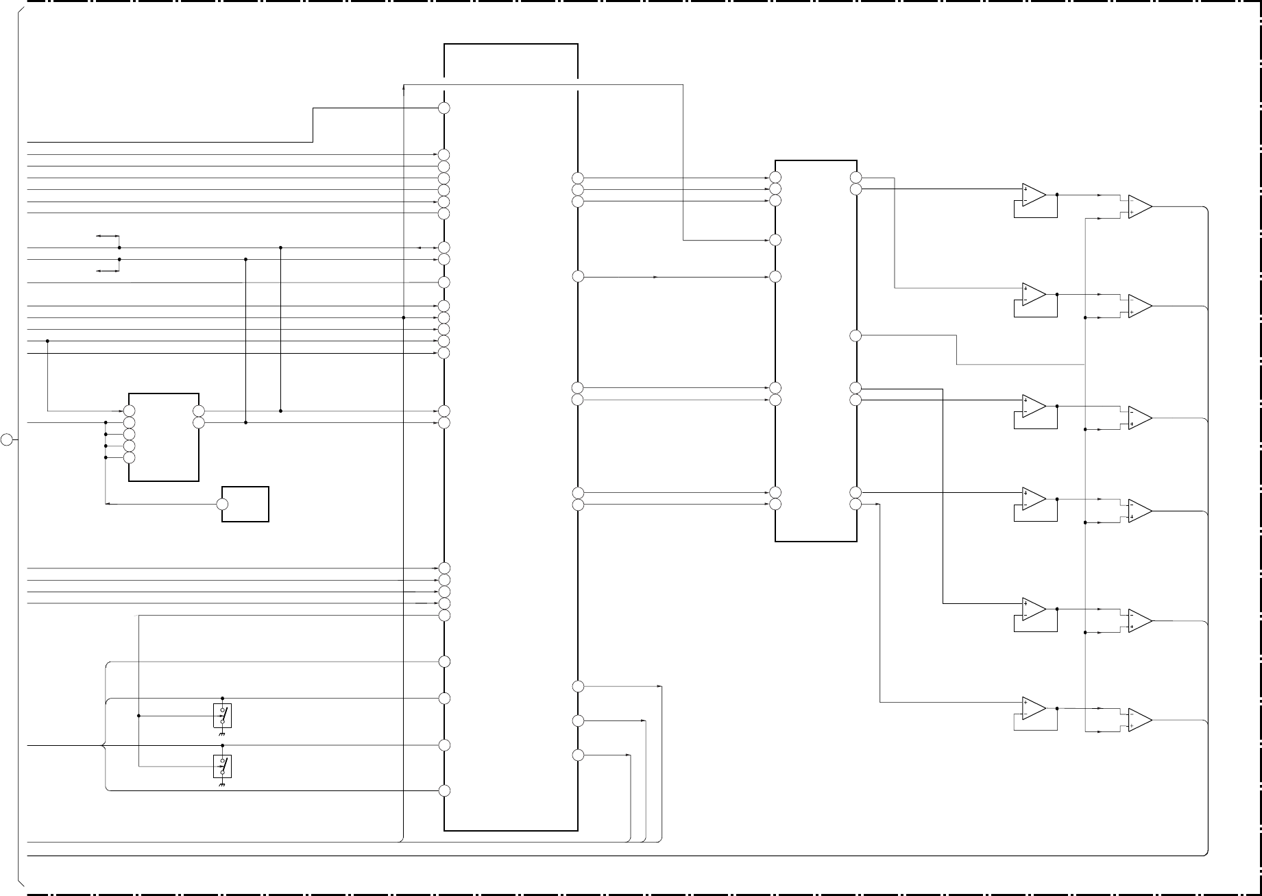
– 44 –
KP-HR432K90/HR532K90/HR532N90/HW572K90
RM-Y909KRM-Y908RM-Y909K RM-Y909K
BLOCK DIAGRAM (9)
7
8
1
2
6
5
32
37
17
10
9
30
23
64
69
61
7
6
62
14
12
8
5
19
18
68
71
67
70
44
51
55
91
4
3
48
4
45
12
8
46
DRV
DRH
BCLK
MUTED
5
WCLK
2
DGV
47
DGH
3
DBV
1
DBH
33
25
16
41
37
RV
RH
OUTC
GV
GH
BV
BH
IC1608
D/A CONVERTER
IC1611
BV-FIL/AMP
RVOUT1
RHOUT1
BCLK
WCLK1
GVOUT1
GHOUT1
BVOUT1
BHOUT1
SHADING
84
DF
26
PWM2
H SAW
DF
H CENT
O EV OUT
HPIN2
XOFDET
XBUSY
XACKM
VP IN
VBLK OUT4
SCLM
SDAT
11
SDAS
X12CRES
XMUTE
XSTOP
XWC
13
XRAMCLR
SCLS
SDAS
ROUT
60
YSIN
56
RIN
57
GIN
58
BIN
52
YMOUT
GOUT
BOUT
YSOUT
WP
VDD
A0
A1
A2
PLCK
PDAT
IC1607
NVM
RST
IC1607
RESET
IC1601
REGI CORRECTION
PLCK
PDAT
RE-YS
RE-R
RE-G
RE-B
REGI MUTE
Q1604
PROT
Q1605
PROT
7
6
5
IC1610
GH-FIL/AMP
7
6
5
1
3
2
1
3
2
1
3
2
IC1609
GV-FIL/AMP
7
6
5
IC1612
GV-FIL/AMP
7
6
5
IC1603
RV-FIL/AMP
7
6
5
IC1602
RH-FIL/AMP
7RH
RV
GH
BV
GV
BH
6
5
(2/2) (REGI CORRECTON)
AD
1
3
2
1
3
2
1
3
2
39
3
TO/FROM
BLOCK DIARAM(8)
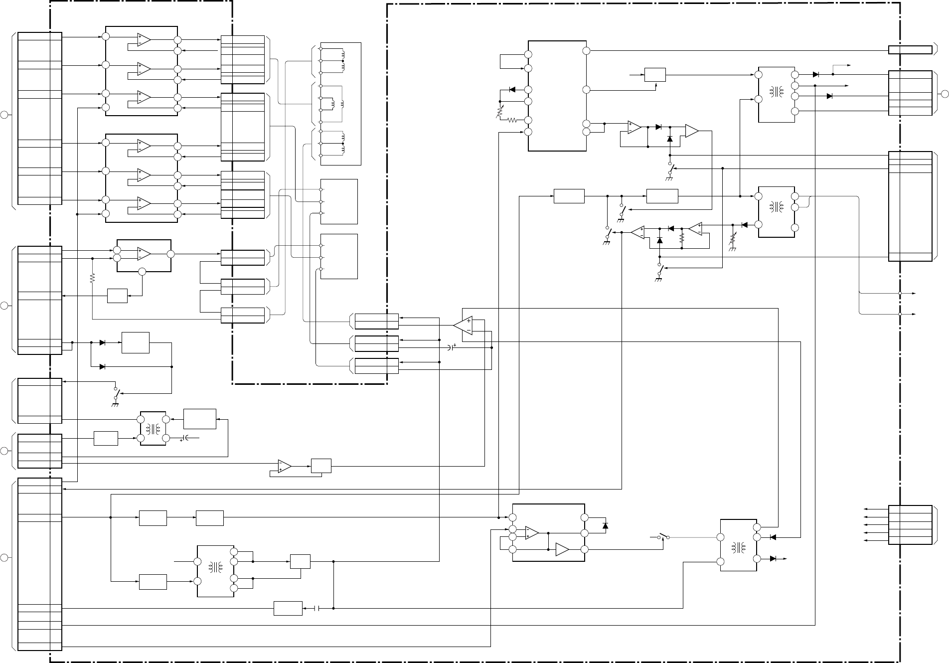
– 45 –
KP-HR432K90/HR532K90/HR532N90/HW572K90
RM-Y909KRM-Y908RM-Y909K RM-Y909K
BLOCK DIAGRAM (10)
F
BH
BV
CN8005
1
2
GH 5
4
7
8
3
5
7
1
2
1
2
4
6
2
1
10
6
4
8
GV
RV
RF
TO
A BOARD
CN4
N
TO
CB BOARD
CN7304
TO
HV BLOCK
TO
G BOARD
CN5004
C
TO
A BOARD
CN1
E
TO
A BOARD
CN3
15
14
6
2
18
16
11
13
9
7
15
14
6
2
18
16
11
13
9
7
1
8
6
9
7
5
18
264
1
12
3
11
10
4
2
6
7
3
4
5
3
7
BUFFER
Q8001
G2-STOP
/CONTROL
Q8003
BV OUT
BV RET
BH OUT
BH RET
GH OUT
GH RET
GV OUT
GV RET
RV OUT
RV RET
RH OUT
RH RET
CN8010
CN8011
CN8012
CN8007
CN8008
CN8009
V DEF
1
4
1
3
2
3
2
1
4
4
1
3
2
V RET
3
D
TO
A BOARD
CN2
TO
FOCUS
PACK
VP
V DRV(+)
CN8006
V DRV(–)
G2 MUTE VCC
G2 CNT
G2
DF2
REGI MUTE
2
HV PROT
DF
CN8004
DF
H CENT
H DRV
HP
ABL
PIN(EW)
CN8002
CN8003
V DEF
V RET
V DEF
V RET
DF V AMP
Q8007
HP AMP
Q8031,8101
DF H BUFF
Q8008-8011,
8014,8015
BUFFER
Q8039
SWITCH
Q8035
1
2
H OUT(B)
H RET(B)
H OUT(G
H RET(G)
H OUT(R)
H RET(R)
1
4
1
4
1
4
14
7
9
18
5
3
7
1
14
12
7
10
1
6
HV
MV
11
1
4
7
5
8
BUFFER
Q8004,8016
H DRIVE
Q8022,8030
AMP
Q8019,8020
T8004
LOT
T8005
FBT
D8039
D8037
D+200V
+135V
CN8022
CN8013
1
3
4
6
9
CN8023
∑IK 1
1
∑IK 2
2
PROT ON/OFF
3
H(–)
7
H(+)
6
200V
1
HV REG
3
CN8016
–15V
+15V
–22V
+22V
135V
–15V
+15V
–22V
+22V
135V
IC8002
CONV.OUT1
IC8001
CONV.OUT1
IC8003
V OUT
MUTE
MUTE
D8005
D8040
D8002
D8012
T8001
DFT
1
3
2
–22V
T8020
HDT
+135V
H OUT
Q8004
IC8005
H.DRIVE
HD IN V REC 9
T8003
HOT
+135V
DF
VCC
D8032
D8032
Q8022
IC8007 D8008
D8023
Q8029
D8043 D8038
VR8002
D8025
Q8028
Q8021
5
67
3
21
3
2
1
75
6
BUFFER
Q8005,8032
AMP
Q8036,8037
IC8008
H DRIVE
ERR OUT
ERR IN
SLOW
SW
VR REG
REF IN
HD IN
MIX+
PWM
OUT
MIX–
MIX OUT
D8022
VR8022
+135V
DY(B)
DY
(V)
SUB
DY
DY
(H)
DY
(G)
SAME AS
ABOVE
DY
(R)
SAME AS
ABOVE
V.DEF
V.MID
V.RET
H(+)F
H(MID)
H(–)
CN8019
CN8018
CN8020
1
2
3
5
1
3
1
3
HV
HV
TO
HV BLOCK
TO
FOCUS PACK
D
(H/V OUT)
6
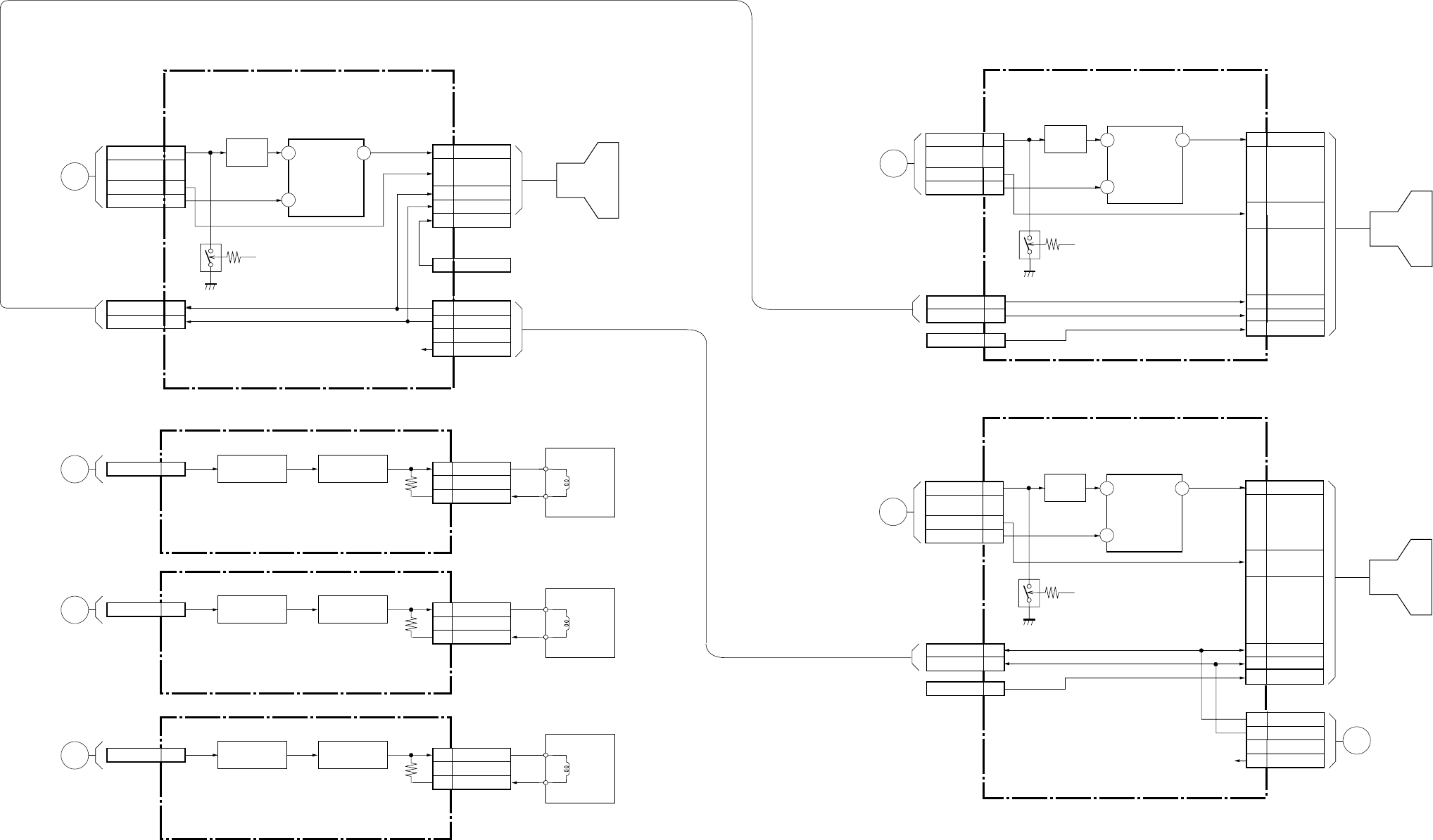
– 46 –
KP-HR432K90/HR532K90/HR532N90/HW572K90
RM-Y909KRM-Y908RM-Y909K RM-Y909K
BLOCK DIAGRAM (11) (EXCEPT HW572K90)
AMP
Q9002-9007
G
GS
IK
8
6
7
10
6
7
10
4, 5,
9, 11
1
8
6
7
1
K
H+
H-
G2
G1
G2
V902
V901
H+
H-
200V
3
1
4
VM 6
H+
H-
6
7
H+
H-
6
7
G2 1
BUFFER
Q7202 V IN V OUT
IK
VM DRIVE
Q9008, 9009
CN7205
CN7202
CN7204
CN9001
CN7209
1
2
VM, OUT
VM, RET
VM
VM ASSY
CN7203
CN9002
K
H+
H-
G2
CR
G1
4, 5,
9, 11
(R DRIVE)
CG(G DRIVE)
V(VM DRIVE)
CN7108
CN7103
CN7104
FOCUS BLOCK
FOCUS BLOCK
200V
J
TO A
BOARD
CN17
H
TO
A
BOARD
CN703
3
5
8
Q7201
+12V
AMP
Q9002-9007
VM 6 VM DRIVE
Q9008, 9009
CN9001
1
2
VM, OUT
VM, RET
VM
VM ASSY
CN9002
V(VM DRIVE)
K
TO A
BOARD
CN18
AMP
Q9002-9007
VM 6 VM DRIVE
Q9008, 9009
CN9001
1
2
VM, OUT
VM, RET
VM
VM ASSY
CN9002
V(VM DRIVE)
L
TO A
BOARD
CN19
R
RS
IK
3
1
4
BUFFER
Q7102 V IN V OUT
IK
CN7102
I
TO
A
BOARD
CN704
3
5
8
Q7101
+12V
8
6
7
10
4, 5,
9, 11 V903
H+
H-
6
7
G2 1
K
H+
H-
G2
CB
G1
(B DRIVE)
CN7309
CN7303
CN7305
FOCUS BLOCK
R
RS
IK
3
1
4
BUFFER
Q7302 V IN V OUT
IK
CN7302
G
TO
A
BOARD
CN702
3
5
8
Q7301
+12V
6
7
1
H+
H-
200V
CN7304
200V
N
TO
A
BOARD
CN8022

– 47 –
KP-HR432K90/HR532K90/HR532N90/HW572K90
RM-Y909KRM-Y908RM-Y909K RM-Y909K
BLOCK DIAGRAM (12) (HW572K90)
AMP
Q9002-9007
G
GS
IK
8
6
7
10
6
7
10
4, 5,
9, 11
1
8
6
7
1
K
H+
H-
G2
G1
G2
V902
V901
H+
H-
200V
3
1
4
VM 6
H+
H-
6
7
H+
H-
6
7
G2 1
V IN- V OUT
IK
VM DRIVE
Q9008, 9009
CN7205
CN7202
CN7204
CN9001
CN7209
1
2
VM, OUT
VM, RET
VM
VM ASSY
CN7203
CN9002
K
H+
H-
G2
CR
G1
4, 5,
9, 11
(R DRIVE)
CG(G DRIVE)
V(B VM DRIVE)
CN7108
CN7103
CN7104
FOCUS BLOCK
FOCUS BLOCK
200V
J
TO A
BOARD
CN17
H
TO
A
BOARD
CN703
2
7
12
Q7201, 7202
IC7201
VIDEO OUT
IC7101
VIDEO OUT
IC7301
VIDEO OUT
+12V
AMP
Q9002-9007
VM 6 VM DRIVE
Q9008, 9009
CN9001
1
2
VM, OUT
VM, RET
VM
VM ASSY
CN9002
V(G VM DRIVE)
K
TO A
BOARD
CN18
AMP
Q9002-9007
VM 6 VM DRIVE
Q9008, 9009
CN9001
1
2
VM, OUT
VM, RET
VM
VM ASSY
CN9002
V(R VM DRIVE)
L
TO A
BOARD
CN19
R
RS
IK
3
1
4
V IN- V OUT
IK
CN7102
I
TO
A
BOARD
CN704
2
7
12
Q7101, 7102
+12V
8
6
7
10
4, 5,
9, 11 V903
H+
H-
6
7
G2 1
K
H+
H-
G2
CB
G1
(B DRIVE)
CN7309
CN7303
CN7305
FOCUS BLOCK
R3
OFFSET
RS
IK
5
1
4
V IN- V OUT
IK
CN7302
G
TO
A
BOARD
CN702
2
7
12
Q7301-7303
+12V
6
7
1
H+
H-
200V
CN7304
200V
N
TO
A
BOARD
CN8022
BUFFER
Q7203
BUFFER
Q7103
BUFFER
Q7304
RC+
3
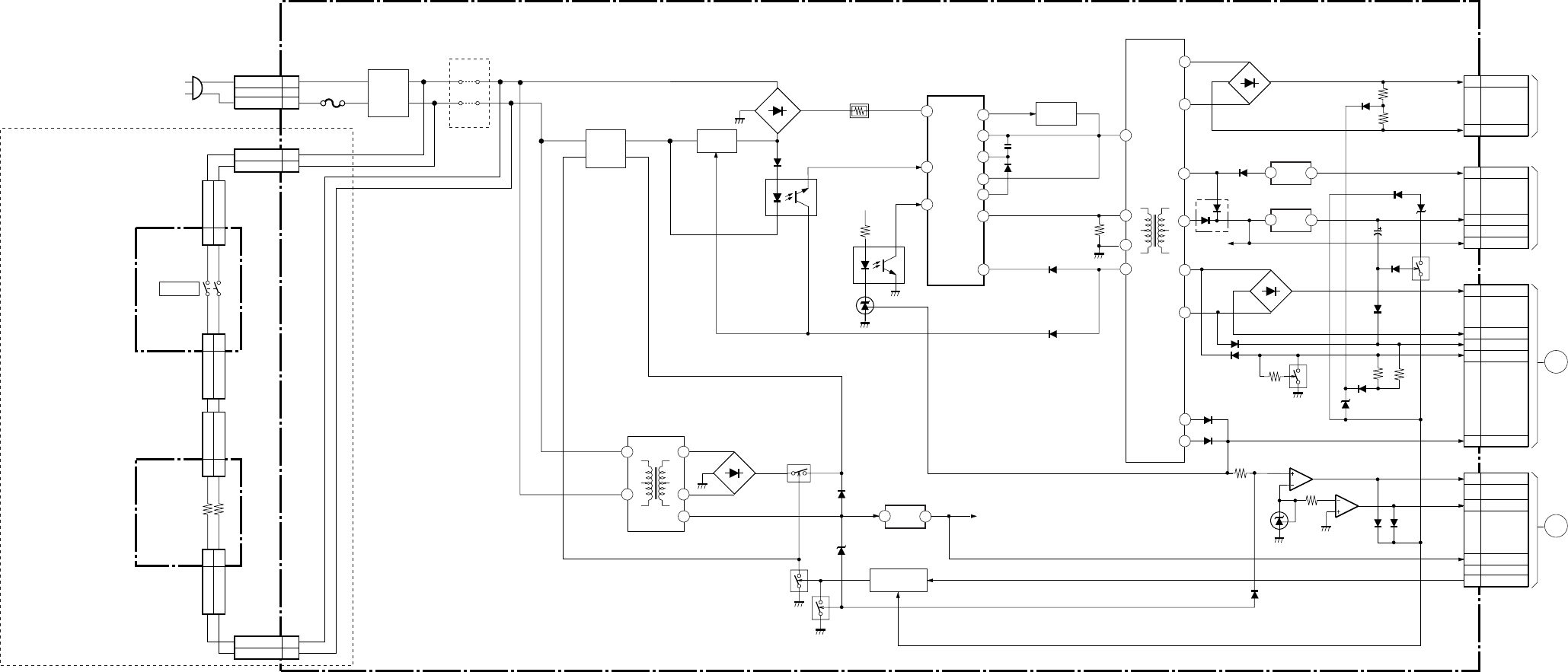
– 48 –
KP-HR432K90/HR532K90/HR532N90/HW572K90
RM-Y909KRM-Y908RM-Y909K RM-Y909K
BLOCK DIAGRAM (13)
Q5001
Q5002
TO
A BOARD
CN4
TO
A BOARD
CN706
M
TO
D BOARD
CN8013
G
TO
A BOARD
CN7
18
1
16
15 1
2
3
4
18
16
O
I
2
1
12
10
14
12
10
9
VS
VB
VG (L)
VC2
OCP
VC1
VG (H)
2
8
VD
V SENSE
+11V F/B
IC6003
DRIVER
T6001
PIT
1
4
3
9
8
T6004
STANDBY
1
2
AC (H)
AC (L)
1
4
AC (N)
AC (L)
CN6005
CN6004 RELAY
RY6003
CONV.
Q6006
RELAY
RY6002
7
9
15
13
IC5003
-5V REG.
IC5004
6V REG.
O
I
IC5006
STANDBY 5V REG.
RELAY DRIVE
Q5003, 5004
5
67
2
31
LINE
FILTER
L6001,
6002
POWER
S9101
+11V
D6007
D6002
PH6002
PH6001
IC501
D6012
D6011, 6020
D6006
D5017
Q5005
D5001
D5022
STBY 5V
D5003
D5010
D5006
D5002
D5009
D5008
Q5006
D5005
D5004
D5013
D5023
D5025
D5031
Q5007
D5018
D5019
D5026
IC5002
IC5005
D5020
D5007
D5014
1
4
AU 19V
AU -19V
CN5002
5
3
1
-5V
6V
11V
CN5003
6
4
3
1
9
+22V
-22V
+15V
-15V
+135V
CN5004
5
4
1
3
OVP
OCP
STBY 5V
RELAY
CN6
G
(POWER SUPPLY)
H1
(2/2)
(POWER SWTICH)
F
(LINE FILTER)
AC IN
110VAC(HR532N90)
220VAC(EXCEPT HR532N90) F6001
JW6005,
HR532N90
EXCEPT HR532N90
6006
JW6001,
6002
1
4
AC (N)
AC (L)
CN6004
1
4
AC (N) OUT
AC (L) OUT
CN9502
1
4
AC (N) IN
AC (L) IN
CN9501
1
4
AC (N) OUT
AC (L) OUT
CN9103
1
4
AC (N) IN
AC (L) IN
CN9104
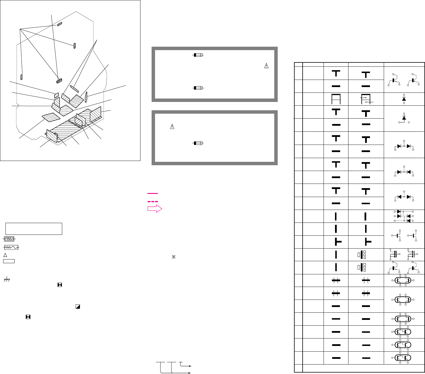
– 49 –
KP-HR432K90/HR532K90/HR532N90/HW572K90
RM-Y909KRM-Y908RM-Y909K RM-Y909K
6-2. CIRCUIT BOARDS LOCATION
6-3. SCHEMATIC DIAGRAMS
Note:
• Capacitors without voltage indication are all 50V.
• All resistors are in ohms.
kΩ=1000Ω, MΩ=1000kΩ
• Indication of resistance, which dose not have one for rating electrical power, is
as follows.
Pitch : 5mm
Rating electrical power : 1/ 4 W
•: nonflammable resistor.
• : fusible resistor.
• : internal component.
• : panel designation and adjustment for repair.
• All variable and adjustable resistors have characteristic curve B, unless otherwise
noted.
• : earth-chassis.
• The components identified by in this basic schematic diagram have been
carefully factory-selected for each set in order to satisfy regulations regarding
X-ray radiation.
Should replacement be required, replace only with the value originally used.
• When replacing components identified by , make the necessary adjustments
indicated. If results do not meet the specified value, change the component
identified by and repeat the adjustment until the specified value is achieved.
(Refer to VR8001 and VR8002 adjustment on Page 35.)
• Readings are taken with a NTSC color-bar signal input.
• Readings are taken with a 10MΩ digital multimeter.
• Voltages are dc with respect to ground unless otherwise noted.
• Voltage variations may be noted due to normal production tolerances.
• All voltages are in V.
* : Measurement impossibillity.
Note: The symbol display is on the component slde.
The components identified by shading and mark
are critical for safety. Replace only with part number
specified.
The symbol indicate fast operating fuse.
Replace only with fuse of same rating as maked.
Note: Les composants identifiés per un tramé et une marque
sont critiques pour la sécurité. Ne les remplacer
que par une piéce portant le numéro spécifié.
Le symbole indique une fusible a action rapide.
Doit etre remplacee par une fusible de meme yaleur,
comme maque.
G
D
S
B1 E1
C2
B2 C1
E2
2
3
4
5
6
7
8
9
0
!¡
!™
!¢
!§
!¶
!•
–
1
G
D
S
B2 E2
C1
B1 C2
E1
B2 E2
C1
B1 C2
E1
B2 E2
C1
B1 C2
E1
!ª
B1 E1
E2
C1(B2)
C2
@º
B1
E2
C1
C2
@™
@£
(B2)
E1
(B2)
E1
E2
B1
C2
C1
@¡
B1
E1
C2
B2
C1
E2
G
SS
D
G
D
B1
E1
C2
B2
C1
E2
B1
E2
C2C1(B2)
E2
B1
C1
C2E1(B2)
C2
B1
C1
E2E1(B2)
C2
B1
C1
E2
B2
E1
C2
Ver.1.5
Transistor
(FET)
Transistor
Transistor
Transistor
Transistor
Transistor
Transistor
Transistor
Transistor
Transistor
Discrete semiconductot
(Chip semiconductors that are not actually used are included.)
Diode
Diode
Diode
Diode
Diode
Diode
Diode
Diode
Diode
Diode
Source
Source
Anode Anode
(NC)
(NC)
Cathode
Anode
Cathode
Common
Cathode Cathode
Common
Cathode Cathode
Common
Common
Common
Common
Cathode
Anode
Base Emitter
Collector
Base Emitter
Collector
Drain
Gate
Gate
Drain
Device Printed symbol Terminal name Circuit
Terminal name of semiconductors in silk screen
printed circuit (
*
)
Anode
Anode
Anode Cathode
Anode Anode
Cathode
!£
Transistor
(FET)
Transistor
(FET)
!∞
Emitter
Collector
Base
Transistor
Source
Gate
Drain
Cathode
Anode
Anode Cathode
Anode
Anode
• Circled numbers are waveform references.
• : B+ bus.
• : B– bus.
•: signal path.(RF)
Reference information
RESISTOR : RN METAL FILM
: RC SOLID
: FPRD NONFLAMMABLE CARBON
: FUSE NONFLAMMABLE FUSIBLE
: RW NONFLAMMABLE WIREWOUND
: RS NONFLAMMABLE METAL OXIDE
: RB NONFLAMMABLE CEMENT
:ADJUSTMENT RESISTOR
COIL : LF-8L MICRO INDUCTOR
CAPACITOR : TA TANTALUM
: PS STYROL
: PP POLYPROPYLENE
: PT MYLAR
: MPS METALIZED POLYESTER
: MPP METALIZED POLYPROPYLENE
: ALB BIPOLAR
: ALT HIGH TEMPERATURE
: ALR HIGH RIPPLE
•Divided schematic diagram
Schematic diagrams of A, AD, B, D, G, and U boards are divided into several
pieces. Information to where the line is to be connected is printed
at the end of each.
For example, [ TO A1/5,A2/5_1 ] means the line is connected to
Ref. No. 1 of A(1/5) and A(2/5) schematic diagrams.
TO A1/5,A2/5_1
Ref. No.
Name of divided schematic diagram
S
CG
CR
G
A
CB
H2
H3
H1
H4
(EXCEPT HW572K90)
V
V
U
D
F
(EXCEPT HR532N90)
AD B
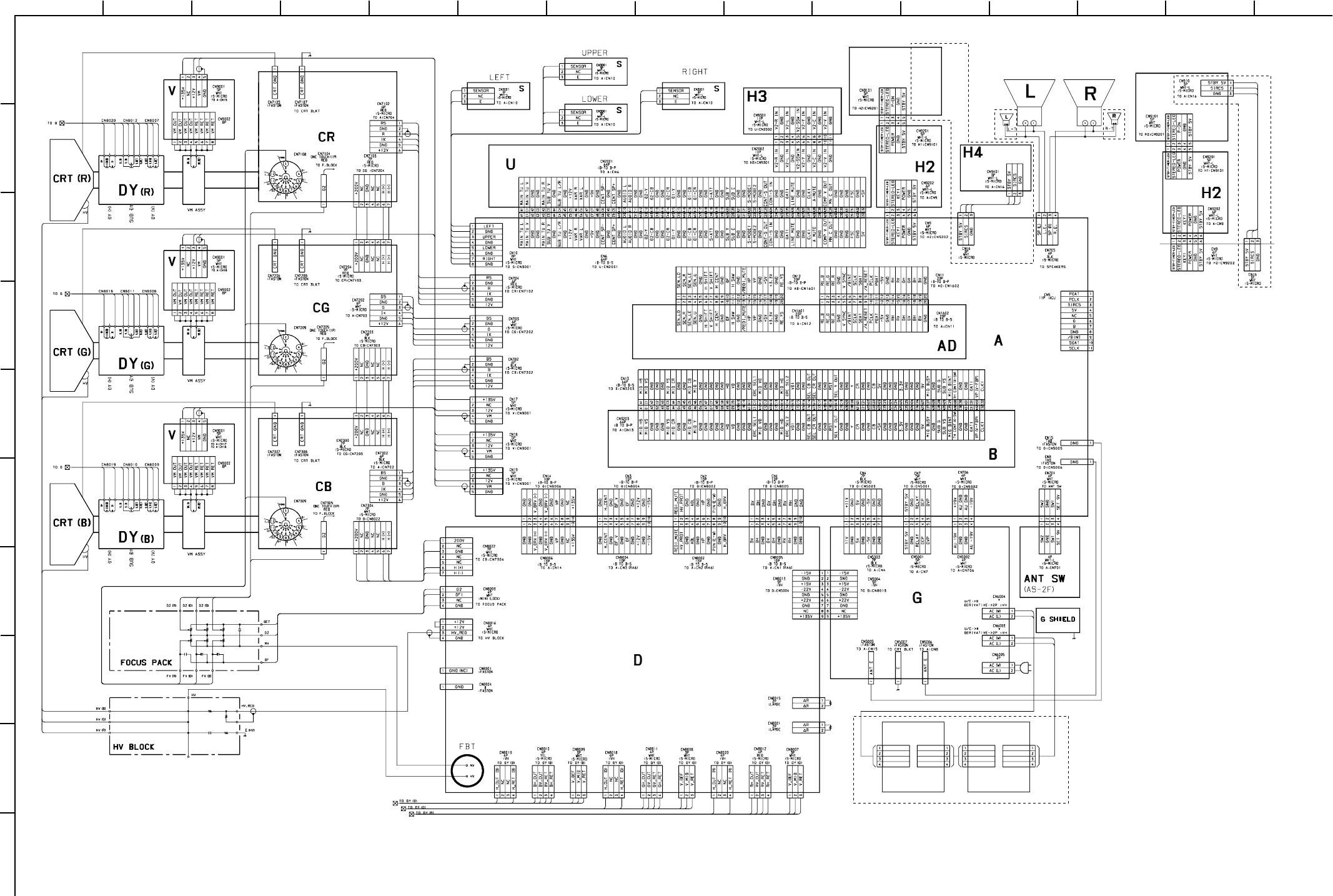
– 50 –
KP-HR432K90/HR532K90/HR532N90/HW572K90
RM-Y909KRM-Y908RM-Y909K RM-Y909K
1
A
B
C
D
E
F
G
H
I
J
212 13
11
10
98765
43 14 15
EXCEPT
HR432K90
EXCEPT
HW572K90
EXCEPT
HW572K90
EXCEPT HR532N90
EXCEPT
HR432K90
H1(1/2)
H1(1/2)
AC (N) IN
CN9104
2P
WHT
:VH
H1(2/2)
CN9103
2P
BLK
:VH
AC (L) IN
NC
NC
AC (N) OUT
AC (L) OUT
NC
NC
AC (N) IN
CN9501
2P
WHT
:VH
F
CN9502
2P
BLK
:VH
AC (L) IN
NC
NC
AC (N) OUT
AC (L) OUT
NC
NC
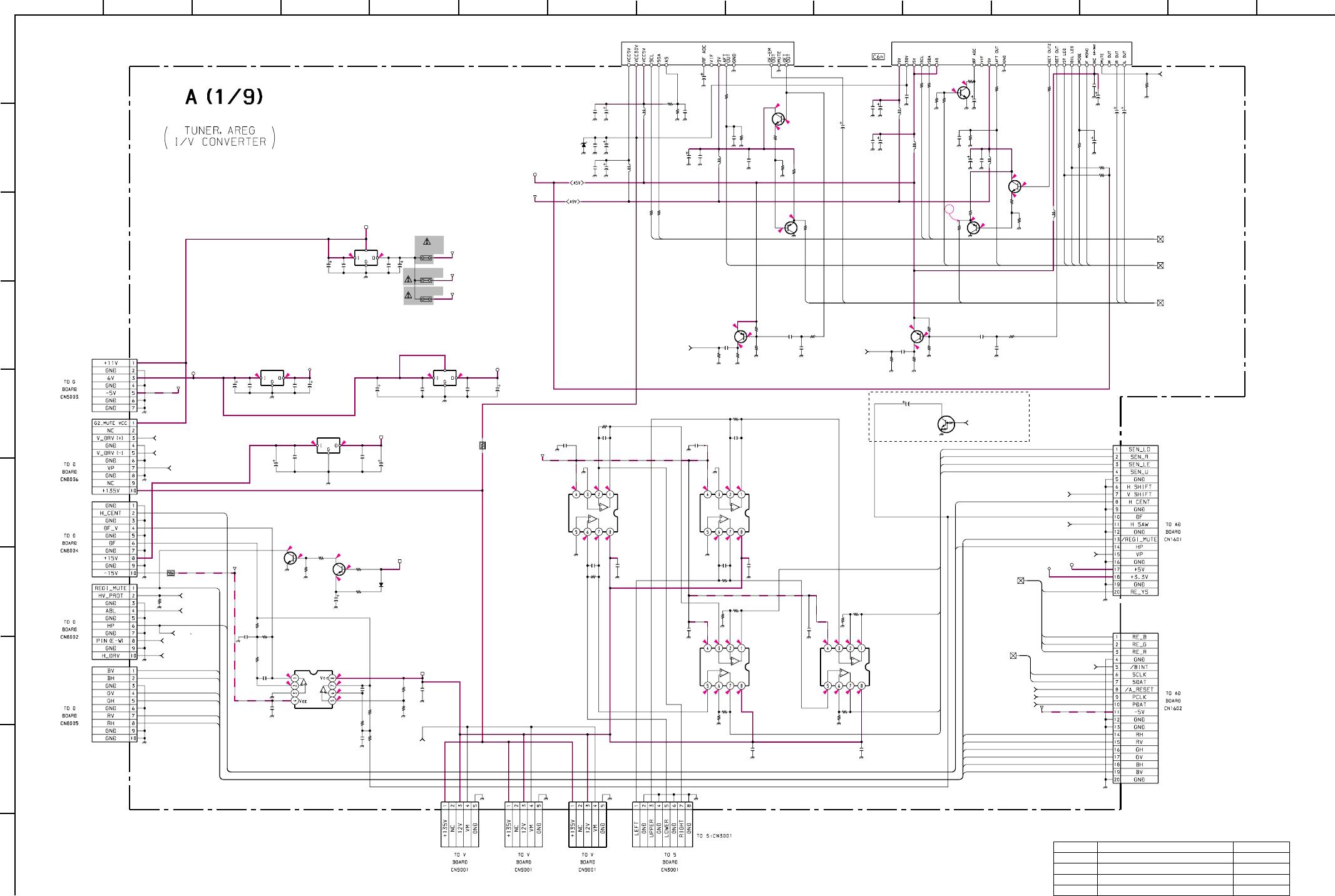
– 51 –
KP-HR432K90/HR532K90/HR532N90/HW572K90
RM-Y909KRM-Y908RM-Y909K RM-Y909K
1
A
B
C
D
E
F
G
H
I
J
212 13
11
10
98765
43 14 15
10.4 9.2
65
6.1 3.4
6.1 3.4
1.5
0
0.1
11.9
0
10.4
0
10.4
10.2
0
11.9
-16.4
0
0
0
0.2
11.9
-16.4
0
0.1
0
0.1
1
11.9
-16.4
5
2.9
04.1
2.2
0.9
5.3 5
0.8
5
2.4
94.8
4.2
3
1
4.7
0
9
0
0
0.1
0
0.2
2
11.9
-16.4
0.1
0.3
1.2
0.3
1.1
1.1
C1
C2
C3C5
C6
C7
C8
C10
C16 C20
C43 C53
C59
C76
C79
C86
C88
C94
C101
C103
C120
C124
C128
C129
C133
C137
C138C139
CN1
CN2
CN3
CN4
CN11
CN12
CN14
R11
R12
R13
R17
R18 R20
R21
R51
R52
R56R57
R60
R64
R65
R69
R70
R73
R81
R100 R107
R111
R112
R113
R114
R126
R127
R131
R133
R134
R136
R137
R138
R46
R55
CN10
C9
L7
L8
L9
L11
L12
L13
C82C83
C84
C49
C113
C125 C136
R145
R75
R10
R42
R143
D1
PS1
PS3
CN19
CN18
CN17
R123
C12
C140 C141
C142C143
C15
C4
R87
R139
C74
C130
C80
C147
R74
C146
C77
C75
C92
C111
C134
C119
C78
R152
R151
R27
R39
R37
R43
C93
C112
R44
D5
TU2
C123
PS2
R141
C81
C95
R68
C110
TU1
R16
C99
R140
C96
R14
R146
R142
R144
C45
C47 C54
C55
C132
R135 R147
Q14
Q11
Q22
Q27
Q2
Q21
Q28
Q7
Q8
IC2
IC1IC12
IC5IC7
IC3
IC10 IC11
IC9
R1
R50
R48
100
16V
100
25V
0.1
25V
F:1608
0.1
25V
F:1608
0.1
25V
F:1608
100
16V
0.1
25V
F:1608
0.01
F:1608
100p
CH:16080.1
25V
F:1608
0.1
25V
F:1608
0.1
25V
F:1608
0.1
25V
F:1608
0.0022
B:1608
100
16V
0.01
16V
B:1608
100
16V
1
16V
F:CHIP
220p
B:1608
10
100
16V
1
16V
F:CHIP 220p
B:1608
0.047
16V
C810
47
25V
B:1608
10
10
10 10
10P
:B TO B-P
10P
:B TO B-P
10P
:B TO B-P
7P
BLK
:S-MICRO
20P
:B-TO B-P
20P
:B-TO B-P
10P
:B TO B-P
15k
1/16W
:RN-CP
18k
1/16W
:RN-CP100k
1/16W
:RN-CP
3.9k
1/16W
:RN-CP
8.2k
1/16W
:RN-CP
3.3k
1/16W
:CHIP
33k
1/16W
:CHIP
10k
1/16W
:CHIP
10k
1/16W
:CHIP
47
1/16W
:CHIP
47
1/16W
:CHIP
10k
1/16W
:CHIP
22k
1/16W
:CHIP
10k
1/16W
:CHIP
1M
1/16W
:CHIP
100k
1/16W
:CHIP
560
1/16W
:RN-CP
2.2k
1/16W
:CHIP
10k
1/16W
:CHIP
10k
1/16W
:CHIP
100 1/16W :CHIP
1M
1/16W
:CHIP
100k
1/16W
:CHIP
100 1/16W :CHIP
2.2k
1/16W
:CHIP
33k
1/16W
:CHIP
22k
1/16W
:CHIP
560
1/16W
:RN-CP
430
1/16W
:RN-CP
1k 1/16W :CHIP
10k
1/16W
:CHIP
10k
1/16W
:CHIP
1.2k
1/16W
:CHIP
1.2k
1/16W
:CHIP
8P
WHT
:S-MICRO
1000p
25V
CH:1608
:LAV35
:LAV35
10µH
10µH:LAV35
:LAV35
:LAV35
:LAV35
0.1
25V
F:1608
0.1
25V
F:1608 100
16V
0.1
25V
F:1608
0.1
25V
F:1608
0.1
25V
F:1608 0.1
25V
F:1608
4.7k
1/16W
:CHIP
4.7k
1/16W
:CHIP
4.7k
1/16W
:CHIP
680k
1/16W
:CHIP
4.7k
1/16W
:CHIP
ICP-N15-T104
ICP-N15-T104
5P
WHT
:S-MICRO
5P
WHT
:S-MICRO
5P
WHT
:S-MICRO
10k
1/16W
:CHIP
100
16V
100
16V100
16V
0.1
25V
F:1608
0.1
25V
F:1608
390p
CH:1608
1SS355-TE
0.1
25V
F:1608
10k
1/16W
:CHIP
47k
1/16W
:CHIP
10
0.01
16V
B:1608
47
*
470
1/16W
:RN-CP
*B:1608
0.1
25V
F:1608
0.1
25V
F:16080.1
25V
F:1608
0.1
25V
F:1608
0.1
25V
F:1608
100
16V
100
25V
10k
1/16W
:CHIP
10k
1/16W
:CHIP
4.3k
1/16W
:RN-CP
680k
1/16W
:CHIP
470k
1/16W
:CHIP
470k
1/16W
:CHIP
10
0.1
25V
F:1608
0.47
:FPRD
UDZS-33B
*
MAIN-TUNER
0.0022 B:1608
ICP-N15-T104
100
1/16W
:CHIP
100
10V
0.01
16V
B:1608
33k
1/16W
:CHIP
0.1
25V
F:1608
BTF-FA401
SUB-TUNER
2.7k
1/16W
:RN-CP
0.047
16V
B:1608
10k
1/16W
:CHIP
0.1
25V
F:1608
43k
1/16W
:CHIP
43k
1/16W
:CHIP
68k
1/16W
:CHIP
68k
1/16W
:CHIP
0.0047
F:1608
0.0047
F:1608 0.0047
F:1608
0.0047
F:1608
470
16V
100
1/16W
:CHIP
#
:CHIP
2SC2412K
2SC2412K
2SC2412K
2SC2412K
2SA1037AK
2SA1037AK
2SA1037AK
2SA1037AK
2SA1037AK
PQ09RF21
BA033T NJM2395AF05
NJM4558M-TE2NJM4558M-TE2
NJM2068V-TE2
DF FILTERNJM4558M-TE2NJM4558M-TE2
NJM78M12FA
18k
2W
:RS
100
1/16W
:CHIP
100
1/16W
:CHIP
IIC-1
TO A1/9,A2/9,A3/9,
A4/9,A5/9,A6/9,A7/9,A9/9_3
TO A1/9,A7/9_5 S-TU-H TO A1/9,A7/9_6
M-TU-H
PIN(E-W)
TO A1/9,A5/9_52
ABL TO A1/9,
A5/9,A8/9_50
TU CONT TO A1/9,A7/9_2
TU OUT TO A1/9,A2/9_1
TO A1/9,A5/9_57 V SHIFT
TO A1/9,A2/9,A5/9_33 VP
TO A1/9,A2/9,A7/9_29 /BINT
TO A1/9,A2/9_24 PCLK
TO A1/9,A2/9_23 PDAT
TO
A1/9,A5/9_54
VM
TO A1/9,A5/9_55 R-SIG
TO A1/9,A7/9_31 3D/RST
5V
3.3V
3.3V
HV PROT
TO A1/9,A7/9_49
V DRIVE+ TO A1/9,A5/9_47
V DRIVE- TO A1/9,A5/9_48
TO A1/9,A8/9_56 H SAW
5V
H DRIVE
TO A1/9,A5/9_53
9V-4
9V-3
9V-2
9V-3
6V5V
TUNER MUTE TO A1/9,A7/9,AA9/9_4
TO A1/9,A2/9,A3/9,
A4/9,A5/9,A6/9,
A7/9,A8/9,A9/9_3
IIC-1
-5V
-5V
+11V
+11V
-15V
-15V
12V
12V
HP IN
TO A1/9,A5/9_51
DAT1
CLK1
AFT2
MONO-1
MOD-1
BIL-1
ST-1
AFT1
AGC
CLK1
DAT1
SUB TU V
SUB TU L/R
MAIN TU R
MAIN TU L
MAIN TU V
DAT1
R-YS
R-B
R-G
R-R
CLK1
AREGI D3
AREGI D0
AREGI D1
AREGI D2
AREGI D1
AREGI D3
H CENT
HP IN
H CENT
HP IN
AREGI D2
AREGI D0
RH
RV
GH
GV
BH
BV
REGI MUTE
REGI MUTE
BV
BH
GV
GH
RV
RH
10µH
10µH
10µH
L14
*
10µH
VP TO A1/9,A2/9,A5/9_33
DTC144EKA
SWITCH
VTIM TO A1/9,A5/9,A8/9_68
Q30
HW572K90
• A (1/9) BOARD * MARK LIST
Ref. No. KP-HR432K90/HR532K90/HW572K90 KP-HR532N90
C146 0.01uF 16V B: CHIP -
C147 0.01uF 16V B: CHIP -
L14 10uH: LAV35 -
TU2 BTF-WL411 BTF-WA412
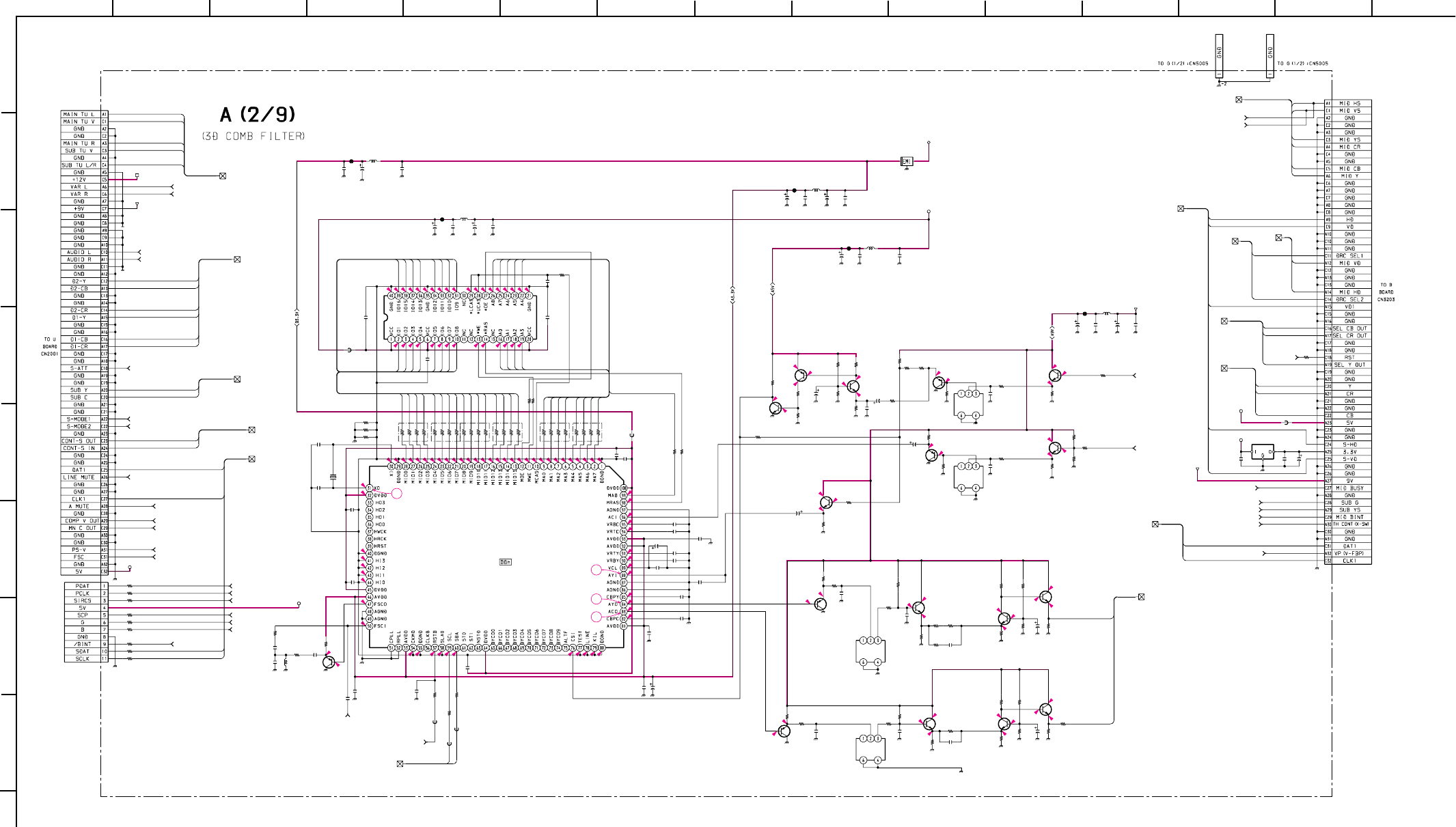
– 52 –
KP-HR432K90/HR532K90/HR532N90/HW572K90
RM-Y909KRM-Y908RM-Y909K RM-Y909K
1
A
B
C
D
E
F
G
H
212 13
11
10
98765
43 14 15
1.9
1.7
1.8
0.7
0.8
2.9
0.6
1.5
1.5
1.6
1.5
1.6
3.3
0
0
0
0
1.9
1.5
0
0
0
4.4
4.4
4.3
0
0
0
0
1.7
2.4
2.3
8.9
3.4
5
0.6
5.5
2.9 6
1.8
2.3
8.9
5.3
6
6.6
1.7
2.3
8.9
8.9
3
2.3
5.9
6.6
1.6 8.9
6.2
2.9
3.5
4.8 3.52.8 3.7
8.9
3.1
8.9
3.1 3.7
4.8
0.1
03.7
2.3
4.9
0
2
2.2
1.6
0
0
1.9
2.1
2.1
2.3
2.3
2.5
1.4
1.5
1
1
2.4
1.6
1.6
1.6
1.6
0.3
0
1.7
0.6
2.7
2
3.3
2
1.6
1
0.8
2.5
1.9
1.1
0
0
1.7
0
1.5
1.6
1.6
1.6
1.5
1.5
1.5
1.6
1.1
2.9
2.4
1.4
1.2
2.3
2.2
1.8
2.1
1.2
1.8
0.7
0.6
1.8
1.7
1.6
2.2
1.9
1.7
0
1.5
0
5
3
4
C14 C17
C18
C19
C23
C24
C27
C28
C29
C30
C31
C33
C34
C35 C37
C38
C39
C40
C42
C44 C46
C50
C51 C52
C57
C60
C61
C62
C65
C66
C67
C68
C69
C70 C73 C87
C90
C97
C98
C102
C108
C109
C114
C115
C116
C121 C126
C135
CN5
CN15
FL4
FL5
FL6
FL7
L2
10µH
220µH
L3
L4
L6
R2
R3
R4
R5
R6
R8
R15
R22
R53
R54
R59
R61
R62
R63
R72
R76
R77
R78
R79
R82
R91
R92
R93
R95
R99
R103
R104
R105
R110
R115
R116
R117
R119
R120
R121
R124
R125
R128
R129
R130
C26
C71
C104
C105 C106
C131
FL3
C63
C13
C36 C41
CN8
CN6
CN13
L5
R80
R90
R118
R122
R85
R154
R155
R89
R7
FB1
FB6
C85
RB1
RB2
RB3RB4RB5
RB6
R23
R24
R25 R26
R40
C48
C72
L1
R71
R67
C22
C21
R29
R32
R19
R36 C58
C56
R101 C127
R49
R88
R109
R102
R328
X1
R96
R108
FB5
R9
R66
Q16
Q19
Q15
Q13
Q18
Q12
Q1
Q20
Q26
Q24
Q25
Q23
Q3
Q4
Q5
Q6
IC4
IC8
IC6
R47
R30 R33
R31
FB4
FB2
FB3
0.1
25V
F:1608
0.1
25V
F:1608
24p
CH:1608
24p
CH:1608
0.01
F:1608
47
16V
47
16V
0.01
F:1608
0.1
25V
F:1608
0.01
F:1608
47
16V
0.1
25V
F:1608
0.01
F:1608
47
16V 0.01
F:1608
0.01
F:1608
0.1
25V
F:1608
0.01
F:1608
0.01
F:1608
47
16V 0.01
F:1608
15p
CH:1608
47
16V 0.01
F:1608
0.1
25V
F:1608
0.1
25V
F:1608
0.1 25V F:1608
47 16V
0.1 25V F:1608
0.1 25V F:1608
0.1 25V F:1608
0.1 25V F:1608
0.1 25V F:1608
0.1 25V F:1608
0.1
25V
F:1608
1
10
470p
CH:1608
1
10
15p
CH:1608
15p
CH:1608
#
B:1608
15p
CH:1608
15p
CH:1608
#
B:1608 #
B:1608
10
11P
:ACU
TAB
:FASTON
220 1/16W :CHIP
220 1/16W :CHIP
220 1/16W :CHIP
220 1/16W :CHIP
220 1/16W :CHIP
220 1/16W :CHIP
1k
1/16W
:CHIP
470
1/16W
:CHIP
470
1/16W
:CHIP
470
1/16W
:CHIP
1k
1/16W
:CHIP
2.2k
1/16W
:CHIP
1k
1/16W
:CHIP
100
1/16W
:CHIP
1k
1/16W
:CHIP
560
1/16W
:CHIP
1k
1/16W
:CHIP
560
1/16W
:RN-CP
560
1/16W
:CHIP
1k
1/16W
:CHIP
0
:1608
5.6k
1/16W
:CHIP
5.6k
1/16W
:CHIP
560
1/16W
:CHIP
2.2k
1/16W
:CHIP
2.2k
1/16W
:CHIP
1k
1/16W
:CHIP
1k
1/16W
:CHIP
100
1/16W
:CHIP
820
1/16W
:CHIP
2.2k
1/16W
:CHIP
1k
1/16W
:CHIP
2.2k
1/16W
:CHIP
12k
1/16W
:CHIP
33k
1/16W
:CHIP
12k
1/16W
:CHIP
33k
1/16W
:CHIP
1k
1/16W
:CHIP
47
1/16W
:CHIP
1k
1/16W
:CHIP
0.1
25V
F:1608
#
25V
:1608
0.1
25V
F:1608
0.1
25V
F:1608 100
16V
2.2
470
6.3V
390p
CH:1608
220
10V 220
10V
TAB
:FASTON
64P
:B-TO B-S
64P
:B-TO B-S
560
1/16W
:RN-CP
0
:1608
820
1/16W
:CHIP
820
1/16W
:CHIP
5.6k
1/16W
:CHIP
5.6k
1/16W
:CHIP
0
:1608
220 1/16W :CHIP
10k 1/16W :CHIP
BLM11A601S
:1608
BLM11A601S
:1608
0.1 25V F:1608
100*4
100*4
100*4 100*4 100*4
100*4
100
1/16W
:CHIP
100
1/16W
:CHIP
100
1/16W
:CHIP
100
1/16W
:CHIP
100
1/16W
:CHIP
#
F:1608
#
CH:1608
:LAV35
220
1/16W
:CHIP
47k
1/16W
:CHIP
0.1
25V
F:1608
0.1
25V
F:1608
0:1608
0:1608
470
1/16W
:CHIP
#1/16W :CHIP #F:1608
0.1
25V
F:1608
#
1/16W
:RN-CP
#
CH:1608
4.7k
1/16W
:CHIP
5.6k
1/16W
:CHIP
68
1/16W
:CHIP
560
1/16W
:CHIP
#
:1608
20MHz
560
1/16W
:CHIP
560
1/16W
:CHIP
0:2012
220 1/16W :CHIP
220k
1/16W
:CHIP
2SA1037AK
2SC2412K
2SA1037AK
2SA1037AK
Q17
2SC2412K
2SC2412K
2SA1037AK
2SA1037AK
2SC2412K
2SC2412K
2SC2412K
2SC2412K
2SC2412K
2SC2412K
2SA1037AK
2SC2412K
2SC2412K
M11B416256A-35J
MEMORY
BA033T
3D COMB/HH DEC
#
1/16W
:CHIP
100
1/16W
:CHIP
100
1/16W
:CHIP
100
1/16W
:CHIP
BLM11A601S
:1608
BLM11A601S
:1608
BLM11A601S
:1608
COMP V OUT TO A2/9,A2/9_19
MN C OUT TO A2/9,A2/9,_20
MAIN Y/C TO A2/9,A3/9_32
TO A2/9,A1/9,A3/9,A4/9,A5/9,A6/9,A7/9,A9/9_3 IIC-1
TO A2/9,A5/9,_46 MID OUT
TO A2/9,A3/9_42 SYNC
TO A2/9,A6/9_40
SEL OUT
TO A2/9,
A2/9,A3/9_59
RST
TO A2/9,A7/9_38 MID BUSY
TO A2/9,A7/9_35 MID BINT
TO A2/9,A1/9,A3/9,A4/9,A5/9,A6/9,A7/9,A9/9_3 IIC-1
IIC-1
TO A2/9,A1/9,A3/9,A4/9,
A5/9,A6/9,A7/9_3
TU OUT TO A2/9,A1/9_1
CTRL-S TO A2/9,A8/9_16
MN C OUT TO A2/9,A1/9_20
D COMP
TO A2/9,A3/9,A6/9_11
SUB Y/C TO A2/9,A4/9_12
PDAT TO A2/9,A1/9_23
PCLK TO A2/9,A1/9_23
SIRCS TO A2/9,A7/9,A8/9_25
/BINT
TO A2/9,A1/9,A7/9
_29
COMP V OUT TO A2/9,A1/9_19
TO A2/9,A3/9_39
Y/CR/CB(DRC)
TO A2/9,A3/9_43 MAIN SYNC
TO A2/9,A3/9_41
DRC-SEL
TO A2/9,A7/9,_34 X SW
TO A2/9,A1/9,A7/9_31 D/RST
TO A2/9,A7/9_45 SIG-H
TO A2/9,A7/9_44 SIG-V
5V
5V
5V
3.3V
TO A2/9,A1/9,A5/9_33 VP
TO A2/9,A4/9_37 SUB G
TO A2/9,A4/9_36 SUB YS
S-ATT TO A2/9,A7/9_13
S-MODE1 TO A2/9,A7/9_14
S-MODE2 TO A2/9,A7/9_15
LINE MUTE TO A2/9,A7/9_17
A MUTE TO A2/9,A7/9_18
9V-4
TO A2/9,A3/9,_30 M-FSC
9V-3
6V
PS-V TO A2/9,A3/9_21
FSC TO A2/9,A4/9_22
SCP TO A2/9,A5/9_26
G1 TO A2/9,A5/9_26
B1 TO A2/9,A5/9_26
VAR L TO A2/9,A9/9_7
VAR R TO A2/9,A9/9_8
AUDIO L TO A2/9,A9/9_9
AUDIO R TO A2/9,A9/9_10
5V
9V-3
12V
IO0
IO1
IO2
IO3
IO4
IO5
IO6
IO7
IO0
IO1
IO2
IO3
IO4
IO5
IO6
IO7
IO8
IO9
IO10
IO11
IO12
IO13
IO14
IO15
IO8
IO9
IO10
IO11
IO12
IO13
IO14
IO15
MA4
MA5
MA6
MA7
MA8
MA0
MA1
MA2
MA3
MA0
MA1
MA2
MA3
MA4
MA5
MA6
MA7
MA8
CR
CB
Y
SEL CB
SEL CR
SEL Y
Y
CR
CB
CLK1
DAT1
CONT-S OUT
CONT-S IN
D1-CR
D1-CB
D1-Y
D2-CR
D2-CB
SUB-C
SUB-Y
MID YS
SEL1
SEL2
D2-Y
CLK1
DAT1
CLK1
DAT1
MAIN TU L
MAIN TU V
MAIN TU R
SUB TU V
SUB TU L/R
DAT1
VS
HS
MAIN C
MAIN Y
VD2
HD2
HD3
CLK1
VD1
S-HD
S-VD
VD3
µPD64082
10µH
4.7µH
10µH
10µH
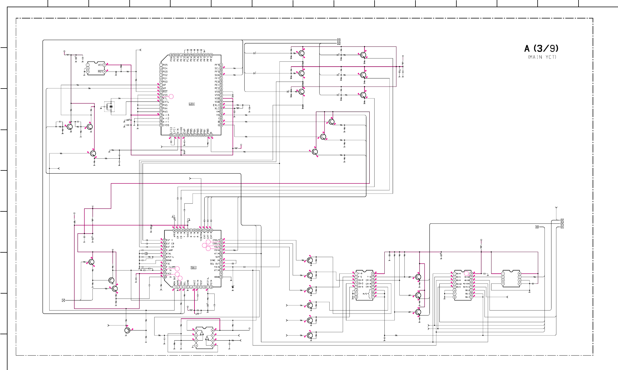
– 53 –
KP-HR432K90/HR532K90/HR532N90/HW572K90
RM-Y909KRM-Y908RM-Y909K RM-Y909K
1
A
B
C
D
E
F
G
H
I
212 13
11
10
98765
43 14 15
0.4
6
5
2.5 0.5
5
9.1
9.1
1.7 1.1
5.3
6
2.8
8.9
0
0
9
9.1
4.4
0
0
0
0
3.8
9.1
4.4
3.8
9.1
4.4 9.1
3.8
4.4 9.1
3.8
4.4 9.1
3.8
4.4
3.8
9.1
5
2.5 1.9
5
2.4 2.2
5
2.4 2.2
2.2
2.8
2.1
2.5
1.8
0
2.2
0
2.2
0
2.2
5.4 4.8
1.2
0
0.4
0.2
5
5
5
2.6
2.4
0
0
2.5
2.2
3.6
3.2
3.3
1.7
1.8
2.6
2.5
3.2
2.8
5
3.2
5
0.4
2.5
1.8
4.4
4.4
4.8
2.8
2.4
1.6
1.7
0
0.4
5
5
0.5
2.5
2.5
2
3.1
0
0
1.8
2.1
2.2
3.6
3.6
3.6
2.9
3.2
3.2
3.2
3.2
0
0
2.6
2.6
4.4
4.3
5
5
2.4
0
2.8
0.5
0.5
0.5
0.5
0.5
0
2.9
4.9
4.9
4.9
0
2.8
2.9
2.6
55
0.5
0.4
0.5
0.4
0
4.9
4.9
8
7
11
9
10
12
13
C307 C310 C314
C315
C316
C317
C321
C325
C326
C328
C330
C341
C344 C345
C348
C353
C355
C356
C358
C373
C391
C426
C500
C501 C502
C505
C506
L301
L303
L304
L307
L310
L315
R302
R303
R304
R306
R308 R309
R310
R312
R313
R314
R315
R316
R317
R336
R347
R349
R351
R352
R353
R357
R358
R359
R360
R361
R363
R364
R365
R367
R368
R369
R370
R371
R372
R374
R375
R376
R377
R378
R379
R380
R381
R382
R383
R384
R386
R387
R388
R389
R390
R391
R392
R393
R394
R395
R396
R398
R399
R400
R401
R402
R403
R404
R405
R432 R433 R439
R444
R445
R446
R450
R451
R452
R602
R613
X302
R355
L308
C319
C329
C336
C349
C359 C361
R539
X303
L306
R505 R506
R509
R512
R307
C312
C309
C372
C417
R344
R343
R333
R334
C322
C365
C364
C363
C371
C370
C369
C323
C351
C360
C327
C343
C354
C352
C357
C437
R616
C318
R325
C335
R362
R319
D307
R397
R340
C324 C366
R428
C422
C350
Q318 Q323
Q317 Q322
Q316 Q321
Q304
Q319
Q306
Q315
Q301
Q314
Q330
Q302
Q329 Q339
Q303
Q328
Q305
Q338
Q327
Q337
Q326
Q325
Q358
IC302
IC310
IC303
IC305 IC307 IC312
IC311
R301
C347 R326
R327
R322
R321
R318
0.1
25V
F:1608
10 0.1 16V B:1608
0.1 16V B:1608
1000p
B:1608
0.1
16V
B:1608
0.1
25V
F:1608
0.1 16V B:1608
470p CH:1608
0.1 16V B:1608
0.01
16V
B:1608
0.0047
B:1608
0.1
16V
B:1608
0.1
16V
B:1608
0.1
25V
F:1608
0.1 16V B:1608
0.1 16V B:1608
0.1 16V B:1608
15p
CH:1608
0.1
25V
F:1608
0.1
25V
F:1608
0.1
25V
F:1608
220p
CH:1608
0.01
F:1608
220p
CH:1608
1000p
B:1608
220p
CH:1608
:CHIP
10µH
:CHIP
:CHIP
:CHIP
:CHIP
:CHIP
100
1/16W
:CHIP
10k
1/16W
:CHIP
10k
1/16W
:CHIP
1.5k
1/16W
:RN-CP
1k
1/16W
:CHIP
220
1/16W
:CHIP
1M
1/16W
:CHIP
100
1/16W
:CHIP
10k
1/16W
:CHIP
10k
1/16W
:CHIP
4.7k
1/16W
:CHIP
1k
1/16W
:CHIP
1k
1/16W
:CHIP
100
1/16W
:CHIP
470
1/16W
:CHIP
220
1/16W
:CHIP
220
1/16W
:CHIP
220 1/16W :CHIP
100 1/16W :CHIP
22k
1/16W
:CHIP
22k
1/16W
:CHIP
22k
1/16W
:CHIP
22k
1/16W
:CHIP
22k
1/16W
:CHIP
100
1/16W
:CHIP
100
1/16W
:CHIP
100
1/16W
:CHIP
1k
1/16W
:CHIP
1k
1/16W
:CHIP
1k
1/16W
:CHIP
2.2k
1/16W
:CHIP
2.2k
1/16W
:CHIP
2.2k
1/16W
:CHIP
330
1/16W
:CHIP
330
1/16W
:CHIP
330
1/16W
:CHIP
22k
1/16W
:CHIP
22k
1/16W
:CHIP
22k
1/16W
:CHIP
22k
1/16W
:CHIP
22k
1/16W
:CHIP
22k
1/16W
:CHIP
100
1/16W
:CHIP
100
1/16W
:CHIP
100
1/16W
:CHIP
100k
1/16W
:CHIP
22k
1/16W
:CHIP
100
1/16W
:CHIP
100
1/16W
:CHIP
100
1/16W
:CHIP
100
1/16W
:CHIP
100
1/16W
:CHIP
100
1/16W
:CHIP
1k
1/16W
:CHIP
1k
1/16W
:CHIP
100k 1/16W :CHIP
10k
1/16W
:CHIP
100k
1/16W
:CHIP
100k
1/16W
:CHIP
100k
1/16W
:CHIP
100k
1/16W
:CHIP
100k
1/16W
:CHIP
100k
1/16W
:CHIP
470
1/16W
:CHIP
470
1/16W
:CHIP
470
1/16W
:CHIP
100
1/16W
:CHIP
100
1/16W
:CHIP
100
1/16W
:CHIP
270
1/16W
:CHIP
270
1/16W
:CHIP
270
1/16W
:CHIP
22k
1/16W
:CHIP
10k
1/16W
:CHIP
12MHz
100
1/16W
:CHIP
:LAV35
0.47 10V B:1608
0.47 10V B:1608
0.47
10V
B:1608
0.47
10V
B:1608
0.47
10V
B:1608
0.47
10V
B:1608
#
:1608
3.58MHz
:CHIP
1k
1/16W
:CHIP 22k
1/16W
:CHIP
22k
1/16W
:CHIP
0
:1608
1.5k
1/16W
:RN-CP
0.1
25V
F:1608
100
16V
100
16V
100
16V
100
1/16W
:CHIP
100
1/16W
:CHIP
100
1/16W
:CHIP
100
1/16W
:CHIP
100
16V
100
16V
100
16V
100
16V
100
16V
100
16V
100
16V
0.1
25V
F:1608
0.1
25V
F:1608
15p
CH:1608
15p CH:1608
4.7
4.7
0.47
10V
B:1608
0.01
25V
B:1608
#
F:1608
10k
1/16W
:CHIP
0.1
25V
F:1608
15k1/16W:CHIP
100
16V
22k
1/16W
:CHIP
0
:1608
UDZS-6.8B
1k
1/16W
:CHIP
3.9k
1/16W
:CHIP
16.3V B:1608
16.3V B:1608
0
:1608
0.1
25V
F:1608
470
16V
2SC2412K 2SC2412K
2SC2412K 2SC2412K
2SC2412K 2SC2412K
2SC2412K
2SC2412K
2SC2412K
2SC2412K
2SC2412K
2SC2412K
2SA1037AK
2SC2412K
2SA1037AK 2SC2412K
2SA1037AK
2SA1037AK
2SC2412K
2SC2412K
2SA1037AK
2SC2412K
2SA1037AK
2SA1037AK
2SA1037AK
CXP85840A-039Q
MAIN-CCD V-CHIP
(MAIN)
PST9145NL
CXA2103Q
YCT-MAIN
(MAIN) SN74LV4053
YCT_SEL SN74LV4053
DRC_SYNC_SEL TC7W08FU
NJM2903M-TE2
100
1/16W
:CHIP
0.1
25V
F:1608 0
:1608
470
1/16W
:CHIP
100
1/16W
:CHIP
1k
1/16W
:CHIP
10k
1/16W
:CHIP
5V
5V
5V
5V
5V
TO A3/9,A2/9_43 MAIN SYNC
MAIN Y/C
TO A3/9,A2/9_32
SYNC TO A3/9,A2/9_42
Y/CR/CB(DRC)
TO A3/9,A2/9_39
DRC-SEL TO A3/9,A2/9_41
TO A3/9,A7/9_58 YUV SW
TO A3/9,A7/9_60 BLOCK-M
9V-4
M-FSC
TO A3/9,
A2/9_30
TO A3/9,A2/9_21 PS-V
9V-4
RST TO A3/9,A1/9,A2/9,A4/9,A7/9_59
SELH TO A3/9,A6/9_73
VD3 TO A3/9,A6/9_74
MON OUT TO A3/9,A6/9_70
TO A3/9,A4/9,A6/9_75
CR OUT
TO A3/9,A4/9,A6/9_76
CB OUT
TO A3/9,A4/9,A6/9_77
Y OUT
D COMP TO A3/9,A2/9,A6/9_11
IIC-1 TO A3/9,A1/9,A2/9,A4/9,A5/9,A6/9,A7/9_3
-1
5V
VP
TO A3/9,A4/9
_78
S VD
TO A3/9,
A4/9_79
9V-4-1
TO A3/9,A4/9,A6/9_71 S HD
TO A3/9,A4/9,A6/9_72 S VD
CLK1
DAT1
R
G
B
YS
DAT1
CLK1
YS
B
G
R
CB
MAIN C
MAIN Y
SEL1
SEL2
Y
CR
D2-CR
D1-CR
D2-Y
D2-CB
D1-Y
D1-CB
VD3
HD2
VD2
HD3
VD1
S-VD
S-HD
VD1CCD
HD1
HD1
VD1CCD
10µH
10µH
220µH
10µH
10µH
10µH
10µH
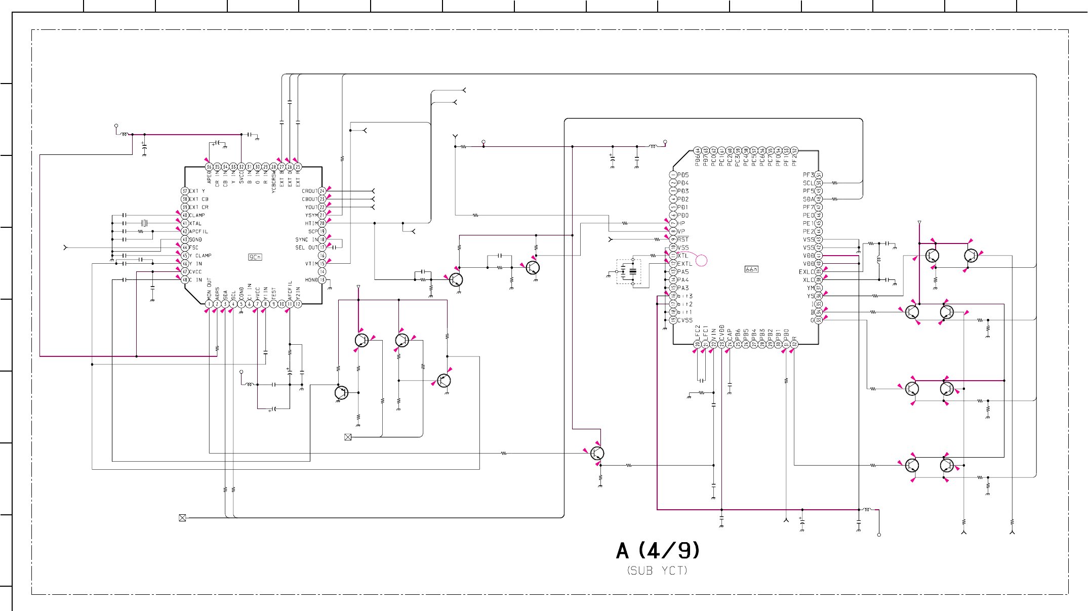
– 54 –
KP-HR432K90/HR532K90/HR532N90/HW572K90
RM-Y909KRM-Y908RM-Y909K RM-Y909K
1
A
B
C
D
E
F
G
H
212 13
11
10
98765
43 14 15
2.7
3.5
3.5
3.5
2.2
9.1 3.7 9.1 3.9
2.3
3.1 3.3
1.6
2.2
2.1
0
0.5
3.4
0.5
0
0
0
2.5
2.5
0
1.7
0.4
14
5
5
2.5
2.1
1.7
2.6
2.9
1.8
0
0
5
1.8
2.6
2.5
3.2
3
4.9 2.5
5
1.7
2.3
0.2
0.4
0.5
3.2
2.3
4.7
4.4
4.5
5
3
2.4
00
0
0
0
0
0
0
09.1
9.1
09.1
0
0
9.1
0
0
0
09.1 9.1
9.1
9.1
C301
C303
C304
C306
C311
C313
C331
C332
C375
C380
C381
C385
C398
C399
C401
C503
L302
L305
L309
L312
R305
R320
R331
R335
R337
R338
R339
R345
R346 R350
R354
R373
R385
R406
R407
R409
R416
R431
R435
R440
R441
R442
R443
R456
R457
R458
R459
R460
R461
R603 R604
R605
R606
R607
R608
R609
X304
R617 R618
R619
C504
L313
C308
C333
C334
C346
C376
X301
C374
R437
R436
C394
C305
C338
C342
R330
C362
C302
C367
C320
Q380
Q381
Q310 Q311
Q324
Q361
Q336
Q363
Q335
Q368
Q307
Q312
Q308
Q320
Q340
IC301
IC304
R408
C340
C337
C339
R323 R324
R412
0.01
16V
B:1608
0.1 16V B:1608
470p CH:1608
0.1 16V B:1608
100
16V
0.1
25V
F:1608
0.1
25V
F:1608
10
0.1
25V
F:1608
1000p
B:1608
0.1
16V
B:1608
0.0047
B:1608
0.1
25V
F:1608
15p
CH:1608
15p
CH:1608
220p
CH:1608
:CHIP
10µH
:CHIP
:CHIP
:CHIP
15k 1/16W :CHIP
10k
1/16W
:CHIP
10k
1/16W
:CHIP
4.7k
1/16W
:CHIP
1.5k
1/16W
:CHIP
1.5k
1/16W
:CHIP
100
1/16W
:CHIP
1.5k
1/16W
:RN-CP
1.5k
1/16W
:RN-CP100
1/16W
:CHIP
4.7k
1/16W
:CHIP
100
1/16W
:CHIP
1k
1/16W
:CHIP
0
:1608
10k 1/16W :CHIP
1k
1/16W
:CHIP
1M
1/16W
:CHIP
100
1/16W
:CHIP
470
1/16W
:CHIP
220
1/16W
:CHIP
220
1/16W
:CHIP
220
1/16W
:CHIP
100 1/16W :CHIP
2.2k
1/16W
:CHIP
2.2k
1/16W
:CHIP
2.2k
1/16W
:CHIP
330
1/16W
:CHIP
330
1/16W
:CHIP
330
1/16W
:CHIP
10k
1/16W
:CHIP
10k
1/16W
:CHIP
10k
1/16W
:CHIP
10k
1/16W
:CHIP
10k
1/16W
:CHIP
10k
1/16W
:CHIP
100
1/16W
:CHIP
12MHz
100
1/16W
:CHIP
100
1/16W
:CHIP
1k
1/16W
:CHIP
1000p
25V
CH:1608
:LAV35
0.47 10V B:1608
0.47
10V
B:1608
0.47
10V
B:1608
0.47
10V
B:1608
0.47
10V
B:1608
3.58MHz
100
16V
100
1/16W
:CHIP
100
1/16W
:CHIP
100
16V
15p CH:1608
4.7
0.01
25V
B:1608
3.9k
1/16W
:CHIP
0.1
25V
F:1608
16.3V B:1608
16.3V B:1608
4.7
2SC2412K
2SC2412K
2SC2412K 2SC2412K
2SC2412K
2SC2412K
2SC2412K
2SC2412K
2SC2412K
2SC2412K
2SC2412K
2SA1037AK
2SA1037AK
2SC2412K
2SC2412K
CXA2103Q
YCT-SUB
(SUB) CXP85840A-039Q
SUB-CCD V-CHIP
(SUB)
1k
1/16W
:CHIP
0.1
16V
B:1608
0.1
16V
B:1608
0.1
16V
B:1608
100
1/16W
:CHIP
100
1/16W
:CHIP
220
1/16W
:CHIP
5V
5V
5V
5V
FSC
TO A4/9,
A2/9_22
SUB Y/C
TO A4/9,A2/9_12
RST
TO A4/9,A2/9,
A3/9_59
TO A4/9,A7/9_61 BLOCK-S
TO A4/9,A2/9_37 SUB G
TO A4/9,A2/9_36 SUB YS
S HD TO A4/9,A6/9_71
S VD TO A4/9,A6/9_72
TO A4/9,A1/9,A2/9,A3/9,A5/9,A6/9,A7/9,A9/9_3 IIC-1
5V-1
VP
TO A4/9,
A3/9_78
S VD TO A4/9,A3/9/_72
CR OUT
TO A4/9,A3/9,A6/9_75
CB OUT
TO A4/9,A3/9,A6/9_76
Y OUT
TO A4/9,A3/9,A6/9_77
9V-4-1
9V-4-1
S HD
TO A4/9,A3/9_71
YS
B
G
YS
R
G
B
S-HD
DAT1
CLK1
DAT1
CLK1
S-VD
SUB-C
SUB-Y
R
10µH
10µH
10µH
10µH
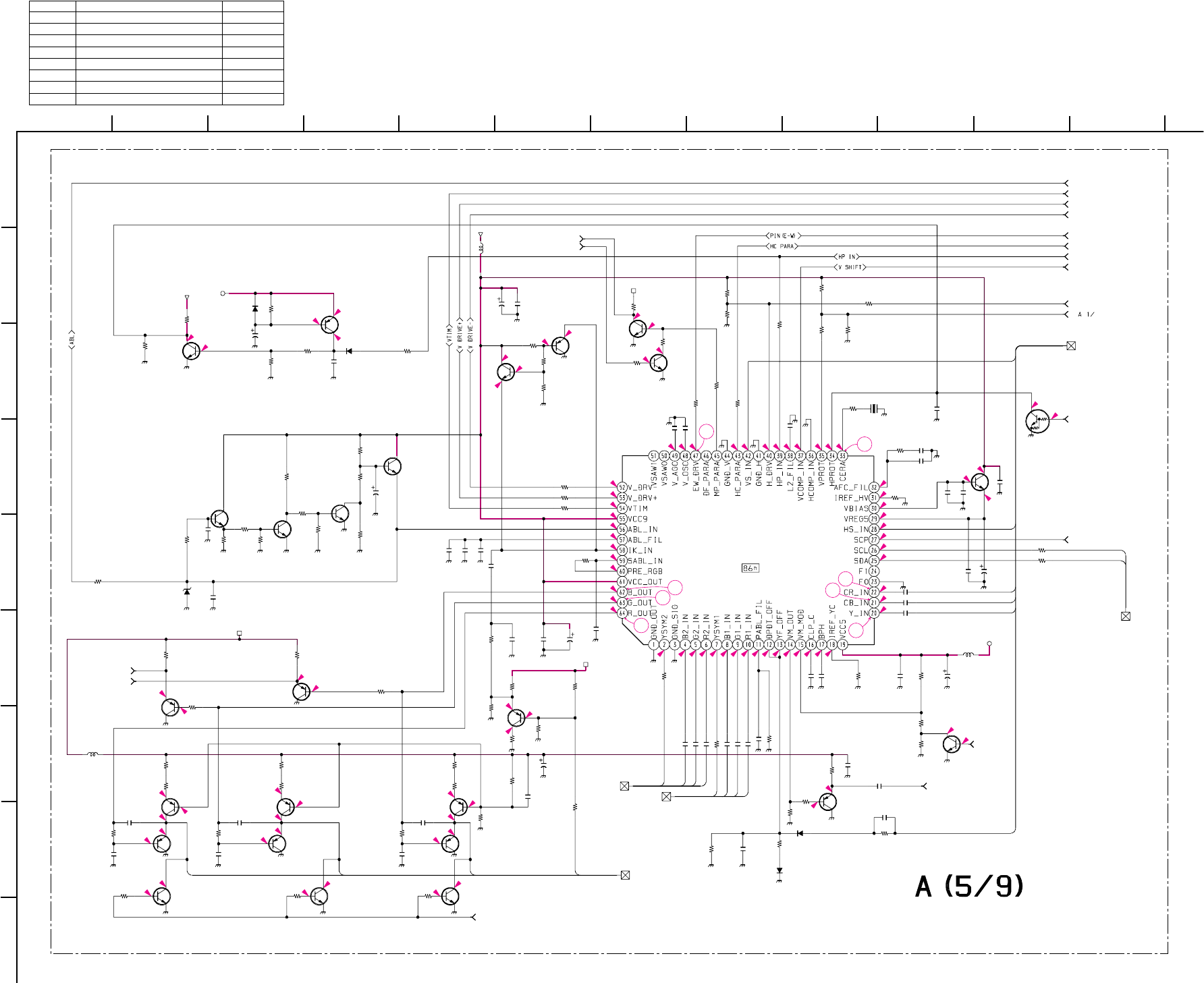
– 55 –
KP-HR432K90/HR532K90/HR532N90/HW572K90
RM-Y909KRM-Y908RM-Y909K RM-Y909K
1
A
B
C
D
E
F
G
H
I
212
11
10
98765
43
0.1 0.7
9.1
3.6
0
3.1
4.4
4.4
0.7
0.2
5
5.7
1.3
1.6
0
0.3
2.7
3.3
0.7
3
0
2.5
3.9
4.4
5.4
3.1
2.7
8.5
3.6 3.4
9.3
0
2.6
0
0
9.1
5.7
0
3.5
0.5
9.1
3.1
5
3.9
1.7
1.7
2.7
2.9
2.9
0
3.1
3.2
3.1
0
3.6
0
3.6
0
0.4
0.4
2.5
3.8
2.6
2.6
1.1
5
8.5
3.3
9.1
2.2
4
2.7 2.1
0.7
2.9
8.5
3.9
0
2.4
9.1
3.5.
9.2 9.2
3.7
3.7
2.9
0.4 0.4
2.7 3.5
9.2
3.9
3.3
3.4
3.6
3.6
2.9
3.6
0.4
4.4
0.81.4
19
18
17
16
15
20
21
22
C425
C428
C429
C432
C433
C439
C440
C443
C466
C470
C483
C490 C494
C498
D312
R472
R482
R483
R484
R495
R496
R503 R511
R515
R516
R517
R519
R521
R526
R527
R538
R540
R541
R544
R547
R551
R552
R553
R554
R559
R566
R567
R570
R575
R576
R577
R597
R599
X307
R514
R562
R572
R473
C424
R561
R574
C458
C486
R571
R625
R624
L316
L317
L321
C442
C485
C489
D317
D318
C495
C455
C488
C484
C476
C449
C480
C481
C482
R596
C477
C472
C406
C407 C408
R418
C507
R480
R477
R504
R507
R508
R593
C487
R623
R311
C368
R489
R329
R342
R348
R356
R366
R543
C438
C409
C431
C435 C478
R332
R341
R419
R420
C479
D321
D319
R594
R598
C497
R558
R476
R557
R490
R501
R556
Q379
Q378
Q356
Q355 Q369
Q373
Q352
Q309
Q313
Q349
Q348
Q353
Q345
Q374
Q331 Q357
Q354
Q367
Q347
Q343 Q351
Q342 Q346 Q350
IC309
C444
R493
C457
C460
C461
R542
C463
C464
C467
C468
R550
R568
R569
#
CH:1608
#
CH:1608
#
CH:1608
#
CH:1608
#
CH:1608
0.1
25V
F:1608
0.1
25V
F:1608
100
16V
47p
CH:1608
0.01
16V
B:1608
0.0047
B:1608
0.1
25V
F:1608 100
16V
0.1
16V
B:1608
UDZS-5.6B
LIMIT
4.7k
1/16W
:CHIP
33k
1/16W
:CHIP
4.7k
1/16W
:CHIP
100
1/16W
:CHIP
4.7k
1/16W
:CHIP
100
1/16W
:CHIP
10k
1/16W
:CHIP 150k
1/16W
:CHIP
100 1/16W :CHIP
100 1/16W :CHIP
100 1/16W :CHIP
*
1/16W
:CHIP
10k
1/16W
:CHIP
33k
1/16W
:CHIP
0
:1608
100
1/16W
:CHIP
100
1/16W
:CHIP
6.8k
1/16W
:CHIP
3.3k
1/16W
:CHIP
100
1/16W
:CHIP
10k
1/16W
:CHIP
100
1/16W
:CHIP
12k
1/16W
:CHIP
100
1/16W
:CHIP
470
1/16W
:CHIP
4.7k
1/16W
:CHIP
4.7k
1/16W
:RN-CP
10k
1/16W
:RN-CP
10k
1/16W
:CHIP
4.7k
1/16W
:CHIP
4.7k
1/16W
:CHIP
1k
1/16W
:CHIP
4.7k
1/16W
:CHIP
2.7MHz
4.7k
1/16W
:CHIP
470
1/16W
:CHIP 15k
1/16W
:CHIP
100
1/16W
:CHIP
#CH:1608
4.7k
1/16W
:CHIP
10k
1/16W
:CHIP
0.1
:PP
0.22
10V
B:1608
0
:1608
#
1/16W
:CHIP
100
1/16W
:CHIP
:LAV35
:LAV35
10µH
:LAV35
2.2
6.3V
F:1608
0.47
10V
B:1608
0.47
10V
B:1608
0.1
25V
F:1608
0.1
:PT
1SS355-TE
1SS355-TE
100
16V
0.1
25V
F:1608
0.1
25V
F:1608
1
6.3V
B:1608
0.1 16V B:1608
0.1 16V B:1608
0.1 16V B:1608
47k
1/16W
:CHIP
4.7
6.3V
B:CHIP
0.47
10V
B:1608
4.7
6.3V
B:CHIP
4.7
6.3V
B:CHIP
4.7
6.3V
B:CHIP
100
1/16W
:CHIP
0.0022
B:1608
4.7k
1/16W
:CHIP
4.7k
1/16W
:CHIP
4.7k
1/16W
:CHIP R504
*
:CHIP
R513
*
:CHIP
R518
*
:CHIP
*
1/16W
:CHIP
*
1/16W
:CHIP
4.7k
1/16W
:CHIP
0.1
16V
B:1608
#
1/16W
:CHIP
39k
1/16W
:CHIP 0.1
16V
B:1608
4.7k
1/16W
:CHIP
4.7k
1/16W
:CHIP
47k
1/16W
:CHIP
47k
1/16W
:CHIP
47k
1/16W
:CHIP
47k
1/16W
:CHIP
2.7k
1/16W
:CHIP
100
16V
#
0.1
16V
B:1608
100
16V 0
:1608
2.2k
1/16W
:RN-CP 3.9k
1/16W
:RN-CP
2.7k
1/16W
:RN-CP
1.8k
1/16W
:RN-CP
47p
CH:1608
1SS355-TE
1SS355-TE
10k
1/16W
:CHIP
10k
1/16W
:CHIP
100
16V
82
1/16W
:CHIP
82
1/16W
:CHIP
82
1/16W
:CHIP
82
1/16W
:CHIP
82
1/16W
:CHIP
82
1/16W
:CHIP
2SA1037AK
2SC2412K
2SA1037AK
Q502
*
Q501
*
2SC2412K DTC144EKA
2SC2412K
2SC2412K
2SC2412K
2SC2412K
2SC2412K
2SA1037AK
2SA1037AK
2SA1037AK
2SC2412K
2SA1037AK 2SA1037AK
2SA1037AK
2SA1226
BUFF
2SA1226
BUFF
2SA1226
BUFF
2SA1226
BUFF
2SC2412K 2SC2412K 2SC2412K
CXA2150AQ
0.068
16V
B:1608
4.7k
1/16W
:CHIP
0.1 16V B:1608
0.1 16V B:1608
0.1 16V B:1608
100 1/16W :CHIP
0.1 16V B:1608
0.1 16V B:1608
0.1 16V B:1608
0.47 10V B:1608
3.3M 1/16W :CHIP
100
1/16W
:CHIP
100
1/16W
:CHIP
TO A5/9,A2/9_27 G1
TO A5/9,A8/9_84 OFFSET
TO A5/9,A7/9_63 MUTE
TO A5/9,A2/9_28 B1
ABL TO A5/9,A1/9,A8/9_50
VTIM TO A5/9,A1/9,A8/9_68
V DRIVE+ TO A5/9,A1/9_47
V DRIVE- TO A5/9,A1/9_48
PIN(E-W) TO A5/9,A1/9_4 52
HC PARA TO A5/9,A8/9_4 67
VM TO A5/9,A1/9_54
MID OUT TO A5/9,A2/9_46
V SHIFT TO A5/9,A1/9_57
HP IN TO A5/9,A1/9_51
P MUTE TO A5/9,A7/9_63
VM LEVEL
TO A5/9,A7/9
_65
H DRIVE TO A5/9,A1/9_53
PROT MUTE TO A5/9,A7/9_66
DRV TO A5/9,A8/9_62
R-SIG
TO A5/9,A1/9_55
OSD
TO A5/9,A7/9
_64
5V
VP TO A5/9,A1/9,A2/9_33
9V-4
9V-4
SCP TO A5/9,A2/9_26
6V
TO A5/9,A1/9,A2/9,A3/9,A4/9,A6/9,A7/9,A9/9_3 IIC-1
12V
12V
12V
MID YS
YSYM
OSD-B
OSD-G
OSD-R
R-R
R-G
R-B
R-YS
VS
HS
CR
CB
Y
DAT1
CLK1
R
G
B
IK
10µH
10µH
(Y/C JUNGLE)
Ref. No. KP-HR432K90/HR532K90/HR532N90 KP-HW572K90
Q501 - 2SA1034AK
Q502 - 2SD601-AQ
R502 - 2.2k: CHIP
R507 2.2k: CHIP 3.3k: CHIP
R508 2.2k: CHIP 1k: CHIP
R510 - 2.2k: CHIP
R513 - 2.7k: CHIP
R519 100: CHIP 1k: CHIP
• A (5/9) BOARD * MARK LIST
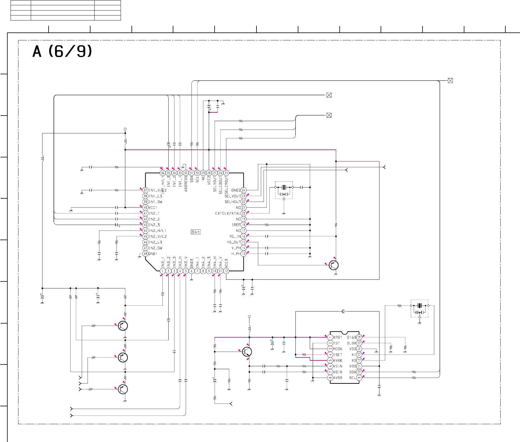
– 56 –
KP-HR432K90/HR532K90/HR532N90/HW572K90
RM-Y909KRM-Y908RM-Y909K RM-Y909K
1
A
B
C
D
E
F
G
H
I
J
212
11
10
98765
43
4.1
0
0
2.4
2.6
4.4
4.3
4.1
3.2
2.8
1
2.9
0.4
0.1
2.6
2.6
2.6
4.4
4.4
2.9
2.9
2.9
1
1
5
2.9
2.8
2.1
1
1
2.8
2.2
2.6
2.1
2.8
2.1
5
5
3.8
3.2
1.4
1.9
1.6
3.2
2.5
2.9
2.9
2.9
1.3
1
1
1
C377
C378
C379
C384
C386
C402
C403
C404
C405
C411
C413
C420
C421
C430
L314
R410 R411
R413
R414
R415
R417 R421
R422
R423
R424
R425
R426
R427
R447
R448 R449
R453
R454
R455
R462
R463
R464
R469
R470
R481
R491 R494
X306
C400
C412
C382
C383
C388
C393
C396
R620
R621
R622
C416
C414
R434
R438
C419
C410
R468
C415
C418
FB301
C390
C387
X305
R492
Q344
Q334
Q341
Q333
Q332
IC306
IC308
C397
C395
C392
C389
R487
R486
L311
0.1
25V
F:1608
0.1
25V
F:1608
0.1
25V
F:1608
0.1 25V F:1608
0.1
25V
F:1608
0.1
25V
F:1608
47
16V
0.1
25V
F:1608
0.1
25V
F:1608
0.1
16V
B:1608
0.1
25V
F:1608
0.1
25V
F:1608
0.001
B:1608 0.1
25V
F:1608
:CHIP
160
1/16W
:RN-CP
160
1/16W
:RN-CP F:1608
100
1/16W
:RN-CP
100
1/16W
:RN-CP
100
1/16W
:RN-CP
100
1/16W
:CHIP
100
1/16W
:CHIP
100
1/16W
:CHIP
100
1/16W
:CHIP
180
1/16W
:RN-CP
180
1/16W
:RN-CP
180
1/16W
:RN-CP
160
1/16W
:RN-CP
100
1/16W
:CHIP
100
1/16W
:CHIP
100
1/16W
:CHIP
47k
1/16W
:CHIP
22k
1/16W
:CHIP
22k
1/16W
:CHIP
470
1/16W
:CHIP
10k 1/16W :RN-CP
100
1/16W
:CHIP 10 1/16W :CHIP
33k
1/16W
:CHIP
1k
1/16W
:CHIP
10k
1/16W
:CHIP
10k
1/16W
:CHIP
14.318MH
100
16V
1
6.3V
B:1608
0.47 10V B:1608
0.47 10V B:1608
0.47
10V
B:1608
0.4710V B:1608
0.4710V B:1608
*:CHIP
*:CHIP
*:CHIP
0.1 25V F:1608
0.01 16V B:1608
100 1/16W :CHIP
100 1/16W :CHIP
100
16V
200
16V
C400
100
16V
C423
0.1
25V
100
1/16W
:CHIP
16.3V B:1608
0.1
16V
B:1608
BLM11A102S
:1608
10
10
4MHz
0
:1608
2SA1037AK
2SA1037AK
2SC2412K
2SA1037AK
2SA1037AK
CXA2151Q
COMPONENT-I/F
CXD2085M
ID-1 DECODER
0.47
10V
B:1608
0.47
10V
B:1608
0.47
10V
B:1608
0.47
10V
B:1608
100
1/16W
:CHIP
100
1/16W
:CHIP
:CHIP
10µH
L318
:CHIP
10µH
5V
5V
SEL OUT TO A6/9,A2/9_40
D COMP TO A6/9,A2/9,A3/9_11
IIC-1
TO A6/9,A1/9,A2/9,A3/9,
A4/9,A5/9,A7/9,A9/9_3
VD3
TO A6/9,A3/9_74
SELH
TO A6/9,A3/9_73
MON OUT TO A6/9,A3/9_70
TO A6/9,A3/9,A4/9_71 S HD
TO A6/9,A3/9,A4/9_72 S VD
TO A6/9,A3/9,A4/9_75 CR OUT
TO A6/9,A3/9,A4/9_76 CB OUT
TO A6/9,A3/9,A4/9_77 Y OUT
S-HD
S-VD
D1-Y
D1-CB
D1-CR
DAT1
CLK1
D2-Y
D2-CB
D2-CR
DAT1
CLK1
SEL Y
SEL CB
SEL CR
10µH
(COMPONENT I/F, ID-1 DECODER)
• A (6/9) BOARD * MARK LIST
Ref. No. KP-HR432K90/HR532K90/HR532N90 KP-HW572K90
R620 68: CHIP 22: CHIP
R621 68: CHIP 22: CHIP
R622 68: CHIP 22: CHIP
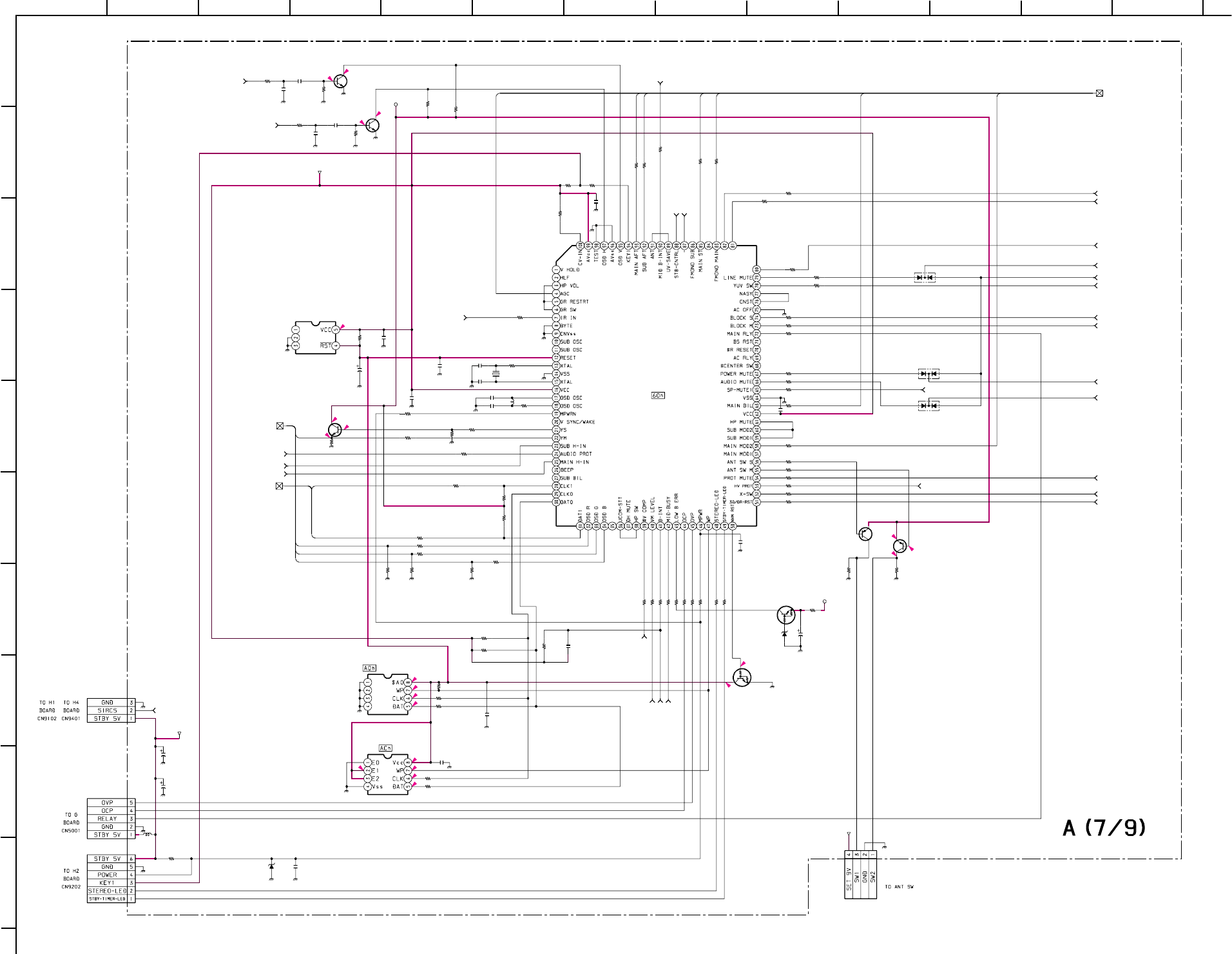
– 57 –
KP-HR432K90/HR532K90/HR532N90/HW572K90
RM-Y909KRM-Y908RM-Y909K RM-Y909K
1
A
B
C
D
E
F
G
H
I
J
212 13
11
10
98765
43
0
0
0
5
4.7
5
5
5
0
5
04.9
5
5
55
4.4
4.4
5
4.5
4.4
0
C702
C710
C713
C714
C719
C730
C731
C732
D711
D712
D713
L701
R701
R705
R706
R707
R708
R709R711
R715
R717
R718
R720
R721
R722
R728
R732
R733
R735
R737
R747
R759
R781
R782
R783
R784
R785
R786
R790
R796
R797
R803
R804
R806
R807
R764
R899
CN701
R743
R714
R702
C799
C707
C701
C706
C705
C800
R716
R703
C708
C745
D703
R789
R736
X701
R710R712R719
C709
CN16
CN9
L10
C11
C145
R153
CN7
D7
C144
Q716
Q715
Q701
Q714
Q707
Q712
Q711
IC701
IC704
IC703
IC702
R746
R748
R751
R753
R754
R755
R756
R758
R763
R765
R898
R897
R738R742
R752
C733
R725
R724
R723
R769
R779
R768
R778
C703
R777
R776
R775
R774
R773
R772
R771
10
22p
CH:1608
15pCH:1608
15pCH:1608
0.001
B:1608
10p
CH:1608
100p
CH:1608
100p
CH:1608
DAN202UT106
OR
DAN202UT106
OR
DAN202UT106
OR
:EL0606
2.2µH
470
1/16W
:CHIP
1001/16W:CHIP
1001/16W:CHIP
1001/16W:CHIP
1001/16W:CHIP
470
1/16W
:CHIP 10k1/16W:CHIP
1001/16W:CHIP
3.3k1/16W:CHIP
3.3k1/16W:CHIP
1001/16W:CHIP
1.5k
1/16W
:CHIP
2.2k
1/16W
:CHIP
0
:1608
1001/16W:CHIP
1k1/16W:CHIP
10k
1/16W
:CHIP
10k
1/16W
:CHIP
100 1/16W :CHIP
1k 1/16W :CHIP
1.5k
1/16W
:CHIP
1001/16W:CHIP
1001/16W:CHIP
1001/16W:CHIP
1k1/16W:CHIP
1k1/16W:CHIP
22k
1/16W
:CHIP
1k
1/16W
:CHIP
4.7k
1/16W
:CHIP
10k
1/16W
:CHIP
22k
1/16W
:CHIP 4.7k
1/16W
:CHIP
4.7k
1/16W
:CHIP
1k 1/16W :CHIP
1k
1/16W
:CHIP
4P
WHT
:S-MICRO
100 1/16W :CHIP
1001/16W:CHIP
47k
1/16W
:CHIP
0.1
25V
F:1608
0.1
25V
F:1608
0.1
25V
F:1608
0.1
25V
F:1608
0.1
25V
F:1608
0.01
16V
B:1608
1k1/16W:CHIP
1k
1/16W
:CHIP
100
10V
0.1
25V
F:1608
UDZS-3.6B
#
:CHIP
2201/16W:CHIP
220
1/16W
:CHIP
220
1/16W
:CHIP
220
1/16W
:CHIP
27p
CH:1608
3P
WHT
:S-MICRO
6P
WHT
:S-MICRO
100
16V
0.01
16V
B:1608
10k
1/16W
:CHIP
5P
WHT
:S-MICRO
UDZS-5.6B
LIMIT
10
2SC2412K
2SC2412K
2SC2412K
DTA144EKA
INV
DTC144EKA
NV-RST
2SA1037AK
#
PST9145NL
RESET
M24C08-WMN6T(A)
NVM
M24C04-MN6T(A)
100 1/16W :CHIP
10k 1/16W :CHIP
1k 1/16W :CHIP
100 1/16W :CHIP
100 1/16W :CHIP
100 1/16W :CHIP
100 1/16W :CHIP
100 1/16W :CHIP
330 1/16W :CHIP
330 1/16W :CHIP
47
1/16W
:CHIP
1k
1/16W
:CHIP
4.7k
1/16W
:RN-CP
1k
1/16W
:CHIP
1k
1/16W
:CHIP
0.001
25V
CH:1608
1001/16W:CHIP
2.2k1/16W:CHIP
2.2k1/16W:CHIP
1001/16W:CHIP
1001/16W:CHIP
1001/16W:CHIP
1001/16W:CHIP
0.1 25VF:1608
1k1/16W:CHIP
#:CHIP
1k1/16W:CHIP
1001/16W:CHIP
1001/16W:CHIP
1k1/16W:CHIP
1001/16W:CHIP
TO A7/9,A1/9_5 M-TU-H
TO A7/9,A1/9_5 S-TU-H
MID BINT
TO A7/9,A2/9_35
TO A7/9,A2/9_38 MID BUSY
LINE MUTE TO A7/9,A2/9_17
TO A7/9,A2/9_29 /BINT
TO A7/9,A9/9_69 AUDIO PROT
YUV SW TO A7/9,A3/9_58
TU CONT TO A7/9,A1/9_2
TO A7/9,A1/9,A2/9,A3/9,
A4/9,A5/9,A6/9,A9/9_3
IIC-1
P MUTE TO A7/9,A5/9_63
TO A7/9,A5/9_65 VM LEVEL
TO A7/9,A5/9_64 OSD
PROT MUTE TO A7/9,A5/9_66
X SW TO A7/9,A2/9_34
HV PROT TO A7/9,A1/9_49
TO A7/9,A2/9_44 SIG-V
TO A7/9,A2/9_45 SIG-H
3D/RST TO A7/9,A1/9,A2/9_31
5V
A MUTE TO A7/9,A2/9_18
BLOCK-M TO A7/9,A3/9_60
BLOCK-S TO A7/9,A4/9_61
S-MODE2 TO A7/9,A2/9_15
S-MODE1 TO A7/9,A2/9_14
S-ATT TO A7/9,A2/9_13
9V-3
5V
SIRCS
TO A7/9,A2/9,8/9_25
TO A7/9,A2/9,A8/9_25
SIRCS
STBY5V
- TO A7/9,A8/9_81
STB CONTROL
TO A7/9,A8/9_80
TO A7/9,A8/9_83
#V COMP
SP MUTE1
TO A7/9,A9/9_82
TUNER MUTE TO A7/9,A1/9,A9/9_4
STBY5V
AFT1
AFT2
ST-1
MONO-1
AGC
OSD-R
OSD-G
OSD-B
BIL-1
MOD-1
YSYM
DAT1
CLK1
*
MAIN-UCOM
100µH
(SYSTEM CONTROL)
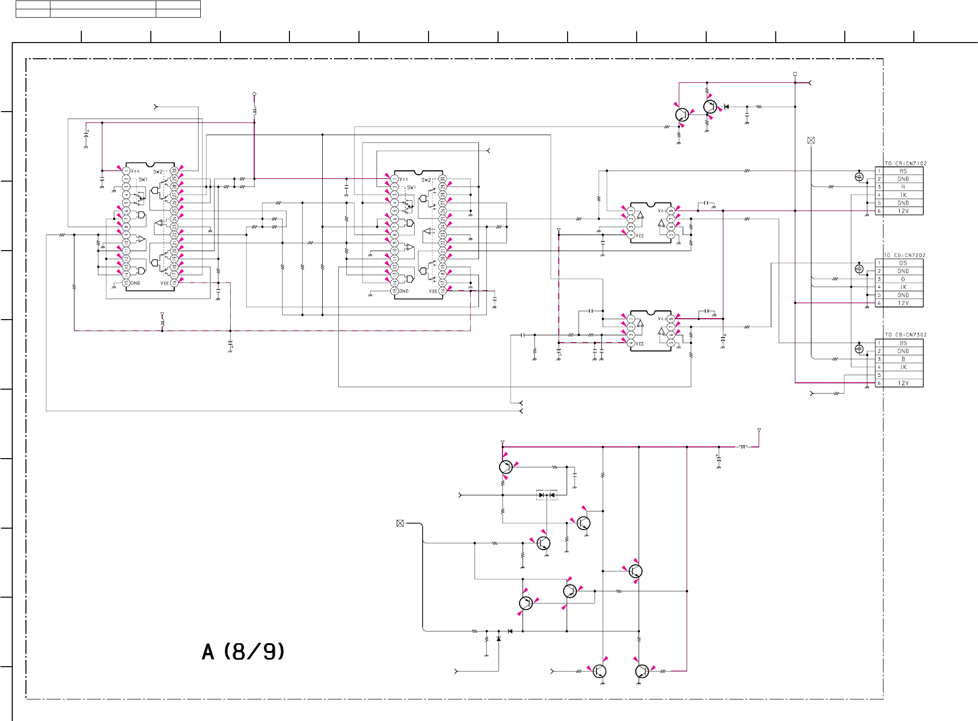
– 58 –
KP-HR432K90/HR532K90/HR532N90/HW572K90
RM-Y909KRM-Y908RM-Y909K RM-Y909K
1
A
B
C
D
E
F
G
H
I
J
212 13
11
10
98765
43 14
011.9
0.1
5
0.1
5
11.9 0.1
11.8
00.19.3
0.1
00
0
0.6
4.2
0
4.4
0
0.1 0.6
0
0
0
4.3
4.9
4
0
0
0
-16.4
-0.4 11.9
-0.3
0
0
0
0
0
0
1.3
0
0
-2
1.2
0.6
-1.3
2.2
3.1
-5
-2
0
0
-2
-2
-5
0.1
0
0
5
0
0
0
0
0
0.2
0
-1.9
0
-1.9
0
-16.4
5
3.1
1.4
1.4
1.4
2.2
0
2.2
2.2
OFFSET
C735
C736
C737
C738
C742
C750
C754
C760 C766
C768
C769
C770
C777
C778
C779
C781
D710
R615
R740
R744
R766
R787
R788
R808 R809
R811
R852
R856
R859 R865
R872
R873
R874
R875
R876
R877
R880
R881
R883
R884
L704
L705
D708
D709
L702
R889
R890
R891
CN703
CN702
CN704
NL702
NL703
NL701
R812
R819
R824
R866
R821
R850
R827
R826
R816
R820
R888
R749
R745
R760
R761
R770
R762
C722 R767
R750
R814
R815
C728
R822
D730
R614
Q702
Q705
Q703 Q709
Q706
Q704
Q708
Q710
Q724
Q726
IC705
IC706
IC710
IC709
R825
R882
100
16V
0.1
25V
F:1608
0.1
25V
F:1608
100
16V
0.1
25V
F:1608
0.1
25V
F:1608
0.01
16V
B:1608
47
25V
0.1
25V
F:1608
180p
CH:1608
0.1
25V
F:1608
120p
CH:1608
0.1
25V
F:1608
0.1
25V
F:1608
100
16V
0.1
25V
F:1608
DAN202UT106
8.2k
1/16W
:CHIP
100
1/16W
:CHIP
1k
1/16W
:CHIP
1k
1/16W
:CHIP
10k
1/16W
:CHIP
100k
1/16W
:CHIP
4.7k
1/16W
:CHIP
15k
1/16W
:CHIP
4.7k
1/16W
:RN-CP
10k
1/16W
:CHIP
4.7k
1/16W
:CHIP
4.7k
1/16W
:RN-CP
4.7k
1/16W
:RN-CP
100
1/16W
:CHIP
4.7k
1/16W
:CHIP
47k
1/16W
:CHIP
4.7k
1/16W
:CHIP
47k
1/16W
:CHIP
2.2k
1/16W
:CHIP
100
1/16W
:CHIP
100
1/16W
:CHIP
8.2k
1/16W
:CHIP
10k
1/16W
:CHIP
:CHIP
:CHIP
10µH
68
1/16W
:CHIP
68
1/16W
:CHIP
R834
:CHIP
*
68
1/16W
:CHIP
6P
WHT
:S-MICRO
6P
BLK
:S-MICRO
6P
RED
:S-MICRO
1SS355-TE
1SS355-TE
#
1/16W
:RN-CP
3.3k
1/16W
:CHIP
27k
1/16W
:CHIP
47k
1/16W
:CHIP
3.3k
1/16W
:CHIP
5.6k
1/16W
:CHIP
#
1/16W
:CHIP
5.6k
1/16W
:CHIP
5.6k
1/16W
:CHIP
27k
1/16W
:CHIP
220k
1/16W
:CHIP
220k
1/16W
:CHIP
47k
1/16W
:CHIP
220k
1/16W
:CHIP
220k
1/16W
:CHIP
100k
1/16W
:CHIP
100k
1/16W
:CHIP
0.1
16V
B:1608
10k
1/16W
:CHIP
2.2k
1/16W
:CHIP
2.4k
1/16W
:RN-CP
5.6k
1/16W
:CHIP
100
16V
#
1/16W
:CHIP
UDZS-6.8B
18k
1/16W
:CHIP
2SA1037AK
2SC2412K
INV.
2SC2412K
INV.2SC2412K
2SA1037AK
2SA1037AK
2SC2412K
2SC2412K
2SC2412K
2SA1037AK
CXA1726AM
SHADING1 CXA1726AM
SHADING2
NJM2068V-TE2
SHADING AMP1
NJM2068V-TE2
SHADING AMP2
3.3k
1/16W
:CHIP
100
1/16W
:CHIP
TO A8/9,A2/9,A7/9_25 SIRCS
TO A8/9,A2/9_16 CTRL-S
ABL TO A8/9,A1/9,A5/9_50
TO A8/9,A5/9_84 OFFSET
VTIM TO A8/9,A1/9,A5/9_68
H SAW TO A8/9,A1/9_56
HC PARA TO A8/9,A5/9_67
DRV TO A8/9,A5/9_62
5V
-5V
STBY 5V-1
STBY 5V
TO A8/9,A7/9_81 -
TO A8/9,A7/9_80 STB CONTROL
TO A8/9,A7/9_83 #V COMP
12V
-15V
CONT-S OUT
CONT-S IN
R
G
B
IK
10µH
0µH
(SHADING)
• A (8/9) BOARD * MARK LIST
Ref. No. KP-HR432K90/HR532K90/HR532N90 KP-HW572K90
R834 - 47: CHIP
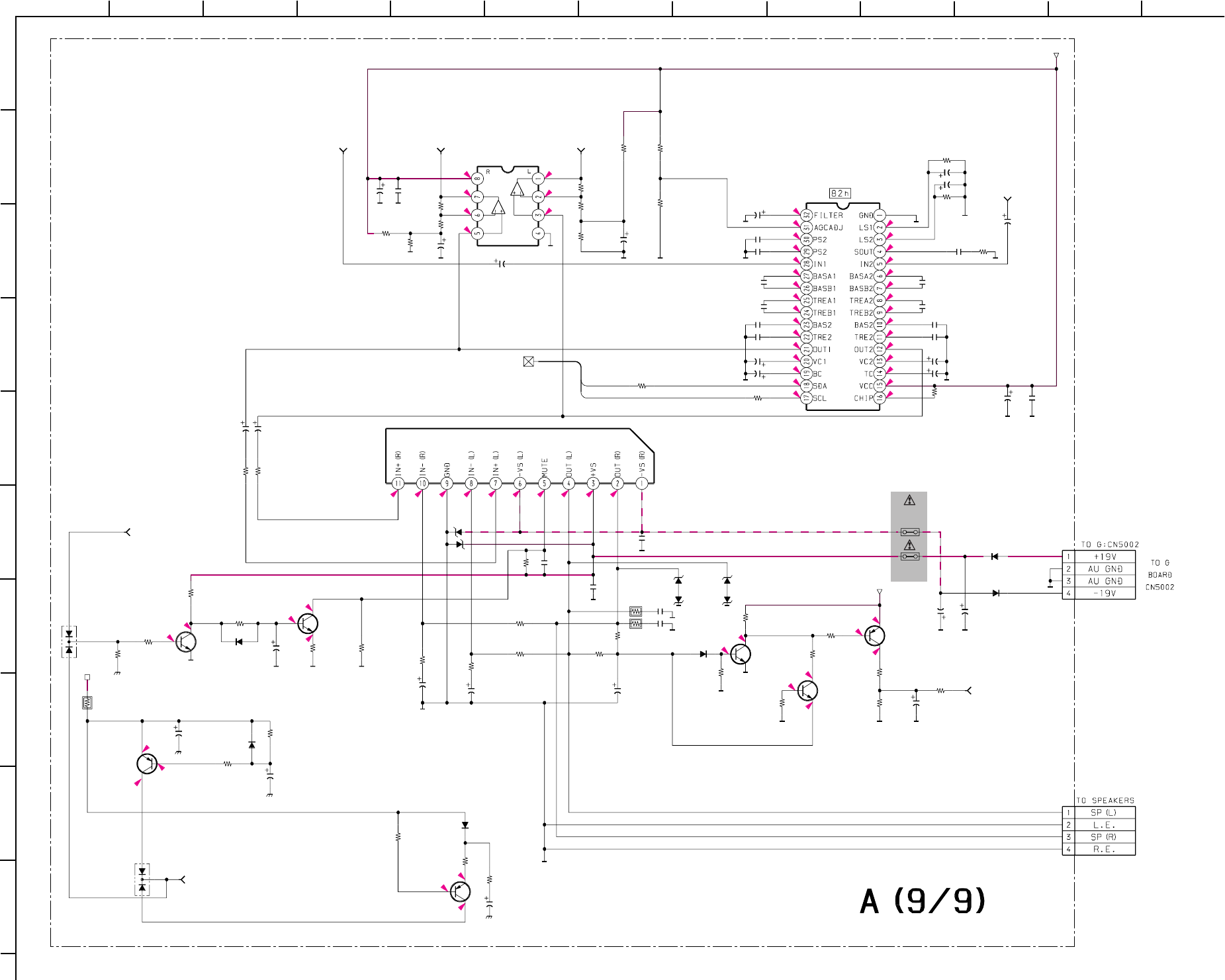
– 59 –
KP-HR432K90/HR532K90/HR532N90/HW572K90
RM-Y909KRM-Y908RM-Y909K RM-Y909K
1
A
B
C
D
E
F
G
H
I
J
212 13
11
10
98765
43
10.4
9.1
9.1
2
1.2
0
4.5
4.5
4.5
4.5
4.5
4.5
4.5
4.5
0
0
10.3
0
4.5
4.8
4.5
4.5
9.1
4.8
4.5
4.6 2.9
4.5
4.5
4.5
4.5
4.6
4.5
4.5
4.5
4.5
4.5
1.2
2
4.4
4.4
0
0
0
0
-22.2
11.6
0
22.1
0
11.6
12.3
13.1
0.3 11.6
0
9
0
9
8.9
9
0
0
0
10.3
10.3
0
C746
C747
C757
C762
C764
C771
C772
D704 R810
R813
R817
R818
R851
R854
R857
R869
R870
R871
R878
R879
R885
R886 R887
R840
C756
C758
C765
C783
C785
R893
C786
C787
C789
C793
C795
C797
R823
D719
D729
C751
C752
CN706
CN705
R841
R862
D720
D721
D718
PS701
PS702
C780
C748
C749
D701
R628
D702
C755
C704
R864
D723
D724
D726
R843
R858
R863
R896
C773
C775
C782
C784
C790
C791
C792
C794
C796
R860
R861 D725
C801
C759
C761
R894
D705
D706
R867
R892
R844
R845
R842
R849
R848
R855
R830
C802
R831
R833
R835
C739
C753
R829
R836
Q718
Q725
Q722
Q717
Q723
Q721
Q713
IC707
IC711
IC708
R868
C788 R895
R828 R832
C741
C740
47
25V
47
25V
0.1
:PT
100
25V
0.1
:PT
0.1
:PT
0.1
:PT
DAN202UT106 10k
1/16W
:CHIP
1M
1/16W
:CHIP
100k
1/16W
:CHIP 10k
1/16W
:CHIP
10k
1/16W
:CHIP
27k
1/16W
:CHIP
27k
1/16W
:CHIP
12k
1/16W
:CHIP
47k
1/16W
:CHIP
100
1/16W
:CHIP
1k
1/16W
:CHIP
1k
1/16W
:CHIP
10k
1/16W
:CHIP
10k
1/16W
:CHIP
1k
1/16W
:CHIP
47k
1/16W
:CHIP
10
47
25V
100
16V
0.001 :PT
4.7
1M
1/16W
:CHIP
4.7
1
10
0.001 :PT
4.7
0.1
16V
B:1608
15k
1/16W
:CHIP
2200
25V
2200
25V
4P
WHT
:S-MICRO
4P
BLK
:S-MICRO
33k
1/16W
:CHIP
33k
1/16W
:CHIP
ERC91-02
ERC91-02
1SS355-TE
1SS355-TE
1SS355-TE
UNH009
2A
UNH009
2A
100 25V
#
47
25V
DAN202UT106
0.47
:FPRD
1SS355-TE
47
25V
47
25V
33k
1/16W
:CHIP
UDZS-22B
UDZS-22B
UDZS-22B
4.7k
1/16W
:CHIP
4.7k
1/16W
:CHIP
47k
1/16W
:CHIP
0
:1608
0.033 16V B:1608
0.0033 16V B:1608
0.033 :PT
0.47 10V B:1608
0.033 16V B:1608
0.0033 16V B:1608
0.033 :PT
0.47 10V B:1608
100
16V
4.7
:FPRD
4.7
:FPRD
UDZS-22B
0.1
16V
B:1608
0.22 25V B:1608
0.22 25V B:1608
#
1/16W
:CHIP
UDZS-33B
UDZS-33B
22k
1/16W
:CHIP
22k 1/16W :CHIP
2.2k
1/16W
:CHIP
470
1/16W
:CHIP
470
1/16W
:CHIP
18k
1/16W
:CHIP
18k
1/16W
:CHIP
2.2k
1/16W
:CHIP
220k
1/16W
:CHIP
470
16V
33k
1/16W
:CHIP
33k
1/16W
:CHIP
22k
1/16W
:CHIP
4.7
#
:PT
0
:1608
0
:1608
2SC2412K
2SA1037AK
2SC2412K
2SC2412K
2SC2412K
2SA1037AK
2SA1037AK
NJM4558M-TE2
AUDIO BUFF.
BH3868BFS-E2
AUDIO PROC.
TDA7265
L,R AMP
22k
1/16W
:CHIP
0.047
16V
B:1608
5.6k
1/16W
:CHIP
470
1/16W
:CHIP
470
1/16W
:CHIP
4.7
4.7
AUDIO R TO A9/9,A2/9_10
AUDIO L TO A9/9,A2/9_9
AUDIO PROT TO A9/9,A7/9_69
TO A9/9,A1/9,A2/9,A3/9,A4/9,A5/9,A6/9,A7/9_3 IIC-1
9V-3
9V-2
TUNER MUTE TO A9/9,A1/9,A7/9_4
VAR L TO A9/9,A2/9_7
VAR R TO A9/9,A2/9_8
+11V
SP MUYE1 TO A9/9,A7/9_82
CLK1
DAT1
(AUDIO)
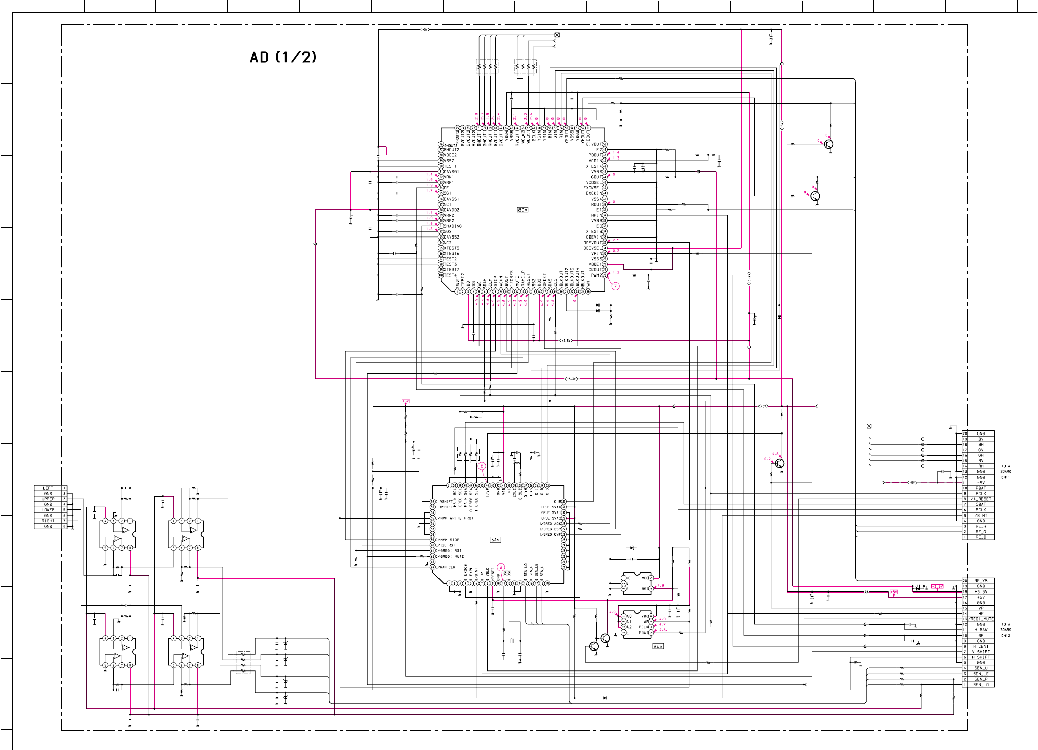
– 60 –
KP-HR432K90/HR532K90/HR532N90/HW572K90
RM-Y909KRM-Y908RM-Y909K RM-Y909K
1
A
B
C
D
E
F
G
H
I
J
212 13
11
10
98765
43 14
C1601
C1602
C1604
C1605
C1606
C1607
C1608
C1609
C1610
C1611
C1612
C1613
C1614
C1615
C1616
C1618
C1619
C1620
C1621
C1622
C1623
C1624
C1628
C1629
C1630
C1631
C1632
C1633
C1637
C1638
C1639
C1640
C1643
C1644
IC1605
IC1607
R1601
R1602
R1603
R1604
R1605
R1607
R1608
R1611 R1614
R1615
R1622
R1636
R1637
R1638
R1645
R1650
R1651
R1654
R1659
R1660
X1601
R1647
C1603
R1710
C1625 C1627
R1609
R1625
R1606
RB1603 RB1604
RB1605
CN1603
C1724
IC1613
C1729
IC1614
C1726
Q1603
Q1604
Q1605
D1601
CN1601
CN1602
C1730
C1653
R1610
C1728
IC1615
C1738
C1739
IC1616
C1742
R1629
R1633
R1631
R1678
R1630
R1612
R1616
R1639
L1601
10µH
R1655 R1656
C1636
R1658
D1605
D1606
D1607
D1604
RB1601
R1653 R1617
R1619
C1634
R1640
Q1601
Q1602
D1602
D1608
R1661
R1676
IC1606
C1723
C1735
C1635
FB1601
FB1602
FB1604
FB1606
IC1601
R1663
R1662
C1731
C1732
C1733
C1734
FB1607
FB1608
FB1609
FB1610
FB1611
FB1612
FB1613
R1664
C1725
R1613
R1677
R1632
C1727
R1628
R1641
L1602
C1641
FB1605
FB1603
FB1617
R1652
R1643
R1623
R1621
R1657
R1642
C1617
R1627
R1634
R1635
R1620
R1618
C1626
R1649
R1648
R1644
R1646
R1624 R1626
100
16V
#
16V
0.1
25V
F:1608
0.1
25V
F:1608
0.1
25V
F:1608
100
16V
0.1
25V
F:1608
0.0022
B:1608
470p
B:1608
0.1 25V F:1608
0.1 25V F:1608
0.1 25V F:1608
0.1 25V F:1608
0.1 25V F:1608
0.1 25V F:1608
100
16V
0.1
25V
F:1608
27p
CH:1608
0.1
25V
F:1608
15p
CH:1608
10p
CH:1608
10p
CH:1608
0.1 25V F:1608
0.1
25V
F:1608
0.1
25V
F:1608 100 16V
0.1
25V
F:1608
0.1
25V
F:1608
22p
CH:1608
22p
CH:1608
100
16V
100
16V
0.1
25V
F:1608
0.1
25V
F:1608
PST9143NL
DEF5V RESET
M24C32-WMN6T(A)
PJED NVM
47k
1/16W
:CHIP
#
1/16W
:CHIP
#
1/16W
:CHIP
10k
1/16W
:CHIP
1k
1/16W
:CHIP
1k
1/16W
:CHIP
100
1/16W
:CHIP
2.2k
1/16W
:CHIP 2.2k
1/16W
:CHIP
1k 1/16W :CHIP
470
1/16W
:CHIP
10k
1/16W
:CHIP
1k 1/16W :CHIP
1k 1/16W :CHIP
330
1/16W
:CHIP
330
1/16W
:CHIP
330
1/16W
:CHIP
4.7k
1/16W
:CHIP
22k
1/16W
:CHIP
1k
1/16W
:CHIP
12MHz
AT-49
10k
1/16W
:CHIP
#
:1608
0:1608
0.1
25V
F:1608
0.1
25V
F:1608
100
1/16W
:CHIP 1k
1/16W
:CHIP
1k
1/16W
:CHIP
100*4 100*4
100*4
#
WHT
:S-MICRO
#
F:1608
#
#
F:1608
#
#
F:1608
20P
:B TO B-S
20P
:B TO B-S
1000
6.3V
#B:1608
#1/16W :CHIP
#B:1608
#
#
F:1608
#
F:1608
#
#
F:1608
#
1/16W
:CHIP
#
1/16W
:CHIP
R1633
10k
1/16W
:CHIP
#
1/16W
:CHIP
#
1/16W
:CHIP
#
1/16W
:CHIP
#
1/16W
:CHIP
#
1/16W
:CHIP
1SS355TE
2SC2412K
2SC2412K
2SC2412K
100 1/16W :CHIP
:LB201616
2.2k
1/16W
:RN-CP
1k
1/16W
:RN-CP
0.1
16V
B:1608
22k
1/16W
:CHIP
UPZS-5.1B
UPZS-5.1B
UPZS-5.1B
D1691
1SS355TE
D1692
1SS355TE D1693
1SS355TE
UPZS-5.1B
#
470
1/16W
:CHIP
#
1/16W
:CHIP
0
:1608
4.7
#
1/16W
:CHIP
#
#
#
#
1k
1/16W
:CHIP
1k
1/16W
:CHIP
CXP86448-636Q
PJED-CPU
#
F:1608
#
F:1608
47p
CH:1608
BLM11A601S
:1608
BLM11A601S
:1608
BLM11A601S
:1608
BLM11A601S
:1608
CM0017AF
DIGITAL-REGI
560
1/16W
:CHIP
3.3k
1/16W
:CHIP
0.01
25V
B:1608
0.01
25V
B:1608
0.01
25V
B:1608
0.01
25V
B:1608
BLM11A601S
:1608
BLM11A601S :1608
BLM11A601S :1608
BLM11A601S :1608
BLM11A601S :1608
BLM11A601S :1608
BLM11A601S :1608
#
1/16W
:CHIP
#
B:1608
#
1/16W
:CHIP
#
1/16W
:CHIP
#
1/16W
:CHIP
#
B:1608
#
1/16W
:CHIP
2.2k
1/16W
:CHIP
:LB2016
0.1
25V
F:1608
BLM11A601S :1608
BLM11A601S :1608
BLM11A601S :1608
1k 1/16W :CHIP
1k 1/16W :CHIP
1k 1/16W :CHIP
1k 1/16W :CHIP
1k 1/16W :CHIP
1k
1/16W
:CHIP
0.1
25V
F:1608
1k 1/16W :CHIP
100
1/16W
:CHIP
100
1/16W
:CHIP
100 1/16W :CHIP
100 1/16W :CHIP
0.1 25V F:1608
100
1/16W
:CHIP
100
1/16W
:CHIP
2.2k
1/16W
:CHIP
2.2k
1/16W
:CHIP
#
1/16W
:CHIP
#
1/16W
:CHIP
R H/V G H/V B H/V T0 AD1/2, AD2/2_1
+5V T0 AD1/2, AD2/2
-5V T0
AD1/2, AD2/2
RH
RV
GH
GV
BH
BV
DBH
DGH
DRH
DBV
DGV
DRV
RE_YS
RE_B
RE_G
RE_R
SEN_LE
SEN_R
SEN_U
SEN_LO
SEN_LO
SEN_R
SEN_LE
SEN_U
SEN_LE
SEN_U
SEN_LO
SEN_R
RE_B
RE_G
RE_R
RE_YS
DIGITAL REG1, PJED CPU)
10µH
REGI MUTE T0 AD1/2, AD2/2_5
DHV MUTE T0 AD1/2, AD2/2_2
WCLK1 MUTE T0 AD1/2, AD2/2_3
BCLK MUTE T0 AD1/2, AD2/2_4
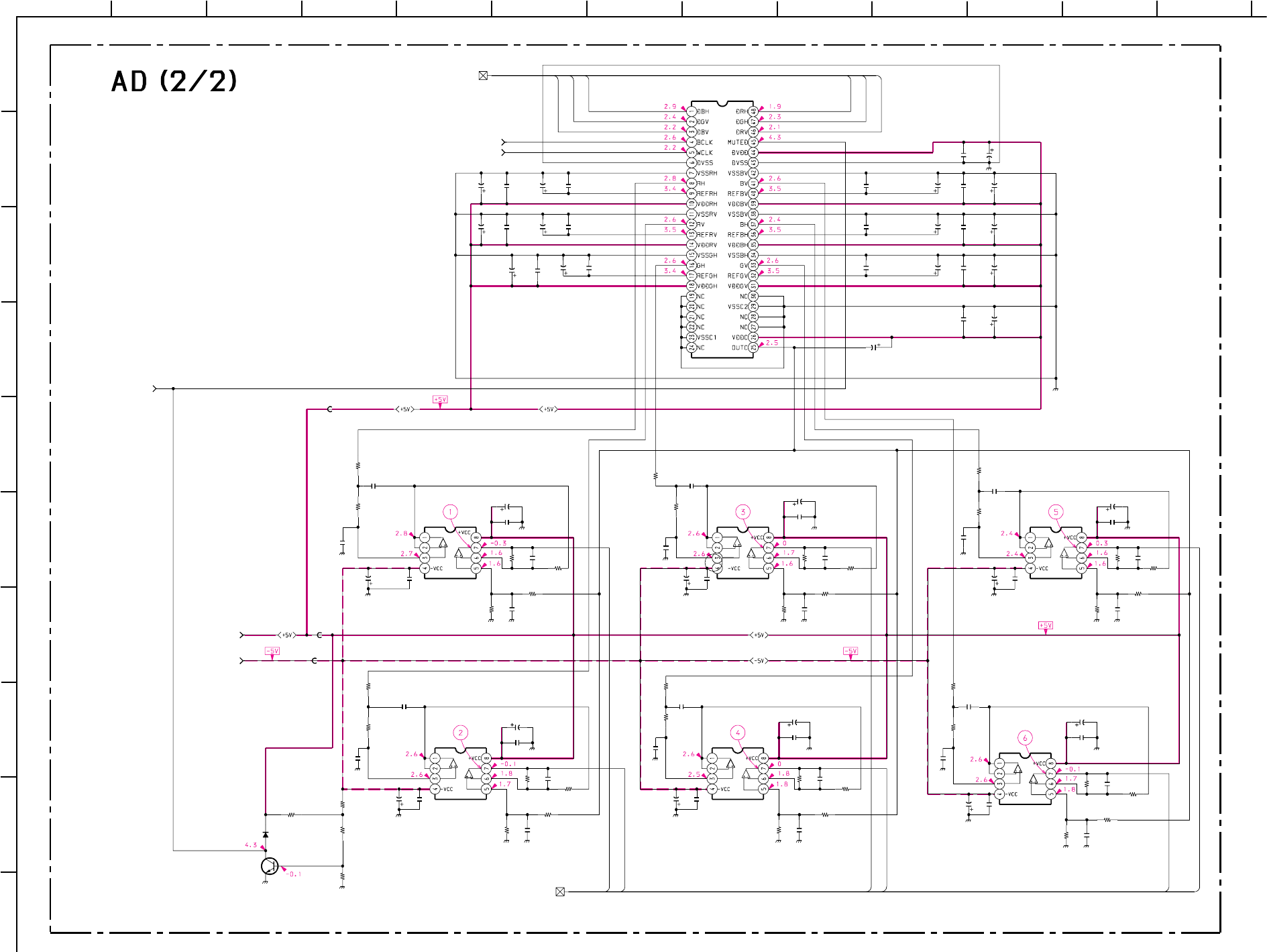
– 61 –
KP-HR432K90/HR532K90/HR532N90/HW572K90
RM-Y909KRM-Y908RM-Y909K RM-Y909K
1
A
B
C
D
E
F
G
H
I
J
212 13
11
10
98765
43
17
R1665
R1666
C1647
R1667
R1668
C1649
C1651
C1652
C1657
C1658
C1659
C1661
C1664
C1665
C1666
C1668
C1669
C1673
C1676
C1677
C1678
C1680
C1681
C1685
C1688
C1690
C1691
C1692
C1693
C1694
C1695
C1696
C1697
C1698
C1699
C1700
C1701
C1704
C1708
C1711
C1712
C1714
C1715
C1717
C1718
C1720
C1721
C1722
R1682
R1683
R1684
R1685
R1698
R1699
R1700
R1701
R1711
R1712
R1713 R1714
C1670
C1656
R1673
R1674
R1675
R1681
R1694
R1695
R1696
R1697
R1705
R1707
R1708
R1709
C1663
Q1606
D1603
R1670
R1672
R1690
R1692
R1702
R1703
C1648
C1650
C1654
C1655
C1660
C1662
C1667
C1679
C1686
C1687
C1689
C1702
C1703
C1705
C1706
C1710
C1713
C1716
C1719
IC1602
IC1603 IC1609
IC1610
IC1611
IC1612
R1669
R1671
R1691
R1693
R1704
R1706
C1645
C1646 C1674
C1675
C1707
C1709
FB1614
FB1615
FB1616
IC1608
C1672
C1671
C1684
C1683
C1682
0.1
25V
F:1608
0.1
25V
F:1608
0.1
25V
F:1608
0.0022
B:1608
0.1
25V
F:1608
0.1
25V
F:1608
0.0022
B:1608
0.1
25V
F:1608
0.1
25V
F:1608
0.0022
B:1608
0.1
25V
F:1608
0.1
25V
F:1608
0.0022
B:1608
0.1
25V
F:1608
0.1
25V
F:1608
0.0022
B:1608
0.1
25V
F:1608
0.0022
B:1608
0.1
25V
F:1608
0.1
25V
F:1608
0.1
25V
F:1608
0.1
25V
F:1608
0.1
25V
F:1608
0.1
25V
F:1608
0.0047
B:CHIP
5p
CH:1608 5p
CH:1608
5p
CH:1608
5p
CH:1608 5p
CH:1608 5p
CH:1608
100p
CH:1608
100p
CH:1608 100p
CH:1608
100p
CH:1608 100p
CH:1608
100p
CH:1608
1k
1/16W
:RN-CP
1k
1/16W
:RN-CP
1k
1/16W
:RN-CP
100
16V
1k
1/16W
:RN-CP
100
16V
100
16V
100
16V
100
16V
100
16V 100
16V
1k
1/16W
:RN-CP
1k
1/16W
:RN-CP
1k
1/16W
:RN-CP
1k
1/16W
:RN-CP
1k
1/16W
:RN-CP
1k
1/16W
:RN-CP
1k
1/16W
:RN-CP
1k
1/16W
:RN-CP
10k
1/16W
:CHIP
10k
1/16W
:CHIP
10k
1/16W
:CHIP 10k
1/16W
:CHIP
0.1
25V
F:1608
0.1
25V
F:1608
10k
1/16W
:RN-CP
10k
1/16W
:RN-CP
10k
1/16W
:RN-CP
10k
1/16W
:RN-CP
10k
1/16W
:RN-CP
10k
1/16W
:RN-CP
10k
1/16W
:RN-CP
10k
1/16W
:RN-CP
10k
1/16W
:RN-CP
10k
1/16W
:RN-CP
10k
1/16W
:RN-CP
10k
1/16W
:RN-CP
100
16V
22k
1/16W
:RN-CP
22k
1/16W
:RN-CP
22k
1/16W
:RN-CP
22k
1/16W
:RN-CP
22k
1/16W
:RN-CP
22k
1/16W
:RN-CP
#
#
#
#
#
#
#
#
#
#
#
#
#
#
#
#
#
#
#
1SS355TE
2SC2412K
NJM2068V-TE2
RH FILTER & AMP
NJM2068V-TE2
RV-FILTER & AMP NJM2068V-TE2
GV FILTER & AMP
NJM2068V-TE2
GH FILTER & AMP
NJM2068V-TE2
BV FILTER & AMP
NJM2068V-TE2
BH FILTER & AMP
22k
1/16W
:RN-CP
22k
1/16W
:RN-CP
22k
1/16W
:RN-CP
22k
1/16W
:RN-CP
22k
1/16W
:RN-CP
22k
1/16W
:RN-CP
0.001
25V
CH:1608
0.001
25V
CH:1608
0.001
25V
CH:1608
0.001
25V
CH:1608
0.001
25V
CH:1608
0.001
25V
CH:1608
BLM11A601S
:1608
BLM11A601S
:1608
BLM11A601S
:1608
CD0031AM
0.1 25V F:1608
0.1 25V F:1608
0.1 25VF:1608
0.1 25V F:1608
0.1 25V F:1608
DHV TO AD 2/2, AD1/2_2
BCLK TO AD 2/2, AD1/2_4
WCLK1 TO AD 2/2, AD1/2_3
REGI MUTE TO AD 2/2, AD1/2_5
+5V TO AD 2/2, AD1/2
-5V TO AD 2/2, AD1/2
R H/V G H/V B H/V TO AD 2/2, AD1/2_1
DRV
DGH
DGV
DRH
GH
GV
BV
BH
DBH
DBV
RV
RH
(PJE DRIVE)
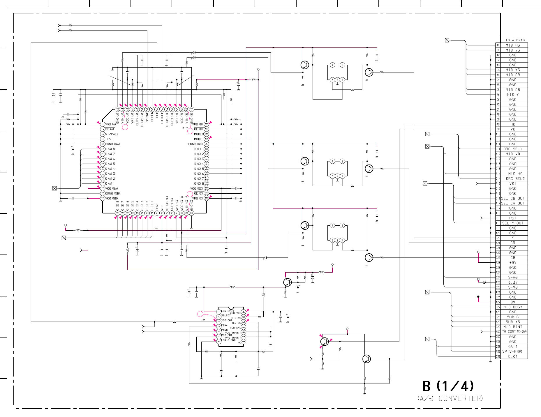
– 62 –
KP-HR432K90/HR532K90/HR532N90/HW572K90
RM-Y909KRM-Y908RM-Y909K RM-Y909K
1
A
B
C
D
E
F
G
H
I
J
212 13
11
10
98765
43
0.6
1
0.7
2
1.3
2
1.4
1.6
3.2
1.5
1.6
1.7
1.7
1.5
1.8
1.6
1.6
4.7
2.4
2.4
3.2
4.7
2.4
1.6
1.6
3.4
2.1
1.4
0.3
1.3
1.4
04.9
0.1
0.4
1.6
2.4
4.7
3.9
2.4
2.4
0.1
1.6
3.2
0
0
1.7
3.2
2
1.5
4.7
3
1
4
2
R3305
R3306
R3307 R3308
R3309
R3310 R3311
R3312
R3313
R3314
R3315
R3316
R3317
R3318
R3319
R3320
R3321 R3322
R3327
R3328
R3329 R3330
R3331
R3334
R3337 R3338 R3339
R3340
R3348
R3351
R3361
R3362
R3363
C3322
C3323
C3331
C3336
C3345
C3352
C3353
C3356
C3361
C3362
L3304
L3305
L3306
L3307
L3308
L3309
R3332
CN3203
C3329
R3301
R3304
R3371
R3302
R3372
R3373 C3334
R3374
R3375
R3377
C3337
R3378
R3379
R3380
R3383
C3332
C3328
FL3301
FL3302
FL3303
R3303
R3376
R3381
R3356
C3310 C3311
C3320
C3321
C3324
C3327
C3338
C3339 C3340
C3344
C3346
C3347
C3348
C3354
C3355
D3301
FB3302
IC3304
IC3305
Q3307
Q3306
Q3309
Q3308
Q3311
Q3310
Q3301
Q3303
Q3304
100
1/16W
:CHIP
100
1/16W
:CHIP
0
:1608 0
:1608
56
1/16W
:RN-CP
56
1/16W
:RN-CP 56
1/16W
:RN-CP
56
1/16W
:RN-CP
15k
1/16W
:CHIP
75
1/16W
:RN-CP
15k
1/16W
:CHIP
68
1/16W
:RN-CP
68
1/16W
:RN-CP
75
1/16W
:RN-CP
56 1/16W :RN-CP
56
1/16W
:RN-CP
56 1/16W :RN-CP 56
1/16W
:RN-CP
15k
1/16W
:CHIP
0
:1608
330
1/16W
:CHIP
330
1/16W
:CHIP
47k
1/16W
:CHIP
100
1/16W
:CHIP
820
1/16W
:CHIP
1k
1/16W
:CHIP
680k
1/16W
:CHIP
680k
1/16W
:CHIP
0
:1608
2.2k
1/16W
:CHIP
2.2k
1/16W
:CHIP
#
1/16W
:CHIP
#
1/16W
:CHIP
47
16V
:AL-CP
10
16V
:AL-CP
47
16V
:AL-CP
10
16V
:AL-CP
47
16V
:AL-CP
10
16V
:AL-CP
47
16V
:AL-CP
47
16V
:AL-CP
0.01
25V
B:1608
4.7
6.3V
B:CHIP
10µH
AMP
AMP
:CHIP
:CHIP
:CHIP
:CHIP
:CHIP
5.1k
1/16W
:RN-CP
64P
:B TO B-P
0.1
16V
B:1608
100
1/16W
:CHIP
100
1/16W
:CHIP
560
1/16W
:RN-CP
470
1/16W
:CHIP
470
1/16W
:CHIP
470
1/16W
:CHIP
0.1
16V
B:1608
100
1/16W
:CHIP
560
1/16W
:RN-CP
470
1/16W
:CHIP
0.1
16V
B:1608
470
1/16W
:CHIP
100
1/16W
:CHIP
560
1/16W
:RN-CP
470
1/16W
:CHIP
10 16V :AL-CP
10 16V :AL-CP
7.2MHz
:LPF
3.6MHz
:LPF
3.6MHz
:LPF
5.6k
1/16W
:RN-CP
5.6k
1/16W
:RN-CP
5.6k
1/16W
:RN-CP
680
1/16W
:CHIP
0.1
25V
F:1608
0.1
25V
F:1608
0.1
25V
F:1608
0.1
25V
F:1608
0.1
25V
F:1608
0.1
25V
F:1608
0.1
25V
F:1608
0.1
25V
F:1608
0.1
25V
F:1608
0.1
25V
F:1608
0.1
25V
F:1608
0.1
25V
F:1608
0.1
25V
F:1608
0.1
25V
F:1608
0.1
25V
F:1608
UDZS-3.9B
REG
BLM41P750S
TLC5733A
3CH 8BIT A/D
TLC2932IPWR
WRITE PLL
2SC2412K
2SA1037AK
BUFFER
BUFFER
BUFFER
2SC2412K
2SA1037AK
2SC2412K
2SA1037AK
2SC2412K
SWITCH
AMP
AMP
AMP
2SC2412K
2SC2412K
5V
5V
3.3V
5V
3.3V
9V
5V
ADHD TO B1/4, B2/4_2
C0
C1
C2
C3
C4
C5
C6
C7
Y0
Y1
Y2
Y3
Y4
Y5
Y6
Y7
MID Y
MID CR
MID CB
DRC SEL2
SEL CR OUT
SEL Y OUT
MID BUSY
MID BINT
VP
DAT1
CLK1
MID VS
MID HS
MID YS
DRC SEL1
SEL CB OUT
HD3
VD3
SUB G
SUB YS
S-HD
S-VD
10µH
100µH
100µH
100µH
10µH
CLP TO B1/4, B2/4_1
Y TO
B1/4, B2/4_42
C TO B1/4, B2/4_43
3.3V-2 TO B1/4, B2/4, B3/4_25
VCO TO B1/4, B2/4_3
PLL TO B1/4, B2/4_4
VD TO B1/4, B2/4_6
IIC1 TO
B1/4, B4/4_2
MID MICRO TO B1/4, B4/4_13
TH CONT TO
B1/4, B4/4_15
RST TO
B1/4, B4/4_12
SEL Y/CR/CB TO
B1/4, B4/4_11
DRC SEL TO B1/4, B4/4_8
MID OUT TO B1/4, B3/4_7
MID SYNC TO
B1/4, B3/4 B4/4_9
VD1 TO
B1/4, B3/4_10
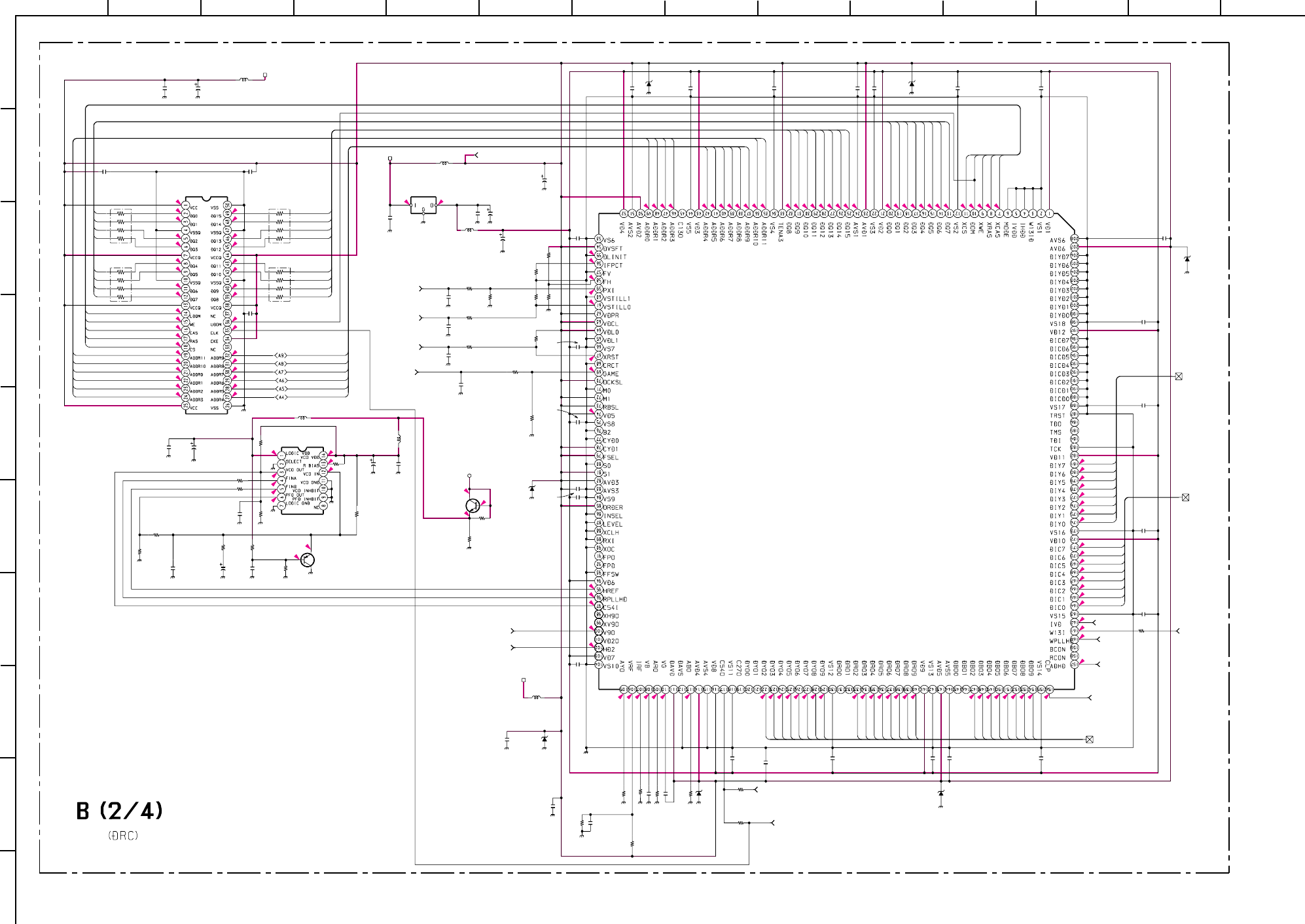
– 63 –
KP-HR432K90/HR532K90/HR532N90/HW572K90
RM-Y909KRM-Y908RM-Y909K RM-Y909K
1
A
B
C
D
E
F
G
H
I
J
212 13
11
10
98765
43 14
3.3
0.3
1
1
0.7
0.5
2
0.5
1.3
1.3
1.7
1.3
1.9
0.7
0.9
0.6
1.4
1.5
1.7
1.5
1.4
1.7
1.5
1.7
1.5
1.6
1.9
1.6
1.9
1.7
1.7
1.5
0.1
3.2
1.3
1.7
1.6
1.9
1.6
1.8
1.7
1.7
1.7
1.3
1.9
2
0.7
0.9
1.8
3.2
3.1
3.2
0.5
3.1
1
1.6
1.3
1.7
1.5
1.5
1.7
1
1.1
1
1.6
1.3
1.8
0
0
0
0.1
0
0
0
0
0
0
0
1.4
1.4
1.5
1
1.2
1.3
1.4
1.6
0.1
3.3
3.3
0
0
0
1.8
1.6
3.2
1.8
0.2
0
0
3.2 1.8
0.9
1.2
1.1
1.7
1.4
1.6
1.5
1.6
1.5
0
0
0
0
0
0
0
2.1
2.2
0.5
1.6
1.5
1.8
1.4
1.7
1.1
1.3
0.9
0.5
3.2
3.2
3.1
3.1
0
3.2
4.2
4.9 4.9
2
0
0
0
0.1
4
2
0
3.2
1.6
2.1
R3323R3324
R3326
R3333
R3336
R3341
R3342
R3343
R3344
R3346
R3347
R3349
R3350
R3352
R3353R3354R3355
R3357
R3359
R3360
R3364
R3368
R3369
R3370
R3382
RB3304
RB3305
RB3306
RB3307
C3303
C3306
C3330
C3342
C3359
C3363
C3375
C3377C3378
C3380
C3381
D3306D3307
D3308
L3301
L3302
L3303
L3310
L3311
L3312
R3325
R3365
R3367
R3345
R3358
D3305
R3366
C3312
C3309
R3335
D3302
D3303
D3304
R3840
C3301
C3302
C3304
C3305
C3307
C3308
C3313C3314C3315C3316C3317C3318C3319
C3325
C3326
C3333
C3335
C3341
C3343
C3349
C3350C3351
C3357
C3358
C3360
C3364
C3365
C3366C3367C3368C3369
C3371
C3372
C3374
C3376
C3379
C3373
IC3301 IC3302
IC3303
IC3306
Q3302
Q3305
C3370
2.2k
1/16W
:CHIP
3.3k
1/16W
:CHIP
2.2k
1/16W
:CHIP
0
:1608
#
1/16W
:CHIP
220
1/16W
:CHIP
3.6k
1/16W
:RN-CP
1001/16W:CHIP
470k
1/16W
:CHIP
1001/16W:CHIP
330
1/16W
:CHIP
620
1/16W
:RN-CP
270
1/16W
:CHIP
470k
1/16W
:CHIP
22k
1/16W
:CHIP
220
1/16W
:CHIP
1k
1/16W
:CHIP
220
1/16W
:RN-CP
220
1/16W
:RN-CP
3.3k
1/16W
:CHIP
0
:1608
#
1/16W
:CHIP
0
:1608
#
1/16W
:CHIP
0
:1608
56*4
56*4
56*4
56*4
100
6.3V
:AL-CP
47
16V
:AL-CP
#
:1608
#
:1608
47
16V
:AL-CP
47
16V
:AL-CP
4.7
6.3V
B:CHIP
0.01
25V
B:1608
47
16V
:AL-CP
#
:1608
#
:1608
##
#
:CHIP
10µH
:CHIP
:CHIP
:CHIP
:CHIP
:CHIP
3.3k
1/16W
:CHIP
3.3k
1/16W
:CHIP
33
1/16W
:CHIP
3.3k 1/16W :RN-CP
220 1/16W :RN-CP
#
2.2k
1/16W
:CHIP
100
6.3V
:AL-CP
100
6.3V
:AL-CP
10k
1/16W
:CHIP
UDZS-9.1B
#
#
33
1/16W
:CHIP
0.1
25V
F:1608
0.1
25V
F:1608
0.1
25V
F:1608
0.1
25V
F:1608
0.1
25V
F:1608
0.1
25V
F:1608
0.1
25V
F:1608
0.1
25V
F:1608
0.1
25V
F:1608
0.1
25V
F:1608
0.1
25V
F:1608
0.1
25V
F:1608
0.1
25V
F:1608
0.1
25V
F:16080.1
25V
F:1608
0.1
25V
F:1608
0.1
25V
F:1608
0.1
25V
F:1608
0.1
25V
F:1608
0.1
25V
F:1608
0.1
25V
F:16080.1
25V
F:1608
0.1
25V
F:1608
0.1
25V
F:1608
0.1
25V
F:1608
0.1
25V
F:1608
0.1
25V
F:1608
0.1
25V
F:1608
0.1
25V
F:1608
0.1
25V
F:1608
0.1
25V
F:1608
0.1 25V F:1608
0.1 25V F:1608
0.1
25V
F:1608
0.1
25V
F:1608
0.1
25V
F:1608
10p
CH:1608
HY57V161610DTC
16M-SDRAM BA18BC0FP-E2
1.8V-REG
CXD2095AQ
DRC-MF
TLC2933IPWR
READ PLL
2SC2412K
SWITCH
SWITCH
2SA1037AK
0.1
25V
F:1608
3.3V
3.3V
PXI TO B2/4, B4/4_24
3.3V-2 B2/4, B1/4, B3/4_25
DRC-FILM TO B2/4, B4/4_16
XDRCVS TO B2/4, B4/4_19
XDRCHS TO B2/4, B4/4_20
DRCDCLK TO B2/4, B4/4_22
C540 TO B2/4, B4/4_21
LINE-W TO
B2/4, B4/4_16
DRC RESET TO
B2/4, B3/4_17
3.3V
5V
XRAS
XWE
DOM
XCS
XCS
XRAS
XCAS
XWE
DOM
Y0
Y1
Y2
Y3
Y4
Y5
Y6
Y7
C0
C1
C2
C3
C4
C5
C6
XCAS
Y0
Y1
Y2
Y3
Y4
Y5
Y6
Y7
CB0
CB1
CB2
CB3
CB4
CB5
CB6
CB7
CR0
CR1
CR2
CR3
CR4
CR5
CR6
CR7
DQ4
DQ5
DQ6
DQ7
DQ0
DQ1
DQ2
DQ3
A0
A1
A2
A3
A10
A11
C7
A4
A5
A6
A7
A8
A9
DQ11
DQ10
DQ9
DQ8
DQ15
DQ14
DQ13
DQ12
A9
A8
A7
A6
A5
A4
A11
A10
A0
A1
A2
A3
DQ2
DQ3
DQ4
DQ5
DQ6
DQ7
DQ1
DQ0
DQ12
DQ13
DQ9
DQ8
DQ10
DQ15
DQ14
DQ11
10µH
1µH
100µH
100µH
10µH
Y TO B2/4, B1/4_42
VCO TO B2/4, B1/4_3
VD TO
B2/4, B1/4_6
ADHD TO
B2/4, B1/4_2
CLP TO
B2/4, B1/4_1
CLP TO
B2/4, B1/4_1
DRC TO
B2/4, B3/4_23
PLL TO
B2/4, B1/4_4
C TO
B2/4, B1/4_43
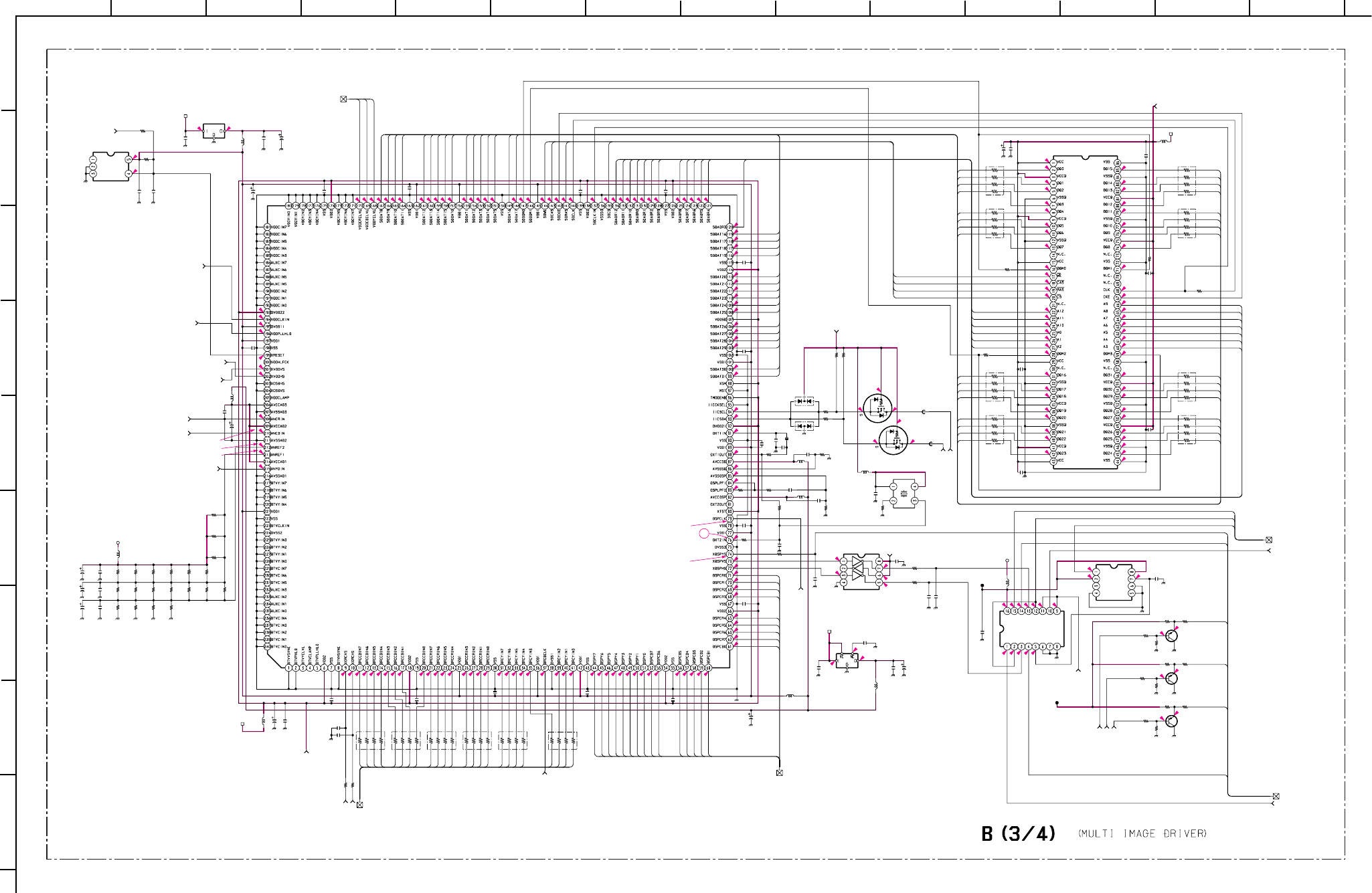
– 64 –
KP-HR432K90/HR532K90/HR532N90/HW572K90
RM-Y909KRM-Y908RM-Y909K RM-Y909K
1
A
B
C
D
E
F
G
H
I
212 13
11
10
98765
43 14
2.5
2.5
0
0.3
1.6
1.6
1.6
1.7
1.4
1.8
1.6
1.4
1.5
1.5
1.8
1.8
0
1.8
1.7
1.5
0.6
0.9
0.7
1.5
1.7
1.3
1.3
0.6
0.9
0.7
1.2
1.2
1.9
1.3
1.3
1.4
0.4
0.1
0.2
0.2
0.5
1
1.5
1.3
2
1.2
1.4
2
1.3
3.2
3.3
2.3
2.5
0.9
1.2
1.2
0.4
2.5
0
0
0
2.5
0.8
1.7
1.9
1.2
1.9
1.2
0
1.4
1.2
1.5
1.3
1.3
3.1
3.2
1.6
2.1
0.4
0
0
1.5
1.5
3.1
3.1
4.6
5
1.5
1.1
1.8
1.5
1.4
1.4
1.6
0.6
1.5
1.1
1.5
1.4
1.3
1.6
2.6
2.6
1.6
1.6
0.1
0
2
0
0.1
0
1.6
1.6
3.9
1.5
1.5
3.2
2.5
2.9
3
0
0.1
1.3
1.4
0
1.6
1.4
7.8
1.3
1.3
2.7
1.7
1.3
1.4
1.1
1.2
1.5
1
1.8
1.8
2.6
1
3.2
3.2
3.1
3.2
4.9
1.6
0.5
2.3
1.6 2.3
1.6 2.2
0.4
3.3
1.2
0.9
1.4
1.7
0.1
1.5
2.3
1.3
0.1
3.1
3.1
3.2
2.9
1.6
1.6
0.1
1.6
1.6
1.3
1.4
1.8
1.1
1.5
0.5 0
1.7
3.2
1.6
1.3
1.3
1.8
1.1
1.5
0.5
2.6
2.6
2.6
0
1.6
0.1
0
2.6
1.5
0
0
1.4
1.2
1.2
1.6
1.4
1.6
2.7
1.3
0
0
0
2
3.2
3.1
4.7
3.2
3.2
0.2
3.2
4.6
0
0
2.6
4.9
0.1
0
0.1
0.1
5
5
R3410
R3421
R3422
R3460
R3461
R3470
R3475
R3489
R3490
R3497
R3575
R3800
R3802 R3803 R3804 R3805
R3806
R3807 R3808 R3809 R3810
R3811
R3812
R3813
R3814 R3815 R3816 R3817
R3821
R3822
R3823
R3824
R3825
R3827
R3828
R3829
R3830
R3834 R3835
R3836
R3837
R3838
R3839 R3841
R3847
R3923
C3405
C3408
C3431 C3440
C3453
C3455
C3457 C3459
C3460
C3461
C3468
C3470
C3471
C3472
C3476
C3497
C3498
D3401
D3402
FB3401
FB3402
L3402
L3405
L3406
L3407
L3408
L3409
L3411
L3415
L3416
X3401
X3402
C3499
R3452
R3498
C3441
R3842
R3881
R3882
R3883
C3404
R3846
RB3421
RB3422
RB3423
RB3424
RB3426
RB3427
RB3428
L3401
L3410
RB3425
RB3407
RB3408
RB3409
RB3410
RB3411
RB3412
R3428
C3407
C3418
C3428
C3436
C3446
R3820
C3406
C3401
C3403
C3409
C3410 C3411 C3412
C3413 C3414
C3417
C3424
C3426
C3435
C3439
C3444
C3449
C3450
C3451
C3452
C3454
C3456
C3458 C3462
C3463 C3464
C3465 C3466 C3467
C3469
C3473
C3475
C3489
C3496
IC3401
IC3403
IC3408
IC3402
IC3411
IC3412
IC3413
IC3409
Q3402
Q3404
Q3411
Q3412
Q3413
10k
1/16W
:CHIP
0
:1608
0
:1608
10k
1/16W
:CHIP
10k
1/16W
:CHIP
100
1/16W
:CHIP
100
1/16W
:CHIP
0
:1608
0
:1608
4.7k
1/16W
:CHIP
#
1/16W
:CHIP
0
:1608
270
1/16W
:RN-CP
270
1/16W
:RN-CP
270
1/16W
:RN-CP
270
1/16W
:RN-CP
56
1/16W
:RN-CP
120
1/16W
:RN-CP
120
1/16W
:RN-CP
120
1/16W
:RN-CP
120
1/16W
:RN-CP
100
1/16W
:CHIP
100 1/16W :CHIP
100
1/16W
:CHIP
10
1/16W
:RN-CP
15
1/16W
:RN-CP
22
1/16W
:RN-CP
22
1/16W
:RN-CP
470
1/16W
:RN-CP
470
1/16W
:RN-CP
2.7k 1/16W :CHIP
2.7k 1/16W :CHIP
2.7k 1/16W :CHIP
#
1/16W
:CHIP
470
1/16W
:RN-CP
470
1/16W
:RN-CP
470
1/16W
:RN-CP
270
1/16W
:RN-CP
270
1/16W
:RN-CP
270
1/16W
:RN-CP
270
1/16W
:RN-CP
270
1/16W
:RN-CP
120
1/16W
:RN-CP
120
1/16W
:RN-CP
22
1/16W
:CHIP
0UH
BLM21B050SPT
100
6.3V
:AL-CP
100
6.3V
:AL-CP
47 16V:AL-CP 12p
CH:1608
10
16V
:AL-CP
10
16V
:AL-CP
10
16V
:AL-CP #
:1608
47p
CH:1608
#
:1608
100
6.3V
:AL-CP
100
6.3V
:AL-CP
#
:1608
#
:1608
10
16V
:AL-CP
#
:1608
#
:1608
DAN202K
DAP202K
BK2125HM102
BK2125HM102
:CHIP
1µH
:CHIP
:CHIP
:CHIP
:CHIP
:CHIP
:CHIP
#
:CHIP
18.543956MHz
74.175824MHz
0.01
25V
B:1608
0:1608
560
1/16W
:CHIP
12p CH:1608
750
1/16W
:RN-CP 68 1/16W :CHIP
68 1/16W :CHIP
68 1/16W :CHIP
100
6.3V
:AL-CP
22
1/16W
:CHIP
47*4
47*4
47*4
47*4
47*4
47*4
47*4
:CHIP
:CHIP
47*4
47*4
47*4
47*4
47*4
47*4
47*4
33
1/16W
:CHIP
0.1
16V
B:1608
0.1
16V
B:1608
0.1
16V
B:1608
0.1
16V
B:1608
0.1
16V
B:1608
470
1/16W
:RN-CP
0.1
16V
B:1608
0.1
25V
F:1608 0.1
25V
F:1608
0.1
25V
F:1608
0.1
25V
F:1608
0.1
25V
F:1608
0.1
25V
F:1608
0.1
25V
F:1608
0.1
25V
F:1608
0.1
25V
F:1608
0.1
25V
F:1608
0.1
25V
F:1608
0.1
25V
F:1608
0.1
25V
F:1608
0.1
25V
F:1608
0.1
25V
F:1608
0.1
25V
F:1608
0.1
25V
F:1608
0.1
25V
F:1608
0.1
25V
F:1608
0.1
25V
F:1608
0.1
25V
F:1608
0.1
25V
F:1608
0.1
25V
F:1608
0.1
25V
F:1608
0.1
25V
F:1608
0.1
25V
F:1608
0.1
25V
F:1608
0.1
25V
F:1608
0.1
25V
F:1608
0.1
25V
F:1608
0.1
25V
F:1608
0.1
25V
F:1608
BA25BC0FP-E2
2.5V-REG
PST9120NL
CXD9509AQ
MULTI IMAGE DRIVE
MT48LC2M32B2TG
64M-SDRAM
TC7W04FU
TC7W08FU
SN74LV4053ANSR
SYNC SW
NJM2870F25
2.5V-REG
2SK2036
LEVEL-SHIFT
2SK2036
LEVEL-SHIFT
2SA1037AK
2SA1037AK
2SA1037AK
3.3V
3.3V
3.3V
5V
5V
3.3V
-1
5V
-1
9V
CB4
CB5
CB6
CB7
Y0
Y1
Y2
Y3
Y4
Y5
Y6
D0
D1
D2
D3
D4
D5
D6
D7
D8
D9
D10
D11
D12
D13
D14
D15
D16
D17
D18
D19
D20
D21
D22
D23
D24
D25
D26
D27
D28
D29
D30
D31
A0
A1
A2
A3
A4
A5
A6
A7
A8
A9
A10
A11
A12
Y7
WE
CAS
RAS
CS
A9
A8
A7
A6
A5
A4
A3
A2
A1
A0
A10
A11
A12
CAS
RAS
WE
CS
CR0
CR1
CR2
CR3
CR4
CR5
CR6
CR7
CB0
CB1
CB2
CB3
CB4
CB5
CB6
CB7
D16
D17
D18
D19
D20
D21
D22
D23
D0
D1
D2
D3
D4
D5
D6
D7
CR-CL
CB-CL
Y-CL
D8
D9
D10
D11
D12
D13
D14
D15
D24
D25
D26
D27
D28
D29
D30
D31
Y0
Y1
Y2
Y3
Y4
Y5
CR3
CR0
CR2
CR1
Y6
Y7
CR7
CB0
CR4
CR5
CR6
CB1
CB2
CB3
HD3
VD3
VD0 VS
MID VS
MID YS
MID Y
MID CB
MID CR
MID HS
10µH
10µH
10µH
10µH
10µH
10µH
10µH
10µH
10µH
CL T0 B3/4, B4/4_26
DRC RESET T0 B3/4, B2/4_17
VDOCLK T0 B3/4, B4/4_27
VDOPLL T0 B3/4, B4/4_28
VDOHS T0 B3/4, B4/4_29
VDOVS T0 B3/4, B4/4_30
ANCR T0 B3/4, B4/4_31
ANCB T0 B3/4, B4/4_32
ANYG T0 B3/4, B4/4_33
DSP CLK T0 B3/4, B4/4_35
DA DATA T0 B3/4, B4/4_34
DRC DCLK T0 B3/4, B2/4_22
DRC T0 B3/4, B2/4_23
XDRCHS T0 B3/4, B2/4_20
XDRCVS T0 B3/4, B2/4_19
3.3V-2 T0 B3/4, B1/4, B2/4_25
3.3V-2 T0
B3/4, B1/4,
B2/4_25
3.3V-2 T0 B3/4, B1/4, B2/4_25
3.3V-2 T0 B3/4, B1/4, B2/4_25
V T0 B3/4, B4/4_39
MID OUT T0 B3/4, B1/4_7
VD1 OUT T0 B3/4, B1/4_10
DRC SEL2 T0 B3/4, B4/4_42
MID SYNC T0 B3/4, B4/4_9
U T0 B3/4, B4/4_38
Y T0 B3/4, B4/4_37
CONT T0
B3/4, B4/4_36
CLK T0 B3/4, B4/4_41
DAT T0 B3/4, B4/4_40
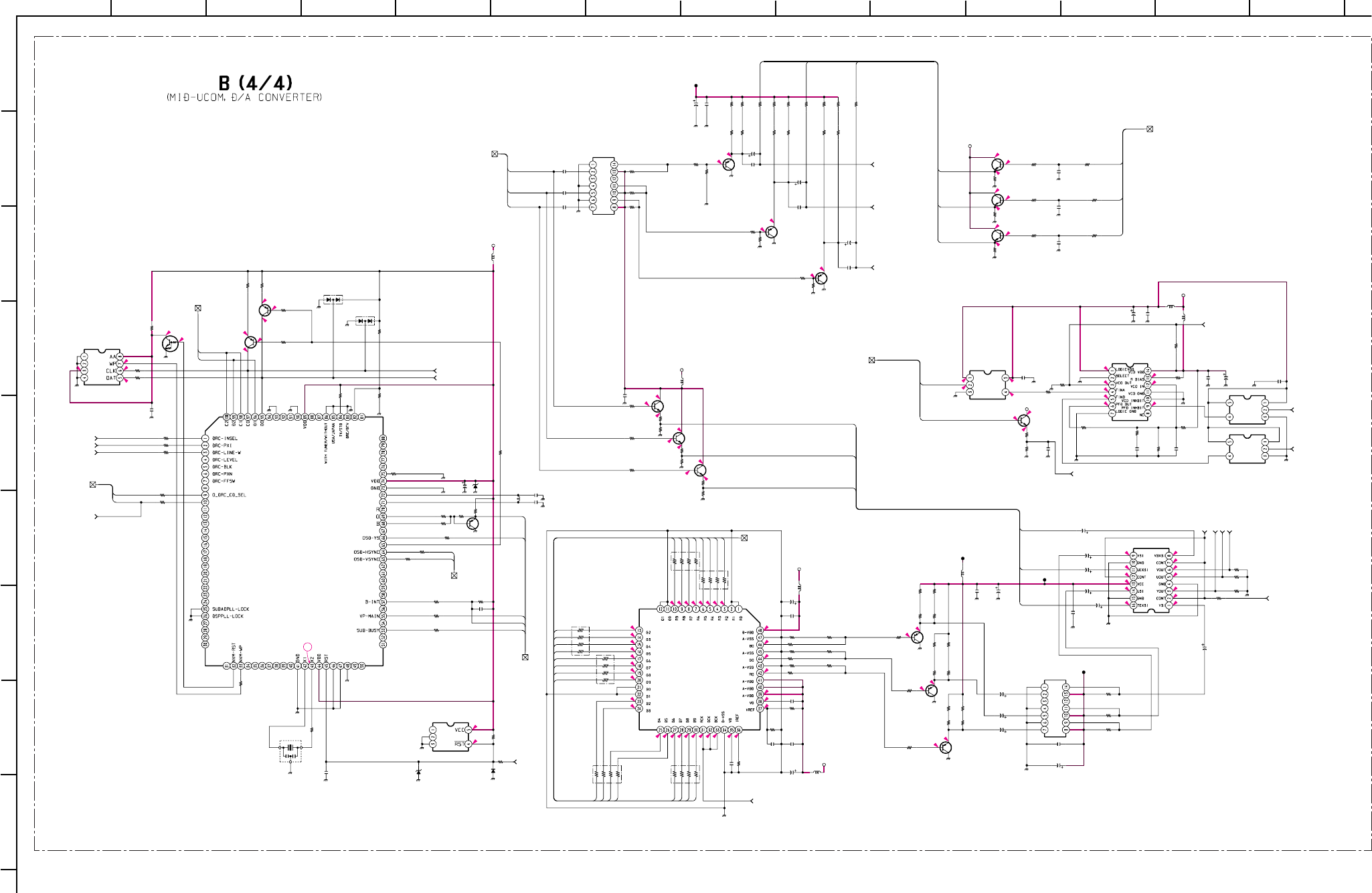
– 65 –
KP-HR432K90/HR532K90/HR532N90/HW572K90
RM-Y909KRM-Y908RM-Y909K RM-Y909K
1
A
B
C
D
E
F
G
H
I
212 13
11
10
98765
43 14
4.9
4.6
4.6
4.1
4.6 4.1
4.6
4.5
4.7
4.9
4.9
4.9
1.3
1.2
1.2
1.7
1.3
1.5
1.9
1.4
1.8
1.8
1.8
1.9
2
2.5
0.9
0.5
0.9
4.9
1.3
1.3
1
1.2
1.2
1.2
1.2
2.1
4.9
0.9
0.6
0.9
0.7
1.7
1.2
1.4
1.2
1.2
6
4.9
2.7
2.1
2.8
4.9 1.1
0.7
4.9 1.8
1.2
4.9
0.5
4.8
0.4
0.1
0.1
4.8
2.3
0.4
2.4 0
0
4
0
2.4
1.6
1
1.1
0.5
1.6
1
4.9
4.6
4.6 4.6
5
3.2
3.2
0
4.9
4.6
9
0
4.9
0
1.8
1.2
2.1
2.7
2
4.9
4.9
2.6
2
1.9
1.9
2.6
2.6
4.9
0
R3023
R3032
R3033
R3034
R3035
R3036
R3037
R3039
R3040
R3050
R3079
R3091 R3092
R3095
R3098
R3099
R3105
R3107
R3108
R3423
R3432
R3434
R3445
R3446
R3448
R3449
R3454
R3457
R3464
R3465
R3466
R3467
R3471
R3472
R3476
R3477
R3478
R3483
R3484
R3485
R3486
R3491
R3492
R3493
R3494
R3495
R3496
R3499
R3501 R3502 R3503 R3504 R3505 R3506
R3507
R3508
R3509 R3510
R3511
R3512
R3801
R3818
R3819
R3826
R3831
R3832
R3833 R3848
R3849
R3850
R3851
R3852
R3854
R3857
R3858
R3862
R3863
R3864 R3865
R3866
R3867
R3868
R3869
R3870
R3871
R3915
R3916
R3917
R3932
R3933
R3953
R3954
R3955
R3956
R3958
RB3401
RB3402
RB3403
RB3404
RB3405 RB3406
C3001
C3002
C3003
C3035
C3089
C3090
C3402
C3415
C3420
C3423
C3425
C3427
C3429
C3434
C3437
C3442
C3443
C3445
C3448
C3474
C3478
C3479
C3481
C3482
C3483
C3484
C3488
C3490
C3491
C3493
C3495
D3089
D3090
D3093
L3001
L3089
L3403
L3404
L3412
L3413
L3414
X3089
FL3003
FL3401
C3433
R3021
R3022
R3104
D3403
R3106
C3096
R3111
C3101
C3102
R3001
R3429
R3109
R3089
R3002
R3103 R3003
R3957
R3937
R3100
R3101
R3096
R3038
L3102
R3447
C3044
C3416
C3419
C3421 C3422
C3430
C3432
C3438
C3447
C3477
C3480
C3485
C3486 C3487
C3492
C3494
R3112
IC3404
IC3405
IC3406
IC3407
IC3089
IC3090
IC3414
IC3410
IC3091
Q3403
Q3407
Q3409
Q3401
Q3408
Q3406
Q3405
Q3005
Q3006
Q3007
Q3091
Q3090
Q3089
Q3001
Q3414
Q3410
Q3415
R3097
R3102
R3110
10k
1/16W
:CHIP
#
1/16W
:CHIP
#
1/16W
:CHIP
#
1/16W
:CHIP
100
1/16W
:CHIP
100
1/16W
:CHIP
100
1/16W
:CHIP
560
1/16W
:RN-CP
560
1/16W
:RN-CP
100
1/16W
:CHIP
1k
1/16W
:CHIP
2.2k
1/16W
:CHIP
2.2k
1/16W
:CHIP
100k
1/16W
:CHIP
47
1/16W
:CHIP
47
1/16W
:CHIP
100
1/16W
:CHIP
0
:1608 470
1/16W
:CHIP
220
1/16W
:CHIP
330
1/16W
:CHIP
100
1/16W
:CHIP
0
:1608 1k
1/16W
:CHIP 680k
1/16W
:CHIP
#
1/16W
:CHIP
2.2k
1/16W
:CHIP
#
1/16W
:CHIP
1k
1/16W
:CHIP
1k
1/16W
:CHIP
#
1/16W
:CHIP
1k
1/16W
:CHIP
1k
1/16W
:CHIP
22
1/16W
:CHIP
1k
1/16W
:CHIP
2.4k
1/16W
:RN-CP
1k
1/16W
:CHIP
2.4k
1/16W
:RN-CP
1k
1/16W
:CHIP
1k
1/16W
:CHIP
22
1/16W
:CHIP
1k
1/16W
:CHIP
1k
1/16W
:CHIP
2.4k
1/16W
:RN-CP
#
1/16W
:CHIP
1k
1/16W
:CHIP
22
1/16W
:CHIP
1k
1/16W
:CHIP
1k
1/16W
:CHIP
1k
1/16W
:CHIP
1k
1/16W
:CHIP
1k
1/16W
:CHIP
1k
1/16W
:CHIP
1k
1/16W
:CHIP
1k
1/16W
:CHIP
1k
1/16W
:CHIP
1k
1/16W
:CHIP
1k
1/16W
:CHIP
1k
1/16W
:CHIP
1k
1/16W
:CHIP
#
1/16W
:CHIP
#
1/16W
:CHIP
#
1/16W
:CHIP
100 1/16W :CHIP
0:1608
0:1608
0:1608 2.2k
1/16W
:CHIP
200 1/16W :RN-CP
200 1/16W :RN-CP
100
1/16W
:CHIP
200 1/16W :RN-CP
2.2k
1/16W
:CHIP
100
1/16W
:CHIP
3.3k
1/16W
:RN-CP 2.2k
1/16W
:CHIP
2.2k
1/16W
:RN-CP
3.3k
1/16W
:CHIP
100
1/16W
:CHIP
0UH BK2125HM601
0UH BK2125HM601
0UH BK2125HM601
13k
1/16W
:RN-CP
13k
1/16W
:RN-CP
13k
1/16W
:RN-CP
10
1/16W
:RN-CP
10
1/16W
:RN-CP
10
1/16W
:RN-CP
#
1/16W
:CHIP
0
:1608
1k
1/16W
:CHIP
1k
1/16W
:CHIP
1k
1/16W
:CHIP
2.2k
1/16W
:CHIP
2.2k
1/16W
:CHIP
33*4
33*4
33*4
33*4
33*4 33*4
47
6.3V
:BP
47
6.3V
:BP
47
6.3V
:BP
0.01
25V
B:1608
0.01
25V
B:1608
47
16V
:AL-CP
10 16V :AL-CP
10
16V
:AL-CP
10
16V
:AL-CP
0.01
25V
B:1608
0.47
10V
B:CHIP
#
:1608
10
16V
:AL-CP
47
16V
:AL-CP
47
16V
:AL-CP
10 16V :AL-CP
0.01
25V
B:1608
47
16V
:AL-CP
0.01
25V
B:1608
10 16V :AL-CP
47
16V
:AL-CP
10
16V
:AL-CP
100
16V
:AL-CP
100
16V
:AL-CP
100
16V
:AL-CP
1
6.3V
B:1608
10
16V
:AL-CP
10 16V :AL-CP
47
16V
:AL-CP
47
16V
:AL-CP
10
16V
:AL-CP
MA153
MA153
#
0
:CHIP
BK2125HS601
:CHIP
:CHIP
:CHIP
:CHIP
:CHIP
20MHz
0.01
25V
B:1608
100 1/16W :CHIP
100 1/16W :CHIP
100 1/16W :CHIP
UDZS-6.8B
560 1/16W :CHIP
0.01
25V
B:1608
100
1/16W
:CHIP
68p
CH:1608
68p
CH:1608
10k
1/16W
:CHIP
1.5k
1/16W
:CHIP
1.5k 1/16W :CHIP
0
:1608
0
:1608
1.2k
1/16W
:CHIP
#
1/16W
:CHIP
AFC79YL25MAIT
AFC19YL34MAIT
2.2k
1/16W
:CHIP
100 1/16W :CHIP
100 1/16W :CHIP
100 1/16W :CHIP
470
1/16W
:CHIP
560
1/16W
:RN-CP
:CHIP
3.9µH
680
1/16W
:CHIP
0.1
25V
F:1608
0.1
25V
F:1608
0.1
25V
F:1608
0.1
25V
F:1608 0.1
25V
F:1608
0.1
25V
F:1608
0.1
25V
F:1608
0.1
25V
F:1608
0.1
25V
F:1608
0.1
25V
F:1608
0.1
25V
F:1608
0.1
25V
F:1608
0.1
25V
F:1608
0.1
25V
F:1608
0.1
25V
F:1608
0.1
25V
F:1608
#
:1608
TLC2932IPWR
WRITE PLL
TC7SET08FU
TC7SET08FU
TC7SET08FU
M24C04-MN6T(A)
NVM
MB94918RPF-G-134
-BND
MID-UCOM
M52055FP
CXD2309Q
D/A
PST9145NL
RESET
2SC2412K
2SC2412K
2SC2412K
2SC2412K
2SA1037AK
2SA1037AK
2SA1037AK
2SC2412K
2SC2412K
2SC2412K
DTC144EKA
NV-RST
2SA1037AK
2SA1037AK
#
2SA1037AK
2SA1037AK
2SA1037AK
100k
1/16W
:CHIP
100
1/16W
:CHIP
100
1/16W
:CHIP
5V
5V
9V
5V
9V
5V
5V
SEL Y/CR/CB T0 B4/4, B1/4_11
5V
5V
5V-1
-1
9V
Y0
Y1
Y2
Y3
Y4
Y5
Y6
Y7
CR0
CR1
CR2
CR3
CR4
CR5
CR6
CR7
Y-CL
CR-CL
TH-CB
TH-Y
CB-CL
SEL CB OUT
SEL CR OUT
SEL Y OUT
TH-Y
TH-CB
TH-CR
MID BUSY
MID BINT
VP
CLK1
DAT1
TH-CR
HD3
VD0 VS
DRC SEL1
DRC SEL2
SUB YS
SUB G
CB0
CB1
CB2
CB3
CB4
CB5
CB6
CB7
Y-CL
CB-CL
CR-CL
CR-CL
CB-CL
Y-CL
S-HD
S-VD
100µH
100µH
0µH
10µH
10µH
10µH
CLK T0 B4/4, B3/4_41
DAT T0 B4/4, B3/4_40
DRC-FILM T0 B4/4, B2/4_16
PXI T0 B4/4, B2/4_24
LINE-W T0 B4/4, B2/4_18
RST
T0
B4/4, B1/4_12
MID MICRO T0 B4/4, B1/4_13
DSP CLK T0 B4/4, B3/4_22
DA DATA
T0 B4/4, B3/4_34
VDOVS T0 B4/4, B3/4_30
VDOCLK T0 B4/4, B3/4_27
CL T0 B4/4, B3/4_26
CONT T0 B4/4, B3/4_36
Y T0 B4/4, B3/4_37
U T0 B4/4, B3/4_38
V T0 B4/4, B3/4_39
VDOHS T0 B4/4, B3/4_29
VDOPLL T0 B4/4, B3/4_28
TH CONT T0 B4/4, B1/4_15
MID SYNC T0 B4/4, B1/4,B3/4_9
ANCR T0 B4/4, B3/4_31
ANCB T0 B4/4, B3/4_32
ANYG T0 B4/4, B3/4_33
MID SYNC T0 B4/4, B1/4, 3/4_9
DRC SEL T0 B4/4, B2/4_8
DRC SEL2 T0 B4/4, B3/4_42
IIC1 T0 B4/4, B1/4_2
D3099
1SS355
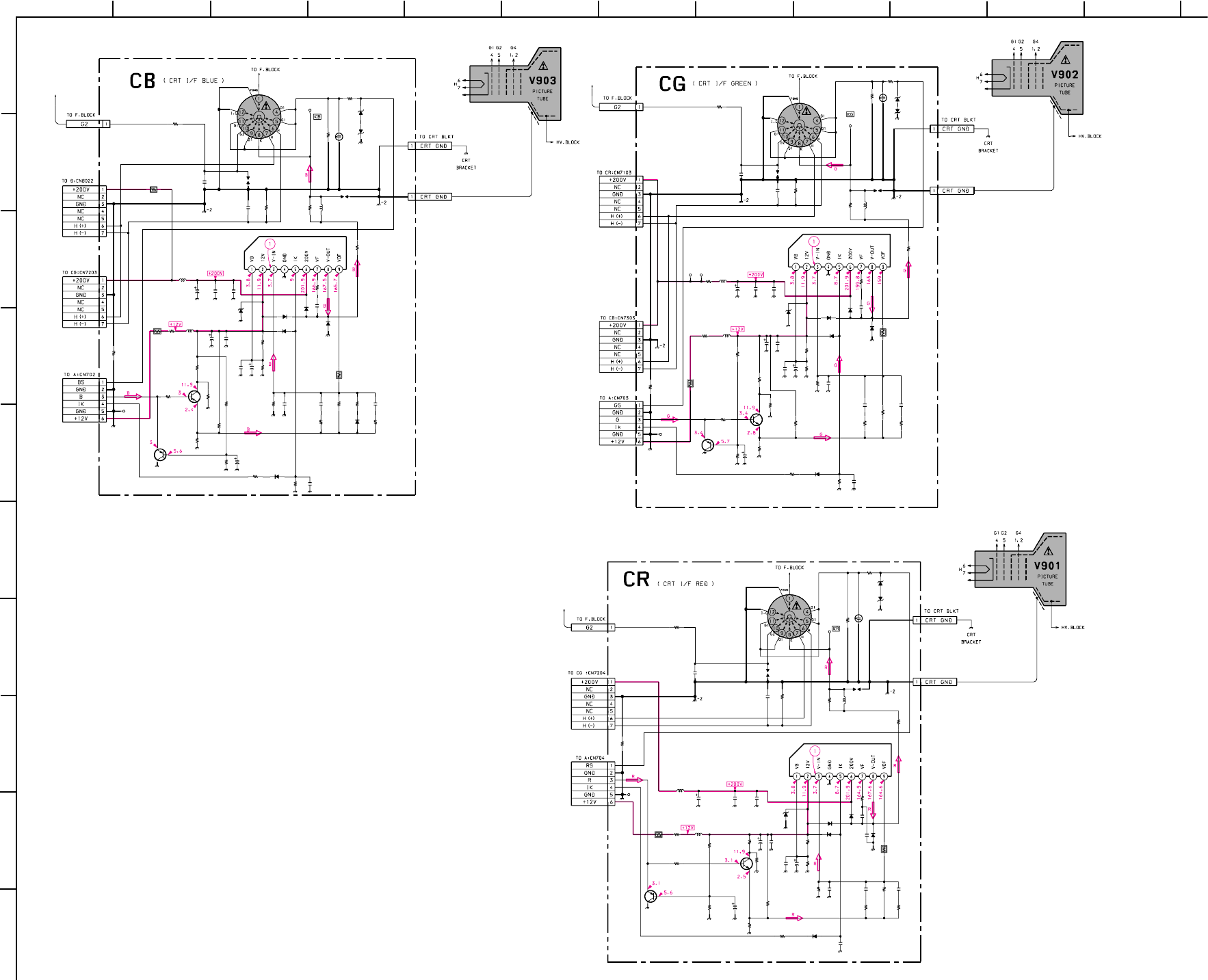
– 66 –
KP-HR432K90/HR532K90/HR532N90/HW572K90
RM-Y909KRM-Y908RM-Y909K RM-Y909K
1
A
B
C
D
E
F
G
H
I
J
212
11
10
98765
43
R7303
R7316
L7303
R7313
C7309
C7306
C7301
CN7305
L7301
IC7301
R7324
C7313
R7317
R7310
R7320
C7303 C7305
R7312
R7311
C7310
R7314
D7307
R7321
D7306
TP7301
SG7302
D7308
SG7301
D7304
C7308
C7304
C7315
R7325
L7302
R7323
R7319
R7322
D7311
D7310
NL7301
C7314
R7318
R7305
R7307
R7309
R7308 C7307
R7304
R7315
C7311
C7302
C7312
R7302
R7301
Q7302
R7326
R7327
R7328
TP7302
CN7304
R7306
D7309
Q7301
D7303
D7305
CN7309
CN7302
CN7303
CN7307
CN7308
560k
1/2W
3.9k :LAV35
680k
1/2W
330p
2kV
B
0.01
500V
:E
22
250V
ONE TOUCH(1P)
(EXCEPT HW572K90)
RED
:LAV35
TDA6111Q/N4
VIDEO OUT
330
1/2W
560p
500V
B
150
1/16W
:CHIP
220
1/16W
:CHIP
2.4k
1/16W
:RN-CP
2200
16V
0.1
16V
B:1608
12k
1/16W
:RN-CP
5.6k
1/16W
:RN-CP
47
2.7k
1/16W
:RN-CP
1SS83TD
PROT.2
100k
3W
:RS
1SS83TD
PROT.4 1SS83TD
PROT.1
1SS83TD
PROT.3
0.1
16V
B:1608
4700p
500V
E
2p
CK:1608
0
:1608
:LAV35
4.7k
1/16W
:RN-CP
1k
1/2W
100
1/2W
MTZJ-13B
PROT
MTZJ-13B
PROT
8p
CH:1608
1.5k
1/16W
:RN-CP
220
1/16W
:CHIP
#
1/16W
:CHIP
12k
1/16W
:RN-CP
7.5k
1/16W
:RN-CP
10
50V
0
:1608
#
1/16W
:CHIP
#
CK:1608
1000p
2kV
:B
100
CH:1608
JW(5)
10
:FPRD
2SA1037AK
BUFF
#
:1608
0
:1608
1.5k
1/16W
:CHIP
7P
WHT
:S-MICRO
100
1/2W
1SS133T-77
BLUE EXP
2SA1037AK
PEAK
MTZJ-13B BIAS
1SS133T-77
OFF SET
6P
BLK
:S-MICRO
7P
BLK
:S-MICRO
:FASTON
:FASTON
4.7µH
47µH
470µH
R7203
R7215 L7203
R7209
C7208
C7204
C7201
CN7205
C7202
L7201
IC7201
R7223
C7213
R7216
R7210
C7205 C7207
R7212
R7211
C7210
R7213
D7207
R7220
D7206
R7219
SG7202
TP7202
D7208
SG7201
D7204
C7209
R7221
C7215
C7206
L7202
R7218
C7214
R7217
R7208
R7204
Q7202
R7206
R7205
C7203
Q7201
D7203
R7202
R7214
D7205
C7211
CN7209
D7210
D7209
C7212
CN7204
CN7203
TP7201
R7201
CN7206
CN7208
R7224
R7225
R7226
TP7204
JR7201
CN7202
R7207
R7222
NL7201
TP7203
560k
1/2W
3.9k :LAV35
4.7µH
680k
1/2W
330p
2kV
B
4700p
500V
E
22
250V
ONE TOUCH(1P)
RED
1000p
2kV
B
:LAV35
TDA6111Q/N4
VIDEO OUT
330
1/2W
560p
500V
B
150
1/16W
:CHIP
220
1/16W
:CHIP
2200
16V
0.1
16V
B:1608
12k
1/16W
:RN-CP
5.6k
1/16W
:RN-CP
47
4.3k
1/16W
:RN-CP
1SS83TD
PROT.2
100k
3W
:RS
1SS83TD
PROT.4
2k
1/16W
:RN-CP
1SS83TD
PROT.1
1SS83TD
PROT.3
0.1
16V
B:1608
0
:1608
3p
CJ:1608
0.01
500V
E
:LAV35
1k
1/2W
8p
CH:1608
1.5k
1/16W
:RN-CP
1.5k
1/16W
:CHIP
220
1/16W
:CHIP
2SC2412K
BUFF
10k
1/16W
:RN-CP
7.5k
1/16W
:RN-CP 10
50V
2SA1037AK
PEAK
MTZJ-13B
BIAS
0
:1608
#
1/16W
:CHIP
1SS133T-77
OFF SET
#
CH:1608
MTZJ-13B
PROT
MTZJ-13B
PROT
100
CH:1608
7P
RED
:S-MICRO
7P
BLK
:S-MICRO
JW(5)
:FASTON
:FASTON
0
:1608
#
:1608
#
:1608
#
0
:1608
6P
WHT
:S-MICRO
100
1/2W
100
1/2W
47µH
470µH
(EXCEPT HW572K90)
C7101
C7102
C7103
C7104 C7105
C7106
C7107
C7108
C7109
C7110
C7111
C7113
CN7103
CN7105
CN7107
D7103 D7104
D7105
D7106
D7107
D7108
D7109
IC7101
L7101
L7102
L7103
NL7101
R7102
R7104
R7105
R7108
R7109
R7110
R7111
R7113
R7114
R7115
R7116
R7117
R7122
SG7101
SG7102
TP7101
Q7102
Q7101
CN7108
R7101
CN7104
R7119
R7121
R7120
CN7102
R7118
C7114 C7115
C7112
R7103
R7123
R7124
R7125 R7112
D7110
TP7102
R7106
R7107
1000p
2kV
B
22
250V
10
50V
4700p
500V
E
0.01
500V
:E
2200
16V
330p
2kV
B
0.1
16V
B:1608
0.1
16V
B:1608 47
#
CH:1608
560p
500V
B
C7116
10p
500V
7P
RED
:S-MICRO
:FASTON
:FASTON
MTZJ-13B
BIAS 1SS83TD
PROT.3
1SS83TD
PROT.4
1SS83TD
PROT.2
1SS83TD
PROT.1
MTZJ-13B
PROT
MTZJ-13B
PROT
TDA6111Q/N4
VIDEO OUT
:LAV35
:LAV35
:LAV35
220
1/16W
:CHIP
560k
1/2W
100
1/2W
1.5k
1/16W
:CHIP
680k
1/2W
5.6k
1/16W
:RN-CP
12k
1/16W
:RN-CP
220
1/16W
:CHIP
3.9k
1k
1/2W
150
1/16W
:CHIP
100
1/2W
330
1/2W
JW(5)
ONE TOUCH(1P)
RED
2.4k
1/16W
:RN-CP
0
:1608
100k
3W
:RS
6P
RED
:S-MICRO
2SA1037AK
PEAK 2SC2412K
BUFF
1.5k
1/16W
:RN-CP
7p
CH:1608
2p
CK:1608
100
CH:1608
0
:1608
0
:1608
#
:1608
#
:1608
3.9k
1/16W
:RN-CP
1SS133
8.2k
1/16W
:RN-CP
10k
1/16W
:RN-CP
4.7µH
470µH
47µH
(EXCEPT HW572K90)
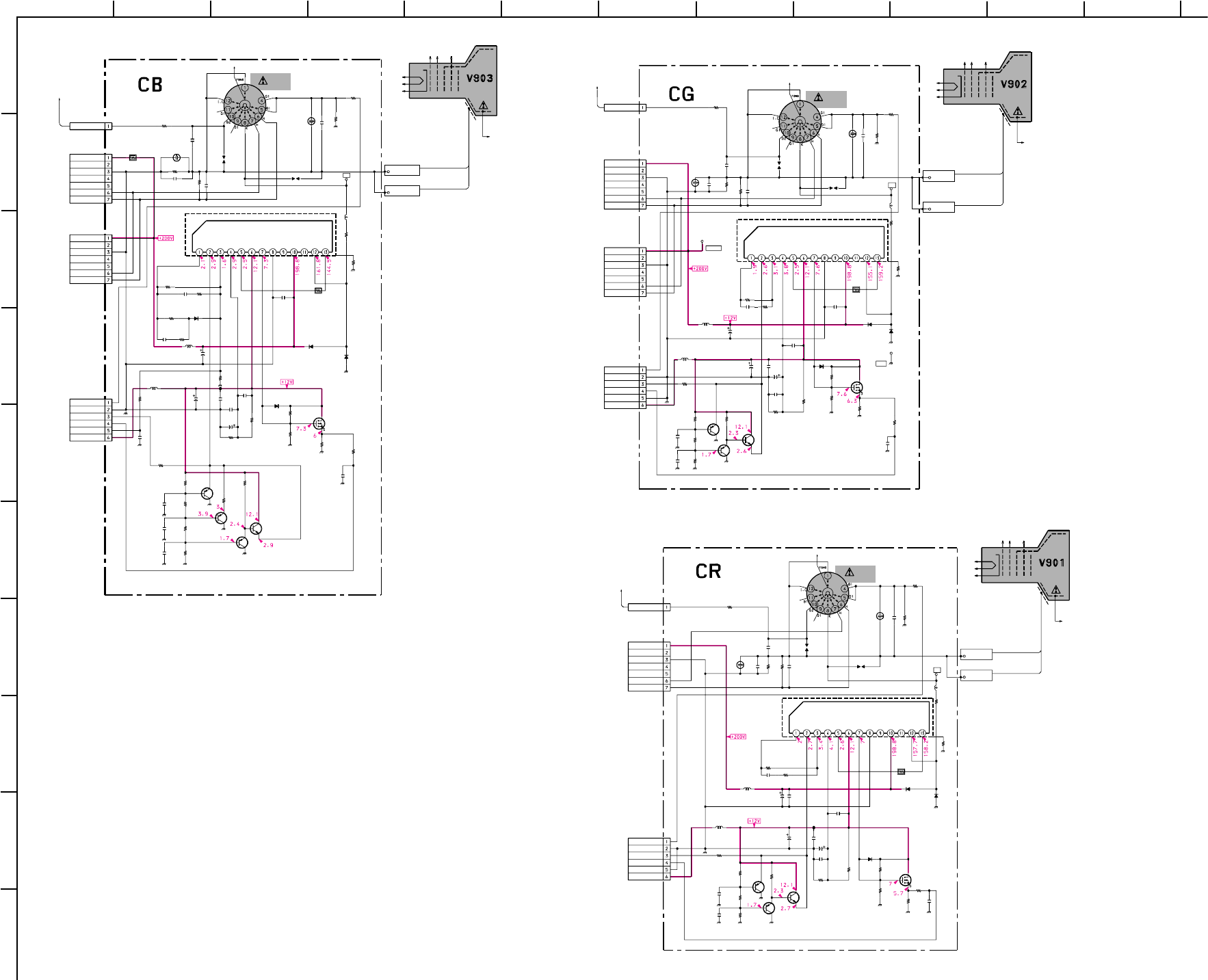
– 67 –
KP-HR432K90/HR532K90/HR532N90/HW572K90
RM-Y909KRM-Y908RM-Y909K RM-Y909K
1
A
B
C
D
E
F
G
H
I
J
212
11
10
98765
43
R7304
C7309
C7308
CN7305
L7302
R7326
C7306C7310
C7312
D7303
SG7302
SG7301
C7311
C7315
L7301
R7324
R7327
CN7308
R7303
R7310
R7309
C7305
R7311
R7322
R7306
R7305
R7321
R7320
R7323
R7325
Q7304
R7315
R7318
CN7309
R7314
C7307
R7302
C7317
C7316
C7304
R7301
CN7307
C7302
R7313
JC7301
C7313
CN7303
R7317
R7319
R7316Q7302
C7314
TP7301
D7304
Q7305
C7318
L7303
CN7304
R7307
Q7301
IC7301
C7303
D7301
D7302
SG7303
C7301
R7312
R7308
CN7302
Q7303
NL7301
560k
1/2W
0.0047
F
22
250V
0P
:ONE TOUCH
:LB2016
330
1/2W
2200
16V0.1
25V
F:1608
100
16V
1SS83TD
PROT
DSP-501N
0.1
25V
F:1608
4700p
500V
E
:LB2016
1k
1/2W
100
1/2W
0P
:FASTON
220
1/16W
:CHIP
5.6k
1/16W
:RN-CP
0
:1608
0.001
2kV
B
1.0k
1/16W
:RN-CP
22k
3W
:RS
2.0k
1/16W
:RN-CP
470
1/16W
:CHIP
240k
1/16W
:RN-CP
240k
1/16W
:RN-CP4.7k
1/16W
:CHIP 1.5k
1/16W
:CHIP
2SK3018
820
1/16W
:RN-CP
3.3k
1/16W
:RN-CP
330
1/16W
:RN-CP
#
F:1608
1.2k
1/16W
:CHIP
2200p
B:1608
8
0.0047
F
0.0047
F
10
:FPRD
0P
:FASTON
22p
CH:1608
330
1/16W
:CHIP
0
:1608
0.1
25V
F:1608
7P
BLK
:S-MICRO
1.5k
1/16W
:RN-CP
2.2k
1/16W
:CHIP
1.1k
1/16W
:RN-CP
2SA1037AK
0.1
25V
F:1608
TERMINAL
1SS83TD
PROT
#
#
F:1608
:LAV35
7P
WHT
:S-MICRO
1001/2W:RC
2SA1037AK
PEAK
TDA6120Q/N2/S1
VIDEO OUT
22p
CH:1608
1SS355TE
1SS355TE
NEON
LAMP
0.01
25V
B:1608
680k
1/2W
150
1/16W
:CHIP
6P
BLK
:S-MICRO
2SC2412K
#
G2
TO F.BLOCK
TO F.BLOCK
12V
VOF
200V
GND
IK
FB
RC+
RC-
GND
VIN-
VIN+
NC
NC
VOUT
NC
NC
NC
GND
HEATER(-)
+200V
HEATER(+)
BS
NC
NC
NC
GND
HEATER(-)
+200V
HEATER(+)
CRT_GND
CRT_GND
TO CG:CN7203
TO D:CN8022
B
IK
OFFSET
+12V
TO A:CN702
KB
HV.BLOCK
6
7
G1G2G4
451,2
TUBE
PICTURE
K 8
H
BUFFER
BUFFER
IK BUFFER
10H
10H
1H
(HW572K90)
R7204
C7206
C7212
C7204
CN7205
C7203
L7202
R7219
C7207C7209
C7210
D7202
SG7202
C7208
L7201
R7217
R7201
R7207R7214
R7218
R7213
R7212
R7215R7216
Q7203
R7210
R7211
C7214
C7213
C7202
R7209
JC7201
C7211
CN7204
CN7203
R7203
R7205
R7202Q7201
C7201
TP7202
D7203
TP7203
Q7204
R7220
C7215
L7203
R7206
CN7208
IC7201
C7205
TP7201
D7201
CN7209
SG7201
R7208
CN7206
CN7202
Q7202
NL7201
560k
1/2W
0.0047
F
4700p
500V
E
22
250V
0P
:ONE TOUCH
0.001
2kV
B
:LB2016
330
1/2W
2200
16V
0.1
25V
F:1608
10016V
1SS83TD
PROT
DSP-501N
0.1
25V
F:1608
:LB2016
1k
1/2W
220
1/16W
:CHIP
820
1/16W
:RN-CP22k
3W
:RS
100
1/2W
120k
1/16W
:RN-CP
120k
1/16W
:RN-CP
4.7k
1/16W
:CHIP
1.5k
1/16W
:CHIP
2SK3018
2.2k
1/16W
:RN-CP
4.7k
1/16W
:RN-CP
2200p
B:1608
0.0047
F
0.0047
F
330
1/16W
:CHIP
0
:1608
0.1
25V
F:1608
7P
RED
:S-MICRO
7P
BLK
:S-MICRO
1.5k
1/16W
:RN-CP
2.2k
1/16W
:CHIP
1.1k
1/16W
:RN-CP2SA1037AK
0.1
25V
F:1608
TERMINAL
1SS83TD
PROT
TERMINAL
#
5.6k
1/16W
:RN-CP
#
F:1608
:LAV35
100
1/2W
:RC0P
:FASTON
TDA6120Q/N2/S1
VIDEO OUT
27p
CH:1608
1SS355TE
PROT
680k
1/2W
0P
:FASTON
6P
WHT
:S-MICRO
2SC2412K
#
G2
TO F.BLOCK
TO F.BLOCK
NC
NC
NC
12V
200V
GND
IK
FB
RC+
RC-
GND
+200V
+200V
NC
NC
VIN+
VIN-
VOUT
VOF
NC
NC
NC
GND
HEATER(-)
+200V
HEATER(+)
CRT_GND
CRT_GND
HEATER(+)
HEATER(-)
TO CR:CN7103
TO CB:CN7303
TO A:CN703
GS
GND
G
IK
GND
+12V
KG
GND
HV.BLOCK
6
7
G1G2G4
451,2
TUBE
PICTURE
K 8
H
BUFFER
PEAK
IK BUFFER
10H
10H
1H
SG7203
NEON
LAMP
(HW572K90)
R7101
R7102
L7101
L7102
R7105
C7103
R7106
C7104
R7107
Q7102
R7108
C7107
SG7101
C7109
C7110
C7111
C7112
SG7102
R7112
R7113
R7114
Q7103
R7115
R7116
R7117
R7118
R7119
CN7104
CN7102
CN7103
IC7101
D7101
C7102
C7108
C7113
C7114
JC7101
NL7101
TP7101
D7102
D7103
R7103
C7101Q7101
Q7104
C7115
CN7108
CN7107
CN7105
R7110R7111
C7106
R7104
R7120
L7103
R7109
C7105
2SK3018
DSP-501N
0.001
2kV
B
22
250V
4700p
500V
E
0.1
25V
F:1608
0.1
25V
F:1608
100
16V
:LB2016
10H
10H
:LB2016
220
1/16W
:CHIP
560k
1/2W
1k
1/16W
:RN-CP
1k
1/2W
22k
3W
:RS
330
1/2W
180k
1/16W
:RN-CP
180k
1/16W
:RN-CP
4.7k
1/16W
:CHIP
100
1/2W
100
1/2W
:RC
1.5k
1/16W
:CHIP
680k
1/2W
0.1
25V
F:1608
2.2k
1/16W
:CHIP
0P
:ONE TOUCH
6P
RED
:S-MICRO
7P
RED
:S-MICRO
TDA6120Q/N2/S1
2SC2412K
1SS355TE
0.0047
F
0.0047
F
0.0047
F
2200p
B:1608
0
:1608
#
TERMINAL
1SS83TD
PROT
1SS83TD
PROT
1.1k
1/16W
:RN-CP
0.1
25V
F:1608
2SA1037AK
#
#
F:1608
0P
:FASTON
0P
:FASTON
3k
1/16W
:RN-CP
5.6k
1/16W
:RN-CP
2200
16V
1.5k
1/16W
:RN-CP
5.6k
1/16W
:RN-CP
:LAV35
1H
470
1/16W
:CHIP
22p
CH:1608
TO F.BLOCK
TO F.BLOCK
G2
NC
NC
NC
+12V
IK
12V
VOF
200V
GND
IK
FB
RC+
RC-
GND
GND
+200V
VIN-
VIN+
NC
NC
VOUT
CRT_GND
CRT_GND
HEATER(+)
HEATER(-)
TO A:CN704
RS
R
GND
TO CG:CN7204
KR
HV.BLOCK
6
7
G1G2G4
451,2
TUBE
PICTURE
K 8
H
BUFFER
IK BUFFER
PEAK
SG7103
NEON
LAMP
(HW572K90)
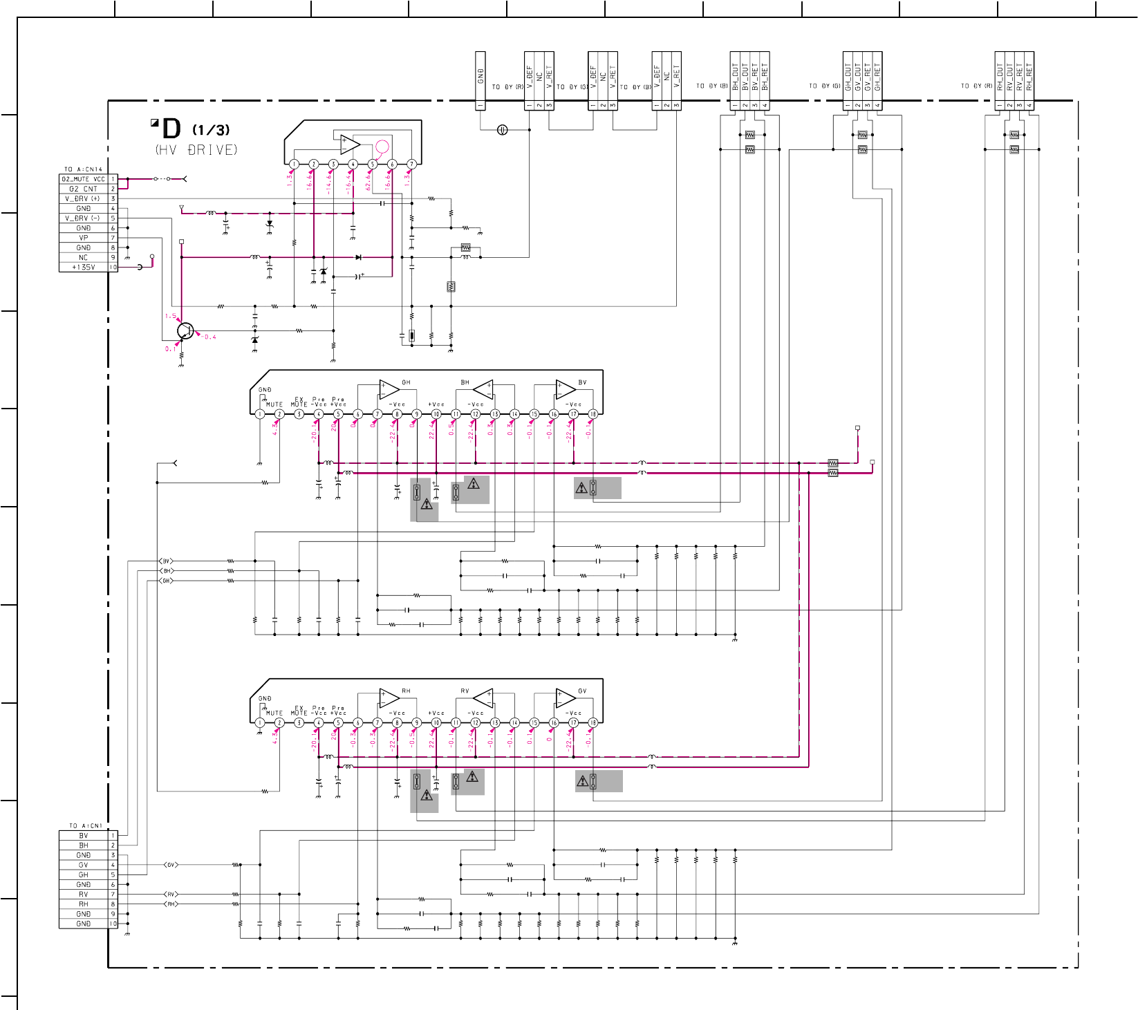
– 68 –
KP-HR432K90/HR532K90/HR532N90/HW572K90
RM-Y909KRM-Y908RM-Y909K RM-Y909K
1
A
B
C
D
E
F
G
H
I
J
211
10
98765
43
1
C8001
C8002
C8003
C8005
C8006
C8008
C8009
C8010
C8011
C8012
C8013
C8019
C8020
C8021
C8022
C8023
C8024
C8025
C8026
C8027
C8028
C8029
C8032
C8033
C8034
C8035
C8036
C8037
C8038
C8039
C8041
C8042
C8043
C8044
CN8007 CN8008 CN8009 CN8010 CN8011 CN8012
CN8024
D8001
D8002
D8004
L8001
L8002 L8003
L8004
L8005
L8007
L8008
NL8002
PS8001
PS8002
PS8003
PS8004
PS8005
PS8006
R8001
R8002
R8003
R8004
R8007
R8008
R8009
R8011
R8012
R8013 R8014
R8015
R8016
R8017
R8018
R8019
R8022
R8025
R8026
R8027
R8029
R8031
R8039
R8040
R8041
R8045
R8046
R8047
R8051
R8052
R8053
R8054
R8056
R8057
R8059
R8060
R8063
R8064
R8066
R8067
R8069
R8070
R8072
R8073
R8074
R8075
R8076
R8077
R8078
R8079
R8081
R8082
R8085
R8086
R8089
R8090
R8091
R8092
R8093
R8094
R8097
R8098
R8100
R8101
R8105
R8106
R8113
R8114
R8115
R8116
R8028
R8058
R8038
R8147
R8044
C8017
CN8006
CN8005
R8036
R8071
C8015
C8007
R8032
FB8024
TH8001
D8003
R8122
R8127
R8049
R8167
R8048
R8179
JW3
IC8003
IC8002
IC8001
Q8001
0.022
:PT
100p
CH:1608
100p
CH:1608
1000
25V
1000
25V
100p
CH:1608
0.01
25V
B:1608
1
:MPS
100p
CH:1608
0.01
25V
B:1608
100p
CH:1608
#CH:1608
#CH:1608
#
100V
:PT
#
CH:1608
0.1
100V
:PT
0.022
:PT
100
100
#B:1608
100
100
100
100
#F:1608
#F:1608
100
100
#F:1608
#F:1608
#CH:1608
#CH:1608
#CH:1608
#CH:1608
3P
WHT
:S-MICRO
3P
WHT
:S-MICRO
3P
WHT
:S-MICRO
4P
YEL
:S-MICRO
4P
WHT
:S-MICRO
4P
RED
:S-MICRO
#
:FASTON
MTZJ-5.6B
SLICE
MTZJ-20B
:PROT
GP08D PUMP UP
:LHL08
47µH
47µH
:LHL08
:LHL08 :LHL08
:LHL08
:LHL08
:LHL08
:LHL08
#
3.15A
3.15A
3.15A
3.15A
3.15A
3.15A
2.2k
1/16W
:CHIP
100 1/16W :CHIP
100 1/16W :CHIP
100 1/16W :CHIP
100 1/16W :CHIP
100 1/16W :CHIP
100 1/16W :CHIP
4.7k
1/16W
:CHIP
4.7k
1/16W
:CHIP
5.6k
1/16W
:RN-CP
5.1k
1/16W
:RN-CP
22k
1/16W
:CHIP
4.7k
1/16W
:CHIP
4.7k
1/16W
:CHIP
1k
1/16W
:CHIP
6.8k
1/16W
:RN-CP
33k
1/16W
:CHIP
4.7k
1/16W
:CHIP
4.7k
1/16W
:CHIP
#1/16W :CHIP
4.7k 1/16W :CHIP
4.7k
1/16W
:CHIP
2.2
1/2W
:RN
220
3W
:RS
5.1k
1/16W
:RN-CP
4.7
1/2W
:RN
4.7
1/2W
:RN
10 1W :RS
4.7
1/2W
:RN
#1/16W :CHIP
4.7
1/2W
:RN
#1/16W :CHIP
4.7k 1/16W :CHIP
4.7k 1/16W :CHIP
4.7
1/2W
:RN
4.7
1/2W
:RN
4.7
1/2W
:RN
4.7
1/2W
:RN
4.7
1/2W
:RN
4.7
1/2W
:RN
4.7
1/2W
:RN
4.7
1/2W
:RN
#1/16W :CHIP
4.7
1/2W
:RN
#1/16W :CHIP
4.7
1/2W
:RN
4.7k 1/16W :CHIP
4.7k 1/16W :CHIP
4.7
1/2W
:RN
4.7
1/2W
:RN
4.7
1/2W
:RN
4.7
1/2W
:RN
4.7
1/2W
:RN
4.7
1/2W
:RN
4.7
1/2W
:RN
4.7
1/2W
:RN
4.7
1/2W
:RN
4.7
1/2W
:RN
4.7
1/2W
:RN
4.7
1/2W
:RN
4.7
1/2W
:RN
4.7
1/2W
:RN
120
3W
:RS
120
3W
:RS
4.7
1/2W
:RN
4.7
1/2W
:RN
120
3W
:RS
120
3W
:RS
120
3W
:RS
120
3W
:RS
#1/16W :CHIP
100
1/16W
:CHIP
100
1/16W
:CHIP
5.6k
1/16W
:RN-CP
6.8k
1/16W
:RN-CP
0.001
B:1608
10P
:B TO B-S
10P
:B TO B-S
2.2
1/2W
:RN
22
:RN
220
100p
CH:1608
1k
1/16W
:CHIP
MPZ2012S331AT
68
MTZJ-22B
:PROT
JW(7.5)
JW(7.5)
:LAV35
:LAV35
:LAV35
:LAV35
LA78045
V.OUT
STK392-560
CONV.OUT 1
STK392-560
CONV.OUT 2
2SC2412K
+22V
-22V
+135V
MUTE VCC TO D1/3, D3/3_6
REGI MUTE TO D1/3, D3/3_1
-15V
+15V
*
10µH
100µH
100µH
47µH
47µH
100µH
100µH
47µH
47µH
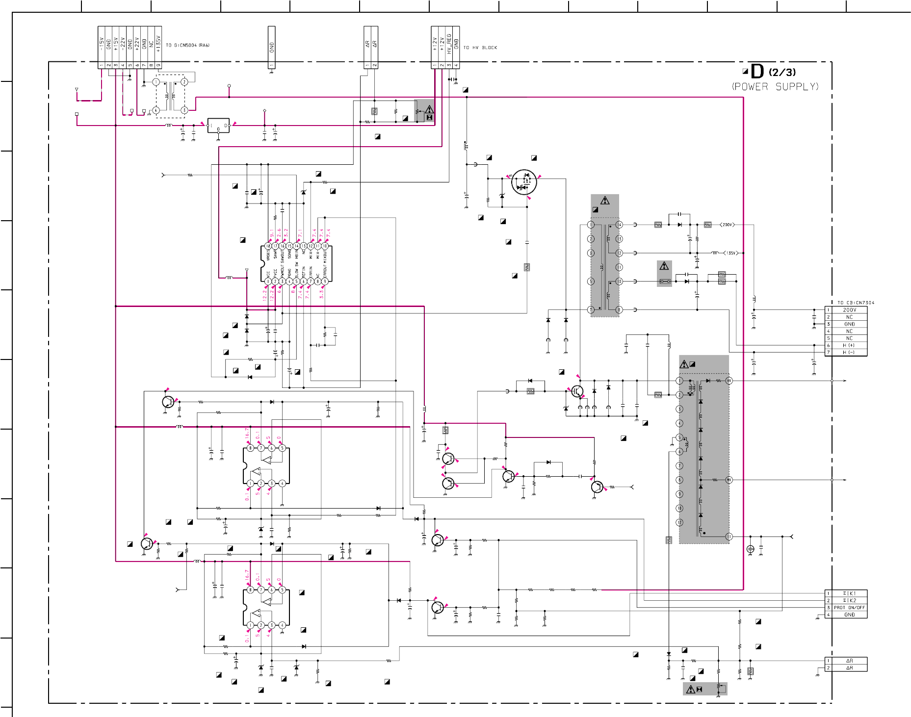
– 69 –
KP-HR432K90/HR532K90/HR532N90/HW572K90
RM-Y909KRM-Y908RM-Y909K RM-Y909K
1
A
B
C
D
E
F
G
H
I
J
212 13
11
10
98765
43
8.9
0
8.9
0
0
0.5
0
0.5
8.9
3.4
3.4
0.6
8.9
192
135.9 115.6
130.9
4.1
8.9
14.6
8.7
4.1
T8005
C8031
C8056
C8060 C8062
C8067
C8070
C8072
C8073
C8075
C8079
C8080
C8083
C8088
C8091
C8094
C8100
C8103
C8108
C8109
C8110
C8113
C8123
C8124
C8127
C8131
C8148
CN8015
CN8021
CN8022
D8013
D8014
D8017
D8038
D8039
L8020
NL8001
R8128
R8129
R8130
R8131
R8132
R8139
R8140
R8141
R8142
R8160
R8161
R8163
R8164
R8166
R8169
R8171
R8173
R8180
R8181
R8182
R8183
R8187
R8190
R8191
R8192R8193R8194R8195
R8197 R8198
R8200
R8203
R8218
R8219
R8224
R8229
R8231
R8158
R8035
R8043
C8136
R8102
R8223
R8208R8225
R8150
R8099
R8151
R8153
R8138
R8050
C8086
C8095
L8017
L8024
L8025
R8055
R8230
C8066
R8006
PS8007
R8061
C8111
C8030
L8018
C8114
C8129
C8142 L8021
R8212
C8119
L8013
FB8003
FB8005
FB8006
FB8020
CN8013
CN8017
CN8016
CN8023
R8184
R8107
R8108
C8112
D8036
D8028
R8196
R8201
R8170
R8176
D8037
FB8001
D8029
D8030
C8087
C8090
R8157
C8138
C8150
C8104
R8168
C8105
C8126
D8007
D8008
D8015
D8016
D8019
D8020
D8022
D8023
D8025
D8043
D8048
VR8001
VR8002
R8159
C8118
D8031
FB8004 L8011
C8051
C8102
C8099
C8143 C8153
T8004
D8034D8035
L8015
FB8008
FB8009
FB8010
FB8011
FB8022
FB8023
IC8004
IC8008
IC8007
IC8006
Q8035
Q8038
Q8022
Q8037
Q8036
Q8032
Q8005
Q8029
Q8021
Q8028
NX-4006//X
:FBT
10
160V
10
250V
100
25V0.01
25V
B:1608
100
25V
10
10
0.01
25V
B:1608
0.01
25V
B:1608
10
10
0.1
:PT
10
100
25V
100
25V
2.2
10
10
56p
CH:1608
1
0.1
:PT
100p
2kV
:B
8200p
1.2kV
:PP
1000
25V
10
100V
100
25V
2P
:LARGE
2P
:LARGE
7P
WHT
:S-MICRO
MTZJ-5.1B
MTZJ-5.1B
#
RGP10GPKG23
RGP02-17PKG23
:LHL08
10k
1/16W
:CHIP
2.2k
1/16W
:CHIP
2.2k
1/16W
:CHIP
10k
1/16W
:CHIP
10k1/16W :CHIP
3.3k
1/16W
:CHIP
10k
1/16W
:CHIP
3.3k
1/16W
:CHIP
10k1/16W:CHIP
10
:FPRD
47k
1/16W
:CHIP
47k
1/16W
:CHIP
56k
1/16W
:RN-CP
10k
1/16W
:RN-CP
47k
1/16W
:CHIP
100
1/16W
:CHIP
47k
1/16W
:CHIP
47k
1/16W
:CHIP
47k
1/16W
:CHIP
220k
1/16W
:CHIP
220k
1/16W
:CHIP
10k
1/16W
:CHIP
2.7k
:RN
2.2k
:RN
15k
:RN15k
:RN15k
:RN15k
:RN
100
1/16W
:CHIP
10k
1/16W
:CHIP
#
:RN
0.47
:FPRD
100k
1/2W
0.47
:FPRD
220k
1/2W
#
1/16W
:RN-CP
#
:FPRD
#
1.2k
1/16W
:RN-CP
100k
1/16W
:RN-CP
0.1
:PT
82k
1/16W
:CHIP
220k1/16W:RN-CP
0.47
1/2W
:FPRD
1
1/2W
:FPRD
100k
1/16W
:RN-CP
100k
1/16W
:RN-CP
1k
1/16W
:RN-CP
1k
1/16W
:RN-CP
10k1/16W :CHIP
10k
1/16W
:CHIP
0.01
25V
B:1608
0.01
25V
B:1608
:LAV35
:LAV35
:LAV35
220k
1/16W
:RN-CP
300k
1/16W
:RN-CP
0.01
25V
B:1608
#
3W
:RS
3.15A
1.2
3W
:RS
1
#
1000
160V
0.01
:PT
0.27
250V
:PP
22
3W
:RS
0.1
25V
F:1608
:LAV35
10µH
L8027
FILTER
DC LINE
MPZ2012S331AT
MPZ2012S331AT
HM601
9P
:VH#
:FASTON
4P
WHT
:S-MICRO
4P
BLK
:S-MICRO
10k
1/16W
:CHIP
10k
1/16W
:CHIP
1k
1/16W
:CHIP
470p
CH:1608
MTZJ-15B
MTZJ-15B
4.7k
22
:FPRD
10k
1/16W
:RN-CP
100k
1/16W
:RN-CP
D2L20U-F
1.1UH
D2L20U-F
D2L20U-F
1
1
82k
1/16W
:RN-CP
1000p
B:1608
:LHL10
:LHL10
0.1
16V
B:1608
0.0015
B:1608
100
1/16W
:CHIP
0.1
16V
B:1608
0.0039
200V
:PT
1SS133
1SS133
1SS133
1SS133
1SS133
1SS133
1SS133
1SS133
1SS133
1SS133
1SS133
2K
10K
12k
1/16W
:CHIP
0.1
250V
:MPS
MTZJ-18B
:PROT
0
:1608:LHL08
1000p
500V
:E
1000p
500V
:E
1000p
25V
CH:1608
11
:LOT
ERC07-15L
DAMPER1
ERC07-15L
DAMPER1
:LAV35
0.45UH
0.45UH
0.45UH
0.45UH
0.45UH
0.45UH
NJM78L12A-T3
BA9759F-E2
NJM2903
NJM2903
2SJ585LS-CC11
1MB12-140
2SC2412K
2SC2412K
2SA1037AK
2SC2412K
2SA1037AK
2SC2412K
2SC2412K
2SC2412K
12V-3
12V
-15V
HD IN TO D2/3, D3/3_2
HV PROT TO D2/3, D3/3_3
+135V
+15V+22V
-22V
10µH
47µH
10µH
10µH
10µH
100µH
10µH
10µH
ABL TO D2/3, D3/3_5
H DRV TO
D2/3, D3/3_4
0
:1608
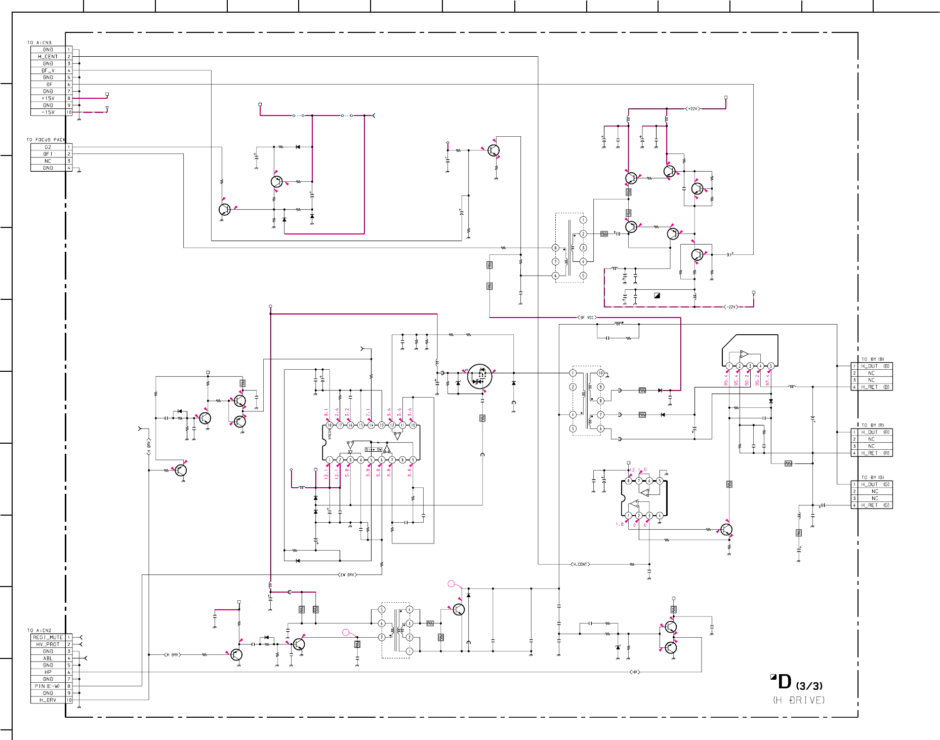
– 70 –
KP-HR432K90/HR532K90/HR532N90/HW572K90
RM-Y909KRM-Y908RM-Y909K RM-Y909K
1
A
B
C
D
E
F
G
H
I
J
212 13
11
10
98765
43
14.6
653
0
14.6
5.2
204
5.8
0
4
22
4.5
-2.3
-2.3
-2.3
-20
-20.6
-2.8
-2.8
112.3135
7.4
11.9
-0.37.4
3.4
3.4
-0.5
0.1
11.9
1.8
7.8
0
0.2
0.2
0.6
0.6
242
3
6.8
4
4
7.4
7.2
7.2
131.1
5.3
-2.6
44.5
22
3.4
2
C8014
C8016
C8018
C8045
C8046
C8048 C8049
C8050
C8052
C8053
C8054
C8055
C8061
C8063
C8064
C8065
C8071
C8074
C8076
C8078
C8082
C8085
C8093
C8097
C8098
C8101
C8115
C8116
C8128
C8130
C8132
C8133
C8137
CN8003
CN8018
CN8019
CN8020
D8021
D8024
D8026
D8027
D8032
D8033
L8006
L8009 L8010
L8012
L8014
L8016
L8019
L8022
R8010
R8020
R8021
R8023
R8024
R8030
R8037
R8042
R8080
R8087
R8088
R8095
R8096
R8103
R8109 R8110
R8111
R8112
R8119
R8120
R8121
R8123
R8124
R8125 R8126
R8134
R8143 R8144
R8148
R8149
R8165
R8174
R8175
R8178
R8189
R8202
R8205
R8213
R8216
R8217
R8220
R8228
R8033
R8034 C8047
C8121
C8040
C8059
R8062
R8065
C8069
C8077
L8026
R8206
C8096
R8211
C8120
C8139
C8106 R8005
C8107
CN8004
CN8002
R8209
R8210
T8001
R8155 R8156
R8154
R8137
R8145
C8081
C8125
L8023
D8045
R8221
C8122
FB8014
FB8015
FB8016
FB8017
FB8018
R8136
R8146
R8118
R8117
R8084
C8152
R8083
C8058
R8104
FB8021
R8068
R8172
C8004
C8084
C8135
D8006
D8010
D8011
D8012
D8046
D8047
FB8002
R8133
R8135
R8152
C8068
C8117
T8002
T8003
D8005
D8040
JW158 JW159
C8057
C8092
C8089
FB8019
IC8009
IC8005
IC8012
Q8007
Q8015
Q8010
Q8009
Q8003
Q8002
Q8008 Q8011
Q8014
Q8027
Q8020
Q8019
Q8016
Q8004
Q8039
Q8024
Q8031
Q8101
Q8030
Q8023
100
25V
100
25V
10
22
22
22 0.01
F:1608
22
22
0.01
F:1608
0.01
F:1608
0.1
25V
F:1608
0.1
16V
B:1608
0.1
16V
B:1608
10
160V
0.047
200V
:PT
10
100
25V
22
25V
1000p
25V
CH:1608
0.047
16V
B:1608
56p
CH:1608
100
160V
220p
2kV
:B
220p
2kV
:B #
:B
0.1
16V
B:1608
0.1
16V
B:1608 #
B:1608
#
B:1608
1000
25V
2.2
250V
1000
25V
4P
WHT
:MINI(LOCK)
4P
:VH
4P
:VH
4P
:VH
PG124S15
DAMPER
MTZJ-15B
MTZJ-5.6B
D2L20U-TA
RGP10GPKG23
BIAS
RGP02-17PKG23
BIAS
:LHL08
:LHL08
10µH47µH
:LAV35
:LAV35
:LAV35
:LHL08
HLC
2.2mH
:LHL08
470k
1/2W
4.7k
1/16W
:CHIP
10k
1/16W
:CHIP
10k
1/16W
:CHIP
10k
1/16W
:CHIP
68k
2W
:RS
68k
2W
:RS
2.7k
1/16W
:CHIP
2.2
1W
:RS
2.2
:FPRD
2.2
:FPRD
22
1/16W
:CHIP
22
1/16W
:CHIP
390
1/16W
:CHIP
270
1/16W
:CHIP 6.8k
680
1/16W
:CHIP
1.8k
1/16W
:CHIP
10k
1/16W
:CHIP
10k
1/16W
:CHIP
100
1/16W
:CHIP
1k
1/16W
:CHIP
0.47
:FPRD
390
1/16W
:CHIP
1.5k
1/16W
:CHIP
4.7k
1W
:RS
56k
1/16W
:RN-CP
100
1/16W
:CHIP
100k
1/16W
:CHIP
10
3W
:RS
4.7k
4.7k
#
1/16W
:CHIP
47k
1/16W
:CHIP
0.47
:FPRD
270
1/2W
0.47
:FPRD
1k
1/16W
:CHIP
10k
1/16W
:CHIP
1k
1/16W
:CHIP
1k
1/16W
:CHIP
68
1/2W
:FPRD
10k
1/16W
:CHIP
10k
1/16W
:CHIP
0.01
F:1608
0.01
2kV
:F
0.01
2kV
:F
0.22
16V
B:1608
4.7k
1/2W
1k
1/2W
0.01
25V
B:1608
0.01
25V
B:1608
:LAV35
0.47
:FPRD
0.0022
100V
:PT
15
3W
:RS
0.1
16V
B:1608
10
0.1
16V
B:1608 10k
1W
:RS
0.047
250V
:MPS
10P
:B TO B-S
10P
:B TO B-S
10k
1/16W
:CHIP
100
1/16W
:CHIP
100k
:RN 100k
:RN
33k
1/16W
:RN-CP
100k
1/16W
:RN-CP
10k
1/16W
:RN-CP
1000p
25V
CH:1608
0.1
16V
B:1608
:LAV35
GP08D
#
1/16W
:CHIP
220
16V
MPZ2012S331AT
MPZ2012S331AT
MPZ2012S331AT
MPZ2012S331AT
MPZ2012S331AT
10k
1/16W
:CHIP
10k
1/16W
:RN-CP
10k
1/16W
:CHIP
10k
1/16W
:CHIP
10k
1/16W
:CHIP
#
B:1608
1k
1/16W
:CHIP
220p
CH:1608
8.2k
1/16W
:CHIP
1.1UH
DFT
100
1/16W
:CHIP
100
:FPRD
220
25V
0.022
:PT
0.75
250V
:PP
1SS133
LIMIT
1SS133
1SS133
1SS133
1SS133
1SS133
1.1UH
8.2k
3W
:RS 8.2k
3W
:RS
10k
1/16W
:RN-CP
1000p
500V
:E
1000p
500V
:E
HDT
HOT
1SS133
RECT
0.47
6800p
1.2kV
:MPP
100p
2kV
:B
1.1UH
LA6500P-FA
BA9759F-E2
NJM2904M(TE2)
2SC4634LS-CB11
DF V AMP
2SC2412K
2SC2412K
2SC3421-Y
DF H BUFF
2SA1037AK
G2-STOP/CONTROL
2SC4634LS-CB11
G2-STOP
2SA1358-Y
DF H BUFF 2SA1037AK
DF H BUFF
2SC2412K
2SJ585LS-CC11
2SC2412K
2SA1037AK
2SC2412K
2SA1037AK
2SC2688(5)-LK
2SC5681-YB
H.OUT
2SC2412K
2SA1037AK
2SA1037AK
2SC2688(5)-LK
H.DRIVE
12V-2
12V-2 12V-2
12V-2
12V-2
12V
-15V
+15V
+15V
+22V
-22V
+135V
H DRV TO D3/3, D2/3_4
HD IN TO D3/3, D2/3_2
MUTE VCC TO D3/3, D1/3_6
REGI MUTE TO D3/3, D2/3_1
HV PROT TO D3/3, D2/3_3
ABL TO D3/3, D2/3_5
12V
*
*
*
100µH
10µH
100µH
10µH
47µH
10µH
R8232
0.22
1W
:RS
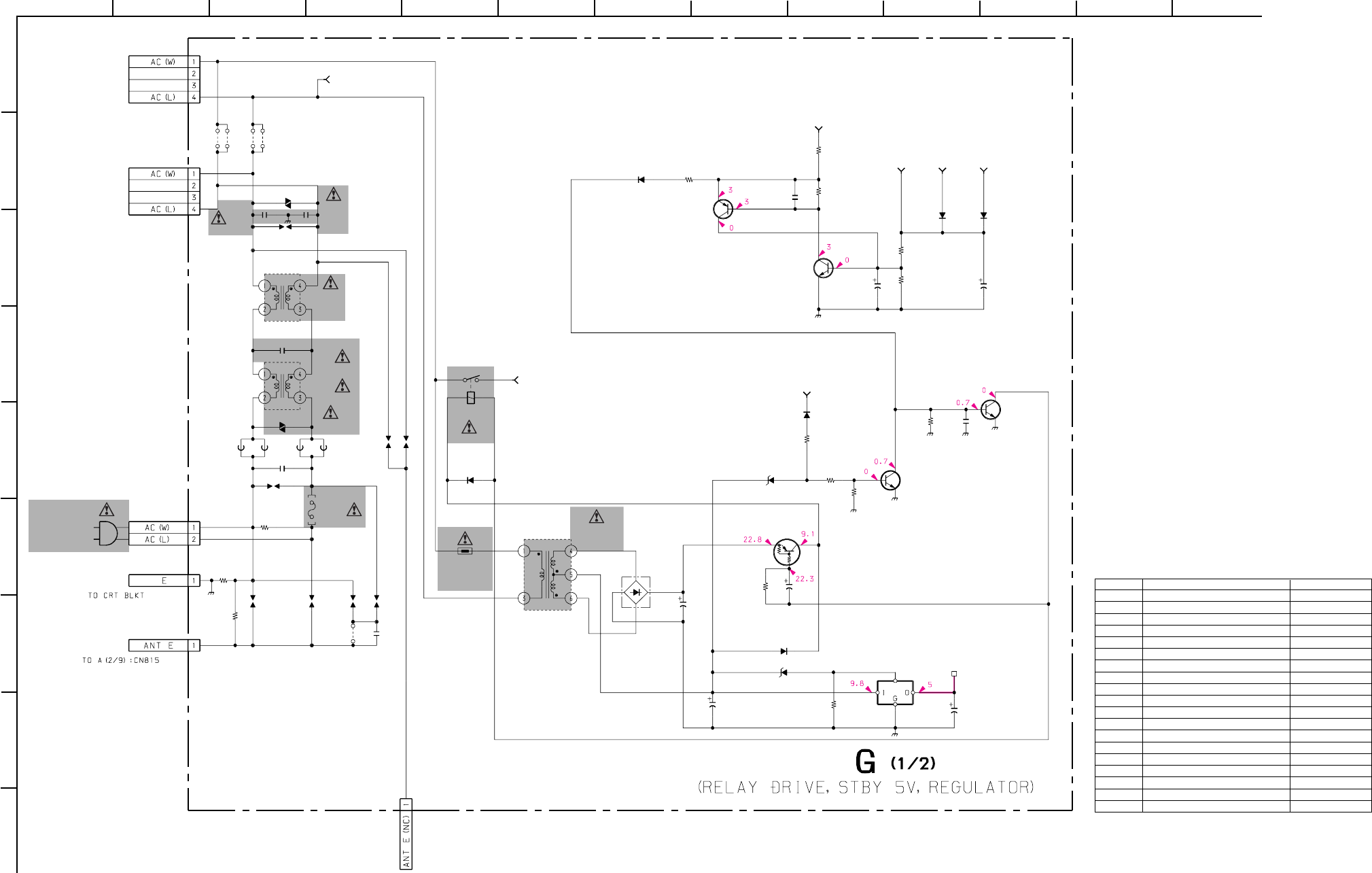
– 71 –
KP-HR432K90/HR532K90/HR532N90/HW572K90
RM-Y909KRM-Y908RM-Y909K RM-Y909K
1
A
B
C
D
E
F
G
H
I
212 13
11
10
98765
43
C5003
C5042
CN6005
R5016
R5021R5026
R5028
R5029
R5030
VD6002
C5060
C5050
C5051
C5053
D5017
R5010
C5054
D5007
D5011
D5014
D5015
D5022
FH6001
FH6002
CN5005
CN5007
110VAC
(HR532N90)
220VAC
(EXCEPT HR532N90)
AC
CN5006
C6012
C6043
C6013
RY6002
C6014
FB6013FB6014
FB6015FB6016
C5049
L6001
L6002
VD6001
F6001
R6018
JW6007
R6015
C6045
R6014
R5013
R5020
D5001
TH6002
CN6003
CN6004
D5020
R5038
T6004
IC5006
Q5001
Q5003
Q5004
Q5002
Q5005
#
B:1608
4.7
2P
10k
1/16W
:CHIP
1k
1/16W
:CHIP
10k
1/16W
:CHIP
1k
1/16W
:CHIP
22k
1/16W
:CHIP
22k
1/16W
:CHIP
#
#
330
63V
2.2
47
S1VBA20
1M
4700
35V
R5048
10k
1/16W
: CHIP
:FASTON
:FASTON
:FASTON
1SS355TE
1SS355TE
1SS355TE
1SS355TE
1SS355TE
D5027
UDZS-5.1B
0.22
250V
:AC
2200p
250V
E
2200p
250V
E
0.47 250V:AC
1.1UH1.1UH
1.1UH1.1UH
0.01
25V
B:1608
LFT
LFT
*
*
*
10MM
JW6001
*
JW6002
*
JW6005
*
JW6006
*
*
*
*
*
1k
1/16W
:CHIP
*
*
*
*
*
*
TRANS.STBY
120V
PQ05RF11
5V REG.
STBY
2SD1782K
2SA1037AK
RELAY DRIVE
RELAY DRIVE
RELAY DRIVE
BUFFER
2SC2412K
*
DTA114EKA-T146
RELAY SW
AC L TO G1/2, G2/2_7
AC W TO G1/2, G2/2_1
OVP TO
G1/2, G2/2_2
RELAY TO G1/2, G2/2_6
PROTECT TO G1/2, G2/2_3
OVP 1 TO G1/2, G2/2_4
OCP TO G1/2, G2/2_5
STBY
5V
Ref. No. KP-HR432K90/HR532K90/HW572K90 KP-HR532N90
C6045 2200p 250V JW (10)
CN6003 2p: VH -
CN6004 2p: VH -
D5001 - UDZSTE1720B
D5020 - 1SS355TE
F6001 5A 250V 6.3A 125V
JW6001 - 7.5mm
JW6002 - 7.5mm
JW6005 - 7.5mm
JW6006 - 7.5mm
JW6007 - 10mm
Q5002 - 2SC2412K
R5013 - 10k 1/16W: CHIP
R5038 - 1k 1/16W: CHIP
R6014 8.2M 1W: RN -
R6015 - 2.2M 1/2W
R6018 1M 1/2W -
TH6002 5mm PTH8L05AR/88: PTC
VD6001 TNR14V621K660 TNR14V471K
• G (1/2) BOARD * MARK LIST
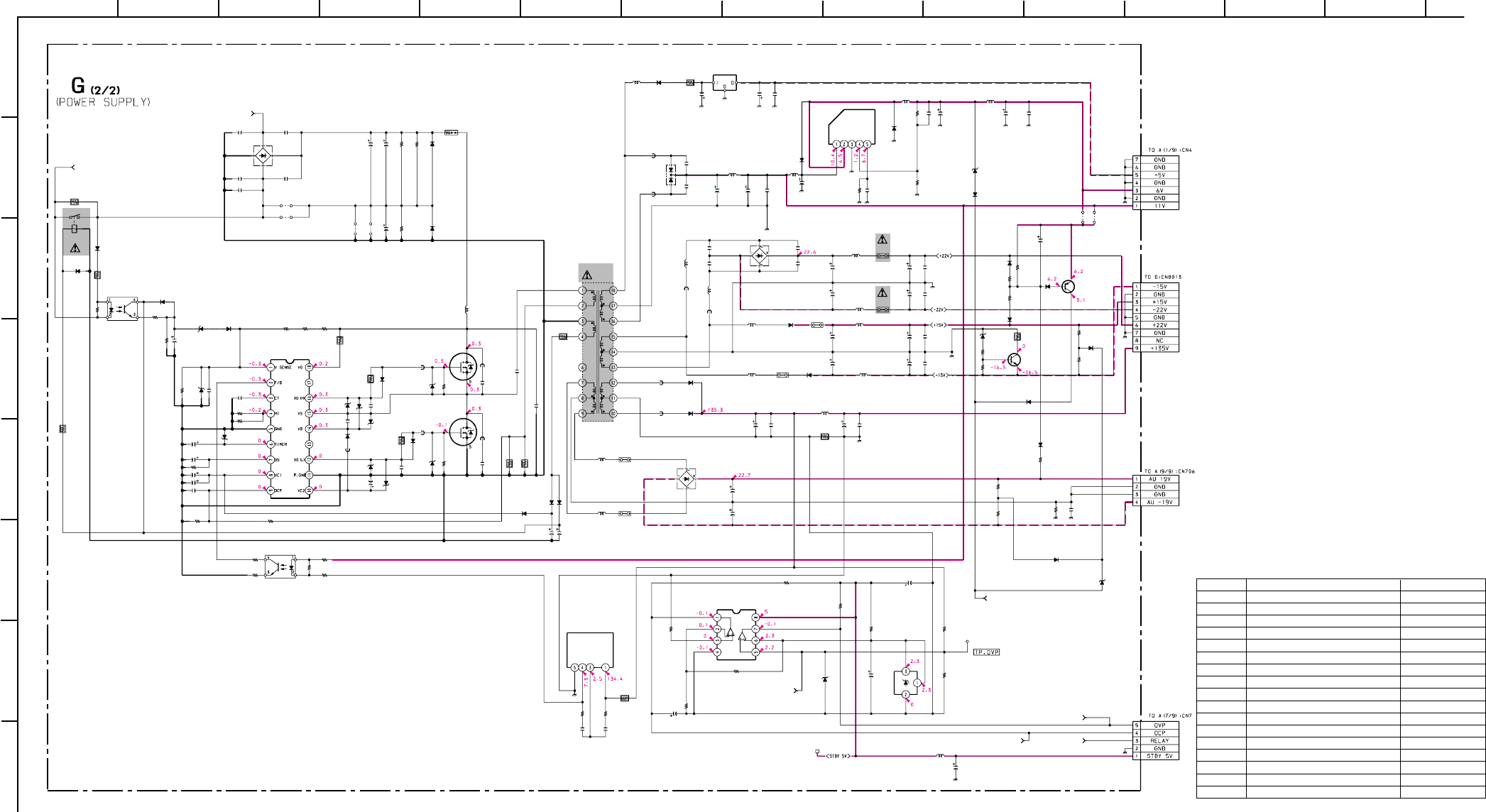
– 72 –
KP-HR432K90/HR532K90/HR532N90/HW572K90
RM-Y909KRM-Y908RM-Y909K RM-Y909K
1
A
B
C
D
E
F
G
H
212 13
11
10
98765
43 14
C5006
C5009
C5010
C5018
C5019
C5024
C5025
C5029
C5030C5031
C5038
C5039
C5040
C5041
C6017
C6018
C6021
C6025
C6029
C6030
C6034
C6036
C6041
CN5003
CN5004
D5006
D5008
D5009
D5010
D6007
D6030
L5003
L5006
L5007
L5013
R5014
R5015
R5017
R5018
R5022
R5023
R5025
R5031
R5034
R5037
R6004
R6042
R6050
R6054
R6058
R6063
R6064
R6081
D6006
RY6003
D6002
R6003
R6006
C6020
C5001
C5002
C5007
C5008
C5011
CN5001
CN5002
R6008
R5033
R6005
L5017
C6002
C6019
C6046
R6080
D5019
D6001
D6005
D6011
D6018
D6020
C5048
C5044
C5036
C5035
C5034
C5045
R5011
R6037R6038
R6041
D5002
D5003
C5012
C6004
C6001
C5017
C5016
L5008
L5009
L5004
L5005
C5027
C5028
C6016
C6022
C6023
L5012
PH6001
PH6002
R6045
D6003
D5018
R5019
R5032
C5026
C5022
D6004
R5024
C5043
L5014
R5007
D5021
C6042
R5027
R5044
C5032
C5037
C5046
D6008
D6010
D6013
D6014
D6015
D6016
D6017
L5016
R5012
C5015
C5021
R5041
R6047
R5035
R5036
R6046
TP5001
D6009
D6019
D5031
D5032
R5046
C6008
R5042
R5040
D5024
JR5001
JR5002
R5043
R5005
R5006
D5025
D5023
D5026
R5047
D5012
D5013
R5045
PS5003
R6036
PS5001
PS5002
R6076
R6040
C5055
PS5006
PS5005
R6062
PS5004
C5033
C5004C5005
R5039
FB6006
FB6007
FB6004
C6047
C6015
C6033
FB5004
L5010
D5004
D5005
D5016
D6012
L5015
L6003
33H
T6001
L5001
L5002
C5047
C5020
FB5001
FB5002
FB5003
FB5005
FB5006
FB6001
D6024
R6057
C6032R6031
C6028
JW6004
JW6003
JW6010R6056
C6031
JW6009
R6002
D6023
R6007
IC5003
IC5004
IC5002
IC5005
IC501
Q5007
Q5006
Q6006
Q6005
IC6003
R6039
100
25V
2200
35V
2200
35V
1000
35V
1000
35V
47
25V
47
25V
47
160V
47
25V
2200
16V
47
25V
47
25V
0.1
16V
B:1608
1000
16V
0.001
B:1608
0.01
F:1608
10
0.001
:PP
0.1
:MPS
47
25V
#
:MPS
#
:B
680p
1kV
7P
BLK
:S-MICRO
9P
:VH
F10P04Q
D2L20U-TA
D2L20U-TA
21DQ06N-TA2B1
D6SB60L
AC-RECT
D1NL20U-TA2
:LHL08
22H
:LHL08
:LHL08
:LHL08
4.7k
1/16W
:CHIP
4.7k1/16W:RN-CP
4.7k
1/16W
:CHIP 1k
1/16W
:CHIP
4.7k
1/16W
:RN-CP
270k
1/16W
:RN-CP
1.6k
1/16W
:RN-CP
#
1/16W
:CHIP
10k
1/16W
:CHIP
1k
1/16W
:CHIP
4.7k
1/16W
:CHIP
13k
1/16W
:RN-CP
1k
:FPRD
10
:FPRD
10
:FPRD
10k
1/16W
:CHIP
0.1
1/2W
:RF
10
:FPRD
D1NL20U-TA2
ERA22-08
1k
1/2W
:FPRD
390
1W
:RN
4.7
1000p
500V
1000p
500V
1000p
500V
1000p
500V
1000p
500V
5P
WHT
:S-MICRO
4P
WHT
:S-MICRO
100k
1/16W
:CHIP
#
1/16W
:CHIP
#
1/16W
:CHIP
220
25V
100
100
0.1
2W
:RS
#
#
#
B:1608
#
B:1608
#
B:1608
#
B:1608
#
B:1608
#
B:1608
560
1/16W
:CHIP
330k
:RN330k
:RN
100
1/16W
:RN-CP
D4SBS6-F
D4SBS6-F
1000p
500V
47
47
1000
25V
1000
25V
:LHL08
:LHL08
:LHL08
:LHL08
470
35V
470
35V
0.0047
250V
:E
0.0047
250V
:E
0.0047
250V
:E
:LHL10
ON3171-RMAIN CONTROL
ON3171-R
2001/16W:RN-CP
UDZS-10B
UDZS-7.5B
1M
1/16W
:CHIP
680
:FPRD
47
25V
47
25V
390
1/16W
:RN-CP
470
16V
:LHL10
0.47
:FPRD
1SS355TE
1SS355TE
1SS355TE
1SS355TE
1SS355TE
1SS355TE
680p
1kV
1k
1/16W
:CHIP
1k
1/16W
:CHIP
#
B:1608
#
B:1608
#
#
#
#
PROTECT
#
PROTECT
#
#
#
PROTECT
:LHL10
0.22
2W
:RS
470
16V
4700
16V
330
1W
:RS
2201/16W:CHIP
6801/16W:CHIP
680
1/16W
:CHIP
2201/16W:CHIP
#
UDZS-4.7B
UDZS-4.7B
1SS355TE
#
#
1/16W
:CHIP
2.2 450V
10k
1/16W
:CHIP
10k
1/16W
:CHIP
1SS355TE
#
0
1k
1/16W
:CHIP
6.8k
1/16W
:CHIP
10k
1/16W
:CHIP
1SS355TE
1SS355TE
D5033
1SS355TE
1SS355TE
10k
1/16W
:CHIP
UDZS-18B
D5034
UDZS-4.7B
UDZS-6.2B
8.2k
1/16W
:CHIP
JW(15)
9.1k
1/16W
:RN-CP
5A
5A
0.1
2W
:RS
330k
:RN
100
16V
JW(5)
JW(5)
10k
1/16W
:CHIP
JW(15)
#
B:1608
##
0
:1608
0
:1608
0
:1608
0
:1608
FB6005
0
:1608
0.056
800V
:PHS
0.0047
250V
:E
#
:E
0.45UH
4.7 H
:LHL08
L5011
4.7H
:LHL08
31DF4N-FC5
31DF4N-FC5
FSQ05A04
10ERA60-TP
PUMP-UP
PIT
:LHL08
:LHL08
0.01
16V
B:1608
330
160V
0.45UH
0.45UH
0.45UH
0.45UH
0.45UH
0.45UH
*
*
*#
*
7.5MM
7.5MM
#*
*
#
6.8
10W
:RB
*
*
1/16W
:CHIP
NJM7905FA
:HS
PQ1CG2032FZ
OVP OCP
REF VOLTAGE
DM-58
CONTROL
2SA1037AK
PROTECT
PROTECT
2SC2411K
IRFIB7N50A
CONVERTER
IRFIB7N50A
CONVERTER
MCZ3001D
DRIVER
330k
1/16W
:CHIP
AC L TO G2/2, G1/2_7
AC W TO G2/2, G1/2_1
OVP TO G2/2, G1/2_2
OCP TO G2/2, G1/2_5RELAY TO G2/2, G1/2_6
OVP 1 TO G2/2, G1/2_4
PROTECT TO G2/2, G1/2_3
STBY
5V
6.8 H
10H47H
22H
22H
47H
47H
33H
15H
47H
33H47H
PC1093J-1-T
PC393C
6.8 H
100H
Ref. No. KP-HR432K90/HR532K90/HW572K90 KP-HR532N90
C6028 560 450V -
C6031 - 1500 250V
C6032 - 1500 250V
D6023 - ERC04-06SE
D6024 1M 1/2W ERC04-06SE
JW6003 - 7.5mm
JW6004 - 7.5mm
JW6009 7.5mm -
JW6010 7.5mm -
JW6029 - 5mm
JW6030 - 5mm
R5020 - 1k 1/16W: CHIP
R6001 0.47 10W: RB -
R6007 1k 1/16W: CHIP 1.5k 1/16W: CHIP
R6056 - 470k 1/2W
R6057 - 470k 1/2W
T6004 TRANS. STBY 240V TRANS. STBY120V
• G (2/2) BOARD * MARK LIST
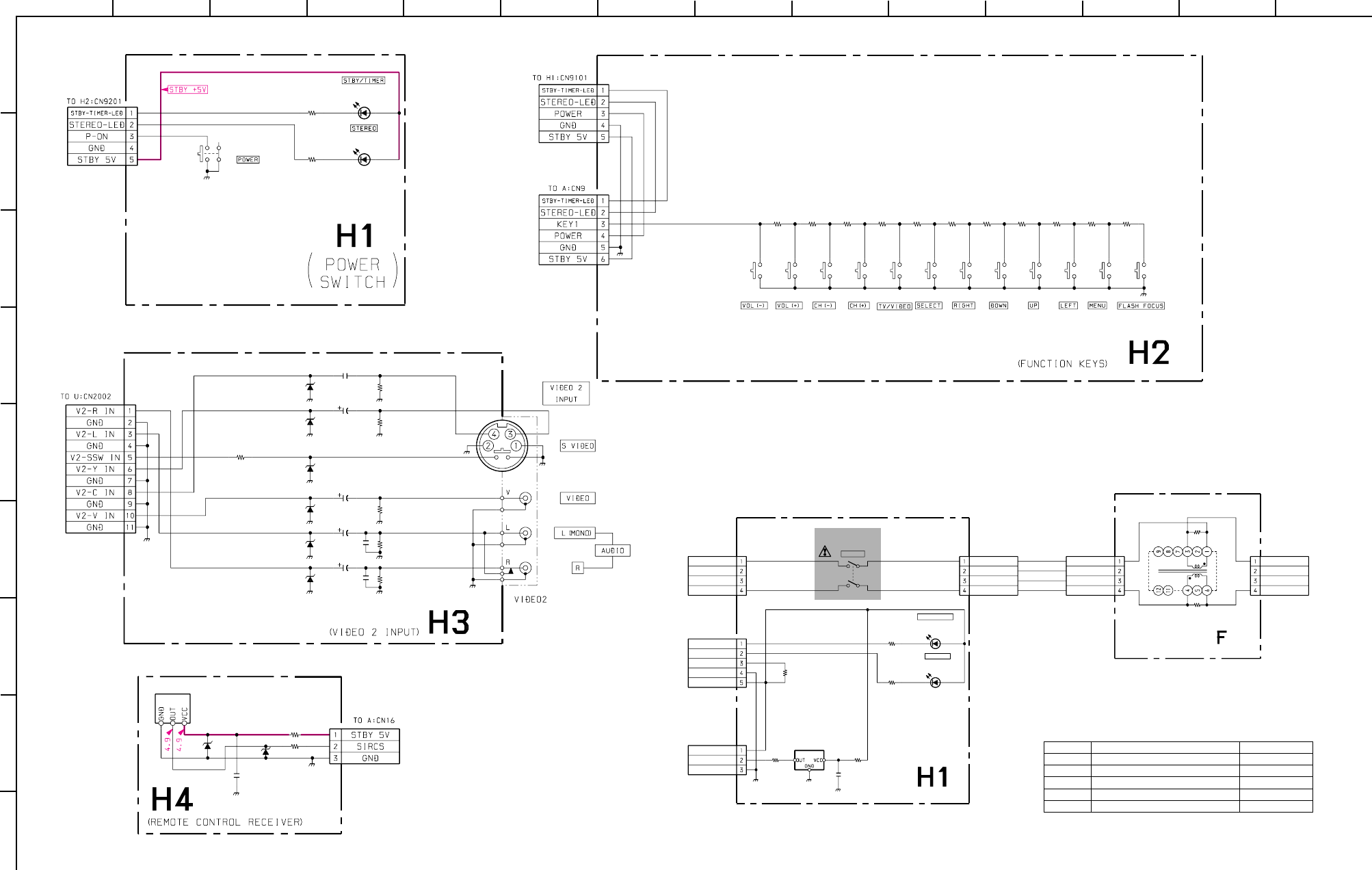
– 73 –
KP-HR432K90/HR532K90/HR532N90/HW572K90
RM-Y909KRM-Y908RM-Y909K RM-Y909K
1
A
B
C
D
E
F
G
H
I
212 13
11
10
98765
43 14
D9101
D9102
CN9101
R9104
R9103
S9101
SLR-325VCT31
SLR-325VCT31
(HR532N90)
5P
WHT
:S-MICRO
220
1/16W
:CHIP
220
1/16W
:CHIP
*
R9205
R9204
R9203
R9202
S9202 S9203 S9204 S9205
R9201
S9201
R9210
R9209
R9208
R9207
S9207 S9208 S9209 S9210
R9206
S9206 S9211
R9211
S9212
CN9202
CN9201
680
1/16W
:RN-CP
470
1/16W
:RN-CP
470
1/16W
:RN-CP
470
1/16W
:RN-CP
470
1/16W
:RN-CP
3.3k
1/16W
:RN-CP
2.2k
1/16W
:RN-CP
1.5k
1/16W
:RN-CP
1k
1/16W
:RN-CP
680
1/16W
:RN-CP
6.8k
1/16W
:RN-CP
6P
WHT-L
:S-MICRO
5P
WHT-L
:S-MICRO
R9304
R9303
R9302
CN9301
R9305
R9306
D9304
D9306
D9305
C9301
C9302
D9303
D9302
D9301
C9304
C9303
R9301
C9305
J9301
75
1/16W
:CHIP
470k
1/16W
:CHIP
470k
1/16W
:CHIP
11P
WHT-L
:S-MICRO
75
1/16W
:CHIP
75
1/16W
:CHIP
MTZJ-10B
PROT
MTZJ-10B
PROT
MTZJ-10B
PROT
10
10
MTZJ-10B
PROT
MTZJ-10B
PROT
MTZJ-10B
PROT
0.47
0.47
C9307
470p
C9308
470p
1k
1/16W
:CHIP
0.01
25V
B:1608 3P
R9401
CN9401
D9402 D9401
R9402
C9401
IC9401
10k
1/16W
:CHIP
3P
WHT-L
:S-MICRO
MTZJ-5.6B
PROTMTZJ-5.6B
PROT
100
1/16W
:CHIP
0.1
16V
B:1608
GP1U28Y
IR SENCOR
(EXCEPT HW572K90)
D9101
D9102
CN9101
R9104
R9103
S9101
CN9104
R9105
C9101
CN9102
R9101 R9102
IC9101
CN9103 CN9502
CN9501 R9501
R9502
L9501
SLR-325VCT31
SLR-325VCT31
5P
WHT
:S-MICRO
220
1/16W
:CHIP
220
1/16W
:CHIP
2P
WHT
:VH
10k
1/16W
:CHIP
2P
BLK
:VH
2P
BLK
:VH
2P
WHT
:VH
0.22
10W
:RB
0.22
10W
:RB
#
*
*
B:1608
*
*
*
:1608 *
:1608
POWER
P-ON
STBY 5V
SIRCS
GND
STBY/TIMER
STEREO
STBY-TIMER-LED
STEREO-LED
TO A:CN16
STBY 5V
TO H2:CN9201
AC(L) IN
NC
NC
AC(N) IN
NC
NC
AC(L) OUT
AC(N) OUT
GND
TO G:CN6004 TO G:CN6003
TO H1:CN9103 TO G:CN6003
AC(N) IN
AC(L) IN
NC
NC
AC(N) OUT
NC
NC
AC(L) OUT
(POWER SWITCH)
(LINE FILTER)
(EXCEPT HR532N90)
(EXCEPT HR532N90)
Ref. No. KP-HR432K90/HR532K90 KP-HW572K90
C9101 - 0.1 16V B: 1608
CN9101 - 3P WHT: S-MICRO
IC9101 - GP1U28Y
R9101 - 10k 1/16W: CHIP
R9102 - 100 1/16W: CHIP
• H1 BOARD * MARK LIST
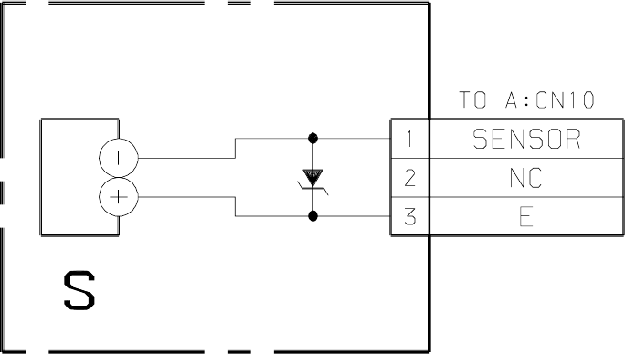
– 74 –
KP-HR432K90/HR532K90/HR532N90/HW572K90
RM-Y909KRM-Y908RM-Y909K RM-Y909K
CN3001
D3001
S3002
3P
WHT
:S-MICRO
MTZJ-T-77-5.6B
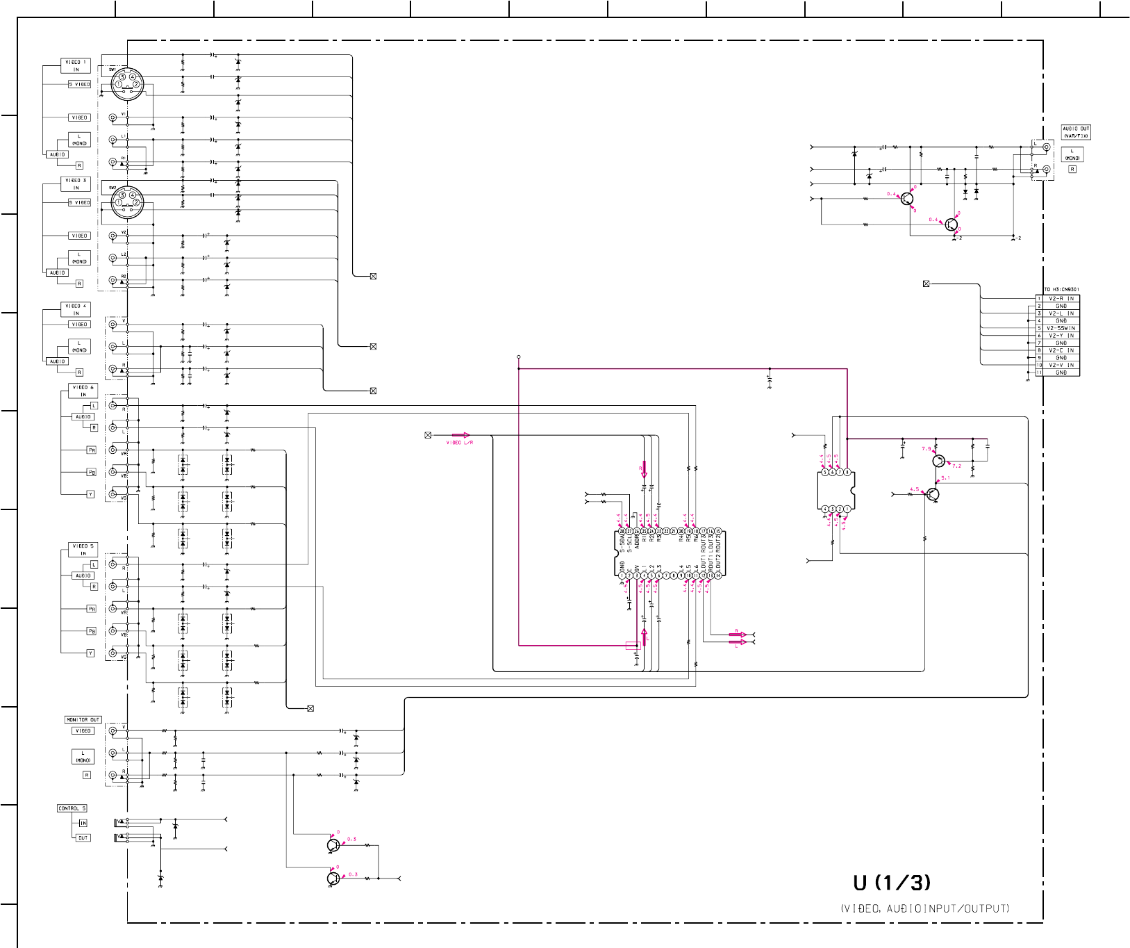
– 75 –
KP-HR432K90/HR532K90/HR532N90/HW572K90
RM-Y909KRM-Y908RM-Y909K RM-Y909K
1
A
B
C
D
E
F
G
H
I
211
10
98765
43
C2007
C2008
C2012
C2013
C2014
C2015
C2016
C2017
C2018
C2019
C2020
C2021
C2022
C2023
C2024
C2025
C2026
C2027
C2028
C2040
C2061
C2083
C2128
CN2002
D2001
D2002
D2003
D2014
D2015
D2016
D2017
D2018
D2021
D2022
D2023
D2024
D2025
D2026
D2027
D2028
D2029
D2030
D2039
D2042
R2001
R2002
R2003
R2004
R2005
R2006
R2007
R2008
R2009
R2010
R2011
R2012
R2013
R2014
R2016
R2017
R2018
R2019
R2020
R2021
R2023
R2024
R2025
R2026
R2027
R2030
R2068
R2070
R2193
R2194
R2195
R2196
R2197
R2198
R2199
D2007
D2012
D2013
D2019
D2020
D2004
D2005
D2006
D2009
D2010
D2011
D2031
D2032
D2040
D2041
D2043
D2044
C2003
R2044
R2045
R2054
R2057
R2091
R2092
D2008
R2105
R2111
R2062
R2061
R2015
C2005
R2107
R2060
R2059
J2003
J2002
R2022
C2002
C2001
J2001
R2065
R2069
R2116
D2033
D2034
Q2005
IC2003
Q2029
Q2007
Q2026
Q2012
Q2006
J2007
J2008
J2006
J2005
J2004
R2036 R2038
C2035
C2032
C2030
R2029
R2028
C2034
C2031
C2029
R2035
R2037
R2101
10
10
10
10
1
1
10
10
1
10
10
1
1
10
10
1
1
22
25V
100
16V
100
16V
10
22
25V
10
11P
WHT-L
:S-MICRO
MTZJ-10B
MTZJ-10B
MTZJ-10B
MTZJ-10B
MTZJ-10B
MTZJ-10B
MTZJ-10B
MTZJ-10B
MTZJ-10B
PROTECT
MTZJ-10B
PROTECT
MTZJ-10B
PROTECT
MTZJ-10B
PROTECT
MTZJ-10B
DEC-L
MTZJ-10B
PROTECT
MTZJ-10B
PROTECT
#
PROTECT
MTZJ-10B
PROTECT
MTZJ-10B
PROTECT
MTZJ-10B
MTZJ-10B
75
1/16W
:CHIP
470k
1/16W
:CHIP
75
1/16W
:RN-CP
75
1/16W
:RN-CP
75
1/16W
:RN-CP
470k
1/16W
:CHIP
470k
1/16W
:CHIP
75
1/16W
:RN-CP
75
1/16W
:RN-CP
75
1/16W
:RN-CP
470k
1/16W
:CHIP
470k
1/16W
:CHIP
470k
1/16W
:CHIP
470k
1/16W
:CHIP
470k
1/16W
:CHIP
75
1/16W
:RN-CP
470k
1/16W
:CHIP
470k
1/16W
:CHIP
75
1/16W
:RN-CP
75
1/16W
:RN-CP
470k
1/16W
:CHIP
470k
1/16W
:CHIP
75
1/16W
:RN-CP
75
1/16W
:RN-CP
75
1/16W
:RN-CP
100
1/16W
:CHIP
2.2k
1/16W
:CHIP
2.2k
1/16W
:CHIP
100
1/16W
:CHIP
470
1/16W
:CHIP
470
1/16W
:CHIP
470
1/16W
:CHIP
470
1/16W
:CHIP
470k
1/16W
:CHIP
470k
1/16W
:CHIP
MTZJ-10B
MTZJ-10B
MTZJ-10B
MTZJ-10B
MTZJ-10B
MA153-TX
MA153-TX
MA153-TX
MA153-TX
MA153-TX
MA153-TX
MA153-TX
MA153-TX
MA153-TX
MA153-TX
MA153-TX
MA153-TX
470
16V
56
1/16W
:CHIP
56
1/16W
:CHIP
56
1/16W
:CHIP
56
1/16W
:CHIP
56
1/16W
:CHIP
56
1/16W
:CHIP
MTZJ-10B
100
1/16W
:CHIP
2.2k
1/16W
:CHIP
470
1/16W
:CHIP
470
1/16W
:CHIP
470k
1/16W
:CHIP
0.1
16V
B:1608
C2053
470p
CH:1608
C2054
470p
CH:1608
C2049
470p
CH:1608
C2051
470p
CH:1608
C2073
470p
CH:1608
C2074
470p
CH:1608
68
1/16W
:CHIP
470
1/16W
:CHIP
470
1/16W
:CHIP
3P
3P
75
1/16W
:RN-CP
0.01 25V B:1608
0.01 25V B:1608
S TERMINAL BLOCK
2.2k 1/16W :CHIP
2.2k 1/16W :CHIP
8.2k
1/16W
:CHIP
1SS133T-77
1SS133T-77
2SC2412K
NJM4558-TE2
AUDIO-BUFFER
IC2001
TEA6422DT
AUDIO SWITCH
2SC2412K
2SC2412K
MUTE
MUTE
2SA1037AK
2SA1037AK
BUFFER
BUFFER
2SC2412K
MUTE
MUTE
2P
3P
5P
5P
3P
100
1/16W
:CHIP
100
1/16W
:CHIP
#
10
10
100
1/16W
:CHIP
100
1/16W
:CHIP
#
10
10
100
1/16W
:CHIP
100
1/16W
:CHIP
#
1/16W
:CHIP
VIDEO 1 IN TO U1/3, U2/3_8
LINE MUTE TO U1/3, U2/3_17
D1/D2 TO U1/3, U2/3_23
CONT S IN
TO U1/3, U2/3_24
CONT S OUT
TO U1/3, U2/3_25
VIDEO 3 IN TO U1/3, U2/3_10
VIDEO 4 IN TO U1/3, U2/3_11
MAIN/SUB/MONI L,R
TO U1/3, U2/3_1
SCL TO U1/3, U2/3, U3/3_5
SDA TO U1/3, U2/3, U3/3_4
R-IN TO U1/3, U3/3_3
M-L TO U1/3, U2/3_15
M-R TO U1/3, U2/3_16
VIDEO 2 IN TO U1/3, U2/3_9
A MUTE TO U1/3, U2/3_6
VAR GND TO U1/3, U2/3_7
VARI R TO U1/3, U2/3_13
VARI L TO U1/3, U2/3_12
MV TO
U1/3, U2/3_14
L-IN TO U1/3, U3/3_2
9V
MAIN-L
SUB-L
MONI-L
MAIN-R
SUB-R
MONI-R
3-V
3-Y
3-C
S13
D2-CR
D2-CB
D2-Y
D1-Y
D1-CB
D1-CR
1-L
1-R
1-C
1-Y
1-V
3-L
3-R
O-R
O-V
2-R
2-L
2-SW
2-Y
2-C
2-V
4-V
4-L
4-R
O-L
O-R
O-L
O-V
S11
MONI-V
(EXCEPT HW572K90)
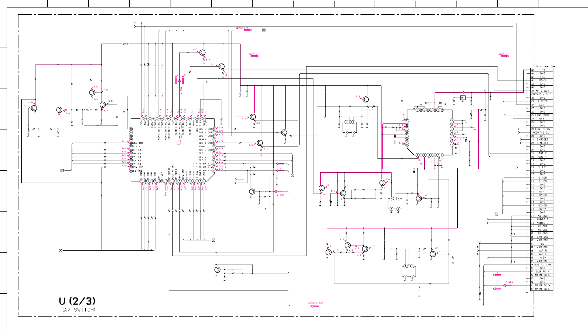
– 76 –
KP-HR432K90/HR532K90/HR532N90/HW572K90
RM-Y909KRM-Y908RM-Y909K RM-Y909K
1
A
B
C
D
E
F
G
H
212 13
11
10
98765
43 14
C2033
C2037
C2038
C2044
C2048
C2055
C2056
C2060C2062
C2084
C2085
C2087
C2090
C2091
C2094
C2096
C2097
C2098
C2099
C2102
C2103
C2111
C2112
C2113
C2114
C2122
FL2001
FL2002
FL2003
R2031
R2032R2034
R2040
R2041
R2043
R2047
R2048
R2049
R2050
R2051
R2052
R2055
R2056
R2058
R2063 R2064
R2066 R2067
R2071
R2072
R2073
R2074
R2075
R2077
R2080
R2081
R2082
R2084
R2085
R2086
R2087
R2089
R2090
R2096
R2097
R2098
R2099
R2100
R2109
R2110
R2113
R2121
R2122
R2125
R2128
R2130
R2133
R2137
R2138
R2142
R2149
R2150
R2151
R2152
R2153
R2155
R2156
R2164
R2166 R2169
R2173
R2174
R2175
R2176
R2177
R2178
R2182
R2183
R2185
R2186
R2187
R2046
R2123
R2124
R2131
R2132
R2136
R2157
R2094
R2095
C2004
R2033
R2102
R2117
R2127
R2146
R2158
R2181
R2203
R2112
R2120 R2093
R2106
R2103
R2104
C2089
C2036
C2043
C2045
C2069
R2184
R2039
R2147
C2059
C2068
CN2001
R2159
R2053
C2046
R2118
R2148
D2035
R2042
FB2001
FB2002
C2115
C2127
C2092
C2006
FL2004
IC2007
IC2004
Q2008
Q2009
Q2022
Q2003
Q2004
Q2001
Q2002
Q2013
Q2016
Q2015
Q2025
Q2017
Q2014
Q2020
Q2027
Q2011
Q2021
Q2019
Q2024
Q2028
C2050
C2052
1
0.047
16V
B:1608
220p
CH:1608
100 16V
0.47 10V B:1608
10
1
0.47 10VB:1608
100
16V0.1
16V
B:1608
10
15p
CH:1608
20p
CH:1608
0.02225V B:1608
0.1
16V
B:1608
0.001
B:1608
15p
CH:1608
15p
CH:1608
0.1
16V
B:1608
0.1
16V
B:1608
0.1
16V
B:1608
0.1
16V
B:1608
10
0.1
16V
B:1608
0.1
16V
B:1608
0.1
16V
B:1608
10
47k
1/16W
:CHIP
100k
1/16W
:CHIP
33
1/16W
:CHIP
1M
1/16W
:CHIP
56k
1/16W
:CHIP
100
1/16W
:CHIP
100 1/16W :CHIP
4.7k 1/16W :CHIP
100 1/16W:CHIP
4.7k1/16W:CHIP
1001/16W:CHIP
470
1/16W
:CHIP
1k
1/16W
:CHIP
1k 1/16W :CHIP
10k
1/16W
:RN-CP
100 1/16W :CHIP 100 1/16W :CHIP
4.7k 1/16W :CHIP 100 1/16W :CHIP
100 1/16W :CHIP
4.7k 1/16W :CHIP
100 1/16W :CHIP
100 1/16W :CHIP
100 1/16W :CHIP
100 1/16W :CHIP
100 1/16W :CHIP
100
1/16W
:CHIP
4.7k 1/16W :CHIP
100 1/16W :CHIP
1k
1/16W
:CHIP
4.7k 1/16W :CHIP
100 1/16W :CHIP
100
1/16W
:CHIP 1k
1/16W
:CHIP
100 1/16W :CHIP
1001/16W :CHIP
2.2k1/16W :CHIP
100 1/16W:CHIP
2.2k 1/16W:CHIP
100
1/16W
:CHIP
100
1/16W
:CHIP
1k
1/16W
:CHIP 100
1/16W
:CHIP
1k
1/16W
:CHIP
2.7k
1/16W
:RN-CP
2.2k
1/16W
:CHIP
100
1/16W
:CHIP
180
1/16W
:RN-CP
2.2k
1/16W
:RN-CP
100
1/16W
:CHIP
330
1/16W
:CHIP
470
1/16W
:CHIP
1k
1/16W
:CHIP
1.8k
1/16W
:RN-CP
1.2k
1/16W
:RN-CP
1k
1/16W
:CHIP
22k
1/16W
:CHIP
47k
1/16W
:CHIP
5.6k
1/16W
:RN-CP
560
1/16W
:CHIP
56k
1/16W
:CHIP
560
1/16W
:CHIP
560
1/16W
:RN-CP
470
1/16W
:CHIP
2.2k
1/16W
:CHIP
100
1/16W
:CHIP
220
1/16W
:RN-CP
0
:1608
220
L2001
47µH
1/16W
:CHIP
470
1/16W
:RN-CP
680
1/16W
:RN-CP
0
:1608
560
1/16W
:CHIP
470
1/16W
:RN-CP
1k
1/16W
:CHIP
2.2k
1/16W
:CHIP
10k
1/16W
:CHIP
390
1/16W
:CHIP
2.2k
1/16W
:CHIP
0
:1608
#
:1608
22
25V
#
:1608
#
:1608
#
:1608
#
:1608
#
:1608
AMP
#
:1608
#
:1608
#
:1608
#1/16W:CHIP
#
1/16W
:CHIP #
1/16W
:CHIP
#1/16W:CHIP
1001/16W :CHIP
100
1/16W
:CHIP
10
0.01
25V
B:1608
0.01 25V
B:1608
0.01
25V
B:1608
0.01
25V
B:1608
3.3k 1/16W :RN-CP
10k
1/16W
:CHIP
270
1/16W
:CHIP
#B:1608
#
B:1608
64P
:B-TO B-P
8.2k
1/16W
:CHIP
470
1/16W
:CHIP
0.47 10V B:1608
1k
1/16W
:CHIP
5.6k
1/16W
:RN-CP
MTZJ-10B PROT
2.2k
1/16W
:CHIP
BLM11A102S
:1608
BLM11A601S
:1608
#
B:1608
#
B:1608
0.1
16V
B:1608
0.1
16V
B:1608
#
CXD2073Q-T4
COMB FILTER
CXA2069Q
AV-SW1
2SC2412K
2SC2412K
2SC2412K
2SA1037AK
2SC2412K
2SC2412K
BUFFER
BUFFER
BUFFER
AMP
AMP
AMP
AMP
AMP
AMP
AMP
AMP
BUFFER
BUFFER
BUFFER
BUFFER
BUFFER
AMP
2SA1037AK
2SC2412K
2SC2412K
2SC2412K
2SC2412K
2SC2412K
#
2SC2412K
2SA1037AK
#
2SA1037AK
2SA1037AK
2SC2412K
2SA1037AK
0.47
10V
B:1608
0.01
25V
B:1608
5V
9V
12V
SCL TO U/2/3, U1/3, U3/3_5
SDA TO U/2/3, U1/3, U3/3_4
MAIN/SUB/MONI L,R
TO U2/3, U1/3_1
VIDEO 3 IN TO U2/3, U1/3_10
VIDEO 1 IN TO U2/3, U1/3_8
VIDEO 2 IN TO U2/3, U1/3_9
MV IN TO U2/3, U1/3_14
VIDEO 4 IN TO U2/3, U1/3_11
M-R TO U2/3, U1/3_16
M-L TO U2/3, U1/3_15
R-OUT TO U2/3, U3/3_20
L-OUT TO U2/3, U3/3_19
VAR GND TO U2/3, U1/3_7
VARI R TO U2/3, U1/3_13
VARI L TO U2/3, U1/3_12
D1/D2 TO U2/3, U3/3_23
S-ATT TO U2/3, U3/3_18
S-MODE1 TO U2/3, U3/3_21
S-MODE2 TO U2/3, U3/3_22
CONT S OUT TO U2/3, U1/3_25
CONT S IN TO U2/3, U1/3_24
LINE MUTE TO
U2/3, U1/3_17
A MUTE TO
U2/3, U1/3_6
A MUTE TO
U2/3, U1/3_6
M-L
M-R
S-V
S-L/R
MONI-L
MONI-R
MAIN-L
MAIN-R
D1-CR
D1-CB
D1-Y
D2-CR
D2-CB
D2-Y
M-V
1-L
1-R
1-C
1-Y
1-V
SUB C
SUB Y
SUB C
SUB Y
4-L
4-V
4-R
2-SW
2-C
2-R
2-Y
2-L
2-V
S13
3-C
3-R
3-Y
3-L
3-V
S11
S-L/R
S-V
M-R
MONI-V
SUB-L
SUB-R
M-V
M-L
2
(EXCEPT HW572K90)
C2075
0.01
B:1608
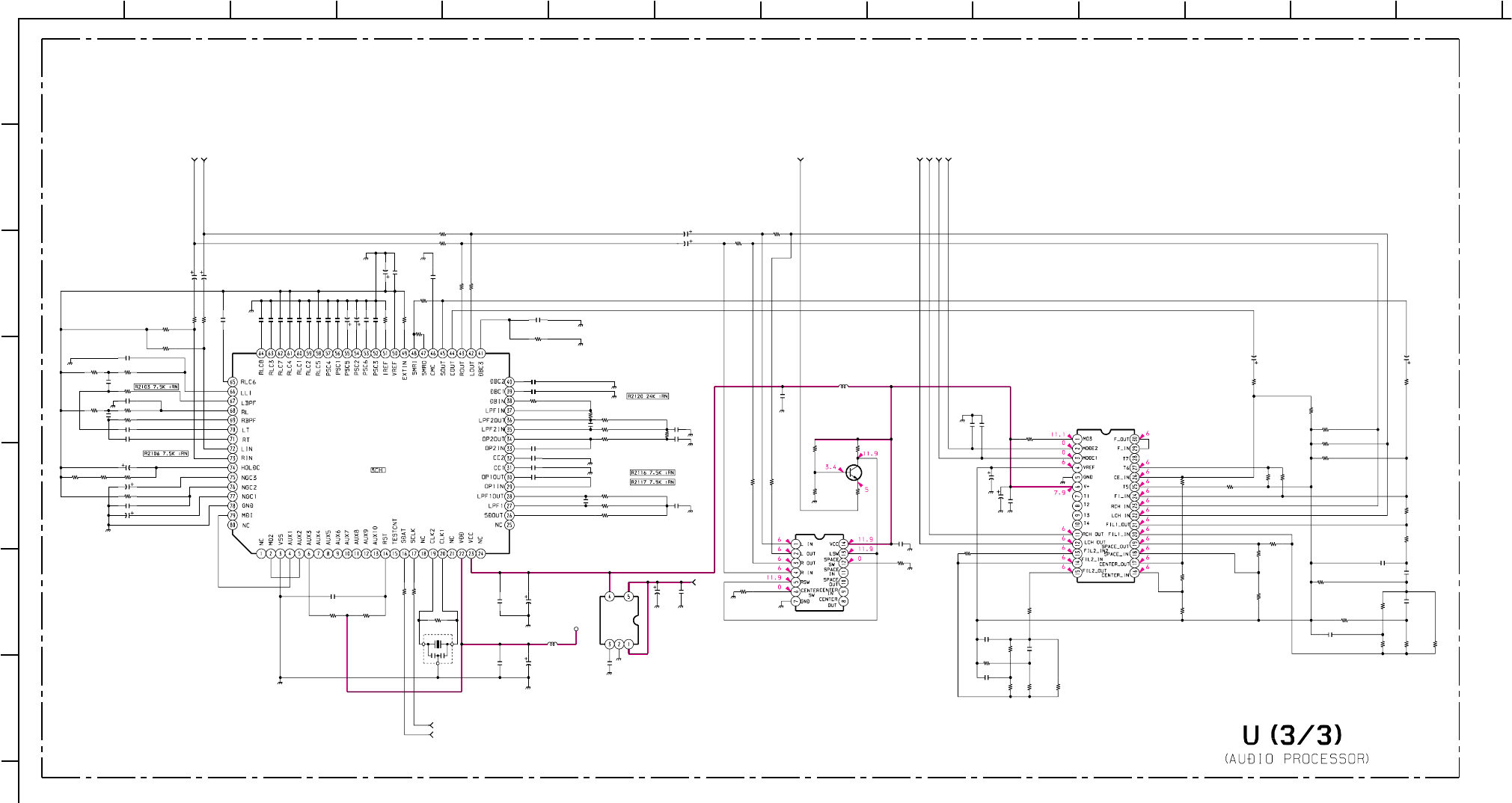
– 77 –
KP-HR432K90/HR532K90/HR532N90/HW572K90
RM-Y909KRM-Y908RM-Y909K RM-Y909K
1
A
B
C
D
E
F
G
212 13
11
10
98765
43 14
C2350
C2351
R2353
R2356
R2365
R2377
R2379
R2380
R2384 R2386
R2387
R2390
R2354
R2360
R2358
C2359
L2302
R2355
R2347 R2349
R2350
R2348
C2353 C2356
C2357
C2358
R2366
R2383
R2382
R2359 R2385
R2357
C2342
C2348
C2349
C2354
C2360
C2367
C2355
C2365
C2366
C2368
R2375
C2301
C2302
C2303
C2304
C2305
C2306
C2307
C2308
C2309
C2310
C2311 C2312
C2313
C2314
C2315
C2316
C2317
C2318
C2319
C2320
C2321
C2322
C2323
C2324
C2325
C2326
C2327
C2328 C2329
C2330
C2331 C2333
C2334
C2335
C2336
C2337
C2338
C2339
C2340
C2341
C2343
C2344
C2345
C2346
C2347
C2352
C2364 C2369
L2301
R2301
R2302
R2303
R2304
R2305
R2306
R2307
R2308
R2309
R2310
R2311
R2312
R2313 R2314
R2315 R2316
R2317
R2318
R2319
R2320
R2321
R2322
R2323
R2324
R2325
R2326 R2327
R2328
R2329
R2330
R2331
R2332
R2333
R2334
R2335
R2336
R2337
R2338
R2340
R2341
R2342
R2343
R2344
R2345
R2346
R2363
R2369
R2374
R2376
R2378
R2381
R2388
R2389
X2301
IC2305
IC2301
IC2302
Q2301
IC2304
10
10
1.5k
1/16W
:CHIP
56k
1/16W
:CHIP
10k
1/16W
:CHIP
4.7k
1/16W
:CHIP
56k
1/16W
:CHIP
1k
1/16W
:CHIP
10k
1/16W
:CHIP
22k
1/16W
:CHIP
1k
1/16W
:CHIP
150k
1/16W
:CHIP
47k
1/16W
:CHIP
2.2M
1/16W
:CHIP
33k
1/16W
:CHIP
0.1
16V
B:1608
:LB2016
10 H
62k
1/16W
:CHIP
68k
1/16W
:CHIP
10k
1/16W
:CHIP
10
1/16W
:CHIP
27k
1/16W
:CHIP
100p
CH:1608 100p
CH:1608
100
16V
100
16V
4.7k
1/16W
:CHIP
4.7k
4.7k
1/16W :CHIP
1/16W :CHIP
1.8k
1/16W
:CHIP
15k
1/16W
:CHIP
10k
1/16W
:CHIP
0.1
16V
B:1608
47
25V
0.01
25V
B:1608
C2370
0.01
25V
B:1608
0.0047
:PT
0.0047
:PT
0.0047
:PT
0.01
:PT
0.22
:MPS
0.01
:PT
0.22
:MPS
#
NJM2180M
NJM2370U10
2SC2412K
NJM4066M
5V
R-IN TO U3/3, U1/3_3
S-ATT TO U3/3, U2/3_18
L-OUT TO U3/3, U2/3_17
S-MODE1 TO U3/3, U2/3_21
S-MODE2 TO U3/3, U2/3_22
R-OUT TO U3/3, U2/3_20
SCL TO U3/3, U1/3, U2/3_5
SDA TO U3/3, U1/3, U2/3_4
L-IN TO U3/3, U1/3_2
12V
*
*
*
*
*
*
*
*
*
*
**
*
*
*
*
*
*
*
*
*
*
*
*
*
*
*
**
*
**
100
16V
C2332
0.01
25V
B:1608
*
*
*
*
*
*
*
*
*
*
*
*
0.01
25V
B:1608
**
*
*
*
*
*
*
*
*
*
*
*
*
*
**
**
*
*
*
*
*
*
*
*
*
**
*
*
*
:1608
*
*
*
*
*
*
*
*
*
*
1.8k
*
1.8k
0
:1608
0
:1608
*
*
*
*
*
*
*
*
*
*
(EXCEPT HW572K90)
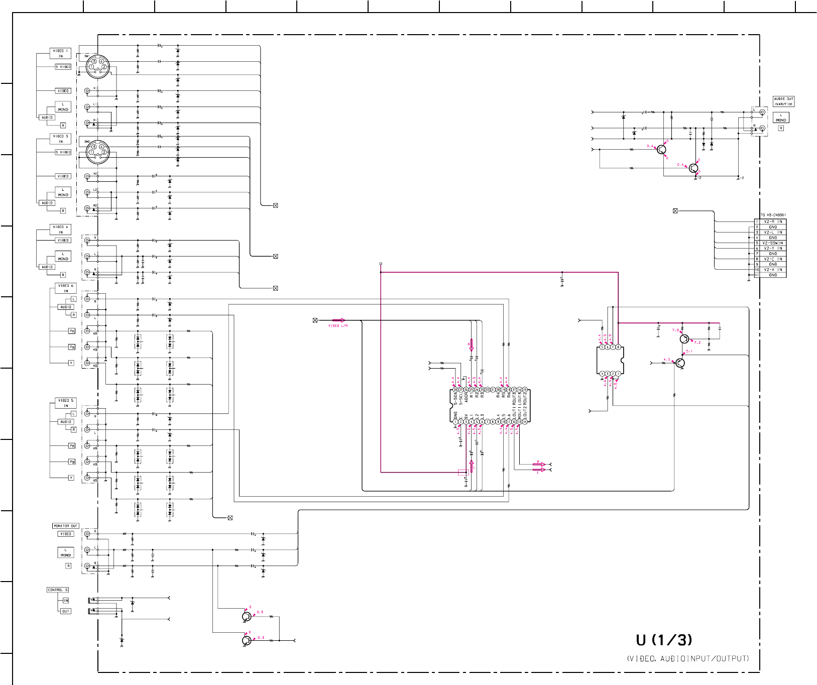
– 78 –
KP-HR432K90/HR532K90/HR532N90/HW572K90
RM-Y909KRM-Y908RM-Y909K RM-Y909K
1
A
B
C
D
E
F
G
H
I
211
10
98765
43
C2007
C2008
C2012
C2013
C2014
C2015
C2016
C2017
C2018
C2019
C2020
C2021
C2022
C2023
C2024
C2025
C2026
C2027
C2028
C2040
C2061
C2083
C2128
CN2002
D2001
D2002
D2003
D2014
D2015
D2016
D2017
D2018
D2021
D2022
D2023
D2024
D2025
D2026
D2027
D2028
D2029
D2030
D2039
D2042
R2001
R2002
R2003
R2004
R2005
R2006
R2007
R2008
R2009
R2010
R2011
R2012
R2013
R2014
R2016
R2017
R2018
R2019
R2020
R2021
R2023
R2024
R2025
R2026
R2027
R2030
R2068
R2070
R2193
R2194
R2195
R2196
R2197
R2198
R2199
D2007
D2012
D2013
D2019
D2020
D2004
D2005
D2006
D2009
D2010
D2011
D2031
D2032
D2040
D2041
D2043
D2044
C2003
R2044
R2045
R2054
R2057
R2091
R2092
D2008
R2105
R2111
R2062
R2061
R2015
C2005
R2107
R2060
R2059
J2003
J2002
R2022
C2002
C2001
J2001
R2065
R2069
R2116
D2033
D2034
Q2005
IC2003
Q2029
Q2007
Q2026
Q2012
Q2006
J2007
J2008
J2006
J2005
J2004
R2036 R2038
C2035
C2032
C2030
R2029
R2028
C2034
C2031
C2029
R2035
R2037
R2101
10
10
10
10
10
10
10
10
1
10
10
1
1
10
10
1
1
22
25V
100
16V
100
16V
10
22
25V
10
11P
WHT-L
:S-MICRO
MTZJ-10B
MTZJ-10B
MTZJ-10B
MTZJ-10B
MTZJ-10B
MTZJ-10B
MTZJ-10B
MTZJ-10B
MTZJ-10B
PROTECT
MTZJ-10B
PROTECT
MTZJ-10B
PROTECT
MTZJ-10B
PROTECT
MTZJ-10B
DEC-L
MTZJ-10B
PROTECT
MTZJ-10B
PROTECT
#
PROTECT
MTZJ-10B
PROTECT
MTZJ-10B
PROTECT
MTZJ-10B
MTZJ-10B
75
1/16W
:CHIP
470k
1/16W
:CHIP
75
1/16W
:RN-CP
75
1/16W
:RN-CP
75
1/16W
:RN-CP
470k
1/16W
:CHIP
470k
1/16W
:CHIP
75
1/16W
:RN-CP
75
1/16W
:RN-CP
75
1/16W
:RN-CP
470k
1/16W
:CHIP
470k
1/16W
:CHIP
470k
1/16W
:CHIP
470k
1/16W
:CHIP
470k
1/16W
:CHIP
75
1/16W
:RN-CP
470k
1/16W
:CHIP
470k
1/16W
:CHIP
75
1/16W
:RN-CP
75
1/16W
:RN-CP
470k
1/16W
:CHIP
470k
1/16W
:CHIP
75
1/16W
:RN-CP
75
1/16W
:RN-CP
75
1/16W
:RN-CP
100
1/16W
:CHIP
2.2k
1/16W
:CHIP
2.2k
1/16W
:CHIP
100
1/16W
:CHIP
470
1/16W
:CHIP
470
1/16W
:CHIP
470
1/16W
:CHIP
470
1/16W
:CHIP
470k
1/16W
:CHIP
470k
1/16W
:CHIP
MTZJ-10B
MTZJ-10B
MTZJ-10B
MTZJ-10B
MTZJ-10B
MA153-TX
MA153-TX
MA153-TX
MA153-TX
MA153-TX
MA153-TX
MA153-TX
MA153-TX
MA153-TX
MA153-TX
MA153-TX
MA153-TX
470
16V
56
1/16W
:CHIP
56
1/16W
:CHIP
56
1/16W
:CHIP
56
1/16W
:CHIP
56
1/16W
:CHIP
56
1/16W
:CHIP
MTZJ-10B
100
1/16W
:CHIP
2.2k
1/16W
:CHIP
470
1/16W
:CHIP
470
1/16W
:CHIP
470k
1/16W
:CHIP
0.1
16V
B:1608
68
1/16W
:CHIP
470
1/16W
:CHIP
470
1/16W
:CHIP
3P
3P
75
1/16W
:RN-CP
0.01 25V B:1608
0.01 25V B:1608
S TERMINAL BLOCK
2.2k 1/16W :CHIP
2.2k 1/16W :CHIP
8.2k
1/16W
:CHIP
1SS133T-77
1SS133T-77
2SC2412K
NJM4558-TE2
AUDIO-BUFFER
IC2001
TEA6422DT
AUDIO SWITCH
2SC2412K
2SC2412K
MUTE
MUTE
2SA1037AK
2SA1037AK
BUFFER
BUFFER
2SC2412K
MUTE
MUTE
2P
3P
5P
5P
3P
100
1/16W
:CHIP
100
1/16W
:CHIP
#
10
10
100
1/16W
:CHIP
100
1/16W
:CHIP
#
10
10
100
1/16W
:CHIP
100
1/16W
:CHIP
#
1/16W
:CHIP
VIDEO 1 IN TO U1/3, U2/3_8
LINE MUTE TO U1/3, U2/3_17
D1/D2 TO U1/3, U2/3_23
CONT S IN
TO U1/3, U2/3_24
CONT S OUT
TO U1/3, U2/3_25
VIDEO 3 IN TO U1/3, U2/3_10
VIDEO 4 IN TO U1/3, U2/3_11
MAIN/SUB/MONI L,R
TO U1/3, U2/3_1
SCL TO U1/3, U2/3, U3/3_5
SDA TO U1/3, U2/3, U3/3_4
R-IN TO U1/3, U3/3_3
M-L TO U1/3, U2/3_15
M-R TO U1/3, U2/3_16
VIDEO 2 IN TO U1/3, U2/3_9
A MUTE TO U1/3, U2/3_6
VAR GND TO U1/3, U2/3_7
VARI R TO U1/3, U2/3_13
VARI L TO U1/3, U2/3_12
MV TO
U1/3, U2/3_14
L-IN TO U1/3, U3/3_2
9V
MAIN-L
SUB-L
MONI-L
MAIN-R
SUB-R
MONI-R
3-V
3-Y
3-C
S13
D2-CR
D2-CB
D2-Y
D1-Y
D1-CB
D1-CR
1-L
1-R
1-C
1-Y
1-V
3-L
3-R
O-R
O-V
2-R
2-L
2-SW
2-Y
2-C
2-V
4-V
4-L
4-R
O-L
O-R
O-L
O-V
S11
MONI-V
C2053
470p
CH:1608
C2054
470p
CH:1608
C2049
470p
CH:1608
C2051
470p
CH:1608
C2073
470p
CH:1608
C2074
470p
CH:1608
(HW572K90)
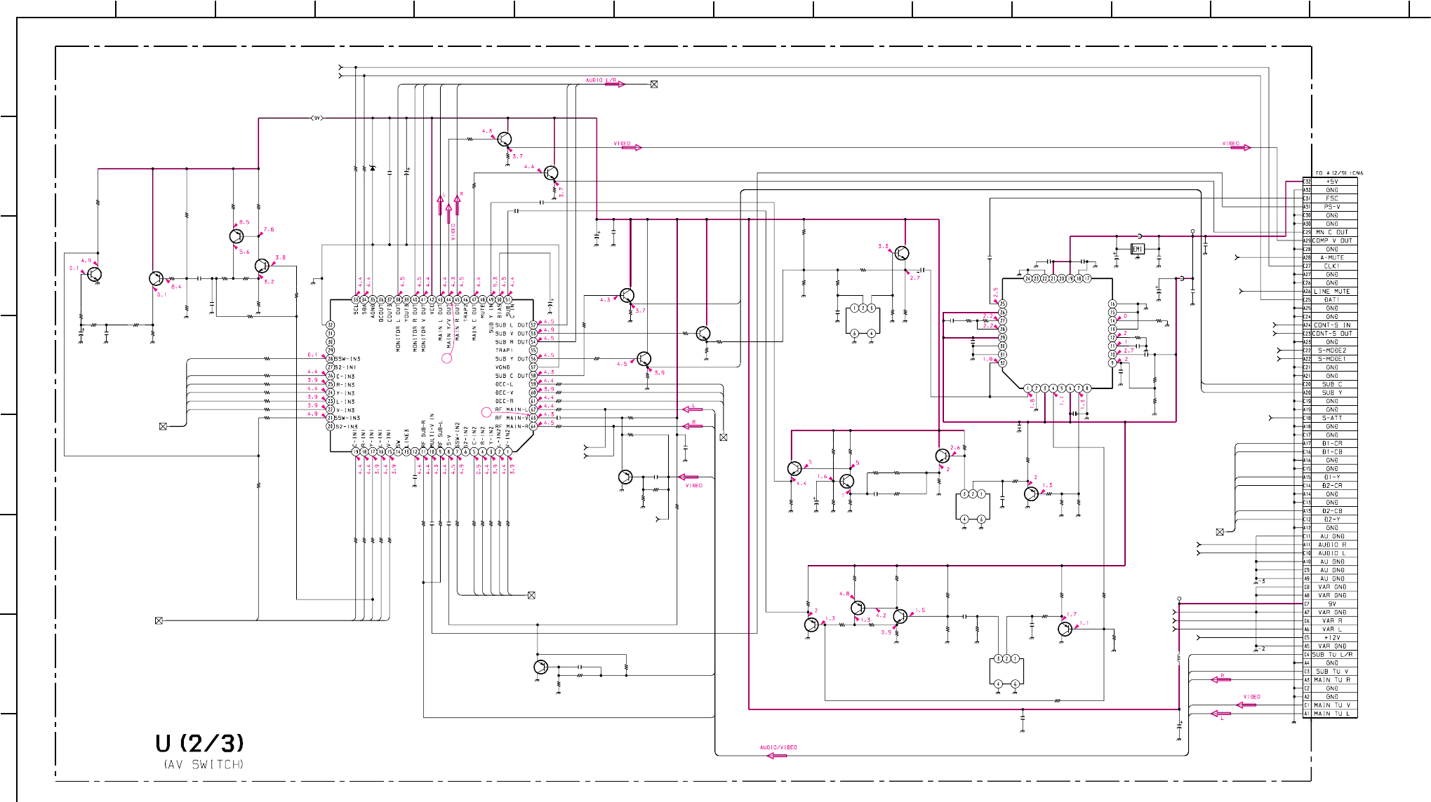
– 79 –
KP-HR432K90/HR532K90/HR532N90/HW572K90
RM-Y909KRM-Y908RM-Y909K RM-Y909K
1
A
B
C
D
E
F
G
H
212 13
11
10
98765
43 14
C2033
C2037
C2038
C2044
C2048
C2055
C2056
C2060 C2062
C2084
C2085
C2087
C2090
C2091
C2094
C2096
C2097
C2098
C2099
C2102
C2103
C2111
C2112
C2113
C2114
C2122
FL2001
FL2002
FL2003
R2031
R2032 R2034
R2040
R2041
R2043
R2047
R2048
R2049
R2050
R2051
R2052
R2055
R2056
R2058
R2063 R2064
R2066 R2067
R2071
R2072
R2073
R2074
R2075
R2077
R2080
R2081
R2082
R2084
R2085
R2086
R2087
R2089
R2090
R2096
R2097
R2098
R2099
R2100
R2109
R2110
R2113
R2121
R2122
R2125
R2128
R2130
R2133
R2137
R2138
R2142
R2149
R2150
R2151
R2152
R2153
R2155
R2156
R2164
R2166 R2169
R2173
R2174
R2175
R2176
R2177
R2178
R2182
R2183
R2185
R2186
R2187
R2046
R2123
R2124
R2131
R2132
R2136
R2157
R2094
R2095
C2004
R2033
R2102
R2117
R2127
R2146
R2158
R2181
R2203
R2112
R2120R2093
R2106
R2103
R2104
C2089
C2036
C2043
C2045
C2069
R2184
R2039
R2147
C2059
C2068
CN2001
R2159
R2053
C2046
R2118
R2148
D2035
R2042
FB2001
FB2002
C2115
C2127
C2092
C2006
FL2004
IC2007
IC2004
Q2008
Q2009
Q2022
Q2003
Q2004
Q2001
Q2002
Q2013
Q2016
Q2015
Q2025
Q2017
Q2014
Q2020
Q2027
Q2011
Q2021
Q2019
Q2024
Q2028
C2050
C2052
1
0.047
16V
B:1608
220p
CH:1608
100 16V
0.47 10V B:1608
10
1
0.4710V B:1608
100
16V 0.1
16V
B:1608
10
15p
CH:1608
20p
CH:1608
0.022 25VB:1608
0.1
16V
B:1608
0.001
B:1608
15p
CH:1608
15p
CH:1608
0.1
16V
B:1608
0.1
16V
B:1608
0.1
16V
B:1608
0.1
16V
B:1608
10
0.1
16V
B:1608
0.1
16V
B:1608
0.1
16V
B:1608
10
47k
1/16W
:CHIP
100k
1/16W
:CHIP
33
1/16W
:CHIP
1M
1/16W
:CHIP
56k
1/16W
:CHIP
100
1/16W
:CHIP
1001/16W :CHIP
4.7k1/16W :CHIP
1001/16W :CHIP
4.7k1/16W:CHIP
1001/16W :CHIP
470
1/16W
:CHIP
1k
1/16W
:CHIP
1k 1/16W:CHIP
10k
1/16W
:RN-CP
100 1/16W :CHIP 100 1/16W :CHIP
4.7k 1/16W :CHIP 100 1/16W :CHIP
100 1/16W :CHIP
4.7k 1/16W :CHIP
100 1/16W :CHIP
100 1/16W :CHIP
100 1/16W :CHIP
100 1/16W :CHIP
100 1/16W :CHIP
100
1/16W
:CHIP
4.7k 1/16W :CHIP
100 1/16W :CHIP
1k
1/16W
:CHIP
4.7k 1/16W :CHIP
100 1/16W :CHIP
100
1/16W
:CHIP 1k
1/16W
:CHIP
1001/16W :CHIP
1001/16W :CHIP
2.2k 1/16W :CHIP
1001/16W:CHIP
2.2k1/16W :CHIP
100
1/16W
:CHIP
100
1/16W
:CHIP
1k
1/16W
:CHIP 100
1/16W
:CHIP
1k
1/16W
:CHIP
2.7k
1/16W
:RN-CP
2.2k
1/16W
:CHIP
100
1/16W
:CHIP
180
1/16W
:RN-CP
2.2k
1/16W
:RN-CP
100
1/16W
:CHIP
330
1/16W
:CHIP
470
1/16W
:CHIP
1k
1/16W
:CHIP
1.8k
1/16W
:RN-CP
1.2k
1/16W
:RN-CP
1k
1/16W
:CHIP
22k
1/16W
:CHIP
47k
1/16W
:CHIP
5.6k
1/16W
:RN-CP
560
1/16W
:CHIP
56k
1/16W
:CHIP
560
1/16W
:CHIP
560
1/16W
:RN-CP
470
1/16W
:CHIP
2.2k
1/16W
:CHIP
100
1/16W
:CHIP
220
1/16W
:RN-CP
0
:1608
220
1/16W
:CHIP
470
1/16W
:RN-CP
680
1/16W
:RN-CP
0
:1608
560
1/16W
:CHIP
470
1/16W
:RN-CP
1k
1/16W
:CHIP
2.2k
1/16W
:CHIP
10k
1/16W
:CHIP
390
1/16W
:CHIP
2.2k
1/16W
:CHIP
0
:1608
#
:1608
22
25V
#
:1608
#
:1608
#
:1608
#
:1608
#
:1608
AMP
#
:1608
#
:1608
#
:1608
#1/16W:CHIP
#
1/16W
:CHIP #
1/16W
:CHIP
#1/16W:CHIP
100 1/16W :CHIP
100
1/16W
:CHIP
10
0.01
25V
B:1608
0.01 25V
B:1608
0.01
25V
B:1608
0.01
25V
B:1608
3.3k 1/16W:RN-CP
10k
1/16W
:CHIP
270
1/16W
:CHIP
#B:1608
#
B:1608
64P
:B-TO B-P
8.2k
1/16W
:CHIP
470
1/16W
:CHIP
0.47 10V B:1608
1k
1/16W
:CHIP
5.6k
1/16W
:RN-CP
MTZJ-10B PROT
2.2k
1/16W
:CHIP
BLM11A102S
:1608
BLM11A601S
:1608
#
B:1608
#
B:1608
0.1
16V
B:1608
0.1
16V
B:1608
#
CXD2073Q-T4
COMB FILTER
CXA2069Q
AV-SW1
2SC2412K
2SC2412K
2SC2412K
2SA1037AK
2SC2412K
2SC2412K
BUFFER
BUFFER
BUFFER
AMP
AMP
AMP
AMP
AMP
AMP
AMP
AMP
BUFFER
BUFFER
BUFFER
BUFFER
BUFFER
AMP
2SA1037AK
2SC2412K
2SC2412K
2SC2412K
2SC2412K
2SC2412K
#
2SC2412K
2SA1037AK
#
2SA1037AK
2SA1037AK
2SC2412K
2SA1037AK
0.47
10V
B:1608
0.01
25V
B:1608
5V
9V
12V
SCL TO U/2/3, U1/3, U3/3_5
SDA TO U/2/3, U1/3, U3/3_4
MAIN/SUB/MONI L,R
TO U2/3, U1/3_1
VIDEO 3 IN TO U2/3, U1/3_10
VIDEO 1 IN TO U2/3, U1/3_8
VIDEO 2 IN TO U2/3, U1/3_9
MV IN TO U2/3, U1/3_14
VIDEO 4 IN TO U2/3, U1/3_11
M-R TO U2/3, U1/3_16
M-L TO U2/3, U1/3_15
R-OUT TO U2/3, U3/3_20
L-OUT TO U2/3, U3/3_19
VAR GND TO U2/3, U1/3_7
VARI R TO U2/3, U1/3_13
VARI L TO U2/3, U1/3_12
D1/D2 TO U2/3, U3/3_23
S-ATT TO U2/3, U3/3_18
S-MODE1 TO U2/3, U3/3_21
S-MODE2 TO U2/3, U3/3_22
CONT S OUT TO U2/3, U1/3_25
CONT S IN TO U2/3, U1/3_24
LINE MUTE TO
U2/3, U1/3_17
A MUTE TO
U2/3, U1/3_6
A MUTE TO
U2/3, U1/3_6
M-L
M-R
S-V
S-L/R
MONI-L
MONI-R
MAIN-L
MAIN-R
D1-CR
D1-CB
D1-Y
D2-CR
D2-CB
D2-Y
M-V
1-L
1-R
1-C
1-Y
1-V
SUB C
SUB Y
SUB C
SUB Y
4-L
4-V
4-R
2-SW
2-C
2-R
2-Y
2-L
2-V
S13
3-C
3-R
3-Y
3-L
3-V
S11
S-L/R
S-V
M-R
MONI-V
SUB-L
SUB-R
M-V
M-L
2
L2001
47µH
(HW572K90)
C2075
0.01
B:1608
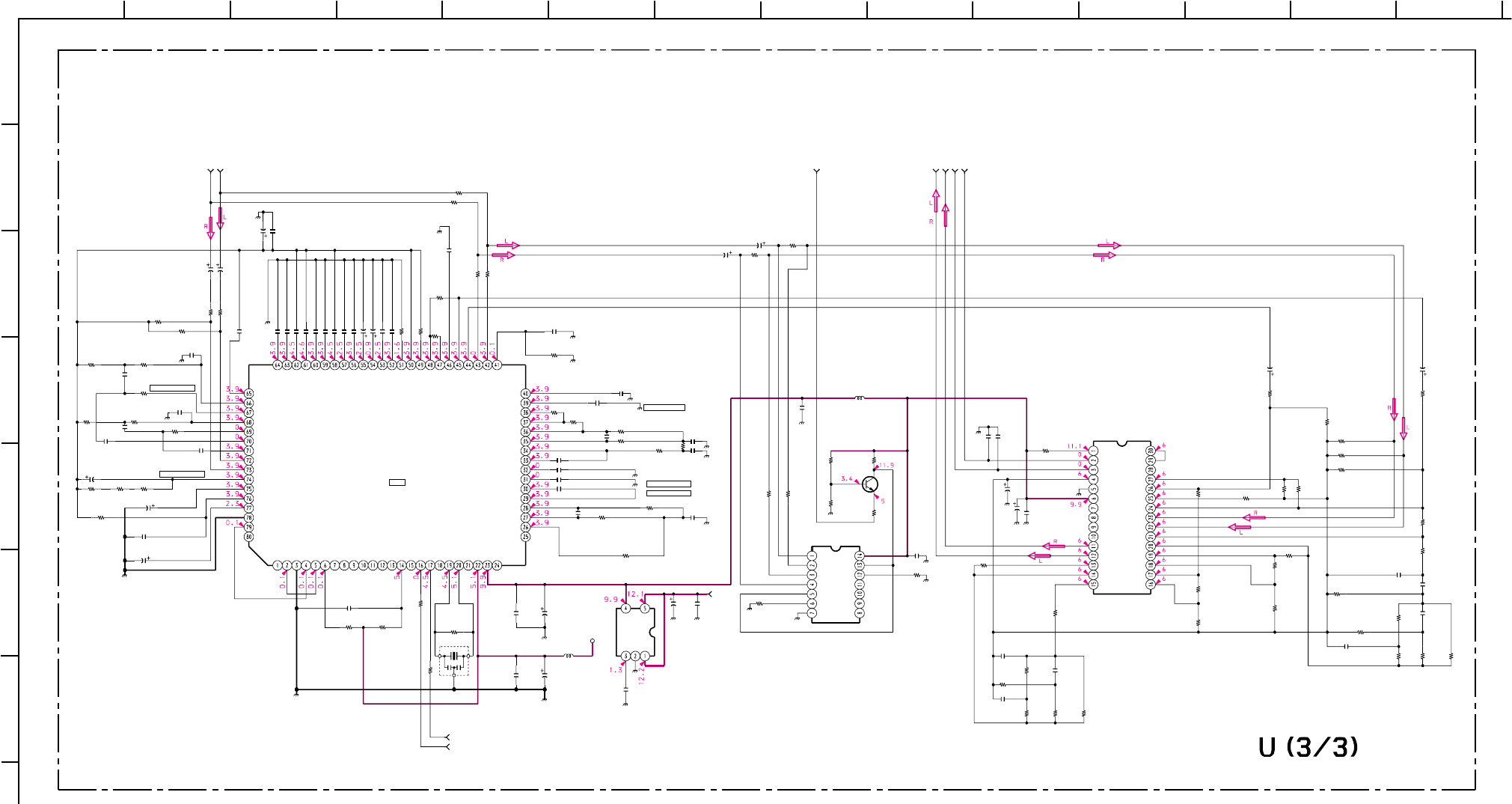
– 80 –
KP-HR432K90/HR532K90/HR532N90/HW572K90
RM-Y909KRM-Y908RM-Y909K RM-Y909K
1
A
B
C
D
E
F
G
212 13
11
10
98765
43 14
C2350
C2351
R2353 R2356
R2365
R2377
R2379
R2380
R2384 R2386
R2387
R2390
R2354
R2360
R2358
C2359
L2302
R2355
C2353 C2356
C2357
C2358
R2366
R2383
R2382
R2359
R2385
R2357
C2342
C2348
C2349
C2354
C2360
C2367
C2355
C2365
C2366
C2368
R2375
C2301
C2302
C2303
C2304
C2305
C2306
C2307
C2308
C2309
C2310
C2311 C2312
C2313
C2323
C2328 C2329
C2330
C2331
C2332
C2333
C2334
C2335
C2336
C2337
C2338
C2339 C2340
C2341
C2344
C2345
C2346
C2347
C2352
C2364 C2369
L2301
R2301
R2302
R2303
R2304
R2305
R2306
R2307
R2308
R2309
R2310
R2311
R2312
R2313 R2314
R2315 R2316
R2318
R2319
R2320
R2321
R2322
R2324
R2325
R2326 R2327
R2329
R2330
R2331
R2332
R2341
R2342
R2343
R2344
R2345
R2346
R2363
R2369
R2374
R2376
R2378
R2381
R2388
R2389
X2301
IC2305
IC2301
IC2302
Q2301
C2314
C2315
C2316
C2317
C2318
C2319
C2320
C2321
C2322
C2324
C2325
C2326
C2327
R2317
R2328
R2338
R2337
R2336 R2340
R2333
R2334 R2335
C2343
R2323
R2347
R2348
R2349
R2350
IC2304
10
10
1.5k
1/16W
:CHIP
56k
1/16W
:CHIP
4.7k
1/16W
:CHIP
4.7k
1/16W
:CHIP
4.7k
1/16W
:CHIP
4.7k
1/16W
:CHIP
56k
1/16W
:CHIP
1k
1/16W
:CHIP
10k
1/16W
:CHIP
22k
1/16W
:CHIP
1k
1/16W
:CHIP
150k
1/16W
:CHIP
56k
1/16W
:CHIP
2.2M
1/16W
:CHIP
33k
1/16W
:CHIP
0.1
16V
B:1608
:LB2016
10 H
62k
1/16W
:CHIP
100p
CH:1608 100p
CH:1608
100
16V
100
16V
15k
1/16W
:CHIP
#1/16W :CHIP
#1/16W :CHIP
1.8k
1/16W
:CHIP 15k
1/16W
:CHIP
10k
1/16W
:CHIP
0.1
16V
B:1608
47
25V
0.01
25V
B:1608
0.0047
:PT
0.0047
:PT
0.0047
:PT
0.01
:PT
0.22
:MPS
0.01
:PT
0.22
:MPS
NJM2180M
NJM2370U10
2SC2412K
#
:CHIP
#
:CHIP
#
:CHIP
#
:CHIP
#
5V
12V
NC
MD2
VSS
AUX1
AUX2
AUX3
AUX4
AUX5
AUX6
AUX7
AUX8
AUX9
AUX10
RST
TESTCNT
NC
CLK2
CLK1
NC
VDD
VCC
NC
NC
SDOUT
LPF1
LPF1OUT
OP1IN
OP1OUT
CC1
CC2
OP2IN
OP2OUT
LPF2IN
LPF2OUT
LPFIN
DBIN
DBC1
DBC2
DBC3
LOUT
ROUT
COUT
SOUT
CMC
SMRO
SMRI
EXTIN
VREF
IREF
PSC3
PSC6
PSC2
PSC5
PSC1
PSC4
RLC5
RLC2
RLC1
RLC4
RLC7
RLC3
RLC8
RLC6
LLI
LBPF
RL
RBPF
LT
RT
LIN
RIN
HOLDC
NGC3
NGC2
GND
MDI
NC
NGC1
SDAT
SCLK
3CH
R2103 7.5K :RN
R2106 7.5K :RN
R2116 7.5K :RN
R2117 7.5K :RN
R2120 24K :RN
CENTER_IN
FIL2_OUT
CENTER_OUT
FIL2_IN
SPACE_IN
FIL2_IN2
SPACE_OUT
LCH OUT
FIL1_IN
RCH OUT
FIL1_OUT
MO3
MODE2
MODE1
VREF
GND
T1
T2
T3
T4
F_OUT
F_IN
T7
T6
CE_IN
T5
FI_IN
RCH IN
LCH IN
V+
L IN
L OUT
R OUT
R IN
RSW
GND
VCC
LSW
SW
IN
OUT
IN
OUT
SPACE
SPACE
SPACE
SW
CENTER CENTER
CENTER
(AUDIO PROCESSOR)
R+10V EG
100
16V
47k
1/16W
:CHIP
4MHz
:FLR50
10 H
0.1
:PT
0.1
:PT
22
25V
0.1
:PT
0.1
:PT
680p
:PT
680p
:PT
22
25V
47
25V
47
25V 47
25V
0.1
:PT
0.01
25V
B:1608
220
16V
0.01
25V
B:1608
0.1
:PT
0.01
25V
B:1608
0.01
25V
B:1608
100
16V
10 10
330k
1/16W
:CHIP
15k
1/16W
:CHIP
15k
1/16W
:CHIP
2.2M
1/16W
:CHIP
100k
1/16W
:CHIP
2.2M
1/16W
:CHIP
47k
1/16W
:CHIP
47k
1/16W
:CHIP
22k
1/16W
:CHIP
22k
1/16W
:CHIP
8.2k
1/16W
:CHIP
8.2k
1/16W
:CHIP
100
1/16W
:CHIP
47k 1/16W :CHIP
100
1/16W
:CHIP
0
:1608 0
:1608
330k
1/16W
:CHIP
22k 1/16W :CHIP
0
:1608 0
:1608
#
#
#
1/16W
:CHIP
#1/16W :CHIP
0
:1608
0
:1608
6.8k
1/16W
:CHIP
6.8k
1/16W
:CHIP
0.0047
B:1603
0.01 25V B:1608
0.022 25V B:1608
0.022 25V B:1608
0.01 25V B:1608
0.0056
25V
B:1608
0.068
16V
B:1608
680p B:1608
0.0033
B:1608
0.0033
B:1608
0.0033
B:1608
15k
1/16W
:CHIP
10k
1/16W
:CHIP
0.68
:MPS
#
#
#
#
#
#
1/16W
:CHIP #
1/16W
:CHIP
#
#
#
#
NJW1106
PROLOGIC DECODE
0.022 :PT
0.022 :PT
0.1 16V B:CHIP
0.1 16V B:CHIP
0.047 :PT
0.047 :PT
0.1 16V B:CHIP
0.22 :PT
0.22 :PT
4.7
4.7
0.22 :PT
0.22 :PT
100k 1/16W :CHIP
10k 1/16W :CHIP
15k 1/16W :CHIP
10k 1/16W :CHIP
6.8k
1/16W
:CHIP
6.8k
1/16W
:CHIP
18k
1/16W
:CHIP
10k
1/16W
:CHIP
15k
1/16W
:CHIP
680p
B:1608
1M
1/16W
:CHIP
R-IN TO U3/3, U1/3_3
S-ATT TO U3/3, U2/3_18
L-OUT TO U3/3, U2/3_17
S-MODE1 TO U3/3, U2/3_21
S-MODE2 TO U3/3, U2/3_22
R-OUT TO U3/3, U2/3_20
SCL TO U3/3, U1/3, U2/3_5
SDA TO U3/3, U1/3, U2/3_4
L-IN TO U3/3, U1/3_2
C2370
0.01
25V
B:1608
(HW572K90)
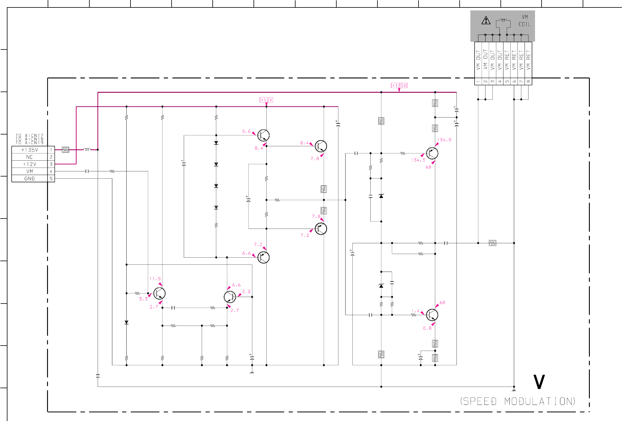
– 81 –
KP-HR432K90/HR532K90/HR532N90/HW572K90
RM-Y909KRM-Y908RM-Y909K RM-Y909K
1
A
B
C
D
E
F
G
H
I
J
212 13
11
10
98765
43 14 15
CN9001
L9001
R9002
R9004
R9005
R9006
R9008
C9006
R9010
R9011
D9005
R9012
C9007
C9008
R9013
R9014
R9015
C9009
C9010
C9013
R9019
R9020
R9021
C9015
R9024
R9025
R9027
R9028
C9019
CN9002
C9014
C9001
R9007
R9001
R9003 R9026
R9009
R9016
D9001
D9002
D9003
D9004
R9029
D9006
D9007
C9018
R9030
C9003
R9017
R9018
R9033
R9034
R9031
R9032
C9002
C9011
C9012
C9017
R9022
R9023
Q9009
Q9006
Q9004
Q9008
Q9002 Q9003
Q9005
Q9007
8P
5P
WHT
:S-MICRO
2.2
160V
470
16V
470
16V
100
16V
100
16V
470
6.3V
470
6.3V
D1NS4
TEMP-CORR
:LHL08
560
:FPRD 2.2
:FPRD
2.2
:FPRD
100
:FPRD
0.001
B:1608
0:1608
47
1/16W
:CHIP
820
1/16W
:CHIP
4.7k
1/16W
:CHIP
4.7k
1/16W
:CHIP
33
1/16W
:CHIP
220
1/16W
:CHIP
1.5k
1/16W
:CHIP
47
1/16W
:CHIP
47
1/16W
:CHIP
10k
1/16W
:CHIP
15
1/16W
:CHIP
15
1/16W
:CHIP
100
:FPRD
0.001
B:1608
#
:1608
100
1/16W
:CHIP
#
1/16W
:CHIP
#
1/16W
:CHIP
#
1/16W
:CHIP
100
1/16W
:CHIP
560
:FPRD
220
3W
:RS
MTZJ-22B
LEV.SHIFT
MTZJ-22B
LEV.SHIFT
1SS355TE
1SS355TE
TEMP-CORR
1SS355TE
TEMP-CORR
1SS355TE
TEMP-CORR
33
160V
0.47
:FPRD
0.47
10V
B:1608
33k
33k
39k
39k
2.2
:FPRD
2.2
:FPRD
0.1
200V
:PT
0.01
200V
:PT
0.01
200V
:PT
0.1
200V
:PT
2.2k
2.2k
2SA2005
VM-OUT
2SA1037AK
BUFFER
2SA1037AK
BUFFER
2SC5511
VM-OUT
2SC2412K
AMP
2SC2412K
AMP
2SC2412K
BUFFER
2SC2412K
BUFFER
10µH
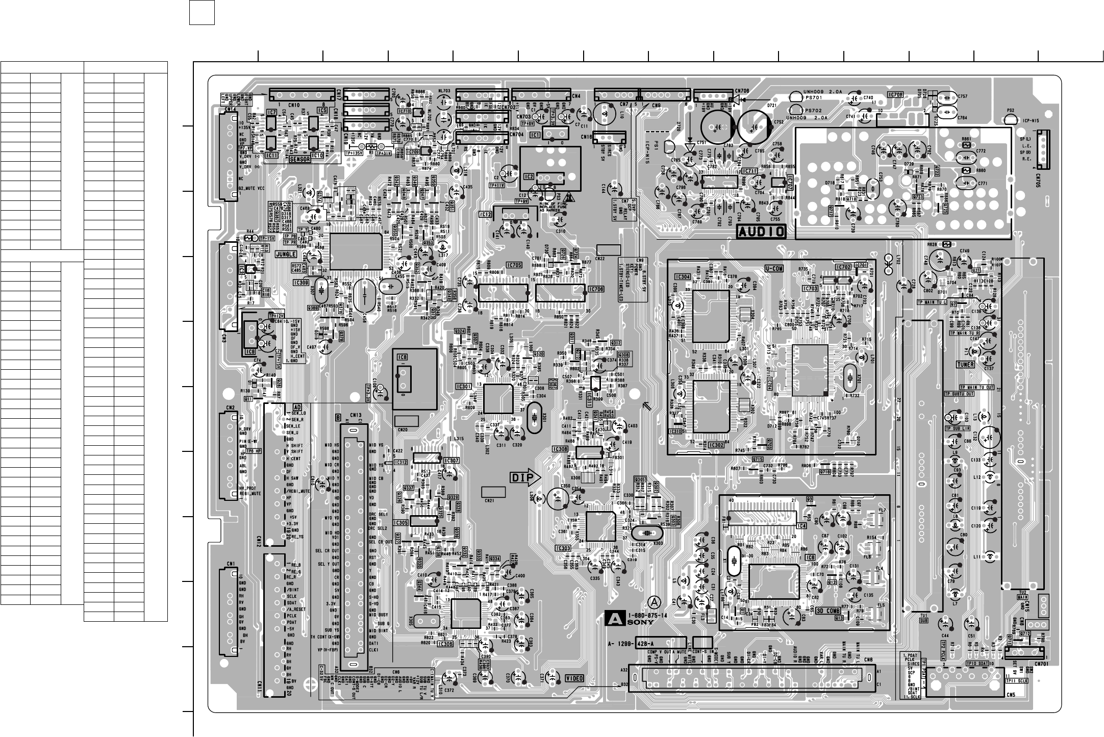
– 82 –
KP-HR432K90/HR532K90/HR532N90/HW572K90
RM-Y909KRM-Y908RM-Y909K RM-Y909K
< Component Side >
– A Board –
1
A
B
C
D
E
F
G
H
I
J
212 13
11
10
98765
43 14
A[TUNER, VIDEO, AUDIO, SYSTEM CONTROL]
TRANSISTOR *
Q1 I-9 2
Q3 G-10 2
Q7 D-12 2
Q11 F-1 2
Q12 H-10 2
Q13 I-11 2
Q21 D-13 2
Q302 G-8 2
Q303 H-8 2
Q305 G-7 2
Q307 E-5 2
Q308 E-7 2
Q310 E-6 2
Q311 E-6
Q312 E-7 2
Q313 D-4 2
Q320 E-6 2
Q324 E-5 2
Q325 G-4 2
Q326 G-4 2
Q327 H-4 2
Q328 G-4 2
Q329 G-4 2
Q330 H-4 2
Q332 H-5 2
Q333 H-5 2
Q334 H-5 2
Q337 G-4 2
Q338 H-4 2
Q339 H-4 2
Q341 F-7 2
Q343 C-4 2
Q344 I-4 2
Q347 C-4 2
Q349 D-4 2
Q351 C-4 2
Q352 D-4 2
Q353 C-4 2
Q355 C-4 2
Q367 C-3 2
Q369 D-2 2
Q374 C-3 2
Q378 D-2 2
Q379 E-3 2
Q703 F-9 2
Q712 I-13 2
Q713 I-13 2
Q715 G-9 2
Q716 G-10 2
Q717 C-10 2
Q718 B-11 2
Q722 B-12 2
Q723 B-12 2
Q724 D-6 2
Q725 C-12 2
Q726 D-6 2
DIODE *
D1 E-2 3
D317 C-3 3
D318 C-3 3
D319 E-2 3
D701 D-12 9
D704 D-12 9
D705 A-12 3
D710 F-11 9
D711 E-9 9
D712 F-9 9
D713 E-9 9
D718 B-10 3
D720 B-8
D721 A-9
D725 A-12 3
D726 A-12 3
D729 B-11 3
D730 D-6 3
IC
IC1 B-6
IC2 B-6
IC3 D-1
IC4 H-9
IC5 A-2
IC6 H-9
IC7 A-2
IC8 E-4
IC9 E-1
IC10 B-2
IC11 B-2
IC12 C-5
IC301 F-5
IC302 F-8
IC303 H-7
IC304 D-8
IC305 H-4
IC306 I-5
IC307 G-4
IC308 D-3
IC309 C-3
IC310 F-8
IC311 F-7
IC312 G-4
IC701 D-11
IC702 D-10
IC703 D-10
IC704 F-10
IC705 D-5
IC706 D-6
IC707 B-10
IC708 A-11
IC709 B-4
IC710 A-4
IC711 B-9
A BOARD
6-4. PRINTED WIRING BOARDS
*: Refer to Terminal name of
semiconductors in silk screen
printed circuit (see page 49)
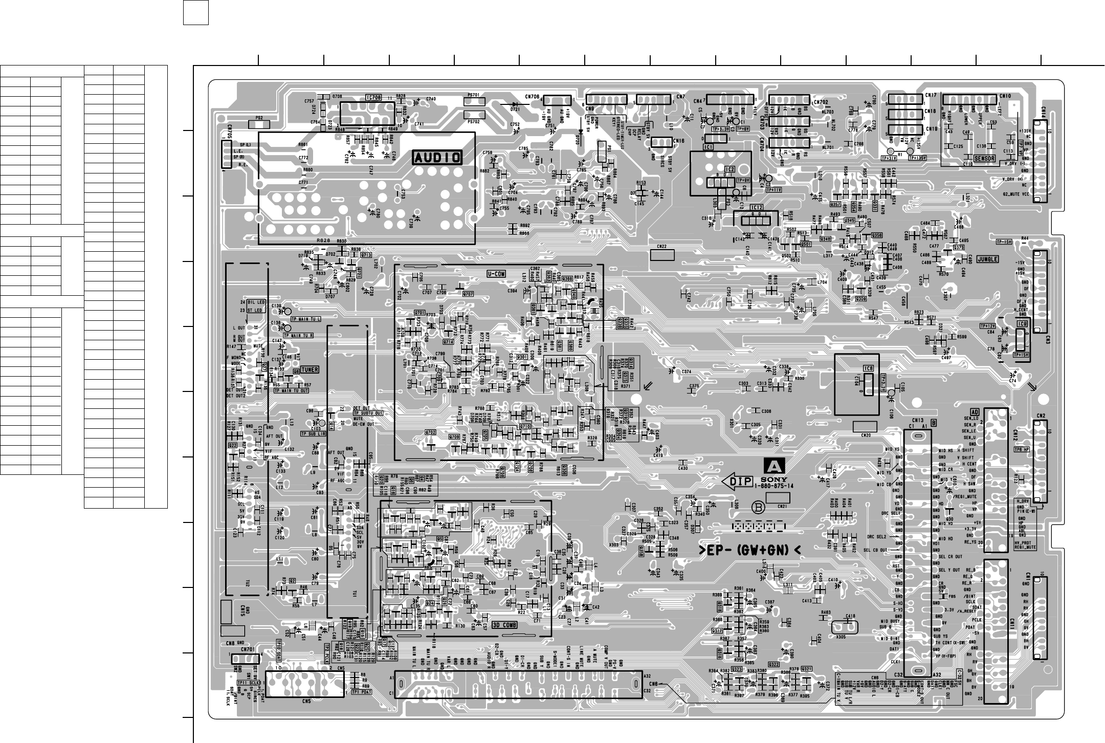
– 83 –
KP-HR432K90/HR532K90/HR532N90/HW572K90
RM-Y909KRM-Y908RM-Y909K RM-Y909K
1
A
B
C
D
E
F
G
H
I
J
212 13
11
10
98765
43 14
– A Board –
< Conductor Side >
A[TUNER, VIDEO, AUDIO, SYSTEM CONTROL]
DIODE *
D5 H-3 3
D7 C-7 3
D307 H-8 3
D312 C-11 3
D321 E-12 3
D702 C-3 3
D703 E-4 3
D706 A-3 3
D708 F-5 3
D709 F-5 3
D719 D-2 3
D720 B-6
D721 A-5
D723 A-3 3
D724 A-3 3
IC
IC1 B-8
IC2 B-9
IC8 E-11
IC9 E-13
IC12 C-9
IC708 A-3
TRANSISTOR *
Q2 I-2 1
Q4 G-4 1
Q5 H-4 1
Q6 G-4 1
Q8 E-2 1
Q14 F-3 1
Q15 H-4 1
Q16 H-4 1
Q17 I-4 1
Q18 H-4 1
Q19 H-4 1
Q20 G-4 1
Q22 F-1 1
Q23 H-4 1
Q24 I-4 1
Q25 H-4 1
Q26 I-4 1
A BOARD
Q27 E-1 1
Q28 I-4 1
Q30 G-12 1
Q301 E-6 1
Q304 F-6 1
Q306 F-6 1
Q309 D-11 1
Q314 E-6 1
Q315 E-6 1
Q316 J-9 1
Q317 I-9 1
Q318 I-9 1
Q319 F-6 1
Q321 J-10 1
Q322 J-10 1
Q323 J-9 1
Q331 C-11 1
Q335 D-6 1
Q336 D-6 1
Q340 D-6 1
Q345 C-11 1
Q348 C-10 1
Q354 C-11 1
Q356 C-11 1
Q357 C-10 1
Q358 H-8 1
Q361 D-6 1
Q363 D-6 1
Q368 D-6 1
Q373 C-12 1
Q380 E-6 1
Q381 E-6 1
Q501 C-10 1
Q502 C-10 1
Q701 D-4 1
Q702 F-4 1
Q704 F-5 1
Q705 F-5 1
Q706 F-6 1
Q707 D-5 1
Q708 F-5 1
Q709 F-5 1
Q710 F-6 1
Q714 D-4 1
Q721 D-3 1
*: Refer to Terminal name of
semiconductors in silk screen
printed circuit (see page 49)
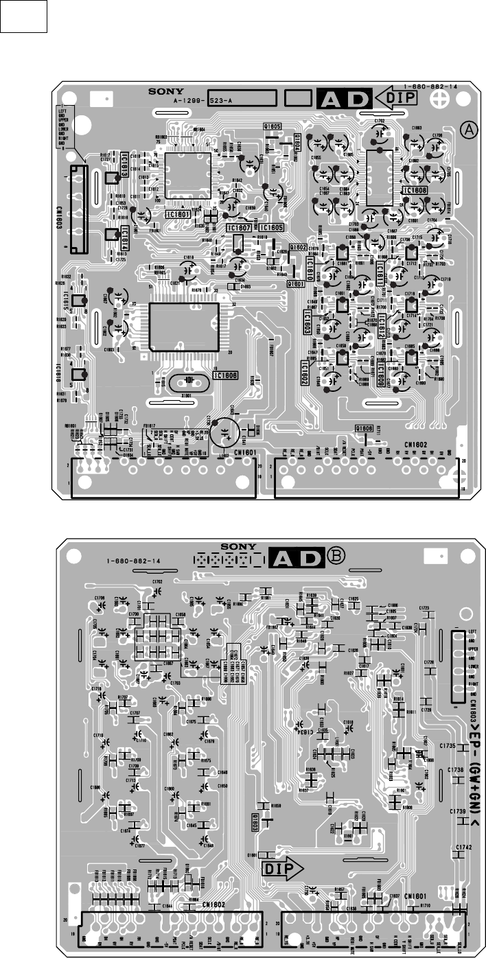
– 84 –
KP-HR432K90/HR532K90/HR532N90/HW572K90
RM-Y909KRM-Y908RM-Y909K RM-Y909K
[DIGITAL REGI, DJED CPU, PJE DRIVE]
AD
– AD Board –
< Component Side >
< Conductor Side >
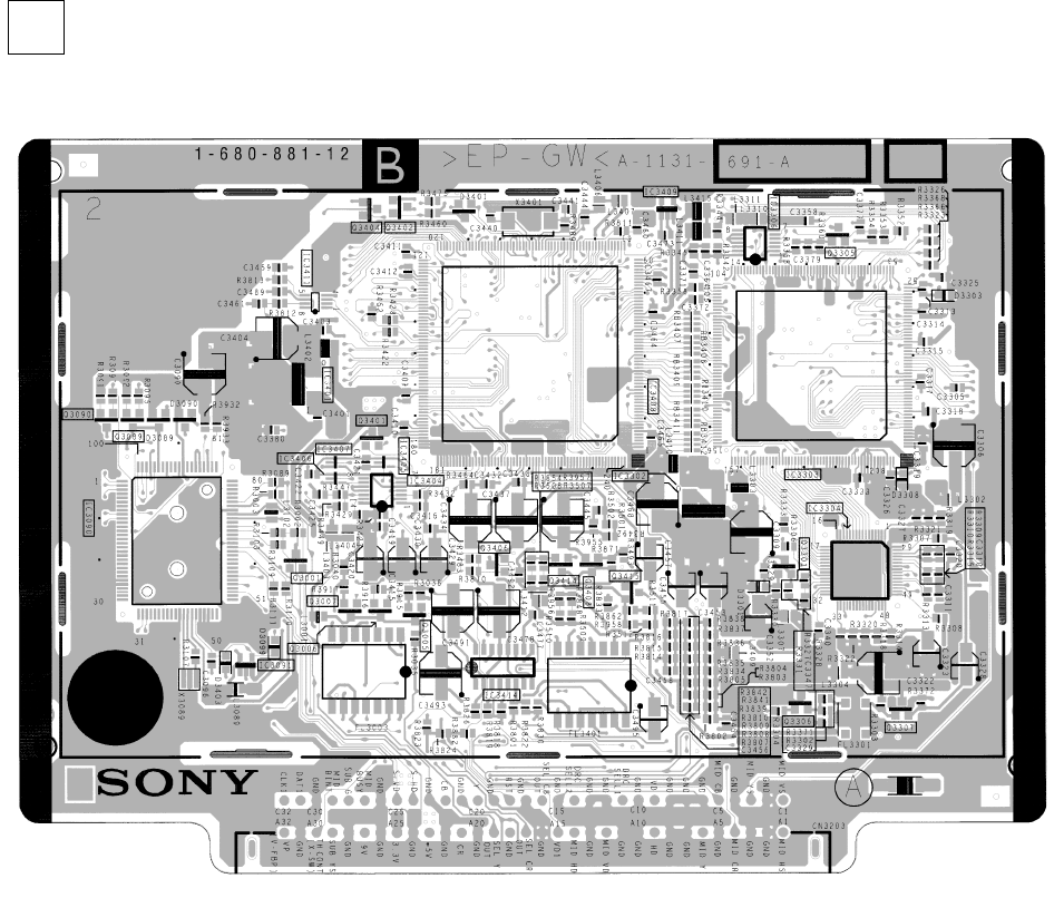
– 85 –
KP-HR432K90/HR532K90/HR532N90/HW572K90
RM-Y909KRM-Y908RM-Y909K RM-Y909K
< Component Side >
– B Board –
B[A/D CONVERTER, DRC, MULTI IMAGA DRIVER, MID-U CON, D/A CONVERTER]
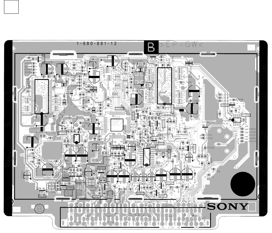
– 86 –
KP-HR432K90/HR532K90/HR532N90/HW572K90
RM-Y909KRM-Y908RM-Y909K RM-Y909K
< Conductor Side >
– B Board –
B[A/D CONVERTER, DRC, MULTI IMAGA DRIVER, MID-U CON, D/A CONVERTER]
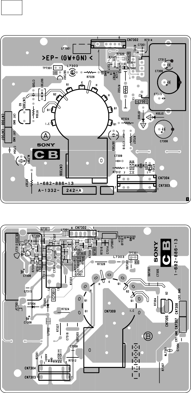
– 87 –
KP-HR432K90/HR532K90/HR532N90/HW572K90
RM-Y909KRM-Y908RM-Y909K RM-Y909K
– CB Board –
[CRT I/F BLUE]
< Component Side >
< Conductor Side >
(HW572K90)
CB
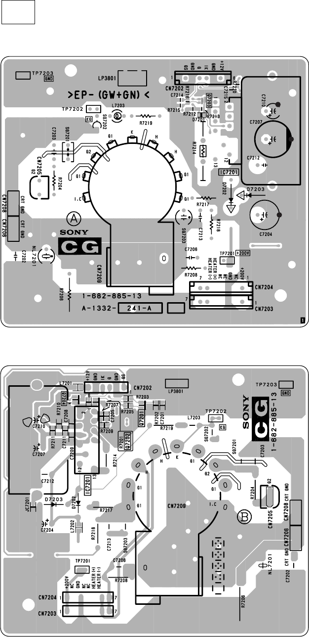
– 88 –
KP-HR432K90/HR532K90/HR532N90/HW572K90
RM-Y909KRM-Y908RM-Y909K RM-Y909K
[CRT I/F GREEN]
– CG Board –
< Component Side >
< Conductor Side >
(HW572K90)
CG
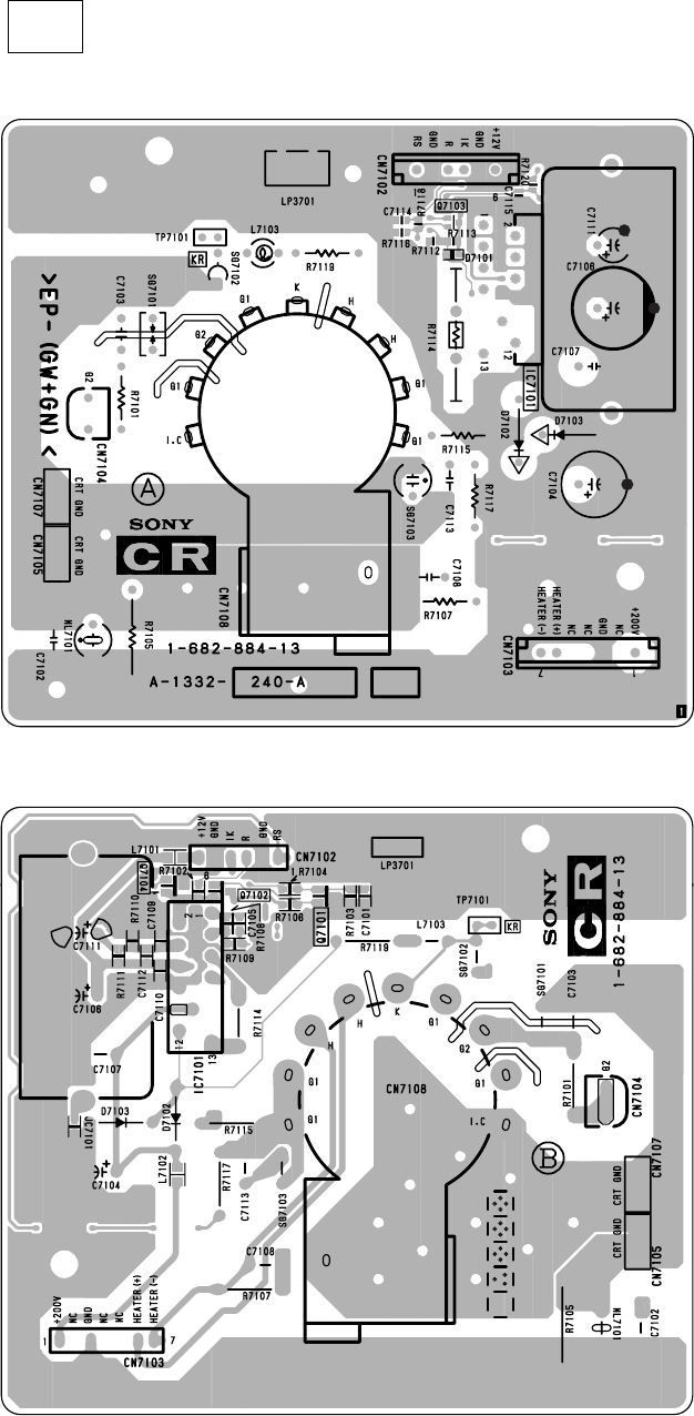
– 89 –
KP-HR432K90/HR532K90/HR532N90/HW572K90
RM-Y909KRM-Y908RM-Y909K RM-Y909K
[CRT I/F RED]
– CR Board –
< Component Side >
< Conductor Side >
(HW572K90)
CR
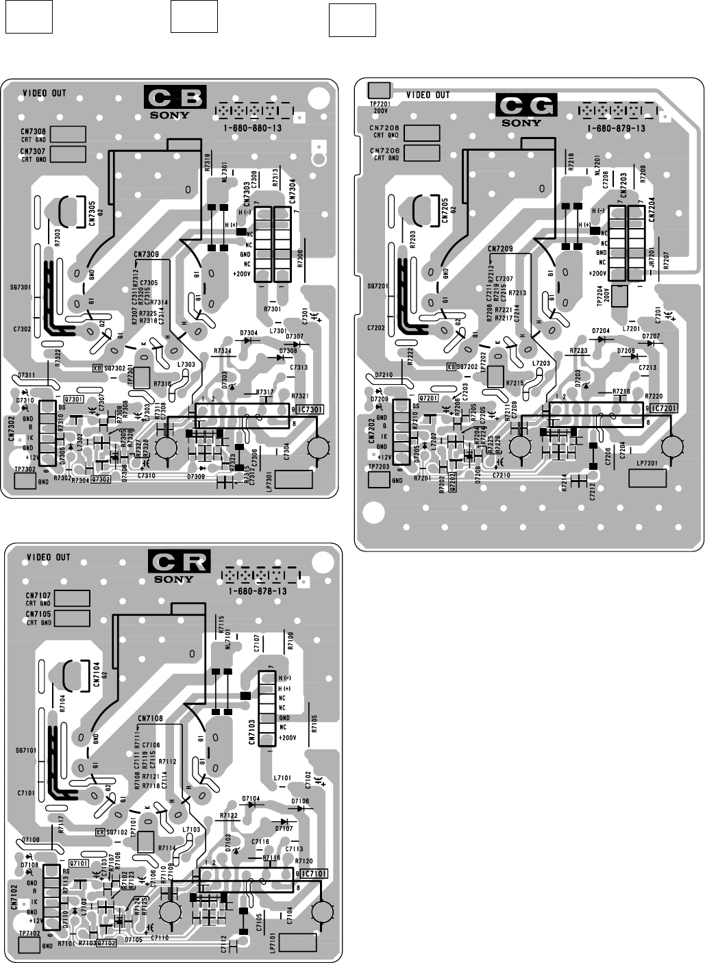
– 90 –
KP-HR432K90/HR532K90/HR532N90/HW572K90
RM-Y909KRM-Y908RM-Y909K RM-Y909K
[CRT I/F BLUE]
CB [CRT I/F GREEN]
CG [CRT I/F RED]
(EXCEPT HW572K90)
CR
(EXCEPT HW572K90)(EXCEPT HW572K90)
– CB Board –
– CR Board –
– CG Board –
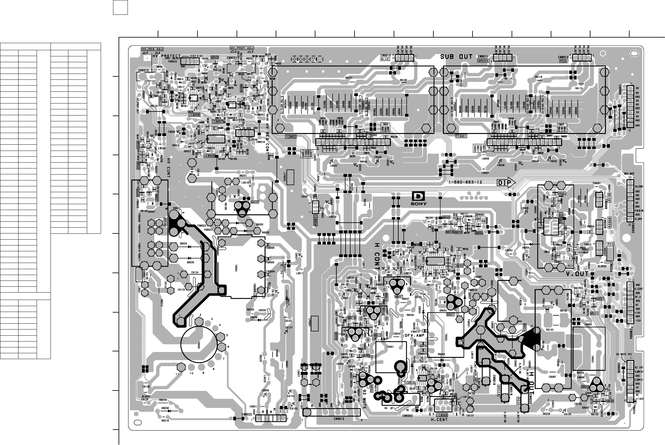
– 91 –
KP-HR432K90/HR532K90/HR532N90/HW572K90
RM-Y909KRM-Y908RM-Y909K RM-Y909K
– D Board –
1
A
B
C
D
E
F
G
H
I
J
212 13
11
10
98765
43 14
TRANSISTOR *
Q8001 E-12 1
Q8002 I-7
Q8003 I-7
Q8004 E-10 1
Q8005 C-1 1
Q8007 G-7
Q8008 H-7
Q8009 H-6
Q8010 H-7 1
Q8011 G-7 1
Q8014 G-7
Q8015 H-7 1
Q8016 E-9 1
Q8019 E-9 1
Q8020 E-9 1
Q8021 B-2 1
Q8022 B-2 1
Q8023 I-13
Q8024 H-11
Q8027 G-9
Q8028 A-3 1
Q8029 B-4 1
Q8030 J-13 1
Q8031 G-13 1
Q8032 D-1 1
Q8035 I-4
Q8036 E-1 1
Q8037 E-1 1
Q8038 E-2
Q8039 I-9
Q8101 G-13 1
DIODE *
D8001 E-11
D8002 E-11
D8003 E-11
D8004 F-11
D8005 H-6
D8006 I-6
D8007 E-1
D8008 C-3
D8009 E-11
D8010 F-8
D8011 F-8
D8012 F-8
D8013 B-3
D8014 C-3
D8015 B-2
D8016 B-4
D8019 C-2
D8020 C-3
D8021 G-10
D8022 C-2
D8023 B-4
D8024 G-9
D8025 A-3
D8026 G-12
D8027 G-9
D8028 E-3
D8029 E-4
D8030 E-4
D8031 E-2
D8032 I-8
D8033 H-8
D8034 F-2
D8035 F-2
D8036 C-3
D8037 G-5
D8038 J-2
D8039 H-4
D8043 B-2
D8045 I-9
D8046 E-9
D8047 J-13
IC
IC8001 C-11
IC8002 C-6
IC8003 E-12
IC8004 E-5
IC8005 F-9
IC8006 B-2
IC8007 B-3
IC8008 C-3
IC8009 J-9
IC8012 I-8
D BOARD
< Conductor Side >
[HV DRIVE, POWER SUPPLY, H DRIVE]
D
*: Refer to Terminal name of
semiconductors in silk screen
printed circuit (see page 49)
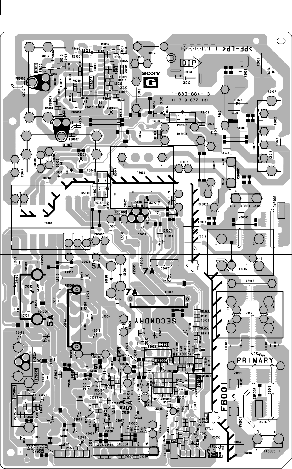
– 92 –
KP-HR432K90/HR532K90/HR532N90/HW572K90
RM-Y909KRM-Y908RM-Y909K RM-Y909K
– G Board –
[RELAY DRIVE, STBY 5V, REGULATOR, POWER SUPPLY]
G
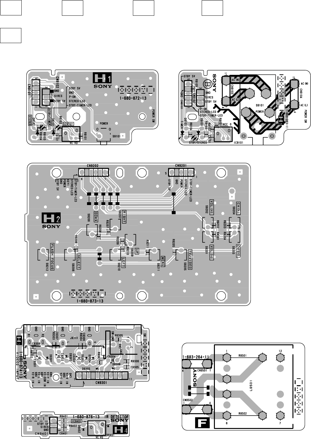
– 93 –
KP-HR432K90/HR532K90/HR532N90/HW572K90
RM-Y909KRM-Y908RM-Y909K RM-Y909K
[POWER SWITCH]
– H1 Board –
– H2 Board –
– H3 Board –
H2 [FUNCTION KEY][VIDEO 2 INPUT]
[LINE FILTER]
(EXCEPT HR532N90)
H3
[IR DETECTOR]
H4
H1
F
(EXCEPT HW572K90)
(HR532N90) – H1 Board – (EXCEPT HR532N90)
– H4 Board – (EXCEPT HW572K90)
– F Board – (EXCEPT HR532N90)
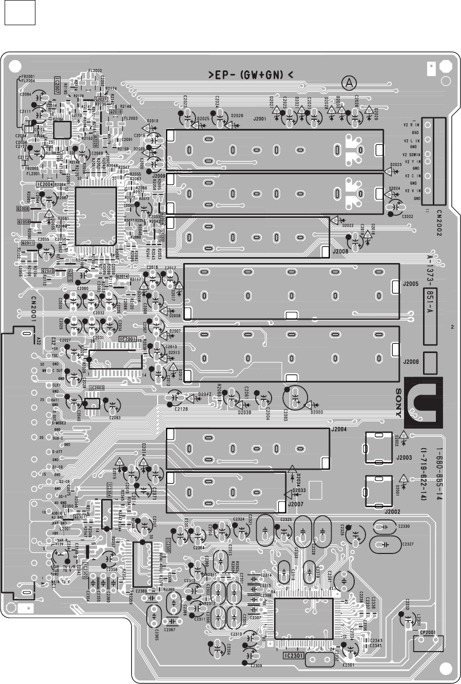
– 94 –
KP-HR432K90/HR532K90/HR532N90/HW572K90
RM-Y909KRM-Y908RM-Y909K RM-Y909K
– U Board –
< Component Side >
U[VIDEO, AUDIO INPUT/OUTPUT, AV SWITCH, AUDIO PROCESSOR]
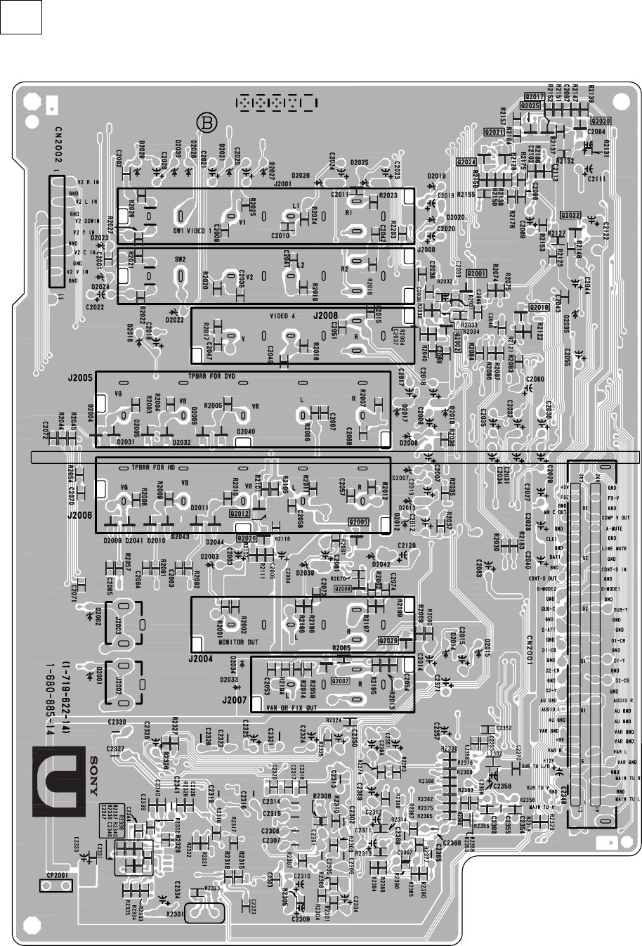
– 95 –
KP-HR432K90/HR532K90/HR532N90/HW572K90
RM-Y909KRM-Y908RM-Y909K RM-Y909K
– U Board –
< Conductor Side >
U[VIDEO, AUDIO INPUT/OUTPUT, AV SWITCH, AUDIO PROCESSOR]
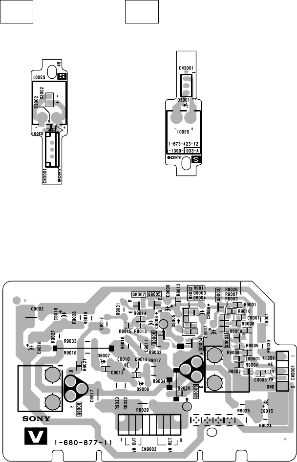
– 96 –
KP-HR432K90/HR532K90/HR532N90/HW572K90
RM-Y909KRM-Y908RM-Y909K RM-Y909K
S
– S Board –
< Component Side > < Conductor Side >
V
– V Board –
[SENSOR][
SPEED MODULATION]
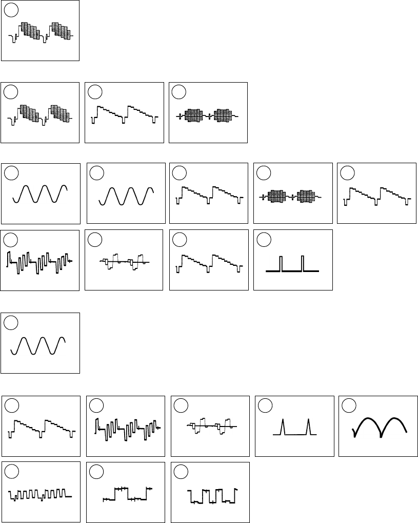
– 97 –
KP-HR432K90/HR532K90/HR532N90/HW572K90
RM-Y909KRM-Y908RM-Y909K RM-Y909K
14
3.6Vp-p (12MHz)
• A(4/9) BOARD WAVEFORMS
6-5. WAVEFORMS
21
4Vp-p (H)
22
4kVp-p (H)
16
2.6Vp-p (H)
17
2.4kVp-p (H)
18
4Vp-p (2.7MHz)
19
2.9kVp-p (V)
15
2.2Vp-p (H)
20
4Vp-p (H)
• A(5/9) BOARD WAVEFORMS
12
3.2Vp-p (H)
13
3.5Vp-p (V)
7
1.6Vp-p (H)
8
2.2p-p (H)
9
1.8Vp-p (H)
5
2.8Vp-p (20MHz)
6
3.6Vp-p (12MHz)
10
1.8Vp-p (H)
11
1.8Vp-p (H)
• A(3/9) BOARD WAVEFORMS
2
2.1Vp-p (H)
3
3Vp-p (H)
4
2Vp-p (H)
• A(2/9) BOARD WAVEFORMS
1
2.1Vp-p (H)
• A(1/9) BOARD WAVEFORMS
– 98 –
KP-HR432K90/HR532K90/HR532N90/HW572K90
RM-Y909KRM-Y908RM-Y909K RM-Y909K
1 2
2.2Vp-p (H) 1.9Vp-p (H)
• U(2/3) BOARD WAVEFORMS
• CG BOARD WAVEFORMS
1
129.5Vp-p (H)
• CR BOARD WAVEFORM
1
141.5Vp-p (H)
• CB BOARD WAVEFORM
97.5Vp-p (H)
1
3.5Vp-p (20Mhz)
6
• B(4/4) BOARD WAVEFORMS
5
1.8Vp-p (74.175824MHz)
• B(3/4) BOARD WAVEFORMS
1 2 3 4
4.5Vp-p (H) 4.5Vp-p (H) 4.2Vp-p (H) 3.1Vp-p (H)
• B(1/4) BOARD WAVEFORMS
1 2 3 4
0.9Vp-p (V) 1.9Vp-p (V) 0.4Vp-p (V) 1.5Vp-p (V)
• AD(2/2) BOARD WAVEFORMS
5 6
0.6Vp-p (V) 1.6Vp-p (V)
9
5Vp-p (V)
8
2.9Vp-p (V)
12MHz
7
5.2Vp-p (H)
• AD(1/2) BOARD WAVEFORMS
• D(1/3) BOARD WAVEFORMS
1
62.6Vp-p (V)
2 3
114Vp-p (H) 1.05kVp-p (H)
• D(3/3) BOARD WAVEFORMS
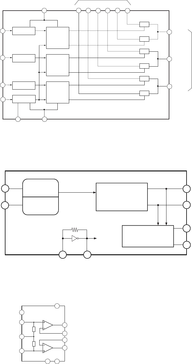
– 99 –
KP-HR432K90/HR532K90/HR532N90/HW572K90
RM-Y909KRM-Y908RM-Y909K RM-Y909K
A BOARD : IC305, 307 SN74LV4053ANSR
11 14
15
4
351213 12
16
7
8
10
9
6
X-
COMMON
A
B
C
INH
VSS
VDD 1Z
IN/OUT
1Y0Z 0Y 1X 0X
VEE
Y-
COMMON OUT/IN
Z-
COMMON
LOGIC LEVEL
CONVERSION
LOGIC LEVEL
CONVERSION
LOGIC LEVEL
CONVERSION
LOGIC LEVEL
CONVERSION
BINARY TO
1OF2
DECODERS
WITH
INHIBIT
TG
TG
TG
TG
TG
TG
BINARY TO
1OF2
DECODERS
WITH
INHIBIT
BINARY TO
1OF2
DECODERS
WITH
INHIBIT
A BOARD : IC308 CXD2085M
10
11
MUTE / ST-BY
L + IN
R-VS L-VS
+VS
L OUT
L -IN
R OUT
R -IN
GND
R + IN
5
7
9
16
2
8
4
3
A BOARD : IC708 TDA7265
VDIN SILCER
DECODE
I
2
CBUS
INTERFACE
SYNC.
SEP.
VSIN
XI XO
SDA
SCL
OLBX
O169
6
7
12
13
15
16
9
10
6-6. IC BLOCK DIAGRAMS
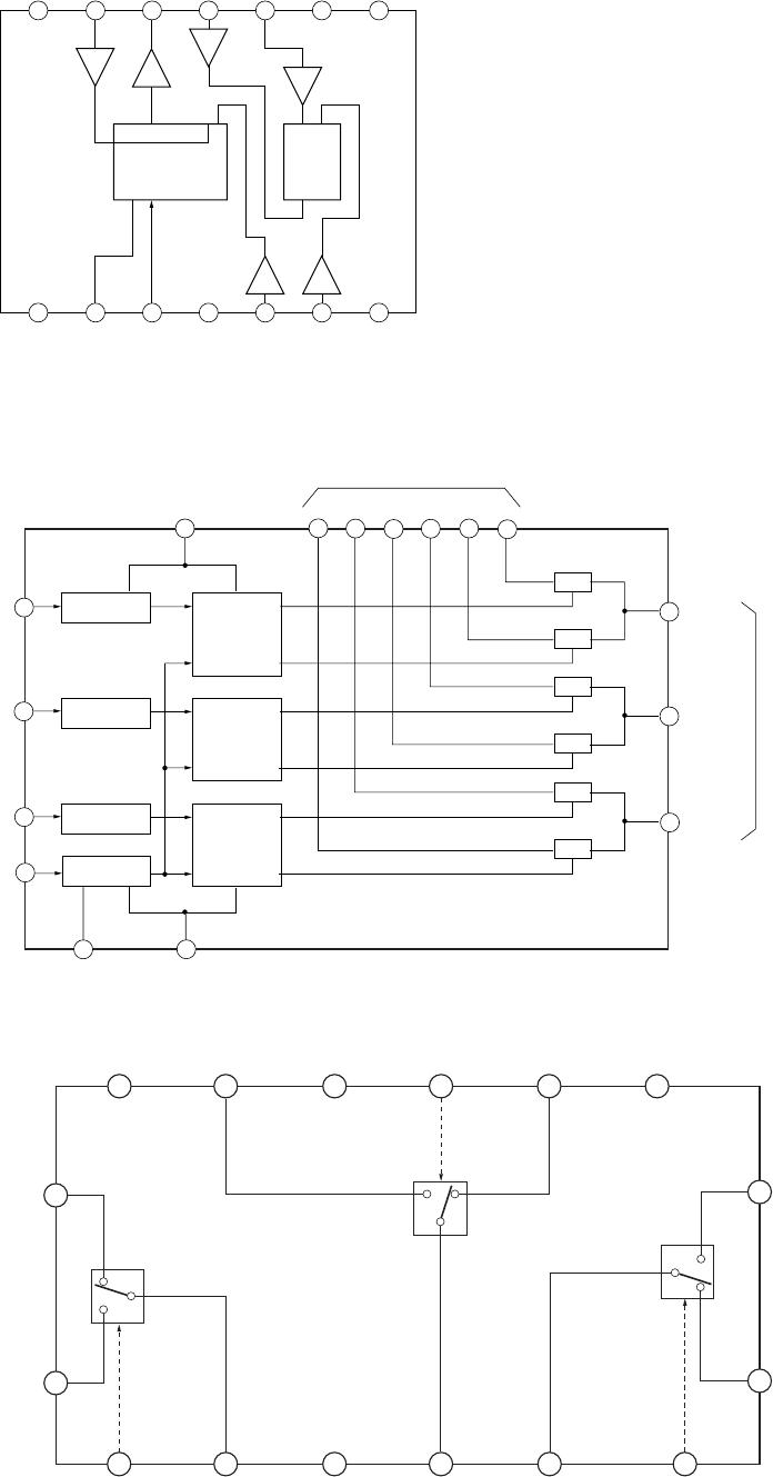
– 100 –
KP-HR432K90/HR532K90/HR532N90/HW572K90
RM-Y909KRM-Y908RM-Y909K RM-Y909K
B BOARD : IC3305, 3404 TLC2932IPWR
1 2 3 4 5 6 7
14 13 12 11 10 9 8
PFD
1/2 DIVIDER
VCO
LOGIC
VDD SELECT
VCO
OUT FIN-A FIN-B
PFD
OUT
LOGIC
GND
VCO
VDD
R BIAS VCO
IN
VCO
GND
VCO
INHIBIT
PFD
INHIBIT
NC
B BOARD : IC3413 SN74LV4053ANSR
11 14
15
4
351213 12
16
7
8
10
9
6
X-
COMMON
A
B
C
INH
VSS
VDD 1Z
IN/OUT
1Y0Z 0Y 1X 0X
VEE
Y-
COMMON OUT/IN
Z-
COMMON
LOGIC LEVEL
CONVERSION
LOGIC LEVEL
CONVERSION
LOGIC LEVEL
CONVERSION
LOGIC LEVEL
CONVERSION
BINARY TO
1OF2
DECODERS
WITH
INHIBIT
TG
TG
TG
TG
TG
TG
BINARY TO
1OF2
DECODERS
WITH
INHIBIT
BINARY TO
1OF2
DECODERS
WITH
INHIBIT
B BOARD : IC3414 M52055P
15
GND1
14
INPUT 2B
3
OUTPUT 1
5
OUTPUT 2
6
OUTPUT 3
4
GND2
16
INPUT 1A
L
H
L
H
1
INPUT 1B
8
INPUT 3A
9
INPUT 3B
13
Vcc
11
INPUT 2A
10
GND3
12
CONTROL
INPUT 2
2
CONTROL
INPUT 1
7
CONTROL
INPUT 3
L
H
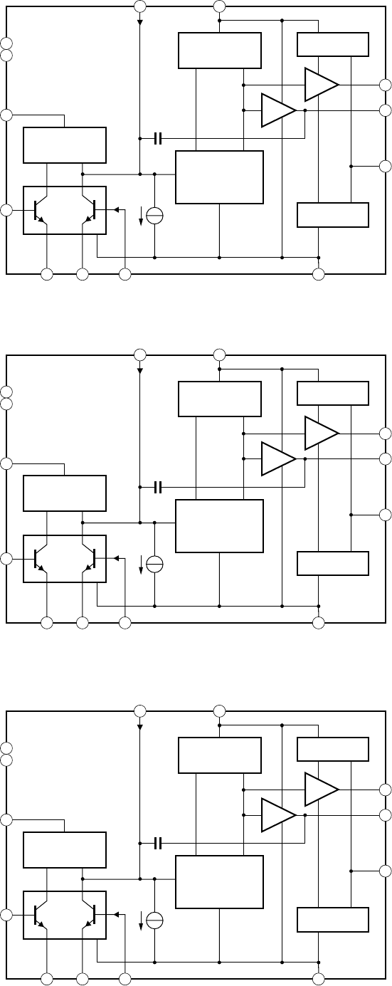
– 101 –
KP-HR432K90/HR532K90/HR532N90/HW572K90
RM-Y909KRM-Y908RM-Y909K RM-Y909K
CG BOARD : IC7201 TDA6120Q
CR BOARD : IC7101 TDA6120Q
CB BOARD : IC7301 TDA6120Q
1x
1x
CURRENT
INPUT
out 1 x
in
out 4 x
MIRROR
1x
in out
CASCODE
MIRROR
4x
in out
CASCODE
+
J5 mA
0.7 pF
n.c.
n.c.
VCC
VIN -
RC - RC + VIN + GND
IIN VDD
2
13 4 8
7
13
12
105
6
9
11
1x
1x
CURRENT
INPUT
out 1 x
in
out 4 x
MIRROR
1x
in out
CASCODE
MIRROR
4x
in out
CASCODE
+
J5 mA
0.7 pF
n.c.
n.c.
VCC
VIN -
RC - RC + VIN + GND
IIN VDD
2
13 4 8
7
13
12
105
6
9
11
1x
1x
CURRENT
INPUT
out 1 x
in
out 4 x
MIRROR
1x
in out
CASCODE
MIRROR
4x
in out
CASCODE
+
J5 mA
0.7 pF
n.c.
n.c.
VCC
VIN -
RC - RC + VIN + GND
IIN VDD
2
13 4 8
7
13
12
105
6
9
11
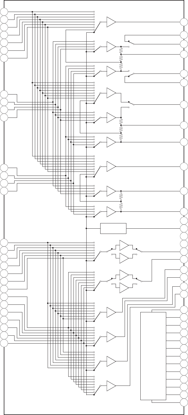
– 102 –
KP-HR432K90/HR532K90/HR532N90/HW572K90
RM-Y909KRM-Y908RM-Y909K RM-Y909K
U BOARD : IC2004 CXA2069Q
TV
V1
V2
V3
V4
V5
V6
8
15
30
22
60
63
153
6dB
6dB
6dB
6dB
6dB
6dB
6dB
6dB
6dB
3
10
17
24
Y1
Y2
Y3
Y4
5
12
19
26
C1
C2
C3
C4 39
37
49
47
46
44
41
58
56
55
51
VOUT1
YIN1
YOUT1
TRAP1
COUT1
CIN1
V/YOUT2
TRAP2
COUT2
VOUT3
YOUT3
COUT3
BIAS
57
50
VGND
BIAS
2
9
16
29
23
59
62 6dB
0dB
6dB
0dB
6dB
6dB
4
11
18
31
25
61
64
6dB
6dB
35
42
52
54
40
38
45
43
V
CC
AGND
LOUT1
ROUT1
LOUT2
ROUT2
LOUT3
ROUT3
Logic
6
7
20
14
13
28
27
21
36
34
33
32
48
DC OUT
SCL
SDA
ADR
S-1
S-2
S-3
S-4
S2-1
S2-2
S2-3
S2-4
MUTE
LTV
LV1
LV2
LV3
LV4
LV5
LV6
RTV
RV1
RV2
RV3
RV4
RV5
RV6
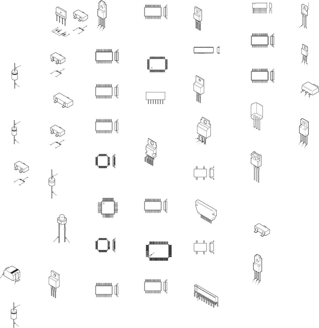
– 103 –
KP-HR432K90/HR532K90/HR532N90/HW572K90
RM-Y909KRM-Y908RM-Y909K RM-Y909K
6-7. SEMICONDUCTORS
1SS83TD
21DP05
D1NL40-TR2
D1NS4
D2L20U
EL1Z
GP08DPKG23
RD10ES-B2
RD15ES-B2
RD18ES-B2
RD20ES-B2
RD5.6ES-B2
RGP02-17EL-6433
UF4005PKG23
CATHODE
ANODE
1SS133T-77
30DF4N-FC5
ERC04-06SE
ERC91-02
CATHODE
ANODE
1SS226
1
2
3
1
2
3
1S355TE-17
DTZ-10B
DTZ-TT11-6.8B
UDZS-TE-17-7.5B
UDZ-TE-17-10B
UDZS-TE-17-18B
UDZS-TE-17-22B
UDZS-TE-17-24B
UDZS-TE-17-3.9B
UDZS-TE-17-33B
UDZS-TE-17-4.7B
UDZS-TE-17-5.1B
UDZS-TE-17-5.6B
UDZS-TE-17-6.2B
UDZS-TE-17-9.1B
CATHODE
ANODE
D1NL20U-TR
CATHODE
ANODE
D4SBS4-F
D6SB60L
+
~~
–
+
~~
–
1
2
3
1
2
3
DAN202K-T-146
1
2
3
1
2
3
DAN202U
CATHODE
ANODE
NC
DAP202K
1
2
3
1
2
3
MTZJ-T-77-13
MTZJ-T-77-22B
CATHODE
ANODE
SLR-325VCT31
CATHODE
ANODE
BA033T
NJM7812FA
TA7812S
BA05T
BCE
BA9759F-E2
1TOP VIEW
18pin SOP
BH3868BFS-E2
1TOP VIEW
32pin SOP
CD0031AM
1TOP VIEW
48pin SOP
CM0017AF
1
TOP VIEW
120pin QFP
CXA2151Q
CXD2013Q-T6
TOP VIEW
1
12
13 24
25
36
3748
CXD2073Q-T4
1
TOP VIEW
32pin QFP
CXD2085M
PCM56P-L
SN74LV4053ANSR
1TOP VIEW
16pin SOP
CXA1726AM
NJM2180M
1TOP VIEW
30pin SOP
CXA2069Q
CXP85840A-039Q
CXP86448-635Q
CX2150AQ
TOP VIEW
64
52
51 33
32
20
19
1
DM-58
MARKING SIDE VIEW
1N
• pin
• Mt (one side, both side)
1
~
N
14pin DIP
LA78045
1
7
M24C08-MN6T
M24C32-WMN6T
NJM2068V
NJM2904M
UPC4558G2
1TOP VIEW
8pin SOP
M306V2ME-175FP
UPD64082GF-3BA
TOP VIEW
INDEX
130
31
50
5180
81
100
MSM514265C-60JS
1TOP VIEW
40pin SOP
NJM2395AF05
PQ09RF21
1234
NJM2903M
UPC393C
1TOP VIEW
8pin DIP
NJM7905FA
12
3
PQ1CG2032FZ
5
1
2
3
4
PST9143NL
PST9145NL
1
5pin CHIP
STK392-560
MARKING SIDE VIEW
12
n
TC7W08FU(TE12R)
1
8pin CHIP
TDA6120Q / N2/S2
1
n
N
TDA7265
MARKING SIDE VIEW
1
11pin ZIP
TEA6422DT
1TOP VIEW
28pin SOP
TLC2933IPWR
1TOP VIEW
14pin SOP
UPC1093J-1-T
123
2SA1358-Y
2SA3421-Y
ECB
2SA1037AK-T146R
2SA1226-T1E3E4
2SC1623-L516
2SD601A-QRS-TX
DTC114EKA-T146
DTC144EKA-T146
E
B
C
2SA2005
2SC5511
BCE
2SC2688-LK
LETTER SIDE
ECB
2SC4634LS-CB11
BCE
2SK2036(TE85L)
B
C
E
IRFIB7N50A
BCE
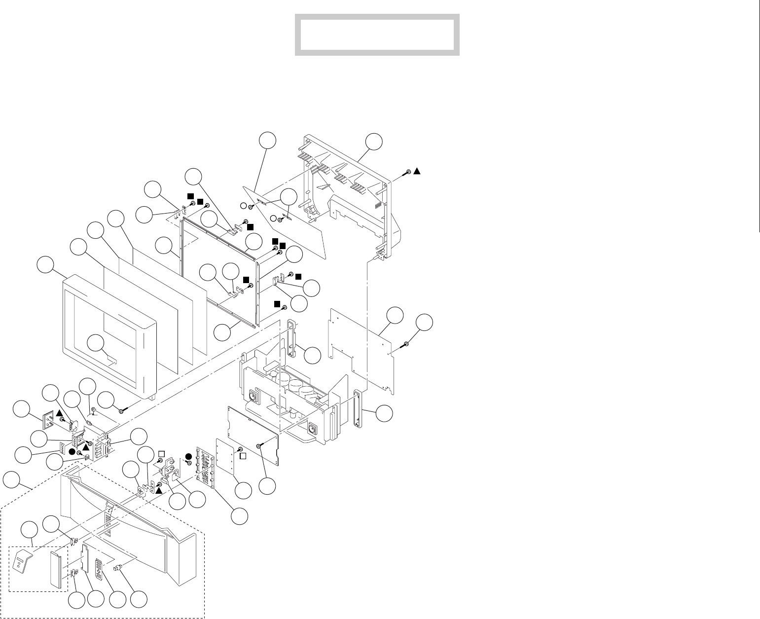
– 104 –
KP-HR432K90/HR532K90/HR532N90/HW572K90
RM-Y909 RM-Y909
7-1. COVER (KP-HR432K90)
r : +BVTP 3X12 7-685-648-79
p : +BVTP 4X12 7-685-661-79
s : +BVTP 4X12 7-685-661-71
® : +BVTP 4X16 7-685-663-79
4 : +BVTP 4X16 7-685-663-91
• Items with no part number and no
description are not stocked because they
are seldom required for routine service
• The construction parts of an assembled part
are indicated with a collation number in the
remark column.
NOTE:
SECTION 7
EXPLODED VIEWS
The components identified by shading and
mark
!
are critical for safety.
Replace only with part number specified.
• Items marked " * " are not stocked since
they are seldom required for routine
service. Some delay should be anticipated
when ordering these items.
REF. NO. PART NO. DESCRIPTION REMARK
–––––––– ––––––––– ––––––––––––– ––––––––– REF. NO. PART NO. DESCRIPTION REMARK
–––––––– ––––––––– ––––––––––––– –––––––––
1 X-4037-770-3 BEZEL (43) ASSY
2 4-078-189-11 SCREEN (43), CONTRAST
3 4-070-284-11 PLATE (L), DIFFUSION
4 4-070-285-12 PLATE (43F), DIFFUSION
5 * 4-070-333-21 HOLDER (S), SCREEN NC
6 * A-1391-179-A S BOARD, COMPLETE
7 * 4-070-332-31 HOLDER (L), SCREEN NC
8 * 4-081-501-01 HOLDER, MIRROR
11 4-085-508-01 MIRROR (43)
12 * 4-081-500-01 COVER (43), MIRROR
13 4-378-522-31 SCREW, TAPPING, HEXAGON HEAD
14 * 4-085-474-01 BOARD (43), REAR
17 * A-1377-062-A H2 BOARD, COMPLETE
18 4-082-284-01 BUTTON, MULTI
19 * A-1377-063-A H1 BOARD, COMPLETE
20 4-082-283-21 BUTTON, POWER
21 4-919-393-02 DAMPER
22 4-082-302-01 HOLDER, SIDE TERMINAL
23 4-082-301-02 BRACKET, H3
24 * A-1377-065-A H3 BOARD, COMPLETE
25 4-082-300-11 DOOR, SIDE TERMINAL
26 4-082-298-01 CAP (L), SPEAKER GRILLE
27 4-083-502-21 PANEL (ASSY), FRONT
29 4-082-282-01 COVER, CONTROL DOOR
30 4-082-291-02 LABEL, CONTROL
31 X-4039-541-1 GRILLE (43) ASSY, SP
25,27,29,30,35,36,37
32 4-082-286-01 GUIDE, LED
33 * A-1377-061-A H4 BOARD, COMPLETE
34 4-083-694-01 SPRING, DOOR
35 3-703-035-12 SHAFT, LID
36 4-042-192-02 CATCHER, PUSH
37 4-045-250-01 DAMPER
38 * 4-069-680-01 BRACKET (B), SENSOR
39 4-086-330-01 LABEL, FRONT TERMINAL
40 4-082-299-01 CAP (R), SPEAKER GRILLE
41 4-085-452-01 BUTTON, POWER
42 4-070-333-31 HOLDER (S), SCREEN NC
43 4-378-522-01 SCREW, TAPPING, HEXAGON HEAD
1
2
34
6
38
6
38
42 5
7
14
17
18
22
13
43
12
33
13
21
34
23
39
19
24
25 36
32
20
31
26
40
27
35 29 30 36
37
41
11
6
38
6
38
5
8
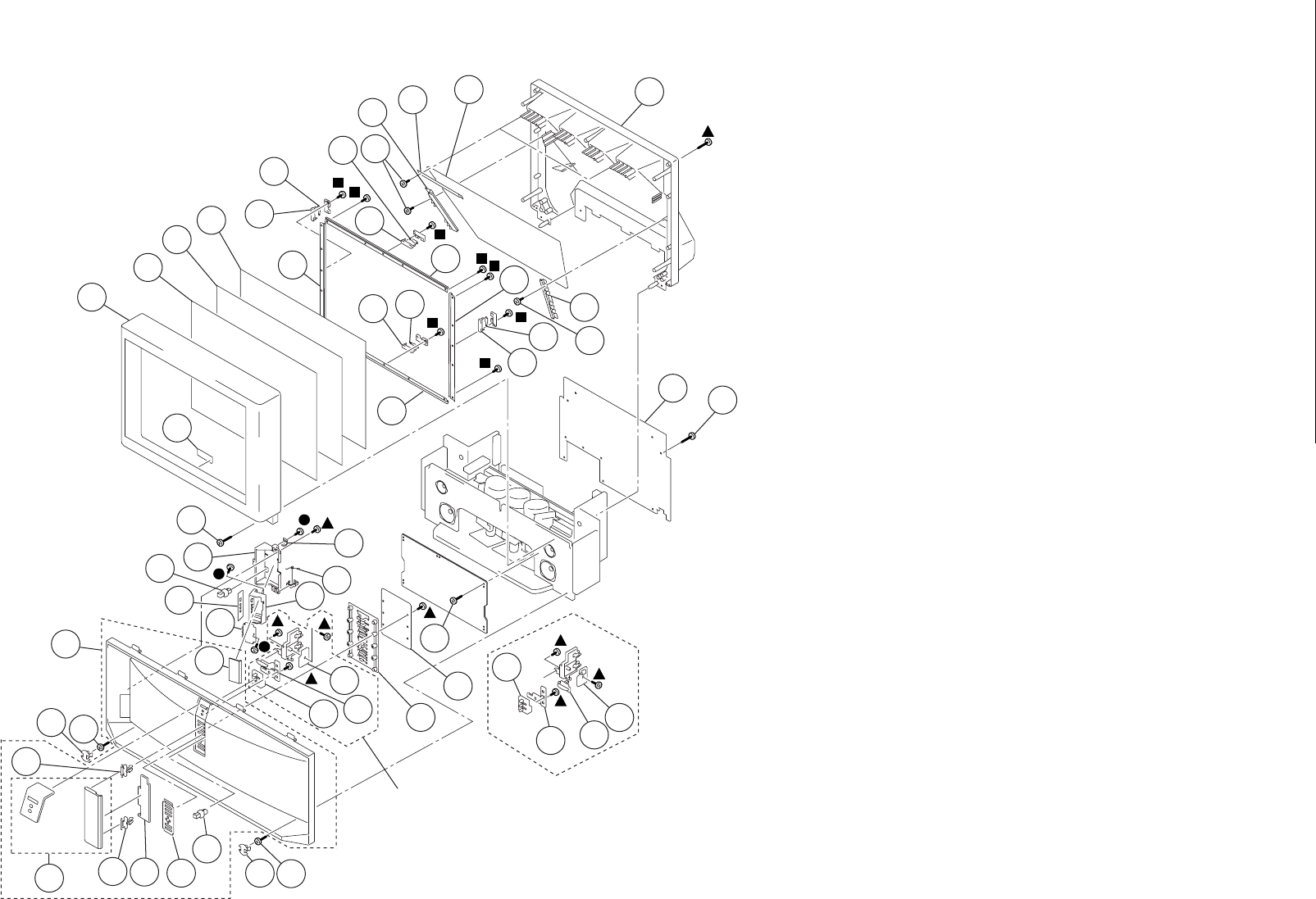
– 105 –
KP-HR432K90/HR532K90/HR532N90/HW572K90
RM-Y909 RM-Y909
7-2. COVER (KP-HR532K90/HR532N90)
r : +BVTP 3X12 7-685-648-79
p : +BVTP 4X12 7-685-661-79
4 : +BVTP 4X16 7-685-663-91
REF. NO. PART NO. DESCRIPTION REMARK
–––––––– ––––––––– ––––––––––––– ––––––––– REF. NO. PART NO. DESCRIPTION REMARK
–––––––– ––––––––– ––––––––––––– –––––––––
51
52
53 54
56
88
56
88
57 55
57
64
67
68
72
63
91
62
83
63
86
71
84
73
69
74
75
89
82
81
63
76
77 85 79 80
86
76 63
87
70
58 59 61
56
88
60
63
56
88
55
69
82
90
70
63
HR532N90 HR532K90
51 X-4039-545-1 BEZNET (53) ASSY
52 4-055-639-11 SCREEN (53), CONTRAST
53 4-070-525-11 PLATE (L), DIFFUSION
54 4-070-602-11 PLATE (53F), DIFFUSION
55 * 4-070-330-02 HOLDER (S), SCREEN YC
56 * A-1391-179-A S BOARD, COMPLETE
57 * 4-070-328-12 HOLDER (L), SCREEN YC
58 * 4-076-705-01 HOLDER (SL), MIRROR
59 * 4-075-234-01 HOLDER (TOP), MIRROR
60 * 4-076-706-01 HOLDER (SR), MIRROR
61 4-070-344-01 MIRROR, REFLECTION
62 * 4-081-503-01 COVER, MIRROR
63 4-378-522-31 SCREW, TAPPING, HEXAGON HEAD
64 * 4-085-475-01 BOARD (53), REAR
67 * A-1377-062-A H2 BOARD, COMPLETE
68 4-082-284-01 BUTTON, MULTI
69 * A-1377-063-A H1 BOARD, COMPLETE (HR532K90)
* A-1377-066-A H1 BOARD, COMPLETE (HR532N90)
70 4-082-283-11 BUTTON, POWER (HR532N90)
4-082-283-21 BUTTON, POWER (HR532K90)
71 4-919-393-02 DAMPER
72 4-082-289-01 HOLDER, FRONT TERMINAL
73 4-082-288-02 BRACKET, H3
74 * A-1377-065-A H3 BOARD, COMPLETE
75 4-082-287-11 DOOR, FRONT TERMINAL
76 4-083-503-11 SCREW CAP, GRILLE
77 4-083-502-21 PANEL (ASSY), FRONT
79 4-082-282-01 COVER, CONTROL DOOR
80 4-082-291-02 LABEL, CONTROL
81 X-4039-542-1 GRILLE ASSY, SPEAKER
75,77,79,80,85,86,87
(HR532N90)
X-4039-546-1 GRILLE (53) ASSY, SPEAKER
75,77,79,80,85,86,87
(HR532K90)
82 4-082-286-01 GUIDE, LED
83 * A-1377-061-A H4 BOARD, COMPLETE
84 4-083-505-01 SPRING, DOOR
85 3-703-035-12 SHAFT, LID
86 4-042-192-02 CATCHER, PUSH
87 4-045-250-01 DAMPER
88 * 4-069-680-01 BRACKET (B), SENSOR
89 4-086-330-01 LABEL, FRONT TERMINAL
90 4-085-452-01 BUTTON, POWER (HR532K90)
91 4-378-522-01 SCREW, TAPPING, HEXAGON HEAD
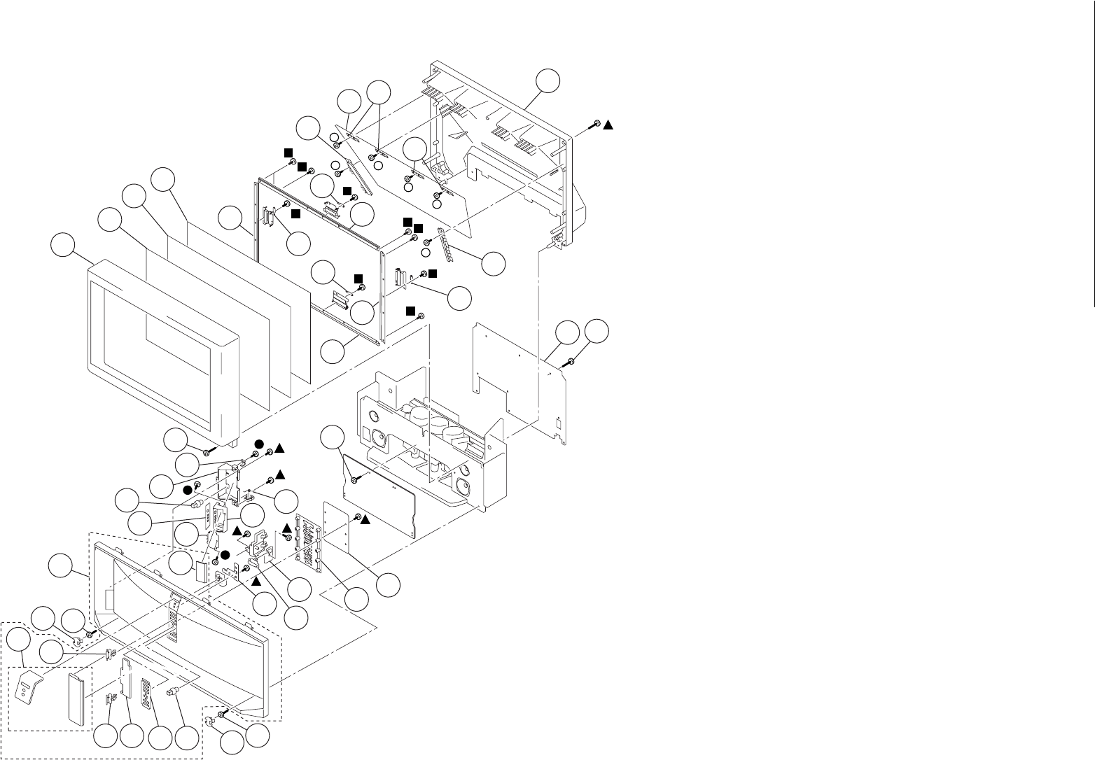
– 106 –
KP-HR432K90/HR532K90/HR532N90/HW572K90
RM-Y909 RM-Y909
7-3. COVER (KP-HW572K90)
r : +BVTP 3X12 7-685-648-79
p : +BVTP 4X12 7-685-661-79
® : +BVTP 4X16 7-685-663-79
4 : +BVTP 4X16 7-685-663-91
REF. NO. PART NO. DESCRIPTION REMARK
–––––––– ––––––––– ––––––––––––– ––––––––– REF. NO. PART NO. DESCRIPTION REMARK
–––––––– ––––––––– ––––––––––––– –––––––––
101 X-4039-626-1 BEZNET (57) ASSY
102 4-086-327-11 SCREEN (57W), CONTRAST
103 4-081-949-11 PLATE (57WL), DIFFUSION
104 4-081-950-11 PLATE (57WFV), DIFFUSION
105 * 4-084-568-01 HOLDER, SCREEN
106 * A-1391-179-A S BOARD, COMPLETE
107 * 4-084-568-11 HOLDER, SCREEN
108 * 4-083-462-01 HOLDER (L), MIRROR SIDE
109 * 4-081-501-01 HOLDER, MIRROR
110 * 4-083-461-01 HOLDER (R), MIRROR SIDE
111 4-084-561-01 MIRROR (57)
112 * X-4039-824-1 COVER ASSY, MIRROR
113 4-378-522-31 SCREW, TAPPING, HEXAGON HEAD
114 * 4-085-688-01 BOARD, REAR
117 * A-1377-062-A H2 BOARD, COMPLETE
118 4-082-284-01 BUTTON, MULTI
119 * A-1377-080-A H1 BOARD, COMPLETE (VAR)
120 4-082-283-21 BUTTON, POWER
121 4-919-393-02 DAMPER
122 4-082-289-01 HOLDER, FRONT TERMINAL
123 4-082-288-02 BRACKET, H3
124 * A-1377-065-A H3 BOARD, COMPLETE
125 4-083-468-11 DOOR, FRONT TERMINAL
126 4-083-503-01 SCREW CAP, GRILLE
127 4-084-563-11 PANEL ASSY, FRONT
129 4-083-731-01 COVER (HW), CONTROL DOOR
130 4-084-571-03 LABEL (HW), CONTROL
131 X-4039-590-1 GRILLE (57) ASSY, SPEAKER
125,127,129,130,136,137
134 4-083-505-01 SPRING, DOOR
135 3-703-035-11 SHAFT, LID
136 4-042-192-02 CATCHER, PUSH
137 4-045-250-01 DAMPER
138 4-085-452-01 BUTTON, POWER
139 4-086-330-01 LABEL, FRONT TERMINAL
140 4-378-522-01 SCREW, TAPPING, HEXAGON HEAD
101
102
103 104
107
105
107
114
117
118
122
113
140
112
113
121
134
123
119
124
125
139
131
113
126
127
135 129 130 136 126 113
137
138
120
106
108
111
106
110
106
106
105
109
109
136
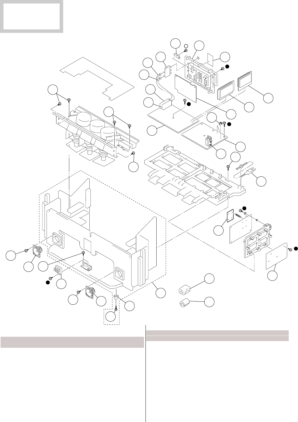
– 107 –
KP-HR432K90/HR532K90/HR532N90/HW572K90
RM-Y909KRM-Y908RM-Y909K RM-Y909K
151 1-544-893-11 SPEAKER (10cm)
153 01-223-925-11 RESISTOR ASSY (HIGH VOLTAGE)
(FOCUS PACK)
154 * A-1299-633-A A BOARD, COMPLETE
155 8-598-475-01 TUNER, FSS BTF-WL411 (TU2)
156 8-598-430-50 TUNER, FSS BTF-FA401 (TU1)
157 * 1-557-056-31 CABLE, P-P
158 * 1-556-945-21 CABLE, P-P
159 1-771-787-11 SWITCH, RF ANTENNA
160 4-081-961-01 BOARD, TERMINAL
161 * A-1373-882-A U BOARD, COMPLETE
162 * A-1136-267-A B BOARD, COMPLETE
163 * A-1299-634-A AD BOARD, COMPLETE
164 * A-1348-132-A D BOARD, COMPLETE
REF. NO. PART NO. DESCRIPTION REMARK
–––––––– ––––––––– ––––––––––––– ––––––––– REF. NO. PART NO. DESCRIPTION REMARK
–––––––– ––––––––– ––––––––––––– –––––––––
7-4. CHASSIS (KP-HR432K90)
r : +BVTP 3X12 7-685-648-79
® : +BVTP 4X16 7-685-663-79
168
168
180
151
153
180
180
151
174
170
169
154
161 162
163
165
166
164
179
175
157
156
155
158 159
160
172
171
168
176
167
178
168
165 01-453-285-21 FBT ASSY, NX-4006//X4P4 (T8005)
166 01-823-473-11 CORD, AC POWER (WITH FILTER)
167 * A-1316-596-A G BOARD, COMPLETE
168 4-378-522-31 SCREW,TAPPING,HEXAGON HEAD
169 1-500-021-11 CLAMP, SLEEVE FERRITE
170 1-543-653-11 CORE ASSY, BEAD(DIVISION TYPE)
171 4-069-675-01 CAP, TERMINAL BOARD
172 4-086-329-01 LABEL, TERMINAL
174 * X-4039-543-1 CABINET (43) ASSY, BOTTOM 176
175 3-710-578-01 COVER VOLUME 6 MOLD
176 4-076-577-01 FOOT
178 * A-1241-525-A F BOARD,COMPLETE
179 4-378-522-01 SCREW, TAPPING, HEXAGON HEAD
180 4-052-894-01 SCREW (4X20), HEAD TAPPING
The components identified by
shading and mark ! are criti-
cal for safety.
Replace only with part number
specified.
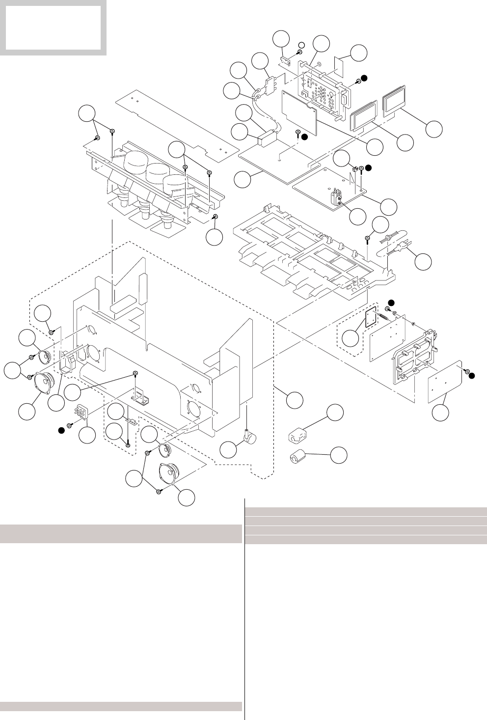
– 108 –
KP-HR432K90/HR532K90/HR532N90/HW572K90
RM-Y909KRM-Y908RM-Y909K RM-Y909K
218
218
231
202
218
201 223
203
218
231
231
202
201
224
220
219
204
211 212
213
215
216
230
214˚
225
207
206
205
208 209
210 222
221
218
227
226
217
229
EXCEPT HR532N90
216 01-790-130-11 CORD, AC POWER (WITH CONNECTOR)
(HR532N90)
01-823-473-11 CORD, AC POWER (WITH FILTER)
(HR532K90)
217 * A-1316-596-A G BOARD, COMPLETE (HR532K90)
* A-1316-597-A G BOARD, COMPLETE (HR532N90)
218 4-378-522-31 SCREW,TAPPING,HEXAGON HEAD
219 1-500-021-11 CLAMP, SLEEVE FERRITE
220 1-543-653-11 CORE ASSY, BEAD(DIVISION TYPE)
221 4-069-675-01 CAP, TERMINAL BOARD
222 4-086-329-01 LABEL, TERMINAL
223 * 4-083-506-01 COVER, CABINET (HS)
224 * X-4039-544-1 CABINET (53) ASSY, BOTTOM
223, 226, 227
225 3-710-578-01 COVER VOLUME 6 MOLD
226 4-075-244-01 CASTER (30 DIA.)
227 4-075-874-01 FOOT, PLASTIC
229 * A-1241-525-A F BOARD,COMPLETE (HR532K90)
230 4-378-522-01 SCREW, TAPPING, HEXAGON HEAD
231 4-052-894-01 SCREW (4X20), HEAD TAPPING
REF. NO. PART NO. DESCRIPTION REMARK
–––––––– ––––––––– ––––––––––––– ––––––––– REF. NO. PART NO. DESCRIPTION REMARK
–––––––– ––––––––– ––––––––––––– –––––––––
7-5. CHASSIS (KP-HR532K90/HR532N90)
r : +BVTP 3X12 7-685-648-79
® : +BVTP 4X16 7-685-663-79
The components identified by
shading and mark ! are criti-
cal for safety.
Replace only with part number
specified.
201 1-544-849-11 SPEAKER (13cm)
202 1-529-403-31 SPEAKER (6.6cm)
203 01-223-925-11 RESISTOR ASSY (HIGH VOLTAGE)
(FOCUS PACK)
204 * A-1299-633-A A BOARD, COMPLETE
205 8-598-475-01 TUNER, FSS BTF-WL411 (TU2)
(HR532K90)
8-598-542-20 TUNER, FSS BTF-WA412 (TU2)
(HR532N90)
206 8-598-430-50 TUNER, FSS BTF-FA401 (TU1)
207 * 1-557-056-31 CABLE, P-P
208 * 1-556-945-21 CABLE, P-P
209 1-771-787-11 SWITCH, RF ANTENNA
210 4-081-961-01 BOARD, TERMINAL
211 * A-1373-882-A U BOARD, COMPLETE
212 * A-1136-267-A B BOARD, COMPLETE
213 * A-1299-634-A AD BOARD, COMPLETE
214 * A-1348-132-A D BOARD, COMPLETE
215 01-453-285-21 FBT ASSY, NX-4006//X4P4 (T8005)
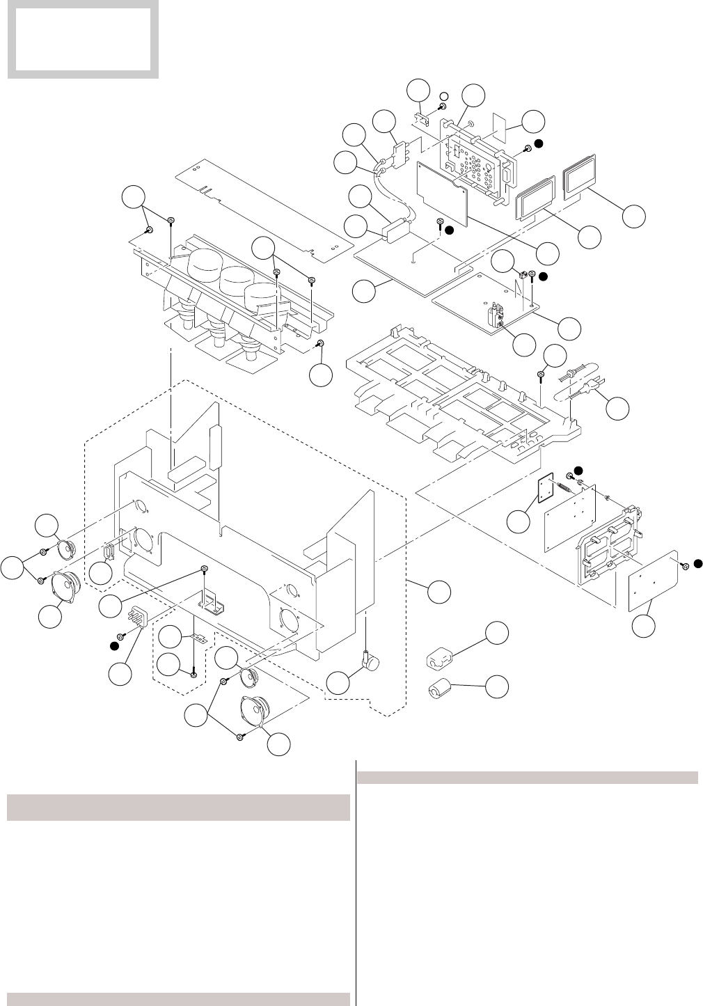
– 109 –
KP-HR432K90/HR532K90/HR532N90/HW572K90
RM-Y909KRM-Y908RM-Y909K RM-Y909K
REF. NO. PART NO. DESCRIPTION REMARK
–––––––– ––––––––– ––––––––––––– ––––––––– REF. NO. PART NO. DESCRIPTION REMARK
–––––––– ––––––––– ––––––––––––– –––––––––
7-6. CHASSIS (KP-HW572K90)
r : +BVTP 3X12 7-685-648-79
® : +BVTP 4X16 7-685-663-79
278
278
281
252
251
273
253
278
281
281
252
251
274
270
269
254
261 262
263
265
266
280
264˚
275
257
256
255
258 259
260
272
271
278
277
276
267
279
251 1-544-894-11 SPEAKER (13cm)
252 1-529-403-31 SPEAKER (6.6cm)
253 01-223-925-11 RESISTOR ASSY (HIGH-VOLTAGE)
(FOCUS PACK)
254 * A-1299-656-A A BOARD, COMPLETE
255 8-598-475-01 TUNER, FSS BTF-WL411 (TU2)
256 8-598-430-50 TUNER, FSS BTF-FA401 (TU1)
257 * 1-557-056-31 CABLE, P-P
258 * 1-556-945-21 CABLE, P-P
259 1-771-787-11 SWITCH, RF ANTENNA
260 4-081-961-01 BOARD, TERMINAL
261 * A-1373-890-A U BOARD, COMPLETE
262 * A-1136-267-A B BOARD, COMPLETE
263 * A-1299-634-A AD BOARD, COMPLETE
264 * A-1348-132-A D BOARD, COMPLETE
265 01-453-285-21 FBT ASSY, NX-4006//X4P4 (T8005)
266 01-823-473-11 CORD, AC POWER (WITH FILTER)
267 * A-1316-596-A G BOARD, COMPLETE
269 1-500-021-11 CLAMP, SLEEVE FERRITE
270 1-543-653-11 CORE ASSY, BEAD (DIVISION TYPE)
271 4-069-675-01 CAP, TERMINAL BOARD
272 4-086-329-11 LABEL, TERMINAL
273 * 4-084-570-01 COVER, CABINET (HW)
274 X-4039-602-1 CABINET (57) ASSY, BOTTOM
273, 276, 277
275 3-710-578-01 COVER, VOLUME, 6 MOLD
276 4-075-244-01 CASTER (DIA. 30)
277 4-075-874-01 FOOT, PLASTIC
278 4-378-522-31 SCREW, TAPPING, HEXAGON HEAD
279 * A-1241-525-A F BOARD,COMPLETE
280 4-378-522-01 SCREW, TAPPING, HEXAGON HEAD
281 4-052-894-01 SCREW (4X20), HEAD TAPPING
The components identified by
shading and mark ! are criti-
cal for safety.
Replace only with part number
specified.
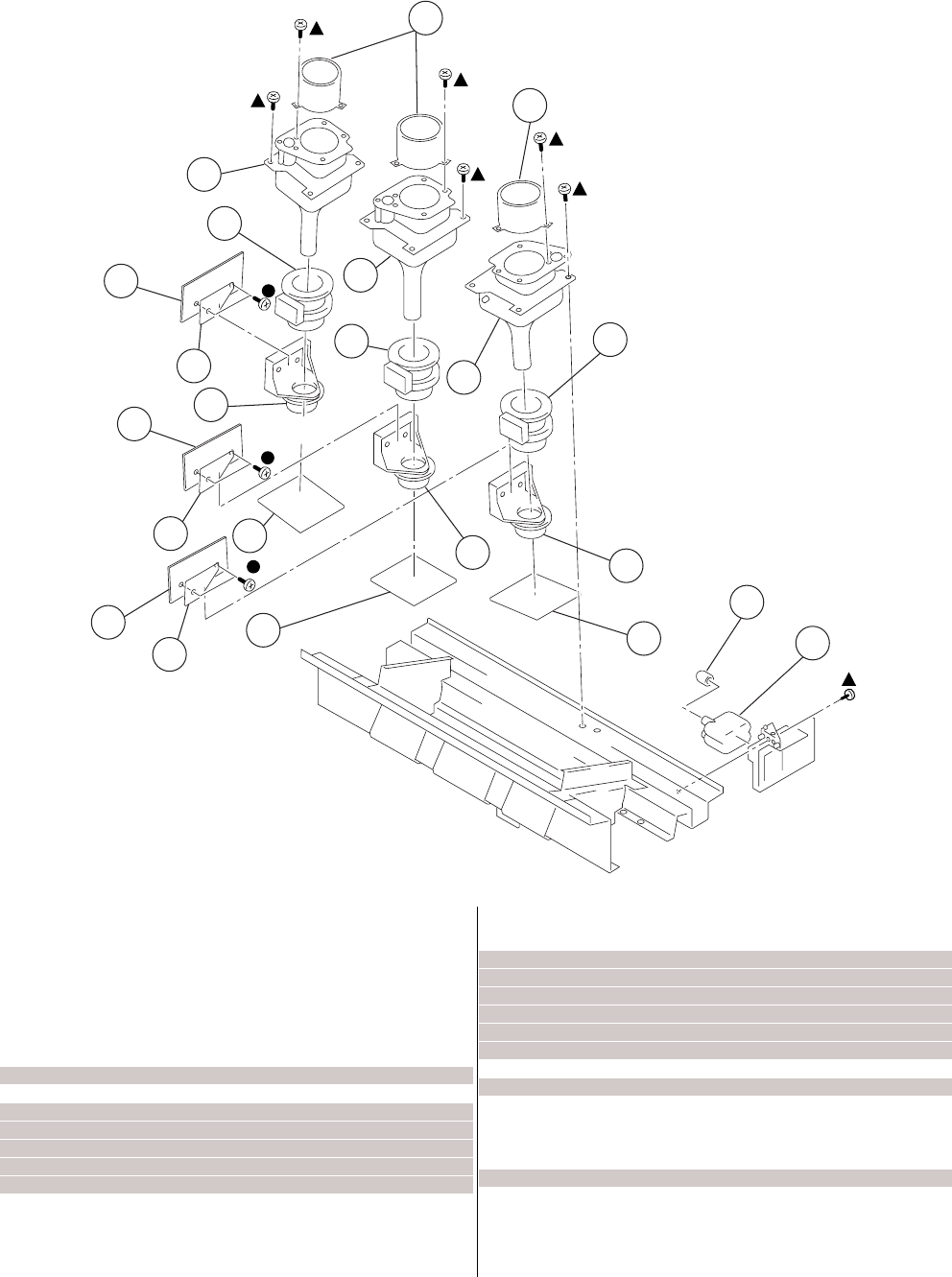
– 110 –
KP-HR432K90/HR532K90/HR532N90/HW572K90
RM-Y909KRM-Y908RM-Y909K RM-Y909K
REF. NO. PART NO. DESCRIPTION REMARK
–––––––– ––––––––– ––––––––––––– ––––––––– REF. NO. PART NO. DESCRIPTION REMARK
–––––––– ––––––––– ––––––––––––– –––––––––
7-7. PICTURE TUBE
r : +BVTP 3X12 7-685-648-79
4 : +BVTP 4X16 7-685-663-91
308
308
307
305
305
305
309
315
315
315
303
303
303
302
301
310
313
312
311
314
314
314
301 * A-1332-251-A CG BOARD, COMPLETE
(EXCEPT HW572K90)
* A-1332-265-A CG BOARD, COMPLETE (HW572K90)
302 * A-1332-250-A CR BOARD, COMPLETE
(EXCEPT HW572K90)
* A-1332-264-A CR BOARD, COMPLETE (HW572K90)
303 01-451-535-11 COIL ASSY, VM
305 01-451-537-11 DEFLECTION YOKE
307 0A-1501-975-ACOUPLER (R) ASSY, CRT
(HR532K90/HR532N90)
0A-1501-980-ACOUPLER (R) ASSY, CRT (HR432K90)
0A-1502-021-ACOUPLER (R) ASSY, CRT (HW572K90)
308 4-056-258-11 LENS (DELTA 78) (EXCEPT HW572K90)
4-083-750-01 LENS (DELTA 260)(HW572K90)
309 0A-1501-976-ACOUPLER (G) ASSY, CRT
(EXCEPT HW572K90)
0A-1502-025-ACOUPLER (G) ASSY, CRT (HW572K90)
310 0A-1501-977-ACOUPLER (B) ASSY, CRT
(HR532K90/HR532N90)
0A-1501-981-ACOUPLER (B) ASSY, CRT (HR432K90)
0A-1502-022-ACOUPLER (B) ASSY, CRT (HW572K90)
311 * A-1332-252-A CB BOARD, COMPLETE
(EXCEPT HW572K90)
* A-1332-266-A CB BOARD, COMPLETE (HW572K90)
312 4-373-137-01 CAP (Z), RUBBER
313 08-598-955-31 BLOCK ASSY, HV HVB-1031
314 * 4-085-133-01 PWB PROTECTION SHEET
315 * A-1342-635-A V BOARD, COMPLETE

KP-HR432K90/HR532K90/HR532N90/HW572K90
RM-Y909KRM-Y908RM-Y909K RM-Y909K
– 111 –
The components identified by shading and
mark
!
are critial for safety.
Replace only with part number specified.
• The components identified by in this manual
have been carefully factory-selected for each set
in order to satisfy regulations regarding X-ray
radiation. Should replacement be required,
replace only with the value originally used.
• Items marked " * " are not stocked since they are
seldom required for routine service. Some delay
should be anticipated when ordering these
items.
• All variable and adjustable resistors have
characteristic curve B, unless otherwise noted.
RESISTORS
• All resistors are in ohms
• F : nonflammable
• CAPACITORS
PF : µµ F
• There are some cases the reference
number on one board overlaps on the
other board. Therefore, when ordering
parts by the reference number, please
include the board name.
SECTION 8
ELECTRICAL PARTS LIST
When indicating parts by reference number,
please include the board name.
REF. NO. PART NO. DESCRIPTION REMARK
–––––––– ––––––––– ––––––––––––– ––––––––– REF. NO. PART NO. DESCRIPTION REMARK
–––––––– ––––––––– ––––––––––––– –––––––––
* A-1299-633-A A BOARD, COMPLETE
(HR432K90/HR532K90)
* A-1299-635-A A BOARD, COMPLETE (HR532N90)
* A-1299-656-A A BOARD, COMPLETE (HW572K90)
*********************
4-382-854-11 SCREW (M3X10), P, SW (+)
< CAPACITOR >
C1 1-126-933-11 ELECT 100UF 20% 16V
C2 1-104-665-11 ELECT 100UF 20% 25V
C3 1-164-156-11 CERAMIC CHIP 0.1UF 25V
C4 1-164-156-11 CERAMIC CHIP 0.1UF 25V
C5 1-164-156-11 CERAMIC CHIP 0.1UF 25V
C6 1-164-156-11 CERAMIC CHIP 0.1UF 25V
C7 1-126-933-11 ELECT 100UF 20% 16V
C8 1-164-156-11 CERAMIC CHIP 0.1UF 25V
C9 1-115-416-11 CERAMIC CHIP 0.001UF 5% 25V
C10 1-162-974-11 CERAMIC CHIP 0.01UF 50V
C11 1-126-933-11 ELECT 100UF 20% 16V
C12 1-126-933-11 ELECT 100UF 20% 16V
C13 1-164-392-11 CERAMIC CHIP 390PF 5% 50V
C14 1-164-156-11 CERAMIC CHIP 0.1UF 25V
C15 1-164-392-11 CERAMIC CHIP 390PF 5% 50V
C16 1-162-927-11 CERAMIC CHIP 100PF 5% 50V
C17 1-164-156-11 CERAMIC CHIP 0.1UF 25V
C18 1-162-975-11 CERAMIC CHIP 24PF 5% 50V
C19 1-162-975-11 CERAMIC CHIP 24PF 5% 50V
C20 1-164-156-11 CERAMIC CHIP 0.1UF 25V
C21 1-164-156-11 CERAMIC CHIP 0.1UF 25V
C22 1-164-156-11 CERAMIC CHIP 0.1UF 25V
C23 1-162-974-11 CERAMIC CHIP 0.01UF 50V
C24 1-126-947-11 ELECT 47UF 20% 16V
C26 1-164-156-11 CERAMIC CHIP 0.1UF 25V
C27 1-126-947-11 ELECT 47UF 20% 16V
C28 1-162-974-11 CERAMIC CHIP 0.01UF 50V
C29 1-164-156-11 CERAMIC CHIP 0.1UF 25V
C30 1-162-974-11 CERAMIC CHIP 0.01UF 50V
C31 1-126-947-11 ELECT 47UF 20% 16V
C33 1-164-156-11 CERAMIC CHIP 0.1UF 25V
C34 1-162-974-11 CERAMIC CHIP 0.01UF 50V
C35 1-126-947-11 ELECT 47UF 20% 16V
C36 1-126-934-11 ELECT 220UF 20% 10V
C37 1-162-974-11 CERAMIC CHIP 0.01UF 50V
C38 1-162-974-11 CERAMIC CHIP 0.01UF 50V
C39 1-164-156-11 CERAMIC CHIP 0.1UF 25V
C40 1-162-974-11 CERAMIC CHIP 0.01UF 50V
C41 1-126-934-11 ELECT 220UF 20% 10V
C42 1-162-974-11 CERAMIC CHIP 0.01UF 50V
C43 1-164-156-11 CERAMIC CHIP 0.1UF 25V
C44 1-126-947-11 ELECT 47UF 20% 16V
C45 1-162-968-11 CERAMIC CHIP 0.0047UF 10% 50V
C46 1-162-974-11 CERAMIC CHIP 0.01UF 50V
C47 1-162-968-11 CERAMIC CHIP 0.0047UF 10% 50V
C49 1-164-156-11 CERAMIC CHIP 0.1UF 25V
C50 1-162-917-11 CERAMIC CHIP 15PF 5% 50V
C51 1-126-947-11 ELECT 47UF 20% 16V
C52 1-162-974-11 CERAMIC CHIP 0.01UF 50V
C53 1-164-156-11 CERAMIC CHIP 0.1UF 25V
C54 1-162-968-11 CERAMIC CHIP 0.0047UF 10% 50V
C55 1-162-968-11 CERAMIC CHIP 0.0047UF 10% 50V
C56 1-164-156-11 CERAMIC CHIP 0.1UF 25V
C57 1-164-156-11 CERAMIC CHIP 0.1UF 25V
C59 1-164-156-11 CERAMIC CHIP 0.1UF 25V
C60 1-164-156-11 CERAMIC CHIP 0.1UF 25V
C61 1-164-156-11 CERAMIC CHIP 0.1UF 25V
C62 1-126-947-11 ELECT 47UF 20% 16V
C63 1-126-935-11 ELECT 470UF 20% 6.3V
C65 1-164-156-11 CERAMIC CHIP 0.1UF 25V
C66 1-164-156-11 CERAMIC CHIP 0.1UF 25V
C67 1-164-156-11 CERAMIC CHIP 0.1UF 25V
C68 1-164-156-11 CERAMIC CHIP 0.1UF 25V
C69 1-164-156-11 CERAMIC CHIP 0.1UF 25V
C70 1-164-156-11 CERAMIC CHIP 0.1UF 25V
C73 1-164-156-11 CERAMIC CHIP 0.1UF 25V
C74 1-126-964-11 ELECT 10UF 20% 50V
C75 1-164-156-11 CERAMIC CHIP 0.1UF 25V
C76 1-162-966-11 CERAMIC CHIP 0.0022UF 10% 50V
C77 1-164-156-11 CERAMIC CHIP 0.1UF 25V
C78 1-104-665-11 ELECT 100UF 20% 25V
C79 1-126-933-11 ELECT 100UF 20% 16V
C80 1-126-967-11 ELECT 47UF 20% 50V
C81 1-104-665-11 ELECT 100UF 20% 10V
C82 1-164-156-11 CERAMIC CHIP 0.1UF 25V
A

KP-HR432K90/HR532K90/HR532N90/HW572K90
RM-Y909KRM-Y908RM-Y909K RM-Y909K
– 112 –
REF. NO. PART NO. DESCRIPTION REMARK
–––––––– ––––––––– ––––––––––––– ––––––––– REF. NO. PART NO. DESCRIPTION REMARK
–––––––– ––––––––– ––––––––––––– –––––––––
C83 1-164-156-11 CERAMIC CHIP 0.1UF 25V
C84 1-126-933-11 ELECT 100UF 20% 16V
C85 1-164-156-11 CERAMIC CHIP 0.1UF 25V
C86 1-162-970-11 CERAMIC CHIP 0.01UF 10% 16V
C87 1-126-960-11 ELECT 1UF 20% 50V
C88 1-126-933-11 ELECT 100UF 20% 16V
C90 1-126-964-11 ELECT 10UF 20% 50V
C92 1-164-156-11 CERAMIC CHIP 0.1UF 25V
C93 1-126-964-11 ELECT 10UF 20% 50V
C94 1-164-346-11 CERAMIC CHIP 1UF 16V
C95 1-162-970-11 CERAMIC CHIP 0.01UF 10% 16V
C96 1-164-156-11 CERAMIC CHIP 0.1UF 25V
C97 1-164-315-11 CERAMIC CHIP 470PF 5% 50V
C98 1-126-960-11 ELECT 1UF 20% 50V
C99 1-165-176-11 CERAMIC CHIP 0.047UF 10% 16V
C101 1-162-960-11 CERAMIC CHIP 220PF 10% 50V
C102 1-126-964-11 ELECT 10UF 20% 50V
C103 1-126-964-11 ELECT 10UF 20% 50V
C104 1-164-156-11 CERAMIC CHIP 0.1UF 25V
C105 1-164-156-11 CERAMIC CHIP 0.1UF 25V
C106 1-126-933-11 ELECT 100UF 20% 16V
C108 1-162-917-11 CERAMIC CHIP 15PF 5% 50V
C109 1-162-917-11 CERAMIC CHIP 15PF 5% 50V
C110 1-164-156-11 CERAMIC CHIP 0.1UF 25V
C111 1-164-156-11 CERAMIC CHIP 0.1UF 25V
C112 1-164-156-11 CERAMIC CHIP 0.1UF 25V
C113 1-164-156-11 CERAMIC CHIP 0.1UF 25V
C115 1-162-917-11 CERAMIC CHIP 15PF 5% 50V
C116 1-162-917-11 CERAMIC CHIP 15PF 5% 50V
C119 1-126-933-11 ELECT 100UF 20% 16V
C120 1-126-933-11 ELECT 100UF 20% 16V
C123 1-162-966-11 CERAMIC CHIP 0.0022UF 10% 50V
C124 1-164-346-11 CERAMIC CHIP 1UF 16V
C125 1-164-156-11 CERAMIC CHIP 0.1UF 25V
C128 1-162-960-11 CERAMIC CHIP 220PF 10% 50V
C129 1-165-176-11 CERAMIC CHIP 0.047UF 10% 16V
C130 1-162-970-11 CERAMIC CHIP 0.01UF 10% 16V
C131 1-126-961-11 ELECT 2.2UF 20% 50V
C132 1-126-935-11 ELECT 470UF 20% 16V
C133 1-126-964-11 ELECT 10UF 20% 50V
C134 1-164-156-11 CERAMIC CHIP 0.1UF 25V
C135 1-126-964-11 ELECT 10UF 20% 50V
C136 1-164-156-11 CERAMIC CHIP 0.1UF 25V
C137 1-126-964-11 ELECT 10UF 20% 50V
C138 1-126-964-11 ELECT 10UF 20% 50V
C139 1-126-964-11 ELECT 10UF 20% 50V
C140 1-126-933-11 ELECT 100UF 20% 16V
C141 1-126-933-11 ELECT 100UF 20% 16V
C142 1-164-156-11 CERAMIC CHIP 0.1UF 25V
C143 1-164-156-11 CERAMIC CHIP 0.1UF 25V
C144 1-126-964-11 ELECT 10UF 20% 50V
C145 1-162-970-11 CERAMIC CHIP 0.01UF 10% 16V
C146 1-162-970-11 CERAMIC CHIP 0.01UF 10% 16V
(EXCEPT HR532N90)
C147 1-126-947-11 ELECT 47UF 20% 25V
(EXCEPT HR532N90)
C301 1-162-970-11 CERAMIC CHIP 0.01UF 10% 16V
C302 1-125-837-91 CERAMIC CHIP 1UF 10% 6.3V
C303 1-107-826-11 CERAMIC CHIP 0.1UF 10% 16V
C304 1-164-315-11 CERAMIC CHIP 470PF 5% 50V
C305 1-162-917-11 CERAMIC CHIP 15PF 5% 50V
C306 1-107-826-11 CERAMIC CHIP 0.1UF 10% 16V
C307 1-164-156-11 CERAMIC CHIP 0.1UF 25V
C308 1-125-891-11 CERAMIC CHIP 0.47UF 10% 10V
C309 1-126-933-11 ELECT 100UF 20% 16V
C310 1-126-964-11 ELECT 10UF 20% 50V
C311 1-126-933-11 ELECT 100UF 20% 16V
C312 1-164-156-11 CERAMIC CHIP 0.1UF 25V
C313 1-164-156-11 CERAMIC CHIP 0.1UF 25V
C314 1-107-826-11 CERAMIC CHIP 0.1UF 10% 16V
C315 1-107-826-11 CERAMIC CHIP 0.1UF 10% 16V
C316 1-162-964-11 CERAMIC CHIP 0.001UF 10% 50V
C317 1-107-826-11 CERAMIC CHIP 0.1UF 10% 16V
C318 1-164-156-11 CERAMIC CHIP 0.1UF 25V
C319 1-125-891-11 CERAMIC CHIP 0.47UF 10% 10V
C320 1-126-963-11 ELECT 4.7UF 20% 50V
C321 1-164-156-11 CERAMIC CHIP 0.1UF 25V
C322 1-126-933-11 ELECT 100UF 20% 16V
C323 1-164-156-11 CERAMIC CHIP 0.1UF 25V
C324 1-125-837-91 CERAMIC CHIP 1UF 10% 6.3V
C325 1-107-826-11 CERAMIC CHIP 0.1UF 10% 16V
C326 1-164-315-11 CERAMIC CHIP 470PF 5% 50V
C327 1-162-917-11 CERAMIC CHIP 15PF 5% 50V
C328 1-107-826-11 CERAMIC CHIP 0.1UF 10% 16V
C329 1-125-891-11 CERAMIC CHIP 0.47UF 10% 10V
C330 1-162-970-11 CERAMIC CHIP 0.01UF 10% 16V
C331 1-164-156-11 CERAMIC CHIP 0.1UF 25V
C332 1-126-964-11 ELECT 10UF 20% 50V
C333 1-125-891-11 CERAMIC CHIP 0.47UF 10% 10V
C334 1-125-891-11 CERAMIC CHIP 0.47UF 10% 10V
C335 1-126-933-11 ELECT 100UF 20% 16V
C336 1-125-891-11 CERAMIC CHIP 0.47UF 10% 10V
C337 1-107-826-11 CERAMIC CHIP 0.1UF 10% 16V
C338 1-126-963-11 ELECT 4.7UF 20% 50V
C339 1-107-826-11 CERAMIC CHIP 0.1UF 10% 16V
C340 1-107-826-11 CERAMIC CHIP 0.1UF 10% 16V
C341 1-162-968-11 CERAMIC CHIP 0.0047UF 10% 50V
C342 1-162-970-11 CERAMIC CHIP 0.01UF 10% 25V
C343 1-126-963-11 ELECT 4.7UF 20% 50V
C344 1-107-826-11 CERAMIC CHIP 0.1UF 10% 16V
C345 1-107-826-11 CERAMIC CHIP 0.1UF 10% 16V
C346 1-125-891-11 CERAMIC CHIP 0.47UF 10% 10V
C347 1-164-156-11 CERAMIC CHIP 0.1UF 25V
C348 1-164-156-11 CERAMIC CHIP 0.1UF 25V
C349 1-125-891-11 CERAMIC CHIP 0.47UF 10% 10V
C350 1-126-935-11 ELECT 470UF 20% 16V
C351 1-164-156-11 CERAMIC CHIP 0.1UF 25V
C352 1-125-891-11 CERAMIC CHIP 0.47UF 10% 10V
C353 1-107-826-11 CERAMIC CHIP 0.1UF 10% 16V
C354 1-126-963-11 ELECT 4.7UF 20% 50V
C355 1-107-826-11 CERAMIC CHIP 0.1UF 10% 16V
C356 1-107-826-11 CERAMIC CHIP 0.1UF 10% 16V
C357 1-162-970-11 CERAMIC CHIP 0.01UF 10% 25V
C358 1-162-917-11 CERAMIC CHIP 15PF 5% 50V
A

KP-HR432K90/HR532K90/HR532N90/HW572K90
RM-Y909KRM-Y908RM-Y909K RM-Y909K
– 113 –
C359 1-125-891-11 CERAMIC CHIP 0.47UF 10% 10V
C360 1-162-917-11 CERAMIC CHIP 15PF 5% 50V
C361 1-125-891-11 CERAMIC CHIP 0.47UF 10% 10V
C362 1-164-156-11 CERAMIC CHIP 0.1UF 25V
C363 1-126-933-11 ELECT 100UF 20% 16V
C364 1-126-933-11 ELECT 100UF 20% 16V
C365 1-126-933-11 ELECT 100UF 20% 16V
C366 1-125-837-91 CERAMIC CHIP 1UF 10% 6.3V
C367 1-125-837-91 CERAMIC CHIP 1UF 10% 6.3V
C368 1-107-826-11 CERAMIC CHIP 0.1UF 10% 16V
C369 1-126-933-11 ELECT 100UF 20% 16V
C370 1-126-933-11 ELECT 100UF 20% 16V
C371 1-126-933-11 ELECT 100UF 20% 16V
C372 1-126-933-11 ELECT 100UF 20% 16V
C373 1-164-156-11 CERAMIC CHIP 0.1UF 25V
C374 1-126-933-11 ELECT 100UF 20% 16V
C375 1-164-156-11 CERAMIC CHIP 0.1UF 25V
C376 1-125-891-11 CERAMIC CHIP 0.47UF 10% 10V
C377 1-164-156-11 CERAMIC CHIP 0.1UF 25V
C378 1-164-156-11 CERAMIC CHIP 0.1UF 25V
C379 1-164-156-11 CERAMIC CHIP 0.1UF 25V
C380 1-162-964-11 CERAMIC CHIP 0.001UF 10% 50V
C381 1-107-826-11 CERAMIC CHIP 0.1UF 10% 16V
C382 1-125-891-11 CERAMIC CHIP 0.47UF 10% 10V
C383 1-125-891-11 CERAMIC CHIP 0.47UF 10% 10V
C384 1-164-156-11 CERAMIC CHIP 0.1UF 25V
C385 1-162-968-11 CERAMIC CHIP 0.0047UF 10% 50V
C386 1-164-156-11 CERAMIC CHIP 0.1UF 25V
C387 1-126-964-11 ELECT 10UF 20% 50V
C388 1-125-891-11 CERAMIC CHIP 0.47UF 10% 10V
C389 1-125-891-11 CERAMIC CHIP 0.47UF 10% 10V
C390 1-126-964-11 ELECT 10UF 20% 50V
C391 1-164-156-11 CERAMIC CHIP 0.1UF 25V
C392 1-125-891-11 CERAMIC CHIP 0.47UF 10% 10V
C393 1-125-891-11 CERAMIC CHIP 0.47UF 10% 10V
C394 1-126-933-11 ELECT 100UF 20% 16V
C395 1-125-891-11 CERAMIC CHIP 0.47UF 10% 10V
C396 1-125-891-11 CERAMIC CHIP 0.47UF 10% 10V
C397 1-125-891-11 CERAMIC CHIP 0.47UF 10% 10V
C398 1-164-156-11 CERAMIC CHIP 0.1UF 25V
C399 1-162-917-11 CERAMIC CHIP 15PF 5% 50V
C400 1-126-933-11 ELECT 100UF 20% 16V
C401 1-162-917-11 CERAMIC CHIP 15PF 5% 50V
C402 1-164-156-11 CERAMIC CHIP 0.1UF 25V
C403 1-126-947-11 ELECT 47UF 20% 16V
C404 1-164-156-11 CERAMIC CHIP 0.1UF 25V
C405 1-164-156-11 CERAMIC CHIP 0.1UF 25V
C406 1-127-760-11 CERAMIC CHIP 4.7UF 10% 6.3V
C407 1-127-760-11 CERAMIC CHIP 4.7UF 10% 6.3V
C408 1-127-760-11 CERAMIC CHIP 4.7UF 10% 6.3V
C410 1-126-934-11 ELECT 220UF 20% 10V
C411 1-107-826-11 CERAMIC CHIP 0.1UF 10% 16V
C412 1-125-837-91 CERAMIC CHIP 1UF 10% 6.3V
C413 1-164-156-11 CERAMIC CHIP 0.1UF 25V
C414 1-162-970-11 CERAMIC CHIP 0.01UF 10% 16V
C415 1-125-837-91 CERAMIC CHIP 1UF 10% 6.3V
C416 1-164-156-11 CERAMIC CHIP 0.1UF 25V
C417 1-126-933-11 ELECT 100UF 20% 16V
C418 1-107-826-11 CERAMIC CHIP 0.1UF 10% 16V
C419 1-126-933-11 ELECT 100UF 20% 16V
C420 1-164-156-11 CERAMIC CHIP 0.1UF 25V
C421 1-162-964-11 CERAMIC CHIP 0.001UF 10% 50V
C422 1-164-156-11 CERAMIC CHIP 0.1UF 25V
C422 1-164-156-11 CERAMIC CHIP 0.1UF 25V
C423 1-164-156-11 CERAMIC CHIP 0.1UF 25V
C430 1-164-156-11 CERAMIC CHIP 0.1UF 25V
C431 1-107-826-11 CERAMIC CHIP 0.1UF 10% 16V
C435 1-126-933-11 ELECT 100UF 20% 16V
C438 1-126-933-11 ELECT 100UF 20% 16V
C439 1-164-156-11 CERAMIC CHIP 0.1UF 25V
C440 1-164-156-11 CERAMIC CHIP 0.1UF 25V
C442 1-135-834-91 CERAMIC CHIP 2.2E+06PF 6.3V
C443 1-126-933-11 ELECT 100UF 20% 16V
C444 1-110-563-11 CERAMIC CHIP 0.068UF 10% 16V
C449 1-125-837-91 CERAMIC CHIP 1UF 10% 6.3V
C455 1-130-495-00 MYLAR 0.1UF 5% 50V
C457 1-107-826-11 CERAMIC CHIP 0.1UF 10% 16V
C458 1-136-244-11 FILM 0.1UF 5% 50V
C460 1-107-826-11 CERAMIC CHIP 0.1UF 10% 16V
C461 1-107-826-11 CERAMIC CHIP 0.1UF 10% 16V
C463 1-107-826-11 CERAMIC CHIP 0.1UF 10% 16V
C464 1-107-826-11 CERAMIC CHIP 0.1UF 10% 16V
C466 1-162-923-11 CERAMIC CHIP 47PF 5% 50V
C467 1-107-826-11 CERAMIC CHIP 0.1UF 10% 16V
C468 1-125-891-11 CERAMIC CHIP 0.47UF 10% 10V
C470 1-162-970-11 CERAMIC CHIP 0.01UF 10% 16V
C472 1-125-891-11 CERAMIC CHIP 0.47UF 10% 10V
C476 1-164-156-11 CERAMIC CHIP 0.1UF 25V
C477 1-127-760-11 CERAMIC CHIP 4.7UF 10% 6.3V
C478 1-216-864-11 SHORT 0
C479 1-162-923-11 CERAMIC CHIP 47PF 5% 50V
C480 1-107-826-11 CERAMIC CHIP 0.1UF 10% 16V
C481 1-107-826-11 CERAMIC CHIP 0.1UF 10% 16V
C482 1-107-826-11 CERAMIC CHIP 0.1UF 10% 16V
C483 1-162-968-11 CERAMIC CHIP 0.0047UF 10% 50V
C484 1-164-156-11 CERAMIC CHIP 0.1UF 25V
C485 1-125-891-11 CERAMIC CHIP 0.47UF 10% 10V
C486 1-115-467-11 CERAMIC CHIP 0.22UF 10% 10V
C487 1-107-826-11 CERAMIC CHIP 0.1UF 10% 16V
C488 1-126-933-11 ELECT 100UF 20% 16V
C489 1-125-891-11 CERAMIC CHIP 0.47UF 10% 10V
C490 1-164-156-11 CERAMIC CHIP 0.1UF 25V
C494 1-126-933-11 ELECT 100UF 20% 16V
C495 1-164-156-11 CERAMIC CHIP 0.1UF 25V
C497 1-126-933-11 ELECT 100UF 20% 16V
C498 1-107-826-11 CERAMIC CHIP 0.1UF 10% 16V
C500 1-164-816-11 CERAMIC CHIP 220PF 2% 50V
C501 1-162-974-11 CERAMIC CHIP 0.01UF 50V
C502 1-164-816-11 CERAMIC CHIP 220PF 2% 50V
C503 1-164-816-11 CERAMIC CHIP 220PF 2% 50V
C504 1-115-416-11 CERAMIC CHIP 0.001UF 5% 25V
C505 1-162-964-11 CERAMIC CHIP 0.001UF 10% 50V
C506 1-164-816-11 CERAMIC CHIP 220PF 2% 50V
REF. NO. PART NO. DESCRIPTION REMARK
–––––––– ––––––––– ––––––––––––– ––––––––– REF. NO. PART NO. DESCRIPTION REMARK
–––––––– ––––––––– ––––––––––––– –––––––––
A

KP-HR432K90/HR532K90/HR532N90/HW572K90
RM-Y909KRM-Y908RM-Y909K RM-Y909K
– 114 –
C507 1-162-966-11 CERAMIC CHIP 0.0022UF 10% 50V
C701 1-164-156-11 CERAMIC CHIP 0.1UF 25V
C702 1-126-964-11 ELECT 10UF 20% 50V
C703 1-164-156-11 CERAMIC CHIP 0.1UF 25V
C704 1-126-947-11 ELECT 47UF 20% 25V
C705 1-164-156-11 CERAMIC CHIP 0.1UF 25V
C706 1-164-156-11 CERAMIC CHIP 0.1UF 25V
C707 1-164-156-11 CERAMIC CHIP 0.1UF 25V
C708 1-104-665-11 ELECT 100UF 20% 10V
C709 1-162-920-11 CERAMIC CHIP 27PF 5% 50V
C710 1-162-919-11 CERAMIC CHIP 22PF 5% 50V
C713 1-162-917-11 CERAMIC CHIP 15PF 5% 50V
C714 1-162-917-11 CERAMIC CHIP 15PF 5% 50V
C719 1-162-964-11 CERAMIC CHIP 0.001UF 10% 50V
C722 1-107-826-11 CERAMIC CHIP 0.1UF 10% 16V
C728 1-126-933-11 ELECT 100UF 20% 16V
C730 1-162-915-11 CERAMIC CHIP 10PF 0.50PF50V
C731 1-162-927-11 CERAMIC CHIP 100PF 5% 50V
C732 1-162-927-11 CERAMIC CHIP 100PF 5% 50V
C733 1-115-416-11 CERAMIC CHIP 0.001UF 5% 25V
C735 1-126-933-11 ELECT 100UF 20% 16V
C736 1-164-156-11 CERAMIC CHIP 0.1UF 25V
C737 1-164-156-11 CERAMIC CHIP 0.1UF 25V
C738 1-126-933-11 ELECT 100UF 20% 16V
C739 1-126-963-11 ELECT 4.7UF 20% 50V
C740 1-126-963-11 ELECT 4.7UF 20% 50V
C741 1-126-963-11 ELECT 4.7UF 20% 50V
C742 1-164-156-11 CERAMIC CHIP 0.1UF 25V
C745 1-164-156-11 CERAMIC CHIP 0.1UF 25V
C746 1-126-947-11 ELECT 47UF 20% 25V
C747 1-126-947-11 ELECT 47UF 20% 25V
C749 1-126-947-11 ELECT 47UF 20% 25V
C750 1-164-156-11 CERAMIC CHIP 0.1UF 25V
C751 1-126-943-11 ELECT 2200UF 20% 25V
C752 1-126-943-11 ELECT 2200UF 20% 25V
C754 1-162-970-11 CERAMIC CHIP 0.01UF 10% 16V
C755 1-126-947-11 ELECT 47UF 20% 25V
C756 1-126-964-11 ELECT 10UF 20% 50V
C757 1-130-495-00 MYLAR 0.1UF 5% 50V
C758 1-126-947-11 ELECT 47UF 20% 25V
C759 1-164-227-11 CERAMIC CHIP 0.022UF 10% 25V
C760 1-104-664-11 ELECT 47UF 20% 25V
C761 1-164-227-11 CERAMIC CHIP 0.022UF 10% 25V
C762 1-104-665-11 ELECT 100UF 20% 25V
C764 1-130-495-00 MYLAR 0.1UF 5% 50V
C765 1-126-933-11 ELECT 100UF 20% 16V
C766 1-164-156-11 CERAMIC CHIP 0.1UF 25V
C768 1-164-218-11 CERAMIC CHIP 180PF 5% 50V
C769 1-164-156-11 CERAMIC CHIP 0.1UF 25V
C770 1-162-928-11 CERAMIC CHIP 120PF 5% 50V
C771 1-130-495-00 MYLAR 0.1UF 5% 50V
C772 1-130-495-00 MYLAR 0.1UF 5% 50V
C773 1-164-677-11 CERAMIC CHIP 0.033UF 10% 16V
C775 1-162-967-11 CERAMIC CHIP 0.0033UF 10% 16V
C777 1-164-156-11 CERAMIC CHIP 0.1UF 25V
C778 1-164-156-11 CERAMIC CHIP 0.1UF 25V
C779 1-126-933-11 ELECT 100UF 20% 16V
C780 1-104-665-11 ELECT 100UF 20% 25V
C781 1-164-156-11 CERAMIC CHIP 0.1UF 25V
C782 1-130-489-00 MYLAR 0.033UF 5% 50V
C783 1-137-364-11 MYLAR 0.001UF 5% 50V
C784 1-125-891-11 CERAMIC CHIP 0.47UF 10% 10V
C785 1-126-963-11 ELECT 4.7UF 20% 50V
C786 1-126-963-11 ELECT 4.7UF 20% 50V
C787 1-126-960-11 ELECT 1UF 20% 50V
C788 1-165-176-11 CERAMIC CHIP 0.047UF 10% 16V
C789 1-126-964-11 ELECT 10UF 20% 50V
C790 1-164-677-11 CERAMIC CHIP 0.033UF 10% 16V
C791 1-162-967-11 CERAMIC CHIP 0.0033UF 10% 16V
C792 1-130-489-00 MYLAR 0.033UF 5% 50V
C793 1-137-364-11 MYLAR 0.001UF 5% 50V
C794 1-125-891-11 CERAMIC CHIP 0.47UF 10% 10V
C795 1-126-963-11 ELECT 4.7UF 20% 50V
C796 1-126-933-11 ELECT 100UF 20% 16V
C797 1-107-826-11 CERAMIC CHIP 0.1UF 10% 16V
C799 1-164-156-11 CERAMIC CHIP 0.1UF 25V
C800 1-162-970-11 CERAMIC CHIP 0.01UF 10% 16V
C801 1-107-826-11 CERAMIC CHIP 0.1UF 10% 16V
C802 1-126-935-11 ELECT 470UF 20% 16V
C810 1-126-947-11 ELECT 47UF 20% 25V
(HW572K90)
< CONNECTOR >
CN1 * 1-779-892-11 CONNECTOR, BOARD TO BOARD 10P
CN2 * 1-779-892-11 CONNECTOR, BOARD TO BOARD 10P
CN3 * 1-779-892-11 CONNECTOR, BOARD TO BOARD 10P
CN4 * 1-564-510-11 PLUG, CONNECTOR 7P
CN5 1-573-979-21 CONNECTOR, BOARD TO BOARD 11P
CN6 * 1-793-922-11 CONNECTOR, DIN (RECEPTACLE)64P
CN7 * 1-564-508-11 PLUG, CONNECTOR 5P
CN8 1-695-915-11 TAB (CONTACT)
CN9 * 1-564-509-11 PLUG, CONNECTOR 6P
CN10 * 1-564-511-11 PLUG, CONNECTOR 8P
CN11 1-573-298-21 CONNECTOR, BOARD TO BOARD 20P
CN12 1-573-298-21 CONNECTOR, BOARD TO BOARD 20P
CN13 * 1-793-922-11 CONNECTOR, DIN (RECEPTACLE)64P
CN14 * 1-779-892-11 CONNECTOR, BOARD TO BOARD 10P
CN15 1-695-915-11 TAB (CONTACT)
CN16 * 1-564-506-11 PLUG, CONNECTOR 3P
CN17 * 1-564-508-11 PLUG, CONNECTOR 5P
CN18 * 1-564-508-11 PLUG, CONNECTOR 5P
CN19 * 1-564-508-11 PLUG, CONNECTOR 5P
CN701 * 1-564-507-11 PLUG, CONNECTOR 4P
CN702 * 1-564-509-11 PLUG, CONNECTOR 6P
CN703 * 1-564-509-11 PLUG, CONNECTOR 6P
CN704 * 1-564-509-11 PLUG, CONNECTOR 6P
CN705 * 1-564-507-11 PLUG, CONNECTOR 4P
CN706 * 1-564-507-11 PLUG, CONNECTOR 4P
< DIODE >
D1 8-719-404-50 MA111-TX
D5 8-719-083-87 UDZS-TE17-33B
D7 8-719-069-55 UDZSTE-175.6B
D307 8-719-069-33 DTZ-TT11-6.8B
D312 8-719-069-55 UDZSTE-175.6B
REF. NO. PART NO. DESCRIPTION REMARK
–––––––– ––––––––– ––––––––––––– ––––––––– REF. NO. PART NO. DESCRIPTION REMARK
–––––––– ––––––––– ––––––––––––– –––––––––
A

KP-HR432K90/HR532K90/HR532N90/HW572K90
RM-Y909KRM-Y908RM-Y909K RM-Y909K
– 115 –
D317 8-719-404-50 MA111-TX
D318 8-719-404-50 MA111-TX
D319 8-719-404-50 MA111-TX
D321 8-719-404-50 MA111-TX
D701 8-719-941-86 DAN202U
D702 8-719-404-50 MA111-TX
D703 8-719-083-57 DIODE UDZSTE-173.6B
D704 8-719-941-86 DAN202U
D705 8-719-083-87 UDZS-TE17-33B
D706 8-719-083-87 UDZS-TE17-33B
D708 8-719-404-50 MA111-TX
D709 8-719-404-50 MA111-TX
D710 8-719-941-86 DAN202U
D711 8-719-941-86 DAN202U
D712 8-719-941-86 DAN202U
D713 8-719-941-86 DAN202U
D718 8-719-404-50 MA111-TX
D719 8-719-404-50 MA111-TX
D720 8-719-920-67 ERC91-02
D721 8-719-920-67 ERC91-02
D723 8-719-083-85 UDZS-TE17-22B
D724 8-719-083-85 UDZS-TE17-22B
D725 8-719-083-85 UDZS-TE17-22B
D726 8-719-083-85 UDZS-TE17-22B
D729 8-719-404-50 MA111-TX
D730 8-719-069-33 DTZ-TT11-6.8B
< FERRITE BEAD >
FB1 1-414-445-11 FERRITE 0UH
FB2 1-414-445-11 FERRITE 0UH
FB3 1-414-445-11 FERRITE 0UH
FB4 1-414-445-11 FERRITE 0UH
FB5 1-216-295-91 SHORT 0
FB6 1-414-445-11 FERRITE 0UH
FB301 1-414-760-21 FERRITE 0UH
< FILTER >
FL3 1-233-512-21 FERRITE 37UH
FL4 1-239-848-11 FILTER, LOW PASS
FL5 1-239-848-11 FILTER, LOW PASS
FL6 1-239-848-11 FILTER, LOW PASS
FL7 1-239-848-11 FILTER, LOW PASS
< IC >
IC1 8-759-445-59 BA033T
IC2 8-759-198-03 PQ09RF21
IC3 8-759-830-08 IC NJM2068V-TE2
IC4 8-759-568-27 MSM514265C-60JS
IC5 8-759-100-96 UPC4558G2
IC6 8-759-594-44 UPD64082GF-3BA
IC7 8-759-100-96 UPC4558G2
IC8 8-759-445-59 BA033T
IC9 8-759-231-58 TA7812S (EXCEPT HW572K90)
IC9 8-759-701-79 NJM7812FA (HW572K90)
IC10 8-759-100-96 UPC4558G2
IC11 8-759-100-96 UPC4558G2
IC12 8-759-833-12 IC NJM2395AF05
IC301 8-752-089-50 CXA2103Q
IC302 8-752-916-40 CXP85840A-039Q
IC303 8-752-089-50 CXA2103Q
IC304 8-752-916-40 CXP85840A-039Q
IC305 8-759-595-97 SN74LV4053ANSR
IC306 8-752-093-84 CXA2151Q
IC307 8-759-595-97 SN74LV4053ANSR
IC308 8-752-395-13 CXD2085M-T4
IC309 8-752-100-25 CXA2150AQ
IC310 8-759-349-11 PST9145NL
IC311 8-759-700-07 NJM2903M
IC312 8-759-082-58 TC7W08FU
IC701 8-759-349-11 PST9145NL
IC702 6-700-149-01 M24C04-MN6T(A)
IC703 8-759-675-72 M24C08-WMN6T
IC704 6-801-140-01 IC M306V2ME-184FP
(EXCEPT HW572K90)
IC704 6-801-141-01 IC M306V2ME-185FP (HW572K90)
IC705 8-752-068-37 CXA1726AM
IC706 8-752-068-37 CXA1726AM
IC707 8-759-100-96 UPC4558G2
IC708 8-759-190-89 TDA7265
IC709 8-759-830-08 IC NJM2068V-TE2
IC710 8-759-830-08 IC NJM2068V-TE2
IC711 8-759-690-57 BH3868BFS-E2
< COIL >
L1 1-414-181-11 INDUCTOR 4.7UH
L2 1-469-555-21 INDUCTOR 10UH
L3 1-469-555-21 INDUCTOR 10UH
L4 1-469-555-21 INDUCTOR 10UH
L5 1-414-193-41 INDUCTOR 220UH
L6 1-469-555-21 INDUCTOR 10UH
L7 1-414-856-11 INDUCTOR 10UH
L8 1-414-856-11 INDUCTOR 10UH
L9 1-414-856-11 INDUCTOR 10UH
L10 1-412-537-31 INDUCTOR 100UH
L11 1-414-856-11 INDUCTOR 10UH
L12 1-414-856-11 INDUCTOR 10UH
L13 1-414-856-11 INDUCTOR 10UH
L14 1-414-856-11 INDUCTOR 10UH
(EXCEPT HR532N90)
L301 1-469-555-21 INDUCTOR 10UH
L302 1-469-555-21 INDUCTOR 10UH
L303 1-469-555-21 INDUCTOR 10UH
L304 1-469-555-21 INDUCTOR 10UH
L305 1-469-555-21 INDUCTOR 10UH
L306 1-414-193-41 INDUCTOR 220UH
L307 1-469-555-21 INDUCTOR 10UH
L308 1-414-856-11 INDUCTOR 10UH
L309 1-469-555-21 INDUCTOR 10UH
L310 1-469-555-21 INDUCTOR 10UH
L311 1-469-555-21 INDUCTOR 10UH
L312 1-469-555-21 INDUCTOR 10UH
L313 1-414-856-11 INDUCTOR 10UH
L314 1-469-555-21 INDUCTOR 10UH
L315 1-469-555-21 INDUCTOR 10UH
REF. NO. PART NO. DESCRIPTION REMARK
–––––––– ––––––––– ––––––––––––– ––––––––– REF. NO. PART NO. DESCRIPTION REMARK
–––––––– ––––––––– ––––––––––––– –––––––––
A

KP-HR432K90/HR532K90/HR532N90/HW572K90
RM-Y909KRM-Y908RM-Y909K RM-Y909K
– 116 –
L316 1-414-856-11 INDUCTOR 10UH
L317 1-414-856-11 INDUCTOR 10UH
L318 1-469-555-21 INDUCTOR 10UH
L321 1-414-856-11 INDUCTOR 10UH
L701 1-414-179-21 INDUCTOR 2.2UH
L702 1-412-911-11 FERRITE 0UH
L704 1-469-555-21 INDUCTOR 10UH
L705 1-469-555-21 INDUCTOR 10UH
< NEON LAMP >
NL701 1-517-778-21 LAMP, NEON
NL702 1-517-778-21 LAMP, NEON
NL703 1-517-778-21 LAMP, NEON
< IC LINK >
PS1 !1-532-679-00 LINK, IC 0.6A
PS2 !1-532-685-00 LINK, IC 0.8A
PS3 !1-532-679-00 LINK, IC 0.6A
PS701 !1-576-336-21 LINK, IC 2A
PS702 !1-576-336-21 LINK, IC 2A
< TRANSISTOR >
Q1 8-729-026-49 2SA1037AK-T146-R
Q2 8-729-026-49 2SA1037AK-T146-R
Q3 8-729-422-27 2SD601A-Q
Q4 8-729-026-49 2SA1037AK-T146-R
Q5 8-729-422-27 2SD601A-Q
Q6 8-729-422-27 2SD601A-Q
Q7 8-729-026-49 2SA1037AK-T146-R
Q8 8-729-026-49 2SA1037AK-T146-R
Q11 8-729-422-27 2SD601A-Q
Q12 8-729-026-49 2SA1037AK-T146-R
Q13 8-729-026-49 2SA1037AK-T146-R
Q14 8-729-422-27 2SD601A-Q
Q15 8-729-026-49 2SA1037AK-T146-R
Q16 8-729-026-49 2SA1037AK-T146-R
Q17 8-729-422-27 2SD601A-Q
Q18 8-729-422-27 2SD601A-Q
Q19 8-729-422-27 2SD601A-Q
Q20 8-729-422-27 2SD601A-Q
Q21 8-729-026-49 2SA1037AK-T146-R
Q22 8-729-422-27 2SD601A-Q
Q23 8-729-422-27 2SD601A-Q
Q24 8-729-422-27 2SD601A-Q
Q25 8-729-422-27 2SD601A-Q
Q26 8-729-422-27 2SD601A-Q
Q27 8-729-422-27 2SD601A-Q
Q28 8-729-026-49 2SA1037AK-T146-R
Q30 1-801-806-11 DTC144EKA (HW572K90)
Q301 8-729-422-27 2SD601A-Q
Q302 8-729-422-27 2SD601A-Q
Q303 8-729-026-49 2SA1037AK-T146-R
Q304 8-729-422-27 2SD601A-Q
Q305 8-729-422-27 2SD601A-Q
Q306 8-729-422-27 2SD601A-Q
Q307 8-729-422-27 2SD601A-Q
Q308 8-729-026-49 2SA1037AK-T146-R
Q309 8-729-422-27 2SD601A-Q
Q310 8-729-422-27 2SD601A-Q
Q311 8-729-422-27 2SD601A-Q
Q312 8-729-026-49 2SA1037AK-T146-R
Q313 8-729-422-27 2SD601A-Q
Q314 8-729-422-27 2SD601A-Q
Q315 8-729-422-27 2SD601A-Q
Q316 8-729-422-27 2SD601A-Q
Q317 8-729-422-27 2SD601A-Q
Q318 8-729-422-27 2SD601A-Q
Q319 8-729-422-27 2SD601A-Q
Q320 8-729-422-27 2SD601A-Q
Q321 8-729-422-27 2SD601A-Q
Q322 8-729-422-27 2SD601A-Q
Q323 8-729-422-27 2SD601A-Q
Q324 8-729-422-27 2SD601A-Q
Q325 8-729-026-49 2SA1037AK-T146-R
Q326 8-729-026-49 2SA1037AK-T146-R
Q327 8-729-026-49 2SA1037AK-T146-R
Q328 8-729-026-49 2SA1037AK-T146-R
Q329 8-729-026-49 2SA1037AK-T146-R
Q330 8-729-026-49 2SA1037AK-T146-R
Q331 8-729-026-49 2SA1037AK-T146-R
Q332 8-729-026-49 2SA1037AK-T146-R
Q333 8-729-026-49 2SA1037AK-T146-R
Q334 8-729-026-49 2SA1037AK-T146-R
Q335 8-729-422-27 2SD601A-Q
Q336 8-729-422-27 2SD601A-Q
Q337 8-729-422-27 2SD601A-Q
Q338 8-729-422-27 2SD601A-Q
Q339 8-729-422-27 2SD601A-Q
Q340 8-729-422-27 2SD601A-Q
Q341 8-729-422-27 2SD601A-Q
Q342 8-729-422-27 2SD601A-Q
Q343 8-729-122-63 2SA1226
Q344 8-729-026-49 2SA1037AK-T146-R
Q345 8-729-026-49 2SA1037AK-T146-R
Q346 8-729-422-27 2SD601A-Q
Q347 8-729-122-63 2SA1226
Q348 8-729-026-49 2SA1037AK-T146-R
Q349 8-729-422-27 2SD601A-Q
Q350 8-729-422-27 2SD601A-Q
Q351 8-729-122-63 2SA1226
Q352 8-729-422-27 2SD601A-Q
Q353 8-729-026-49 2SA1037AK-T146-R
Q354 8-729-026-49 2SA1037AK-T146-R
Q355 8-729-422-27 2SD601A-Q
Q356 8-729-026-49 2SA1037AK-T146-R
Q357 8-729-026-49 2SA1037AK-T146-R
Q358 8-729-026-49 2SA1037AK-T146-R
Q361 8-729-422-27 2SD601A-Q
Q363 8-729-422-27 2SD601A-Q
Q367 8-729-122-63 2SA1226
Q368 8-729-422-27 2SD601A-Q
Q369 1-801-806-11 TR DTC144EKA
Q373 8-729-422-27 2SD601A-Q
Q374 8-729-422-27 2SD601A-Q
REF. NO. PART NO. DESCRIPTION REMARK
–––––––– ––––––––– ––––––––––––– ––––––––– REF. NO. PART NO. DESCRIPTION REMARK
–––––––– ––––––––– ––––––––––––– –––––––––
A
The components identified by
shading and mark ! are criti-
cal for safety.
Replace only with part number
specified.

KP-HR432K90/HR532K90/HR532N90/HW572K90
RM-Y909KRM-Y908RM-Y909K RM-Y909K
– 117 –
Q378 8-729-422-27 2SD601A-Q
Q379 8-729-026-49 2SA1037AK-T146-R
Q380 8-729-422-27 2SD601A-Q
Q381 8-729-422-27 2SD601A-Q
Q501 8-729-026-49 2SA1037AK-T146-R (HW572K90)
Q502 8-729-422-27 2SD601A-Q (HW572K90)
Q701 8-729-422-27 2SD601A-Q
Q702 8-729-026-49 2SA1037AK-T146-R
Q703 8-729-422-27 2SD601A-Q
Q704 8-729-026-49 2SA1037AK-T146-R
Q705 8-729-422-27 2SD601A-Q
Q706 8-729-026-49 2SA1037AK-T146-R
Q707 1-801-806-11 TR DTC144EKA
Q708 8-729-422-27 2SD601A-Q
Q709 8-729-422-27 2SD601A-Q
Q710 8-729-422-27 2SD601A-Q
Q712 8-729-026-49 2SA1037AK-T146-R
Q713 8-729-026-49 2SA1037AK-T146-R
Q714 8-729-027-38 DTA144EKA-T146
Q715 8-729-422-27 2SD601A-Q
Q716 8-729-422-27 2SD601A-Q
Q717 8-729-422-27 2SD601A-Q
Q718 8-729-422-27 2SD601A-Q
Q721 8-729-026-49 2SA1037AK-T146-R
Q722 8-729-422-27 2SD601A-Q
Q723 8-729-422-27 2SD601A-Q
Q724 8-729-422-27 2SD601A-Q
Q725 8-729-026-49 2SA1037AK-T146-R
Q726 8-729-026-49 2SA1037AK-T146-R
< RESISTOR >
R1 1-216-464-11 METAL OXIDE 18K 5% 2W
R2 1-216-813-11 RES-CHIP 220 5% 1/16W
R3 1-216-813-11 RES-CHIP 220 5% 1/16W
R4 1-216-813-11 RES-CHIP 220 5% 1/16W
R5 1-216-813-11 RES-CHIP 220 5% 1/16W
R6 1-216-813-11 RES-CHIP 220 5% 1/16W
R7 1-216-833-11 RES-CHIP 10K 5% 1/16W
R8 1-216-813-11 RES-CHIP 220 5% 1/16W
R9 1-216-813-11 RES-CHIP 220 5% 1/16W
R10 1-216-829-11 RES-CHIP 4.7K 5% 1/16W
R11 1-218-720-11 METAL CHIP 15K 0.5% 1/16W
R12 1-218-722-11 METAL CHIP 18K 0.5% 1/16W
R13 1-218-740-11 METAL CHIP 100K 0.5% 1/16W
R14 1-218-295-11 RES-CHIP 43K 5% 1/16W
R15 1-216-821-11 RES-CHIP 1K 5% 1/16W
R16 1-218-702-11 METAL CHIP 2.7K 0.5% 1/16W
R17 1-218-706-11 METAL CHIP 3.9K 0.5% 1/16W
R18 1-218-714-11 METAL CHIP 8.2K 0.5% 1/16W
R19 1-216-817-11 RES-CHIP 470 5% 1/16W
R20 1-216-827-11 RES-CHIP 3.3K 5% 1/16W
R21 1-216-839-11 RES-CHIP 33K 5% 1/16W
R22 1-216-817-11 RES-CHIP 470 5% 1/16W
R23 1-216-809-11 RES-CHIP 100 5% 1/16W
R24 1-216-809-11 RES-CHIP 100 5% 1/16W
R25 1-216-809-11 RES-CHIP 100 5% 1/16W
R26 1-216-809-11 RES-CHIP 100 5% 1/16W
R27 1-218-707-11 METAL CHIP 4.3K 0.5% 1/16W
R29 1-216-864-11 SHORT 0
R30 1-216-809-11 RES-CHIP 100 5% 1/16W
R31 1-216-809-11 RES-CHIP 100 5% 1/16W
R32 1-216-864-11 SHORT 0
R33 1-216-809-11 RES-CHIP 100 5% 1/16W
R37 1-216-853-11 RES-CHIP 470K 5% 1/16W
R39 1-216-855-11 RES-CHIP 680K 5% 1/16W
R40 1-216-809-11 RES-CHIP 100 5% 1/16W
R42 1-216-855-11 RES-CHIP 680K 5% 1/16W
R43 1-216-853-11 RES-CHIP 470K 5% 1/16W
R44 1-249-377-11 CARBON 0.47 5% 1/4W
R46 1-216-822-11 RES-CHIP 1.2K 5% 1/16W
R48 1-216-809-11 RES-CHIP 100 5% 1/16W
R49 1-216-829-11 RES-CHIP 4.7K 5% 1/16W
R50 1-216-809-11 RES-CHIP 100 5% 1/16W
R51 1-216-833-11 RES-CHIP 10K 5% 1/16W
R52 1-216-833-11 RES-CHIP 10K 5% 1/16W
R53 1-216-817-11 RES-CHIP 470 5% 1/16W
R54 1-216-817-11 RES-CHIP 470 5% 1/16W
R55 1-216-822-11 RES-CHIP 1.2K 5% 1/16W
R56 1-216-805-11 RES-CHIP 47 5% 1/16W
R57 1-216-805-11 RES-CHIP 47 5% 1/16W
R59 1-216-821-11 RES-CHIP 1K 5% 1/16W
R60 1-216-833-11 RES-CHIP 10K 5% 1/16W
R61 1-216-825-11 RES-CHIP 2.2K 5% 1/16W
R62 1-216-821-11 RES-CHIP 1K 5% 1/16W
R63 1-216-809-11 RES-CHIP 100 5% 1/16W
R64 1-216-837-11 RES-CHIP 22K 5% 1/16W
R65 1-216-833-11 RES-CHIP 10K 5% 1/16W
R66 1-216-849-11 RES-CHIP 220K 5% 1/16W
R67 1-216-841-11 RES-CHIP 47K 5% 1/16W
R68 1-216-839-11 RES-CHIP 33K 5% 1/16W
R69 1-216-857-11 RES-CHIP 1M 5% 1/16W
R70 1-216-845-11 RES-CHIP 100K 5% 1/16W
R71 1-216-813-11 RES-CHIP 220 5% 1/16W
R72 1-216-821-11 RES-CHIP 1K 5% 1/16W
R73 1-218-686-11 METAL CHIP 560 0.5% 1/16W
R74 1-218-684-11 METAL CHIP 470 0.5% 1/16W
R75 1-216-829-11 RES-CHIP 4.7K 5% 1/16W
R76 1-216-818-11 RES-CHIP 560 5% 1/16W
R77 1-216-821-11 RES-CHIP 1K 5% 1/16W
R78 1-218-686-11 METAL CHIP 560 0.5% 1/16W
R79 1-216-818-11 RES-CHIP 560 5% 1/16W
R80 1-218-686-11 METAL CHIP 560 0.5% 1/16W
R81 1-216-825-11 RES-CHIP 2.2K 5% 1/16W
R82 1-216-821-11 RES-CHIP 1K 5% 1/16W
R85 1-216-830-11 RES-CHIP 5.6K 5% 1/16W
R87 1-216-833-11 RES-CHIP 10K 5% 1/16W
R88 1-216-830-11 RES-CHIP 5.6K 5% 1/16W
R89 1-216-813-11 RES-CHIP 220 5% 1/16W
R90 1-216-864-11 SHORT 0
R91 1-216-864-11 SHORT 0
R92 1-216-830-11 RES-CHIP 5.6K 5% 1/16W
R93 1-216-830-11 RES-CHIP 5.6K 5% 1/16W
REF. NO. PART NO. DESCRIPTION REMARK
–––––––– ––––––––– ––––––––––––– ––––––––– REF. NO. PART NO. DESCRIPTION REMARK
–––––––– ––––––––– ––––––––––––– –––––––––
A

KP-HR432K90/HR532K90/HR532N90/HW572K90
RM-Y909KRM-Y908RM-Y909K RM-Y909K
– 118 –
R95 1-216-818-11 RES-CHIP 560 5% 1/16W
R96 1-216-818-11 RES-CHIP 560 5% 1/16W
R99 1-216-825-11 RES-CHIP 2.2K 5% 1/16W
R100 1-216-833-11 RES-CHIP 10K 5% 1/16W
R102 1-216-818-11 RES-CHIP 560 5% 1/16W
R103 1-216-825-11 RES-CHIP 2.2K 5% 1/16W
R104 1-216-821-11 RES-CHIP 1K 5% 1/16W
R105 1-216-821-11 RES-CHIP 1K 5% 1/16W
R107 1-216-833-11 RES-CHIP 10K 5% 1/16W
R108 1-216-818-11 RES-CHIP 560 5% 1/16W
R109 1-216-807-11 RES-CHIP 68 5% 1/16W
R110 1-216-809-11 RES-CHIP 100 5% 1/16W
R111 1-216-809-11 RES-CHIP 100 5% 1/16W
R112 1-216-857-11 RES-CHIP 1M 5% 1/16W
R113 1-216-845-11 RES-CHIP 100K 5% 1/16W
R114 1-216-809-11 RES-CHIP 100 5% 1/16W
R115 1-216-820-11 RES-CHIP 820 5% 1/16W
R116 1-216-825-11 RES-CHIP 2.2K 5% 1/16W
R117 1-216-821-11 RES-CHIP 1K 5% 1/16W
R118 1-216-820-11 RES-CHIP 820 5% 1/16W
R119 1-216-825-11 RES-CHIP 2.2K 5% 1/16W
R120 1-216-834-11 RES-CHIP 12K 5% 1/16W
R121 1-216-839-11 RES-CHIP 33K 5% 1/16W
R122 1-216-820-11 RES-CHIP 820 5% 1/16W
R123 1-216-833-11 RES-CHIP 10K 5% 1/16W
R124 1-216-834-11 RES-CHIP 12K 5% 1/16W
R125 1-216-839-11 RES-CHIP 33K 5% 1/16W
R126 1-216-825-11 RES-CHIP 2.2K 5% 1/16W
R127 1-216-839-11 RES-CHIP 33K 5% 1/16W
R128 1-216-821-11 RES-CHIP 1K 5% 1/16W
R129 1-216-805-11 RES-CHIP 47 5% 1/16W
R130 1-216-821-11 RES-CHIP 1K 5% 1/16W
R131 1-216-837-11 RES-CHIP 22K 5% 1/16W
R133 1-218-686-11 METAL CHIP 560 0.5% 1/16W
R134 1-218-683-11 METAL CHIP 430 0.5% 1/16W
R135 1-216-809-11 RES-CHIP 100 5% 1/16W
R136 1-216-821-11 RES-CHIP 1K 5% 1/16W
R137 1-216-833-11 RES-CHIP 10K 5% 1/16W
R138 1-216-833-11 RES-CHIP 10K 5% 1/16W
R139 1-216-841-11 RES-CHIP 47K 5% 1/16W
R140 1-216-833-11 RES-CHIP 10K 5% 1/16W
R141 1-216-809-11 RES-CHIP 100 5% 1/16W
R142 1-216-843-11 RES-CHIP 68K 5% 1/16W
R143 1-216-829-11 RES-CHIP 4.7K 5% 1/16W
R144 1-216-843-11 RES-CHIP 68K 5% 1/16W
R145 1-216-829-11 RES-CHIP 4.7K 5% 1/16W
R146 1-218-295-11 RES-CHIP 43K 5% 1/16W
R151 1-216-833-11 RES-CHIP 10K 5% 1/16W
R152 1-216-833-11 RES-CHIP 10K 5% 1/16W
R153 1-216-833-11 RES-CHIP 10K 5% 1/16W
R154 1-216-830-11 RES-CHIP 5.6K 5% 1/16W
R155 1-216-864-11 SHORT 0
R301 1-216-809-11 RES-CHIP 100 5% 1/16W
R302 1-216-809-11 RES-CHIP 100 5% 1/16W
R303 1-216-833-11 RES-CHIP 10K 5% 1/16W
R304 1-216-833-11 RES-CHIP 10K 5% 1/16W
R305 1-216-835-11 RES-CHIP 15K 5% 1/16W
R306 1-218-696-11 METAL CHIP 1.5K 0.5% 1/16W
R307 1-218-696-11 METAL CHIP 1.5K 0.5% 1/16W
R308 1-216-821-11 RES-CHIP 1K 5% 1/16W
R309 1-216-813-11 RES-CHIP 220 5% 1/16W
R310 1-216-857-11 RES-CHIP 1M 5% 1/16W
R311 1-216-840-11 RES-CHIP 39K 5% 1/16W
R312 1-216-809-11 RES-CHIP 100 5% 1/16W
R313 1-216-833-11 RES-CHIP 10K 5% 1/16W
R314 1-216-833-11 RES-CHIP 10K 5% 1/16W
R315 1-216-829-11 RES-CHIP 4.7K 5% 1/16W
R316 1-216-821-11 RES-CHIP 1K 5% 1/16W
R317 1-216-821-11 RES-CHIP 1K 5% 1/16W
R318 1-216-833-11 RES-CHIP 10K 5% 1/16W
R319 1-216-864-11 SHORT 0
R320 1-216-833-11 RES-CHIP 10K 5% 1/16W
R321 1-216-821-11 RES-CHIP 1K 5% 1/16W
R322 1-216-809-11 RES-CHIP 100 5% 1/16W
R323 1-216-809-11 RES-CHIP 100 5% 1/16W
R324 1-216-809-11 RES-CHIP 100 5% 1/16W
R325 1-216-835-11 RES-CHIP 15K 5% 1/16W
R326 1-216-864-11 SHORT 0
R327 1-216-817-11 RES-CHIP 470 5% 1/16W
R329 1-216-829-11 RES-CHIP 4.7K 5% 1/16W
R330 1-216-828-11 RES-CHIP 3.9K 5% 1/16W
R331 1-216-833-11 RES-CHIP 10K 5% 1/16W
R332 1-218-700-11 METAL CHIP 2.2K 0.5% 1/16W
R333 1-216-809-11 RES-CHIP 100 5% 1/16W
R334 1-216-809-11 RES-CHIP 100 5% 1/16W
R335 1-216-829-11 RES-CHIP 4.7K 5% 1/16W
R336 1-216-809-11 RES-CHIP 100 5% 1/16W
R337 1-216-823-11 RES-CHIP 1.5K 5% 1/16W
R338 1-216-823-11 RES-CHIP 1.5K 5% 1/16W
R339 1-216-809-11 RES-CHIP 100 5% 1/16W
R340 1-216-828-11 RES-CHIP 3.9K 5% 1/16W
R341 1-218-706-11 METAL CHIP 3.9K 0.5% 1/16W
R342 1-216-841-11 RES-CHIP 47K 5% 1/16W
R343 1-216-809-11 RES-CHIP 100 5% 1/16W
R344 1-216-809-11 RES-CHIP 100 5% 1/16W
R345 1-218-696-11 METAL CHIP 1.5K 0.5% 1/16W
R346 1-218-696-11 METAL CHIP 1.5K 0.5% 1/16W
R347 1-216-817-11 RES-CHIP 470 5% 1/16W
R348 1-216-841-11 RES-CHIP 47K 5% 1/16W
R349 1-216-813-11 RES-CHIP 220 5% 1/16W
R350 1-216-809-11 RES-CHIP 100 5% 1/16W
R351 1-216-813-11 RES-CHIP 220 5% 1/16W
R352 1-216-813-11 RES-CHIP 220 5% 1/16W
R353 1-216-809-11 RES-CHIP 100 5% 1/16W
R354 1-216-829-11 RES-CHIP 4.7K 5% 1/16W
R355 1-216-809-11 RES-CHIP 100 5% 1/16W
R356 1-216-841-11 RES-CHIP 47K 5% 1/16W
R357 1-216-837-11 RES-CHIP 22K 5% 1/16W
R358 1-216-837-11 RES-CHIP 22K 5% 1/16W
R359 1-216-837-11 RES-CHIP 22K 5% 1/16W
R360 1-216-837-11 RES-CHIP 22K 5% 1/16W
R361 1-216-837-11 RES-CHIP 22K 5% 1/16W
R362 1-216-837-11 RES-CHIP 22K 5% 1/16W
R363 1-216-809-11 RES-CHIP 100 5% 1/16W
REF. NO. PART NO. DESCRIPTION REMARK
–––––––– ––––––––– ––––––––––––– ––––––––– REF. NO. PART NO. DESCRIPTION REMARK
–––––––– ––––––––– ––––––––––––– –––––––––
A

KP-HR432K90/HR532K90/HR532N90/HW572K90
RM-Y909KRM-Y908RM-Y909K RM-Y909K
– 119 –
R364 1-216-809-11 RES-CHIP 100 5% 1/16W
R365 1-216-809-11 RES-CHIP 100 5% 1/16W
R366 1-216-841-11 RES-CHIP 47K 5% 1/16W
R367 1-216-821-11 RES-CHIP 1K 5% 1/16W
R368 1-216-821-11 RES-CHIP 1K 5% 1/16W
R369 1-216-821-11 RES-CHIP 1K 5% 1/16W
R370 1-216-825-11 RES-CHIP 2.2K 5% 1/16W
R371 1-216-825-11 RES-CHIP 2.2K 5% 1/16W
R372 1-216-825-11 RES-CHIP 2.2K 5% 1/16W
R373 1-216-809-11 RES-CHIP 100 5% 1/16W
R374 1-216-815-11 RES-CHIP 330 5% 1/16W
R375 1-216-815-11 RES-CHIP 330 5% 1/16W
R376 1-216-815-11 RES-CHIP 330 5% 1/16W
R377 1-216-837-11 RES-CHIP 22K 5% 1/16W
R378 1-216-837-11 RES-CHIP 22K 5% 1/16W
R379 1-216-837-11 RES-CHIP 22K 5% 1/16W
R380 1-216-837-11 RES-CHIP 22K 5% 1/16W
R381 1-216-837-11 RES-CHIP 22K 5% 1/16W
R382 1-216-837-11 RES-CHIP 22K 5% 1/16W
R383 1-216-809-11 RES-CHIP 100 5% 1/16W
R384 1-216-809-11 RES-CHIP 100 5% 1/16W
R385 1-216-821-11 RES-CHIP 1K 5% 1/16W
R386 1-216-809-11 RES-CHIP 100 5% 1/16W
R387 1-216-845-11 RES-CHIP 100K 5% 1/16W
R388 1-216-837-11 RES-CHIP 22K 5% 1/16W
R389 1-216-809-11 RES-CHIP 100 5% 1/16W
R390 1-216-809-11 RES-CHIP 100 5% 1/16W
R391 1-216-809-11 RES-CHIP 100 5% 1/16W
R392 1-216-809-11 RES-CHIP 100 5% 1/16W
R393 1-216-809-11 RES-CHIP 100 5% 1/16W
R394 1-216-809-11 RES-CHIP 100 5% 1/16W
R395 1-216-821-11 RES-CHIP 1K 5% 1/16W
R396 1-216-821-11 RES-CHIP 1K 5% 1/16W
R397 1-216-821-11 RES-CHIP 1K 5% 1/16W
R398 1-216-845-11 RES-CHIP 100K 5% 1/16W
R399 1-216-833-11 RES-CHIP 10K 5% 1/16W
R400 1-216-845-11 RES-CHIP 100K 5% 1/16W
R401 1-216-845-11 RES-CHIP 100K 5% 1/16W
R402 1-216-845-11 RES-CHIP 100K 5% 1/16W
R403 1-216-845-11 RES-CHIP 100K 5% 1/16W
R404 1-216-845-11 RES-CHIP 100K 5% 1/16W
R405 1-216-845-11 RES-CHIP 100K 5% 1/16W
R406 1-216-864-11 SHORT 0
R407 1-216-833-11 RES-CHIP 10K 5% 1/16W
R408 1-216-821-11 RES-CHIP 1K 5% 1/16W
R409 1-216-821-11 RES-CHIP 1K 5% 1/16W
R410 1-218-673-11 METAL CHIP 160 0.5% 1/16W
R411 1-218-673-11 METAL CHIP 160 0.5% 1/16W
R412 1-216-813-11 RES-CHIP 220 5% 1/16W
R413 1-218-668-11 METAL CHIP 100 0.5% 1/16W
R414 1-218-668-11 METAL CHIP 100 0.5% 1/16W
R415 1-218-668-11 METAL CHIP 100 0.5% 1/16W
R416 1-216-857-11 RES-CHIP 1M 5% 1/16W
R417 1-216-809-11 RES-CHIP 100 5% 1/16W
R418 1-216-809-11 RES-CHIP 100 5% 1/16W
R419 1-218-702-11 METAL CHIP 2.7K 0.5% 1/16W
R420 1-218-698-11 METAL CHIP 1.8K 0.5% 1/16W
R421 1-216-809-11 RES-CHIP 100 5% 1/16W
R422 1-216-809-11 RES-CHIP 100 5% 1/16W
R423 1-216-809-11 RES-CHIP 100 5% 1/16W
R424 1-218-674-11 METAL CHIP 180 0.5% 1/16W
R425 1-218-674-11 METAL CHIP 180 0.5% 1/16W
R426 1-218-674-11 METAL CHIP 180 0.5% 1/16W
R427 1-218-673-11 METAL CHIP 160 0.5% 1/16W
R428 1-216-864-11 SHORT 0
R431 1-216-809-11 RES-CHIP 100 5% 1/16W
R432 1-216-817-11 RES-CHIP 470 5% 1/16W
R433 1-216-817-11 RES-CHIP 470 5% 1/16W
R434 1-216-809-11 RES-CHIP 100 5% 1/16W
R435 1-216-817-11 RES-CHIP 470 5% 1/16W
R436 1-216-809-11 RES-CHIP 100 5% 1/16W
R437 1-216-809-11 RES-CHIP 100 5% 1/16W
R438 1-216-809-11 RES-CHIP 100 5% 1/16W
R439 1-216-817-11 RES-CHIP 470 5% 1/16W
R440 1-216-813-11 RES-CHIP 220 5% 1/16W
R441 1-216-813-11 RES-CHIP 220 5% 1/16W
R442 1-216-813-11 RES-CHIP 220 5% 1/16W
R443 1-216-809-11 RES-CHIP 100 5% 1/16W
R444 1-216-809-11 RES-CHIP 100 5% 1/16W
R445 1-216-809-11 RES-CHIP 100 5% 1/16W
R446 1-216-809-11 RES-CHIP 100 5% 1/16W
R447 1-216-809-11 RES-CHIP 100 5% 1/16W
R448 1-216-809-11 RES-CHIP 100 5% 1/16W
R449 1-216-809-11 RES-CHIP 100 5% 1/16W
R450 1-216-814-11 RES-CHIP 270 5% 1/16W
R451 1-216-814-11 RES-CHIP 270 5% 1/16W
R452 1-216-814-11 RES-CHIP 270 5% 1/16W
R453 1-216-841-11 RES-CHIP 47K 5% 1/16W
R454 1-216-837-11 RES-CHIP 22K 5% 1/16W
R455 1-216-837-11 RES-CHIP 22K 5% 1/16W
R456 1-216-825-11 RES-CHIP 2.2K 5% 1/16W
R457 1-216-825-11 RES-CHIP 2.2K 5% 1/16W
R458 1-216-825-11 RES-CHIP 2.2K 5% 1/16W
R459 1-216-815-11 RES-CHIP 330 5% 1/16W
R460 1-216-815-11 RES-CHIP 330 5% 1/16W
R461 1-216-815-11 RES-CHIP 330 5% 1/16W
R462 1-216-817-11 RES-CHIP 470 5% 1/16W
R463 1-218-716-11 METAL CHIP 10K 0.5% 1/16W
R464 1-216-809-11 RES-CHIP 100 5% 1/16W
R468 1-216-809-11 RES-CHIP 100 5% 1/16W
R469 1-216-797-11 RES-CHIP 10 5% 1/16W
R470 1-216-839-11 RES-CHIP 33K 5% 1/16W
R472 1-216-829-11 RES-CHIP 4.7K 5% 1/16W
R473 1-216-809-11 RES-CHIP 100 5% 1/16W
R476 1-216-808-11 RES-CHIP 82 5% 1/16W
R477 1-216-829-11 RES-CHIP 4.7K 5% 1/16W
R480 1-216-829-11 RES-CHIP 4.7K 5% 1/16W
R481 1-216-821-11 RES-CHIP 1K 5% 1/16W
R482 1-216-839-11 RES-CHIP 33K 5% 1/16W
R483 1-216-829-11 RES-CHIP 4.7K 5% 1/16W
R484 1-216-809-11 RES-CHIP 100 5% 1/16W
R486 1-216-809-11 RES-CHIP 100 5% 1/16W
R487 1-216-809-11 RES-CHIP 100 5% 1/16W
R489 1-216-829-11 RES-CHIP 4.7K 5% 1/16W
REF. NO. PART NO. DESCRIPTION REMARK
–––––––– ––––––––– ––––––––––––– ––––––––– REF. NO. PART NO. DESCRIPTION REMARK
–––––––– ––––––––– ––––––––––––– –––––––––
A

KP-HR432K90/HR532K90/HR532N90/HW572K90
RM-Y909KRM-Y908RM-Y909K RM-Y909K
– 120 –
R490 1-216-808-11 RES-CHIP 82 5% 1/16W
R491 1-216-833-11 RES-CHIP 10K 5% 1/16W
R492 1-216-864-11 SHORT 0
R493 1-216-829-11 RES-CHIP 4.7K 5% 1/16W
R494 1-216-833-11 RES-CHIP 10K 5% 1/16W
R495 1-216-829-11 RES-CHIP 4.7K 5% 1/16W
R496 1-216-809-11 RES-CHIP 100 5% 1/16W
R501 1-216-808-11 RES-CHIP 82 5% 1/16W
R502 1-216-825-11 RES-CHIP 2.2K 5% 1/16W
R503 1-216-833-11 RES-CHIP 10K 5% 1/16W
R504 1-216-829-11 RES-CHIP 4.7K 5% 1/16W
R505 1-216-821-11 RES-CHIP 1K 5% 1/16W
R506 1-216-837-11 RES-CHIP 22K 5% 1/16W
R507 1-216-825-11 RES-CHIP 2.2K 5% 1/16W
(EXCEPT HW572K90)
R507 1-216-827-11 RES-CHIP 3.3K 5% 1/16W
(HW572K90)
R508 1-216-821-11 RES-CHIP 1K 5% 1/16W
(HW572K90)
R508 1-216-825-11 RES-CHIP 2.2K 5% 1/16W
(EXCEPT HW572K90)
R509 1-216-837-11 RES-CHIP 22K 5% 1/16W
R510 1-216-825-11 RES-CHIP 2.2K 5% 1/16W
(HW572K90)
R511 1-216-847-11 RES-CHIP 150K 5% 1/16W
(EXCEPT HW572K90)
R512 1-216-864-11 SHORT 0
R513 1-216-826-11 RES-CHIP 2.7K 5% 1/16W
(HW572K90)
R514 1-216-829-11 RES-CHIP 4.7K 5% 1/16W
(EXCEPT HW572K90)
R515 1-216-809-11 RES-CHIP 100 5% 1/16W
R516 1-216-809-11 RES-CHIP 100 5% 1/16W
R517 1-216-809-11 RES-CHIP 100 5% 1/16W
R518 1-216-829-11 RES-CHIP 4.7K 5% 1/16W
(HW572K90)
R519 1-216-809-11 RES-CHIP 100 5% 1/16W
(EXCEPT HW572K90)
R519 1-216-821-11 RES-CHIP 1K 5% 1/16W
(HW572K90)
R521 1-216-833-11 RES-CHIP 10K 5% 1/16W
R526 1-216-839-11 RES-CHIP 33K 5% 1/16W
(EXCEPT HW572K90)
R527 1-216-864-11 SHORT 0
R538 1-216-809-11 RES-CHIP 100 5% 1/16W
R540 1-216-809-11 RES-CHIP 100 5% 1/16W
R541 1-216-831-11 RES-CHIP 6.8K 5% 1/16W
R542 1-216-809-11 RES-CHIP 100 5% 1/16W
R543 1-216-826-11 RES-CHIP 2.7K 5% 1/16W
R544 1-216-827-11 RES-CHIP 3.3K 5% 1/16W
R547 1-216-809-11 RES-CHIP 100 5% 1/16W
R550 1-216-863-11 RES-CHIP 3.3M 5% 1/16W
R551 1-216-833-11 RES-CHIP 10K 5% 1/16W
R552 1-216-809-11 RES-CHIP 100 5% 1/16W
R553 1-216-834-11 RES-CHIP 12K 5% 1/16W
R554 1-216-809-11 RES-CHIP 100 5% 1/16W
R556 1-216-808-11 RES-CHIP 82 5% 1/16W
R557 1-216-808-11 RES-CHIP 82 5% 1/16W
R558 1-216-808-11 RES-CHIP 82 5% 1/16W
R559 1-216-817-11 RES-CHIP 470 5% 1/16W
R561 1-216-829-11 RES-CHIP 4.7K 5% 1/16W
R562 1-216-817-11 RES-CHIP 470 5% 1/16W
R566 1-216-829-11 RES-CHIP 4.7K 5% 1/16W
R567 1-218-708-11 METAL CHIP 4.7K 0.5% 1/16W
R568 1-216-809-11 RES-CHIP 100 5% 1/16W
R569 1-216-809-11 RES-CHIP 100 5% 1/16W
R570 1-218-716-11 METAL CHIP 10K 0.5% 1/16W
R571 1-216-864-11 SHORT 0
R572 1-216-835-11 RES-CHIP 15K 5% 1/16W
R574 1-216-833-11 RES-CHIP 10K 5% 1/16W
R575 1-216-833-11 RES-CHIP 10K 5% 1/16W
R576 1-216-829-11 RES-CHIP 4.7K 5% 1/16W
R577 1-216-829-11 RES-CHIP 4.7K 5% 1/16W
R593 1-216-829-11 RES-CHIP 4.7K 5% 1/16W
R594 1-216-833-11 RES-CHIP 10K 5% 1/16W
R596 1-216-841-11 RES-CHIP 47K 5% 1/16W
R597 1-216-821-11 RES-CHIP 1K 5% 1/16W
R598 1-216-833-11 RES-CHIP 10K 5% 1/16W
R599 1-216-829-11 RES-CHIP 4.7K 5% 1/16W
R602 1-216-837-11 RES-CHIP 22K 5% 1/16W
R603 1-216-833-11 RES-CHIP 10K 5% 1/16W
R604 1-216-833-11 RES-CHIP 10K 5% 1/16W
R605 1-216-833-11 RES-CHIP 10K 5% 1/16W
R606 1-216-833-11 RES-CHIP 10K 5% 1/16W
R607 1-216-833-11 RES-CHIP 10K 5% 1/16W
R608 1-216-833-11 RES-CHIP 10K 5% 1/16W
R609 1-216-809-11 RES-CHIP 100 5% 1/16W
R613 1-216-833-11 RES-CHIP 10K 5% 1/16W
R614 1-216-836-11 RES-CHIP 18K 5% 1/16W
R615 1-216-832-11 RES-CHIP 8.2K 5% 1/16W
R616 1-216-833-11 RES-CHIP 10K 5% 1/16W
R617 1-216-809-11 RES-CHIP 100 5% 1/16W
R618 1-216-809-11 RES-CHIP 100 5% 1/16W
R619 1-216-821-11 RES-CHIP 1K 5% 1/16W
R620 1-216-801-11 RES-CHIP 22 5% 1/16W
(HW572K90)
R620 1-216-807-11 RES-CHIP 68 5% 1/16W
(EXCEPT HW572K90)
R621 1-216-801-11 RES-CHIP 22 5% 1/16W
(HW572K90)
R621 1-216-807-11 RES-CHIP 68 5% 1/16W
(EXCEPT HW572K90)
R622 1-216-801-11 RES-CHIP 22 5% 1/16W
(HW572K90)
R622 1-216-807-11 RES-CHIP 68 5% 1/16W
(EXCEPT HW572K90)
R624 1-216-809-11 RES-CHIP 100 5% 1/16W
R628 1-249-377-11 CARBON 0.47 5% 1/4W
R701 1-216-817-11 RES-CHIP 470 5% 1/16W
R702 1-216-841-11 RES-CHIP 47K 5% 1/16W
R703 1-216-821-11 RES-CHIP 1K 5% 1/16W
R705 1-216-809-11 RES-CHIP 100 5% 1/16W
R706 1-216-809-11 RES-CHIP 100 5% 1/16W
R707 1-216-809-11 RES-CHIP 100 5% 1/16W
R708 1-216-809-11 RES-CHIP 100 5% 1/16W
REF. NO. PART NO. DESCRIPTION REMARK
–––––––– ––––––––– ––––––––––––– ––––––––– REF. NO. PART NO. DESCRIPTION REMARK
–––––––– ––––––––– ––––––––––––– –––––––––
A

KP-HR432K90/HR532K90/HR532N90/HW572K90
RM-Y909KRM-Y908RM-Y909K RM-Y909K
– 121 –
R709 1-216-817-11 RES-CHIP 470 5% 1/16W
R710 1-216-813-11 RES-CHIP 220 5% 1/16W
R711 1-216-833-11 RES-CHIP 10K 5% 1/16W
R712 1-216-813-11 RES-CHIP 220 5% 1/16W
R714 1-216-809-11 RES-CHIP 100 5% 1/16W
R715 1-216-809-11 RES-CHIP 100 5% 1/16W
R716 1-216-821-11 RES-CHIP 1K 5% 1/16W
R717 1-216-827-11 RES-CHIP 3.3K 5% 1/16W
R718 1-216-827-11 RES-CHIP 3.3K 5% 1/16W
R719 1-216-813-11 RES-CHIP 220 5% 1/16W
R720 1-216-809-11 RES-CHIP 100 5% 1/16W
R721 1-216-823-11 RES-CHIP 1.5K 5% 1/16W
R722 1-216-825-11 RES-CHIP 2.2K 5% 1/16W
R723 1-216-825-11 RES-CHIP 2.2K 5% 1/16W
R724 1-216-825-11 RES-CHIP 2.2K 5% 1/16W
R725 1-216-809-11 RES-CHIP 100 5% 1/16W
R728 1-216-864-11 SHORT 0
R732 1-216-809-11 RES-CHIP 100 5% 1/16W
R733 1-216-821-11 RES-CHIP 1K 5% 1/16W
R735 1-216-833-11 RES-CHIP 10K 5% 1/16W
R736 1-216-813-11 RES-CHIP 220 5% 1/16W
R737 1-216-833-11 RES-CHIP 10K 5% 1/16W
R738 1-218-708-11 METAL CHIP 4.7K 0.5% 1/16W
R740 1-216-809-11 RES-CHIP 100 5% 1/16W
R742 1-216-821-11 RES-CHIP 1K 5% 1/16W
R743 1-216-809-11 RES-CHIP 100 5% 1/16W
R744 1-216-821-11 RES-CHIP 1K 5% 1/16W
R745 1-216-841-11 RES-CHIP 47K 5% 1/16W
R746 1-216-809-11 RES-CHIP 100 5% 1/16W
R747 1-216-809-11 RES-CHIP 100 5% 1/16W
R748 1-216-833-11 RES-CHIP 10K 5% 1/16W
R749 1-216-849-11 RES-CHIP 220K 5% 1/16W
R750 1-216-825-11 RES-CHIP 2.2K 5% 1/16W
R751 1-216-821-11 RES-CHIP 1K 5% 1/16W
R752 1-216-821-11 RES-CHIP 1K 5% 1/16W
R753 1-216-809-11 RES-CHIP 100 5% 1/16W
R754 1-216-809-11 RES-CHIP 100 5% 1/16W
R755 1-216-809-11 RES-CHIP 100 5% 1/16W
R756 1-216-809-11 RES-CHIP 100 5% 1/16W
R758 1-216-809-11 RES-CHIP 100 5% 1/16W
R759 1-216-821-11 RES-CHIP 1K 5% 1/16W
R760 1-216-849-11 RES-CHIP 220K 5% 1/16W
R761 1-216-849-11 RES-CHIP 220K 5% 1/16W
R762 1-216-845-11 RES-CHIP 100K 5% 1/16W
R763 1-216-815-11 RES-CHIP 330 5% 1/16W
R764 1-216-821-11 RES-CHIP 1K 5% 1/16W
R765 1-216-815-11 RES-CHIP 330 5% 1/16W
R766 1-216-821-11 RES-CHIP 1K 5% 1/16W
R767 1-216-833-11 RES-CHIP 10K 5% 1/16W
R768 1-216-809-11 RES-CHIP 100 5% 1/16W
R769 1-216-809-11 RES-CHIP 100 5% 1/16W
R770 1-216-845-11 RES-CHIP 100K 5% 1/16W
R771 1-216-809-11 RES-CHIP 100 5% 1/16W
R772 1-216-821-11 RES-CHIP 1K 5% 1/16W
R773 1-216-809-11 RES-CHIP 100 5% 1/16W
R774 1-216-809-11 RES-CHIP 100 5% 1/16W
R775 1-216-821-11 RES-CHIP 1K 5% 1/16W
R777 1-216-821-11 RES-CHIP 1K 5% 1/16W
R778 1-216-809-11 RES-CHIP 100 5% 1/16W
R779 1-216-809-11 RES-CHIP 100 5% 1/16W
R781 1-216-823-11 RES-CHIP 1.5K 5% 1/16W
R782 1-216-809-11 RES-CHIP 100 5% 1/16W
R783 1-216-809-11 RES-CHIP 100 5% 1/16W
R784 1-216-809-11 RES-CHIP 100 5% 1/16W
R785 1-216-821-11 RES-CHIP 1K 5% 1/16W
R786 1-216-821-11 RES-CHIP 1K 5% 1/16W
R787 1-216-833-11 RES-CHIP 10K 5% 1/16W
R788 1-216-845-11 RES-CHIP 100K 5% 1/16W
R790 1-216-837-11 RES-CHIP 22K 5% 1/16W
R796 1-216-821-11 RES-CHIP 1K 5% 1/16W
R797 1-216-829-11 RES-CHIP 4.7K 5% 1/16W
R803 1-216-833-11 RES-CHIP 10K 5% 1/16W
R804 1-216-837-11 RES-CHIP 22K 5% 1/16W
R806 1-216-829-11 RES-CHIP 4.7K 5% 1/16W
R807 1-216-829-11 RES-CHIP 4.7K 5% 1/16W
R808 1-216-829-11 RES-CHIP 4.7K 5% 1/16W
R809 1-216-835-11 RES-CHIP 15K 5% 1/16W
R810 1-216-833-11 RES-CHIP 10K 5% 1/16W
R811 1-218-708-11 METAL CHIP 4.7K 0.5% 1/16W
R813 1-216-857-11 RES-CHIP 1M 5% 1/16W
R814 1-218-701-11 METAL CHIP 2.4K 0.5% 1/16W
R815 1-216-830-11 RES-CHIP 5.6K 5% 1/16W
R816 1-216-830-11 RES-CHIP 5.6K 5% 1/16W
R817 1-216-845-11 RES-CHIP 100K 5% 1/16W
R818 1-216-833-11 RES-CHIP 10K 5% 1/16W
R819 1-216-827-11 RES-CHIP 3.3K 5% 1/16W
R820 1-216-838-11 RES-CHIP 27K 5% 1/16W
R821 1-216-827-11 RES-CHIP 3.3K 5% 1/16W
R823 1-216-835-11 RES-CHIP 15K 5% 1/16W
R824 1-216-838-11 RES-CHIP 27K 5% 1/16W
R825 1-216-827-11 RES-CHIP 3.3K 5% 1/16W
R826 1-216-830-11 RES-CHIP 5.6K 5% 1/16W
R828 1-216-817-11 RES-CHIP 470 5% 1/16W
R829 1-216-864-11 SHORT 0
R830 1-216-849-11 RES-CHIP 220K 5% 1/16W
R831 1-216-839-11 RES-CHIP 33K 5% 1/16W
R832 1-216-817-11 RES-CHIP 470 5% 1/16W
R833 1-216-839-11 RES-CHIP 33K 5% 1/16W
R834 1-216-805-11 RES-CHIP 47 5% 1/16W
(HW572K90)
R835 1-216-837-11 RES-CHIP 22K 5% 1/16W
R836 1-216-864-11 SHORT 0
R840 1-216-841-11 RES-CHIP 47K 5% 1/16W
R841 1-216-839-11 RES-CHIP 33K 5% 1/16W
R842 1-216-817-11 RES-CHIP 470 5% 1/16W
R843 1-216-829-11 RES-CHIP 4.7K 5% 1/16W
R844 1-216-825-11 RES-CHIP 2.2K 5% 1/16W
R845 1-216-817-11 RES-CHIP 470 5% 1/16W
R848 1-216-836-11 RES-CHIP 18K 5% 1/16W
R849 1-216-836-11 RES-CHIP 18K 5% 1/16W
R850 1-216-830-11 RES-CHIP 5.6K 5% 1/16W
R851 1-216-833-11 RES-CHIP 10K 5% 1/16W
R852 1-216-833-11 RES-CHIP 10K 5% 1/16W
R854 1-216-838-11 RES-CHIP 27K 5% 1/16W
REF. NO. PART NO. DESCRIPTION REMARK
–––––––– ––––––––– ––––––––––––– ––––––––– REF. NO. PART NO. DESCRIPTION REMARK
–––––––– ––––––––– ––––––––––––– –––––––––
A

KP-HR432K90/HR532K90/HR532N90/HW572K90
RM-Y909KRM-Y908RM-Y909K RM-Y909K
– 122 –
R855 1-216-825-11 RES-CHIP 2.2K 5% 1/16W
R856 1-216-829-11 RES-CHIP 4.7K 5% 1/16W
R857 1-216-838-11 RES-CHIP 27K 5% 1/16W
R858 1-216-829-11 RES-CHIP 4.7K 5% 1/16W
R859 1-218-708-11 METAL CHIP 4.7K 0.5% 1/16W
R860 1-249-389-11 CARBON 4.7 5% 1/4W
R861 1-249-389-11 CARBON 4.7 5% 1/4W
R862 1-216-839-11 RES-CHIP 33K 5% 1/16W
R863 1-216-841-11 RES-CHIP 47K 5% 1/16W
R864 1-216-839-11 RES-CHIP 33K 5% 1/16W
R865 1-218-708-11 METAL CHIP 4.7K 0.5% 1/16W
R866 1-216-841-11 RES-CHIP 47K 5% 1/16W
R867 1-216-837-11 RES-CHIP 22K 5% 1/16W
R868 1-216-837-11 RES-CHIP 22K 5% 1/16W
R869 1-216-834-11 RES-CHIP 12K 5% 1/16W
R870 1-216-841-11 RES-CHIP 47K 5% 1/16W
R871 1-216-809-11 RES-CHIP 100 5% 1/16W
R872 1-216-809-11 RES-CHIP 100 5% 1/16W
R873 1-216-829-11 RES-CHIP 4.7K 5% 1/16W
R874 1-216-841-11 RES-CHIP 47K 5% 1/16W
R875 1-216-829-11 RES-CHIP 4.7K 5% 1/16W
R876 1-216-841-11 RES-CHIP 47K 5% 1/16W
R877 1-216-825-11 RES-CHIP 2.2K 5% 1/16W
R878 1-216-821-11 RES-CHIP 1K 5% 1/16W
R879 1-216-821-11 RES-CHIP 1K 5% 1/16W
R880 1-216-809-11 RES-CHIP 100 5% 1/16W
R881 1-216-809-11 RES-CHIP 100 5% 1/16W
R882 1-216-809-11 RES-CHIP 100 5% 1/16W
R883 1-216-832-11 RES-CHIP 8.2K 5% 1/16W
R884 1-216-833-11 RES-CHIP 10K 5% 1/16W
R885 1-216-833-11 RES-CHIP 10K 5% 1/16W
R886 1-216-833-11 RES-CHIP 10K 5% 1/16W
R887 1-216-821-11 RES-CHIP 1K 5% 1/16W
R888 1-216-849-11 RES-CHIP 220K 5% 1/16W
R889 1-216-807-11 RES-CHIP 68 5% 1/16W
R890 1-216-807-11 RES-CHIP 68 5% 1/16W
R891 1-216-807-11 RES-CHIP 68 5% 1/16W
R892 1-216-837-11 RES-CHIP 22K 5% 1/16W
R893 1-216-857-11 RES-CHIP 1M 5% 1/16W
R895 1-216-830-11 RES-CHIP 5.6K 5% 1/16W
R896 1-216-864-11 SHORT 0
R897 1-216-821-11 RES-CHIP 1K 5% 1/16W
R898 1-216-805-11 RES-CHIP 47 5% 1/16W
R899 1-216-821-11 RES-CHIP 1K 5% 1/16W
< NETWORK RESISTOR >
RB1 1-233-576-11 RES, CHIP NETWORK 100
RB2 1-233-576-11 RES, CHIP NETWORK 100
RB3 1-233-576-11 RES, CHIP NETWORK 100
RB4 1-233-576-11 RES, CHIP NETWORK 100
RB5 1-233-576-11 RES, CHIP NETWORK 100
RB6 1-233-576-11 RES, CHIP NETWORK 100
< TUNER >
TU1 8-598-430-50 TUNER, FSS BTF-FA401
TU2 8-598-475-01 TUNER, FSS BTF-WL411
(EXCEPT HR532N90)
TU2 8-598-542-20 TUNER, FSS BTF-WA412 (HR532N90)
< VIBRATOR >
X1 1-577-110-11 VIBRATOR, CRYSTAL
X301 1-567-505-11 OSCILLATOR, CRYSTAL
X302 1-767-179-31 VIBRATOR, SERAMIC
X303 1-567-505-11 OSCILLATOR, CRYSTAL
X304 1-767-179-31 VIBRATOR, SERAMIC
X305 1-781-282-11 VIBRATOR, CERAMIC
X306 1-767-989-11 VIBRATOR, CERAMIC
X307 1-760-895-21 VIBRATOR, CERAMIC
X701 1-579-358-21 VIBLATOR, CRYSTAL
****************************************************************************************
* A-1299-634-A AD BOARD, COMPLETE
**********************
< CAPACITOR >
C1601 1-126-933-11 ELECT 100UF 20% 16V
C1604 1-164-156-11 CERAMIC CHIP 0.1UF 25V
C1605 1-164-156-11 CERAMIC CHIP 0.1UF 25V
C1606 1-164-156-11 CERAMIC CHIP 0.1UF 25V
C1607 1-126-933-11 ELECT 100UF 20% 16V
C1608 1-164-156-11 CERAMIC CHIP 0.1UF 25V
C1609 1-162-966-11 CERAMIC CHIP 0.0022UF 10% 50V
C1610 1-162-962-11 CERAMIC CHIP 470PF 10% 50V
C1611 1-164-156-11 CERAMIC CHIP 0.1UF 25V
C1612 1-164-156-11 CERAMIC CHIP 0.1UF 25V
C1613 1-164-156-11 CERAMIC CHIP 0.1UF 25V
C1614 1-164-156-11 CERAMIC CHIP 0.1UF 25V
C1615 1-164-156-11 CERAMIC CHIP 0.1UF 25V
C1616 1-164-156-11 CERAMIC CHIP 0.1UF 25V
C1617 1-164-156-11 CERAMIC CHIP 0.1UF 25V
C1618 1-126-933-11 ELECT 100UF 20% 16V
C1619 1-164-156-11 CERAMIC CHIP 0.1UF 25V
C1620 1-162-920-11 CERAMIC CHIP 27PF 5% 50V
C1621 1-164-156-11 CERAMIC CHIP 0.1UF 25V
C1622 1-162-917-11 CERAMIC CHIP 15PF 5% 50V
C1623 1-162-915-11 CERAMIC CHIP 10PF 0.50PF50V
C1624 1-162-915-11 CERAMIC CHIP 10PF 0.50PF50V
C1625 1-164-156-11 CERAMIC CHIP 0.1UF 25V
C1626 1-164-156-11 CERAMIC CHIP 0.1UF 25V
C1627 1-164-156-11 CERAMIC CHIP 0.1UF 25V
C1628 1-164-156-11 CERAMIC CHIP 0.1UF 25V
C1629 1-164-156-11 CERAMIC CHIP 0.1UF 25V
C1630 1-164-156-11 CERAMIC CHIP 0.1UF 25V
C1631 1-126-933-11 ELECT 100UF 20% 16V
C1632 1-164-156-11 CERAMIC CHIP 0.1UF 25V
C1633 1-164-156-11 CERAMIC CHIP 0.1UF 25V
C1634 1-126-963-11 ELECT 4.7UF 20% 50V
C1635 1-162-923-11 CERAMIC CHIP 47PF 5% 50V
C1636 1-107-826-11 CERAMIC CHIP 0.1UF 10% 16V
C1637 1-162-919-11 CERAMIC CHIP 22PF 5% 50V
REF. NO. PART NO. DESCRIPTION REMARK
–––––––– ––––––––– ––––––––––––– ––––––––– REF. NO. PART NO. DESCRIPTION REMARK
–––––––– ––––––––– ––––––––––––– –––––––––
ADA

KP-HR432K90/HR532K90/HR532N90/HW572K90
RM-Y909KRM-Y908RM-Y909K RM-Y909K
– 123 –
C1638 1-162-919-11 CERAMIC CHIP 22PF 5% 50V
C1639 1-126-933-11 ELECT 100UF 20% 16V
C1640 1-126-933-11 ELECT 100UF 20% 16V
C1641 1-164-156-11 CERAMIC CHIP 0.1UF 25V
C1643 1-164-156-11 CERAMIC CHIP 0.1UF 25V
C1644 1-164-156-11 CERAMIC CHIP 0.1UF 25V
C1645 1-115-416-11 CERAMIC CHIP 0.001UF 5% 25V
C1646 1-115-416-11 CERAMIC CHIP 0.001UF 5% 25V
C1647 1-164-690-91 CERAMIC CHIP 0.0022UF 5% 50V
C1649 1-164-690-91 CERAMIC CHIP 0.0022UF 5% 50V
C1651 1-164-156-11 CERAMIC CHIP 0.1UF 25V
C1652 1-164-156-11 CERAMIC CHIP 0.1UF 25V
C1656 1-164-156-11 CERAMIC CHIP 0.1UF 25V
C1657 1-164-156-11 CERAMIC CHIP 0.1UF 25V
C1658 1-164-156-11 CERAMIC CHIP 0.1UF 25V
C1659 1-164-156-11 CERAMIC CHIP 0.1UF 25V
C1661 1-164-156-11 CERAMIC CHIP 0.1UF 25V
C1663 1-126-933-11 ELECT 100UF 20% 16V
C1664 1-126-933-11 ELECT 100UF 20% 16V
C1665 1-126-933-11 ELECT 100UF 20% 16V
C1666 1-162-927-11 CERAMIC CHIP 100PF 5% 50V
C1668 1-162-927-11 CERAMIC CHIP 100PF 5% 50V
C1669 1-162-910-11 CERAMIC CHIP 5PF 0.25PF50V
C1670 1-164-156-11 CERAMIC CHIP 0.1UF 25V
C1671 1-164-156-11 CERAMIC CHIP 0.1UF 25V
C1672 1-164-156-11 CERAMIC CHIP 0.1UF 25V
C1673 1-162-910-11 CERAMIC CHIP 5PF 0.25PF50V
C1674 1-115-416-11 CERAMIC CHIP 0.001UF 5% 25V
C1675 1-115-416-11 CERAMIC CHIP 0.001UF 5% 25V
C1676 1-164-690-91 CERAMIC CHIP 0.0022UF 5% 50V
C1677 1-126-933-11 ELECT 100UF 20% 16V
C1678 1-164-690-91 CERAMIC CHIP 0.0022UF 5% 50V
C1680 1-164-156-11 CERAMIC CHIP 0.1UF 25V
C1681 1-164-156-11 CERAMIC CHIP 0.1UF 25V
C1682 1-164-156-11 CERAMIC CHIP 0.1UF 25V
C1683 1-164-156-11 CERAMIC CHIP 0.1UF 25V
C1684 1-164-156-11 CERAMIC CHIP 0.1UF 25V
C1685 1-164-156-11 CERAMIC CHIP 0.1UF 25V
C1688 1-164-156-11 CERAMIC CHIP 0.1UF 25V
C1690 1-162-927-11 CERAMIC CHIP 100PF 5% 50V
C1691 1-126-933-11 ELECT 100UF 20% 16V
C1692 1-126-933-11 ELECT 100UF 20% 16V
C1693 1-126-933-11 ELECT 100UF 20% 16V
C1694 1-162-927-11 CERAMIC CHIP 100PF 5% 50V
C1695 1-162-910-11 CERAMIC CHIP 5PF 0.25PF50V
C1696 1-162-910-11 CERAMIC CHIP 5PF 0.25PF50V
C1697 1-164-156-11 CERAMIC CHIP 0.1UF 25V
C1698 1-164-156-11 CERAMIC CHIP 0.1UF 25V
C1699 1-164-156-11 CERAMIC CHIP 0.1UF 25V
C1700 1-164-156-11 CERAMIC CHIP 0.1UF 25V
C1701 1-162-968-11 CERAMIC CHIP 0.0047UF 10% 50V
C1704 1-126-933-11 ELECT 100UF 20% 16V
C1707 1-115-416-11 CERAMIC CHIP 0.001UF 5% 25V
C1708 1-164-690-91 CERAMIC CHIP 0.0022UF 5% 50V
C1709 1-115-416-11 CERAMIC CHIP 0.001UF 5% 25V
C1711 1-164-690-91 CERAMIC CHIP 0.0022UF 5% 50V
C1712 1-164-156-11 CERAMIC CHIP 0.1UF 25V
C1714 1-164-156-11 CERAMIC CHIP 0.1UF 25V
C1715 1-164-156-11 CERAMIC CHIP 0.1UF 25V
C1717 1-162-927-11 CERAMIC CHIP 100PF 5% 50V
C1718 1-164-156-11 CERAMIC CHIP 0.1UF 25V
C1720 1-162-910-11 CERAMIC CHIP 5PF 0.25PF50V
C1721 1-162-927-11 CERAMIC CHIP 100PF 5% 50V
C1722 1-162-910-11 CERAMIC CHIP 5PF 0.25PF50V
C1730 1-126-916-11 ELECT 1000UF 20% 6.3V
C1731 1-162-970-11 CERAMIC CHIP 0.01UF 10% 25V
C1732 1-162-970-11 CERAMIC CHIP 0.01UF 10% 25V
C1733 1-162-970-11 CERAMIC CHIP 0.01UF 10% 25V
C1734 1-162-970-11 CERAMIC CHIP 0.01UF 10% 25V
< CONNECTOR >
CN1601 1-573-301-21 CONNECTOR, BOARD TO BOARD 20P
CN1602 1-573-301-21 CONNECTOR, BOARD TO BOARD 20P
< DIODE >
D1601 8-719-404-50 MA111-TX
D1603 8-719-404-50 MA111-TX
D1604 8-719-069-54 UDZSTE-175.1B
D1605 8-719-069-54 UDZSTE-175.1B
D1606 8-719-069-54 UDZSTE-175.1B
D1607 8-719-069-54 UDZSTE-175.1B
D1691 8-719-404-50 MA111-TX
D1692 8-719-404-50 MA111-TX
D1693 8-719-404-50 MA111-TX
< FERRITE BEAD >
FB1601 1-414-445-11 FERRITE 0UH
FB1602 1-414-445-11 FERRITE 0UH
FB1603 1-414-445-11 FERRITE 0UH
FB1604 1-414-445-11 FERRITE 0UH
FB1605 1-414-445-11 FERRITE 0UH
FB1606 1-414-445-11 FERRITE 0UH
FB1607 1-414-445-11 FERRITE 0UH
FB1608 1-414-445-11 FERRITE 0UH
FB1609 1-414-445-11 FERRITE 0UH
FB1610 1-414-445-11 FERRITE 0UH
FB1611 1-414-445-11 FERRITE 0UH
FB1612 1-414-445-11 FERRITE 0UH
FB1613 1-414-445-11 FERRITE 0UH
FB1614 1-414-445-11 FERRITE 0UH
FB1615 1-414-445-11 FERRITE 0UH
FB1616 1-414-445-11 FERRITE 0UH
FB1617 1-414-445-11 FERRITE 0UH
< IC >
IC1601 8-759-683-55 IC CM0017AF
IC1602 8-759-830-08 IC NJM2068V-TE2
IC1603 8-759-830-08 IC NJM2068V-TE2
IC1605 8-759-352-91 PST9143NL
IC1606 8-752-928-13 IC CXP86448-636Q
IC1607 8-759-682-41 M24C32-WMN6T(A)
IC1608 8-759-829-87 IC CD0031AM
REF. NO. PART NO. DESCRIPTION REMARK
–––––––– ––––––––– ––––––––––––– ––––––––– REF. NO. PART NO. DESCRIPTION REMARK
–––––––– ––––––––– ––––––––––––– –––––––––
AD

KP-HR432K90/HR532K90/HR532N90/HW572K90
RM-Y909KRM-Y908RM-Y909K RM-Y909K
– 124 –
IC1609 8-759-830-08 IC NJM2068V-TE2
IC1610 8-759-830-08 IC NJM2068V-TE2
IC1611 8-759-830-08 IC NJM2068V-TE2
IC1612 8-759-830-08 IC NJM2068V-TE2
< COIL >
L1601 1-469-555-21 INDUCTOR 10UH
L1602 1-469-555-21 INDUCTOR 10UH
< TRANSISTOR >
Q1603 8-729-422-27 2SD601A-Q
Q1604 8-729-422-27 2SD601A-Q
Q1605 8-729-422-27 2SD601A-Q
Q1606 8-729-422-27 2SD601A-Q
< RESISTOR >
R1600 1-216-833-11 RES-CHIP 10K 5% 1/16W
R1601 1-216-841-11 RES-CHIP 47K 5% 1/16W
R1604 1-216-833-11 RES-CHIP 10K 5% 1/16W
R1605 1-216-821-11 RES-CHIP 1K 5% 1/16W
R1606 1-216-821-11 RES-CHIP 1K 5% 1/16W
R1607 1-216-821-11 RES-CHIP 1K 5% 1/16W
R1608 1-216-809-11 RES-CHIP 100 5% 1/16W
R1609 1-216-809-11 RES-CHIP 100 5% 1/16W
R1611 1-216-825-11 RES-CHIP 2.2K 5% 1/16W
R1614 1-216-825-11 RES-CHIP 2.2K 5% 1/16W
R1615 1-216-821-11 RES-CHIP 1K 5% 1/16W
R1618 1-216-809-11 RES-CHIP 100 5% 1/16W
R1619 1-216-864-11 SHORT 0
R1620 1-216-809-11 RES-CHIP 100 5% 1/16W
R1621 1-216-821-11 RES-CHIP 1K 5% 1/16W
R1622 1-216-817-11 RES-CHIP 470 5% 1/16W
R1623 1-216-821-11 RES-CHIP 1K 5% 1/16W
R1625 1-216-821-11 RES-CHIP 1K 5% 1/16W
R1627 1-216-821-11 RES-CHIP 1K 5% 1/16W
R1634 1-216-809-11 RES-CHIP 100 5% 1/16W
R1635 1-216-809-11 RES-CHIP 100 5% 1/16W
R1636 1-216-833-11 RES-CHIP 10K 5% 1/16W
R1637 1-216-821-11 RES-CHIP 1K 5% 1/16W
R1638 1-216-821-11 RES-CHIP 1K 5% 1/16W
R1639 1-216-809-11 RES-CHIP 100 5% 1/16W
R1641 1-216-825-11 RES-CHIP 2.2K 5% 1/16W
R1642 1-216-821-11 RES-CHIP 1K 5% 1/16W
R1643 1-216-821-11 RES-CHIP 1K 5% 1/16W
R1644 1-216-825-11 RES-CHIP 2.2K 5% 1/16W
R1645 1-216-815-11 RES-CHIP 330 5% 1/16W
R1646 1-216-825-11 RES-CHIP 2.2K 5% 1/16W
R1647 1-216-833-11 RES-CHIP 10K 5% 1/16W
R1648 1-216-809-11 RES-CHIP 100 5% 1/16W
R1649 1-216-809-11 RES-CHIP 100 5% 1/16W
R1650 1-216-815-11 RES-CHIP 330 5% 1/16W
R1651 1-216-815-11 RES-CHIP 330 5% 1/16W
R1652 1-216-821-11 RES-CHIP 1K 5% 1/16W
R1653 1-216-817-11 RES-CHIP 470 5% 1/16W
R1654 1-216-829-11 RES-CHIP 4.7K 5% 1/16W
R1655 1-218-700-11 METAL CHIP 2.2K 0.5% 1/16W
R1656 1-218-692-11 METAL CHIP 1K 0.5% 1/16W
R1657 1-216-821-11 RES-CHIP 1K 5% 1/16W
R1658 1-216-837-11 RES-CHIP 22K 5% 1/16W
R1659 1-216-837-11 RES-CHIP 22K 5% 1/16W
R1660 1-216-821-11 RES-CHIP 1K 5% 1/16W
R1661 1-216-821-11 RES-CHIP 1K 5% 1/16W
R1662 1-216-827-11 RES-CHIP 3.3K 5% 1/16W
R1663 1-216-818-11 RES-CHIP 560 5% 1/16W
R1665 1-218-692-11 METAL CHIP 1K 0.5% 1/16W
R1666 1-218-692-11 METAL CHIP 1K 0.5% 1/16W
R1667 1-218-692-11 METAL CHIP 1K 0.5% 1/16W
R1668 1-218-692-11 METAL CHIP 1K 0.5% 1/16W
R1669 1-218-724-11 METAL CHIP 22K 0.5% 1/16W
R1670 1-218-724-11 METAL CHIP 22K 0.5% 1/16W
R1671 1-218-724-11 METAL CHIP 22K 0.5% 1/16W
R1672 1-218-724-11 METAL CHIP 22K 0.5% 1/16W
R1673 1-218-716-11 METAL CHIP 10K 0.5% 1/16W
R1674 1-218-716-11 METAL CHIP 10K 0.5% 1/16W
R1675 1-218-716-11 METAL CHIP 10K 0.5% 1/16W
R1676 1-216-821-11 RES-CHIP 1K 5% 1/16W
R1681 1-218-716-11 METAL CHIP 10K 0.5% 1/16W
R1682 1-218-692-11 METAL CHIP 1K 0.5% 1/16W
R1683 1-218-692-11 METAL CHIP 1K 0.5% 1/16W
R1684 1-218-692-11 METAL CHIP 1K 0.5% 1/16W
R1685 1-218-692-11 METAL CHIP 1K 0.5% 1/16W
R1690 1-218-724-11 METAL CHIP 22K 0.5% 1/16W
R1691 1-218-724-11 METAL CHIP 22K 0.5% 1/16W
R1692 1-218-724-11 METAL CHIP 22K 0.5% 1/16W
R1693 1-218-724-11 METAL CHIP 22K 0.5% 1/16W
R1694 1-218-716-11 METAL CHIP 10K 0.5% 1/16W
R1695 1-218-716-11 METAL CHIP 10K 0.5% 1/16W
R1696 1-218-716-11 METAL CHIP 10K 0.5% 1/16W
R1697 1-218-716-11 METAL CHIP 10K 0.5% 1/16W
R1698 1-218-692-11 METAL CHIP 1K 0.5% 1/16W
R1699 1-218-692-11 METAL CHIP 1K 0.5% 1/16W
R1700 1-218-692-11 METAL CHIP 1K 0.5% 1/16W
R1701 1-218-692-11 METAL CHIP 1K 0.5% 1/16W
R1702 1-218-724-11 METAL CHIP 22K 0.5% 1/16W
R1703 1-218-724-11 METAL CHIP 22K 0.5% 1/16W
R1704 1-218-724-11 METAL CHIP 22K 0.5% 1/16W
R1705 1-218-716-11 METAL CHIP 10K 0.5% 1/16W
R1706 1-218-724-11 METAL CHIP 22K 0.5% 1/16W
R1707 1-218-716-11 METAL CHIP 10K 0.5% 1/16W
R1708 1-218-716-11 METAL CHIP 10K 0.5% 1/16W
R1709 1-218-716-11 METAL CHIP 10K 0.5% 1/16W
R1710 1-216-864-11 SHORT 0
R1711 1-216-833-11 RES-CHIP 10K 5% 1/16W
R1712 1-216-833-11 RES-CHIP 10K 5% 1/16W
R1713 1-216-833-11 RES-CHIP 10K 5% 1/16W
R1714 1-216-833-11 RES-CHIP 10K 5% 1/16W
< NETWORK RESISTOR >
RB1603 1-233-576-11 RES, CHIP NETWORK 100
RB1604 1-233-576-11 RES, CHIP NETWORK 100
RB1605 1-233-576-11 RES, CHIP NETWORK 100
REF. NO. PART NO. DESCRIPTION REMARK
–––––––– ––––––––– ––––––––––––– ––––––––– REF. NO. PART NO. DESCRIPTION REMARK
–––––––– ––––––––– ––––––––––––– –––––––––
AD

KP-HR432K90/HR532K90/HR532N90/HW572K90
RM-Y909KRM-Y908RM-Y909K RM-Y909K
– 125 –
< VIBRATOR >
X1601 1-767-925-21 VIBRATOR, CRYSTAL
****************************************************************************************
* A-1136-267-A B BOARD, COMPLETE
*********************
< CAPACITOR >
C3001 1-128-453-21 ELECT CHIP 47UF 20% 6.3V
C3002 1-128-453-21 ELECT CHIP 47UF 20% 6.3V
C3003 1-128-453-21 ELECT CHIP 47UF 20% 6.3V
C3035 1-162-970-11 CERAMIC CHIP 0.01UF 10% 25V
C3044 1-164-156-11 CERAMIC CHIP 0.1UF 25V
C3089 1-162-970-11 CERAMIC CHIP 0.01UF 10% 25V
C3090 1-126-204-11 ELECT CHIP 47UF 20% 16V
C3096 1-162-970-11 CERAMIC CHIP 0.01UF 10% 25V
C3101 1-162-925-11 CERAMIC CHIP 68PF 5% 50V
C3102 1-162-925-11 CERAMIC CHIP 68PF 5% 50V
C3301 1-164-156-11 CERAMIC CHIP 0.1UF 25V
C3302 1-164-156-11 CERAMIC CHIP 0.1UF 25V
C3303 1-126-206-11 ELECT CHIP 100UF 20% 6.3V
C3304 1-164-156-11 CERAMIC CHIP 0.1UF 25V
C3305 1-164-156-11 CERAMIC CHIP 0.1UF 25V
C3306 1-126-204-11 ELECT CHIP 47UF 20% 16V
C3307 1-164-156-11 CERAMIC CHIP 0.1UF 25V
C3308 1-164-156-11 CERAMIC CHIP 0.1UF 25V
C3309 1-126-206-11 ELECT CHIP 100UF 20% 6.3V
C3310 1-164-156-11 CERAMIC CHIP 0.1UF 25V
C3311 1-164-156-11 CERAMIC CHIP 0.1UF 25V
C3312 1-126-206-11 ELECT CHIP 100UF 20% 6.3V
C3313 1-164-156-11 CERAMIC CHIP 0.1UF 25V
C3314 1-164-156-11 CERAMIC CHIP 0.1UF 25V
C3315 1-164-156-11 CERAMIC CHIP 0.1UF 25V
C3316 1-164-156-11 CERAMIC CHIP 0.1UF 25V
C3317 1-164-156-11 CERAMIC CHIP 0.1UF 25V
C3318 1-164-156-11 CERAMIC CHIP 0.1UF 25V
C3319 1-164-156-11 CERAMIC CHIP 0.1UF 25V
C3320 1-164-156-11 CERAMIC CHIP 0.1UF 25V
C3321 1-164-156-11 CERAMIC CHIP 0.1UF 25V
C3322 1-126-204-11 ELECT CHIP 47UF 20% 16V
C3323 1-124-779-00 ELECT CHIP 10UF 20% 16V
C3324 1-164-156-11 CERAMIC CHIP 0.1UF 25V
C3325 1-164-156-11 CERAMIC CHIP 0.1UF 25V
C3326 1-164-156-11 CERAMIC CHIP 0.1UF 25V
C3327 1-164-156-11 CERAMIC CHIP 0.1UF 25V
C3328 1-124-779-00 ELECT CHIP 10UF 20% 16V
C3329 1-107-826-11 CERAMIC CHIP 0.1UF 10% 16V
C3331 1-126-204-11 ELECT CHIP 47UF 20% 16V
C3332 1-124-779-00 ELECT CHIP 10UF 20% 16V
C3333 1-164-156-11 CERAMIC CHIP 0.1UF 25V
C3334 1-107-826-11 CERAMIC CHIP 0.1UF 10% 16V
C3335 1-164-156-11 CERAMIC CHIP 0.1UF 25V
C3336 1-124-779-00 ELECT CHIP 10UF 20% 16V
C3337 1-107-826-11 CERAMIC CHIP 0.1UF 10% 16V
C3338 1-164-156-11 CERAMIC CHIP 0.1UF 25V
C3339 1-164-156-11 CERAMIC CHIP 0.1UF 25V
C3340 1-164-156-11 CERAMIC CHIP 0.1UF 25V
C3341 1-164-156-11 CERAMIC CHIP 0.1UF 25V
C3343 1-164-156-11 CERAMIC CHIP 0.1UF 25V
C3344 1-164-156-11 CERAMIC CHIP 0.1UF 25V
C3345 1-126-204-11 ELECT CHIP 47UF 20% 16V
C3346 1-164-156-11 CERAMIC CHIP 0.1UF 25V
C3347 1-164-156-11 CERAMIC CHIP 0.1UF 25V
C3348 1-164-156-11 CERAMIC CHIP 0.1UF 25V
C3349 1-164-156-11 CERAMIC CHIP 0.1UF 25V
C3350 1-164-156-11 CERAMIC CHIP 0.1UF 25V
C3351 1-164-156-11 CERAMIC CHIP 0.1UF 25V
C3352 1-124-779-00 ELECT CHIP 10UF 20% 16V
C3353 1-126-204-11 ELECT CHIP 47UF 20% 16V
C3354 1-164-156-11 CERAMIC CHIP 0.1UF 25V
C3355 1-164-156-11 CERAMIC CHIP 0.1UF 25V
C3356 1-126-204-11 ELECT CHIP 47UF 20% 16V
C3357 1-164-156-11 CERAMIC CHIP 0.1UF 25V
C3358 1-164-156-11 CERAMIC CHIP 0.1UF 25V
C3359 1-126-204-11 ELECT CHIP 47UF 20% 16V
C3360 1-164-156-11 CERAMIC CHIP 0.1UF 25V
C3361 1-162-970-11 CERAMIC CHIP 0.01UF 10% 25V
C3362 1-127-760-11 CERAMIC CHIP 4.7UF 10% 6.3V
C3363 1-126-204-11 ELECT CHIP 47UF 20% 16V
C3364 1-164-156-11 CERAMIC CHIP 0.1UF 25V
C3365 1-164-156-11 CERAMIC CHIP 0.1UF 25V
C3366 1-164-156-11 CERAMIC CHIP 0.1UF 25V
C3367 1-164-156-11 CERAMIC CHIP 0.1UF 25V
C3368 1-164-156-11 CERAMIC CHIP 0.1UF 25V
C3369 1-164-156-11 CERAMIC CHIP 0.1UF 25V
C3370 1-164-156-11 CERAMIC CHIP 0.1UF 25V
C3371 1-164-156-11 CERAMIC CHIP 0.1UF 25V
C3372 1-164-156-11 CERAMIC CHIP 0.1UF 25V
C3373 1-162-915-11 CERAMIC CHIP 10PF 0.50PF50V
C3374 1-164-156-11 CERAMIC CHIP 0.1UF 25V
C3375 1-127-760-11 CERAMIC CHIP 4.7UF 10% 6.3V
C3376 1-164-156-11 CERAMIC CHIP 0.1UF 25V
C3377 1-162-970-11 CERAMIC CHIP 0.01UF 10% 25V
C3378 1-126-204-11 ELECT CHIP 47UF 20% 16V
C3379 1-164-156-11 CERAMIC CHIP 0.1UF 25V
C3401 1-164-156-11 CERAMIC CHIP 0.1UF 25V
C3402 1-124-779-00 ELECT CHIP 10UF 20% 16V
C3403 1-164-156-11 CERAMIC CHIP 0.1UF 25V
C3404 1-126-206-11 ELECT CHIP 100UF 20% 6.3V
C3405 1-126-206-11 ELECT CHIP 100UF 20% 6.3V
C3406 1-107-826-11 CERAMIC CHIP 0.1UF 10% 16V
C3407 1-107-826-11 CERAMIC CHIP 0.1UF 10% 16V
C3408 1-126-206-11 ELECT CHIP 100UF 20% 6.3V
C3409 1-164-156-11 CERAMIC CHIP 0.1UF 25V
C3410 1-164-156-11 CERAMIC CHIP 0.1UF 25V
C3411 1-164-156-11 CERAMIC CHIP 0.1UF 25V
C3412 1-164-156-11 CERAMIC CHIP 0.1UF 25V
C3413 1-164-156-11 CERAMIC CHIP 0.1UF 25V
C3414 1-164-156-11 CERAMIC CHIP 0.1UF 25V
C3415 1-124-779-00 ELECT CHIP 10UF 20% 16V
C3416 1-164-156-11 CERAMIC CHIP 0.1UF 25V
C3417 1-164-156-11 CERAMIC CHIP 0.1UF 25V
C3418 1-107-826-11 CERAMIC CHIP 0.1UF 10% 16V
REF. NO. PART NO. DESCRIPTION REMARK
–––––––– ––––––––– ––––––––––––– ––––––––– REF. NO. PART NO. DESCRIPTION REMARK
–––––––– ––––––––– ––––––––––––– –––––––––
BAD

KP-HR432K90/HR532K90/HR532N90/HW572K90
RM-Y909KRM-Y908RM-Y909K RM-Y909K
– 126 –
C3419 1-164-156-11 CERAMIC CHIP 0.1UF 25V
C3420 1-124-779-00 ELECT CHIP 10UF 20% 16V
C3421 1-164-156-11 CERAMIC CHIP 0.1UF 25V
C3422 1-164-156-11 CERAMIC CHIP 0.1UF 25V
C3423 1-162-970-11 CERAMIC CHIP 0.01UF 10% 25V
C3424 1-164-156-11 CERAMIC CHIP 0.1UF 25V
C3425 1-125-891-11 CERAMIC CHIP 0.47UF 10% 10V
C3426 1-164-156-11 CERAMIC CHIP 0.1UF 25V
C3428 1-107-826-11 CERAMIC CHIP 0.1UF 10% 16V
C3429 1-124-779-00 ELECT CHIP 10UF 20% 16V
C3430 1-164-156-11 CERAMIC CHIP 0.1UF 25V
C3431 1-126-204-11 ELECT CHIP 47UF 20% 16V
C3432 1-164-156-11 CERAMIC CHIP 0.1UF 25V
C3433 1-162-970-11 CERAMIC CHIP 0.01UF 10% 25V
C3434 1-126-204-11 ELECT CHIP 47UF 20% 16V
C3435 1-164-156-11 CERAMIC CHIP 0.1UF 25V
C3436 1-107-826-11 CERAMIC CHIP 0.1UF 10% 16V
C3437 1-126-204-11 ELECT CHIP 47UF 20% 16V
C3438 1-164-156-11 CERAMIC CHIP 0.1UF 25V
C3439 1-164-156-11 CERAMIC CHIP 0.1UF 25V
C3440 1-162-916-11 CERAMIC CHIP 12PF 5% 50V
C3441 1-162-916-11 CERAMIC CHIP 12PF 5% 50V
C3442 1-124-779-00 ELECT CHIP 10UF 20% 16V
C3443 1-162-970-11 CERAMIC CHIP 0.01UF 10% 25V
C3444 1-164-156-11 CERAMIC CHIP 0.1UF 25V
C3445 1-126-204-11 ELECT CHIP 47UF 20% 16V
C3446 1-107-826-11 CERAMIC CHIP 0.1UF 10% 16V
C3447 1-164-156-11 CERAMIC CHIP 0.1UF 25V
C3448 1-162-970-11 CERAMIC CHIP 0.01UF 10% 25V
C3449 1-164-156-11 CERAMIC CHIP 0.1UF 25V
C3450 1-164-156-11 CERAMIC CHIP 0.1UF 25V
C3451 1-164-156-11 CERAMIC CHIP 0.1UF 25V
C3452 1-164-156-11 CERAMIC CHIP 0.1UF 25V
C3453 1-124-779-00 ELECT CHIP 10UF 20% 16V
C3454 1-164-156-11 CERAMIC CHIP 0.1UF 25V
C3455 1-124-779-00 ELECT CHIP 10UF 20% 16V
C3456 1-164-156-11 CERAMIC CHIP 0.1UF 25V
C3457 1-124-779-00 ELECT CHIP 10UF 20% 16V
C3458 1-164-156-11 CERAMIC CHIP 0.1UF 25V
C3460 1-162-923-11 CERAMIC CHIP 47PF 5% 50V
C3462 1-164-156-11 CERAMIC CHIP 0.1UF 25V
C3463 1-164-156-11 CERAMIC CHIP 0.1UF 25V
C3464 1-164-156-11 CERAMIC CHIP 0.1UF 25V
C3465 1-164-156-11 CERAMIC CHIP 0.1UF 25V
C3466 1-164-156-11 CERAMIC CHIP 0.1UF 25V
C3467 1-164-156-11 CERAMIC CHIP 0.1UF 25V
C3468 1-126-206-11 ELECT CHIP 100UF 20% 6.3V
C3469 1-164-156-11 CERAMIC CHIP 0.1UF 25V
C3470 1-126-206-11 ELECT CHIP 100UF 20% 6.3V
C3473 1-164-156-11 CERAMIC CHIP 0.1UF 25V
C3474 1-124-779-00 ELECT CHIP 10UF 20% 16V
C3475 1-164-156-11 CERAMIC CHIP 0.1UF 25V
C3476 1-124-779-00 ELECT CHIP 10UF 20% 16V
C3477 1-164-156-11 CERAMIC CHIP 0.1UF 25V
C3478 1-126-204-11 ELECT CHIP 47UF 20% 16V
C3479 1-124-779-00 ELECT CHIP 10UF 20% 16V
C3480 1-164-156-11 CERAMIC CHIP 0.1UF 25V
C3481 1-117-681-11 ELECT CHIP 100UF 20% 16V
C3482 1-117-681-11 ELECT CHIP 100UF 20% 16V
C3483 1-117-681-11 ELECT CHIP 100UF 20% 16V
C3484 1-125-837-91 CERAMIC CHIP 1UF 10% 6.3V
C3485 1-164-156-11 CERAMIC CHIP 0.1UF 25V
C3486 1-164-156-11 CERAMIC CHIP 0.1UF 25V
C3487 1-164-156-11 CERAMIC CHIP 0.1UF 25V
C3488 1-124-779-00 ELECT CHIP 10UF 20% 16V
C3489 1-164-156-11 CERAMIC CHIP 0.1UF 25V
C3490 1-124-779-00 ELECT CHIP 10UF 20% 16V
C3491 1-126-204-11 ELECT CHIP 47UF 20% 16V
C3492 1-164-156-11 CERAMIC CHIP 0.1UF 25V
C3493 1-126-204-11 ELECT CHIP 47UF 20% 16V
C3494 1-164-156-11 CERAMIC CHIP 0.1UF 25V
C3495 1-124-779-00 ELECT CHIP 10UF 20% 16V
C3496 1-164-156-11 CERAMIC CHIP 0.1UF 25V
C3499 1-162-970-11 CERAMIC CHIP 0.01UF 10% 25V
< CONNECTOR >
CN3203* 1-793-923-11 CONNECTOR, DIN (PLUG) 64P
< DIODE >
D3089 8-719-800-76 1SS226
D3090 8-719-800-76 1SS226
D3099 8-719-988-61 1SS355TE-17
D3301 8-719-083-58 UDZSTE-173.9B
D3302 8-719-069-60 UDZSTE-179.1B
D3401 8-719-914-43 DAN202K
D3402 8-719-914-45 DAP202K
D3403 8-719-069-33 DTZ-TT11-6.8B
< FERRITE BEAD >
FB3302 1-500-451-11 FERRITE 0UH
FB3401 1-414-235-22 FERRITE 0UH
FB3402 1-414-235-22 FERRITE 0UH
< FILTER >
FL3003 1-781-924-11 FILTER, LOW PASS (SMD)
FL3301 1-234-558-21 FILTER, LOW PASS
FL3302 1-234-557-21 FILTER, LOW PASS
FL3303 1-234-557-21 FILTER, LOW PASS
FL3401 1-781-923-11 FILTER, LOW PASS (SMD)
< IC >
IC3089 6-700-149-01 IC M24C04-MN6T(A)
IC3090 8-759-832-08 IC MB94918RPF-G-134-BND
IC3091 8-759-349-11 PST9145NL
IC3301 8-759-832-53 W981616AH-7-EL1
IC3302 8-759-832-05 IC BA18BC0FP-E2
IC3303 8-752-409-78 IC CXD2095AQ
IC3304 8-759-447-90 TLC5733AIPM
IC3305 8-759-669-75 TLC2932IPWR
IC3306 8-759-669-78 TLC2933IPWR-12
IC3401 6-700-394-01 IC BA25BC0FP-E2
IC3402 8-759-677-39 MB81F643242B-D
IC3403 8-759-460-29 PST9120NL
REF. NO. PART NO. DESCRIPTION REMARK
–––––––– ––––––––– ––––––––––––– ––––––––– REF. NO. PART NO. DESCRIPTION REMARK
–––––––– ––––––––– ––––––––––––– –––––––––
B

KP-HR432K90/HR532K90/HR532N90/HW572K90
RM-Y909KRM-Y908RM-Y909K RM-Y909K
– 127 –
IC3404 8-759-669-75 TLC2932IPWR
IC3405 8-759-453-97 TC7SET08FU(TE85L
IC3406 8-759-453-97 TC7SET08FU(TE85L
IC3407 8-759-453-97 TC7SET08FU(TE85L
IC3408 8-759-672-57 CXD9509AQ
IC3409 8-759-833-72 IC NJM2870F25-TE2
IC3410 8-752-367-59 CXD2309Q
IC3411 8-759-082-57 TC7W04FU
IC3412 8-759-082-58 TC7W08FU
IC3413 8-759-595-97 SN74LV4053ANSR
IC3414 8-759-548-56 M52055FP
< COIL >
L3001 1-216-295-91 SHORT 0
L3089 1-414-233-22 FERRITE 0UH
L3102 1-412-946-11 INDUCTOR 3.9UH
L3301 1-412-058-11 INDUCTOR 10UH
L3302 1-469-555-21 INDUCTOR 10UH
L3303 1-412-052-21 INDUCTOR 1UH
L3304 1-469-555-21 INDUCTOR 10UH
L3305 1-469-555-21 INDUCTOR 10UH
L3306 1-469-561-21 INDUCTOR 100UH
L3307 1-469-555-21 INDUCTOR 10UH
L3308 1-469-561-21 INDUCTOR 100UH
L3309 1-469-561-21 INDUCTOR 100UH
L3310 1-469-561-21 INDUCTOR 100UH
L3311 1-469-561-21 INDUCTOR 100UH
L3312 1-469-555-21 INDUCTOR 10UH
L3401 1-412-058-11 INDUCTOR 10UH
L3402 1-412-052-21 INDUCTOR 1UH
L3403 1-469-561-21 INDUCTOR 100UH
L3404 1-469-561-21 INDUCTOR 100UH
L3405 1-469-555-21 INDUCTOR 10UH
L3406 1-469-555-21 INDUCTOR 10UH
L3407 1-469-555-21 INDUCTOR 10UH
L3408 1-469-555-21 INDUCTOR 10UH
L3409 1-469-555-21 INDUCTOR 10UH
L3410 1-412-058-11 INDUCTOR 10UH
L3411 1-412-058-11 INDUCTOR 10UH
L3412 1-469-555-21 INDUCTOR 10UH
L3413 1-469-555-21 INDUCTOR 10UH
L3414 1-469-555-21 INDUCTOR 10UH
L3416 1-469-555-21 INDUCTOR 10UH
< TRANSISTOR >
Q3005 8-729-422-27 2SD601A-Q
Q3006 8-729-422-27 2SD601A-Q
Q3007 8-729-422-27 2SD601A-Q
Q3089 8-729-026-49 2SA1037AK-T146-R
Q3090 8-729-026-49 2SA1037AK-T146-R
Q3091 1-801-806-11 TR DTC144EKA
Q3301 8-729-422-27 2SD601A-Q
Q3302 8-729-422-27 2SD601A-Q
Q3303 8-729-422-27 2SD601A-Q
Q3304 8-729-422-27 2SD601A-Q
Q3305 8-729-026-49 2SA1037AK-T146-R
Q3306 8-729-026-49 2SA1037AK-T146-R
Q3307 8-729-422-27 2SD601A-Q
Q3308 8-729-026-49 2SA1037AK-T146-R
Q3309 8-729-422-27 2SD601A-Q
Q3310 8-729-026-49 2SA1037AK-T146-R
Q3311 8-729-422-27 2SD601A-Q
Q3401 8-729-422-27 2SD601A-Q
Q3402 8-729-028-28 2SK2036(TE85L)
Q3403 8-729-422-27 2SD601A-Q
Q3404 8-729-028-28 2SK2036(TE85L)
Q3405 8-729-026-49 2SA1037AK-T146-R
Q3406 8-729-026-49 2SA1037AK-T146-R
Q3407 8-729-422-27 2SD601A-Q
Q3408 8-729-026-49 2SA1037AK-T146-R
Q3409 8-729-422-27 2SD601A-Q
Q3410 8-729-026-49 2SA1037AK-T146-R
Q3411 8-729-026-49 2SA1037AK-T146-R
Q3412 8-729-026-49 2SA1037AK-T146-R
Q3413 8-729-026-49 2SA1037AK-T146-R
Q3414 8-729-026-49 2SA1037AK-T146-R
Q3415 8-729-026-49 2SA1037AK-T146-R
< RESISTOR >
R3001 1-216-833-11 RES-CHIP 10K 5% 1/16W
R3002 1-216-864-11 SHORT 0
R3021 1-216-809-11 RES-CHIP 100 5% 1/16W
R3022 1-216-809-11 RES-CHIP 100 5% 1/16W
R3023 1-216-833-11 RES-CHIP 10K 5% 1/16W
R3035 1-216-809-11 RES-CHIP 100 5% 1/16W
R3036 1-216-809-11 RES-CHIP 100 5% 1/16W
R3037 1-216-809-11 RES-CHIP 100 5% 1/16W
R3038 1-218-686-11 METAL CHIP 560 0.5% 1/16W
R3039 1-218-686-11 METAL CHIP 560 0.5% 1/16W
R3040 1-218-686-11 METAL CHIP 560 0.5% 1/16W
R3050 1-216-809-11 RES-CHIP 100 5% 1/16W
R3079 1-216-821-11 RES-CHIP 1K 5% 1/16W
R3089 1-216-864-11 SHORT 0
R3091 1-216-825-11 RES-CHIP 2.2K 5% 1/16W
R3092 1-216-825-11 RES-CHIP 2.2K 5% 1/16W
R3095 1-216-845-11 RES-CHIP 100K 5% 1/16W
R3096 1-216-817-11 RES-CHIP 470 5% 1/16W
R3097 1-216-845-11 RES-CHIP 100K 5% 1/16W
R3098 1-216-805-11 RES-CHIP 47 5% 1/16W
R3099 1-216-805-11 RES-CHIP 47 5% 1/16W
R3100 1-216-809-11 RES-CHIP 100 5% 1/16W
R3101 1-216-809-11 RES-CHIP 100 5% 1/16W
R3102 1-216-809-11 RES-CHIP 100 5% 1/16W
R3103 1-216-822-11 RES-CHIP 1.2K 5% 1/16W
R3104 1-216-809-11 RES-CHIP 100 5% 1/16W
R3105 1-216-809-11 RES-CHIP 100 5% 1/16W
R3106 1-216-818-11 RES-CHIP 560 5% 1/16W
R3107 1-216-864-11 SHORT 0
R3108 1-216-817-11 RES-CHIP 470 5% 1/16W
R3109 1-216-823-11 RES-CHIP 1.5K 5% 1/16W
R3110 1-216-809-11 RES-CHIP 100 5% 1/16W
R3111 1-216-809-11 RES-CHIP 100 5% 1/16W
R3301 1-216-809-11 RES-CHIP 100 5% 1/16W
R3302 1-216-817-11 RES-CHIP 470 5% 1/16W
REF. NO. PART NO. DESCRIPTION REMARK
–––––––– ––––––––– ––––––––––––– ––––––––– REF. NO. PART NO. DESCRIPTION REMARK
–––––––– ––––––––– ––––––––––––– –––––––––
B

KP-HR432K90/HR532K90/HR532N90/HW572K90
RM-Y909KRM-Y908RM-Y909K RM-Y909K
– 128 –
R3303 1-218-710-11 METAL CHIP 5.6K 0.5% 1/16W
R3304 1-216-809-11 RES-CHIP 100 5% 1/16W
R3305 1-216-809-11 RES-CHIP 100 5% 1/16W
R3306 1-216-809-11 RES-CHIP 100 5% 1/16W
R3307 1-216-864-11 SHORT 0
R3308 1-216-864-11 SHORT 0
R3309 1-218-662-11 METAL CHIP 56 0.5% 1/16W
R3310 1-218-662-11 METAL CHIP 56 0.5% 1/16W
R3311 1-218-662-11 METAL CHIP 56 0.5% 1/16W
R3312 1-218-662-11 METAL CHIP 56 0.5% 1/16W
R3313 1-216-835-11 RES-CHIP 15K 5% 1/16W
R3314 1-218-665-11 METAL CHIP 75 0.5% 1/16W
R3315 1-216-835-11 RES-CHIP 15K 5% 1/16W
R3316 1-218-664-11 METAL CHIP 68 0.5% 1/16W
R3317 1-218-664-11 METAL CHIP 68 0.5% 1/16W
R3318 1-218-665-11 METAL CHIP 75 0.5% 1/16W
R3319 1-218-662-11 METAL CHIP 56 0.5% 1/16W
R3320 1-218-662-11 METAL CHIP 56 0.5% 1/16W
R3321 1-218-662-11 METAL CHIP 56 0.5% 1/16W
R3322 1-218-662-11 METAL CHIP 56 0.5% 1/16W
R3323 1-216-825-11 RES-CHIP 2.2K 5% 1/16W
R3324 1-216-827-11 RES-CHIP 3.3K 5% 1/16W
R3325 1-216-827-11 RES-CHIP 3.3K 5% 1/16W
R3326 1-216-825-11 RES-CHIP 2.2K 5% 1/16W
R3327 1-216-835-11 RES-CHIP 15K 5% 1/16W
R3328 1-216-864-11 SHORT 0
R3329 1-216-815-11 RES-CHIP 330 5% 1/16W
R3330 1-216-815-11 RES-CHIP 330 5% 1/16W
R3331 1-216-841-11 RES-CHIP 47K 5% 1/16W
R3332 1-218-709-11 METAL CHIP 5.1K 0.5% 1/16W
R3333 1-216-864-11 SHORT 0
R3334 1-216-809-11 RES-CHIP 100 5% 1/16W
R3335 1-216-833-11 RES-CHIP 10K 5% 1/16W
R3337 1-216-820-11 RES-CHIP 820 5% 1/16W
R3338 1-216-821-11 RES-CHIP 1K 5% 1/16W
R3339 1-216-855-11 RES-CHIP 680K 5% 1/16W
R3340 1-216-855-11 RES-CHIP 680K 5% 1/16W
R3341 1-216-813-11 RES-CHIP 220 5% 1/16W
R3342 1-218-705-11 METAL CHIP 3.6K 0.5% 1/16W
R3343 1-216-809-11 RES-CHIP 100 5% 1/16W
R3344 1-216-853-11 RES-CHIP 470K 5% 1/16W
R3345 1-218-704-11 METAL CHIP 3.3K 0.5% 1/16W
R3346 1-216-809-11 RES-CHIP 100 5% 1/16W
R3347 1-216-815-11 RES-CHIP 330 5% 1/16W
R3348 1-216-864-11 SHORT 0
R3349 1-218-687-11 METAL CHIP 620 0.5% 1/16W
R3350 1-216-814-11 RES-CHIP 270 5% 1/16W
R3351 1-216-825-11 RES-CHIP 2.2K 5% 1/16W
R3352 1-216-853-11 RES-CHIP 470K 5% 1/16W
R3353 1-216-837-11 RES-CHIP 22K 5% 1/16W
R3354 1-216-813-11 RES-CHIP 220 5% 1/16W
R3355 1-216-821-11 RES-CHIP 1K 5% 1/16W
R3356 1-216-819-11 RES-CHIP 680 5% 1/16W
R3357 1-218-676-11 METAL CHIP 220 0.5% 1/16W
R3358 1-218-676-11 METAL CHIP 220 0.5% 1/16W
R3359 1-218-676-11 METAL CHIP 220 0.5% 1/16W
R3360 1-216-827-11 RES-CHIP 3.3K 5% 1/16W
R3361 1-216-825-11 RES-CHIP 2.2K 5% 1/16W
R3364 1-216-864-11 SHORT 0
R3365 1-216-827-11 RES-CHIP 3.3K 5% 1/16W
R3366 1-216-825-11 RES-CHIP 2.2K 5% 1/16W
R3367 1-216-803-11 RES-CHIP 33 5% 1/16W
R3369 1-216-864-11 SHORT 0
R3371 1-218-686-11 METAL CHIP 560 0.5% 1/16W
R3372 1-216-817-11 RES-CHIP 470 5% 1/16W
R3373 1-216-817-11 RES-CHIP 470 5% 1/16W
R3374 1-216-809-11 RES-CHIP 100 5% 1/16W
R3375 1-218-686-11 METAL CHIP 560 0.5% 1/16W
R3376 1-218-710-11 METAL CHIP 5.6K 0.5% 1/16W
R3377 1-216-817-11 RES-CHIP 470 5% 1/16W
R3378 1-216-817-11 RES-CHIP 470 5% 1/16W
R3379 1-216-809-11 RES-CHIP 100 5% 1/16W
R3380 1-218-686-11 METAL CHIP 560 0.5% 1/16W
R3381 1-218-710-11 METAL CHIP 5.6K 0.5% 1/16W
R3382 1-216-864-11 SHORT 0
R3383 1-216-817-11 RES-CHIP 470 5% 1/16W
R3410 1-216-833-11 RES-CHIP 10K 5% 1/16W
R3421 1-216-864-11 SHORT 0
R3422 1-216-864-11 SHORT 0
R3423 1-216-813-11 RES-CHIP 220 5% 1/16W
R3428 1-216-803-11 RES-CHIP 33 5% 1/16W
R3429 1-216-823-11 RES-CHIP 1.5K 5% 1/16W
R3432 1-216-815-11 RES-CHIP 330 5% 1/16W
R3434 1-216-809-11 RES-CHIP 100 5% 1/16W
R3445 1-216-864-11 SHORT 0
R3446 1-216-821-11 RES-CHIP 1K 5% 1/16W
R3447 1-216-819-11 RES-CHIP 680 5% 1/16W
R3448 1-216-855-11 RES-CHIP 680K 5% 1/16W
R3452 1-216-864-11 SHORT 0
R3454 1-216-825-11 RES-CHIP 2.2K 5% 1/16W
R3460 1-216-833-11 RES-CHIP 10K 5% 1/16W
R3461 1-216-833-11 RES-CHIP 10K 5% 1/16W
R3464 1-216-821-11 RES-CHIP 1K 5% 1/16W
R3465 1-216-821-11 RES-CHIP 1K 5% 1/16W
R3467 1-216-821-11 RES-CHIP 1K 5% 1/16W
R3470 1-216-809-11 RES-CHIP 100 5% 1/16W
R3471 1-216-821-11 RES-CHIP 1K 5% 1/16W
R3472 1-216-801-11 RES-CHIP 22 5% 1/16W
R3475 1-216-809-11 RES-CHIP 100 5% 1/16W
R3476 1-216-821-11 RES-CHIP 1K 5% 1/16W
R3477 1-218-701-11 METAL CHIP 2.4K 0.5% 1/16W
R3478 1-216-821-11 RES-CHIP 1K 5% 1/16W
R3483 1-218-701-11 METAL CHIP 2.4K 0.5% 1/16W
R3484 1-216-821-11 RES-CHIP 1K 5% 1/16W
R3485 1-216-821-11 RES-CHIP 1K 5% 1/16W
R3486 1-216-801-11 RES-CHIP 22 5% 1/16W
R3489 1-216-864-11 SHORT 0
R3490 1-216-864-11 SHORT 0
R3491 1-216-821-11 RES-CHIP 1K 5% 1/16W
R3492 1-216-821-11 RES-CHIP 1K 5% 1/16W
R3493 1-218-701-11 METAL CHIP 2.4K 0.5% 1/16W
R3495 1-216-821-11 RES-CHIP 1K 5% 1/16W
R3496 1-216-801-11 RES-CHIP 22 5% 1/16W
REF. NO. PART NO. DESCRIPTION REMARK
–––––––– ––––––––– ––––––––––––– ––––––––– REF. NO. PART NO. DESCRIPTION REMARK
–––––––– ––––––––– ––––––––––––– –––––––––
B

KP-HR432K90/HR532K90/HR532N90/HW572K90
RM-Y909KRM-Y908RM-Y909K RM-Y909K
– 129 –
R3497 1-216-829-11 RES-CHIP 4.7K 5% 1/16W
R3498 1-216-818-11 RES-CHIP 560 5% 1/16W
R3499 1-216-821-11 RES-CHIP 1K 5% 1/16W
R3501 1-216-821-11 RES-CHIP 1K 5% 1/16W
R3502 1-216-821-11 RES-CHIP 1K 5% 1/16W
R3503 1-216-821-11 RES-CHIP 1K 5% 1/16W
R3504 1-216-821-11 RES-CHIP 1K 5% 1/16W
R3505 1-216-821-11 RES-CHIP 1K 5% 1/16W
R3506 1-216-821-11 RES-CHIP 1K 5% 1/16W
R3507 1-216-821-11 RES-CHIP 1K 5% 1/16W
R3508 1-216-821-11 RES-CHIP 1K 5% 1/16W
R3509 1-216-821-11 RES-CHIP 1K 5% 1/16W
R3510 1-216-821-11 RES-CHIP 1K 5% 1/16W
R3511 1-216-821-11 RES-CHIP 1K 5% 1/16W
R3512 1-216-821-11 RES-CHIP 1K 5% 1/16W
R3800 1-216-864-11 SHORT 0
R3802 1-218-678-11 METAL CHIP 270 0.5% 1/16W
R3803 1-218-678-11 METAL CHIP 270 0.5% 1/16W
R3804 1-218-678-11 METAL CHIP 270 0.5% 1/16W
R3805 1-218-678-11 METAL CHIP 270 0.5% 1/16W
R3806 1-218-662-11 METAL CHIP 56 0.5% 1/16W
R3807 1-218-670-11 METAL CHIP 120 0.5% 1/16W
R3808 1-218-670-11 METAL CHIP 120 0.5% 1/16W
R3809 1-218-670-11 METAL CHIP 120 0.5% 1/16W
R3810 1-218-670-11 METAL CHIP 120 0.5% 1/16W
R3811 1-216-809-11 RES-CHIP 100 5% 1/16W
R3812 1-216-809-11 RES-CHIP 100 5% 1/16W
R3813 1-216-809-11 RES-CHIP 100 5% 1/16W
R3814 1-218-644-11 METAL CHIP 10 0.5% 1/16W
R3815 1-218-648-11 METAL CHIP 15 0.5% 1/16W
R3816 1-218-652-11 METAL CHIP 22 0.5% 1/16W
R3817 1-218-652-11 METAL CHIP 22 0.5% 1/16W
R3820 1-218-684-11 METAL CHIP 470 0.5% 1/16W
R3821 1-218-684-11 METAL CHIP 470 0.5% 1/16W
R3822 1-218-684-11 METAL CHIP 470 0.5% 1/16W
R3823 1-216-826-11 RES-CHIP 2.7K 5% 1/16W
R3824 1-216-826-11 RES-CHIP 2.7K 5% 1/16W
R3825 1-216-826-11 RES-CHIP 2.7K 5% 1/16W
R3826 1-216-809-11 RES-CHIP 100 5% 1/16W
R3828 1-218-684-11 METAL CHIP 470 0.5% 1/16W
R3829 1-218-684-11 METAL CHIP 470 0.5% 1/16W
R3830 1-218-684-11 METAL CHIP 470 0.5% 1/16W
R3831 1-216-864-11 SHORT 0
R3832 1-216-864-11 SHORT 0
R3833 1-216-864-11 SHORT 0
R3834 1-218-678-11 METAL CHIP 270 0.5% 1/16W
R3835 1-218-678-11 METAL CHIP 270 0.5% 1/16W
R3836 1-218-678-11 METAL CHIP 270 0.5% 1/16W
R3837 1-218-678-11 METAL CHIP 270 0.5% 1/16W
R3838 1-218-678-11 METAL CHIP 270 0.5% 1/16W
R3839 1-218-670-11 METAL CHIP 120 0.5% 1/16W
R3840 1-216-803-11 RES-CHIP 33 5% 1/16W
R3841 1-218-670-11 METAL CHIP 120 0.5% 1/16W
R3842 1-218-689-11 METAL CHIP 750 0.5% 1/16W
R3846 1-216-801-11 RES-CHIP 22 5% 1/16W
R3847 1-216-801-11 RES-CHIP 22 5% 1/16W
R3848 1-216-825-11 RES-CHIP 2.2K 5% 1/16W
R3849 1-218-675-11 METAL CHIP 200 0.5% 1/16W
R3850 1-218-675-11 METAL CHIP 200 0.5% 1/16W
R3851 1-216-809-11 RES-CHIP 100 5% 1/16W
R3852 1-218-675-11 METAL CHIP 200 0.5% 1/16W
R3854 1-216-825-11 RES-CHIP 2.2K 5% 1/16W
R3857 1-216-809-11 RES-CHIP 100 5% 1/16W
R3858 1-218-704-11 METAL CHIP 3.3K 0.5% 1/16W
R3862 1-216-825-11 RES-CHIP 2.2K 5% 1/16W
R3863 1-218-700-11 METAL CHIP 2.2K 0.5% 1/16W
R3864 1-216-827-11 RES-CHIP 3.3K 5% 1/16W
R3865 1-216-809-11 RES-CHIP 100 5% 1/16W
R3866 1-414-234-22 FERRITE 0UH
R3867 1-414-234-22 FERRITE 0UH
R3868 1-414-234-22 FERRITE 0UH
R3869 1-218-719-11 METAL CHIP 13K 0.5% 1/16W
R3870 1-218-719-11 METAL CHIP 13K 0.5% 1/16W
R3871 1-218-719-11 METAL CHIP 13K 0.5% 1/16W
R3881 1-216-807-11 RES-CHIP 68 5% 1/16W
R3882 1-216-807-11 RES-CHIP 68 5% 1/16W
R3883 1-216-807-11 RES-CHIP 68 5% 1/16W
R3915 1-218-644-11 METAL CHIP 10 0.5% 1/16W
R3916 1-218-644-11 METAL CHIP 10 0.5% 1/16W
R3917 1-218-644-11 METAL CHIP 10 0.5% 1/16W
R3923 1-412-363-21 FERRITE 0UH
R3933 1-216-864-11 SHORT 0
R3937 1-216-809-11 RES-CHIP 100 5% 1/16W
R3953 1-216-821-11 RES-CHIP 1K 5% 1/16W
R3954 1-216-821-11 RES-CHIP 1K 5% 1/16W
R3955 1-216-821-11 RES-CHIP 1K 5% 1/16W
R3956 1-216-825-11 RES-CHIP 2.2K 5% 1/16W
R3957 1-216-825-11 RES-CHIP 2.2K 5% 1/16W
R3958 1-216-825-11 RES-CHIP 2.2K 5% 1/16W
< NETWORK RESISTOR >
RB3304 1-234-525-21 RES, CHIP NETWORK 56
RB3305 1-234-525-21 RES, CHIP NETWORK 56
RB3306 1-234-525-21 RES, CHIP NETWORK 56
RB3307 1-234-525-21 RES, CHIP NETWORK 56
RB3401 1-234-524-21 RES, CHIP NETWORK 33
RB3402 1-234-524-21 RES, CHIP NETWORK 33
RB3403 1-234-524-21 RES, CHIP NETWORK 33
RB3404 1-234-524-21 RES, CHIP NETWORK 33
RB3405 1-234-524-21 RES, CHIP NETWORK 33
RB3406 1-234-524-21 RES, CHIP NETWORK 33
RB3407 1-239-409-11 RES, CHIP NETWORK 47 (3216)
RB3408 1-239-409-11 RES, CHIP NETWORK 47 (3216)
RB3409 1-239-409-11 RES, CHIP NETWORK 47 (3216)
RB3410 1-239-409-11 RES, CHIP NETWORK 47 (3216)
RB3411 1-239-409-11 RES, CHIP NETWORK 47 (3216)
RB3412 1-239-409-11 RES, CHIP NETWORK 47 (3216)
RB3421 1-239-409-11 RES, CHIP NETWORK 47 (3216)
RB3422 1-239-409-11 RES, CHIP NETWORK 47 (3216)
RB3423 1-239-409-11 RES, CHIP NETWORK 47 (3216)
RB3424 1-239-409-11 RES, CHIP NETWORK 47 (3216)
RB3425 1-239-409-11 RES, CHIP NETWORK 47 (3216)
RB3426 1-239-409-11 RES, CHIP NETWORK 47 (3216)
REF. NO. PART NO. DESCRIPTION REMARK
–––––––– ––––––––– ––––––––––––– ––––––––– REF. NO. PART NO. DESCRIPTION REMARK
–––––––– ––––––––– ––––––––––––– –––––––––
B

KP-HR432K90/HR532K90/HR532N90/HW572K90
RM-Y909KRM-Y908RM-Y909K RM-Y909K
– 130 –
RB3427 1-239-409-11 RES, CHIP NETWORK 47 (3216)
RB3428 1-239-409-11 RES, CHIP NETWORK 47 (3216)
< VIBRATOR >
X3089 1-781-945-21 VIBRATOR, CERAMIC
X3401 1-781-887-21 VIBRATOR, CRYSTAL
X3402 1-781-579-21 OSCILLATOR, CRYSTAL
****************************************************************************************
* A-1332-252-A CB BOARD, COMPLETE
(EXCEPT HW572K90)
**********************
4-382-854-11 SCREW (M3X10), P, SW (+)
< CAPACITOR >
C7301 1-107-662-11 ELECT 22UF 20% 250V
C7302 1-104-570-11 CERAMIC 0.001UF 10% 2KV
C7303 1-126-768-11 ELECT 2200UF 20% 16V
C7304 1-161-830-00 CERAMIC 0.0047UF 500V
C7305 1-107-826-11 CERAMIC CHIP 0.1UF 10% 16V
C7306 1-102-050-00 CERAMIC 0.01UF 99% 500V
C7307 1-126-964-11 ELECT 10UF 20% 50V
C7308 1-107-826-11 CERAMIC CHIP 0.1UF 10% 16V
C7309 1-162-115-00 CERAMIC 330PF 10% 2KV
C7310 1-126-967-11 ELECT 47UF 20% 50V
C7312 1-162-927-11 CERAMIC CHIP 100PF 5% 50V
C7313 1-102-157-00 CERAMIC 560PF 10% 500V
C7314 1-162-913-11 CERAMIC CHIP 8PF 0.50PF50V
C7315 1-162-907-11 CERAMIC CHIP 2PF 0.25PF50V
< CONNECTOR >
CN7302* 1-564-509-11 PLUG, CONNECTOR 6P
CN7303* 1-564-510-11 PLUG, CONNECTOR 7P
CN7304* 1-564-510-11 PLUG, CONNECTOR 7P
CN7305 1-785-879-11 CONNECTOR, ONE TOUCH
CN7307 1-695-915-11 TAB (CONTACT)
CN7308 1-695-915-11 TAB (CONTACT)
CN7309!1-251-182-11 SOCKET, CRT
< DIODE >
D7303 8-719-921-88 MTZJ-13B
D7304 8-719-901-83 1SS83
D7305 8-719-991-33 1SS133T-77
D7306 8-719-901-83 1SS83
D7307 8-719-901-83 1SS83
D7308 8-719-901-83 1SS83
D7309 8-719-991-33 1SS133T-77
D7310 8-719-921-88 MTZJ-13B
D7311 8-719-921-88 MTZJ-13B
< IC >
IC7301 8-759-360-83 TDA6111Q/N4
< COIL >
L7301 1-414-223-11 INDUCTOR 470UH
L7302 1-414-187-11 INDUCTOR 47UH
L7303 1-414-181-11 INDUCTOR 4.7UH
< NEON LAMP >
NL7301 1-517-778-21 LAMP, NEON
< TRANSISTOR >
Q7301 8-729-026-49 2SA1037AK-T146-R
Q7302 8-729-026-49 2SA1037AK-T146-R
< RESISTOR >
R7301 1-249-393-11 CARBON 10 5% 1/4W
R7303 1-260-132-11 CARBON 560K 5% 1/2W
R7304 1-216-864-11 SHORT 0
R7305 1-216-813-11 RES-CHIP 220 5% 1/16W
R7306 1-219-743-11 CARBON 100 5% 1/2W
R7308 1-218-713-11 METAL CHIP 7.5K 0.5% 1/16W
R7309 1-218-718-11 METAL CHIP 12K 0.5% 1/16W
R7310 1-216-813-11 RES-CHIP 220 5% 1/16W
R7311 1-218-710-11 METAL CHIP 5.6K 0.5% 1/16W
R7312 1-218-718-11 METAL CHIP 12K 0.5% 1/16W
R7313 1-260-133-11 CARBON 680K 5% 1/2W
R7314 1-218-702-11 METAL CHIP 2.7K 0.5% 1/16W
R7316 1-249-424-11 CARBON 3.9K 5% 1/4W
R7317 1-216-811-11 RES-CHIP 150 5% 1/16W
R7318 1-218-696-11 METAL CHIP 1.5K 0.5% 1/16W
R7319 1-260-328-11 CARBON 1K 5% 1/2W
R7320 1-218-701-11 METAL CHIP 2.4K 0.5% 1/16W
R7321 1-215-929-11 METAL OXIDE 100K 5% 3W
R7322 1-260-087-11 CARBON 100 5% 1/2W
R7323 1-218-708-11 METAL CHIP 4.7K 0.5% 1/16W
R7324 1-260-093-11 CARBON 330 5% 1/2W
R7325 1-216-864-11 SHORT 0
R7327 1-216-864-11 SHORT 0
R7328 1-216-823-11 RES-CHIP 1.5K 5% 1/16W
< SPARK GAP >
SG7301 1-519-422-11 GAP, SPARK
SG7302 1-517-729-31 GAP, SPARK
****************************************************************************************
* A-1332-266-A CB BOARD, COMPLETE (HW572K90)
**********************
4-382-854-11 SCREW (M3X10), P, SW (+)
< CAPACITOR >
C7301 1-162-970-11 CERAMIC CHIP 0.01UF 10% 25V
C7302 1-162-919-11 CERAMIC CHIP 22PF 5% 50V
C7303 1-162-919-11 CERAMIC CHIP 22PF 5% 50V
C7304 1-101-003-00 CERAMIC 0.0047UF 50V
C7305 1-104-570-11 CERAMIC 0.001UF 10% 2KV
C7306 1-126-768-11 ELECT 2200UF 20% 16V
C7308 1-107-662-11 ELECT 22UF 20% 250V
C7309 1-101-003-00 CERAMIC 0.0047UF 0V
C7310 1-164-156-11 CERAMIC CHIP 0.1UF 25V
C7311 1-164-156-11 CERAMIC CHIP 0.1UF 25V
REF. NO. PART NO. DESCRIPTION REMARK
–––––––– ––––––––– ––––––––––––– ––––––––– REF. NO. PART NO. DESCRIPTION REMARK
–––––––– ––––––––– ––––––––––––– –––––––––
CBB
The components identified by
shading and mark ! are criti-
cal for safety.
Replace only with part number
specified.

KP-HR432K90/HR532K90/HR532N90/HW572K90
RM-Y909KRM-Y908RM-Y909K RM-Y909K
– 131 –
C7312 1-126-933-11 ELECT 100UF 20% 16V
C7313 1-164-156-11 CERAMIC CHIP 0.1UF 25V
C7314 1-164-156-11 CERAMIC CHIP 0.1UF 25V
C7315 1-161-830-00 CERAMIC 0.0047UF 500V
C7316 1-101-003-00 CERAMIC 0.0047UF 50V
C7317 1-162-966-11 CERAMIC CHIP 0.0022UF 10% 50V
< CONNECTOR >
CN7302* 1-564-509-11 PLUG, CONNECTOR 6P
CN7303* 1-564-510-11 PLUG, CONNECTOR 7P
CN7304* 1-564-510-11 PLUG, CONNECTOR 7P
CN7305 1-785-879-11 CONNECTOR, ONE TOUCH
CN7307 1-695-915-11 TAB (CONTACT)
CN7308 1-695-915-11 TAB (CONTACT)
CN7309!1-251-182-11 SOCKET, CRT
< DIODE >
D7301 8-719-988-61 1SS355TE-17
D7302 8-719-988-61 1SS355TE-17
D7303 8-719-901-83 1SS83
D7304 8-719-901-83 1SS83
< IC >
IC7301 8-759-680-01 TDA6120Q/N2/S1
< JUMPER RESISTOR >
JC7301 1-216-864-11 SHORT 0
< COIL >
L7301 1-469-555-21 INDUCTOR 10UH
L7302 1-469-555-21 INDUCTOR 10UH
L7303 1-414-855-31 INDUCTOR 1UH
< TRANSISTOR >
Q7301 8-729-026-49 2SA1037AK-T146-R
Q7302 8-729-026-49 2SA1037AK-T146-R
Q7303 8-729-422-27 2SD601A-Q
Q7304 8-729-048-50 2SK3018-T106
< RESISTOR >
R7301 1-249-393-11 CARBON 10 5% 1/4W
R7302 1-216-822-11 RES-CHIP 1.2K 5% 1/16W
R7303 1-216-813-11 RES-CHIP 220 5% 1/16W
R7304 1-260-132-11 CARBON 560K 5% 1/2W
R7305 1-216-817-11 RES-CHIP 470 5% 1/16W
R7306 1-218-699-11 METAL CHIP 2K 0.5% 1/16W
R7307 1-219-743-11 CARBON 100 5% 1/2W
R7308 1-216-811-11 RES-CHIP 150 5% 1/16W
R7309 1-216-864-11 SHORT 0
R7310 1-218-710-11 METAL CHIP 5.6K 0.5% 1/16W
R7311 1-218-692-11 METAL CHIP 1K 0.5% 1/16W
R7312 1-260-133-11 CARBON 680K 5% 1/2W
R7313 1-216-815-11 RES-CHIP 330 5% 1/16W
R7314 1-218-680-11 METAL CHIP 330 0.5% 1/16W
R7315 1-218-690-11 METAL CHIP 820 0.5% 1/16W
R7316 1-218-693-11 METAL CHIP 1.1K 0.5% 1/16W
R7317 1-218-696-11 METAL CHIP 1.5K 0.5% 1/16W
R7318 1-218-704-11 METAL CHIP 3.3K 0.5% 1/16W
R7319 1-216-825-11 RES-CHIP 2.2K 5% 1/16W
R7320 1-218-749-11 METAL CHIP 240K 0.5% 1/16W
R7321 1-218-749-11 METAL CHIP 240K 0.5% 1/16W
R7322 1-215-925-11 METAL OXIDE 22K 5% 3W
R7323 1-216-829-11 RES-CHIP 4.7K 5% 1/16W
R7324 1-260-328-11 CARBON 1K 5% 1/2W
R7325 1-216-823-11 RES-CHIP 1.5K 5% 1/16W
R7326 1-260-093-11 CARBON 330 5% 1/2W
R7327 1-260-087-11 CARBON 100 5% 1/2W
< SPARK GAP >
SG7301 1-519-422-11 GAP, SPARK
SG7302 1-517-729-31 GAP, SPARK
SG7303 1-517-778-21 LAMP, NEON
*******************************************************************************************
* A-1332-251-A CG BOARD, COMPLETE (EXCEPT
HW572K90)
**********************
4-382-854-11 SCREW (M3X10), P, SW (+)
< CAPACITOR >
C7201 1-107-662-11 ELECT 22UF 20% 250V
C7202 1-104-570-11 CERAMIC 0.001UF 10% 2KV
C7203 1-126-964-11 ELECT 10UF 20% 50V
C7204 1-161-830-00 CERAMIC 0.0047UF 500V
C7205 1-126-768-11 ELECT 2200UF 20% 16V
C7206 1-102-050-00 CERAMIC 0.01UF 99% 500V
C7207 1-107-826-11 CERAMIC CHIP 0.1UF 10% 16V
C7208 1-162-115-00 CERAMIC 330PF 10% 2KV
C7209 1-107-826-11 CERAMIC CHIP 0.1UF 10% 16V
C7210 1-126-967-11 ELECT 47UF 20% 50V
C7212 1-162-927-11 CERAMIC CHIP 100PF 5% 50V
C7213 1-102-157-00 CERAMIC 560PF 10% 500V
C7214 1-162-913-11 CERAMIC CHIP 8PF 0.50PF50V
C7215 1-162-908-11 CERAMIC CHIP 3PF 0.25PF50V
< CONNECTOR >
CN7202* 1-564-509-11 PLUG, CONNECTOR 6P
CN7203* 1-564-510-11 PLUG, CONNECTOR 7P
CN7204* 1-564-510-11 PLUG, CONNECTOR 7P
CN7205 1-785-879-11 CONNECTOR, ONE TOUCH
CN7206 1-695-915-11 TAB (CONTACT)
CN7208 1-695-915-11 TAB (CONTACT)
CN7209!1-251-182-11 SOCKET, CRT
< DIODE >
D7203 8-719-921-88 MTZJ-13B
D7204 8-719-901-83 1SS83
D7205 8-719-991-33 1SS133T-77
D7206 8-719-901-83 1SS83
D7207 8-719-901-83 1SS83
D7208 8-719-901-83 1SS83
D7209 8-719-921-88 MTZJ-13B
REF. NO. PART NO. DESCRIPTION REMARK
–––––––– ––––––––– ––––––––––––– ––––––––– REF. NO. PART NO. DESCRIPTION REMARK
–––––––– ––––––––– ––––––––––––– –––––––––
CG
CB
The components identified by
shading and mark ! are criti-
cal for safety.
Replace only with part number
specified.

KP-HR432K90/HR532K90/HR532N90/HW572K90
RM-Y909KRM-Y908RM-Y909K RM-Y909K
– 132 –
D7210 8-719-921-88 MTZJ-13B
< IC >
IC7201 8-759-360-83 TDA6111Q/N4
< JUMPER RESISTOR >
JR7201 1-216-864-11 SHORT 0
< COIL >
L7201 1-414-223-11 INDUCTOR 470UH
L7202 1-414-187-11 INDUCTOR 47UH
L7203 1-414-181-11 INDUCTOR 4.7UH
< NEON LAMP >
NL7201 1-517-778-21 LAMP, NEON
< TRANSISTOR >
Q7201 8-729-026-49 2SA1037AK-T146-R
Q7202 8-729-422-27 2SD601A-Q
< RESISTOR >
R7202 1-216-864-11 SHORT 0
R7203 1-260-132-11 CARBON 560K 5% 1/2W
R7204 1-216-813-11 RES-CHIP 220 5% 1/16W
R7205 1-218-713-11 METAL CHIP 7.5K 0.5% 1/16W
R7206 1-218-716-11 METAL CHIP 10K 0.5% 1/16W
R7207 1-219-743-11 CARBON 100 5% 1/2W
R7208 1-216-823-11 RES-CHIP 1.5K 5% 1/16W
R7209 1-260-133-11 CARBON 680K 5% 1/2W
R7210 1-216-813-11 RES-CHIP 220 5% 1/16W
R7211 1-218-710-11 METAL CHIP 5.6K 0.5% 1/16W
R7212 1-218-718-11 METAL CHIP 12K 0.5% 1/16W
R7213 1-218-707-11 METAL CHIP 4.3K 0.5% 1/16W
R7215 1-249-424-11 CARBON 3.9K 5% 1/4W
R7216 1-216-811-11 RES-CHIP 150 5% 1/16W
R7217 1-218-696-11 METAL CHIP 1.5K 0.5% 1/16W
R7218 1-260-328-11 CARBON 1K 5% 1/2W
R7219 1-218-699-11 METAL CHIP 2K 0.5% 1/16W
R7220 1-215-929-11 METAL OXIDE 100K 5% 3W
R7221 1-216-864-11 SHORT 0
R7222 1-260-087-11 CARBON 100 5% 1/2W
R7223 1-260-093-11 CARBON 330 5% 1/2W
R7224 1-216-864-11 SHORT 0
< SPARK GAP >
SG7201 1-519-422-11 GAP, SPARK
SG7202 1-517-729-31 GAP, SPARK
****************************************************************************************
* A-1332-265-A CG BOARD, COMPLETE (HW572K90)
**********************
4-382-854-11 SCREW (M3X10), P, SW (+)
< CAPACITOR >
C7201 1-164-156-11 CERAMIC CHIP 0.1UF 25V
C7202 1-101-003-00 CERAMIC 0.0047UF 50V
C7203 1-104-570-11 CERAMIC 0.001UF 10% 2KV
C7204 1-107-662-11 ELECT 22UF 20% 250V
C7205 1-162-920-11 CERAMIC CHIP 27PF 5% 50V
C7206 1-101-003-00 CERAMIC 0.0047UF 50V
C7207 1-126-768-11 ELECT 2200UF 20% 16V
C7208 1-164-156-11 CERAMIC CHIP 0.1UF 25V
C7209 1-164-156-11 CERAMIC CHIP 0.1UF 25V
C7210 1-126-933-11 ELECT 100UF 20% 16V
C7211 1-164-156-11 CERAMIC CHIP 0.1UF 25V
C7212 1-161-830-00 CERAMIC 0.0047UF 500V
C7213 1-101-003-00 CERAMIC 0.0047UF 50V
C7214 1-162-966-11 CERAMIC CHIP 0.0022UF 10% 50V
< CONNECTOR >
CN7202* 1-564-509-11 PLUG, CONNECTOR 6P
CN7203* 1-564-510-11 PLUG, CONNECTOR 7P
CN7204* 1-564-510-11 PLUG, CONNECTOR 7P
CN7205 1-785-879-11 CONNECTOR, ONE TOUCH
CN7206 1-695-915-11 TAB (CONTACT)
CN7208 1-695-915-11 TAB (CONTACT)
CN7209!1-251-182-11 SOCKET, CRT
< DIODE >
D7201 8-719-988-61 1SS355TE-17
D7202 8-719-901-83 1SS83
D7203 8-719-901-83 1SS83
< IC >
IC7201 8-759-680-01 TDA6120Q/N2/S1
< JUMPER RESISTOR >
JC7201 1-216-864-11 SHORT 0
< COIL >
L7201 1-469-555-21 INDUCTOR 10UH
L7202 1-469-555-21 INDUCTOR 10UH
L7203 1-414-855-31 INDUCTOR 1UH
< TRANSISTOOR >
Q7201 8-729-026-49 2SA1037AK-T146-R
Q7202 8-729-422-27 2SD601A-Q
Q7203 8-729-048-50 2SK3018-T106
< RESISTOR >
R7201 1-216-813-11 RES-CHIP 220 5% 1/16W
R7202 1-218-693-11 METAL CHIP 1.1K 0.5% 1/16W
R7203 1-218-696-11 METAL CHIP 1.5K 0.5% 1/16W
R7204 1-260-132-11 CARBON 560K 5% 1/2W
R7205 1-216-825-11 RES-CHIP 2.2K 5% 1/16W
R7206 1-219-743-11 CARBON 100 5% 1/2W
R7207 1-218-690-11 METAL CHIP 820 0.5% 1/16W
R7208 1-260-133-11 CARBON 680K 5% 1/2W
R7209 1-216-815-11 RES-CHIP 330 5% 1/16W
REF. NO. PART NO. DESCRIPTION REMARK
–––––––– ––––––––– ––––––––––––– ––––––––– REF. NO. PART NO. DESCRIPTION REMARK
–––––––– ––––––––– ––––––––––––– –––––––––
CG
The components identified by
shading and mark ! are criti-
cal for safety.
Replace only with part number
specified.

KP-HR432K90/HR532K90/HR532N90/HW572K90
RM-Y909KRM-Y908RM-Y909K RM-Y909K
– 133 –
R7210 1-218-700-11 METAL CHIP 2.2K 0.5% 1/16W
R7211 1-218-708-11 METAL CHIP 4.7K 0.5% 1/16W
R7212 1-218-742-11 METAL CHIP 120K 0.5% 1/16W
R7213 1-218-742-11 METAL CHIP 120K 0.5% 1/16W
R7214 1-215-925-11 METAL OXIDE 22K 5% 3W
R7215 1-216-829-11 RES-CHIP 4.7K 5% 1/16W
R7216 1-216-823-11 RES-CHIP 1.5K 5% 1/16W
R7217 1-260-099-11 CARBON 1K 5% 1/2W
R7218 1-260-087-11 CARBON 100 5% 1/2W
R7219 1-260-093-11 CARBON 330 5% 1/2W
R7220 1-218-710-11 METAL CHIP 5.6K 0.5% 1/16W
< SPARK GAP >
SG7201 1-519-422-11 GAP, SPARK
SG7202 1-517-729-31 GAP, SPARK
SG7203 1-517-778-21 LAMP, NEON
*******************************************************************************************
* A-1332-250-A CR BOARD, COMPLETE
(EXCEPT HW572K90)
**********************
4-382-854-11 SCREW (M3X10), P, SW (+)
< CAPACITOR >
C7101 1-104-570-11 CERAMIC 0.001UF 10% 2KV
C7102 1-107-662-11 ELECT 22UF 20% 250V
C7103 1-126-964-11 ELECT 10UF 20% 50V
C7104 1-161-830-00 CERAMIC 0.0047UF 500V
C7105 1-102-050-00 CERAMIC 0.01UF 99% 500V
C7106 1-126-768-11 ELECT 2200UF 20% 16V
C7107 1-162-115-00 CERAMIC 330PF 10% 2KV
C7108 1-107-826-11 CERAMIC CHIP 0.1UF 10% 16V
C7109 1-107-826-11 CERAMIC CHIP 0.1UF 10% 16V
C7110 1-126-967-11 ELECT 47UF 20% 50V
C7112 1-162-927-11 CERAMIC CHIP 100PF 5% 50V
C7113 1-102-157-00 CERAMIC 560PF 10% 500V
C7114 1-162-912-11 CERAMIC CHIP 7PF 0.50PF50V
C7115 1-162-907-11 CERAMIC CHIP 2PF 0.25PF50V
C7116 1-107-504-11 CERAMIC 10PF 500V
< CONNECTOR >
CN7102* 1-564-509-11 PLUG, CONNECTOR 6P
CN7103* 1-564-510-11 PLUG, CONNECTOR 7P
CN7104 1-785-879-11 CONNECTOR, ONE TOUCH
CN7105 1-695-915-11 TAB (CONTACT)
CN7107 1-695-915-11 TAB (CONTACT)
CN7108!1-251-182-11 SOCKET, CRT
< DIODE >
D7103 8-719-921-88 MTZJ-13B
D7104 8-719-901-83 1SS83
D7105 8-719-901-83 1SS83
D7106 8-719-901-83 1SS83
D7107 8-719-901-83 1SS83
D7108 8-719-921-88 MTZJ-13B
D7109 8-719-921-88 MTZJ-13B
D7110 8-719-991-33 1SS133T-77
< IC >
IC7101 8-759-360-83 TDA6111Q/N4
< COIL >
L7101 1-414-223-11 INDUCTOR 470UH
L7102 1-414-187-11 INDUCTOR 47UH
L7103 1-414-181-11 INDUCTOR 4.7UH
< NEON LAMP >
NL7101 1-517-778-21 LAMP, NEON
< TRANSISTOR >
Q7101 8-729-026-49 2SA1037AK-T146-R
Q7102 8-729-422-27 2SD601A-Q
< RESISTOR >
R7102 1-216-813-11 RES-CHIP 220 5% 1/16W
R7103 1-216-864-11 SHORT 0
R7104 1-260-132-11 CARBON 560K 5% 1/2W
R7105 1-219-743-11 CARBON 100 5% 1/2W
R7106 1-218-714-11 METAL CHIP 8.2K 0.5% 1/16W
R7107 1-218-716-11 METAL CHIP 10K 0.5% 1/16W
R7108 1-216-823-11 RES-CHIP 1.5K 5% 1/16W
R7109 1-260-133-11 CARBON 680K 5% 1/2W
R7110 1-218-710-11 METAL CHIP 5.6K 0.5% 1/16W
R7111 1-218-718-11 METAL CHIP 12K 0.5% 1/16W
R7112 1-218-706-11 METAL CHIP 3.9K 0.5% 1/16W
R7113 1-216-813-11 RES-CHIP 220 5% 1/16W
R7114 1-249-424-11 CARBON 3.9K 5% 1/4W
R7115 1-260-328-11 CARBON 1K 5% 1/2W
R7116 1-216-811-11 RES-CHIP 150 5% 1/16W
R7117 1-260-087-11 CARBON 100 5% 1/2W
R7118 1-218-696-11 METAL CHIP 1.5K 0.5% 1/16W
R7119 1-218-701-11 METAL CHIP 2.4K 0.5% 1/16W
R7120 1-215-929-11 METAL OXIDE 100K 5% 3W
R7121 1-216-864-11 SHORT 0
R7122 1-260-093-11 CARBON 330 5% 1/2W
R7123 1-216-864-11 SHORT 0
< SPARK GAP >
SG7101 1-519-422-11 GAP, SPARK
SG7102 1-517-729-31 GAP, SPARK
****************************************************************************************
* A-1332-264-A CR BOARD, COMPLETE (HW572K90)
**********************
4-382-854-11 SCREW (M3X10), P, SW (+)
< CAPACITOR >
C7101 1-164-156-11 CERAMIC CHIP 0.1UF 25V
C7102 1-101-003-00 CERAMIC 0.0047UF 50V
C7103 1-104-570-11 CERAMIC 0.001UF 10% 2KV
REF. NO. PART NO. DESCRIPTION REMARK
–––––––– ––––––––– ––––––––––––– ––––––––– REF. NO. PART NO. DESCRIPTION REMARK
–––––––– ––––––––– ––––––––––––– –––––––––
CR
CG
The components identified by
shading and mark ! are criti-
cal for safety.
Replace only with part number
specified.

KP-HR432K90/HR532K90/HR532N90/HW572K90
RM-Y909KRM-Y908RM-Y909K RM-Y909K
– 134 –
C7104 1-107-662-11 ELECT 22UF 20% 250V
C7105 1-162-919-11 CERAMIC CHIP 22PF 5% 50V
C7106 1-126-768-11 ELECT 2200UF 20% 16V
C7107 1-161-830-00 CERAMIC 0.0047UF 500V
C7108 1-101-003-00 CERAMIC 0.0047UF 50V
C7109 1-164-156-11 CERAMIC CHIP 0.1UF 25V
C7110 1-164-156-11 CERAMIC CHIP 0.1UF 25V
C7111 1-126-933-11 ELECT 100UF 20% 16V
C7112 1-164-156-11 CERAMIC CHIP 0.1UF 25V
C7113 1-101-003-00 CERAMIC 0.0047UF 50V
C7114 1-162-966-11 CERAMIC CHIP 0.0022UF 10% 50V
< CONNECTOR >
CN7102* 1-564-509-11 PLUG, CONNECTOR 6P
CN7103* 1-564-510-11 PLUG, CONNECTOR 7P
CN7104 1-785-879-11 CONNECTOR, ONE TOUCH
CN7105 1-695-915-11 TAB (CONTACT)
CN7107 1-695-915-11 TAB (CONTACT)
CN7108!1-251-182-11 SOCKET, CRT
< DIODE >
D7101 8-719-404-50 MA111-TX
D7101 8-719-988-61 1SS355TE-17
D7102 8-719-901-83 1SS83
D7103 8-719-901-83 1SS83
< IC >
IC7101 8-759-680-01 TDA6120Q/N2/S1
< JUMPER RESISTOR >
JC7101 1-216-864-11 SHORT 0
< COIL >
L7101 1-469-555-21 INDUCTOR 10UH
L7102 1-469-555-21 INDUCTOR 10UH
L7103 1-414-855-31 INDUCTOR 1UH
< TRANSISTOR >
Q7101 8-729-026-49 2SA1037AK-T146-R
Q7102 8-729-422-27 2SD601A-Q
Q7103 8-729-048-50 2SK3018-T106
< RESISTOR >
R7101 1-260-132-11 CARBON 560K 5% 1/2W
R7102 1-216-813-11 RES-CHIP 220 5% 1/16W
R7103 1-218-693-11 METAL CHIP 1.1K 0.5% 1/16W
R7104 1-218-696-11 METAL CHIP 1.5K 0.5% 1/16W
R7105 1-219-743-11 CARBON 100 5% 1/2W
R7106 1-216-825-11 RES-CHIP 2.2K 5% 1/16W
R7107 1-260-133-11 CARBON 680K 5% 1/2W
R7108 1-218-692-11 METAL CHIP 1K 0.5% 1/16W
R7109 1-216-817-11 RES-CHIP 470 5% 1/16W
R7110 1-218-703-11 METAL CHIP 3K 0.5% 1/16W
R7111 1-218-710-11 METAL CHIP 5.6K 0.5% 1/16W
R7112 1-218-746-11 METAL CHIP 180K 0.5% 1/16W
R7113 1-218-746-11 METAL CHIP 180K 0.5% 1/16W
REF. NO. PART NO. DESCRIPTION REMARK
–––––––– ––––––––– ––––––––––––– ––––––––– REF. NO. PART NO. DESCRIPTION REMARK
–––––––– ––––––––– ––––––––––––– –––––––––
R7114 1-215-925-11 METAL OXIDE 22K 5% 3W
R7115 1-260-328-11 CARBON 1K 5% 1/2W
R7116 1-216-829-11 RES-CHIP 4.7K 5% 1/16W
R7117 1-260-087-11 CARBON 100 5% 1/2W
R7118 1-216-823-11 RES-CHIP 1.5K 5% 1/16W
R7119 1-260-093-11 CARBON 330 5% 1/2W
R7120 1-218-710-11 METAL CHIP 5.6K 0.5% 1/16W
< SPARK GAP >
SG7101 1-519-422-11 GAP, SPARK
SG7102 1-517-729-31 GAP, SPARK
SG7103 1-517-778-21 LAMP, NEON
*******************************************************************************************
* A-1348-132-A D BOARD, COMPLETE
***********************
4-382-854-11 SCREW (M3X10), P, SW (+)
7-682-952-09 SCREW +PSW 3X16
< CAPACITOR >
C8001 1-137-372-11 MYLAR 0.022UF 5% 50V
C8002 1-162-927-11 CERAMIC CHIP 100PF 5% 50V
C8003 1-162-927-11 CERAMIC CHIP 100PF 5% 50V
C8004 1-104-666-11 ELECT 220UF 20% 25V
C8005 1-126-942-61 ELECT 1000UF 20% 25V
C8006 1-126-942-61 ELECT 1000UF 20% 25V
C8007 1-162-927-11 CERAMIC CHIP 100PF 5% 50V
C8008 1-162-927-11 CERAMIC CHIP 100PF 5% 50V
C8009 1-162-970-11 CERAMIC CHIP 0.01UF 10% 25V
C8010 1-136-177-00 FILM 1UF 5% 50V
C8011 1-162-927-11 CERAMIC CHIP 100PF 5% 50V
C8012 1-162-970-11 CERAMIC CHIP 0.01UF 10% 25V
C8013 1-162-927-11 CERAMIC CHIP 100PF 5% 50V
C8014 1-104-665-11 ELECT 100UF 20% 25V
C8015 1-126-969-11 ELECT 220UF 20% 50V
C8016 1-104-665-11 ELECT 100UF 20% 25V
C8017 1-162-964-11 CERAMIC CHIP 0.001UF 10% 50V
C8018 1-126-964-11 ELECT 10UF 20% 50V
C8023 1-106-220-00 MYLAR 0.1UF 10% 100V
C8024 1-137-372-11 MYLAR 0.022UF 5% 50V
C8025 1-126-968-11 ELECT 100UF 20% 50V
C8026 1-126-968-11 ELECT 100UF 20% 50V
C8028 1-126-968-11 ELECT 100UF 20% 50V
C8029 1-126-968-11 ELECT 100UF 20% 50V
C8031 1-107-636-11 ELECT 10UF 20% 160V
C8032 1-126-968-11 ELECT 100UF 20% 50V
C8033 1-126-968-11 ELECT 100UF 20% 50V
C8036 1-126-968-11 ELECT 100UF 20% 50V
C8037 1-126-968-11 ELECT 100UF 20% 50V
C8040 1-115-349-51 CERAMIC 0.01UF 2KV
C8045 1-126-965-11 ELECT 22UF 20% 50V
C8046 1-126-965-11 ELECT 22UF 20% 50V
C8047 1-162-974-11 CERAMIC CHIP 0.01UF 50V
C8048 1-126-965-11 ELECT 22UF 20% 50V
C8049 1-162-974-11 CERAMIC CHIP 0.01UF 50V
C8050 1-126-965-11 ELECT 22UF 20% 50V
CR D
The components identified by
shading and mark ! are criti-
cal for safety.
Replace only with part number
specified.

KP-HR432K90/HR532K90/HR532N90/HW572K90
RM-Y909KRM-Y908RM-Y909K RM-Y909K
– 135 –
C8051 1-102-038-00 CERAMIC 0.001UF 500V
C8052 1-126-965-11 ELECT 22UF 20% 50V
C8053 1-162-974-11 CERAMIC CHIP 0.01UF 50V
C8054 1-162-974-11 CERAMIC CHIP 0.01UF 50V
C8055 1-164-156-11 CERAMIC CHIP 0.1UF 25V
C8056 1-107-652-11 ELECT 10UF 20% 250V
C8057 1-126-959-11 ELECT 0.47UF 20% 50V
C8058 1-164-230-11 CERAMIC CHIP 220PF 5% 50V
C8059 1-127-715-91 CERAMIC CHIP 0.22UF 10% 16V
C8060 1-104-665-11 ELECT 100UF 20% 25V
C8061 1-107-826-11 CERAMIC CHIP 0.1UF 10% 16V
C8062 1-162-970-11 CERAMIC CHIP 0.01UF 10% 25V
C8063 1-107-826-11 CERAMIC CHIP 0.1UF 10% 16V
C8064 1-107-636-11 ELECT 10UF 20% 160V
C8065 1-106-383-00 MYLAR 0.047UF 10% 200V
C8066 1-162-970-11 CERAMIC CHIP 0.01UF 10% 25V
C8067 1-104-665-11 ELECT 100UF 20% 25V
C8068 1-102-038-00 CERAMIC 0.001UF 500V
C8069 1-162-970-11 CERAMIC CHIP 0.01UF 10% 25V
C8070 1-126-964-11 ELECT 10UF 20% 50V
C8071 1-126-964-11 ELECT 10UF 20% 50V
C8072 1-126-964-11 ELECT 10UF 20% 50V
C8073 1-162-970-11 CERAMIC CHIP 0.01UF 10% 25V
C8074 1-104-665-11 ELECT 100UF 20% 25V
C8075 1-162-970-11 CERAMIC CHIP 0.01UF 10% 25V
C8076 1-128-551-11 ELECT 22UF 20% 25V
C8077 1-162-970-11 CERAMIC CHIP 0.01UF 10% 25V
C8078 1-115-416-11 CERAMIC CHIP 0.001UF 5% 25V
C8079 1-126-964-11 ELECT 10UF 20% 50V
C8080 1-126-964-11 ELECT 10UF 20% 50V
C8081 1-115-416-11 CERAMIC CHIP 0.001UF 5% 25V
C8082 1-165-176-11 CERAMIC CHIP 0.047UF 10% 16V
C8083 1-130-495-00 MYLAR 0.1UF 5% 50V
C8084 1-130-992-11 FILM 0.022UF 5% 50V
C8085 1-162-924-11 CERAMIC CHIP 56PF 5% 50V
C8086 1-162-970-11 CERAMIC CHIP 0.01UF 10% 25V
C8087 1-126-960-11 ELECT 1UF 20% 50V
C8088 1-126-964-11 ELECT 10UF 20% 50V
C8089 1-107-444-11 CERAMIC 100PF 10% 2KV
C8090 1-126-960-11 ELECT 1UF 20% 50V
C8091 1-104-665-11 ELECT 100UF 20% 25V
C8092 1-117-640-11 FILM 6800PF 3% 1.2KV
C8093 1-107-648-91 ELECT 100UF 20% 160V
C8094 1-104-665-11 ELECT 100UF 20% 25V
C8095 1-162-970-11 CERAMIC CHIP 0.01UF 10% 25V
C8096 1-136-684-51 MYLAR 0.0022UF 10% 100V
C8097 1-162-131-11 CERAMIC 220PF 10% 2KV
C8098 1-162-131-11 CERAMIC 220PF 10% 2KV
C8099 1-115-416-11 CERAMIC CHIP 0.001UF 5% 25V
C8100 1-126-961-11 ELECT 2.2UF 20% 50V
C8102 1-102-038-00 CERAMIC 0.001UF 500V
C8103 1-126-964-11 ELECT 10UF 20% 50V
C8104 1-162-965-11 CERAMIC CHIP 0.0015UF 10% 50V
C8105 1-107-826-11 CERAMIC CHIP 0.1UF 10% 16V
C8106 1-107-826-11 CERAMIC CHIP 0.1UF 10% 16V
C8107 1-136-187-11 MYLAR 0.047UF 10% 250V
C8108 1-126-964-11 ELECT 10UF 20% 50V
C8109 1-162-924-11 CERAMIC CHIP 56PF 5% 50V
C8110 1-126-960-11 ELECT 1UF 20% 50V
C8111 1-126-960-11 ELECT 1UF 20% 50V
C8112 1-164-315-11 CERAMIC CHIP 470PF 5% 50V
C8113 1-130-495-00 MYLAR 0.1UF 5% 50V
C8114 1-125-473-11 ELECT(BLOCK) 1000UF 20% 160V
C8115 1-107-826-11 CERAMIC CHIP 0.1UF 10% 16V
C8116 1-107-826-11 CERAMIC CHIP 0.1UF 10% 16V
C8117 1-102-038-00 CERAMIC 0.001UF 500V
C8118 1-136-189-00 MYLAR 0.1UF 10% 250V
C8119 1-164-156-11 CERAMIC CHIP 0.1UF 25
C8120 1-107-826-11 CERAMIC CHIP 0.1UF 10% 16V
C8121 1-115-349-51 CERAMIC 0.01UF 2KV
C8122 1-126-934-11 ELECT 220UF 20% 16V
C8123 1-107-444-11 CERAMIC 100PF 10% 2KV
C8124 1-117-642-11 FILM 8200PF 3% 1.2KV
C8125 1-107-826-11 CERAMIC CHIP 0.1UF 10% 16V
C8126 1-106-357-00 MYLAR 0.0039UF 99% 200V
C8127 1-126-942-61 ELECT 1000UF 20% 25V
C8129 1-137-150-11 MYLAR 0.01UF 5% 50V
C8131 1-128-582-11 ELECT 10UF 20% 100V
C8132 1-126-942-61 ELECT 1000UF 20% 25V
C8133 1-107-649-11 ELECT 2.2UF 20% 250V
C8135 1-117-813-11 FILM 0.75UF 5% 250V
C8136 1-130-495-00 MYLAR 0.1UF 5% 50V
C8137 1-126-942-61 ELECT 1000UF 20% 25V
C8138 1-162-964-11 CERAMIC CHIP 0.001UF 10% 50V
C8139 1-126-964-11 ELECT 10UF 20% 50V
C8142 1-117-664-11 FILM 0.27UF 5% 250V
C8143 1-126-960-11 ELECT 1UF 20% 50V
C8148 1-104-665-11 ELECT 100UF 20% 25V
C8150 1-107-826-11 CERAMIC CHIP 0.1UF 10% 16V
C8153 1-126-960-11 ELECT 1UF 20% 50V
< CONNECTOR >
CN8002* 1-779-890-11 CONNECTOR, BOARD TO BOARD 10P
CN8003* 1-691-135-11 PIN, CONNECTOR (PC BOARD) 4P
CN8004* 1-779-890-11 CONNECTOR, BOARD TO BOARD 10P
CN8005* 1-779-890-11 CONNECTOR, BOARD TO BOARD 10P
CN8006* 1-779-890-11 CONNECTOR, BOARD TO BOARD 10P
CN8007* 1-564-506-11 PLUG, CONNECTOR 3P
CN8008* 1-564-506-11 PLUG, CONNECTOR 3P
CN8009* 1-564-506-11 PLUG, CONNECTOR 3P
CN8010* 1-564-507-11 PLUG, CONNECTOR 4P
CN8011 * 1-564-507-11 PLUG, CONNECTOR 4P
CN8012* 1-564-507-11 PLUG, CONNECTOR 4P
CN8013* 1-766-177-11 PIN, CONNECTOR (PC BOARD) 9P
CN8015* 1-506-371-00 PIN, CONNECTOR 2P
CN8016* 1-564-507-11 PLUG, CONNECTOR 4P
CN8018* 1-580-689-11 PIN, CONNECTOR (PC BOARD) 4P
CN8019* 1-580-689-11 PIN, CONNECTOR (PC BOARD) 4P
CN8020* 1-580-689-11 PIN, CONNECTOR (PC BOARD) 4P
CN8021* 1-506-371-00 PIN, CONNECTOR 2P
CN8022* 1-564-510-11 PLUG, CONNECTOR 7P
CN8023* 1-564-507-11 PLUG, CONNECTOR 4P
REF. NO. PART NO. DESCRIPTION REMARK
–––––––– ––––––––– ––––––––––––– ––––––––– REF. NO. PART NO. DESCRIPTION REMARK
–––––––– ––––––––– ––––––––––––– –––––––––
D

KP-HR432K90/HR532K90/HR532N90/HW572K90
RM-Y909KRM-Y908RM-Y909K RM-Y909K
– 136 –
< DIODE >
D8001 8-719-109-98 RD5.6ESB2
D8002 8-719-110-53 RD20ES-B2
D8003 8-719-924-13 MTZJ-T-77-22B
D8004 8-719-908-03 GP08D
D8005 8-719-991-33 1SS133T-77
D8006 8-719-991-33 1SS133T-77
D8007 8-719-991-33 1SS133T-77
D8008 8-719-991-33 1SS133T-77
D8009 8-719-991-33 1SS133T-77
D8010 8-719-991-33 1SS133T-77
D8011 8-719-991-33 1SS133T-77
D8012 8-719-991-33 1SS133T-77
D8013 8-719-921-88 RD5.1ESB2
D8014 8-719-921-88 RD5.1ESB2
D8015 8-719-991-33 1SS133T-77
D8016 8-719-991-33 1SS133T-77
D8019 8-719-991-33 1SS133T-77
D8020 8-719-991-33 1SS133T-77
D8021 8-719-061-21 FMQ-G5FMS
D8022 8-719-991-33 1SS133T-77
D8023 8-719-991-33 1SS133T-77
D8024 8-719-921-88 RD15ES-B2
D8025 8-719-991-33 1SS133T-77
D8026 8-719-109-89 RD5.6ESB2
D8027 8-719-028-45 D2L20U
D8028 8-719-921-88 RD15ES-B2
D8029 8-719-028-45 D2L20U
D8030 8-719-028-45 D2L20U
D8031 8-719-921-88 RD18ES-B2
D8032 8-719-302-43 EL1Z
D8033 8-719-028-72 RGP02-17EL-6433
D8034 6-500-004-01 DIODE ERD07-15L
D8035 6-500-004-01 DIODE ERD07-15L
D8036 8-719-921-88 RD15ES-B2
D8037 8-719-028-45 D2L20U
D8038 8-719-302-43 EL1Z
D8039 8-719-028-72 RGP02-17EL-6433
D8043 8-719-991-33 1SS133T-77
D8045 8-719-908-03 GP08D
D8046 8-719-991-33 1SS133T-77
D8047 8-719-991-33 1SS133T-77
< FERRITE BEAD >
FB8001 1-410-397-21 FERRITE 1.1UH
FB8002 1-410-397-21 FERRITE 1.1UH
FB8003 1-216-864-11 SHORT 0
FB8004 1-216-864-11 SHORT 0
FB8005 1-469-869-21 FERRITE 0UH
FB8006 1-469-869-21 FERRITE 0UH
FB8008 1-410-396-41 FERRITE 0.45UH
FB8009 1-410-396-41 FERRITE 0.45UH
FB8010 1-410-396-41 FERRITE 0.45UH
FB8011 1-410-396-41 FERRITE 0.45UH
FB8014 1-469-869-21 FERRITE 0UH
FB8015 1-469-869-21 FERRITE 0UH
FB8016 1-469-869-21 FERRITE 0UH
FB8017 1-469-869-21 FERRITE 0UH
FB8018 1-469-869-21 FERRITE 0UH
FB8019 1-410-397-21 FERRITE 1.1UH
FB8020 1-414-229-11 FERRITE 0UH
FB8021 1-410-397-21 FERRITE 1.1UH
FB8022 1-410-396-41 FERRITE 0.45UH
FB8023 1-410-396-41 FERRITE 0.45UH
FB8024 1-469-869-21 FERRITE 0UH
< IC >
IC8001 8-749-019-08 IC STK392-560
IC8002 8-749-019-08 IC STK392-560
IC8003 8-759-593-33 LA78045
IC8004 8-759-077-88 AN77L12-TA
IC8005 8-759-585-82 BA9759F-E2
IC8006 8-759-700-07 NJM2903M
IC8007 8-759-700-07 NJM2903M
IC8008 8-759-585-82 BA9759F-E2
IC8009 8-759-803-42 LA6500-FA
IC8012 8-759-701-01 NJM2904M
< COIL >
L8001 1-412-533-21 INDUCTOR 47UH
L8002 1-412-533-21 INDUCTOR 47UH
L8003 1-412-525-31 INDUCTOR 10UH
L8004 1-412-533-21 INDUCTOR 47UH
L8005 1-412-533-21 INDUCTOR 47UH
L8006 1-412-525-31 INDUCTOR 10UH
L8007 1-412-533-21 INDUCTOR 47UH
L8008 1-412-533-21 INDUCTOR 47UH
L8009 1-412-525-31 INDUCTOR 10UH
L8010 1-414-187-11 INDUCTOR 47UH
L8011 1-412-525-31 INDUCTOR 10UH
L8012 1-414-187-11 INDUCTOR 47UH
L8013 1-414-856-11 INDUCTOR 10UH
L8014 1-414-189-31 INDUCTOR 100UH
L8015 1-414-189-31 INDUCTOR 100UH
L8016 1-412-537-31 INDUCTOR 100UH
L8017 1-414-856-11 INDUCTOR 10UH
L8018 1-406-663-21 INDUCTOR 47UH
L8019 1-419-352-11 COIL, HORIZONTAL LINEARITY
L8020 1-412-525-31 INDUCTOR 10UH
L8021 1-406-659-11 INDUCTOR 10UH
L8022 1-412-552-11 INDUCTOR 2.2mmH
L8023 1-414-856-11 INDUCTOR 10UH
L8024 1-414-856-11 INDUCTOR 10UH
L8025 1-414-856-11 INDUCTOR 10UH
L8026 1-414-856-11 INDUCTOR 10UH
L8027 1-230-510-11 DC LINE FILTER
< NEON LAMP >
NL8001 1-517-778-21 LAMP, NEON
< IC LINK >
PS8001!1-533-595-31 LINK, IC 3.15A
REF. NO. PART NO. DESCRIPTION REMARK
–––––––– ––––––––– ––––––––––––– ––––––––– REF. NO. PART NO. DESCRIPTION REMARK
–––––––– ––––––––– ––––––––––––– –––––––––
D
The components identified by
shading and mark ! are criti-
cal for safety.
Replace only with part number
specified.

KP-HR432K90/HR532K90/HR532N90/HW572K90
RM-Y909KRM-Y908RM-Y909K RM-Y909K
– 137 –
PS8002!1-533-595-31 LINK, IC 3.15A
PS8003!1-533-595-31 LINK, IC 3.15A
PS8004!1-533-595-31 LINK, IC 3.15A
PS8005!1-533-595-31 LINK, IC 3.15A
PS8006!1-533-595-31 LINK, IC 3.15A
PS8007!1-533-595-31 LINK, IC 3.15A
< TRANSISTOR >
Q8001 8-729-422-27 2SD601A-Q
Q8002 8-729-046-80 2SC4634LS-CB11
Q8003 8-729-026-49 2SA1037AK-T146-R
Q8004 8-729-026-49 2SA1037AK-T146-R
Q8005 8-729-026-49 2SA1037AK-T146-R
Q8007 8-729-046-80 2SC4634LS-CB11
Q8008 8-729-207-89 2SA1358-Y
Q8009 8-729-207-82 2SC3421-Y
Q8010 8-729-422-27 2SD601A-Q
Q8011 8-729-026-49 2SA1037AK-T146-R
Q8014 8-729-422-27 2SD601A-Q
Q8015 8-729-422-27 2SD601A-Q
Q8016 8-729-422-27 2SD601A-Q
Q8019 8-729-026-49 2SA1037AK-T146-R
Q8020 8-729-422-27 2SD601A-Q
Q8021 8-729-422-27 2SD601A-Q
Q8022 8-729-422-27 2SD601A-Q
Q8023 8-729-048-47 2SC2688(5)-LK
Q8024 8-729-056-50 TRANSISTOR 2SC5681-YB
Q8027 8-729-050-13 2SJ585LS-CC11
Q8028 8-729-422-27 2SD601A-Q
Q8029 8-729-422-27 2SD601A-Q
Q8030 8-729-026-49 2SA1037AK-T146-R
Q8031 8-729-422-27 2SD601A-Q
Q8032 8-729-422-27 2SD601A-Q
Q8035 8-729-050-13 2SJ585LS-CC11
Q8036 8-729-026-49 2SA1037AK-T146-R
Q8037 8-729-422-27 2SD601A-Q
Q8038 8-729-038-10 TRANSISTOR 1MB12-140-F153A
Q8039 8-729-048-47 2SC2688(5)-LK
Q8101 8-729-026-49 2SA1037AK-T146-R
< RESISTOR >
R8001 1-216-825-11 RES-CHIP 2.2K 5% 1/16W
R8002 1-216-809-11 RES-CHIP 100 5% 1/16W
R8003 1-216-809-11 RES-CHIP 100 5% 1/16W
R8004 1-216-809-11 RES-CHIP 100 5% 1/16W
R8005 1-215-875-11 METAL OXIDE 10K 5% 1W
R8007 1-216-809-11 RES-CHIP 100 5% 1/16W
R8008 1-216-809-11 RES-CHIP 100 5% 1/16W
R8009 1-216-809-11 RES-CHIP 100 5% 1/16W
R8010 1-260-131-11 CARBON 470K 5% 1/2W
R8011 1-216-829-11 RES-CHIP 4.7K 5% 1/16W
R8012 1-216-829-11 RES-CHIP 4.7K 5% 1/16W
R8013 1-218-710-11 METAL CHIP 5.6K 0.5% 1/16W
R8014 1-218-709-11 METAL CHIP 5.1K 0.5% 1/16W
R8015 1-216-837-11 RES-CHIP 22K 5% 1/16W
R8016 1-216-829-11 RES-CHIP 4.7K 5% 1/16W
R8017 1-216-829-11 RES-CHIP 4.7K 5% 1/16W
R8018 1-216-821-11 RES-CHIP 1K 5% 1/16W
R8019 1-218-712-11 METAL CHIP 6.8K 0.5% 1/16W
R8020 1-216-829-11 RES-CHIP 4.7K 5% 1/16W
R8021 1-216-833-11 RES-CHIP 10K 5% 1/16W
R8022 1-216-839-11 RES-CHIP 33K 5% 1/16W
R8023 1-216-833-11 RES-CHIP 10K 5% 1/16W
R8024 1-216-833-11 RES-CHIP 10K 5% 1/16W
R8025 1-216-829-11 RES-CHIP 4.7K 5% 1/16W
R8026 1-216-829-11 RES-CHIP 4.7K 5% 1/16W
R8029 1-216-829-11 RES-CHIP 4.7K 5% 1/16W
R8030 1-215-903-11 METAL OXIDE 68K 5% 2W
R8031 1-216-829-11 RES-CHIP 4.7K 5% 1/16W
R8032 1-216-821-11 RES-CHIP 1K 5% 1/16W
R8033 1-216-833-11 RES-CHIP 10K 5% 1/16W
R8034 1-216-833-11 RES-CHIP 10K 5% 1/16W
R8035 1-218-694-11 METAL CHIP 1.2K 0.5% 1/16W
R8036 1-214-800-11 METAL 2.2 1% 1/2W
R8037 1-215-903-11 METAL OXIDE 68K 5% 2W
R8038 1-216-809-11 RES-CHIP 100 5% 1/16W
R8039 1-214-800-11 METAL 2.2 1% 1/2W
R8040 1-215-913-11 METAL OXIDE 220 5% 3W
R8041 1-218-709-11 METAL CHIP 5.1K 0.5% 1/16W
R8042 1-216-826-11 RES-CHIP 2.7K 5% 1/16W
R8043 1-218-740-11 METAL CHIP 100K 0.5% 1/16W
R8044 1-218-712-11 METAL CHIP 6.8K 0.5% 1/16W
R8045 1-214-808-11 METAL 4.7 1% 1/2W
R8046 1-214-808-11 METAL 4.7 1% 1/2W
R8047 1-215-857-71 METAL OXIDE 10 5% 1W
R8048 1-414-189-31 INDUCTOR 100UH
R8049 1-414-189-31 INDUCTOR 100UH
R8050 1-216-833-11 RES-CHIP 10K 5% 1/16W
R8051 1-214-808-11 METAL 4.7 1% 1/2W
R8053 1-214-808-11 METAL 4.7 1% 1/2W
R8055 1-218-748-11 METAL CHIP 220K 0.5% 1/16W
R8056 1-216-829-11 RES-CHIP 4.7K 5% 1/16W
R8057 1-216-829-11 RES-CHIP 4.7K 5% 1/16W
R8058 1-216-809-11 RES-CHIP 100 5% 1/16W
R8059 1-214-808-11 METAL 4.7 1% 1/2W
R8060 1-214-808-11 METAL 4.7 1% 1/2W
R8061 1-216-390-11 METAL OXIDE 1.2 5% 3W
R8062 1-260-107-11 CARBON 4.7K 5% 1/2W
R8063 1-214-808-11 METAL 4.7 1% 1/2W
R8064 1-214-808-11 METAL 4.7 1% 1/2W
R8065 1-260-328-11 CARBON 1K 5% 1/2W
R8066 1-214-808-11 METAL 4.7 1% 1/2W
R8067 1-214-808-11 METAL 4.7 1% 1/2W
R8068 1-216-809-11 RES-CHIP 100 5% 1/16W
R8069 1-214-808-11 METAL 4.7 1% 1/2W
R8070 1-214-808-11 METAL 4.7 1% 1/2W
R8071 1-215-381-00 METAL 22 1% 1/4W
R8073 1-214-808-11 METAL 4.7 1% 1/2W
R8075 1-214-808-11 METAL 4.7 1% 1/2W
R8076 1-216-829-11 RES-CHIP 4.7K 5% 1/16W
R8077 1-216-829-11 RES-CHIP 4.7K 5% 1/16W
R8078 1-214-808-11 METAL 4.7 1% 1/2W
R8079 1-214-808-11 METAL 4.7 1% 1/2W
REF. NO. PART NO. DESCRIPTION REMARK
–––––––– ––––––––– ––––––––––––– ––––––––– REF. NO. PART NO. DESCRIPTION REMARK
–––––––– ––––––––– ––––––––––––– –––––––––
D
The components identified by
shading and mark ! are criti-
cal for safety.
Replace only with part number
specified.

KP-HR432K90/HR532K90/HR532N90/HW572K90
RM-Y909KRM-Y908RM-Y909K RM-Y909K
– 138 –
R8080 1-216-353-00 METAL OXIDE 2.2 5% 1W
R8081 1-214-808-11 METAL 4.7 1% 1/2W
R8082 1-214-808-11 METAL 4.7 1% 1/2W
R8083 1-216-821-11 RES-CHIP 1K 5% 1/16W
R8084 1-216-833-11 RES-CHIP 10K 5% 1/16W
R8085 1-214-808-11 METAL 4.7 1% 1/2W
R8086 1-214-808-11 METAL 4.7 1% 1/2W
R8087 1-249-385-11 CARBON 2.2 5% 1/4W
R8088 1-249-385-11 CARBON 2.2 5% 1/4W
R8089 1-214-808-11 METAL 4.7 1% 1/2W
R8090 1-214-808-11 METAL 4.7 1% 1/2W
R8091 1-214-808-11 METAL 4.7 1% 1/2W
R8092 1-214-808-11 METAL 4.7 1% 1/2W
R8093 1-214-808-11 METAL 4.7 1% 1/2W
R8094 1-214-808-11 METAL 4.7 1% 1/2W
R8095 1-216-801-11 RES-CHIP 22 5% 1/16W
R8096 1-216-801-11 RES-CHIP 22 5% 1/16W
R8097 1-214-808-11 METAL 4.7 1% 1/2W
R8098 1-214-808-11 METAL 4.7 1% 1/2W
R8099 1-218-740-11 METAL CHIP 100K 0.5% 1/16W
R8100 1-216-475-11 METAL OXIDE 120 5% 3W
R8101 1-216-475-11 METAL OXIDE 120 5% 3W
R8102 1-218-738-11 METAL-CHIP 82K 0.5% 1/16W
R8103 1-216-816-11 RES-CHIP 390 5% 1/16W
R8104 1-216-832-11 RES-CHIP 8.2K 5% 1/16W
R8105 1-214-808-11 METAL 4.7 1% 1/2W
R8106 1-214-808-11 METAL 4.7 1% 1/2W
R8107 1-216-833-11 RES-CHIP 10K 5% 1/16W
R8108 1-216-821-11 RES-CHIP 1K 5% 1/16W
R8109 1-216-814-11 RES-CHIP 270 5% 1/16W
R8110 1-249-427-11 CARBON 6.8K 5% 1/4W
R8111 1-216-819-11 RES-CHIP 680 5% 1/16W
R8112 1-216-824-11 RES-CHIP 1.8K 5% 1/16W
R8113 1-216-475-11 METAL OXIDE 120 5% 3W
R8114 1-216-475-11 METAL OXIDE 120 5% 3W
R8115 1-216-475-11 METAL OXIDE 120 5% 3W
R8116 1-216-475-11 METAL OXIDE 120 5% 3W
R8117 1-216-833-11 RES-CHIP 10K 5% 1/16W
R8118 1-216-833-11 RES-CHIP 10K 5% 1/16W
R8119 1-216-833-11 RES-CHIP 10K 5% 1/16W
R8120 1-216-833-11 RES-CHIP 10K 5% 1/16W
R8121 1-216-809-11 RES-CHIP 100 5% 1/16W
R8123 1-216-821-11 RES-CHIP 1K 5% 1/16W
R8124 1-249-377-11 CARBON 0.47 5% 1/4W
R8125 1-216-816-11 RES-CHIP 390 5% 1/16W
R8126 1-216-823-11 RES-CHIP 1.5K 5% 1/16W
R8128 1-216-833-11 RES-CHIP 10K 5% 1/16W
R8129 1-216-825-11 RES-CHIP 2.2K 5% 1/16W
R8130 1-216-825-11 RES-CHIP 2.2K 5% 1/16W
R8131 1-216-833-11 RES-CHIP 10K 5% 1/16W
R8132 1-216-833-11 RES-CHIP 10K 5% 1/16W
R8133 1-216-486-00 METAL OXIDE 8.2K 5% 3W
R8134 1-215-873-00 METAL OXIDE 4.7K 5% 1W
R8135 1-216-486-00 METAL OXIDE 8.2K 5% 3W
R8136 1-216-833-11 RES-CHIP 10K 5% 1/16W
R8137 1-218-740-11 METAL CHIP 100K 0.5% 1/16W
R8138 1-216-833-11 RES-CHIP 10K 5% 1/16W
R8139 1-216-827-11 RES-CHIP 3.3K 5% 1/16W
R8140 1-216-833-11 RES-CHIP 10K 5% 1/16W
R8141 1-216-827-11 RES-CHIP 3.3K 5% 1/16W
R8142 1-216-833-11 RES-CHIP 10K 5% 1/16W
R8143 1-218-734-11 METAL CHIP 56K 0.5% 1/16W
R8144 1-216-809-11 RES-CHIP 100 5% 1/16W
R8145 1-218-716-11 METAL CHIP 10K 0.5% 1/16W
R8146 1-218-716-11 METAL CHIP 10K 0.5% 1/16W
R8147 1-218-710-11 METAL CHIP 5.6K 0.5% 1/16W
R8148 1-218-740-11 METAL-CHIP 100K 0.5% 1/16W
R8149 1-215-905-11 METAL OXIDE 10 5% 3W
R8150 1-218-740-11 METAL CHIP 100K 0.5% 1/16W
R8151 1-218-692-11 METAL CHIP 1K 0.5% 1/16W
R8152 1-218-716-11 METAL CHIP 10K 0.5% 1/16W
R8153 1-218-692-11 METAL CHIP 1K 0.5% 1/16W
R8154 1-218-728-11 METAL CHIP 33K 0.5% 1/16W
R8155 1-215-469-00 METAL 100K 1% 1/4W
R8156 1-215-469-00 METAL 100K 1% 1/4W
R8157 1-218-738-11 METAL CHIP 82K 0.5% 1/16W
R8159 1-216-834-11 RES-CHIP 12K 5% 1/16W
R8160 1-249-393-11 CARBON 10 5% 1/4W
R8161 1-216-841-11 RES-CHIP 47K 5% 1/16W
R8163 1-216-841-11 RES-CHIP 47K 5% 1/16W
R8164 1-218-734-11 METAL CHIP 56K 0.5% 1/16W
R8165 1-249-425-11 CARBON 4.7K 5% 1/4W
R8166 1-218-716-11 METAL CHIP 10K 0.5% 1/16W
R8167 1-414-189-31 INDUCTOR 100UH
R8168 1-216-809-11 RES-CHIP 100 5% 1/16W
R8169 1-216-841-11 RES-CHIP 47K 5% 1/16W
R8170 1-218-716-11 METAL CHIP 10K 0.5% 1/16W
R8171 1-216-809-11 RES-CHIP 100 5% 1/16W
R8172 1-249-405-11 CARBON 100 5% 1/4W
R8173 1-216-841-11 RES-CHIP 47K 5% 1/16W
R8174 1-249-425-11 CARBON 4.7K 5% 1/4W
R8176 1-218-740-11 METAL CHIP 100K 0.5% 1/16W
R8178 1-216-841-11 RES-CHIP 47K 5% 1/16W
R8179 1-414-189-31 INDUCTOR 100UH
R8180 1-216-841-11 RES-CHIP 47K 5% 1/16W
R8181 1-216-841-11 RES-CHIP 47K 5% 1/16W
R8182 1-218-748-11 RES-CHIP 220K 5% 1/16W
R8183 1-218-748-11 RES-CHIP 220K 5% 1/16W
R8184 1-216-833-11 RES-CHIP 10K 5% 1/16W
R8187 1-216-833-11 RES-CHIP 10K 5% 1/16W
R8189 1-249-377-11 CARBON 0.47 5% 1/4W
R8190 1-215-431-00 METAL 2.7K 1% 1/4W
R8191 1-215-429-00 METAL 2.2K 1% 1/4W
R8192 1-215-449-00 METAL 15K 1% 1/4W
R8193 1-215-449-00 METAL 15K 1% 1/4W
R8194 1-215-449-00 METAL 15K 1% 1/4W
R8195 1-215-449-00 METAL 15K 1% 1/4W
R8196 1-249-425-11 CARBON 4.7K 5% 1/4W
R8197 1-216-809-11 RES-CHIP 100 5% 1/16W
R8198 1-216-833-11 RES-CHIP 10K 5% 1/16W
R8201 1-249-397-11 CARBON 22 5% 1/4W
R8202 1-260-092-11 CARBON 270 5% 1/2W
R8203 1-249-377-11 CARBON 0.47 5% 1/4W
REF. NO. PART NO. DESCRIPTION REMARK
–––––––– ––––––––– ––––––––––––– ––––––––– REF. NO. PART NO. DESCRIPTION REMARK
–––––––– ––––––––– ––––––––––––– –––––––––
D
KP-HR432K90/HR532K90/HR532N90/HW572K90
RM-Y909KRM-Y908RM-Y909K RM-Y909K
– 139 –
R8205 1-249-377-11 CARBON 0.47 5% 1/4W
R8206 1-249-377-11 CARBON 0.47 5% 1/4W
R8208 1-260-288-11 CARBON 0.47 5% 1/2W
R8209 1-216-833-11 RES-CHIP 10K 5% 1/16W
R8210 1-216-809-11 RES-CHIP 100 5% 1/16W
R8211 1-215-906-11 METAL OXIDE 15 5% 3W
R8212 1-215-907-11 METAL OXIDE 22 5% 3W
R8213 1-216-821-11 RES-CHIP 1K 5% 1/16W
R8216 1-216-833-11 RES-CHIP 10K 5% 1/16W
R8217 1-216-821-11 RES-CHIP 1K 5% 1/16W
R8218 1-260-123-11 CARBON 100K 5% 1/2W
R8219 1-249-377-11 CARBON 0.47 5% 1/4W
R8220 1-216-821-11 RES-CHIP 1K 5% 1/16W
R8223 1-218-748-11 METAL CHIP 220K 0.5% 1/16W
R8224 1-260-127-11 CARBON 220K 5% 1/2W
R8225 1-260-292-11 CARBON 1 5% 1/2W
R8228 1-260-314-11 CARBON 68 5% 1/2W
R8230 1-218-751-11 METAL CHIP 300K 0.5% 1/16W
R8232 1-216-341-11 METAL OXIDE 0.22 1W
< TRANSFORMER >
T8001 1-435-142-11 TRANSFORMER, FERRITE (DFT)
T8002 1-437-400-11 TRANSFORMER, FERRITE (HDT)
T8003 1-437-401-11 TRANSFORMER, FERRITE (HOT)
T8004 !1-437-399-11 TRANSFORMER, FERRITE (LOT)
T8005 !1-453-285-21 FBT ASSY, NX-4006//X4P4
< THERMISTOR >
TH8001 1-800-193-00 THERMISTOR
< VARIABLE RESISTOR >
VR8001!1-225-627-91 RES, VAR, ADJ,CERME 2K
VR8002!1-225-629-91 RES, VAR, ADJ, CERMET 10K
****************************************************************************************
* A-1241-525-A F BOARD, COMPLETE
(EXCEPT HR532N90)
*********************
1-533-223-11 HOLDER, FUSE
* 4-374-846-01 COVER, CAPACITOR, CAP TYPE
4-382-854-11 SCREW (M3X10), P, SW (+)
< CONNECTOR >
CN9501* 1-580-689-11 PIN, CONNECTOR (PC BOARD) 4P
CN9502* 1-580-689-31 PIN, CONNECTOR (PC BOARD) 4P
< RESISTOR >
R9501 !1-240-303-11 CMT-MELF 0.22 5% 10W
R9502 !1-240-303-11 CMT-MELF 0.22 5% 10W
****************************************************************************************
* A-1316-596-A G BOARD, COMPLETE
(EXCEPT HR532N90)
* A-1316-597-A G BOARD, COMPLETE (HR532N90)
*********************
1-533-223-11 HOLDER, FUSE
* 4-374-846-01 COVER, CAPACITOR, CAP TYPE
4-382-854-11 SCREW (M3X10), P, SW (+)
< CAPACITOR >
C5001 1-164-645-11 CERAMIC 1000PF 10% 500V
C5002 1-164-645-11 CERAMIC 1000PF 10% 500V
C5006 1-104-665-11 ELECT 100UF 20% 25V
C5007 1-164-645-11 CERAMIC 1000PF 10% 500V
C5008 1-164-645-11 CERAMIC 1000PF 10% 500V
C5009 1-126-953-11 ELECT 2200UF 20% 35V
C5010 1-126-953-11 ELECT 2200UF 20% 35V
C5011 1-164-645-11 CERAMIC 1000PF 10% 500V
C5012 1-164-645-11 CERAMIC 1000PF 10% 500V
C5015 1-115-758-11 ELECT 470UF 20% 16V
C5016 1-126-942-61 ELECT 1000UF 20% 25V
C5017 1-126-942-61 ELECT 1000UF 20% 25V
C5018 1-126-952-11 ELECT 1000UF 20% 35V
C5019 1-126-952-11 ELECT 1000UF 20% 35V
C5020 1-110-626-11 ELECT 330UF 20% 160V
C5021 1-115-771-51 ELECT 0.0047F 20% 16V
C5022 1-126-947-11 ELECT 47UF 20% 25V
C5024 1-107-888-11 ELECT 47UF 20% 25V
C5025 1-126-947-11 ELECT 47UF 20% 25V
C5026 1-126-947-11 ELECT 47UF 20% 25V
C5027 1-126-951-11 ELECT 470UF 20% 35V
C5028 1-126-951-11 ELECT 470UF 20% 35V
C5029 1-107-639-11 ELECT 47UF 20% 160V
C5030 1-126-947-11 ELECT 47UF 20% 25V
C5031 1-126-768-11 ELECT 2200UF 20% 16V
C5038 1-126-947-11 ELECT 47UF 20% 25V
C5039 1-126-947-11 ELECT 47UF 20% 25V
C5040 1-107-826-11 CERAMIC CHIP 0.1UF 10% 16V
C5041 1-126-767-11 ELECT 1000UF 20% 16V
C5042 1-126-963-11 ELECT 4.7UF 20% 50V
C5043 1-126-935-11 ELECT 470UF 20% 16V
C5047 1-162-970-11 CERAMIC CHIP 0.01UF 10% 16V
C5049 1-162-970-11 CERAMIC CHIP 0.01UF 10% 25V
C5050 1-128-554-11 ELECT 330UF 20% 63V
C5051 1-126-961-11 ELECT 2.2UF 20% 50V
C5053 1-126-967-11 ELECT 47UF 20% 50V
C5054 1-126-955-11 ELECT 4700UF 20% 35V
C5055 1-126-933-11 ELECT 100UF 20% 16V
C6001 1-126-967-11 ELECT 47UF 20% 50V
C6002 1-104-666-11 ELECT 220UF 20% 25V
C6004 1-126-967-11 ELECT 47UF 20% 50V
C6008 1-117-228-11 MYLAR 2.2UF 10% 450V
C6012 !1-119-888-51 CERAMIC 2200PF 20% 250V
C6013 !1-119-888-51 CERAMIC 2200PF 20% 250V
C6014 !1-104-708-11 MYLAR 0.47UF 20% 250V
C6015 1-161-964-91 CERAMIC 0.0047UF 250V
C6016 1-161-964-91 CERAMIC 0.0047UF 250V
C6017 1-162-964-11 CERAMIC CHIP 0.001UF 10% 50V
C6018 1-162-974-11 CERAMIC CHIP 0.01UF 50V
C6019 1-126-968-11 ELECT 100UF 20% 50V
C6020 1-126-963-11 ELECT 4.7UF 20% 50V
C6021 1-126-964-11 ELECT 10UF 20% 50V
C6022 1-161-964-91 CERAMIC 0.0047UF 250V
C6023 1-161-964-91 CERAMIC 0.0047UF 250V
REF. NO. PART NO. DESCRIPTION REMARK
–––––––– ––––––––– ––––––––––––– ––––––––– REF. NO. PART NO. DESCRIPTION REMARK
–––––––– ––––––––– ––––––––––––– –––––––––
G
The components identified by
shading and mark ! are criti-
cal for safety.
Replace only with part number
specified.
• The components identified by in this manual have
been carefully factory-selected for each set in order to
satisfy regulations regarding X-ray radiation. Should
replacement be required, replace only with the value
originally used. FD

KP-HR432K90/HR532K90/HR532N90/HW572K90
RM-Y909KRM-Y908RM-Y909K RM-Y909K
– 140 –
C6025 1-136-479-11 FILM 0.001UF 2% 50V
C6028 1-125-906-11 ELECT 560UF 20% 450V
(EXCEPT HR532N90)
C6029 1-136-165-00 FILM 0.1UF 5% 50V
C6030 1-126-947-11 ELECT 47UF 20% 25V
C6031 1-137-750-11 ELECT 1500UF 20% 250V
(HR532N90)
C6032 1-137-750-11 ELECT 1500UF 20% 250V
(HR532N90)
C6041 1-125-969-91 CERAMIC 680PF 10% 1KV
C6042 1-125-969-91 CERAMIC 680PF 10% 1KV
C6043 !1-104-706-11 MYLAR 0.22UF 20% 250V
C6045 1-117-700-11 CERAMIC 0.0022UF 99% 250V
(EXCEPT HR532N90)
C6046 1-126-968-11 ELECT 100UF 20% 50V
C6047 1-135-998-21 FILM 56000PF 3% 800V
< CONNECTOR >
CN5001* 1-564-508-11 PLUG, CONNECTOR 5P
CN5002* 1-564-507-11 PLUG, CONNECTOR 4P
CN5003* 1-564-510-11 PLUG, CONNECTOR 7P
CN5004* 1-766-177-11 PIN, CONNECTOR (PC BOARD) 9P
CN5005 1-695-915-11 TAB (CONTACT)
CN5006 1-695-915-11 TAB (CONTACT)
CN5007 1-695-915-11 TAB (CONTACT)
CN6003 1-580-689-11 PIN, CONNECTOR (PC BOARD) 4P
(EXCEPT HR532N90)
CN6004 1-580-689-31 PIN, CONNECTOR (PC BOARD) 4P
(EXCEPT HR532N90)
CN6005 1-580-843-11 PIN, CONNECTOR (POWER)
< DIODE >
D5001 8-719-083-69 UDZSTE-1724B (HR532N90)
D5002 8-719-060-89 D4SBS6-F
D5003 8-719-060-89 D4SBS6-F
D5004 8-719-083-45 DIODE 31DF4N-FC5
D5005 8-719-083-45 DIODE 31DF4N-FC5
D5006 8-719-052-37 F10P04Q
D5007 8-719-404-50 MA111-TX
D5008 8-719-028-45 D2L20U
D5009 8-719-028-45 D2L20U
D5010 8-719-200-31 21DQ05
D5011 8-719-404-50 MA111-TX
D5012 8-719-083-66 DIODE UDZSTE-1718B
D5013 8-719-069-56 UDZSTE-176.2B
D5014 8-719-404-50 MA111-TX
D5015 8-719-404-50 MA111-TX
D5016 8-719-083-44 DIODE FSQ05A04
D5017 8-719-073-25 S1VBA20
D5018 8-719-056-84 UDZ-TE-17-7.5B
D5019 8-719-404-50 MA111-TX
D5020 8-719-404-50 MA111-TX (HR532N90)
D5021 8-719-404-50 MA111-TX
D5022 8-719-404-50 MA111-TX
D5023 8-719-404-50 MA111-TX
D5024 8-719-404-50 MA111-TX
D5025 8-719-404-50 MA111-TX
D5026 8-719-404-50 MA111-TX
D5027 8-719-069-55 UDZSTE-17-5.6B
D5031 8-719-404-50 MA111-TX
D5033 8-719-404-50 MA111-TX
D5034 8-719-083-60 UDZSTE-17-4.7B
D6001 8-719-404-50 MA111-TX
D6002 8-719-948-45 ERA22-08
D6003 8-719-069-87 DTZ10B
D6004 8-719-404-50 MA111-TX
D6005 8-719-404-50 MA111-TX
D6006 8-719-063-70 D1NL20U
D6007 8-719-022-99 D6SB60L
D6009 8-719-083-60 UDZSTE-174.7B
D6011 8-719-404-50 MA111-TX
D6012 8-719-979-64 UF4005PKG23
D6019 8-719-083-60 UDZSTE-174.7B
D6023 8-719-068-00 ERC04-06SE (HR532N90)
D6024 1-219-759-11 CARBON 1M 5% 1/2W
(EXCEPT HR532N90)
D6024 8-719-068-00 ERC04-06SE (HR532N90)
D6030 8-719-063-70 D1NL20U
< FUSE >
F6001 !1-532-299-00 FUSE 5A 250V (EXCEPT HR532N90)
F6001 !1-576-193-11 FUSE 6.3A 125V (HR532N90)
< FERRITE BEAD >
FB5001 1-410-396-41 FERRITE 0.45UH
FB5002 1-410-396-41 FERRITE 0.45UH
FB5003 1-410-396-41 FERRITE 0.45UH
FB5004 1-410-396-41 INDUCTOR 0.45UH
FB5005 1-410-396-41 FERRITE 0.45UH
FB5006 1-410-396-41 FERRITE 0.45UH
FB6001 1-410-396-41 FERRITE 0.45UH
FB6004 1-216-295-91 SHORT 0
FB6005 1-216-295-91 SHORT 0
FB6006 1-216-295-91 SHORT 0
FB6007 1-216-295-91 SHORT 0
FB6013 1-410-397-21 FERRITE 1.1UH
FB6014 1-410-397-21 FERRITE 1.1UH
FB6015 1-410-397-21 FERRITE 1.1UH
FB6016 1-410-397-21 FERRITE 1.1UH
< IC >
IC501 8-749-012-13 DM-58
IC5002 8-759-103-93 UPC393C
IC5003 8-759-701-84 NJM7905FA
IC5004 8-759-640-19 PQ1CG2032FZ
IC5005 8-759-198-31 UPC1093J-1-T
IC5006 8-759-069-28 PQ05RF11
IC6003 8-759-670-30 MCZ3001D
< JUMPER RESISTOR >
JR5002 1-216-864-11 SHORT 0
JR5003 1-216-295-91 SHORT 0
REF. NO. PART NO. DESCRIPTION REMARK
–––––––– ––––––––– ––––––––––––– ––––––––– REF. NO. PART NO. DESCRIPTION REMARK
–––––––– ––––––––– ––––––––––––– –––––––––
The components identified by
shading and mark ! are criti-
cal for safety.
Replace only with part number
specified. G

KP-HR432K90/HR532K90/HR532N90/HW572K90
RM-Y909KRM-Y908RM-Y909K RM-Y909K
– 141 –
< COIL >
L5001 1-412-523-41 INDUCTOR 6.8UH
L5002 1-412-523-41 INDUCTOR 6.8UH
L5003 1-412-529-11 INDUCTOR 22UH
L5004 1-412-531-31 INDUCTOR 33UH
L5005 1-412-527-11 INDUCTOR 15UH
L5006 1-412-533-21 INDUCTOR 47UH
L5007 1-412-533-21 INDUCTOR 47UH
L5008 1-412-529-11 INDUCTOR 22UH
L5009 1-412-529-11 INDUCTOR 22UH
L5010 1-412-521-31 INDUCTOR 4.7UH
L5011 1-412-521-31 INDUCTOR 4.7UH
L5012 1-406-663-21 INDUCTOR 47UH
L5013 1-412-525-31 INDUCTOR 10UH
L5014 1-406-663-21 INDUCTOR 47UH
L5015 1-424-862-11 INDUCTOR 33UH
L5016 1-406-663-21 INDUCTOR 47UH
L5017 1-412-537-31 INDUCTOR 100UH
L6001 !1-437-479-11 TRANSFORMER, LINE FILTER
L6002 !1-437-479-11 TRANSFORMER, LINE FILTER
L6003 1-424-862-11 INDUCTOR 33UH
< PHOTO COUPLER >
PH6001 8-749-924-35 ON3171-R
PH6002!8-749-924-35 ON3171-R
< IC LINK >
PS5001!1-533-597-31 LINK, IC 5A
PS5002!1-533-597-31 LINK, IC 5A
< TRANSISTOR >
Q5001 8-729-050-50 TRANSISTOR 2SD1782K-T146-R
Q5002 8-729-422-27 2SD601A-Q (HR532N90)
Q5003 8-729-026-49 2SA1037AK-T146-R
Q5004 8-729-422-27 2SD601A-Q
Q5005 8-729-027-23 DTA114EKA-T146
Q5006 8-729-901-87 2SC2411K-CQ
Q5007 8-729-026-49 2SA1037AK-T146-R
Q6005 8-729-052-32 IRFIB7N50A
Q6006 8-729-052-32 IRFIB7N50A
< RESISTOR >
R5005 1-216-831-11 RES-CHIP 6.8K 5% 1/16W
R5006 1-216-833-11 RES-CHIP 10K 5% 1/16W
R5007 1-249-377-11 CARBON 0.47 5% 1/4W
R5010 1-247-903-00 CARBON 1M 5% 1/4W
R5011 1-216-818-11 RES-CHIP 560 5% 1/16W
R5012 1-216-361-00 METAL OXIDE 0.22 5% 2W
R5013 1-216-833-11 RES-CHIP 10K 5% 1/16W
(HR532N90)
R5014 1-216-829-11 RES-CHIP 4.7K 5% 1/16W
R5015 1-218-708-11 METAL CHIP 4.7K 0.5% 1/16W
R5016 1-216-833-11 RES-CHIP 10K 5% 1/16W
R5017 1-216-829-11 RES-CHIP 4.7K 5% 1/16W
R5018 1-216-821-11 RES-CHIP 1K 5% 1/16W
R5019 1-216-857-11 RES-CHIP 1M 5% 1/16W
R5020 1-216-821-11 RES-CHIP 1K 5% 1/16W
R5021 1-216-821-11 RES-CHIP 1K 5% 1/16W
R5022 1-218-708-11 METAL CHIP 4.7K 0.5% 1/16W
R5023 1-218-750-11 METAL CHIP 270K 0.5% 1/16W
R5024 1-218-682-11 METAL CHIP 390 0.5% 1/16W
R5025 1-218-697-11 METAL CHIP 1.6K 0.5% 1/16W
R5026 1-216-833-11 RES-CHIP 10K 5% 1/16W
R5027 1-216-821-11 RES-CHIP 1K 5% 1/16W
R5028 1-216-821-11 RES-CHIP 1K 5% 1/16W
R5029 1-216-837-11 RES-CHIP 22K 5% 1/16W
R5030 1-216-837-11 RES-CHIP 22K 5% 1/16W
R5032 1-249-415-11 CARBON 680 5% 1/4W
R5034 1-216-833-11 RES-CHIP 10K 5% 1/16W
R5035 1-216-819-11 RES-CHIP 680 5% 1/16W
R5036 1-216-819-11 RES-CHIP 680 5% 1/16W
R5037 1-216-821-11 RES-CHIP 1K 5% 1/16W
R5038 1-216-821-11 RES-CHIP 1K 5% 1/16W
(HR532N90)
R5039 1-216-864-11 SHORT 0
R5040 1-216-833-11 RES-CHIP 10K 5% 1/16W
R5041 1-215-866-11 METAL OXIDE 330 5% 1W
R5042 1-216-833-11 RES-CHIP 10K 5% 1/16W
R5043 1-216-821-11 RES-CHIP 1K 5% 1/16W
R5044 1-216-821-11 RES-CHIP 1K 5% 1/16W
R5045 1-216-832-11 RES-CHIP 8.2K 5% 1/16W
R5047 1-216-833-11 RES-CHIP 10K 5% 1/16W
R5048 1-216-833-11 RES-CHIP 10K 5% 1/16W
R6001 1-220-797-11 CEMENT 0.47 5% 10W
(EXCEPT HR532N90)
R6002 1-240-251-11 CMT-MELF 6.8 5% 10W
R6003 1-260-328-11 CARBON 1K 5% 1/2W
R6004 1-216-829-11 RES-CHIP 4.7K 5% 1/16W
R6006 1-216-430-11 METAL OXIDE 390 5% 1W
R6007 1-216-821-11 RES-CHIP 1K 5% 1/16W
(EXCEPT HR532N90)
R6007 1-216-823-11 RES-CHIP 1.5K 5% 1/16W
(HR532N90)
R6008 1-216-845-11 RES-CHIP 100K 5% 1/16W
R6014 1-218-265-11 METAL 8.2M 5% 1W
(EXCEPT HR532N90)
R6015 1-219-776-11 CARBON 2.2M 10% 1/2W
(HR532N90)
R6018 1-219-959-11 CARBON 1M 5% 1/2W
(EXCEPT HR532N90)
R6036 1-218-715-11 METAL CHIP 9.1K 0.5% 1/16W
R6037 1-215-481-00 METAL 330K 1% 1/4W
R6038 1-215-481-00 METAL 330K 1% 1/4W
R6039 1-216-851-11 RES-CHIP 330K 5% 1/16W
R6040 1-215-481-00 METAL 330K 1% 1/4W
R6041 1-218-668-11 METAL CHIP 100 0.5% 1/16W
R6042 1-218-719-11 METAL CHIP 13K 0.5% 1/16W
R6045 1-218-675-11 METAL CHIP 200 0.5% 1/16W
R6046 1-216-813-11 RES-CHIP 220 5% 1/16W
R6047 1-216-813-11 RES-CHIP 220 5% 1/16W
R6050 1-249-417-11 CARBON 1K 5% 1/4W
R6054 1-249-393-11 CARBON 10 5% 1/4W
R6056 1-260-131-11 CARBON 470K 5% 1/2W
(HR532N90)
R6057 1-260-131-11 CARBON 470K 5% 1/2W
(HR532N90)
REF. NO. PART NO. DESCRIPTION REMARK
–––––––– ––––––––– ––––––––––––– ––––––––– REF. NO. PART NO. DESCRIPTION REMARK
–––––––– ––––––––– ––––––––––––– –––––––––
The components identified by
shading and mark ! are criti-
cal for safety.
Replace only with part number
specified. G

KP-HR432K90/HR532K90/HR532N90/HW572K90
RM-Y909KRM-Y908RM-Y909K RM-Y909K
– 142 –
R6058 1-249-393-11 CARBON 10 5% 1/4W
R6062 1-216-833-11 RES-CHIP 10K 5% 1/16W
R6063 1-216-833-11 RES-CHIP 10K 5% 1/16W
R6064 1-202-933-61 FUSIBLE 0.1 10% 1/2W
R6076 1-243-979-71 METAL OXIDE 0.1 5% 2W
R6080 1-243-979-71 METAL OXIDE 0.1 5% 2W
R6081 1-249-393-11 CARBON 10 5% 1/4W
< RELAY >
RY6002!1-755-395-11 RELAY (AC POWER)
RY6003!1-755-395-11 RELAY (AC POWER)
< TRANSFORMER >
T6001 !1-437-436-11 CONVERTER TRANSFORMER (PIT)
T6004 !1-435-675-11 TRANSFORMER, STANDBY(HR532N90)
T6004 !1-435-676-11 TRANSFORMER, STANDBY
(EXCEPT HR532N90)
< POSISTOR >
TH6002 1-804-475-21 POSISTOR (HR532N90)
< VARISTOR >
VD6001 1-801-073-31 VARISTOR TNR14V471K660 (HR532N90)
VD6001 1-803-918-11 VARISTOR (EXCEPT HR532N90)
****************************************************************************************
* A-1377-063-A H1 BOARD, COMPLETE
(HR432K90/HR532K90)
* A-1377-066-A H1 BOARD, COMPLETE (HR532N90)
**********************
< CONNECTOR >
CN9101* 1-564-508-11 PLUG, CONNECTOR 5P
CN9103* 1-580-689-31 PIN, CONNECTOR (PC BOARD) 4P
(HR432K90/HR532K90)
CN9104* 1-580-689-11 PIN, CONNECTOR (PC BOARD) 4P
(HR432K90/HR532K90)
< DIODE >
D9101 8-719-053-43 SLR-325VCT31
D9102 8-719-053-43 SLR-325VCT31
< RESISTOR >
R9103 1-216-813-11 RES-CHIP 220 5% 1/16W
R9104 1-216-813-11 RES-CHIP 220 5% 1/16W
R9105 1-216-833-11 RES-CHIP 10K 5% 1/16W
(HR432K90/HR532K90)
< SWITCH >
S9101 !1-571-433-21 SWITCH, PUSH (AC POWER)
(HR432K90/HR532K90)
S9101 1-571-532-21 SWITCH, TACTIL (HR532N90)
****************************************************************************************
* A-1377-080-A H1 BOARD, COMPLETE (HW572K90)
**********************
< CAPACITOR >
C9101 1-107-826-11 CERAMIC CHIP 0.1UF 10% 16V
< CONNECTOR >
CN9101* 1-564-508-11 PLUG, CONNECTOR 5P
CN9102* 1-564-506-11 PLUG, CONNECTOR 3P
CN9103* 1-580-689-31 PIN, CONNECTOR (PC BOARD) 4P
CN9104* 1-580-689-11 PIN, CONNECTOR (PC BOARD) 4P
< DIODE >
D9101 8-719-053-43 SLR-325VCT31
D9102 8-719-053-43 SLR-325VCT31
< IC >
IC9101 8-719-066-43 GP1U28Y
< RESISTOR >
R9101 1-216-833-11 RES-CHIP 10K 5% 1/16W
R9102 1-216-809-11 RES-CHIP 100 5% 1/16W
R9103 1-216-813-11 RES-CHIP 220 5% 1/16W
R9104 1-216-813-11 RES-CHIP 220 5% 1/16W
R9105 1-216-833-11 RES-CHIP 10K 5% 1/16W
< SWITCH >
S9101 !1-571-433-21 SWITCH, PUSH (AC POWER)
****************************************************************************************
* A-1377-062-A H2 BOARD, COMPLETE
**********************
< CONNECTOR >
CN9201* 1-564-520-11 PLUG, CONNECTOR 5P
CN9202 1-564-521-11 PLUG, CONNECTOR 6P
< RESISTOR >
R9201 1-218-684-11 METAL CHIP 470 0.5% 1/16W
R9202 1-218-684-11 METAL CHIP 470 0.5% 1/16W
R9203 1-218-684-11 METAL CHIP 470 0.5% 1/16W
R9204 1-218-684-11 METAL CHIP 470 0.5% 1/16W
R9205 1-218-688-11 METAL CHIP 680 0.5% 1/16W
R9206 1-218-688-11 METAL CHIP 680 0.5% 1/16W
R9207 1-218-692-11 METAL CHIP 1K 0.5% 1/16W
R9208 1-218-696-11 METAL CHIP 1.5K 0.5% 1/16W
R9209 1-218-700-11 METAL CHIP 2.2K 0.5% 1/16W
R9210 1-218-704-11 METAL CHIP 3.3K 0.5% 1/16W
R9211 1-218-712-11 METAL CHIP 6.8K 0.5% 1/16W
< SWITCH >
S9201 1-572-198-11 SWITCH, KEYBOARD
S9202 1-572-198-11 SWITCH, KEYBOARD
S9203 1-572-198-11 SWITCH, KEYBOARD
S9204 1-572-198-11 SWITCH, KEYBOARD
S9205 1-572-198-11 SWITCH, KEYBOARD
REF. NO. PART NO. DESCRIPTION REMARK
–––––––– ––––––––– ––––––––––––– ––––––––– REF. NO. PART NO. DESCRIPTION REMARK
–––––––– ––––––––– ––––––––––––– –––––––––
H2H1G
The components identified by
shading and mark ! are criti-
cal for safety.
Replace only with part number
specified.

KP-HR432K90/HR532K90/HR532N90/HW572K90
RM-Y909KRM-Y908RM-Y909K RM-Y909K
– 143 –
S9206 1-572-198-11 SWITCH, KEYBOARD
S9207 1-572-198-11 SWITCH, KEYBOARD
S9208 1-572-198-11 SWITCH, KEYBOARD
S9209 1-572-198-11 SWITCH, KEYBOARD
S9210 1-572-198-11 SWITCH, KEYBOARD
S9211 1-572-198-11 SWITCH, KEYBOARD
S9212 1-572-198-11 SWITCH, KEYBOARD
****************************************************************************************
* A-1377-065-A H3 BOARD, COMPLETE
**********************
< CAPACITOR >
C9301 1-126-964-11 ELECT 10UF 20% 50V
C9302 1-126-964-11 ELECT 10UF 20% 50V
C9303 1-126-959-11 ELECT 0.47UF 20% 50V
C9304 1-126-959-11 ELECT 0.47UF 20% 50V
C9305 1-163-021-11 CERAMIC CHIP 0.01UF 10% 50V
C9307 1-164-315-11 CERAMIC CHIP 470PF 5% 50V
C9308 1-164-315-11 CERAMIC CHIP 470PF 5% 50V
< CONNECTOR >
CN9301* 1-564-526-11 PLUG, CONNECTOR 11P
< DIODE >
D9301 8-719-110-17 RD10ESB2
D9302 8-719-110-17 RD10ESB2
D9303 8-719-110-17 RD10ESB2
D9304 8-719-110-17 RD10ESB2
D9305 8-719-110-17 RD10ESB2
D9306 8-719-110-17 RD10ESB2
< JACK >
J9301 1-565-929-11 TERMINAL BLOCK, S 3P
< RESISTOR >
R9301 1-216-821-11 RES-CHIP 1K 5% 1/16W
R9302 1-216-853-11 RES-CHIP 470K 5% 1/16W
R9303 1-216-853-11 RES-CHIP 470K 5% 1/16W
R9304 1-218-285-11 RES-CHIP 75 5% 1/16W
R9305 1-218-285-11 RES-CHIP 75 5% 1/16W
R9306 1-218-285-11 RES-CHIP 75 5% 1/16W
**************************************************************************************************************
* A-1377-061-A H4 BOARD, COMPLETE (EXCEPT
HW572K90)
**********************
< CAPACITOR >
C9401 1-107-826-11 CERAMIC CHIP 0.1UF 10% 16V
< CONNECTOR >
CN9401* 1-564-518-11 PLUG, CONNECTOR 3P
< DIODE >
D9401 8-719-923-38 RD5.6ESB2
D9402 8-719-923-38 RD5.6ESB2
< IC >
IC9401 8-719-066-43 GP1U28Y
< RESISTOR >
R9401 1-216-833-11 RES-CHIP 10K 5% 1/16W
R9402 1-216-809-11 RES-CHIP 100 5% 1/16W
****************************************************************************************
* A-1391-179-A S BOARD, COMPLETE
*********************
< CONNECTOR >
CN3001* 1-564-506-11 PLUG, CONNECTOR 3P
< DIODE >
D3001 8-719-109-89 RD5.6ESB2
< SOLAR BATTERY >
S3002 1-756-063-21 BATTERY, SOLAR
*****************************************************************************************
* A-1373-882-A U BOARD, COMPLETE
(EXCEPT HW572K90)
*********************
< CAPACITOR >
C2001 1-163-021-91 CERAMIC CHIP 0.01UF 10% 50V
C2002 1-163-021-91 CERAMIC CHIP 0.01UF 10% 50V
C2003 1-126-935-11 ELECT 470UF 20% 16V
C2004 1-128-551-11 ELECT 22UF 20% 25V
C2005 1-107-826-11 CERAMIC CHIP 0.1UF 10% 16V
C2006 1-107-826-11 CERAMIC CHIP 0.1UF 10% 16V
C2007 1-126-964-11 ELECT 10UF 20% 50V
C2008 1-126-964-11 ELECT 10UF 20% 50V
C2012 1-126-964-11 ELECT 10UF 20% 50V
C2013 1-126-964-11 ELECT 10UF 20% 50V
C2014 1-126-960-11 ELECT 1UF 20% 50V
C2015 1-126-960-11 ELECT 1UF 20% 50V
C2016 1-126-964-11 ELECT 10UF 20% 50V
C2017 1-126-964-11 ELECT 10UF 20% 50V
C2018 1-126-960-11 ELECT 1UF 20% 50V
C2019 1-126-964-11 ELECT 10UF 20% 50V
C2020 1-126-964-11 ELECT 10UF 20% 50V
C2021 1-126-960-11 ELECT 1UF 20% 50V
C2022 1-126-960-11 ELECT 1UF 20% 50V
C2023 1-126-964-11 ELECT 10UF 20% 50V
C2024 1-126-964-11 ELECT 10UF 20% 50V
C2025 1-126-960-11 ELECT 1UF 20% 50V
C2026 1-126-960-11 ELECT 1UF 20% 50V
C2027 1-128-551-11 ELECT 22UF 20% 25V
C2028 1-126-933-11 ELECT 100UF 20% 16V
REF. NO. PART NO. DESCRIPTION REMARK
–––––––– ––––––––– ––––––––––––– ––––––––– REF. NO. PART NO. DESCRIPTION REMARK
–––––––– ––––––––– ––––––––––––– –––––––––
H4H3H2 S U
The components identified by
shading and mark ! are criti-
cal for safety.
Replace only with part number
specified.

KP-HR432K90/HR532K90/HR532N90/HW572K90
RM-Y909KRM-Y908RM-Y909K RM-Y909K
– 144 –
C2029 1-126-964-11 ELECT 10UF 20% 50V
C2030 1-126-964-11 ELECT 10UF 20% 50V
C2031 1-126-964-11 ELECT 10UF 20% 50V
C2032 1-126-964-11 ELECT 10UF 20% 50V
C2033 1-126-960-11 ELECT 1UF 20% 50V
C2036 1-162-970-11 CERAMIC CHIP 0.01UF 10% 25V
C2037 1-165-176-11 CERAMIC CHIP 0.047UF 10% 16V
C2038 1-164-816-11 CERAMIC CHIP 220PF 2% 50V
C2040 1-126-933-11 ELECT 100UF 20% 16V
C2043 1-162-970-11 CERAMIC CHIP 0.01UF 10% 25V
C2044 1-126-933-11 ELECT 100UF 20% 16
C2045 1-162-970-11 CERAMIC CHIP 0.01UF 10% 25V
C2046 1-125-891-11 CERAMIC CHIP 0.47UF 10% 10V
C2048 1-125-891-11 CERAMIC CHIP 0.47UF 10% 10V
C2049 1-164-315-11 CERAMIC CHIP 470PF 5% 50V
C2050 1-125-891-11 CERAMIC CHIP 0.47UF 10% 10V
C2051 1-164-315-11 CERAMIC CHIP 470PF 5% 50V
C2052 1-162-970-11 CERAMIC CHIP 0.01UF 10% 25V
C2053 1-164-315-11 CERAMIC CHIP 470PF 5% 50V
C2054 1-164-315-11 CERAMIC CHIP 470PF 5% 50V
C2055 1-126-964-11 ELECT 10UF 20% 50V
C2056 1-125-891-11 CERAMIC CHIP 0.47UF 10% 10V
C2060 1-126-933-11 ELECT 100UF 20% 16V
C2061 1-126-964-11 ELECT 10UF 20% 50V
C2062 1-107-826-11 CERAMIC CHIP 0.1UF 10% 16V
C2069 1-162-970-11 CERAMIC CHIP 0.01UF 10% 25V
C2073 1-164-315-11 CERAMIC CHIP 470PF 5% 50V
C2074 1-164-315-11 CERAMIC CHIP 470PF 5% 50V
C2075 1-162-970-11 CERAMIC CHIP 0.01UF 10% 25V
C2083 1-128-551-11 ELECT 22UF 20% 25V
C2084 1-126-964-11 ELECT 10UF 20% 50V
C2085 1-162-917-11 CERAMIC CHIP 15PF 5% 50V
C2087 1-164-160-11 CERAMIC CHIP 20PF 5% 50V
C2089 1-126-964-11 ELECT 10UF 20% 50V
C2090 1-164-227-11 CERAMIC CHIP 0.022UF 10% 25V
C2091 1-107-826-11 CERAMIC CHIP 0.1UF 10% 16V
C2092 1-107-826-11 CERAMIC CHIP 0.1UF 10% 16V
C2094 1-162-964-11 CERAMIC CHIP 0.001UF 10% 50V
C2096 1-162-917-11 CERAMIC CHIP 15PF 5% 50V
C2097 1-162-917-11 CERAMIC CHIP 15PF 5% 50V
C2098 1-107-826-11 CERAMIC CHIP 0.1UF 10% 16V
C2099 1-107-826-11 CERAMIC CHIP 0.1UF 10% 16V
C2102 1-107-826-11 CERAMIC CHIP 0.1UF 10% 16V
C2103 1-107-826-11 CERAMIC CHIP 0.1UF 10% 16V
C2111 1-126-964-11 ELECT 10UF 20% 50V
C2112 1-107-826-11 CERAMIC CHIP 0.1UF 10% 16V
C2113 1-107-826-11 CERAMIC CHIP 0.1UF 10% 16V
C2114 1-107-826-11 CERAMIC CHIP 0.1UF 10% 16V
C2122 1-126-964-11 ELECT 10UF 20% 50V
C2128 1-126-964-11 ELECT 10UF 20% 50V
C2332 1-162-970-11 CERAMIC CHIP 0.01UF 10% 25V
C2334 1-126-933-11 ELECT 100UF 20% 16V
C2342 1-107-826-11 CERAMIC CHIP 0.1UF 10% 16V
C2348 1-126-947-11 ELECT 47UF 20% 25V
C2349 1-162-970-11 CERAMIC CHIP 0.01UF 10% 25V
C2350 1-126-964-11 ELECT 10UF 20% 50V
C2351 1-126-964-11 ELECT 10UF 20% 50V
C2352 1-162-970-11 CERAMIC CHIP 0.01UF 10% 25V
C2353 1-162-927-11 CERAMIC CHIP 100PF 5% 50V
C2354 1-137-368-11 MYLAR 0.0047UF 5% 50V
C2355 1-137-150-11 MYLAR 0.01UF 5% 50V
C2356 1-162-927-11 CERAMIC CHIP 100PF 5% 50V
C2357 1-126-933-11 ELECT 100UF 20% 16V
C2358 1-126-933-11 ELECT 100UF 20% 16V
C2359 1-107-826-11 CERAMIC CHIP 0.1UF 10% 16V
C2360 1-137-368-11 MYLAR 0.0047UF 5% 50V
C2365 1-136-169-00 FILM 0.22UF 5% 50V
C2366 1-137-150-11 MYLAR 0.01UF 5% 50V
C2367 1-137-368-11 MYLAR 0.0047UF 5% 50V
C2368 1-136-169-00 FILM 0.22UF 5% 50V
C2370 1-162-970-11 CERAMIC CHIP 0.01UF 10% 25V
< CONNECTOR >
CN2001* 1-793-923-11 CONNECTOR, DIN (PLUG) 64P
CN2002* 1-564-526-11 PLUG, CONNECTOR 11P
< DIODE >
D2001 8-719-110-53 RD10ESB2
D2002 8-719-110-53 RD10ESB2
D2003 8-719-110-53 RD10ESB2
D2004 8-719-800-76 1SS226
D2005 8-719-800-76 1SS226
D2006 8-719-800-76 1SS226
D2007 8-719-110-53 RD10ESB2
D2008 8-719-110-53 RD10ESB2
D2009 8-719-800-76 1SS226
D2010 8-719-800-76 1SS226
D2011 8-719-800-76 1SS226
D2012 8-719-110-53 RD10ESB2
D2013 8-719-110-53 RD10ESB2
D2014 8-719-110-53 RD10ESB2
D2015 8-719-110-53 RD10ESB2
D2016 8-719-110-53 RD10ESB2
D2017 8-719-110-53 RD10ESB2
D2018 8-719-110-53 RD10ESB2
D2019 8-719-110-53 RD10ESB2
D2020 8-719-110-53 RD10ESB2
D2021 8-719-110-53 RD10ESB2
D2022 8-719-110-53 RD10ESB2
D2023 8-719-110-53 RD10ESB2
D2024 8-719-110-53 RD10ESB2
D2025 8-719-110-53 RD10ESB2
D2026 8-719-110-53 RD10ESB2
D2027 8-719-110-53 RD10ESB2
D2029 8-719-110-53 RD10ESB2
D2030 8-719-110-53 RD10ESB2
D2031 8-719-800-76 1SS226
D2032 8-719-800-76 1SS226
D2033 8-719-991-33 1SS133T-77
D2034 8-719-991-33 1SS133T-77
D2035 8-719-110-53 RD10ESB2
D2039 8-719-110-53 RD10ESB2
D2040 8-719-800-76 1SS226
REF. NO. PART NO. DESCRIPTION REMARK
–––––––– ––––––––– ––––––––––––– ––––––––– REF. NO. PART NO. DESCRIPTION REMARK
–––––––– ––––––––– ––––––––––––– –––––––––
U

KP-HR432K90/HR532K90/HR532N90/HW572K90
RM-Y909KRM-Y908RM-Y909K RM-Y909K
– 145 –
D2041 8-719-800-76 1SS226
D2042 8-719-110-53 RD10ESB2
D2043 8-719-800-76 1SS226
D2044 8-719-800-76 1SS226
< FERRITE BEAD >
FB2001 1-414-760-21 FERRITE 0UH
FB2002 1-414-445-11 FERRITE 0UH
< FILTER >
FL2001 1-239-848-11 FILTER, LOW PASS
FL2002 1-239-848-11 FILTER, LOW PASS
FL2003 1-239-848-11 FILTER, LOW PASS
< IC >
IC2001 8-759-351-01 TEA6422DT
IC2003 8-759-100-96 UPC4558G2
IC2004 8-752-080-04 CXA2069Q
IC2007 8-752-394-69 CXD2073Q-T4
IC2302 8-759-578-49 NJM2370U10-TE2
IC2304 8-759-711-10 NJU4066BM
IC2305 8-759-686-15 NJM2180M
< JACK >
J2001 1-573-967-12 BLOCK, (S) TERMINAL
J2002 1-764-143-11 JACK
J2003 1-764-143-11 JACK
J2004 1-750-517-21 JACK BLOCK, PIN 3P
J2005 1-815-015-11 JACK BLOCK, PIN
J2006 1-815-015-11 JACK BLOCK, PIN
J2007 1-750-516-21 JACK BLOCK, PIN 2P
J2008 1-750-517-21 JACK BLOCK, PIN 3P
< COIL >
L2001 1-469-559-21 INDUCTOR 47UH
L2302 1-469-555-21 INDUCTOR 10UH
< TRANSISTOR >
Q2001 8-729-422-27 2SD601A-Q
Q2002 8-729-026-49 2SA1037AK-T146-R
Q2003 8-729-026-49 2SA1037AK-T146-R
Q2004 8-729-422-27 2SD601A-Q
Q2005 8-729-422-27 2SD601A-Q
Q2006 8-729-422-27 2SD601A-Q
Q2007 8-729-422-27 2SD601A-Q
Q2008 8-729-422-27 2SD601A-Q
Q2009 8-729-422-27 2SD601A-Q
Q2012 8-729-026-49 2SA1037AK-T146-R
Q2013 8-729-422-27 2SD601A-Q
Q2015 8-729-422-27 2SD601A-Q
Q2016 8-729-422-27 2SD601A-Q
Q2017 8-729-422-27 2SD601A-Q
Q2019 8-729-026-49 2SA1037AK-T146-R
Q2020 8-729-422-27 2SD601A-Q
Q2021 8-729-026-49 2SA1037AK-T146-R
Q2022 8-729-422-27 2SD601A-Q
Q2024 8-729-422-27 2SD601A-Q
Q2025 8-729-422-27 2SD601A-Q
Q2026 8-729-026-49 2SA1037AK-T146-R
Q2027 8-729-026-49 2SA1037AK-T146-R
Q2028 8-729-026-49 2SA1037AK-T146-R
Q2029 8-729-120-28 2SC1623-L5L6
Q2301 8-729-422-27 2SD601A-Q
< RESISTOR >
R2001 1-218-285-11 RES-CHIP 75 5% 1/16W
R2002 1-216-853-11 RES-CHIP 470K 5% 1/16W
R2003 1-218-665-11 METAL CHIP 75 0.5% 1/16W
R2004 1-218-665-11 METAL CHIP 75 0.5% 1/16W
R2005 1-218-665-11 METAL CHIP 75 0.5% 1/16W
R2006 1-216-853-11 RES-CHIP 470K 5% 1/16W
R2007 1-216-853-11 RES-CHIP 470K 5% 1/16W
R2008 1-218-665-11 METAL CHIP 75 0.5% 1/16W
R2009 1-218-665-11 METAL CHIP 75 0.5% 1/16W
R2010 1-218-665-11 METAL CHIP 75 0.5% 1/16W
R2011 1-216-853-11 RES-CHIP 470K 5% 1/16W
R2012 1-216-853-11 RES-CHIP 470K 5% 1/16W
R2013 1-216-853-11 RES-CHIP 470K 5% 1/16W
R2014 1-216-853-11 RES-CHIP 470K 5% 1/16W
R2015 1-216-853-11 RES-CHIP 470K 5% 1/16W
R2016 1-216-853-11 RES-CHIP 470K 5% 1/16W
R2017 1-218-665-11 METAL CHIP 75 0.5% 1/16W
R2018 1-216-853-11 RES-CHIP 470K 5% 1/16W
R2019 1-216-853-11 RES-CHIP 470K 5% 1/16W
R2020 1-218-665-11 METAL CHIP 75 0.5% 1/16W
R2021 1-218-665-11 METAL CHIP 75 0.5% 1/16W
R2022 1-218-665-11 METAL CHIP 75 0.5% 1/16W
R2023 1-216-853-11 RES-CHIP 470K 5% 1/16W
R2024 1-216-853-11 RES-CHIP 470K 5% 1/16W
R2025 1-218-665-11 METAL CHIP 75 0.5% 1/16W
R2026 1-218-665-11 METAL CHIP 75 0.5% 1/16W
R2027 1-218-665-11 METAL CHIP 75 0.5% 1/16W
R2028 1-216-809-11 RES-CHIP 100 5% 1/16W
R2029 1-216-809-11 RES-CHIP 100 5% 1/16W
R2030 1-216-809-11 RES-CHIP 100 5% 1/16W
R2031 1-216-841-11 RES-CHIP 47K 5% 1/16W
R2032 1-216-845-11 RES-CHIP 100K 5% 1/16W
R2034 1-216-803-11 RES-CHIP 33 5% 1/16W
R2035 1-216-809-11 RES-CHIP 100 5% 1/16W
R2036 1-216-809-11 RES-CHIP 100 5% 1/16W
R2037 1-216-809-11 RES-CHIP 100 5% 1/16W
R2038 1-216-809-11 RES-CHIP 100 5% 1/16W
R2039 1-216-833-11 RES-CHIP 10K 5% 1/16W
R2040 1-216-857-11 RES-CHIP 1M 5% 1/16W
R2041 1-216-842-11 RES-CHIP 56K 5% 1/16W
R2042 1-216-825-11 RES-CHIP 2.2K 5% 1/16W
R2043 1-216-809-11 RES-CHIP 100 5% 1/16W
R2044 1-216-806-11 RES-CHIP 56 5% 1/16W
R2045 1-216-806-11 RES-CHIP 56 5% 1/16W
R2046 1-216-818-11 RES-CHIP 560 5% 1/16W
R2047 1-216-809-11 RES-CHIP 100 5% 1/16W
R2048 1-216-829-11 RES-CHIP 4.7K 5% 1/16W
R2049 1-216-809-11 RES-CHIP 100 5% 1/16W
R2050 1-216-829-11 RES-CHIP 4.7K 5% 1/16W
R2051 1-216-809-11 RES-CHIP 100 5% 1/16W
REF. NO. PART NO. DESCRIPTION REMARK
–––––––– ––––––––– ––––––––––––– ––––––––– REF. NO. PART NO. DESCRIPTION REMARK
–––––––– ––––––––– ––––––––––––– –––––––––
U

KP-HR432K90/HR532K90/HR532N90/HW572K90
RM-Y909KRM-Y908RM-Y909K RM-Y909K
– 146 –
R2052 1-216-817-11 RES-CHIP 470 5% 1/16W
R2053 1-216-817-11 RES-CHIP 470 5% 1/16W
R2054 1-216-806-11 RES-CHIP 56 5% 1/16W
R2055 1-216-821-11 RES-CHIP 1K 5% 1/16W
R2056 1-216-821-11 RES-CHIP 1K 5% 1/16W
R2057 1-216-806-11 RES-CHIP 56 5% 1/16W
R2058 1-218-716-11 METAL CHIP 10K 0.5% 1/16W
R2059 1-216-817-11 RES-CHIP 470 5% 1/16W
R2060 1-216-817-11 RES-CHIP 470 5% 1/16W
R2061 1-216-817-11 RES-CHIP 470 5% 1/16W
R2062 1-216-817-11 RES-CHIP 470 5% 1/16W
R2063 1-216-809-11 RES-CHIP 100 5% 1/16W
R2064 1-216-809-11 RES-CHIP 100 5% 1/16W
R2065 1-216-825-11 RES-CHIP 2.2K 5% 1/16W
R2066 1-216-829-11 RES-CHIP 4.7K 5% 1/16W
R2067 1-216-809-11 RES-CHIP 100 5% 1/16W
R2068 1-216-825-11 RES-CHIP 2.2K 5% 1/16W
R2069 1-216-825-11 RES-CHIP 2.2K 5% 1/16W
R2070 1-216-825-11 RES-CHIP 2.2K 5% 1/16W
R2071 1-216-809-11 RES-CHIP 100 5% 1/16W
R2072 1-216-829-11 RES-CHIP 4.7K 5% 1/16W
R2073 1-216-809-11 RES-CHIP 100 5% 1/16W
R2074 1-216-809-11 RES-CHIP 100 5% 1/16W
R2075 1-216-809-11 RES-CHIP 100 5% 1/16W
R2077 1-216-809-11 RES-CHIP 100 5% 1/16W
R2080 1-216-809-11 RES-CHIP 100 5% 1/16W
R2081 1-216-809-11 RES-CHIP 100 5% 1/16W
R2082 1-216-829-11 RES-CHIP 4.7K 5% 1/16W
R2084 1-216-809-11 RES-CHIP 100 5% 1/16W
R2085 1-216-821-11 RES-CHIP 1K 5% 1/16W
R2086 1-216-829-11 RES-CHIP 4.7K 5% 1/16W
R2087 1-216-809-11 RES-CHIP 100 5% 1/16W
R2089 1-216-809-11 RES-CHIP 100 5% 1/16W
R2090 1-216-821-11 RES-CHIP 1K 5% 1/16W
R2091 1-216-806-11 RES-CHIP 56 5% 1/16W
R2092 1-216-806-11 RES-CHIP 56 5% 1/16W
R2094 1-216-864-11 SHORT 0
R2096 1-216-809-11 RES-CHIP 100 5% 1/16W
R2097 1-216-809-11 RES-CHIP 100 5% 1/16W
R2098 1-216-825-11 RES-CHIP 2.2K 5% 1/16W
R2099 1-216-809-11 RES-CHIP 100 5% 1/16W
R2100 1-216-825-11 RES-CHIP 2.2K 5% 1/16W
R2103 1-216-809-11 RES-CHIP 100 5% 1/16W
R2104 1-216-809-11 RES-CHIP 100 5% 1/16W
R2105 1-216-809-11 RES-CHIP 100 5% 1/16W
R2107 1-216-807-11 RES-CHIP 68 5% 1/16W
R2109 1-216-809-11 RES-CHIP 100 5% 1/16W
R2110 1-216-809-11 RES-CHIP 100 5% 1/16W
R2111 1-216-825-11 RES-CHIP 2.2K 5% 1/16W
R2113 1-216-821-11 RES-CHIP 1K 5% 1/16W
R2116 1-216-832-11 RES-CHIP 8.2K 5% 1/16W
R2118 1-216-821-11 RES-CHIP 1K 5% 1/16W
R2121 1-216-809-11 RES-CHIP 100 5% 1/16W
R2122 1-216-821-11 RES-CHIP 1K 5% 1/16W
R2123 1-218-684-11 METAL CHIP 470 0.5% 1/16W
R2124 1-216-821-11 RES-CHIP 1K 5% 1/16W
R2125 1-218-702-11 METAL CHIP 2.7K 0.5% 1/16W
R2128 1-216-825-11 RES-CHIP 2.2K 5% 1/16W
R2130 1-216-809-11 RES-CHIP 100 5% 1/16W
R2131 1-216-825-11 RES-CHIP 2.2K 5% 1/16W
R2132 1-216-833-11 RES-CHIP 10K 5% 1/16W
R2133 1-218-674-11 METAL CHIP 180 0.5% 1/16W
R2136 1-216-816-11 RES-CHIP 390 5% 1/16W
R2137 1-218-700-11 METAL CHIP 2.2K 0.5% 1/16W
R2138 1-216-809-11 RES-CHIP 100 5% 1/16W
R2142 1-216-815-11 RES-CHIP 330 5% 1/16W
R2147 1-216-814-11 RES-CHIP 270 5% 1/16W
R2148 1-218-710-11 METAL CHIP 5.6K 0.5% 1/16W
R2149 1-216-817-11 RES-CHIP 470 5% 1/16W
R2150 1-216-821-11 RES-CHIP 1K 5% 1/16W
R2151 1-218-698-11 METAL CHIP 1.8K 0.5% 1/16W
R2152 1-218-694-11 METAL CHIP 1.2K 0.5% 1/16W
R2153 1-216-821-11 RES-CHIP 1K 5% 1/16W
R2155 1-216-837-11 RES-CHIP 22K 5% 1/16W
R2156 1-216-841-11 RES-CHIP 47K 5% 1/16W
R2157 1-216-825-11 RES-CHIP 2.2K 5% 1/16W
R2159 1-216-832-11 RES-CHIP 8.2K 5% 1/16W
R2164 1-218-710-11 METAL CHIP 5.6K 0.5% 1/16W
R2166 1-216-818-11 RES-CHIP 560 5% 1/16W
R2169 1-216-842-11 RES-CHIP 56K 5% 1/16W
R2173 1-216-818-11 RES-CHIP 560 5% 1/16W
R2174 1-218-686-11 METAL CHIP 560 0.5% 1/16W
R2175 1-216-817-11 RES-CHIP 470 5% 1/16W
R2176 1-216-825-11 RES-CHIP 2.2K 5% 1/16W
R2177 1-216-809-11 RES-CHIP 100 5% 1/16W
R2178 1-218-676-11 METAL CHIP 220 0.5% 1/16W
R2182 1-216-864-11 SHORT 0
R2183 1-216-813-11 RES-CHIP 220 5% 1/16W
R2184 1-218-704-11 METAL CHIP 3.3K 0.5% 1/16W
R2185 1-218-684-11 METAL CHIP 470 0.5% 1/16W
R2186 1-218-688-11 METAL CHIP 680 0.5% 1/16W
R2187 1-216-864-11 SHORT 0
R2193 1-216-809-11 RES-CHIP 100 5% 1/16W
R2194 1-216-817-11 RES-CHIP 470 5% 1/16W
R2195 1-216-817-11 RES-CHIP 470 5% 1/16W
R2196 1-216-817-11 RES-CHIP 470 5% 1/16W
R2197 1-216-817-11 RES-CHIP 470 5% 1/16W
R2198 1-216-853-11 RES-CHIP 470K 5% 1/16W
R2199 1-216-853-11 RES-CHIP 470K 5% 1/16W
R2324 1-216-864-11 SHORT 0
R2325 1-216-864-11 SHORT 0
R2330 1-216-864-11 SHORT 0
R2331 1-216-833-11 RES-CHIP 10K 5% 1/16W
R2341 1-216-832-11 RES-CHIP 8.2K 5% 1/16W
R2342 1-216-824-11 RES-CHIP 1.8K 5% 1/16W
R2343 1-216-832-11 RES-CHIP 8.2K 5% 1/16W
R2344 1-216-824-11 RES-CHIP 1.8K 5% 1/16W
R2345 1-216-864-11 SHORT 0
R2346 1-216-864-11 SHORT 0
R2347 1-216-843-11 RES-CHIP 68K 5% 1/16W
R2348 1-216-838-11 RES-CHIP 27K 5% 1/16W
R2349 1-216-833-11 RES-CHIP 10K 5% 1/16W
R2350 1-216-797-11 RES-CHIP 10 5% 1/16W
REF. NO. PART NO. DESCRIPTION REMARK
–––––––– ––––––––– ––––––––––––– ––––––––– REF. NO. PART NO. DESCRIPTION REMARK
–––––––– ––––––––– ––––––––––––– –––––––––
U

KP-HR432K90/HR532K90/HR532N90/HW572K90
RM-Y909KRM-Y908RM-Y909K RM-Y909K
– 147 –
R2353 1-216-823-11 RES-CHIP 1.5K 5% 1/16W
R2354 1-216-841-11 RES-CHIP 47K 5% 1/16W
R2355 1-218-890-11 RES-CHIP 62K 5% 1/16W
R2356 1-216-842-11 RES-CHIP 56K 5% 1/16W
R2357 1-216-833-11 RES-CHIP 10K 5% 1/16W
R2358 1-216-839-11 RES-CHIP 33K 5% 1/16W
R2359 1-216-824-11 RES-CHIP 1.8K 5% 1/16W
R2360 1-216-861-11 RES-CHIP 2.2M 5% 1/16W
R2363 1-216-864-11 SHORT 0
R2365 1-216-833-11 RES-CHIP 10K 5% 1/16W
R2366 1-216-829-11 RES-CHIP 4.7K 5% 1/16W
R2369 1-216-864-11 SHORT 0
R2376 1-216-833-11 RES-CHIP 10K 5% 1/16W
R2377 1-216-829-11 RES-CHIP 4.7K 5% 1/16W
R2379 1-216-842-11 RES-CHIP 56K 5% 1/16W
R2380 1-216-821-11 RES-CHIP 1K 5% 1/16W
R2381 1-216-831-11 RES-CHIP 6.8K 5% 1/16W
R2382 1-216-829-11 RES-CHIP 4.7K 5% 1/16W
R2383 1-216-829-11 RES-CHIP 4.7K 5% 1/16W
R2384 1-216-833-11 RES-CHIP 10K 5% 1/16W
R2385 1-216-835-11 RES-CHIP 15K 5% 1/16W
R2386 1-216-837-11 RES-CHIP 22K 5% 1/16W
R2387 1-216-821-11 RES-CHIP 1K 5% 1/16W
R2390 1-216-847-11 RES-CHIP 150K 5% 1/16W
****************************************************************************************
* A-1373-890-A U BOARD, COMPLETE (HW572K90)
*********************
< CAPACITOR >
C2001 1-163-021-91 CERAMIC CHIP 0.01UF 10% 50V
C2002 1-163-021-91 CERAMIC CHIP 0.01UF 10% 50V
C2003 1-126-935-11 ELECT 470UF 20% 16V
C2004 1-128-551-11 ELECT 22UF 20% 25V
C2005 1-107-826-11 CERAMIC CHIP 0.1UF 10% 16V
C2006 1-107-826-11 CERAMIC CHIP 0.1UF 10% 16V
C2007 1-126-964-11 ELECT 10UF 20% 50V
C2008 1-126-964-11 ELECT 10UF 20% 50V
C2012 1-126-964-11 ELECT 10UF 20% 50V
C2013 1-126-964-11 ELECT 10UF 20% 50V
C2014 1-126-960-11 ELECT 1UF 20% 50V
C2015 1-126-960-11 ELECT 1UF 20% 50V
C2016 1-126-964-11 ELECT 10UF 20% 50V
C2017 1-126-964-11 ELECT 10UF 20% 50V
C2018 1-126-960-11 ELECT 1UF 20% 50V
C2019 1-126-964-11 ELECT 10UF 20% 50V
C2020 1-126-964-11 ELECT 10UF 20% 50V
C2021 1-126-960-11 ELECT 1UF 20% 50V
C2022 1-126-960-11 ELECT 1UF 20% 50V
C2023 1-126-964-11 ELECT 10UF 20% 50V
C2024 1-126-964-11 ELECT 10UF 20% 50V
C2025 1-126-960-11 ELECT 1UF 20% 50V
C2026 1-126-960-11 ELECT 1UF 20% 50V
C2027 1-128-551-11 ELECT 22UF 20% 25V
C2028 1-126-933-11 ELECT 100UF 20% 16V
C2029 1-126-964-11 ELECT 10UF 20% 50V
C2030 1-126-964-11 ELECT 10UF 20% 50V
C2031 1-126-964-11 ELECT 10UF 20% 50V
C2032 1-126-964-11 ELECT 10UF 20% 50V
C2033 1-126-960-11 ELECT 1UF 20% 50V
C2036 1-162-970-11 CERAMIC CHIP 0.01UF 10% 25V
C2037 1-165-176-11 CERAMIC CHIP 0.047UF 10% 16V
C2038 1-164-816-11 CERAMIC CHIP 220PF 2% 50V
C2040 1-126-933-11 ELECT 100UF 20% 16V
C2043 1-162-970-11 CERAMIC CHIP 0.01UF 10% 25V
C2044 1-126-933-11 ELECT 100UF 20% 16V
C2045 1-162-970-11 CERAMIC CHIP 0.01UF 10% 25V
C2046 1-125-891-11 CERAMIC CHIP 0.47UF 10% 10V
C2048 1-125-891-11 CERAMIC CHIP 0.47UF 10% 10V
C2049 1-164-315-11 CERAMIC CHIP 470PF 5% 50V
C2050 1-125-891-11 CERAMIC CHIP 0.47UF 10% 10V
C2051 1-164-315-11 CERAMIC CHIP 470PF 5% 50V
C2052 1-162-970-11 CERAMIC CHIP 0.01UF 10% 25V
C2053 1-164-315-11 CERAMIC CHIP 470PF 5% 50V
C2054 1-164-315-11 CERAMIC CHIP 470PF 5% 50V
C2055 1-126-964-11 ELECT 10UF 20% 50V
C2056 1-125-891-11 CERAMIC CHIP 0.47UF 10% 10V
C2060 1-126-933-11 ELECT 100UF 20% 16V
C2061 1-126-964-11 ELECT 10UF 20% 50V
C2062 1-107-826-11 CERAMIC CHIP 0.1UF 10% 16V
C2069 1-162-970-11 CERAMIC CHIP 0.01UF 10% 25V
C2073 1-164-315-11 CERAMIC CHIP 470PF 5% 50V
C2074 1-164-315-11 CERAMIC CHIP 470PF 5% 50V
C2075 1-162-970-11 CERAMIC CHIP 0.01UF 10% 25V
C2083 1-128-551-11 ELECT 22UF 20% 25V
C2084 1-126-964-11 ELECT 10UF 20% 50V
C2085 1-162-917-11 CERAMIC CHIP 15PF 5% 50V
C2087 1-164-160-11 CERAMIC CHIP 20PF 5% 50V
C2089 1-126-964-11 ELECT 10UF 20% 50V
C2090 1-164-227-11 CERAMIC CHIP 0.022UF 10% 25V
C2091 1-107-826-11 CERAMIC CHIP 0.1UF 10% 16V
C2092 1-107-826-11 CERAMIC CHIP 0.1UF 10% 16V
C2094 1-162-964-11 CERAMIC CHIP 0.001UF 10% 50V
C2096 1-162-917-11 CERAMIC CHIP 15PF 5% 50V
C2097 1-162-917-11 CERAMIC CHIP 15PF 5% 50V
C2098 1-107-826-11 CERAMIC CHIP 0.1UF 10% 16V
C2099 1-107-826-11 CERAMIC CHIP 0.1UF 10% 16V
C2102 1-107-826-11 CERAMIC CHIP 0.1UF 10% 16V
C2103 1-107-826-11 CERAMIC CHIP 0.1UF 10% 16V
C2111 1-126-964-11 ELECT 10UF 20% 50V
C2112 1-107-826-11 CERAMIC CHIP 0.1UF 10% 16V
C2113 1-107-826-11 CERAMIC CHIP 0.1UF 10% 16V
C2114 1-107-826-11 CERAMIC CHIP 0.1UF 10% 16V
C2122 1-126-964-11 ELECT 10UF 20% 50V
C2128 1-126-964-11 ELECT 10UF 20% 50V
C2301 1-130-495-00 MYLAR 0.1UF 5% 50V
C2302 1-130-495-00 MYLAR 0.1UF 5% 50V
C2303 1-162-968-11 CERAMIC CHIP 0.0047UF 10% 50V
C2304 1-128-551-11 ELECT 22UF 20% 25V
C2305 1-130-495-00 MYLAR 0.1UF 5% 50V
C2306 1-130-495-00 MYLAR 0.1UF 5% 50V
C2307 1-136-357-11 MYLAR 680PF 5% 50V
C2308 1-136-357-11 MYLAR 680PF 5% 50V
C2309 1-128-551-11 ELECT 22UF 20% 25V
C2310 1-126-947-11 ELECT 47UF 20% 25V
REF. NO. PART NO. DESCRIPTION REMARK
–––––––– ––––––––– ––––––––––––– ––––––––– REF. NO. PART NO. DESCRIPTION REMARK
–––––––– ––––––––– ––––––––––––– –––––––––
U

KP-HR432K90/HR532K90/HR532N90/HW572K90
RM-Y909KRM-Y908RM-Y909K RM-Y909K
– 148 –
C2311 1-126-947-11 ELECT 47UF 20% 25V
C2312 1-126-947-11 ELECT 47UF 20% 25V
C2313 1-130-495-00 MYLAR 0.1UF 5% 50V
C2314 1-137-372-11 MYLAR 0.022UF 5% 50V
C2315 1-137-372-11 MYLAR 0.022UF 5% 50V
C2316 1-107-826-11 CERAMIC CHIP 0.1UF 10% 16V
C2317 1-107-826-11 CERAMIC CHIP 0.1UF 10% 16V
C2318 1-137-374-11 MYLAR 0.047UF 5% 50V
C2319 1-137-374-11 MYLAR 0.047UF 5% 50V
C2320 1-107-826-11 CERAMIC CHIP 0.1UF 10% 16V
C2321 1-137-378-11 MYLAR 0.22UF 5% 50V
C2322 1-137-378-11 MYLAR 0.22UF 5% 50V
C2323 1-162-970-11 CERAMIC CHIP 0.01UF 10% 25V
C2324 1-126-963-11 ELECT 4.7UF 20% 50V
C2325 1-126-963-11 ELECT 4.7UF 20% 50V
C2326 1-137-378-11 MYLAR 0.22UF 5% 50V
C2327 1-137-378-11 MYLAR 0.22UF 5% 50V
C2328 1-126-934-11 ELECT 220UF 20% 16V
C2329 1-162-970-11 CERAMIC CHIP 0.01UF 10% 25V
C2330 1-130-495-00 MYLAR 0.1UF 5% 50V
C2331 1-162-970-11 CERAMIC CHIP 0.01UF 10% 25V
C2332 1-162-970-11 CERAMIC CHIP 0.01UF 10% 25V
C2333 1-126-933-11 ELECT 100UF 20% 16V
C2334 1-126-933-11 ELECT 100UF 20% 16V
C2335 1-162-970-11 CERAMIC CHIP 0.01UF 10% 25V
C2336 1-164-227-11 CERAMIC CHIP 0.022UF 10% 25V
C2337 1-164-227-11 CERAMIC CHIP 0.022UF 10% 25V
C2338 1-162-970-11 CERAMIC CHIP 0.01UF 10% 25V
C2339 1-164-172-11 CERAMIC CHIP 0.0056UF 10% 25V
C2340 1-110-563-11 CERAMIC CHIP 0.068UF 10% 16V
C2341 1-136-175-00 FILM 0.68UF 5% 50V
C2342 1-107-826-11 CERAMIC CHIP 0.1UF 10% 16V
C2343 1-162-963-11 CERAMIC CHIP 680PF 10% 50V
C2344 1-162-963-11 CERAMIC CHIP 680PF 10% 50V
C2345 1-162-967-11 CERAMIC CHIP 0.0033UF 10% 50V
C2346 1-162-967-11 CERAMIC CHIP 0.0033UF 10% 50V
C2347 1-162-967-11 CERAMIC CHIP 0.0033UF 10% 50V
C2348 1-126-947-11 ELECT 47UF 20% 25V
C2349 1-162-970-11 CERAMIC CHIP 0.01UF 10% 25V
C2350 1-126-964-11 ELECT 10UF 20% 50V
C2351 1-126-964-11 ELECT 10UF 20% 50V
C2353 1-162-927-11 CERAMIC CHIP 100PF 5% 50V
C2354 1-137-368-11 MYLAR 0.0047UF 5% 50V
C2355 1-137-150-11 MYLAR 0.01UF 5% 50V
C2356 1-162-927-11 CERAMIC CHIP 100PF 5% 50V
C2357 1-126-933-11 ELECT 100UF 20% 16V
C2358 1-126-933-11 ELECT 100UF 20% 16V
C2359 1-107-826-11 CERAMIC CHIP 0.1UF 10% 16V
C2360 1-137-368-11 MYLAR 0.0047UF 5% 50V
C2364 1-126-964-11 ELECT 10UF 20% 50V
C2365 1-136-169-00 FILM 0.22UF 5% 50V
C2366 1-137-150-11 MYLAR 0.01UF 5% 50V
C2367 1-137-368-11 MYLAR 0.0047UF 5% 50V
C2368 1-136-169-00 FILM 0.22UF 5% 50V
C2369 1-126-964-11 ELECT 10UF 20% 50V
C2370 1-162-970-11 CERAMIC CHIP 0.01UF 10% 25V
< CONNECTOR >
CN2001* 1-793-923-11 CONNECTOR, DIN (PLUG) 64P
CN2002* 1-564-526-11 PLUG, CONNECTOR 11P
< DIODE >
D2001 8-719-110-17 RD10ESB2
D2002 8-719-110-17 RD10ESB2
D2003 8-719-110-17 RD10ESB2
D2004 8-719-800-76 1SS226
D2005 8-719-800-76 1SS226
D2006 8-719-800-76 1SS226
D2007 8-719-110-17 RD10ESB2
D2008 8-719-110-17 RD10ESB2
D2009 8-719-800-76 1SS226
D2010 8-719-800-76 1SS226
D2011 8-719-800-76 1SS226
D2012 8-719-110-17 RD10ESB2
D2013 8-719-110-17 RD10ESB2
D2014 8-719-110-17 RD10ESB2
D2015 8-719-110-17 RD10ESB2
D2016 8-719-110-17 RD10ESB2
D2017 8-719-110-17 RD10ESB2
D2018 8-719-110-17 RD10ESB2
D2019 8-719-110-17 RD10ESB2
D2020 8-719-110-17 RD10ESB2
D2021 8-719-110-17 RD10ESB2
D2022 8-719-110-17 RD10ESB2
D2023 8-719-110-17 RD10ESB2
D2024 8-719-110-17 RD10ESB2
D2025 8-719-110-17 RD10ESB2
D2026 8-719-110-17 RD10ESB2
D2027 8-719-110-17 RD10ESB2
D2029 8-719-110-17 RD10ESB2
D2030 8-719-110-17 RD10ESB2
D2031 8-719-800-76 1SS226
D2032 8-719-800-76 1SS226
D2033 8-719-991-33 1SS133T-77
D2034 8-719-991-33 1SS133T-77
D2035 8-719-110-17 RD10ESB2
D2039 8-719-110-17 RD10ESB2
D2040 8-719-800-76 1SS226
D2041 8-719-800-76 1SS226
D2042 8-719-110-17 RD10ESB2
D2043 8-719-800-76 1SS226
D2044 8-719-800-76 1SS226
< FERRITE BEAD >
FB2001 1-414-760-21 FERRITE 0UH
FB2002 1-414-445-11 FERRITE 0UH
< FILTER >
FL2001 1-239-848-11 FILTER, LOW PASS
FL2002 1-239-848-11 FILTER, LOW PASS
FL2003 1-239-848-11 FILTER, LOW PASS
REF. NO. PART NO. DESCRIPTION REMARK
–––––––– ––––––––– ––––––––––––– ––––––––– REF. NO. PART NO. DESCRIPTION REMARK
–––––––– ––––––––– ––––––––––––– –––––––––
U

KP-HR432K90/HR532K90/HR532N90/HW572K90
RM-Y909KRM-Y908RM-Y909K RM-Y909K
– 149 –
< IC >
IC2001 8-759-351-01 TEA6422DT
IC2003 8-759-100-96 UPC4558G2
IC2004 8-752-080-04 CXA2069Q
IC2007 8-752-394-69 CXD2073Q-T4
IC2301 6-700-393-01 NJW1106FC2
IC2302 8-759-578-49 NJM2370U10-TE2
IC2305 8-759-686-15 NJM2180M
< JACK >
J2001 1-573-967-12 BLOCK, (S) TERMINAL
J2002 1-764-143-11 JACK
J2003 1-764-143-11 JACK
J2004 1-750-517-21 JACK BLOCK, PIN 3P
J2005 1-815-015-11 JACK BLOCK, PIN
J2006 1-815-015-11 JACK BLOCK, PIN
J2007 1-750-516-21 JACK BLOCK, PIN 2P
J2008 1-750-517-21 JACK BLOCK, PIN 3P
< COIL >
L2001 1-469-559-21 INDUCTOR 10UH
L2301 1-469-555-21 INDUCTOR 10UH
L2302 1-469-555-21 INDUCTOR 10UH
< TRANSISTOR >
Q2001 8-729-422-27 2SD601A-Q
Q2002 8-729-026-49 2SA1037AK-T146-R
Q2003 8-729-026-49 2SA1037AK-T146-R
Q2004 8-729-422-27 2SD601A-Q
Q2005 8-729-422-27 2SD601A-Q
Q2006 8-729-422-27 2SD601A-Q
Q2007 8-729-422-27 2SD601A-Q
Q2008 8-729-422-27 2SD601A-Q
Q2009 8-729-422-27 2SD601A-Q
Q2012 8-729-026-49 2SA1037AK-T146-R
Q2013 8-729-422-27 2SD601A-Q
Q2015 8-729-422-27 2SD601A-Q
Q2016 8-729-422-27 2SD601A-Q
Q2017 8-729-422-27 2SD601A-Q
Q2019 8-729-026-49 2SA1037AK-T146-R
Q2020 8-729-422-27 2SD601A-Q
Q2021 8-729-026-49 2SA1037AK-T146-R
Q2022 8-729-422-27 2SD601A-Q
Q2024 8-729-422-27 2SD601A-Q
Q2025 8-729-422-27 2SD601A-Q
Q2026 8-729-026-49 2SA1037AK-T146-R
Q2027 8-729-026-49 2SA1037AK-T146-R
Q2028 8-729-026-49 2SA1037AK-T146-R
Q2029 8-729-422-27 2SD601A-Q
< RESISTOR >
R2001 1-218-285-11 RES-CHIP 75 5% 1/16W
R2002 1-216-853-11 RES-CHIP 470K 5% 1/16W
R2003 1-218-665-11 METAL CHIP 75 0.5% 1/16W
R2004 1-218-665-11 METAL CHIP 75 0.5% 1/16W
R2005 1-218-665-11 METAL CHIP 75 0.5% 1/16W
R2006 1-216-853-11 RES-CHIP 470K 5% 1/16W
R2007 1-216-853-11 RES-CHIP 470K 5% 1/16W
R2008 1-218-665-11 METAL CHIP 75 0.5% 1/16W
R2009 1-218-665-11 METAL CHIP 75 0.5% 1/16W
R2010 1-218-665-11 METAL CHIP 75 0.5% 1/16W
R2011 1-216-853-11 RES-CHIP 470K 5% 1/16W
R2012 1-216-853-11 RES-CHIP 470K 5% 1/16W
R2013 1-216-853-11 RES-CHIP 470K 5% 1/16W
R2014 1-216-853-11 RES-CHIP 470K 5% 1/16W
R2015 1-216-853-11 RES-CHIP 470K 5% 1/16W
R2016 1-216-853-11 RES-CHIP 470K 5% 1/16W
R2017 1-218-665-11 METAL CHIP 75 0.5% 1/16W
R2018 1-216-853-11 RES-CHIP 470K 5% 1/16W
R2019 1-216-853-11 RES-CHIP 470K 5% 1/16W
R2020 1-218-665-11 METAL CHIP 75 0.5% 1/16W
R2021 1-218-665-11 METAL CHIP 75 0.5% 1/16W
R2022 1-218-665-11 METAL CHIP 75 0.5% 1/16W
R2023 1-216-853-11 RES-CHIP 470K 5% 1/16W
R2024 1-216-853-11 RES-CHIP 470K 5% 1/16W
R2025 1-218-665-11 METAL CHIP 75 0.5% 1/16W
R2026 1-218-665-11 METAL CHIP 75 0.5% 1/16W
R2027 1-218-665-11 METAL CHIP 75 0.5% 1/16W
R2028 1-216-809-11 RES-CHIP 100 5% 1/16W
R2029 1-216-809-11 RES-CHIP 100 5% 1/16W
R2030 1-216-809-11 RES-CHIP 100 5% 1/16W
R2031 1-216-841-11 RES-CHIP 47K 5% 1/16W
R2032 1-216-845-11 RES-CHIP 100K 5% 1/16W
R2034 1-216-803-11 RES-CHIP 33 5% 1/16W
R2035 1-216-809-11 RES-CHIP 100 5% 1/16W
R2036 1-216-809-11 RES-CHIP 100 5% 1/16W
R2037 1-216-809-11 RES-CHIP 100 5% 1/16W
R2038 1-216-809-11 RES-CHIP 100 5% 1/16W
R2039 1-216-833-11 RES-CHIP 10K 5% 1/16W
R2040 1-216-857-11 RES-CHIP 1M 5% 1/16W
R2041 1-216-842-11 RES-CHIP 56K 5% 1/16W
R2042 1-216-825-11 RES-CHIP 2.2K 5% 1/16W
R2043 1-216-809-11 RES-CHIP 100 5% 1/16W
R2044 1-216-806-11 RES-CHIP 56 5% 1/16W
R2045 1-216-806-11 RES-CHIP 56 5% 1/16W
R2046 1-216-818-11 RES-CHIP 560 5% 1/16W
R2047 1-216-809-11 RES-CHIP 100 5% 1/16W
R2048 1-216-829-11 RES-CHIP 4.7K 5% 1/16W
R2049 1-216-809-11 RES-CHIP 100 5% 1/16W
R2050 1-216-829-11 RES-CHIP 4.7K 5% 1/16W
R2051 1-216-809-11 RES-CHIP 100 5% 1/16W
R2052 1-216-817-11 RES-CHIP 470 5% 1/16W
R2053 1-216-817-11 RES-CHIP 470 5% 1/16W
R2054 1-216-806-11 RES-CHIP 56 5% 1/16W
R2055 1-216-821-11 RES-CHIP 1K 5% 1/16W
R2056 1-216-821-11 RES-CHIP 1K 5% 1/16W
R2057 1-216-806-11 RES-CHIP 56 5% 1/16W
R2058 1-218-716-11 METAL CHIP 10K 0.5% 1/16W
R2059 1-216-817-11 RES-CHIP 470 5% 1/16W
R2060 1-216-817-11 RES-CHIP 470 5% 1/16W
R2061 1-216-817-11 RES-CHIP 470 5% 1/16W
R2062 1-216-817-11 RES-CHIP 470 5% 1/16W
R2063 1-216-809-11 RES-CHIP 100 5% 1/16W
REF. NO. PART NO. DESCRIPTION REMARK
–––––––– ––––––––– ––––––––––––– ––––––––– REF. NO. PART NO. DESCRIPTION REMARK
–––––––– ––––––––– ––––––––––––– –––––––––
U

KP-HR432K90/HR532K90/HR532N90/HW572K90
RM-Y909KRM-Y908RM-Y909K RM-Y909K
– 150 –
R2064 1-216-809-11 RES-CHIP 100 5% 1/16W
R2065 1-216-825-11 RES-CHIP 2.2K 5% 1/16W
R2066 1-216-829-11 RES-CHIP 4.7K 5% 1/16W
R2067 1-216-809-11 RES-CHIP 100 5% 1/16W
R2068 1-216-825-11 RES-CHIP 2.2K 5% 1/16W
R2069 1-216-825-11 RES-CHIP 2.2K 5% 1/16W
R2070 1-216-825-11 RES-CHIP 2.2K 5% 1/16W
R2071 1-216-809-11 RES-CHIP 100 5% 1/16W
R2072 1-216-829-11 RES-CHIP 4.7K 5% 1/16W
R2073 1-216-809-11 RES-CHIP 100 5% 1/16W
R2074 1-216-809-11 RES-CHIP 100 5% 1/16W
R2075 1-216-809-11 RES-CHIP 100 5% 1/16W
R2077 1-216-809-11 RES-CHIP 100 5% 1/16W
R2080 1-216-809-11 RES-CHIP 100 5% 1/16W
R2081 1-216-809-11 RES-CHIP 100 5% 1/16W
R2082 1-216-829-11 RES-CHIP 4.7K 5% 1/16W
R2084 1-216-809-11 RES-CHIP 100 5% 1/16W
R2085 1-216-821-11 RES-CHIP 1K 5% 1/16W
R2086 1-216-829-11 RES-CHIP 4.7K 5% 1/16W
R2087 1-216-809-11 RES-CHIP 100 5% 1/16W
R2089 1-216-809-11 RES-CHIP 100 5% 1/16W
R2090 1-216-821-11 RES-CHIP 1K 5% 1/16W
R2091 1-216-806-11 RES-CHIP 56 5% 1/16W
R2092 1-216-806-11 RES-CHIP 56 5% 1/16W
R2094 1-216-864-11 SHORT 0
R2096 1-216-809-11 RES-CHIP 100 5% 1/16W
R2097 1-216-809-11 RES-CHIP 100 5% 1/16W
R2098 1-216-825-11 RES-CHIP 2.2K 5% 1/16W
R2099 1-216-809-11 RES-CHIP 100 5% 1/16W
R2100 1-216-825-11 RES-CHIP 2.2K 5% 1/16W
R2103 1-216-809-11 RES-CHIP 100 5% 1/16W
R2104 1-216-809-11 RES-CHIP 100 5% 1/16W
R2105 1-216-809-11 RES-CHIP 100 5% 1/16W
R2107 1-216-807-11 RES-CHIP 68 5% 1/16W
R2109 1-216-809-11 RES-CHIP 100 5% 1/16W
R2110 1-216-809-11 RES-CHIP 100 5% 1/16W
R2111 1-216-825-11 RES-CHIP 2.2K 5% 1/16W
R2113 1-216-821-11 RES-CHIP 1K 5% 1/16W
R2116 1-216-832-11 RES-CHIP 8.2K 5% 1/16W
R2118 1-216-821-11 RES-CHIP 1K 5% 1/16W
R2121 1-216-809-11 RES-CHIP 100 5% 1/16W
R2122 1-216-821-11 RES-CHIP 1K 5% 1/16W
R2123 1-218-684-11 METAL CHIP 470 0.5% 1/16W
R2124 1-216-821-11 RES-CHIP 1K 5% 1/16W
R2125 1-218-702-11 METAL CHIP 2.7K 0.5% 1/16W
R2128 1-216-825-11 RES-CHIP 2.2K 5% 1/16W
R2130 1-216-809-11 RES-CHIP 100 5% 1/16W
R2131 1-216-825-11 RES-CHIP 2.2K 5% 1/16W
R2132 1-216-833-11 RES-CHIP 10K 5% 1/16W
R2133 1-218-674-11 METAL CHIP 180 0.5% 1/16W
R2136 1-216-816-11 RES-CHIP 390 5% 1/16W
R2137 1-218-700-11 METAL CHIP 2.2K 0.5% 1/16W
R2138 1-216-809-11 RES-CHIP 100 5% 1/16W
R2142 1-216-815-11 RES-CHIP 330 5% 1/16W
R2147 1-216-814-11 RES-CHIP 270 5% 1/16W
R2148 1-218-710-11 METAL CHIP 5.6K 0.5% 1/16W
R2149 1-216-817-11 RES-CHIP 470 5% 1/16W
R2150 1-216-821-11 RES-CHIP 1K 5% 1/16W
R2151 1-218-698-11 METAL CHIP 1.8K 0.5% 1/16W
R2152 1-218-694-11 METAL CHIP 1.2K 0.5% 1/16W
R2153 1-216-821-11 RES-CHIP 1K 5% 1/16W
R2155 1-216-837-11 RES-CHIP 22K 5% 1/16W
R2156 1-216-841-11 RES-CHIP 47K 5% 1/16W
R2157 1-216-825-11 RES-CHIP 2.2K 5% 1/16W
R2159 1-216-832-11 RES-CHIP 8.2K 5% 1/16W
R2164 1-218-710-11 METAL CHIP 5.6K 0.5% 1/16W
R2166 1-216-818-11 RES-CHIP 560 5% 1/16W
R2169 1-216-842-11 RES-CHIP 56K 5% 1/16W
R2173 1-216-818-11 RES-CHIP 560 5% 1/16W
R2174 1-218-686-11 METAL CHIP 560 0.5% 1/16W
R2175 1-216-817-11 RES-CHIP 470 5% 1/16W
R2176 1-216-825-11 RES-CHIP 2.2K 5% 1/16W
R2177 1-216-809-11 RES-CHIP 100 5% 1/16W
R2178 1-218-676-11 METAL CHIP 220 0.5% 1/16W
R2182 1-216-864-11 SHORT 0
R2183 1-216-813-11 RES-CHIP 220 5% 1/16W
R2184 1-218-704-11 METAL CHIP 3.3K 0.5% 1/16W
R2185 1-218-684-11 METAL CHIP 470 0.5% 1/16W
R2186 1-218-688-11 METAL CHIP 680 0.5% 1/16W
R2187 1-216-864-11 SHORT 0
R2193 1-216-809-11 RES-CHIP 100 5% 1/16W
R2194 1-216-817-11 RES-CHIP 470 5% 1/16W
R2195 1-216-817-11 RES-CHIP 470 5% 1/16W
R2196 1-216-817-11 RES-CHIP 470 5% 1/16W
R2197 1-216-817-11 RES-CHIP 470 5% 1/16W
R2198 1-216-853-11 RES-CHIP 470K 5% 1/16W
R2199 1-216-853-11 RES-CHIP 470K 5% 1/16W
R2301 1-216-851-11 RES-CHIP 330K 5% 1/16W
R2302 1-216-835-11 RES-CHIP 15K 5% 1/16W
R2303 1-216-835-11 RES-CHIP 15K 5% 1/16W
R2304 1-216-861-11 RES-CHIP 2.2M 5% 1/16W
R2305 1-216-845-11 RES-CHIP 100K 5% 1/16W
R2306 1-216-861-11 RES-CHIP 2.2M 5% 1/16W
R2307 1-216-831-11 RES-CHIP 6.8K 5% 1/16W
R2308 1-216-841-11 RES-CHIP 47K 5% 1/16W
R2309 1-216-831-11 RES-CHIP 6.8K 5% 1/16W
R2310 1-216-841-11 RES-CHIP 47K 5% 1/16W
R2311 1-216-837-11 RES-CHIP 22K 5% 1/16W
R2312 1-216-837-11 RES-CHIP 22K 5% 1/16W
R2313 1-216-832-11 RES-CHIP 8.2K 5% 1/16W
R2314 1-216-832-11 RES-CHIP 8.2K 5% 1/16W
R2316 1-216-841-11 RES-CHIP 47K 5% 1/16W
R2317 1-216-845-11 RES-CHIP 100K 5% 1/16W
R2318 1-216-809-11 RES-CHIP 100 5% 1/16W
R2319 1-216-841-11 RES-CHIP 47K 5% 1/16W
R2320 1-216-809-11 RES-CHIP 100 5% 1/16W
R2321 1-216-833-11 RES-CHIP 10K 5% 1/16W
R2322 1-216-835-11 RES-CHIP 15K 5% 1/16W
R2323 1-216-857-11 RES-CHIP 1M 5% 1/16W
R2326 1-216-864-11 SHORT 0
R2327 1-216-864-11 SHORT 0
R2328 1-216-833-11 RES-CHIP 10K 5% 1/16W
R2329 1-216-851-11 RES-CHIP 330K 5% 1/16W
REF. NO. PART NO. DESCRIPTION REMARK
–––––––– ––––––––– ––––––––––––– ––––––––– REF. NO. PART NO. DESCRIPTION REMARK
–––––––– ––––––––– ––––––––––––– –––––––––
U

KP-HR432K90/HR532K90/HR532N90/HW572K90
RM-Y909KRM-Y908RM-Y909K RM-Y909K
– 151 –
R2332 1-216-837-11 RES-CHIP 22K 5% 1/16W
R2333 1-216-836-11 RES-CHIP 18K 5% 1/16W
R2334 1-216-833-11 RES-CHIP 10K 5% 1/16W
R2335 1-216-835-11 RES-CHIP 15K 5% 1/16W
R2336 1-216-831-11 RES-CHIP 6.8K 5% 1/16W
R2337 1-216-833-11 RES-CHIP 10K 5% 1/16W
R2338 1-216-835-11 RES-CHIP 15K 5% 1/16W
R2340 1-216-831-11 RES-CHIP 6.8K 5% 1/16W
R2341 1-216-864-11 SHORT 0
R2343 1-216-864-11 SHORT 0
R2353 1-216-823-11 RES-CHIP 1.5K 5% 1/16W
R2354 1-216-842-11 RES-CHIP 56K 5% 1/16W
R2355 1-218-890-11 RES-CHIP 62K 5% 1/16W
R2356 1-216-842-11 RES-CHIP 56K 5% 1/16W
R2357 1-216-833-11 RES-CHIP 10K 5% 1/16W
R2358 1-216-839-11 RES-CHIP 33K 5% 1/16W
R2359 1-216-824-11 RES-CHIP 1.8K 5% 1/16W
R2360 1-216-861-11 RES-CHIP 2.2M 5% 1/16W
R2365 1-216-829-11 RES-CHIP 4.7K 5% 1/16W
R2366 1-216-835-11 RES-CHIP 15K 5% 1/16W
R2374 1-216-864-11 SHORT 0
R2375 1-216-829-11 RES-CHIP 4.7K 5% 1/16W
R2376 1-216-829-11 RES-CHIP 4.7K 5% 1/16W
R2377 1-216-829-11 RES-CHIP 4.7K 5% 1/16W
R2379 1-218-331-11 RES-CHIP 51K 5% 1/16W
R2380 1-216-821-11 RES-CHIP 1K 5% 1/16W
R2384 1-216-833-11 RES-CHIP 10K 5% 1/16W
R2385 1-216-835-11 RES-CHIP 15K 5% 1/16W
R2386 1-216-837-11 RES-CHIP 22K 5% 1/16W
R2387 1-216-821-11 RES-CHIP 1K 5% 1/16W
R2389 1-216-864-11 SHORT 0
R2390 1-216-847-11 RES-CHIP 150K 5% 1/16W
****************************************************************************************
* A-1342-635-A V BOARD, COMPLETE
*********************
4-382-854-11 SCREW (M3X10), P, SW (+)
< CAPACITOR >
C9002 1-104-999-11 MYLAR 0.1UF 10% 200V
C9003 1-125-891-11 CERAMIC CHIP 0.47UF 10% 10V
C9006 1-126-935-11 ELECT 470UF 20% 6.3V
C9007 1-126-933-11 ELECT 100UF 20% 16V
C9008 1-126-935-11 ELECT 470UF 20% 6.3V
C9009 1-126-933-11 ELECT 100UF 20% 16V
C9010 1-107-667-11 ELECT 2.2UF 20% 160V
C9011 1-107-364-11 MYLAR 0.01UF 10% 200V
C9012 1-107-364-11 MYLAR 0.01UF 10% 200V
C9013 1-162-964-11 CERAMIC CHIP 0.001UF 10% 50V
C9014 1-162-964-11 CERAMIC CHIP 0.001UF 10% 50V
C9015 1-126-935-11 ELECT 470UF 20% 16V
C9017 1-104-999-11 MYLAR 0.1UF 10% 200V
C9018 1-107-638-11 ELECT 33UF 20% 160V
C9019 1-126-935-11 ELECT 470UF 20% 16V
< CONNECTOR >
CN9001* 1-564-508-11 PLUG, CONNECTOR 5P
CN9002* 1-770-723-11 CONNECTOR, BOARD TO BOARD 8P
< DIODE >
D9001 8-719-404-50 MA111-TX
D9002 8-719-404-50 MA111-TX
D9003 8-719-404-50 MA111-TX
D9004 8-719-404-50 MA111-TX
D9005 8-719-510-02 D1NS4
D9006 8-719-924-13 MTZJ-T-77-22B
D9007 8-719-924-13 MTZJ-T-77-22B
< COIL >
L9001 1-412-525-31 INDUCTOR 10UH
< TRANSISTOR >
Q9002 8-729-422-27 2SD601A-Q
Q9003 8-729-422-27 2SD601A-Q
Q9004 8-729-026-49 2SA1037AK-T146-R
Q9005 8-729-422-27 2SD601A-Q
Q9006 8-729-026-49 2SA1037AK-T146-R
Q9007 8-729-422-27 2SD601A-Q
Q9008 8-729-045-04 2SC5511
Q9009 8-729-045-05 2SA2005
< RESISTOR >
R9002 1-216-805-11 RES-CHIP 47 5% 1/16W
R9004 1-216-820-11 RES-CHIP 820 5% 1/16W
R9005 1-216-829-11 RES-CHIP 4.7K 5% 1/16W
R9006 1-216-829-11 RES-CHIP 4.7K 5% 1/16W
R9007 1-216-809-11 RES-CHIP 100 5% 1/16W
R9008 1-216-803-11 RES-CHIP 33 5% 1/16W
R9009 1-216-809-11 RES-CHIP 100 5% 1/16W
R9010 1-216-813-11 RES-CHIP 220 5% 1/16W
R9011 1-216-864-11 SHORT 0
R9012 1-216-823-11 RES-CHIP 1.5K 5% 1/16W
R9013 1-216-805-11 RES-CHIP 47 5% 1/16W
R9014 1-216-805-11 RES-CHIP 47 5% 1/16W
R9015 1-216-833-11 RES-CHIP 10K 5% 1/16W
R9016 1-249-414-11 CARBON 560 5% 1/4W
R9017 1-249-435-11 CARBON 33K 5% 1/4W
R9018 1-249-435-11 CARBON 33K 5% 1/4W
R9019 1-249-414-11 CARBON 560 5% 1/4W
R9020 1-216-799-11 RES-CHIP 15 5% 1/16W
R9021 1-216-799-11 RES-CHIP 15 5% 1/16W
R9022 1-249-421-11 CARBON 2.2K 5% 1/4W
R9023 1-249-421-11 CARBON 2.2K 5% 1/4W
R9024 1-249-405-11 CARBON 100 5% 1/4W
R9025 1-249-385-11 CARBON 2.2 5% 1/4W
R9027 1-249-385-11 CARBON 2.2 5% 1/4W
R9028 1-249-405-11 CARBON 100 5% 1/4W
R9029 1-215-913-11 METAL OXIDE 220 5% 3W
R9030 1-249-377-11 CARBON 0.47 5% 1/4W
R9031 1-249-385-11 CARBON 2.2 5% 1/4W
R9032 1-249-385-11 CARBON 2.2 5% 1/4W
REF. NO. PART NO. DESCRIPTION REMARK
–––––––– ––––––––– ––––––––––––– ––––––––– REF. NO. PART NO. DESCRIPTION REMARK
–––––––– ––––––––– ––––––––––––– –––––––––
V
U

KP-HR432K90/HR532K90/HR532N90/HW572K90
RM-Y909KRM-Y908RM-Y909K RM-Y909K
– 152 –
R9033 1-249-436-11 CARBON 39K 5% 1/4W
R9034 1-249-436-11 CARBON 39K 5% 1/4W
****************************************************************************************
MISCELLANEOUS
*****************
!1-223-925-11 RESISTOR ASSY (HIGH-VOLTAGE)
(FOCUS PACK)
!1-451-535-11 COIL ASSY, VM
!1-451-537-11 DEFLECTION YOKE
!1-453-285-21 FBT ASSY, NX-4006//X4P4 (T8005)
1-500-021-11 CLAMP, SLEEVE FERRITE
1-529-403-31 SPEAKER (6.6cm) (EXCEPT HR432K90)
1-543-653-11 CORE ASSY, BEAD (DIVISION TYPE)
1-544-849-11 SPEAKER (13cm) (HR532K90/HR532N90)
1-544-893-11 SPEAKER (10cm) (HR432K90)
1-544-894-11 SPEAKER (13cm) (HW572K90)
* 1-556-945-21 CABLE, P-P
* 1-557-056-31 CABLE, P-P
1-771-787-11 SWITCH, RF ANTENNA
!1-790-130-11 CORD, AC POWER(WITH CONNECTOR)
(HR532N90)
!1-823-473-11 CORD, AC POWER
(WITH FILTER)(EXCEPT HR532N90)
!8-598-955-31 BLOCK ASSY, HV HVB-1031
!A-1501-975-ACOUPLER (R) ASSY, CRT
(HR532K90/HR532N90)
!A-1501-976-ACOUPLER (G) ASSY, CRT
(EXCEPT HW572K90)
!A-1501-977-ACOUPLER (B) ASSY, CRT
(HR532K90/HR532N90)
!A-1501-980-ACOUPLER (R) ASSY, CRT
(HR432K90)
!A-1501-981-ACOUPLER (B) ASSY, CRT (HR432K90)
!A-1502-021-ACOUPLER (R) ASSY, CRT (HW572K90)
!A-1502-022-ACOUPLER (B) ASSY, CRT (HW572K90)
!A-1502-025-ACOUPLER (G) ASSY, CRT (HW572K90)
**************************************************************************************************************
ACCESSORIES & PACKING MATERIALS
*************************************
* 4-030-895-01 JOINT
* 4-041-423-11 SHEET, PROTECTION (HR432K90)
* 4-055-672-01 BAG, PROTECTION
(HR532K90/HR532N90)
* 4-055-673-01 SHEET, PROTECTION
(EXCEPT HR432K90)
* 4-060-976-02 BAG, PROTECTION (HR432K90)
* 4-069-994-01 TRAY (HR532K90/HR532N90)
* 4-069-995-01 BOARD, TOP (HR532K90/HR532N90)
* 4-076-420-01 BAG, PROTECTION (HW572K90)
* 4-084-059-01 BOARD, BOTTOM(HR532K90/HR532N90)
* 4-084-061-01 INDIVIDUAL CARTON
(HR532K90/HR532N90)
* 4-084-062-01 CUSHION (UPPER)
(HR532K90/HR532N90)
* 4-084-063-01 CUSHION (LOWER)
(HR532K90/HR532N90)
4-085-459-11 MANUAL, INSTRUCTION
(HR432K90/HR532K90)
4-085-459-21 MANUAL, INSTRUCTION (HR532N90)
* 4-085-510-01 INDIVIDUAL CARTON (HR432K90)
* 4-085-511-01 TRAY (HR432K90)
* 4-085-512-01 CUSHION, UPPER (HR432K90)
* 4-085-513-01 CUSHION, LOWER (HR432K90)
* 4-085-704-01 INDIVIDUAL CARTON (HW572K90)
* 4-085-705-01 TRAY (HW572K90)
* 4-085-706-01 BOARD, TOP (HW572K90)
* 4-085-707-01 BOARD, BOTTOM(HW572K90)
* 4-085-708-01 CUSHION (UPPER) (HW572K90)
* 4-085-709-01 CUSHION (LOWER) (HW572K90)
4-085-753-11 MANUAL, INSTRUCTION (HW572K90)
**************************************************************************************************************
REMOTE COMMANDER
**********************
1-476-853-11 REMOTE COMMANDER (RM-Y908)
(HR532N90)
1-477-055-11 REMOTE COMMANDER (RM-Y909K)
(EXCEPT HR532N90)
9-965-438-01
Sony Corporation
HNC. HVC. Visual Products East Asia Dep
English
2001KA02-1
©2001.11
REF. NO. PART NO. DESCRIPTION REMARK
–––––––– ––––––––– ––––––––––––– ––––––––– REF. NO. PART NO. DESCRIPTION REMARK
–––––––– ––––––––– ––––––––––––– –––––––––
V
The components identified by
shading and mark ! are criti-
cal for safety.
Replace only with part number
specified.

Operating Instructions
© 2001 Sony Corporation
4-085-459-E1(1)
Projection TV
Operating Instructions
KP-HR432K90
KP-HR532K90
2
WARNING
To prevent fire or shock hazard, do not
expose the projection TV to rain or
moisture.
This symbol is intended to alert the user to the
presence of uninsulated “dangerous voltage”
within the product’s enclosure that may be of
sufficient magnitude to constitute a risk of
electric shock to persons.
This symbol is intended to alert the user to the
presence of important operating and
maintenance (servicing) instructions in the
literature accompanying the appliance.
CAUTION
To prevent electric shock, do not use this polarized AC
plug with an extension cord, receptacle or other outlet
unless the blades can be fully inserted to prevent blade
exposure.
CAUTION
When using TV games, computers, and similar
products with your projection TV, or viewing a
TV station whose logo always stays on the
screen, keep the brightness and contrast
functions at low settings. If a fixed (non-moving)
pattern such as a station logo is left on the screen
for long periods of time, especially at a high
brightness or contrast setting, the image can be
permanently imprinted onto the screen. These
types of imprints are not covered by your
warranty.
Note on convergence adjustment
Before you use your projection TV, make sure to adjust
convergence. For details, see “Adjusting the Convergence
Automatically – FLASH FOCUS™ –” on page 30.
Safety
❑Operate the projection TV only on 220 V AC.
❑If any liquid or solid object should fall inside the
cabinet, unplug the projection TV immediately and
have it checked by qualified service personnel
before operating it further.
❑Pull the power cord out by the plug. Do not pull the
power cord itself.
Even if your projection TV is turned off, it is still
connected to the AC power source (mains) as long as
the power cord is plugged in.
Unplug the projection TV befor moving it or if you
are not going to use it for several days.
For details concerning safety precautions, see
“Important Safeguards” on page 3.
Installing
❑To prevent internal heat buildup, do not block the
ventilation openings.
❑Do not install the projection TV in a hot or humid
place, or in a place subject to excessive dust or
mechanical vibration.
❑Avoid operating the projection TV at temperature
below 5°C.
❑If the projection TV is transported directly from a
cold to a warm location, or if the room temperature
changes suddenly, the picture may be blurred or
show poor color. In this case, please wait a few hours
to let the moisture evaporate before turning on the
projection TV.
❑To obtain the best picture, do not expose the screen
to direct illumination or direct sunlight. It is
recommended to use spot lighting directed down
from the ceiling or to cover the windows that face
the screen with opaque drapery. It is desirable to
install the projection TV in a room where the floor
and walls are not of a reflective material.
TruSurround and the ( ) symbol are trademarks of SRS
Labs, Inc.
TruSurround technology is incorporated under license
from SRS Labs, Inc.
BBE and BBE Symbol are trademarks of BBE Sound,
Inc. and are licensed by BBE Sound, Inc. under U.S.
Patent No. 4,638,258 and 4,482,866.
CAUTION
RISK OF ELECTRIC SHOCK
DO NOT OPEN
ATTENTION
RISQUE DE CHOC ELECTRIQUE,
NE PAS OUVRIR
PRECAUCION
RIESGO DE CHOQUE ELECTRICO
CAUTION : TO REDUCE THE RISK OF ELECTRIC SHOCK,
DO NOT REMOVE COVER (OR BACK).
NO USER-SERVICEABLE PARTS INSIDE.
REFER SERVICING TO QUALIFIED SERVICE PERSONNEL.
NO ABRIR
You are cautioned that any changes or
modifications not expressly approved in
this manual could void your warranty and
your authority to operate this equipment.
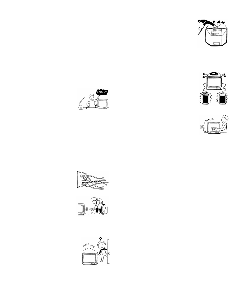
3
Important Safeguards
For your protection, please read these instructions
completely, and keep this manual for future reference.
Carefully observe and comply with all warnings, cautions
and instructions placed on the set or described in the
operating instructions or service manual.
WARNING
To guard against injury, the following basic safety
precautions should be observed in the installation, use
and servicing of the set.
Use
Power Sources
This set should be operated only from
the type of power source indicated on
the serial/model plate. If you are not sure
of the type of electrical power supplied
to your home, consult your dealer or
local power company. For those sets designed to operate
from battery power, refer to the operating instructions.
Grounding or Polarization
This set is equipped with a polarized AC power cord plug
(a plug having one blade wider than the other), or with a
three-wire grounding type plug (a plug having a third pin
for grounding). Follow the instructions below:
Overloading
Do not overload wall outlets, extension
cords or convenience receptacles
beyond their capacity, since this can
result in fire or electric shock.
Always turn the set off when it is not
being used. When the set is left
unattended and unused for long
periods of time, unplug it from the
wall outlet as a precaution against the
possibility of an internal malfunction that could create a
fire hazard.
If a snapping or popping sound from a TV
set is continuous or frequent while the TV
is operating, unplug the TV and consult
your dealer or service technician. It is
normal for some TV sets to make
occasional snapping or popping sounds,
particularly when being turned on or off.
Object and Liquid Entry
Never push objects of any kind into the
set through the cabinet slots as they may
touch dangerous voltage points or short
out parts that could result in a fire or
electric shock. Never spill liquid of any
kind on the set.
Attachments
Do not use attachments not
recommended by the manufacturer, as
they may cause hazards.
Cleaning
Clean the cabinet of the projection TV
with a dry soft cloth. To remove dust
from the screen, wipe it gently with a soft
cloth. Stubborn stains may be removed
with a cloth slightly dampened with
solution of mild soap and warm water. Never use strong
solvents such as thinner or benzine for cleaning.
If the picture becomes dark after using the projection TV
for a long period of time, it may be necessary to clean the
inside of the projection TV. Consult qualified service
personnel.
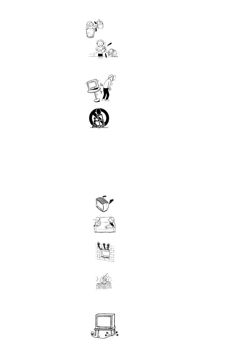
4
Installation
Water and Moisture
Do not use power-line operated sets
near water — for example, near a
bathtub, washbowl, kitchen sink, or
laundry tub, in a wet basement, or
near a swimming pool, etc.
Accessories
Do not place the set on an unstable
cart, stand, table or shelf. The set
may fall, causing serious injury to a
child or an adult and serious damage
to the set. Use only a cart or stand
recommended by the manufacturer
for the specific model of projection
TV. An appliance and cart
combination should be moved with
care. Quick stops, excessive force,
and uneven surfaces may cause the appliance and cart
combination to overturn.
Ventilation
The slots and openings in the cabinet and in the back or
bottom are provided for necessary ventilation. To ensure
reliable operation of the set, and to protect it from
overheating, these slots and openings must never be
blocked or covered.
❑Never cover the slots and openings
with a cloth or other materials.
❑Never block the slots and openings by
placing the set on a bed, sofa, rug or
other similar surface.
❑Never place the set in a confined
space, such as a bookcase or built-in
cabinet, unless proper ventilation is
provided.
❑Do not place the set near or over a
radiator or heat register, or where it is
exposed to direct sunlight.
Power-Cord Protection
Do not allow anything to rest on or roll
over the power cord, and do not place the
set where the power cord is subject to
wear or abuse.
Antennas
Outdoor Antenna Grounding — If an outdoor antenna is
installed, follow the precautions below.
An outdoor antenna system should not be located in the
vicinity of overhead power lines or other electric light or
power circuits, or where it can come in contact with such
power lines or circuits.
WHEN INSTALLING AN OUTDOOR ANTENNA
SYSTEM, EXTREME CARE SHOULD BE TAKEN TO
KEEP FROM CONTACTING SUCH POWER LINES
OR CIRCUITS AS CONTACT WITH THEM IS
ALMOST INVARIABLY FATAL.
Be sure the antenna system is grounded so as to provide
some protection against voltage surges and built-up static
charges.
Lightning
For added protection for this television receiver during a
lightning storm, or when it is left unattended and unused
for long periods of time, unplug it from the wall outlet
and disconnect the antenna. This will prevent damage to
the receiver due to lightning and power-line surges.
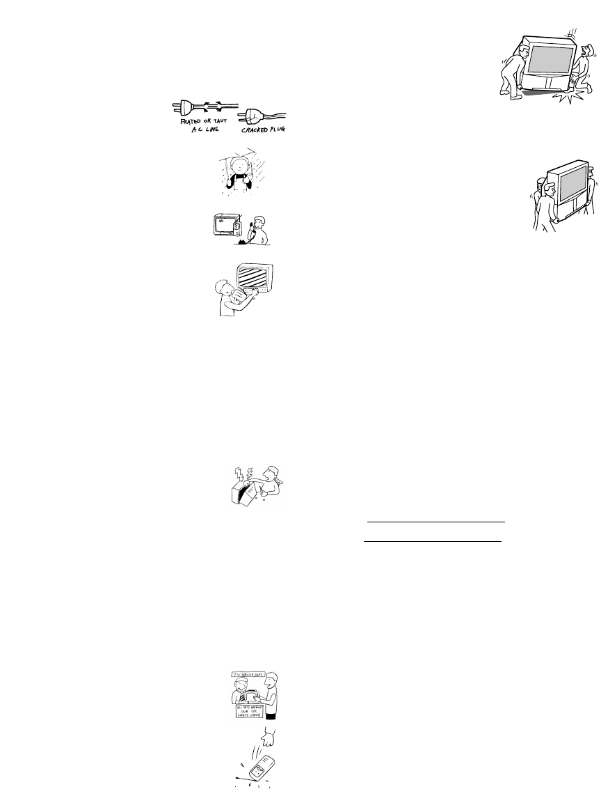
5
Service
Damage Requiring Service
Unplug the set from the wall outlet and refer servicing to
qualified service personnel under the following
conditions:
❑When the power cord or
plug is damaged or frayed.
❑If liquid has been spilled into
the set.
❑If the set has been exposed
to rain or water.
❑If the set has been subject to
excessive shock by being
dropped, or the cabinet has
been damaged.
❑If the set does not operate
normally when following the
operating instructions.
Adjust only those controls
that are specified in the
operating instructions.
Improper adjustment of other controls may result in
damage and will often require extensive work by a
qualified technician to restore the set to normal
operation.
❑When the set exhibits a distinct change in
performance, it indicates a need for service.
Servicing
Do not attempt to service the set yourself
since opening the cabinet may expose you to
dangerous voltage or other hazards. Refer all
servicing to qualified service personnel.
Replacement Parts
When replacement parts are required, be sure the service
technician certifies in writing that he has used
replacement parts specified by the manufacturer that have
the same characteristics as the original parts.
Unauthorized substitutions may result in fire, electric
shock or other hazards.
Safety Check
Upon completion of any service or repairs
to the set, ask the service technician to
perform routine safety checks (as specified
by the manufacturer) to determine that the
set is in safe operating condition, and to so
certify. When the set reaches the end of its
useful life, improper disposal could result
in a picture tube implosion. Ask a qualified
service technician to dispose of the set.
For Safety
Be careful when moving
the projection TV
When you place the projection TV
in position, be careful not to drop it
on your foot or fingers.
Watch your footing while installing the projection TV.
Carry the projection TV in the
specified manner
If you carry the projection TV in a manner
other than the specified manner and
without the specified number of persons, it
may drop and a serious injury may be
caused. Be sure to follow the instructions mentioned
below.
❑Carry the projection TV with the specified number
of persons (see page 9).
❑Do not carry the projection TV holding the speaker
grill.
❑Hold the projection TV tightly when carrying it.
Owner’s Record
The model and serial numbers are located at the rear of
the projection TV, below the Sony logo, on the sticker,
and also on the TV box (white label). Record these
numbers in the spaces provided below. Refer to them
whenever you call upon your Sony dealer regarding this
product.
Model No.
Serial No.

6
Contents
Important Safeguards...............................................3
Introducing the Sony Projection TV
Presenting the Sony Projection TV..........................7
Using this manual ....................................................8
Installing and Connecting the
Projection TV
Contents ...................................................................9
Inserting Batteries into the Remote Control ............9
Carrying Your Projection TV ..................................9
Installing the Projection TV...................................10
Connector Types....................................................11
Projection TV Controls and Connectors................12
Basic Connections (Connecting Cable TV or
Antenna).........................................................15
Connecting a VCR and Cable................................18
Connecting a VCR and Cable Box ........................19
Connecting Two VCRs for Tape Editing ..............21
Connecting an Audio Receiver..............................22
Connecting a DVD Player with Component
Video Connectors ..........................................23
Connecting a DVD Player with A/V Connectors ..24
Connecting a Digital TV Receiver.........................25
Connecting a Camcorder .......................................26
Connecting an AV Receiver ..................................27
Using the CONTROL S Feature............................28
Setting Up the Projection TV Automatically.........29
Adjusting the Convergence Automatically
– FLASH FOCUS™ –...................................30
Using the Features
Using the Remote Control .....................................31
Watching the TV....................................................34
Watching the Digital TV........................................36
Using Favorite Channels........................................37
Using Twin View™...............................................38
Using the Freeze Function .....................................41
Using Channel Index .............................................42
Using the Menus
Overview................................................................44
Using the Video Menu..........................................45
Using the Audio Menu..........................................47
Using the Channel Menu ......................................49
Using the Parent Menu (Channel Block)..............51
Using the Timer Menu..........................................52
Using the Setup Menu ..........................................53
Other Information
Programming the Remote Control.........................55
Operating Other Components with Your
Projection TV Remote Control......................58
Troubleshooting.....................................................60
Specifications.........................................................63

7
Introducing the Sony Projection TV
Presenting the Sony Projection TV
Thank you for purchasing the Sony Projection TV.
This manual is for models KP-HR432K90 and KP-HR532K90.
Model KP-HR532K90 is used for illustration purposes.
Features Some of the features that you will enjoy with your new projection TV
include:
❑1080i Capable: Enables you to receive the 1080i, 720p, 480p and 480i
digital TV formats. By using the VIDEO 5/6 IN jacks, you can connect
a DTV (digital television) receiver to view DTV programs.
❑DRC™ Multi-Function: Unlike conventional line doublers, the DRC
feature doubles vertical and horizontal lines, resulting in four times the
density for quality sources such as DVD and Digital camcorder.
❑CineMotion™: Using the 2-3 Pull-Down technology, the CineMotion
feature allows you to obtain a smooth picture movement when playing
back movies or other video sources on film.
❑Twin View™: Using Multi-Image Driver (MID-X), Twin View allows
you to watch two programs side by side with the ability to zoom in on
one picture and listen to the program in the selected window. You can
watch pictures from two different sources (1080i, 720p, 480p or 480i)
simultaneously.
❑16:9 Enhancement: Vertical Compression technology that maximizes
picture resolution on “anamorphic” or “enhanced for wide screen”
sources, including selected DVDs.
❑Steady Sound™: Equalizes volume levels so there is consistent output
between programs and commercials.
❑Component Video Inputs: Offers the best video quality for DVD
(480p, 480i) and Digital Set-top box (1080i, 720p, 480p, 480i)
connections.
❑S-VIDEO Inputs: Provides a high-quality image for connected
equipment.
❑Favorite Channel Preview: Preview up to eight favorite channels
without leaving the current channel.
❑Channel Index: Allows you to view and choose from twelve programs.
❑Flash Focus™: Allows you to adjust convergence automatically.

Introducing the Sony Projection TV
8
Using this manual
We recommend that you carefully review the contents of the following three
sections in the order shown to ensure that you fully understand the operation
of your new projection TV.
1Installing and Connecting the Projection TV
This section guides you through your initial setup. It shows you how to
install your projection TV, to connect your new components and to connect
the antenna and cable.
2Using the Features
This section shows you how to begin using your new projection TV. It also
shows you how to use your remote control functions.
3Using the menus
This section teaches you how to access on-screen menus and adjust your
projection TV settings.
Instructions in this manual are written for the remote control. Similar
controls are also found on the projection TV console.

9
Installing and Connecting the Projection TV
Contents
The box contains your new projection TV, a remote control and two AA
batteries. No peripheral cables are included. If you intend to add additional
equipment to your projection TV, please check the hookup instructions for
your desired setup before you begin. You may need to purchase cables and/
or splitters to complete the hookup properly.
Inserting Batteries into the Remote Control
Insert two size AA (R6) batteries (supplied) by matching the + and – on the
batteries to the diagram inside the battery compartment.
Carrying Your Projection TV
Carrying the projection TV requires three (3) or more people.
The projection TV has been equipped with casters for easy movement on a
hard surface. (for KP-HR532K90 only)
Please move your projection TV using the casters.
✍Remove the batteries to avoid damage from possible battery leakage
whenever you anticipate that the remote control will not be used for an
extended period.
✍Handle the remote control with care. Avoid dropping it, getting it wet, or
placing it in direct sunlight, near a heater, or where the humidity is high.
✍Your remote control can be programmed to operate most video
equipment. (See “Programming the Remote Control” on page 55.)
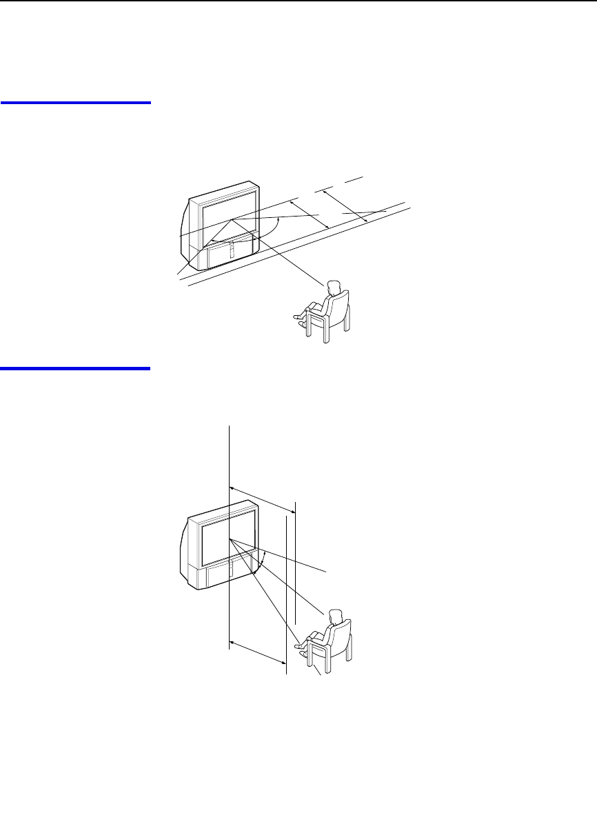
Installing and Connecting the Projection TV
10
Installing the Projection TV
Recommended
viewing area
(Horizontal)
60˚
60 60˚
min. 1.8 m
43"
min. 2.1 m
53"
20˚
20˚
min. 2.1 m
53"
min. 1.8 m
43"
Recommended
viewing area
(Vertical)

Installing and Connecting the Projection TV
11
Installing and Connecting the Projection TV
Connector Types
You may find it necessary to use some of the following connector types
during set up.
Coaxial cable
Standard TV cable and antenna cable
S Video cable
High quality video cable for enhanced picture quality
Audio/Video cable
Video - Yellow
Audio (Left) - White
Audio (Right) - Red
Some DVD Players are equipped with the following three video connectors:
Y - Green
PB (CB, Cb or B–Y) - Blue
PR (CR, Cr or R–Y) - Red
CONTROL S cable
CONTROL S connections are exclusive to Sony products and allow greater
control of all Sony equipment.
Plug Type
Screw-on Type
Push into connection.
Screw into connection.
Align guides and push
into connection.
Push into connection.
Push into connection.
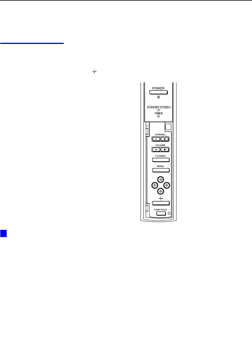
Installing and Connecting the Projection TV
12
Projection TV Controls and Connectors
Front Panel Menu
Controls The front panel menu controls allow access to the on-screen menus without
the use of a remote control. Pressing MENU brings up the on-screen menus.
The arrow buttons move the on-screen cursor in the menus and the Select
button ( ) selects the menu item.
If power is in
STANDBY, press CH+/–
to turn on.
z
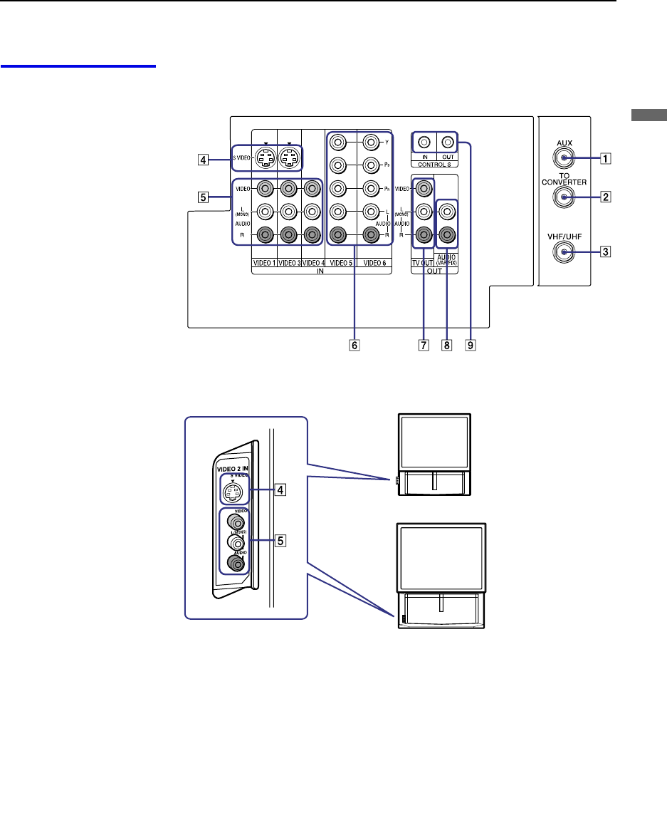
Installing and Connecting the Projection TV
13
Installing and Connecting the Projection TV
Projection TV Rear
and Front/Side
Panel Connectors Rear of projection TV
Front or side of projection TV
KP-HR432K90
KP-HR532K90

Installing and Connecting the Projection TV
14
Connection Description
1AUX Allows you to view local and cable channels if your cable
provider does not feature local channels. You can switch
between local and cable channels easily by pressing ANT
on the remote control. Devices connected to the AUX
input cannot be viewed in Twin View.
2TO CONVERTER This is a VHF/UHF OUT jack that lets you set up your
projection TV to switch between scrambled channels
(through a cable box) and normal cable channels (CATV).
Use this jack instead of a splitter to get better picture
quality when switching between scrambled and
unscrambled cable channels.
3VHF/UHF Connects to your VHF/UHF antenna or cable.
4S VIDEO
(Rear and front/
side)
Connects to the S VIDEO OUT jack of your VCR or other
S VIDEO-equipped video component. Provides better
picture quality than the VHF/UHF jacks or the Video IN
jack.
5VIDEO
(L/R)/AUDIO
(Rear and front/
side)
Connects to the audio and video OUT jacks on your VCR
or other video component. A fourth video input (VIDEO
2) is located on the side panel (for KP-HR432K90) or the
front panel (for KP-HR532K90) of the projection TV.
6Y/PB/PR
(L/R)/AUDIO Connects to your DVD player’s or Digital Set-top box’s
component video (Y, PB, PR) and audio (L/R) jacks.
7TV OUT Connects to an AV receiver for greater control of all audio
and video equipment (see page 27). For detailed
information about connection, refer to the operating
manual supplied with the AV receiver.
8AUDIO OUT
(VAR/FIX)
L (MONO)/R
Connects to the left and right audio inputs of your audio or
video component.
9CONTROL S
IN/OUT To control other Sony equipment with the projection TV's
remote control, connect the CONTROL S IN jack of the
equipment to the CONTROL S OUT jack on the
projection TV with the CONTROL S cable.
To control the projection TV with a remote control for
another Sony product, connect the CONTROL S OUT
jack of the equipment to the CONTROL S IN jack on the
projection TV with the CONTROL S cable.
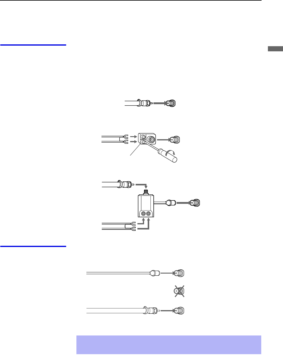
Installing and Connecting the Projection TV
15
Installing and Connecting the Projection TV
Basic Connections (Connecting Cable TV or Antenna)
Connecting Directly
to Cable or an
Antenna
The connection you choose depends on the cable found in your home. Newer
homes are equipped with standard coaxial cable (see A); older homes
probably have 300-ohm twin lead cable (see B); other homes may contain
both (see C).
A VHF Only or VHF/UHF or Cable
B VHF Only or UHF Only or VHF/UHF
C VHF and UHF
Cable and Antenna If your cable provider does not feature local channels, you may find this set
up convenient.
Select CABLE or antenna (ANT) mode by pressing ANT on the remote
control.
75-ohm coaxial
cable Rear of projection TV
VHF/UHF
Rear of projection TV
Antenna connector
300-ohm twin lead cable VHF/UHF
Rear of projection TV
75-ohm coaxial cable VHF/UHF
U/V Splitter
(not supplied)
300-ohm twin lead cable
✍To receive channels with an antenna, you need to turn your Cable to OFF
(see page 49) and perform the Auto Program function (see page 50).
CATV cable
Rear of projection TV
TO
CONVERTER
(No connection to
TO CONVERTER)
VHF/UHF
Antenna cable
AUX

Installing and Connecting the Projection TV
16
Cable Box
Connections Cable Box and Cable
This is the preferred basic cable TV hookup to use if:
❑Your cable TV company scrambles some channels, but not all of them
(pay channels vs. regular cable channels) and you need to use a cable
box, and
❑You want to enjoy the Twin View feature.
With this setup you can:
❑Use the projection TV remote control to change channels using your
cable box when the signal is scrambled.
❑Use the projection TV remote control to change channels using your
projection TV when the signal is not scrambled. (Your projection TV’s
tuner provides a better signal than the cable box.)
❑Use the Twin View feature. (When all channels are routed through your
cable box, only one channel is sent to the projection TV, so you can not
use the Twin View or Channel Index features for your cable box.)
1Connect the Cable TV cable to the projection TV’s VHF/UHF jack.
2Using a coaxial cable, connect the projection TV’s TO CONVERTER
jack to the cable box’s IN jack. The projection TV’s internal converter
allows you to switch between unscrambled signals coming straight into
the projection TV and scrambled signals coming in through the cable
box, eliminating the need for an external splitter.
3Using a coaxial cable, connect the cable box’s OUT jack to the
projection TV’s AUX jack.
✍Pressing ANT on the remote control switches between the channels
coming in through the cable box (scrambled) and those coming directly
to the TV (unscrambled).
Rear of
projection TV
TO
CONVERTER
VHF/UHF
AUX
Cable box
OUT
IN
Signal
75-ohm coaxial cable (not supplied)
CATV cable (unscrambled channels)
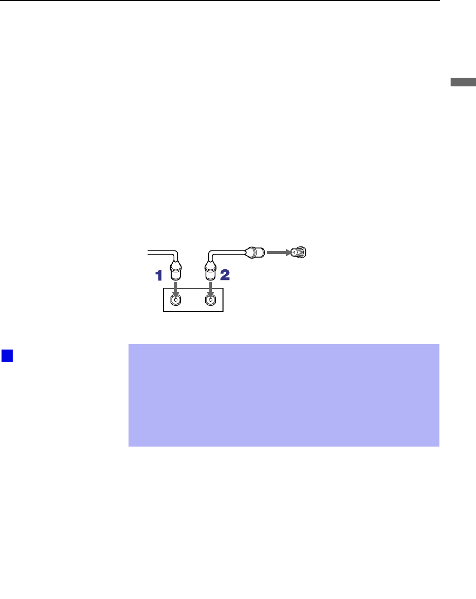
Installing and Connecting the Projection TV
17
Installing and Connecting the Projection TV
Cable Box Only
Use this hookup if:
❑You subscribe to a cable TV system that uses scrambled or encoded
signals requiring a cable box to view all channels, and
❑You do not intend to hook up any other audio or video equipment to
your projection TV.
When all channels are routed through your cable box, only one unscrambled
channel is sent to the projection TV, so you cannot use the Twin View
feature. If some channels are scrambled, but others are not, consider using
the hookup on page 16 instead.
1Connect the coaxial connector from your cable service to the cable
box’s IN jack.
2Using a coaxial cable, connect the cable box’s OUT jack to the TV’s
VHF/UHF jack.
Also, set Cable to ON in the Channel menu. (see page 49)
✍If you will be controlling all channel selection through your cable box,
consider using the Channel Fix feature to set your projection TV to
channel 3 or 4 (see page 50).
✍Your Sony remote control can be programmed to operate your cable box
(see “Programming the Remote Control” on page 55).
✍To change channels using the cable box, set your projection TV to
channel 3 or 4 depending on the cable box channel output.
VHF/UHF
Rear of projection TV
Cable
IN OUT
Cable box
Setting the Channel
Fix feature in the Channel
menu (see “Using the
Channel Menu” on page
49) ensures that you do
not accidentally switch
the channels using your
projection TV.
z

Installing and Connecting the Projection TV
18
Connecting a VCR and Cable
Use this hookup if:
❑You have cable TV that does not require a cable box.
Disconnect all power sources before making any connections.
1Connect the cable TV cable to the VCR’s IN jack.
2Using a coaxial cable, connect the VCR’s OUT jack to the projection
TV’s VHF/UHF jack.
3Using AUDIO and S VIDEO cables, connect the VCR’s Audio and
S VIDEO OUT jacks to the projection TV’s AUDIO and S VIDEO IN
jacks.
Coaxial cable
Rear of Projection TV
VIDEO (yellow)
AUDIO-L (white)
AUDIO-R (red)
Cable
VCR
VMC-810S/820S
(not supplied)
S VIDEO
YC-15V/30V (not supplied)
✍If your VCR is not equipped with S VIDEO, use a VIDEO cable (yellow)
instead of the S VIDEO cable.

Installing and Connecting the Projection TV
19
Installing and Connecting the Projection TV
Connecting a VCR and Cable Box
Use this hookup if:
❑Your cable TV company scrambles some channels, but not all of them
(pay channels vs. regular cable channels) and you need to use a cable
box, and
❑You want to enjoy the Twin View feature.
With this setup you can:
❑Use the projection TV remote control to change channels on your cable
box when the signal is scrambled. To program your Sony Remote
control to operate your cable box, see “Programming the Remote
Control” on page 55.
❑Use the projection TV remote control to change channels using your
projection TV when the signal is not scrambled. Your projection TV’s
tuner provides a better signal than the cable box.
❑Use the Twin View feature. (When all channels are routed through your
cable box, only one signal is sent to the projection TV, so you cannot
use the Twin View feature.)
Disconnect all power sources before making any connections.
1Connect the Cable TV cable to the projection TV’s VHF/UHF jack.
2Using a coaxial cable, connect the TV’s TO CONVERTER jack to the
cable box’s IN jack. The projection TV’s internal converter allows you
to switch between unscrambled signals coming straight into the
projection TV and scrambled signals coming in through the cable box,
eliminating the need for an external splitter.
3Using a coaxial cable, connect the cable box’s OUT jack to the VCR’s
IN jack.
4Using AUDIO and S VIDEO cables, connect the VCR’s AUDIO and S
VIDEO OUT jacks to the projection TV’s AUDIO and S VIDEO IN
jacks.
5Using a coaxial cable, connect the VCR’s OUT jack to the projection
TV’s AUX jack.
✍To view scrambled channels, set your projection TV to AUX 3 or 4
(depending on your cable box output). Change channels using your
cable box.

Installing and Connecting the Projection TV
20
Coaxial
cable
Cable box
VCR
Rear of projection TV
VIDEO (yellow)
AUDIO-L (white)
AUDIO-R (red)
VMC-810S/820S
(not supplied)
Coaxial cable
YC-15V/30V
(not supplied)
S VIDEO
✍If your VCR is not equipped with S VIDEO, use a VIDEO cable (yellow)
instead of the S VIDEO cable.
✍You will not be able to change channels on the VCR. Set your projection
TV and VCR to channel 3 or 4, depending on your cable box channel
output.
✍Pressing ANT on the remote control switches between the channels
coming in through the cable box (scrambled) and those coming directly
to the projection TV (unscrambled).

Installing and Connecting the Projection TV
21
Installing and Connecting the Projection TV
Connecting Two VCRs for Tape Editing
If you connect two VCRs, you can record from one VCR to the other while
using your TV to monitor what is being recorded.
Disconnect all power sources before making any connections.
1Using AUDIO and VIDEO cables, connect the playback VCR’s Audio
and Video OUT jacks to the recording VCR’s Audio and Video IN
jacks.
2Using AUDIO and VIDEO cables, connect the recording VCR’s
AUDIO and Video OUT jacks to the projection TV’s AUDIO and
VIDEO IN jacks.
Rear of projection TV
VCR (playback) VCR (recording)
VMC-810S/820S (not supplied)
AUDIO-R (red)
AUDIO-L (white)
VIDEO (yellow)
✍To perform tape editing, set the projection TV to the video input intended
for playback by pressing TV/VIDEO on the remote control.
✍You may need to change the video input on your VCR. Consult your
VCR’s operating manual for instructions.
✍If your VCRs have an S VIDEO jack: For best picture quality, use an
S VIDEO connection instead of the yellow video cable on your combined
A/V cable.
Using an S VIDEO cable, connect the playback VCR’s S VIDEO OUT jack
to the recording VCR’s S VIDEO IN jack. S VIDEO does not provide audio,
so audio cables must still be connected to provide sound.
✍You cannot record signals from equipment connected to the Y, PB, PR
input.
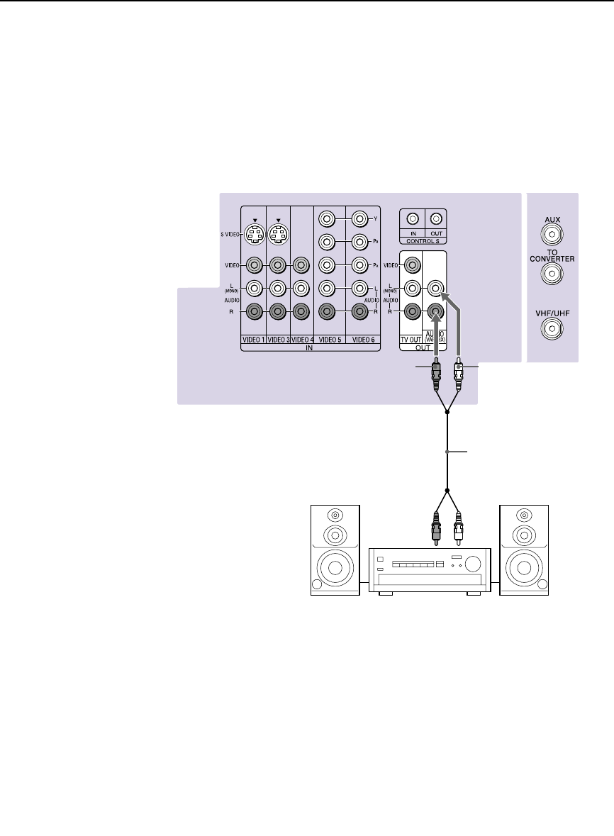
Installing and Connecting the Projection TV
22
Connecting an Audio Receiver
Disconnect all power sources before making any connections.
Using audio cables, connect the projection TV’s AUDIO OUT (VAR/FIX)
jacks to the audio receiver’s audio LINE IN jacks.
Rear of projection TV
AUDIO-R
(red) AUDIO-L
(white)
Line
input
RK-74A
(not supplied)

Installing and Connecting the Projection TV
23
Installing and Connecting the Projection TV
Connecting a DVD Player with Component
Video Connectors
This is the preferred hookup to use if:
❑Your DVD player has component (Y, PB, PR) jacks.
Disconnect all power sources before making any connections.
1Using three separate component video cables, connect the DVD player’s
Y, B-Y and R-Y jacks to the Y, PB and PR jacks on the projection TV.
Use the VIDEO IN 5 or 6 connections.
2Using an audio cable, connect the DVD player’s Audio OUT jacks to
the projection TV’s AUDIO IN jacks. Be sure to use the same row of
inputs that you used for the video connection (VIDEO IN 5 or 6).
✍The Y, B-Y and R-Y jacks on your DVD player are sometimes labeled
Y, CB and CR, or Y, PB and PR. If so, connect the cables to like colors.
VMC-10HG (not supplied)
Rear of projection TV
RK-74A (not supplied)
DVD player
AUDIO-R (red)
AUDIO-L (white)
PR
PB
Y

Installing and Connecting the Projection TV
24
Connecting a DVD Player with A/V Connectors
Use this hookup if:
❑Your DVD player does not have component (Y, PB, PR) jacks.
Disconnect all power sources before making any connections.
1Using audio cables, connect the DVD player’s Audio OUT jacks to the
projection TV’s AUDIO IN jacks.
2Using an S VIDEO cable, connect the DVD player’s S VIDEO jack to
the projection TV’s S VIDEO jack.
✍If your DVD player has video component output connectors: for best
picture quality use the connection described on page 23.
Rear or projection TV
YC-15V/30V
(not supplied)
DVD player
RK-74A (not supplied)
AUDIO-R (red)
AUDIO-L (white)
S VIDEO
✍Use TV/VIDEO on the remote control to switch between the VCR, DVD
player and cable TV inputs.
✍If your VCR is not equipped with S VIDEO, use a VIDEO cable (yellow)
instead of the S VIDEO cable.

Installing and Connecting the Projection TV
25
Installing and Connecting the Projection TV
Connecting a Digital TV Receiver
Disconnect all power sources before making any connections.
1Using three separate component video cables, connect the Digital TV
Set-top box’s Y, PB and PR jacks to the projection TV.
2Using an audio cable, connect the Digital TV Set-top box’s Audio OUT
jacks to the projection TV’s AUDIO IN jacks.
✍The Y, PB and PR jacks do not provide audio, so audio cables must
be connected to provide sound.
Component video connection is necessary to view 480p, 720p and
1080i formats. You may also use the S VIDEO or Composite Video
connections, however, composite video (Y, PB, PR) will provide the
best picture quality for all format types.
Be sure to read the
Set-top box manual.
z
VMC-10HG (not supplied)
Digital TV Set-top box
RK-74A (not supplied)
AUDIO-R (red)
AUDIO-L (white)
Rear of
projection TV
PR
PB
Y
✍You cannot record the signal from any equipment connected into the
Y, PB and PR connectors.
✍This projection TV is not compatible with digital TV receivers
configured with RGB or VGA output connectors.
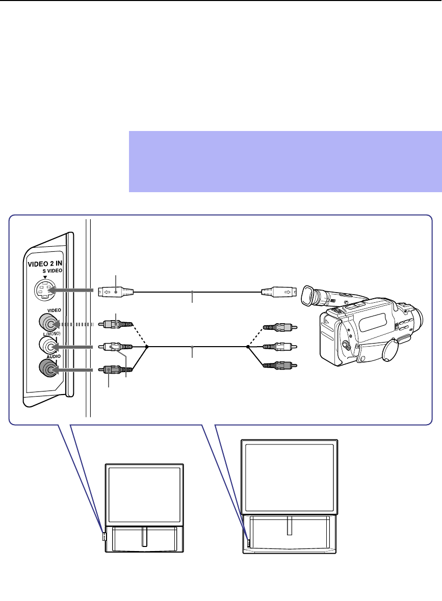
Installing and Connecting the Projection TV
26
Connecting a Camcorder
For easy connection of the camcorder, the projection TV has front Audio and
Video inputs (shown below). However, if you prefer, you can also connect
the camcorder to the projection TV’s rear Audio and Video IN jacks.
Using AUDIO and S VIDEO cables, connect the camcorder’s Audio and S
VIDEO OUT jacks to the projection TV’s AUDIO and S VIDEO IN jacks.
✍If you have a mono camcorder, connect its left audio output to the
projection TV’s AUDIO L (MONO) jack.
✍If your camcorder is not equipped with S VIDEO, use a VIDEO cable
(yellow) instead of the S VIDEO cable.
VIDEO (yellow)
A/V output
AUDIO-L (white)
AUDIO-R (red)
S VIDEO
YC-15V/30V (not supplied)
VMC-810S/820S
(not supplied)
KP-HR432K90 KP-HR532K90
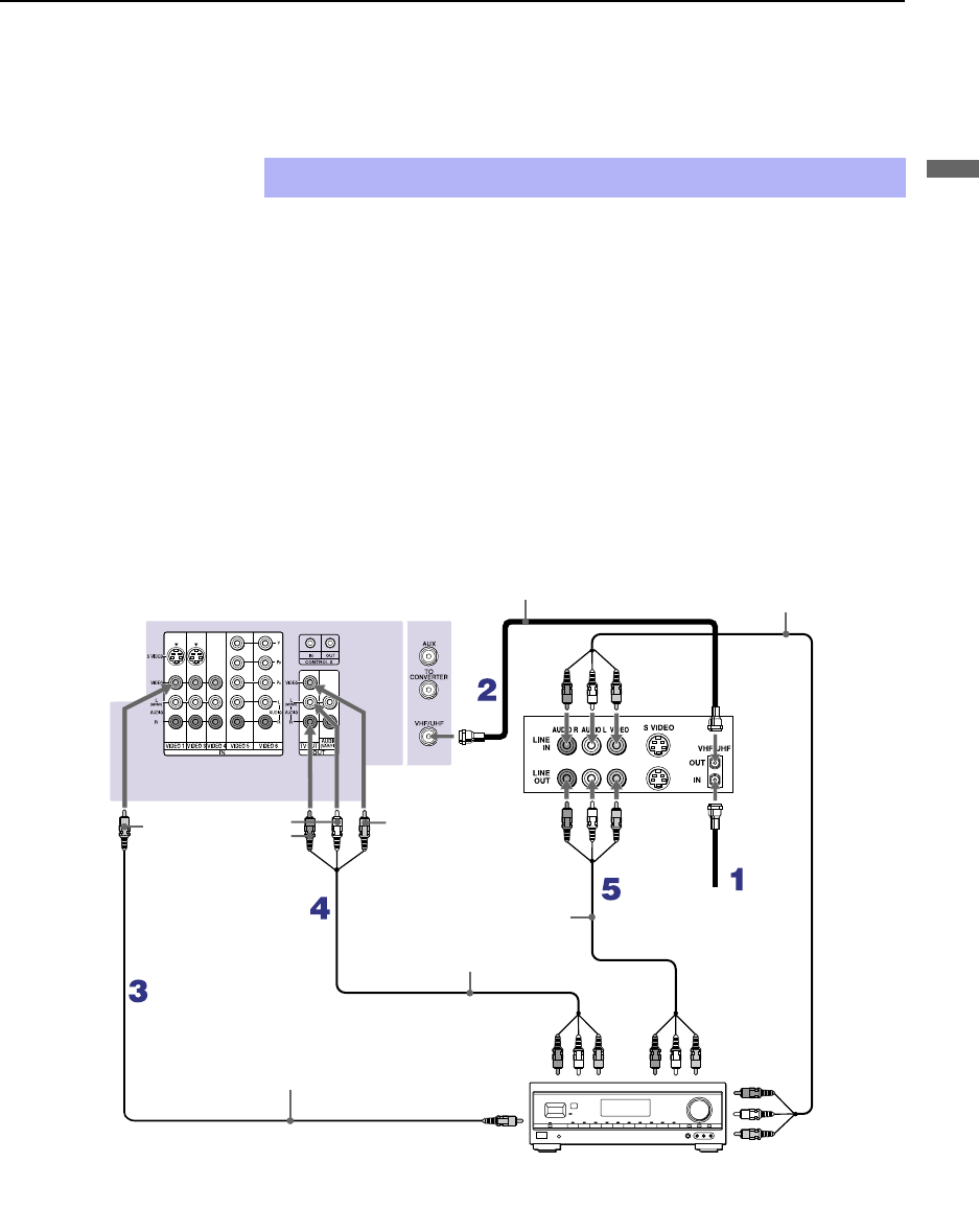
Installing and Connecting the Projection TV
27
Installing and Connecting the Projection TV
Connecting an AV Receiver
For greater control of all audio and video equipment, connect an AV receiver.
Disconnect all power sources before making any connections.
1Connect the coaxial cable from the incoming cable connection or
antenna to IN on the VCR.
2Using a coaxial cable, connect OUT on the VCR to VHF/UHF on the
projection TV.
3Using a VIDEO cable, connect VIDEO of VIDEO 1 IN on the
projection TV to MONITOR OUT on the AV receiver.
4Using an AUDIO/VIDEO cable, connect TV OUT on the projection TV
to AUDIO/VIDEO 2 IN on the AV receiver.
5Using an AUDIO/VIDEO cable, connect the video equipment to the AV
receiver.
6Select the Setup menu and set “Video Label” to “Receiver” to fix your
TV’s input to AV receiver (see “Video Label” on page 54).
✍Change “Video Label” for the VIDEO 1 input to “Receiver” (see page 54).
Rear of projection TV
AUDIO-L
AUDIO-R
VMC-10HG (not supplied)
Cable/
Antenna
Coaxial cable (not supplied) VMC-810S/820S
(not supplied)
VMC-810S/820S
(not supplied)
AUDIO/
VIDEO 1 IN
AUDIO/VIDEO 1 OUT
AV receiver
VMC-810S/820S (not supplied)
MONITOR
OUT
VIDEO VIDEO
VCR
AUDIO/
VIDEO 2 IN
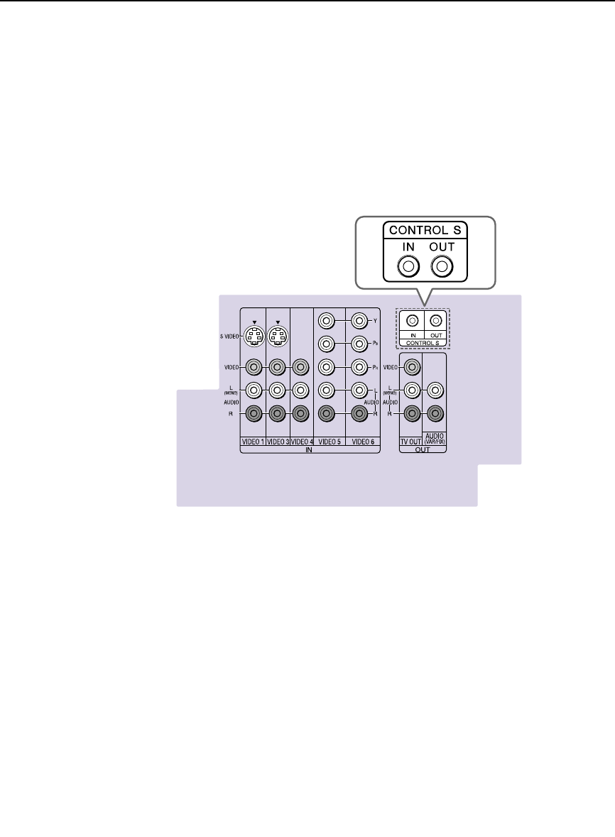
Installing and Connecting the Projection TV
28
Using the CONTROL S Feature
CONTROL S allows you to control your projection TV system and other
Sony equipment with one remote control. In addition to allowing you to
control multiple devices with one remote control, the CONTROL S feature
allows you to always point your remote control at your projection TV,
instead of having to point it at the other equipment, which might be hidden
or out of direct line of sight.
Rear of projection TV

Installing and Connecting the Projection TV
29
Installing and Connecting the Projection TV
Setting Up the Projection TV Automatically
After you finish connecting your projection TV, you can run Auto Setup to
set up your channels. The Auto Setup screen appears when you turn your
projection TV on for the first time after installing it. If you do not want to set
up the channels at this time, you can do it later by using the Auto Program
feature in the Channel menu (see page 50).
Using Auto Setup 1Press POWER on the front panel of your projection TV to turn on the
projection TV.
2Press the TV (FUNCTION) button on your remote control. Red light will
briefly appear.
3Press CH+ on your projection TV to run Auto Setup, or press CH– to
exit. If you use the channel buttons on your remote control, be sure to
use the main set of buttons ( ).
✍The Auto Setup feature does not apply for installations that use a cable
box for all channel selection.
✍You can run Auto Program by selecting it in the Channel menu, as
described on page 50.
Projection TV front panel
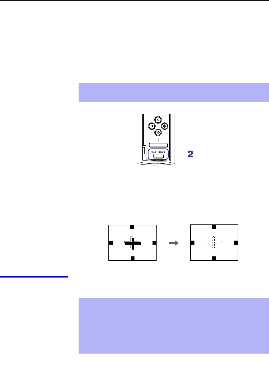
Installing and Connecting the Projection TV
30
Adjusting the Convergence Automatically – FLASH FOCUS™ –
The projection tube image appears on the screen in three colors (red, green
and blue). If they do not converge, the color is poor and the picture blurs.
Before you use your projection TV, be sure to adjust the convergence.
The FLASH FOCUS feature allows you to adjust the convergence
automatically.
1Receive a TV or cable TV program.
2Press FLASH FOCUS.
The cross pattern shown below appears and FLASH FOCUS begins to
work. The adjustment is completed when the cross pattern becomes
white and you are returned to the program you were watching.
To obtain an
optimum
convergence for
Digital TV programs
The optimum convergence alignment varies with digital TV formats.
Whenever you find that the picture blurs, press FLASH FOCUS.
✍It is recommended to perform FLASH FOCUS about 30 minutes after the
projection TV is first turned on.
Projection TV
front panel
✍You cannot perform any other functions until FLASH FOCUS has
completed its cycle.
✍If you perform any other operation while FLASH FOCUS is in progress,
FLASH FOCUS operation is canceled.
✍Unshielded speakers or other metallic objects can cause picture
distortion if placed close to the projection TV.
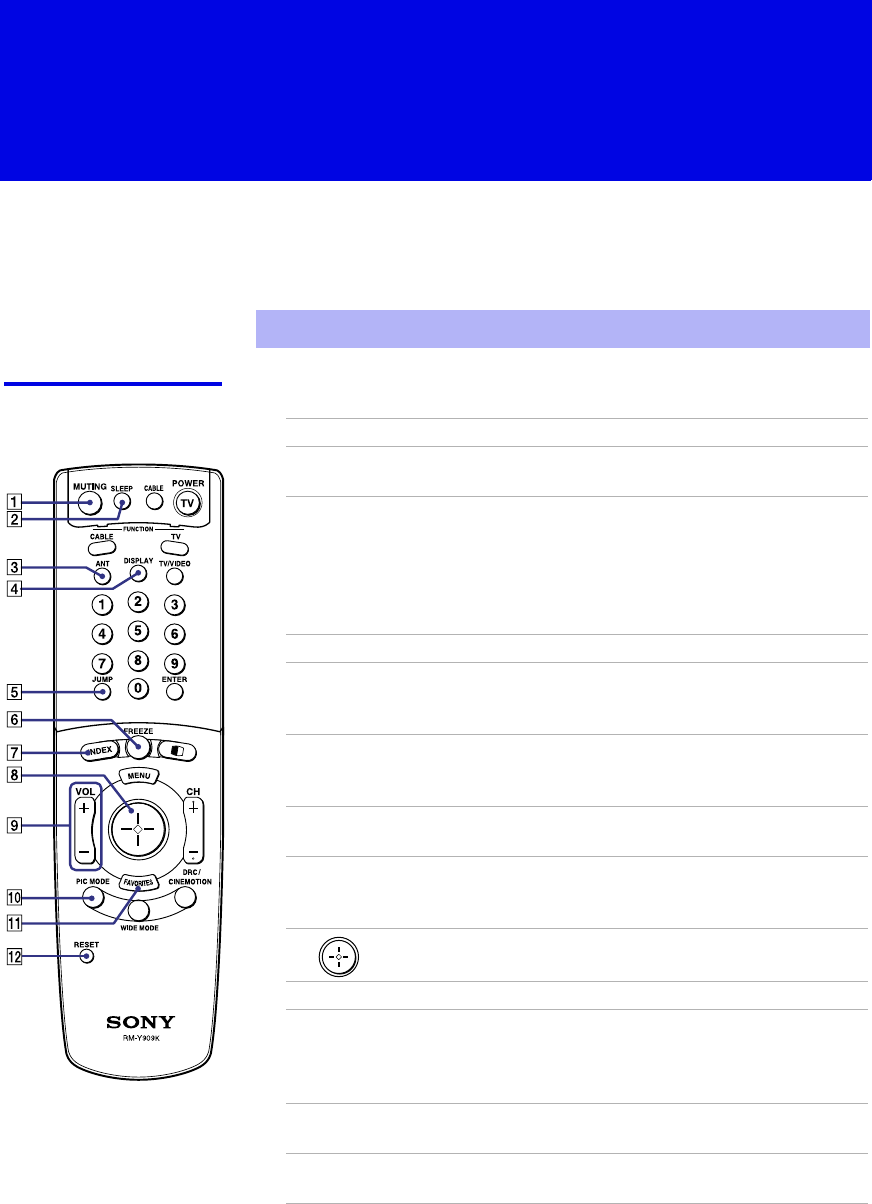
31
Using the Features
Using the Remote Control
The following table describes the buttons on the remote control that are for
more advanced functions.
Button Descriptions Outside Panel
✍Main Power button must be turned ON to activate the remote control.
Button Description
1MUTING Press to mute the sound. Press again or press VOL + to
restore the sound.
2SLEEP Press repeatedly until the projection TV displays the time
in minutes (15, 30, 45, 60, or 90) that you want the
projection TV to remain on before shutting off
automatically. Cancel by pressing until SLEEP OFF
appears. While the Sleep feature is set, press once to view
the remaining time.
3ANT Changes between the VHF/UHF input and the AUX input.
4DISPLAY Press once to display the current time and channel label (if
set) and channel number. Press again to turn Display off.
See page 52 for details on setting the time.
5JUMP Press to jump back and forth between two channels. The
projection TV alternates between the current channel and
the last channel that was selected.
6FREEZE Freezes the window picture. Press again to restore the
picture.
7INDEX Press to enter the Channel Index mode. You can view and
select from twelve channels without leaving the current
one.
8The joystick allows for movement of the on-screen cursor.
Pressing down on the center of the joystick selects the item.
9VOL +/–Adjusts the volume.
q; PIC MODE Press repeatedly to step through the available video picture
modes: Vivid, Standard, Movie and Pro. Also available in
the Video menu. For details, see “Selecting Video Options”
on page 45.
qa FAVORITES Displays the Favorite Channels list. For details, see “Using
Favorite Channels” on page 37.
qs RESET Press when in a menu to reset the settings to the factory
defaults.
(Continued)
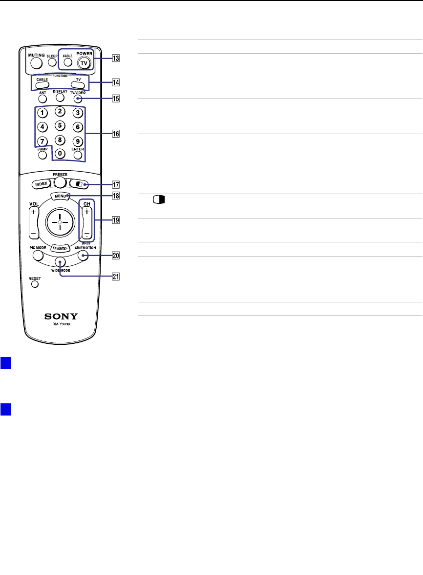
Using the Features
32
qd POWER
buttons
(GREEN)
Turn on and off the projection TV and other audio/video
equipment you have programmed into the remote control.
For instructions, see “Programming the Remote Control”
on page 55.
qf FUNCTION
buttons Select the equipment (TV, CABLE) that you want to
operate. The indicator lights up momentarily when pushed
to show which device the remote control is operating.
qg TV/VIDEO
Cycles through the video equipment connected to your
projection
TV’s video inputs:
TV
,
VIDEO 1
,
VIDEO 2
,
VIDEO 3
,
VIDEO 4
,
VIDEO 5
and
VIDEO 6
.
qh 0 – 9 and
ENTER Press 0 - 9 to select a channel, the channel changes after 2
seconds. Press ENTER to select immediately.
qj Turns on/off Twin View. For details, see “Using Twin
View™” on page 38.
qk MENU Press to display the projection TV on-screen menu. Press
again to exit from the menu.
ql CH +/–Scan through channels.
w; DRC/
CINEMOTION Press repeatedly to step through the available high-
resolution picture modes: Interlaced, Progressive and
CineMotion. For details, see “Using the Video Menu” on
page 45.
wa WIDE MODE No function on this set.
Button Description
To scan rapidly through the
channels, press and hold down
CH+ or CH–.
If power is in STANDBY,
press 0-9 or CH+/– to turn on.
z
z
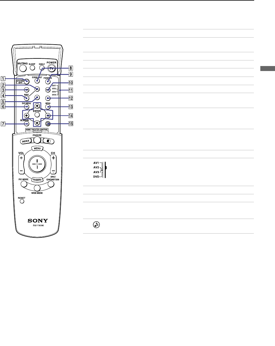
Using the Features
33
Using the Features
Inside Panel
Button Description
1SYSTEM OFF Press to turn off the projection TV and all equipment
connected with S-Link.
2NPlay
3mRewind
4REC Record
5xStop
6DVD MENU Displays the DVD menu.
7BILINGUAL Press to scroll through the bilingual options: MAIN,
MAIN+SUB, and SUB.
8CODE SET Used for programming the remote control to operate non-
Sony video equipment. For details, see “Programming the
Remote Control” on page 55.
9POWER Press to turn on the DVD/VCR player you have
programmed into the remote control. For instructions, see
“Programming the Remote Control” on page 55.
q; MFast-forward
qa Use to switch control for connected video equipment. You
can program one video source for each switch position. For
details, see “Programming the Remote Control” on page
55.
qs X Pause (Press again to resume normal playback)
qd MENU Displays the video equipment menu.
qf M
MM
M, m
mm
m, <
<<
<, ,
,,
,,
and ENTER Use to operate the DVD menu.
qg Press to select an audio option: Steady Sound ON or
OFF.

Using the Features
34
Watching the TV
Many TV features can be accessed directly through the remote control. The
following will explain the function of some of the buttons found on your
remote control.
Buttons for
Projection TV
Operations
1 TV (FUNCTION)
Activates the remote control for use with the projection TV.
2 ANT— (AUX input)
Press to change between the VHF/UHF input and the AUX input.
3 TV (POWER)
Turns the projection TV on and off. If a video input indication (e.g.,
VIDEO 1, VIDEO 2) appears on the screen, press TV/VIDEO or
CH +/ – until a channel number appears.
4 0-9 and ENTER
Use for direct channel selection. Press 0-9 to select a channel (for example,
to select channel 10, press 1 and 0). The channel will change after 2 seconds,
or you can press ENTER for immediate selection.
5 CH +/–
Press to scan through the channels (+ up or – down).
6 VOL +/–
Press to adjust the volume (+ up or – down).
7 JUMP
Press to alternate or jump back and forth between two channels. The
projection TV will jump between the current channel and the last channel
selected.
8 MUTING
Press to mute the sound. “MUTING” will appear on the screen and will dim
three seconds later. To restore the sound, press again or press VOL +.
9 FREEZE — (yellow labeled button)
This is useful when you need to copy down information that appears on the
TV’s screen (see “Using the Freeze Function” on page 41).
q; SLEEP
Press repeatedly until the projection TV displays the approximate time in
minutes (15, 30, 45, 60, or 90) that you want the projection TV to remain on
before shutting off automatically.
Cancel by pressing SLEEP until “SLEEP OFF” appears.

Using the Features
35
Using the Features
qa DISPLAY
Press to display the channel number, current time and channel label (if set).
To turn the display off, press DISPLAY again.
qs TV/VIDEO
Press repeatedly to scroll through available video inputs: TV, VIDEO 1,
VIDEO 2, VIDEO 3, VIDEO 4, VIDEO 5 and VIDEO 6.
If you select Skip as a Video Label in the Setup menu, your projection TV
will skip the video input you selected (see “Video Label” on page 54).
qd BILINGUAL
Press to scroll through the bilingual options: MAIN, MAIN+SUB, and SUB.
qf PIC MODE
Press PIC MODE repeatedly to directly choose one of five different video
modes that best suits the program you are watching.
Vivid: Select for enhanced picture contrast and sharpness.
Standard: Select to display a standard picture for normal viewing
environments.
Movie: Select to display a finely detailed picture for low light environments.
Pro (Professional): Select to display a picture with minimum enhancements.
When you select each mode, you can also adjust the picture quality (such as
Brightness, Color, etc.) to suit your taste. For details, see “Mode” on page
45.

Using the Features
36
Watching the Digital TV
When you have connected the DTV receiver, you can enjoy digital TV
programs. This projection TV is capable of receiving the 1080i, 720p, 480p
and 480i digital TV formats.
To view a digital TV program
1Connect the DTV receiver to VIDEO 5 or 6 IN on the projection TV
(for details, see page 25).
2Press TV/VIDEO to select VIDEO 5 or 6.
3Select a digital channel on the DTV receiver. For details, see the
Operating Manual of the DTV receiver.
4Adjust the volume of the projection TV as necessary.
✍This projection TV is not capable of displaying a native 720p format
signal. When a 720p format signal is received, it is converted into a 480p
format signal.
✍The optimum convergence alignment varies with digital TV formats.
Whenever you find that the picture blurs, press FLASH FOCUS (for
details, see page 30).

Using the Features
37
Using the Features
Using Favorite Channels
The Favorite Channel feature lets you select programs from a list of favorite
channels that you preset.
To display a list of your favorite channels:
1Press FAVORITES.
The Favorite Channel options appear.
2Move the joystick up or down to highlight the channel you want to
watch. The program on that channel appears in the preview window.
Press to select.
✍Your Favorite Channel options can be set automatically or manually. The
factory setting for Favorite Channel is Auto.
When Favorite Channel is set to Auto, the last eight channels selected
with 0-9 buttons will be set as Favorite Channel options. If you want to
input your own selections as Favorite Channel settings, see “Favorite
Channel” on page 49.
Favorios
124
6
10
12
2
8
8
4
Exit
Preview window

Using the Features
38
Using Twin View™
Twin View enables you to watch two programs at the same time. You can
also change the size of both the left and right pictures.
Displaying Twin
Pictures To display twin pictures
1Make sure your projection TV is
tuned to a working channel.
2Press .
To cancel twin pictures
❑Press again (or press ).
Activating the
Picture Although two pictures appear on the screen at the same time, only one
picture is active. Change the picture size by using the joystick. For an active
picture, you can:
❑Change channels.
❑Adjust the volume.
❑Switch the input sources from VHF/UHF to cable by pressing ANT or
TV/VIDEO to switch the video input.
❑Change the picture size by pressing the joystick up or down.
To activate the right picture
❑Move the joystick to the right.
To activate the left picture
❑Move the joystick to the left.
,
,
,
,

Using the Features
39
Using the Features
✍ANT is not effective in the right picture.
✍JUMP is not effective in Twin View.
✍When you adjust the twin screen sizes, the projection TV memorizes
the change. The next time you use the Twin View feature, the
memorized sizes appear.
✍When viewing an enhanced 16:9 picture, the aspect ratio changes to
4:3 in Twin View. The picture will be reformatted to that aspect ratio.
✍If viewing a 720p or 1080i format input source, the aspect ratio will
maintain the original 16:9 aspect ratio.
✍Hookups that affect your ability to use Twin View:
- If you are viewing all channels through the cable box, the Twin
View feature will not work. The cable box only unscrambles one
signal at a time, so the right picture will be the same as the left
picture.
- You can watch a scrambled cable channel and another video
source. Be sure your DVD player or VCR is connected to one of the
VIDEO IN 1-6 and AUX inputs on the rear of the projection TV.
Pictures from equipment connected to VIDEO 5, 6 and AUX will
only appear in the left picture, not in the right.
✍The active picture is highlighted in cyan.

Using the Features
40
Changing the
Picture Size The zoom feature lets you change the size of the left and right pictures.
To enlarge the left
picture (reduce the
right)
1Move the joystick
left to activate the
left picture (if not
already activated).
2Move the joystick
up to enlarge the
picture and move
the joystick down
to reduce the
picture.
To enlarge the right
picture (reduce the
left)
1Move the joystick
right to activate the
right picture (if not
already activated).
2Move the joystick
up to enlarge the
picture and move
the joystick down to
reduce the picture.
✍When you adjust the twin screen sizes, the projection TV memorizes the
change. The next time you use the Twin View function, the memorized
sizes appear.

Using the Features
41
Using the Features
Using the Freeze Function
The FREEZE button allows you to temporarily capture a program’s picture.
You can use this feature to write down information such as phone numbers,
recipes, etc.
To use the Freeze function
1When the program information you want to capture is displayed, press
FREEZE.
2The projection TV switches to Twin View mode and displays the
“frozen” picture on the right, while the current program continues on the
left.
3To cancel and return to normal viewing, press FREEZE.
✍Freeze feature is not available if you are already in Twin View™ mode.
Current program
in progress
Frozen picture
Call 555-1234

Using the Features
42
Using Channel Index
Channel Index allows you to display multiple channels and select one
directly.
The channels used for Channel Index will come directly from the projection
TV’s list of receivable channels (those set during “Auto Program” on page
50).
To use the Channel Index function
1Press INDEX.
The current channel will be reduced in size and displayed in the center
of the screen in normal motion picture format. The first twelve
receivable channels will appear one after another, clockwise, around the
center picture. These small pictures are updated in intervals of one
second. The channel number and channel caption (if set) on the second
and later appearances will dim.
A cyan-colored frame will appear to indicate current channel selection.
2Move the joystick in any direction to move the cyan frame to the
channel that you wish to view, and press .
The selected channel will zoom in and move to the center, and the sound
of that channel will be heard.
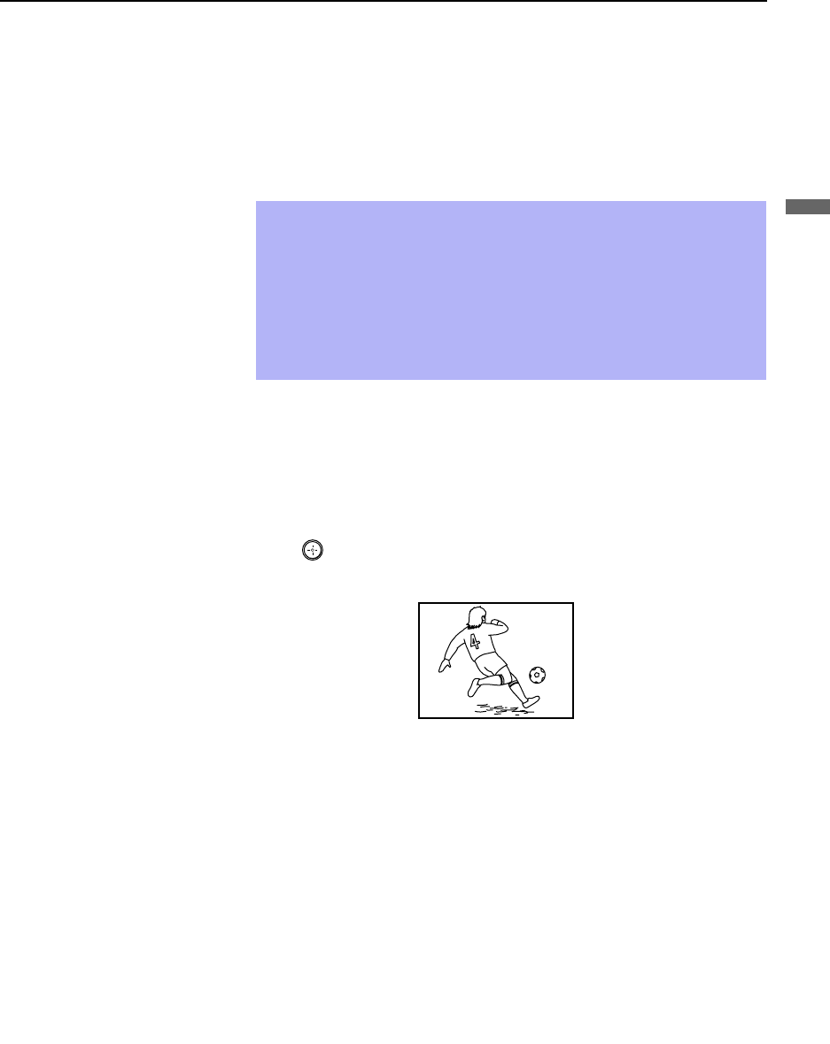
Using the Features
43
Using the Features
For the center picture you can:
❑Change the channel by pressing 0-9 and ENTER.
❑Switch the input sources from VHF/UHF to cable by pressing ANT
or to the video input by pressing TV/VIDEO, without changing the
surrounding channels.
3If you wish to view another channel, repeat step 2.
To view another twelve channels, press CH+.
To view the previous twelve, press CH–.
To view the normal picture of the selected channel, proceed to step 4.
4Press .
The center picture will be enlarged for normal viewing.
To cancel Channel Index
❑Press INDEX again to resume normal viewing.
✍Sound will only be heard from the center picture.
✍If one of the pictures received through Channel Index is snowy, the
entire screen may become unstable. In this case, erase the snowy
channel (see “Channel Skip/Add” on page 50).
✍If you leave the Channel Index screen displayed for an hour without
any additional operation, Channel Index is canceled and the normal
picture reappears.
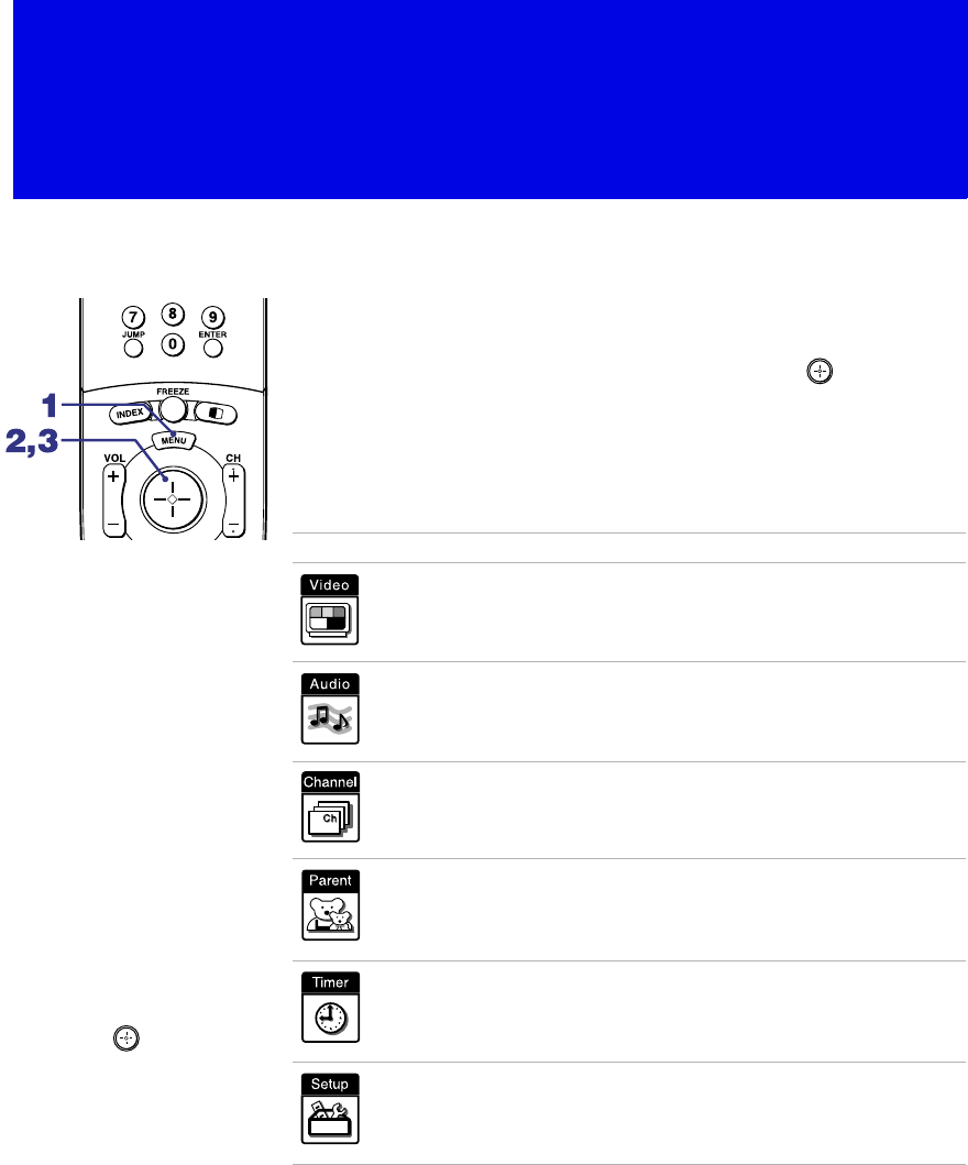
44
Using the Menus
Overview
Opening and choosing a menu:
1Press MENU to display the menu screen.
2Move the joystick to the desired menu icon and press to select it.
3Use the joystick to scroll through the features.
4See the specific menu page for instructions on moving through the
menu.
The menu gives you access to the following features:
Menu Icon Description Page
Allows you to make adjustments to your picture settings.
It also allows you to customize the Picture Mode based on
the type of program you are viewing.
45
Offers enhanced audio options such as customizing the
Effect of the sound on your projection TV.
47
Allows you to set up a Favorite Channel list, run the Auto
Program function, and more.
49
Lets you control the viewing of programs. 51
Lets you set the clock on your projection TV and allows
you to program your projection TV for scheduled viewing
using the Timers.
52
Provides several options for setting up your channels,
labeling your Video inputs, and selecting the language of
the on-screen menus.
53
To end a menu session:
Press MENU again.
To end one menu
session and move to
another:
Press the joystick V to
return to the menu icons.
Move the joystick B
BB
B or b
bb
b to
choose the next menu icon
and press to select it.
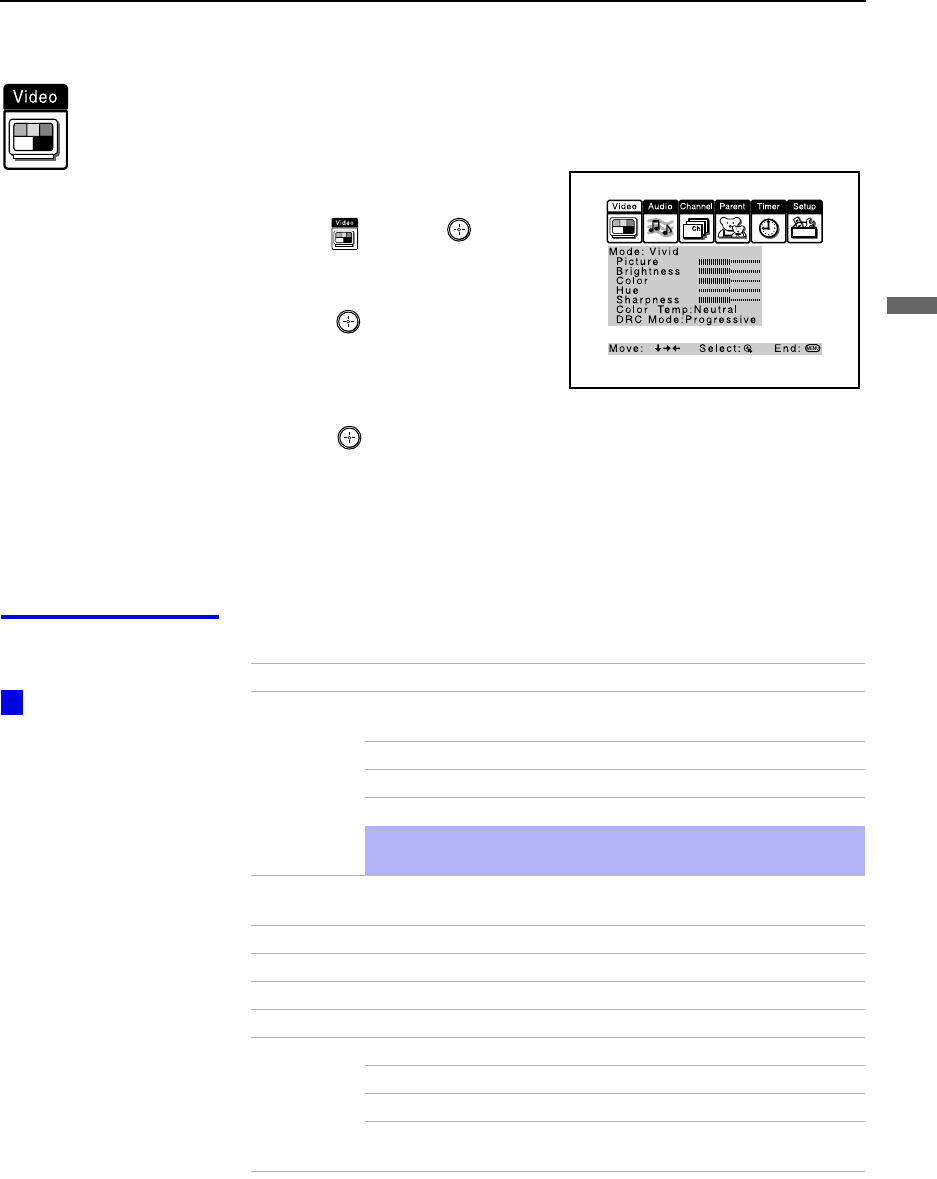
Using the Menus
45
Using the Menus
Using the Video Menu
To select the Video Menu
1Press MENU.
2Move the joystick to the Video
icon and press .
3Use the joystick to scroll
through the features.
4Press to select a feature. That
feature’s adjustment appears.
5Use the joystick to make the
desired adjustments.
6Press to select/set.
7Press MENU to exit the menu screen.
To restore the factory default settings for Picture, Brightness, Color,
Hue, Sharpness and Color Temp
❑Press RESET on the remote control when in the Video menu.
Selecting Video
Options The Video menu includes the following options.
To quickly and easily
change from one Video
Mode to another, use the
PIC MODE on the remote
control.
z
Option Description
Mode
Customized
picture
viewing
Vivid Select for enhanced picture contrast and
sharpness.
Standard Recommended for Normal viewing conditions.
Movie Select for soft, film like, picture.
Pro Select for professional monitor like appearance.
✍You can alter the Video menu settings (Picture, Brightness,
Color, etc.) for each Mode.
Picture Adjust to increase picture contrast and deepen the color or decrease
picture contrast and soften the color.
Brightness Adjust to brighten or darken the picture.
Color Adjust to increase or decrease color intensity.
Hue Adjust to increase or decrease the green tones.
Sharpness Adjust to sharpen or soften the picture.
Color Temp
White
intensity
adjustment
Choose from three color temperatures:
Cool Select to give the white colors a blue tint.
Neutral Select to give the white colors a neutral tint.
Warm Select to give the white colors a red tint (NTSC-
Standard).
(Continued)

Using the Menus
46
DRC Mode
Digital
Reality
Creation
Creates a high-resolution picture with 4x density, for high quality
sources (i.e., DVD player).
Select from Interlaced, Progressive and CineMotion.
Interlaced Recommended for moving pictures.
Progressive Recommended for still images and text.
CineMotion Recommended for 24 frame-per-second films.
Option Description
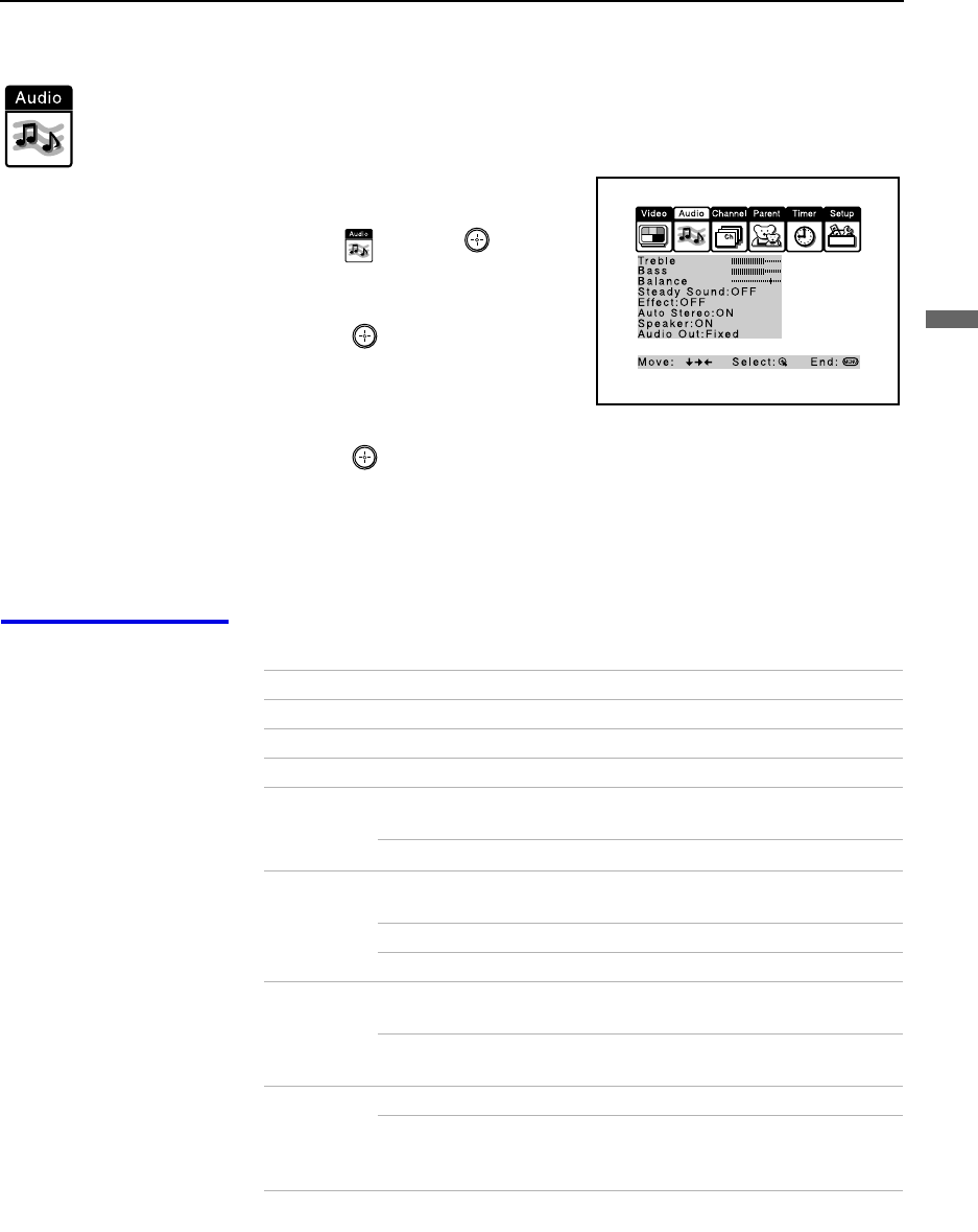
Using the Menus
47
Using the Menus
Using the Audio Menu
To select the Audio Menu
1Press MENU.
2Move the joystick to the Audio
icon and press .
3Use the joystick to scroll through
the options.
4Press to select an option.
That option’s settings appear.
5Use the joystick to scroll through
the settings.
6Press to select the desired setting.
7Press MENU to exit the menu screen.
To restore the factory default settings for Treble, Bass and Balance
❑Press RESET on the remote control when in the Audio menu.
Selecting Audio
Options The Audio menu includes the following options:
Option Description
Treble Adjust to increase or decrease higher-pitched sounds.
Bass Adjust to increase or decrease lower-pitched sounds.
Balance Adjust to emphasize left or right speaker balance.
Steady
Sound ON Select to stabilize the volume.
OFF Select to turn off Steady Sound.
Effect TruSurround Select for surround sound (for stereo programs
only).
Simulated Adds a surround-like effect to mono programs.
OFF Normal stereo or mono reception.
Auto Stereo
Enjoy stereo
and mono
programs
ON Select for stereo reception when viewing a program
broadcast in stereo.
OFF Select for mono reception. (Use to reduce noise
during weak stereo broadcasts.)
Speaker ON Select to turn on the projection TV speakers.
OFF Select to turn off the projection TV speakers and
listen to the projection TV's sound only through
your external audio system speakers.
(Continued)

Using the Menus
48
Audio Out
Easy control
of volume
adjustments
Variable The projection TV’s speakers are turned off, but
the volume output from your audio system can still
be controlled by the projection TV’s remote
control.
Fixed The projection TV’s speakers are turned off and the
volume, bass and treble output of the projection TV
is fixed. Use your audio receiver’s volume control
to adjust the volume through your audio system.
Option Description
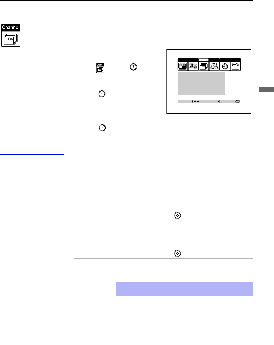
Using the Menus
49
Using the Menus
Using the Channel Menu
To select the Channel Menu
1Press MENU.
2Move the joystick to the Channel
icon and press .
3Use the joystick to scroll
through the features.
4Press to select a feature. That
feature’s options appear.
5Use the joystick to scroll
through the options.
6Press to select the desired option.
7Press MENU to exit the menu screen.
Selecting Channel
Options The Channel menu includes the following options:
Video Audio Channel Setup
Parent Timer
Favorite Channel:Auto
Cable:ON
Channel fix:OFF
Auto Program
Channel Skip/Add
Channel Label
Move: Select: End:
MENU
Option Description
Favorite Channel Auto Select if you want Favorite Channel options to
be set automatically to the last eight channels
selected with the 0-9 buttons.
Manual Select if you want to input your own selections
as Favorite Channel options.
1Press to select a favorite channel
number.
2Use the joystick to scroll through the
channels until you find the channel you
want to add to your favorites.
3Press to select it.
Cable ON Select if you are receiving cable channels with a
CATV cable.
OFF Select if you are using an antenna.
✍You should run Auto Program after changing the Cable
setting.
(Continued)

Using the Menus
50
Channel Fix
Useful when you
have a cable box
connected
2-6 “Fix” your projection TV’s channel setting to 3
or 4 and use the cable box or VCR to change
channels. Select one of these settings if you
have connected the device to the VHF/UHF
jack.
AUX 2-6 Same as 2-6, except you select one of these
settings if you have connected the device to the
AUX jack. (see page 14)
VIDEO 1 Use when connecting an AV receiver to control
external video sources. TV output should be
connected through the AV receiver.
Auto Program Automatically programs the projection TV for all receivable
channels.
Channel
Skip/Add Removes and adds viewable channels.
1Use the joystick to scroll through the channels until you
find the channel you want to skip/add.
2Press to select it.
3Press the joystick up or down to toggle between “Add” and
“Skip.”
4Press to select.
Channel Label Label up to 20 channels with their station call letters.
Option Description
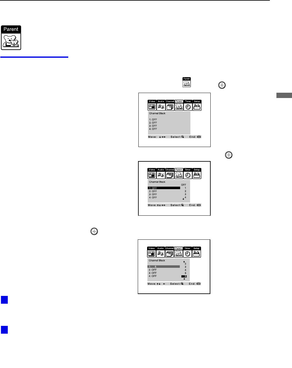
Using the Menus
51
Using the Menus
Using the Parent Menu (Channel Block)
The Parent menu allows you to set up the TV to block up to 4 channels.
Using the Parent
Menu To block channels
1Press MENU.
2Move the joystick to the Parent icon and press .
3Move the joystick up or down to select 1-4, and press .
4Move the joystick down to select the channel to be blocked, and press
.
5Press MENU to exit the menu screen.
To cancel channel block settings
❑Set Channel Block to OFF in step 4.
Performing Auto
Program will erase the
Channel Block settings.
Selecting ''Receiver” of
Video Label will erase the
Channel Block Settings.
z
z
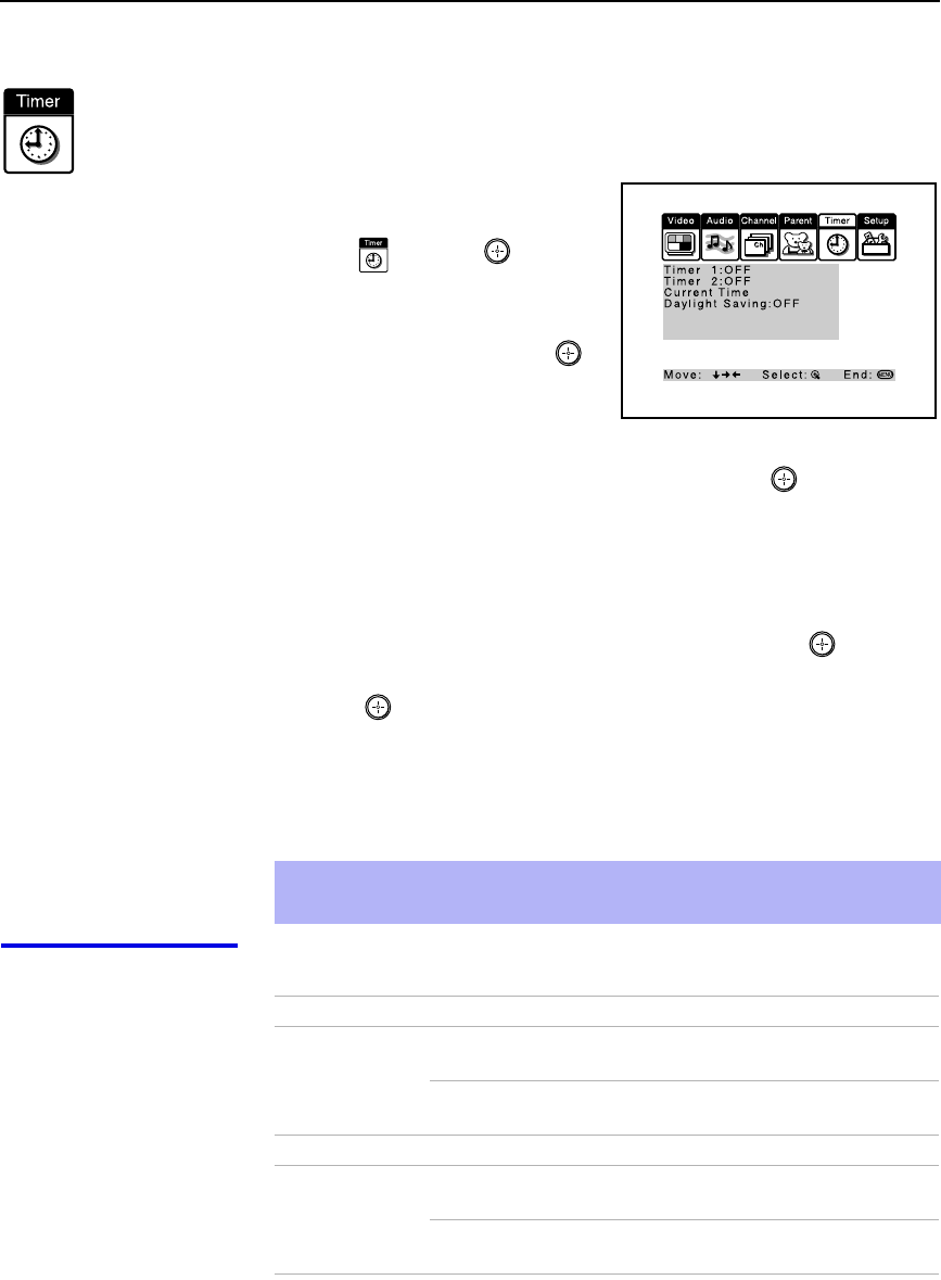
Using the Menus
52
Using the Timer Menu
To select the Timer menu
1Press MENU.
2Move the joystick to the Timer
icon and press .
To set the Current Time
1Use the joystick to select
“Current Time”, then press .
2If it is currently Daylight Saving
Time, be sure to set the mode to
“ON” first.
3Use the joystick to enter the correct time, then press .
4Press MENU to exit the menu screen.
To set the Timer
Before setting the timer, be sure to set your projection TV’s clock to the
current time and Daylight Saving Mode.
1Move the joystick to “Timer 1” or “Timer 2”, then press .
2Use the joystick to enter your day, time and channel preferences, then
press to select each one.
3Press MENU to exit the menu screen.
To reset the Clock or Timers
❑Press RESET on the remote control after selecting that option in the
Timer menu.
Selecting Timer
Options The Timer menu includes the following options:
✍Turning off the main power of the projection TV will clear the timer settings.
✍Selecting Channel Fix will clear the timer settings.
Option Description
Timer 1
Timer 2 Program Select to set the Timer by day, time, duration,
and channel.
OFF Select to turn off the Timer. (Your previous
settings will be saved.)
Current Time Set the current time.
Daylight Saving ON Select in the Spring to adjust the time during
Daylight Saving Time.
OFF Select in the Fall to adjust the time at the end
of Daylight Saving Time.
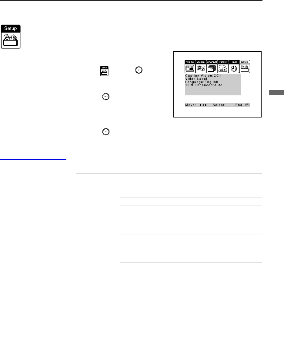
Using the Menus
53
Using the Menus
Using the Setup Menu
To select the Setup Menu
1Press MENU.
2Move the joystick to the Setup
icon and press .
3Use the joystick to scroll through
the features.
4Press to select a feature. That
feature’s options appear.
5Use the joystick to scroll through
the options.
6Press to select the desired option.
7Press MENU to exit the menu screen.
Selecting
Setup Options The Setup menu includes the following options:
Option Description
Caption Vision Allows you to select from three closed caption modes (for
programs that are broadcast with closed captioning).
OFF Turns off Caption Vision.
CC1, CC2,
CC3, CC4 Displays a printed version of the
dialog or sound effects of a program.
(Should be set to CC1 for most
programs.)
TEXT1, TEXT2,
TEXT3, TEXT4 Displays network/station information
presented using either half or the
whole screen (if available). For closed
captioning, set to CC1.
XDS
(Extended Data
Service)
Displays a network name, program
name, program length, and time of the
show if the broadcaster offers this
service.
(Continued)

Using the Menus
54
Video Label Allows you to label the audio/video components you connected
to the projection TV so you can identify them when using TV/
VIDEO. When in the Setup menu’s Video Label feature, use
the joystick to highlight an input to label, then press to
select it. Use the joystick to scroll through the labels. Press
to select the component you connected to each of the input
jacks on the back of your projection TV. Select “Skip” if you do
not have a component connected to a particular set of input
jacks.
VIDEO 1/2/3/4 VHS, 8mm, Beta, LD, Game, DVD,
Web, Receiver, DTV, Skip
VIDEO 5/6 DVD, DTV, HD, Skip
If you select “Skip”, your projection TV skips this connection
when you press TV/VIDEO.
✍When you select “Receiver” on Video Label, your projection
TV’s input is fixed.
Language Select to display all on-screen menus in your language of
choice: English, Español, Français.
16:9 Enhanced Provides enhanced picture resolution for widescreen sources,
such as selected DVD titles (only available when the projection
TV is in VIDEO mode). Press TV/VIDEO and select from one
of the following options:
AUTO To activate automatically when a 16:9
signal is received.
ON To activate manually.
OFF To deactivate manually.
✍AUTO/ON will appear when the projection TV is in VIDEO mode 1-6.
ON/OFF will appear when the projection TV is in VIDEO mode 5-6 and the 480p
signal occurs.
Option Description
To use this feature
with widescreen DVDs,
set your DVD player to
16:9 aspect ratio.
z

55
Other Information
Programming the Remote Control
The remote control is preset to operate Sony brand video equipment.
If you have video equipment other than Sony brand that you want to control
with the projection TV’s remote control, use the following procedures to
program the remote control.
From the “Manufacturer’s Codes” listed on page 57, select the three-digit
code number for the manufacturer’s code for your component. If more than
one code number is listed, start with the number listed first. Use the code
number to complete the following procedure.
To program a cable box
1Open the panel of the remote control.
2Press CODE SET inside the panel.
3Close the panel and press CABLE (FUNCTON).
4Enter the three-digit manufacturer’s code number using the 0-9 buttons.
5Press ENTER.
6To check if the code number works, aim the projection TV’s remote
control at the component and press the green POWER button that
corresponds with that component. If it responds, the programming is
completed. If not, try using the other codes listed for that manufacturer.
Sony
Equipment Switch Position
on Remote Control Programmable
Code Number
Beta, ED Beta VCRs AV1 303
8 mm VCR AV2 302
VHS VCR AV3 301
DVD Player DVD 751
✍The equipment must have infrared (IR) remote capability in order to be
used with the remote control.
(Continued)
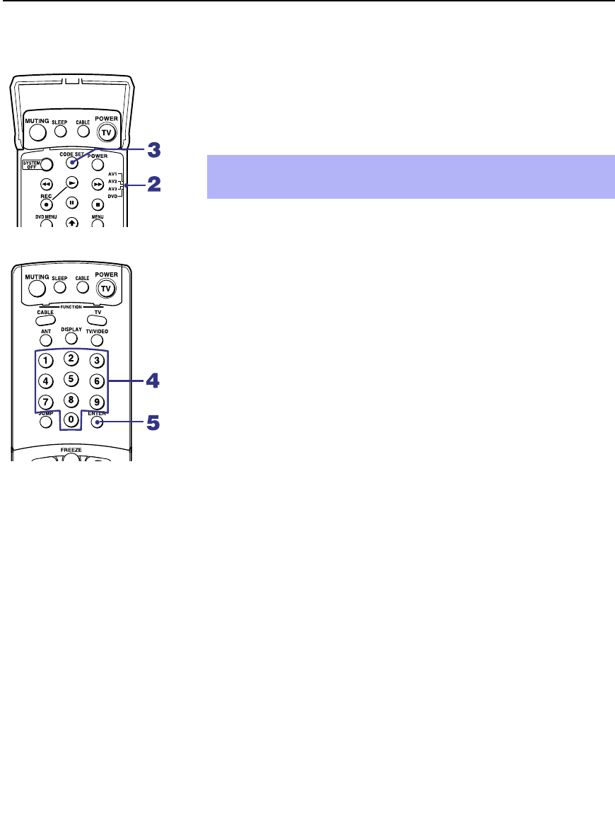
Other Information
56
To program video equipment
1Open the panel of the remote control.
2Move the slide switch to the desired component type.
3Press CODE SET inside the panel.
4Close the panel and enter the three-digit manufacturer’s code number
using the 0-9 buttons.
5Press ENTER.
6To check if the code number works, aim the projection TV’s remote
control at the component, open the panel, and press the green POWER
button. If it responds, the programming is completed. If not, try using
the other codes listed for that manufacturer.
Tips
❑If more than one code number is listed, try entering them one by one
until you come to the correct code for your component.
❑If you enter a new code number, the code number you previously
entered at that setting is erased.
❑In some rare cases, you may not be able to operate your component with
the Sony remote control. In this case, use the component’s own remote
control unit.
✍You must perform step 4 within 10 seconds of step 3, or you must
start again from step 3.

Other Information
57
Other Information
Manufacturer’s Codes
VCRs
DVD Players
Cable Boxes
Manufacturer Code
Sony 301
Admiral
(M. Ward)
327
Aiwa 338, 344
Audio Dynamic 314, 337
Broksonic 319, 317
Canon 309, 308
Citizen 332
Craig 302, 332
Criterion 315
Curtis Mathes 304, 338, 309
Daewoo 341, 312, 309
DBX 314, 336, 337
Dimensia 304
Emerson 319, 320, 316,
317, 318, 341
Fisher 330, 335
Funai 338
General Electric 329, 304, 309
Go Video 322, 339, 340
Goldstar 332
Hitachi 306, 304,
305, 338
Instant Replay 309, 308
JC Penney 309, 305, 304,
330, 314, 336,
337
JVC 314, 336, 337,
345, 346, 347
Kenwood 314, 336, 332,
337
LXI (Sears) 332, 305, 330,
335, 338
Magnavox 308, 309, 310
Marantz 314, 336, 337
Marta 332
Memorex 309, 335
Minolta 305, 304
Mitsubishi/
MGA
323, 324, 325,
326
Multitech 325, 338, 321
NEC 314, 336, 337
Olympic 309, 308
Optimus 327
Panasonic 308, 309, 306,
307
Pentax 305, 304
Philco 308, 309
Philips 308, 309, 310
Pioneer 308
Quasar 308, 309, 306
RCA/
PROSCAN
304, 305, 308,
309, 311, 312,
313, 310, 329
Realistic 309, 330, 328,
335, 324, 338
Sansui 314
Samsung 322, 313, 321
Sanyo 330, 335
Scott 312, 313, 321,
335, 323, 324,
325, 326
Sharp 327, 328
Shintom 315
Signature 2000
(M. Ward)
338, 327
SV2000 338
Sylvania 308, 309, 338,
310
Symphonic 338
Tashiro 332
Tatung 314, 336, 337
Teac 314, 336, 338,
337
Technics 309, 308
Toshiba 312, 311
Manufacturer Code
Wards 327, 328, 335,
331, 332
Yamaha 314, 330, 336,
337
Zenith 331
Manufacturer Code
Sony 751
Panasonic 753
Pioneer 752
RCA 755
Toshiba 754
Manufacturer Code
Hamlin/Regal 222, 223, 224,
225, 226
Jerrold/G. I. 201, 202, 203,
204, 205, 206,
207, 208, 218
Oak 227, 228, 229
Panasonic 219, 220, 221
Pioneer 214, 215
Scientific
Atlanta
209, 210, 211
Tocom 216, 217
Zenith 212, 213
Manufacturer Code

Other Information
58
Operating Other Components with Your Projection TV Remote
Control
Operating a VCR Open the panel and move the slide switch to the AV input you coded for this
device.
Operating a DVD
Player Open the panel and move the slide switch to the DVD input you coded for
this device.
To Do This ... Press
Turn on/off green POWER button (inside the panel)
Change channels CH +/–
Record N and REC simultaneously
Play N
Stop x
Fast forward M
Rewind the tape m
Pause X (press again to resume normal playback)
Search the picture
forward or backward
M or m during playback
(release to resume normal playback)
Change input mode Slide switch
To Do This ... Press
Turn on/off green POWER button (inside the panel)
Play N
Stop x
Pause X (press again to resume normal playback)
Step through different tracks of
an audio disc
M to step forward or m to step backward
Step through different chapters
of a video disc
CH+ to step forward or CH– to step backward
Display the DVD menu DVD MENU
Display the menu (Setup) MENU
Operate the DVD menu M, m, <, ,, ENTER

Other Information
59
Other Information
Operating a Cable
Box To Do This ... Press
Turn on/off CABLE (POWER)
Select Cable Box CABLE (FUNCTION)
Select a channel 0-9 buttons, ENTER
Change channels CH +/–
Back to previous channel JUMP

Other Information
60
Troubleshooting
Problem Possible Remedies
No picture
(screen not lit),
no sound
❏Make sure the projection TV’s power cord is connected securely to the wall outlet.
❏Push the power button on the front of the projection TV.
❏Check to see if the TV/VIDEO setting is correct: when watching TV, set to TV,
and when watching connected equipment, set to VIDEO 1, 2, 3, 4, 5 or 6.
❏Try another channel. It could be station trouble.
❏The Channel Block feature is activated (see “Using the Parent Menu (Channel
Block)” on page 51).
❏If your projection TV does not turn on, and a red light keeps flashing, your
projection TV may need service. Call your local Sony Service Center.
Remote control
does not operate
❏Batteries could be weak. Replace the batteries.
❏Press TV (FUNCTION) when operating your projection TV.
❏Make sure the projection TV’s power cord is connected securely to the wall outlet.
❏Locate the projection TV at least 3-4 feet away from fluorescent lights.
❏Check the orientation of the batteries.
Dark, poor or no
picture (screen lit),
good sound
❏Adjust the Picture setting in the Video menu (see page 45).
❏Adjust the Brightness setting in the Video menu (see page 45).
❏Check antenna/cable connections.
❏Adjust the convergence again using FLASH FOCUS (see “Adjusting the
Convergence Automatically – FLASH FOCUS™ –” on page 30).
Good picture,
no sound
❏Press MUTING so that “MUTING” disappears from the screen (see page 31).
❏Make sure Speaker is set to ON in the Audio menu (see page 47).
Cannot receive digital channels
(when a DTV receiver is
connected)
❏Check the connections between the DTV receiver and the projection TV (see page
25).
❏Check your local listings to find out if you can receive digital broadcasts in your
area.
Cannot receive upper channels
(UHF) when using an antenna
❏Change Cable to OFF (see page 49).
❏Use Auto Program in the Channel menu to add receivable channels that are not
presently in TV memory (see page 50).
No color ❏Adjust the Color settings in the Video menu (see page 45).
Only snow and noise
appear on the screen
❏Check the Cable setting in the Channel menu (see “Cable” on page 49).
❏Check the antenna/cable connections.
❏Make sure the channel is broadcasting programs.
❏Press ANT to change the input mode (see page 34).
Dotted lines
or stripes
❏Adjust the antenna.
❏Move the projection TV away from noise sources such as cars, neon signs, or hair-
dryers.
Projection TV is fixed to one
channel
❏Use Auto Program in the Channel menu to add receivable channels that are not
presently in TV memory (see page 50).
❏Check your Channel Fix settings (see page 50).
Double images or ghosts ❏Use a highly directional outdoor antenna or a cable (when the problem is caused by
reflections from nearby mountains or tall buildings).

Other Information
61
Other Information
Cannot operate menu ❏If the item you want to choose appears in gray, you cannot select it.
❏Turn the projection TV’s power off and on again.
Cannot receive any channels
when using cable TV
❏Use Auto Program in the Channel menu to add receivable channels that are not
presently in TV memory (see page 50).
❏Check your cable settings.
❏Make sure Cable is set to ON in the Channel menu (see page 49).
Cannot gain enough volume
when using a cable box
❏Increase the volume of the cable box using the cable box’s remote control. Then
press TV (FUNCTION) and adjust the projection TV’s volume.
Channel Index does not display
all available channels
❏Make sure Cable is set to ON in the Channel menu (see “Cable” on page 49).
❏Use Auto Program in the Channel menu to add receivable TV channels that are
not presently in TV memory (see page 50).
Cannot receive channels
Unable to select a channel
❏Use Auto Program in the Channel menu to add receivable TV channels that are
not presently in TV memory (see page 50).
Cannot change channels with
the remote control
❏Be sure you have not inadvertently switched your projection TV from channel 3 or
4 setting if you are using another device to change channels.
❏If you are using another device to control channels, be sure the “function” button
for that device has been pressed, or the slide switch is set correctly. For example, if
you are using your cable to control channels, be sure to press CABLE.
Cannot cycle through the other
video equipment connected to
the projection TV
❏Be sure the Video Label feature has not been set to Skip (see page 54).
There is a black box on the
screen
❏You have selected a text option in the Setup menu and no text is available (see
page 53 to reset Setup selections). To turn this feature off, select OFF in the
Caption Vision option. If you were trying to get closed captioning, select CC1
instead of Text 1-4.
There is no twin picture or it is
just static
❏Be sure your twin picture is set to a video source/channel that has a program airing.
❏You may be tuned to a video input with nothing connected to it. Try cycling
through your video inputs using TV/VIDEO.
❏Twin View is not set to receive a signal from the AUX input. If you have
connected a VCR, DVD player or satellite receiver to the AUX input on the
projection TV, it will not show in the second picture.
You get the same program in the
window picture as in the main
picture
❏Both may be set to the same channel. Try changing channels in either the main
picture or the window picture.
❏You may be running all your channels through a cable box. The cable box will
only unscramble one signal at a time, so you cannot use the Twin View feature. If
possible, run a direct cable to your projection TV’s VHF/UHF input (this will only
work if your cable system provides an unscrambled signal).
You cannot get anything but TV
channels in your second picture
❏Be sure the video label has not been set to skip your video inputs. See the Setup
menu on page 53.
Favorite Channel does not
display your choices
❏Verify that Favorite Channel is set to Manual in the Channel menu (see
“Favorite Channel” on page 49).
Problem Possible Remedies
(Continued)


Other Information
63
Other Information
Specifications
Projection System 3 picture tubes, 3 lenses, horizontal in-line system
Picture Tube 7-inch high-brightness monochrome tubes (6.3 raster size), with optical
coupling and liquid cooling system
Projection Lenses High performance, large
diameter hybrid lens F1.1
Antenna 75 ohm external terminal for VHF/UHF
Television System NTSC, American TV Standard
Screen Size (measured diagonally) 43 inches (KP-HR432K90)
53 inches (KP-HR532K90)
Channel Coverage
VHF 2-13
UHF 14-69
CATV 1-125
Power Requirements 220 V, 60 Hz
Number of Inputs/Outputs
Video (IN) 4 1 Vp-p, 75 ohms unbalanced, sync negative
S Video (IN) 3 Y: 1 Vp-p, 75 ohms unbalanced, sync
negative
C: 0.286 Vp-p (Burst signal), 75 ohms
Audio (IN) 6 500 mVrms (100% modulation)
Impedance: 47 kiloohms
AUDIO (VAR/FIX) OUT 1 500 mVrms (100 % modulation), Impedance:
470 ohms
TV Out 1 1 Vp-p, 75 ohms unbalanced, sync negative
CONTROL S (IN/OUT) 1 Minijacks
Component Video Input 2 (Y, PB, PR) Y: 1.0 Vp-p, 75 ohms unbalanced, sync
negative
PB: 0.7 Vp-p, 75 ohms
PR: 0.7 Vp-p, 75 ohms
RF Inputs 2
Converter 1
Speaker Output 20 W × 2
Dimensions (W × H × D) 966 × 1,072 × 577 mm (KP-HR432K90)
1,180 × 1,430 × 626 mm (KP-HR532K90)
Mass 56 kg (KP-HR432K90)
71 kg (KP-HR532K90)
Power Consumption
In Use 230 W
In Standby 1.2 W
Supplied Accessories
Remote Control RM-Y909K
AA (R6) Batteries 2 supplied for remote control
Optional Accessories
AV Cable VMC-810/820/830 HG
(Continued)

Other Information
64
Design and specifications are subject to change without notice.
Audio Cable RKC-515HG
Control S Cable RK-G69HG
Component Video Cable VMC-10/30 HG

65
Other Information
Index
16:9 (widescreen) 7, 54
A
Activating a Twin View screen 38
Adding channels to the channel list 50
Adjusting audio, Steady Sound 47
ANT button 31
Antenna, connecting 15
Aspect ratio, 16:9 in Twin View 39
Audio menu 44, 47
Audio receiver, connecting 22
Audio/Video cable 11
Auto Program (channel setup) 29, 50
Auto Setup 29, 50
AV receiver, connecting to TV OUT 14
B
Balance, adjusting 47
Bass, adjusting 47
Batteries, inserting into remote 9
Bilingual audio 47
BILINGUAL button 33
BILINGUAL, using 35
Blocking programs. See Ratings.
Brightness, adjusting 45
C
Cable
setting ON/OFF 49
with VCR, connecting 18
Cable box
connecting with VCR 19
using with TV remote control 59
Camcorder, connecting 26
Caption Vision 53
CATV. See cable.
Channel Block 51
Channel Index
described 7
using 42
Channel list, adding channels 50
Channel menu 44, 49
Channel Skip/Add 50
Channels
Auto Program 50
creating labels 50
setting up 29
CineMotion, DRC 32, 46
Closed caption modes 53
CODE SET button 33
Color temperature, adjusting 45
Color, adjusting 45
Connecting
Audio receiver 22
AV receiver 27
Cable box 16, 17, 19–20
Cable or antenna 15
Camcorder 26
Digital TV Receiver 25
DVD player 23, 24
VCR 19–21
Connector Types 11
Contents of box 9
CONTROL S 28
Convergence, adjusting automatically 30
D
Daylight saving 52
Digital Reality Creation 46
Digital TV
connecting 25
watching 36
Digital TV program 36
Digital TV receiver, connecting 25
DISPLAY button 31
Display, turning off 31
DRC (Digital Reality Creation) Mode, described 7
DRC⁄CINEMOTION button 32
DVD MENU button 33
DVD player
using with TV remote control 58
with A/V connectors, connecting 24
with component video connectors, connecting 23
(Continued)

66
E
Effect
OFF 47
Simulated 47
TruSurround 47
Enhanced picture resolution, 16:9 54
Enlarging pictures, in Twin View 40
Extended Data Service 53
F
Favorite Channel
auto 49
described 7
manual 49
setting up 49
using 37
FAVORITES button 31
Features 7
Flash Focus
described 7
performing 30
FREEZE button 31
Freeze, using 34, 41
Front Panel Controls 12
FUNCTION buttons (WHITE) 32
H
Hookups 15
Hue, adjusting 45
I
Inputs, labeling 54
Installation of the projection TV 15–28
J
JUMP button 31
Jump, using 34
L
Label
channels 50
video inputs 54
Locking programs 51
M
MENU button 32
MENU button (inside panel) 33
Menus
Audio 44, 47
Channel 44, 49
Parent 44, 51
Setup 44, 53
Timer 44, 52
Video 44, 45
MODE
Movie 35
Pro 35
Standard 35
Vivid 35
Muting, using 34
P
Parent menu 44, 51
PIC MODE button 31
Picture contrast, adjusting 45
Picture size, adjusting in Twin View 40
POWER button 33
POWER buttons (GREEN) 32
Presetting channels 29
Problems, troubleshooting 60
R
Rear panel controls and connections 13, 14
Remote control
buttons inside panel 33
Function of buttons 34
inserting batteries 9
programming 55–57
Remote control, operating other components with
Cable box 59
DVD player 58
VCR 58
Removing channels from the channel list 50
RESET button 31
Resetting
Audio options 47
Timer options 52
Video options 45
S
S Video cable 11
SAT/CABLE function button 32
SAT/CABLE power button 32
Setting up channels 29
Setup menu 44, 53
Sharpness, adjusting 45
SLEEP button 31

67
Other Information
Sleep, using 35
Specifications 63–64
Steady Sound
adjusting 47
described 7
Surround sound 47
SYSTEM OFF button 33
T
Tape-to-tape editing 21
Time
set current 52
set daylight saving 52
Timer menu 44, 52
Timer setting 52
Treble, adjusting 47
Troubleshooting 60
TV function button 32
TV power button 32
TV/VIDEO button 32
Twin View™
activating a picture 38
described 7
using 38
V
VCR
connecting two, for tape editing 21
using with TV remote control 58
with cable box, connecting 19
with cable, connecting 18
Video inputs, labeling 54
Video menu 44, 45
Video Modes, selecting 45
Viewing area, recommended 10
VOL +/– button 31, 34
W
Widescreen 54
Widescreen, described 7
Z
Zoom feature, with Twin View 40

Printed in Malaysia
Operating Instructions
© 2001 Sony Corporation
4-085-459-F1(1)
Projection TV
Operating Instructions
KP-HR532N90
2
WARNING
To prevent fire or shock hazard, do not
expose the projection TV to rain or
moisture.
This symbol is intended to alert the user to the
presence of uninsulated “dangerous voltage”
within the product’s enclosure that may be of
sufficient magnitude to constitute a risk of
electric shock to persons.
This symbol is intended to alert the user to the
presence of important operating and
maintenance (servicing) instructions in the
literature accompanying the appliance.
CAUTION
To prevent electric shock, do not use this polarized AC
plug with an extension cord, receptacle or other outlet
unless the blades can be fully inserted to prevent blade
exposure.
CAUTION
When using TV games, computers, and similar
products with your projection TV, or viewing a
TV station whose logo always stays on the
screen, keep the brightness and contrast
functions at low settings. If a fixed (non-moving)
pattern such as a station logo is left on the screen
for long periods of time, especially at a high
brightness or contrast setting, the image can be
permanently imprinted onto the screen. These
types of imprints are not covered by your
warranty.
Safety
❑Operate the projection TV only on 110 V AC.
❑The plug is designed, for safety purposes, to fit into
the wall outlet only one way. If you are unable to
insert the plug fully into the outlet, contact your
dealer.
❑If any liquid or solid object should fall inside the
cabinet, unplug the projection TV immediately and
have it checked by qualified service personnel
before operating it further.
❑If you will not be using the projection TV for several
days, disconnect the power by pulling the plug itself.
Never pull on the cord.
For details concerning safety precautions, see
“Important Safeguards” on page 3.
Installing
❑To prevent internal heat buildup, do not block the
ventilation openings.
❑Do not install the projection TV in a hot or humid
place, or in a place subject to excessive dust or
mechanical vibration.
❑Avoid operating the projection TV at temperature
below 5°C.
❑If the projection TV is transported directly from a
cold to a warm location, or if the room temperature
changes suddenly, the picture may be blurred or
show poor color. In this case, please wait a few hours
to let the moisture evaporate before turning on the
projection TV.
❑To obtain the best picture, do not expose the screen
to direct illumination or direct sunlight. It is
recommended to use spot lighting directed down
from the ceiling or to cover the windows that face
the screen with opaque drapery. It is desirable to
install the projection TV in a room where the floor
and walls are not of a reflective material.
Note on convergence adjustment
Before you use your projection TV, make sure to adjust
convergence. For details, see “Adjusting the Convergence
Automatically – FLASH FOCUS™ –” on page 32.
TruSurround and the ( ) symbol are trademarks of SRS
Labs, Inc.
TruSurround technology is incorporated under license
from SRS Labs, Inc.
BBE and BBE Symbol are trademarks of BBE Sound,
Inc. and are licensed by BBE Sound, Inc. under U.S.
Patent No. 4,638,258 and 4,482,866.
CAUTION
RISK OF ELECTRIC SHOCK
DO NOT OPEN
ATTENTION
RISQUE DE CHOC ELECTRIQUE,
NE PAS OUVRIR
PRECAUCION
RIESGO DE CHOQUE ELECTRICO
CAUTION : TO REDUCE THE RISK OF ELECTRIC SHOCK,
DO NOT REMOVE COVER (OR BACK).
NO USER-SERVICEABLE PARTS INSIDE.
REFER SERVICING TO QUALIFIED SERVICE PERSONNEL.
NO ABRIR
3
Important Safeguards
For your protection, please read these instructions
completely, and keep this manual for future reference.
Carefully observe and comply with all warnings, cautions
and instructions placed on the set or described in the
operating instructions or service manual.
WARNING
To guard against injury, the following basic safety
precautions should be observed in the installation, use
and servicing of the set.
Use
Power Sources
This set should be operated only from
the type of power source indicated on
the serial/model plate. If you are not sure
of the type of electrical power supplied
to your home, consult your dealer or
local power company. For those sets designed to operate
from battery power, refer to the operating instructions.
Grounding or Polarization
This set is equipped with a polarized AC power cord plug
(a plug having one blade wider than the other), or with a
three-wire grounding type plug (a plug having a third pin
for grounding). Follow the instructions below:
Overloading
Do not overload wall outlets, extension
cords or convenience receptacles
beyond their capacity, since this can
result in fire or electric shock.
Always turn the set off when it is not
being used. When the set is left
unattended and unused for long
periods of time, unplug it from the
wall outlet as a precaution against the
possibility of an internal malfunction that could create a
fire hazard.
If a snapping or popping sound from a TV
set is continuous or frequent while the TV
is operating, unplug the TV and consult
your dealer or service technician. It is
normal for some TV sets to make
occasional snapping or popping sounds,
particularly when being turned on or off.
Object and Liquid Entry
Never push objects of any kind into the
set through the cabinet slots as they may
touch dangerous voltage points or short
out parts that could result in a fire or
electric shock. Never spill liquid of any
kind on the set.
Attachments
Do not use attachments not
recommended by the manufacturer, as
they may cause hazards.
Cleaning
Clean the cabinet of the projection TV
with a dry soft cloth. To remove dust
from the screen, wipe it gently with a soft
cloth. Stubborn stains may be removed
with a cloth slightly dampened with
solution of mild soap and warm water. Never use strong
solvents such as thinner or benzine for cleaning.
If the picture becomes dark after using the projection TV
for a long period of time, it may be necessary to clean the
inside of the projection TV. Consult qualified service
personnel.

4
Installation
Water and Moisture
Do not use power-line operated sets
near water — for example, near a
bathtub, washbowl, kitchen sink, or
laundry tub, in a wet basement, or
near a swimming pool, etc.
Accessories
Do not place the set on an unstable
cart, stand, table or shelf. The set
may fall, causing serious injury to a
child or an adult and serious damage
to the set. Use only a cart or stand
recommended by the manufacturer
for the specific model of projection
TV. An appliance and cart
combination should be moved with
care. Quick stops, excessive force,
and uneven surfaces may cause the appliance and cart
combination to overturn.
Ventilation
The slots and openings in the cabinet and in the back or
bottom are provided for necessary ventilation. To ensure
reliable operation of the set, and to protect it from
overheating, these slots and openings must never be
blocked or covered.
❑Never cover the slots and openings
with a cloth or other materials.
❑Never block the slots and openings by
placing the set on a bed, sofa, rug or
other similar surface.
❑Never place the set in a confined
space, such as a bookcase or built-in
cabinet, unless proper ventilation is
provided.
❑Do not place the set near or over a
radiator or heat register, or where it is
exposed to direct sunlight.
Power-Cord Protection
Do not allow anything to rest on or roll
over the power cord, and do not place the
set where the power cord is subject to
wear or abuse.
Antennas
Outdoor Antenna Grounding
If an outdoor antenna is installed, follow the precautions
below. An outdoor antenna system should not be located
in the vicinity of overhead power lines or other electric
light or power circuits, or where it can come in contact
with such power lines or circuits.
WHEN INSTALLING AN OUTDOOR ANTENNA
SYSTEM, EXTREME CARE SHOULD BE TAKEN TO
KEEP FROM CONTACTING SUCH POWER LINES
OR CIRCUITS AS CONTACT WITH THEM IS
ALMOST INVARIABLY FATAL.
Be sure the antenna system is grounded so as to provide
some protection against voltage surges and built-up static
charges.
Lightning
For added protection for this television receiver during a
lightning storm, or when it is left unattended and unused
for long periods of time, unplug it from the wall outlet
and disconnect the antenna. This will prevent damage to
the receiver due to lightning and power-line surges.
5
Service
Damage Requiring Service
Unplug the set from the wall outlet and refer servicing to
qualified service personnel under the following
conditions:
❑When the power cord or
plug is damaged or frayed.
❑If liquid has been spilled into
the set.
❑If the set has been exposed
to rain or water.
❑If the set has been subject to
excessive shock by being
dropped, or the cabinet has
been damaged.
❑If the set does not operate
normally when following the
operating instructions.
Adjust only those controls
that are specified in the
operating instructions.
Improper adjustment of
other controls may result in
damage and will often
require extensive work by a
qualified technician to restore the set to normal
operation.
❑When the set exhibits a distinct change in
performance, it indicates a need for service.
Servicing
Do not attempt to service the set yourself
since opening the cabinet may expose you to
dangerous voltage or other hazards. Refer all
servicing to qualified service personnel.
Replacement Parts
When replacement parts are required, be sure the service
technician certifies in writing that he has used
replacement parts specified by the manufacturer that have
the same characteristics as the original parts.
Unauthorized substitutions may result in fire, electric
shock or other hazards.
Safety Check
Upon completion of any service or repairs
to the set, ask the service technician to
perform routine safety checks (as specified
by the manufacturer) to determine that the
set is in safe operating condition, and to so
certify. When the set reaches the end of its
useful life, improper disposal could result
in a picture tube implosion. Ask a qualified
service technician to dispose of the set.
For Safety
Be careful when moving
the projection TV
When you place the projection TV
in position, be careful not to drop it
on your foot or fingers.
Watch your footing while installing the projection TV.
Carry the projection TV in the
specified manner
If you carry the projection TV in a manner
other than the specified manner and
without the specified number of persons, it
may drop and a serious injury may be
caused. Be sure to follow the instructions mentioned
below.
❑Carry the projection TV with the specified number
of persons (see page 9).
❑Do not carry the projection TV holding the speaker
grill.
❑Hold the projection TV tightly when carrying it.
Owner’s Record
The model and serial numbers are located at the rear of
the projection TV, below the Sony logo, on the sticker,
and also on the TV box (white label). Record these
numbers in the spaces provided below. Refer to them
whenever you call upon your Sony dealer regarding this
product.
Model No.
Serial No.

6
Contents
Important Safeguards...............................................3
Introducing the Sony Projection TV
Presenting the Sony Projection TV..........................7
Using this manual ....................................................8
Installing and Connecting the
Projection TV
Contents ...................................................................9
Inserting Batteries into the Remote Control ............9
Carrying Your Projection TV ..................................9
Installing the Projection TV...................................10
Connector Types....................................................11
Projection TV Controls and Connectors................12
Basic Connections (Connecting Cable TV or
Antenna).........................................................15
Connecting a VCR and Cable................................18
Connecting a VCR and Cable Box ........................19
Connecting Two VCRs for Tape Editing ..............21
Connecting a Satellite Receiver.............................22
Connecting a Satellite Receiver with a VCR.........23
Connecting an Audio Receiver..............................24
Connecting a DVD Player with Component
Video Connectors ..........................................25
Connecting a DVD Player with A/V Connectors ..26
Connecting a Digital TV Receiver.........................27
Connecting a Camcorder .......................................28
Connecting an AV Receiver ..................................29
Using the CONTROL S Feature............................30
Setting Up the Projection TV Automatically.........31
Adjusting the Convergence Automatically
– FLASH FOCUS™ –...................................32
Using the Features
Using the Remote Control .....................................33
Watching the TV....................................................36
Watching the Digital TV........................................38
Using Favorite Channels........................................39
Using Twin View™...............................................40
Using the Freeze Function .....................................43
Using Channel Index .............................................44
Using the Menus
Overview................................................................46
Using the Video Menu..........................................47
Using the Audio Menu..........................................49
Using the Channel Menu ......................................51
Using the Parent Menu (Channel Block)..............53
Using the Timer Menu..........................................54
Using the Setup Menu ..........................................55
Other Information
Programming the Remote Control.........................57
Operating Other Components with Your
Projection TV Remote Control......................60
Troubleshooting.....................................................62
Specifications.........................................................65

7
Introducing the Sony Projection TV
Presenting the Sony Projection TV
Thank you for purchasing the Sony Projection TV.
This manual is for model KP-HR532N90.
Features Some of the features that you will enjoy with your new projection TV
include:
❑1080i Capable: Enables you to receive the 1080i, 720p, 480p and 480i
digital TV formats. By using the VIDEO 5/6 IN jacks, you can connect
a DTV (digital television) receiver to view DTV programs.
❑DRC™ Multi-Function: Unlike conventional line doublers, the DRC
feature doubles vertical and horizontal lines, resulting in four times the
density for quality sources such as DVD, Satellite and Digital
camcorder.
❑CineMotion™: Using the 2-3 Pull-Down technology, the CineMotion
feature allows you to obtain a smooth picture movement when playing
back movies or other video sources on film.
❑Twin View™: Using Multi-Image Driver (MID-X), Twin View allows
you to watch two programs side by side with the ability to zoom in on
one picture and listen to the program in the selected window. You can
watch pictures from two different sources (1080i, 720p, 480p or 480i)
simultaneously.
❑16:9 Enhancement: Vertical Compression technology that maximizes
picture resolution on “anamorphic” or “enhanced for wide screen”
sources, including selected DVDs.
❑Steady Sound™: Equalizes volume levels so there is consistent output
between programs and commercials.
❑Component Video Inputs: Offers the best video quality for DVD
(480p, 480i) and Digital Set-top box (1080i, 720p, 480p, 480i)
connections.
❑S-VIDEO Inputs: Provides a high-quality image for connected
equipment.
❑Favorite Channel Preview: Preview up to eight favorite channels
without leaving the current channel.
❑Channel Index: Allows you to view and choose from twelve programs.
❑Flash Focus™: Allows you to adjust convergence automatically.

Introducing the Sony Projection TV
8
Using this manual
We recommend that you carefully review the contents of the following three
sections in the order shown to ensure that you fully understand the operation
of your new projection TV.
1Installing and Connecting the Projection TV
This section guides you through your initial setup. It shows you how to
install your projection TV, to connect your new components and to connect
the antenna and cable.
2Using the Features
This section shows you how to begin using your new projection TV. It also
shows you how to use your remote control functions.
3Using the menus
This section teaches you how to access on-screen menus and adjust your
projection TV settings.
Instructions in this manual are written for the remote control. Similar
controls are also found on the projection TV console.

9
Installing and Connecting the Projection TV
Contents
The box contains your new projection TV, a remote control and two AA
batteries. No peripheral cables are included. If you intend to add additional
equipment to your projection TV, please check the hookup instructions for
your desired setup before you begin. You may need to purchase cables and/
or splitters to complete the hookup properly.
Inserting Batteries into the Remote Control
Insert two size AA (R6) batteries (supplied) by matching the + and – on the
batteries to the diagram inside the battery compartment.
Carrying Your Projection TV
Carrying the projection TV requires three (3) or more people.
The projection TV has been equipped with casters for easy movement on a
hard surface.
Please move your projection TV using the casters.
✍Remove the batteries to avoid damage from possible battery leakage
whenever you anticipate that the remote control will not be used for an
extended period.
✍Handle the remote control with care. Avoid dropping it, getting it wet, or
placing it in direct sunlight, near a heater, or where the humidity is high.
✍Your remote control can be programmed to operate most video
equipment. (See “Programming the Remote Control” on page 57.)
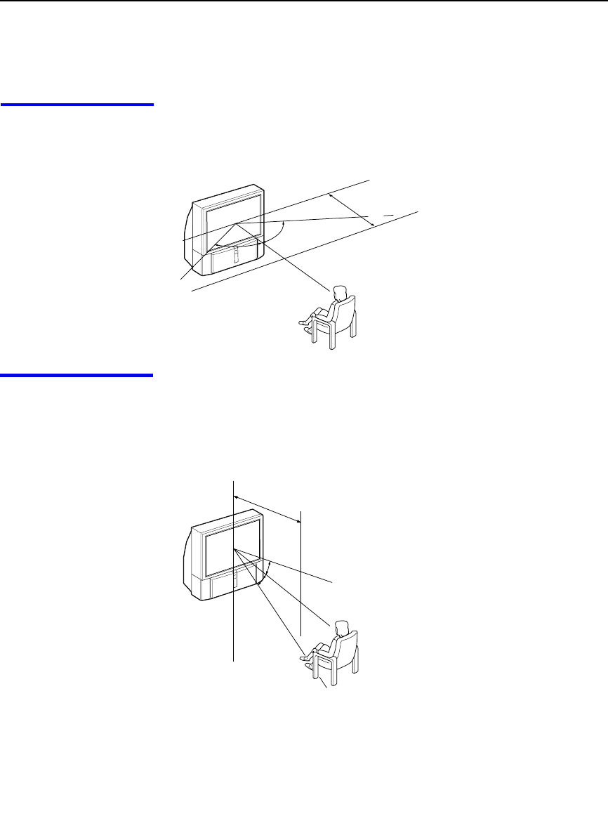
Installing and Connecting the Projection TV
10
Installing the Projection TV
Recommended
viewing area
(Horizontal)
60˚
60 60˚
min. 2.1 m
20˚
20˚
min. 2.1 m
Recommended
viewing area
(Vertical)
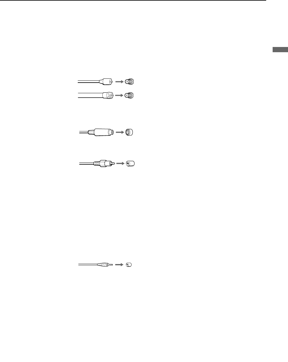
Installing and Connecting the Projection TV
11
Installing and Connecting the Projection TV
Connector Types
You may find it necessary to use some of the following connector types
during set up.
Coaxial cable
Standard TV cable and antenna cable
S Video cable
High quality video cable for enhanced picture quality
Audio/Video cable
Video - Yellow
Audio (Left) - White
Audio (Right) - Red
Some DVD Players are equipped with the following three video connectors:
Y - Green
PB (CB, Cb or B–Y) - Blue
PR (CR, Cr or R–Y) - Red
CONTROL S cable
CONTROL S connections are exclusive to Sony products and allow greater
control of all Sony equipment.
Plug Type
Screw-on Type
Push into connection.
Screw into connection.
Align guides and push
into connection.
Push into connection.
Push into connection.
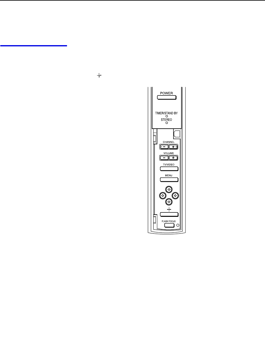
Installing and Connecting the Projection TV
12
Projection TV Controls and Connectors
Front Panel Menu
Controls The front panel menu controls allow access to the on-screen menus without
the use of a remote control. Pressing MENU brings up the on-screen menus.
The arrow buttons move the on-screen cursor in the menus and the Select
button ( ) selects the menu item.
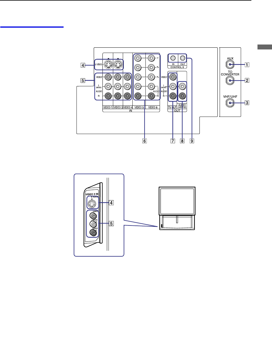
Installing and Connecting the Projection TV
13
Installing and Connecting the Projection TV
Projection TV Rear
and Front Panel
Connectors Rear of projection TV
Front of projection TV
(Continued)

Installing and Connecting the Projection TV
14
Connection Description
1AUX Allows you to view local and cable channels if your cable
provider does not feature local channels. You can switch
between local and cable channels easily by pressing ANT
on the remote control. Devices connected to the AUX
input cannot be viewed in Twin View.
2TO CONVERTER This is a VHF/UHF OUT jack that lets you set up your
projection TV to switch between scrambled channels
(through a cable box) and normal cable channels (CATV).
Use this jack instead of a splitter to get better picture
quality when switching between scrambled and
unscrambled cable channels.
3VHF/UHF Connects to your VHF/UHF antenna or cable.
4S VIDEO
(Rear and front) Connects to the S VIDEO OUT jack of your VCR or other
S VIDEO-equipped video component. Provides better
picture quality than the VHF/UHF jacks or the Video IN
jack.
5VIDEO
(L/R)/AUDIO
(Rear and front)
Connects to the audio and video OUT jacks on your VCR
or other video component. A fourth video input (VIDEO
2) is located on the front panel of the projection TV.
6Y/PB/PR
(L/R)/AUDIO Connects to your DVD player’s or Digital Set-top box’s
component video (Y, PB, PR) and audio (L/R) jacks.
7TV OUT Connects to an AV receiver for greater control of all audio
and video equipment (see page 29). For detailed
information about connection, refer to the operating
manual supplied with the AV receiver.
8AUDIO OUT
(VAR/FIX)
L (MONO)/R
Connects to the left and right audio inputs of your audio or
video component.
9CONTROL S
IN/OUT To control other Sony equipment with the projection TV's
remote control, connect the CONTROL S IN jack of the
equipment to the CONTROL S OUT jack on the
projection TV with the CONTROL S cable.
To control the projection TV with a remote control for
another Sony product, connect the CONTROL S OUT
jack of the equipment to the CONTROL S IN jack on the
projection TV with the CONTROL S cable.

Installing and Connecting the Projection TV
15
Installing and Connecting the Projection TV
Basic Connections (Connecting Cable TV or Antenna)
Connecting Directly
to Cable or an
Antenna
The connection you choose depends on the cable found in your home. Newer
homes are equipped with standard coaxial cable (see A); older homes
probably have 300-ohm twin lead cable (see B); other homes may contain
both (see C).
A VHF Only or VHF/UHF or Cable
B VHF Only or UHF Only or VHF/UHF
C VHF and UHF
Cable and Antenna If your cable provider does not feature local channels, you may find this set
up convenient.
Select CABLE or antenna (ANT) mode by pressing ANT on the remote
control.
75-ohm coaxial
cable Rear of projection TV
VHF/UHF
Rear of projection TV
Antenna connector
300-ohm twin lead cable VHF/UHF
Rear of projection TV
75-ohm coaxial cable VHF/UHF
U/V Splitter
(not supplied)
300-ohm twin lead cable
✍To receive channels with an antenna, you need to turn your Cable to OFF
(see page 51) and perform the Auto Program function (see page 52).
CATV cable
Rear of projection TV
TO
CONVERTER
(No connection to
TO CONVERTER)
VHF/UHF
Antenna cable
AUX
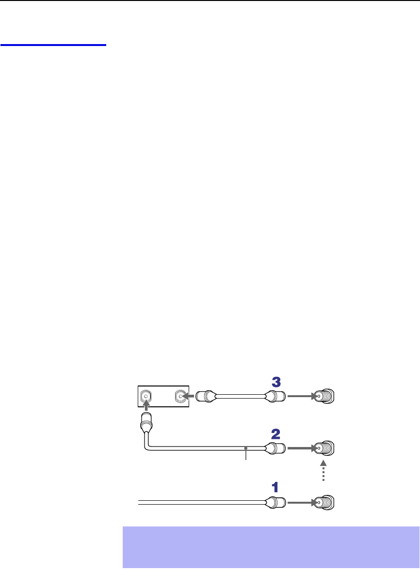
Installing and Connecting the Projection TV
16
Cable Box
Connections Cable Box and Cable
This is the preferred basic cable TV hookup to use if:
❑Your cable TV company scrambles some channels, but not all of them
(pay channels vs. regular cable channels) and you need to use a cable
box, and
❑You want to enjoy the Twin View feature.
With this setup you can:
❑Use the projection TV remote control to change channels using your
cable box when the signal is scrambled.
❑Use the projection TV remote control to change channels using your
projection TV when the signal is not scrambled. (Your projection TV’s
tuner provides a better signal than the cable box.)
❑Use the Twin View feature. (When all channels are routed through your
cable box, only one channel is sent to the projection TV, so you can not
use the Twin View or Channel Index features for your cable box.)
1Connect the Cable TV cable to the projection TV’s VHF/UHF jack.
2Using a coaxial cable, connect the projection TV’s TO CONVERTER
jack to the cable box’s IN jack. The projection TV’s internal converter
allows you to switch between unscrambled signals coming straight into
the projection TV and scrambled signals coming in through the cable
box, eliminating the need for an external splitter.
3Using a coaxial cable, connect the cable box’s OUT jack to the
projection TV’s AUX jack.
✍Pressing ANT on the remote control switches between the channels
coming in through the cable box (scrambled) and those coming directly
to the TV (unscrambled).
Rear of
projection TV
TO
CONVERTER
VHF/UHF
AUX
Cable box
OUT
IN
Signal
75-ohm coaxial cable (not supplied)
CATV cable (unscrambled channels)

Installing and Connecting the Projection TV
17
Installing and Connecting the Projection TV
Cable Box Only
Use this hookup if:
❑You subscribe to a cable TV system that uses scrambled or encoded
signals requiring a cable box to view all channels, and
❑You do not intend to hook up any other audio or video equipment to
your projection TV.
When all channels are routed through your cable box, only one unscrambled
channel is sent to the projection TV, so you cannot use the Twin View
feature. If some channels are scrambled, but others are not, consider using
the hookup on page 16 instead.
1Connect the coaxial connector from your cable service to the cable
box’s IN jack.
2Using a coaxial cable, connect the cable box’s OUT jack to the TV’s
VHF/UHF jack.
Also, set Cable to ON in the Channel menu. (see page 51)
✍If you will be controlling all channel selection through your cable box,
consider using the Channel Fix feature to set your projection TV to
channel 3 or 4 (see page 52).
✍Your Sony remote control can be programmed to operate your cable box
(see “Programming the Remote Control” on page 57).
✍To change channels using the cable box, set your projection TV to
channel 3 or 4 depending on the cable box channel output.
VHF/UHF
Rear of projection TV
Cable
IN OUT
Cable box
Setting the Channel
Fix feature in the Channel
menu (see “Using the
Channel Menu” on page
51) ensures that you do
not accidentally switch
the channels using your
projection TV.
z
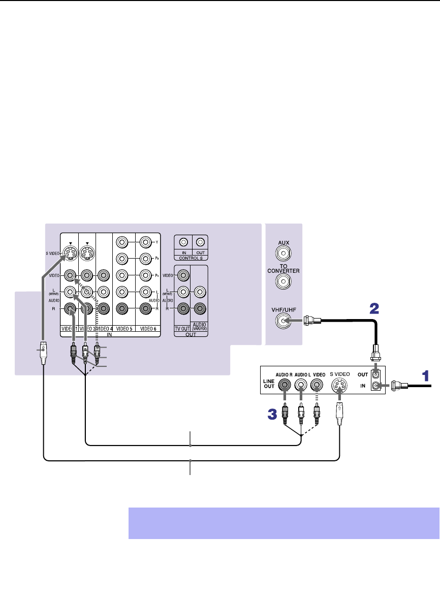
Installing and Connecting the Projection TV
18
Connecting a VCR and Cable
Use this hookup if:
❑You have cable TV that does not require a cable box.
Disconnect all power sources before making any connections.
1Connect the cable TV cable to the VCR’s IN jack.
2Using a coaxial cable, connect the VCR’s OUT jack to the projection
TV’s VHF/UHF jack.
3Using AUDIO and S VIDEO cables, connect the VCR’s Audio and
S VIDEO OUT jacks to the projection TV’s AUDIO and S VIDEO IN
jacks.
Coaxial cable
Rear of Projection TV
VIDEO (yellow)
AUDIO-L (white)
AUDIO-R (red)
Cable
VCR
VMC-810S/820S
(not supplied)
S VIDEO
YC-15V/30V (not supplied)
✍If your VCR is not equipped with S VIDEO, use a VIDEO cable (yellow)
instead of the S VIDEO cable.

Installing and Connecting the Projection TV
19
Installing and Connecting the Projection TV
Connecting a VCR and Cable Box
Use this hookup if:
❑Your cable TV company scrambles some channels, but not all of them
(pay channels vs. regular cable channels) and you need to use a cable
box, and
❑You want to enjoy the Twin View feature.
With this setup you can:
❑Use the projection TV remote control to change channels on your cable
box when the signal is scrambled. To program your Sony Remote
control to operate your cable box, see “Programming the Remote
Control” on page 57.
❑Use the projection TV remote control to change channels using your
projection TV when the signal is not scrambled. Your projection TV’s
tuner provides a better signal than the cable box.
❑Use the Twin View feature. (When all channels are routed through your
cable box, only one signal is sent to the projection TV, so you cannot
use the Twin View feature.)
Disconnect all power sources before making any connections.
1Connect the Cable TV cable to the projection TV’s VHF/UHF jack.
2Using a coaxial cable, connect the TV’s TO CONVERTER jack to the
cable box’s IN jack. The projection TV’s internal converter allows you
to switch between unscrambled signals coming straight into the
projection TV and scrambled signals coming in through the cable box,
eliminating the need for an external splitter.
3Using a coaxial cable, connect the cable box’s OUT jack to the VCR’s
IN jack.
4Using AUDIO and S VIDEO cables, connect the VCR’s AUDIO and S
VIDEO OUT jacks to the projection TV’s AUDIO and S VIDEO IN
jacks.
5Using a coaxial cable, connect the VCR’s OUT jack to the projection
TV’s AUX jack.
✍To view scrambled channels, set your projection TV to AUX 3 or 4
(depending on your cable box output). Change channels using your
cable box.
(Continued)
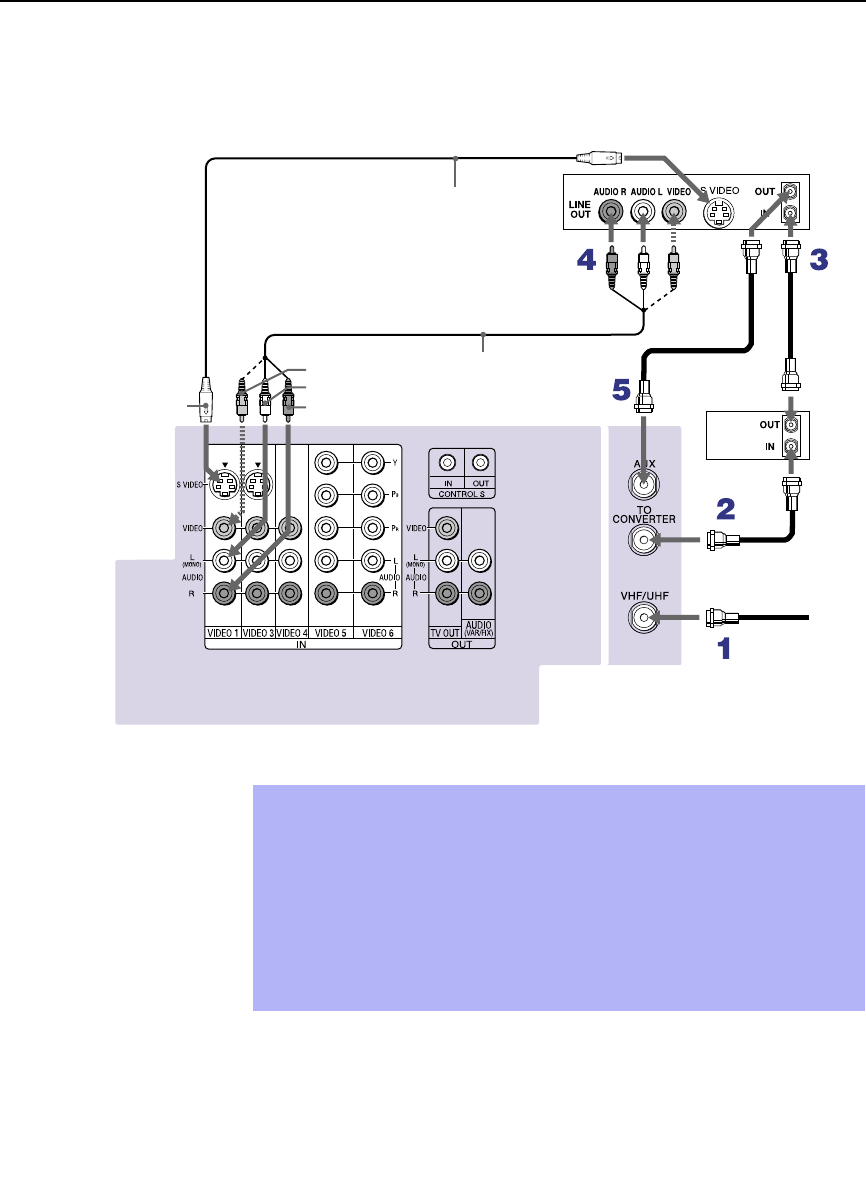
Installing and Connecting the Projection TV
20
Coaxial
cable
Cable box
VCR
Rear of projection TV
VIDEO (yellow)
AUDIO-L (white)
AUDIO-R (red)
VMC-810S/820S
(not supplied)
Coaxial cable
YC-15V/30V
(not supplied)
S VIDEO
✍If your VCR is not equipped with S VIDEO, use a VIDEO cable (yellow)
instead of the S VIDEO cable.
✍You will not be able to change channels on the VCR. Set your projection
TV and VCR to channel 3 or 4, depending on your cable box channel
output.
✍Pressing ANT on the remote control switches between the channels
coming in through the cable box (scrambled) and those coming directly
to the projection TV (unscrambled).

Installing and Connecting the Projection TV
21
Installing and Connecting the Projection TV
Connecting Two VCRs for Tape Editing
If you connect two VCRs, you can record from one VCR to the other while
using your TV to monitor what is being recorded.
Disconnect all power sources before making any connections.
1Using AUDIO and VIDEO cables, connect the playback VCR’s Audio
and Video OUT jacks to the recording VCR’s Audio and Video IN
jacks.
2Using AUDIO and VIDEO cables, connect the recording VCR’s
AUDIO and Video OUT jacks to the projection TV’s AUDIO and
VIDEO IN jacks.
Rear of projection TV
VCR (playback) VCR (recording)
VMC-810S/820S (not supplied)
AUDIO-R (red)
AUDIO-L (white)
VIDEO (yellow)
✍To perform tape editing, set the projection TV to the video input intended
for playback by pressing TV/VIDEO on the remote control.
✍You may need to change the video input on your VCR. Consult your
VCR’s operating manual for instructions.
✍If your VCRs have an S VIDEO jack: For best picture quality, use an
S VIDEO connection instead of the yellow video cable on your combined
A/V cable.
Using an S VIDEO cable, connect the playback VCR’s S VIDEO OUT jack
to the recording VCR’s S VIDEO IN jack. S VIDEO does not provide audio,
so audio cables must still be connected to provide sound.
✍You cannot record signals from equipment connected to the Y, PB, PR
input.
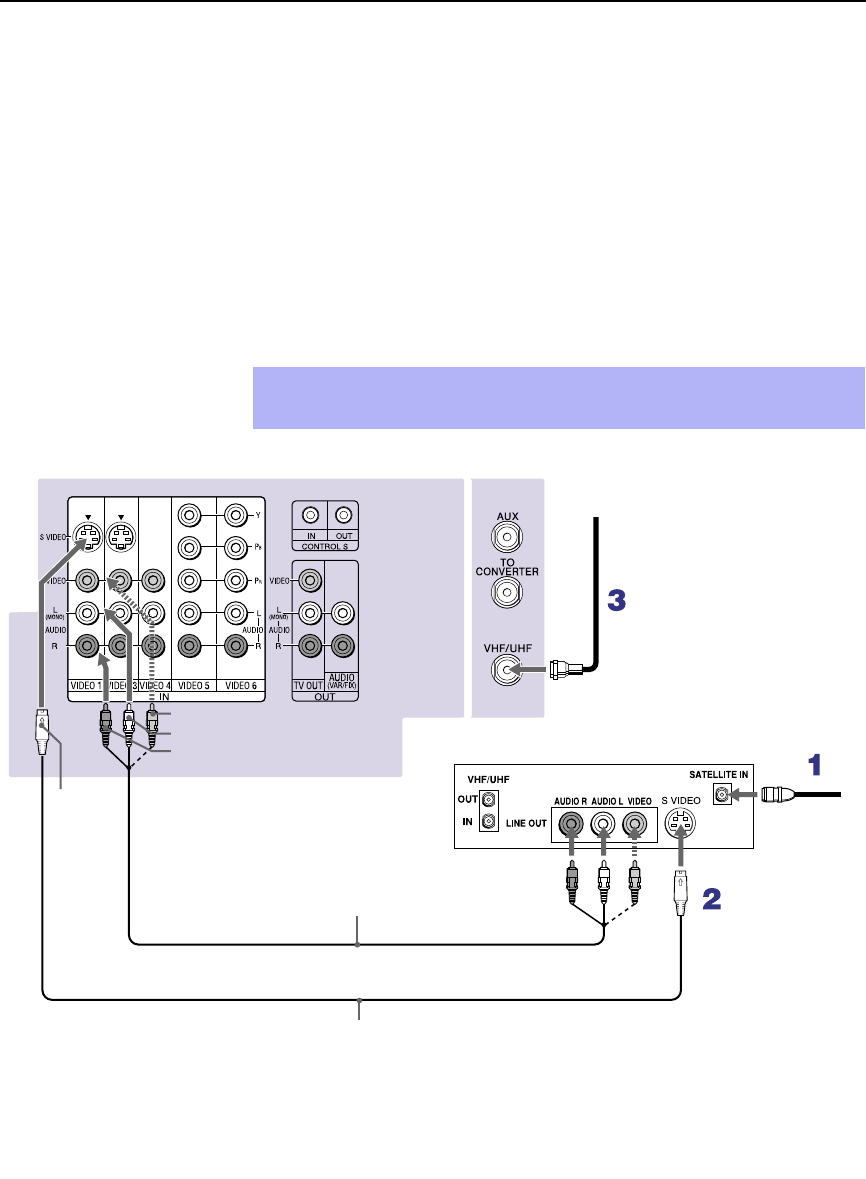
Installing and Connecting the Projection TV
22
Connecting a Satellite Receiver
Disconnect all power sources before making any connections.
1Connect the satellite antenna cable to the satellite receiver’s
SATELLITE IN jack.
2Using AUDIO and S VIDEO cables, connect the satellite receiver’s
AUDIO and S VIDEO OUT jacks to the projection TV’s AUDIO and
S VIDEO IN jacks.
3Connect a coaxial cable from your cable or antenna to the projection
TV’s VHF/UHF jack.
✍If your satellite receiver is not equipped with S VIDEO, use a VIDEO cable
(yellow) instead of the S VIDEO cable.
Coaxial
cable
Satellite receiver
VMC-810S/820S (not supplied)
R
ear of projection TV
VIDEO (yellow)
AUDIO-L (white)
AUDIO-R (red)
Satellite
antenna
cable
S
VIDEO
YC-15V/30V (not supplied)
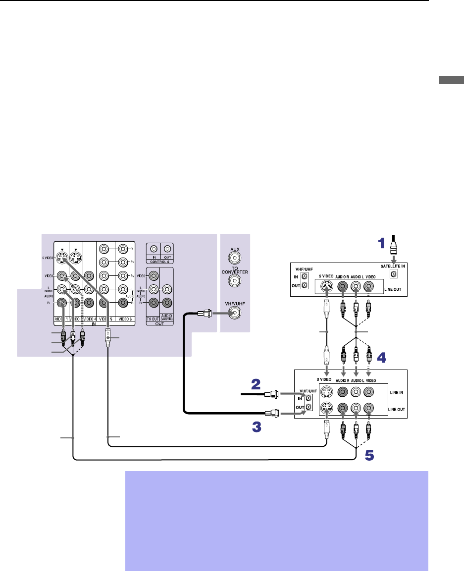
Installing and Connecting the Projection TV
23
Installing and Connecting the Projection TV
Connecting a Satellite Receiver with a VCR
Disconnect all power sources before making any connections.
1Connect the satellite antenna cable to the satellite receiver’s
SATELLITE IN jack.
2Connect the CATV cable to the VCR’s VHF/UHF IN jack.
3Using a coaxial cable, connect the VCR’s OUT jack to the projection
TV’s VHF/UHF jack.
4Using AUDIO and S VIDEO cables, connect the satellite receiver’s
AUDIO and S VIDEO OUT jacks to the VCR’s AUDIO and S VIDEO
IN jacks.
5Using AUDIO and S VIDEO cables, connect the VCR’s AUDIO and
S VIDEO OUT jacks to the TV’s AUDIO and S VIDEO IN jacks.
Coaxial
cable
Rear of projection TV
S VIDEO
AUDIO-R (red)
AUDIO-L (white)
VIDEO (yellow)
Satellite receiver
VCR
YC-15V/30V
(not supplied) VMC-810S/
820S (not
supplied)
YC-15V/30V (not supplied)
VMC-810S/820S
(not supplied)
Satellite
antenna
cable
Cable
✍Be sure your VCR’s video input is set correctly. Consult your VCR’s
operating manual for instructions.
✍
Use TV/VIDEO to select
- VIDEO 1 to watch satellite TV or the VCR (Your VCR must be turned on).
- VHF/UHF to watch cable TV.
✍If your VCR or satellite receiver is not equipped with S VIDEO, use a
VIDEO cable (yellow) instead of the S VIDEO cable.

Installing and Connecting the Projection TV
24
Connecting an Audio Receiver
Disconnect all power sources before making any connections.
Using audio cables, connect the projection TV’s AUDIO OUT (VAR/FIX)
jacks to the audio receiver’s audio LINE IN jacks.
Rear of projection TV
AUDIO-R
(red) AUDIO-L
(white)
Line
input
RK-74A
(not supplied)
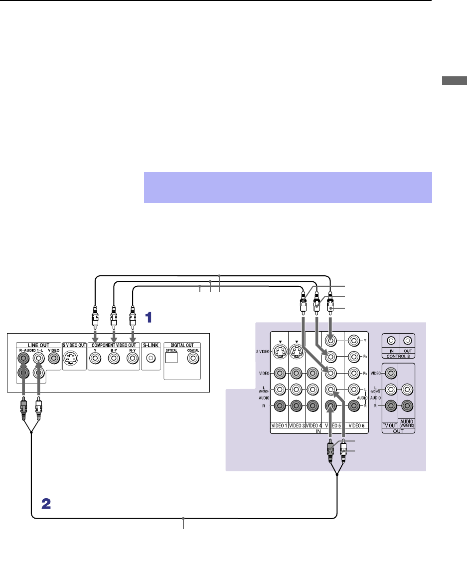
Installing and Connecting the Projection TV
25
Installing and Connecting the Projection TV
Connecting a DVD Player with Component
Video Connectors
This is the preferred hookup to use if:
❑Your DVD player has component (Y, PB, PR) jacks.
Disconnect all power sources before making any connections.
1Using three separate component video cables, connect the DVD player’s
Y, B-Y and R-Y jacks to the Y, PB and PR jacks on the projection TV.
Use the VIDEO IN 5 or 6 connections.
2Using an audio cable, connect the DVD player’s Audio OUT jacks to
the projection TV’s AUDIO IN jacks. Be sure to use the same row of
inputs that you used for the video connection (VIDEO IN 5 or 6).
✍The Y, B-Y and R-Y jacks on your DVD player are sometimes labeled
Y, CB and CR, or Y, PB and PR. If so, connect the cables to like colors.
VMC-10HG (not supplied)
Rear of projection TV
RK-74A (not supplied)
DVD player
AUDIO-R (red)
AUDIO-L (white)
PR
PB
Y

Installing and Connecting the Projection TV
26
Connecting a DVD Player with A/V Connectors
Use this hookup if:
❑Your DVD player does not have component (Y, PB, PR) jacks.
Disconnect all power sources before making any connections.
1Using audio cables, connect the DVD player’s Audio OUT jacks to the
projection TV’s AUDIO IN jacks.
2Using an S VIDEO cable, connect the DVD player’s S VIDEO jack to
the projection TV’s S VIDEO jack.
✍If your DVD player has video component output connectors: for best
picture quality use the connection described on page 25.
Rear or projection TV
YC-15V/30V
(not supplied)
DVD player
RK-74A (not supplied)
AUDIO-R (red)
AUDIO-L (white)
S VIDEO
✍Use TV/VIDEO on the remote control to switch between the VCR, DVD
player and cable TV inputs.
✍If your VCR is not equipped with S VIDEO, use a VIDEO cable (yellow)
instead of the S VIDEO cable.

Installing and Connecting the Projection TV
27
Installing and Connecting the Projection TV
Connecting a Digital TV Receiver
Disconnect all power sources before making any connections.
1Using three separate component video cables, connect the Digital TV
Set-top box’s Y, PB and PR jacks to the projection TV.
2Using an audio cable, connect the Digital TV Set-top box’s Audio OUT
jacks to the projection TV’s AUDIO IN jacks.
✍The Y, PB and PR jacks do not provide audio, so audio cables must
be connected to provide sound.
Component video connection is necessary to view 480p, 720p and
1080i formats. You may also use the S VIDEO or Composite Video
connections, however, composite video (Y, PB, PR) will provide the
best picture quality for all format types.
Be sure to read the
Set-top box manual.
z
VMC-10HG (not supplied)
Digital TV Set-top box
RK-74A (not supplied)
AUDIO-R (red)
AUDIO-L (white)
Rear of
projection TV
PR
PB
Y
✍You cannot record the signal from any equipment connected into the
Y, PB and PR connectors.
✍This projection TV is not compatible with digital TV receivers
configured with RGB or VGA output connectors.
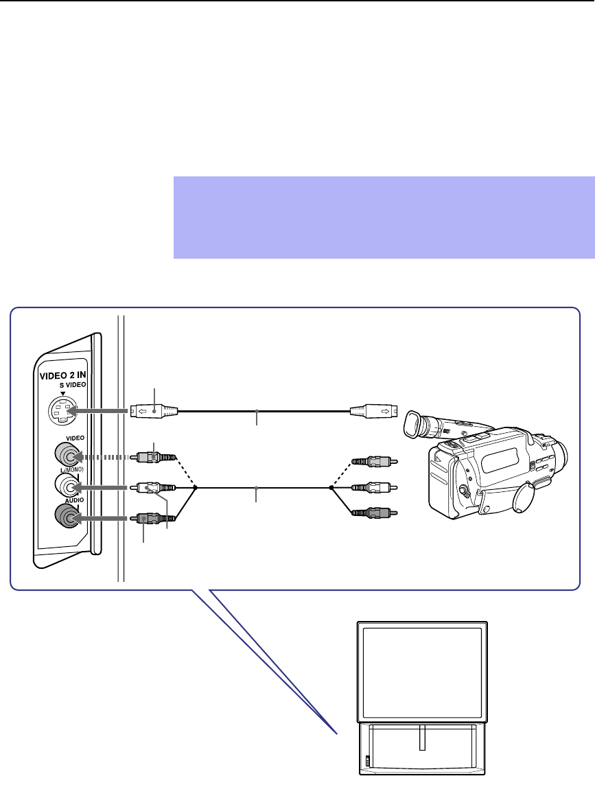
Installing and Connecting the Projection TV
28
Connecting a Camcorder
For easy connection of the camcorder, the projection TV has front Audio and
Video inputs (shown below). However, if you prefer, you can also connect
the camcorder to the projection TV’s rear Audio and Video IN jacks.
Using AUDIO and S VIDEO cables, connect the camcorder’s Audio and S
VIDEO OUT jacks to the projection TV’s AUDIO and S VIDEO IN jacks.
✍If you have a mono camcorder, connect its left audio output to the
projection TV’s AUDIO L (MONO) jack.
✍If your camcorder is not equipped with S VIDEO, use a VIDEO cable
(yellow) instead of the S VIDEO cable.
VIDEO (yellow)
A/V output
AUDIO-L (white)
AUDIO-R (red)
S VIDEO
YC-15V/30V (not supplied)
VMC-810S/820S
(not supplied)

Installing and Connecting the Projection TV
29
Installing and Connecting the Projection TV
Connecting an AV Receiver
For greater control of all audio and video equipment, connect an AV receiver.
Disconnect all power sources before making any connections.
1Connect the coaxial cable from the incoming cable connection or
antenna to IN on the VCR.
2Using a coaxial cable, connect OUT on the VCR to VHF/UHF on the
projection TV.
3Using a VIDEO cable, connect VIDEO of VIDEO 1 IN on the
projection TV to MONITOR OUT on the AV receiver.
4Using an AUDIO/VIDEO cable, connect TV OUT on the projection TV
to AUDIO/VIDEO 2 IN on the AV receiver.
5Using an AUDIO/VIDEO cable, connect the video equipment to the AV
receiver.
6Select the Setup menu and set “Video Label” to “Receiver” to fix your
TV’s input to AV receiver (see “Video Label” on page 56).
✍Change “Video Label” for the VIDEO 1 input to “Receiver” (see page 56).
Rear of projection TV
AUDIO-L
AUDIO-R
VMC-10HG (not supplied)
Cable/
Antenna
Coaxial cable (not supplied) VMC-810S/820S
(not supplied)
VMC-810S/820S
(not supplied)
AUDIO/
VIDEO 1 IN
AUDIO/VIDEO 1 OUT
AV receiver
VMC-810S/820S (not supplied)
MONITOR
OUT
VIDEO VIDEO
VCR
AUDIO/
VIDEO 2 IN

Installing and Connecting the Projection TV
30
Using the CONTROL S Feature
CONTROL S allows you to control your projection TV system and other
Sony equipment with one remote control. In addition to allowing you to
control multiple devices with one remote control, the CONTROL S feature
allows you to always point your remote control at your projection TV,
instead of having to point it at the other equipment, which might be hidden
or out of direct line of sight.
Rear of projection TV
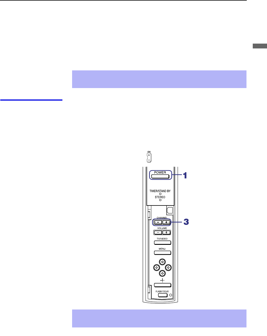
Installing and Connecting the Projection TV
31
Installing and Connecting the Projection TV
Setting Up the Projection TV Automatically
After you finish connecting your projection TV, you can run Auto Setup to
set up your channels. The Auto Setup screen appears when you turn your
projection TV on for the first time after installing it. If you do not want to set
up the channels at this time, you can do it later by using the Auto Program
feature in the Channel menu (see page 52).
Using Auto Setup 1Press POWER on the front panel of your projection TV or on the remote
control to turn on the projection TV.
2Press the TV (FUNCTION) button on your remote control. Red light will
briefly appear.
3Press CH+ on your projection TV to run Auto Setup, or press CH– to
exit. If you use the channel buttons on your remote control, be sure to
use the main set of buttons ( ).
✍The Auto Setup feature does not apply for installations that use a cable
box for all channel selection.
✍You can run Auto Program by selecting it in the Channel menu, as
described on page 52.
Projection TV front panel

Installing and Connecting the Projection TV
32
Adjusting the Convergence Automatically – FLASH FOCUS™ –
The projection tube image appears on the screen in three colors (red, green
and blue). If they do not converge, the color is poor and the picture blurs.
Before you use your projection TV, be sure to adjust the convergence.
The FLASH FOCUS feature allows you to adjust the convergence
automatically.
1Receive a TV or cable TV program.
2Press FLASH FOCUS.
The cross pattern shown below appears and FLASH FOCUS begins to
work. The adjustment is completed when the cross pattern becomes
white and you are returned to the program you were watching.
To obtain an
optimum
convergence for
Digital TV programs
The optimum convergence alignment varies with digital TV formats.
Whenever you find that the picture blurs, press FLASH FOCUS.
✍It is recommended to perform FLASH FOCUS about 30 minutes after the
projection TV is first turned on.
Projection TV
front panel
✍You cannot perform any other functions until FLASH FOCUS has
completed its cycle.
✍If you perform any other operation while FLASH FOCUS is in progress,
FLASH FOCUS operation is canceled.
✍Unshielded speakers or other metallic objects can cause picture
distortion if placed close to the projection TV.

33
Using the Features
Using the Remote Control
The following table describes the buttons on the remote control that are for
more advanced functions.
Button Descriptions Outside Panel
✍Main Power button must be turned ON to activate the remote control.
Button Description
1MUTING Press to mute the sound. Press again or press VOL + to
restore the sound.
2SLEEP Press repeatedly until the projection TV displays the time
in minutes (15, 30, 45, 60, or 90) that you want the
projection TV to remain on before shutting off
automatically. Cancel by pressing until SLEEP OFF
appears. While the Sleep feature is set, press once to view
the remaining time.
3ANT Changes between the VHF/UHF input and the AUX input.
4DISPLAY Press once to display the current time and channel label (if
set) and channel number. Press again to turn Display off.
See page 54 for details on setting the time.
5JUMP Press to jump back and forth between two channels. The
projection TV alternates between the current channel and
the last channel that was selected.
6FREEZE Freezes the window picture. Press again to restore the
picture.
7 INDEX Press to enter the Channel Index mode. You can view and
select from twelve channels without leaving the current
one.
8The joystick allows for movement of the on-screen cursor.
Pressing down on the center of the joystick selects the item.
9VOL +/–Adjusts the volume.
q; PIC MODE Press repeatedly to step through the available video picture
modes: Vivid, Standard, Movie and Pro. Also available in
the Video menu. For details, see “Selecting Video Options”
on page 47.
qa FAVORITES Displays the Favorite Channels list. For details, see “Using
Favorite Channels” on page 39.
qs RESET Press when in a menu to reset the settings to the factory
defaults.
(Continued)
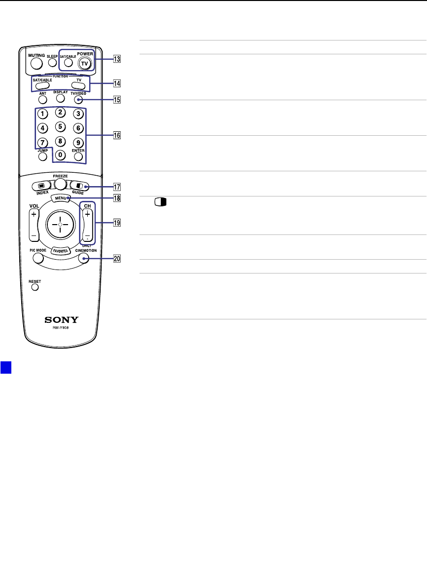
Using the Features
34
qd POWER
buttons
(GREEN)
Turn on and off the projection TV and other audio/video
equipment you have programmed into the remote control.
For instructions, see “Programming the Remote Control”
on page 57.
qf FUNCTION
buttons Select the equipment (TV, SAT/CABLE) that you want to
operate. The indicator lights up momentarily when pushed
to show which device the remote control is operating.
qg TV/VIDEO
Cycles through the video equipment connected to your
projection
TV’s video inputs:
TV
,
VIDEO 1
,
VIDEO 2
,
VIDEO 3
,
VIDEO 4
,
VIDEO 5
and
VIDEO 6
.
qh 0 – 9 and
ENTER Press 0 - 9 to select a channel, the channel changes after 2
seconds. Press ENTER to select immediately.
qj
GUIDE
Turns on/off Twin View. For details, see “Using Twin
View™” on page 40.
Displays the program guide of your satellite.
qk MENU Press to display the projection TV on-screen menu. Press
again to exit from the menu.
ql CH +/–Scan through channels.
w; DRC/
CINEMOTION Press repeatedly to step through the available high-
resolution picture modes: Interlaced, Progressive and
CineMotion. For details, see “Using the Video Menu” on
page 47.
Button Description
To scan rapidly through the
channels, press and hold down
CH+ or CH–.
z
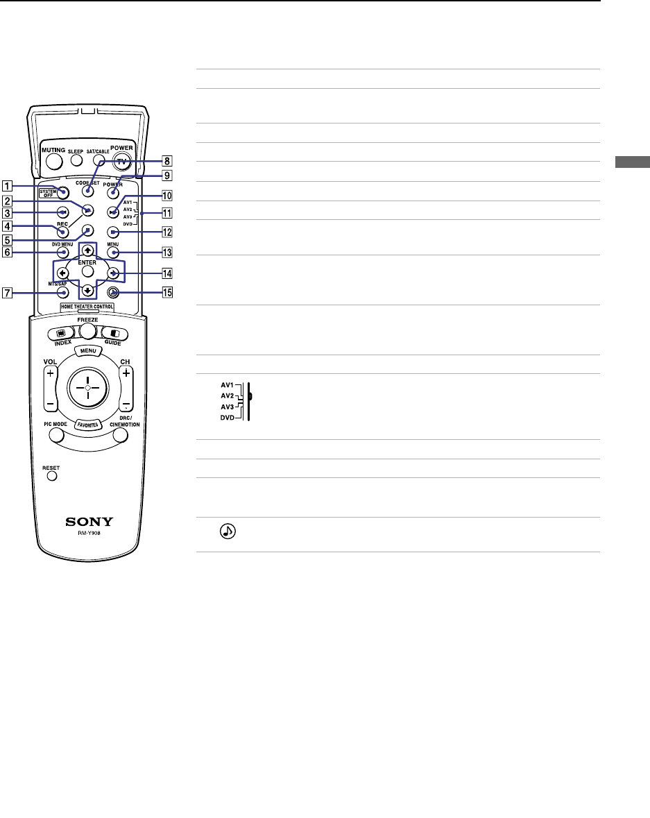
Using the Features
35
Using the Features
Inside Panel
Button Description
1SYSTEM OFF Press to turn off the projection TV and all equipment
connected with S-Link.
2NPlay
3mRewind
4REC Record
5xStop
6DVD MENU Displays the DVD menu.
7MTS/SAP Press to scroll through the Multi-channel TV Sound (MTS)
options: Stereo, Auto SAP, and Mono.
8CODE SET Used for programming the remote control to operate non-
Sony video equipment. For details, see “Programming the
Remote Control” on page 57.
9POWER Press to turn on the DVD/VCR player you have
programmed into the remote control. For instructions, see
“Programming the Remote Control” on page 57.
q; MFast-forward
qa Use to switch control for connected video equipment. You
can program one video source for each switch position. For
details, see “Programming the Remote Control” on page
57.
qs X Pause (Press again to resume normal playback)
qd MENU Displays the video equipment menu.
qf M, m, <, ,,
and ENTER Use to operate the DVD menu.
qg Press to select an audio option: Steady Sound ON or
OFF.
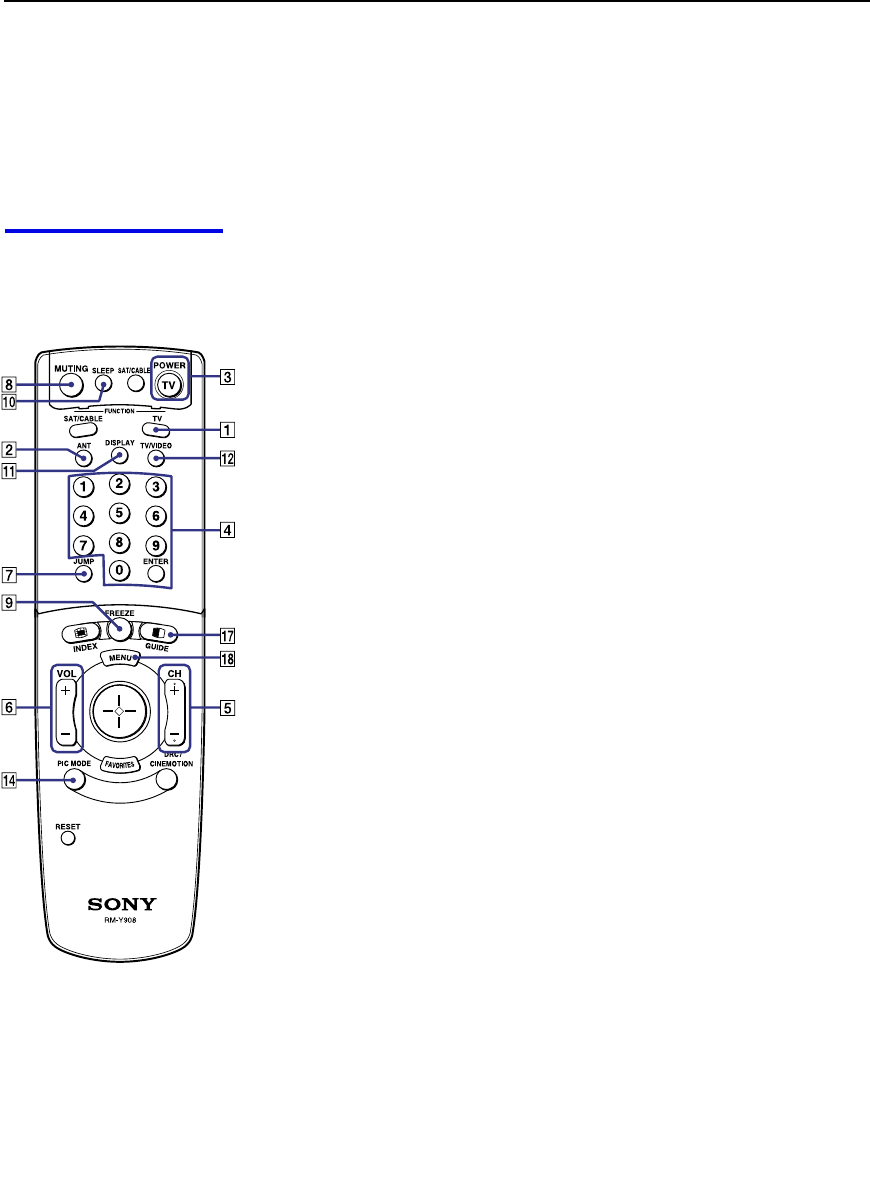
Using the Features
36
Watching the TV
Many TV features can be accessed directly through the remote control. The
following will explain the function of some of the buttons found on your
remote control.
Buttons for
Projection TV
Operations
1 TV (FUNCTION)
Activates the remote control for use with the projection TV.
2 ANT— (AUX input)
Press to change between the VHF/UHF input and the AUX input.
3 TV (POWER)
Turns the projection TV on and off. If a video input indication (e.g.,
VIDEO 1, VIDEO 2) appears on the screen, press TV/VIDEO or
CH +/ – until a channel number appears.
4 0-9 and ENTER
Use for direct channel selection. Press 0-9 to select a channel (for example,
to select channel 10, press 1 and 0). The channel will change after 2 seconds,
or you can press ENTER for immediate selection.
5 CH +/–
Press to scan through the channels (+ up or – down).
6 VOL +/–
Press to adjust the volume (+ up or – down).
7 JUMP
Press to alternate or jump back and forth between two channels. The
projection TV will jump between the current channel and the last channel
selected.
8 MUTING
Press to mute the sound. “MUTING” will appear on the screen and will dim
three seconds later. To restore the sound, press again or press VOL +.
9 FREEZE — (yellow labeled button)
This is useful when you need to copy down information that appears on the
TV’s screen (see “Using the Freeze Function” on page 43).
q; SLEEP
Press repeatedly until the projection TV displays the approximate time in
minutes (15, 30, 45, 60, or 90) that you want the projection TV to remain on
before shutting off automatically.
Cancel by pressing SLEEP until “SLEEP OFF” appears.
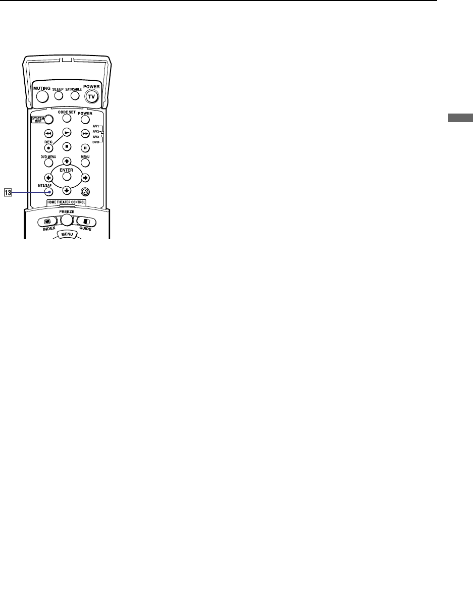
Using the Features
37
Using the Features
qa DISPLAY
Press to display the channel number, current time and channel label (if set).
To turn the display off, press DISPLAY again.
qs TV/VIDEO
Press repeatedly to scroll through available video inputs: TV, VIDEO 1,
VIDEO 2, VIDEO 3, VIDEO 4, VIDEO 5 and VIDEO 6.
If you select Skip as a Video Label in the Setup menu, your projection TV
will skip the video input you selected (see “Video Label” on page 56).
qd MTS/SAP
Press to scroll through the Multi-channel TV Sound (MTS) options (see
“MTS” on page 49).
qf PIC MODE
Press PIC MODE repeatedly to directly choose one of five different video
modes that best suits the program you are watching.
Vivid: Select for enhanced picture contrast and sharpness.
Standard: Select to display a standard picture for normal viewing
environments.
Movie: Select to display a finely detailed picture for low light environments.
Pro (Professional): Select to display a picture with minimum enhancements.
When you select each mode, you can also adjust the picture quality (such as
Brightness, Color, etc.) to suit your taste. For details, see “Mode” on page
47.

Using the Features
38
Watching the Digital TV
When you have connected the DTV receiver, you can enjoy digital TV
programs. This projection TV is capable of receiving the 1080i, 720p, 480p
and 480i digital TV formats.
To view a digital TV program
1Connect the DTV receiver to VIDEO 5 or 6 IN on the projection TV
(for details, see page 27).
2Press TV/VIDEO to select VIDEO 5 or 6.
3Select a digital channel on the DTV receiver. For details, see the
Operating Manual of the DTV receiver.
4Adjust the volume of the projection TV as necessary.
✍This projection TV is not capable of displaying a native 720p format
signal. When a 720p format signal is received, it is converted into a 480p
format signal.
✍The optimum convergence alignment varies with digital TV formats.
Whenever you find that the picture blurs, press FLASH FOCUS (for
details, see page 32).

Using the Features
39
Using the Features
Using Favorite Channels
The Favorite Channel feature lets you select programs from a list of favorite
channels that you preset.
To display a list of your favorite channels:
1Press FAVORITES.
The Favorite Channel options appear.
2Move the joystick up or down to highlight the channel you want to
watch. The program on that channel appears in the preview window.
Press to select.
✍Your Favorite Channel options can be set automatically or manually. The
factory setting for Favorite Channel is Auto.
When Favorite Channel is set to Auto, the last eight channels selected
with 0-9 buttons will be set as Favorite Channel options. If you want to
input your own selections as Favorite Channel settings, see “Favorite
Channel” on page 51.
Favorios
124
6
10
12
2
8
8
4
Exit
Preview window

Using the Features
40
Using Twin View™
Twin View enables you to watch two programs at the same time. You can
also change the size of both the left and right pictures.
Displaying Twin
Pictures To display twin pictures
1Make sure your projection TV is
tuned to a working channel.
2Press .
To cancel twin pictures
❑Press again (or press ).
Activating the
Picture Although two pictures appear on the screen at the same time, only one
picture is active. Change the picture size by using the joystick. For an active
picture, you can:
❑Change channels.
❑Adjust the volume.
❑Switch the input sources from VHF/UHF to cable by pressing ANT or
TV/VIDEO to switch the video input.
❑Change the picture size by pressing the joystick up or down.
To activate the right picture
❑Move the joystick to the right.
To activate the left picture
❑Move the joystick to the left.
,
,
,
,

Using the Features
41
Using the Features
✍ANT is not effective in the right picture.
✍JUMP is not effective in Twin View.
✍When you adjust the twin screen sizes, the projection TV memorizes
the change. The next time you use the Twin View feature, the
memorized sizes appear.
✍When viewing an enhanced 16:9 picture, the aspect ratio changes to
4:3 in Twin View. The picture will be reformatted to that aspect ratio.
✍If viewing a 720p or 1080i format input source, the aspect ratio will
maintain the original 16:9 aspect ratio.
✍Hookups that affect your ability to use Twin View:
- If you are viewing all channels through the cable box, the Twin
View feature will not work. The cable box only unscrambles one
signal at a time, so the right picture will be the same as the left
picture.
- You can watch a scrambled cable channel and another video
source. Be sure your DVD player, VCR or satellite receiver are
connected to one of the VIDEO IN 1-6 and AUX inputs on the rear
of the projection TV. Pictures from equipment connected to VIDEO
5, 6 and AUX will only appear in the left picture, not in the right.
✍The active picture is highlighted in cyan.

Using the Features
42
Changing the
Picture Size The zoom feature lets you change the size of the left and right pictures.
To enlarge the left
picture (reduce the
right)
1Move the joystick
left to activate the
left picture (if not
already activated).
2Move the joystick
up to enlarge the
picture and move
the joystick down
to reduce the
picture.
To enlarge the right
picture (reduce the
left)
1Move the joystick
right to activate the
right picture (if not
already activated).
2Move the joystick
up to enlarge the
picture and move
the joystick down to
reduce the picture.
✍When you adjust the twin screen sizes, the projection TV memorizes the
change. The next time you use the Twin View function, the memorized
sizes appear.

Using the Features
43
Using the Features
Using the Freeze Function
The FREEZE button allows you to temporarily capture a program’s picture.
You can use this feature to write down information such as phone numbers,
recipes, etc.
To use the Freeze function
1When the program information you want to capture is displayed, press
FREEZE.
2The projection TV switches to Twin View mode and displays the
“frozen” picture on the right, while the current program continues on the
left.
3To cancel and return to normal viewing, press FREEZE.
✍Freeze feature is not available if you are already in Twin View™ mode.
Current program
in progress
Frozen picture
Call 555-1234
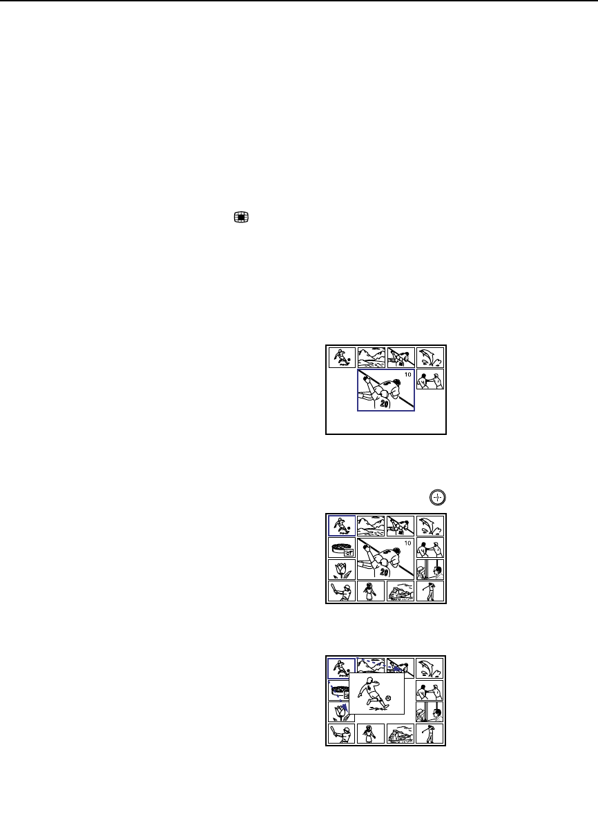
Using the Features
44
Using Channel Index
Channel Index allows you to display multiple channels and select one
directly.
The channels used for Channel Index will come directly from the projection
TV’s list of receivable channels (those set during “Auto Program” on page
52).
To use the Channel Index function
1Press .
The current channel will be reduced in size and displayed in the center
of the screen in normal motion picture format. The first twelve
receivable channels will appear one after another, clockwise, around the
center picture. These small pictures are updated in intervals of one
second. The channel number and channel caption (if set) on the second
and later appearances will dim.
A cyan-colored frame will appear to indicate current channel selection.
2Move the joystick in any direction to move the cyan frame to the
channel that you wish to view, and press .
The selected channel will zoom in and move to the center, and the sound
of that channel will be heard.

Using the Features
45
Using the Features
For the center picture you can:
❑Change the channel by pressing 0-9 and ENTER.
❑Switch the input sources from VHF/UHF to cable by pressing ANT
or to the video input by pressing TV/VIDEO, without changing the
surrounding channels.
3If you wish to view another channel, repeat step 2.
To view another twelve channels, press CH+.
To view the previous twelve, press CH–.
To view the normal picture of the selected channel, proceed to step 4.
4Press .
The center picture will be enlarged for normal viewing.
To cancel Channel Index
❑Press again to resume normal viewing.
✍Sound will only be heard from the center picture.
✍If one of the pictures received through Channel Index is snowy, the
entire screen may become unstable. In this case, erase the snowy
channel (see “Channel Skip/Add” on page 52).
✍If you leave the Channel Index screen displayed for an hour without
any additional operation, Channel Index is canceled and the normal
picture reappears.

46
Using the Menus
Overview
Opening and choosing a menu:
1Press MENU to display the menu screen.
2Move the joystick to the desired menu icon and press to select it.
3Use the joystick to scroll through the features.
4See the specific menu page for instructions on moving through the
menu.
The menu gives you access to the following features:
Menu Icon Description Page
Allows you to make adjustments to your picture settings.
It also allows you to customize the Picture Mode based on
the type of program you are viewing.
47
Offers enhanced audio options such as listening to second
audio programming (SAP), or customizing the Effect of
the sound on your projection TV.
49
Allows you to set up a Favorite Channel list, run the Auto
Program function, and more.
51
Lets you control the viewing of programs. 53
Lets you set the clock on your projection TV and allows
you to program your projection TV for scheduled viewing
using the Timers.
54
Provides several options for setting up your channels,
labeling your Video inputs, and selecting the language of
the on-screen menus.
55
To end a menu session:
Press MENU again.
To end one menu
session and move to
another:
Press the joystick V to
return to the menu icons.
Move the joystick B or b to
choose the next menu icon
and press to select it.

Using the Menus
47
Using the Menus
Using the Video Menu
To select the Video Menu
1Press MENU.
2Move the joystick to the Video
icon and press .
3Use the joystick to scroll
through the features.
4Press to select a feature. That
feature’s adjustment appears.
5Use the joystick to make the
desired adjustments.
6Press to select/set.
7Press MENU to exit the menu screen.
To restore the factory default settings for Picture, Brightness, Color,
Hue, Sharpness and Color Temp
❑Press RESET on the remote control when in the Video menu.
Selecting Video
Options The Video menu includes the following options.
To quickly and easily
change from one Video
Mode to another, use the
PIC MODE on the remote
control.
z
Option Description
Mode
Customized
picture
viewing
Vivid Select for enhanced picture contrast and
sharpness.
Standard Recommended for Normal viewing conditions.
Movie Select for soft, film like, picture.
Pro Select for professional monitor like appearance.
✍You can alter the Video menu settings (Picture, Brightness,
Color, etc.) for each Mode.
Picture Adjust to increase picture contrast and deepen the color or decrease
picture contrast and soften the color.
Brightness Adjust to brighten or darken the picture.
Color Adjust to increase or decrease color intensity.
Hue Adjust to increase or decrease the green tones.
Sharpness Adjust to sharpen or soften the picture.
Color Temp
White
intensity
adjustment
Choose from three color temperatures:
Cool Select to give the white colors a blue tint.
Neutral Select to give the white colors a neutral tint.
Warm Select to give the white colors a red tint (NTSC-
Standard).
(Continued)

Using the Menus
48
DRC Mode
Digital
Reality
Creation
Creates a high-resolution picture with 4x density, for high quality
sources (i.e., DVD player, Satellite receiver).
Select from Interlaced, Progressive and CineMotion.
Interlaced Recommended for moving pictures.
Progressive Recommended for still images and text.
CineMotion Recommended for 24 frame-per-second films.
Option Description

Using the Menus
49
Using the Menus
Using the Audio Menu
To select the Audio Menu
1Press MENU.
2Move the joystick to the Audio
icon and press .
3Use the joystick to scroll through
the options.
4Press to select an option.
That option’s settings appear.
5Use the joystick to scroll through
the settings.
6Press to select the desired setting.
7Press MENU to exit the menu screen.
To restore the factory default settings for Treble, Bass and Balance
❑Press RESET on the remote control when in the Audio menu.
Selecting Audio
Options The Audio menu includes the following options:
Option Description
Treble Adjust to increase or decrease higher-pitched sounds.
Bass Adjust to increase or decrease lower-pitched sounds.
Balance Adjust to emphasize left or right speaker balance.
Steady
Sound ON Select to stabilize the volume.
OFF Select to turn off Steady Sound.
Effect TruSurround Select for surround sound (for stereo programs
only).
Simulated Adds a surround-like effect to mono programs.
OFF Normal stereo or mono reception.
MTS
Enjoy stereo,
bilingual and
mono
programs
Stereo Select for stereo reception when viewing a program
broadcast in stereo.
Auto-SAP Select to automatically switch the projection TV to
second audio programs when a signal is received.
(If no SAP signal is present, the projection TV
remains in Stereo mode.)
Mono Select for mono reception. (Use to reduce noise
during weak stereo broadcasts.)
(Continued)

Using the Menus
50
Speaker ON Select to turn on the projection TV speakers.
OFF Select to turn off the projection TV speakers and
listen to the projection TV's sound only through
your external audio system speakers.
Audio Out
Easy control
of volume
adjustments
Variable The projection TV’s speakers are turned off, but
the volume output from your audio system can still
be controlled by the projection TV’s remote
control.
Fixed The projection TV’s speakers are turned off and the
volume, bass and treble output of the projection TV
is fixed. Use your audio receiver’s volume control
to adjust the volume through your audio system.
Option Description

Using the Menus
51
Using the Menus
Using the Channel Menu
To select the Channel Menu
1Press MENU.
2Move the joystick to the Channel
icon and press .
3Use the joystick to scroll
through the features.
4Press to select a feature. That
feature’s options appear.
5Use the joystick to scroll
through the options.
6Press to select the desired option.
7Press MENU to exit the menu screen.
Selecting Channel
Options The Channel menu includes the following options:
Video Audio Channel Setup
Parent Timer
Favorite Channel:Auto
Cable:ON
Channel fix:OFF
Auto Program
Channel Skip/Add
Channel Label
Move: Select: End:
MENU
Option Description
Favorite Channel Auto Select if you want Favorite Channel options to
be set automatically to the last eight channels
selected with the 0-9 buttons.
Manual Select if you want to input your own selections
as Favorite Channel options.
1Press to select a favorite channel
number.
2Use the joystick to scroll through the
channels until you find the channel you
want to add to your favorites.
3Press to select it.
Cable ON Select if you are receiving cable channels with a
CATV cable.
OFF Select if you are using an antenna.
✍You should run Auto Program after changing the Cable
setting.
(Continued)

Using the Menus
52
Channel Fix
Useful when you
have a cable box
or satellite
receiver connected
2-6 “Fix” your projection TV’s channel setting to 3
or 4 and use the cable box, VCR or satellite
receiver to change channels. Select one of these
settings if you have connected the device to the
VHF/UHF jack.
AUX 2-6 Same as 2-6, except you select one of these
settings if you have connected the device to the
AUX jack. (see page 14)
VIDEO 1 Use when connecting an AV receiver to control
external video sources. TV output should be
connected through the AV receiver.
Auto Program Automatically programs the projection TV for all receivable
channels.
Channel
Skip/Add Removes and adds viewable channels.
1Use the joystick to scroll through the channels until you
find the channel you want to skip/add.
2Press to select it.
3Press the joystick up or down to toggle between “Add” and
“Skip.”
4Press to select.
Channel Label Label up to 20 channels with their station call letters.
Option Description
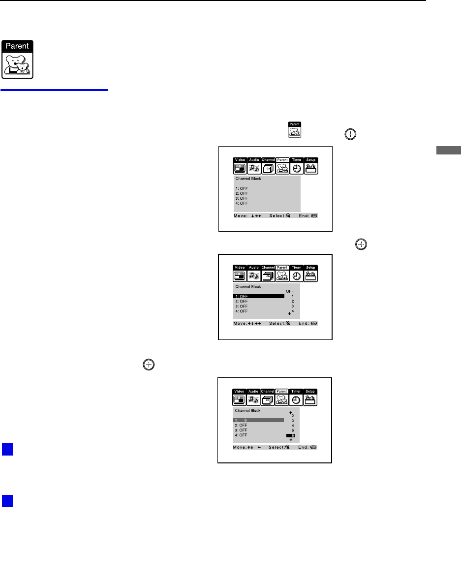
Using the Menus
53
Using the Menus
Using the Parent Menu (Channel Block)
The Parent menu allows you to set up the TV to block up to 4 channels.
Using the Parent
Menu To block channels
1Press MENU.
2Move the joystick to the Parent icon and press .
3Move the joystick up or down to select 1-4, and press .
4Move the joystick down to select the channel to be blocked, and press
.
5Press MENU to exit the menu screen.
To cancel channel block settings
❑Set Channel Block to OFF in step 4.
Performing Auto
Program will erase the
Channel Block settings.
Selecting “Receiver”
of Video Label will erase
the Channel Block
settings.
z
z
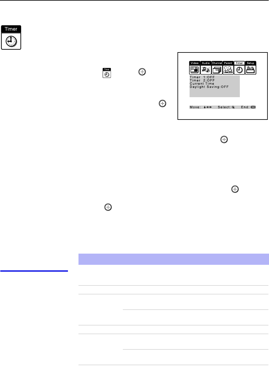
Using the Menus
54
Using the Timer Menu
To select the Timer menu
1Press MENU.
2Move the joystick to the Timer
icon and press .
To set the Current Time
1Use the joystick to select
“Current Time”, then press .
2If it is currently Daylight Saving
Time, be sure to set the mode to
“ON” first.
3Use the joystick to enter the correct time, then press .
4Press MENU to exit the menu screen.
To set the Timer
Before setting the timer, be sure to set your projection TV’s clock to the
current time and Daylight Saving Mode.
1Move the joystick to “Timer 1” or “Timer 2”, then press .
2Use the joystick to enter your day, time and channel preferences, then
press to select each one.
3Press MENU to exit the menu screen.
To reset the Clock or Timers
❑Press RESET on the remote control after selecting that option in the
Timer menu.
Selecting Timer
Options The Timer menu includes the following options:
✍Selecting Channel Fix will clear the timer settings.
Option Description
Timer 1
Timer 2 Program Select to set the Timer by day, time, duration,
and channel.
OFF Select to turn off the Timer. (Your previous
settings will be saved.)
Current Time Set the current time.
Daylight Saving ON Select in the Spring to adjust the time during
Daylight Saving Time.
OFF Select in the Fall to adjust the time at the end
of Daylight Saving Time.

Using the Menus
55
Using the Menus
Using the Setup Menu
To select the Setup Menu
1Press MENU.
2Move the joystick to the Setup
icon and press .
3Use the joystick to scroll through
the features.
4Press to select a feature. That
feature’s options appear.
5Use the joystick to scroll through
the options.
6Press to select the desired option.
7Press MENU to exit the menu screen.
Selecting
Setup Options The Setup menu includes the following options:
Option Description
Caption Vision Allows you to select from three closed caption modes (for
programs that are broadcast with closed captioning).
OFF Turns off Caption Vision.
CC1, CC2,
CC3, CC4 Displays a printed version of the
dialog or sound effects of a program.
(Should be set to CC1 for most
programs.)
TEXT1, TEXT2,
TEXT3, TEXT4 Displays network/station information
presented using either half or the
whole screen (if available). For closed
captioning, set to CC1.
XDS
(Extended Data
Service)
Displays a network name, program
name, program length, and time of the
show if the broadcaster offers this
service.
(Continued)

Using the Menus
56
Video Label Allows you to label the audio/video components you connected
to the projection TV so you can identify them when using TV/
VIDEO. When in the Setup menu’s Video Label feature, use
the joystick to highlight an input to label, then press to
select it. Use the joystick to scroll through the labels. Press
to select the component you connected to each of the input
jacks on the back of your projection TV. Select “Skip” if you do
not have a component connected to a particular set of input
jacks.
VIDEO 1/2/3/4 VHS, 8mm, Beta, LD, Game, SAT,
DVD, Web, Receiver, DTV, Skip
VIDEO 5/6 DVD, DTV, HD, Skip
If you select “Skip”, your projection TV skips this connection
when you press TV/VIDEO.
✍When you select “Receiver” on Video Label, your projection
TV’s input is fixed.
Language Select to display all on-screen menus in your language of
choice: English, Español, Français.
16:9 Enhanced Provides enhanced picture resolution for widescreen sources,
such as selected DVD titles (only available when the projection
TV is in VIDEO mode). Press TV/VIDEO and select from one
of the following options:
AUTO To activate automatically when a 16:9
signal is received.
ON To activate manually.
OFF To deactivate manually.
✍AUTO/ON will appear when the projection TV is in VIDEO mode 1-6.
ON/OFF will appear when the projection TV is in VIDEO mode 5-6 and the
480p signal occurs.
Option Description
To use this feature
with widescreen DVDs,
set your DVD player to
16:9 aspect ratio.
z
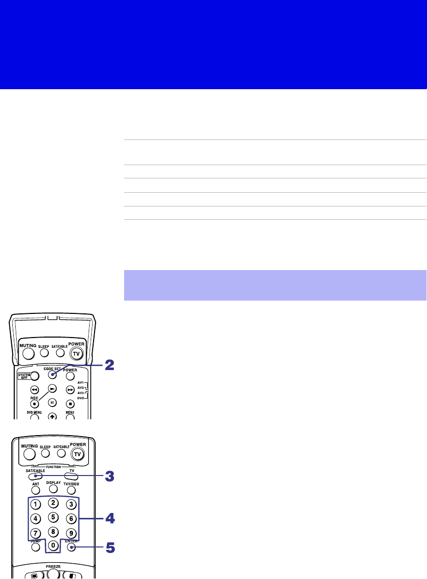
57
Other Information
Programming the Remote Control
The remote control is preset to operate Sony brand video equipment.
If you have video equipment other than Sony brand that you want to control
with the projection TV’s remote control, use the following procedures to
program the remote control.
From the “Manufacturer’s Codes” listed on page 59, select the three-digit
code number for the manufacturer’s code for your component. If more than
one code number is listed, start with the number listed first. Use the code
number to complete the following procedure.
To program a cable box or a satellite receiver
1Open the panel of the remote control.
2Press CODE SET inside the panel.
3Close the panel and press SAT/CABLE (FUNCTON).
4Enter the three-digit manufacturer’s code number using the 0-9 buttons.
5Press ENTER.
6To check if the code number works, aim the projection TV’s remote
control at the component and press the green POWER button that
corresponds with that component. If it responds, the programming is
completed. If not, try using the other codes listed for that manufacturer.
Sony
Equipment Switch Position
on Remote Control Programmable
Code Number
Beta, ED Beta VCRs AV1 303
8 mm VCR AV2 302
VHS VCR AV3 301
DVD Player DVD 751
✍The equipment must have infrared (IR) remote capability in order to be
used with the remote control.
(Continued)
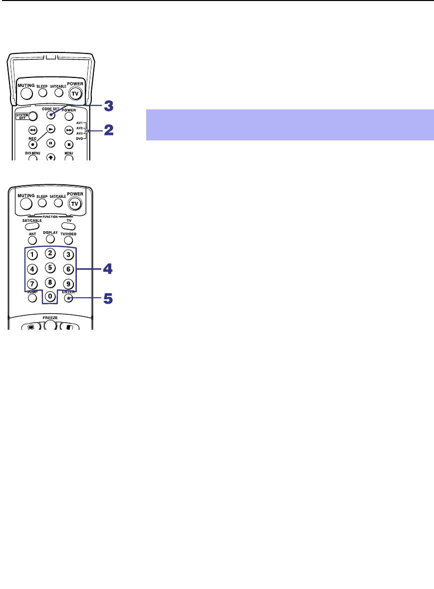
Other Information
58
To program video equipment
1Open the panel of the remote control.
2Move the slide switch to the desired component type.
3Press CODE SET inside the panel.
4Close the panel and enter the three-digit manufacturer’s code number
using the 0-9 buttons.
5Press ENTER.
6To check if the code number works, aim the projection TV’s remote
control at the component, open the panel, and press the green POWER
button. If it responds, the programming is completed. If not, try using
the other codes listed for that manufacturer.
Tips
❑If more than one code number is listed, try entering them one by one
until you come to the correct code for your component.
❑If you enter a new code number, the code number you previously
entered at that setting is erased.
❑In some rare cases, you may not be able to operate your component with
the Sony remote control. In this case, use the component’s own remote
control unit.
✍You must perform step 4 within 10 seconds of step 3, or you must
start again from step 3.

Other Information
59
Other Information
Manufacturer’s Codes
VCRs
DVD Players
Cable Boxes
Satellite Receivers
Manufacturer Code
Sony 301
Admiral
(M. Ward)
327
Aiwa 338, 344
Audio Dynamic 314, 337
Broksonic 319, 317
Canon 309, 308
Citizen 332
Craig 302, 332
Criterion 315
Curtis Mathes 304, 338, 309
Daewoo 341, 312, 309
DBX 314, 336, 337
Dimensia 304
Emerson 319, 320, 316,
317, 318, 341
Fisher 330, 335
Funai 338
General Electric 329, 304, 309
Go Video 322, 339, 340
Goldstar 332
Hitachi 306, 304,
305, 338
Instant Replay 309, 308
JC Penney 309, 305, 304,
330, 314, 336,
337
JVC 314, 336, 337,
345, 346, 347
Kenwood 314, 336, 332,
337
LXI (Sears) 332, 305, 330,
335, 338
Magnavox 308, 309, 310
Marantz 314, 336, 337
Marta 332
Memorex 309, 335
Minolta 305, 304
Mitsubishi/
MGA
323, 324, 325,
326
Multitech 325, 338, 321
NEC 314, 336, 337
Olympic 309, 308
Optimus 327
Panasonic 308, 309, 306,
307
Pentax 305, 304
Philco 308, 309
Philips 308, 309, 310
Pioneer 308
Quasar 308, 309, 306
RCA/
PROSCAN
304, 305, 308,
309, 311, 312,
313, 310, 329
Realistic 309, 330, 328,
335, 324, 338
Sansui 314
Samsung 322, 313, 321
Sanyo 330, 335
Scott 312, 313, 321,
335, 323, 324,
325, 326
Sharp 327, 328
Shintom 315
Signature 2000
(M. Ward)
338, 327
SV2000 338
Sylvania 308, 309, 338,
310
Symphonic 338
Tashiro 332
Tatung 314, 336, 337
Teac 314, 336, 338,
337
Technics 309, 308
Toshiba 312, 311
Manufacturer Code
Wards 327, 328, 335,
331, 332
Yamaha 314, 330, 336,
337
Zenith 331
Manufacturer Code
Sony 751
Panasonic 753
Pioneer 752
RCA 755
Toshiba 754
Manufacturer Code
Hamlin/Regal 222, 223, 224,
225, 226
Jerrold/G. I. 201, 202, 203,
204, 205, 206,
207, 208, 218
Oak 227, 228, 229
Panasonic 219, 220, 221
Pioneer 214, 215
Scientific
Atlanta
209, 210, 211
Tocom 216, 217
Zenith 212, 213
Manufacturer Code
Sony 801
General
Electric
802
Hitachi 805
Hughes 804
Panasonic 803
RCA/
PROSCAN
802, 808
Toshiba 806, 807
Manufacturer Code

Other Information
60
Operating Other Components with Your Projection TV Remote
Control
Operating a VCR Open the panel and move the slide switch to the AV input you coded for this
device.
Operating a DVD
Player Open the panel and move the slide switch to the DVD input you coded for
this device.
To Do This ... Press
Turn on/off green POWER button (inside the panel)
Change channels CH +/–
Record N and REC simultaneously
Play N
Stop x
Fast forward M
Rewind the tape m
Pause X (press again to resume normal playback)
Search the picture
forward or backward
M or m during playback
(release to resume normal playback)
Change input mode Slide switch
To Do This ... Press
Turn on/off green POWER button (inside the panel)
Play N
Stop x
Pause X (press again to resume normal playback)
Step through different tracks of
an audio disc
M to step forward or m to step backward
Step through different chapters
of a video disc
CH+ to step forward or CH– to step backward
Display the DVD menu DVD MENU
Display the menu (Setup) MENU
Operate the DVD menu M, m, <, ,, ENTER

Other Information
61
Other Information
Operating a Cable
Box
Operating a Satellite
Receiver
To Do This ... Press
Turn on/off SAT/CABLE (POWER)
Select Cable Box SAT/CABLE (FUNCTION)
Select a channel 0-9 buttons, ENTER
Change channels CH +/–
Back to previous channel JUMP
To Do This ... Press
Turn on/off SAT/CABLE (POWER)
Select Satellite Receiver SAT/CABLE (FUNCTION)
Select a channel 0-9 buttons, ENTER
Change channels CH +/–
Back to previous channel JUMP
Display channel number DISPLAY
Display DBS guide GUIDE
Display DBS menu MENU
Move highlight (cursor) Joystick or arrows
Select item

Other Information
62
Troubleshooting
Problem Possible Remedies
No picture
(screen not lit),
no sound
❏Make sure the projection TV’s power cord is connected securely to the wall outlet.
❏Push the power button on the front of the projection TV.
❏Check to see if the TV/VIDEO setting is correct: when watching TV, set to TV,
and when watching connected equipment, set to VIDEO 1, 2, 3, 4, 5 or 6.
❏Try another channel. It could be station trouble.
❏The Channel Block feature is activated (see “Using the Parent Menu (Channel
Block)” on page 53).
❏If your projection TV does not turn on, and a red light keeps flashing, your
projection TV may need service. Call your local Sony Service Center.
Remote control
does not operate
❏Batteries could be weak. Replace the batteries.
❏Press TV (FUNCTION) when operating your projection TV.
❏Make sure the projection TV’s power cord is connected securely to the wall outlet.
❏Locate the projection TV at least 3-4 feet away from fluorescent lights.
❏Check the orientation of the batteries.
Dark, poor or no
picture (screen lit),
good sound
❏Adjust the Picture setting in the Video menu (see page 47).
❏Adjust the Brightness setting in the Video menu (see page 47).
❏Check antenna/cable connections.
❏Adjust the convergence again using FLASH FOCUS (see “Adjusting the
Convergence Automatically – FLASH FOCUS™ –” on page 32).
Good picture,
no sound
❏Press MUTING so that “MUTING” disappears from the screen (see page 33).
❏Make sure Speaker is set to ON in the Audio menu (see page 50).
❏Check the MTS setting in the Audio menu (see “MTS” on page 49).
Cannot receive digital channels
(when a DTV receiver is
connected)
❏Check the connections between the DTV receiver and the projection TV (see page
27).
❏Check your local listings to find out if you can receive digital broadcasts in your
area.
Cannot receive upper channels
(UHF) when using an antenna
❏Change Cable to OFF (see page 51).
❏Use Auto Program in the Channel menu to add receivable channels that are not
presently in TV memory (see page 52).
No color ❏Adjust the Color settings in the Video menu (see page 47).
Only snow and noise
appear on the screen
❏Check the Cable setting in the Channel menu (see “Cable” on page 51).
❏Check the antenna/cable connections.
❏Make sure the channel is broadcasting programs.
❏Press ANT to change the input mode (see page 36).
Dotted lines
or stripes
❏Adjust the antenna.
❏Move the projection TV away from noise sources such as cars, neon signs, or hair-
dryers.
Projection TV is fixed to one
channel
❏Use Auto Program in the Channel menu to add receivable channels that are not
presently in TV memory (see page 52).
❏Check your Channel Fix settings (see page 52).
Double images or ghosts ❏Use a highly directional outdoor antenna or a cable (when the problem is caused by
reflections from nearby mountains or tall buildings).

Other Information
63
Other Information
Cannot operate menu ❏If the item you want to choose appears in gray, you cannot select it.
❏Turn the projection TV’s power off and on again.
Cannot receive any channels
when using cable TV
❏Use Auto Program in the Channel menu to add receivable channels that are not
presently in TV memory (see page 52).
❏Check your cable settings.
❏Make sure Cable is set to ON in the Channel menu (see page 51).
Cannot gain enough volume
when using a cable box
❏Increase the volume of the cable box using the cable box’s remote control. Then
press TV (FUNCTION) and adjust the projection TV’s volume.
Channel Index does not display
all available channels
❏Make sure Cable is set to ON in the Channel menu (see “Cable” on page 51).
❏Use Auto Program in the Channel menu to add receivable TV channels that are
not presently in TV memory (see page 52).
Cannot receive channels
Unable to select a channel
❏Use Auto Program in the Channel menu to add receivable TV channels that are
not presently in TV memory (see page 52).
Cannot change channels with
the remote control
❏Be sure you have not inadvertently switched your projection TV from channel 3 or
4 setting if you are using another device to change channels.
❏If you are using another device to control channels, be sure the “function” button
for that device has been pressed, or the slide switch is set correctly. For example, if
you are using your cable to control channels, be sure to press SAT/CABLE.
Cannot cycle through the other
video equipment connected to
the projection TV
❏Be sure the Video Label feature has not been set to Skip (see page 56).
There is a black box on the
screen
❏You have selected a text option in the Setup menu and no text is available (see
page 55 to reset Setup selections). To turn this feature off, select OFF in the
Caption Vision option. If you were trying to get closed captioning, select CC1
instead of Text 1-4.
There is no twin picture or it is
just static
❏Be sure your twin picture is set to a video source/channel that has a program airing.
❏You may be tuned to a video input with nothing connected to it. Try cycling
through your video inputs using TV/VIDEO.
❏Twin View is not set to receive a signal from the AUX input. If you have
connected a VCR, DVD player or satellite receiver to the AUX input on the
projection TV, it will not show in the second picture.
You get the same program in the
window picture as in the main
picture
❏Both may be set to the same channel. Try changing channels in either the main
picture or the window picture.
❏You may be running all your channels through a cable box. The cable box will
only unscramble one signal at a time, so you cannot use the Twin View feature. If
possible, run a direct cable to your projection TV’s VHF/UHF input (this will only
work if your cable system provides an unscrambled signal).
You cannot get anything but TV
channels in your second picture
❏Be sure the video label has not been set to skip your video inputs. See the Setup
menu on page 55.
Favorite Channel does not
display your choices
❏Verify that Favorite Channel is set to Manual in the Channel menu (see
“Favorite Channel” on page 51).
Problem Possible Remedies
(Continued)


Other Information
65
Other Information
Specifications
Projection System 3 picture tubes, 3 lenses, horizontal in-line system
Picture Tube 7-inch high-brightness monochrome tubes (6.3 raster size), with optical
coupling and liquid cooling system
Projection Lenses High performance, large
diameter hybrid lens F1.1
Antenna 75 ohm external terminal for VHF/UHF
Television System NTSC, American TV Standard
Screen Size (measured diagonally) 53 inches
Channel Coverage
VHF 2-13
UHF 14-69
CATV 1-125
Power Requirements 110 V AC, 60 Hz
Number of Inputs/Outputs
Video (IN) 4 1 Vp-p, 75 ohms unbalanced, sync negative
S Video (IN) 3 Y: 1 Vp-p, 75 ohms unbalanced, sync
negative
C: 0.286 Vp-p (Burst signal), 75 ohms
Audio (IN) 6 500 mVrms (100% modulation)
Impedance: 47 kiloohms
AUDIO (VAR/FIX) OUT 1 500 mVrms (100 % modulation), Impedance:
470 ohms
TV Out 1 1 Vp-p, 75 ohms unbalanced, sync negative
CONTROL S (IN/OUT) 1 Minijacks
Component Video Input 2 (Y, PB, PR) Y: 1.0 Vp-p, 75 ohms unbalanced, sync
negative
PB: 0.7 Vp-p, 75 ohms
PR: 0.7 Vp-p, 75 ohms
RF Inputs 2
Converter 1
Speaker Output 20 W × 2
Dimensions (W × H × D) 1,180 × 1,417 × 632 mm
Mass 71.2 kg
Power Consumption
In Use 280 W
In Standby Under 1 W
(Continued)

Other Information
66
Design and specifications are subject to change without notice.
Supplied Accessories
Remote Control RM-Y908
AA (R6) Batteries 2 supplied for remote control
Optional Accessories
AV Cable VMC-810/820/830 HG
Audio Cable RKC-515HG
Control S Cable RK-G69HG
Component Video Cable VMC-10/30 HG

67
Other Information
Index
16:9 (widescreen) 7, 56
A
Activating a Twin View screen 40
Adding channels to the channel list 52
Adjusting audio, Steady Sound 49
ANT button 33
Antenna, connecting 15
Aspect ratio, 16:9 in Twin View 41
Audio menu 46, 49
Audio receiver, connecting 24
Audio/Video cable 11
Auto Program (channel setup) 31, 52
Auto Setup 31, 52
AV receiver, connecting to TV OUT 14
B
Balance, adjusting 49
Bass, adjusting 49
Batteries, inserting into remote 9
Bilingual audio 49
Brightness, adjusting 47
C
Cable
setting ON/OFF 51
with VCR, connecting 18
Cable box
connecting with VCR 19
using with TV remote control 61
Camcorder, connecting 28
Caption Vision 55
CATV. See cable.
Channel Index
described 7
using 44
Channel list, adding channels 52
Channel menu 46, 51
Channel Skip/Add 52
Channels
Auto Program 52
creating labels 52
setting up 31
CineMotion, DRC 34, 48
Closed caption modes 55
CODE SET button 35
Color temperature, adjusting 47
Color, adjusting 47
Connecting
Audio receiver 24
AV receiver 29
Cable box 16, 17, 19–20
Cable or antenna 15
Camcorder 28
Digital TV Receiver 27
DVD player 25, 26
Satellite receiver 22, 23
VCR 19–21, 23
Connector Types 11
Contents of box 9
CONTROL S 30
Convergence, adjusting automatically 32
D
Daylight saving 54
Digital Reality Creation 48
Digital TV
connecting 27
watching 38
Digital TV program 38
Digital TV receiver, connecting 27
DISPLAY button 33
Display, turning off 33
DRC (Digital Reality Creation) Mode, described 7
DRC⁄CINEMOTION button 34
DVD MENU button 35
DVD player
using with TV remote control 60
with A/V connectors, connecting 26
with component video connectors, connecting 25
E
Effect
OFF 49
Simulated 49
TruSurround 49
Enhanced picture resolution, 16:9 56
Enlarging pictures, in Twin View 42
Extended Data Service 55
(Continued)

68
F
Favorite Channel
auto 51
described 7
manual 51
setting up 51
using 39
FAVORITES button 33
Features 7
Flash Focus
described 7
performing 32
FREEZE button 33
Freeze, using 36, 43
Front Panel Controls 12
FUNCTION buttons (WHITE) 34
H
Hookups 15
Hue, adjusting 47
I
Inputs, labeling 56
Installation of the projection TV 15–30
J
JUMP button 33
Jump, using 36
L
Label
channels 52
video inputs 56
Locking programs 53
M
MENU button 34
MENU button (inside the panel) 35
Menus
Audio 46, 49
Channel 46, 51
Parent 46, 53
Setup 46, 55
Timer 46, 54
Video 46, 47
MODE
Movie 37
Pro 37
Standard 37
Vivid 37
MTS/SAP button 35
MTS/SAP, using 37
Muting, using 36
P
Parent menu 46, 53
PIC MODE button 33
Picture contrast, adjusting 47
Picture size, adjusting in Twin View 42
POWER button 35
POWER buttons (GREEN) 34
Presetting channels 31
Problems, troubleshooting 62
R
Rear panel controls and connections 13, 14
Remote control
buttons inside panel 35
Function of buttons 36
inserting batteries 9
programming 57–59
Remote control, operating other components with
Cable box 61
DVD player 60
Satellite receiver 61
VCR 60
Removing channels from the channel list 52
RESET button 33
Resetting
Audio options 49
Timer options 54
Video options 47
S
S Video cable 11
SAT/CABLE function button 34
SAT/CABLE power button 34
Satellite receiver
connecting 22
using with TV remote control 61
Setting up channels 31
Setup menu 46, 55
Sharpness, adjusting 47
SLEEP button 33
Sleep, using 37
Specifications 65–66
Steady Sound
adjusting 49

69
Other Information
described 7
Surround sound 49
SYSTEM OFF button 35
T
Tape-to-tape editing 21
Time
set current 54
set daylight saving 54
Timer menu 46, 54
Timer setting 54
Treble, adjusting 49
Troubleshooting 62
TV function button 34
TV power button 34
TV/VIDEO button 34
Twin View™
activating a picture 40
described 7
using 40
V
VCR
connecting two, for tape editing 21
using with TV remote control 60
with cable box, connecting 19
with cable, connecting 18
with satellite receiver, connecting 23
Video inputs, labeling 56
Video menu 46, 47
Video Modes, selecting 47
Viewing area, recommended 10
VOL +/– button 33, 36
W
Widescreen 56
Widescreen, described 7
Z
Zoom feature, with Twin View 42

Printed in Malaysia
Operating Instructions
© 2001 Sony Corporation
4-085-753-E1(1)
Projection TV
Operating Instructions
KP-HW572K90

2
WARNING
To prevent fire or shock hazard, do not
expose the projection TV to rain or
moisture.
This symbol is intended to alert the user to the
presence of uninsulated “dangerous voltage”
within the product’s enclosure that may be of
sufficient magnitude to constitute a risk of
electric shock to persons.
This symbol is intended to alert the user to the
presence of important operating and
maintenance (servicing) instructions in the
literature accompanying the appliance.
CAUTION
To prevent electric shock, do not use this polarized AC
plug with an extension cord, receptacle or other outlet
unless the blades can be fully inserted to prevent blade
exposure.
CAUTION
When using TV games, computers, and similar
products with your projection TV, or viewing a
TV station whose logo always stays on the
screen, keep the brightness and contrast
functions at low settings. If a fixed (non-moving)
pattern such as a station logo is left on the screen
for long periods of time, especially at a high
brightness or contrast setting, the image can be
permanently imprinted onto the screen. These
types of imprints are not covered by your
warranty.
Note on convergence adjustment
Before you use your projection TV, make sure to adjust
convergence. For details, see “Adjusting the Convergence
Automatically – FLASH FOCUS™ –” on page 30.
Safety
❑Operate the projection TV only on 220 V AC.
❑If any liquid or solid object should fall inside the
cabinet, unplug the projection TV immediately and
have it checked by qualified service personnel
before operating it further.
❑Pull the power cord out by the plug. Do not pull the
power cord itself.
Even if your projection TV is turned off, it is still
connected to the AC power source (mains) as long as
the power cord is plugged in.
Unplug the projection TV befor moving it or if you
are not going to use it for several days.
For details concerning safety precautions, see
“Important Safeguards” on page 3.
Installing
❑To prevent internal heat buildup, do not block the
ventilation openings.
❑Do not install the projection TV in a hot or humid
place, or in a place subject to excessive dust or
mechanical vibration.
❑Avoid operating the projection TV at temperature
below 5°C.
❑If the projection TV is transported directly from a
cold to a warm location, or if the room temperature
changes suddenly, the picture may be blurred or
show poor color. In this case, please wait a few hours
to let the moisture evaporate before turning on the
projection TV.
❑To obtain the best picture, do not expose the screen
to direct illumination or direct sunlight. It is
recommended to use spot lighting directed down
from the ceiling or to cover the windows that face
the screen with opaque drapery. It is desirable to
install the projection TV in a room where the floor
and walls are not of a reflective material.
TruSurround and the ( ) symbol are trademarks of SRS
Labs, Inc.
TruSurround technology is incorporated under license
from SRS Labs, Inc.
Manufactured under license from Dolby Laboratories.
Dolby and the double-D symbol are trademarks of Dolby
Laboratories.
Confidential unpublished works. © 1992-1997 Dolby
Laboratories. All rights reserved.
BBE and BBE Symbol are trademarks of BBE Sound,
Inc. and are licensed by BBE Sound, Inc. under U.S.
Patent No. 4,638,258 and 4,482,866.
CAUTION
RISK OF ELECTRIC SHOCK
DO NOT OPEN
ATTENTION
RISQUE DE CHOC ELECTRIQUE,
NE PAS OUVRIR
PRECAUCION
RIESGO DE CHOQUE ELECTRICO
CAUTION : TO REDUCE THE RISK OF ELECTRIC SHOCK,
DO NOT REMOVE COVER (OR BACK).
NO USER-SERVICEABLE PARTS INSIDE.
REFER SERVICING TO QUALIFIED SERVICE PERSONNEL.
NO ABRIR
You are cautioned that any changes or modifications
not expressly approved in this manual could void your
warranty and your authority to operate this equipment.

3
Important Safeguards
For your protection, please read these instructions
completely, and keep this manual for future reference.
Carefully observe and comply with all warnings, cautions
and instructions placed on the set or described in the
operating instructions or service manual.
WARNING
To guard against injury, the following basic safety
precautions should be observed in the installation, use
and servicing of the set.
Use
Power Sources
This set should be operated only from
the type of power source indicated on
the serial/model plate. If you are not sure
of the type of electrical power supplied
to your home, consult your dealer or
local power company. For those sets designed to operate
from battery power, refer to the operating instructions.
Grounding or Polarization
This set is equipped with a polarized AC power cord plug
(a plug having one blade wider than the other), or with a
three-wire grounding type plug (a plug having a third pin
for grounding). Follow the instructions below:
Overloading
Do not overload wall outlets, extension
cords or convenience receptacles
beyond their capacity, since this can
result in fire or electric shock.
Always turn the set off when it is not
being used. When the set is left
unattended and unused for long
periods of time, unplug it from the
wall outlet as a precaution against the
possibility of an internal malfunction that could create a
fire hazard.
If a snapping or popping sound from a TV
set is continuous or frequent while the TV
is operating, unplug the TV and consult
your dealer or service technician. It is
normal for some TV sets to make
occasional snapping or popping sounds,
particularly when being turned on or off.
Object and Liquid Entry
Never push objects of any kind into the
set through the cabinet slots as they may
touch dangerous voltage points or short
out parts that could result in a fire or
electric shock. Never spill liquid of any
kind on the set.
Attachments
Do not use attachments not
recommended by the manufacturer, as
they may cause hazards.
Cleaning
Clean the cabinet of the projection TV
with a dry soft cloth. To remove dust
from the screen, wipe it gently with a soft
cloth. Stubborn stains may be removed
with a cloth slightly dampened with
solution of mild soap and warm water. Never use strong
solvents such as thinner or benzine for cleaning.
If the picture becomes dark after using the projection TV
for a long period of time, it may be necessary to clean the
inside of the projection TV. Consult qualified service
personnel.
4
Installation
Water and Moisture
Do not use power-line operated sets
near water — for example, near a
bathtub, washbowl, kitchen sink, or
laundry tub, in a wet basement, or
near a swimming pool, etc.
Accessories
Do not place the set on an unstable
cart, stand, table or shelf. The set
may fall, causing serious injury to a
child or an adult and serious damage
to the set. Use only a cart or stand
recommended by the manufacturer
for the specific model of projection
TV. An appliance and cart
combination should be moved with
care. Quick stops, excessive force,
and uneven surfaces may cause the appliance and cart
combination to overturn.
Ventilation
The slots and openings in the cabinet and in the back or
bottom are provided for necessary ventilation. To ensure
reliable operation of the set, and to protect it from
overheating, these slots and openings must never be
blocked or covered.
❑Never cover the slots and openings
with a cloth or other materials.
❑Never block the slots and openings by
placing the set on a bed, sofa, rug or
other similar surface.
❑Never place the set in a confined
space, such as a bookcase or built-in
cabinet, unless proper ventilation is
provided.
❑Do not place the set near or over a
radiator or heat register, or where it is
exposed to direct sunlight.
Power-Cord Protection
Do not allow anything to rest on or roll
over the power cord, and do not place the
set where the power cord is subject to
wear or abuse.
Antennas
Outdoor Antenna Grounding — If an outdoor antenna is
installed, follow the precautions below.
An outdoor antenna system should not be located in the
vicinity of overhead power lines or other electric light or
power circuits, or where it can come in contact with such
power lines or circuits.
WHEN INSTALLING AN OUTDOOR ANTENNA
SYSTEM, EXTREME CARE SHOULD BE TAKEN TO
KEEP FROM CONTACTING SUCH POWER LINES
OR CIRCUITS AS CONTACT WITH THEM IS
ALMOST INVARIABLY FATAL.
Be sure the antenna system is grounded so as to provide
some protection against voltage surges and built-up static
charges.
Lightning
For added protection for this television receiver during a
lightning storm, or when it is left unattended and unused
for long periods of time, unplug it from the wall outlet
and disconnect the antenna. This will prevent damage to
the receiver due to lightning and power-line surges.
5
Service
Damage Requiring Service
Unplug the set from the wall outlet and refer servicing to
qualified service personnel under the following
conditions:
❑When the power cord or
plug is damaged or frayed.
❑If liquid has been spilled into
the set.
❑If the set has been exposed
to rain or water.
❑If the set has been subject to
excessive shock by being
dropped, or the cabinet has
been damaged.
❑If the set does not operate
normally when following the
operating instructions.
Adjust only those controls
that are specified in the
operating instructions. Improper adjustment of other
controls may result in damage and will often require
extensive work by a qualified technician to restore
the set to normal operation.
❑When the set exhibits a distinct change in
performance, it indicates a need for service.
Servicing
Do not attempt to service the set yourself
since opening the cabinet may expose you to
dangerous voltage or other hazards. Refer all
servicing to qualified service personnel.
Replacement Parts
When replacement parts are required, be sure the service
technician certifies in writing that he has used
replacement parts specified by the manufacturer that have
the same characteristics as the original parts.
Unauthorized substitutions may result in fire, electric
shock or other hazards.
Safety Check
Upon completion of any service or repairs
to the set, ask the service technician to
perform routine safety checks (as specified
by the manufacturer) to determine that the
set is in safe operating condition, and to so
certify. When the set reaches the end of its
useful life, improper disposal could result
in a picture tube implosion. Ask a qualified
service technician to dispose of the set.
For Safety
Be careful when moving
the projection TV
When you place the projection TV
in position, be careful not to drop it
on your foot or fingers.
Watch your footing while installing the projection TV.
Carry the projection TV in the
specified manner
If you carry the projection TV in a manner
other than the specified manner and
without the specified number of persons, it
may drop and a serious injury may be
caused. Be sure to follow the instructions mentioned
below.
❑Carry the projection TV with the specified number
of persons (see page 9).
❑Do not carry the projection TV holding the speaker
grill.
❑Hold the projection TV tightly when carrying it.
Owner’s Record
The model and serial numbers are located at the rear of
the projection TV, below the Sony logo, on the sticker,
and also on the TV box (white label). Record these
numbers in the spaces provided below. Refer to them
whenever you call upon your Sony dealer regarding this
product.
Model No.
Serial No._________________________

6
Contents
Important Safeguards...............................................3
Introducing the Sony Projection TV
Presenting the Sony Projection TV..........................7
Using this manual ....................................................8
Installing and Connecting the
Projection TV
Contents ...................................................................9
Inserting Batteries into the Remote Control ............9
Carrying Your Projection TV ..................................9
Installing the Projection TV...................................10
Connector Types....................................................11
Projection TV Controls and Connectors................12
Basic Connections (Connecting Cable TV or
Antenna).........................................................15
Connecting a VCR and Cable................................18
Connecting a VCR and Cable Box ........................19
Connecting Two VCRs for Tape Editing ..............21
Connecting an Audio Receiver..............................22
Connecting a DVD Player with Component
Video Connectors ..........................................23
Connecting a DVD Player with A/V Connectors ..24
Connecting a Digital TV Receiver.........................25
Connecting a Camcorder .......................................26
Connecting an AV Receiver ..................................27
Using the CONTROL S Feature............................28
Setting Up the Projection TV Automatically.........29
Adjusting the Convergence Automatically
– FLASH FOCUS™ –...................................30
Using the Features
Using the Remote Control .....................................31
Watching the TV....................................................34
Watching the Digital TV........................................36
Using Favorite Channels........................................37
Using Twin View™...............................................38
Using the Freeze Function .....................................41
Using Scrolling Channel Index..............................42
Using Wide Screen Mode......................................44
Using the Menus
Overview................................................................45
Using the Video Menu..........................................46
Using the Audio Menu..........................................48
Using the Channel Menu ......................................50
Using the Wide Menu...........................................52
Using the Timer Menu..........................................54
Using the Setup Menu ..........................................55
Other Information
Programming the Remote Control.........................58
Operating Other Components with Your
Projection TV Remote Control......................61
Troubleshooting.....................................................63
Specifications.........................................................65

7
Introducing the Sony Projection TV
Presenting the Sony Projection TV
Thank you for purchasing the Sony Projection TV.
This manual is for model KP-HW572K90.
Features Some of the features that you will enjoy with your new projection TV
include:
❑1080i Capable: Enables you to receive the 1080i, 720p, 480p and 480i
digital TV formats. By using the VIDEO 5/6 IN jacks, you can connect
a DTV (digital television) receiver to view DTV programs.
❑DRC™ Multi-Function: Unlike conventional line doublers, the DRC
feature doubles vertical and horizontal lines, resulting in four times the
density for quality sources such as DVD and Digital camcorder.
❑CineMotion™: Using the 2-3 Pull-Down technology, the CineMotion
feature allows you to obtain a smooth picture movement when playing
back movies or other video sources on film.
❑Twin View™: Using Multi-Image Driver (MID-X), Twin View allows
you to watch two programs side by side with the ability to zoom in on
one picture and listen to the program in the selected window. You can
watch pictures from two different sources (1080i, 720p, 480p or 480i)
simultaneously.
❑Steady Sound™: Equalizes volume levels so there is consistent output
between programs and commercials.
❑Component Video Inputs: Offers the best video quality for DVD
(480p, 480i) and Digital Set-top box (1080i, 720p, 480p, 480i)
connections.
❑S-VIDEO Inputs: Provides a high-quality image for connected
equipment.
❑Favorite Channel Preview: Preview up to eight favorite channels
without leaving the current channel.
❑Scrolling Channel Index: Allows you to view and choose channels
from scrolling pictures without leaving the current channel.
❑Wide Screen Mode: Allows you to watch 4:3 normal broadcasts in
wide screen mode (16:9 aspect ratio).
❑Auto Wide: Allows you to select the wide screen mode automatically.
❑Flash Focus™: Allows you to adjust convergence automatically.

Introducing the Sony Projection TV
8
Using this manual
We recommend that you carefully review the contents of the following three
sections in the order shown to ensure that you fully understand the operation
of your new projection TV.
1Installing and Connecting the Projection TV
This section guides you through your initial setup. It shows you how to
install your projection TV, to connect your new components and to connect
the antenna and cable.
2Using the Features
This section shows you how to begin using your new projection TV. It also
shows you how to use your remote control functions.
3Using the menus
This section teaches you how to access on-screen menus and adjust your
projection TV settings.
Instructions in this manual are written for the remote control. Similar
controls are also found on the projection TV console.
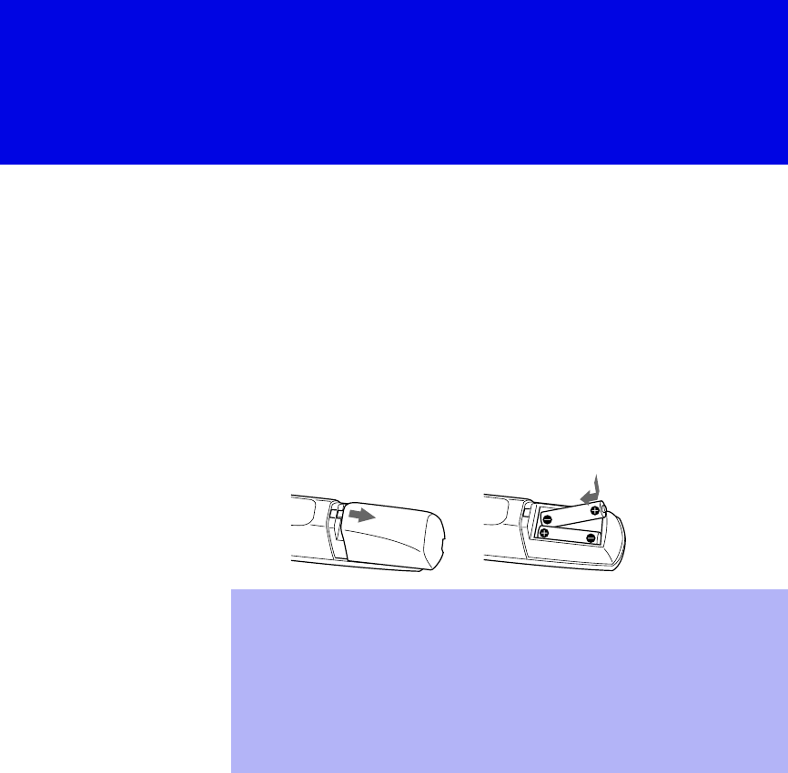
9
Installing and Connecting the Projection TV
Contents
The box contains your new projection TV, a remote control and two AA
batteries. No peripheral cables are included. If you intend to add additional
equipment to your projection TV, please check the hookup instructions for
your desired setup before you begin. You may need to purchase cables and/
or splitters to complete the hookup properly.
Inserting Batteries into the Remote Control
Insert two size AA (R6) batteries (supplied) by matching the + and – on the
batteries to the diagram inside the battery compartment.
Carrying Your Projection TV
Carrying the projection TV requires three (3) or more people.
The projection TV has been equipped with casters for easy movement on a
hard surface.
Please move your projection TV using the casters.
✍Remove the batteries to avoid damage from possible battery leakage
whenever you anticipate that the remote control will not be used for an
extended period.
✍Handle the remote control with care. Avoid dropping it, getting it wet, or
placing it in direct sunlight, near a heater, or where the humidity is high.
✍Your remote control can be programmed to operate most video
equipment. (See “Programming the Remote Control” on page 58.)
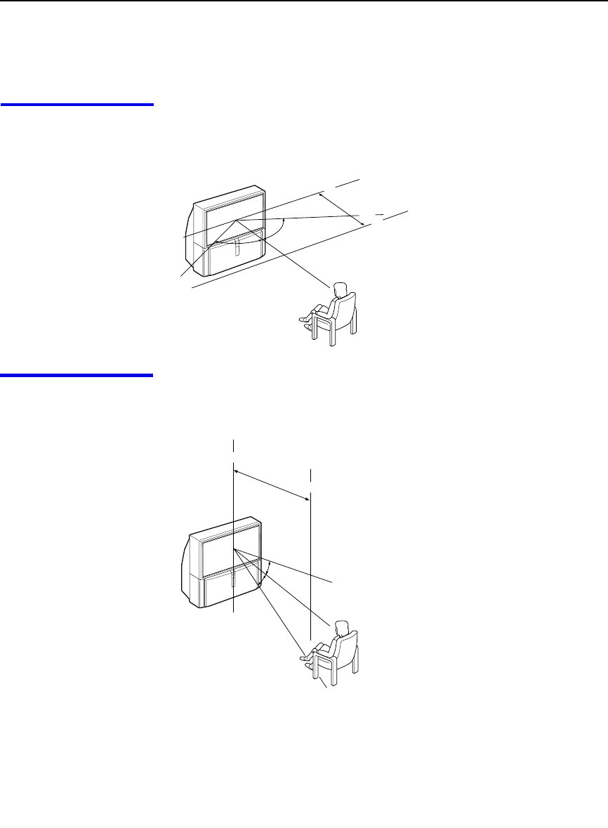
Installing and Connecting the Projection TV
10
Installing the Projection TV
Recommended
viewing area
(Horizontal)
60˚
60 60˚
min. 2.1 m (approx. 7 ft.)
20
˚
20
˚
min. 2.1 m (approx. 7 ft.)
Recommended
viewing area
(Vertical)
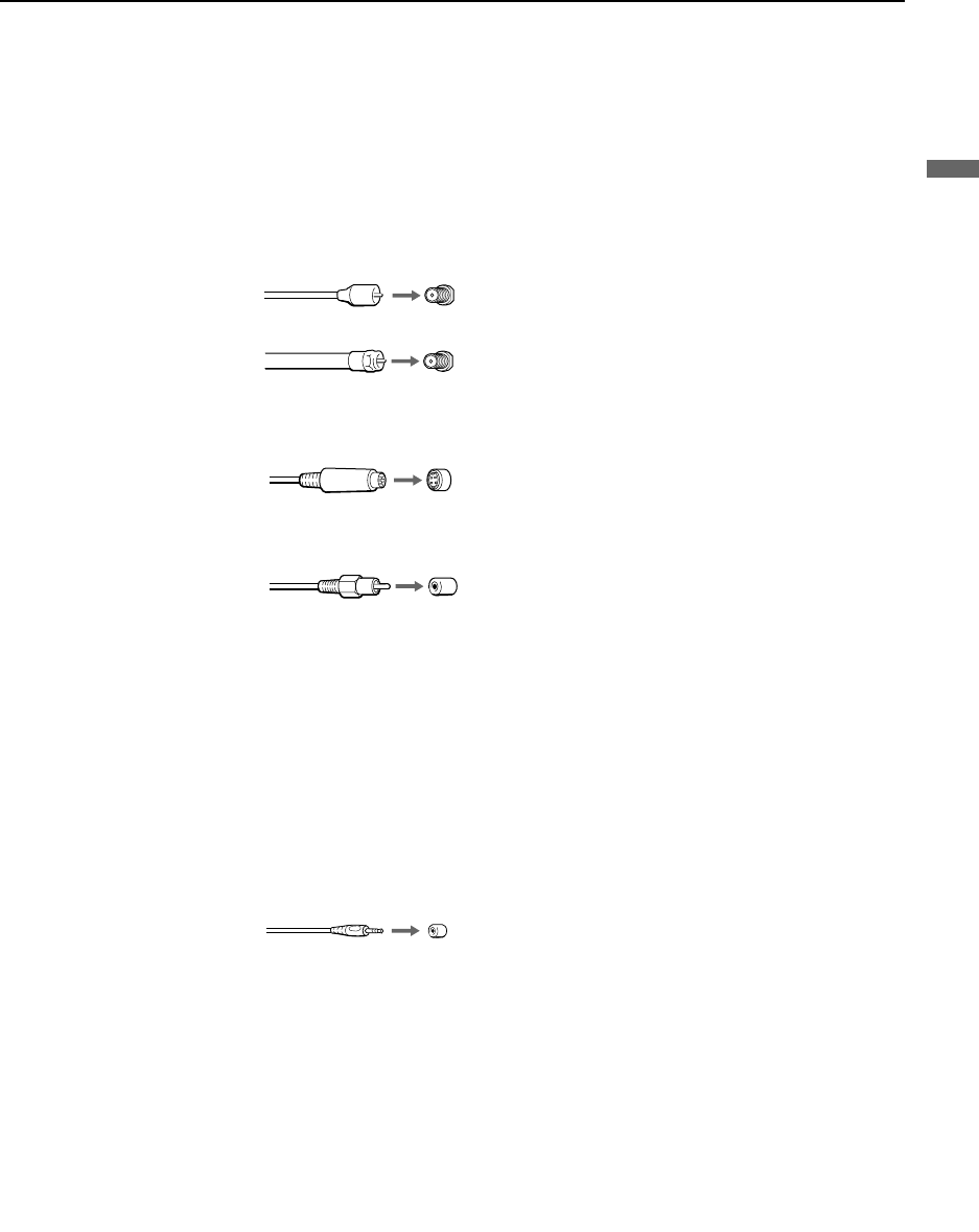
Installing and Connecting the Projection TV
11
Installing and Connecting the Projection TV
Connector Types
You may find it necessary to use some of the following connector types
during set up.
Coaxial cable
Standard TV cable and antenna cable
S Video cable
High quality video cable for enhanced picture quality
Audio/Video cable
Video - Yellow
Audio (Left) - White
Audio (Right) - Red
Some DVD Players are equipped with the following three video connectors:
Y - Green
PB (CB, Cb or B–Y) - Blue
PR (CR, Cr or R–Y) - Red
CONTROL S cable
CONTROL S connections are exclusive to Sony products and allow greater
control of all Sony equipment.
Plug Type
Screw-on Type
Push into connection.
Screw into connection.
Align guides and push
into connection.
Push into connection.
Push into connection.

Installing and Connecting the Projection TV
12
Projection TV Controls and Connectors
Front Panel Menu
Controls The front panel menu controls allow access to the on-screen menus without
the use of a remote control. Pressing MENU brings up the on-screen menus.
The arrow buttons move the on-screen cursor in the menus and the Select
button ( ) selects the menu item.
If power is in
STANDBY, press CH+/–
to turn on.
z
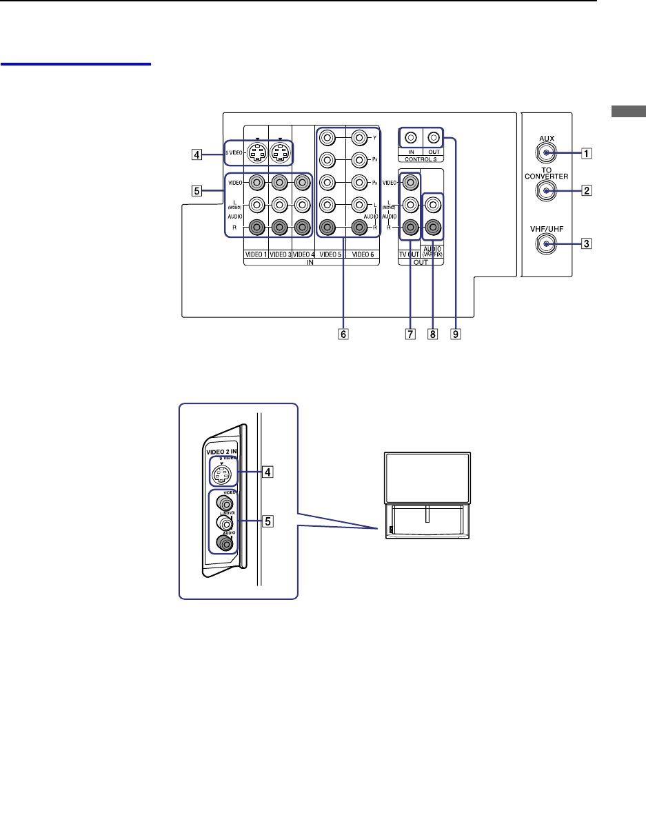
Installing and Connecting the Projection TV
13
Installing and Connecting the Projection TV
Projection TV Rear
and Front Panel
Connectors Rear of projection TV
Front of projection TV

Installing and Connecting the Projection TV
14
Connection Description
1AUX Allows you to view local and cable channels if your cable
provider does not feature local channels. You can switch
between local and cable channels easily by pressing ANT
on the remote control. Devices connected to the AUX
input cannot be viewed in Twin View.
2TO CONVERTER This is a VHF/UHF OUT jack that lets you set up your
projection TV to switch between scrambled channels
(through a cable box) and normal cable channels (CATV).
Use this jack instead of a splitter to get better picture
quality when switching between scrambled and
unscrambled cable channels.
3VHF/UHF Connects to your VHF/UHF antenna or cable.
4S VIDEO
(Rear and front) Connects to the S VIDEO OUT jack of your VCR or other
S VIDEO-equipped video component. Provides better
picture quality than the VHF/UHF jacks or the Video IN
jack.
5VIDEO
(L/R)/AUDIO
(Rear and front)
Connects to the audio and video OUT jacks on your VCR
or other video component. A fourth video input (VIDEO
2) is located on the front panel of the projection TV.
6Y/PB/PR
(L/R)/AUDIO Connects to your DVD player’s or Digital Set-top box’s
component video (Y, PB, PR) and audio (L/R) jacks.
7TV OUT Connects to an AV receiver for greater control of all audio
and video equipment (see page 27). For detailed
information about connection, refer to the operating
manual supplied with the AV receiver.
8AUDIO OUT
(VAR/FIX)
L (MONO)/R
Connects to the left and right audio inputs of your audio or
video component.
9CONTROL S
IN/OUT To control other Sony equipment with the projection TV's
remote control, connect the CONTROL S IN jack of the
equipment to the CONTROL S OUT jack on the
projection TV with the CONTROL S cable.
To control the projection TV with a remote control for
another Sony product, connect the CONTROL S OUT
jack of the equipment to the CONTROL S IN jack on the
projection TV with the CONTROL S cable.

Installing and Connecting the Projection TV
15
Installing and Connecting the Projection TV
Basic Connections (Connecting Cable TV or Antenna)
Connecting Directly
to Cable or an
Antenna
The connection you choose depends on the cable found in your home. Newer
homes are equipped with standard coaxial cable (see A); older homes
probably have 300-ohm twin lead cable (see B); other homes may contain
both (see C).
A VHF Only or VHF/UHF or Cable
B VHF Only or UHF Only or VHF/UHF
C VHF and UHF
Cable and Antenna If your cable provider does not feature local channels, you may find this set
up convenient.
Select CABLE or antenna (ANT) mode by pressing ANT on the remote
control.
75-ohm coaxial
cable Rear of projection TV
VHF/UHF
Rear of projection TV
Antenna connector
300-ohm twin lead cable VHF/UHF
Rear of projection TV
75-ohm coaxial cable VHF/UHF
U/V Splitter
(not supplied)
300-ohm twin lead cable
✍To receive channels with an antenna, you need to turn your Cable to OFF
(see page 50) and perform the Auto Program function (see page 51).
CATV cable
Rear of projection TV
TO
CONVERTER
(No connection to
TO CONVERTER)
VHF/UHF
Antenna cable
AUX

Installing and Connecting the Projection TV
16
Cable Box
Connections Cable Box and Cable
This is the preferred basic cable TV hookup to use if:
❑Your cable TV company scrambles some channels, but not all of them
(pay channels vs. regular cable channels) and you need to use a cable
box, and
❑You want to enjoy the Twin View feature.
With this setup you can:
❑Use the projection TV remote control to change channels using your
cable box when the signal is scrambled.
❑Use the projection TV remote control to change channels using your
projection TV when the signal is not scrambled. (Your projection TV’s
tuner provides a better signal than the cable box.)
❑Use the Twin View feature. (When all channels are routed through your
cable box, only one channel is sent to the projection TV, so you can not
use the Twin View or Channel Index features for your cable box.)
1Connect the Cable TV cable to the projection TV’s VHF/UHF jack.
2Using a coaxial cable, connect the projection TV’s TO CONVERTER
jack to the cable box’s IN jack. The projection TV’s internal converter
allows you to switch between unscrambled signals coming straight into
the projection TV and scrambled signals coming in through the cable
box, eliminating the need for an external splitter.
3Using a coaxial cable, connect the cable box’s OUT jack to the
projection TV’s AUX jack.
✍Pressing ANT on the remote control switches between the channels
coming in through the cable box (scrambled) and those coming directly
to the TV (unscrambled).
Rear of
projection TV
TO
CONVERTER
VHF/UHF
AUX
Cable box
OUT
IN
Signal
75-ohm coaxial cable (not supplied)
CATV cable (unscrambled channels)
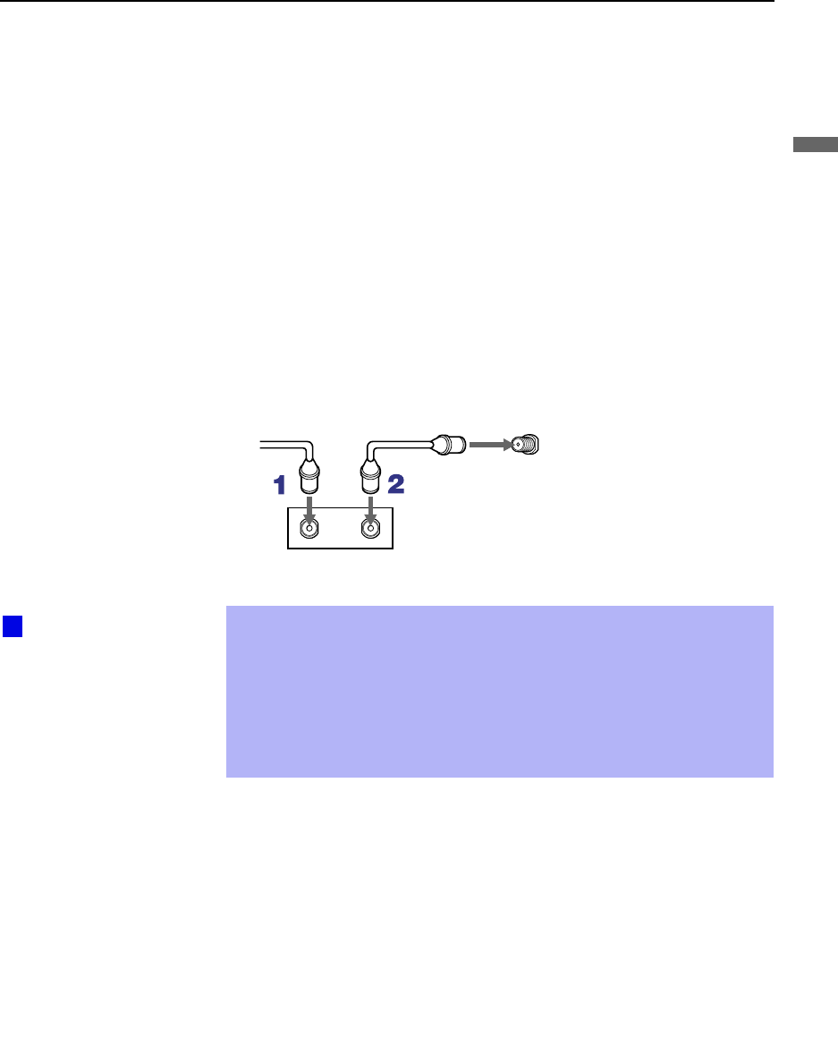
Installing and Connecting the Projection TV
17
Installing and Connecting the Projection TV
Cable Box Only
Use this hookup if:
❑You subscribe to a cable TV system that uses scrambled or encoded
signals requiring a cable box to view all channels, and
❑You do not intend to hook up any other audio or video equipment to
your projection TV.
When all channels are routed through your cable box, only one unscrambled
channel is sent to the projection TV, so you cannot use the Twin View
feature. If some channels are scrambled, but others are not, consider using
the hookup on page 16 instead.
1Connect the coaxial connector from your cable service to the cable
box’s IN jack.
2Using a coaxial cable, connect the cable box’s OUT jack to the TV’s
VHF/UHF jack.
Also, set Cable to ON in the Channel menu. (see page 50)
✍Your Sony remote control can be programmed to operate your cable box
(see “Programming the Remote Control” on page 58).
✍To change channels using the cable box, set your projection TV to
channel 3 or 4 depending on the cable box channel output. If you will be
controlling all channel selection through your cable box, consider using
the Channel Fix feature to set your projection TV to channel 3 or 4 (see
page 51).
VHF/UHF
Rear of projection TV
Cable
IN OUT
Cable box
Setting the Channel
Fix feature in the Channel
menu (see “Using the
Channel Menu” on page
50) ensures that you do
not accidentally switch
the channels using your
projection TV.
z

Installing and Connecting the Projection TV
18
Connecting a VCR and Cable
Use this hookup if:
❑You have cable TV that does not require a cable box.
Disconnect all power sources before making any connections.
1Connect the cable TV cable to the VCR’s IN jack.
2Using a coaxial cable, connect the VCR’s OUT jack to the projection
TV’s VHF/UHF jack.
3Using AUDIO and S VIDEO cables, connect the VCR’s Audio and
S VIDEO OUT jacks to the projection TV’s AUDIO and S VIDEO IN
jacks.
Coaxial cable
Rear of Projection TV
VIDEO (yellow)
AUDIO-L (white)
AUDIO-R (red)
Cable
VCR
VMC-810S/820S
(not supplied)
S VIDEO
YC-15V/30V (not supplied)
✍If your VCR is not equipped with S VIDEO, use a VIDEO cable (yellow)
instead of the S VIDEO cable.

Installing and Connecting the Projection TV
19
Installing and Connecting the Projection TV
Connecting a VCR and Cable Box
Use this hookup if:
❑Your cable TV company scrambles some channels, but not all of them
(pay channels vs. regular cable channels) and you need to use a cable
box, and
❑You want to enjoy the Twin View feature.
With this setup you can:
❑Use the projection TV remote control to change channels on your cable
box when the signal is scrambled. To program your Sony Remote
control to operate your cable box, see “Programming the Remote
Control” on page 58.
❑Use the projection TV remote control to change channels using your
projection TV when the signal is not scrambled. Your projection TV’s
tuner provides a better signal than the cable box.
❑Use the Twin View feature. (When all channels are routed through your
cable box, only one signal is sent to the projection TV, so you cannot
use the Twin View feature.)
Disconnect all power sources before making any connections.
1Connect the Cable TV cable to the projection TV’s VHF/UHF jack.
2Using a coaxial cable, connect the TV’s TO CONVERTER jack to the
cable box’s IN jack. The projection TV’s internal converter allows you
to switch between unscrambled signals coming straight into the
projection TV and scrambled signals coming in through the cable box,
eliminating the need for an external splitter.
3Using a coaxial cable, connect the cable box’s OUT jack to the VCR’s
IN jack.
4Using AUDIO and S VIDEO cables, connect the VCR’s AUDIO and S
VIDEO OUT jacks to the projection TV’s AUDIO and S VIDEO IN
jacks.
5Using a coaxial cable, connect the VCR’s OUT jack to the projection
TV’s AUX jack.
✍To view scrambled channels, set your projection TV to AUX 3 or 4
(depending on your cable box output). Change channels using your
cable box.

Installing and Connecting the Projection TV
20
Coaxial
cable
Cable box
VCR
Rear of projection TV
VIDEO (yellow)
AUDIO-L (white)
AUDIO-R (red)
VMC-810S/820S
(not supplied)
Coaxial cable
YC-15V/30V
(not supplied)
S VIDEO
✍If your VCR is not equipped with S VIDEO, use a VIDEO cable (yellow)
instead of the S VIDEO cable.
✍You will not be able to change channels on the VCR. Set your projection
TV and VCR to channel 3 or 4, depending on your cable box channel
output.
✍Pressing ANT on the remote control switches between the channels
coming in through the cable box (scrambled) and those coming directly
to the projection TV (unscrambled).
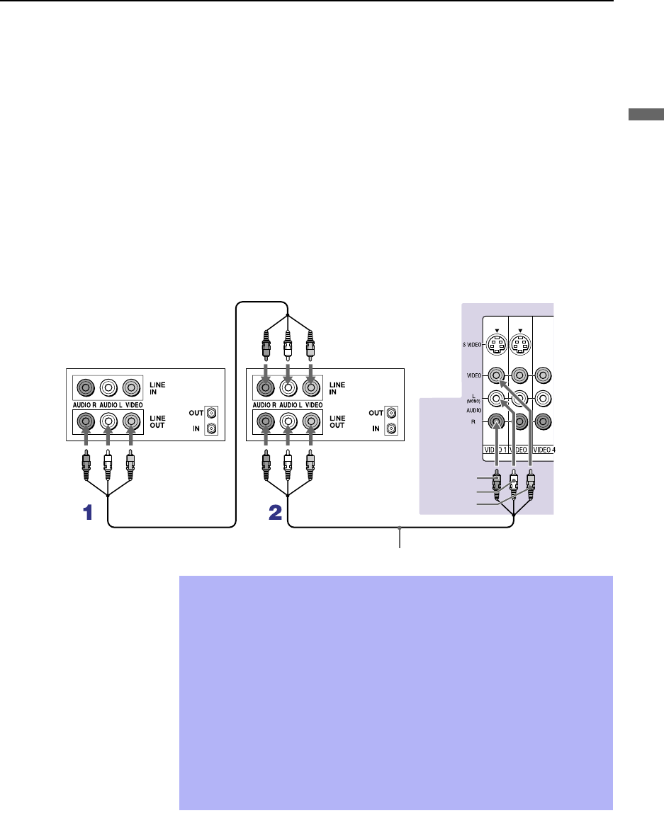
Installing and Connecting the Projection TV
21
Installing and Connecting the Projection TV
Connecting Two VCRs for Tape Editing
If you connect two VCRs, you can record from one VCR to the other while
using your TV to monitor what is being recorded.
Disconnect all power sources before making any connections.
1Using AUDIO and VIDEO cables, connect the playback VCR’s Audio
and Video OUT jacks to the recording VCR’s Audio and Video IN
jacks.
2Using AUDIO and VIDEO cables, connect the recording VCR’s
AUDIO and Video OUT jacks to the projection TV’s AUDIO and
VIDEO IN jacks.
Rear of projection TV
VCR (playback) VCR (recording)
VMC-810S/820S (not supplied)
AUDIO-R (red)
AUDIO-L (white)
VIDEO (yellow)
✍To perform tape editing, set the projection TV to the video input intended
for playback by pressing TV/VIDEO on the remote control.
✍You may need to change the video input on your VCR. Consult your
VCR’s operating manual for instructions.
✍If your VCRs have an S VIDEO jack: For best picture quality, use an
S VIDEO connection instead of the yellow video cable on your combined
A/V cable.
Using an S VIDEO cable, connect the playback VCR’s S VIDEO OUT jack
to the recording VCR’s S VIDEO IN jack. S VIDEO does not provide audio,
so audio cables must still be connected to provide sound.
✍You cannot record signals from equipment connected to the Y, PB, PR
input.

Installing and Connecting the Projection TV
22
Connecting an Audio Receiver
Disconnect all power sources before making any connections.
Using audio cables, connect the projection TV’s AUDIO OUT (VAR/FIX)
jacks to the audio receiver’s audio LINE IN jacks.
Rear of projection TV
AUDIO-R
(red) AUDIO-L
(white)
Line
input
RK-74A
(not supplied)

Installing and Connecting the Projection TV
23
Installing and Connecting the Projection TV
Connecting a DVD Player with Component
Video Connectors
This is the preferred hookup to use if:
❑Your DVD player has component (Y, B-Y, R-Y) jacks.
Disconnect all power sources before making any connections.
1Using three separate component video cables, connect the DVD player’s
Y, B-Y and R-Y jacks to the Y, PB and PR jacks on the projection TV.
Use the VIDEO IN 5 or 6 connections.
2Using an audio cable, connect the DVD player’s Audio OUT jacks to
the projection TV’s AUDIO IN jacks. Be sure to use the same row of
inputs that you used for the video connection (VIDEO IN 5 or 6).
✍The Y, B-Y and R-Y jacks on your DVD player are sometimes labeled
Y, CB and CR, or Y, PB and PR. If so, connect the cables to like colors.
VMC-10HG (not supplied)
Rear of projection TV
RK-74A (not supplied)
DVD player
AUDIO-R (red)
AUDIO-L (white)
PR
PB
Y
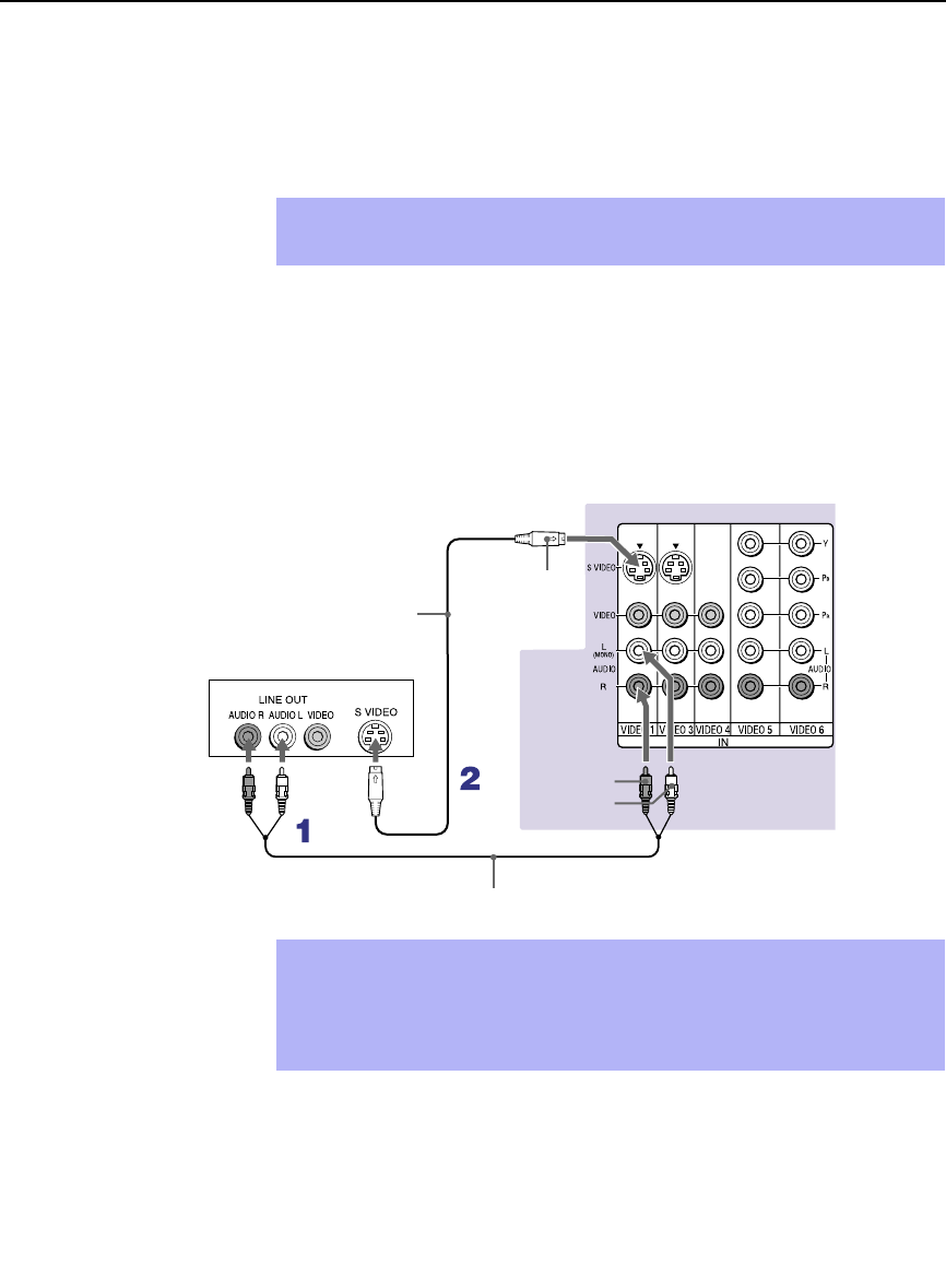
Installing and Connecting the Projection TV
24
Connecting a DVD Player with A/V Connectors
Use this hookup if:
❑Your DVD player does not have component (Y, PB, PR) jacks.
Disconnect all power sources before making any connections.
1Using audio cables, connect the DVD player’s Audio OUT jacks to the
projection TV’s AUDIO IN jacks.
2Using an S VIDEO cable, connect the DVD player’s S VIDEO jack to
the projection TV’s S VIDEO jack.
✍If your DVD player has video component output connectors: for best
picture quality use the connection described on page 23.
Rear or projection TV
YC-15V/30V
(not supplied)
DVD player
RK-74A (not supplied)
AUDIO-R (red)
AUDIO-L (white)
S VIDEO
✍Use TV/VIDEO on the remote control to switch between the VCR, DVD
player and cable TV inputs.
✍If your VCR is not equipped with S VIDEO, use a VIDEO cable (yellow)
instead of the S VIDEO cable.
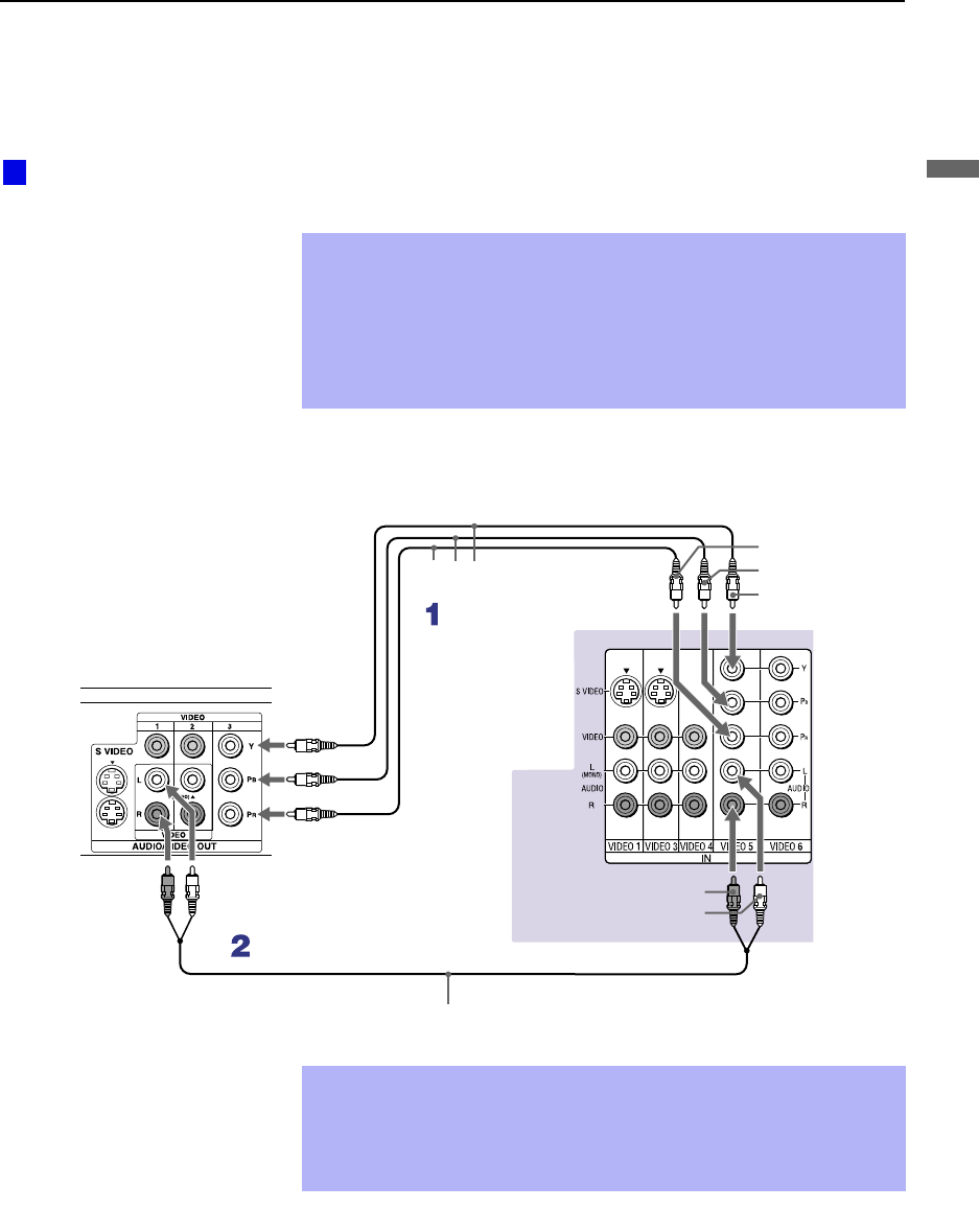
Installing and Connecting the Projection TV
25
Installing and Connecting the Projection TV
Connecting a Digital TV Receiver
Disconnect all power sources before making any connections.
1Using three separate component video cables, connect the Digital TV
Set-top box’s Y, PB and PR jacks to the projection TV.
2Using an audio cable, connect the Digital TV Set-top box’s Audio OUT
jacks to the projection TV’s AUDIO IN jacks.
✍The Y, PB and PR jacks do not provide audio, so audio cables must
be connected to provide sound.
✍Component video connection is necessary to view 480p, 720p and
1080i formats. You may also use the S VIDEO or Composite Video
connections, however, composite video (Y, PB, PR) will provide the
best picture quality for all format types.
Be sure to read the
Set-top box manual.
z
VMC-10HG (not supplied)
Digital TV Set-top box
RK-74A (not supplied)
AUDIO-R (red)
AUDIO-L (white)
Rear of
projection TV
PR
PB
Y
✍You cannot record the signal from any equipment connected into the
Y, PB and PR connectors.
✍This projection TV is not compatible with digital TV receivers
configured with RGB or VGA output connectors.
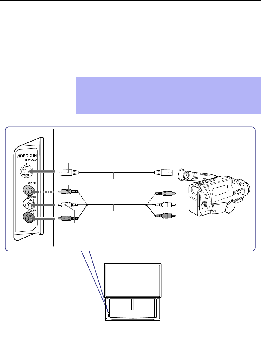
Installing and Connecting the Projection TV
26
Connecting a Camcorder
For easy connection of the camcorder, the projection TV has front Audio and
Video inputs (shown below). However, if you prefer, you can also connect
the camcorder to the projection TV’s rear Audio and Video IN jacks.
Using AUDIO and S VIDEO cables, connect the camcorder’s Audio and S
VIDEO OUT jacks to the projection TV’s AUDIO and S VIDEO IN jacks.
✍If you have a mono camcorder, connect its left audio output to the
projection TV’s AUDIO L (MONO) jack.
✍If your camcorder is not equipped with S VIDEO, use a VIDEO cable
(yellow) instead of the S VIDEO cable.
VIDEO (yellow)
A/V output
AUDIO-L (white)
AUDIO-R (red)
S VIDEO
YC-15V/30V (not supplied)
VMC-810S/820S
(not supplied)

Installing and Connecting the Projection TV
27
Installing and Connecting the Projection TV
Connecting an AV Receiver
For greater control of all audio and video equipment, connect an AV receiver.
Disconnect all power sources before making any connections.
1Connect the coaxial cable from the incoming cable connection or
antenna to IN on the VCR.
2Using a coaxial cable, connect OUT on the VCR to VHF/UHF on the
projection TV.
3Using a VIDEO cable, connect VIDEO of VIDEO 1 IN on the
projection TV to MONITOR OUT on the AV receiver.
4Using an AUDIO/VIDEO cable, connect TV OUT on the projection TV
to AUDIO/VIDEO 2 IN on the AV receiver.
5Using an AUDIO/VIDEO cable, connect the video equipment to the AV
receiver.
6Select the Setup menu and set “Video Label” to “Receiver” to fix your
TV’s input to AV receiver (see “Video Label” on page 56).
✍Change “Video Label” for the VIDEO 1 input to “Receiver” (see page 56).
Rear of projection TV
AUDIO-L
AUDIO-R
VMC-10HG (not supplied)
Cable/
Antenna
Coaxial cable (not supplied) VMC-810S/820S
(not supplied)
VMC-810S/820S
(not supplied)
AUDIO/
VIDEO 1 IN
AUDIO/VIDEO 1 OUT
AV receiver
VMC-810S/820S (not supplied)
MONITOR
OUT
VIDEO VIDEO
VCR
AUDIO/
VIDEO 2 IN

Installing and Connecting the Projection TV
28
Using the CONTROL S Feature
CONTROL S allows you to control your projection TV system and other
Sony equipment with one remote control. In addition to allowing you to
control multiple devices with one remote control, the CONTROL S feature
allows you to always point your remote control at your projection TV,
instead of having to point it at the other equipment, which might be hidden
or out of direct line of sight.
Rear of projection TV

Installing and Connecting the Projection TV
29
Installing and Connecting the Projection TV
Setting Up the Projection TV Automatically
After you finish connecting your projection TV, you can run Auto Setup to
set up your channels. The Auto Setup screen appears when you turn your
projection TV on for the first time after installing it. If you do not want to set
up the channels at this time, you can do it later by using the Auto Program
feature in the Channel menu (see page 51).
Using Auto Setup 1Press POWER on the front panel of your projection TV to turn on the
projection TV.
2Press the TV (FUNCTION) button on your remote control. Red light will
briefly appear.
3Press CH+ on your projection TV to run Auto Setup, or press CH– to
exit. If you use the channel buttons on your remote control, be sure to
use the main set of buttons ( ).
✍The Auto Setup feature does not apply for installations that use a cable
box for all channel selection.
✍You can run Auto Program by selecting it in the Channel menu, as
described on page 51.
Projection TV front panel

Installing and Connecting the Projection TV
30
Adjusting the Convergence Automatically – FLASH FOCUS™ –
The projection tube image appears on the screen in three colors (red, green
and blue). If they do not converge, the color is poor and the picture blurs.
Before you use your projection TV, be sure to adjust the convergence.
The FLASH FOCUS feature allows you to adjust the convergence
automatically.
1Receive a TV or cable TV program.
2Press FLASH FOCUS.
The cross pattern shown below appears and FLASH FOCUS begins to
work. The adjustment is completed when the cross pattern becomes
white and you are returned to the program you were watching.
To obtain an
optimum
convergence for
Digital TV programs
The optimum convergence alignment varies with digital TV formats.
Whenever you find that the picture blurs, press FLASH FOCUS.
✍It is recommended to perform FLASH FOCUS about 30 minutes after the
projection TV is first turned on.
Projection TV
front panel
✍You cannot perform any other functions until FLASH FOCUS has
completed its cycle.
✍If you perform any other operation while FLASH FOCUS is in progress,
FLASH FOCUS operation is canceled.
✍Unshielded speakers or other metallic objects can cause picture
distortion if placed close to the projection TV.
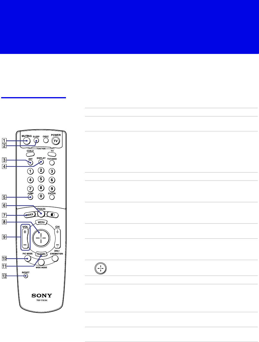
31
Using the Features
Using the Remote Control
The following table describes the buttons on the remote control that are for
more advanced functions.
Button Descriptions Outside Panel
Button Description
1MUTING Press to mute the sound. Press again or press VOL + to
restore the sound.
2SLEEP Press repeatedly until the projection TV displays the time
in minutes (15, 30, 45, 60, or 90) that you want the
projection TV to remain on before shutting off
automatically. Cancel by pressing until SLEEP OFF
appears. While the Sleep feature is set, press once to view
the remaining time.
3ANT Changes between the VHF/UHF input and the AUX input.
4DISPLAY Press once to display the current time and channel label (if
set) and channel number. Press again to turn Display off.
See page 54 for details on setting the time.
5JUMP Press to jump back and forth between two channels. The
projection TV alternates between the current channel and
the last channel that was selected.
6FREEZE Freezes the window picture. Press again to restore the
picture.
7INDEX Press to enter the Scrolling Channel Index mode. You can
view and select from all receivable channels scrolling on
the screen without leaving the current one.
8The joystick allows for movement of the on-screen cursor.
Pressing down on the center of the joystick selects the item.
9VOL +/–Adjusts the volume.
q; PIC MODE Press repeatedly to step through the available video picture
modes: Vivid, Standard, Movie and Pro. Also available in
the Video menu. For details, see “Selecting Video Options”
on page 46.
qa FAVORITES Displays the Favorite Channels list. For details, see “Using
Favorite Channels” on page 37.
qs RESET Press when in a menu to reset the settings to the factory
defaults.
(Continued)
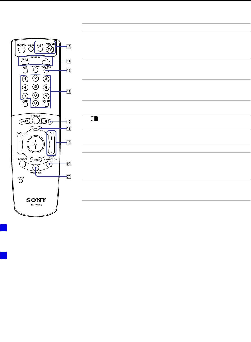
Using the Features
32
qd POWER
buttons
(GREEN)
Turn on and off the projection TV and other audio/video
equipment you have programmed into the remote control.
For instructions, see “Programming the Remote Control”
on page 58.
qf FUNCTION
buttons Select the equipment (TV, CABLE) that you want to
operate. The indicator lights up momentarily when pushed
to show which device the remote control is operating.
qg TV/VIDEO
Cycles through the video equipment connected to your
projection
TV’s video inputs:
TV
,
VIDEO 1
,
VIDEO 2
,
VIDEO 3
,
VIDEO 4
,
VIDEO 5
and
VIDEO 6
.
qh 0 – 9 and
ENTER Press 0 - 9 to select a channel, the channel changes after 2
seconds. Press ENTER to select immediately.
qj Turns on/off Twin View. For details, see “Using Twin
View™” on page 38.
qk MENU Press to display the projection TV on-screen menu. Press
again to exit from the menu.
ql CH +/–Scan through channels.
w; DRC/
CINEMOTION Press repeatedly to step through the available high-
resolution picture modes: Interlaced, Progressive and
CineMotion. For details, see “Using the Video Menu” on
page 46.
wa WIDE MODE Press to step through the wide screen modes: Wide Zoom,
Normal, Full and Zoom. For details, see “Using Wide
Screen Mode” on page 44.
Button Description
To scan rapidly through the
channels, press and hold down
CH+ or CH–.
If power is in STANDBY,
press 0-9 or CH+/– to turn on.
z
z

Using the Features
33
Using the Features
Inside Panel
Button Description
1SYSTEM OFF Press to turn off the projection TV and all equipment
connected with S-Link.
2NPlay
3mRewind
4REC Record
5xStop
6DVD MENU Displays the DVD menu.
7BILINGUAL Press to scroll through the bilingual options: MAIN,
MAIN+SUB, and SUB.
8CODE SET Used for programming the remote control to operate non-
Sony video equipment. For details, see “Programming the
Remote Control” on page 58.
9POWER Press to turn on the DVD/VCR player you have
programmed into the remote control. For instructions, see
“Programming the Remote Control” on page 58.
q; MFast-forward
qa Use to switch control for connected video equipment. You
can program one video source for each switch position. For
details, see “Programming the Remote Control” on page
58.
qs X Pause (Press again to resume normal playback)
qd MENU Displays the video equipment menu.
qf M
MM
M, m
mm
m, <
<<
<, ,
,,
,,
and ENTER Use to operate the DVD menu.
qg Press to select an audio option: Steady Sound ON or
OFF.
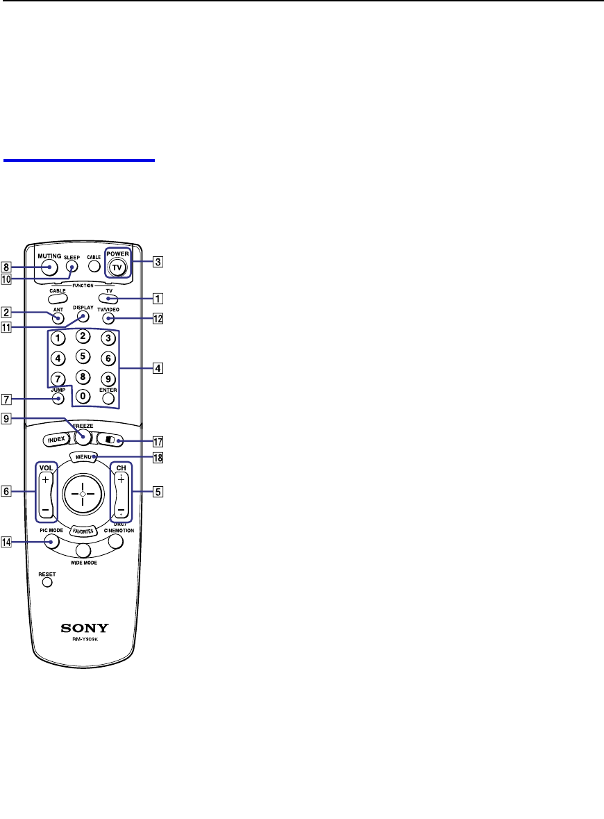
Using the Features
34
Watching the TV
Many TV features can be accessed directly through the remote control. The
following will explain the function of some of the buttons found on your
remote control.
Buttons for
Projection TV
Operations
1 TV (FUNCTION)
Activates the remote control for use with the projection TV.
2 ANT— (AUX input)
Press to change between the VHF/UHF input and the AUX input.
3 TV (POWER)
Turns the projection TV on and off. If a video input indication (e.g.,
VIDEO 1, VIDEO 2) appears on the screen, press TV/VIDEO or
CH +/ – until a channel number appears.
4 0-9 and ENTER
Use for direct channel selection. Press 0-9 to select a channel (for example,
to select channel 10, press 1 and 0). The channel will change after 2 seconds,
or you can press ENTER for immediate selection.
5 CH +/–
Press to scan through the channels (+ up or – down).
6 VOL +/–
Press to adjust the volume (+ up or – down).
7 JUMP
Press to alternate or jump back and forth between two channels. The
projection TV will jump between the current channel and the last channel
selected.
8 MUTING
Press to mute the sound. “MUTING” will appear on the screen and will dim
three seconds later. To restore the sound, press again or press VOL +.
9 FREEZE — (yellow labeled button)
This is useful when you need to copy down information that appears on the
TV’s screen (see “Using the Freeze Function” on page 41).
q; SLEEP
Press repeatedly until the projection TV displays the approximate time in
minutes (15, 30, 45, 60, or 90) that you want the projection TV to remain on
before shutting off automatically.
Cancel by pressing SLEEP until “SLEEP OFF” appears.
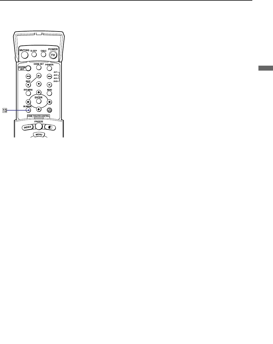
Using the Features
35
Using the Features
qa DISPLAY
Press to display the channel number, current time and channel label (if set).
To turn the display off, press DISPLAY again.
qs TV/VIDEO
Press repeatedly to scroll through available video inputs: TV, VIDEO 1,
VIDEO 2, VIDEO 3, VIDEO 4, VIDEO 5 and VIDEO 6.
If you select Skip as a Video Label in the Setup menu, your projection TV
will skip the video input you selected (see “Video Label” on page 56).
qd BILINGUAL
Press to scroll through the bilingual options: MAIN, MAIN+SUB, and SUB.
qf PIC MODE
Press PIC MODE repeatedly to directly choose one of five different video
modes that best suits the program you are watching.
Vivid: Select for enhanced picture contrast and sharpness.
Standard: Select to display a standard picture for normal viewing
environments.
Movie: Select to display a finely detailed picture for low light environments.
Pro (Professional): Select to display a picture with minimum enhancements.
When you select each mode, you can also adjust the picture quality (such as
Brightness, Color, etc.) to suit your taste. For details, see “Mode” on page
46.

Using the Features
36
Watching the Digital TV
When you have connected the DTV receiver, you can enjoy digital TV
programs. This projection TV is capable of receiving the 1080i, 720p, 480p
and 480i digital TV formats.
To view a digital TV program
1Connect the DTV receiver to VIDEO 5 or 6 IN on the projection TV
(for details, see page 25).
2Press TV/VIDEO to select VIDEO 5 or 6.
3Select a digital channel on the DTV receiver. For details, see the
Operating Manual of the DTV receiver.
4Adjust the volume of the projection TV as necessary.
✍This projection TV is not capable of displaying a native 720p format
signal. When a 720p format signal is received, it is converted into a 480p
format signal.

Using the Features
37
Using the Features
Using Favorite Channels
The Favorite Channel feature lets you select programs from a list of favorite
channels that you preset.
To display a list of your favorite channels:
1Press FAVORITES.
The Favorite Channel options appear.
2Move the joystick up or down to highlight the channel you want to
watch. The program on that channel appears in the preview window.
Press to select.
✍Your Favorite Channel options can be set automatically or manually. The
factory setting for Favorite Channel is Auto.
When Favorite Channel is set to Auto, the last eight channels selected
with 0-9 buttons will be set as Favorite Channel options. If you want to
input your own selections as Favorite Channel settings, see “Favorite
Channel” on page 50.
Favorios
124
6
10
12
2
8
8
4
Exit
Preview window
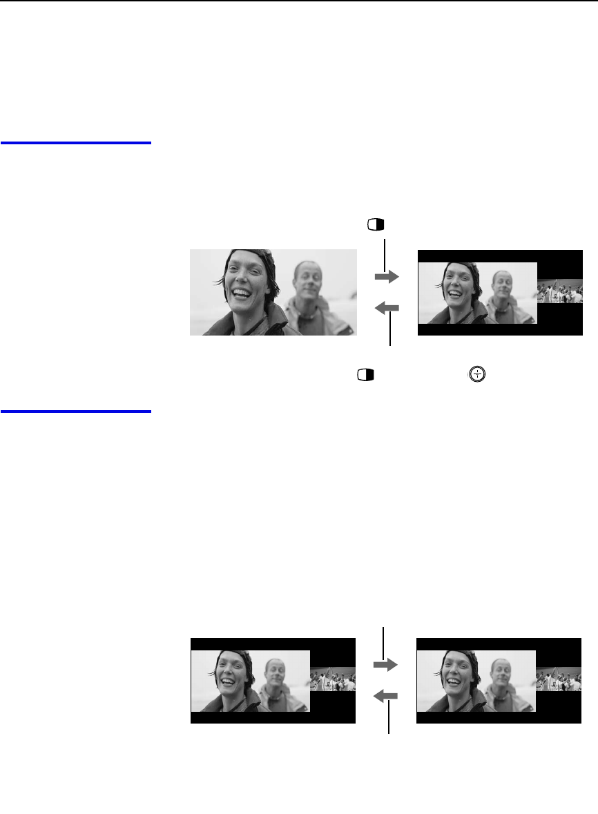
Using the Features
38
Using Twin View™
Twin View enables you to watch two programs at the same time. You can
also change the size of both the left and right pictures.
Displaying Twin
Pictures To display twin pictures
1Make sure your projection TV is
tuned to a working channel.
2Press .
To cancel twin pictures
❑Press again (or press ).
Activating the
Picture Although two pictures appear on the screen at the same time, only one
picture is active. Change the picture size by using the joystick. For an active
picture, you can:
❑Change channels.
❑Adjust the volume.
❑Switch the input sources from VHF/UHF to cable by pressing ANT or
TV/VIDEO to switch the video input.
❑Change the picture size by pressing the joystick up or down.
To activate the right picture
❑Move the joystick to the right.
To activate the left picture
❑Move the joystick to the left.

Using the Features
39
Using the Features
✍ANT is not effective in the right picture.
✍JUMP is not effective in Twin View.
✍When you adjust the twin screen sizes, the projection TV memorizes
the change. The next time you use the Twin View feature, the
memorized sizes appear.
✍Hookups that affect your ability to use Twin View:
- If you are viewing all channels through the cable box, the Twin
View feature will not work. The cable box only unscrambles one
signal at a time, so the right picture will be the same as the left
picture.
- You can watch a scrambled cable channel and another video
source. Be sure your DVD player or VCR is connected to one of the
VIDEO IN 1-6 and AUX inputs on the rear of the projection TV.
Pictures from equipment connected to VIDEO 5, 6 and AUX will
only appear in the left picture, not in the right.
✍The active picture is highlighted in cyan.

Using the Features
40
Changing the
Picture Size The zoom feature lets you change the size of the left and right pictures.
To enlarge the left
picture (reduce the
right)
1Move the joystick
left to activate the
left picture (if not
already
activated).
2Move the joystick
up to enlarge the
picture and move
the joystick down
to reduce the
picture.
To enlarge the right
picture (reduce the
left)
1Move the joystick
right to activate the
right picture (if not
already activated).
2Move the joystick
up to enlarge the
picture and move
the joystick down to
reduce the picture.
✍When you adjust the twin screen sizes, the projection TV memorizes the
change. The next time you use the Twin View function, the memorized
sizes appear.
v
V

Using the Features
41
Using the Features
Using the Freeze Function
The FREEZE button allows you to temporarily capture a program’s picture.
You can use this feature to write down information such as phone numbers,
recipes, etc.
To use the Freeze function
1When the program information you want to capture is displayed, press
FREEZE.
2The projection TV switches to Twin View mode and displays the
“frozen” picture on the right, while the current program continues on the
left.
3To cancel and return to normal viewing, press FREEZE.
✍Freeze feature is not available if you are already in Twin View™ mode.
Call 555-1234
Frozen picture
Current program
in progress
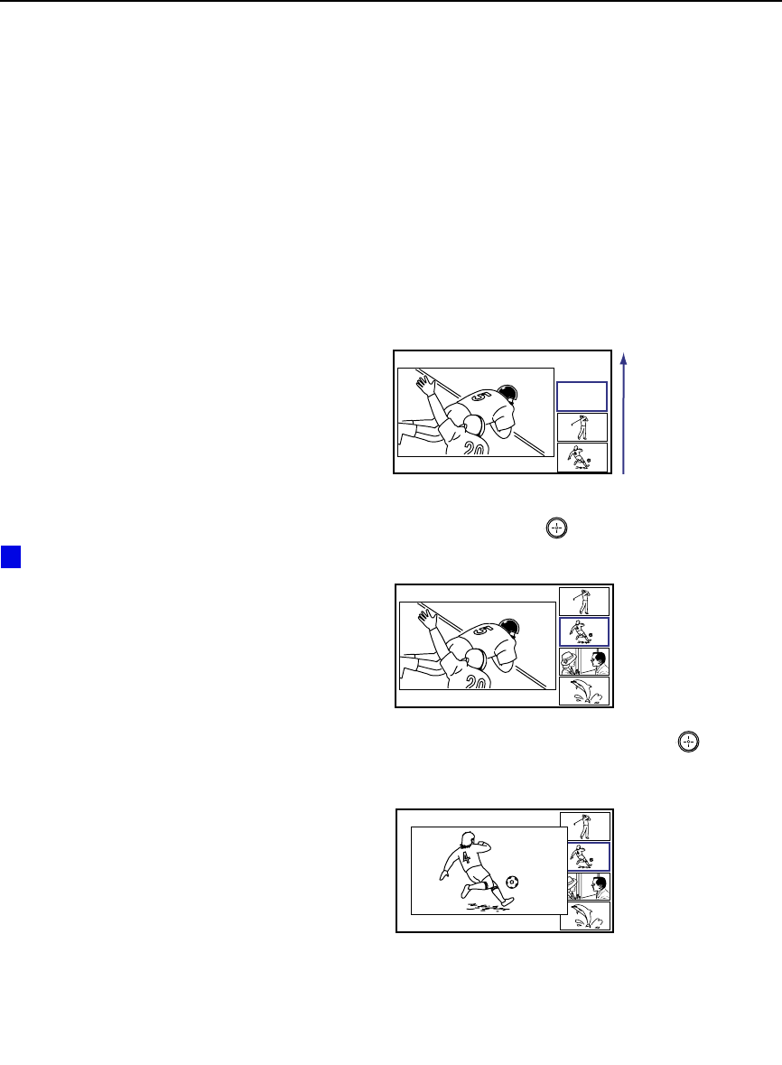
Using the Features
42
Using Scrolling Channel Index
Scrolling Channel Index allows you to view and select from all receivable
channels scrolling on the screen without leaving the current channel.
To use the Scrolling Channel Index function
1Press INDEX.
The current channel will be reduced in size and displayed on the left in
normal motion picture format. The first channel is briefly displayed on
the bottom-right side of the screen, then frozen. It scrolls up and the next
channel appears on the bottom-right, and the process is repeated with
the other channels.
2Move the joystick up and down so that the channel you wish to view is
displayed in the cyan frame, and press .
To return to scrolling, move the joystick up and down again.
3To enlarge the selected channel into the left frame, press again.
The selected channel will be displayed in normal motion picture, and
the sound also switches to this channel.
10
To change the direction of
scrolling, move the joystick up
or down once.
To increase scrolling speed,
hold the joystick up or down.
z
10
8
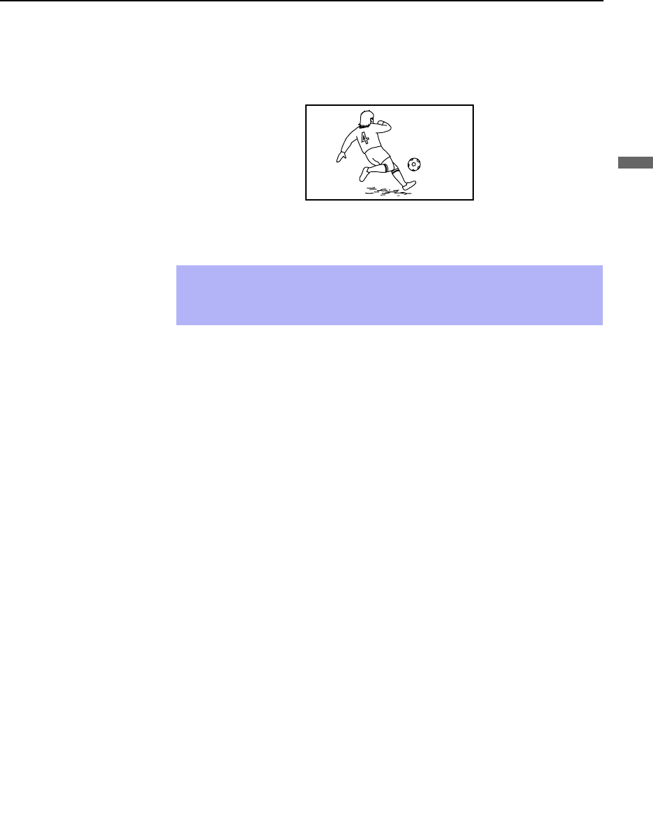
Using the Features
43
Using the Features
4Press INDEX.
The selected channel will be enlarged for normal viewing.
To cancel Scrolling Channel Index
Press INDEX again to resume normal viewing.
✍If you leave the Scrolling Channel Index screen displayed for an hour
without any additional operation, Channel Index is canceled and the
normal picture reappears.
8

Using the Features
44
Using Wide Screen Mode
Wide Screen Mode lets you watch 4:3 normal broadcasts in several Wide
Screen modes (16:9 aspect ratio).
❑Press WIDE MODE repeatedly to toggle through the following Wide
Mode settings.
Wide Zoom enlarges the 4:3 picture,
while the upper and lower parts of the
picture are condensed to fit the 16:9
screen.
Normal returns the 4:3 picture to its
original size.
Full Mode stretches the 4:3 picture
horizontally only, to fill the 16:9 screen.
Zoom Mode enlarges the 4:3 picture
horizontally and vertically to an equal
aspect ratio that fills the 16:9 screen.
Useful for watching Letterbox movies.
You can also access the
Wide Mode settings in the
Wide menu. For details, see
page 52.
When you change
channels or inputs, the Wide
Mode settings revert to Wide
Zoom (or the 4:3 Default
setting in the Wide menu). To
retain the current Wide Mode
setting as channels and
inputs are changed, set 4:3
Default to Off. For details,
see page 52.
z
z
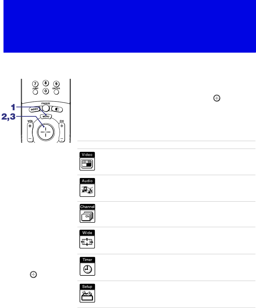
45
Using the Menus
Overview
Opening and choosing a menu:
1Press MENU to display the menu screen.
2Move the joystick to the desired menu icon and press to select it.
3Use the joystick to scroll through the features.
4See the specific menu page for instructions on moving through the
menu.
The menu gives you access to the following features:
Menu Icon Description Page
Allows you to make adjustments to your picture settings.
It also allows you to customize the Picture Mode based on
the type of program you are viewing.
46
Offers enhanced audio options such as customizing the
Effect of the sound on your projection TV.
48
Allows you to set up a Favorite Channel list, run the Auto
Program function, and more.
50
Allows you to set the wide screen mode, adjust the
vertical center in wide mode, and set the 4:3 Default
mode.
52
Lets you set the clock on your projection TV and allows
you to program your projection TV for scheduled viewing
using the Timers.
54
Provides several options for setting up your channels,
labeling your Video inputs, and selecting the language of
the on-screen menus.
55
To end a menu session:
Press MENU again.
To end one menu
session and move to
another:
Press the joystick V to
return to the menu icons.
Move the joystick B
BB
B or b
bb
b to
choose the next menu icon
and press to select it.
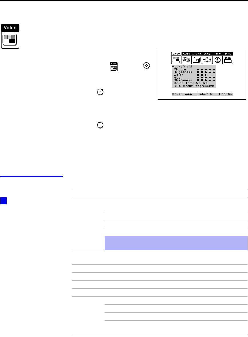
Using the Menus
46
Using the Video Menu
To select the Video Menu
1Press MENU.
2Move the joystick to the
Video icon and press .
3Use the joystick to scroll
through the features.
4Press to select a feature.
That feature’s adjustment
appears.
5Use the joystick to make the desired adjustments.
6Press to select/set.
7Press MENU to exit the menu screen.
To restore the factory default settings for Picture, Brightness, Color,
Hue, Sharpness and Color Temp
❑Press RESET on the remote control when in the Video menu.
Selecting Video
Options The Video menu includes the following options.
To quickly and easily
change from one Video
Mode to another, use the
PIC MODE on the remote
control.
z
Option Description
Mode
Customized
picture
viewing
Vivid Select for enhanced picture contrast and
sharpness.
Standard Recommended for Normal viewing conditions.
Movie Select for soft, film like, picture.
Pro Select for professional monitor like appearance.
✍You can alter the Video menu settings (Picture, Brightness,
Color, etc.) for each Mode.
Picture Adjust to increase picture contrast and deepen the color or decrease
picture contrast and soften the color.
Brightness Adjust to brighten or darken the picture.
Color Adjust to increase or decrease color intensity.
Hue Adjust to increase or decrease the green tones.
Sharpness Adjust to sharpen or soften the picture.
Color Temp
White
intensity
adjustment
Choose from three color temperatures:
Cool Select to give the white colors a blue tint.
Neutral Select to give the white colors a neutral tint.
Warm Select to give the white colors a red tint (NTSC-
Standard).

Using the Menus
47
Using the Menus
DRC Mode
Digital
Reality
Creation
Creates a high-resolution picture with 4x density, for high quality
sources (i.e., DVD player).
Select from Interlaced, Progressive and CineMotion.
Interlaced Recommended for moving pictures.
Progressive Recommended for still images and text.
CineMotion Recommended for 24 frame-per-second films.
Option Description
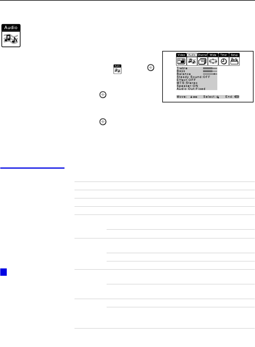
Using the Menus
48
Using the Audio Menu
To select the Audio Menu
1Press MENU.
2Move the joystick to the
Audio icon and press .
3Use the joystick to scroll
through the options.
4Press to select an option.
That option’s settings appear.
5Use the joystick to scroll through the settings.
6Press to select the desired setting.
7Press MENU to exit the menu screen.
To restore the factory default settings for Treble, Bass and Balance
❑Press RESET on the remote control when in the Audio menu.
Selecting Audio
Options The Audio menu includes the following options:
A virtual surround
system attempts to create
the same surround effect
produced by a
multichannel system using
only the left and right
speakers. Most effective
for programs encoded in
Dolby Surround.
z
Option Description
Treble Adjust to increase or decrease higher-pitched sounds.
Bass Adjust to increase or decrease lower-pitched sounds.
Balance Adjust to emphasize left or right speaker balance.
Steady
Sound ON Select to stabilize the volume.
OFF Select to turn off Steady Sound.
Effect Dolby Virtual Select for surround sound (for stereo programs
only).
Simulated Adds a surround-like effect to mono programs.
OFF Normal stereo or mono reception.
Auto Stereo
Enjoy stereo
and mono
programs
ON Select for stereo reception when viewing a program
broadcast in stereo.
OFF Select for mono reception. (Use to reduce noise
during weak stereo broadcasts.)
Speaker ON Select to turn on the projection TV speakers.
OFF Select to turn off the projection TV speakers and
listen to the projection TV's sound only through
your external audio system speakers.

Using the Menus
49
Using the Menus
Audio Out
Easy control
of volume
adjustments
Variable The projection TV’s speakers are turned off, but
the volume output from your audio system can still
be controlled by the projection TV’s remote
control.
Fixed The projection TV’s speakers are turned off and the
volume, bass and treble output of the projection TV
is fixed. Use your audio receiver’s volume control
to adjust the volume through your audio system.
Option Description
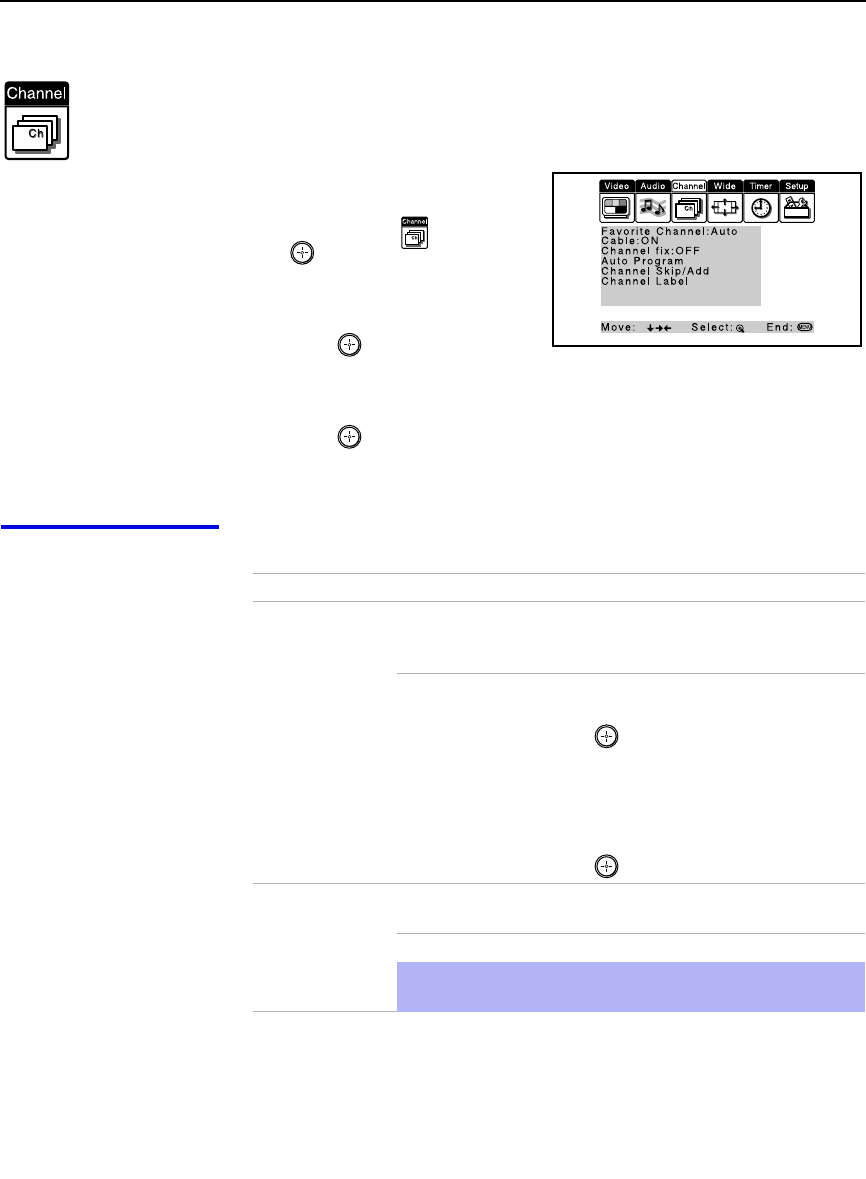
Using the Menus
50
Using the Channel Menu
To select the Channel Menu
1Press MENU.
2Move the joystick to the
Channel icon and press
.
3Use the joystick to scroll
through the features.
4Press to select a feature.
That feature’s options appear.
5Use the joystick to scroll through the options.
6Press to select the desired option.
7Press MENU to exit the menu screen.
Selecting Channel
Options The Channel menu includes the following options:
Option Description
Favorite Channel Auto Select if you want Favorite Channel options to
be set automatically to the last eight channels
selected with the 0-9 buttons.
Manual Select if you want to input your own selections
as Favorite Channel options.
1Press to select a favorite channel
number.
2Use the joystick to scroll through the
channels until you find the channel you
want to add to your favorites.
3Press to select it.
Cable ON Select if you are receiving cable channels with a
CATV cable.
OFF Select if you are using an antenna.
✍You should run Auto Program after changing the Cable
setting.

Using the Menus
51
Using the Menus
Channel Fix
Useful when you
have a cable box
connected
2-6 “Fix” your projection TV’s channel setting to 3
or 4 and use the cable box or VCR to change
channels. Select one of these settings if you
have connected the device to the VHF/UHF
jack.
AUX 2-6 Same as 2-6, except you select one of these
settings if you have connected the device to the
AUX jack. (see page 14)
VIDEO 1 Use when connecting an AV receiver to control
external video sources. TV output should be
connected through the AV receiver.
Auto Program Automatically programs the projection TV for all receivable
channels.
Channel
Skip/Add Removes and adds viewable channels.
1Use the joystick to scroll through the channels until you
find the channel you want to skip/add.
2Press to select it.
3Press the joystick up or down to toggle between “Add” and
“Skip.”
4Press to select.
Channel Label Label up to 20 channels with their station call letters.
Option Description
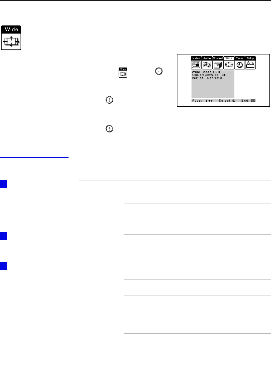
Using the Menus
52
Using the Wide Menu
To select the Wide menu
1Press MENU.
2Use the joystick to move to the
Wide icon and press .
3Move the joystick to scroll
through the features.
4Press to select a feature.
That feature’s options appear.
5Use the joystick to scroll through the options.
6Press to select the desired option.
7Press MENU to exit the menu screen.
Selecting Wide
Options The Wide menu includes the following options:
To change from one
Wide Mode to another,
use the WIDE MODE
button on the remote
control.
Wide Mode is
unavailable while in Twin
View.
The 4:3 Default
functions only when the
projection TV receives
480i signals.
z
z
z
Option Description
Wide Mode
Select a Wide
Mode to use for
4:3 sources.
Wide Zoom Select to enlarge the 4:3 picture, while the
upper and lower parts of the picture are
condensed to fit the wide screen.
Normal Select to return the 4:3 picture to normal
mode.
Full Select to enlarge the 4:3 picture horizontally
only, to fill the wide screen.
Zoom Select to enlarge the 4:3 picture horizontally
and vertically to an equal aspect ratio that fills
the wide screen.
4:3 Default
Select the default
Screen Mode to
use for 4:3
sources.
Wide Zoom Select to enlarge the 4:3 picture, while the
upper and lower parts of the picture are
condensed to fit the wide screen.
Normal Select to return the 4:3 picture to normal
mode.
Full Select to enlarge the 4:3 picture horizontally
only, to fill the wide screen.
Zoom Select to enlarge the 4:3 picture horizontally
and vertically to an equal aspect ratio that fills
the wide screen.
Off Select to continue using the current Wide
Mode setting when the channel or input is
changed.

Using the Menus
53
Using the Menus
Vertical Center Allows you to move the position of the picture up and down in
the window. (Available only in Wide Zoom and Zoom modes.)
Move the joystick up or down to choose a position and press
.
Option Description
If 4:3 Default is set to
anything but Off, the Wide
Mode setting changes
only for the current
channel. When you
change channels (or
inputs), Wide Mode is
automatically replaced
with the 4:3 Default
setting. To retain the
current Wide Mode setting
as channels and inputs
are changed, set 4:3
Default to Off.
z
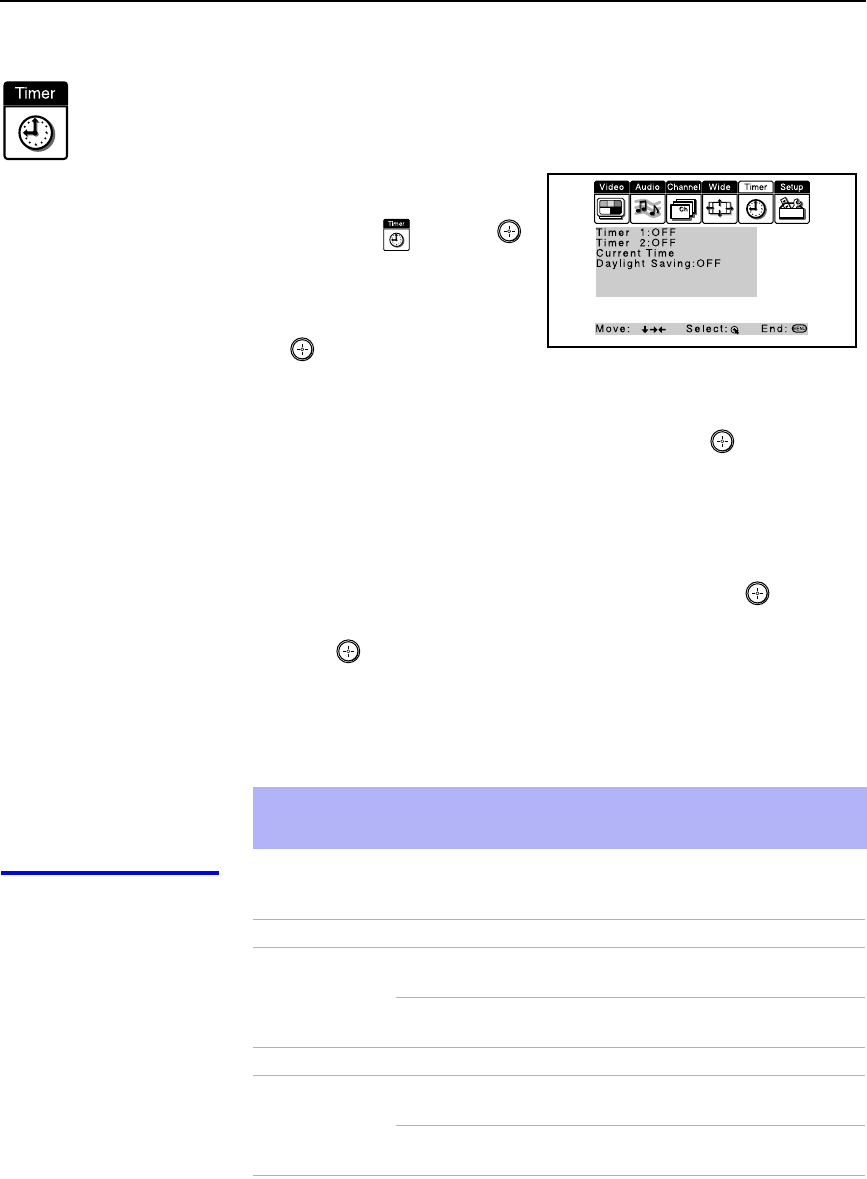
Using the Menus
54
Using the Timer Menu
To select the Timer menu
1Press MENU.
2Move the joystick to the
Timer icon and press .
To set the Current Time
1Use the joystick to select
“Current Time”, then press
.
2If it is currently Daylight Saving Time, be sure to set the mode to “ON”
first.
3Use the joystick to enter the correct time, then press .
4Press MENU to exit the menu screen.
To set the Timer
Before setting the timer, be sure to set your projection TV’s clock to the
current time and Daylight Saving Mode.
1Move the joystick to “Timer 1” or “Timer 2”, then press .
2Use the joystick to enter your day, time and channel preferences, then
press to select each one.
3Press MENU to exit the menu screen.
To reset the Clock or Timers
❑Press RESET on the remote control after selecting that option in the
Timer menu.
Selecting Timer
Options The Timer menu includes the following options:
✍Turning off the main power of the projection TV will clear the timer settings.
✍Selecting Channel Fix will clear the timer settings.
Option Description
Timer 1
Timer 2 Program Select to set the Timer by day, time, duration,
and channel.
OFF Select to turn off the Timer. (Your previous
settings will be saved.)
Current Time Set the current time.
Daylight Saving ON Select in the Spring to adjust the time during
Daylight Saving Time.
OFF Select in the Fall to adjust the time at the end
of Daylight Saving Time.
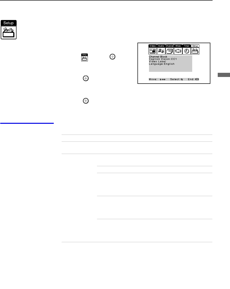
Using the Menus
55
Using the Menus
Using the Setup Menu
To select the Setup Menu
1Press MENU.
2Move the joystick to the Setup
icon and press .
3Use the joystick to scroll
through the features.
4Press to select a feature.
That feature’s options appear.
5Use the joystick to scroll through the options.
6Press to select the desired option.
7Press MENU to exit the menu screen.
Selecting
Setup Options The Setup menu includes the following options:
Option Description
Channel Block Allows you to set up the TV to block up to 4 channels. See
“Using the Channel Block Menu” on page 57
Caption Vision Allows you to select from three closed caption modes (for
programs that are broadcast with closed captioning).
OFF Turns off Caption Vision.
CC1, CC2,
CC3, CC4 Displays a printed version of the
dialog or sound effects of a program.
(Should be set to CC1 for most
programs.)
TEXT1, TEXT2,
TEXT3, TEXT4 Displays network/station information
presented using either half or the
whole screen (if available). For closed
captioning, set to CC1.
XDS
(Extended Data
Service)
Displays a network name, program
name, program length, and time of the
show if the broadcaster offers this
service.
(Continued)

Using the Menus
56
Video Label Allows you to label the audio/video components you connected
to the projection TV so you can identify them when using TV/
VIDEO. When in the Setup menu’s Video Label feature, use
the joystick to highlight an input to label, then press to
select it. Use the joystick to scroll through the labels. Press
to select the component you connected to each of the input
jacks on the back of your projection TV. Select “Skip” if you do
not have a component connected to a particular set of input
jacks.
VIDEO 1/2/3/4 VHS, 8mm, Beta, LD, Game, DVD,
Web, Receiver, DTV, Skip
VIDEO 5/6 DVD, DTV, HD, Skip
If you select “Skip”, your projection TV skips this connection
when you press TV/VIDEO.
✍When you select “Receiver” on Video Label, your projection
TV’s input is fixed.
Language Select to display all on-screen menus in your language of
choice: English, Español, Français.
Option Description
To use this feature
with widescreen DVDs,
set your DVD player to
16:9 aspect ratio.
z
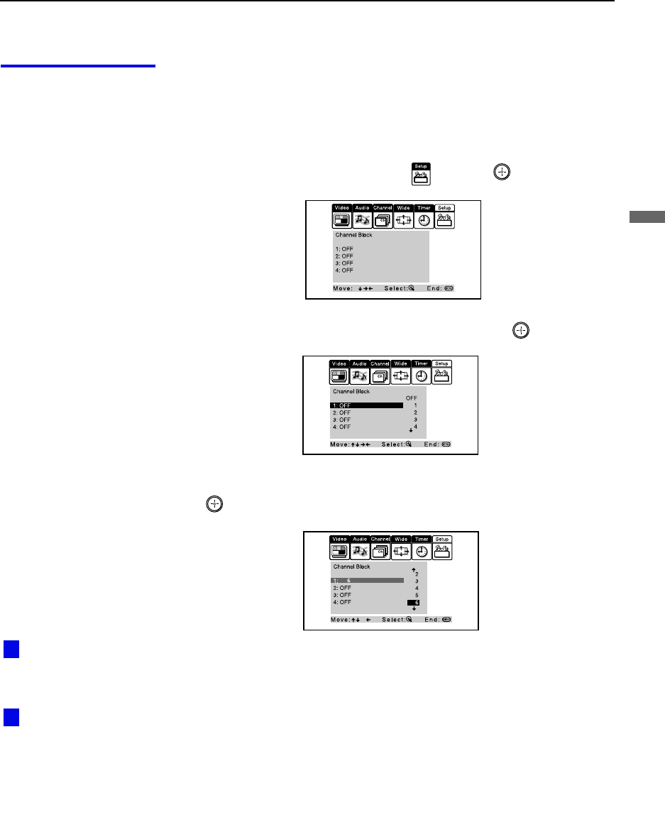
Using the Menus
57
Using the Menus
Using the Channel
Block Menu The Channel Block menu allows you to set up the TV to block up to 4
channels.
To block channels
1Press MENU.
2Move the joystick to the Setup icon and press .
3Move the joystick up or down to select 1-4, and press .
4Move the joystick down to select the channel to be blocked, and press
.
5Press MENU to exit the menu screen.
To cancel channel block settings
Set Channel Block to OFF in step 4.
Performing Auto
Program will erase the
Channel Block settings.
Selecting ''Receiver”
of Video Label will erase
the Channel Block
settings.
z
z
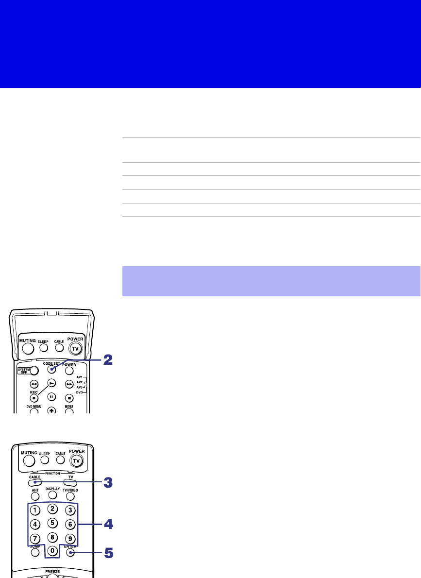
58
Other Information
Programming the Remote Control
The remote control is preset to operate Sony brand video equipment.
If you have video equipment other than Sony brand that you want to control
with the projection TV’s remote control, use the following procedures to
program the remote control.
From the “Manufacturer’s Codes” listed on page 60, select the three-digit
code number for the manufacturer’s code for your component. If more than
one code number is listed, start with the number listed first. Use the code
number to complete the following procedure.
To program a cable box
1Open the panel of the remote control.
2Press CODE SET inside the panel.
3Close the panel and press CABLE (FUNCTON).
4Enter the three-digit manufacturer’s code number using the 0-9 buttons.
5Press ENTER.
6To check if the code number works, aim the projection TV’s remote
control at the component and press the green POWER button that
corresponds with that component. If it responds, the programming is
completed. If not, try using the other codes listed for that manufacturer.
Sony
Equipment Switch Position
on Remote Control Programmable
Code Number
Beta, ED Beta VCRs AV1 303
8 mm VCR AV2 302
VHS VCR AV3 301
DVD Player DVD 751
✍The equipment must have infrared (IR) remote capability in order to be
used with the remote control.
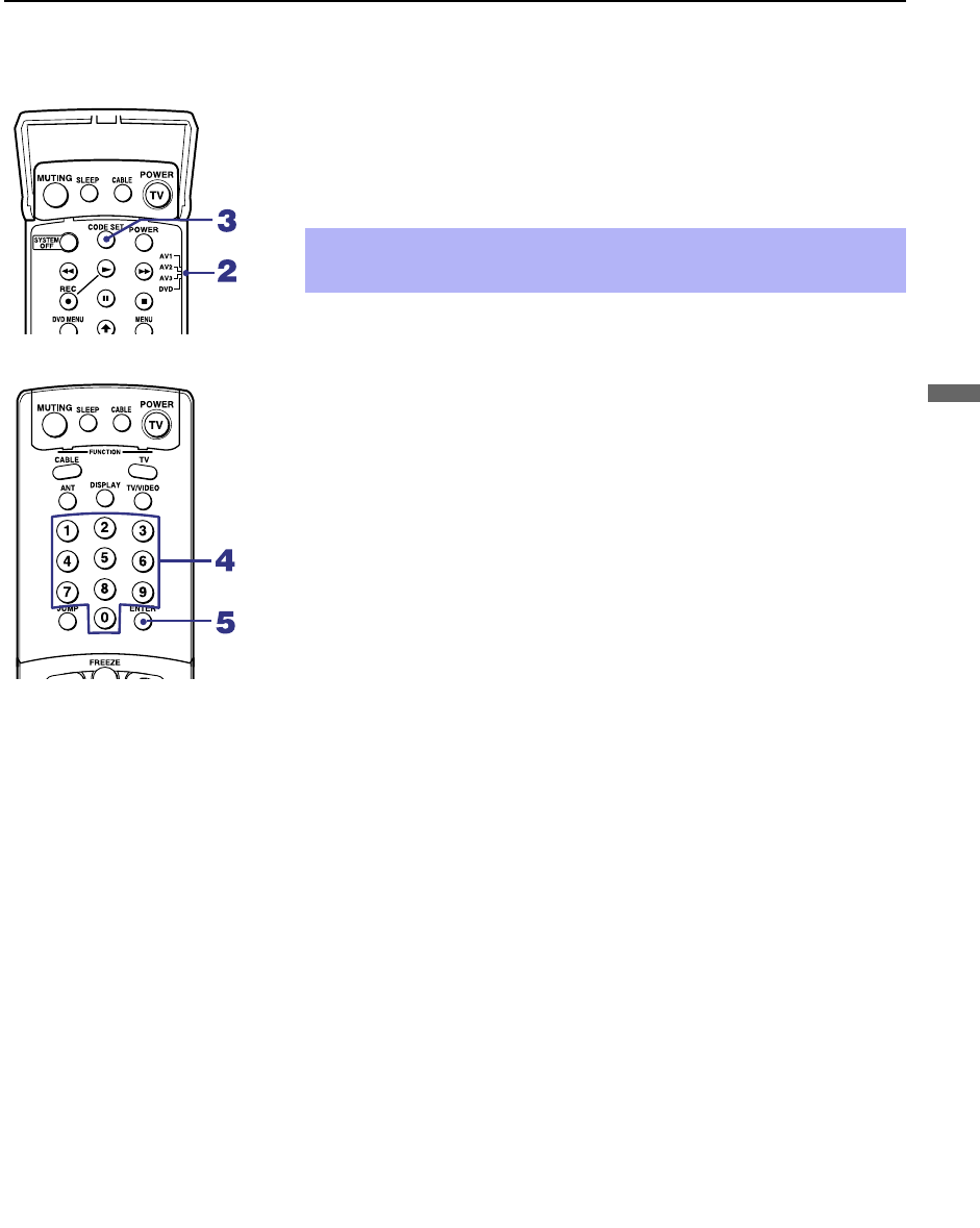
Other Information
59
Other Information
To program video equipment
1Open the panel of the remote control.
2Move the slide switch to the desired component type.
3Press CODE SET inside the panel.
4Close the panel and enter the three-digit manufacturer’s code number
using the 0-9 buttons.
5Press ENTER.
6To check if the code number works, aim the projection TV’s remote
control at the component, open the panel, and press the green POWER
button. If it responds, the programming is completed. If not, try using
the other codes listed for that manufacturer.
Tips
❑If more than one code number is listed, try entering them one by one
until you come to the correct code for your component.
❑If you enter a new code number, the code number you previously
entered at that setting is erased.
❑In some rare cases, you may not be able to operate your component with
the Sony remote control. In this case, use the component’s own remote
control unit.
✍You must perform step 4 within 10 seconds of step 3, or you must
start again from step 3.

Other Information
60
Manufacturer’s Codes
VCRs
DVD Players
Cable Boxes
Manufacturer Code
Sony 301
Admiral
(M. Ward)
327
Aiwa 338, 344
Audio Dynamic 314, 337
Broksonic 319, 317
Canon 309, 308
Citizen 332
Craig 302, 332
Criterion 315
Curtis Mathes 304, 338, 309
Daewoo 341, 312, 309
DBX 314, 336, 337
Dimensia 304
Emerson 319, 320, 316,
317, 318, 341
Fisher 330, 335
Funai 338
General Electric 329, 304, 309
Go Video 322, 339, 340
Goldstar 332
Hitachi 306, 304,
305, 338
Instant Replay 309, 308
JC Penney 309, 305, 304,
330, 314, 336,
337
JVC 314, 336, 337,
345, 346, 347
Kenwood 314, 336, 332,
337
LXI (Sears) 332, 305, 330,
335, 338
Magnavox 308, 309, 310
Marantz 314, 336, 337
Marta 332
Memorex 309, 335
Minolta 305, 304
Mitsubishi/
MGA
323, 324, 325,
326
Multitech 325, 338, 321
NEC 314, 336, 337
Olympic 309, 308
Optimus 327
Panasonic 308, 309, 306,
307
Pentax 305, 304
Philco 308, 309
Philips 308, 309, 310
Pioneer 308
Quasar 308, 309, 306
RCA/
PROSCAN
304, 305, 308,
309, 311, 312,
313, 310, 329
Realistic 309, 330, 328,
335, 324, 338
Sansui 314
Samsung 322, 313, 321
Sanyo 330, 335
Scott 312, 313, 321,
335, 323, 324,
325, 326
Sharp 327, 328
Shintom 315
Signature 2000
(M. Ward)
338, 327
SV2000 338
Sylvania 308, 309, 338,
310
Symphonic 338
Tashiro 332
Tatung 314, 336, 337
Teac 314, 336, 338,
337
Technics 309, 308
Toshiba 312, 311
Manufacturer Code
Wards 327, 328, 335,
331, 332
Yamaha 314, 330, 336,
337
Zenith 331
Manufacturer Code
Sony 751
Panasonic 753
Pioneer 752
RCA 755
Toshiba 754
Manufacturer Code
Hamlin/Regal 222, 223, 224,
225, 226
Jerrold/G. I. 201, 202, 203,
204, 205, 206,
207, 208, 218
Oak 227, 228, 229
Panasonic 219, 220, 221
Pioneer 214, 215
Scientific
Atlanta
209, 210, 211
Tocom 216, 217
Zenith 212, 213
Manufacturer Code

Other Information
61
Other Information
Operating Other Components with Your Projection TV Remote
Control
Operating a VCR Open the panel and move the slide switch to the AV input you coded for this
device.
Operating a DVD
Player Open the panel and move the slide switch to the DVD input you coded for
this device.
To Do This ... Press
Turn on/off green POWER button (inside the panel)
Change channels CH +/–
Record N and REC simultaneously
Play N
Stop x
Fast forward M
Rewind the tape m
Pause X (press again to resume normal playback)
Search the picture
forward or backward
M or m during playback
(release to resume normal playback)
Change input mode Slide switch
To Do This ... Press
Turn on/off green POWER button (inside the panel)
Play N
Stop x
Pause X (press again to resume normal playback)
Step through different tracks of
an audio disc
M to step forward or m to step backward
Step through different chapters
of a video disc
CH+ to step forward or CH– to step backward
Display the DVD menu DVD MENU
Display the menu (Setup) MENU
Operate the DVD menu M, m, <, ,, ENTER

Other Information
62
Operating a Cable
Box To Do This ... Press
Turn on/off CABLE (POWER)
Select Cable Box CABLE (FUNCTION)
Select a channel 0-9 buttons, ENTER
Change channels CH +/–
Back to previous channel JUMP

Other Information
63
Other Information
Troubleshooting
Problem Possible Remedies
No picture
(screen not lit),
no sound
❏Make sure the projection TV’s power cord is connected securely to the wall outlet.
❏Push the power button on the front of the projection TV.
❏Check to see if the TV/VIDEO setting is correct: when watching TV, set to TV,
and when watching connected equipment, set to VIDEO 1, 2, 3, 4, 5 or 6.
❏Try another channel. It could be station trouble.
❏The Channel Block feature is activated (see “Using the Channel Block Menu” on
page 57).
❏If your projection TV does not turn on, and a red light keeps flashing, your
projection TV may need service. Call your local Sony Service Center.
Remote control
does not operate
❏Batteries could be weak. Replace the batteries.
❏Press TV (FUNCTION) when operating your projection TV.
❏Make sure the projection TV’s power cord is connected securely to the wall outlet.
❏Locate the projection TV at least 3-4 feet away from fluorescent lights.
❏Check the orientation of the batteries.
Dark, poor or no
picture (screen lit),
good sound
❏Adjust the Picture setting in the Video menu (see page 46).
❏Adjust the Brightness setting in the Video menu (see page 46).
❏Check antenna/cable connections.
❏Adjust the convergence again using FLASH FOCUS (see “Adjusting the
Convergence Automatically – FLASH FOCUS™ –” on page 30).
Good picture,
no sound
❏Press MUTING so that “MUTING” disappears from the screen (see page 31).
❏Make sure Speaker is set to ON in the Audio menu (see page 48).
Cannot receive digital channels
(when a DTV receiver is
connected)
❏Check the connections between the DTV receiver and the projection TV (see page
25).
❏Check your local listings to find out if you can receive digital broadcasts in your
area.
Cannot receive upper channels
(UHF) when using an antenna
❏Change Cable to OFF (see page 50).
❏Use Auto Program in the Channel menu to add receivable channels that are not
presently in TV memory (see page 51).
No color ❏Adjust the Color settings in the Video menu (see page 46).
Only snow and noise
appear on the screen
❏Check the Cable setting in the Channel menu (see “Cable” on page 50).
❏Check the antenna/cable connections.
❏Make sure the channel is broadcasting programs.
❏Press ANT to change the input mode (see page 34).
Dotted lines
or stripes
❏Adjust the antenna.
❏Move the projection TV away from noise sources such as cars, neon signs, or hair-
dryers.
Projection TV is fixed to one
channel
❏Use Auto Program in the Channel menu to add receivable channels that are not
presently in TV memory (see page 51).
❏Check your Channel Fix settings (see page 51).
Double images or ghosts ❏Use a highly directional outdoor antenna or a cable (when the problem is caused by
reflections from nearby mountains or tall buildings).
(Continued)

Other Information
64
Cannot operate menu ❏If the item you want to choose appears in gray, you cannot select it.
❏Turn the projection TV’s power off and on again.
Cannot receive any channels
when using cable TV
❏Use Auto Program in the Channel menu to add receivable channels that are not
presently in TV memory (see page 51).
❏Check your cable settings.
❏Make sure Cable is set to ON in the Channel menu (see page 50).
Cannot gain enough volume
when using a cable box
❏Increase the volume of the cable box using the cable box’s remote control. Then
press TV (FUNCTION) and adjust the projection TV’s volume.
Channel Index does not display
all available channels
❏Make sure Cable is set to ON in the Channel menu (see “Cable” on page 50).
❏Use Auto Program in the Channel menu to add receivable TV channels that are
not presently in TV memory (see page 51).
Cannot receive channels
Unable to select a channel
❏Use Auto Program in the Channel menu to add receivable TV channels that are
not presently in TV memory (see page 51).
Cannot change channels with
the remote control
❏Be sure you have not inadvertently switched your projection TV from channel 3 or
4 setting if you are using another device to change channels.
❏If you are using another device to control channels, be sure the “function” button
for that device has been pressed, or the slide switch is set correctly. For example, if
you are using your cable to control channels, be sure to press CABLE.
Cannot cycle through the other
video equipment connected to
the projection TV
❏Be sure the Video Label feature has not been set to Skip (see page 56).
There is a black box on the
screen
❏You have selected a text option in the Setup menu and no text is available (see
page 55 to reset Setup selections). To turn this feature off, select OFF in the
Caption Vision option. If you were trying to get closed captioning, select CC1
instead of Text 1-4.
There is no twin picture or it is
just static
❏Be sure your twin picture is set to a video source/channel that has a program airing.
❏You may be tuned to a video input with nothing connected to it. Try cycling
through your video inputs using TV/VIDEO.
❏Twin View is not set to receive a signal from the AUX input. If you have
connected a VCR, DVD player or satellite receiver to the AUX input on the
projection TV, it will not show in the second picture.
You get the same program in the
window picture as in the main
picture
❏Both may be set to the same channel. Try changing channels in either the main
picture or the window picture.
❏You may be running all your channels through a cable box. The cable box will
only unscramble one signal at a time, so you cannot use the Twin View feature. If
possible, run a direct cable to your projection TV’s VHF/UHF input (this will only
work if your cable system provides an unscrambled signal).
You cannot get anything but TV
channels in your second picture
❏Be sure the video label has not been set to skip your video inputs. See the Setup
menu on page 55.
Favorite Channel does not
display your choices
❏Verify that Favorite Channel is set to Manual in the Channel menu (see
“Favorite Channel” on page 50).
Some video sources do not
appear when you press TV/
VIDEO
❏Ensure that Video Label is not set to Skip (see “Video Label” on page 56).
Problem Possible Remedies

Other Information
65
Other Information
Specifications
Projection System 3 picture tubes, 3 lenses, horizontal in-line system
Picture Tube 7-inch high-brightness monochrome tubes (6.3 raster size), with optical
coupling and liquid cooling system
Projection Lenses High performance, large
diameter hybrid lens F1.1
Antenna 75 ohm external terminal for VHF/UHF
Television System NTSC, American TV Standard
Screen Size (measured diagonally) 57 inches
Channel Coverage
VHF 2-13
UHF 14-69
CATV 1-125
Power Requirements 220 V, 60 Hz
Number of Inputs/Outputs
Video (IN) 4 1 Vp-p, 75 ohms unbalanced, sync negative
S Video (IN) 3 Y: 1 Vp-p, 75 ohms unbalanced, sync negative
C: 0.286 Vp-p (Burst signal), 75 ohms
Audio (IN) 6 500 mVrms (100% modulation)
Impedance: 47 kiloohms
AUDIO (VAR/FIX) 1 500 mVrms at the maximum volume setting
(Variable)
500 mVrms (Fixed)
Impedance (output): 2 kiloohms
TV Out 1 Video: 1 Vp-p 75 ohms unbalanced, Sync
negative
Audio: 500 mVrms (100% modulation)
Impedance (output): 1 kiloohms
CONTROL S (IN/OUT) 1 Minijacks
Component Video Input 2 (Y, PB, PR) Y: 1.0 Vp-p, 75 ohms unbalanced, sync
negative
PB: 0.7 Vp-p, 75 ohms
PR: 0.7 Vp-p, 75 ohms
RF Inputs 2
Converter 1
Speaker Output 20 W × 2
Dimensions (W × H × D) 1,326 × 1,377 × 690 mm
Mass 89 kg
Power Consumption
In Use 230 W
In Standby 1.2 W
Supplied Accessories
Remote Control RM-Y909K
AA (R6) Batteries 2 supplied for remote control
(Continued)

Other Information
66
Design and specifications are subject to change without notice.
Optional Accessories
AV Cable VMC-810/820/830 HG
Audio Cable RKC-515HG
Control S Cable RK-G69HG
Component Video Cable VMC-10/30 HG

67
Other Information
Index
A
Activating a Twin View screen 38
Adding channels to the channel list 51
Adjusting audio, Steady Sound 48
ANT button 31
Antenna, connecting 15
Audio menu 45, 48
Audio receiver, connecting 22
Audio/Video cable 11
Auto Program (channel setup) 29, 51
Auto Setup 29, 51
AV receiver, connecting to TV OUT 14
B
Balance, adjusting 48
Bass, adjusting 48
Batteries, inserting into remote 9
Bilingual audio 48
BILINGUAL button 33
BILINGUAL, using 35
Brightness, adjusting 46
C
Cable
setting ON/OFF 50
with VCR, connecting 18
Cable box
connecting with VCR 19
using with TV remote control 62
CABLE function button 32
CABLE power button 32
Camcorder, connecting 26
Caption Vision 55
CATV. See cable.
Channel Index
described 7
Channel list, adding channels 51
Channel menu 45, 50
Channel Skip/Add 51
Channels
Auto Program 51
creating labels 51
setting up 29
CineMotion, DRC 32, 47
Closed caption modes 55
CODE SET button 33
Color temperature, adjusting 46
Color, adjusting 46
Connecting
Audio receiver 22
AV receiver 27
Cable box 16, 17, 19–20
Cable or antenna 15
Camcorder 26
Digital TV Receiver 25
DVD player 23, 24
VCR 19–21
Connector Types 11
Contents of box 9
CONTROL S 28
Convergence, adjusting automatically 30
D
Daylight saving 54
Digital Reality Creation 47
Digital TV
connecting 25
watching 36
Digital TV program 36
Digital TV receiver, connecting 25
DISPLAY button 31
Display, turning off 31
DRC (Digital Reality Creation) Mode, described 7
DRC⁄CINEMOTION button 32
DVD MENU button 33
DVD player
using with TV remote control 61
with A/V connectors, connecting 24
with component video connectors, connecting 23
E
Effect
OFF 48
Simulated 48
TruSurround 48
Enlarging pictures, in Twin View 40
Extended Data Service 55
(Continued)

68
F
Favorite Channel
auto 50
described 7
manual 50
setting up 50
using 37
FAVORITES button 31
Features 7
Flash Focus
described 7
performing 30
FREEZE button 31
Freeze, using 34, 41
Front Panel Controls 12
FUNCTION buttons (WHITE) 32
H
Hookups 15
Hue, adjusting 46
I
Inputs, labeling 56
Installation of the projection TV 15–28
J
JUMP button 31
Jump, using 34
L
Label
channels 51
video inputs 56
M
MENU button 32
MENU button (inside panel) 33
Menus
Audio 45, 48
Channel 45, 50
Setup 45, 55
Timer 45, 54
Video 45, 46
menus
Timer 52
MODE
Movie 35
Pro 35
Standard 35
Vivid 35
Muting, using 34
P
PIC MODE button 31
Picture contrast, adjusting 46
Picture size, adjusting in Twin View 40
POWER button 33
POWER buttons (GREEN) 32
Presetting channels 29
Problems, troubleshooting 63
R
Rear panel controls and connections 13, 14
Remote control
buttons inside panel 33
Function of buttons 34
inserting batteries 9
programming 58–60
Remote control, operating other components with
Cable box 62
DVD player 61
VCR 61
Removing channels from the channel list 51
RESET button 31
Resetting
Audio options 48
Timer options 54
Video options 46
S
S Video cable 11
Setting up channels 29
Setup menu 45, 55
Sharpness, adjusting 46
SLEEP button 31
Sleep, using 34
Specifications 65–66
Steady Sound
adjusting 48
described 7
Surround sound 48
SYSTEM OFF button 33
T
Tape-to-tape editing 21
Time
set current 54
set daylight saving 54

69
Other Information
Timer menu 45, 52, 54
Timer setting 54
Treble, adjusting 48
Troubleshooting 63
TV function button 32
TV power button 32
TV/VIDEO button 32
Twin View™
activating a picture 38
described 7
using 38
V
VCR
connecting two, for tape editing 21
using with TV remote control 61
with cable box, connecting 19
with cable, connecting 18
Video inputs, labeling 56
Video menu 45, 46
Video Modes, selecting 46
Viewing area, recommended 10
VOL +/– button 31, 34
W
Wide menu 52
WIDE MODE button 32
Z
Zoom feature, with Twin View 40

Printed in Japan
