KTR Rotex GS Clamping Ring Hub Size 42 Dimensions Table
User Manual: KTR Rotex GS Clamping Ring Hub Size 42 Dimensions Table
Open the PDF directly: View PDF ![]() .
.
Page Count: 4
FEATURESDESCRIPTION
910 East Orangefair Ln. Anaheim, CA 92801 Tel. (714) 992-6990 Fax. (714) 992-0471 www.anaheimautomation.com
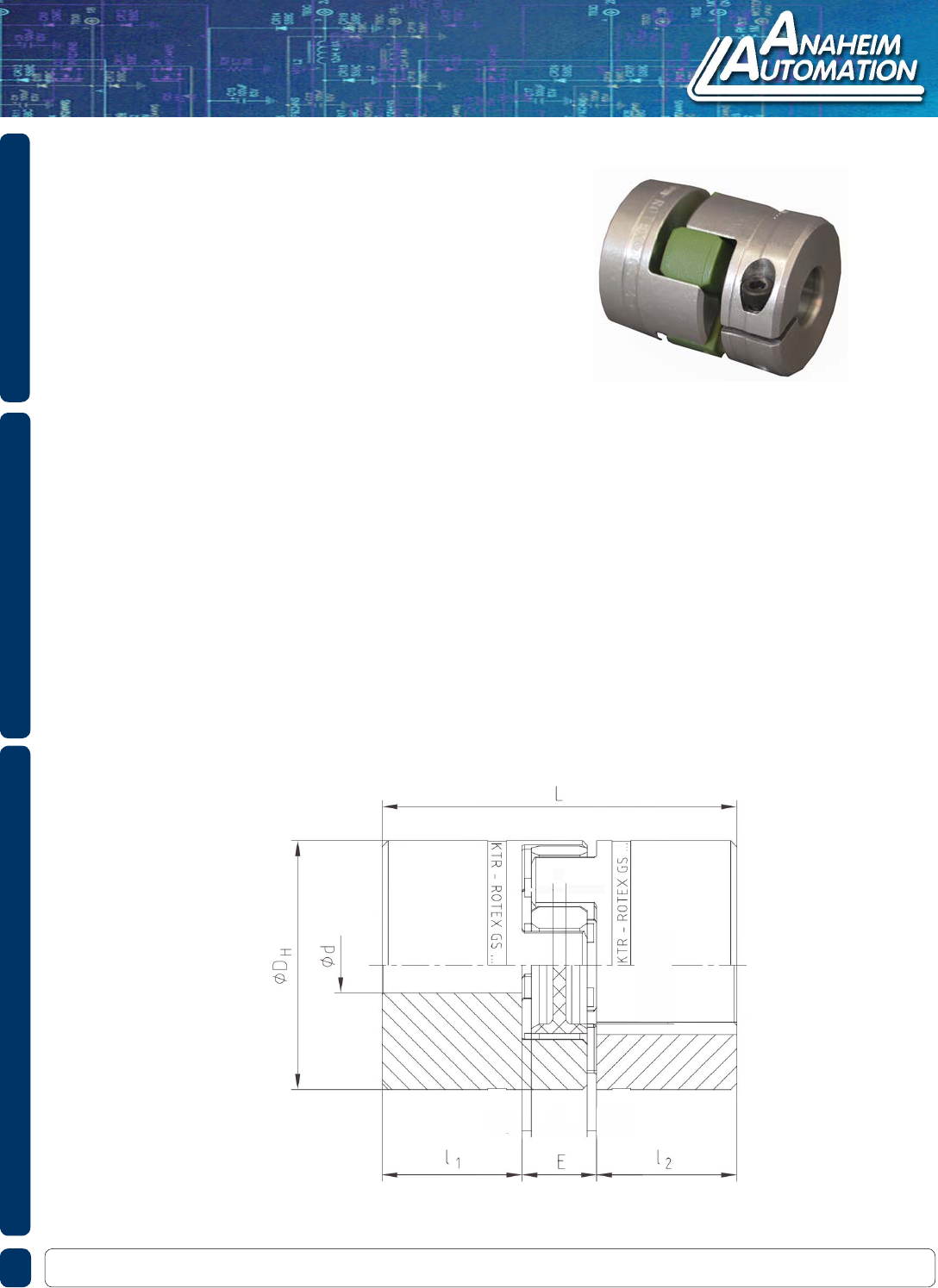
Rotex® couplings are deigned to transmit torque between drive and driven components via
curved jaw hubs and elastomeric elements commonly known as spiders. The combination
between these components provides dampening and accommodation for misalignments.
This product is available in a variety of metals, elastomers and mounting congurations to
meet your specic needs.
Ordering Guideline: There are three individual part numbers you will need for a complete
coupler (i.e., 2 HUBS and 1 Spider). Please choose the hub sizes that match the criteria for
your application. In addition to the hubs, you will need to choose a spider, from the spider
section.
Customization options are available; allow Anaheim Automation to specify the coupling
designed for your application!
L011402
KTR Rotex® GS 07 Series
KTR Rotex® GS 07 Series
• High-Quality Spider Design
• Handles the Most Demanding Applications
• Max Torque of 42 in-lb.
• Allows for Different Bore Diameters
• No Backlash
• No Maintenance
• Requires Three Individual Part Numbers
• Easy Assembly
• Wide Variety of Sizes
DIMENSIONS
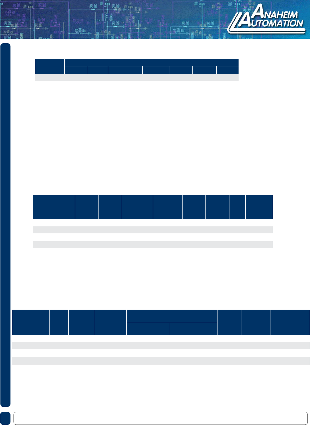
Item
Bore
Diameter
(mm)
Hub
Design
Outside
Diameter
(mm)
Length Thru
Bore
“I1 I2”
(mm)
Coupling
Length
“L”
(mm)
Setscrew
Torque
(Nm)
t
(mm) Material
KTR-BA550077150350 76 2.0, 2.5 14 7.112 22 0.372 3.556 Aluminum
KTR-BA550077150450 102 2.0, 2.5 14 7.112 22 0.372 3.556 Aluminum
KTR-BA550077150550 127 2.0, 2.5 14 7.112 22 0.372 3.556 Aluminum
KTR-BA550077150650 152 2.0, 2.5 14 7.112 22 0.372 3.556 Aluminum
KTR-BA550077150750 178 2.0, 2.5 14 7.112 22 0.372 3.556 Aluminum
SPECIFICATIONS
910 East Orangefair Ln. Anaheim, CA 92801 Tel. (714) 992-6990 Fax. (714) 992-0471 www.anaheimautomation.com
Item Color Material Type/Hard-
ness
Max Speed
(rpm) Rated
Torque
(in-lb)
Max Torque
(in-lb)
Mass Moment of
Inertia
(lb-in-sec²)
Clamping Hub Clamping Ring Hub
KTR-550071000003 Blue Polyamide 80 Shore-A-GS 27,000 - 6.2 12.39 8.85 x 10⁻⁷
KTR-550071000001 Yellow Polyamide 92 Shore-A-GS 27,000 - 11 21 8.85 x 10⁻⁷
KTR-550071000002 Red Polyamide 95/98 Shore A-GS 27,000 - 18 35 8.85 x 10⁻⁷
KTR-550071000025 Green Hytrel 64 Shore D-H-GS 27,000 - 21 42 8.85 x 10⁻⁷
Metric Bores
Spiders
Item Dimensions (in)
DHL l1 , l2E b s a
Size 42 3.7 5.0 2.0 1.0 0.8 0.11 0.16
Hub Diagram
910 East Orangefair Ln. Anaheim, CA 92801 Tel. (714) 992-6990 Fax. (714) 992-0471 www.anaheimautomation.com
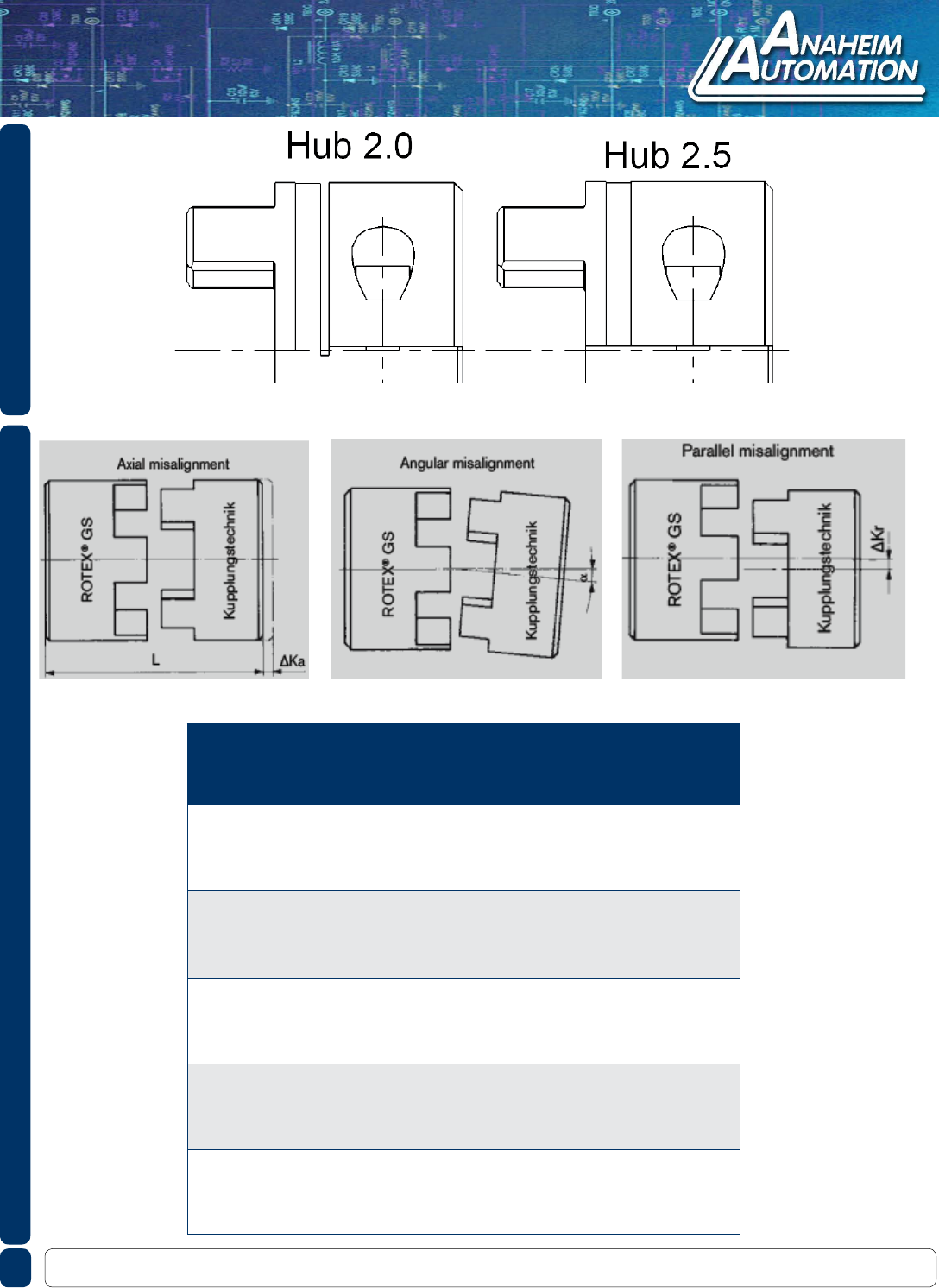
Shaft Misalignment
Size Spider
GS
Misalignments Standard Misalignments DKM
(in)
Axial
ΔKa2
(in)
Parallel
ΔKr
(degree)
Angular
a
(in)
Axial
ΔKa2
(in)
Parallel
ΔKr
(degree)
Angular
a
5
70
+0.016
-0.008
0.006 1.2
+0.016
-0.016
0.007 1.2
80 0.005 1.1 0.006 1.1
92 0.002 1.0 0.006 1.0
98 0.002 0.9 0.005 0.9
7
80
+0.024
-0.012
0.006 1.1
+0.024
-0.024
0.009 1.1
92 0.004 1.0 0.008 1.0
98 0.002 0.9 0.007 0.9
64 0.002 0.8 0.007 0.8
9
80
+0.031
-0.016
0.007 1.1
+0.031
-0.031
0.011 1.1
92 0.005 1.0 0.010 1.0
98 0.003 0.9 0.009 0.9
64 0.002 0.8 0.008 0.8
12
80
+0.035
-0.016
0.008 1.1
+0.035
-0.035
0.014 1.1
92 0.006 1.0 0.013 1.0
98 0.003 0.9 0.011 0.9
64 0.002 0.8 0.010 0.8
14
80
+0.039
-0.020
0.008 1.1
+0.039
-0.039
0.016 1.1
92 0.006 1.0 0.015 1.0
98 0.004 0.9 0.013 0.9
64 0.002 0.8 0.011 0.8
Misalignments
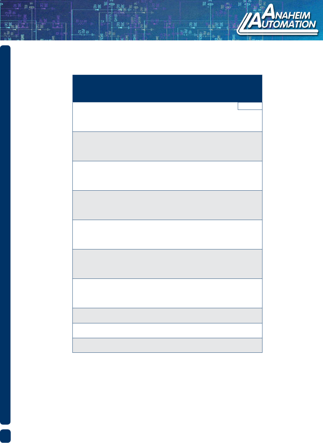
Shaft Misalignment
Misalignments
Size Spider
GS
Misalignments Standard Misalignments DKM
(in)
Axial
ΔKa2
(in)
Parallel
ΔKr
(degree)
Angular
a
(in)
Axial
ΔKa2
(in)
Parallel
ΔKr
(degree)
Angular
a
19
80
+0.047
-0.020
0.008 1.1
+0.047
-0.039
0.019 1.1
92 0.006 1.0 0.018 1.0
98 0.004 0.9 0.016 0.9
64 0.002 0.8 0.014 0.8
24
92
+0.055
-0.020
0.006 1.0
+0.055
-0.039
0.023 1.0
98 0.004 0.9 0.021 0.9
64 0.004 0.8 0.019 0.8
72 0.002 0.7 0.017 0.7
28
92
+0.059
-0.028
0.006 1.0
+0.059
-0.055
0.026 1.0
98 0.004 0.9 0.024 0.9
64 0.003 0.8 0.021 0.8
72 0.002 0.7 0.018 0.7
38
92
+0.071
-0.028
0.007 1.0
+0.071
-0.055
0.030 1.0
98 0.006 0.9 0.027 0.9
64 0.004 0.8 0.024 0.8
72 0.002 0.7 0.021 0.7
42
92
+0.079
-0.039
0.007 1.0
+0.079
-0.079
0.033 1.0
98 0.006 0.9 0.030 0.9
64 0.004 0.8 0.026 0.8
72 0.002 0.7 0.023 0.7
48
92
+0.083
-0.039
0.009 1.0
+0.083
-0.079
0.036 1.0
98 0.006 0.9 0.032 0.9
64 0.004 0.8 0.029 0.8
72 0.003 0.7 0.025 0.7
55
92
+0.087
-0.039
0.009 1.0
+0.087
-0.079
0.040 1.0
98 0.007 0.9 0.036 0.9
64 0.005 0.8 0.032 0.8
72 0.004 0.7 0.028 0.7
65
95 +0.102
-0.039
0.009 0.9 - - -
64 0.008 0.8 - - -
75 95 +0.118
-0.059
0.009 0.9 - - -
64 0.08 0.8 - - -
90 95 +0.134
-0.059
0.09 0.9 - - -
64 0.08 0.8 - - -
