Service Manual _KV 14CT1B KV14CT1B
User Manual: KV14CT1B
Open the PDF directly: View PDF ![]() .
.
Page Count: 152 [warning: Documents this large are best viewed by clicking the View PDF Link!]
- KV-14CT1B/1E/1K/1U
- TABLE OF CONTENTS
- CAUTION
- WARNING
- SELF DIAGNOSTIC FUNCTION
- DISASSEMBLY
- SET-UP ADJUSTMENTS
- CIRCUIT ADJUSTMENTS
- DIAGRAMS
- EXPLODED VIEWS
- ELECTRICAL PARTS LIST
- 4-093-927-12(1)
- 4-093-927-32(1)
- 4-093-927-52(1)
- 4-093-927-62(1)
- 4-093-927-72(1)
MODEL COMMANDER DEST. CHASSIS NO.
CHASSIS
TRINITRON
®
COLOR TV
SERVICE MANUAL BX1
MODEL COMMANDER DEST. CHASSIS NO.
KV-14CT1B RM-W100 FR SCC-U89C-A
KV-14CT1E RM-W100 ESP SCC-U91C-A
KV-14CT1K RM-W100 OIRT SCC-U92C-A
KV-14CT1U RM-W100 UK SCC-U93B-A

– 2 –
KV-14CT1B/14CT1U/14CT1E/14CT1K
RM-W100
TABLE OF CONTENTS
CAUTION & WARNING ....................................................... 3
SPECIFICATION & WARNING (UK only) ..........................3
SELF DIAGNOSTIC FUNCTION ........................................ 4
1. DISASSEMBLY
1-1. Rear Cover Removal ................................................... 7
1-2. Speaker Removal ........................................................ 7
1-3. Service Position .......................................................... 7
1-4. Chassis Assy Removal ................................................ 7
1-5. Terminal Bracket Removal ......................................... 7
1-6. A Board Removal ....................................................... 7
1-7. Picture Tube Removal ................................................. 8
2. SET-UP ADJUSTMENTS
2-1. Beam Landing ............................................................. 9
2-2. Convergence .............................................................. 10
2-3. Focus Adjustment ..................................................... 12
2-4. G2 (SCREEN) Adjustment ....................................... 12
2-5. White Balance Adjustement ..................................... 12
3. CIRCUIT ADJUSTMENTS
3-1. Adjustment With Commander .................................. 13
3-2. Adjustment Item Table ............................................. 14
3-3. T-Mode ...................................................................... 24
3-4. TT-Mode ................................................................... 24
3-5. T-Cyan Mode ............................................................ 24
3-6. Sub Brightness Adjustment ...................................... 25
3-7. Sub Contrast Adjustment .......................................... 25
3-8. Sub Color Adjustment .............................................. 25
3-9. Tuner AGC Adjustment ............................................ 25
3-10. Deflection Adjustment .............................................. 26
Section Title Page Section Title Page
4. DIAGRAMS
4-1. Block Diagram .......................................................... 27
4-2. Circuit Board Location ............................................. 28
4-3. Schematic Diagram ................................................... 28
4-3-1. C Board .......................................................... 29
4-3-2. A Board – Processor (Block A) ..................... 30
4-3-3. A Board – Audio (Block B) ........................... 32
4-3-4. A Board – Power Supply (Block C) .............. 34
4-3-5. A Board – Deflection (Block D) .................... 36
4-3-6. A Board – Tuner (Block E) ............................ 38
4-3-7. A Board – Jack, Scart Terminal (Block F) .... 40
4-4. Voltage List and Waveforms ..................................... 42
4-5. Printed Wiring Boards and Parts Location ............... 45
4-6. Semiconductors ......................................................... 48
5. EXPLODED VIEWS
5-1. Chassis ...................................................................... 50
6. ELECTRICAL PARTS LIST......................................... 51
INSTRUCTION MANUAL
CAUTION
SHORT CIRCUIT THE ANODE OF THE PICTURE TUBE AND THE
ANODE CAP TO THE METAL CHASSIS, CRT SHIELD, OR THE
CARBON PAINTED ON THE CRT, AFTER REMOVAL OF THE
ANODE CAP.
WARNING !!
AN ISOLATION TRANSFORMER SHOULD BE USED DURING
ANY SERVICE WORK TO AVOID POSSIBLE SHOCK HAZARD
DUE TO LIVE CHASSIS, THE CHASSIS OF THIS RECEIVER IS
DIRECTLY CONNECTED TO THE POWER LINE.
SAFETY-RELATED COMPONENT WARNING !!
COMPONENTS IDENTIFIED BY SHADING AND MARKED
!
ON
THE SCHEMATIC DIAGRAMS, EXPLODED VIEWS AND IN THE
PARTS LIST ARE CRITICAL FOR SAFE OPERATION. REPLACE
THESE COMPONENTS WITH SONY PARTS WHOSE PART
NUMBERS APPEAR AS SHOWN IN THIS MANUAL OR IN
SUPPLEMENTS PUBLISHED BY SONY.
ATTENTION
APRES AVOIR DECONNECTE LE CAP DE’LANODE,
COURT-CIRCUITER L’ANODE DU TUBE CATHODIQUE ET
CELUI DE L’ANODE DU CAP AU CHASSIS METALLIQUE DE
L’APPAREIL, OU AU COUCHE DE CARBONE PEINTE SUR LE
TUBE CATHODIQUE OU AU BLINDAGE DU TUBE
CATHODIQUE.
ATTENTION !!
AFIN D’EVITER TOUT RISQUE D’ELECTROCUTION
PROVENANT D’UN CHÁSSIS SOUS TENTION, UN
TRANSFORMATEUR D’ISOLEMENT DOIT ETRE UTILISÈ LORS
DE TOUT DÈPANNAGE LE CHÁSSIS DE CE RÈCEPTEUR EST
DIRECTMENT RACCORDÈ Á L’ALIMENTATION SECTEUR.
ATTENTION AUX COMPOSANTS RELATIFS Á
LA SECURITÈ!!
LES COMPOSANTS IDENTIFIÈS PAR UNE TRAME ET PAR UNE
MARQUE
!
SUR LES SCHÈMAS DE PRINCIPE, LES VUES
EXPLOSÈES ET LES LISTES DE PIECES SONT D’UNE
IMPOR-TANCE CRITIQUE POUR LA SÈCURITÈ DU
FONCTIONNEMENT,
NE LES REMPLACER QUE PAR DES COMPSANTS SONY DONT
LE NUMÈRO DE PIÈCE EST INDIQUÈ DANS LE PRÈSENT
MANUEL OU DANS DES SUPPLÈMENTS PUBLIÈS PAR SONY.
– 3 –
KV-14CT1B/14CT1U/14CT1E/14CT1K
RM-W100
CAUTION
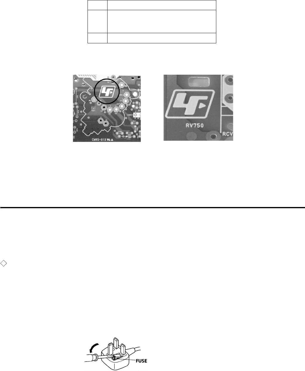
Lead Free Soldered Boards
The circuit boards listed below (Table 1) may have been processed using Lead Free Solder. The boards are
identified by the LF logo . e.g A,C board (see example).
The servicing of these boards requires special precautions to be taken as outlined below:
1. It is strongly recommended to use Sony Approved Lead Free Solder material in order to guarantee optimal
quality of new solder joints.
2. Due to higher melting point of Lead Free Solder, the soldering iron tip temperature needs to be set to chip
(350 degree centigrade) and lead component (380 degree centigrade) for not more than 4 seconds. This requires
soldering equipment capable of accurate temperature control coupled with a good heat recovery characteristics.
WARNING
(FOR EUROPE MODEL WITH “U” (UK) ONLY)
(KV-14CT1U only)
The flexible mains lead is supplied to connected a B.S. 1363 fused plug having a fuse of 5 AMP rating. Should the
fuse need to be replaced, use a 5 AMP FUSE approved by ASTA to BS 1362, i.e one that carries the
ASA
T
mark.
IF THE PLUG SUPPLIED WITH THIS APPLIANCE IS NOT SUITABLE FOR THE OUTLET SOCKETS IN YOUR
HOME, IT SHOULD BE CUT OFF AND APPROPRIATE PLUG FITTED. THE PLUG SEVERED FROM THE MAINS
LEAD MUST BE DESTROYED AS A PLUG WITH BARED WIRES IS DANGEROUS IF ENGAGED IN A LIVE
SOCKET.
When an alternative type of plug is used, it should be fitted with a 5 AMP FUSE, otherwise the circuit should be
protected by a 5 AMP FUSE at the distribution board.
Board Function
A ONE CHIP PROCESSOR, DEFLECTION,
POWER SUPPLY, AUDIO, TUNER, IF,
JACK,SCART TERMINAL
C RGB AMP
example 1 (A Board) example 2 (C Board)
How to replace the fuse?
Open the fuse compartment with
a screw driver blade and replace
the fuse.
(Table 1)

– 4 –
KV-14CT1B/14CT1U/14CT1E/14CT1K
RM-W100
The units in this manual contain a self diagnostic function. If an error occurs, the STANDBY (1) indicator will automatically
begin to flash. A description of the self-diagnosis function is explained in the instruction manual. The number of times the
STANDBY (1) indicator flashes translates to a probable source of the problem. If an error symptom cannot be reproduced,
the remote commander can be used to review the failure occurrence data stored in memory to reveal past problems and
how often these problems occur.
1. DIAGNOSTIC TEST INDICATORS
When an errors occurs, the STANDBY (1) indicator will flash a set number of times to indicate the possible cause of the
problem. If there is more than one error, the indicator will identify the first of the problem areas.
Result for all of the following diagnosis items are displayed on screen. No error has occured if the screen displays a “0”.
*If a +B overcurrent is detected, stoppage of the vertical deflection is detected simultaneously. The symptom that is
diagnosed first by the mirco controller is displayed on the screen.
** Refer to Screen (G2) Adjustment in this manual.
SELF DIAGNOSTIC FUNCTION
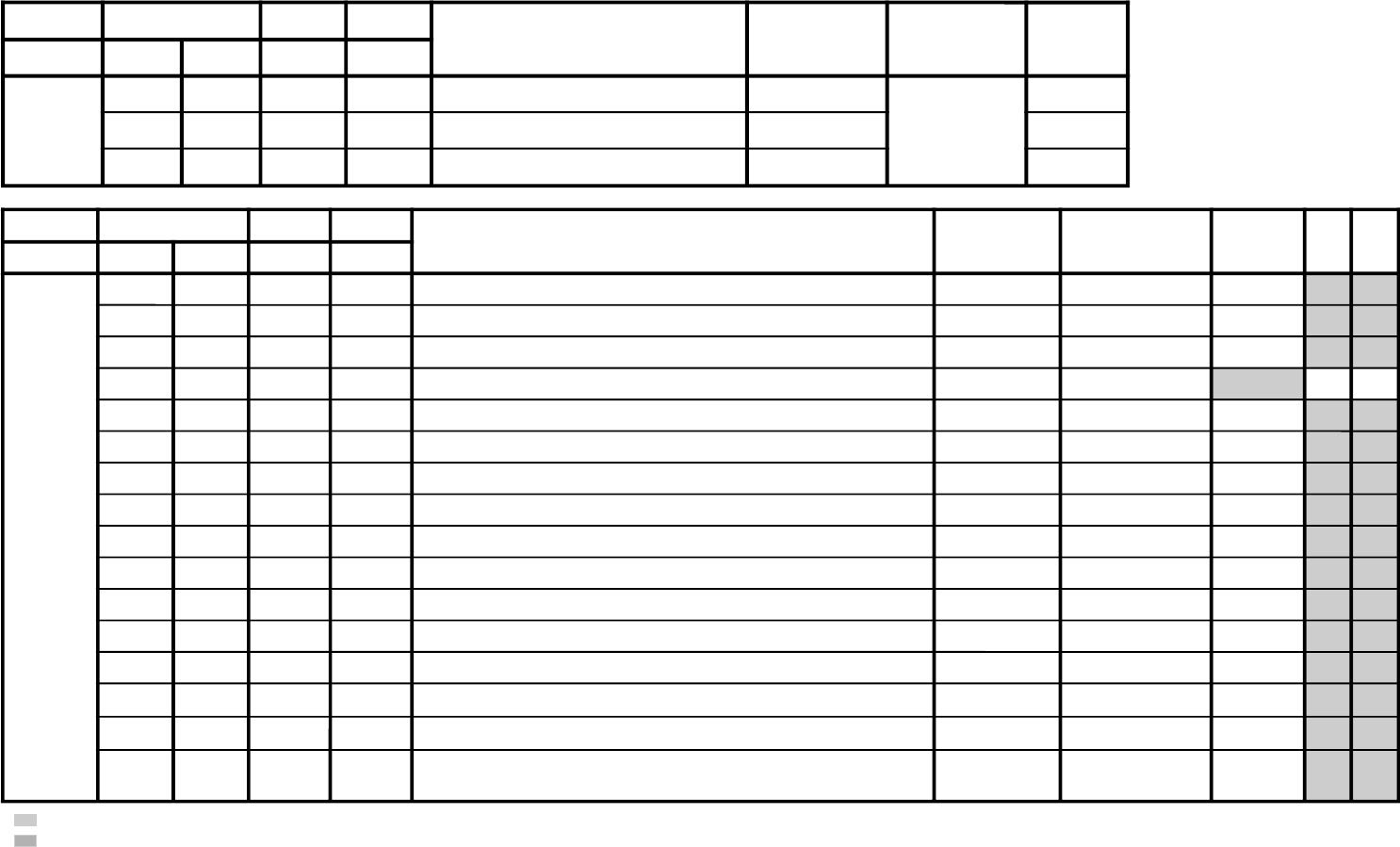
Diagnosis
Item
Description
Power does
not turn on
+B overcurrent
(OCP)*
V-Protect
IK (AKB)
HV Protect
No. of timer
STANDBY (1)
indicator flashes
Does not light
2 times
4 times
5 times
8 times
Self-Diagnostic
display/
Diagnosis result
–
2:0
or
2:1 ~ 255
4:0
or
4:1 ~ 255
5:0
or
5:1 ~ 255
8:0
or
8:1 ~ 255
Probable Cause
Location
• Power cord is not plugged
in.
• Fuse is burned out (F600)
A board.
• H OUT (Q805) is shorted.
(A board)
• IC751 is shorted. (C board)
• +13V is not supplied.
(A board)
• IC804 is faulty. (A board)
• Video OUT (IC1545) is
faulty. (A board)
• IC001 is faulty. (A board)
• Screen (G2) is improperly
adjusted.**
• IC604 faulty.
• IC602 faulty.
Detected
Symptoms
• Power does not come on.
• No power is supplied on
TV.
• AC Power supply is faulty.
• Power does not come on.
• Load on power line is
shorted.
• Has entered standby state
after horizontal raster.
• Vertical deflection pulse is
stopped.
• Power line is shorted or
power supply is shorted.
• No raster is generated.
• CRT Cathode current
detection reference pulse
output is small.
• No power supply to CRT
ANODE.
• No RASTER is generated.
– 5 –
KV-14CT1B/14CT1U/14CT1E/14CT1K
RM-W100
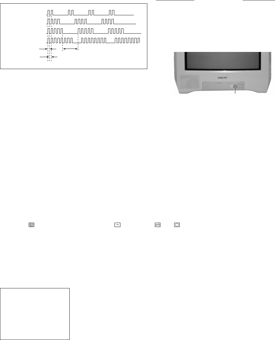
2. DISPLAY OF STANDBY (1) INDICATOR
FLASH COUNT
3. STOPPING THE STANDBY (1) INDICATOR FLASH
Turn off the power switch on the TV main unit or unplug the power cord from the outlet to stop the STANDBY (1)
indicator from flashing.
4. SELF-DIAGNOSTIC SCREEN DISPLAY
For errors with symptoms such as "power sometimes shuts off" or "screen sometimes goes off" that cannot be confirmed,
it is possible to bring up past occurrences of failure on the screen for confirmation.
[To Bring Up Screen Test]
In standby mode, press buttons on the remote commander sequentially in rapid succession as shown below:
Display /Channel 5/Volume /Power / TV
˘
Note that this differs from entering the service mode (volume [+]).
The following screen will be displayed indicating the error count.
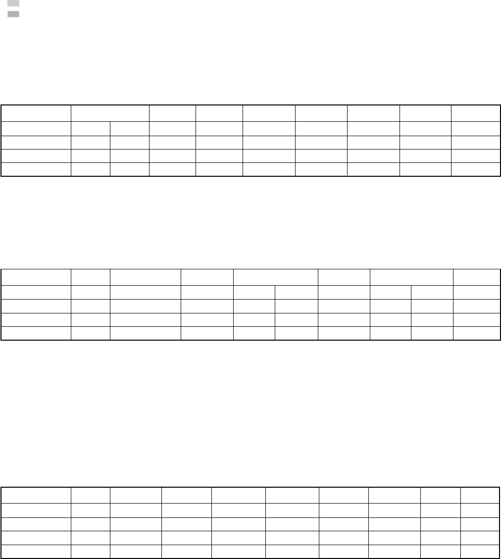
Diagnostic Item Flash Count*
+B overcurrent 2 times
V-Protect 4 times
IK (AKB) 5 times
HV Protect 8 times
* One flash count is not used for self-diagnosis.
Lamp OFF 3 sec
Lamp ON 300ms
Lamp OFF 300ms
STANDBY u indicator
2 : 0
3 : N/A
4 : 0
5 : 1
8 : 0
101 : N/A
ERROR MENU
Numeral "0" means that no fault was detected.
Numeral "1" means the number of a fault occurrence (1 ~ 255).
– 6 –
KV-14CT1B/14CT1U/14CT1E/14CT1K
RM-W100
5. HANDLING OF SELF-DIAGNOSTIC SCREEN DISPLAY
Since the diagnostic results displayed on the screen are not automatically cleared, always check the self-diagnostic screen
during repairs. When you have completed the repairs, clear the result display to “0”.
Unless the result display is cleared to “0”, the self-diagnosis function will not be able to detect subsequent faults after
completion of the repairs.
[Clearing the result display]
To clear the result display to “0”, press buttons on the remote commander subsequent as shown below when the
self-diagnostic screen is being displayed.
8 / -
[Quitting Self-diagnostic screen]
To quit the entire self-diagnostic screen, turn off the power switch on the remote commander or the main unit.
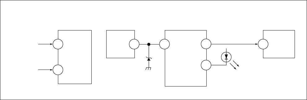
6. SELF-DIAGNOSTIC CIRCUIT
[+B overcurrent $OCP%] Occurs when an overcurrent on the +B(135V) line is detected by pin 32 of IC001 (A board).
If the voltage of pin 32 of IC001 (A board) is more than 4V, the unit will automatically go to
standby.
[V-PROTECT] Occurs when an absence of the vertical deflection pulse is detected by pin 13 of IC001
(A board).
[IK $AKB%] If the RGB levels* do not balance within 15 sec after the power is turned on, this error will be
detected by IC001 (A board). TV will stay on, but there will be 5 times LED blinking.
[HV PROTECT] Occurs when IC001 internal HV protect detects an abnormal H-Pulse (frequency) due to
improper power supply to IC001. TV cuts off high voltage power of anode CRT. No picture will
be detected. eg: IC602, IC604 go faulty.
* (Refers to the RGB levels of the AKB detection Ref pulse that detects IK.)
A BOARD
IC001
Y/CHROMA JUNGLE
A BOARD
IC804
V.OUT
A BOARD
IC001
SYSTEM
A BOARD
IC003
MEMORY
FROM
C BOARD
IC751 PIN 5
IK
EHTO
RED LED
DISPLAY
SDA1
V.GUARD
SDA
5
F.B-PLS 3 1384
32 122
A BOARD
FROM
Q804
COLLECTOR
99
– 7 –
KV-14CT1B/14CT1U/14CT1E/14CT1K
RM-W100
SECTION 1
DISASSEMBLY
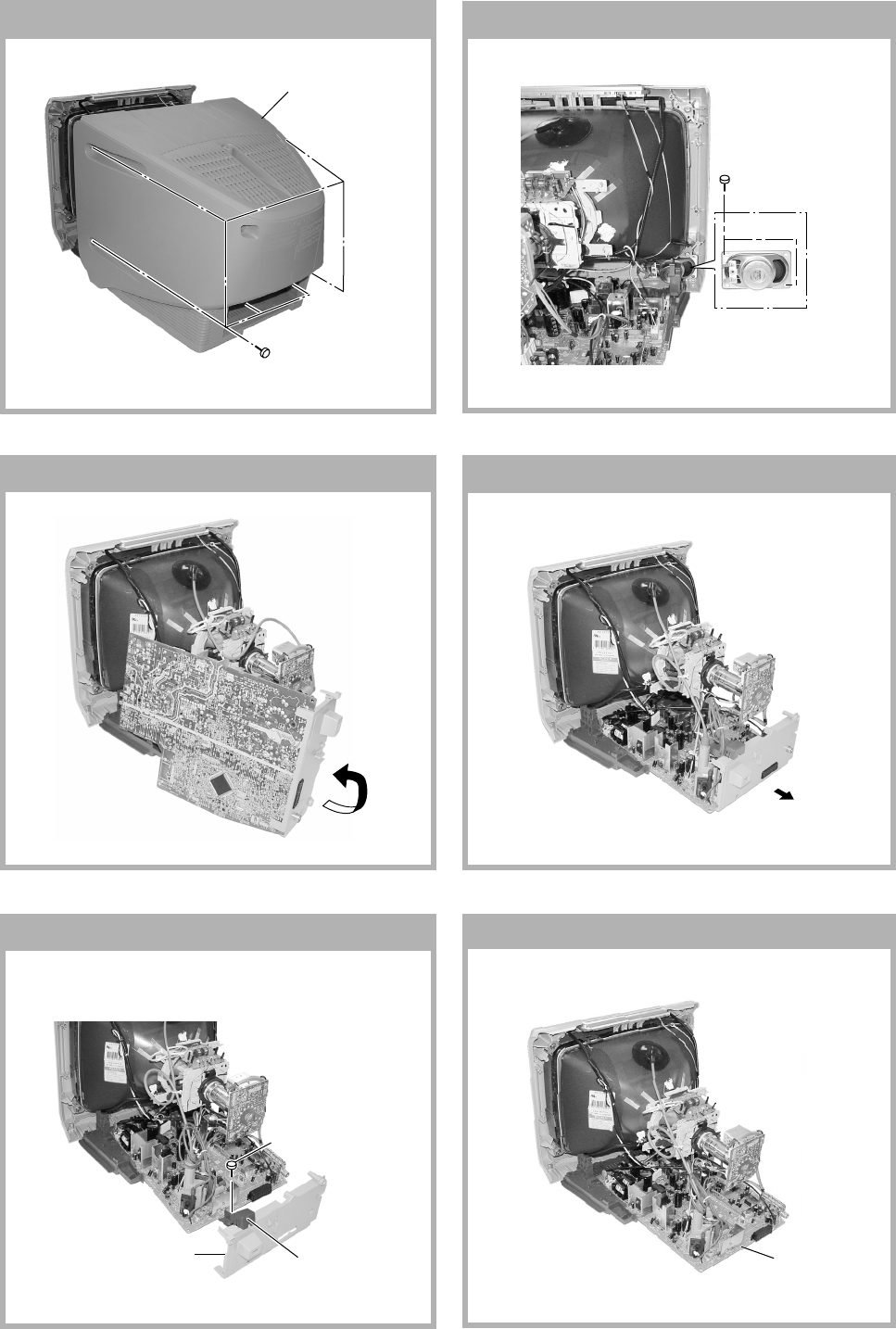
1-1. REAR COVER REMOVAL 1-2. SPEAKER REMOVAL
1-3. SERVICE POSITION 1-4. CHASSIS ASSY REMOVAL
1-6. A BOARD REMOVAL
1-5. TERMINAL BRACKET REMOVAL
2 Six screws
(+BVTP 4 × 16)
1 Rear cover
Two screws
(+BVTP 3 x 12)
2 Terminal
bracket
1 One screw
(+BVTP 4 × 16)
Bracket, FBT
A Board
– 8 –
KV-14CT1B/14CT1U/14CT1E/14CT1K
RM-W100
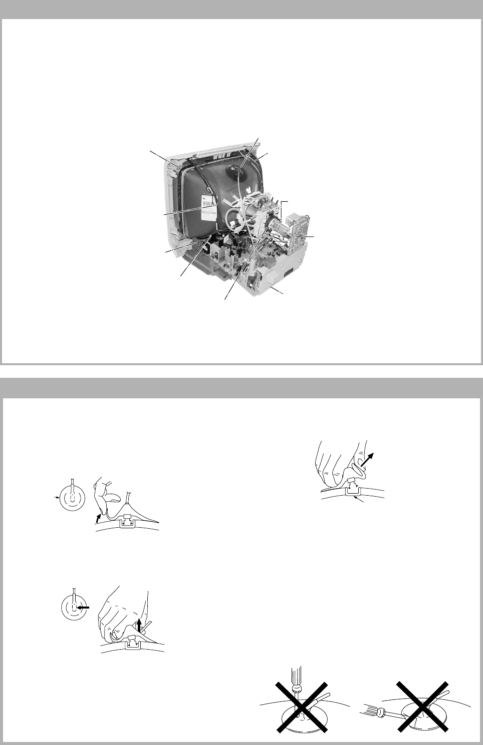
• REMOVAL OF ANODE-CAP
Note:
•After removing the anode, short circuit the anode of the picture tube and the anode cap to the metal chassis, CRT
shield or carbon paint on the CRT.
•REMOVING PROCEDURES
1Turn up one side of the rubber cap in the direction
indicated by the arrow a.
2Using a thumb pull up the rubber cap firmly in the di-
rection indicated by the arrow b.
3When one side of the rubber cap is separated from
the anode button, the anode-cap can be removed by
turning up the rubber cap and pulling it up in the
direction of the arrow c.
•HOW TO HANDLE AN ANODE-CAP
1Do not damage the surface of anode-caps with
sharp shaped objects.
2Do not press the rubber too hard so as not to
damage the inside of anode-cap.
A metal fitting called the shatter-hook terminal is
built into the rubber.
3Do not turn the foot of rubber over too hard.
The shatter-hook terminal will stick out or damage
the rubber.
anode button
1-7. PICTURE TUBE REMOVAL
Note:
•Please make sure the TV set is not in standing position before removing necessary CRT support located on bottom
right and left.
1) Place the TV set with the CRT face down on a cushion jig.
2) Removal the rear cover.
3) Unplug all interconnecting leads from the Deflection Yoke, Degaussing Coils and CRT grounding strap.
a
a
b
b
c
qa Earth Coating Assy
4 Anode Cap Removal
9 Degaussing Coil Removal (x1)
5 C Board Removal
7 Chassis Assy Removal
8 Support, CRT(14) Removal (x2)
0 Spring Tension Removal
qs Screw, Tapping 5 + Crown Washer
8 Loosen the Neck Assembly
fixing screw and removal
6 Loosen the Deflection Yoke
fixing screw and remove
– 9 –
KV-14CT1B/14CT1U/14CT1E/14CT1K
RM-W100
• The following adjustments should be made when a
complete realignment is required or a new picture tube is
installed.
Set the controls as follows unless otherwise noted:
VIDEO MODE .................................................. STANDARD
PICTURE CONTROL .......................................... NORMAL
BRIGHTNESS CONTROL .................................... NORMAL
Perform the adjustments in the following order :
1. Beam Landing
2. Convergence
3. Focus
4. Screen (G2)
5. White Balance
Note : Test Equipment Required.
1. Pattern Generator
2. Degausser
3. DC Power Supply
4. Digital Multimeter
5. Oscilloscope
SECTION 2
SET-UP ADJUSTMENTS
Preparation:
In order to reduce the influence of geomagnetism on the
set's picture tube, face it east or west. Switch on the set's
power and degauss with the degausser.
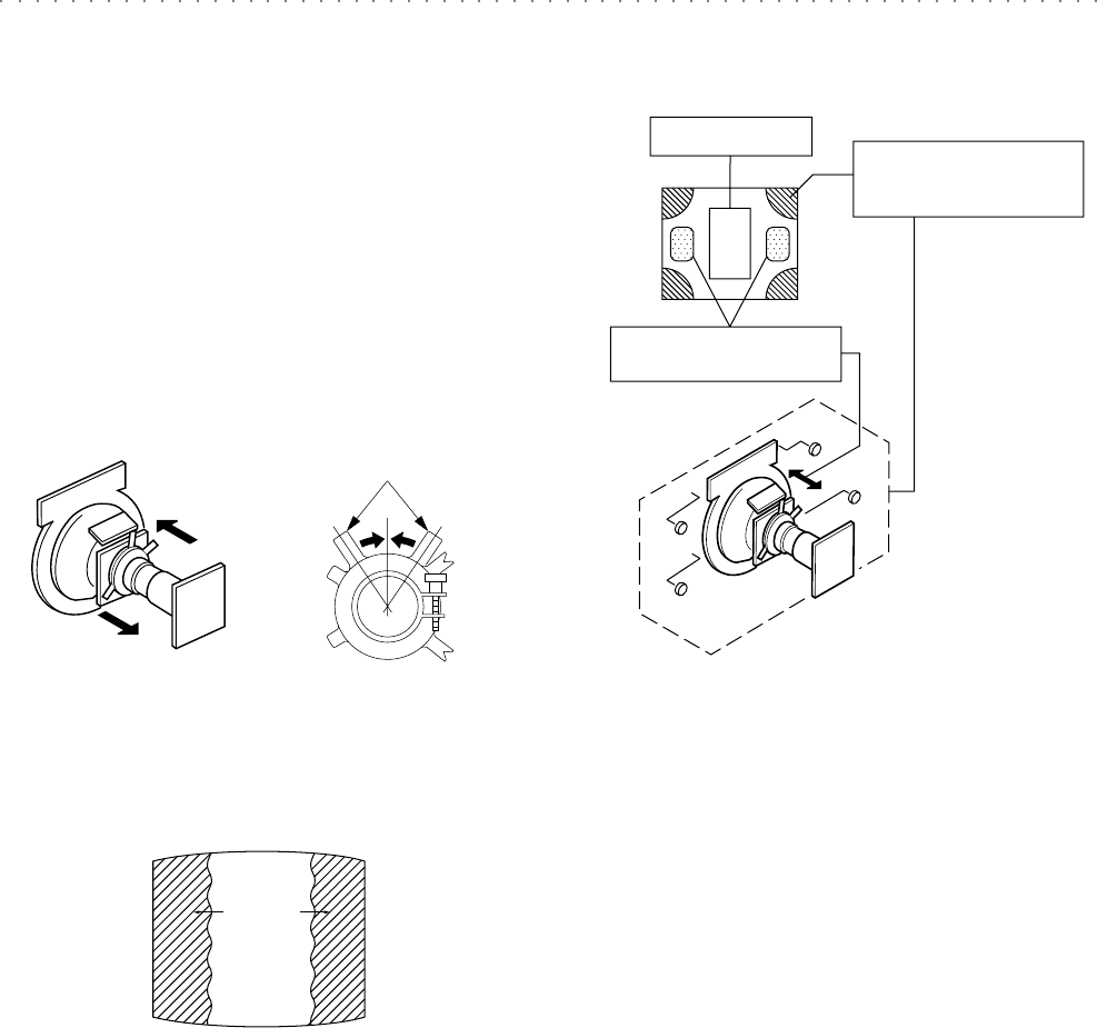
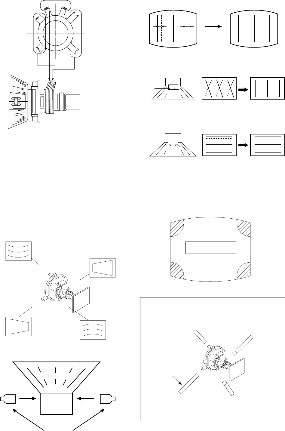
2-1. BEAM LANDING
Picture Mode : LIVE
1. Input a white signal with the pattern generator.
Set the contrast and brightness to normal.
2. Set the pattern generator raster signal to a green raster.
3. Move the deflection yoke to the rear and adjust with the
purity control so that the green is at the centre and the
blue and red take up equally sized areas on each side
of the screen. (see figure 2-1 and figure 2-1-1)
4. Move the deflection yoke forward and adjust so that the
entire screen is green. (see figure 2-1-2)
5. Switch the raster signal to blue, then red and verify the
condition.
6. When the position of deflection yoke have been
decided, fasten the deflection yoke with the screws and
DY spacers.
Figure 2-1 Figure 2-1-1
Purity control
Figure 2-1-2
Red
Blue
Green
7. If the beam does not land correctly in all the corners,
use a magnet to correct if. (see figure 2-1-3)
Caution:
High voltages are present on the Deflection yoke
terminals. Take care when handling the deflection yoke
whilst carrying out adjustments.
Figure 2-1-3
Purity control
corrects this area. Disk magnets or rotatable
disk magnets correct these
areas (a-d).
Deflection yoke positioning
corrects these areas.
a
b
b
c
c
d
d
a
– 10 –
KV-14CT1B/14CT1U/14CT1E/14CT1K
RM-W100
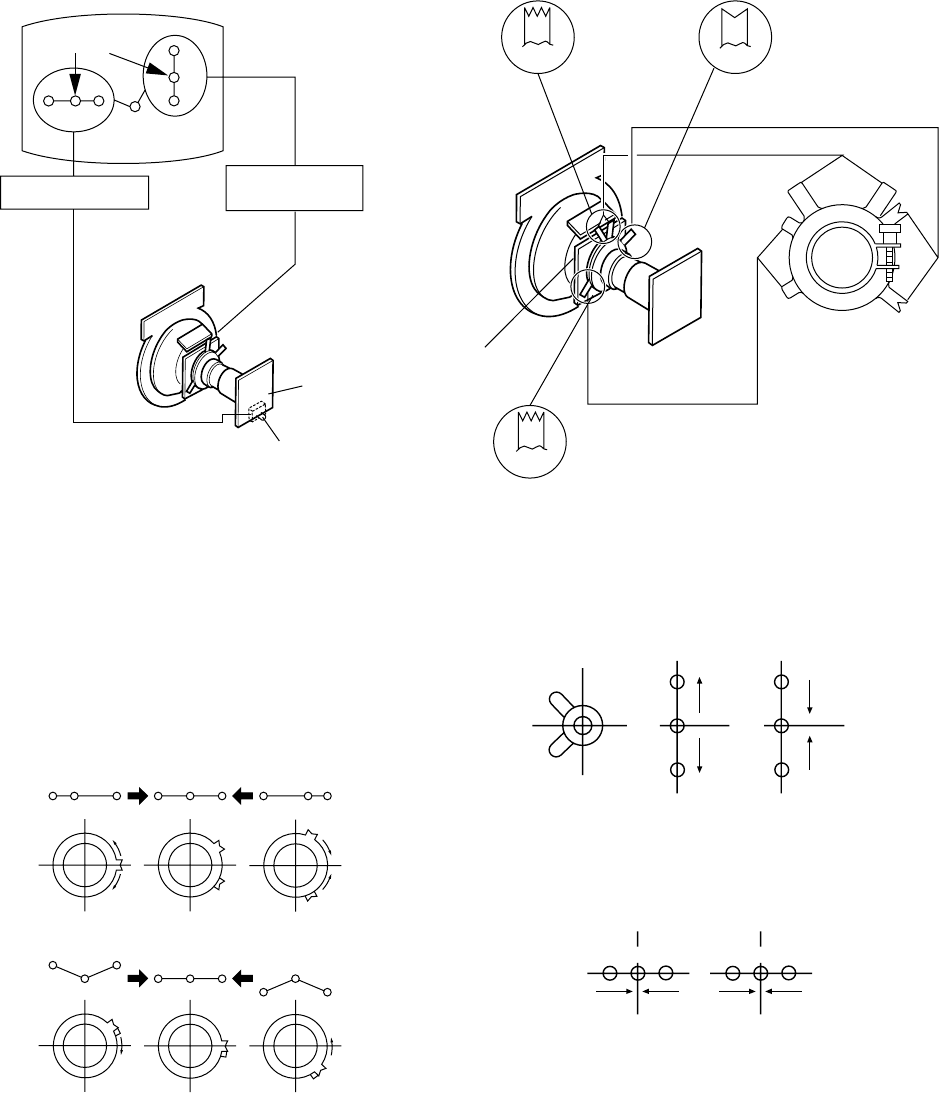
2-2. CONVERGENCE
Preparation:
•Before starting this adjustment, adjust the focus,
horizontal size and vertical size.
•Receive dot/hatch signal.
•Picture Mode : MOVIE
(A) Horizontal and Vertical Static Convergence
1. (Moving vertically), adjust the V.STAT magnet so that
the red, green and blue dots are on top of each other at
ther centre of the screen.
2. (Moving horizontally), adjust the H.STAT VR control so
that the red, green and blue dots are on top of each
other at the centre of the screen.
3. BMC (Hexapole)Magnet
If the red, green and blue dots are not balanced or
aligned then use the BMC magnet to adjust in the
manner described below.
Centre dot
R G B
R
G
B
H. STAT VR V. STAT
Magnet
RV750
C Board
BG R R G B R GB
RB
RG
GGB
RB
4. If the H.STAT variable resistor cannot bring the red,
green and blue dots together at the centre of the
screen, adjust the horizontal convergence with the H.
STAT variable resistor and the V.STAT magnet in the
manner given below.
(In this case, the H.STAT variable resistor and the
V.STAT magnet influence each other, so be sure to
perform adjustments while tracking.)
Operation of V.STAT magnet.
If the V.STAT is moved in the "A" and "B" arrows, the red,
green and blue dots moves as shown below.
Moved RV750 H.STAT the red, green and blue dots move
as shown below.
BMC (Hexapole)
V.STAT
DY pocket
Purity
V.STAT
BMCPurity
B
G
R
B
G
R
AB
BGR
A
RGB
B
– 11 –
KV-14CT1B/14CT1U/14CT1E/14CT1K
RM-W100
5. Layout of each control.
6. Geometry Adjustment.
Preparation:
Before starting this adjustment, adjust the horizontal and
vertical static convergence.
a) Remove the deflection yoke spacer.
b) Tilt the deflection yoke as indicated in the figure below
and optimise the geometry.
Tilting the DY up and down will balance the upper and
lower pin adjustment.
Tilting the DY left and right will balance the H-Trap
adjustment.
c) Re-install the deflection yoke spacer.
7. H-TILT Adjustment
Purity
BMC (Hexapole)
V.STAT
,
,
,
,
,
Tilt Direction
Deflection Yoke
TLH pieces
H-TILT correction can be performed by adding a TLH
correction assembly to the Deflection Yoke.
8. YCH Adjustment
9. TLV Adjustment
10. Screen Corner Convergence.
If you are unable to adjust the corner convergence
properly, this can be corrected with the use of Piece
A(90) Conv. Correct.
Deflection Yoke
YCH VR
Deflection Yoke
TLV VR
ba
cd
a-d : screen-corner
misconvergence
a
d
c
b
Install the Piece A(90) Conv. Correct
assembly for the area that needs correcting.
Convergence adjustment with
Piece A(90) Conv. Correct
Piece A(90) Conv. Correct
4-094-690-01
– 12 –
KV-14CT1B/14CT1U/14CT1E/14CT1K
RM-W100
2-3. FOCUS ADJUSTMENT
1. Receive digital monoscope pattern.
2. Set Picture Mode to PERSONAL.
3. Adjust focus VR to obtain the best focus at the centre of
the screen.
4. Change the receiving signal to white pattern and blue
back.
5. Confirm magenta ring is not noticeable. In case
magenta is very obvious, adjust the focus VR to take
balance of magenta ring and focus.
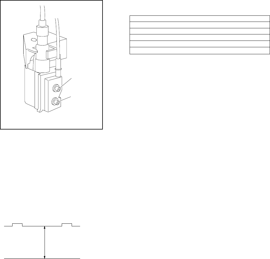
2-4. G2(SCREEN) ADJUSTMENT
1. Input a dot signal from the pattern generator.
2. Set the Picture, Brightness and Colour to minimum.
3. Apply 165V DC from an external power supply to the
R,G and B cathodes of the CRT.
4. Adjust brightness to obtain cathode value to value
below.
5. Whilst watching the picture, adjust the G2 control
[SCREEN] located on the Flyback Transformer to the
point just before the flyback return lines disappear.
FOCUS
SCREEN
FLYBACK TRANSFORMER (T802)
Cathode setting voltage:
165 V ± 2 (VDC) – 14"
2-5. WHITE BALANCE ADJUSTMENT
1. Enter into Service Menu.
2. Input white pattern signal.
3. Set picture to PERSONAL mode.
4. Select WHBL "RDRV" and fix the value to 25 hex.
5. Adjust WHBL "GDRV" and "BDRV" and adjust the data
for best white balance in highlight condition.
6. Adjust WHBL "BKOR" and "BKOG" and adjust the data
for best white balance cut-off condition.
7. Set the offset settings for LIVE and GAME mode as
stated in the table 1 below:-
Live TPersonal TGame
Adjusted value +2 BKOR (adjusted) Adjusted value
Adjusted value -3 BKOG (adjusted) Adjusted value
25hex RDRV (25hex) 25hex
Adjusted value +2 GDRV (adjusted) Adjusted value -2
Adjusted value +4 BDRV (adjusted) Adjusted value -6
OFFSET TABLE (Table 1)
– 13 –
KV-14CT1B/14CT1U/14CT1E/14CT1K
RM-W100
SECTION 3
CIRCUIT ADJUSTMENTS
3-1. ADJUSTMENT WITH COMMANDER
Service adjustment to this model can be performed using the supplied remote commander RM-W100.
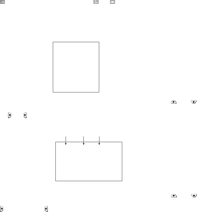
a. ENTERING SERVICE MODE
With the unit on standby, press the following sequence of buttons on the remote commander.
'TT – –' will appear in the upper right corner of the screen.
Other status information will also be displayed.
b. Press 'MENU' on the remote commander to obtain service menu on the screen.
GEOM
WHBL
SADJ
YC
SYNC
PICT
SW
VIF
c. The screen only displays 8 items at one time. To move to the corresponding item use the up down buttons on
the remote commander.
d. Press the right / left button or ENTER button on the remote commander to enter into the required item.
e. The screen only display 12 items at one time. To move to the corresponding item use the up down buttons on
the remote commander.
f. Press right to increase or left to decrease the data.
g. Press the 'MENU' button on the remote commander to quit from Service Menu. Screen will still display 'TT – –'. To exit
from 'TT – –' menu, press 0 twice, 'TEST', 'TV' or switch the TV into standby mode.
Note:
• After carrying out the service adjustments, to prevent the customer accessing the 'Service Menu' switch the TV set
OFF and then ON.
52(0,63)
HPOS
Item
Name Range Data
40(0,63)
HPAR
/ Display / Channel 5 / Volume [+] / Power / TV
– 14 –
KV-14CT1B/14CT1U/14CT1E/14CT1K
RM-W100
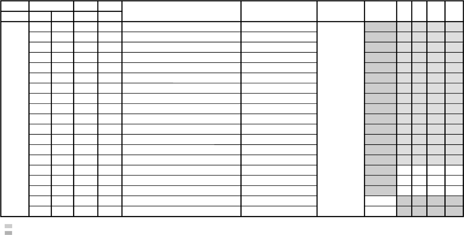
JVTytilanoitcnuFlaitinIegnaR noitcnuFetoN&elbaTemaNeciveDnommoC050605w06w
yrogetaCoNemaNceDceD
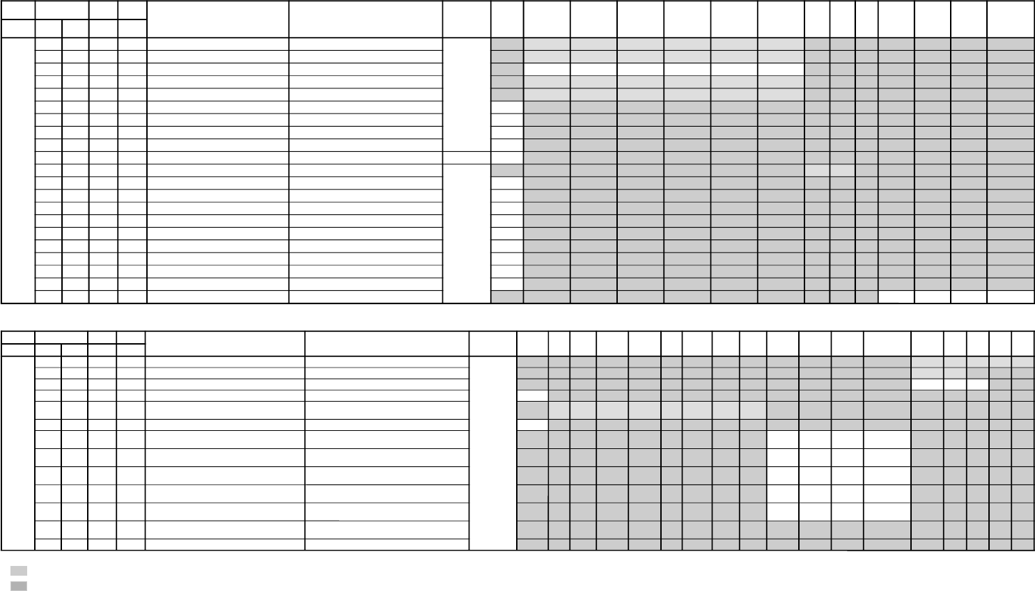
MOEG 000SOPH130360)SH(tfihSlatnoziroH )BGRNPJ+(06w/05w/06/05 rossecorP-VT 13 13 13 13
100RAPH130360margolellaraPlatnoziroH06w/05w/06/05 13 13 13 13
200WOBH130360woBlatnoziroH06w/05w/06/05 13 13 13 13
300NILV130360ytiraeniLlacitreV06w/05w/06/05 13 13 13 13
400RCSV130360llorcSlacitreV06w/05w/06/05 13 13 13 13
500ZISH130360)WE(htdiWWE )BGRNPJ+(06w/05w/06/05 13 13 13 13
600WPWE130360)WP(htdiW/alobaraPWE06w/05w/06/05 13 13 13 13
700POCU710360alobaraPrenroCreppUWE06w/05w/06/05 71 71 71 71
800POCL710360alobaraPrenroCrewoLWE06w/05w/06/05 71 71 71 71
900ZTWE130360muizeparTWE06w/05w/06/05 13 13 13 13
010PLSV130360)SV(epolSlacitreV06w/05w/06/05 13 13 13 13
110ZISV510360edutilpmAlacitreV06w/05w/06/05 51 51 51 51
210ROCS410360)CS(noitcerroC-S06w/05w/06/05 41 41 41 41
310SOPV130360)HSV(tfihSlacitreV06w/05w/06/05 13 13 13 13
410LBH000100edoMgniknalBBGR06w/05w/06/05 10101010
510FBW700510)FBW(gniknalBediWfognimiT06w/05w/06/05 90909090
610RBW700510)RBW(gniknalBediWfognimiT06w/05w/06/05 01010101
710LBS000100gniknalBecivreSenon00
810YPOC000100aeraMVNzH06/05llaotatadOEGehtypoCenon00
3-2. ADJUSTMENT ITEM TABLE
• shaded items are adjustable data.
• no data.
– 15 –
KV-14CT1B/14CT1U/14CT1E/14CT1K
RM-W100
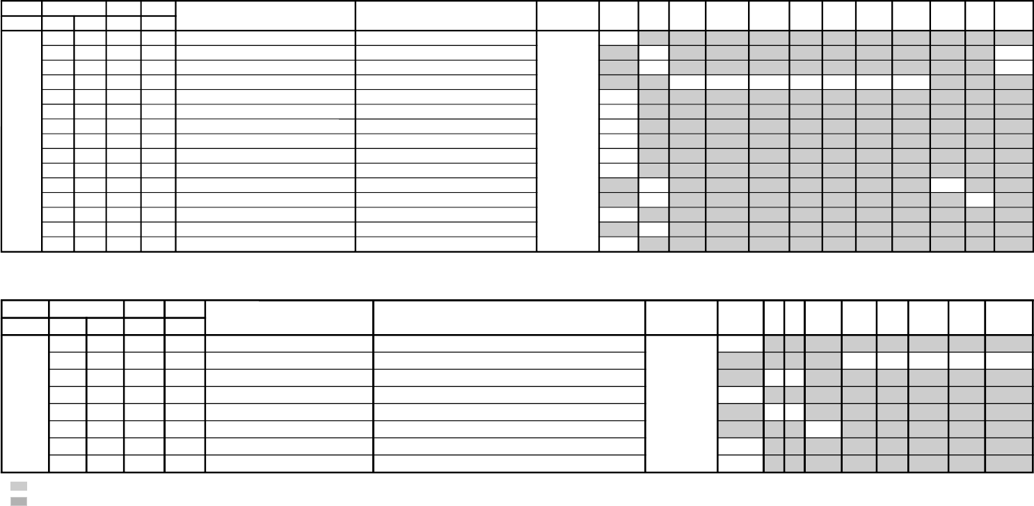
JVTytilanoitcnuFlaitinIegnaR noitcnuFetoN&elbaTemaNeciveDnommoCeviL
)rehtoLOOC(
EMAG
)rehtoMRAW(
/EIVOM
LANOSREP
LARTUEN(
)rehto
EVIL
)BGRLOOC(
EMAG
)BGRMRAW(
/EIVOM
LANOSREP
LARTUEN(
)BGR
rehtOBGRVUYedomciP
0
)EVIL(
edomciP
1
)EIVOM(
edomciP
2
)EMAG(
edomciP
3
)LANOSREP(
yrogetaCoNemaNceDceD
LBHW000ROKB130360RtesffOleveLkcalB )srehtO/BGR/VU(*)lamroN/WOL/HGIH(pmetlocrossecorP-VT 13 13 13 13 13 13
100GOKB130360GtesffOleveLkcalB )srehtO/BGR/VU(*)lamroN/WOL/HGIH(pmetloc 13 13 13 13 13 13
200VRDR730360RtnioPetihW )srehtO/BGR/VU(*)lamroN/WOL/HGIH(pmetloc 737373737373
300VRDG730360GtnioPetihW )srehtO/BGR/VU(*)lamroN/WOL/HGIH(pmetloc 73 73 73 73 73 73
400VRDB730360BtnioPetihW )srehtO/BGR/VU(*)lamroN/WOL/HGIH(pmetloc 73 73 73 73 73 73
500GPL000100teserPniaGBGR enon00
600RGP130721)RGP(RniaGteserP enon54
700GGP130721)GGP(GniaGteserP enon54
800BGP130721)BGP(BniaGteserP enon54
900FONG000510tesffOniaGteserP enonpoolCCC80
010TRBS130360ssenthgirB-buS VUY/BGR/srehtO 43 03
110ORBS000300)ciPtnegilletnI(tesffOssenthgirB-buS enon00
210LGE000100metsySCCCpooLniaGelbanE enon00
310LGS000300metsySCCCnitnerruChgiHfonoitceleS enon00
410BKA000100noitazilibatStnerruCkcalB enon00
510SBC000100gnitimiLtnerruCmaeBfoecneuqeSlortnoC enon00
610BBGR000300gniknalBBGR enon00
710GBLB000100tuptuOneerG&eulBfogniknalB enon00
810BFO000100eulBtesffOleveLkcalB enon00
910RBSN000510tesffOssenthgirBdradnatS-noN enon50
020PBW000300)woL:3,2,lamroN:1,hgiH:0(gnittespmeTroloC edoMerutciP 00102010
JVTytilanoitcnuFlaitinIegnaR noitcnuFetoN&elbaTemaNeciveDnommoClap05
)VT(
lap05
)oediV(
maces05
)VT(
maces05
)oediv(
VT06oediV06BGR05BGR06edomciP
0
)EVIL(
edomciP
1
)EIVOM(
edomciP
2
)EMAG(
edomciP
3
)LANOSREP(
PI-VT
NO
oediVBGRVT
ediW
oediV
ediW
yrogetaCoNemaNceDceD
JDAS000XAMP360360mumixaMerutciP )BGRNPJ+(>ediW/lamroN</)ediW/lamroN(*)oediV/VT(rossecorP-VT 43 43 62 62
100EUHS700510euH-buS oediV/VT 70 80
200PHSS510360ssenprahS-buS )BGRNPJ+(VUY/oediV/VT 321301
300OHSS000300)ciPtnegilletnI(tesffOssenprahS-buS enon 30
400LOCS130360roloC-buS /)oediv(maces05/)vt(maces05/)oediv(lap05/)vt(lap05
BGR06/BGR05/VUY06/VUY05/oediv06/VT06 42 82 42 82 22 62 82 62
500OOCS000300)ciPtnegilletnI(tesffOroloC-buS enon 20
600CIP130721,)dilavni(001>;)dilav(001~0:AG[lortnoCerutciP
])dilavni(6tiberongi;)dilav(36~0:srehtO
)ataDteseRresU=lanosreP:AG(edoMerutciP 36538355
700LOC130721,)dilavni(001>;)dilav(001~0:AG[lortnoCroloC
])dilavni(6tiberongi;)dilav(36~0:srehtO
)ataDteseRresU=lanosreP:AG(edoMerutciP 63131313
800TRB130721,)dilavni(001>;)dilav(001~0:AG[lortnoCssenthgirB
])dilavni(6tiberongi;)dilav(36~0:srehtO
)ataDteseRresU=lanosreP:AG(edoMerutciP 13531313
900EUH130721,)dilavni(001>;)dilav(001~0:AG[lortnoCeuH
])dilavni(6tiberongi;)dilav(36~0:srehtO
)ataDteseRresU=lanosreP:AG(edoMerutciP 13131313
010PHS130721,)dilavni(001>;)dilav(001~0:AG[lortnoCssenprahS
])dilavni(6tiberongi;)dilav(36~0:srehtO
)ataDteseRresU=lanosreP:AG(edoMerutciP 53821313
110OCEP200300edomevasrewopniataderutciP
)ylnoNAPAJrofdilav(
)hcumocE/dtsocE(*edoMerutciP
210VLRP200300)ylnoNAPAJrofdilav(edomevasrewopfotneiciffeoC hcumocE/dtsocE
• shaded items are adjustable data.
• no data.
– 16 –
KV-14CT1B/14CT1U/14CT1E/14CT1K
RM-W100
JVTytilanoitcnuFlaitinIegnaR noitcnuFetoN&elbaTemaNeciveDnommoC0506srehtOPI-VT
NO
oediVtxeteleTPI-VT
FFO
langiSoN
yrogetaCoNemaNceDceD
CNYS000SYS000100tupnICNYSYnonoitazinorhcnyS rossecorP-VT 00
100OF000300tnatsnoCemiT1esahP )FR(langisoNrogninuTotuA/txeteleT/oediV/FFOPIVT/NOPIVT 0030103000
200DIV000100edoMtnedIoediV 06/05 0000
300LSF000100cnySlacitreVrofleveLgnicilSdecroF 00
400LSS000100rotarapeScnySleveLgnicilS 06/05 0000
500DIVS100700noitacifitnedIoediVrofnoitceleSecruoS srehtO/VUY 00
600FROF000300ycneuqerFdleiFdecroF 30
700KVM000100gniyeKnoisiVorcaM 10
JVTytilanoitcnuFlaitinIegnaR noitcnuFetoN&elbaTemaNeciveDnommoCsrehtO)VT(LAP)VT(CSTNMACES
)VT(
LAP
)oediV(
CSTN
)oediV(
MACES
)oediV(
TUPNI-SMACESCSTNVT
yrogetaCoNemaNceDceD
CY000QRFP000300yaleDdnaycneuqerFretneCgnikaeP rossecorP-VT 00
100APR100300toohSrevO&erPoitaR rehto/VT 20 10
200OPR200300skaePevitageN&evitisoPfooitaR rehto/VT 10 10
300YLDY210510yaleD-Y TUPNI-S/VUY+)OEDIV/VT(*)MACES/CSTN/LAP( 60606050505050
400TAMC000300xirtaM)ASU/napaJ(CSTNroMACES-LAP )BGRNPJ( 00
500LCA100100gnitimiLroloCcitamotuA 10
600BC000100ycneuqerFretneCssapdnaBamorhC )xif0:oediV*(VThtiwylnodilav 00
700OBS100300tesffOkcalBMACES 10
800ESHC100300ytivitisneStnedICSTN/LAP 20
900OLC000100retliF)lleB(ehcolCfoycneuqerFretneC 00
010PRTC000100edoMparTamorhC srehto/MACES 00 10
110SPB000100eniLyaleDdnab-esaBamorhCfossapyB srehto/CSTN 00 00
210OCF000100nOroloCdecroF 00
310TNIT130360lortnoCtniTdnaB-esaB srehtO/VUY 13
410VUT000100slangiSVUnolortnoCtniT 00
• shaded items are adjustable data.
• no data.
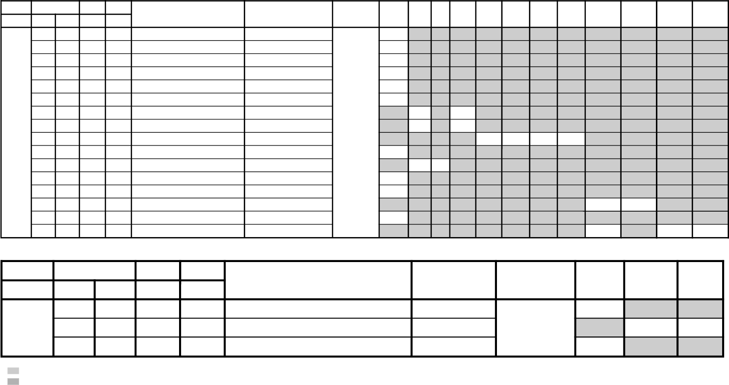
– 17 –
KV-14CT1B/14CT1U/14CT1E/14CT1K
RM-W100
JVTytilanoitcnuFlaitinIegnaRnoitcnuFetoN&elbaTemaNeciveDnommoCsrehtOBGR:erutciP
eviL
VT
)eviL(
VT
)srehtO(
oediV
)eviL(
oediV
)srehtO(
pmeTroloC
)LOOC(
pmeTroloC
)srehtO(
pmeTroloC
)mraW(
pmeTroloC
)lartueN(
yrogetaCoNemaNceDceD
TCIP000LDAC700510leveLevirDedohtaC rossecorP-VT30
100AFC000300edoMretliFbmoC 10
200COS200300leveLgnippilCtfoS 20
300LWP100100hctiwSgnitimiLetihWkaeP 10
400LTHW600510gnitimiLetihWkaeP 70
500MAG100100ammaG 10
600STW100300hctertSetihWdnalortnoCammaGsrehtO/eviL 00 10
700RFT000100langiSecnanimuLfooitaRrefsnarTCD)BGRNPJ+(srehtO/eviL 00 10
800ROC300300gniroC)srehto/anyD(*)oediV/VT( 20200010
900OROC000100)ciPtnegilletnI(tesffOgniroC 10
010SKB300300hctertSkcalBsrehto/BGR 2020
110SAA100100hctertSkcalBehtffohctiwSotaerAkcalB 10
210KSD000100lortnoCnikScimanyD 00
310SLB000100hctertSeulB)SREHTO/HGIH(pmetloc 1000
410SLBN000100tiucriChctertSeulBnoitarepO 00
510RRN000100noitcudeRdeRnoN )LAMRON/WOL/HGIH(pmetloc 10 0000
JVTytilanoitcnuFlaitinIegnaR noitcnuFetoN&elbaTemaNeciveDnommoCVToediV
yrogetaCoNemaNceDceD
WS 0002VC000100noitceleSlangiStupnI2SBVC rossecorP-VT 00
100OVS10030084@niPISBVC/OVS/OVFIfonoitcnuFVUY/oediV/VT 1010
200LFD000100noitcetorPhsalF 00
• shaded items are adjustable data.
• no data.
– 18 –
KV-14CT1B/14CT1U/14CT1E/14CT1K
RM-W100
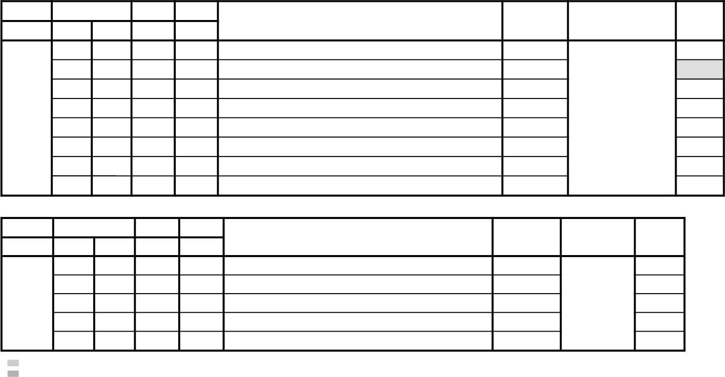
JVTytilanoitcnuFlaitinIegnaR noitcnuFetoN&elbaTemaNeciveDnommoC
yrogetaCoNemaNceDceD
MEDS 000SWMF000300rotaludomeDMFrofnoitceleSwodniW rossecorP-VT 20
100SSQ100100)ledoMAGtpecxe(edoMrefilpmA)SSQ(dnuoStilpSisauQ 10
200BPB000100retliFssapdnaBdnuoSfossapyB 00
300OLMA000100dnuoSMAroflangiStuptuOoiduA 00
400CVPH000100lortnoCemuloVenohPdaeH 00
JVTytilanoitcnuFlaitinIegnaR noitcnuFetoN&elbaTemaNeciveDnommoC
yrogetaCoNemaNceDceD
FIV 000DFIO630360rotaludomeDFItesffO rossecorP-VT 63
100TCGA130360revo-ekaTCGA 63
200MTS000100edoMgninuThcraeS 10
300DG000100langiS1SBVCnoyaleDpuorG 00
400SCGA100300deepSCGAFI 00
500IFF000100LLPFIretliFtsaF 00
600PMAO300300)metsyS'L&Lylno(edutilpmAlangiStuptuOoediV 30
700IAV000100)metsyS'L&Lylno(noitcerroCedutilpmAlangiStuptuOImetsyS 10
• shaded items are adjustable data.
• no data.
– 19 –
KV-14CT1B/14CT1U/14CT1E/14CT1K
RM-W100
JVTytilanoitcnuFlaitinIegnaRnoitcnuFetoN&elbaTemaNeciveDnommoC
yrogetaCoNemaNceDceD
TXT000VXT930360spilihProfnoitisoPlacitreVtxeteleTredoceDtxeT73
100DHT500721tfihSegdEevitcAcnys-HtxeteleT 50
200RBT400510ssenthgirBBGRtxeteleT 80
JVTytilanoitcnuFlaitinIegnaRnoitcnuFetoN&elbaTemaNeciveDnommoC0506
yrogetaCoNemaNceDceD
MTPO000THSA600700)nim5*atad(remitffotuhsotua 60
100BDSO000510ssenthgirBDSO h06orciM/RMM30
200HDSO500510noitisoPlatnoziroHDSO h06orciM/RMM60
300VDSO730360noitisoPlacitreVDSO 06/05h06orciM/RMM 1633
400ETUM000100)delbane=1(hctiwSetuMlangiSoN 10
500LUFR510510)hf0nehwelbasiD(dekcolnUretfaretnuoCegnahClangiSFR 40
600KLFR510510)hf0nehwelbasiD(dekcoLretfaretnuoCegnahClangiSFR 00
700LUVA510510)hF0nehwelbasiD(dekcolnUretfaretnuoCegnahClangiSVA 40
800KLVA510510)hF0nehwelbasiD(dekcoLretfaretnuoCegnahClangiSVA 00
900GNAL000300noitidnocgnippihsegaugnalDSO 00
010TXTH000100wsrotarapescnys rossecorP-VT00
110SSMC000100wscnyS rossecorP-VT10
210OXCD721552eulaVhsalFmorftesffOOXCD h06orciM/RFS07
310LBXE000510esioNetihWetanimilEotremiTgniknalBdednetxE 70
410SYST000300)ledoMAG(teseRtseTtaMVNnimetsySVTeziromeM 00
510UOVT100100tuohtiwetuM:1,ffOetuMsyawlA:0noitidnocetumtuoVT
)ledoMORUE(langis
10
• shaded items are adjustable data.
• no data.

– 20 –
KV-14CT1B/14CT1U/14CT1E/14CT1K
RM-W100
JVTytilanoitcnuFlaitinIegnaR noitcnuFetoN&elbaTemaNeciveDnommoC
yrogetaCoNemaNceDceD
BTPO 000LLAI000100)MVNnideziromemton(hctiwSetirWdradnatS 00
1001BPO000552)detalermetsyS(1noitpO *
2002BPO000552)detalerlangiSoediV(2noitpO *
3003BPO000552)detalergnidoceDoeretS(3noitpO *
4004BPO000552)suoenallecsiM(4noitpO *
5005BPO000552)suoenallecsiM(5noitpO *
6006BPO000552)detaleregaugnaLDSO(6noitpO *
700TWSB000510)MVNnideziromemton(emiTtiaWhctiwSdnaB 00
• shaded items are adjustable data.
• no data.
* refer page 21-23 for data.
– 21 –
KV-14CT1B/14CT1U/14CT1E/14CT1K
RM-W100
NOTE
• shaded items are adjustable data.
• no data.
•Standard data listed on the Adjustment Item Table are reference values, therefore it may be different for each model and
for each mode.
•Note for Different Data: Those are the standard data values written on the microprocessor. Therefore, the data values of
the modes are stored respectively in the memory. In case of a device replacement, adjustment by rewriting the data
value is necessary for some items.
Item
KV-14CT1B
KV-14CT1U
KV-14CT1E
KV-14CT1K
OPTION NOTE
OPB1
SPEED SEARCH (Time of speed search) 00 = disabled (original cycle speed),
01 = 4 time speed from the original,
10 = 6 time speed from the original,
11 = 8 time speed from the original
TV System Selection 0 = disabled, 1 = enabled
D/K
0
0
1
1
I
1
1
0
0
B/G
1
0
1
1
L(Euro), M(GA)
1
0
0
0
L'
1
0
0
0
M/N
0
0
0
0
0
0
0
0
SPEED SEARCH
D1 (D1 Terminal) 0 = not available, 1 = available
AV Multi/PAM (AV Multi Terminal) – JP 0 = not available, 1 = available
Portable Audio Mode – GA 0 = not available, 1 = available
Component (Component [YCbCr] Terminals) 0 = not available, 1 = available
Composite (No. of Composite Terminals) 00 = no composite terminal(Euro : no Scart) BX1L: No Video
(SCART) (No. of SCART Terminals) 01 = 1 composite terminal (Euro : 1 Scart) BX1L:2 Video in
10 = 2 composite terminal (Euro : 2 Scart) BX1L:3 Video in
11 = 3 composite terminal (Euro : no terminal BX1L: 4 Video in)
SECAM (SECAM Color System) 0 = disabled, 1 = enabled
Color decording (Color Crystal Selection) 00 = PAL/NTSC/SECAM (Multi), 01 = NTSC (3.58MHz)
10 = PAL/NTSC/SECAM (4.43MHz), 11 = PAL/NTSC (Tri-Norma)
HDEV (High Deviation Mode) 0 = disabled, 1 = enabled
NICAM ST (NICAM Stereo) 0 = disabled, 1 = enabled
NICAM BI (NICAM Bilingual) 0 = disabled, 1 = enabled
A2 ST/BI (A2 [West German] Stereo/Bilingual) 0 = disabled, 1 = enabled
Thai Bilingual (A2 [Thai] Bilingual) or Force SAP if JP/US ST is active 0 = disabled, 1 = enabled
JP/US ST (JP/US Stereo) 0 = disabled, 1 = enabled
Korean ST (Korean Stereo) 0 = disabled, 1 = enabled
MONO (Monaural Model) 0 = Stereo (SSD) Model, 1 = Monaural Model
Item
KV-14CT1B
KV-14CT1U
KV-14CT1E
KV-14CT1K
OPB2
0
0
0
0
SECAM
1
1
1
1
1
1
1
1
0
0
0
0
Component
0
0
0
0
D1
0
0
0
0
AV Multi/PAM(GA)
0
0
0
0
Composite (SCART) Color decording
Item
KV-14CT1B
KV-14CT1U
KV-14CT1E
KV-14CT1K
OPB3
MONO
1
1
1
1
Korean ST
0
0
0
0
JP/US ST
0
0
0
0
Thai Bilingual
0
0
0
0
A2 ST
0
0
0
0
NICAM BI
0
0
0
0
HDEV
0
0
0
0
NICAM ST
0
0
0
0
1
1
1
1
DEC
94
96
69
69
0
0
0
0
DEC
12
12
12
12
DEC
01
01
01
01
– 22 –
KV-14CT1B/14CT1U/14CT1E/14CT1K
RM-W100
Firmware (SSD Firmware Downloading) 0 = disabled, 1 = enabled
SMAT Surround Matrix 0 = Active, 1 = Passive
1 spk Models 1 Speaker Models 0 = 2 or 3 Speakers Models, 1 = 1 speaker Models
VM (Velocity Modulation) 0 = disabled, 1 = enabled
Equalizer (5-band Equalizer Model) 0 = Bass/Treble Model, 1 = Equalizer Model
Surround (US/GA Surround Selection) 0 = Off/Simulated/Surround,
1 = Off/Simulated/WOW/TruSurround (US)
1 = Off/Simulated/SRS(3D)Surround (GA)
V-Chip (V-Chip Model) 0 = Channel Block Model (no rating)
1 = Parental Control Model (rating)
TOP (Forced TOP) 0 = Auto Mode (TOP/FLOF), 1 = Forced TOP
TEXT (Teletext Model) 0 = Non-Teletext Model, 1 = Teletext Model
Item
KV-14CT1B
KV-14CT1U
KV-14CT1E
KV-14CT1K
OPB4
TEXT
1
1
1
1
TOP
0
0
0
0
V-Chip
0
0
0
0
Surround
0
0
0
0
Equalizer
0
0
0
0
VM
0
0
0
0
Firmware/SMAT
0
0
0
0
1 spk Models
1
1
1
1
Full Surround (Full Surround option - no for euro model) 0 = Normal surround model,
1 = Full surround model (Off/simulated/surround/SRS/WOW/TruSurround
No Surround (No Surround Model) 0 = Surround Model, 1 = Non-Surround Model
Forced 60 (Forced 60Hz in no signal) 0 = 50Hz, 1 = 60Hz
ASD (Automatic Standard Detection) 0 = disabled, 1 = enabled
Tilt (Tilt Correction/PIC Rotation) 0 = disabled, 1 = enabled
IP Plus (Intelligent Picture Plus) 0 = disabled, 1 = enabled
IP (Intelligent Picture) 0 = disabled, 1 = enabled
Wide (Wide Mode/V-Compressed) 0 = disabled, 1 = enabled
Item
KV-14CT1B
KV-14CT1U
KV-14CT1E
KV-14CT1K
OPB5
Wide
1
1
1
1
IP
1
1
1
1
IP Plus
1
1
1
1
Tilt
1
1
1
1
ASD
0
0
0
0
Forced 60
0
0
0
0
Full Surround
0
0
0
0
No Surround
1
1
1
1
DEC
65
65
65
65
DEC
79
79
79
79

– 23 –
KV-14CT1B/14CT1U/14CT1E/14CT1K
RM-W100
GA US (US Model Destination) 0 = US/Canada/Latin,
1 = Taiwan/Korea/Philippine
Latin (US Model Latin Destination) 0 = US/Canada (No Volume Figure Display)
1 = Latin (Volume Figure Display)
Feature 2 (Temporary for BX1L) 0 = Comb Not available
1 = Comb Available
Feature 1 (Temporary for BX1L) 0 = PiP Not available
1 = PiP Available
OSD Language Selection US 01xx = French,
(English always available except JP) 0x1x = Spanish
0xx1 = Portuguese
US (GA NTSC) 1x1x = Complicated Chinese,
1xx1 = Korean
GA 1xxx = Simplified Chinese,
x1xx = Arabic,
xx1x = Thai
xxx1 = Vietnamese
EU 0000 = Destination ADE
0001 = Destination BL
0010 = Destination KR
0011 = Destination U
Item
KV-14CT1B
KV-14CT1U
KV-14CT1E
KV-14CT1K
OPB6
1
1
0
0
0
1
0
1
0
0
0
0
0
0
0
0
Feature 1
0
0
0
0
Feature 2
0
0
0
0
GA US
0
0
0
0
Latin
0
0
0
0
OSD Language Selection DEC
01
03
00
02
– 24 –
KV-14CT1B/14CT1U/14CT1E/14CT1K
RM-W100
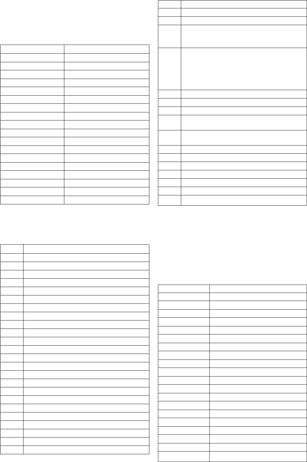
3-3. T-MODE:
T-Mode is available by pressing the 'TEST' button once,
OSD 'T' appears. The function described below are
available by selecting the indicated keys. The 'T' is released
automatically after each command is executed.
KEY T-MODE FUNCTION
volume + volume maximum
volume –volume minimum
picture + picture maximum
picture –picture minimum
colour up colour maximum
colour down colour minimum
brightness-bright brightness maximum
brightness-dark brightness minimum
hue-purplish hue-purplish
hue-greenish hue-greenish
sharpness-sharp sharpness maximum
sharpness-soft sharpness minimum
balance left balance full left (only stereo)
balance right balance full right (only stereo)
treble up treble maximum (only stereo)
treble down treble minimum (only stereo)
bass up bass maximum (only stereo)
bass down bass minimum (only stereo)
3-4. TT-MODE:
TT-Mode is available by pressing the 'TEST' button twice,
OSD 'TT – –' appears. The function described below are
available by pressing two digits.
00 Exit from TT mode
01 Set Picture Level to Maximun
02 Set Picture Level to Minimum
03 Set Volume to 35%
04 Set Volume to 50%
05 Set Volume to 65%
06 Set Volume to 80%
07 Ageing Mode On
08 Shipping Condition
11 Sub Picture Adjustment
12 Sub Colour Adjustment
13 Sub Brightness Adjustment
14 Text H Position Adjustment
15 Rotation Coil Test
19 Factory Mode Enable/Disable
21 Destination ADEKR
22 Destination BL
24 Destination U
31 Auto Shutoff Disable/Enable
33 Rotation On/Off
41 Re-initialise NVM
43 Select Dual A Sound (only stereo)
44 Select Dual B Sound (only stereo)
45 Select Mono Sound (only stereo)
46 Select Stereo Sound (only stereo)
48 Set NVM as non-virgin
49 Set NVM as virgin
61 Auto AGC Adjustment
64 RGB priority (toggle)
On: FS input (Pin 16)is always active
Off: FS input is active only in AV1 (Scart)
65 RGB Auto Detection (Toggle)
Auto: AV1 or RGB is automatically selected at
the change of AV input to AV1 (Scart) by user or
mode Pin 8
Off: AV input toggle has AV1 and RGB
respectively (TV --> AV1 --> RGB --> AV2 -->...)
67 Manual AGC Adjustment
71 Force PAL Video
72 Un-force PAL (cancel the function above)
73 Enable Zweiton D/K2 System (6.5/6.74)
(only stereo)
74 Enable Zweiton D/K3 System (6.5/5.74)
(only stereo)
78 Balance Full Left (only stereo)
79 Balance Full Right (only stereo)
81 Auto NICAM DCXO calibration (only stereo)
87 Local Keys Test
93 Set 16:9 zoom mode
95 Set 4:3 Zoom Mode
99 Display Error and Working Time Menu
To release the 'TT-Mode', press 0 twice, press 'TEST',
press 'TV' or switch the TV into standby mode.
3-5. T-Cyan MODE:
T-Cyan Mode is available by pressing the 'TEST' and 'Cyan'
keys. T-Cyan is basically for white balance and geometry
adjustments. The functions described below are available
by pressing the indicated keys.
In T-Cyan Mode a single 'T' is displayed in cyan colour. To
release from this mode, press the 'TV' key once.
KEY T CYAN FUNCTION
1 Pin Amplitude –
2 Vertical Centre –
3 Pin Amplitude +
4 Vertical Centre –
5 Vertical Size +
6 Horizontal Centre +
7 Horizontal Size –
8 Vertical Centre +
9 Horizontal Size +
0 Vertical Size –
Volume + Upper Corner Pin +
Volume –Lower Corner Pin +
Programme + Upper Corner Pin –
Programme –Lower Corner Pin –
Cyan Bow –
Yellow Pin Phase –
Green Bow –
Red Pin Phase +
Video Vangle +
Information Vangle –
– 25 –
KV-14CT1B/14CT1U/14CT1E/14CT1K
RM-W100
3-6. SUB BRIGHTNESS ADJUSTMENT
1. Input a PAL monoscope pattern.
2. Go to Test Mode.
3. Press 'Test' 'Test 13' on the Remote commander.
PICTURE MINIMUM, BRIGHTNESS 50%
4. Select WHBL "SBRT" by pressing right or left
button and adjust "SBRT" data. To adjust the data,
again press right to increase or left to decrease the
data until there is barely a difference between 0 IRE
and 10 IRE signal levels.
3-7. SUB CONTRAST ADJUSTMENT
1. Select Video Mode.
2. Input PAL Colour Bar to TV set.
3. Set the following condition:
PICTURE 100%, COLOUR 0%, BRIGHTNESS 50%
(IN PERSONAL MODE)
4. Connect an oscilloscope to pin 4 (R output) of CN004.
5. Enter Service Menu.
6. Set PICT 03 "PWL" to 00 and WHBL 17 "BLBG" to 01.
7. Select SADJ "PMAX" with right or left button of the
commander then adjust VR within spec with right or
left button.
8. Set "PWL" and "BLBG" back to initial data respectively.
OR
1. Input a video signal that contains a small 100% white
area on a black background.
2. Connect a digital voltmeter to pin 10 of J751 (C board).
3. Adjust the sub-contrast ("TT11") to obtain a voltage of
81+/–5V.
VR
3-8. SUB COLOUR ADJUSTMENT
1. Receive a PAL colour bar signal.
2. Connect an oscilloscope to Pin 2 of CN004(A board).
3. Enter into the Service Menu.
4 Set PICT 06 "WTS" to 00.
5. Adjust SADJ "SCOL" data so that the cyan, magenta
and blue colour bars are equal level.
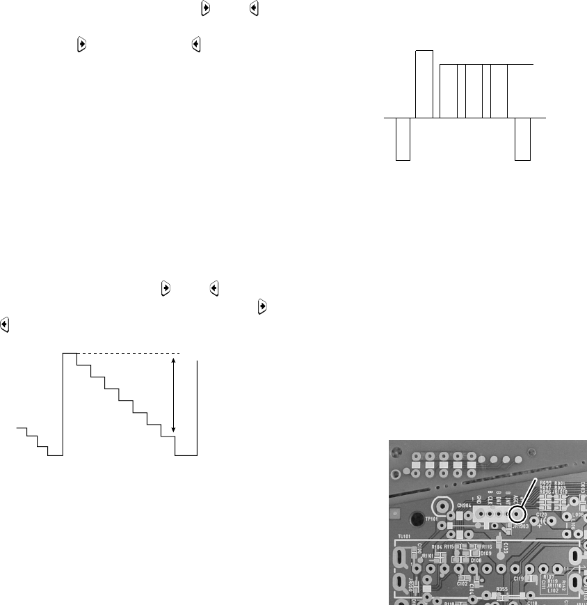
3-9. TUNER AGC ADJUSTMENT
Note: There should be no need to adjust the AGC as this
is pre-adjusted during manufacturing. If the AGC
does need adjustment then follow steps 1 to 4 as
below.
1. Receive a signal of 61dBuV/75ohm terminated via the
tuner antenna socket.
2. Connect a voltmeter to the AGC pin 5 of CN904 (mount
side of A board).
3. Confirm that the AGC voltage is 3.2volts +/–0.5volts.
4. If adjustment is required, then re-adjust the AGCT in
service menu to obtain a voltage of 3.2V +/–0.5V.
B-Out Waveform
same level
PIN 5
[ Print side of A board ]
VR = 1.38 ± 0.03 Vp-p
(Difference is within 30mV)
– 26 –
KV-14CT1B/14CT1U/14CT1E/14CT1K
RM-W100
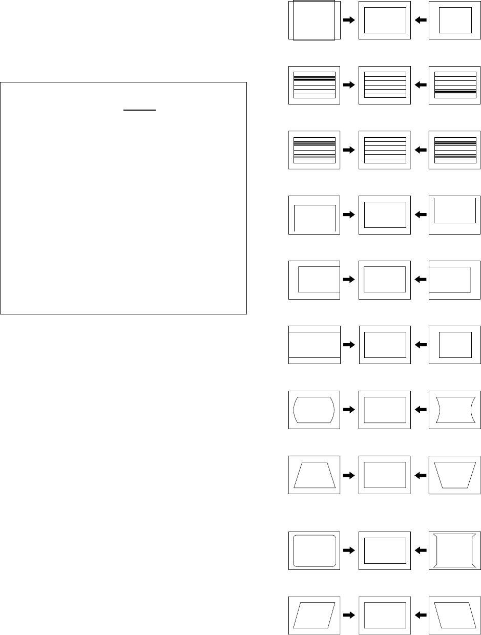
3-10. DEFLECTION ADJUSTMENT
1. Set the TV mode to normal (4:3).
2. Enter into the 'GEOMETRY' service menu.
3. Select and adjust each item in order to obtain the
optimum image. (see table below)
4. Repeat the above for 16:9.
GEOMETRY
Remark
HPOS (0,63) Adj Horizontal Shift
HPAR (0,63) Adj Horizontal Parallelogram
HBOW (0,63) Adj Horizontal Bow
VLIN (0,63) Adj Vertical Linearity
VSCR (0,63) 31 Vertical Scroll
HSIZ (0,63) Adj EW Width
EWPW (0,63) Adj EW Parabola/Width
UCOP (0,63) Adj EW Upper Corner Parabola
LCOP (0,63) Adj EW Lower Corner Parabola
EWTZ (0,63) Adj EW Trapezium
VSLP (0,63) 31 Vertical Scope
VSIZ (0,63) Adj Vertical Amplitude
SCOR (0,63) Adj S-Correction
VPOS (0,63) Adj Vertical Shift
WBF (0,63) 06 Timing of Wide Blanking
WBR (0,63) 06 Timing of Wide Blanking
EW Width (HSIZ)
Vertical Amplitude (VSIZ)
EW Trapezium (EWTZ)
Horizontal Shift (HPOS)
Horizontal Parallelogram (HPAR)
EW Parabola/Width (EWPW)
EW Lower Coner Parabola (LCOP)
EW Upper Coner Parabola (UCOP)
Vertical Shift (VPOS)
Vertical Linearity (VLIN)
S-Correction (SCOR)
– 27 –
KV-14CT1B/14CT1U/14CT1E/14CT1K
RM-W100
SECTION 4
DIAGRAMS
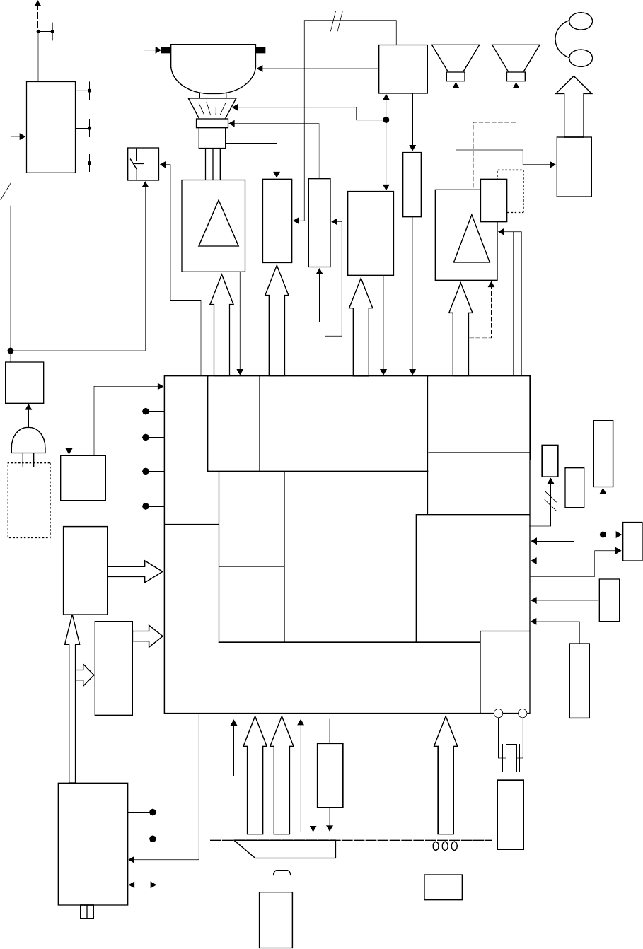
4-1. BLOCK DIAGRAM
(MONO MODELS)
FSS TUNER
SIF SAW
VIF SAW
POWER
Color
Decoder
ONE CHIP
Micro
Text
V-chip
YUV
Processor
RGB
Jungle
DAC
I/O port
VIF & SIF De-emphasis
PLL
A
D
C
RGB Amp
V-out
LED
B-INT
IIC Device
NVM
SIRCS
Key buttons
24.576MHz
Audio Amp
RGB
AV1
Front Input
AV2
IN
SCART 1
IN
AV2
FBT
feedback
Pin out
H-drive
H-out
Audio Amp
1ch
2ch
ATT HP
R
L
3W
(2 Spk model only)
3W
Rot. Cct*
DGC
HV
MAIN
Power
Supper
RGBout
EW, Hd
mute
stdby
Relay
+/-15V
1.8V
RESET
CISPR
IF
12C 5V 30V
STBY
3.3V 1.8V 5V 8V
DGC RELAY 115
3.3/5V
KR
KG
*Except 14"
Hout
KB
8V AUDIO VCC
+B line
30V
RGBout 85 ~ 87
IK 84
23.VD+
22.VD-
ROT CTRL 112
ROT SW 113
21.EWD
67.HOUT
66.AFC
32.EHTO
83.ABL
SCARTHPL 62
AUDIO MUTE 106
49.INL2
CV
Lout
TVout TVout
G
B
R
FBLK
R
L
CV
Mode 1
L
R
51.CVBS2/Y2
39. MONO OUTL
64.CVBS0
77.SCARTFBL
78~80.RGB3
53.INL3
55.CVBS3
116.Mode 1
31.AGCout
11.Xtalout
10.Xtalin
119.KEY
97.SIRCS
99.SDA1
108,109,SCLO,SDAO
102.B INT
122~3.RED LED,GREEN LED
AUDIO STBY 105
IK
V+, V-
On/Off
Hp
EHT, ABL
AGCin
AC in ~
220 ~ 240V 50Hz
– 28 –
KV-14CT1B/14CT1U/14CT1E/14CT1K
RM-W100
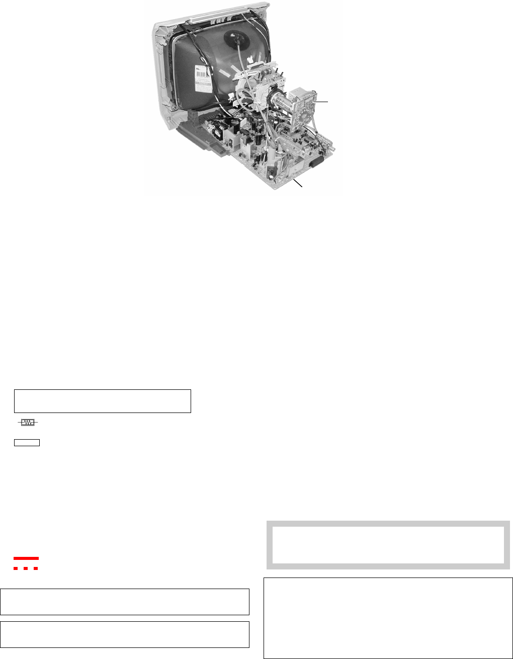
4-2. CIRCUIT BOARDS LOCATION
4-3. SCHEMATIC DIAGRAM
Note:
•All capacitors are in µF unless otherwise noted.
•All electrolytic capacitors are rated at 50V unless otherwise noted.
•All resistors are in ohms.
kΩ = 1000Ω, MΩ = 1000kΩ
•Indication of resistance which does not have rating electrical
power is as follows.
Pitch: 5 mm
Rating electrical power 1/4W (CHIP: 1/10W)
•: nonflammable resistor.
•¢: internal component.
•: panel designation or adjustment for repair.
•All variable and adjustable resistors have characteristic curve B
unless otherwise noted.
• Readings are taken with a color-bar signal input.
• Readings are taken with a 10 MΩ digital multimeter.
• Voltage are dc with respect to ground unless otherwise
noted.
• Voltage variations may be noted due to normal production
tolerances.
• All voltage are in Volt.
•✽: Cannot be measured.
• Circled numbers are waveform references.
• : B +bus.
• : B –bus.
• k: signal path.
Note: The reference number which starts with Wxxx
(eg: W003) indicates a wire to wire connection.
Note: Components marked as XX are not fitted on this
model.
Reference information
RESISTOR : RN METAL FILM
: RC SOLID
: FPRD NONFLAMMABLE CARBON
: FUSE NONFLAMMABLE FUSIBLE
: RS NONFLAMMABLE METAL OXIDE
: RB NONFLAMMABLE CEMENT
: RW NONFLAMMABLE WIREWOUND
: ✽ADJUSTMENT RESISTOR
COIL : LF-8L MICRO INDUCTOR
CAPACITOR : TA TANTALUM
: PS STYROL
: PP POLYPROPYLENE
: PT MYLAR
: MPS METALIZED POLYESTER
: MPP METALIZED POLYPROPYLENE
: ALB BIPOLAR
: ALT HIGH TEMPERATURE
: ALR HIGH RIPPLE
Note: The component identified by shading and mark
! are critical for safety. Replace only with part
number specified.
Note: “A” board schematic diagram is divided into 6 blocks.
Each block is named by its function and block “alphabet”.
eg: Processor (Block A)
Joint connection between boards can be identified using
the block alphabet followed by sequence numbering.
eg: -<HOUT-DEFL (A10) To D11
Meaning: Block A joint A10 is connected to Block D joint
D11
C board
A Board
– 29 –
KV-14CT1B/14CT1U/14CT1E/14CT1K
RM-W100
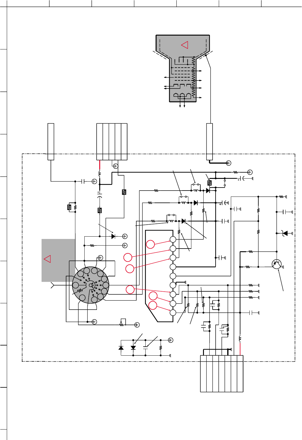
4-3-1. C Board Schematic Diagram
A
12345 6 7
B
C
D
E
F
G
H
I
J
2kV
4700p
E
C752
1000
B
C782
1
1P
CN705
GND
1SS133T-77
1SS133T-77
D780
D781
L750
XX
22uH
L780
Q701
XX
CHIP
XX
XX
R775
CHIP
XX
R777
R766
XX
R767
XX
R768
XX
R784
XX
R785
XX
R786
XX
UDZSTE-175.6B
D782
CHIP
CHIP
XX
R776
CHIP
XX
R778
250V
4.7
C754
JW702
XX
C759
XX
50V
CH
1
2
3
4
5
WHT
5P
CN703
200V
NC
GND
H1
NC
3
4
5
6
7
8
9
10
11
13
1GND
GND
1
J751
110M
RV750
XX
R760
1/2W
100
R763
1/2W
100
R764
1/2W
100
R765
1/2W
560k
R773
1/2W
1k
R756 1/2W
1k
R757
1/2W
1k
R758
D756
D755
HSS82-TJ
HSS82-TJ
HSS82-TJ
D754
R774
150
3W
RS
1/2W
100
R783
R713
0
C783
1000
B
1
CN704
1P
1000V
9
87
6
5
4
312
TDA6108A
IC751
B IN
G IN
R IN
GND
IK
VDD
R OUT
G OUT
B OUT
0.47
R794
GP08D
D750
1/2W
470k
R780
1/2W
FPRD
100K
R795
1
2
3
4
5
6
7
7P
CN701
WHT
GND
B
G
R
GND
1K
9V
1000
B
C786
C753
500V
1000p
C787
2W
R781
0.47
JW1781
5.0MM JW1782
5.0MM
5.0MM
JW1783
CHIP
680
R752
CHIP
680
R753
CHIP
680
R754
250V
10
C751
250V
4.7
C781
XX
C788
XX
XX
C790
C789
XX
L781
XX
XX
L782
L783
R-OUT
FV
RCV
B-BX1s11532-...-C..-14CT
SOCKET CRT
H
KG G2
CV KR G1 G4
HV
KB
PICTURE
TUBE
C
RGB AMP
To A Board
CN004
To A Board(Block D)
CN801
To G2
To Earth Coating Assy
RGB-OUT
IK-BUFFER
PROT
PROT
PROT
PROT
!
2
1
345
6
A34LRG70X
!
FPRD
FPRD
FPRD
A
123456789101112
13 14 15
B
C
D
E
F
G
H
I
J
KV-14CT1B/14CT1U/14CT1E/14CT1K
RM-W100
KV-14CT1B/14CT1U/14CT1E/14CT1K
RM-W100
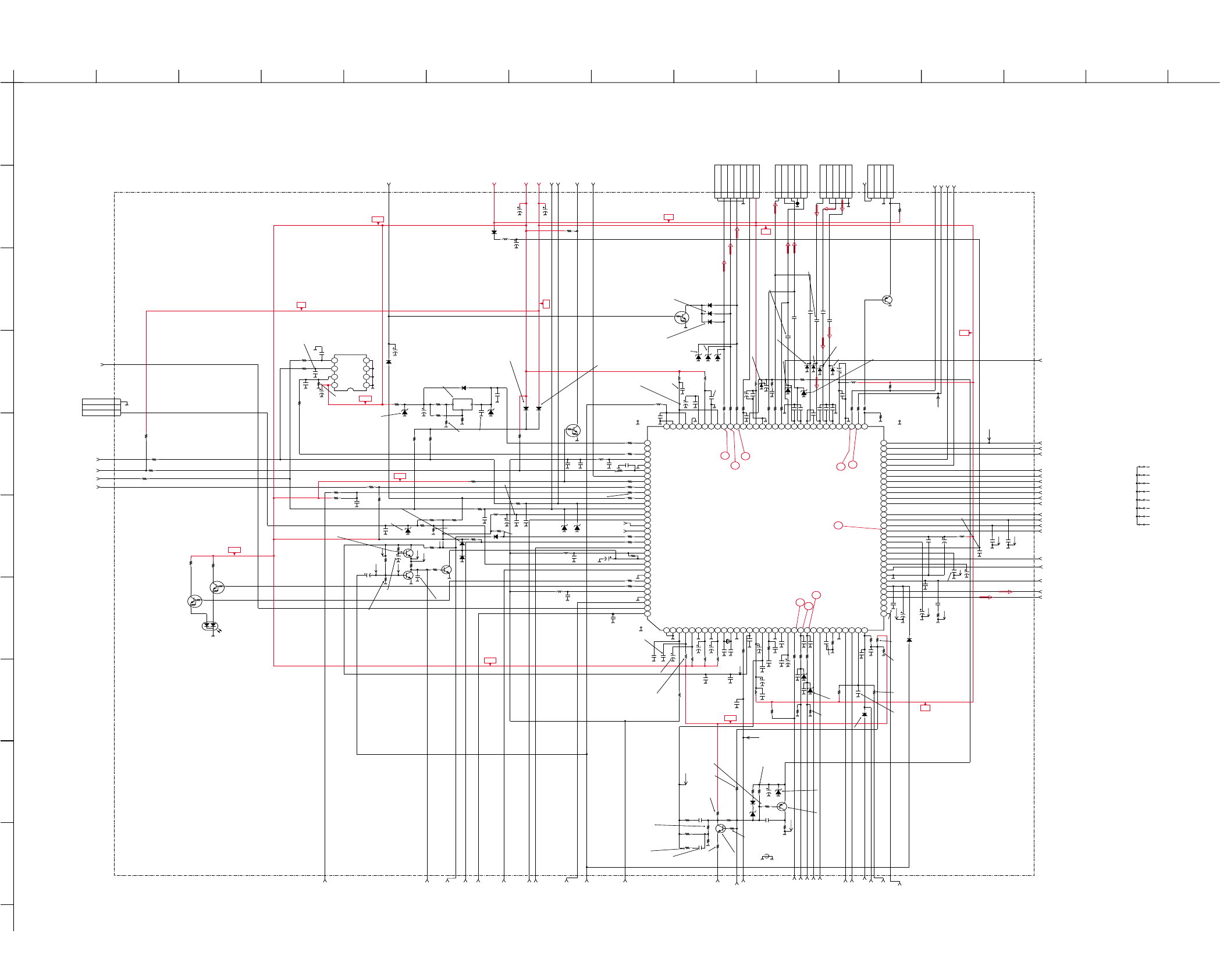
4-3-2. A Board – Processor (Block A)
– 31 –– 30 –
16V
0.1
B
C070
2.2
C073
16V
0.1
B:CHIP
C069
2.2
C064
XX
B
C061
16V
0.1
B
C063
16V
0.22
B:CHIP
B:CHIP
C019
16V
0.22
C022
22
C024
22
C029
22
C031
CHIP
100
R038
CHIP
100
R039
CHIP
100
R041 CHIP
100
R056 CHIP
100
R058
16V
0.1
B
C038
4.7
C037
CHIP
0
R356
16V
0.1
B
C054
UDZSTE-179.1B
D023
UDZSTE-179.1B
D024
UDZSTE-179.1B
D025
MMDL914T1
D059
MMDL914T1
D058
MMDL914T1
D057
16V
0.22
C030
35V
47
C026
16V
0.1
C028
16V
0.22
C025
10V
0.47
B:CHIP
B:CHIP
B:CHIP
B:CHIP
C023
4700
B
C041
16V
0.22
B:CHIP
C042
16V
0.22
B
C048
25V
0.022
B
C049 CHIP
100
R045
CHIP
100
R046
CHIP
100
R048
1000
B
C052 1000
B
C089
1000
B
C081
1000
B
C080
UDZSTE-175.6B
D065
UDZSTE-175.6B
D064
25V
0.01
B
C057
CHIP
680
R061
CHIP
100
R060
1000
B
C058
CHIP
1M
R312
CHIP
150k
R313
Q009
XX
MSD601-RT1
Q008
RN-CP
XX
R326
XX
B
C084
UDZSTE-175.6B
D062
XX
C079
CHIP
47k
R311
CHIP
1k
R310
UDZSTE-175.6B
D060
MMDL914T1
D061
RN-CP
XX
R327
CHIP
XX
R307
CHIP
XX
R308
CHIP
XX
R305
CHIP
XX
R306
CHIP
1M
R309
CHIP
2.2M
R303
CHIP
680k
R304
CHIP
XX
R302
CHIP
2.2M
R301
CHIP
100
R300 68p
CH
C078
16V
0.047
B
C077
470p
CH
C010
XX
B
C009
35V
47
C008
CHIP
R360
0
CHIP
R361
XX CHIP
R363
0
CHIP
R362
XX
CHIP
100
R331
CHIP
100
R323
CHIP
100R020
CHIP
100
R018
CHIP
100
R030
CHIP
100
R023
CHIP
100
R024
CHIP
100
R341
CHIP
100
R025
CHIP
100
R339
8765
4
3
21
CAT24WC16JI-TE13
IC003
100p
CH
C001
100p
CH
C003
CHIP
100
R002
CHIP
100
R004
16V
0.1
B
C092
16V
0.1
B
C093
16V
0.1
B
C094
16V
0.1
B
C095
16V
0.1
B
C096
G
R
SPB-25MVWF
D914
CHIP
220
R096
CHIP220
R097
CHIP
XX
R006
MMDL914T1
D003
MMDL914T1
D002
1
2
CHIP
2.2k
R012
100p
CH
C021
CHIP
10k
R010
16V
0.22
C014
16V
0.22
B:CHIP
B:CHIP
C018
25V
0.022
C325
CHIP
100
R014
16V
0.1
B
C020
CHIP
10k
R340
CHIP
2.2k
R324
CHIP
4.7k
R338
CHIP
470
R337
D067
XX
XX
RN-CP
4.7k
R320
100p
CH
C091
12
XX
B
C011
CHIP
100
R029
100p
CH
C090
RN-CP
4.7k
R322
16V
0.22
B
C012
CHIP
100
R026
1
2
3
WHT
3P
CN005
GND
NC
KEY
GP08D
D066
CHIP
R316
XX
MMDL914T1
D056
CHIP
4.7k
R001
CHIP
4.7k
R003
D004
XX
XX
F
C051
F
C068
XX
F
C071
XX
XX
F
C097
XX
F
C098
XX
F
C099
D006
XX
D007
XX
D008
XX
D009
XX
1
2
3
4
5
WHT
CN007
Y OUT
GND
U OUT / FB
GND
V OUT
1
2
3
4
CN003
WHT
+B
NC
GND
VM OUT
1
2
3
4
5
YEL
CN009
Y IN / G
GND
U IN / B
V IN / R
GND
JW1088
XX
JW1089
XX
JW1090
XX JW1091
XX
JW1092
XX JW1093
XX
JW1094
XX
JW1095
XX
2SIF
SIFIN2-IF
SIFIN1-IF
VIFIN2-IF
EWD-DEFL
OVP-DEFL
VD+-DEFL
VD--DEFL
VIFIN1-IF
+B
HOUT-DEFL
AFC-DEFL
LSL-AUDIO
TUAGC-IF
-13V-DEFL
ABL
AUDIO-STDBY
PWR-OFF-MUTE
DGC-RELAY
SCL-0
SDA-0
MOMUTE-AUDIO
M-SYS-IF
D1_JP/MODE1_EU
9V
3.3V
5V
AUDIO-MUTE
STBY_SW
VGUARD-DEFL
LSR-AUDIO
AGC-MUTE
S1/VC
C1
CVBS1/Y1
INR1
INL1
CVBS3
INR3
INL3
CVBS2/Y2
INR2
INL2
MON-OUT
IFVO/IF_MON_OUT
OUTR
PLLIF (A65) To E18
OUTL
D1_JP/MODE2_EU/
MONSW-MONO
SCARTHPL
SCARTHPR
CVBSO
10uH
L003
10uH
L005
10uH
L006
10uH
L007
10uH
L008
10uH
L009
MONO_OUTL
ROT_CTRL
ROT_SW
16V
0.22
B
C300
CHIP
XX
JR1010
MMDL914T1
D063
TP02
TP03 TP04
RN-CP
2.2K
R319
CHIP
2.2k
R042
XX
CH
C032 XX
CH
C034
VCC
GND
OUT
RPM7240-H5
IC002
470p
CH
C301
B_DAT
B_INT
B_CLK CHIP
220
R099
CHIP
10k
R355
16V
2.2
F
C302
CHIP
1k
R364
CHIP
0
JR1011
1.8V_AUDIO
1.8V_MAIN
W003
W004
W008
10uH
L012
UN2216
Q006
UN2216
Q007
CHIP
220
R087
CHIP
220
R098
D005
XX
CHIP
68k
R379
CHIP
100
R380
25V
0.01
B
C308
W009
W010
W011
25V
0.01
B
C072
16V
100
C004
XX
C309
CHIP
XX
R382
CHIP
12k
R044 25V
6800
B
C046
16V
2.2
C044
F
RN-CP
6.8k
R314
RN-CP
6.8k
R315
CHIP
100
R384
CHIP
100
R385
CHIP
100
R386
SCARTFBL/A16
RN-CP
39k
R051
16V
470
C002
16V
100
C304
16V
100
C036
16V
100
C056
16V
100
C005
16V
100
C006
CHIP
4.7k
R336
UDZSTE-175.6B
D068
UDZSTE-175.6B
D054
UDZSTE-175.6B
D055
0.15
C055
1
2
3
4
5
6
7
WHT
CN004
GND
B OUT
G OUT
R OUT
GND
IK
9V
470
C013
2.2
C311
XX
F
C314
R387
3.3
C065
1000
B
C312
1000
B
C313
RESET
W022
W015
D069
XX
XX
D070
25V
0.022
B
C053
XX
Q010
CHIP
XX
R059
CHIP
XX
R377
CHIP
R392
10k
CHIP
1.5k
R015
12345678910
11 12 13 14 15 16 17 18 19 20 21 22 23 24 25 26 27 28 29 30 31 32
33
34
35
36
37
38
39
40
41
42
43
44
45
46
47
48
49
50
51
52
53
54
55
56
57
58
59
60
61
62
63
64
6566676869707172737475767778798081828384858687888990919293949596
97
98
99
100
101
102
103
104
105
106
107
108
109
110
111
112
113
114
115
116
117
118
119
120
121
122
123
124
125
126
127
128
TDA11020H/NIA000AK
IC001
VSSP2
VSSC4
VDDC4(1.8V)
VDDA3(3.3V)
VREF_POS_LSL
VREF_NEG_LSL+LSR
VREF_POS_LSR+HPL
VREF_NEG_HPL+HPR
VREF_POS_HPR
XTALIN
XTALOUT
VSSA1
VGUARD
DECDIG
VP1
PH2LF
PH1LF
GND1
SECPLL
DECBG
EWD
VD-
VD+
VIFIN1
VIFIN2
VSC
IREF
GNDIF
SIFIN1
SIFIN2
AGCOUT
EHT0
AVL/2SIF
D1 LIN
D1 RIN
OUTL
OUTR
DECSDEM
MONO_OUTL
GND2
PLLIF
SIFAGC/SCART
IFVO/IF_MON_OUT
INTC0-IF
VCC8V
AGC2SIF
VP2
MON-OUT
INL2
INR2
CVBS2/Y2
C2
INL3
INR3
CVBS3
INL1
INR1
CVBS1/Y1
C1
LSL
LSR
SCARTHPL
SCARTHPR
CVBS0
VM
AFC
HOUT
VSSCOMB
VDDCOMB
VIN
UIN
YIN
YSYNC
YOUT
UOUT
VOUT
SCARTFBL
R-Y/RIN
Y/GIN
B-Y/BIN
GND3
VP3
ABL
IK
R OUT
G OUT
B OUT
VDDA(3.3V)
VREFAD_NE
VREFAD_PO
VREFAD
GNDA
VDDA(1.8)
VDDA2
VSSADC
VDDADC(1.8)
SIRSC
SCL1
SDA1
VDDC2
VSSC2
B INT
D1_JP/MODE2_EU/MONSW-MONO
MOMUTE-AUDIO
AUDIO STDBY
AUDIO MUTE
HD SW
SCL0
SDA0
VDDP(3.3V)
S1/VC(GA)
ROT CTRL
ROT SW
STBY_SW
DGC RELAY
D1_JP/MODE1_EU
VDDC1(1.8V)
DECV1V8
KEY
S2
VSSC1/P
RED LED
GREEN LED
VDDC3(1.8V)
VSSC3
AGC-MUTE
SECAM L-L
M-SYS-IF
24.5MHz
X001
MMDL914T1
D071
MMDL914T1
D072
10V
0.47
B
C316
UN2211
Q016
CHIP
4.7k
R394
47uH
L004
16V
220
C317
1.1uH
FB001
16V
100
C303
10
C050
16V
0.1
B
C318
CHIP
100
R393
47p
CH
C319
47p
CH
C320
CHIP
3.3k
R317
C015
UN2211
Q001
OCP-PROTECT
D073
XX
CHIP
100k
R395
10uH
L010
10uH
L011
10uH
L013
10uH
L031
10uH
L032
10uH
L033
10uH
L035
10uH
L036
10uH
L037
W030
W031
W032
W033 W034
MMDL914T1
D074
W037
Q012
Q013
XX
XX
XX
XX
XX
XX
XXXX
XX
MSD601-RT1
Q014
C315
C310
R381
R383
R388
CHIP
1k
R011
25V
0.01
B
C321
25V
0.022
C324
1000p
B
C322
W038 W039
0.001
B
C323
W042
W043
W044
S2
R391
B_DAT
B_INT
A
PROCESSOR (BLOCK A)
B-BX1s11532-...-A..(BLOCK A)-14CT
(A1) To B6
(A2)
(A3) To C1,D18
(A4) To C9,D12,E16,F1
(A5) To E14
(A6) To E15
(A7) To B8
(A8) To F25
(A9) To C11,D15,E11
(A10) To D11
(A11) To D2
(A12) To B3
(A13) To B2
(A15) To F17
(A16) To F18
(A17) To B1,F19
(A18) To F8
(A19) To F10
(A20) To F12
(A21) To F11
(A22) To F13
(A23) To F15
(A24) To F14
(A25) To F22
(A26) To F20
(A27) To F21
(A28) To F4
(A29) To E5
(A30) To F26
(A31) To F3
(A32) To F2
(A14) To F16
To E3(A33)
(A34)
(A35)
To D8(A36)
To E1(A37)
To E2(A38)
To E7(A39)
To E1 0
To D1 0
To E8(A40)
To D5(A41)
To D7(A42)
To D1(A43)
To D4(A45)
(A44)
To D6(A46)
TO C2
To B13,C10
To E12
To F2 4
To F23 (A51)
To F25 (A52)
To E9
To C15
To C13
To C3 (A56)
(A57)
To B7 (A58)
To F28 (A59)
To F29(A60)
To F27(A61)
SECAM L-L
To E6 (A62)
(A63)
(A64)
To D16
To D17
PP
To B9
(A55)
(A54)
(A53)
(A50)
(A49)
(A48)
(A47)
To B14,B4,C8,D14,E13,F6
To D3
To CN905
(Block F)
To CN701
(C Board)
XX XX
XX
XX
To Top Switch
NVM
PROTECTION
PROTECTION
PROTECTION
IC RECEIVER
3.3V POWER SUPPLY
5V POWER SUPPLY
1.8V DETECT
1.8V DETECT
RESET
ESD PROTECT DIODE
CLAMPING DIODE
CLAMPING DIODE
R LED SW
G LED SW
LED
R-MUTE
G-MUTE
B-MUTE
RGB-MUTE(SPOT)
PROTECTION
PROTECTION
VM BUFFER
PROTECTION PROTECTION
PROTECTION
PROTECTION
PROTECTION
SYSTEM CONTROLLER,
VIDEO PROCESSOR,
AUDIO PROCESSOR
GEOMETRIC CORRECTION
ABL
ABL
ABL BUFFER
SLICER
OCP
PROTECTION
PROTECTION
PROTECT
PROTECT
RELAY
PROT
12
3
4
5
6
7
8
9
TV-L
TV-R
V IN
U IN
Y IN
B
G
R
Y-OU T
V-OUT
U-OUT
Y-IN
U-IN
V-IN
3.3V 9V
5V
5V
5V
5V
3.3V
3.3V
3.3V
3.3V
3.3V
5V
25V
D075
UDZSTE-179.1B
A
123456789101112
13 14 15
B
C
D
E
F
G
H
I
J
KV-14CT1B/14CT1U/14CT1E/14CT1K
RM-W100
KV-14CT1B/14CT1U/14CT1E/14CT1K
RM-W100
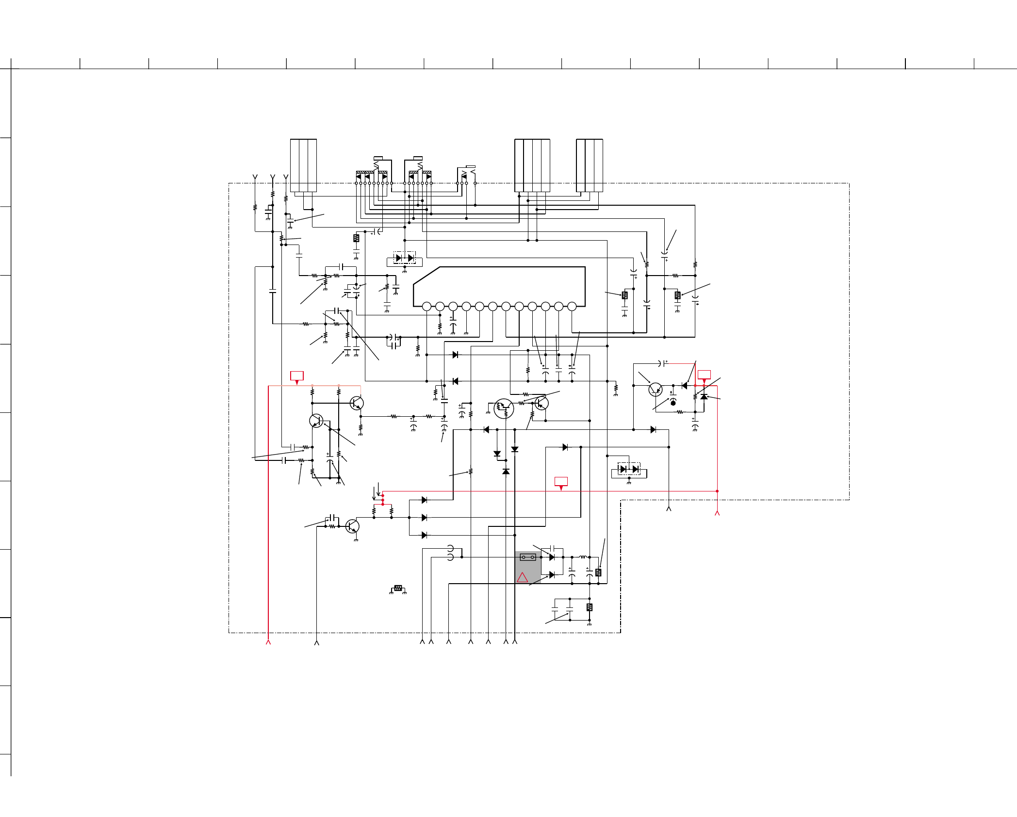
4-3-3. A Board – Audio (Block B)
– 33 –– 32 –
MSB709-RT1
Q202
CHIP
15k
R214 CHIP
1k
R221
MMDL914T1
D205
CHIP
10k
R216
MMDL914T1
D201 MMDL914T1
D204
MMDL914T1
D203
MMDL914T1
D202
CHIP
15k
R213
16V
220
C219
CHIP
0
R220
MSB709-RT1
Q201
D206
XX
C221
XX
25V
0.1
B:CHIP
C213 22
C218
XX
C229
CHIP
XX
R230
CHIP
XX
R229
CHIP
XX
R222
Q204
XX
CHIP
XX
R223
CHIP
XX
R224
CHIP
XX
R226
Q205
XX
XX
C225
CHIP
XX
R225
16V
XX
F
C226
16V
XX
F
C227
1
2
3
WHT
CN201
XX
3D OUT+
GND
GND/3D OUT-
D207
XX
MMDL914T1
D208
XX
C223 25V
1000
C217
25V
C212
1000
100
C210
PETP
0.047
C232
PT
XX
C230
CHIP
XX
R232
UN2211
Q200
CHIP
10k
R215
CHIP
0
R212
1
2
3
WHT
3P
CN202
SP
GND
GND
D209
XX
D210
XX
CHIP
XX
R238
To A2,B14,C8,D14,E13,F6 (B4) 9V
To F5 (B5) MON-MUTE-AUDIO
LSL-AUDIO (B2) To A13
LSR-AUDIO (B3) To A12
To A57 (B9) AUDIO-MUTE
To A58 (B7) AUDIO-STDBY
To A7 (B8) MOMUTE-AUDIO
To A1 (B6) PWR-OFF-MUTE
To A2,B4,C8,D14,E13,F6 (B14) 9V
SCARTHPL (B1)
25V
XX
C214
XX
C216
PT
XX
C231
CHIP
XX
R237
CHIP
XX
JR1256
470p
CH:CHIP
C234
XX
CH
C235
CHIP
100
R239
C215
XX
CHIP
10k
R236
81234 97
65101112
IC200
AN17804A
OUTC/NC
IN R/NC
RF
S_GND
IN L
IN C/NC
OUTL
MUTE
PW_GND
VCC
STBY
OUTR/NC
XX
FB2607
1.1uH
FB2602 5A
PS2601
500V
470p
B
C2631
1000
C2636
35V
1000
C2648
To C4 (B12) AUDIO_1
To C5 (B11) AUDIO_2
To C6 (B10) AUDIO_GND
JL217
CHIP
0
R218
S3L20UF4
D2625
330
R219
16V
XX
F
C224
XX
C228
CHIP
XX
R227
CHIP
XX
R228
FPRD
XX
R2645
FPRD
1
R2646
4.7
C211
XX
C236
J201
XX
2
7
3
5
1
4
9
6
8
1PS226-115
D211
D2626
XX
XX
C205
CHIP
XX
R201
CHIP
1.5k
R207
CHIP
XX
R208
CHIP
XX
R200
CHIP
XX
R202
XX
R211
CHIP
16V
0.22
B
C200
16V
F
C201
XX
1PS226-115
D200
10uH
L2601
1
2
3
4
WHT
CN200
XX
SP L
GND
GND
SP R
16V
XX
B
C202
16V
0.033
B
C203
XX
B
C208
J202
XX
2
3
1
4
2.2
C209
XX
C237
PT
CHIP
1.5k
R203
CHIP
6.8k
R205
CHIP
10k
R204
CHIP
22k
R210
CHIP
0
R240
330
R217
J200
JACK
1
2
3
4
5
6
7
47
R235
FPRD
R233
XX
XX
R234
FPRD
0.1
C204
MPS 16V
0.033
C206
B
XX
C207
C220
10
CHIP
2.2k
R241
CHIP
2.2k
R242
MMDL914T1
D212
MMDL914T1
D213
To A48,C10 (B13) 1.8V_AUDIO
FPRD
10k
R2647
W040
W041
UN2211
Q206
RN-CP
XX
R8016
16V
XX
F
C2649
D214
MMDL914T1
AUDIO(BLOCK B)
A
B-BX1s11532-...-A..(BLOCK B)-14CT
To A17,F19
To Speaker To Speaker
PROTECT
AUDIO AMP
MIXER
MIXER
AC MUTE
9V
9V 9V
C2602
470P
B:CHIP
C2601
XX
!
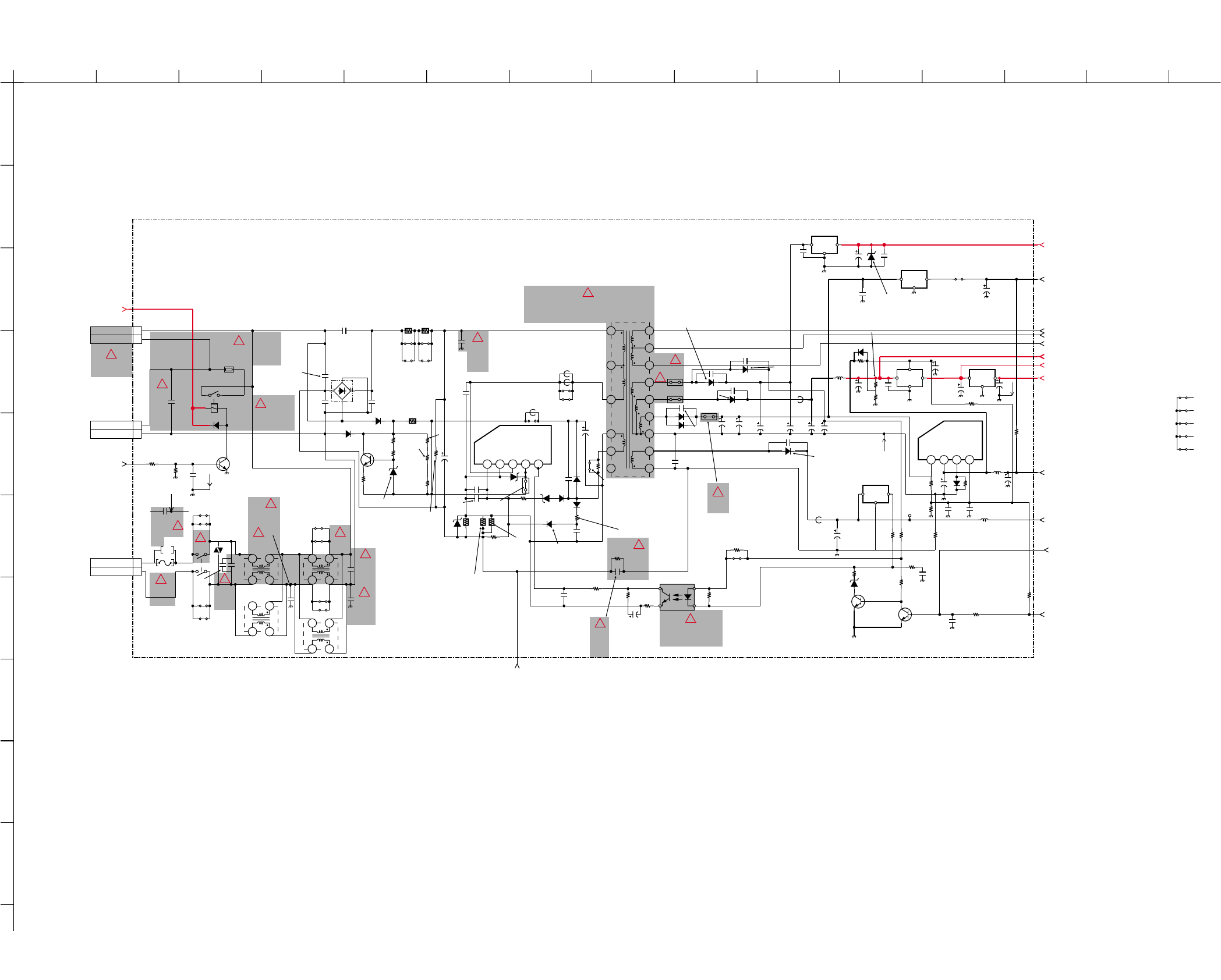
A
123456789101112
13 14 15
B
C
D
E
F
G
H
I
J
KV-14CT1B/14CT1U/14CT1E/14CT1K
RM-W100
KV-14CT1B/14CT1U/14CT1E/14CT1K
RM-W100
4-3-4. A Board – Power Supply (Block C)
– 35 –– 34 –
1
2
2P
CN602
AC IN
AC IN
MSD601-RT1
Q601
CHIP
10k
R602
CHIP
10k
R609
S600
XX
R618
RN-CP
XX
R623
XX
D615
470p
CH
C644
D1NL20U
D618
RN-CP
150k
R645
RN-CP
1.5k
R646
4.7
C621
CHIP
1k
R647
MSD601-RT1
Q608
MSD601-RT1
Q609
4.7k
R631 100V
XX
C646
XX
R640
RU4AM-T3
D621
500V
470p
B
C654
470
C635
500V
470p
B
C653
VCC
GND
OUT
BA033T
IC606 16V
100
C641
5A
PS602 500V
470p
B
C626
16V
470
C647
G
TA7805S
IC604
16V
100
C638
16V
100
C639
1.1uH
FB603
25V
470
C634
XX
D614
XX 1000
C650
500V
4700
E
C605
500V
4700p
E
C606
500V
4700
E
C609
500V
4700p
E
C610
RD5.1ESB2
D629
MMDL914T1
D600
CHIP
0
R625
JW1653
5
2.2k
R636
XX
FB601
220p
CH
C616
220
R621 XX
R633
1
2
2P
CN601
DGC
DGC
0uH
FB608
JW1603
XX
JW1604
XX JW1605
XX
JW1611
5
To A54 (C15) DGC-RELAY
+B (C11) To A9,D15,E11
3.3V (C1) To A3,D18
11V (C7) To C16,D13
5V (C9) To A4,D12,E16,F1
9V (C8) To A2,B4,B14,D14,E13,F6
To C7,D13 (C16) 11V
FH601 FH602
275V
MPS
0.22
C660
25V
XX
B
C661
XX
R653
XX
JW1654
W001
W002
JW1660
XX
JW1661
XX
PQ018EF01SZH
IC603
I O I O
G
PQ09RDISJ00H
IC602
D3SB60F3
D604
VDR600
2200
B
C623
To Heat Sink IC601 (C14) HS-A007
AUDIO_1 (C4) To B12
AUDIO_2 (C5) To B11
AUDIO_GND (C6) To B10
MPS
0.1
C666
RY600
16V
100
C649
35V
3300
C630
5A
PS603
16V
0.1
B
C662
CHIP
XX
JR1601
1.8V_MAIN (C2) To A47
1.8V_AUDIO (C10) To A48,B13
22uH
L602
16V
100
C668
CHIP
100
R655
XX
C669
1
R656
XX
JW1632
12
MPS
0.1
C602
RD5.1ESB2
D605
10MM
JW1662
10.MM
JW1663
THP600
FH603
250V
4700p
E
C600
PT
0.047
C619
35V
2200
C632
MTZJ-T-77-15
D633
S3L20UF4
D624
7
31 6
17
12
14
13
18
1
15
8
10
11
5
9
T602
D620
D639
XX
D3S6M-F
500V
470p
B
C652
5A
PS604
17.5
JW1665
CHIP
XX
R654
XX
R665
XX
R666
CHIP
33k
R668
XX
R669
250V
5A
F600
XX
JW1630
XX
JW1631
XX
JW1633
AM01AV1
D602
AM01AV1
D603
W018
FB605
XX
160V
330
C665
XX
FB610
250V
330p
B
C657 TP601
FN155
Q605
250V
330p
B
C670
XX
R651
11EQS10-TB5
D622
HOLD_DOWN (C12) To D9
JW1602
XX STBY_SW (C13) To A55
RD3.6SB
D635
25V
0.01
B
C672
W024
47uH
L600
47uH
L601
RN
XX
R660
RN
XX
R661
250V
330p
B
C625
250V
2200p
E
2W
RS
0.33
R620
2W
RS
0.33
R619
XX
C673
XX
B
C674
XX
220
C675
1W
8.2M
R650
RN
CHIP
4.7k
R634
450V
220
C611
XX
R672
CHIP
CHIP
10k
R635
16V
2.2
F
C678
XX
C679
D636
XX
1
2
2P
CN603
DGCT
DGCT
XX
JR1602
XX
R675
RN
560k
R658
RN
2.2k
R612
2.2
R627
RN
2.2k
R624
47
C624
1.5kV
MPS
680p
C612
2kV
1500p
C628
RN
680k
R659
470p
CH
C680
XX
JW1666
5
JW1667
5A
PS605
MA2ZD14001S0
D637
5
JW1092
5
JW1091
5
JW1088
JW1089
XX
5
JW1090
CHIP
1k
R667
16V
100
C637
C682
MMDL914T1
D638
14
T604
XX
14
T605
XX
10ERB20-TA2B5
D617
10ERB20-TA2B5
D619
10ERB20-TB3
D623
0.47
C643
B
VCC
GND
OUT
BA18BC0FP-E2
IC607
14
T600
14
T603
C685
C
OG
SE135N-LF38
IC605
PC123Y22JOOF
PH600
STR-F6267S LF1357
IC601
XX
R616
3.3
R639
SPARK GAP
SPARK GAP
SPARK GAP
SPARK GAP
3
3
3
3
2
2
2
2
12345 1234
POWER SUPPLY (BLOCK C)
A
PROTECT
RELAY SW
REG
PROTECTION
RECTIFY
RECTIFY
BUFFER
AC RECT
REG
REG
RECT
RECT
SWITCHING REG
20V RECT
20V RECT
11V RECT
+B RECT
PHOTO COUPLER
SW
SW
REG
ERROR-AMP
18 V REG
5V REG
9V REG
1.8V REG
ESD PROTECT
3.3V REG
!
16V
B-BX1s11532-...-A..(BLOCK C)-14CT
RELAY,AC POWER
THERMISTOR,POSITIVE
LFC LFC
VARISTOR
To DGC
To AC Power
10V
16V
CONVERTER TRANSFORMER(SRT)
10W
!
!
!
!
!
!
!
!
!
!
!
!
!!
!
!
C622
!
!
!
!
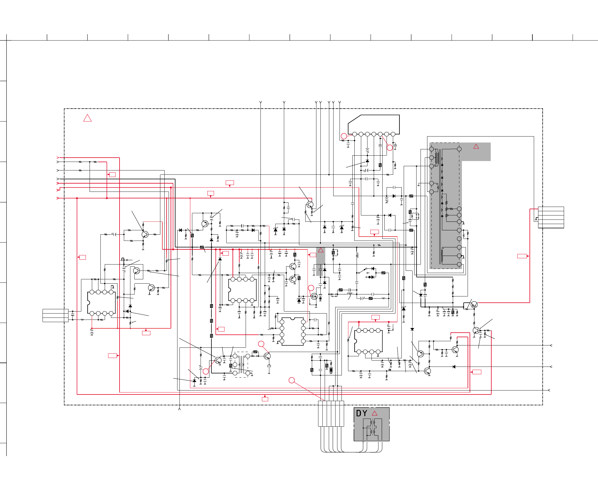
A
123456789101112
13 14 15
B
C
D
E
F
G
H
I
J
KV-14CT1B/14CT1U/14CT1E/14CT1K
RM-W100
KV-14CT1B/14CT1U/14CT1E/14CT1K
RM-W100
4-3-5. A Board – Deflection (Block D)
– 37 –– 36 –
XX
C817
CHIP
2.2k
R846
CHIP
0
R843
CHIP
0
R423
CHIP
10k
R847
CHIP
1k
R851
RN-CP
10k
R852
CHIP
2.2k
R861
CHIP
150k
R424
18k
R854
CHIP
3.3k
R853
CHIP
1k
R865
33k
R859
CHIP
100k
R866
10k
R856
CHIP
CHIP
CHIP
CHIP
5.6k
R864
CHIP
0
R872
CHIP
47k
R873
2200p
B
C839
MSB709-RT1
Q807
MSD601-RT1
Q806
FPRD
10
R868
1
R869
UDZSTE-179.1B
D815
S
IRF614-037
Q808
BY228/A52A/
D816
EGP20G
D817
S800
4.7mH
L803
35V
220
C855
MPS
0.47
C858
GP08D
D820
35V
25V
100
C854
2.2
R891
1/2W
FPRD
0.47
R400
500V
1000
B
C860
D824
25V
220
C857
1/2W
FPRD
0.47
R401
ELIZ
ELIZ
D823
500V
1000p
B
C862
25V
220
C861
CHIP
22k
R887
CHIP
10k
R421
CHIP
4.7k
R420
1000
B:CHIP
C845
16V
100
C828
CHIP
6.8k
R844
CHIP
0
R839
CHIP
27k
R838
1/2W
FPRD
0.47
R405
1/2W
150k
R833
CHIP
4.7k
R831
16V
100
C811
CHIP
33k
R824
1000
B:CHIP
C809
5
JW1837
12
1.1uH
FB800
500V
1000
B
C810
500V
220p
B
C808
1/2W
FPRD
2.2k
R830
2SC3209LK-TP
Q803
1000p
B:CHIP
C807
CHIP
22k
R821 1
C805
4700p
C837
CHIP
R803
C800
CHIP
R806
C803
CHIP
R805
CHIP
XX
R810
CHIP
XX
R816
CHIP
XX
R815
CHIP
XX
R817 XX
D801
CHIP
XX
R813
CHIP
XX
R812
CHIP
XX
R818
ELIZ
D827
500V
470p
B
C868
1/2W
FPRD
4.7k
R414
250V
33
C869
2.2mH
L805
C859
XX
C872
CHIP
R884
CHIP
XX XX
XX
XX
XX
XX XX XX
XX
XX
R886
C853
C856
CHIP
R892
XX
Q810
CHIP
R403
CHIP
R408
XX
C804
160V
33
C867
330k
R826
1W
RS
220
R871
1
2
3
4
5
6
6P
DY800
H+
H+
H-
H-
V-
V+
1SS133T-77
D804
1SS133T-77
D805
220p
CH
C832
25V
0.022
B
C826
16V
0.1
C833
XX XX
C818 16V
0.1
B:CHIP
B:CHIP
C831
16V
0.047
B
C844
C821
25V
0.01
B
C822
25V
0.01
B
C825
25V
0.01
B
C830
25V
0.01
B
C835
XX
C812
16V
B
XX
C813
16V
B
XX
C815
16V
B
XX
C829
16V
B
XX
C834
16V
B
D812
XX
XX
R841
CHIP
XX
R842
CHIP XX
R845
CHIP
XX
R848
CHIP
XX
100K
R857
CHIP
XX
R858
CHIP
XX
R402
2W
RS
1/2W
RN
68k
R411
XX
R419
RN
CHIP
10k
R876
XX
C816
XX
C864
500V
B
XX
C865
PT
XX
D800
8765
4
3
2
1
XX
IC800
47k
R888
CHIP
CHIP
R801
CHIP
R800
CHIP
XX
R814 1SS133T-77
D807
1SS133T-77
D809
1SS133T-77
D808
Q800
XX
Q801
MSD601-RT1
Q802
XX
Q809
MSD601-RT1
Q814
1
2
3
4
5
WHT
5P
CN801
XX
200V
NC
GND
H1
NC
1/2W
220k
R406
7.5
JW1834
XX
L804
12
FPRD
XX
R840
CHIP
XX
R425
To A4,C9,E16,F1 (D12) 5V
To C7,C16 (D13) 11V
(D14) 9V
To A9,C11,E11 (D15) +B
To A10 (D11) HOUT-DEFL
VD--DEFL (D7) To A42
VD+-DEFL (D5) To A41
ABL (D4) To A45
VGUARD-DEFL (D3) To A44
AFC-DEFL (D2) To A11
EWD-DEFL (D1) To A43
-13V-DEFL (D6) To A46
3W
RS
1k
R829
CHIP
R8003
To A63 (D16) ROT_CTRL
CHIP
XX
XX
XX
XX
XX
XX
XX
XX XX
XX XX
XX
R8004
To A64 (D17) ROT_SW
To A3,C1 (D18) 3.3V
XX
R8007
XX
R8008
CHIP
R8000
CHIP
R8001
25V
XX
B
C874
XX
Q816
CHIP
XX
R8002
OVP-DEFL (D8) To A36
MMDL914T1
D830
XX
CH
C875
CHIP
47k
R8011
CHIP
47k
R8012
CHIP
2.2k
R882
12.5
JW1839
HOLD_DOWN (D9) To C12
OCP-PROTECT (D10) To A35
1W
RS
XX
R422
XX
XX
XX
D828
L800
CHIP
R804
2W
RS
1.5
R827
2SC5885
Q805
1234567
STV9302A
IC804
DRV-IN
VCC (+13V)
F.B-PLS
VSS (-13V)
OUTPUT
VCC (OUT)
REF-VOLT
2SC3209LK
Q8010
CHIP
6.8k
R8009
1W
RS
1
R878
C866
FPRD
1.2K
R822
16V
0.047
B
C863
1/2W
150k
R835
CHIP
XX
R898
CHIP
XX
XX
XX
XX
R8014
1/2W
4.7k
R416
22mH
L802
8765
432
1
TJM4558CDT
IC802
RN-CP
XX
R8015
TH800
XX
UDZSTE-175.6B
D829
200V
PT
0.022
C806
200V
PT
0.01
C848
200V
PT
0.022
C849
XX
D826
250V
PP
0.15
C841
250V
PP
0.27
C852
100V
PT
0.1
C838
100V
PT
0.1
C850
2kV
330p
C846
10ERB20-TB3
D819
10ERB20-TB3
D821
400V
PP
0.033
C842
2SA1091-0
Q804
2SA1091-0
Q8009
3W
RS
1.5k
R825
3W
RS
1.5k
R828
XX
D831
RN-CP
RN-CP
6.8k
R893
CHIP
6.8k
R881
2.2k
R895
CHIP
2.2k
R870
8765
4321
LM2903DT
IC801
W019
5
JW1840
7.5
JW1841
10
JW1842
XX
R896
XX
L806
1000
C876
0.01
B:CHIP B:CHIP
B:CHIP
C877
0.01
C878
XX
B
C879
W025
W026
220P
C836
RN
R897
R894
RN-CP
RN-CP
R899
1.2kV
0.011
C840
PP
120k
R8010
RN
100k
R8013
RN
RN
180k
R823
RN
180k
R834
220k
R879
220k
R880
RN
R417
100k
R877
C870
200V
PT
0.01
C847
FV
11
13
HV
2
SV
4
1
10
9
8
7
5
6
T802
1
2
3
3P
CN800
RED
NS-
NC
NS+
8765
4321
XX
IC803
CHIP
R802
CHIP
XX
R807
CHIP
XX
R808
CHIP
XX
R809
CHIP
XX
R8005
CHIP
2.2k
R820
3W
RS
68
R890
2.2k
R883
450V
1
C851
4
2
1
36
T800
RD5.1ESB2
D818
RN
33k
R413
3`W
RS
100
R889
CHIP
R855
0.015
C882
RN
68k
R412
To NS COIL
A
DEFLECTION (BLOCK D)
B-BX1s11532-...-A..-(BLOCK D)-14CT
CHL
H.DY H.DY V
.DY V
.DY
!
!
!
To A2,B14,B4,C8,E13,F6
To DY
To CN703
(C Board)
PIN DRIVE
BUFFER
BUFFER
STOPPER
STOPPER
ROTATION
AMP
STOPPER
STOPPER
STOPPER
STOPPER
COMPARATOR
H-DRIVE
PROTECT
H-OUT
PIN AMP
PROTECT
PIN-DRIVE
PIN-DRIVE
STOPPER
PROTECTOR
CLAMP
V-OUT
V-DRIVE
H-CENT 1
STOPPER
SWITCH
BUFFER
MIXER
MIXER
SWITCH
CLAMPER
H-OUT
H-CENT1
RECT
CLAMPER
10
11
12
13
14
15
3.3V
3.3V
9V
11V
9V
5V
5V
5V
5V
9V
11V
11V
11V
200V
HDT
NX-4450//M3A4
!
B
2KV
200V
PT

A
123456789101112
13 14 15
B
C
D
E
F
G
H
I
J
KV-14CT1B/14CT1U/14CT1E/14CT1K
RM-W100
KV-14CT1B/14CT1U/14CT1E/14CT1K
RM-W100
4-3-6. A Board – Tuner (Block E)
– 39 –– 38 –
D102
XX
XX
XX
C116
22
C118
UPC574J
D103
4700p
B
C109
16V
470
C107
CHIP
XX
R118
CHIP
0
R154
CHIP
XX
R100
CHIP
100
R115
CHIP
100
R116
1000p
B
C100
C129
XX
16V
B
XX
R104
CHIP
XX
R141
CHIP BPF
G
IO
CF100
XX
12
3
JR1101
0
CHIP XX
B
C111
XX
L102
Q102
XX
CHIP
XX
R106
CHIP
XX
R107
XX
B
C115
XX
L101
CHIP
XX
R110
XX
L103
XX
Q100
JR1100
16V
470
C108
To A37 (E1) SIFIN2-IF
To A38 (E2) SIFIN1-IF
To A62 (E6) SECAM-L-L
To A39 (E7) VIFIN2-IF
To A40 (E8) VIFIN1-IF
To A53 (E9) M-SYS-IF
To A34 (E10) TUAGC-IF
To A9,C11,D15 (E11) +B
To A2,B14,B4,C8,D14,F6 (E13) 9V
To A5 (E14) SDA-0
To A6 (E15) SCL-0
To A4,C9,D12,F1 (E16) 5V
To A33 (E3) 2SIF
To A49 (E12) AGC-MUTE
To A29 (E5) IFVO/IF_MON_OUT
CT139
XX
3W
RS
22k
R121
CHIP
100
R150
To F7 (E4) IFVO
CHIP
XX
R151
CHIP
XX
JR1109
1
TP101
XX
CHIP
XX
JR1110
RN-CP
XX
R108
CHIP
XX
R109 XX
CH
C117 XX
R126
CHIP
XX XX
L105
RN-CP
XX
R119
SWF101
1
2
3
4
5
SWF102
1
2
3
4
5
XX
R123
CHIP
I
GGO
O SWF100
AGC
AS
CLOCK
DATA
5V
33V
IF OUT
TU101
16V
470
C120
XX
C106
XX
L100
0.01
B:CHIP
C119
To F30 (E17) TU-AGC
16V
XX
C101
CHIP
7.5k
R152
47uH
L106
MMDL914T1
D107
CHIP
XX
JR1108
47p
CH
C102 47p
CH
C104
0.01
B
C112
XX
D101
XX
L104
XX
Q105
XX
Q106
CHIP
R122
CHIP
XX
XX
XX
R124
CHIP
R125 CHIP
R128
CHIP
XX
R142
CHIP
XX
JR1107
XX
R130
CHIP
1000p
B
C136
1000p
B
C137
UDZSTE-175.6B
D108
UDZSTE-175.6B
D109
2.2
C1233
25V
0.01
B
C139
W045
W046
A
TUNER (BLOCK E)
*
FILTER SURFACE WAVE FILTER SURFACE WAVE *
B-BX1s11532-...-A..(BLOCK E)-14CT
REGULATOR
BUFFER
SWITCH
FILTER
SWITCH
DIODE
AMP
SELECTOR
DIODE
5V
9V
33V
9V
9V
390
R088
CHIP
To A65 (E18) PLLIF
B
C070
0.1
16V
A BOARD ✽ MARK LIST
KV-14CT1B KV-14CT1E KV-14CT1K KV-14CT1U
SWF102 Filter Surface Wave XX XX XX
TU101 BTP-AC421 BTP-AC421 BTP-AC421 BTP-AU621
Note: The parts indicated as "XX" in this circuit diagram are
not listed here, as they are not used for these models.
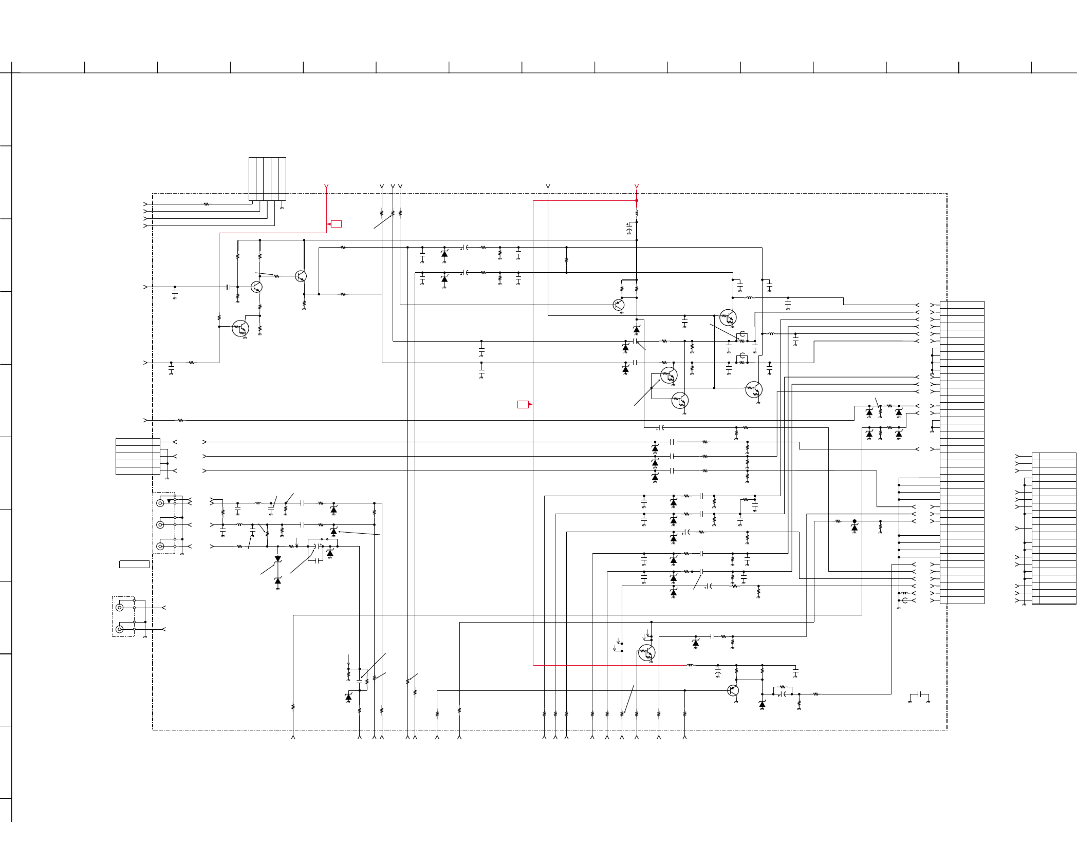
A
123456789101112
13 14 15
B
C
D
E
F
G
H
I
J
KV-14CT1B/14CT1U/14CT1E/14CT1K
RM-W100
KV-14CT1B/14CT1U/14CT1E/14CT1K
RM-W100
4-3-7. A Board – Jack, Scart Terminal (Block F)
– 41 –– 40 –
D912
D903 16V
1
F
C908
CHIP
75
R922
C952
0.1
16V
B
UDZSTE-175.6B
D904
XX
C921
470p
CH
C940
XX
F
C919
CHIP
75
R930
D916
XX
UDZSTE-175.6B
UDZSTE-175.6B
UDZSTE-175.6B
D913
UDZSTE179.1B
D928
CHIP
75
R928
UN2216
Q909
CHIP
XX
R9005
CHIP
75
R929
D917
XX
D911
CHIP
220k
R921
CHIP
470k
R967
UN2216
Q908
470p
CH
C947
CHIP
XX
R941
CHIP
39k
R908
CHIP
470
R993
(F25) D1_JP/MODE2_EU/MONSW-MONO
To 27 (F21) INL2
To A26 (F20) INR2
To A14 (F16) SCARTFBL/A16
To A25 (F22) CVBS2/Y2
To A18 (F8) C1
MON-MUTE-AUDIO (F5) To B5
To A23 (F15) INR3
To E4 (F7) IFVO
MON-OUT (F4) To A28
OUTR (F3) To A31
5V (F1) To A4,C9,D12,E16
9V (F6) To A2,B4,B14,C13,D14,E13
B-Y/BIN
To A20 (F12) INR1
To A17,B1 (F19) SCARTHPL
To A16 (F18) SCARTHPR
To A21 (F11) INL1
R-Y/RIN
TO A19 (F10) CVBS1/Y1
OUTL (F2) To A32
To A22 (F13) CVBS3
Y/GIN
To A24 (F14) INL3
CHIP
100
R9021
CHIP
100
R9023
To A15 (F17) CVBSO
To A51 (F9) S1/VC
CHIP
XX
R9038
CHIP
0
R9039
To A30 (F26) MONO_OUTL
CHIP
100
R9035
CHIP
100
R9034
To A50 (F24) D1_JP/MODE1_EU
16V
0.1
B
C953
UN2211
Q912
CHIP
1M
R9040
CHIP
1M
R9041
CHIP
3.3k
R9042
CHIP
1k
R9043
CHIP
100
R9045
CHIP
2.2k
R9046
CHIP
10k
R9047
D920
UDZSTE-175.6B
D927
UDZSTE-175.6B
Q903
MSB709-RT1
R947
33k
CHIP
R949
10k
CHIP
R954
1k
CHIP
R957
75
CHIP
L901
3.9uH
JR1901
0
CHIP
L
R
V
J903
XX
16V
XX
C903
B
C905
XX
XX
C906
XX
F
C907
16V
XX
F
C909
XX
CH
C910
XX
CH
C911
XX
CH
C922
XX
CH
C925
XX
CH
C939
XX
CH
C946
D900
XX
D901
XX
D905
XX
UDZSTE-175.6B
UDZSTE-175.6B
D902
D906
XX
D907
XX
D908
XX
D910
XX
D922
XX
D923
XX
D929
XX
XX
FB901
JR1902
0
CHIP
XX
Q900
Q901
XX
Q902
XX
CHIP
XX
R902
CHIP
XX
R904
CHIP
XX
R905
CHIP
XX
R906
CHIP
XX
R910
CHIP
XX
R907
CHIP
XX
R909
CHIP
XX
R913
CHIP
XX
R914
CHIP
XX
R924
CHIP
XX
R915
CHIP
XX
R916
CHIP
XX
R920
CHIP
XX
R923
CHIP
XX
R917
CHIP
XX
R919
CHIP
XX
R932
CHIP
XX
R933
R948
XX
CHIP
CHIP
XX
R970
CHIP
XX
R992
CHIP
XX
R9014
CHIP
XX
R9016
CHIP
XX
R9017
CHIP
XX
R9018
CHIP
XX
R9019
CHIP
XX
R9020
CHIP
XX
R9022
CHIP
XX
R9028
CHIP
XX
R9030
CHIP
XX
R9031
R950
XX
CHIP A1
A2
A3
A6
A7
A8
A11
A15
A16
A19
A20
B1
A2
B2
B3
B1
A2
B2
B3
A6
B6
A7
A6
B6
A7
A8 A8
B8 B8
A11 A11
A19
B19
A20 A20
B19
A19
A16
B15
A15
B20 B20
A1 A1 A1
B1
A2
B2
A3
B3
A4
A5
A6
B4
B5
B6
A7
B7
A8
B8
A9
B9
A10
B10
A11
B11
A12
B12
A13
B13
A14
B14
A15
B15
A16
B16
A17
B17
A18
B18
A19
B19
A20
B20
A21
B21
CN901
XX
R OUT 1
R IN 3
L OUT 1
GND
GND
L IN 3
BY
MODE 1
GND
AV L
Y
NC
GND
GND
RY
BLK
GND
GND
V OUT TV
V IN 3
GND
R OUT 2
R IN 1
L OUT 2
GND
GND
L IN 1
NC
MODE 2
GND
AV L
NC
NC
GND
GND
C2 IN
NC
GND
GND
V OUT MON
V IN 1
GND
A3 A3
B15
A16
A15
To A60 (F29) B_INT
To A59 (F28) B_DAT
To A61 (F27) B_CLK
A21
B21 B21
A21
A21
CHIP
XX
R931
F1
F3
F4
F2
F1
F2
F3
F4
CHIP
XX
R9050
CHIP
0
R9051
CHIP
0
R9052
16V
1
F
C918
UDZSTE-175.6B
D915
CHIP
220k
R940
V
J909
F2
F3
UDZSTE-175.6B
D918
CHIP
75
R9053
5
JW1901
CHIP
0
R943
CHIP
470
R9044
1
2
3
4
5
6
7
8
9
10
11
12
13
14
15
16
17
18
19
20
21
21P
CN902
R OUT 1
R IN 3
L OUT 1
GND
GND
L IN 3
BY
MODE 1
GND
AV L
Y
NC
GND
GND
RY
BLK
GND
GND
V OUT TV
V IN 3
GND
CHIP
0
JR1903
To E17 (F30)TU-AGC
CHIP
XX
R9056
16V
100
C956
CHIP
100
R9025
MSD601-RT1
Q911
MSD601-RT1
Q910
XX
C902
XX
B
C957
0.22
C904
16V
0.22
C955
B
47uH
L902
CHIP
XX
JR1905
1
2
3
4
5
WHT
5P
CN904
GND
B CLK
B DAT
B INT
AGC
D921
XX
1uH
L903
1uH
L904
XX
FB902
XX
FB903
CHIP
100
R925
CHIP
100
R926
CHIP
100
R927
16V
0.1
C060
B
16V
0.1
C062
B
16V
0.1
C067
B
1
2
3
4
5
YEL
XX
CN905
Y OUT
GND
U OUT / FB
GND
V OUT
Y/GIN
R-Y/RIN
B-Y/BIN
XX
CH
C958
XX
CH
C959
XX
CH
C960
XX
CH
C961
XX
CH
C962
XX
CH
C963
XX
CH
C964
XX
CH
C965
1uH
L905
1uH
L906
16V
2.2
F
C967
CHIP
XX
R911
CHIP
47
R918
CHIP
10k
R945
CHIP
XX
R946
CHIP
27k
R9027
CHIP
XX
R9026
1000p
B
C972
XX
CH
C968
XX
CH
C969
XX
CH
C970
XX
CH
C971
W028
10
C973
XX
C974
330p
CH
C915
XX
F
C900
XX
F
C901
XX
CH
C912
XX
CH
C913
XX
CH
C914
XX
CH
C916
W035
0.001
B
C975
To A52 (F23) S2
CHIP
100
R9037
UDZSTE-175.6B
D930
330p
CH
C917
XX
C061
CHIP
100
R9057
CHIP
0
R9036
1k
R9062
UN2211
Q913
W016
W017
W047
W048
CHIP
100
R9013
L900
10uH
R953
470k
CHIP
R951
75
CHIP
R952
1k
CHIP
C923
47
16V
470
C976
XX
JR1906
R2
L2
VIDEO 2
VIDEO IN 2
L
To A 8
A
JACK (BLOCK F)
B-BX1s11532-...-A..(BLOCK F)-14CT
To Bus Connector
5V
9V
AMP
AMP GAIN ADJUST
AUDIO MONO BUFFER
PROTECT
PROTECTION
PROTECTION
PROTECTION
PROTECT
SWITCHING
TRANSISTOR
MONITOR OUT BUFFER
PROTECTION
PROTECTION
PROTECTION
PROTECTION
PROTECTION
PROTECTION
PROTECTION
PROTECT
PROTECT
PROTECTION
PROTECTION
AUDIO MUTE
PROTECT
PROTECT
PROTECT
35V
D931
RD3.6SB
D932
RD3.6SB
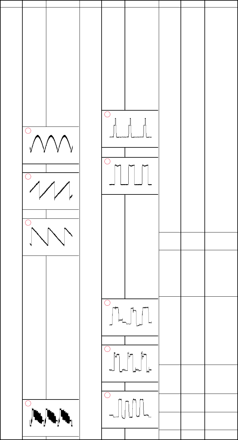
– 42 –
KV-14CT1B/14CT1U/14CT1E/14CT1K
RM-W100
Ref Pin No. Voltage[v]
IC001 1 0
20
3 2.0
4 3.3
5 3.3
60
7 3.3
80
9 3.3
10 –
11 1.5
12 0
13 0.1
14 2.5
15 0
16 1.8
17 2.3
18 0
19 2.3
20 2.3
21 4.0
820.0mVp-p
1
22 1.7
1.76Vp-p
2
23 1.8
1.92Vp-p
3
24 2.0
25 2.0
26 2.4
27 0
28 0
29 0.2
30 0.2
31 4.8
32 0.5
33 0
34 0
35 0
36 2.4
37 0
38 2.2
39 2.4
40 0
41 0
42 0
43 0.5
44 0
45 8.5
46 2.8
47 0
48 1.3
1.96Vp-p
4
Ref Pin No. Voltage[v]Ref Pin No. Voltage[v]
A BOARD VOLTAGE LIST AND WAVEFORM
49 2.2
50 2.2
51 1.4
52 0
53 2.2
54 2.2
55 0
56 2.2
57 2.2
58 1.4
59 1.6
60 2.3
61 0
62 0
63 2.4
64 1.3
65 0.4
66 0.7
5.36Vp-p
5
67 1.4
3.12Vp-p
6
68 0
69 4.9
70 1.3
71 1.3
72 1.3
73 2.0
74 1.8
75 0.1
76 0
77 0
78 1.3
79 1.3
80 1.3
81 0
82 4.9
83 0
84 3.2
85 0
1.54Vp-p
7
86 1.7
1.40Vp-p
8
87 1.1
1.46Vp-p
9
88 3.3
89 0
90 3.3
91 0
92 0
93 1.7
94 3.3
95 0
96 1.7
97 3.2
98 0.7
99 0.7
100 2.0
101 3.3
102 0.02
103 0.02
104 3.0
105 2.7
106 0.01
107 3.3
108 0.08
109 3.3
110 3.3
111 1.05
112 0.5
113 0
114 2.0
115 0
116 0
117 2.0
118 2.0
119 0
120 2.0
121 0
122 0
123 3.3
124 0
125 0
126 3.3
127 3.4
128 3.3
IC002 VCC 113
OUT 110
GND 10.9
IC003 1 0
20
30
40
5 2.6
60
70
8 3.3
IC200 1 0.0
2 0.0
3 19.7
4 0.0
5 0.0
6 0.0
7 0.0
8 10.7
90
10 0.80
11 0
12 9.6
IC601 1 3.06
2 20.5
3 0.03
4 0.05
5 0.50
IC602 I 10.2
G0
O -9.02
IC604 I 4.96
G0
O -9.02
IC800 1 5.7
4-4. VOLTAGE MEASUREMENT & WAVEFORM
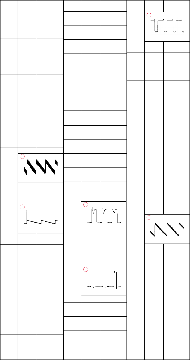
– 43 –
KV-14CT1B/14CT1U/14CT1E/14CT1K
RM-W100
A BOARD VOLTAGE LIST AND WAVEFORM
Ref Pin No. Voltage[v]Ref Pin No. Voltage[v]Ref Pin No. Voltage[v]
2 5.09
3 5.09
40
5 4.6
6 4.6
7 4.6
8 10.2
IC801 1 2.0
2 0.8
3 1.5
40
5 2.7
6 2.0
7 6.0
8 9.0
IC802 1 3.0
2 3.2
3 3.2
40
5 3.0
6 3.0
7 4.0
8 9.1
IC803 1 0
20
30
40
50
60
70
8 10.3
IC804 1 0.41
680.0mVp-p
15
2 12.3
3 -12.3
4 -13.3
5 20.1
53.6Vp-p
14
6 13.04
7 0.42
PH600 1 23.8
2 22.8
30
4 2.7
Q001 B 0
C 2.2
E0
Q006 B 0
C0
E0
Q007 B 0
C 3.34
E 1.0
Q008 B -0.28
C0
E0
Q009 B 0
C0
E0
Q012 B 0.6
C0
E0
Q105 B 3.6
C0
E0
Q106 B 0
C 4.2
E 4.8
Q200 B 1.9
C0
E0
Q201 B 20.2
C 20.9
E 20.9
Q202 B 9.0
C 0.1
E 8.9
Q205 B 2.7
C 5.5
E0
Q601 B 0.04
C 14.2
E0
Q605 B 24.8
C 219
E 23.5
Q608 B 0
C 20.2
E0
Q609 B 0.62
C0
E0
Q800 B 1.8
C 9.0
E 1.15
Q801 B 0.42
C0
E0
Q802 B 0
C 4.6
E0
Q803 B 0
1.38Vp-p
12
C 6.21
E0
Q804 B 133.7
C0
E 133.6
Q805 B 0
C 137.4
312.0Vp-p
11
E0
Q806 B 5.8
C 9.0
E 5.6
Q807 B 6.0
C0
E 5.6
Q808 S 0
9.400V
13
G 5.6
D 10.05
Q814 B 0
C 5.0
E 0.1
Q900 B 4.7
C0
E 4.1
Q901 B 0.2
C0
E0
Q903 B 4.35
C0
E 4.9
Q908 B 0.2
C 0.6
E0
Q909 B 0
C 0.2
E 0.6
Q910 B 2.43
C 4.7
E 4.10
Q911 B 2.43
C 4.7
E 4.2
Q912 B 0.07
C 0.6
E0
Q8009 B 194.5
C 194.5
E 194.7
Q8010 B 0.54
C0
E0
DY800
1.36Vp-p
10
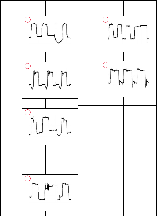
– 44 –
KV-14CT1B/14CT1U/14CT1E/14CT1K
RM-W100
C BOARD VOLTAGE LIST AND WAVEFORM
Ref Pin No. Voltage[v]Ref Pin No. Voltage[v]
IC751 1 1.8
940.0Vp-p
1
2 1.8
1.26Vp-p
2
3 1.8
1.34Vp-p
3
40
5 4.3
6 194.5
7 141.8
102.0Vp-p
4
8 141.8
100.0Vp-p
5
9 143.7
70.0Vp-p
6
Q701 B 4.35
C0
E0
J751 4 0.20
7 0.20
11 0.20
3 285.3
50
60
8 143.8
9 142.0
10 143.0
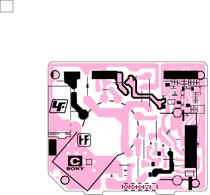
– 45 –
KV-14CT1B/14CT1U/14CT1E/14CT1K
RM-W100
200V
NC
NC
GND
H1
B
G
R
GND
1K
9V
1-688-692-12
(1-722-796-12)
B IN
G IN
R IN
GND
IK
VDD
R OUT
G OUT
B OUT
GND
KR
KG
G1-3
KB
G1-2
H2
H1
G1-1
G2
RCV
G4
1
3
456
7
8
9
10
11
13
GND
2
1
8
9
1
7
1
5
D750
D754
D755
D756
IC751
D781
J751
A701
A703 A705
RV750
L750
CN701
CN703
CN704
CN705
L780
L781
L782
L783
R756
R757
R758
R760
R763
R764 R765
R773
R774
R780
R781
R783
C751
C752
C753
C754
R794
R795
EY701
EY703
C781
C782
C787
JW1781
JW1782
D782
Q701
R713
R752
R753
R754
R766
R767
R768
R775
R777
R778
R784
C783
C786
C788
C789
C790
D780
R2
EY706
EY707 A704
A702
R785
R776
R786
C759
JW1750
C [RGB OUT]
PRINTED WIRING BOARDS
– C Board –
4-5. PRINTED WIRING BOARD & PARTS LOCATION
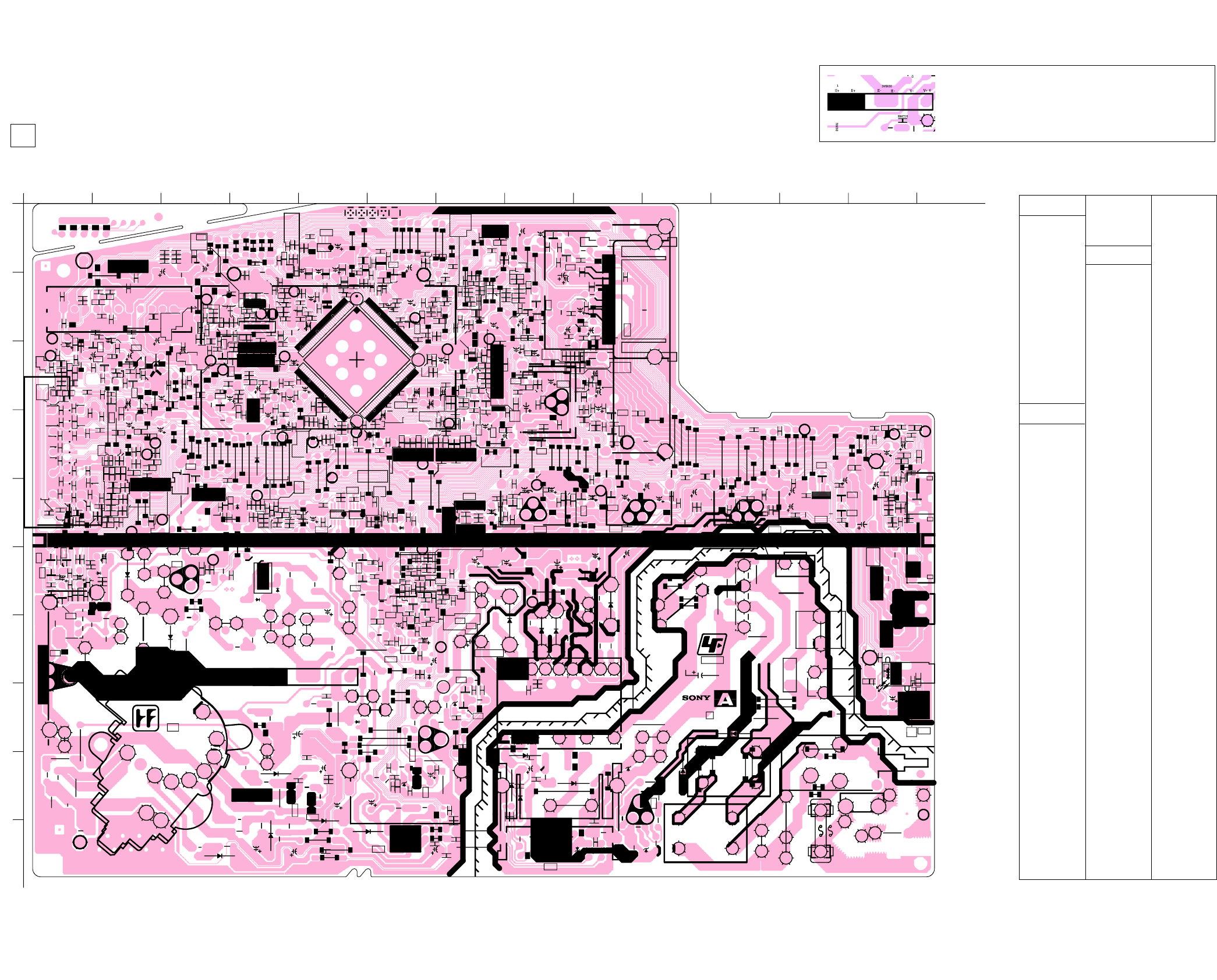
KV-14CT1B/14CT1U/14CT1E/14CT1K
RM-W100
KV-14CT1B/14CT1U/14CT1E/14CT1K
RM-W100
NOTE:
The circuit indicated at left contains high voltage of over
1220 Vp-p. Please pay attention when inspecting or
repairing it to prevent an electric shock.
A[PROCESSOR, AUDIO, POWER SUPPLY, DEFLECTION, TUNER, JACK, SCART TERMINAL]
– 47 –– 46 –
PRINTED WIRING BOARDS
– A Board –
R018
R400
R401
FB605
R402
R403
FB608
W030
R211
R405
W031
R212
R406
W032
R213
CN003
1
4
W033
CN004
17
R214
R408
FB800
R020
W034
CN005
1
3
R215
PS2601
W035
R216
R217
CN007
1
5
R023
FB610
R218
R024
R219
R025
CN009
1
5
R602
R026
J903
CN200
14
CN201
13
R411
R029
CN202
3
2
R412
R413
R220
SWF100
R414
R221
R609
J909
SWF101
R222
SWF102
R416
R223
R417
R800
R224
R030
R801
R225
R419
W045
R802
R226
W046
W047
R803
R227
W048
R804
R228
W049
R805
R229
R806
R612
R807
R808
R420
R038
R9005
R809
R421
R039
R616
R422
R423
W050
R230
R424
R618
R425
C001
R619
R232
C002
W053
R233
C003
W054
R810
R234
W055
C005
R235
R041
CN601
C006
R812
R042
R236
CN602
CN603
R813
R237
R814
C008
R044
R238
R620
R815
C009
R045
TU101
1
11
R239
R621
R816
R046
R817
R9013
R623
C200
R818
R048
R9014
R624
C201
R625
C202
R9016
C203
R9017
R627
1
3
CN800
C204
R9018
C010
R240
C205
CN801
1
5
X001
R9019
C011
R241
C206
C012
R242
C207
C013
C208
R820
C014
C209
R821
R051
R822
R823
R824
R9020
C018
R631
R9021
R825
R826
R056
R9022
R633
R9023
R827
C210
R634
R828
R058
C211
R829
R9025
TP101
R635
R059
C212
R636
R9026
C213
R9027
C214
C020
R9028
C215
R639
C021
C216
C022
C217
C023
C218
C024
R830
R060
C600
C219
C025
R831
R061
FH601
C026
FH602
C602
R833
FH603
R640
R9030
C028
R834
R835
R9031
C029
C606
C220
R838
R9034
C221
C609
R9035
R839
R645
R9036
R646
R9037
C223
R647
C800
C224
R9038
C030
C225
R9039
C031
C226
C032
C803
C227
C804
C228
C610
C034
TH800
R840
C229
R841
C805
C611
C806
C036
R842
C612
C037
C807
R843
R650
R9040
C038
C808
R844
R845
R9041
C809
R651
R9042
R846
C616
R9043
R847
R653
C230
R654
R9044
R848
C231
R655
R9045
C619
C232
R656
R9046
R9047
C234
C810
R658
C811
C235
C041
R659
C236
C042
C812
C237
C813
C044
C815
R851
C621
R852
C046
C816
C622
R853
C623
R9050
R854
C048
S600
R660
C624
C625
R9051
R855
C049
R661
C626
R9052
R856
R087
R857
R9053
C628
R858
R088
R859
R665
R9056
R666
R667
R9057
C050
R668
C051
JW1611
R669
C822
C052
C053
C630
S800
C054
C825
C055
R861
C632
C056
C826
C057
C634
R864
C058
C828
C635
C829
R865
R9062
R866
R096
R672
C637
R097
C638
R098
R868
C639
R099
R869
R675
C830
C060
C831
C061
C062
C832
D002
D003
C063
C833
RY600
C834
R870
Q100
C064
D004
C641
C065
D005
C835
R871
FB2602
D006
Q102
B
C
C836
R872
C643
C837
D007
C067
R873
JR1100
C838
D008
C068
C644
JR001
C839
C069
JR1101
Q105
D009
JR002
C646
R876
Q106
C647
JR003
R877
FB2607
D200
JR004
R878
DY800
KB004
EY201
D201
C649
R879
KB005
JR005
JR006
D202
KB006
JR1107
D204
JR1108
JR008
C840
C070
D205
JR1109
C071
JR009
C841
D206
C842
C072
D207
C073
JR200
D208
C650
C844
R880
D209
C845
R881
C652
C846
R882
C653
R883
C077
C847
C654
L100
C078
R884
C848
JR1110
C849
C079
L101
L102
R886
JR012
JR013
C657
R887
L103
D210
R888
JR014
L104
D211
R889
JR015
L105
L106
JR016
D212
JR017
D213
JR018
C850
C080
D214
C081
IC001
C851
JR019
IC002
OVCC
C852
D023
IC003
C853
JW1837
D024
D600
C660
C854
R890
C084
D025
C661
R891
C855
C662
R892
C856
D602
R893
C857
D603
JR020
+
D604
C858
R894
R895
C665
C089
C859
JR021
D605
R896
C666
R897
IC200
1
12
C668
JR600
R898
JR024
JR601
L2601
R899
C669
JR025
JR026
JR602
JR027
D800
C860
C090
D801
C091
C861
C862
C092
JW1653
C863
C093
C094
C670
Q900
C864
JW1654
Q901
D805
C095
C865
C672
C866
Q902
C096
D807
Q903
C867
C097
C673
JR800
C098
C868
D808
D614
C674
C869
C099
D809
JR1901
D615
C675
JR1902
D617
JR1903
Q908
JR804
D618
C678
JR805
JR1905
Q909
D619
C679
JR1906
JR036
JR037
JR038
C870
D812
C872
C680
D620
Q910
C874
D621
Q911
D815
C875
IC601
C682
IC602
I
O
G
D622
D816
Q912
C876
Q913
IO G
IC603
D623
D817
C877
IC604
IO
D624
D818
L900
T600
JR040
C878
C685
D819
L901
JR041
C879
IC606
I
O
L902
T602
IC607
T603
L903
T604
L904
T605
L905
D629
L906
IC800
14
5
8
D820
IC801
D821
IC802
C882
IC803
D823
D054
IC804
1
2
6
7
D824
T800
D055
T801
T802
D056
D826
D057
D827
D633
D058
J200
D828
JR050
D635
D059
J201
D829
JR051
J202
D636
D637
D638
D830
D060
D061
D831
D062
D063
D064
R100
D065
D066
D067
R104
JR254
D068
D069
JR255
R106
R107
R108
R109
D070
R300
R301
D071
R302
D072
R303R304
R110
D074
D075
R305 R306
R307
R308
R115
R309
R116
R118
R119
R310
R311
R312
R313
R314
R121
R315
FB901
R122
R316
FB902
R317
R123
FB903
R124
R319
R125
R126
R128
R320
R322
R323
R324
R130
R902
R326
R327
C1233
R904
R905
R906
R907R908
R909
JR096
JR097
JR098
C100
R331
C101
C102
R910
C104
THP600
R141
R911
R336
R142
C106
R337
C107
R913
R338
R914
C108
R339
R915
C109
R916
R917
R918
C300
C301
R919
C302
C303
R340
R341
C111
B2
2
20
21
111
C112
C308
CN904
15
R150
R920
R921
R151
C115
C309
CN905
5
1
C116
R152
R922
C117
R923
R154
R924
C118
C119
R925
R926
R927
R928 R929
C311
C312
C313
C314
C120
C316
C317
R930
C318
R931
R355
C319
R356
R932
R933
C129
C320
C321
C322
C323
R360
C900
R361
C901
R362
C902
R363
C903
R940
C904
R364
R941
C905
A001
TP601
C906
C136
C907
C137
C908
R945
C909
C139
R946
R947
R948
C2601
R949
C2602
C910
C911
C912
C913
A010
R950
C914
C915
C916
R952
A012
C917
R377
TP03
R953
C918
R954
C919
R379
R957
A017
A018
A019
JW1901
R380
C921
C922
C923
A020
R384
C925
R385
R386
Q001
R967
Q006
Q007
Q008
Q009
D101
R392
D102
R393
R970
R394 Q201
CT139
R395
Q202
D107
D108
Q204
Q010
D109
Q205
C939
Q206
Q013
JR1010
C2631
JR1011
Q016
L003
L004
C940
L005
Q8009
EB
L006
C2636
L007
JR300
L008
L009
C946
C947
Q8010
BE
JR111
JR112
L010
Q601
L011
L012
L013
JR1601
Q605
B
E
JR1602
C952
C953
Q608
C2648
Q609
D2625
C955
C956
R992
C957
R993
C958
Q800
C959
Q801
Q802
E
B
PH600
1
2
34
Q804
EB
R8000
R8001
Q805
BE
Q806
R8002
R8003
Q807
C960
L600
G
S
Q808
R8004
D900
C961
L601
Q809
D901
R8005
C962
L602
D902
C963
D903
R8007
C964
R8008
D904
C965
R8009
D905
D906
D907
C967
Q810
D908
C968
JR901
C969
JR902
JR903
JR904
Q814
R8010
L800
JR905
L031
R8011
JR906
Q816
L032
L802
R8012
JR907
L803
L033
R8014
D910
L804
C970
D911
R8015
L805
L035
C971
D912
L036
L806
C972
L037
D913
C973
D914
C974
D915
W001
C975
C976
D916
W002
D917
W003
D918
R2645
FB001
R2646
R2647
D920
D921
D922
D923
D927
D928
D929
R001
R002
W016
R003
W017
R004
W018
JR1256
R006
D930
D931
D932
R200
R201
R202
PS602
R203
PS603
W024
R204
R010
CF100
PS604
PS605
W025
R205
R011
W026
R012
W027
R207
R208
R014
VDR600
W028
R015
FB601
FB603
1-688-691-12
(1-722-796-12)
R2
VRL
SP R
GND
SP L
GND
SP
GND
GND
DGCT
DGC
DGC
DGCT
NS-
NC
NS+
KEY
NC
GND
3D GND
OUT-
GND/3D
R
OUT+
B OUT
G OUT
R OUT
GND
IK
9V
GND
U OUT
V OUT
GND
Y OUT
4
8
5
1
2
3
4
5
6
7
8
9
10
11
12
13
FBT
GND
V IN
U IN
GND
Y IN
+B
NC
GND
VM OUT
H+ H+ H- H- V- V+
H1
NC
GND
NC
200V
H+
+B
200V
H1
GND
GND -13V
+13V
ABL
F600
AC IN
AC IN
41
8
5
8
1
4
5
1
128
32
33
64
65
96
97
AGC
B INT
B DAT
B CLK
GND
1
6
1
58
1
2
4
GND
Y OUT
GND
GND
U OUT/FB
V OUT
1
5
G
SECONDARY
PRIMARY
R1201
C328
C325
W010
JR908
R951
IC605
D639
A
12345 6 7 89101112
13 14
B
C
D
E
F
G
H
I
J
A BOARD
IC
IC001 C-6
IC002 H-14
IC003 A-5
IC200 B-9
IC601 J-8
IC602 E-9
IC603 E-11
IC604 E-8
IC605 I-6
IC606 C-8
IC607 E-12
IC800 E-7
IC801 E-5
IC802 E-5
IC803 G-6
IC804 J-6
PH600 I-7
TRANSISTOR
Q001 D-7
Q006 E-13
Q007 E-13
Q008 F-7
Q009 D-7
Q010 D-3
Q013 A-6
Q016 B-8
Q100 C-2
Q102 A-3
Q105 C-3
Q106 C-4
Q202 C-8
Q203 A-8
Q204 D-9
Q205 D-9
Q206 B-8
Q601 D-12
Q605 I-10
Q608 H-7
Q609 G-7
Q800 E-8
Q8009 I-4
Q801 E-9
Q8010 I-5
Q802 E-9
Q804 I-6
Q805 G-1
Q806 F-5
Q807 F-5
Q808 F-3
Q809 F-6
Q810 G-7
Q814 D-8
Q816 G-7
Q900 C-3
Q901 F-1
Q902 F-1
Q903 D-2
Q908 F-1
Q909 G-1
Q910 C-2
Q911 C-2
Q912 C-2
Q913 B-6
DIODE
D002 A-4
D003 A-3
D004 D-7
D005 D-7
D006 D-7
D007 D-6
D008 D-6
D009 D-5
D023 B-7
D024 B-7
D025 C-8
D054 G-14
D055 H-13
D056 G-13
D057 D-8
D058 C-7
D059 C-7
D060 D-6
D061 D-6
D062 C-7
D063 G-7
D064 B-4
D065 B-4
D066 D-4
D067 B-7
D068 A-7
D069 B-7
D070 B-6
D071 A-7
D072 B-6
D074 C-4
D075 C-7
D101 C-3
D102 C-3
D107 B-1
D108 B-2
D109 B-2
D200 E-14
D202 D-8
D203 A-8
D204 C-8
D205 C-8
D206 C-8
D207 A-8
D208 B-8
D209 C-9
D210 D-12
D211 E-11
D212 B-8
D213 B-8
D214 B-8
D600 G-13
D602 I-10
D603 H-11
D604 F-11
D605 J-9
D614 J-9
D615 I-8
D617 I-8
D618 I-8
D619 I-8
D620 G-8
D621 G-8
D622 F-9
D623 G-9
D624 G-8
D625 F-9
D629 H-7
D633 I-9
D635 D-8
D636 J-9
D637 E-11
D638 E-11
D639 G-8
D800 E-8
D801 E-8
D805 G-6
D807 E-6
D808 H-5
D809 F-4
D812 E-4
D815 F-3
D816 G-3
D817 F-2
D818 I-6
D819 F-4
D820 J-5
D821 F-4
D823 J-4
D824 J-3
D826 G-5
D827 I-4
D829 E-4
D830 I-6
D831 F-6
D900 D-4
D901 C-1
D902 E-2
D903 E-2
D904 D-2
D905 C-1
D906 E-2
D907 E-2
D908 D-2
D910 D-2
D911 D-3
D912 D-2
D913 D-3
D914 G-13
D915 D-13
D916 D-13
D917 D-13
D918 D-5
D921 E-2
D922 E-2
D923 E-2
D927 D-1
D928 F-1
D929 F-1
D930 D-2
D931 D-14
D932 D-13
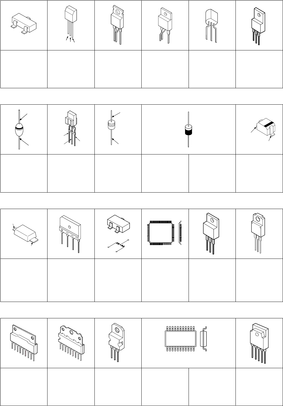
– 48 –
KV-14CT1B/14CT1U/14CT1E/14CT1K
RM-W100
TOP VIEW
MSD601-RT1
UN2211
UN2216
MSB709-RT1
AM01AV1
D1NL20U
D3SB6M-F
EGP20G
EL1Z
GPO8D
RU4AM-T3
BY228/A52A SPB-25MVWF
MA2ZD14001SO
UDZSTE-175.6B
UDZSTE-179.1B
1PS226-115
HSS82-TJ
RD5.1ESB2
MTZJ-T-77-15
UPC574J
1SS133T-77
4-6. SEMICONDUCTORS
TRANSISTOR
DIODE
MMDL914T1
RD3.6SB
SE135N-LF38 BA033T
AN17804A TA7805S
TDA11020H/
N1A000AK
E
B
C
2SC3209LK
ECB
IRF614-005 FN155 2SA1091-0 2SC5885
CATHODE
ANODE
CATHODE
ANODE
(GRN) ANODE
(GRN)
CATHODE
ANODE
CATHODE
A
NODE
ANODE
CATHODE
D3SB60F3
IC
S3L20UF4
10ERB20-TB3
10ERB20-TA2B5
11EQS10-TBS
D3S6M-F
3
1
2
1
3
2
TDA6108AJK/N1
1
9
CAT24WC16J1-TE13
LM2903DT
TJM4558CDT
Small Outline L-leaded Package
Pin 8
~
98
SOP
1TOP VIEW
STR-F6264S-LF1357
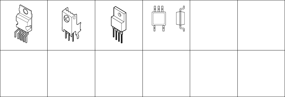
– 49 –
KV-14CT1B/14CT1U/14CT1E/14CT1K
RM-W100
IC
STV9302A RPM7240-SH5 PQ09RD1SJ00H
PQ018EFO1SZH
1
7
BA18BC0FP-E2
TOP VIEW
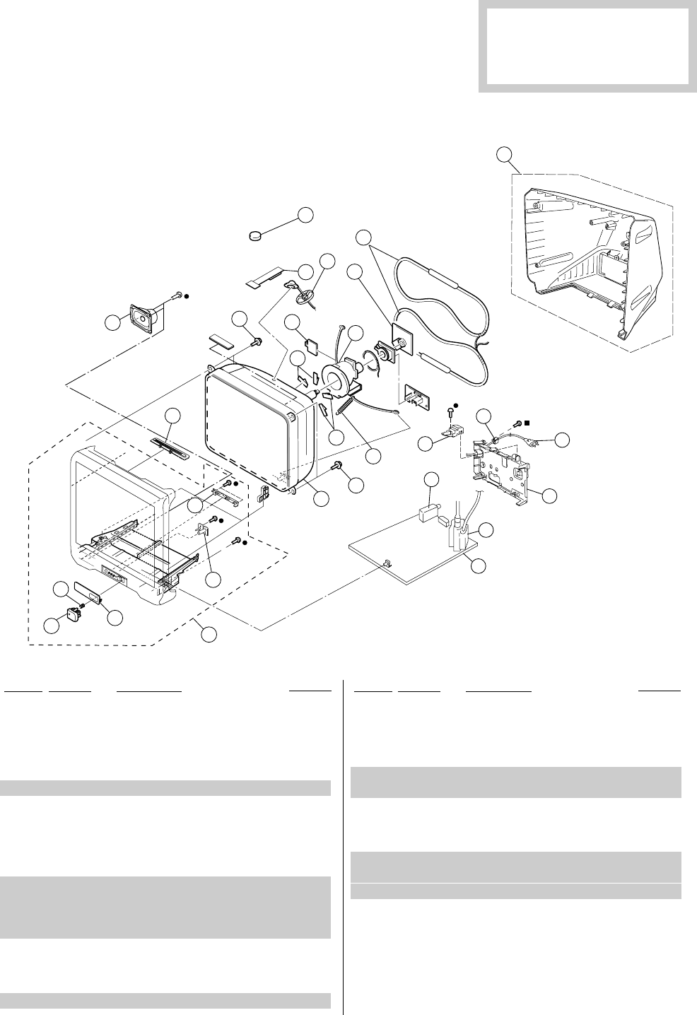
– 50 –
KV-14CT1B/14CT1U/14CT1E/14CT1K
RM-W100
SECTION 5
EXPLODED VIEWS
•Items marked " ∗ " are not stocked since
they are seldom required for routine
service. Some delay should be
anticipated when ordering these items.
The components identified by
shading and mark ! are critical
for safety.
Replace only with part number
specified.
NOTE:
•Items with no part number and no
description are not stocked because
they are seldom required for routine
service.
•The construction parts of an assembled
part are indicated with a collation
number in the remark column.
5-1. CHASSIS
r: 7-685-648-79 SCREW +BVTP 3 × 12
p: 7-685-663-71 SCREW +BVTP 4 × 16
6
27
2
3
5
1
4
14
9
10
10
11 12
13
15
16
7
17 14
25
18
19
21
23
24
26
22
20
8
1 X-4041-369-1 BEZNET ASSY 2-5, 27
2 * 4-092-231-01 GUIDE, LIGHT
3 4-092-229-01 DOOR CONTROL
4 4-092-230-01 BUTTON POWER
5 4-036-405-71 SPRING COMPRESSION
6!8-735-570-05 PICTURE TUBE (A34LRG70X)
7 1-452-032-00 MAGNET DISC
8 4-091-911-01 COVER REAR ( x 6 screws)
9 4-202-554-02 HOLDER HV CABLE
10 4-074-601-02 SPACER DY
11 4-077-228-02 PIECE TLH CONVERGENCE
12 !8-451-401-51 DEFLECTION YOKE (Y14RSA-L3)
(KV-14CT1B/1K/1U)
!8-451-401-11 DEFLECTION YOKE (Y14RSA-S)
(KV-14CT1E)
13 * A-1405-473-A MOUNTED PWB, C
14 4-057-862-01 SCREW, TAPPING 5 + CROWN WASHER
15 4-369-318-21 SPRING TENSION
16 !1-456-278-11 DEGAUSSING COIL
REF. NO. PART NO. DESCRIPTION REMARK REF. NO. PART NO. DESCRIPTION REMARK
17 1-825-293-11 LOUD SPEAKER (5 x 9 CM)
18 4-094-690-01 PIECE A (90) CONV, CORRECT
19 * A-1302-283-A COMPLETE PWB, A (KV-14CT1B)
* A-1302-405-A COMPLETE PWB, A (KV-14CT1E/1K)
* A-1302-428-A COMPLETE PWB, A (KV-14CT1U)
20 !1-453-309-21 TRANSFORMER ASSY FLYBACK
(NX-4450//M3A4)
21 8-598-623-00 TUNER FSS BTP-AC421 (KV-14CT1B/1E/1K)
8-598-624-00 TUNER FSS BTP-AU621 (KV-14CT1U)
22 * 4-093-760-01 BRACKET TERMINAL
23 !1-783-083-11 CORD POWER (WITH FILTER)
(KV-14CT1B/1E/1K)
!1-776-204-12 CORD, POWER (FILTER) (KV-14CT1U)
24 4-022-115-00 HOLDER AC CORD
25 1-477-678-71 TOP SWITCH BLOCK
26 * 4-092-370-11 BRACKET, FBT
27 * 4-093-771-01 COVER, FRONT PANEL

– 51 –
The components identified by shading
and mark ! are critical for safety.
Replace only with part number specified.
REF NO. PART NO. DESCRIPTION REMARK REF NO. PART NO. DESCRIPTION REMARK
KV-14CT1B/14CT1U/14CT1E/14CT1K
RM-W100
* A-1302-283-A COMPLETE PWB, A (KV-14CT1B)
* A-1302-405-A COMPLETE PWB, A (KV-14CT1E/1K)
* A-1302-428-A COMPLETE PWB, A (KV-14CT1U)
****************
* 1-564-508-11 PLUG, CONNECTOR 5P
* 1-564-510-11 PLUG, CONNECTOR 7P
1-900-704-55 LEAD ASSY, JUMPER
4-382-854-01 SCREW (M3X8), P, SW (+)
4-382-854-21 SCREW (M3X14), P, SW (+)
A015 * 4-055-304-01 HOLDER, LED
A016 * 4-042-408-01 PIN, COATING LEAD
A018 * 4-042-408-01 PIN, COATING LEAD
COMMON PARTS LIST
<CAPACITOR>
C001 1-162-927-11 CERAMIC CHIP 100PF 5.00% 50V
C002 1-126-935-11 ELECT 470UF 20.00% 16V
C003 1-162-927-11 CERAMIC CHIP 100PF 5.00% 50V
C004 1-126-933-11 ELECT 100UF 20.00% 16V
C005 1-126-933-11 ELECT 100UF 20.00% 16V
C006 1-126-933-11 ELECT 100UF 20.00% 16V
C008 1-126-947-11 ELECT 47UF 20.00% 25V
C010 1-164-315-11 CERAMIC CHIP 470PF 5.00% 50V
C012 1-127-715-91 CERAMIC CHIP 0.22UF 10% 16V
C013 1-126-933-11 ELECT 100UF 20.00% 16V
C014 1-127-715-91 CERAMIC CHIP 0.22UF 10% 16V
C018 1-127-715-91 CERAMIC CHIP 0.22UF 10% 16V
C020 1-107-826-11 CERAMIC CHIP 0.1UF 10.00% 16V
C021 1-162-927-11 CERAMIC CHIP 100PF 5.00% 50V
C022 1-127-715-91 CERAMIC CHIP 0.22UF 10% 16V
C023 1-125-891-11 CERAMIC CHIP 0.47UF 10.00% 10V
C024 1-126-965-91 ELECT 22UF 20.00% 50V
C025 1-127-715-91 CERAMIC CHIP 0.22UF 10% 16V
C026 1-126-947-11 ELECT 47UF 20.00% 25V
C028 1-107-826-11 CERAMIC CHIP 0.1UF 10.00% 16V
C029 1-126-965-91 ELECT 22UF 20.00% 50V
C030 1-127-715-91 CERAMIC CHIP 0.22UF 10% 16V
C031 1-126-965-91 ELECT 22UF 20.00% 50V
C036 1-126-933-11 ELECT 100UF 20.00% 16V
C037 1-126-963-11 ELECT 4.7UF 20.00% 50V
C038 1-107-826-11 CERAMIC CHIP 0.1UF 10.00% 16V
C041 1-162-968-11 CERAMIC CHIP 0.0047UF 10.00% 50V
C042 1-127-715-91 CERAMIC CHIP 0.22UF 10% 16V
C044 1-164-505-11 CERAMIC CHIP 2.2UF 16V
C046 1-162-969-11 CERAMIC CHIP 0.0068UF 10.00% 25V
C048 1-127-715-91 CERAMIC CHIP 0.22UF 10% 16V
C049 1-164-227-11 CERAMIC CHIP 0.022UF 10.00% 25V
C050 1-126-964-11 ELECT 10UF 20.00% 50V
C052 1-162-964-11 CERAMIC CHIP 0.001UF 10.00% 50V
C053 1-164-227-11 CERAMIC CHIP 0.022UF 10.00% 25V
C054 1-107-826-11 CERAMIC CHIP 0.1UF 10.00% 16V
C055 1-136-167-00 FILM 0.15UF 5.00% 50V
C056 1-126-933-11 ELECT 100UF 20.00% 16V
C057 1-162-970-11 CERAMIC CHIP 0.01UF 10.00% 25V
C058 1-162-964-11 CERAMIC CHIP 0.001UF 10.00% 50V
C060 1-107-826-11 CERAMIC CHIP 0.1UF 10.00% 16V
C061 1-162-966-11 CERAMIC CHIP 0.0022UF 10.00% 50V
C062 1-107-826-11 CERAMIC CHIP 0.1UF 10.00% 16V
C063 1-107-826-11 CERAMIC CHIP 0.1UF 10.00% 16V
C064 1-126-961-11 ELECT 2.2UF 20.00% 50V
C065 1-126-962-11 ELECT 3.3UF 20.00% 50V
C067 1-107-826-11 CERAMIC CHIP 0.1UF 10.00% 16V
C069 1-107-826-11 CERAMIC CHIP 0.1UF 10.00% 16V
C070 1-107-826-11 CERAMIC CHIP 0.1UF 10.00% 16V
C072 1-162-970-11 CERAMIC CHIP 0.01UF 10.00% 25V
C073 1-126-961-11 ELECT 2.2UF 20.00% 50V
C077 1-165-176-11 CERAMIC CHIP 0.047UF 10.00% 16V
C078 1-162-927-11 CERAMIC CHIP 100PF 5.00% 50V
C080 1-162-964-11 CERAMIC CHIP 0.001UF 10.00% 50V
C081 1-162-964-11 CERAMIC CHIP 0.001UF 10.00% 50V
C089 1-162-964-11 CERAMIC CHIP 0.001UF 10.00% 50V
C090 1-162-927-11 CERAMIC CHIP 100PF 5.00% 50V
C091 1-162-927-11 CERAMIC CHIP 100PF 5.00% 50V
C092 1-107-826-11 CERAMIC CHIP 0.1UF 10.00% 16V
C093 1-107-826-11 CERAMIC CHIP 0.1UF 10.00% 16V
C094 1-107-826-11 CERAMIC CHIP 0.1UF 10.00% 16V
C095 1-107-826-11 CERAMIC CHIP 0.1UF 10.00% 16V
C096 1-107-826-11 CERAMIC CHIP 0.1UF 10.00% 16V
C100 1-162-964-11 CERAMIC CHIP 0.001UF 10.00% 50V
C101 1-126-933-11 ELECT 100UF 20.00% 16V
C102 1-162-923-11 CERAMIC CHIP 47PF 5.00% 50V
C104 1-162-923-11 CERAMIC CHIP 47PF 5.00% 50V
C107 1-126-935-11 ELECT 470UF 20.00% 16V
C108 1-126-935-11 ELECT 470UF 20.00% 16V
C109 1-162-968-11 CERAMIC CHIP 0.0047UF 10.00% 50V
C112 1-163-021-91 CERAMIC CHIP 0.01UF 10.00% 50V
C116 1-162-968-11 CERAMIC CHIP 0.0047UF 10.00% 50V
C118 1-126-965-91 ELECT 22UF 20.00% 50V
C119 1-163-021-91 CERAMIC CHIP 0.01UF 10.00% 50V
C120 1-126-935-11 ELECT 470UF 20.00% 16V
C136 1-162-964-11 CERAMIC CHIP 0.001UF 10.00% 50V
C137 1-162-964-11 CERAMIC CHIP 0.001UF 10.00% 50V
C139 1-162-970-11 CERAMIC CHIP 0.01UF 10.00% 25V
C200 1-127-715-91 CERAMIC CHIP 0.22UF 10% 16V
C203 1-162-970-11 CERAMIC CHIP 0.01UF 10.00% 25V
C204 1-130-495-00 MYLAR 0.1UF 5.00% 50V
C206 1-164-227-11 CERAMIC CHIP 0.022UF 10.00% 25V
C209 1-126-961-11 ELECT 2.2UF 20.00% 50V
SECTION 6
ELECTRICAL PARTS LIST
NOTE:
The components identified by shading
and mark ! are critical for safety.
Replace only with part number specified.
When indicating parts by reference
number, please include the board name.
•Items marked " ∗ " are not stocked since
they are seldom required for routine
service. Some delay should be antici-
pated when ordering these items.
•All variable and adjustable resistors have
characteristic curve B, unless otherwise
noted.
•All resistors are in ohms
•F : nonflammable
CAPACITORS
•MF : µF, PF : µµF
COILS
• MMH : mH, UH : µH
REF NO. PART NO. DESCRIPTION REMARK REF NO. PART NO. DESCRIPTION REMARK
A

– 52 –
The components identified by shading
and mark ! are critical for safety.
Replace only with part number specified.
REF NO. PART NO. DESCRIPTION REMARK REF NO. PART NO. DESCRIPTION REMARK
KV-14CT1B/14CT1U/14CT1E/14CT1K
RM-W100
C210 1-126-968-11 ELECT 100UF 20.00% 50V
C211 1-126-963-11 ELECT 4.7UF 20.00% 50V
C212 1-126-942-61 ELECT 1000UF 20.00% 25V
C213 1-115-339-11 CERAMIC CHIP 0.1UF 10.00% 50V
C217 1-126-942-61 ELECT 1000UF 20.00% 25V
C218 1-126-965-91 ELECT 22UF 20.00% 50V
C219 1-126-934-11 ELECT 220UF 20.00% 16V
C220 1-126-964-11 ELECT 10UF 20.00% 50V
C223 1-128-549-11 ELECT 3300UF 20.00% 35V
C232 1-137-374-11 MYLAR 0.047UF 5.00% 50V
C234 1-164-315-11 CERAMIC CHIP 470PF 5.00% 50V
C300 1-127-715-91 CERAMIC CHIP 0.22UF 10% 16V
C301 1-164-315-11 CERAMIC CHIP 470PF 5.00% 50V
C302 1-164-505-11 CERAMIC CHIP 2.2UF 16V
C303 1-126-933-11 ELECT 100UF 20.00% 16V
C304 1-126-933-11 ELECT 100UF 20.00% 16V
C308 1-162-970-11 CERAMIC CHIP 0.01UF 10.00% 25V
C311 1-126-961-11 ELECT 2.2UF 20.00% 50V
C312 1-162-964-11 CERAMIC CHIP 0.001UF 10.00% 50V
C313 1-162-964-11 CERAMIC CHIP 0.001UF 10.00% 50V
C316 1-125-891-11 CERAMIC CHIP 0.47UF 10.00% 10V
C317 1-126-934-11 ELECT 220UF 20.00% 16V
C318 1-107-826-11 CERAMIC CHIP 0.1UF 10.00% 16V
C319 1-162-923-11 CERAMIC CHIP 47PF 5.00% 50V
C320 1-162-923-11 CERAMIC CHIP 47PF 5.00% 50V
C321 1-162-970-11 CERAMIC CHIP 0.01UF 10.00% 25V
C322 1-162-964-11 CERAMIC CHIP 0.001UF 10.00% 50V
C323 1-162-964-11 CERAMIC CHIP 0.001UF 10.00% 50V
C325 1-164-227-11 CERAMIC CHIP 0.022UF 10.00% 25V
C328 1-162-970-11 CERAMIC CHIP 0.01UF 10.00% 25V
C600 !1-119-895-51 CERAMIC 4700PF 20.00% 250V
C602 !1-165-538-11 MYLAR 0.1UF 10 275V
C605 1-161-830-00 CERAMIC 0.0047UF 99% 500V
C606 1-161-830-00 CERAMIC 0.0047UF 99% 500V
C609 1-161-830-00 CERAMIC 0.0047UF 99% 500V
C610 1-161-830-00 CERAMIC 0.0047UF 99% 500V
C611 1-117-751-11 ELECT(BLOCK) 220UF 20.00% 450V
C612 1-125-893-11 FILM 680PF 3.00% 1.5KV
C616 1-164-230-11 CERAMIC CHIP 220PF 5.00% 50V
C619 1-130-491-00 MYLAR 0.047UF 5.00% 50V
C621 1-126-963-11 ELECT 4.7UF 20.00% 50V
C622 !1-119-894-51 CERAMIC 2200PF 20.00% 250V
C623 1-162-966-11 CERAMIC CHIP 0.0022UF 10.00% 50V
C624 1-126-967-11 ELECT 47UF 20.00% 50V
C625 !1-127-942-51 CERAMIC 330PF 10% 250V
C626 1-102-228-00 CERAMIC 470PF 10.00% 500V
C628 1-125-772-91 CERAMIC 1500PF 10.00% 2KV
C630 1-128-549-11 ELECT 3300UF 20.00% 35V
C632 1-126-953-11 ELECT 2200UF 20.00% 35V
C634 1-126-941-11 ELECT 470UF 20.00% 25V
C635 1-126-971-11 ELECT 470UF 20.00% 50V
C637 1-126-933-11 ELECT 100UF 20.00% 16V
C638 1-126-933-11 ELECT 100UF 20.00% 16V
C639 1-126-933-11 ELECT 100UF 20.00% 16V
C641 1-126-933-11 ELECT 100UF 20.00% 16V
C643 1-125-891-11 CERAMIC CHIP 0.47UF 10.00% 10V
C644 1-164-315-11 CERAMIC CHIP 470PF 5.00% 50V
C647 1-126-935-11 ELECT 470UF 20.00% 16V
C649 1-126-933-11 ELECT 100UF 20.00% 16V
C652 1-102-228-00 CERAMIC 470PF 10.00% 500V
C653 1-102-228-00 CERAMIC 470PF 10.00% 500V
C654 1-102-228-00 CERAMIC 470PF 10.00% 500V
C657 !1-127-942-51 CERAMIC 330PF 10% 250V
C660 !1-165-539-11 MYLAR 0.22UF 10 275V
C662 1-107-826-11 CERAMIC CHIP 0.1UF 10.00% 16V
C665 1-110-626-11 ELECT 330UF 20.00% 160V
C666 !1-165-538-11 MYLAR 0.1UF 10 275V
C668 1-126-933-11 ELECT 100UF 20.00% 16V
C670 !1-127-942-51 CERAMIC 330PF 10% 250V
C672 1-162-970-11 CERAMIC CHIP 0.01UF 10.00% 25V
C678 1-164-505-11 CERAMIC CHIP 2.2UF 16V
C680 1-164-315-11 CERAMIC CHIP 470PF 5.00% 50V
C682 1-115-466-91 ELECT 1000UF 20.00% 16V
C685 1-126-934-11 ELECT 220UF 20.00% 16V
C805 1-126-960-11 ELECT 1UF 20.00% 50V
C806 1-106-375-12 MYLAR 0.022UF 99% 200V
C807 1-162-964-11 CERAMIC CHIP 0.001UF 10.00% 50V
C808 1-102-244-00 CERAMIC 220PF 10.00% 500V
C809 1-162-964-11 CERAMIC CHIP 0.001UF 10.00% 50V
C810 1-162-318-11 CERAMIC 0.001UF 10.00% 500V
C811 1-126-933-11 ELECT 100UF 20.00% 16V
C822 1-162-970-11 CERAMIC CHIP 0.01UF 10.00% 25V
C825 1-162-970-11 CERAMIC CHIP 0.01UF 10.00% 25V
C826 1-164-227-11 CERAMIC CHIP 0.022UF 10.00% 25V
C828 1-126-933-11 ELECT 100UF 20.00% 16V
C830 1-162-970-11 CERAMIC CHIP 0.01UF 10.00% 25V
C831 1-107-826-11 CERAMIC CHIP 0.1UF 10.00% 16V
C832 1-164-230-11 CERAMIC CHIP 220PF 5.00% 50V
C833 1-107-826-11 CERAMIC CHIP 0.1UF 10.00% 16V
C835 1-162-970-11 CERAMIC CHIP 0.01UF 10.00% 25V
C836 1-162-131-11 CERAMIC 220PF 10.00% 2KV
C837 1-162-968-11 CERAMIC CHIP 0.0047UF 10.00% 50V
C838 1-106-220-00 MYLAR 0.1UF 10.00% 100V
C839 1-162-966-11 CERAMIC CHIP 0.0022UF 10.00% 50V
C840 !1-117-645-11 FILM 11000PF 3.00% 1.2KV
C841 1-117-661-71 FILM 0.15UF 5.00% 250V
C842 1-100-123-21 FILM 0.033UF 5% 400V
C844 1-165-176-11 CERAMIC CHIP 0.047UF 10.00% 16V
C845 1-162-964-11 CERAMIC CHIP 0.001UF 10.00% 50V
C846 1-117-767-91 CERAMIC 330PF 10.00% 2KV
C847 1-107-364-11 MYLAR 0.01UF 10.00% 200V
C848 1-107-364-11 MYLAR 0.01UF 10.00% 200V
C849 1-106-375-12 MYLAR 0.022UF 99% 200V
C850 1-106-220-00 MYLAR 0.1UF 10.00% 100V
C851 1-107-675-11 ELECT 1UF 20.00% 450V
C852 1-117-664-11 FILM 0.27UF 5.00% 250V
C854 1-126-948-11 ELECT 100UF 20.00% 35V
C855 1-107-894-11 ELECT 220UF 20.00% 35V
C857 1-104-666-11 ELECT 220UF 20.00% 25V
C858 1-137-194-81 FILM 0.47UF 5.00% 50V
C860 1-162-318-11 CERAMIC 0.001UF 10.00% 500V
C861 1-104-666-11 ELECT 220UF 20.00% 25V
C862 1-162-318-11 CERAMIC 0.001UF 10.00% 500V
C863 1-165-176-11 CERAMIC CHIP 0.047UF 10.00% 16V
C867 1-165-441-81 ELECT 33UF 20% 160V
C868 1-102-228-00 CERAMIC 470PF 10.00% 500V
C869 1-107-654-11 ELECT 33UF 20.00% 250V
C876 1-162-964-11 CERAMIC CHIP 0.001UF 10.00% 50V
C877 1-162-970-11 CERAMIC CHIP 0.01UF 10.00% 25V
C878 1-162-970-11 CERAMIC CHIP 0.01UF 10.00% 25V
A

– 53 –
The components identified by shading
and mark ! are critical for safety.
Replace only with part number specified.
REF NO. PART NO. DESCRIPTION REMARK REF NO. PART NO. DESCRIPTION REMARK
KV-14CT1B/14CT1U/14CT1E/14CT1K
RM-W100
C882 1-106-363-00 MYLAR 0.0068UF 99% 200V
C904 1-126-957-11 ELECT 0.22UF 20.00% 50V
C908 1-164-346-11 CERAMIC CHIP 1UF 16V
C909 1-164-346-11 CERAMIC CHIP 1UF 16V
C914 1-162-959-11 CERAMIC CHIP 330PF 5.00% 50V
C915 1-162-959-11 CERAMIC CHIP 330PF 5.00% 50V
C917 1-162-959-11 CERAMIC CHIP 330PF 5.00% 50V
C918 1-164-346-11 CERAMIC CHIP 1UF 16V
C923 1-126-947-11 ELECT 47UF 20.00% 25V
C940 1-164-315-11 CERAMIC CHIP 470PF 5.00% 50V
C947 1-164-315-11 CERAMIC CHIP 470PF 5.00% 50V
C952 1-107-826-11 CERAMIC CHIP 0.1UF 10.00% 16V
C953 1-107-826-11 CERAMIC CHIP 0.1UF 10.00% 16V
C955 1-127-715-91 CERAMIC CHIP 0.22UF 10% 16V
C956 1-126-933-11 ELECT 100UF 20.00% 16V
C967 1-164-505-11 CERAMIC CHIP 2.2UF 16V
C972 1-162-964-11 CERAMIC CHIP 0.001UF 10.00% 50V
C973 1-126-964-11 ELECT 10UF 20.00% 50V
C975 1-162-964-11 CERAMIC CHIP 0.001UF 10.00% 50V
C976 1-126-935-11 ELECT 470UF 20.00% 16V
C1019 1-127-715-91 CERAMIC CHIP 0.22UF 10% 16V
C1233 1-126-961-11 ELECT 2.2UF 20.00% 50V
C2602 1-102-114-00 CERAMIC 470PF 10.00% 50V
C2631 1-102-228-00 CERAMIC 470PF 10.00% 500V
C2636 1-126-972-11 ELECT 1000UF 20.00% 50V
C2648 1-126-952-11 ELECT 1000UF 20.00% 35V
<CONNECTOR>
CN005 * 1-564-506-11 PLUG, CONNECTOR 3P
CN202 * 1-564-506-11 PLUG, CONNECTOR 3P
CN601 * 1-691-134-11 PIN, CONNECTOR (PC BOARD) 2P
CN602 * 1-580-843-11 PIN, CONNECTOR (POWER)
CN603*!1-508-786-13 PIN, CONNECTOR (5MM PITCH) 2P
CN902 1-794-656-11 CONNECTOR, SCART 21P
CN904 * 1-564-508-11 PLUG, CONNECTOR 5P
<DIODE>
D002 8-719-081-97 MMDL914T1
D003 8-719-081-97 MMDL914T1
D023 8-719-069-60 UDZSTE-179.1B
D024 8-719-069-60 UDZSTE-179.1B
D025 8-719-069-60 UDZSTE-179.1B
D054 8-719-069-55 DIODE UDZSTE-175.6B
D055 8-719-069-55 DIODE UDZSTE-175.6B
D056 8-719-081-97 MMDL914T1
D057 8-719-081-97 MMDL914T1
D058 8-719-081-97 MMDL914T1
D059 8-719-081-97 MMDL914T1
D060 8-719-069-54 UDZSTE-175.1B
D061 8-719-081-97 MMDL914T1
D062 8-719-069-55 DIODE UDZSTE-175.6B
D063 8-719-081-97 MMDL914T1
D064 8-719-069-55 DIODE UDZSTE-175.6B
D065 8-719-069-55 DIODE UDZSTE-175.6B
D066 8-719-908-03 GP08D
D068 8-719-069-55 DIODE UDZSTE-175.6B
D071 8-719-081-97 MMDL914T1
D072 8-719-081-97 MMDL914T1
D072 8-719-404-50 MA111-TX
D074 8-719-081-97 MMDL914T1
D075 8-719-069-60 UDZSTE-179.1B
D101 8-719-066-11 1PS184-115
D103 8-759-157-40 UPC574J
D107 8-719-074-43 BAS316-115
D107 8-719-081-97 MMDL914T1
D107 8-719-404-50 MA111-TX
D108 8-719-069-55 DIODE UDZSTE-175.6B
D109 8-719-069-55 DIODE UDZSTE-175.6B
D200 8-719-062-51 1PS226-115
D201 8-719-081-97 MMDL914T1
D202 8-719-081-97 MMDL914T1
D203 8-719-081-97 MMDL914T1
D204 8-719-081-97 MMDL914T1
D205 8-719-081-97 MMDL914T1
D208 8-719-081-97 MMDL914T1
D211 8-719-062-51 1PS226-115
D212 8-719-081-97 MMDL914T1
D213 8-719-081-97 MMDL914T1
D214 8-719-081-97 MMDL914T1
D600 8-719-081-97 MMDL914T1
D602 6-500-481-31 DIODE AM01AV1
D603 6-500-481-31 DIODE AM01AV1
D604 8-719-077-77 D3SB60F3
D605 8-719-109-85 RD5.1ESB2
D617 6-500-567-11 DIODE 10ERB20-TA2B5
D618 8-719-063-70 D1NL20U
D619 6-500-567-11 DIODE 10ERB20-TA2B5
D621 8-719-312-10 RU4AM-T3
D622 8-719-085-37 11EQS10-TB5
D623 6-500-567-31 DIODE 10ERB20-TB3
D624 8-719-510-73 S3L20UF4
D629 8-719-109-85 RD5.1ESB2
D633 8-719-923-86 MTZJ-T-77-15
D635 8-719-157-97 RD3.6SB
D637 8-719-072-70 MA2ZD14001S0
D638 8-719-081-97 MMDL914T1
D639 8-719-027-22 D3S6M-F
D804 8-719-991-33 1SS133T-77
D805 8-719-991-33 1SS133T-77
D807 8-719-991-33 1SS133T-77
D808 8-719-991-33 1SS133T-77
D809 8-719-991-33 1SS133T-77
D815 8-719-069-60 UDZSTE-179.1B
D816 8-719-081-00 DIODE BY228/A52A/
D817 8-719-979-85 EGP20G
D818 8-719-109-85 RD5.1ESB2
D819 6-500-567-31 DIODE 10ERB20-TB3
D820 8-719-908-03 GP08D
D821 6-500-567-31 DIODE 10ERB20-TB3
D823 8-719-302-43 EL1Z
D824 8-719-302-43 EL1Z
D827 8-719-302-43 EL1Z
D829 8-719-069-55 DIODE UDZSTE-175.6B
D830 8-719-081-97 MMDL914T1
D903 8-719-069-55 DIODE UDZSTE-175.6B
D904 8-719-069-55 DIODE UDZSTE-175.6B
D911 8-719-069-55 DIODE UDZSTE-175.6B
D912 8-719-069-55 DIODE UDZSTE-175.6B
D913 8-719-069-55 DIODE UDZSTE-175.6B
D914 8-719-083-18 DIODE SPB-25MVWF
A

– 54 –
The components identified by shading
and mark ! are critical for safety.
Replace only with part number specified.
REF NO. PART NO. DESCRIPTION REMARK REF NO. PART NO. DESCRIPTION REMARK
KV-14CT1B/14CT1U/14CT1E/14CT1K
RM-W100
D915 8-719-069-55 DIODE UDZSTE-175.6B
D918 8-719-069-55 DIODE UDZSTE-175.6B
D920 8-719-069-55 DIODE UDZSTE-175.6B
D927 8-719-069-55 DIODE UDZSTE-175.6B
D928 8-719-069-60 UDZSTE-179.1B
D930 8-719-069-55 DIODE UDZSTE-175.6B
D931 8-719-157-97 RD3.6SB
D932 8-719-157-97 RD3.6SB
D933 6-500-028-01 DIODE MM3Z9V1ST1
D933 8-719-069-60 UDZSTE-179.1B
D933 8-719-070-62 DIODE PDZ9.1B-115
D2625 8-719-510-73 S3L20UF4
<CONNECTOR>
DY800 * 1-580-798-11 CONNECTOR PIN (DY) 6P
<FUSE>
F600 !1-576-232-21 FUSE 5A 250V 5A
<FERRITE BEAD>
FB001 1-410-397-21 FERRITE 1.1UH
FB603 1-410-397-21 FERRITE 1.1UH
FB608 1-412-911-31 FERRITE 0UH
FB800 1-410-397-21 FERRITE 1.1UH
FB2602 1-410-397-21 FERRITE 1.1UH
FH603 1-533-725-11 FUSE HOLDER 0A 0V
<IC>
IC001 6-703-512-01 IC TDA11020H/N1A000AK
IC002 6-704-532-01 RPM7240-H5
IC003 8-759-678-07 CAT24WC16JI-TE1
IC200 6-703-474-01 IC AN17804A
IC601 6-704-263-01 IC STR-F6267S LF1357
IC602 6-703-479-01 IC PQ09RD1SJ00H
IC603 6-703-478-01 IC PQ018EF01SZH
IC604 8-759-231-53 TA7805S
IC605 6-705-063-01 IC SE135N-LF38
IC606 8-759-445-59 BA033T
IC607 8-759-832-05 IC BA18BC0FP-E2
IC801 6-703-708-01 IC LM2903DT
IC802 6-701-937-01 IC TJM4558CDT
IC804 6-703-470-01 IC STV9302A
<JACK>
J200 1-770-786-22 JACK
J909 1-779-205-11 JACK, PIN 2P
<CHIP CONDUCTOR>
JR001 1-216-864-11 SHORT CHIP 0
JR002 1-216-864-11 SHORT CHIP 0
JR003 1-216-864-11 SHORT CHIP 0
JR004 1-216-864-11 SHORT CHIP 0
JR005 1-216-864-11 SHORT CHIP 0
JR006 1-216-864-11 SHORT CHIP 0
JR008 1-216-864-11 SHORT CHIP 0
JR009 1-216-864-11 SHORT CHIP 0
JR012 1-216-864-11 SHORT CHIP 0
JR013 1-216-864-11 SHORT CHIP 0
JR014 1-216-864-11 SHORT CHIP 0
JR015 1-216-864-11 SHORT CHIP 0
JR016 1-216-864-11 SHORT CHIP 0
JR017 1-216-864-11 SHORT CHIP 0
JR018 1-216-864-11 SHORT CHIP 0
JR019 1-216-864-11 SHORT CHIP 0
JR020 1-216-864-11 SHORT CHIP 0
JR021 1-216-864-11 SHORT CHIP 0
JR024 1-216-864-11 SHORT CHIP 0
JR025 1-216-864-11 SHORT CHIP 0
JR026 1-216-864-11 SHORT CHIP 0
JR027 1-216-864-11 SHORT CHIP 0
JR036 1-216-864-11 SHORT CHIP 0
JR037 1-216-864-11 SHORT CHIP 0
JR038 1-216-864-11 SHORT CHIP 0
JR040 1-216-864-11 SHORT CHIP 0
JR041 1-216-864-11 SHORT CHIP 0
JR050 1-216-864-11 SHORT CHIP 0
JR051 1-216-864-11 SHORT CHIP 0
JR093 1-216-864-11 SHORT CHIP 0
JR096 1-216-864-11 SHORT CHIP 0
JR097 1-216-864-11 SHORT CHIP 0
JR098 1-216-864-11 SHORT CHIP 0
JR111 1-216-864-11 SHORT CHIP 0
JR112 1-216-864-11 SHORT CHIP 0
JR200 1-216-864-11 SHORT CHIP 0
JR300 1-216-864-11 SHORT CHIP 0
JR600 1-216-864-11 SHORT CHIP 0
JR601 1-216-864-11 SHORT CHIP 0
JR602 1-216-864-11 SHORT CHIP 0
JR800 1-216-864-11 SHORT CHIP 0
JR805 1-216-864-11 SHORT CHIP 0
JR901 1-216-864-11 SHORT CHIP 0
JR902 1-216-864-11 SHORT CHIP 0
JR903 1-216-864-11 SHORT CHIP 0
JR904 1-216-864-11 SHORT CHIP 0
JR905 1-216-864-11 SHORT CHIP 0
JR906 1-216-864-11 SHORT CHIP 0
JR907 1-216-864-11 SHORT CHIP 0
JR1011 1-216-864-11 SHORT CHIP 0
JR1100 1-216-864-11 SHORT CHIP 0
JR1101 1-216-864-11 SHORT CHIP 0
JR1107 1-216-864-11 SHORT CHIP 0
JR1108 1-216-864-11 SHORT CHIP 0
JR1902 1-216-864-11 SHORT CHIP 0
JR1903 1-216-864-11 SHORT CHIP 0
JR1907 1-216-864-11 SHORT CHIP 0
<COIL>
L003 1-414-856-11 INDUCTOR 10UH
L004 1-414-187-11 INDUCTOR 47UH
L005 1-414-856-11 INDUCTOR 10UH
L006 1-414-856-11 INDUCTOR 10UH
L007 1-414-856-11 INDUCTOR 10UH
L008 1-414-856-11 INDUCTOR 10UH
L009 1-414-856-11 INDUCTOR 10UH
L010 1-469-525-91 INDUCTOR 10UH
L011 1-469-525-91 INDUCTOR 10UH
L012 1-412-058-11 INDUCTOR 10UH
A

– 55 –
The components identified by shading
and mark ! are critical for safety.
Replace only with part number specified.
REF NO. PART NO. DESCRIPTION REMARK REF NO. PART NO. DESCRIPTION REMARK
KV-14CT1B/14CT1U/14CT1E/14CT1K
RM-W100
L013 1-469-525-91 INDUCTOR 10UH
L031 1-469-525-91 INDUCTOR 10UH
L032 1-469-525-91 INDUCTOR 10UH
L033 1-469-525-91 INDUCTOR 10UH
L035 1-469-525-91 INDUCTOR 10UH
L036 1-469-525-91 INDUCTOR 10UH
L037 1-469-525-91 INDUCTOR 10UH
L100 1-414-857-11 INDUCTOR 100UH
L104 1-410-989-11 INDUCTOR 0.47UH
L106 1-414-187-11 INDUCTOR 47UH
L600 1-412-533-21 INDUCTOR 47UH
L601 1-412-533-21 INDUCTOR 47UH
L602 1-412-529-11 INDUCTOR 22UH
L800 1-424-795-11 COIL, HORIZONTAL LINEARITY
L802 1-406-679-11 INDUCTOR 22MH
L803 1-414-493-41 INDUCTOR 4.7MH
L805 1-408-947-00 INDUCTOR 2.2MH
L900 1-469-525-91 INDUCTOR 10UH
L901 1-412-001-31 INDUCTOR 3.9UH
L902 1-414-187-11 INDUCTOR 47UH
L903 1-410-993-42 INDUCTOR 1UH
L904 1-410-993-42 INDUCTOR 1UH
L905 1-410-993-42 INDUCTOR 1UH
L906 1-410-993-42 INDUCTOR 1UH
L2601 1-412-525-31 INDUCTOR 10UH
<PHOTO COUPLER>
PH600 !6-600-187-01 PHOTO COUPLER PC123Y22JOOF
<IC LINK>
PS602 !1-533-597-41 IC LINK 5A 90V
PS603 !1-533-597-41 IC LINK 5A 90V
PS604 1-533-597-41 IC LINK 5A 90V
PS605 !1-533-597-41 IC LINK 5A 90V
PS2601 !1-533-597-41 IC LINK 5A 90V
<TRANSISTOR>
Q001 8-729-421-22 UN2211
Q006 8-729-424-67 UN2216
Q007 8-729-424-67 UN2216
Q008 8-729-010-25 MSD601-RT1
Q013 8-729-010-25 MSD601-RT1
Q016 8-729-421-22 UN2211
Q105 8-729-424-67 UN2216
Q106 8-729-424-67 UN2216
Q200 8-729-421-22 UN2211
Q201 8-729-010-05 MSB709-RT1
Q202 8-729-010-05 MSB709-RT1
Q206 8-729-421-22 UN2211
Q601 8-729-010-25 MSD601-RT1
Q605 6-550-572-01 TRANSISTOR FN155
Q608 8-729-010-25 MSD601-RT1
Q609 8-729-010-25 MSD601-RT1
Q803 8-729-140-50 2SC3209LK
Q804 8-729-200-17 2SA1091-O
Q805 6-550-410-01 TRANSISTOR 2SC5885
Q806 8-729-010-25 MSD601-RT1
Q807 8-729-010-05 MSB709-RT1
Q808 8-729-053-33 IRF614-037
Q814 8-729-010-25 MSD601-RT1
Q903 8-729-010-05 MSB709-RT1
Q908 8-729-424-67 UN2216
Q909 8-729-424-67 UN2216
Q910 8-729-010-25 MSD601-RT1
Q911 8-729-010-25 MSD601-RT1
Q912 8-729-421-22 UN2211
Q913 8-729-421-22 UN2211
Q8009 8-729-200-17 2SA1091-O
Q8010 8-729-140-50 2SC3209LK
<RESISTOR>
R001 1-216-829-11 METAL CHIP 4.7K 5% 1/10W
R002 1-216-809-11 METAL CHIP 100 5% 1/10W
R003 1-216-829-11 METAL CHIP 4.7K 5% 1/10W
R004 1-216-809-11 METAL CHIP 100 5% 1/10W
R010 1-216-833-11 METAL CHIP 10K 5% 1/10W
R011 1-216-821-11 METAL CHIP 1K 5% 1/10W
R012 1-216-825-11 METAL CHIP 2.2K 5% 1/10W
R014 1-216-809-11 METAL CHIP 100 5% 1/10W
R015 1-216-823-11 METAL CHIP 1.5K 5% 1/10W
R018 1-216-809-11 METAL CHIP 100 5% 1/10W
R020 1-216-809-11 METAL CHIP 100 5% 1/10W
R023 1-216-825-11 METAL CHIP 2.2K 5% 1/10W
R024 1-216-809-11 METAL CHIP 100 5% 1/10W
R025 1-216-809-11 METAL CHIP 100 5% 1/10W
R026 1-216-809-11 METAL CHIP 100 5% 1/10W
R029 1-216-809-11 METAL CHIP 100 5% 1/10W
R030 1-216-809-11 METAL CHIP 100 5% 1/10W
R038 1-216-809-11 METAL CHIP 100 5% 1/10W
R039 1-216-809-11 METAL CHIP 100 5% 1/10W
R041 1-216-809-11 METAL CHIP 100 5% 1/10W
R042 1-216-825-11 METAL CHIP 2.2K 5% 1/10W
R044 1-216-834-11 METAL CHIP 12K 5% 1/10W
R045 1-216-809-11 METAL CHIP 100 5% 1/10W
R046 1-216-809-11 METAL CHIP 100 5% 1/10W
R048 1-216-809-11 METAL CHIP 100 5% 1/10W
R051 1-218-885-11 METAL CHIP 39K 0.5% 1/10W
R056 1-216-809-11 METAL CHIP 100 5% 1/10W
R058 1-216-809-11 METAL CHIP 100 5% 1/10W
R060 1-216-809-11 METAL CHIP 100 5% 1/10W
R061 1-216-819-11 METAL CHIP 680 5% 1/10W
R087 1-216-813-11 METAL CHIP 220 5% 1/10W
R088 1-216-816-11 METAL CHIP 390 5% 1/10W
R096 1-216-813-11 METAL CHIP 220 5% 1/10W
R097 1-216-813-11 METAL CHIP 220 5% 1/10W
R098 1-216-813-11 METAL CHIP 220 5% 1/10W
R099 1-216-813-11 METAL CHIP 220 5% 1/10W
R115 1-216-809-11 METAL CHIP 100 5% 1/10W
R116 1-216-809-11 METAL CHIP 100 5% 1/10W
R121 1-215-925-11 METAL OXIDE 22K 5% 3W
R122 1-216-825-11 METAL CHIP 2.2K 5% 1/10W
R124 1-216-825-11 METAL CHIP 2.2K 5% 1/10W
R125 1-216-825-11 METAL CHIP 2.2K 5% 1/10W
R128 1-216-864-11 SHORT CHIP 0
R130 1-216-809-11 METAL CHIP 100 5% 1/10W
R142 1-216-825-11 METAL CHIP 2.2K 5% 1/10W
R150 1-216-809-11 METAL CHIP 100 5% 1/10W
R152 1-218-713-11 METAL CHIP 7.5K 0.5% 1/10W
A

– 56 –
The components identified by shading
and mark ! are critical for safety.
Replace only with part number specified.
REF NO. PART NO. DESCRIPTION REMARK REF NO. PART NO. DESCRIPTION REMARK
KV-14CT1B/14CT1U/14CT1E/14CT1K
RM-W100
R401 1-260-288-11 CARBON 0.47 5% 1/2W
R405 1-260-288-11 CARBON 0.47 5% 1/2W
R406 1-260-127-11 CARBON 220K 5% 1/2W
R411 1-214-909-00 METAL 68K 1% 1/2W
R412 1-214-773-00 METAL 68K 1% 1/4W
R413 1-215-457-00 METAL 33K 1% 1/4W
R414 1-260-336-11 CARBON 4.7K 5% 1/2W
R416 1-260-107-11 CARBON 4.7K 5% 1/2W
R420 1-216-829-11 METAL CHIP 4.7K 5% 1/10W
R421 1-216-833-11 METAL CHIP 10K 5% 1/10W
R423 1-216-864-11 SHORT CHIP 0
R424 1-218-899-11 METAL CHIP 150K 0.5% 1/16W
R602 1-216-833-11 METAL CHIP 10K 5% 1/10W
R609 1-216-833-11 METAL CHIP 10K 5% 1/10W
R612 1-215-429-00 METAL 2.2K 1% 1/4W
R619 1-216-363-21 METAL OXIDE 0.33 5% 2W
R620 1-216-363-21 METAL OXIDE 0.33 5% 2W
R621 1-249-409-11 CARBON 220 5% 1/4W
R624 1-215-429-00 METAL 2.2K 1% 1/4W
R625 1-216-864-11 SHORT CHIP 0
R627 1-249-385-11 CARBON 2.2 5% 1/4W
R631 1-249-425-11 CARBON 4.7K 5% 1/4W
R634 1-216-829-11 METAL CHIP 4.7K 5% 1/10W
R635 1-216-833-11 METAL CHIP 10K 5% 1/10W
R636 1-249-421-11 CARBON 2.2K 5% 1/4W
R639 1-202-962-11 CEMENTED 3.3 5% 10W
R645 1-218-899-11 METAL CHIP 150K 0.5% 1/16W
R646 1-218-851-11 METAL CHIP 1.5K 0.5% 1/10W
R647 1-216-821-11 METAL CHIP 1K 5% 1/10W
R650 !1-240-917-91 METAL 8.2M 5% 1W
R655 1-216-809-11 METAL CHIP 100 5% 1/10W
R656 1-249-381-11 CARBON 1 5% 1/4W
R658 1-245-480-21 METAL 560K 1% 1/4W
R659 1-245-482-21 METAL 680K 1% 1/4W
R667 1-216-821-11 METAL CHIP 1K 5% 1/10W
R668 1-216-839-11 METAL CHIP 33K 5% 1/10W
R820 1-216-825-11 METAL CHIP 2.2K 5% 1/10W
R821 1-216-837-11 METAL CHIP 22K 5% 1/10W
R822 1-249-418-11 CARBON 1.2K 5% 1/4W
R823 1-245-468-21 METAL 180K 1% 1/4W
R824 1-216-839-11 METAL CHIP 33K 5% 1/10W
R825 1-243-608-71 METAL OXIDE 1.5K 5% 3W
R826 1-247-891-00 CARBON 330K 5% 1/4W
R827 1-216-317-71 METAL OXIDE 1.5 5% 2W
R828 1-243-608-71 METAL OXIDE 1.5K 5% 3W
R829 1-243-606-71 METAL OXIDE 1K 5% 3W
R830 1-260-332-51 CARBON 2.2K 5% 1/2W
R831 1-216-829-11 METAL CHIP 4.7K 5% 1/10W
R833 1-260-125-11 CARBON 150K 5% 1/2W
R834 1-245-468-21 METAL 180K 1% 1/4W
R835 1-260-125-11 CARBON 150K 5% 1/2W
R838 1-216-838-11 METAL CHIP 27K 5% 1/10W
R839 1-216-864-11 SHORT CHIP 0
R843 1-216-864-11 SHORT CHIP 0
R844 1-218-867-11 METAL CHIP 6.8K 5% 1/10W
R846 1-216-825-11 METAL CHIP 2.2K 5% 1/10W
R847 1-216-833-11 METAL CHIP 10K 5% 1/10W
R851 1-216-821-11 METAL CHIP 1K 5% 1/10W
R852 1-218-871-11 METAL CHIP 10K 0.5% 1/10W
R853 1-218-859-11 METAL CHIP 3.3K 0.5% 1/10W
R154 1-216-864-11 SHORT CHIP 0
R203 1-216-823-11 METAL CHIP 1.5K 5% 1/10W
R204 1-216-833-11 METAL CHIP 10K 5% 1/10W
R205 1-218-867-11 METAL CHIP 6.8K 5% 1/10W
R207 1-216-827-11 METAL CHIP 3.3K 5% 1/10W
R210 1-216-837-11 METAL CHIP 22K 5% 1/10W
R212 1-216-864-11 SHORT CHIP 0
R213 1-216-835-11 METAL CHIP 15K 5% 1/10W
R214 1-216-835-11 METAL CHIP 15K 5% 1/10W
R215 1-216-833-11 METAL CHIP 10K 5% 1/10W
R216 1-216-833-11 METAL CHIP 10K 5% 1/10W
R217 1-249-411-11 CARBON 330 5% 1/4W
R218 1-216-295-91 SHORT CHIP 0
R219 1-249-411-11 CARBON 330 5% 1/4W
R220 1-216-864-11 SHORT CHIP 0
R221 1-216-821-11 METAL CHIP 1K 5% 1/10W
R235 1-249-401-11 CARBON 47 5% 1/4W
R236 1-216-833-11 METAL CHIP 10K 5% 1/10W
R239 1-216-809-11 METAL CHIP 100 5% 1/10W
R240 1-216-864-11 SHORT CHIP 0
R241 1-216-825-11 METAL CHIP 2.2K 5% 1/10W
R242 1-216-825-11 METAL CHIP 2.2K 5% 1/10W
R300 1-216-809-11 METAL CHIP 100 5% 1/10W
R301 1-216-861-11 METAL CHIP 2.2M 5% 1/10W
R303 1-216-861-11 METAL CHIP 2.2M 5% 1/10W
R304 1-216-855-11 METAL CHIP 680K 5% 1/10W
R307 1-216-855-11 METAL CHIP 680K 5% 1/10W
R309 1-216-857-11 METAL CHIP 1M 5% 1/10W
R310 1-216-821-11 METAL CHIP 1K 5% 1/10W
R311 1-216-841-11 METAL CHIP 47K 5% 1/10W
R312 1-216-857-11 METAL CHIP 1M 5% 1/10W
R313 1-216-847-11 METAL CHIP 150K 5% 1/10W
R314 1-218-867-11 METAL CHIP 6.8K 0.5% 1/10W
R315 1-218-867-11 METAL CHIP 6.8K 0.5% 1/10W
R317 1-216-827-11 METAL CHIP 3.3K 5% 1/10W
R320 1-218-863-11 METAL CHIP 4.7K 0.5% 1/10W
R322 1-218-863-11 METAL CHIP 4.7K 0.5% 1/10W
R323 1-216-809-11 METAL CHIP 100 5% 1/10W
R324 1-216-825-11 METAL CHIP 2.2K 5% 1/10W
R331 1-216-809-11 METAL CHIP 100 5% 1/10W
R336 1-216-829-11 METAL CHIP 4.7K 5% 1/10W
R337 1-216-817-11 METAL CHIP 470 5% 1/10W
R338 1-216-829-11 METAL CHIP 4.7K 5% 1/10W
R339 1-216-809-11 METAL CHIP 100 5% 1/10W
R340 1-216-833-11 METAL CHIP 10K 5% 1/10W
R341 1-216-809-11 METAL CHIP 100 5% 1/10W
R355 1-218-871-11 METAL CHIP 10K 0.5% 1/10W
R356 1-216-864-11 SHORT CHIP 0
R360 1-216-864-11 SHORT CHIP 0
R363 1-216-864-11 SHORT CHIP 0
R364 1-216-821-11 METAL CHIP 1K 5% 1/10W
R379 1-216-843-11 METAL CHIP 68K 5% 1/10W
R380 1-216-809-11 METAL CHIP 100 5% 1/10W
R384 1-216-809-11 METAL CHIP 100 5% 1/10W
R385 1-216-809-11 METAL CHIP 100 5% 1/10W
R386 1-216-809-11 METAL CHIP 100 5% 1/10W
R392 1-216-833-11 METAL CHIP 10K 5% 1/10W
R393 1-216-809-11 METAL CHIP 100 5% 1/10W
R394 1-216-829-11 METAL CHIP 4.7K 5% 1/10W
R395 1-216-845-11 METAL CHIP 100K 5% 1/10W
R400 1-260-288-11 CARBON 0.47 5% 1/2W
A

– 57 –
The components identified by shading
and mark ! are critical for safety.
Replace only with part number specified.
REF NO. PART NO. DESCRIPTION REMARK REF NO. PART NO. DESCRIPTION REMARK
KV-14CT1B/14CT1U/14CT1E/14CT1K
RM-W100
R854 1-218-877-11 METAL CHIP 18K 0.5% 1/10W
R855 1-216-864-11 SHORT CHIP 0
R856 1-218-871-11 METAL CHIP 10K 0.5% 1/10W
R859 1-218-883-11 METAL CHIP 33K 0.5% 1/10W
R861 1-216-825-11 METAL CHIP 2.2K 5% 1/10W
R864 1-218-865-11 METAL CHIP 5.6K 0.5% 1/10W
R865 1-216-821-11 METAL CHIP 1K 5% 1/10W
R866 1-218-895-11 METAL CHIP 100K 0.5% 1/10W
R868 1-249-393-11 CARBON 10 5% 1/4W
R869 1-249-381-11 CARBON 1 5% 1/4W
R870 1-218-855-11 METAL CHIP 2.2K 0.5% 1/10W
R871 1-243-692-71 METAL OXIDE 220 5% 1W
R872 1-216-864-11 SHORT CHIP 0
R873 1-216-841-11 METAL CHIP 47K 5% 1/10W
R876 1-216-833-11 METAL CHIP 10K 5% 1/10W
R877 1-218-895-11 METAL CHIP 100K 0.5% 1/10W
R878 1-216-349-00 METAL OXIDE 1 5% 1W
R879 1-245-470-21 METAL 220K 1% 1/4W
R880 1-245-470-21 METAL 220K 1% 1/4W
R881 1-218-867-11 METAL CHIP 6.8K 0.5% 1/10W
R882 1-216-825-11 METAL CHIP 2.2K 5% 1/10W
R883 1-249-421-11 CARBON 2.2K 5% 1/4W
R887 1-216-837-11 METAL CHIP 22K 5% 1/10W
R888 1-218-887-11 METAL CHIP 47K 0.5% 1/10W
R889 1-243-531-71 METAL OXIDE 100 5% 3W
R890 1-215-910-00 METAL OXIDE 68 5% 3W
R891 1-249-385-11 CARBON 2.2 5% 1/4W
R893 1-218-867-11 METAL CHIP 6.8K 0.5% 1/10W
R895 1-218-855-11 METAL CHIP 2.2K 0.5% 1/10W
R907 1-216-840-11 METAL CHIP 39K 5% 1/10W
R908 1-216-840-11 METAL CHIP 39K 5% 1/10W
R918 1-216-805-11 METAL CHIP 47 5% 1/10W
R920 1-216-849-11 METAL CHIP 220K 5% 1/10W
R921 1-216-849-11 METAL CHIP 220K 5% 1/10W
R922 1-218-285-11 METAL CHIP 75 5% 1/10W
R925 1-216-809-11 METAL CHIP 100 5% 1/10W
R926 1-216-809-11 METAL CHIP 100 5% 1/10W
R927 1-216-809-11 METAL CHIP 100 5% 1/10W
R928 1-218-285-11 METAL CHIP 75 5% 1/10W
R929 1-218-285-11 METAL CHIP 75 5% 1/10W
R930 1-218-285-11 METAL CHIP 75 5% 1/10W
R940 1-216-849-11 METAL CHIP 220K 5% 1/10W
R945 1-216-833-11 METAL CHIP 10K 5% 1/10W
R947 1-216-839-11 METAL CHIP 33K 5% 1/10W
R949 1-216-833-11 METAL CHIP 10K 5% 1/10W
R951 1-216-021-00 RES-CHIP 68 5% 1/10W
R952 1-216-821-11 METAL CHIP 1K 5% 1/10W
R953 1-216-853-11 METAL CHIP 470K 5% 1/10W
R954 1-216-821-11 METAL CHIP 1K 5% 1/10W
R957 1-218-285-11 METAL CHIP 75 5% 1/10W
R967 1-216-853-11 METAL CHIP 470K 5% 1/10W
R993 1-216-817-11 METAL CHIP 470 5% 1/10W
R1201 1-216-853-11 METAL CHIP 470K 5% 1/10W
R2646 1-249-381-11 CARBON 1 5% 1/4W
R2647 1-249-429-11 CARBON 10K 5% 1/4W
R8009 1-218-867-11 METAL CHIP 6.8K 5% 1/10W
R8010 1-245-464-21 METAL 120K 1% 1/4W
R8011 1-216-841-11 METAL CHIP 47K 5% 1/10W
R8012 1-216-841-11 METAL CHIP 47K 5% 1/10W
R8013 1-245-462-21 METAL 100K 1% 1/4W
R9013 1-216-809-11 METAL CHIP 100 5% 1/10W
R9021 1-216-809-11 METAL CHIP 100 5% 1/10W
R9023 1-216-809-11 METAL CHIP 100 5% 1/10W
R9025 1-216-809-11 METAL CHIP 100 5% 1/10W
R9027 1-216-838-11 METAL CHIP 27K 5% 1/10W
R9034 1-216-809-11 METAL CHIP 100 5% 1/10W
R9035 1-216-809-11 METAL CHIP 100 5% 1/10W
R9036 1-216-864-11 SHORT CHIP 0
R9037 1-216-809-11 METAL CHIP 100 5% 1/10W
R9039 1-216-864-11 SHORT CHIP 0
R9040 1-216-857-11 METAL CHIP 1M 5% 1/10W
R9041 1-216-857-11 METAL CHIP 1M 5% 1/10W
R9042 1-216-827-11 METAL CHIP 3.3K 5% 1/10W
R9043 1-216-821-11 METAL CHIP 1K 5% 1/10W
R9044 1-216-817-11 METAL CHIP 470 5% 1/10W
R9045 1-216-809-11 METAL CHIP 100 5% 1/10W
R9046 1-216-825-11 METAL CHIP 2.2K 5% 1/10W
R9047 1-216-833-11 METAL CHIP 10K 5% 1/10W
R9051 1-216-864-11 SHORT CHIP 0
R9052 1-216-864-11 SHORT CHIP 0
R9053 1-218-285-11 METAL CHIP 75 5% 1/10W
R9057 1-216-809-11 METAL CHIP 100 5% 1/10W
R9062 1-249-417-11 CARBON 1K 5% 1/4W
<RELAY>
RY600 !1-755-198-12 RELAY, AC POWER
<SWITCH>
S600 !1-571-433-31 SWITCH, PUSH (AC POWER)
S800 1-572-707-11 SWITCH, LEVER
SWF100 1-579-273-11 FILTER, SURFACE WAVE
SWF101 1-767-873-11 FILTER, SURFACE WAVE
<TRANSFORMER>
T600 !1-456-354-11 LINE FILTER COIL
T602 !1-439-692-11 CONVERTER TRANSFORMER (SRT)
T603 !1-456-354-11 LINE FILTER COIL
T800 1-435-374-11 TRANSFORMER, FERRITE (HDT)
T802 !1-453-309-21 TRANSFORMER ASSY FLY BACK
(NX-4450//M3A4)
<THERMISTOR>
THP600!1-804-530-11 THERMISTOR, POSITIVE
<TEST PIN>
TP02 1-536-354-00 POST PIN
TP03 1-536-354-00 POST PIN
TP04 1-536-354-00 POST PIN
TP601 1-536-354-00 POST PIN
<VARISTOR>
VDR600 1-804-995-11 VARISTOR
<CRYSTAL>
X001 1-795-839-21 QUARTZ CRYSTAL UNIT
A

– 58 –
The components identified by shading
and mark ! are critical for safety.
Replace only with part number specified.
REF NO. PART NO. DESCRIPTION REMARK REF NO. PART NO. DESCRIPTION REMARK
KV-14CT1B/14CT1U/14CT1E/14CT1K
RM-W100
VARIANT PARTS LIST
<SWITCH>
SWF102 1-767-083-11 FILTER, SURFACE WAVE (KV-14CT1B)
<TUNER>
TU101 8-598-623-00 TUNER, FSS BTP-AC421
(KV-14CT1B/1E/1K)
TU101 8-598-624-00 TUNER, FSS BTP-AU621
(KV-14CT1U)
*************************************************************************************************
* A-1405-473-A MOUNTED PWB, C
*****************
4-382-854-01 SCREW (M3X8), P, SW (+)
<CAPACITOR>
C751 1-107-961-91 ELECT 10UF 20.00% 250V
C752 1-115-350-51 CERAMIC 0.0047UF 2KV
C754 1-107-651-11 ELECT 4.7UF 20.00% 250V
C781 1-107-960-11 ELECT 4.7UF 20.00% 250V
C782 1-102-074-00 CERAMIC 0.001UF 10.00% 50V
C783 1-162-964-11 CERAMIC CHIP 0.001UF 10.00% 50V
C786 1-162-964-11 CERAMIC CHIP 0.001UF 10.00% 50V
C787 1-164-645-11 CERAMIC 1000PF 10.00% 500V
<CONNECTOR>
CN701 * 1-564-510-11 PLUG, CONNECTOR 7P
CN703 * 1-564-508-11 PLUG, CONNECTOR 5P
CN704 1-695-915-11 TAB (CONTACT)
CN705 1-695-915-11 TAB (CONTACT)
<DIODE>
D750 8-719-908-03 GP08D
D754 8-719-970-83 HSS82-TJ
D755 8-719-970-83 HSS82-TJ
D756 8-719-970-83 HSS82-TJ
D780 8-719-991-33 1SS133T-77
D781 8-719-991-33 1SS133T-77
D782 8-719-069-55 DIODE UDZSTE-175.6B
<IC>
IC751 6-703-482-01 IC TDA6108AJF/N1
<JACK>
J751 !1-451-544-11 SOCKET, CRT
<COIL>
L780 1-410-667-31 INDUCTOR 22UH
<RESISTOR>
R713 1-216-864-11 SHORT CHIP 0
R752 1-216-819-11 METAL CHIP 680 5% 1/10W
R753 1-216-819-11 METAL CHIP 680 5% 1/10W
R754 1-216-819-11 METAL CHIP 680 5% 1/10W
R756 1-219-746-11 METAL 1K 5% 1/2W
R757 1-219-746-11 METAL 1K 5% 1/2W
R758 1-219-746-11 METAL 1K 5% 1/2W
R763 1-260-087-11 CARBON 100 5% 1/2W
R764 1-260-087-11 CARBON 100 5% 1/2W
R765 1-260-087-11 CARBON 100 5% 1/2W
R773 1-260-132-11 CARBON 560K 5% 1/2W
R774 1-215-912-11 METAL OXIDE 150 5% 3W
R780 1-260-131-11 CARBON 470K 5% 1/2W
R781 1-243-949-71 METAL OXIDE 0.47 5% 2W
R783 1-260-087-11 CARBON 100 5% 1/2W
R794 1-249-377-11 CARBON 0.47 5% 1/4W
R795 1-260-352-11 CARBON 100K 5% 1/2W
<VARIABLE RESISTOR>
RV750 1-241-656-11 RES, ADJ, METAL FILM 110M
*************************************************************************************************
ACCESSORIES AND PACKING MATERIALS
***************************************
1-501-615-32 ANTENNA, LOOP (KV-14CT1U)
1-501-939-12 ANTENNA, TELESCOPIC
(KV-14CT1B/1E/1K)
* 4-093-050-01 CUSHION (PULP), UPPER
* 4-093-051-01 CUSHION (PULP), LOWER
* 4-093-115-01 INDIVIDUAL CARTON
* 4-206-555-01 BAG, PROTECTION
4-093-927-12 MANUAL, INSTRUCTION (KV-14CT1B)
4-093-927-72 MANUAL, INSTRUCTION (KV-14CT1B)
4-093-927-22 MANUAL, INSTRUCTION (KV-14CT1E)
* 4-093-927-32 MANUAL, INSTRUCTION (KV-14CT1E)
4-093-927-42 MANUAL, INSTRUCTION (KV-14CT1E)
4-093-927-62 MANUAL, INSTRUCTION (KV-14CT1K)
4-093-927-52 MANUAL, INSTRUCTION (KV-14CT1U)
*************************************************************************************************
REMOTE COMMANDER
**********************
1-477-861-11 STANDARDTYPE COMMANDER RM-W100
A C
9-872-366-01
Sony Corporation
Sony Technology Malaysia Sdn. Bhd.
Visual Products English
2003.8

R
FD Trinitron
Colour Television
KV-21CT1B
KV-14CT1B
© 2003 Sony Corporation
Mode d’emploi
Bedienungsanleitung
Manuale d’Istruzioni
Gebruiksaanwijzing
FR
DE
IT
NL
4-093-927-12(1)
01CoverKV21CT1B.fm Page 1 Thursday, July 3, 2003 12:07 PM

FR
PDVWHUSDJH ULJKW
3
.9&7%B*US8B)5
Introduction
0HUFLG·DYRLUFKRLVLFHWpOpYLVHXUFRXOHXU6RQ\j(FUDQ3ODW)'7ULQLWURQ
$YDQWG·XWLOLVHUOHWpOpYLVHXUOLVH]DWWHQWLYHPHQWFHPDQXHOHWFRQVHUYH]OHSRXUYRXV\
UpIpUHUHQVXLWH
6\PEROHVXWLOLVpVGDQVFHPDQXHO
5HPDUTXHVLPSRUWDQWHV
,QIRUPDWLRQFRQFHUQDQWODIRQFWLRQ
,QVWUXFWLRQVjVXLYUH
/HVWRXFKHVQRLUHVGHOD
WpOpFRPPDQGHLQGLTXHQWVXUTXHOOHV
WRXFKHVDSSX\HUSRXUH[pFXWHUOHV
GLYHUVHVIRQFWLRQV
5pVXOWDWGHVLQVWUXFWLRQV
Table des matières
,QWURGXFWLRQ
&RQVLJQHVGHVpFXULWp
Description générale
3UpVHQWDWLRQJpQpUDOHGHVWRXFKHVGHODWpOpFRPPDQGH
3UpVHQWDWLRQJpQpUDOHGHVWRXFKHVGXWpOpYLVHXU
Installation
,QVHUWLRQGHVSLOHVGDQVODWpOpFRPPDQGH
%UDQFKHPHQWGHO·DQWHQQHDPRYLEOHSRXU.9&7%XQLTXHPHQW
%UDQFKHPHQWGHO·DQWHQQHH[WpULHXUHHWGXPDJQpWRVFRSH
Première mise en service
0LVHVRXVWHQVLRQHWPpPRULVDWLRQDXWRPDWLTXHGHVFKDvQHVGXWpOpYLVHXU
Système des menus
,QWURGXFWLRQDX6\VWqPHGHVPHQXVHWVRQXWLOLVDWLRQ
,PDJH
6RQ
7HPSRULVDWLRQ
5pJODJHGHVFKDvQHV
5pJODJH
Télétexte
Informations complémentaires
&RQQH[LRQGHVpTXLSHPHQWVHQRSWLRQ
8WLOLVDWLRQGHVpTXLSHPHQWVHQRSWLRQ
6SpFLILFDWLRQV
'pSDQQDJH
/HVSULQFLSDX[pPHWWHXUVIUDQoDLV
Table des matières
)5.9&7%IP3DJH)ULGD\-XO\$0
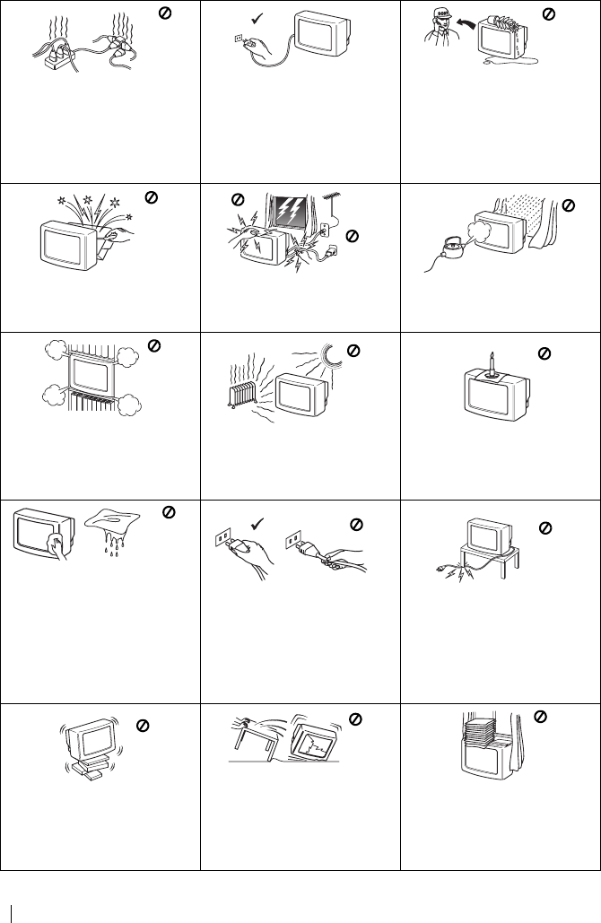
PDVWHUSDJH OHIW
4
.9&7%B*US8B)5
Consignes de sécurité
&HPRGqOHIRQFWLRQQHXQLTXHPHQWVXU
WHQVLRQVHFWHXUGHYROWV1H
FRQQHFWH]SDVWURSG·DSSDUHLOVVXUOD
PrPHSULVHDILQGHQHSDVULVTXHUXQ
LQFHQGLHRXXQFKRFpOHFWULTXH
3RXUGHVUDLVRQVHQYLURQQHPHQWDOHVHW
GHVpFXULWpLOHVWUHFRPPDQGpGHQH
SDVODLVVHUOHWpOpYLVHXUHQYHLOOH
ORUVTXHYRXVQHO·XWLOLVH]SDV3RXUGHV
SpULRGHVSURORQJpHVG·LQXWLOLVDWLRQ
GpEUDQFKH]OHGHODSULVHGHFRXUDQW
1·LQWURGXLVH]MDPDLVDXFXQREMHWGDQV
OHWpOpYLVHXUDILQGHQHSDVULVTXHUXQ
FKRFpOHFWULTXH$VVXUH]YRXVGHQH
MDPDLVUHQYHUVHUGHOLTXLGHGDQV
O·DSSDUHLO6LXQOLTXLGHRXXQREMHW
SpQpWUDLWGDQVOHWpOpYLVHXU
GpEUDQFKH]OHSDUODSULVHVHFWHXUHW
QHO·XWLOLVH]SOXVDYDQWVDYpULILFDWLRQ
SDUOHVHUYLFHDSUqVYHQWH
1·RXYUH]SDVOHFDSRWHWOHERvWLHU
DUULqUHGXWpOpYLVHXU&RQWDFWH]
WRXMRXUVOHVHUYLFHDSUqVYHQWHHQFDV
GHSUREOqPH
3RXUYRWUHVpFXULWpQHWRXFKH]DXFXQH
SDUWLHGXWpOpYLVHXUFRUGRQVHFWHXURX
FkEOHG·DQWHQQHORUVG·XQRUDJH
3RXUpFDUWHUWRXWULVTXHG·LQFHQGLHRX
G·pOHFWURFXWLRQQ·H[SRVH]SDVOH
WpOpYLVHXUjO·KXPLGLWpRXjODSOXLH
1·REVWUXH]MDPDLVOHVRULILFHV
G·DpUDWLRQGXWpOpYLVHXU3RXUXQH
DpUDWLRQFRUUHFWHODLVVH]WRXMRXUVXQ
HVSDFHOLEUHG·DXPRLQVFPDXWRXU
GHO·DSSDUHLOVXUWRXWVLYRXV
O·HQFDVWUH]GDQVXQPHXEOH
1HSRVH]MDPDLVOHWpOpYLVHXUGDQVXQ
HQGURLWFKDXGKXPLGHRXWURS
SRXVVLpUHX[1HO·LQVWDOOH]SDVGDQVXQ
HQGURLWRLOSRXUUDLWrWUHVRXPLVjGHV
YLEUDWLRQVPpFDQLTXHV
3RXUQHSDVULVTXHUXQLQFHQGLH
pORLJQH]GXWpOpYLVHXUWRXWREMHW
LQIODPPDEOHRXOXPLqUHLQFDQGHVFHQWH
SDUH[HPSOHGHVERXJLHV
1HWWR\H]O·pFUDQHWOHFRIIUHWGHYRWUH
WpOpYLVHXUDYHFXQFKLIIRQGRX[
OpJqUHPHQWKXPLGH1·XWLOLVH]SDVGH
WDPSRQDEUDVLIG·DSSDUHLOGH
QHWWR\DJHDOFDOLQGHSRXGUH
UpFXUUHQWHRXGHVROYDQWFRPPHGH
O·DOFRROGXEHQ]LQHRXXQYDSRULVDWHXU
DQWLVWDWLTXH&RPPHSUpFDXWLRQGH
VpFXULWpQRXVYRXVUHFRPPDQGRQVGH
WRXMRXUVGpEUDQFKHUOHWpOpYLVHXUDYDQW
OHQHWWR\DJH
'pEUDQFKH]OHWpOpYLVHXUSDUODILFKH
G·DOLPHQWDWLRQ1HWLUH]SDVVXUOH
FRUGRQ
3UHQH]JDUGHGHQHSDVSODFHUGHV
REMHWVORXUGVVXUOHFRUGRQ
G·DOLPHQWDWLRQDILQGHQHSDV
O·HQGRPPDJHU
1RXVYRXVUHFRPPDQGRQVGHQHSDV
HQURXOHUGHFRUGRQWURSORQJDXWRXU
GHVVXSSRUWVjO·DUULqUHGXWpOpYLVHXU
,QVWDOOH]OHWpOpYLVHXUVXUXQPHXEOH
VWDEOH1HSHUPHWWH]SDVDX[HQIDQWV
GHPRQWHUGHVVXV1HSODFH]SDVOH
WpOpYLVHXUVXUXQF{WpRXVXUODIDoDGH
'pEUDQFKH]OHWpOpYLVHXUGXFRXUDQW
VHFWHXUDYDQWGHOHGpSODFHU'·XQH
IDoRQJpQpUDOHSHQGDQWVRQWUDQVSRUW
pYLWH]OHVYLEUDWLRQVHWOHV
GpIRUPDWLRQV6LOHWpOpYLVHXUWRPEDLW
RXpWDLWHQGRPPDJpIDLWHVOHYpULILHU
LPPpGLDWHPHQWSDUOHVHUYLFHDSUqV
YHQWH
1HFRXYUH]SDVOHV]RQHVG·DpUDWLRQGX
WpOpYLVHXUDYHFGHVpOpPHQWVWHOVTXH
GHVULGHDX[GHVMRXUQDX[HWF
Consignes de sécurité
)5.9&7%IP3DJH)ULGD\-XO\$0
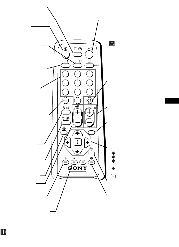
FR
PDVWHUSDJH ULJKW
5
.9&7%B*US8B)5
Présentation générale des touches de la télécommande
2XWUHOHVIRQFWLRQVGHWpOpYLVLRQWRXWHVOHVWRXFKHVGHFRXOHXUVRQWDXVVLXWLOLVpHVSRXUOHV
IRQFWLRQVGHWpOpWH[WH3RXUWRXWUHQVHLJQHPHQWFRPSOpPHQWDLUHFRQVXOWH]OHFKDSLWUH
´7pOpWH[WHµGHFHPRGHG·HPSORLYRLUSDJH
TV
123
46
789
0
5
MENU
PROG
A/B
Visualisation de
l’information sur l’écran
$SSX\H]VXUFHWWHWRXFKHSRXU
SUpVHQWHUWRXWHVOHVLQIRUPDWLRQV
VXUO·pFUDQ$SSX\H]jQRXYHDX
SRXUOHVIDLUHGLVSDUDvWUH
Coupure du son
$SSX\H]VXUFHWWHWRXFKHSRXU
FRXSHUOHVRQ
$SSX\H]jQRXYHDXSRXUOH
UpFXSpUHU
Sélection de la source
d’entrée
$SSX\H]SOXVLHXUVIRLVVXUFHWWH
WRXFKHMXVTX·jFHTXHOHV\PEROH
GHODVRXUFHG·HQWUpHDSSDUDLVVH
VXUO·pFUDQ
&HWWHWRXFKHQHIRQFWLRQQHTX·HQ
PRGHWpOpWH[WH
/DIRQFWLRQ$%DVVRFLpHjFHWWH
WRXFKHQHIRQFWLRQQHSDVVXUFH
WpOpYLVHXU
Sélection des chaînes
$SSX\H]VXUFHVWRXFKHVSRXU
VpOHFWLRQQHUOHVFKDvQHV
3RXUGHVQXPpURVGHFKDvQHj
GHX[FKLIIUHVDSSX\H]VXUOH
WURLVLqPHFKLIIUHUDSLGHPHQW
RX
$SSX\H]VXUHWHQVXLWHVXUOH
SUHPLHUHWOHVHFRQGFKLIIUH
6LYRXVYRXVWURPSH]HQ
LQWURGXLVDQWOHSUHPLHUFKLIIUH
LQWURGXLVH]FHSHQGDQWOH
GHX[LqPHFKLIIUHGHjHW
UpSpWH]HQVXLWHO·RSpUDWLRQ
Marche Temporaire
5pJOH]OHWpOpYLVHXUSRXUTX·LOVH
PHWWHDXWRPDWLTXHPHQWVRXV
WHQVLRQ
Arrêt Temporaire
5pJOH]OHWpOpYLVHXUSRXUTX·LOVH
PHWWHDXWRPDWLTXHPHQWKRUV
WHQVLRQ
7RXFKHVDQVIRQFWLRQVXUFHW
DSSDUHLO
Réglage du volume
$SSX\H]VXUFHWWHWRXFKHSRXU
UpJOHUOHYROXPHGXWpOpYLVHXU
&HWWHWRXFKHQHIRQFWLRQQHTX·HQ
PRGHWpOpWH[WH
/DIRQFWLRQ
9
DVVRFLpHjFHWWHWRXFKH
QHIRQFWLRQQHSDVVXUFHWpOpYLVHXU
Sélection du mode d’image
$SSX\H]SOXVLHXUVIRLVVXUFHWWH
WRXFKHSRXUFKDQJHUGHPRGH
G·LPDJH
Eteindre temporairement le téléviseur
$SSX\H]VXUFHWWHWRXFKHSRXUpWHLQGUHWHPSRUDLUHPHQWOH
WpOpYLVHXUOHYR\DQWGHPLVHHQYHLOOH
1
V·pFODLUHUD$SSX\H]j
QRXYHDXSRXUDOOXPHUOHWpOpYLVHXUjSDUWLUGXPRGHYHLOOHVWDQGE\
3RXUXQHPHLOOHXUHpFRQRPLH
G·pQHUJLHLOHVWFRQVHLOOp
G·pWHLQGUHFRPSOqWHPHQWOH
WpOpYLVHXUORUVTX·RQQHO·XWLOLVH
SDV
(QO·DEVHQFHGHVLJQDO
DQWHQQHVLO·RQQ·DSSXLHVXU
DXFXQHWRXFKHOHWpOpYLVHXU
SDVVHUDDXWRPDWLTXHPHQWHQ
PRGHYHLOOHVWDQGE\DXERXWGH
PLQXWHV
Sélection du mode TV
$SSX\H]VXUFHWWHWRXFKHSRXU
GpVDFWLYHUOHWpOpWH[WHRXO·HQWUpH
YLGpR
Retour à la dernière chaîne
$SSX\H]SOXVLHXUVIRLVVXUFHWWH
WRXFKHSRXUUHYHQLUjODGHUQLqUH
FKDvQHVpOHFWLRQQpHODFKDvQH
SUpFpGHQWHGRLWDYRLUpWpYLVLRQ
QpHSHQGDQWVHFRQGHVDX
PRLQV
Sélection des chaînes
$SSX\H]VXUFHWWHWRXFKHSRXU
VpOHFWLRQQHUODFKDvQHVXLYDQWHRX
ODFKDvQHSUpFpGHQWH
Activation du Système des
Menus
$SSX\H]VXUFHWWHWRXFKHSRXU
TXHOHPHQXDSSDUDLVVHVXU
O·pFUDQ$SSX\H]jQRXYHDXSRXU
OHGpVDFWLYHU
Touches de sélection du
menu
0RQWHUG·XQQLYHDX
'HVFHQGUHG·XQQLYHDX
$OOHUDXPHQXRXjOD
VpOHFWLRQSUpFpGHQWH
$OOHUDXPHQXRXjOD
VpOHFWLRQVXLYDQWH
&RQILUPHUODVpOHFWLRQ
Sélection du Télétexte
$SSX\H]VXUFHWWHWRXFKHSRXU
DIILFKHUOHWpOpWH[WH
Sélection du format de
l’écran
$SSX\H]SOXVLHXUVIRLVVXUFHWWH
WRXFKHSRXUSDVVHUGXIRUPDWGH
O·pFUDQLPDJH
FRQYHQWLRQQHOOHjXQHLPDJHDX
IRUPDW
Description générale
)5.9&7%IP3DJH)ULGD\-XO\$0
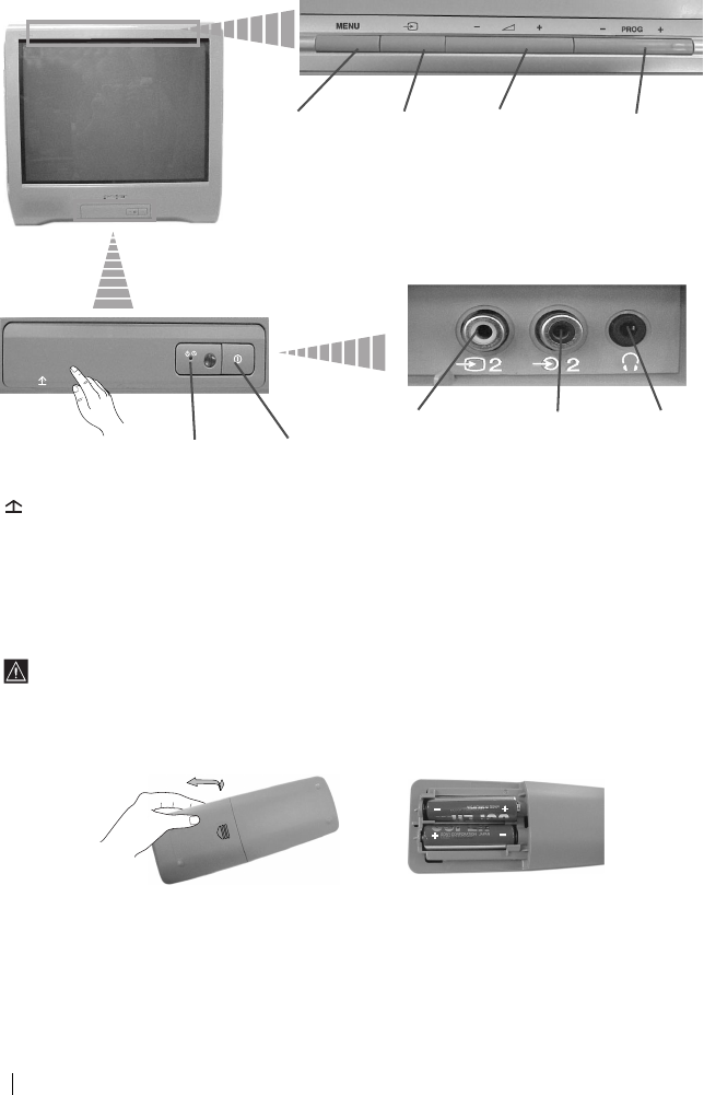
PDVWHUSDJH OHIW
6
.9&7%B*US8B)5
Présentation générale des touches du
téléviseur
Insertion des piles dans la télécommande
9pULILH]TXHOHVSLOHVVRQWFRUUHFWHPHQWSODFpHV
5HVSHFWH]O·HQYLURQQHPHQWGpSRVH]OHVSLOHVXVDJpHVGDQVOHVFRQWHQHXUVSUpYXVjFHW
HIIHW
$FWLYDWLRQ
GX6\VWqPH
GHV0HQXV
7RXFKHGH
VpOHFWLRQGH
ODVRXUFH
G·HQWUpH
7RXFKHVGH
FRQWU{OHGX
VRQ
7RXFKHGH
VpOHFWLRQGHV
FKDvQHV
5HOHYH]OH
FRXYHUFOHVXU
OHTXHOODPDUTXH
HVWLQVFULWH
SRXUDFFpGHUDX
SDQQHDXGH
FRPPDQGH
,QGLFDWHXU
GHPLVHHQ
YHLOOH
VWDQGE\
,QWHUUXSWHXU
PDUFKHDUUrW
3ULVHHQWUpH
YLGpR
3ULVHHQWUpH
DXGLR
3ULVH
FDVTXH
Description générale-Installation
)5.9&7%IP3DJH)ULGD\-XO\$0
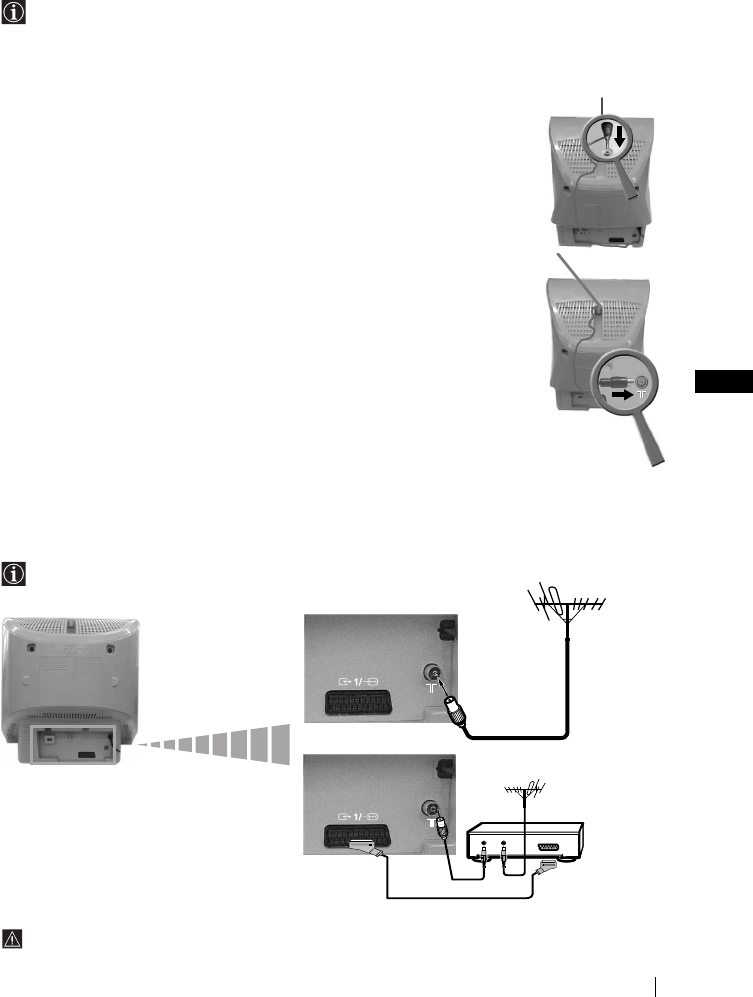
FR
PDVWHUSDJH ULJKW
7
.9&7%B*US8B)5
Branchement de l’antenne amovible
(pour KV-14CT1B uniquement)
3RXUXQHPHLOOHXUHUpFHSWLRQGHO·LPDJHQRXVYRXVFRQVHLOORQVGHFRQQHFWHUO·DSSDUHLOj
XQHDQWHQQHH[WpULHXUH&HSHQGDQWVLYRXVQHGLVSRVH]SDVG·DQWHQQHH[WpULHXUHPDLVTXH
OHVLJQDO9+)8+)HVWVXIILVDPPHQWIRUWYRXVSRXYH]FRQQHFWHUO·DQWHQQHWpOHVFRSLTXH
IRXUQLHDYHFFHWDSSDUHLOFRPPHLQGLTXpFLGHVVRXV
1,QVpUH]O·DQWHQQHGDQVODUDLQXUHVLWXpHVXUODSDUWLHVXSpULHXUHGX
WpOpYLVHXUMXVTX·jFHTX·HOOHIDVVH´FOLFµ
2&RQQHFWH]OHFkEOHGHO·DQWHQQHDXFRQQHFWHXUDUULqUHGHO·DSSDUHLO.
3$OOXPH]O·DSSDUHLOHWRULHQWH]O·DQWHQQHGHIDoRQjREWHQLUXQH
ERQQHUpFHSWLRQGHO·LPDJH
Branchement de l’antenne extérieure et du
magnétoscope
/HVFkEOHVGHFRQQH[LRQQHVRQWSDVIRXUQLV
3RXUGHSOXVDPSOHVGpWDLOVVXUOHEUDQFKHPHQWGXPDJQpWRVFRSHFRQVXOWH]OHFKDSLWUH
´&RQQH[LRQGHVpTXLSHPHQWVHQRSWLRQµGHFHPRGHG·HPSORLYRLUSDJH
OUT IN
RX
PDJQpWRVFRSH
/HEUDQFKHPHQWSDUFRQQHFWHXU3pULWHOHVWSUpVHQWpHQRSWLRQ
Installation
)5.9&7%IP3DJH)ULGD\-XO\$0
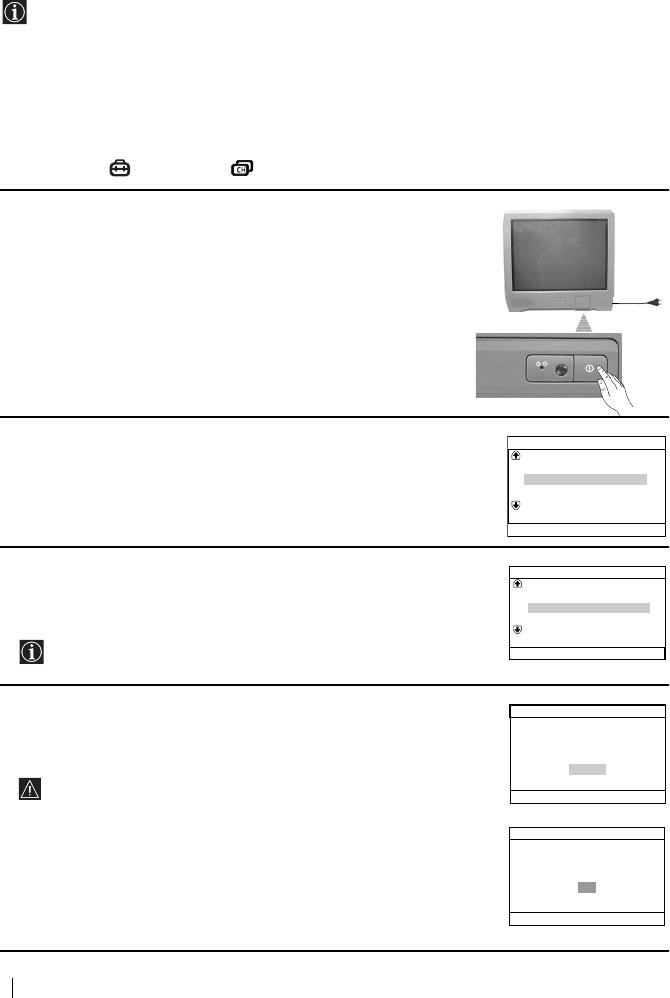
PDVWHUSDJH OHIW
8
.9&7%B*US8B)5
Mise sous tension et mémorisation
automatique des chaînes du téléviseur
/DSUHPLqUHIRLVTXHYRXVDOOXPHUH]OHWpOpYLVHXUXQHVpTXHQFHGHPHQXVDSSDUDvWUDVXU
OpFUDQ(OOHYRXVSHUPHWWUDGHVpOHFWLRQQHUODODQJXHGHVpFUDQVGHPHQXV
VpOHFWLRQQHUOHSD\VGDQVOHTXHOYRXVGpVLUH]XWLOLVHUODSSDUHLOFKHUFKHUHWPpPRULVHU
DXWRPDWLTXHPHQWWRXWHVOHVFKDvQHVGLVSRQLEOHVpPHWWHXUV79PRGLILHUORUGUHGDQV
OHTXHOOHVFKDvQHVpPHWWHXUV79DSSDUDLVVHQWVXUOpFUDQHWUpJOHUOLQFOLQDLVRQGH
OLPDJHSRXU.9&7%XQLTXHPHQW
&HSHQGDQWVLDXERXWGXQFHUWDLQWHPSVYRXVGHYH]jQRXYHDXFKDQJHUODODQJXHGHV
PHQXVRXGHSD\VUHSUHQGUHODPpPRULVDWLRQDXWRPDWLTXHHQFDVGHGpPpQDJHPHQWSDU
H[RXPRGLILHUORUGUHGHVFDQDX[YRXVSRXYH]OHIDLUHHQVpOHFWLRQQDQWOHPHQX
DSSURSULp 5pJODJHRX 5pJODJHGHVFKDvQHV
1&RQQHFWH]OLQWHUUXSWHXUGXWpOpYLVHXUjODSULVHGHFRXUDQW
9&$+]$SSX\H]VXUOLQWHUUXSWHXUPDUFKHDUUrW
!GHODSDUWLHIURQWDOHGXWpOpYLVHXUSRXUODOOXPHU/DSUHPLqUH
IRLVTXHYRXVDOOXPHUH]OHWpOpYLVHXUOHPHQX/DQJXDJH
/DQJXHDSSDUDvWUDDXWRPDWLTXHPHQWVXUOpFUDQ
2$SSX\H]VXUODWRXFKH2²VXUOHSDQQHDXGHFRPPDQGH
VXSpULHXUSRXUVpOHFWLRQQHUODODQJXHSXLVDSSX\H]VXUtSRXU
FRQILUPHUODVpOHFWLRQ$SDUWLUGHFHPRPHQWWRXVOHVPHQXV
DSSDUDvWURQWGDQVODODQJXHTXHYRXVDYH]FKRLVLH
3/HPHQX3D\VDSSDUDvWUDDXWRPDWLTXHPHQWVXUOpFUDQ$SSX\H]
VXUODWRXFKH2²SRXUVpOHFWLRQQHUOHSD\VGDQVOHTXHOYRXV
GpVLUH]XWLOLVHUOHWpOpYLVHXUHWDSSX\H]HQVXLWHVXUODWRXFKHt
SRXUFRQILUPHUODVpOHFWLRQ
6LOHSD\VRYRXVDOOH]XWLOLVHUOHWpOpYLVHXUQHILJXUHSDVVXUOD
OLVWHVpOHFWLRQQH]´µDXOLHXGHVpOHFWLRQQHUXQSD\V
4$VVXUH]YRXVTXHOHFkEOHG·DQWHQQHHVWFRUUHFWHPHQWEUDQFKp
VXLYDQWOHVLQVWUXFWLRQVIRXUQLHVSXLVDSSX\H]VXUtSRXU
FRQILUPHU/HUpJODJHHWODPpPRULVDWLRQDXWRPDWLTXHGHWRXVOHV
FDQDX[pPHWWHXUV79GLVSRQLEOHVFRPPHQFHQW
&HSURFHVVXVSHXWGHPDQGHUTXHOTXHVPLQXWHV6R\H]
SDWLHQWHWQDSSX\H]VXUDXFXQHWRXFKHWDQWTXHGXUHUDOH
SURFHVVXVGHPpPRULVDWLRQ6LQRQOHSURFHVVXVQHVHUDLWSDV
FRPSOHW
6LOHWpOpYLVHXUQDWURXYpDXFXQHFKDvQHpPHWWHXU79DSUqV
ODPpPRULVDWLRQDXWRPDWLTXHYRXVYHUUH]DSSDUDvWUHVXU
OpFUDQXQPHVVDJHYRXVGHPDQGDQWGHEUDQFKHUODQWHQQH
9HXLOOH]ODEUDQFKHUFRPPHLQGLTXpjODSDJH GHFHPDQXHO
HWDSSX\H]HQVXLWHVXUODWRXFKHt/HSURFHVVXVGH
PpPRULVDWLRQDXWRPDWLTXHUHSUHQGUD
Language
Svenska
English
Nederlands
Français
Select language
Norsk
Confirm [t]
Select [
–
2+]
Pays
Sélection pays
Sverige
Norge
Schweiz/Suisse/Svizzera
Italia
–
Confirm.[t]
Sélect. [–2+]
Réglage des chaînes en
Connectez l'antenne
automatique?
Non
Réglage initial
Oui
Confirm. [t]
Sélect. [–2+]Fin
[
MENU
]
Mémorisation auto.
Confirm. [t]Fin
[
MENU
]
Pas de chaîne trouvée
Merci de brancher l'antenne
OK
Première mise en service
)5.9&7%IP3DJH)ULGD\-XO\$0
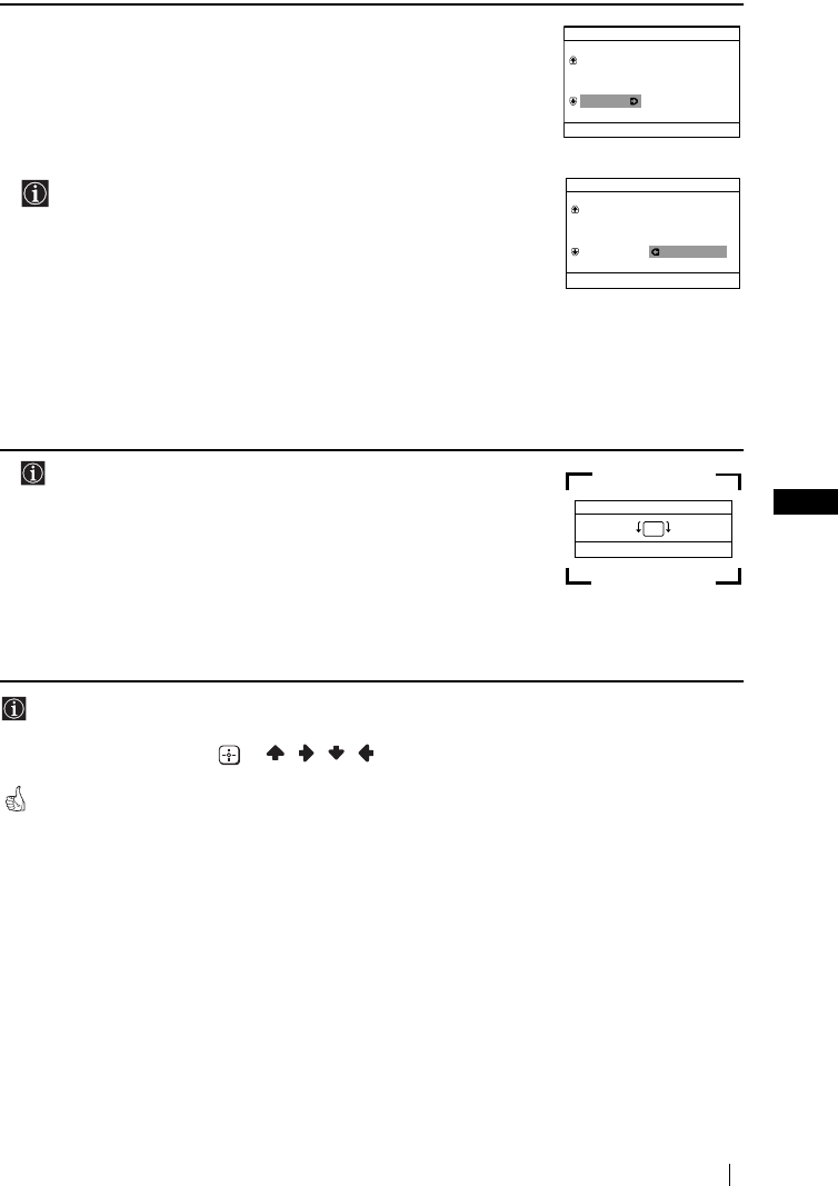
FR
PDVWHUSDJH ULJKW
9
.9&7%B*US8B)5
5/RUVTXHWRXWHVOHVFKDvQHVpPHWWHXUV79RQWpWpUpJOpHVHW
PpPRULVpHVOHPHQX2UGUHGHVFKDvQHVDSSDUDvW
DXWRPDWLTXHPHQWVXUO·pFUDQ,OSHUPHWGHFKDQJHUO·RUGUH
G·DSSDULWLRQGHVFKDvQHVVXUO·pFUDQ
a)
6LYRXVQHGpVLUH]SDVFKDQJHUO·RUGUHGHVFKDvQHVDSSX\H]VXU
0(18
b) 6LYRXVGpVLUH]FKDQJHUO·RUGUHGHVFKDvQHV
/HFKDQJHPHQWGHO·HPSODFHPHQWG·XQHFKDvQHERXOHYHUVHUD
O·RUGUHGHVFKDvQHVVXLYDQWHV,OIDXWGRQFFRPPHQFHUFHWWH
UpRUJDQLVDWLRQGDQVO·RUGUHFURLVVDQWH[7)VXUOHQXPpUR
)UDQFHVXUOHQXPpUR)UDQFHVXUOHQXPpURHWF
$SSX\H]VXUODWRXFKH2²SRXUVpOHFWLRQQHUOHQXPpUR
GHODFKDvQHHWOHFDQDOpPHWWHXU79TXHYRXVGpVLUH]
FKDQJHUGHSODFHHWDSSX\H]HQVXLWHVXUt
$SSX\H]VXUODWRXFKH2²SRXUVpOHFWLRQQHUOHQRXYHDX
QXPpURGHFKDvQHVRXVOHTXHOYRXVGpVLUH]PpPRULVHUOH
FDQDOpPHWWHXU79VpOHFWLRQQpHWDSSX\H]HQVXLWHVXUt
5HSUHQH]jEHWEVLYRXVGpVLUH]UpRUJDQLVHUGDXWUHV
FKDvQHVGHWpOpYLVLRQ
6/·RSWLRQVXLYDQWHHVWXQLTXHPHQWGLVSRQLEOHSRXUOH
.9&7%
'XIDLWGXPDJQpWLVPHWHUUHVWUHOLPDJHSHXWDSSDUDvWUHSHQFKpH
/HPHQX5RWDWLRQG·LPDJHYRXVSHUPHWGHUpJOHUOLPDJHVL
QpFHVVDLUH
a) 6LFHODQHVWSDVQpFHVVDLUHDSSX\H]VXUt
b) 6LFHODVDYqUHQpFHVVDLUHDSSX\H]VXU2²SRXUUHFWLILHU
WRXWHLQFOLQDLVRQGHOLPDJH)LQDOHPHQWDSSX\H]VXUODWRXFKH
tSRXUODPpPRULVHU
3RXUTXHOHPHQXDSSDUDLVVHGHQRXYHDXPDLQWHQH]HQIRQFpHODWRXFKH0(18GX
SDQQHDXGHFRPPDQGHVXSpULHXUSHQGDQWFLQTVHFRQGHVHQYLURQ
/HVWRXFKHV0(18 HW GHODWpOpFRPPDQGHSHXYHQWpJDOHPHQWrWUH
XWLOLVpHVSRXUHIIHFWXHUOHVRSpUDWLRQVFLGHVVXV
/HWpOpYLVHXUHVWSUrWjIRQFWLRQQHU
Ordre des chaînes
Chaînes:
Sélect. canal
Confirm. [t]
Sélect. [
–
2+]Quit.
[
MENU
]
TVE
TVE2
TV3
04 C33
01
02
03
Ordre des chaînes
Chaînes:
Sélect. nouveau N
o
Sélect. [–2+]Confirm. [t]Quit. [
MENU
]
01 TVE
02 TVE2
03 TV3
04 C33 03 TV3
Confirm. [t]Fin
Sélect. [
–
2+]
Rotation d'image
[2+]
[–2]
[
MENU
]
Première mise en service
)5.9&7%IP3DJH)ULGD\-XO\$0
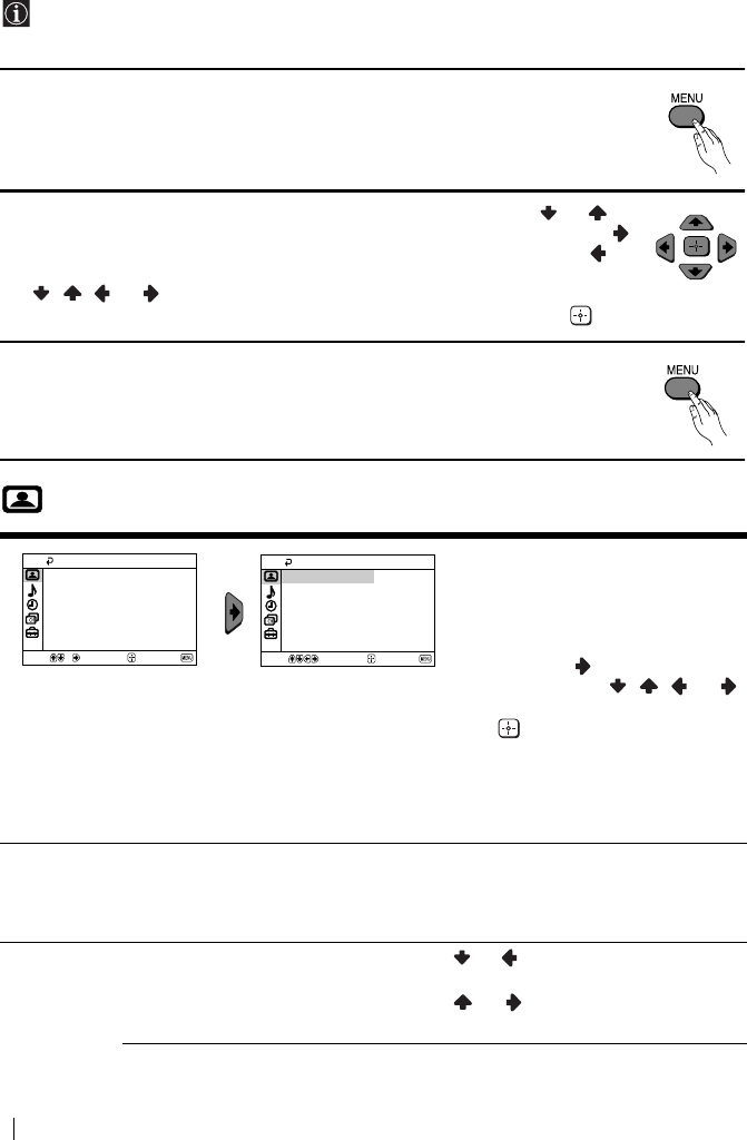
PDVWHUSDJH OHIW
10
.9&7%B*US8B)5
Introduction au Système des menus et son utilisation
&HWpOpYLVHXUXWLOLVHXQV\VWqPHGHPHQXVVXUpFUDQSRXUYRXVJXLGHUGDQVOHVGLYHUVHV
RSpUDWLRQVTXHYRXVHIIHFWXH]8WLOLVH]OHVWRXFKHVVXLYDQWHVGHODWpOpFRPPDQGHSRXU
SDVVHUGXQPHQXjODXWUH
1$SSX\H]VXUODWRXFKH0(18SRXUSUpVHQWHUOHSUHPLHUQLYHDXGHPHQXVXU
OpFUDQ
23RXUREWHQLUOHPHQXRXORSWLRQGpVLUpHDSSX\H]VXUODWRXFKH RX
3RXUHQWUHUGDQVOHPHQXRXORSWLRQVpOHFWLRQQpHDSSX\H]VXUODWRXFKH
3RXUUHYHQLUDXPHQXRXjORSWLRQSUpFpGHQWHDSSX\H]VXUODWRXFKH
3RXUPRGLILHUOHVUpJODJHVGHORSWLRQVpOHFWLRQQpHDSSX\H]VXUODWRXFKH
RX
3RXUFRQILUPHUHWPpPRULVHUYRWUHVpOHFWLRQDSSX\H]VXUODWRXFKH
3$SSX\H]VXUODWRXFKH0(18SRXUUHYHQLUjOLPDJHWpOpYLVpH
Image
/HPHQX´OPDJHµYRXVSHUPHWGH
PRGLILHUOHVUpJODJHVGHOLPDJH
3RXUFHOD
$SUqVDYRLUVpOHFWLRQQpORSWLRQ
TXHYRXVGpVLUH]PRGLILHUDSSX\H]
VXUODWRXFKH 3XLVDSSX\H]
SOXVLHXUVIRLVVXU RX
SRXUPRGLILHUOHUpJODJHHWHQVXLWH
VXU SRXUHQWUHUFHQRXYHDX
UpJODJHHQPpPRLUH
&HPHQXYRXVSHUPHWDXVVLGH
PRGLILHUOHPRGHGHOLPDJHVXLYDQW
OHW\SHGHFKDvQHTXHYRXVrWHVHQ
WUDLQGHUHJDUGHU
0RGH 6WXGLRSRXUUpJOHUOHFRQWUDVWHHWODQHWWHWpGHO·LPDJH
&LQpPDSRXUXQHLPDJHPHWWDQWOHVGpWDLOVHQYDOHXU
-HX[SRXUOHVMHX[VXUFRQVROH
3HUVRQQHOSRXUXQUpJODJHHQIRQFWLRQGHYRVSUpIpUHQFHV
&RQWU{OHGH
OLPDJH
&RQWUDVWH $SSX\H]VXUODWRXFKH RX SRXUUpGXLUHOHFRQWUDVWHGH
O·LPDJH
$SSX\H]VXUODWRXFKH RX
SRXUUHQIRUFHUOHFRQWUDVWH
GHO·LPDJH
Sélect. Confirm. Fin
Image
Image intelligente: Oui
Contrôle de l'image
Mode: Studio
Sélect. Confirm. Fin
Image
Image intelligente: Oui
Contrôle de l'image
Mode: Studio
Système des menus
)5.9&7%IP3DJH)ULGD\-XO\$0
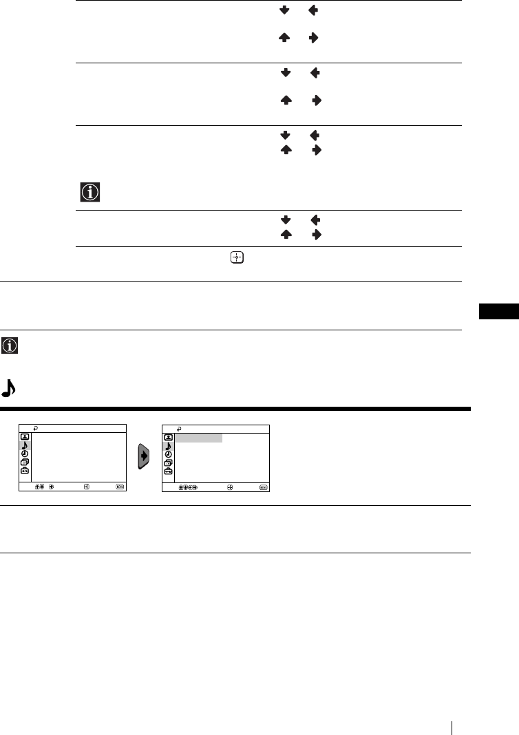
FR
PDVWHUSDJH ULJKW
11
.9&7%B*US8B)5
$FKDTXHPRGLILFDWLRQGXUpJODJH´&RQWU{OHGHOLPDJHµ´0RGHµSDVVH
DXWRPDWLTXHPHQWj´3HUVRQQHOµHWOHQRXYHDXUpJODJHHVWHQUHJLVWUpVRXV´3HUVRQQHOµ
Son
/XPLQRVLWp $SSX\H]VXUODWRXFKH RX SRXUREWHQLUXQHLPDJHSOXV
VRPEUH
$SSX\H]VXUODWRXFKH RX
SRXUREWHQLUXQHLPDJHSOXV
OXPLQHXVH
&RXOHXUV $SSX\H]VXUODWRXFKH RX SRXUUpGXLUHO·LQWHQVLWpGHV
FRXOHXUV
$SSX\H]VXUODWRXFKH RX
SRXUDXJPHQWHUO·LQWHQVLWp
GHVFRXOHXUV
7HLQWH $SSX\H]VXUODWRXFKH RX SRXUDIIDLEOLUOHVWRQVYHUWV
$SSX\H]VXUODWRXFKH RX
SRXULQWHQVLILHUOHVWRQV
YHUWV
7HLQWHQHSHXWrWUHUpJOpSRXUOHVLJQDOFRXOHXU176&SH[YLGpRV
SURYHQDQWGHV(WDWV8QLV
1HWWHWp $SSX\H]VXUODWRXFKH RX SRXUDGRXFLUO·LPDJH
$SSX\H]VXUODWRXFKH RX
SRXUUDYLYHUO·LPDJH
5j= 6pOHFWLRQQH] SRXUUDPHQHUO·LPDJHjODFRQILJXUDWLRQ
G·XVLQH
,PDJH
LQWHOOLJHQWH
2XL$UUrW 6pOHFWLRQQH]SRXURSWLPLVHUODTXDOLWpG·LPDJH
3DUH[HPSOHUpGXLUHOHQLYHDXVRQRUHORUVTXHOHVLJQDOHVW
IDLEOH
/HPHQX´6RQµSHUPHWGHPRGLILHU
OHVSDUDPqWUHVGXVRQ
9ROXPHDXWR 2XL$UUrW
/HQLYHDXGXYROXPHGHVFKDvQHVpPHWWHXUV79GRLWUHVWHUVWDEOH
LQGpSHQGDPPHQWGXVLJQDOpPLVSH[GDQVOHFDVG·DQQRQFHVSXEOLFLWDLUHV
Son
Volume auto.: Arrêt
Sélect. Confirm. Fin
Son
Volume auto.: Arrêt
Sélect. Confirm. Fin
Système des menus
)5.9&7%IP3DJH)ULGD\-XO\$0
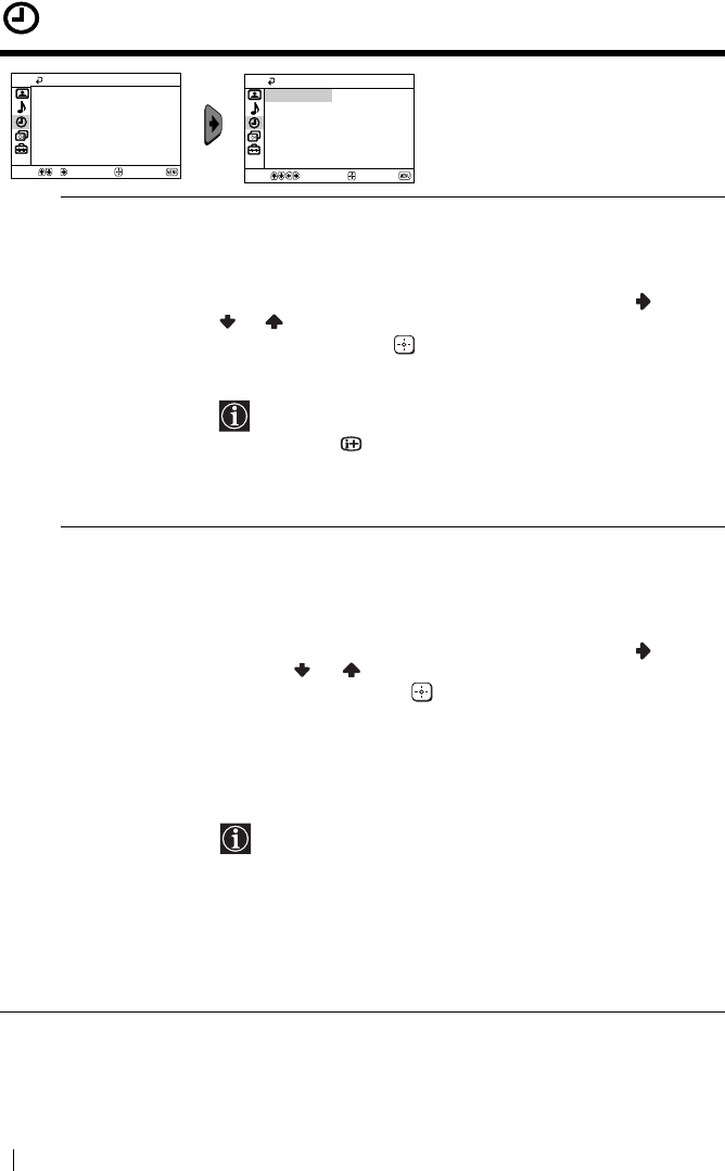
PDVWHUSDJH OHIW
12
.9&7%B*US8B)5
Temporisation
/HPHQX´7HPSRULVDWLRQµYRXV
SHUPHWGHPRGLILHUOHVUpJODJHVGX
SURJUDPPDWHXU
$UUrW7HPSRUDLUH /·RSWLRQ´$UUrWWHPSRµTXLIDLWSDUWLHGXPHQX´7HPSRULVDWLRQµ
YRXVSHUPHWGHVpOHFWLRQQHUXQWHPSVDSUqVOHTXHOOHWpOpYLVHXU
SDVVHDXWRPDWLTXHPHQWHQPRGHGDUUrWWHPSRUDLUHVWDQGE\
3RXUFHOD
$SUqVDYRLUVpOHFWLRQQpORSWLRQDSSX\H]VXUODWRXFKH SXLVVXU
RX SRXUVpOHFWLRQQHUODGXUpHKHXUHPLQXWHVDXSOXVHW
DSSX\H]VXUODWRXFKH SRXUHQWHUFHWWHQRXYHOOHGRQQpHHQ
PpPRLUH
6LSHQGDQWTXHYRXVUHJDUGH]ODWpOpYLVLRQYRXVGpVLUH]
VDYRLUOHWHPSVTXLUHVWHDYDQWODUUrWDSSX\H]VXUOD
WRXFKH
8QHPLQXWHDYDQWTXHOHWpOpYLVHXUQHSDVVHHQPRGH
GDWWHQWHOHPHVVDJH´/HWpOpYDVDUUrWHUµVDIILFKH
DXWRPDWLTXHPHQWjOpFUDQGXWpOpYLVHXU
0DUFKH
7HPSRUDLUH
/RSWLRQ´0DUFKHWHPSRµTXLIDLWSDUWLHGXPHQX
´7HPSRULVDWLRQµYRXVSHUPHWGHVpOHFWLRQQHUXQHSpULRGHGH
WHPSVDSUqVODTXHOOHOHWpOpYLVHXUVHFRQQHFWHUDDXWRPDWLTXHPHQW
jSDUWLUGXPRGHGDUUrWWHPSRUDLUHVWDQGE\
3RXUFHOD
$SUqVDYRLUVpOHFWLRQQpORSWLRQDSSX\H]VXUODWRXFKH SXLVVXU
ODWRXFKH RXSRXUVpOHFWLRQQHUODGXUpHKHXUHVDXSOXV
HWDSSX\H]VXUODWRXFKH SRXUHQWUHUFHWWHQRXYHOOHGRQQpHHQ
PpPRLUH)LQDOHPHQWDSSX\H]VXUODWRXFKH&/1GHPLVHHQYHLOOH
VWDQGE\GHODWpOpFRPPDQGHHWORUVTXHOHWHPSVIL[pVHVHUD
pFRXOpOHWpOpYLVHXUVDOOXPHUDDXWRPDWLTXHPHQW8QHIRLVOHGpODL
VpOHFWLRQQppFRXOpOHWpOpYLVHXUVHPHWDXWRPDWLTXHPHQWVRXV
WHQVLRQHW´0DUFKHWHPSRµVDIILFKHjOpFUDQ
/·LQGLFDWHXU1GHPLVHHQYHLOOHVWDQGE\GXWpOpYLVHXU
VDOOXPHHQRUDQJHSRXULQGLTXHUTXHODIRQFWLRQGH
PLQXWHULH´0DUFKHWHPSRµHVWDFWLYpH
7RXWHSDQQHRXFRXSXUHGHFRXUDQWDQQXOHUDFHWWH
IRQFWLRQ
6LDXFXQHWRXFKHQHVWDFWLYpHSHQGDQWSOXVGXQHKHXUH
DSUqVODPLVHVRXVWHQVLRQGXWpOpYLVHXUjODLGHGHOD
IRQFWLRQ´0DUFKHWHPSRµOHWpOpYLVHXUSDVVH
DXWRPDWLTXHPHQWHQPRGHGDWWHQWH
Temporisation
Marche tempo.:
Arrêt tempo.: Arrêt
Arrêt
Sélect. Fin
Confirm.
Temporisation
Marche tempo.:
Arrêt tempo.: Arrêt
Arrêt
Sélect. Confirm. Fin
Système des menus
)5.9&7%IP3DJH)ULGD\-XO\$0
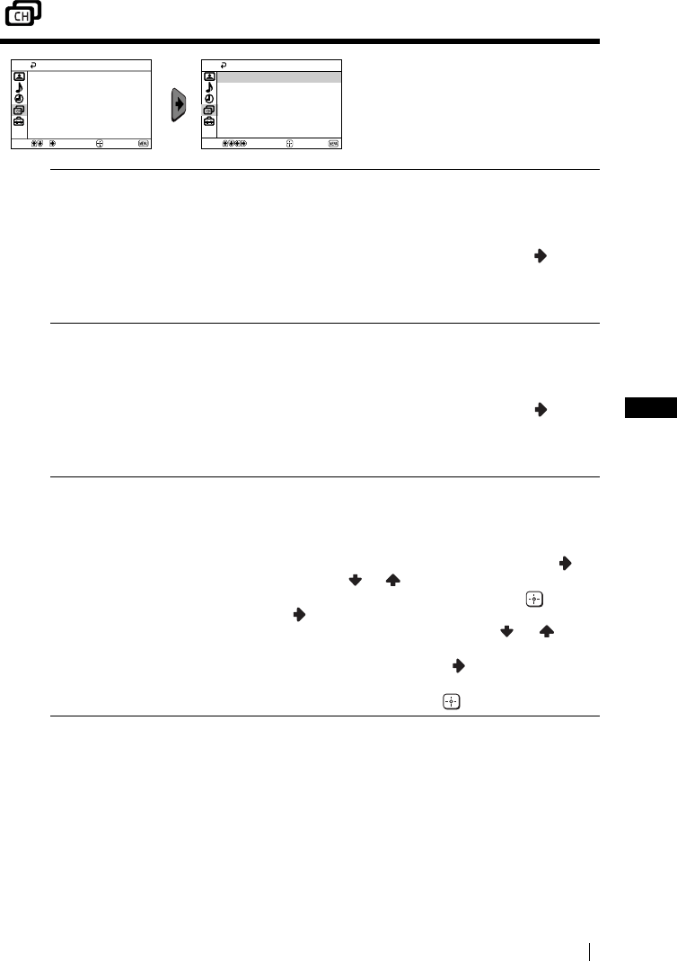
FR
PDVWHUSDJH ULJKW
13
.9&7%B*US8B)5
Réglage des chaînes
/HPHQX´5pJODJHGHVFKDvQHVµYRXV
SHUPHWGHSUpVpOHFWLRQQHUGHVFKDvQHV
VXUFHWpOpYLVHXU
0pPRULVDWLRQ
DXWRPDWLTXHV
/RSWLRQ´0pPRULVDWLRQDXWRµGXPHQX´5pJODJHGHVFKDvQHVµ
SHUPHWDXWpOpYLVHXUGHFKHUFKHUHWGHPpPRULVHUWRXVOHVFDQDX[
pPHWWHXUV79GLVSRQLEOHV
3RXUFHOD
$SUqVDYRLUVpOHFWLRQQpORSWLRQDSSX\H]VXUODWRXFKH HW
SURFpGH]HQVXLWHFRPPHLQGLTXpDXFKDSLWUH´0LVHVRXVWHQVLRQHW
PHPRULVDWLRQDXWRPDWLTXHGHVFKDvQHVGXWpOpYLVHXUµpWDSH
YRLUSDJH
2UGUHGHVFKDvQHV /RSWLRQ´2UGUHGHVFKDvQHVµGXPHQX´5pJODJHGHVFKDvQHVµ
YRXVSHUPHWGHFKDQJHUORUGUHGDSSDULWLRQGHVFDQDX[
pPHWWHXUV79
3RXUFHOD
$SUqVDYRLUVpOHFWLRQQpORSWLRQDSSX\H]VXUODWRXFKH HW
SURFpGH]HQVXLWHFRPPHLQGLTXpGDQVOHFKDSLWUH´0LVHVRXV
WHQVLRQHWPHPRULVDWLRQDXWRPDWLTXHGHVFKDvQHVGXWpOpYLVHXUµ
pWDSHEYRLUSDJH
1RPVGHVFKDvQHV /RSWLRQ´1RPVGHVFKDvQHVµGXPHQX´5pJODJHGHVFKDvQHVµYRXV
SHUPHWGDWWULEXHUjXQHFKDvQHXQQRPGHFLQTFDUDFWqUHV
PD[LPXP
3RXUFHOD
$SUqVDYRLUVpOHFWLRQQpORSWLRQDSSX\H]VXUODWRXFKH
$SSX\H]VXUODWRXFKH RX SRXUVpOHFWLRQQHUODFKDvQHTXH
YRXVGpVLUH]QRPPHUSXLVDSSX\H]VXUODWRXFKH
$SSX\H]VXU
/RUVTXHOHSUHPLHUpOpPHQWGHODFRORQQH
1RPHVWPLVHQYDOHXUDSSX\H]VXUODWRXFKH RX SRXU
VpOHFWLRQQHUXQHOHWWUHXQFKLIIUHRX´BµSRXUXQHVSDFHHQ
EODQFHWDSSX\H]HQVXLWHVXUODWRXFKH
SRXUFRQILUPHUFH
FDUDFWqUH6pOHFWLRQQH]OHVTXDWUHDXWUHVFDUDFWqUHVGHODPrPH
IDoRQHWDSSX\H]HQILQVXUODWRXFKH SRXUOHVPpPRULVHU
Réglage des chaînes
Noms des chaînes
Mémorisation manuelle
Ordre des chaînes
Mémorisation auto.
Sélect. Confirm. Fin
Réglage des chaînes
Noms des chaînes
Mémorisation manuelle
Ordre des chaînes
Mémorisation auto.
Sélect. Confirm. Fin
Système des menus
YRLUSDJHVXLYDQWH693
)5.9&7%IP3DJH)ULGD\-XO\$0
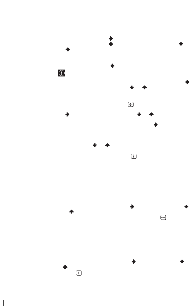
PDVWHUSDJH OHIW
14
.9&7%B*US8B)5
0pPRULVDWLRQ
PDQXHOOH
/RSWLRQ´0pPRULVDWLRQPDQXHOOHµGXPHQX´5pJODJHGHV
FKDvQHVµYRXVSHUPHW
a) 'HUpJOHUOHVFDQDX[pPHWWHXUV79RXXQHHQWUpHPDJQHWRVFRSH
GDQVORUGUHGHVFKDvQHVTXHYRXVGpVLUH]
3RXUFHOD
$SUqVDYRLUVpOHFWLRQQpORSWLRQ´0pPRULVDWLRQPDQXHOOHµ
DSSX\H]VXUODWRXFKH /RSWLRQ&KDvQHpWDQWPLVHHQUHOLHI
DSSX\H]VXUODWRXFKHHWHQVXLWHDSSX\H]VXUODWRXFKH
RX
SRXUVpOHFWLRQQHUOHQXPpURGHFKDvQHVXUOHTXHOYRXVGpVLUH]
PpPRULVHUXQpPHWWHXU79RXOHFDQDOYLGpRSRXUOHFDQDOYLGpR
QRXVYRXVFRQVHLORQVGHVpOHFWLRQHUODFKDvQHVQXPpUR´µ
$SSX\H]VXUODWRXFKH
/RSWLRQVXLYDQWHDSSDUDvWUDXQLTXHPHQWVXLYDQWOHSD\V
VpOHFWLRQQpGDQVOHPHQX´/DQJXH3D\Vµ
$SUqVDYRLUVpOHFWLRQQpORSWLRQ1RUPHDSSX\H]VXUODWRXFKH
HWHQVXLWHDSSX\H]VXUODWRXFKHRX SRXUVpOHFWLRQQHUOD
QRUPHGpPLVVLRQGHWpOpYLVLRQ%*SRXUO(XURSHRFFLGHQWDOH/
SRXUOD)UDQFH,SRXUOD*UDQGH%UHWDJQHRX'.SRXUO·(XURSH
GHO·(VW$SSX\H]VXUODWRXFKH
$SUqVDYRLUVpOHFWLRQQpORSWLRQ&DQDODSSX\H]VXUODWRXFKH
HWHQVXLWHDSSX\H]VXUODWRXFKH RX SRXUVpOHFWLRQQHU
OHW\SHGHFDQDO´&µSRXUOHVFKDvQHVKHUW]LHQQHVRX´6µSRXU
OHVFKDvQHVFkEOpHV$SSX\H]VXUODWRXFKH SXLVDSSX\H]
VXUOHVWRXFKHVQXPpULTXHVSRXULQWURGXLUHGLUHFWHPHQWOH
QXPpURGXFDQDOGHOpPHWWHXU79RXFHOXLGXVLJQDOGXFDQDO
YLGpR6LYRXVQHFRQQDLVVH]SDVOHQXPpURGXFDQDODSSX\H]
VXUODWRXFKH RX SRXUOHFKHUFKHU/RUVTXHYRXV
WURXYHUH]OHFDQDOTXHYRXVGpVLUH]HQWUHUHQPpPRLUH
DSSX\H]GHX[IRLVVXUODWRXFKH
5HSUHQH]WRXWHVFHVpWDSHVSRXUUpJOHUHWPpPRULVHUGDXWUHVFDQDX[
b) 0rPHORUVTXHODIRQFWLRQGHUpJODJHILQDXWRPDWLTXH$)7HVW
WRXMRXUVDFWLYpHLOHVWFHSHQGDQWSRVVLEOHVLYRXVREVHUYH]XQH
GLVWRUVLRQGHOLPDJHGHODUpJOHUPDQXHOOHPHQWSRXUHQ
DPpOLRUHUODUpFHSWLRQ
3RXUFHOD
3HQGDQWTXHYRXVUHJDUGH]ODFKDvQHpPHWWHXU79VXUODTXHOOH
YRXVGpVLUH]SURFpGHUjFHUpJODJHILQVpOHFWLRQQH]ORSWLRQ$)7
HWHQVXLWHDSSX\H]VXUODWRXFKH $SSX\H]VXUODWRXFKH
RX SRXUUpJOHUOHQLYHDXGHIUpTXHQFHGXFDQDOHQWUHHW
)LQDOHPHQWDSSX\H]GHX[IRLVVXUODWRXFKH SRXUHQWUHU
HQPpPRLUHFHWWHQRXYHOOHGRQQpH
c)
6DXWHUGHVQXPpURVGHFKDvQHTXHYRXVQHGpVLUH]SDVXWLOLVHU
ORUVTXHODVpOHFWLRQHVWHIIHFWXpHDXPR\HQGHVWRXFKHV352*²
3RXUFHOD
(QPHWWDQWHQYDOHXUORSWLRQ&KDvQHDSSX\H]VXUODWRXFKH352*
²MXVTXjODSSDULWLRQGXQXPpURGHFKDvQHTXHYRXVGpVLUH]
VXSSULPHU/RUVTXHFHOXLFLDSSDUDvWVXUOpFUDQVpOHFWLRQQH]ORSWLRQ
6DXWHWHQVXLWHDSSX\H]VXUODWRXFKH $SSX\H]VXUODWRXFKHRX
SRXUVpOHFWLRQQHU2XLHWILQDOHPHQWDSSX\H]GHX[IRLVVXUOD
WRXFKH SRXUOHPpPRULVHU
6LYRXVGpVLUH]SOXVWDUGDQQXOHUFHWWHIRQFWLRQVpOHFWLRQQH]jQRXYHDX
´1RQµDXOLHXGH´2XLµ
Système des menus
)5.9&7%IP3DJH)ULGD\-XO\$0
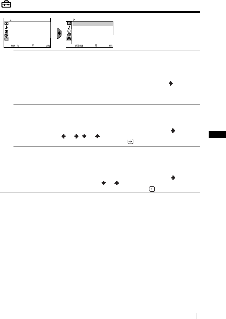
FR
PDVWHUSDJH ULJKW
15
.9&7%B*US8B)5
Réglage
/HPHQX´5pJODJHµYRXVSHUPHWGH
PRGLILHUGLYHUVHVFRQILJXUDWLRQVGH
FHWpOpYLVHXU
/DQJXH3D\V /RSWLRQ´/DQJXH3D\VµGXPHQX´5pJODJHµYRXVSHUPHWGH
VpOHFWLRQQHUODODQJXHGDQVODTXHOOHYRXVGpVLUH]TXHOHVPHQXVVXU
pFUDQDSSDUDLVVHQW(OOHYRXVSHUPHWDXVVLGHVpOHFWLRQQHUOHSD\V
GDQVOHTXHOYRXVGpVLUH]XWLOLVHUOHWpOpYLVHXU
3RXUFHOD
$SUqVDYRLUVpOHFWLRQQpORSWLRQDSSX\H]VXUODWRXFKH HWSURFpGH]
HQVXLWHFRPPHLOYRXVHVWLQGLTXpDXFKDSLWUH´0LVHVRXVWHQVLRQHW
PHPRULVDWLRQDXWRPDWLTXHGHVFKDvQHVGXWpOpYLVHXUµpWDSHVHW
YRLUSDJH
5RWDWLRQGLPDJH
SRXU
.9&7%
XQLTXHPHQW
'XIDLWGXPDJQpWLVPHWHUUHVWUHOLPDJHWpOpYLVpHSHXWDSSDUDvWUH
SHQFKpH'DQVFHFDVYRXVSRXYH]ODUpJOHUHQXWLOLVDQWORSWLRQ
´5RWDWLRQGLPDJHµGXPHQX´5pJODJHµ
3RXUFHOD
$SUqVDYRLUVpOHFWLRQQpORSWLRQDSSX\H]VXUODWRXFKH $SSX\H]
VXU RX RX SRXUUHFWLILHUWRXWHLQFOLQDLVRQGHOLPDJH
)LQDOHPHQWDSSX\H]VXUODWRXFKH SRXUOHPpPRULVHU
&HQWUDJH59% (QFRQQHFWDQWXQHVRXUFHGHVLJQDX[59%FRPPHXQH´3OD\6WDWLRQµ
LOVHSHXWTXHYRXVD\H]jUpJOHUOHFHQWUDJHKRUL]RQWDOGHOLPDJH
'DQVFHFDVYRXVSRXYH]OHIDLUHHQXWLOLVDQWORSWLRQ´&HQWUDJH59%µ
GXPHQX´5pJODJHµ
3RXUFHOD
$SUqVDYRLUVpOHFWLRQQpORSWLRQDSSX\H]VXUODWRXFKH 3XLV
DSSX\H]VXUODWRXFKH RX SRXUUpJOHUOHFHQWUDJHGHOLPDJHGH
j)LQDOHPHQWDSSX\H]VXUODWRXFKH SRXUOHPpPRULVHU
Réglage
Centrage RVB: 0
Rotation d'image
Sélection Confirm. Fin
Langue/Pays
Réglage
Centrage RVB: 0
Rotation d'image
Langue/Pays
Sélect. Confirm. Fin
Système des menus
)5.9&7%IP3DJH)ULGD\-XO\$0
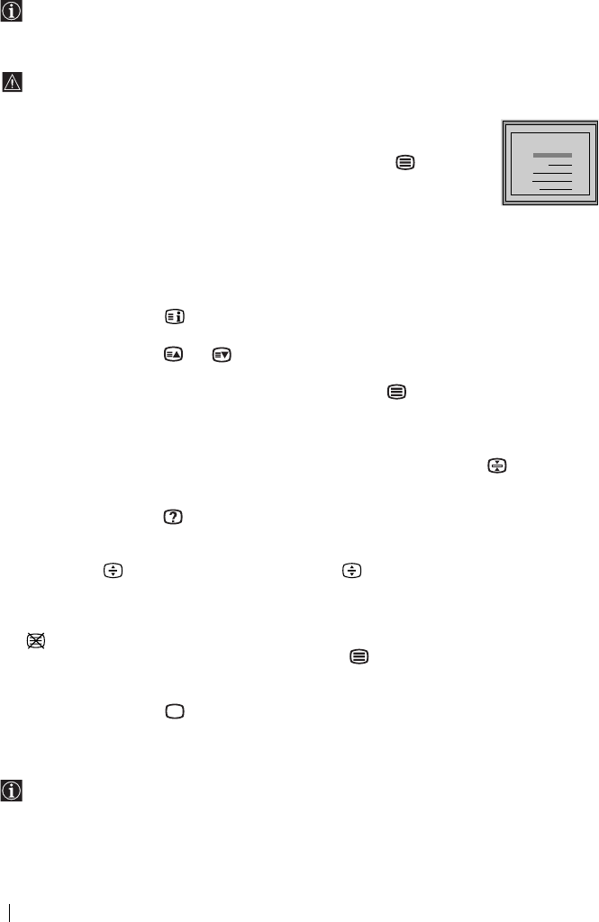
PDVWHUSDJH OHIW
16
.9&7%B*US8B)5
Télétexte
/HWpOpWH[WHHVWXQVHUYLFHGLQIRUPDWLRQTXHGLIIXVHODSOXSDUWGHVFKDvQHVWpOpYLVpHV/D
SDJHGXVRPPDLUHGXVHUYLFHGHWpOpWH[WHHQJpQpUDOODSDJHH[SOLTXHFRPPHQW
XWLOLVHUFHVHUYLFH3RXUpYROXHUjOLQWpULHXUGXWpOpWH[WHXWLOLVH]OHVWRXFKHVGHOD
WpOpFRPPDQGHFRPPHLQGLTXpFLGHVVRXV
9pULILH]TXHYRXVXWLOLVH]XQFDQDOGHWpOpYLVLRQGLVSRVDQWGXQVLJQDOGpPLVVLRQ
VXIILVDPPHQWIRUWSRXUpYLWHUGHVHUUHXUVGHWpOpWH[WH
Entrer dans le service de Télétexte :
$SUqVDYRLUVpOHFWLRQQpODFKDvQHpPHWWHXU79TXLWUDQVPHWOHVHUYLFHGH
WpOpWH[WHTXHYRXVGpVLUH]FRQVXOWHUDSSX\H]VXUODWRXFKH
Sélectionner une page de Télétexte :
$ODLGHGHVWRXFKHVQXPpULTXHVGHODWpOpFRPPDQGHLQWURGXLVH]OHVWURLV
FKLIIUHVGXQXPpURGHSDJHTXHYRXVGpVLUH]FRQVXOWHU
6LYRXVYRXVWURPSH]FKRLVLVVH]WURLVFKLIIUHVTXHOFRQTXHVHWUHFRPPHQFH]HQVXLWHjLQWURGXLUHOH
QXPpURGHSDJHFRUUHFW
6LOHFRPSWHXUGHSDJHVQHVDUUrWHSDVFHVWTXHODSDJHGHPDQGpHQHVWSDVGLVSRQLEOH'DQVFHFDV
LQWURGXLVH]XQDXWUHQXPpURGHSDJH
Pour vérifier le contenu d'un service Télétexte :
$SSX\H]VXUODWRXFKH
Sélectionner la page suivante ou la page précédente :
$SSX\H]VXUODWRXFKH RX
Superposer le télétexte à l'image télévisée :
3HQGDQWTXHYRXVYR\H]OHWpOpWH[WHDSSX\H]VXUODWRXFKH $SSX\H]jQRXYHDXVXUFHWWH
WRXFKHSRXUVRUWLUGXPRGHWpOpWH[WH
Pour figer une page Télétexte :
&HUWDLQHVSDJHVGHWpOpWH[WHFRPSUHQQHQWGHVSDJHVVHFRQGDLUHVTXLGpILOHQW
DXWRPDWLTXHPHQW3RXUILJHUXQHSDJHVHFRQGDLUHDSSX\H]VXUODWRXFKH $SSX\H]j
QRXYHDXVXUFHWWHWRXFKHSRXUOLEpUHUOHEORFDJH
Voir une information cachée (par ex. : la solution d'une devinette) :
$SSX\H]VXUODWRXFKH $SSX\H]jQRXYHDXVXUFHWWHWRXFKHSRXUTXHOLQIRUPDWLRQVRLW
jQRXYHDXFDFKpH
Pour agrandir l'affichage Télétexte :
$SSX\H]VXU $FKDTXHSUHVVLRQVXUODWRXFKH ODIILFKDJH7pOpWH[WHFKDQJHFRPPH
VXLW$JUDQGLUODPRLWLpVXSpULHXUHt$JUDQGLUODPRLWLpLQIpULHXUHt7DLOOHQRUPDOH
Pour afficher une page Télétexte pendant le visionnage d'un programme télévisé.
6DLVLVVH]OHQXPpURGH7pOpWH[WHDXTXHOYRXVVRXKDLWH]YRXVUpIpUHUSXLVDSSX\H]VXU
/RUVTXHOHQXPpURGHSDJHVDIILFKHDSSX\H]VXU SRXUYLVLRQQHUOHWH[WHGHODSDJH
7pOpWH[WH
Quitter le service Télétexte :
$SSX\H]VXUODWRXFKH
Fastext
/HVHUYLFH)DVWH[WSHUPHWGDYRLUDFFqVDX[SDJHVGHWpOpWH[WHHQDSSX\DQWVXUXQHVHXOH
WRXFKH
/RUVTXHYRXVrWHVGDQVOHVHUYLFHGHWpOpWH[WHHWDXFDVRLO\DpPLVVLRQGHVLJQDX[)DVWH[W
XQPHQXGHFRGHVFRXOHXUVDIILFKHDXEDVGHODSDJHLOSHUPHWGDFFpGHUGLUHFWHPHQWj
XQHSDJH3RXUFHODDSSX\H]VXUODWRXFKHGHFRXOHXUFRUUHVSRQGDQWHGHODWpOpFRPPDQGH
URXJHYHUWHMDXQHRXEOHXH
TELETEXT
Index
Programme
News
Sport
Weather
25
153
101
98
TELETEXT
Index
Programme
News
Sport
Weather
25
153
101
98
TELETEXT
Index
Programme
News
Sport
Weather
25
153
101
98
TELETEXT
Index
Programme
News
Sport
Weather
25
153
101
98
TELETEXT
Index
Programme
News
Sport
Weather
25
153
101
98
TELETEXT
Index
Programme
News
Sport
Weather
25
153
101
98
TELETEXT
Index
Programme
News
Sport
Weather
25
153
101
98
TELETEXT
Index
Programme
News
Sport
Weather
25
153
101
98
Télétexte
)5.9&7%IP3DJH)ULGD\-XO\$0
FR
PDVWHUSDJH ULJKW
17
.9&7%B*US8B)5
Connexion des équipements en option
9RXVSRXYH]FRQQHFWHUjYRWUHWpOpYLVHXUXQHODUJHJDPPHGpTXLSHPHQWVRSWLRQQHOV
FRPPHLOOXVWUpFLGHVVRXVOHVFkEOHVGHFRQQH[LRQQHVRQWSDVIRXUQLV
Connexion d'un magnétoscope :
3RXUFRQQHFWHUXQPDJQpWRVFRSHFRQVXOWH]OHFKDSLWUH´%UDQFKHPHQWGHODQWHQQHH[WpULHXUHHW
GXPDJQpWRVFRSHµ
1RXVYRXVFRQVHLOORQVGHFRQQHFWHUOHPDJQpWRVFRSHHQXWLOLVDQWXQFkEOH3pULWHO)DXWHGHTXRL
YRXVGHYUH]UpJOHUPDQXHOOHPHQWOHFDQDOGXVLJQDOYLGpRSDUOHPHQX´0pPRULVDWLRQ
PDQXHOOHµSRXUFHODFRQVXOWH]OHSDUDJUDSKHDSDJH
&RQVXOWH]DXVVLOHPRGHG·HPSORLGHYRWUHPDJQpWRVFRSHSRXUVDYRLUFRPPHQWREWHQLUOHFDQDO
GXVLJQDOYLGpR
Utilisation des équipements en option
1&RQQHFWH]OpTXLSHPHQWRSWLRQQHODXFRQQHFWHXUDGpTXDWGXWpOpYLVHXUFRPPHLQGLTXpFL
GHVVXV
2$OOXPH]OpTXLSHPHQWTXHYRXVDYH]FRQQHFWp
33RXUREWHQLUOLPDJHGHOpTXLSHPHQWFRQQHFWpDSSX\H]SOXVLHXUVIRLVVXUODWRXFKH
MXVTXjFHTXHOHV\PEROHFRUUHFWGHQWUpHVLQVFULYHVXUOpFUDQ
43RXUUHYHQLUjOLPDJHWpOpYLVpHDSSX\H]VXUODWRXFKH GHODWpOpFRPPDQGH
Symbole Signaux d'entrée
16LJQDOGHQWUpHDXGLRYLGpRSDUOHFRQQHFWHXU3pULWHOC
16LJQDOGHQWUpH59%SDUOHFRQQHFWHXU3pULWHOC&HV\PEROHQDSSDUDvW
TXHVLXQHHQWUpH59%HVWFRQQHFWpH
6LJQDOGHQWUpHYLGpRGXFRQQHFWHXU5&$AHWVLJQDOGHQWUpHDXGLRGX
FRQQHFWHXUB
AB
12
C
&DPpVFRSH
PP+L
'9& '9'0DJQpWRVFRSH
´3OD\6WDWLRQµ
GpFRGHXU
(QEUDQFKDQWXQFDVTXHOHV
KDXWSDUOHXUVGXWpOpYLVHXU
VHGpFRQQHFWHURQW
DXWRPDWLTXHPHQW
´3OD\6WDWLRQµHVWXQSURGXLWGH
6RQ\&RPSXWHU(QWHUWDLQPHQW,QF
´3OD\6WDWLRQµHVWXQHPDUTXH
FRPPHUFLDOHGH6RQ\&RPSXWHU
(QWHUWDLQPHQW,QF
Informations complémentaires
)5.9&7%IP3DJH)ULGD\-XO\$0

PDVWHUSDJH OHIW
18
.9&7%B*US8B)5
Spécifications
Norme de TV :
6XLYDQWOHSD\VVpOHFWLRQQp
%*+/,'.
Standard couleur :
3$/6(&$0
176&HQWUpHYLGpRVHXOHPHQW
Couverture de canaux :
9+) ((
8+) ((
&$79 66
+<3(5 66
/ ))%4))
, 8+)%%
'. 5555
Tube image :
(FUDQSODW)'7ULQLWURQ
Connecteurs arrières :
i &RQQHFWHXU3pULWHOGHEURFKHV
QRUPH&(1(/(&\FRPSULV
HQWUpHDXGLRYLGpRHQWUpH59%
VRUWLHDXGLRYLGpR79
Connecteurs frontaux :
t HQWUpHYLGpR²FRQQHFWHXU5&$
HQWUpHDXGLR²FRQQHFWHXU5&$
SULVHSRXUFDVTXH
Sortie son :
[:SXLVVDQFHPXVLFDOH
[:506
Consommation d'énergie :
.9&7%:
.9&7%:
Consommation d'énergie en mode veille
(standby) :
:
Dimensions (l x h x prf) :
.9&7%(QY[[PP
.9&7%(QY[[PP
Poids
.9&7%(QYNJ
.9&7%(QYNJ
Accessoires fournis :
WpOpFRPPDQGH50:
SLOHVQRUPH,(&
$QWHQQHSRXU.9&7%XQLTXHPHQW
Divers :
7pOpWH[WH)DVWH[W723WH[W
$UUrWWHPSRUDLUH
0DUFKHWHPSRUDLUH
La conception et les spécifications sont susceptibles de subir des modifications sans
préavis de notre part.
Papier recyclé - Chlore : 0%
Informations complémentaires
)5.9&7%IP3DJH)ULGD\-XO\$0
FR
PDVWHUSDJH ULJKW
19
.9&7%B*US8B)5
Dépannage
9RLFLTXHOTXHVVROXWLRQVVLPSOHVTXLYRXVSHUPHWWURQWGHUpVRXGUHGHVSUREOqPHVOLpVjOD
TXDOLWpGHOLPDJHHWGXVRQ
(QFDVGHSDQQHFRQILH]YRWUHWpOpYLVHXUjXQSHUVRQQHOVSpFLDOLVp
1RXYUH]MDPDLVODSSDUHLO
Problème Solution
3DVGLPDJHpFUDQQRLUHWSDVGH
VRQ
9pULILH]TXHODQWHQQHHVWELHQEUDQFKpH
$OOXPH]OHWpOpYLVHXUHQDSSX\DQWVXUODWRXFKH!GH
ODSDUWLHIURQWDOHGHODSSDUHLO
6LOHYR\DQW1GXWpOpYLVHXUHVWELHQDOOXPpDSSX\H]
VXUODWRXFKH&1GHODWpOpFRPPDQGH
0DXYDLVHLPDJHRXSDVGLPDJH
PDLVERQQHTXDOLWpVRQRUH
3DUOHV\VWqPHGHVPHQXVHQWUH]GDQVOH´&RQWU{OH
GHOLPDJHµHWVpOHFWLRQQH]´5j=µSRXUUHYHQLUDX[
UpJODJHVGXVLQHYRLUSDJH
3DVGLPDJHQLGHPHQX
GLQIRUPDWLRQGHOpTXLSHPHQW
RSWLRQQHOEUDQFKpjODSULVH3pULWHO
VLWXpHjODUULqUHGHODSSDUHLO
9pULILH]TXHOpTXLSHPHQWRSWLRQQHOHVWDOOXPpHW
DSSX\H]SOXVLHXUVIRLVVXUODWRXFKH GHOD
WpOpFRPPDQGHMXVTXjFHTXHOHV\PEROHGHQWUpH
FRUUHFWDSSDUDLVVHVXUOpFUDQYRLUSDJH
,PDJHGHERQQHTXDOLWpPDLVSDVGH
VRQ
$SSX\H]VXUODWRXFKH GHODWpOpFRPPDQGH
9pULILH]TX·XQFDVTXHQ·HVWSDVEUDQFKp
3DVGHFRXOHXUSURJUDPPHV
FRXOHXU
3DUOHV\VWqPHGHPHQXVHQWUH]GDQVOHPHQX
´&RQWU{OHGHOLPDJHµHWVpOHFWLRQQH]´5j=µSRXU
UHYHQLUDX[UpJODJHVGXVLQHYRLUSDJH
'LVWRUVLRQGHOLPDJHHQFKDQJHDQW
GHFKDvQHRXHQVpOHFWLRQQDQWOH
WpOpWH[WH
(WHLJQH]OpTXLSHPHQWEUDQFKpDX[FRQQHFWHXUV
3pULWHOEURFKHVVLWXpjODUULqUHGXWpOpYLVHXU
&DUDFWqUHVHUURQpVVXUOHVSDJHVGH
WpOpWH[WH
3DUOHPHQXVpOHFWLRQQH]ORSWLRQ´/DQJXH3D\VµHW
VpOHFWLRQQH]HQVXLWHOHSD\VGDQVOHTXHOIRQFWLRQQHOH
WpOpYLVHXUYRLUSDJH
/LPDJHDSSDUDvWSHQFKpH
SRXU.9&7%XQLTXHPHQW
3DUOHV\VWqPHGHVPHQXVVpOHFWLRQQH]ORSWLRQ
´5RWDWLRQGLPDJHµGDQVOHPHQX´5pJODJHµHW
FRUULJH]OLQFOLQDLVRQYRLUSDJH
,PDJHPDLVEUXLW 3DUOHV\VWqPHGHPHQXVVpOHFWLRQQH]ORSWLRQ´$)7µ
GXPHQX´0pPRULVDWLRQPDQXHOOHµHWUpJOH]
PDQXHOOHPHQWODPpPRULVDWLRQSRXUREWHQLUXQH
PHLOOHXUHLPDJHYRLUSDJH
3DUOHV\VWqPHGHVPHQXVVpOHFWLRQQH]ORSWLRQ
´,PDJHLQWHOOLJHQWHµGXPHQX´,PDJHµHW
VpOHFWLRQQH]´2XLµSRXUDWWpQXHUOHEUXLWGHOLPDJH
YRLUSDJH
7pOpFRPPDQGHQRQRSpUDWLRQQHOOH &KDQJH]OHVSLOHV
/·LQGLFDWHXU1GHPLVHHQYHLOOH
VWDQGE\GXWpOpYLVHXUFOLJQRWHHQ
URXJH
9HXLOOH]FRQWDFWHUOHVHUYLFHDSUqVYHQWH6RQ\OHSOXV
SURFKH
Informations complémentaires
)5.9&7%IP3DJH)ULGD\-XO\$0

PDVWHUSDJH OHIW
20
.9&7%B*US8B)5
Les principaux émetteurs français
&RPSWHWHQXGHVpYROXWLRQVOHVpPHWWHXUVHWFDQDX[DQQRQFpVFLDSUqVVRQWGRQQpVjWLWUH
G·LQIRUPDWLRQHWQRQG·HQJDJHPHQW3RXUODUpFHSWLRQGHODPDMRULWpGHVpPHWWHXUV
O·DQWHQQHGRLWrWUHHQ´SRVLWLRQKRUL]RQWDOHµ/RUVTX·HOOHGRLWrWUHHQ´SRVLWLRQYHUWLFDOHµ
ODOHWWUH9VXLWOHQXPpURGHFDQDO
EMETTEURS
CANAUX
TF1 A2 FR3 CANAL+ ARTE M6
1 ABBEVIUE limeux 63 67 60
2 AJACCIO Coli Chiavari 31 21 24
3 ALBERTVILLE tort du Mont 45 39 42 07V
4 ALENCON Mont d'Amain 48 51 54
5 ALES l'Hermitage 52 60
ALES Mont Boquet 27 21 24 65
6 AMIENS St-Just/DURY 41 47 44 05 ou 10 49 52
7 ANGERS Rochefort 47 44 41 10 51 53
8 ANGOULEME St-Saturnin 31 34
9 ARGENTON/CREUSE Malicornay 46 40 43
10
AURILLAC ALIVERGNE La Bastide
54 09V
11 AUTUN Bois de Rol 48 51 54
12 AUXERRE Molesmes 37 31 34
13
AVIGNON Mont Ventoux/LE PONTET 42 45 39 47 54
14 BAR DE LUC Willeroncourt 51 48 54
15 BASTIA Serra di Pigno 41 47 44
16 BAYONNE La Rhune 64 58 61 07V 56
17 BERGERAC Audrix 37 34 31
18 BESANÇON Lomont/BREGILLE 47 41 44 03V 45
BESANÇON Montfaucon 29 23 26 08V
19 BORDEAUX Bouilac 63 57 60 08 65 43
20 BOULOGNE Mont Lambert 29 34 37 10
21 BOUGES Neuvy 23 26 29 08 21
22 BOURG EN BRESSE "Ramasse" 38 32
23 BREST Roc Tr dudon 27 21 24 10 34
24 BRIVE Lissac 23 29 26 06
25 CAEN "Brullemail" 48 51 54 04
CAEN Mont Pincon/CHU 22 25 28 09 38 60
26 CANNES Vallarius 63
27 CARCASSONE Pic de Nore 64 58 61 03V
28 CHAMBERY Mont du Chat 29 58 23 08
29 CHAMONIX Aiguille du Midi 25 28 22
30 CHAMPAGNOLLE Le Bulay 58 61 64
31 CHARTES Montlandon 55 50 63 09 47
32 CHAUMONT Chalindray 52 49 55
33 CHERBOURG Olgosville 65 59 62 06 ou 08 35
34 CLERMONT-FERRAND Puy de Côme/ROYAT 22 28 25 05 58 61
35 CLUSES St-Sigismond 56 50 53 06
36 CORTE Antisanti 59 61 54
37 DUON Nuit St-Georges 59 62 65 09 46V 43V
38 DUNQUERQUE Mont de Cats 42 39 45 59 62
39 EPINAL Bois de la Vierge 65 60 63 10V
40 FORBACH Kreutzberg 47 22 25 28
41 GAP Mont Colombis 27 21 24 09
42 GEX Mont Rond 27 21 24 05V
43 GRENOBLE Chamrousse 56 50 53 06 ou 09 59 62
44 GUERET St-Léger 64 58 61 09
45 HIRSON Landouzy 54 48 51
46 HYERES Cap Bénal 65 59 62 06
47 LA BAULE ESCOUBLAC "St-Clare" 38
48 LA ROCHELLE "Mireuil" 48 51
59 LAVAL Mont Rochard 63 57 60
50 LE CREUSOT Mont St-Vincent 35 33 30 67 38 60
51 LE HAVRE Harfleur 46 43 40 05 53
52 LE HAVRE Basse Normandie 35
53 LE MANS Mayer 24 27 21 05V 32
54 LE PUY St-Jean de Nay 63 57 60
55 LENS "Bouvigny" 51 54
56 LESPARRE Ordonnac 39 45 42
57 LILLE Boubigny/LAMBERSART 27 21 24 05 51 54
58 LIMOGES Les Cars 56 50 53 05/07/10
59 LONGWY Bois du châ 52 47 44 08
60 LORIENT "Plaoermeur" 62
61 LYON Fourvière 61 58 64 66 28 22
62 LYON Mont Pilat 46 40 43 10
63 MACON Bois de Cenves 57 55 49
64 MANTES Mudétour 64 58 61 55 53
Informations complémentaires
)5.9&7%IP3DJH)ULGD\-XO\$0

FR
PDVWHUSDJH ULJKW
21
.9&7%B*US8B)5
Les principaux émetteurs français
EMETTEURS CANAUX
TF1 A2 FR3 CANAL+ ARTE M6
65 MARSEILLE Grande Etoile 29 23 26 05 32 38
66 MARSEILLE Pomègues 40 46 43 57 54
67 MAUBEUGE Rousies 39 42 45 29 32
68 MENDE Truc de Fortino 37/31 34 68
69 MENTON Cap Martin 62 50 56 68
70 MELZ Luttange 37 34 31 05V 39
71 MEZIERES Sury 29 23 26 36
72 MILLAU Levezou 47 44 41 10
73 MONTLUCON "Maregnon" 49 52
74 MONNETTIER MORNEX Mont Saléve 42 45 48 64
75 MONTMELLIAN Le Fort 64 58 61 09
76 MONTPELLIER Saint-Baudille 56 50 53 63 48V
77 MORTAIN Grande Fontaine 50 52 55
78 MORTEAU Monteblon 48 54 51
79 MULHOUSE Belvédère 27 21 24 05 55
80 NANCY Malzéville 23 29 26 08 55 43
81 NANTES Hute Goulaine 23 29 26 09V 21 65
82 NEUF CHATEL Croixdelle 51 48 54 65
83 NEVERS "Challuy" 41
84 NICE Mont Alban/LA MADELEINE 64 58 61 66 ou 32 51
85 NIMES "Bas Rhône" 31 37
86 NIORT Maisonnay 22 28 25 06V 38
87 NIORT Sud Vendée58
88 ORLEANS Trainou 42 39 45 52 53
89 PARIS Tour Eiffel 25 22 28 06 30 33
PARIS EST Chennevières 43 46 40 53 48 58
PARIS NORD Sannois 45 39 56 59 65 62
PARIS SUD Villebon 49 52 62 65 58 42
90 PARTHENAY Amailoux 52 49 55
91 PERPIGNAN Pic Néoulous 22 25 28 07
92 PIGNANS N D des Anges 46 43 40 56
93 POITIERS "Les Couronneries"
/Hospital des Champs 41 41
94 PORTO VECCHIO Col de Méla 40 34 37
95 PRIVAS Crète Blandine 64 58 61
96 QUIMPER 29 37 31 06
97 REIMS Charleville 29 23 26 36
98 REIMS Hutvillers 43 46 40 09 63
99 RENNES Saint-Pern 39 45 42 07 34 31
100 ROUEN Grande Couronne 23 33 26 07 59 62
101 SAINT ETTIENNE Croix de Guizay 35 30 33 38 65 62
102 SAINT ETTIENNE "Pilat" 46 40 43 10
103 SAINT FLOUR Vabres 52 49 55
104 SAINT GINGOLPH Montpélerin 39 41 63
105 SAINT-MALO 53V 45 42 07
106 SAINT-MARTIN DE BELLE VILLE
Point de la Masse 48 51 54
107 SAINT-NAZAIRE "Pornichet la Ville-Blais" 23 29 26 06
108 SAINT-NAZAIRE "Etoile du Matin" 55 52
109 SAINT-QUENTIN "Gauchy" 30 33
110 SAINT-RAPHAEL Pic de l'Ours 25 28 22 10V
111 SARREBOURG Donon 40 53 50
112 SENS Gisy les Nobles 57 63 60 05
113 SERRES Beaumont 50 53 56 04
114 STRASBOURG Nordhein 62 56 43 10V
115 TARASCON S/ARIEGE Montoulieu 52 55 49 08
116 TOULON Cap Sicié 51 48 54 09 57 60
117 TOULOUSE Pechbonnieu 45 39 42 07
TOULOUSE Pic du Midi 27 21 24 05 32 34
TOULOUSE Acquitaine 47
118 TOURETTE DU CHAHTEAU Mt Vial 54 62 65
119 TOURS Chissay 65 59 62 57
120 TROYES Les riceys 27 24 21 07 29
121 USSEL Meymac 42 45 39
122 UTELLE La Madone 47 44 41
123 VALENCE "St-Romaine de l'Erps" 53
124 VALENCIENNES "marly" 49 34
125 VANNES Moustoir' AC 50 56 53 05 58
126 VERDUN Septsarges 65 59 62
127 VILLERS COTTEREST Fleury 65V 59V 62V
128 VITTEL Thullières 30 35 32
129 WISSEMBOURG Eselberg 54 48 51
YRLUSDJHVXLYDQWH693
Informations complémentaires
)5.9&7%IP3DJH)ULGD\-XO\$0
PDVWHUSDJH OHIW
22
.9&7%B*US8B)5
Les principaux émetteurs français
5pSDUWLWLRQ(XURSpHQQHGHVQRUPHVHWVWDQGDUGV
PAL SECAM
IRL
I
I
I
GB
DZ
MA TN
BG
CY RL
YU
CH
AL
GR
NL
CZ
PL
RF
B-G
B-G
B-G
B-G B-G
B-G
B-H
B-H
B-H
B-G D-K
D-K
D-K
B-G
B-G
B-G
B-G
B-G
B-G
B-G
D
D
H
A
P
E
DK
NS
SF
B
B
BB
B
SK
IL
D-K
D-K
R
TR
B
L
F
L
L
G
D-K
Informations complémentaires
)5.9&7%IP3DJH)ULGD\-XO\$0

R
FD Trinitron
Colour Television
Manual de Instrucciones
KV-21CT1E
KV-14CT1E
© 2003 Sony Corporation
ES
Manual de Instruções
Brugervejledning
Käyttöohjeet
Bruksanvisning
PT
DK
FI
NO
Instruktionsbok SE
4-093-927-32(1)
01COVKV21CT1E.fm Page 2 Friday, July 4, 2003 3:14 PM
ES
master page=right
3
KV-14CT1E_BCNMixU3_ES
4-093-927-32(1)
Introducción
Gracias por elegir este televisor en color Sony de Pantalla Plana FD Trinitron.
Antes de utilizar el televisor, lea este manual atentamente y consérvelo para futuras
referencias.
Símbolos utilizados en este manual:
• Información importante.
• Información sobre la función.
•1,2...Secuencia de las instrucciones a
seguir.
• Los botones sombreados del mando a
distancia, muestran los botones que
ha de pulsar para ejecutar las
diferentes instrucciones.
• Información sobre el resultado de las
instrucciones.
Indice
Introducción ............................................................................................................................................ 3
Normas de seguridad..............................................................................................................................4
Descripción general
Descripción general de los botones del mando a distancia...............................................................5
Descripción general de los botones del televisor ...............................................................................6
Instalación
Instalación de las pilas en el mando a distancia..................................................................................6
Conexión de una antena portátil (sólo para KV-14CT1E) ................................................................7
Conexión de una antena exterior y del vídeo ..................................................................................... 7
Primera puesta en marcha
Encendido y Sintonización automática del TV .................................................................................. 8
Sistema de menús en pantalla
Introducción y manejo del sistema de menús .................................................................................. 10
Imagen .............................................................................................................................................. 10
Sonido............................................................................................................................................... 11
Temporizador .................................................................................................................................. 12
Ajuste de canales............................................................................................................................. 13
Configuracíon.................................................................................................................................. 15
Teletexto........................................................................................................................................... 16
Información complementaria
Conexión de equipos opcionales ........................................................................................................ 17
Manejo de los equipos opcionales...................................................................................................... 17
Especificaciones .................................................................................................................................... 18
Solución de problemas......................................................................................................................... 19
Indice
01ESKV21CT1E.fm Page 3 Friday, July 4, 2003 3:31 PM
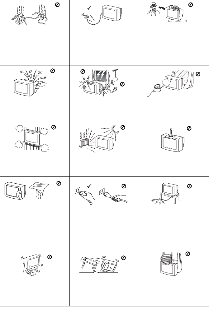
master page=left
4
KV-14CT1E_BCNMixU3_ES
4-093-927-32(1)
Normas de Seguridad
Este aparato sólo debe utilizarse
con fuentes de alimentación de
220-240 V CA. No enchufe
demasiados aparatos en el mismo
enchufe ya que podría causar
descargas eléctricas o incendio.
Por razones medioambientales y
de seguridad, se recomienda no
dejar el aparato en modo de
desconexión temporal cuando no
se utilice. Apáguelo pulsando el
interruptor principal y
desenchufándolo cuando vaya a
estar ausente.
Nunca introduzca objetos ni
derrame ningún tipo de líquido
dentro del aparato ya que podría
provocar descargas eléctricas o
incendio. En caso de que algún
objeto o líquido caiga dentro del
aparato, no utilice el televisor.
Avise de inmediato al servicio
técnico.
No abra la tapa posterior del
aparato. En caso necesario, acuda
al servicio técnico.
Para su propia seguridad,
durante una tormenta, no toque
ninguna parte del aparato;
especialmente el cable de
alimentación y el de la antena.
Para evitar riesgo de incendio o
descargas eléctricas, no exponga
el aparato a la lluvia ni a la
humedad.
No obstruya ni cubra las ranuras
de ventilación del aparato. Para
que haya una ventilación correcta,
deje un espacio de al menos 10 cm
alrededor del aparato.
Nunca instale el aparato en lugares
excesivamente calientes, húmedos
o polvorientos. No instale el
aparato en lugares donde pueda
sufrir vibraciones mecánicas.
Para evitar riesgo de incendio,
mantenga lejos del aparato los
objetos inflamables, velas, y todo
aquello que pudiera causar
incendio.
Limpie la pantalla y el mueble del
televisor con un pa
ño suave y
ligeramente humedecido. No
utilice estropajos, limpiadores
abrasivos, alcalinos, ning
ún tipo
de disolvente, como alcohol o
bencina ni sprays antiest
áticos.
Como medida de seguridad,
desenchufe el televisor antes de
limpiarlo.
Desenchufe el aparato tirando
directamente de la clavija. Nunca
tire del cable.
No coloque objetos pesados sobre
el cable de alimentación ya que
podría dañarlo.
Le recomendamos que enrolle la
parte sobrante del cable de
alimentación en el enrollacables
situado en la parte posterior del
aparato.
Coloque el aparato sobre un estante
o mueble lo suficientemente fuerte,
grande y estable para sostenerlo. No
permita que los niños salten sobre
él. No lo coloque de lado o boca
arriba.
Si ha de mover el aparato,
desenchúfelo antes de hacerlo. Al
transportarlo, tenga cuidado con las
superficies desiguales, escalones,
etc. Si se le cae el aparato o sufre
algún golpe, avise inmediatamente
al servicio técnico.
No cubra las ranuras de
ventilación con ningún objeto
como cortinas, periódicos, etc.
Normas de seguridad
01ESKV21CT1E.fm Page 4 Friday, July 4, 2003 3:31 PM
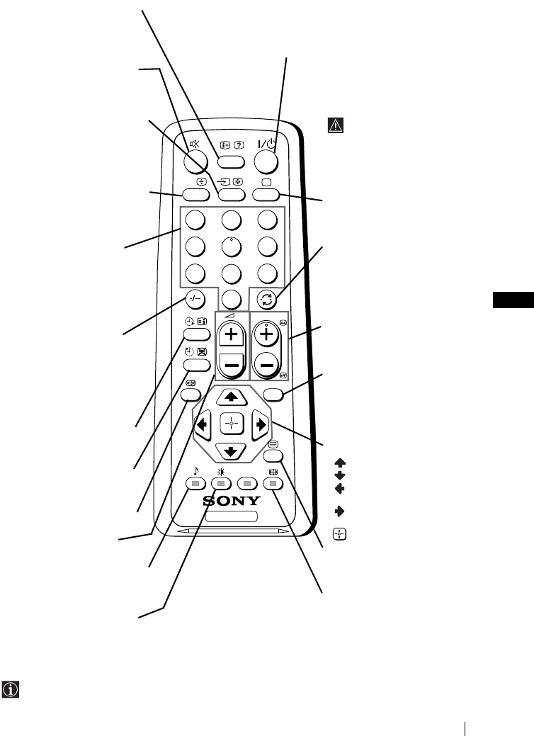
ES
master page=right
5
KV-14CT1E_BCNMixU3_ES
4-093-927-32(1)
Descripción general de los botones del mando a distancia
Además de las funciones de televisión, todos los botones con color se utilizan también para
las operaciones de teletexto. Para más información, consulte el capítulo sobre “Teletexto”
de este manual de instrucciones (ver página 16).
TV
123
46
789
0
5
MENU
PROG
A/B
Mostrar información en
pantalla
Púlselo para mostrar todas las
indicaciones en pantalla.
Vuelva a pulsarlo para cancelar.
Eliminación del sonido
Púlselo para eliminar el sonido.
Vuelva a pulsarlo para
recuperarlo.
Selección de la fuente de
entrada
Púlselo repetidamente hasta que
el símbolo de la fuente de
entrada deseada aparezca en la
pantalla.
Este botón sólo funciona en modo
deteletexto.
La función A/B asociada a este
botón, no funciona en este
televisor.
Selección de canales
Púlselos para seleccionar canales.
Para números de programa
de dos dígitos, pulse el
segundo dígito en un tiempo
inferior a 3 segundos.
o
Pulse -/-- y a continuación, el
primer y el segundo dígito.
Si se equivoca al introducir el
primer dígito, continúe
introduciendo el segundo dígito
(del 0 al 9) y, seguidamente,
repita de nuevo la operación.
Conexión automática
Configure el televisor para
que se conecte
automáticamente.
Desconexión automática
Configure el televisor para
que se desconecte
automáticamente
Botón sin función en este aparato.
Ajuste del volumen
Púlselo para ajustar el
volumen del televisor.
Este botón sólo funciona en modo
deteletexto. La función 9
asociada a este botón, no
f
unciona en este televisor.
Selección del modo de
imagen
Púlselo repetidamente para
cambiar el modo de imagen.
Apagar temporalmente el televisor
Púlselo para apagar temporalmente el televisor (el indicador
de modo de espera 1 se iluminará). Vuelva a pulsarlo para
encender el televisor desde el modo de desconexión
temporal (standby). Para ahorrar energía, se
recomienda apagar por
completo el televisor cuando
no lo utilice.
Si durante 15 minutos no
hay señal de televisión ni
se pulsa ningún botón, el
televisor pasará au-
tomáticamente al modo
de desconexión temporal
(standby).
Selección del modo TV
Púlselo para desactivar el
teletexto o la entrada de vídeo.
Vuelta al último canal
seleccionado
Púlselo para volver a ver el
último canal seleccionado (el
canal anterior debe haber sido
visionado previamente
durante al menos 5 segundos).
Selección de canales
Púlselo para seleccionar el
canal siguiente o anterior.
Activación del sistema de
menús
Púlselo para ver el menú en
pantalla. Vuelva a pulsarlo
para desactivarlo y ver la
pantalla normal de televisión.
Botones para la selección
del menú
Subir un nivel
Bajar un nivel
Ir al menú o selección
anterior
Ir al menú o selección
siguiente
Confirmar la selección
Selección de Teletexto
Púlselo para visualizar el
teletexto.
Selección del formato de
la pantalla
Púlselo repetidamente para
cambiar el formato de la
pantalla: 4:3 para imagen
convencional o 16:9 para
imitación de pantalla amplia.
Descripción general
01ESKV21CT1E.fm Page 5 Friday, July 4, 2003 3:31 PM
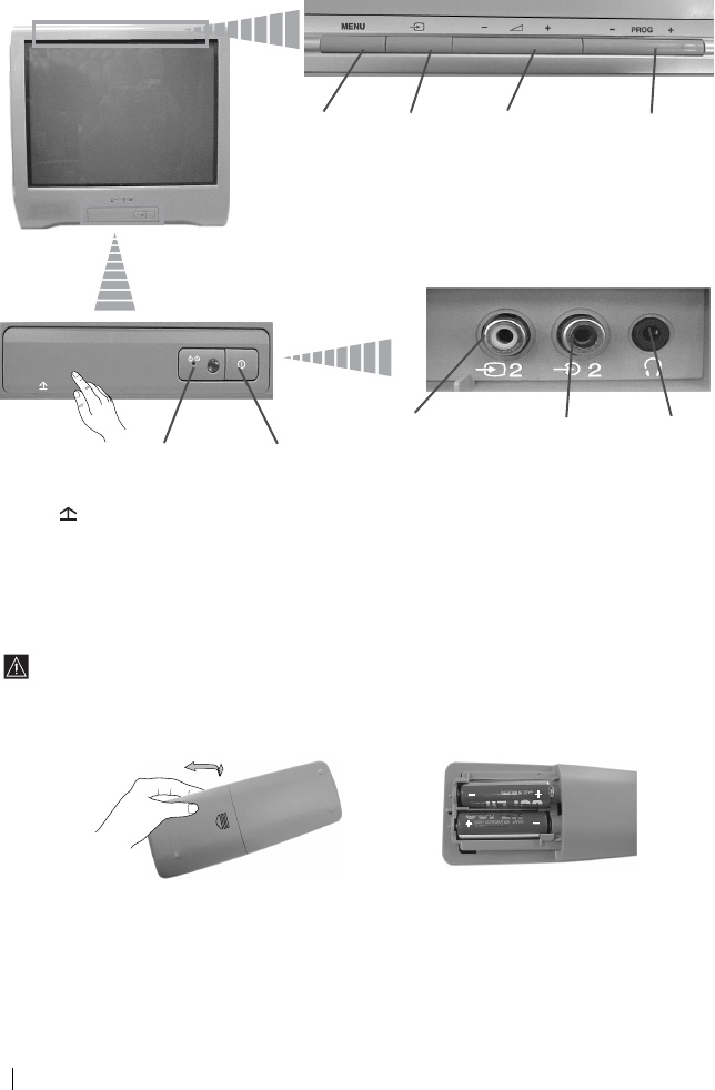
master page=left
6
KV-14CT1E_BCNMixU3_ES
4-093-927-32(1)
Descripción general de los botones del
televisor
Instalación de las pilas en el mando a distancia
Asegúrese de colocar las pilas suministradas con las polaridades en la posición correcta.
Sea respetuoso con el medio ambiente y deposite las pilas usadas en el contenedor
específico para ello.
Activación
del sistema
de menús
Botón de
selecci
ó
n de la
fuente de
entrada
Botones de
control del
volumen
Botones de selección
de programas
siguiente o anterior
(seleccionan emisoras
de televisión)
Levante la
solapa de la
puerta con la
marca para
mostrar el panel
de control.
Indicador de
modo de
desconexión
temporal
(standby)
Interruptor de
encendido/
apagado
Toma de
entrada de
vídeo
Toma de
entrada de
audio
Toma de
auriculares
Descripción general - Instalación
01ESKV21CT1E.fm Page 6 Friday, July 4, 2003 3:31 PM
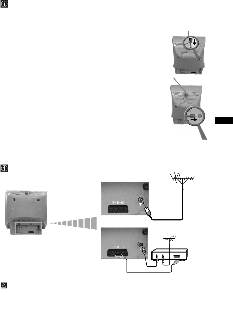
ES
master page=right
7
KV-14CT1E_BCNMixU3_ES
4-093-927-32(1)
Conexi
ón de una antena portátil
(sólo para KV-14CT1E)
Para obtener una mejor recepción de imagen, le recomendamos que conecte el televisor a
una antena exterior. No obstante, si no dispone de antena exterior pero la señal local de
VHF/UHF es lo suficientemente fuerte, puede conectar la antena telescópica suministrada
con este televisor tal y como se indica a continuación:
1inserte la antena en la ranura situada en la parte superior del televisor
hasta que ésta haga “clic”.
2Conecte el cable de la antena al terminal situado en la parte posterior
del televisor.
3Encienda el televisor y oriente la antena para obtener una buena
recepción de imagen.
Conexión de la antena y del vídeo
Los cables de conexión no se suministran.
Para más detalles sobre la conexión del vídeo, consulte el capítulo “Conexión de equipos
opcionales” de este manual de instruccíones (ver página 17).
OUT IN
o
vídeo
La conexión a través del Eurocouector es opcional
Instalación
01ESKV21CT1E.fm Page 7 Friday, July 4, 2003 3:31 PM
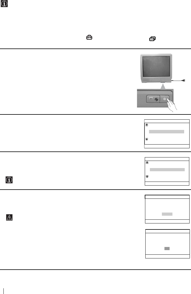
master page=left
8
KV-14CT1E_BCNMixU3_ES
4-093-927-32(1)
Encendido y Sintonización automática del TV
La primera vez que encienda el televisor, aparecerá en la pantalla una secuencia de menús
a través de los cuales podrá: 1) seleccionar el idioma de los menús, 2) seleccionar el país
donde desea utilizar el aparato, 3) buscar y almacenar automáticamente todos los canales
disponibles (emisoras de televisión) 4) cambiar el orden en que los canales (emisoras de
televisión) aparecen en pantalla y 5) ajustar la inclinación de la imagen (sólo para
KV-21CT1E).
No obstante, si más adelante necesita modificar alguno de estos ajustes, puede hacerlo
seleccionando la opción apropiada en (menú de Configuración) o (menú Ajuste de
chanales).
1Conecte el enchufe del televisor a la toma de corriente (220-240V
CA, 50Hz). Pulse el interruptor de encendido/apagado ! de la
parte frontal del televisor para encenderlo.
La primera vez que encíenda el televisor, el menú Language
(Idioma) aparecerá automáticamente en la pantalla.
2Pulse el botón 2 +/– del panel de control superior para
seleccionar el idioma y, a continuación, pulse el botón t para
confirmar la selección. A partir de ahora, todos los menús
aparecerán en el idioma seleccionado.
3En la pantalla aparecerá automáticamente el menú País. Pulse el
botón 2 +/– para seleccionar el país donde desea utilizar el
televisor y, a continuación, pulse el botón t para confirmar la
selección.
Si en la lista no aparece el país donde va a utilizar el televisor,
seleccione “-” en lugar de un país.
4Asegúrese de que la antena está conectada conforme a las
indicaciones y pulse el botón t para confirmarlo. El televisor
empieza a sintonizar y memorizar automáticamente todos los
canales (emisoras de televisión) disponibles.
• Este proceso puede durar unos minutos. Tenga paciencia y
no pulse ningún botón mientras dure el proceso de
sintonización o de lo contrario, elproceso no se completaría.
• Si el televisor no ha encontrado ningún canal (emisora de
televisión) tras efectuar la sintonización automática, en la
pantalla aparecerá un mensaje pidiéndole que conecte la
antena. Por favor conéctela tal y como se indica en la pág. 7
de este manual y pulse t. El proceso de sintonización
automática se reanudará de nuevo.
Language
Svenska
English
Nederlands
Français
Select language
Norsk
Confirm [t]
Select [
–
2+]
Sverige
Norge
País
Schweiz/Suisse/Svizzera
Seleccione país
Italia
_
Confirmar [t]
Sel. [–2+]
¿Desea iniciar la sintonía
Por favor, primero conecte
la antena
automática?
No
Ajuste inicial
Sí
[MENU]
Confirmar [t]Fin
Sel. [–2+]
No se encuentra el canal
Por favor conecte la antena
Sintonia Automática
OK
[
MENU
]
Confirmar [t]Fin
Primera puesta en marcha
01ESKV21CT1E.fm Page 8 Friday, July 4, 2003 3:31 PM
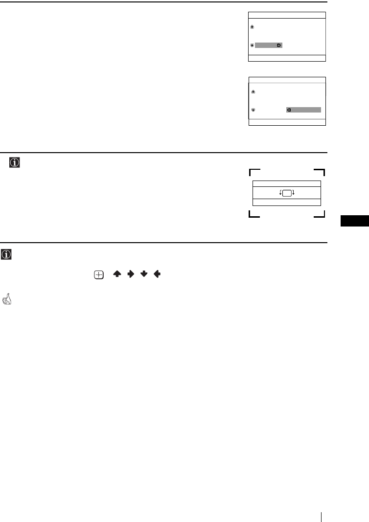
ES
master page=right
9
KV-14CT1E_BCNMixU3_ES
4-093-927-32(1)
5Una vez que el televisor ha sintonizado y memorizado todos los
canales (emisoras de televisión), en pantalla aparece
automáticamente el menú Ordenación de Programas para que
pueda cambiar el orden en que los canales aparecen en la pantalla.
a) Si no desea cambiar el orden de los canales, pulse MENU.
b) Si desea cambiar el orden de los canales:
1Pulse el botón 2 +/– para seleccionar el número de
programa con el canal (emisora de televisión) que desea
cambiar de posición y, a continuación, pulse t.
2Pulse 2 +/– para seleccionar el nuevo número de
programa en el que desea memorizar el canal (emisora de
televisión) seleccionado y, a continuación, pulse t.
3Repita los pasos b)1 y b)2 si desea reordenar otros canales
de televisión.
6 La opción siguiente sólo está disponible para el modelo
KV-21CT1E.
Debido al magnetismo terrestre, es posible que la imagen aparezca
inclinada. El menú Rotación Imagen le permite reajustar la imagen
en caso necesario.
a) Si no es necesario, pulse t.
b) Si es necesario, pulse 2 +/– para corregir la inclinación de la
imagen y, por último, pulse t para almacenarla.
• Para hacer que el menú aparezca de nuevo, mantenga pulsado durante unos 5 segundos
el botón MENU del panel de control superior.
• Los botones MENU, y / / / del mando a distancia también se pueden
utilizar para las operaciones mencionadas arriba.
El televisor está listo para funcionar.
Ordenación de Programas
Programa:
Seleccione canal
[
MENU
]
Confirmar [t]Salir
Sel. [–2+]
TVE
TVE2
TV3
04 C33
01
02
03
Programa:
Sel. nueva posición
Ordenación de Programas
[MENU]
Confirmar [t]Salir
Sel. [–2+]
01 TVE
02 TVE2
03 TV3
04 C33 03 TV3
Fin
[
MENU
]
[2+]
[
–
2]
Rotación Imagen
Confirmar [t]
Sel. [–2+]
Primera puesta en marcha
01ESKV21CT1E.fm Page 9 Friday, July 4, 2003 3:31 PM
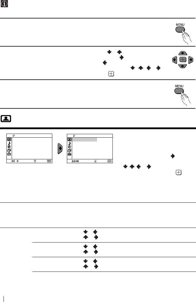
master page=left
10
KV-14CT1E_BCNMixU3_ES
4-093-927-32(1)
Introducción y manejo del sistema de menús
Este televisor utiliza un sistema de menús en pantalla para guiarle en las diferentes
operaciones. Utilice los siguientes botones del mando a distancia para desplazarse a través
de los menús:
1Pulse el botón MENU para mostrar el primer nivel de menú en pantalla.
2• Para resaltar el menú u opción deseados, pulse o .
• Para entrar en el menú u opción seleccionados, pulse .
• Para volver al menú u opción anterior, pulse .
• Para modificar los ajustes de la opción seleccionada, pulse / / o .
• Para confirmar y memorizar su selección, pulse .
3Pulse el botón MENU para volver a la pantalla normal de televisión.
Imagen
El menú de “Imagen” le permite
modificar los ajustes de la imagen.
Para ello:
Tras seleccionar la opción que
desea modificar, pulse , A
continuación, pulse repetidamente
// o
para modificar el
ajuste y finalmente pulse para
memorizarlo.
Este menú también le permite
modificar el modo de imagen según
el tipo de programa que esté
viendo:
Modo Directo (para realzar el contraste y la nitidez de la imagen).
Películas (para una imagen detallada con precisión).
Juegos (para juegos electónicos).
Personal (para ajustar sus preferencias).
Ajuste de la
Imagen
Contraste Pulse o para reducir el contraste de la imagen.
Pulse o para reazar el contraste de la imagen.
Brillo Pulse o para oscurecer la imagen.
Pulse o para incrementar el brillo de la imagen.
Color Pulse o para disminuir la intensidad del color.
Pulse o para aumentar la intensidad del color.
Imagen
Sí
Ajuste de la Imagen
Directo
Sel.
Confirmar
Fin
Imagen inteligente:
Modo:
Imagen
Sí
Ajuste de la Imagen
DirectoModo:
Sel.
Confirmar
Fin
Imagen inteligente:
Sistema de menús en pantalla
01ESKV21CT1E.fm Page 10 Friday, July 4, 2003 3:31 PM
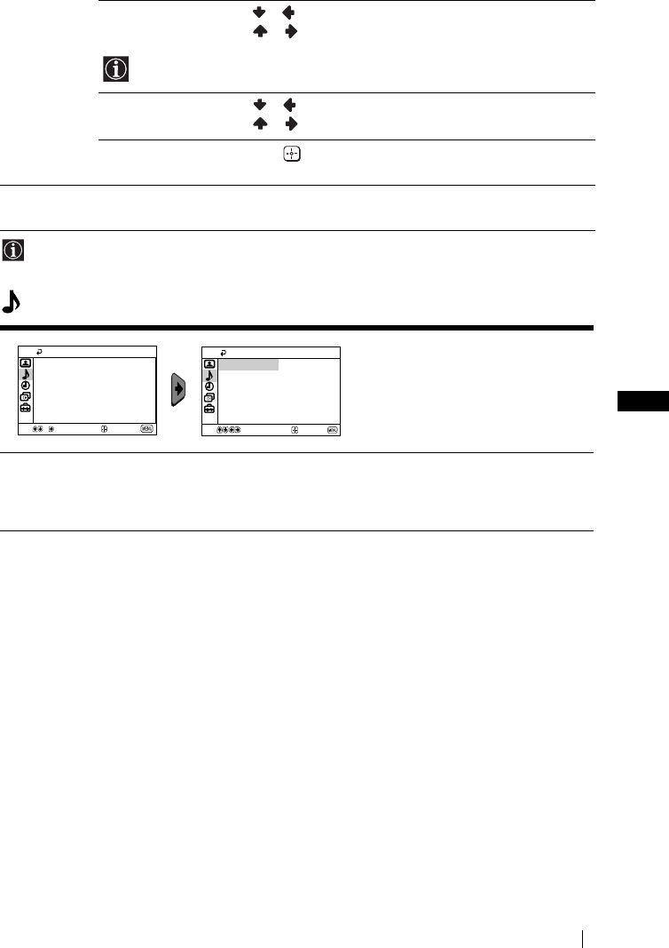
ES
master page=right
11
KV-14CT1E_BCNMixU3_ES
4-093-927-32(1)
Si se realizan modificaciones en “Ajuste de la Imagen”, “Modo” se ajustará
automáticamente en “Personal” y el nuevo valor se almacenará en dicho ajuste.
Sonido
Tonalidad Pulse o para aminorar los tonos verdes.
Pulse o para incrementar los tonos verdes.
Tonalidad no se puede ajustar para la señal de color NTSC (p.ej. vídeos
de los EE.UU.).
Nitidez Pulse o para atenuar la imagen.
Pulse o para avivar la imagen.
Preestablecido Seleccione para restablecer la imagen a los niveles
prefijados en fábrica.
Imagen
inteligente
Sí/No Seleccionar para optimizar la calidad de la imagen.
P. ej., para reducir el nivel de ruido cuando la señal es débil.
El menú “Sonido” le permite cambiar
los ajustes de sonido.
Auto
Volumen
Sí/No
El nivel de volumen de los canales (emisoras de televisión) debe permanecer
estable, independientemente de la señal emitida (p.ej., en el caso de anuncios
publicitarios).
Sonido
NoAuto Volumen:
Sel.
Confirmar
Fin
Sel. Confirmar Fin
Sonido
Auto Volumen: No
Sistema de menús en pantalla
01ESKV21CT1E.fm Page 11 Friday, July 4, 2003 3:31 PM
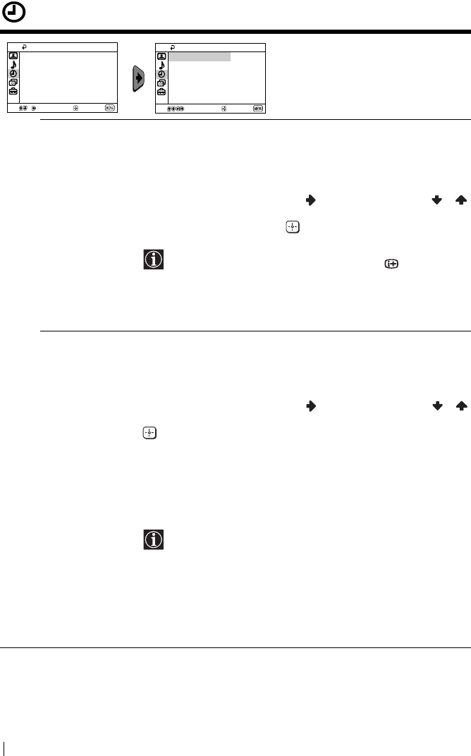
master page=left
12
KV-14CT1E_BCNMixU3_ES
4-093-927-32(1)
Temporizador
El menú “Temporizador” le permite
modificar los ajustes del
temporizador.
Desconexión
Automática
La opción de “Desconex. Aut.” dentro del menú “Temporizador”,
le permite seleccionar un periodo de tiempo tras el cual el televisor
entrará automáticamente en la modalidad de desconexión
temporal (standby).
Para ello:
Tras seleccionar la opción, pulse . A continuación pulse o
para seleccionar el intervalo de tiempo (máximo 1 hora 30
minutos) y finalmente pulse para memorizarlo.
• Si desea ver el tiempo restante hasta la desconexión
mientras ve la televisión, pulse el botón .
• Un minuto antes de que el televisor entre en modo de
desconexión temporal, aparecerá automáticamente el
mensaje “1 minuto para apagarse” en la pantalla del
televisor.
Conexión
Automática
La opción de “Conexión Aut.” dentro del menú “Temporizador”,
le permite seleccionar un periodo de tiempo tras el cual el televisor
se conectará automáticamente desde la modalidad de desconexión
temporal (standby).
Para ello:
Tras seleccionar la opción, pulse . A continuación pulse o
para seleccionar el intervalo de tiempo (máximo 12 horas) y pulse
para memorizarlo. Finalmente pulse el botón &/1 de
desconexión temporal (standby) del mando a distancia, y tras el
intervalo de tiempo fijado, el televisor se encenderá
automáticamente.
Una vez seleccionado el tiempo, el televisor se enciende
automáticamente y en la pantalla aparece la indicación “Conexión
Aut.”.
• El indicador de modo de desconexión temporal (standby)
1 del televisor se iluminará en ámbar para indicar que
“Conexión Aut.” está activado.
• Cualquier fallo o interrupción en el fluido eléctrico,
anulará esta función.
• Si después de que el televisor se haya encendido con el
ajuste "Conexión Aut." no pulsa ningún botón durante
más de una hora, el televisor entrará automáticamente en
el modo de espera.
Temporizador
No
Desconex. Aut.:
No
Conexión Aut.:
Sel.
Confirmar
Fin
Temporizador
No
No
Conexión Aut.:
Sel.
Confirmar
Fin
Desconex. Aut.:
Sistema de menús en pantalla
01ESKV21CT1E.fm Page 12 Monday, July 7, 2003 2:15 PM

ES
master page=right
13
KV-14CT1E_BCNMixU3_ES
4-093-927-32(1)
Ajuste de canales
El menú "Ajuste de canales" permite
memorizar los canales de este
televisor.
Sintonía
Automática
La opción de “Sintonía Automática” dentro del menú “Ajuste de
canales”, le permite que el televisor busque y almacene todos los
canales (emisoras de televisión) disponibles.
Para ello:
Tras seleccionar la opción, pulse y, a continuación, proceda tal
y como se indica en el capítulo “Encendido y Sintonización
automática del TV”, pasos 4 (ver página 8).
Ordenación de
Programas
La opción de “Ordenación de Programas” dentro del menú
“Ajuste de canales”, le permite cambiar el orden en que los canales
(emisoras de televisión) aparecen en el televisor.
Para ello:
Tras seleccionar la opción, pulse y, a continuación, proceda tal
y como se indica en el capítulo “Encendido y Sintonización
automática del TV”, paso 5b) (ver página 9).
Etiquetado de
Programas
La opción “Etiquetado de Programas” dentro del menú “Ajuste de
canales”, le permite asignar un nombre, de cinco caracteres como
máximo, a un canal.
Para ello:
1 Tras seleccionar la opción, pulse . Pulse o para
seleccionar el número de programa que desea etiquetar, a
continuación, pulse .
2Pulse
. Con el primer elemento de la columna Nombre
resaltado, pulse o para seleccionar una letra , un número
o “_” para un espacio en blanco y a continuación, pulse para
confirmar ese carácter. Seleccione los otros cuatro caracteres de
la misma forma. Finalmente pulse para memorizarlo.
Ajuste de canales
Sintonía Automática
Ordenación de Programas
Etiquetado de Programas
Sintonía Manual
Sel.
Confirmar
Fin
Ajuste de canales
Ordenación de Programas
Etiquetado de Programas
Sintonía Manual
Sel.
Confirmar
Fin
Sintonía Automática
Sistema de menús en pantalla
continúa...
01ESKV21CT1E.fm Page 13 Friday, July 4, 2003 3:31 PM
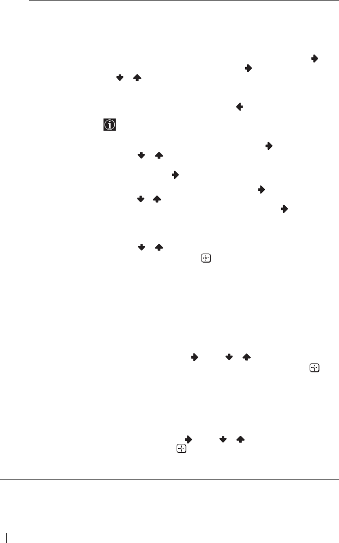
master page=left
14
KV-14CT1E_BCNMixU3_ES
4-093-927-32(1)
Sintonía Manual La opción de “Sintonía Manual” dentro del menú “Ajuste de
canales”, le permite:
a) Sintonizar uno a uno y en el orden de programa que desee, los
canales (emisoras de televisión) o una entrada de vídeo.
Para ello:
1 Tras seleccionar la opción de “Sintonía Manual”, pulse . Con
la opción Programa resaltada, pulse y, a continuación, pulse
o para seleccionar el número de programa (posición) en
el que desea sintonizar una emisora de televisión o el canal de
vídeo (para el canal de vídeo recomendamos que seleccione el
número de programa “0”). Pulse .
La siguien8te opción sólo aparecerá dependiendo del país
que haya seleccionado en el menú “Idioma/País”.
2 Tras seleccionar la opción Sistema, pulse . A continuación,
pulse o para seleccionar el sistema de televisión (B/G
para los países de Europa occidental o D/K para los de Europa
oriental). Pulse .
3 Tras seleccionar la opción Canal, pulse y, a continuación,
pulse o para seleccionar el tipo de canal (“C” para canales
terrestres o “S” para canales por cable). Pulse . A
continuación, pulse los botones numéricos para introducir
directamente el número del canal de la emisora de televisión o
el de la señal del canal de vídeo. Si no sabe el número del canal,
pulse o para buscarlo. Cuando encuentre el canal que
desea memorizar pulse dos veces.
Repita todos estos pasos para sintonizar y memorizar más canales.
b) Aún cuando la sintonización fina automática (AFT) está siempre
activada, también puede ajustarla de forma manual para
obtener una mejor recepción de la imagen en caso de que ésta
aparezca distorsionada.
Para ello:
Mientras esté viendo el canal (emisora de televisión) en el que
deseerealizar la sintonización fina, seleccione la opción AFT y,
a continuación, pulse . Pulse o para ajustar el nivel de
frecuencia del canal entre –15 y +15. Finalmente, pulse dos
veces para memorizarlo.
c) Omitir los números de programa que no desee para saltárselos
al seleccionarlos con los botones PROG +/–.
Para ello:
Resaltando la opción Programa, pulse PROG + o – hasta que
aparezca el número de programa que desea omitir. Cuando éste
aparezca en la pantalla, seleccione la opción Omitir y, a
continuación, pulse . Pulse o para seleccionar Sí y
finalmente, pulse dos veces para memorizarlo.
Si más adelante desea anular esta función, seleccione de nuevo “No”
en lugar de “Sí”.
Sistema de menús en pantalla
01ESKV21CT1E.fm Page 14 Friday, July 4, 2003 3:31 PM
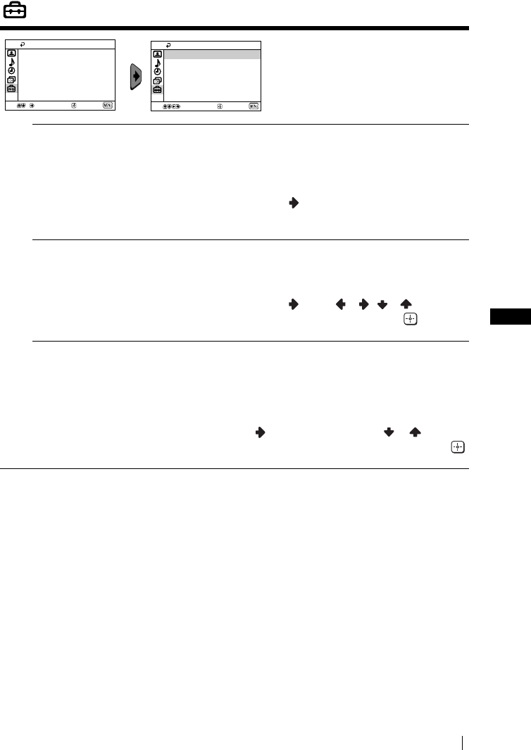
ES
master page=right
15
KV-14CT1E_BCNMixU3_ES
4-093-927-32(1)
Configuracíon
El menu “Configuracíon“ le permite
modificar algunas de las
configuraciones de este televisor.
Idioma/País La opción de “Idioma/País” dentro del menú “Configuración”, le
permite seleccionar el idioma en que desea que aparezcan los menús
en la pantalla. También le permite seleccionar el país donde desea
utilizar el televisor.
Para ello:
Tras seleccionar la opción, pulse y, a continuación, proceda tal y
como se indica en el capítulo “Encendido y Sintonización automática
del TV”, pasos 2 y 3 (ver página 8).
Rotación Imagen
(sólo para
KV-21CT1E)
Debido al magnetismo terrestre, es posible que la imagen aparezca
inclinada. En este caso, puede reajustarla utilizando la opción de
“Rotación Imagen” dentro del menú “Configuración”.
Para ello:
Tras seleccionar la opción, pulse . Pulse o ( o ) para
corregir la inclinación de la imagen y, por último, pulse para
almacenarla.
Centrado RGB Al conectar una fuente de señales RGB, como una “PlayStation”,
puede que sea necesario ajustar el centrado horizontal de la imagen.
En este caso, puede ajustarla utilizando la opción de “Centrado RGB”
dentro del menú “Configuración”.
Para ello:
Mientras esté viendo una señal de entrada RGB seleccione la opción
“Centrado RGB”, y pulse . A continuación pulse o para
ajustar el centrado de la imagen entre –10 y +10. Finalmente, pulse
para memorizarlo.
Configuración
Rotación Imagen
Centrado RGB: 0
Sel.
Confirmar
Fin
Idioma/País
Configuración
Idioma/País
Rotación Imagen
Centrado RGB: 0
Sel.
Confirmar
Fin
Sistema de menús en pantalla
01ESKV21CT1E.fm Page 15 Friday, July 4, 2003 3:31 PM
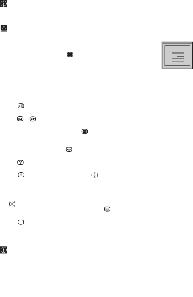
master page=left
16
KV-14CT1E_BCNMixU3_ES
4-093-927-32(1)
Teletexto
Teletexto es un servicio de información que transmiten la mayoría de las emisoras de
televisión. La página de índice del servicio de teletexto (página 100 por lo general)
proporciona información sobre cómo utilizar este servicio. Para operar dentro del teletexto,
utilice los botones del mando a distancia tal y como se indica en esta página.
Asegúrese de utilizar un canal de televisión con una señal fuerte, pues de lo contrario,
podrían producirse errores de teletexto.
Entrar en el servicio de Teletexto:
Tras seleccionar el canal (emisora de televisión) que transmita el servicio de
teletexto que desee ver, pulse .
Seleccionar una página de Teletexto:
Introduzca los tres dígitos del número de página que desee ver, utilizando
los botones numéricos del mando a distancia.
• Si se equivoca, introduzca tres dígitos cualesquiera y, a continuación, vuelva a introducir el número
de pagina correcto.
• Si el contador de páginas no se detiene, es porque la página requerida no está disponible. En ese caso,
introduzca otro número de página.
Para comprobar el contenido de un servicio de Teletexto:
Pulse .
Seleccionar la página siguiente o anterior:
Pulse o .
Superponer teletexto con la imagen de televisión:
Mientras esté viendo teletexto, pulse . Púlselo de nuevo para salir del modo de teletexto.
Retener una página:
Algunas páginas de teletexto contienen subpáginas que van rotando automáticamente. Para
retener una subpágina, pulse . Púlselo de nuevo para cancelar la retención.
Visualizar una información oculta (p. ej.: soluciones de adivinanzas):
Pulse . Púlselo de nuevo para volver a ocultar la información.
Para ampliar la pantalla del Teletexto:
Pulse . Cada vez que pulse este botón , la pantalla del Teletexto cambiará del modo
siguiente: Aumentar la mitad superior t Aumentar la mitad inferior t Tamaño normal.
Para esperar a que aparezca una página de Teletexto mientras ve un programa de
televisión.
1 Introduzca el número de Teletexto de la página que desea consultar y, a continuación, pulse
.
2 Cuando aparezca el número de página, pulse para ver el texto.
Salir del servicio de teletexto:
Pulse .
Fastext
El servicio Fastext permite acceder a las páginas de teletexto mediante la pulsación de un
solo botón.
Estando dentro del servicio de teletexto y en caso de que se emitan señales de Fastext, en la
parte inferior de la pantalla aparece un menú de códigos de color que le permite acceder
directamente a una página. Para ello, pulse el botón de color correspondiente (rojo, verde,
amarillo o azul) del mando a distancia.
TELETEXT
Index
Programme
News
Sport
Weather
25
153
101
98
TELETEXT
Index
Programme
News
Sport
Weather
25
153
101
98
TELETEXT
Index
Programme
News
Sport
Weather
25
153
101
98
TELETEXT
Index
Programme
News
Sport
Weather
25
153
101
98
TELETEXT
Index
Programme
News
Sport
Weather
25
153
101
98
TELETEXT
Index
Programme
News
Sport
Weather
25
153
101
98
TELETEXT
Index
Programme
News
Sport
Weather
25
153
101
98
TELETEXT
Index
Programme
News
Sport
Weather
25
153
101
98
Teletexto
01ESKV21CT1E.fm Page 16 Friday, July 4, 2003 3:31 PM
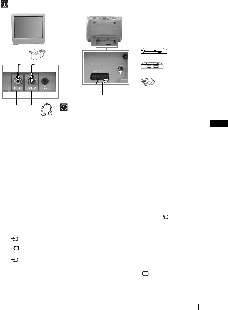
ES
master page=right
17
KV-14CT1E_BCNMixU3_ES
4-093-927-32(1)
Conexión de equipos opcionales
Es posible conectar al televisor una amplia gama de equipos opcionales tal y como se
muestra a continuación (los cables de conexión no se suministran).
Conexión de un vídeo:
Para conectar un vídeo, consulte el capítulo “Conexión de una antena exterior y del vídeo”. Le
aconsejamos que conecte el vídeo utilizando un cable de Euroconector. Si no utiliza este cable,
tendrá que sintonizar manualmente el canal de la señal de vídeo mediante el menú de “Sintonía
Manual” (para ello, consulte el apartado a) de la página 14). Consulte también el manual de
instrucciones de su vídeo para ver cómo conseguir el canal de la señal de vídeo.
Manejo de los equipos opcionales
1Conecte el equipo opcional al conector adecuado del televisor tal y como se indica arriba.
2Encienda el equipo conectado.
3Para ver la imagen del equipo conectado, pulse repetidamente el botón hasta que
aparezca en la pantalla el símbolo correcto de entrada.
4Para recuperar la imagen normal de televisión, pulse el botón del mando a distancia.
Símbolo Señales de entrada
1•Señal de entrada de audio/vídeo mediante el Euroconector C
1•Señal de entrada RGB mediante el Euroconector C. Este símbolo sólo
aparece si ha conectado una entrada RGB.
2•Señal de entrada de vídeo a través del conector RCA A y señal de
entrada de audio a través de B.
AB
12
C
8mm/Hi8/
DVC
videocámara DVD/Vídeo
“PlayStation”*
Descodificador
Al conectar los auriculares,
los altavoces del televisor se
desconectarán
automáticamente.
*
“PlayStation”
es un producto
de Sony Computer
Entertainment, Inc.
*
“PlayStation”
es una marca
registrada de Sony Computer
Entertainment, Inc.
Información complementaria
01ESKV21CT1E.fm Page 17 Friday, July 4, 2003 3:31 PM
master page=left
18
KV-14CT1E_BCNMixU3_ES
4-093-927-32(1)
Especificaciones
El sistema de recepción de señales de estos televisores, cumplen la normativa requerida por la
ley española del Real Decreto 1160/89.
Sistema de TV:
Dependiendo del país que haya seleccionado:
B/G/H, D/K
Sistema de color:
PAL, SECAM
NTSC 3.58, 4.43 (sólo entrada de vídeo)
Cobertura de canales:
VHF: E2-E12
UHF: E21-E69
CATV: S1-S20
HYPER: S21-S41
D/K: R1-R12, R21-R69
Tubo de imagen:
Pantalla Plana FD Trinitron
Terminales posteriores:
i1/ Euroconector de 21 pins (norma
CENELEC) incluidas entrada de
audio/vídeo, entrada RGB,
salida de audio/vídeo de TV.
Terminales frontales:
t2 entrada de vídeo – conector RCA
2 entrada de audio – conector RCA
toma para auriculares
Salida de sonido:
1 x 6 W (potencia musical)
1 x 3 W (RMS)
Consumo de energía:
•KV-21CT1E: 56 W
•KV-14CT1E: 50 W
Consumo de energía en modo de
desconexión temporal (standby):
< 1 W
Dimensiones (an x al x prf):
•KV-21CT1E: Approx. 497 x 461 x 487 mm
•KV-14CT1E: Approx. 374 x 355 x 420 mm
Peso:
•KV-21CT1E: Approx. 24 kg
•KV-14CT1E: Approx. 11 kg
Accesorios suministrados:
1
Mando a distancia (RM-W100)
2 Pilas de norma IEC.
1 Antena telescópica (sólo para KV-14CT1E)
Otras características:
•Teletexto, Fastext, TOPtext.
•Desconexión automática.
•Conexión automática.
Diseñi y especificaciones sujetos a cambios sin previo aviso.
Paper Ecológico - Libre de cloro
Información complementaria
01ESKV21CT1E.fm Page 18 Friday, July 4, 2003 3:31 PM
ES
master page=right
19
KV-14CT1E_BCNMixU3_ES
4-093-927-32(1)
Solución de problemas
A continuación se ofrecen algunas soluciones sencillas para resolver problemas
relacionados con la imagen y el sonido.
En caso de averías, haga que personal especializado examine el televisor.
No abra nunca el aparato.
Problema Solución
Ausencia de imagen (la pantalla
aparece oscura) y sin sonido.
•Compruebe la conexión de la antena.
•Enchufe el televisor y pulse el botón ! de la parte
frontal del aparato.
•Si el indicador 1 del televisor está encendido, pulse
el botón &/1 del mando a distancia.
La imagen es deficiente o inexistente
pero la calidad de sonido es buena.
•Mediante el sistema de menús, entre en el menú de
“Ajuste de la Imagen” y seleccione “Preestablecido”
para recuperar los ajustes de fábrica (ver página 10).
Ausencia de imagen o del menú de
información del equipo opcional
conectado al Euroconector de la
parte posterior del televisor.
•Asegúrese que ha encendido el equipo opcional y
pulse varias veces el botón del mando a distancia
hasta que el símbolo de entrada correcto aparezca en
la pantalla (ver página 17).
Buena calidad de imagen pero no
hay sonido.
•Pulse el botón + del mando a distancia.
• Compruebe que los auriculares están desconectados.
Los programas en color no se ven en
color.
•Mediante el sistema de menús, entre en el menú de
“Ajuste de la Imagen” y seleccione “Preestablecido”
para recuperar los ajustes de fábrica (ver página 10).
La imagen aparece distorsionada al
cambiar de programa o al
seleccionar el teletexto.
•Apague el equipo conectado al Euroconector de 21
pins de la parte posterior del televisor.
Caracteres erróneos en las páginas
de teletexto.
•Mediante el sistema de menús, seleccione la opción
“Idioma/País” y seleccione el país en el cual está
operando el televisor (ver página 15).
La imagen aparece inclinada.
(sólo para KV-21CT1E)
•Mediante el sistema de menús, seleccione la opción
“Rotación Imagen” dentro del menú de
“Configuración” y corrija la inclinación
(ver página 15).
Imagen con ruido. •Mediante el sistema de menús, seleccione la opción
“AFT” dentro del menú de “Sintonía Manual” y
ajuste la sintonización manualmente para obtener
una mejor recepción de la imagen (ver página 14).
•Mediante el sistema de menús, seleccione la opción
“Imagen inteligente” dentro del menú de “Imagen” y
seleccione “Si” para atenuar el ruido de imagen
(ver página 10).
El mando a distancia no funciona. •Cambie las pilas.
El indicador de modo de espera 1
parpadeará en rojo en el televisor.
•Póngase en contacto con el servicio técnico de Sony
más cercano.
Información complementaria
01ESKV21CT1E.fm Page 19 Friday, July 4, 2003 3:31 PM

4-093-927-52(1)
R
© 2003 Sony Corporation
Instruction Manual GB
FD Trinitron
Colour Television
KV-21CT1U
KV-14CT1U
01CoverKV21CT1U.fm Page 2 Thursday, July 3, 2003 10:06 AM
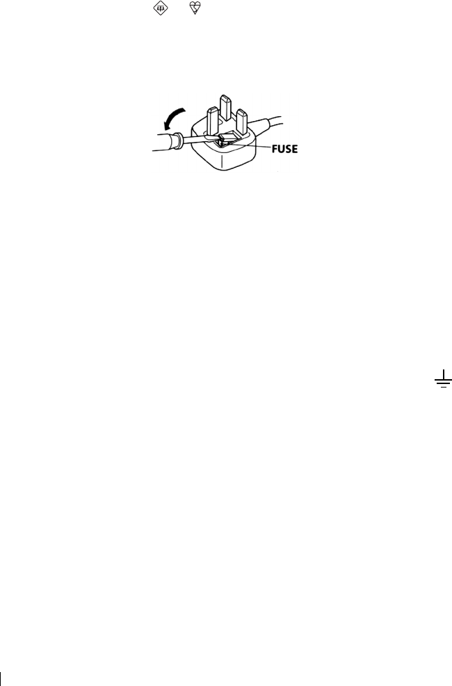
master page=left
2
KV-21CT1U_Grp U5_GB
4-093-927-52(1)
NOTICE FOR CUSTOMERS IN THE UNITED KINGDOM
A moulded plug complying with BS1363 is fitted to this equipment for your safety and
convenience.
Should the fuse in the plug supplied need to be replaced, a 5 AMP fuse approved by ASTA or
BSI to BS 1362 (i.e. marked with or ) must be used.
When an alternative type of plug is used it should be fitted with a 5 AMP FUSE, otherwise the
circuit should be protected by a 5 AMP FUSE at the distribution board.
If the plug supplied with this equipment has a detachable fuse cover, be sure to attach the fuse
cover after you change the fuse. Never use the plug without the fuse cover. If you should lose
the fuse cover, please contact your nearest Sony service centre.
How to replace the fuse
Open the fuse compartment with a blade screwdriver, and replace the fuse.
• IMPORTANT
If the plug supplied is not suitable for the socket outlets in your home, it should be cut off and
an appropriate plug fitted in accordance with the following instructions:
The wires in this mains lead are coloured in accordance with the following code:
Blue Neutral
Brown Live
As the colours of the wires in the mains lead of this apparatus may not correspond with the
coloured markings identifying the terminals in your plug, proceed as follows:
The wire which is coloured blue must be connected to the terminal which is marked with the
letter N or coloured black. The wire which is coloured brown must be connected to the
terminal which is marked with the letter L or coloured red. Do not connect either wire to the
earth terminal in the plug which is marked by the letter E or by the safety earth symbol
or coloured green or green and yellow.
WARNING
• To prevent shock hazard, do not insert the plug cut off from the mains lead into a socket outlet.
This plug cannot be used and should be destroyed.
• To prevent fire or shock hazard, do not expose the unit to rain or moisture.
• Dangerously high voltages are present inside the set. Do not open the cabinet. Refer servicing
to qualified personnel only.
02GBKV21CT1U.fm Page 2 Thursday, July 3, 2003 9:57 AM
master page=right
3
KV-21CT1U_Grp U5_GB
4-093-927-52(1)
GB
Introduction
Thank you for choosing this Sony FD Trinitron Colour Television.
Before operating the TV, please read this manual thoroughly and retain it for future
reference.
Symbols used in the manual:
• Important information.
• Information on a feature.
•1,2...Sequence of instructions.
• Shaded buttons on the remote
control show you the buttons you
have to press to follow the sequence
of the instructions.
• Informs you of the result of
instructions.
Table of Contents
Notice for Customers in the United Kingdom ................................................................................... 2
Introduction............................................................................................................................................. 3
Safety Information .... ..............................................................................................................................4
Overview
Overview of Remote Control Buttons .... .............................................................................................5
Overview of TV Buttons ........................................................................................................................ 6
Installation
Inserting Batteries into the Remote Control ....................................................................................... 6
Connecting an Indoor Aerial (only for KV-14CT1U) ........................................................................ 7
Connecting an Outdoor Aerial and VCR ............................................................................................7
First Time Operation
Switching On the TV and Automatically Tuning .............................................................................. 8
Menu System
Introducing and Using the Menu System ......................................................................................... 10
Picture............................................................................................................................................... 10
Sound................................................................................................................................................ 11
Timer................................................................................................................................................. 12
Channel Set Up ............................................................................................................................... 13
Set Up ............................................................................................................................................... 15
Teletext................................................................................................................................................ 16
Additional Information
Connecting Optional Equipment ....................................................................................................... 17
Using Optional Equipment ................................................................................................................. 17
Specifications......................................................................................................................................... 18
Troubleshooting .................................................................................................................................... 19
Television Channel Number Guide for United Kingdom .............................................................. 20
Table of Contents
02GBKV21CT1U.fm Page 3 Thursday, July 3, 2003 9:57 AM
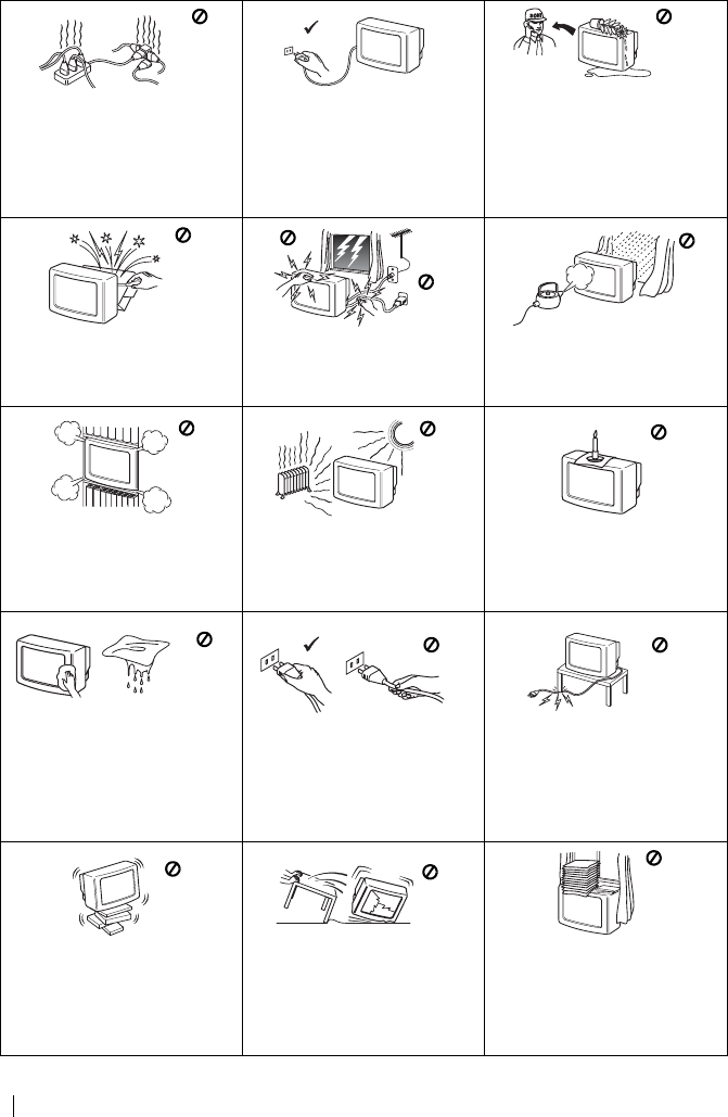
master page=left
4
KV-21CT1U_Grp U5_GB
4-093-927-52(1)
Safety Information
This set is to operate on a 220-
240V AC supply only. Take care
not to connect too many
appliances to the same power
socket as this could result in fire
or electric shock.
For environmental and safety
reasons, it is recommended that
the TV set is not left in standby
mode when not in use.
Disconnect from the mains.
Never push objects of any kind
into the set as this could result in
a fire or electric shock. Never
spill liquid of any kind on the
set. If any liquid or solid object
does fall through, do not operate
the TV. Have it checked immedi-
ately by qualified personnel.
Do not open the cabinet and the
rear cover of the TV. Refer to
qualified service personnel only.
For your own safety, do not
touch any part of the TV, power
lead or aerial lead during
lightning storms.
To prevent fire or shock hazard,
do not expose the TV to rain or
moisture.
Do not cover the ventilation
openings of the TV. For
ventilation, leave a space of at
least 10cm all around the set.
Never place the TV in hot, humid
or excessively dusty places. Do
not install the TV where it may be
exposed to mechanical
vibrations.
To prevent fire, keep
inflammable objects or naked
lights (e.g. candles) away from
the TV.
Clean the screen and cabinet with a
soft, lightly dampened cloth. Do
not use any type of abrasive pad,
alkaline cleaner, scouring powder
or solvent, such as alcohol or
benzine, or antistatic spray. As a
safety precaution, unplug the TV
before cleaning it.
Pull out the power lead by the
plug. Do not pull on the power
lead itself.
Take care not to place heavy
objects on the power lead as this
could result in damage.
We recommend you wind any
excess lead around the holders
provided on the rear of the TV.
Place the TV on a secure stable
stand. Do not allow children to
climb on to it. Do not place the
TV on its side or face up.
Unplug the power lead before
moving the TV. Avoid uneven
surfaces, quick steps or excessive
force. If the set has been dropped
or damaged, have it checked
immediately by qualified service
personnel.
Do not cover the ventilation
openings of the TV with items
such as curtains or newspapers,
etc.
Safety Information
02GBKV21CT1U.fm Page 4 Thursday, July 3, 2003 9:57 AM
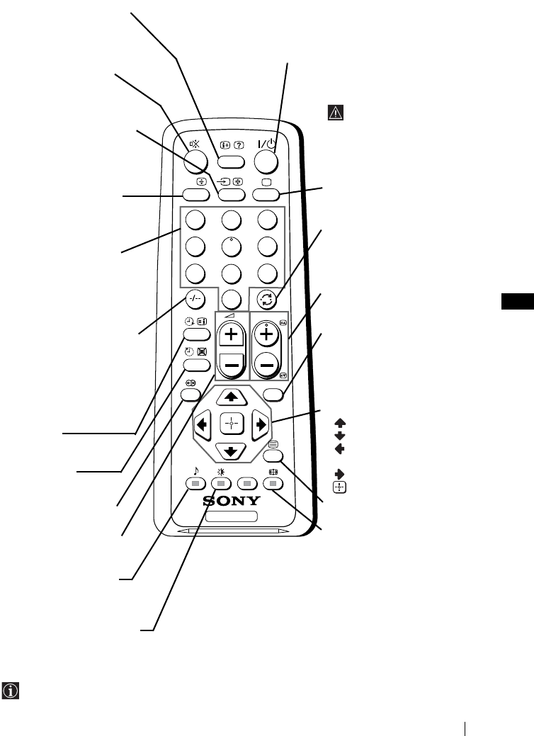
master page=right
5
KV-21CT1U_Grp U5_GB
4-093-927-52(1)
GB
Overview of Remote Control Buttons
Besides TV functions, all coloured buttons as well as green symbols are also used for Teletext
operation. For more details, please refer to “Teletext” section of this instruction manual (see page 16).
TV
123
46
789
0
5
MENU
PROG
A/B
Displaying on screen
information
Press to display all on-screen
indications. Press again to
cancel.
Muting the sound
Press to mute TV sound.
Press again to restore the
sound.
Selecting input source
Press repeatedly until the
desired input symbol of the
source appears on the TV
screen.
This button only works in
Teletext mode.
Function A/B associated to this
button does not work with this TV.
Selecting channels
Press to select channels.
For double-digit programme
numbers, enter the second
digit within 3 seconds.
or
Press -/-- and then the first
and second digit.
If you enter an incorrect first
digit, this should be corrected
by entering another digit (0-9)
and then selecting -/-- button
again to enter the programme
number of your choice.
On timer
Set TV to switch on
automatically.
Sleep timer
Set TV to switch off
automatically.
This button does not work
on this set.
Adjusting TV volume
Press to adjust the volume of
the TV.
This button only works in
Teletext mode.
Function
9
associated to this
button does not work with this TV.
Selecting picture mode
Press repeatedly to change
the picture mode.
To temporarily switch off TV
Press to temporarily switch off TV (the standby
indicator 1 on TV lights up). Press again to switch on
TV from standby mode.
To save energy we recommend
switching off completely
when TV is not in use.
After 15 minutes
without a signal and
without any button
being pressed, the TV
switches automatically
into standby mode.
Selecting TV mode
Press to switch off teletext or
video input.
Back to the channel last
watched
Press to watch the last
channel selected (watched for
at least 5 seconds).
Selecting channels
Press to select the next or
previous channel.
Displaying the menu
system
Press to display the menu on
the TV screen. Press again to
remove the menu display
from the TV screen.
Menu selection
Scroll Up
Scroll Down
Previous menu or
selection
Next menu or selection
Confirm your selection
Selecting Teletext
Press to switch on teletext.
Selecting screen format
Press to view programmes in
16:9 mode. Press again to
return to 4:3 mode.
Overview
02GBKV21CT1U.fm Page 5 Thursday, July 3, 2003 9:57 AM
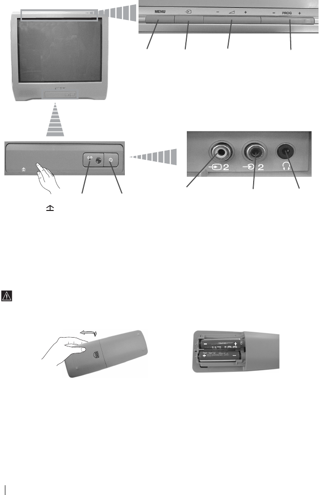
master page=left
6
KV-21CT1U_Grp U5_GB
4-093-927-52(1)
Overview of TV Buttons
Inserting Batteries into the Remote Control
Make sure you insert the supplied batteries using the correct polarities.
Always remember to dispose of used batteries in an environmental friendly way.
Displaying
the menu
system
Selecting
Input
source
Volume
control
buttons
Programme Up or
Down buttons
(selects TV
channels)
Lift up the door
flap with
mark to
reveal the
control panel.
Standby
indicator
On/Off
switch
Video Input
jack
Audio Input
jack
Headphone
jack
Overview-Installation
02GBKV21CT1U.fm Page 6 Thursday, July 3, 2003 9:57 AM
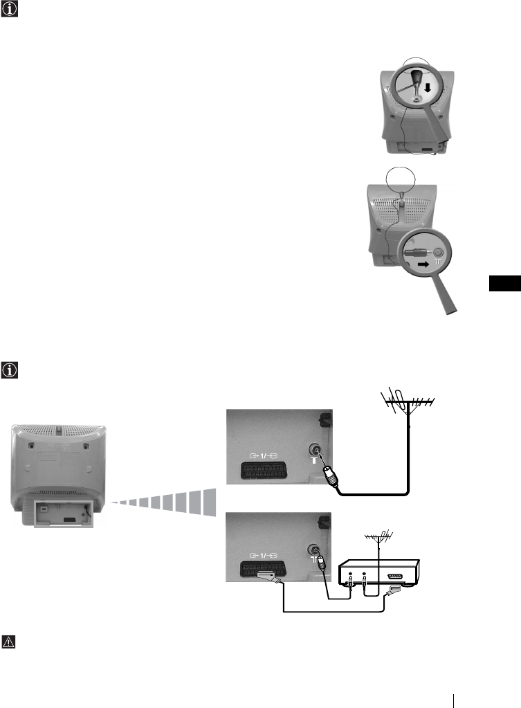
master page=right
7
KV-21CT1U_Grp U5_GB
4-093-927-52(1)
GB
Connecting an Indoor Aerial (only for KV-14CT1U)
For a better reception we recommend you connect an external aerial. However, where an
external aerial is not available and your local UHF signal is strong, you can connect the
supplied loop aerial as follows:
1Insert the loop aerial into the opening on top of the set until it clicks.
2Connect the aerial connector to the aerial socket on the rear of the set.
3After switching on the TV, adjust the aerial for optimum reception.
Connecting an Outdoor Aerial and VCR
Connecting cables are not supplied.
For more details of VCR connection, please refer to the section “Connecting Optional
Equipment” of this instruction manual (see page 17).
OUT IN
or
VCR
Scart lead is optional.
Installation
02GBKV21CT1U.fm Page 7 Thursday, July 3, 2003 9:57 AM
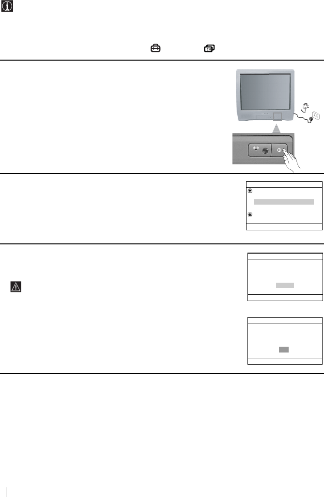
master page=left
8
KV-21CT1U_Grp U5_GB
4-093-927-52(1)
Switching On the TV and Automatically Tuning
The first time you switch on your TV, a sequence of menu screens appear on the TV
enabling you to: 1) choose the language of the menu screen, 2) search and store all available
channels (TV Broadcast), 3) change the order in which the channels (TV Broadcast) appear
on the screen and 4) adjust the picture slant (only for KV-21CT1U).
However, if you need to change any of these settings at a later date, you can do that by
selecting the appropriate option in the (Set Up) or (Channel Set Up) menu.
1Connect the TV plug to the mains socket (220-240V AC, 50Hz).
Press ! On/Off button on the TV set to switch on the TV. The
first time you switch on the TV, a Language menu displays
automatically on the TV screen.
2Press 2 +/– button on the top control panel to select the language,
then press t to confirm your selection. From now on all menus
will appear in the selected language.
3Ensure the aerial is connected as instructed, then press t to
confirm. The TV automatically starts searching and storing all
available broadcast channels for you.
• This procedure could take some minutes. Please be patient
and do not press any buttons, otherwise automatic tuning
will not be completed.
• If no channels were found during the auto tuning process, a
new menu appears automatically on the screen asking you
to connect the aerial. Please connect the aerial (see page 7)
and press t. The auto tuning process will start again.
Language
Svenska
English
Nederlands
Français
Select language
Norsk
Confirm [t]
Select [
–
2+]
Do you want to start automatic
First please connect aerial
tuning?
No
Initial Set Up
Yes
Select [
–
2+]Confirm [t]
Auto Tuning
No channel found
Please connect aerial
OK
Confirm [t]
End
[
MENU
]
First Time Operation
02GBKV21CT1U.fm Page 8 Thursday, July 3, 2003 9:57 AM
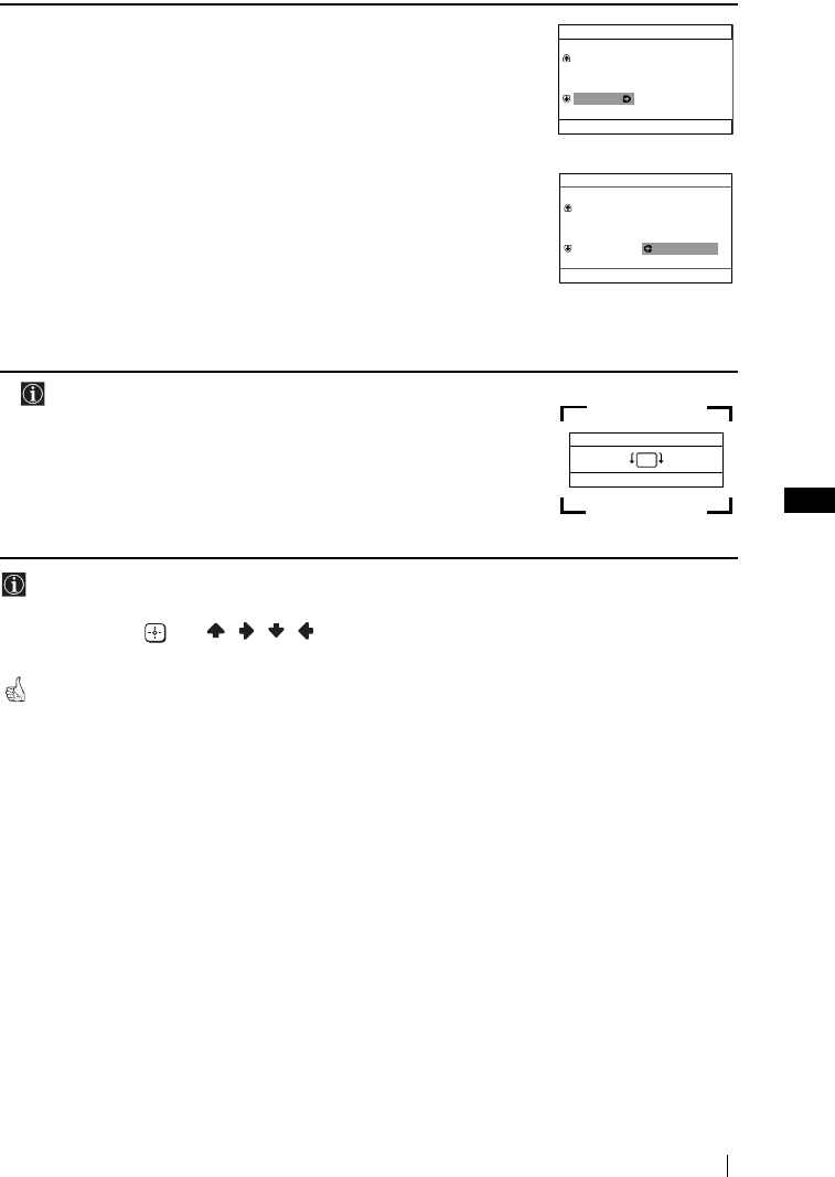
master page=right
9
KV-21CT1U_Grp U5_GB
4-093-927-52(1)
GB
4After all available channels are captured and stored, the
Programme Sorting menu appears automatically on the screen
enabling you to change the order in which the channels appear on
the screen.
a) If you wish to keep the broadcast channels in the tuned order,
press MENU.
b) If you wish to store the channels in a different order:
1Press 2 +/– to select the programme number with the
channel (TV Broadcast) you wish to rearrange, then press
t.
2Press 2 +/– to select the new programme number position
for your selected channel (TV Broadcast), then press t.
3Repeat steps b)1 and b)2 if you wish to change the order of
the other channels.
5 The following option is only available for KV-21CT1U.
Because of the earth’s magnetism, the picture might slant. The
Picture Rotation menu allows you to correct the picture slants if it
is necessary.
a) If it is not necessary, press t.
b) If it is necessary, press 2 +/– to correct any slant of the
picture. Finally press t to store.
• To allow this menu to appear again, press and hold MENU button at top control panel for
about 5 seconds.
• The MENU, and / / / buttons on the remote control can also be used for the
operations above.
Your TV is now ready for use.
Programme Sorting
Programme:
Select channel
Select [–2+]Confirm [t]
Exit
[
MENU
]
TVE
TVE2
TV3
04 C33
01
02
03
Programme Sorting
Programme:
Select new position
Select [
–
2+]
Confirm [t]
Exit
[
MENU
]
01 TVE
02 TVE2
03 TV3
04 C33 03 TV3
Picture Rotation
Select [–2+]
[–2][2+]
Confirm [t]
End
[
MENU
]
First Time Operation
02GBKV21CT1U.fm Page 9 Thursday, July 3, 2003 9:57 AM
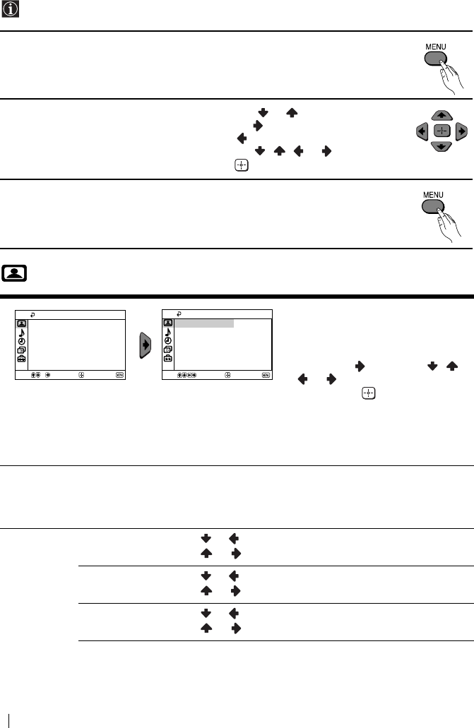
master page=left
10
KV-21CT1U_Grp U5_GB
4-093-927-52(1)
Introducing and Using the Menu System
Your TV uses an on-screen menu system to guide you through the operations. Use the
following buttons on the Remote Control to operate the menu system:
1Press MENU to switch the menu on.
2• To highlight the desired menu or option, press or .
• To enter to the selected menu or option, press .
• To return to the last menu or option, press .
• To alter settings of your selected option, press / / or .
• To confirm and store your selection, press .
3Press MENU to remove the menu from the screen.
Picture
The “Picture” menu allows you to
alter the picture adjustments.
To do this:
After selecting the item you want to
alter, press , then press / /
or repeatedly to adjust it and
finally press to store the new
adjustment.
This menu also allows you to
customize the picture mode based
on the programme you are
watching:
Mode Live (for enhanced picture contrast and sharpness).
Movie (for a finely detailed picture).
Game (for a picture from game).
Personal (for your own custom settings).
Picture
Adjustment
Contrast Press or to reduce picture contrast.
Press or to enhance picture contrast.
Brightness Press or to darken the picture.
Press or to brighten the picture.
Colour Press or to decrease colour intensity.
Press or to increase colour intensity.
Picture
Intelligent Picture: On
Picture Adjustment
Live
Mode:
Select Confirm End
Select Confirm End
Picture
Intelligent Picture: On
Picture Adjustment
Mode: Live
Menu System
02GBKV21CT1U.fm Page 10 Thursday, July 3, 2003 9:57 AM
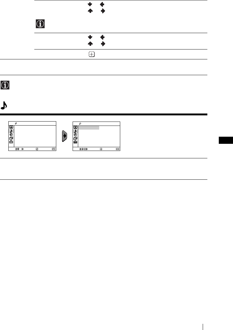
master page=right
11
KV-21CT1U_Grp U5_GB
4-093-927-52(1)
GB
If any changes are made to “Picture Adjustment”, “Mode” will switch automatically to
“Personal” and the new setting will be stored as “Personal”.
Sound
Hue Press or to decrease the green tones.
Press or to increase the green tones.
Hue can only be adjusted for NTSC colour signal (e.g. USA video tapes).
Sharpness Press or to soften the picture.
Press or to sharpen the picture.
Reset Select to reset the picture to the factory preset levels.
Intelligent
Picture
On/Off Select to optimize the picture quality.
E.g. reduce noise level when signal is weak.
The “Sound” menu allows you to
alter the sound adjustments.
Auto Volume On/Off
Volume level of the channels will stay the same, independent of the broadcast
signal (e.g. in the case of advertisements).
Select Confirm End
Sound
Auto Volume: Off
Select Confirm End
Sound
Auto Volume: Off
Menu System
02GBKV21CT1U.fm Page 11 Thursday, July 3, 2003 9:57 AM
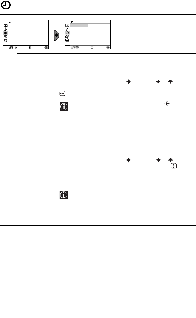
master page=left
12
KV-21CT1U_Grp U5_GB
4-093-927-52(1)
Timer
The “Timer” menu allows you to alter
the timer adjustments.
Sleep Timer The “Sleep Timer” option in the “Timer” menu allows you to select
a time period for the TV to switch itself automatically into the
standby mode.
To do this:
After selecting the option, press , then press or to set the
time period delay (max. of 1 hour and 30 minutes) and finally press
to store.
• While watching the TV, you can press the button on
the remote control to display the time remaining.
• One minute before the TV switches itself into standby
mode, “TV will turn off soon” is displayed on the TV
screen automatically.
On Timer The “On Timer” option in the “Timer” menu allows you to select a
time period for the TV to switch itself automatically on from
standby mode.
To do this:
After selecting the option, press , then press or to set the
time period delay (max. of 12 hours) and finally press to store.
Finally press the standby button &/1 on the remote control. After
the selected length of time, the TV switches on automatically and
“On Timer” will appear on the screen.
• The standby indicator 1 on the TV set lights up in amber
to indicate that “On Timer” is active.
• Any loss of power will cause these settings to be cleared.
• If no buttons are pressed for more than one hour after the
TV is turned on using the “On Timer”, the TV
automatically goes into standby mode.
Timer
On Timer:
Sleep Timer: Off
Off
Select Confirm End
Timer
On Timer:
Sleep Timer: Off
Off
Select Confirm End
Menu System
02GBKV21CT1U.fm Page 12 Thursday, July 3, 2003 9:57 AM
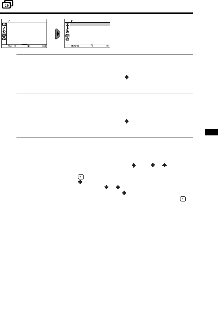
master page=right
13
KV-21CT1U_Grp U5_GB
4-093-927-52(1)
GB
Channel Set Up
The “Channel Set Up” menu allows
you to preset channels on this TV.
Auto Tuning The “Auto Tuning” option in the “Channel Set Up” menu allows
you to automatically search and store all available TV channels.
To do this:
After selecting the option, press and then proceed in the same
way as in the step 3 of the section “Switching On the TV and
Automatically Tuning” (see page 8).
Programme
Sorting
The “Programme Sorting” option in the “Channel Set Up” menu
allows you to change the order in which the channels (TV
Broadcast) appear on the screen.
To do this:
After selecting the option, press and then proceed in the same
way as in step 4b) of the section “Switching On the TV and
Automatically Tuning” (see page 9).
Programme Labels The “Programme Labels” option in the “Channel Set Up” menu
allows you to name a channel using up to five characters (letters or
numbers).
To do this:
1 After selecting the option, press . Press or to select the
programme number with the channel you wish to name, then
press .
2Press
. With the first element of the label column
highlighted, press or to select a letter or number (select
“_” for a blank), then press to confirm this character. Select
the other four characters in the same way. Finally press to
store.
Select End
Channel Set Up
Programme Labels
Manual Programme Preset
Programme Sorting
Auto Tuning
Confirm Select End
Channel Set Up
Programme Labels
Manual Programme Preset
Programme Sorting
Auto Tuning
Confirm
Menu System
continued...
02GBKV21CT1U.fm Page 13 Thursday, July 3, 2003 9:57 AM
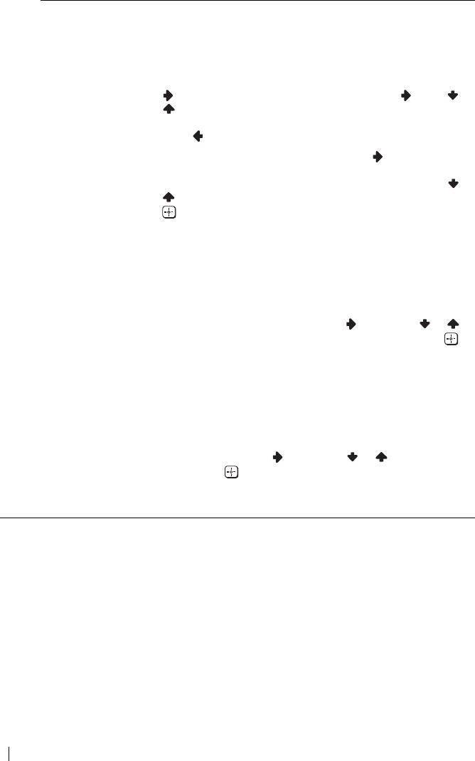
master page=left
14
KV-21CT1U_Grp U5_GB
4-093-927-52(1)
Manual
Programme
Preset
The “Manual Programme Preset” option in the “Channel Set Up”
menu allows you to:
a) Preset channels or a video input source one by one to the
programme order of your choice.
To do this:
1 After selecting the “Manual Programme Preset” option, press
. Highlight the Programme option and press . Press or
to select a programme number on which you want to preset
the channel (for VCR, select programme number “0”), then
press .
2 After selecting the Channel option, press . Then press the
number buttons to directly enter the channel number of the TV
Broadcast. If you do not know the channel number, press or
to search for it. When you tune the desired channel, press
twice to store.
Repeat all the above steps to tune and store more channels.
b) Normally the automatic fine tuning (AFT) will give the best
possible picture, however you can manually fine tune the TV to
obtain a better picture if the picture is distorted.
To do this:
While watching the channel (TV Broadcast) you wish to fine
tune, select the AFT option and press . Next press or to
adjust the fine tuning between -15 and +15. Finally press
twice to store.
c) Skip any unwanted programme numbers when they are selected
with the PROG +/– button.
To do this:
Highlighting the Programme option, press PROG +/– to select
the programme number you want to skip. When the
programme you want to skip appears on the screen, select the
Skip option and press . Next press or to select Yes.
Finally press twice to confirm and store.
To cancel this function afterwards, select No instead of Yes in the step
above.
Menu System
02GBKV21CT1U.fm Page 14 Thursday, July 3, 2003 9:57 AM
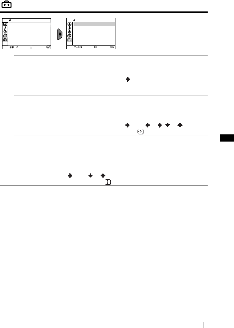
master page=right
15
KV-21CT1U_Grp U5_GB
4-093-927-52(1)
GB
Set Up
The “Set Up” menu allows you to
alter various options on this TV.
Language The “Language” option in the “Set Up” menu allows you to select the
language that the menus are displayed in.
To do this:
After selecting the option, press and then proceed in the same way
as in the step 2 of the section “Switching On the TV and Automatically
Tuning” (see page 8).
Picture Rotation
(only for
KV-21CT1U)
Because of the earth’s magnetism, the picture might slant. In this case,
you can correct the picture slant by using the option “Picture
Rotation” in the “Set Up” menu.
To do this:
After selecting the option, press . Press or ( or ) to correct
any slant of the picture. Finally press to store.
RGB Centring When connecting an RGB source, such as a “PlayStation”, you may
need to readjust the horizontal position of the picture. In that case, you
can readjust it through the “RGB Centring” option in the “Set Up”
menu.
To do this:
While watching an RGB source, select the “RGB Centring” option and
press . Press or to adjust the centre of the picture between -10
and +10. Finally press to confirm and store.
Select End
Set Up
RGB Centring: 0
Picture Rotation
Language
Confirm
Select End
Set Up
RGB Centring: 0
Picture Rotation
Language
Confirm
Menu System
02GBKV21CT1U.fm Page 15 Thursday, July 3, 2003 9:57 AM

master page=left
16
KV-21CT1U_Grp U5_GB
4-093-927-52(1)
Teletext
Teletext is an information service transmitted by most TV stations. The index page of the
Teletext service (usually page 100) gives you information on how to use the service. To
operate Teletext, use the remote control buttons as indicated below.
Be sure to use a channel (TV Broadcast) with a strong signal, otherwise Teletext errors may
occur.
To switch on Teletext:
After selecting the TV channel which carries the Teletext service you wish to
view, press .
To select a Teletext page:
Input 3 digits for the page number, using the numbered buttons.
• If you have made a mistake, retype the correct page number.
• If the counter on the screen continues searching, it is because this page is not available. In that case,
input another page number.
To check the contents of a Teletext service:
Press .
To access the next or preceding page:
Press or .
To superimpose teletext on to the TV:
Whilst you are viewing Teletext, press . Press it again to cancel Teletext mode.
To freeze a teletext page:
Some Teletext pages have sub-pages which follow on automatically. To stop them, press
. Press it again to cancel the freeze.
To reveal concealed information (e.g., answer to a quiz):
Press . Press it again to conceal the information.
To enlarge the Teletext display:
Press . Each time you press , the Teletext display changes as follows: Enlarge upper
half t Enlarge lower half t Normal size.
To stand by for a Teletext page while watching a TV program.
1 Enter the Teletext number that you want to refer to, then press .
2 When the page number is displayed, press to show the Text.
To switch off Teletext:
Press .
Fastext
Fastext service lets you access pages with one push of a button.
While you are in Teletext mode and Fastext is broadcast, a colour coded menu appears at
the bottom of the teletext page. Press the colour button (red, green, yellow or blue) to access
the corresponding page.
TELETEXT
Index
Programme
News
Sport
Weather
25
153
101
98
TELETEXT
Index
Programme
News
Sport
Weather
25
153
101
98
TELETEXT
Index
Programme
News
Sport
Weather
25
153
101
98
TELETEXT
Index
Programme
News
Sport
Weather
25
153
101
98
TELETEXT
Index
Programme
News
Sport
Weather
25
153
101
98
TELETEXT
Index
Programme
News
Sport
Weather
25
153
101
98
TELETEXT
Index
Programme
News
Sport
Weather
25
153
101
98
TELETEXT
Index
Programme
News
Sport
Weather
25
153
101
98
Teletext
02GBKV21CT1U.fm Page 16 Thursday, July 3, 2003 9:57 AM

master page=right
17
KV-21CT1U_Grp U5_GB
4-093-927-52(1)
GB
Connecting Optional Equipment
Using the following instructions, you can connect a wide range of optional equipment to
your TV set (connecting cables are not supplied).
Connecting a VCR:
To connect a VCR, please refer to the section “Connecting an outdoor aerial and VCR” of this
instruction manual. We recommend you connect your VCR using a Scart lead. If you do not
have a Scart lead, tune in the VCR test signal to the TV programme number “0” by using the
“Manual Programme Preset” option (for details on how to manually programme these presets,
see page 14, step a).
Refer to your VCR instruction manual to find out how to find the output channel of your VCR.
Using Optional Equipment
1Connect your equipment to the designated TV socket, as indicated above.
2Switch on the connected equipment.
3To watch the picture of the connected equipment, press repeatedly until the correct
input symbol appears on the screen.
4Press button on the remote control to return to the normal TV picture.
Symbol Input Signals
1•Audio / video input signal through the Scart connector C
1•RGB input signal through the Scart connector C. This symbol appears
only if a RGB source has been connected.
2•Video input signal through the phono socket A and Audio input signal
through B.
AB
12
C
8mm/Hi8/
DVC
camcorder DVD/VCR
“PlayStation”*
decoder
When you connect the
headphones, the TV
speakers will
automatically be muted
* “PlayStation”
is a product
of Sony Computer
Entertainment, Inc.
* “PlayStation
” is a trademark
of Sony Computer
Entertainment, Inc.
Additional Information
02GBKV21CT1U.fm Page 17 Thursday, July 3, 2003 9:57 AM
master page=left
18
KV-21CT1U_Grp U5_GB
4-093-927-52(1)
Specifications
TV system:
I
Colour system:
PAL, SECAM
NTSC 3.58, 4.43 (only Video In)
Channel Coverage:
UHF B21-B69
Picture Tube:
Flat Display FD Trinitron
Rear Terminals
i1/ 21-pin Scart connector
(CENELEC standard) including
audio/video input, RGB input,
TV audio/video output.
Front Terminals
t2 video input – phono jack
2 audio input – phono jack
headphone jack
Sound Output:
1 x 6 W (music power)
1 x 3 W (RMS)
Power Consumption:
•KV-21CT1U: 56 W
•KV-14CT1U: 50 W
Standby Power Consumption:
< 1 W
Dimensions (w x h x d):
•KV-21CT1U: Approx. 497 x 461 x 487 mm
•KV-14CT1U: Approx. 374 x 355 x 420 mm
Weight:
•KV-21CT1U: Approx. 24 kg
•KV-14CT1U: Approx. 11 kg
Accessories supplied:
1 Remote Control (RM-W100)
2 Batteries (IEC designated)
1 Loop aerial (only for KV-14CT1U)
Other features:
•Teletext, Fastext, TOPtext
•Sleep Timer
•On Timer
Design and specifications are subject to change without notice.
Ecological Paper- Totally Chlorine Free
Additional Information
02GBKV21CT1U.fm Page 18 Thursday, July 3, 2003 9:57 AM
master page=right
19
KV-21CT1U_Grp U5_GB
4-093-927-52(1)
GB
Troubleshooting
Here are some simple solutions to the problems which may affect the picture and sound.
In case of problems, have your TV serviced by qualified personnel. Never open the casing
yourself.
Problem Solution
No picture (screen is dark) and no
sound.
•Check the aerial connection.
•Plug the TV in and press the ! button on the front of
TV.
•If the standby indicator 1 is on, press &/1 button on
the remote control.
Poor or no picture (screen is dark),
but good sound.
•Using the menu system, select the “Picture
Adjustment” menu and select “Reset” to return to the
factory settings (see page 10).
No picture or no menu information
from equipment connected to the
Scart connector.
•Check that the optional equipment is on and press
repeatedly on the remote control until the correct
input symbol is displayed on the screen (see page 17).
Good picture, no sound. •Press the + button on the remote control.
•Check that the headphones are not connected.
No colour on colour programmes. •Using the menu system, select the “Picture
Adjustment” menu and select “Reset” to return to
factory settings (see page 10).
Distorted picture when changing
programmes or selecting teletext.
•Turn off any equipment connected to the Scart
connector on the rear of the TV.
Picture slanted
(only for KV-21CT1U).
•Using the menu system, select the “Picture Rotation”
option in the “Set Up” menu to correct the picture
slant (see page 15).
Noisy picture when viewing a TV
channel.
•Using the menu system, select the “Manual
Programme Preset” menu and adjust Fine Tuning
(AFT) to obtain better picture reception (see page 14).
•Using the menu system, select the “Intelligent
Picture” option in the “Picture” menu and select
“On” to reduce the noise in the picture (see page 10).
Remote control does not function. •Replace the batteries.
The standby indicator 1 on the TV
flashes red.
•Contact your nearest Sony service centre.
Additional Information
02GBKV21CT1U.fm Page 19 Thursday, July 3, 2003 9:57 AM
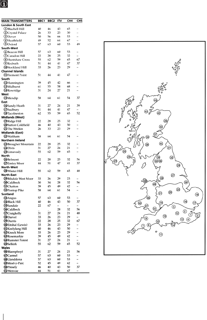
master page=left
20
KV-21CT1U_Grp U5_GB
4-093-927-52(1)
Television Channel Number Guide for United Kingdom
Only the main transmitters are listed. Information regarding the regional sub-relay channel
numbers can be obtained by contacting The BBC Engineering Information Dept., Telephone
Number 020 7852 5040.
Additional Information
02GBKV21CT1U.fm Page 20 Thursday, July 3, 2003 9:57 AM
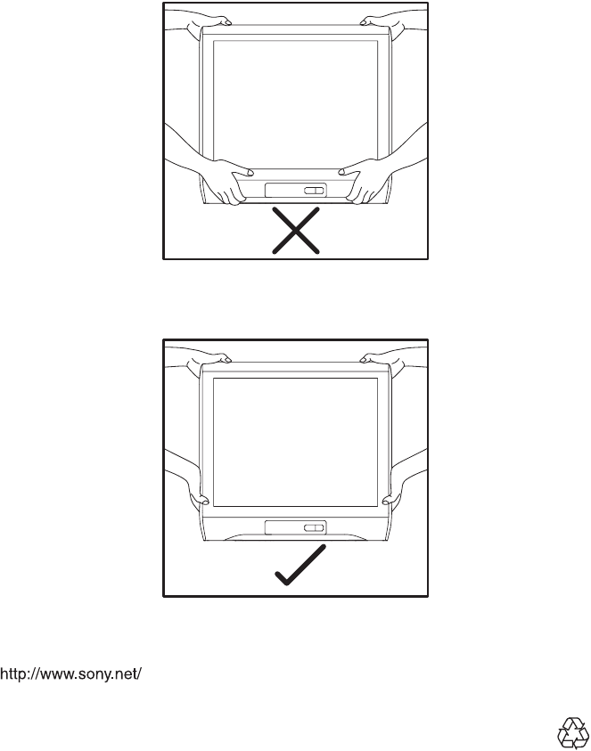
Sony España, S.A.
Printed in Spain
KV-21CT1U
01CoverKV21CT1U.fm Page 1 Thursday, July 3, 2003 10:06 AM

4-093-927-62(1)
R
© 2003 Sony Corporation
Instruction Manual
Инструкции за експлоатация
Návod k obsluze
Kezelési útmutató
Instrukcja obsługi
Инструкция по эксплуатации
GB
BG
CZ
HU
PL
RU
SK
Návod na obsluhu
FD Trinitron
Colour Television
KV-21CT1K
KV-14CT1K
01CoverKV21CT1K.fm Page 2 Wednesday, July 9, 2003 9:31 AM
GB
master page=right
3
KV-14CT1K_Grp U6
4-093-927-62(1)
Introduction
Thank you for choosing this Sony FD Trinitron Colour Television.
Before operating the TV, please read this manual thoroughly and retain it for future
reference.
Symbols used in the manual:
• Important information.
• Information on a feature.
•1,2...Sequence of instructions.
• Shaded buttons on the remote control
show you the buttons you have to
press to follow the sequence of the
instructions.
• Informs you of the result of
instructions.
Table of Contents
Introduction............................................................................................................................................. 3
Safety Information .... ..............................................................................................................................4
Overview
Overview of Remote Control Buttons .... .............................................................................................5
Overview of TV Buttons ........................................................................................................................ 6
Installation
Inserting Batteries into the Remote Control ....................................................................................... 6
Connecting an Indoor Aerial (only for KV-14CT1K)......................................................................... 7
Connecting an Outdoor Aerial and VCR ............................................................................................7
First Time Operation
Switching On the TV and Automatically Tuning .............................................................................. 8
Menu system
Introducing and Using the Menu System ......................................................................................... 10
Picture............................................................................................................................................... 10
Sound................................................................................................................................................ 11
Timer................................................................................................................................................. 12
Channel Set Up ............................................................................................................................... 13
Set Up ............................................................................................................................................... 15
Teletext................................................................................................................................................ 16
Additional Information
Connecting Optional Equipment ....................................................................................................... 17
Using Optional Equipment ................................................................................................................. 17
Specifications......................................................................................................................................... 18
Troubleshooting .................................................................................................................................... 19
Table of Contents
01GBKV21CT1K.fm Page 3 Wednesday, July 9, 2003 8:39 AM

master page=left
4
KV-14CT1K_Grp U6
4-093-927-62(1)
Safety Information
This set is to operate on a 220-
240V AC supply only. Take care
not to connect too many
appliances to the same power
socket as this could result in fire
or electric shock.
For environmental and safety
reasons, it is recommended that
the TV set is not left in standby
mode when not in use.
Disconnect from the mains.
Never push objects of any kind
into the set as this could result in
a fire or electric shock. Never
spill liquid of any kind on the
set. If any liquid or solid object
does fall through, do not operate
the TV. Have it checked immedi-
ately by qualified personnel.
Do not open the cabinet and the
rear cover of the TV. Refer to
qualified service personnel only.
For your own safety, do not
touch any part of the TV, power
lead or aerial lead during
lightning storms.
To prevent fire or shock hazard,
do not expose the TV to rain or
moisture.
Do not cover the ventilation
openings of the TV. For
ventilation, leave a space of at
least 10cm all around the set.
Never place the TV in hot, humid
or excessively dusty places. Do
not install the TV where it may
be exposed to mechanical
vibrations.
To prevent fire, keep
inflammable objects or naked
lights (e.g. candles) away from
the TV.
Clean the screen and cabinet with a
soft, lightly dampened cloth. Do
not use any type of abrasive pad,
alkaline cleaner, scouring powder
or solvent, such as alcohol or
benzine, or antistatic spray. As a
safety precaution, unplug the TV
before cleaning it.
Pull out the power lead by the
plug. Do not pull on the power
lead itself.
Take care not to place heavy
objects on the power lead as this
could result in damage.
We recommend you wind any
excess lead around the holders
provided on the rear of the TV.
Place the TV on a secure stable
stand. Do not allow children to
climb on to it. Do not place the
TV on its side or face up.
Unplug the power lead before
moving the TV. Avoid uneven
surfaces, quick steps or excessive
force. If the set has been dropped
or damaged, have it checked
immediately by qualified service
personnel.
Do not cover the ventilation
openings of the TV with items
such as curtains or newspapers,
etc.
Safety Information
01GBKV21CT1K.fm Page 4 Wednesday, July 9, 2003 8:39 AM
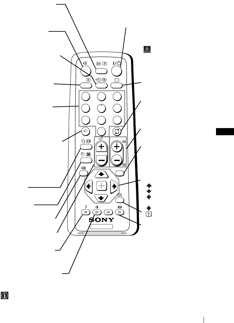
GB
master page=right
5
KV-14CT1K_Grp U6
4-093-927-62(1)
Overview of Remote Control Buttons
Besides TV functions, all coloured buttons as well as green symbols are also used for
Teletext operation. For more details, please refer to “Teletext” section of this instruction
manual (see page 16).
TV
123
46
789
0
5
MENU
PROG
A/B
Displaying on screen
information
Press to display all on-screen
indications. Press again to
cancel.
Muting the sound
Press to mute TV sound.
Press again to restore the
sound.
Selecting input source
Press repeatedly until the
desired input symbol of the
source appears on the TV
screen.
This button only works in
Teletext mode.
Function A/B associated to this
button does not work with this TV.
Selecting channels
Press to select channels.
For double-digit programme
numbers, enter the second
digit within 3 seconds.
or
Press -/-- and then the first
and second digit.
If you enter an incorrect first
digit, this should be corrected
by entering another digit (0-9)
and then selecting -/-- button
again to enter the programme
number of your choice.
On timer
Set TV to switch on
automatically.
Sleep timer
Set TV to switch off
automatically.
This button does not work
on this set.
Adjusting TV volume
Press to adjust the volume
of the TV.
This button only works in
Teletext mode.
Function
9
associated to this
button does not work with this TV.
Selecting picture mode
Press repeatedly to change
the picture mode.
To temporarily switch off TV
Press to temporarily switch off TV (the standby
indicator 1 on TV lights up). Press again to switch on
TV from standby mode.
To save energy we recommend
switching off completely
when TV is not in use.
After 15 minutes
without a signal and
without any button
being pressed, the TV
switches automatically
into standby mode.
Selecting TV mode
Press to switch off teletext or
video input.
Back to the channel last
watched
Press to watch the last
channel selected (watched for
at least 5 seconds).
Selecting channels
Press to select the next or
previous channel.
Displaying the menu
system
Press to display the menu on
the TV screen. Press again to
remove the menu display
from the TV screen.
Menu selection
Scroll Up
Scroll Down
Previous menu or
selection
Next menu or selection
Confirm your selection
Selecting Teletext
Press to switch on teletext.
Selecting screen format
Press to view programmes in
16:9 mode. Press again to
return to 4:3 mode.
Overview
01GBKV21CT1K.fm Page 5 Wednesday, July 9, 2003 8:39 AM

master page=left
6
KV-14CT1K_Grp U6
4-093-927-62(1)
Overview of TV Buttons
Inserting Batteries into the Remote Control
Make sure you insert the supplied batteries using the correct polarities.
Always remember to dispose of used batteries in an environmental friendly way.
Displaying
the menu
system
Selecting
Input
source
Volume
control
buttons
Programme Up or
Down buttons
(selects TV
channels)
Standby
indicator
On/Off
switch
Video Input
jack
Audio Input
jack
Headphone
jack
Lift up the door
flap with
mark to reveal
the control
panel.
Overview-Installation
01GBKV21CT1K.fm Page 6 Wednesday, July 9, 2003 8:39 AM
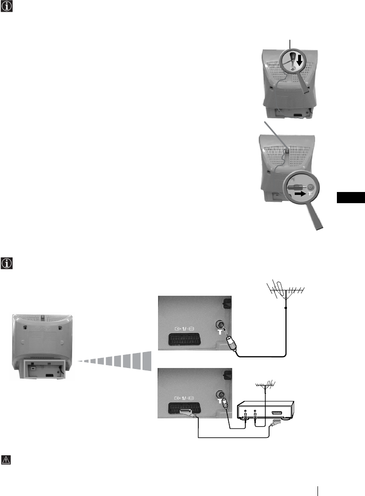
GB
master page=right
7
KV-14CT1K_Grp U6
4-093-927-62(1)
Connecting an Indoor Aerial (only for KV-14CT1K)
For a better reception we recommend you connect an external aerial. However, where an
external aerial is not available and your local VHF/UHF signal is strong, you can connect
the supplied indoor aerial as follows:
1Insert the aerial into the opening on top of the set until it clicks.
2Connect the aerial connector to the aerial socket on the rear of the
set.
3After switching on the TV, adjust the aerial for optimum reception.
Connecting an Outdoor Aerial and VCR
Connecting cables are not supplied.
For more details of VCR connection, please refer to the section “Connecting Optional
Equipment” of this instruction manual (see page 17).
OUT IN
or
VCR
Scart lead is optional.
Installation
01GBKV21CT1K.fm Page 7 Wednesday, July 9, 2003 8:39 AM
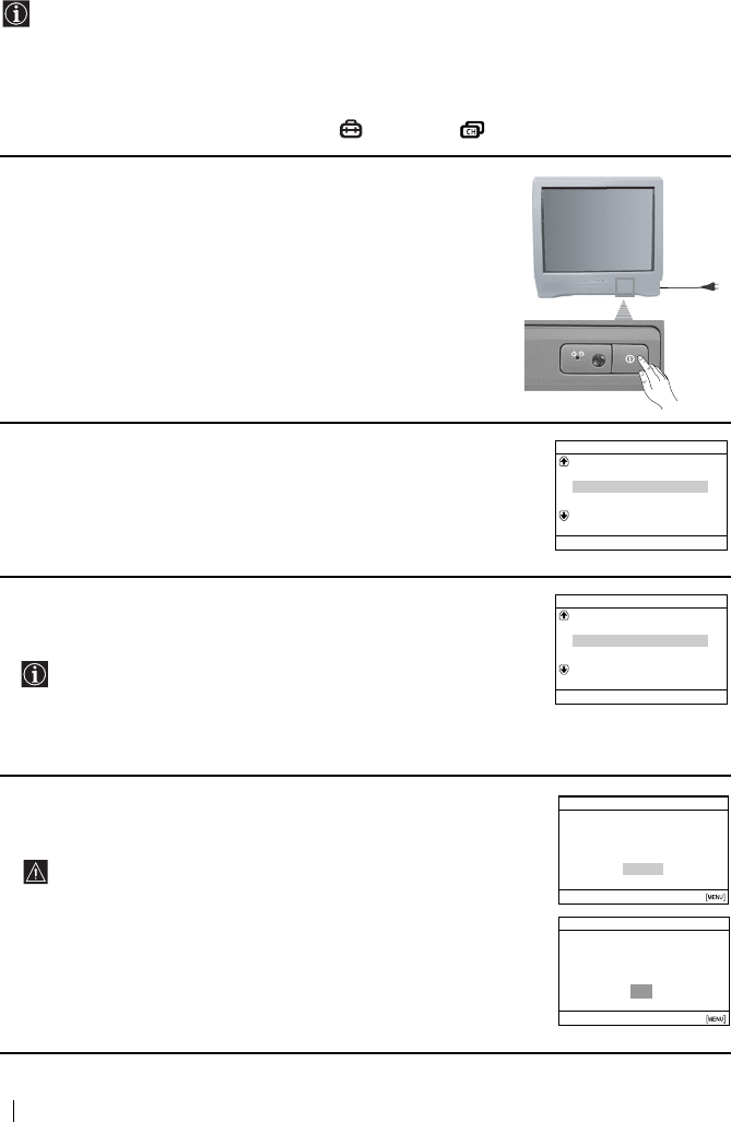
master page=left
8
KV-14CT1K_Grp U6
4-093-927-62(1)
Switching On the TV and Automatically Tuning
The first time you switch on your TV, a sequence of menu screens appear on the TV
enabling you to: 1) choose the language of the menu screen, 2) choose the country in which
you wish to operate the TV, 3) search and store all available channels (TV Broadcast), 4)
change the order in which the channels (TV Broadcast) appear on the screen and 5) adjust
the picture slant (only for KV-21CT1K).
However, if you need to change any of these settings at a later date, you can do that by
selecting the appropriate option in the (Set Up) or (Channel Set Up) menu.
1Connect the TV plug to the mains socket (220-240 V AC, 50 Hz).
Press ! On/Off button on the TV set to switch on the TV. The
first time you switch on the TV, a Language menu displays
automatically on the TV screen.
2Press 2 +/– button on the top control panel to select the language,
then press t to confirm your selection. From now on all menus
will appear in the selected language.
3The Country menu appears automatically on the TV screen. Press
2 +/– button to select the country in which you will operate the
TV set, then press t to confirm your selection.
• If the country in which you want to use the TV set does not
appear in the list, select “-” instead of a country.
• In order to avoid wrong teletext characters for Cyrillic
languages we recommend to select Russia in the case that
your own country does not appear in the list.
4Ensure the aerial is connected as instructed, then press t to
confirm. The TV automatically starts searching and storing all
available broadcast channels for you.
•This procedure could take some minutes. Please be patient
and do not press any buttons, otherwise automatic tuning
will not be completed.
•If no channels were found during the auto tuning process, a
new menu appears automatically on the screen asking you
to connect the aerial. Please connect the aerial (see page 7)
and press t. The auto tuning process will start again.
Language
Svenska
English
Nederlands
Français
Select language
Norsk
Confirm [t]
Select [–2+]
Country
Schweiz/Suisse/Svizzera
Italia
Select Country
Norge
Sverige
–
Confirm [t]
Select [–2+]
Do you want to start automatic
First please connect aerial
tuning?
No
Initial Set Up
Yes
Confirm [t]
Select [
–
2+]End
Auto Tuning
No channel found
Please connect aerial
OK
Confirm [t]End
First Time Operation
01GBKV21CT1K.fm Page 8 Wednesday, July 9, 2003 8:39 AM
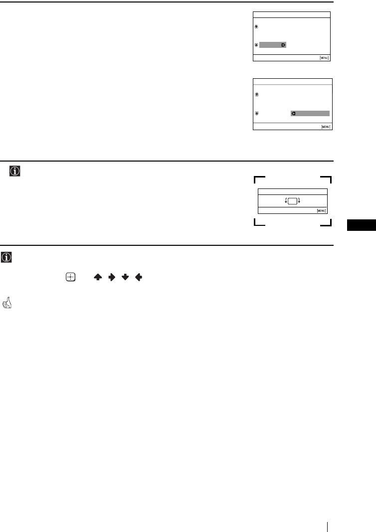
GB
master page=right
9
KV-14CT1K_Grp U6
4-093-927-62(1)
5After all available channels are captured and stored, the
Programme Sorting menu appears automatically on the screen
enabling you to change the order in which the channels appear on
the screen.
a) If you wish to keep the broadcast channels in the tuned order,
press MENU.
b) If you wish to store the channels in a different order:
1Press 2 +/– to select the programme number with the
channel (TV Broadcast) you wish to rearrange, then press
t.
2Press 2 +/– to select the new programme number position
for your selected channel (TV Broadcast), then press t.
3Repeat steps b) 1 and b) 2 if you wish to change the order of
the other channels.
6 The following option is only available for KV-21CT1K.
Because of the earth’s magnetism, the picture might slant. The
Picture Rotation menu allows you to correct the picture slants if it
is necessary.
a) If it is not necessary, press t.
b) If it is necessary, press 2 +/– to correct any slant of the
picture. Finally press t to store.
•To allow this menu to appear again, press and hold MENU button at top control panel for
about 5 seconds.
• The MENU, and / / / buttons on the remote control can also be used for the
operations above.
Your TV is now ready for use.
Programme Sorting
Programme:
TVE
TVE2
TV3
Select channel
04 C33
01
02
03
Confirm [t]
Select [
–
2+]Exit
Programme Sorting
Programme:
01 TVE
02 TVE2
03 TV3
Select new position
04 C33 03 TV3
Confirm [t]
Select [
–
2+]Exit
Picture Rotation
Confirm [t]End
Select [
–
2+]
[2+]
[
–
2]
First Time Operation
01GBKV21CT1K.fm Page 9 Wednesday, July 9, 2003 8:39 AM
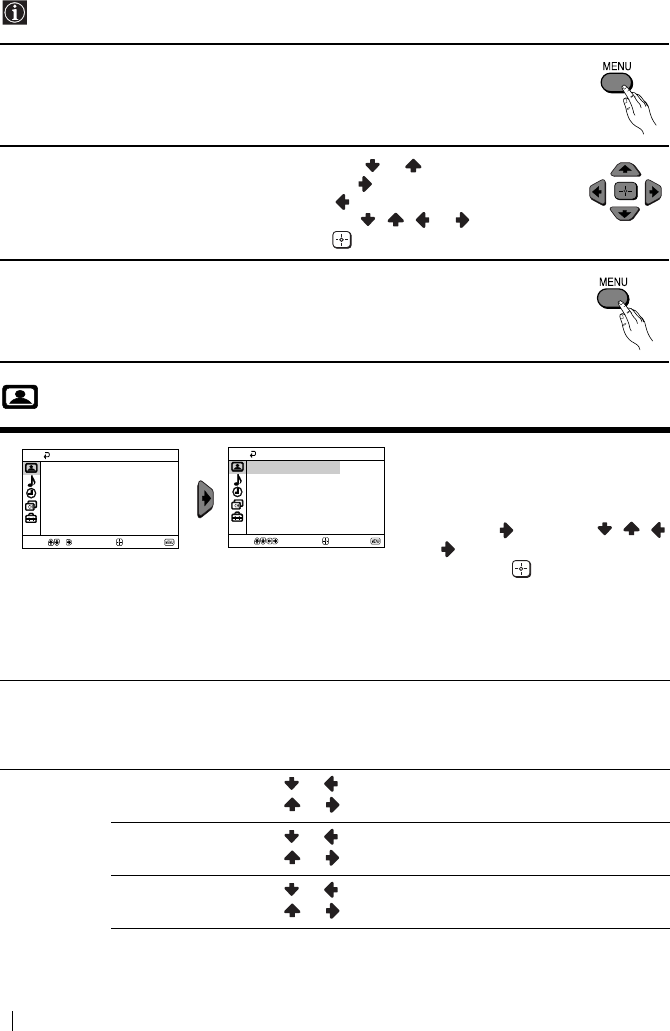
master page=left
10
KV-14CT1K_Grp U6
4-093-927-62(1)
Introducing and Using the Menu System
Your TV uses an on-screen menu system to guide you through the operations. Use the
following buttons on the Remote Control to operate the menu system:
1Press MENU to switch the menu on.
2• To highlight the desired menu or option, press or .
• To enter to the selected menu or option, press .
• To return to the last menu or option, press .
• To alter settings of your selected option, press / / or .
• To confirm and store your selection, press .
3Press MENU to remove the menu from the screen.
Picture
The “Picture” menu allows you to
alter the picture adjustments.
To do this:
After selecting the item you want to
alter, press , then press / /
or repeatedly to adjust it and
finally press to store the new
adjustment.
This menu also allows you to
customize the picture mode based
on the programme you are
watching:
Mode Live (for enhanced picture contrast and sharpness).
Movie (for a finely detailed picture).
Game (for a picture from game).
Personal (for your own custom settings).
Picture
Adjustment
Contrast Press or to reduce picture contrast.
Press or to enhance picture contrast.
Brightness Press or to darken the picture.
Press or to brighten the picture.
Colour Press or to decrease colour intensity.
Press or to increase colour intensity.
Picture
Intelligent Picture: On
Picture Adjustment
Mode: Live
Confirm
Select End
Picture
Intelligent Picture: On
Picture Adjustment
Mode: Live
Confirm
Select End
Menu System
01GBKV21CT1K.fm Page 10 Wednesday, July 9, 2003 8:39 AM

GB
master page=right
11
KV-14CT1K_Grp U6
4-093-927-62(1)
If any changes are made to “Picture Adjustment”, “Mode” will switch automatically to
“Personal” and the new setting will be stored as “Personal”.
Sound
Hue Press or to decrease the green tones.
Press or to increase the green tones.
Hue can only be adjusted for NTSC colour signal (e.g. USA video tapes).
Sharpness Press or to soften the picture.
Press or to sharpen the picture.
Reset Select to reset the picture to the factory preset levels.
Intelligent
Picture
On/Off Select to optimize the picture quality.
E.g. reduce noise level when signal is weak.
The “Sound” menu allows you to
alter the sound adjustments.
Auto
Volume
On/Off
Volume level of the channels will stay the same, independent of the broadcast
signal (e.g. in the case of advertisements).
Select Confirm End
Sound
Auto Volume: Off
Select Confirm End
Sound
Auto Volume: Off
Menu System
01GBKV21CT1K.fm Page 11 Wednesday, July 9, 2003 8:39 AM

master page=left
12
KV-14CT1K_Grp U6
4-093-927-62(1)
Timer
The “Timer” menu allows you to alter
the timer adjustments.
Sleep Timer The “Sleep Timer” option in the “Timer” menu allows you to select
a time period for the TV to switch itself automatically into the
standby mode.
To do this:
After selecting the option, press , then press or to set the
time period delay (max. of 1 hour 30 minutes) and finally press
to store.
• While watching the TV, you can press the button on
the remote control to display the time remaining.
• One minute before the TV switches itself into standby
mode, “TV will turn off soon” is displayed on the TV
screen automatically.
On Timer The “On Timer” option in the “Timer” menu allows you to select a
time period for the TV to switch itself automatically on from
standby mode.
To do this:
After selecting the option, press , then press or to set the
time period delay (max. of 12 hours) and finally press to store.
Finally press the standby button &/1 on the remote control. After
the selected length of time, the TV switches on automatically and
“On Timer” will appear on the screen.
• The standby indicator 1 on the TV set lights up in amber
to indicate that “On Timer” is active.
• Any loss of power will cause these settings to be cleared.
• If no buttons are pressed for more than one hour after the
TV is turned on using the “On Timer”, the TV
automatically goes into standby mode.
Timer
On Timer:
Sleep Timer: Off
Off
Select Confirm End
Timer
On Timer:
Sleep Timer: Off
Off
Select Confirm End
Menu System
01GBKV21CT1K.fm Page 12 Wednesday, July 9, 2003 8:39 AM
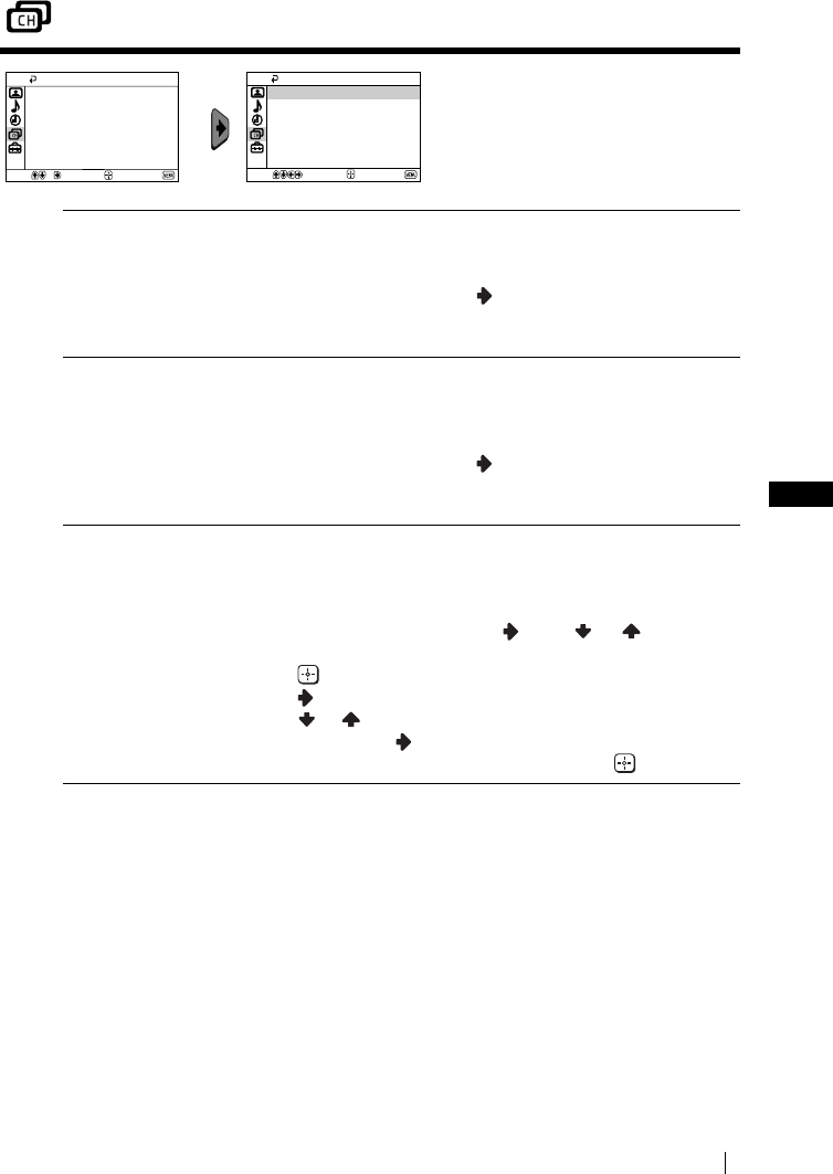
GB
master page=right
13
KV-14CT1K_Grp U6
4-093-927-62(1)
Channel Set Up
The “Channel Set Up” menu allows
you to preset channels on this TV.
Auto Tuning The “Auto Tuning” option in the “Channel Set Up” menu allows
you to automatically search and store all available TV channels.
To do this:
After selecting the option, press and then proceed in the same
way as in the step 4 of the section “Switching On the TV and
Automatically Tuning” (see page 8).
Programme
Sorting
The “Programme Sorting” option in the “Channel Set Up” menu
allows you to change the order in which the channels (TV
Broadcast) appear on the screen.
To do this:
After selecting the option, press and then proceed in the same
way as in step 5b) of the section “Switching On the TV and
Automatically Tuning” (see page 9).
Programme Labels The “Programme Labels” option in the “Channel Set Up” menu
allows you to name a channel using up to five characters (letters or
numbers).
To do this:
1 After selecting the option, press . Press or to select the
programme number with the channel you wish to name, then
press .
2Press
. With the first element of the label column highlighted,
press or to select a letter or number (select “_” for a
blank), then press to confirm this character. Select the other
four characters in the same way. Finally press to store.
Select End
Channel Set Up
Programme Labels
Manual Programme Preset
Programme Sorting
Auto Tuning
Confirm Select End
Channel Set Up
Programme Labels
Manual Programme Preset
Programme Sorting
Auto Tuning
Confirm
Menu System
continued...
01GBKV21CT1K.fm Page 13 Wednesday, July 9, 2003 8:39 AM
master page=left
14
KV-14CT1K_Grp U6
4-093-927-62(1)
Manual
Programme
Preset
The “Manual Programme Preset” option in the “Channel Set Up”
menu allows you to:
a) Preset channels or a video input source one by one to the
programme order of your choice.
To do this:
1 After selecting the “Manual Programme Preset” option, press
. Highlight the Programme option and press . Press or
to select a programme number on which you want to preset
the channel (for VCR, select programme number “0”), then
press .
The following option is only available depending on the
country you have selected in the “Language/Country”
menu.
2 After selecting the System option, press . Press or to
select the TV Broadcast system (B/G for western European
countries or D/K for eastern European countries), then press
.
3 After selecting the Channel option, press . Then press or
to select the channel tuning (C for terrestrial channels or S
for cable channels). Next press . After that, press the number
buttons to directly enter the channel number of the TV
Broadcast. If you do not know the channel number, press or
to search for it. When you tune the desired channel, press
twice to store.
Repeat all the above steps to tune and store more channels.
b) Normally the automatic fine tuning (AFT) will give the best
possible picture, however you can manually fine tune the TV to
obtain a better picture if the picture is distorted.
To do this:
While watching the channel (TV Broadcast) you wish to fine
tune, select the AFT option and press . Next press or to
adjust the fine tuning between -15 and +15. Finally press
twice to store.
c) Skip any unwanted programme numbers when they are selected
with the PROG +/– button.
To do this:
Highlighting the Programme option, press PROG +/– to select
the programme number you want to skip. When the programme
you want to skip appears on the screen, select the Skip option
and press . Next press or to select Yes. Finally press
twice to confirm and store.
To cancel this function afterwards, select No instead of Yes in the step
above.
Menu System
01GBKV21CT1K.fm Page 14 Wednesday, July 9, 2003 8:39 AM

GB
master page=right
15
KV-14CT1K_Grp U6
4-093-927-62(1)
Set Up
The “Set Up” menu allows you to
alter various options on this TV.
Language/
Country
The “Language/Country” option in the “Set Up” menu allows you to
select the language that the menus are displayed in.
To do this:
After selecting the option, press and then proceed in the same way
as in the step 2 and 3 of the section “Switching On the TV and
Automatically Tuning” (see page 8).
Picture Rotation
(only for
KV-21CT1K)
Because of the earth’s magnetism, the picture might slant. In this case,
you can correct the picture slant by using the option “Picture
Rotation” in the “Set Up” menu.
To do this:
After selecting the option, press . Press or ( or ) to correct
any slant of the picture. Finally press to store.
RGB Centring When connecting an RGB source, such as a “PlayStation”, you may
need to readjust the horizontal position of the picture. In that case, you
can readjust it through the “RGB Centring” option in the “Set Up”
menu.
To do this:
While watching an RGB source, select the “RGB Centring” option and
press . Press or to adjust the centre of the picture between -10
and +10. Finally press to confirm and store.
Select End
Set Up
RGB Centring: 0
Picture Rotation
Language/Country
Confirm
Select End
Set Up
RGB Centring: 0
Picture Rotation
Language/Country
Confirm
Menu System
01GBKV21CT1K.fm Page 15 Wednesday, July 9, 2003 8:39 AM
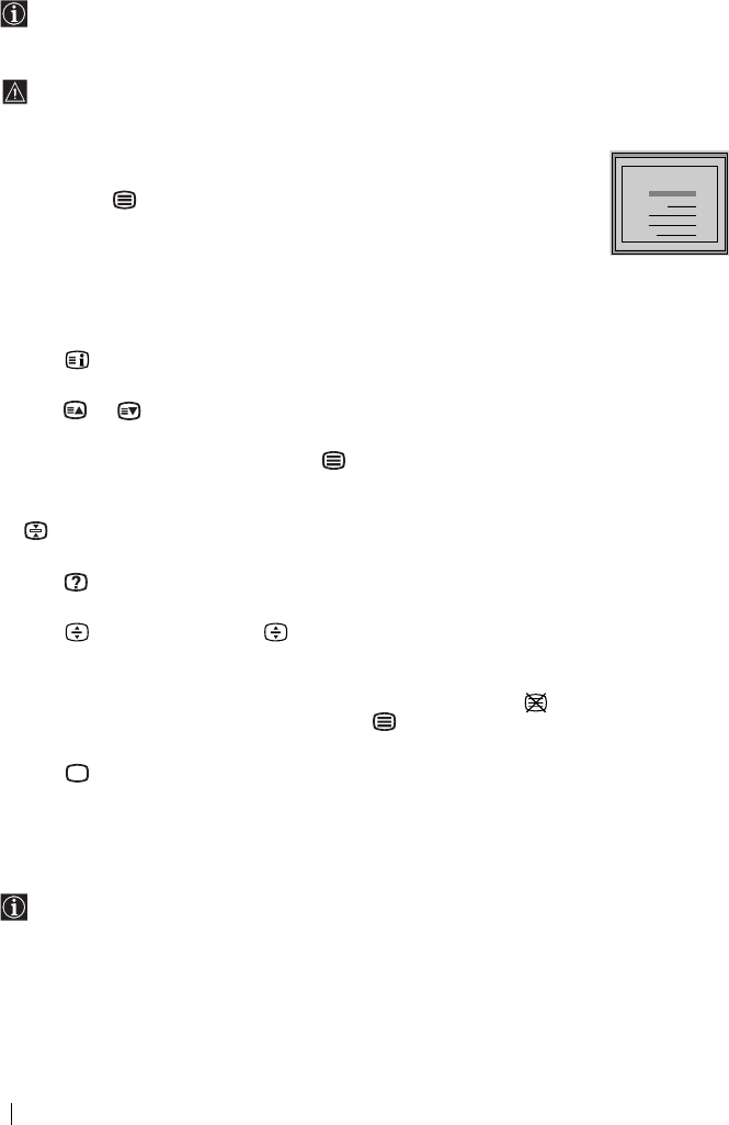
master page=left
16
KV-14CT1K_Grp U6
4-093-927-62(1)
Teletext
Teletext is an information service transmitted by most TV stations. The index page of the
Teletext service (usually page 100) gives you information on how to use the service. To
operate Teletext, use the remote control buttons as indicated below.
Be sure to use a channel (TV Broadcast) with a strong signal, otherwise Teletext errors may
occur.
To switch on Teletext :
After selecting the TV channel which carries the Teletext service you wish to
view, press .
To select a Teletext page:
Input 3 digits for the page number, using the numbered buttons.
• If you have made a mistake, retype the correct page number.
• If the counter on the screen continues searching, it is because this page is not available. In that case,
input another page number.
To check the contents of a Teletext service:
Press .
To access the next or preceding page:
Press or .
To superimpose teletext on to the TV:
Whilst you are viewing Teletext, press . Press it again to cancel Teletext mode.
To freeze a teletext page:
Some Teletext pages have sub-pages which follow on automatically. To stop them, press
. Press it again to cancel the freeze.
To reveal concealed information (e.g., answer to a quiz):
Press . Press it again to conceal the information.
To enlarge the Teletext display:
Press . Each time you press , the Teletext display changes as follows: Enlarge upper
half t Enlarge lower half t Normal size.
To stand by for a Teletext page while watching a TV program.
1 Enter the Teletext number that you want to refer to, then press .
2 When the page number is displayed, press to show the Text.
To switch off Teletext:
Press .
Fastext
Fastext service lets you access pages with one push of a button.
While you are in Teletext mode and Fastext is broadcast, a colour coded menu appears at
the bottom of the teletext page. Press the colour button (red, green, yellow or blue) to access
the corresponding page.
TELETEXT
Index
Programme
News
Sport
Weather
25
153
101
98
TELETEXT
Index
Programme
News
Sport
Weather
25
153
101
98
TELETEXT
Index
Programme
News
Sport
Weather
25
153
101
98
TELETEXT
Index
Programme
News
Sport
Weather
25
153
101
98
TELETEXT
Index
Programme
News
Sport
Weather
25
153
101
98
TELETEXT
Index
Programme
News
Sport
Weather
25
153
101
98
TELETEXT
Index
Programme
News
Sport
Weather
25
153
101
98
TELETEXT
Index
Programme
News
Sport
Weather
25
153
101
98
Teletext
01GBKV21CT1K.fm Page 16 Wednesday, July 9, 2003 8:39 AM
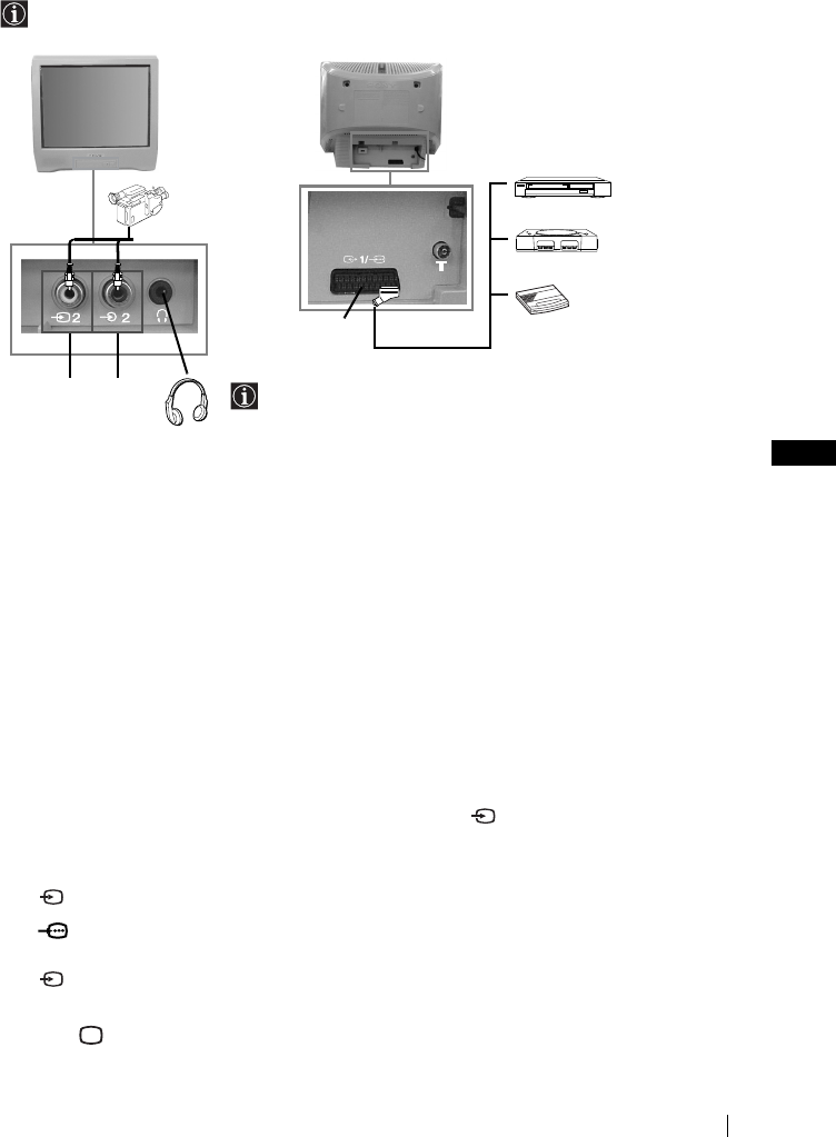
GB
master page=right
17
KV-14CT1K_Grp U6
4-093-927-62(1)
Connecting Optional Equipment
Using the following instructions, you can connect a wide range of optional equipment to
your TV set (connecting cables are not supplied).
Connecting a VCR:
To connect a VCR, please refer to the section “Connecting an outdoor aerial and VCR” of this
instruction manual. We recommend you connect your VCR using a Scart lead. If you do not
have a Scart lead, tune in the VCR test signal to the TV programme number “0” by using the
“Manual Programme Preset” option (for details on how to manually programme these presets,
see page 14, step a).
Refer to your VCR instruction manual to find out how to find the output channel of your VCR.
Using Optional Equipment
1Connect your equipment to the designated TV socket, as indicated above.
2Switch on the connected equipment.
3To watch the picture of the connected equipment, press repeatedly until the correct
input symbol appears on the screen.
4Press button on the remote control to return to the normal TV picture.
Symbol Input Signals
1•Audio/video input signal through the Scart connector C.
1•RGB input signal through the Scart connector C. This symbol appears
only if a RGB source has been connected.
2•Video input signal through the phono socket A and Audio input signal
through B.
AB
12
C
8mm/Hi8/
DVC
camcorder DVD/VCR
“PlayStation”*
decoder
When you connect the
headphones, the TV
speakers will
automatically be muted
* “PlayStation” is a product
of Sony Computer
Entertainment, Inc.
* “PlayStation” is a trademark
of Sony Computer
Entertainment, Inc.
Additional Information
01GBKV21CT1K.fm Page 17 Wednesday, July 9, 2003 8:39 AM

master page=left
18
KV-14CT1K_Grp U6
4-093-927-62(1)
Specifications
TV system:
Depending on your country selection:
B/G/H, D/K
Colour system:
PAL, SECAM
NTSC 3.58, 4.43 (only Video In)
Channel Coverage:
VHF: E2-E12
UHF: E21-E69
CATV: S1-S20
HYPER: S21-S41
D/K: R1-R12, R21-R69
Picture Tube:
Flat Display FD Trinitron
Rear Terminals
i1/ 21-pin Scart connector
(CENELEC standard) including
audio/video input, RGB input,
TV audio/video output.
Front Terminals
t2 video input – phono jack
2 audio input – phono jack
headphones jack
Sound Output:
1 x 6 W (music power)
1 x 3 W (RMS)
Power Consumption:
•KV-21CT1K: 56 W
•KV-14CT1K: 50 W
Standby Power Consumption:
< 1 W
Dimensions (w x h x d):
•KV-21CT1K: Approx. 497 x 461 x 487 mm
•KV-14CT1K: Approx. 374 x 355 x 420 mm
Weight:
•KV-21CT1K: Approx. 24 kg
•KV-14CT1K: Approx. 11 kg
Accessories supplied:
1 Remote Control (RM-W100)
2 Batteries (IEC designated)
1 Aerial (only for KV-14CT1K)
Other features:
•Teletext, Fastext, TOPtext
•Sleep Timer
•On Timer
Design and specifications are subject to change without notice.
Ecological Paper- Totally Chlorine Free
Additional Information
01GBKV21CT1K.fm Page 18 Wednesday, July 9, 2003 8:39 AM
GB
master page=right
19
KV-14CT1K_Grp U6
4-093-927-62(1)
Troubleshooting
Here are some simple solutions to the problems which may affect the picture and sound.
In case of problems, have your TV serviced by qualified personnel. Never open the casing
yourself.
Problem Solution
No picture (screen is dark) and no
sound.
•Check the aerial connection.
•Plug the TV in and press the ! button on the front of
TV.
•If the standby indicator 1 is on, press &/1 button on
the remote control.
Poor or no picture (screen is dark),
but good sound.
•Using the menu system, select the “Picture
Adjustment” menu and select “Reset” to return to the
factory settings (see page 10).
No picture or no menu information
from equipment connected to the
Scart connector.
•Check that the optional equipment is on and press
repeatedly on the remote control until the correct
input symbol is displayed on the screen (see page 17).
Good picture, no sound. •Press the + button on the remote control.
•Check that headphones are not connected.
No colour on colour programmes. •Using the menu system, select the “Picture
Adjustment” menu and select “Reset” to return to
factory settings (see page 10).
Distorted picture when changing
programmes or selecting teletext.
•Turn off any equipment connected to the Scart
connector on the rear of the TV.
Wrong characters appear when
viewing teletext.
•Using the menu system, enter the “Language/
Country” option in the “Set Up” menu and select the
country in which you operate the TV set. For Cyrillic
languages, we recommend to select Russia in the case
that your own country does not appear in the list (see
page 15).
Picture slanted.
(only for KV-21CT1K)
•Using the menu system, select the “Picture Rotation”
option in the “Set Up” menu to correct the picture
slant (see page 15).
Noisy picture when viewing a TV
channel.
•Using the menu system, select the “Manual
Programme Preset” menu and adjust Fine Tuning
(AFT) to obtain better picture reception (see page 14).
•Using the menu system, select the “Intelligent
Picture” option in the “Picture” menu and select
“On” to reduce the noise in the picture (see page 10).
Remote control does not function. •Replace the batteries.
The standby indicator 1 on the TV
flashes red.
•Contact your nearest Sony service centre.
Additional Information
01GBKV21CT1K.fm Page 19 Wednesday, July 9, 2003 8:39 AM

4-093-927-72(1)
R
© 2003 Sony Corporation
Instruction Manual GB
FD Trinitron
Colour Television
KV-21CT1B
KV-14CT1B
01CoverKV21CT1B.fm Page 2 Saturday, July 5, 2003 10:54 AM
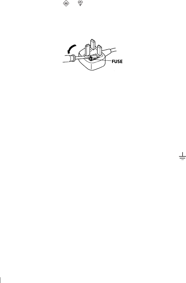
master page=left
2
KV-14CT1B_Grp U28
4-093-927-72(1)
NOTICE FOR CUSTOMERS
A moulded plug complying with BS1363 is fitted to this equipment for your safety and
convenience.
Should the fuse in the plug supplied need to be replaced, a 5 AMP fuse approved by ASTA or
BSI to BS 1362 (i.e. marked with or ) must be used.
When an alternative type of plug is used it should be fitted with a 5 AMP FUSE, otherwise the
circuit should be protected by a 5 AMP FUSE at the distribution board.
If the plug supplied with this equipment has a detachable fuse cover, be sure to attach the fuse
cover after you change the fuse. Never use the plug without the fuse cover. If you should lose
the fuse cover, please contact your nearest Sony service centre.
How to replace the fuse
Open the fuse compartment with a blade screwdriver, and replace the fuse.
• IMPORTANT
If the plug supplied is not suitable for the socket outlets in your home, it should be cut off and
an appropriate plug fitted in accordance with the following instructions:
The wires in this mains lead are coloured in accordance with the following code:
Blue Neutral
Brown Live
As the colours of the wires in the mains lead of this apparatus may not correspond with the
coloured markings identifying the terminals in your plug, proceed as follows:
The wire which is coloured blue must be connected to the terminal which is marked with the
letter N or coloured black. The wire which is coloured brown must be connected to the
terminal which is marked with the letter L or coloured red. Do not connect either wire to the
earth terminal in the plug which is marked by the letter E or by the safety earth symbol
or coloured green or green and yellow.
WARNING
• To prevent shock hazard, do not insert the plug cut off from the mains lead into a socket outlet.
This plug cannot be used and should be destroyed.
• To prevent fire or shock hazard, do not expose the unit to rain or moisture.
• Dangerously high voltages are present inside the set. Do not open the cabinet. Refer servicing
to qualified personnel only.
01GBKV21CT1B.fm Page 2 Saturday, July 5, 2003 11:00 AM
GB
master page=right
3
KV-14CT1B_Grp U28
4-093-927-72(1)
Introduction
Thank you for choosing this Sony FD Trinitron Colour Television.
Before operating the TV, please read this manual thoroughly and retain it for future
reference.
Symbols used in the manual:
• Important information
• Information on a feature.
•1,2...Sequence of instructions.
• Shaded buttons on the remote control
show you the buttons you have to
press to follow the sequence of the
instructions.
• Informs you of the result of
instructions.
Table of Contents
Notice for Customers ............................................................................................................................. 2
Introduction............................................................................................................................................. 3
Safety Information .... ..............................................................................................................................4
Overview
Overview of Remote Control Buttons .... .............................................................................................5
Overview of TV Buttons ........................................................................................................................ 6
Installation
Inserting Batteries into the Remote Control ....................................................................................... 6
Connecting an Indoor Aerial (only for KV-14CT1B) ......................................................................... 7
Connecting an Outdoor Aerial and VCR ............................................................................................7
First Time Operation
Switching On the TV and Automatically Tuning .............................................................................. 8
Menu System
Introducing and Using the Menu System ......................................................................................... 10
Picture............................................................................................................................................... 10
Sound................................................................................................................................................ 11
Timer................................................................................................................................................. 12
Channel Set Up ............................................................................................................................... 13
Set Up ............................................................................................................................................... 15
Teletext................................................................................................................................................ 16
Additional Information
Connecting Optional Equipment ....................................................................................................... 17
Using Optional Equipment ................................................................................................................. 17
Specifications......................................................................................................................................... 18
Troubleshooting .................................................................................................................................... 19
Table of Contents
01GBKV21CT1B.fm Page 3 Saturday, July 5, 2003 11:00 AM
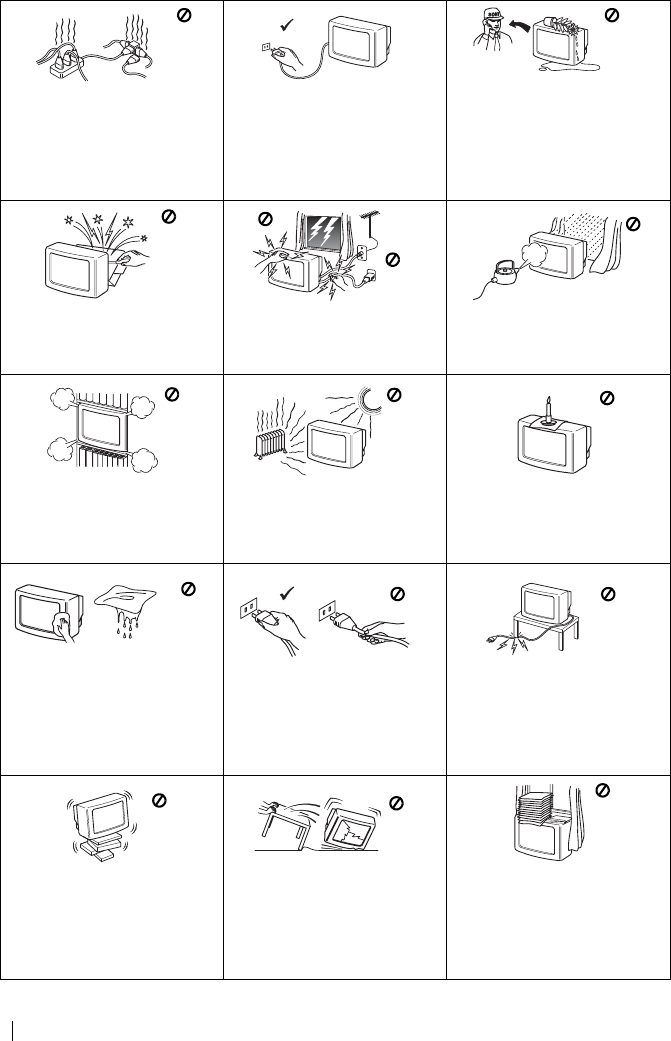
master page=left
4
KV-14CT1B_Grp U28
4-093-927-72(1)
Safety Information
This set is to operate on a 220-
240V AC supply only. Take care
not to connect too many
appliances to the same power
socket as this could result in fire
or electric shock.
For environmental and safety
reasons, it is recommended that
the TV set is not left in standby
mode when not in use.
Disconnect from the mains.
Never push objects of any kind
into the set as this could result in
a fire or electric shock. Never
spill liquid of any kind on the
set. If any liquid or solid object
does fall through, do not operate
the TV. Have it checked immedi-
ately by qualified personnel.
Do not open the cabinet and the
rear cover of the TV. Refer to
qualified service personnel only.
For your own safety, do not
touch any part of the TV, power
lead or aerial lead during
lightning storms.
To prevent fire or shock hazard,
do not expose the TV to rain or
moisture.
Do not cover the ventilation
openings of the TV. For
ventilation, leave a space of at
least 10cm all around the set.
Never place the TV in hot, humid
or excessively dusty places. Do
not install the TV where it may be
exposed to mechanical
vibrations.
To prevent fire, keep
inflammable objects or naked
lights (e.g. candles) away from
the TV.
Clean the screen and cabinet with a
soft, lightly dampened cloth. Do
not use any type of abrasive pad,
alkaline cleaner, scouring powder
or solvent, such as alcohol or
benzine, or antistatic spray. As a
safety precaution, unplug the TV
before cleaning it.
Pull out the power lead by the
plug. Do not pull on the power
lead itself.
Take care not to place heavy
objects on the power lead as this
could result in damage.
We recommend you wind any
excess lead around the holders
provided on the rear of the TV.
Place the TV on a secure stable
stand. Do not allow children to
climb on to it. Do not place the
TV on its side or face up.
Unplug the power lead before
moving the TV. Avoid uneven
surfaces, quick steps or excessive
force. If the set has been dropped
or damaged, have it checked
immediately by qualified service
personnel.
Do not cover the ventilation
openings of the TV with items
such as curtains or newspapers,
etc.
Safety Information
01GBKV21CT1B.fm Page 4 Saturday, July 5, 2003 11:00 AM
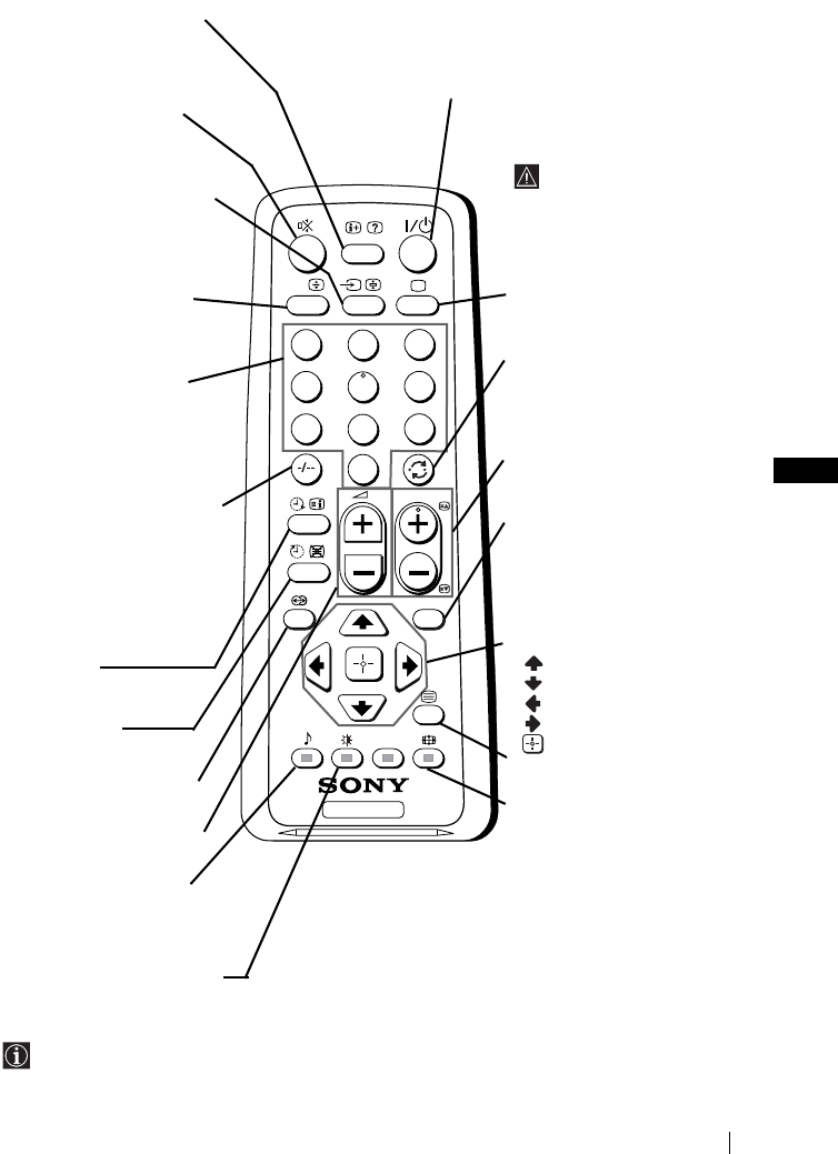
GB
master page=right
5
KV-14CT1B_Grp U28
4-093-927-72(1)
Overview of Remote Control Buttons
Besides TV functions, all coloured buttons as well as green symbols are also used for
Teletext operation. For more details, please refer to “Teletext” section of this instruction
manual (see page 16).
TV
123
46
789
0
5
MENU
PROG
A/B
Displaying on screen
information
Press to display all on-screen
indications. Press again to
cancel.
Muting the sound
Press to mute TV sound.
Press again to restore the
sound.
Selecting input source
Press repeatedly until the
desired input symbol of the
source appears on the TV
screen.
This button only works in
Teletext mode.
Function A/B associated to this
button does not work with this TV.
Selecting channels
Press to select channels.
For double-digit programme
numbers, enter the second
digit within 3 seconds.
or
Press -/-- and then the first
and second digit.
If you enter an incorrect first
digit, this should be corrected
by entering another digit (0-9)
and then selecting -/-- button
again to enter the programme
number of your choice.
On timer
Set TV to switch on
automatically.
Sleep timer
Set TV to switch off
automatically.
This button does not work
on this set.
Adjusting TV volume
Press to adjust the volume
of the TV.
This button only works in
Teletext mode.
Function
9
associated to this
button does not work with this TV.
Selecting picture mode
Press repeatedly to change
the picture mode.
To temporarily switch off TV
Press to temporarily switch off TV (the standby
indicator 1 on TV lights up). Press again to switch on
TV from standby mode.
To save energy we recommend
switching off completely
when TV is not in use.
After 15 minutes
without a signal and
without any button
being pressed, the TV
switches automatically
into standby mode.
Selecting TV mode
Press to switch off teletext or
video input.
Back to the channel last
watched
Press to watch the last
channel selected (watched for
at least 5 seconds).
Selecting channels
Press to select the next or
previous channel.
Displaying the menu
system
Press to display the menu on
the TV screen. Press again to
remove the menu display
from the TV screen.
Menu selection
Scroll Up
Scroll Down
Previous menu or selection
Next menu or selection
Confirm your selection
Selecting Teletext
Press to switch on teletext.
Selecting screen format
Press to view programmes in
16:9 mode. Press again to
return to 4:3 mode.
Overview
01GBKV21CT1B.fm Page 5 Saturday, July 5, 2003 11:00 AM
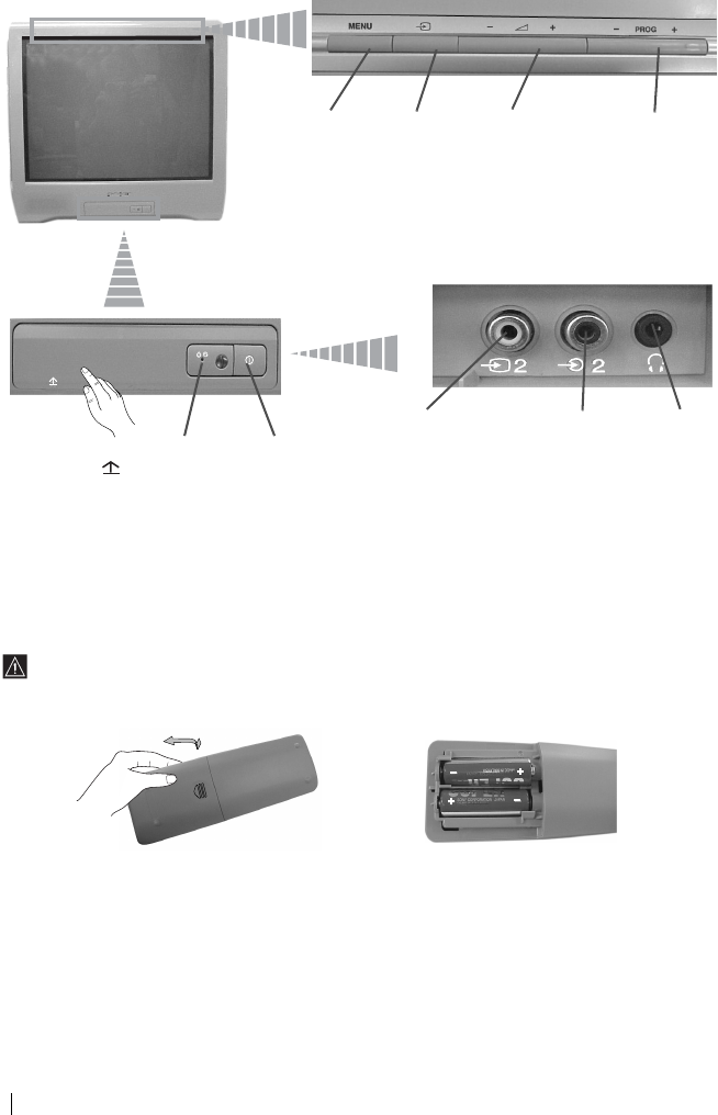
master page=left
6
KV-14CT1B_Grp U28
4-093-927-72(1)
Overview of TV Buttons
Inserting Batteries into the Remote Control
Make sure you insert the supplied batteries using the correct polarities.
Always remember to dispose of used batteries in an environmental friendly way.
Displaying
the menu
system
Selecting
Input
source
Volume
control
buttons
Programme Up or
Down buttons
(selects TV
channels)
Lift up the door
flap with
mark to reveal
the control
panel.
Standby
indicator
On/Off
switch
Video Input
jack
Audio Input
jack
Headphone
jack
Overview-Installation
01GBKV21CT1B.fm Page 6 Saturday, July 5, 2003 11:00 AM

GB
master page=right
7
KV-14CT1B_Grp U28
4-093-927-72(1)
Connecting an Indoor Aerial (only for KV-14CT1B)
For a better reception we recommend you connect an external aerial. However, where an
external aerial is not available and your local VHF/UHF signal is strong, you can connect
the supplied indoor aerial as follows:
1Insert the aerial into the opening on top of the set until it clicks.
2Connect the aerial connector to the aerial socket on the rear of the
set.
3After switching on the TV, adjust the aerial for optimum reception.
Connecting an Outdoor Aerial and VCR
Connecting cables are not supplied.
For more details of VCR connection, please refer to the section “Connecting Optional
Equipment” of this instruction manual (see page 17).
OUT IN
or
VCR
Scart lead is optional.
Installation
01GBKV21CT1B.fm Page 7 Saturday, July 5, 2003 11:00 AM

master page=left
8
KV-14CT1B_Grp U28
4-093-927-72(1)
Switching On the TV and Automatically Tuning
The first time you switch on your TV, a sequence of menu screens appear on the TV
enabling you to: 1) choose the language of the menu screen, 2) choose the country in which
you wish to operate the TV, 3) search and store all available channels (TV Broadcast), 4)
change the order in which the channels (TV Broadcast) appear on the screen and 5) adjust
the picture slant (only for KV-21CT1B).
However, if you need to change any of these settings at a later date, you can do that by
selecting the appropriate option in the (Set Up) or (Channel Set Up) menu.
1Connect the TV plug to the mains socket (220-240 V AC, 50 Hz).
Press ! On/Off button on the TV set to switch on the TV. The
first time you switch on the TV, a Language menu displays
automatically on the TV screen.
2Press 2 +/– button on the top control panel to select the language,
then press t to confirm your selection. From now on all menus
will appear in the selected language.
3The Country menu appears automatically on the TV screen. Press
2 +/– button to select the country in which you will operate the
TV set, then press t to confirm your selection.
• If the country in which you want to use the TV set does not
appear in the list, select “-” instead of a country.
• In order to avoid wrong teletext characters for Cyrillic
languages we recommend to select Russia in the case that
your own country does not appear in the list.
4Ensure the aerial is connected as instructed, then press t to
confirm. The TV automatically starts searching and storing all
available broadcast channels for you.
•This procedure could take some minutes. Please be patient
and do not press any buttons, otherwise automatic tuning
will not be completed.
•If no channels were found during the auto tuning process, a
new menu appears automatically on the screen asking you
to connect the aerial. Please connect the aerial (see page 7)
and press t. The auto tuning process will start again.
Language
Svenska
English
Nederlands
Français
Select language
Norsk
Confirm [t]
Select [
–
2+]
Country
Schweiz/Suisse/Svizzera
Italia
Select Country
Norge
Sverige
–
Confirm [t]
Select [
–
2+]
Do you want to start automatic
First please connect aerial
tuning?
No
Initial Set Up
Yes
Confirm [t]
Select [
–
2+]End
Auto Tuning
No channel found
Please connect aerial
OK
Confirm [t]End
First Time Operation
01GBKV21CT1B.fm Page 8 Saturday, July 5, 2003 11:00 AM
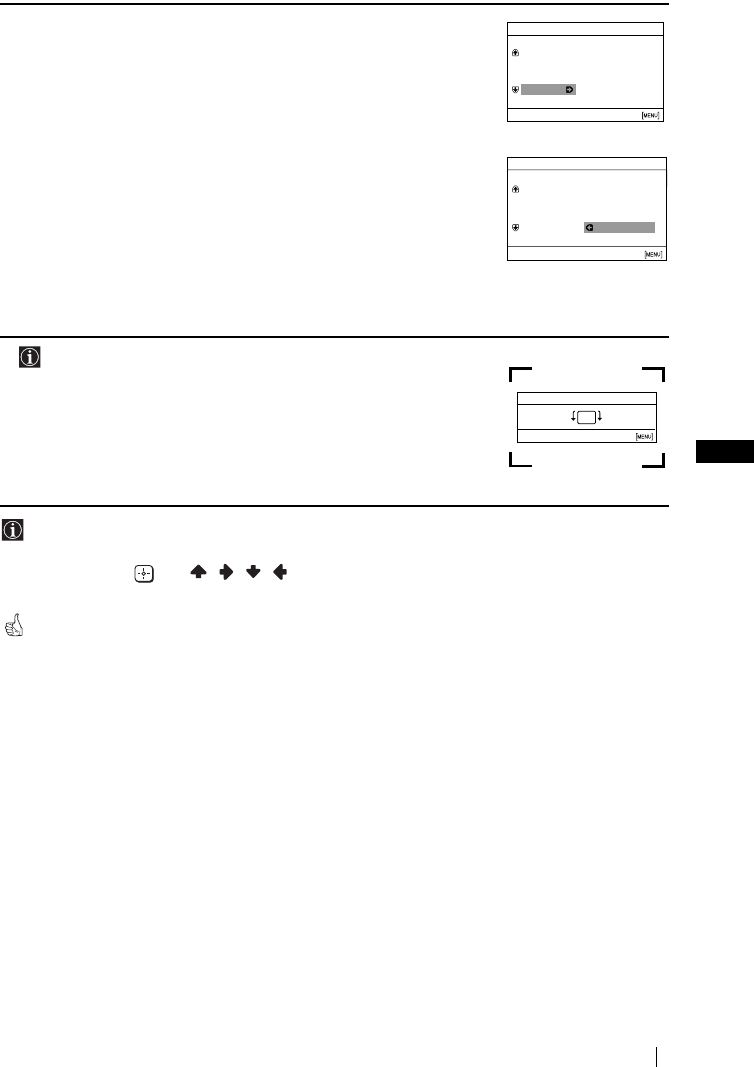
GB
master page=right
9
KV-14CT1B_Grp U28
4-093-927-72(1)
5After all available channels are captured and stored, the
Programme Sorting menu appears automatically on the screen
enabling you to change the order in which the channels appear on
the screen.
a) If you wish to keep the broadcast channels in the tuned order,
press MENU.
b) If you wish to store the channels in a different order:
1Press 2 +/– to select the programme number with the
channel (TV Broadcast) you wish to rearrange, then press
t.
2Press 2 +/– to select the new programme number position
for your selected channel (TV Broadcast), then press t.
3Repeat steps b) 1 and b) 2 if you wish to change the order of
the other channels.
6 The following option is only available for KV-21CT1B.
Because of the earth’s magnetism, the picture might slant. The
Picture Rotation menu allows you to correct the picture slants if it
is necessary.
a) If it is not necessary, press t.
b) If it is necessary, press 2 +/– to correct any slant of the
picture. Finally press t to store.
• To allow this menu to appear again, press and hold MENU button at top control panel for
about 5 seconds.
• The MENU, and / / / buttons on the remote control can also be used for the
operations above.
Your TV is now ready for use.
Programme Sorting
Programme:
Select channel
Confirm [t]
Select [
–
2+]Exit
TVE
TVE2
TV3
04 C33
01
02
03
Programme Sorting
Programme:
Select new position
Confirm [t]
Select [
–
2+]Exit
01 TVE
02 TVE2
03 TV3
04 C33 03 TV3
Picture Rotation
Confirm [t]End
Select [
–
2+]
[2+]
[
–
2]
First Time Operation
01GBKV21CT1B.fm Page 9 Saturday, July 5, 2003 11:00 AM
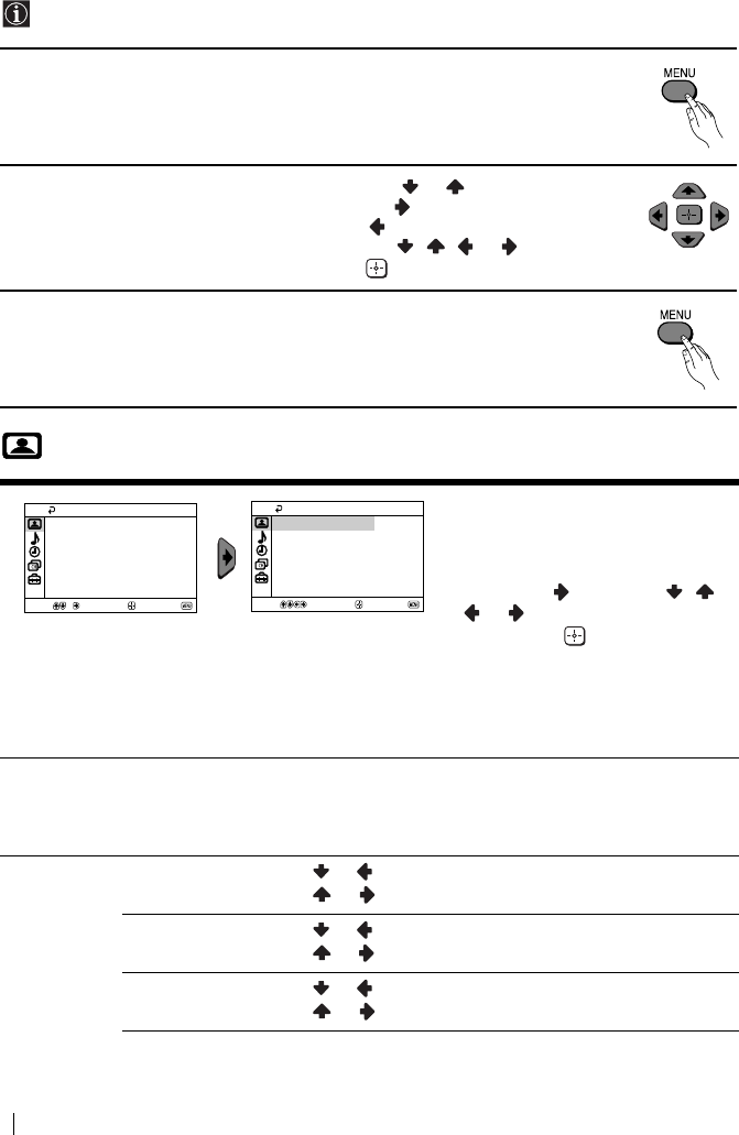
master page=left
10
KV-14CT1B_Grp U28
4-093-927-72(1)
Introducing and Using the Menu System
Your TV uses an on-screen menu system to guide you through the operations. Use the
following buttons on the Remote Control to operate the menu system:
1Press MENU to switch the menu on.
2• To highlight the desired menu or option, press or .
• To enter to the selected menu or option, press .
• To return to the last menu or option, press .
• To alter settings of your selected option, press / / or .
• To confirm and store your selection, press .
3Press MENU to remove the menu from the screen.
Picture
The “Picture” menu allows you to
alter the picture adjustments.
To do this:
After selecting the item you want to
alter, press , then press / /
or repeatedly to adjust it and
finally press to store the new
adjustment.
This menu also allows you to
customize the picture mode based
on the programme you are
watching:
Mode Live (for enhanced picture contrast and sharpness).
Movie (for a finely detailed picture).
Game (for a picture from game).
Personal (for your own custom settings).
Picture
Adjustment
Contrast Press or to reduce picture contrast.
Press or to enhance picture contrast.
Brightness Press or to darken the picture.
Press or to brighten the picture.
Colour Press or to decrease colour intensity.
Press or to increase colour intensity.
Picture
Intelligent Picture: On
Picture Adjustment
Mode: Live
Confirm
Select End
Picture
Intelligent Picture: On
Picture Adjustment
Mode: Live
Confirm
Select End
Menu System
01GBKV21CT1B.fm Page 10 Saturday, July 5, 2003 11:00 AM

GB
master page=right
11
KV-14CT1B_Grp U28
4-093-927-72(1)
If any changes are made to “Picture Adjustment”, “Mode” will switch automatically to
“Personal” and the new setting will be stored as “Personal”.
Sound
Hue Press or to decrease the green tones.
Press or to increase the green tones.
Hue can only be adjusted for NTSC colour signal (e.g. USA video tapes).
Sharpness Press or to soften the picture.
Press or to sharpen the picture.
Reset Select to reset the picture to the factory preset levels.
Intelligent
Picture
On/Off Select to optimize the picture quality.
E.g. reduce noise level when signal is weak.
The “Sound” menu allows you to
alter the sound adjustments.
Auto
Volume
On/Off
Volume level of the channels will stay the same, independent of the broadcast
signal (e.g. in the case of advertisements).
Select Confirm End
Sound
Auto Volume: Off
Select Confirm End
Sound
Auto Volume: Off
Menu System
01GBKV21CT1B.fm Page 11 Saturday, July 5, 2003 11:00 AM
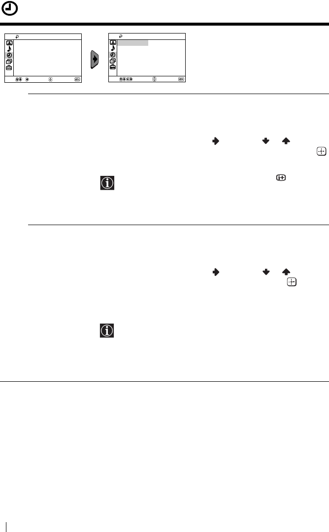
master page=left
12
KV-14CT1B_Grp U28
4-093-927-72(1)
Timer
The “Timer” menu allows you to alter
the timer adjustments.
Sleep Timer The “Sleep Timer” option in the “Timer” menu allows you to select
a time period for the TV to switch itself automatically into the
standby mode.
To do this:
After selecting the option, press , then press or to set the
time period delay (max. of 1 hour 30 minutes) and finally press
to store.
• While watching the TV, you can press the button on
the remote control to display the time remaining.
• One minute before the TV switches itself into standby
mode, “TV will turn off soon” is displayed on the TV
screen automatically.
On Timer The “On Timer” option in the “Timer” menu allows you to select a
time period for the TV to switch itself automatically on from
standby mode.
To do this:
After selecting the option, press , then press or to set the
time period delay (max. of 12 hours) and finally press to store.
Finally press the standby button &/1 on the remote control. After
the selected length of time, the TV switches on automatically and
“On Timer” will appear on the screen.
• The standby indicator 1 on the TV set lights up in amber
to indicate that “On Timer” is active.
• Any loss of power will cause these settings to be cleared.
• If no buttons are pressed for more than one hour after the
TV is turned on using the “On Timer”, the TV
automatically goes into standby mode.
Timer
On Timer:
Sleep Timer: Off
Off
Select Confirm End
Timer
On Timer:
Sleep Timer: Off
Off
Select Confirm End
Menu System
01GBKV21CT1B.fm Page 12 Saturday, July 5, 2003 11:00 AM
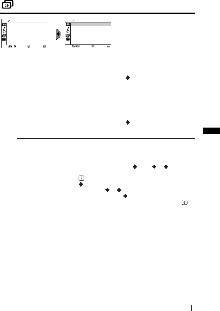
GB
master page=right
13
KV-14CT1B_Grp U28
4-093-927-72(1)
Channel Set Up
The “Channel Set Up” menu allows
you to preset channels on this TV.
Auto Tuning The “Auto Tuning” option in the “Channel Set Up” menu allows
you to automatically search and store all available TV channels.
To do this:
After selecting the option, press and then proceed in the same
way as in the step 4 of the section “Switching On the TV and
Automatically Tuning” (see page 8).
Programme
Sorting
The “Programme Sorting” option in the “Channel Set Up” menu
allows you to change the order in which the channels (TV
Broadcast) appear on the screen.
To do this:
After selecting the option, press and then proceed in the same
way as in step 5b) of the section “Switching On the TV and
Automatically Tuning” (see page 9).
Programme Labels The “Programme Labels” option in the “Channel Set Up” menu
allows you to name a channel using up to five characters (letters or
numbers).
To do this:
1 After selecting the option, press . Press or to select the
programme number with the channel you wish to name, then
press .
2Press
. With the first element of the label column
highlighted, press or to select a letter or number (select
“_” for a blank), then press to confirm this character. Select
the other four characters in the same way. Finally press to
store.
Select End
Channel Set Up
Programme Labels
Manual Programme Preset
Programme Sorting
Auto Tuning
Confirm Select End
Channel Set Up
Programme Labels
Manual Programme Preset
Programme Sorting
Auto Tuning
Confirm
Menu System
continued...
01GBKV21CT1B.fm Page 13 Saturday, July 5, 2003 11:00 AM
master page=left
14
KV-14CT1B_Grp U28
4-093-927-72(1)
Manual
Programme
Preset
The “Manual Programme Preset” option in the “Channel Set Up”
menu allows you to:
a) Preset channels or a video input source one by one to the
programme order of your choice.
To do this:
1 After selecting the “Manual Programme Preset” option, press
. Highlight the Programme option and press . Press or
to select a programme number on which you want to preset
the channel (for VCR, select programme number “0”), then
press .
The following option is only available depending on the
country you have selected in the “Language/Country”
menu.
2 After selecting the System option, press . Press or to
select the TV Broadcast system (B/G for western European
countries, L for France, I for United Kingdom or D/K for
eastern European countries), then press .
3 After selecting the Channel option, press . Then press or
to select the channel tuning (C for terrestrial channels or S
for cable channels). Next press . After that, press the number
buttons to directly enter the channel number of the TV
Broadcast. If you do not know the channel number, press or
to search for it. When you tune the desired channel, press
twice to store.
Repeat all the above steps to tune and store more channels.
b) Normally the automatic fine tuning (AFT) will give the best
possible picture, however you can manually fine tune the TV to
obtain a better picture if the picture is distorted.
To do this:
While watching the channel (TV Broadcast) you wish to fine
tune, select the AFT option and press . Next press or to
adjust the fine tuning between -15 and +15. Finally press
twice to store.
c) Skip any unwanted programme numbers when they are selected
with the PROG +/– button.
To do this:
Highlighting the Programme option, press PROG +/– to select
the programme number you want to skip. When the
programme you want to skip appears on the screen, select the
Skip option and press . Next press or to select Yes.
Finally press twice to confirm and store.
To cancel this function afterwards, select No instead of Yes in the step
above.
Menu System
01GBKV21CT1B.fm Page 14 Saturday, July 5, 2003 11:00 AM
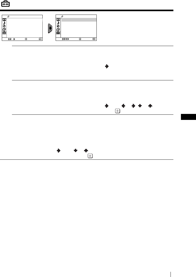
GB
master page=right
15
KV-14CT1B_Grp U28
4-093-927-72(1)
Set Up
The “Set Up” menu allows you to
alter various options on this TV.
Language/
Country
The “Language/Country” option in the “Set Up” menu allows you to
select the language that the menus are displayed in.
To do this:
After selecting the option, press and then proceed in the same way
as in the step 2 and 3 of the section “Switching On the TV and
Automatically Tuning” (see page 8).
Picture Rotation
(only for
KV-21CT1B)
Because of the earth’s magnetism, the picture might slant. In this case,
you can correct the picture slant by using the option “Picture
Rotation” in the “Set Up” menu.
To do this:
After selecting the option, press . Press or ( or ) to correct
any slant of the picture. Finally press to store.
RGB Centring When connecting an RGB source, such as a “PlayStation”, you may
need to readjust the horizontal position of the picture. In that case, you
can readjust it through the “RGB Centring” option in the “Set Up”
menu.
To do this:
While watching an RGB source, select the “RGB Centring” option and
press . Press or to adjust the centre of the picture between -10
and +10. Finally press to confirm and store.
Select End
Set Up
RGB Centring: 0
Picture Rotation
Language/Country
Confirm
Select End
Set Up
RGB Centring: 0
Picture Rotation
Language/Country
Confirm
Menu System
01GBKV21CT1B.fm Page 15 Saturday, July 5, 2003 11:00 AM

master page=left
16
KV-14CT1B_Grp U28
4-093-927-72(1)
Teletext
Teletext is an information service transmitted by most TV stations. The index page of the
Teletext service (usually page 100) gives you information on how to use the service. To
operate Teletext, use the remote control buttons as indicated below.
Be sure to use a channel (TV Broadcast) with a strong signal, otherwise Teletext errors may
occur.
To switch on Teletext:
After selecting the TV channel which carries the Teletext service you wish to
view, press .
To select a Teletext page:
Input 3 digits for the page number, using the numbered buttons.
• If you have made a mistake, retype the correct page number.
• If the counter on the screen continues searching, it is because this page is not available. In that case,
input another page number.
To check the contents of a Teletext service:
Press .
To access the next or preceding page:
Press or .
To superimpose teletext on to the TV:
Whilst you are viewing Teletext, press . Press it again to cancel Teletext mode.
To freeze a teletext page:
Some Teletext pages have sub-pages which follow on automatically. To stop them, press
. Press it again to cancel the freeze.
To reveal concealed information (e.g., answer to a quiz):
Press . Press it again to conceal the information.
To enlarge the Teletext display:
Press . Each time you press , the Teletext display changes as follows: Enlarge upper
half t Enlarge lower half t Normal size.
To stand by for a Teletext page while watching a TV program.
1 Enter the Teletext number that you want to refer to, then press .
2 When the page number is displayed, press to show the Text.
To switch off Teletext:
Press .
Fastext
Fastext service lets you access pages with one push of a button.
While you are in Teletext mode and Fastext is broadcast, a colour coded menu appears at
the bottom of the teletext page. Press the colour button (red, green, yellow or blue) to access
the corresponding page.
TELETEXT
Index
Programme
News
Sport
Weather
25
153
101
98
TELETEXT
Index
Programme
News
Sport
Weather
25
153
101
98
TELETEXT
Index
Programme
News
Sport
Weather
25
153
101
98
TELETEXT
Index
Programme
News
Sport
Weather
25
153
101
98
TELETEXT
Index
Programme
News
Sport
Weather
25
153
101
98
TELETEXT
Index
Programme
News
Sport
Weather
25
153
101
98
TELETEXT
Index
Programme
News
Sport
Weather
25
153
101
98
TELETEXT
Index
Programme
News
Sport
Weather
25
153
101
98
Teletext
01GBKV21CT1B.fm Page 16 Saturday, July 5, 2003 11:00 AM
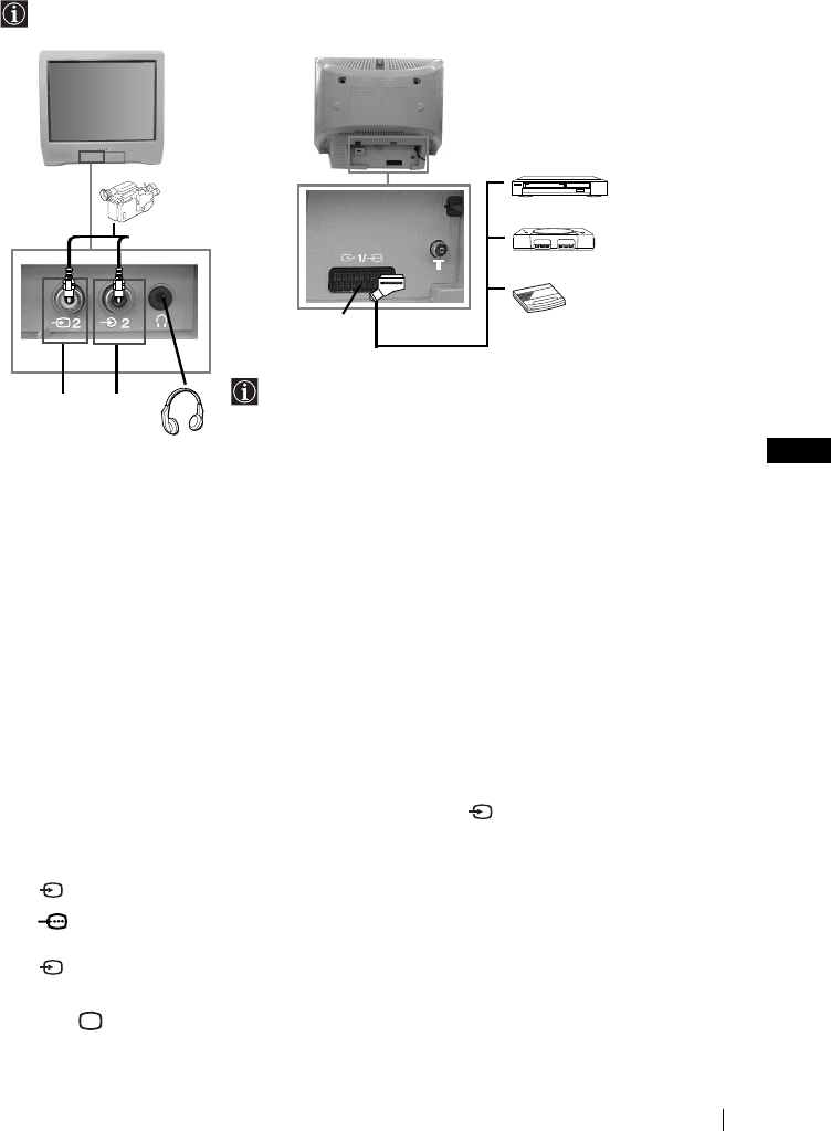
GB
master page=right
17
KV-14CT1B_Grp U28
4-093-927-72(1)
Connecting Optional Equipment
Using the following instructions, you can connect a wide range of optional equipment to
your TV set (connecting cables are not supplied).
Connecting a VCR:
To connect a VCR, please refer to the section “Connecting an outdoor aerial and VCR” of this
instruction manual. We recommend you connect your VCR using a Scart lead. If you do not
have a Scart lead, tune in the VCR test signal to the TV programme number “0” by using the
“Manual Programme Preset” option (for details on how to manually programme these presets,
see page 14, step a).
Refer to your VCR instruction manual to find out how to find the output channel of your VCR.
Using Optional Equipment
1Connect your equipment to the designated TV socket, as indicated above.
2Switch on the connected equipment.
3To watch the picture of the connected equipment, press repeatedly until the correct
input symbol appears on the screen.
4Press button on the remote control to return to the normal TV picture.
Symbol Input Signals
1•Audio / video input signal through the Scart connector C
1•RGB input signal through the Scart connector C. This symbol appears
only if a RGB source has been connected.
2•Video input signal through the phono socket A and Audio input signal
through B.
AB
12
C
8mm/Hi8/
DVC
camcorder DVD/VCR
“PlayStation”*
decoder
When you connect the
headphones, the TV
speakers will
automatically be muted
* “PlayStation”
is a product
of Sony Computer
Entertainment, Inc.
* “PlayStation
” is a trademark
of Sony Computer
Entertainment, Inc.
Additional Information
01GBKV21CT1B.fm Page 17 Saturday, July 5, 2003 11:00 AM
master page=left
18
KV-14CT1B_Grp U28
4-093-927-72(1)
Specifications
TV system:
Depending on your country selection:
B/G/H, L, I, D/K
Colour system:
PAL, SECAM
NTSC 3.58, 4.43 (only Video In)
Channel Coverage:
VHF: E2-E12
UHF: E21-E69
CATV: S1-S20
HYPER: S21-S41
L: F2-F10, B-Q, F21-F69
I: UHF B21-B69
D/K: R1-R12, R21-R69
Picture Tube:
Flat Display FD Trinitron
Rear Terminals
i1/ 21-pin Scart connector
(CENELEC standard) including
audio/video input, RGB input,
TV audio/video output.
Front Terminals
t2 video input – phono jack
2 audio input – phono jack
headphones jack
Sound Output:
1 x 6 W (music power)
1 x 3 W (RMS)
Power Consumption:
•KV-21CT1B: 56 W
•KV-14CT1B: 50 W
Standby Power Consumption:
< 1 W
Dimensions (w x h x d):
•KV-21CT1B: Approx. 497 x 461 x 487 mm
•KV-14CT1B: Approx. 374 x 355 x 420 mm
Weight:
•KV-21CT1B: Approx. 24 kg
•KV-14CT1B: Approx. 11 kg
Accessories supplied:
1 Remote Control (RM-W100)
2 Batteries (IEC designated)
1 Aerial (only for KV-14CT1B)
Other features:
•Teletext, Fastext, TOPtext
•Sleep Timer
•On Timer
Design and specifications are subject to change without notice.
Ecological Paper- Totally Chlorine Free
Additional Information
01GBKV21CT1B.fm Page 18 Saturday, July 5, 2003 11:00 AM

GB
master page=right
19
KV-14CT1B_Grp U28
4-093-927-72(1)
Troubleshooting
Here are some simple solutions to the problems which may affect the picture and sound.
In case of problems, have your TV serviced by qualified personnel. Never open the casing
yourself.
Problem Solution
No picture (screen is dark) and no
sound.
•Check the aerial connection.
•Plug the TV in and press the ! button on the front of
TV.
•If the standby indicator 1 is on, press &/1 button on
the remote control.
Poor or no picture (screen is dark),
but good sound.
•Using the menu system, select the “Picture
Adjustment” menu and select “Reset” to return to the
factory settings (see page 10).
No picture or no menu information
from equipment connected to the
Scart connector.
•Check that the optional equipment is on and press
repeatedly on the remote control until the correct
input symbol is displayed on the screen (see page 17).
Good picture, no sound. •Press the + button on the remote control.
•Check that headphones are not connected.
No colour on colour programmes. •Using the menu system, select the “Picture
Adjustment” menu and select “Reset” to return to
factory settings (see page 10).
Distorted picture when changing
programmes or selecting teletext.
•Turn off any equipment connected to the Scart
connector on the rear of the TV.
Wrong characters appear when
viewing teletext.
•Using the menu system, enter the “Language/
Country” option in the “Set Up” menu and select the
country in which you operate the TV set. For Cyrillic
languages, we recommend to select Russia in the case
that your own country does not appear in the list (see
page 15).
Picture slanted
(only for KV-21CT1B).
•Using the menu system, select the “Picture Rotation”
option in the “Set Up” menu to correct the picture
slant (see page 15).
Noisy picture when viewing a TV
channel.
•Using the menu system, select the “Manual
Programme Preset” menu and adjust Fine Tuning
(AFT) to obtain better picture reception (see page 14).
•Using the menu system, select the “Intelligent
Picture” option in the “Picture” menu and select
“On” to reduce the noise in the picture (see page 10).
Remote control does not function. •Replace the batteries.
The standby indicator 1 on the TV
flashes red.
•Contact your nearest Sony service centre.
Additional Information
01GBKV21CT1B.fm Page 19 Saturday, July 5, 2003 11:00 AM

Sony España, S.A.
Printed in Spain
KV-21CT1B
01CoverKV21CT1B.fm Page 1 Saturday, July 5, 2003 10:54 AM
