Black Box Switch KVT417A R2 KVT517A Rev2
User Manual: Black Box Switch KVT417A-R2
Open the PDF directly: View PDF ![]() .
.
Page Count: 36
KVT517A
BL A C K B OX®
Control your 4-post rack- or cabinet-mounted
USB or PS/2 servers with the compact
ServView V KVM tray.
Widescreen model is now available.
ServView V KVM Tray
KVT517A-1UV-R2 KVT517A-16PV
KVT517A-8PV KVT517A-16UV
KVT517A-8UV KVT517A-8DV-WIDE
Order toll-free in the U.S.: Call 877-877-BBOX (outside U.S. call 724-746-5500) •
FREE technical support 24 hours a day, 7 days a week: Call 724-746-5500 or fax 724-746-0746 •
Mailing address: Black Box Corporation, 1000 Park Drive, Lawrence, PA 15055-1018 •
Web site: www.blackbox.com • E-mail: info@blackbox.com
Customer
Support
Information

724-746-5500 | blackbox.com
Page 2 KVT517A
Trademarks Used in this Manual
We‘re here to help! If you have any questions about your application
or our products, contact Black Box Tech Support at 724-746-5500
or go to blackbox.com and click on “Talk to Black Box.”
You’ll be live with one of our technical experts in less than 30 seconds.
Trademarks Used in This Manual
Black Box and the Double Diamond logo are registered trademarks, and ServView and ServSwitch are trademarks, of
BB Technologies, Inc.
Centronics is a registered trademark of Centronics Corporation.
PS/2 is a registered trademark of International Business Machines Corporation.
UL is a registered trademark of Underwriters Laboratories Inc.
Any other trademarks mentioned in this manual are acknowledged to be the property of the trademark owners.

724-746-5500 | blackbox.com
Page 3
KVT517A
FCC and IC RFI Statements
Federal Communications Commission and Industry Canada Radio Frequency Interference
Statements
This equipment generates, uses, and can radiate radio-frequency energy, and if not installed and used properly, that is, in strict
accordance with the manufacturer’s instructions, may cause inter ference to radio communication. It has been tested and found to
comply with the limits for a Class A computing device in accordance with the specifications in Subpart B of Part 15 of FCC rules,
which are designed to provide reasonable protection against such interference when the equipment is operated in a commercial
environment. Operation of this equipment in a residential area is likely to cause interference, in which case the user at his own
expense will be required to take whatever measures may be necessary to correct the interference.
Changes or modifications not expressly approved by the party responsible for compliance could void the user’s authority to
operate the equipment.
This digital apparatus does not exceed the Class A limits for radio noise emis sion from digital apparatus set out in the Radio
Interference Regulation of Industry Canada.
Le présent appareil numérique n’émet pas de bruits radioélectriques dépassant les limites applicables aux appareils numériques de
la classe A prescrites dans le Règlement sur le brouillage radioélectrique publié par Industrie Canada.

724-746-5500 | blackbox.com
Page 4 KVT517A
NOM Statement
Instrucciones de Seguridad
(Normas Oficiales Mexicanas Electrical Safety Statement)
1. Todas las instrucciones de seguridad y operación deberán ser leídas antes de que el aparato eléctrico sea operado.
2. Las instrucciones de seguridad y operación deberán ser guardadas para referencia futura.
3. Todas las advertencias en el aparato eléctrico y en sus instrucciones de operación deben ser respetadas.
4. Todas las instrucciones de operación y uso deben ser seguidas.
5. El aparato eléctrico no deberá ser usado cerca del agua—por ejemplo, cerca de la tina de baño, lavabo, sótano mojado o cerca
de una alberca, etc.
6. El aparato eléctrico debe ser usado únicamente con carritos o pedestales que sean recomendados por el fabricante.
7. El aparato eléctrico debe ser montado a la pared o al techo sólo como sea recomendado por el fabricante.
8. Servicio—El usuario no debe intentar dar servicio al equipo eléctrico más allá a lo descrito en las instrucciones de operación.
Todo otro servicio deberá ser referido a personal de servicio calificado.
9. El aparato eléctrico debe ser situado de tal manera que su posición no interfiera su uso. La colocación del aparato eléctrico
sobre una cama, sofá, alfombra o superficie similar puede bloquea la ventilación, no se debe colocar en libreros o gabinetes
que impidan el flujo de aire por los orificios de ventilación.
10. El equipo eléctrico deber ser situado fuera del alcance de fuentes de calor como radiadores, registros de calor, estufas u otros
aparatos (incluyendo amplificadores) que producen calor.
11. El aparato eléctrico deberá ser connectado a una fuente de poder sólo del tipo descrito en el instructivo de operación, o como
se indique en el aparato.
12. Precaución debe ser tomada de tal manera que la tierra fisica y la polarización del equipo no sea eliminada.
13. Los cables de la fuente de poder deben ser guiados de tal manera que no sean pisados ni pellizcados por objetos colocados
sobre o contra ellos, poniendo particular atención a los contactos y receptáculos donde salen del aparato.
14. El equipo eléctrico debe ser limpiado únicamente de acuerdo a las recomendaciones del fabricante.
15. En caso de existir, una antena externa deberá ser localizada lejos de las lineas de energia.
16. El cable de corriente deberá ser desconectado del cuando el equipo no sea usado por un largo periodo de tiempo.
17. Cuidado debe ser tomado de tal manera que objectos liquidos no sean derramados sobre la cubierta u orificios de ventilación.
18. Servicio por personal calificado deberá ser provisto cuando:
A: El cable de poder o el contacto ha sido dañado; u
B: Objectos han caído o líquido ha sido derramado dentro del aparato; o
C: El aparato ha sido expuesto a la lluvia; o
D: El aparato parece no operar normalmente o muestra un cambio en su desempeño; o
E: El aparato ha sido tirado o su cubierta ha sido dañada.

724-746-5500 | blackbox.com
Page 5
KVT517A
Table of Contents
1. Specifications ...................................................................................................................................................................6
2. Overview ...................................................................................................................................................................7
2.1 Introduction ............................................................................................................................................................... 7
2.2 What’s Included......................................................................................................................................................... 8
2.3 ServView V KVM Tray Kit Part Numbers ................................................................................................................... 8
2.4 1U-Height KVM Switch Function Modules ................................................................................................................ 9
2.5 Rear Bracket Extensions ............................................................................................................................................. 9
3. Assembly and Installation .................................................................................................................................................... 11
3.1 Assembly ................................................................................................................................................................. 11
3.2 Installation ............................................................................................................................................................... 17
4. Operation ................................................................................................................................................................. 19
4.1 KVM Control and Status LEDs ................................................................................................................................. 19
4.2 Extra Keyboard and Mouse Control ........................................................................................................................ 21
4.3 Opening and Closing the Console ........................................................................................................................... 22
4.3.1 Opening the Console ....................................................................................................................................22
4.3.2 Closing the Console ...................................................................................................................................... 24
4.3.3 Opening the Keyboard/Touch Pad and LCD Monitor Individually ................................................................. 25
4.4 Replacing the Keyboard and Touch Pad .................................................................................................................. 26
4.4.1 Removing the Keyboard ................................................................................................................................ 26
4.4.2 Replacing the Keyboard ................................................................................................................................ 27
4.4.3 Alternate Way to Fasten the Keyboard (Recommended) ............................................................................... 29
4.4.4 Replacing the Touch Pad ...............................................................................................................................30
5. Troubleshooting .................................................................................................................................................................32
5.1 Calling Black Box ..................................................................................................................................................... 32
5.2 Shipping and Packaging .......................................................................................................................................... 32

724-746-5500 | blackbox.com
Page 6 KVT517A
Chapter 1: Specifcations
1. Specifications
Specification KVT517A models KVT517A-WIDE model
Active Display Area: 10.6"H x 13.3"W (27 x 33.8 cm) 9"H x 14.5"W (22.9 x 36.7 cm)
Approvals: CE, FCC for the product; UL®, TUV, CE, FCC for the product; UL®, TUV,
CE for power supply CE for power supply
Backlight Unit: 4 CCFLs edge-light (top/bottom) 4 CCFLs edge-light (top/bottom)
Brightness (cd/m^2): 300 (center) 400 center
Contrast Ratio (Typical): 800:1 500:1
Display Color (RGB 6-bits
+ FRC data): 16.2 M 262 K
Display Mode: Normally white Normally white
Input Signal: RGB analog, H/V separate RGB analog, H/V separate
Pixel Pitch: 0.264 mm (H) x 0.264 mm (V) 0.191 mm (H) x 0.190 mm (V)
Plug-n-Play VESA: VESA DDC 2B VESA DDC 2B
Resolution: 1280 x 1024 @ 60/70/75 Hz 1920 x 1080P
VGA Resolution for Optimum
Performance: 1280 x 1024 @60 Hz 1920 x 1080P
' Viewing Angle (Typical): -80 to +80 (H), -80 to +80 -70 to +70 (H), -60 to +60
Connectors: (1) Centronics® female (1) Centronics female
Temperature: Operating: +32 to +122° F (0 to +50° C); Operating: +32 to +122° F (0 to +50° C);
Storage: -4 to +140° F (-20 to +60° C) Storage: -4 to +140° F (-20 to +60° C)
Humidity (Relative): Operating: 8–95%; Operating: 8–95%;
Storage: Less than or equal to 95% Storage: Less than or equal to 95%
Power Consumption 37 watts 13.6 watts
(Maximum, Typical):
Power: 12 VDC (from external 100–240-VAC 12 VDC (from external 100–240-VAC
power adapter), 47–63 Hz power adapter), 47–63 Hz
Size: 1.75"H (1U) x 17"W x 19.5" to 39.5"D 1.75"H (1U) x 17"W x 19.5" to 39.5"D
(4.4 x 43.2 x 49.5 to 100.3 cm) (4.4 x 43.2 x 49.5 to 100.3 cm)
Weight: 23 lb. (10.4 kg) 23 lb. (10.4 kg)
724-746-5500 | blackbox.com
Page 7
KVT517A
Chapter 2: Overview
2. Overview
2.1 Introduction
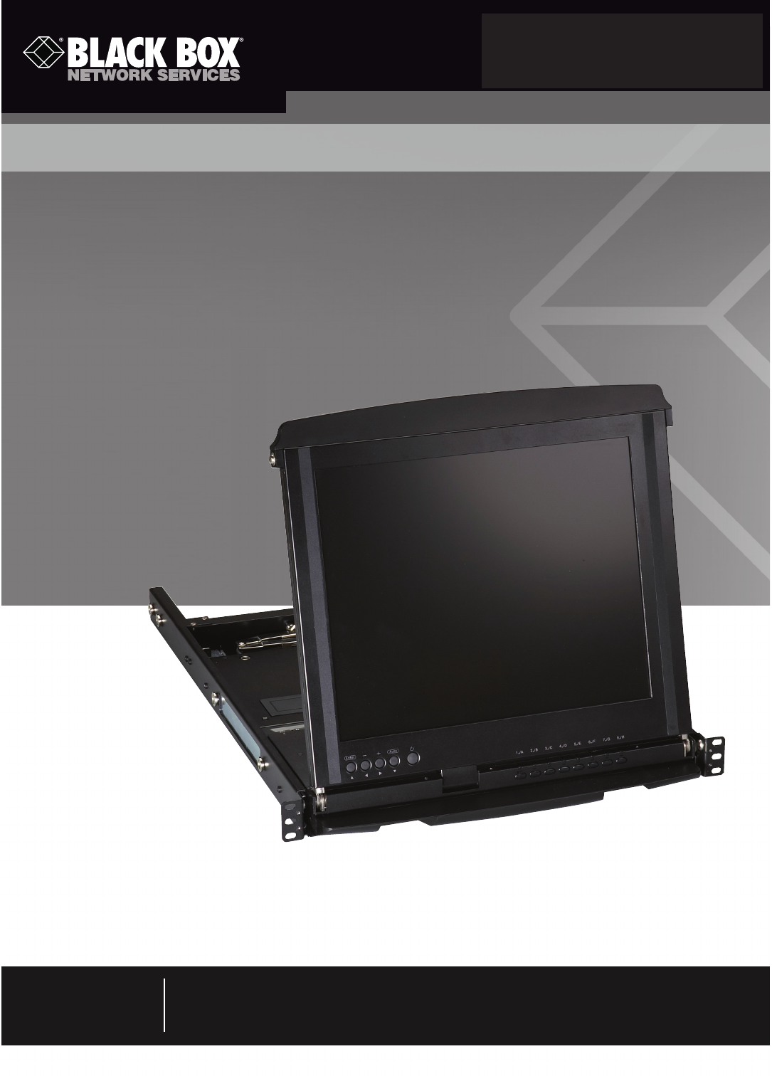
Each ServView™ V KVM Tray Kit includes a KVM Tray (KVT517A or KVT517A-WIDE), a KVM module (KVT6S1UV, KVT4S8PV,
KVT4S8UV, KVT4S16PV, KVT4S16UV, KVT8DVIU, KVT8CATUV, KVT16CATUV, KVT1IP8CATUV, KVT1IP16CATUV,
KVT4IP16CATUV), and a universal rear bracket extension kit. This manual describes how to use the ServView V KVM Tray and the
rear bracket extension kit, and a separate manual (included with your kit) explains how to use the KVM module.
Control your 4-post-rack- or cabinet-mounted USB or PS/2® server with the compact, easy-to-use ServView V KVM Tray. It con-
sists of a keyboard, mouse, LCD panel, and KVM module housed in an industry-standard 19" 1U-height rack drawer (see Figure
2-1). The unique dual-rail design allows the keyboard and LCD display to slide in and out independently of each other, so you can
stow the keyboard out of the way when you’re not using it.
The ServView has a 17" standard or widescreen LCD panel. It features a full 105-key, low-profile, sturdy keyboard and touch pad
with an ergonomically designed hand rest. The KVT517A has a maximum resolution of 1280 x 1024. The KVT517A-WIDE has a
maximum resolution of 1920 x 1080P.
Install the ServView in 4-post racks or cabinets that have rail space of 23.7"D to 45.3"D (60.2 to 115.1 cm).
NOTE: This is the depth measured between the front pole and rear pole inside a 4-post rack or cabinet, not the outside depth of
the enclosure.
When installing the ServView, you’ll need to use the universal Rear Bracket Extension Kit that’s included in your ServView Kit.
A KVM module is also included with the ServView. To control more than one USB or PS/2 server, connect the ServView to a
ServSwitch™.
The KVM module comes with a universal Centronics® 36-pin connector; use it to connect the module to the console drawer. The
module has a barrel connector for power (or a locking power connector for the CATx modules). The small screws (0.12" x 0.24"
[0.5 x 1.1 cm]) listed in Section 2.2 secure the brackets to the KVM module. The large screws (0.19" x 0.43" [0.3 x 0.6 cm]) are
used in place of 10-32 or 12-24 screws (described in Chapter 3, not included) if required by your rack.
1U dual-rail slide drawer
with keyboard, touch pad,
and 17" monitor (KVT517A
or KVT517A-WIDE)
Universal rear bracket
extension kit
KVM module
(KVT6S1UV, KVT4S8PV,
KVT4S8UV, KVT4S16PV,
KVT4S16UV, KVT8DVIU,
KVT8CATUV, KVT16CATUV,
KVT1IP8CATUV, KVT1IP16CATUV,
or KVT4IP16CATUV)
Figure 2-1. ServView Kit components (left to right): Rear Bracket Extension Kit,
KVM Module with power supply, and 1U slide drawer.
724-746-5500 | blackbox.com
Page 8 KVT517A
Chapter 2: Overview
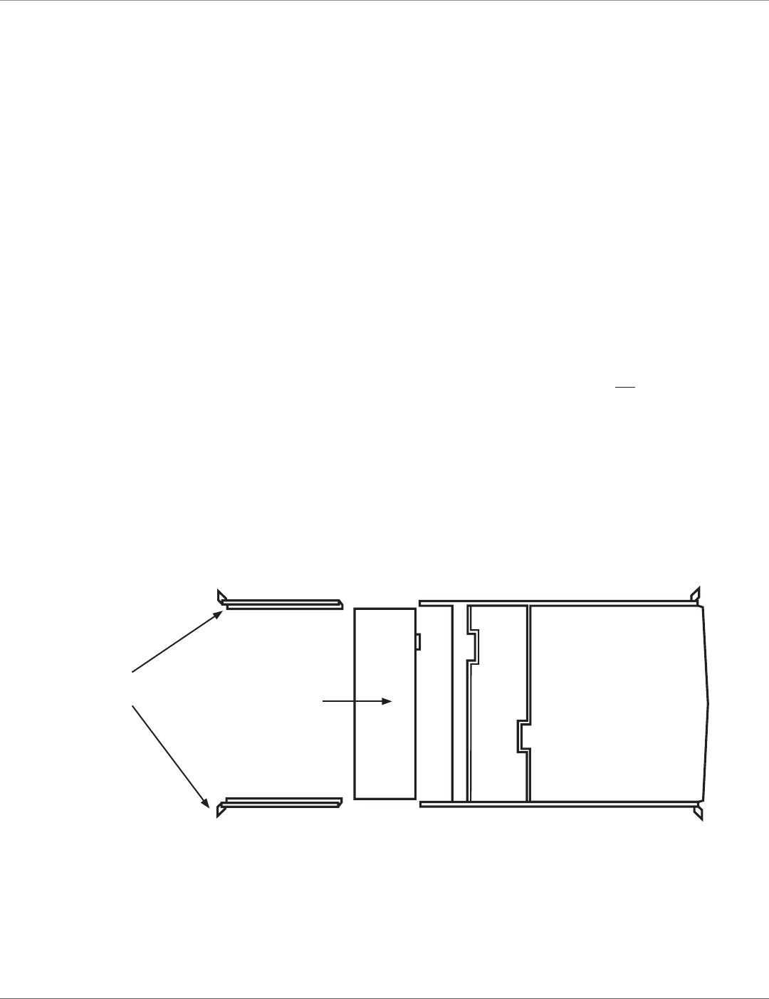
Figure 2-2. ServView V Tray, closed position.
2.2 What’s Included
• (1) 1U dual-rail drawer with keyboard, touch pad, and LCD monitor
• (1) KVM module with power supply (based on product code)
• (1) universal rear rail kit (includes [2] brackets, [2] extensions, and [8] screws)
• (10) 0.19" x 0.43" (0.5 x 1.1 cm) screws
• (10) 0.12" x 0.24" (0.3 x 0.6 cm) screws
• This user’s manual
You might also need 12-24 or 10-32 nuts/bolts.
2.3 ServView V KVM Tray Kit Part Numbers
The ServView V KVM Tray Kit includes a ServView V KVM Tray, a PS/2 or USB KVM module, and a universal rear bracket exten-
sion kit. Table 2-1 lists the available kits.
Table 2-1. ServView V KVM Tray Kit components.
Kit Part Number KVM Module P/N Link Rail Depths
KVT517A-1UV-R2 KVT6S1UV 1-port DVI/VGA USB/PS2 23.7"–45.3"
KVT517A-8UV KVT4S8UV 8-port VGA USB/PS2 23.7"–45.3"
KVT517A-16UV KVT4S16UV 16-port VGA USB/PS2 23.7"–45.3"
KVT517A-8PV KVT4S8PV 8-port VGA PS/2 23.7"–45.3"
KVT517A-16PV KVT4S16PV 16-port VGA PS/2 23.7"–45.3"
KVT517A-8DV-WIDE KVT8DVIU 8-port DVI USB 23.7"–45.3"
KVT517A-8CATX KVT8CATUV 8-port CX CATx 23.7"–45.3"
KVT517A-16CATX KVT16CATUV 16-port CX CATx 23.7"–45.3"
KVT517A-8CATX KVT1IP8CATUV 8-port CX CATx 23.7"–45.3"
KVT517A-16CATX-1IP KVT1IP16CATUV 16-port CX CATx 23.7"–45.3"
KVT517A-16CATX-4IP KVT4IP16CATUV 16-port CX CATx 23.7"–45.3"
724-746-5500 | blackbox.com
Page 9
KVT517A
Chapter 2: Overview
2.4 1U-Height KVM Switch Function Modules
When a 1U KVM switch function module is slid into the rear side of the console drawer, the entire setup takes 1U space of a rack
or cabinet. Table 2-2 describes the available 1U-height modules.
Table 2-2. 1U-height KVM Switch Function Modules.
Part Number Interface
KVT6S1UV 1-port PS/2 or USB + DVI/VGA
KVT4S8PV 8-port PS/2 + VGA
KVT4S8UV 8-port PS/2 or USB + VGA
KVT4S16PV 16-port PS/2 + VGA
KVT4S16UV 16-port PS/2 or USB + VGA
KVT517A-8DV-WIDE 8-port USB + DVI
KVT8CATUV 8-port CX CATx
KVT16CATUV 16-port CX CATx
KVT1IP8CATUV 8-port CX CATx with 1 IP User
KVT1IP16CATUV 16-port CX CATx with 1 IP User
KVT4IP16CATUV 16-port CX CATx with 4 IP Users
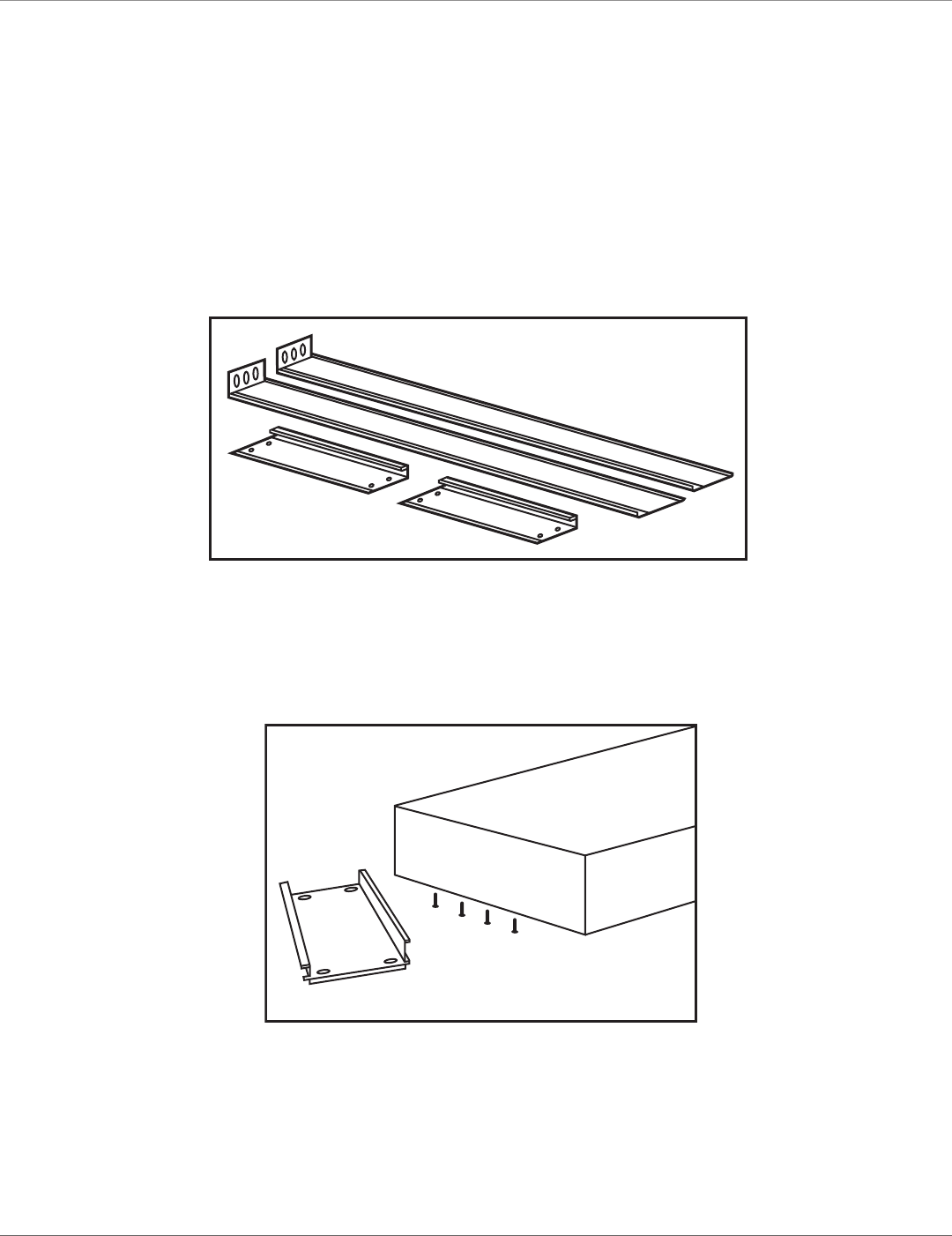
2.5 Rear Bracket Extensions
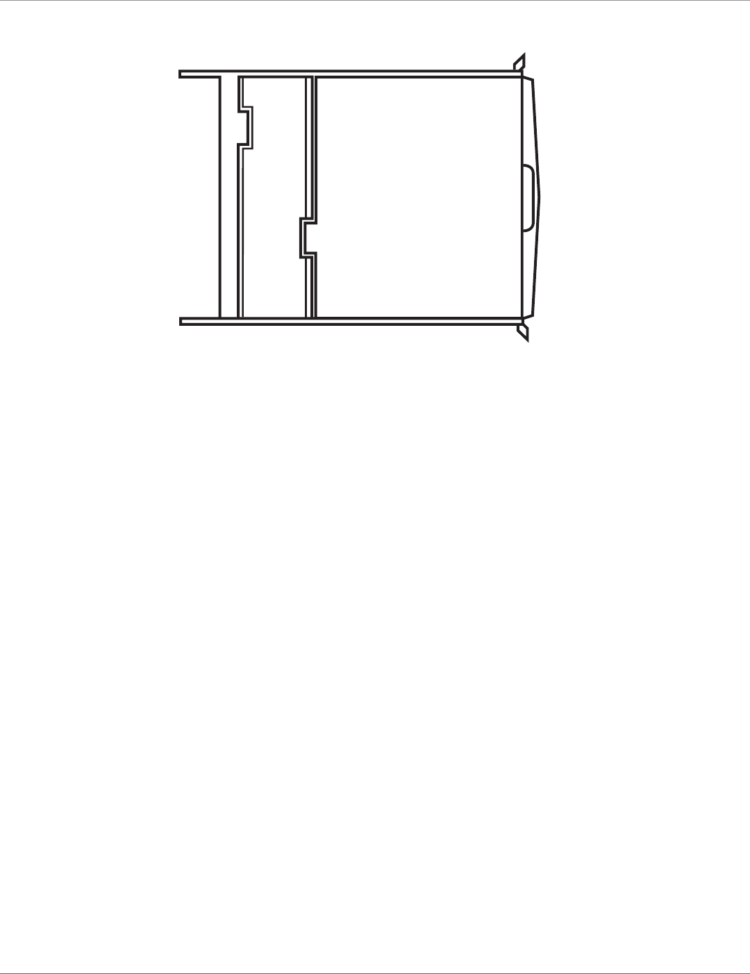
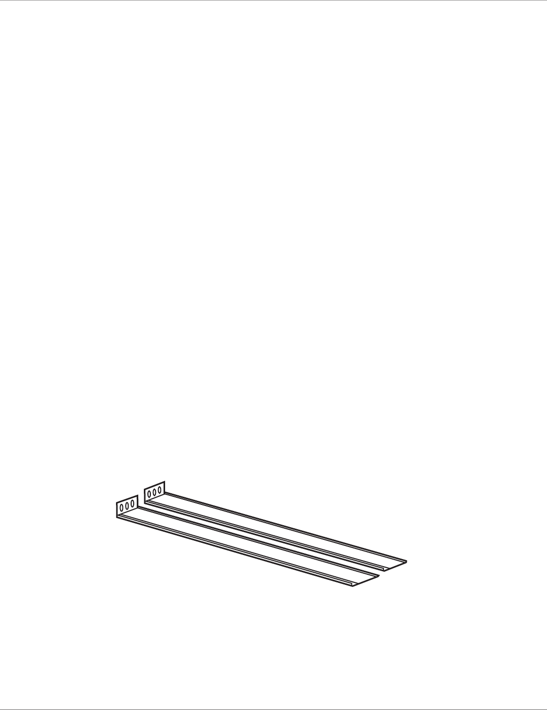
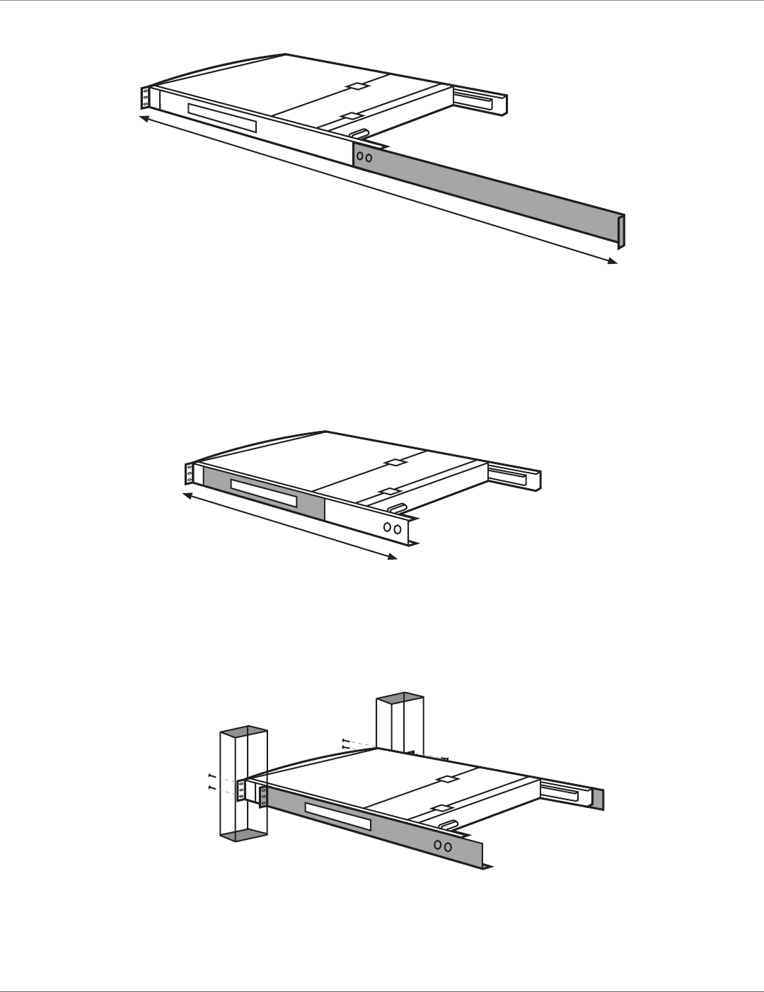
Figure 2-3 shows the rear bracket pair, and Figures 2-4 and 2-5 show the ServView V in its maximum and minimum extension
positions.
Figure 2-3. Rear bracket pair.
NOTE: The lengths in Figures 2-4 and 2-5 are the depths measured between the front pole and rear pole inside a 4-post rack
or cabinet, not the outside depth of the enclosure.
724-746-5500 | blackbox.com
Page 10 KVT517A
Chapter 2: Overview
45.3" (115.1 cm)
Figure 2-4. The maximum depth of the unit.
23.7" (60.2 cm)
Figure 2-5. The minimum depth of the unit.
Open rack
post 1
Open rack
post 2
ServView V Tray
Figure 2-6. ServView V Tray installed on an open rack.
724-746-5500 | blackbox.com
Page 11
KVT517A
Chapter 3: Assembly and Installation
3. Assembly and Installation
3.1 Assembly
1. Choose a proper position in the cabinet for the rack drawer.
2. Using eight counter-sunk screws (included), attach the extensions (included with your ServView V Kit) to both sides of the KVM
switch module. See Figures 3-1 through 3-5. The wide-edged plastic extension should be on the top side (see Figure 3-5).
NOTE: The CATx KVM switch modules will only accept between (2) and (4) mounting screws on each extension, depending on
the kit part numbers.
Rear brackets
Extensions
Figure 3-1. Rear brackets and extensions.
KVM module
Extensions
(4) counter-sunk
screws
Figure 3-2. Attaching the extensions to the KVM module.
724-746-5500 | blackbox.com
Page 12 KVT517A
Chapter 3: Assembly and Installation
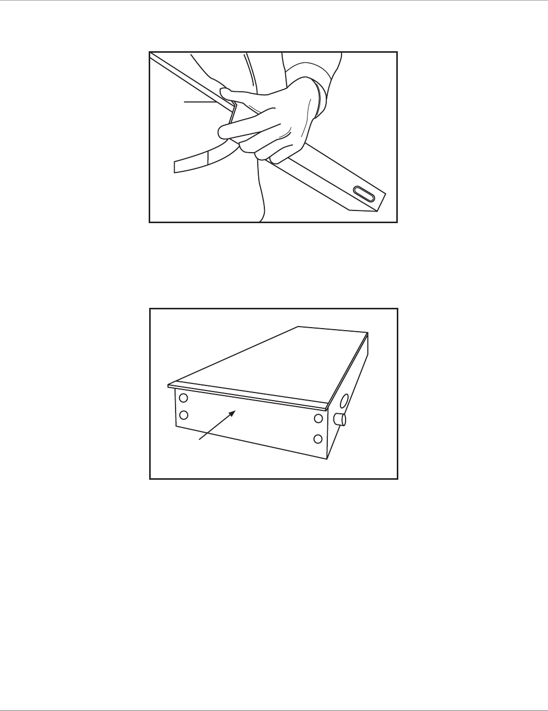
Extension
Switch module
Figure 3-3. Attaching the extensions to one side of the KVM switch module.
Extension on
side of switch
module
Switch
module
Figure 3-4. KVM switch module with extensions attached.
724-746-5500 | blackbox.com
Page 13
KVT517A
Chapter 3: Assembly and Installation
The wide-edged plastic
extension should be on
the top side.
Figure 3-5. Back view of module with extensions attached.
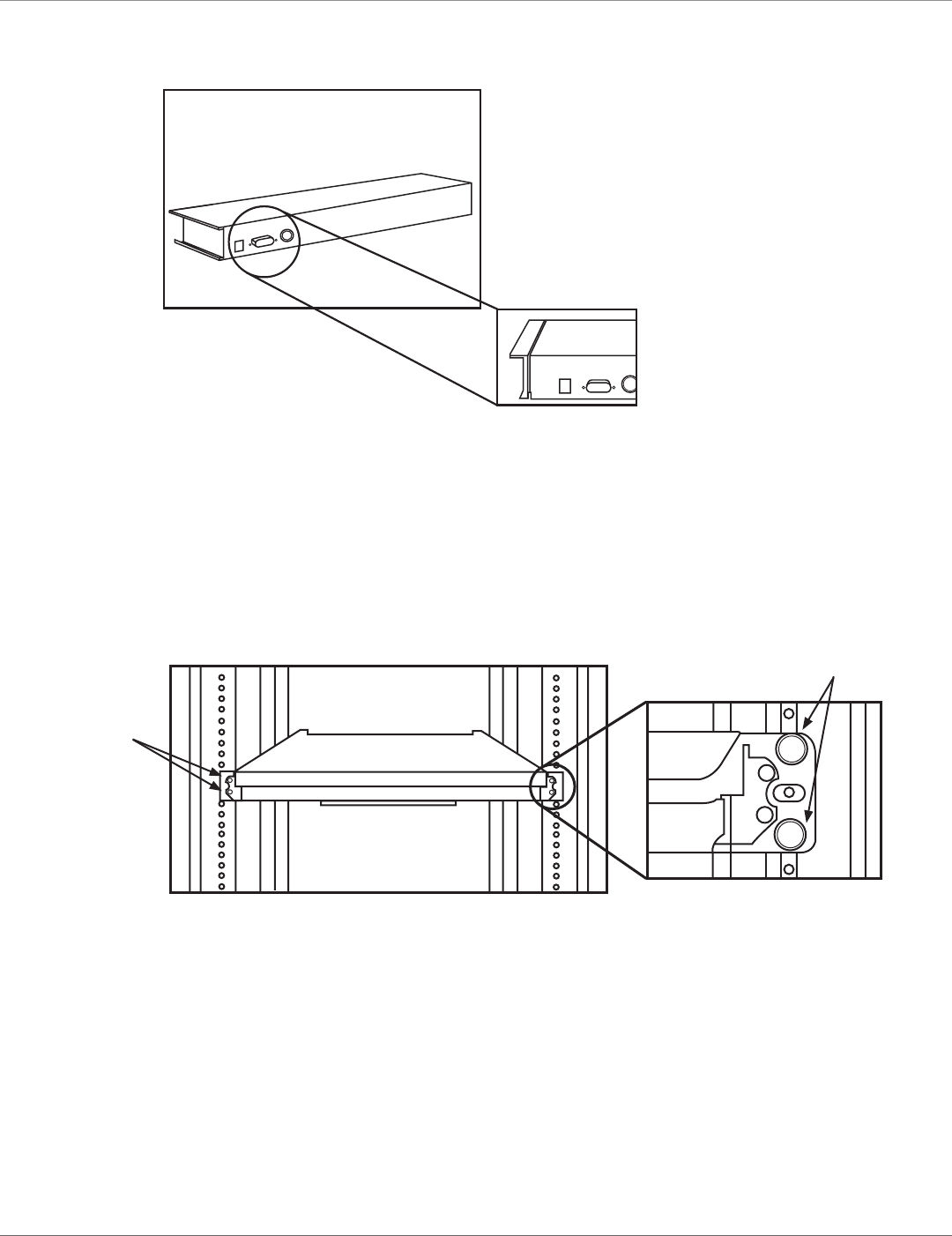
3. Using four cabinet screws (included), screw the unit onto the rack. See Figures 3-6 and 3-7.
WARNING: Do not remove the safety stopper until you complete the assembly.
+
+
+
+
+
+
+
+
(2) cabinet
screws
ServView
V Tray
Rack Rack
(2) cabinet
screws
Figure 3-6. Securing the ServView V KVM Tray to the rack.
724-746-5500 | blackbox.com
Page 14 KVT517A
Chapter 3: Assembly and Installation
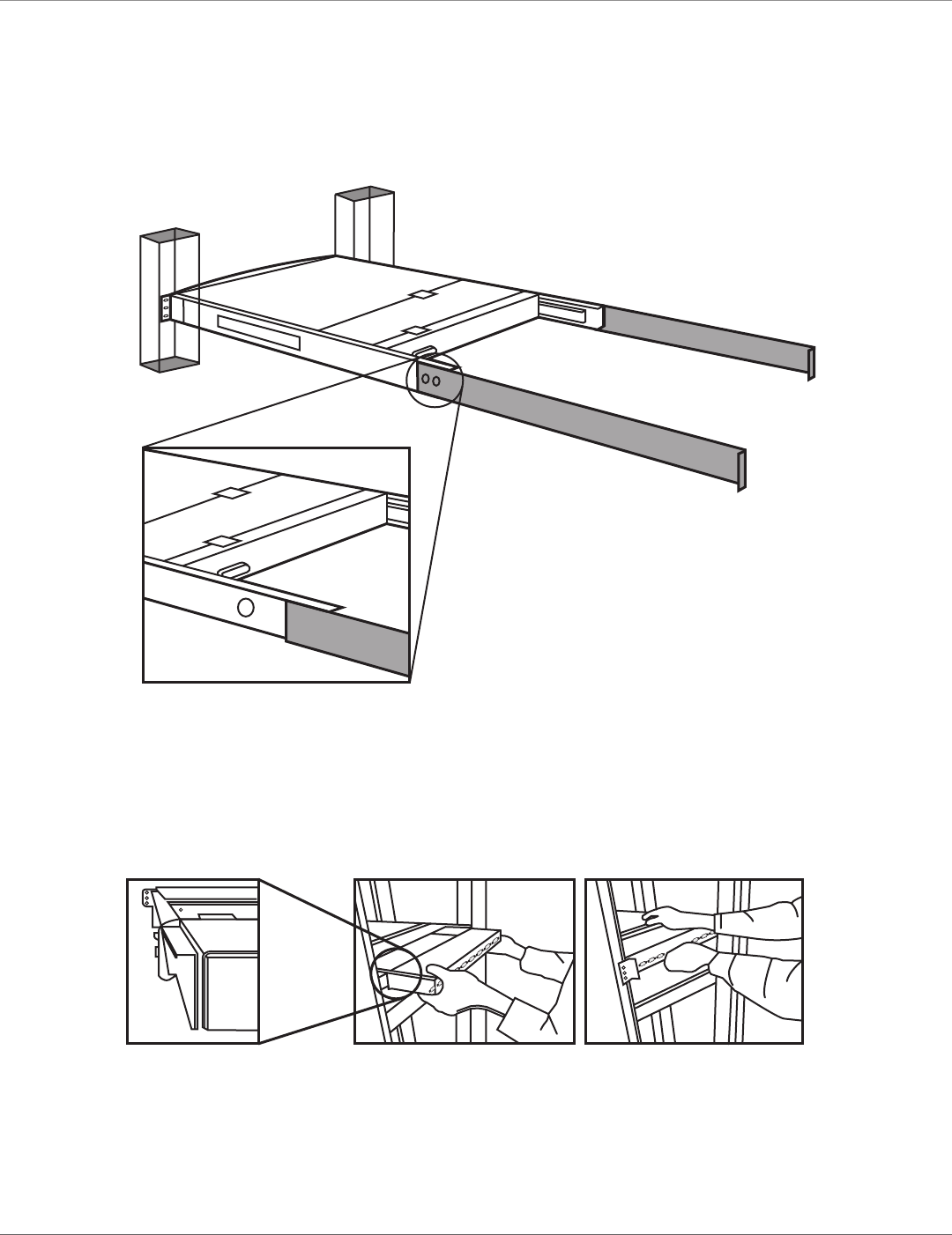
4. Slide the rear bracket into both sides of the unit. Make sure that the two wheels with screws are inside the bracket’s track
while sliding in the rear bracket. See Figure 3-7.
ServView V
KVM Tray
Rear bracket
Rear bracket
Bracket track
Figure 3-7. Install the rear bracket onto the ServView V KVM Tray’s extensions.
5. Push the KVM switch module evenly towards the drawer. See Figure 3-8.
Figure 3-8. Pushing the module towards the drawer.
724-746-5500 | blackbox.com
Page 15
KVT517A
Chapter 3: Assembly and Installation
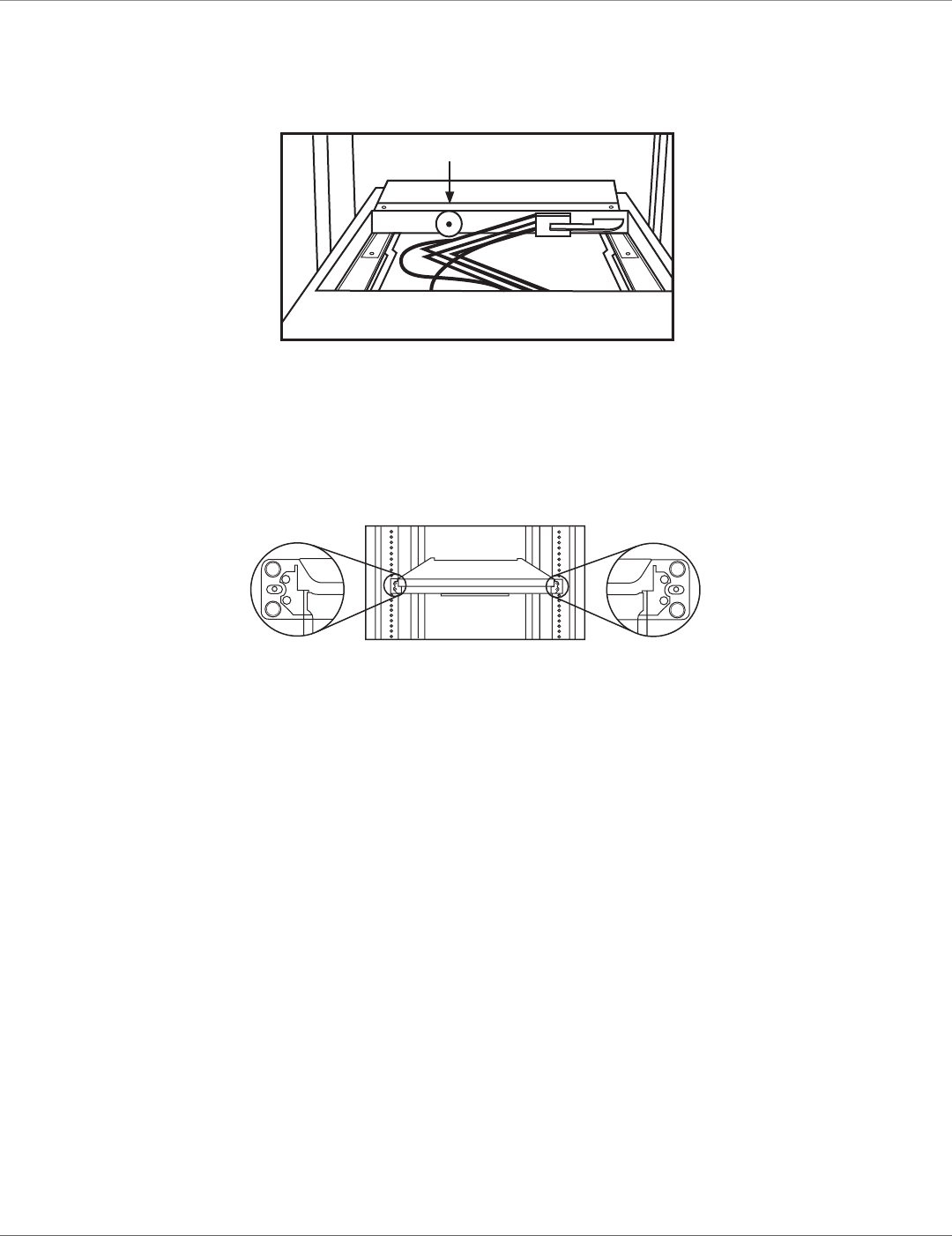
6. Slide the console drawer out and tightly fasten the screw to the module. See Figure 3-9.
Screw
Module
Figure 3-9. Fasten the screw to the module.
7. Remove the four screws held in place with safety stoppers from the front sides of the drawer (left and right) in sequence.
See Figure 3-10.
+
+
+
+
+
+
+
+
+
+
+
+
(2) screws held
in place with
safety stoppers
(2) screws held
in place with
safety stoppers
Figure 3-10. Removing the four screws.
724-746-5500 | blackbox.com
Page 16 K V T517A
Chapter 3: Assembly and Installation
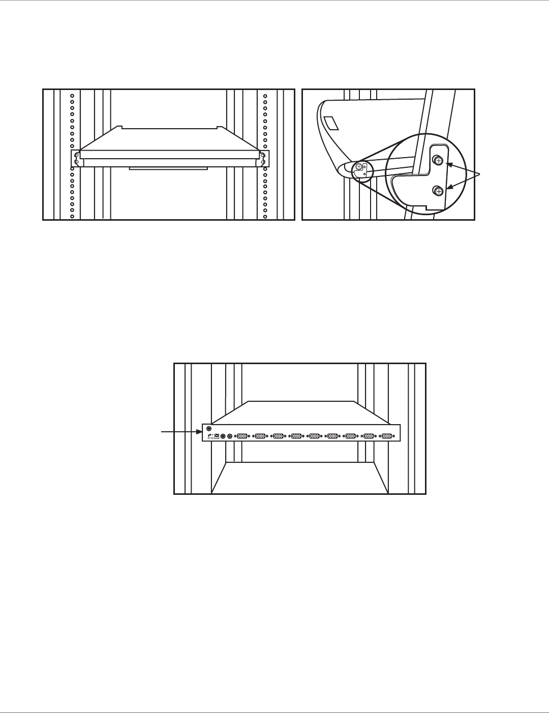
8. Slide out the drawer and then remove the four screws and two safety stoppers from the left and right sides of the KVM Tray in
sequence. See Figures 3-11 and 3-12.
+
+
+
+
Drawer
Safety
stoppers
Figure 3-11. Sliding the drawer out. Figure 3-12. Removing the safety stoppers.
WARNING: The safety stoppers prevent the drawer from sliding out when in transit. Once you remove the safety stoppers, the
drawer may slide out and cause serious injury.
9. Connect the power supply to the power jack on the switch module. See Figure 3-13.
Power
connector
Figure 3-13. Attaching the power supply to the module.
To replace a module, follow Steps 5 and 6 on pages 14–15.
724-746-5500 | blackbox.com
Page 17
KVT517A
Chapter 3: Assembly and Installation
3.2 Installation
To install a non Centronics compatible KVM switch module in the ServView V, refer to the user’s manual for that module.
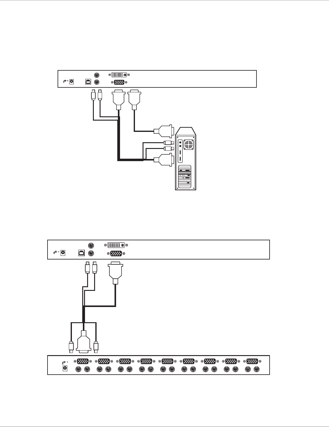
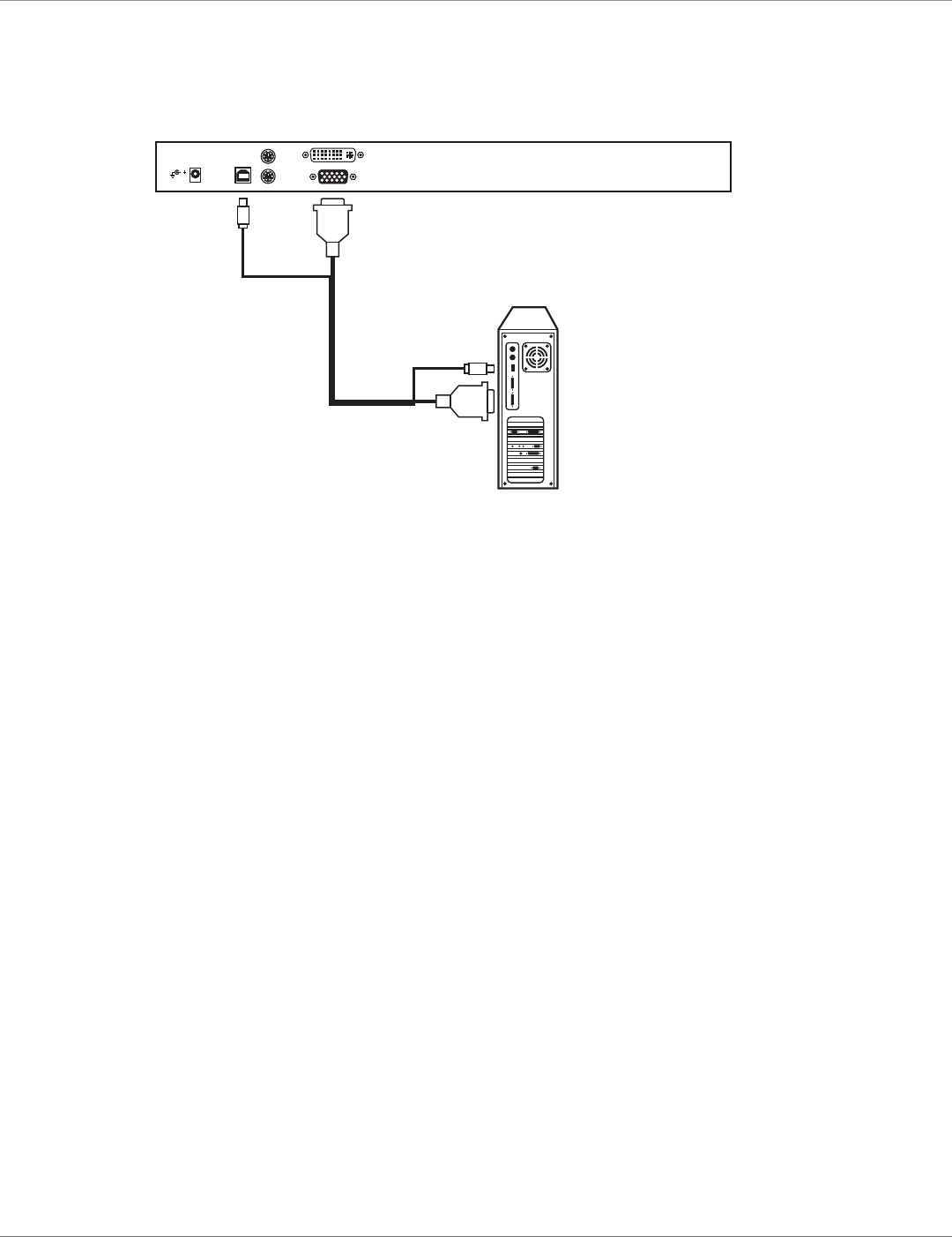
The 1-port PS/2 and USB switch module connects to a PS/2 console as shown in Figure 3-14.
DVI cable
Male-to-Male
6-Pin Mini DIN
for Keyboard
Male-to-Female
HD15 for Monitor
KVT6S1UV
Male-to-Male
6-Pin Mini DIN
for Keyboard
Figure 3-14. 1-port module and PS/2 connected components.
The non Centronics compatible switch module connects to a KVM switch as shown in Figure 3-15.
Male-to-Female
HD15 for Mouse
Male-to-Female
HD15 for VGA
Male-to-Male
6-Pin Mini DIN
for Keyboard
Console
Connectors
KVT6S1UV
Figure 3-15. 1-port module and 8-port KVM switch with PS/2 console.
NOTE: Only one video signal (DVI or VGA) can be active at one time.
724-746-5500 | blackbox.com
Page 18 KVT517A
Chapter 3: Assembly and Installation
The 1-port PS/2 and USB switch module connects to a USB console as shown in Figure 3-16.
USB A–B
Male-to-Female
HD15 for VGA
KVT6S1UV
Figure 3-16. 1-port module and USB connected components.
724-746-5500 | blackbox.com
Page 19
KVT517A
Chapter 4: Operation
4. Operation
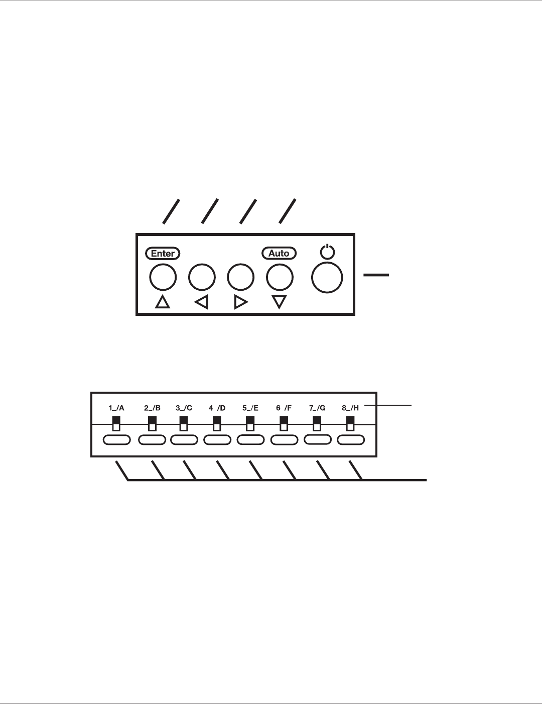
4.1 KVM Control and Status LEDs
KVM control and status information applies only if an 8- or 16-port KVM switch module (KVT4S8UV, KVT4S16UV, KVT4S8PV,
KVT4S16PV, KVT8CATUV, KVT16CATUV, KVT1IP8CATUV, KVT1IP16CATUV, KVT4IP16CATUV) is installed in the ServView V Tray.
It does not apply to the 1-port KVM switch module (KVT6S1UV). Figures 4-1 and 4-2 show the ServView V Tray’s LCD monitor
function buttons and computer selection buttons. An LED lighting bar is at the edge of the handle. Table 4-1 describes the but-
tons’ and LEDs’ functions.
+
–
7 6 5 4
3
Figure 4-1. LCD monitor function buttons.
1
2
Figure 4-2. Computer selection buttons.

724-746-5500 | blackbox.com
Page 20 KVT517A
Chapter 4: Operation
Table 4-1. Front-panel function buttons (operate only if a KVM switch card is installed).
Button or Function Description
LED
1 Computer selection button (lower) Press one of these push buttons to select a computer port. For
16-port models, 1–8 represent the lower 8 ports and A–H represent
the higher 8 ports. Ports 1 and A share the same push button. If
Port 1 is already selected, tap its push button to select Port A. If Port
1 is not selected, press and hold push button 1 for two seconds to
select Port 1.
2 Computer selection LED (upper) When computer Ports 1–8 are selected, this indicator lights red.
When computer Ports A–H are selected, the indicator lights flash
red.
3 LCD power button Press this button to turn on power. When power is on, the LCD
lights.
4 Auto key Press this dual-function button to automatically adjust the best
setting for the current display signal.
When using the OSD menu, press the Auto key to exit.
When the unit is operating, turn on the OSD menu to set the LCD
panel as an ordinary LCD monitor.
5 + key When using the OSD submenu, press this dual-function key to
increase the value.
When using the OSD menu, press this dual-function key to move to
the next item.
6 - key When using the OSD submenu, press this dual-function key to
decrease the value.
When using the OSD menu, press this dual-function key to move to
the previous item.
7 Enter key Press this dual-function key to start the OSD function.
When using the OSD menu, press this dual-function key to enter the
OSD submenu.
724-746-5500 | blackbox.com
Page 21
KVT517A
Chapter 4: Operation
4.2 Extra Keyboard and Mouse Control
The ServView V KVM Tray supports all wireless keyboards and mice, so you can extend your keyboard and mouse control without
cable. Typically, you can manage all your servers within 30 feet (10 m) of the ServTray.
NOTE: Check your wireless keyboard specs for distances supported.
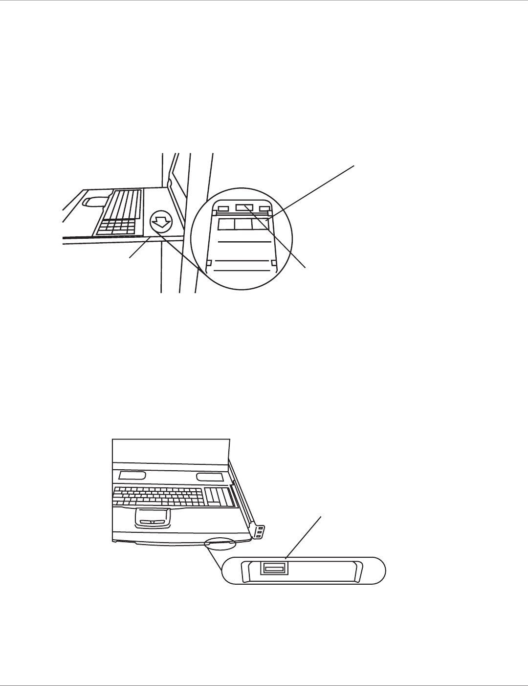
You can even install a wireless transceiver in a hidden compartment for an extra keyboard/mouse. Push and lift the lid as shown
in Figure 4-3. Via a slide switch, choose wireless keyboard and mouse combination or wireless mouse only for a keyboard/mouse
transceiver.
Touch pad function disabled
Scroll function disabled
enabled
Figure 4-3. Hidden compartment for wireless transceiver.
An expanded USB Type A connector underneath the drawer is shown in Figure 4-3.
Slide the switch to the “keyboard and mouse combo” position or to the “mouse-only” position for an expanded keyboard/mouse
transceiver. See Figure 4-4.
Plug in USB
(keyboard/mouse) here
Figure 4-4. USB Type A connector for corded or cordless keyboard and mouse.
Tab function disabled
enabled
Plug in USB (keyboard/mouse)
wireless receiver
Lid
724-746-5500 | blackbox.com
Page 22 KVT517A
Chapter 4: Operation
4.3 Opening and Closing the Console
The ServView V Tray contains two parts: LCD monitor and keyboard/touch pad. You can slide the two parts together or
separately. This enables users to view the LCD monitor without pulling out the keyboard.
WARNING: Do not lean on the console or keyboard when it is pulled out.
Do not place any object or use significant force on the console drawer when it is pulled out. This may cause personal
injury and/or property damage.
Do not put your fingers, hands, or anything else on the rear cabinet. Do not touch any part behind the rear cabinet.
Keep the area behind the drawer clear.
Do not apply force to the monitor screen and do not scratch it. This could damage the screen.
Never disassemble or modify the console drawer for any purpose. This may cause personal injury and/or property
damage.
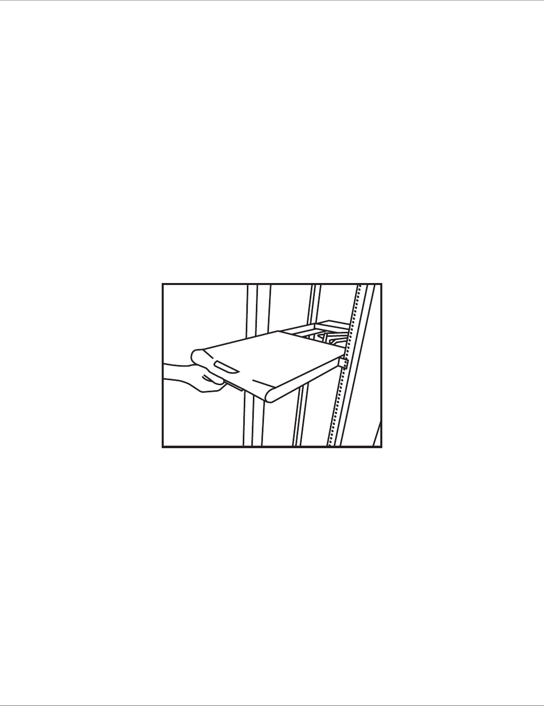
4.3.1 Opening the Console
Opening Together
1. You can pull out the LCD monitor and keyboard/touch pad together. See Figure 4-5.
Monitor and
keyboard/
touch pad
Figure 4-5. Pulling out the monitor and keyboard/touch pad together.
724-746-5500 | blackbox.com
Page 23
KVT517A
Chapter 4: Operation
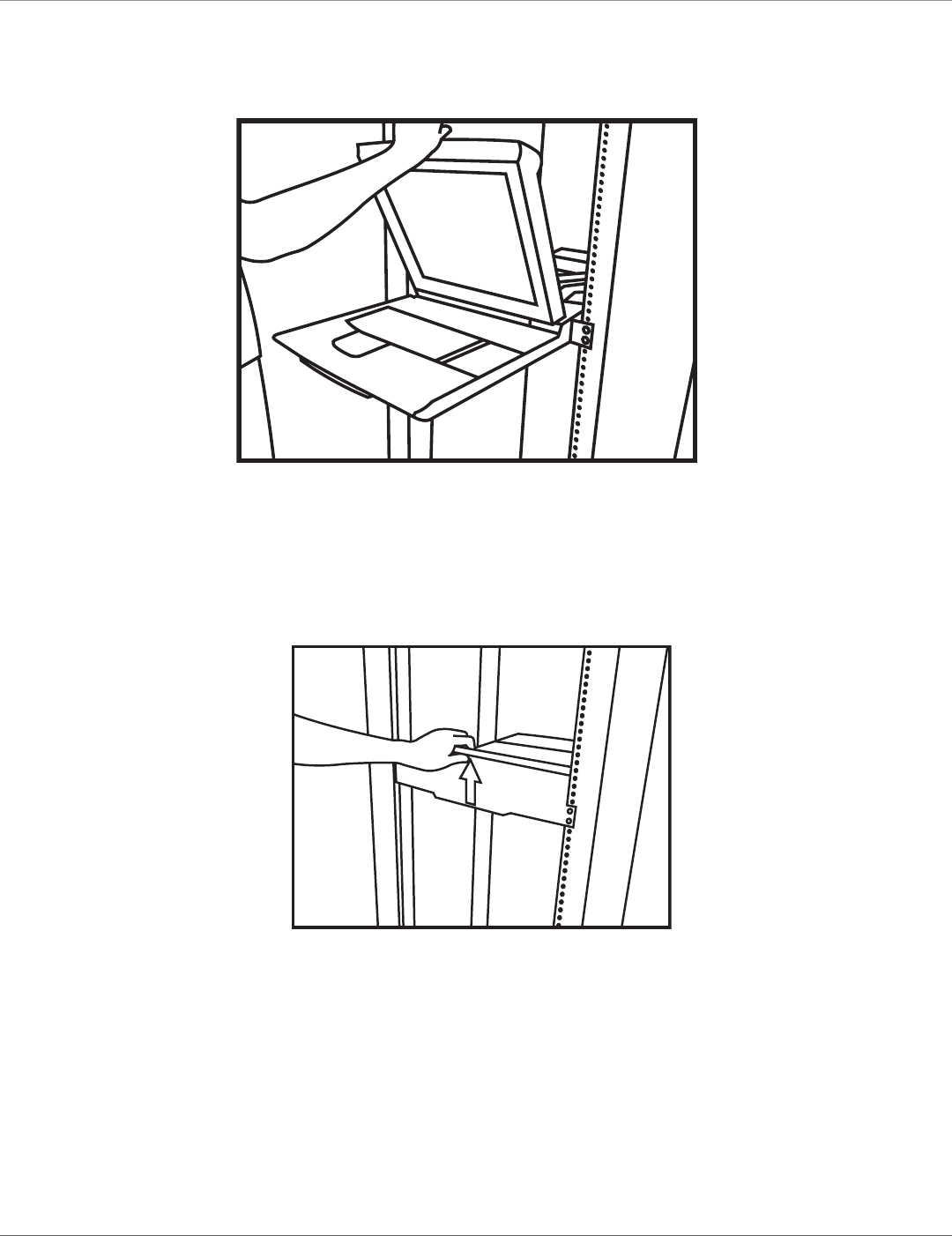
2. When it rests at the position you want, lift out the LCD panel at an angle appropriate for screen display. See
Figure 4-6.
Keyboard/
touch pad
LCD
monitor
Figure 4-6. Lift out the LCD panel.
Opening LCD Monitor Only
1. Holding the LCD monitor’s handle, pull it upwards. See Figure 4-7.
Figure 4-7. Opening the LCD monitor only.
2. When the LCD monitor is released, you will hear a click.
3. Tilt the monitor to an appropriate viewing position. See Figure 4-6.
724-746-5500 | blackbox.com
Page 24 KVT517A
Chapter 4: Operation
4.3.2 Closing the Console
1. Fold the LCD monitor.
2. Holding the handle, push the folded monitor back evenly.
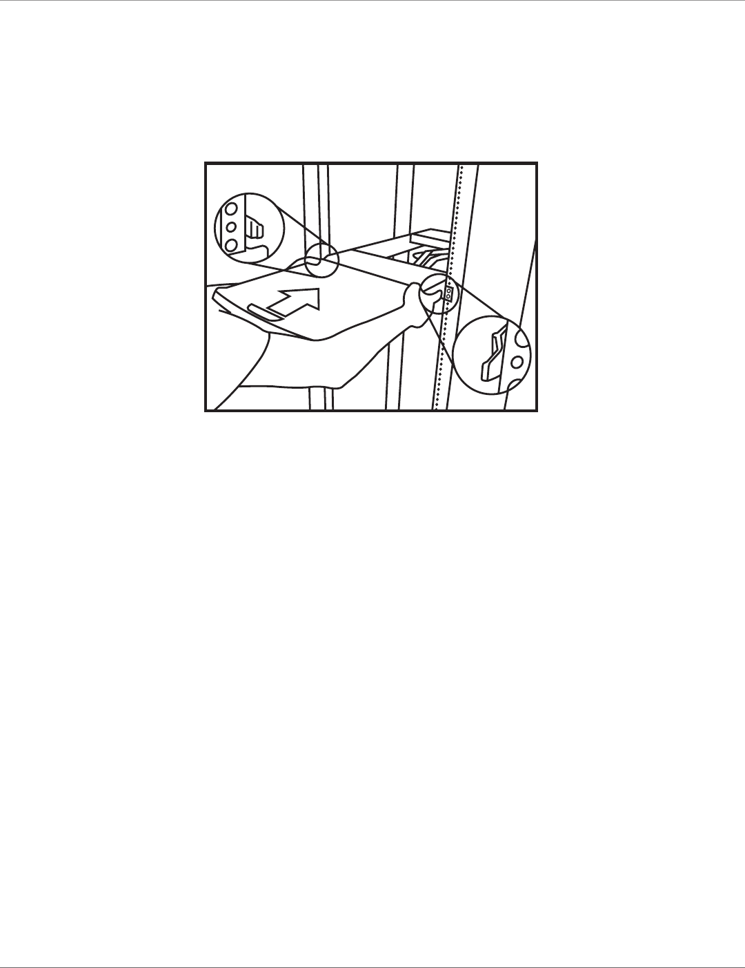
3. Press the two metal plates down together and push the console back slowly and evenly. See Figure 4-8.
Metal plate
Metal
plate
Figure 4-8. Closing the console.
CAUTION: When the LCD monitor is pulled out all the way, you will see both edges of two metal unlock plates extended outside.
To push the monitor back to the cabinet, first press and hold these two unlock plates together to flatten the monitor.
Then push the monitor back slowly and completely to move the metal plates inside the console.
724-746-5500 | blackbox.com
Page 25
KVT517A
Chapter 4: Operation
4.3.3 Opening the Keyboard/Touch Pad and LCD Monitor Individually
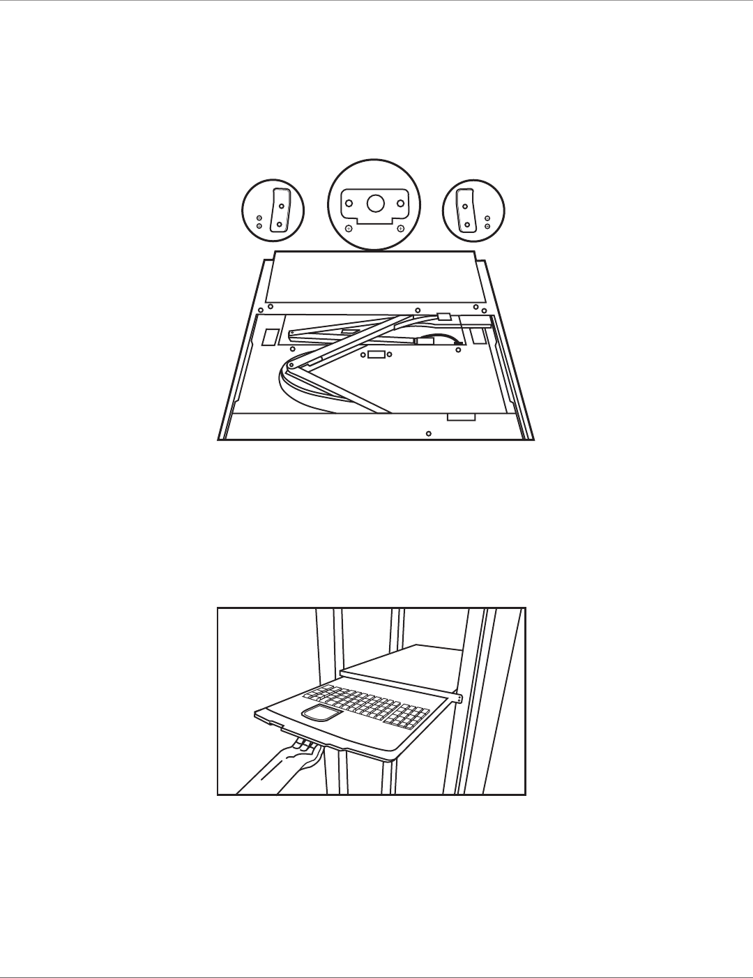
1. To pull out the keyboard touch pad independently, you must first remove the two pairs of screws fastened on a bracket at the
keyboard’s upper cover on the ends of the left and right sides. See Figure 4-9.
(2) screws
and brackets
(2) screws
and brackets
Figure 4-9. Screws on the keyboard/touch pad and LCD monitor assembly.
2. Unscrew and remove the screws one at a time.
3. Then put the screws aside and pull out the keyboard/touch pad and LCD monitor individually. See Figure 4-10.
Figure 4-10. Pulling out the keyboard/touch pad and LCD monitor.
724-746-5500 | blackbox.com
Page 26 KVT517A
Chapter 4: Operation
4.4 Replacing the Keyboard and Touch Pad
4.4.1 Removing the Keyboard
You can remove the keyboard for maintenance or a language change.
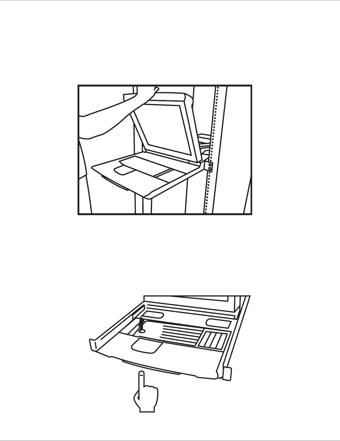
1. Pull the keyboard out to the end and unfold the LCD monitor. See Figure 4-11.
Figure 4-11. Unfold monitor.
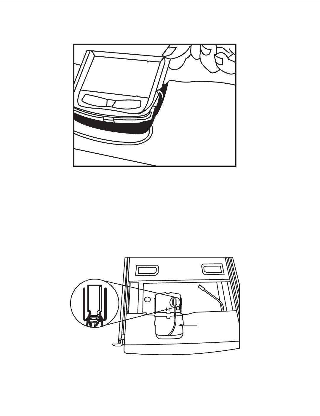
2. There is a round hole under the drawer. Using a finger, push the keyboard up and through the hole. See Figure 4-12.
3. Lift it up and locate the mini USB cable under the keyboard.
4. Gently unplug the mini USB cable and take it out.
Figure 4-12. Push keyboard up through round hole under the drawer.
724-746-5500 | blackbox.com
Page 27
KVT517A
Chapter 4: Operation
4.4.2 Replacing the Keyboard
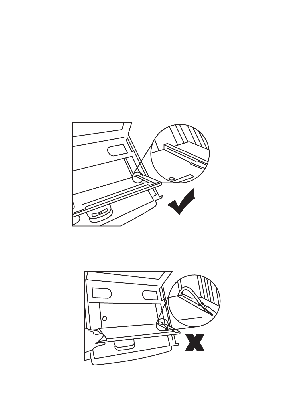
1. When installing a keyboard, make sure you place the cable flat inside the tray.
2. Hold the keyboard evenly with your hands and place it over the foam. Do not use one hand to squeeze the keyboard inside the
tray.
3. Double-check that the USB cable is placed inside the tray without any twist.
4. Plug in the keyboard connector firmly. See Figures 4-13 through 4-17.
WARNING: Make sure you place the USB cable inside the line holder in a fixed position.
After placing the keyboard inslde the tray, make sure the keyboard is positioned flat to avoid any scratching
or damage.
Figure 4-13. Correct way to replace the keyboard, diagram #1.
Figure 4-14. Wrong way to replace the keyboard, diagram #1.
724-746-5500 | blackbox.com
Page 28 KVT517A
Chapter 4: Operation
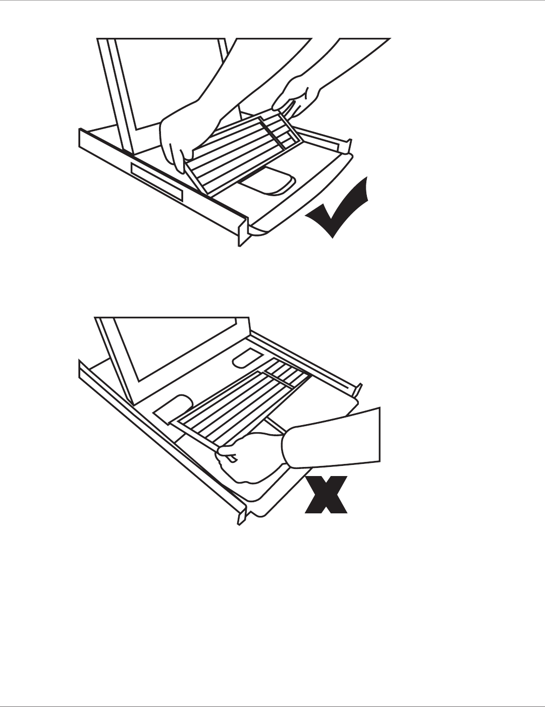
Figure 4-15. Correct way to replace the keyboard, diagram #2.
Figure 4-16. Wrong way to replace the keyboard, diagram #2.
724-746-5500 | blackbox.com
Page 29
KVT517A
Chapter 4: Operation
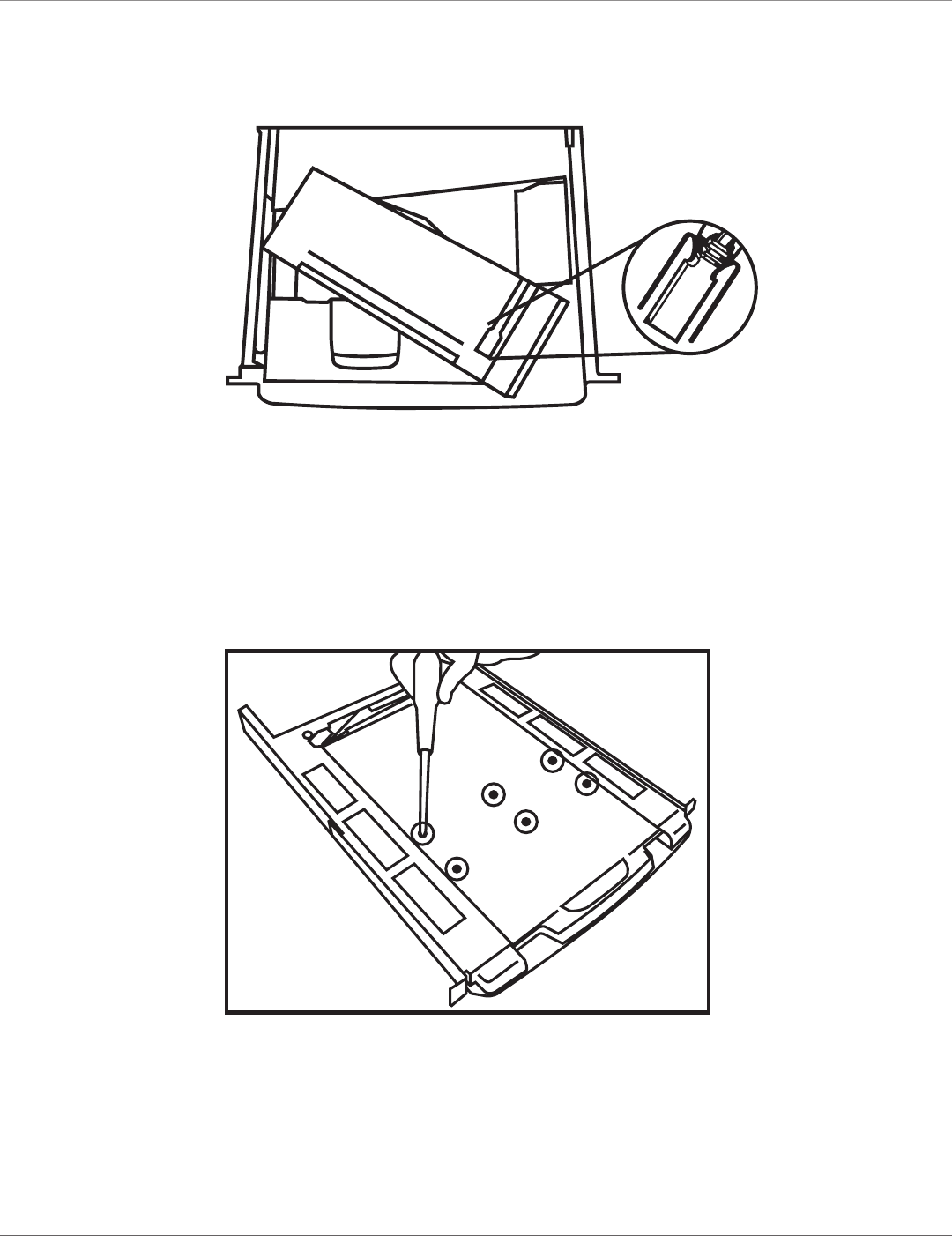
Figure 4-17. Locating the triangular mark on the mini USB connector.
NOTE: Make sure the triangular mark on the mini-USB connector faces outwards.
4.4.3 Alternate Way to Fasten the Keyboard (Recommended)
1. Pull the keyboard out as shown in Figure 4-5.
2. Use the included six tapping screws to fasten the the keyboard and tray together as shown in Figure 4-18.
Figure 4-18. Fasten the keyboard and tray together.
724-746-5500 | blackbox.com
Page 30 KVT517A
Chapter 4: Operation
4.4.4 Replacing the Touch Pad
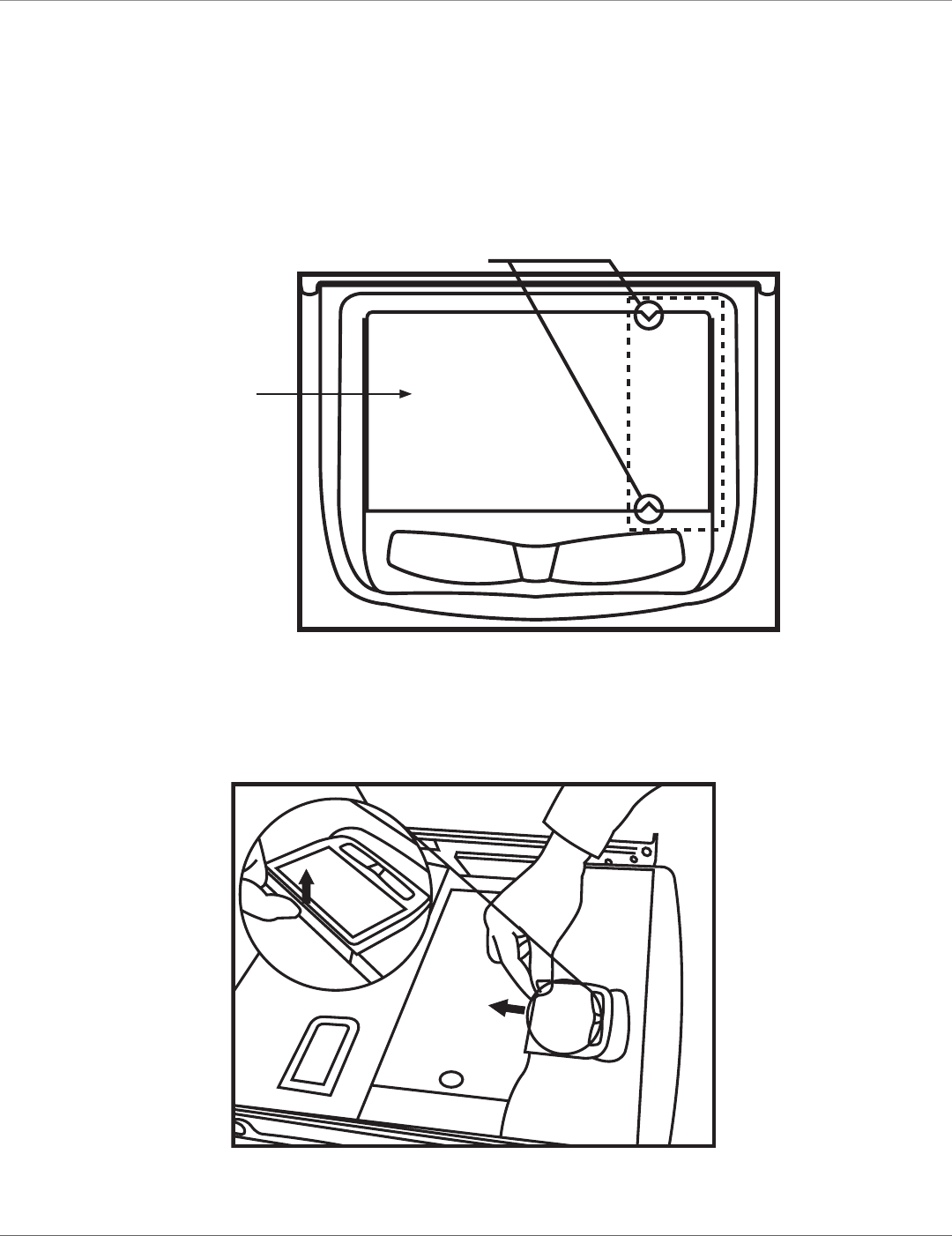
Touch Pad and its Wheel
The right side of the touch pad simulates a wheel mouse. When touching this area, you will see two small triangular marks (this is
the simulated wheel). See Figure 4-19.
Touch pad
Simulated wheel
Figure 4-19. Touch pad showing simulated mouse area.
1. To remove the touch pad, press the tab underneath it upward to release the latch. See Figure 4-20.
Figure 4-20. Releasing the latch on the touchpad.
724-746-5500 | blackbox.com
Page 31
KVT517A
Chapter 4: Operation
2. Then slide the touch pad outwards until it is lifted up and is away from the notches, as shown in Figure 4-21.
Figure 4-21. Removing the touch pad.
Installing the Touch Pad
The touch pad attaches to the tray via a mini-USB cable.
To replace the touch pad, adjust the length of the mini USB cable and slide the touch pad all the way in until you hear a clicking
sound that indicates the touch pad is locked into position. See Figure 4-22.
Mini USB Cable
Touch
pad Tray
Figure 4-22. Installing the touchpad.
NOTE: Make sure the triangular mark on the mini USB connector faces outwards.

724-746-5500 | blackbox.com
Page 32 KVT517A
Chapter 5: Troubleshooting
5. Troubleshooting
5.1 Calling Black Box
If you determine that your ServView V KVM Tray is malfunctioning, do not attempt to alter or repair the unit. It contains no user-
serviceable parts. Contact Black Box at 724-746-5500.
Before you do, make a record of the history of the problem. We will be able to provide more efficient and accurate assistance if
you have a complete description, including:
• the nature and duration of the problem.
• when the problem occurs.
• the components involved in the problem.
• any particular application that, when used, appears to create the problem or make it worse.
5.2 Shipping and Packaging
If you need to transport or ship your ServView V KVM Tray:
• Package it carefully. We recommend that you use the original container.
• If you are shipping the ServTray for repair, make sure you include everything that came in the original package. Before you ship,
contact Black Box to get a Return Authorization (RA) number.

724-746-5500 | blackbox.com
Page 33
KVT517A
NOTES

724-746-5500 | blackbox.com
Page 34 KVT517A
NOTES

724-746-5500 | blackbox.com
Page 35
KVT517A
NOTES

724-746-5500 | blackbox.com
About Black Box
Black Box Network Services is your source for an extensive range of networking and infrastructure products. You’ll find everything
from cabinets and racks and power and surge protection products to media converters and Ethernet switches all supported by
free, live 24/7 Tech support available in 30 seconds or less.
© Copyright 2011. Black Box Corporation. All rights reserved.
BLACK BOX®
Black Box Tech Support: FREE! Live. 24/7.
Tech support the
way it should be.
Great tech support is just 30 seconds away at 724-746-5500 or blackbox.com.
KVT517A, version 2
