6487 Picoammeter/Voltage Source Keithley Manual
Keithley_6487_Manual
Keithley_6487_Manual
Keithley_6487_Manual
User Manual:
Open the PDF directly: View PDF ![]() .
.
Page Count: 338 [warning: Documents this large are best viewed by clicking the View PDF Link!]
- Model 6487 Picoammeter/Voltage Source Reference Manual
- Safety Precautions
- Table of Contents
- 1 Getting Started
- 2 Measurement Concepts and Connections
- 3 Measurements and Sourcing Voltage
- 4 Range, Units, Digits, Rate, and Filters
- 5 Relative, mX+b, m/X+b, and log
- 6 Buffer and Sweeps
- 7 Triggering
- 8 Limit Tests and Digital I/O
- 9 Remote Operation
- 10 Status Structure
- 11 Comman Commands
- 12 SCPI Signal Oriented Measurement Commands
- 13 DISPlay, FORMat, and SYSTem
- 14 SCPI Reference Tables
- 15 Performance Verification
- 16 Calibration
- 17 Routine Maintenance
- A Specifications
- B Status and Error Messages
- C DDC Emulation Commands
- D IEEE-488 Bus Overview
- E IEE-488 and SCPI Conformance Information
- F Remote Calibration
- G Applications Guide
- Index

www.keithley.com
ECNED
IF
NO
C
F
O
E
RUS
AEM
R
E
T
A
E
R
G
A
Reference Manual
6487-901-01 Rev. B / March 2011
Model 6487 Picoammeter/Voltage Source
Model 6487 Picoammeter/Voltage Source
Model 6487
Picoammeter/Voltage Source
Reference Manual
© 2002-2011, Keithley Instruments, Inc.
Cleveland, Ohio, U.S.A.
All rights reserved.
Any unauthorized reproduction, photocopy, or use the information herein, in whole or in part,
without the prior written approval of Keithley Instruments, Inc. is strictly prohibited.
All Keithley Instruments product names are trademarks or registered trademarks of Keithley
Instruments, Inc. Other brand names are trademarks or registered trademarks of their respective
holders.
The Lua 5.0 software and associated documentation files are copyright © 1994-2008, Tecgraf,
PUC-Rio. Terms of license for the Lua software and associated documentation can be accessed at
the Lua licensing site (http://www.lua.org/license.html).
Keithley's standard terms and conditions of sale in effect at the time of acceptance of buyer's order
by Keithley shall apply to all purchase of goods and performance of services from Keithley, to the
exclusion of any additional or different terms and conditions, including any terms or conditions
which buyer may purport to apply under any buyer's request for quotation, purchase order or similar
document, or which buyer may offer in response to these terms. A copy of Keithley's current terms
can be accessed at http://www.keithley.com/company/termsandconditions (these "Terms"). To
obtain a printed copy of these Terms, please contact your local sales office or send an email to
orders@keithley.com. Buyer's assent to these Terms, and only these Terms, shall be conclusively
presumed from buyer's acceptance of delivery of the products and/or services provided by Keithley.
Document number: 6487-901-01 Rev. B / March 2011

Safety Precautions
04/09
The following safety precautions should be observed before using this product and any associated instrumentation.
Although some instruments and accessories would normally be used with non-hazardous voltages, there are
situations where hazardous conditions may be present.
This product is intended for use by qualified personnel who recognize shock hazards and are familiar with the safety
precautions required to avoid possible injury. Read and follow all installation, operation, and maintenance
information carefully before using the product. Refer to the user documentation for complete product specifications.
If the product is used in a manner not specified, the protection provided by the product warranty may be impaired.
The types of product users are:
Responsible body is the individual or group responsible for the use and maintenance of equipment, for ensuring
that the equipment is operated within its specifications and operating limits, and for ensuring that operators are
adequately trained.
Operators use the product for its intended function. They must be trained in electrical safety procedures and proper
use of the instrument. They must be protected from electric shock and contact with hazardous live circuits.
Maintenance personnel perform routine procedures on the product to keep it operating properly, for example,
setting the line voltage or replacing consumable materials. Maintenance procedures are described in the user
documentation. The procedures explicitly state if the operator may perform them. Otherwise, they should be
performed only by service personnel.
Service personnel are trained to work on live circuits, perform safe installations, and repair products. Only properly
trained service personnel may perform installation and service procedures.
Keithley Instruments products are designed for use with electrical signals that are rated Measurement Category I
and Measurement Category II, as described in the International Electrotechnical Commission (IEC) Standard IEC
60664. Most measurement, control, and data I/O signals are Measurement Category I and must not be directly
connected to mains voltage or to voltage sources with high transient over-voltages. Measurement Category II
connections require protection for high transient over-voltages often associated with local AC mains connections.
Assume all measurement, control, and data I/O connections are for connection to Category I sources unless
otherwise marked or described in the user documentation.
Exercise extreme caution when a shock hazard is present. Lethal voltage may be present on cable connector jacks
or test fixtures. The American National Standards Institute (ANSI) states that a shock hazard exists when voltage
levels greater than 30V RMS, 42.4V peak, or 60VDC are present. A good safety practice is to expect that hazardous
voltage is present in any unknown circuit before measuring.
Operators of this product must be protected from electric shock at all times. The responsible body must ensure that
operators are prevented access and/or insulated from every connection point. In some cases, connections must be
exposed to potential human contact. Product operators in these circumstances must be trained to protect
themselves from the risk of electric shock. If the circuit is capable of operating at or above 1000 volts, no conductive
part of the circuit may be exposed.
Do not connect switching cards directly to unlimited power circuits. They are intended to be used with impedance-
limited sources. NEVER connect switching cards directly to AC mains. When connecting sources to switching cards,
install protective devices to limit fault current and voltage to the card.
Before operating an instrument, make sure the line cord is connected to a properly grounded power receptacle.
Inspect the connecting cables, test leads, and jumpers for possible wear, cracks, or breaks before each use.
When installing equipment where access to the main power cord is restricted, such as rack mounting, a separate
main input power disconnect device must be provided in close proximity to the equipment and within easy reach of
the operator.

For maximum safety, do not touch the product, test cables, or any other instruments while power is applied to the
circuit under test. ALWAYS remove power from the entire test system and discharge any capacitors before:
connecting or disconnecting cables or jumpers, installing or removing switching cards, or making internal changes,
such as installing or removing jumpers.
Do not touch any object that could provide a current path to the common side of the circuit under test or power line
(earth) ground. Always make measurements with dry hands while standing on a dry, insulated surface capable of
withstanding the voltage being measured.
The instrument and accessories must be used in accordance with specifications and operating instructions, or the
safety of the equipment may be impaired.
Do not exceed the maximum signal levels of the instruments and accessories, as defined in the specifications and
operating information, and as shown on the instrument or test fixture panels, or switching card.
When fuses are used in a product, replace with the same type and rating for continued protection against fire hazard.
Chassis connections must only be used as shield connections for measuring circuits, NOT as safety earth ground
connections.
If you are using a test fixture, keep the lid closed while power is applied to the device under test. Safe operation
requires the use of a lid interlock.
If a screw is present, connect it to safety earth ground using the wire recommended in the user documentation.
The symbol on an instrument means caution, risk of danger. The user should refer to the operating instructions
located in the user documentation in all cases where the symbol is marked on the instrument.
The symbol on an instrument means caution, risk of danger. User standard safety precautions to avoid
personal contact with these voltages.
The symbol on an instrument shows that the surface may be hot. Avoid personal contact to prevent burns.
The symbol indicates a connection terminal to the equipment frame.
If this symbol is on a product, it indicates that mercury is present in the display lamp. Please note that the lamp
must be properly disposed of according to federal, state, and local laws.
The WARNING heading in the user documentation explains dangers that might result in personal injury or death.
Always read the associated information very carefully before performing the indicated procedure.
The CAUTION heading in the user documentation explains hazards that could damage the instrument. Such
damage may invalidate the warranty.
Instrumentation and accessories shall not be connected to humans.
Before performing any maintenance, disconnect the line cord and all test cables.
To maintain protection from electric shock and fire, replacement components in mains circuits - including the power
transformer, test leads, and input jacks - must be purchased from Keithley Instruments. Standard fuses with
applicable national safety approvals may be used if the rating and type are the same. Other components that are
not safety-related may be purchased from other suppliers as long as they are equivalent to the original component
(note that selected parts should be purchased only through Keithley Instruments to maintain accuracy and
functionality of the product). If you are unsure about the applicability of a replacement component, call a Keithley
Instruments office for information.
To clean an instrument, use a damp cloth or mild, water-based cleaner. Clean the exterior of the instrument only. Do
not apply cleaner directly to the instrument or allow liquids to enter or spill on the instrument. Products that consist
of a circuit board with no case or chassis (e.g., data acquisition board for installation into a computer) should never
require cleaning if handled according to instructions. If the board becomes contaminated and operation is affected,
the board should be returned to the factory for proper cleaning/servicing.
!

Table of Contents
1 Getting Started
Introduction ................................................................................ 1-2
Overview of this manual ............................................................ 1-2
General information ................................................................... 1-3
Warranty information .......................................................... 1-3
Contact information ............................................................ 1-3
Safety symbols and terms ................................................... 1-3
Unpacking and Inspection .................................................. 1-3
Reference manual ............................................................... 1-4
Additional references .......................................................... 1-4
Power-up .................................................................................... 1-5
Line power connection ........................................................ 1-5
Line frequency .................................................................... 1-6
Power-up sequence ............................................................. 1-7
Front panel operation ................................................................. 1-8
Status and error messages .......................................................... 1-8
Default settings .......................................................................... 1-8
Front panel setup operation ................................................. 1-9
Remote setup operation ...................................................... 1-9
Menus ....................................................................................... 1-12
Main menus ....................................................................... 1-12
Configuration menus ......................................................... 1-13
SCPI programming .................................................................. 1-14
Optional command words ................................................. 1-14
Query commands .............................................................. 1-14
2 Measurement Concepts
and Connections
Connection fundamentals ........................................................... 2-2
Input connector ................................................................... 2-2
Voltage source output connectors ....................................... 2-2
Maximum input levels ........................................................ 2-3
Low-noise input cables ....................................................... 2-3
Voltage source test leads ..................................................... 2-4
Basic connections to DUT ......................................................... 2-4
Current measurement connections ...................................... 2-4
Ohms measurement connections ........................................ 2-5
Voltage source connections ................................................. 2-6
Voltages greater than 505V ................................................. 2-6
Noise and safety shields ...................................................... 2-8
Using a test fixture ..................................................................... 2-8

General purpose test fixture ................................................ 2-9
Model 8009 resistivity test fixture ..................................... 2-11
Floating measurements ...................................................... 2-12
Interlock .................................................................................... 2-13
Interlock connections ........................................................ 2-13
Interlock operation ............................................................ 2-14
Interlock programming ...................................................... 2-14
Analog output ........................................................................... 2-14
Measurement considerations .................................................... 2-16
3 Measurements and
Sourcing Voltage
Measurement overview ............................................................... 3-2
Current measurements ......................................................... 3-2
Voltage source ..................................................................... 3-2
Performance considerations ........................................................ 3-3
Warm-up period ................................................................... 3-3
Voltage offset correction ..................................................... 3-3
Autozero .............................................................................. 3-3
Zero check and zero correct ................................................ 3-4
Current measurements ................................................................ 3-7
Procedure ............................................................................. 3-7
Programming example ...................................................... 3-11
Ohms measurements ................................................................. 3-11
Overview ........................................................................... 3-11
Procedure ........................................................................... 3-12
SCPI programming — ohms measurements ..................... 3-14
Programming example — ohms measurements ................ 3-15
Voltage source operation .......................................................... 3-15
Voltage source edit keys .................................................... 3-15
Configuring the voltage source ......................................... 3-15
Sourcing voltage ................................................................ 3-16
Operate considerations ...................................................... 3-18
Compliance indication ....................................................... 3-18
Open interlock indication .................................................. 3-18
SCPI commands — voltage source ................................... 3-19
Programming example — voltage ..................................... 3-20
Alternating voltage ohms mode ................................................ 3-21
Overview ........................................................................... 3-21
Storing A-V ohms readings ............................................... 3-23
Recalling A-V ohms readings ........................................... 3-24
Operating considerations ................................................... 3-25
SCPI commands — A-V ohms ......................................... 3-28
Programming example — A-V ohms measurements ........ 3-31

4 Range, Units, Digits,
Rate, and Filters
Range, units, and digits .............................................................. 4-2
Range .................................................................................. 4-2
Units .................................................................................... 4-3
Digits ................................................................................... 4-4
SCPI programming — range and digits .............................. 4-4
Rate ............................................................................................ 4-6
SCPI programming — rate ................................................. 4-7
Damping ..................................................................................... 4-8
Filters ......................................................................................... 4-8
Median filter ........................................................................ 4-9
Median filter control ........................................................... 4-9
Digital filter ....................................................................... 4-10
SCPI programming — filters ............................................ 4-12
5 Relative, mX+b, m/X+b, and log
Relative ...................................................................................... 5-2
Setting and controlling relative ........................................... 5-2
SCPI programming — relative .......................................... 5-4
mX+b, m/X+b (reciprocal), and logarithmic ............................. 5-5
mX+b and m/X+b ............................................................... 5-5
Configuring and controlling mX+b and m/X+b ................. 5-5
Logarithmic ......................................................................... 5-6
SCPI programming — mX+b, m/X+b, and log .................. 5-7
6 Buffer and Sweeps
Buffer operations ........................................................................ 6-2
Store .................................................................................... 6-2
Recall .................................................................................. 6-2
Buffer timestamps ............................................................... 6-3
Buffer statistics ................................................................... 6-4
SCPI programming ............................................................. 6-4
Programming example ........................................................ 6-8
Voltage sweeps ........................................................................... 6-8
Overview ............................................................................. 6-8
Sweep operation ................................................................ 6-10
Recalling sweep data ........................................................ 6-10
Operating considerations .................................................. 6-10
Sweep example ................................................................. 6-11
SCPI programming — sweeps .......................................... 6-12
Programming example ...................................................... 6-15

7 Triggering
Trigger models ............................................................................ 7-2
Idle and initiate .................................................................... 7-4
Trigger model operation ...................................................... 7-5
Trigger model configuration — front panel ........................ 7-8
SCPI programming ................................................................... 7-10
Programming example ...................................................... 7-11
External triggering .................................................................... 7-12
Input trigger requirements ................................................. 7-12
Output trigger specifications ............................................. 7-13
External trigger example ................................................... 7-13
8 Limit Tests and Digital I/O
Limit testing ................................................................................ 8-2
Binning ....................................................................................... 8-5
Component handler interface .............................................. 8-7
Component handler types .................................................... 8-8
Digital output clear pattern ................................................ 8-10
Digital I/O port ......................................................................... 8-11
Sink mode — controlling external devices ....................... 8-12
Source mode — logic control ............................................ 8-14
Setting digital output lines ................................................. 8-14
SCPI programming — digital output pattern .................... 8-15
Front panel operation — limit tests .......................................... 8-16
Limit test configuration ..................................................... 8-16
Performing limit tests ........................................................ 8-17
SCPI programming — limit tests ............................................. 8-18
Programming example ...................................................... 8-21
9 Remote Operation
Selecting and configuring an interface ....................................... 9-2
Interfaces ............................................................................. 9-2
Languages ............................................................................ 9-2
Interface selection and configuration procedures ................ 9-3
GPIB operation and reference .................................................... 9-4
GPIB bus standards ............................................................. 9-4
GPIB bus connections ......................................................... 9-4
Primary address ................................................................... 9-6
General IEEE-488 bus commands ...................................... 9-7
Front panel GPIB operation ................................................ 9-9
Programming syntax ......................................................... 9-10
RS-232 interface reference ....................................................... 9-16
Sending and receiving data ................................................ 9-16

RS-232 settings ................................................................. 9-16
RS-232 connections .......................................................... 9-18
Error messages .................................................................. 9-19
10 Status Structure
Overview .................................................................................. 10-2
Clearing registers and queues ................................................... 10-4
Programming and reading registers ......................................... 10-5
Programming enable registers ........................................... 10-5
Reading registers ............................................................... 10-6
Status byte and service request (SRQ) ..................................... 10-7
Status byte register ............................................................ 10-7
Service request enable register .......................................... 10-8
Serial polling and SRQ ..................................................... 10-9
Status byte and service request commands ....................... 10-9
Status register sets .................................................................. 10-10
Register bit descriptions .................................................. 10-10
Queues .................................................................................... 10-17
Output queue ................................................................... 10-18
Error queue ..................................................................... 10-19
11 Common Commands
Common commands ................................................................ 11-2
12 SCPI Signal Oriented Measurement Commands
13 DISPlay, FORMat, and SYSTem
DISPlay subsystem .................................................................. 13-2
FORMat subsystem .................................................................. 13-4
SYSTem subsystem .................................................................. 13-9
14 SCPI Reference Tables
General notes ............................................................................ 14-2
15 Performance Verification
Introduction .............................................................................. 15-2
Verification test requirements .................................................. 15-2
Environmental conditions ................................................. 15-2
Warm-up period ................................................................ 15-3
Line power ........................................................................ 15-3
Recommended test equipment ................................................. 15-3
Verification limits ..................................................................... 15-5

Example reading limits calculation ................................... 15-5
Calibrator voltage calculations ................................................. 15-5
Performing the verification test procedures .............................. 15-6
Test considerations ............................................................ 15-6
Restoring factory defaults ................................................. 15-6
Offset voltage calibration ......................................................... 15-7
Current measurement accuracy ................................................ 15-7
20µA-20mA range accuracy .............................................. 15-7
2nA-2µA range accuracy ................................................... 15-8
Voltage source output accuracy .............................................. 15-10
16 Calibration
Introduction .............................................................................. 16-2
Environmental conditions ......................................................... 16-2
Temperature and relative humidity .................................... 16-2
Warm-up period ................................................................. 16-2
Line power ......................................................................... 16-2
Calibration considerations ........................................................ 16-3
Calibration cycle ....................................................................... 16-3
Recommended calibration equipment ...................................... 16-3
Calibration errors ...................................................................... 16-4
Calibration menu ...................................................................... 16-5
Aborting calibration .................................................................. 16-6
Current calculations .................................................................. 16-6
Calibration procedure ............................................................... 16-7
Preparing for calibration .................................................... 16-7
Offset voltage calibration .................................................. 16-7
Current calibration ............................................................. 16-8
Voltage source calibration ............................................... 16-12
Entering calibration dates and saving calibration ............ 16-13
Locking out calibration ................................................... 16-14
Calibration support ................................................................. 16-14
Changing the calibration code ......................................... 16-14
Resetting the calibration code ......................................... 16-15
Displaying calibration dates ............................................ 16-15
Displaying the calibration count ..................................... 16-15
17 Routine Maintenance
Introduction .............................................................................. 17-2
Setting line voltage and replacing line fuse .............................. 17-2
Front panel tests ........................................................................ 17-3
DISP test ............................................................................ 17-4
KEY test ............................................................................ 17-4

A Specifications
B Status and Error Messages
Eliminating common SCPI errors ............................................. B-7
-113, "Undefined header" .................................................. B-7
-410, "Query INTERRUPTED" ......................................... B-7
- 420, "Query UNTERMINATED" .................................... B-8
C DDC Emulation Commands
DDC language ........................................................................... C-2
Sweeps or A-V ohms in DDC mode ................................ C-10
Status words ..................................................................... C-11
Status byte format ............................................................ C-12
D IEEE-488 Bus Overview
Introduction ............................................................................... D-2
Bus description .......................................................................... D-3
Bus lines .................................................................................... D-4
Data lines ........................................................................... D-5
Bus management lines ....................................................... D-5
Handshake lines ................................................................. D-5
Bus commands .......................................................................... D-6
Uniline commands ............................................................. D-9
Universal multiline commands .......................................... D-9
Addressed multiline commands ....................................... D-10
Address commands .......................................................... D-10
Unaddress commands ...................................................... D-10
Common commands ........................................................ D-11
SCPI commands ............................................................... D-11
Command codes ............................................................... D-11
Typical command sequences ............................................ D-12
IEEE command groups .................................................... D-13
Interface function codes .......................................................... D-14
E IEEE-488 and SCPI
Conformance Information
Introduction ................................................................................ E-2
GPIB 488.1 Protocol .................................................................. E-3
Selecting the 488.1 protocol ....................................................... E-4
Protocol differences ................................................................... E-5
Message exchange protocol (MEP) .................................... E-5
Using SCPI-based programs ............................................... E-5
NRFD hold-off .................................................................... E-6

NDAC hold-off ................................................................... E-6
Trigger-on-talk ................................................................... E-7
Message available ............................................................... E-7
General operation notes ...................................................... E-7
SRQ when buffer fills with 200 readings ........................... E-8
F Remote Calibration
Introduction ............................................................................... F-2
Calibration commands ............................................................... F-2
Remote calibration overview ..................................................... F-3
G Applications Guide
Measurement considerations ..................................................... G-2
Leakage currents and guarding .......................................... G-2
Input bias current ................................................................ G-3
Voltage burden .................................................................... G-4
Noise and source impedance .............................................. G-5
Electrostatic interference and shielding ............................. G-7
Making connections ......................................................... G-10
Typical range change transients ....................................... G-12
Steps to minimize impact of range change transients ...... G-16
Zero check on / off response ............................................ G-17
Applications ............................................................................. G-18
Diode leakage current ....................................................... G-18
Capacitor leakage current ................................................. G-19
Measuring high resistance ................................................ G-19
Alternating voltage ohms measurement ........................... G-20
Cable insulation resistance ............................................... G-21
Surface insulation resistance (SIR) .................................. G-22
Photodiode characterization prior to dicing ..................... G-23
Focused ion beam applications ........................................ G-25
Using switching systems to measure multiple current sources G-26

1
Getting Started
•Introduction — Description of the Model 6487 Picoammeter.
•Overview of this manual — Provides content of this manual.
•General information — Covers general information that includes warranty infor-
mation, contact information, safety symbols and terms, and inspection.
•Power-up — Covers line power connection, line voltage setting, fuse replacement,
power line frequency, and the power-up sequence.
•Front panel operation — Shows the location of front panel controls, displays, and
indicators.
•Status and error messages — Status and error messages.
•Default settings — Covers the five instrument setup configurations available to the
user: three user defined, GPIB defaults, or factory defaults.
•Menus — Listing of the main and configuration menu items.
•SCPI programming — Explains how SCPI commands are presented in this
manual.

1-2 Getting Started Model 6487 Reference Manual
Introduction
The Model 6487 is a high resolution bus-programmable (RS-232 and IEEE-488)
picoammeter. The Model 6487 has the following current measurement ranges: 8 ranges,
from 20mA down to the 2nA range. The Model 6487 also has a built-in ±500V DC voltage
source and an ohms function that includes an alternating voltage mode for enhanced high
resistance measurement accuracy.
Overview of this manual
This manual describes how to connect, program, and maintain the Model 6487
Picoammeter. The sections of the manual are organized as follows:
–Section 1: Getting Started
–Section 2: Measurement Concepts and Connections
–Section 3: Measurements and Sourcing Voltage
–Section 4: Range, Units, Digits, Rate, and Filters
–Section 5: Relative, mX+b, m/X+b, and log
–Section 6: Buffer and Sweeps
–Section 7: Triggering
–Section 8: Limit Tests and Digital I/O
–Section 9: Remote Operation
–Section 10: Status Structure
–Section 11: Common Commands
–Section 12: SCPI Signal Oriented Measurement Commands
–Section 13: DISPlay, FORMat, and SYSTem
–Section 14: SCPI Reference Tables
–Section 15: Performance Verification
–Section 16: Calibration
–Section 17: Routine Maintenance
Appendices to this manual contain specifications and also provide additional information
on specific topics. The appendices are organized as follows:
–Appendix A: Specifications
–Appendix B: Status and Error Messages
–Appendix C: DDC Emulation Commands
–Appendix D: IEEE-488 Bus Overview
–Appendix E: IEEE-488 and SCPI Conformance Information
–Appendix F: Remote Calibration
–Appendix G: Applications Guide
Model 6487 Reference Manual Getting Started 1-3
General information
Warranty information
Warranty information is located at the front of this manual. Should your Model 6487
require warranty service, contact the Keithley representative or authorized repair facility in
your area for further information. When returning the instrument for repair, be sure to fill
out and include the service form at the back of this manual to provide the repair facility
with the necessary information.
Contact information
Worldwide phone numbers are listed at the front of this manual. If you have any questions,
please contact your local Keithley representative or call one of our Application Engineers
at 1-800-348-3735 (U.S. and Canada only).
Safety symbols and terms
The following symbols and terms may be found on the instrument or used in this manual:
The symbol on an instrument indicates that the user should refer to the operating
instructions located in the manual.
The symbol on the instrument shows that high voltage may be present on the termi-
nal(s). Use standard safety precautions to avoid personal contact with these voltages.
The symbol on an instrument shows that it can source or measure 1000 volts or more,
including the combined effect of normal and common mode voltages. Use standard safety
precautions to avoid personal contact with these voltages.
The WA R N I N G heading used in this manual explains dangers that might result in per-
sonal injury or death. Always read the associated information very carefully before per-
forming the indicated procedure.
The CAUTION heading used in this manual explains hazards that could damage the
instrument. Such damage may invalidate the warranty.
Unpacking and Inspection
Inspection for damage
The Model 6487 was carefully inspected electrically and mechanically before shipment.
After unpacking all items from the shipping carton, check for any obvious signs of physi-
cal damage that may have occurred during transit. (There may be a protective film over the
display lens, which can be removed.) Report any damage to the shipping agent immedi-
ately. Save the original packing carton for possible future shipment. Before removing the
Model 6487 from the bag, observe the following handling precautions.
!

1-4 Getting Started Model 6487 Reference Manual
Handling precautions
• Always grasp the Model 6487 by the covers.
• After removing the Model 6487 from its anti-static bag, inspect it for any obvious
signs of physical damage. Report any such damage to the shipping agent
immediately.
• When the Model 6487 is not installed and connected, keep the unit in its anti-static
bag and store it in the original packing carton.
Package content
The following items are included with every Model 6487 order:
• Model 6487 Picoammeter with line cord
• Protective triax Shield/Cap (CAP-31)
• 7078-TRX-3 Triax cable
• Model 8607 1kV Source banana cable set
• CS-459 4-Pin Female interlock connector
• Accessories as ordered
• Certificate of calibration
• Model 6487 User’s Manual (P/N 6487-900-00)
• Product information CD-ROM that contains PDFs of the User’s and Reference
Manuals
Reference manual
If a printed copy of the Model 6487 Reference Manual is required, order the manual pack-
age. The Keithley part number for the reference manual package is 6487-901-00. The
manual package includes an instruction manual and any pertinent addenda.
Additional references
While reading this document, you may find it helpful to consult the following documenta-
tion for reference:
Model 6487 User’s Manual — Supplied in printed form and as a PDF on the Product
Information CD-ROM included with your shipment, this manual contains basic operating
information for the user.
Low Level Measurements handbook — Keithley’s guide for effective low current, low
voltage, and high impedance measurements. Refer to www.keithley.com for more details.
Model 6487 Reference Manual Getting Started 1-5
Power-up
Line power connection
Follow the procedure below to connect the Model 6487 to line power and turn on the
instrument.
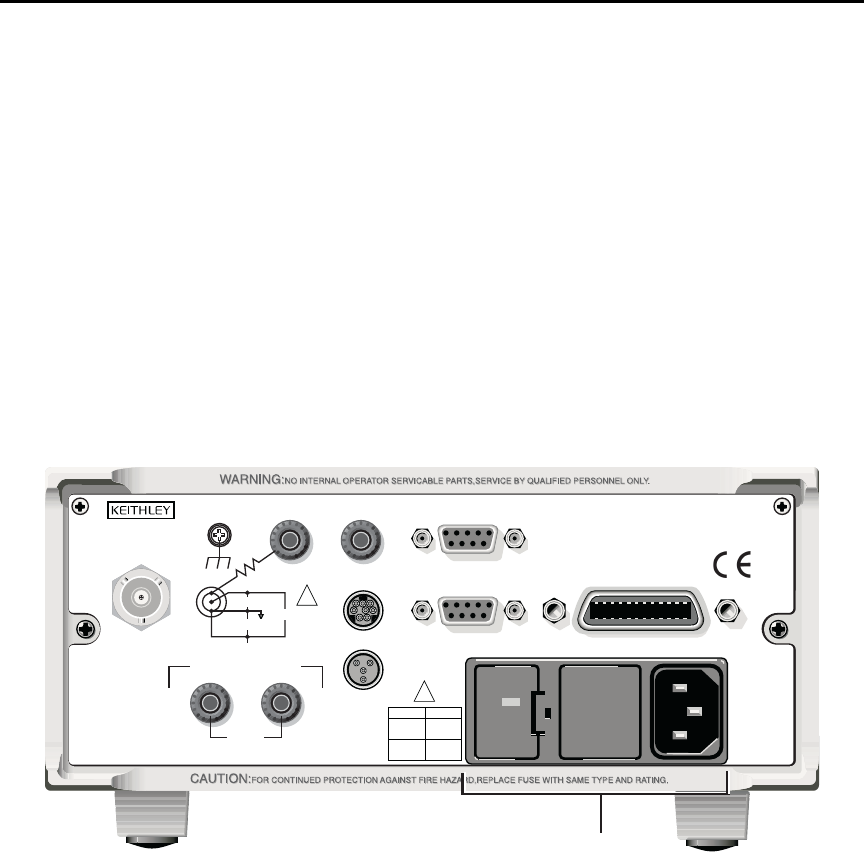
1. Check to see that the line voltage indicated in the window of the fuse holder assem-
bly (Figure 1-1) is correct for the operating voltage in your area. If not, refer to the
procedure in Section 17 for setting line voltage and fuse replacement.
`^rqflk Operating the instrument on an incorrect line voltage may cause dam-
age to the instrument, possibly voiding the warranty.
Figure 1-1
Rear panel
2. Before plugging in the power cord, make sure that the front panel power switch is
in the off (O) position.
3. Connect the female end of the supplied power cord to the AC receptacle on the rear
panel. Connect the other end of the power cord to a grounded AC outlet.
120
LINE RATING
50, 60Hz
50 VA MAX
INPUT
(CHANGE IEEE ADDRESS
WITH FRONT PANEL MENU)
IEEE-488
CAT I
TRIGGER LINK RS-232
MADE IN
U. S. A .
ANALOG OUT DIGITAL I/O
INTERLOCK
505V
MAX
V-SOURCE OUTPUT
505V PK TO CHASSIS
LO HI
!
!
FUSE LINE
400mAT
(SB)
100 VAC
120 VAC
200mAT
(SB)
220 VAC
240 VAC
505V PK
505V PK
505V PK
Power Module

1-6 Getting Started Model 6487 Reference Manual
t^okfkd The power cord supplied with the Model 6487 contains a separate
ground wire for use with grounded outlets. When proper connections
are made, instrument chassis is connected to power line ground
through the ground wire in the power cord. Failure to use a grounded
outlet may result in personal injury or death due to electric shock.
4. Turn on the instrument by pressing the front panel power switch to the on (I)
position.
Line frequency
The Model 6487 operates at line frequencies of 50 or 60Hz. When auto detect is enabled
(factory default), line frequencies are automatically sensed and set accordingly, therefore
there are no switches to set. Use the :SYSTem:LFRequency? command (query) to read the
line frequency. The factory default setting is Auto-Detect enabled.
If the power line is noisy, auto detect may not be able to lock in on a frequency. If this
occurs, set the frequency manually. This may be accomplished using the front panel (see
the following procedure) or over the bus. Refer to Table 1-1 for commands.
Front panel procedure
1. Press MENU.
2. Scroll to the LFREQ: menu item using the and RANGE keys. The present set-
ting is displayed.
3. Press the cursor key.
4. Use the and RANGE keys to scroll to the desired menu item:
AUTOXX, 50, or 60
5. Press ENTER.
klqb In the setting of AUTOXX, XX is the currently detected frequency.
SCPI programming — line frequency
Table 1-1
SCPI commands — line frequency
Command Description
SYSTem
:LFRequency <freq>
:AUTO <b>
:AUTO?
[:STATE]
[:STATE]?
:LFRequency?
SYSTem Subsystem:
Set power line frequency (in Hz) to 50 or 60.
Turn automatic frequency detection ON or OFF.
Read the present automatic detected line frequency
state (1 = on, 0 = off).
Read present line frequency setting.

Model 6487 Reference Manual Getting Started 1-7
Power-up sequence
The following power-up sequence occurs when the Model 6487 is turned on:
1. The Model 6487 performs self-tests on its EPROM and RAM with all digits and
annunciators turned on. If a failure is detected, the instrument momentarily dis-
plays an error message and the ERR annunciator turns on. Error messages are
listed in Appendix B.
klqb If a problem develops while the instrument is under warranty, return it to
Keithley Instruments Inc., for repair.
2. If the instrument passes the self-tests, the firmware revision levels are displayed.
For example:
6487 A01
3. After the firmware revision levels are displayed, the detected line frequency is
displayed.
For example:
FREQ: 60Hz
4. After the detected line frequency is displayed, information on the selected remote
interface is displayed:
a. GPIB — If the GPIB is the selected interface, the instrument will display the
selected language (SCPI, 488.1, or DDC) and primary address.
Examples:
SCPI ADDR: 22
DDC ADDR: 22
b. RS-232 — If RS-232 is the selected interface, the instrument will display the
baud rate setting. For example:
RS-232: 9600b
5. If the FACTory setup is selected as the power-on setup, the unit is placed in the
default reading mode after the communication information is displayed. If a setup
other than FACTory is selected, the configured setup will be displayed. For exam-
ple, if the USR1 setup (User Setup #1) is selected:
USING USR1
klqb To configure power-on set up:
1. Display PWR-ON: menu, press CONFIG and then SETUP.
2. Use and RANGE keys to scroll through the menu items.
3. Press ENTER to select or EXIT to quit without changing power-on setup.
1-8 Getting Started Model 6487 Reference Manual
Front panel operation
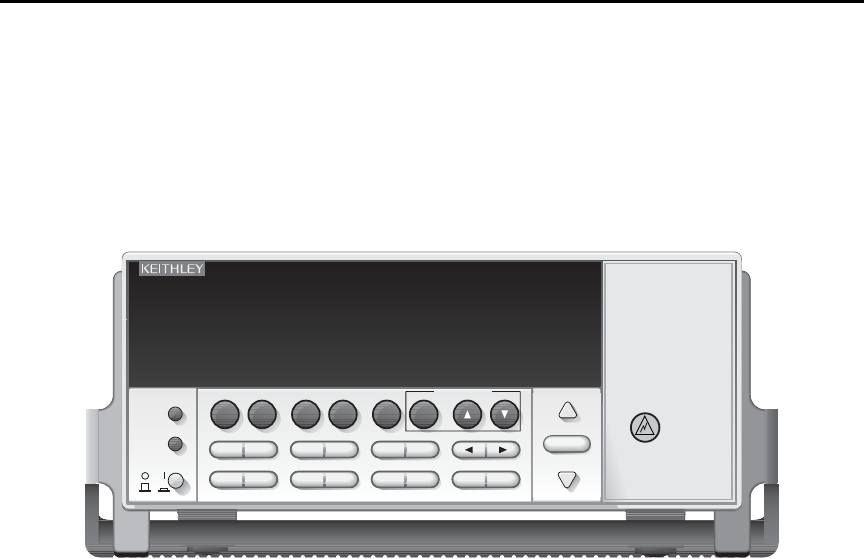
Figure 1-2 shows the front panel of the Model 6487. For a detailed description of the vari-
ous controls, displays, and indicators, see Section 1 of the Model 6487 User’s Manual.
Figure 1-2
Front panel
Status and error messages
Status and error messages are displayed momentarily. During operation and programming,
you will encounter a number of front panel messages. Typical messages are either of status
or error variety, as listed in Appendix B.
Messages, both status and error, are held in queues. For information on retrieving mes-
sages from queues, see Section 10.
Default settings
The Model 6487 can be restored to one of five setup configurations: factory default
(FACT), three user-saved (USR0, USR1, and USR2), and bus default (GPIB). As shipped
from the factory, the Model 6487 powers up to the factory default settings. Factory default
settings provide a general purpose setup for front panel operation, while the bus default
(GPIB) settings do the same for remote operation. Factory and GPIB default settings are
listed in Table 1-2.
The instrument will power up to whichever default setup was saved as the power-on setup.
klqb At the factory, the factory default setup is saved into the USR0, USR1, and USR2
setups.
6487 PICOAMMETER /VOLTAGE SOURCE
RANGE
AUTO
CONFIG/
LOCAL
MENU
POWER
RANGE
EXIT ENTER
LIMIT RATEDIGITS
STORE RECALL
I | Ω
MATH FILT ZCHK REL OPER
COMM DISPTRIG
AZERO DAMP
SAVE SETUP
V-SOURCE VOLTAGE
SOURCE
OPERATE

Model 6487 Reference Manual Getting Started 1-9
Front panel setup operation
To save a user setup
1. Configure the Model 6487 for the desired measurement application.
2. Press SAVE to access the save setup menu.
3. Use the or RANGE key to display the desired memory location
(0 = USR0, 1 = USR1, 2 = USR2).
4. Press ENTER.
To restore any setup
1. Press SETUP to display the restore menu:
2. Use the or RANGE key to display the desired setup (FACT, USR0, USR1,
USR2, or GPIB).
3. Press ENTER.
To select power-on setup
1. Press CONFIG and then SETUP to display the power-on menu.
2. Use the or RANGE key to display the desired setup (FACT, USR0, USR1,
USR2, or GPIB).
3. Press ENTER.
Remote setup operation
Saving and restoring user setups
The *SAV and *RCL commands are used to save and recall user setups. These commands
are documented in Section 11.
Restoring factory or GPIB default setups
The SYSTem:PRESet command returns Model 6487 to the factory defaults and the
*RST command returns it to the GPIB defaults. The *RST command is documented in
Section 11 and SYSTem:PRESet is covered in Section 13.
Selecting power-on setup
The SYSTem:POSetup command is used to select which setup to return to on power-up.
The SYSTem:POSetup command is documented in Section 13.

1-10 Getting Started Model 6487 Reference Manual
Table 1-2
Default settings
Setting
Factory
(:SYStem:PRESet)
GPIB
(*RST)
Arm Layer (CONFIG ARM):
Arm-In Source Event
Arm Count
Input Trigger Link Line
Source Bypass
Output Trigger Link Line
Output Trigger
IMM
INF
1
NEVER
2
Off
*
1
*
*
*
*
Buffer (STORE):
Count
Disabled
No effect
*
*
Damping (DAMP) On *
Digital Filter (FILT):
Count
Type
Off
10
Moving
*
*
*
Display Resolution (DIGITS) 5-digits *
Format byte order Swapped Normal
Function Amps *
GPIB:
Address
Language
No effect (On at factory)
No effect (22 at factory)
No effect (SCPI at factory)
*
*
*
Limit Tests:
Limit 1 and Limit 2:
HI and LO Values
Disabled
1, -1
*
*
*
Log (MATH) OFF *
Median Filter (FILT):
Rank
Off
1
*
*
MX+B (MATH):
“M” Value
“B” Value
Units
Disabled
1.0
0.0
X
*
*
*
*
M/X+B (MATH)
“M” Value
“B” Value
Units
Disabled
1.0
0.0
X
*
*
*
*
Ohms Mode Normal *
Range AUTO *
*This factory (:SYStem:PRESet) and bus (*RST) GPIB defaults are the same. Bus settings that are different
*from factory reset are as shown.

Model 6487 Reference Manual Getting Started 1-11
Rate:
NPLC
Slow
6.0 (60Hz) or 5.0 (50Hz)
*
*
Rel:
Rel Value (VAL)
Off
0.0
*
*
RS-232:
All Settings
No effect (Off at factory)
No effect
*
*
Trigger Layer (CONFIG TRIG):
Trig-In Source Event
Trigger Count
Trigger Delay
Input Trigger Link Line
Source Bypass
Output Trigger Link Line
IMM
1
0
1
NEVER
2
*
*
*
*
*
*
*
Units No effect *
Voltage Source:
Operate
Amplitude
Range
Current Limit
10V Range Interlock
Sweeps:
Start Voltage
Stop Voltage
Step Voltage
Center Voltage
Span Voltage
Delay
Off
0V
10V
25mA
Off
0V
10V
1V
5V
10V
1s
*
*
*
*
*
*
*
*
*
*
*
Zero Check Enabled *
Zero Correct Disabled *
Table 1-2 (con t . )
Default settings
Setting
Factory
(:SYStem:PRESet)
GPIB
(*RST)
*This factory (:SYStem:PRESet) and bus (*RST) GPIB defaults are the same. Bus settings that are different
*from factory reset are as shown.

1-12 Getting Started Model 6487 Reference Manual
Menus
Main menus
Many aspects of operation are configured through the main menus summarized in
Table 1-3. Refer to the section listed in the table for in-depth information. To access the
main menus, press the MENU key. Use the and RANGE keys to scroll through the menu
items and the and cursor keys to change options. Press ENTER to save any changes
made and leave the menu. Press EXIT to leave the menu without saving changes.
klqb The MENU key is used to access the menu structure. However, if in remote for
IEEE-488 bus operation (REM annunciator is lit), pressing the menu key has no
effect. Press the LOCAL key to place the unit in local operation, then press the
MENU key to access the menu items.
Table 1-3
Main MENU structure
Menu item Description Reference
CAL Provides path to the following calibration submenu items:
VOFFSET, COUNT, RUN, VSRC-RUN, DATES, UNLOCK,
LOCK, and SAVE. See reference section for verification and
calibration information.
Section 15,
Section 16
TSTAMP Timestamp format can be ABSolute or DELTa. Section 6
UNITS Readings can be displayed in ENGineering units or
SCIentific notation.
Section 6
TEST Run display or key tests. Section 17
SNUM Displays the units serial number. Section 11
LFREQ Line frequency can be manually set to 50 or 60 Hz, or
AUTOmatically set. The number after AUTO indicates present
detected frequency value.
“Line frequency,”
page 1-6

Model 6487 Reference Manual Getting Started 1-13
Configuration menus
Many keys have configuration menus that allow you to configure various Model 6487
operating modes. Table 1-4 summarizes the various configuration menus available. To
access a configuration menu, press CONFIG and then the corresponding front panel key.
Table 1-4
Configuration menus
Key* Description Reference
I | ΩConfigure normal or alternating voltage ohms modes. Section 3
MATH Set up MX + B, M/X + B, and LOG math functions. Section 5
FILT Configure median and average filters. Section 4
REL Enter relative value. Section 4
OPER Select DC or SWEEP mode, set source amplitude and current limit. Section 3
COMM Configure GPIB or RS-232 interface. Section 9
TRIG Configure trigger parameters. Section 7
LIMIT Set up and enable limit tests. Section 8
RATE Set integration rate in number of power line cycles (NPLCs). Section 4
SETUP Select power-on setup. page 9
STORE Select number of readings to store in buffer. Section 6
RANGE Set upper auto range limit. Section 4
RANGE Set lower auto range limit. Section 4
* Press CONFIG followed by indicated key to access configuration menu.

1-14 Getting Started Model 6487 Reference Manual
SCPI programming
SCPI programming information is integrated with front panel operation throughout this
manual. SCPI commands are listed in tables and additional information that pertains
exclusively to remote operation is provided after each table. The SCPI tables may refer-
ence you to other sections of this manual.
klqb Except for Section 14, most SCPI tables in this manual are abridged. That is,
they do NOT include most optional command words and query commands.
Optional command words and query commands are summarized as follows.
Optional command words
In order to be in conformance with the IEEE-488.2 and SCPI standards, the Model 6487
accepts optional command words. Any command word that is enclosed in brackets ([]) is
optional and need not be included in the program message.
Query commands
Most command words have a query form. A query command is identified by the question
mark (?) that follows the command word. A query command requests (queries) the pro-
grammed status of that command. When a query command is sent and the Model 6487 is
addressed to talk, the response message is sent to the computer.

2
Measurement Concepts
and Connections
•Connection fundamentals — Covers fundamental information about connecting
test circuits to the picoammeter.
•Basic connections to DUT — Details connecting test circuits to the picoammeter
for both current and ohms measurements.
•Using a test fixture — Discusses using general test fixtures as well as the
Model 8009 test fixture.
•Interlock — Covers interlock connections and operation.
•Analog output — Covers analog output connections and discusses considerations
when using the analog output.
•Measurement considerations — Summarizes considerations that could affect
overall measurement accuracy.
2-2 Measurement Concepts and Connections Model 6487 Reference Manual
Connection fundamentals
The following provides important fundamental information on input connections to the
Model 6487. Typical connection drawings are provided in “Basic connections to DUT,”
page 2-4. More detailed connections for specific measurements are in Section 3.
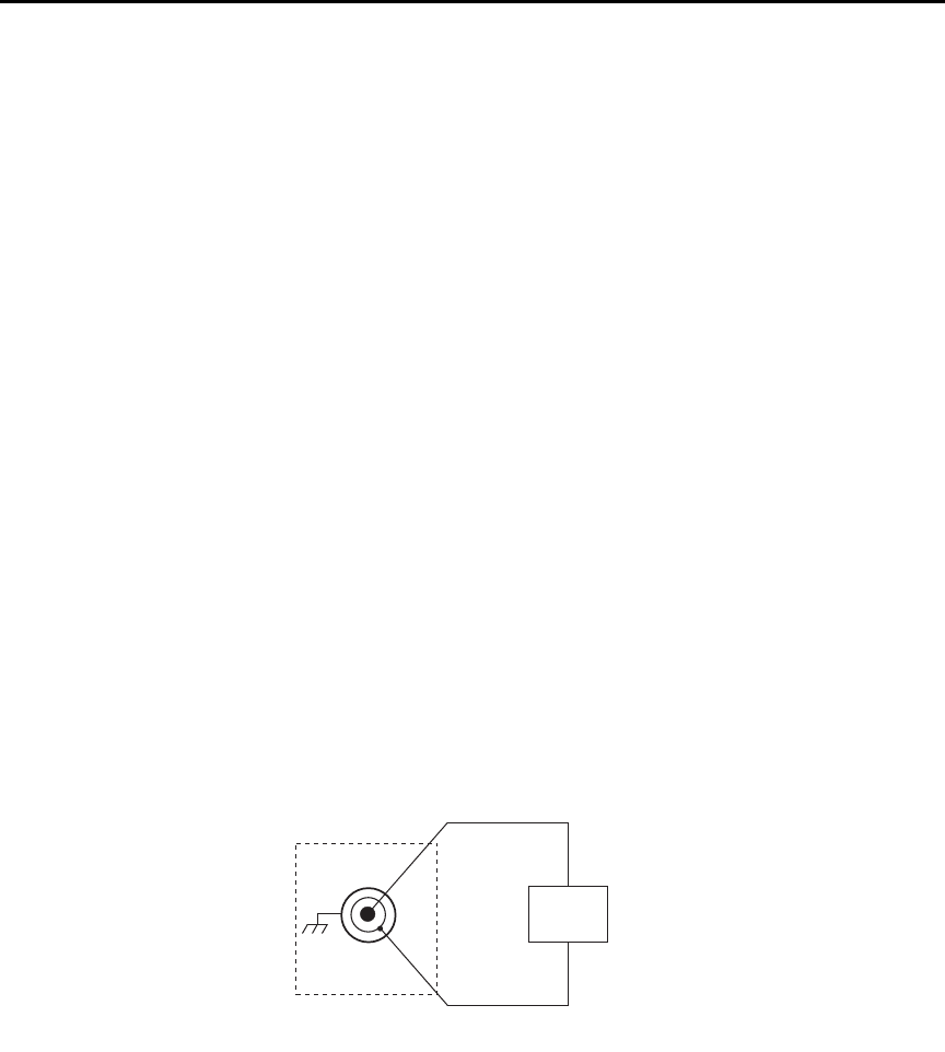
Input connector
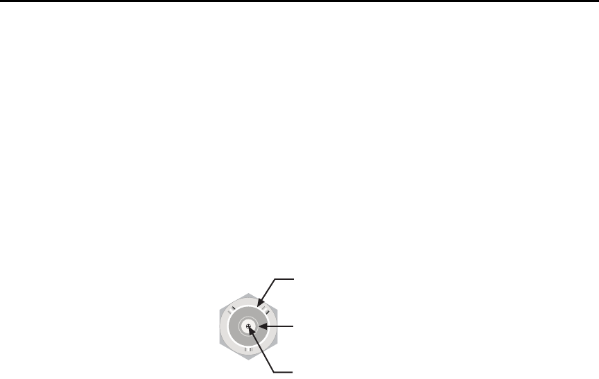
The rear panel INPUT connector is a 3-lug female triax connector (Figure 2-1). Make con-
nections using a male terminated triax cable (“Low-noise input cables,” page 2-3.)
Figure 2-1
Triax input connector
Voltage source output connectors
The rear panel V-SOURCE OUTPUT HI and LO connectors (see Figure 1-1 in Section 1)
are used to connect the voltage source to the DUT. The voltage source is primarily used for
ohms measurements but can also be used for stand-alone source operation. See “Ohms
measurement connections,” page 2-5 and “Voltage source connections,” page 2-6 for
details.
Input Low
CAT I
Chassis Ground
Input High
Model 6487 Reference Manual Measurement Concepts and Connections 2-3
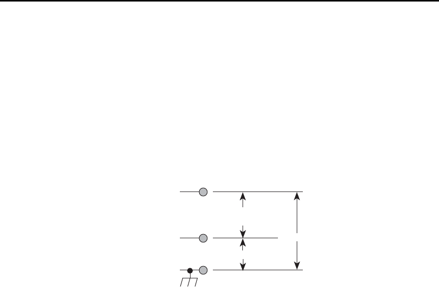
Maximum input levels
The maximum input levels to the Model 6487 are summarized in Figure 2-2.
t^okfkd The maximum safe voltage between the voltage source or ammeter
common and chassis ground (common mode voltage) is 505V peak.
Exceeding this voltage can create a shock hazard.
`^rqflk Maximum continuous input voltage is 505V peak.
Figure 2-2
Maximum input levels
Low-noise input cables
When making precision measurements, you should always use low-noise cables for
INPUT connections. The following low-noise cables are recommended for use with the
Model 6487:
Model 237-ALG-2 Triax Cable — This 2m (6.6 ft) low-noise triax cable terminated with
a 3-slot male triax connector on one end and 3 alligator clips on the other end.
Models 7078-TRX-3, 7078-TRX-10, and 7078-TRX-20 Triax Cables — These are low-
noise triax cables terminated at both ends with 3-slot male triax connectors. The -3 model
is 3 ft. (0.9m) in length, the -10 model is 10 ft. (3m) in length, and the -20 model is 20 ft.
(6m) in length.
klqb As a general rule, always use the shortest possible cable for measurements.
Input HI
Input LO
505V Peak
Chassis Ground
Max Continuous
Input = 505V Peak
505V Peak
2-4 Measurement Concepts and Connections Model 6487 Reference Manual
Voltage source test leads
When using the voltage source, the test leads must be rated for 505V minimum and should
include safety sheaths. These test leads are recommended for use with the Model 6487:
Model 8606 High Performance Probe Tip Kit — Consists of two spade lugs, two alliga-
tor clips, and two spring hook test probes. (The spade lugs and alligator clips are rated at
30V RMS, 42.4V peak; the test probes are rated at 1000V.) These components are
designed to be used with high performance test leads terminated with banana plugs, such
as the Model 8607 High Performance Banana Cables.
Model 8607 High Performance Banana Cables — Consists of two high voltage (1000V)
banana cables. The cables are terminated with banana plugs that have retractable sheaths.
t^okfkd Use only test leads with a minimum rating of 505V peak for connec-
tions to the voltage source to avoid a possible shock hazard.
Basic connections to DUT
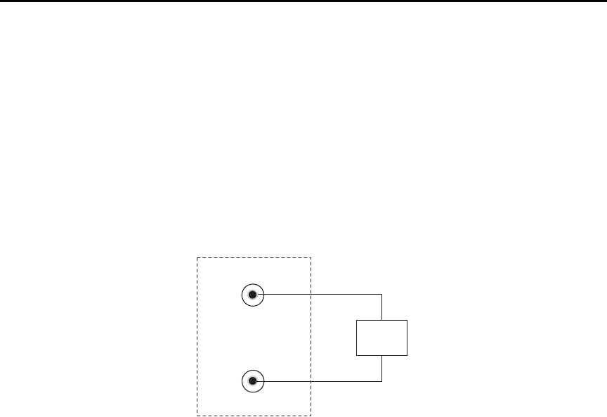
Current measurement connections
Basic connections for current measurements are shown in Figure 2-3; the DUT is the
current to be measured. Circuit high is connected to the center conductor of the input
connector and circuit low is connected to the connector’s input LO (inner shield).
Figure 2-3
Basic current measurement connections
HI
LO
DUT
INPUT*
6487
* Maximum Continuous Input: 505V Peak
Model 6487 Reference Manual Measurement Concepts and Connections 2-5
t^okfkd If it is possible for the DUT or external supply to present more than
505V to the input HI, it is imperative that the connection between
input LO and the external voltage source be sufficiently low impedance
and capable of carrying the short-circuit current of the source, in order
that the LO not exceed 505V.
`^rqflk Current limiting resistors are required for DUTs capable of forcing
voltages 505V or greater. Damage to the instrument may result if volt-
ages greater than 505V are forced on the Model 6487 INPUT HI.
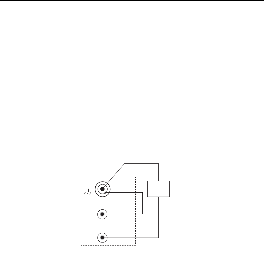
Ohms measurement connections
Basic connections for ohms measurements are shown in Figure 2-4; the DUT is the resis-
tance to be measured. Circuit high is connected to the center conductor of the INPUT con-
nector and circuit low is connected to the V-SOURCE OUTPUT HI terminal. Note that
INPUT LO and V-SOURCE OUTPUT LO are connected together externally.
Figure 2-4
Basic ohms connections
HI
LO
DUT
INPUT*
LO
HI
V-SOURCE OUTPUT
6487
* Maximum Continuous Input: 505V Peak.
2-6 Measurement Concepts and Connections Model 6487 Reference Manual
Voltage source connections
Basic connections for using the voltage source independently are shown in Figure 2-5; the
DUT is the load for the voltage source. DUT high is connected to V-SOURCE OUTPUT
HI and DUT LO is connected to V-SOURCE OUTPUT LO.
`^rqflk Do not connect external sources to the 6487 voltage source. External
sources may damage the 6487 voltage source.
Figure 2-5
Basic voltage source connections
Voltages greater than 505V
Occasionally, when making very high resistance measurements, it may be necessary to use
an external voltage source with voltages greater than the maximum tolerable input voltage
of 505V. In the event that the resistance to be measured becomes shorted or an incorrect
value of resistance is inserted in the test setup, the voltage source can permanently damage
the Model 6487. To prevent this damage, the following steps should be taken as a protec-
tion precaution.
To prevent accidental damage, a series resistor should be added to the test setup. The min-
imum value of this series resistor depends on the lowest current range to be used in the
measurement. If it will not be necessary to use the lower measurement ranges, a smaller
series resistor can be used, reducing the effect it will have on measurement accuracy. The
lowest necessary measurement range can be determined from the measurement range
accuracy specs, the applied voltage, and largest resistance desired to measure. If using
auto range, program the Model 6487 to not use its lowest ranges when autoranging.
HI
LO
DUT
LO
HI
V-Source
Output
6487

Model 6487 Reference Manual Measurement Concepts and Connections 2-7
To set the auto range lower limit from the front panel:
1. Press the CONFIG key.
2. Press the down RANGE key ( ).
3. Use the and RANGE keys to scroll through the available lower limit settings.
4. Press ENTER to save the displayed value as the lower limit. Press EXIT to return
to the previous setting.
To set the auto range lower limit over the bus, use [CURRent]:RANGe:AUTO:LLIMit
(Section 4).
Use the following formula to determine the minimum resistance for proper current limit-
ing resistors:
Lowest range to be used Rin
2nA or 20nA 11MΩ
200nA or 2μA3.5MΩ
20μA or 200μA50kΩ
2mA or 20mA 510Ω
The series limiting resistor should have a minimum power rating of:
Example: If measuring 100GΩ resistances using an external voltage source of 750V, and
thus, a lowest necessary current range of 20nA, the minimum series resistance that will
prevent damage in the case of a shorted resistor would be:
minimum Rseries = (750V - 505V)/505V×11 MΩ = 12.25MΩ
minimum power rating = (750V)2/14MΩ =41mW
klqb The 12.25MΩ in series will increase the measured resistance to 100.012GΩ
The Model 6487 can be programmed to calculate the resistance and subtract the series
resistance. Using the M/X+B function, in the example above, one would set M to 500, B to
-14e6, and the units character to “omega”. For more details on the M/X+B function, see
Section 5.
MinRseries SourceVoltage 505V–
505V
-----------------------------------------------------------
⎝⎠
⎛⎞
Rin
=
MinPowerRating SourceVoltage2Rseries
⁄=
2-8 Measurement Concepts and Connections Model 6487 Reference Manual
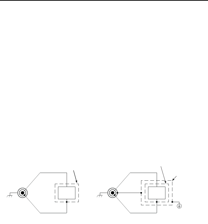
Noise and safety shields
Figure 2-6 shows typical measurement shielding. In Figure 2-6(A), a noise shield is used
to prevent unwanted signals from being induced on the picoammeter input. Amps
measurements below 1μA may benefit from effective shielding. Typically, the noise shield
is connected to picoammeter input LO. Additionally, Figure 2-6(B) shows an added safety
shield connected to earth ground and Model 6487 chassis. This type of shielding should be
used whenever hazardous voltages will be present in the test circuit.
t^okfkd The maximum safe voltage between picoammeter LO and chassis
ground (common mode voltage) is 505V peak. The Model 6487 does
not internally limit the LO-to-chassis voltage. Exceeding 505V can cre-
ate a shock hazard.
If it is possible for the DUT or external supply to present more than
505V to the input HI, it is imperative that the connection between
input LO and the external voltage source be sufficiently low impedance
and capable of carrying the short-circuit current of the source, in order
that the LO not exceed 505V.
`^rqflk The LO to chassis breakdown voltage is 505V. Exceeding this voltage
may cause damage to the instrument.
Figure 2-6
Shielding for measurements (unguarded)
Using a test fixture
Whenever possible, use a shielded low-leakage test fixture to make precision measure-
ments and for safety when high voltages (>30V) are used.
HI
LO
DUT
INPUT
B. Safety Shield
Safety
Earth
Ground
Chassis
Ground
Metal Noise Shield
Metal Safety
Shield
HI
LO
DUT
INPUT
Metal Noise Shield
A. Noise Shield
Model 6487 Reference Manual Measurement Concepts and Connections 2-9
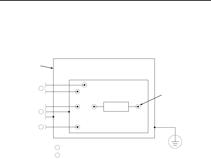
General purpose test fixture
A general purpose test fixture is shown in Figure 2-7. This test fixture will accommodate a
variety of connection requirements.
Figure 2-7
General purpose test fixture connections
Test fixture chassis
• The chassis of the test fixture should be metal so that it can function as a shield for
the DUT or test circuit.
• The test box must have a lid that closes to prevent contact with live circuitry.
• The test fixture must have a screw terminal that is used exclusively for connection
to safety earth ground.
t^okfkd To provide protection from shock hazards, the test fixture chassis must
be properly connected to safety earth ground. A grounding wire (#18
AWG or larger) must be attached securely to the test fixture at a screw
terminal designed for safety grounding. The other end of the ground
wire must be attached to a known safety earth ground.
Metal Chassis
To Voltage
Source
To 6487
Input
To 6487
COMMON Metal Guard Plate
Banana Jacks
3-Lug Female Triax Connector
Insulated
Terminal
Post (6)
Safety
Earth
Ground
A
A
A
B
B
DUT

2-10 Measurement Concepts and Connections Model 6487 Reference Manual
Guard plate
A metal guard plate will provide guarding or noise shielding for the DUT or test circuit. It
will also serve as a mounting panel for DUT or test circuits. The guard plate must be insu-
lated with appropriate spacing from the chassis of the test fixture commensurate with the
external source used.
Connectors, terminals, and internal wiring
Basic connector requirements include a female triax connector and two banana jacks. The
banana jacks provide for connection to the power supply (either the internal voltage source
or an external power supply). The banana jacks must be insulated from the chassis of the
test fixture.
DUT and test circuits are to be mounted on the guard plate using insulated terminals. To
minimize leakage, select terminals that use virgin Teflon insulators.
Inside the test fixture, use an insulated wire to connect the shell of the triax connector to
the guard plate (the guard plate will serve as a noise shield).
Handling and cleaning test fixtures
Dust, body oil, solder flux, and other contaminants on connector and terminal insulators
can significantly decrease the leakage resistance resulting in excessive leakage currents.
Contaminants on DUT and test circuit components can create a leakage path. The leakage
currents may be large enough to corrupt low-level measurements.
Handling tips:
• Do not touch the bodies of DUT or test circuit components. If you can not handle
them by their leads, use clean cotton gloves to install them in the test fixture.
• Do not touch any connector or terminal insulator.
• If installing a test circuit that is on a PC board, handle the board by the edges. Do not
touch any board traces or components.
Cleaning tips:
• Use dry nitrogen gas to clean dust off connector and terminal insulators, DUT, and
other test circuit components.
• If you have just built the test fixture, remove any solder flux using methanol along
with clean foam-tipped swabs or a clean soft brush. Clean the areas as explained in
the next tip.
• To clean contaminated areas, use methanol and clean foam-tipped swabs. After
cleaning a large area, you may want to flush the area with methanol. Blow dry with
dry nitrogen gas.
• After cleaning, the test fixture (and any other cleaned devices or test circuits)
should be allowed to dry in a 122° F (50° C) low-humidity environment for several
hours.
Model 6487 Reference Manual Measurement Concepts and Connections 2-11
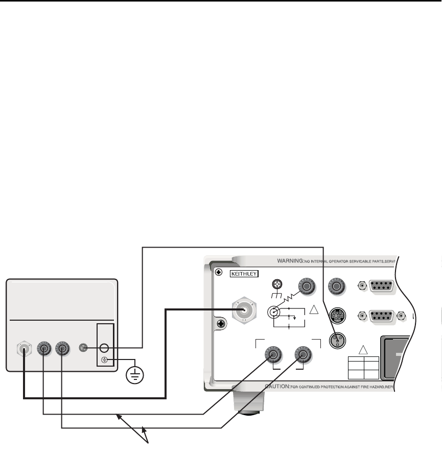
Model 8009 resistivity test fixture
This test fixture allows volume resistivity in the range from 103 to 1018¾-cm and surface
resistivity in the range from 103 to 1017¾/sq. Features include:
• A 3-lug triax connector and dual binding posts make connections to the
Model 6487 simple.
• Guarded electrodes that can accommodate samples up to 1/8” thick and 4” x 4”.
• Safety Interlock: When properly connected to the Model 6487, the V-source goes
into a high impedance state when the test fixture’s lid is opened. Note that this
could leave a charged device in the fixture.
• Screw terminal on the test fixture for safety earth ground.
For typical connections to the Model 6487, refer to Figure 2-8.
Figure 2-8
Typical connections for measurements using the Model 8009 test fixture
120
INPUT
(CHA
WITH
CAT I
TRIGGER LINK RS-232
MADE IN
U. S . A.
ANALOG OUT DIGITAL I/O
INTERLOCK
505V
MAX
V-SOURCE OUTPUT
505V PK TO CHASSIS
LO HI
!
!
FUSE LINE
400mAT
(SB)
100 VAC
120 VAC
200mAT
(SB)
220 VAC
240 VAC
505V PK
505V PK
505V PK
METER SOURCE
LID
INTERLOCK
METER SOURCE
LID
INTERLOCK
TRIAX
XXX MAX
HI/LO
MAX INPUT
XXXXV
Model 8009
6517-ILC-3 Safety Interlock Cable
7078-TRX-3 Triax Cable
8607 Banana Plug Cables
Model 6487
Warning: Connect fixture ground to
safety earth ground using
safety ground wire supplied
with the test fixture.
TRIAX
2-12 Measurement Concepts and Connections Model 6487 Reference Manual
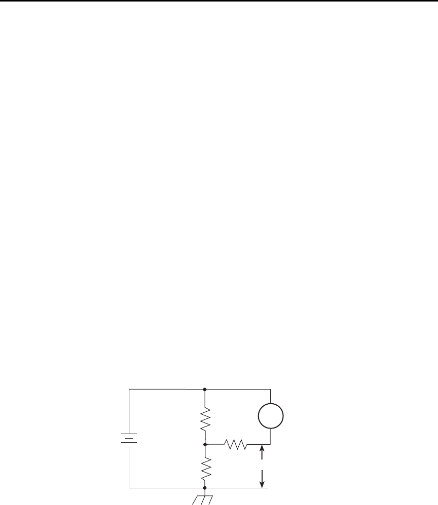
Floating measurements
Figure 2-9 shows an example where the Model 6487 floats.
t^okfkd Before attempting floating measurements, make sure to have a thor-
ough understanding of any dangers involved. Take adequate precau-
tions before connecting any instruments or power sources. Also, make
sure to read and understand information contained in “Connection
fundamentals,” page 2-2. Death or injury due to electrical shock can
result if adequate safety measures are not taken.
The maximum safe voltage between picoammeter LO and chassis
ground (common mode voltage) is 505V. The Model 6487 does not
internally limit the LO-to-chassis voltage. Exceeding 505V can create a
shock hazard.
If it is possible for the DUT or external supply to present more than
505V to the input HI, it is imperative that the connection between
input LO and the external voltage source be sufficiently low impedance
and capable of carrying the short-circuit current of the source, in order
that the LO not exceed 505V.
`^rqflk Connecting COMMON or ANALOG OUT to earth while floating the
input may damage the instrument.
The LO-to-chassis breakdown voltage is 505V. Exceeding this voltage
may cause damage to the instrument.
Figure 2-9
Floating measurements
20V
R1
20V
A
+
–
R2
6487
Picoammeter
R3
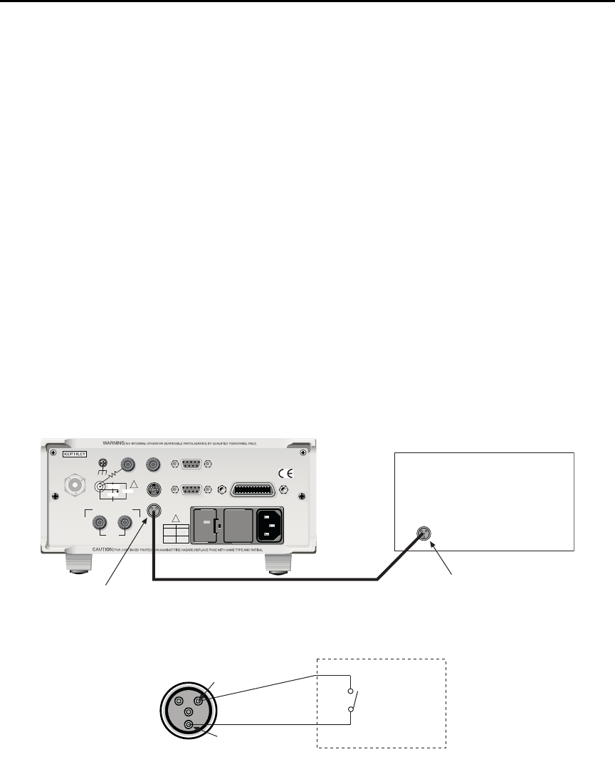
Model 6487 Reference Manual Measurement Concepts and Connections 2-13
Interlock
The Model 6487 has a built-in interlock that works in conjunction with the voltage source.
The interlock prevents the voltage source from being operated on the 50V and 500V
ranges, and optionally on the 10V range, to assure safe operation.
Interlock connections
Figure 2-10 shows interlock connections and the pin diagram of the INTERLOCK
connector. Typically, the INTERLOCK connector is connected to the same type of
connector on the test fixture. A normally open switch is connected to pins 1 and 2 of the
INTERLOCK connector as shown. When the switch is open, the interlock is asserted and
the voltage source cannot be placed in operate on the 50V or 500V voltage source ranges,
and optionally for the 10V range.
t^okfkd If the voltage source is operating when the interlock is asserted, the
voltage source will change to a high impedance state, possibly leaving
charged DUT capacitance.
Figure 2-10
Interlock connections
120
LINE RATING
50, 60Hz
50 VA MAX
INPUT
(CHANGE IEEE ADDRESS
WITH FRONT PANEL MENU)
IEEE-488
CAT I
TRIGGER LINK RS-232
MADE IN
U. S.A .
ANALOG OUT DIGITAL I/O
505V
MAX
V-SOURCE OUTPUT
505V PK TO CHASSIS
LO HI INTERLOCK
INTERLOCK
!
!
FUSE LINE
400mAT
(SB)
100 VAC
120 VAC
200mAT
(SB)
220 VAC
240 VAC
505V PK
505V PK
505V PK
Model 6487Test Fixture
Interlock
Connector
Interlock
Connector
Interlock
Cable
Pin 1
Pin 2
Test Fixture
Normally
Open
Switch
Interlock Asserted
(Output Inhibited)
with Open Switch

2-14 Measurement Concepts and Connections Model 6487 Reference Manual
Interlock operation
The interlock is always operational for the 50V and 500V voltage source ranges. To enable
the voltage source output, pins 1 and 2 of the INTERLOCK connector must be shorted
together. For the 10V range, the interlock is optional and can be controlled with interlock
programming (see below).
Interlock programming
Table 2-1 summarizes the commands associated with controlling the 10V range interlock
and determining if the interlock is asserted. For example, to enable the 10V range inter-
lock, send SOURce[1]:VOLTage:INTerlock[:STATe] ON. See Section 3 and Section 14
for information on additional voltage source commands.
Analog output
The Model 6487 has an analog output on the rear panel. The ANALOG OUT provides a
scaled, inverting ±2V output. A full-scale reading corresponds to ±2V output.
t^okfkd The maximum safe voltage between the voltage source or ammeter and
chassis ground (common mode voltage) is 505V DC. Exceeding this
voltage can create a shock hazard.
`^rqflk Connecting COMMON or ANALOG OUT to earth while floating the
input may damage the instrument.
klqb Analog outputs will be at same voltages as applied to the triax shell.
Connections for using this output are shown in Figure 2-11. For a full-scale input (i.e.
2mA on the 2mA range), the output will be -2V. Example analog outputs are listed in
Table 2-2.
Table 2-1
Interlock commands
Command Description Default
SOURce[1]
:VOLTage
:INTerlock
[:STATe] <b>
:FAIL?
SOURce1 Subsystem:
Interlock control:
Enable or disable 10V range interlock.1
Query if interlock is asserted:2
1 = asserted; source cannot be turned on.
OFF
1. Interlock is always enabled for 50V and 500V ranges and cannot be programmed.
2. Query can be used for all three source ranges: 10V, 50V, and 500V.
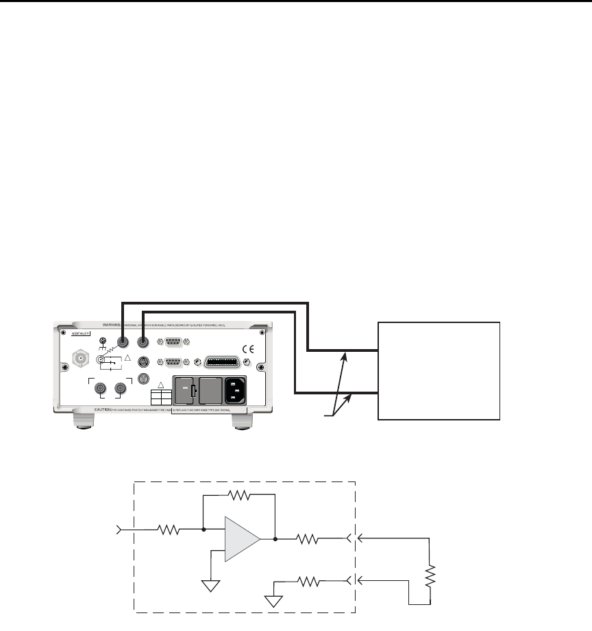
Model 6487 Reference Manual Measurement Concepts and Connections 2-15
The 2V analog output signal is not corrected during calibration. Gain errors of up to 2.5%
may appear at this output, depending on range.
The output impedance is <100¾. To minimize the effects of loading, the input impedance
of the device connected to the ANALOG OUT should be as high as possible. For example,
for a device that has an input impedance of 1M¾, the error due to loading will be approxi-
mately 0.01%. High capacitance connected to the analog output will increase the rise time.
An internal 1k¾ resistance is connected between COM and analog common for protec-
tion. The effects of this resistance on analog output accuracy are negligible.
Rel and the result of mX+b, m/X+b, or LOG have no affect on the analog output. The 2V
analog output is scaled only to the actual input.
Figure 2-11
Typical analog output connections
Test Lead
120
LINE RATING
50, 60Hz
50 VA MAX
INPUT
(CHANGE IEEE ADDRESS
WITH FRONT PANEL MENU)
IEEE-488
CAT I
TRIGGER LINK RS-232
MADE IN
U.S .A .
ANALOG OUT DIGITAL I/O
INTERLOCK
505V
MAX
V-SOURCE OUTPUT
505V PK TO CHASSIS
LO HI
!
!
FUSE LINE
400mAT
(SB)
100 VAC
120 VAC
200mAT
(SB)
220 VAC
240 VAC
505V PK
505V PK
505V PK
* 1kΩ included for protection.
Virtually 0Ω for accuracy purposes.
Model 6487 Rear Panel
RL = Input Resistance of
measuring device
Input from
Prescaler
COM
A
+
-
A
<100Ω
Measuring Device
(i.e. Chart recorder)
Analog Output
A. Connections
LO
HI
B. Equivalent Circuit
Model 6487
1kΩ∗

2-16 Measurement Concepts and Connections Model 6487 Reference Manual
Measurement considerations
There are a variety of factors to consider when making low-level measurements. These
considerations are summarized in Table 2-3 and are detailed in Appendix G of this manual
and Appendix B of the Model 6487 User’s Manual. For comprehensive information on all
measurement considerations, refer to the Low Level Measurements handbook, which is
available from Keithley Instruments. Check www.keithley.com for more details on the
handbook.
Table 2-2
Example 2V analog output values
Range Applied signal Analog output value (nominal)*
20nA 10.5nA -1.05V
2mA -1.65mA 1.65V
* Output values are within ±(2.5% + 2mV) of nominal value.
Table 2-3
Summary of measurement considerations
Considerations Description
See Appendix G for details
Input bias current Offset current of Model 6487 could affect low current measurements.
Voltage burden Offset voltage of Model 6487 could cause errors if it is high in relation to the
voltage of the measured circuit.
Noise Noise generated by source resistance and source capacitance.
See Model 6487 User’s Manual Appendix B for details
Ground loops Multiple ground points can create error signals.
Triboelectric effects Charge currents generated in a cable by friction between a conductor and the
surrounding insulator (i.e. bending a triax cable).
Piezoelectric and stored
charge effects
Currents generated by mechanical stress on certain insulating materials.
Electrochemical effects Currents generated by the formation of chemical batteries on a circuit board
caused by ionic contamination.
Humidity Reduces insulation resistance on PC boards and test connection insulators.
Light Light sensitive components must be tested in a light-free environment.
Electrostatic interference Charge induced by bringing a charged object near your test circuit.
Magnetic fields The presence of magnetic fields can generate EMF (voltage).
Electromagnetic
interference (EMI)
EMI from external sources (i.e. radio and TV transmitters) can affect sensitive
measurements.

3
Measurements and
Sourcing Voltage
•Measurement overview — Explains the basic measurement and voltage source
capabilities of Model 6487.
•Performance considerations — Covers warm-up period, voltage offset correction,
autozero, zero check, and zero correct.
•Current measurements — Provides a basic procedure to measure current.
•Ohms measurements — Covers methods to set up and use the ohms measurement
function.
•Voltage source operation — Discusses configuring and using the voltage source.
•Alternating voltage ohms mode — Discusses the alternating voltage mode that
can be used to improve accuracy and repeatability of very high resistance
measurements.

3-2 Measurements and Sourcing Voltage Model 6487 Reference Manual
Measurement overview
Current measurements
The basic current measurement capabilities of the Model 6487 are summarized in
Table 3-1. Accuracy for each measurement function and range is listed in the specifica-
tions (Appendix A).
Voltage source
The basic voltage source output capabilities of the Model 6487 are summarized in
Table 3-2. Accuracy specifications are shown in Appendix A.
Table 3-1
Basic current measurement capabilities
Range Maximum Reading 5 -Digit Resolution
2nA
20nA
200nA
2uA
20uA
200uA
2mA
20mA
±2.1nA
±21nA
±210nA
±2.1µA
±21µA
±210µA
±2.1mA
±21mA
10fA
100fA
1pA
10pA
100pA
1nA
10nA
100nA
Table 3-2
Basic voltage source output capabilities
Range Maximum Output Step Size
10V
50V
500V
±10.1V
±50.5V
±505V
200µV
1mV
10mV

Model 6487 Reference Manual Measurements and Sourcing Voltage 3-3
Performance considerations
Warm-up period
Model 6487 can be used within one minute after it is turned on. However, the instrument
should be turned on and allowed to warm up for at least one hour before use to achieve
rated accuracy. If the instrument has been exposed to extreme temperatures, allow extra
time for the internal temperature to stabilize.
Voltage offset correction
Voltage offset correction should be performed periodically to null input amplifier offsets.
To perform correction:
1. Press the MENU key, select CAL, then press ENTER.
2. The unit will display the following:
CAL: VOFFSET
3. Press ENTER. The instrument will prompt as follows:
INPUT CAP
4. Connect the triax shielding cap to the INPUT jack.
5. Press ENTER to complete voltage offset correction.
6. Press EXIT to return to normal display.
To perform correction via remote, connect the triax shielding cap to the INPUT, then send
CALibration:UNPRotected:VOFFset.
Autozero
To help maintain stability and accuracy over time and changes in temperature, the
Model 6487 periodically measures internal voltages corresponding to offsets (zero) and
amplifier gains. These measurements are used in the algorithm to calculate the reading of
the input signal. This process is known as autozeroing.
When autozero is disabled, the offset and gain measurements are not performed. This
increases measurement speed up to three times. However, the zero and gain reference
points can eventually drift resulting in inaccurate readings of the input signal. It is recom-
mended that autozero only be disabled for short periods of time.
To disable autozero from the front panel, press the AZERO button. This button toggles
autozero on and off. It can also be enabled by restoring factory or GPIB default conditions.
When autozero is enabled, a colon will be displayed after the reading.
For example:
Autozero disabled: 0.00258 nA +00.0
Autozero enabled: 0.00258 nA: +00.0
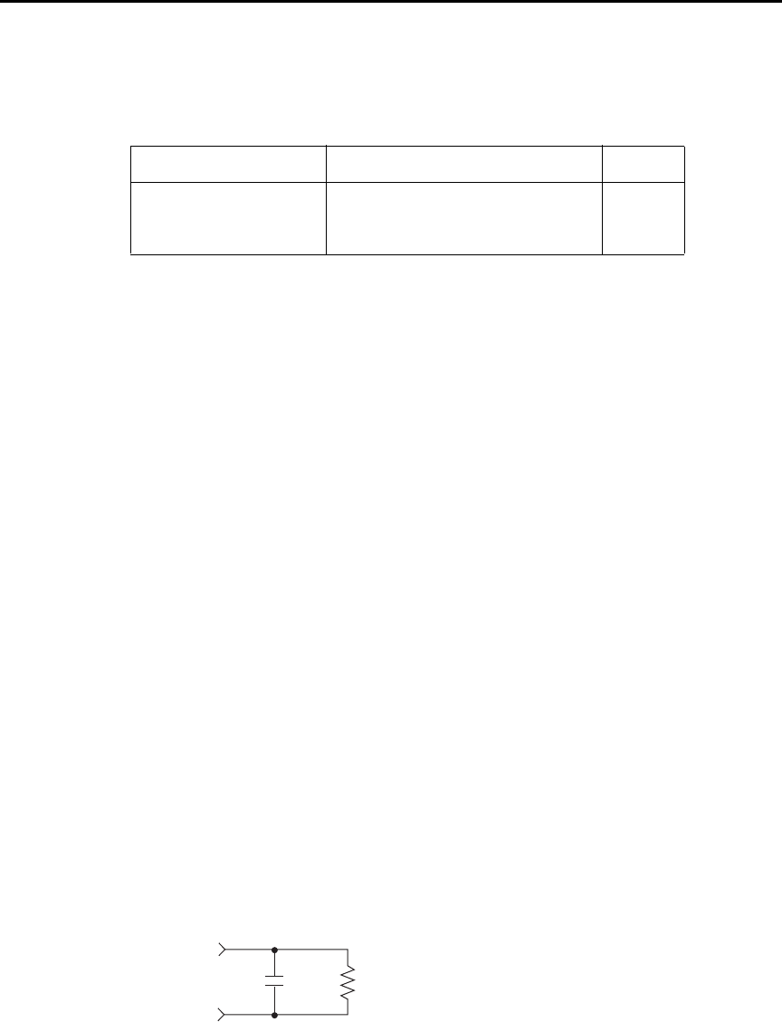
3-4 Measurements and Sourcing Voltage Model 6487 Reference Manual
SCPI programming
SYSTem:AZERo[:STATe] <b>
Sending this command over the bus does not update the display while in remote. To verify
the AZERo state, send the query. The displayed autozero state will be updated when the
instrument is placed back in local.
Programming example
The following examples enable or disable the autozero feature:
SYST:AZER ON ' Enable autozero.
SYST:AZER OFF ' Disable autozero.
SYST:AZER? ' Query autozero. 1=on, 0=off
Zero check and zero correct
Zero check
When zero check is enabled (on), the input amplifier is reconfigured to shunt the input sig-
nal to low with the input impedance (Figure 3-1).
klqb The ZCHK key toggles zero check on and off. If zero check is enabled
(“ZEROCHK” message displayed), press ZCHK to disable it.
From the front panel, enable/disable zero check by pressing the ZCHK key (ZEROCHK
message displayed). Refer to Table 3-4 for bus commands.
klqb Leave zero check enabled when connecting or disconnecting input signals.
Figure 3-1
Equivalent input impedance with zero check enabled
Table 3-3
SCPI commands — autozero
Command Description Default
SYSTem
:AZERo
[:STATe] <b>
SYSTem Subsystem:
Enable or disable autozero. ON
CIN
Input RIN
510Ω ||200nF .......... 2mA, 20mA
50kΩ || 2nF.............. 20mA, 200μA
3.5MΩ || 120pF ....... 200nA, 2μA
11MΩ || 100pF ........ 2nA, 20nA

Model 6487 Reference Manual Measurements and Sourcing Voltage 3-5
Zero correct
klqb The Model 6487 saves a single Zero Correct value (not one for each range). For
best results, acquire a new Zero Correct value after changing to the desired
range.
The Model 6487 has a zero correct feature to algebraically subtract the voltage offset term
from the measurement (to actually reduce the voltage at the input terminals, see “Voltage
offset correction,” page 3-3). Perform the following steps to algebraically zero correct the
measurement:
klqb The REL key toggles zero correct on and off if zero check is enabled
(“ZEROCCHK” message displayed). The MON annunciator turns on when zero
correct is enabled.
1. Enable zero check (“ZEROCHK” message displayed).
2. Select the range that will be used for the measurement or select the lowest range.
3. Press REL to enable zero correct (“ZCORRECT ON” message displayed briefly).
4. Press ZCHK to disable zero check.
5. Readings can now be taken from the display. The MON annunciator indicates that
the displayed reading is zero corrected.
klqb With regard to the zero correct feature:
• The Model 6487 will remain zero corrected even if it is upranged. If
downranged, re-zero the instrument.
• The Model 6487 does not have to be re-zero corrected as long as the
ambient temperature remains stable.
• Zero correction cancels the voltage offset term of the amplifier. With both
zero check and zero correct enabled, the instrument may not display a
perfectly zeroed reading.
• If the Model 6487 is operating at or near TCAL, zero correction will have
very little effect. TCAL is the internal temperature of the Model 6487 when it
was last calibrated.

3-6 Measurements and Sourcing Voltage Model 6487 Reference Manual
SCPI programming — zero check and zero correct
A) SYSTem:ZCORrect[:STATe] <b>
This method to perform zero correction is consistent with the way it is performed from the
front panel. That is, zero correction is performed while zero check is enabled. The zero
correct state can be turned on and off repeatedly without requiring a new value. If no ACQ
has been performed since the most recent reset, zero is used for the ACQ value.
B) SYSTem:ZCORrect:ACQuire
The zero correct value can only be acquired while zero check is enabled and zero correct
state is off. The internal offset measured at that moment will become the correction value.
Zero correction can then be applied and zero check disabled. This acquire method makes it
convenient if you need to re-zero the instrument often.
klqb Before sending a SYST:ZCOR:ACQ command, send a SYST:ZCOR:STAT OFF
command. Failure to do so means that you have a higher chance of getting a bad
Zero Correct value, particularly if your last Zero Correction was accomplished
on a different range.
Table 3-4
SCPI commands — zero check and zero correct
Commands Description Default Ref
SYSTem
:ZCHeck
[:STATe] <b>
:ZCORrect
[:STATe] <b>
:ACQuire
INITiate
SYSTem Subsystem:
Zero check:
Enable or disable zero check. When
Zero check is on, the reading on the
display is replaced with ZEROCHK.
Zero correct:
Enable or disable zero correct.
Acquire a new zero correct value.
Trigger a reading.
ON
OFF A
B

Model 6487 Reference Manual Measurements and Sourcing Voltage 3-7
The following command sequence uses the acquire method to zero correct the 200µA
range:
*RST ' Set instrument to known default
' conditions in one-shot trigger mode.
SYST:ZCH ON ' Enable zero check.
CURR:RANG 2E-4 ' Set instrument to 200uA range.
INIT ' Trigger one reading.
SYST:ZCOR:STAT OFF ' Turn zero correct off.
SYST:ZCOR:ACQ ' Acquire zero correct value.
SYST:ZCH OFF ' Disable zero check.
SYST:ZCOR ON ' Perform zero correction.
The INITiate command in the above sequence is used to trigger a reading. This reading is
the offset that is acquired as the zero correct value. See Section 7 for more information on
INITiate.
klqb Sending the :ACQuire command while zero check is disabled will result in an
error. The command will not be executed.
Current measurements
Procedure
t^okfkd The maximum safe voltage between picoammeter LO and chassis
ground (common mode voltage) is 505V. The Model 6487 does not
internally limit the LO to chassis voltage. Exceeding 505V can create a
shock hazard.
If it is possible for the DUT or external supply to present more than
505V to the input HI, it is imperative that the connection between
input LO and the external voltage source be sufficiently low impedance
and capable of carrying the short-circuit current of the source, in order
that the LO not exceed 505V.
`^rqflk The LO to chassis breakdown voltage is 505V. Exceeding this voltage
may cause damage to the instrument.
The maximum input voltage and current to Model 6487 is 505V peak
and 21mA. Exceeding either of these values may cause damage to the
instrument that is not covered by the warranty.
To achieve optimum precision for low-level current measurements, input bias current and
voltage burden can be minimized by performing the offset correction procedure. Informa-
tion about these offsets are provided in “Measurement considerations” on page -2.

3-8 Measurements and Sourcing Voltage Model 6487 Reference Manual
klqb After overloading with high voltage, it may take several minutes for the input
current to drop to within specified limits. Input current can be verified by plac-
ing the protection cap on the input connector and then use the ground link to
connect COMMON and CHASSIS ground. With the instrument on the 2nA range
and zero check disabled, allow the reading to settle until the input bias current is
within specifications. The specifications for input bias current are included in
the offset portion of the accuracy specification listed in Appendix A.
Perform the following steps to measure current:
Step 1. Select current function
Press the I | ¾ key to make sure the current function is selected.
Step 2. Enable zero check
Zero check should always be enabled before making connection changes. The ZCHK key
toggles zero check on and off. When on, the “ZEROCHK” message is displayed.
Step 3. Perform zero correction
To achieve optimum accuracy for low current measurements, it is recommended that you
zero correct the picoammeter:
• Select the 2nA range (which is the lowest range).
• Press the REL key so that the MON annunciator is on.
Step 4. Select a manual measurement range or enable auto range
Use the RANGE and keys to select a manual measurement range or press AUTO to
enable auto range. With auto range enabled, the instrument will automatically go to the
most sensitive range to make the measurement. See Section 4 for details on range.
Step 5. Connect the current to be measured to the picoammeter
Basic connections for measurements are shown in Figure 3-2.
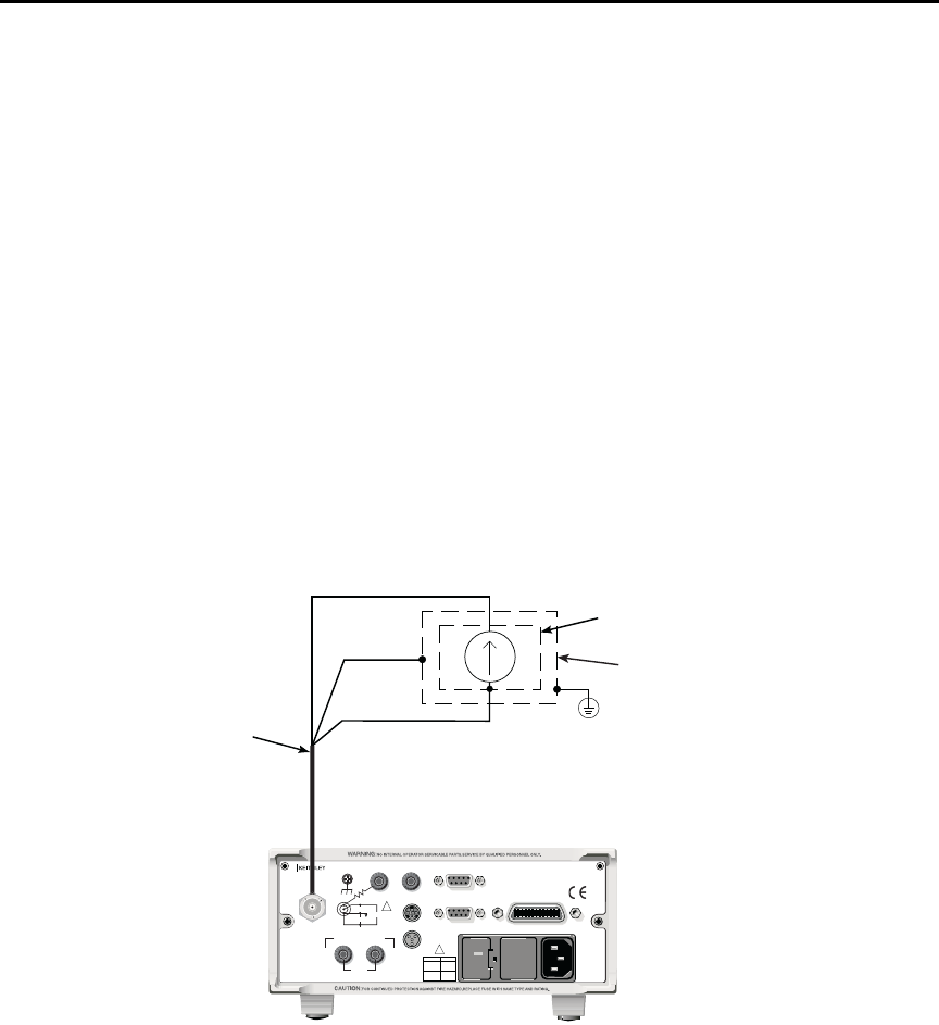
Model 6487 Reference Manual Measurements and Sourcing Voltage 3-9
t^okfkd A safety shield is advisable whenever floating measurements are being
made (see “Floating measurements,” page 2-12). Connections for the
safety shield are shown in Figure 3-2. The metal safety shield must
completely surround the noise shield or floating test circuit and it must
be connected to safety earth ground using #18 AWG or larger wire.
klqb When not making floating measurements, it is recommended that you ground
measurement LO at only one place in the circuit, such as with the ground link
connection on the rear panel of the Model 6487.
Fundamental information on making connections to the picoammeter input is
provided in Section 2.
Step 6. Disable zero check and take a reading from the display
If the readings are noisy, you may want to use filtering to reduce noise. Use filtering if the
noise is caused by a noisy input signal. Filtering is covered in Section 4.
Figure 3-2
Connections for amps
Black (LO)
Red (HI)
237-ALG-2
Cable
Metal Noise Shield
Metal Safety Shield
Safety
Earth
Ground
Green
(Chassis)
Model 6487
120
LINE RATING
50, 60Hz
50 VA MAX
INPUT
(CHANGE IEEE ADDRESS
WITH FRONT PANEL MENU)
IEEE-488
CAT I
TRIGGER LINK RS-232
MADE IN
U.S .A .
ANALOG OUT DIGITAL I/O
INTERLOCK
505V
MAX
V-SOURCE OUTPUT
505V PK TO CHASSIS
LO HI
!
!
FUSE LINE
400mAT
(SB)
100 VAC
120 VAC
200mAT
(SB)
220 VAC
240 VAC
505V PK
505V PK
505V PK

3-10 Measurements and Sourcing Voltage Model 6487 Reference Manual
SCPI programming
A) SENSe:DATA?
This command does not trigger a reading. It simply returns the last “raw” reading string. It
will not return the result of any instrument calculation. The reading reflects what is
applied to the input.
While Model 6487 is busy performing measurements, the :DATA? command will not
return the reading string until the instrument finishes and goes into the idle state.
klqb The format that the reading string is returned in is set by commands in
Section 13.
If there is no reading available when :DATA? is sent, an error (-230) will occur.
B) FUNCtion ‘CURRent’
Use this command to select the current function instead of the ohms function.
C) INITiate
To return a fresh (new) reading, you can send the INITiate command to trigger one or
more readings before sending :DATA?. Details on INITiate are provided in Section 7.
D) READ?
The READ? command can be used to return “fresh” readings. This command triggers and
returns the readings. See Section 12 for details.
Table 3-5
SCPI commands — amps function
Commands Description Default Ref
[SENSe]
:DATA?
:FUNCtion ‘CURRent’
INITiate
READ?
SENSe Subystem:
Return latest “raw” reading.
Select current function.
Trigger one or more readings.
Trigger and return reading(s).
CURR
A
B
C
D

Model 6487 Reference Manual Measurements and Sourcing Voltage 3-11
Programming example
The following command sequence will perform one zero corrected amps measurement:
*RST ' Return 6487 to RST defaults.
FUNC ‘CURR’ ' Select current function.
SYST:ZCH ON ' Enable zero check.
CURR:RANG 2e-9 ' Select the 2nA range.
INIT ' Trigger reading to be used as zero
' correction.
SYST:ZCOR:STAT OFF ' Turn zero correct off.
SYST:ZCOR:ACQ ' Use last reading taken as zero
' correct value.
SYST:ZCOR ON ' Perform zero correction.
CURR:RANG:AUTO ON ' Enable auto range.
SYST:ZCH OFF ' Disable zero check.
READ? ' Trigger and return one reading.
Ohms measurements
Overview
To measure ohms with the Model 6487, you must set up the voltage source to the desired
range, value, and current limit (see “Voltage source operation,” page 3-15), choose an
appropriate current measurement range (or use auto range), and enable the ohms function.
With the ohms function enabled, the Model 6487 calculates the measured resistance from
the voltage source value and the measured current: R = V/I. When setting up the voltage
source, choose as high a voltage value as possible for maximum current, keeping in mind
such factors as the power dissipation and voltage coefficient of the resistance being tested.
klqb Ohms measurements can be made using either the DC or alternating voltage
modes. See “Alternating voltage ohms mode,” page 3-21 for information on the
alternating voltage mode.

3-12 Measurements and Sourcing Voltage Model 6487 Reference Manual
Procedure
t^okfkd Always turn off the Model 6487 power before changing voltage source
connections to avoid a possible shock hazard.
Perform the following steps to measure resistance:
Step 1. Set up voltage source
Press either of the V-SOURCE adjustment keys, then use a manual RANGE key to set the
voltage source range. Set the voltage and current limit to the desired values using the cur-
sor and RANGE keys.
Step 2. Perform zero correction
To achieve optimum accuracy for high resistance measurements, it is recommended that
you zero correct the picoammeter before enabling the ohms function. To do so, make sure
that zero check and the 2nA range are selected, then press the REL key to perform zero
correction. The MON annunciator will be on when zero correct is enabled.
Step 3. Select a manual current range or enable auto range
Use the manual RANGE keys to select a manual measurement range or press AUTO to
enable auto range. When using manual ranging, choose an appropriate value based on the
voltage source setting and the expected measured resistance: I = V/R.
Step 4. Connect the resistance to be measured to the picoammeter
Basic connections for ohms measurements are shown in Figure 3-3. Note that both the
picoammeter INPUT and the V-SOURCE OUTPUT jacks are connected to the resistance
under test.
t^okfkd A safety shield is advisable whenever measurements are being made
with voltages over 30V DC. Connections for the safety shield are
shown in Figure 3-3. The metal safety shield must completely surround
the noise shield or floating test circuit and it must be connected to
safety earth ground using #18 AWG or larger wire.
Step 5. Select ohms function
Press the I|¾ key to make sure the ohms function is selected.
Step 6. Turn on voltage source
Press the OPER key to turn on the voltage source output. The VOLTAGE SOURCE
OPERATE indicator will turn on.
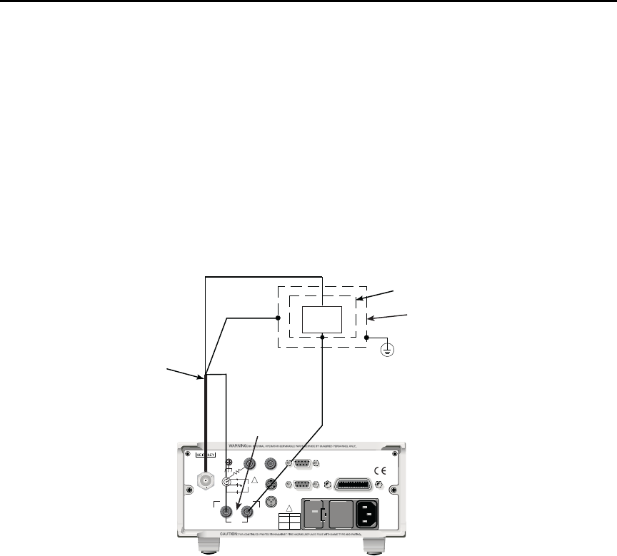
Model 6487 Reference Manual Measurements and Sourcing Voltage 3-13
Step 7. Disable zero check and take a reading from the display
Press ZCHK to disable zero check and display readings. If the readings are noisy, use fil-
tering to reduce noise.
klqb For any ohms measurements, the ohms reading is invalid and unknown if the
voltage source is in compliance. Therefore, a value of -9.9e+36 will be returned
over the GPIB and the message I-LIMIT will be displayed on the front panel for
both normal readings and buffer recall readings for any ohms readings where
the voltage source went into compliance.
Figure 3-3
Connections for ohms measurements
Black (LO)
Red (HI)
237-ALG-2
Cable
Metal Noise Shield
Metal Safety Shield
Safety
Earth
Ground
Green
(Chassis)DUT
DUT = Device Under Test.
Model 6487
V-SOURCE
OUTPUT
120
LINE RATING
50, 60Hz
50 VA MAX
INPUT
(CHANGE IEEE ADDRESS
WITH FRONT PANEL MENU)
IEEE-488
CAT I
TRIGGER LINK RS-232
MADE IN
U.S .A .
ANALOG OUT DIGITAL I/O
INTERLOCK
505V
MAX
V-SOURCE OUTPUT
505V PK TO CHASSIS
LO HI
!
!
FUSE LINE
400mAT
(SB)
100 VAC
120 VAC
200mAT
(SB)
220 VAC
240 VAC
505V PK
505V PK
505V PK

3-14 Measurements and Sourcing Voltage Model 6487 Reference Manual
SCPI programming — ohms measurements
A) [SENSe[1]][:CURRent[:DC]]:OHMS <b>
Use this command to turn the ohms function on or off. When the ohms function is enabled,
the Model 6487 calculates the reading from the measured current and the voltage source
setting: R = V/I. Additional OHMS commands control the alternate voltage ohms mode as
described in “Alternating voltage ohms mode,” page 3-21.
B) SOURce[1]:VOLTage
These commands select the voltage source range, set the source level and current limit,
and turn the source output on and off. Additional voltage source commands control volt-
age sweeps (see Section 6).
Table 3-6
SCPI commands — basic ohms measurements
Commands* Description Default Ref
Measurements:
[SENSe[1]]
[:CURRent[:DC]]
:OHMS <b>
:RANGe <n>
:AUTO <b>
Sourcing voltage:
SOURce[1]
:VOLTage
[:LEVel]
[:IMMediate]
[:AMPLitude] <NRf>
:RANGe <NRf>
:ILIMit <NRf>
:STATe <b>
READ?
SENSe[1] subsystem:
Enable or disable ohms function.
Select manual current range (-0.021 to 0.021A).
Enable or disable auto current range.
SOURce[1] subsystem:
Voltage source commands:
Set output voltage (-505V to +505V).
Set voltage source range (10, 50, or 500).
Set current limit (25μA, 250μA, 2.5mA, or 25mA).
Turn voltage source output on or off.
Trigger and return reading(s).
OFF
ON
0V
10V
25mA
OFF
A
B
* Zero correct and zero check commands not included. See Table 3-4.

Model 6487 Reference Manual Measurements and Sourcing Voltage 3-15
Programming example — ohms measurements
The following command sequence will perform one zero-corrected resistance
measurement:
*RST ' Return 6487 to GPIB defaults.
FORM:ELEM READ,UNIT ' Measurement, units elements only.
SYST:ZCH ON ' Enable zero check.
RANG 2e-9 ' Select the 2nA range.
INIT ' Trigger reading to be used as zero
' correction.
SYST:ZCOR:ACQ ' Use last reading taken as zero
' correct value.
SYST:ZCOR ON ' Perform zero correction.
RANG:AUTO ON ' Enable auto current range.
SOUR:VOLT:RANG 10 ' Select 10V source range.
SOUR:VOLT 10 ' Set voltage source output to 10V.
SOUR:VOLT:ILIM 2.5e-3 ' Set current limit to 2.5mA.
SENS:OHMS ON ' Enable ohms function.
SOUR:VOLT:STAT ON ' Put voltage source in operate.
SYST:ZCH OFF ' Disable zero check.
READ? ' Trigger and return one reading.
Voltage source operation
Voltage source edit keys
The V-SOURCE and keys will operate in the same manner as the RANGE and keys if
they are not being used to change the voltage source values. The AUTO key acts as a
shortcut to set the V-SOURCE to 0V.
Configuring the voltage source
To set up the voltage source:
1. Press CONFIG then OPER.
2. Select either the DC mode for normal operation or SWEEP for voltage sweeps (see
Section 6 for details on sweeps). Press ENTER.
3. After the mode is selected, the reading disappears and is replaced with a full-
resolution value of the voltage source with the left-most position highlighted for
editing.
4. Use the RANGE and arrows to change the voltage source range and indicate the
range selected (10V, 50V, or 500V).
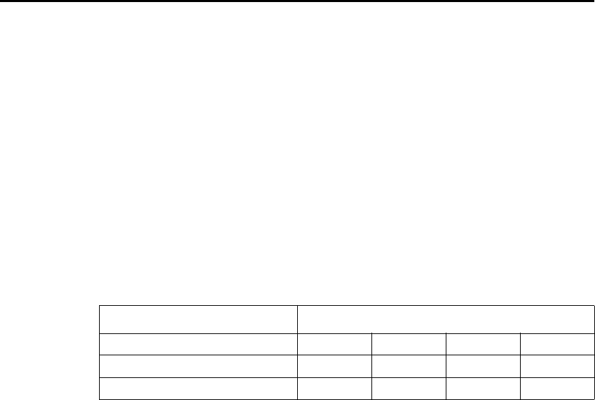
3-16 Measurements and Sourcing Voltage Model 6487 Reference Manual
5. Enter the desired voltage source value, then press ENTER. Voltage values are
changed immediately from this configuration by pressing the arrow keys. The and
arrows are used to select the digit being edited and the V-SOURCE and keys
change the value. The digits will not increment beyond the limit for the present
source range with subsequent source arrow key presses.
klqb The V-SOURCE and keys will operate in the same manner as the RANGE
and keys if they are not being used to change the voltage source values.
6. After the voltage value and range is selected, press ENTER to advance to the cur-
rent limit display and select the desired current limit. The current limit display
offers different choices depending on the source range (Table 3-7). Pressing
ENTER or EXIT from this display returns you to the normal readings display.
Sourcing voltage
t^okfkd Always turn off the Model 6487 power before changing voltage source
connections to avoid a possible shock hazard.
Perform the following steps to source voltage:
Step 1. Set up voltage source
Press either of the V-SOURCE adjustment keys, then use a manual RANGE key to set the
voltage source range. Set the voltage and current limit to the desired values using the cur-
sor and RANGE keys.
Table 3-7
Voltage source current limits
Source Range: Selectable Current Limit
10.0000V Range 25µA 250µA 2.5mA 25mA
50.000V Range 25µA 250µA 2.5mA
500.00V Range 25µA 250µA 2.5mA
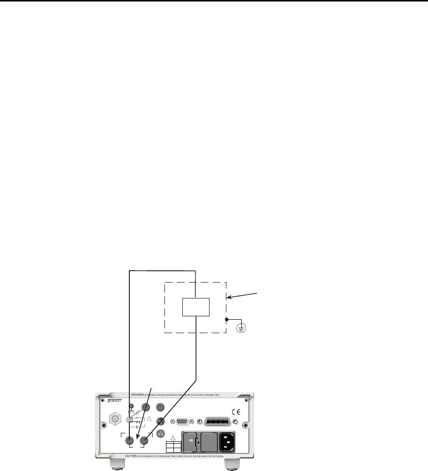
Model 6487 Reference Manual Measurements and Sourcing Voltage 3-17
Step 2. Connect the load to the source output
Basic connections for sourcing voltage are shown in Figure 3-4.
t^okfkd A safety shield is advisable whenever measurements are being made
with voltages over 30V DC. Connections for the safety shield are
shown in Figure 3-4. The metal safety shield must completely surround
the noise shield or floating test circuit and it must be connected to
safety earth ground using #18 AWG or larger wire.
Step 3. Turn on voltage source
Press the OPER key to turn on the voltage source output. The VOLTAGE SOURCE
OPERATE indicator will turn on.
`^rqflk Do not connect external sources to the 6487 voltage source. External
sources may damage the 6487 voltage source.
Figure 3-4
Connections for sourcing voltage
Metal Safety Shield
Safety
Earth
Ground
Model 6487
V-SOURCE
OUTPUT
Load
120
LINE RATING
50, 60Hz
50 VA MAX
INPUT
(CHANGE IEEE ADDRESS
WITH FRONT PANEL MENU)
IEEE-488
CAT I
TRIGGER LINK RS-232
MADE IN
U.S .A .
ANALOG OUT DIGITAL I/O
INTERLOCK
505V
MAX
V-SOURCE OUTPUT
505V PK TO CHASSIS
LO HI
!
!
FUSE LINE
400mAT
(SB)
100 VAC
120 VAC
200mAT
(SB)
220 VAC
240 VAC
505V PK
505V PK
505V PK

3-18 Measurements and Sourcing Voltage Model 6487 Reference Manual
Operate considerations
OPER (operate) key
The OPER (operate) key will function to turn the voltage source off, even if the instrument
is operating under remote control (REM annunciator on), assuming that the LLO (Local
Lockout) function has not been employed. While in remote, the OPER key will only turn
the source off. To turn it on, the Model 6487 must be in local (see Section 9).
Voltage source off state
The voltage source is not in a high-impedance state when it is turned off. Rather, it is in a
state that acts just like the voltage source was programmed to 0V on the selected range. It
will enter this state on power-up after the VOLTAGE SOURCE OPERATE light blinks. In
contrast, the safety interlock will cause the voltage source to go into a high-impedance
state instead of 0V output and the source will stay in the high-impedance state until the
operate state is changed to on. The exception is the 10V range where the interlock is
optional. The OPERATE light and front panel display do not indicate the difference
between 0V output and high-impedance output caused by an open interlock. The interlock
status is available by query via remote (see Table 3-8).
Compliance indication
At any time, it is possible that the voltage source will go into compliance (current limit
reached). Should this situation occur, the OCOMP annunciator (Output Compliance) will
flash and the displayed voltage value for readings of less than 6 digits will alternate
between showing the value and displaying “CMPL”. If you are in a menu where the volt-
age source value is not shown on the right-most four characters of the display, only the
flashing OCOMP annunciator will be shown.
Open interlock indication
If the interlock is asserted (opened) while the unit is on 50 or 500V range, the voltage
source will also technically be in compliance. However, there will be no indication of that
status over the front panel or in the status registers (Section 10). The open interlock takes
precedence.

Model 6487 Reference Manual Measurements and Sourcing Voltage 3-19
SCPI commands — voltage source
A) [:LEVel] [:IMMediate] [:AMPLitude] <NRf>
Use this command to set the voltage source output level from -505V to 505V. Note that if
the STATe is on, then the voltage will change as soon as this command is processed. Send-
ing a value outside of the present range will generate Error -222 “Parameter Out of
Range”. To go to a higher value, you must first change the source range.
B) RANGe <NRf>
This command selects the range: 10V, 50V, or 500V. If you choose a range lower than the
present level, the level will be changed to the maximum value for that range. The range
selected will be the one that best accommodates the value sent. A value of 10.01, for
example, will select the 50V range.
C) ILIMit <NRf>
Use this command to set the voltage source current limit to 25μA, 250μA, 2.5mA, or
25mA. Note, however, that the maximum current limit for the 50V and 500V ranges is
2.5mA.
Table 3-8
SCPI commands — voltage source
Commands Description Default Ref
SOURce[1]
:VOLTage
[:LEVel]
[:IMMediate]
[:AMPLitude] <NRf>
SOURce[1] subsystem:
Voltage source commands:
Set output voltage level (-505V to +505V).
:RANGe <NRf>
:ILIMit <NRf>
:STATe <b>
:INTerlock <b>
:FAIL?
Set voltage source range (10, 50, or 500V).
Set current limit (25μA, 250μA, 2.5mA, or 25mA).1
Turn voltage source output on or off.
Enable or disable interlock for 10V range.2
Query interlock state (1 = asserted, and source
output cannot be turned on).
0V
10V
25mA
OFF
OFF
A
B
C
D
E
1. 25mA not available for 50V and 500V ranges.
2. See Section 2 for interlock operation.

3-20 Measurements and Sourcing Voltage Model 6487 Reference Manual
D) STATe <b>
This command turns the voltage source output on or off. However, the voltage source out-
put cannot be turned on if the interlock is asserted. When the voltage source is turned off,
the source will be a low-impedance 0V source (limited to approximately 1mA) and will
discharge small capacitances (DUT, cables, etc.).
E) INTerlock <b>
These commands control the interlock for the 10V range and query whether or not the
interlock is asserted. Note that for the 50 and 500V ranges, this setting is ignored since the
interlock is directly tied to the hardware and cannot be bypassed. Therefore, this command
has no effect when the source is on any range other than the 10V range. Attempting to turn
off the interlock state while on the 50 or 500V ranges will generate a -221 “Settings Con-
flict” error. Upranging from the 10V range will always cause the interlock to be enabled.
When you range back down to the 10V range, the interlock state will be reset to what it
was when you left the 10V range. See Section 2 for more interlock information.
t^okfkd When the interlock is asserted, the voltage source will change to a
high-impedance state. This situation could leave any connected device
charged to the last programmed voltage.
Programming example — voltage
The following command sequence will output 5V on the 10V range with a 2.5mA limit:
*RST ' Return 6487 to GPIB defaults.
SOUR:VOLT:RANG 10 ' Select 10V source range.
SOUR:VOLT 5 ' Set voltage source output to 5.
SOUR:VOLT:ILIM 2.5e-3 ' Set current limit to 2.5mA.
SOUR:VOLT:STAT ON ' Put voltage source in operate.

Model 6487 Reference Manual Measurements and Sourcing Voltage 3-21
Alternating voltage ohms mode
Overview
Ohms can be measured in one of two ways: DC (normal) or alternating voltage (A-V). The
alternating voltage ohms method is especially useful when the resistance or device being
measured exhibits high background currents or high noise currents. These are typical
problems seen when measuring high resistances, devices with moderate to high capaci-
tance, or when adequate shielding is unavailable. By measuring current differences caused
by a change in applied voltage, the alternating voltage method greatly reduces effects of
currents that are not caused by the applied voltage, i.e., not resistive current. The A-V
mode consists of switching the source level between 0V and a user-selected value
(Figure 3-5). During each phase, one or several readings are collected into separate buffers
for that phase, designated V-High and V-Zero. A third buffer is created by subtracting the
n-th reading of the V-Zero buffer from its counterpart in the V-High buffer and storing
these differences in a buffer designated V-Delta. Both from the front panel and via remote,
A-V ohms readings always come from the V-Delta buffer.
The purpose of the alternating voltage ohms mode is to improve the accuracy and
repeatability of very high resistance measurements, which are subject to errors from
background currents in the test setup. By taking two current measurements, one at a
specific step voltage and a second at 0V, these background currents can be largely nulled
out and the resistance calculated from the source voltage and measured current is closer to
the actual DUT resistance. Data stored in the buffer can also be averaged to improve
repeatability.
Key test parameters for A-V ohms include the step voltage, measurement time, and the
number of test cycles. The optimum step voltage value depends on the measured resis-
tance and desired current. The measurement time must be carefully chosen to assure ade-
quate settling during both the step-voltage (V-High) and 0V (V-Zero) phases of the
measurement. The number of cycles to measure and average is often a compromise
between improvement in repeatability and the overall measurement time.
Figure 3-5
Alternating voltage ohms
V-High
V-Zero (0V)
One Cycle
Time Time
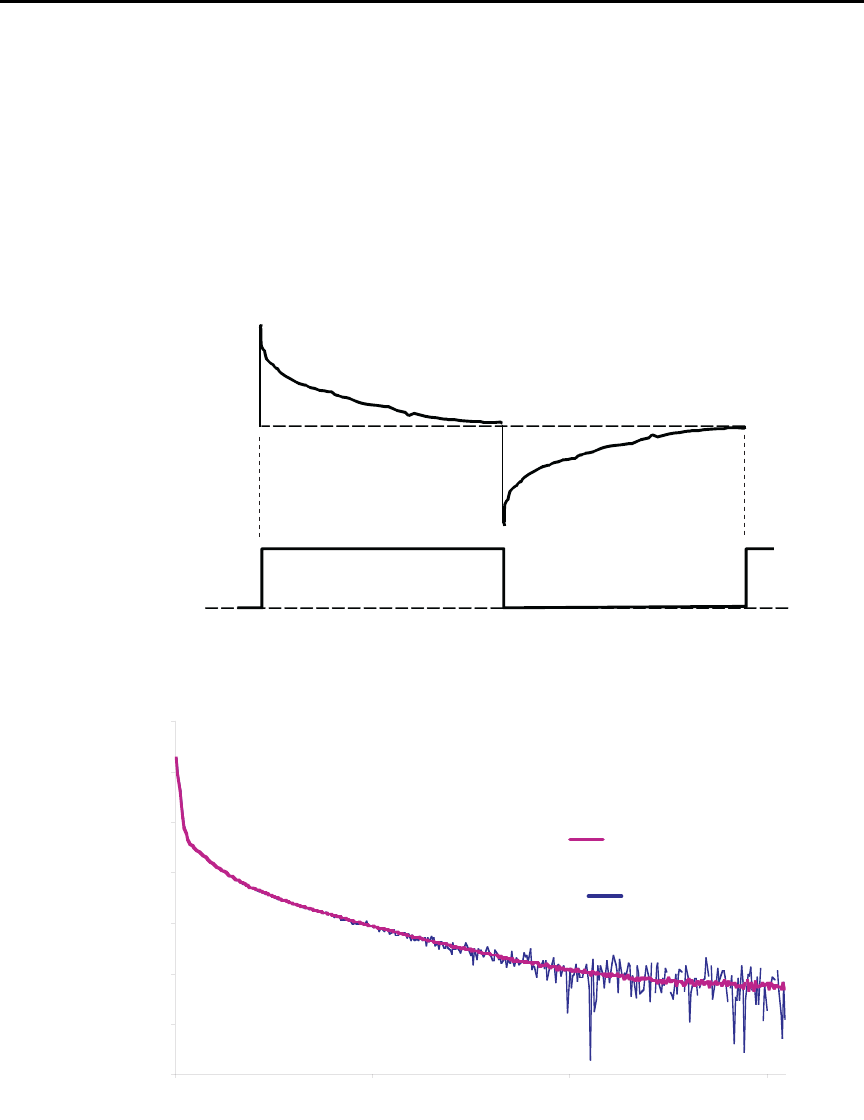
3-22 Measurements and Sourcing Voltage Model 6487 Reference Manual
Figure 3-6 shows a comparison of the A-V voltage and the resulting current. When the
voltage first makes a transition from low to high or high to low, the current initially
increases to maximum and then decays to its quiescent value. The decay period, of course,
depends on the RC time constant (τ) of the circuit being tested.
Figure 3-7 demonstrates the clear advantages of A-V ohms. The decaying curve shows
how current decays time without averaging, while the steady-steady current plot at the bot-
tom shows substantially improved results due to averaging of the A-V readings.
Figure 3-6
A-V voltage and current
Figure 3-7
Averaged A-V current
Current
Voltage
Without
Averaging
Current
(nA)
10
3
Time (s)
05
6
1
15
12
With Averaging
15
9
18
0
Model 6487 Reference Manual Measurements and Sourcing Voltage 3-23
Storing A-V ohms readings
Follow the steps below to setup and use the A-V ohms mode. Refer to Table 3-9 for A-V
ohms configuration menu items.
klqb The following procedure assumes the Model 6487 is connected to the DUT. See
Figure 3-3 and Section 2 for details on ohms connections.
klqb Before starting the configuration process for A-V ohms, make sure the 6487 is
on a current measurement range high enough to not overflow with the applied V-
HI value. Autorange is turned off while A-V ohms is running.
1. Press CONFIG then I | ¾ to access the ohms configuration menu.
2. Select ALT-VOL, then press ENTER. The unit will prompt for the high voltage
value:
V-HI:+10.0000
If you have “regular” readings in the buffer, you will be prompted to clear the
buffer. Use CONFIG → STOR 0000 RDGs → ENTER to clear
3. Enter the desired high voltage level, then press ENTER. The unit will prompt for
the time that the voltage source value will be at each phase in the A-V cycle:
TIME: 15.00 s
4. Enter the desired time, then press ENTER. The Model 6487 will prompt for the
one-shot mode:
ONE-SHOT: YES
5. Select either YES to enable the one-shot mode (taking only one current measure-
ment at the end of each phase) or NO to disable the one-shot mode (taking current
measurements continuously during each phase, which will result in a difference
buffer of many points, detailing the step response of the DUT), then press ENTER.
The unit will prompt for the number of A-V cycles:
CYCLES: 0003
Table 3-9
A-V ohms menu selections
Menu Item Description Default
V-HI High source voltage value (-505 to 505V). 10V
TIME Time for each A-V phase. 15s*
ONE-SHOT Enable (YES) or disable (NO) one shot mode (one reading per phase). YES
CYCLES Number of A-V cycles (one high and low step): 1 to 9999. 3
AUTOCLEAR Enable (Y) or disable (N) buffer auto clear with A-V ohms. Y
* Default depends on integration time when entering A-V ohms menu: 15s for 1 PLC or greater, 1s for 0.1 PLC, and 0.1s for 0.02 PLC.

3-24 Measurements and Sourcing Voltage Model 6487 Reference Manual
6. Set the desired number of A-V cycles, then press ENTER. The unit will prompt
you as to whether or not you wish to clear the buffer automatically when a new
A-V measurement is started:
AUTOCLEAR: Y
7. Select Y or N as desired, then press ENTER.
8. At this point, the voltage source is in operate at 0V and the unit displays the
message TRIG TO STRT.
9. To start storing A-V ohms readings, press the TRIG key. The asterisk (*) character
will turn on to indicate the A-V readings are being stored. It will turn off when
storage is complete.
klqb To halt the A-V process, press the EXIT key once. The voltage source turns off
and the I|¾ TO REARM message will display. A second press of the EXIT key
takes you back to the normal reading display. From this reading display, you can
still press the I|¾ once and the A-V ohms sequence will again be armed.
Alternatively from this reading display, press CONFIG → I|¾ and change the
selection back to NORMAL to take regular (not A-V) ohms readings.
Pressing the EXIT or OPER key while A-V ohms is in progress will cause the
message I|¾ TO REARM to appear.
Recalling A-V ohms readings
Over the front panel, you can view both amps and ohms A-V readings during the recall
process. To do so, press the RECALL key, then use the and cursor keys to cycle among
amps, ohms, voltage source, and time values for each reading. Use the RANGE and
keys to cycle through individual readings or buffer statistics, which are calculated on the
basis of the amps readings (see Figure 3-8 for recall sequence).
Note that the maximum current will result in a minimum ohms reading and vice-versa.
The MIN reading applies to the minimum current (maximum ohms), while the MAX read-
ing applies to the maximum current (minimum ohms).
Expressing the standard deviation in ohms is not meaningful; therefore it cannot be
viewed in ohms and will always show a blank (“---------”). The same applies for the Pk-Pk
display. Average will be converted to ohms.
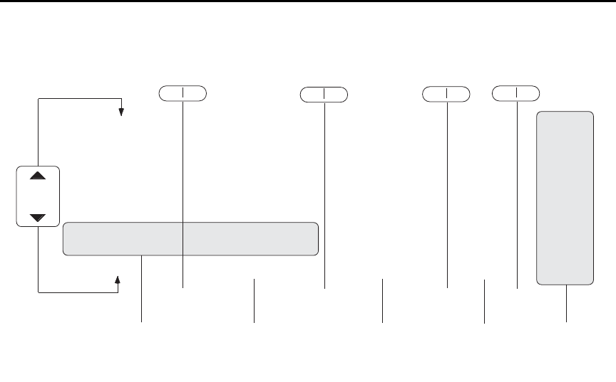
Model 6487 Reference Manual Measurements and Sourcing Voltage 3-25
Figure 3-8
A-V ohms reading recall sequence
Operating considerations
Range
Auto range cannot be used with A-V ohms. Auto range will be automatically disabled
when arming A-V ohms from the front panel. Over the GPIB, however, sending the
CURR:OHMS:AVOL:ARM command with auto range on will result in error +852 “No
A-V ohms with Autorange”. Also, only the following ranges can be used: 20nA, 2µA,
200µA, and 20mA. If on any other range, the unit will uprange to the closest allowed range.
Filtering
The median and average filters are not used in the A-V ohms mode. Once the A-V ohms
process is complete, the state of the filters will be restored.
Rate and autozero
During A-V ohms, integration rates are restricted to either 0.02 PLC, 0.1 PLC, 1 PLC, 6 PLC,
or 60 PLC. Autozero is turned off but restored after completion if it was previously on. If the
integration rate is set to any other value, it will be set to the closest of these settings. However,
the original integration rate will not be restored at the conclusion of the A-V ohms cycle.
Integration times of 0.02 PLC and 0.1 PLC will automatically cause the display to be dis-
abled during the A-V ohms run. After the desired number of cycles has completed (or an
OHMS:AVOL:ABORt command is received), the display will be restored.
RANGE
RANGE
RDG NO. 10
Reading Value (Amps) Reading Value (Ohms) Vsource
RDG NO. 9
Reading Value (Amps) Reading Value (Ohms) Vsource
RDG NO. 8
Reading Value (Amps) Reading Value (Ohms) Vsource
RDG NO. 7
Reading Value (Amps) Reading Value (Ohms) Vsource
RDG NO. 6
Reading Value (Amps) Reading Value (Ohms) Vsource
RDG NO. 5
Reading Value (Amps) Reading Value (Ohms) Vsource
RDG NO. 4
Reading Value (Amps) Reading Value (Ohms) Vsource
RDG NO. 3
Reading Value (Amps) Reading Value (Ohms) Vsource
RDG NO. 2
Reading Value (Amps) Reading Value (Ohms) Vsource
RDG NO. 1
Reading Value (Amps) Reading Value (Ohms) Vsource
STD DEV
Standard Deviation Value ---------- ----------
AVERAGE
Average Value ---------- ----------
PK-PK
Peak to Peak Value ---------- ----------
MIN AT
XX Minimum Value (Amps)* Minimum Value (Ohms)* Vsource
MAX AT
XX Maximum Value (Amps)* Maximum Value (Ohms)* Vsource
gp
STD DEV
Standard Deviation Value
AVERAGE
Average Value
PK-PK
Peak to Peak Value
Buffer Statistics Buffer
Timestamps
Timestamp
Timestamp
Timestamp
Timestamp
Timestamp
Timestamp
Timestamp
Timestamp
Timestamp
Timestamp
Timestamp
----------
----------
----------
Timestamp
Timestamp
▲
▲
▲
▲
▲
▲
Voltage Source
▲
▲
*Maximum current will result in minimum ohms and vice-versa.
The MIN value applies to the minimum amps (maximum ohms) reading.
The MAX value applies to the maximum amps (minimum ohms) reading.
Amps Ohms
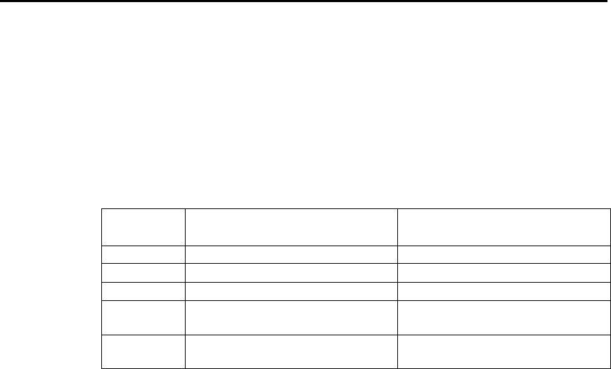
3-26 Measurements and Sourcing Voltage Model 6487 Reference Manual
Triggering considerations
When A-V ohms is selected, the ARM-IN trigger source is forced to TIMER and the time
interval selected will be slightly higher than that required for the A/D integration. For
example, at 1 PLC the integration time is 16.67 msec, so sending the OHM:AVOL:ARM
command will set the ARM-IN timer interval to 18 msec. (The detailed table is below.)
Likewise, the ARM-IN count will be set to INFinite. When exiting A-V ohms with an
AVOL:OHMS:ABOR command or when the desired number of cycles has completed, the
previous trigger model settings will be restored. See Section 7 for additional triggering
information.
Trigger state after A/V ohms
Once an A-V ohms reading sequence has been completed, the instrument will be left in the
trigger IDLE state. If you are operating remotely (GPIB or RS-232), over the front panel,
normal readings will resume after completing A-V ohms (although the “I/¾ TO REARM”
message will obscure these readings untill you press EXIT). Send an INIT:IMM command
to resume taking readings. See Section 7 for more triggering information.
Normal ohms with A-V ohms
Normal ohms (SENS:OHMS:STAT) is not compatible with A-V ohms since the latter
relies on differences between current measurements in time. Therefore, the I | ¾ key is
ignored and the SENS:OHMS:STAT command is rejected with an error +850 “Not
Allowed with A-V Ohms” while A-V ohms is armed.
Buffer operation
The same memory space is used for the regular 3,000 point buffer as for the three A-V
ohms buffers. If there are already readings in the buffer, attempting to arm A-V ohms read-
ings results in a -225 “Out of Memory” error. To avoid inadvertently writing over any
desired readings, either send a TRAC:CLEar command over the bus or attempt to store 0
readings to manually clear the buffer from the front panel. From the front panel, attempt-
ing to select A-V ohms from the CONFIG -> OHMS menu will generate the message
“CLEAR BUFFER” if there are already readings in the buffer.
The converse also applies if you have collected some A-V ohms readings and then press
the STORE key. If the buffer has stored A-V ohms readings, you will be given the
“CLEAR BUFFER” prompt so that you do not inadvertently write over the A-V ohms
PLC
50Hz measurement interval
(milliseconds)
60Hz measurement interval
(milliseconds)
0.02 00020002
0.1 00040004
10022 0018
5 (50Hz)
6 (60Hz)
0102 0102
50 (50Hz)
60 (60Hz)
1002 1002

Model 6487 Reference Manual Measurements and Sourcing Voltage 3-27
data you have collected (easy to do, since STORE is located right next to RECALL).
When working remotely, sending the TRAC:FEED:CONT NEXT command while there
are A-V ohms readings in the buffer will result in a -225 “Out of Memory” error. Send
TRAC:CLEar to clear out the buffer before attempting to store buffer readings.
Command restrictions
When A-V ohms is running, the following commands are locked out. Attempting any of
them returns error +850 “Not Allowed with A-V Ohms.”
SENS:CURR:DC:MED:STAT
SENS:CURR:DC:MED:RANK
SENS:CURR:DC:AVER:TCON
SENS:CURR:OHMS:STAT
SENS:CURR:DC:NPLC
SENS:CURR:DC:RANG
SENS:CURR:DC:RANG:AUTO
SOUR:VOLT[:LEV][:IMM][:AMPL]
SOUR:VOLT:STATe
SOUR:VOLT:RANGe
TRAC:FEED
TRAC:FEED:CONT
TRAC:POIN
TRAC:TST:FORM
TRAC:DATA?
SYST:AZER:STAT
DISP:ENAB
Tight timing is crucial to getting reliable results with A-V ohms. Anything that changes
the timing between readings would make it impossible to continue averaging in with any
previously collected readings. Therefore, the following command is locked out from the
GPIB while A-V ohms readings are present in the buffer. You must first clear the buffer
with TRAC:CLEar, otherwise an error +851 “Not allowed with A-V Ohms buffer” will be
generated.
SENS:CURR:DC:NPLC
Over the front panel, pressing any key (for example RATE) that would change one of the
settings associated with this command will automatically cause the buffer to be cleared if
the following conditions are true:
• There are A-V ohms readings present in the buffer.
• SENS:CURR:OHMS:AVOL:CLE:AUTO is set to OFF.
• The front panel ohms mode is set for ALT-VOL.
If the buffer is cleared by one of these key presses, a “BUF CLEARED” message will be
displayed. Regardless of whether the buffer gets cleared by the key press (it does not, for
instance, if the OHMS:AVOL:CLE:AUTO setting is true), you also will have to re-enter
the CONFIG-> I | Ω menu to select a new time interval before making another A-V ohms
run from the front panel.

3-28 Measurements and Sourcing Voltage Model 6487 Reference Manual
Interlock
Attempting to run A-V ohms from the front panel while the interlock is open and failing
will result in the error message “CLOSE INTLCK” being displayed. If trying to run
remotely with the :ARM command the error event +802 “Output Blocked by Interlock” is
generated.
SCPI commands — A-V ohms
Table 3-10
SCPI commands — A-V ohms
Commands Description Default Ref
To make measurements:
[SENSe[1]]
[:CURRent[:DC]]
:OHMS
:AVOLtage
[:ARM]
[:ARM]?
:ABORt
:VOLTage <NRf>
:TIME <NRf>
:POINts?
:ONEShot <b>
:CYCLes <NRf>
:UNITs <name>
:CLEar
:AUTO <b>
:BCOunt?
SENSe[1] subsystem:
Current measurement commands:
Ohms mode commands:
Path to A-V ohms commands:
Arm A-V ohms mode.
Query if A-V ohms is armed. (1 = armed).
Abort A-V ohms mode.
Set high voltage value (-505 to 505V).
Set time interval for each phase.
Query number of points.
Enable or disable one-shot mode.
Set number of A-V cycles (1 to 9999).
Select AMPS or OHMS units.
Clear A-V ohms buffer.
Enable/disable A-V buffer auto clear.
Query number of A-V points.
10V
15s*
ON
3
AMPS
ON
A
A
B
C
D
E
F
G
H
I
I
J
To access A/V readings:
TRACe
:DATA? [BUFFER]
:MODE?
CALCulate3
:FORMat <name>
:DATA?
TRACe subsystem:
Request data from BUFFER.
Query buffer mode: DC or AVOLtage.
CALCulate3 Subsystem:
Select buffer statistic; MINimum, MAXimum,
MEAN, SDEViation, or PKPK.
Read the selected buffer statistic.
BUFFER
MEAN
K
L
Section 6
*Default depends on integration rate: 15s for 1 PLC or greater, 1s for 0.1 PLC, and 0.1s for 0.02 PLC.

Model 6487 Reference Manual Measurements and Sourcing Voltage 3-29
A) OHMS:AVOLtage[:ARM]
This command arms the A-V ohms mode. Once this command is sent, the next INIT com-
mand starts A-V readings. Sending this command, if there are normal readings in the
buffer, results in error -225 “Out of Memory”. Use TRAC:CLEar to clear out the buffer. If
there are A-V ohms readings in the A-V buffers, this command will automatically clear
those buffers in preparation for the next run if the OHMS:AVOL:CLEar:AUTO state is
true. Note that ARMing the A-V ohms mode will also set the source value to zero and turn
operate on. The ARM command is not allowed if the picoammeter is in auto range
(CURR:RANG:AUTO ON); attempting to send the ARM command if autoranging results
in error +852 “No A-V ohms with Autorange”. If the combination of integration time and
programmed TIME interval would result in more than the maximum 1,000 readings per
phase, error +853 “Too Many A-V Ohms Readings” is returned.
The :ARM? query returns a “1” if A-V ohms has been armed even if the unit is still in the
idle state (See Section 7).
klqb We strongly recommend that no commands except for the INIT be sent after
sending the OHMS:AVOL:ARM command.
B) OHMS:AVOLtage:ABORt
This command closes the A-V buffer and resets the source value back to 0V. The source is
also placed in standby.
C) OHMS:AVOLtage:VOLTage <NRf>
This command sets the positive voltage. During each A-V cycle, the voltage source level
alternates between 0V and this programmed value.
D) OHMS:AVOLtage:TIME <NRf>
This command sets the time interval in seconds that the source will be in each phase. The
number of readings collected per phase will be determined by the integration period and
trigger delay, if any. Note that changing the time will clear out any A-V buffer data that
has been collected regardless of whether CLEar:AUTO is enabled or not. Sending a time
value that would result in more than the maximum of 1000 readings per phase based on
the present integration time will result in error +853 “Too Many A-V Ohms Readings”.
The default time interval depends on the integration time selected.
60Hz
0.02 PLC 0.1 PLC 1 PLC 6 PLC 60 PLC
Time (milliseconds) 2 4 18 102 1002
50Hz
0.02 PLC 0.1 PLC 1 PLC 5 PLC 50 PLC
Time (milliseconds) 2 4 22 102 1002

3-30 Measurements and Sourcing Voltage Model 6487 Reference Manual
E) OHMS:AVOLtage:POINts?
This query returns the number of points per phase based on the user-supplied TIME value
above. If the number of points would be greater than the maximum of 1,000 (for example,
if you had set a new integration rate but not yet changed the AVOL:TIME value), then
-999 will be returned. A -999 return value indicates that you cannot send the
OHMS:AVOL:ARM command until you adjust either the time interval or the integration
rate to obtain a valid number of points.
F) OHMS:AVOLtage:ONEShot <b>
This command controls the one-shot A-V ohms mode. If the one-shot mode is ON, then
only a single reading is collected for each voltage phase at the end of the TIME interval
given above.
G) OHMS:AVOLtage:CYCLes <NRf>
This command sets the number of cycles to run A-V ohms. A cycle is defined as one
V-High and one V-Zero step.
H) OHMS:AVOLtage:UNITs <name>
This command sets the units that the A-V ohms readings will be stored and returned in,
amps or ohms.
I) OHMS:AVOLtage:CLEar
CLE manually clears the A-V ohms buffers. TRAC:CLEar will also do the same thing.
AUTO ON enables A-V ohms auto-clear. If enabled, arming the next A-V ohms run will
clear out the buffers. If disabled, subsequent A-V ohms runs will get averaged in with the
saved readings.
J) OHMS:AVOLtage:BCOunt?
This query returns the number of V-High/V-Low cycles that have been averaged to result
in the data stored in the A-V ohms buffer.
K) TRACe:DATA? [BUFFER]
This query returns data either from the normal buffer or the A-V ohms buffer. If A-V ohms
is not on and no A-V ohms readings have been collected, normal buffer readings will be
returned. If A-V ohms readings have been collected, A-V ohms readings will be returned.
L) TRACe:MODE?
This query returns the type of data stored in the buffer (either DC or AVOLtage).

Model 6487 Reference Manual Measurements and Sourcing Voltage 3-31
Programming example — A-V ohms measurements
The following command sequence will perform A-V ohms measurements with a 5V high
value, 10s per phase, and 5 A-V cycles:
*RST ' Return 6487 to GPIB defaults.
TRAC:CLE ' Clear buffer of all readings.
RANG 20e-3 ' Select 20mA range (turn off auto).
OHMS:AVOL:VOLT 5 ' Set high voltage to 5V.
OHMS:AVOL:ONES OFF ' Disable one-shot mode.
OHMS:AVOL:CLE:AUTO ON ' Enable buffer auto clear.
OHMS:AVOL:TIME 10 ' Set time per phase to 10s. (A)
OHMS:AVOL:CYCL 5 ' Set number of A-V cycles to 5. (B)
OHMS:AVOL:UNIT OHMS ' Select ohms units.
SYST:ZCH OFF ' Disable zero check.
OHMS:AVOL:ARM ' Arm A-V ohms, turn on source.
INIT ' Trigger A-V readings.
' Wait for time [(A) × 2] × cycles (B)
' before requesting readings. 100s in
' this example.
TRAC:DATA? ' Request data from A-V ohms buffer.

4
Range, Units, Digits,
Rate, and Filters
•Range, units, and digits — Provides details on measurement range, reading units,
and display resolution selection. Includes the SCPI commands for remote
operation.
•Rate — Provides details on reading rate selection. Includes the SCPI commands
for remote operation.
•Damping — Provides details on damping, including the SCPI commands for
remote operation.
•Filters — Explains how to configure and control the digital and median filters.
Includes the SCPI commands for remote operation.
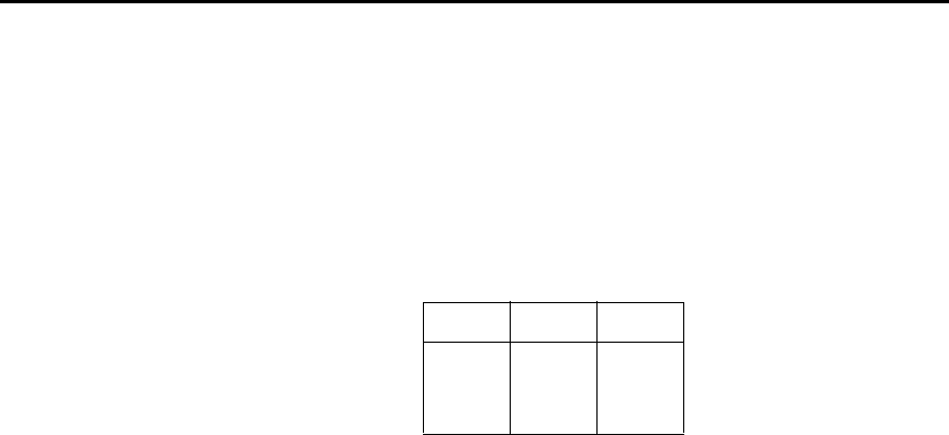
4-2 Range, Units, Digits, Rate, and Filters Model 6487 Reference Manual
Range, units, and digits
Range
The ranges for current measurements are listed in Table 4-1.
The full scale readings for every measurement range are 5% over range. For example, on
the 20µA range, the maximum input current is ± 21µA. Input values that exceed the maxi-
mum readings cause the overflow message (OVRFLOW) to be displayed.
Manual ranging
To select a range, press the RANGE or key. The instrument changes one range per
key-press. If the instrument displays the OVRFLOW message on a particular range, select
a higher range until an on-range reading is displayed. Use the lowest range possible with-
out causing an overflow to ensure best accuracy and resolution.
Autoranging
When using autorange, the instrument automatically goes to the most sensitive available
range to measure the applied signal. Up-ranging occurs at 105% of range, while
down-ranging occurs at the range value. For example, if on the 20µA range, the instrument
will go up to the 200µA range when the input signal exceeds 21µA. While on the 200µA
range, the instrument will go down to the 20µA range when the input level goes below
20µA.
The AUTO key toggles the instrument between manual ranging and autoranging. The
AUTO annunciator turns on when autoranging is selected. To disable autoranging, press
AUTO or the RANGE or . Pressing AUTO to disable autoranging leaves the instru-
ment on the present range.
Every time an autorange occurs, a search for every available range of the selected function
is performed. The time it takes to perform the search could slow down range change speed
significantly. Setting upper and/or lower autorange limits can reduce search time.
klqb Range limits and groups are not in effect for manual ranging. Every range is
accessible with manual range selection.
Table 4-1
Measurement ranges
nA μAmA
2nA 2μA 2mA
20nA 20μA 20mA
200nA 200μA

Model 6487 Reference Manual Range, Units, Digits, Rate, and Filters 4-3
Autorange limits
Search time for amps can be reduced by setting upper and/or lower autorange limits. For
example, if you know the maximum input will be around 1µA, set the upper current range
limit to 2µA. This eliminates the 20µA, 200µA, 2mA, and 20mA ranges from the search,
thereby increasing the range change speed. Should the input exceed 2.1µA, the
OVRFLOW message will be displayed.
Perform the following steps to set upper and/or lower autorange limits.
1. Press CONFIG key (CONFIGURE: will be displayed).
2. Display the desired limit (UPPER or LOWER):
a. Press the RANGE key to display the present UPPER range limit.
b. Press the RANGE key to display the present LOWER range limit.
3. Scroll through the available range limits using the or RANGE key.
4. Press ENTER when the desired range is flashing.
klqb If you attempt to select an incompatible range limit, it will be ignored and TOO
LARGE or TOO SMALL will be displayed briefly. For example, if the lower
range limit is 20µA, trying to set the upper limit to 2µA will result in the TOO
SMALL error.
Units
klqb Changing the display resolution is not allowed if displaying readings in scien-
tific notation.
Readings can be displayed using engineering (ENG) units (i.e. 1.236 mA) or scientific
(SCI) notation (i.e. 1.236E-03A). Perform the following steps to change the units setting:
1. Press MENU key.
2. Scroll down to the UNITS item using the or RANGE key (UNITS: will be
flashing).
3. Press ENTER to select setting (ENG or SCI will be flashing).
4. Use the or key to display the desired units setting.
5. Press ENTER.
6. Press EXIT to return to normal display.
klqbp 1. The units setting can only be changed from the front panel (no remote
operation).
2. Scientific notation provides more resolution on small values than
engineering units.

4-4 Range, Units, Digits, Rate, and Filters Model 6487 Reference Manual
Digits
The DIGITS key sets display resolution for the Model 6487. Display resolution can be set
from 3 to 6 digits. This single global setting affects display resolution for all measure-
ment ranges.
To set display resolution, press (and release) the DIGITS key until the desired number of
digits is displayed.
klqb Changing the integration rate does not change display resolution. Also changing
display resolution does not change the rate setting.
The voltage source value will not be displayed with the 6 digit setting.
SCPI programming — range and digits
Table 4-2
SCPI commands — digits
Commands Description Default
[:CURRent]
:RANGe
[:UPPer] <n>
: AUTO <b>
:ULIMit <n>
:LLIMit <n>
For Digits:
DISPlay
:DIGits <n>
Measure current:
Range selection:
Specify expected reading; -0.021 to 0.021 (A).
See Table 4-3.
Enable or disable autorange.
Specify upper range limit for autorange:
-0.021 to 0.021 (A).
Specify lower range limit for autorange:
-0.021 to 0.021 (A).
DISPlay Subsystem:
Set display resolution: 4 to 7, where <n> of:
4 = 3 digit resolution
5 = 4 digit resolution
6 = 5 digit resolution
7 = 6 digit resolution
Note: Rational numbers can be used. For
example, to set 5 resolution send a value
of 4.5 (the 6487 rounds it to 5).
200μA
ON
20mA
2nA
6

Model 6487 Reference Manual Range, Units, Digits, Rate, and Filters 4-5
Programming example — range and digits
The following command sequence selects the 20mA range and sets display resolution to 3:
*RST ' Restore RST defaults.
CURR:RANG 0.02 ' Set to 20mA range.
DISP:DIG 3.5 ' Set display resolution to 3 digits.
Table 4-3
Ranges and values
Range <n> value
Display (5 digit
resolution)
20mA
2mA
200µA
20µA
2µA
200nA
20nA
2nA
2E-2 or 0.02
2E-3 or 0.002
2E-4 or 0.0002
2E-5 or 0.00002
2E-6 or 0.000002
2E-7 or 0.0000002
2E-8 or 0.00000002
2E-9 or 0.000000002
00.0000mA
0.00000mA
000.000µA
00.0000µA
0.00000µA
000.000nA
00.0000nA
0.00000nA
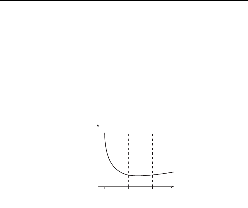
4-6 Range, Units, Digits, Rate, and Filters Model 6487 Reference Manual
Rate
The RATE key selects the integration time of the A/D converter. This is the period of time
the input signal is measured. The integration time affects the amount of reading noise, as
well as the ultimate reading rate of the instrument. The integration time is specified in
parameters based on a number of power line cycles (NPLCs), where 1 PLC for 60Hz is
16.67msec (1/60) and 1 PLC for 50Hz (and 400Hz) is 20msec (1/50).
In general, the Model 6487 has a parabola-like shape for its speed vs. noise characteristics
and is shown in Figure 4-1. The Model 6487 is optimized for the 1 PLC to 10 PLC reading
rate. At these speeds (lowest noise region in the graph), The Model 6487 will make correc-
tions for its own internal drift and still be fast enough to settle a step response <100ms.
Figure 4-1
Speed vs. noise characteristics
The rate setting is global for all ranges. Therefore, it does not matter what range is pres-
ently selected when you set rate.
There are two ways to set rate. You can select slow, medium, or fast by using the RATE
key or you can set the number of power cycles from the NPLC menu that is accessed by
pressing CONFIG / LOCAL (while in LOCAL) and then RATE.
RATE Key — The RATE key selections are explained as follows:
•SLOW — Selects the slowest preset integration time (6 PLC for 60Hz or 5 PLC for
50Hz). The SLOW rate provides better noise performance at the expense of speed.
•MED — Selects the medium integration time (1 PLC). Select the MED rate when
a compromise between noise performance and speed is acceptable.
•FAST — Selects the fastest preset integration time (0.1 PLC). Select the FAST rate if
speed is of primary importance (at the expense of increased reading noise).
Lowest
noise
region
Voltage
Noise
166.7μs 16.67ms 166.67ms
Integration Time

Model 6487 Reference Manual Range, Units, Digits, Rate, and Filters 4-7
To change the rate setting, press (and release) the RATE key until the desired rate annunci-
ator (SLOW, MED, or FAST) is displayed.
NPLC Menu — From this menu you can set rate by setting the PLC value. Perform the
following steps to set NPLC:
1. Press CONFIG / LOCAL and then RATE to display the present PLC value.
2. Use the , , , and keys to adjust to the desired PLC value. Valid values are:
60Hz operation: 0.01 to 60
50Hz operation: 0.01 to 50
3. Press ENTER.
klqb The SLOW, MED, or FAST annunciator will only turn on if the set PLC value
corresponds exactly to the slow (5 or 6 PLC for the respective frequency of 50 or
60Hz), medium (1 PLC), or fast (0.1 PLC) integration rate. For example, with
the integration rate set to 2 PLC, none of the rate annunciators will turn on.
SCPI programming — rate
Table 4-4 contains the path and the command to set rate.
Programming example — rate
The following command sets the integration rate for all measurement ranges to 2 PLC:
CURR:NPLC 2 ' Set integration rate to 2 PLC.
Table 4-4
SCPI commands — rate
Command Description Default
[:SENSe]
[:CURRent]
:NPLCycles <n>
SENSe Subsystem:
Specify integration rate: 0.01 (PLCs) to
60.0 (60Hz) or 50.0 (50Hz)
6.0 (60Hz)
5.0 (50Hz)

4-8 Range, Units, Digits, Rate, and Filters Model 6487 Reference Manual
Damping
High capacitance seen at the input will increase reading noise. This capacitance can be
attributed to a long input cable or to the capacitance of the source or a combination of
both. Enabling damping (analog filtering) will reduce this type of noise for current mea-
surements. However, damping will also slow down the response of the measurement.
klqb Use damping to reduce noise caused by input capacitance. Use filtering to
reduce noise caused by a noisy input signal.
To toggle damping on or off simply press the DAMP key. DAMP ON or DAMP OFF will
be displayed briefly to indicate the present state of damping. Note that the FILT
annunciator is used for both the analog damping filter and the two types of digital filters.
Filters
Filtering stabilizes noisy measurements caused by noisy input signals. The Model 6487
uses two types of filters: median and digital. The displayed, stored, or transmitted reading
is simply the result of the filtering processes. Note that both the median and digital filters
can be in effect at the same time.
With both filters enabled, the median filter operation is performed first. After the median
filter yields a reading, it is sent to the stack of the digital filter. Therefore, a filtered reading
will not be displayed until both filter operations are completed.
The settings for the filter are global. The FILT key is used to control both filters. When
either the median or digital filter is enabled, the FILT annunciator is on. Note that the FILT
annunciator is used for both the digital filters and the analog damping filter.
Table 4-5
SCPI commands — Damping
Command Description Default
[:SENSe]
[:CURRent]
:DAMPing
[:STATe] <b>
[:STATe]?
SENSe Subsystem:
Path to Current functions
Control Damping (analog filter)
Enable or disable damping filter.
Query damping filter state.
ON

Model 6487 Reference Manual Range, Units, Digits, Rate, and Filters 4-9
Median filter
The median filter is used to determine the "middle-most" reading from a group of readings
that are arranged according to size. For example, assume the following readings:
20mA, 1mA, 3mA
The readings are rearranged in an ascending order as follows:
1mA, 3mA, 20mA
From the above readings, it is apparent that 3mA is the median (middle-most) reading.
The number of sample readings used for the median calculation is determined by the
selected rank (1 to 5) as follows:
Sample readings = (2 × R) + 1
where; R is the selected rank (1 to 5)
For example, a rank of 5 will use the last 11 readings to determine the median;
(2 × 5) + 1 = 11. Each new reading replaces the oldest reading and the median is then
determined from the updated sample of readings.
Median filter operation — The median filter operates as a moving type filter. For exam-
ple, if the median filter is configured to sample 11 readings (Rank 5), the first filtered read-
ing will be calculated (and displayed) after 11 readings are acquired and placed in its filter
stack. Each subsequent reading will then be added to the stack (oldest reading discarded)
and another median filter reading will be calculated and displayed. The median filter oper-
ation will reset (start over) whenever the Zero Check operation is performed or the range
is changed.
Median filter control
To configure the median filter:
1. Press the CONFIG key.
2. Press the FILT key.
3. Select MEDIAN, then press ENTER.
4. Change the display to MEDIAN ON, then press ENTER.
5. The present rank will be displayed (flashing).
6. Use the RANGE ( or ) keys to display the desired rank (1 to 5).
7. Press ENTER to set. To return to the previously set value, press EXIT instead of
ENTER.
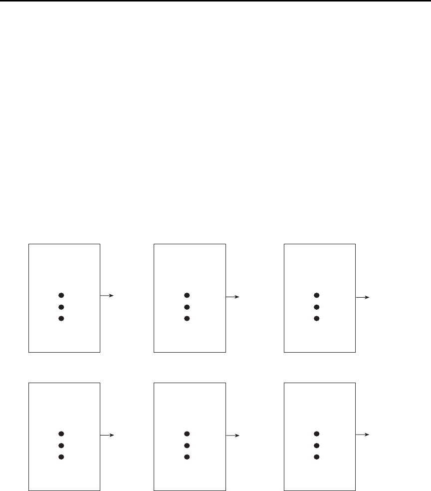
4-10 Range, Units, Digits, Rate, and Filters Model 6487 Reference Manual
Digital filter
Digital filter types
An additional filter parameter is type (type is either moving or repeating). Filter types are
compared in Figure 4-2.
Moving Filter — Every time a reading conversion occurs, the readings in the stack are
averaged to yield a single filtered reading. The stack type is first-in, first-out. After the
stack fills, the newest reading conversion replaces the oldest. Note that the instrument does
not wait for the stack to fill before releasing readings.
Repeating Filter — Takes a selected number of reading conversions, averages them, and
yields a reading. It then flushes its stack and starts over.
Figure 4-2
Digital filter types; moving and repeating
Conversion #10
#9
#8
#7
#6
#5
#4
#3
#2
#1
Conversion
Reading
#10
Conversion #12
#11
#10
#9
#8
#7
#6
#5
#4
#3
Conversion
Reading
#12
Conversion #11
#10
#9
#8
#7
#6
#5
#4
#3
#2
Conversion
Reading
#11
A. Class - Average, Readings = 10, Type - Moving
Conversion #10
#9
#8
#7
#6
#5
#4
#3
#2
#1
Conversion
Reading
#1
Conversion #20
#19
#18
#17
#16
#15
#14
#13
#12
#11
Conversion
Reading
#2
Conversion #30
#29
#28
#27
#26
#25
#24
#23
#22
#21
Conversion
Reading
#3
B. Class - Average, Readings = 10, Type - Repeating

Model 6487 Reference Manual Range, Units, Digits, Rate, and Filters 4-11
Response time
The various filter parameters have the following effects on the time needed to display,
store, or output a filtered reading:
•Number of reading conversions — Speed and noise are tradeoffs.
Operation consideration
The digital filter operation will reset (start over) whenever the zero check operation is per-
formed or the range is changed.
Digital filter control
To configure the average filter:
1. Press CONFIG then FILT.
2. Set the display to AVERAGE ON, then press ENTER. The present number of read-
ing conversions to average (filter count) will be displayed (flashing).
3. Set filter count (2 to 100):
• Use the RANGE and or keys to display the desired filter count value at the
RDGS prompt.
• Press ENTER to set.
4. Set filter type (REPEAT or MOVING AV):
• Use the RANGE keys to display the desired filter type at the TYPE: prompt.
• Press ENTER to set.

4-12 Range, Units, Digits, Rate, and Filters Model 6487 Reference Manual
SCPI programming — filters
Programming example
The following command sequence configures and enables both filters:
' Median Filter:
MED:RANK 5 ' Set rank to 5.
MED ON ' Enable median filter.
' Digital Filter:
AVER:COUN 20 ' Set filter count to 20.
AVER:TCON MOV ' Select moving filter.
AVER ON ' Enable digital filter.
Table 4-6
SCPI commands — filters
Commands Description Default
For median filter:
[:SENSe[1]]
:MEDian
:RANK <n>
[:STATe] <b>
For digital filter:
[:SENSe[1]]
:AVERage
:TCONtrol <name>
:COUNt <n>
[:STATe] <b>
SENSe Subsystem:
Median Filter:
Specify filter rank: 1 to 5.
Enable or disable median filter.
SENSe Subsystem:
Digital Filter:
Select filter control: MOVing or REPeat.
Specify filter count: 2 to 100.
Enable or disable digital filter.
1
OFF
MOV
10
OFF


5-2 Relative, mX+b, m/X+b, and log Model 6487 Reference Manual
Relative
Relative (Rel) nulls an offset or subtracts a baseline reading from present and future read-
ings. When a Rel value is established, subsequent readings will be the difference between
the actual input and the Rel value.
Displayed (Rel’ed) Reading = Actual Input - Rel Value
A Rel value is the same for all measurement ranges. For example, a Rel value of 1E-6 is
1µA on the 2µA range. It is also 1µA on the 20µA range and the 200µA range. Note
changing ranges does not disable Rel.
When a Rel value is larger than the selected range, the display is formatted to accommo-
date the Rel’ed reading. However, this does not increase the maximum allowable input for
that range. An over-range input signal will still cause the display to overflow. For example,
on the 20µA range, the Model 6487 still overflows for a 21µA input.
klqb Rel can be used on the result of the mX+b, m/X+b, or LOG calculations. How-
ever, Rel will disable whenever a math function is enabled or disabled.
Setting and controlling relative
From the front panel, there are two ways to set the Rel value. You can use the input reading
as the Rel value or you can manually key in the Rel value.
REL key
When the REL key is used to enable Rel, the present display reading is used as the Rel
value. Perform the following steps to set a Rel value:
1. Disable zero check by pressing ZCHK.
2. Display the reading you want as the Rel value. This could be a zero offset reading
that you want to null out or it could be an applied level that you want to use as a
baseline.
3. Press REL. The REL annunciator turns on and subsequent readings will be the dif-
ference between the actual input and the Rel value.
4. To disable REL, press the REL key a second time or select a different measurement
function. The REL annunciator turns off.
klqb When Rel is disabled, the Rel value is remembered. To reinstate the previous Rel
value, press CONFIG then press REL and finally press ENTER. If the REL is
disabled and then REL is pressed again, it will determine and set a new null
value.
With zero check enabled, the REL key controls zero correct, not relative.

Model 6487 Reference Manual Relative, mX+b, m/X+b, and log 5-3
Displaying or manually keying in REL
Pressing CONFIG and then REL displays the present Rel value. This displayed Rel value
can be enabled (pressing ENTER) or a different Rel value can be entered and enabled.
1. Press CONFIG and then REL. The present Rel value will be displayed.
2. To change the Rel value, use the RANGE and cursor keys and change the value. To
change Rel polarity, place the cursor on the polarity sign and press either manual
RANGE key. To change the Rel range, place the cursor on the range symbol (at the
end of the reading) and use the manual RANGE keys (Table 5-1).
3. With the desired Rel value displayed, press ENTER to enable Rel.
Table 5-1
Range symbols for rel values
Symbol Prefix Exponent
ppico- 10
-12
nnano-10
-9
µmicro-10
-6
m milli- 10-3
ˆ (none) 100
K kilo- 103
Mmega-10
6
Ggiga-10
9
T tera- 1012

5-4 Relative, mX+b, m/X+b, and log Model 6487 Reference Manual
SCPI programming — relative
A) :FEED <name>
With SENSe[1] selected, the Rel operation will be performed on the input signal. With
CALCulate[1] selected, the Rel operation will be performed on the result of the mX+b or
m/X+b calculation.
B) :STATe <b>
This command toggles the state of Rel without acquiring new values. This operation is dif-
ferent than the REL key on the front panel (which toggles the Rel state) — the front panel
key acquires new values when pressed (unless CONFIG is pressed first). If a NULL value
has not been acquired before enabling Rel, 0.000000E+00 will be used.
C) :DATA? and :DATA:LATest?
With Rel enabled, these commands will return one or more Rel’ed readings. They will not
trigger fresh (new) readings. Use the INITiate command to trigger new readings (see
Section 7 for details on INITiate).
If the instrument is programmed to perform a finite number of measurements, the :DATA?
command will return all the Rel’ed readings after the last reading is taken. The
:DATA:LATest? command will only return the last (latest) Rel’ed reading.
Table 5-2
SCPI commands — relative (null)
Commands Description Default Ref
CALCulate2 Path to configure and control limit testing (CALC2):
:FEED <name> Specify reading to Rel: SENSe[1] or CALCulate[1]. SENS1 A
:NULL Configure and control Relative.
:ACQuire Use input signal as Rel value.
:OFFSet <NRf> Specify Rel value: -9.999999e20 to 9.999999e20. 0.0
:STATe <b> Enable or disable Rel. OFF B
:DATA? Return Rel’ed readings triggered by INITiate. C
:DATA:LATest? Return only the latest Rel’ed reading. C
INITiate Trigger one or more readings.

Model 6487 Reference Manual Relative, mX+b, m/X+b, and log 5-5
If the instrument is programmed to perform an infinite number of measurements (arm
count or trigger count set to infinite), you cannot use the :DATA? command to return
Rel’ed readings. However, you can use the :DATA:LATest? command to return the last
Rel’ed reading after aborting the measurement process. After sending the INITiate com-
mand to start the measurement process, use the ABORt command to abort the measure-
ment process, then use :DATA:LATest? to return to the last Rel’ed reading.
Programming example — relative
This program fragment establishes a 1µA baseline for measurements:
CALC2:NULL:OFFS 1e-6 ' Set Rel value of 1μA.
CALC2:NULL:STAT ON ' Enable Rel.
CALC2:FEED SENS ' Rel input signal.
SYST:ZCH OFF ' Turn off zero check.
INIT ' Trigger reading(s).
CALC2:DATA? ' Request Rel’ed reading.
mX+b, m/X+b (reciprocal), and logarithmic
mX+b and m/X+b
The following math operations manipulate normal display readings (X) mathematically
according to the following calculations:
Y = mX+b
Y = m/X+b
where: X is the normal display reading
m and b are user-entered constants for scale factor and offset
Y is the displayed result
klqb Changing the “m” or “b” for mX+b also changes it for m/X+b.
Configuring and controlling mX+b and m/X+b
To configure and control either of these math calculations, perform the following steps:
klqb Enabling or disabling math disables Rel (if Rel is enabled).
1. Press CONFIG then MATH to enter the math configuration menu.
2. Using the manual RANGE keys, select either MATH: mX+B or MATH: M/X+B,
then press ENTER to select the desired function and display the present scale
factor:
M: +1.000000 ^ (factory default)

5-6 Relative, mX+b, m/X+b, and log Model 6487 Reference Manual
3. Key in a scale factor value. The and keys control cursor position and the and
RANGE keys increment and decrement the digit value. To change range, place
the cursor on the range symbol and use the and keys. With the cursor on the
polarity sign, the and keys toggle polarity.
klqb Range symbols are defined in Table 5-1.
4. Press ENTER to enter the M value and display the offset (B) value:
B: +0.000000 P (factory default)
5. Key in the offset value.
6. Press ENTER to set the B value and display the one-character UNITS designator:
UNITS: X (factory default)
klqb The configuration for mX+b calculations consists of a units designator, a value
for M, and a value for B. This configuration is used for both the mX+b and the
m/X +b calculations. Therefore, changing either configuration (of the mX+b or
the m/X+b calculation) also changes the other calculation’s configuration.
7. To change the units designator (default is “X”), press the cursor key and use
the manual RANGE keys. The character can be any letter in the alphabet
(A through Z).
8. Press ENTER.
9. To enable math, press the MATH key from normal display. The MATH annunciator
and the units designator will turn on and the result of the calculation will be
displayed.
Logarithmic
This calculation converts input readings to logarithm base 10 values. The calculation is
performed as follows:
where: X is the input reading
y is the logarithmic result
For example: Assume that exactly 1mA is being measured by the Model 6487.
klqb This calculation uses the absolute value of the normal input reading, as the log
of a negative number cannot be computed.
10Xlog Y=
1.000000mA
10
log 3–=

Model 6487 Reference Manual Relative, mX+b, m/X+b, and log 5-7
To control log, perform the following steps:
klqb Enabling or disabling math disables Rel (if Rel is enabled).
1. Press CONFIG then MATH to enter the math configuration menu.
2. Using either manual RANGE key, select MATH: LOG10, then press ENTER to
select the log function.
3. To enable math, press the MATH key from normal display. The MATH annunciator
and the “L” designator will turn on and the result of the calculation will be
displayed.
SCPI programming — mX+b, m/X+b, and log
A) :FORMat <name>
This command selects the desired math function in the same manner as the front panel
CONFIG MATH menu. Functions names include MXB (mX + b), RECiprocal (m/X + b),
and LOG10.
B) :KMATh
Use these commands to set the M (scale factor), B (offset), and units for the MX + B and
reciprocal math functions.
Table 5-3
SCPI commands — mX+b, m/X+b, and log
Commands Description Default Ref
CALCulate[1]
:FORMat <name>
:KMATh
:MMFactor <n>
:MBFactor <n>
:MUNits <name>
:STATe <b>
:DATA?
:DATA:LATest?
CALCulate1 Subsystem:
Select calculation: MXB, RECiprocal, or LOG10.
Path to configure mX+b and m/X+b:
Specify scale factor (M) for mX+b and m/X+b:
-9.99999e20 to 9.99999e20.
Specify offset (B) for mX+b and m/X+b:
-9.99999e20 to 9.99999e20.
Specify units for mX+b or m/x+b result:
1 character: A–Z, ‘[‘=¾, ‘\’=°, ‘]’=%.
Enable or disable the selected calculation.
Returns all CALC1 results triggered by the INITiate.
Returns only the latest CALC1 reading.
MXB
1.0
0.0
“X”
OFF
A
B
C
C

5-8 Relative, mX+b, m/X+b, and log Model 6487 Reference Manual
C) :DATA? and :DATA:LATest?
The INITiate command must be sent to trigger the measurements and calculations. The
number of calculations depend on how many measurements the instrument is programmed
to perform.
If the instrument is programmed to perform a finite number of measurements, the :DATA?
command will return all the CALC1 readings after the last reading is taken. The
:DATA:LATest? command will only return the last (latest) CALC1 reading.
If the instrument is programmed to perform an infinite number of measurements (arm
count or trigger count set to infinite), you cannot use the :DATA? command to return
CALC1 readings. However, you can use the :DATA:LATest? command to return the last
CALC1 reading after aborting the measurement process. After sending the INITiate com-
mand to start the measurement process, use the ABORt command to abort the measure-
ment process, then use :DATA:LATest? to return the last CALC1 reading.
Programming example — mX+b
This command sequence performs a single mX+b calculation, using “X” as the units des-
ignator, and displays the result on the computer CRT:
*RST 'Restore RST defaults.
CALC:FORM MXB 'Select mX+b calculation.
CALC:KMAT:MMF 2e-3 'Set scale factor (M) to 2e-3.
CALC:KMAT:MBF 5e-4 'Set offset (B) to 5e-4.
CALC:KMAT:MUN ‘X’ 'Select X as units.
CALC:STAT ON 'Enable calculation.
SYST:ZCH OFF 'Disable zero check.
INIT 'Perform one measurement and
'calculate mX+b.
CALC:DATA? 'Request mX+b result.


6-2 Buffer and Sweeps Model 6487 Reference Manual
Buffer operations
The Model 6487 has a buffer to store from one to 3000 readings. It also stores overflow
readings and the voltage source value. Each reading has a timestamp. The timestamp for
each reading is referenced to the time the measure/store process is started. In addition,
recalled data includes statistical information (maximum, minimum, peak-to-peak,
average, and standard deviation).
The buffer fills with the specified number of readings and stops. Readings are placed in the
buffer after any filters and/or math operations have been performed. Math operations
include relative, mX+b, m/X+b, LOG, or limit tests.
Buffered data is overwritten each time the storage operation is selected. The data is
volatile — it is not saved through a power cycle.
Measurement function changes are permissible during the storage process. Note however,
that the statistics will be based on the readings of the different measurement functions.
Store
Perform the following steps to store readings:
1. Set up the instrument for the desired configuration.
2. Press CONFIG (CONFIGURE: will be displayed).
3. Press STORE. The present buffer size (in readings) is displayed.
4. Use the cursor and keys and the RANGE and keys to set the number of
readings to store (1 to 3000).
5. Press ENTER to save the buffer size. Press the STORE key. If in the immediate
trigger mode, the storage process will start immediately. If in the external input
trigger mode, each input trigger (or press of TRIG key) will store a reading. See
Section 7 for information on triggering.
klqb The asterisk (*) annunciator turns on to indicate that the data storage operation
is enabled. It will turn off when the storage process is finished (buffer full).
Recall
Perform the following steps to view stored readings and buffer statistics:
1. Press RECALL. The message RDG NO. 1 is displayed. Note that the arrow annun-
ciator (↔) also turns on to indicate that additional data is available for viewing.
2. Use the RANGE and keys and the cursor and keys to navigate through the
reading numbers and buffer statistics, reading values, voltage source values, and
timestamps (Figure 6-1). For information on how to set buffer timestamps, see
“Buffer timestamps,” page 6-3.
3. Press EXIT to return to the normal display.
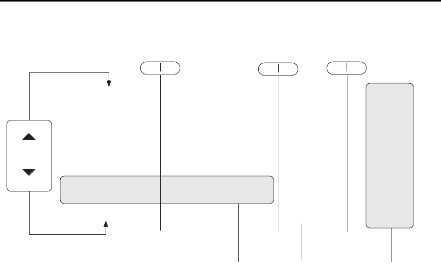
Model 6487 Reference Manual Buffer and Sweeps 6-3
Figure 6-1
Buffer locations
Buffer timestamps
Use the TSTAMP: menu item to change the timestamp format. To access the menu:
1. Press MENU.
2. Scroll to the TSTAMP: menu item using RANGE and keys.
3. Press ENTER.
4. Using RANGE and keys, select desired setting. Available options are ABS
(absolute) or DELT (delta).
5. ABS: each timestamp is referenced to the first reading stored in the buffer. The first
reading always has a timestamp of 0000000.0000.
6. DELT: each timestamp provides the time between the readings.
RANGE
RANGE
RDG NO. 10
Reading Value Vsource
RDG NO. 9
Reading Value Vsource
RDG NO. 8
Reading Value Vsource
RDG NO. 7
Reading Value Vsource
RDG NO. 6
Reading Value Vsource
RDG NO. 5
Reading Value Vsource
RDG NO. 4
Reading Value Vsource
RDG NO. 3
Reading Value Vsource
RDG NO. 2
Reading Value Vsource
RDG NO. 1
Reading Value Vsource
STD DEV
Standard Deviation Value ----------
AVERAGE
Average Value ----------
PK-PK
Peak to Peak Value ----------
MIN AT
XX Minimum Value Vsource
MAX AT
XX Maximum Value Vsource
g
STD DEV
Standard Deviation Value
AVERAGE
Average Value
PK-PK
Peak to Peak Value
Buffer Statistics Buffer Timestamps
Timestamp
Timestamp
Timestamp
Timestamp
Timestamp
Timestamp
Timestamp
Timestamp
Timestamp
Timestamp
Timestamp
----------
----------
----------
Timestamp
Timestamp
▲
▲
▲
▲
▲
▲
Voltage Source

6-4 Buffer and Sweeps Model 6487 Reference Manual
Buffer statistics
•MIN and MAX provides the minimum and maximum readings stored in the buffer.
It also indicates the buffer location of these readings.
• The PK-PK (peak-to-peak) value is the difference between the maximum and
minimum readings stored in the buffer:
PK-PK = MAX - MIN
•Average is the mean of the buffer readings. Mean is calculated as follows:
Where: Xi is a stored reading
n is the number of stored readings
• The STD DEV value is the standard deviation of the buffered readings. Standard
deviation is calculated as follows:
Where: Xi is a stored reading
n is the number of stored readings
Avg is the mean of the buffer readings
klqb If any readings stored in the buffer are the result of an overflow or overvoltage
condition, the buffer statistics calculation will not be performed. Buffer recall
via front panel operation will show a series of dashes in place of the requested
buffer statistics value. In remote operation, the corresponding buffer statistics
will be represented by the value +9.91e37.
SCPI programming
Commands associated with buffer operation are listed in Table 6-1. The TRACe com-
mands are used to store and recall readings in the buffer. The FORMat:ELEMents com-
mand is used to specify which data elements to include in the response message for
TRACe:DATA? (which is the command to read the buffer). The CALCulate3 commands
are used to obtain statistics from the buffer data.
yn
ΣXi
n
-----
i=1
=
y
n
ΣAvg Xi
–()
2
i1=
n1–
------------------------------------=

Model 6487 Reference Manual Buffer and Sweeps 6-5
klqb The Model 6487 uses IEEE-754 floating point format for statistics calculations.
When programming the buffer via remote, the trigger count set with the
TRIG:COUN command should normally equal the number of buffer readings to
store set with TRAC:POIN. See Section 7 for details on triggering.
If the voltage source was in compliance when the reading was acquired, the
recalled front panel SRC: display will show the voltage value dimmed. Over the
GPIB, a value of -999 returned for the voltage source element indicates that the
source was in compliance.
For any ohms measurements, the ohms reading is invalid and unknown if the
voltage source is in compliance. Therefore, a value of -9.9e+36 will be returned
over the GPIB and the message I-LIMIT will be displayed on the front panel for
both normal readings and buffer recall readings for any ohms readings where
the voltage source went into compliance.
Table 6-1
SCPI commands — buffer
Commands Description Default Ref
:TRACe
:CLEar
:FREE?
:POINts <n>
:ACTual?
:FEED <name>
:CONTrol <name>
:TSTamp
:FORMat <name>
:DATA?
:MODE?
TRACe Subsystem:
Clear readings from buffer.
Query bytes available and bytes in use.
Specify number of readings to store: 1 to 3000.
Returns number of readings actually stored in buffer.
Select source of readings: SENSe[1], CALCulate[1], or
CALCulate2.
Select buffer control mode: NEVer or NEXT.
Timestamp:
Select timestamp format: ABSolute or DELTa.
Read all readings in buffer.
Query the type of data (DC or AVOL) stored in the
buffer.
See Note
100
SENS1
NEV
ABS
A
B
C
D
E
:FORMat
:ELEMents <list>
FORMat Subsystem:
Specify data elements for :TRACe:DATA? response
message: READing, UNITs, VSOurce, TIME,
STATus, ALL, or DEFault (all elements except
VSOurce).
All
except
VSO
Section 13
F
:CALCulate3
:FORMat <name>
:DATA?
CALCulate3 Subsystem:
Select buffer statistic: MINimum, MAXimum, MEAN,
SDEViation, or PKPK.
Read the selected buffer statistic.
MEAN G
H
Note: SYSTem:PRESet and *RST have no effect on :TRACe commands. The listed defaults are power-on defaults.

6-6 Buffer and Sweeps Model 6487 Reference Manual
A) :TRACe:FREE?
Two values, separated by commas, are returned. The first value indicates how many bytes
of memory are available and the second value indicates how many bytes are reserved to
store readings.
B) :TRACe:FEED <name>
Name parameters:
• SENSe — Raw input readings are stored in the buffer.
• CALCulate1 — The results of the mX+b, m/X+b, or log calculation are stored in
the buffer. See Section 5 for information on mX+b, m/X+b, or log.
• CALCulate2 — Test limit or Rel readings are stored in the buffer. See Section 8 for
information on limit tests.
C) :TRACe:FEED:CONTrol <name>
Name parameters:
• NEXT — Enables the buffer and turns on the asterisk (*) annunciator. After the
buffer stores the specified number of readings, the asterisk annunciator turns off.
• NEVer — Disables the buffer.
D) :TRACe:TSTamp:FORMat <name>
Name parameters:
• ABSolute — Each timestamp is referenced to the first reading stored in the buffer.
• DELTa — Timestamps provide the time between each buffer reading.
• The timestamp data element can be included with each buffer reading (see Ref F).
E) :TRACe:DATA?
1. The response message will include one to four data elements for each stored read-
ing. Use the FORMat:ELEMents command (see Ref F) to specify the elements.
2. Reading an empty buffer will result in the “ERROR: -230” display message.
3. Buffer data can be sent in the binary format. (See “FORMat subsystem,” page 13-4
for details).

Model 6487 Reference Manual Buffer and Sweeps 6-7
F) :FORMat:ELEMents <list>
List parameters:
• READing — Includes the buffer reading in each data string.
• UNITs — Identifies amps, ohms, or math units.
• VSOurce — Includes voltage source value in each reading string.
• TIME — Includes the timestamp for each reading. Timestamp can be in the abso-
lute or delta format (see Ref D).
• STATus — Includes a status word for each reading. It provides status information
on instrument operation. (See “FORMat subsystem,” page 13-4.)
• DEFault — All except VSource.
• ALL — Includes all reading elements.
• At least one data element must be in the list. Listed elements must be separated by
a comma (i.e. FORMat:ELEMents, READing, TIME). Elements not listed will not
accompany the response message for TRACe:DATA?. Data in the response mes-
sage will be in order of the listed data elements set by this command.
G) :CALCulate3:FORMat <name>
This command selects the statistic to be returned by CALCulate3:DATA? (see Ref H).
Name parameters:
• MINimum — Select the lowest reading stored in the buffer.
• MAXimum — Select the largest reading stored in the buffer.
• MEAN — Select the mean average statistic for the readings stored in the buffer.
• SDEViation — Select the standard deviation statistic for the readings stored in the
buffer.
• PKPK — Select the peak-to-peak statistic for readings stored in the buffer.
Peak-to-Peak is calculated as follows: PKPK = MAXimum - MINimum.
H) :CALCulate3:DATA?
1. If the number of data points in the buffer is one or none, CALCulate3:DATA? will
result in an error (-230).
2. If there is a lot of data in the buffer, some statistic operations may take too long and
cause a bus time-out error. To avoid this, send CALC3:DATA? and then wait for
the MAV (message available) bit in the Status Byte Register to set before address-
ing the Model 6487 talk (Section 10).

6-8 Buffer and Sweeps Model 6487 Reference Manual
Programming example
The following program fragment stores 20 readings into the buffer and then calculates the
mean average on the buffer readings:
' Select data elements:
*RST ' Return 6487 to RST defaults.
FORM:ELEM READ,TIME ' Select reading and timestamp.
' Store and Recall Readings:
TRIG:COUN 20 ' Set trigger model to take 20 readings.
TRAC:POIN 20 ' Set buffer size to 20.
TRAC:FEED SENS ' Store raw input readings.
TRAC:FEED:CONT NEXT ' Start storing readings.
SYST:ZCH OFF ' Disable zero check.
INIT ' Trigger readings setup to SRQ on
' buffer full.
TRAC:DATA? ' Request all stored readings.
' Acquire Mean Statistic for Buffer Readings:
CALC3:FORM MEAN ' Select mean statistic.
CALC3:DATA? ' Request mean statistic.
Voltage sweeps
The Model 6487 voltage source can be used to generate voltage sweeps from a start volt-
age to a stop voltage at discrete step voltages. The Model 6487 stores readings in the
buffer for later recall, one set of readings per voltage step.
Overview
As shown in Figure 6-2, a voltage sweep is performed from a start voltage to a step voltage
at discrete step voltages. At each step voltage:
• The source voltage is set to the new value.
• The unit waits for the programmed delay period.
• The reading is taken and stored in the buffer for later recall.
Note that sweeps can be positive-going or negative-going by programming the start and
stop voltages accordingly, but the programmed step voltage is always positive.
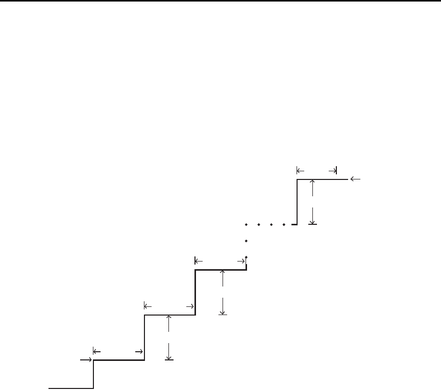
Model 6487 Reference Manual Buffer and Sweeps 6-9
The front panel sweep parameters are not error checked until you have entered a STEP
value. If there are too many points, the error message “TOO MANY PTS” briefly appears
and you will be taken back to the start (STRT) value entry menu.
Likewise, a step size larger than the (stop-start) interval results in the message “STEP
TOO BIG”. Note that as long as the front panel V-MODE setting is SWEEP, the TRIG key
will function to initiate sweeps rather than as a trigger source. To return the TRIG key to
its normal behavior, use CONFIG -> OPER to set V-MODE back to DC.
Figure 6-2
Voltage sweeps
Start
Stop
Step
Step
Step
X
X
X
X
Delay
Delay
Delay
Delay
Note: X = Measurements taken.

6-10 Buffer and Sweeps Model 6487 Reference Manual
Sweep operation
Using Table 6-2 as a guide, follow these steps to generate sweeps from the front panel:
1. Press CONFIG then OPER. The unit will prompt for DC or SWEEP operation.
2. Select SWEEP, then press ENTER. The unit will prompt for the STRT (start)
voltage.
3. Using the manual RANGE and cursor keys, enter the desired start voltage, then
press ENTER. The unit will then prompt for the STOP voltage.
4. Enter the stop voltage, then press ENTER. The unit will prompt for the step
voltage.
5. Enter the step voltage, then press ENTER. The unit will prompt for the delay.
6. Enter the delay period, then press ENTER. The unit will prompt you to press TRIG
to start the sweep. The SCAN annunciator will be on to show the sweep is armed.
7. To start a sweep, press the TRIG key. The voltage source will be placed in operate,
the sweep will be performed, and readings will be stored in the buffer for later
recall. To abort a sweep in progress, press the EXIT key.
Recalling sweep data
To recall sweep data, press the RECALL key then use the manual RANGE and cursor
keys to display readings. See “Recall,” page 6-2 for more information.
Operating considerations
Buffer
The reading (TRACe) buffer is cleared at the start of the sweep and readings collected
during the sweep are placed into the buffer. The voltage source value is stored as a reading
element.
Table 6-2
Sweep parameter menu selections
Sweep Menu Description Default
STRT Start voltage (-505 to 505V). 0V
STOP Stop voltage (-505 to 505V). 10V
STEP Step voltage (-505 to 505V). 1V
DEL Delay between source and measure (0s to 999.9999s). 1s

Model 6487 Reference Manual Buffer and Sweeps 6-11
Source range
The source range will be fixed at the lowest range required to properly handle all points in
the sweep. For example, a 10-point sweep from +2V to +11 V in 1V steps will start on the
50V range and remain on the 50V range for all points in the sweep.
Sweep direction
Sweeps can go in either direction, but the STEP is an absolute value and is always posi-
tive. It can range from zero to the value of (START - STOP).
Command restrictions
While a sweep is in progress, most voltage source control commands, trigger model com-
mands, and buffer (TRACe subsystem) commands are locked out. Sending any of the
commands listed below generates the error code +840 “Not allowed with sweep on”:
SOUR:VOLT[:LEV][:IMM][:AMPL]
SOUR:VOLT:STATe
SOUR:VOLT:RANGe
ARM:SEQ1:COUN
ARM:SEQ1:SOUR
ARM:SEQ1:TIM
TRIG:SEQ1:COUN
TRIG:SEQ1:SOUR
TRIG:SEQ1:DEL
TRIG:SEQ1:DEL:AUTO
TRAC:FEED
TRAC:FEED:CONT
TRAC:POIN
TRAC:CLE
TRAC:TST:FORM
Sweep example
For a linear sweep from -25V to +25V in 5 V steps, sweep parameters would be set as
follows:
•Start: -25
• Stop: 25
• Step: 5
This sweep will have 11 points corresponding to the voltage source values -25, -20, -15,
-10, -5, 0, 5, 10, 15, 20, and 25. Changing the step to 7V results in values of -25, -18, -11,
-4, 3, 10, 17, and 24, which shows that only complete steps are executed.

6-12 Buffer and Sweeps Model 6487 Reference Manual
SCPI programming — sweeps
Interlock
Attempting to initialize a sweep over the front panel while the interlock is open and failing
will result in the error message "CLOSE INTLCK" being displayed. If trying to arm
remotely with the SOUR:VOLT:SWE:INIT command, the error event +802 "Output
Blocked by Interlock"is generated.
Trigger model
Sweeps do not change any of the trigger model settings (Section 7), other than to inter-
nally perform the equivalent of an ABORt command and return to the Idle layer when the
SOUR:VOLT:SWE:INIT command is received. Trigger and Arm Counts, sources, and
delays are exactly what they were before the sweep was started. The only difference is that
the sweep delay is added between the setting of the source to the new value and the acqui-
sition of the reading.The implications of this fact are that you must have the trigger and
arm counts properly set before sending the SOUR:VOLT:SWE:INIT command.
Example A
*RST
SYST:ZCH OFF
SOUR:VOLT:SWE:STAR 0
SOUR:VOLT:SWE:STOP 10
SOUR:VOLT:SWE:STEP 1
SOUR:VOLT:SWE:DEL 2
SOUR:VOLT:SWE:INIT
INIT:IMM
Because the *RST command sets the ARM and TRIG layer counts both to 1, the
INIT:IMM will take only a single reading in the sweep. To collect all 11 readings, you
would need to send eleven INIT:IMM commands. After each INIT:IMM command
arrives, the source will jump immediately to the new voltage, there will be a two-second
delay, then the reading will be collected.
Example B
*RST
SYST:ZCH OFF
ARM:COUN INF
SOUR:VOLT:SWE:STAR 0
SOUR:VOLT:SWE:STOP 10
SOUR:VOLT:SWE:STEP 1
SOUR:VOLT:SWE:DEL 2
SOUR:VOLT:SWE:INIT
INIT:IMM

Model 6487 Reference Manual Buffer and Sweeps 6-13
This example is the same as before except that a setting for the ARM layer count to infinite
has been added. Now, after the INIT:IMM is received, the sweep will begin and all 11
points will be collected with no further commands required. Each point will be spaced
roughly two seconds apart (slightly longer due to the fact that the command sequence
leaves Autozero on). Once the sweep is complete, the source will go to 0V and will be
turned off, but readings will continue to be taken since the ARM count is infinite. These
readings will no longer be separated by the 2-second sweep delay, but instead will be col-
lected at the normal (Slow, 6 PLC) rate.
Status model
Bit 3 of the Operation Condition Register (Section 10) is used to indicate that a sweep is in
progress. It will be set true when the SOUR:VOLT:SWE:INIT command is received and it
remains high until either the last sweep point is completed or a SOUR:VOLT:SWE:ABOR
command is received.
A) :VOLTage:SWEep:STARt <NRf>
This command programs the start voltage, which is the initial setting of the voltage source
during the sweep.
B) :VOLTage:SWEep:STOP <NRf>
This command programs the stop voltage, which is the final setting of the voltage source
during the sweep.
Table 6-3
SCPI commands — sweeps
Commands Description Default Ref.
SOURce[1]
:VOLTage
:SWEep
:STARt <NRf>
:STOP <NRf>
:STEP <NRf>
:CENTer <NRf>
:SPAN <NRf>
:DELay <NRf>
:INITiate
:ABORt
:STATe?
INITiate
SOURce1 subsystem:
Voltage source commands:
Sweep commands
Set start voltage: -505V to 505V.
Program stop voltage: -505V to 505V.
Program step voltage: -505V to 505V.
Program center voltage: -505V to 505V.
Program span voltage: -505V to 505V.
Set delay: 0 to 999.9999s.
Arm sweep, put source in operate.
Abort sweep, put source in standby.
Query if sweep running: 1 = sweep in progress.
Trigger sweep.
0V
10V
1V
5V
10V
1s
A
B
C
D
E
F
G
H
I

6-14 Buffer and Sweeps Model 6487 Reference Manual
C) :VOLTage:SWEep:STEP <NRf>
This command programs the step voltage. In cases where there are not an exact number of
steps between the start and stop point, the last step will be truncated. Step sizes larger than
the (stop - start) interval will generate Error -842 “Sweep step size too large”. Step sizes
that will result in a sweep with more than the 3,000 point buffer maximum or below the
minimum source resolution for the source range required by the sweep will also generate
Error +841 “Sweep step size too small”. The STEP size is an absolute value, so the lower
limit is zero and the upper limit is restricted by the STARt and STOP settings.
D) :VOLTage:SWEep:CENTer <NRf>
This command enters the mid-point of the sweep. Note that CENTer and SPAN are inti-
mately coupled with STARt and STOP and simply offer another way to specify the sweep.
E) :VOLTage:SWEep:SPAN <NRf>
This command enters the total span of the sweep. CENTer and SPAN are coupled with
STARt and STOP and are another way to specify the sweep.
F) :VOLTage:SWEep:DELay <NRf>
This command programs the delay period, which is the time that the Model 6487 waits
after sourcing the voltage before starting to take the measurement at each step.
G) :VOLTage:SWEep:INITiate
This command places the voltage source in operate and begins sweep operation with the
next trigger. Once the sweep is triggered, the buffer is opened and the unit begins saving
readings. Error checking is held off until the SOUR:VOLT:SWEep:INIT command is sent.
A step size that is too small and would result in more than 3,000 points in the sweep gen-
erates Error +841 “Sweep step size too small”. If the step size exceeds the interval (STOP
- STARt), then you get Error +842 “Sweep step size too large”.
H) :VOLTage:SWEep:ABORt
This command immediately places the voltage source in standby (Operate off), cancels
buffer storage, and restores the trigger model to its prior settings before the sweep was
started.
I) :VOLTage:SWEep:STATe?
This query provides a means to determine whether or not a sweep is still running. A
returned value of 1 indicates that the sweep is still in progress, while a value of 0 shows
that no sweep is active.

Model 6487 Reference Manual Buffer and Sweeps 6-15
Programming example
The following command sequence performs a sweep from 1V to 10V in 1V increments
and recalls all readings:
*RST ' Return 6487 to RST defaults.
SOUR:VOLT:SWE:STAR 1 ' Start voltage = 1V.
SOUR:VOLT:SWE:STOP 10 ' Stop voltage = 10V.
SOUR:VOLT:SWE:STEP 1 ' Step voltage = 1V.
SOUR:VOLT:SWE:DEL 0.1 ' 0.1s delay.
ARM:COUN INF ' Reset arm count.
FORM:ELEM READ,VSO ' Select reading, voltage source data.
SOUR:VOLT:SWE:INIT ' Arm sweep, put source in operate.
SYST:ZCH OFF ' Turn off zero check.
INIT ' Trigger sweep.
TRAC:DATA? ' Request all stored sweep readings.

7
Triggering
•Trigger models — Explains the various components of the trigger models which
control the triggering operations of the instrument. Also, explains how to configure
the trigger model from the front panel.
•SCPI programming — Includes the commands used to configure the trigger
model and the commands to control the measurement process.
•External triggering — Explains external triggering which allows the Model 6487
to trigger other instruments and to be triggered by other instruments.
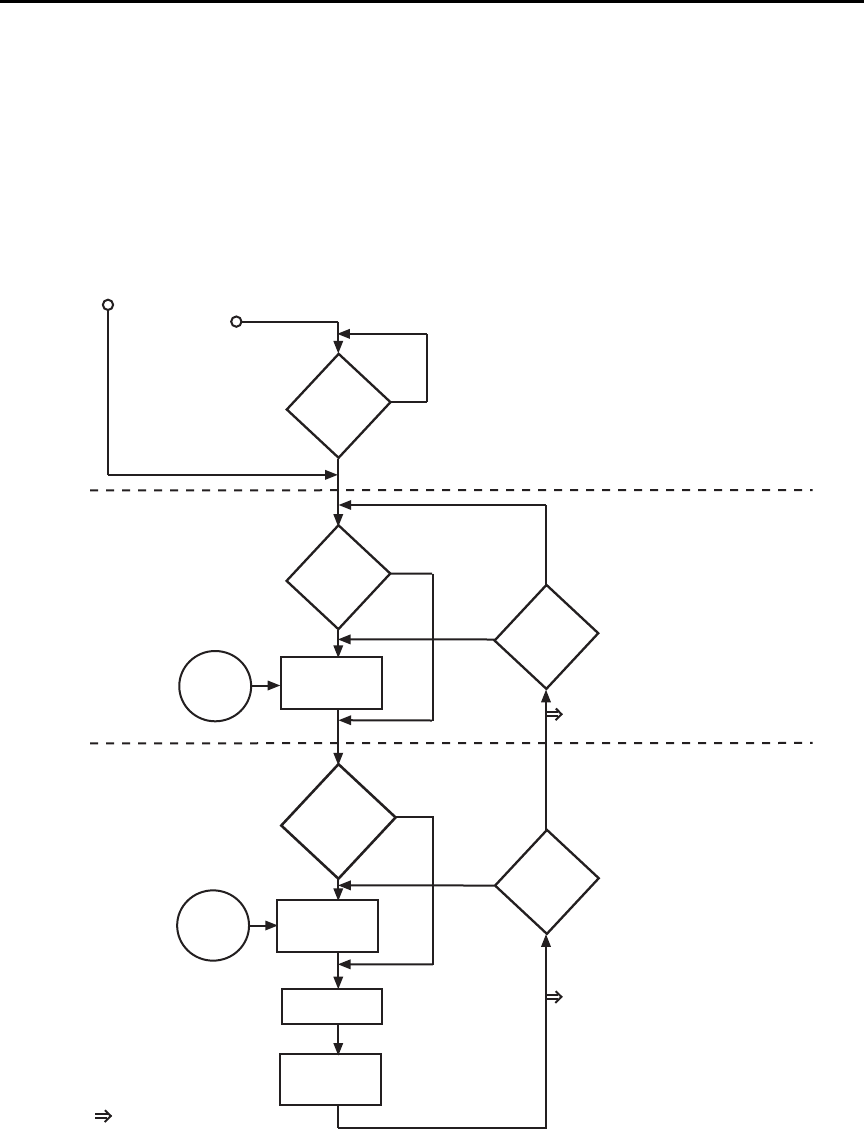
7-2 Triggering Model 6487 Reference Manual
Trigger models
The flowcharts in Figure 7-1 and Figure 7-2 summarize triggering for the Model 6487.
They are called trigger models because they are modeled after the SCPI commands to con-
trol triggering (operation).
Figure 7-1
Trigger model — front panel operation
Arm-In
Source
Immediate
GPIB
Timer
Manual
TLink
/STest
STest
BSTest
Arm Event
Detector
Trigger Event
Detector
Trigger Delay
MEASURE
Action
No
Yes
Idle
Another
Arm
?
Another
Trigger
?
Yes
No
Arm
Layer
Trigger
Layer
Trigger-In
Source
Yes
Halt
?
No
Once
Bypass
Arm Event
Detector
?
Never
Bypass
Trigger Event
Detector
?
Once
Never
Output Trigger
(VMC) On/Off
Trigger
Count
1
Output
Trigger
(TL Done)
On/Off
Arm
Count
INF
Immediate
TLINk
Press HALT
Turn 6487 ON
0.0 sec
Factory Default
Output Trigger
✛
✛
✛
✛
✛
✛
✛
✛
✛
✛
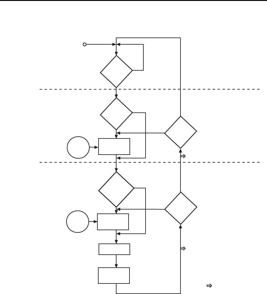
Model 6487 Reference Manual Triggering 7-3
Figure 7-2
Trigger model — remote operation
The difference between front panel operation (Figure 7-1) and remote operation
(Figure 7-2) is within the idle state of the instrument. Nomenclature in Figure 7-1 relates
to the various names used for configuration menu items while Figure 7-2 provides the
SCPI commands to control operation.
Arm-In
Event
Arm Event
Detector
Trigger Event
Detector
Trigger Delay
MEASURE
Action
No
Yes
Idle
Another
Arm
?
Another
Trigger
?
Yes
No
Arm
Layer
Trigger
Layer
= Output Trigger
Trigger-In
Source
0.0 sec
No
See Note
INITiate
?
Yes
SOURce
ARM
:DIRection
ACCeptor
ARM:SOURce IMMediate
ARM:SOURce BUS
ARM:SOURce TIMer
ARM:SOURce MANual
ARM:SOURce TLINk
ARM:SOURce NSTest
ARM:SOURce PSTest
ARM:SOURce BSTest
TRIGger
:DIRection
SOURce
ACCeptor
TRIGger:DELay <n> TRIGger:OUTPut SENSe | NONE
TRIGger:COUNt <n>
ARM:OUTPut TRIGger|NONE
ARM:COUNt <n>
TRIGger:SOURce IMMediate
TRIGger:SOURce TLINk
Note: The following commands place the
Model 6487 into idle: ABORt,
*RST, SYSTem:PRESet, *RCL <NRf>,
DCL, and SDC.
TRIGger:DELay:AUTO <b>

7-4 Triggering Model 6487 Reference Manual
Idle and initiate
While in the idle state, the instrument cannot perform measurements. While in idle, the
reading remains frozen or dashes replace the reading (i.e. -.------ A). Once the Model 6487
is taken out of idle, operation proceeds through the trigger model.
Front panel operation — As shown in Figure 7-1, the Model 6487 immediately leaves
the idle state when it is turned on. Typically, operation remains in the arm and trigger
layers of the trigger model. However, the Model 6487 can be put into the idle state at any
time by selecting HALT in the trigger configuration menu. To take the instrument out of
idle, press the TRIG key. Other front panel keys can be pressed instead, but they may
change the setup.
Remote operation — As shown in Figure 7-2, an initiate command is required to take the
instrument out of idle. The following commands perform an initiate operation:
•INITiate
• READ?
•MEASure?
While operating within the trigger model (not in idle), most commands will not be exe-
cuted until the instrument completes all of its programmed operations and returns to the
idle state. The IFC, SDC, and DCL commands can be executed under any circumstance
while operating within the trigger model. They will abort any other command or query.
The following commands can be executed while operating within the trigger model except
when a READ? or MEASure? is being processed:
•ABORt
•SYSTem:PRESet
• *TRG or GET
•*RST
• *RCL <NRf>
klqb For fastest response, use SDC or DCL to return to idle (see Section 9 for details
on general bus commands).

Model 6487 Reference Manual Triggering 7-5
Trigger model operation
Once the instrument is taken out of idle, operation proceeds through the trigger model to
perform a measurement (measure action).
klqb The following discussion focuses on the front panel trigger model (Figure 7-1).
However, equivalent SCPI commands are included where appropriate.
Event detectors and control sources
A control source holds up operation until the programmed event occurs and is detected.
Note that there are two detector bypasses. A bypass around a detector is only enabled if the
appropriate TLink control source is selected. See TLink control source (Arm-In and Trig-
ger-In) as follows for details.
Arm-In source — The Arm-In control sources are explained as follows:
•Immediate (ARM:SOURce IMMediate) — Event detection for the arm layer is
satisfied immediately allowing operation to continue into the trigger layer.
•GPIB (ARM:SOURce BUS) — Event detection for the arm layer is satisfied when
a bus trigger (GET or *TRG) is received by the Model 6487.
•Timer (ARM:SOURce TIMer) — Event detection for the arm layer is immediately
satisfied after the instrument leaves the idle state. Detection for each subsequent
pass is satisfied when the programmed timer interval elapses. The timer resets to its
initial state when the instrument goes back into idle.
•Manual (ARM:SOURce MANual) — Event detection for the arm layer is satisfied
by pressing the TRIG key. The Model 6487 must be in the local mode for it to
respond to the TRIG key. Press LOCAL or send LOCAL 14 over the bus to place
the Model 6487 in local.
•TLink (ARM:SOURce TLINk) — Event detection for the arm layer is satisfied
when an input trigger via the TRIGGER LINK connector is received by the
Model 6487. Note that if the source bypass is set to ONCE (ARM:DIRection
SOURce), operation will initially loop around the source detector after the instru-
ment leaves the idle state. Detection for each subsequent pass is satisfied by an
input trigger. The bypass resets when the instrument goes into idle.
•/STest (ARM:SOURce NSTest) — Event detection for the arm layer is satisfied
when a negative-going pulse (via the SOT line of the Digital I/O) is received from a
component handler (see Limit Tests and Digital I/O in Section 8).
•STest (ARM:SOURce PSTest) — Event detection for the arm layer is satisfied
when a positive-going pulse (via the SOT line of the Digital I/O) is received from a
component handler (see Limit Tests and Digital I/O in Section 8).
•BSTest (ARM:SOURce BSTest) — Event detection for the arm layer is satisfied
when either a positive-going or a negative-going pulse (via the SOT line of the Dig-
ital I/O) is received from a component handler (see Limit Tests and Digital I/O in
Section 8).

7-6 Triggering Model 6487 Reference Manual
Trigger-In source — The Trigger-In control sources are explained as follow:
•Immediate (TRIGger:SOURce IMMediate) — Event detection for the trigger
layer is satisfied immediately allowing operation to continue to perform a
measurement.
•TLink (TRIGger:SOURce TLINk) — Event detection for the trigger layer is satis-
fied when an input trigger via the TRIGGER LINK connector is received by the
Model 6487. Note that if the source bypass is set to ONCE (TRIGger:DIRection
SOURce), operation will loop around the source detector on the initial pass
through the arm layer. Detection for each subsequent pass is satisfied by an input
trigger. The bypass resets when the Model 6487 leaves the trigger layer.
Trigger delay
A programmable delay is available after event detection. It can be set manually (0 to
999.9998 seconds) or an auto delay can be used. With auto delay selected, the Model 6487
automatically sets delay according to range. The auto delay settings are listed in Table 7-1.
Table 7-1
Auto delay settings
Range Delay
2nA
20nA
200nA
2μA
20μA
200μA
2mA
20mA
10ms
10ms
10ms
10ms
5ms
5ms
1ms
0.5ms
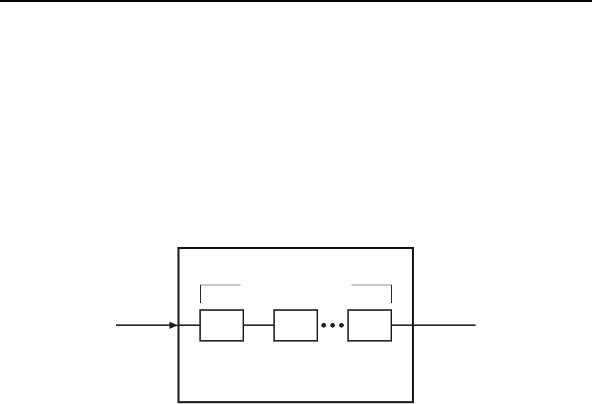
Model 6487 Reference Manual Triggering 7-7
Measure action
The measure action block of the trigger model is where a measurement is performed.
However, if the repeating filter is enabled (Figure 7-3), the instrument samples the speci-
fied number of reading conversions to yield single filtered reading. Only one reading con-
version is performed if the digital filter is disabled or after the specified number of reading
conversions for a moving average filter is reached.
If a voltage sweep is active, one measure action per voltage step is performed.
Figure 7-3
Measure action block of trigger model
Output triggers
The Model 6487 can send out an output trigger (via the rear panel TRIGGER LINK
connector) right after the measure action and/or when operation leaves the trigger layer.
An output trigger can be used to trigger another instrument to perform an operation
(e.g., select the next output step for a source).
Counters
Programmable counters are used to repeat operations within the trigger model layers. For
example, if the trigger count is set for 10, operation will keep looping around in the trigger
layer until 10 measurements are performed. If the arm count is set to 2, operation will then
loop back through the arm layer and go back into the trigger layer to perform 10 more
measurements.
Filter Process (Repeat)
CONV CONV CONV
CONV = Reading Conversion
Measure Action

7-8 Triggering Model 6487 Reference Manual
Trigger model configuration — front panel
klqb See “SCPI Programming” (Table 7-3) for the SCPI commands to configure the
trigger model over the bus.
Press CONFIG and then TRIG to configure both the TRIG and ARM layers of the trigger
model.
klqb When done configuring the trigger level, press ENTER to confirm value and then
use the EXIT key to save changes and leave trigger model configuration.
Once in trigger model configuration mode, use the RANGE keys to display either the
TRIGGER layer or the ARM layer menus. Press ENTER to select the desired menu. Then
use the RANGE keys to display menu items. Use the cursor keys to key in values. A menu
item or value is selected by pressing ENTER. Use the EXIT key to exit from the menu
(saving all changes made).
Table 7-2
Trigger model menu structure
Menu Description
CONFIG Path to TRIG and ARM menus. Access by pressing
CONFIG and then TRIG.
-TRIG Path to TRIG layer sub-menus.
--COUNT
---INF
---FIN
Set TRIG measure count.
Specify an INFinite measure count.
Specify a FINite measure count: 1–2048.
--DELAY
---MAN
---AUTO
Set trigger delay.
Specify trigger delay: 0–999.9998 sec.
Enable auto delay.
--TRIG-OUT
---LINE
----TLINK
---EVENTS
----VMC
Configure output triggers.
Select the output trigger link line.
Set trigger link value: 1–6.
Select VMC (voltmeter complete) output trigger.
Enable/disable VMC (on or off).
--TRIG-IN
---SOURCE
----IMM
----TLINK
-----TLINK
-----EVENT
Path to control source.
Set the TRIG-IN control source.
Set control source to IMMediate.
Set control source to TLINK.
Set TLINK value: 1–6.
Enable (set to ONCE) or disable (set to NEVER).

Model 6487 Reference Manual Triggering 7-9
klqb Input trigger and output triggers cannot share the same trigger link line.
Defaults set line 1 as the input and line 2 as the output.
-HALT Stops triggering. Press TRIG to resume.
-ARM Path to ARM layer submenus.
--ARM-IN
---IMM
---GPIB
---TIMER
---MAN
---TLINK
----TLINK
----EVENT
---/STEST
---STEST
---BSTEST
Path to ARM-IN control source.
Set control source to IMMediate.
Set control source to GPIB.
Set control source to TIMER. Set timer from
0.001S to 27H, 46M, and 39.992S.
Set control source to MANual.
Set control source to TLINK.
Set TLINK value: 1–6.
Enable (set to ONCE) or disable (set to NEVER).
Set control to negative pulse on SOT line (Section 8).
Set control to positive pulse on SOT line (Section 8).
Set control to positive or negative pulse on SOT line
(Section 8).
--ARM-OUT
---LINE
----TLINK
---EVENT
----T - L - DONE
Path to ARM-OUT trigger.
Set the output trigger link line.
Set trigger link value: 1–6.
Set Trigger Layer Done event.
Enable/disable Trigger Layer Done (on / off).
--COUNT
---INF
---FIN
Set ARM measure count.
Specify an INFinite measure count.
Specify a FINite measure count: 1–2048.
Table 7-2 (con t . )
Trigger model menu structure
Menu Description

7-10 Triggering Model 6487 Reference Manual
SCPI programming
A) ABORt
If operation has been started by the INITiate command, ABORt will cancel all operations
and immediately return the instrument to the idle state. If operation has been started by
READ? (or MEASure?), ABORt has no effect.
Table 7-3
SCPI commands — triggering
Command Description Default Ref
ABORt
INITiate
FETCh?
READ?
ARM[:SEQuence[1]]
[:LAYer[1]]
:SOURce <name>
:COUNt <n>
:TIMer <n>
[:TCONfigure]
:DIRection <name>
[:ASYNchronous]
:ILINe <NRf>
:OLINe <NRf>
:OUTPut <name>
TRIGger
:CLEar
[:SEQuence[1]]
:SOURce <name>
:COUNt <n>
:DELay <n>
:AUTO <b>
[:TCONfigure]
:DIRection <name>
[:ASYNchronous]
:ILINe <NRf>
:OLINe <NRf>
:OUTPut <name>
Reset trigger system (goes to idle state).
Initiate one trigger cycle.
Request latest reading.
Trigger and request a “fresh” reading.
Arm Layer:
Select control source: IMMediate, TIMer, BUS,
MANual, TLINk, PSTest, NSTest, or BSTest.
Set measure count: 1 to 2048, or INF (infinite).
Set timer interval: 0.001 to 99999.999 (sec).
Enable (SOURce) or disable (ACCeptor) bypass.
Configure input/output triggers:
Select input trigger line: 1, 2, 3, 4, 5, or 6.
Select output trigger line: 1, 2, 3, 4, 5, or 6.
Output trigger (TRIGger) or not at all (NONE).
Trigger Layer:
Clear pending input trigger immediately.
Trigger path.
Select control source: IMMediate or TLINk.
Set measure count: 1 to 2048 or INF (infinite).
Set trigger delay: 0 to 999.9998 (sec).
Enable or disable auto delay.
Enable (SOURce) or disable (ACCeptor) bypass.
Configure input/output triggers:
Select input trigger line: 1, 2, 3, 4, 5, or 6.
Select output trigger line: 1, 2, 3, 4, 5, or 6.
Output trigger after measurement (SENSe) or
not at all (NONE).
IMM
1
0.1
ACC
1
2
NONE
IMM
1
0.0
OFF
ACC
1
2
NONE
A
B
B
B
C
D
E
E
F
D
E
E

Model 6487 Reference Manual Triggering 7-11
B) INITiate, FETCh, and READ?
1. After sending the INITiate command to take the instrument out of idle, the instru-
ment will perform one or more measurements and then return to idle. The FETCh?
command can then be used to read the last reading that was measured.
2. If INITiate is sent while the instrument is operating within the trigger model, it will
not execute until the operation returns to the idle state.
3. One alternative to using INITiate is to use the READ? command. When READ? is
sent, the instrument is taken out of idle and all readings that are taken are returned
(See Section 12 for details on READ?).
C) ARM:SOURce <name>
With the TIMer control source selected, use the ARM:TIMer command to set the timer
interval.
D) ARM:DIRection <name>
The source bypass can only be used if the TLINk control source is selected.
E) ARM:ILINe <NRf> and ARM:OLINe <NRf>
Input trigger and output trigger cannot share the same trigger link line. Defaults set line 1
as the input and line 2 as the output.
F) TRIGger:CLEar
When this action command is sent, any pending (latched) input triggers are cleared imme-
diately. When the picoammeter is being latched by another instrument, it may inadvert-
ently receive and latch input triggers that do not get executed. These pending triggers
could adversely affect subsequent operation.
When using external triggering, it is recommended that TRIGger:CLEar be sent after
sending the ABORt command and at the beginning of a program before sending a initiate
command. (See “INITiate” command.)
Programming example
The following command sequence will trigger and return 10 readings.
*RST ' Return 6487 to RST defaults.
ARM:SOUR IMM ' Set arm control source Immediate.
ARM:COUN 1 ' Set arm count to 1.
TRIG:SOUR IMM ' Set trigger control source Immediate.
TRIG:COUN 10 ' Set trigger count to 10.
SYST:ZCH OFF ' Disable zero check.
READ? ' Trigger and return 10 readings.
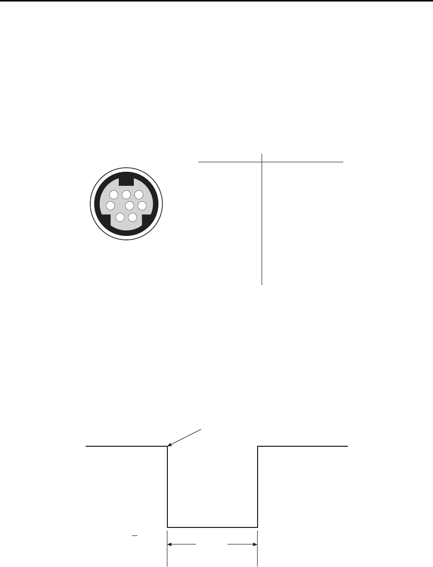
7-12 Triggering Model 6487 Reference Manual
External triggering
Input and output triggers are received and sent via the rear panel TRIGGER LINK connec-
tor. The trigger link has six lines. At the factory line #2 is selected for output triggers and
line #1 is selected for input triggers. These input/output assignments can be changed as
previously explained in this section. The connector pinout is shown in Figure 7-4.
Figure 7-4
Trigger link connection operation
Input trigger requirements
An input trigger is used to satisfy event detection for a trigger model layer that is using the
TLINK control source. The input requires a falling-edge, TTL-compatible pulse with the
specifications shown in Figure 7-5.
Figure 7-5
Trigger link input pulse specifications
876
54
3
21
Rear Panel Pinout Pin Number Description
1
2
3
4
5
6
7
8
Trigger Link 1
Trigger Link 2
Trigger Link 3
Trigger Link 4
Trigger Link 5
Trigger Link 6
Ground
Ground
Trigger Link
Triggers on
Leading Edge
TTL High
(2V-5V)
TTL Low
(<0.8V)
2 μs
Minimum
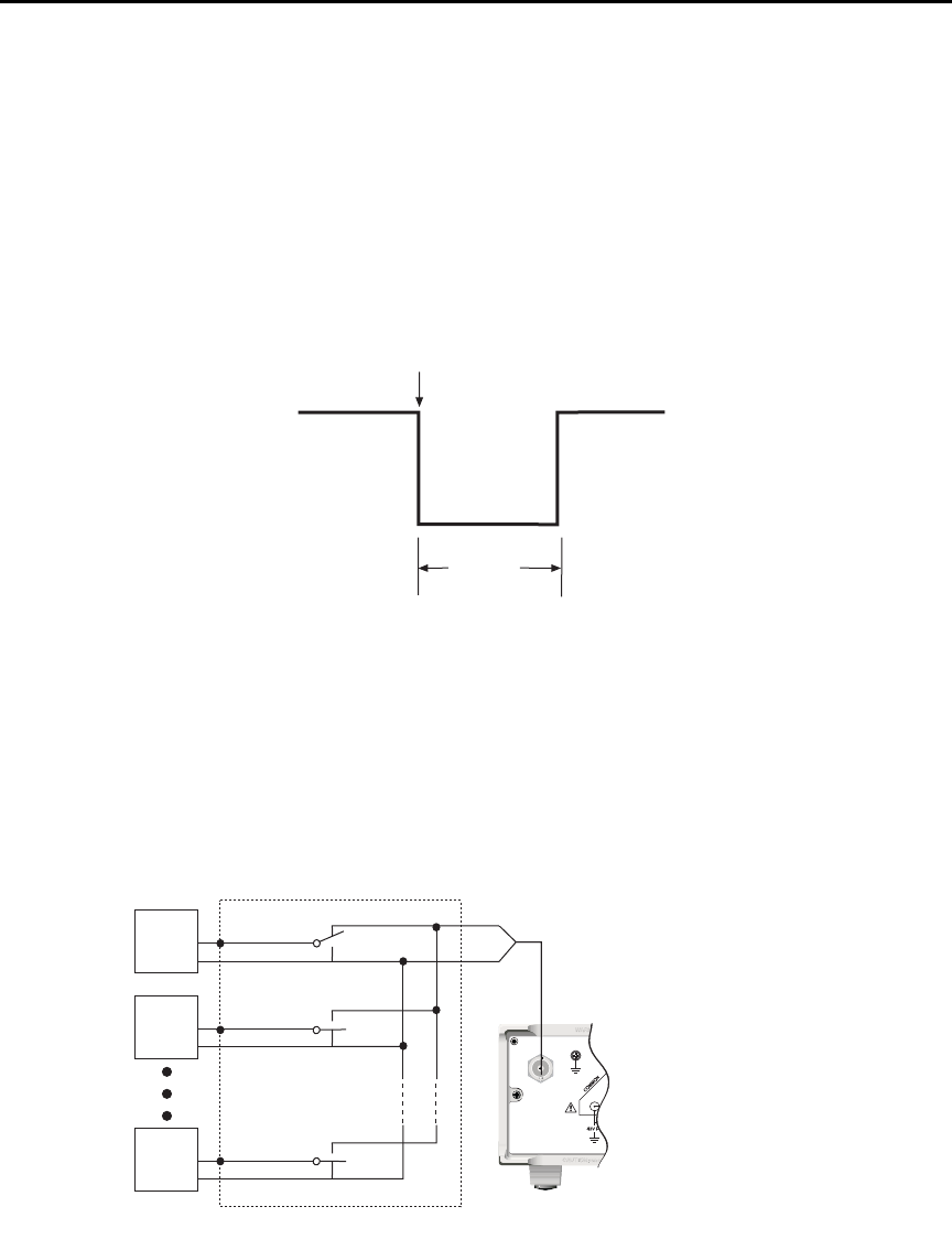
Model 6487 Reference Manual Triggering 7-13
Output trigger specifications
The Model 6487 can be programmed to output a trigger immediately after a measurement
and/or when operation leaves the trigger layer of the trigger model. The output trigger pro-
vides a TTL-compatible output pulse that can be used to trigger other instruments. The
specifications for this trigger pulse are shown in Figure 7-6. A trigger link line can source
1mA and sink up to 50mA.
Figure 7-6
Trigger link output pulse specifications
External trigger example
In a simple test system, you may want to close a switching channel and measure the cur-
rent from a DUT connected to that channel. Such a test system is shown in Figure 7-7.
This example uses a Model 6487 to measure 10 DUTs switched by a Model 7158 low cur-
rent card in a Model 7001 or 7002 switch system.
Figure 7-7
DUT test system
Meter Complete
TTL High
(3.4V Typical)
TTL Low
(0.25V Typical)
5μs
Minimum
120
FUSE LINE
630mA
LINE RATING
50, 60Hz
30 VA
T
(SB)
100 VAC
120 VAC
315mAT
(SB)
220 VAC
240 VAC
!
INPUT
(CHANGE IEEE ADDRESS
WITH FRONT PANEL MENU)
IEEE-488
CAT I
TRIGGER LINK RS-232
MADE IN
U.S.A.
RANGE
DEPENDENT
ANALOG OUT
DUT
#2
DUT
#1
DUT
#10
7158 Low Current Card
OUTPUT
Model 6487
Picoammeter
DUT
#3-#9
LO
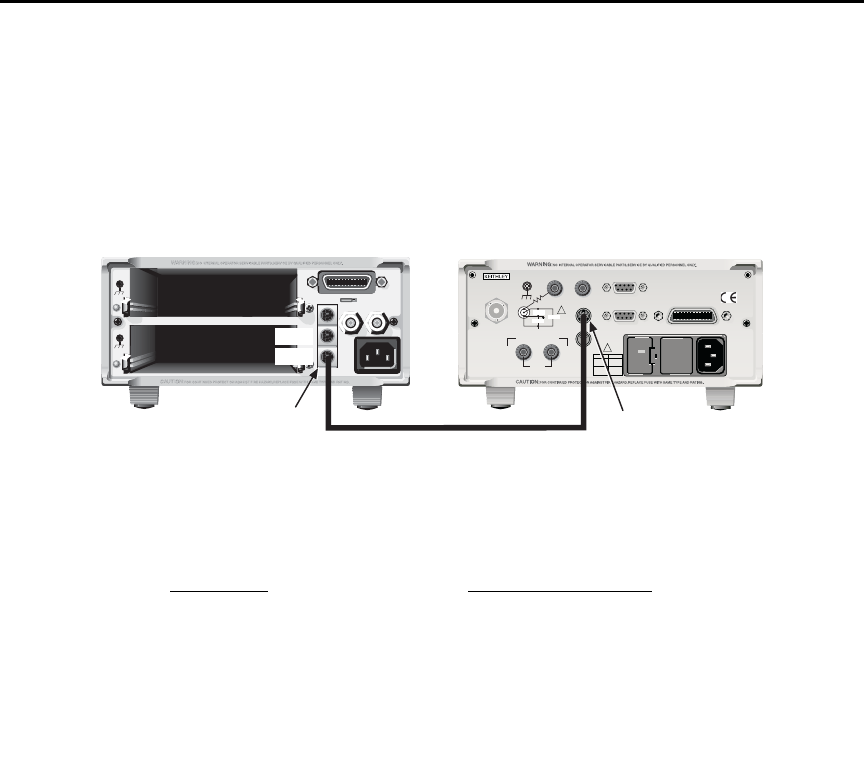
7-14 Triggering Model 6487 Reference Manual
The trigger link connections for this test system are shown in Figure 7-8. The trigger link
of the Model 6487 is connected to the trigger link (IN or OUT) of the switching main-
frame. Note that with the default trigger settings of the switching mainframe, line #1 is an
input and line #2 is an output.
Figure 7-8
Trigger link connections
For this example, the Model 6487 and switching mainframe are configured as follows:
To store readings in the Model 6487 buffer, first set the number of points to store in the
buffer:
1. Press CONFIG and then STORE.
2. Set the buffer size to 10 using the RANGE and cursor keys.
3. Press ENTER.
4. The next time STORE is pressed, the asterisk (*) annunciator turns on to indicate
the buffer is enabled. (See the Model 6487 User’s Manual for buffer details.)
To start the test, press STEP on the switching mainframe to take it out of idle and start the
scan. The switching mainframes output pulse triggers the Model 6487 to take a reading
and store it. the Model 6487 then sends an output trigger pulse to the switching mainframe
to close the next channel. This process continues until all 10 channels are scanned, mea-
sured, and stored.
Model 6487 Switching Mainframe
Factory Defaults Restored Factory Defaults Restored
Trig-In Event = TLink Scan List = 1!1-1!10
Trigger Input Line = #2 Number of Scans = 1
Trigger Output Line = #1 Channel Spacing = TrigLink
Trigger Output Event = ON
Trigger Count = 10
Trigger Delay = Auto
MADE IN USA
7001 or 7002 Switch System Model 6487 Picoammeter
OUT
IN
Trigger
Link
120
LINE RATING
50, 60Hz
50 VA MAX
INPUT
(CHANGE IEEE ADDRESS
WITH FRONT PANEL MENU)
IEEE-488
CAT I
TRIGGER LINK RS-232
MADE IN
U.S .A .
ANALOG OUT DIGITAL I/O
505V
MAX
V-SOURCE OUTPUT
505V PK TO CHASSIS
LO HI INTERLOCK
!
!
FUSE LINE
400mAT
(SB)
100 VAC
120 VAC
200mAT
(SB)
220 VAC
240 VAC
505V PK
505V PK
505V PK
Trigger
Link
Trigger Link Cable
(8501)
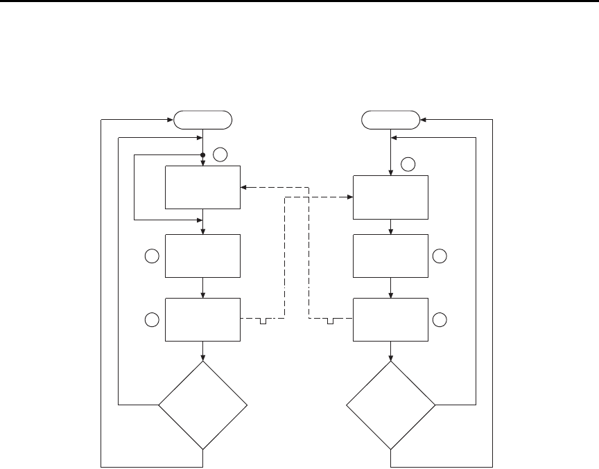
Model 6487 Reference Manual Triggering 7-15
Figure 7-9
Operation model for triggering example
Details of this testing process are explained in the following paragraphs and are referenced
to the operation model shown in Figure 7-9.
A. Operation of the Model 6487 starts at point A in the flowchart where it waits for
an external trigger.
B. Pressing STEP takes Model 7001/7002 out of idle and places operation at point
B in the flowchart.
C. For the first pass through Model 7001/7002, the scanner does not wait at point
B. Instead, it closes the first channel (point C).
D. After the relay settles, Model 7001/7002 outputs a trigger pulse. Since the
instrument is programmed to scan 10 channels, operation loops back to point B
where it waits for an input trigger.
E. and F. With the Model 6487 at point A, the output trigger pulse from Model 7001/7002
triggers a measurement of DUT #1 (point E). After the measurement is com-
plete, the Model 6487 outputs a trigger pulse and then loops back to point A
where it waits for another input trigger.
Idle
Bypass B
Wait for
Trigger Link
Trigger
Scan
Channel
C
Output
Trigger
Trigger
D
No Scanned
10
Channels
?
Yes
7001or 7002
Make
Measurement
Made
10
Measurements
?
6487
Press STEP to start scan
A
Wait for
Trigger Link
Trigger
E
Output
Trigger
Trigger F
No
Yes
Idle

7-16 Triggering Model 6487 Reference Manual
The trigger applied to Model 7001/7002 from the Model 6487 closes the next channel in
the scan, which then triggers the Model 6487 to measure that DUT. This process continues
until all 10 channels are scanned and measured.

8
Limit Tests and Digital I/O
•Limit testing — Explains the basic Limit 1 and Limit 2 testing operations.
•Binning — Explains how to use a component handler to perform binning
operations.
•Digital I/O port — Explains how to use the digital I/O port to control external
circuitry.
•Front panel operation — limit tests — Explains how to configure and run limit
tests from the front panel.
•SCPI programming — limit tests — Covers the SCPI commands for remote limit
test operation.
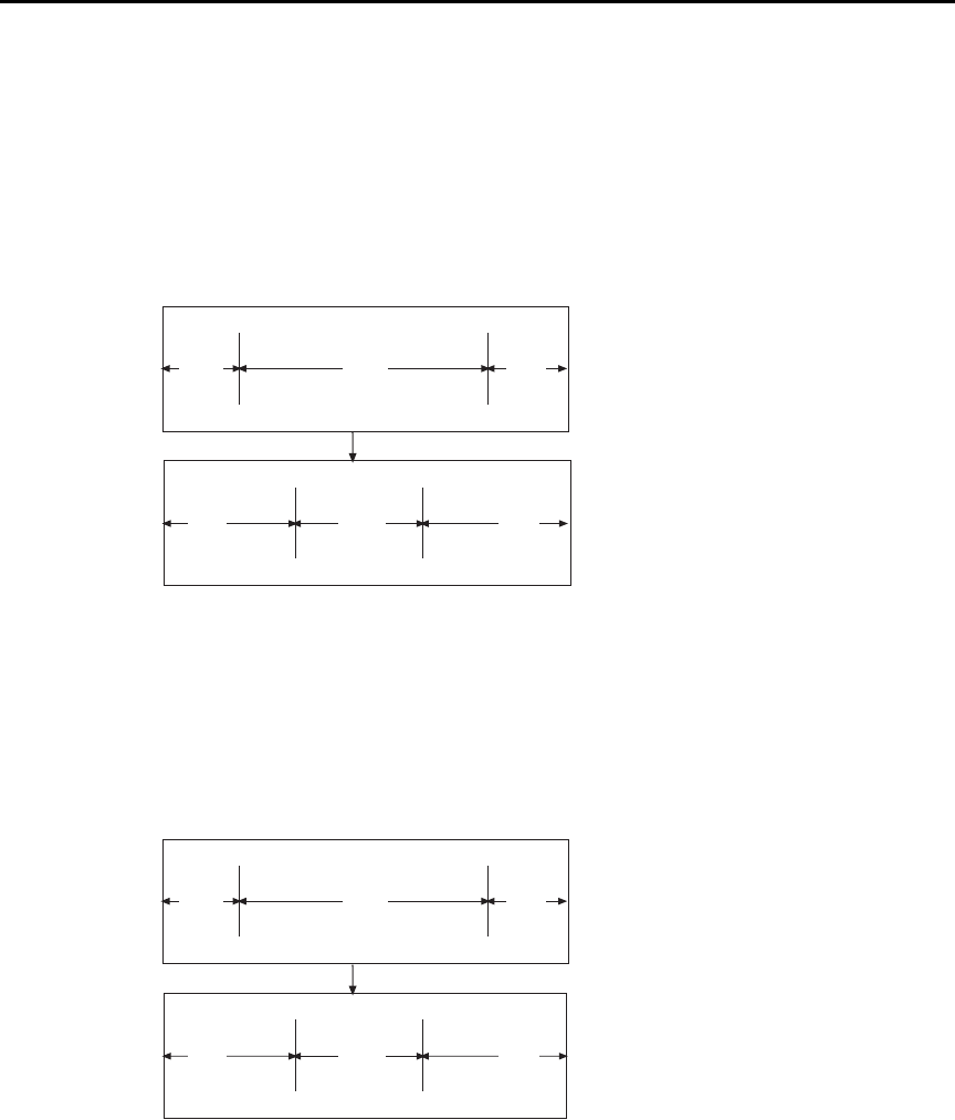
8-2 Limit Tests and Digital I/O Model 6487 Reference Manual
Limit testing
As shown in Figure 8-1, there are two limit tests that can be performed on a DUT. Limit 1
is used as the wide pass band and Limit 2 is used as the narrow pass band. It is up to the
user to specify limits that conform to this pass band relationship.
Figure 8-1
Limit tests
Figure 8-2 shows an example where the HI and LO limits for Limit 1 are ±2mA and the HI
and LO limits for Limit 2 are ±1mA. A 0mA reading passes both Limit 1 and Limit 2 tests.
A +1.5mA reading passes Limit 1 but fails Limit 2. A +2.5mA reading fails both Limit 1
and Limit 2.
Figure 8-2
Limit tests example
LO
LO
Limit
Limit
HI
HI
Limit
Limit
Limit 1 Test
(Wide Pass Band)
Limit 2 Test
(Narrow Pass Band)
Fail
Fail Fail
FailPass
Pass
-2mA
-1mA
LO Limit
LO Limit
+2mA
+1mA
HI Limit
HI Limit
Limit 1 Test
(Wide Pass Band)
Limit 2 Test
(Narrow Pass Band)
Fail
Fail Fail
FailPass
Pass

Model 6487 Reference Manual Limit Tests and Digital I/O 8-3
The 2-stage limit testing process is shown in . If Limit 1 fails, the L1 message is displayed
and the test is finished. Limit 2 is not tested because the pass band relationship between
the two stages implies that if Limit 1 fails, Limit 2 must also fail. If Limit 1 passes, the
Limit 2 test is performed. If Limit 2 fails, the L2 message is displayed. If both Limit 1 and
Limit 2 pass, the OK message is displayed. The display messages for limit tests are sum-
marized in Table 8-1.
klqb When limit tests are enabled, the voltage source value display is not visible, but
it can still be viewed by using the CONFIG V-SOURCE menu or by pressing the
V-SOURCE up or down arrow keys.
A test is only performed if it is enabled. Therefore, you can perform a single-stage test or a
2-stage test. In the flowchart (), operation simply proceeds through a disabled test.
Table 8-1
Test limit display messages
Display
Message
Limit 1
Test Result
Limit 2
Test Result
:OK Pass Pass
:L1 Fail Not Performed
:L2 Pass Fail
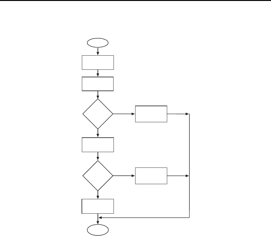
8-4 Limit Tests and Digital I/O Model 6487 Reference Manual
Figure 8-3
Operation model for limit test
klqb Display messages indicate which test or tests have failed, but they do not
indicate which limit (HI or LO) has failed. When using remote operation, you
can determine which limit failed by reading the measurement event register. See
Ref C for the FAIL? commands in Table 8-3 on page 8-18.
Relative (Rel), mX+b, m/X+b, and log can be used with limit testing. The tests
will be done on the result of the math operation (not the input values). These
math operations are covered in Section 5.
Application — A typical application for a 2-stage limit test is to sort a batch of DUT
according to tolerance. For example, you may want to sort diodes (all having the same
nominal value) into three groups, 1%, 5%, and >5%. The limits for Limit 1 would be the
5% tolerances and the limits for Limit 2 would be the 1% tolerances. If a diode passes both
tests, it belongs in the 1% group. If it passes Limit 1 but fails Limit 2, it belongs in the 5%
group. If it fails both tests, it belongs in the >5% group.
Pass
?
Start
Measure
DUT
Yes
Limit 1
Test
No Display
“L1”
Limit 2
Test
Pass
?Display
“L2”
Display
“OK”
Yes
No
End
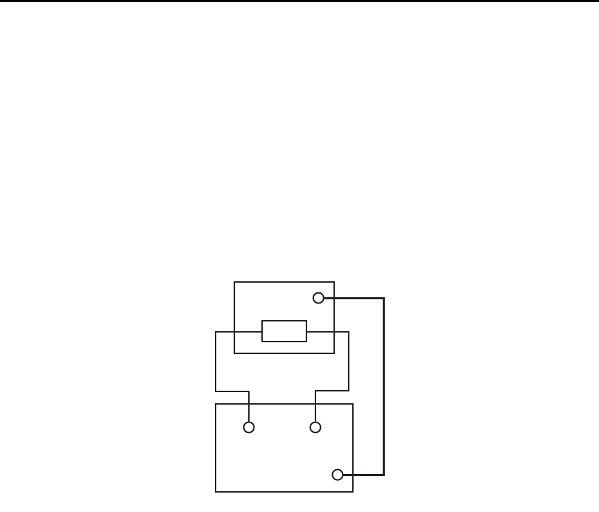
Model 6487 Reference Manual Limit Tests and Digital I/O 8-5
Binning
Even though no additional equipment is required to perform limit tests on the DUT, the
Model 6487 can be used with a component handler to perform binning operations. Based
on the outcome of a test, the component handler will place the DUT in the assigned bin.
Figure 8-4 shows a basic binning system. After all programmed testing on the DUT is
completed, the appropriate digital output pattern is sent to the component handler, which
then places the DUT in the appropriate bin. The component handler selects the next DUT
and the testing process is repeated.
Figure 8-4
Binning system
Handler
Dig
In
DUT
HI LO
Input
Dig
I/O
6487
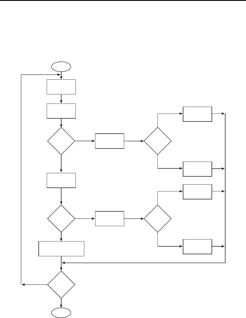
8-6 Limit Tests and Digital I/O Model 6487 Reference Manual
Figure 8-5 shows the basic limit testing flowchart expanded to include binning. Notice
that there are five possible output patterns (one pass pattern and four fail patterns), but
only one will be sent to the component handler for each DUT that is tested.
Figure 8-5
Operation model for limit testing with binning
Pass
?
Start
Measure
DUT
Yes
Limit 1
Test
No Display
“L1”
Limit 2
Test
Pass
?Display
“L2”
Display “OK” and
Output Pass Pattern
Yes
No
End
Which
Limit
Failed
?
Output Fail
Pattern
HI Limit
Failure
Output Fail
Pattern
LO Limit
Failure
Which
Limit
Failed
?
Output Fail
Pattern
HI Limit
Failure
Output Fail
Pattern
LO Limit
Failure
Test
Another
DUT
?
No
Yes
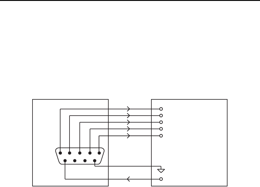
Model 6487 Reference Manual Limit Tests and Digital I/O 8-7
Component handler interface
The Model 6487 is interfaced to a component handler via the Digital I/O port as shown in
Figure 8-6. (See “Digital I/O port,” page 8-11 for more information.) The I/O port has four
lines for output signals and one line for input signals. The input line is used to start the test
and the output lines are used to send the test pass/fail signal(s) to the component handler to
perform the binning operation.
Figure 8-6
Handler interface connections
The digital I/O lines are available at the DB-9 connector on the rear panel of the
Model 6487. A custom cable using a standard female DB-9 connector is required for con-
nection to the Model 6487.
Start of test
The SOT (start of test) line of the Digital I/O is used to control the start of the testing pro-
cess. When /STest is the selected arm-in event for the arm layer of the trigger model, the
testing process will start when the SOT line is pulled low. When STest is the selected
arm-in event, the test will start when the SOT line is pulled high. When BSTest is the
selected arm-in event, the test will start when the SOT line is pulled either high or low.
Section 7 provides details on trigger model configuration.
klqb If you do not wish to use the SOT line to start the test, you can use the immediate
arm-in event. The testing process will start as soon as the LIMIT key is pressed
(assuming one or both limit tests are enabled).
The component handler will either maintain the SOT line high or low. This is its “not
ready” condition. When the component handler is ready (DUT properly position in the
handler), it will either pull the SOT line low or high to start the test.
6487
Out 1
Out 2
Out 3
Out 4
Gnd
Dig I/O
1
6
5
9
Input (SOT)
Handler
Line 1
Line 2
Line 3
Line 4 (or EOT)
SOT Strobe Line
Relay Clamp Voltage
V External

8-8 Limit Tests and Digital I/O Model 6487 Reference Manual
Digital output patterns
The Model 6487 uses digital output bit patterns to communicate test results to the compo-
nent handler. For each limit test, unique fail patterns are used for the HI and LO limits. A
pass pattern is used to indicate that there were no errors. After a test is finished, the appro-
priate output pattern is sent to the component handler. The handler decodes the bit pattern
and places the DUT in the appropriate bin.
The Model 6487 can be used with either of the two basic types of handlers. When used
with a category pulse handler, the Model 6487 pulses one of the four handler lines. The
handler then places the DUT into the bin assigned to the pulsed line.
When used with a category register handler, the Model 6487 outputs a bit pattern to three
handler lines. After the Model 6487 sends the end-of-test (EOT) strobe pulse to the fourth
handler line, the handler places the DUT into the bin assigned to that bit pattern.
Component handler types
The Model 6487 can accommodate two different types of component handlers: category
pulse and category register.
Category pulse component handler
When using this type of handler, the Model 6487 pulses one of the four handler lines when
a pass or fail condition occurs. The handler then places the DUT in the bin assigned to that
pulsed line. When interfacing to this type of handler, a maximum of four component
handler bins are supported.
If the handler requires low-going pulses, then the four digital output lines of the
Model 6487 must be initially set to high. This initial HI, HI, HI, HI clear pattern on the
output lines represents a “no action” condition for the handler since it is waiting for one of
the lines to go low. A line goes low when the defined fail or pass pattern sets it low. For
example, if you want a particular test failure to pulse line #4 of the handler, the defined fail
pattern has to be HI, HI, HI, LO. When the failure occurs, line #4 will be pulled low and
the DUT will be placed in the bin assigned to that pulsed line.
If the handler requires a high-going pulse, the four digital output lines of the Model 6487
must initially be set low. The LO, LO, LO, LO clear pattern represents the “no action”
condition for the handler. When one of those lines are pulled high by a defined pass or fail
bit pattern (i.e., LO, LO, LO, HI), the DUT will be placed in the bit assigned to that pulsed
line.

Model 6487 Reference Manual Limit Tests and Digital I/O 8-9
Category register component handler
When using this type of handler, the Model 6487 sends a bit pattern to three handler lines
when a pass or fail condition occurs. This bit pattern determines the bin assignment for the
DUT. With the pass/fail pattern on the output, line #4 is then pulsed. This EOT (end-of-
test) pulse latches the bit pattern into the register of the handler, which places the DUT in
the assigned bin. When interfacing to this type of handler, a maximum of eight component
handler bins are supported.
If the handler requires a low-going EOT pulse, line #4 of the digital output must initially
be set high. When the EOT line is pulsed low, the binning operation occurs. When using
the CONFIG LIMITS MENU to define pass/fail bit patterns, line #4 must be set low. If,
for example, the required fail pattern by the handler is HI, LO, HI, then you must define
the fail pattern of the test to be HI, LO, HI, LO. When the test fails, the HI, LO, HI bit pat-
tern is sent to the handler. When line #4 goes LO, the bit pattern is latched into the register
of the handler and the binning operation occurs.
Conversely, if the handler requires a high-going EOT pulse, the EOT line of the digital
output must initially be set low (off). When the EOT line is pulsed high, the binning oper-
ation occurs.
Line 4 mode
When using a category pulse component handler, the Model 6487 must be set to the Busy
or /Busy mode. In the Busy mode, the idle state for line 4 is LO. When the test starts (SOT
line pulsed), line 4 goes HI (busy state). After the test is finished, it goes back to LO. For
the /Busy mode, the idle state for line 4 is HI and busy state is LO.
When using a catagory register component handler, the Model 6487 must be set for the
End of Test mode. In this mode, the Model 6487 sends the EOT pulse to the component
handler as previously explained.

8-10 Limit Tests and Digital I/O Model 6487 Reference Manual
Digital output clear pattern
After every binning operation, the digital output needs to be reset to a clear pattern, which
serves as a “no action” condition for the component handler.
The Model 6487 can be programmed to automatically clear the digital output after the
pass or fail pattern is sent. With auto-clear, you must specify the required pulse width
(delay) for the pass or fail pattern. When not using auto-clear, you must return the digital
output to its clear pattern.
klqb With the Busy line 4 mode selected, the clear state of line 4 is LO, regardless of
the configured clear pattern. With the /Busy mode selected, the clear state of line
4 is HI.
Auto-Clear timing — The following example timing diagram (Figure 8-7) and discussion
explain the relationship between the digital output lines for auto-clear.
Figure 8-7
Digital output auto-clear timing example
Initially, the four digital output lines are cleared (in this case, they are all set high). Limit
tests start when the Start-Of-Test (SOT) pulse is received from the component handler.
When the testing process is finished, the pass or fail pattern is applied to the digital output.
As shown in the diagram, lines 2, 3, and 4 go low while line 1 remains high.
The pulse width (delay) of the pass/fail pattern can be set from 0 to 60 sec (10µsec resolu-
tion) as required by the component handler. Note that the delay specifies the pulse width
of line 4. The pulse width of lines 1, 2, and 3 is actually 20µsec longer. Line 4 is skewed
because it is used as the End-Of-Test (EOT) strobe by category register component han-
SOT*
Line 1
Line 2
Line 3
Line 4
(EOT) 10μs10μs
Delay
*With the SOT line being pulsed low (as shown), /START TEST must be the selected
arm event for the trigger model. If the SOT line is instead pulsed high by the
handler, START TEST must be the selected arm event.
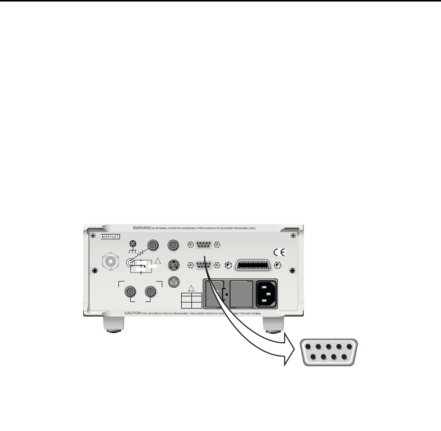
Model 6487 Reference Manual Limit Tests and Digital I/O 8-11
dlers. Lines 1, 2, and 3 establish the bit pattern and then 10µsec later the SOT strobe
“tells” the handler to read the bit pattern and perform the binning operation. This 10µsec
offset is used to make sure the correct bit pattern is read by the handler.
After the pass/fail is read by the handler, the digital output returns to the clear pattern.
Digital I/O port
The Model 6487's Digital I/O port is a male DB-9 connector located on the rear panel. The
port location and pin designations are shown in Figure 8-8. The four active-low, digital
output lines and one input line are used to control external circuitry.
Figure 8-8
Digital I/O port
Typical applications for the digital I/O port include the following:
•Component handler control — When performing limit tests, a component han-
dler can be used to sort DUT into bins. (See “Binning,” page 8-5 for details.) The
digital I/O of the Model 6487 serves as the interface between the limit tests and the
component handler. Via the digital input line (pin 6), the component handler can
tell the Model 6487 when it is ready for the test. Via the digital output lines, The
Model 6487 sends digital output patterns to the component handler and tells it
when the test is finished. A digital output pattern determines which bin the DUT
belongs in.
120
LINE RATING
50, 60Hz
50 VA MAX
INPUT
(CHANGE IEEE ADDRESS
WITH FRONT PANEL MENU)
IEEE-488
CAT I
TRIGGER LINK RS-232
MADE IN
U. S. A .
ANALOG OUT DIGITAL I/O
505V
MAX
V-SOURCE OUTPUT
505V PK TO CHASSIS
LO HI INTERLOCK
!
!
FUSE LINE
400mAT
(SB)
100 VAC
120 VAC
200mAT
(SB)
220 VAC
240 VAC
505V PK
505V PK
505V PK
Model 6487 Picoammeter
9876
54321
DIGITAL I/O
1 = Digital Output #1
2 = Digital Output #2
3 = Digital Output #3
4 = Digital Output #4 (EOT*)
5 = VEXT
6 = SOT*
7 = Not Used
8 = Not Used
9 = Digital Ground*Start of Test (SOT) and End of Te st
(EOT) are used for Limit Tests.
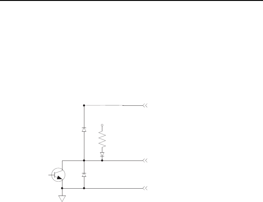
8-12 Limit Tests and Digital I/O Model 6487 Reference Manual
•External device control — Each digital output can be used as a control switch for
an external device (i.e. relay) circuit. Each output line can sink up to 500mA. Drive
voltage is provided by an external source (+5V to +33V).
•Logic Control — The four digital outputs can be used as inputs to logic devices.
The simplified schematic for the digital outputs is shown in Figure 8-9. Note that this
illustration shows the schematic for one digital output. All four digital output circuits are
identical.
Figure 8-9
Digital I/O port simplified schematic
Sink mode — controlling external devices
Each output can be operated from an external supply (voltage range from +5V to +33V
applied through the external device being driven). The high current sink capacity of the
output driver allows direct control of relays, solenoids, and lamps (no additional circuitry
needed).
As shown in Figure 8-9, each of the four digital, open-collector outputs includes a built-in
pull up resistor to +5V. The output transistor is capable of sinking 500mA from voltages
up to +33V. Each output channel contains a fly-back diode for protection when switching
inductive loads (such as a low power solenoid or relay coils). To use these fly-back diodes,
connect the external supply voltage to pin 5 of the digital I/O port. Make sure the external
supply voltage is between +5V and +33V and the current required by the device does not
exceed 500mA.
+5V
1kΩ (Pull-up)
Pin 9 - Digital Ground
Digital Output
Pin 5 - External Voltage Flyback
connection (+5V to +33V)
Digital Output
Flyback Diode
Protection
Diode

Model 6487 Reference Manual Limit Tests and Digital I/O 8-13
`^rqflk Do not exceed +33V maximum voltage on pin 5 of the digital I/O port
and do not use any output line to sink >500mA. Exceeding these limits
may cause damage to the instrument that is not covered by the
warranty.
An externally powered relay connected to the digital output port is shown in Figure 8-10.
Other externally powered devices can be similarly connected by replacing the relay with
the device. When the output line is set LO (0V), the output transistor sinks current through
the external device. In the HI state, the output transistor is off (transistor switch open).
This interrupts current flow through the external device.
Figure 8-10
Controlling externally powered relays
+5V
1kΩ
Pull Up
Resistor
Pin 9 - Digital Ground
Pin 1 - Digital Output #1
Pin 5 - External Voltage Flyback Connection
Digital Output #1
Flyback Diode
To three other
digital outputs
Relay
Coil
(+)
(+)
(-)
(-)
External Power
(+5V to +33V)
Transistor
Switch
Flyback
Diode
Equivalent Circuit
Relay
Coil External Power
(+5V to +33V)
Model 6487
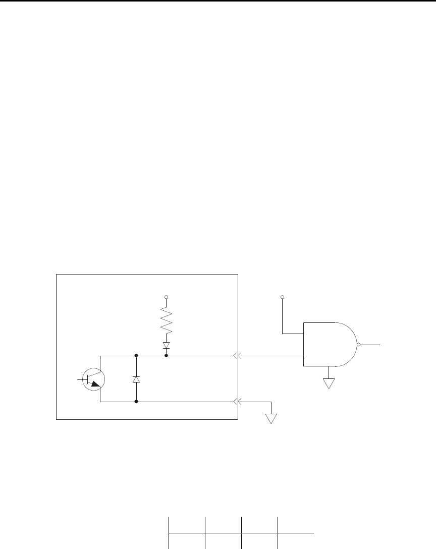
8-14 Limit Tests and Digital I/O Model 6487 Reference Manual
Source mode — logic control
The digital outputs can be used as logic inputs to active TTL, low-power TTL, or CMOS
inputs. For this mode of operation, the output lines can source up to 2mA.
`^rqflk Each output line can source up to 2mA. Exceeding 2mA may cause
damage to the Model 6487 that is not covered by the warranty.
Figure 8-11 shows how to connect a logic device to one of the output lines. When the out-
put line is set HI, the transistor will turn off (transistor switch open) to provide a reliable
logic high output (>3.75V). When the output line is set LO, the transistor turns on (transis-
tor switch closed) to route current to digital ground. As a result, a low logic output (0V) is
provided at the output.
If the second input (B) of the NAND gate is connected to another output line of the port,
the output of the NAND gate will go to logic 0 when both digital outputs are set HI.
Figure 8-11
NAND gate control
Setting digital output lines
Digital output lines are set by selecting a decimal value (0 to 15) that corresponds to the
4-bit BCD pattern of the output. To determine the value, add up the decimal weight values
for the desired HI lines:
Output HI Line: Out 4 Out 3 Out 2 Out 1
Decimal Weight: 8 4 2 1
+5V
1kΩ
Pull Up
Resistor
Pin 9
Pin 1
Logic
Device
NAND
B
A
Model 6487
Model 6487 Reference Manual Limit Tests and Digital I/O 8-15
For example, to set output lines 3 and 1 HI (0101 bit pattern), set the output value to
5(4+1).
Perform the following steps to set the digital output pattern from the front panel:
1. Press CONFIG and then LIMIT to access the limits menu.
2. Press the cursor keys until “LIMIT:PASS” is displayed.
3. Press ENTER. The present digital output pattern value will be displayed.
4. Use the cursor and RANGE keys to display the desired output pattern value (0 to
15), and press ENTER.
5. Press EXIT to return to the normal display state.
SCPI programming — digital output pattern
Programming example
The following command sequence sets output lines 4 and 2 HI and output lines 3 and
1LO.
SOUR2:TTL 10 ' Set output lines 4 and 2 HI.
SOUR2:TTL? ' Request output pattern value.
Table 8-2
SCPI commands — digital outputs
Command Description Default
:SOURce2 SOURce2 Subsystem:
:TTL <NRf> | <NDN> Specify 4-bit digital output pattern (see “Parameter Values” below). 15
:TTL? Query the digital output pattern. The value returned is in the
decimal format.
Parameter Values (see Note):
<NRf> = 0 to 15 Decimal format
<NDN> = #Bxxxx Binary format (each x = 1 or 0)
= #Hx Hexadecimal format (x = 0 to F)
= #Qxx Octal format (x = 0 to 17)
Note: The <NDN> parameter type can be used to set the output pattern using non-decimal values. Convert the decimal value to its
binary, hexadecimal, or octal equivalent and include the appropriate header (#B, #H, or #Q). For example, to set output lines 4
and 2 HI using the binary format, send SOURce2:TTL #B1010.

8-16 Limit Tests and Digital I/O Model 6487 Reference Manual
Front panel operation — limit tests
Limit test configuration
Most aspects of limit testing are configured from the limit configuration menu. Once in a
menu structure, use the cursor keys to display menu items. Use the cursor keys to key in
values. To change polarity of a value, place the cursor on “+” or “-” and press either of the
RANGE keys. To change range for the value, place the cursor on the range symbol and
scroll using the range keys (P = pico, N = nano, µ = micro, m = milli, ^ = x1, K = kilo,
M = mega, G = giga, T = tera). A menu item or value is selected by pressing ENTER.
Digital output bit patterns — An output pattern is set by selecting a decimal value (0 to
15) that corresponds to the 4-bit BCD pattern of the output. To determine the output pat-
tern value, add up the decimal weight values for the desired HI lines:
For example, to set an output pattern to 0101 (lines 3 and 1 HI), set the output value to
5(4+1).
Limits configuration menu
The configuration menu for limits is structured as follows. Bullets denote the main items
of the menu. To access the menu, press CONFIG and then LIMIT.
LIMIT 1 — Configure Limit 1 test:
•CONTROL — Enable or disable Limit 1 test.
•HILIM — Set the HI limit (-9.999999T to +9.999999T).
•LOLIM — Set the LO limit (-9.999999T to +9.999999T).
LIMIT 2 — Configure Limit 2 test:
•CONTROL — Enable or disable Limit 2 test.
•HILIM — Set the HI limit (-9.999999T to +9.999999T).
•LOLIM — Set the LO limit (-9.999999T to +9.999999T).
PASS — Set the digital output bit pattern for the “all tests pass” condition (0 to 15).
DIG CLR (Digital Clear):
•AUTO CLR — Enable or disable auto-clear for the digital output.
•DEL (Delay) — Set the pass/fail pattern pulse width (0 to 60 sec with 10µsec
resolution).
•DIGOUT — Set the digital output clear pattern (0 to 15).
Output HI Line: Out 4 Out 3 Out 2 Out 1
Decimal Weight: 8421

Model 6487 Reference Manual Limit Tests and Digital I/O 8-17
LIN4MOD (Line 4 Mode):
•ENDOFTST (End of Test) — With this mode, Model 6487 will pulse the EOT line
when the test is finished. Use with catagory register component handlers.
•/BUSY and BUSY — Pulls line 4 LO (/Busy) or HI (Busy) while the test is in pro-
cess. Use with catagory pulse component handlers.
Arm layer configuration menu
To access the menu, press CONFIG and then TRIG. Use the RANGE keys to scroll to the
ARM menu.
•ARM-IN — Select the “start of test” option:
–IMM (Immediate) — Test starts when LIMIT key is pressed.
–/STEST — Test starts when the handler pulls the SOT line of the Digital I/O
low.
–STEST — Test starts when the handler pulls the SOT line of the Digital I/O
high.
–BSTEST — Test starts when the handler pulls the SOT line of the Digital I/O
either high or low.
klqb The other arm-in control sources are seldom used with component handlers, but
are available.
Performing limit tests
Step 1. Configure test system
As previously explained, testing the system could be as simple as connecting a DUT to the
Model 6487.
Step 2. Configure measurement
Configure the Model 6487 for the desired measurement as covered in the previous sections
of this manual.
Step 3. Configure limit tests
Configure the Model 6487 for the limit tests as explained in “Limit test configuration,”
page 8-16.
Step 4. Start testing process
To enable the limit tests, press the LIMIT key—the testing process will start when LIMIT
is pressed. The testing process can be terminated at any time by again pressing the LIMIT
key.

8-18 Limit Tests and Digital I/O Model 6487 Reference Manual
SCPI programming — limit tests
Table 8-3
Limit test commands
Command Description Default Ref
:CALCulate2 CALCulate2 Subsystem:
:FEED <name> Select input path for limit testing: CALCulate[1]
or SENSe[1].
SENS A
:LIMit[1] Limit 1 Testing:
:UPPer Configure upper limit:
[:DATA] <n> Set limit: -9.99999e20 to 9.99999e20. 1.0
:SOURce2 <NDN> or <NRf> Specify 4-bit output “fail” pattern. 15 B
:LOWer Configure lower limit:
[:DATA] <n> Set limit: -9.99999e20 to 9.99999e20. -1.0
:SOURce2 <NDN> or <NRf> Specify 4-bit output “fail” pattern. 15 B
:STATe <b> Enable or disable Limit 1 test. OFF
:FAIL? Return result of Limit 1 test: 0 (pass) or 1 (fail). C
:LIMit2 Limit 2 Testing:
:UPPer Configure upper limit:
[:DATA] <n> Set limit: -9.99999e20 to 9.99999e20. 1.0
:SOURce2 <NDN> or <NRf> Specify 4-bit output “fail” pattern. 15 B
:LOWer Configure lower limit:
[:DATA] <n> Set limit: -9.99999e20 to 9.99999e20. -1.0
:SOURce2 <NDN> or <NRf> Specify 4-bit output “fail” pattern. 15 B
:STATe <b> Enable or disable Limit 2 test. OFF
:FAIL? Return result of Limit 2 test: 0 (pass) or 1 (fail). C
:CLIMits Composite Limits:
:CLEar Clear I/O port and restore it back to
SOURce2:TTL settings:
[:IMMediate] Clears I/O port immediately.
:AUTO <b> When enabled, I/O port clears when :INITiate
sent.
ON
:PASS Define “pass” digital output pattern.
:SOURce2 <NDN> or <NRf> Specify 4-bit pass pattern (no failures). 15 B
:DATA? Return CALC2 reading(s) triggered by INITiate. D
:LATest? Return last (latest) CALC2 reading. D

Model 6487 Reference Manual Limit Tests and Digital I/O 8-19
A) :FEED <name>
Name parameters:
• CALCulate1 — Limit tests will be performed on the result of a math calculation
(mX+b, m/x+b, or log).
• SENSe — Limit tests will be performed on the input signal. Note however, that Rel
can be used on the result of a math calculation as well as the input signal. Limit
tests will be performed on the result of the Rel operation (see CALCulate1:NULL).
Details on relative, mX+b, m/X+b, and log are provided in Section 5.
Command Description Default Ref
:SOURce2 SOURce2 Subsystem:
:TTL <NDN> or <NRf> Specify 4-bit digital output clear pattern. 15 B
:CLEar Clear I/O port (return output to TTL pattern):
[:IMMediate] Clear I/O port immediately.
:AUTO <b> Enable or disable auto-clear. OFF
:DELay <n> Specify delay (pulse-width) for pass/fail
pattern: 0 to 60 (sec).
0.0001
:TTL4 Line 4 Mode configuration:
:MODE <name> Select output line 4 mode: EOTest or BUSY. EOT
:BSTate <ttl> Select active TTL level for busy: 1 (HI) or 0 (LO). 0
Trigger Subystem: Sec 7
ARM Arm Layer:
:SOURce <name> Select control source: NSTest, PSTest, BSTest, or
IMMediate.
IMM E
INITiate Initiate one trigger cycle.
FORMat FORMat subsystem:
:SOURce2 <name> Select data format for reading output patterns:
<name> = ASCii Decimal format
HEXadecimal Hexadecimal format
OCTal Octal format
BINary Binary format
ASC
Table 8-3 (cont.)
Limit test commands

8-20 Limit Tests and Digital I/O Model 6487 Reference Manual
B) <NDN> and <NRf> parameters
<NDN> = #Bxxxx Binary format (each x = 1 or 0)
= #Hx Hexadecimal format (x = 0 to F)
= #Qxx Octal format (x = 0 to 17)
<NRf> = 0 to 15 Decimal format
An output pattern is set by sending a parameter value that corresponds to the 4-bit BCD
pattern of the output. The parameter value can be sent in the binary, decimal, hexadecimal,
or octal format. For example, if you wish to set lines 4, 2, and 1 HI, the binary parameter
value would be 1011. To use one of the other formats, convert the binary number to its
decimal, hexadecimal, or octal equivalent:
Binary 1011 = Decimal 11 = Hexadecimal B = Octal 13
The <NDN> (non-decimal numeric) parameter type is used to send non-decimal values.
These values require a header (#B, #H, or #Q) to identify the data format being sent. The
letter in the header can be upper or lower case. The <NRf> (numeric representation for-
mat) parameter type is used to send decimal values and does not use a header.
The following examples show the proper parameter syntax to set an output pattern to 1101
(lines 4, 3, and 1 set HI):
#b1101 Binary format (<NDN> parameter type)
#hD Hexadecimal format (<NDN> parameter type)
#q15 Octal format (<NDN> parameter type)
13 Decimal format (<NRf> parameter type)
klqb When a query command to read a programmed output pattern (i.e.,
CALC2:LIM:UPP:SOUR2?) is sent, the format for the returned value is deter-
mined by the presently selected response message format for output patterns
(see FORMat:SOURce2 command in Table 8-3).
C) :FAIL?
In the event of a failure, you can read the measurement event register to determine which
limit (upper or lower) failed. See Section 10 to program and read the measurement event
register.
D) :DATA? and :DATA:LATest?
The INITiate command must be sent to perform the programmed number of measure-
ments. If the instrument is programmed to perform a finite number of measurements, the
:DATA? command will return all the CALC2 readings after the last reading is taken. The
:DATA:LATest? command will only return the last (latest) CALC2 reading.

Model 6487 Reference Manual Limit Tests and Digital I/O 8-21
If the instrument is programmed to perform an infinite number of measurements (arm
count or trigger count set to infinite), you cannot use the :DATA? command to return
CALC2 readings. However, you can use the :DATA:LATest? command to return the last
CALC2 reading after aborting the measurement process. After sending the INITiate com-
mand to start the measurement process, use the ABORt command to abort the measure-
ment process, then use :DATA:LATest? to return the last CALC2 reading.
Sending :DATA? or :DATA:LATest? without first sending INITiate will return “old” read-
ings or cause an error (-220) if limit is not enabled or there are no readings available.
E) :ARM:SOURce <name>
Typical “start of test” options:
• IMMediate — Test starts when LIMIT key is pressed.
• NSTest — Test starts when component handler pulls the SOT line low.
• PSTest — Test starts when component handler pulls the SOT line high.
• BSTest — Test starts when component handler pulls the SOT line high or low.
Programming example
The following command sequence will test DUT using the limit tests example shown in
Figure 8-2.
*RST ' Restore RST defaults.
CALC2:LIM:UPP 2e-3 ' Set upper limit for Limit 1 (2mA).
CALC2:LIM:LOW -2e-3 ' Set lower limit for Limit 1 (-2mA).
CALC2:LIM:STAT ON ' Enable Limit 1 test.
CALC2:LIM2:UPP 1e-3 ' Set upper limit for Limit 2 (1mA).
CALC2:LIM2:LOW -1e-3 ' Set lower limit for Limit 2 (-1mA).
CALC2:LIM2:STAT ON ' Enable Limit 2 test.
' Connect DUT to input.
SYST:ZCH OFF ' Disable zero check.
INIT ' Perform tests on DUT (one measurement).
CALC2:LIM:FAIL? ' Return result of Limit 1 test.
CALC2:LIM2:FAIL? ' Return result of Limit 2 test.

9
Remote Operation
•Selecting and configuring an interface — Explains how to select and configure
an interface: GPIB or RS-232.
•GPIB operation and reference — Covers the following GPIB topics:
GPIB bus standards
GPIB bus connections
Primary address
General IEEE-488 bus commands
Front panel GPIB operation
Programming syntax
•RS-232 interface reference — Provides basic reference information for the
RS-232 interface and explains how to make connections to the computer.

9-2 Remote Operation Model 6487 Reference Manual
Selecting and configuring an interface
Interfaces
The Model 6487 supports two built-in remote interfaces:
• GPIB interface
• RS-232 interface
You can use only one interface at a time. At the factory, the GPIB bus is selected. You can
select the interface only from the front panel. The interface selection is stored in non-
volatile memory; it does not change when power has been off or after a remote interface
reset.
GPIB interface — The GPIB is the IEEE-488 interface. The Model 6487 must be
assigned to a unique address. At the factory the address is set to 22, but can be set to any
value from 0 to 30. However, the address must not conflict with the address assigned to
other instruments in the system. You can use either the SCPI or DDC language to program
the instrument.
RS-232 interface — When using the RS-232 interface, you must set baud rate, data bits,
parity, terminator, and flow control. For the RS-232 interface, you can only use the SCPI
language to program the instrument.
Languages
For the GPIB interface, there are three programming languages to choose from:
• SCPI language (488.2)
• DDC language
• 488.1 language
klqb For the RS-232 interface, only the SCPI language can be used to program the
instrument. When the RS-232 interface is selected, it automatically defaults to
SCPI.
SCPI language — Standard Commands for Programmable Instrument (SCPI) is fully
supported by the GPIB and RS-232 interfaces. Always calibrate the Model 6487 using the
SCPI language.
DDC language — The Model 6487 implements most DDCs (device-dependent com-
mands) available in the Keithley Model 487 picoammeter. The available commands are
provided in Appendix C. See the Model 487 Instruction Manual for details on operation.
The PDF of this manual is on the CD-ROM that was included with your shipment.
488.1 language — See Appendix E for details.

Model 6487 Reference Manual Remote Operation 9-3
Interface selection and configuration procedures
klqb The unit will reset if the language is changed (SCPI, 488.1, and DDC).
When you select (enable) the GPIB interface, the RS-232 interface disables. Conversely,
selecting (enabling) the RS-232 interface disables the GPIB interface.
Select the interface from the COMM menu structure (access by pressing the COMM key
while in local). Use the RANGE keys to change the selected interface (RS-232 or GPIB).
Press ENTER to save the change.
klqb When an interface is enabled (on) or disabled (off), the instrument will exit from
the menu structure and perform the power-on sequence.
Configuring the GPIB interface
Select the GPIB interface from the COMM menu structure (access by pressing the
COMM key while in local). After selecting the GPIB interface, press the CONFIG key and
then the COMM key to configure the GPIB address and language. From this menu you can
check or change the following settings:
• Primary address: 0–30
• Language: SCPI (SCPI 1996.0 which includes 488.2), 488.1, or DDC
Press the RANGE keys to scroll through ADDress and LANGuage available. To make
changes to a setting, press the cursor right key. Then use the RANGE keys and the cursor
keys to select and modify the value as desired. Press ENTER to save the changes and stay
in the menu (pressing EXIT also saves the changes but leaves the menu).
RS-232 interface
klqb Only the SCPI language can be used with the RS-232 interface. The instrument
defaults to the SCPI language when the RS-232 interface is selected (enabled).
Select the RS-232 interface from the COMM menu structure (access by pressing the
COMM key while in local). After selecting the RS-232 interface, press the CONFIG key
and then the COMM key to configure the RS-232 interface and check or change the fol-
lowing settings:
• BAUD: Baud rate (57.6K, 38.4k, 19.2k, 9600, 4800, 2400, 1200, 600, or 300)
• BITS: Data bits (7 or 8)
• PARITY: Parity (NONE, ODD, or EVEN)
• TX TERMINATOR: Terminator (CR, LF, CRLF, or LFCR)
• FLOW: Flow control (NONE or Xon/Xoff)
klqb See “RS-232 interface reference,” on page 9-16 for information on RS-232
settings and connections to the computer.

9-4 Remote Operation Model 6487 Reference Manual
Press the RANGE keys to scroll through the available RS-232 settings. To make changes
to a setting, press the right cursor key and then use the RANGE keys to select and modify
the value as desired. Press ENTER to save the changes and move to the next menu item
(pressing EXIT also saves the changes but leaves the menu). At the last menu item,
ENTER will save and exit the menu.
GPIB operation and reference
GPIB bus standards
The GPIB bus is the IEEE-488 instrumentation data bus with hardware and programming
standards originally adopted by the IEEE (Institute of Electrical and Electronic Engineers)
in 1975. The Model 6487 conforms to these standards:
• IEEE-488.1-1987
• IEEE-488.2-1992
These standards define a syntax for sending data to and from instruments, how an instru-
ment interprets this data, what registers should exist to record the state of the instrument,
and a group of common commands.
• SCPI 1996.0 (Standard Commands for Programmable Instruments)
This standard defines a command language protocol. It goes one step further than
IEEE-488.2-1992 and defines a standard set of commands to control every programmable
aspect of an instrument.
GPIB bus connections
To connect the Model 6487 to the GPIB bus, use a cable equipped with standard IEEE-488
connectors as shown in Figure 9-1.
Figure 9-1
IEEE-488 connector
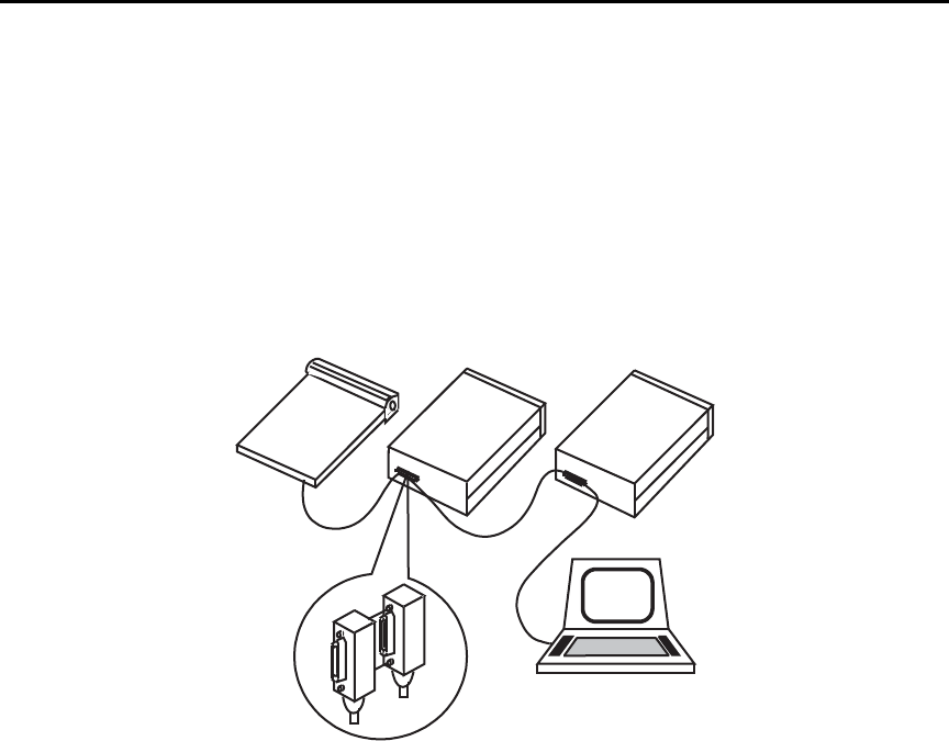
Model 6487 Reference Manual Remote Operation 9-5
To allow many parallel connections to one instrument, stack the connector. Two screws are
located on each connector to ensure that connections remain secure. Current standards call
for metric threads, which are identified with dark-colored screws. Earlier versions had dif-
ferent screws, which were silver-colored. Do not use these types of connectors on the
Model 6487, because it is designed for metric threads.
Figure 9-2 shows a typical connecting scheme for a multi-unit test system.
Figure 9-2
Multi-unit connections
To avoid possible mechanical damage, stack no more than three connectors on any one
unit.
klqb To minimize interference caused by electromagnetic radiation, use only shielded
IEEE-488 cables. Available shielded cables from Keithley are Models 7007-1
and 7007-2.
Instrument
Controller
Instrument Instrument
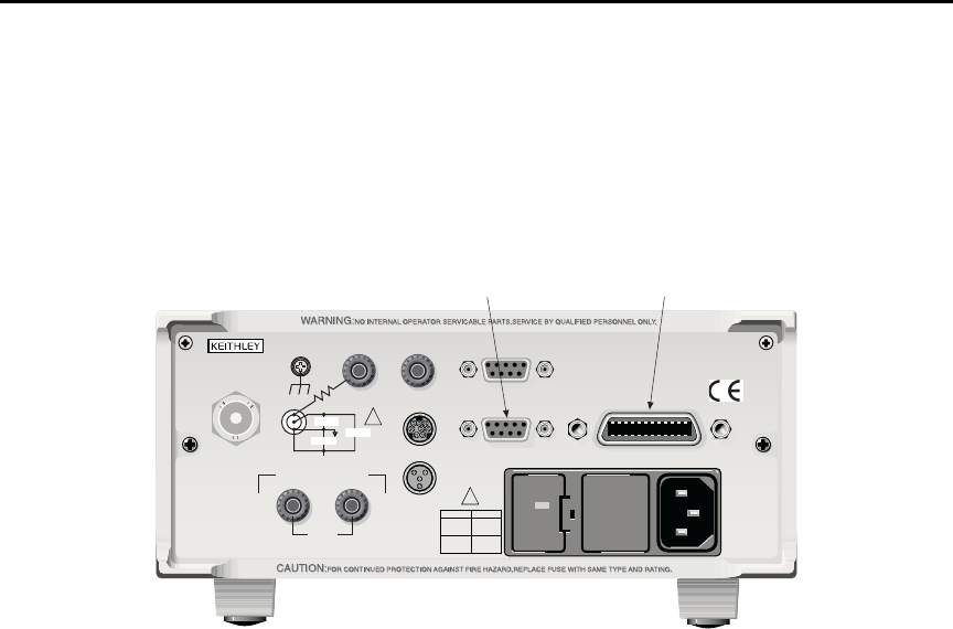
9-6 Remote Operation Model 6487 Reference Manual
To connect the Model 6487 to the IEEE-488 bus, follow these steps:
1. Line up the cable connector with the connector located on the rear panel. The con-
nector is designed so that it will fit only one way. Figure 9-3 shows the location of
the IEEE-488 connector.
Figure 9-3
IEEE-488 and RS-232 connector locations
2. Tighten the screws securely, making sure not to over tighten them.
3. Connect any additional connectors from other instruments as required for your
application.
4. Make sure that the other end of the cable is properly connected to the controller.
Most controllers are equipped with an IEEE-488 style connector, but a few may
require a different type of connecting cable. See your controllers instruction man-
ual for information about properly connecting to the IEEE-488 bus.
klqb You can only have 15 devices connected to an IEEE-488 bus, including the con-
troller. The maximum cable length is either 20 meters or two meters times the
number of devices, whichever is less. Not observing these limits may cause
erratic bus operation.
Primary address
The Model 6487 ships from the factory with a GPIB address of 22. When the instrument
powers up, it momentarily displays the primary address. You can set the address to a value
of 0-30. Do not assign the same address to another device or to a controller that is on the
same GPIB bus.
120
LINE RATING
50, 60Hz
50 VA MAX
INPUT
(CHANGE IEEE ADDRESS
WITH FRONT PANEL MENU)
IEEE-488
CAT I
TRIGGER LINKRS-232
MADE IN
U.S.A.
ANALOG OUT DIGITAL I/O
505V
MAX
V-SOURCE OUTPUT
505V PK TO CHASSIS
LO HI INTERLOCK
!
!
FUSELINE
400mAT
(SB) 100 VAC
120 VAC
200mAT
(SB)
220 VAC
240 VAC
505V PK
505V PK 505V PK
IEEE-488RS-232

Model 6487 Reference Manual Remote Operation 9-7
Usually controller addresses are 0 or 21, but see the controllers instruction manual for
details. Make sure the address of the controller is the same as that specified in the control-
lers programming language. To make sure the unit’s interface is properly selected and con-
figured or to check or change the GPIB address, refer to “Selecting and configuring an
interface,” page 9-2.
General IEEE-488 bus commands
Commands and associated statements
General commands are those commands, such as DCL, that have the same general mean-
ing regardless of the instrument. Table 9-1 lists the general bus commands.
REN (remote enable)
The remote enable command is sent to the Model 6487 by the controller to set up the
instrument for remote operation. Generally, the instrument should be placed in the remote
mode before you attempt to program it over the bus. Simply setting REN true does not
actually place the instrument in the remote state. You must address the instrument to listen
after setting REN true before it goes into remote.
Note that the instrument does not have to be in remote to be a talker.
Note that all front panel controls, except for LOCAL and POWER, are inoperative while
the instrument is in remote. You can restore normal front panel operation by pressing the
LOCAL key.
Table 9-1
General bus commands
Command Effect on Model 6487
REN Goes into remote when next addressed to listen.
IFC Reset interface; all devices go into talker and listener idle states.
LLO LOCAL key locked out.
GTL Cancel remote; restore front panel operation for Model 6487.
DCL Returns all devices to known conditions.
SDC Returns Model 6487 to known conditions.
GET Initiates a trigger.
SPE, SPD Serial polls Model 6487.

9-8 Remote Operation Model 6487 Reference Manual
IFC (interface clear)
The IFC command is sent by the controller to place all instruments on the bus in the local,
talker, listener idle states. The Model 6487 responds to the IFC command by canceling
front panel TALK or LSTN lights, if the instrument was previously placed in one of those
states. Note that this command does not affect the status of the instrument; settings, data,
and event registers are not changed.
To send the IFC command, the controller must set the IFC line true for a minimum of
100µs.
LLO (local lockout)
Use the LLO command to prevent local operation of the instrument. After the unit receives
LLO, all its front panel controls except the POWER are inoperative. In this state, pressing
LOCAL will not restore control to the front panel. The GTL command restores control to
the front panel.
GTL (go to local)
Use the GTL command to put a remote mode instrument into local mode. The GTL com-
mand also restores front panel key operation.
DCL (device clear)
Use the DCL command to clear the GPIB interface and return it to a known state. Note
that the DCL command is not an addressed command, so all instruments equipped to
implement DCL will do so simultaneously.
When the Model 6487 receives a DCL command, it clears the input buffer and output
queue, cancels deferred commands, and clears any command that prevents the processing
of any other device command. A DCL does not affect instrument settings and stored data.
SDC (selective device clear)
The SDC command is an addressed command that performs essentially the same function
as the DCL command. However, since each device must be individually addressed, the
SDC command provides a method to clear only selected instruments instead of clearing all
instruments simultaneously, as is the case with DCL.
GET (group execute trigger)
GET is a GPIB trigger that is used as an event to control operation. The Model 6487 reacts
to this trigger if it is the programmed control source. The control source is programmed
from the SCPI TRIGger subsystem.

Model 6487 Reference Manual Remote Operation 9-9
SPE, SPD (serial polling)
Use the serial polling sequence to obtain the Model 6487 serial poll byte. The serial poll
byte contains important information about internal functions. Generally, the serial polling
sequence is used by the controller to determine which of several instruments has requested
service with the SRQ line. However, the serial polling sequence may be performed at any
time to obtain the status byte from the Model 6487.
Front panel GPIB operation
The following paragraphs describe aspects of the front panel that are part of GPIB opera-
tion, including messages, status indicators, and the LOCAL key.
Error and status messages
See Appendix B for a list of error and status messages associated with IEEE-488 program-
ming. The instrument can be programmed to generate an SRQ and command queries can
be performed to check for specific error conditions.
GPIB status indicators
The REM (remote), TALK (talk), LSTN (listen), and SRQ (service request) annunciators
show the GPIB bus status. Each of these indicators is described below.
•REM — This indicator shows when the instrument is in the remote state. REM
does not necessarily indicate the state of the REM line, as the instrument must be
addressed to listen with REM true before the REM indicator turns on. When the
instrument is in remote, all front panel keys, except for the LOCAL key, are locked
out. When REM is turned off, the instrument is in the local state and front panel
operation is restored.
•TALK — This indicator is on when the instrument is in the talker active state.
Place the unit in the talk state by addressing it to talk with the correct MTA (My
Talk Address) command. TALK is off when the unit is in the talker idle state. Place
the unit in the talker idle state by sending a UNT (Untalk) command, addressing it
to listen, or sending the IFC (Interface Clear) command.
•LSTN — This indicator is on when the Model 6487 is in the listener active state,
which is activated by addressing the instrument to listen with the correct MLA (My
Listen Address) command. LSTN is off when the unit is in the listener idle state.
Place the unit in the listener idle state by sending UNL (Unlisten), addressing it to
talk, or sending the IFC (Interface Clear) command over the bus.
•SRQ — You can program the instrument to generate a service request (SRQ) when
one or more errors or conditions occur. When this indicator is on, a service request
has been generated. This indicator stays on until the serial poll byte is read or all
the conditions that caused SRQ have ceased to exist.

9-10 Remote Operation Model 6487 Reference Manual
LOCAL key
The LOCAL key cancels the remote state and restores local operation of the instrument.
Pressing the LOCAL key also turns off the REM indicator and returns the display to nor-
mal if a user-defined message was displayed. If the unit is in local (not in remote), the
LOCAL key acts as a configure key (see “Front panel operation,” page 4-8.)
If the LLO (Local Lockout) command is in effect, the LOCAL key is also inoperative.
Programming syntax
The following paragraphs cover syntax for both common commands and SCPI commands.
For more information, see the IEEE-488.2 and SCPI standards.
Command words
Program messages are made up of one or more command words.
Commands and command parameters
Common commands and SCPI commands may or may not use a parameter. The following
are some examples:
*SAV <NRf> Parameter (NRf) required.
*RST No parameter used.
:DISPlay:ENABle <b> Parameter <b> required.
:SYSTem:PRESet No parameter used.
Put at least one space between the command word and the parameter.
•Brackets [ ] — Some command words are enclosed in brackets ([ ]). These brack-
ets are used to denote an optional command word that does not need to be included
in the program message. For example:
:INITiate[:IMMediate]
These brackets indicate that :IMMediate is implied (optional) and does not have to
be used. Thus, the above command can be sent in one of two ways:
:INITiate or :INITiate:IMMediate
Notice that the optional command is used without the brackets. When using
optional command words in your program, do not include the brackets.
•Parameter types — The following are some of the common parameter types:
<b> Boolean — Used to enable or disable an instrument operation. 0 or
OFF disables the operation and 1 or ON enables the operation.
:DISPlay:ENABle ON Enable the display

Model 6487 Reference Manual Remote Operation 9-11
<name> Name parameter — Select a parameter name from a listed group.
<name> = NEVer
= NEXT
:CALCulate:FORMat MXB Select Mx + B calculation
<NRf> Numeric representation format — A number that can be expressed
as an integer (e.g., 8), a real number (e.g., 23.6), or an exponent
(2.3E6).
:TRACe:POINts 20 Set buffer size to 20
<NDN> Non-decimal numeric — A non-decimal value that can be used to
program status enable registers. A unique header identifies the for-
mat; #B (binary), #H (hexadecimal), and #Q (octal).
*SRE #B10001 Set bits B0 and B4 of Service
Request Enable Register
<n> Numeric value — Can consist of an NRf number or one of the fol-
lowing name parameters: DEFault, MINimum, or MAXimum.
When the DEFault parameter is used, the instrument is programmed
to the *RST default value. When the MINimum parameter is used,
the instrument is programmed to the lowest allowable value. When
the MAXimum parameter is used, the instrument is programmed to
the largest allowable value.
:ARM:TIMer 0.1 Sets timer to 100 msec.
:ARM:TIMer DEFault Sets timer to 0.1 sec.
:ARM:TIMer MINimum Sets timer to 1 msec.
:ARM:TIMer MAXimum Sets timer to 999999.999 sec.
•Angle brackets < > — Used to denote a parameter type. Do not include the brack-
ets in the program message.
:DISPlay:ENABle <b>
The <b> indicates that a Boolean type parameter is required. Thus, to enable the
display, you must send the command with the ON or 1 parameter as follows.
:DISPlay:ENABle ON or 1

9-12 Remote Operation Model 6487 Reference Manual
Query commands
The query command requests the presently programmed status. It is identified by the ques-
tion mark (?) at the end of the fundamental form of the command. Most commands have a
query form.
:ARM:TIMer? Queries the timer interval
Most commands that require a numeric parameter (<n>) can also use the DEFault, MINi-
mum, and MAXimum parameters for the query form. These query forms are used to deter-
mine the *RST default value and the upper and lower limits for the fundamental
command.
:ARM:TIMer? DEFault Queries the *RST default value
:ARM:TIMer? MINimum Queries the lowest allowable value
:ARM:TIMer? MAXimum Queries the largest allowable value
Case sensitivity
Common commands and SCPI commands are not case sensitive. You can use upper or
lower case and any case combination. Examples:
*RST = *rst
:DATA? = :data?
:SYSTem:PRESet = :system:preset
Long-form and short-form versions
A SCPI command word can be sent in its long-form or short-form version. The command
tables in this manual use the long-form version. However, the short-form version is indi-
cated by upper case characters.
:SYSTem:PRESet long-form
:SYST:PRES short form
:SYSTem:PRES long-form and short-form combination
Note that each command word must be in either long-form or short-form. For example,
:SYSTe:PRESe is illegal and will generate an error. The command will not be executed.
Short-form rules
Use the following rules to determine the short-form version of any SCPI command:
• If the length of the command word is four letters or less, no short form version
exists.
:auto = :auto

Model 6487 Reference Manual Remote Operation 9-13
These rules apply to command words that exceed four letters:
• If the fourth letter of the command word is a vowel, delete it and all letters after it.
immediate = :imm
• If the fourth letter of the command word is a consonant, retain it but drop all the
letters after it.
:format = :form
• If the command contains a question mark (?) or a non-optional number included in
the command word, you must include it in the short-form version.
:delay? = :del?
• Command words or characters that are enclosed in brackets ([ ]) are optional and need
not be included in the program message.
Program messages
A program message is made up of one or more command words sent by the computer to
the instrument. Each common command is simply a three letter acronym preceded by an
asterisk (*). The following SCPI commands from the STATus subsystem are used to help
explain how command words are structured to formulate program messages.
Single command messages
The above command structure has three levels. The first level is made up of the root com-
mand (:STATus) and serves as a path. The second level is made up of another path
(:OPERation) and a command (:PRESet). The third path is made up of one command for
the :OPERation path. The three commands in this structure can be executed by sending
three separate program messages as follows:
:stat:oper:enab <NRf>
:stat:oper:enab?
:stat:pres
In each of the above program messages, the path pointer starts at the root command (:stat)
and moves down the command levels until the command is executed.
Command structure
:STATus Path (Root)
:OPERation Path
:ENABle <NRf> Command and parameter
:ENABle? Query command
:PRESet Command

9-14 Remote Operation Model 6487 Reference Manual
Multiple command messages
You can send multiple command messages in the same program message as long as they
are separated by semicolons (;). The following is an example showing two commands in
one program message:
:stat:oper; :stat:oper:enab <NRf>
When the above is sent, the first command word is recognized as the root command (:stat).
When the next colon is detected, the path pointer moves down to the next command level
and executes the command. When the path pointer sees the colon after the semicolon (;), it
resets back to the root level and starts over.
Commands that are on the same command level can be executed without having to retype
the entire command path. Example:
:stat:oper:enab <NRf>; enab?
After the first command (:enab) is executed, the path pointer is at the third command level
in the structure. Since :enab? is also on the third level, it can be entered without repeating
the entire path name. Notice that the leading colon for :enab? is not included in the pro-
gram message. If a colon were included, the path pointer would reset to the root level and
expect a root command. Since :enab? is not a root command, an error would occur.
Command path rules
• Each new program message must begin with the root command, unless it is
optional (e.g., [:SENSe]). If the root is optional, simply treat a command word on
the next level as the root.
• The colon (:) at the beginning of a program message is optional and need not be
used.
:stat:pres = stat:pres
• When the path pointer detects a colon (:), it moves down to the next command
level. An exception is when the path pointer detects a semicolon (;), which is used
to separate commands within the program message.
• When the path pointer detects a colon (:) that immediately follows a semicolon (;),
it resets to the root level.
• The path pointer can only move down. It cannot be moved up a level. Executing a
command at a higher level requires that you start over at the root command.
Using common commands and SCPI commands in the same message
Both common commands and SCPI commands can be used in the same message as long
as they are separated by semicolons (;). A common command can be executed at any com-
mand level and will not affect the path pointer.
:stat:oper:enab <NRf>; *ESE <NRf>

Model 6487 Reference Manual Remote Operation 9-15
Program Message Terminator (PMT)
Each program message must be terminated with an LF (line feed), EOI (end or identify),
or an LF+EOI. The bus will hang if your computer does not provide this termination. The
following example shows how a program message must be terminated:
:trac:poin 10 <PMT>
Command execution rules
• Commands execute in the order that they are presented in the program message.
• An invalid command generates an error and, of course, is not executed.
• Valid commands that precede an invalid command in a multiple command program
message are executed.
• Valid commands that follow an invalid command in a multiple command program
message are ignored.
• For fastest command execution:
1. Do not use optional command words (i.e., [:SENSE [1]]).
2. Do not use the colon (:) at the beginning of a program message.
3. Always use the short-form versions of commands and parameters.
4. Minimize the amount of “white” space in command strings.
5. Keep numeric parameters simple (i.e., 1 vs. 1.000e + 00).
6. Use all uppercase.
Response messages
A response message is the message sent by the instrument to the computer in response to a
query command program message.
Sending a response message
After sending a query command, the response message is placed in the output queue.
When the Model 6487 is addressed to talk, the response message is sent from the output
queue to the computer.
Multiple response messages
If you send more than one query command in the same program message (see “Multiple
command messages,” on page 9-14), the multiple response messages for all the queries is
sent to the computer when the Model 6487 is addressed to talk. The responses are sent in
the order that the query commands were sent and are separated by semicolons (;). Items
within the same query are separated by commas (,). The following example shows the
response message for a program message that contains four single item query commands:
0; 1; 1; 0

9-16 Remote Operation Model 6487 Reference Manual
Response Message Terminator (RMT)
Each response is terminated with an LF (line feed) and EOI (end or identify). The follow-
ing example shows how a multiple response message is terminated:
0; 1; 1; 0; <RMT>
Message exchange protocol
Two rules summarize the message exchange protocol:
Rule 1. Always tell the Model 6487 what to send to the computer. The following two
steps must always be performed to send information from the instrument to the
computer:
1. Send the appropriate query command(s) in a program message.
2. Address the Model 6487 to talk.
Rule 2. The complete response message must be received by the computer before
another program message can be sent to the Model 6487.
RS-232 interface reference
Sending and receiving data
The RS-232 interface transfers data using seven or eight data bits and one stop bit. Parity
selections include none, odd, or even. When using the RS-232 interface, the unit will not
respond to DDC or general GPIB commands.
RS-232 settings
The procedure to select and configure the RS-232 interface is provided in “Selecting and
configuring an interface,” page 9-2. Make sure the controller you connect to the
Model 6487 also uses these settings.
klqb You can break data transmissions by sending a ^C or ^X character string to the
Model 6487. This clears any pending operation and discards any pending
output.
Baud rate
The baud rate is the rate at which the Model 6487 and the programming terminal commu-
nicate. You can choose from one of the following rates: 57.6k, 38.4k, 19.2k, 9600, 4800,
2400, 1200, 600, or 300.

Model 6487 Reference Manual Remote Operation 9-17
Make sure that the programming terminal that you are connecting to the Model 6487 can
support the baud rate you selected. Both the Model 6487 and the other device must be con-
figured for the same baud rate.
Data and stop bits
The RS-232 can be set to transfer data using seven or eight data bits and one stop bit.
Parity
Parity for the RS-232 interface can be set to none, even, or odd.
Terminator
The Model 6487 can be configured to terminate each program message that it transmits to
the controller with any of the following combinations of <CR> and <LF>:
• LF line feed
• CR carriage return
• LFCR line feed, carriage return
• CRLF carriage return, line feed
Flow control (signal handshaking)
Signal handshaking between the controller and the instrument allows the two devices to
communicate to each other regarding being ready or not ready to receive data. The
Model 6487 does not support hardware handshaking (flow control).
Software flow control is in the form of X_ON and X_OFF characters and is enabled when
XonXoFF is selected from the RS232 FLOW menu. When the input queue of the
Model 6487 becomes more than i full, the instrument issues an X_OFF command. The
control program should respond to this and stop sending characters until the Model 6487
issues the X_ON, which it will do once its input buffer has dropped below full. The
Model 6487 recognizes X_ON and X_OFF sent from the controller. An X_OFF will cause
the Model 6487 to stop outputting characters until it sees an X_ON. Incoming commands
are processed after the <CR> character is received from the controller.
If NONE is the selected flow control, then there will be no signal handshaking between the
controller and the Model 6487. Data will be lost if transmitted before the receiving device
is ready.
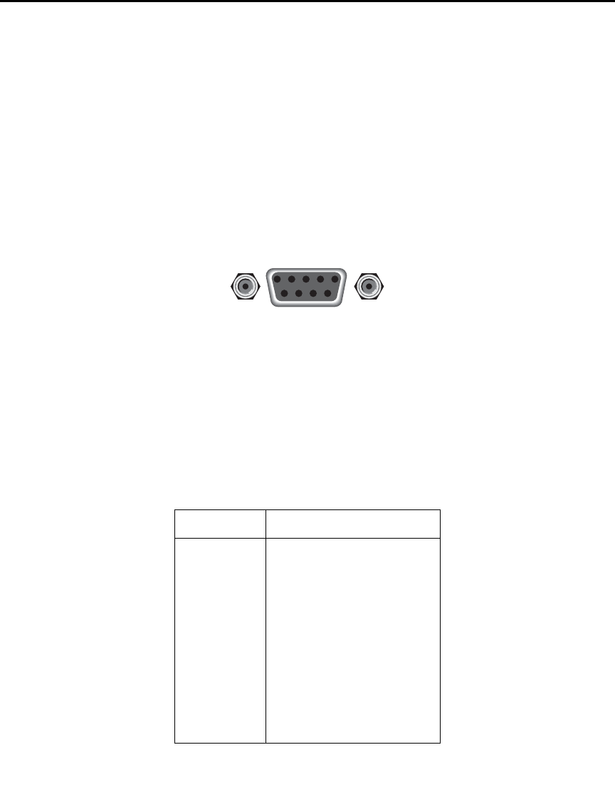
9-18 Remote Operation Model 6487 Reference Manual
RS-232 connections
The RS-232 serial port can be connected to the serial port of a controller (i.e., personal
computer) using a straight through RS-232 cable terminated with DB-9 connectors. Do
not use a null modem cable. The serial port uses the transmit (TXD), receive (RXD), and
signal ground (GND) lines of the RS-232 standard. It does not use the hardware handshak-
ing lines CTS and RTS. Figure 9-4 shows the rear panel connector for the RS-232 inter-
face and Table 9-2 shows the pinout for the connector. The connector location on the rear
panel is shown in Figure 9-3.
Figure 9-4
RS-232 interface connector
If your computer uses a DB-25 connector for the RS-232 interface, you will need a cable
or adapter with a DB-25 connector on one end and a DB-9 connector on the other, wired
straight through (not null modem). Table 9-3 provides pinout identification for the 9-pin
(DB-9) or 25-pin (DB-25) serial port connector on the computer (PC).
Table 9-2
RS-232 connector pinout
Pin number Description
1DCD, data carrier detect
2TXD, transmit data
3RXD, receive data
4DTR, data terminal ready
5GND, signal ground
6DSR, data set ready
7RTS, request to send
8CTS, clear to send
9No connections
RTS and CTS are tied together.
DCD, DTR, and DSR are tied together.
TXD and RXD are swapped on Model 6487 and PC so
that null modem cable is not required.
9876
54321
Rear Panel Connector
RS232

Model 6487 Reference Manual Remote Operation 9-19
Error messages
See Appendix B for RS-232 error messages.
Tab l e 9 -3
PC serial port pinout
Signal
DB-9
pin number
DB-25
pin number
DCD, data carrier detect 1 8
RXD, receive data 2 3
TXD, transmit data 3 2
DTR, data terminal ready 420
GND, signal ground 5 7
DSR, data set ready 6 6
RTS, request to send 7 4
CTS, clear to send 8 5
RI, ring indicator 922

10
Status Structure
•Overview — Provides an operational overview of the status structure for the
Model 6487.
•Clearing registers and queues — Covers the actions that clear (reset) registers and
queues.
•Programming and reading registers — Explains how to program enable registers
and read any register in the status structure.
•Status byte and service request (SRQ) — Explains how to program the status
byte to generate service requests (SRQs). Shows how to use the serial poll
sequence to detect SRQs.
•Status register sets — Provides bit identification and command information for
the four status register sets: standard event status, operation event status, measure-
ment event status, and questionable event status.
•Queues — Provides details and command information on the output queue and
error queue.

10-2 Status Structure Model 6487 Reference Manual
Overview
The Model 6487 provides a series of status registers and queues allowing the operator to
monitor and manipulate the various instrument events. The status structure is shown in
Figure 10-1. The heart of the status structure is the status byte register. This register can be
read by the user’s test program to determine if a service request (SRQ) has occurred and
what event caused it.
Status byte and SRQ — The status byte register receives the summary bits of four status
register sets and two queues. The register sets and queues monitor the various instrument
events. When an enabled event occurs, it sets a summary bit in the status byte register.
When a summary bit of the status byte is set and its corresponding enable bit is set (as pro-
grammed by the user), the RQS/MSS bit will set to indicate that an SRQ has occurred.
Status register sets — A typical status register set is made up of a condition register, an
event register, and an event enable register. A condition register is a read-only register that
constantly updates to reflect the present operating conditions of the instrument.
When an event occurs, the appropriate event register bit sets to 1. The bit remains latched
to 1 until the register is reset. When an event register bit is set and its corresponding enable
bit is set (as programmed by the user), the output (summary) of the register will set to 1,
which in turn sets the summary bit of the status byte register.
Queues — The Model 6487 uses an output queue and an error queue. The response mes-
sages to query commands are placed in the output queue. As various programming errors
and status messages occur, they are placed in the error queue. When a queue contains data,
it sets the appropriate summary bit of the status byte register.
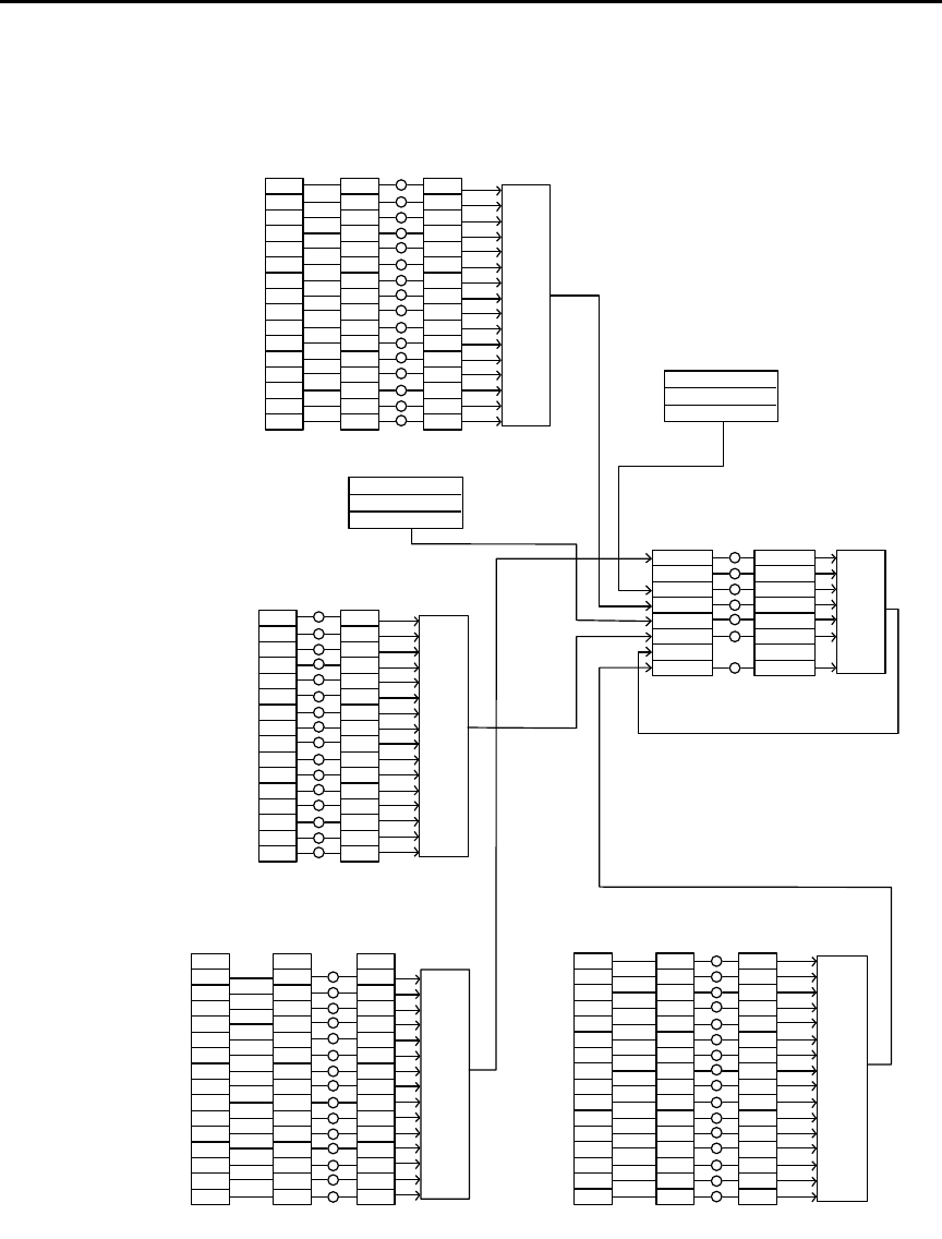
Model 6487 Reference Manual Status Structure 10-3
Figure 10-1
Model 6487 status mode structure
0
2
3
5
6
Cal
10
11
12
13
15
Condition
Register
(Always Zero)
0
2
3
5
6
10
11
12
13
15
Event
Register
0
11 1
2
3
5
6
10
11
12
13
15
Event Enable
Register
&
&
&
&
&
&
&
&
&
&
&
&
&
&
&
&
Logical
OR
Swp
Trig
7
Idle
11
12
13
Condition
Register
7
Idle
11
12
13
Event
Register
7
Idle
11
12
13
Register
&
&
&
&
&
&
&
&
&
&
&
&
&
&
Logical
OR
Idle
EAV
QSB
MAV
ESB
RQS/MSS
OSB
Status
Byte
Register
1
EAV
QSB
MAV
ESB
6
OSB
Service
Request
Enable
Register
&
&
&
&
&
&
&
Logical
OR
*STB? *SRE
*SRE?
Master Summary Status (MSS)
MSB = Measurement Summary Bit
EAV = Error Available
QSB = Questionable Summary Bit
MAV = Message Available
ESB = Event Summary Bit
RQS/MSS = Request for Service/Master Summary Status
OSB = Operation Summary Bit
Error Queue
Output Queue
Trig Trig
Note : RQS bit is in serial poll byte,
MSS bit is in *STB? response.
1
14 14
OPC
QYE
DDE
EXE
CME
URQ
PON
8
9
10
11
12
13
15
Event
Register
8
9
10
11
12
13
15
Register
&
&
&
&
&
&
&
&
&
&
&
&
&
&
&
&
Logical
OR
(Always Zero)
Operation Complete
Query Error
Device Specific Error
Execution Error
Command Error
User Request
Power On
OPC
QYE
DDE
EXE
CME
URQ
PON
*ESR? *ESE <NRf>
*ESE?
MSB MSB
12
13
12
13
Event
Register
12
13
Register
&
&
&
&
&
&
&
&
&
&
&
&
&
Logical
OR
Condition
Register
11
Calibration Summary
Warn
222
4
IOV
Cal
A-V
Cal Cal
INT INT INT
Trigger Layer
Command Warning
999
15 15 15
&
&
14 14 14
&
15 15 15&
Calibrating
8
9
Cal
Warn
4
8
9
Cal
Warn
4
8
9
:CONDition? [:EVENt]? :ENABle <NRf>
:ENABle?
Low Limit 1 Fail
High Limit 1 Fail
Low Limit 2 Fail
High Limit 2 Fail
Limits Pass
Reading Available
Reading Overflow
Buffer Available
Buffer Full
LL1F
HL1F
LL2F
HL2F
LP
RAV
ROF
BAV
(Always Zero)
BFL
:CONDition? [:EVENt]? :ENABle <NRf>
:ENABle?
LL1F
HL1F
LL2F
HL2F
LP
RAV
ROF
BAV
BFL
LL1F
HL1F
LL2F
HL2F
LP
RAV
ROF
BAV
BFL
4
Arm Layer Arm
8
4
Arm
8
4
Arm
8
Questionable Event Registers
Event Enable
Standard Event Registers
Event Enable
Measurement Event Registers
Event Enable
Operation Event Registers
:CONDition? [:EVENt]? :ENABle <NRf>
:ENABle?
000
Input Overvoltage IOV IOV
VSC VSC VSC
Interlock Asserted
Voltage Source Compliance
A-V Ohms A-V A-V
Sweeping Swp Swp

10-4 Status Structure Model 6487 Reference Manual
Clearing registers and queues
When the Model 6487 is turned on, the bits of all registers in the status structure are clear
(reset to 0) and the two queues are empty. Commands to reset the event and event enable
registers and the error queue are listed in Table 10-1. In addition to these commands, any
enable register can be reset by sending the 0 parameter value with the individual command
to program the register.
klqb SYSTem:PRESet and *RST have no effect on status structure registers and
queues.
Table 10-1
Common and SCPI commands — reset registers and clear queues
Commands Description Ref
To reset registers:
*CLS
STATus
:PRESet
To clear error queue:
*CLS
STATus
:QUEue
:CLEar
SYSTem
:ERRor
:CLEar
Reset all bits of the following event registers to 0:
Standard event register
Operation event register
Measurement event register
Questionable event register
STATus subsystem:
Reset all bits of the following enable registers to 0:
Operation event enable register
Measurement event enable register
Questionable event enable register
Clear all messages from error queue
STATus subsystem:
Error queue:
Clear messages from error queue
SYSTem subsystem:
Error queue:
Clear messages from error queue
Note 1
Note 1
Note 2
Note 3
Note 3
Notes:
1. The standard event enable register is not reset by STATus:PRESet or *CLS. Send the 0 parameter value with
*ESE to reset all bits of that enable register to 0 (see “Status byte and service request (SRQ),” page 10-7).
2. STATus:PRESet has no effect on the error queue.
3. Use either of the two clear commands to clear the error queue.

Model 6487 Reference Manual Status Structure 10-5
Programming and reading registers
Programming enable registers
The only registers that can be programmed by the user are the enable registers. All other
registers in the status structure are read-only registers. The following explains how to
ascertain the parameter values for the various commands used to program enable registers.
The actual commands are covered later in this section (Table 10-3 through Table 10-6).
A command to program an event enable register is sent with a parameter value that deter-
mines the desired state (0 or 1) of each bit in the appropriate register. An enable register
can be programmed using any of the following data formats for the parameter value:
binary, decimal, hexadecimal, or octal.
The bit positions of the register (Figure 10-1) indicate the binary parameter value. For
example, if you wish to sets bits B4, B3, and B1, the binary value would be 11010 (where
B4=1, B3=1, B1=1 and all other bits are 0). When you use one of the other formats, con-
vert the binary number to its decimal, hexadecimal, or octal equivalent:
Binary 11010 = Decimal 26 = Hexadecimal 1A = Octal 32
Note that Figure 10-2 includes the decimal weight for each register bit. To set bits B4, B3,
and B1, the decimal parameter value would be the sum of the decimal weights for those
bits (16+8+2 = 26).
Figure 10-2
16-bit status register
The <NDN> (non-decimal numeric) parameter type is used to send non-decimal values.
These values require a header (#B, #H, or #Q) to identify the data format being sent. The
letter in the header can be upper or lower case. The <NRf> (numeric representation for-
B7
B15
B6 B5 B4 B3 B2 B1 B0
0/1
0/1
0/1
0/1
0/1
0/1
0/1
0/1
0/1
0/1
0/1
0/1
0/1
0/1
0/1
0/1
128
(2 )
7
32768
(2 )
15
64
(2 )
6
16384
(2 )
14
32
(2 )
5
8192
(2 )
13
16
(2 )
4
4096
(2 )
12
8
(2 )
3
2048
(2 )
11
4
(2 )
2
1024
(2 )
10
2
(2 )
1
512
(2 )
9
1
(2 )
0
256
(2 )
8
Bit Position
Bit Position
Binary Value
Binary Value
Decimal Weights
Decimal Weights
A. Bits 0 through 7
B. Bits 8 through 15
B14 B13 B12 B11 B10 B9 B8

10-6 Status Structure Model 6487 Reference Manual
mat) parameter type is used to send decimal values and does not use a header. The follow-
ing examples show the proper parameter syntax for setting bits B5, B3, and B2:
#b101100 Binary format (<NDN> parameter type)
#h2C Hexadecimal format (<NDN> parameter type)
#q54 Octal format (<NDN> parameter type)
44 Decimal format (<NRf> parameter type)
Valid characters for the non-decimal parameter values are shown as follows:
Reading registers
Any register in the status structure can be read by using the appropriate query (?) com-
mand. The following explains how to interpret the returned value (response message). The
actual query commands are covered later in this section (Table 10-3 through Table 10-6).
The response message will be a value that indicates which bits in the register are set. That
value (if not already binary) will have to be converted to its binary equivalent. For exam-
ple, for a binary value of 100101, bits B5, B2, and B0 are set.
The returned value can be in the binary, decimal, hexadecimal, or octal format. The
FORMat:SREGister command is used to select the data format for the returned value
(Table 10-2).
For non-decimal formats, one of the following headers will accompany the returned value
to indicate which format is selected:
#B = Header for binary values,
#H = Header for hexadecimal values,
#Q = Header for octal values.
<NDN> Format Valid Characters
Binary 1’s and 0’s
Hexadecimal 0 through 9 and A through F
Octal 0 through 7
Table 10-2
SCPI command — data formats for reading status registers
Command Description Default
:FORMat
:SREGister <name>
FORMat subsystem
Select data format for reading status registers:
<name>= ASCii Decimal format
HEXadecimal Hexadecimal format
OCTal Octal format
BINary Binary format
ASCii
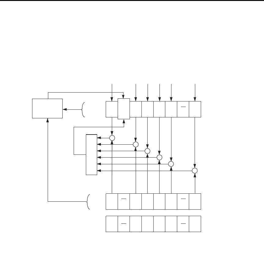
Model 6487 Reference Manual Status Structure 10-7
Status byte and service request (SRQ)
Service request is controlled by two 8-bit registers: the status byte register and the service
request enable register. Figure 10-3 shows the structure of these registers.
Figure 10-3
Status byte and service request
Status byte register
The summary messages from the status registers and queues are used to set or clear the
appropriate bits (B0, B2, B3, B4, B5, and B7) of the status byte register. These summary
bits do not latch and their states (0 or 1) are solely dependent on the summary messages
(0 or 1). For example, if the standard event register is read, its register will clear. As a
result, its summary message will reset to 0, which in turn will reset the ESB bit in the
status byte register.
Status Summary Messages (6)
OSB
(B7)
RQS
(B6)
MSS
ESB
(B5)
MAV
(B4)
QSB
(B3)
EAV
(B2) (B1) (B0)
OR
* SRE
* SRE?
Status Byte
Register
Service Request
Enable Register
OSB = Operation Summary Bit
MSS = Master Summary Status
RQS = Request for Service
ESB = Event Summary Bit
MAV = Message Available
QSB = Questionable Summary Bit
EAV = Error Available
MSB = Measurement Summary Bit
& = Logical AND
OR = Logical OR
OSB
(B7) (B6)
ESB
(B5)
MAV
(B4)
QSB
(B3)
EAV
(B2) (B1) (B0)
&
&
&
&
&
MSB
MSB
&
128
(27)
32
(25)
16
(24)
8
(23)
4
(22)
1
(20)
Decimal
Weights
* STB?
Serial Poll
Service
Request
Generation

10-8 Status Structure Model 6487 Reference Manual
The bits of the status byte register are described as follows:
•Bit B0, measurement status (MSB) — Set summary bit indicates that an enabled
measurement event has occurred.
•Bit B1 — Not used.
•Bit B2, error available (EAV) — Set summary bit indicates that an error or status
message is present in the error queue.
•Bit B3, questionable summary bit (QSB) — Set summary bit indicates that an
enabled questionable event has occurred.
•Bit B4, message available (MAV) — Set summary bit indicates that a response
message is present in the output queue.
•Bit B5, event summary bit (ESB) — Set summary bit indicates that an enabled
standard event has occurred.
•Bit B6, request service (RQS)/master summary status (MSS) — Set bit indicates
that an enabled summary bit of the status byte register is set.
•Bit B7, operation summary (OSB) — Set summary bit indicates that an enabled
operation event has occurred.
Depending on how it is used, bit B6 of the status byte register is either the request for ser-
vice (RQS) bit or the master summary status (MSS) bit:
• When using the serial poll sequence of the Model 6487 to obtain the status byte
(a.k.a. serial poll byte), B6 is the RQS bit. See “Serial polling and SRQ,” page 10-9
for details on using the serial poll sequence.
• When using the *STB? command (Table 10-3) to read the status byte, B6 is the
MSS bit.
Service request enable register
The generation of a service request is controlled by the service request enable register.
This register is programmed by you and is used to enable or disable the setting of bit B6
(RQS/MSS) by the status summary message bits (B0, B2, B3, B4, B5, and B7) of the sta-
tus byte register. As shown in Figure 10-3, the summary bits are logically ANDed (&)
with the corresponding enable bits of the service request enable register. When a set (1)
summary bit is ANDed with an enabled (1) bit of the enable register, the logic “1” output
is applied to the input of the OR gate and, therefore, sets the MSS/RQS bit in the status
byte register.
The individual bits of the service request enable register can be set or cleared by using the
*SRE common command. To read the service request enable register, use the *SRE?
query command. The service request enable register clears when power is cycled or a
parameter value of 0 is sent with the *SRE command (i.e. *SRE 0). The commands to pro-
gram and read the SRQ enable register are listed in Table 10-3.

Model 6487 Reference Manual Status Structure 10-9
Serial polling and SRQ
Any enabled event summary bit that goes from 0 to 1 will set bit B6 and generate an SRQ
(service request). In your test program, you can periodically read the status byte to check
if an SRQ has occurred and what caused it. If an SRQ occurs, the program can, for exam-
ple, branch to an appropriate subroutine that will service the request.
Typically, SRQs are managed by the serial poll sequence of the Model 6487. If an SRQ
does not occur, bit B6 (RQS) of the status byte register will remain cleared and the pro-
gram will simply proceed normally after the serial poll is performed. If an SRQ does
occur, bit B6 of the status byte register will set and the program can branch to a service
subroutine when the SRQ is detected by the serial poll.
The serial poll automatically resets RQS of the status byte register. This allows subsequent
serial polls to monitor bit B6 for an SRQ occurrence generated by other event types. After
a serial poll, the same event can cause another SRQ, even if the event register that caused
the first SRQ has not been cleared.
The serial poll does not clear MSS. The MSS bit stays set until all status byte summary
bits are reset.
SPE, SPD (serial polling)
The SPE, SPD general bus command is used to serial poll the Model 6487. Serial polling
obtains the serial poll byte (status byte). Typically, serial polling is used by the controller
to determine which of several instruments has requested service with the SRQ line.
Status byte and service request commands
The commands to program and read the status byte register and service request enable reg-
ister are listed in Table 10-3. For details on programming and reading registers, see “Pro-
gramming enable registers,” page 10-5 and “Reading registers,” page 10-6.
To reset the bits of the service request enable register to 0, use 0 as the parameter value for
the *SRE command (i.e. *SRE 0).
Table 10-3
Common commands — status byte and service request enable registers
Command Description Default
*STB? Read status byte register.
*SRE <NDN> or <NRf> Program the service request enable register:
<NDN> = #Bxx…x Binary format (each x = 1 or 0)
= #Hx Hexadecimal format (x = 0 to FF)
= #Qx Octal format (x = 0 to 377)
<NRf> = 0 to 255 Decimal format
(Note)
*SRE? Read the service request enable register.
Note: *CLS and STATus:PRESet have no effect on the service request enable register.

10-10 Status Structure Model 6487 Reference Manual
Programming example — set MSS (B6) when error occurs
The first command of the following sequence enables EAV (error available). When an
invalid command is sent (line 4), bits B2 (EAV) and B6 (MSS) of the status byte register
set to 1. The last command reads the status byte register using the binary format (which
directly indicates which bits are set). The command to select format (FORMat:SREGister)
is documented in Table 10-2. To determine the exact nature of the error, you will have to
read the error queue (see “Queues,” page 10-17).
*CLS ' Clear Error Queue.
*SRE 4 ' Enable EAV.
FORM:SREG BIN ' Select binary format.
BadCommand ' Generate error.
*STB? ' Read Status Byte Register.
Status register sets
As shown in Figure 10-1, there are four status register sets in the status structure of the
Model 6487: standard event status, operation event status, measurement event status, and
questionable event status.
Register bit descriptions
Standard event status
The used bits of the standard event register (Figure 10-4) are described as follows:
•Bit B0, operation complete (OPC) — Set bit indicates that all pending selected
device operations are completed and the Model 6487 is ready to accept new com-
mands. This bit only sets in response to the *OPC? query command. See
Section 11 for details on *OPC and *OPC?.
•Bit B2, query error (QYE) — Set bit indicates that you attempted to read data
from an empty output queue.
•Bit B3, device-dependent error (DDE) — Set bit indicates that an instrument
operation did not execute properly due to some internal condition.
•Bit B4, execution error (EXE) — Set bit indicates that the Model 6487 detected
an error while trying to execute a command.
•Bit B5, command error (CME) — Set bit indicates that a command error has
occurred.
Command errors include:
— IEEE-488.2 syntax error — The Model 6487 received a message that does not fol-
low the defined syntax of the IEEE-488.2 standard.
— Semantic error — The Model 6487 received a command that was misspelled or
received an optional IEEE-488.2 command that is not implemented.
— The instrument received a Group Execute Trigger (GET) inside a program message.
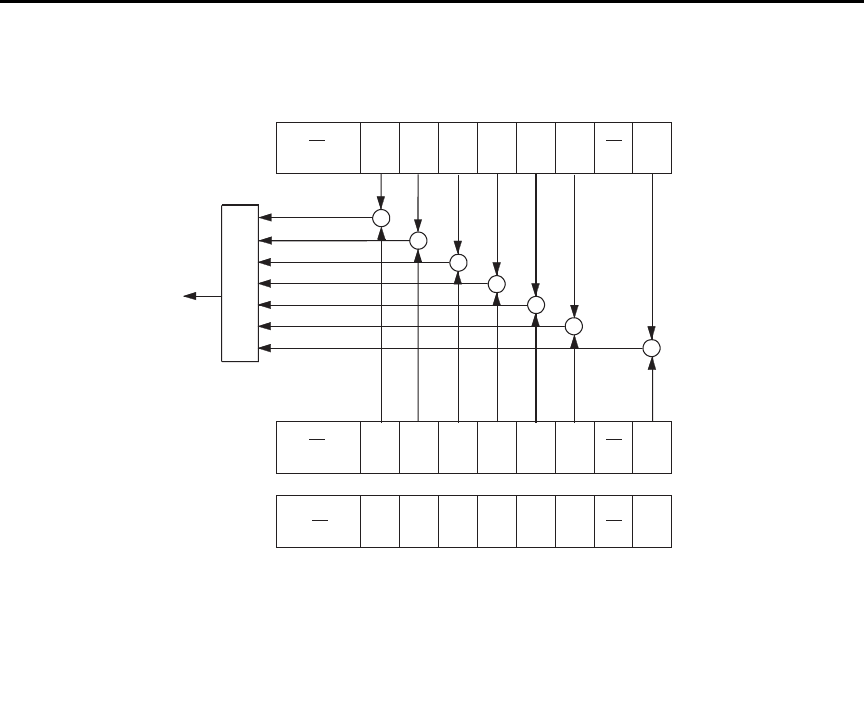
Model 6487 Reference Manual Status Structure 10-11
Figure 10-4
Standard event status
•Bit B6, user request (URQ) — Set bit indicates that the LOCAL key on the
Model 6487 front panel was pressed.
•Bit B7, power ON (PON) — Set bit indicates that Model 6487 has been turned off
and turned back on since the last time this register has been read.
PON
(B7)
CME
(B5)
EXE
(B4)
DDE
(B3)
QYE
(B2) (B1)
OR
Standard Event
Register
Standard Event
Enable Register
PON = Power On
URQ = User Request
CME = Command Error
EXE = Execution Error
DDE = Device-Dependent Error
QYE = Query Error
OPC = Operation Complete
& = Logical AND
OR = Logical OR
&
&
&
&
&
OPC
(B0)
&
128
(27)
32
(25)
16
(24)
8
(23)
4
(22)
1
(20)
Decimal
Weights
URQ
(B6)
(B15 - B8)
PON
(B7)
CME
(B5)
EXE
(B4)
DDE
(B3)
QYE
(B2) (B1)
OPC
(B0)
URQ
(B6)
(B15 - B8)
*ESR?
*ESE <NRf>
*ESE?
64
(26)
To ESB bit
of Status Byte
Register
&
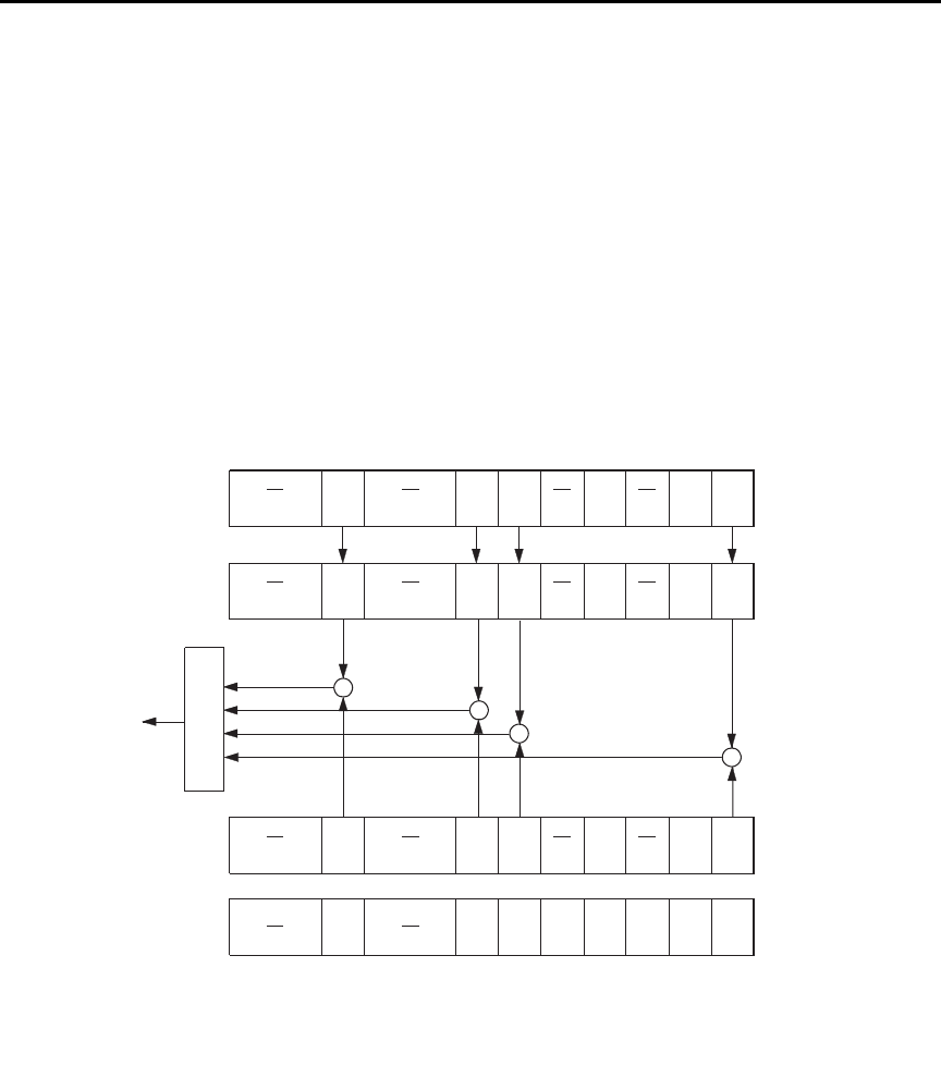
10-12 Status Structure Model 6487 Reference Manual
Operation event status
The used bits of the operation event register (Figure 10-5) are described as follows:
•Bit B0, calibrating (CAL) — Set bit indicates that the Model 6487 is calibrating.
•Bit B1, A-V Ohms — Set bit indicates that alternating voltage ohms is running.
•Bit B3, Sweeping — Set bit indicates that a voltage sweep is running.
•Bit B5, waiting for trigger event (Trig) — Set bit indicates that the Model 6487 is
in the trigger layer waiting for a TLINK trigger event to occur.
•Bit B6, waiting for arm event (Arm) — Set bit indicates that the Model 6487 is in
the arm layer waiting for an arm event to occur.
•Bit B10, idle state (Idle) — Set bit indicates the Model 6487 is in the idle state.
Figure 10-5
Operation event status
OR
Operation Event
Enable Register
Idle = In Idle
Trig = Waiting for trigger event
Arm = Waiting for arm event
Cal = Calibrating
A-V = A-V Ohms
Swp = Sweep running
& = Logical AND
OR = Logical OR
&
&
&
Cal
(B0)
&
1024
(210)
32
(25)
Decimal
Weights
Cal
(B0)
[:EVENt]?
64
(26)
Cal
(B0)
Trig
(B5)
Arm
(B6)
Idle
(B10) (B9-B7)
(B15-B11)
:CONDition? Trig
(B5)
Arm
(B6)
Idle
(B10) (B9-B7)
(B15-B11)
Operation Condition
Register
Operation Event
Register
Trig
(B5)
Arm
(B6)
Idle
(B10) (B9-B7)
(B15-B11)
1
(20)
:ENABle <NRf>
:ENABle?
To OPC bit
of Status Byte
Register
(B4)
Swp
(B3)
A-V
(B1)
(B2)
(B4)
Swp
(B3)
A-V
(B1)
(B2)
(B4)
Swp
(B3)
A-V
(B1)
(B2)
16
(24)
8
(23)
4
(22)
2
(21)
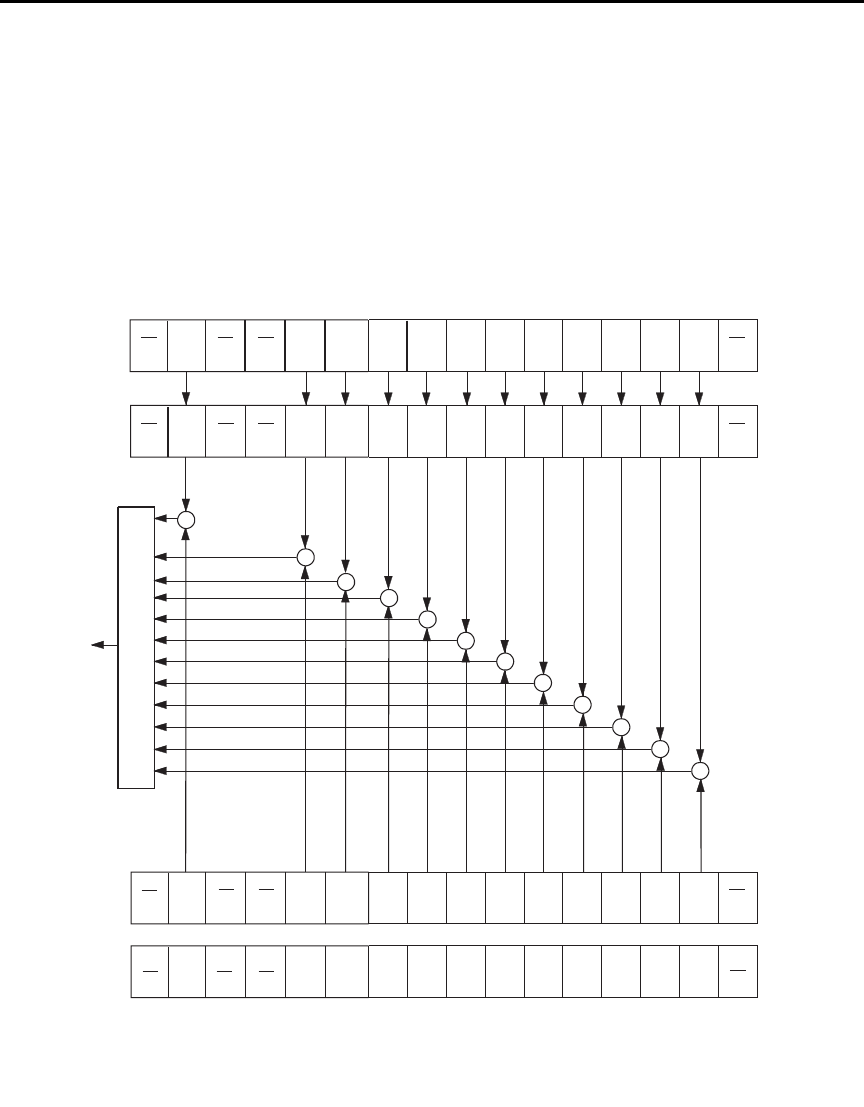
Model 6487 Reference Manual Status Structure 10-13
Measurement event status
The used bits of the measurement event register (Figure 10-6) are described as follows:
•Bit B1, low limit 1 fail (LL1F) — Set bit indicates that the low limit 1 test has
failed.
•Bit B2, high limit 1 fail (HL1F) — Set bit indicates that the high limit 1 test has
failed.
Figure 10-6
Measurement event status
ROF
(B7)
LP
(B5)
HL2F
(B4)
LL2F
(B3)
HL1F
(B2)
OR
BFL = Buffer Full
BAV = Buffer Available
ROF = Reading Overflow
RAV = Reading Available
LP = Limits Pass
IOV = Input Overvoltage
& = Logical AND
OR = Logical OR
&
&
&
&
&
(B0)
&
128
(27)
32
(25)
16
(24)
8
(23)
4
(22)
2
(21)
Decimal
Weights
RAV
(B6)
[:EVENt]?
64
(26)
BFL
(B9)
BAV
(B8)
&
&
&
LL1F
(B1)
ROF
(B7)
LP
(B5)
HL2F
(B4)
LL2F
(B3)
HL1F
(B2)
Measurement
Condition
Register
(B0)
RAV
(B6)
(B15)
:CONDition? BFL
(B9)
BAV
(B8)
LL1F
(B1)
Measurement
Event Register
ROF
(B7)
LP
(B5)
HL2F
(B4)
LL2F
(B3)
HL1F
(B2) (B0)
RAV
(B6)
BFL
(B9)
BAV
(B8)
LL1F
(B1)
512
(29)
256
(28)
HL2F = High Limit 2 Fail
LL2F = Low Limit 2 Fail
HL1F = High Limit 1 Fail
LL1F = Low Limit 1 Fail
INT = Interlock Asserted
VSC = Voltage Source Compliance
:ENABle <NRf>
:ENABle?
Measurement
Event Enable
Register
To MSB
bit of Status
Byte Register
IOV
(B10)
&
INT
(B11)
(B12)
VSC
(B14)
&
&
(B13)
(B15)
IOV
(B10)
INT
(B11)
(B12)
VSC
(B14) (B13)
(B15)
IOV
(B10)
INT
(B11)
(B12)
VSC
(B14) (B13)
1024
(210)
2048
(211)
16384
(214)

10-14 Status Structure Model 6487 Reference Manual
•Bit B3, low limit 2 fail (LL2F) — Set bit indicates that the low limit 2 test has
failed.
•Bit B4, high limit 2 fail (HL2F) — Set bit indicates that the high limit 2 test has
failed.
•Bit B5, limits pass (LP) — Set bit indicates that all limit tests passed.
•Bit B6, reading available (RAV) — Set bit indicates that a reading was taken and
processed.
•Bit B7, reading overflow (ROF) — Set bit indicates that the reading exceeds the
selected measurement range of the Model 6487.
•Bit B8, buffer available (BAV) — Set bit indicates that there are at least two
readings in the buffer.
•Bit B9, buffer full (BFL) — Set bit indicates that the buffer is full. This bit will
also be set when a voltage sweep has been completed (Section 6), and if the
programmed number of A-V ohms cycles have been taken (Section 3).
•Bit B10, input overvoltage (IOV) — Set bit indicates there is an input over
voltage condition.
•Bit B11, output interlock asserted (INT) — Set bit indicates that the output
interlock is asserted and the voltage source output cannot be turned on.
•Bit B14, voltage source compliance (VSC) — Set bit indicates that the voltage
source is in compliance.
Questionable event status
The used bits of the questionable event register (Figure 10-7) are described as follows:
•Bit B7, calibration summary (Cal) — Set bit indicates that an invalid calibration
constant was detected during the power-up sequence. This error will clear after
successful calibration of the Model 6487.
•Bit B14, command warning (Warn) — Set bit indicates that a signal oriented
measurement command parameter has been ignored.
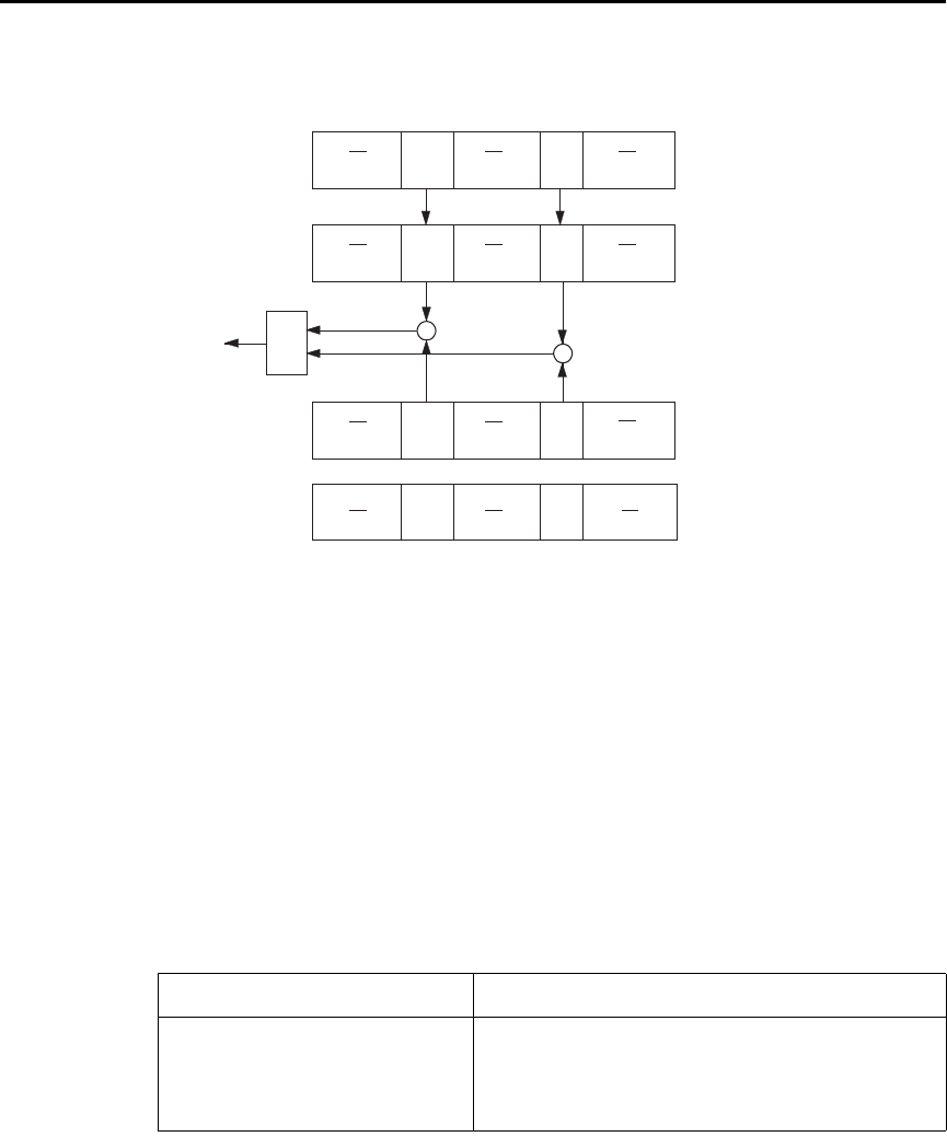
Model 6487 Reference Manual Status Structure 10-15
Figure 10-7
Questionable event status
Condition registers
As Figure 10-1 shows, each status register set (except the standard event register set) has a
condition register. A condition register is a real-time, read-only register that constantly
updates to reflect the present operating conditions of the instrument. For example, while
the Model 6487 is in the idle state, bit B10 (Idle) of the operation condition register will be
set. When the instrument is taken out of idle, bit B10 clears.
The commands to read the condition registers are listed in Table 10-4. For details on read-
ing registers, see “Reading registers,” page 10-6.
Table 10-4
Common and SCPI commands — condition registers
Command Description
STATus
:OPERation:CONDition?
:MEASurement:CONDition?
:QUEStionable:CONDition?
STATus subsystem:
Read operation condition register.
Read measurement condition register.
Read questionable condition register.
OR
Warn = Command Warning
Cal = Calibration Summary
& = Logical AND
OR = Logical OR
&
&
16384
(214)
Decimal
Weights
[:EVENt]?
128
(27)
(B6-B0)
Cal
(B7)
Warn
(B14) (B13-B8)
(B15)
:CONDition? Cal
(B7)
Warn
(B14) (B13-B8)
(B15)
Questionable
Condition Register
:ENABle <NRf>
:ENABle?
(B6-B0)
Questionable
Event Register
Warn
(B14) (B13-B8)
(B15) (B6-B0)
Questionable Event
Enable Register
Cal
(B7)
To QSB bit
of Status Byte
Register

10-16 Status Structure Model 6487 Reference Manual
Event registers
As Figure 10-1 shows, each status register set has an event register. When an event occurs,
the appropriate event register bit sets to 1. The bit remains latched to 1 until the register is
reset. Reading an event register clears the bits of that register. *CLS resets all four event
registers.
The commands to read the event registers are listed in Table 10-5. For details on reading
registers, see “Reading registers,” page 10-6.
Event enable registers
As Figure 10-1 shows, each status register set has an enable register. Each event register
bit is logically ANDed (&) to a corresponding enable bit of an enable register. Therefore,
when an event bit is set and the corresponding enable bit is set (as programmed by the
user), the output (summary) of the register will set to 1, which in turn sets the summary bit
of the status byte register.
The commands to program and read the event enable registers are listed in Table 10-6. For
details on programming and reading registers, see “Programming enable registers,”
page 10-5 and “Reading registers,” page 10-6.
klqb The bits of any enable register can be reset to 0 by sending the
0 parameter value with the appropriate enable command
(i.e. STATus:OPERation:ENABle 0).
Table 10-5
Common and SCPI commands — event registers
Command Description
*ESR?
STATus
:OPERation:[:EVENt]?
:MEASurement:[:EVENt]?
:QUEStionable:[:EVENt]?
Read standard event status register.
STATus subsystem:
Read operation event register.
Read measurement event register.
Read questionable event register.
Note: Power-up and *CLS resets all bits of all event registers to 0. STATus:PRESet has no effect.

Model 6487 Reference Manual Status Structure 10-17
Programming example — program and read registers
This command sequence programs and reads the measurement registers. Registers are
read using the binary format (which directly indicates which bits are set). The command to
select format (FORMat:SREGister) is documented in Table 10-2.
FORM:SREG BIN ' Select binary format to read registers.
STAT:MEAS:ENAB 512 ' Enable BFL (buffer full).
STAT:MEAS:COND? ' Read Measurement Condition Register.
STAT:MEAS? ' Read Measurement Event Register.
Queues
The Model 6487 uses two queues which are first-in, first-out (FIFO) registers:
• Output queue — Used to hold reading and response messages.
• Error queue — Used to hold error and status messages.
The Model 6487 status model (Figure 10-1) shows how the two queues are structured with
the other registers.
Table 10-6
Common and SCPI commands — event enable registers
Command Description
*ESE <NDN> or <NRf>
*ESE?
STATus
:OPERation
:ENABle <NDN> or <NRf>
:ENABle?
:MEASurement
:ENABle <NDN> or <NRf>
:ENABle?
:QUEStionable
:ENABle <NDN> or <NRf>
:ENABle?
Program standard event enable register (see “Parameters”).
Read standard event enable register.
STATus subsystem:
Operation event enable register:
Program enable register (see “Parameters”).
Read enable register.
Measurement event enable register:
Program enable register (see “Parameters”).
Read enable register.
Questionable event enable register:
Program enable register (see “Parameters”).
Read measurement event enable register.
Parameters:
<NDN> = #Bxx…x Binary format (each x = 1 or 0)
= #Hx Hexadecimal format (x = 0 to FFFF)
= #Qx Octal format (x = 0 to 177777)
<NRf> = 0 to 65535 Decimal format
Note: Power-up and STATus:PRESet resets all bits of all enable registers to 0. *CLS has no effect.

10-18 Status Structure Model 6487 Reference Manual
Output queue
The output queue holds data that pertains to the normal operation of the instrument. For
example, when a query command is sent, the response message is placed in the output
queue.
When data is placed in the output queue, the message available (MAV) bit in the status
byte register sets. A data message is cleared from the output queue when it is read. The
output queue is considered cleared when it is empty. An empty output queue clears the
MAV bit in the status byte register.
A message is read from the output queue by addressing the Model 6487 to talk after the
appropriate query is sent.

Model 6487 Reference Manual Status Structure 10-19
Error queue
The error queue holds error and status messages. When an error or status event occurs, a
message that defines the error/status is placed in the error queue.
When a message is placed in the error queue, the error available (EAV) bit in the status
byte register is set. An error/status message is cleared from the error queue when it is read.
The error queue is considered cleared when it is empty. An empty error queue clears the
EAV bit in the status byte register.
The error queue holds up to 10 error/status messages. The commands to read the error
queue are listed in Table 10-7. When you read a single message in the error queue, the
“oldest” message is read and then removed from the queue. If the queue becomes full, the
message “350, ‘queue overflow’” will occupy the last memory location. On power-up, the
error queue is empty. When empty, the message “0, No Error” is placed in the queue.
Messages in the error queue are preceded by a code number. Negative (-) numbers are
used for SCPI defined messages and positive (+) numbers are used for Keithley defined
messages. The messages are listed in Appendix B. As shown in Table 10-7, there are com-
mands to read the entire message (code and message) or the code only.
On power-up, all error messages are enabled and will go into the error queue as they occur.
Status messages are not enabled and will not go into the queue. As listed in Table 10-7,
there are commands to enable and/or disable messages. For these commands, the <list>
parameter is used to specify which messages to enable or disable. The messages are speci-
fied by their codes. The following examples show various forms for using the <list>
parameter.
<list> = (-110) Single message
= (-110:-222) Range of messages (-110 through -222)
= (-110:-222, -220) Range entry and single entry (separated by a comma)
When you enable messages, messages not specified in the list are disabled. When you dis-
able messages, each listed message is removed from the enabled list.
To prevent all messages from entering the error queue, send the enable command along
with the null list parameter as follows: STATus:QUEue:ENABle ().

10-20 Status Structure Model 6487 Reference Manual
Programming example — read error queue
The following command reads the error queue:
STAT:QUE? ' Read Error Queue.
Table 10-7
SCPI commands — error queue
Command Description Default
STATus
:QUEue
[:NEXT]?
:ENABle <list>
:ENABle?
:DISable <list>
:DISable?
:CLEar
SYSTem
:ERRor
[:NEXT]?
:ALL?
:COUNt?
:CODE
[:NEXT]?
:ALL?
STATus subsystem:
Read error queue:
Read and clear oldest error/status (code and message).
Specify error and status messages for error queue.
Read the enabled messages.
Specify messages not to be placed in queue.
Read the disabled messages.
Clear messages from error queue.
SYSTem subsystem:
Read error queue:
Read and clear oldest error/status (code and message).
Read and clear all errors/status (code and message).
Read the number of messages in queue.
Code numbers only:
Read and clear oldest error/status (code only).
Read and clear all errors/status (codes only).
(Note 1)
(Note 2)
(Note 2)
(Note 1)
Notes:
1. Power-up and *CLS empties the error queue. STATus:PRESet has no effect.
2. Power-up enables error messages and disables status messages. *CLS and STATus:PRESet have no effect.


11-2 Common Commands Model 6487 Reference Manual
Common commands
Common commands (summarized in Table 11-1) are device commands that are common
to all devices on the bus. These commands are designated and defined by the IEEE-488.2
standard.
Table 11-1
IEEE-488.2 common commands and queries
Mnemonic Name Description Ref
*CLS Clear status Clears all event registers and error queue. Section 10
*ESE <NRf> Event enable command Program the standard event enable register. Section 10
*ESE? Event enable query Read the standard event enable register. Section 10
*ESR? Event status register query Read the standard event enable register and clear it. Section 10
*IDN? Identification query Returns the manufacturer, model number, serial
number, and firmware revision levels of the unit.
A
*OPC Operation complete command Set the operation complete bit in the standard event
register after all pending commands have been
executed.
B
*OPC? Operation complete query Places an ASCII “1” into the output queue when all
pending selected device operations have been
completed.
B
*OPT? Option query Returns model number of any installed options.
*RCL <NRf> Recall command Returns Model 6487 to the user-saved setup. C
*RST Reset command Returns Model 6487 to the *RST default
conditions.
D
*SAV <NRf> Save command Saves the present setup as the user-saved setup. C
*SRE <NRf> Service request enable command Programs the service request enable register. Section 10
*SRE? Service request enable query Reads the service request enable register. Section 10
*STB? Status byte query Reads the status byte register. Section 10
*TRG Trigger command Sends a bus trigger to Model 6487. E
*TST? Self-test query Performs a checksum test on ROM and returns the
result.
F
*WAI Wait-to-continue command Wait until all previous commands are executed. G

Model 6487 Reference Manual Common Commands 11-3
A) IDN? — identification query Reads identification code
The identification code includes the manufacturer, model number, serial number, and firm-
ware revision levels and is sent in the following format:
KEITHLEY INSTRUMENTS INC., MODEL 6487, xxxxxxx, yyyyy/zzzzz/w
Where: xxxxxxx is the serial number.
yyyyy/zzzzz is the firmware revision levels of the digital board ROM and
display board ROM. Note that yyyyy also provides build date and time
information. w is the board revision level.
B) OPC — operation complete Sets OPC bit
OPC? — operation complete query Places a “1” in output queue
When *OPC is sent, the OPC bit in the standard event register will set after all pending
command operations are complete. When *OPC? is sent, an ASCII “1” is placed in the
output queue after all pending command operations are complete.
Typically, either one of these commands is sent after the INITiate command. The INITiate
command is used to take the instrument out of idle in order to perform measurements.
While operating within the trigger model layers, all sent commands (except DCL, SDC,
IFC, SYSTem:PRESet, *RST, GET, and ABORt) will not execute.
After all programmed operations are completed, the instrument returns to the idle state at
which time all pending commands (including *OPC and/or *OPC?) are executed. After
the last pending command is executed, the OPC bit and/or an ASCII “1” is placed in the
output queue.
Programming example — The following command sequence will perform 10 measure-
ments. After the measurements are completed (in approximately 10 seconds), an ASCII
“1” will be placed in the output queue.
*RST ' Return 6487 to RST defaults (idle).
TRIG:DEL 1 ' Set trigger delay for 1 second.
ARM:COUN 10 ' Program for 5 measurements and stop.
INIT ' Start measurements.
*OPC? ' Send *OPC?.

11-4 Common Commands Model 6487 Reference Manual
C) SAV <NRf> — save Save present setup in memory
RCL <NRf> — recall Return to setup stored in memory
Parameters 0 = Memory location 0
1 = Memory location 1
2 = Memory location 2
Use the *SAV command to save the present instrument setup configuration in memory for
later recall. Any control affected by *RST can be saved by the *SAV command. The *RCL
command is used to restore the instrument to the saved setup configuration. Three setup
configurations can be saved and recalled.
The Model 6487 ships from the factory with SYSTem:PRESet defaults loaded into the
available setup memory. If a recall error occurs, the setup memory defaults to the
SYSTem:PRESet values.
Programming example:
*SAV 2 ' Save present setup in memory location 2.
*RST ' Set 6487 to RST defaults.
*RCL 2 ' Return (recall) 6487 to setup stored in memory location 2.
D) RST — reset Return Model 6487 to RST defaults
When the *RST command is sent, the Model 6487 performs the following operations:
1. Returns Model 6487 to the RST default conditions (see “Default” column of SCPI
tables).
2. Cancels all pending commands.
3. Cancels response to any previously received *OPC and *OPC? commands.
E) TRG — trigger Send bus trigger to Model 6487
Use the *TRG command to issue a GPIB trigger to the Model 6487. It has the same effect
as a group execute trigger (GET).
Use the *TRG command as an event to control operation. The Model 6487 reacts to this
trigger if BUS is the programmed arm control source. The control source is programmed
from the TRIGger subsystem.
klqb Details on triggering are covered in Section 7.
Programming example — The following command sequence configures the Model 6487
to be controlled by bus triggers. The last line, which sends a bus trigger, triggers one mea-
surement. Each subsequent bus trigger will also trigger a single measurement.
*RST ' Restore RST defaults.
ARM:SOUR BUS ' Select BUS control source.
ARM:COUN INF ' Set arm layer count to infinite.
INIT ' Take 6487 out of idle.
*TRG ' Trigger one measurement.

Model 6487 Reference Manual Common Commands 11-5
F) TST? — self-test query Run self-test and read result
Use this query command to perform a checksum test on ROM. The command places the
coded result (0 or 1) in the output queue. When the Model 6487 is addressed to talk, the
coded result is sent from the output queue to the computer.
A returned value of zero (0) indicates that the test passed and a value of one (1) indicates
that the test failed.
G) WAI — wait-to-continue Wait until previous commands are completed
Effectively, the *WAI command is a No-Op (no operation) for the Model 6487 and thus,
does not need to be used.
Two types of device commands exist:
• Sequential commands — A command whose operations are allowed to finish
before the next command is executed.
• Overlapped commands — A command that allows the execution of subsequent
commands while device operations of the overlapped command are still in
progress.
The *WAI command is used to suspend the execution of subsequent commands until the
device operations of all previous overlapped commands are finished. The *WAI command
is not needed for sequential commands.

12
SCPI Signal Oriented
Measurement Commands

12-2 SCPI Signal Oriented Measurement Commands Model 6487 Reference Manual
The signal oriented measurement commands are used to acquire readings. You can use
these high level instructions to control the measurement process. These commands are
summarized in Table 12-1.
klqb The readings acquired by these commands depend on which data elements are
selected. (See Table 13-3 for details.)
A) CONFigure[:<function>] Configure Model 6487 for “one-shot” measurements
<function> = CURRent[:DC] Configure current
This command configures the instrument for “one-shot” measurements. Each subsequent
READ? command will then trigger a single measurement and acquire the reading (see
READ? for details).
If the instrument is in idle, this command will execute immediately. If the instrument is not
in idle, execution of the command will execute when the operation returns to the idle state.
When this command is executed, the Model 6487 will be configured as follows:
• The specified function is selected.
• All controls related to the selected function are defaulted to the *RST values.
• The event control sources of the trigger model are set to immediate.
• The arm and trigger count values of the trigger model are set to one.
• The delay of the trigger model is set to zero.
• The Model 6487 is placed in the idle state.
• All math calculations are disabled.
• Buffer operation is disabled. A storage operation presently in process will be
aborted.
• Autozero is enabled.
This command is automatically asserted when the :MEASure? command is sent.
Table 12-1
Signal oriented measurement command summary
Command Description Ref
CONFigure[:<function>]
CONFigure?
FETCh?
READ?
MEASure[:<function>]?
Places Model 6487 in a “one-shot” measurement
mode. <function> = CURR[:DC]
Queries the selected function. Returns ‘CURR’.
Requests the latest reading(s).
Performs an INITiate and a :FETCh?.
Performs a CONFigure:<function> and a :READ?.
A
B
C
D

Model 6487 Reference Manual SCPI Signal Oriented Measurement Commands 12-3
Programming example — The following command sequence selects and configures the
Model 6487 for “one-shot” measurements. Each subsequent READ? triggers a single
measurement and requests the reading.
CONF:CURR ' Perform CONFigure operations.
READ? ' Trigger measurement and request reading.
B) FETCh? Request latest reading
This command requests the latest post-processed readings. After sending this command
and addressing the Model 6487 to talk, the readings are sent to the computer. This com-
mand does not affect the instrument setup.
This command does not trigger a measurement. The command simply requests the last
group of readings. Note that this command can repeatedly return the same readings. Until
there is a new reading(s), this command continues to return the old reading(s). If your
application requires a “fresh” reading, use the :READ? command.
This command is automatically asserted when the :READ? or :MEASure? command is
sent.
C) READ? Trigger measurement(s) and request reading(s)
This command is used to trigger and acquire readings. The number of readings depends on
how the trigger model is configured. For example, if configured for 20 measurements (arm
count 1, trigger count 20), 20 sets of readings will be acquired.
When this command is sent, the following commands execute in the order they are
presented:
• INITiate
• FETCh?
If the instrument is in the idle state, INITiate takes the instrument out of idle to perform
the programmed number of measurements. If the instrument is not in the idle state, execu-
tion of this command will wait until it goes back into idle.
The FETCh? command is executed to acquire the reading(s). The readings are sent to the
computer when the Model 6487 is addressed to talk.
klqb If the instrument is programmed to perform an infinite number of measurements
(arm count or trigger count set to infinite), you cannot use the READ? command
to trigger and acquire readings. Use INITiate to start (trigger) the measurement
process, send ABORt to abort the measurement process, and then use
SENSe:DATA[:LATest]? to return the last (latest) reading.

12-4 SCPI Signal Oriented Measurement Commands Model 6487 Reference Manual
D) MEASure[:<function>]? Configure and perform “one-shot” measurement
<function> = CURRent[:DC] Measure current
This command combines all of the other signal oriented measurement commands to per-
form a “one-shot” measurement and acquire the reading.
When this command is sent, the following commands execute in the order that they are
presented.
• CONFigure:<function>
• READ?
When :CONFigure is executed, the instrument goes into a “one-shot” measurement mode.
See CONFigure for details.
When READ? is executed, its operations will then be performed. In general, an INITiate is
executed to perform the measurement and a FETCh? is executed to acquire the reading.
See :READ? for details.


13-2 DISPlay, FORMat, and SYSTem Model 6487 Reference Manual
DISPlay subsystem
The commands in this subsystem are used to control the display over the bus.
A) DISPlay:ENABle <b>
With front panel circuitry turned off, the instrument operates at a higher speed. While dis-
abled, the display is frozen and all front panel controls (except LOCAL) are disabled. Nor-
mal display operations can be resumed by using :ENABle to enable the display, pressing
the LOCAL key, or cycling power.
Table 13-1
SCPI commands — display
Command Description Default Ref
:DISPlay
:DIGits <n>
:DIGits?
:ENABle <b>
:ENABle?
[:WINDow[1]]
:TEXT
[:DATA] <a>
[:DATA]?
:STATe <b>
Set display resolution: 4 to 7.
Query display resolution.
Turn front panel display on or off.
Query front panel display status.
Path to control user text messages:
Define ASCII message “a” (up to 12 characters).
Query defined ASCII message.
Enable or disable text message mode.
6
(see Note)
(see Note)
Section 4
A
B
C
Note: *RST and SYSTem:PRESet have no effect on the display circuitry and user-defined text messages.

Model 6487 Reference Manual DISPlay, FORMat, and SYSTem 13-3
B) DISPlay:TEXT[:DATA] <a>
Message Types: String ‘aa…a’ or “aa…a”
Indefinite Block #0aa…a
Definite Block #XYaa…a
where: Y = number of characters in message (up to 12)
X = number of digits that make up Y (1 or 2)
The display message can be up to 12 characters (ASCII) long. A space is counted as a
character. Excess message characters result in an error. Note that for the string type, the
message must be enclosed by single or double quotes.
An indefinite block message must be the only command in the program message or the
last command in the program message. If you include a command after an indefinite block
message (on the same line), it will be treated as part of the message and is displayed
instead of executed.
C) DISPlay:TEXT:STATe <b>
When the text message mode is enabled, a defined message is displayed. When disabled,
the message is removed from the display.
GPIB operation — A user-defined message remains displayed only as long as the instru-
ment is in remote. Taking the instrument out of remote (by pressing LOCAL or sending
the GTL (go to local) command) or cycling power cancels the message and disables the
text message mode.
RS-232 operation — A user-defined message can be cancelled by sending
SYSTem:LOCal, pressing LOCAL, or cycling power.

13-4 DISPlay, FORMat, and SYSTem Model 6487 Reference Manual
FORMat subsystem
The commands in this subsystem are used to select the format for transferring data over
the bus.
A) FORMat:DATA <type>[,<length>]
Parameters ASCii = ASCII format
REAL, 32 = Binary IEEE-754 single precision format
SREal = Binary IEEE-754 single precision format
klqb <length> is not used for the ASCii or SREal parameters. It is optional for the
REAL parameter. If you do not use <length> with REAL, <length> defaults to
32 (single precision format). The double precision format (<length> = 64) is
not supported by Model 6487.
Table 13-2
SCPI commands — data format
Command Description Default Ref
:FORMat
:DATA <type>[,<length>] Specify data format: ASCii, REAL, 32 or SREal. ASCii A
:DATA? Query data format.
:ELEMents <item list> Specify data elements: READing, UNITS,
VSOurce, TIME, STATus, DEFault, and ALL.
All except
VSO
B
:BORDer <name> Specify byte order: NORMal or SWAPped. (see Note) C
:BORDer? Query byte order.
:SREGister <name> Select data format for reading status registers:
ASCii, HEXadecimal, OCTal, or BINary.
ASC
Section 10
:SREGister? Query data format for reading status registers.
:SOURce2 <name> Select data format for reading output patterns:
ASCii, HEXadecimal, OCTal, or BINary.
ASC Section 8
:SOURce2? Query data format for output patterns.
Note: *RST default is NORMal. SYSTem:PRESet default is SWAPped.
Model 6487 Reference Manual DISPlay, FORMat, and SYSTem 13-5
The response to READ?, FETCh?, MEASure?, TRACe:DATA?, CALC1:DATA?,
CALC2:DATA?, or CALC3:DATA? over the GPIB can be returned in either the ASCii or
binary format. All other queries are returned in ASCii, regardless of the selected format.
Over the RS-232 interface, only the ASCII format is allowed.
klqb Regardless of which data format for output strings is selected, the instrument
will only respond to input commands using the ASCII format.
ASCII data format
The ASCII data format is in a direct readable form for the operator. Most programming
languages easily convert ASCII mantissa and exponent to other formats. However, some
speed is compromised to accommodate the conversion. Figure 13-1 shows an example
ASCII string that includes all the data elements. See :ELEMents for information on the
data elements.
Figure 13-1 also shows the byte order of the data string. Data elements not specified by the
:ELEMents command are simply not included in the string. Note that the status value is
always an integer, but it is still expressed in scientific notation.
Figure 13-1
ASCII data format
+1.040564E-06A, +2.2362990+2, +1.380000E+2, +123.4500
Reading Timestamp StatusUnits V-source
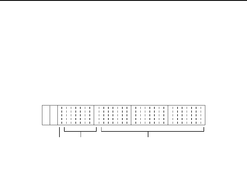
13-6 DISPlay, FORMat, and SYSTem Model 6487 Reference Manual
IEEE-754 single precision format
REAL 32 or SREal will select the binary IEEE-754 single precision data format.
Figure 13-2 shows the normal byte order format for each data element. For example, if
three data elements are selected, the data string for each reading conversion is made up of
three 4-byte data blocks. Note that the data string for each reading conversion is preceded
by a 2-byte header that is the binary equivalent of an ASCII # sign and 0. Figure 13-2 does
not show the byte for the terminator that is attached to the end of each data string. Note
that the byte order of the data string can be sent in reverse order.
Figure 13-2
IEEE-754 single precision data format (32 data bits)
During binary transfers, never un-talk Model 6487 until after the data is read (input) to the
computer. Also, to avoid erratic operation, the readings of the data string (and terminator)
should be acquired in one piece. The header (#0) can be read separately before the rest of
the string.
The number of bytes to be transferred can be calculated as follows:
Bytes = 2 + (Rdgs × 4) + 1
where: 2 is the number of bytes for the header (#0).
Rdgs is the product of the number of selected data elements, arm count and
trigger count.
4 is the number of bytes for each reading.
1 is the byte for the terminator.
For example, assume the instrument is configured to perform 10 measurements and send
them to the computer using the binary format:
Bytes = 2 + (10 × 4) + 1
= 43
Byte 1
70
Header Byte 2
70
Byte 3
70
Byte 4
70
se f
#0
s = sign bit (0 = positive, 1 = negative)
e = exponent bits (8)
f = fraction bits (23)
Normal byte order shown. For swapped byte order,
bytes sent in reverse order: Header, Byte 4, Byte 3
Byte 2, Byte 1.
The header and terminator are sent only once for each READ?.

Model 6487 Reference Manual DISPlay, FORMat, and SYSTem 13-7
B) FORMat:ELEMents <item list>
Parameters READing = Current or ohms reading
UNITs = Units
TIME = Timestamp
STATus = Status information
VSOurce = Voltage source value
ALL = All data elements
DEFault = All except VSOurce
The specified elements are included in the data string in response to :FETCh?, :READ?,
:MEASure?, and :TRACe:DATA?. Note that each element in the item list must be sepa-
rated by a comma (i.e. send “:ELEMents READing, UNITs, TIME”) to include the read-
ing with units and the time elements in the data string. The elements for the ASCii, ALL
format in the order sent are shown in Figure 13-1. Note that elements are delimited with
commas.
Reading — Returns the current reading for the current function or the ohms readings if
ohms is enabled. An overflow reading is returned as +9.9E37. When a specified data ele-
ment has invalid data associated with it, NAN (Not A Number) will be the response. NAN
is returned as +9.91E37. -9.9e+36 will be returned for any ohms reading taken when the
voltage source was in compliance.
Units — Units reference the returned readings units of measure. For the current function,
“A” will be returned. For the ohms function, “OHMS” will be returned.
Voltage source — This element returns the programmed voltage source value in volts
when the voltage source is in operate. Zero will be returned when the voltage source out-
put is off. -999 will be returned if the voltage source was in compliance.
Timestamp — Timestamp references the returned data string to a point in time. The
timestamp operates as a timer that starts at zero seconds when the instrument is turned on
or when the timestamp is reset (SYSTem:TIME:RESet). After 99,999.99 seconds, the
timer resets to zero and starts over.
For buffer readings, timestamp can be referenced to the first reading stored in the buffer
(absolute format) which is timestamped at 0 seconds or to the time between each stored
reading (delta format). The TRACe:TSTamp:FORMat command is used to select the
timestamp format.
Status — The status word provides information about Model 6487 operation. The 16-bit
status word is sent in decimal form. The decimal value has to be converted to the binary
equivalent to determine the state of each bit in the word. For example, if the returned status
value is 9, the binary equivalent is 00000001001. Bits 0 and 3 are set. The bits are
explained as follows:
Bit 0 (OFLO) — Set to 1 if measurement performed while in over-range (overflowed
reading).
Bit 1 (Filter) — Set to 1 when measurement performed with the averaging filter enabled.

13-8 DISPlay, FORMat, and SYSTem Model 6487 Reference Manual
Bit 2 (Math) — Set to 1 when measurement performed with CALC1 enabled.
Bit 3 (Null) — Set to 1 if null for CALC2 is enabled.
Bit 4 (Limits) — Set to 1 if a limit test (CALC2) is enabled.
Bits 5 and 6 (Limit Results) — Provides limit test results:
Bit 7 (Overvoltage) — Set to 1 if measurement performed with an overvoltage condition
on the input.
Bit 9 (Zero Check) — Set to 1 when zero check is enabled.
Bit 10 (Zero Correct) — Set to 1 when zero correct is enabled.
Example — The ASCII data string on page 13-5 contains all four data elements. The sta-
tus value of 138 has a binary equivalent of 01001010, which indicates that bits B1, B3, and
B7 are set. Therefore, the reading is 1.04056µA with null (REL) and the AVG filter
enabled. The reading was taken 223.6299 seconds after the instrument was turned on. The
voltage source was on and set to +123.45V.
C) FORMat:BORDer <name>
Parameters NORMal = Normal byte order for IEEE-754 binary format
SWAPped = Reverse byte order for IEEE-754 binary format
For normal byte order, the data format for each element is sent as follows:
Byte 1 Byte 2 Byte 3 Byte 4
For reverse byte order, data is sent as follows:
Byte 4Byte 3Byte 2Byte 1
The “#0” header is not affected by this command. The header is always sent at the begin-
ning of the data string for each measurement conversion.
The ASCII data format can only be sent in the normal byte order. The SWAPped selection
is ignored when the ASCII format is selected.
klqb The SWAPped byte order must be used when transmitting binary data to any
IBM PC.
Bit 6 Bit 5
0 0 All limit tests passed
0 1 CALC2:LIM1 test failed
1 0 CALC2:LIM2 test failed

Model 6487 Reference Manual DISPlay, FORMat, and SYSTem 13-9
SYSTem subsystem
Table 13-3
SCPI commands — system
Command Description Default Ref
:SYSTem
:ZCHeck
[:STATe] <b>
[:STATe?
:ZCORrect
[:STATe] <b>
[:STATe?]
:ACQuire
:PRESet
:LFRequency <freq>
:LFRequency?
:AUTO
[:STATe] <b>
[:STATe]?
:AZERo
[:STATe] <b>
[:STATe]?
:TIME
:RESet
:POSetup <name>
:POSetup?
:VERSion?
:ERRor
[:NEXT]?
:ALL?
:COUNt?
:CODE
[:NEXT]?
:ALL?
Zero check:
Enable or disable zero check.
Query zero check state.
Zero correct:
Enable or disable zero correct.
Query zero correct state.
Acquire a new zero correct value.1
Return to SYSTem:PRESet defaults.
Select power line frequency: 50 or 60 (Hz).
Query power line frequency
Path to control auto line frequency selection.
Turn automatic line frequency ON or OFF.
Query automatic line frequency state.
Path to control autozero:
Enable or disable autozero.
Query autozero state.
Timestamp:
Reset timestamp to 0 seconds.
Select power-on setup; RST, PRESet, or SAV0-2
Query power-on setup.
Query SCPI revision level.
Read messages in error queue:
Return and clear oldest error (code and message).
Return and clear all errors (code and message).
Return the number of errors.
Error code numbers only:
Return and clear oldest error (code only).
Return and clear all errors (codes only).
ON
OFF
ON
Note2
Section 3
Section 3
A
Section 1
Section 3
B
C
D
Section 10

13-10 DISPlay, FORMat, and SYSTem Model 6487 Reference Manual
A) SYSTem:PRESet
Returns the instrument to states optimized for front panel operation. SYSTem:PRESet
defaults are listed in the SCPI tables in Section 14.
B) SYSTem:TIME:RESet
Resets the absolute timestamp to 0 seconds. The timestamp also resets when power is
cycled or after the instrument is on for 99,999.99 seconds. The TRACe:TSTamp:FORMat
command is used to select the absolute timestamp. See the Model 6487 User’s Manual for
details.
C) SYSTem:POSetup <name>
Parameters RST Power-up to *RST defaults
PRESet Power-up to SYSTem:PRESet defaults
SAVx Power-up to setup stored in memory
(x = memory location 0, 1, or 2)
The *RST and SYSTem:DEFaults are listed in the SCPI tables in the Section 14. A setup
is saved in memory using the *SAV command. See Section 11 (Common Commands) for
details.
Command Description Default Ref
:SYSTem
:CLEar
:KEY <NRf>
:KEY?
:LOCal
:REMote
:RWLock
:KLOCK <b>
:KLOCK?
Clear messages from error queue.
Simulate key-press.
Query last key pressed.
RS-232 interface:
Take Model 6487 out of remote (RS-232 only).
Equivalent to GTL.
Put Model 6487 in remote (RS-232 only).
Equivalent to REN.
Enable local lockout (RS-232 only).
Equivalent to LLO.
When true, functions the same as local lockout and
prevents LOCAL key from taking unit out of
remote.
Query key lock state.
OFF
Section 10
E
Section 9
Section 9
1. ZCH:STAT must be ON and ZCOR:STAT must be OFF in order to acquire a new zero correct value.
2. Clearing the error queue - power-up and *CLS clears the error queue. *RST, SYSTem:PRESet, and STATus:PRESet have no effect
on the error queue.
Table 13-3 (cont.)
SCPI commands — system

Model 6487 Reference Manual DISPlay, FORMat, and SYSTem 13-11
D) SYSTem:VERSion
Read the version of the SCPI standard being used by Model 6487. Example response
message: 1996.0.
E) SYSTem:KEY <NRf>
Parameters 1 = CONFIG/LOCAL key 17 = MENU key
2 = I | Ω key 18 = COMM key
3 = MATH key 19 = DISP key
4 = FILT key 20 = TRIG key
5 = ZCHK key 21 = LIMIT key
6 = REL key 22 = DIGITS key
7 = OPER key 23 = RATE key
8 = SOURCE up arrow key 24 = Cursor left arrow key
9 = ------- 25 = -------
10 = ------- 26 = SAVE key
11 = RANGE up arrow key 27 = SETUP key
12 = AUTO key 28 = STORE key
13 = RANGE down arrow key 29 = RECALL key
14 = ENTER key 30 = AZERO key
15 = Cursor right arrow key 31 = DAMP key
16 = SOURCE down arrow key 32 = EXIT key
This command is used to simulate front panel key presses. For example, send the follow-
ing command to simulate pressing the “MATH” key: SYSTem:KEY 3. The queue for the
:SYST:KEY? query command can only hold one key-press and this query cannot be used
to determine keys physically pressed from the front panel.
When :SYST:KEY? is sent and Model 6487 is addressed to talk, the key-press code num-
ber for the last :SYST:KEY command is sent to the computer. The value is -1 if a
:SYST:KEY command has not been sent since the last time the unit was placed in remote.
Note that sending :SYST:KEY 1 will simulate a press of the CONFIG key, not LOCAL.
To place the instrument in the local state, send the GTL command as described in
Section 9.

14
SCPI Reference Tables
•Table 14-1 — CALCulate command summary
•Table 14-2 — DISPlay command summary
•Table 14-3 — FORMat command summary
•Table 14-4 — SENSe command summary
•Table 14-5 — SOURce command summary
•Table 14-6 — STATus command summary
•Table 14-7 — SYSTem command summary
•Table 14-8 — TRACe command summary
•Table 14-9 — TRIGger command summary
•“Calibration commands” — See Appendix F, Table F-1 on page F-2.

14-2 SCPI Reference Tables Model 6487 Reference Manual
General notes
• Brackets ([ ]) are used to denote optional character sets. These optional characters
do not have to be included in the program message. Do not use brackets in the pro-
gram message.
• Angle brackets (< >) are used to indicate parameter type. Do not use angle brackets
in the program message.
• The Boolean parameter (<b>) is used to enable or disable an instrument operation.
1 or ON enables the operation and 0 or OFF disables the operation.
• Uppercase characters indicated the short-form version for each command word.
• Default parameter — Listed parameters are both the *RST and SYSTem:PRESet
defaults, unless noted otherwise. Parameter notes are located at the end of each
table.
• Ref — Refers you to the section (Sec) that provides operation information for that
command or command subsystem.
• SCPI — A checkmark (√) indicates that the command and its parameters are SCPI
confirmed. An unmarked command indicates that it is a SCPI command, but does
not conform to the SCPI standard set of commands. It is not a recognized com-
mand by the SCPI consortium. SCPI confirmed commands that use one or more
non-SCPI parameters are explained by notes.
Table 14-1
CALCulate command summary
Command Description
Default
parameter
Ref
Section SCPI
:CALCulate[1] Path to configure and control CALC1 calculations. 5√
:FORMat <name> Select math format; MXB (mX+b), RECiprocal
(m/X+b), or LOG10.
MXB √
:FORMat? Query math format. √
:KMATh Configure math calculations:
:MMFactor <NRf> Set “m” for mX+b and m/X+b calculation:
-9.99999e20 to 9.99999e20.
1.0
:MMFactor? Query “m” factor.
:MA1Factor <NRf> Set “m” for mX+b and m/X+b calculation
(same as MMFactor).
1.0
:MA1Factor? Query “m” factor (same as MMFactor?).
:MBFactor <NRf> Set “b” for mX+b and m/X+b calculation:
-9.99999e20 to 9.99999e20.
0.0
:MBFactor? Query “b” factor.

Model 6487 Reference Manual SCPI Reference Tables 14-3
:CALCulate[1] 5
:KMATh
:MA0Factor <NRf> Set “b” for mX+b and m/X+b calculation
(same as MBFactor).
1.0
:MA0Factor? Query “b” factor (same as MBFactor?).
:MUNits <name> Specify units for mX+b or m/X+b result:
1 character: A–Z, ‘[‘=Ω, ‘\’=°, ‘]’=%.
“X”
:MUNits? Query units.
:STATe <b> Enable or disable CALC1 calculation. OFF √
:STATe? Query state of CALC1 calculation. √
:DATA? Return all CALC1 results triggered by INITiate. √
:LATest? Return last (latest) reading.
:CALCulate2 Path to configure and control limit testing
(CALC2):
8√
:FEED <name> Select input path for limit testing: CALCulate[1]
or SENSe[1].
SENS √
:FEED? Query input path for limit tests. √
:LIMit[1] Limit 1 Testing: √
:UPPer Configure upper limit: √
[:DATA] <n> Set limit: -9.99999e20 to 9.99999e20. 1.0 √
[:DATA]? Query upper limit. √
:SOURce2 <NDN> or
<NRf>
Specify 4-bit I/O “fail” pattern (0 to 15). 15 (see
note)
√
:SOURce2? Query output pattern value. √
:LOWer Configure lower limit: √
[:DATA] <n> Set limit: -9.99999e20 to 9.99999e20. -1.0 √
[:DATA]? Query lower limit. √
:SOURce2 <NDN> or
<NRf>
Specify 4-bit I/O “fail” pattern (0 to 15). 15 (see
note)
√
SOURce2 parameter values:
<NRf> = 0 to 15 Decimal format
<NDN> = #Bxxxx Binary format (each x = 1 or 0)
= #Hx Hexadecimal format (x = 0 to F)
= #Qxx Octal format (x = 0 to 17)
Table 14-1 (cont.)
CALCulate command summary
Command Description
Default
parameter
Ref
Section SCPI

14-4 SCPI Reference Tables Model 6487 Reference Manual
:SOURce2? Query output pattern value. √
:STATe <b> Enable or disable limit 1 test. OFF √
:STATe? Query state of limit 1 test. √
:FAIL? Return result of limit 1 test: 0 (pass) or 1 (fail). √
:CALCulate2 8
:LIMit2 Limit 2 Testing: √
:UPPer Configure upper limit: √
[:DATA] <n> Set limit: -9.99999e20 to 9.99999e20. 1.0 √
[:DATA]? Query upper limit. √
:SOURce2 <NDN> or
<NRf>
Specify 4-bit I/O “fail” pattern (0 to 15). 15 (see
note)
√
:SOURce2? Query output pattern value. √
:LOWer Configure lower limit: √
[:DATA] <n> Set limit; -9.99999e20 to 9.99999e20. -1.0 √
[:DATA]? Query lower limit. √
:SOURce2 <NDN> or
<NRf>
Specify 4-bit I/O “fail” pattern (0 to 15). 15 (see
note)
√
:SOURce2? Query output pattern value. √
:STATe <b> Enable or disable limit 2 test. OFF √
:STATe? Query state of limit 2 test. √
:FAIL? Return result of limit 2 test: 0 (pass) or 1 (fail). √
:CLIMits Composite limits:
:CLEar Clear I/O port and restore it back to
SOURce2:TTL settings.
[:IMMEDIATE] Clear I/O port immediately.
:AUTO <b> When enabled, I/O port clears when INITiate
is sent.
ON
:AUTO? Query auto-clear state.
:PASS Define “pass” Digital I/O output pattern:
SOURce2 parameter values:
<NRf> = 0 to 15 Decimal format
<NDN> = #Bxxxx Binary format (each x = 1 or 0)
= #Hx Hexadecimal format (x = 0 to F)
= #Qxx Octal format (x = 0 to 17)
Table 14-1 (cont.)
CALCulate command summary
Command Description
Default
parameter
Ref
Section SCPI

Model 6487 Reference Manual SCPI Reference Tables 14-5
:SOURce2 <NDN> or
<NRf>
Set 4-bit “pass” pattern. 15 (see
note)
:SOURce2? Query output bit pattern.
:DATA? Return all CALC2 readings triggered by INI-
Tiate.
√
:LATest? Return only the last (latest) reading.
:NULL Configure and control Rel: 5√
:ACQuire Use input signal as Rel value.
:OFFSet <NRf> Specify Rel value: -9.999999e20 to
9.999999e20.
0.0 √
:OFFSet? Query Rel value. √
:STATe <b> Enable or disable Rel. OFF √
:STATe? Query state of Rel. √
:CALCulate3 Path to configure and control CALC3 calculations
on buffer data:
6√
:FORMat <name> Select buffer statistic; MEAN, SDEViation,
MAXimum, MINimum or PKPK.
MEAN √
:FORMat? Query selected statistic. √
:DATA? Read the selected buffer statistic. √
SOURce2 parameter values:
<NRf> = 0 to 15 Decimal format
<NDN> = #Bxxxx Binary format (each x = 1 or 0)
= #Hx Hexadecimal format (x = 0 to F)
= #Qxx Octal format (x = 0 to 17)
Table 14-1 (cont.)
CALCulate command summary
Command Description
Default
parameter
Ref
Section SCPI

14-6 SCPI Reference Tables Model 6487 Reference Manual
Table 14-2
DISPlay command summary
Command Description
Default
parameter
Ref
Section SCPI
:DISPlay 13
:DIGits <n> Set display resolution: 4 to 7. 6 4
:DIGits? Query display resolution.
:ENABle <b> Turn front panel display on or off. (Note 1) √
:ENABle? Query display state. √
[:WINDow[1]] Path to control user text messages: √
:TEXT (Note 2) √
[:DATA] <a> Define ASCII message “a” (up to 12
characters).
√
[:DATA]? Read text message. √
:STATe <b> Enable or disable text message mode. (Note 3) √
:STATe? Query state of text message mode. √
Notes:
1. *RST and SYSTem:PRESet have no effect on the display circuitry. Pressing LOCAL or cycling power enables (ON) the display
circuit.
2. *RST and SYSTem:PRESet have no effect on a user-defined message. Pressing LOCAL or cycling power cancels all user-defined
messages.
3. *RST and SYSTem:PRESet have no effect on the state of the message mode. Pressing LOCAL or cycling power disables (OFF)
the message mode.

Model 6487 Reference Manual SCPI Reference Tables 14-7
Table 14-3
FORMat command summary
Command Description
Default
parameter
Ref
Section SCPI
:FORMat 13
[:DATA]
<type>[,<length>]
Specify data format; ASCii, REAL, 32, or
SREal.
ASC √
[:DATA]? Query data format. √
:ELEMents <item list> Specify data elements; READing, UNITs,
VSOurce, TIME, STATus, DEFault, and ALL.
All except
VSO
:ELEMents? Query data format elements.
:BORDer <name> Specify byte order; NORMal or SWAPped. (see Note) √
:BORDer? Query byte order. √
:SREGister <name> Select data format for reading status registers;
ASCii, HEXadecimal, OCTal, or BINary.
ASC
:SREGister? Query format for reading event registers.
:SOURce2 <name> Select data format for reading output patterns:
ASCii, HEXadecimal, OCTal, or BINary.
ASC
:SOURce2? Query data format for output patterns.
Note: *RST default is NORMal. SYSTem:PRESet default is SWAPped.
Table 14-4
SENSe command summary
Command Description
Default
parameter
Ref.
Section SCPI
[:SENSe[1]]
[:FUNCtion][:<name>] Select measure function:
<name> = ‘CURRent[:DC]’
‘CURR’
:DATA Path to return instrument readings: 3√
[:LATest]? Return the last instrument reading. √
[:CURRent[:DC]] Path to configure amps function: √
:NPLCycles <NRf> Set integration rate in line cycles (PLC):
0.01 to 60.0 (60 Hz) or 50.0 (50Hz).
6 (60Hz)
5 (50Hz)
4√
:NPLCycles? Query NPLC. √

14-8 SCPI Reference Tables Model 6487 Reference Manual
[:SENSe[1]]
[:CURRent[:DC]]
:RANGe Configure measurement range: 4√
[:UPPer] <NRf> Select range: -0.021 to 0.021 (amps). 2.1e-4 √
[:UPPer]? Query range value. √
:AUTO <b> Enable or disable autorange. (see Note) √
:AUTO? Query state of autorange. √
:ULIMit <NRf> Select autorange upper limit: -0.021 to
0.021 (amps).
2.1e-2
:ULIMit? Query upper limit for autorange.
:LLIMit <NRf> Select autorange lower limit: -0.021 to
0.021 (amps).
2.1e-9
:LLIMit? Query lower limit for autorange.
:AVERage Path to control the Digital Filter: 4
:TCONtrol <name> Select filter control: MOVing or REPeat. MOV
:TCONtrol? Query filter control.
:COUNt <n> Specify filter count: 2 to 100. 10
:COUNt? Query filter count.
[:STATe] <b> Enable or disable digital filter. OFF
[:STATe]? Query state of digital filter.
:MEDian Path to control median filter: 4
:RANK <NRf> Specify “n” for rank: 1 to 5 (rank = 2n+1). 1
:RANK? Query rank.
[:STATe] <b> Enable or disable median filter. OFF
[:STATe]? Query state of median filter.
:DAMPing Path to control analog filter damping: 4
[:STATe] <b> Enable or disable analog filter damping. ON
[:STATe]? Query filter damping state.
[:SENSe[1]]
Note: *RST default is ON and SYSTem:PRESet default is OFF.
Table 14-4 (cont.)
SENSe command summary
Command Description
Default
parameter
Ref.
Section SCPI

Model 6487 Reference Manual SCPI Reference Tables 14-9
[:DAMPing]
:OHMS Path to control ohms: 3
[:STATe] <b> Enable or disable ohms for SENSe1 data. OFF
[:STATe]? Query ohms SENSe1 data state.
:AVOLtage Path to A-V ohms commands: 3
[:ARM] Arm A-V ohms mode.
[:ARM]? Query if A-V ohms is armed.
(1 = armed).
:ABORt Abort A-V ohms mode.
:VOLTage <NRf> Set high voltage value (-505 to 505V). 10V
:VOLTage? Query high voltage value.
:TIME <NRf> Set time interval for each phase. 15s*
:TIME? Query time interval for each phase.
:POINts? Query number of points.
:ONEShot <b> Enable or disable one-shot mode. ON
:ONEShot? Query state of one-shot mode.
:CYCLes <NRf> Set number of A-V cycles (1 to 9999). 3
:CYCLes? Query number of A-V cycles.
:UNITs <name> Select AMPS or OHMS units. AMPS
:UNITs? Query units.
:CLEar Clear A-V ohms buffer.
:AUTO <b> Enable/disable A-V buffer auto clear. ON
:AUTO? Query auto clear state.
:BCOunt? Query number of A-V cycles that have
been completed and are averaged to make
up present buffer.
*15s for 1 PLC or greater, 1s for 0.1 PLC, and 0.1s for 0.02 PLC.
Table 14-4 (cont.)
SENSe command summary
Command Description
Default
parameter
Ref.
Section SCPI

14-10 SCPI Reference Tables Model 6487 Reference Manual
Table 14-5
SOURce command summary
Command Description
Default
parameter
Ref.
Section SCPI
:SOURce[1]
:VOLTage
[:LEVel]
[:IMMediate]
SOURce1 subsystem:
Path to voltage source commands.
3
[:AMPLitude]
<NRf>
Set voltage source amplitude (-500 to
500).10
[:AMPLitude]? Query voltage source amplitude.
:RANGe <NRf> Set source range (10, 50, or 500[V]). 102
:ILIMit <NRf> Set source current limit (2.5e-5 to 2.5e-2[A]).32.5e-2
:STATe <b> Enable or disable source output.4OFF
:STATe? Query source output state.
:INTerlock Path to control interlock:
[:STATe] <b> Enable or disable interlock for 10V range.5OFF
[:STATe]? Query interlock state.6
:FAIL? Query interlock status (1 = interlock
asserted).7
1. If voltage source is in operate, value will be updated immediately. Value cannot be set above voltage source range.
2. Default for DDC mode (see Appendix C) is 50V.
3. Limit settings are: 25μA, 250μA, 2.5mA, and 25mA; current limit will be set to closest programmed value. For the 500V and the
50V ranges, the maximum ILIMit is 2.5mA (0.0025A). On the 10V range, any of the four current limit choices can be selected.
The default 10V Ilimit is 25mA or 2.5mA in DDC mode (see Appendix C).
4. STATe ON places source in operate.
5. Ignored for 50V and 500V ranges since interlock is always enabled. Attempting to turn off the interlock state while on the 50 or
500V range will generate a “-221 Settings Conflict” error. Upranging from the 10V range will always cause the interlock to be
enabled. When the unit returns to the 10V range, the interlock state will be reset to the state it had when the unit left the 10V range.
6. Querying the interlock state while on the 50V or 500V range will always return TRUE.
7. Asserted interlock indicates that voltage source cannot be placed in operate.

Model 6487 Reference Manual SCPI Reference Tables 14-11
:SOURce[1]
:VOLTage
:SWEep Sweep commands: 6
:STARt <NRf> Program start voltage: -505V to 505V. 0V
:STARt? Query start voltage.
:STOP <NRf> Program stop voltage: -505V to 505V. 10V
:STOP? Query stop voltage.
:STEP <NRf> Program step voltage: -505V to 505V. 1V
:STEP? Query step voltage.
:CENTer <NRf> Program center voltage: -505V to 505V. 5V
:CENTer? Query center voltage.
:SPAN <NRf> Program span voltage: -505V to 505V. 10V
:SPAN? Query span voltage.
:DELay <NRf> Set delay: 0 to 999.9999s. 1s
:DELay? Query delay.
:INITiate Arm sweep, put source in operate.
:ABORt Abort sweep, put source in standby.
:STATe? Query if sweep running: 1 = sweep in
progress.
:SOURce2 Path to control Digital I/O port: 8
:TTL Set I/O port value directly:
[:LEVel] <NRf> or
<NDN>
Specify 4-bit Digital I/O pattern (0 to 15). 15 (see
note)
[:LEVel]? Query output value.
:CLEar Clear I/O port (return output to TTL value).
[:IMMediate] Clear I/O port immediately.
:AUTO <b> Enable or disable auto-clear. OFF
SOURce2 parameter values:
<NRf> = 0 to 15 Decimal format
<NDN> = #Bxxxx Binary format (each x = 1 or 0)
= #Hx Hexadecimal format (x = 0 to F)
= #Qxx Octal format (x = 0 to 17)
Table 14-5 (cont.)
SOURce command summary
Command Description
Default
parameter
Ref.
Section SCPI

14-12 SCPI Reference Tables Model 6487 Reference Manual
:AUTO? Query auto-clear state.
:DELay <n> Specify delay (pulse width) for pass/fail
pattern: 0 to 60 (sec).
0.0001
:DELay? Query delay value.
:TTL4 Line 4 mode configuration:
:MODE <name> Select output line 4 mode: EOTest or BUSY. EOT
:MODE? Query line 4 mode.
:BSTate <b> Select active TTL level for busy: 1 = ON
or 0 = OFF.
0
:BSTATe? Query active busy TTL level.
Table 14-5 (cont.)
SOURce command summary
Command Description
Default
parameter
Ref.
Section SCPI

Model 6487 Reference Manual SCPI Reference Tables 14-13
Table 14-6
STATus command summary
Command Description
Default
parameter
Ref
Section SCPI
:STATus (Note 1) 10 √
:MEASurement Measurement event registers:
[:EVENt]? Read the event register. (Note 2)
:ENABle <NDN> or
<NRf>
Program the enable register. (Note 3)
:ENABle? Read the enable register.
:CONDition? Read the condition register.
:STATus 10
:OPERation Operation event registers: √
[:EVENt]? Read the event register. (Note 2) √
:ENABle <NDN> or
<NRf>
Program the enable register. (Note 3) √
:ENABle? Read the enable register. √
:CONDition? Read the condition register. √
:QUEStionable Questionable event registers: √
[:EVENt]? Read the event register. (Note 2) √
:ENABle <NDN> or
<NRf>
Program the enable register. (Note 3) √
:ENABle? Read the enable register. √
:CONDition? Read the condition register. √
:PRESet Return status registers to default states. √
:QUEue Read error queue: √
[:NEXT]? Read and clear oldest error/status (code and
message).
(Note 4) √
:ENABle <list> Specify error and status messages for error
queue.
(Note 5) √
:ENABle? Read the enabled messages. √
Notes:
1. Commands in this subsystem are not affected by *RST or SYSTem:PRESet. The effects of cycling power, *CLS and
STATus:PRESet are explained by the following notes.
2. Event registers — Power-up and *CLS clears all bits. STATus:PRESet has no effect.
3. Enable registers — Power-up and STATus:PRESet clears all bits. *CLS has no effect.
4. Error queue — Power-up and *CLS empties the error queue. STATus:PRESet has no effect.
5. Error queue messages — Power-up enables error messages and disables status messages. *CLS and STATus:PRESet have no
effect.

14-14 SCPI Reference Tables Model 6487 Reference Manual
:DISable <list> Specify messages not to be placed in queue. (Note 5)
:DISable? Read the disabled messages.
:CLEar Clear messages from error queue.
Parameters:
<NDN> = #Bxx…x Binary format (each x = 1 or 0)
= #Hx Hexadecimal format (x = 0 to FFFF)
= #Qx Octal format (x = 0 to 177777)
<NRf> = 0 to 65535 Decimal format
<list> = (100:200, -224) Example of a range and single entry (+100 through +200 and -224).
Notes:
1. Commands in this subsystem are not affected by *RST or SYSTem:PRESet. The effects of cycling power, *CLS, and
STATus:PRESet are explained by the following notes.
2. Event registers — Power-up and *CLS clears all bits. STATus:PRESet has no effect.
3. Enable registers — Power-up and STATus:PRESet clears all bits. *CLS has no effect.
4. Error queue — Power-up and *CLS empties the error queue. STATus:PRESet has no effect.
5. Error queue messages — Power-up enables error messages and disables status messages. *CLS and STATus:PRESet have no
effect.
Table 14-6 (cont.)
STATus command summary
Command Description
Default
parameter
Ref
Section SCPI

Model 6487 Reference Manual SCPI Reference Tables 14-15
Table 14-7
SYSTem command summary (see Section 13 for detailed information)
Command Description
Default
parameter
Ref
Section SCPI
:SYSTem 13
:ZCHeck Zero check: 3
[:STATe] <b> Enable or disable zero check. ON
[:STATe]? Query state of zero check.
:ZCORrect Zero correct: 3
[:STATe] <b> Enable or disable zero correct. OFF
[:STATe]? Query state of zero correct.
:ACQuire Acquire a new zero correct value. *
:PRESet Return to SYSTem:PRESet defaults. √
:LFRequency <freq> Select power line frequency: 50 or 60 (Hz). 60 1
:LFRequency? Query frequency setting.
:AUTO Path to control auto frequency.
[:STATe] <b> Enable or disable auto frequency. ON
[:STATe]? Query state of auto frequency.
:AZERo Path to control autozero: 3√
[:STATe] <b> Enable or disable autozero. ON √
[:STATe]? Query state of autozero. √
:TIME Timestamp:
:RESet Reset timestamp to 0 seconds.
:POSetup <name> Select power-on setup: RST, PRESet, or SAVx
(where x = 0 – 2).
PRES
:POSetup? Query power-on setup.
:VERSion? Query SCPI revision level. √
:ERRor Read error queue: (see note) 10 √
[:NEXT]? Read and clear oldest error/status (code and
message).
:ALL? Read and clear all errors/status (code and
message).
* ZCH:STAT must be ON and ZCOR:STAT must be OFF in order to acquire a new zero correct value.
Note: Clearing the error queue – Power-up and *CLS clears the error queue. *RST, SYSTem:PRESet, and STATus:PRESet have no
effect on the error queue.

14-16 SCPI Reference Tables Model 6487 Reference Manual
:COUNt? Read the number of messages in queue.
:CODE Code numbers only:
[:NEXT]? Read and clear oldest error/status (code
only).
:ALL? Read and clear all errors/status (codes only).
:SYSTem:
:CLEar Clear messages from error queue. 10
:KEY <NRf> Simulate key-press. √
:KEY? Query the last “pressed” key. √
RS-232 interface: 9
:LOCal While in LLO, removes the LLO and places the
Model 6487 in local (RS-232 only).
:REMote Places the Model 6487 in remote if not in LLO
(RS-232 only).
:RWLock Places the Model 6487 in local lockout (RS-232
only).
:KLOCK <b> When true, functions the same as local lockout
and prevents LOCAL key from taking unit out
of remote.
OFF 9
:KLOCK? Query key lock state.
Table 14-7 (cont.)
SYSTem command summary (see Section 13 for detailed information)
Command Description
Default
parameter
Ref
Section SCPI

Model 6487 Reference Manual SCPI Reference Tables 14-17
Table 14-8
TRACe command summary
Command Description
Default
parameter
Ref
Section SCPI
:TRACe|:DATA Use :TRACe or :DATA as root command. Note16√
:DATA? [BUFFER] Read the contents of normal or A-V ohms
buffer.2BUFFER √
:MODE? Query buffer mode:
DC (normal) or AVOLtage (A-V ohms).
:CLEar Clear readings from buffer.
:FREE? Query bytes available and bytes in use. √
:POINts <n> Specify size of buffer: 1 to 3000. 100 √
:ACTual? Query number of readings stored in buffer.
:POINts? Query buffer size. √
:FEED <name> Select source of readings for buffer: SENSe[1],
CALCulate[1], or CALCulate2.
SENS1 √
:CONTrol <name> Select buffer control mode: NEXT or NEVer. NEV √
:CONTrol? Query buffer control mode. √
:FEED? Query source of readings for buffer. √
:TSTamp Timestamp:
:FORMat <name> Select timestamp format: ABSolute or DELta. ABS
:FORMat? Query timestamp format.
1. SYSTem:PRESet and *RST have no effect on the commands in this subsystem. The listed defaults are power-on defaults.
2. Readings come from A-V ohms buffer if available; normal buffer readings otherwise.

14-18 SCPI Reference Tables Model 6487 Reference Manual
Table 14-9
TRIGger command summary
Command Description
Default
parameter
Ref
Section SCPI
:INITiate Path to initiate measurement cycle(s): 7√
[:IMMediate] Initiate one trigger cycle. √
:ABORt Reset trigger system (goes to idle state). √
:ARM[:SEQuence[1]] Path to configure arm layer: √
[:LAYer[1]]
:SOURce <name> Select control source: IMMediate, TIMer,
BUS, TLINk, MANual, PSTest, NSTest, or
BSTest.
IMM √
:SOURce? Query arm control source. √
:COUNt <n> Set measure count: 1 to 2048 or INF (infinite). 11√
:COUNt? Query measure count. √
:TIMer <n> Set timer interval: 0.001 to 99999.999 (sec). 0.100 √
:TIMer? Query timer interval. √
[:TCONfigure] √
:DIRection <name> Enable (SOURce) or disable (ACCeptor)
bypass.
ACC √
:DIRection? Query arm source bypass. √
[:ASYNchronous] Configure input/output triggers:
:ILINe <NRf> Select input trigger line: 1, 2, 3, 4, 5, or 6. 1
:ILINe? Query input trigger line.
:OLINe <NRf> Select output trigger line: 1, 2, 3, 4, 5, or 6. 2
:OLINe? Query output trigger line.
:OUTPut <name> Output trigger (TRIGger) or not at all
(NONE).
NONE
:OUTPut? Query output trigger status.
1. *RST default is 1. SYST:PRES default is INF.

Model 6487 Reference Manual SCPI Reference Tables 14-19
:TRIGger Trigger layer: 7√
:CLEar Clear pending input trigger immediately.
[:SEQuence[1]] Trigger path.
:SOURce <name> Select control source: IMMediate or TLINk. IMM √
:SOURce? Query trigger control source. √
:COUNt <n> Set measure count: 1 to 2048 or INF (infinite). 1√
:COUNt? Query measure count. √
:DELay <n> Set trigger delay: 0 to 999.9999 (sec). 0.0 √
:AUTO <b> Enable or disable auto delay. OFF √
:AUTO? Query state of auto delay. √
:DELay? Query delay value. √
[:TCONfigure] √
:DIRection <name> Enable (SOURce) or disable (ACCeptor)
bypass.
ACC √
:DIRection? Query trigger source bypass. √
[:ASYNchronous] Configure input/output triggers:
:ILINe <NRf> Select input trigger line; 1, 2, 3, 4, 5, or 6. 1
:ILINe? Query input trigger line.
:OLINe <NRf> Select output trigger line; 1, 2, 3, 4, 5, or 6. 2
:OLINe? Query output trigger line.
:OUTPut <name> Output trigger after measurement (SENSe)
or not at all (NONE).
NONE
:OUTPut? Query output trigger status.
Table 14-9 (cont.)
TRIGger command summary
Command Description
Default
parameter
Ref
Section SCPI

15
Performance Verification
•Verification test requirements — Summarizes environmental conditions, warm-
up period, and line power requirements.
•Recommended test equipment — Lists all equipment necessary for verification
and gives pertinent specifications.
•Verification limits — Describes how reading limits are calculated and gives an
example.
•Calibrator voltage calculations — Details the method for calculating calibrator
voltages when testing the 2nA to 2μA ranges.
•Performing the verification test procedures — Summarizes test considerations
and describes how to restore factory defaults.
•Offset voltage calibration — Lists steps necessary to null voltage offset before
performing verification.
•Current measurement accuracy — Lists detailed steps for verifying measure-
ment accuracy of all current ranges. The 2nA to 2μA and 20μA to 20mA ranges
are covered separately because of the different test equipment required.
•Voltage source output accuracy — Summarizes the method to test voltage source
output accuracy.

15-2 Performance Verification Model 6487 Reference Manual
Introduction
Use the procedures in this section to verify that Model 6487 accuracy is within the limits
stated in the instrument’s one-year accuracy specifications. You can perform these verifica-
tion procedures:
• When you first receive the instrument to make sure that it was not damaged during
shipment.
• To verify that the unit meets factory specifications.
• To determine if calibration is required.
• Following calibration to make sure it was performed properly.
t^okfkd The information in this section is intended only for qualified service
personnel. Do not attempt these procedures unless you are qualified to
do so. Some of these procedures may expose you to hazardous voltages,
which could cause personal injury or death if contacted. Use standard
safety precautions when working with hazardous voltages.
klqb If the instrument is still under warranty and its performance is outside specified
limits, contact your Keithley representative or the factory to determine the cor-
rect course of action. Refer to Section 16 for calibration procedures.
Verification test requirements
Be sure that you perform the verification tests:
• Under the proper environmental conditions.
• After the specified warm-up period.
• Using the correct line voltage.
• Using the proper test equipment.
• Using the specified test signals and reading limits.
Environmental conditions
Conduct your performance verification procedures in a test environment with:
• An ambient temperature of 65° to 82°F (18° to 28°C).
• A relative humidity of less than 70% unless otherwise noted.

Model 6487 Reference Manual Performance Verification 15-3
Warm-up period
Allow the Model 6487 to warm up for at least one hour before conducting the verification
procedures. If the instrument has been subjected to temperature extremes (those outside
the ranges stated above), allow additional time for the instrument’s internal temperature to
stabilize. Typically, allow one extra hour to stabilize a unit that is 18°F (10°C) outside the
specified temperature range.
Allow the test equipment to warm up for the minimum time specified by the manufacturer.
Line power
The Model 6487 requires a line voltage of 100 to 120V or 220 to 240V at a line frequency
of 50 to 60Hz. Verification tests must be performed within this range. Be sure the line volt-
age setting agrees with the expected line voltage (Section 17).
Recommended test equipment
Table 15-1 summarizes recommended verification equipment. You can use alternate
equipment, but keep in mind that test equipment accuracy will add to the uncertainty of
each measurement. Generally, the test equipment should have accuracy or uncertainty at
least four times better than corresponding Model 6487 specifications. Note, however, that
the recommended calibrator listed in Table 15-1 does not meet this requirement for 20μA
output. See Table 16-2 and Table 16-3 in Section 16 for details on uncertainty ratios.

15-4 Performance Verification Model 6487 Reference Manual
Table 15-1
Recommended performance verification equipment
Description Manufacturer/Model Specifications
Calibrator Fluke 5700A DC Voltage:1
2V: 7ppm
20V: 5ppm
200V: 7ppm
DC Current:1
20μA: 550ppm
200μA: 100ppm
2mA: 55ppm
20mA: 55ppm
Electrometer Calibration
Standard
Keithley Model 5156 Nominal Resistance:2
100MΩ: 200ppm
1GΩ: 300ppm
Digital Multimeter Keithley Model 2001 DC Voltage:3
10V: 32ppm
50V: 50ppm
500V: 53ppm
Low-noise triax cable
Low-noise coax cable
Triax shielding cap
Triax-to-BNC adapter
Dual banana-to-BNC adapter
Banana plug test leads
Keithley 7078-TRX-3
Keithley 4801
Keithley CAP-31
Keithley 7078-TRX-BNC
Pomona 1269
Keithley 8607
1. 90-day, 23°±5°C full-range accuracy specifications shown. Uncertainty for 20μA output current does not meet the recommended
four-times better uncertainty specification.
2. 23°±3°C accuracy of characterization.
3. One-year, DMM accuracy specifications at specified voltage and range.

Model 6487 Reference Manual Performance Verification 15-5
Verification limits
The verification limits stated in this section have been calculated using only Model 6487
one-year accuracy specifications and they do not include test equipment uncertainty. If a
particular measurement falls outside the allowable range, recalculate new limits based on
both Model 6487 specifications and corresponding test equipment specifications.
Example reading limits calculation
As an example of how verification limits are calculated, assume you are testing the 20mA
range using a 20mA input value. Using the Model 6487 20mA range accuracy specifica-
tion of ±(0.1% of reading + 1μA), the calculated reading limits are:
Reading limits = 20mA ± [(20mA × 0.1%) + 1μA]
= 20mA ± (0.02mA + 0.001mA)
= 20mA ± 0.021mA
= 19.979mA to 20.021mA
Calibrator voltage calculations
When verifying the 2nA-2μA current ranges, you must calculate the actual calibrator volt-
ages from the desired current values and the characterized Model 5156 Calibration
Standard resistor values.
Calibrator voltages required for verification currents are calculated as follows:
V = IR
Where: V = required calibrator voltage
I = verification current
R = actual standard resistor value
For example, assume you are testing the 20nA range using an actual 100.5MΩ standard
resistor value. The actual calibrator voltage is: 20nA × 100.5MΩ = 2.01V.

15-6 Performance Verification Model 6487 Reference Manual
Performing the verification test procedures
Test considerations
When performing the verification procedures:
• Be sure to restore Model 6487 factory front panel defaults and perform voltage off-
set calibration as outlined below.
• Make sure that the test equipment is properly warmed up and properly connected to
the correct Model 6487 terminal(s).
• Be sure the test equipment is set up for the proper function and range.
• Allow the input signal to settle before making a measurement.
• Do not connect test equipment to the Model 6487 through a scanner, multiplexer,
or other switching equipment.
t^okfkd The maximum safe voltage between the voltage source or ammeter and
chassis ground (common mode voltage) is 505V DC. Exceeding this
voltage can create a shock hazard.
`^rqflk Maximum continuous input voltage is 505V DC. Exceeding this value
may cause instrument damage.
Restoring factory defaults
Before performing the verification procedure, restore the instrument to its factory front
panel defaults as follows:
1. Press SETUP. The instrument will display the following prompt:
RESTORE: FACT
2. Using either RANGE key, select FACT then restore the factory default conditions
by pressing ENTER.
klqb You can use either RANGE key to select among FACT, GPIB, and USR0 to USR2
setups. Be sure you use FACT defaults for the verification procedure.

Model 6487 Reference Manual Performance Verification 15-7
Offset voltage calibration
Before performing the current performance verification procedure, perform offset voltage
calibration as outlined below.
1. Press the MENU key, select CAL, then press ENTER.
2. The unit will display the following:
CAL: VOFFSET
3. Press ENTER. The instrument will prompt as follows:
INPUT CAP
4. Connect the triax shielding cap to the INPUT jack.
5. Press ENTER to complete offset voltage calibration.
6. Press EXIT to return to normal display.
Current measurement accuracy
Follow the steps below to verify that Model 6487 current measurement accuracy is within
specified limits. The test involves applying accurate DC currents and then verifying that
the Model 6487 current readings are within required limits.
20µA-20mA range accuracy
1. With the power off, connect the current calibrator to the Model 6487 INPUT jack
(Figure 15-1). Use the appropriate coax cable, triax-to BNC adapter, and BNC-to-
dual banana plug adapter where shown.
2. Turn on the Model 6487 and calibrator. Allow them to warm up for one hour.
3. Set the Model 6487 to the 20μA range using the up or down RANGE key.
4. With zero check enabled, zero correct the Model 6487 and then disable zero check.
5. Set the calibrator current to 0.0000μA and make sure the output is turned on.
6. Enable the Model 6487 REL mode. Leave REL enabled for the remainder of the
test.
7. Verify current measurement accuracy for each of the currents listed in Table 15-2.
For each test point:
• Select the correct Model 6487 measurement range.
• Set the calibrator current to the indicated value.
• Verify that the Model 6487 current reading is within the limits given in the
table.
8. Repeat the procedure for negative source currents with the same magnitudes as
those listed in Table 15-2.
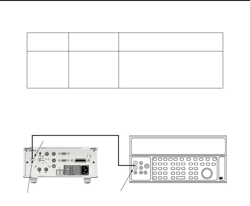
15-8 Performance Verification Model 6487 Reference Manual
Figure 15-1
Connections for 20µA to 20mA range verification
2nA-2µA range accuracy
1. With the power off, connect the voltage calibrator and Model 5156 Electrometer
Calibration Standard to the Model 6487 INPUT jack (Figure 15-2). Initially, make
connections to the 1GΩ resistor in the calibration standard.
2. Turn on the Model 6487 and calibrator power. Allow them to warm up for one
hour.
3. Set the Model 6487 to the 2nA range.
4. With zero check enabled, zero correct the instrument and then disable zero check.
5. Set the calibrator voltage to 0.0000V and make sure the output is turned on.
6. Enable the Model 6487 REL mode. Leave REL enabled for the remainder of the
test.
Table 15-2
Reading limits for 20µA to 20mA ranges
Model 6487
Range
Calibrator
Current
Model 6487 Current Reading Limits
(1 Year, 18°C-28°C)
20μA20.0000μA19.9790 to 20.0210μA
200μA200.000μA199.790 to 200.210μA
2mA 2.00000mA 1.99790 to 2.00210mA
20mA 20.0000mA 19.9790 to 20.0210mA
120
LINE RATING
50, 60Hz
50 VA MAX
INPUT
(CHANGE IEEE ADDRESS
WITH FRONT PANEL MENU)
IEEE-488
CAT I
TRIGGER LINK RS-232
MADE IN
U.S .A .
ANALOG OUT DIGITAL I/O
505V
MAX
V-SOURCE OUTPUT
505V PK TO CHASSIS
LO HI INTERLOCK
!
!
FUSE LINE
400mAT
(SB)
100 VAC
120 VAC
200mAT
(SB)
220 VAC
240 VAC
505V PK
505V PK
505V PK
Dual banana-to-BNC
adapter. Connect
Output LO to shield.
Triax-to-BNC
Adapter
INPUT
Model 6487 PicoammeterDC Current Calibrator
Coax Cable

Model 6487 Reference Manual Performance Verification 15-9
7. Verify current measurement accuracy for each of the currents listed in Table 15-3.
For each test point:
• Make connections to the indicated calibration standard resistor.
• Select the correct Model 6487 measurement range.
• Calculate the actual required calibrator voltage: V = IR; where I is the desired
applied current and R is the actual standard resistor value.
• Set the calibrator to the calculated voltage.
• Verify that the Model 6487 current reading is within the reading limits listed in
the table.
8. Repeat the procedure for negative source currents with the same magnitudes as
those listed in Table 15-3.
Table 15-3
Reading limits for 2nA to 2µA ranges
Model
6487
range
Nominal
calibrator
voltage
Calibration
standard
resistor1
Nominal
applied
current
Actual
voltage2
Model 6487 current
reading limits
(1 Year, 18°C-28°C)
2nA 2V 1GΩ2.00000nA ______V 1.99160 to 2.00840nA
20nA 2V 100MΩ20.0000nA ______V 19.9190 to 20.0810nA
200nA 20V 100MΩ200.000nA ______V 199.590 to 200.410nA
2μA 200V 100MΩ2.00000μA ______V 1.99690 to 2.00310μA
1. Nominal resistance values shown. Use actual characterized value for calculations.
2. Calculate actual calibrator voltage as follows: V = IR; where I is desired applied current and R is actual standard resistance value.
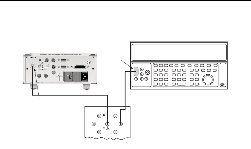
15-10 Performance Verification Model 6487 Reference Manual
Figure 15-2
Connections for 2nA to 2µA range verification
Voltage source output accuracy
Follow the steps below to verify that Model 6487 voltage source output accuracy is within
specified limits. The test involves setting the voltage source output to specific values and
then verifying that DMM voltage readings are within required limits.
t^okfkd Hazardous voltages will be present during the following procedure.
Use care to avoid a shock hazard. The interlock must be closed to test
the 50V and 500V ranges. See Section 2 for interlock information.
1. With the power off, connect the DMM INPUT terminals to the Model 6487
V-SOURCE OUTPUT jacks (Figure 15-3). Be sure to observe polarity (HI to HI;
LO to LO).
2. Turn on the DMM and Model 6487; allow them to warm up for one hour.
3. Select the DMM DCV function and enable autoranging.
4. Temporarily short the ends of the DMM test leads together, then enable the DMM
REL mode to null offsets. Leave REL enabled for the remainder of the tests.
INPUT
Triax Cable Connect Calibrator to
100MΩ or 1GΩ Resistor
Link Shield and Chassis
120
LINE RATING
50, 60Hz
50 VA MAX
INPUT
(CHANGE IEEE ADDRESS
WITH FRONT PANEL MENU)
IEEE-488
CAT I
TRIGGER LINK RS-232
MADE IN
U.S .A .
ANALOG OUT DIGITAL I/O
505V
MAX
V-SOURCE OUTPUT
505V PK TO CHASSIS
LO HI INTERLOCK
!
!
FUSE LINE
400mAT
(SB)
100 VAC
120 VAC
200mAT
(SB)
220 VAC
240 VAC
505V PK
505V PK
505V PK
Model 6487 Picoammeter
DC Voltage Calibrator
BNC-to-dual
Banana Plug
Adapter
100GΩ
100MΩ
10GΩ
1GΩ
1nF
100nF
OUTPUT
Connect
Cable
Shield to
Output LO
Low-noise
Coax Cable
Note:
Model 5156 Calibration Standard
!
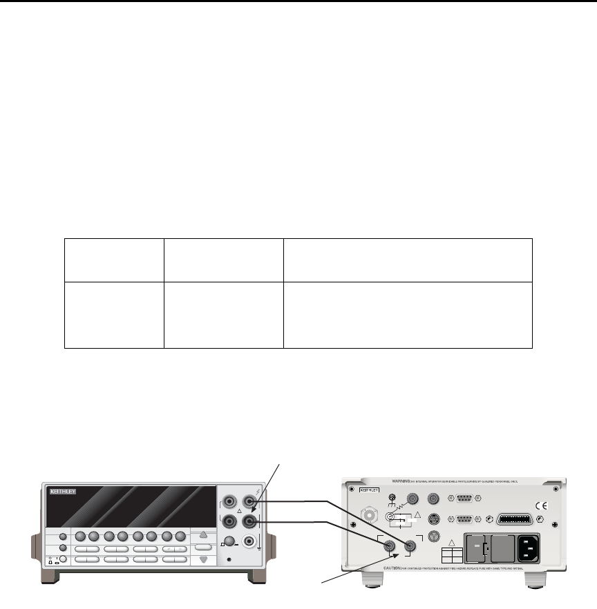
Model 6487 Reference Manual Performance Verification 15-11
5. Verify voltage source accuracy for each of the values listed in Table 15-4. For each
test point:
• Select the correct Model 6487 voltage source range.
• Set the voltage source output to the indicated value.
• Make sure the voltage source is in operate (output on).
• Verify that the DMM voltage reading is within the limits given in the table.
6. Repeat the procedure for negative source currents with the same magnitudes as
those listed in Table 15-4.
Figure 15-3
Connections for voltage source output accuracy
Table 15-4
Reading limits for voltage source accuracy
Model 6487
Source Range
Output
Voltage
Model 6487 Output Voltage Limits
(1 Year, 18°C-28°C)
10V 10.000V 9.989 to 10.011V
50V 50.000V 49.946 to 50.054V
500V 500.00V 499.21 to 500.79V
NEXT
PREV
POWER
DISPLAY
2001 MULTIMETER
DCV ACV DCI ACI Ω2Ω4
FREQ TEMP
REL TRIG
INFO LOCAL EXIT ENTER
RANGE
RANGE
!
FR
500V
PEAK
FRONT/REAR
2A 250V
AMPS
CAL
STORE RECALL
CHAN SCAN
FILTER MATH
CONFIG MENU
HI
INPUT
LO
SENSE
Ω 4 WIRE
INPUTS
350V
PEAK
1100V
PEAK
AUTO
Model 2001 DMM
120
LINE RATING
50, 60Hz
50 VA MAX
INPUT
(CHANGE IEEE ADDRESS
WITH FRONT PANEL MENU)
IEEE-488
CAT I
TRIGGER LINK RS-232
MADE IN
U. S.A .
ANALOG OUT DIGITAL I/O
505V
MAX
V-SOURCE OUTPUT
505V PK TO CHASSIS
LO HI INTERLOCK
!
!
FUSE LINE
400mAT
(SB)
100 VAC
120 VAC
200mAT
(SB)
220 VAC
240 VAC
505V PK
505V PK
505V PK
Model 6487
INPUT
V-SOURCE
OUTPUT

16
Calibration
•Environmental conditions — Summarizes temperature and relative humidity,
warm-up period, and line power requirements.
•Calibration considerations — Lists considerations to take into account when
calibrating the unit.
•Calibration cycle — States how often the Model 6487 should be calibrated.
•Recommended calibration equipment — Lists all equipment necessary for cali-
bration and gives pertinent specifications.
•Calibration errors — Discusses error messages that might occur during
calibration.
•Calibration menu — Discusses calibration menu items.
•Aborting calibration — Describes how to halt the calibration procedure at any
time.
•Current calculations — Details how to calculate currents from calibrator voltages
and standard resistor values when calibrating the 2nA to 2μA ranges.
•Calibration procedure — Provides step-by-step procedures for calibrating all cur-
rent ranges, as well as all three ranges of the voltage source. The 2nA to 2μA and
20μA to 20mA ranges require separate procedures because of the different calibra-
tion equipment involved.
•Calibration support — Describes how to change the calibration code, reset the
calibration code, and view calibration dates and count.

16-2 Calibration Model 6487 Reference Manual
Introduction
Use the procedures in this section to calibrate the Model 6487 from the front panel. (See
Appendix F for information on remote calibration.) These procedures require accurate test
equipment to source precise DC voltages, currents, and resistances.
t^okfkd The information in this section is intended only for qualified service
personnel. Do not attempt these procedures unless you are qualified to
do so. Some of these procedures may expose you to hazardous voltages.
Environmental conditions
Temperature and relative humidity
Conduct the calibration procedures at an ambient temperature of 22° to 24°C with relative
humidity of less than 70% unless otherwise noted.
Warm-up period
Allow the Model 6487 to warm up for at least one hour before performing calibration.
If the instrument has been subjected to temperature extremes (those outside the ranges
stated above), allow additional time for the instrument’s internal temperature to stabilize.
Typically, allow one extra hour to stabilize a unit that is 10°C outside the specified temper-
ature range.
Allow the test equipment to warm up for the minimum time specified by the manufacturer.
Line power
The Model 6487 requires a line voltage of 100 to 120V or 220 to 240V at a line frequency
of 50 to 60Hz. The instrument must be calibrated while operating from a line voltage
within this range. Be sure the line voltage setting agrees with the expected line voltage
(Section 17).

Model 6487 Reference Manual Calibration 16-3
Calibration considerations
When performing the calibration procedures:
• Make sure that the test equipment is properly warmed up and connected to the cor-
rect Model 6487 terminal(s).
• Always allow the source signal to settle before calibrating each point.
• Do not connect test equipment to the Model 6487 through a scanner or other
switching equipment.
• If an error occurs during calibration, the Model 6487 will generate an appropriate
error message.
t^okfkd The maximum safe voltage between the voltage source or ammeter and
chassis ground (common mode voltage) is 505V DC. Exceeding this
voltage can create a shock hazard.
`^rqflk Maximum continuous input voltage is 505V DC. Exceeding this value
may cause instrument damage.
Calibration cycle
Perform verification at least once a year to ensure the unit meets or exceeds its specifica-
tions (see Section 15). Calibrate if necessary.
Recommended calibration equipment
Table 16-1 lists the recommended equipment for the calibration procedures. You can use
alternate equipment, but keep in mind that test equipment uncertainty will affect calibra-
tion accuracy. Calibration equipment should have accuracy specifications at least four
times better than corresponding Model 6487 specifications. Note, however, that the recom-
mended calibrator listed in Table 16-1 does not meet this requirement for 20μA output.
Table 16-2 lists uncertainty ratios for current calibration equipment, while Table 16-3 lists
uncertainty ratios for voltage source calibration equipment.

16-4 Calibration Model 6487 Reference Manual
Calibration errors
The Model 6487 checks for errors after each calibration step, minimizing the possibility
that improper calibration may occur due to operator error. If an error is detected during
calibration, the instrument will display an appropriate error message. The unit will then
prompt you to repeat the calibration step that caused the error.
Table 16-1
Recommended calibration equipment
Description Manufacturer/Model Specifications
Calibrator Fluke 5700A DC Voltage:1
2V: 7ppm
20V: 5ppm
200V: 7ppm
DC Current:1
20μA: 550ppm
200μA: 100ppm
2mA: 55ppm
20mA: 55ppm
Electrometer Calibration
Standard
Keithley Model 5156 Nominal Resistance:2
100MΩ: 200ppm
1GΩ: 300ppm
Digital Multimeter Keithley Model 2001 DC Voltage:3
10V: 32ppm
50V: 50ppm
500V: 53ppm
Low-noise triax cable
Low-noise coax cable
Triax shielding cap
Triax-to-BNC adapter
Dual banana-to-BNC adapter
Banana plug test leads
Keithley 7078-TRX-3
Keithley 4801
Keithley CAP-31
Keithley 7078-TRX-BNC
Pomona 1269
Keithley 8607
1. 90-day, 23°±5°C full-range accuracy specifications shown. Includes ppm of range and offset. Uncertainty for 20µA output cur-
rent does not meet the recommended four-times better uncertainty specification.
2. 23°±3°C accuracy of characterization.
3. One-year, DMM accuracy specifications at specified voltage and range.

Model 6487 Reference Manual Calibration 16-5
Calibration menu
You can access the calibration menu by pressing MENU, selecting CAL, and then press-
ing ENTER. The various selections are summarized in Table 16-4. Use the up and down
RANGE keys to scroll through these selections.
Table 16-2
Current test uncertainty ratios with recommended equipment
Range 5700 + 5156
Test uncertainty
ratio
2nA 7ppm + 300ppm 13.0
20nA 7ppm + 200ppm 19.3
200nA 5ppm + 200ppm 9.8
2μA 7ppm + 200ppm 7.2
20μA 550ppm 1.8
200μA 100ppm 10.0
2mA 55ppm 18.2
20mA 55ppm 18.2
Table 16-3
Voltage source test uncertainty ratios with recommended equipment
Range 2001 DMM
Test uncertainty
ratio
10V 32ppm 31.2
50V 50ppm 20.0
500V 53ppm 28.3

16-6 Calibration Model 6487 Reference Manual
Aborting calibration
You can abort the calibration procedure at any time by pressing the EXIT key.
Current calculations
When calibrating the 2nA-2μA current ranges, you must calculate the actual current val-
ues from the applied calibrator voltages and the characterized Model 5156 Calibration
Standard resistor values. Calibration currents are calculated as follows:
I = V/R
Where: I = required calibration current
V = calibrator voltage
R = actual standard resistor value
For example, assume you are calibrating the 20nA range using a 2V calibrator voltage
with an actual 100.5MΩ standard resistor value. The actual calibration current is:
2V/100.5MΩ = 19.9005nA.
Table 16-4
Calibration menu
Menu Item* Description
VOFFSET Performs offset voltage calibration.
COUNT Displays calibration count.
RUN Calibrates present current range.
VSRC-RUN Calibrates present voltage source range.
DATES Displays calibration and due dates.
UNLOCK Unlocks calibration using code.
LOCK Locks cal, exits to the main menu.
SAVE Saves calibration constants.
* Press MENU, select CAL, then press ENTER to access. Use up or
down RANGE key to scroll through selections.

Model 6487 Reference Manual Calibration 16-7
Calibration procedure
The calibration procedure should be performed in the following order:
• Preparing for calibration
• Offset voltage calibration
• Current calibration
• Voltage source calibration
• Entering calibration dates and saving calibration
• Locking out calibration
Preparing for calibration
1. Turn on the Model 6487 and the calibrator; allow them to warm up for at least one
hour before performing calibration.
2. Press MENU, select CAL, then press ENTER. The instrument will display the
following:
CAL: VOFFSET
3. Use the up or down RANGE key to display the following:
CAL: UNLOCK
4. Press ENTER. The instrument will prompt for the calibration code:
CODE? 000000
5. Enter the present calibration code on the display. (Factory default: 006487.) Use
the up and down RANGE keys to select the letter or number and use the left and
right arrow keys to choose the position. Press ENTER to complete the process and
the unit will display:
CAL UNLOCKED
Followed by:
NEW CODE? N
6. With N displayed, press ENTER.
Offset voltage calibration
Before performing the remaining calibration steps, perform offset voltage calibration as
outlined below.
1. From the calibration menu, use the up or down RANGE key to display the
following:
CAL: VOFFSET
2. Press ENTER. The instrument will prompt as follows:
INPUT CAP
3. Connect the triax shielding cap to the rear panel INPUT jack.
4. Press ENTER to complete offset voltage calibration.
5. Press EXIT to return to normal display.

16-8 Calibration Model 6487 Reference Manual
Current calibration
20μA-20mA range calibration
1. Connect the triax shielding cap to the Model 6487 rear panel INPUT jack.
2. Select the Model 6487 20μA range.
3. Press MENU, select CAL, then press ENTER. At the CAL: RUN prompt, press
ENTER. The unit will prompt for the zero calibration point:
20μA ZERO
4. With the triax shielding cap connected to the INPUT jack for a 0μA input current,
press ENTER.
5. The unit will prompt for the positive full-scale cal point:
+20μA CAL
6. Connect the current calibrator to the Model 6487 INPUT jack (Figure 16-1). Use
the coax cable and two adapters where shown.
7. Press ENTER. The unit will prompt for the positive full-scale current:
+20.00000 μA
8. Set the calibrator current to +20.00000μA then adjust the display to agree with the
calibrator current.
9. Press ENTER. The unit will prompt for the negative full-scale calibration point:
-20μA CAL
10. Press ENTER. The Model 6487 will prompt for the negative full-scale calibration
current:
-20.00000 μA
11. Set the calibrator output to –20.00000μA, then adjust the display to agree with the
calibrator value. Press ENTER to complete calibration of the present range.
12. Press EXIT to return to normal display.
13. Repeat steps 1 through 12 for the 200μA through 20mA ranges using Table 16-5 as
a guide.
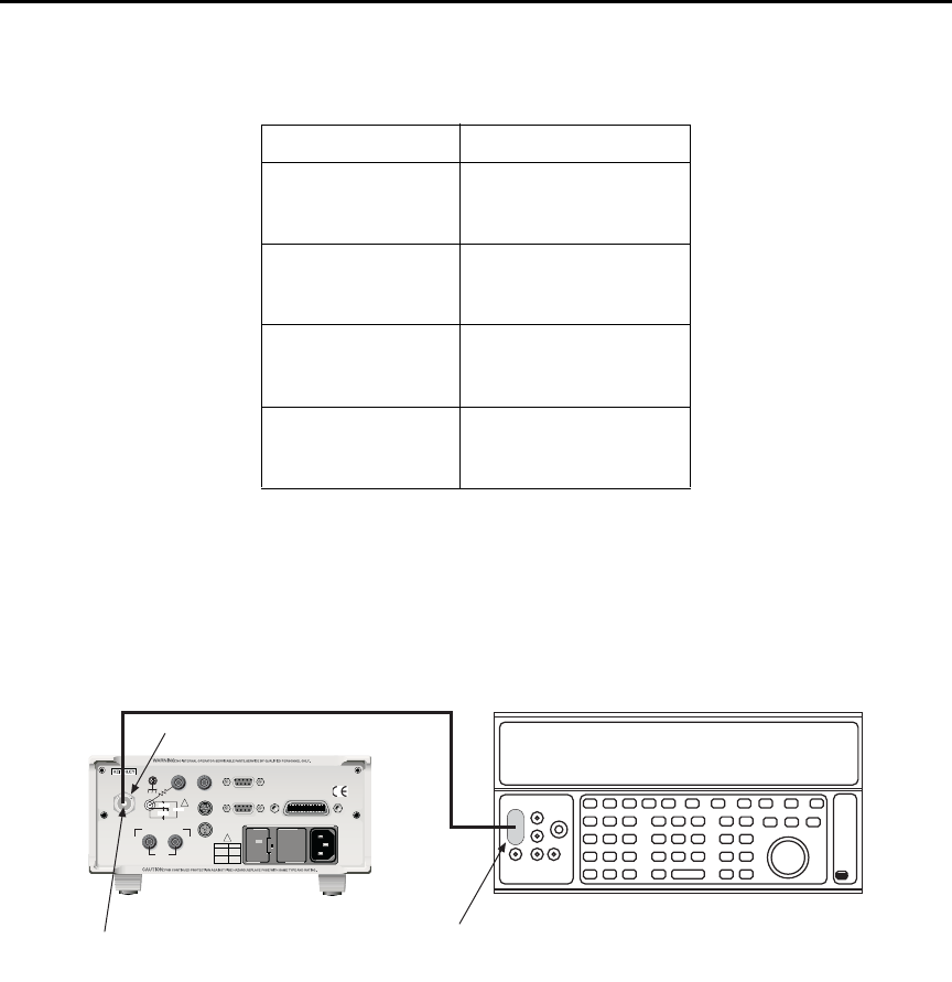
Model 6487 Reference Manual Calibration 16-9
Figure 16-1
Connections for 20µA to 20mA range calibration
2nA-2μA range calibration
1. Connect the voltage calibrator and the Model 5156 Electrometer Calibration
Standard to the Model 6487 INPUT jack (Figure 16-2). Initially, make connections
to the 1GΩ resistance.
2. Set the calibrator to output volts and make sure the calibrator output is turned on.
3. Select the Model 6487 2nA range.
Table 16-5
20µA to 20mA range calibration summary
Model 6487 Range Calibrator Currents*
20μA0μA
+20.00000μA
-20.00000μA
200μA0μA
+200.0000μA
-200.0000μA
2mA 0mA
+2.000000mA
-2.000000mA
20mA 0mA
+20.00000mA
-20.00000mA
* Calibrate zero, positive full-scale, and negative full-scale
for each range. Triax shielding cap used for zero calibra-
tion point for all ranges. See procedure.
120
LINE RATING
50, 60Hz
50 VA MAX
INPUT
(CHANGE IEEE ADDRESS
WITH FRONT PANEL MENU)
IEEE-488
CAT I
TRIGGER LINK RS-232
MADE IN
U.S .A .
ANALOG OUT DIGITAL I/O
505V
MAX
V-SOURCE OUTPUT
505V PK TO CHASSIS
LO HI INTERLOCK
!
!
FUSE LINE
400mAT
(SB)
100 VAC
120 VAC
200mAT
(SB)
220 VAC
240 VAC
505V PK
505V PK
505V PK
Dual banana-to-BNC
adapter. Connect
Output LO to shield.
Triax-to-BNC
Adapter
INPUT
Model 6487 PicoammeterDC Current Calibrator
Coax Cable

16-10 Calibration Model 6487 Reference Manual
4. Press MENU, select CAL, then press ENTER. At the CAL: RUN prompt, press
ENTER again. The unit will prompt for the zero calibration point:
2NA ZERO
5. Set the calibrator voltage to 0V then press ENTER.
6. The instrument will prompt for the positive full-scale calibration point:
+2NA CAL
7. Press ENTER. The instrument will prompt for the positive full-scale calibration
current:
+2.000000 NA
8. Set the calibrator voltage to +2.000000V. Calculate the actual calibration current
from the calibrator voltage and the actual standard resistor value: I = V/R. Adjust
the Model 6487 display to agree with the calculated current, then press ENTER.
9. The Model 6487 will prompt for the negative full-scale calibration point:
-2NA CAL
10. Press ENTER. The instrument will prompt for the negative full-scale current:
-2.000000 NA
11. Set the calibrator output voltage to –2.000000V, then calculate the calibration cur-
rent from the calibrator voltage and standard resistor value: I = V/R. Adjust the
Model 6487 display to agree with the calculated current, then press ENTER to
complete calibration of the present range.
12. Press EXIT to return to normal display.
13. Repeat steps 3 through 12 for the 20nA through 2μA ranges using Table 16-6 as a
guide. Be sure to make connections to the correct standard resistor and set the cali-
brator voltages to the correct values.
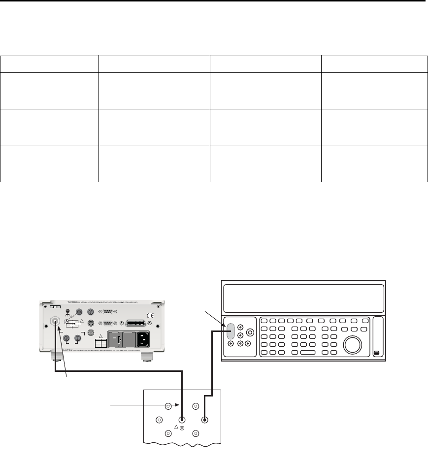
Model 6487 Reference Manual Calibration 16-11
Figure 16-2
Connections for 2nA to 2µA range calibration
Table 16-6
2nA to 2µA range calibration summary
Model 6487 range Calibrator voltages Standard resistors1Calibration currents2
2nA 0V
+2.000000V
-2.000000V
1GΩ
1GΩ
1GΩ
0nA
+2nA
-2nA
20nA 0V
+2.000000V
-2.000000V
100MΩ
100MΩ
100MΩ
0nA
+20nA
-20nA
2μA0V
+200.0000V
-200.0000V
100MΩ
100MΩ
100MΩ
0μA
+2μA
-2μA
1. 1Nominal resistance values.
2. 2Nominal currents. Calculate actual currents from calibrator voltage and actual standard resistor value: I = V/R. Calibrate zero,
positive full-scale, and negative full-scale for each range.
INPUT
Triax Cable Connect Calibrator to
100MΩ or 1GΩ Resistor
Link Shield and Chassis
120
LINE RATING
50, 60Hz
50 VA MAX
INPUT
(CHANGE IEEE ADDRESS
WITH FRONT PANEL MENU)
IEEE-488
CAT I
TRIGGER LINK RS-232
MADE IN
U.S .A .
ANALOG OUT DIGITAL I/O
505V
MAX
V-SOURCE OUTPUT
505V PK TO CHASSIS
LO HI INTERLOCK
!
!
FUSE LINE
400mAT
(SB)
100 VAC
120 VAC
200mAT
(SB)
220 VAC
240 VAC
505V PK
505V PK
505V PK
Model 6487 Picoammeter
DC Voltage Calibrator
BNC-to-dual
Banana Plug
Adapter
100GΩ
100MΩ
10GΩ
1GΩ
1nF
100nF
OUTPUT
Connect
Cable
Shield to
Output LO
Low-noise
Coax Cable
Note:
Model 5156 Calibration Standard
!

16-12 Calibration Model 6487 Reference Manual
Voltage source calibration
t^okfkd Hazardous voltages will be present during the following procedure.
Use care to avoid a shock hazard. The interlock must be closed to cali-
brate the 50V and 500V ranges. See Section 2 for interlock
information.
1. Set the DMM to measure DC volts and enable autoranging.
2. Temporarily short the ends of the DMM test leads together, then enable the DMM
REL mode. Leave REL enabled for the rest of the calibration procedure.
3. Connect the DMM to the Model 6487 V-SOURCE OUTPUT jacks (Figure 16-3).
4. Select the Model 6487 voltage source 10V range.
5. Press MENU, select CAL, then press ENTER. At the CAL: VSRC-RUN prompt,
press ENTER again. The unit will prompt for the negative full-range calibration
point:
V: -10V CAL
6. Press ENTER. The voltage source will be placed in operate and the instrument will
prompt for the negative full-scale calibration voltage:
-10.00000 V
7. Note the DMM voltage reading. Adjust the Model 6487 display to agree with that
voltage and then press ENTER.
8. Operate will turn off and the instrument will prompt for the zero calibration point:
V: 10V ZERO
9. Press ENTER. The voltage source will be placed in operate and the instrument will
prompt for the zero calibration voltage:
+0.00000 V
10. Note the DMM voltage reading. Adjust the Model 6487 display to agree with that
voltage and then press ENTER.
11. Operate will turn off and the unit will prompt for the positive full-range calibration
point:
V: +10V CAL
12. Press ENTER. The voltage source will be placed in operate and the instrument will
prompt for the positive full-scale calibration voltage:
+10.00000 V
13. Note the DMM voltage reading. Adjust the Model 6487 display to agree with that
voltage and then press ENTER.
14. Press EXIT to return to normal display.
15. Repeat steps 4 through 14 for the 50V and 500V ranges using Table 16-7 as a
guide.
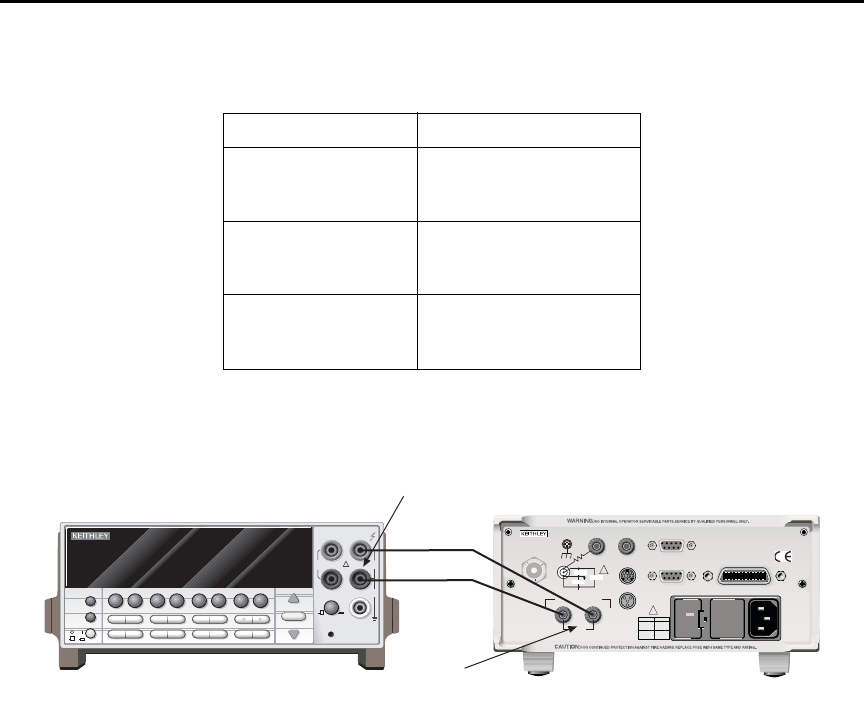
Model 6487 Reference Manual Calibration 16-13
Figure 16-3
Connections for voltage source calibration
Entering calibration dates and saving calibration
klqb For temporary calibration without saving new calibration constants, proceed to
“Locking out calibration”.
1. Press MENU, select CAL, then press ENTER to access the calibration menu.
2. Use either RANGE key to display the following:
CAL: SAVE
3. Press ENTER. The unit will prompt for today’s calibration date:
DATE: 11/15/02
4. Use the arrow and RANGE keys to set the date, then press ENTER. The unit will
then prompt for the calibration due date:
NDUE: 11/15/03
Table 16-7
Voltage source calibration summary
Model 6487 Range Calibration Voltages*
10V -10.00000V
+0.00000V
+10.0000V
50V -50.00000V
+0.00000V
+50.00000V
500V -500.0000V
+0.00000V
+500.0000V
* Nominal values. Adjust display to agree with DMM reading.
NEXT
PREV
POWER
DISPLAY
2001 MULTIMETER
DCV ACV DCI ACI Ω2Ω4
FREQ TEMP
REL TRIG
INFO LOCAL EXIT ENTER
RANGE
RANGE
!
FR
500V
PEAK
FRONT/REAR
2A 250V
AMPS
CAL
STORE RECALL
CHAN SCAN
FILTER MATH
CONFIG MENU
HI
INPUT
LO
SENSE
Ω 4 WIRE
INPUTS
350V
PEAK
1100V
PEAK
AUTO
Model 2001 DMM
120
LINE RATING
50, 60Hz
50 VA MAX
INPUT
(CHANGE IEEE ADDRESS
WITH FRONT PANEL MENU)
IEEE-488
CAT I
TRIGGER LINK RS-232
MADE IN
U. S.A .
ANALOG OUT DIGITAL I/O
505V
MAX
V-SOURCE OUTPUT
505V PK TO CHASSIS
LO HI INTERLOCK
!
!
FUSE LINE
400mAT
(SB)
100 VAC
120 VAC
200mAT
(SB)
220 VAC
240 VAC
505V PK
505V PK
505V PK
Model 6487
INPUT
V-SOURCE
OUTPUT

16-14 Calibration Model 6487 Reference Manual
5. Set the calibration due date as desired then press ENTER. The unit will prompt you
as follows:
SAVE CAL?YES
6. With the YES prompt displayed, press ENTER to save and lock out calibration.
The unit will display:
CAL SAVED
klqb Calibration will also be locked out once saved.
Locking out calibration
Use the following procedure to lock out calibration without saving new calibration
constants:
1. Press MENU, select CAL, then press ENTER. Use the up RANGE key to display
the following:
CAL: LOCK
2. Press ENTER. The instrument will display the following message:
CAL LOCKED.
Calibration support
Changing the calibration code
Follow the steps below to change the calibration code:
1. Press MENU, select CAL, then press ENTER. The instrument will display the
following:
CAL: VOFFSET
2. Use the up or down RANGE key to display the following:
CAL: UNLOCK
3. Press ENTER. The instrument will prompt for the present calibration code:
CODE? 000000
4. Enter the present calibration code on the display. (Factory default: 006487.) Use
the up and down RANGE keys to select the letter or number and use the left and
right arrow keys to choose the position. Press ENTER to complete the process and
the unit will display:
CAL ENABLED
Followed by:
NEW CODE? Y/N
5. Select Y, then press ENTER. The unit will prompt for the new code:
CODE? 000000
6. Enter the new code, then press ENTER.
7. Using the LOCK selection in the calibration menu, lock out calibration after
changing the code.

Model 6487 Reference Manual Calibration 16-15
Resetting the calibration code
If you forget the calibration code, you can unlock calibration by shorting together the CAL
pads which are located on the display circuit board inside the unit. Doing so will also reset
the code to the factory default (006487).
Displaying calibration dates
To display calibration dates at any time:
1. From normal display, press MENU, select CAL, then press ENTER. The unit will
display the following:
CAL: VOFFSET
2. Use either RANGE key to select CAL: DATES, then press ENTER. The
Model 6487 will display the last calibration date, for example:
DATE: 11/15/02
3. Press ENTER to view the calibration due date, for example:
NDUE: 11/15/03
4. Press EXIT to return to normal display.
Displaying the calibration count
To display the calibration count at any time:
1. From normal display, press MENU, select CAL, then press ENTER. The unit will
display the following:
CAL: VOFFSET
2. Use either RANGE key to select CAL:COUNT from the calibration menu, then
press ENTER. The unit displays the calibration count, for example:
COUNT: 1
3. Press EXIT to return to normal display.


17-2 Routine Maintenance Model 6487 Reference Manual
Introduction
The information in this section deals with routine type maintenance that can be performed
by the operator and includes procedures for setting the line voltage, replacing the line fuse,
and running the front panel tests.
Setting line voltage and replacing line fuse
t^okfkd Disconnect the line cord at the rear panel and remove all test cables
and leads connected to the instrument before replacing the line fuse.
The power line fuse is located in the power module next to the AC power receptacle
(Figure 17-1). If the line voltage must be changed or if the line fuse requires replacement,
perform the following steps:
1. Place the tip of a flat-blade screwdriver into the power module by the fuse holder
assembly (Figure 17-1). Gently push in and to the left. Release pressure on the
assembly and its internal spring will push it out of the power module.
2. Remove the fuse and replace it with the type listed in Table 17-1.
t^okfkd For continued protection against fire or instrument damage, replace
the fuse only with the type and rating listed. If the instrument repeat-
edly blows fuses, it will require servicing.
3. If configuring the instrument for a different line voltage, remove the line voltage
selector from the assembly and rotate it to the proper position. When the selector is
installed into the fuse holder assembly, the correct line voltage appears inverted in
the window.
4. Install the fuse holder assembly into the power module by pushing it in until it
locks in place.
Table 17-1
Line fuse ratings
Line Voltage Rating Keithley Part No.
100/120V 0.4A, 250V, 5 × 20mm,
slow blow
FU-106-.400
220/240V 0.2A, 250V, 5 × 20mm,
slow-blow
FU-106-.200
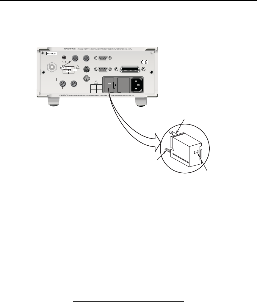
Model 6487 Reference Manual Routine Maintenance 17-3
Figure 17-1
Line fuse location
Front panel tests
The front panel tests are summarized in Table 17-2. To run a test, simply press the MENU
key, select TEST, and press ENTER to access the test menu. Scroll through the menu
choices with the RANGE keys and press ENTER.
Table 17-2
Front panel tests
Test Description
DISP Test display
KEY Test front panel keys
120
LINE RATING
50, 60Hz
50 VA MAX
INPUT
(CHANGE IEEE ADDRESS
WITH FRONT PANEL MENU)
IEEE-488
CAT I
TRIGGER LINK RS-232
MADE IN
U. S. A .
ANALOG OUT DIGITAL I/O
505V
MAX
V-SOURCE OUTPUT
505V PK TO CHASSIS
LO HI INTERLOCK
!
!
FUSE LINE
400m
AT
(SB)
100 VAC
120 VAC
200mAT
(SB)
220 VAC
240 VAC
505V PK
505V PK
505V PK
Fuse
Spring
Window
Fuse Holder Assembly
120
Model 6487 Picoammeter

17-4 Routine Maintenance Model 6487 Reference Manual
DISP test
The display test allows you to verify that each segment and annunciator in the vacuum
fluorescent display is working properly. Perform the following steps to run the display
test:
1. Press MENU, select TEST, and press ENTER to access the self-test options.
2. Use the up or down RANGE key to display TEST: DISP.
3. Press ENTER to start the test. There are four parts to the display test. Each time
ENTER is pressed, the next part of the test sequence is selected. The four parts of
the test sequence are as follows:
• All annunciators are displayed.
• The segments of each digit are sequentially displayed.
• The 12 digits (and annunciators) are sequentially displayed.
• The annunciators located at either end of the display are sequentially
displayed.
4. When finished, abort the display test by pressing EXIT. The instrument returns to
normal operation.
KEY test
The KEY test allows you to check the functionality of each front panel key. Perform the
following steps to run the KEY test:
1. Press MENU, select TEST, and press ENTER to access the self-test options.
2. Use the up or down RANGE key to display TEST: KEY.
3. Press ENTER to start the test. When a key is pressed, the label name for that key is
displayed to indicate that it is functioning properly. When the key is released, the
message NO KEY PRESS is displayed.
4. Pressing EXIT tests the EXIT key. However, the second consecutive press of EXIT
aborts the test and returns the instrument to normal operation.

A
Specifications
Rev. A
HW 10/25/02
6487 Picoammeter Specifications
TYPICAL ANALOG
5¹⁄₂ DIGIT ACCURACY (1YR)
1
RISE TIME (10% TO 90%)
3
DEFAULT ±(% RDG. + OFFSET) TYPICAL DAMPING
4
RANGE RESOLUTION 18°–28°C, 0–70% RH RMS NOISE
2
OFF ON
2 nA 10 fA 0.3 % + 400 fA 20 fA 4 ms 80 ms
20 nA 100 fA 0.2 % + 1 pA 20 fA 4 ms 80 ms
200 nA 1 pA 0.15 % + 10 pA 1 pA 300 µs 1 ms
2 µA 10 pA 0.15% + 100 pA 1 pA 300 µs 1 ms
20 µA 100 pA 0.1 % + 1 nA 100 pA 110 µs 110 µs
200 µA 1 nA 0.1 % + 10 nA 100 pA 110 µs 110 µs
2 mA 10 nA 0.1 % + 100 nA 10 nA 110 µs 110 µs
20 mA 100 nA 0.1 % + 1 µA 10 nA 110 µs 110 µs
Specifications are subject to change without notice.
REMOTE OPERATION
IEEE-488 BUS IMPLEMENTATION: SCPI (IEEE-488.2, SCPI-1996.0);
DDC (IEEE-488.1).
LANGUAGE EMULATION: Keithley Model 486/487 emulation via
DDC mode.
RS-232 IMPLEMENTATION:
Supports: SCPI 1996.0.
Baud Rates: 300, 600, 1200, 2400, 4800, 9600, 19.2k, 38.4k, 57.6k.
Protocols: Xon/Xoff, 7 or 8 bit ASCII, parity-odd/even/none.
Connector: DB-9 TXD/RXD/GND.
GENERAL
AMMETER INPUT CONNECTOR: Three lug triaxial on rear panel.
ANALOG OUTPUT CONNECTOR: Two banana jacks on rear panel.
VOLTAGE SOURCE OUTPUT CONNECTOR: Two banana jacks on rear
panel.
INTERLOCK CONNECTOR: 4 pin DIN.
TRIGGER LINE: Available, see manual for usage.
DISPLAY: 12 character vacuum fluorescent.
DIGITAL FILTER: Median and averaging (selectable from 2 to 100
readings).
RANGING: Automatic or manual.
AUTORANGING TIME
3
:<250ms (analog filter off, 1PLC)
OVERRANGE INDICATION: Display reads “OVRFLOW”.
CONVERSION TIME: Selectable 0.01 PLC to 60 PLC (50PLC under
50Hz operation). (Adjustable from 200µs to 1s)
READING RATE:
To internal buffer 1000 readings/second
1
To IEEE-488 bus 900 readings/second
1, 2
BUFFER: Stores up to 3000 readings.
PROGRAMS: Provide front panel access to IEEE address, choice of
engineering units or scientific notation, and digital calibration.
EMC: Conforms with European Union Directive 89/336/EEC,
EN61326-1.
SAFETY: Conforms with European Union Directive 73/23/EEC,
EN61010-1, CAT I.
ENVIRONMENT:
Operating: 0°–50°C; relative humidity 70% non-condensing, up to
35°C. Above 35°C, derate humidity by 3% for each °C.
Storage: –10°C to +65°C.
WARM-UP: 1 hour to rated accuracy (see manual for recommended
procedure).
POWER: 100–120V or 220–240V, 50–60Hz, (50VA).
PHYSICAL:
Case Dimensions: 90mm high ×214mm wide ×369mm deep (3
1
⁄
2
in.
×8
3
⁄
8
in. ×14
9
⁄
16
in.).
Working Dimensions: From front of case to rear including power
cord and IEEE-488 connector: 394mm (15.5 inches).
NET WEIGHT: <4.7 kg (<10.3 lbs).
Notes:
1
0.01 PLC, digital filters off, front panel off, auto zero off.
2
Binary transfer mode.
IEEE-488.1.
3
Measured from trigger in to meter complete
.
TEMPERATURE COEFFICIENT: 0°–18°C & 28°–50°C. For each °C, add 0.1 ×(% rdg + offset) to
accuracy spec.
INPUT VOLTAGE BURDEN: <200µV on all ranges except <1mV on 20mA range.
MAXIMUM INPUT CAPACITANCE: Stable to 10nF on all nA ranges and 2µA range; 1µF on 20µA
and 200µA ranges, and on mA ranges.
MAXIMUM CONTINUOUS INPUT VOLTAGE: 505 VDC
NMRR
1
:(50 or 60Hz) :60dB
ISOLATION (Ammeter Common or Voltage Source to chassis): Typically >1×10
11
Ωin parallel
with <1nF.
MAXIMUM COMMON MODE VOLTAGE (Between Chassis and Voltage Source or Ammeter):
505 VDC.
MAXIMUM VOLTAGE BETWEEN VOLTAGE SOURCE AND AMMETER: 505 VDC
ANALOG OUTPUT: Scaled voltage output (inverting 2V full scale on all ranges) 2.5% ±2mV
ANALOG OUTPUT IMPEDANCE
3
:<100Ω, DC-2kHz.
VOLTAGE SOURCE
Range Step Size Accuracy
5
Noise (p-p) Temperature Typical Rise Typical Fall
(Max)
(typical)
±
(% PROG. + OFFSET)
0.1 - 10 Hz Coefficient Time
6,8
Time
7,8
18°C
- 28°C, 0 - 70% R.H. (10%-90%) (90%-10%)
±10.100 200µV 0.1% + 1mV <50µV (0.005% + 20µV) / ˚C 250
µs 150 µs
±50.500 1mV 0.1% + 4mV <150µV (0.005% + 200µV) / ˚C 250
µs 300 µs
±505.00 10mV 0.15% + 40mV <1.5mV (0.008% + 2mV) / ˚C 4.5 ms 1 ms
SELECTABLE CURRENT LIMIT: 2.5mA, 250
µ
A, 25
µ
A for 50V and 500V ranges, 25mA additional
limit for 10V range. All current limits are -20%/+35% of nominal.
WIDEBAND NOISE
9
:<30mVp-p 0.1Hz - 20MHz.
TYPICAL TIME STABILITY:
±
(0.003% + 1mV) over 24 hours at constant temperature (within 1°C,
between 18°C - 28°C, after 5 minute settling).
OUTPUT RESISTANCE: <2.5Ω.
VOLTAGE SWEEPS: Supports linear voltage sweeps on fixed source range, one current or resist-
ance measurement per step. Maximum sweep rate: 200 steps per second. Maximum step count
3000. Optional delay between step and measure.
RESISTANCE MEASUREMENT (V/I): Used with voltage source; resistance calculated from voltage
setting and measured current. Accuracy is based on voltage source accuracy plus ammeter
accuracy. Typical accuracy better than 0.6% for readings between 1kΩand 1TΩ.
ALTERNATING VOLTAGE RESISTANCE MEASUREMENT: Offers alternating voltage resistance
measurements for resistances from 10
9
Ωto 10
15
Ω. Alternates between 0V and user-selectable
voltage up to
±505V.
1
At 1 PLC – limited to 60 rdgs/sec under this condition.
2
At 6 PLC, 1 standard deviation, 100 readings, filter off, capped input – limited to 10 rdgs/sec
under this condition.
3
Measured at analog output with resistive load >2kΩ.
4
Maximum rise time can be up to 25% greater.
5
Accuracy does not include output resistance/load regulation.
6
Rise Time is from 0V to
± full-scale voltage (increasing magnitude)
.
7
Fall Time is from
± full-scale voltage to 0V (decreasing magnitude)
.
8
For capacitive loads, add C*ΔV/I
Limit
to Rise Time, and C*ΔV/1mA to Fall Time.
9
Measured with LO connected to chassis ground.

B
Status and Error Messages

B-2 Status and Error Messages Model 6487 Reference Manual
Table B-1
Status and error messages
Number Description Event
-440
-430
-420
-410
-363
-362
-361
-360
-350
-330
-315
-314
-285
-284
-282
-281
-260
-241
-230
-225
-224
-223
-222
-221
-220
-215
-214
-213
-212
-211
-210
-202
-201
-200
-178
-171
-170
-168
-161
-160
Query unterminated after indefinite
response
Query deadlocked
Query unterminated
Query interrupted
Input buffer overrun
Framing error in program message
Parity error in program message
Communications error
Queue overflow
Save/recall memory lost
Self-test failed
Configuration memory lost
Program syntax error
Program currently running
Illegal program name
Cannot create program
Expression error
Hardware missing
Data corrupt or stale
Out of memory
Illegal parameter value
Too much data
Parameter data out of range
Settings conflict
Parameter error
Arm deadlock
Trigger deadlock
Init ignored
Arm ignored
Trigger ignored
Trigger error
Settings lost due to rtl
Invalid while in local
Execution error
Expression data not allowed
Invalid expression
Expression error
Block data not allowed
Invalid block data
Block data error
EE
EE
EE
EE
EE
EE
EE
EE
SYS
EE
EE
EE
EE
EE
EE
EE
EE
EE
EE
EE
EE
EE
EE
EE
EE
EE
EE
EE
EE
EE
EE
EE
EE
EE
EE
EE
EE
EE
EE
EE

Model 6487 Reference Manual Status and Error Messages B-3
-158
-154
-151
-150
-148
-144
-141
-140
-128
-124
-123
-121
-120
-114
-113
-112
-111
-110
-109
-108
-105
-104
-103
-102
-101
-100
+000
+101
+102
+103
+104
+105
+106
String data not allowed
String too long
Invalid string data
String data error
Character data not allowed
Character data too long
Invalid character data
Character data error
Numeric data not allowed
Too many digits
Exponent too large
Invalid character in number
Numeric data error
Header suffix out of range
Undefined header
Program mnemonic too long
Header separator error
Command header error
Missing parameter
Parameter not allowed
GET not allowed
Data type error
Invalid separator
Syntax error
Invalid character
Command error
No error
Measurement events:*
Low limit 1 failed
High limit 1 failed
Low limit 2 failed
High limit 2 failed
Active limit tests passed
Reading available
EE
EE
EE
EE
EE
EE
EE
EE
EE
EE
EE
EE
EE
EE
EE
EE
EE
EE
EE
EE
EE
EE
EE
EE
EE
EE
SE
SE
SE
SE
SE
SE
SE
Table B-1 (c o nt.)
Status and error messages
Number Description Event

B-4 Status and Error Messages Model 6487 Reference Manual
+107
+108
+109
+110
+111
+200
+300
+301
+303
+305
+306
+310
+315
+408
+414
+500
+501
+502
+507
+508
+509
+510
+511
+512
+513
+514
+515
+602
+603
+604
+605
+606
+607
Reading overflow
Buffer available
Buffer full
Input overvoltage
OUTPUT interlock asserted
Standard events:*
Operation complete
Operation events:*
Device calibrating
Device in A-V Ohms
Device sweeping
Waiting in trigger layer
Waiting in arm layer
Re-entering the idle layer
V-source compliance detected
Questionable events:*
Questionable calibration
Command warning
Calibration errors:
Date of calibration not set
Next date of calibration not set
Calibration data invalid
Measurement offset data invalid
Measurement gain data invalid
Not permitted with cal locked
Not permitted with cal un-locked
Voltage offset not converging
Current offset not converging
10V Positive Vsource Offset
50V Positive Vsource Offset
500V Positive Vsource Offset
Lost data errors:
GPIB address lost
Power-on state lost
DC calibration data lost
Calibration dates lost
GPIB communication language lost
Vsource calibration data lost
SE
SE
SE
SE
SE
SE
SE
SE
SE
SE
SE
SE
SE
SE
SE
EE
EE
EE
EE
EE
EE
EE
EE
EE
EE
EE
EE
EE
EE
EE
EE
EE
EE
Table B-1 (c o nt.)
Status and error messages
Number Description Event

Model 6487 Reference Manual Status and Error Messages B-5
+700
+701
+800
+801
+802
+804
+805
+806
+807
+808
+811
+812
+813
+814
+815
+816
+817
+818
+819
+820
+821
+830
+831
+840
+841
+842
+850
+851
+852
+853
+900
Communication errors:
Invalid system communication
ASCII only with RS-232
Additional (more informative) command
execution errors:
Illegal with storage active
Insufficient vector data
OUTPUT blocked by interlock
Expression list full
Undefined expression exists
Expression not found
Definition not allowed
Expression cannot be deleted
Not an operator or number
Mismatched parentheses
Not a number of data handle
Mismatched brackets
Too many parentheses
Entire expression not parsed
Unknown token
Error parsing mantissa
Error parsing exponent
Error parsing value
Invalid data handle index
Invalid with INFinite ARM:COUNT
Invalid with INFinite TRIG:COUNT
Not allowed with sweep on
Sweep step size too small
Sweep step size too large
Not Allowed with A-V Ohms
Not Allowed with A-V Ohm Buffer
No A-V ohms with Autorange
Too Many A-V Ohms Readings
Internal system error
EE
EE
EE
EE
EE
EE
EE
EE
EE
EE
EE
EE
EE
EE
EE
EE
EE
EE
EE
EE
EE
EE
EE
EE
EE
EE
EE
EE
EE
EE
EE
Table B-1 (c o nt.)
Status and error messages
Number Description Event

B-6 Status and Error Messages Model 6487 Reference Manual
klqb SCPI-confirmed messages are described in Volume 2: Command Reference of
the Standard Commands for Programmable Instruments. Refer to the
:SYSTem:ERRor? command.
+950
+951
+952
+953
+954
+955
+956
+957
+958
+960
+961
+962
+963
+965
+966
DDC Status Model:
Rdg overflow
Rdg ready
Buffer full
IDDC error
IDDCO error
Trig overrun
No remote
Number error
DDC ready
DDC Mode IDDC Error
DDC Mode IDDCO Error
Keithley 6487 Serial Poll Byte Events:
DDC Ready
DDC Reading Done
DDC Buffer Full
DDC Reading overflow
SE
SE
SE
EE
EE
EE
EE
EE
SE
EE
EE
SE
SE
SE
SE
EE = error event
SE = status event
SYS = system error event
NOTE: Errors and status messages with a positive number are instrument-
dependent. Negative errors are reserved by SCPI.
* Measurement events are flagged in Measurement Event Register, standard
events are flagged in Standard Event Register, operation events are flagged in
Operation Event Register, and questionable events are flagged in Questionable
Event Register. See Section 10 for details.
Table B-1 (c o nt.)
Status and error messages
Number Description Event

Model 6487 Reference Manual Status and Error Messages B-7
Eliminating common SCPI errors
There are three SCPI errors that occur more often than any others:
• -113, "Undefined header"
• -410, "Query INTERRUPTED"
• -420, "Query UNTERMINATED"
The following paragraphs discuss the most common causes for these errors and methods
for avoiding them.
-113, "Undefined header"
This error indicates that the command you sent to the instrument did not contain a recog-
nizable command name. The most likely causes for this error are:
•Missing space between the command and its parameter. There must be one or more
spaces (blanks) between the command and its parameter. For example:
:SOUR1:VOLT10 Incorrect (no space between command and parameter)
:SOUR1:VOLT 10 Correct
•Improper short or long form. Check the command list in Section 14 for the correct
command name.
•Blanks (spaces) within the command name. For example:
:SYST :ERR? Incorrect (space between :SYST and :ERR?)
:SYST:ERR? Correct
-410, "Query INTERRUPTED"
This error occurs when you have sent a valid query to the instrument and then send it
another command, query, or a Group Execute Trigger (GET) before it has had a chance to
send the entire response message (including the line-feed/EOI terminator). The most
likely causes are:
•Sending a query to the instrument and then sending another command or query
before reading the response to the first query. For example, the following sequence
of commands will cause an error -410:
:SYST:ERR?
*OPC?
This sequence generates an error because you must read the response to
:SYST:ERR? before sending the *OPC? query.
•Incorrectly configured IEEE-488 driver. The driver must be configured so that
when talking on the bus it sends line-feed with EOI as the terminator and when lis-
tening on the bus it expects line-feed with EOI as the terminator. See the reference
manual for your particular IEEE-488 interface.

B-8 Status and Error Messages Model 6487 Reference Manual
- 420, "Query UNTERMINATED"
This error occurs when you address the instrument to talk and there is no response mes-
sage to send. The most likely causes are:
•Not sending a query. You must send a valid query to the instrument before address-
ing it to talk.
•Sending an invalid query. If you have sent a query and still get this error, make sure
that the instrument is processing the query without error. For example, sending an
ill-formed query that generates an error -113, "Undefined header" and then
addressing the instrument to talk will generate an error -420, "Query UNTERMI-
NATED" as well.
•Valid query following an invalid command. This situation can occur when you send
multiple commands or queries (program message units) within one command
string (program message). When the Model 6487 detects an error in a program
message unit, it discards all further program message units until the end of the
string; for example:
:SENS1:DATE?; :SOUR1:VOLT?
In the above program message, the program message unit :SENS1:DATE? will gen-
erate error -113, "Undefined header" and the Model 6487 will discard the second
program message unit :SOUR1:VOLT? even though it is a valid query.

C
DDC Emulation Commands

C-2 DDC Emulation Commands Model 6487 Reference Manual
DDC language
The Model 6487 can be configured to accept the device-dependent commands (DDCs) of
the Keithley Model 487 picoammeter by enabling the DDC language. To do so, use the
LANG/DDC selection in the CONFIG COMM menu, as described in “Selecting and con-
figuring an interface,” page 9-2 in Section 9. The commands for controlling the Model
6487 with the DDC language are provided in Table C-1. For details on Model 487 opera-
tion, refer to the appropriate instruction manual PDF on the product information CD-ROM
included with your shipment.
Since the architecture of the Model 6487 differs from that of the Model 487, some com-
mands are different and cannot be used. Be sure to refer to the notes at the end of the table
for information on command restrictions.
`^rqflk The DDC language is intended to be used only over the IEEE-488 bus.
Using front panel controls in conjunction with this language may cause
erratic operation. In this case, results cannot be guaranteed.
Table C-1
Device dependent command summary
Mode Command
Description
Equivalent SCPI or 488.2 commands Note Default
Display
Intensity
A0 Normal display
DISPlay:ENABle ON
X
A1 Dim display A
A2 Turn display off
DISPlay:ENABle OFF
Reading
Source
B0 Picoammeter readings
READ?, FETCh?, MEAS?, or
[SENSe[1]]:DATA[:LATest]?
X
B1 Buffer reading (returns one at a time)
TRACe:DATA? (returns entire buffer)
B2 All buffer readings
TRACe:DATA? (returns entire buffer)
B3 Maximum reading from buffer
CALCulate3:FORMat MAXimum
CALCulate3:DATA?
B4 Minimum reading from buffer
CALCulate3:FORMat MINimum
CALCulate3:DATA?

Model 6487 Reference Manual DDC Emulation Commands C-3
Zero
Check
C0 Disable Zero Check
SYSTem:ZCHeck OFF
X
C1 Enable Zero Check
SYSTem:ZCHeck ON
C2 Enable Zero Check and perform Zero Correct
SYSTem:ZCHeck ON
SYSTem:ZCORrect ON
B
Display
Text
Da Display ASCII text message up to 12 characters
DISPlay:TEXT <string>
DISPlay:TEXT:STATe ON
D Cancel display text mode (return to normal display)
DISPlay:TEXT:STATe OFF
X
Ohms
F0 Disable ohms
[SENSe[1]]:OHMS OFF
X
F1 Enable ohms
[SENSe[1]]:OHMS ON
Data
Format
G0 ASCII readings with prefix (NDCA-1.23456E-02)
SCPI not
available See
FORMat
subsystem.
X
G1 ASCII readings without prefix (-1.23456E-02)
G2 ASCII readings with prefix and buffer suffix (if in B1 or B2,
NDCA-1.23456E-02,012)
G3 ASCII readings without prefix and buffer suffix (if in B1 or
B2, -1.23456E-02,012)
G4 Binary readings, IEEE-754 std., single-precision, byte order
reversed.
FORMat:DATA SREal
FORMat:BORDer SWAPped
G5 Binary readings, IEEE-754 std., single-precision, normal
byte order.
FORMat:DATA SREal
FORMat:BORDer NORMal
G6 Binary readings with exponent, byte order reversed (not sup-
ported)
C
G7 Binary readings with exponent, normal byte order
(not supported)
C
Table C-1 (co n t .)
Device dependent command summary
Mode Command
Description
Equivalent SCPI or 488.2 commands Note Default

C-4 DDC Emulation Commands Model 6487 Reference Manual
Hit Key
H1 Hit CONFIG/LOCAL key
D
H2 Hit I | Ω key
H3 Hit MATH key
H4 Hit FILT key
H5 Hit ZCHK key
H6 Hit REL key
H7 Hit OPER key
H8 Hit V-SOURCE up key
H11 Hit RANGE up key
H12 Hit AUTO key
H13 Hit RANGE down key
H14 Hit ENTER key
H15 Hit right cursor key
H16 Hit V-SOURCE down key
H17 Hit MENU key
H18 Hit COMM key
H19 Hit DISP key
H20 Hit TRIG key
H21 Hit LIMIT key
H22 Hit DIGITS key
H23 Hit RATE key
H24 Hit cursor left key
H26 Hit SAVE key
H27 Hit SETUP key
H28 Hit STORE key
H29 Hit RECALL key
H30 Hit AZERO key
H31 Hit DAMP key
H32 Hit EXIT key
Self Test
J0 Perform RAM/ROM self-test
*TST? (Test ROM only)
E
J1 Perform RAM/ROM and display self-test
*TST? (Test ROM only)
Table C-1 (co n t .)
Device dependent command summary
Mode Command
Description
Equivalent SCPI or 488.2 commands Note Default

Model 6487 Reference Manual DDC Emulation Commands C-5
EOI and
Bus
Hold-off
K0 Enable both EOI and bus hold-off on X SCPI not
available
X
K1 Disable EOI, enable bus hold-off on X SCPI not
available
K2 Enable EOI, disable bus hold-off on X SCPI not
available
K3 Disable both EOI and bus hold-off on X SCPI not
available
Default
Conditions
and
Calibration
L0 Return to factory defaults and save (L1)
SYSTem:PRESet
*SAV 0
F
L1 Save present states as default conditions
*SAV 0
L2 Return to saved defaults
*RCL 0
L3-L6 Calibration commands (not supported) G
SRQ
SRQ Mask
Bits:
(H)
M0 Clears SRQ mask (SRQ disabled)
*SRE 0
(None) X
M1 Reading Overflow
STATus:MEASurement[:EVENt]:ENABle 128
*SRE 1
(B0)
page C-14
M2 Data Store Full
STATus:MEASurement[:EVENt]:ENABle 512
*SRE 1
(B1)
page C-14
M4 Data Store Half Full
(not SCPI supported)
(B2)
page C-14
M8 Reading Done
STATus:MEASurement[:EVENt]:ENABle 64
*SRE 1
(B3)
page C-14
M16 Ready (B4)
page C-14, I
M32 Error (B5)
page C-14, I
M128 Voltage source error (B7)
page C-15, I
Table C-1 (co n t .)
Device dependent command summary
Mode Command
Description
Equivalent SCPI or 488.2 commands Note Default

C-6 DDC Emulation Commands Model 6487 Reference Manual
Data Store N0 Stop storage, clear buffer J
Nn Arm data store, set buffer size “n” where n =1 to 512 J
Operate
O0 Place voltage source in standby
SOURce[1]:VOLTage:STATe OFF
X
O1 Place voltage source in operate
SOURce[1]:VOLTage:STATe ON
Filters
P0 Both analog and digital filters off
P1 Enable digital filter, disable analog filter K
P2 Disable digital filter, enable analog filter
P3 Enable both digital and analog filters K X
Interval
Q0 175msec
TRIGger:DELay 0.175 X
Q1 Set to “n” seconds, n= 0.01msec to 999.999sec
TRIGger:DELay <NRf>
L
Range
R0 Enable autorange
[SENSe[1]]:RANGe:AUTO ON
X
R1 2nA range
[SENSe[1]]:RANGe 2e-9
R2 20nA range
[SENSe[1]]:RANGe 20e-9
R3 200nA range
[SENSe[1]]:RANGe 200e-9
R4 2μA range
[SENSe[1]]:RANGe 2e-6
R5 20μA range
[SENSe[1]]:RANGe 20e-6
R6 200μA range
[SENSe[1]:RANGe 200e-6
R7 2mA range
[SENSe[1]]:RANGe 2e-3
R8 20mA range
[SENSe[1]]:RANGe 20e-3
M
R9 20mA range
[SENSe[1]]:RANGe 20e-3
M
R10 Disable autorange
[SENSe[1]]:RANGe:AUTO OFF
M
Table C-1 (co n t .)
Device dependent command summary
Mode Command
Description
Equivalent SCPI or 488.2 commands Note Default

Model 6487 Reference Manual DDC Emulation Commands C-7
Integration
Period
S0 Fast integration (1.6msec at 4-1/2 digit resolution)
[SENSe[1]]:FUNCtion:NPLCycles 0.1 (at 60Hz)
S1 Line cycle (16.67msec, 60Hz; 20msec, 50Hz; 5-1/2d)
[SENSe[1]]:FUNCtion:NPLCycles 1.0 (at 60Hz)
Trigger
Mode
T0 Continuous, triggered by talk SCPI not
available
T1 One-shot, triggered by talk
ARM[:SEQuence[1]]:COUNt 1
TRIGger[:SEQuence[1]]:COUNt 1
Only in
488.1 mode
T2 Continuous, triggered by GET
ARM[:SEQuence[1]]:SOURce BUS
ARM[:SEQuence[1]]:COUNt 1
TRIGger[:SEQuence[1]]:COUNt INF
INIT[:IMMediate]
T3 One-shot, triggered by GET
ARM[:SEQuence[1]]:SOURce BUS
ARM[:SEQuence[1]]:COUNt INF
TRIGger[:SEQuence[1]]:COUNt 1
INIT[:IMMediate]
T4 Continuous, triggered by X SCPI Not
Available
T5 One-shot, triggered by X SCPI Not
Available
T6 Continuous, triggered by External Trigger
ARM[:SEQuence[1]]:SOURce TLINk
ARM[:SEQuence[1]]:SOURce COUNt 1
TRIGger[:SEQuence[1]]:COUNt INF
INITiate[:IMMediate]
X
T7 One-shot, triggered by External Trigger
ARM[:SEQuence[1]]:SOURce TLINk
ARM[:SEQuence[1]]:SOURce COUNt INF
TRIGger[:SEQuence[1]]:COUNt 1
INITiate[:IMMediate]
T8 Continuous on Operate SCPI Not
Available
T9 One-shot on Operate SCPI Not
Available
Table C-1 (co n t .)
Device dependent command summary
Mode Command
Description
Equivalent SCPI or 488.2 commands Note Default

C-8 DDC Emulation Commands Model 6487 Reference Manual
Status
Word
U0 Return status word. See Figure C-1. Each SCPI
parameter must be queried individually. For example:
SENSe[1]:CURRent:RANGe?
U1 Send error conditions. See Figure C-2.
U2 Send model number and firmware revision
SYSTem:VERsion?
U3 Send calibration value
CALibration:PROTected:SENSe:DATA?
U4 Send interval
ARM:TIMer?
U5 Send delay
TRIGger:DELay?
U6 Send relative value for current
CALCulate[1]:NULL:OFFSet?
U7 Send relative value for V/I ohms
CALCulate[1]:NULL:OFFSet?
U8 Send voltage source value
SOURce[1]:VOLtage?
U9 Send voltage source status word. See Figure C-3.
Voltage
Source
Vn,r,l Voltage source value, range, current limit
n = -505 to 505
SOURce[1]:VOLTage <NRf>
r: 0 = 50V range; 1 = 500V range
SOURce[1]:VOLTage:RANge <NRf>
l: 0 = 25μA limit; 1 = 2.5mA limit
SOURce[1]:VOLTage:ILIMit <NRf>
0V
50V
2.5mA
Delay Wn Delay trigger for “n’ seconds. n = 0 to 999.999sec
TRIGger:DELay <NRf>
0
Execute X Execute other device-dependent commands. SCPI not appli-
cable (SCPI commands execute as they are received)
Terminator
Y0 CR LF (carriage return, line feed) X
Y1 LF CR (line feed, carriage return)
Y2 CR (carriage return)
Y3 LF (line feed) N
Y4 None
Table C-1 (co n t .)
Device dependent command summary
Mode Command
Description
Equivalent SCPI or 488.2 commands Note Default

Model 6487 Reference Manual DDC Emulation Commands C-9
A) Only characters will be dimmed. Annunciators will not be dimmed.
B) Zero Correct and Zero Correct notes:
a. Sending C2X will perform a Zero Correct operation. If the unit is not
already in Zero Check, then Zero Check will be turned on first, then the
Zero Correct value collected, then Zero Check will be turned off.
b. The 487 offers no way to "turn off" Zero Correct. Once a C2 command
has been sent, Zero Correct (and the corresponding MON annunciator)
will remain on. To turn off the Zero Correct and MON annunciator, use
the front panel to turn off Zero Correct.
c. Like the 487, subsequent C2 commands will cause a new Zero Correct
value to be acquired.
d. The 6487 saves only a single Zero Correct value, not one for each range
as with the 487. For best results, send a C2 command to acquire new Zero
Correct value after going to the desired range. Also, unlike the 487, Zero
Correct values are not saved across power cycles and must be re-acquired
after power cycling the unit.
C) G6 and G7 are not supported by the Model 6487 since they are seldom used.
D) The Model 487 uses different keys and menu structure than the Model 6487, so
key mapping is not comparable.
E) The J commands (J0, J1) for RAM and ROM self-tests will be accepted but take no
action. RAM and ROM are tested at power-up. The display may be tested from the
front panel.
Relative
(REL)
Z0 Disable relative
CALCulate[1]:NULL:STATe OFF
X
Z1 Enable relative using present reading as baseline
CALCulate[1]:NULL:ACQuire
CALCulate[1]:NULL:STATe ON
Z2,V Enable relative using V as baseline: V = -2e-2 to 2e-2A for
current. V = 0Ω to 50.5e16Ω for V/I ohms.
CALCulate2:NULL:OFFSet <NRf>
CALCulate2:NULL:STATe ON
Z3 Enable relative using previously defined baseline
CALCulate[1]:NULL:STATe ON
Table C-1 (co n t .)
Device dependent command summary
Mode Command
Description
Equivalent SCPI or 488.2 commands Note Default

C-10 DDC Emulation Commands Model 6487 Reference Manual
F) Since the Model 487 DDC Mode allows for one saved user setup to be the power-
on default, the *SAV 0 location is used for the saved DDC defaults. Therefore,
changing the instrument language to DDC will clear out the *SAV 0 location and
load it with the DDC factory defaults. A setup saved using the DDC mode L1 com-
mand will be saved into this location. Likewise, changing the Model 6487 language
from DDC mode to SCPI will return the SYST:PRESet factory defaults into the
*SAV 0 setup location, overwriting the setup that had been stored with the DDC
mode L1 command.
G) Calibration can be performed only with SCPI calibration commands. See
Appendix F.
H) Multiple SRQ conditions can be enabled by adding up M command values. For
example, M33 enables SRQ both on reading done and on error.
I) The DDC errors do not map one-to-one with SCPI errors. There are two SCPI
errors that cover all of the 6487 Error Events (EE). This will be fairly equivalent
to using the M16 DDC command. After getting an SRQ on an Error Event, to
clear the event, read the Standard Event Register (*ESR?, then talk the instru-
ment). There may also be an Error Available event set in the status byte (serial
poll).
J) Buffer operating notes:
a. The 6487 does not support a continuous wrap-around buffer. Therefore,
the N0 command will simply stop storage and clear the buffer.
b. Nx (x=1-512) will arm the buffer and storage will commence at the first
trigger. A key difference between the 487 and the 6487 is that pressing
the LOCAL key on a 6487 puts the unit back into continuous trigger
mode, so storage will start immediately. On the 487, however, you must
press LOCAL followed by a separate press of the TRIGGER key. If all
triggering is handled over the GPIB, this difference will not matter in
actual practice. Although the 6487 buffer is capable of storing 3000 read-
ings, in DDC mode the limit is the same 512 readings as the 487.
K) The digital filter is always a 4-point moving average type and cannot be changed in
DDC mode.
L) See ARM and TRIGger subsystems in Section 14.
M) The 487 does not allow R8 or R9, since its highest measurement range is R7,
which is the 2mA range. The 6487 accepts R8 and R9, both of which select the
20mA range. Whether R8 or R9 is sent, an '8' will show up in the range position
of the U0 response string. R10 is still used to disable auto range and remain on
the present range as in the 487.
N) SCPI PMT (Program Message Terminator) is always LF + EOI.
klqb DDC timing is not guaranteed to match the timing of the original instrument
(487) being emulated.

Model 6487 Reference Manual DDC Emulation Commands C-11
Sweeps or A-V ohms in DDC mode
Sweeps or A-V ohms are not allowed in the DDC mode. A “SCPI ONLY” message will be
displayed if you attempt to use sweeps or A-V ohms from the front panel.
Status words
The U0, U2, and U9 status words are shown in Figure C-1, Figure C-2, and Figure C-3.
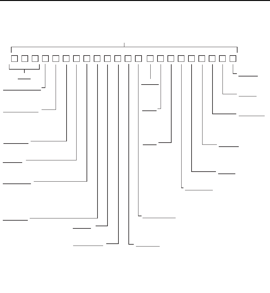
C-12 DDC Emulation Commands Model 6487 Reference Manual
Figure C-1
U0 machine status word
TERMINATOR
0 = CR LF*
1 = LF CR
2 = CR
3 = LF
4 = None
PREFIX
READING SOURCE
0 = Picoammeter*
1 = One buffer reading
2 = All buffer readings
3 = Max. buffer reading
4 = Min. buffer reading
RANGE
0 = Auto Off
1 = Auto On*
1 = 2nA
2 = 20nA
3 = 200nA
4 = 2μA
5 = 20μA
6 = 200μA
7 = 2mA
8 = 20mA
DATA STORE SIZE
000 = Disabled*
nnn = 001 to 512 (size)
CAL LOCK
0 = Locked*
1 = Unlocked
SRQ MASK**
000 = SRQ Disabled*
001 = Reading Overflow
002 = Data Store Full
004 = Data Store 1/2 Full
008 = Reading Done
016 = Ready
032 = Error
128 = V-source Error
TRIGGER
0 = Continuous on Talk
1 = One-shot on Talk
2 = Continuous on Get
3 = One-shot on Get
4 = Continuous on “X”
5 = One-shot on “X”
6 = Continuous on Ext Trig*
7 = One-shot on Ext Trig
8 = Contiuous on Operate
9 = One-shot on Operate
*Default settings
Status Word
DISPLAY INTENSITY
0 = Normal*
1 = Dim (Characters)
2 = Off
ZERO CHECK
0 = Disabled*
1 = Enabled
V/I OHMS
0 = Disabled*
1 = Enabled
DATA FORMAT
0 = Rdg with prefix (ASCII)*
1 = Rdg without prefix (ASCII)
2 = Rdg, buffer location with prefix
3 = Rdg, buffer location without prefix
4 = Binary rdg, byte reversed
5 = Binary rdg, normal byte order
HIT BUTTON
01 = CONFIG
02 = I | Ω
03 = MATH
04 = FILT
05 = ZCHK
06 = REL
07 = OPER
08 = SOURCE Up
11 = RANGE Up
12 = AUTO
13 = RANGE Down
14 = ENTER
15 = Cursor Right
16 = SOURCE Down
17 = MENU
18 = COMM
19 = DISP
20 = TRIG
21 = LIMIT
22 = DIGITS
23 = RATE
24 = Cursor Left
26 = SAVE
27 = SETUP
28 = STORE
29 = RECALL
30 = AZERO
31 = DAMP
32 = EXIT
SELF TEST
0 = No error*
1 = ROM error
EOI, HOLD-OFF
0 = EOI & hold-off*
1 = No EOI, hold-off
2 = EOI, no hold-off
3 = No EOI, no hold-off
**Add up values for multiple SRQ conditions
RELATIVE
0 = Off*
1 = On
V-SOURCE
00 = 50V rg, 25μA lim
01 = 50V rg, 2.5mA lim*
10 = 500V rg, 25μA lim
11 = 500V rg, 2.5mA lim
OPERATE
0 = Off*
1 = On
FILTERS
0 = Both off
1 = A off, D on
2 = A on, D off
3 = Both on*
INTEGRATION
0 = Fast
1 = Line cycle*
487 cABCF GH J KMN OPR S T VYZ
Model 6487 Reference Manual DDC Emulation Commands C-13
Figure C-2
U1 error status word
Figure C-3
U9 voltage source status word
Status byte format
The status byte contains information relating to data and error conditions within the instru-
ment. When a particular bit is set, certain conditions are present. Table C-2 lists the mean-
ings of the various bits and Figure C-4 shows the general format of the status byte, which
is obtained by using the SPE, SPD polling sequence.
If the status byte is read when no SRQ was generated by the Model 6487 (bit 6 is clear),
the current status of the instrument will be read. For example, if a reading was done, bit 3
would be set.
SRQ is enabled by setting the corresponding bit with the SRQ mask using the M com-
mand (see Table C-1). The Model 6487 may be programmed to generate an SRQ for more
than one condition simultaneously, simply by adding up the command option values.
487 1/0 1/0 1/0 1/0 1/0 1/0 1/0 1/0 1/0 1/0 1/0 1/0 1/0
1 = E PROM
Cal Constants
2
1 = E PROM Defaults
2
1= Calibration
1= Zero Check
1= No Remote
1 = Self-Test
1 = Trigger Overrun
1 = Conflict
1 = Cal Locked
1 = V-Source
1 = V-Source Conflict
1 = IDDC
1 = IDDCO
487 1/0 1/0
1= Interlock Open
1 = Current Limit

C-14 DDC Emulation Commands Model 6487 Reference Manual
When an SRQ is generated by the Model 6487, bit 6 of the status byte will be set. After an
SRQ, the status byte will remain unchanged until it is read.
The various bits in the status byte are described below:
Reading Overflow (B0) — Set when an overrange input is applied to the instrument.
Cleared when on on-scale reading has been made.
Data Store Full (B1) — Set when the number of readings stored is equal to the buffer
size. Cleared by re-arming data store.
Data Store 1/2 Full (B2) — Set when the number of readings stored is equal to half the
buffer size. Cleared by re-arming data store.
Reading Done (B3) — Set when the instrument has completed the present conversion and
is ready to take another reading. Cleared when the reading has been sent.
Ready (B4) — Set when the instrument has processed all previous commands and is
ready to begin processing new commands or triggers. Cleared while instrument is process-
ing commands or triggers.
Error (B5) — Set when one of the following errors has occurred:
–IDDC
–IDDCO
– No remote
–Self test
– Trigger overrun
– Conflict
– Cal locked
– Zero check
– Calibration error
–E
2PROM defaults error
–E
2PROM cal constants error
– V-source conflict
– Interlock
This bit is cleared when the U1 status word is read to determine the nature of the error (see
Figure C-2.)
RQS (B6) — Set when the Model 6487 has generated a request for service via the SRQ
line. Cleared by reading the status byte.

Model 6487 Reference Manual DDC Emulation Commands C-15
Voltage Source Error (B7) — Set if the voltage source has reached current limit or if the
interlock is tripped. Cleared by reading U9 status after correcting the voltage source error
(see Figure C-3).
klqb Once the Model 6487 has generated an SRQ, its status byte must be read to
clear the SRQ line. Otherwise, the instrument will continuously assert SRQ.
Figure C-4
Status byte format
Table C-2
Status byte and SRQ mask interpretation
Bit Decimal
Weighting Description
0 (LSB) 1 Reading Overflow
1 2 Data Store Full
2 4 Data Store 1/2 Full
3 8 Reading done
4 16 Ready
532 Error
6 64 RQS (Request for Service)*
7 128 Voltage Source Error
* Status byte only
MSB B7 B6 B5 B4 B3 B2 B1 B0 LSB
Reading
Done
Data
Store
Full Reading
OverflowErrorRQS*
Data
Store
1/2 Full
Ready
V-source
Error
* Status bye only

D
IEEE-488 Bus Overview
•Bus description – This section gives a detailed description of the bus. Introduces
and defines the controller, talker, and listener.
•Bus lines – This section describes the operation of data lines, bus management
lines, and handshake lines.
•Bus commands – This section describes the purpose of bus commands, lists the
three catagories of bus commands, and defines the three catagories.
•Interface function codes – This section lists and defines the interfce function
codes for the Model 6487.

D-2 IEEE-488 Bus Overview Model 6487 Reference Manual
Introduction
The IEEE-488 bus is a communication system between two or more electronic devices. A
device can be either an instrument or a computer. When a computer is used on the bus, it
serves as a supervisor of the communication exchange between all the devices and is
known as the controller. Supervision by the controller consists of determining which
device will talk and which device will listen. As a talker, a device will output information;
as a listener, a device will receive information. To simplify the task of keeping track of the
devices, a unique address number is assigned to each.
On the bus, only one device can talk at a time and is addressed to talk by the controller.
The device that is talking is known as the active talker. The devices that need to listen to
the talker are addressed to listen by the controller. Each listener is then referred to as an
active listener. Devices that do not need to listen are instructed to unlisten. The reason for
the unlisten instruction is to optimize the speed of bus information transfer since the task
of listening takes up bus time.
Through the use of control lines, a handshake sequence takes place in the transfer process
of information from a talker to a listener. This handshake sequence helps ensure the credi-
bility of the information transfer. The basic handshake sequence between an active con-
troller (talker) and a listener is as follows:
1. The listener indicates that it is ready to listen.
2. The talker places the byte of data on the bus and indicates that the data is available
to the listener.
3. The listener, aware that the data is available, accepts the data and then indicates
that the data has been accepted.
4. The talker, aware that the data has been accepted, stops sending data and indicates
that data is not being sent.
5. The listener, aware that there is no data on the bus, indicates that it is ready for the
next byte of data.

Model 6487 Reference Manual IEEE-488 Bus Overview D-3
Bus description
The IEEE-488 bus, which is also referred to as the GPIB (General Purpose Interface Bus),
was designed as a parallel transfer medium to optimize data transfer without using an
excessive number of bus lines. In keeping with this goal, the bus has only eight data lines
that are used for both data and with most commands. Five bus management lines and three
handshake lines round out the complement of bus signal lines.
A typical setup for controlled operation is shown in Figure D-1. Generally, a system will
contain one controller and a number of other instruments to which the commands are
given. Device operation is categorized into three operators: controller, talker, and listener.
The controller controls the instruments on the bus. The talker sends data while a listener
receives data. Depending on the type of instrument, any particular device can be a talker
only, a listener only, or both a talker and listener.
There are two categories of controllers: system controller and basic controller. Both are
able to control other instruments, but only the system controller has the absolute authority
in the system. In a system with more than one controller, only one controller may be active
at any given time. Certain protocol is used to pass control from one controller to another.
The IEEE-488 bus is limited to 15 devices, including the controller. Thus, any number of
talkers and listeners up to that limit may be present on the bus at one time. Although sev-
eral devices may be commanded to listen simultaneously, the bus can have only one active
talker or communications would be scrambled.
A device is placed in the talk or listen state by sending an appropriate talk or listen com-
mand. These talk and listen commands are derived from an instrument’s primary address.
The primary address may have any value between 0 and 31, and is generally set by rear
panel DIP switches or programmed in from the front panel of the instrument. The actual
listen address value sent out over the bus is obtained by ORing the primary address with
$20. For example, if the primary address is $14, the actual listen address is $34 ($34 = $14
+ $20). In a similar manner, the talk address is obtained by ORing the primary address
with $40. With the present example, the talk address derived from a primary address of
$14 would be $54 ($54 = $14 + $40).
The IEEE-488 standards also include another addressing mode called secondary address-
ing. Secondary addresses lie in the range of $60-$7F. Note, however, that many devices,
including the Model 6487, do not use secondary addressing.
Once a device is addressed to talk or listen, the appropriate bus transactions take place. For
example, if the instrument is addressed to talk, it places its data string on the bus one byte
at a time. The controller reads the information and the appropriate software can be used to
direct the information to the desired location.
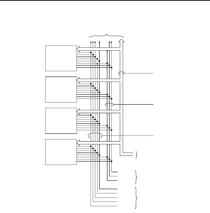
D-4 IEEE-488 Bus Overview Model 6487 Reference Manual
Figure D-1
IEEE-488 bus configuration
Bus lines
The signal lines on the IEEE-488 bus are grouped into three different categories: data
lines, management lines, and handshake lines. The data lines handle bus data and com-
mands, while the management and handshake lines ensure that proper data transfer and
operation takes place. Each bus line is active low, with approximately zero volts represent-
ing a logic 1 (true). The following paragraphs describe the operation of these lines.
DEVICE 1
ABLE TO
TALK, LISTEN
AND CONTROL
(COMPUTER)
DEVICE 2
ABLE TO
TALK AND
LISTEN
2182
DEVICE 3
ONLY ABLE
TO LISTEN
(PRINTER)
DEVICE 4
ONLY ABLE
TO TALK
DAV
NRFD
NDAC
IFC
AT N
SRQ
REN
EOI
DATA BUS
DATA BYTE
TRANSFER
CONTROL
GENERAL
INTERFACE
MANAGEMENT
DIO 1–8 DATA
(8 LINES)
HANDSHAKE
BUS
MANAGEMENT
TO OTHER DEVICES
(6487)

Model 6487 Reference Manual IEEE-488 Bus Overview D-5
Data lines
The IEEE-488 bus uses eight data lines that transfer data one byte at a time. DIO1 (Data
Input/Output) through DIO8 (Data Input/Output) are the eight data lines used to transmit
both data and multiline commands and are bi-directional. The data lines operate with low
true logic.
Bus management lines
The five bus management lines help to ensure proper interface control and management.
These lines are used to send the uniline commands.
ATN (Attention) — The ATN state determines how information on the data bus is to be
interpreted.
IFC (Interface Clear) — The IFC line controls clearing of instruments from the bus.
REN (Remote Enable) — The REN line is used to place the instrument on the bus in the
remote mode.
EOI (End or Identify) — The EOI line is used to mark the end of a multi-byte data
transfer sequence.
SRQ (Service Request) — The SRQ line is used by devices when they require service
from the controller.
Handshake lines
The bus handshake lines operate in an interlocked sequence. This method ensures reliable
data transmission regardless of the transfer rate. Generally, data transfer will occur at a
rate determined by the slowest active device on the bus.
One of the three handshake lines is controlled by the source (the talker sending informa-
tion), while the remaining two lines are controlled by accepting devices (the listener or lis-
teners receiving the information). The three handshake lines are:
DAV (DATA VALID) — The source controls the state of the DAV line to indicate to any
listening devices whether or not data bus information is valid.
NRFD (Not Ready For Data) — The acceptor controls the state of NRFD. It is used to
signal to the transmitting device to hold off the byte transfer sequence until the accepting
device is ready.
NDAC (Not Data Accepted) — NDAC is also controlled by the accepting device. The
state of NDAC tells the source whether or not the device has accepted the data byte.
The complete handshake sequence for one data byte is shown in Figure D-2. Once data is
placed on the data lines, the source checks to see that NRFD is high, indicating that all
active devices are ready. At the same time, NDAC should be low from the previous byte
transfer. If these conditions are not met, the source must wait until NDAC and NRFD have
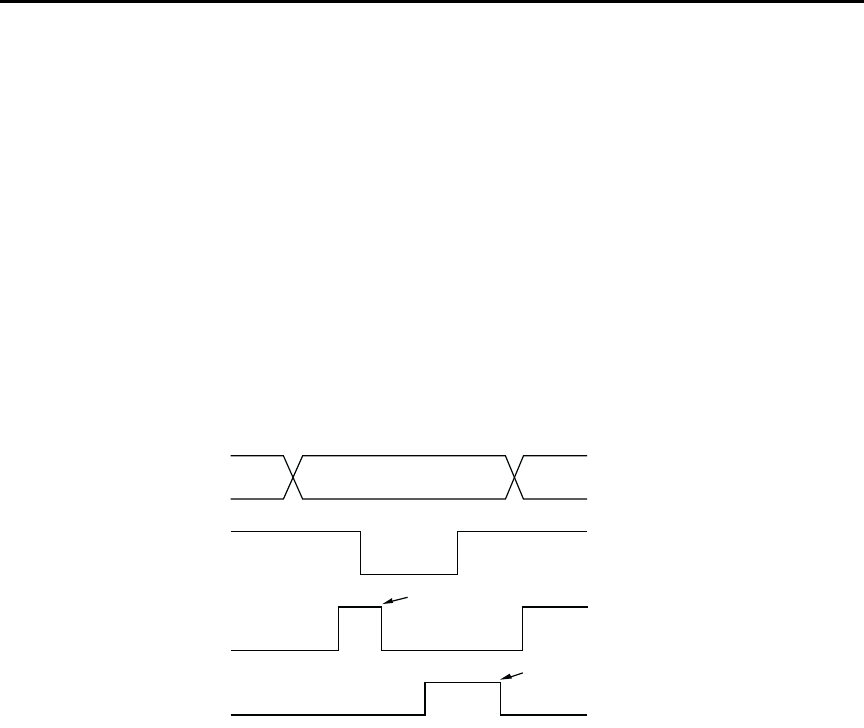
D-6 IEEE-488 Bus Overview Model 6487 Reference Manual
the correct status. If the source is a controller, NRFD and NDAC must be stable for at least
100ns after ATN is set true. Because of the possibility of a bus hang up, many controllers
have time-out routines that display messages in case the transfer sequence stops for any
reason.
Once all NDAC and NRFD are properly set, the source sets DAV low, indicating to accept-
ing devices that the byte on the data lines is now valid. NRFD will then go low, and NDAC
will go high once all devices have accepted the data. Each device will release NDAC at its
own rate, but NDAC will not be released to go high until all devices have accepted the data
byte.
The previous sequence is used to transfer both data, talk, and listen addresses, as well as
multiline commands. The state of the ATN line determines whether the data bus contains
data, addresses, or commands as described in the following paragraphs.
Figure D-2
IEEE-488 handshake sequence
Bus commands
The instrument may be given a number of special bus commands through the IEEE-488
interface. The following paragraphs briefly describe the purpose of the bus commands
which are grouped into the following three categories.
1. Uniline commands — Sent by setting the associated bus lines true. For example,
to assert REN (Remote Enable), the REN line would be set low (true).
2. Multiline commands — General bus commands which are sent over the data lines
with the ATN line true (low).
3. Common commands — Commands that are common to all devices on the bus;
sent with ATN high (false).
4. SCPI commands — Commands that are particular to each device on the bus; sent
with ATN (false).
DATA
DAV
SOURCE
SOURCE
VALID
NRFD
NDAC
ACCEPTOR
ACCEPTOR
ALL READY
ALL ACCEPTED

Model 6487 Reference Manual IEEE-488 Bus Overview D-7
These bus commands and their general purpose are summarized in Table D-1.
Table D- 1
IEEE-488 bus command summary
Command
type Command
State of
ATN line Comments
Uniline
Multiline
Universal
Addressed
Unad-
dressed
Common
SCPI
REN (Remote Enable)
EOI
IFC (Interface Clear)
ATN (Attention)
SRQ
LLO (Local Lockout)
DCL (Device Clear)
SPE (Serial Enable)
SPD (Serial Poll Disable)
SDC (Selective Device Clear)
GTL (Go To Local)
UNL (Unlisten)
UNT (Untalk)
—
—
X
X
X
Low
X
Low
Low
Low
Low
Low
Low
Low
Low
High
High
Set up devices for remote operation.
Marks end of transmission.
Clears interface.
Defines data bus contents.
Controlled by external device.
Locks out local operation.
Returns device to default conditions.
Enables serial polling.
Disables serial polling.
Returns unit to default conditions.
Returns device to local.
Removes all listeners from the bus.
Removes any talkers from the bus.
Programs IEEE-488.2 compatible instru-
ments for common operations.
Programs SCPI compatible instruments for
particular operations.
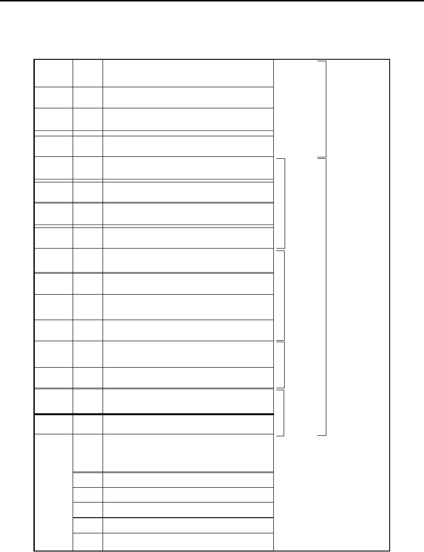
D-8 IEEE-488 Bus Overview Model 6487 Reference Manual
Table D- 2
Command codes
D7
D6
D5
D4
X
0
0
0
Command
X
0
0
1
Command
X
0
1
0
Primary
Address
X
0
1
1
Primary
Address
X
1
0
0
Primary
Address
X
1
0
1
Primary
Address
X
1
1
0
X
1
1
1
Bits D3
⎠
D2
⎠
D1
⎠
D0
⎠
Column♦
Row ⎠
0 (A) 0 (B) 1 (A) 1 (B) 2 (A) 2 (B) 3 (A) 3(B) 4 (A) 4 (B) 5 (A) 5 (B) 6 (A) 6 (B) 7 (A) 7 (B)
0
0
0
0
0
0
0
0
1
1
1
1
1
1
1
1
0
0
0
0
1
1
1
1
0
0
0
0
1
1
1
1
0
0
1
1
0
0
1
1
0
0
1
1
0
0
1
1
0
1
0
1
0
1
0
1
0
1
0
1
0
1
0
1
0
1
2
3
4
5
6
7
8
9
10
11
12
13
14
15
NUL
SOH
STX
ETX
EOT
ENQ
ACK
BEL
BS
HT
LF
VT
FF
CR
SO
SI
GTL
SDC
PPC*
GET
TCT*
DLE
DC1
DC2
DC3
DC4
NAK
SYN
ETB
CAN
EM
SUB
ESC
FS
GS
RS
US
LLO
DCL
PPU*
SPE
SPD
SP
!
“
#
$
%
&
‘
(
)
•
+
,
-
.
/
0
1
2
3
4
5
6
7
8
9
10
11
12
13
14
15
0
1
2
3
4
5
6
7
8
9
:
;
<
=
>
?
16
17
18
19
20
21
22
23
24
25
26
27
28
29
30
UNL
@
A
B
C
D
E
F
G
H
I
J
K
L
M
N
O
0
1
2
3
4
5
6
7
8
9
10
11
12
13
14
15
P
Q
R
S
T
U
V
W
X
Y
Z
[
\
]
∞
16
17
18
19
20
21
22
23
24
25
26
27
28
29
30
UNT
a
b
c
d
e
f
g
h
i
j
k
l
m
n
o
p
q
r
s
t
u
v
w
x
y
z
{
:
}
≅
DEL
ADDRESSED
COMMAND
GROUP
(ACG)
UNIVERSAL
COMMAND
GROUP
(UCG)
LISTEN
ADDRESS
GROUP
(LAG)
TA L K
ADDRESS
GROUP
(TAG)
PRIMARY
COMMAND
GROUP
(PCG)
SECONDARY
COMMAND
GROUP
(SDC)
*PPC (PARALLEL POLL CONFIGURE) PPU (PARALLEL POLL UNCONFIGURE),
and TCT (TAKE CONTROL) not implemented by Model 2182.
Note: D0 = DIO1 ... D7 = DIO8; X = Don’t Care.
6514.

Model 6487 Reference Manual IEEE-488 Bus Overview D-9
Uniline commands
ATN, IFC, and REN are asserted only by the controller. SRQ is asserted by an external
device. EOI may be asserted either by the controller or other devices depending on the
direction of data transfer. The following is a description of each command. Each command
is sent by setting the corresponding bus line true.
REN (Remote Enable) — REN is sent to set up instruments on the bus for remote opera-
tion. When REN is true, devices will be removed from the local mode. Depending on
device configuration, all front panel controls, except the LOCAL button (if the device is so
equipped), may be locked out when REN is true. Generally, REN should be sent before
attempting to program instruments over the bus.
EOI (End or Identify) — EOI is used to positively identify the last byte in a multi-byte
transfer sequence, thus allowing data words of various lengths to be transmitted easily.
IFC (Interface Clear) — IFC is used to clear the interface and return all devices to the
talker and listener idle states.
ATN (Attention) — The controller sends ATN while transmitting addresses or multiline
commands.
SRQ (Service Request) — SRQ is asserted by a device when it requires service from a
controller.
Universal multiline commands
Universal commands are those multiline commands that require no addressing. All devices
equipped to implement such commands will do so simultaneously when the commands
are transmitted. As with all multiline commands, these commands are transmitted with
ATN true.
LLO (Local Lockout) — LLO is sent to the instrument to lock out the LOCAL key and all
their front panel controls.
DCL (Device Clear) — DCL is used to return instruments to some default state. Instru-
ments usually return to their power-up conditions.
SPE (Serial Poll Enable) — SPE is the first step in the serial polling sequence which is
used to determine which device has requested service.
SPD (Serial Poll Disable) — SPD is used by the controller to remove all devices on the
bus from the serial poll mode and is generally the last command in the serial polling
sequence.

D-10 IEEE-488 Bus Overview Model 6487 Reference Manual
Addressed multiline commands
Addressed commands are multiline commands that must be preceded by the device listen
address before that instrument will respond to the command in question. Note that only
the addressed device will respond to these commands. Both the commands and the address
preceding it are sent with ATN true.
SDC (Selective Device Clear) — The SDC command performs essentially the same
function as the DCL command except that only the addressed device responds. Generally,
instruments return to their power-up default conditions when responding to the SDC
command.
GTL (Go To Local) — The GTL command is used to remove instruments from the
remote mode. With some instruments, GTL also unlocks front panel controls if they were
previously locked out with the LLO command.
GET (Group Execute Trigger) — The GET command is used to trigger devices to per-
form a specific action that depends on device configuration (for example, take a reading).
Although GET is an addressed command, many devices respond to GET without
addressing.
Address commands
Addressed commands include two primary command groups and a secondary address
group. ATN is true when these commands are asserted. The commands include:
LAG (Listen Address Group) — These listen commands are derived from an instru-
ment’s primary address and are used to address devices to listen. The actual command
byte is obtained by ORing the primary address with $20.
TAG (Talk Address Group) — The talk commands are derived from the primary address
by ORing the address with $40. Talk commands are used to address devices to talk.
SCG (Secondary Command Group) — Commands in this group provide additional
addressing capabilities. Many devices (including the Model 6487) do not use these
commands.
Unaddress commands
The two unaddress commands are used by the controller to remove any talkers or listeners
from the bus. ATN is true when these commands are asserted.
UNL (Unlisten) — Listeners are placed in the listener idle state by the UNL command.
UNT (Untalk) — Any previously commanded talkers will be placed in the talker idle
state by the UNT command.

Model 6487 Reference Manual IEEE-488 Bus Overview D-11
Common commands
Common commands are commands that are common to all devices on the bus. These com-
mands are designated and defined by the IEEE-488.2 standard.
Generally, these commands are sent as one or more ASCII characters that tell the device to
perform a common operation, such as reset. The IEEE-488 bus treats these commands as
data in that ATN is false when the commands are transmitted.
SCPI commands
SCPI commands are commands that are particular to each device on the bus. These com-
mands are designated by the instrument manufacturer and are based on the instrument
model defined by the Standard Commands for Programmable Instruments (SCPI) Consor-
tium’s SCPI standard.
Generally, these commands are sent as one or more ASCII characters that tell the device to
perform a particular operation, such as setting a range or closing a relay. The IEEE-488
bus treats these commands as data in that ATN is false when the commands are
transmitted.
Command codes
Command codes for the various commands that use the data lines are summarized in
Table D-2. Hexadecimal and the decimal values for the various commands are listed in
Table D-3.
Table D-3
Hexadecimal and decimal command codes
Command Hex value Decimal value
GTL
SDC
GET
LLO
DCL
SPE
SPD
LAG
TAG
SCG
UNL
UNT
01
04
08
11
14
18
19
20-3F
40-5F
60-7F
3F
5F
1
4
8
17
20
24
25
32-63
64-95
96-127
63
95

D-12 IEEE-488 Bus Overview Model 6487 Reference Manual
Typical command sequences
For the various multiline commands, a specific bus sequence must take place to properly
send the command. In particular, the correct listen address must be sent to the instrument
before it will respond to addressed commands. Table D-4 lists a typical bus sequence for
sending the addressed multiline commands. In this instance, the SDC command is being
sent to the instrument. UNL is generally sent as part of the sequence to ensure that no
other active listeners are present. Note that ATN is true for both the listen command and
the SDC command byte itself.
Table D-5 gives a typical common command sequence. In this instance, ATN is true while
the instrument is being addressed, but it is set high while sending the common command
string.
Tab l e D -4
Typical bus sequence
Step Command ATN state
Data bus
ASCII Hex Decimal
1
2
3
4
UNL
LAG*
SDC
Set low
Stays low
Stays low
Returns high
?
.
EOT
3F
36
04
63
54
4
*Assumes primary address = 22.
Tab l e D -5
Typical addressed command sequence
Step Command ATN state
Data bus
ASCII Hex Decimal
1
2
3
4
5
6
UNL
LAG*
Data
Data
Data
Data
Set low
Stays low
Set high
Stays high
Stays high
Stays high
?
.
*
R
S
T
3F
36
2A
52
53
54
63
54
42
82
83
84
*Assumes primary address = 22.

Model 6487 Reference Manual IEEE-488 Bus Overview D-13
IEEE command groups
Command groups supported by the Model 6487 are listed in Table D-6. Common com-
mands and SCPI commands are not included in this list.
Table D- 6
IEEE command groups
HANDSHAKE COMMAND GROUP
NDAC = NOT DATA ACCEPTED
NRFD = NOT READY FOR DATA
DAV = DATA VALID
UNIVERSAL COMMAND GROUP
ATN = ATTENTION
DCL = DEVICE CLEAR
IFC = INTERFACE CLEAR
REN = REMOTE ENABLE
SPD = SERIAL POLL DISABLE
SPE = SERIAL POLL ENABLE
ADDRESS COMMAND GROUP
LISTEN
TALK
LAG = LISTEN ADDRESS GROUP
MLA = MY LISTEN ADDRESS
UNL = UNLISTEN
TAG = TALK ADDRESS GROUP
MTA = MY TALK ADDRESS
UNT = UNTALK
OTA = OTHER TALK ADDRESS
ADDRESSED COMMAND GROUP
ACG = ADDRESSED COMMAND GROUP
GTL = GO TO LOCAL
SDC = SELECTIVE DEVICE CLEAR
STATUS COMMAND GROUP
RQS = REQUEST SERVICE
SRQ = SERIAL POLL REQUEST
STB = STATUS BYTE
EOI = END OF IDENTIFY

D-14 IEEE-488 Bus Overview Model 6487 Reference Manual
Interface function codes
The interface function codes, which are part of the IEEE-488 standards, define an instru-
ment’s ability to support various interface functions and should not be confused with pro-
gramming commands found elsewhere in this manual. The interface function codes for the
Model 6487 are listed in Table D-7.
The codes define Model 6487 capabilities as follows:
SH (Source Handshake Function) — SH1 defines the ability of the instrument to initiate
the transfer of message/data over the data bus.
AH (Acceptor Handshake Function) — AH1 defines the ability of the instrument to
guarantee proper reception of message/data transmitted over the data bus.
T (Talker Function) — The ability of the instrument to send data over the bus to other
devices is provided by the T function. Instrument talker capabilities (T5) exist only after
the instrument has been addressed to talk.
L (Listener Function) — The ability for the instrument to receive device-dependent data
over the bus from other devices is provided by the L function. Listener capabilities (L4) of
the instrument exist only after it has been addressed to listen.
SR (Service Request Function) — SR1 defines the ability of the instrument to request
service from the controller.
RL (Remote-Local Function) — RL1 defines the ability of the instrument to be placed in
the remote or local modes.
Table D - 7
Model 6487 interface function codes
Code Interface function
SH1
AH1
T5
L4
SR1
RL1
PP0
DC1
DT1
C0
E1
TE0
LE0
Source Handshake capability
Acceptor Handshake capability
Talker (basic talker, talk-only, serial poll, unaddressed to talk on LAG)
Listener (basic listener, unaddressed to listen on TAG)
Service Request capability
Remote/Local capability
No Parallel Poll capability
Device Clear capability
Device Trigger capability
No Controller capability
Open collector bus drivers
No Extended Talker capability
No Extended Listener capability

Model 6487 Reference Manual IEEE-488 Bus Overview D-15
E (Bus Driver Type) — The instrument has open-collector bus drivers (E1).
TE (Extended Talker Function) — The instrument does not have extended talker capa-
bilities (TE0).
LE (Extended Listener Function) — The instrument does not have extended listener
capabilities (LE0).

E
IEEE-488 and SCPI
Conformance Information
•GPIB 488.1 Protocol – This section introduces the GPIB 488.1 protocol.
•Selecting the 488.1 protocol – This section describes how to select the 488.1
protocol.
•Protocol differences – This section covers the differences between the 488.1 proto-
col and the SCPI protocol.

E-2 IEEE-488 and SCPI Conformance Information Model 6487 Reference Manual
Introduction
The IEEE-488.2 standard requires specific information about how the Model 6487 imple-
ments the standard. Paragraph 4.9 of the IEEE-488.2 standard (Std 488.2-1987) lists the
documentation requirements. Table E-1 provides a summary of the requirements and pro-
vides the information or references the manual for that information. Table E-2 lists the
coupled commands used by the Model 6487.
The Model 6487 complies with SCPI version 1996.0. Table 14-1 through Table 14-9 list
the SCPI confirmed commands and the non-SCPI commands implemented by the
Model 6487.
Table E-1
IEEE-488 documentation requirements
Requirements Description or Reference
(1)
(2)
(3)
(4)
(5)
(a)
(b)
(c)
(d)
(e)
(6)
(7)
(8)
(9)
(10)
(11)
(12)
(13)
(14)
IEEE-488 Interface Function Codes.
Behavior of 6487 when the address is set outside the
range 0-30.
Behavior of 6487 when valid address is entered.
Power-On Setup Conditions.
Message Exchange Options:
Input buffer size.
Queries that return more than one response message
unit.
Queries that generate a response when parsed.
Queries that generate a response when read.
Coupled commands.
Functional elements required for SCPI commands.
Buffer size limitations for block data.
Syntax restrictions.
Response syntax for every query command.
Device-to-device message transfer that does not follow
rules of the standard.
Block data response size.
Common Commands implemented by 6487.
Calibration query information.
Trigger macro for *DDT.
See Appendix D.
Cannot enter an invalid address.
Address changes and bus resets.
Determine by :SYSTem:POSetup
(Section 14).
2048 bytes.
None.
All queries (Common Commands and
SCPI).
None.
See Table E-2.
Contained in SCPI command
subsystems tables (see Table 14-1
through Table 14-9).
Block display messages: 12 characters
max.
See Programming Syntax in Section 9.
See Programming Syntax in Section 9.
None.
See Display Subsystem in Section 13.
See Common Commands in Section 11.
Appendix F.
Not applicable.
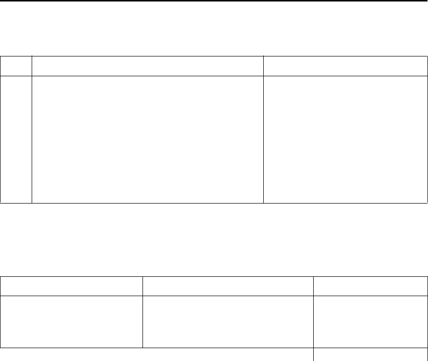
Model 6487 Reference Manual IEEE-488 and SCPI Conformance Information E-3
GPIB 488.1 Protocol
The Model 6487 supports two GPIB protocols: SCPI (488.2) and 488.1. The 488.1 proto-
col is included to significantly increase speed over the GPIB.
When using the 488.1 protocol, throughput is enhanced up to 10 times for data sent to the
6487 (command messages) and up to 20 times for data returned by the Picoammeter
(response messages). The speed of readings sent over the GPIB is also increased.
klqb With the 488.1 protocol selected, you will still use SCPI commands to program
the Model 6487. Operation differences between the two protocols are discussed
in this appendix.
(15)
(16)
(17)
(18)
(19)
(20)
(21)
(22)
(23)
Macro information.
Response to *IDN (identification).
Storage area for *PUD and *PUD?
Resource description for *RDT and *RDT?
Effects of *RST, *RCL, and *SAV.
*TST information.
Status register structure.
Sequential or overlapped commands.
Operation complete messages.
Not applicable.
See Common Commands in Section 11.
Not applicable.
Not applicable.
See Common Commands in Section 11.
See Common Commands in Section 11.
See Status Structure in Section 10.
All are sequential except :INIT which is
overlapped.
*OPC, *OPC?, and *WAI; see
Common Commands in Section 11.
Table E-2
Coupled commands
Sending Changes To
CALC2:NULL:ACQ
TRAC:POIN <n>
TRAC:CLE
CALC2:NULL:OFFS <n>
TRAC:FEED:CONT <name>
TRAC:FEED:CONT <name> TRAC:CLE
Acquired value
NEV
NEV
Table E-1 (cont.)
IEEE-488 documentation requirements
Requirements Description or Reference

E-4 IEEE-488 and SCPI Conformance Information Model 6487 Reference Manual
Selecting the 488.1 protocol
Perform the following steps to select the 488.1 protocol:
klqb The Model 6487 must be set up to be remotely controlled over the GPIB to select
the 488.1 protocol. SCPI language is the only language available over the
RS-232 bus. To setup the M odel 6487 to use GPIB from the local measurement
mode:
• Press the COMM button.
• Using the RANGE keys, select GPIB.
• Press Enter to complete the change.
1. Press CONFIG (CONFIGURE: will be displayed).
2. Press COMM to access the communications menu. If a BAUD is displayed flash-
ing, the 6487 is configured to use the RS-232 bus. See the Note above and change
to control over the GPIB.
3. Scroll using a RANGE key until LANG is displayed.
4. Press the right cursor key to place the cursor on the currently selected language
(either DDC, SCPI, or 488.1 will be flashing).
5. Scroll using a RANGE key until 488.1 is displayed. To change back to 488.2, scroll
to the SCPI menu item.
6. Press ENTER to save the change.
When switching between the SCPI protocol, DDC protocol, and 488.1 protocol, the
instrument resets. The GPIB protocol setting is saved in EEPROM and the unit will power
up with that selected protocol.
The GPIB protocol cannot be changed over the bus. However, there is a query command to
determine the presently selected protocol. When the 488.1 protocol is selected, the mes-
sage exchange protocol (MEP) disables. Therefore, if you use the following query to
request the state of MEP, you will know which protocol is enabled:
:SYSTem:MEP[:STATe]?
If a “1” is returned, MEP is enabled and the SCPI protocol is selected. A “0” indicates that
MEP is disabled and the 488.1 protocol is enabled. To summarize:
1 = SCPI protocol
0 = 488.1 protocol

Model 6487 Reference Manual IEEE-488 and SCPI Conformance Information E-5
Protocol differences
The following information covers the differences between the 488.1 protocol and the SCPI
protocol.
Message exchange protocol (MEP)
When the 488.1 protocol is selected, the MEP is disabled to speed up GPIB operation.
The following guidelines/limitations must be followed when using the 488.1 protocol:
• If a query is sent, it must be the only command on the line (this limitation also
means no multiple queries can be sent). Otherwise, full SCPI command syntax is
still supported including long-form and short form commands, multiple com-
mands, and MIN/MAX/DEF parameter definitions.
For example, the following command strings are invalid:
:CURR:RANG .020; *OPC?
:CURR:RANG?;: READ?
:READ?;:READ?
The following strings are valid:
curr:nplc 1.0;:curr:rang min
:CURR:RANG? MAX
:READ?
• When a query is sent, either the data must be read back or a Device Clear (DCL) or
Interface Clear (IFC) must be performed to reset the query.
• When sending a command or query, do not attempt to read data from the
Model 6487 until the terminator has been sent (usually Line Feed with EOI).
Otherwise, a DCL or IFC must be sent to reset the input parser.
• When receiving data, all data, up to and including the terminator (LF with EOI),
must be accepted. Otherwise, a DCL or IFC must be sent to reset the output task.
• Empty command strings (terminator only) should not be sent.
Using SCPI-based programs
In general, an existing SCPI-based program will run properly and faster in the 488.1 pro-
tocol as long as it meets the above guidelines and limitations.
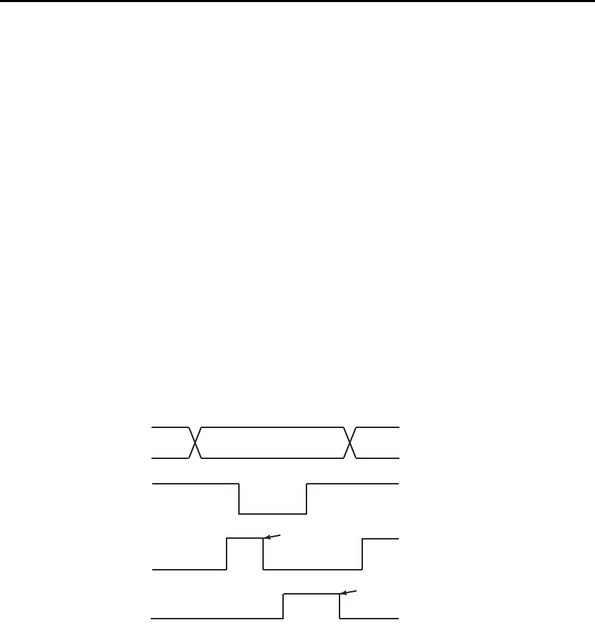
E-6 IEEE-488 and SCPI Conformance Information Model 6487 Reference Manual
NRFD hold-off
*OPC, *OPC?, and *WAI are still functional but are not needed for the 488.1 protocol.
When sending commands, the GPIB is automatically held off when it detects a terminator.
The hold-off is released when all the commands have finished executing or if there is some
parser or command error. An exception is an initiate command, which releases the hold-off
immediately and does not wait for all of the readings to be acquired. This immediate
release of bus hold-off is done to support GET, SDC, IFC, *TRG, *RCL, *RST,
SYSTem:PRESet, and ABORt during data acquisition.
NDAC hold-off
NDAC hold-off is included with the GPIB 488.1 protocol mode to allow a single instru-
ment to hold off all others on the bus until it is finished executing a command. The follow-
ing command controls NDAC hold-off:
SYSTem:MEP:HOLDoff ON | OFF
The default is OFF, but NRFD hold-off will still be enabled and will prevent an instrument
from accepting further commands. See Figure E-1 for the complete IEEE-488 handshake
sequence.
Figure E-1
IEEE-488 handshake sequence
D ATA
DAV
SOURCE
SOURCE
VALID
ALL READY ACCEPTOR
NRFD
NDAC
ALL ACCEPTED
ACCEPTOR

Model 6487 Reference Manual IEEE-488 and SCPI Conformance Information E-7
Trigger-on-talk
Trigger-on-talk functionality has been added for the 488.1 protocol. If a query has not
been received by the instrument, the Model 6487 will automatically assume a READ?
command has been sent when it is addressed to talk. This technique increases GPIB speed
by decreasing the transmission and parser times for the command.
Trigger-on-talk is extremely useful in the single-shot reading mode (*RST default) and is
the main reason for a >2x speed improvement over the SCPI protocol.
The ARM:SOUR BUS and ARM:COUN INF commands are not supported by READ?
with the 488.1 protocol selected. If you send one of these commands, a DCL or IFC may
be required to reset the GPIB.
Message available
The MAV (message available) bit in the Serial Poll byte will be set when the query is fin-
ished being processed, not when there is data available in the output buffer (as with the
SCPI protocol). For the 488.1 protocol, output data will not be formatted until the first
request for data is received. This delay may cause unexpected time-outs when using SRQ
on MAV for queries that take a long time to execute.
General operation notes
• The TALK, LSTN, and SRQ annunciators are not functional in the 488.1 protocol.
This speeds up data throughput greatly. The REM annunciator still operates since it
is critical to fundamental GPIB operation.
• If the unit is in REMote, the GTL command may not put the Model 6487 into the
local mode. Only the front panel LOCAL key is guaranteed to operate, if not in
local lockout (LLO). GTL will still disable LLO.
• IEEE-488 bus commands and features (GET, IFC, SDC, DCL, LLO, Serial Poll,
and SRQ) are still fully supported.
• Multiple TALKs on the same query are supported as in the SCPI protocol. This fea-
ture is useful when reading back long ASCII strings.

E-8 IEEE-488 and SCPI Conformance Information Model 6487 Reference Manual
SRQ when buffer fills with 200 readings
The following QuickBasic program (Figure E-2) will store 200 readings in the buffer.
When the buffer fills to the set amount (200 readings), an SRQ will occur and a message
will be displayed on the computer to indicate the event.
Figure E-2
Program example
' $INLCUDE: 'ieeeqb.bi'
CLS 'Clear PC output screen.
CONST addr = 22 'Set instrument address.
'
' Init GPIB
'
CALL initialize(21, 0)
CALL transmit("unt unl listen " + STR$(addr) + " sdc unl", status%)'Restore *rst defaults
CALL send(addr, "*rst", status%) 'Send Device Clear.
CALL send(addr, "trac:cle", status%) 'Clear buffer.
CALL send(addr, "trig:coun 200", status%) '200 trigger count.
CALL send(addr, "trac:poin 200", status%) 'Set buffer size to 200.
CALL send(addr, "trac:feed:cont next", status%) 'Enable buffer.
CALL send(addr, "stat:pres", status%) 'Reset measure enable bits.
CALL send(addr, "*cls", status%) 'Clear all event registers.
CALL send(addr, "stat:meas:enab 512", status%) 'Enable buffer bit B9.
CALL send(addr, "*ese 0", status%) 'Disable standard events.
CALL send(addr, "*sre 1", status%) 'Enable measurement events.
CALL send(addr, "syst:zch off", status%) 'Disable zero check.
CALL send(addr, "init", status%) 'Start measurement/store process.
WAITSRQ:
WHILE srq = 0:WEND 'Wait for GPIB SRQ line to go true.
CALL spoll(addr, poll%, status%) 'Clear rqs/mss bit in status bit
'register.
CALL send(addr, "*cls", status%) 'Clear all event registers.
PRINT "BUFFER FULL" 'Display buffer full message.
END


F-2 Remote Calibration Model 6487 Reference Manual
Introduction
This appendix contains a summary of Model 6487 remote calibration commands and a
basic remote calibration procedure. See Section 16 for complete calibration information.
Calibration commands
Table F-1 summarizes Model 6487 remote calibration commands.
Table F-1
Calibration commands
Command Description
:CALibration Calibration subsystem.
:PROTected Commands protected by code/password.
:CODE '<code>' Eight character code/password used to enable or unlock calibration.
(Default: KI006487.)
:CODE? Calibration code query.
:LOCK Lock out further calibration.
:LOCK? Return 1 if calibration is locked, 0 otherwise.
:SENSe <NRf> Calibrate active current range.
:DATA? Query measurement cal constants.
:VSOurce Voltage source calibration commands:
:NFSCale Turn on source, set it to negative full scale for present source range.
:NFSValue <NRf> Calibrate negative full scale using DMM reading.
:ZERO Set source output to 0V and turn on output.
:ZVALue <NRf> Calibrate source zero using DMM reading.
:PFSCale Turn on source, set it to positive full scale for present source range.
:PFSValue <NRf> Calibrate positive full scale using DMM reading.
:SOURce Path to query source calibration constants.
:DATA? Query constants for present source range. Three values are returned:
Vnegative, Vpositive, and Vzero.
:SAVE Save all calibration data to non-volatile memory.
:DATE <yyyy, mm, dd> Year, Month, Day when cal was last performed.
:DATE? Query last cal date.
:NDUE <yyyy, mm, dd> Year, Month, Day when 6487 is due for re-cal.
:NDUE? Query cal due date.
:COUNt? Returns how many times 6487 has been calibrated.
:UNPRotected Commands not protected by code/password.
:VOFFset Voltage offset correction.

Model 6487 Reference Manual Remote Calibration F-3
Remote calibration overview
The steps below outline the general procedure for calibrating the Model 6487 using
remote commands. Refer to Section 16 for details on calibration steps, calibration points,
and test equipment connections.
1. Send the following command to unlock calibration:
:CAL:PROT:CODE 'KI006487'
Note that the above command uses the factory default code.
2. Perform voltage offset correction by sending the following command:
:CAL:UNPR:VOFF
Be sure a triax shielding cap is connected to the INPUT jack before sending the
above command.
3. Send the appropriate command to select the current range to be calibrated. For
example, the following command selects the 20mA range:
:SENS:CURR:RANG 2e-2
4. Make appropriate connections (see Figure 16-1 and Figure 16-2), then send the
commands for each calibration point for the selected function and range. For exam-
ple, send the following commands for the 20mA range:
:CAL:PROT:SENS 0
:CAL:PROT:SENS 2e-2
:CAL:PROT:SENS –2e-2
5. Repeat steps 3 and 4 for each range (Table F-2).
t^okfkd Hazardous voltages will be present during voltage source calibration
steps. Use care to avoid a shock hazard. The interlock must be closed
to calibrate the 50V and 500V ranges. See Section 2 for interlock
information.
6. Be sure the DMM is connected to the Model 6487 voltage source terminals (see
Figure 16-3), then send the commands for each calibration point for the selected
range, as summarized in Table F-3. Be sure to include the actual DMM reading for
each step where shown.
7. Repeat step 6 for each voltage source range.
8. After all current and voltage source ranges are calibrated, send the commands to
program the calibration dates; for example:
:CAL:PROT:DATE 2002,12,15
:CAL:PROT:NDUE 2003,12,15
9. Finally, send the following commands to save calibration constants and then lock
out calibration:
:CAL:PROT:SAVE
:CAL:PROT:LOCK

F-4 Remote Calibration Model 6487 Reference Manual
Table F-2
Current calibration commands by range
Range Commands*
2nA :SENS:CURR:RANG 2e-9
:CAL:PROT:SENS 0
:CAL:PROT:SENS 2e-9
:CAL:PROT:SENS –2e-9
20nA :SENS:CURR:RANG 2e-8
:CAL:PROT:SENS 0
:CAL:PROT:SENS 2e-8
:CAL:PROT:SENS –2e-8
200nA :SENS:CURR:RANG 2e-7
:CAL:PROT:SENS 0
:CAL:PROT:SENS 2e-7
:CAL:PROT:SENS –2e-7
2μA :SENS:CURR:RANG 2e-6
:CAL:PROT:SENS 0
:CAL:PROT:SENS 2e-6
:CAL:PROT:SENS –2e-6
20μA :SENS:CURR:RANG 2e-5
:CAL:PROT:SENS 0
:CAL:PROT:SENS 2e-5
:CAL:PROT:SENS –2e-5
200μA :SENS:CURR:RANG 2e-4
:CAL:PROT:SENS 0
:CAL:PROT:SENS 2e-4
:CAL:PROT:SENS –2e-4
2mA :SENS:CURR:RANG 2e-3
:CAL:PROT:SENS 0
:CAL:PROT:SENS 2e-3
:CAL:PROT:SENS –2e-3
20mA :SENS:CURR:RANG 2e-2
:CAL:PROT:SENS 0
:CAL:PROT:SENS 2e-2
:CAL:PROT:SENS –2e-2
* Full-scale calibration values for 2nA to 2μA ranges should be calcu-
lated from calibrator voltages and standard resistance values. (See
Section 16.) Values for 20μA to 20mA ranges can be used as shown.

Model 6487 Reference Manual Remote Calibration F-5
Table F-3
Voltage source calibration commands by range
Range Commands*
10V :SOUR1:VOLT:RANG 10
:CAL:PROT:VSO:NFSC
:CAL:PROT:VSO:NFSV <DMM_Reading>
:CAL:PROT:VSO:ZERO
:CAL:PROT:VSO:ZVAL <DMM_Reading>
:CAL:PROT:VSO:PFSC
:CAL:PROT:VSO:PFSV <DMM_Reading>
50V :SOUR1:VOLT:RANG 50
:CAL:PROT:VSO:NFSC
:CAL:PROT:VSO:NFSV <DMM_Reading>
:CAL:PROT:VSO:ZERO
:CAL:PROT:VSO:ZVAL <DMM_Reading>
:CAL:PROT:VSO:PFSC
:CAL:PROT:VSO:PFSV <DMM_Reading>
500V :SOUR1:VOLT:RANG 500
:CAL:PROT:VSO:NFSC
:CAL:PROT:VSO:NFSV <DMM_Reading>
:CAL:PROT:VSO:ZERO
:CAL:PROT:VSO:ZVAL <DMM_Reading>
:CAL:PROT:VSO:PFSC
:CAL:PROT:VSO:PFSV <DMM_Reading>
* Include <DMM_Reading> from output voltage generated by previous step.
For example, :CAL:PROT:VSO:NFSV <DMM_Reading> value is generated by
:CAL:PROT:VSO:NFSC command.

G
Applications Guide
•Measurement considerations — Covers measurement considerations for low cur-
rent measurements including Leakage currents and guarding, Input bias current,
Voltage burden, Noise and source impedance, Electrostatic interference and shield-
ing, and Making connections.
•Applications — Covers applications to measure Diode leakage current, Capacitor
leakage current, Measuring high resistance, Cable insulation resistance, Surface
insulation resistance (SIR), Photodiode characterization prior to dicing, Focused
ion beam applications and Using switching systems to measure multiple current
sources.

G-2 Applications Guide Model 6487 Reference Manual
Measurement considerations
Some considerations for making accurate amps measurements are summarized as follows.
Additional measurement considerations are covered in Appendix C of the Model 6487
User’s Manual. For comprehensive information on precision measurements, refer to the
Low Level Measurements handbook, which is available from Keithley Instruments.
It is critical that the picoammeter perform the measurement without interfering with the
flow of current in the circuit, possibly affecting operation or inducing additional errors.
Voltage burden is the terminal voltage of a picoammeter and ideally this voltage should be
zero (no resistive or offset effect). Some meters, such as DMMs, utilize a shunt resistor to
measure the voltage drop across a known resistance and a typical burden of 200mV is not
unusual.
The Keithley Model 6487 uses an alternative approach referred to as a feedback picoam-
meter, where the voltage burden is simply the input voltage of an operational amplifier.
Furthermore, since the input voltage of the operational amplifier is the output voltage
divided by the gain (typically 500,000) the voltage burden is in the microvolt range.
Leakage currents and guarding
Leakage currents are generated by high resistance paths between the measurements circuit
and nearby sources. These currents can considerably degrade the accuracy of low current
measurements. Some ways to reduce leakage currents are to use good quality insulators,
maintain cleanliness on the surface of insulators, reduce humidity, and use guarding.
Guarding also reduces the effect of shunt capacitance in the measurement circuit.
One way to reduce leakage currents is to use good quality insulators when building the test
circuit. The best insulator is air. If possible, use air as the insulator for the sensitive node
(the part of the circuit between the source of current and the ammeter HI input). Because
this connection must eventually be mechanically supported, good insulators should still be
used whenever it is necessary to make physical contact to the sensitive node. Some good
quality insulators are Teflon, polyethylene, and sapphire. Avoid materials such as pheno-
lics and nylon. Refer to Keithley’s Low Level Handbook for additional information on
choosing the best insulator.
Humidity may also degrade low current measurements. The amount of water an insulator
absorbs will vary depending upon the insulator. It is best to choose an insulator on which
water vapor does not readily form a continuous film. Sometimes this is unavoidable if the
material being measured absorbs water easily, so it is best to make the measurements in an
environmentally controlled room. In some cases, an insulator may have ionic contami-
nants and, especially in high humidity, a spurious current may be generated.
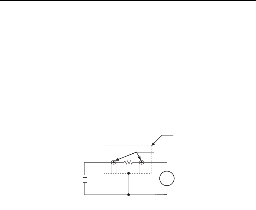
Model 6487 Reference Manual Applications Guide G-3
Another way to reduce leakage currents is to use guarding. A guard is a conductor con-
nected to a low impedance point in the circuit that is nearly at the same potential as the
high impedance lead (the sensitive node) being guarded. Guarding can isolate the high-
impedance input lead of the picoammeter from leakage current due to voltage sources.
Guarding may also be necessary to prevent leakage current due to test fixturing.
Figure G-1 shows a high-megohm resistor supported on two insulators mounted in a metal
test fixture. This circuit is guarded by connecting the LO of the picoammeter to the metal
case. This will put the top of the insulator support post on the right at almost the same
potential as the bottom. The voltage difference is equal to the voltage burden of the
picoammeter. Since the top and the bottom of the insulator are at nearly the same poten-
tial, no significant current will flow through it and nearly all the current from the device
under test will flow through the picoammeter.
Figure G-1
Guarding to reduce leakage currents
Input bias current
An ideal picoammeter would read 0A with an open input. In practice, however, ammeters
do have some current that flows when the input is open. This current is known as the input
bias (offset) current. It should be noted that this current emanates from points within the
ammeter and flows through the internal ammeter circuitry, but it does not flow through the
DUT. The input bias current for the Model 6487 is included in the offset portion of the
accuracy specification.
6487
V-Source
+
-
6487
Picoammeter
Metal
Shield
Measured
Current
HI
LO
HI
LO
Equivalent Circuit
DUT
Test Fixture
Insulators
A

G-4 Applications Guide Model 6487 Reference Manual
Voltage burden
The input resistance of the picoammeter causes a small voltage drop across the input ter-
minals. This voltage is known as the voltage burden. If the voltage burden is large in rela-
tion to the voltage of the measured circuit, then significant measurement errors will occur.
Refer to Figure G-2 to see how voltage burden affects current measurements. Assume VS
is 5mV and RS is 5kΩ to configure a 1μA current source (5mV/5kΩ = 1µA). An ideal
picoammeter with zero voltage burden would allow 1μA to flow and measure it
accurately.
In practice, however, every picoammeter has a voltage burden. If the voltage burden (VB)
is 1mV, the current that flows will be:
The 1mV voltage burden caused a 20% reduction in actual current. Percent error in a mea-
sured reading (IM) due to voltage burden can be calculated as follows:
The voltage burden of the Model 6487 depends on the selected range (see specifications).
Voltage burden may be reduced by performing the voltage offset correction procedure.
Voltage offset correction procedure
klqb To maintain specified operation, any time there is a substantial change in the
ambient temperature, the voltage offset procedure should be performed and
saved.
1. Press the MENU key to display the following:
CAL: VOFFSET
2. Press ENTER. The instrument will prompt as follows:
INPUT CAP
3. It is not necessary to disconnect signal cables from the Model 6487, but it is recom-
mended that signal currents be reduced to zero if possible. During the calibration,
the input impedance will be 3.5MΩ, therefore continued signal currents will
present a corresponding voltage to the DUT.
4. Press ENTER to complete offset voltage calibration.
5. Press EXIT to return to normal display.
klqb Like the other calibration procedures, this calibration is not permanently stored
until CAL:UNLOCK and CAL:SAVE have been performed. Saving the results of
this calibration at a temperature other than that at which the Model 6487 will be
used will adversely affect measurement results.
IM
VSVB
–
RS
-------------------- 5mV 1mV–
5kΩ
-------------------------------0.8μA== =
IM% error 100%
VS/VB
()
----------------------=
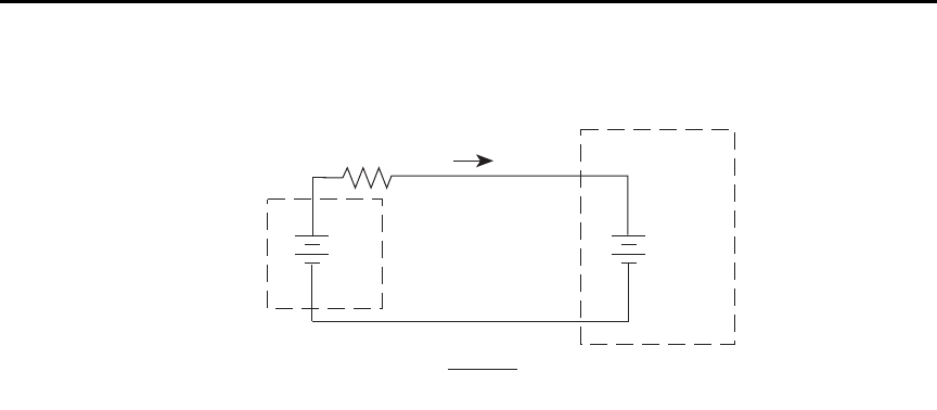
Model 6487 Reference Manual Applications Guide G-5
Figure G-2
Voltage burden considerations
Noise and source impedance
Noise can seriously affect sensitive current measurements. The following paragraphs dis-
cuss how source resistance and input capacitance affect noise performance.
Source resistance
The source resistance of the DUT will affect the noise performance of current measure-
ments. As the source resistance is reduced, the noise gain of the picoammeter will
increase, as we will now discuss.
Figure G-3 shows a simplified model of the feedback picoammeter. RS and CS represent
the source resistance and source capacitance, VS is the source voltage, and VNOISE is the
noise voltage. Finally, RF and CF are the feedback resistance and capacitance respectively.
The source noise gain of the circuit can be given by the following equation:
Note that as RS decreases in value, the output noise increases. For example, when RF = RS,
the input noise is multiplied by a factor of two. Since decreasing the source resistance can
have a detrimental effect on noise performance, there are usually minimum recommended
source resistance values based on measurement range. Table G-1 summarizes minimum
recommended source resistance values for various measurement ranges. Note that the rec-
ommended source resistance varies by measurement range because the RF value also
depends on the measurement range.
Rs
Vs
IM = RS
VS - VB
I
VB
(Voltage
Burden)
+
-
+
-
6487
V-Source
Model of 6487 Picoammeter
Input Characteristics Before
Voltage Offset Correction
Output VNOISE Input VNOISE 1R
F/RS
+()=
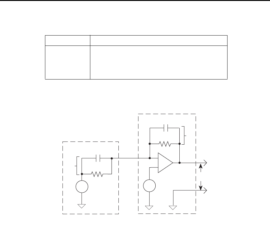
G-6 Applications Guide Model 6487 Reference Manual
Figure G-3
Simplified model of a feedback picoammeter
Source capacitance
DUT source capacitance will also affect the noise performance of the Model 6487 picoam-
meter. In general, as source capacitance increases, the noise also increases. To see how
changes in source capacitance can affect noise gain, again refer to the simplified picoam-
meter model in Figure G-3. The elements of interest for this discussion are the source
capacitance (CS) and the feedback capacitance (CF). Taking into account the capacitive
reactance of these two elements, the previous noise gain formula must be modified as
follows:
Table G- 1
Minimum recommended source resistance values
Range Minimum recommended source resistance
2nA, 20nA 1 MΩ to 1 GΩ
200nA, 2µA 10 kΩ to 10 MΩ
20µA, 200µA 100Ω to 100 kΩ
2mA, 20mA 10Ω to 1kΩ
RF
CF
-
+
Vnoise
RS
CS
VS
VO
ZF
ZS
6487
Picoammeter
Current
Source
Output VNOISE Input VNOISE 1Z
F/ZS
+()=

Model 6487 Reference Manual Applications Guide G-7
Here, ZF represents the feedback impedance made up of CF and RF
, while ZS is the source
impedance formed by RS and CS. Furthermore,
and,
Note that as CS increases in value, ZS decreases in value, thereby increasing the noise gain.
Again, at the point where ZS = ZF
, the input noise is amplified by a factor of two.
The maximum value of source capacitance (CS) for the lower ranges of the Model 6487
picoammeter is 10,000pF. You can, however, usually measure at higher source capacitance
values by inserting a resistor in series with the picoammeter input, but remember that any
series resistance will increase the voltage burden by IIN • RSERIES. For example, the range
of resistance listed in Table G-1 will result in voltage burden values in range of 2mV to
2V. A useful alternative to a series resistor is a series diode or two diodes in parallel
back-to-back. The diodes can be small-signal types and should be in a light-tight
enclosure.
Electrostatic interference and shielding
Electrostatic interference is probably the most common source of error when making low
current measurements. Electrostatic coupling or interference occurs when an electrically
charged object is brought near an uncharged object. At low impedance levels, the effect of
the interference are not noticeable because the charge dissipates rapidly. However, high
resistance materials do not allow the charge to decay quickly, which may result in unstable
measurements. The erroneous readings may be due to either DC or AC electrostatic fields,
so electrostatic shielding will help minimize the effects of these fields.
DC fields can produce noisy readings or undetected errors. These fields can be detected
when movement near an experiment (such as the movement of the person operating the
instrument or others in the immediate vicinity) causes fluctuations on the picoammeter's
display. To perform a quick check for interference, place a piece of charged plastic, such
as a comb, near the circuit. A large change in the meter reading indicates insufficient
shielding.
AC fields can be equally troublesome. These are caused most often by power lines and RF
fields. If the AC voltage at the input is large, part of this signal is rectified, producing an
error in the DC signal being measured. This can be checked by observing the analog out-
put of the picoammeter with an oscilloscope. A clipped waveform indicates a need to
improve electrostatic shielding.
ZF
RF
2πfRFCF
()
21+[]
-------------------------------------------------=
ZS
RS
2πfRSCS
()
21+[]
-------------------------------------------------=
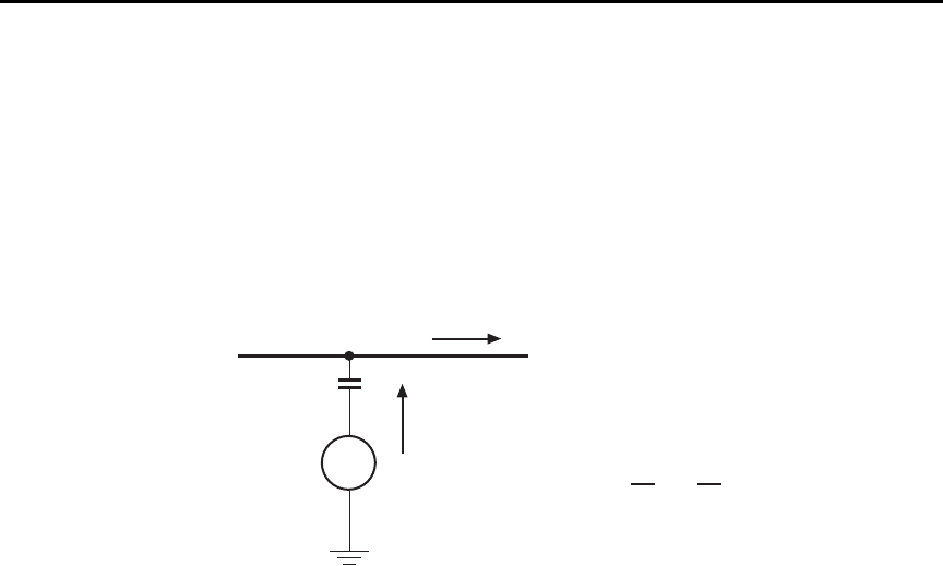
G-8 Applications Guide Model 6487 Reference Manual
Figure G-4 shows an example of AC electrostatic coupling. An electrostatic voltage
source in the vicinity of a conductor, such as a cable or trace on a PC board, generates a
current proportional to the rate of change of the voltage and of the coupling capacitance.
This current can be calculated with the following equation:
Figure G-4
Electrostatic coupling
For example, two conductors, each with lcm2 area and spaced lcm apart by air, will have
almost 0.1pF of capacitance. With a voltage difference of 100V and a vibration causing a
change of capacitance of 0.01pF/second (a 10% fluctuation), a current of 1pA will be
generated.
To reduce the effects of the fields, a shield can be built to enclose the circuit being mea-
sured. The easiest type of shield to make is a simple metal box or meshed screen that
encloses the test circuit. Shielded boxes are also available commercially.
Figure G-5 illustrates an example of shielding. Made from a conductive material, the
shield is always connected to the low impedance input of the electrometer or picoammeter.
If circuit low is floating above ground, observe special safety precautions to prevent any-
one from touching the shield, such as triaxial cable with the outer shield at earth potential.
iC
dV
d
------- VdC
dt
-------
+=
V
Coupling
capacitance
Electrostatic
voltage source
Ground-referenced
signal conductor
C
i
i = C + V
dV
dt
dC
dt
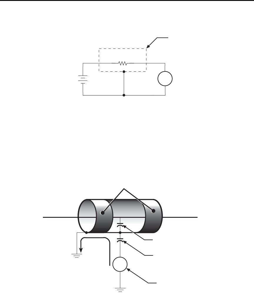
Model 6487 Reference Manual Applications Guide G-9
Figure G-5
Shielding a high impedance device
The cabling in the circuit also requires shielding. Capacitive coupling between an electro-
static noise source and the signal conductors or cables can be greatly reduced by surround-
ing those conductors with a grounded metal shield (Figure G-6). With this shield in place,
the noise current generated by the electrostatic voltage source and the coupling capaci-
tance flows through the shield to ground rather than through the signal conductors.
Figure G-6
Electrostatic shielding
A
+
-
6487
V-Source 6487
Picoammeter
Measured
Current
(I)
Metal
Shield
HI
LO
HI
LO
High Impedance
DUT
Equivalent Circuit
V
Noise
current
Shield
Shield-to-cable
capacitance
Source-to-shield
capacitance
Electrostatic
voltage source
Ground-referenced
signal conductor
Ground
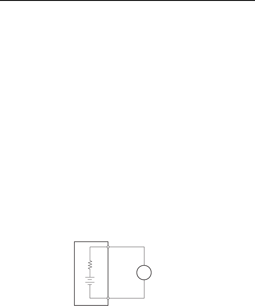
G-10 Applications Guide Model 6487 Reference Manual
To summarize, error currents due to electrostatic coupling can be minimized by following
these guidelines:
• Keep all charged objects (including people) and conductors away from sensitive
areas of the test circuit.
• Avoid movement and vibration near the test area.
• When measuring currents <10nA, shield the device under test by surrounding it
with a metal enclosure and connect the enclosure electrically to the test circuit
common terminal.
Shielding vs. Guarding
Shielding usually implies the use of a metallic enclosure to prevent electrostatic interfer-
ence from affecting a high impedance circuit. Guarding implies the use of an added low
impedance conductor, maintained at the same potential as the high impedance circuit,
which will intercept any interfering voltage or current. A guard does not necessarily pro-
vide shielding. (“Leakage currents and guarding,” page G-2.)
Making connections
To avoid measurement errors, it is critical to make proper connections from the picoam-
meter to the device under test. To make a proper connection, always connect the high
resistance terminal of the meter to the highest resistance point of the circuit under
test.
Figure G-7 shows a picoammeter connected to a current source that consists of a voltage
source in series with a resistor. An AC powered voltage source usually has a significant
level (often several volts) of line frequency common mode voltage.
Figure G-7
Connecting the HI terminal (picoammeter) to high resistance
+
-
6487
Picoammeter
Current Source
RHI
LO
A
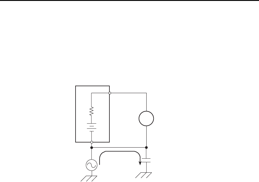
Model 6487 Reference Manual Applications Guide G-11
As shown in Figure G-8, this will cause a current (i) to flow through the low to ground
capacitance of the picoammeter (A). Picoammeter HI is connected to the higher resistance
side of the circuit being measured, the “R” side of this current source. This circuit is con-
nected properly, so this current does not flow through the picoammeter and, therefore,
does not cause any measurement errors.
Figure G-8
Proper connection
However, when the HI of the picoammeter is connected to the low impedance side of the
DUT, this AC current (i) flows through the picoammeter (A) as illustrated in Figure G-9.
This current may affect the measurement accuracy, especially at low signal levels.
Current Source
6487
Picoammeter
+
-
i
HI
LO
R
A
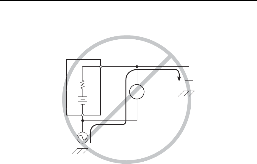
G-12 Applications Guide Model 6487 Reference Manual
Figure G-9
Improper connection
Refer to “Connection fundamentals,” page 2-2 for details on appropriate types of cabling
and connectors to use when making picoammeter measurements.
Typical range change transients
During a range change, a picoammeter cannot perfectly maintain its voltage burden speci-
fication. When a range change occurs, the picoammeter will momentarily become a
current-limited voltage source (Figure G-10).
Current Source
6487
Picoammeter
+
-i
HI
LO
R
A
Current Source
6487
Picoammeter
+
-i
HI
LO
R
A
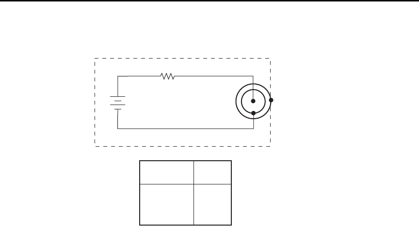
Model 6487 Reference Manual Applications Guide G-13
Figure G-10
Range change voltage transients
klqb The current that can be inadvertently delivered to the DUT is limited by an
internal resistance. This internal resistance varies as the range is changed. For
example, manually up-ranging from 2
μ
A to the 20
μ
A range can never deliver
more than 10V/50k
Ω
= 200
μ
A to the DUT. This current will be further limited
by any impedance of the DUT.
+
-
6487
Picoammeter
HI
LO
R
V Transient
F
Range being
changed to:
2mA, 20mA
20μA, 200μA
200nA, 2μA
2nA, 20nA
RF
500Ω
50kΩ
5MΩ
500MΩ
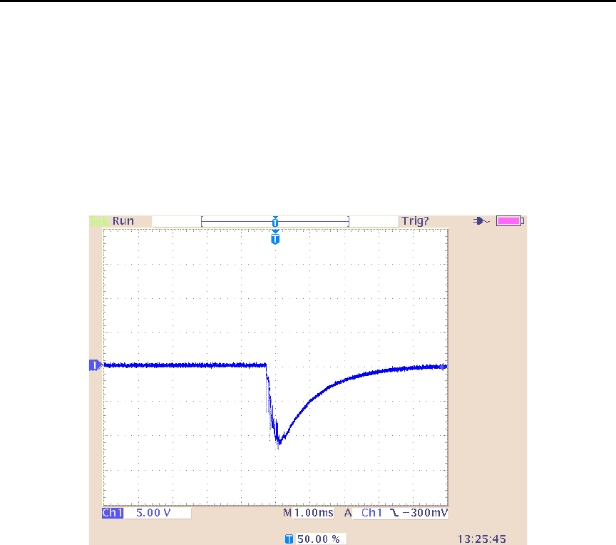
G-14 Applications Guide Model 6487 Reference Manual
Up-range input response
Figure G-11 illustrates the type of transient voltage that can be expected when up-ranging
with a full-scale input signal (200μA signal on 200μA range, up-range to 2mA range).
Both the magnitude and duration of this voltage are reduced for lower current ranges. The
current limit imposed by the RF is also greatly reduced. The polarity depends on the polar-
ity of the input current. Figure G-11 was measured with a positive input current.
Figure G-11
Transient Voltage
When it is necessary to up-range during auto-ranging operation, multiple ranges may be
crossed to find the correct range. The duration of the transient in Figure G-11 can be
extended in this case, but the magnitude will not increase significantly.
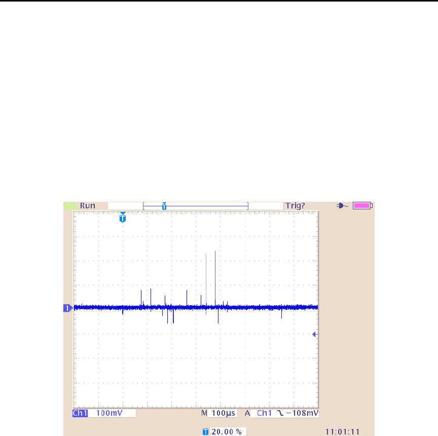
Model 6487 Reference Manual Applications Guide G-15
Down-range voltage transients are smaller
With the exception of the change from the 2mA range to the 200μA range, the down-range
voltage transient is significantly smaller than the up-range transients. Figure G-12 shows
the voltage presented at the input, measured during a change from 20μA to 2μA with a
2μA input current. The vast difference from the previous figures in voltage scale and time
scale should be noted. Note also that the current limiting resistor will be that of the 2μA
range, 100 times greater than upranging across the same boundary. The voltage transient
of the 2mA to 200μA change with a 200μA input signal is similar to the up-range
response, with the exception that the current limiting R will be 100 times greater in the
case of down-ranging.
Figure G-12
Down-range voltage transients

G-16 Applications Guide Model 6487 Reference Manual
Steps to minimize impact of range change transients
When changing between the following range pairs (up or down), no input transients occur:
2nA and 20nA, 200nA and 2μA, 20μA and 200μA, 2mA and 20mA. This is not true when
auto-ranging upwards across these boundaries.
Run test with a fixed range
If possible, run the test within a fixed range. Choose the higher range from any of the
range pairs listed above. Alternatively, the autorange upper limit
(:RANGe:AUTO:ULIMit, see “Noise and safety shields” or “Autorange limits” in the
6487 User’s Manual) can be set so that the internal limiting resistor (RF) cannot be
reduced to the lower values. Choose the appropriate range to accommodate the maximum
current expected during normal measurements.
Down-range by starting at highest current necessary
Make use of down-ranging by starting at the highest current necessary and reducing down
to zero, the range change transients can be reduced significantly compared to up-ranging
transients.
Using protection circuitry
Using protection circuitry can greatly reduce currents and voltages presented to devices
being tested, as well as serving to protect the Model 6487 from any externally generated
transients. If using the scheme from “Noise and safety shields” in the 6487 User’s Manual,
size the external current limiting resistor such that the sum of the external resistor and the
lowest RF will limit a 10V transient to a current level acceptable to the DUT.
Reduce up-ranging transient
If the application requires that up-ranging be used, and when the transient through the
internal limiting resistor RF would damage the DUT, the up-ranging transient can be
reduced greatly by reducing the input current to <10% of the present range before forcing
the range change up (manual or fixed-ranging over the bus). This can be true when running
the first I-V curve on devices whose characteristics are not yet known, so that sweeping
from low current towards high current is the only way to avoid exceeding a maximum cur-
rent through the device.
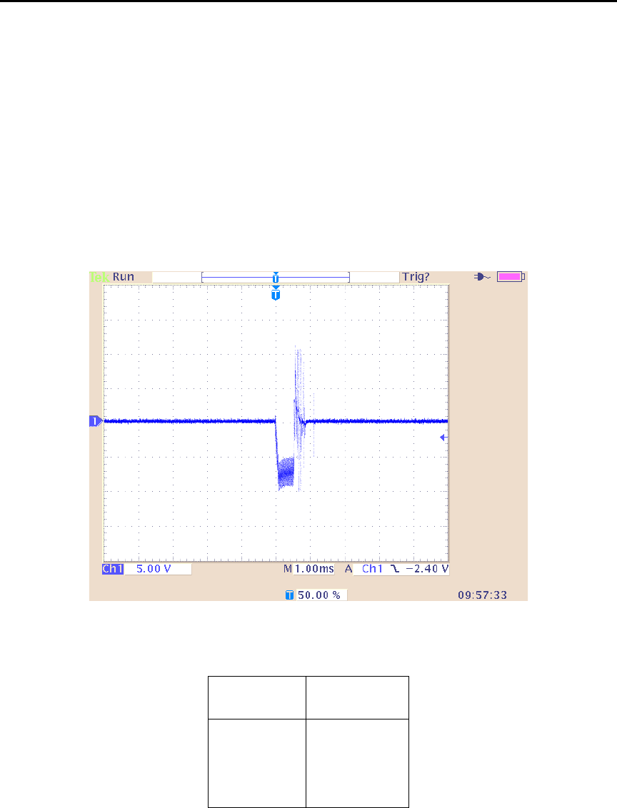
Model 6487 Reference Manual Applications Guide G-17
Zero check on / off response
Figure G-13 shows the transient that can be expected from input HI to LO during a change
in the zero check mode with no input current. The transition is similar for entering and
leaving zero check. For current ranges 2μA and below, the magnitude of the response is
not as large, but similar in duration. As with range change transients, the zero check tran-
sient is presented through an internal impedance which will limit the resulting current
through the DUT (Table G-2). If there is an input current while in zero check, the input
voltage will depend on the current and the zero check input impedance for the specific
range.
Figure G-13
Zero check transient
Table G- 2
Internal impedance for zero check transient
Range Zcheck Transient
impedance
2mA,20mA 500Ω
20μA,200μA 50kΩ
200nA,2μA3.5MΩ
2nA,20nA 11MΩ
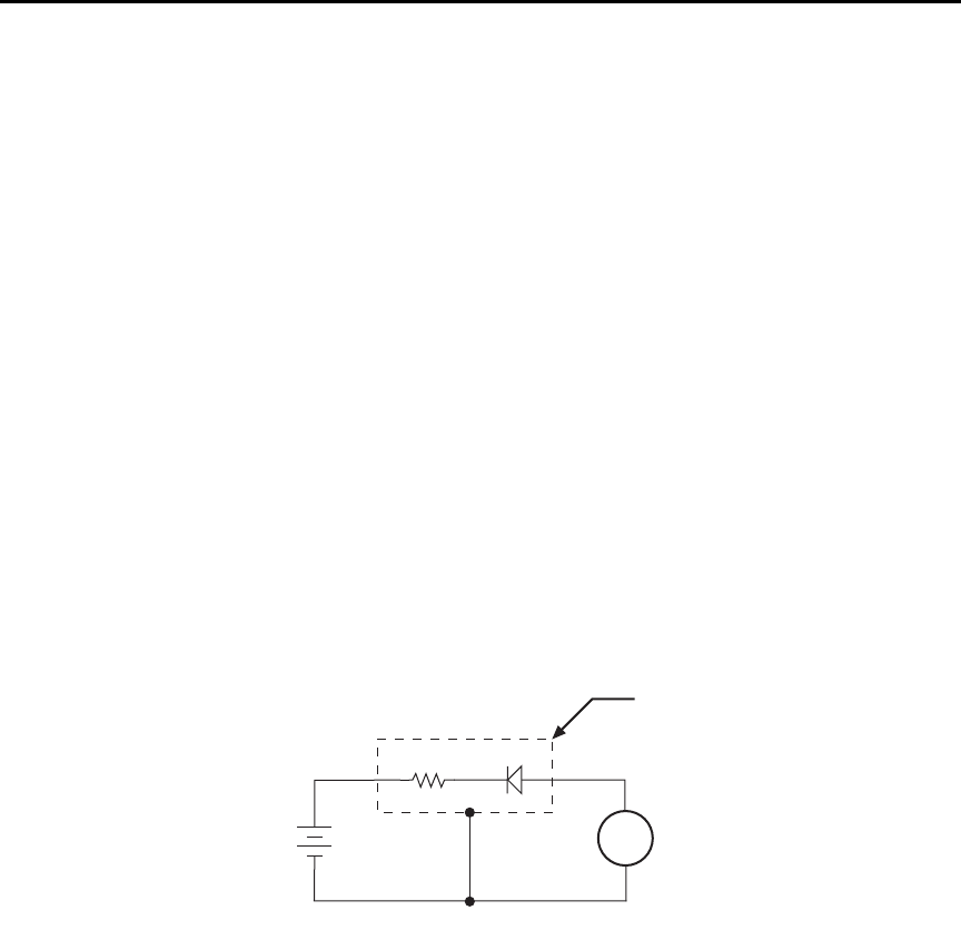
G-18 Applications Guide Model 6487 Reference Manual
Applications
Diode leakage current
Figure G-14 shows how to measure the leakage current for a diode. By sourcing a positive
voltage, the leakage current through the diode will be measured. Note that if you source a
negative voltage, you will forward bias the diode. Resistor R is used to limit current in the
event that the diode shorts out or it becomes forward biased. Select a value of R that will
limit current to 20mA or less.
A profile for leakage current can be developed by measuring current at various voltage
levels. For example, program the voltage source to sweep voltage from 1 to 10V in 1V
steps. The Model 6487 performs a current measurement on each voltage step. To ensure
that the voltage is settled before each current measurement, you can program the
Model 6487 for a delay. For example, if you program the Model 6487 for a one second
delay, each measurement will be performed after the voltage step is allowed to settle for
one second. The current measurements are stored in the buffer.
klqb Buffer and voltage sweep operation are covered in Section 6.
Figure G-14
Connections; diode leakage current test
klqb The details on “Typical range change transients,” page G-12 may be particu-
larly relevant to this application
A
+
-
6487
V-Source 6487
Picoammeter
Metal
Shield
HI
LO
HI
LO
RDiode
Equivalent Circuit
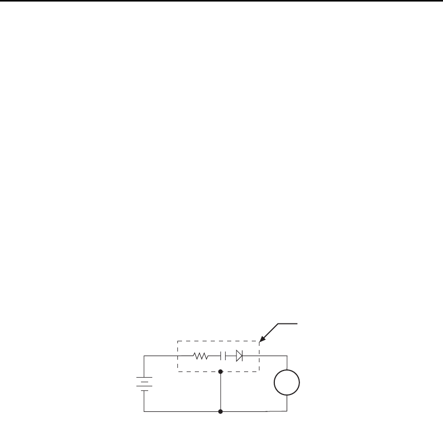
Model 6487 Reference Manual Applications Guide G-19
Capacitor leakage current
Figure G-15 shows how to measure the leakage current for a capacitor. The magnitude of
the leakage is dependent on the type of dielectric and the applied voltage.
A resistor and a diode are used to limit noise for the measurement. The resistor limits the
current in case the capacitor becomes shorted, and it also offsets the effects of decreasing
capacitive reactance with increasing frequency, which affects picoammeter noise perfor-
mance (see “Source capacitance,” page G-6). A good starting point is to choose a resis-
tance value that results in an RC time constant of 0.5 to 2 seconds. (See Table G-1 for
minimum recommended resistance values based on measurement range.) The diode acts
like a variable resistance, low while the capacitor is charging, and much higher when the
capacitor is fully charged. As a result, the resistance value can be significantly smaller.
Also damping may help to reduce noise (see “Damping,” page 4-8).
For this test, a fixed bias voltage is to be applied to the capacitor for a specified time to
allow the capacitor to fully charge (current decays exponentially with time). The leakage
current is then measured. After the measurement, the voltage source is set to output 0V for
a specified time to allow the capacitor to discharge. Note that measurements with the volt-
age source in the high-impedance state (from interlock opening) might have high noise
pickup caused by an unshielded voltage source HI terminal.
Figure G-15
Connections; capacitor leakage current test
Measuring high resistance
The Model 6487 can be used to make high resistance (>1GΩ) measurements using the
built-in voltage source. The alternating voltage ohms mode (Section 3) can be used to
improve accuracy and repeatability of very high resistance measurements. High resistance
measurement applications include insulation resistance testing and resistivity measure-
ments of insulators.
6487
V-Source A
+
-
6487
Picoammeter
Metal
Shield
HI
LO
HI
LO
Equivalent Circuit
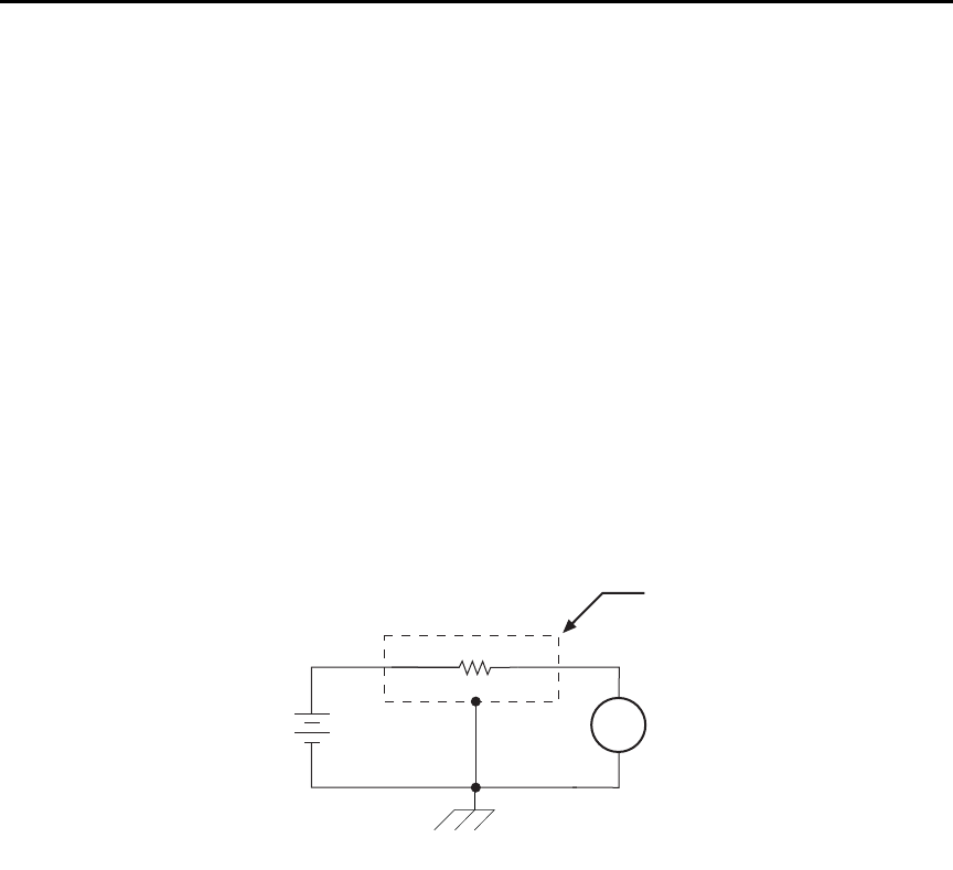
G-20 Applications Guide Model 6487 Reference Manual
To measure high resistance, the internal voltage source is placed in series with the
unknown resistance and the picoammeter. Since the voltage drop across the picoammeter
is negligible, essentially all the voltage appears across the unknown resistance. The result-
ing current is measured by the picoammeter. The resistance is then calculated and dis-
played using Ohm's Law:
where: V is the sourced test voltage
I is the measured current
The basic configuration for measuring high resistance using the Model 6487 Picoammeter
is shown in Figure G-16. The HI terminal of the Model 6487 picoammeter is connected to
one end of the unknown resistance (R) and the HI terminal of the internal voltage source to
the other end of the resistance. The LO terminal of the picoammeter is connected to the
LO terminal of the voltage source. Both LO terminals are also connected to earth ground.
This should be done via the ground link on the rear of the Model 6487.
Figure G-16
Measuring high resistance using the 6487
To prevent generated current due to electrostatic interference, place the unknown resis-
tance in a shielded test fixture. The metal shield is connected to the LO terminal of the
6487.
Alternating voltage ohms measurement
To reduce measurement errors caused by background currents, use the alternating voltage
ohms measurement mode. The step voltage and time for each phase should be carefully
chosen to assure proper circuit settling, while the averaging a number of reading cycles
will improve repeatability. See “Alternating voltage ohms mode,” page 3-21 in Section 3
for details.
RV
I
----=
6487
V-Source
(V) A
+
-
6487
Picoammeter
Unknown Resistance
(R)
Measured
Current
Metal
Shield
HI
LO
HI
LO
Equivalent Circuit
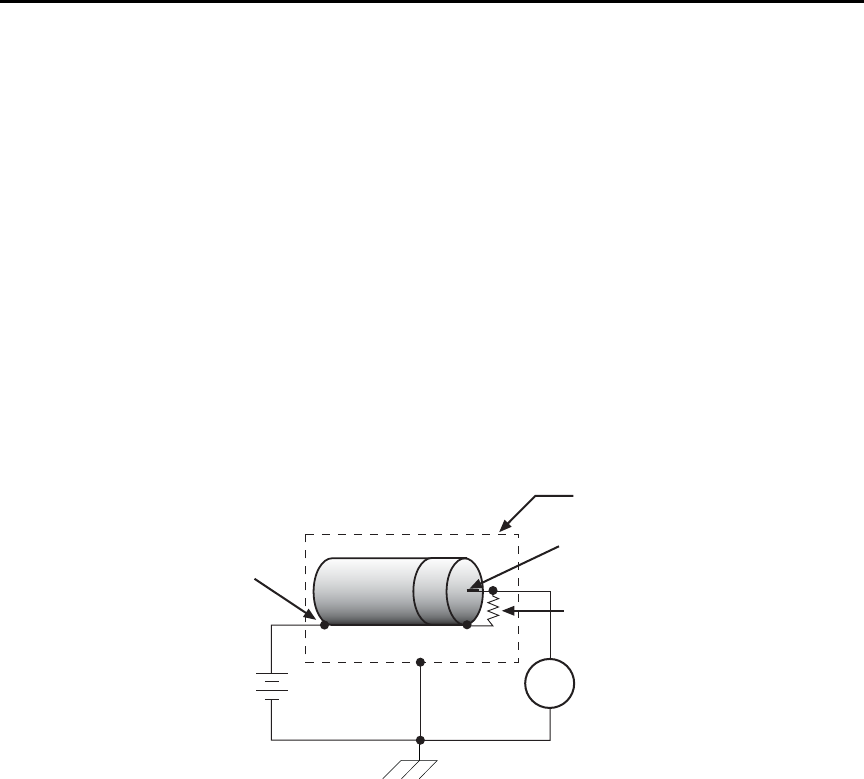
Model 6487 Reference Manual Applications Guide G-21
Cable insulation resistance
Figure G-17 shows how to measure the insulation resistance of a cable. The resistance of
the insulator between the shield and the inner conductor is being measured. The cable
sample should be kept as short as possible to minimize input capacitance to the
picoammeter.
For this test, a fixed bias voltage is applied across the insulator for a specified time to allow
the charging effects of cable capacitance to stabilize. The current is then measured. Cable
resistance (R) can then be calculated as follows:
where: V is the sourced bias voltage
I is the measured current
Figure G-17
Connections; cable insulation resistance test
RV
I
----=
6487
V-Source
(V) A
+
-
6487
Picoammeter
Equivalent Cable
Resistance (R)
Measured
Current
Metal
Shield
Center Conductor
Cable
Shield
HI
LO
HI
LO
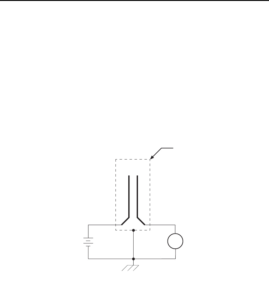
G-22 Applications Guide Model 6487 Reference Manual
Surface insulation resistance (SIR)
Figure G-18 shows how to measure the insulation resistance between PC board traces.
Note that the drawing shows a “Y” test pattern for the measurement. This is a typical test
pattern for SIR tests.
A bias voltage (typically 50V) is applied to the test pattern for a specified time (typically
one second) to polarize the test pattern. The test voltage (typically 100V) is then applied
and, after a specified time (typically one second), the Model 6487 measures the current.
Surface insulation resistance can now be calculated as follows:
where: V is the sourced test voltage
I is the measured current
Figure G-18
Connections; surface insulation resistance test
SIR V
I
----=
A
+
-
HI
LO
HI
LO
PC Board
Test Pattern
6487
V-Source
(V)
6487
Picoammeter
Measured
Current
(I)
Metal
Shield
Equivalent Circuit
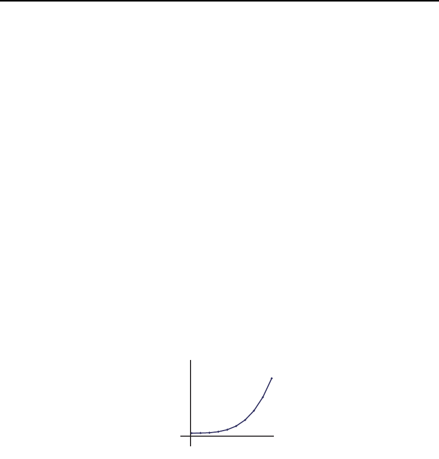
Model 6487 Reference Manual Applications Guide G-23
Photodiode characterization prior to dicing
The Model 6487 can be used as part of a cost-effective semiconductor photodiode leakage
test system. This test characterizes the photo current under various illumination
conditions.
In addition to the Model 6487, specialized equipment is required. This equipment includes
a calibrated optical source in addition to semiconductor equipment (probe card or needle
mounts, etc.). Several Model 6487s can be connected to probe pads to provide leakage
current readings forced by the bias voltage source. As an alternative, one or more
Model 6487s could be switched through a switching mainframe and matrix switch card
arrangement to take current measurements from multiple pads.
Measuring photodiode leakage can be described in two steps:
1. Vsweep, Imeas in total darkness.
2. Vbias, Imeas in calibrated optical flux.
In the 1st step, voltage sweeps and the resulting current leakage is measured (see “Voltage
sweeps,” page 6-8). Then, a bias voltage is applied and resulting current leakage is mea-
sured while light is incrementally increased in calibrated steps. The results produce a
graph similar to Figure G-19.
Figure G-19
General photodiode leakage
I
V
0
General photodiode
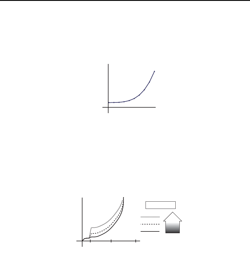
G-24 Applications Guide Model 6487 Reference Manual
P.I.N. (Positive Intrinsic Negative) diodes respond as shown in Figure G-20.
Figure G-20
PIN photodiode leakage
In total darkness, Avalanche diodes respond as shown by the solid line in Figure G-21.
Notice the small irregularity of the curve while sweeping around 10-12V. This irregularity
is made larger under additional applied light (see dashed lines of Figure G-21).
Figure G-21
Avalanche photodiode leakage
I
V
05
P.I.N. photodiode
I
V
0
Avalanche photodiode
10 50 100
LEGEND
More
Light
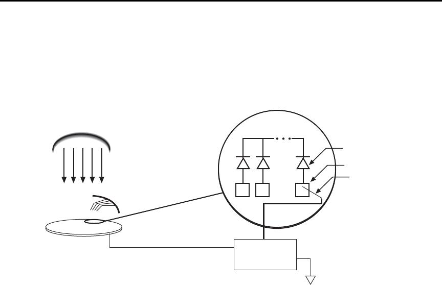
Model 6487 Reference Manual Applications Guide G-25
Connections are made to the Model 6487 through the triax input connector (located on the
rear panel) (Figure G-22) as well as the voltage source output terminals to provide the nec-
essary bias voltage.
Figure G-22
Basic connection scheme
klqb The details on “Typical range change transients,” page G-12 may be particu-
larly relevant to this application
Focused ion beam applications
Focused Ion Beam (FIB) systems have been developed to perform nanometer-scale imag-
ing, micro machining, and mapping in the semiconductor industry. Typical applications
include mask repair, circuit modification, defect analysis, and sample preparation of site-
specific locations on integrated circuits.
FIB systems use a finely focused ion beam for imaging or for site specific sputtering or
milling. The magnitude of the beam current determines what type of operation is per-
formed. A low beam current results in very little material being sputtered and is, therefore,
ideal for imaging applications. Utilization of high beam currents resulting in a great deal
of material being removed by sputtering, and is subsequently well suited for precision
milling operations.
Therefore, whether the application calls for imaging or a complete circuit modification,
monitoring and control of the beam current is critical to the success of the process. The ion
beam current cannot be measured directly, but requires the use of an ion detector. There
are several detectors commonly used throughout the industry including Channeltron®,
Daly, Microchannel plate, and the Faraday cup. The Faraday cup can only be used in an
analog mode and is, therefore, not as sensitive as newer current pulse devices.
Calibrated Light Source
Wafer
Probe Needles
Model 6487
Pads
Probe Needles
Photodiode
Bias Voltage
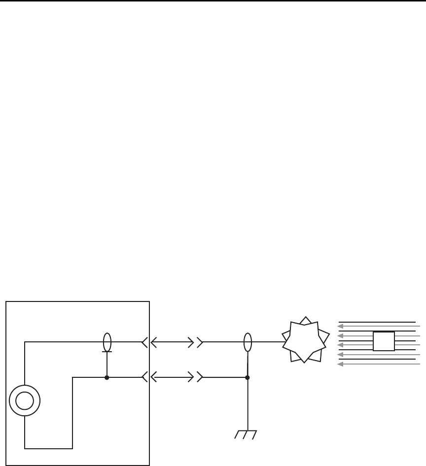
G-26 Applications Guide Model 6487 Reference Manual
The function of the detector is to develop a secondary current proportional to the current
of the primary ion beam, without interfering with the primary beam. The basic operation
of most detectors is similar; an ion from the primary beam strikes the detector and a sec-
ondary ion is generated, isolated from the primary ion stream. This current is then mea-
sured and used to control the intensity of the beam.
The secondary currents generated by the detectors are very low and require a high degree
of accuracy and measurement repeatability. Currents as low as 5 or 6pA are not uncom-
mon; therefore, the measurement device must be capable of achieving resolutions below
1pA.
The Model 6487 is ideal for this application because it offers a wide selection of range set-
tings spanning from 20mA to 2nA. This will result in 5-1/2 digit resolution ranging from
100nA to 10fA. Numerous ranges, and fine measurement granularity, will meet all cur-
rent requirements for this application, as well as provide additional sensitivity for future
development needs.
Signal connections to the picoammeter are made using the triax connector mounted on the
rear panel. If the source on the ions is biased off ground, then the ion detector will most
likely be at ground potential. A simple coaxial vacuum feedthrough can be used to make
the connection between the detector and the picoammeter (Figure G-23).
Figure G-23
Focused Ion Beam signal connections
Using switching systems to measure multiple current sources
Refer to “External trigger example,” page 7-13.
6487
Picoammeter
Ion
Detector Ion
Beam
Im
Coaxial Vacuum
Feedthrough

Index
VOFFset F-2
Symbols
“Selecting and configuring an interface,” page
8-2 9-7
A
acquire method to zero correct 3-7
Additional references 1-4
Address commands D-10
Addressed multiline commands D-10
Alternating G-20
analog 2-15
Applications Guide G-1
ARM layer 7-8
configuration menu 8-17
Autoranging 4-2
limits 4-3
Autozero 3-3
autozero 3-25
Avalanche photo diode leakage G-24
avoiding measurement errors G-10
B
Baseline Suppression (Rel) C-9
Basic 2-4, 2-5, 2-6, 3-2
connection scheme G-25
connections to DUT 2-4
Baud rate 9-16
Binning 8-5
Buffer 3-26, 6-1, 6-10
Size C-4
Bus
description D-3
management lines D-5
C
CAL
VOFFSET 3-3, 15-7
CALCulate command summary 14-2
Calibration 16-1, 16-3, 16-4, 16-5, 16-7, F-2
Displaying count 16-15
Displaying dates 16-15
Resetting code 16-15
SCPI commands F-2
Calibration commands F-2
Calibration considerations 16-3
Calibration cycle 16-3
Calibration errors 16-4
Calibration menu 16-5
Calibrator 15-4, 16-4
Calibrator voltage calculations 15-5
Capacitor leakage current G-19
Case sensitivity 9-12
Category 8-8, 8-9
Changing the calibration code 16-14
cleaning
test fixtures 2-10
tips 2-10
Clearing registers and queues 10-4
Command 3-27, 6-11
codes D-9, D-11
execution rules 9-15
path rules 9-14
words 9-10
Common 11-1
Common Commands 11-2, D-11
Compliance 3-18
Component 8-7, 8-8
Condition registers 10-15
CONFIG/LOCAL key 9-10
Configuration 1-13
Connections 2-1, 2-4, 2-5, 2-6
fundamentals 2-2
Connections for 20mA to 20mA range
calibration 16-9
Connections for 20mA to 20mA range
verification 15-8, 15-10
Connections for 2nA to 2mA range calibration
16-11, 16-13
Connections for 2nA to 2mA range verification
15-11
Connectors 2-10
Contact information 1-3
control sources 7-5
Controlling 8-13
Counters 7-7
coupling, electrostatic G-7, G-8
Current 3-2, 3-7, F-4
Current calculations 16-6
Current calibration 16-8
Current measurement accuracy 15-7
currently detected frequency 1-6
D
Data
and stop bits 9-17
Format C-3
Data lines D-5
Data Store (Buffer) C-6
DC current calibrator 15-8, 15-10
DCL (device clear) 9-8
DDC C-1

DDC language 9-2, C-2
Default 1-10
Default settings 1-8
detected line frequency 1-7
Device C-2
Digital 4-10, 8-8, 8-10, 8-11, 8-12
Calibration C-8
filter 4-10, C-6
filter control 4-11
digital board revision levels 11-3
Digits 4-4, C-4
DISP test 17-4
display board revision levels 11-3
DISPlay command summary 14-6
display on or off 13-2
DISPlay subsystem 13-2
DISPlay, FORMat, and SYSTem 13-1
Displaying Rel 5-3
E
Electrometer Calibration 15-4
Electrostatic interference G-7
Enable register 10-2, 10-5
Enable registers 10-4, 10-5
engineering 4-3
Entering calibration dates 16-13
Environmental conditions 15-2
EOI and Bus Hold-off C-5
Equipment 16-3
Error
and status messages 9-9, B-2
queue 10-19
Errors 16-4
Event detectors 7-5
Event enable registers 10-16
Event registers 10-16
Example reading limits calculation 15-5
Execute C-8
External trigger example 7-13
External triggering 7-12
F
Features 1-5
Filtering 3-25
Filters 4-8
firmware revision level 1-7, 11-3
Floating 2-12
Floating measurements 2-12
Flow control, RS-232 (signal handshaking)
9-17
Focused ion beam applications G-25
Focused Ion Beam signal connections G-26
FORMat command summary 14-7
FORMat subsystem 13-4
Front 1-8
Front and rear panel 1-5
Front panel GPIB operation 9-9
Front panel tests 17-3
G
General 2-9
General IEEE-488 bus commands 9-7
General photo diode leakage G-23
GET (group execute trigger) 9-8
GPIB
Protocol selection E-4
GPIB 488.1 Protocol E-3
GPIB interface 9-2, 9-3
GPIB status indicators 9-9
GTL (go to local) 9-8
Guard plate 2-10
Guarding to reduce leakage currents G-3
H
Handler 8-7
Handling 1-4
Handling tips 2-10
Handshake lines D-5
I
identification query 11-3
Idle and initiate 7-4
IEEE
command groups D-13
IEEE-488
bus command summary D-7
bus configuration D-4
Bus Overview D-1
connector 9-4
documentation requirements E-2
SCPI Conformance Information E-1
IEEE-488 handshake sequence D-6
IEEE-488.2 common commands and queries
11-2
IFC (interface clear) 9-8
Input
connector 2-2
trigger requirements 7-12
Input bias current G-3
Inspection 1-3
Instruction Manual 1-4
Interface
available 9-2
configuration 9-3
function codes D-14
selection 9-3

Interlock 2-13, 2-14
internal wiring 2-10
K
Keithley 237-BNC-TRX 15-4, 16-4
Keithley 4801 15-4
Keithley CAP-18 15-4, 16-4
Keithley Model 5156 15-4, 16-4
KEY test 17-4
L
Languages 9-2
Leakage currents and guarding G-2
Limit test configuration 8-16
Limit Tests 8-1
Limits configuration menu 8-16
Line 8-9
Line frequency 1-6
Line fuse location 17-3
Line fuse ratings 17-2
Line power connection 1-5
LLO (local lockout) 9-8
Locking out calibration 16-14
LOG C-3
Logarithmic 5-6
Long-form and short-form versions 9-12
Low noise input cables 2-3
M
Main 1-12
Making connections G-10
management lines, bus D-5
Manual ranging 4-2
manually keying in REL 5-3
Maximum 2-3
Maximum input levels 2-3
MEAN 6-7
Measure action 7-7
Measurement 3-2
measurement 2-16
Measurement considerations 2-14, G-2
measurement errors, avoiding G-10
Measurement event status 10-13
Measurement overview 2-2
Measurement ranges 4-2
Measurements 3-1
Measuring High Resistance Using the 6487
G-20
Measuring high resistance with external bias
source G-19
Median filter 4-9
Menu 1-12, 16-5
Model 6487 interface function codes D-14
Multiple command messages 9-14
Multiple response messages 9-15
mX 5-5
mX+b, m/X+b (reciprocal), and Logarithmic
5-5
N
NAND 8-14
Noise G-5
Noise and safety shields 2-8
Noise and source impedance G-5
noisy readings G-7
NPLC Menu 4-7
O
Offset voltage calibration 15-7, 16-7
Ohms 3-11
OPER 3-18
Operating 3-25, 6-10
operating at a higher speed 13-2
Operation 8-6
consideration 4-11
event status 10-12
Optional command words 1-14
Output queue 10-18
Output trigger specifications 7-13
Output triggers 7-7
Overview of this manual 1-2
P
Package 1-4
Parity, RS-232 9-17
peak-to-peak 6-7
Performance 3-3
Performance verification 15-1
Performing 8-17
Phone number 1-3
Photodiode characterization prior to dicing
G-23
PIN photo diode leakage G-24
PKPK 6-7
polling sequence C-12
Pomona 1269 15-4, 16-4
Power-up 1-5
Power-up sequence 1-7
Primary address 9-6
Procedure 16-7
Program Message Terminator (PMT) 9-15
Program messages 9-13
Programming enable registers 10-5
Q
Query commands 1-14, 9-12

Questionable event status 10-14
Queues 10-17
R
Range 3-25, C-6
and values 4-5
symbols for rel values 5-3
Units, Digits, Rate, and Filters 4-1
range change transients G-12
Rate 3-25, 4-6
RATE Key 4-6
Reading limits for 20mA to 20mA ranges 15-8,
15-11
Reading limits for 2nA to 2mA ranges 15-9
Reading Mode C-2
Reading registers 10-6
Rear panel 1-5
Recall 6-2
Recalling 6-10
reciprocal 5-5
Recommended test equipment 15-3
Register bit descriptions 10-10
Registers
Bit descriptions 10-10
Condition 10-15
Enable registers 10-4, 10-5
Event 10-16
Reading 10-6
reinstate the previous Rel 5-2
REL 5-2
Relative, mX+b, m/X+b (Reciprocal), and Log
5-1
Remote 9-1
Remote calibration F-1
Remote setup operation 1-9
REN (remote enable) 9-7
resistivity 2-11
Response 9-15
Message Terminator (RMT) 9-16
time 4-11
restore setup 1-9
Routine maintenance 17-1
RS-232
connections 9-18
RS-232 interface 9-2, 9-3, 9-16
RS-232 settings 9-16
S
safety shield 3-9, 3-12, 3-17
Safety symbols and terms 1-3
Saving calibration 16-13
scientific (SCI) 4-3
SCPI 3-14, 3-19, 3-28, 8-15
SCPI commands D-11
amps function 3-10, 3-14
autozero 3-4
buffer 6-5, 6-13
reset registers and clear queues 10-4
system 13-9
triggering 7-10
SCPI errors, eliminating B-7
SCPI language 9-2
SCPI programming
filters 4-12
line frequency 1-6
mX+b, m/X+b, and log 5-7
range and digits 4-4
rate 4-7
relative 5-4
zero check and zero correct 3-6
SCPI Reference Tables 14-1
SCPI Signal Oriented Measurement Commands
12-1
SDC (selective device clear) 9-8
SDEViation 6-7
select power-on setup 1-9
Sending a response message 9-15
Sending and receiving data, RS-232 9-16
SENSe 14-7
SENSe command summary 14-10
serial number 1-12, 11-3
Serial polling and SRQ 10-9
Service request enable register 10-8
Setting 8-14
Setting and controlling relative 5-2
Setting line voltage and replacing line fuse 17-2
Shielding 2-8
shielding G-7, G-8
Shielding vs. Guarding G-10
Short-form rules 9-12
Single command messages 9-13
Sink 8-12
Source 6-11, 8-14
Source capacitance G-6
source impedance G-5
Source resistance G-5
Source Resistance (minimum recommended)
G-6
Sourcing 3-16
SPE, SPD (serial polling) 9-9, 10-9
SPE, SPD polling sequence C-12
Specifications A-1
Speed vs. noise characteristics 4-6
SRQ 10-7, C-5, E-8
Standard event status 10-10
Start 8-7
statistics 6-4

Status 1-8, C-11
Status and Error Messages B-1
Status byte
and mask interpretation C-14
and service request (SRQ) 10-7
format C-12
Status byte format C-14
Status byte register 10-7
STATus command summary 14-13
Status register sets 10-10
Status Structure 10-1
Status Word C-8
STD DEV 6-4
Store 6-2
Store Calibration C-5
Storing A-V ohms readings 3-23
Support 16-14
Sweep 6-10, 6-11
Sweeps 6-1
sweeps 6-8
Sweeps or A-V ohms in DDC mode C-10
SYSTem command summary 14-15
T
terminals 2-10
Terminator 9-17
Test 2-9
Test fixture 2-8
Test limit display messages 8-3
tests
front panel 17-3
timestamps 6-3
TRACe command summary 14-17
Triax 2-2
Trigger 7-5
TRIGger command summary 14-18
Trigger delay 7-6
Trigger Mode C-7
Trigger model
configuration 7-8
menu structure 7-8
Triggering 7-1
Typical addressed command sequence D-12
Typical bus sequence D-12
Typical command sequences D-12
U
U0 Status word C-11
U1 Status word C-12
U2 Status word C-12
Unaddress commands D-10
undetected errors G-7
Uniline commands D-9
Units 4-3
Universal multiline commands D-9
Unpacking 1-3
user setup 1-9
Using common commands and SCPI commands
in the same message 9-14
V
Verification limits 15-5
Verification test procedures 15-6
Verification test requirements 15-2
VOFFSET 16-6
Voltage 2-2, 2-4, 3-2, 3-3, 3-15, 3-18, F-5
Voltage burden G-4
Voltage source edit keys 3-15
voltage transients G-13
W
Warm-up period 3-3
Warranty information 1-3
Z
Zero 3-4, 3-5
Zero Check C-3

Specifications are subject to change without notice.
All Keithley trademarks and trade names are the property of Keithley Instruments, Inc.
All other trademarks and trade names are the property of their respective companies.
A GREATER MEASURE OF CONFIDENCE
Keithley Instruments, Inc.
Corporate Headquarters • 28775 Aurora Road • Cleveland, Ohio 44139 • 440-248-0400 • Fax: 440-248-6168 • 1-888-KEITHLEY • www.keithley.com
12/06
7.5X9BackCovr 12-06.qxd 1/10/07 2:45 PM Page 1
