Keysight DSAV334A Infiniium V Series Oscilloscope 33 GHz 4 Analog Channels Datasheet
User Manual: Keysight-DSAV334A-Infiniium-V-Series-Oscilloscope-33-GHz-4-Analog-Channels-datasheet
Open the PDF directly: View PDF ![]() .
.
Page Count: 47
Keysight Technologies
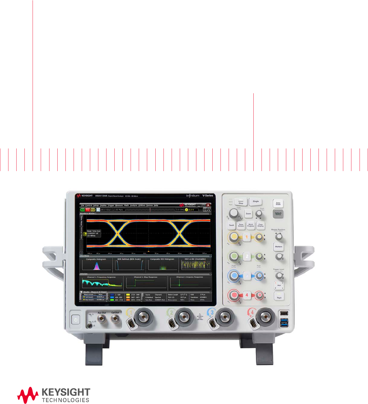
Infiniium V-Series Oscilloscopes
8 to 33 GHz
Data Sheet
02 | Keysight | Infiniium V-Series Oscilloscopes - Data Sheet
Table of Contents
Achieve Clarity Faster with Infiniium V-Series Oscilloscopes ��������������������������������������������������������������������03
Achieve Clarify Faster with the Best-in-class Infiniium V-Series Oscilloscopes ���������������������������������������06
Industry’s Best Signal Integrity �������������������������������������������������������������������������������������������������������������������08
Industry’s Fastest Mixed Signal Oscilloscope ��������������������������������������������������������������������������������������������� 10
Industry’s Leading Hardware Serial Trigger ������������������������������������������������������������������������������������������������ 11
Industry’s Most Advanced and Flexible 30-GHz Probing System ������������������������������������������������������������� 13
Industry’s Most Advanced Probing System ������������������������������������������������������������������������������������������������ 14
Industry’s Most Comprehensive Software �������������������������������������������������������������������������������������������������� 16
Achieve Clarify Faster - Frequency Domain Performance ������������������������������������������������������������������������� 24
Most Advanced Platform �����������������������������������������������������������������������������������������������������������������������������26
Keysight Infiniium Oscilloscope Portfolio ����������������������������������������������������������������������������������������������������27
Infiniium V-Series Ordering Configuration ��������������������������������������������������������������������������������������������������28
Ordering Configuration �������������������������������������������������������������������������������������������������������������������������������� 33
Infiniium V-Series Performance Characteristics ����������������������������������������������������������������������������������������� 34
Evolving Since 1939 ������������������������������������������������������������������������������������������������������������������������������������� 47

03 | Keysight | Infiniium V-Series Oscilloscopes - Data Sheet
Achieve Clarity Faster with Infiniium V-Series Oscilloscopes
Groundbreaking oscilloscope technology
The Keysight Technologies, Inc� Infiniium V-Series oscilloscopes
incorporate innovative technology designed to deliver superior
measurements� Whether you are testing multiple high-speed
serial lanes or a massive parallel bus, the new 12�5 Gb/s,
industry’s longest 160-bit hardware serial trigger and world’s
fastest 20 GSa/s digital channels will provide timely validation
and debug� Our oscilloscope’s low-noise front end technology,
advanced InfiniiMax III/III+ Series probes and revolutionary
voltage termination adapter provide up to 33 GHz performance
with the industry’s best signal integrity� Together with the
broadest software solution coverage, the V-Series helps you
achieve clarity faster in your design characterization to ensure
your product ships on time�
Fastest analysis and enhanced usability
We put the groundbreaking oscilloscope technology in an
innovate industrial design frame with a standard 500 GB
removable solid state drive and high-powered motherboard for
fastest analysis, capacitive 12�1” display for multi-touch usability
and USB 3�0 ports for fast data offload speed� Coupled with the
next-generation Infiniium user interface, the V-Series makes
displaying, analyzing and sharing information much easier� It is
the first user interface to take advantage of multiple displays
and touch screens� It features up to 8 waveform windows with up
to 16 grids in each of them, allowing 128 simultaneous viewing
spaces�
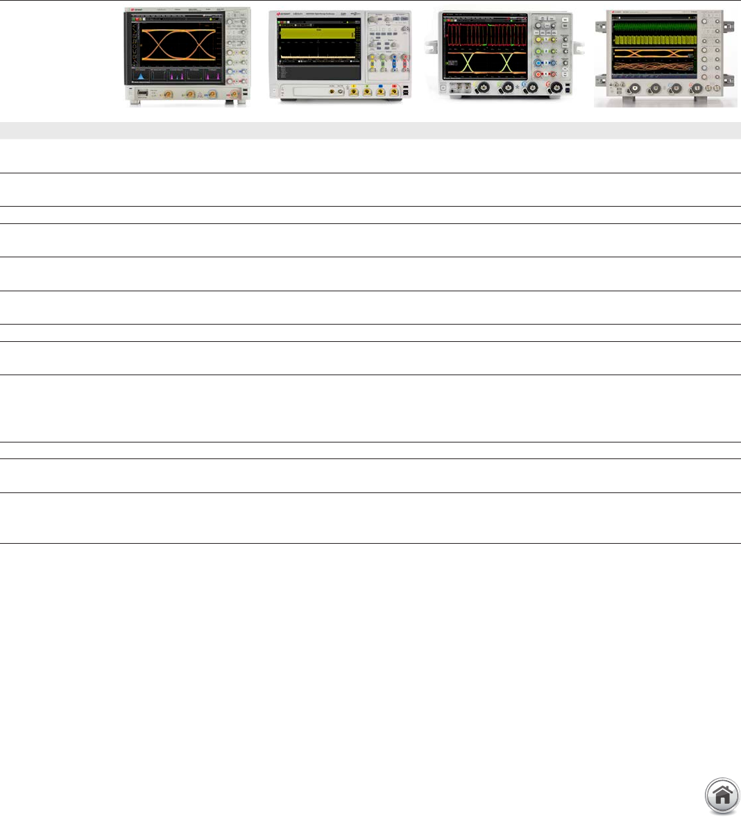
DSO models DSA models MSO models Analog bandwidth Sample rate Max memory Bandwidth upgradability
4 analog
channels
4 analog
channels
4 analog channels +
16 digital channels
2 channels 4 channels 2 channels 4 channels 4 channels
DSOV334A DSAV334A MSOV334A 33 GHz 16 GHz 80 GSa/s 40 GSa/s 2 Gpts Yes. Each model is
upgradable to each
higher bandwidth step
or the max bandwidth of
33 GHz.
DSOV254A DSAV254A MSOV254A 25 GHz 16 GHz 80 GSa/s 40 GSa/s 2 Gpts
DSOV204A DSAV204A MSOV204A 20 GHz 16 GHz 80 GSa/s 40 GSa/s 2 Gpts
DSOV164A DSAV164A MSOV164A 16 GHz 16 GHz 80 GSa/s 40 GSa/s 2 Gpts
DSOV134A DSAV134A MSOV134A 13 GHz 13 GHz 80 GSa/s 40 GSa/s 2 Gpts
DSOV084A DSAV084A MSOV084A 8 GHz 8 GHz 80 GSa/s 40 GSa/s 2 Gpts
04 | Keysight | Infiniium V-Series Oscilloscopes - Data Sheet
Achieve Clarity Faster with Infiniium V-Series Oscilloscopes (Continued)
Industry’s most advanced probing system
The InfiniiMax III and III+ probing systems provide unmatched
signal fidelity and bandwidth performance up to 30 GHz to meet
today’s high-speed signal probing requirements�
– Lowest noise and flattest frequency response
– Unique S-parameters stored in each probe, automatically
downloaded to the scope for correction
– PrecisionProbe for most accurate correction to the probe tip
– InfiniiMode feature allows differential, single-ended and
common mode measurements without probe reconnection
– First magnetically engaged probe for secure connection
– Lowest-noise active voltage termination adapter
– Industry’s only bandwidth upgradable probes
Keysight’s proprietary and custom front-end technology yields
the industry’s lowest noise floor and jitter measurement floor of
real-time oscilloscope hardware available today�
Infiniium V-Series’ low-noise front end and the revolutionary
voltage termination adapter provide the industry’s best signal
integrity�
05 | Keysight | Infiniium V-Series Oscilloscopes - Data Sheet
Industry’s best signal integrity for superior
measurement accuracy
The Infiniium V-Series family has the best-in-class signal
integrity real-time oscilloscopes in the industry, delivering
the most margin for your design validation� They are ideal for
spectral analysis of transients and wideband RF applications�
– True analog bandwidth to 33 GHz
– Lowest noise floor (2�10 mV at 50 mV/div, 33 GHz)
– Lowest intrinsic jitter (100 fs)
– Highest Effective Number Of Bits (ENOB) values in excess of
5�5
– Flattest frequency magnitude and phase response
– Spurious Free Dynamic Range (SFDR) exceeding 50 dBc
Industry’s most comprehensive software solution
The V-Series has the deepest and broadest range of software
solutions to accelerate understanding of your signal performance
from fundamental analysis to debug and compliance�
– Analysis tools including jitter separation (Dual-Dirac, tail-fit,
BUJ), eye-diagram, advanced de-embedding, FFE/CTLE/
DFE equalizations and crosstalk analysis
– World’s fastest digital channels, ideal for DDR4/LPDDR4
trigger and decode as well as parallel bus validation
– Debug with industry’s longest 160-bit, 12�5 Gb/s hardware
serial trigger, PRBS error detector and zone touch trigger
– Compliance software and technical expertise for high-speed
standards (USB 3�1, PCIe® Gen 4, HDMI 2�0, MIPI®, Ethernet
100G, PAM-4, etc�) for highest measurement confidence
Achieve Clarity Faster with Infiniium V-Series Oscilloscopes (Continued)
06 | Keysight | Infiniium V-Series Oscilloscopes - Data Sheet
Achieve Clarify Faster with the Best-in-class Infiniium V-Series Oscilloscopes
33 GHz true analog bandwidth and 80 GSa/s
sample rate with ultra low-noise, intrinsic
jitter and highest ENOB�
Find rare events with the industry’s longest
160-bit, 12�5 Gb/s hardware serial trigger and
PRBS error detector�
Increase your productivity with the
next-generation Infiniium user interface,
optimized for multiple displays and up to 128
simultaneous viewing spaces�
Enhance your visual and touch experience
with a 12�1” XGA (1024 x 768) high resolution
capacitive touch screen�
Identify anomalies easily with a 256-level
intensity-graded or color-graded persistence
display that provides a three-dimensional
view of your signals�
Support remote control over Ethernet, GPIB
and USB interfaces� Remote programming
allows oscilloscope and software automation�
LXI class C compliant, Web-interface and
MATLAB enabled�
Correct insertion loss and skew of your test
setup with PrecisionProbe� The oscilloscope
generates an edge of 12 ps rise time to enable
TDT calibration�
Capture the longest signal trace of up
to 25 ms at 80 GSa/s sample rate using
highest 2 Gpts of acquisition memory�
Trigger, analyze and debug your parallel
bus with world’s fastest digital channels�
Decode cutting-edge DDR4 and LPDDR4
protocol memory buses�
07 | Keysight | Infiniium V-Series Oscilloscopes - Data Sheet
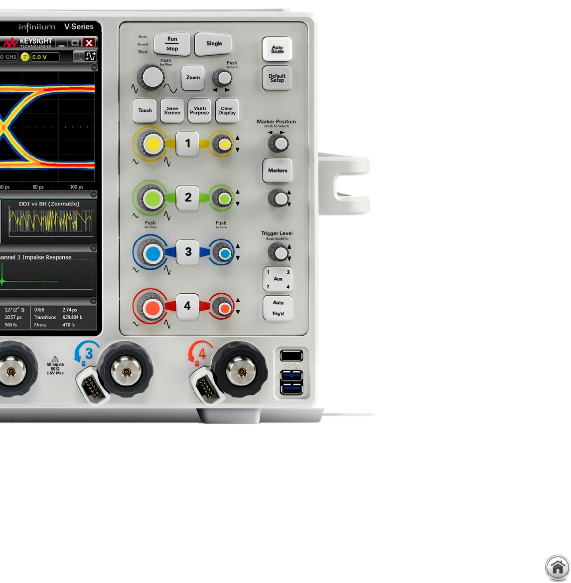
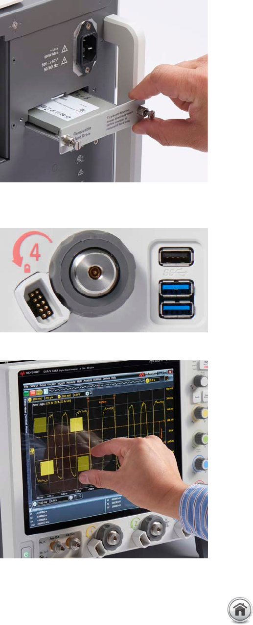
New industrial design and front panel layout
that enhances user experience and operation
of the oscilloscope�
Save Screen button provides quick access to
capture oscilloscope waveform and analysis
screenshots�
Customizable multipurpose key allows
you to customize its function to make your
favorite measurements, execute a script, save
waveforms or load a setup�
Access the marker and change the positions
quickly through the dedicated marker
controls�
Quick access to fine control by pressing the
horizontal and vertical knobs�
Five USB 3�0 host and device ports at the
front and back panel for data offload speed�
Additional USB 2�0 ports provide connectivity
to your USB keyboard, mouse and other
peripherals�
Standard 500 GB removable solid state drive
improves processing speed and enhances
data security� 1 TB storage option is available�
Threaded 3�5 mm RF connectors with
convenient torque mechanism ensures the most
reliable signal integrity and consistent 8 in� lbs�
connection� The AutoProbe II interface provides
a robust interface for the InfiniiMax III and III+
probing system�
External 10-MHz reference clock input and
output for precise timebase synchronization
with more than one oscilloscope, RF
instruments or logic analyzers�
08 | Keysight | Infiniium V-Series Oscilloscopes - Data Sheet
Groundbreaking oscilloscope technology for highest measurement accuracy
Whether you are deploying emerging high-speed bus technology, identifying spectral content of wideband RF signals or analyzing
transient physical phenomena, you need the truest representation of your signal under test� Keysight invests in leading-edge
technology to bring you the highest real-time oscilloscope measurement accuracy available today�
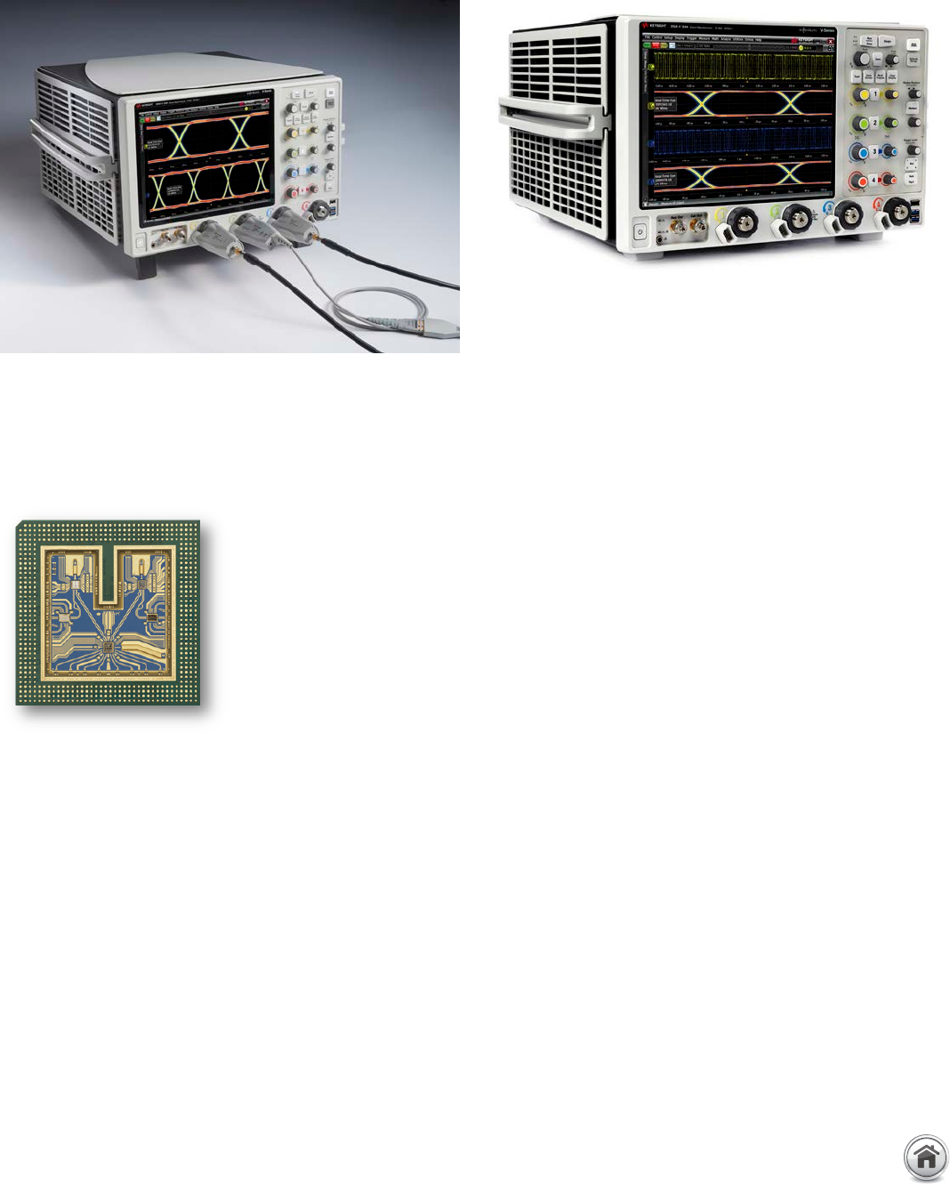
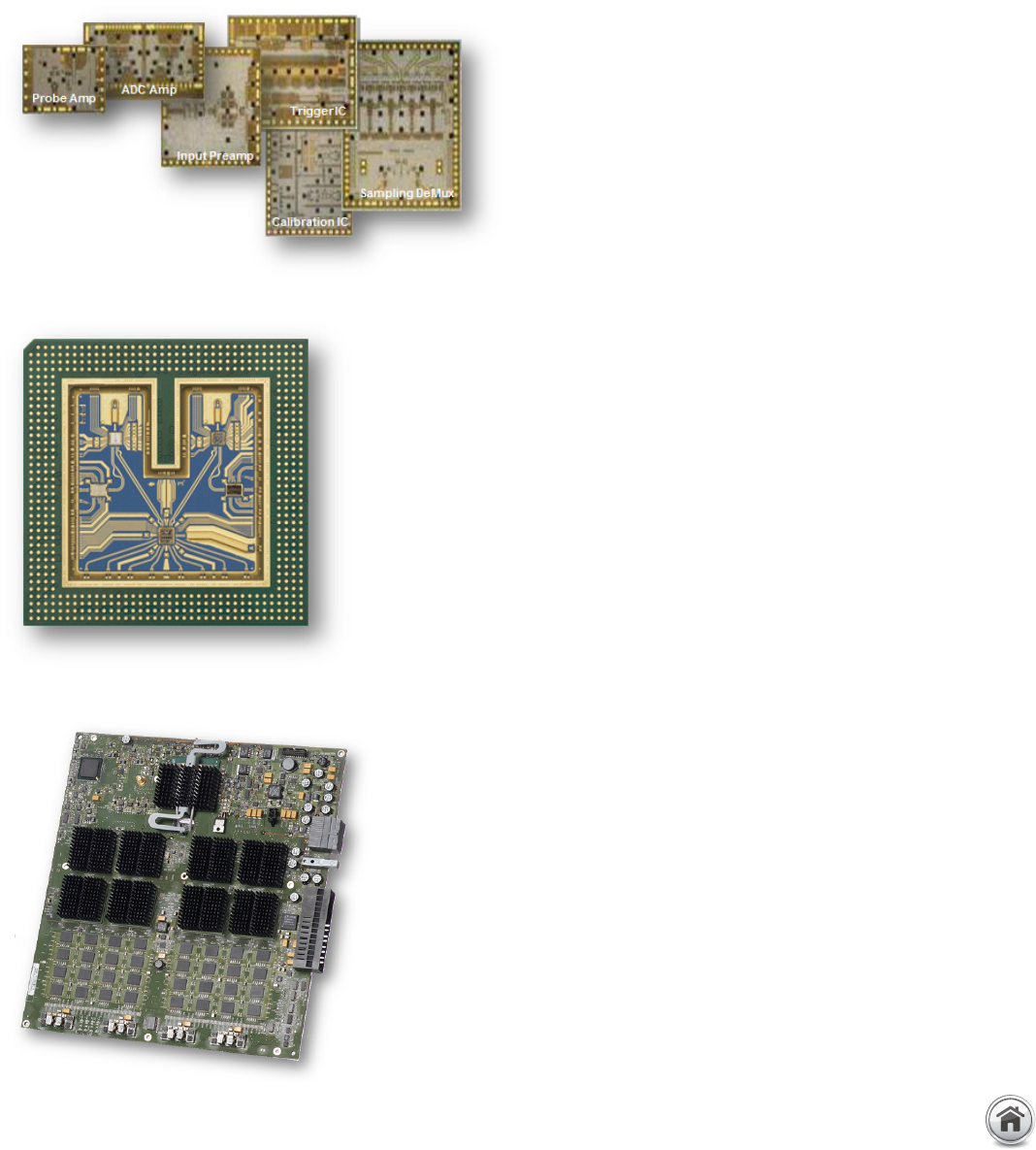
Indium Phosphide Integrated Circuits�
Front-end multi-chip module�
Acquisition board�
Industry’s Best Signal Integrity
Keysight utilizes a proprietary Indium Phosphide (InP) integrated
circuit process to design the key technology blocks to deliver
high-bandwidth performance, ultra-low noise and high-voltage
signal input� This process is used in the pre-amplifier, trigger,
sampling, ADC and probe amplifier integrated circuit design� Not
only does this mean you are purchasing the best oscilloscope
on the market today, but you can also count on technology
leadership from Keysight in the future�
Infiniium V-Series’ front-end multi-chip module integrates the
pre-amplifier, trigger and sampling technology blocks using
a proprietary cutting-edge packaging technology� Based on
fine-line microcircuit processes and extensive experience with RF
design, Keysight developed a front-end that provides excellent
high-frequency electrical properties along with superior heat
dissipation� The unique technology includes a quasi-coaxial
path in the packaging to ensure signal shielding and delivers
a high-speed clock to the sampler chip for the most accurate
sampling time base�
All technology blocks, including the front-end, analog-to-
digital converter (ADC), memory controller, digital channels
and hardware serial trigger, are meticulously laid out on the
acquisition board with outstanding noise and coupling isolation�
Time scale accuracy of 0�1 parts per million after calibration is
achieved through precise clock synchronization and distribution,
as well as the use of a 10-MHz oven-controlled crystal oscillator
(OCXO) with ± 0�1 ppm of accuracy�
09 | Keysight | Infiniium V-Series Oscilloscopes - Data Sheet
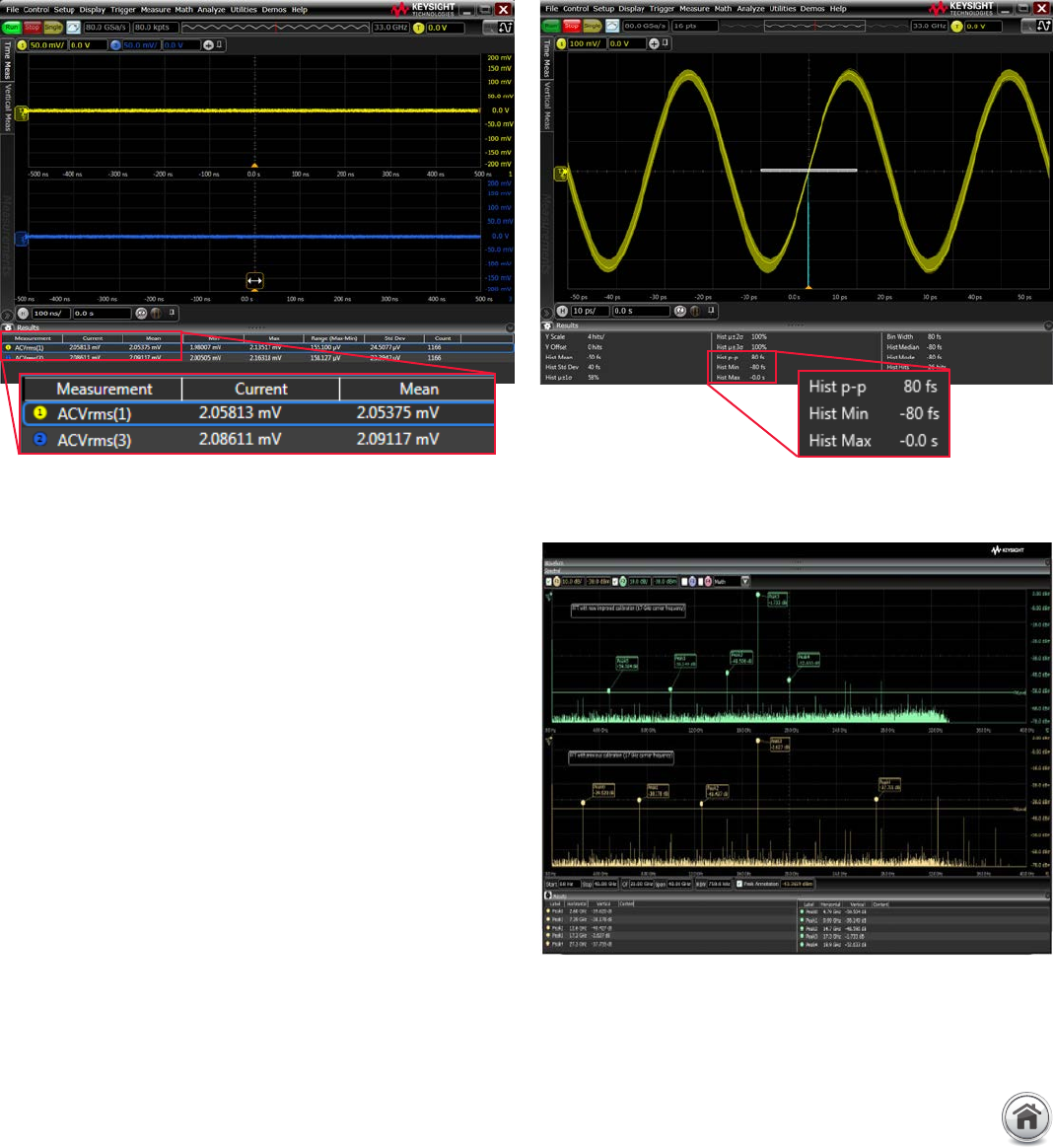
Superior measurements
Oscilloscope bandwidth allows signal rise times to be more accurately depicted� The oscilloscope noise floor directly impacts the
Y-axis voltage placement of each signal data point� The V-Series combines superiority in these characteristics with extremely low
sample clock jitter (< 100 fs)� This ensures the lowest possible contribution to jitter measurements� In addition, the V-Series has the
industry’s deepest memory of up to 2 Gpts, allowing you to resolve low frequency jitter components in a single measurement�
Keysight’s oscilloscopes are constantly improving in measurement
accuracy� The latest innovation is an improved calibration routine
that better aligns the sample points of the analog-to-digital
converter� The improved calibration results in higher spurious
free dynamic range (SFDR) and effective number of bits (ENOB)�
The SFDR is improved as much as 15 dBc depending on the
carrier frequency� Higher SFDR is ideal for making RF and optical
measurements where spectral purity is of the utmost importance�
Improved SFDR and ENOB also means better jitter performance�
Ultimately this means the V-Series now features the highest SFDR
and ENOB of any oscilloscope on the market�
Ultra-low noise at 33-GHz full bandwidth (2�10 mV at 50 mV/div)� Jitter measurement floor of less than 100 fs (80 fs with 30 GHz input sine
wave)�
Improved calibration increases the spurious free dynamic range by up to
15 dBc�
Industry’s Best Signal Integrity (Continued)
10 | Keysight | Infiniium V-Series Oscilloscopes - Data Sheet
Industry’s Fastest Mixed Signal Oscilloscope
World’s fastest 20 GSa/s digital channels,
delivering best analog and digital performance
Today’s designs require access to complex triggers and multiple
instruments� A mixed signal oscilloscope (MSO) integrates
traditional analog channels with 16 digital channels, providing up
to 20 channels you can use at once� Keysight MSOs seamlessly
integrate the familiar controls of an oscilloscope with the
additional digital data acquisition and pattern recognition of a
logic analyzer� You can trigger across any combination of analog
and digital channels, as well as decode the acquired data� The
MSO has the ability to label each individual channel as part of a
bus for decoding, saving hours of manual work� With the fastest
20 GSa/s sample rate, it provides superior insight into low-speed
serial and high-speed parallel bus interfaces�
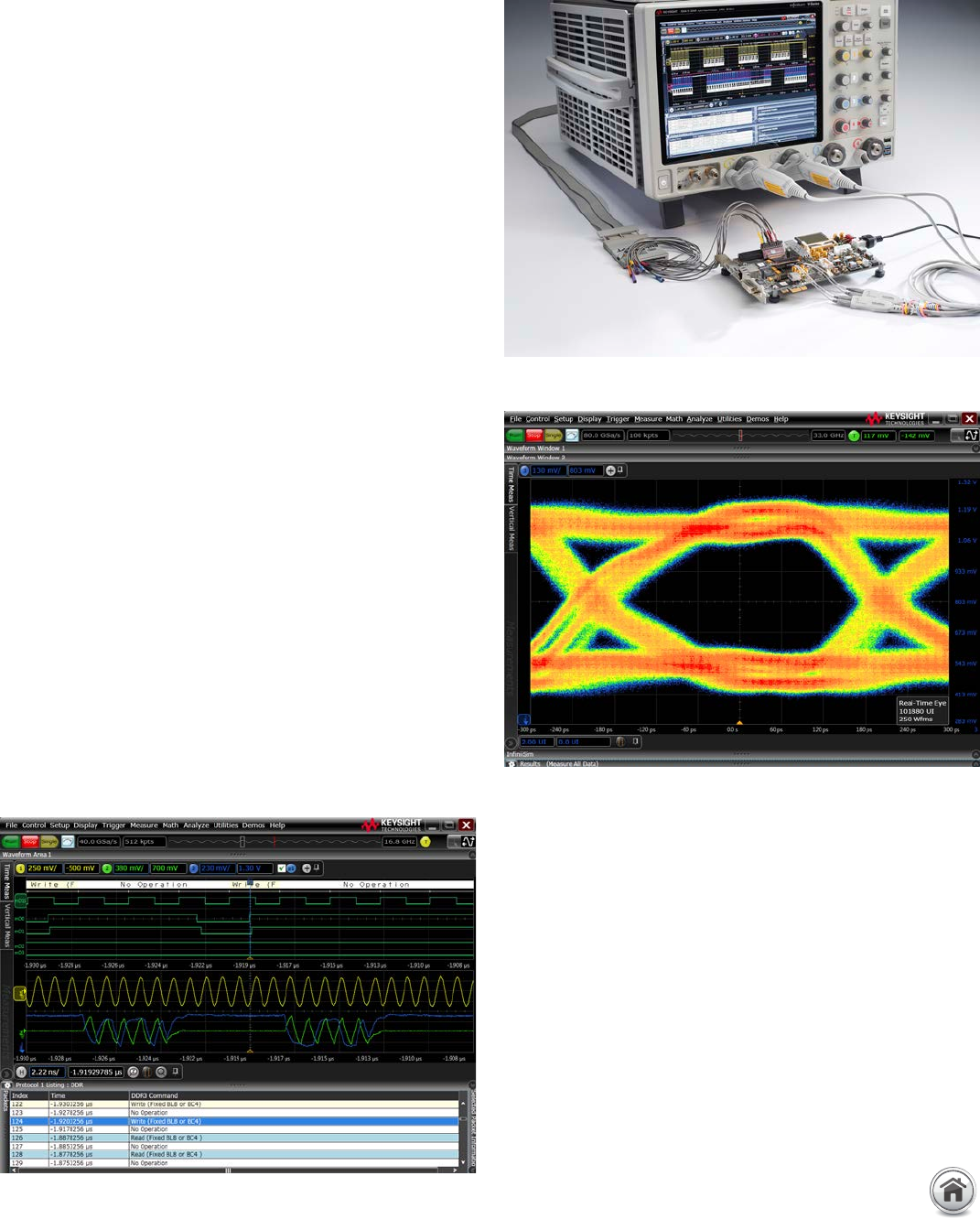
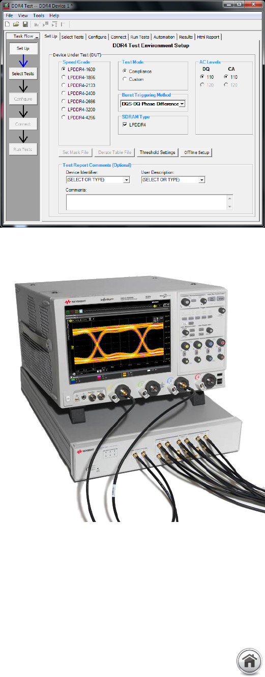
MSO optimized for DDR/LPDDR2, 3, and 4
protocol triggering and decode
The MSO is specially targeted at DDR/LPDDR2, 3 and 4 memory
technologies, simplifying the complicated task of triggering,
analyzing and debugging the parallel buses� The additional
digital channels mean you can probe at the various command
signals to easily trigger on the different DDR commands
such as read, write, activate, precharge and more� DDR
triggering makes read and write separation easy, providing fast
electrical characterization, real-time eye analysis and timing
measurements� The DDR protocol decoder can decipher the DDR
packets and provide a time-aligned listing window to search for
specific packet information�
All of the above features come standard with the MSO� The
MSO is fully compatible with Keysight’s 90-pin logic analysis
connectors, making it easy to connect to your devices�
DDR3 test setup with mixed signal oscilloscope�
DDR3 protocol decode and write command trigger�
DDR3 write data burst eye-diagram analysis�
11 | Keysight | Infiniium V-Series Oscilloscopes - Data Sheet
Industry’s Leading Hardware Serial Trigger
Challenges identifying and debugging high-speed
serial buses
In today’s high-speed serial application debug, it is not
always easy to find errors that happen rarely or occasionally�
Conventional oscilloscopes usually have limitations because of
the long dead time between acquisitions, which cause infrequent
errors or events to be missed� Furthermore, it is becoming more
difficult to identify and debug the root cause of design problems,
whether it is physical or protocol layer related�
Industry’s longest 160-bit sequence and sixteen-
8b/10b symbols hardware serial trigger
The Infiniium V-Series’ 12�5 Gb/s hardware serial trigger with
the industry’s longest 160-bit sequence provides an effective
event trigger to find and debug the most challenging problems
in your design� You can specify to trigger on bit 1 (high), 0 (low)
and X (don’t care) conditions when searching for a specific event�
The 160-bit sequence length is critical to trigger at the longest
symbol in an application such as USB 3�1 and PCI Express® Gen
3 symbols that are 132-bit and 130-bit long� If the trigger bit
sequence is insufficient, you will not be able to reliably trigger on
an event you want to identify, making the debug process more
challenging�
The hardware serial trigger also provides 8b/10b triggering
of up to 16 symbols of “K” and “D” codes� Since the 8b/10b
symbols can be transmitted with either disparity to maintain the
DC-balanced on the line, the hardware serial trigger is designed
to trigger on both disparities so you do not miss an event� In
additional, the V-Series can decode the data packet at the
application level such as PCIe Gen 3, USB 3�0 and SATA packets,
providing deeper protocol insight into the application� When
there is an error, you can now go in and debug the issue whether
it is related to the physical layer, where the signal integrity
is corrupted, or protocol layer, where the data is incorrectly
transmitted�
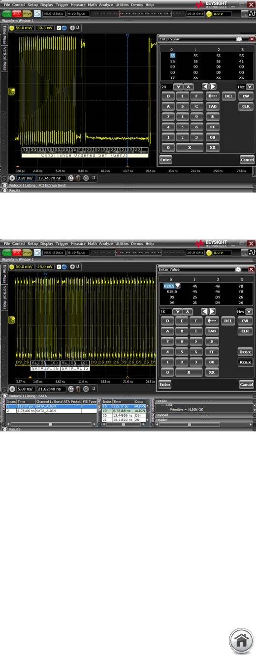
V-Series’ hardware serial trigger finds a PCI Express Gen 3 compliance
ordered set symbol that is 130-bit long (PCIe Gen 3 uses 128b/130b
encoding)�
The V-Series’ 8b/10b hardware triggers at 16 “K” and “D” symbols of the
SATA signal� The software protocol decoder further decodes the symbols
into higher-level data packets such as the SATA ALIGN packets�
12 | Keysight | Infiniium V-Series Oscilloscopes - Data Sheet
Industry’s Leading Hardware Serial Trigger (Continued)
Industry’s only 12�5 Gb/s hardware serial trigger
with SSC tracking at oscilloscope channel
The Infiniium V-Series hardware serial trigger’s speed covers
most common high-speed serial bus rates starting from
480 Mb/s up to 12�5 Gb/s, which include USB 2�0, USB 3�1, PCI
Express Gen 3, HDMI 2�0 and SAS-3 applications� Most of these
applications also support spread spectrum clocking (SSC) where
the high-speed signal is modulated, and the V-Series’ hardware
serial trigger is able to track the SSC at the oscilloscope input
channel or with the use of an external reference clock input� The
hardware serial trigger will recover and generate a sub-rate clock
when locked to the signal�
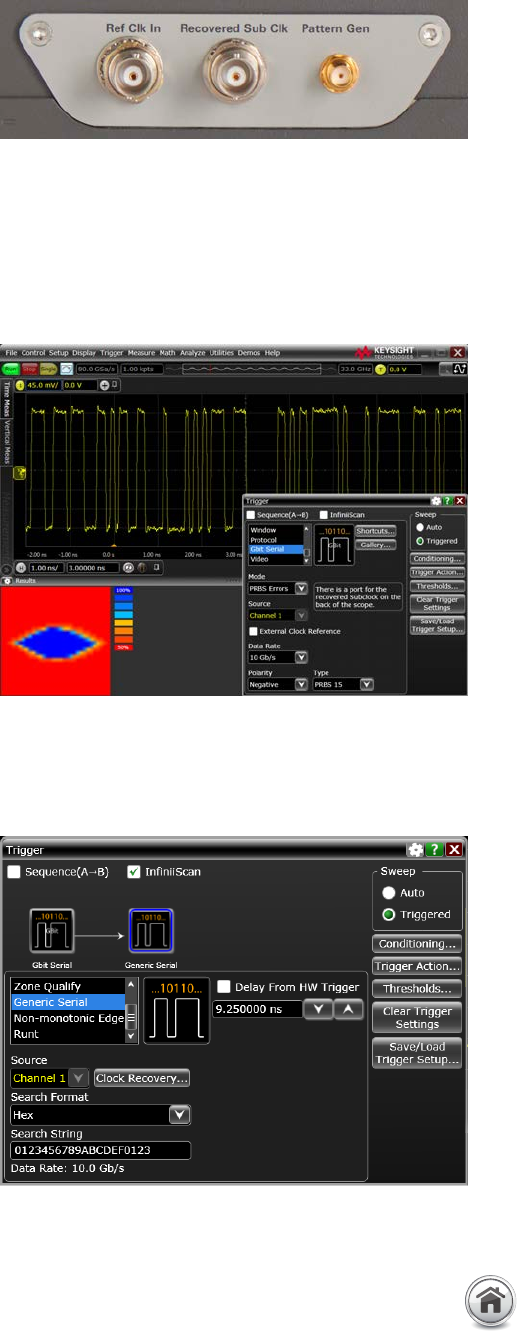
External reference clock input is one of the methods to enable SSC
tracking by the hardware serial trigger�
PRBS error detector triggers on a bit error in the PRBS-15 signal� An
eye view plot (bottom left) is provided to show the quality of the signal
received by the hardware serial trigger� The hardware serial trigger
works when there is enough eye opening (blue area) to discern the bit
value�
Hardware serial trigger and InfiniiScan’s software serial trigger provide
up to 240-bit sequence trigger�
Use with InfiniiScan’s software serial trigger for up
to 240-bit sequence trigger
The hardware serial trigger can be combined with InfiniiScan’s
software event trigger to provide a two-stage trigger for up to
240-bit sequence� This is particularly powerful for the V-Series
with its deep acquisition memory (up to 2 Gpts), providing long
trace capture of 25 ms at the high resolution sampling rate of
80 GSa/s� The hardware first finds the 160-bit event condition
and then uses InfiniiScan for an additional 80-bit event trigger�
The InfiniiScan event trigger is not limited to bit sequence search�
Other search functions such as zone touch trigger allow you to
visually draw zones on the oscilloscope display as a second stage
trigger�
Industry’s first PRBS error detector
The PRBS error detector can trigger and display the bit error of
the PRBS-7, 15, 23, and 31 signals� It identifies the error when
the pattern does not match the expected PRBS pattern that has
been set in the oscilloscope� When the next error happens, the
oscilloscope will replace the display with the next bit error� This
allows you to discover if the error is related to the bit pattern,
which is related to inter-symbol interference (ISI)� The hardware
serial trigger provides an eye view plot to show the signal quality
of the signal received�
13 | Keysight | Infiniium V-Series Oscilloscopes - Data Sheet
To take advantage of your investment in a high-bandwidth oscilloscope, you must have a probing system that can deliver high
performance measurements� InfiniiMax III and III+ probing systems provide up to 30 GHz of bandwidth, delivering unrivaled
performance and real-world usability� The InfiniiMode feature allows convenient measurement of differential, single-ended and
common mode signals with a single probe tip – without reconnecting the probe from its connection point�
Industry’s only fully-integrated probe amplifier with unique S-parameter correction
Each individual InfiniiMax III and III+ probe amplifier stores its unique S-parameters and is automatically downloaded to the
oscilloscope when connected for probe response correction� The S-parameters of the various probe heads are also applied to further
flatten the probe’s magnitude and phase response for better measurement accuracy� Traditionally, probe correction uses a nominal
model based on a typical probe amplifier instead of the specific amplifier� Generally, the biggest variations between probing systems
are a result of the probe amplifier� The ability to correct a specific probe amplifier’s response results in a more accurate probe
correction, which yields a more accurate measurement�
Industry’s only upgradable probes
Purchase the probing performance you need today with
confidence that you can expand your performance in the future
with InfiniiMax III bandwidth-upgradable probes� Upgrade to
higher performance at a fraction of the cost�
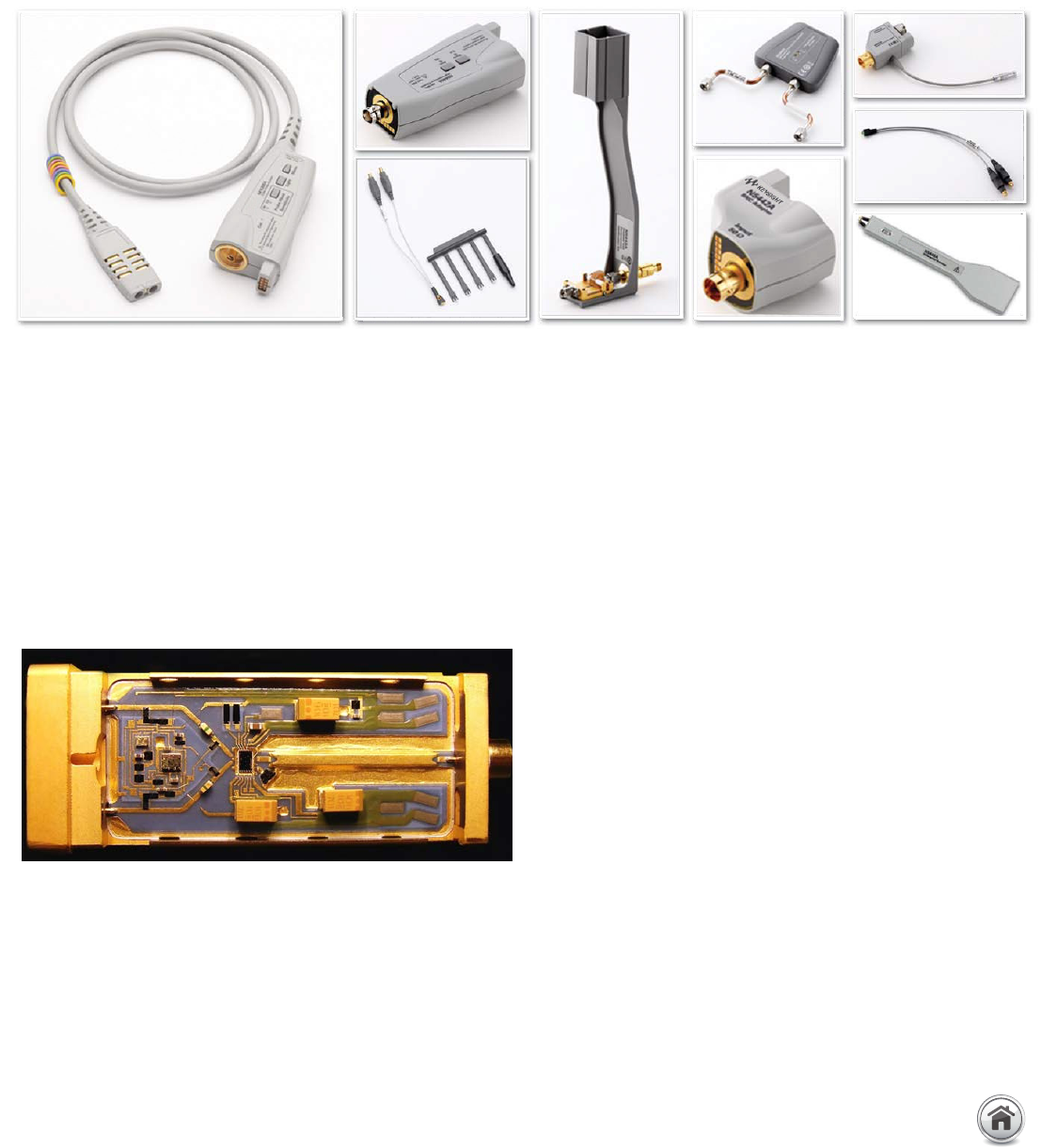
The InfiniiMax III and III+ 30-GHz probing system includes accessories to enable probing with a ZIF tip, browsing or connecting to 2�92 mm/3�5 mm/
SMA inputs�
The InfiniiMax III and III+ probing system uses the same InP technology
that enables high-bandwidth and low-noise oscilloscope measurements�
Industry’s Most Advanced and Flexible 30-GHz Probing System
14 | Keysight | Infiniium V-Series Oscilloscopes - Data Sheet
For more information about InfiniiMax III and III+ probes matching the performance of your Infiniium oscilloscope, see the InfiniiMax III
and III+ probes and accessories data sheet with the Keysight publication number 5990-5653EN�
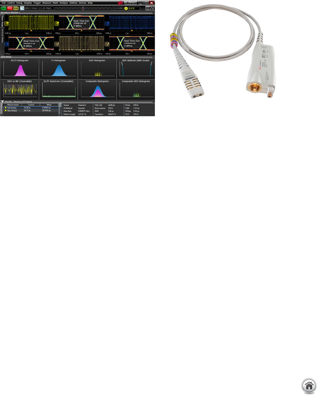
Industry’s lowest-noise active voltage termination
adapter
The N7010A active termination adapter provides a low noise
single-ended cabled measurement solution with 50 Ω voltage
termination (VTERM) up to 30 GHz bandwidth� The adapter is
optimized for low amplitude signal measurements with its high
signal-to-noise-ratio and low noise performance� The range of
the VTERM can be set to ± 4 V, which is ideal for applications such
as HDMI, DisplayPort, MHL and MIPI M-PHY®, which require
voltage termination� The adapter is compatible with 2�92 mm,
3�5 mm, and SMA connectors, as well as a SMP connector when
an adapter is used�
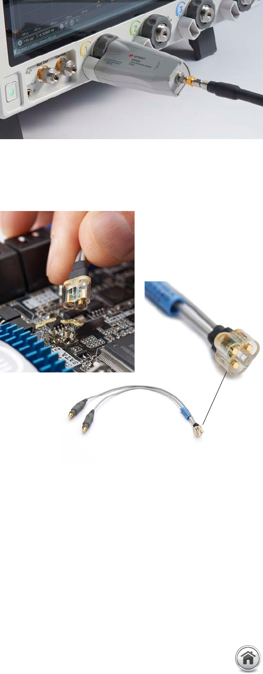
Industry’s first magnetically-engaged probe head
and tip
The N2848A/49A QuickTip offers the industry’s first
magnetically-engaged probe head and tip for a quick and secure
connection� The N2848A QuickTip probe head quickly snaps to
the N2849A probe tip, utilizing magnets to connect to the two
sides of the differential signal and ground� Multiple N2849A
probe tips can be installed on a board or device, allowing quick
and reliable measurement of many probe points� The QuickTip
supports InfiniiMode probing when used with the InfiniiMax
III+ probe amplifier and supports differential probing with the
InfiniiMax III probe amplifier�
N7010A active termination adapter provides a low noise single-ended
cabled measurement solution with 50 Ω voltage termination (VTERM) up to
30 GHz bandwidth�
The N2848A/49A is the industry’s first magnetically-engaged probe
head and tip for a quick and secure connection�
Industry’s Most Advanced Probing System
15 | Keysight | Infiniium V-Series Oscilloscopes - Data Sheet
Turn your V-Series into a Time-Domain
Transmission (TDT) instrument to quickly
characterize and compensate any probes, cables
or measurement setup�
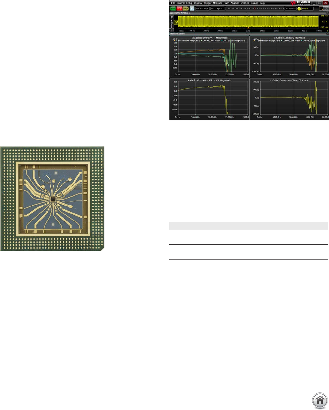
PrecisionProbe technology turns your oscilloscope into the
ultimate characterization tool� It provides quick characterization
of your entire measurement setup (including probes, cables and
switches) without the need for extra equipment� PrecisionProbe
takes advantage of the Infiniium V-Series’ 12 ps edge to
characterize and compensate for loss on the measurement
system�
PrecisionProbe compensation technology:
– Creates custom probe transfer function (Vout/Vin)
– Characterizes probed system transfer function
(Vout/Vin = Vout/Vsrc)
– Removes unwanted cable insertion loss (S21)
Now every probe and cable in the system can have the exact
same frequency response without measurement variation caused
by probe or cable difference� You can properly characterize
custom probes as well�
When you combine InfiniiMax III and III+ probes with switches
between the amplifier and the probe head, PrecisionProbe allows
full correction for each probe’s path� For increased accuracy,
PrecisionProbe Advanced with faster edge (6 ps) is available�
The magnitude and phase response of a cable corrected using
PrecisionProbe�
Keysight uses Indium Phosphide process to produce a 12 ps edge step
response, ideal for characterizing cable and probe frequency response�
Industry’s Most Advanced Probing System (Continued)
PCIe Gen 3 measurement improvement with PrecisionProbe
Root
complex
Eye height with
standard calibration
Eye height with
PrecisionProbe
Margin
improvements
5 GT/s 306.6 mV 348.33 mV 13.6%
8 GT/s 96.82 mV 106.01 mV 9.4%
16 | Keysight | Infiniium V-Series Oscilloscopes - Data Sheet
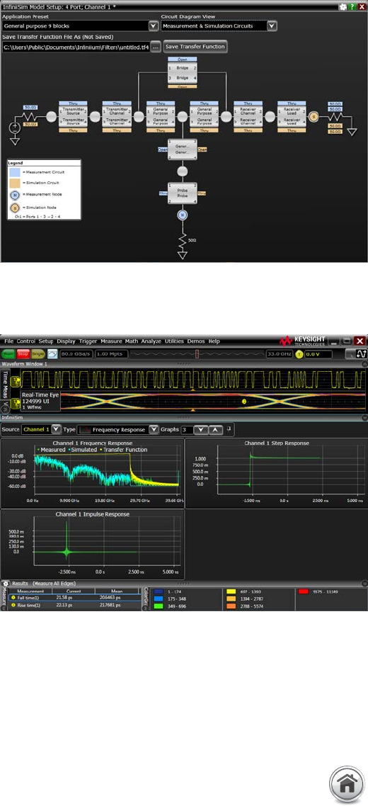
Hardware-accelerated rendering
The Infiniium V-Series renders the waveform in real time through
the oscilloscope hardware so it does not increase processing
time� Rendered waveforms are obtained quickly, which saves you
much time compared to processing done in software�
Circuit models to define your setup
The InfiniiSim waveform transformation toolset provides a
graphical user interface for you to define your measurement
system, including an arbitrarily complex system� Select from
the application preset for different topologies� Define the circuit
blocks with open, through, RLC circuit, or S-parameter files�
Model reflections
With the InfiniiSim waveform transformation toolset, you can
transform signals with confidence, whether you are inserting
or removing channel elements or relocating the measurement
point� InfiniiSim lets you model up to 27 different elements or
S-parameters at once, as well as the interaction between them�
InfiniiSim is the only toolset with the ability to model more than
one element including reflection model� The V-Series provides its
own input reflection (S11) in all modeling�
Model your system with as much detail as you
need
InfiniiSim features the model setup that best matches your
design� Whether it is a simple single-element model or an
advanced general-purpose model with up to 27 elements in the
link, you can perfectly model your design and simulate the exact
probing point you want�
The most advanced waveform transformation software helps you render (embed/de-embed) waveforms
anywhere in your design�
The InfiniiSim waveform transformation toolset provides the most flexible and accurate means to render waveforms anywhere in
your design� The highly-configurable system modeling enables you to de-embed the effects of unwanted channel elements, embed
waveforms with channel models, view waveforms in physically improbable locations and compensate for loading of probes and other
circuit elements�
InfiniiSim allows embedding and de-embedding of up to 27 different
elements or S-parameter models at once to meet your most demanding
requirements�
InfiniiSim renders the waveform through hardware acceleration�
Industry’s Most Comprehensive Software
17 | Keysight | Infiniium V-Series Oscilloscopes - Data Sheet
Serial data equalization opens the closed eye using CTLE and DFE
methods�
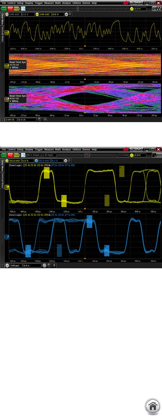
Draw up to eight “must intersect” or “must not intersect” zones to trigger
on a specific event and condition�
Open tightly shut eyes with equalization
Serial data equalization for the Infiniium V-Series provides fast
and accurate equalization using feed-forward equalization (FFE),
continuous time linear equalization (CTLE) and decision feedback
equalization (DFE) modeling in real time� The tool allows you to
use a combination of the equalization, which is found in actual
designs�
Serial data equalization software allows you to input your own
equalizer settings and tap values that are used in your design,
allowing you to simulate the eye opening in your receiver� If you
prefer, the software can find the optimal tap values for you as
well, which you can use as reference for your designs�
Powerful and flexible software trigger
The InfiniiScan software is a powerful tool for identifying signal
integrity issues that hardware triggering is unable to find in your
design� This innovative tool scans through thousands of acquired
waveforms per second to help you isolate signal anomalies,
saving you time and improving your designs� It includes an 80-bit
sequence trigger to find events of interest�
InfiniiScan’s zone touch trigger allows you to draw up to
eight “must intersect” or “must not intersect” zones on the
oscilloscope display to visually determine the event-identify
condition� If you can see the event of interest on the screen,
the zone touch trigger can be used to quickly and easily
isolate it, saving significantly more time than complicated
hardware triggers� Other triggers include non-monotonic edge,
measurement limit search, runt and pulse width�
Industry’s Most Comprehensive Software (Continued)
18 | Keysight | Infiniium V-Series Oscilloscopes - Data Sheet
Real-time eye and clock recovery
Serial data analysis (SDA) software provides flexible clock
recovery including 1st- and 2nd-order PLL, explicit and constant
clock� With a stable clock, you can look at real-time eyes of
transition and non-transition bits� V-Series oscilloscopes with
SDA software also provide a unique view of bits preceding an
eye�
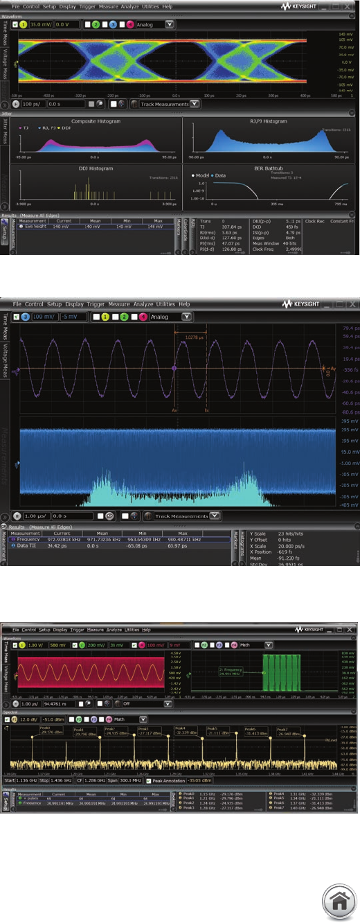
Measurement trends and jitter spectrum
The EZJIT tool helps you quickly analyze the causes of jitter�
Measurement trends allow you to see deeper views of factors
affecting measurements� Jitter spectrum is a fast method to find
the causes of jitter� The trend also allows you to characterize
spread spectrum clock (SSC) if it meets frequency and
modulation deviation requirements�
Two ways to separate jitter
EZJIT Plus comes with two ways to separate jitter: the industry-
standard spectral method and the emerging tail-fit method� Both
methods allow for simple separation of RJ and DJ, but the tail-fit
method provides jitter separation in the unique case of non-
symmetrical histograms and aperiodic bounded uncorrelated
jitter (ABUJ)�
Unique RJ/DJ threshold view
EZJIT Plus also provides a unique spectral view of the jitter
spectrum with the threshold drawn on the chart� The spectral
view provides insight into the decision point of the separation and
allows for narrow or wide, tail-fit, or dual-dirac�
Tools to determine the correct settings
SDA, EZJIT, and EZJIT Plus come with an array of visual tools
to make analyzing the data simple and ensure that the correct
settings are chosen for difficult design decisions� For example,
the improved bathtub curve is a helpful visual tool to determine
which jitter separation method best fits the data�
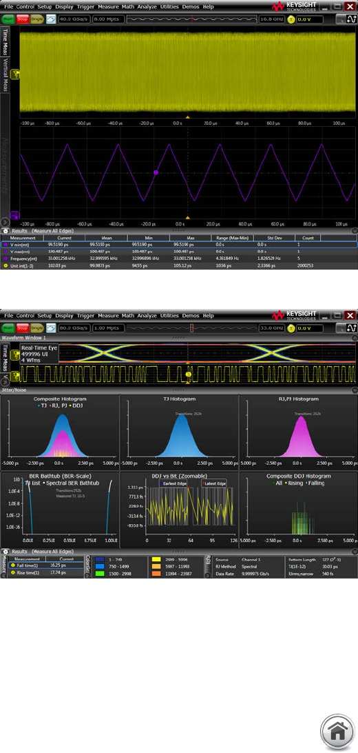
Gain insight into the causes of signal jitter to ensure your design has high reliability
With faster edge speeds and shrinking data-valid windows in today’s high-speed digital designs, insight into the causes of jitter has
become critical for success� Using EZJIT and EZJIT Plus jitter analysis software, the Infiniium V-Series helps you identify and quantify
jitter components that affect the reliability of your design� Time correlation of jitter to the real-time signal makes it easy to trace
jitter components to their sources� Additional compliance presets and a setup wizard simplify and automate RJ/DJ separation for
testing against industry standards� EZJIT Plus automatically detects embedded clock frequencies and repetitive data patterns on the
oscilloscope inputs and calculates the level of data-dependent jitter (DDJ) that contributes to the total jitter (TJ) by each transition in
the pattern, a feature unique to Infiniium oscilloscopes�
Extract measurement trend from the signal for SSC characterization�
Multiple jitter analysis plots for enhanced visualization�
Industry’s Most Comprehensive Software (Continued)
19 | Keysight | Infiniium V-Series Oscilloscopes - Data Sheet
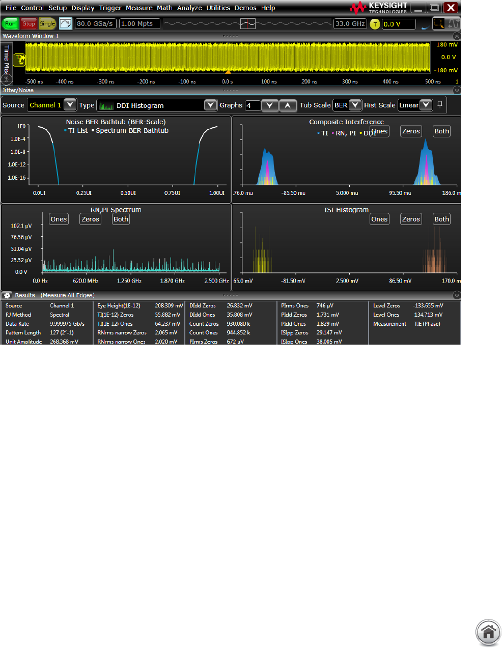
More than your standard jitter
package
To efficiently determine root cause for any
type of signal degradation in the amplitude
domain, you must first determine whether
the problem is caused by random or
deterministic sources� To accomplish
this task, EZJIT Complete takes analysis
techniques used in the time domain
(jitter analysis) and extends them into the
amplitude domain�
More than just an eye contour
EZJIT Complete is an in-depth view
into impairments related to signal
levels – either logic ones or logic zeroes
– deviating from their ideal positions�
Existing eye-diagram tools simply provide
a view of an eye contour but do not
provide real measurement data other than
nice graphics and eye contour�
EZJIT Complete uses separation
techniques to allow each bit to be
examined to determine correlated effects,
as well as make multiple measurements
on individual bits to determine
uncorrelated effects� Use FFTs to analyze
the frequency domain and extract random
components� Dual-Dirac modeling
techniques are also carried from the
jitter domain and used in the interference
domain�
Key measurements
With EZJIT Complete, the V-Series
oscilloscopes offer the following
unique noise measurements:
– Total interference (TI)
– Deterministic interference (DI)
– Random noise (RN)
– Periodic interference (PI)
– Inter-symbol interference (ISI)
– Relative intensity noise (RIN - dBm
or dB/Hz)
– Q-factor
Industry’s Most Comprehensive Software (Continued)
Discover signal anomalies in the amplitude noise domain of the waveform
Noise analysis with EZJIT Complete software for insight into the sources of noise in the signal�
20 | Keysight | Infiniium V-Series Oscilloscopes - Data Sheet
Use you PC to view and analyze data away from
your oscilloscope
Now you can do additional signal viewing and analysis away from
your oscilloscope and target system� Capture waveforms on your
oscilloscope, save them to a file, and recall the waveforms into
Keysight’s Infiniium Offline application on your PC�
View and analyze anywhere your PC goes
Take advantage of the large, high-resolution screens and
multiple displays found in your office� Use familiar oscilloscope
controls to quickly navigate and zoom in to any event of interest�
Use auto measurements and functions for additional insight�
Share scope measurements more easily across
your team
You can share entire data records instead of being limited
exclusively to static screen shots� Collaborate with teams
members who work in different locations�
Create more useful documentation
Add up to 100 bookmark annotations and up to 20 simultaneous
measurements on the oscilloscope display� Use features such
as “right-click” and “cut-and-paste” to move screen images
between applications, without ever having to save the image to
a file�
Access all advanced analysis capabilities
Infiniium Offline includes a variety of upgrade options including
serial decode upgrades for a variety of serial buses, jitter analysis
and serial data analysis found in your oscilloscope�
Industry’s Most Comprehensive Software (Continued)
Infiniium Offline software supports a wide array of Infiniium applications�
Use Infiniium Offline to find signal anomalies such as power supply
coupling�
Peak search capability makes Infiniium Offline a frequency domain tool�
21 | Keysight | Infiniium V-Series Oscilloscopes - Data Sheet
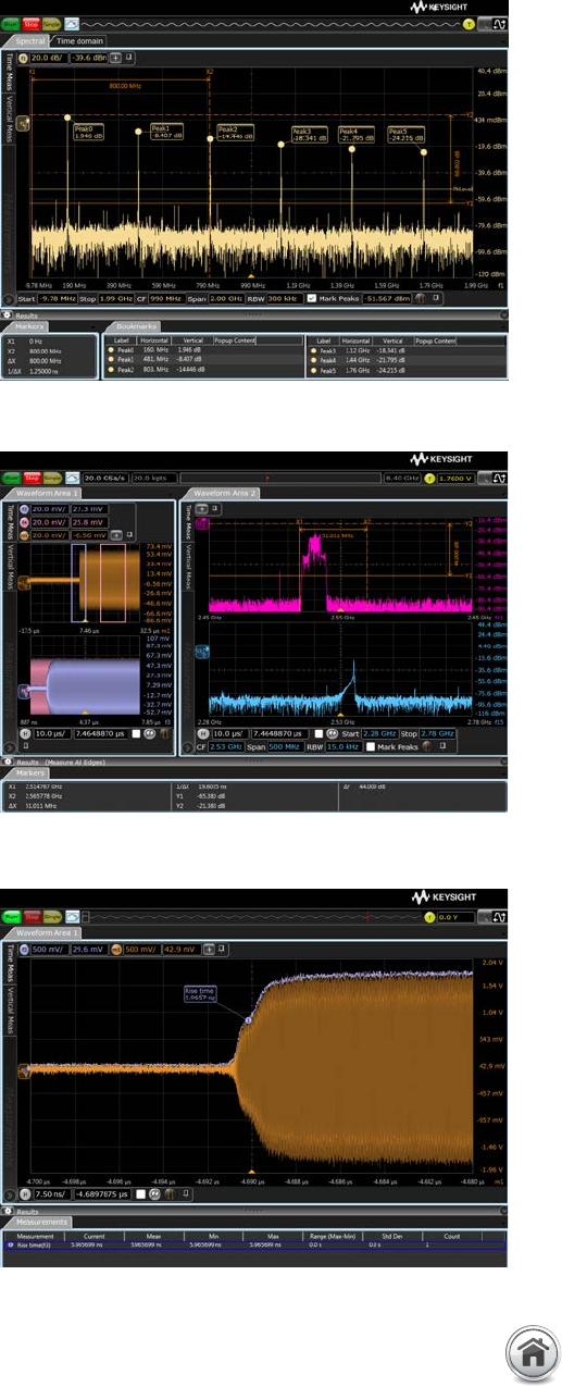
Enhanced FFTs view
The Infiniium V-Series allows you to see frequency domain and
time domain at the same time� The standard spectral viewer
includes FFT controls such as start/stop, center frequency/span
and resolution bandwidth (RBW)� Readout includes power and
frequency axis annotation and a peak table�
Envelope measurements and AM demodulation
Envelope measurement tracks the outline and AM demodulation
of a burst signal� This is required for applications such as near-
field communication (NFC) and wireless charging applications�
Add measurements such as rise time to the envelope function for
characterization of the burst signal�
Gated measurements and FFTs
The V-Series supports gated math and analysis including
FFTs� Use any of the standard 16 independent gates to narrow
measurements and FFT computations to a specific time window�
Drag the gate in the time domain, and see time correlated FFT
measurements for specified time periods� The example at the
right shows two simultaneous FFTs�
Industry’s Most Comprehensive Software (Continued)
Enhanced frequency and time domain measurements
Peak readouts in the FFT plot�
Perform measurements in the area of interest through the gated function�
Envelope detection of signal burst�
22 | Keysight | Infiniium V-Series Oscilloscopes - Data Sheet
Compliance applications with deep standard
technical expertise
Today’s demanding environment means you have less time to
understand the details of the technologies you are testing�
You also have less time to develop test automation software to
increase measurement throughput and decrease time to market�
Keysight’s compliance applications and expertise save you time
and resources with measurement automation� Compliance
applications are certified to test to the exact specifications of
each technology standard� If a test passes on the V-Series in
your lab, you can be assured that it will pass in test labs and
plugfests worldwide� Keysight experts are on multiple technology
boards and industry standards committees, and they help to
define compliance requirements�
Setup wizards combined with intelligent test filtering give you
confidence that you are running the right tests� Comprehensive
HTML reports with visual documentation and pass/fail results
guarantee that critical information is retained� Check the
V-Series ordering configuration for supported standards�
Test customization and switch automation
The N5467B user-defined application’s add-in provides you with
the ability to add additional tests, instrument control and device
control into the existing compliance applications� The compliance
applications can be controlled via the remote programming
interface (standard feature) for test automation�
Compliance applications on the V-Series support a switch
matrix, making testing simpler by automating test for each lane
of a multi-lane bus� Typical testing requires reconnecting the
oscilloscope each time you switch a lane, which increases test
time and possible inaccuracies� The V-Series solves this problem
by supporting a switch matrix through its compliance test�
Simply connect the switch to the oscilloscope and all the lanes,
and then press run to complete full testing of your entire device�
The compliance application fully supports PrecisionProbe and
InfiniiSim software, giving you the ability to characterize and
normalize every switch path to the device under test�
Industry’s Most Comprehensive Software (Continued)
DDR4 and LPDDR4 compliance application providing full electrical and
timing characterization based on JEDEC specification�
Test automation for multilane interface testing with no compromise
on accuracy, which reduces test time and effort� An Infiniium 90000
X-Series oscilloscope is shown above�
23 | Keysight | Infiniium V-Series Oscilloscopes - Data Sheet
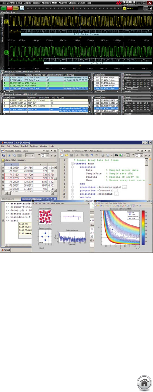
Decodes more than 20 protocol standards
The Infiniium V-Series oscilloscopes come with more than 20
protocol decoders for decoding high-speed serial bus and
low-speed serial interface protocols� The list includes the
industry’s only 64b/66b decoder used by Ethernet 10GBASE-KR
standard and multilane MIPI decode� The V-Series protocol
decoders feature time-correlated markers that let you easily
move between the listing window and the waveform� It generates
CRC value from the payload and compares the value with the
embedded CRC to verify if any bit error has occurred� Once an
error is detected, you can further debug the problem, whether it
is caused by physical or protocol issues�
Multiple protocol decoders can be used at the same time with
analog and digital channels� They feature search and trigger
capability that lets you scan through the waveform to find the
trigger condition that interests you� Protocol decoders are
available in the Infiniium Offline tool as well� Check the V-Series
ordering configuration for supported protocols�
Combine V-Series and MATLAB for even more
analysis
Enhance the V-Series with a seamless gateway to powerful
MATLAB analysis functionality� User-defined function software
adds new analysis capabilities to the V-Series beyond traditional
math/analysis features� Now you have the freedom to develop
your own math functions or filters using MATLAB and its signal
processing toolbox� With a seamless integration to MATLAB, the
V-Series allows you to display your math and analysis functions
live on the oscilloscope screen, just like any other scope-
standard functions�
Industry’s Most Comprehensive Software (Continued)
Packet decode and CRC verification through the oscilloscope MIPI
UniPro and UFS protocol decoders�
Seamless integration of oscilloscope and MATLAB software enhances
the analysis capability�
24 | Keysight | Infiniium V-Series Oscilloscopes - Data Sheet
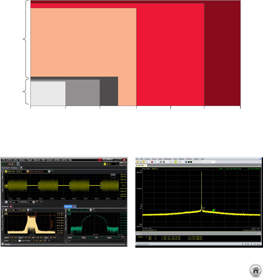
Wideband and multi-channel FFT measurements
For frequency domain measurements that require you to see more than 500 MHz of signal spectral bandwidth and multiple FFTs
simultaneously, the V-Series offers wider bandwidth than spectrum analyzers and comes standard with 4 ports (channels) per
instrument�
The V-Series enables users to make wideband measurements up to 33 GHz and up to 16 simultaneous FFTs� You can analyze even
higher bandwidth signals by combining the V-Series with a down converter circuit�
Achieve Clarify Faster - Frequency Domain Performance
Use Infiniium capture and analysis of radar bursts as shown in this
orthogonal frequency-division multiplexing (OFDM) example�
Using data acquired from V-Series, VSA shows phase noise of
—125 dBC/Hz at 10 kHz and —131 dBc/Hz at 100 kHz�
1� S, V, and Z-Series 2 ch full bandwidth, 4 ch half bandwidth�
2� Up to 50 GHz carrier�
3� 3�6 GHz to 50 GHz carrier�
RF signal spectral bandwidth
Up
to 4 11 1
1
0 MHz
BW
S-Series
2
PXA
510 MHz
2
UXA
1 GHz 3
PXA +
Scope
1.2 GHz
V-Series Z-Series
510 MHz
BW 1 GHz
BW 8 GHz
BW 13 GHz
BW 32 GHz
BW ... 63 GHz
BW
Channels
25 | Keysight | Infiniium V-Series Oscilloscopes - Data Sheet
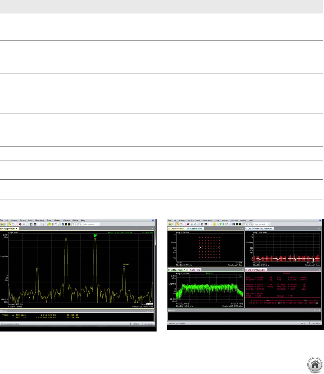
Trying to interpret traditional oscilloscope time-domain specifications can be challenging when trying to determine if a specific scope
can be recommended for RF, µW, and mmW measurements� With correction filters, low-noise front end and spurious free dynamic
range calibration, the V-Series oscilloscopes can be used for wideband frequency domain applications�
V-Series typical values (tested at 33 GHz bandwidth, 1
channel on one scope unless noted)
Sensitivity/noise density (1 mV/div; —38 dBm range)
Power spectral density measurement at 1.0001 GHz, 1.0001 GHz center frequency,
500 kHz span, and 3 kHz RBW
159 dBm/Hz
Noise figure (derived from measurement above) +15 dB
Signal-to-noise ratio/dynamic range
(—1 dBm, 1 GHz input carrier, 0 dBm scope input range)
1 GHz center frequency, 100 MHz span, 1 kHz RBW, measurement at +20 MHz from
center
+111 dB
Absolute amplitude accuracy (0 to 30 GHz) ± 0.5 dB
Deviation from linear phase (0 to 33 GHz) ± 3 deg
Phase noise (at 1 GHz)
10 kHz offset
100 kHz offset
—125 dBc/Hz
—131 dBc/Hz
EVM
(802.121 2.4 GHz carrier, 20 MHz wide, 64 QAM) —47 dB (0.47%)
Spurious responses (—4.6 dBm input signal, —4 dBm input range)
Spurious free dynamic range (SFDR)
1 GHz, —4.6 dBm signal present at input, FFT = 5 GHz span, 3 GHz center, 100 kHz RBW +67 dB
2nd harmonic distortion
1 GHz input, —4.6 dBm, 5 GHz span, 3 GHz center, 100 KHz RBW —51 dBc
3rd harmonic distortion
1 GHz input, —4.6 dBm, 5 GHz span, 3 GHz center, 100 KHz RBW —51 dBc
Two-tone third-order Intercept (TOI) Point
0 dBm input tones, 2.436 and 2.438 GHz, 2 MHz separation, 2.437 GHz center frequency,
10 MHz span, 30 kHz RBW, 8 dBm range
+26 dBm
Input match (S11)
(< 50 mV/div, 0 to 30 GHz, no attenuation)
(> = 50 mV/div, 0 to 30 GHz, no attentuation)
—15 dB; 1.4 VSWR
—21 dB; 1.2 VSWR
Typical frequency domain characteristics for the Infiniium V-Series (not guaranteed, subject to change)�
Using data acquired from the V-Series, VSA shows an excellent third
order intercept (TOI) value of 26 dBm�
Using data acquired from the V-Series, VSA shows an error vector
magnitude (EVM) for IEEE 802�11 QAM 64 of 0�47%�
Achieve Clarify Faster - Frequency Domain Performance (Continued)
26 | Keysight | Infiniium V-Series Oscilloscopes - Data Sheet
Most Advanced Platform
Standard features on V-Series platform for the most advanced oscilloscope
Standard 500 GB removable SSD for fast boot up, increased reliability
and enhanced security�
Five USB 3�0 ports provide fast data offload�
Capacitive touch and touch-friendly user interface enhances the
oscilloscope usability�
Fast, reliable and secure storage
The V-Series features 500 GB removable SSD for
– Fast boot-up time
– Increased reliability
– Easy removal for secure environments
Powerful CPU and motherboard
V-Series includes an Intel Core i5 quad core processor with
16 GB of DDR3 RAM for fast computations, even with advanced
math and deep memory� The I/O ports on the oscilloscope
include
– Ethernet 10/100/1000BASE-T
– 4 USB 3�0 host ports (2 in front, 2 at the back)
– 1 USB 3�0 device port (1 at the back)
– 3 USB 2�0 host ports (1 in front, 2 at the back)
– DisplayPort and VGA video out� Drivers support up to two
simultaneous displays
Fast data offload
For applications that require digitized waveforms to be offloaded,
the V-Series has fastest offload interfaces�
– USB 3�0 for up to 200 MB/s data offload
– Ethernet 1000BASE-T for up to 80 MB/s offload
Touch-screen innovation
V-Series oscilloscopes incorporate a capacitive touch screen� In
addition, Infiniium software includes a large number of touch-
friendly enhancements including handles, enlarged touch fields
when touch is enabled, and gestures (multi-touch)�
27 | Keysight | Infiniium V-Series Oscilloscopes - Data Sheet
Keysight’s Infiniium oscilloscope lineup includes bandwidths from 500 MHz to 63 GHz� Use the following selection guide to determine
which best matches your specific needs� All Infiniium real-time oscilloscopes feature the following:
– Industry’s best signal integrity for each family series
– Industry’s most advanced probing system
– Industry’s most comprehensive software solutions
Infiniium Series S-Series 90000A Series V-Series Z-Series
Available bandwidths 500 MHz, 1 GHz, 2.5 GHz,
4 GHz, 6 GHz, 8 GHz
2.5 GHz, 4 GHz, 6 GHz, 8 GHz,
12 GHz, 13 GHz
8 GHz, 13 GHz, 16 GHz, 20 GHz,
25 GHz, 33 GHz
20 GHz, 25 GHz, 33 GHz,
50 GHz, 63 GHz
Maximum upgradable
bandwidth
8 GHz 13 GHz 33 GHz 63 GHz
Maximum sample rate 20 GSa/s 40 GSa/s 80 GSa/s 160 GSa/s
Maximum memory
(2-channel)
800 Mpts 1 Gpts 2 Gpts 2 Gpts
Standard memory
(2-channel)
100 Mpts 40 Mpts 100 Mpts 100 Mpts
Standard memory
(4-channel)
50 Mpts 20 Mpts 50 Mpts 50 Mpts
Channel inputs 50 Ω and 1 MΩ 50 Ω 50 Ω 50 Ω
Connector type Precision BNC (f) Precision BNC (f) 3.5 mm (m) 3.5 mm (m) (33 GHz input)
1.85 mm (m) (> 33 GHz input)
Connector mate BNC (m) BNC (m) SMA (f), 2.92 mm (f) SMA (f), 2.92 mm (f)
(33 GHz input)
2.4 mm (f), 1.85 mm (f)
(> 33 GHz input)
MSO models Yes No Yes 2No
Hardware serial
trigger option
No No Yes 1, 2 No
Supported InfiniiMax
probe series
InfiniiMax I
InfiniiMax II
InfiniiMax III+
InfiniiMax I
InfiniiMax II
InfiniiMax III+
InfiniiMax III/III+ InfiniiMax I/II
with N5442A adapter
InfiniiMax III/III+ InfiniiMax I/
II with N5442A adapter
1� Trigger at a maximum 160-bit sequence or sixteen 8b/10b symbols� Works only on Channel 1�
2� Either MSO or hardware serial trigger option can be added to the oscilloscope�
Keysight Infiniium Oscilloscope Portfolio

28 | Keysight | Infiniium V-Series Oscilloscopes - Data Sheet
Get the most out of your oscilloscope investment by choosing options and software for your most common tasks� Configure your
Infiniium V-Series oscilloscope in three easy steps�
1� Choose your oscilloscope, memory and options
Oscilloscope main-frame
Oscilloscope models 1Analog bandwidth Sample rate
DSO models(4
analog channels)
DSA models(4
analog channels) 2
MS O models(4 analog channels + 16
digital channels)
2 channel 4 channel 2 channel 4 channel
DSOV334A DSAV334A MSOV334A 33 GHz 16 GHz 80 GSa/s 40 GSa/s
DSOV254A DSAV254A MSOV254A 25 GHz 16 GHz 80 GSa/s 40 GSa/s
DSOV204A DSAV204A MSOV204A 20 GHz 16 GHz 80 GSa/s 40 GSa/s
DSOV164A DSAV164A MSOV164A 16 GHz 16 GHz 80 GSa/s 40 GSa/s
DSOV134A DSAV134A MSOV134A 13 GHz 13 GHz 80 GSa/s 40 GSa/s
DSOV084A DSAV084A MSOV084A 8 GHz 8 GHz 80 GSa/s 40 GSa/s
All models come with front cover, power cord, keyboard, mouse, calibration cable, ESD wrist strap and (5) coax adapters 3�
The 8 and 13 GHz models come standard with two N5442A precision BNC adapters�
Oscilloscope memory depth 4
Acquisition memory depth upgrade Option number on new oscilloscope
50 Mpts/channel memory Standard
100 Mpts/channel memory 5DSOV000-100
200 Mpts/channel memory DSOV000-200
500 Mpts/channel memory DSOV000-500
1 Gpts/channel memory DSOV000-01G
2 Gpts/channel memory DSOV000-02G
Options
Description Option number on new oscilloscope
Hardware serial trigger 6DSOV000-810
MSO with additional 16 digital channels 6Standard on MSO models
1 TB removable solid state drive (SSD) with Windows 7 DSOV000-801
GPIB card-interface DSOV000-805
Performance verification and deskew fixture DSOV000-808
Stack mount kit option for stacking two frames N2117A
Rack mount kit N5470A
ANSI Z540 compliant calibration DSOV000-A6J
Calibration + uncertainties + guardbanding (accredited) DSOV000-AMG
DSA option for MSO models 7MSOV000-DSA
Testmobile scope cart 1180CZ
1� All models ship standard with 3-year warranty�
2� DSA models come standard with 100 Mpts/channel, EZJIT Complete, and Serial Data Analysis�
3� Oscilloscope 8, 13, and 16 GHz models come with 3�5 mm female-to-female adapters rated to 25 GHz (part number 1250-3758)� All other models come
with 3�5 mm female-to-female adapters rated to 35 GHz (part number 5061-5311)�
4� Memory depth per channel when 4 channels are turned on�
5� DSA models come with 100 Mpts/channel standard�
6� Either MSO or hardware serial trigger option can be added to the oscilloscope� Upgrade is not available when the oscilloscope already has the MSO or
hardware serial trigger installed�
7� Available for MSO models only� DSA option comes standard with 100 Mpts/channel, EZJIT Complete, and Serial Data Analysis�
Infiniium V-Series Ordering Configuration

29 | Keysight | Infiniium V-Series Oscilloscopes - Data Sheet
2� Choose your probes and accessories
Probe amplifier
Description Model number
30 GHz InfiniiMax III probe amplifier N2803A
25 GHz InfiniiMax III probe amplifier N2802A
20 GHz InfiniiMax III probe amplifier N2801A
16 GHz InfiniiMax III probe amplifier N2800A
20 GHz InfiniiMax III+ probe amplifier 1N7003A
16 GHz InfiniiMax III+ probe amplifier 1N7002A
13 GHz InfiniiMax III+ probe amplifier 1N7001A
8 GHz InfiniiMax III+ probe amplifier 1N7001A
Probe head
Description Model number
16 GHz QuickTip probe head 2N2848A
QuickTip probe tip (set of 4) 2N2849A
16 GHz solder-in probe head N5441A
26 GHz solder-in probe head 2N2836A
28 GHz zero insertion force (ZIF) probe head N5439A
200 Ω ZIF tip for high sensitivity 3N5447A
25 GHz PC board ZIF tip (for normal sensitivity) N2838A
30 GHz browser probe head N5445A
Browser tip replacement (set of 4) N5476A
28 GHz 3.5 mm/2.92 mm/SMA probe head 2N5444A
Probe adapter
Description Model number
30 GHz voltage termination adapter (50 Ω to 3.5 mm female-to-male
connector)
N7010A
Performance verification and deskew fixture N5443A
Precision BNC adapter (50 Ω to 3.5 mm (female) to precision BNC (female)
connector)
N5442A
Sampling scope adapter (50 Ω to 3.5 mm female-to-male connector) N5477A
High impedance probe adapter (includes one N2873A passive probe) N5449A
For more information about Keysight’s InfiniiMax probes and accessories selection guide, view the Keysight publication number
5968-7141EN�
For more information about Keysight’s InfiniiMax III and III+ probing system, view the data sheet with the Keysight publication number
5990-5653EN�
1� With InfiniiMode technology, allowing you to switch to differential, single-ended, and common mode without adjusting probe tip connections�
2� Probe head that supports InfiniiMode connections�
3� Compatible only with InfiniiMax III probe amplifier�
Infiniium V-Series Ordering Configuration (Continued)

30 | Keysight | Infiniium V-Series Oscilloscopes - Data Sheet
MSO probes and accessories
Description Model number
Single-ended flying lead set E5382B
Single-ended soft touch connectorless probe E5390A
1/2 size soft touch connectorless probe E5398A
Differential soft touch probe E5387A
Differential flying leads E5381A
The MSO is compatible with all Keysight 90-pin cable connectors� The N2815A MSO/LA cable comes standard with MSO models or
MSO upgrade�
3� Choose your measurement-specific software
Measurement and analysis software
Description License type
Fixed Floating
Factory-installed on
new scope purchase or
user-installed on existing
scope
User-installed
transportable license
Server-based license
EZJIT Complete jitter analysis N8823A-1FP N8823A-1TP N5435A-067
EZJIT Plus jitter analysis N5400A-1FP N5400A-1TP N5435A-001
EZJIT jitter analysis E2681A-1FP E2681A-1TP N5435A-002
Frequency domain analysis N8832A-001 — —
High-speed SDA and clock recovery E2688A-1FP E2688A-1TP N5435A-003
InfiniiScan software triggering N5414B-1FP N5414B-1TP N5435A-004
InfiniiSim advanced signal de-embedding N5465A-1FP N5465A-1TP N5435A-027
InfiniiSim basic signal de-embedding N5465A-3FP N5465A-3TP N5435A-026
MATLAB - Basic digital analysis N8831A-001 — —
MATLAB - Standard digital analysis N8831A-002 — —
MultiScope software - combines two scopes 1 — N8834A-ATP N5435A-085
MultiScope software - combines up to five scopes 1 — N8834A-BTP N5435A-086
MultiScope software - combines up to ten scopes 1 — N8834A-CTP N5435A-090
Pulse amplitude modulation (PAM-4) analysis N8827A-1FP N8827A-1TP N5435A-077
PrecisionProbe calibration N2809A-1FP N2809A-1TP N5435A-044
Serial data equalization N5461A-1FP N5461A-1TP N5435A-025
Spectrum visualizer 64996A-1FP 64996A-1TP —
User-defined function N5430A-1FP N5430A-1TP N5435A-005
1� Supports any combination of Infiniium oscilloscope models with software 5�50 and above�
Infiniium V-Series Ordering Configuration (Continued)

31 | Keysight | Infiniium V-Series Oscilloscopes - Data Sheet
3� Choose your measurement-specific software (Continued)
Compliance test and validation software
Description License type
Fixed Floating
Factory-installed on new
scope purchase or user-
installed on existing scope
User-installed transportable
license
Server-based license
BroadR-Reach N6467A-1FP N6467A-1TP N5435A-062
DDR1 and LPDDR1 U7233A-1FP U7233A-1TP N5435A-021
DDR2 and LPDDR2 N5413B-1FP N5413B-1TP N5435A-037
DDR3 and LPDDR3 U7231B-1FP U7231B-1TP N5435A-053
DDR4 and LPDDR4 N6462A-1FP N6462A-1TP N5435A-056
DisplayPort 1.2 U7232C-1FP U7232C-1TP N5435A-041
eDP 1.4 N6469A-1FP N6469A-1TP N5435A-083
eMMC N6465A-1FP N6465A-1TP N5435A-061
Ethernet + EEE 10/100/1000BASE-T N5392B-1FP N5392B-1TP N5435A-060
Ethernet 10GBASE-T U7236A-1FP U7236A-1TP N5435A-023
Ethernet 10GBASE-KR N8814B-1FP N8814B-1TP N5435A-059
Ethernet 100GBASE-CR10 N8828A-1FP N8828A-1FP N5435A-078
Ethernet 100GBASE-CR4 N8830A-1FP N8830A-1FP N5435A-080
Ethernet 100GBASE-KR4 N8829A-1FP N8829A-1FP N5435A-079
GDDR5 U7245A-1FP U7245A-1TP —
HDMI 2.0 N5399C-1FP N5399C-1TP N5435A-070
MHL 3.0 N6460B-1FP N6460B-1TP N5435A-078
MIPI D-PHYSM U7238C-1FP U7238C-1TP N5435A-022
MIPI M-PHY U7249C-1FP U7249C-1TP N5435A-043
MOST N6466A-1FP N6466A-1TP N5435A-068
PCI Express Gen4 N5393F-1FP N5393F-1TP N54 35A-112
SAS-3 N5412D-1FP N5412D-1TP N5435A-073
SATA Gen 3 N5411B-1FP N5411B-1TP N5435A-028
SFP+ N6468A-1FP N6468A-1TP N5435A-074
USB 2.0 N5416A-1FP N5416A-1TP N5435A-017
USB 3.1 U7243B-1FP U7243B-1TP N5435A-075
USB HSIC U7248A-1FP U7248A-1TP N5435A-042
UHS-I U7246A-1FP U7246A-1TP —
UHS-II N6461A-1FP N6461A-1TP N5435A-052
User-defined application N5467B-1FP N5467B-1TP N5435A-058
Thunderbolt N6463B-1FP N6463B-1TP N5435A-057
XAUI N5431A-1FP N5431A-1TP N5435A-018
Infiniium V-Series Ordering Configuration (Continued)

32 | Keysight | Infiniium V-Series Oscilloscopes - Data Sheet
3� Choose your measurement-specific software (Continued)
Protocol decode software
Description License type
Fixed Floating
Factory-installed on new
scope purchase or user-
installed on existing scope
User-installed transportable
license
Server-based license
8b/10b (generic) -1 -1 -1
64b/66b Ethernet (10GBASE-KR) N8815A-1FP N8815A-1TP N5435A-045
CAN/LIN/FlexRay/CAN-FD N8803C-1FP N8803C-1TP N5435C-103
DDR2/3/4 and LPDDR2/3/4 -2 -2 -2
Ethernet 10BASE-T/100BASE-TX N8825A-1FP N8825A-1TP N5435A-088
I²C/SPI N5391A-1FP N5391A-1TP N5435A-006
I2S protocol triggering and decode N8811A-1TP N8811A-1TP 105
JTAG N8817A-1FP N8817A-1TP N5435A-038
MIPI CSI-3 N8820A-1FP N8820A-1TP N5435A-065
MIPI DigRF® v4 N8807A-1FP N8807A-1TP N5435A-047
MIPI D-PHY N8802 A-1FP N8802A-1TP N5435A-036
MIPI LLI N8809A-1FP N8809A-1TP N5435A-049
MIPI RFFE N8824A-1FP N8824A-1TP N5435A-072
MIPI UFS N8818A-1FP N8818A-1TP N5435A-063
MIPI UniPro N8808A-1FP N8808A-1TP N5435A-048
SPMI protocol trigger and decode N8845A-1FP N8845A-2FP N5435A-114
Generic Raw – NRZ protocol decode -1 -1 -1
Generic Raw – PAM-4 protocol decode -3 -3 -3
PCIe 1 and 2 N5463A-1FP N5463A-1TP N5435A-032
PCIe 3 N8816A-1FP N8816A-1TP N5435A-046
RS-232/UART N5462A-1FP N5462A-1TP N5435A-031
SATA N8801A-1FP N8801A-1TP N5435A-035
SSIC N8819A-1FP N8819A-1TP N5435A-064
SVID N8812A-1FP N8812A-1TP N5435A-054
USB 2.0 N5464A-1FP N5464A-1TP N5435A-034
USB 3.0 N8805A-1FP N8805A-1TP N5435A-071
1� Standard on DSA models or with high-speed SDA option�
2� Standard on MSO models or with MSO upgrade�
3� Requires PAM-4 app and SDA option (firmware 6�0 and up)�
Infiniium V-Series Ordering Configuration (Continued)

33 | Keysight | Infiniium V-Series Oscilloscopes - Data Sheet
Upgrade your existing oscilloscope
Bandwidth upgrades
Description Option number for existing oscilloscopes
(post-sale)
Bandwidth upgrade to 13 GHz DSOV13GBW
Bandwidth upgrade to 16 GHz 1DSOV16GBWU
Bandwidth upgrade to 20 GHz 1DSOV20GBWU
Bandwidth upgrade to 25 GHz 1DSOV25GBWU
Bandwidth upgrade to 33 GHz 1DSOV33GBWU
Memory upgrades
Description Option number for existing oscilloscopes
(post-sale)
50 to 100 Mpts/channel memory upgrade N2810A-100
100 to 200 Mpts/channel memory upgrade N2810A-200
200 to 500 Mpts/channel memory upgrade N2810A-500
500 Mpts/channel to 1 Gpts/channel memory upgrade N2810A-01G
1 Gpts/channel to 2 Gpts/channel memory upgrade N2810A-02G
Other upgrades
Description Option number for existing oscilloscopes
(post-sale)
Hardware serial trigger upgrade 1, 2 N2119AU
MSO upgrade 1, 2 N2118AU
Additional 500 GB removable solid state drive (SSD) with Windows 7 N2110A-500
Additional 1 TB removable solid state drive (SSD) with Windows 7 N2110A-01T
GPIB card-interface 82351B
Performance verification and deskew fixture N5443A
Stack mount kit option for stacking two frames N2117A
Rack mount N5470A
Testmobile scope cart 1180CZ
1� Return to Keysight service center is required to perform upgrade�
2� Either MSO or hardware serial trigger option can be added to the oscilloscope� Upgrade is not available when the oscilloscope already has the MSO or
hardware serial trigger installed�
Ordering Configuration

34 | Keysight | Infiniium V-Series Oscilloscopes - Data Sheet
Vertical
DSO/DSA/MSO models V084A V134A V164A V204A V254A V334A
Vertical - oscilloscope channels
Input channels DSO/DSA models - 4 analog
MSO models - 4 analog + 16 digital
Analog bandwidth (—3 dB)
2 channel 1
2 channel (typical)
4 channel 1
4 channel (typical)
8 GHz
8.4 GHz
8 GHz
8.4 GHz
13 GHz
13.6 GHz
13 GHz
13.6 GHz
16 GHz
16.8 GHz
16 GHz
16.8 GHz
20 GHz
21 GHz
16 GHz
16.8 GHz
25 GHz
26.2 GHz
16 GHz
16.8 GHz
32 GHz
33 GHz
16 GHz
16.8 GHz
Rise time/fall time
10 to 90% 5
20 to 80% 6
55.0 ps
38.9 ps
33.8 ps
23.9 ps
27.5 ps
19.4 ps
22.0 ps
15.6 ps
17.6 ps
12.4 ps
13.3 ps
9.4 ps
Input impedance 250 Ω, ± 3%
Input sensitivity 31 mV/div to 1 V/div
Full scale hardware sensitivity 60 mV to 8 V (oscilloscope only)
60 mV to 1.2 V (oscilloscope with N7010A voltage termination adapter)
Input coupling DC
Vertical resolution 3, 4 8 bits, ≥ 12 bits with high-resolution mode or averaging
Channel-to-channel isolation
(any two channels with equal V/div
settings)
Channel-to-channel: 1-3, 1-4, 2-3, and 2-4
DC to BW: 70 dB
Channel-to-channel: 1-2 and 3-4
DC to 4 GHz: 50 dB
4 to 12 GHz: 40 dB
12 GHz to BW: 35 dB
DC gain accuracy 1, 2, 3, 4 ± 2% of full scale at full resolution channel scale (± 2.5% for ≤ 5 mV/div)
Maximum input voltage ± 5 V
Offset range Vertical sensitivity Available offset Available offset (oscilloscope with
N7010A voltage termination adapter)
1 to 49 mV/div ± 0.4 V Additional ± 4 V
50 to 79 mV/div ± 0.7 V Additional ± 4 V
80 to 134 mV/div ± 1.2 V Additional ± 4 V
135 to 239 mV/div ± 2.2 V Additional ± 4 V
240 mV/div to 1 V/div ± 4.0 V Additional ± 4 V
Offset accuracy 1≤ 3.5 V: ± (2% of channel offset + 1% of full scale + 1 mV)
> 3.5 V: ± (2% of channel offset + 1% of full scale)
Dynamic range ± 4 div from center screen
DC voltage measurement accuracy Dual cursor: ± [(DC gain accuracy) + (resolution)]
Single cursor: ± [(DC gain accuracy) + (offset accuracy) + (resolution/2)]
1� Denotes warranted specifications, all others are typical� Specifications are valid after 30-minute warm up period and ± 5% from oscilloscope firmware
calibration temperature�
2� Input impedance is valid when V/div scaling is adjusted to show all waveform vertical values within scope display�
3� Full scale is defined as eight vertical divisions� Magnification is used below 7�5 mV/div� Below 7�5 mV/div, full scale is defined as 60 mV/div� The major scale
settings are 1 mV/div, 2 mV/div, 5 mV/div, 10 mV/div, 20 mV/div, 50 mV/div, 100 mV/div, 200 mV/div, 500 mV/div and 1V/div�
4� Vertical resolution for 8 bits = 0�4% of full scale, for 12 bits = 0�024% of full scale�
5� Calculation based on Tr = 0�44/BW�
6� Calculation based on Tr = 0�31/BW�
Infiniium V-Series Performance Characteristics

35 | Keysight | Infiniium V-Series Oscilloscopes - Data Sheet
RMS noise floor (oscilloscope only) V084A V134A V164A V204A V254A V334A
Vertical setting (mVrms) 8 GHz 13 GHz 16 GHz 20 GHz 25 GHz 33 GHz
5 mV/div 0.21 mV 0.27 mV 0.31 mV 0.37 mV 0.45 mV 0.58 mV
10 mV/div 0.23 mV 0.28 mV 0.36 mV 0.42 mV 0.49 mV 0.60 mV
20 mV/div 0.46 mV 0.57 mV 0.65 mV 0.74 mV 0.83 mV 1.04 mV
50 mV/div 1.04 mV 1.09 mV 1.32 mV 1.54 mV 1.73 mV 2.09 mV
100 mV/div 1.92 mV 2.30 mV 2.63 mV 3.02 mV 3.39 mV 3.98 mV
200 mV/div 4.39 mV 5.52 mV 6.14 mV 6.92 mV 8.16 mV 9.88 mV
500 mV/div 10.07 mV 12.42 mV 13.68 mV 15.05 mV 17.0 8 mV 20.25 mV
1 V/div 18.47 mV 21.36 mV 26.12 mV 30.15 mV 34.36 mV 39.35 mV
RMS noise floor (with N7010A voltage termination adapter)
Vertical setting (mVrms) 8 GHz 13 GHz 16 GHz 20 GHz 25 GHz 30 GHz
5 mV/div 0.28 mV 0.41 mV 0.44 mV 0.51 mV 0.65 mV 0.84 mV
10 mV/div 0.30 mV 0.42 mV 0.48 mV 0.57 mV 0.70 mV 0.86 mV
20 mV/div 0.54 mV 0.74 mV 0.84 mV 0.99 mV 1.20 mV 1.48 mV
50 mV/div 1.21 mV 1.64 mV 1.86 mV 2.18 mV 2.64 mV 3.21 mV
100 mV/div 2.42 mV 3.25 mV 3.68 mV 4.30 mV 5.16 mV 6.21 mV
200 mV/div 4.84 mV 6.48 mV 7.33 mV 8.53 mV 10.18 mV 12.18 mV
500 mV/div 12.16 mV 16.39 mV 18.64 mV 21.89 mV 26.42 mV 32.06 mV
1 V/div 24.21 mV 32.50 mV 36.80 mV 42.99 mV 51.55 mV 61.98 mV
Vertical - digital channels On all MSO models
Input channels 16 digital channels
Threshold groupings Two individual threshold settings (1 for channels 0 to 7 and 1 for channels 8 to 15)
Threshold selections TTL (1.4 V), CMOS (2.5 V), ECL (—1.3 V), PECL (3.7 V), custom (± 3.75 V in 10 mV increments)
Maximum input voltage ± 40 V peak CAT I
Threshold accuracy ± (100 mV + 3% of threshold setting)
Input dynamic range ± 10 V about threshold
Minimum input voltage swing 200 mV peak-to-peak
Input impedance (flying leads) 20 kΩ ± 2% (~0.7 pF) at probe tip
Resolution 1 bit
Analog bandwidth 3 GHz (depends on probing)
Infiniium V-Series Performance Characteristics (Continued)
Effective number of Bits (ENOB) (Signal 80% of full scale)
Vertical setting 8 GHz 13 GHz 16 GHz 20 GHz 25 GHz 33 GHz
7 mV/div 5.9 5.7 5.5 5.4 5.1 5.0
10 mV/div 6.1 5.9 5.8 5.7 5.5 5.2
20 mV/div 6.3 6.1 6.0 5.8 5.6 5.4
50 mV/div 6.4 6.2 6.2 6.0 5.8 5.6
100 mV/div 6.6 6.4 6.2 6.0 5.8 5.6
36 | Keysight | Infiniium V-Series Oscilloscopes - Data Sheet
Infiniium V-Series Performance Characteristics (Continued)
Horizontal
Horizontal system: Oscilloscope channels
Main timebase range 2 ps/div to 200 s/div
Main timebase delay range 0 s ± 200 s real time
Resolution 1 ps
Reference position Continuously adjustable across horizontal display range
Zoom time base range 1 ps/div to current main time scale setting
Time scale accuracy 1, 8 ± (0.1 ppm initial + 0.1 ppm/year aging)
Oscilloscope channel de-skew range ± 1 ms range, 10 fs resolution
Intrinsic jitter 6
(Sample clock jitter)
Acquired time range or
delta-time interval
Internal reference External reference
< 1 µs (100 ns/div) 100 fs rms 100 fs rms
10 µs (1 µs/div) 200 fs rms 200 fs rms
100 µs (10 µs/div) 500 fs rms 200 fs rms
1 ms (100 µs/div) 2 ps rms 500 fs rms
Inter-channel intrinsic jitter 3100 fs rms
Inter-channel skew drift 3, 7 < 50 fs rms
Jitter measurement floor 2
–Time interval error
( )
2
2
Intrinsic Jitter
Noise Floor
Slew Rate +
–Period jitter
( )
2
2
2
Noise Floor Intrinsic Jitter
Slew Rate +
–Cycle-cycle/N-cycle jitter
( )
2
2
3
Noise Floor Intrinsic Jitter
Slew Rate +
Inter-channel jitter measurement floor 2, 3, 5
( ) ( )
2 2 2
1 2
Time Interval Time Interval Inter channel
Error Edge Error Edge Intrinsic Jitter
+ +
1� Denotes warranted specifications, all others are typical� Specifications are valid after a 30-minute warm-up period and ± 5 °C from firmware calibration
temperature�
2� Sample rate at maximum� Noise and slew rate determined at fixed-voltage measurement threshold, near middle of signal� Displayed signal not vertically
clipped� Slew rate of sine wave = (peak signal amplitude) ⦁ 2 ⦁ π ⦁ f, slew rate of fast step ~= (10 to 90% rise time)�
3� Intra-channel = both edges on the same channel, Inter-channel = two edges on different channels� Time Interval Error(Edge1) = time-interval error
measurement floor of first edge, Time Interval Error(Edge2) = time-interval error measurement floor of second edge�
4� Reading is the displayed Delta Time Measurement Accuracy measurement value� Do not double the listed Time Scale Accuracy value in Delta Time
Measurement Accuracy formula�
5� Scope channels and signal interconnect de-skewed prior to measurement�
6� External timebase reference values measured using a Wenzel 501-04608A 10 MHz reference� Intrinsic jitter value depends on acquisition time range for
Time Interval Error formula and depends on delta-time between edges for all two-edge formulas�
7� Skew between channels caused by ± 5 °C temperature change�
8� Initial = immediately after factory or user calibration�

37 | Keysight | Infiniium V-Series Oscilloscopes - Data Sheet
Infiniium V-Series Performance Characteristics (Continued)
Horizontal (Continued)
Horizontal system: Oscilloscope channels (Continued)
Delta time measurement accuracy 2, 3, 4, 5
–Intra-channel
–No averaging
()( )
2 2
5
1 2
Time Interval Time Interval Time Scale Delta
Error Edge Error Edge Accuracy Time
± + +
–256 averages
( ) ( )
2 2
5
1 2
16
Time Interval Time Interval Time Scale Delta
Error Edge Error Edge Accuracy Time
± + +
–Inter-channel
–No averaging
( ) ( )
2 2 2
5
1 2
Time Interval Time Interval Inter channel
Error Edge Error Edge Intrinsic Jitter
Time Scale Delta Interchannel
Accuracy Time Skew Drift
+ +
±
+ +
–256 averages
( ) ( )
2 2 2
5
1 2
16
Time Interval Time Interval Inter channel
Error Edge Error Edge Intrinsic Jitter
Time Scale Delta Interchannel
Accuracy Time Skew Drift
+ +
±
+ +
2� Sample rate at maximum� Noise and slew rate determined at fixed-voltage measurement threshold, near middle of signal� Displayed signal not vertically
clipped� Slew rate of sine wave = (peak signal amplitude) ⦁ 2 ⦁ π ⦁ f, slew rate of fast step ~= (10 to 90% rise time)�
3� Intra-channel = both edges on the same channel, Inter-channel = two edges on different channels� Time Interval Error(Edge1) = time-interval error
measurement floor of first edge, Time Interval Error(Edge2) = time-interval error measurement floor of second edge�
4� Reading is the displayed Delta Time Measurement Accuracy measurement value� Do not double the listed Time Scale Accuracy value in Delta Time
Measurement Accuracy formula�
5� Scope channels and signal interconnect de-skewed prior to measurement�

38 | Keysight | Infiniium V-Series Oscilloscopes - Data Sheet
Acquisition
Acquisition - oscilloscope channels V084A V134A V164A V204A V254A V334A
Maximum real-time sample rate
2 channels 80 GSa/s 80 GSa/s 80 GSa/s 80 GSa/s 80 GSa/s 80 GSa/s
4 channels 40 GSa/s 40 GSa/s 40 GSa/s 40 GSa/s 40 GSa/s 40 GSa/s
Memory depth per channel 4 channels 2 channels
Standard 50 Mpts 100 Mpts
Option 100 (standard on DSA model) 100 Mpts 200 Mpts
Option 200 200 Mpts 500 Mpts
Option 500 500 Mpts 1 Gpts
Option 01G 1 Gpts 1 Gpts
Option 02G 2 Gpts 2 Gpts
Maximum acquired time at highest
real-time resolution
40 GSa/s 80 GSa/s
Standard 1.25 ms 1.25 ms
Option 100 (standard on DSA model) 2.5 ms 2.5 ms
Option 200 5 ms 5 ms
Option 500 12.5 ms 12.5 ms
Option 01G 25 ms 12.5 ms
Option 02G 50 ms 25 ms
Maximum waveform update rate > 400,000 waveforms per second (when in segmented memory mode)
Infiniium V-Series Performance Characteristics (Continued)
Sampling modes - oscilloscope channels
Real-time Successive single shot acquisitions
Real-time with averaging Averages are selectable from 2 to 65,534
Real-time with peak detect 80 GSa/s in 2-channel mode, 40 GSa/s in 4-channel mode
Real-time with hi-resolution Real-time boxcar averaging reduces random noise and increases resolution
Equivalent time Resolution 338 fs
Gaussian magnitude, linear phase Slow filter roll off while maintaining linear phase
Roll mode Scrolls sequential waveform points across the display in a right-to-left rolling motion. Works at sample rates up
to 10 MSa/s with a maximum record length of 40 Mpts.
Segmented memory Captures bursting signals at maximum sample rate without consuming memory during periods of inactivity.
–Maximum time between triggers is 562,950 seconds
–Re-arm time: 2.5 μs
Memory depth: 20 M 50 M 100 M 200 M 500 M 1 G 2 G
Max # of segments: 4096 8192 16384 32768 65536 131072 131072
Filters - Sin(x)/x interpolation On/off selectable FIR digital filter. Digital signal process adds points between acquired data points to enhance
measurement accuracy and waveform display.
Acquisition - digital channels
Maximum real-time sample rate 10 GSa/s with 16 channels, 20 GSa/s with 8 channels
Maximum memory depth per channel Up to 1 Gpts
Minimum width glitch detection 50 ps
39 | Keysight | Infiniium V-Series Oscilloscopes - Data Sheet
Trigger
Trigger - oscilloscope channels
Trigger sources Channel 1, channel 2, channel 3, channel 4, and aux
Sensitivity Internal low: 2.0 div p-p for 0 to 22 GHz
Internal high: 0.3 div p-p for 0 to 18 GHz, 1.0 div p-p for > 18 to 22 GHz
Auxiliary: 2.5 GHz
Edge trigger bandwidth > 20 GHz
Minimum pulse width trigger
Hardware
Software (InniiScan)
250 ps
40 ps
Level range
Internal
Auxiliary
± 4 div from center screen or ± 4 V, whichever is smaller
± 5 V, also limit input signal to ± 5 V
Sweep modes Auto (continuous), triggered, single, segmented
Display jitter 2, 3, 4 (Trigger jitter) 230 fs rms
Trigger holdoff range 100 ns to 10 s
Trigger qualification (and qualifier) Single and multiple channels may be logically qualified with any other trigger mode
Trigger actions Specify an action to occur (and the frequency of the action) when a trigger conditions occurs.
Actions include email on trigger and execute "multipurpose" user setting.
Trigger sequences Three stage trigger sequences including two-stage hardware (find event (A) and trigger event (B))
and one-stage InfiniiScan software trigger. Supports all hardware trigger modes except “edge
then edge” and “video” and "Gbit serial." Supports “delay (by time)” and “reset (by time or event)”
between two hardware sequences. The minimum latency between “find event (A)” and “trigger event
(B)” is 3 ns.
Trigger - digital channels MSO models
Threshold range (user-defined) ± 3.75 V in 10 mV increments
Threshold accuracy ± (100 mV + 3% of threshold setting)
Protocol triggering All MSO models come standard with protocol trigger for DDR, LPDDR, DDR2, LPDDR2, DDR3,
LPDDR3, DDR4, and LPDDR4
1� Denotes warranted specifications, all others are typical� Specifications are valid after a 30-minute warm-up period and ± 5 °C from firmware calibration
temperature�
2� Internal edge trigger mode with JitterFree correction� Value depends on scope settings and trigger signal characteristics, and is equal to TIE value
expressed in the formula above using the minimum Time Scale Accuracy value�
3� Value shown represents typical Display jitter for DSOV164A at 100 mV/div triggering on 500 mVpp 8 GHz sin wave signal�
4� Sample rate at maximum� Noise and slew rate determined at fixed-voltage trigger threshold, near middle of signal� Displayed signal not vertically clipped�
Infiniium V-Series Performance Characteristics (Continued)

40 | Keysight | Infiniium V-Series Oscilloscopes - Data Sheet
Trigger (Continued)
Trigger mode - hardware
Edge (analog and digital) Triggers on a specified slope (rising, falling or alternating between rising and falling) and voltage level on any
channel or auxiliary trigger
Edge transition (analog) Triggers on rising and falling edges that cross two voltage levels in > or < the amount of time specified. Edge
transition setting from 250 ps
Edge then edge (time) (analog and
digital)
The trigger is qualified by an edge. After a specified time delay between 10 ns to 10 s, a rising or falling edge on any
one selected input will generate the trigger
Edge then edge (event) (analog and
digital)
The trigger is qualified by an edge. After a specified delay between 1 to 16,000,000 rising or falling edges, another
rising or falling edge on any one selected input will generate the trigger
Glitch (analog and digital) Trigger on glitches narrower than the other pulses in your waveform by specifying a width less than your narrowest
pulse and a polarity. Trigger on glitches as narrow as 125 ps (analog only). Glitch range settings from 250 ps to 10 s
Pulse width (analog and digital) Triggers on a pulse width that is wider or narrower than the other pulses in your waveform by specifying a pulse
width and a polarity. Trigger on pulse widths as narrow as 125 ps (analog only). Pulse width range settings from 250
ps to 10 s. Trigger point can be "end of pulse" to "time out"
Runt (analog) Triggers on a pulse that crosses one threshold but fails to cross a second threshold before crossing the first again.
Can be time qualified with minimum setting of 250 ps
Timeout (analog and digital) Triggers when a channel stays high, low or unchanged for too long. Timeout settings from 250 ps to 10 s
Pattern (analog and digital) Triggers when a specified logical combination of the channels is entered, exited or present for a specified period of
time or is within a specified time range or times out. Each channel can have a value of high (H), low (L), or don't care
(X)
State (analog and digital) Pattern trigger clocked by rising, falling, or alternating between rising and falling edge of one channel
Setup and hold (analog) Trigger on setup, hold or setup and hold violations in your circuit. Requires a clock and data signal on any two inputs
(except aux or line) channels as trigger sources. Setup and/or hold time must then be specified
Window (analog) Triggers on an event associated with a window defined by two-user adjustable thresholds. Event can be window
"entered," "exited," "inside (time qualified)" or "outside (time qualified)" voltage range. Trigger point can be "cross
window boundary" or "time out." Time qualify range from 250 ps to 10 s
Gbit serial (analog) 1Triggers on bit patterns at rates from 480 Mb/s to 12.5 Gb/s
Generic mode - Trigger up to 160-bit sequence of arbitrary NRZ data (high, low, don’t care)
8b/10b mode - Trigger up to 10 “K” and “D” code symbols. Alignment character is K28.5 (either disparity)
PRBS errors mode - Count accumulated bits and errors, and trigger bit error for PRBS 7, 15, 23, and 31
Video (analog) Triggers from negative sync composite video, field 1, field 2, or alternating fields for interlaced systems, any field,
specified line or any line for interlaced or non-interlaced systems. Support NTSC, PAL-M (525/60), PAL, SECAM
(625/50), EDTV (480p/60), EDTV (576p/50), HDTV (720p/60), HDTV (720p/50), HDTV (1080i/60), HDTV (1080i/50),
HDTV (1080p/60), HDTV (1080p/50), HDTV (1080p/30), HDTV (1080p/25), HDTV (1080p/24) and user-defined
formats
Trigger mode - software
InfiniiScan event identification software
Zone qualify Software triggers on the user-defined zones on screen. Zones can be specified as either “must intersect” or “must
not intersect.” Up to eight zones can be defined across multiple channels
Generic serial Software triggers on NRZ-encoded data up to 80-bit pattern. Support multiple clock data recovery methods
including constant frequency, 1st-order PLL, 2nd-order PLL, explicit clock, explicit 1st-order PLL, explicit 2nd-order
PLL, Fibre Channel, FlexRay receiver, FlexRay transmitter (requires E2688A except for the constant frequency clock
data recovery mode)
Measurement limit Software triggers on the results of the measurement values. For example, when the “pulse width” measurement is
turned on, InfiniiScan measurement software triggers on a glitch as narrow as 40 ps. When the “time interval error
(TIE)” is measured, InfiniiScan can trigger on a specific TIE value
Non-monotonic edge Software triggers on the non-monotonic edge. The non-monotonic edge is specified by setting a hysteresis value
Runt Software triggers on a pulse that crosses one threshold but fails to cross a second threshold before crossing the
first again. Unlike hardware runt trigger, InfiniiScan runt trigger can be further qualified via a hysteresis value
Protocol Require specified protocol option (I2C, SPI, CAN, LIN, RS-232/UART, SVID, USB, PCIe, SATA, SAS, MIPI, Ethernet,
10G-KR, DVI/HDMI, XAUI, and generic 8b/10b)
1� Models with hardware serial trigger option�
Infiniium V-Series Performance Characteristics (Continued)

41 | Keysight | Infiniium V-Series Oscilloscopes - Data Sheet
Measurements and math
Oscilloscope measurements
Number of measurements 20 simultaneous measurements (can be made on either main, zoom or gated region)
Measurement update rate > 50,000 measurement/sec (one measurement turned on)
> 250,000 measurement/sec (10 measurements turned on)
Measurement access
Drop down measurement list Measurement menu access to all measurements
Multipurpose Front panel button activates up to 10 pre-selected or up to 10 user-defined measurements
Drag-and-drop measurement toolbar Measurement toolbar with common measurement icons that can be dragged and dropped onto the
displayed waveforms
Measurement modes
Statistics Displays the current, mean, minimum, maximum, range (max-min), standard deviation, count, edge,
direction, meas window, icon x, and icon y
Histograms
Source Waveform or measurement
Orientation Vertical (for timing and jitter measurements) or horizontal (noise and amplitude change) modes, regions are
defined using waveform markers
Measurements Mean, standard deviation, mean ± 1, 2, and 3 sigma, median, mode, peak-to-peak, min, max, total hits,
peak (area of most hits), X scale hits, and X offset hits
Marker modes Manual markers, track waveform data, track measurements, and delta marker values can be displayed
Waveform measurements
Voltage (analog) Peak-to-peak, minimum, maximum, average, RMS, amplitude, base, top, overshoot, preshoot, V overshoot,
V preshoot, upper, middle, lower, crossing point voltage, pulse top, pulse base, pulse amplitude
Time (analog) Rise time, fall time, period, frequency, positive width, negative width, duty cycle, Tmin, Tmax, Tvolt,
channel-to-channel delta time, channel-to-channel phase, count pulses, burst width, burst period, burst
interval, setup time, hold time, edge-edge, edge time, slew rate
Time (digital) Period, frequency, positive width, negative width, duty cycle, delta time
Clock (analog) Period, frequency, duty cycle, clock, phase, TIE 1, N-period 1, period-period 1, + width to + width 1, - width
to - width 1, duty cycle- to-duty cycle
Data (analog) Setup time, hold time , time interval error 1, unit interval, noise, N-UI, UI-UI, data rate, clock recovery rate,
DDPWS, de-emphasis
Mixed (analog) Area, slew rate
Frequency domain (analog) FFT frequency, FFT magnitude, FFT delta frequency, FFT delta magnitude, peak detect mode, amplitude
modulation
Eye (analog) Eye height, eye width, eye jitter, crossing %, Q factor, duty cycle distortion
Level qualication Any channels that are not involved in a measurement can be used to level-qualify all timing measurements
1� Requires EZJIT Plus (Option N5400A) or EZJIT Complete (Option N8823A) software�
Infiniium V-Series Performance Characteristics (Continued)

42 | Keysight | Infiniium V-Series Oscilloscopes - Data Sheet
Measurements and math (Continued)
Oscilloscope measurements
Eye-diagram measurements 1Eye height, eye width, eye jitter, crossing percentage, Q factor, and duty-cycle distortion
Jitter analysis measurements 2
Clock Time interval error, N-period, period to period, + width to + width, - width to - width, and duty cycle-to-
duty cycle
Data Random jitter (RJ), deterministic jitter (DJ), aperiodic bounded uncorrelated jitter (ABUJ), periodic jitter
(PJ), data dependent jitter (DDJ), duty cycle distortion (DCD), intersymbol interference (ISI)
Jitter separation Spectral method (RJ narrow and wide), tailfit
RJ setting Ability to fix random jitter (RJ) for crosstalk measurements
Mask testing Allows pass/fail testing to user-defined or Keysight-supplied waveform templates. Automask lets
you create a mask template from a captured waveform and define a tolerance range in time/voltage
or screen divisions. Test modes (run until) include test forever, test to specified time or event limit,
and stop on failure. Executes “multipurpose” user setting on failure. “Unfold real-time eye” feature
will allow individual bit errors to be observed by unfolding a real-time eye when clock recovery is on.
Communications mask test kit option provides a set of ITU-T G.703, ANSI T1.102, and IEEE 802.3
industry-standard masks for compliance testing.
Math functions
Waveform math
Number of functions Up to 16 independent functions
Number of gating functions Up to 16 horizontal measurement gates (any function can be used as a gate)
Math source Any combination of channels, memories or other functions
Hardware accelerated math Differential and common mode (analog)
Operators Absolute value, add, AM demodulation, average, Butterworth 1, common mode, delay, differentiate,
divide, envelope, FFT magnitude, FFT phase, FIR 1, gating, high pass filter, histogram, integrate, invert,
LFE1, low pass filter (4th-order Bessel Thompson filter), magnify, max, meas trend, min, multiply, RT
Eye 1, smoothing, SqrtSumOfSquare 1, square, square root, subtract, versus, chart (MSO models) and
user-defined function 3, 4
FFT
Frequency range DC to 40 GHz (at 80 GSa/s) or 20 GHz (at 40 GSa/s)
Frequency resolution Resolution = sample rate/memory depth
Window modes Hanning, flattop, rectangular, Blackman-Harris, Hamming
Number of FFTs Display up to 16 FFTs, each in their own grid with up to eight in their own waveform area
Peak mode Choose peak callouts to display peak values on the screen
1� Requires Serial Data Analysis (Option E2688A) software�
2� Requires EZJIT Plus (Option N5400A) or EZJIT Complete (Option N8823A) software�
3� Requires MATLAB (Option N8831A) software�
4� Requires user-defined function (Option N5430A) software�
Infiniium V-Series Performance Characteristics (Continued)

43 | Keysight | Infiniium V-Series Oscilloscopes - Data Sheet
Display, computer system, I/O ports, and file types
Display
Display 12.1-inch color XGA TFT-LCD with capacitive touch screen
Intensity grayscale 256-level intensity-graded display
Resolution XGA 1024 pixels horizontally x 768 pixels vertically
Annotation Up to 100 bookmarks can be inserted into the waveform window. Each can float or be tied to a specific
waveform
Grids Up to 16 waveform grids, each with 8-bit vertical resolution
Waveform windows Up to eight individual waveform windows, allowing up to 128 viewing spaces
Waveform styles Connected dots, dots, infinite persistence, variable persistence, color-graded infinite persistence. Includes
up to 256 levels of intensity-graded waveforms.
Computer system and peripherals
Operating system Windows 7 64-bit
CPU Intel Core i5-3550S quad core CPU at 3.00 GHz
PC system memory 16 GB DDR3 RAM
Storage drive Standard 500 GB removable SSD
Optional 1 TB removable SSD (Option 801)
Peripherals Optical USB mouse and compact keyboard supplied. All Infiniium models support any Windows-compatible
input device with a USB interface
LXI compliance LXI class C
Infiniium V-Series Performance Characteristics (Continued)

44 | Keysight | Infiniium V-Series Oscilloscopes - Data Sheet
Display, computer system, I/O ports, and file types (Continued)
I/O ports
Ethernet (LAN) RJ-45 connector, supports 10BASE-T, 100BASE-T, and 1000BASE-T. Enables Web-enabled remote
control, email on trigger, data/file transfers, and network printing
USB 8 total ports
–Front panel: Two USB 3.0 host ports and one USB 2.0 host port
–Back panel: Two USB 3.0 host ports, one USB 3.0 device port and two USB 2.0 ports
–USB 3.0 port supports up to 200 MB/s data offload
External display Two ports: One DisplayPort and one VGA video out
Drivers support up to two simultaneous displays
GPIB IEEE-488 digital communication bus for instrument control
Oscilloscope ports
Auxiliary out 100 MHz, square wave, PRBS 27-1, PRBS 215-1, PRBS 223-1, and PRBS 231-1
Calibration out DC (± 2.4 V), 100 MHz, square wave, PRBS 27-1, PRBS 215-1, PRBS 223-1, and PRBS 231-1
Trigger out Peak-to-peak amplitude into 50 Ω: 2.4 V, offset: 0 V
Time base reference output Peak-to-peak amplitude into 50 Ω: 750 mV, offset: 0 V when derived from the internal reference
Signal amplitude follows reference input when derived from external reference
Time base external reference input
(impedance into 50 Ω)
Amplitude: 178 mV peak to 1 V peak
Frequency: 10 MHz ± 5 ppm high-quality sine wave or square wave
Auxiliary trigger in External trigger input
Digital channels connector 1Digital channel inputs
Pattern generator 2Demo pattern output from the hardware serial trigger
Peak-to-peak amplitude into 50 Ω: 400 mV, offset: 400 mV
Reference clock in 2External clock reference input to the hardware serial trigger
Peak-to-peak amplitude: 0.8 V to 3.6 V. Voltage range: —0.1 V to 3.7 V
Clock rise and fall time (10 to 90%): 1 ns or faster
Recovered clock out 2Sub-rate clock output generated by the hardware serial trigger
Peak-to-peak amplitude into 50 Ω: 1 V, offset: 0 V
File types
Analog waveform Compressed internal format (*.wfm (200 Mpts))
Comma-separated values (*.csv (2 Gpts))
Tab separated values (*.tsv (2 Gpts))
Public binary format (*.bin (500 Mpts))
Y value file (*.txt (2 Gpts))
Hierarchical data file (*.h5 (2 Gpts))
Composite setup and data file (*.osc (2 Gpts))
Digital waveform Hierarchical data file (*.h5 (2 Gpts)) composite setup and data file (*.osc (2 Gpts))
Images BMP, PNG, TIFF, GIF, or JPEG
1� MSO models only�
2� Models with hardware serial trigger option�
Infiniium V-Series Performance Characteristics (Continued)

45 | Keysight | Infiniium V-Series Oscilloscopes - Data Sheet
General and environmental
General characteristics
Temperature Operating: 5 to +40 °C
Non-operating: —40 to +65 °C
Humidity Operating: Up to 95% relative humidity (non-condensing) at +40 °C
Non-operating: Up to 90% relative humidity at +65 °C
Altitude Operating: Up to 4,000 meters (12,000 feet)
Non-operating: Up to 15,300 meters (50,000 feet)
Vibration Operating random vibration 5 to 500 Hz, 10 minutes per axis, 0.21 g(rms)
Non-operating random vibration 5 to 500 Hz, 10 minutes per axis, 2.0 g(rms); resonant search 5 to 500 Hz
Swept sine, 1 octave/minute sweep rate, (0.50 g), 5 minute resonant dwell at 4 resonances per axis
Power 100 to 240 VAC at 50/60 Hz; input power 800 Watts
Weight Frame: 52.2 lbs. (23.7 kg); shipping: 71.7 lbs. (32.5 kg)
Dimensions Height: 10.5 in (26.6 cm); width: 17.2 in (43.6 cm); depth: 19.4 in (49.2 cm)
Safety IEC 61010-1:2010/EN 61010-1 3rd Edition
CAN / CSA22.2 No. 61010-1-12
UL Std. 61010-1 (3rd Edition)
Pollution degree 2
Installation category 2
Measurement category 1
Environment For indoor use only
Infiniium V-Series Performance Characteristics (Continued)

46 | Keysight | Infiniium V-Series Oscilloscopes - Data Sheet
www.axiestandard.org
AdvancedTCA® Extensions for Instrumentation and Test (AXIe) is an
open standard that extends the AdvancedTCA for general purpose and
semiconductor test� The business that became Keysight was a founding
member of the AXIe consortium� ATCA®, AdvancedTCA®, and the ATCA logo
are registered US trademarks of the PCI Industrial Computer Manufacturers
Group�
www.lxistandard.org
LAN eXtensions for Instruments puts the power of Ethernet and the Web
inside your test systems� The business that became Keysight was a founding
member of the LXI consortium�
www.pxisa.org
PCI eXtensions for Instrumentation (PXI) modular instrumentation delivers a
rugged, PC-based high-performance measurement and automation system�
Learn more at
www�keysight�com/find/software
Start with a 30-day free trial�
www�keysight�com/find/free_trials
Download your next insight
Keysight software is downloadable
expertise� From first simulation through
first customer shipment, we deliver the
tools your team needs to accelerate from
data to information to actionable insight�
– Electronic design automation (EDA)
software
– Application software
– Programming environments
– Productivity software
47 | Keysight | Infiniium V-Series Oscilloscopes - Data Sheet
This information is subject to change without notice�
© Keysight Technologies, 2015 - 2017
Published in USA, July 17, 2017
5992-0425EN
www�keysight�com
For more information on Keysight
Technologies’ products, applications or
services, please contact your local Keysight
office� The complete list is available at:
www.keysight.com/find/contactus
Americas
Canada (877) 894 4414
Brazil 55 11 3351 7010
Mexico 001 800 254 2440
United States (800) 829 4444
Asia Pacific
Australia 1 800 629 485
China 800 810 0189
Hong Kong 800 938 693
India 1 800 11 2626
Japan 0120 (421) 345
Korea 080 769 0800
Malaysia 1 800 888 848
Singapore 1 800 375 8100
Taiwan 0800 047 866
Other AP Countries (65) 6375 8100
Europe & Middle East
Austria 0800 001122
Belgium 0800 58580
Finland 0800 523252
France 0805 980333
Germany 0800 6270999
Ireland 1800 832700
Israel 1 809 343051
Italy 800 599100
Luxembourg +32 800 58580
Netherlands 0800 0233200
Russia 8800 5009286
Spain 800 000154
Sweden 0200 882255
Switzerland 0800 805353
Opt� 1 (DE)
Opt� 2 (FR)
Opt� 3 (IT)
United Kingdom 0800 0260637
For other unlisted countries:
www.keysight.com/find/contactus
(BP- 6-20-17)
DEKRA Certified
ISO9001 Quality Management System
www.keysight.com/go/quality
Keysight Technologies, Inc�
DEKRA Certified ISO 9001:2015
Quality Management System
Evolving Since 1939
Our unique combination of hardware, software, services, and people can help you
reach your next breakthrough� We are unlocking the future of technology�
From Hewlett-Packard to Agilent to Keysight�
myKeysight
www.keysight.com/find/mykeysight
A personalized view into the information most relevant to you�
Keysight Services
www.keysight.com/find/service
Keysight Services can help from acquisition to renewal across your
instrument’s lifecycle� Our comprehensive service offerings—one-stop
calibration, repair, asset management, technology refresh, consulting,
training and more—helps you improve product quality and lower costs�
Three-Year Warranty
www.keysight.com/find/ThreeYearWarranty
Keysight’s committed to superior product quality and lower total cost
of ownership� Keysight is the only test and measurement company with
three-year warranty standard on all instruments, worldwide� And, we provide
a one-year warranty on many accessories, calibration devices, systems and
custom products�
Keysight Assurance Plans
www.keysight.com/find/AssurancePlans
Up to ten years of protection and no budgetary surprises to ensure your
instruments are operating to specification, so you can rely on accurate
measurements�
Keysight Channel Partners
www.keysight.com/find/channelpartners
Get the best of both worlds: Keysight’s measurement expertise and product
breadth, combined with channel partner convenience�
MIPI® service marks and logo marks are owned by MIPI Alliance, Inc� and any use of such
marks by Keysight Technologies is under license� Other service marks and trade names are
those of their respective owners�
PCI-SIG®, PCIe® and the PCI Express® are US registered trademarks and/or service marks
of PCI-SIG�
www.keysight.com/find/V-Series
