Kinco HMIware User Manual
User Manual:
Open the PDF directly: View PDF ![]() .
.
Page Count: 537 [warning: Documents this large are best viewed by clicking the View PDF Link!]
- Preface
- Index
- Basic Part
- 1 Introduction
- 2 Starting
- 2.1 How to use Kinco HMIware
- 2.2 How to get Kinco HMIware software
- 2.3 Kinco HMIware Installation and Operating Environment Requirement
- 2.4 Install/Uninstall
- 2.5 Start/Quit
- 2.6 System Language Change
- 2.7 F1 Help
- 2.8 Upgrade/Update
- 2.9 Software Compatibility
- 2.10 Install USB Driver
- 2.11 Software Application Program Introduction
- 3 Make Project
- Advanced Part
- 1 User Interface
- 1.1 Interface Layout
- 1.2 Menu
- 1.3 Toolbar
- 1.3.1 Basic Toolbar
- 1.3.2 Draw Toolbar
- 1.3.3 Page Switch Toolbar
- 1.3.4 Position Toolbar
- 1.3.5 Line Width Toolbar
- 1.3.6 Line Style Toolbar
- 1.3.7 System Toolbar
- 1.3.8 Database Toolbar
- 1.3.9 Code Edit Toolbar
- 1.3.10 Fill Effect Toolbar
- 1.3.11 Label Position Toolbar
- 1.3.12 State Switch Toolbar
- 1.3.13 Font Toolbar
- 1.3.14 Status Bar
- 1.3.15 Tip Text
- 1.3.16 Toolbar Options
- 1.4 Software window
- 1.5 Configuration Edit Area
- 2 Basic Design Method
- 2.1 Window screen
- 2.2 Draw
- 2.3 Text
- 2.4 Keyboard
- 2.5 Code Type
- 2.6 Language Switching
- 2.7 RTC Set
- 2.8 LOGO Screen(Logo)
- 2.9 Exchange Serial
- 2.10 Replace Devices
- 2.11 Index Function
- 2.12 Buzzer
- 2.13 Screen Saver
- 2.14 Password Setting
- 2.15 Data Encryption
- 2.16 Animation Effects
- 2.17 Multi-Copy
- 2.18 Group
- 2.19 Find /Replace
- 3 Window
- 4 Component
- 4.1 Common Setting of Component
- 4.2 Button/Switch Components
- 4.3 Lamp Component
- 4.4 Number Components
- 4.5 Text Components
- 4.6 Graph/Meter Components
- 4.7 Alarm Component
- 4.8 Window Component
- 4.9 Graphic Components
- 4.10 Video Input Component
- 4.11 Multiple State Neon Lamp
- 4.12 Animation Components
- 4.13 Grid Components
- 4.14 Data Transmission Component
- 4.15 Project Database
- 4.16 Auxiliary Component
- 5 Better Understanding of Library
- 6 System Parameters
- 7 Compile/Simulate/Download/Upload
- 8 KHManager
- 9 Macro
- 10 Password
- 10.1 Project Protection
- 10.2 Window Protection
- 10.3 Component Protection
- 10.3.1 Security Level Protection for Components
- 10.3.2 User Permission Protection for Components
- 10.3.3 System Reserved Registers Related to User Permissions
- 10.3.4 System Reserved Registers Related to Add/Delete Users and User Permissions Online
- 10.3.5 Window for User Permission Password Input
- 10.3.6 Application of Security Level Protection for Components
- 10.3.7 Application of User Permission Protection for Component
- 11 Recipe/ RecipeEditor
- 12 KHMonitor
- 13 Print
- 14 HMI Communication
- 15 VNC
- 16 Register
- Hardware Part
- 1 Name and Specification
- 2 Connection with Preiferal Equipments
- 3 System Setting Mode
- 4 Touch Screen Calibrate Mode
- 5 Firmware Update Mode
- 6 Maintenance and Tending
- Appendix 1 Regular PLC Used for HMI
- Appendix 2 List of Error Information
- Appendix 3 List of System Prompt Message


Safety Precautions
Read this manual and related manuals that mentioned in this manual carefully before you use the products, at the same time
operate the products under the premise of full safety attention. In order to use the products safely, we use the following icons
and graphic symbols to represent precautions, and there is some important safety content for the precautions icons, please be
sure to observe them.
Danger
If rated precautions are not taken, it may cause personal injury or death.
Warning
If rated precautions are not taken, it may cause personal injury.
Be Care
If rated precautions are not taken, it may cause slightly personal injury
Notice
If rated precautions are not taken, it may cause undesirable result or state.
Forbidden
Some instructions, processes and remove operations are forbidden to ensure correct use of product
Put away this manual after reading, so that you can read it anytime.
Note when using the product:
- The following places should be avoided when using MT series HMI:
The place that the temperature and humidity exceeds the range of the specifications
The place with high humidity that may cause condensed water
The place that the temperature changes acutely
The place that is shined by ultraviolet ray
The place with heavy dust
The place that is polluted by chemicals
The place that is polluted by oily substance
The place with heavy shock and vibration
The place that is exposed to sunshine and wind directly.
- The communication cables that connect HMI and PLC should be kept far from equipments that may generate
interference, like VFD, motor at the same time. At the same time do not put the control cable, power cable and
high line in the same wireway or nearby, or the interference may causes the malfunction of the equipment.
- Please ensure the security of the system before you power on the HMI.
2
- The proper configuration program is must when you want to use HMI to control PLC.
- Please install the USB driver before you use USB cable to download user data
- Please use finger or professional touch pen to operate the HMI
- The input operation may fail if the HMI is touched rapidly and continuously. Please input the content after the
previous operation is input successfully.
- If the backlight is off or the HMI has no display, do not touch it by mistake. Please confirm the safety of the
system and then operate it.
- If the dip switches are changed, the operation takes effects after the restart button is pressed or the HMI is
powered off and on.
- When you change the 3V battery in HMI, please choose the right model and install it correctly.
Copyright©2008 Kinco Automation Ltd. All Rights Reserved
Kinco Automation Ltd.

1
Preface
Thank you for choosing Kinco MT series HMI.
Before you use the MT series products, please read this manual carefully and understand it fully to ensure the personal and
equipment safety.
About this manual
This manual is for the usage and design way of Kinco HMIware configuration software (“Kinco HMIware” for short). You
can download it at our official English web site: http://www.kinco.cn/en/
!
The content in this manual may not be updated in time because of the improvement of products or other reasons.
We advice customer to pay attention to the information at our web site in order to ensure the right timely
information of product specifications and accessories
When you use this manual, some rated manuals and supporting details maybe involved. They are:
- Communication Connection Help
This manual provides some information of rated communication setting, supported registers and communication cables when
the MT series HMI communicate with the PLC that it supports.
- Product documents
Like catalog, products parameter list, order explanation, installation explanation manual, warranty and so on.
- Examples
Some demo programs at our site.
- Range of Application
This manual provides guides to Kinco HMIware, so that you can develop the project in HMI.
- Target Population
This manual is for the people, commissioning engineers, technical support and Maintenance engineers who use Kinco MT
series HMI and has basic knowledge in automation area. If necessary, they should have the ability to program with C
language.
- How to use this manual
This manual introduce the process, components, configuration methods, operation details and using skills from easy to
difficult and step by step. It has three parts: introductory part, junior part and senior part. The new starter can start form
introductory part, the one who has experience with Kinco HMIware just need to run over the introductory part, the engineer
with rich experience in Kinco HMIware can start from the third part directly.
- The icons and terms in this manual
2
- Safety icons and terms
Danger
If rated precautions are not taken, it may cause personal injury or death.
Warning
If rated precautions are not taken, it may cause personal injury.
Be Care
If rated precautions are not taken, it may cause slightly personal injury
Notice
If rated precautions are not taken, it may cause undesirable result
Forbidden
Some instructions, processes and remove operations are forbidden to ensure correct use of product
- General information of icons and items
!
Provide tips or added information for using product correctly
Link to the rated information of other manuals
The items with explanation and footnotes。
Content for tips
☞ Link to the rated information of this manual
- Items
The following are the items in this manual:
Items used in this manual Meaning
Kinco HMIware The software for Kinco MT series HMI: Kinco HMIware configuration software
HMI Kinco MT series HMI
PLC Programmable Logic Controller
PC Personal Computer
External Storage Device The U disk or SD card that Kinco MT series HMI supports.
3
The following items are different from the official trade mark or name
Items used in this manual Official trade mark or name
Windows 98 Microsoft® Windows® 98 Operation System
Windows Me Microsoft® Windows® Me Operation System
Windows 2000 Microsoft® Windows® 2000 Operation System
Windows XP Microsoft® Windows® XP Operation System
Windows Vista Microsoft® Windows® Vista Operation System
Windows 7 Microsoft® Windows® 7 Operation System
Windows Server 2003 Microsoft® Windows Server® 2003 Operation System
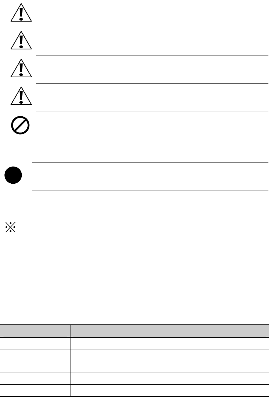
The following items describe the operation of mouse:
Item Operation Step Picture
Click Do not move the mouse; press the left button, then release.
Right Click Do not move the mouse; press the right button, then release.
Double Click
Do not move the mouse; press the left button two times quickly, this operation
only takes effect on left button.
Drag
Hold pressing the left button and move the mouse, release the left button at the
target position.
Move Move the mouse to the target position and stop.
Input
Press the left button in the input box, then release. When there is a cursor in the
input box, input the content.
Operation Click, double click or right click the blank
4
- Precautions when using the software
Install the proper Kinco HMIware according to the language of the OS, if you install the Chinese version in English OS,
some function may be abnormal, because there is no Chinese character library in English OS.
- Kinco HMIware is backward compatible, but not the reverse. That is to say, the project that compiled by the higher
version software cannot be opened and compiled by lower version, but the project that compiled by lower version
software can be opened and compiled by higher version.
- The *.pkg file that compiled by the version that earlier than EV5000 V1.3.0 cannot be decompiled
- Please remember the password if you use the project password, upload password and decompilation password, we
cannot provide the reset the password service or any universal password.
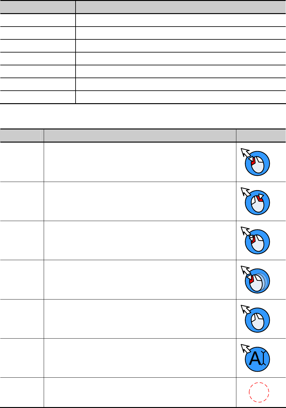
- The display difference between the Kinco HMIware and HMI:
(1) When you configure the project, there are some grids as the aligning reference in Kinco HMIware configuration area,
there is no grids in HMI screen.
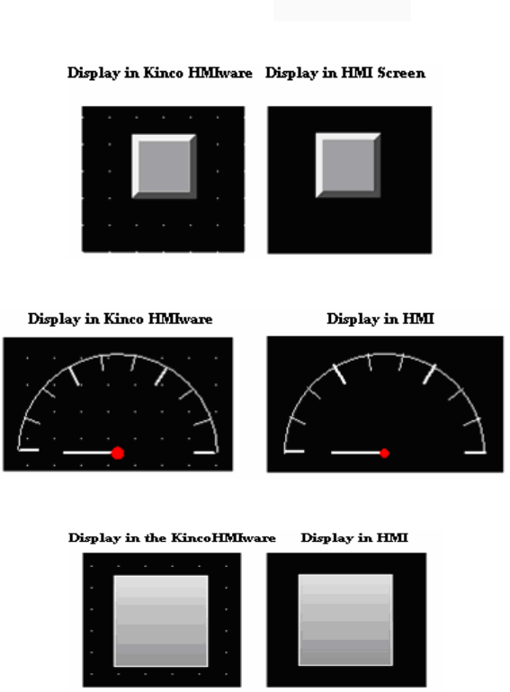
(2) The following size difference maybe happen when using dial scale and dial axis.
(3) If the graphic uses the gradient color as fill color, the following display difference maybe happen.
- Product Support
- Online support
If you have any question when using the product, you can contact our overseas technical engineers; they can support you
online or by email.
5
- Technical Training
If you have any question about the product described in this manual, you can contact our company directly or local
distributors. About the technical training, please pay attention to the information at our site or consult the sales manager.
- Contact us
Kinco Automation Ltd
Email: sales@kinco.cn

1
Index
Part1 Basic Part
Preface....................................................................................................................................................................................... 1
1 Introduction ............................................................................................................................................................................ 1
1.1 About Kinco HMIware ............................................................................................................................................... 1
1.2 Features List of Kinco HMIware................................................................................................................................ 1
2 Starting ................................................................................................................................................................................. 13
2.1 How to use Kinco HMIware..................................................................................................................................... 13
2.2 How to get Kinco HMIware software....................................................................................................................... 13
2.3 Kinco HMIware Installation and Operating Environment Requirement................................................................... 13
2.4 Install/Uninstall ........................................................................................................................................................ 13
2.4.1 Install Kinco HMIware................................................................................................................................. 13
2.4.2 Uninstall Kinco HMIware............................................................................................................................ 14
2.5 Start/Quit .................................................................................................................................................................. 14
2.5.1 Start Kinco HMIware ................................................................................................................................... 14
2.5.2 Quit Kinco HMIware.................................................................................................................................... 15
2.6 System Language Change ........................................................................................................................................ 15
2.7 F1 Help..................................................................................................................................................................... 16
2.8 Upgrade/Update........................................................................................................................................................ 16
2.9 Software Compatibility............................................................................................................................................. 16
2.10 Install USB Driver.................................................................................................................................................. 17
2.11 Software Application Program Introduction ........................................................................................................... 19
3 Make Project......................................................................................................................................................................... 21
3.1 Project Requirement ................................................................................................................................................. 21
3.2 System Analysis ....................................................................................................................................................... 22
3.3 Make Project............................................................................................................................................................. 24
3.3.1 Create Project ............................................................................................................................................... 24
3.3.2 Device Selection, Connection and Parameters Setting ................................................................................. 25
3.3.3 Edit Frame.................................................................................................................................................... 27
3.3.4 Save Project.................................................................................................................................................. 46
3.3.5 Project Simulation ........................................................................................................................................ 46
3.3.6 Download Project......................................................................................................................................... 47
3.4 Project Folder Introductions ..................................................................................................................................... 47
Part2 Advanced Part
1 User Interface ....................................................................................................................................................................... 51
1.1 Interface Layout ....................................................................................................................................................... 51
1.2 Menu ........................................................................................................................................................................ 51
1.2.1 File Menu ..................................................................................................................................................... 51
1.2.2 Edit Menu..................................................................................................................................................... 52
2
1.2.3 View Menu ................................................................................................................................................... 52
1.2.4 Screen Menu................................................................................................................................................. 52
1.2.5 Draw Menu................................................................................................................................................... 53
1.2.6 Components Menu ....................................................................................................................................... 53
1.2.7 Tools Menu................................................................................................................................................... 53
1.2.8 Option Menu ................................................................................................................................................ 53
1.2.9 Window Menu.............................................................................................................................................. 53
1.2.10 Help Menu.................................................................................................................................................. 53
1.3 Toolbar...................................................................................................................................................................... 54
1.3.1 Basic Toolbar................................................................................................................................................ 54
1.3.2 Draw Toolbar................................................................................................................................................ 54
1.3.3 Page Switch Toolbar..................................................................................................................................... 54
1.3.4 Position Toolbar ........................................................................................................................................... 54
1.3.5 Line Width Toolbar....................................................................................................................................... 55
1.3.6 Line Style Toolbar ........................................................................................................................................ 55
1.3.7 System Toolbar............................................................................................................................................. 55
1.3.8 Database Toolbar.......................................................................................................................................... 55
1.3.9 Code Edit Toolbar ........................................................................................................................................ 55
1.3.10 Fill Effect Toolbar ...................................................................................................................................... 55
1.3.11 Label Position Toolbar................................................................................................................................ 56
1.3.12 State Switch Toolbar................................................................................................................................... 56
1.3.13 Font Toolbar ............................................................................................................................................... 56
1.3.14 Status Bar ................................................................................................................................................... 56
1.3.15 Tip Text ...................................................................................................................................................... 56
1.3.16 Toolbar Options.......................................................................................................................................... 56
1.4 Software window...................................................................................................................................................... 56
1.4.1 Graph Element Window ............................................................................................................................... 57
1.4.2 Project Files Window ................................................................................................................................... 58
1.4.3 Project Sstructure Window ........................................................................................................................... 58
1.4.4 Message Window ......................................................................................................................................... 59
1.4.5 Component List Window.............................................................................................................................. 60
1.5 Configuration Edit Area............................................................................................................................................ 61
1.5.1 Construct Window........................................................................................................................................ 61
1.5.2 HMI Edit Window ........................................................................................................................................ 62
1.5.3 Graphic Edit Window................................................................................................................................... 62
1.5.4 Macro Edit Window ..................................................................................................................................... 63
1.5.5 Edit Initial Window ...................................................................................................................................... 63
2 Basic Design Method............................................................................................................................................................ 64
2.1 Window screen ......................................................................................................................................................... 64
2.1.1 Specification of window screen.................................................................................................................... 64
2.1.2 Window Display Methods ............................................................................................................................ 64
2.1.3 Display Position ........................................................................................................................................... 67
2.1.4 Display Order............................................................................................................................................... 67
2.1.5 Copy/Delete Windows.................................................................................................................................. 68
3
2.2 Draw......................................................................................................................................................................... 69
2.2.1 Image Format ............................................................................................................................................... 69
2.2.2 Vector ........................................................................................................................................................... 69
2.2.3 Geometric Figures Attribution...................................................................................................................... 72
2.2.4 About Fountain Fill ...................................................................................................................................... 73
2.2.5 Bitmap.......................................................................................................................................................... 74
2.2.6 About Transparent Color .............................................................................................................................. 74
2.3 Text........................................................................................................................................................................... 75
2.3.1 Font Type...................................................................................................................................................... 76
2.3.2 Dot Matrix Font............................................................................................................................................ 76
2.3.3 Vector Font ................................................................................................................................................... 76
2.3.4 Graph Font ................................................................................................................................................... 77
2.3.5 Text Attribute Edition................................................................................................................................... 78
2.3.6 Notes for Using V
ector Font......................................................................................................................... 78
2.4 Keyboard .................................................................................................................................................................. 79
2.4.1 Keyboard Type ............................................................................................................................................. 79
2.4.2 NUM Keyboard............................................................................................................................................ 81
2.4.3 ASCII Keyboard........................................................................................................................................... 83
2.4.4 HEX Keyboard............................................................................................................................................. 83
2.4.5 Create your Own Mumber Keyboard ........................................................................................................... 84
2.4.6 Create your Oown Unicode Keyboard ......................................................................................................... 86
2.4.7 Call Keyboard in the Group Component Library ......................................................................................... 87
2.5 Code Type................................................................................................................................................................. 88
2.5.1 BIN............................................................................................................................................................... 88
2.5.2 BCD ............................................................................................................................................................. 89
2.5.3 LSB .............................................................................................................................................................. 89
2.6 Language Switching ................................................................................................................................................. 89
2.7 RTC Set .................................................................................................................................................................... 91
2.7.1 Through Special Registers............................................................................................................................ 92
2.7.2 Calibrate System Time in System Setup Screen........................................................................................... 93
2.7.3 System Time and PLC Time Synchronization.............................................................................................. 93
2.8 LOGO Screen(Logo)........................................................................................................................................... 96
2.8.1 LOGO Screen Specification ......................................................................................................................... 96
2.8.2 Init Screen Setting ........................................................................................................................................ 96
2.8.3 Note for Using Init Screen............................................................................................................................ 98
2.9 Exchange Serial........................................................................................................................................................ 98
2.10 Replace Devices ..................................................................................................................................................... 99
2.10.1 Replace HMI ............................................................................................................................................ 100
2.10.2 Replace PLC............................................................................................................................................. 101
2.11 Index Function...................................................................................................................................................... 102
2.11.1 Index Register........................................................................................................................................... 102
2.11.2 Index Station Num.................................................................................................................................... 103
2.12 Buzzer................................................................................................................................................................... 105
2.12.1 Touch Beep............................................................................................................................................... 105
4
2.12.2 Alarm Beep............................................................................................................................................... 106
2.13 Screen Saver......................................................................................................................................................... 107
2.14 Password Setting .................................................................................................................................................. 108
2.14.1 Project Protection ..................................................................................................................................... 108
2.14.2 Screen Protection...................................................................................................................................... 108
2.14.3 Component Protection.............................................................................................................................. 109
2.15 Data Encryption.................................................................................................................................................... 110
2.16 Animation Effects................................................................................................................................................. 112
2.17 Multi-Copy ........................................................................................................................................................... 115
2.18 Group.................................................................................................................................................................... 116
2.19 Find /Replace........................................................................................................................................................ 119
3 Window .............................................................................................................................................................................. 121
3.1 Window Types ........................................................................................................................................................ 121
3.2 System Default Window......................................................................................................................................... 123
3.3 Edit Window........................................................................................................................................................... 124
3.3.1 Window Add............................................................................................................................................... 124
3.3.2 Window Opening........................................................................................................................................ 125
3.3.3 Window Copy/ Multi-Windows Copy........................................................................................................ 126
3.3.4 Window Deletion/ Multi-Windows Deletion.............................................................................................. 127
3.4 Window Attribute ................................................................................................................................................... 128
3.4.1 Open Window Attribute Box...................................................................................................................... 128
3.4.2 Window Attribute Descriptions .................................................................................................................. 129
3.5 Components Related to Window ............................................................................................................................ 132
4 Component ......................................................................................................................................................................... 133
4.1 Common Setting of Component ............................................................................................................................. 133
4.1.1 Create and Delete Component.................................................................................................................... 133
4.1.2 Execution Order of Components ................................................................................................................ 134
4.1.3 Methods to Open Attributes Window ......................................................................................................... 135
4.1.4 Basic Setting............................................................................................................................................... 136
4.1.5 Tag Setting.................................................................................................................................................. 138
4.1.6 Graphics Setting......................................................................................................................................... 139
4.1.7 Control Setting Option ............................................................................................................................... 140
4.1.8 Display Setting ........................................................................................................................................... 143
4.1.9 Touch Sound Control.................................................................................................................................. 145
4.1.10 Save Historical Data................................................................................................................................. 146
4.2 Button/Switch Components.................................................................................................................................... 147
4.2.1 Bit State Setting.......................................................................................................................................... 148
4.2.2 Bit State Switch.......................................................................................................................................... 151
4.2.3 Multiple State Setting................................................................................................................................. 152
4.2.4 Multiple State Switch ................................................................................................................................. 156
4.2.5 Combination Operations............................................................................................................................. 158
4.2.6 Function Key.............................................................................................................................................. 159
4.3 Lamp Component ................................................................................................................................................... 165
4.3.1 Bit State Lamp............................................................................................................................................ 165
5
4.3.2 Multiple State Display................................................................................................................................ 167
4.4 Number Components.............................................................................................................................................. 167
4.4.1 Number Input ............................................................................................................................................. 169
4.4.2 Number Display ......................................................................................................................................... 171
4.5 Text Components.................................................................................................................................................... 171
4.5.1 Text Iput ..................................................................................................................................................... 174
4.5.2 Text Display ............................................................................................................................................... 174
4.5.3 Note Book .................................................................................................................................................. 175
4.6 Graph/Meter Components ...................................................................................................................................... 175
4.6.1 Trend Curve................................................................................................................................................ 178
4.6.2 XY Plot....................................................................................................................................................... 190
4.6.3 Oscillograph ............................................................................................................................................... 194
4.6.4 Meter .......................................................................................................................................................... 196
4.6.5 Bar Picture.................................................................................................................................................. 198
4.7 Alarm Component .................................................................................................................................................. 201
4.7.1 Event Display ............................................................................................................................................. 203
4.7.2 Historical Event Display ............................................................................................................................ 207
4.7.3 Event Bar.................................................................................................................................................... 208
4.7.4 Alarm Display ............................................................................................................................................ 210
4.7.5 Alarm Bar................................................................................................................................................... 211
4.8 Window Component............................................................................................................................................... 211
4.8.1 Direct Window ........................................................................................................................................... 211
4.8.2 Indirect Window......................................................................................................................................... 213
4.9 Graphic Components .............................................................................................................................................. 214
4.9.1 Vector Graph .............................................................................................................................................. 214
4.9.2 Bitmap........................................................................................................................................................ 214
4.9.3 Free Plotting............................................................................................................................................... 214
4.9.4 Dynamic Graph .......................................................................................................................................... 215
4.9.5 GIF ............................................................................................................................................................. 215
4.10 Video Input Component........................................................................................................................................ 216
4.10.1 Video ........................................................................................................................................................ 216
4.10.2 Camera ..................................................................................................................................................... 218
4.11 Multiple State Neon Lamp.................................................................................................................................... 219
4.11.1 Bit State Neon Lamp ................................................................................................................................ 219
4.11.2 Bit State Neon Lamp ................................................................................................................................ 220
4.12 Animation Components ........................................................................................................................................ 221
4.12.1 Animation................................................................................................................................................. 221
4.12.2 Moving Component.................................................................................................................................. 222
4.12.3 Pipeline..................................................................................................................................................... 226
4.13 Grid Components.................................................................................................................................................. 227
4.13.1 Grid .......................................................................................................................................................... 227
4.13.2 Historical Data Display ............................................................................................................................ 228
4.13.3 User Info Display ..................................................................................................................................... 233
4.13.4 Operation Log .......................................................................................................................................... 234
6
4.13.5 Data Report .............................................................................................................................................. 236
4.13.6 Data Curve ............................................................................................................................................... 246
4.14 Data Transmission Component............................................................................................................................. 252
4.14.1 Recipe....................................................................................................................................................... 252
4.14.2 Data Transmission .................................................................................................................................... 254
4.15 Project Database ................................................................................................................................................... 255
4.15.1 Text Library.............................................................................................................................................. 256
4.15.2 Address Tag .............................................................................................................................................. 257
4.15.3 Event Information .................................................................................................................................... 258
4.15.4 Alarm Information.................................................................................................................................... 262
4.15.5 PLC Control ............................................................................................................................................. 264
4.15.6 Sound Lib................................................................................................................................................. 271
4.15.7 Data Logger.............................................................................................................................................. 272
4.15.8 Schedule List............................................................................................................................................ 274
4.16 Auxiliary Component ........................................................................................................................................... 278
4.16.1 Scale......................................................................................................................................................... 278
4.16.2 Timer ........................................................................................................................................................ 279
4.16.3 Scroll Bar ................................................................................................................................................. 282
4.16.4 Date/Time................................................................................................................................................. 283
4.16.5 Note Pad................................................................................................................................................... 283
4.16.6 File List .................................................................................................................................................... 284
4.16.7 Trigger Touch ........................................................................................................................................... 284
5 Better Understanding of Library......................................................................................................................................... 286
5.1 Text Library ............................................................................................................................................................ 286
5.1.1 Create a Text Library.................................................................................................................................. 286
5.1.2 Export/Import Text Library ........................................................................................................................ 288
5.1.3 Set the Language of Text Library ............................................................................................................... 288
5.1.4 Text Library Application ............................................................................................................................ 289
5.2 Address Tag Library ............................................................................................................................................... 291
5.2.1 Build a Address tag Library........................................................................................................................ 291
5.2.2 Address Tag Application............................................................................................................................. 291
5.3 Graphic Library ...................................................................................................................................................... 292
5.3.1 Import Graphics.......................................................................................................................................... 292
5.3.2 Build New Graphics ................................................................................................................................... 296
5.3.3 Edit Graphics.............................................................................................................................................. 305
5.3.4 How to Use the Graphics............................................................................................................................ 308
5.4 Sound Lib Application............................................................................................................................................ 310
5.4.1 Import Audio File....................................................................................................................................... 310
5.4.2 How to Use Audio File............................................................................................................................... 312
6 System Parameters.............................................................................................................................................................. 314
6.1 HMI Attributes ....................................................................................................................................................... 314
6.1.1 HMI............................................................................................................................................................ 314
6.1.2 Task Bar ..................................................................................................................................................... 315
6.1.3 HMI Extended Attributes ........................................................................................................................... 317
7
6.1.4 HMI System Information Text ................................................................................................................... 320
6.1.5 Security Levels Setting............................................................................................................................... 321
6.1.6 User Permissions Setting............................................................................................................................ 321
6.1.7 Historical Events Storage ........................................................................................................................... 322
6.1.8 Print Setting................................................................................................................................................ 323
6.1.9 Serial Port Setting....................................................................................................................................... 324
6.1.10 Extended Memory .................................................................................................................................... 326
6.1.11 HMI License Setting................................................................................................................................. 326
6.2 PLC Attribute ......................................................................................................................................................... 329
7 Compile/Simulate/Download/Upload................................................................................................................................. 331
7.1 Compilation............................................................................................................................................................ 331
7.1.1 Methods of Compilation............................................................................................................................. 331
7.2 Simulation .............................................................................................................................................................. 331
7.2.1 Modes of Simulation .................................................................................................................................. 331
7.2.2 Exit Simulation........................................................................................................................................... 332
7.3 Download ............................................................................................................................................................... 332
7.3.1 Download Method Selection ...................................................................................................................... 332
7.3.2 Download via U disk or SD card................................................................................................................ 334
7.3.3 Download Selection ................................................................................................................................... 334
7.4 Upload/ Download/Compile Project via KHManager ............................................................................................ 338
8 KHManager ........................................................................................................................................................................ 339
8.1 Introduction to KHManager ................................................................................................................................... 339
8.2 Methods of Open KHManager ............................................................................................................................... 340
8.3 Download ............................................................................................................................................................... 340
8.4 Upload .................................................................................................................................................................... 341
8.5 System Operation ................................................................................................................................................... 341
8.6 Get Version ............................................................................................................................................................. 341
8.7 Decompile Operation.............................................................................................................................................. 341
8.8 Data Decryption ..................................................................................................................................................... 342
9 Macro.................................................................................................................................................................................. 343
9.1 Macro Editing Environment ................................................................................................................................... 343
9.2 Macro Edit.............................................................................................................................................................. 343
9.2.1 Build Macro ............................................................................................................................................... 343
9.2.2 Delete Macro.............................................................................................................................................. 344
9.2.3 Rename Macro ........................................................................................................................................... 344
9.2.4 Program Macro........................................................................................................................................... 345
9.2.5 Execute Macro............................................................................................................................................ 348
9.3 Macro Application.................................................................................................................................................. 348
9.4 Local Variable Function.......................................................................................................................................... 350
9.5 Array Application ................................................................................................................................................... 351
9.6 Some Notes on the Macro ...................................................................................................................................... 354
10 Password........................................................................................................................................................................... 355
10.1 Project Protection ................................................................................................................................................. 356
10.1.1 Project Password Protection ..................................................................................................................... 356
8
10.1.2 Upload Password Protection and Prohibit Uploading............................................................................... 356
10.1.3 Decompilation Password Protection and Prohibit Decompiling............................................................... 358
10.1.4 Download Password Protection................................................................................................................ 359
10.2 Window Protection ............................................................................................................................................... 360
10.2.1 Window Password Setting........................................................................................................................ 360
10.2.2 Security Level Setting of Window............................................................................................................ 361
10.2.3 System reserved registers related to security level ................................................................................... 362
10.2.4 Security level password input window ..................................................................................................... 362
10.2.5 Modifying Password Online..................................................................................................................... 363
10.2.6 Application of Passwords Required for Switching Windows ................................................................... 364
10.3 Component Protection .......................................................................................................................................... 365
10.3.1 Security Level Protection for Components............................................................................................... 365
10.3.2 User Permission Protection for Components............................................................................................ 365
10.3.3 System Reserved Registers Related to User Permissions......................................................................... 366
10.3.4 System Reserved Registers Related to Add/Delete Users and User Permissions Online.......................... 366
10.3.5 Window for User Permission Password Input .......................................................................................... 367
10.3.6 Application of Security Level Protection for Components ....................................................................... 368
10.3.7 Application of User Permission Protection for Component...................................................................... 369
11 Recipe/ RecipeEditor ........................................................................................................................................................ 378
11.1 Register Related to the Recipe.............................................................................................................................. 378
11.2 Method for Checking the Recipe Size .................................................................................................................. 379
11.2.1 Method for Checking the RW Size ........................................................................................................... 379
11.2.2 Calculation for Recipe Address Range ..................................................................................................... 380
11.3 Usage of Recipe.................................................................................................................................................... 381
11.3.1 Absolute Address...................................................................................................................................... 381
11.3.2 Index Address ........................................................................................................................................... 381
11.3.3 Application of Recipe............................................................................................................................... 382
11.4 RecipeEditor ......................................................................................................................................................... 384
11.4.1 Recipe Editor Start-up .............................................................................................................................. 385
11.4.2 Recipe Editor User interface..................................................................................................................... 386
11.4.3 Usage of RecipeEditor.............................................................................................................................. 388
11.5 Recipe Uploading/ Downloading/ Clearing.......................................................................................................... 395
12 KHMonitor ....................................................................................................................................................................... 396
12.1 Descriptions of KHMonitor.................................................................................................................................. 396
12.2 Start KHMonitor................................................................................................................................................... 396
12.3 KHMonitor Interface ............................................................................................................................................ 396
12.4 How to Use KHMonitor ....................................................................................................................................... 397
13 Print .................................................................................................................................................................................. 400
13.1 Type of Printer supports local printing ................................................................................................................. 400
13.2 Printing-related Components ................................................................................................................................ 401
13.3 Pictbridge Print..................................................................................................................................................... 403
13.4 Print Function Setting Method.............................................................................................................................. 405
13.4.1 Local Print: HMI serial is connected directly to the Printer ..................................................................... 405
13.4.2 Local Print: HMI USB Slave is connected directly to the Printer ............................................................ 406
9
13.4.3 Network Print (remote print): Through Network Printer to Print HMI Screen......................................... 407
13.4 Print Page Application Skills................................................................................................................................ 412
13.5 Print Error............................................................................................................................................................. 413
14 HMI Communication........................................................................................................................................................ 414
14.1 Serial Communication .......................................................................................................................................... 414
14.1.1 HMI and PC Serial Communication......................................................................................................... 414
14.1.2 HMI and PLC /Controller Serial Communication .................................................................................... 414
14.1.3 Serial Communication Related Settings ................................................................................................... 421
14.2 Network Port Communication.............................................................................................................................. 421
14.2.1 HMI and PC Network Port Communication............................................................................................. 421
14.2.2 HMI and HMI Port Communication Network.......................................................................................... 422
14.2.3 HMI and PLC/Controller Network Port Communication......................................................................... 423
14.2.4 FTP Function............................................................................................................................................ 426
14.3 Field Bus Communication .................................................................................................................................... 429
14.3.1 CAN Communicate .................................................................................................................................. 429
14.3.2 DP Communicate ..................................................................................................................................... 430
14.4 MPI Communicate................................................................................................................................................ 435
14.5 MODBUS Protocol Applications(Master-slave mode).................................................................................... 439
14.5.1 MODBUS Protocol Overview.................................................................................................................. 439
14.5.2 MODBUS Protocol Communication Format ........................................................................................... 441
14.5.3 MODBUS Protocol in the HMI Application ............................................................................................ 447
15 VNC.................................................................................................................................................................................. 453
15.1 Various client-sides............................................................................................................................................... 453
15.2 Access via LAN.................................................................................................................................................... 454
15.2.1 Remote control HMI by PC via LAN....................................................................................................... 454
15.2.2 Remote control HMI by mobile via LAN................................................................................................. 457
15.2.3 Remote control HMI by browser via LAN............................................................................................... 458
15.3 Access via WAN ................................................................................................................................................... 460
16 Register............................................................................................................................................................................. 464
16.1 Local Registers of HMI ........................................................................................................................................ 464
16.1.1 Bit Address ............................................................................................................................................... 464
16.1.2 Word Address ........................................................................................................................................... 464
16.2 System Special Registers of HMI......................................................................................................................... 465
16.2.1 Parameter Setting of Hardware................................................................................................................. 466
16.2.2 System Setting.......................................................................................................................................... 467
16.2.3 Components Setting ................................................................................................................................. 474
16.2.4 Security Leve l and User Permission........................................................................................................ 476
16.2.5 Data and Project Management.................................................................................................................. 478
16.2.6 Communication ........................................................................................................................................ 480
Part3 Hardware Part
1 Name and Specification...................................................................................................................................................... 485
1.1 Name of Each Part......................................................................................................................................... 485
1.2 Specifications of Each Part............................................................................................................................ 486
10
2 Connection with Preiferal Equipments ............................................................................................................................... 491
2.1 Connection via Serial Port............................................................................................................................. 491
2.2 Connection via USB Interfaces ..................................................................................................................... 493
2.3 Connection via LAN Interfaces..................................................................................................................... 494
3 System Setting Mode.......................................................................................................................................................... 496
3.1 Methods to Display System Setting Mode .................................................................................................... 496
3.2 System Setting............................................................................................................................................... 496
4 Touch Screen Calibrate Mode............................................................................................................................................. 498
4.1 Methods to Display Touch Screen Calibrate Mode ....................................................................................... 498
4.2 Touch Screen Calibrate Setting ..................................................................................................................... 498
5 Firmware Update Mode...................................................................................................................................................... 499
5.1 Methods to Display Firmware Update Mode ................................................................................................ 499
5.2 Firmware Update Setting............................................................................................................................... 499
6 Maintenance and Tending................................................................................................................................................... 500
6.1 Maintenance.................................................................................................................................................. 500
6.2 Tending.......................................................................................................................................................... 500
Appendix 1 Regular PLC Used for HMI ............................................................................................................................... 502
Appendix 2 List of Error Information.................................................................................................................................... 506
Appendix 3 List of System Prompt Message......................................................................................................................... 511

Basic Part
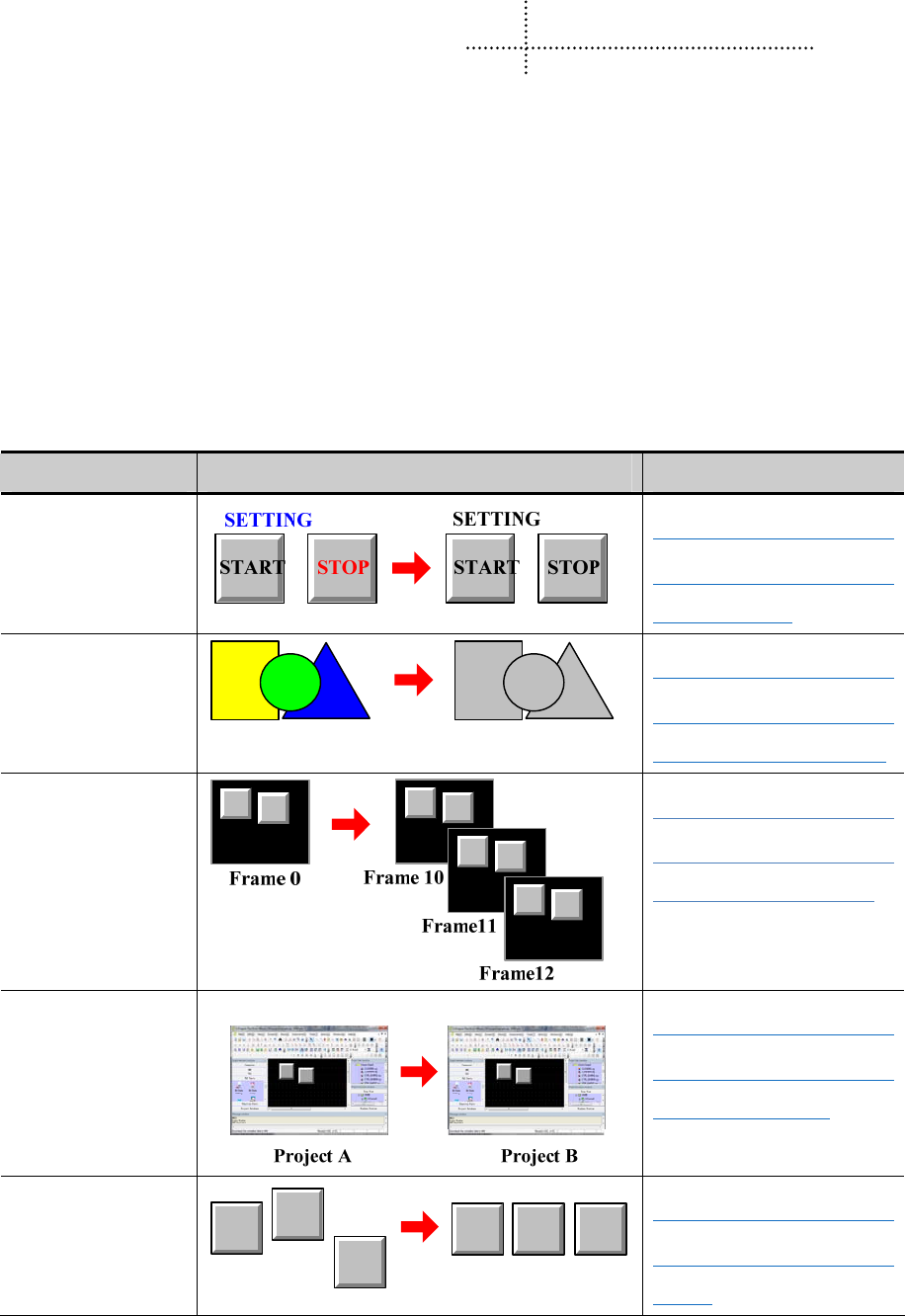
1
1 Introduction
This chapter mainly introduces the features and functions of Kinco HMIware Configuration Software.
1.1 About Kinco HMIware
Kinco HMIware Configuration Software(Hereinafter referred to as “Kinco HMIware”)is a human-machine interface(HMI)
configuration software developed by Kinco Electric (Shanghai) Ltd. (Hereinafter referred to as “Kinco”),it is special for
MT4000/5000 series HMI. Kinco HMIware provides a powerful integrated development environment for users. Products
are widely applied in various kinds of fields such as medical, chemical industry, electric power, printing, textile, food,
national defense and engineering machinery, intelligent household, high speed railway and so on.
1.2 Features List of Kinco HMIware
- Edit operation functions
Functions Diagrams Notes
Batch to modify font
properties
☞Details please refer to
【Advanced Part 2.3.5 Text
Attribute Edition】
Batch to modify graph
properties
☞Details please refer to
【Advanced Part 2.2.3
Geometric Figures Attribution】
Batch to copy windows
☞Details please refer to
【Advanced Part 3.3.3 Window
Copy /Multi-Windows Copy】
Crossing projects to
copy components
☞Details please refer to
【Advanced Part 2.1.5
Copy/Delete windows】
Batch to set components
alignment
☞Details please refer to
【Advanced Part 1.2.2 Edit
Menu】

Kinco HMIware Configuration Edit Software
2
Batch to set components
same size
☞Details please refer to
【Advanced Part 1.2.2 Edit
Menu】
Batch to set components
same space
☞Details please refer to
【Advanced Part 1.2.2 Edit
Menu】
Overlay windows
☞Details please refer to
【Advanced Part 2.1.2 Windows
Display Methods】
Group components
☞Details please refer to
【Advanced Part 2.18 Group】
Multi-copy components
☞Details please refer to
【Advanced Part 2.17
Multi-copy】
Exchange serial ports
☞Details please refer to
【Advanced Part 2.9 Exchange
Serial】
Exchange devices
☞Details please refer to
【Advanced Part 2.10 Replace
Devices】
- Functions of Components
Switch and lamp
Functions Diagrams Notes
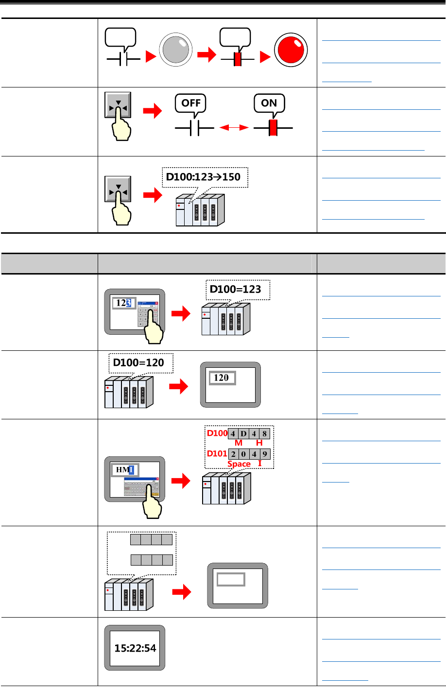
Basic Part Introduction
3
Lamps for displaying
states of device’s
address
ONOFF ☞Details please refer to
【Advanced Part 4.3 Lamp
Component】
Switches for changing
states of device’s
address
☞Details please refer to
【Advanced Part 4.2
Button/Switch Component】
Switches for changing
the value of device’s
address
☞Details please refer to
【Advanced Part 4.2
Button/Switch Component】
Number/Text input and display
Functions Diagrams Notes
Number input
☞Details please refer to
【Advanced Part 4.4.1 Number
Input】
Number display
☞Details please refer to
【Advanced Part 4.4.2 Number
Display】
Text input
☞Details please refer to
【Advanced Part 4.5.1 Text
Input】
Text display
MH
ISpace
D100
D101
4D48
2049
HMI
☞Details please refer to
【Advanced Part 4.5.2 Text
Display】
System time display
☞Details please refer to
【Advanced Part 4.16.4
Date/Time】
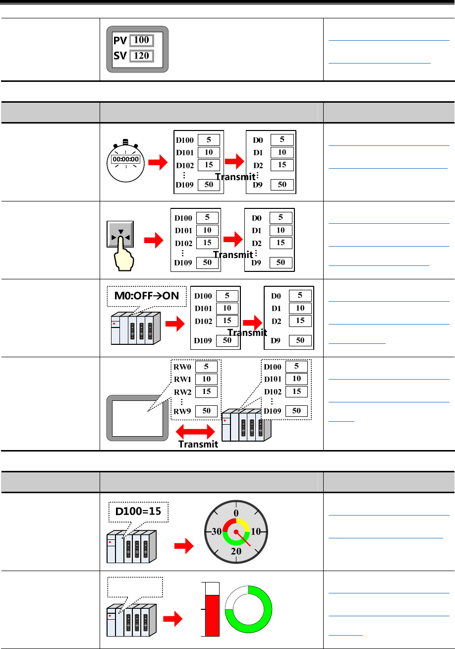
Kinco HMIware Configuration Edit Software
4
Text annotations
☞Details please refer to
【Advanced Part 2.3 Text】
Data transmission
Functions Diagrams Notes
Transmit data by timing
☞Details please refer to
【Advanced Part 4.16.2 Timer】
Transmit data by touch
☞Details please refer to
【Advanced Part 4.14 Data
Transmission Component】
Transmit data by trigger
...
...
☞Details please refer to
【Advanced Part 4.14.2 Data
Transmission】
Data transmit by recipe
☞Details please refer to
【Advanced Part 4.14.1 Recipe
Data】
Meter and Graph
Functions Diagrams Notes
Display data as meter
☞Details please refer to
【Advanced Part 4.6.4 Meter】
Display data as bar
graph
D100=75
0
100
50
☞Details please refer to
【Advanced Part 4.6.5 Bar
Picture】
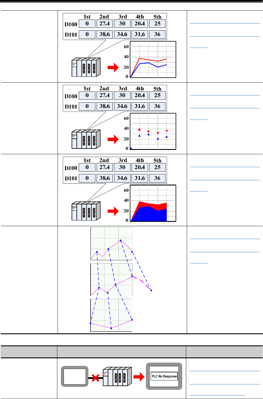
Basic Part Introduction
5
Display data as trend
curve
☞Details please refer to
【Advanced Part 4.6.1 Trend
Curve】
Display data as dot
graph.
☞Details please refer to
【Advanced Part 4.6.1 Trend
Curve】
Display data as
projection graph
☞Details please refer to
【Advanced Part 4.6.1 Trend
Curve】
Zoom of trend curve Normal
Zoom out
Zoom in
☞Details please refer to
【Advanced Part 4.6.1 Trend
Curve】
Alarm
Functions Diagrams Notes
System alarm
information
☞Details please refer to
【Advanced Part 6.1.4 HMI
System Information Text】
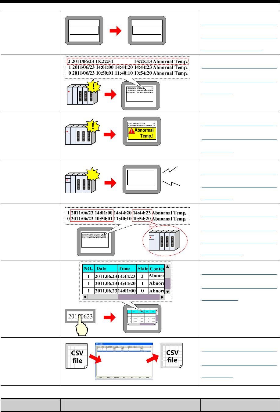
Kinco HMIware Configuration Edit Software
6
User-defined system
alarm information
PLC No Response PLC disconnect
☞Details please refer to
【Advanced Part 6.1.4 HMI
System Information Text】
Display user-defined
alarm information when
alarm happen
☞Details please refer to
【Advanced Part 4.7 Alarm
Component】
Display alarm
infromation in popup
window when alarm
happen
☞Details please refer to
【Advanced Part 4.7 Alarm
Component】
The buzzer will peal
when alarm happen
!Beep...
2 2011/06/23 15:22:54 15
1 2011/06/23 14:01:00 14:44:20 14
0 2011/06/23 10:50:01 11:40:10 10
☞Details please refer to
【Advanced Part 4.7 Alarm
Component】
Obtain the alarm time
of event information
from external clock.
☞Details please refer to
【Advanced Part 2.7.3 System
time and PLC CPU time
synchronization】
Query historical event
records by inputting
date or file number
☞Details please refer to
【Advanced Part 4.7.2 Historical
Event Display】
Import/Export
alarm/event logon
information
☞Details please refer to
【Advanced Part 4.7 Alarm
Component】
Conditional control
Functions Diagrams Notes
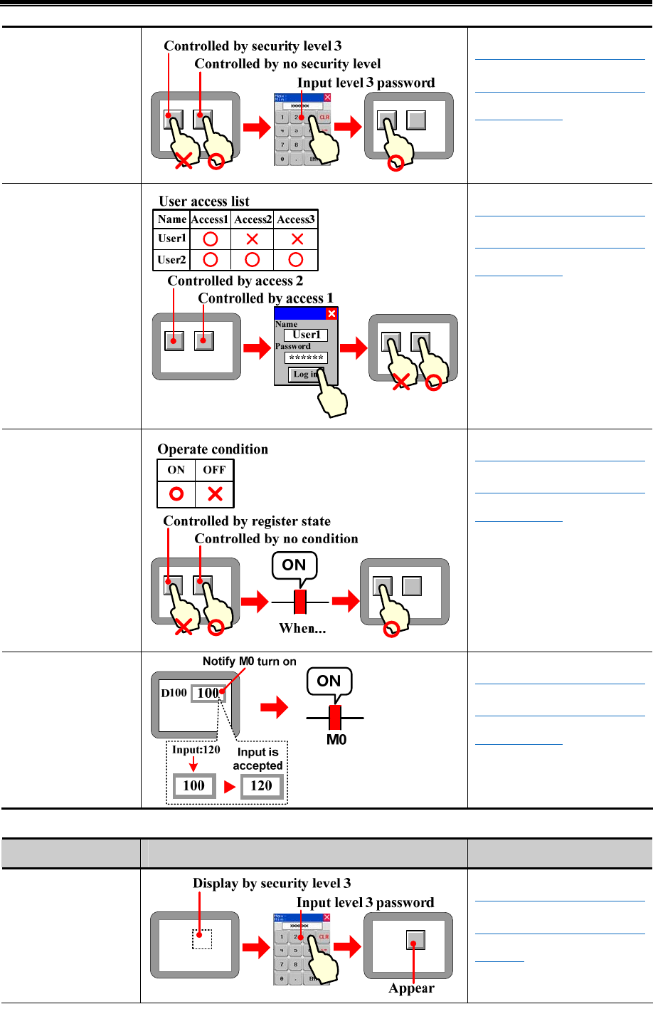
Basic Part Introduction
7
Components are limited
by user security level.
☞Details please refer to
【Advanced Part 4.1.7 Control
Setting Option】
Components are limited
by user permission.
☞Details please refer to
【Advanced Part 4.1.7 Control
Setting Option】
Components are limited
by the status of
registers.
☞Details please refer to
【Advanced Part 4.1.7 Control
Setting Option】
Notification operation
☞Details please refer to
【Advanced Part 4.1.7 Control
Setting Option】
Conditional Display
Functions Diagrams Notes
Display components
according to user
security level.
☞Details please refer to
【Advanced Part 4.1.8 Display
Setting】
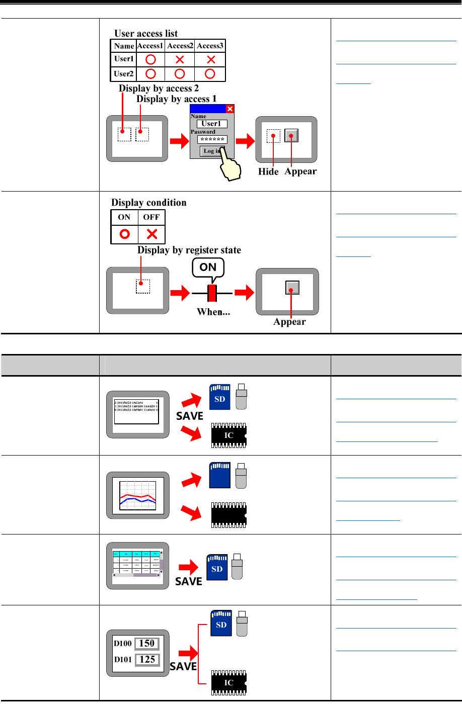
Kinco HMIware Configuration Edit Software
8
Display components
according to user
permission.
☞Details please refer to
【Advanced Part 4.1.8 Display
Setting】
Display components
according to the status
of registers.
☞Details please refer to
【Advanced Part 4.1.8 Display
Setting】
- Data Storage Function
Functions Diagrams Notes
Save historical event
information.
☞Details please refer to
【Advanced Part 6.1.7
Historical Events Storage】
Save sampling data of
trend curve.
IC
SD
SAVE
☞Details please refer to
【Advanced Part 4.1.10 Save
Historical Data】
Save operation records
☞Details please refer to
【Advanced Part 6.1.3 HMI
Extended Attributes】
Save recipe data
☞Details please refer to
【Advanced Part 4.14.1 Recipe】
- Data Clear Function
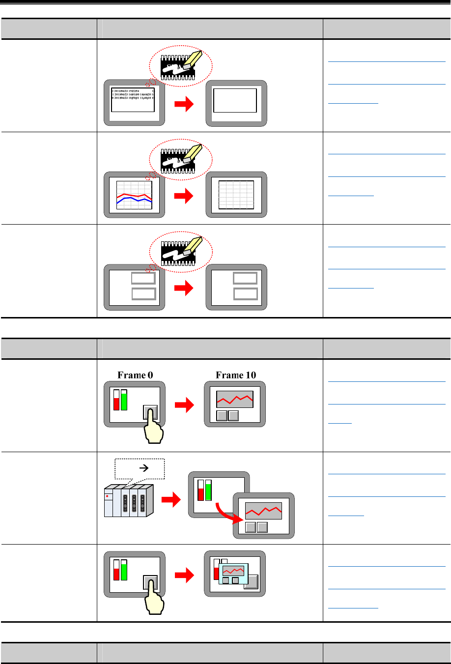
Basic Part Introduction
9
Functions Diagrams Notes
Clear historical event
records.
☞Details please refer to
【Advanced Part 4.7 Alarm
Component】
Clear historical data
records of trend curve.
☞Details please refer to
【Advanced Part 8.3
Download】
Clear historical recipe
data. D100
D101
150
125
SRAM
D100
D101
0
0
☞Details please refer to
【Advanced Part 8.3
Download】
- Window Changing Function
Functions Diagrams Notes
Change window by
touch button.
☞Details please refer to
【Advanced Part 4.2.6 Function
Key】
Change window by
PLC control.
Frame 0
Frame 10
D0:0 10
☞Details please refer to
【Advanced Part 4.15.5 PLC
Control】
Popup other window in
current window.
☞Details please refer to
【Advanced Part 4.8 Window
Component】
- Password Protection Function
Functions Diagrams Notes
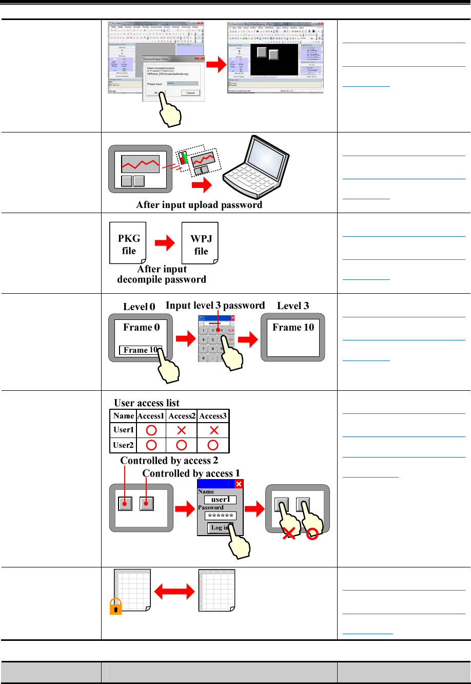
Kinco HMIware Configuration Edit Software
10
Password protection for
project.
☞Details please refer to
【Advanced Part 10.1 Project
Protection】
Password protection for
uploading project.
☞Details please refer to
【Advanced Part 10.1 Project
Protection】
Password protection for
decompiling project.
☞Details please refer to
【Advanced Part 10.1 Project
Protection】
Password protection for
user security level.
☞Details please refer to
【Advanced Part 10.2 Window
Protection】
Password protection for
user permission.
☞Details please refer to
【Advanced Part 10.3.2 User
Permission Protection for
Components】
CSV file encryption
CSV
file
CSV
file
Decrypt
Encrypt
☞Details please refer to
【Advanced Part 2.15 Data
Encryption】
- External Input/ Output
Functions Diagrams Notes
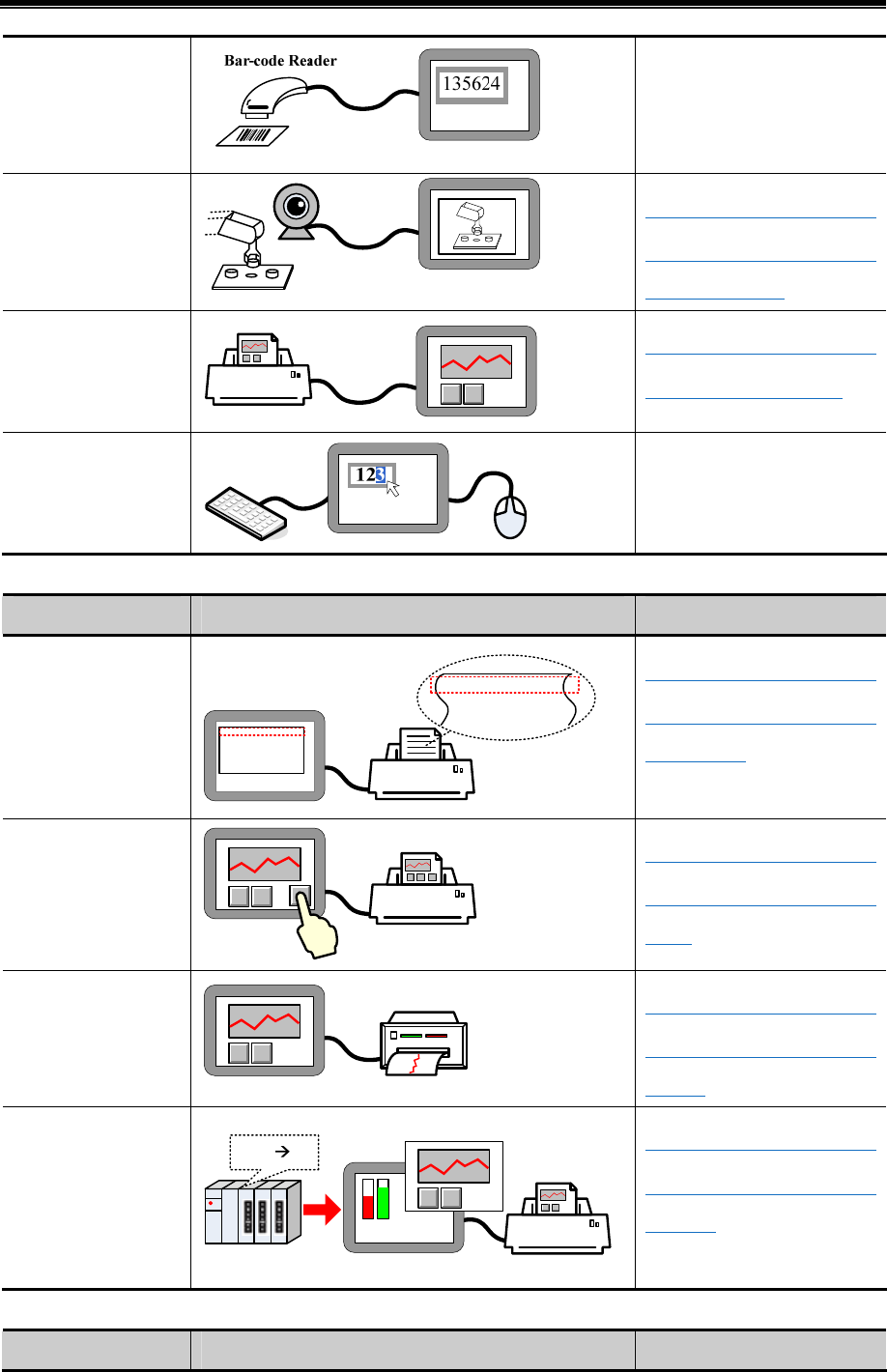
Basic Part Introduction
11
Read data from barcode
reader.
☞Details please refer to【HMI
and PLC connection guide 】
manual
Obtain image from
video.
☞Details please refer to
【Advanced Part 4.10 Video
Input Component】
Printout the screen
image or data.
☞Details please refer to
【Advanced Part 13 Print】
Connect keyboard and
mouse.
- Print Function
Functions Diagrams Notes
Trigger printing event
information.
2 2011/06/23 15:22:54 15
1 2011/06/23 14:01:00 14:44:20 14
0 2011/06/23 10:50:01 11:40:10 10
15:25:54 Abnormal T
14:01:00 Abnormal T
10:50:01 Abnormal T
☞Details please refer to
【Advanced Part 4.15.3 Event
Information】
Touch button to print
screen image.
☞Details please refer to
【Advanced Part 4.2.6 Function
Key】
Print trend curve real
time.
☞Details please refer to
【Advanced Part 4.6.1 Trend
Curve】
Print screen image by
PLC control.
D0:0 10
Frame 0
Frame 10
☞Details please refer to
【Advanced Part 4.15.5 PLC
Control】
- Upload/Download
Functions Diagrams Notes
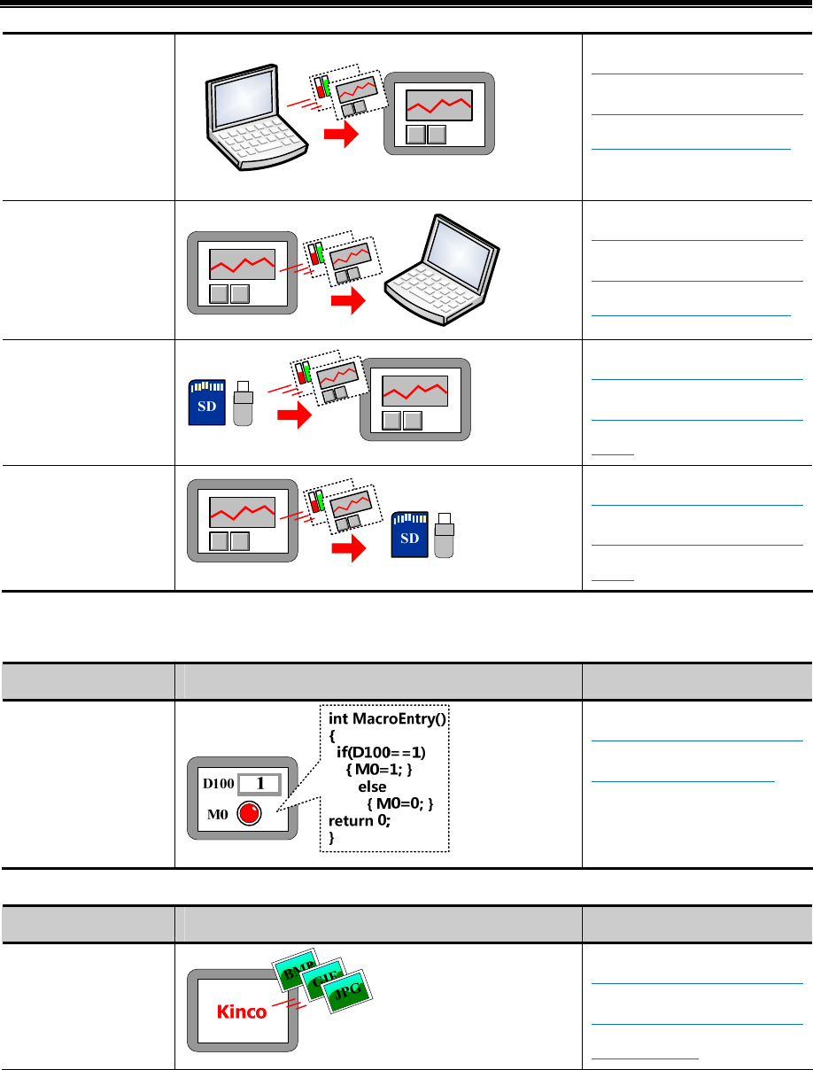
Kinco HMIware Configuration Edit Software
12
Download project from
PC.
☞Details please refer to
【Advanced Part 7 Compile
/Simulate/Download/Upload】
Upload project from
HMI to PC.
☞Details please refer to
【Advanced Part 7 Compile
/Simulate/Download/Upload】
Download project from
external memory.
☞Details please refer to
【Advanced Part 4.2.6 Function
Key】
Upload project from
HMI to external
memory.
☞Details please refer to
【Advanced Part 4.2.6 Function
Key】
- Script Function
Macro
Functions Diagrams Notes
Execute data operation
or control the display
in HMI by macro.
☞Details please refer to
【Advanced Part 9 Macro】
- Other Function
Functions Diagrams Notes
Customize logo.
☞Details please refer to
【Advanced Part 2.8 Logo
Screen (Logo)】
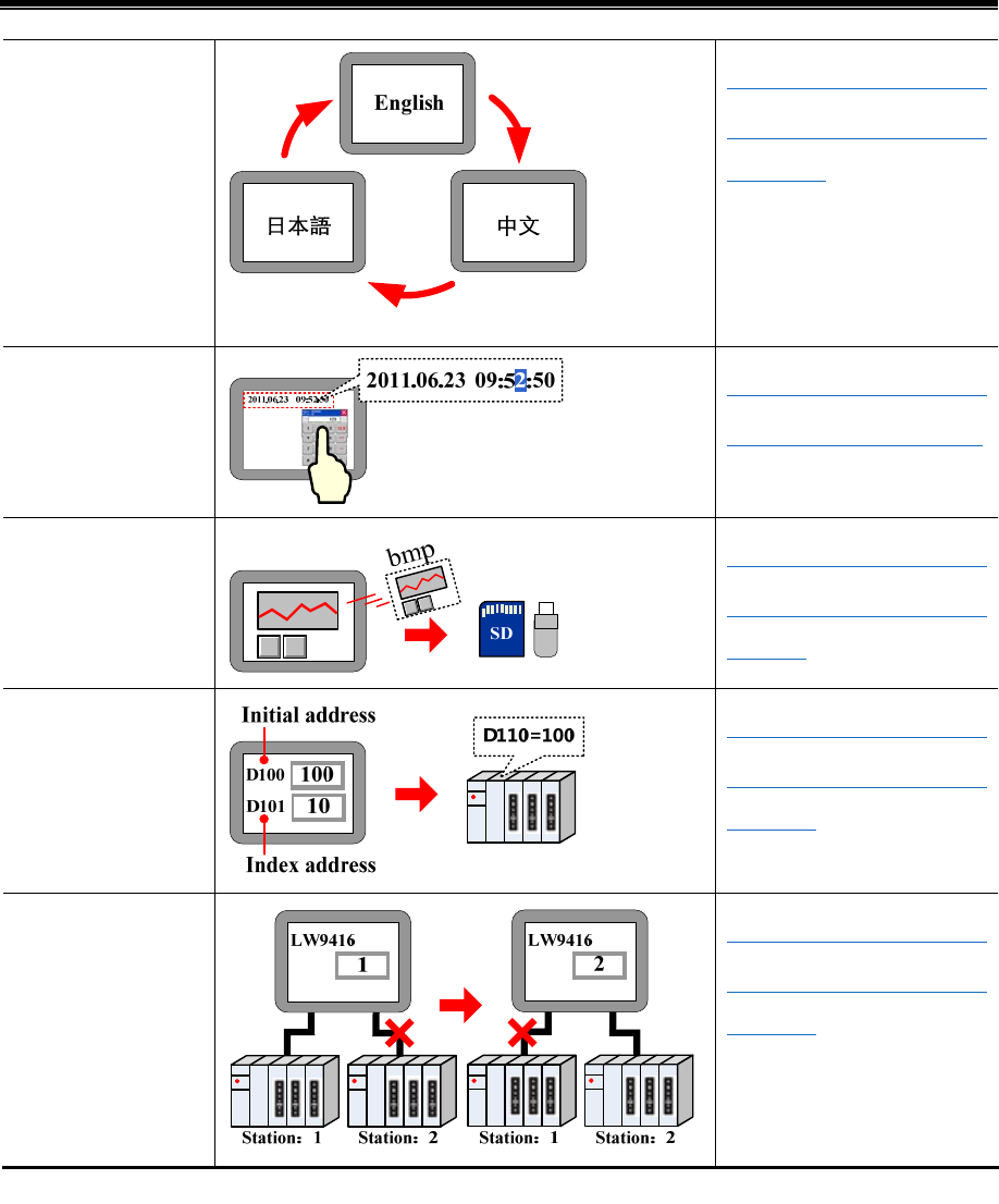
Basic Part Introduction
13
Change languages
online
☞Details please refer to
【Advanced Part 2.6 Language
Switching】
Clock setting
☞Details please refer to
【Advanced Part 2.7 RTC Set】
Save screen by
screenshot function
☞Details please refer to
【Advanced Part 4.15.5 PLC
Control】
Index for register
address(Offset)
☞Details please refer to
【Advanced Part 2.11 Index
Function】
Index for PLC station
number.(Offset)
☞Details please refer to
【Advanced Part 2.11 Index
Function】
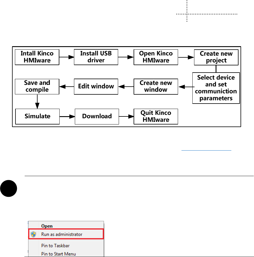
13
2 Starting
2.1 How to use Kinco HMIware
The procedure for using Kinco HMIware is shown in following figure.
2.2 How to get Kinco HMIware software
Users can download Kinco HMIware software from download center in Kinco’s website: http://www.kinco.cn/en/
2.3 Kinco HMIware Installation and Operating Environment Requirement
!Note for using Windows Vista/Windows 7 OS:
- When using Windows Vista/Windows 7 OS, don’t install Kinco HMIware in system disk(C:).
- When using Windows Vista/Windows 7 OS, Kinco HMIware must run as administrator. Right click
the icon of Kinco HMIware.exe, and then select “Run as administrator” as following figure:
2.4 Install/Uninstall
There are two versions of Kinco HMIware (Chinese version and English version).
2.4.1 Install Kinco HMIware
The procedure of installation is as following:
Double click“Setup.exe”file to run the installation program.
Enter welcome window.
Select installation directory, the default directory is “D:\Program Files” and it will create “Kinco HMIware” folder
automatically. Click【Browse】to change the installation directory.
Confirm installation.
It will appear installation statues of Kinco HMIware, click【Install】to start installing software.
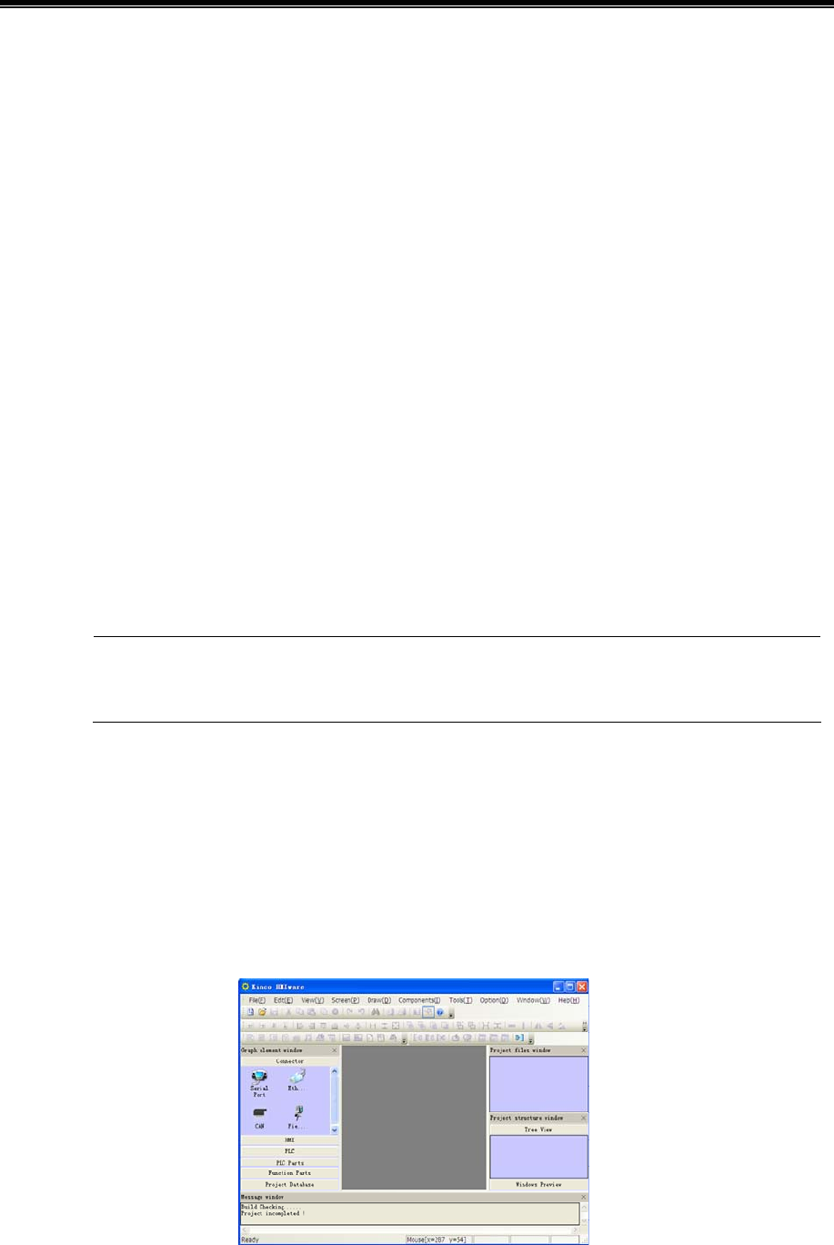
Kinco HMIware Configuration Edit Software
14
Install successfully
If the software install successfully, then it will appear the information. Click【Finish】to finish installation.
After finishing installation, Kinco HMIware will create a complete startup directory in【Start】menu, and create the shortcut
of Kinco HMIware and EVManager in desktop of operation system.
In above installation process, the user can click【Cancel】to quit installation.
2.4.2 Uninstall Kinco HMIware
Please quit Kinco HMIware firstly before uninstalling.
Run uninstall.
Method 1:Uninstall from【Start】menu.
【Start】【All Programs】【Kinco】【Kinco HMIware】【Uninstall】
Method 2:Uninstall from【Control Panel】【Add/Del Programs】
Uninstall procedure
Select “Remove”, click【Next】to start uninstalling process.
Modify Select new program features to add or select currently installed features to remove.
Repair Reinstall all program features installed by previous setup.
Remove Remove all installed features.
If there are some files or folders added in the install directory of Kinco HMIware, please delete these
contents by manual after uninstalling the software.
2.5 Start/Quit
2.5.1 Start Kinco HMIware
Method 1:Start in【Start】menu.
【Start】【All Programs】【Kinco】【Kinco HMIware_ENU】【Kinco HMIware】
Method 2:Double click the shortcut of Kinco HMIware in desktop to start software.
- When it is first time to start Kinco HMIware, it will display window as following:
- When it is not the first time to start Kinco HMIware, then it will open the last operated project automatically.
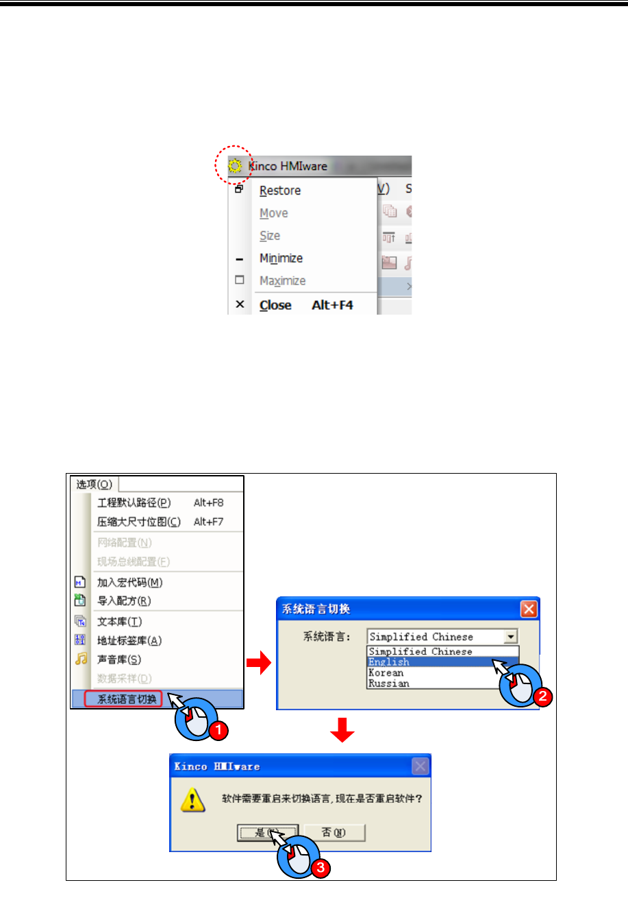
Basic Part Starting
15
2.5.2 Quit Kinco HMIware
After starting Kinco HMIware software, there are several ways to quit the software as follows:
- Click the【Close】button on the upper right side of the window.
- Click the icon of Kinco HMIware on the upper left of the window, then select “Close” in the control menu.
- Click Kinco HMIware【File】menu, then select “Quit” in the pull-down menu.
- Press【Alt】key and【F4】key on the keyboard at the same time.
2.6 System Language Change
Kinco HMIware supports switching multiple languages, user can switch the software language by the System Language of
Option(O) in the software menu bar. It supports Chinese, English, Korean and Russian switching at this moment.
- Switch the Chinese version to English version
- Switch the English version to Chinese version
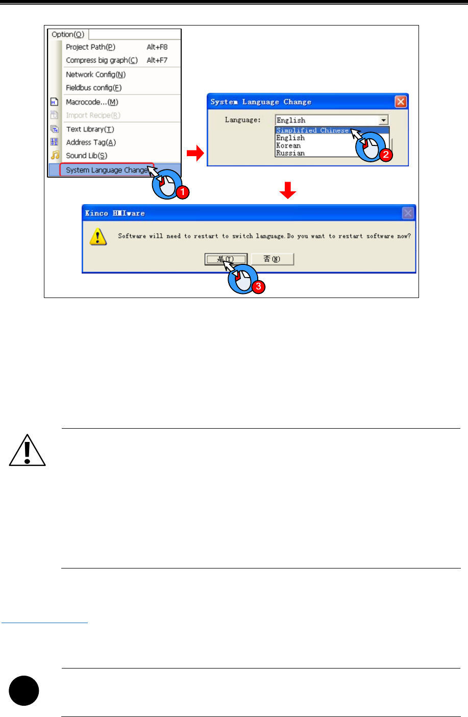
Kinco HMIware Configuration Edit Software
16
2.7 F1 Help
When user use the Kinco HMIware software, there are there methods to use the F1 help.
- Press the F1 on the keyboard
- Click the [Help] button on the component attribute
- Click the [Help] menu
2.8 Upgrade/Update
Note
1. To ensure the product working properly, it is forbidden to update, modify, uninstall and reinstall before
the software is closed.
2. Before updating software, to ensure the product working properly, please uninstall the old version
software completely.
3. Please backup the project made by old version software before using the new version software to
update the project made by old version software.
The latest software or upgrade package can be downloaded from the download centre in Kinco’s website :
http://www.kinco.cn/en
2.9 Software Compatibility
!
In Kinco HMIware, projects made by old version software can be opened by new version software, but
project made by new version software can’t be opened by old version software.
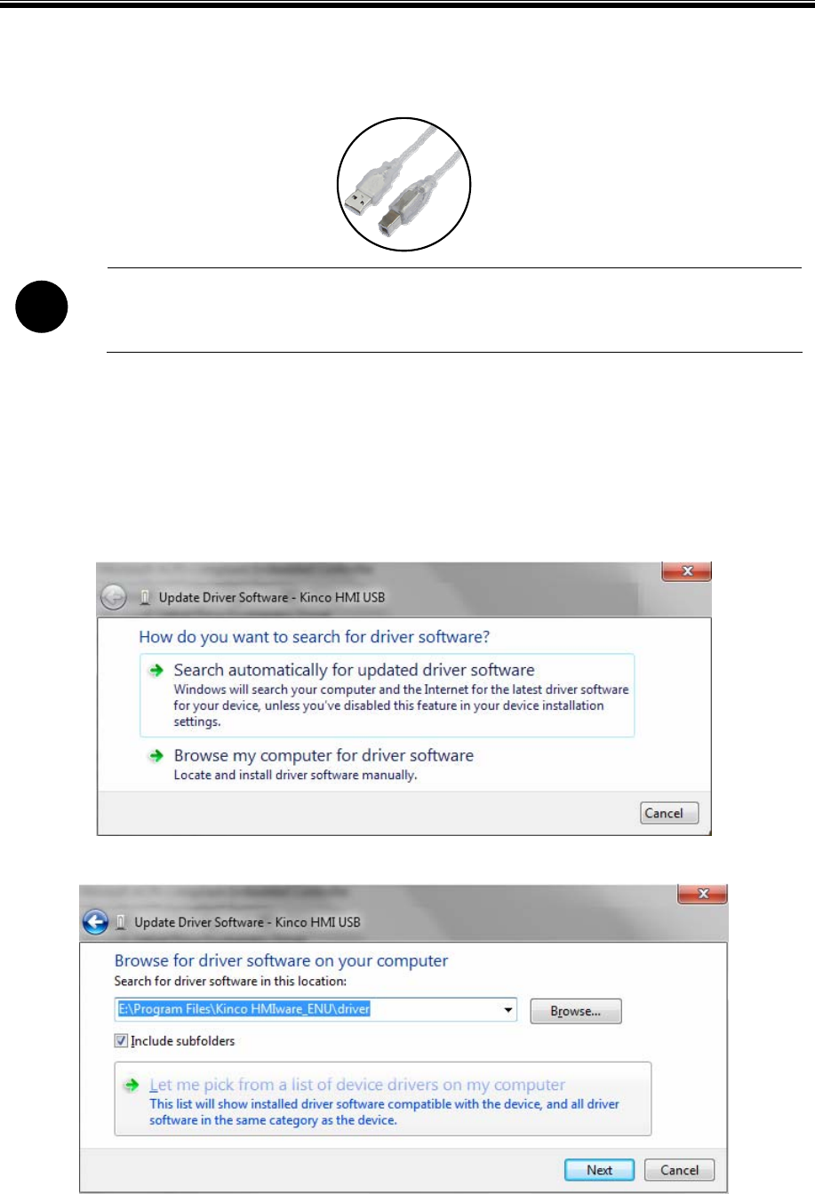
Basic Part Starting
17
2.10 Install USB Driver
!
USB driver must be installed by manual, can’t be installed automatically.
When it is first time to use Kinco HMIware, it need to install the USB driver for downloading HMI project.
Users can install USB driver by manual as following procedure:
Use USB cable to connect the USB SLAVE port of HMI to USB HOST port of PC, and connect the power supply of
HMI
correctly and power on, then it will popup dialog box of【Update Driver Software】,then click “Browse my computer for
driver software”:
Following dialog box will display. Click【Browse】:
Set the route to the driver folder in the install directory of Kinco HMIware, then click【OK】:
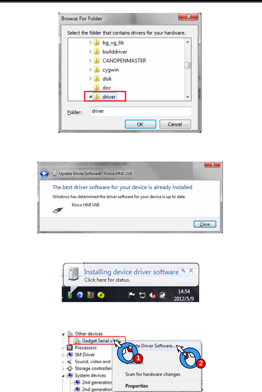
Kinco HMIware Configuration Edit Software
18
After finishing installation, it will popup the dialog box of “The best driver software for your device is already
installed”, then click【Close】to quit.
If PC doesn’t popup【Installing device driver software】automatically in the first step, but there is a balloon tips in the
toolbar as following figure:
Then open【Device Manager】【Universal Serial Bus Controllers】,there is a detection icon of unknown device. Right click
The icon and select “Update Driver Software” as following figure:
At this time, it will popup【Update Driver Software】automatically:
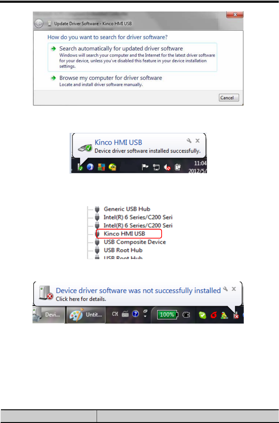
Basic Part Starting
19
Select “No,” and click【Next】,then continue the installation procedure of USB driver as above.
After finishing installation, there is a balloon tip of “Kinco HMI USB” on the toolbar as following figure:
After that, open【Device Manager】,the unknown device will change to “Kinco HMI USB” in【Universal Serial Bus
Controllers】.It means the USB driver installation is successful.
If the USB driver can’t be installed correctly, there is a balloon tips on the toolbar of operation system as following figure:
Then there is an icon of unknown device in【Device Manager】.For this problem, please select the right directory to reinstall
USB driver.
2.11 Software Application Program Introduction
Kinco HMIware software is integrated with Kinco HMIware.exe, EVManager, EVPLCAddressView, RecipeEditor.exe and
PDOManager and so on. Additionally, there are two manuals integrated in Kinco HMIware software. Users can find the
shortcuts of these functional units in【Start】【All Programs】【Kinco】【Kinco HMIware_ENU】.Their descriptions
are shown in following table:
Functional Unit Descriptions
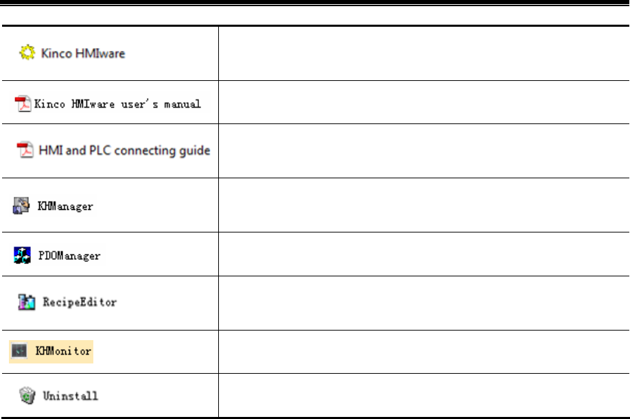
Kinco HMIware Configuration Edit Software
20
Main software which is used to create, edit, compile, simulate and download
project.
User’s Manual
Guide manual about communication between Kinco HMI and supported control
devices.
Auxiliary software, it is used to upload, download, decompile, HMI firmware
update, obtain HMI system information an so on.
Auxiliary software, it is used to configure the CAN communication parameters.
Auxiliary software, it is used to create, view or edit recipe data file and external
memory data file.
Auxiliary software, it is used to monitor the HMI and PLC registers.
Uninstall software; it is used to uninstall Kinco HMIware software.
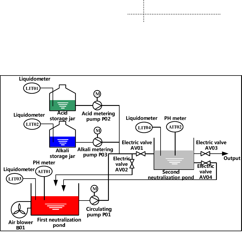
21
3 Make Project
This chapter takes PH value of neutralization pond control system for example to explain the process of making project by
Kinco HMIware.
3.1 Project Requirement
The project requires auto-control mode and manual control mode.
- In full-automatic control mode, after pressing “Start” button, the system will detect the water level of first
neutralization pond automatically. When the liquid meter(LIT03) detect that the water level reaches preset height, then
it will enter automatic circulation process: close electric valve(AV01),open electric valve (AV02),and start air
blower(B01) and circulating pump(P01) to aerate and circulation stir. After stirring uniform, it will start acid metering
pump(P02) or alkali metering pump(P03).When the PH value detected by AIT01 satisfies effluent standard
(6≤PH≤9),then stop P02 or P03,open AV01 and close AV02,then let off the qualified water to the second
neutralization pond. If the water level detected by LIT04 reaches the preset height, then it will detect the PH value of
AIT02 automatically. If it satisfies 6≤PH≤9, then close AV04 and open AV03.Let off the water until the water level
detected by LIT04 is lower than lower limit, then close AV03.If it doesn’t satisfy the requirement, then it will close
AV03 and open AV04 to continue processing.
When detecting the water level of the first neutralization pond lower than lower limit, then stop B01 and P01, herein
this process finish. When the water level of the first neutralization pond reach preset height, then continue to next
process.

Kinco HMIware Configuration Edit Software
22
In the circulation process, LIT01 and LIT02 real time monitor the liquid level of acid storage jar and alkali storage jar.
If
it is lower than lower limit, then it will show alarm information.
- In manual control mode, every process is controlled separately by manual according to the value of AIT01 and AIT02
instead of being triggered by the water level of neutralization pond.
3.2 System Analysis
According to project requirement, this control system can be consisting of upper computer, PLC and instrumentation.
PLC is mainly used to sample data (data of liquid meter and PH meter), control device (air blower, circulating pump, electric
valve).Here we use HMI as upper computer to communicate with PLC by RS-232C.
The configuration and parameters are shown in following table.
- Upper computer system configuration:
Software Kinco HMIware software
One PC with Windows XP/Vista/7 operation system and Kinco HMIware software.
One MT series HMI(Herein we choose MT5320T)
One PLC(Herein we choose Kinco CPU306EX)
One DC24V power supply for HMI
One AC220V power supply for PLC
One specified USB download cable(Herein we choose USB port for downloading program)
Hardware
One RS232C cross cable for communication between HMI and PLC.(Herein we choose RS232C
communication)
- PLC address allocation
Device Address Device Address
Start switch SW01 I 0.0 Liquid meter LIT01 AIW 4
Emergency stop switch
SW02
I 0.1 Liquid meter LIT02 AIW 6
Air blower B01 Q 0.0 Liquid meter LIT03 AIW 8
Circulating pump P01 Q 0.1 Liquid meter LIT04 AIW 10
Metering pump P02 Q 0.2 Electric valve AV01 Q 1.0
Metering pump P03 Q 0.3 Electric valve AV02 Q 1.1
PH meter AIT01 AIW 0 Electric valve AV03 Q 1.2
PH meter AIT02 AIW 2 Electric valve AV04 Q 1.3
Auxiliary relay AR01 M 0.0(Turn on when the liquid
level of LIT01 is lower than lower
limit)
Auxiliary relay AR05 M 0.4(Turn on when the liquid
level of LIT03 is lower than
lower limit)
Auxiliary relay AR02 M 0.1(Turn on when the liquid Auxiliary relay AR06 M 0.5(Turn on when the liquid
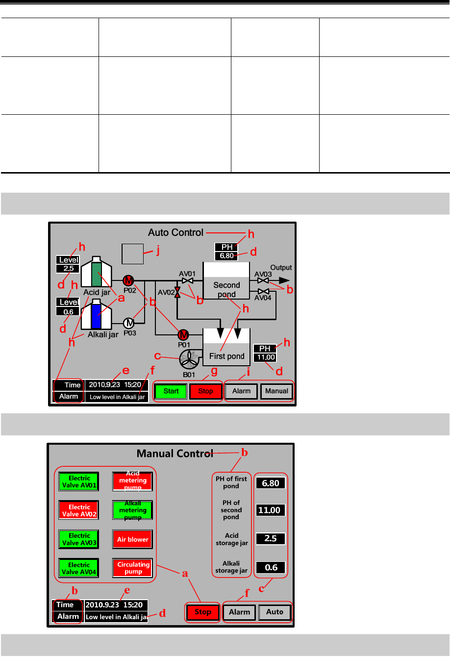
Basic Part Make Project
23
level of LIT01 is higher than
upper limit)
level of LIT03 is higher than
upper limit)
Auxiliary relay AR03 M 0.2(Turn on when the liquid
level of LIT02 is lower than lower
limit)
Auxiliary relay AR07 M 0.6(Turn on when the liquid
level of LIT04 is lower than
lower limit)
Auxiliary relay AR04 M 0.3(Turn on when the liquid
level of LIT02 is higher than
upper limit)
Auxiliary relay AR08 M 0.7(Turn on when the liquid
level of LIT04 is higher than
upper limit)
- HMI frame
Auto Control
a. Bar Graph
b. Bit State Lamp
c. Multiple State Display
d. Number Display
e. Date/Time
f. Event Bar
g. Bit State Switch
h. Text
i. Function Key
j. Timer
Manual Control
a. Bit State Switch
b. Text
c. Number Display
d. Event Bar
e. Date/Time
f. Function Key
Alarm Display
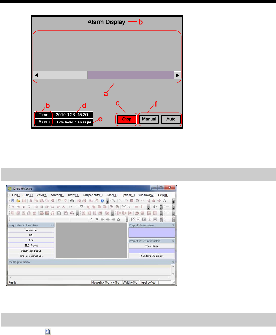
Kinco HMIware Configuration Edit Software
24
a. Event Display
b. Text
c. Bit State Switch
d. Date/Time
e. Event Bar
f. Function Key
3.3 Make Project
Following are the procedure for making project in Kinco HMIware.
3.3.1 Create Project
Start Kinco HMIware
☞Details please refer to【Basic Part 2.5.1 Start Kinco HMIware】
Create Project
Click the icon in toolbar to create project.
Input project name.(Herein the project name is set as “PH control system”)
Select path of saving project.(Herein we use the default path)
Click【OK】to finish creating project.
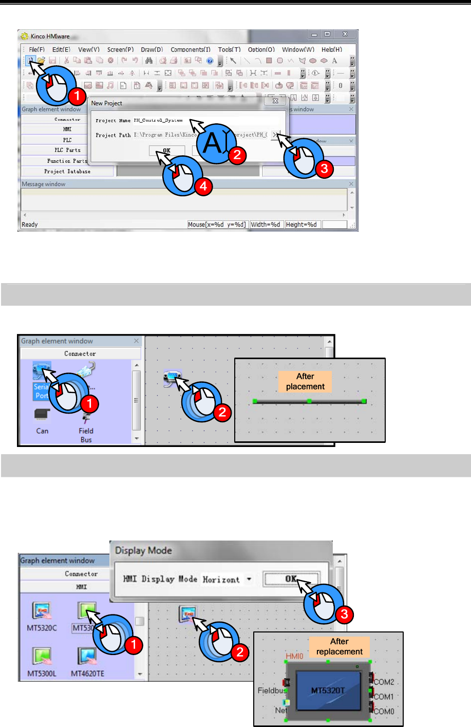
Basic Part Make Project
25
After creating project, it will popup grey grid working area. This area is named “Construct Window”.
3.3.2 Device Selection, Connection and Parameters Setting
Device selection——select communication method
Drag “Serial Port” in【Graph element window】—【Connector】to construct window.
Device selection——select HMI model
Drag “MT5320T”in【Graph element window】—【HMI】to construct window.
When you release the mouse after dragging HMI icon, it will popup【Display Mode】dialog box as following figure. There
are “Horizontal” and “Vertical” option in it.(Herein we select “Horizontal”), then click【OK】
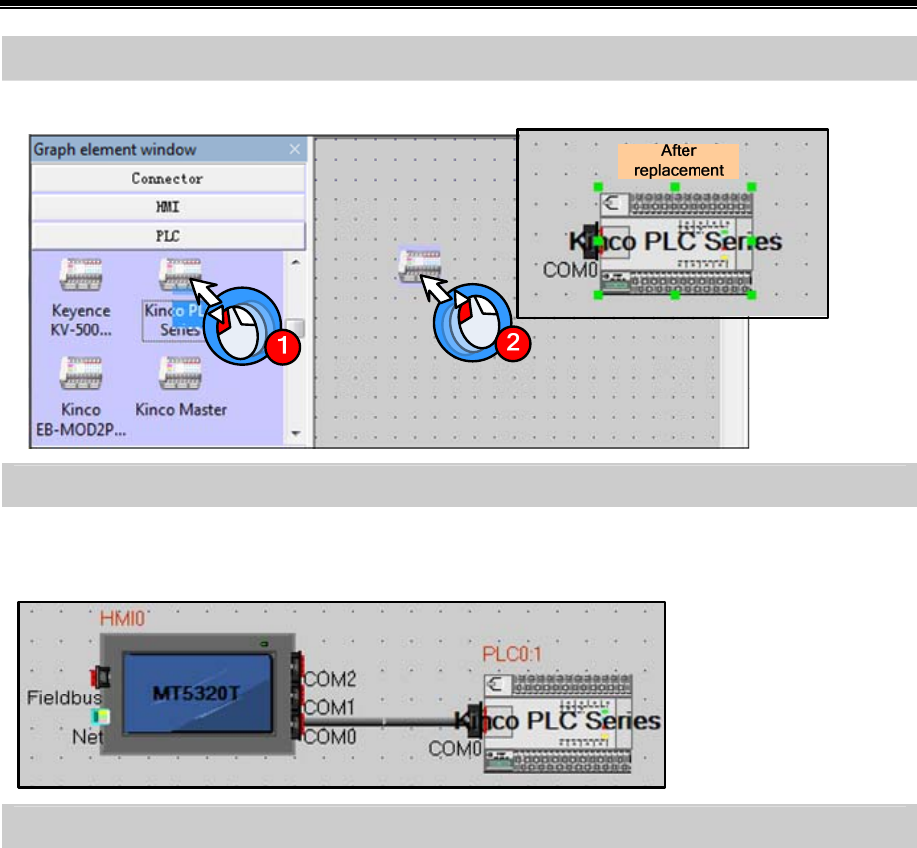
Kinco HMIware Configuration Edit Software
26
Device selection——select PLC mode(or communication protocol)
Drag “Kinco PLC Series” in【Graph element window】—【PLC】to construct window.
Device connection
Drag HMI icon to make “COM” port approach to the left side of connector(herein we choose COM0) until the connector
moving together with HMI. Then connect PLC and connector by the same way.
Parameters setting——HMI setting
Double click HMI,it will popup window of【HMI Attribute】
Click【Task Bar】option
Cancel the option of “Display Task Bar” in【Task Bar】(Herein we don’t need to use "Task Bar”)
Click【COM0 Setting】option and set the corresponding parameters of COM0 according to the communication
parameters of PLC. Others all set as default.
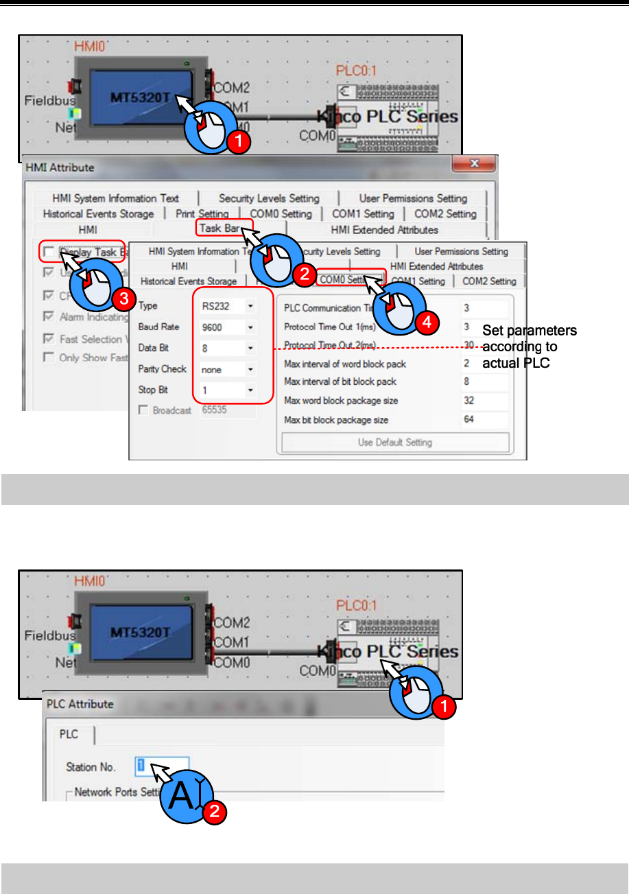
Basic Part Make Project
27
Parameters setting——slave station no. setting
Double click PLC,it will popup【PLC Attribute】window.
Set “Station No.” according to PLC’s actual station no. (Herein the PLC’s station no. is 1)
3.3.3 Edit Frame
Open HMI edit window
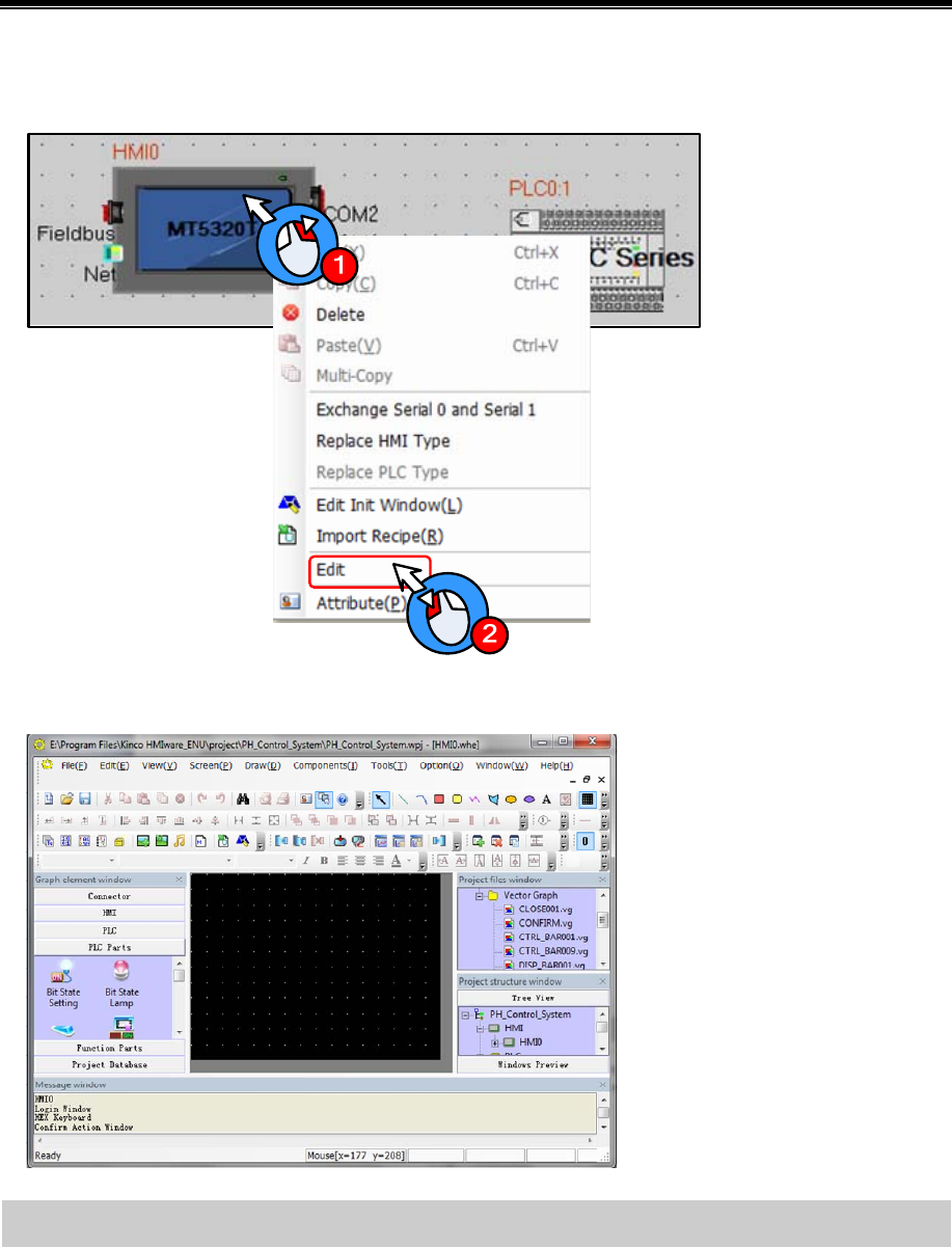
Kinco HMIware Configuration Edit Software
28
Right click HMI icon
Click “Edit” in the popup menu as following figure.
It will open HMI edit window as following figure(It will open Frame0 by default)
Edit frame——Create new frame
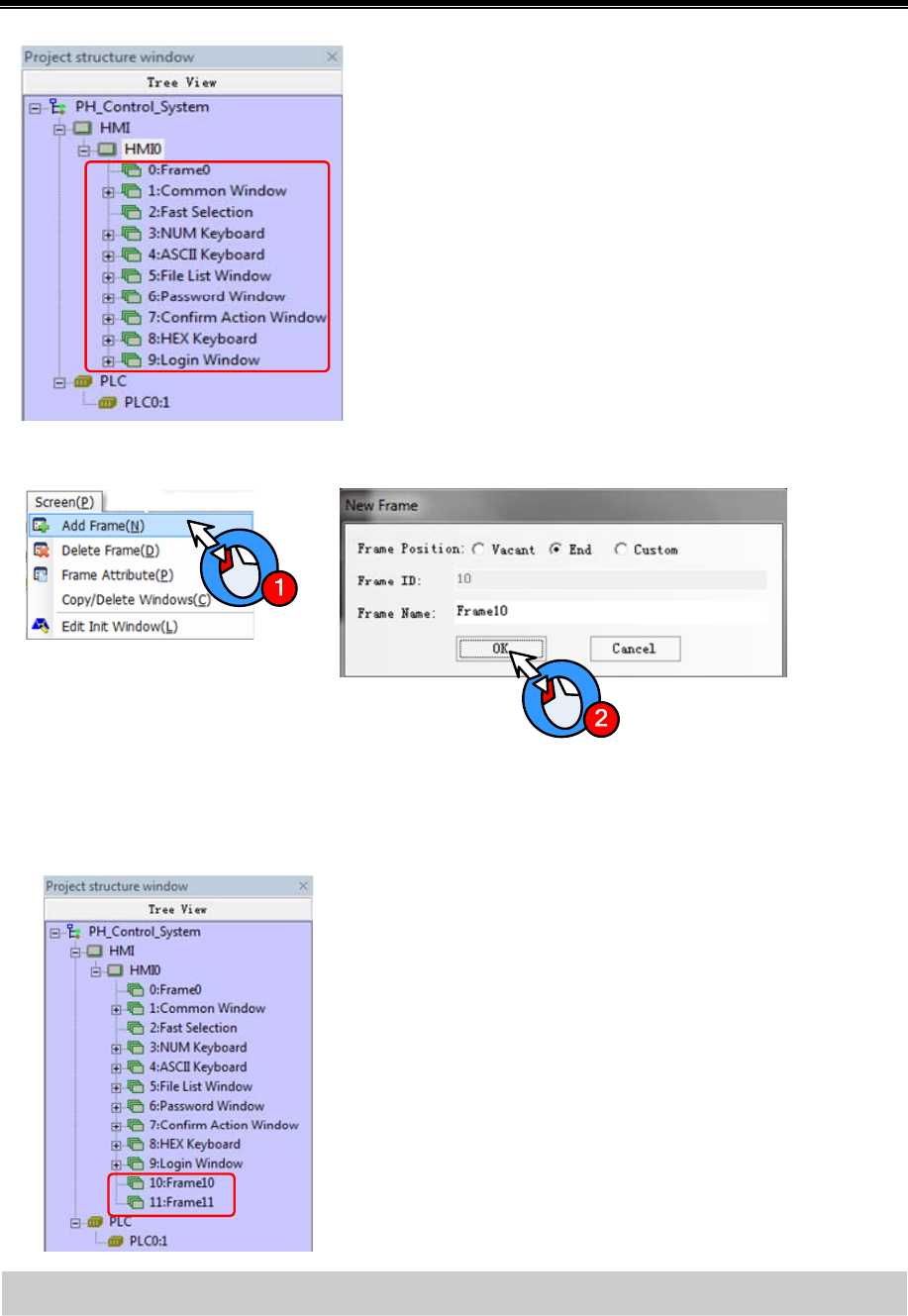
Basic Part Make Project
29
System will create frame 0~9 automatically when creating HMI.
Therein, frame 1~9 are specified system windows. Only Frame0 can
be used freely by user. According to the system analysis, we need to
create two windows.
Procedure for adding frame:
Click【Screen】menu, select “Add Frame”.
System will popup【New Frame】window, therein “Frame Name” can be defined freely(Herein we use system default
name “Frame10”).Then click【OK】.And then create Frame11 by the same way.
After creating new frames, they will show in【Project structure
window】as shown in left figure.
Edit “Auto Control” frame——Change background color
The initial background color of windows is black(RGB:0,0,0).User can change the background color according to actual
requirement(Herein we set the background color as light grey color (RGB:182,182,182))
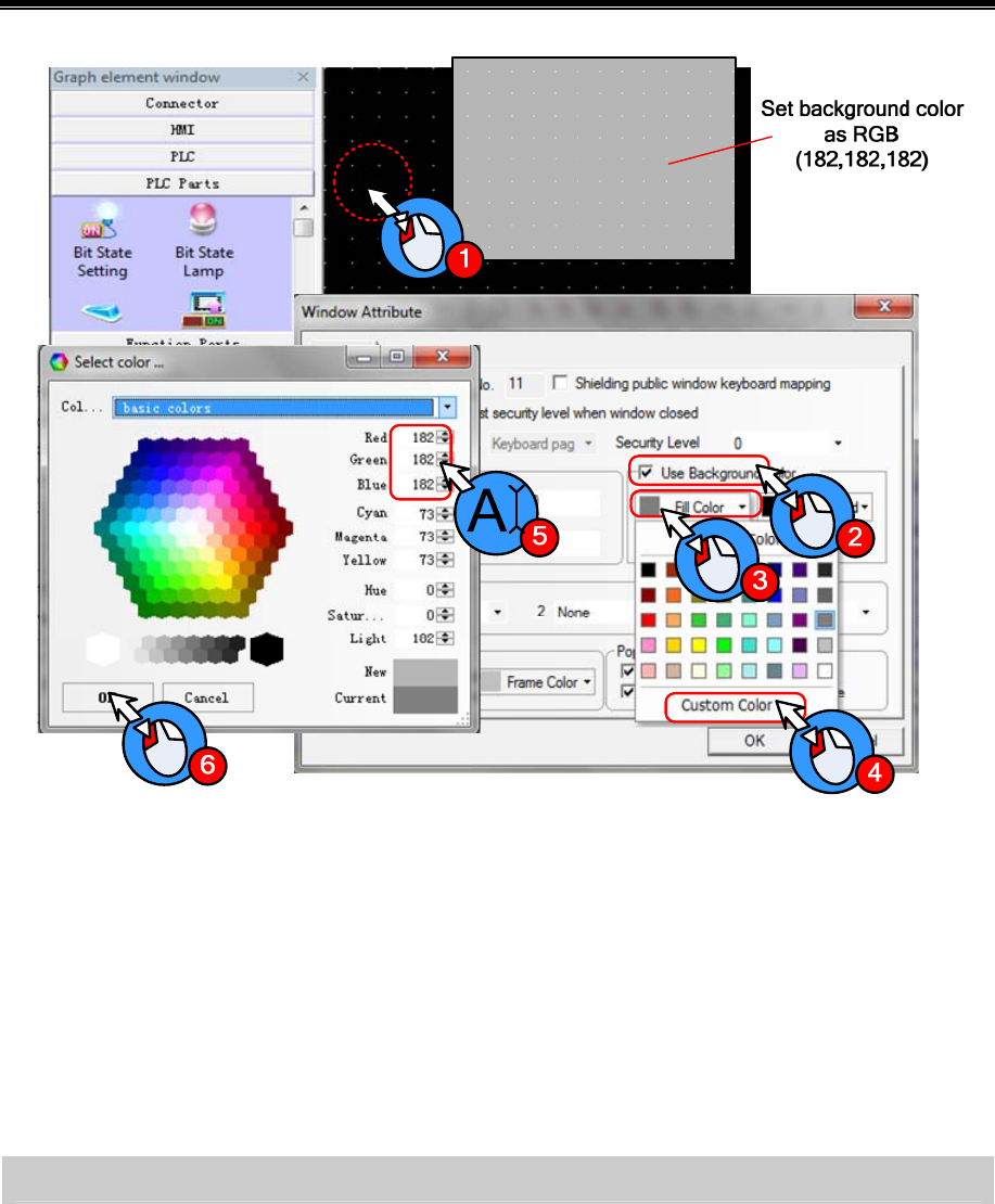
Kinco HMIware Configuration Edit Software
30
Operation procedure is as following:
Double click background area, it will popup【Window Attribute】dialog box.
Click “Use Background Color”
Click “Fill Color”
Click “Custom Color”, it will popup【Select color】window
Choose the desired color or set RGB value in Red(R),Green(G)and Blue(B).
Finally click【OK】
Edit “Auto Control” frame——Edit frame title

Basic Part Make Project
31
Click icon in toolbar, it will popup【Text Attribute】window
Type “Auto Control” in【Content】area.
Select【Vector Font】
Setting in “Font Attribute”:
Font Times New Roman
Size 16
Alignment Center
Color Black
After finishing setting font attribute, then click【OK】
Then there is a red box in the edit window. Choose and put on a suitable place.
Create title of” Manual Control” and “Alarm Display” by the same way.
Edit “Auto Control” frame——Draw the operation flow chart of PH control system
Draw the operation flow chart of PH control system by using line, rectangle and polygon.
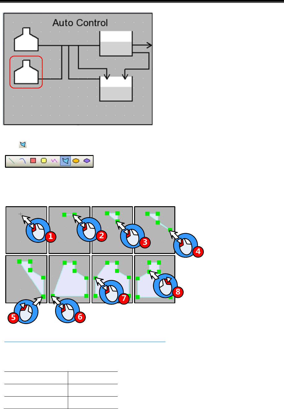
Kinco HMIware Configuration Edit Software
32
Take the graph in red box in the figure above for example, the procedure of drawing is as follows:
Click icon in “Draw Toolbar”.
~Move mouse to edit area, it will appear “+”.Then click 7 times on the related position.
Right click mouse to finish drawing polygon.
☞More drawing methods please refer to【Advanced Part 2.2 Draw】
Double click polygon to open the “Graphic Attribute” window.
Set graphic attribute of polygon as follows:
Line Color Black
Line Width 2 pound
Background Fill Color White
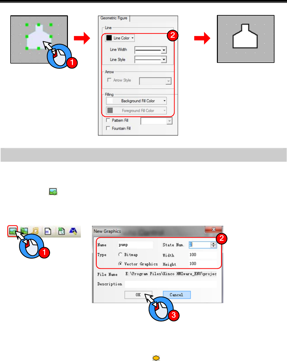
Basic Part Make Project
33
Edit “Auto Control” frame——Draw graph of metering pump
If there is no desired graph in the system image library, then user can create a new graph.
- New Graphics
Click the icon in Database Toolbar, it will popup【New Graphics】window
Set the attribute as following figure
Click【OK】to enter edit window of vector graph
- Draw graph
Select state0 in the edit window of vector graph,click icon in the Draw Toolbar
~Move the mouse to the black edit area below, it will appear “+”.Then press left mouse button and drag to
lower right side. Then release at the proper position to finish drawing a circle.
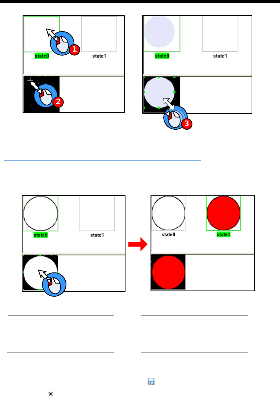
Kinco HMIware Configuration Edit Software
34
Select state1 and draw a graph by the same way as drawing state0.
☞More details about new graph please refer to【Advanced Part 5.3 Graphic Library】
- Set graphics attribute
Double click the graph to open【Graphics Attribute】window,then set the attribute of state0 and state1.
state0 Graphics Attribute state1 Graphics Attribute
Line Color Black
Line Width 2 Pound
Background Fill Color White
Line Color Black
Line Width 2 Pound
Background Fill Color Red
- Save graph
After finishing drawing graph of metering pump, click icon in Basic Toolbar to save file pump.vg
Click the icon on the upper right of graph edit window to quit the window.
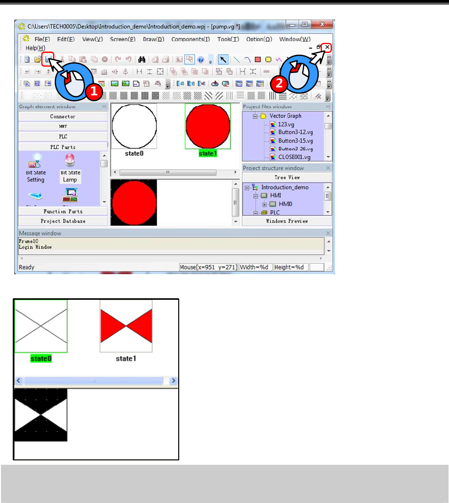
Basic Part Make Project
35
Create a new graph and draw graph of electric valve named
valve.vg as shown in left figure.
Edit “Auto Control” frame——Add Bit State Lamp components (metering pump, circulating pump and electric
valve)
Add 7 “Bit State Lamp” components for state indication of metering pump, circulating pump and electric valve. The
procedure is as follows:
Select “Bit State Lamp” from【Graph element window】—【PLC Parts】,then press left mouse button and drag to HMI
edit area.
Release mouse and it will popup attribute box of【Bit State Lamp】
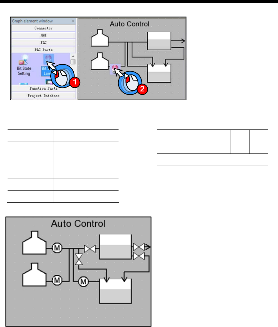
Kinco HMIware Configuration Edit Software
36
Set the components attribute as follows:
Circulating pump P01/Metering pump P02/ Metering pump P03 Electric valve AV01/AV02/AV03/AV04
Read Address Q0.1 Q0.2 Q0.3
Function Normal
Tag Use;0:M;1:M
Font Type Vector Font
Font Attribute Arial,11,Black,Bold
Graph Vector Graph:pump.vg
Read
Address
Q1.0 Q1.1 Q1.2 Q1.3
Function Normal
Tag Not use
Graph Vector Graph:valve.vg
After finishing setting the components, the screen will show as following figure:
Finally add text in the screen. The procedure of adding text is the same as【Edit frame title】,show as following:
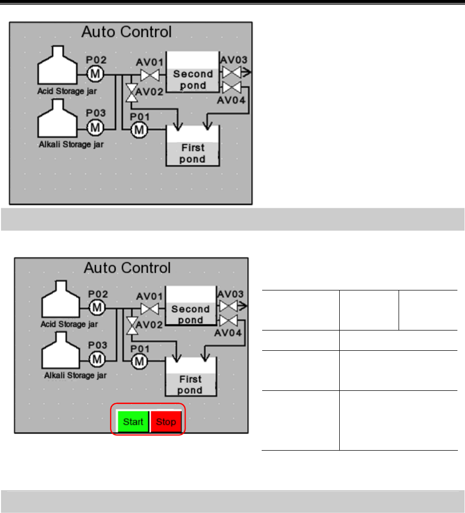
Basic Part Make Project
37
Edit “Auto Control” frame——Add Bit State Switch components(Start, emergency stop)
Add two “Bit State Switch” as “Start” and “Emergency stop” button as shown in following figure:
Add two “Bit State Switch” and set the attribute
as follows:Start/Emergency stop
Read/Write
Address
I0.0 I0.1
Switch Type Reset
Tag Use ;0:Start/Emergency
stop;1:Start/Emergency stop
Graph Vector Graph;
Button3-15.vg*
Button3-12.vg*
*Button3-12.vg/Button3-15.vg are imported from
【System Image Library】—【VG】—【Button】
Edit “Auto Control” frame——Add Function Key components
Add two “Function Key” from【Graph element window】—【Function Parts】,which are used to change window to
“Alarm Display” and “Manual Control”.
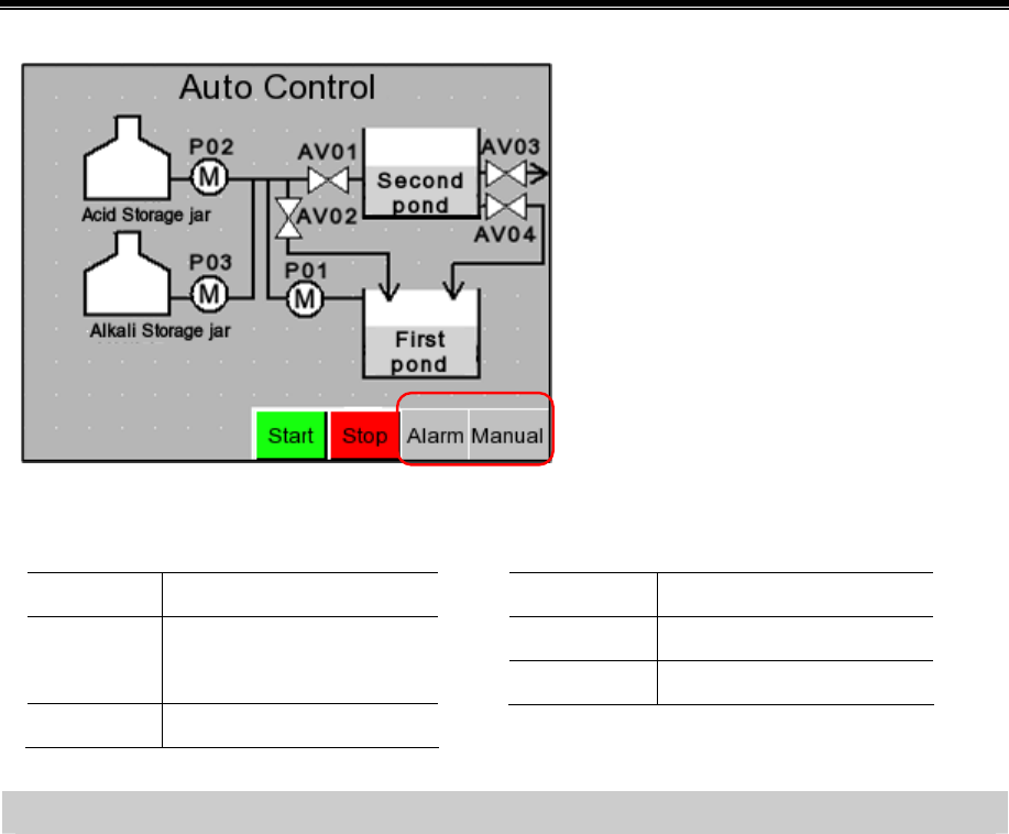
Kinco HMIware Configuration Edit Software
38
Set the attributes as follows:
Manual Control Alarm
Function Key Change window[Frame10]
Tag Use;0:Manual Control;1:
Manual Control
Graph Vector Graph:CONFIRM.vg
Function Key Change window[Frame11]
Tag Use;0:Alarm;1:Alarm
Graph Vector Graph:CONFIRM.vg
Edit “Auto Control” frame——Add Event Information Logon
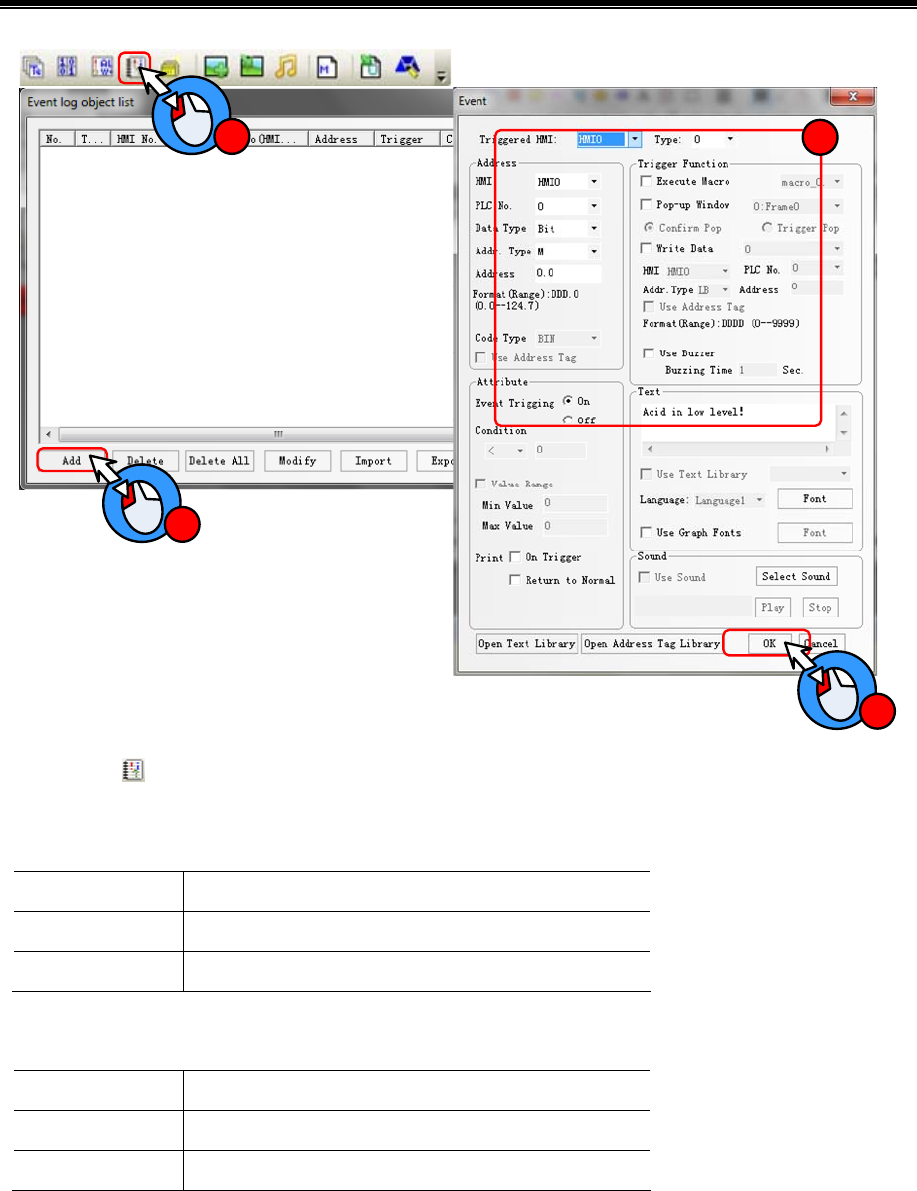
Basic Part Make Project
39
1
2
3
4
Click icon in Database Toolbar to open【Event log object list】window
Click【Add】button, it will popup【Event】window
Add one event information logon as follows:
Address M0.0
Event Trigging On
Text The liquid level of alkali storage jar is below lower limit!
Click【OK】button to close【Event】window and finish the first event information logon.
By the same way, add second event information logon.
Address M0.2
Event Trigging On
Text The liquid level of acid storage jar is below lower limit!
Then click【OK】button to close【Event log object list】

Kinco HMIware Configuration Edit Software
40
Edit “Auto Control” frame——Add information bar
Information bar include current system time and current alarm display.
Firstly add a rectangle graph and two line as background of information bar as following figure:
Set the attributes as follows:
Rectangle Line
Line Color White
Background Fill Color Black
Line Color White
☞More drawing methods please refer to【Advanced Part 2.2 Draw】
Add “Date/Time” from【Graph element window】—【Function Parts】for displaying current system time.
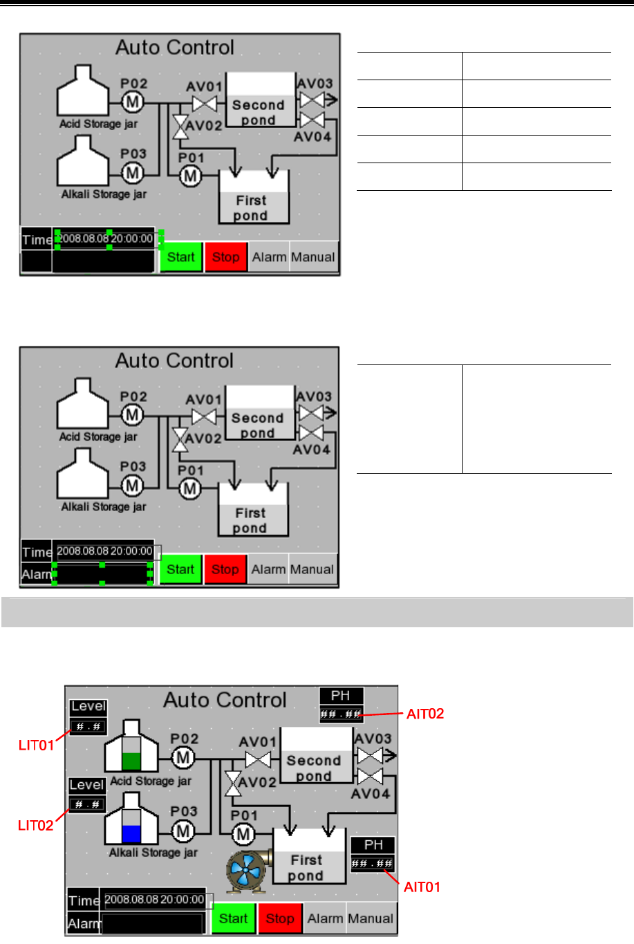
Basic Part Make Project
41
Set the attributes as follows:
Date Display:YYYY.MM.DD
Time Display:HH:MM:SS
Font Type Vector Font
Font Attribute Arial,8,White
Graph No use
Finally add a text of “Time” as shown in left
figure:
Add “Event Bar” from【Graph element window】—【Function Parts】for rolling displaying alarm information
Set the attributes as follows:
Format Event Trig Time
Standard Time Format
Extended Date Format
Event Trig Date
Finally add a text of “Alarm” as shown in left
figure:
Edit “Auto Control” frame——Add Number Display component
Add 4 “Number Display” from 【Graph element window】—【PLC Parts】for display the liquid level of alkali(acid)
storage jar and the PH value of first(second) neutralization pond.
Set the attributes as follows:
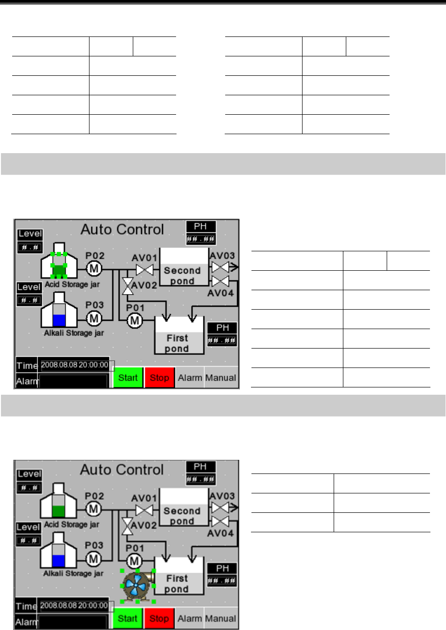
Kinco HMIware Configuration Edit Software
42
PH meter AIT01/AIT02 Liquid meter LIT01/LIT02
Read Address AIW 0 AIW 5
Data Type Unsigned int
Integer/Decimal 2/2
Min/Max 0/1400
Graph No use
Read Address AIW 4 AIW 6
Data Type Unsigned int
Integer/Decimal 1/1
Min/Max 0/50
Graph No use
Edit “Auto Control” frame——Add Bar Picture components
Add 2“Bar Picture” from【Graph element window】—【PLC Parts】for displaying the liquid level of alkali(acid) storage
jar
Set the attributes as follows:
Acid storage jar/Alkali storage jar
Read Address AIW 4 AIW 6
Border Color Black
Normal Color Green/Blue
Alarm Lower/Upper Red/Yellow
Minimum/Maximum 0/50
Alarm Lower/Upper 5/45
Graph No use
Edit “Auto Control” frame——Add Multiple State Display and Timer components
Add one “Multiple State Display” from【Graph element window】—【 PLC Parts】for displaying the rotary of fan blade
of air blower.
Set the attributes as follows:
Read Address LW 0
State Num. 3
Graph Bitmap:fan-05.bg*
*fan-05.bg is imported from 【System Image
Library】—【BG】—【Fan】
Add one “Timer “component from【Graph element window】—【Function Parts】for changing the state value of
“Multiple State Display” component.
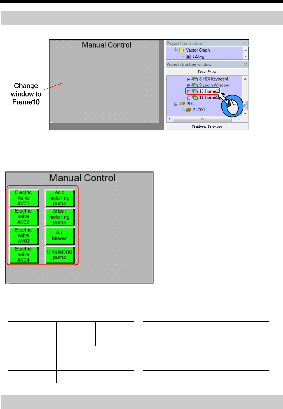
Basic Part Make Project
43
Edit “Manual Control” frame——Add Bit State Switch components
Click “10:Frame10”in【Project structure window】to change window to frame10 as shown in following figure:
Add 8 “Bit State Switch” components from【Graph element window】—【PLC Parts】for controlling the start and stop
of electric valve, metering pump, circulating pump and air blower.
Set the attributes as follows:
Electric valve AV01/AV02/AV03/AV04 Air blower/Circulating pump/Acid metering pump/Alkali
metering pump
Read/Write
Address
Q1.0 Q1.1 Q1.2 Q1.3
Switch Type Toggle
Tag Use
Graph Vector Graphics:Button3-15.vg
Read/Write
Address
Q0.0 Q0.1 Q0.2 Q0.3
Switch Type Toggle
Tag Use
Graph Vector Graphics:Button3-15.vg
Edit “Manual Control” frame——Add Number Display components
Add 4 rectangles as the background graph of “Number Display” components
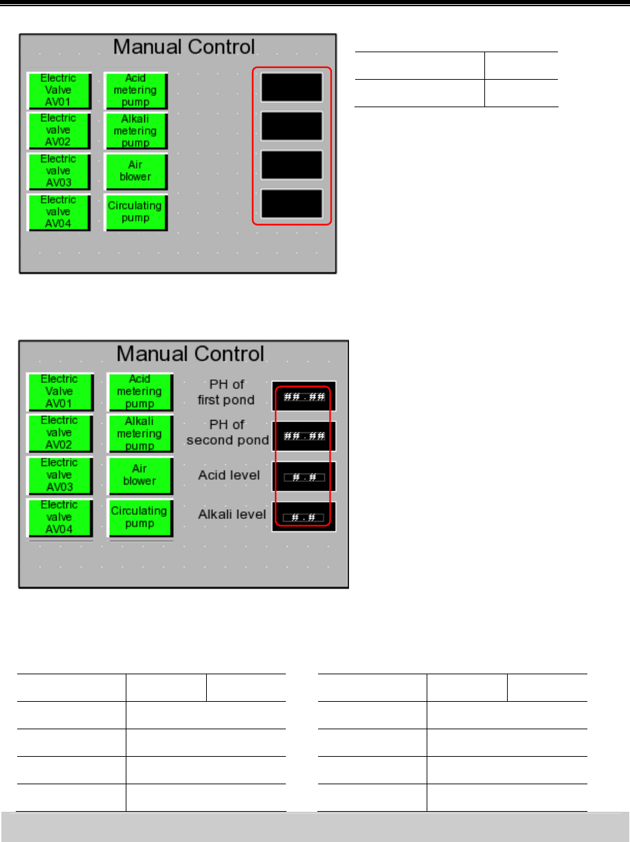
Kinco HMIware Configuration Edit Software
44
Set the attributes as follows:
Line Color White
Background Fill Color Black
Add 4“Number Display” components from【Graph element window】—【PLC Parts】for displaying the liquid level of
acid(alkali) storage jar and the PH value of first(second) neutralization pond
Set the attributes as follows:
PH value of first neutralization pond / PH value of
second neutralization pond
Acid storage jar / Alkali storage jar
Read Address AIW 0 AIW 2
Data Type Unsigned int
Integer/Decimal 2/2
Min/Max 0/1400
Graph No use
Read Address AIW 4 AIW 6
Data Type Unsigned int
Integer/Decimal 1/1
Min/Max 0/50
Graph No use
Edit “Manual Control” frame——Add information bar
The information bar in “Manual Control” frame is the same as “Auto Control”fram. Therefore we can copy the
information bar from “Auto Control” frame to “Manual Control” frame.
Select all information bars in “Auto Control” frame and right click.
Click【Copy】
Change to “Manual Control” frame and right click.
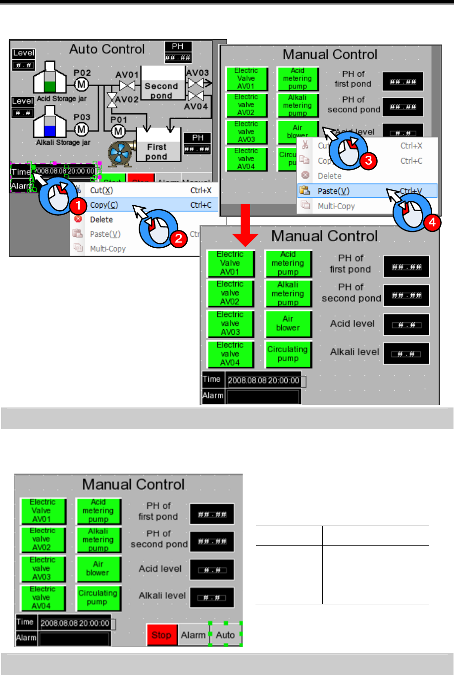
Basic Part Make Project
45
Click【Paste】
Edit “Manual Control” frame——Add “Emergency stop” button and “Change window” button
Copy the “Emergency stop “button, “Alarm” button and “Manual Control” button in “Auto Control” frame and
paste in this frame.
Double click “Manual Control” button to open
the attribute box of【Function Key】and modify as
follows:
Function Key Change window[Frame0]
Tag Use
0:Auto Control
1:Auto Control
Edit “Alarm Display” frame——Add Event Display component
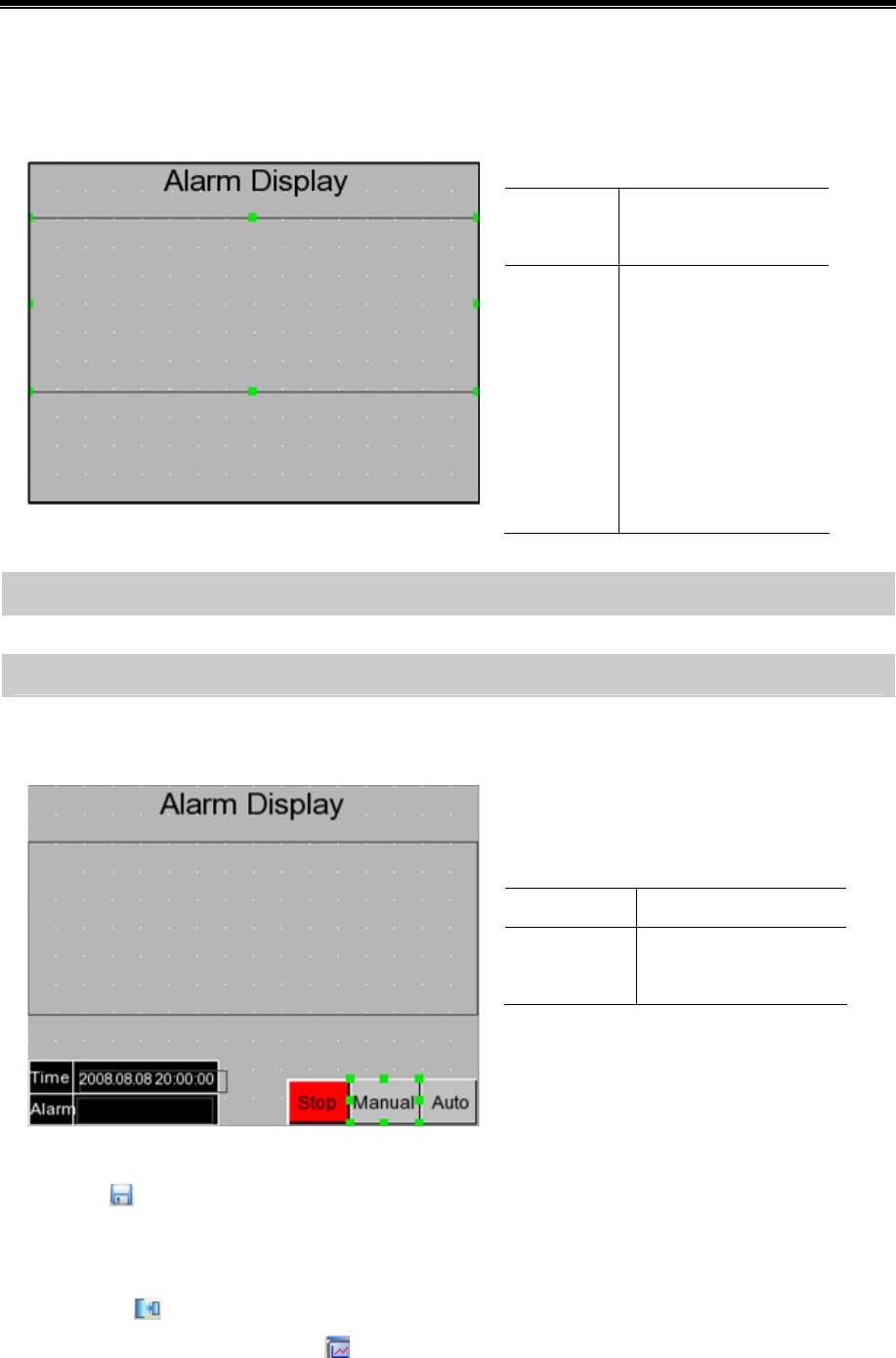
Kinco HMIware Configuration Edit Software
46
Change window to Frame11。
Add one “Event Display” component from【Graph element window】—【 PLC Parts】for displaying the triggered alarm
information which have logined in “Event Information Logon”
Set the attributes as follows:
Read
Address
LW1
Format Sequence No.
Event Trig Time
Acknowledge Time
Return to Normal Time
Standard Time Format
Extended Date Format
Event Trig Date
Edit “Alarm Display” frame——Add information bar
The procedure is the same as【Edit “Manual Control” frame——add information bar】
Edit “Alarm Display” frame——Add “Emergency stop” button and “Change window” button
Copy the “Emergency stop” button, “Alarm” button and “Auto Control” button in “Manual Control” frame and
paste in this frame.
Double click “Alarm” button to open the
attribute box of【Function Key】and modify as
follows:
Function Key Change window[Frame10]
Tag Use;0:Manual Control;
1:Manual Control
3.3.4 Save Project
Click the icon in Basic Toolbar to save the project.
3.3.5 Project Simulation
After finishing project, user can simulate the project by “Off-line simulation”. The procedure is as follows:
Click the icon in System Toolbar to compile the project.
After compilation succeed, click the icon in System Toolbar to popup the dialog box of【EVSimulator】
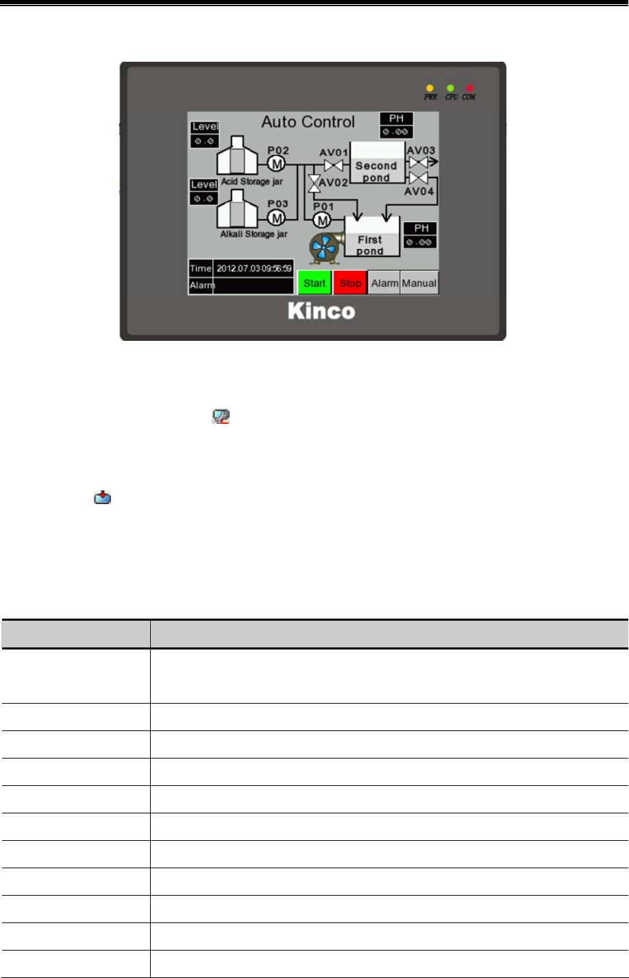
Basic Part Make Project
47
Select the HMI need to compile and then click【Simulate】button to start simulation as shown in following figure:
3.3.6 Download Project
The procedure of downloading project is as follows:
Choose download way. Click the icon in System Toolbar to open the dialog box of【Project Setting Option】
Select “USB”in【Download Device】(Herein we use USB for downloading)
Click【OK】button to close the dialog box of【Project Setting Option】
Click the icon in the System Toolbar, it will popup the dialog box of【EVDownload】
Select the HMI need to download and then click【Download】button to start downloading
3.4 Project Folder Introductions
When we create a new project, it will generate specified folders automatically. In these folders, it will generate some files
corresponding to the operation. The instructions of the files are as following table.
Name Instructions
HMIn “n” indicates number. All HMI used in one project will generate independent folder. This
folder is used to store macro file and project file.
image It is used to store initial picture of bitmap in project.
ProjBK It is used to store the old project which is backuped by new software.
sound It is used to store the initial file and convert file of the sound in project.
tar It is used to store data files for project compilation.
temp It is used to store the project which is stored at the last time.
vg It is used to store the vector graphics and bitmap in project.
EVWindows.dat System file
PLCGEDefaultProperties System file
name.wpj Project management file, opened by Kinco HMIware.
name.bak Data file backup by system automatically

Kinco HMIware Configuration Edit Software
48
name.pkg Data package file generated by compilation, it is used for downloading to HMI.

50
Advanced Part
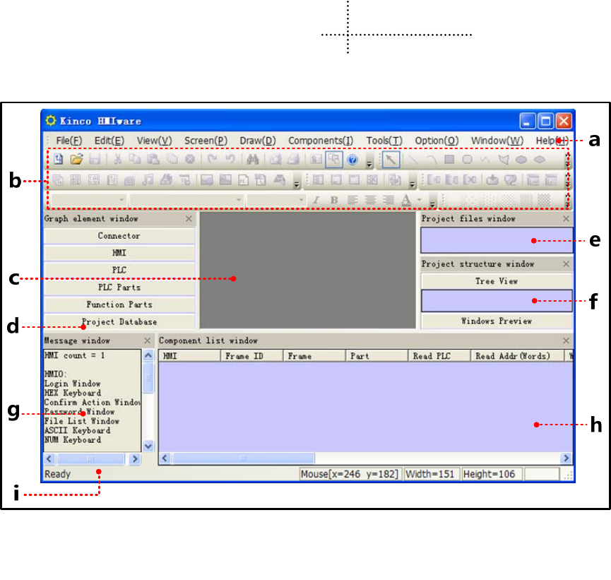
51
1 User Interface
1.1 Interface Layout
After opening Kinco HMIware, the main interface displays as below:
a. Menu bar b. Toolbar c. Configuration edit area d. Component library window e. Project file window f.
Project construct window g. Compile information window h. Component list window i. Status bar
The main interface of Kinco HMIware is composed by the following parts:
- Menu
- Toolbar
- Software window
- Edit area
1.2 Menu
1.2.1 File Menu
- Save as:Save project to a new path.
- Project password:Set password for opening project.
- 4 files recently opened:The software automatically remembers most recently opened 4 files’ name in the “File”
menu to facilitate user open project directly.
Quit:Close the software, then software will prompt users to save unsaved project.

Kinco HMIware Configuration Edit Software
52
1.2.2 Edit Menu
- Undo: Cancel the latest operation, and return to the state before this operation; redo: Redo the latest operation which
has been undone by the Undo operation.
!
Can only undo or redo one step, multiple steps of undo and redo is not supported.
- Find/Replace: Find/Replace component address or tag.
- Nudge: Left/Right/Up/Down: Move the selected component left/right/up/down by one pixel.
- Align: Left/Right/Top/Bottom/Vertical Midline/Horizontal Midline: Align the selected components.
- Size: Width/Height/Both: Set the selected components to the same width/height/ size.
- Layer: Set Top Layer/Set Bottom Layer/Previous Layer/Next Layer: Adjust the sequence of the multiple overlapped
components.
- Group/Ungroup: Group/Ungroup multiple components.
- Same Horizontal/Vertical Space: Implement the equal horizontal/vertical space between multiple selected components.
- Align Horizontal/Vertical Center: Place multiple selected components in the horizontal/vertical center of the window.
- Flip Horizontally/Vertically/Rotate 90 Degree: Set the selected component to flip horizontally/vertically/rotate 90
degree.
- Select All Components: Select all the components in the frame.
- Show Grid: Display screen grid; Alignment Grid: Move by grid; Define the Grid Spacing: Self-define the screen grid
space.
- Lock Component: Lock the components, then the components cannot be moved again.
The locked components support copy and paste.
- Reset Toolbar: The toolbar restore to default state.
1.2.3 View Menu
- Language:Quickly switch language 1,2,3,4.
- State:Quickly switch state 0,1,2,3.
- Zoom:25%~300%;Normal Size: Display in proportion of 1:1.
- Display Component’s Name: Whether or not display component’s name.
- Attribute:Attribute of window or component.
1.2.4 Screen Menu
- Add Frame:Add configuration window.

Advanced Part User Interface
53
- Delete Frame:Delete configuration window.
- Frame Attribute: Open the attribute page of the current window.
- Copy/Delete Windows: Copy/Delete configuration windows.
- Edit Init Window: Edit starting up logo.
1.2.5 Draw Menu
- Static Text: Add static text
- New Graphics: Add new graphics;
- Import Graphics Library: Import graphics of the system default image library.
- Group components:Use the group element; Save the group element: Save the group component to system library.
components;
- Load Image: When creating a new bitmap graphic, single click【Load Image】to browse and import pictures.
- Transparent Color: To make the bitmap transparent.
- Multicolor-Gray switch: Single click【Multicolor-Gray switch】to switch between multicolor image and grayscale
image.
1.2.6 Components Menu
☞More details about components please refer to【Advanced Part 4 Component】
1.2.7 Tools Menu
- Download Way: Selectable download way: USB/Serial port/Ethernet
- Recipe Editor: Open recipe editing window.
1.2.8 Option Menu
- Project Path: Set the default save path for project.
- Compress big graph: Compress large bitmap size to reduce project size when quantities of bitmaps are used in the
project.
1.2.9 Window Menu
- Cascade:Arrange current opened windows in cascade sequence.
- Tile Horizontally: Tile current opened windows horizontally.
- Tile Vertically: Tile current opened windows vertically.
- Construct Window: Users configuration connection of HMI and PLC, as well set communication parameter in the
window.
- HMI Edit Window:User editing window.
- Close All Window:Close the current opened project.
1.2.10 Help Menu
- Kinco HMIware Manual:Kinco HMIware user manual.
- Communication Connection Guide:Connection guide of Kinco HMIware communicating with various PLCs and
controllers.
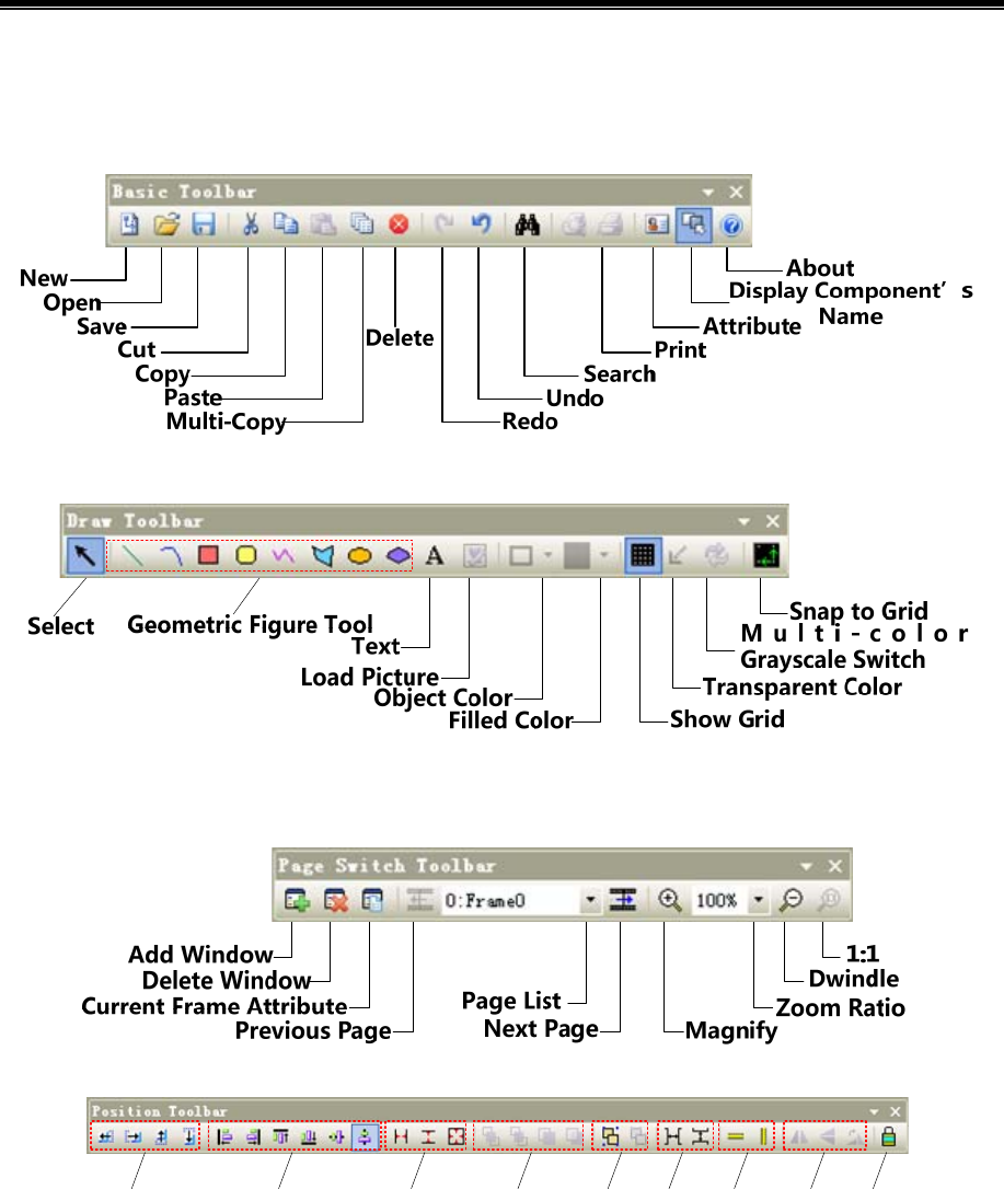
Kinco HMIware Configuration Edit Software
54
- Version Information:Version information of the software.
1.3 Toolbar
1.3.1 Basic Toolbar
1.3.2 Draw Toolbar
- Select: Single click【Select】icon to cancel the selected objects.
1.3.3 Page Switch Toolbar
1.3.4 Position Toolbar
abc
def ghi
a:Nudge Left/Right/Up/Down by one pixel
b:Align Left/Right/Top/Bottom/Vertical Midline/Horizontal Midline
c:Make Same Width/Height/Size
d:Set Top/Set Bottom/Previous Layer/Next Layer
e:Group/Ungroup
f:Same Horizontal Space/Same Vertical Space
g:Align Horizontal Center/Vertical Center
h:Flip Horizontally/Vertically/Rotate 90 Degree
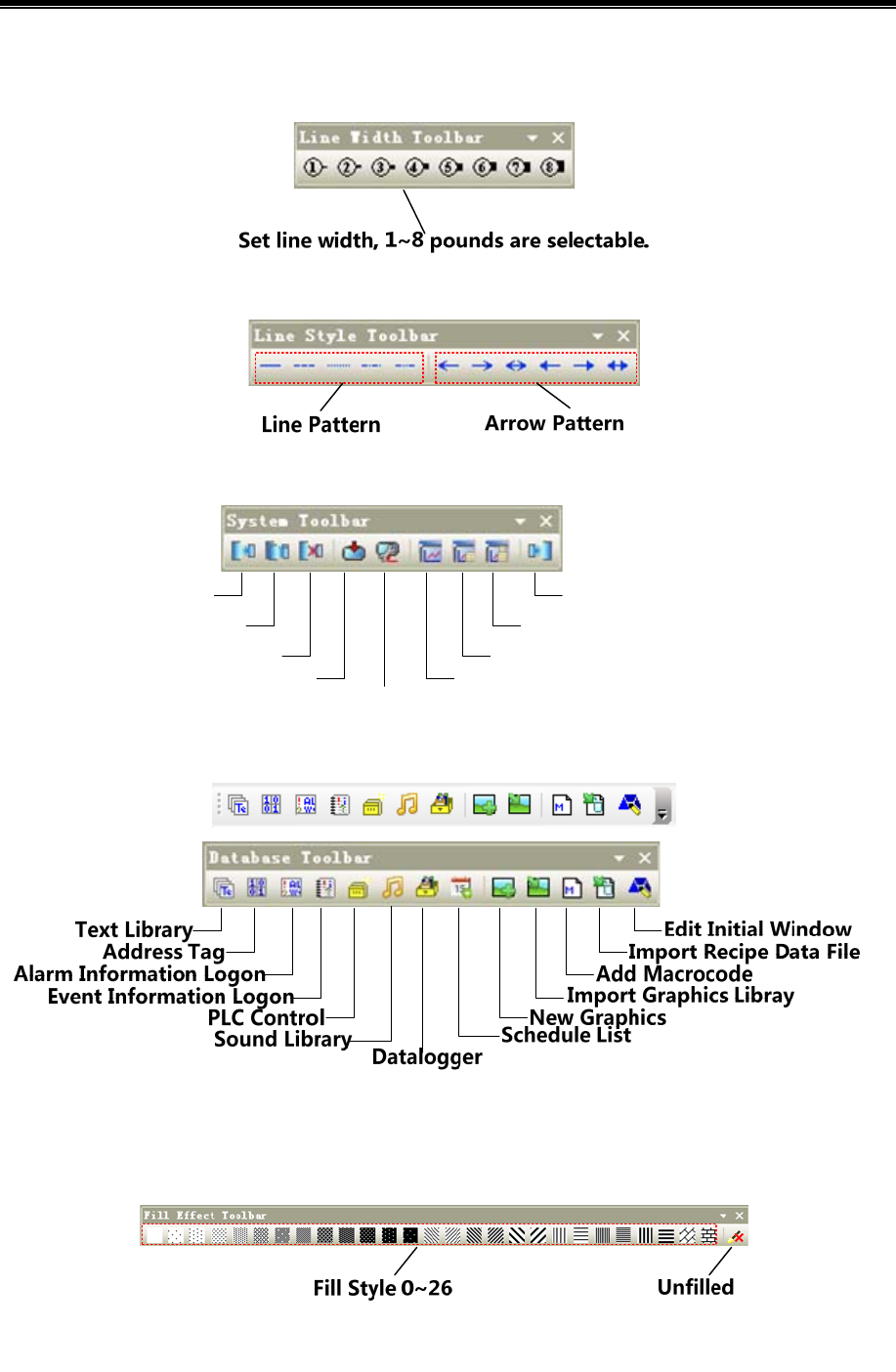
Advanced Part User Interface
55
i:Lock Component Position
1.3.5 Line Width Toolbar
1.3.6 Line Style Toolbar
1.3.7 System Toolbar
Download
Method
Compile Decompile
Direct Online Simulation
Indirect Online Simulation
Offline SimulationDownload
Clear Build Result
Compile All
1.3.8 Database Toolbar
1.3.9 Code Edit Toolbar
Code Edit Toolbar: Do not support currently.
1.3.10 Fill Effect Toolbar
- Filled Style 0~26:when check【Window Attribute】-【Use Background Color】,there are 26 filled styles selectable.
Filled style 0 indicates unfilled.
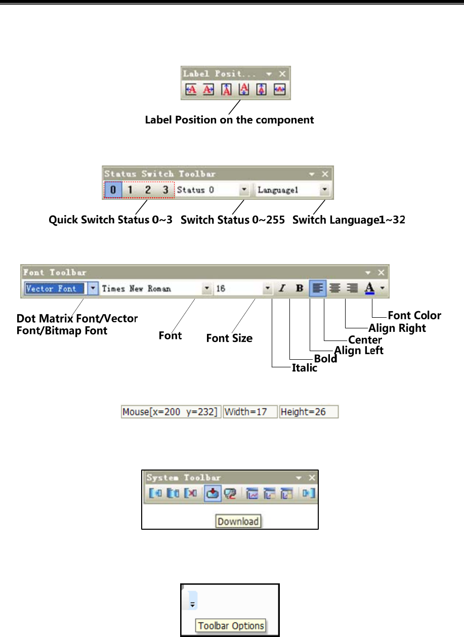
Kinco HMIware Configuration Edit Software
56
- Unfilled: When【Use Background Color】 is checked, single click 【Unfilled】to cancel fill color and filled style.
1.3.11 Label Position Toolbar
1.3.12 State Switch Toolbar
1.3.13 Font Toolbar
1.3.14 Status Bar
- 【Status Bar】:Shows the current X, Y coordinate values of mouse position, width/height of the target object.
1.3.15 Tip Text
- 【Tip Text】:When mouse is hovering over toolbar icon, the responding tip text will display.
1.3.16 Toolbar Options
- 【Toolbar Options】:Single click the down arrow【Toolbar Options】,【Display/hide panel】 will display for user to
start closed toolbars.
1.4 Software window
Kinco HMIware software windows include: Graph element window, Project files window, Project structure window,
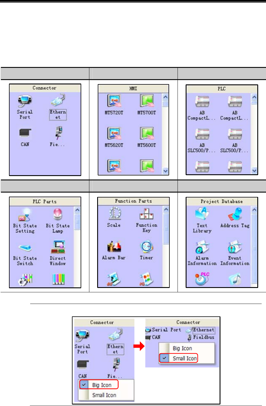
Advanced Part User Interface
57
Message window, Component list window.
1.4.1 Graph Element Window
Graph element window is one of the most indispensable windows, which is mainly for supply configuration with devices,
components and other design elements.
Graph element window is composed of the following 6 element libraries:
Connector HMI PLC/Controller
PLC Parts Function Parts Project Database
1. Right click on the Graphic Element Window to switch between big icon and small icon of parts:
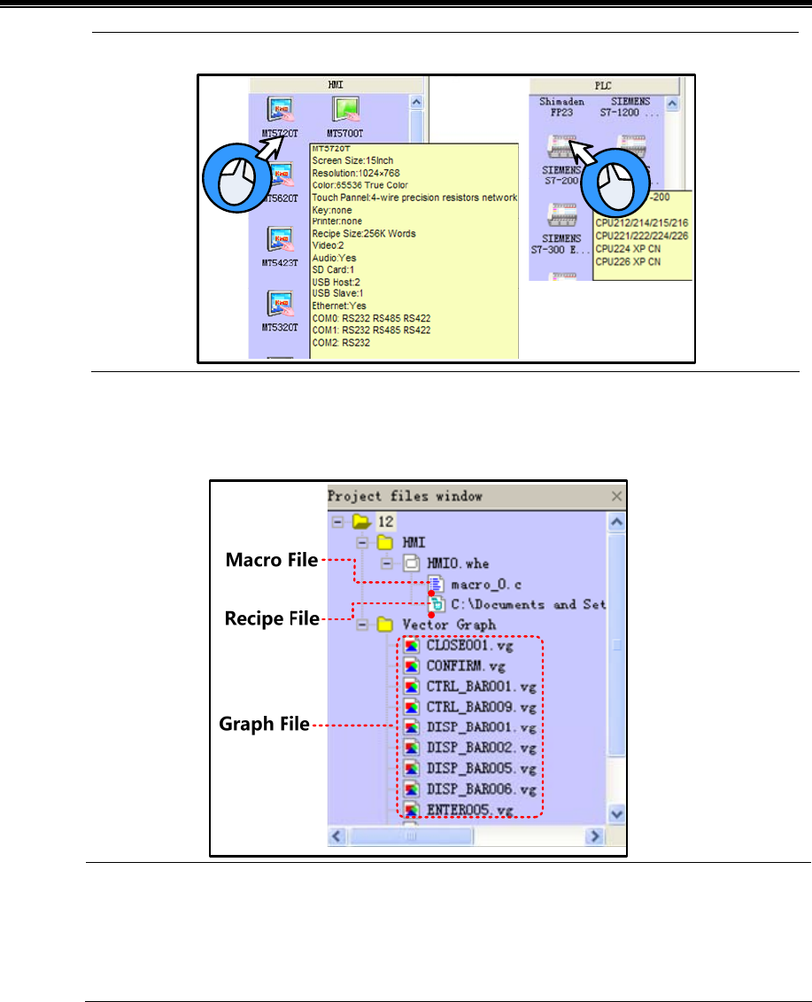
Kinco HMIware Configuration Edit Software
58
2. Hover mouse over icons of HMI or PLC to view information of the corresponding devices:
1.4.2 Project Files Window
Project files window is for displaying all graphic libraries, macro files, recipe files and other information include in the
current project.
1. Double click macrocode file in Project files window to open macro edit window and edit corresponding
macrocode.
2. Double click graphic files in Project files window to open graphic edit window and edit corresponding
graphic.
1.4.3 Project Sstructure Window
Project structure window is for displaying all the elements in the current project by tree diagram or previews.
Tree structure: Displaying all the elements in the current project by tree diagram:
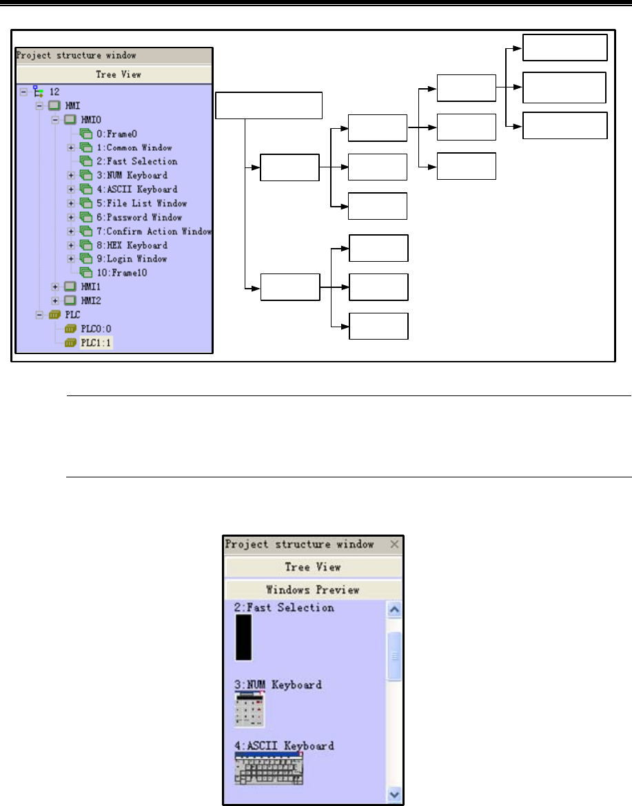
Advanced Part User Interface
59
Project Name
HMI
PLC
HMI0
HMI1
HMIn
PLC0
PLC1
PLCn
Frame n
Frame 1
Frame 0
Component2
Component 1
Component 0
Click the project name in Project structure window to expand the topological structure; Click “HMIn” or
“Frame n” to display the responding configuration window of the certain HMI; Click component to display
configuration window which the component belongs to.
Preview:Display the frames of the configuration project in the form of thumbnail.
1.4.4 Message Window
Message window displays information of the loaded projects and compilation results, in order to facilitate users accurately
search the errors in the project.
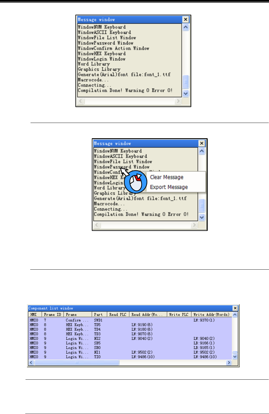
Kinco HMIware Configuration Edit Software
60
Users could delete or export compilation information in Message window by right click.
Clear message: clear all the compilation information shown in Message window.
Export message: export all the compilation information shown in Message window to the current project file,
the exported file name is log.txt by default.
1.4.5 Component List Window
Component list window is for check information of all the components used by current projects, including affiliated
HMI/PLC,Frame No., component ID, address type, address and so on.
1. Open Component list window from the drop list of【View】 Menu.
2. Double click the line of a component, then configuration edit window will change to the frame which the
component belongs to.
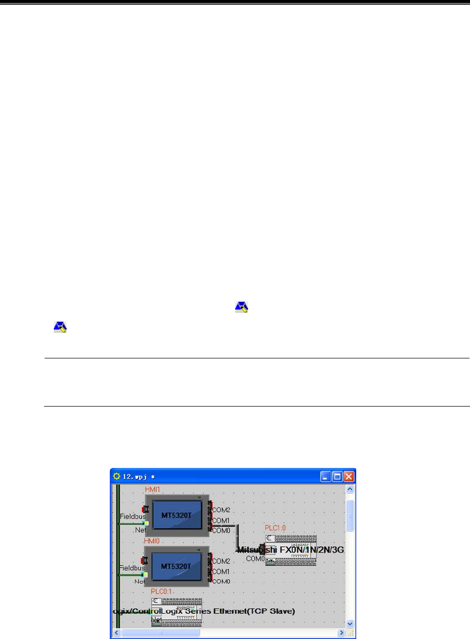
Advanced Part User Interface
61
1.5 Configuration Edit Area
The windows can be opened in configuration edit area areas follows:
- Construct Window
Open Construct window by clicking “Construct Window” in 【Window】menu or clicking project name in Project
structure window.
- HMI Edit Window
Drag a HMI into the Construct Window, and then open HMI Edit Window by right clicking on the HMI icon and select
“Edit”, or clicking “HMI n” or “Frame n” in Project structure window.
- Graphic Edit Window
Open Graphic Edit window by creating a new graphic or by double clicking one graphic file in Project files window.
- Macro Edit Window
Open Macrocode Edit Window by creating a new macro or by double clicking macro files in Project files window.
- Edit Init Window
Enter the Edit Init Window by selecting HMI and clicking the icon of the Database Toolbar in Construct Window, or by
clicking the in HMI Edit Window.
When multiple edit windows are opened, you can arrange the windows by “Cascade”/ “Tile Horizontally”/
“Tile Vertically” in 【Window】menu.
1.5.1 Construct Window
Users can configure communication connection between devices and set communication parameter in Construct Window.
- Communication connection configuration
Drag devices and cables from 【Connector】/【HMI】/【PLC】list of Graph element window into the Construct Window. Drag
devices to connect with wire ends. To make sure the connection is established, drag devices, then the properly attached wire
ends will move with the mouse.
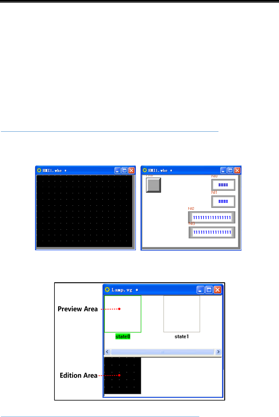
Kinco HMIware Configuration Edit Software
62
- Communication parameter setting
Double click icon of HMI or PLC to open 【HMI Attribute】or【PLC Attribute】.
Serial communication
Set serial communication parameter in 【COMX Setting】—【HMI Attribute】;Set communication parameters of
PLC/Controller in 【PLC Attribute】.
Ethernet communication
Set communication parameters of HMI or PLC/controller in【HMI Attribute】—【Network Device Setting】.
Field Bus communication
Set communication parameters of HMI or PLC/controller in【HMI Attribute】—【Field Bus Setting】.
☞More details about communication please refer to【Advanced Part 14 HMI Communication】
1.5.2 HMI Edit Window
Design and edit project frames in the HMI Edit Window.
1.5.3 Graphic Edit Window
Users could edit vector graphics (.vg) and bitmap graphic (*.bg) in Graphic Edit Window.
☞More details about graphics edit please refer to【Advance Part 5.3 Graphic Library】
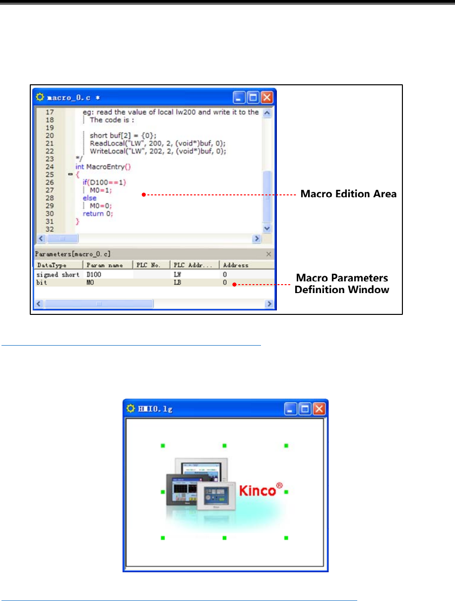
Advanced Part User Interface
63
1.5.4 Macro Edit Window
In Macro Edit Window, users could write source code to realize such functions as operation and logic by using standard C
language.
☞More details about Macro please refer to【Advance Part 9 Macro】
1.5.5 Edit Initial Window
In Edit Initial Window, users could replace or edit the default initial window of HMI.
☞More details about initial window please refer to【Advanced Part 2.8 LOGO Screen (Logo)】
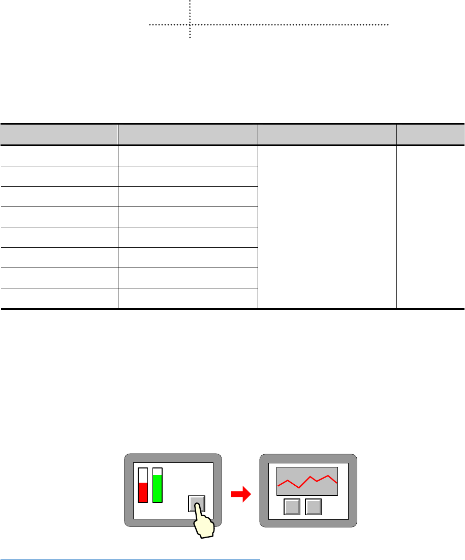
64
2 Basic Design Method
2.1 Window screen
This chapter mainly introduces the specification of basic windows in Kinco HMIware , and how to use and display them.
2.1.1 Specification of window screen
Specification of new basic window:
Size (pixel)(width × height)Max size(pixel)(width × height)Min size (pixel)(width × height) Number
320×234 320×234
320×240 320×240
480×234 480×234
480×272 480×272
640×480 640×480
800×480 800×480
800×600 800×600
1024×768 1024×768
10×10 1~32768
2.1.2 Window Display Methods
Change window
Window change is to shut down the current window (including the sub window) and open another appointed one.
This operation can be finished by the following two methods:
Use function key
Function key:[change window],fill a number in [window number]
You can change window though touch the function key.
☞More information refers to【Advanced Part 4.2.6 Function Key】
Use plc control
“PLC control”:[change window],determine a control address,
You can change window by changing the value in this address.

Advanced Part Basic Design Method
65
☞More information refers to 【Advanced Part 4.15.5 PLC Control 】
- Window overlay
Window overlay is to integrate some windows into one screen.
This function can be realized with two methods:
Bottom window
Double click at the space on the basic window, you can see [window attribute] frame. Once chosen as a bottom
window, all the components on it will also show on the basic window.
Default common window:[1:Common Window],users also can define any other one freely. All the components on
the common window will show on all the basic windows.
☞More information refers to【Advanced Part 3 Window】
1. 3 bottom windows can be used by one basic window at most
2. only one common window
3. Only components of bottom window or common window are shown on the basic window, excluding
attribute settings like background color or frame color.
- Window overlay
- Window overlay is to integrate some windows into one screen.
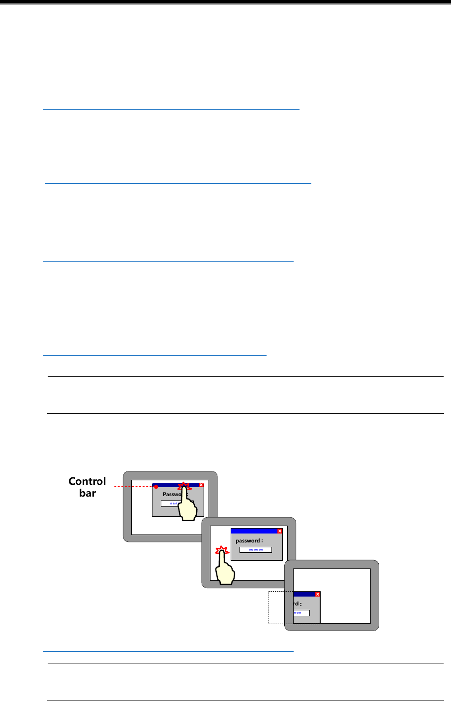
Kinco HMIware Configuration Edit Software
66
This function can be realized with following methods:
Direct window
You can switch on or off to open or close popup the window. Its size is determined by the one of direct window.
Keyboard window is direct window.
☞More information refers to【Advanced Part 4.8.1 Direct Window】
Indirect window
By changing the value, you can open or close the specific window. Its size is determined by the one of indirect
window.
☞More information refers to 【Advanced Part 4.8.2 Indirect Window】
Function key
Function key:[Popup window] to open the specific window,[close window] to close it.Its size is determined by
none but itself.
☞More information refers to【Advanced Part 4.2.6 Function Key】
Fast selection window
Default fast selection window [2:Fast Selection], users also can define any other one freely.
By click [Menu] on task bar, the fast selection window will display and it will shut down after click again.
it. Its size is determined by none but itself.
☞More information refers to 【Advanced Part 3 Window】
1. No limit of popup window .But it`s better to use much fewer or much RAM will not be released.
2. only one fast selection window
- Window move
The place will be changed by using “control bar” of function key.
☞More information refers to【Advanced Part 4.2.6 Function Key】
Basic window cannot be moved ,only popup windows can.
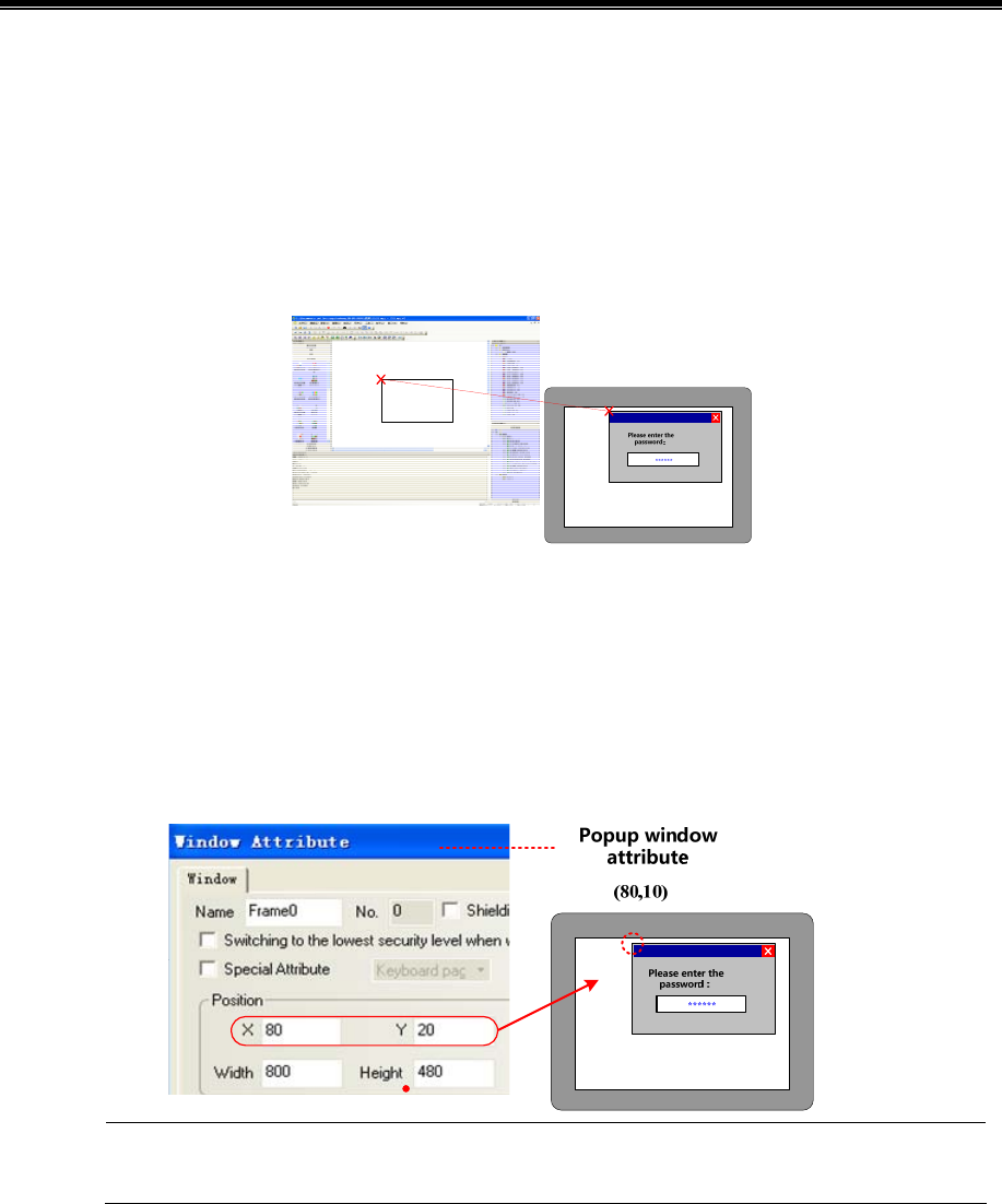
Advanced Part Basic Design Method
67
2.1.3 Display Position
Different types of windows display in different styles:
Popup window by “direct window” or “indirect window”
According to component position
The popup window will display where the “direct window”or “indirect window” is put.
According to setting value
Set [variable display coordinate], values or addresses determine the position of popup window (coordinate of top left
corner point.
- Function key [popup window]
Set values of “X”,”Y” in [window attribute]-[position], they are the coordinates of the popup window.
Its position cannot be changed when the screen is a basic window and it can only display full screen.
2.1.4 Display Order
Different types of windows display on a screen in its order.
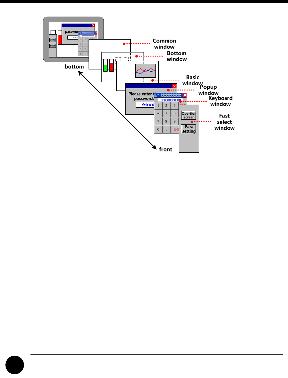
Kinco HMIware Configuration Edit Software
68
2.1.5 Copy/Delete Windows
(1)copy window
Copy in Same project or different projects
- Same project
Same project: same HMI or different HMIs
Same HMI
Copy things from frame A to frame B:
Right click [copy]
Right click the component on frame A , choose[copy],then change to frame B and paste it on it. By this way, only
component is copied, not window attribute.
[copy/delete window]
Click[frame]-[copy/delete window] ,set “count”, “source window”, “destination windows”, click
“OK”. By this way, all the components and window attribution are copied.
Copy across HMI
Copy across HMI can only realized by right click [copy].
!
[Screen]—[copy/delete window]: this copy operation across the HMI windows are not supported
- Copy across project
When copy across different projects, you should open the related two projects with Kinco HMIware, and then right click
[copy].
(2)delete window
You can delete windows as belows:
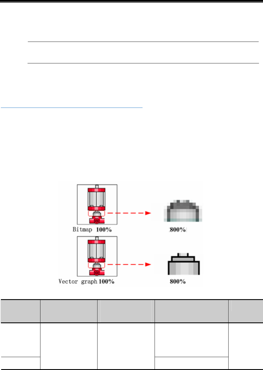
Advanced Part Basic Design Method
69
- Right click [delete]
Right click the frame you want to delete under [project structure window], then it will be delete.
Windows are deleted one by one, multi-deletion is not supported.
- [copy/delete windows]
Click HMI you want to handle, click [screen]-[copy/delete windows-[delete window],[delete single window]can delete an
appointed window,[delete multi-windows]can delete continuous-number windows.
☞More information refers to【Advanced Part 3.3 Edit Window】
2.2 Draw
This chapter introduces Kinco HMIware image format and picture drawing and using.
2.2.1 Image Format
Kinco HMIware mainly supports two format vg and bg. When createing a vector graph, its default format is vg, while
createing a bit map, its default format is bg.
Differences between vector graph and bitmap is shown as below:
Specification of created graph:
Graph format Max size(pixel)
(width × height)
Min size(pixel)
(width × height)
Graph types State limit
Vector graph
(vg)
line, round-corner rectangle,
rectangle, ellipse, sector, broken
line, curve, polygon and so on
Bitmap (bg)
320×240 2×2
Jpg, bmp, gif, png and so on
1~256
2.2.2 Vector
[vector],in short, enlarge or narrow without distortion. Geometric figures which can be infinitely enlarged without color
change and blurred are mostly in this form

Kinco HMIware Configuration Edit Software
70
In Kinco HMIware, you can create vector graph through in two ways:
- Import from image library
Import graph you need from [image library]-[vector graph].
☞More information refer s to [Advanced Part 5.3.1 Import Grahpics]
- Use drawing tools in
Draw in picture edit window
Use component [vector graph].open window edition, draw as you need with drawing tools, save, exit edit window, a new
vector graph is finished.
☞More information refers to [Advanced Part 5.3.2 Build New Graphics]
Draw in configuration window
Draw in the edit window with drawing tools, right click the graph done, choose “save to the VG map”, a new vector graph
is finished
☞More information refers to [Advanced Part 5.3.2 Build New Graphics]
Now we will introduce how to use drawing tools:
Choose an icon, drag in the edit area :
line
Graphic instrument Drawing step
~move mouse into edit area,”+”shows
up, press left on mouse and drag
release at the position you prefer a line is
finished
curve
Graphic instrument Drawing step
move mouse into edit area,”+”shows up,
press left on mouse and drag
,press left on mouse and drag
release the mouse you can see a circle
click at the start point
click at the finishing point ,a curve is finished
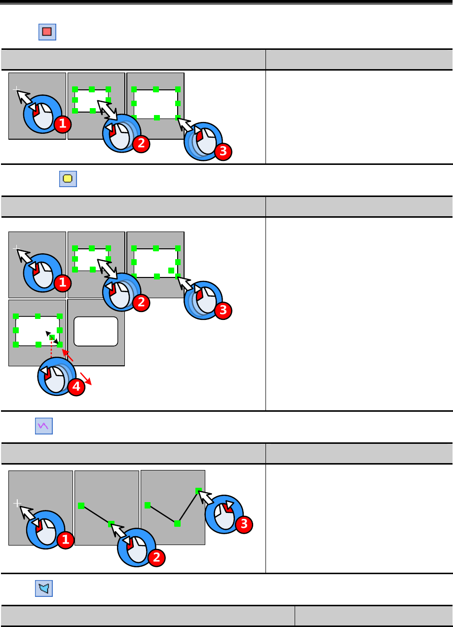
Advanced Part Basic Design Method
71
rectangle
Graphic instrument Drawing step
move mouse into edit area,”+”shows up
press left on mouse and drag
release at the position you prefer a rectangle
is finished
roundrectangle
Graphic instrument Drawing step
move mouse into edit area,”+”shows up,
click to set the starting point
press left on mouse and drag to the position
you want
release the mouse, a roundrectangle is
finished
Point at the small green block on the bottom
right corner, when the arrow turns two-ways,
press left on mouse and drag, ou can change its
radius.
polyline
Graphic instrument Drawing step
move mouse into edit area,”+”shows up,
click to set the starting point
click at the set points
right click to finish drawing
polygon
Graphic instrument Drawing step

Kinco HMIware Configuration Edit Software
72
~ move mouse into edit
area,”+”shows up, click 7 times at 7
points
right click to finish drawing
ellipse
sector
Graphic instrument Drawing step
move mouse into edit area,”+”shows up,
click to set the centre point
press left on mouse and drag to the position
you want
release the mouse ,a closed circle shows up
click at starting point
click at the ending point ,a sector is finished
2.2.3 Geometric Figures Attribution
Attributions as below:
graphics Graphic samples Setting attribute
Graphic instrument Drawing step
move mouse into edit area,”+”shows up,
click to set the starting point
press left on mouse and drag to the position
you want
release the mouse, a ellipse is finished
With the same width and height ,a ellipse turns to
be a circle
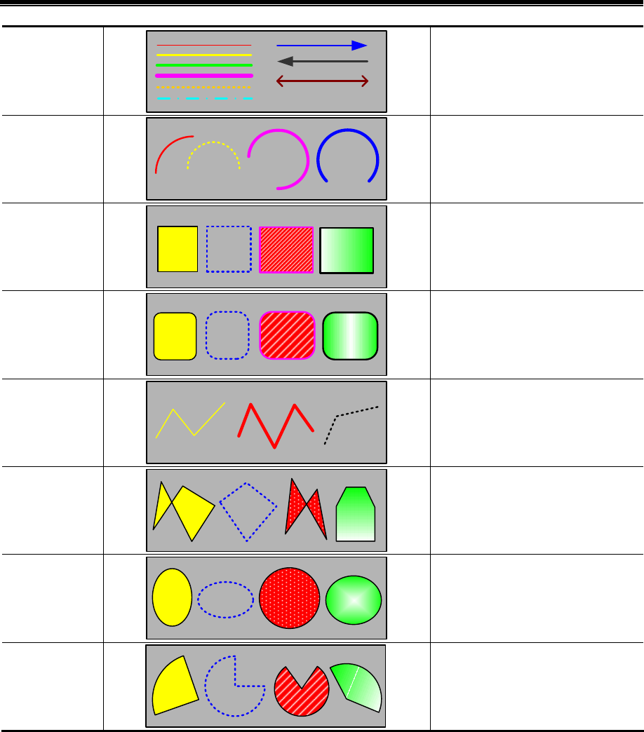
Advanced Part Basic Design Method
73
Line
line color, line style、line width、arrow
style
Curve
line color、line style、line width
Rectangle
line color、background fill color、
foreground fill color、pattern fill、
fountain fill、line style、line width
RoundRectangle
line color、background fill color、
foreground fill color、pattern fill、
fountain fill、line style、line width
PolyLine
line color、line style、line width
PolyGon
line color、background fill color、
foreground fill color、pattern fill、
fountain fill、line style、line width
Ellipse
line color、background fill color、
foreground fill color、pattern fill、
fountain fill、line style、line width
Sector
line color、background fill color、
foreground fill color、pattern fill、
fountain fill、line style、line width
Users can modify attribute in two ways:
- Attribution frame
Double click the graph,modify in [graphics attribute]
- Tools bar
Choose the graph, modify its attribute through[drawing tools]/[ line width]/[line style].In this way, you can only set line
color\filled color\line width and line style.
2.2.4 About Fountain Fill
The closed graphics can be set fountain fill.
Double click the graph,choose[fountain fill]choose the foreground fill color, background fill color line color .
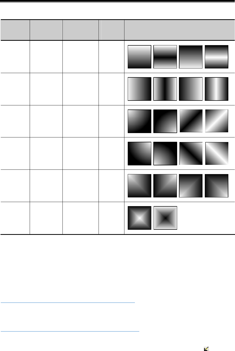
Kinco HMIware Configuration Edit Software
74
Example:
Fountain
Fill
Foreground
Fill Color
Background Fill
Color
Line
Color
Deformation
Horizontal ■ □ ■
Vertical ■ □ ■
Oblique ■ □ ■
Under
Oblique ■ □ ■
Corner of
Radiation ■ □ ■
Centre for
Radiation ■ □ ■
2.2.5 Bitmap
[bitmap],in short,structured with pixel,enlarger or narrow with distortion. Bitmap is structured with pixel array and each
has its own information. We can change the graph by dealing with every pixel.
In Kinco HMIware, bitmap is created in two ways:
- Import from image library
Import from[image library]-[BG]
5☞More information refer s to [Advanced Part 5.3.1 Import Grahpics]
- Import pictures in forms of jpg、bmp、gif、png
Bitmap, open the edit window ,import pictures in forms of jpg, bmp, gif, png and so on, save, exit ,a new bitmap is created.
5☞More information refers to [Advanced Part 5.3.2 Build New Graphics]
2.2.6 About Transparent Color
If a picture influences the aesthetic, users can deal with the pure color with[transparent] tool in drawing tools :
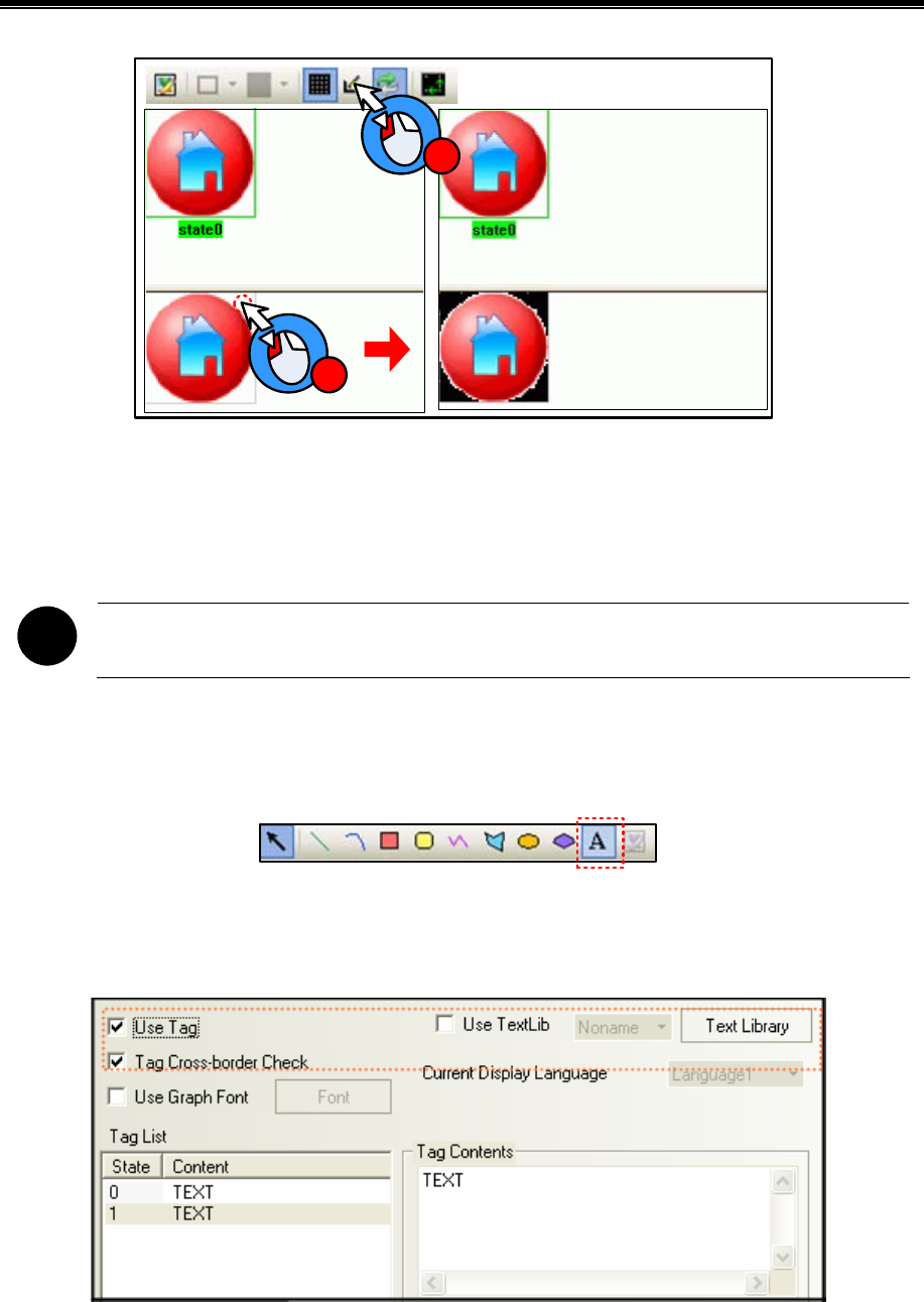
Advanced Part Basic Design Method
75
1
2
“Transparent” can only deal with simple actions, not suggested to use.
Besides,bitmap supports PNG format, so you can edit a picture with another editor and convert it into PNG form before
import.
!
GIF and PNG form picture doesn`t support transparent action
2.3 Text
User can add the text for the component by the following way in Kinco HMIware.
- Set in Draw Toolbar.
- Click the [A] icon in Draw Toolbar, and input the needed text content in [Text Attribute]-[Display Setting].
Position free
- Set [Use Tag] or [Use TextLib] in the component attribute.
Select [Use Tag] in the [Tag] option in component attribute, and input the needed text contents in [Tag Contents], or select
[Use TextLib], if there are TextLib logon in the project.
Only shown on the component
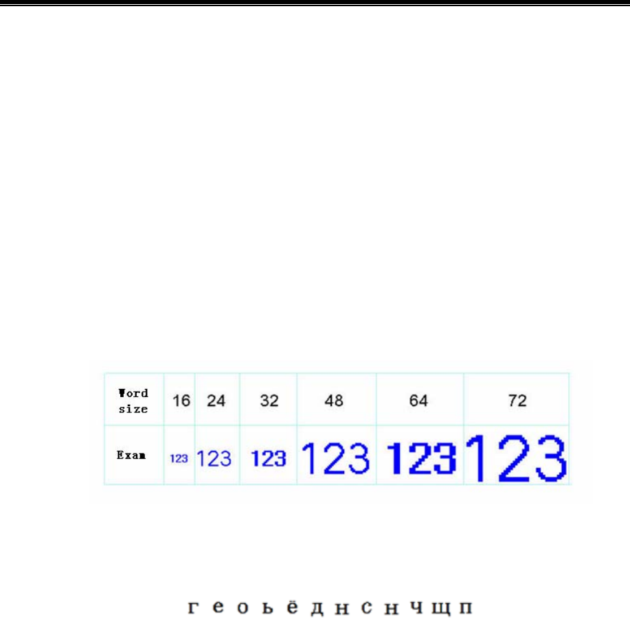
Kinco HMIware Configuration Edit Software
76
2.3.1 Font Type
Kinco HMIware provides 3 available fonts, i.e. dot matrix font, vector font and graph font. The advantages and
disadvantages of these three fonts will be described as follows; users can select the suitable font type according to its
characteristics.
2.3.2 Dot Matrix Font
Dot Matrix font saves the bitmap for each character of the required Chinese character set. Each primitive (small picture) is
spliced together to form a character string when it is used.
- Disadvantages of dot matrix font:
Only SimSun is supported.
The scaling effect is poor.
For each character, 3 kinds of bitmaps (8×8, 16×8, 24×16 (height*width)) are reserved respectively, so the effect
is very poor when the larger font is displayed, as shown below:
full-width deal only for unASCII characters
Kinco HMIware deals with ASCII characters as half-width ones, while unASCII as full-width ones. So if each
character has different width, the intervals may be different:
advantages of dot matrix font:
A smallest storage space is occupied by dot matrix font.
2.3.3 Vector Font
V
ector font intercepts the characters that are used by the user from the corresponding font library through checking the setup
of the user-set fonts, and then makes them into TrueType font file (*.ttf format) for HMI to use.
Disadvantages of vector font:
Only Support the TrueType installed in the operating system (*.ttf format).
Without selecting “Vector Fonts Edge Blur”,the font is displayed with some projections, and comparison
results as shown below:
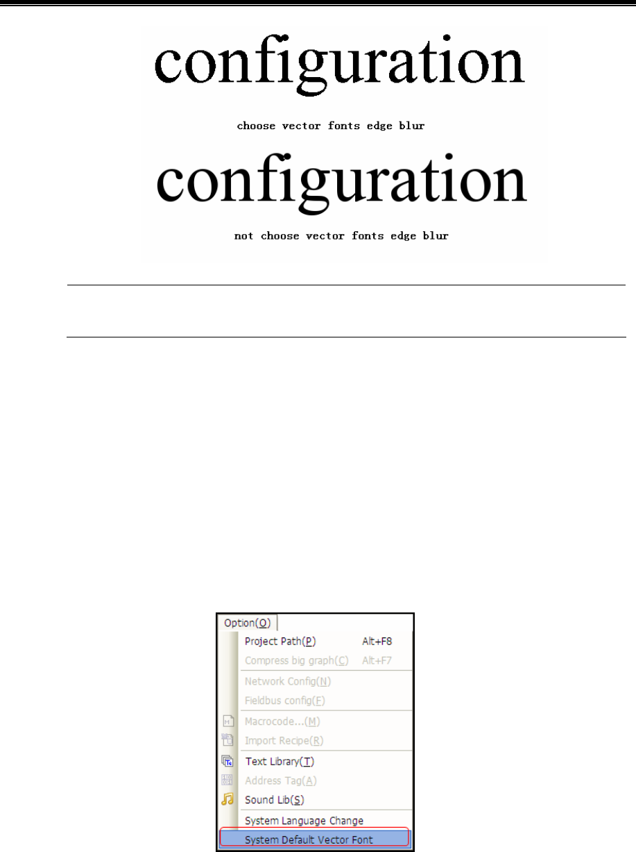
Advanced Part Basic Design Method
77
“Vector Fonts Edge Blur” can be set in [HMI Attribute]-[HMI Extended Attributes].
- Advantages of vector font:
A smaller storage space is occupied. It adopts the method of intercepting the matrix from the font file, thus
reducing the size of the font file. For the same character in the same font, only one matrix needs to be intercepted
regardless of the size, color, bold/italic styles.
The font size can be set freely without any deformation
Support the alignment method for multiple-line text.
Text library can support the vector font.
- System default vector font setting
User can define the default vector font in [System Default Vector Font] in [Option].
[Example] Set System Default Font as “Arial”, when using tag or text and select “Vector Font”, it will select
“Arial”by default automatically.
2.3.4 Graph Font
Graph font treats the whole character string as a whole, and intercepts the whole bitmap and saves it in the project.
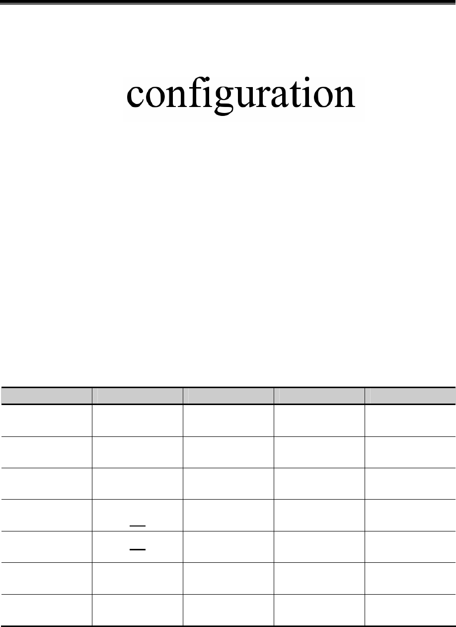
Kinco HMIware Configuration Edit Software
78
Disadvantages of graph font:
A larger storage space is occupied. Because the character string saves as bitmap, so it needs a larger space. For
example: Four characters “configuration”displayed in zero SimSun needs 1824 bytes, as shown below:
In addition, the graph font should be intercepted again if the content, size or colors vary slightly, thus causing a
linear increase in the occupied space.
Text library can’t support the graph font.
- Advantages of graph font:
Support all installed fonts in current operating system.
The scaling effect is good.
2.3.5 Text Attribute Edition
User can modify the font attribute through the following two methods:
- Modify in the component attribute dialog box
Double-click component /text to set the font attributes in [Component Attribute]-[Tag] or [Text Attribute].
- Modify in Font Toolbar
Selected component/ text, and then set the font attributes in [Font Toolbar]. This method can support multi-modify font
attribute.
Different font types support different font attribute to be modified, specific as below:
: Support;--: Unsupport
Font Attribute Graphic Dot Matrix Font Vector Font Graph Font
Common A
Bold A --
Italic A --
Underline A -- --
strikeout A -- --
Size A A A
Color A A A
2.3.6 Notes for Using Vector Font
Based on the special treating method for the vector font, the following conditions should be paid attention to when the vector
font is used:
1. Some fonts may not support some characters, or have poor support effects.
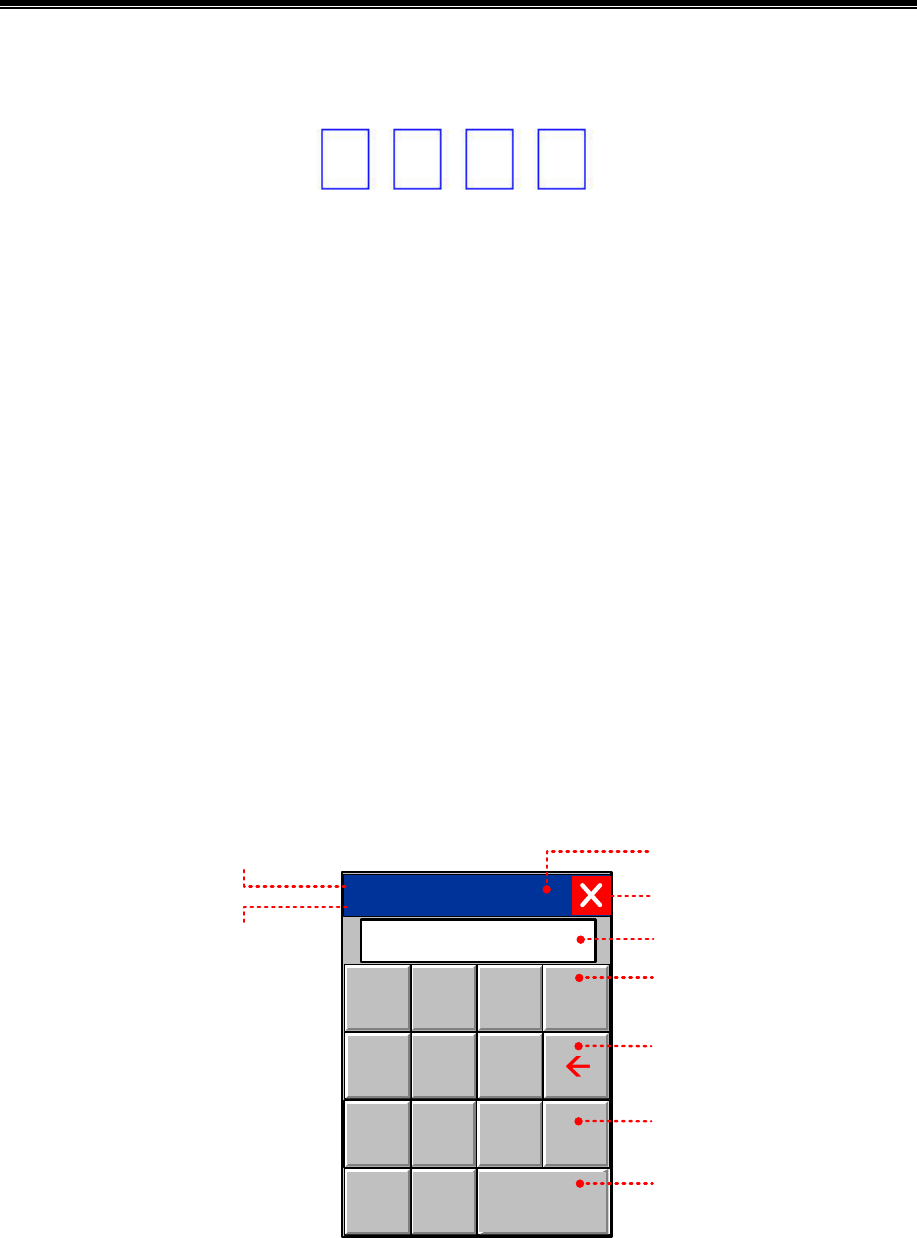
Advanced Part Basic Design Method
79
For example, the Chinese characters can be displayed by using Arial font, because there are no corresponding Chinese
characters in Arial font library. Otherwise the effect will as shown below:
2. Because the dot matrix font and graph font have many disadvantages in the storage space and scaling etc, therefore, use
the vector font as much as possible when it can meet the project requirements.
3. Avoid using too many fonts as much as possible.
It too many types of vector fonts (e.g. dozens or more) are used by the user, the number of font files will be too many, thus
affecting the compilation speed, downloading speed and screen switching speed.
4. Use the common fonts in operating system as much as possible.
If a certain project uses “Microsoft Elegant Black” font when it is edited on PC, and when it is transferred to another PC
where no “Microsoft Elegant Black” font exists for editing, then all the “Microsoft Elegant Black” characters used in
the project will be changed to “SimSun” automatically.
2.4 Keyboard
This chapter describes keyboard type and methods of calling keyboard in Kinco HMIware.
2.4.1 Keyboard Type
Kinco HMIware support three keyboard for users: NUMERAL Keyboard、ASCII Keyboard and HEX Keyboard. And users
can make own keyboard or use external USB keyboard.
- NUM Keyboard:NUM Keyboard for number input component.
Max:AAAAAAAAAAAA
Min:AAAAAAAAAAAA
123
456
789
0.ENTER
CLR
_
AAAAAAAAAA
Max value*
Min value* Input
display
clear
backspace
enter
Window
control bar
Shut down
minus
※ 1. The values shown here are max and min in Max/Min Value Setting in [Number Input Component Attribute]-[Numeric
Data], Keyboard permission input value range is limited by the value.
2. If [Proportion Conversion] is selected, the values shown here are max and min after proportion conversion.
- ASCII Keyboard:ASCII Keyboard for text input component or number input component.
Lowercase:
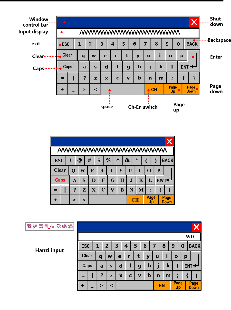
Kinco HMIware Configuration Edit Software
80
Caps:
Chinese Input:
※Set Chinese Font Box Height in [HMI Attribute]-[HMI Extended Attributes], height range from 24 to 99 (pixel).
- HEX Keyboard:for HEX character input
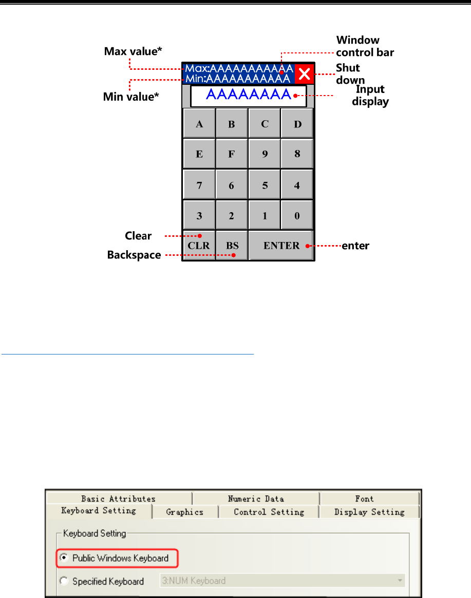
Advanced Part Basic Design Method
81
※1. The values shown here are max and min in Max/Min Value Setting in [Number Input Component Attribute]-[Numeric
Data], Keyboard permission input value range is limited by the value.
2. If [Proportion Conversion] is selected, the values shown here are max and min after proportion conversion.
☞More information refers to [Advanced Part 4.2.6 Function Key]
2.4.2 NUM Keyboard
Through the following three methods, Number Input Component will pop up NUM Keyboard in Kinco HMIware.
- Use public windows keyboard
This method is system default.
Open [Number Input Component Attribute] - [Keyboard Setting] dialog box, and then select [Public Windows Keyboard], as
shown below:
Put two “direct window” components respectively on the left and right side of [Frame 1:Common Window],choose
[Frame 3:NUM Keyboard] in frame ID.
Take apart in the middle of a screen, when the components on the left side is triggered, the direct window on the right side
will pop the keyboard, It`s the same with the other side.
- Use Specified Keyboard
This method can pop up keyboard made by user self.
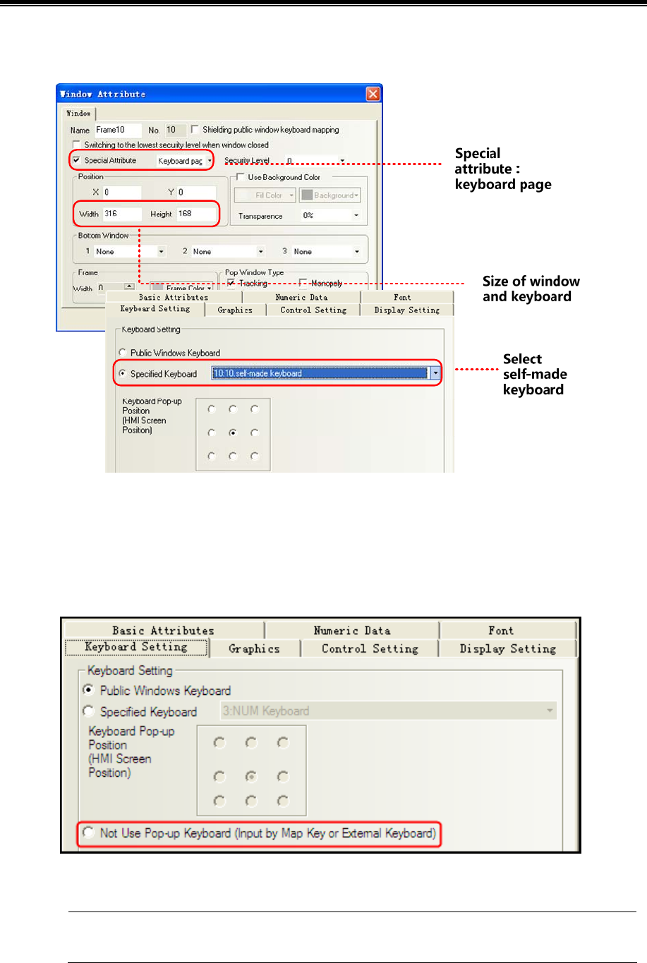
Kinco HMIware Configuration Edit Software
82
Use specified keyboard. Only after setting window attribute as “keyboard page” can you find the page in [input
attribute]-[keyboard setting]-[specified keyboard].
- Use external keyboard
This method need connect USB Host keyboard.
Open [Number Input Component Attribute] - [Keyboard Setting] dialog box, and then select [Not Use Pop-up Keyboard], as
shown below:
No keyboard will pop up, while user can input things through circumscribed keyboard.
It is only applicable to the HMI supporting the USB HOST.
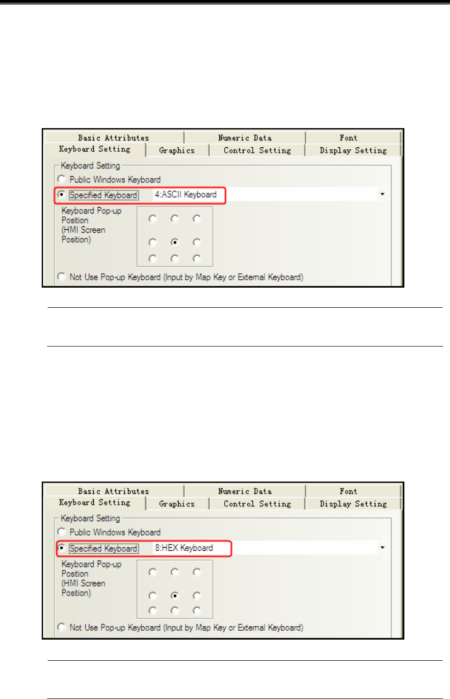
Advanced Part Basic Design Method
83
2.4.3 ASCII Keyboard
Through the following two methods, Text Input component / Note Book component will pop up ASCII Keyboard in Kinco
HMIware.
- Use Specified Keyboard
This method is system default.
Default keyboard:[Frame 4:ASCII Keyboard]
If you want to us your own keyboard, you should set it as a keyboard page ,and choose the frame ID of the
keyboard window.
- Use external keyboard
Same as number input,No keyboard will pop up, while user can input things through circumscribed keyboard.
2.4.4 HEX Keyboard
When input hex number, you should make it with two methods as below:
- Use Specified Keyboard
[number input attribute]-[keyboard setting]-[specified keyboard],choose[Frame 8:HEX Keyboard].
If you want to us your own keyboard, you should set it as a keyboard page, and choose the frame ID of the
keyboard window.
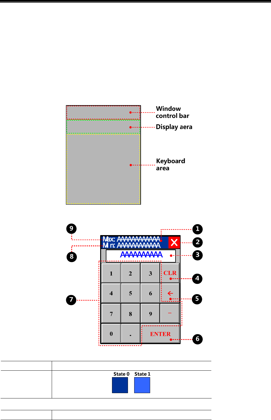
Kinco HMIware Configuration Edit Software
84
- Use external keyboard
Same as number input
No keyboard will pop up, while user can input things through circumscribed keyboard.
2.4.5 Create your Own Mumber Keyboard
Num keys0-9, enter, delete and backspace
Determine the layout:
Create keyboard:
function key,move the window,attribute setting:
Function Switch Window: Popup window title bar
Graphics
Select Vector Graphics:
function key,close the window,attribute setting:
Function Keyboard Function:Escape
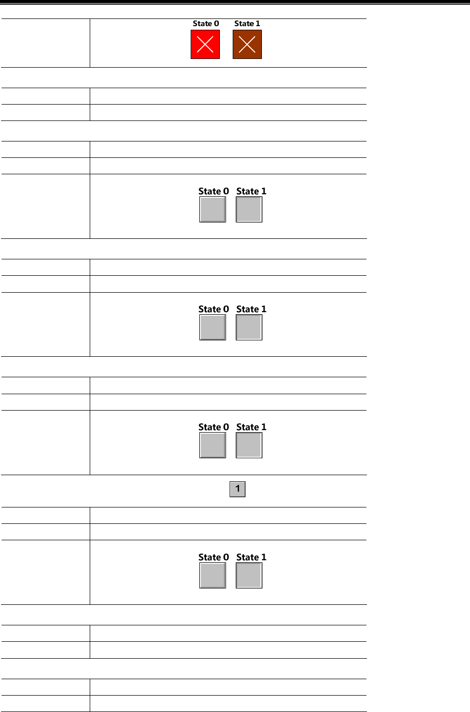
Advanced Part Basic Design Method
85
Graphics
Select Vector Graphics:
text display,display the characters, attribute setting:
Read address LW 9070*1(special register)
Data width 6
function key,delete,attribute setting:
Function Keyboard Function:Clear
Tag 0:CLR;1:CLR
Graphics
Select Vector Graphics:
function key,backspace,attribute setting:
Function Keyboard Function:Back Space
Tag 0:;1:
Graphics
Select Vector Graphics:
function key,enter,attribute setting:
Function Keyboard Function:Enter
Tag Sselect;0:ENTER;1:ENTER
Graphics
Select Vector Graphics:
function key,character input,attribute setting:take for example
Function Keyboard Function:Unicode
Tag 0:1;1:1
Graphics
Select Vector Graphics:
number display,display min value, attribute setting:
Read address LW 9190*2(special register)
Data width 6
number display,display max value, attribute setting:
Read address LW 9180*3(special register)
Data width 6
※ 1.LW9060 ~ LW9075 special registers,cache the latest input
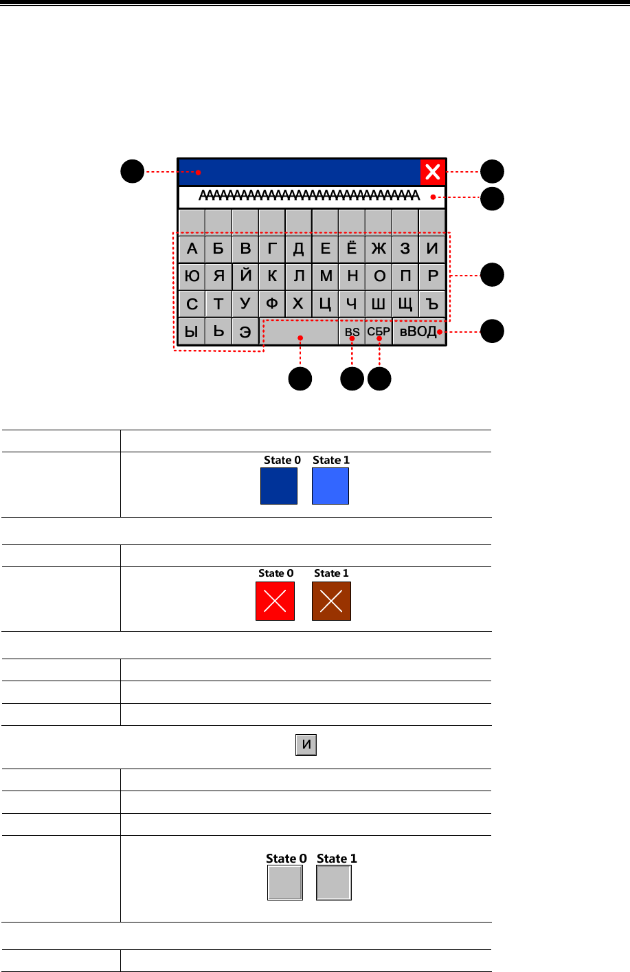
Kinco HMIware Configuration Edit Software
86
2. LW9190 ~ LW9197 special register,min value display
3. LW9180 ~ LW9187 special register,max value display
2.4.6 Create your Oown Unicode Keyboard
Unicode uses two bytes to form a character,often used to display characters cannot display by ASCII, kanji for example.
Take Russia as an example:
1234567890
12
3
4
5
678
function key,move the window,attribute setting:
Function Switch Window: Popup window title bar
Graphics
Select Vector Graphics:
function key,close the window,attribute setting:
Function Keyboard Function:Escape
Graphics
Select Vector Graphics:
text display,display the characters, attribute setting:
Read address LW 9060(special register)
Data width 16
Unicode choose
function key,character input,attribute setting:take for example
Function Keyboard Function:Unicode
Tag 0:И;1:И
Font vector:Arial Unicode MS
Graphics
Select Vector Graphics:
function key,enter,attribute setting:
Function Keyboard Function:Enter
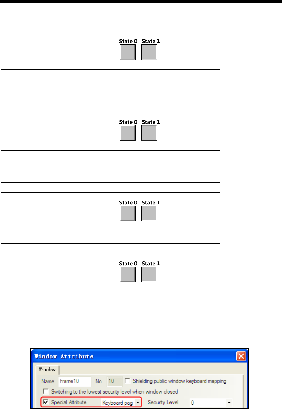
Advanced Part Basic Design Method
87
Tag 0:вВОД;1:вВОД
Font vector:Arial Unicode MS
Graphics
Select Vector Graphics:
function key,delete,attribute setting:
Function Keyboard Function:Clear
Tag 0:СБР;1:СБР
Font vector:Arial Unicode MS
Graphics
Select Vector Graphics:
function key,backspace,attribute setting::
Function Keyboard Function:Back Space
Tag 0:BS;1:BS
Font vector:Arial Unicode MS
Graphics
Select Vector Graphics:
function key,space,attribute setting:
Function Keyboard Function:Unicode
Graphics
Select Vector Graphics:
2.4.7 Call Keyboard in the Group Component Library
Kinco HMIware provides 21 default keyboards in Group Components Library, the method of calling the keyboard in Group
Components Library is as follows:
【example】number input calls a keyboard made of group(text input/note book)。[Example]
Createe a new window named Frame10, and select [Keyboard Page] from [Special Attribute] in Window Attribute.
Right-click the mouse in the blank area in the Frame10 window to select [Group]-[Use the group element], then select
[keyboard] from [Group Components] in [Edit Box of Group Components Library], and select the right keyboard from
[Preview] and click [Place Group Components] button, then the keyboard will appear in Frame10.
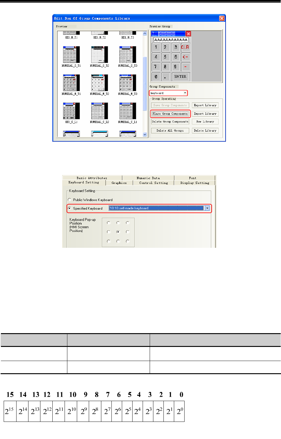
Kinco HMIware Configuration Edit Software
88
Modify the window size of Frame 10 to the same size as the specified keyboard.
Place one number input component (LW0) in Frame0, and select [Specified Keyboard] in [Keyboard Setting] in
[Number Input Component Attribute], select [10:Frame10].
Save, compile, and run the project. Then click the number input component (LW0) to make the specified num keyboard
pop up in the middle of HMI screen.
2.5 Code Type
Kinco HMIware can support code type: BIN, BCD and LSB. User can select the correct encoding type according to the
actual encoding type of data process.
2.5.1 BIN
BIN(Binary)is binary code type. Most digital systems are based on BIN code to process the data
Code Type Word data range Dword data range
Signed BIN -32767~32767 -2147483648~2147483647
Unsigned BIN 0~65535 0~4294967295
[Example]
Convert binary data 1001 0100 to decimal data:

Advanced Part Basic Design Method
89
1001 0100 = 1×27+0×26+0×25+1×24+0×23+1×22+0×21+0×20 = 148
2.5.2 BCD
BCD (Binary Coded Decimal) is two-decimal code. The encoding type represents a decimal number 0 to 9 with 4-bit binary
number. Example 9 (Decimal) =1001 (Binary).
As easy to deal with,often use for BCD switch and BCD nixie tube display 由
Code Type Word data range Dword data range
BCD 0~9999 0~99999999
[Example]
Decimal data is +123,the binary data is 0000 0000 0111 1011 (64+32+16+8+2+1=123). But BCD data is #123,it can be
simply expressed as 0000 0001 0010 0011
Decimal data is -413,the binary data is 1111 1110 0110 0011(complement for negative number,negation adding 1). But
BCD data is #F413,it can be simply expressed as 1111 0100 0001 0011
2.5.3 LSB
LSB is the acronym of Least Significant Bit. This encoding type first converts the data in the buffer to binary data, and then
determines the current state of component based on the number of consecutive “0”at the least significant bits of the binary
dat. [Example] Take the data with word address for example:
Decimal Binary State
0 0000 0000 0000 0000 All bit are 0, the state is 16
1 0000 0000 0000 0001 The number of consecutive “0”at least significant bits is 0, the state is 0
2 0000 0000 0000 0010 The number of consecutive “0”at least significant bits is 1, the state is 1
3 0000 0000 0000 0011 The number of consecutive “0”at least significant bits is 0, the state is 0
4 0000 0000 0000 0100 The number of consecutive “0”at least significant bits is 2, the state is 2
5 0000 0000 0000 0101 The number of consecutive “0”at least significant bits is 0, the state is 0
6 0000 0000 0000 0110 The number of consecutive “0”at least significant bits is 1, the state is 1
7 0000 0000 0000 0111 The number of consecutive “0”at least significant bits is 0, the state is 0
8 0000 0000 0000 1000 The number of consecutive “0”at least significant bits is 3, the state is 3
2.6 Language Switching
User can pre-register the content written in multiple languages to text library in Kinco HMIware. The switching display
among the multiple languages contents can be realized by modifying the value of special register, which refers to LW9130 in
Kinco HMIware.
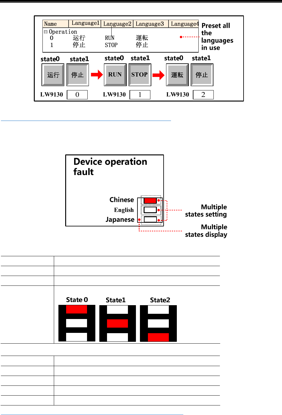
Kinco HMIware Configuration Edit Software
90
☞ For details about text library, refers to [Advanced Part 5.1 Text Library]
There are two following usages for switching display among the multiple languages by LW9130.
- Use Multiple State Setting and Multiple State Display components.
Createe one Multiple State Display component, the attribute is:
Read Address LW9130(HMI system special register)
State Num. 3
Tag No
Graphics Use vector graphic, createe one vector graphic with 3 state
Three multiple state settings stack up upon a multiple state display in corresponding order, attribute settings:
Write Address LW9130(HMI system special register)
Setting Mode Set Constant
Set Value 0/1/2
Tag No
Graphics No
☞ For details about component attribute, refer to [Advanced Part 4 Component]
When running, the effect is as shown below:
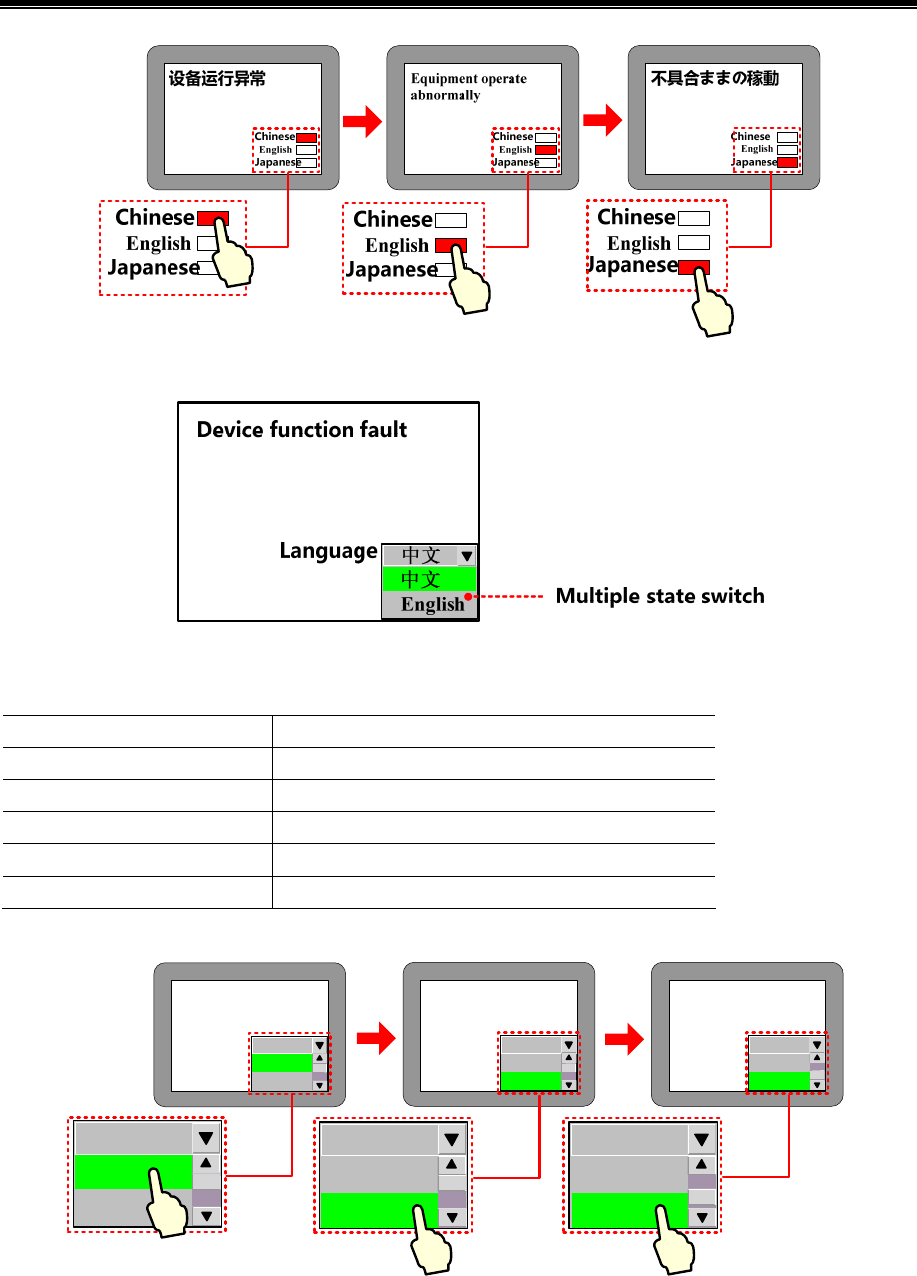
Advanced Part Basic Design Method
91
- Use Multiple State Switch
Createe one Multiple State Switch component, the attribute is:
Read/ Write Address LW9130(HMI system special register)
Control Mode Dropdown List
State Num. 3
Select/Background/Border Color bright green/gray /lack
Tag Use;0:Chinese;1:English;2:Japanese
Graphics No
When running, the effect is as shown below:
设备运行异常
Language
English
Chinese
Chinese
Chinese
Chinese
English
Equipment operate
abnormally
Language English
Chinese
English
English
Chinese
English
不具合ままの稼動
Language
English
Japanese
Japanese
English
Japanese
Japanese
2.7 RTC Set
MT series HMI has real time(RTC)function, BIN coded format,for real time and date display. Once HMI is power off,
battery is backup
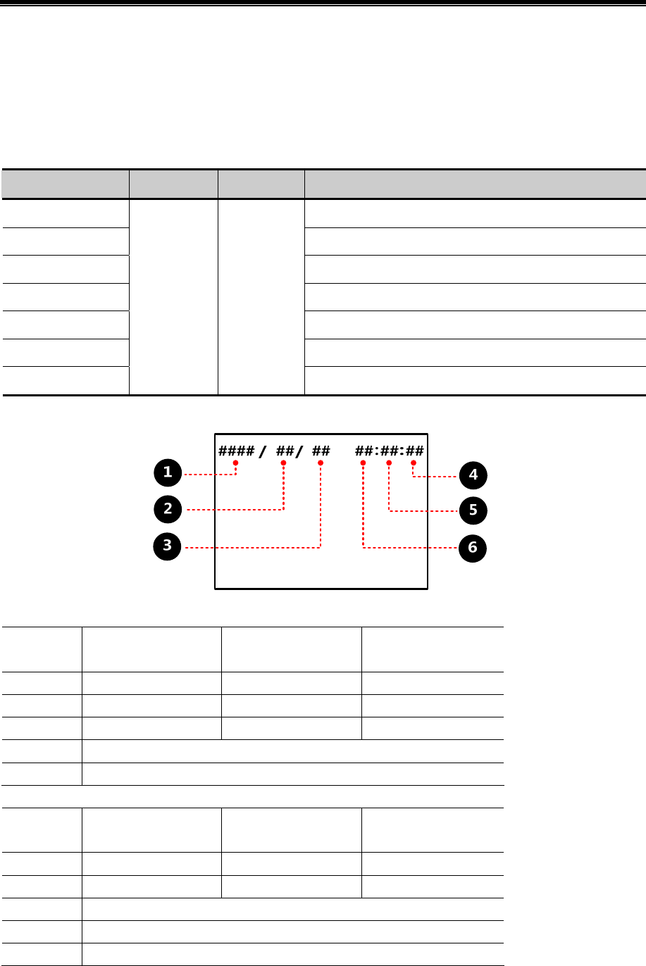
Kinco HMIware Configuration Edit Software
92
In Kinco HMIware,components with real time clock:time, event display, event bar, historical event display, historical data
display, operation log, trend curve ,XY plot.
So when using components above, you should ensure the accuracy of time or you may get wrong information
2.7.1 Through Special Registers
LW10000~LW10006:
Special Register Address Type Code Type Descriptions
LW10000 Second, the effective value range from 0 to 59
LW10001 Minute, the effective value range from 0 to 59
LW10002 Hour, the effective value range from 0 to 23
LW10003 Day, the effective value range from 1 to 31
LW10004 Month, the effective value range from 1 to 12
LW10005 Year, the effective value range from 2000 to 2037
LW10006
WORD BIN
Week, the effective value range from 0 [Sun] to 6 [Sat]
[Example]set year, month, date, minute, second, use 6 number input components as shown :
attributes:
Read/Write
Address
LW10005(HMI system
special register)
LW10004(HMI system
special register)
LW10003(HMI system
special register)
Integer 4 2 2
Min/ Max 2000/2037 1/12 1/31
Alignment Left Leading 0 Leading 0
Font Color Black
Graphics No
attributes:
Read/Write
Address
LW10002(HMI system
special register)
LW10001(HMI system
special register)
LW10000(HMI system
special register)
Integer 2 2 2
Min/ Max 0/23 0/59 0/59
Alignment Leading 0
Font Color Black
Graphics No
Input the real time to get the right time information:
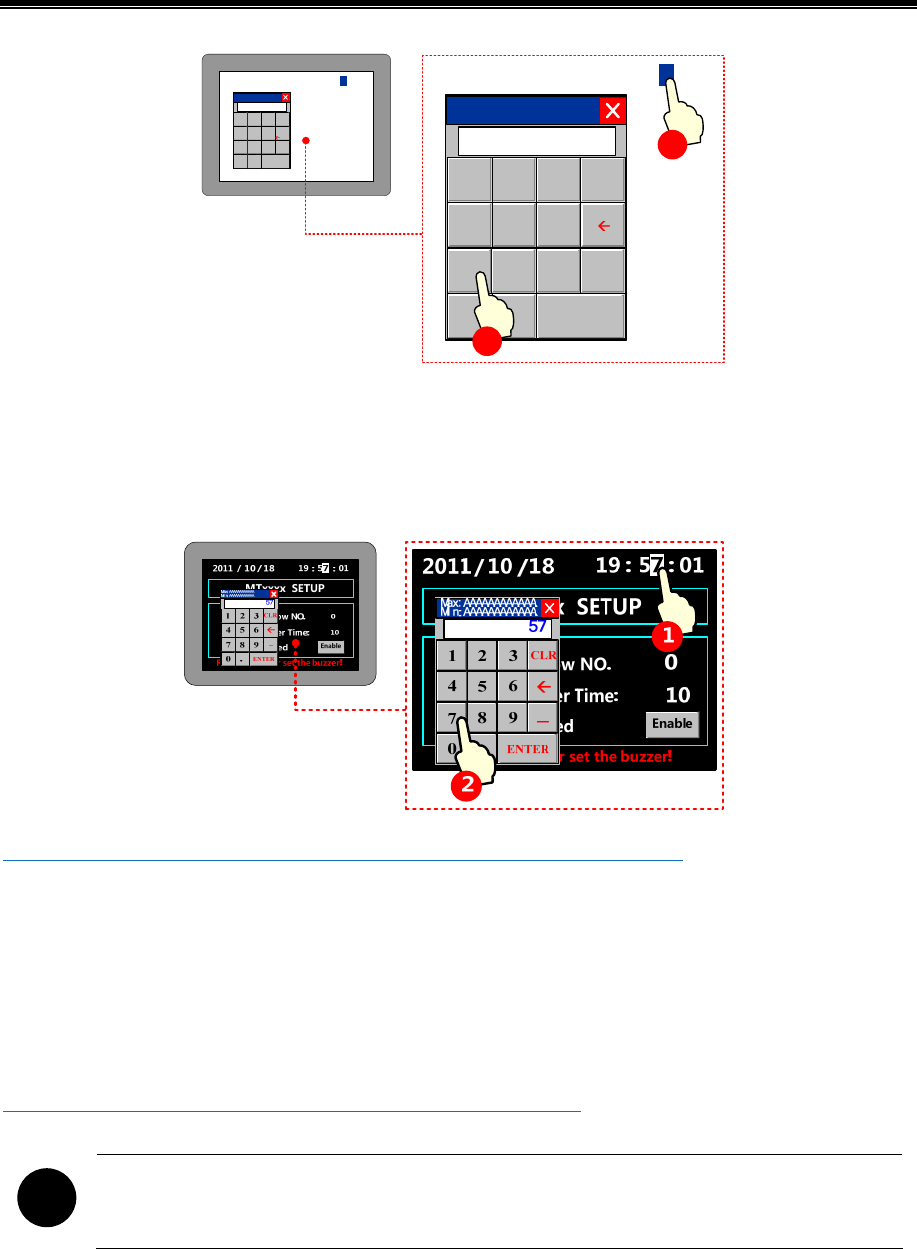
Advanced Part Basic Design Method
93
2011 /10/18 19
:01
:
57
Max:AAAAAAAAAAAA
Min:AAAAAAAAAAAA
12 3
45 6
78 9
0.ENTER
CLR
_
57
2011 / 10 / 18 19 :01
:
57
Max:AAAAAAAAAAAA
Min:AAAAAAAAA AAA
123
456
789
0.ENTER
CLR
_
20
1
2
2.7.2 Calibrate System Time in System Setup Screen
Switch to system setting mode, modify time on this interface.
Take one HMI for example:
☞More infermationrefers to[Hardware Part 3.1 Methods to Display System Setting Mode】
2.7.3 System Time and PLC Time Synchronization
There are two following way to make the system time and PLC CPU time synchronization:
- Use Data Transmission function of Timer component
In this way, we will use the Timer component to transfer the data in the time register of PLC to HMI system special register
LW10000~LW10006.
☞ For details about Timer component, refers to [Advanced Part 4.16.2 Timer]
!
Minimum execution cycle is 100ms,so there is an inevitable time deviation between HMI and PLC.
- Use The External Clock for Event
Only for trigger time and return to normal time of event (HMI time for acknowledge time ).
Choose “use external time for event”- [HMI attribute]-[HMI extended attributes ],related time will read from special

Kinco HMIware Configuration Edit Software
94
registers: LW9010~LW9017 ,which get time by timer receiving from PLC CPU clock.
LW9010~9017:
Data Type Code Type Address Descriptions Address Descriptions
LW9010 Second, the effective value
range from 0 to 59 LW9014 Month, the effective value range
from 1 to 12
LW9011 Minute, the effective value
range from 0 to 59 LW9015 Year, the effective value range
from 1980 to 2079
LW9012 Hour, the effective value
range from 0 to 23 LW9016 Week, the effective value range
from 0[Sun] to 6[Sat]
WORD BIN
LW9013 Date, the effective value
range from 1 to 31 LW9017 Millisecond, the effective value
range from 0 to 999
!
Minimum execution cycle is 100ms,so there is an inevitable time deviation between HMI and PLC.
[Example] Take FX2N PLC for example:
FX2N CPU clock
Addr. Type Descriptions Addr. Type Descriptions
D8013 Second, the effective value range from 0 to
59 D8017 Month, the effective value range from 1 to
12
D8014 Minute, the effective value range from 0 to
59 D8018 Year, the effective value range from 1980 to
2079
D8015 Hour, the effective value range from 0 to 23 D8019 Week, the effective value range from 0[Sun]
to 6[Sat]
D8016 Date, the effective value range from 1 to 31
Select “Use External Time for Event” in [HMI Attribute]-[HMI Extended Attributes].
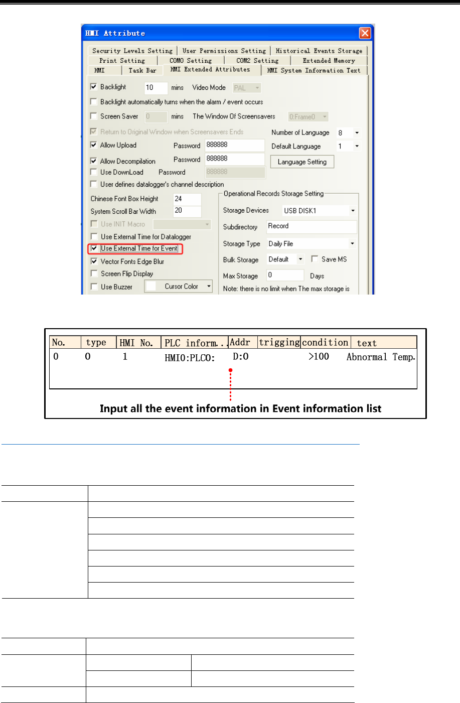
Advanced Part Basic Design Method
95
Add the needed event to Event Information List.
☞ For details about event information logon, refers to [Advanced Part 4.15.3 Event Information]
use a event display to display information written in event information list.
attribute:
Read Address LW 0(HMI Local Register)
Sequence No.
Event Trig Time
Acknowledge Time
Return to Normal Time
Standard Time Format(H:M:S)
Format
Extended Date Format(Y/M/D)
use a timer to transport data from PLC to HMI
attribute:
Execution Cycle 1×100ms
Source Address Destination Address Data Transmission
SD 8013*(PLC register)LW 9010(HMI system special register)
Data Type Word
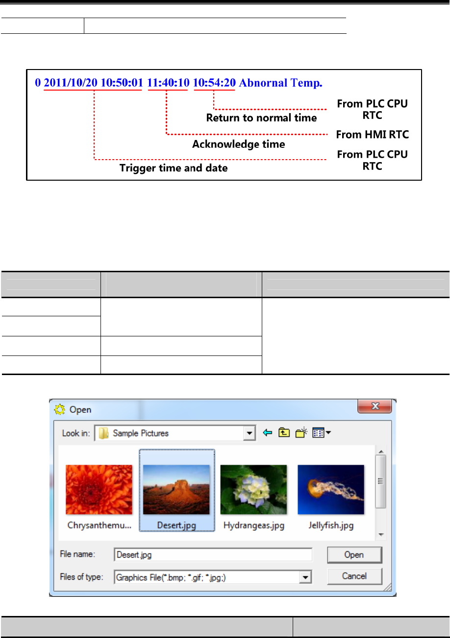
Kinco HMIware Configuration Edit Software
96
Data Transmission 6(word)
※ FX2N PLC D8000~D8255 corresponding to HMI SD8000~SD8255。
value in D0 is larger than 100:
2.8 LOGO Screen(Logo)
LOGO screen is the screen that appears during the startup of HMI. LOGO screen can be customized by users.
2.8.1 LOGO Screen Specification
The specification of LOGO screen
HMI models Max size(pixel)
(Width×Height) Picture format
MT4424T/TE
MT4414T/TE
800×480
MT4620TE 800×600
Others Width×Height<131000
Jpg, bmp, gif and so on
2.8.2 Init Screen Setting
- Change initial window:
Graph instrument step
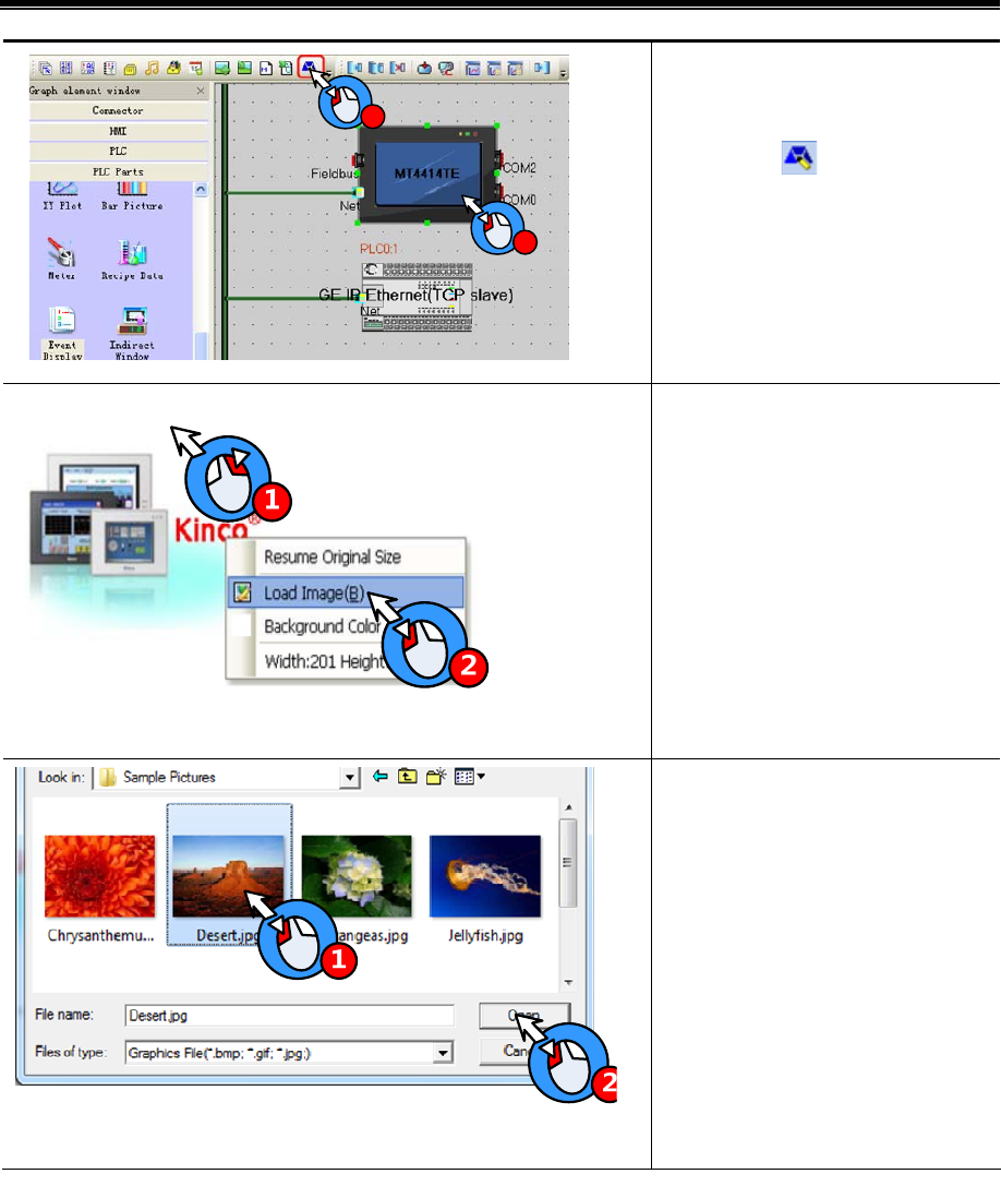
Advanced Part Basic Design Method
97
2
1
Select the HMI to be set LOGO
screen in Construct Window.
Click the icon in Toolbar.
Right-click in the editing space after
entering the LOGO screen setting
window.
Select “Load Image”
There are will pop up [Open] dialog
box, user can find the path of picture to
be imported and select the picture.
Click [Open] button.
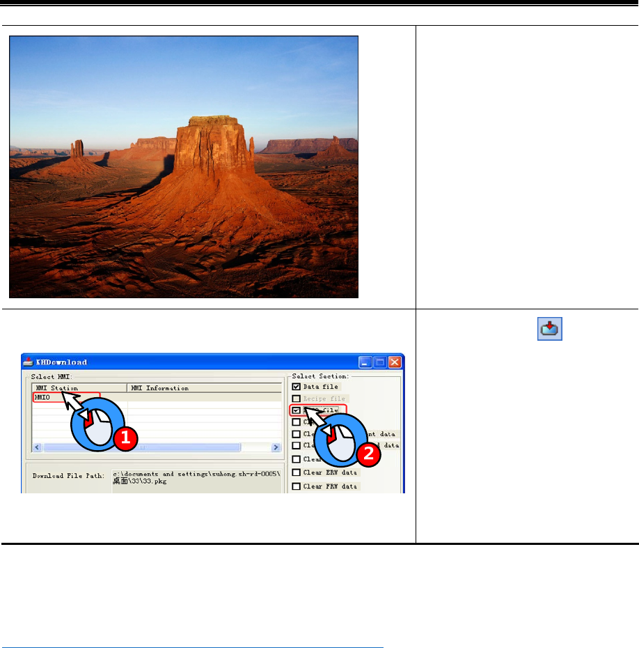
Kinco HMIware Configuration Edit Software
98
LOGO Screen is set successfully.
HMI Click the icon in the
toolbar, and pop up the [KHDownload]
dialog box, then select the HMI to be
downloaded the LOGO screen.
Select the [LOGO file] and click the
[Download] button that means the
LOGO screen will be downloaded to the
HMI.
The method for not showing LOGO:
Open [KHManager]-[Download Operate] and select “Unshow LOGO”, then click the [Set] button. If the setting is successful,
[Set Successfully] dialog box will appear. And then LOGO screen will not appear during the startup of HMI next time.
☞ For details about KHManager, refer to [Advanced Part 8 KHManager].
2.8.3 Note for Using Init Screen
Pictures for initial screen should keep in allowed size.
2.9 Exchange Serial
By “exchange serial 0 and serial 1”,all the devices connected to these two ports along with their parameters will be
exchanged without bothering to reset.
In Kinco HMIware construct window select the HMI which to exchange serial, right-click and select "Exchange serial 0 and
serial 1 ", as shown below:
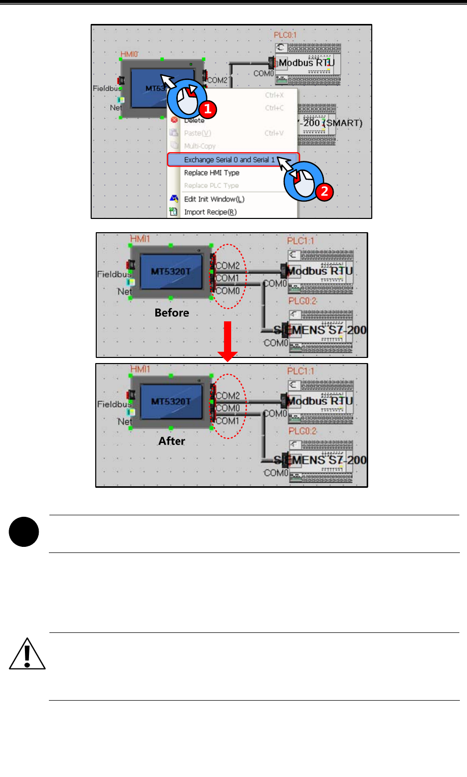
Advanced Part Basic Design Method
99
!
Exchange serial function is only applicable to COM0 and COM1, are not suitable for COM2
2.10 Replace Devices
In the industrial field, we often need to change devices. Kinco HMIware has shortcuts to make it.
Note
HMI replacement must be carried out through the [Replace HMI Type] option, and if it is done by getting
the original HMI deleted and then a needed HMI type created, the original project screen will be lost.
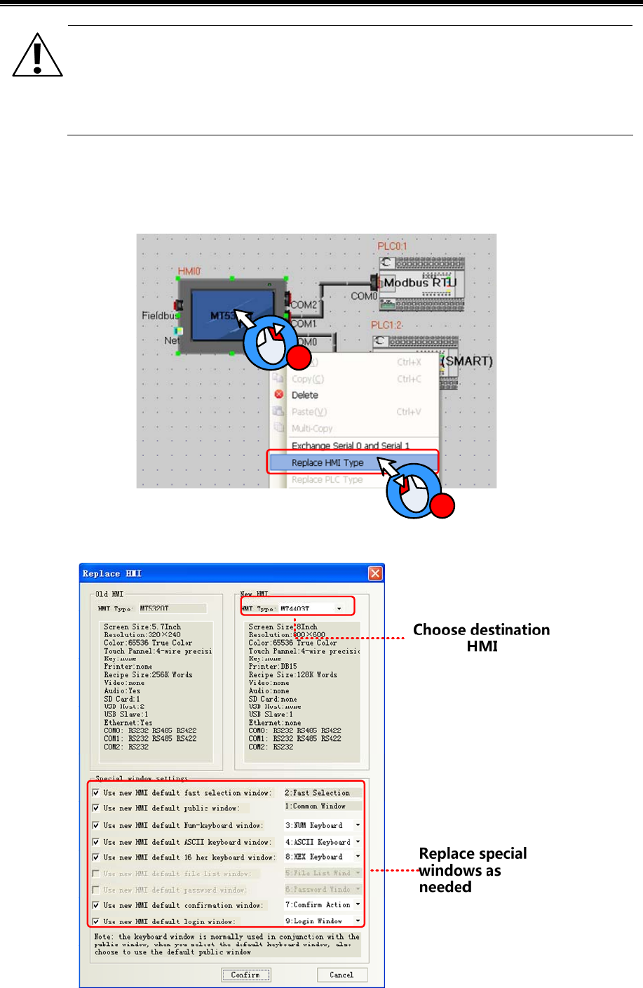
Kinco HMIware Configuration Edit Software
100
Note
PLC replacement must be carried out through the [Replace PLC Type] option,and if it is done by getting the
original PLC deleted and then a needed PLC type created, the PLC address type set in the original project
will be replaced by the HMI local address.
2.10.1 Replace HMI
Select a HMI icon and right-click it in the Construct Window of Kinco HMIware, and then click “Replace HMI Type”, as
shown below:
1
2
Then, the [Replace HMI Type] dialog box will pop up:
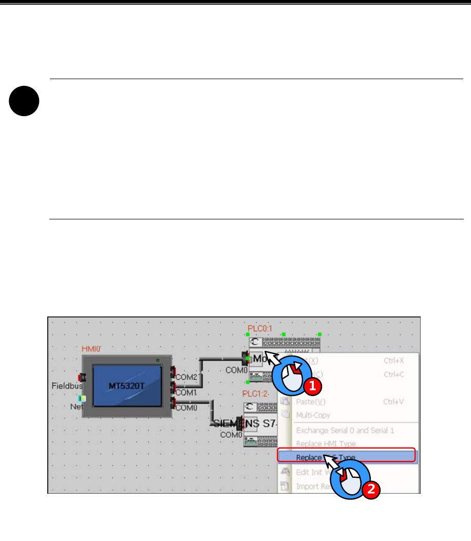
Advanced Part Basic Design Method
101
Choose the HMI you want in []new HMI]-[HMI type],If resolution ratio of the two differ a lot ,it is suggested to choose all
the special windows ,or the old ones are in use. Click OK to finish.
!
1. Replace a HMI with 3 serials with one with 2,you should connect the device to COM0 or COM1 if it is
once connect to COM1.Otherwise ,replacement won`t be allowed.
2. HMI with Ethernet can only replaced by one has too
3.Once the new HMI type doesn`t support components in the old ones, all them will disappear
automatically.
4. If resolution ratio of the two types are different size of component will be enlarged or narrowed,
excluding word size..
2.10.2 Replace PLC
Select a PLC icon and right-click it in the Construct Window of Kinco HMIware, and then click “Replace PLC Type”, as
shown below:
Then, the [Replace PLC Type] dialog box will pop up:
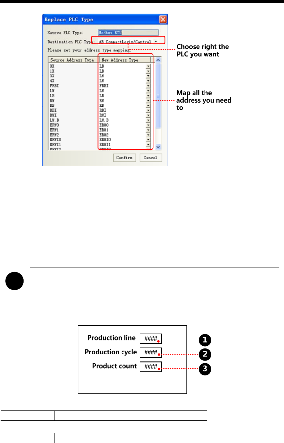
Kinco HMIware Configuration Edit Software
102
The user can select the replace PLC type in the pull-down list of the destination PLC type, and the user select new address
types in address type mapping list according to the address type relationship between source PLC type and destination PLC
type.
2.11 Index Function
2.11.1 Index Register
We can change operator address by changing value of a register .In this way, we call this register index register. Real
address=initial address + value of index register. After using index register, only the real register value will be modified, not
the initial one.
!
Some backgrounders including event information logon, alarm information logon, PLC control,
macro ,trend curve, XY plot, oscilloscope do not have this function.
[Example]
Number Input component, the attribute is:
Read/Write Address LW 0(HMI local register)
Number Display component, the attribute is:
Read Address D 100(PL C register)
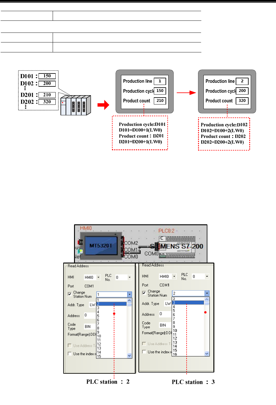
Advanced Part Basic Design Method
103
Index Register select:LW 0
Number Display component, the attribute is:
Read Address D 200(PLC register)
Index Register select:LW 0
You can check all the product indicator data by input line number
2.11.2 Index Station Num
When HMI communicates with more than one PLC through one port, it usually needs to drag many PLCs on the screen. If
there are a lot, it will be a little crowd. In order to avoid it, user can make it by [change station num.
When editing a project, only one PLC is dragged out, by change choose [change station num] in component attribute, you
can switch to different station PLCs.
0 ~ 255 station ID,special registers LW9416 ~ LW9431
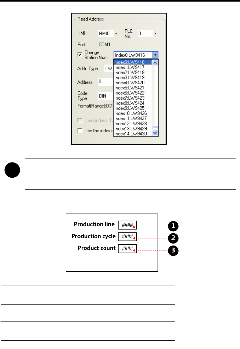
Kinco HMIware Configuration Edit Software
104
!
1. Some backgrounders including event information logon, alarm information logon, PLC control, macro,
trend curve, XY plot, and oscilloscope do not have this function.
2. Special register index station ID, 16 different number devices to max on one screen .
[Example]
Number input, attribute:
read/write address LW 9416(special register)
Number display, attribute:
Read address D 100(PLC register)
Change station num Index0:LW9416
Number display, attribute:
Read address D 101(PLC register)
Change station num Index0:LW9416
You can check all the product indicator data by input line number
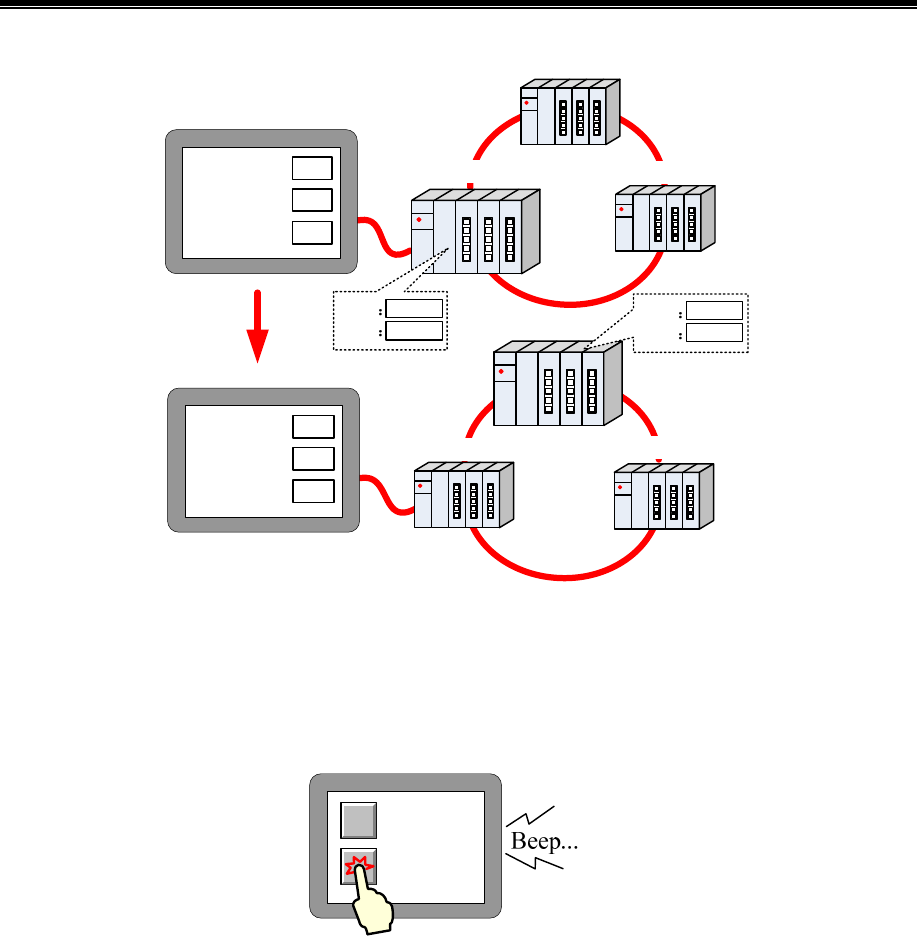
Advanced Part Basic Design Method
105
Station 1 Station 3
Station 2
Station 1
Station 2
Station 3
D100
D101
200
320
D100
D101
150
210
Production line
Production cycle
Product count
1
150
210
Production line
Production cycle
Product count
2
200
320
2.12 Buzzer
Buzzer is built HMI body, and can issue a "beep" sound device. The buzzer is usually used for touch and alarm.
2.12.1 Touch Beep
Touch beep means that when user touches the screen components, the buzzer will issue a "beep" sound.
Enabling and disabling the touch beep can be achieved through the following three ways:
- Set in [HMI Attribute]-[HMI Extended Attributes]:
Check the "User buzzer" means that enable the buzzer sounds, as shown:
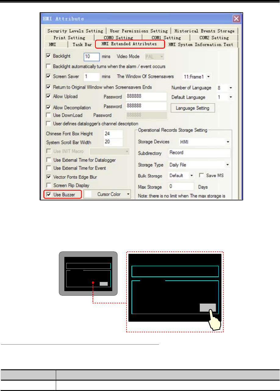
Kinco HMIware Configuration Edit Software
106
Save, compile and download to the HMI, then setting can take effect.
- Set in system setting mode
Switch to system setting mode, and set the buzzer enable or disable.
Take a HMI for example:
2011 / 10 / 18 19 : : 01
MTxxxx SETUP
Option
Startup Window NO.
Backlight Saver Time:
Buzzer Disabled
0
10
Enable
Reset HMI after set the buzzer!
57 2011 / 10 /18 19 : : 01
MTxxxx SETUP
Option
Startup Window NO.
Backlight Saver Time:
Buzzer Disabled
0
10
Enable
Reset HMI after set the buzzer!
57
☞More information refers to [Hardware Part 3 System Setting Mode]
- Change the value of LW10012 to make buzzer enable or disable.
LW10012 Specific instructions as shown in table:
System Register Descriptions
LW 10012 0:buzzer disable; 1: buzzer enable
2.12.2 Alarm Beep
When item logon in the alarm information or event information is triggered, HMI will beep.
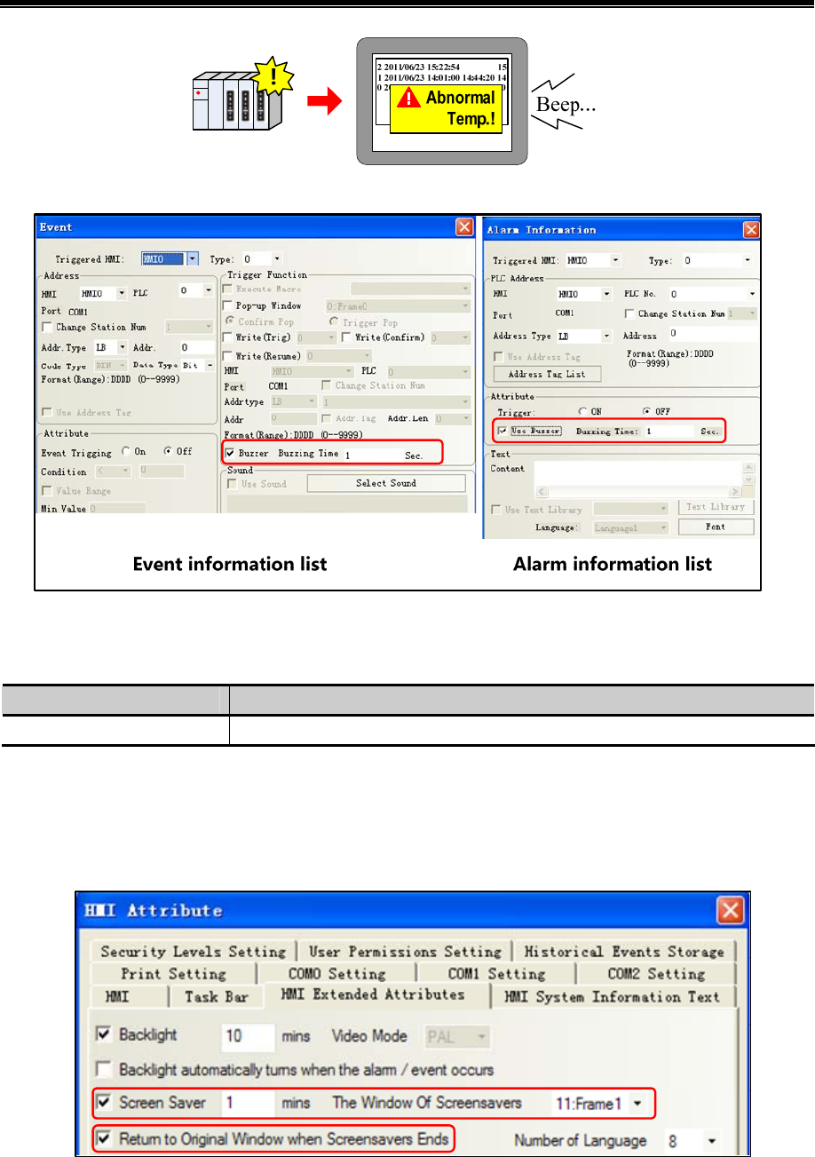
Advanced Part Basic Design Method
107
Choose “buzzer” as below:
Users can choose buzzing time raging from 1 to 65535, unit: second
User should set value of LB9141 to shut off the buzzer:
Special register address Specification
LB 9141 ON:shut off buzzer,reset to 0
2.13 Screen Saver
Use a screen saver function can effectively prevent the screen in a important frame by inadvertently touch screen causes
disoperation.
Screen saver function is enabled in the [HMI Attribute] - [HMI extended attributes]:
When the HMI screen in the set period of time without touched, the screen will switch to the specified window that
screensaver window.
If the screen saver window is a non-fixed value, you can change the value of the special register LW9532 to change
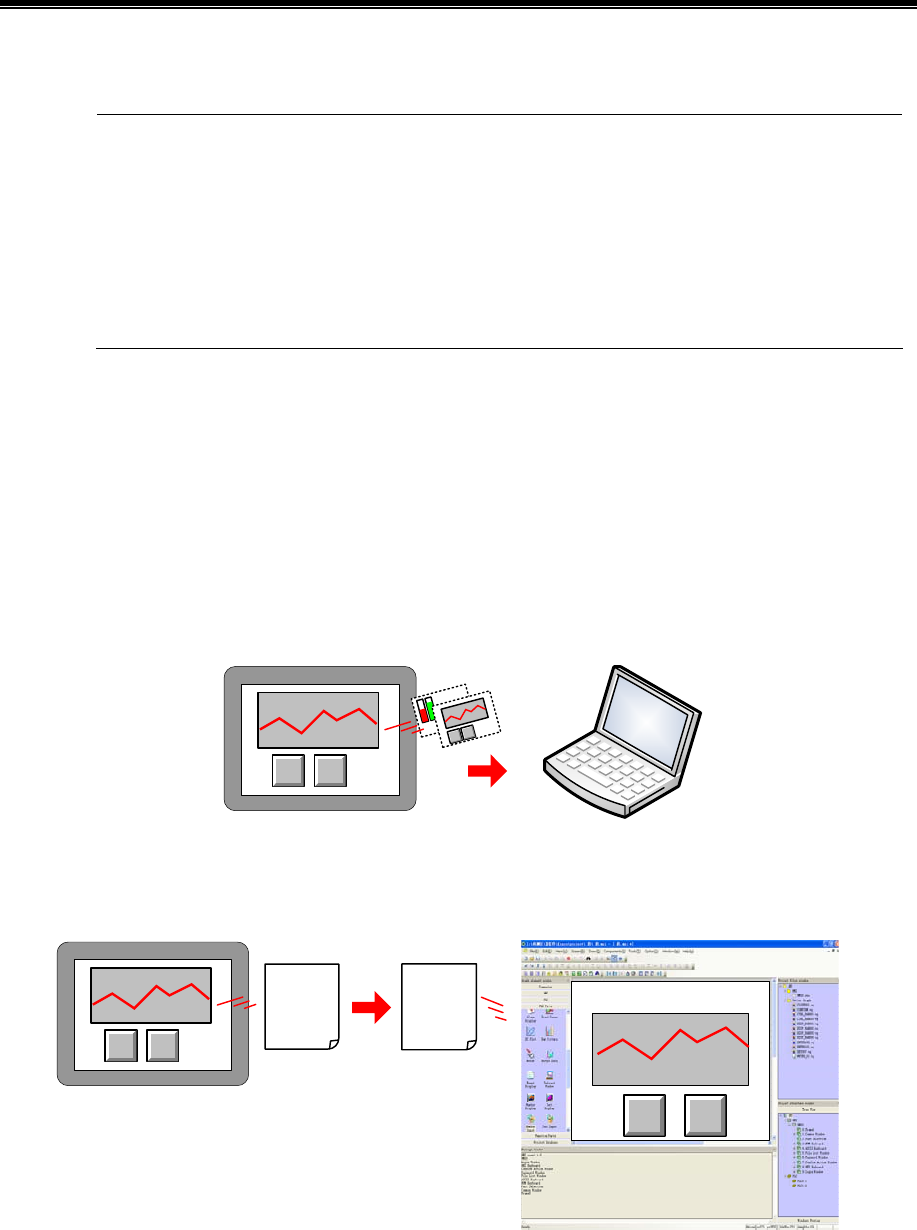
Kinco HMIware Configuration Edit Software
108
screensaver window number.
1. Screen saver time range from 1 to 65535, unit is minute; if set to 0, it means does not use the screen
saver function.
2. Check the "Return to original window when screensavers ends", which means that when the system
enters screen, if there are touch-screen operation, the system will switch back to the previous window
into screensavers. Uncheck it means to continue to stay in the screensaver window, you need to set
window switching element to switch screen.
2.14 Password Setting
Kinco HMIware security function includes project protect, screen protect and component protect.
2.14.1 Project Protection
- project protection:before you can open a project ,you should input password
- Project password protection:
- Upload protect:before uploading ,you should input a password
- Project upload projection:
After input upload password
- Project decompile protection::when turning pkg into wpj, you should input a password
- Project decompile protection:
WPJ
file
After input decompile
password
PKG
file
2.14.2 Screen Protection
You can set security levels or user permissions to limit operator from entering some important windows.
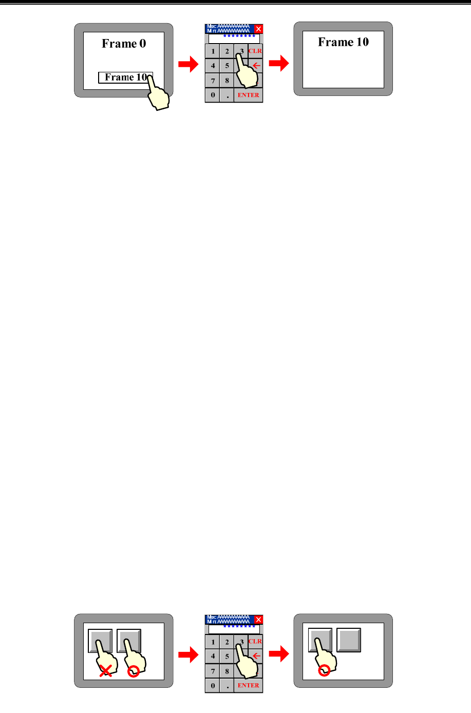
Advanced Part Basic Design Method
109
- security levels to protect screen
Set number of security levels and relevant password in [HMI attribute]-[security levels].
There are two ways:
Take window A switching to window B for example:
Window security level
Window security level is set to 0(default), Window B security level is set to 1, then window A can be switched to window
B when the system security level is equal or up to 1. So user must input the 1 or up 1 level password before switching the
window.
About password window:
User can pop password window with the help of direct window, while function key will be used to switch the state of it.
User can also create a new window or call the system one[Frame9:Login Window].
Set the control authority
Set control setting to the component changing window. Choose “conditional enable” in [attribute]-[control
setting]-[Touching enabled setting], select “security level”, set minimum level:1(or higher than 1).Then only users
whose level is not less than 1can operate this component.
- screen protection through user permission
You need first to assign authority in [HMI attribute]-[user permissions setting]
Then you can set control setting of a component to implement this function.
Choose “conditional enabling”in [HMI attribute]-[control setting]-[touching enabled setting],select “permission control”,
“select permission”:1 (for example).
Only user who has permission 1 can use this component. User can input its name and password to get the permission.
About login window:
User can also create a new window or call the system one [Frame9: Login Window].
2.14.3 Component Protection
In Kinco HMIware, you can limit others to operate some important components by set security levels or user permissions.
In two following ways you can protect components from being used without allowance:
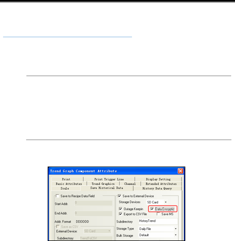
Kinco HMIware Configuration Edit Software
110
- Through Security Level
- Through Permission Control
☞For details about password, refers to [Advaced part 10 Password]
2.15 Data Encryption
For the data stored in the external memory – USB disk\ SD card, data encryption function can be used to limit the user to
make modification, editing and so on to the data files as CSV format.
1. If the [data decryption] operation is not performed to the CSV file generated for the component using
[Data Encryption], the illegible characters will be displayed in the opened CSV file.
2. If the data is decrypted through KHManager, the CSV file can only be opened for viewing instead of
modifying or editing.
3. If the encrypted file is modified by someone intentionally, the error prompt will appear during the
[Decompile] operation in KHManager, making the damage of source file informed to the user.
4. The components supporting [Data Encryption] function are trend curve, XY plot, historical data
display components.
Take the setting method of [Data Encryption] for sampling data file of the Trend Curve as example:
(1) [Trend graph component attribute] - [Save historical data] - Select [Save to external device] - Select [Data Encryption].
(2)The illegible characters will be displayed in the generated CSV file after the encryption if it is directly opened.
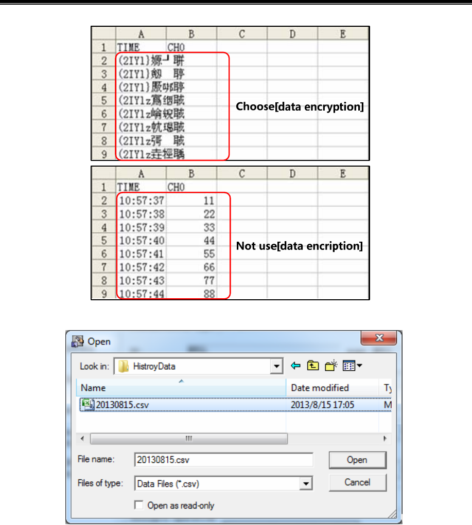
Advanced Part Basic Design Method
111
(3)Open the KHManager software to decrypt CSV file.
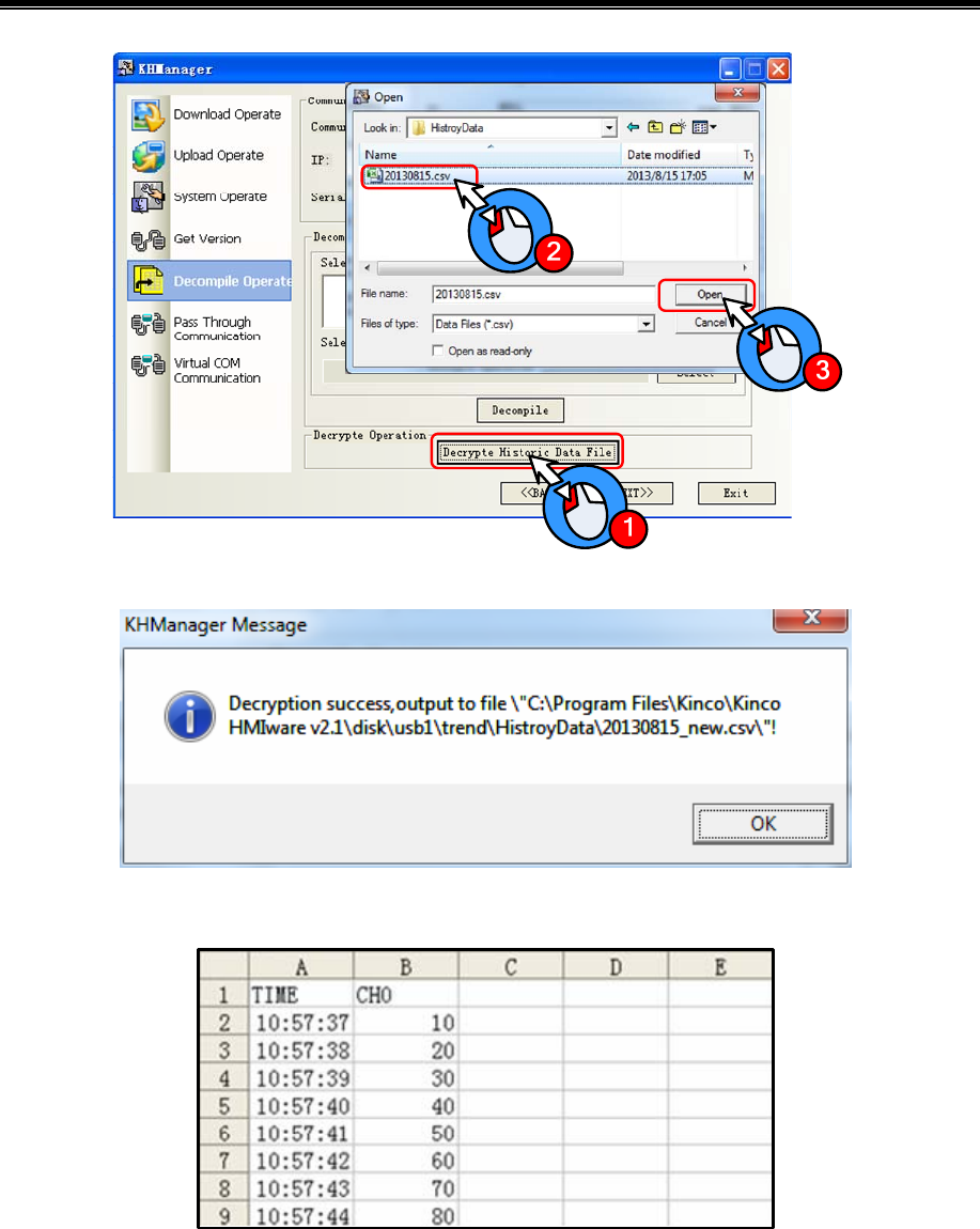
Kinco HMIware Configuration Edit Software
112
The following dialog box will pop up after the successful decryption.
The display effect of the CSV file decrypted successfully is as shown below.
2.16 Animation Effects
In Kinco HMIware, user can make the screen more vivid by using animation effects in three ways:
- using multiple state display component
By frequently switching some static pictures ,you can see a continuous effect .
[Example]multiple state display making animation effect of an air blower
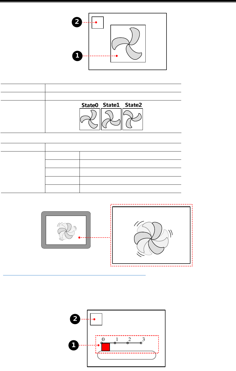
Advanced Part Basic Design Method
113
multiple state display,making animation effect of an air blower,attribute:
Read address LW 0 (HMI local register)
Move type 3
Graphics
Vector graphics:
timer,change values of multiple state display,attribute:
Execution Cycle 1×100ms
Mode Periodical JOG++ (circle)
Date Type word
Asc value 1
Upper 2
State Setting
Addr. Type LW 0 (HMI local register)
When the project is run, the effect is as shown:
☞More information refers to [Adcanced Part 4.3.2 Multiple State Display]
- Animation
By changing values, component can move from one position to another, so user will see a continuous action effect.
[Example]ambition making conveyer belt effect
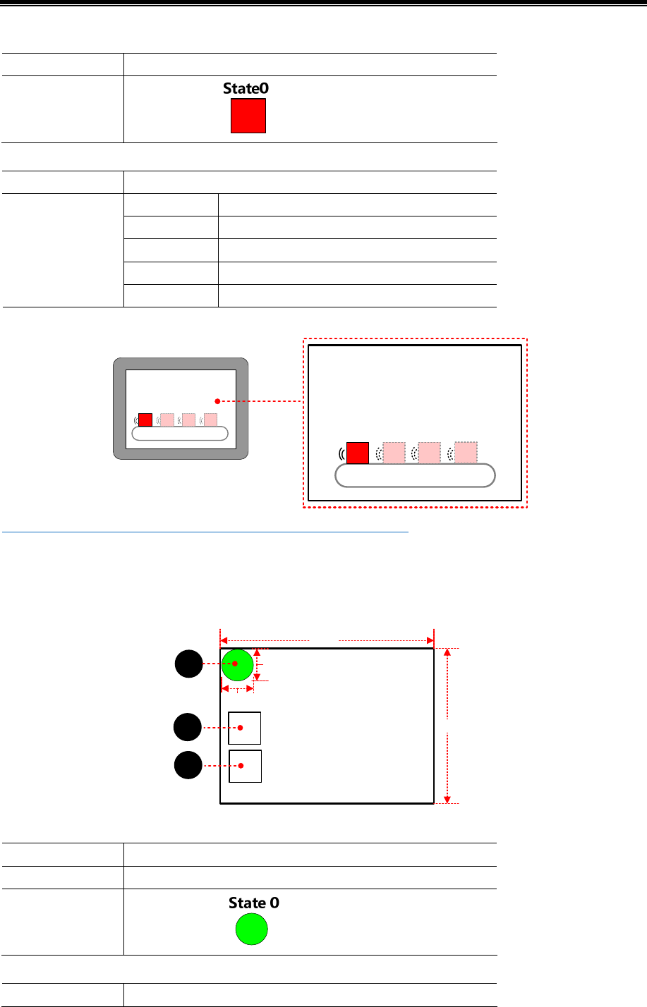
Kinco HMIware Configuration Edit Software
114
ambition, attribute:
Read address LW 0(HMI local register)
Graphics
Vector graphics:
timer,change values of presupposed path, attribute:
Execution Cycle 1×100ms
Mode Periodical JOG++ (circle)
Date Type word
Asc value 1
Upper 3
State Setting
Addr. Type LW 1(HMI local register)
When the project is ran, the effect is as shown:
☞More infermation refers to [Advanced Part 4.12.1 Animation Components]
- Moving component
- By changing values, component can move from one position to another ,so user will see a continuous action effect.
[Example] moving component making ball moving effect
2
1
50px
50px
320px
240px
3
Moving component property is set to:
Read address LW 0 (HMI local register)
Move type X & Y axis
Graphics
Vector graphics:
Timer element, used to change the X-direction coordinate values of moving element, property is set to:
Execution Cycle 2×100ms
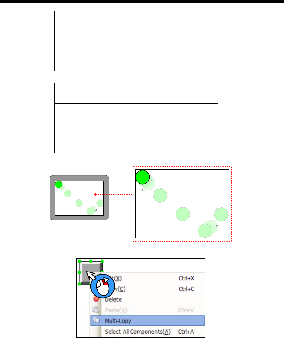
Advanced Part Basic Design Method
115
Mode Periodical Bounce(turnover upon limit)
Date Type word
Step 1
Upper 0
Lower 270(320-50)
State Setting
Addr. Type LW 1(HMI local register)
Timer element, used to change the Y-direction coordinate values of moving element, property is set to:
Execution Cycle 3×100ms
Mode Periodical Bounce(turnover upon limit)
Date Type word
Step 1
Upper 0
Lower 190(240-50)
State Setting
Mode LW 2(HMI local register)
When the project is ran, the effect is as shown:
2.17 Multi-Copy
The method of multi-copy:
Select components, click the right mouse button and select [Multi-Copy], pop up multiple copies Properties window.
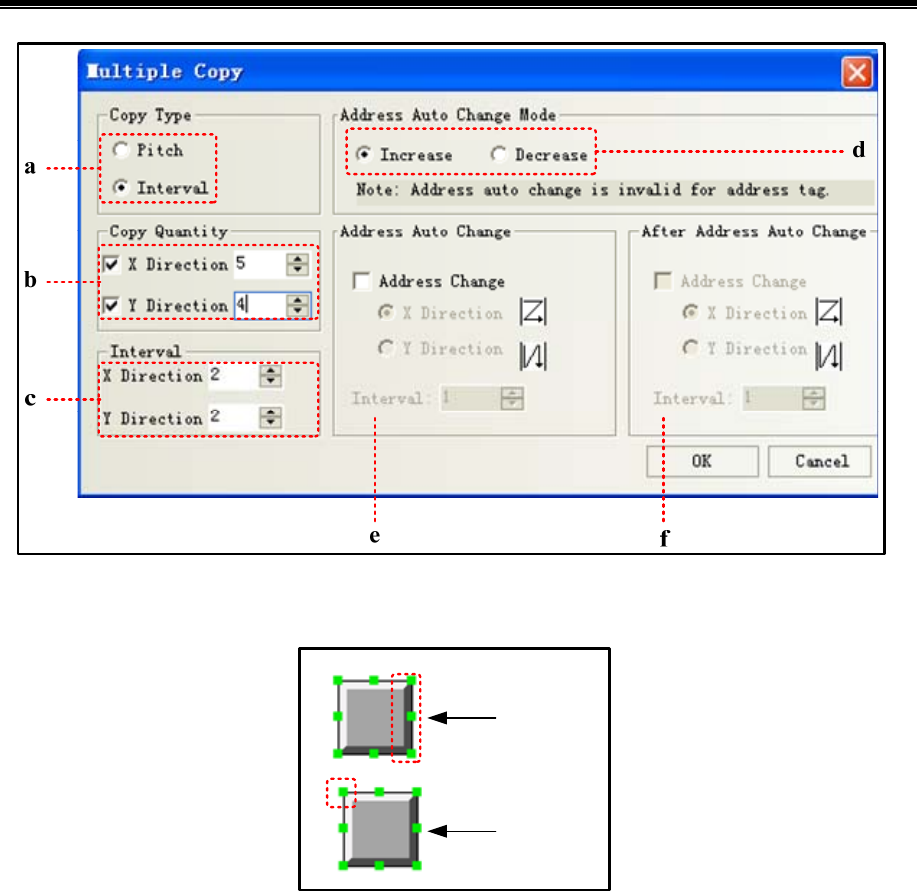
Kinco HMIware Configuration Edit Software
116
a:Interval makes the right border of the component as the start point to perform the copy. Pitch makes the 1st point in the
upper-left corner of the component as the start point to perform the copy.
Interval
Pitch
b:Copy quantity:Duplication elements quantity
c:Interval:The distance between the duplicated elements, in pixels
d:Increase/ Decrease:Address Increase or decrease
e:Address auto change:Integer bit register address auto increase or decrease
f:After address auto change:The register address after the decimal point auto increase or decrease
2.18 Group
Several components or the graphics are combined together and saved into the Group Components Library, thus making them
called by other projects conveniently.
The format of Group Components Library is *.pgl.
- How to open [edit box of group components library]
Click [Draw] menu-[Group components]-[use the group element]
Right-click the mouse in the blank space of the window, select [Groups]- [use the group element], then the [edit box of
group components library] dialog will pop up, as shown below:
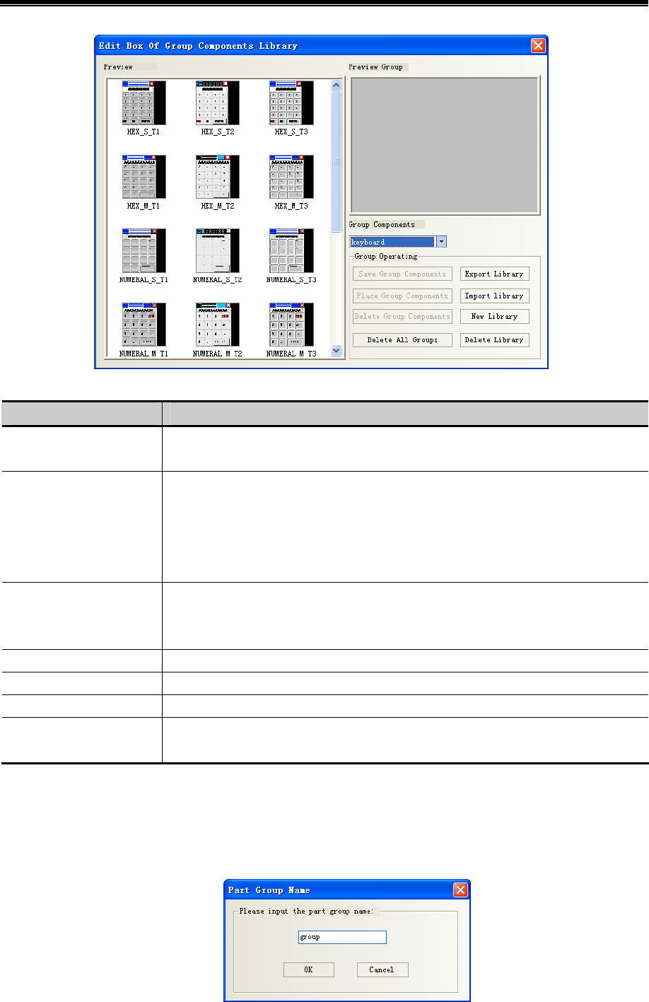
Advanced Part Basic Design Method
117
Name Description
Export Library Make the [Group Components Library] saved in the path defined by the user for convenient
import.
Import Library The default path of group components library is the userlib directory under the installation
path of Kinco HMIware, and the user can also import the group components library from
the self-defined path. Click [Import Library], and select the required group components
library in the path corresponding to the saved group components library, then click [Open]
to add this group components library to the group components library of the current project.
New Library Click [New Library] button will make the dialog pop up, and the user can put the name of
this new created group components library in it. The default path to save the group
components library is the userlib directory under the installation path of the software.
Delete Library Delete the group components library opened currently.
Delete All Groups Delete all the graphics in the group components library opened currently.
Delete Group Components Delete the selected graphics in the group components library opened currently.
Place Group Components Place the selected group graphics in the group components library opened currently into the
screen edited currently.
[Example]: How to add group graphics to a new created group components library is described as follows:
(1) Click [use the group element] in [Group components] in [Draw], and click [New Library] after the Edit Box of
Group Components Library pops up, and input “group” as the name of the group components library in the
group component library name dialog box, as shown below:
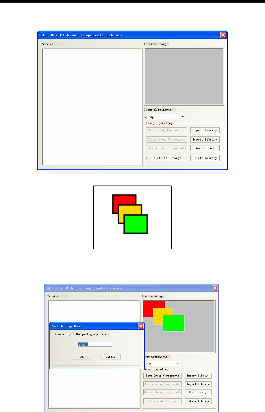
Kinco HMIware Configuration Edit Software
118
Click [Enter] to create an empty group components library as shown below:
(2)Place 3 rectangles in the screen, as shown below:
Selected these 3 rectangles, and right-click the mouse to select [Group]-[Save the group elements], and then click the [Save
Group Components] button in the Edit box of Group Components Library dialog box to make the following dialog box pop
up.
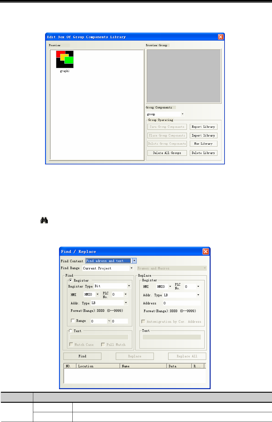
Advanced Part Basic Design Method
119
(3)Input “graph 1”in the Part Group Name dialog box, and then click [OK] button, then these 3 rectangles with the
name of [graph 1] will be added into the new created group components library with the name of [group], as shown below:
(4)If there are other group components to be added into the group components library with the name of [group], the
operation method is the same as that mentioned above. And you just need to select [group] in the Group Components Library
list as the path to save it.
2.19 Find /Replace
- Click [edit] menu-[find/ replace]
- Click the icon on toolbar
- Press the PC keyboard shortcuts “CTRL” + “ F”
The following dialog box will pop up:
Name Description
Current Project All the frames, macros, background database in HMI will be searched. Find Range
Background Only the background database components, such as event information logon,alarm

Kinco HMIware Configuration Edit Software
120
Database information logon,trend carve etc. will be searched.
Frames and Macros All the frames and macros in current project will be searched.
All Frames All the frames in current project will be searched.
All HMI
All Macros All the macros in current project will be searched.
Frames and Macros All the frames and macros in the selected HMI will be searched.
All Frames All the components in all the frames in the selected HMI will be
searched.
Current Frame All the components in the current frame in the selected HMI will
be searched.
Current HMI
All Macros Only all the macros in the current HMI will be searched.
Register Type It means to find the device with Bit type or Word type. Register
Addr. Type It represents the device type and device address in the controller
where the search is performed. Checking “Range” means the
search will be performed in the set range of address.
Unselect match
case/ full match
It means the judgment of the case of the characters and the
consistency in the whole text will not be done during the search.
Match Case It means the match of the case of the characters in the text to be
searched is required.
Find
Text
Full Match It means the match of the text to be searched in the whole text is
required.
Replace After this option is set, the device type and address found according to the set conditions will be replaced by
the specified device type and address. “Automigration by Cor. Address” in the Replace part will take
effect once the “Range” in Find part is selected. If “Automigration by Cor. Address”is not selected, the
replace address is the same; while if “Automigration by Cor. Address”is selected, the replace address is the
consecutive address which will automatically deviate by making the set replace address as the start address.
When the above parameters are set, if the “Find” button in the dialog box is clicked, the search of address
meeting the condition will be performed the window locating in the Find Range. If the component is found,
then No., Location, Name and Data will be displayed in the bottom white box. When the component
meeting the requirements is found, the screen will automatically switch to the position where this component
locates and the attribute dialog box for this component will pop up after this component is double-clicked.
Clicking “Replace” or “Replace All” means the found component meeting the conditions will be
replaced by the component with the address type and address set in the “Replace” part.

121
3 Window
Window is the basic element for HMI project, each screen is made of some windows. With window, you can place the
various components, graphics, texts displayed on the HMI screen.
3.1 Window Types
According to the different of the function or using ways, there are 3 types of windows: Basic Window, Common Window
and Fast Selection Window. The Basic Window after its size is changed can also be used as pop-up window. All the windows
can be used as the bottom window. Specific descriptions are shown as below:
Window Types Descriptions
Basic Window This window is the most commonly used window. When Basic Window is changed by using [Function
Key]-[change window] or [PLC Control]-[change window] function, the current screen will be cleared
(All the windows rather than Common Window and Fast Selection Window will be cleared.), and the
Basic Window to be changed will be displayed in the current screen. When the component in Basic
Window calls the pop-up windows, the Basic Window is always on opening status, and the original
information will be reserved, and the called pop-up window will be attached to the current Basic
Window. The master-slave relationship is between Basic Window and all of related pop-up windows.
When Basic Window N is switched to Basic Window M, all of the sub-windows of Basic Window N
will be closed while Basic Window M and is sub-windows will be displayed.
Fast Selection
Window
This window is the window called by the operation buttons, is generally used to place the commonly
used buttons. And it will be always displayed in the screen until the operation button makes it hidden.
The default Fast Selection Window is Frame 2. You can modify the other window as Fast Selection
Window in [HMI Attribute]-[HMI Extended Attributes]-[Fast Selection Window].
Common
Window
The components in this window will be displayed in the other window, but does not include Pop-up
Window. Usually each window shared or the same components will be put in Common Window. The
default Common Window is Frame 1. You can modify the other window as Common Window in [HMI
Attribute]-[HMI Extended Attributes]-[Public Window].
Bottom Window This window is generally used to put some common components such as background graphics, charts,
and titles and so on. Using this window, you needn’t to edit the some components repeatedly. The
components in Bottom Window will be inserted into the general window during, and in fact window
isn’t displayed at all.
Pop-up Window All the Pop-up windows are attached to the current Basic Window. The windows closed by the function
key only can close Pop-up window, direct window or indirect window, can’t close Basic Window. The
direct window, indirect window, [Event Information Logon]-[Pop-up window] and [Function
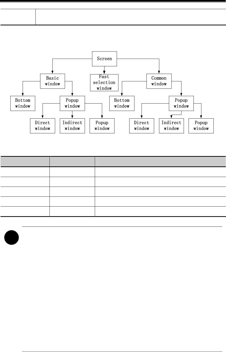
Kinco HMIware Configuration Edit Software
122
Key]-[Popup window] all belong to the Pop-up window.
One screen can include Basic Window, Fast Selection Window, Common Window, while every Basic Window or Common
Window can include many Bottom Windows and Pop-up Windows. The relationship between them is shown as below:
※ The pop windows by Event information logon and Function key setup
The number of windows in each project is limited as follows:
Window Type Default Window No. The largest number of windows
Basic Window 0 The window No. ranges: basic window 0, 10 to 32767
Common Window 1 1
Fast Selection Window 2 1
Bottom Window -- Up to 3 bottom windows can be set for each window.
Pop-up Window -- Unlimited until the memory runs out
!
1.As once opened,the popup window won`t release the RAM unless closed,it is suggest to use it as few as
possible.
2. The same window can be opened once by one related window, therefore you can’t open the same
window by 2 or up direct window/ indirect window in the basic window.
3. All the Pop-up windows are attached to the current basic window, so when the current window is switched
to the other Basic Window, the Pop-up window will be closed. In this case, if the window is switched back to
this Basic Window, you will find that the Pop-up window originally attached to this window still exist;
otherwise you use the [Close window] function of function key.
4.A popup window in the common window does exist until shut down with the Function key [Close window]
5. Fast Selection Window supports the Pop-up window.
6. Use Basic window rather than Popup window, Indirect window or direct window which may slow down
the communication speed.
7. The actual largest number of Basic window and Popup window is related to HMI`s RAM.
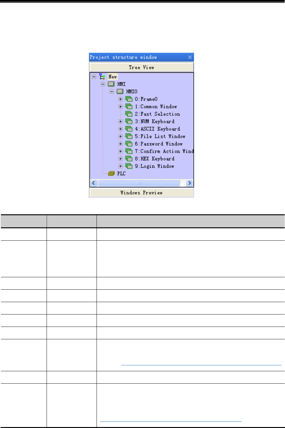
Advanced Part Window
123
3.2 System Default Window
A new project has 10 default windows as seen in the Project structure window as follows:
Default windows description:
Window number Window name Description
0 Frame0 Basic window,default initial window
1 Common Window
Common window,two popup windows used to pop default keyboard. Do not
delete these two windows or the keyboard is unavailable.
Attention: Devices used in every window can be put in it
2 Fast Selection
Fast Selection,used in coordinate with [Fast selection window] in HMI attribute
3 NUM Keyboard
NUM Keyboard,default keyboard
4 ASCII Keyboard
ASCII keyboard,backup
5 File List Window
File List Window,used in coordinate with [Input/Export] in Function key
6 Password Window
Password Window,used in coordinate with File List Window
7
Confirm Action
Window
Confirm Action Window,pop up when [Control setting]-[Operator confirm] is
chosen ☞For details,refer to【Advanced Part 4.1.7 Control Setting Option】
8 HEX Keyboard HEX Keyboard, backup
9 Login Window
Login Window,pop up when [Control setting]-[Conditional enable]-[Security
level]-[auto show login window] is chosen
☞More information refer to【Advanced Part 10 Password】
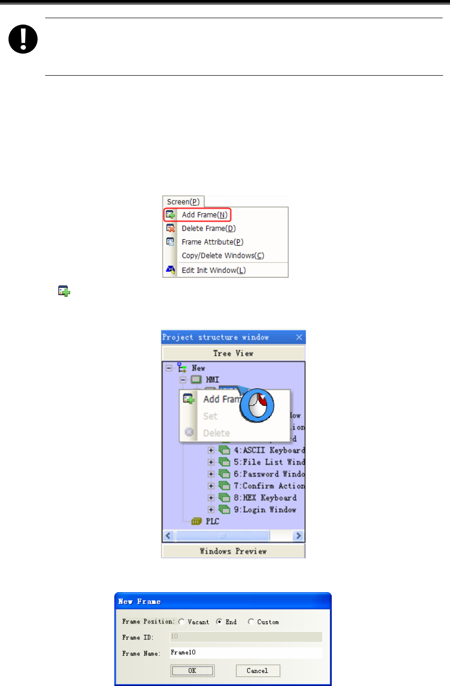
Kinco HMIware Configuration Edit Software
124
1. Default Frame 0~9 no deletion
2.Device address and attribute in Frame1-9 cannot been modified, or they may not be in normal use. You
can only change the text set
3.3 Edit Window
3.3.1 Window Add
A new project has 10 system default windows. User can add some new windows, and there are 3 methods to create a new
window.
- Click the [Add Frame] in [Screen] menu.
- Click the icon of [Add Window] in [Page Switch Toolbar].
- Select the HMI0 to right click in Project Structure Window and select [Add Frame],
Click [Add Frame], and the [New Frame] dialog box will pop up.
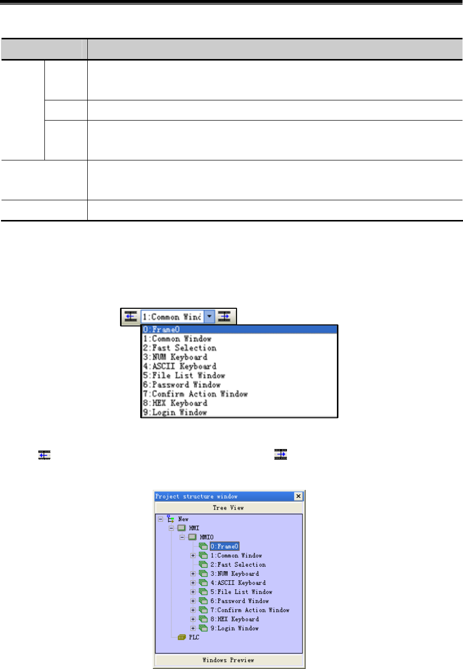
Advanced Part Window
125
Specific descriptions are shown as below:
Name Descriptions
Vacant When the existing windows are not in a continuous order, the new window will automatically insert
in the first vacant place.
End The new frame will automatically be numbered next to the existing last number. Default choice.
Frame
Position
Custom The new frame number can be defined freelyfrom10 to 32767 without duplicating the existing
number.
Frame ID New frame number. When the Frame position is [Vacant]or[End],this option is unavailable. Only
when it is [Custom], you can modify it.
Frame Name Ether default or custom
After [New Frame] setting,click【New】,a new frame is created.
3.3.2 Window Opening
There are 4 methods to open the window after the window is created.
- Select the window in the pull-down menu in [Page Switch Toolbar].
- Click the icon of [Previous page]/[Next page] to open the window. The previous window can be displayed by clicking
the icon, and the next window can be displayed by clicking the incon.
- Click the window ID in [Project Structure window]-[Tree View].
- Double-click the window ID in [Project Structure window]-[Windows Preview].
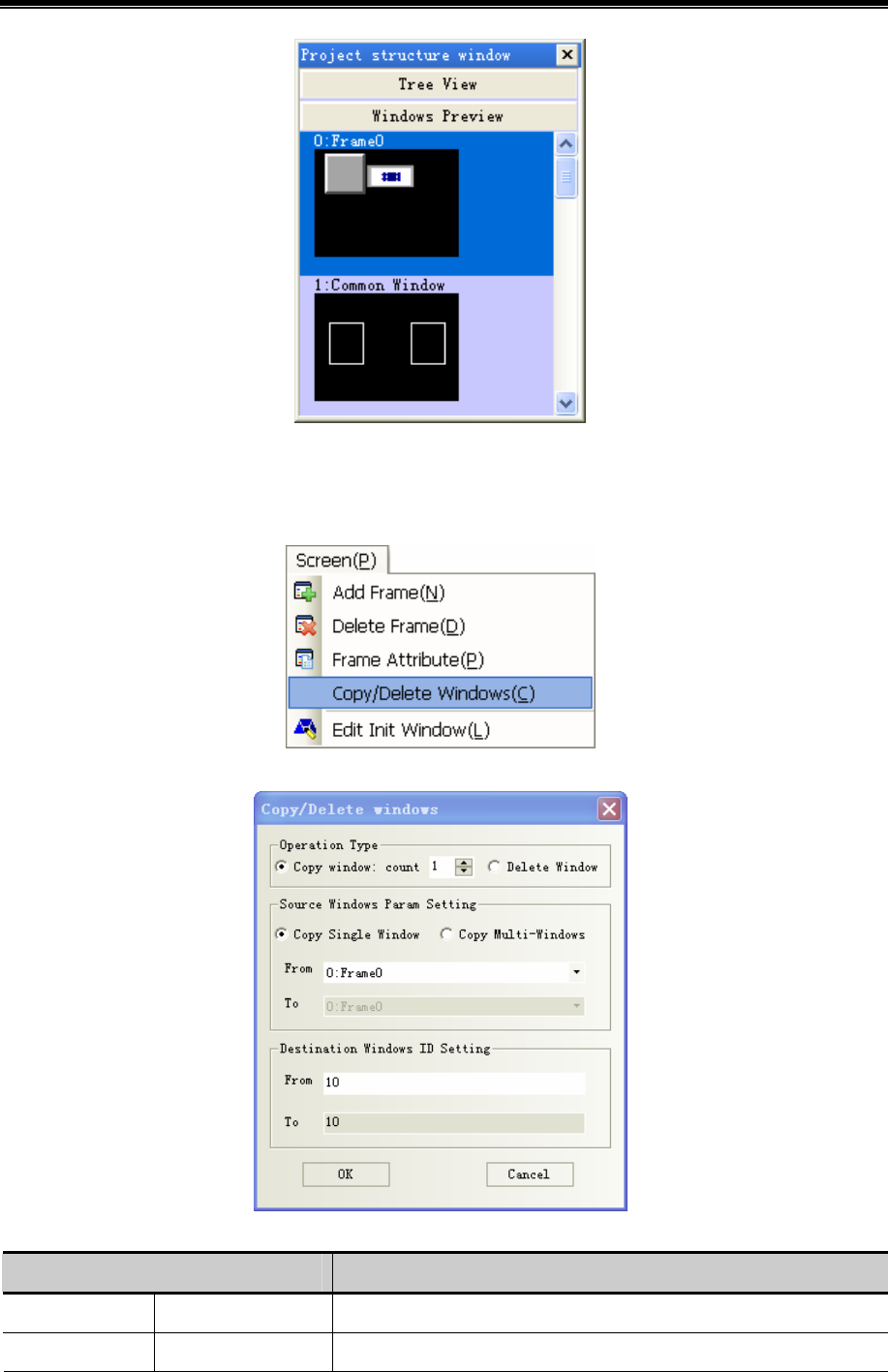
Kinco HMIware Configuration Edit Software
126
3.3.3 Window Copy/ Multi-Windows Copy
Window support the function of copy and multi copy. Click the [Copy/Delete windows] in [Screen] menu to copy
window.
Click [Copy/Delete windows] and the following dialog box will pop up:
Specific descriptions are shown as below:
Name Descriptions
Operation Type Copy window:count Select the function of Copy window and set the count
Source Windows Copy Single Window Set the starting source copied window ID
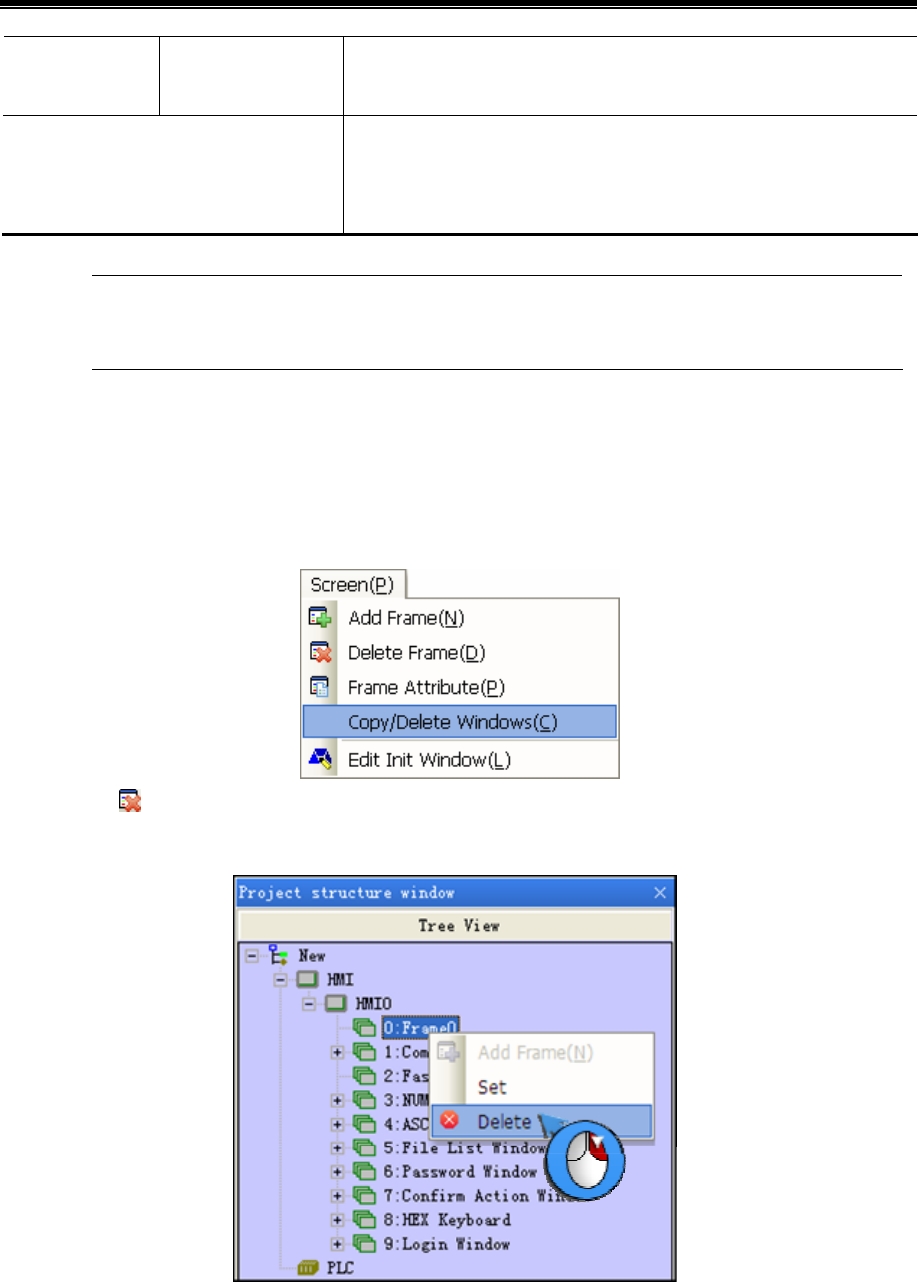
Advanced Part Window
127
Param Setting Copy Multi-Windows Set the starting source copied window ID and the end source window ID,
from window M to window N will be copied at the same time.
Destination windows ID Setting
Set the starting destination windows ID. The end destination window ID
will increase automatically according to the copied number and the number
of the source window, can’t be modified.
The destination window ID mustn’t be the existing window ID.
3.3.4 Window Deletion/ Multi-Windows Deletion
- Delete the current window
There are 4 methods to delete the current window:
Click [Delete Frame] in [Screen] menu.
Click the icon of Delete Frame in [Page Switch Toolbar]
Right click the selected window in [Project Structure window]-[Tree View], select [Delete].
Selected the window in [Project Structure window]-[Tree View], and press the [Delete] key of PC keyboard.
- Delete custom window
Click the [Copy/Delete windows] in [Screen] menu to delete window.
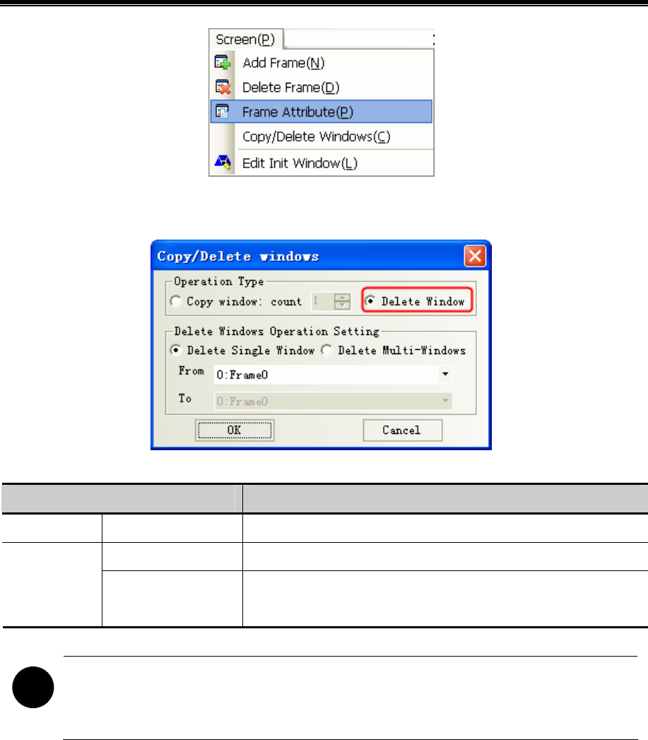
Kinco HMIware Configuration Edit Software
128
Click [Copy/Delete windows] to pop up the [Copy/Delete windows] properties dialog box,and select [Delete
Window].
Specific descriptions are shown as below:
Name Descriptions
Operation Type Delete Window Select the function of delete window.
Delete Single Window Set the starting deleted window ID Delete Window
Operation
Setting
Delete Multi-Windows Set the starting source deleted window ID and the end source window ID,
from window M to window N will be deleted at the same time.
!
1. After delete window, all components in this window will lost and can’t be recovered. Be careful with using
this function.
2. The windows from Window 0 to window 9 are system default window, unable to delete.
3.4 Window Attribute
3.4.1 Open Window Attribute Box
There are 5 methods to change the window attribute in Kinco HMIware software.
- Click [Frame Attribute] in [Screen] menu.
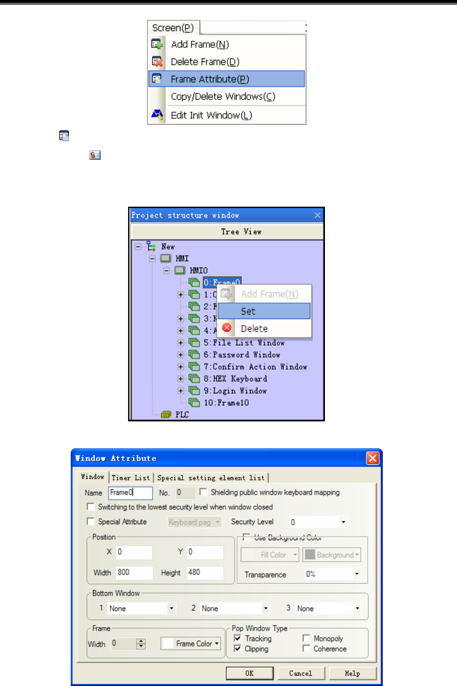
Advanced Part Window
129
- Click the icon in the [Current Frame Attribute] in [Page Switch Toolbar].
- Directly click the icon.
- Double-click the blank in the current window.
- Right click the selected window to set in [Project structure window]-[Tree View], select [set].
3.4.2 Window Attribute Descriptions
Window attribute descriptions are shown as below:

Kinco HMIware Configuration Edit Software
130
Window attribute descriptions
Name Assign the name for each window for convenient differentiation.
No. The window No. ranges from 0 to 32767. Window No. can be set when the new window
is created, and it can’t be changed after it has been created.
Security Level Set the security level for the current window
☞For details, refer to [Advanced Part 10 Password]
Switching to the lowest security
level when window closed
This function is used with security level.
☞For details, refer to [Advanced Part 10 Password]
X/Y This function is only valid for using “popup window” function of
the function key. When the window is set this attribute, the vertex in
the upper-left of the window will be displayed in the special X/Y
position.
Position
Width/Height Set the width and height of the window. If the special attribute features
[Print page], the width and height both can be larger than the fact
screen size, but do not exceed 1024.
☞For details, refer to [Advanced Part 13 Print]
Bottom Window Set the corresponding bottom windows for the current window. The bottom window is in
the bottom of the edit window as background graphics. The window to be set as the
bottom window must be the created window, where the components used by the
multiple windows together can be put.
Frame Set the width and the color of frame. The frame width ranges from 0 to 16. If the width
is not 0, the color can be selected for the frame.
Shielding public window
keyboard mapping
If the shielding public window keyboard mapping is selected, it will shield the keyboard
in the common window. This function is only valid for the self-keyboard HMI.
Keyboard page: Set the current window as keyboard window, and use with the specified
keyboard of the keyboard setting in component attribute. ☞For details, refer to
[Advanced Part 2.4 Keyboard]
Print page: Set the current window as print window. ☞For details, refer to [Advanced
Part 13 Print]
Special Attribute
Video page: Set the current window as video window. It is set when video component is
put in pop-up window.
Use Background Color [Fill color] is the background color, [Background] is the filling graphics color. If the fill
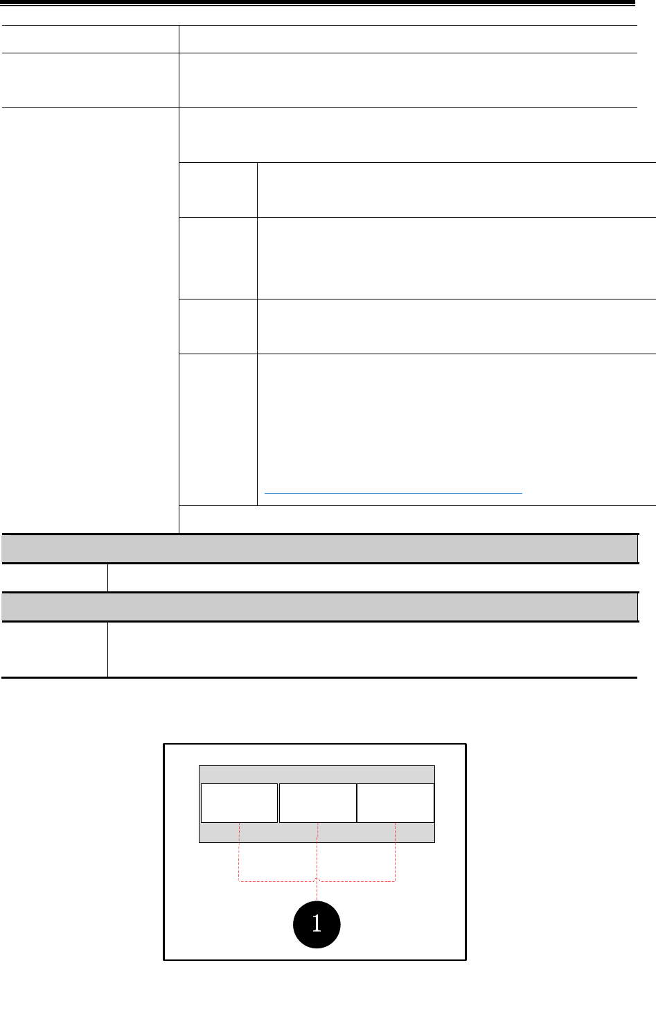
Advanced Part Window
131
style is 0, only fill color is displayed in this window.
Transparence It is only valid for the pop-up window and the fast selection window. Transparence is
0%, 20%, 50%, 80%, 100%
The Pop Window Type shows the relationship between one pop-up window and its
adjacent window.
Monopoly If one window features “Monopoly”, its parent window will be frozen
after it pops up, and it will always be displayed in the Top layer。
Clipping If one window features “Clipping”, the border of this window will be
restricted by its parent window, i.e. the part displayed out of the border of its
parent window will be cut off.
Tracking If one window features “Tracking”, it will move together when its parent
window moves.
Coherence Window A and Window B are both attached to the Basic Window. Generally,
Window A will be displayed in the Top layer when it is touched. But if
“Coherence” is selected, it will not be displayed in the Top layer even if it
is touched, but it will always be attached to its parent window.
☞For details, refer to [Advanced Part 3 Window]
Pop Window Type
Note: If “Clipping” is selected, “Tracking” must be selected simultaneously.
Timer List descriptions
Timer List Show all the timers. If there is none,it won`t display.
Special setting element list descriptions
Special setting
element list
Show all the timers and setting components with window attribute. If there is none ,it won`t display
【Example】Pop Frame10,11,12 over Frame0,transparence are respectively0%,20%,80%.Moreover,initial coordinate are
respectively(0,0),(110,0),(220,0).
Popup
frame10 Popup
frame11
Popup
frame12
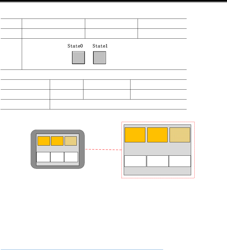
Kinco HMIware Configuration Edit Software
132
frame0:3 function keys to pop frame10,11,12:
function Change window:pop frame10 pop frame10 pop frame10
Tag Use tag;0:Pop frame10 Use tag;0:Pop frame11 Use tag;0:Pop frame12
Graphic
Vector graphic:
Frame10,11,12attribute settings:
Initial coordinate 0 110 220
transparence 0% 20% 80%
Background color choose,fill color:yellow
Save, compile and download. In operation,click function key, you can see frame as bellow
Popup
frame10
Popup
frame11
Popup
frame12 Popup
frame10
Popup
frame11
Popup
frame12
3.5 Components Related to Window
Components directly related to the window are: Direct window, indirect window, and function key (Change window, Goto
Prev, Change common window, Change fast selection window, Popup window, Close window, Popup window title bar and
Minimize).
Functions directly related to the window are: Change Window, Write Data to PLC (Current Base Window), Change Window
(Ignore the window 0) of PLC Control.
☞ For details about contents of these components, refer to [Advaced part 4 Component]
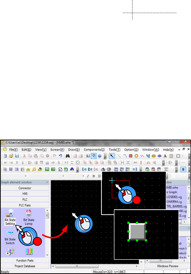
133
4 Component
Components are the objects by which user inputs and operate data; user can execute some operations by operating these
objects. The attribute of component must be set correctly according to actual application. Different attributes influence the
component operating and executing result directly. This chapter will introduce the detail of component attribute.
4.1 Common Setting of Component
4.1.1 Create and Delete Component
(1)Create component
There are two ways to create component:
- Create from the Graph element window
In the PLC parts/Function parts/projects database of Graph element window, drag the component to the edit area, then the
attribute window will pops up automatically, there will be a “+” cursor when you click the OK of attribute window, then
move the cursor to appropriate position and click left button to put the component, click right button to cancel creating
component. As shown in following picture:
2
1
- Create from Menu
Click the components(I) menu, chose a wanted component, then the attribute window will pops up automatically, there
will be a “+” cursor when you click the OK of attribute window, then move the cursor to appropriate position and click
left button to put the component, click right button to cancel creating component.
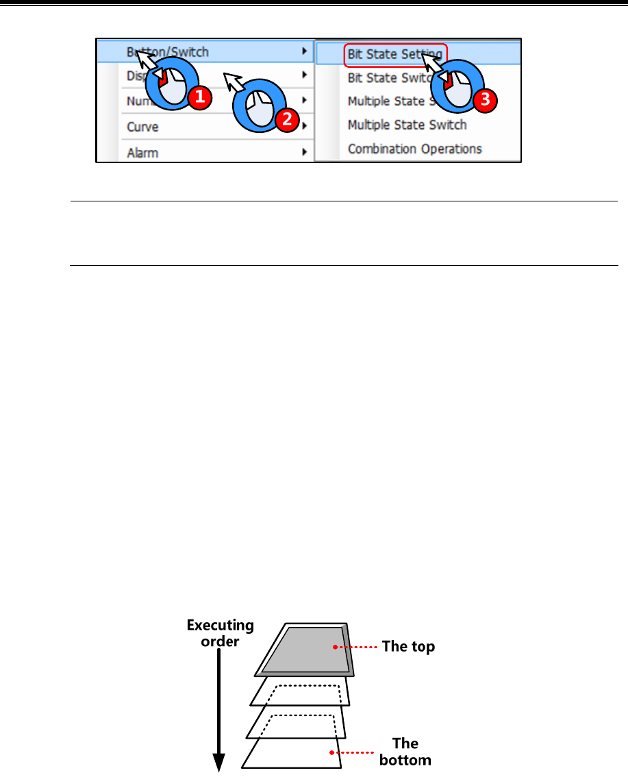
Kinco HMIware Configuration Edit Software
134
Text library, address tag and sound lib are in the Option(O) menu
(2)Delete component
There are two ways to delete the components that have created
- Delete by right click menu
Chose the component, right click then click the Delete to delete the selected component
- Delete by Delete key on the key board
Chose the component, then press the Delete key on the keyboard to delete component
4.1.2 Execution Order of Components
In some application, there is a chance that one touch to trigger multiple components execution, so the customer stacks
several components together.
At this time, if there is a touch operation, the stacked components are not executed at the same time but executed according
to the order of components.
The top component is executed first, then the following components. As shown in the following picture:
Besides, customer can check the layer position of the stacked components
Right click the stacked components; you can see the following options:
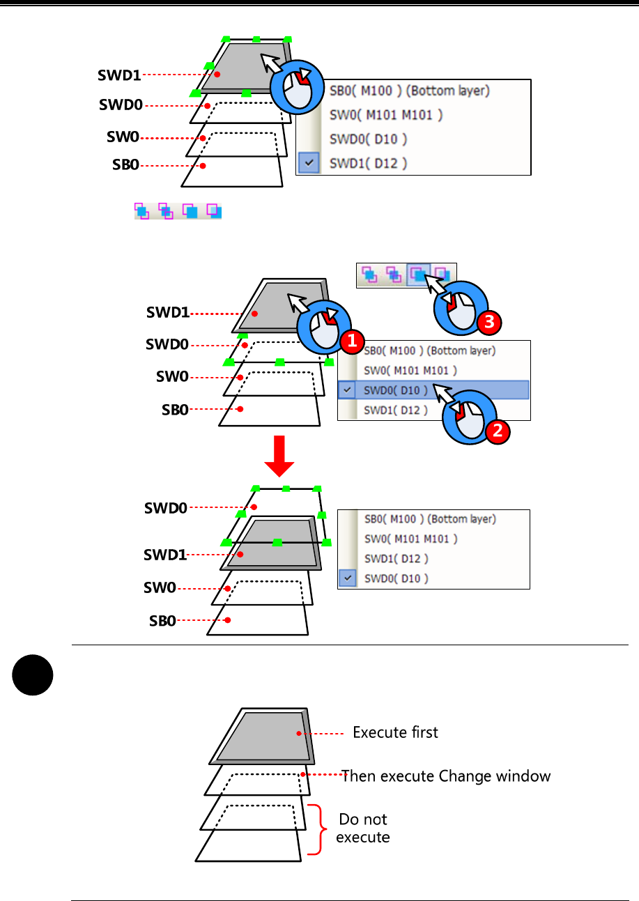
Advanced Part Component
135
You can use the tool bar (set top/set bottom/ previous layer/next layer) to adjust the layer position of the
stacked components
!
1. If there is a component that executes Change window operation in the stacked components, the
components that under this Change window component will not be executed.
2. The number of stacked components should be less than 32.
4.1.3 Methods to Open Attributes Window
The attributes window will pop up automatically when the component created, and there are three methods to open attribute
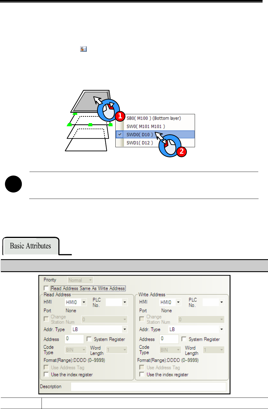
Kinco HMIware Configuration Edit Software
136
window of the created component.
- Double click to open attribute window
- Chose the component, right click, chose the Attribute operation in the menu
- Chose the component, click the icon on the tool bar
How to open attributes window of stacked components
When multiple components stacked together, the lower component can be selected by right click, then open attributes
window by above methods.
!
Multiple attribute windows can not be open at the same time
4.1.4 Basic Setting
In the Basic Attributes option, customer can set the operation object, address type and other related attributes
Detail description of Basic Attributes
Priority Reserved

Advanced Part Component
137
The register address to which the status value or data that writes. If it is unavailable, the component is
read-only component, the display status depends on the value and data in the Read Address
HMI The HMI number; the number is distributed automatically in order when the HMI
is built
PLC No. The PLC controller number; the number is distributed automatically in order
when the PLC controller is built
Change Station Num When HMI communicate with multiple PLC controllers, you can use this option
to connect corresponding PLC controller. This option is used in the application
that uses one HMI-multiple PLCs or ,multiple HMIs-multiple PLCs but only one
PLC in the program
☞For details, refer to [Advanced Part 2.11.2 Index Station Num]
Addr. Type Chose the address type of the PLC register or HMI local register
Bit registers in HMI : LB、LW.B、RB、RBI、FRB、FRBI
Word registers in HMI: LW、RW、RWI、ERW0~2、ERWI0~2、FRW、FRWI
5☞For details, refer to [Advanced Part 15.1 Local Register of HMI]
PLC/Controllers’ address type is different according to different PLC/controller
device
Refer to the Communication Connection Gui☞de for more details about
PLC/controller address type
Address Set the register address of the command or data
Code Type BIN, BCD or LSB
☞For details, refer to [Advanced Part 2.5 Cdoe Type]
Word Length The register number that the component takes up, It is usually 1, it also changes
according to different components and address type.
System Register The registers in HMI which have special use
☞For details, refer to [Advanced Part 15.2 System Special Registers of HMI]
Format The format of the address type in PLC/controller or HMI
Use Address Tag Use the addresses that have been defined in the Address Tag
☞For details, refer to [Advanced Part 5.2 Address Tag Library]
Write Address
Use the index
register
Use a certain register as the index register of the component
☞For details, refer to [Advanced Part 2.11.1 Index Register]
Read Address The register address from which the status value or data read. If it is unavailable, the component is

Kinco HMIware Configuration Edit Software
138
write-only component; the display status cannot display the data or state of read address.
Description The reference name of this component.
4.1.5 Tag Setting
In the Tag option of component attribute, set the display text of each state.
Detail description of Tag
Use Tag Use the tag
Use Graph Font Use graph font mode in tag text
☞For details, refer to [Advanced Part 2.3.4 Grahp Font]
Checked Adjust the component size automatically according to the tag content, as following
picture:
Tag Cross-border
Check
Uncheck Do not adjust the component size automatically according to the tag content, the tag
content that cross border will be cut, as following picture:

Advanced Part Component
139
Use Textlib Use the text in the textlib as tag content
☞For details, refer to [Advanced Part 5.1 Text Library]
Tag List The comment text corresponding to each state
Tag Content Input the comment text of each state here
Copy Contents
to All State
Chose one state in the Tag list, click this option to copy the tag content of this state to all the state
Front Type Use vector font or dot matrix font in tag content
☞For details, refer to [Advanced Part 2.3 Text]
Font Attribute Set the attributes of the tag content, like font, size, alignment, color and so on. The current font
attributes can be copied to each state or tag content of each language
- The steps to set tag:
Add tag content of state 0 Step
Check the “Use Tag
Chose the state 0 in Tag List
Input comment text in the Tag
Content
Add tag content of state 1
Chose the state 1 in Tag List
Input comment text in the Tag
Content
4.1.6 Graphics Setting
Set the graphic of each state in the Graphics option of component attribute, the graphic can be vector or bit map.
Detail description of Graphics
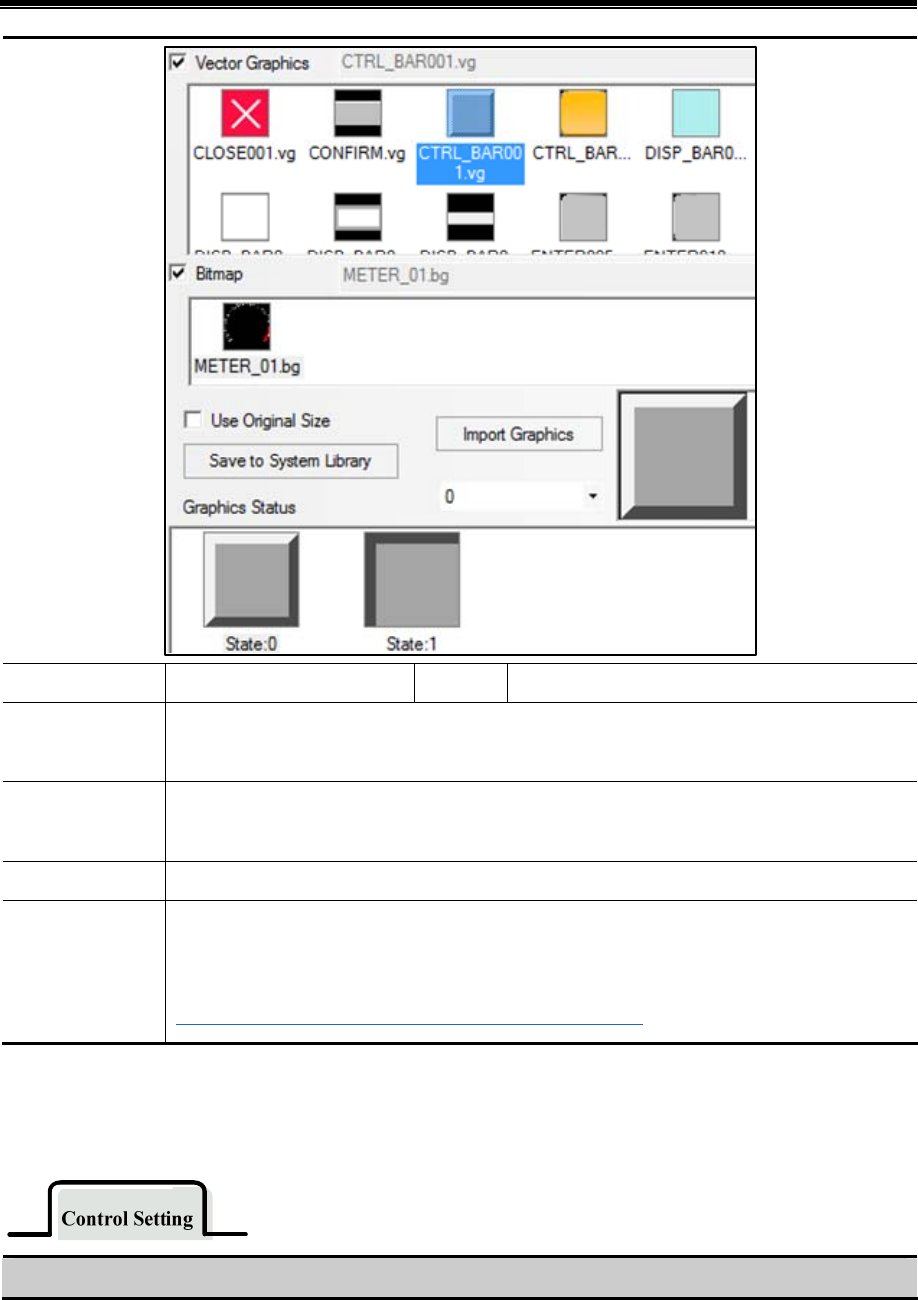
Kinco HMIware Configuration Edit Software
140
Vector Graphics Use vector graphic to display Bitmap Use bitmap to display
Use original size This option is effective when chose bitmap as graphic, if it is checked, component will display the
original size of the graphic
Save to System
Library
Save the checked graphic or graphic of some state to the system library in the UserselPath file folder
Import Graphics Import vg or bg format graphic from system library or external
Graphics Status Preview the graphic of the checked state. For some stateless control component, like Vector Graph
and Bitmap, The graphic display in Vector or Bitmap is the picture checked here.
☞Refer to Advanced Part 5.3 Graphic Library for more details
4.1.7 Control Setting Option
Set the control conditions and security in the Control Setting, also can set the trigger macro and trigger register operation
here.
Detail description of Control Setting

Advanced Part Component
141
Always valid The touch is enabled always the time. The operator can operate is all the time
Always invalid The touch is never enabled. The operator cannot control operator it
Security Level: If clicked means the current security level must higher than the set
security, so the operator can operate this component to set the state value or data to the
corresponding register.
☞For details, refer to [Advanced Part 10.3.1 Security Level Protection for
Components]
Touching
Enable
Setting Conditional
Enabling
Permission Control: If clicked means the operator must has corresponding permission so
he can operate this component to set the state value or data to the corresponding register.
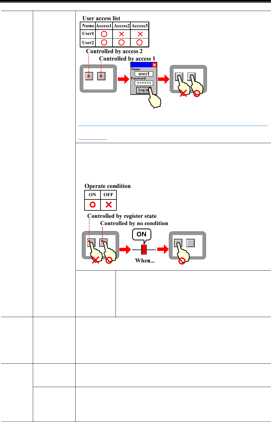
Kinco HMIware Configuration Edit Software
142
☞For details, refer to [Advanced Part 10.3.2 User Permission Protection for
Components]
Register Control: if clicked means the specified bit register or word register must satisfy
the setting conditions, so that operator can operate this component to set the state value
or data to the corresponding register.
Auto show
login window
If clicked means when touch the component but the current user
security level or permission cannot satisfy the setting security level or
permission, the password input window (Frame9: Login window)
will pop up automatically.
Show Element
Invalid Tag
If clicked means when the component is touch invalid, the component will display touch
invalid tag. This function is optional only when the Always Invalid or Conditional
Enabling is selected. The color of touch invalid tag can be set in HMI Extended
Attributes of HMI Attributes
Min Press Time The minimum time of a hold pressing to make touch effective. The unit is 100ms, when
it is set to 0, it means do not set this option.
Security
Setting
Operator
Confirm
If clicked means when touch the component, the Confirm Window (Frame7:Confirm
Action Window) will pop up. Click YES to make this touch effective and if click Cancel
or do not click YES during the wait(s), the touch operation will be canceled
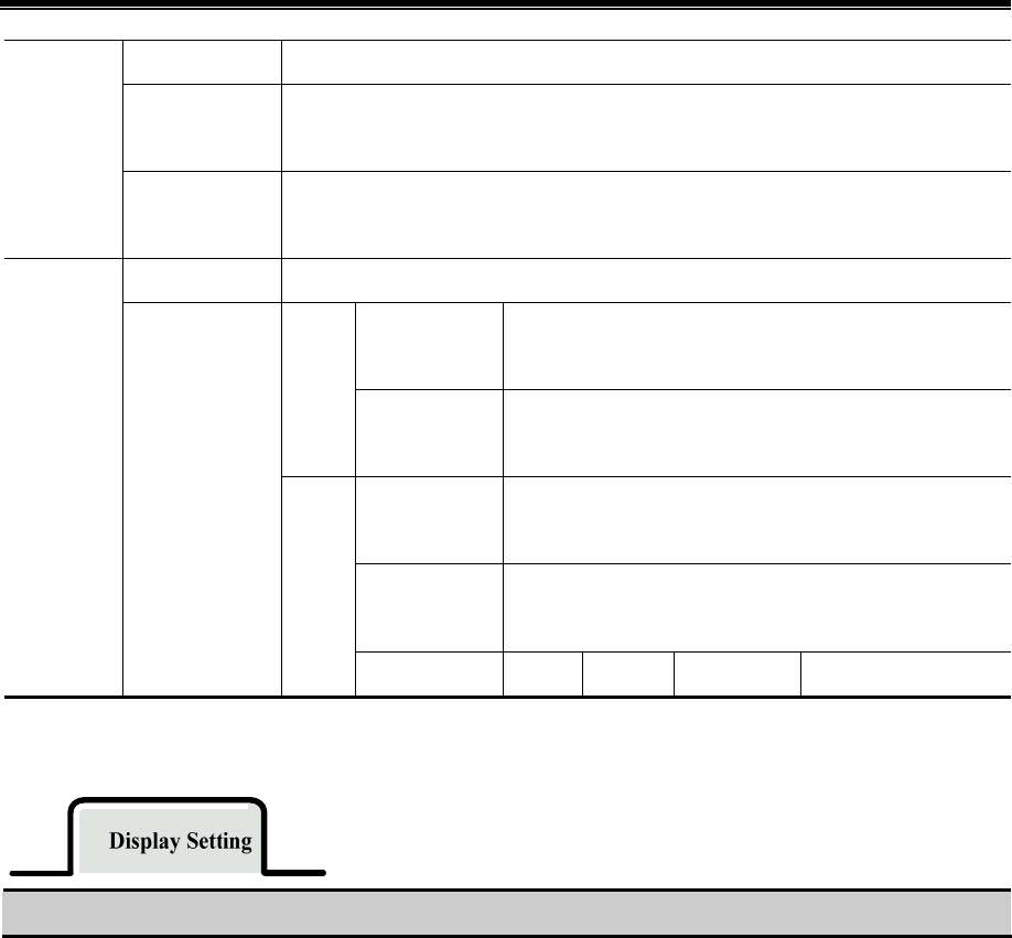
Advanced Part Component
143
automatically.
Record
Operations
If clicked means the operation event will be recorded , this event can be displayed in the
Operation Log , and saved in csv file in the external storage
Min Time
Interval(Second)
The minimum time interval between two touch operations of one same component or
two different components. 0 means do not set the Min time Interval
Trigger Macro Execute the specified macro when the operation to the component is successful
Written Notice
Write the “Write Value” to the specified register before the
operation is executed successfully
Word
After Written
Notice
Write the “Write Value” to the specified register after the
operation is executed successfully
Written Notice
Write the On/Off signal to the specified register before the
operation is executed successfully
After Written
Notice
Write the On/Off signal to the specified register after the
operation is executed successfully
Notificatio
n Trigger Register
Bit
Write Value Set 1 Set 0 Set 0 Pulse Set 1 Pulse
4.1.8 Display Setting
Set the display condition, display size, position in the Display Setting.
Detail description of Display Setting
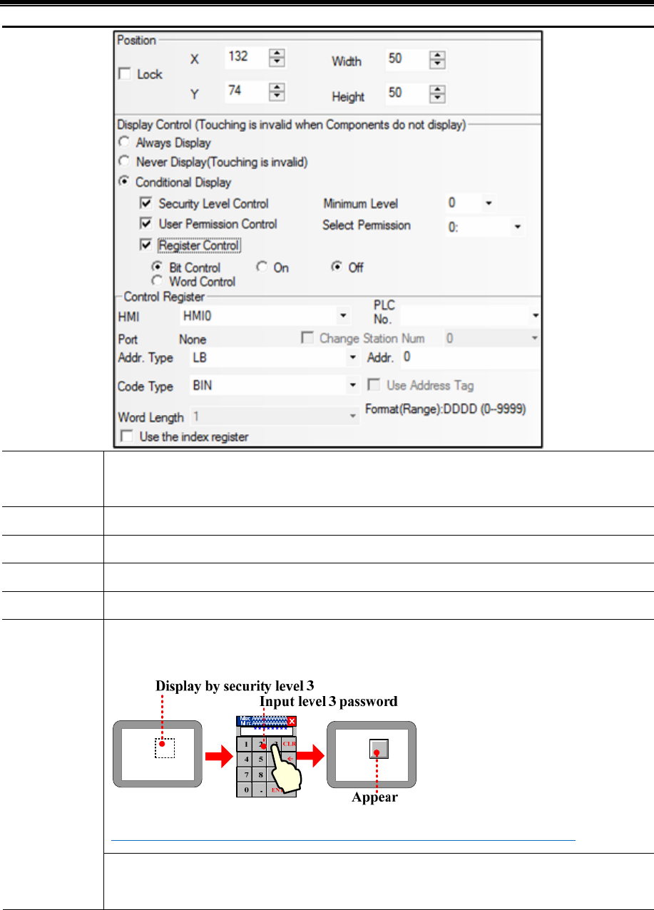
Kinco HMIware Configuration Edit Software
144
Lock If clicked means the component is locked, the position of component cannot be changed by mouse or
moving keys on keyboard
X/Y The coordinate value of the top left of component
Width/Height The width and height of component(The unit is pixel)
Always Display If clicked means the component is displayed all the time
Never Display If clicked means the component is hidden, the hidden component cannot touch
Security Level Control: Clicked means the component is displayed only when the current security level
is higher than the setting level.
☞For details, refer to [Advanced Part 10.3.1 Security Level Protection for Components]
Conditional
Display
User Permission Control: If clicked means the component is displayed only when the operator has
corresponding permission
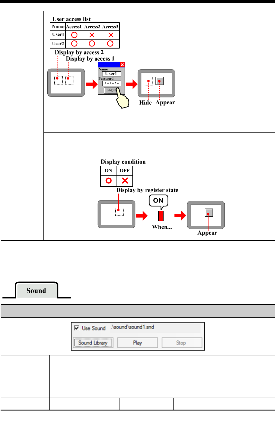
Advanced Part Component
145
☞For details, refer to [Advanced Part 10.3.2 User Permission Protection for Components]
Register Control: Click means he component is displayed only when the specified bit register or word
register satisfies the condition
.
4.1.9 Touch Sound Control
In the Sound option, set the sound when the component is touched
Detail description of Sound
Use Sound Set the sound when the component is touched.
Sound Library Open the sound library attributes box.
☞For details, refer to [Advanced Part 4.15.6 Sound Lib]
Play Play and listen the audio Stop Stop the audio
☞For details, refer to [Advanced Part 5.4 Sound Lib Application]
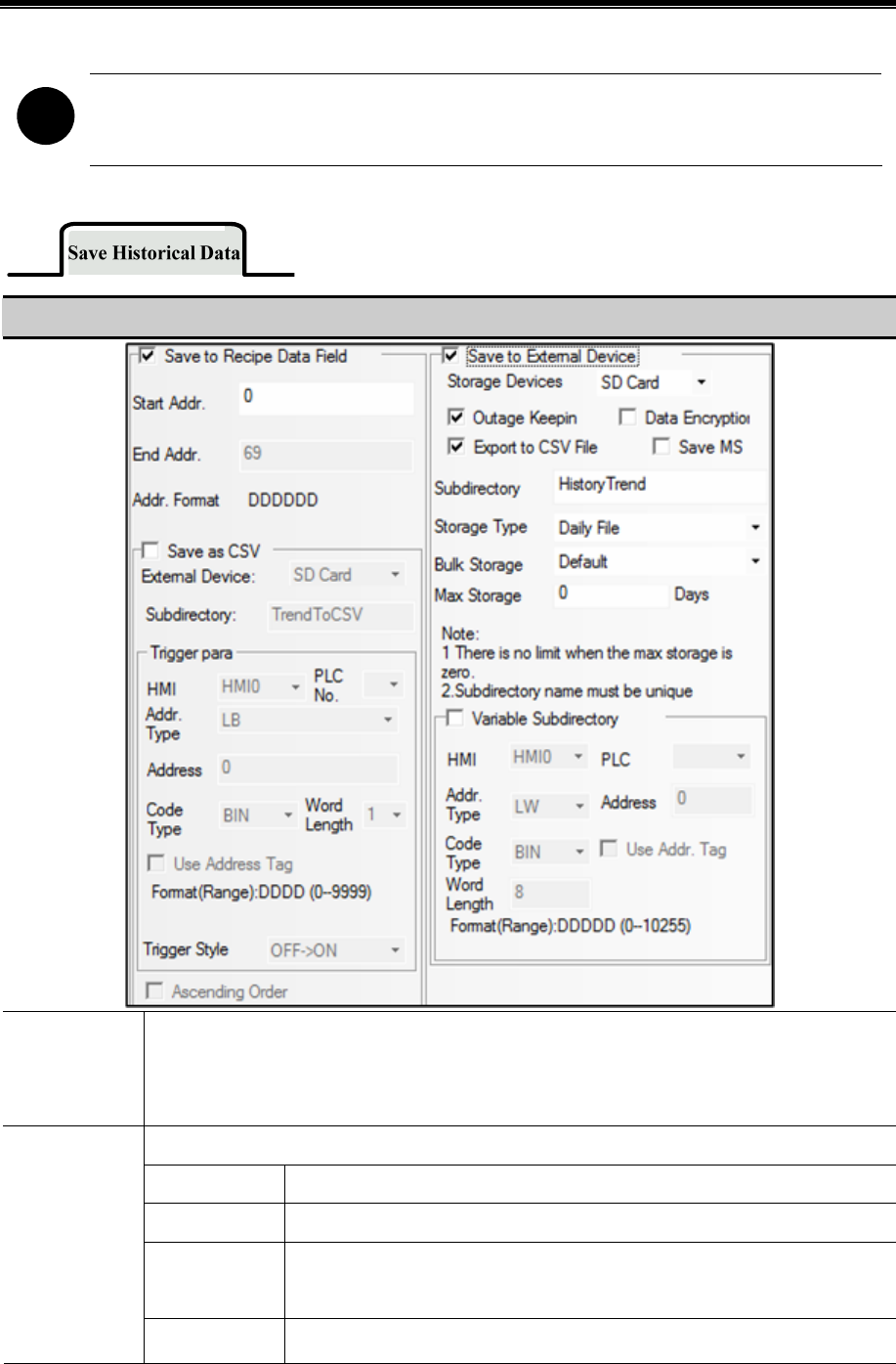
Kinco HMIware Configuration Edit Software
146
!
“The sound function is only suitable for the HMI with audio output port.
4.1.10 Save Historical Data
Detail description of Save Historical Data
Save to Recipe
Data Field
Save sampling data to the recipe register (RW) of HMI
The end address = the start address + 20 +sampling page number*(4+ channel number). If the data
exceeds the storage limit, the sampling data will cover the previous data
Save the sampling data to the external device
Storage Devices SD card, USB DISK1*、USB DISK2* are optional
Outage keep in If the HMI is powered off and restart, the information can be regained
Export to csv
File
Save the sampling data to external device in CSV file. This CSV file is saved in
/trend/subdirectory/file name
Save to External
Device
Data Encryption Encrypt the sampling data

Advanced Part Component
147
☞For details, refer to [Advanced Part 2.15 Data Encryption]
Save MS Save the sampling time to ms level and record in CSV file
Subdirectory Set the subdirectory name of CSV file when it is saved in external device, customer
can change this name
The default subdirectory name of History Data is History Data, Trend Curve is
History Trend, XY plot is XY-CHART
Daily File Save the sampling data by days, and the name of CSV files is in
“yyyy mmdd” form
Storage Type
Single File Save the sampling data by items, and the name of CSV file is the
Subdirectory
Bulk Storage Provide a buffer storage mode, Only when the data is up to the bulk storage setting,
and then write the data to SD card or U disk. The “Default” means don’t use buffer
storage mode, as soon as there is sampling data, write this data to SD card or U disk
Max Storage Set the limit of the storage: if it is by Daily File, the unit is day, if it is by Single
File, the unit is item. If chose the “Daily File”, the file name is as “yyyymmdd”,
The Max Storage means the maximum csv file number under this routine, if csv
file exceeds the max storage number; the previous files will be deleted. If chose
the “Single File” in Storage Type, the CSV file named by the Subdirectory name,
The Max Storage means the maximum items in this csv file, if the items is up to
the limit, the data will not be saved
Va ri a bl e
Subdirectory
The Subdirectory is read from specified registers, the maximum register number is 16
※ If a HMI has two USB host, the number of U disk depends on the sequence they plug in HMI. That is to say the first U
disk that plug in HMI is USB DISK1, and the second U disk that plug in HMI is USB DISK2. It does no matter with the
slot position.
!
When the sampling data is saving to external storage device, the special system register should set OFF
before removing the external storage device, or the data will be damaged or lost. They are LB9153(SD
card)、LB9154(USB disk1)、LB9155(USB disk2)
4.2 Button/Switch Components
They are Bit State Setting, Bit State Switch, Multiple State Setting, Multiple State Switch, Combination Operations, and
Function Key and so on.
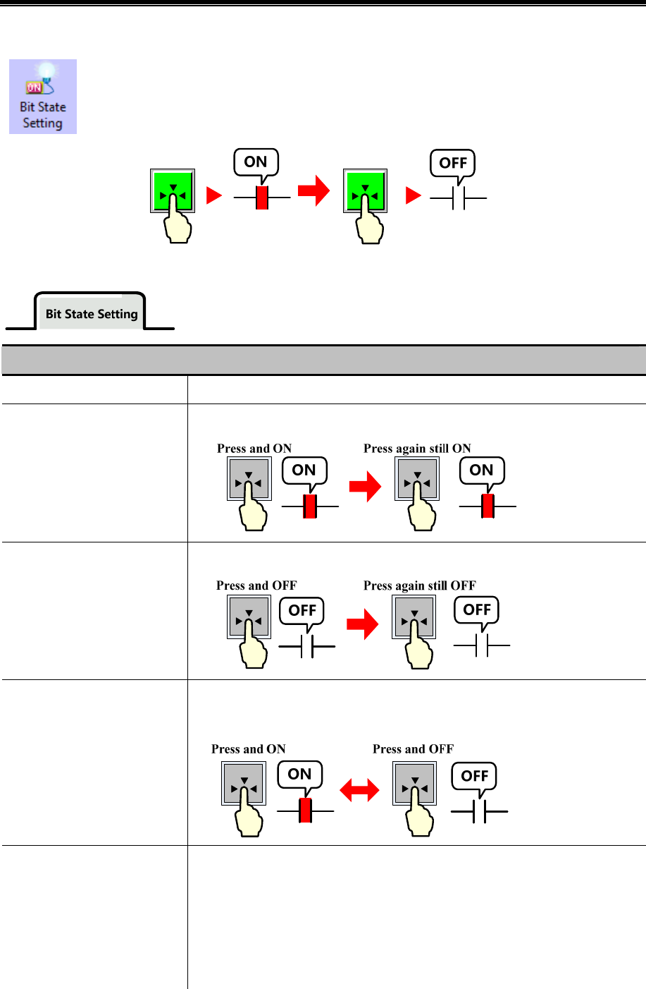
Kinco HMIware Configuration Edit Software
148
4.2.1 Bit State Setting
The Bit State Setting defines a touch area. When this area is active, this button can set the HMI bit address
or PLC bit address On or Off. The display status of this component will not be changed by the input value.
Detail description of Bit State Setting
Type Function description
On
Press to set specified address ON, still ON if released or pressed again
Off
Press to set bit address OFF, still OFF if released or pressed again
Toggle
Press to set specified address ON, still ON if released; Press again to set address OFF,
Still OFF if released
Reset
Only when this component is hold pressing, the specified address is ON, change to
OFF if released
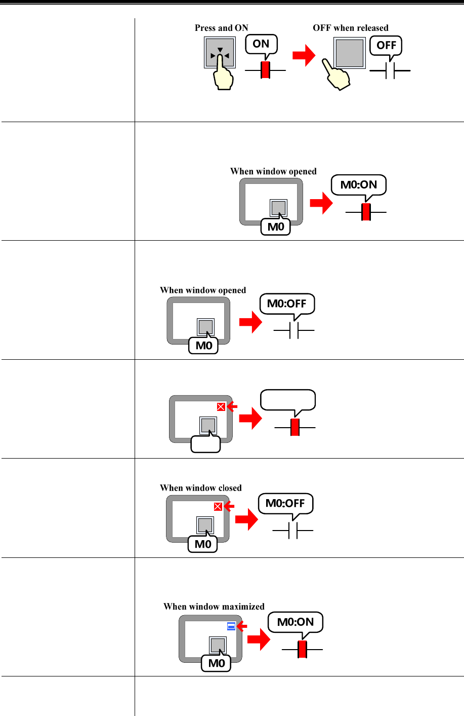
Advanced Part Component
149
Set On when Window Open
When the window which contains this component opens, the specified address is set
ON
Set Off when Window Open
When the window that contains this component opens, the specified address is set
OFF
Set On when Window Close
When the window that contains this component closes, the specified address is set ON
When window closed M0:ON
M0
Set OFF when Window Close
When the window that contains this component closes, the specified address is set OFF
Set ON when Window
Maximized
When the window that contains this component is maximized, the specified address is
set ON
Set OFF when Window
Maximized
When the window that contains this component is maximized, the specified address is
set OFF
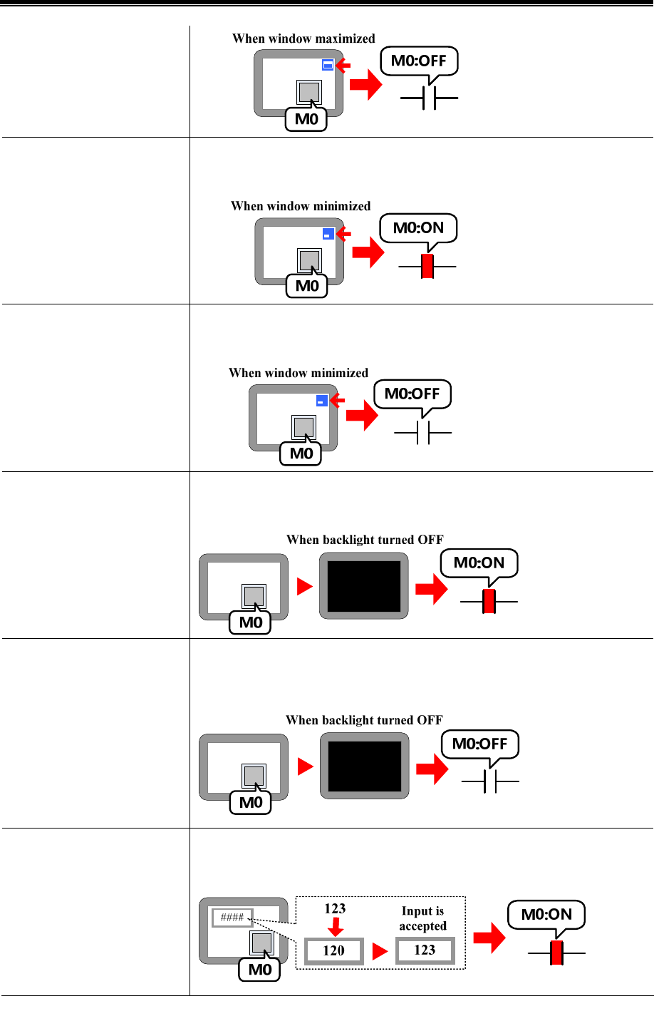
Kinco HMIware Configuration Edit Software
150
Set ON when Window
Minimized
When the window that contains this component is minimized, the specified address is
set ON
Set OFF when Window
Minimized
When the window that contains this component is minimized, the specified address is
set OFF
Set On when Backlight Off
When the backlight of the window that contains this component is off, the specified
address is set ON
Set On when Backlight Off
When the backlight of the window that contains this component is off, the specified
address is set OFF
Set On when Input Success
In the window which contains this component, when a Number Input component
inputs successfully, the specified address is set ON
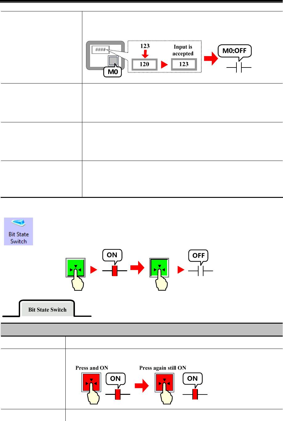
Advanced Part Component
151
Set OFF when Input Success
In the window which contains this component, when a Number Input component
inputs successfully, the specified address is set OFF
Set 0 pulse
Press button to set 0 while produce a specific width negative pulse. When time is over,
it returns to 1. Users can set pulse width to ensure PLC to receive signal 0. 100ms lest
and users need to set it long enough. Or it is too short for PLC to receive because of
communication time or scan time.
Set 1 pulse
Press button to set 1 while produce a specific width positive pulse. When time is over,
it returns to 0. Users can set pulse width to ensure PLC to receive signal 1. 100ms lest
and users need to set it long enough. Or it is too short for PLC to receive because of
communication time or scan time.
Key
Map the component to the F1~F12 of external keyboard or F1~F8 of the HMI which
has keys itself. This function is suitable for the HMI with USB host or HMI with keys
itself
4.2.2 Bit State Switch
The Bit State Switch is a combination of Bit State Lamp and Bit State Setting component, it defines a
touch area, if this area is active, this component can switch HMI or PLC bit address between on and off, at
the same time, the display state of component will change according to the value of read address.
Detail description of Bit State Switch
Switch Type Function description
On
Press to set specified address ON, still ON if released or pressed again
Off Press to set specified address OFF, still OFF if released or pressed again
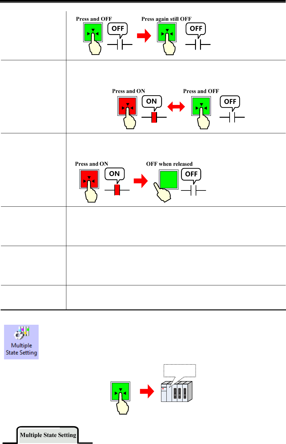
Kinco HMIware Configuration Edit Software
152
Toggle
Press to set specified address ON, still ON if released; Press again to set address OFF, Still
OFF if released
Reset
Only when this component is hold pressing, the specified address is ON, change to OFF if
released
Set 0 pulse
Press button to set 0 while produce a specific width negative pulse. When time is over, it
returns to 1. Users can set pulse width to ensure PLC to receive signal 0. 100ms lest and users
need to set it long enough. Or it is too short for PLC to receive because of communication
time or scan time.
Set 1 pulse
Press button to set 1 while produce a specific width positive pulse. When time is over, it
returns to 0. Users can set pulse width to ensure PLC to receive signal 1. 100ms lest and users
need to set it long enough. Or it is too short for PLC to receive because of communication
time or scan time.
Key
Map the component to the F1~F12 of external keyboard or F1~F8 of the HMI which has keys
itself. This function is suitable for the HMI with USB host or HMI with keys itself
4.2.3 Multiple State Setting
The Multiple State Setting component defines a touch area, if this area is active; this component writes a
setting value to a specified register in HMI or PLC. The display status of component will not be changed
by the value of read address.
Write data“125”
to D100 D100=125
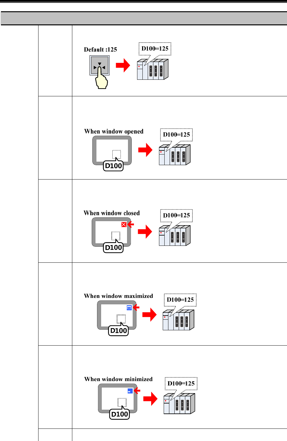
Advanced Part Component
153
Detail description of Multiple State Setting
Set
Constant
Press component to set the setting constant to a specified register
Set at
Window
Open
When the window with this component opens, set the setting constant to a specified register
automatically
Set at
Window
Close
When the window with this component closes, set the setting constant to a specified register
automatically
Set at
Window
Maximized
When the window with this component is maximized, set the setting constant to a specified
register automatically
Set at
Window
Minimized
When the window with this component is minimized, set the setting constant to a specified
register automatically
Setting Mode
Set at When the backlight of the window that contains this component is off, set the setting value
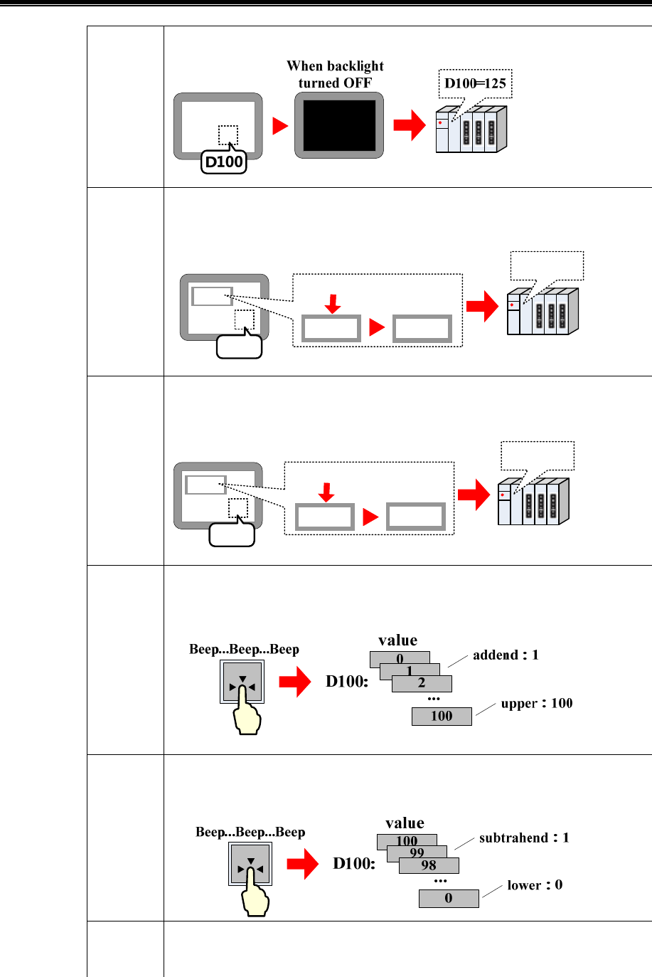
Kinco HMIware Configuration Edit Software
154
Backlight
Off
to a specified register automatically
Set at Enter
success
In the window which contains this component, when a Number Input component inputs
successfully, set the setting value to a specified register automatically
####
120
123
123
Input is
accepted
D100=125
D100
Set at Enter
Fail
In the window which contains this component, when a Number Input component inputs
unsuccessfully, set the setting value to a specified register automatically
####
120
123
120
Input is not
accepted
D100=125
D100
Add value The value in specified register will be added “Addend” every time presses this button, the
result will not exceed the Upper limit
Sub value The value in specified register will be subtracted “Subtrahend” every time presses this
button; the result will not exceed the Lower limit
Jog++ If hold pressing the button exceeding the “Delay Time”, the value in specified register will
be added “Addend” in a “Jog Speed” time. The result will not exceed the Upper limit
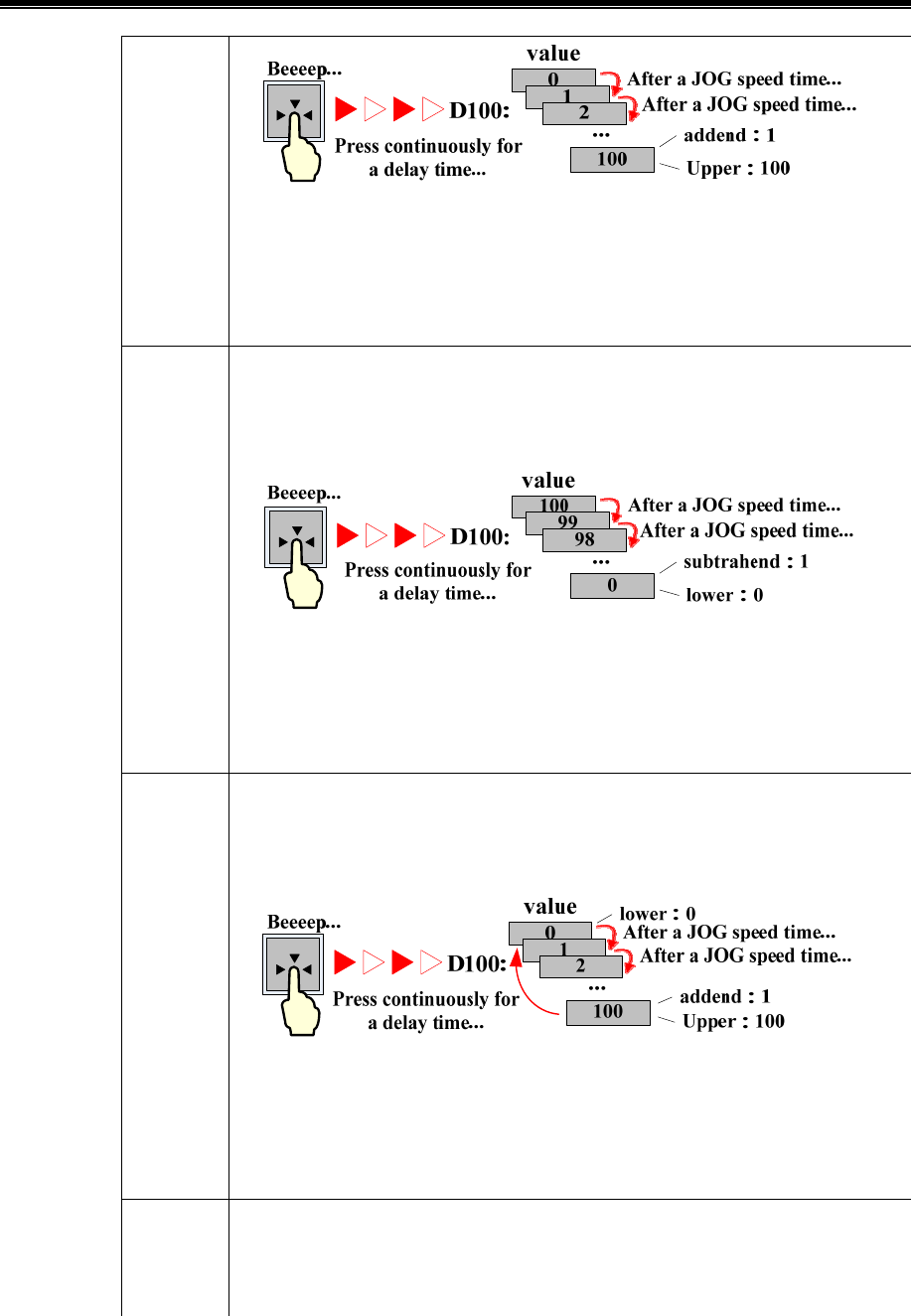
Advanced Part Component
155
If the “Immediate Execution of Increase/Decrease Progressively” is checked, the value in
specified register will be added “Addend” immediately at every press. If hold pressing the
button, the value in specified register will be added “Addend” in every “Jog Speed” time
until reaches the Upper limit
Jog-- If hold pressing the button exceeding the “Delay Time”, the value in specified register will
be subtracted “Subtrahend” in a “Jog Speed” time. The result will not exceed the Lower
limit
If the “Immediate Execution of Increase/Decrease Progressively” is checked, the value in
specified register will be subtracted “Subtrahend” immediately at every press. If hold
pressing the button, the value in specified register will be subtracted “Subtrahend” in every
“Jog Speed” time until reaches the “Lower” limit
Jog++(Circ
le)
If hold pressing the button exceeding the “Delay Time”, the value in specified register will
be added “Addend” in a “Jog Speed” time until reaches the Upper limit, then adds addend
from the Lower limit
If the “Immediate Execution of Increase/Decrease Progressively” is checked, the value in
specified register will be added “Addend” immediately at every press. If hold pressing the
button, the value in specified register will be added “Addend” in every “Jog Speed” time
until reaches the Upper limit, then adds addend from the Lower limit
Jog--(Circl
e)
If hold pressing the button exceeding the “Delay Time”, the value in specified register will
be subtracted “Subtrahend” in a “Jog Speed” time until reaches the Lower limit, then
subtract subtrahend form the Upper limit
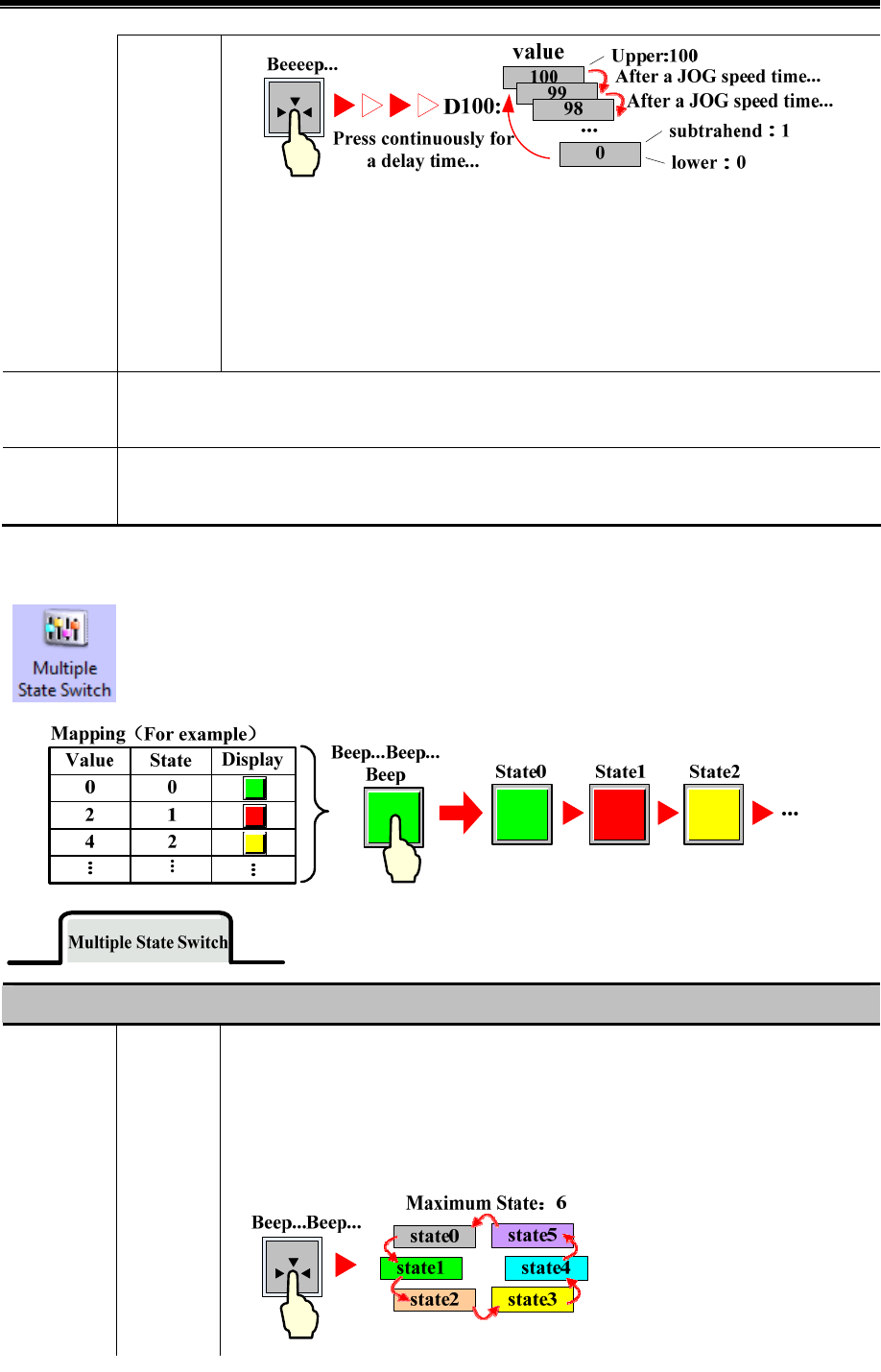
Kinco HMIware Configuration Edit Software
156
If the “Immediate Execution of Increase/Decrease Progressively” is checked, the value in
specified register will be subtracted “Subtrahend” immediately at every press. If hold
pressing the button, the value in specified register will be subtracted “Subtrahend” in every
“Jog Speed” time until reaches the “Lower” limit, then subtract subtrahend form the Upper
limit
Va ri a bl e
Parameters
The parameters, like Set Value, Addend, Subtrahend, Upper, Lower, are read from specified registers
Key Map the component to the F1~F12 of external keyboard or F1~F8 of the HMI which has keys itself. This
function is suitable for the HMI with USB host or HMI with keys itself
4.2.4 Multiple State Switch
The Multiple State Switch is the combination of Multiple State Display and Multiple State Setting. It
displays the mapping status according to the value of Read Address (the maximum mapping status is
256). At the same time, it defines an area, when this area is touched, this component writes the
mapping value to the Write Address. The Write Address and Read Address can be the same or different.
Detail description of Multiple State Switch
Control Add The State No. adds 1 every time press this button, and the mapping value is write to the
Write Address, at the same time this component displays corresponding graph according to
the value of Read Address.
Unloop unchecked:
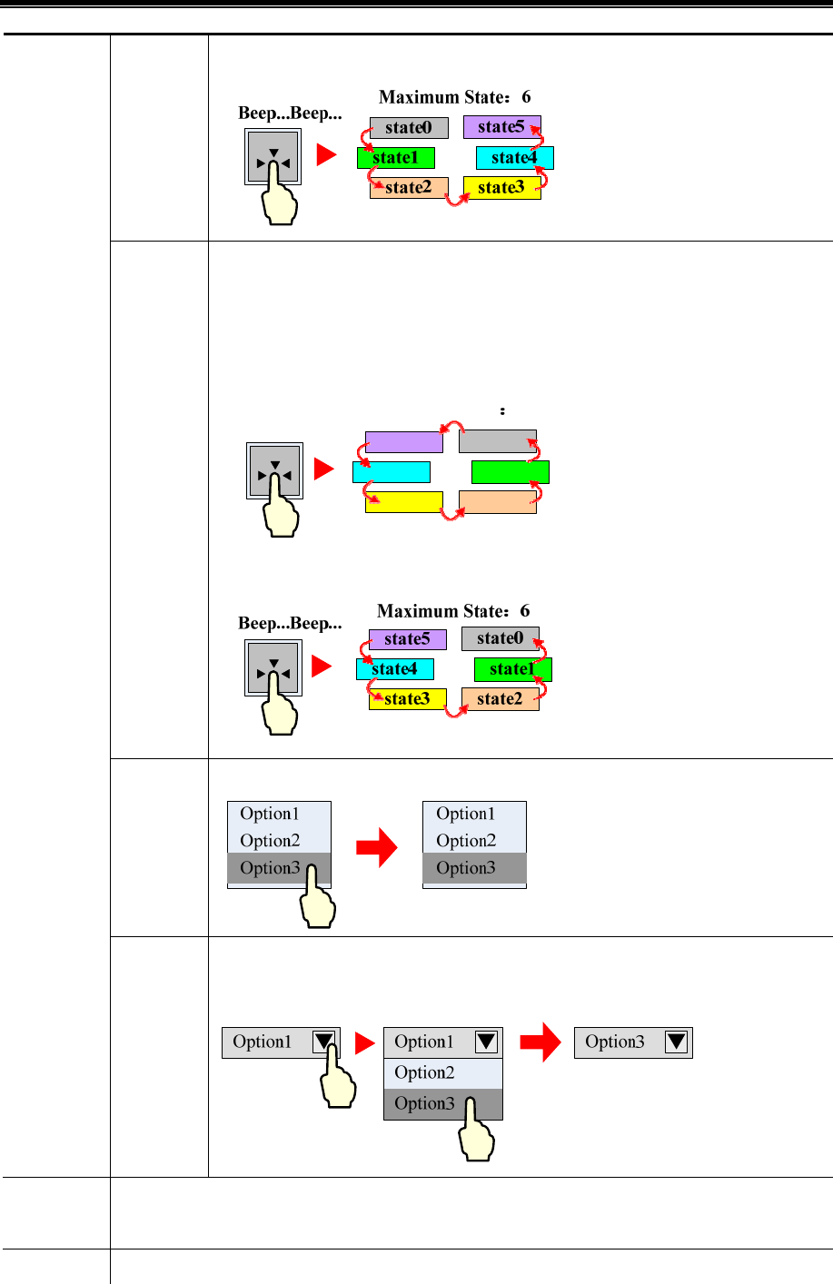
Advanced Part Component
157
Unloop checked:
Sub The State No. subtracts 1 every time press this button, and the mapping value is write to the
Write Address, at the same time this component displays corresponding graph according to
the value of Read Address.
Unloop unchecked:
state5
state4
state3
state0
state2
state1
Beep...Beep... Maximum State 6
Unloop checked:
List Display the state in list, and the current selected state is in Select Color
Dropdown
List
Display the state in dropdown list, but only display the current selected state. Click the
dropdown list to display all the states
State Num. The maximum state number is 256.(The BIN or BCD encoding supports 256 states at most, and the LSB
encoding supports 17 states at most.)
Map Value When the value in Read Address equals one of the values in the Map Value list, the component displays the
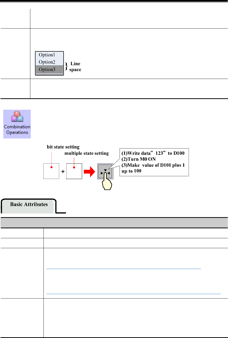
Kinco HMIware Configuration Edit Software
158
corresponding graph and tag. When the component switches to one state, the corresponding Map Value
is write to the Write Address
Line Spacing If chose the List or Dropdown List as control mode, this option is used to set the line space between each
tag. The unit is pixel
Key Map the component to the F1~F12 of external keyboard or F1~F8 of the HMI which has keys itself. This
function is suitable for the HMI with USB host or HMI with keys itself
4.2.5 Combination Operations
The Combination Operations is used to combine multiple bit state setting and multiple state setting as one
component. So the operator can execute bit state setting and multiple states setting operation by 0nly one
button.
Detail description of Combination Operations basic attributes
Component List Add multiple Bit State Setting and Multiple State Setting components by right click.
Write Address Set the Write Address of the components in the Component List
Setting Mode Bit State Setting supports On, Off, and Toggle mode only.
☞For details about Bit State Setting, refer to [Advanced Part 4.2.1 Bit State Setting]
Multiple State Setting components support Set Constant, Add and Sub mode only.
☞For details about Multiple State Setting, refer to [Advanced Part 4.2.3 Multiple State Setting]
Exiting when
component
execution Fail
If checked means that the execution will stop if one of the components fails during the sequence
execution, the next component will not be executed. If unchecked means the Combination
Operation executes from top to bottom, if one of the components fails during the sequence
execution, then jump to execute the next component.
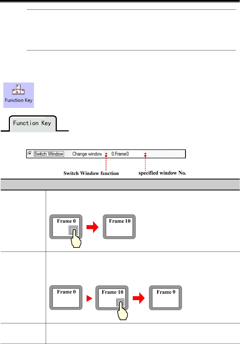
Advanced Part Component
159
1. When add the components, use the “Insert before” and “Insert behind” option to set the order of the
components
2. Use the Move UP and Move Down to change the order in component list
3. Use the Delete option to delete components
4.2.6 Function Key
The Function Key provides functions like Switch Window, Keyboard Function, Clear Event, Touch
Calibration, save Screenshot to Extended Memory, Execute Macro, and Print and so on. It also can be
used to design the key board, and Function Key does not have control register, it executes functions by
touch.
- Switch Window
Description of Switch Window function
Change Window
Press the function key to close the current window (sub windows in this window included) and
switch to the window with specified window No.
Goto Prev
Press the function key to close the current basic window, and come back to the previous window.
For example, switch fram0 to frame 10, press this function key in frame 10 to back to frame 0. This
function is only suitable for basic window
Change Common
Window
If pressed, the Common Window (The default is Frame 1) will be replaced by the specified window
as the new Common Window
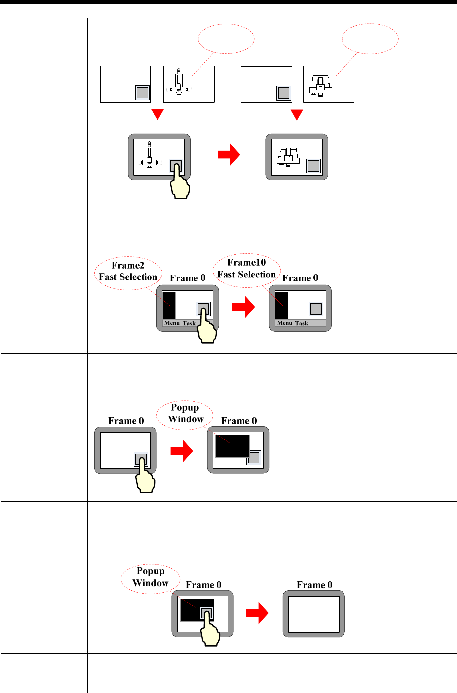
Kinco HMIware Configuration Edit Software
160
Frame 0 Frame 0
Frame 1 Frame 10
Frame 0
+
Frame 0
+
Common
Window Common
Window
Change Fast
selection window
If pressed, the Fast Selection Window (The default is Frame 2) will be replaced by the specified
window as the new Fast Selection Window
Pop up window
If pressed, the specified window will pop up, and displayed above the current window, the current
window will not close
Close Window
Use this option to close the pop-up window, but cannot close the Direct Window and Indirect
Window, because they are controlled by the bit or word register. The Close Window function can
close the pop up window only, but cannot control data in
register
Pop up window title
bar
Hold pressing this function key to move the pop up window. This function is suitable for pup up
window, direct/indirect window only
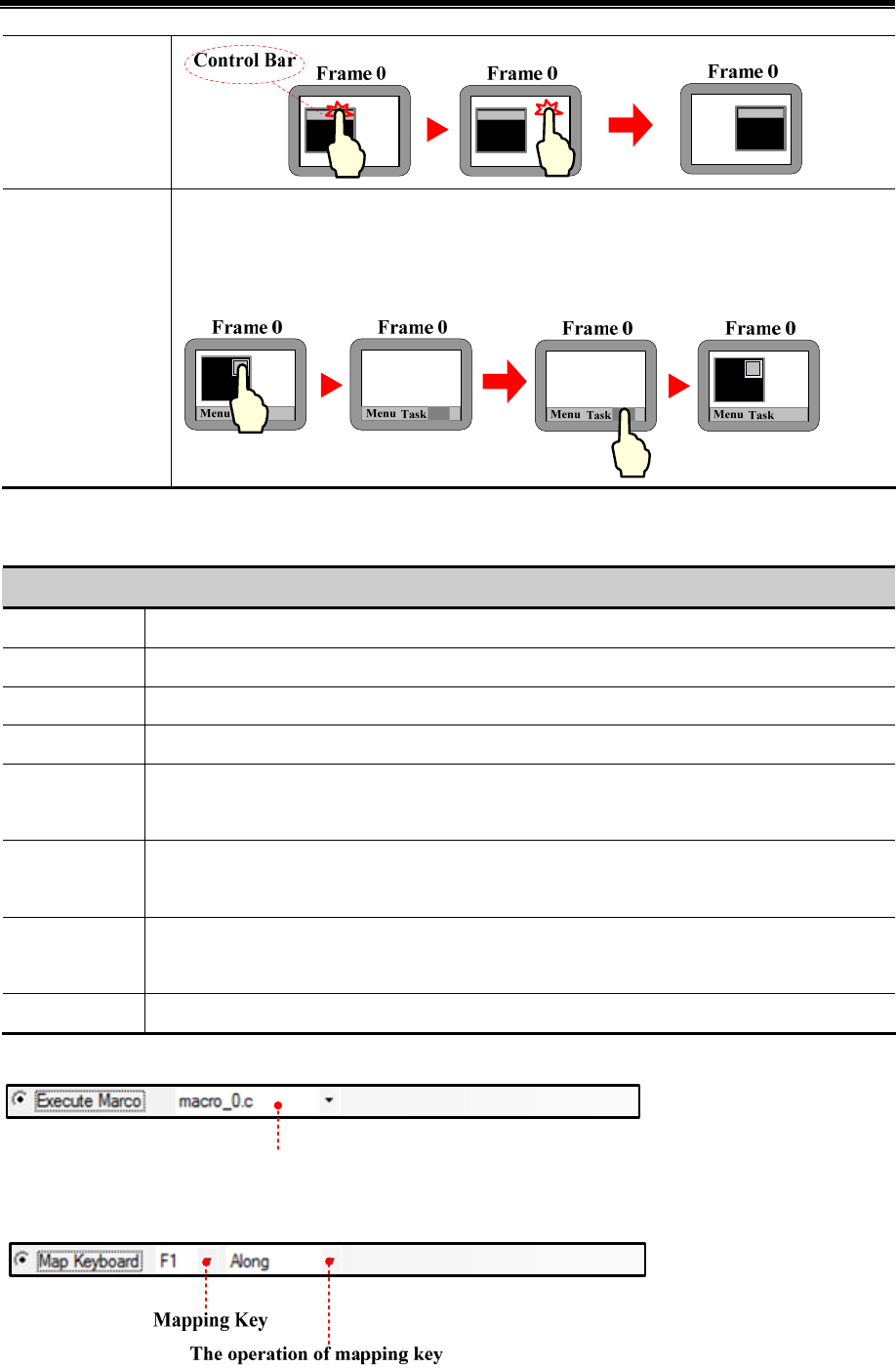
Advanced Part Component
161
Minimize
If pressed, the pop up window will be minimized in the task bar. Press the window icon on task bar
to reset the window to original position. This function is suitable for pup up window, direct/indirect
window only
- Map Keyboard
Use this function to make virtual keyboard.
Function description of keyboard
Enter The same function as the Enter on the keyboard
Backspace The same function as the Backspace on the keyboard
Clear Clear the content in the Number Input and Text Input component
Escape Cancel operation, the same function as the ESC on the keyboard
Unicode
Set the input characters in the “Number Input” and “Text Input” component. The number (0, 1, 2…) or
ASCII and Unicode (a, b, c…) are operational
Cursor
Move the cursor according to the mode, like Move up, Move down, Move left, Move right, Line head,
Line tail, First position, Last position. This function is suitable for the Note Book component only
Select Text
Select text operation, Start select and Finish select included. This function is suitable for the Note Book
component only
Text Operation Set the text operation, includes Copy, Cut, and Paste. This function is suitable for the Note Book only
- Execute Macro
Chose the macro
Press function key to execute the existing macro.

Kinco HMIware Configuration Edit Software
162
This function can set function for the F1~F8 of HMI, includes Along, Backwards, ESC, Enter and so on. This function is
suitable for MT4201T HMI only.
- Touch Calibration
Press function key with this option checked to enter the touch calibration screen. Customer can calibrate the touch panel.
Enter the calibration screen without set the DIP switches
- Clear Event
Press function key to clear the event information in the Event Display component.
- Save Screenshot to The Extended Memory.
Press function key to save the screenshot to the extended memory in bmp picture. So the customer can print or check the
screen of HMI.
☞For details about Save Screenshot to the Extended Memory, refer to [Advanced Part 4.15.5 PLC Control]
- Import/Export
Press function key to import/export project or recipe data.
!
This function must works with the File List Window and only the HMI with USB host or SD card supports
it
Description of Import/Export function
Import project to
HMI
Import the project (pkg file) from extended memory to HMI. After that, HMI will restart
automatically and run the project.
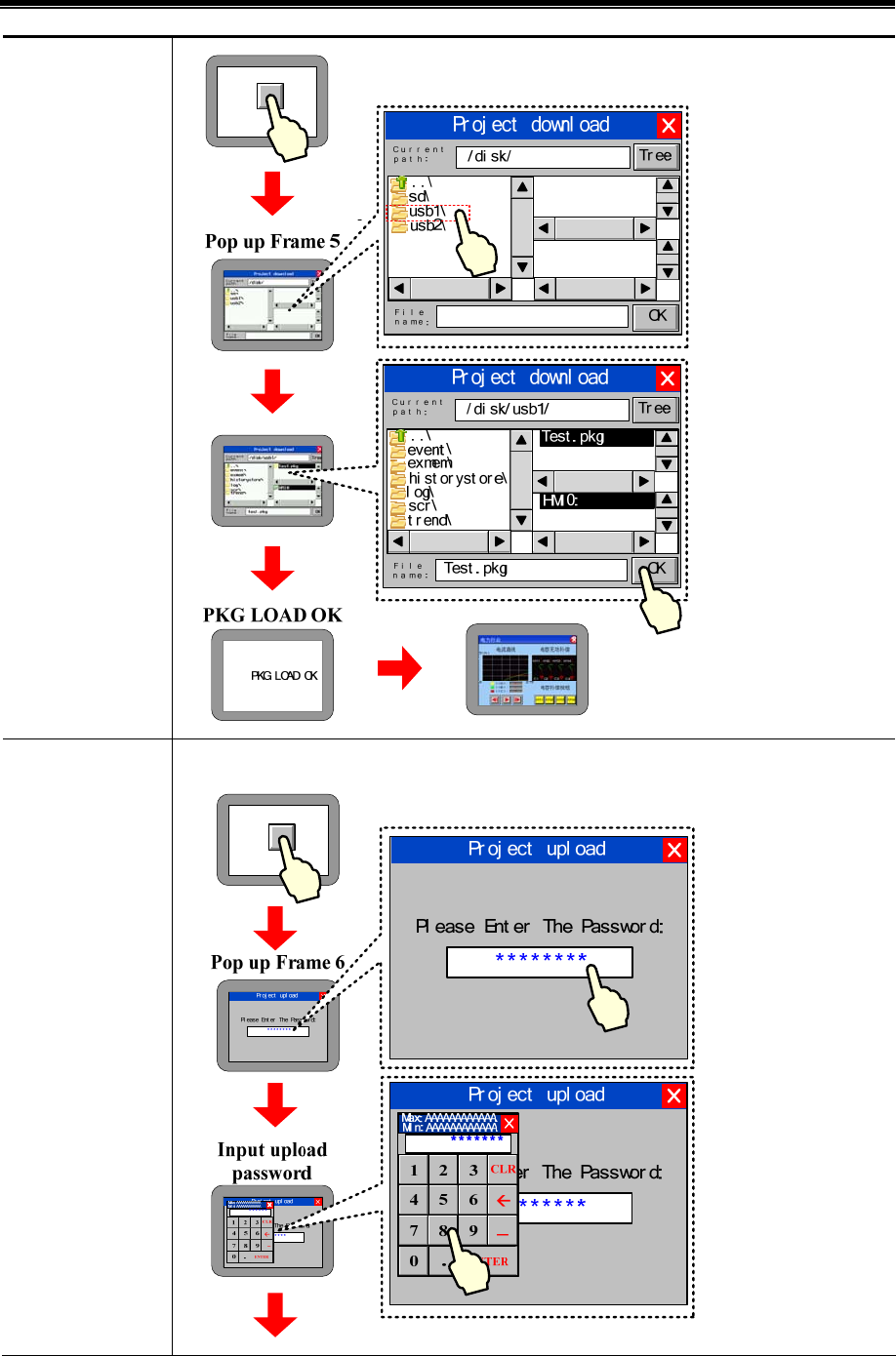
Advanced Part Component
163
Export Project from
HMI
Export the project(pkg file) in HMI to extended memory
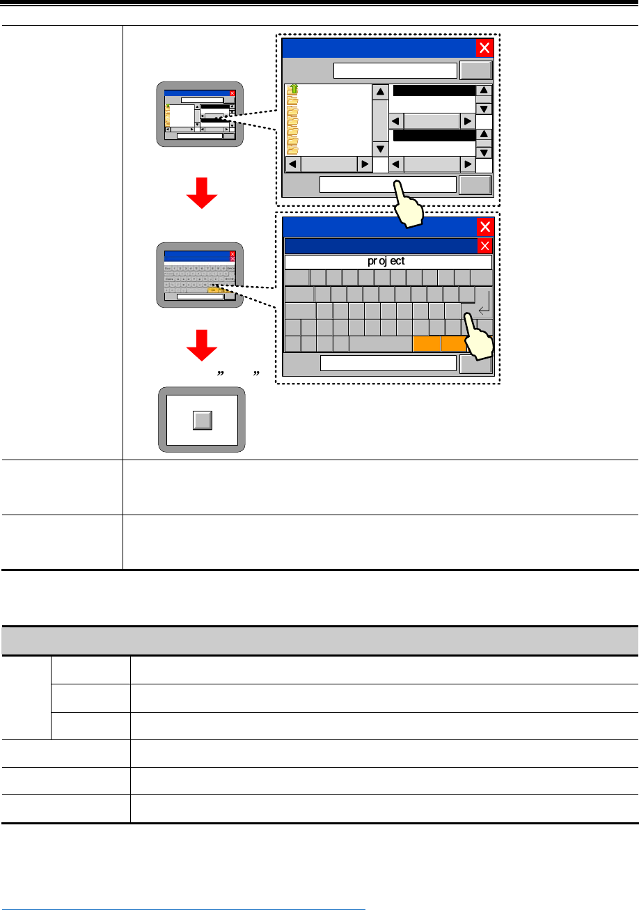
Kinco HMIware Configuration Edit Software
164
Pop up Frame 5 and
select save path
Input file name
After press OK
Pr oj ect upl oad
..\
event \
exmem\
hi s t or yst or e\
log\
scr \
t r end\
Tes t . pkg
HMI0:
Current
path:
Fi le
name:
Tr ee
OK
/ di sk / usb1/
Tes t . pkg
Pr oj ect upl oad
..\
event \
exmem\
hi st or yst or e\
l og\
scr \
t r end\
Test.pkg
HMI0:
Current
pat h:
File
name:
Tr ee
OK
/ di sk/ usb1/
Test.pkg
Pr oj ect upl oad
..\
event \
exmem\
hi st o ry st or e\
log\
scr \
t r end\
Test . pkg
HMI0:
Cur r ent
path:
Fi le
name:
Tr ee
OK
/ di sk / usb1/
Pr oj ect
Pr oj ect
Pr oj ect upl oad
..\
event \
exmem\
hi st or yst or e\
l og\
scr \
t r end\
Test.pkg
HMI0:
Cu r r e n t
pat h:
File
name:
Tr ee
OK
/ di sk/ usb1/
pr oj ect
v
ESC 1234567890
BACK
Clear qwertyuiop
asdfghj kl
=|?zxcvb
nm
;{
}
+_>< CH Page
Up Page
Down
ENT
Caps
Import Recipe to
HMI
Import the recipe file (.rcp) in extended memory to HMI. The operation steps are the similar with
Import Project to HMI
Export Recipe from
HMI
Export the recipe file (.rcp) in HMI to extended memory. The operation steps are the similar with
Export Project from HMI
- Message Board
This function works with the Message Pad; it can be used as an assistant tool of Message Pad.
Description of Message Board
Pen Press the function key to set the tool as a pen for Message Pad
Erase Press the function key to set the toll as a eraser for Message Pad
Tool
Clear Block Press the function key to clear the selected area of the Message Pad
Pen Color Set color of pen
Pen Width Set width of pen, 1~8 pixel are optional
Clear Press function key to clear all content on Message Pad
- Print
Press function key to print the current screen.
☞For details about print, refer to [Advanced Part 4.15.5 PLC Control]
- Map Keyboard
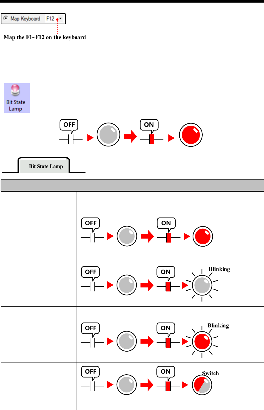
Advanced Part Component
165
Map the function key to the F1~F12 of the keyboard. This function is suitable for HMI with USB host only.
4.3 Lamp Component
4.3.1 Bit State Lamp
The Bit State Lamp is used to indicate the state (0 or 1) of bit register in HMI or PLC. It can display tag
text and graphic.
Detail description of Bit State Lamp
Function Description
Normal
Display the corresponding graphic according to the state. This graphic isn’t blinking
Value 1 Blinking on state 0,
value0 Showing state 0
The blinking frequency (Rate) can be set.
Value 1 Blinking on state 1,
value0 Showing state 0
The blinking frequency (Rate) can be set
Value 1 switch Blinking on state
1 and 0, value0 Showing state 0
Value 0 Blinking on state 0, The blinking frequency (Rate) can be set.
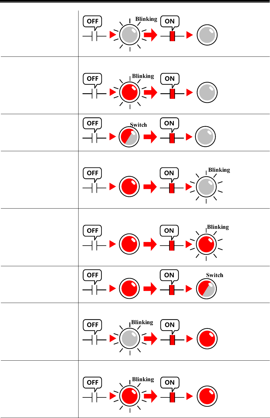
Kinco HMIware Configuration Edit Software
166
value 1 Showing state 0
Value 0 Blinking on state 1,
value 1 Showing state 0
The blinking frequency (Rate) can be set
Value 0 switch Blinking on state
1 and 0, value 1 Showing state 0
Value 1 Blinking on state 0,
value 0 Showing state 1
The blinking frequency (Rate) can be set
Value 1 Blinking on state 1,
value 0 Showing state 1
The blinking frequency (Rate) can be set
Value 1 switch Blinking on state
1 and 0, value 0 Showing state 1
Value 0 Blinking on state 0,
value 1 Showing state 1
The blinking frequency (Rate) can be set
Value 0 Blinking on state 1,
value 1 Showing state 1
The blinking frequency (Rate) can be set
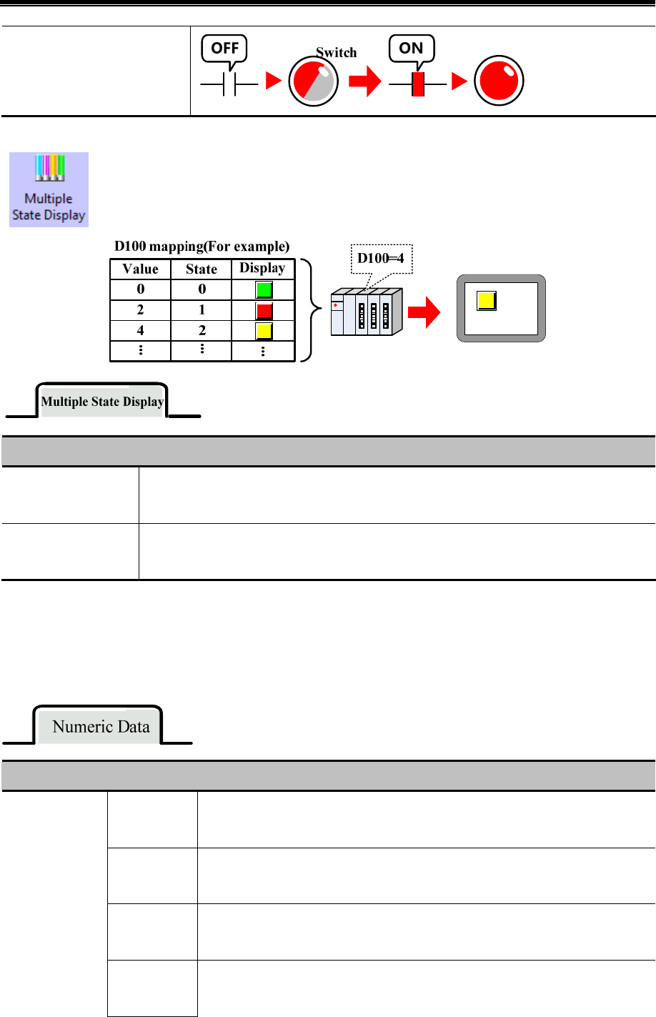
Advanced Part Component
167
Value 0 switch Blinking on state
1 and 0, value 1 Showing state 1
4.3.2 Multiple State Display
The Multiple State Display displays the mapping state according to the value in the specified HMI
register or PLC register. It supports 256 mapping states at most.
Description of Multiple State Display
State Num.
Set the state number of Multiple State Display, it is up to 256. (The BIN or BCD encoding
supports 256 state at most, and the LSB encoding supports 17 states at most)
Data Mapping
Set the mapping value of each state. When the value in specified register equals the setting value,
the component displays corresponding state
4.4 Number Components
Number components include Number Input Component and Number Display Component. They are used to write data to a
specified register or read data from a register and display this value.
- Common Attributes of Number Component.
Description of number
signed int
Display the data in signed decimal integer (0~9) format.16 bits data range:
-32768~32767; 32 bit data range: -2147483648~2147483647
unsigned int
Display the data in unsigned decimal integer (0~9) format.16 bits data range:
0~65535; 32 bit data range: 0~4294967295
Hex
Display the data in hex (0~F) format. The integer part can be set, no decimal. 6 bits
data range: 0~65535; 32 bit data range: 0~4294967295
Data type
Bin
Display the data in binary (0, 1) format. The integer part can be set, no decimal. 6 bits
data range: 0~65535; 32 bit data range: 0~4294967295

Kinco HMIware Configuration Edit Software
168
Password
Display data in “*” format. Only the data type and date width can be set, other
options are ignored
Float
Transform the 32 bits IEEE float data to decimal data and display in decimal. The
default data width is DWORD
Double
Transform the 64 bits IEEE float data to decimal data and display in decimal. The
default data width is 4-DWORD
Data Width Set the data width of the register 16 bits or 32 bits(WORD or DWORD)
Integer/Decimal Set the display bit number before and behind decimal dot
Show plus sign When the data type is signed int, click this option to display the “+” symbol before positive number
Max/Min Value
Setting
Set input/display range for Number Input/Display Component. “Variable Max/Min Value” checked
means that the Max/Min Value is variable, and set read register of this variable. The word length of this
register depends on the data width of component. For example, the Max/Min Value is LW0, if the word
width is WORD, the LW0 is minimum value register, LW1 is Maximum value register; and if the word
width is DWORD, the LW0 and LW1 are minimum value registers, LW2 and LW3 are the maximum
value registers
Off normal
upper/lower
If the data is exceeds the Max/Min Value range, the component will display the data in the setting
color.
Flash
If the value in certain register exceeds the upper limit or lower limit, the data in the component will be
flashing to enhance the alarm effect.
Proportion
Conversion
The data will be displayed after calculating by proportion, the Min Value and Max Value is must be set
in the function. For example, the original data is A, and the displaying data is B. Then the relationship
between is as followings:
B= Min Value+(A-Min)*Proportion and the Proportion=( Max Value -Min Value)/( Max-Min)
For example the original data is 20, according to the following setting, the displaying data is
15+(20-0)*(55-15)/(100-0)=23. So the component displays 23
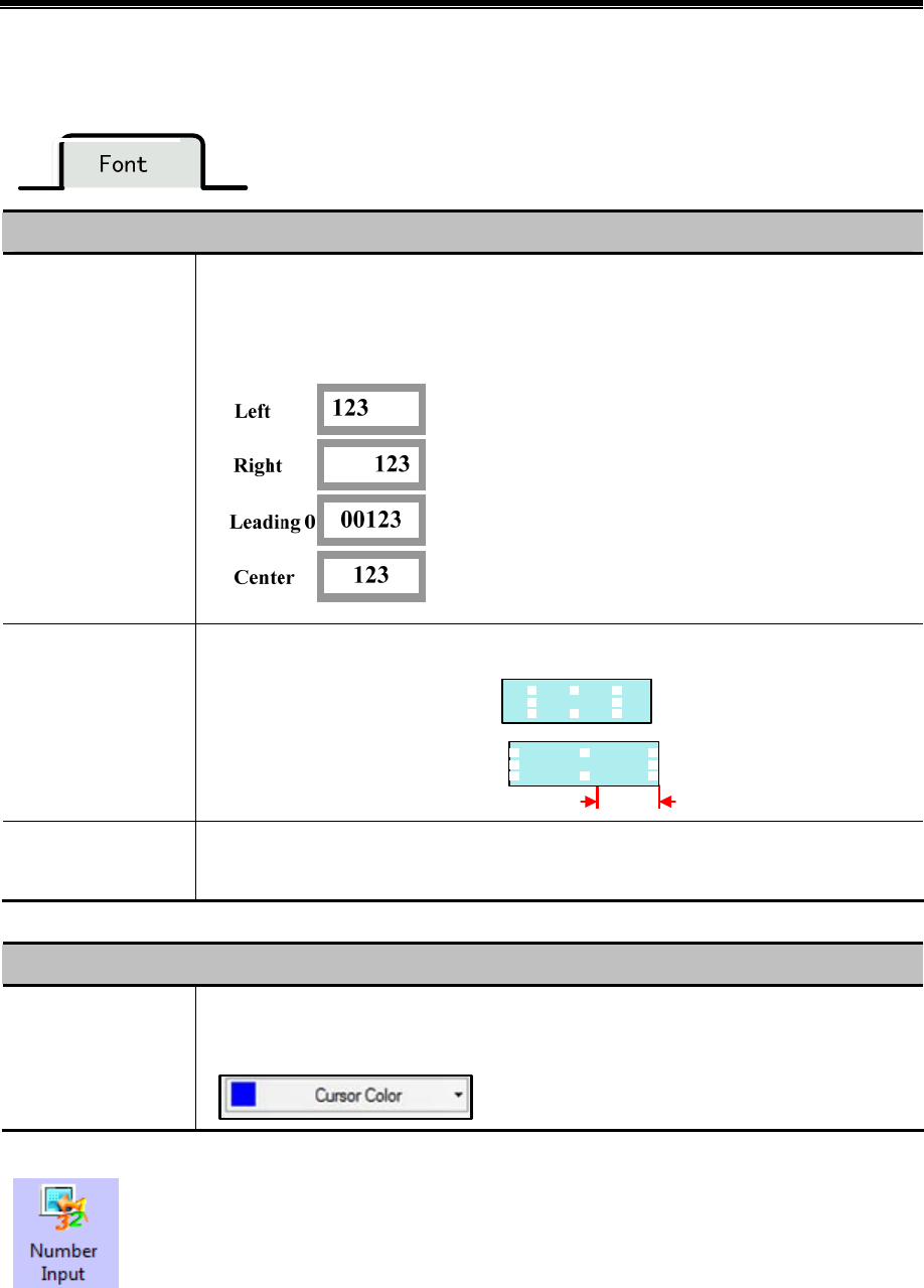
Advanced Part Component
169
※ For signed/unsigned int, if the Decimal is set, the original data will be displayed after left shift the Decimal bits, but also
set the original data to the register.
Description of Font
Alignment
Set the display position of data,, it has for methods , they are Left, Right, Leading 0, Center.
For example, the Integer is 5, Decimal is 0, input value is 123, then the following are the
displaying in four different methods:
Font Adjustment
Add the width of display area, the units is pixel
Horizontal Increased 0 pixel
60
px
#####
#####
Horizontal Increased 60 pixel
Key
Map the component to the F1~F12 of external keyboard or F1~F8 of the HMI which has keys
itself. This function is suitable for the HMI with USB host or HMI with keys itself
- Related Attributes Setting of Numeric Data
Other Related Attributes
Cursor
Set the Cursor Color when Numeric Data is triggered in the HMI Extended Attributes of HMI
Attributes.
4.4.1 Number Input
Number Input Component write the data in value to the certain HMI or PLC register, at the same time
display the written date on HMI.
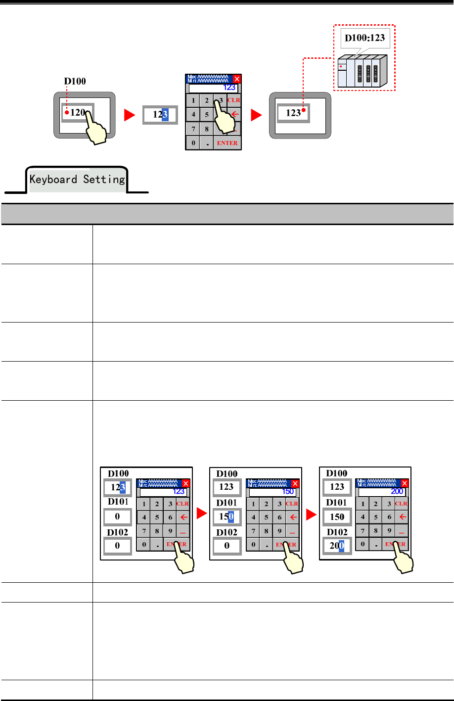
Kinco HMIware Configuration Edit Software
170
Attributes Description of Keyboard Setting
Public Windows
Keyboard
Use the Public Windows Keyboard
It is the default setting , and use the keyboard in Frame3: NUM Keyboard
Specified Keyboard
Use the specified keyboard in designated window. If use the self-made keyboard, the window
where the keyboard is should set the Keyboard Page in Window Attribute, so the window number
can be displayed in the Specified Keyboard list
Keyboard Pop-Up
Position
Set the keyboard pop-up position on HMI
Do not Use Pup-Up
Keyboard
When the Number Input Component is triggered, do not pup up keyboard. The HMI supports
USB can use the external keyboard
Use Input Order
The popped-up keyboard can input data to the components continuously by order. During the
input operating, the keyboard will not disappear when press ENTER, and the input cursor will
flash among the component in circle. The keyboard will be closed by press Close button
Input Order Set the input order number for the component
After Input Is
Completerd, No
Longer Sequentialy
Input
No more sequent input once it is completed once and the keyboard is shut of
Group For multiple groups of components that need input the data continuously, the first triggered
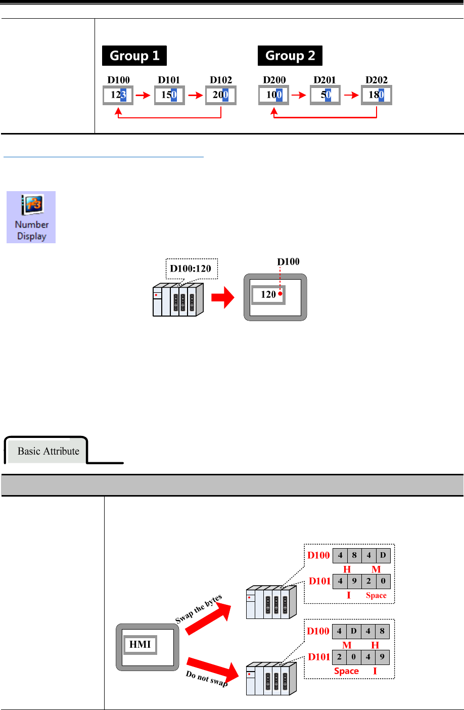
Advanced Part Component
171
component decides where the cursor circles
☞For details, refer to [Advanced Part 2.4 Keyboard]
4.4.2 Number Display
Number Display is used to display the value in specific HMI or PLC register on HMI.
4.5 Text Components
The text components contain Text Input, Note Book, Text Display, they are used to decode the data by ASCII then write it to
specific register in character string or read data from specific register then display it in character string after the data
decoded by ASSIC
- Common Attributes Setting of Text Components
Common Attributes Description of Text Component
High byte and low byte
swaps
Swap the high byte and low byte, then display the high byte on the left and low byte on the
right
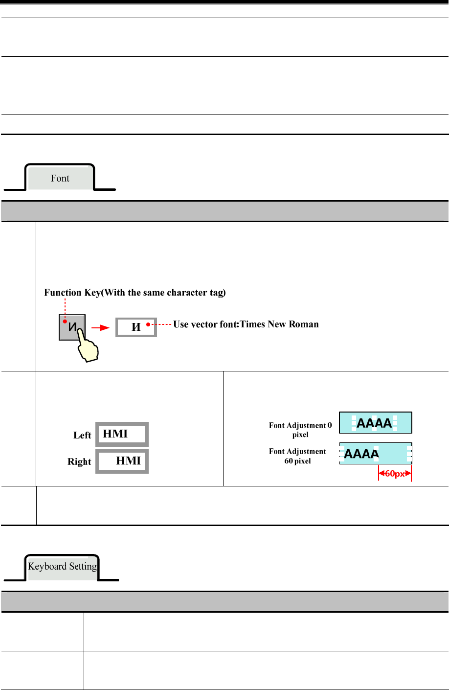
Kinco HMIware Configuration Edit Software
172
Unicode
If checked, the text content is decoded by Unicode and displayed. It is usually used to display
multiple languages
Extended ASCII
This mode can display the extended ASCII character between 0X80~0XFF. If checked, the text
cannot display Chinese character; the Unicode and Extended ASSCII cannot be chosen at the
same time
Word Length The word length is 1~16 optional. Each word contains 2 ASCII characters
Description of Font Attribute
Font
Type
Use the Vector Font or Dot Matrix Font to display character string
Note: Generally speaking, if it is not ASCII character, it cannot be displayed by vector font, but the Unicode
character input by Unicode keyboard with sane character tag can be displayed by vector font. For example:
Align
ment
Set the displaying position of character string,
including two methods: Left, Right.
Font
Adjust
ment
Add the display area width at the right side, the
units is pixel.
Key
Map the component to the F1~F12 of external keyboard or F1~F8 of the HMI which has keys itself. This function
is suitable for the HMI with USB host or HMI with keys itself
Description of Keyboard Setting Attributes
Public Windows
Keyboard
Use the public windows keyboard, the default keyboard is the [Frame3:NUM Keyboard]
Specified Keyboard
Use the keyboard in specified window. The default keyboard is the [Frame 4:ASCII Keyboard] If
you use the self-regulating keyboard, you should set the Special Attribute in HMI Attribute to
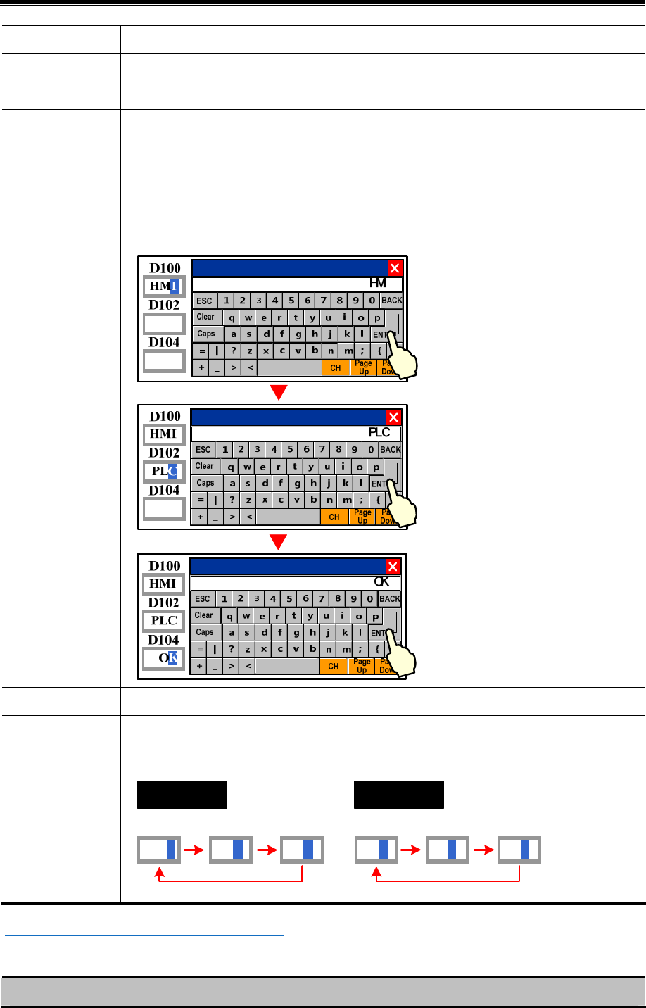
Advanced Part Component
173
Keyboard Page, then you can select the Window’s number in Specified Keyboard list
Keyboard Pop-up
Position
Set the position of the pop-up window in the screen
Not Use pop-p
Keyboard
Do not pop up keyboard when trigger text input or text book component, but use the external USB
keyboard if the HMI supports the USB host
Use Input Order
Input the component continuously when the keyboard is popped up, the keyboard will not be closed
when press the ENTER key during the inputting, the input cursor will flash in cycle among the
components that set the Input Order, the keyboard will be closed when click the Close button
Input Order Set the input order for the components
Group
Sort the components that need to input continuously in different groups, the first triggered
component decides which group the cursor will flash among
Group 1
HMI
D100 D102
PLC
D104
OK
Group 2
100
D200 D202
50
D204
180
5 ☞For details, refer to [Advanced Part 2.4 Keyboard]
- Related attributes settings about the Text component
Description of related attributes
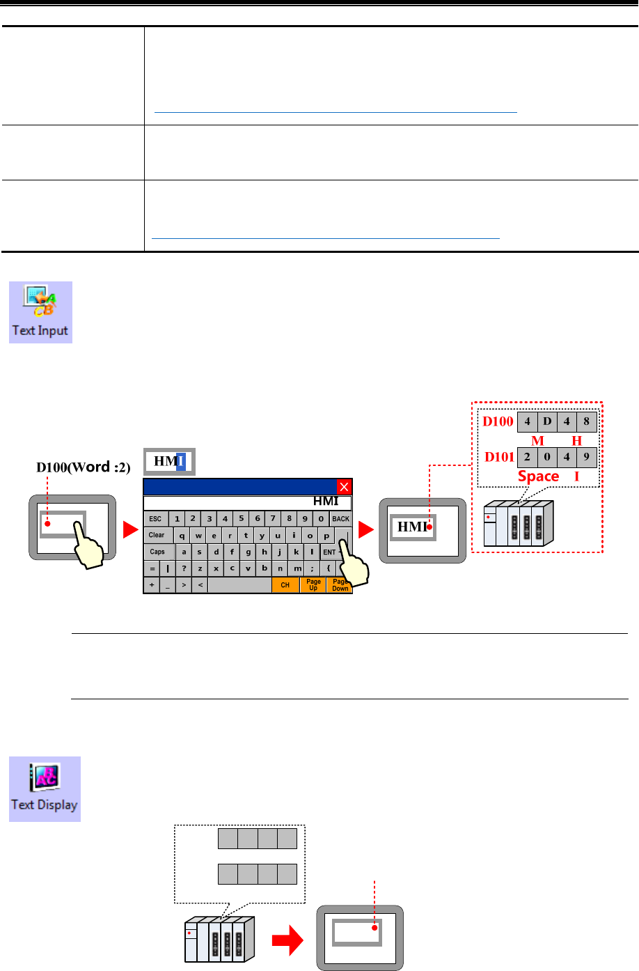
Kinco HMIware Configuration Edit Software
174
Cursor Color
Set the cursor color when the Text Input component or Note Book component is triggered in
the HMI Extended Attributes of HMI Attributes
☞For details, refer to [Advanced Part 6.1.3 HMI Extended Attributes]
Cursor Move
Use the Keyboard Function in the function key to move the cursor Refer to Advance Part ☞
4.2.6 Function Key for more information.
Text Operation
Use the Keyboard Function in the function key to select, copy, cut, and paste the text content.
☞Refer to Advanced Part4.2.6 Function Key for more information.
4.5.1 Text Iput
The Text Input decodes the data according to ASCII, and then writes it to the HMI or PLC register in
character string, at the same time displays the written data in character string on HMI. The written data is
saved in the continuous registers that begin from “Read Address”. When displaying the data, the low byte
characters are displayed on the left and the high byte characters are displayed on the right.
The Text Input component cannot display the multiple rows text content
4.5.2 Text Display
The Text Display component displays the HMI or PLC data in character string on HMI after decoding it
according to the ASCII.
HMI
4 D 4 8
2049
MH
ISpace
D100
D101 D100(Word No.:2)
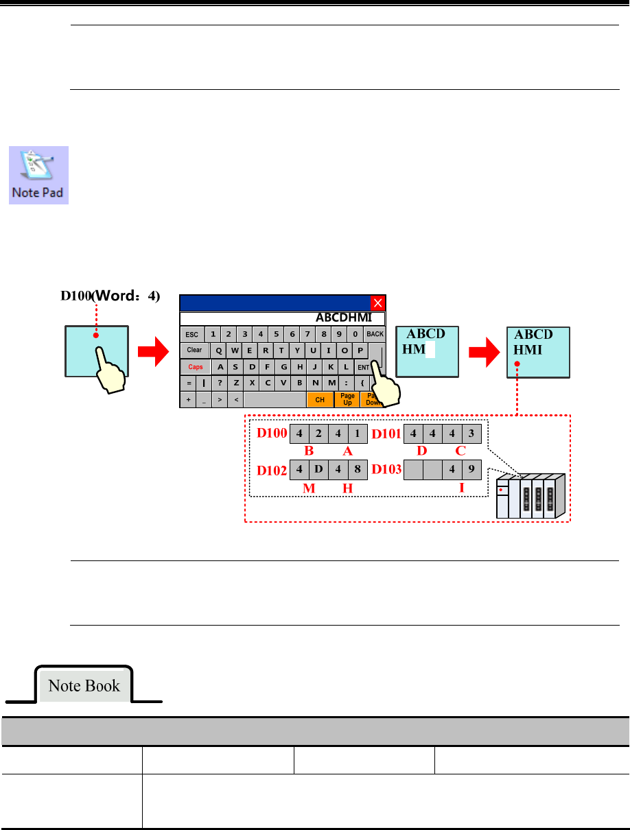
Advanced Part Component
175
The Text Display component cannot display the multiple rows text content
4.5.3 Note Book
The Note Book is the same as the Text Input; they decode the data according to ASCII, and then write it to
the HMI or PLC register in character string, at the same time displays the written data in character string
on HMI. The written data is saved in the continuous register that begins “Read Address”. When displaying
the data, the low byte characters are displayed on the left and the high byte characters are displayed on the
right.
The Note Book component can display the multiple rows text content
Description of Note Book attributes
Total Lines The total lines of input text Display Line Display area line
The Word Register
Number of Per Line
The most data length per line, the unit is word. A length of a ASSIC character is a byte, and
1word = 2 bytes
4.6 Graph/Meter Components
In Kinco HMIware, customer can display the data in chart/graph. The graph/meter components contain Trend Curve, XY
plot, Oscillograph, Bar Picture, Meter and so on.
The Trend Curve, XY plot and Oscillograph are graphs; they are usually used to display data in a single or a series of
continuous registers in graph on HMI. The customer can use them according to their function and actual application.
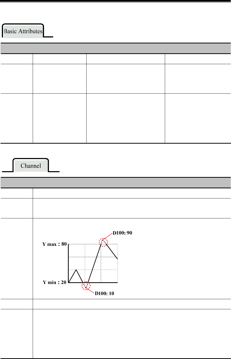
Kinco HMIware Configuration Edit Software
176
- The common attributes of graph setting.
Description of Basic Attributes
Component Trend Curve XY Plot Oscillograph
Read Address
Set the sampling register
address of the first
channel
Set the sampling register address of the
first channel. The address assigning
depends on the type of XY plot
Set the sampling register address
of the first channel
Word Length
It depends on the
sampling channel number,
if the channel is
m,(m<17), the word
length is m
The word length depends on the
channel number, sampling points, XY
plot type and the read register type. The
user can not change this
It depends on the channel
number and sampling rate. If the
channel number is m(0<m<17)
and sampling rate is n(0<n<256),
the word length is m*n
Detail description of channel attributes.
Line Width Display the width of the curve
Data Type
Set the data format of sampling data. It contains 16-bit signed, 16-bit unsigned, 32-bit signed, 32-bit
unsigned, float and double
Y max/Y min
Set the display range of sampling data on X axis and Y axis
Color Set the color of curve
Channel use
variable limit
The Y max/Y min value is from specified registers. In multiple channel application, user can set specified
registers for Y max/ Y min of each channel. Trend Curve: if the Specified Address is Y min; the Specified
Address+1 is the Y max. XY plot: if the Specified Address is Y min, the Specified Address+1 is the Y
max, the Specified Address+2 is the X min and the Specified Address+3 is the X max. Oscillograph: if the
Specified Address is Y min, the Specified Address+1 is the Y max
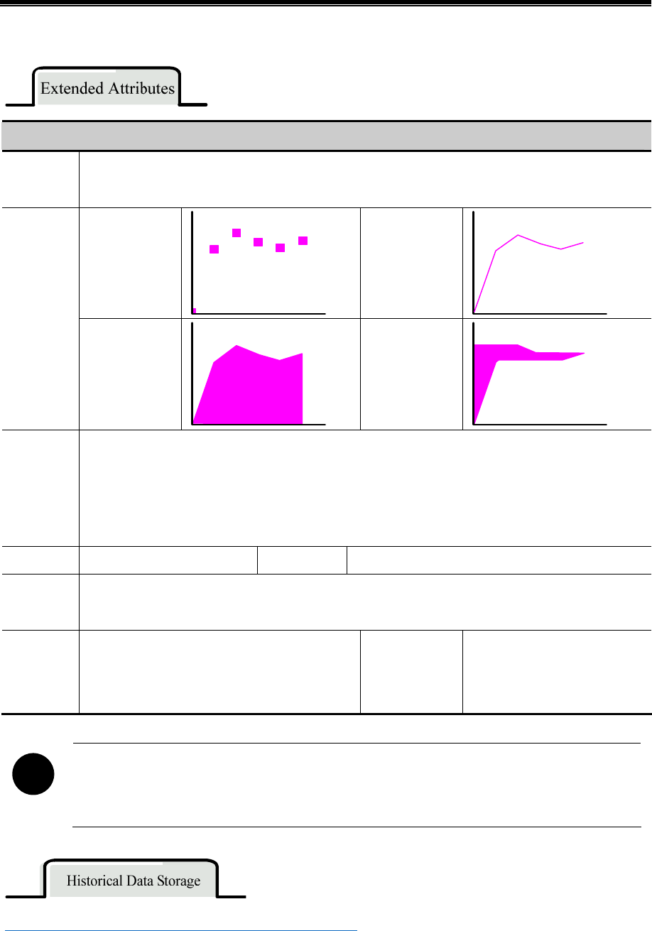
Advanced Part Component
177
Detail description of extended attributes
Channel
Properties
Chose a channel to edit. The available channels depend on the channel number set in Trend Graphics or XY
Curve Graphics or Scope Chart page. And set the line style and line width
Dot
Line
Connect
Style
X axis
projection
Y axis
projection
Node
Graph
Chose the graph of nodes, the following six types are available
●▲■○ᇞ□×
Node Size Set the size of node Node Color Set the color of node
Use Grid
The curve use the background and grid, users can set the line and row number, as well as the line width ,
color and type
Va ri a bl e
Period
When use the Time sampling, the Circle time can
be read from specified register. Note: The
Oscillograph does not support variable period
Number of
points
The number of sampling points
can be read from specified
register
!
If the circle period and sampling point number use the variable value, the variable value will be used in
priority. And the default value will be used if the variable value cannot be got because of the
communication problem
☞For details, refer to [Advanced Part 4.1.10 Save Historical Data]

Kinco HMIware Configuration Edit Software
178
!
The Trend Curve and Historical Data Display can be used at the same, but when the trend curve and
historical data display sample the same register and the data is saved in external device, the Subdirectories
should be different, or the only save historical data in just one of the component
- About the display of curve.
The Trend Curve and XY plot run at the backstage, the trend curve and XY plot will not be cut off when changing the frame.
On the other hand, the Oscillograph does not support running at backstage; the data sampling and curve will be cut off
when changing the frame.
The special attributes of these curves are as follows.
4.6.1 Trend Curve
The Trend Curve reads a series specified continuous registers (in HMI or PLC) in period and display them
in curve. The new data will be read from specified registers and displayed at the right/left/top/down side
of curve, it is a real-time curve.
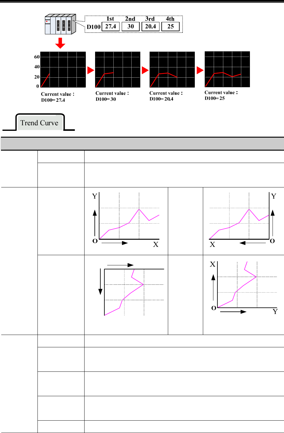
Advanced Part Component
179
Detail description of trend curve attributes
Single page Only display the sampling value in current page, there is no extended curve
Type
Multiple pages
There is extended curve. When the curve goes on, the previous sampling data will not
disappear. The historical data will be stored in the buffer area
Start from left
Start from
right
Attributes
Start from top
X
Y
O
Start from
bottom
Time sampling Sample the date timely
OFFON trigger
sampling
The sampling will be triggered when specified register changes from OFF to ON
ONOFF trigger
sampling
The sampling will be triggered when specified register changes from ON to OFF
OFFON
trigger sampling
The sampling will be triggered when specified register changes
Sampling
Methods
OFFON reset The sampling will be triggered when specified register changes from OFF to ON. And
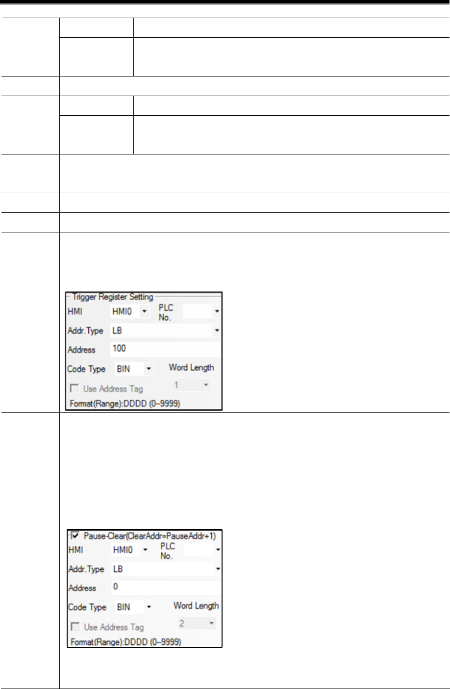
Kinco HMIware Configuration Edit Software
180
trigger sampling the specified register will be reset to OFF automatically
ONOFF reset
trigger sampling
The sampling will be triggered when specified register changes from ON to OFF. And
the specified register will be reset to ON automatically
Cycle The time interval between two sampling points. The unit could be 1s or 100ms
Continue The sampling will continue even the all sampling points are finished
Sam.Type
Once
The sampling will stop automatically when all the sampling points are finished, the
sampling executes only once
Sampling
points
Sampling points on each page
PageNum This option is valid in the Multiple Page type
Channel The number of the channel, it is 16 channels at most
Control
Register
Setting
This option is valid in the trigger sampling .Take the following picture for example, the LB100(bit register
in the HMI) is the trigger register, when the LB100 satisfies the setting condition in the Sampling Method ,
the sampling will be triggered
Pause-Clear
Set the Pause and Clear register, the default word length is 2, the set address is used to stop the curve, and
the set address +1 is used to clear the curve. The Pause function just stops the change of curve, but not
stops the sampling. The Clear function will clear the curve on the Trend curve. Take the following picture
for example, the LB0(bit register in HMI) is set to control the Pause-Clear function, when the LB0 is
ON , curve will stop refreshing, when the LB0 is OFF , the curve will continue to display, when the LB1
is ON the curve on the Trend Curve will be cleared
SCRO
Set the register to turn the page of Multiple Page curve, default word length is 3. This option is valid when
the Multiple Page is chosen. Use this function to browse multiple page curves, and this function can be
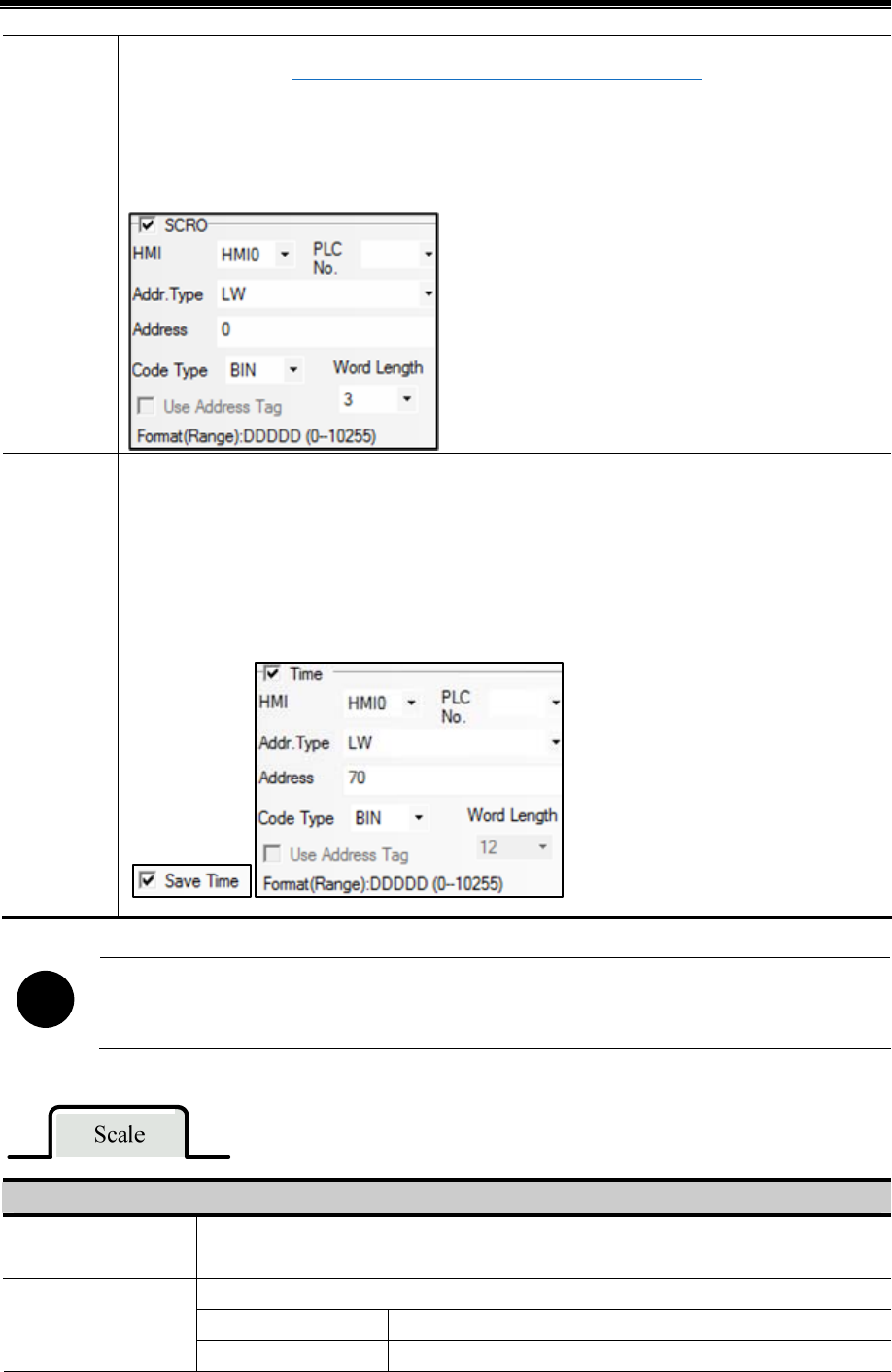
Advanced Part Component
181
used with Scroll Bar. ☞For details, refer to [Advanced Part 4.16.3 Scroll Bar]
Take the following picture for example, if the specified register is LW0(word address in HMI), so the LW0
is the current browsing index value of scroll bar, the LW1 is the start browsing index value, and the LW2
is the max browsing index value
Time
This option is used to save the start sampling time and end sampling time of current page, this option is
valid when the Save Time option is chosen. Default word length is 12. Take the following picture for
example, if the specified address is LW70(word register in HMI), the start time of current time (second,
minute, hour, day, month, year) are LW70, LW71, LW72, LW73, LW74, LW75. The end time of current
page (second, minute, hour, day, month, year) are LW76, LW77, LW78, LW79, LW80, LW81
!
If “Use scroll bar” is selected in [Trend Graph Component Attribute]-[Scale], the [Scroll] cannot be selected
in [Trend Graph Component Attribute]-[Trend Graphics].
Description of Scale attributes
Use Scroll Bar The trend curve uses the system scroll bar, user can set the scroll bar width, the width range is
20~120, units is pixels.
The trend curve uses the system vertical axis scale.
Scale color Set the color of vertical color.
Use Vertical Axis Scale
Display Scale Frame Display the scale frame or not.
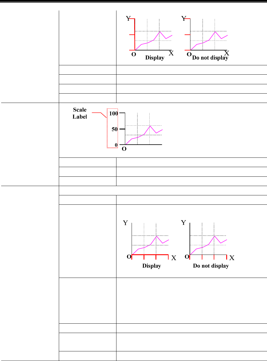
Kinco HMIware Configuration Edit Software
182
Major Scale Number Set the major scale number.
Major Scale Length Set the major scale length, the unit is pixels.
Minor Scale Number Set the minor scale number.
Minor Scale Length Set the minor scale length, the unit is pixels.
Label Font Set the label font
Integer The integer number of scale (User cannot adjust it ).
Use Scale Label
Decimal The decimal number of scale (User cannot adjust it ).
Trend Curve displays the horizontal scale.
Scale Color Set the vertical scale color.
Display Scale Frame Display the scale frame or not.
Time scale interval The time interval between two time scale point, the unit is sampling
circle, for example, if the Time scale interval is 3, the time interval
between two scale point is three sampling circles’ time. So the
displayed scale number depends on the sampling points number and
time scale interval.
Length Set the length of time scale, the unit is pixel.
Mark each sampling
point scale
Mark a scale on each sampling point
Use Horizontal Axis
Time Scale
Length Set the length of each sampling points, the unit is pixel.
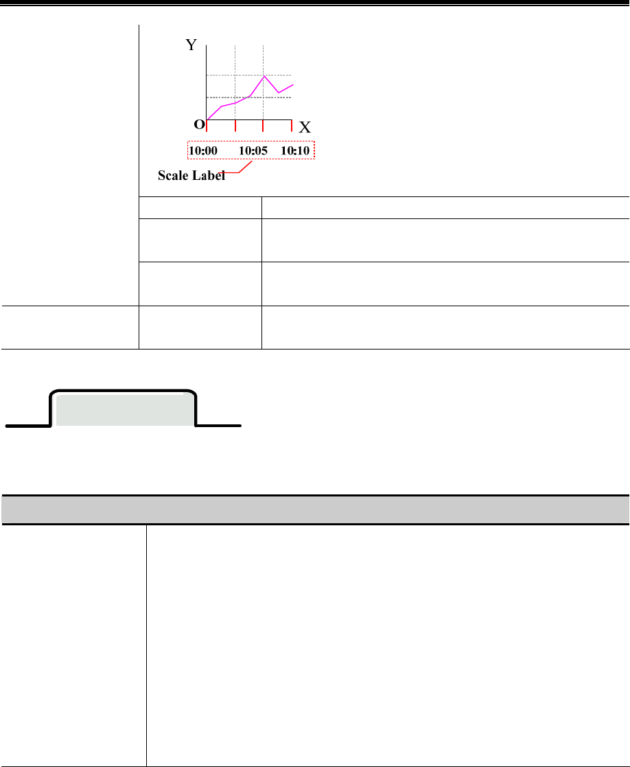
Advanced Part Component
183
Label Font Set the scale label font
Time Display and set the time format, there are three formats: HH:MM:SS、
HH:MM、HH:MM:SS:MS
Use Scale Label
Date Display and set the date format, there are three formats:
DD*MM*YY、MM*DD*YY、YY*MM*DD. Separator: /、—、.
Vertical Axis Scale
Reference Channel
Channel The max/min of vertical axis is based on the max/min of specified
channel.
History Data Query
Select “History Data Query” in [History Data Query] of [Trend Graph Component Attribute], then set Query Address and
Query Trigger Address to make history data query function for trend graph.
Description of History Data Query attributes
Query Address
History data query address, the word length is 8.
Start Date: Specified address, word length is 2, input year and date in this address.
Start Time: Specified address+2, word length is 2, input time (hour, minute and second) in this
address.
End Date: Specified address+4, word length is 2, input year and date in this address.
End Time: Specified address+6, word length is 2, input time (hour, minute and second) in this
address.
Take the following picture for example, the specified address is LW200, and user wants to
query the data between 9:30:40 14th, Aug, 2012 and 14:16:30 15th, Aug, 2012.
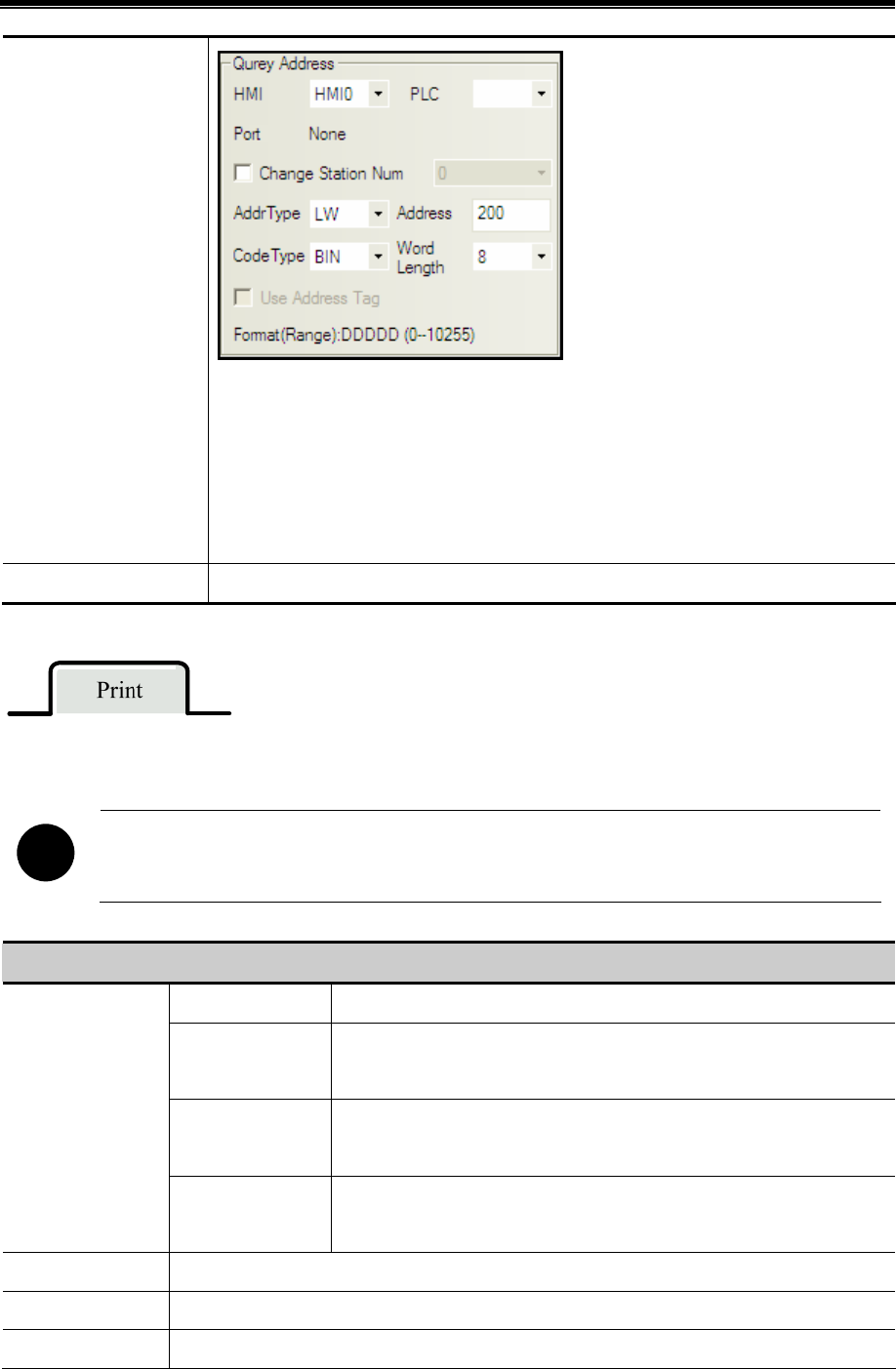
Kinco HMIware Configuration Edit Software
184
So the Specified address are as follows:
Start Date: LW200=20120814
Start Time: LW202=93040
End Date: LW204=20120815
End Time: LW206=141630
Query Trigger Address When the specified address status is on, the trend will trig query function.
If the Open printing option is checked, the trend curve can be printed in real-time.
!
The real-time printing in Trend Curve only supports micro printer
Description of printing attributes
Print per point The printing is triggered by every sampling point
Print per page
The printing is triggered when all the sampling points on a whole page is
finished
Print whole
The printing is triggered after all the sampling points on all pages are
finished in multiple page trend curves
Mode
Trigger by register
The printing is triggered when the specified register satisfies the setting
condition
Paper Width Set the paper width according to the printer
Step The pixel between two small grids
Vertical axis scale Set the standard channel of vertical axis scale. That is to say set the upper limit and lower limit of

Advanced Part Component
185
reference channel vertical axis
Time Mode Set the display time mode of horizontal axis. Two modes are optional: HH:MM、HH:MM:SS
OFFON
If chose the Trigger by register in the Mode, the printing will be triggered
when specified register changes from OFF to ON
ONOFF
If chose the Trigger by register in the Mode, the printing will be triggered
when specified register changes from ON to OFF
OFFON
If chose the Trigger by register in the Mode, the printing will be triggered
when specified register changes its state
OFFON(Reset) If chose the Trigger by register in the Mode, the printing will be triggered
when specified register changes from OFF to ON, then the register will be
reset to OFF automatically
Trigger Style
ONOFF(Reset)
If chose the Trigger by register in the Mode, the printing will be triggered
when specified register changes from ON to OFF, then the register will be
reset to ON automatically
Print axis The horizontal axis and vertical axis of printing. The line type, line width and axis color can be set
Print horizontal
axis(time)
The display time interval (show time), font size and color can be set. The show time means the
display interval between the previous printing time and the next printing time, the unit is sampling
points
Print vertical
axis(scale)
Print vertical axis has two forms: Percentage and Sampling value. The font size and color of vertical
axis are changeable
Print baseline
The baseline is the standard line in horizontal direction. Two baselines can be printed at most. The
base line value, baseline type, line width and baseline color can be set. The baseline value is
suggested not to exceed the limit of standard channel
!
This function is valid only when the Open Printing is checked
Description of Print Trigger Line Attribute
Trigger Register When value of specified register changes, print a trigger line
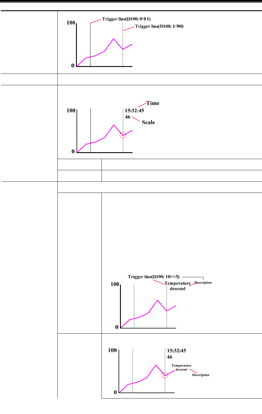
Kinco HMIware Configuration Edit Software
186
Line Type/Width/Color Set the type, width and color of trigger line
Set the time and scale of trigger line
Font Size Set the font size of trigger line time and scale font
Print line scale/time
Font Color Set the font color of trigger line time and scale font
Set the comments information of print trigger line
Trigger Line State
Num
Set the state number and corresponding value of trigger state description,
1~256 are optional. For example, set the trigger line state Num to 3, the
corresponding value are 0, 1, 2. And the value 0 corresponds to description
“temperature rise”, the value 1 corresponds to description “temperature
unchanged” and value 2 corresponds to description “temperature descend”
When the value of specified register is 2, the trigger line and
corresponding description will be printed
Print state description
Position of
description
Top:
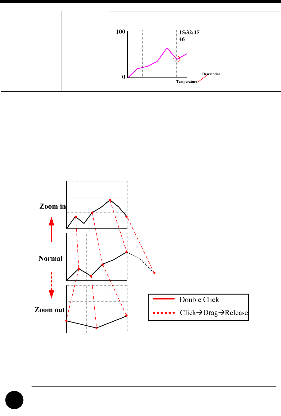
Advanced Part Component
187
Bottom
【Extend application of Trend Curve】
- View and zoom function
Use the LB9110 to open or close the zoom function. When the LB9110 is ON, the zoom function will be opened.
Zoom out view: In multiple pages trend curve and the page number is more than 1. When LB9110 is ON, double click on the
trend curve screen to zoom out the curve.
Zoom in view: When LB9110 is ON, drag the mouse to select a section curve to view the zoomed in curve.
- Cursor function
The system special register LB9111 can enable the cursor function. When LB9111 is on, user can touch and trag the cursor to
the data point that user want to select.
!
The priority of LB9111 is higher than LB9110. If LB9111 is on, the zoom function will be disabling.
- Sampling time and sampling coordinates query function.
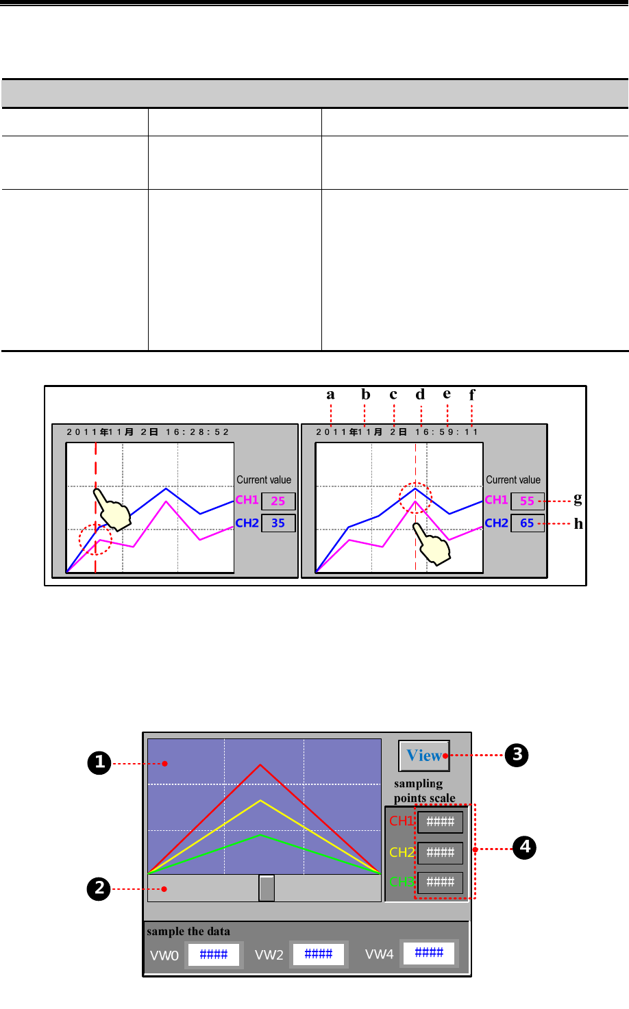
Kinco HMIware Configuration Edit Software
188
When the LB9110 is ON, customer can query the sampling time and sampling coordinates by system registers. Related
system registers are as follows::
Description of related system registers
Special register address Function Description
LW9200~LW9205
Display the viewed sampling
point time of trend curve
These registers are second, minute, hour, day, month, and
year. The Code Type is BIN
LW9210~LW9210+N
Display the coordinates of
viewed sampling point
N means the channel number, display the Y coordinates of
viewed sampling point in each channel. For example the
channel is 2, the LW9210 displays the Y coordinate value
of current viewed sampling point in channel 1, and the
LW9211 displays the Y coordinate value of current viewed
sampling point in channel 2
Take the following picture for example
a. Number Display,LW9205 b. Number Display,LW9204 c. Number Display,LW9203
d. Number Display,LW9202 e. Number Display,LW9201 f. Number Display,LW9200
g. Number Display,LW9210 h. Number Display,LW9211
Take MT5320T communicating with SIEMENS S7-200 for example, sample the data in VW0, VW2, VW4 and draw them in
a curve, at the same time the sampling points scale can be viewed.

Advanced Part Component
189
Build a new Trend Curve component, the component attribute is as followings:
Basic Attribute
Read Address VW 0(PLC register)
Trend Graphics
Type Multiple Pages
PageNum 10
Channel 3
SCR0 Checked, address: LW 0(HMI local register)
Channel
No. 0 Y Min/Max: 0/500 Color:■(Red)
No. 1 Y Min/Max: 0/500 Color:■(Yellow)
No. 2 Y Min/Max: 0/500 Color:■(Green)
Extended Attributes
Use Grid Checked, Lines/Columns: 3/3, Background color: ■(blue-gray),
Grid color: □(white), Grid Line Style:- - -
Save Historical Data
Save to recipe data field Checked, Start address: 0
Add a Scroll Bar component to turn page of the historical curve, the setting is as followings:
Basic Attributes
Write address LW 0 (HMI local register)
Scroll Bar
Background Image Vector Graphics, CONFIRM.vg
Button Image Vector Graphics, CTRL_BAR001.vg
Scroll Bar Extended Attributes
Max/Min Value Setting 0/100
Variable Max/Min Value Unchecked
Add a Bit State Switch to zoom the curve, the setting is as follows:
Read/Write Address LB 9110(special system register in HMI)
Switch Type Toggle
Tag Use Tag checked; 0: View; 1: Cancel
Font Use Font Graph: Times New Roman, Size 12, Center, Blue.
Graphics Vector Graphics checked: CONFIRM.vg
Add three Number Display components to display the value of current sampling points, the setting is as follows:
Read Address LW 9210/LW 9211/LW 9212(special system register in HMI)
The effect is as follows:
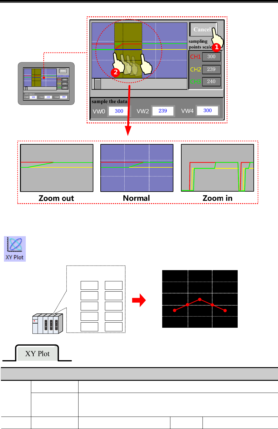
Kinco HMIware Configuration Edit Software
190
4.6.2 XY Plot
XY Plot read a series of continuous registers from specified HMI local registers or PLC/Controller
registers in a period, and plots them in dual axle curve, it can reflect the relationship of two variables.
(X-axis)
D100
5
10
15
20
25
(Y-axis)
D101
30
40
50
40
30
1st
2nd
3rd
4th
5th
100
80
60
40
20
00102030
Detail explanation of XY Plot attributes
Single Page Only display the data change information of current page, there is no curve extension.
Type
Multiple Pages
There is XY plot extension, each channel can be saved, when the XY plot extends, the
historical sampling data will not be lost, but save in the buffer area.
Attributes Standard Invalid Track Invalid
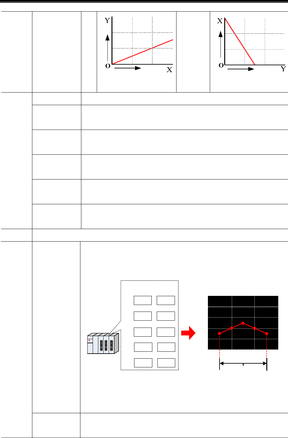
Advanced Part Component
191
Trend
Hor
izo
ntal
Vertical
Time Sampling Sample data periodically.
OFFON trigger
sampling
When specified register changes from OFF to ON, then trigger the sampling.
ONOFF trigger
sampling
When specified register changes from ON to OFF , then trigger the sampling.
OFFNO
trigger sampling
When specified register changes its state , then trigger the sampling.
OFFON reset
trigger sampling
When specified register changes from OFF to ON, then trigger the sampling. The
specified register will be reset automatically after being triggered.
Sampling
Method
ONOFF reset
trigger sampling
When specified register changes from ON to OFF, then trigger the sampling. The
specified register will be reset automatically after being triggered.
Cycle The time interval of the two pages or two sampling points. The unit can be s or 100ms.
Standard
Sampling multiple points every time or in each period, with X and Y components. The
register number is related to the channel number and sampling number. For example,
there is m channels and n sampling points, that is to say, the register number is m*n*2.
D100
5
10
15
20
25
D101
30
40
50
40
30
1st
2nd
3rd
4th
5th
D102 D103
D104 D105
D106 D107
D108 D109
(X-axis) (Y-axis)
100
80
60
40
20
00102030
One Cycle
Example, suppose the Read Address is D100, and there is 1 channel, 5 sampling points
in each page; so this XY plot will take 10 registers. They are D100, D101, …, D109
which corresponding to the X11, Y11, X12, Y12, …, X15, Y15.
XY Plot
Type
Track
Sampling one point each time, with X and Y components. The register number is related
to the channel number. For example, the channel number is m, sampling points is n, so
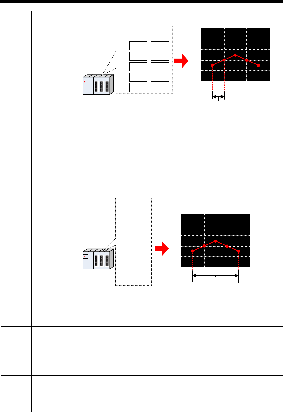
Kinco HMIware Configuration Edit Software
192
the register number is m*2.
(X-axis)
D100
5
10
15
20
25
(Y-axis)
D101
30
40
50
40
30
1st
2nd
3rd
4th
5th
100
80
60
40
20
00102030
12345
One Cycle
Example, suppose the Read Address is D100, and there is 1 channel, 5 sampling points
in each page; so this XY plot will take 2 registers. They are D100 and D101 which
corresponding to the X1 and Y1.
Trend
Sampling multiple points every time or in each period, with Y components, but no X
components. The register number is related to the channel number and sampling number.
For example, there is m channels and n sampling points, that is to say, the register
number is m*n.
D100
30
40
50
40
30
1st
2nd
3rd
4th
5th
D101
D102
D103
D104
(Y-axis)
100
80
60
40
20
0
D100 D101
D102
D103 D104
One Cycle
Example, suppose the Read Address is D100, and there is 1 channel, 5 sampling points
in each page; so this XY plot will take 5 registers. They are D100, D101, …, D104
which corresponding to the Y11, Y12, …Y15.
Sampling
Points
The sampling points displayed on each page
PageNum This option is valid only when the Multiple Pages is chosen.
Channel Displayed curve number.
Trigger
Register
Setting
This option is valid when use the trigger sampling in the Sample Methods. Take the following picture for
example, set the LB100 (HMI local register) as the trigger register, the sampling will be triggered when the
state in LB100 satisfies the setting in Sampling Method.
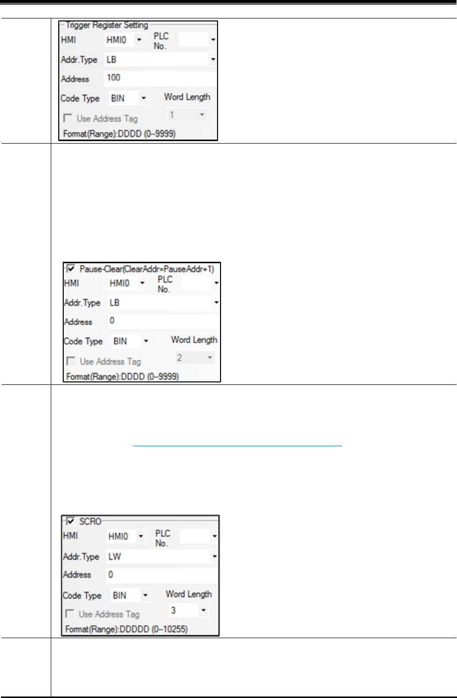
Advanced Part Component
193
Pause/Cle
ar
Set the register that controls the Pause and Clear function, the default word length is 2, the [set register]
controls the Pause, and [set register+1] controls the Clear. The Pause function only stops the change of curve,
but not stops the sampling. The Clear function clears the curve displayed on the XY plot. Take the following
picture for example, set LB0 (HMI local register) as the register to control Pause and Clear. When LB0 is ON,
the screen on XY Plot will stop refreshing; when LB0 is OFF, the screen on XY Plot will continue to display
the change of curve. When LB1 is ON, the curve on XY Plot will be cleared.
SCR0
Set the register to turn page of multiple pages of XY Plot, the default word length is 3. This option is valid
when the Multiple Pages is chosen. Use this function to scroll the multiple pages XY plot, and can be used
with the Scroll Bar. ☞For details, refer to [Advanced Part 4.16.3 Scroll Bar]
Take the following picture for example, the specified register is LW0 (HMI local register), so the LW0 is the
current index value of scroll bar, LW1 is start index value of scroll bar, LW2 is the maximum index value of
scroll bar.
Time
Use this function to save the start time and end time of current page. This function is valid when the “Save
Time” is checked. The default word length is 12. Take the following picture for example, the specified
address that is used to save time is LW70(HMI local register), the start time (Second, Minute, Hour, Day,

Kinco HMIware Configuration Edit Software
194
Month and Year) of current page are LW70, LW71, LW72, LW73, LW74 and LW75. the end time (Second,
Minute, Hour, Day, Month and Year) of current page are LW76, LW77, LW78, LW79, LW80 and LW81.
4.6.3 Oscillograph
The function of Oscillograph component is similar to the Trend Curve. They read continuous registers
form specified HMI local registers or PLC/Controller registers periodically, and plots them in single axis
curve.
Detail explanation of Oscillograph attributes
Single
page
Only display the data change information of current page, there is no curve extension.
Type
Multiple
Pages
There is XY plot extension, each channel can be saved, when the XY plot extends, the
historical sampling data will not be lost, but save in the buffer area.
Property The direction that Oscillograph curve starts.
Start from
Left
Start from
Right
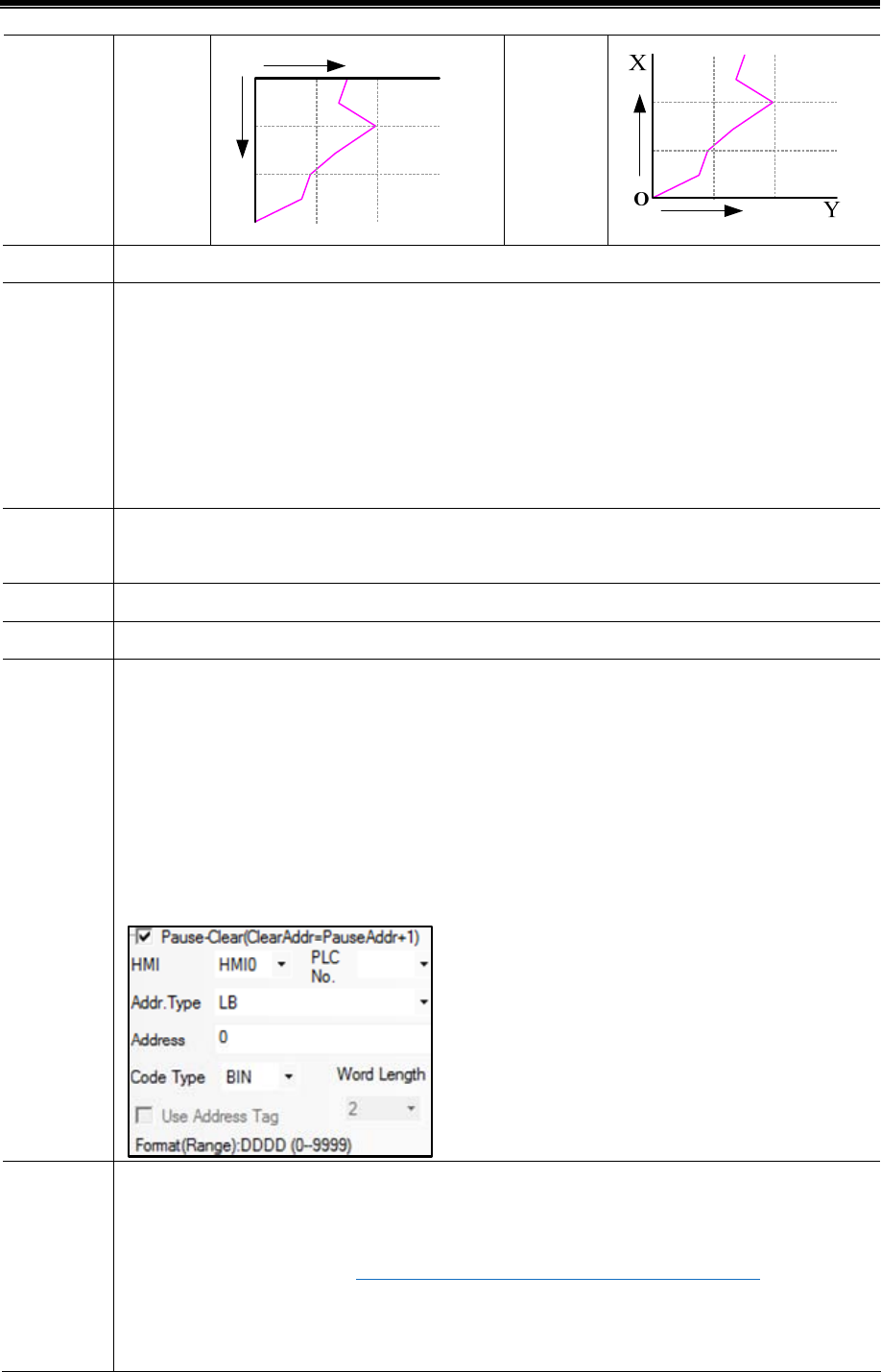
Advanced Part Component
195
Start from
Top
X
Y
O
Start from
bottom
Cycle The time interval of every 2 sampling points. The unit can be s or 100ms.
Sampling
Rate
When use the rate sampling, the Oscillograph reads [Sampling Rate number] groups data each time. For
example, the Read Address is LW10 (HMI local register), Sampling Rate is 2, Channel is 3, so the read
address is LW10~LW15. The address distribution is as follows: three channels’ data of the first group are
saved in LW10, LW11 and LW12; three channels’ data of the second group are saved in LW13, LW14, and
LW15. If the sampling cycle is 1s, the Oscillograph reads these two groups data every second. The rate
sampling makes the curve more smooth and accurate
Sampling
points
Sampling points number displayed on each page
PageNum This option is valid when the Multiple Pages is checked
Channel Displayed curve number
Pause/Clear
Set the register that controls the Pause and Clear function, the default word length is 2, the [set register]
controls the Pause, and [set register+1] controls the Clear. The Pause function only stops the change of
curve, but not stops the sampling. The Clear function clears the curve displayed on the Oscillograph. Take
the following picture for example, set LB0 (HMI local register) as the register to control Pause and Clear.
When LB0 is ON, the screen on Oscillograph will stop refreshing; when LB0 is OFF, the screen on
Oscillograph will continue to display the change of curve. When LB1 is ON, the curve on Oscillograph will
be cleared.
SCR0
Set the register to turn page of multiple pages of Oscillograph, the default word length is 3. This option is
valid when the Multiple Pages is chosen. Use this function to scroll the multiple pages Oscillograph, and
can be used with the Scroll Bar. ☞For details, refer to [Advanced Part 4.16.3 Scroll Bar]
Take the following picture for example, the specified register is LW0 (HMI local register), so the LW0 is
the current index value of scroll bar, LW1 is start index value of scroll bar, LW2 is the maximum index
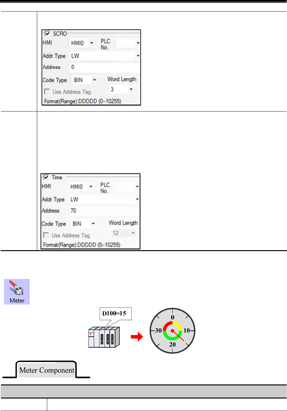
Kinco HMIware Configuration Edit Software
196
value of scroll bar.
Time
Use this function to save the start time and end time of current page. This function is valid when the “Save
Time” is checked. The default word length is 12. Take the following picture for example, the specified
address that is used to save time is LW70(HMI local register), the start time (Second, Minute, Hour, Day,
Month and Year) of current page are LW70, LW71, LW72, LW73, LW74 and LW75. the end time (Second,
Minute, Hour, Day, Month and Year) of current page are LW76, LW77, LW78, LW79, LW80 and LW81.
4.6.4 Meter
Meter component displays the data of HMI or PLC/Controller in instrument chart.
Detail explanation of Meter attributes
Dial Style Pie, Circularity(point up), Circularity(point down)
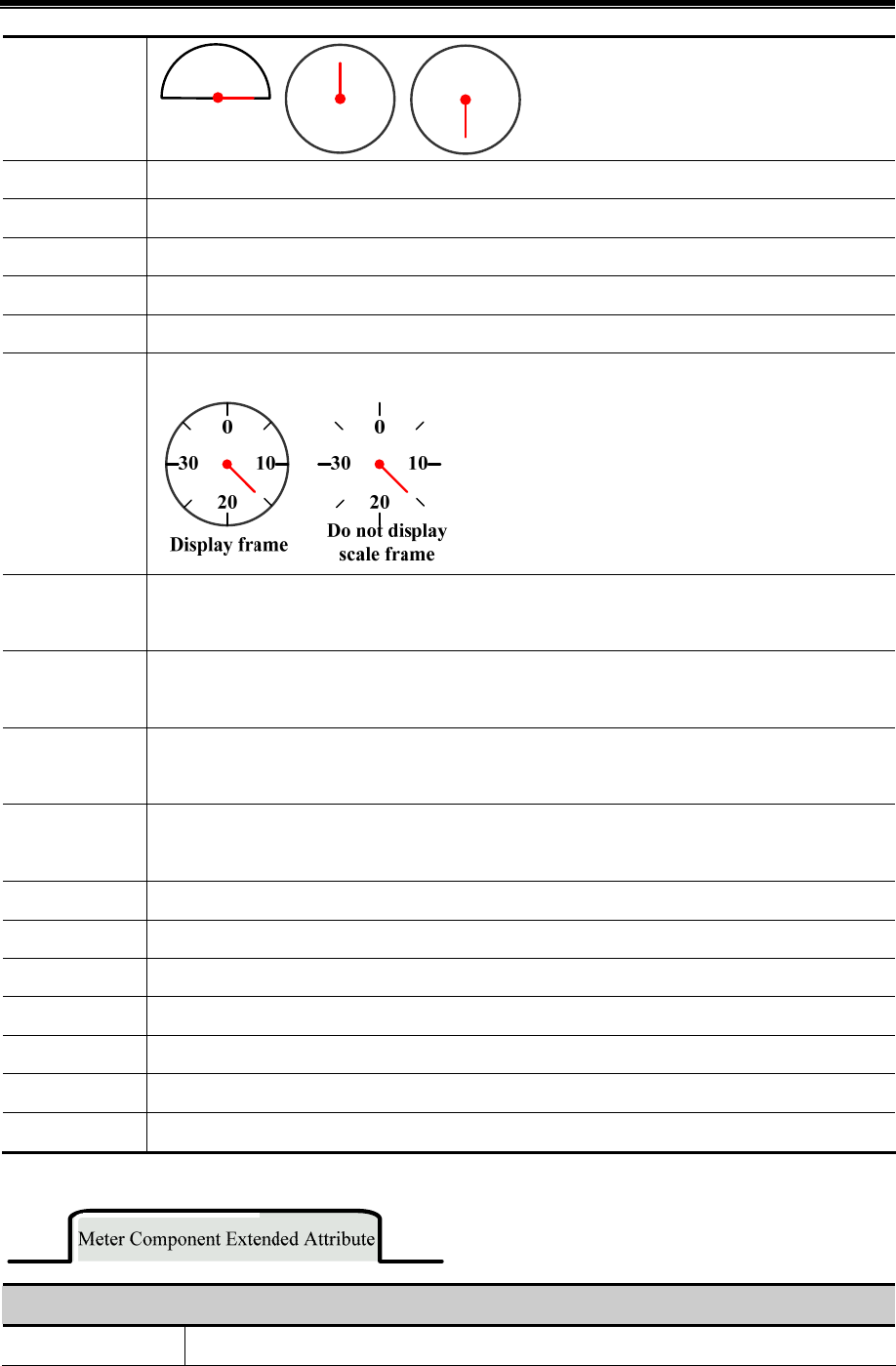
Advanced Part Component
197
Hand color Chose the color of the meter hand
Length Set the length of the meter hand, the maximum is the radius of the actual circle
Width Set the width of meter hand
Hand Style Chose the style of meter hand
Scale color Chose the color of meter scale
Show Scale
Frame
Set to display the scale frame or not
The Number of
Main Scale
Set the number of main scale, 0~50 are optional
The Length of
Main Scale
Set the length of main scale, the maximum cannot exceed the radius length of actual circle
The Number of
Minor Scale
Set the number of minor scale, 0~10 are optional
The Length of
Minor Scale
Set the length of main scale, the maximum cannot exceed the radius length of actual circle
Use Scale Tag Set to display the scale tag or not
Tag Font Click the Tag Font to set the font of tag
Integer The integer number of scale tag (Can not be set, it will change according to the maximum of meter )
Decimal Set the decimal number of the scale tag, 0~8 are optional
Use Dial Axis Checked to set the axis size and color
Axis Width Set the size of meter axis, the maximum cannot exceed the radius length of actual circle
Axis Color Set the color of meter axis
Explanations of Meter Extended Attributes
Maximum/Minimum Set the display range of meter.
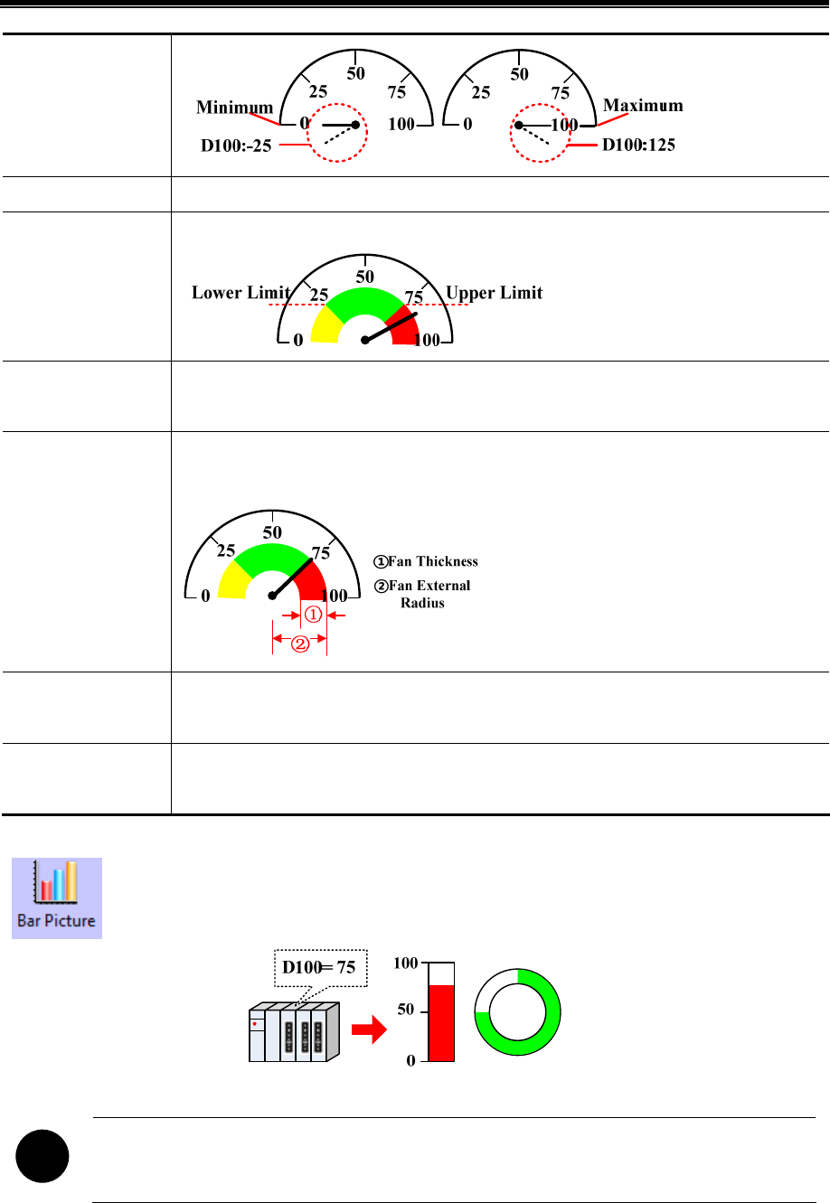
Kinco HMIware Configuration Edit Software
198
Variable Min/Max Set the registers where variable Minimum and Maximum are stored.
Upper Limit/Lower
Limit
Set the color of the Upper/Lower Limit.
Fan Thickness
Set the thickness of the circle color block. The maximum can not exceed the radius of meter
circle, and should be equal to or smaller than the Fan External Radius.
Fan External Radius
Set the radius of circle color block. The maximum can not exceed the radius of meter circle, and
should be equal to or larger than the Fan External Radius.
Lower Limit/Upper
Limit
Set the alarm range of the meter component.
Variable Lower/Upper
Limit
Set the register where the alarm range be stored.
4.6.5 Bar Picture
Bar Picture displays the data in HMI local register or PLC/Controller register in percentage of bar picture ,
that is to say the bar picture displays the percentage of actual value compared to the set
maximum/minimum value.
!
Bar Picture does not support the float data format
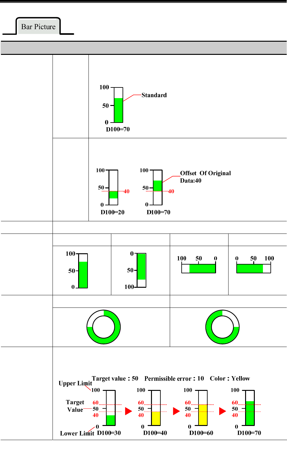
Advanced Part Component
199
Detail Explanation of Bar Picture Attributes
Standard
Display the percentage of actual value compared to the set
maximum/minimum value in bar picture.
Bar Type
Offset
Display the offset value of actual value compared to the original data in bar
picture.
Bar Shape Art direction
Up Bottom Left Right
Rectangle
Clockwise Counter clockwise
Circle
Target Value
If the value in specified register is in the permissible range, the bar picture displays specified color
in filling area.
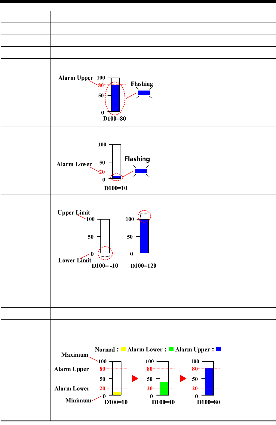
Kinco HMIware Configuration Edit Software
200
Diameter of Fan Set the diameter of fan when the Bar Shape is Circle, the unit is pixel.
Start Angle Set the start angle of fan when the Bar Shape is Circle.
End Angle Set the end angle of fan when the Bar Shape is Circle.
Color Set the color for Normal state, Upper/Lower Limit, Frame and Background.
Over Upper Limit
Flashing
When the value in specified register exceeds the Alarm Upper, the filling area in bar picture flashes.
Over Lower Limit
Flashing
When the value in specified register exceeds the Alarm Lower, the filling area in bar picture flashes.
Maximum/
Minimum
Set the upper/lower limit of bar picture.
The percentage of filling area of Bar Picture can be calculated by the following formula:
The percentage of filling area of Bar Picture= (Value in specified
register-[Minimum])/([Maximum]-[Minimum])*100%
Variable Min/Max The Maximum and Minimum are read from specified registers.
Alarm
Upper/Lower
Set the alarm range, when the value in specified registered is larger than Alarm Upper or smaller
than Alarm Lower, the filling area of bar picture displays the specified Alarm Color.
Variable Alarm The Variable Alarm Upper/Lower are read from specified registers.
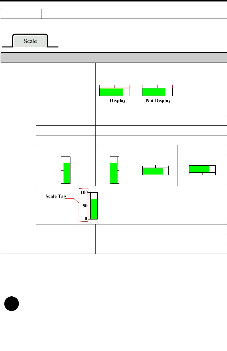
Advanced Part Component
201
Upper/Lower
Detail Explanation of Scale Attributes
Scale Color Set the scale color
Show Scale Frame
Set to display scale frame or not.
The Number of Main Scale Set the number of main scale
The Length of Main Scale Set the length of main scale, unit is pixel.
The Number of Minor Scale Set the number of minor scale
Use Scale
The Length of Minor Scale Set the length of minor scale, unit is pixel.
Left Right Up Bottom
Scale Display
Position
Tag Font Set the font of tag
Integer Integer of scale cannot be set by user.
Use Scale Tag
Decimal Decimal of scale, can be set by user.
4.7 Alarm Component
Alarm component is used to display user alarm or user event information. Inco HMIware provides components of event
display, historical event display, event bar, alarm display and alarm bar for displaying alarm information.
!
1.The event information displaying in components of event display, historical event display, event bar must
be preset in【Event Information Logon】in project database.
2. The alarm information displaying in components of alarm display, alarm bar must be preset in【Alarm
Information Logon】in project database.
3. Alarm information can’t be saved, and alarm display component can only display the unrecovered alarm
information.
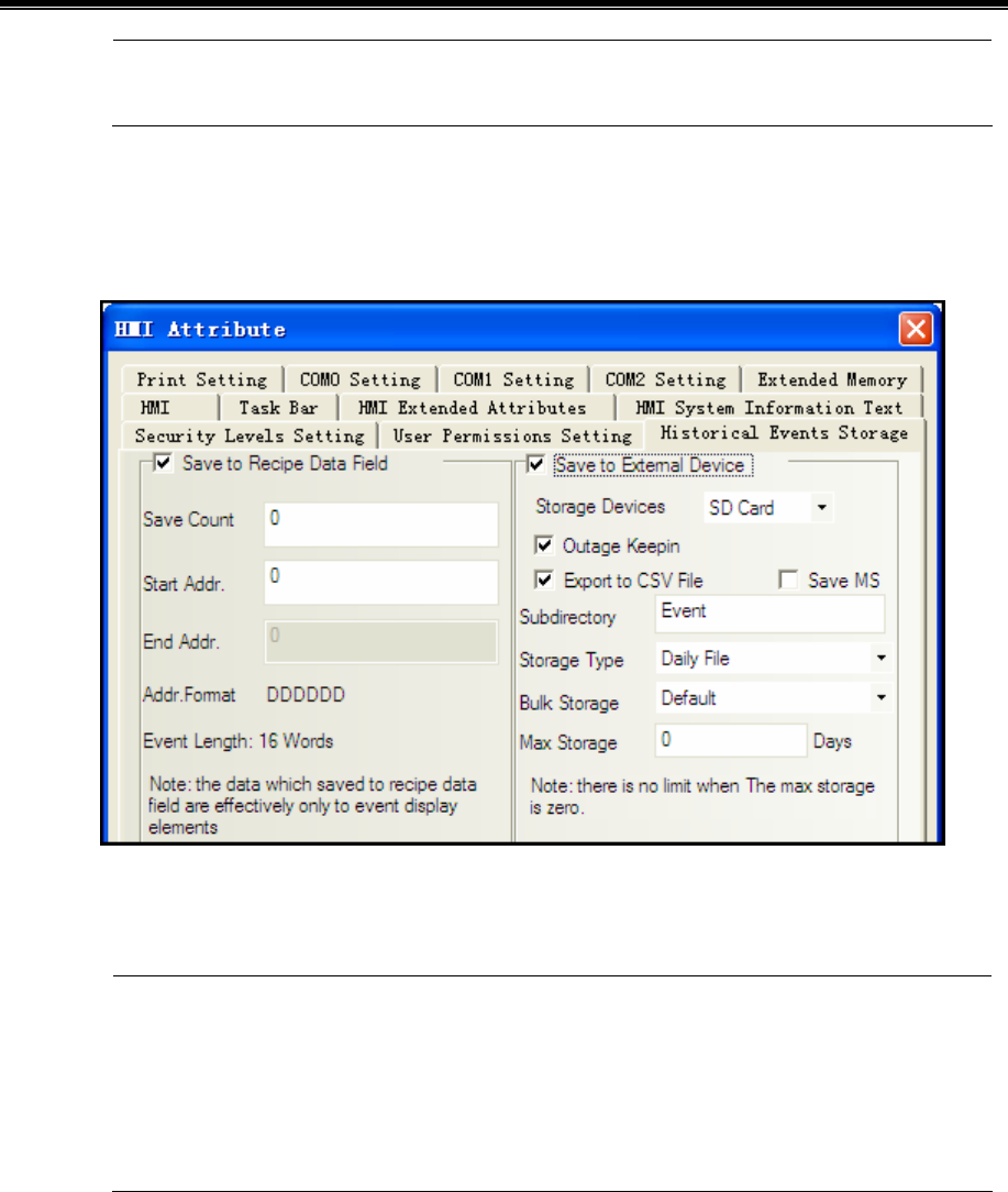
Kinco HMIware Configuration Edit Software
202
4. Event information can be saved, and event display component can display both unrecovered event
information and recovered event information.
- Related attribute of event information setting
Event information storage
Set the storage of event information in【HMI Attribute】—【Historical Events Storage】.
(1)Save to Recipe Data Field
It is used to save event information to recipe memory of HMI (RW register).
1.”Save Count” must be greater than 0.If “Save Count” is 0, then system won’t save event to recipe data
field.
2.”Start Addr.” can be user-defined. The length of one event information is 16 words. System will set “End
Addr.” Automatically according to “Save Count”.
3. Event information which saves to recipe data field cannot display in historical event display component.
(2)Save to External Device
It is used to save event information to external device.
When “Storage Type” is set as “Daily File”, then the event information will save to path “event/Subdirectory
name/yyyymmdd.csv”.When “Storage Type” is set as “Single File”, then the event information will save to path
“event/Subdirectory name/ Subdirectory name.csv”.(Therein,yyyymmdd is event execution date such as 20110101)
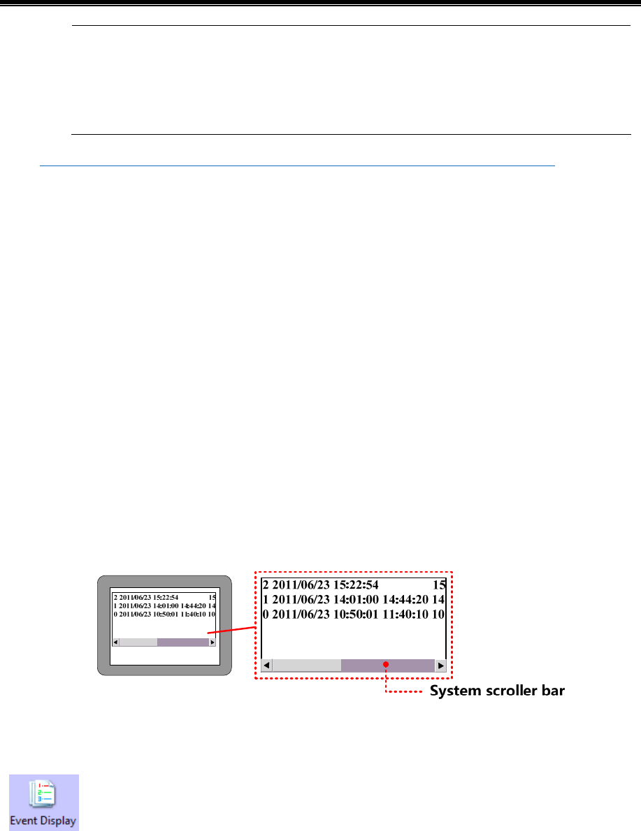
Advanced Part Component
203
1. Only the HMI with USB HOST or SD Card support saving to external device.
2. Only the event information which is saved to external device can query by date or order sequence and
display in “Historical Event Display” component.
3.Event information can save to recipe data field and external device at the same time.
5☞For details about historical event storage, refer to [Advanced Part 6.1.7 Historical Events Storage]
Event information clear
There are four ways to clear event information which displaying in event display component.
(1)Set LW10015 as 0 and restart HMI.
This way is used to clear all the event information which are saved in recipe data field.
(2)Tick【Clear History Event Data】in【EVDownload】when downloading project. The event information will be clear
after downloading.
This way is used to clear all the event information which are saved in recipe data field and external device.
(3)Use【Clear Event】function in function key.
This way is used to clear all the event information which are saved in recipe data field.
(4)Use【Clear History Event】function in【KHManager】.
This way is used to clear all the event information which are saved in recipe data field and external device.
System Scroll Bar Width setting
When the information in Event Display component cannot totally display horizontally, then system will provide scroll
bar automatically.
The width of system scroll bar can be set in【HMI Attribute】—【HMI Extended Attributes】,the range is 20~120(Pixel).
4.7.1 Event Display
Event display is used to display event information logon in “Event Information Logon”. The displaying
events will be sorted by triggered time.
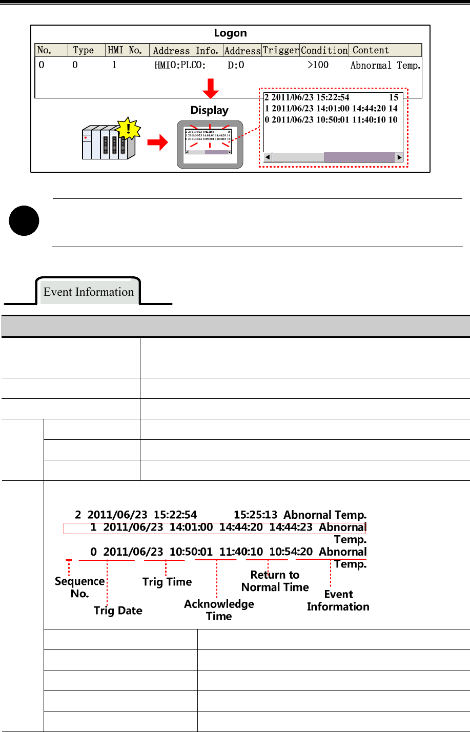
Kinco HMIware Configuration Edit Software
204
!
【Read Address】in Event Display component is used to scroll the event information(Up or down).
Related setting descriptions for event information
Display Type Range
This event display component can only display the event within this type range. The
event type is set in “Event Information Logon”.
Row Space The space between two rows or two Columns.
Acknowledge Type Set the acknowledge method for triggered event. Click or Double Click.
Acknowledge Color The color of event information after affirming.
Back to Normal Color The color of event information after event back to normal.
Color
Select Area Color The color of dotted line for indicating user information.
The format of event information. All the format information display in front of event information.
Sequence No. Sequence No. of events, it starts from 0.
Event Trig Time The time when event triggered
Acknowledge Time The time when event acknowledged
Return to Normal Time The time when event returns to normal
Format
Extended Time Format(D/H:M) Time format is Day/Hour: Minute

Advanced Part Component
205
Short Time Format(H:M) Time format is Hour: Minute
Standard Time Format(H:M:S) Time format is Hour:Minute:Second
Precise Time Format(H:M:S:MS) Time format is Hour:Minute:Second:Millisecond
Extended Date Format(Y/M/D) Date format is Year/Month/Day
Event Trig Date(M/D) Date format is Month/Day
Time Ascending Order Display
Tick it indicate that the events display by ascending order of sequence
No. and time. Or the event display by descending order of sequence
No. and time.
Only show the Event which doesn’t
recover
Tick it to only show the event which doesn’t recover. Or it will display
all the events.
【Example】Take the serial communication between MT5320T and SIEMENS S7-200 for example, when the temperature is
higher than 80 or the pressure is higher than 120Mpa,then the HMI will display alarm and output buzzer alarm, then it ℃
can display and query historical event record.
NO. Trig.
Time
Acknowledge
Time
Return to
Normal Time Event
VW0 #### VW2 ####
Temperature/Pressure
Event
Display
Multiple
State Setting
Text
Create new project [Event], and then add two windows Frame10 and Frame11 which are used for temperature alarm and
pressure alarm. Set the attributes as follows:
Name Alarm window_1/Alarm window_2
X/Y 80/80
Width/Height 200/100
Use Background Color Tick, Fill Color:■(Yellow)
Frame Width:2 Frame Color:■(Gray-50)
Pop Window Type Monopoly: tick
Add two texts and function keys in Frame10 and Frame11, and then draw a alarm symbol.
Set attributes of text as follows:
Content Abnormal Temp./Abnormal Pressure
Font Type Vector Font
Font Attribute Font:Arial Black Size:12 Color:■(Red)
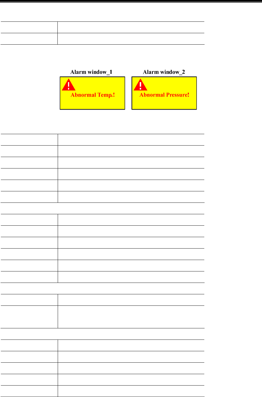
Kinco HMIware Configuration Edit Software
206
Set attributes of function key as follows:
Switch Window Close window
Graphics No use
Set the size of function key to the same as the size of window.
Add event information in【Project Database】—【Event Information Logon】.Set event information as follows:
Temperature Alarm:
Data Type Word
Address VW 0(PLC register)
Condition >80
Pop-up window Tick,[10:Alarm window_1]
Use buzzer Tick,1 second
Text Abnormal Temp.!
Pressure Alarm:
Data Type Word
Address VW 2(PLC register)
Condition >120
Pop-up window Tick,[10:Alarm window_2]
Use buzzer Tick,1 second
Text Abnormal Pressure!
Add “Event Display” component in Frame0,set its attribute as follows::
Read Address LW 0(HMI local register)
Format Tick Sequence No., Event Trig. Time, Acknowledge Time, Return
to Normal Time, Standard Time Format (H:M:S).
Add two “Multiple State Setting” components in Frame0, and set their attributes as follows:
Write Address LW 0(HMI local register)
Setting Mode Sub/Add
Subtrahend/Addend 1/1
Lower/Upper 0/100
Graphics Use vector graphics,Button6-27.vg/Button6-28.vg
Historical events storage setting
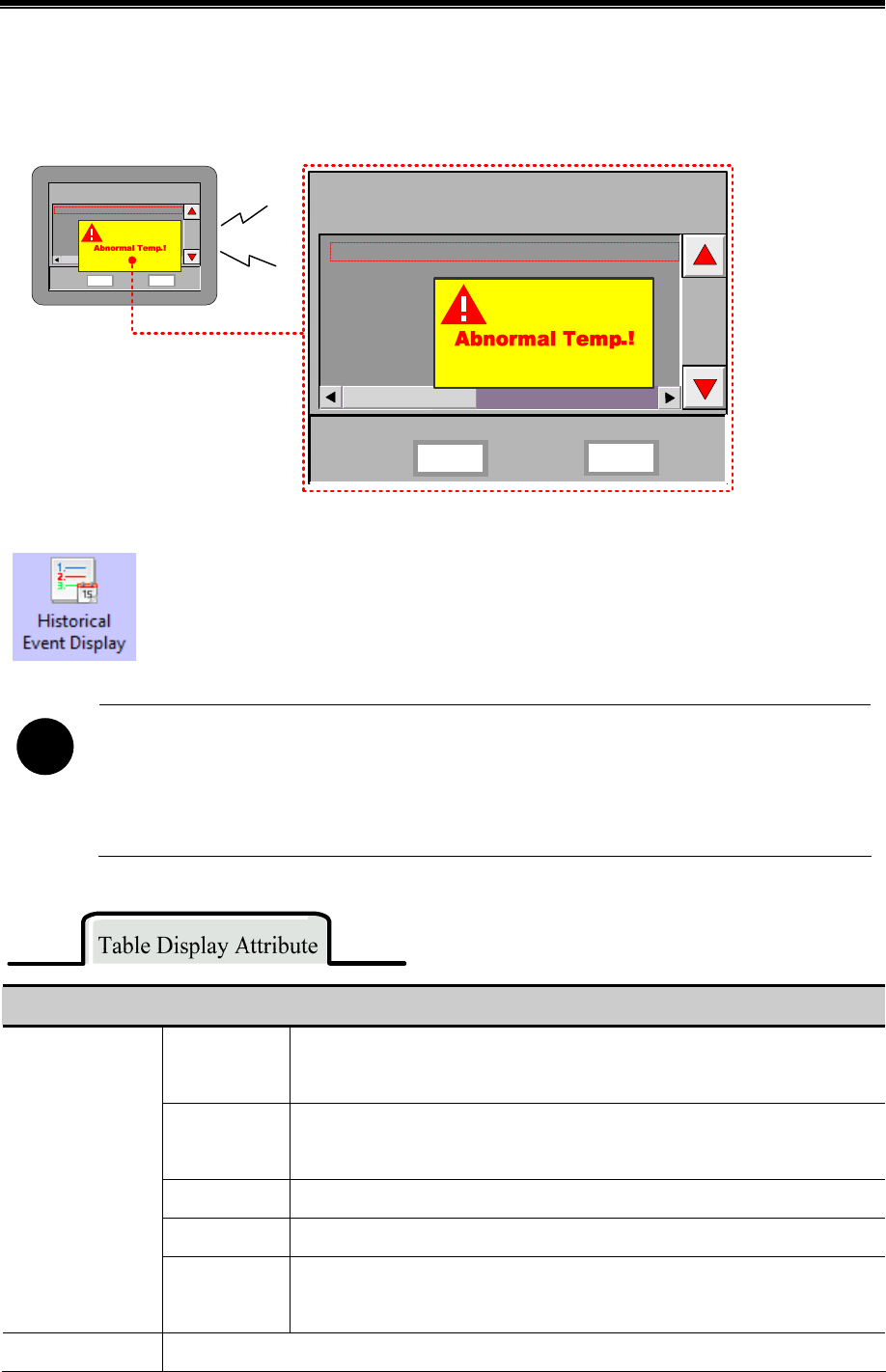
Advanced Part Component
207
Open【HMI Attribute】—【Historical Events Storage】,tick【Save to Recipe Data Field】, set【Save Count】to 100,set
【Start Addr.】as 0,means events will be saved in the registers start from RW0.
When the value of VW0 is larger than 80 :℃
NO. Trig.
Time
Acknowledge
Time
Return to
Normal
Time Event
VW0 VW2
Temperature/Pressure
90 100
2 15:22:54 15:25:13 Abno
1 14:01:00 14:44:20 14:44:23
Abno
0 10:50:01 11:40:10 10:54:20
Abno
NO. Trig.
Time
Acknowledge
Time
Return to
Normal
Time Event
VW0 90 VW2 100
Temperature/Pressure
2 15:22:54 15:25:13 Abnornal T
1 14:01:00 14:44:20 14:44:23 Abnornal
T
0 10:50:01 11:40:10 10:54:20 Abnornal
T
Beep...
4.7.2 Historical Event Display
Historical event display is used to query the triggered historical event information, which are added in
“Event Information Logon”, and display them as form format.
!
1.【Read Address】in “Historical Event Display” component is used to query historical event. Word length is
2 by default.
2.It must tick the option “Save to External Device” in【HMI Attribute】—【Historical Event Storage】and
set the subdirectory when using “Historical Event Display” component.
Descriptions for Table Display Attribute
Time
It is used to set whether display time for trigger, acknowledge and recovery events
and time format. Therein, YY means year, MM means month, DD means day.
Date
It is used to set whether display date for trigger, acknowledge and recovery events
and time format. Therein, YY means year, MM means month, DD means day.
Separator Choose the separator for date, there are three format options. Such as 11/06/24.
Sequence No. Set whether display the sequence no. of event information
Table Display
Ascending
Order
Selecting it indicates the event information is sequenced by ascending order
according to time. Or it is sequenced by descending order.
Background Setting Set the border width and the color of background, title bar and border of Historical Event Display

Kinco HMIware Configuration Edit Software
208
component.
Query by File
Order
If selecting it, then when the value of the specific register is 0,it means to display
the historical event information of today or the latest day. When the value is 1,it
means to display the historical event information of the previous day. And by
parity of reasoning.
For example, there are two files in extended memory, 20110621.csv and
20110624.csv.When the value of the specific register is 0, then it will display the
historical event in Jun.24th, 2011.When the value is 1, then it will display the
events in Jun.21st, 2011.
Historical Event
Query
Query by Date
If selecting it, then when input the date in the specific register, it will display the
historical event in this day. The format of inputting date is yyyymmdd (yyyy
means year, mm means month, dd means day).
For example, when input 20110624 in the specific register, then it will display the
historical events in Jun.24th, 2011.
Separator Setting
Set the color, line style, line width of separator line, and row space and column space. The unit of
row space and column space is pixel.
Tick “Horizontal Line” to display horizontal separator line. Tick “Vertical Line” to display vertical
separator line.
Trigger
Set the status information which is used to display in status column of the table
when event is triggered. It is set as 0 by default.
Confirm
Set the status information which is used to display in status column of the table
when event is confirmed. It is set as 1 by default.
Status display
Resume
Set the status information used to display in status column of the table when event
is resumed. It is set as 2 by default.
Title Bar Setting Set the name and font attribute of title bar.
4.7.3 Event Bar
Event Bar is used to display and roll the triggered information from right to left which is already set in
“Event Information Logon”.
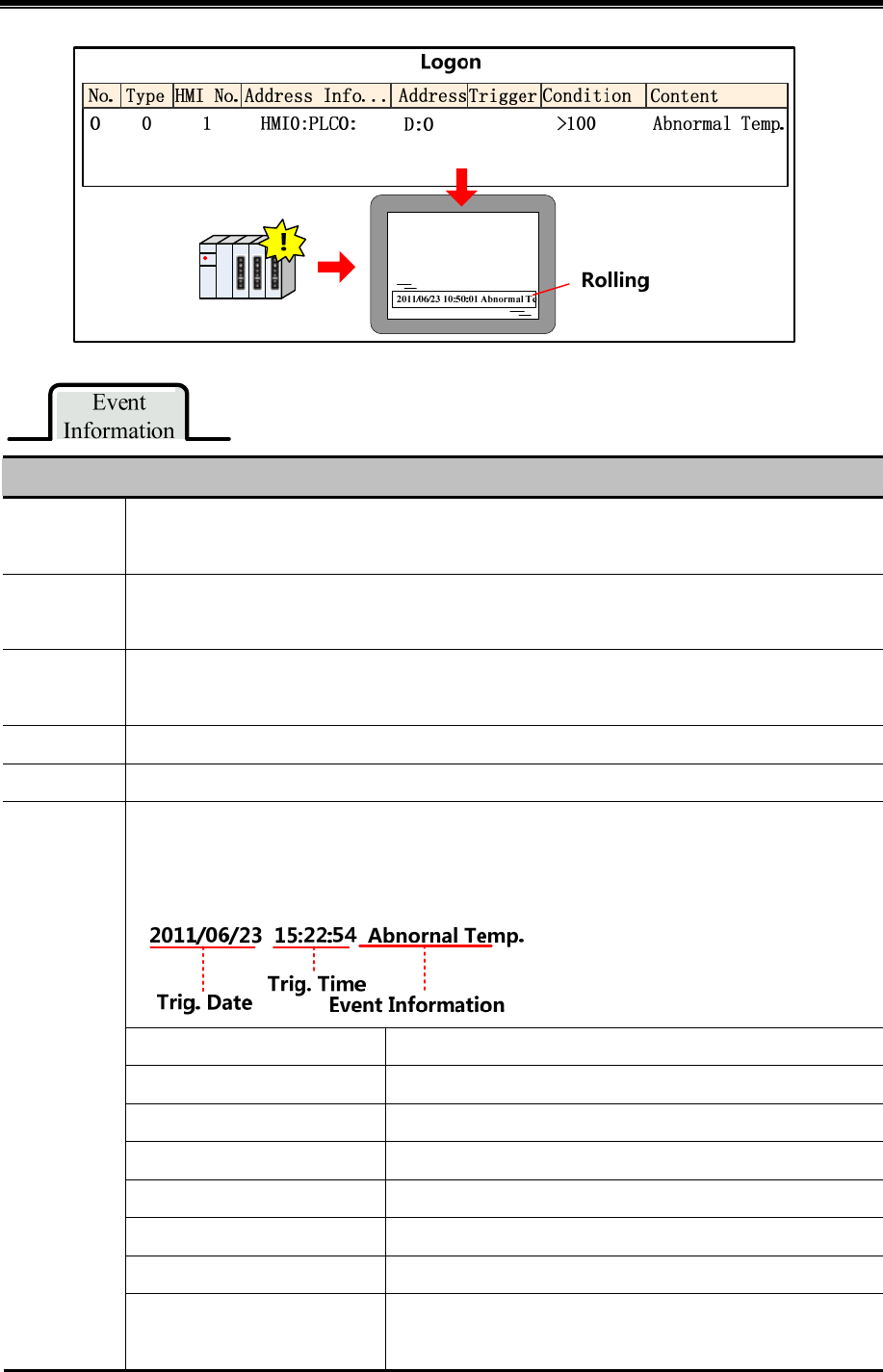
Advanced Part Component
209
Attribute Descriptions of Event Information
Display Type
Range
Set type range of event information, only this type range will display in the Event Bar. The type of event
information is set in “Event Information Logon”.
Moving Step
Set the moving step of event information. The unit is pixel. The bigger the value, the faster the moving
speed.
Moving Rate
Set the interval time of moving the event information. The unit is 100ms.The bigger the value, the slower
the moving speed.
Gap Space Set the space between two events ranging from1-7 pixel.
Moving Style Set moving style:from right to left or from right to left
Set the display format of event information. All the format information will display in front of event
information.
Event Trig. Time The time when event is triggered.
Extended Time Format (D/H:M) Time format is Day/Hour: Minute.
Short Time Format (H:M) Time format is Hour: Minute.
Standard Time Format (H:M:S) Time format is Hour: Minute: Second.
Precise Time Format (H:M:S:MS) Time format is Hour: Minute: Second: Millisecond.
Extended Date Format (Y/M/D) Date format is Year/Month/Day.
Event Trig. Date(M/D) Date format is Month/Day.
Format
Time Ascending Order Display
Selecting it to display the event information by time ascending
order.
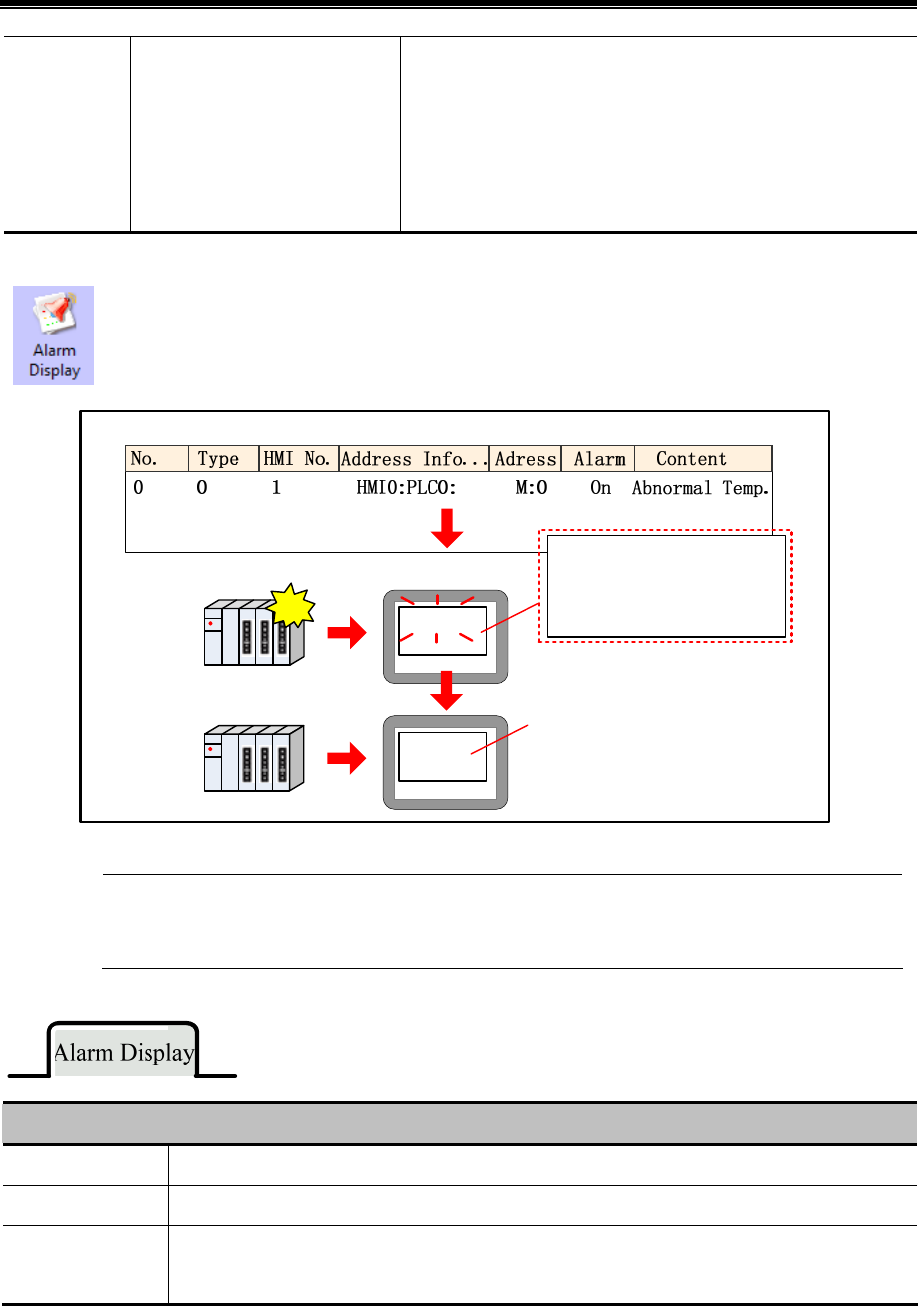
Kinco HMIware Configuration Edit Software
210
For example,2011/06/23 15:22:54 Event 1 2011/06/23 16:20:40
Event 2
Cancel it to display the event information by time descending order.
For example, 2011/06/23 16:20:40 Event 2 2011/06/23 15:22:54
Event 1
4.7.4 Alarm Display
Alarm Display component is used to display the triggered alarm information which is already set in
“Alarm Information Logon”. The alarm information will not remove until the alarm condition is cleared.
Logon
Abnormal Temp.!
!
Display Abnormal Temp.!
Alarm
Recovery
Remove
【Read Address】in Alarm Display component is used to roll the alarm information(Upward or downward)
Attribute Descriptions for Alarm Display
Row Space Set the interval between two alarm information. The unit is pixel.
Column Space Set the interval between two characters or words in the alarm information. The unit is pixel.
Display Type
Range
Set the type range of alarm information, only this type range will display in the alarm display. The
type of alarm information is set in “Alarm Information Logon”.
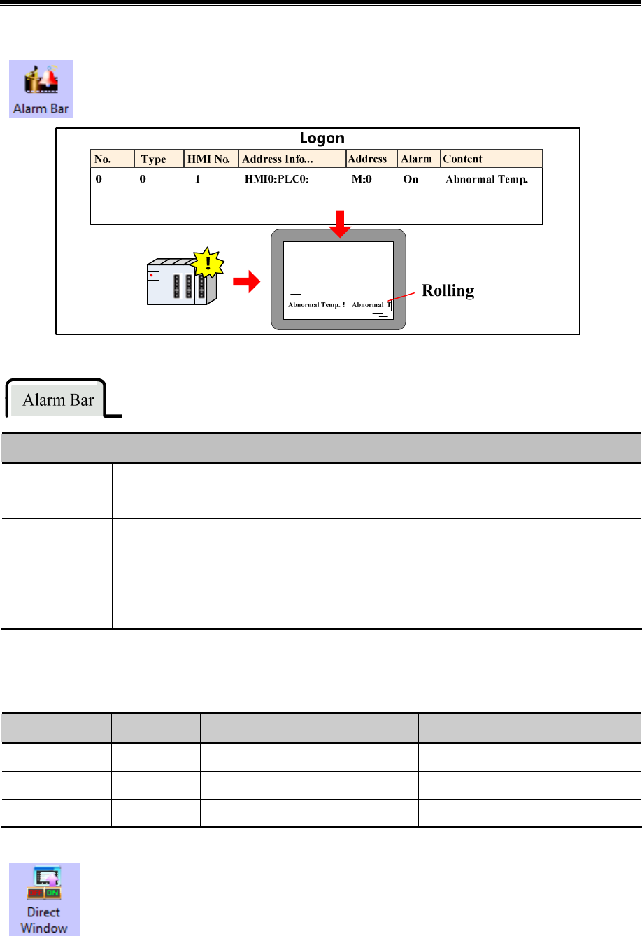
Advanced Part Component
211
4.7.5 Alarm Bar
Alarm Bar is used to display and roll the triggered alarm information which is already set in “Alarm
Information Logon”.
Attribute Descriptions of Alarm Bar
Moving Step
Set the moving step of alarm information. The unit is pixel. The bigger the value, the faster the
moving speed.
Moving Rate
Set the interval time of moving the alarm information. The unit is 100ms.The bigger the value, the
slower the moving speed.
Display Type
Range
Set type range of alarm information, only this type range will display in the Alarm Bar. The type of
alarm information is set in “Alarm Information Logon”.
4.8 Window Component
Kinco HMIware provides two window components, Direct Window and Indirect Window, which are used for popup window.
The main differences between the two window components and 【Popup Window】in Function Key are as follows:
Component Read Address Control Method Window No.
Direct Window Bit According to the state of Read Address Specify in the attribute
Indirect Window Word According to the value of Read Address According to the value of Read Address
Function Key None Touch Specify in the attribute
4.8.1 Direct Window
Direct Window is used to define a display area and display the specific window in this area according to
the state of Read Address.
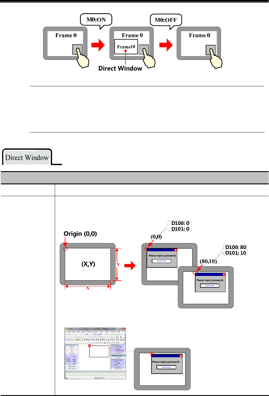
Kinco HMIware Configuration Edit Software
212
1. Direct Window’s open or close depends on the state of Read Address, it means that it will popup window
when the state of Read Address is ON, and close window when the state is OFF.
2. Generally the size of Direct Window should be set the same as the size of specific popup window.
3. There is no limit for the quantity of Direct Window.
Attribute Descriptions of Direct Window
Frame ID Specify the window which will display in the display area of Direct Window
Variable Display
Coordinates
Select it to set the coordinates of Direct Window as variable. [Address] is used for X
coordinate,[Address+1] is used for Y coordinate.
Cancel it to set the coordinates of Direct Window as constant.
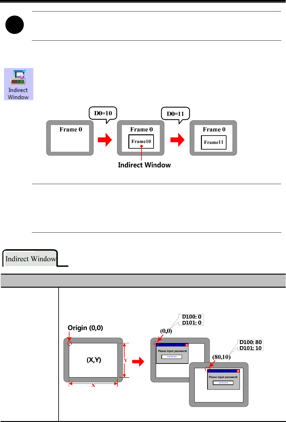
Advanced Part Component
213
!
Direct Window can be closed by the “Close Window” function in Function Key
4.8.2 Indirect Window
Indirect Window is used to define a display area and display the window whose number is the same as the
value of Read Address.
1. It will close window when the value of the register is 0. And it will popup window 0 when the value is
-1.
2. Generally the size of Indirect Window should be set the same as the size of specific popup window.
3. There is no limit for the quantity of Indirect Window.
Explanation of Indirect Window attributes
Variable Display
Coordinates
Select it to set the coordinates of Indirect Window as variable. [Address] is used for X coordinate,
[Address+1] is used for Y coordinate.
Cancel it to set the coordinates of Indirect Window as constant.
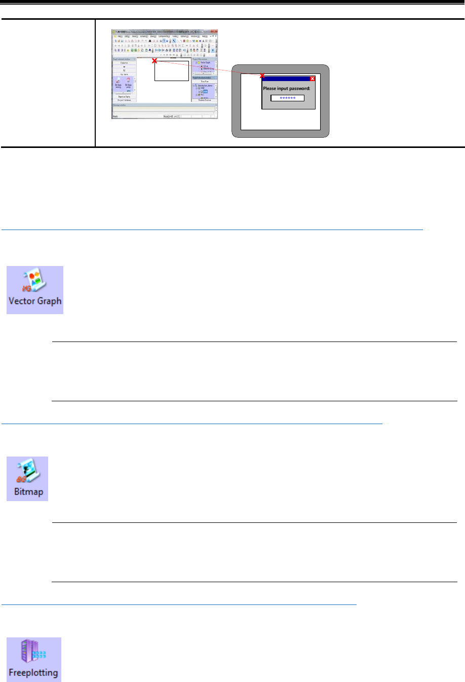
Kinco HMIware Configuration Edit Software
214
4.9 Graphic Components
Kinco HMIware provides Vector Graph and Bitmap which can be used to display vg or bg pictures in system graph library
and graph library in project files window.
☞For details about how to build and edit Bitmap and Vector Graph, refer to [Advanced Part 5.3 Graphic Library]
4.9.1 Vector Graph
Vector Graph component is used to display vg pictures in system graph library and Project Files Window
graph library.
There is no register control in Vector Graph component, and graph doesn’t support multiple states
switching display. If you want to control vector graph by register, you can chose corresponding vector
graphics-Graphics option of other components, like Bit State Switch, Multiple State Setting etc.
☞For details about vector graphics in graphics option, refer to [Advanced Part 4.1.6 Graphics Setting]
4.9.2 Bitmap
Bitmap component is used to display bg pictures in system graph library and Project Files Window graph
library.
There is no register control in Bitmap component, and graph doesn’t support multiple states switching
display. If you want to control bitmap by register, you can chose corresponding bitmap in Graphics option
of other components, like Bit State Switch, Multiple State Setting etc.
☞For details about bitmap in graphics option, refer to [Advanced Part 4.1.6 Graphics Setting]
4.9.3 Free Plotting
Free Plotting component plots graph according the states of specified bit or word register. This
component doesn’t open to ordinary customer.
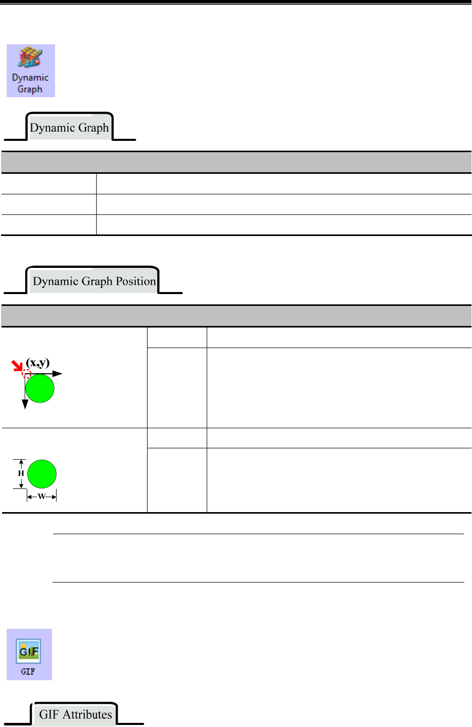
Advanced Part Component
215
4.9.4 Dynamic Graph
Dynamic Graph can change the position and size of rectangle, ellipse or line according to value in the
specified HMI/ PLC register.
Attribute explanation of Dynamic Graph
Graphic Type Chose the graph type, rectangle, ellipse and line are optional
Line Set the frame line color, line width and line type
Filling Set the filling color and picture of rectangle and ellipse
Attribute explanation of Dynamic Graph Position
Unchecked The dynamic graph position(X, Y) are constant. The Upper-left Corner of Variable
Checked
The dynamic graph position(X, Y) read from specified register. X
position=specified register, Y position = specified register +1.
Unchecked The dynamic graph width and height are constant. The Width/Height of Variable
Checked
The dynamic graph width and height read from specified register.
Width=specified register, Height= specified register +1.
The component takes the upper-left as base point, X direction moving means increasing towards right. Y
direction moving means increasing towards down. The moving unit is pixel
4.9.5 GIF
GIF component is used to display the gif picture, and the switching frequency of gif picture can be
controlled.
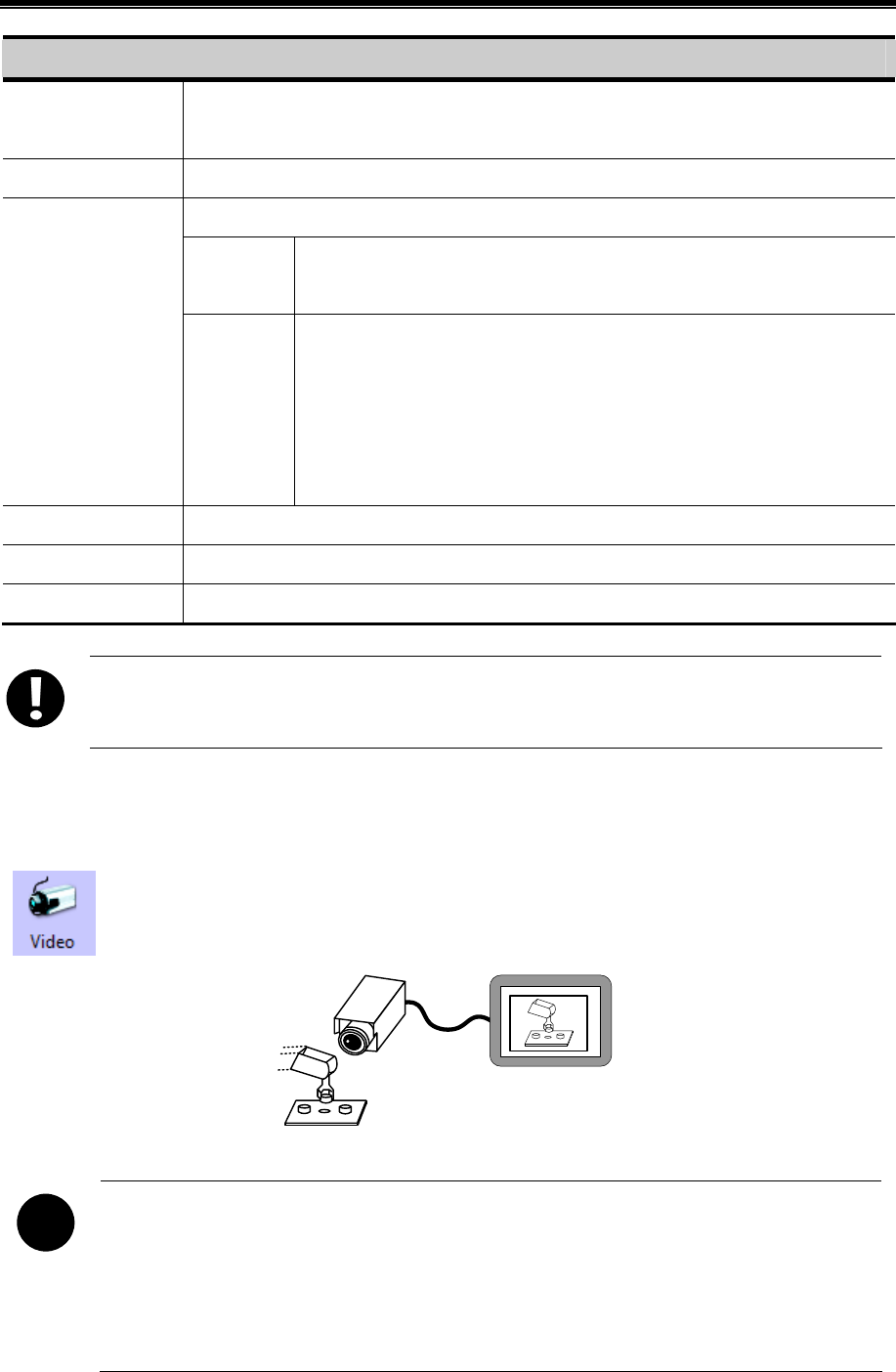
Kinco HMIware Configuration Edit Software
216
Description of GIF Attributes
Use Start Address If checked, when the specified register is ON, GIF displays animation, when register is OFF, GIF
displays static picture.
Use GIF Default Freq Use the default frequency of gif picture.
User set frequency for the gif picture.
Switching
Frequency
Different frequencies mean different switching speed of gif picture; the larger
value means the slower switching speed. Unit: 100ms.
Use defined Freq
Use Variable
Frequency
The switching frequency is read from specified register. Unit: 100ms.
Note: If the specified register is PLC register, but the HMI does not
communication successfully with the PLC all the time, the gif use the default
frequency. If the communication is cut off, the gif uses the latest historical value
in the specified PLC register.
Load GIF Load the gif picture from PC, and preview the loaded gif picture in Preview area.
GIF Preview Preview the loaded gif picture in this area.
Use Original Size If checked, the component size is the same as the gif original size.
GIF component only support the gif format picture.
4.10 Video Input Component
4.10.1 Video
Video component is used to monitor the industrial site picture in real time, supporting the CVBS signal.
!
1. Only the HMI with BNC connector can support the Video component
2. Supports PAL and NTSC format. And the video mode are optional in HMI Attribute>>HMI Extended
Attributes
3. If the video is displayed in pup up window, the pop up window should be set Video Page in Window
Attribute>> Special Attribute
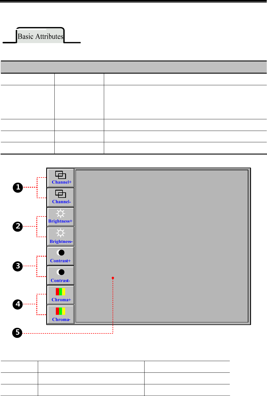
Advanced Part Component
217
The default Word Length of Read Address is 4, each word corresponds to different function attribute as follows:
Explanation of Video component Read Address
Read Address Function Description
Specified Address Switch channel
Switch channels, if the value is 0 , the component displays the video
image from channel 0 ; if the value is 1 , the component displays the video
image from channel 1;
Specified Address+1 Adjust brightness Adjustable range: 0~255
Specified Address +2 Adjust contrast Adjustable range: 0~255
Specified Address +3 Adjust chromaticity Adjustable range: 0~255
[Example] Take MT5620T for example, build a new project.
Multiple State Setting component, it is used to switch the channels (There are only 2 CVBS port on MT5620T), its
attributes are as followings:
Write Address LW 0(HMI local register) LW 0(HMI local register)
Setting Mode Jog++; Addend:1; Upper:1 Jog--; Subtrahend:1; Lower:0
Tag Use Tag; 0: Channel+; 1:Channel+ Use Tag; 0: Channel-; 1:Channel-
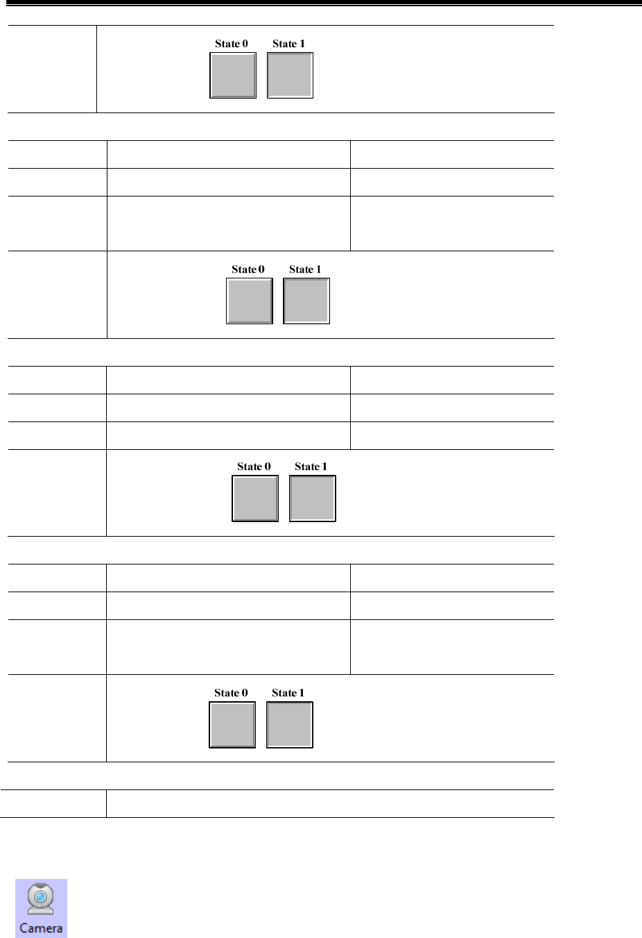
Kinco HMIware Configuration Edit Software
218
Graphics
Use Vector Graphics
Multiple State Setting component, it is used to adjust brightness, it attributes are as followings:
Write Address LW 1(HMI local register) LW 1(HMI local register)
Setting Mode Jog++; Addend:1; Upper:255 Jog--; Subtrahend:1; Lower:0
Tag Use Tag; 0: Brightness+; 1: Brightness + Use Tag; 0: Brightness-; 1:
Brightness -
Graphics
Use Vector Graphics
Multiple State Setting component, it is used to adjust contrast, it attributes are as followings:
Write Address LW 2(HMI local register) LW 2(HMI local register)
Setting Mode Jog++; Addend:1; Upper:255 Jog--; Subtrahend:1; Lower:0
Tag Use Tag; 0: contrast+; 1: contrast + Use Tag; 0: contrast-; 1: contrast -
Graphics
Use Vector Graphics:
Multiple State Setting component, it is used to adjust chromaticity, it attributes are as followings:
Write Address LW 3(HMI local register) LW 3(HMI local register)
Setting Mode Jog++; Addend:1; Upper:255 Jog--; Subtrahend:1; Lower:0
Tag Use Tag; 0: chromaticity +; 1: chromaticity + Use Tag; 0: chromaticity-; 1:
chromaticity -
Graphics
Use Vector Graph:
The Video component, its attributes is as followings:
Read Address LW 0(HMI local register)
4.10.2 Camera
Camera component is also used to monitor the industrial image as the Video component, and the Camera
component supports the USB camera video input.
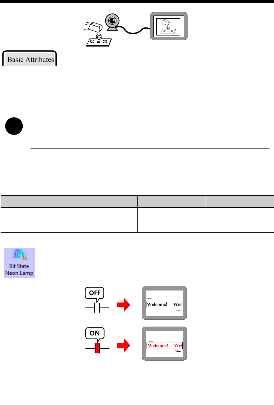
Advanced Part Component
219
Camera component uses the Read Address to open, close, switch the camera.
For example, suppose the Read Address is LW0 (HMI local register), when LW0 is 0, the camera is close; when LW0 is 1,
the camera on USB HOST1 is open; when LW0 is 2 , the camera on the USB HOST2 is open.
!
1. The Camera component is only suitable for the HMI with USB HOST port.
2. If there are cameras on both USB HOST1 and USB HOST2, the two cameras can not be open at the
same time. That is to say when one camera is open, the other is closed automatically.
4.11 Multiple State Neon Lamp
The Multiple States Neon Lamp component displays text content circularly in neon. Knico HMIware provides Bit State
Neon Lamp and Multiple State Neon Lamp, their differences are as followings:
Component Control Address Code Type State Number
Bit State Neon Lamp Bit BIN 1~2
Multiple State Neon Lamp Word BIN、BCD or LSB 1~256
4.11.1 Bit State Neon Lamp
The Bit States Neon Lamp component displays tag content circularly in neon, supports tag content in state
0 and state 1.
Change the states of Read Address to switching display the tag content in corresponding states.
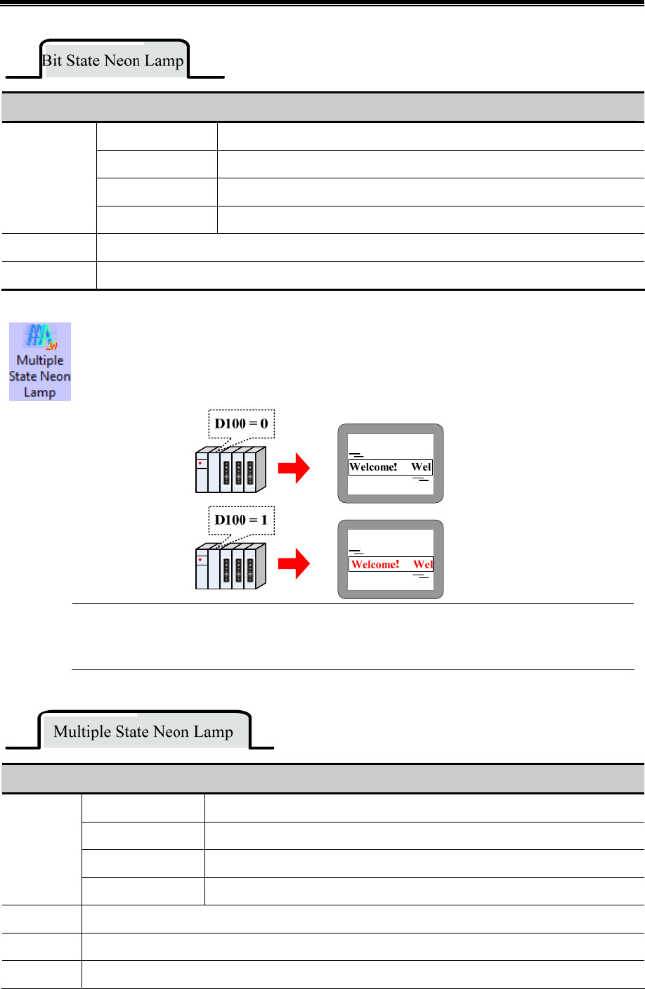
Kinco HMIware Configuration Edit Software
220
Detail Description of Bit States Neon Lamp
From left to right The text moves from left frame to right frame circularly.
From right to left The text moves from right frame to left frame circularly.
From top to bottom The text moves from top frame to bottom frame circularly.
Moving Style
Form bottom to top The text moves from bottom frame to top frame circularly.
Step Length The distance of each movement, the unit is pixel point.
Speed The time interval between previous moving text and next moving text, the unit is ms.
4.11.2 Bit State Neon Lamp
The Bit State Neon Lamp component displays tag content circularly in neon, supports 256 states tag
content at most.
Change the value of Read Address to switching display the tag contents corresponding to the value.
Detail Description of Multiple State Neon Lamp
From left to right The text moves from left frame to right frame circularly.
From right to left The text moves from right frame to left frame circularly.
From top to bottom The text moves from top frame to bottom frame circularly.
Moving
Style
Form bottom to top The text moves from bottom frame to top frame circularly.
Step Length The distance of each movement, the unit is pixel point.
Speed The time interval between previous moving text and next moving text, the unit is ms.
State Num Set the state number of Multiple State Neon lamp, 256 states at most.
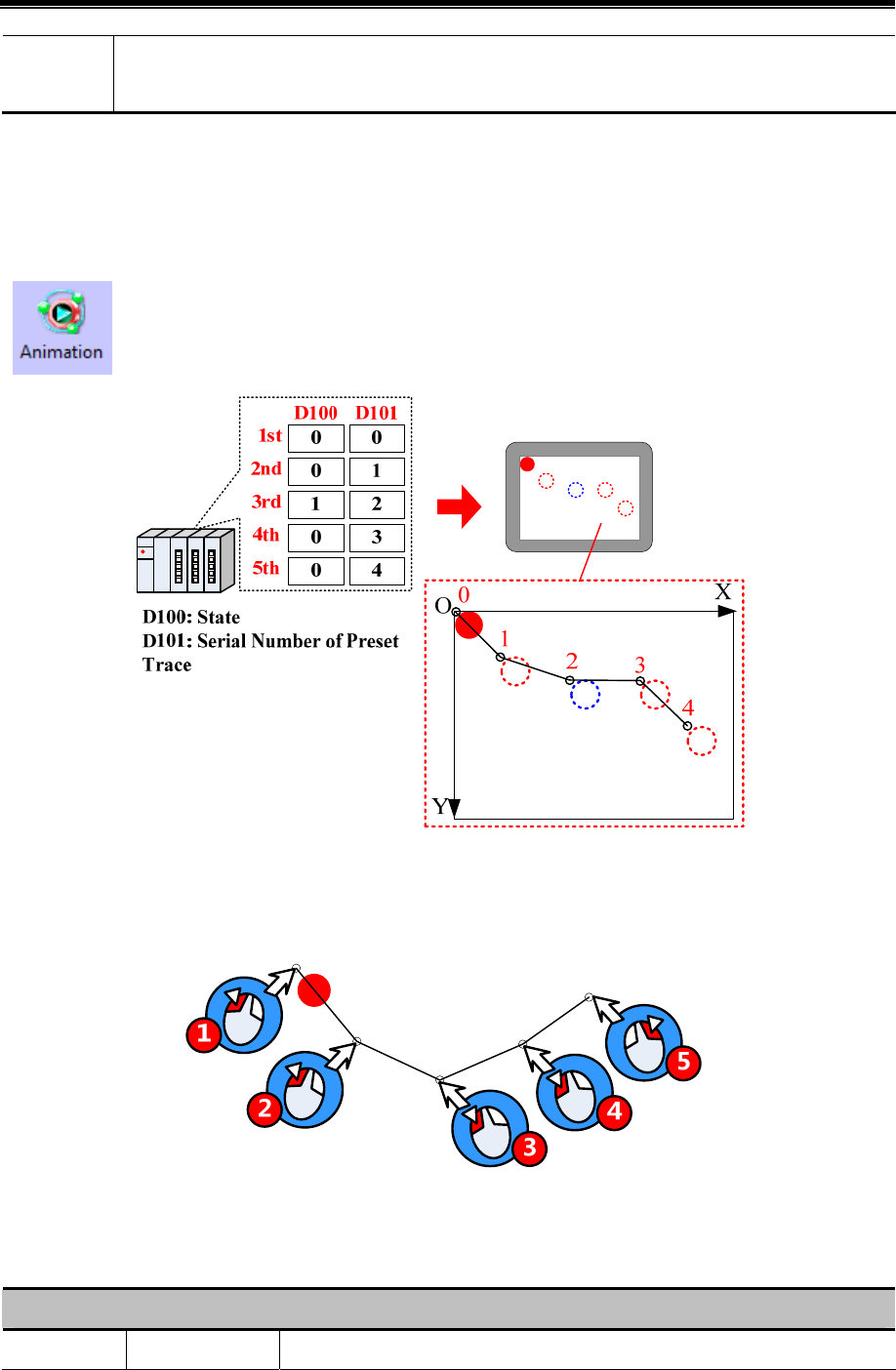
Advanced Part Component
221
Data
Mapping
Set the mapping value of each state. When the value in Read Address equals to the corresponding value, the
component displays the corresponding tag content of this value.
4.12 Animation Components
In Kinco HMIware, the Animation and Moving Components are used to realize animation effect and make the HMI picture
more vivid.
4.12.1 Animation
Animation component can preset the trace of moving component, and change the component state and
preset trace position according to value of the HMI register or PLC register.
Steps to preset the Animation trace:
Drag the Animation component to the edit area, there will be a “+”icon, press the left mouse button at appropriate position,
so a moving position is preset. Press the right mouse button to end the presetting after all the all the positions are set.
The default word length of Animation component is 2, each word corresponding to the different control function , see the
details follows:
Read Address description of Animation Component
Read Address Control Function Description
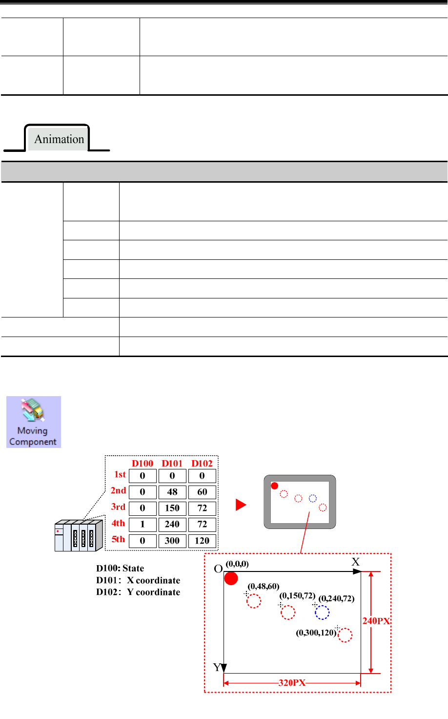
Kinco HMIware Configuration Edit Software
222
Specified
Address
Component State
When the value in control address equals to the state number of component, the
Animation Component display corresponding tag or picture.
Specified
Address +1
Number of preset
trace
When the value in control address equals to the number , the Animation Component
moves to corresponding position.
Attribution Description of Animation Component.
No. and
coordinates
Set the coordinate position of the moving node on HMI.
The number 0 means the first moving node, the number 1 means the second moving node.
Add Node Add a moving node at the end of preset trace
Insert Node Insert a moving node after the selected moving node
Delete Node Delete the selected moving node
Shift Up Exchange the position of the selected node and the previous node
Moving Node
List
Shift Down Exchange the position of the selected node and the next node
Size(Width, Height) Set the display size of Animation component
State Num: Set the state number of Animation component.
4.12.2 Moving Component
The Moving Component can change the display state and position according to the value of HMI register
or PLC register.
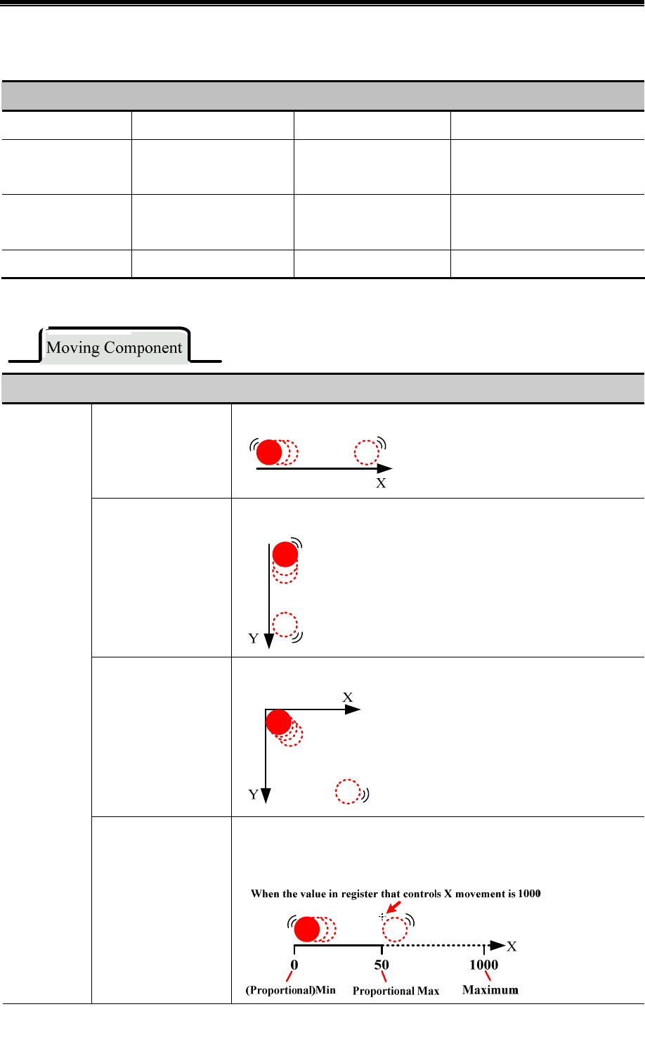
Advanced Part Component
223
The default word length of Moving Component is 3, each word corresponding to the different control function, see the
details follows:
Read Address Description of Moving Component
Type X Axis Only Y Axis Only X&Y Axis
Specified Address
Component State
256 states at most
Component State
256 states at most
Component State
256 states at most
Specified Address +1
X axis displacement (pixel
point)
Y axis displacement (pixel
point)
X axis displacement (pixel point)
Specified Address +2 Reserved Reserved Y axis displacement (pixel point)
Moving Type Description
X axis only
The component moves along the X axis horizontally
Y axis only
The component moves along the Y axis vertically
X & Y axis
The component moves along the X and Y axis at the same time.
Type
X Scaling
The component moves along the X axis horizontally, but the relative moving
position can be set by the input value and proportional value.
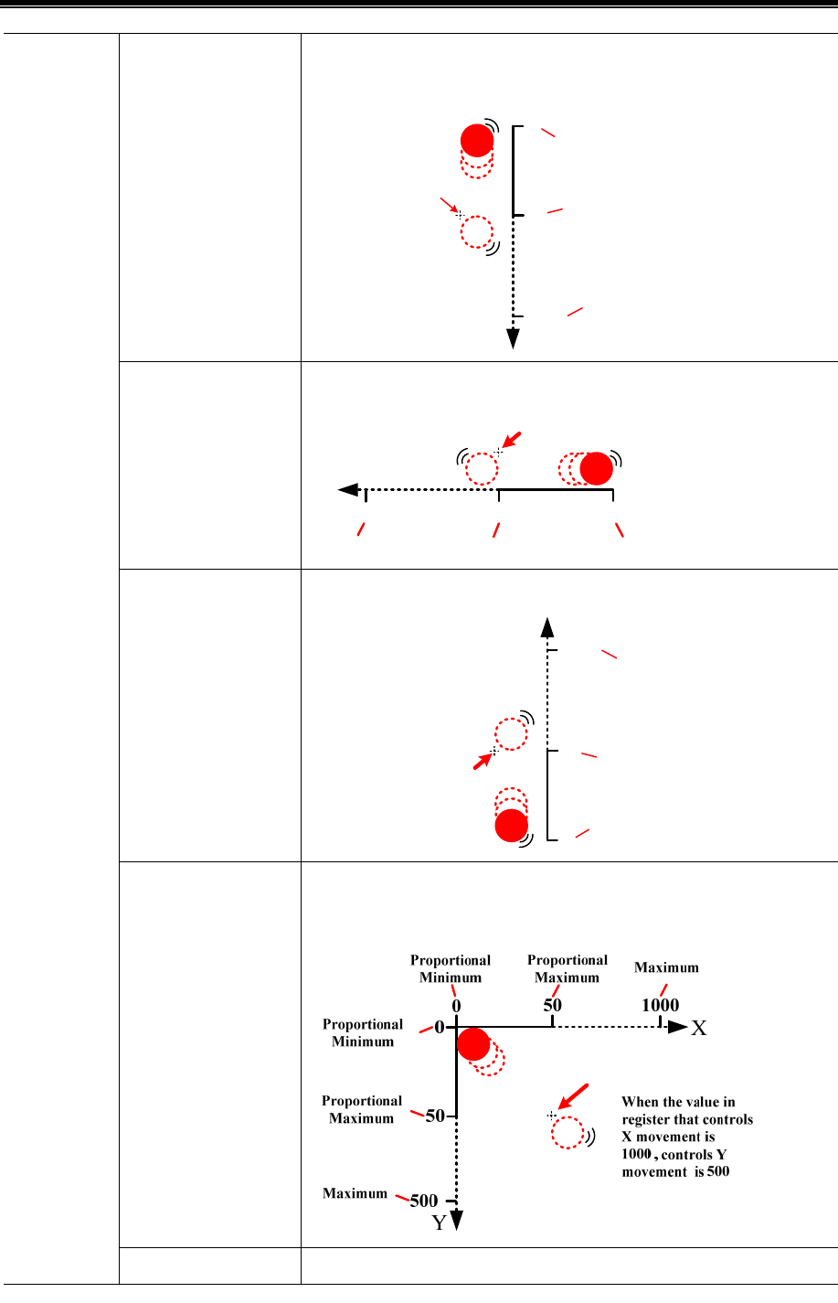
Kinco HMIware Configuration Edit Software
224
Y Scaling
The component moves along the Y axis vertically, but the relative moving
position can be set by the input value and proportional value.
Y
0
50
1000
When the
value in
register that
controls Y
movement is
1000
(Proportional)
Min
Proportional
Max
Maximum
X Reverse Scaling
It is similar with the X Scaling, but with the reverse direction.
X
0
50
1000
Proportional Min
Proportional Max
Maximum
When the value in register that controls X movement is 1000
Y Reverse Scaling
It is similar with the Y Scaling, but with the reverse direction.
(Proportional)
Minimun
Proportional
Maximum
Maximum
When the value in
register that controls
Y movement is 1000
Y
0
50
1000
X Scaling, Y Scaling
The component moves along the X and Y axis at the same time, the relative
moving position can be set by the input value and proportional value.
X Scaling, Y Reverse The component moves along the X and Y axis at the same time, and the
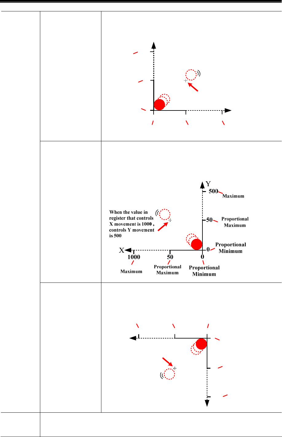
Advanced Part Component
225
Scaling relative moving position can be set by the input value and proportional value,
but in reverse direction in Y axis.
X
050 1000
Y
0
50
500
When the value in
register that
controls X
movement is 1000 ,
controls Y
movement is 500
Proportional
Minimum Proportional
Maximum Maximum
(Proportional)
Minimum
Proportional
Maximum
Maximu
m
X Reverse Scaling, Y
Scaling
The component moves along the X and Y axis at the same time, and the
relative moving position can be set by the input value and proportional value,
but in reverse direction in X axis.
X Reverse Scaling, Y
Reverse Scaling
The component moves along the X and Y axis with reverse direction, and the
relative moving position can be set by the input value and proportional value
X
0
501000
Y
0
50
500
When the value in
register that controls
X movement is 1000 ,
controls Y movement
is 500
Proportional
Minimum
Proportional
Maximum
Maximum
Proportiona
Minimum
Proportional
Maximum
Maximum
Status
Number
Set the status number that can be switching display.
Kinco HMIware Configuration Edit Software
226
Va ri a bl e
Min/Max
According to different Type, the Maximum/Minimum of X, Maximum/Minimum of Y, Proportional
Upper/Lower Limit of X and Proportional Upper/Lower Limit of Y are read from specified registers.
※1.X Scaling or Y Scaling
Suppose the read data is A, and the actual display position is B. You can get the B according to the following formula:
B=Current Position + (A-Minimum)*Proportional Value, and Proportional Value=(Proportional Upper Limit –
Proportional Lower Limit )/(Maximum-Minimum)
2. X Reverse Scaling or Y Scaling
Suppose the read data is A, and the actual display position is B. You can get the B according to the following formula:
B=Current Position + (Maximum-A)*Proportional Value, and Proportional Value= (Proportional Upper Limit –
Proportional Lower Limit )/(Maximum-Minimum)
4.12.3 Pipeline
Pipeline component is used to build pipeline effect in the HMI program.
Basic Attributes of Pipeline
Radius Set the radius of pipeline.
Thickness Set the thickness of pipeline border.
Body color Set the color of pipeline(the first color)
Border color Set the color of pipe border.
If checked, the pipeline color can be changed by specified register.
Body color 2 Set the second color of pipeline
Body color 3 Set the third color of pipeline
Body Color Changeable
Default color View the display effect of pipeline
Flicker If checked, use specified register to switch on/off the flicker effect.
Basic Attributes
Use Flow Effect If checked, use specified register to control the flow effect.
Symbol Select the flow symbol
Copy Symbol to All Pipe Copy the current flow symbol to all the pipes
Symbol Color Set the color of flow symbol.
Copy Color to All Pipe Copy the current flow symbol color to all the pipes
Display Length Set the length percentage of flow symbol in the pipe, 1~100 are
optional.
Copy Length to All Pipe Copy the length percentage to all the pipes
Default Flow
Effect
User Flowinfo to All Pipe Copy the flow effect to all pipes.
Advanced Part Component
227
Not use Flowinfo to All Pipe All the pipes do not use flow effect.
Control Address If the bit1 of specified register is ON, Pipeline uses the second color; if the bit2 is ON, Pipeline uses the
third color; Bit3 is on, Pipeline starts to flicker(when the Flicker is checked), that is to say the pipeline
switching displays the first color , second color(bit1 is ON) or third color(bit 2 is ON). If the bit3 is ON,
the pipeline display the flow effect(the Use Flow Effect is checked).
Note: if the bit1 and bit2 are ON or OFF at the same time, pipeline displays the first color, the flicker is
invalid.
For example, the Control Address is LW0 (HMI local address), word length is 1.
When the LW0 =1 or LW.B0.0 is ON, the Pipeline display the second color; When the LW0 =2 or
LW.B0.1 is ON, the Pipeline display the third color; When the LW0 =5 or LW.B0.0 and LWB0.2 are
ON at the same time, the Pipeline switching display the first color and the second color. When the LW0
=8 or LW.B0.3 is ON, the Pipeline display the flow effect.
Description of Pipe Info
Number Number 0 is the first pipeline; Number 1 is the second pipeline and so on.
Coordinates The start coordinates of the pipeline component.
Pipe List
Type Display the current pipe type, there are HLNE (Horizontal), Bend Node (Bend),
VLINE (Vertical).
Select the corresponding pipe number, and set its parameters.
Type Set the type of current pipe.
Pipe Setting
Coordinates Set coordinates of current pipe.
Select the corresponding pipe number, and set its flow effect.
Symbol Set the flow symbol of current pipeline.
Color Set the color of flow symbol
Follow Effect
Display Length Set the display percentage of current pipeline.
4.13 Grid Components
4.13.1 Grid
The Grid can be selected in row, column or cell. User can set the row number , column number, Select
Color, Background Color, Border Color, and the Grid writes the column number and row number to the
specified HMI or PLC register.

Kinco HMIware Configuration Edit Software
228
Grid component takes different register number according to the different Type, see the detail as follows:
Type Row register Column register Register number
Select in row Specified address — 1
Select in col — Specified address 1
Select in cell Specified address Specified address +1 2
Description of Grid Attributes
Type
Set the select type.
Row/Column Set the row number and column number.
Color Set the Select Color, Background Color and Border Color.
4.13.2 Historical Data Display
Historical Data Display component read data from specified HMI or PLC continuous registers
periodically, and display them in grid.
!
1. The Read Address of Historical Data Display component is register address of the first channel.
2. The Word Length of Historical Data Display depends on the channel number, if the channel number is m
(0<m<17), the Word Length is m.
3. When use the Historical Data Display component, one of the Save to Recipe Data Field and Save to
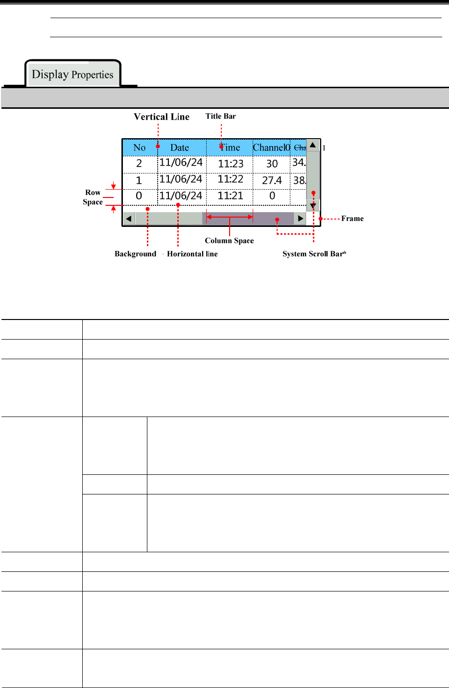
Advanced Part Component
229
External Device option, or both must be checked.
Detail Description of Display Properties
※If the information in Historical Data Display component cannot be displayed entirely, the scroll bar will be built
automatically to make user to view the whole information. And the width of system scroll bar can be set in HMI
Attributes >> HMI Extended Attributes, ranges from 20~120 pixel.
Channel The continuous register number, 16 channels at most.
Sequence No. Display the sequence number or not.
Ascending Order
Checked means the sampling data information is arranged in ascending order, that is to say the latest
sampling data is displayed at bottom; Unchecked means the sampling data information is arranged
in descending order, that is to say the latest sampling data is displayed at top.
Date
Checked means to display the sampling date, and choose the date format, three
formats are optional, in the date format, YY means year, MM means month, DD
means day.
Date Separator Choose the date separator; three formats are optional, for example 11/06/24.
Date/Time Display
Time
Checked means to display the sampling time, and choose the time format, three
formats are optional, in the date format, HH means hour, MM means minute, SS
means second, MS means millisecond.
Color Setting Set the color for grid background and tile bar.
Border Setting Set the border color and border line width of grid.
Separator Setting
Set the separator color, style and width of each row and column in grid, the unit of Row Space and
Column Space is pixel point. And check the Horizontal Line means to display horizontal line, check
the Vertical Line means to display vertical line.
Historical Data
Query
The data that is saved to the external device can be queried by specified register in Historical Data
Query. The default length of specified register is 2.
Kinco HMIware Configuration Edit Software
230
Query by file
order
Check the “Query by file order”, when the value in specified register is 0, it
means to query today or the latest day’s historical data, 1 means to query the
previous day’s historical data and so on. For example, there are two csv file in
the external device, when the value in specified register is 0, the historical data
file saved on 24th, June, 2011 is queried and displayed, when the value in
specified register is 1, the historical data file saved on 21st, June, 2011 is queried
and displayed.
Query by date
Check the “Query by date” and input the date to the specified register, then the
historical data in corresponding date is queried and displayed. The format of
inputting date is yyyymmdd, yyyy means year, mm means month, and dd means
day, for example, input 20110624 in the specified register, the historical data
sampled on 24th, June, 2011 is queried and displayed.
Variable Circle The sampling circle is read from specified register in Time Sampling mode.
!
If the Variable Circle is configured, the Variable Circle value will be used preferentially; and the preset
value is called when the Variable Circle value cannot not be read because of losing communication..
Detail Description of Background Attribute
Time Sampling Sample the data periodically.
OFFON
trigger sampling
Only when the specified register changes from OFF to ON, the sampling is
triggered.
ONOFF
trigger sampling
Only when the specified register changes from ON to OF, the sampling is
triggered.
OFFNO
trigger sampling
Only when the specified register changes its status, the sampling is triggered.
OFFON reset
trigger sampling
Only when the specified register changes from OFF to ON, the sampling is
triggered, and the specified register resets automatically.
Sampling Methods
ONOFF reset
trigger sampling
Only when the specified register changes from ON to OFF, the sampling is
triggered, and the specified register resets automatically.
Cycle
Time interval between every two sampling points, the sampling points can be second or hundred
milliseconds.
Sam. Type Continuous The sampling will continue after all the sampling points are finished.
Advanced Part Component
231
Once
The sampling will stop after all the sampling points are finished, the sampling is
executed once.
Sampling Points In the “Once”Sam.Type , the sampling will stop after all the Sampling Points are finished
Trigger Register
Setting
It is the specified register in the “Trigger Sampling” Sampling Method.
Pause
The default word length is 2. The pause function is used to stop the sampling, the pause address is
the specified address. The clear function is used to clear the sample data saved in the flash, the clear
address is the specified address+1.
Note: If “Historical Data Query”is selected, the display data is from external device, at the time
the clear function is disable.
Description of Channel Properties
Display Checked means displaying this channel data information in grid.
Data Type
Set the data format of sampling data, supporting format is 16-bit signed, 16-bit unsigned, 32-bit
signed, 32-bit unsigned, float, double.
Min/Max Limit N/A Integer N/A Decimal N/A
☞For details, refer to [Advanced Part 4.1.10 Save Historical Data]
!
Historical Data Display component and Trend Curve can be used together, but when they sample the same
registers and save the data in external device, the sub routine of saving file must be different, or chose only
one historical data (Historical Data Display component or Trend Curve.) to save.
Select [Use Background Data Print] to enable realtime print historical data. If [Net Print] is select, historical data can be
printed in network.
Description of Background Data Print
Use Background Data Print Enable the background data print
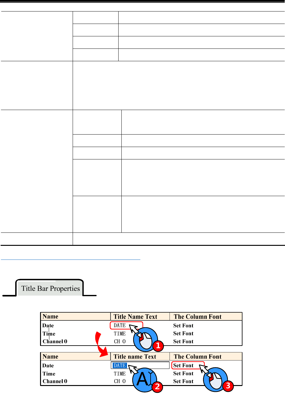
Kinco HMIware Configuration Edit Software
232
Real-time Print every sampling data in real-time.
Batch Trigger printing when the sampling point number equals the set value.
Point Set the sampling points number in batch printing
Print Type
Trig Trigger printing when the specified register satisfies the set condition.
Net Print Enable the Net Print, download the program to HMI, and then run the Net Print.exe to
connect the network printer to print historical data.
Note: If the Net Print is checked, the local printing is invalid. Even if the local printer is
connected to HMI, the HMI still cannot print via local printer.
Print Serial
Number
Print serial number of each sampling point.
Print Table Header Print the table header of Historical Data Display component.
Print Grid Pint the grid ground of Historical Data Display component.
Print Date Print date of each sampling data, and select the date format and
separator. There are three date format and separator, YY means year ,
MM means month, DD means day.
Print Content
Print Time Print time of each sampling data, and select the time format and
separator. There are three date formats and separators, HH means
hour, MM means minute, SS means second, MS means millisecond.
Grid Set the line type, line width and color of grid background.
5☞For details, refer to [Advanced Part 13.3.2 Network Print]
User can set the title name a font in this page, see as follows:
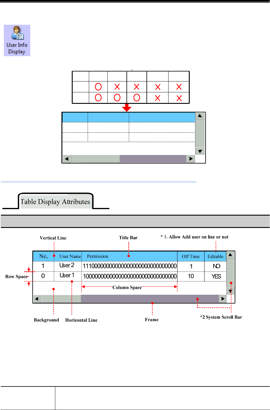
Advanced Part Component
233
4.13.3 User Info Display
When configure the “User Permission Setting” function, use the User Info Display component to dispay
the user information(system registered or added on line.) in table format.
User Permission registered in system
User1
User2
Permission
2Permission
3... Permission
32
User2
1
0User1
111000000000000000
NO. User Name Permission
100000000000000000
User
Name Permission
1
5☞For details, refer to [Advanced Part 10.3.2 User Permission Protection for Components]
Description of Table Display Attributes
*1. Users that registered in User Permission Setting of HMI Attribute cannot be deleted on line, so the Editable option in
the User Infor Display component is “NO”.
*2. When the user information cannot be wholly displayed in vertical or horizontal direction, system will provide scroll
bar automatically. The width of system scroll bar can be set in HMI Extend Attributes of HMI Attributes, the width
are optional from 20 to 120(pixel).
Table Display
Attributes
Checked means displaying sequence number before each item.
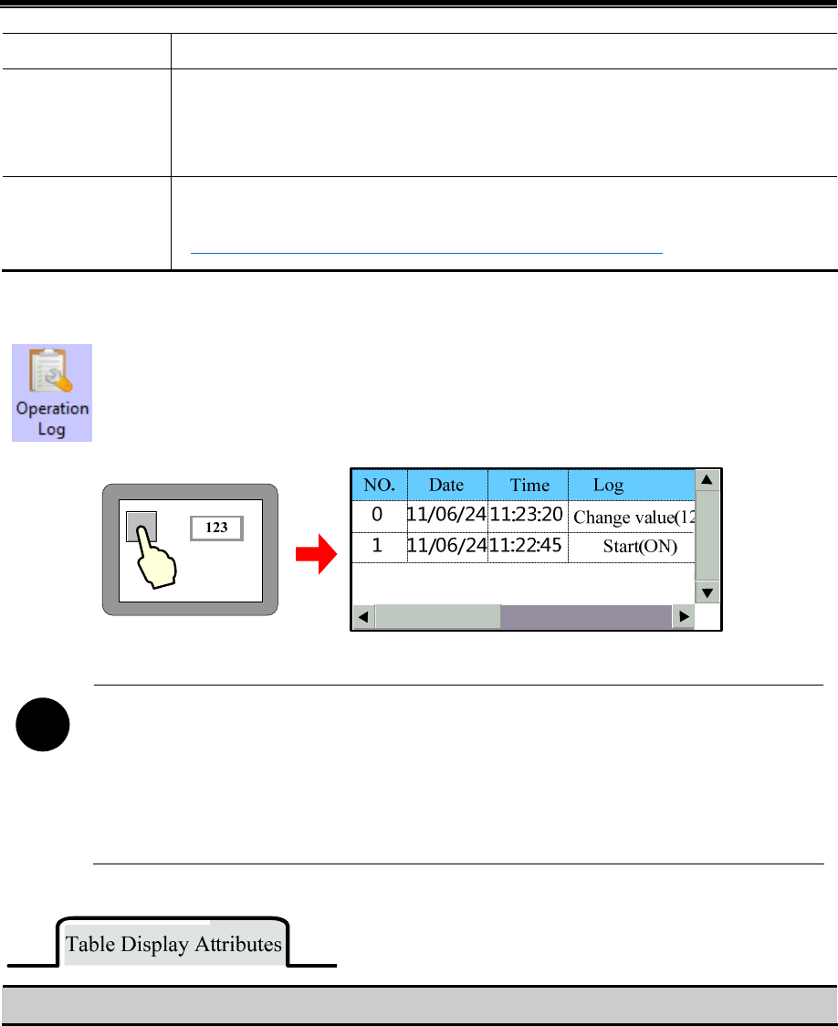
Kinco HMIware Configuration Edit Software
234
Back Ground Setting Set the background, title bar, frame color and frame width of table.
Separator Setting
Set the separator color, line style, width and row space, column space. The unit of row space and
column space are pixel point. Check the “Vertical Line” means displaying the vertical separator
line, and check the “Horizontal Line” means displaying the horizontal separator line.
Title Bar Setting
Set the display name and font attribute of table title bar.
☞For details, refer to [Advanced Part 4.13.2 Historical Data Display]
4.13.4 Operation Log
The Operation Log component recode the all the operations on the HMI and display them in table, these
recode can be saved as CSV file in external memory device.
!
1. The Read Address of Operation Log is the specified register that is used to query the operation log, the
default word length is
2. The Operation Log can display operation result of Bit State Setting, Number Input , Text Input
component and so on.
3. The Operation Log component is only suitable for HMI with SD card or U disk.
Description of Table Display Attributes

Advanced Part Component
235
* When the operation log cannot be wholly displayed in vertical or horizontal direction, system will provide scroll bar
automatically. The width of system scroll bar can be set in HMI Extend Attributes of HMI Attributes, the width are optional
from 20 to 120(pixel).
Time Checked means displaying the operation time and chose the time format, three
formats are operational. HH means hour, MM means minute, SS means second,
MS means millisecond.
Date Checked means displaying the operation date and chose the time format, three
formats are operational, YY means year, MM means month, DD means day.
Date Separator Choose the date separator, three formats are operation, for example 11/06/24
Sequence No. Checked mean displaying sequence number of each operation log.
User Name* Checked means displaying operation user name.
Table Display
Ascending Order Checked means that the operation logs are arrange in ascending time order, that is
to say the latest log is at the bottom; unchecked means that the operation logs
are arrange in descending time order, that is to say the latest log is on the top.
Background
Setting
Set the background, title bar, frame color and frame width of operation log table.
Query by File
Order
If the “Query by File Order” is checked, 0 in specified register means to call
today’s log or latest day’s log; 1 means to call the previous day’s log and so on.
For example, there are two operation log csv file in external memory device, they
are 20110621.csv and 20110624.csv, when the value in specified register is 0, the
csv file that is saved on 24th , June, 2011 is called, when the value in specified
register is 1, the csv file that is saved on 21st , June, 2011 is called and displayed.
Historical Logs
Query
Query by Date If the “Query By Date” is checked, input date in specified register to call the
corresponding operation log. The inputting date format is yyyymmdd, yyyy
means year, mm means month, dd means day. For example, input 20110624 to
specified register, the operation log that is saved on 24th, June, 2011 is called
and displayed.
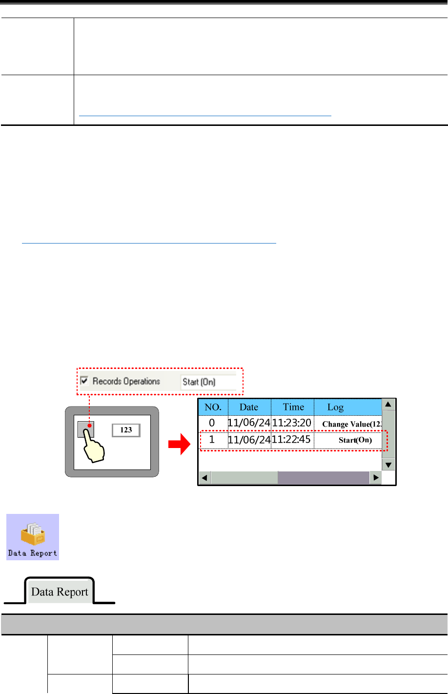
Kinco HMIware Configuration Edit Software
236
Separator Setting Set the separator color, line style, width and row space, column space. The unit of row space and
column space are pixel point. Check the “Ver t i ca l L i n e ” means displaying the vertical separator line,
and check the “Horizontal Line” means displaying the horizontal separator line.
Title Bar Setting Set the display name and font attribute of table title bar.
☞For details, refer to [Advanced Part 4.13.2 Historical Data Display]
*When using the User Permission function, the User Name column displays the current user name.
Related attributes settings of Operation Log.
>> Operation Recode Storage Setting
User needs to set the storage path for Operation Log storage file in HMI Attributes>> HMI Extended Attributes>>
Operation Recode Storage Setting.
☞For details, refer to [Advanced Part 6.1.3 HMI Extended Attributes]
If the CSV file is stored by Daily File type, the storage path is log/subdirectory/yyyymmmdd.csv; if the CSV file is
stored by Signal File type, the storage path is log/subdirectory/subdirectory.csv. Note: yyyymmdd is the date on which
the operation log is built, for example 20110101.
Recode Operations setting in component attributes.
The components whose operation log needs recoding must check the Recodes Operations in Control Setting of
component attributes and input description information in the text frame.
4.13.5 Data Report
Data Report is used to display the data that is logged in the Data Logger and stored in external memory
device on the HMI in report. The logged registers can be continuous or discontinuous registers.
Detail Description of Data Report
Real time Update the report data timely according to the settings.
Report mode
History Input the time range to query the historical report.
Data
Report
Attribute Report type Trigger Report In the user defined time interval, trigger the sampling to get the instant

Advanced Part Component
237
data.
Free Report Display all the data in the user defined time interval.
Note: In the real-time Report Mode, if the Free Report exceeds the
user defined length, the earliest data will be deleted, then the whole
report moves up
Daily Report Display the data of one day.
Note: In the real-time Report Mode, the Daily Report is displayed in
circle. The new data is displayed at the bottom of report. If the report
exceeds the length of row number, the newest data displays at the top
of report, and all the data in previous circle will be deleted, only the
newest row data is reserved, and then start a new circle.
Monthly Report Display the data of the moth
Quarterly Report Display the data of three months
Annual Report Display the data of a year.
By Order The sampling data is sequenced by time order; the newest data is at
the bottom.
Dis. Order
Reverse The sampling data is sequenced by reverse time order, the newest data
is at the top
Report Line
Set the displaying lines of report, this parameter is only suitable for the Trigger Report and
Free Report.
Note:
1. The line number of Daily Report is created automatically according to the Timer
Interval, for example, the time interval is 1 hour, so the line number is 24.
2. The line number of Monthly Report is 31, Quarterly Report is 3, and Annual Report is
12.
3. In the “History” Report mode, the line number of Free Report and Free Report depends
on the user defined time interval.
Get Value
Type
There are five options; they are Instantaneous Value, Min Value, Max Value, Average Value
and Added Value.
When the Get value Type is one of Min Value, Max Value, Average Value or Added Value,
the report displays the min value, max value, average value or added value of all the
sampling values in a circle.
Time Record
There are Begin Time, Mid Time, and End Time.
The time that displayed in the report can be begin time, middle time or end time.
Empty Data Specified Value When there is no value in sampling register, the report displays specified

Kinco HMIware Configuration Edit Software
238
value, the default value is 0.
Process Last Valid Value When there is no value in sampling register, the report displays the last
valid value.
Time Interval
The time interval of report, there are two options, they are minute and hour.
Note: This option is only suitable when the Free Report and Daily Report are selected.
Because the time interval of Monthly Port and Quarterly Report are month, and time
interval of Annual Report is year.
History Inquire Address, the word length is 8.
Trigger Report
Start Date: specified address, word length is 2, input year and date in this address.
Start Time: specified address +2, word length is 2, input time (hour, minute and minute)
in this address.
End Date: specified address +4, word length is 2, input year and date in this address.
End Time: specified address +6, word length is 2, input time (hour, minute and second)
in this address.
Take the following picture for example, the specified address is LW200, and user wants
to query the data between 9:30:40 14th, Aug, 2012 and 14:16:30 15th, Aug, 2012.
So the specified addresses are as follows:
Start Date:LW200=20120814
Start Time:LW202=93040
End Date:LW204=20120815
End Time:LW206=141630
History
Inquire
Address
Trigger Report
Start Date: specified address, word length is 2, input year and date in this address.
Start Time: specified address +2, word length is 2, input time (hour, minute and minute)
in this address.
End Date: specified address +4, word length is 2, input year and date in this address.
End Time: specified address +6, word length is 2, input time (hour, minute and second)
in this address.
Take the following picture for example, the specified address is LW200, and user wants
to query the data between 9:30:40 14th, Aug, 2012 and 14:16:30 15th, Aug, 2012.
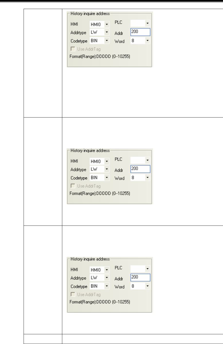
Advanced Part Component
239
So the specified addresses are as follows:
Start Date:LW200=20120814
Start Time:LW202=93040
End Date:LW204=20120815
End Time:LW206=141630
Daily Report
The specified address, word length is 2, and input year and date in this address.
Take the following picture for example, the specified address is LW200, and user wants
to query the data on 14th, Aug, 2012.
So the specified address is as follows:
LW200=20120814
Monthly Report
The specified address, word length is 2, and input year and month in this address.
Take the following picture for example, the specified address is LW200, and user wants
to query the data in Aug, 2012.
So the specified address is as follows:
LW200=201208
Quarterly Report
The specified address, word length is 2, and input year and quarter number in this
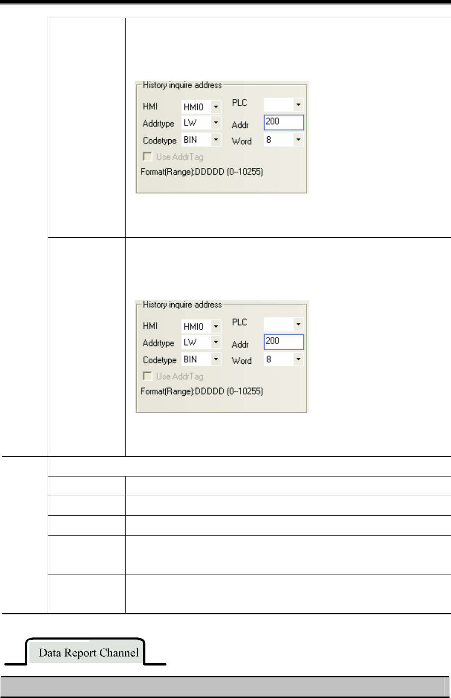
Kinco HMIware Configuration Edit Software
240
address.
Take the following picture for example, the specified address is LW200, and user wants
to query the data of the third quarter 2012.
So the specified address is as follows:
LW200=201203
Annual Report
The specified address, word length is 2, and input year in this address.
Take the following picture for example, the specified address is LW200, and user wants
to query the data of 2012.
So the specified address is as follows:
LW200=2012
When the specified register satisfies the set condition, output report data.
OFFON Only when the specified register changes from OFF to ON, HMI outputs report data.
ONOFF Only when the specified register changes from ON to OFF, HMI outputs report data.
OFFON Only when the specified register changes its status, HMI outputs report data.
OFFON(reset)
Only when the specified register changes from OFF to ON, HMI outputs report data, and
then reset the specified register automatically.
Trig
history
inquire
ONOFF(Reset)
Only when the specified register changes from ON to OFF, HMI outputs report data, and
then reset the specified register automatically.
Detail Description of Data Report Channel
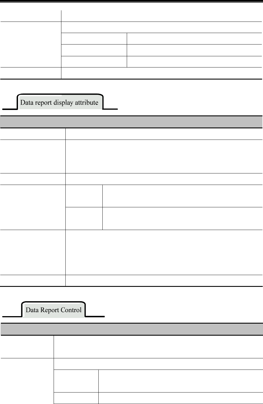
Advanced Part Component
241
Data Logger Click this button to pop up Data Logger library.
Click this button pop up the dialog box to choose channels.
Data Sample List Display all the sampling data in the Data Logger library.
Data Sample Channel Display all channel information of one sampling data.
Data Report Channel List
The data-report channel list Display the selected channels of current report.
Data report channel. Set the title, integer and decimal of report channel.
Details of Data report display attributes
Serial number Display the serial number of sampling data or not.
Display time
If checked, report displays the sampling time, and chooses the time format and separator.
There are three formats optional, HH means hour, MM means minute, SS means second,
MS means millisecond.
Back color Set the background color and title bar color.
Date Format Display sampling date, and choose the date format, there are three formats
optional, YY means year, MM means month and DD mans day.
Display date
Separator Select the date separator, three formats are optional, for example
12/07/19.
Separator border settings
Set the color, type and width of separating line, and set the width of each row and column,
the unit is pixel
If the Horizontal Line is checked, report displays horizontal separator, if the Vertical Line is
checked, report displays vertical separator,
Title bar settings Set the display name and font of title bar.
Details of Data Report Control attributes
Pause Address
In real-time report mode, use a bit register to pause data sampling, ON means pause, OFF means
outputting data.
In real-time report mode, use a bit register to clear the sampling data in Data Report Display.
OFFON
Only when the specified register changes from OFF to ON, HMI clears the
sampling data in Data Report Display.
Data clear address
ONOFF
Only when the specified register changes from ON to OFF, HMI clears the
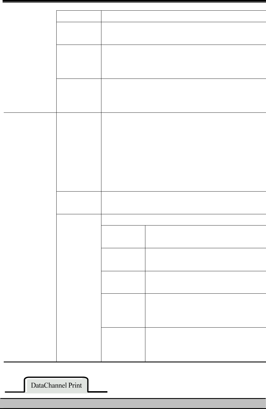
Kinco HMIware Configuration Edit Software
242
sampling data in Data Report Display.
OFFON
Only when the specified register changes its status, HMI clears the sampling
data in Data Report Display.
OFFON(Reset)
Only when the specified register changes from OFF to ON, HMI clears the
sampling data in Data Report Display, and then reset the specified register
automatically.
ONOFF(Reset)
Only when the specified register changes from ON to OFF, HMI clears the
sampling data in Data Report Display., and then reset the specified register
automatically.
Export Dir The subroutine name of the exported sample data file in the external
memory device, the default name is ReportToCSV, user can modify it
himself and the detail routine in external memory device is :\external
memory device\export\Export Dir, the file name is named according to the
saving time: year-month-day, hour: minute: second: millisecond, for
example 20120903-110552.csv
File format: csv.
Save Disk Save the exported data to the external memory device: SD card, USB1 or
USB2.
When the specified register satisfies the set condition, HMI exports data.
OFFON
Only when the specified register changes from OFF to
ON, HMI exports report data.
ONOFF
Only when the specified register changes from ON to
OFF, HMI exports report data.
OFFON
Only when the specified register changes its status,
HMI exports report data.
OFFON(reset)
Only when the specified register changes from OFF to
ON, HMI exports report data, and then reset the
specified register automatically.
Sample Data Export
Export data
Trigger Param.
ONOFF(Reset)
Only when the specified register changes from ON to
OFF, HMI exports report data, and then reset the
specified register automatically.
Description of print attributes
Advanced Part Component
243
Enable background
data print
Check the option to enable print function for Real Time Data Report.
Note:only the Real Time report mode support print function.
Print per point Print is triggered be every sampled point.
Print per batch When number of sampled points equals to preset number of points, print is
triggered.
Number of
points
Set number of points for print per batch
Print is triggered when the assigned register satisfy corresponding condition.
There are up to 5 trigger modes selectable:
OFF→ON Print is triggered when the assigned registers changes form OFF to
ON.
ON→OFF Print is triggered when the assigned registers changes form ON to
OFF.
OFF↔ON Print is triggered when the assigned register changes states.
OFF→ON
(Auto
reset)
Print is triggered when the assigned registers changes form OFF to
ON. Then the assigned register resets automatically.
Mode
Trigger by
register
ON→OFF
(Auto
reset)
Print is triggered when the assigned registers changes form ON to
OFF. Then the assigned register resets automatically.
Net print Enable the Net Print, download program to HMI. And then run the NetPrint.exe to connect network
printer to print Data Report.
Note: if the Net Print is checked, the local printing is invalid. Even If the local printer is connected to
HMI, the HMI still cannot print via local printer.
Print Sequence
No.
Print sequence NO. of sampled data.
Print Title Print the title of data report display component.
Print Grid Print grid background of data report display component.
Print Date Check this option to print date for each sampled data, and set date format and
separator. There are up to 3 data formats and separators selectable. YY indicates
year; MM indicates month; DD indicates day.
Print setting
Print Time Check this option to print time for each sampled data, and set time format and
separator. There are up to 3 time formats and separators selectable. HH indicates
hour; MM indicates minute; MS indicates millisecond.
Grid attributes Set grid attributes such as grid line style, width, color. Also the title and font are settable here.
Details of Page Display Setting attributes
Number of items per page Maximum items displayed in one page
TotalPages Addr Total page number is calculated according to inquiry time:total page=number of total
Kinco HMIware Configuration Edit Software
244
items/Number of items per page
PageNumber Addr Users could unquiry by page number, Range:0~(Total page-1),0 indicates the first page.
1. Do not put multiple free reports in a same window, it will affect the communicate speed.
2. Do not add too many data channels in a signal Free Report.
3. If there are multiple free reports or multiple channels report in a same window, please use the minute or
hour as Time Interval.
4. If you want to plug off the external memory device when HMI is in operation, we suggest using the safe
mode, but not plug it off directly. Safe Mode: set the LB9153 (SD card), LB9154 (USB1), LB9155
(USB2) OFF first, then plug of the corresponding memory device.
5. When you download the project again, check the Clear data report option in KHDownload, or the
residual information may cause the data error for the new sampling data.
Take the MT4522T for example, suppose the sampling address is Dword0, three channels’ data, and the sampling data is
stored in SD card, user can query the data in any time interval.
Build a new project, and add a Data Logger, the parameters are as follows:
Data Sample HMI HMI0
Sample Point 10
Sample Type Circling Sample
Get Data Type Sample Continue
Channel 3
Sample Circle 10
Data Type 16-bit signed/32-bit signed/float
Sample channel
Description Channel 0/Channel 1/Channel 2
Data Sample Control
Sample Address D0
Save Disk SD Card Sample Data Save
Save Dir SampleDataStore
Build a Data Report in Frame0 to display data in the Data Logger , the attributes setting is as follows::
Report mode History
Report type Trig type
Disp.type By order
Get value type InstantantaneousValue
Data report attribute
Empty data process 0
History inquire address LW0
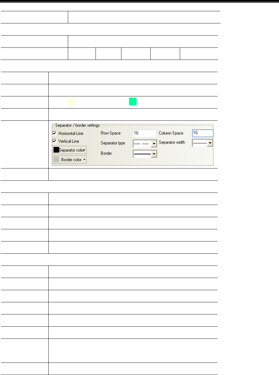
Advanced Part Component
245
Trig history inquire LB0,Trigger type: OFF>>ON, Reset
Data report channel:
The data-report channel list Add channel 0 and chann2 to this list
Data report Channel Integer 4 Decimal 2
Data report display attribute
Serial Number Checked
Display time Checked, the format is HH:MM:SS
Back color Back:(light yellow);title: (light blue)
Display date Date format:YY*MM*DD;separator:/
Separator/border
setting
Title Bar Setting Default setting.
Put 4 Number Input components and a Bit State Switch in frame0:
Start Date LW0,DWORD
Start Time LW2,DWORD
End Date LW4,DWORD
End Time LW6,DWORD
Inquire Trigger LB0;Switch Type: toggle.
Put 3 Timer components in frame0 to simulate the change of D_Word registers, the attributes setting are as follows:
Mode Periodical Jog++(circle)
Data Type Word
Asc Value 1/6/3
Upper 100/150/200
Addr.Type D_word
Address 0/1/3
Value Type Unsigned Int (word length 1)/Signed Int (word length 2)/float (word
length 2)
Timer Trigger mode: All time, Execution Cycle:10
After a period of time, suppose the HMI system time is 2012/11/09, 16:50:00, we want to query the data between 16:40:30
and 16:41:00, the operation is as follows.
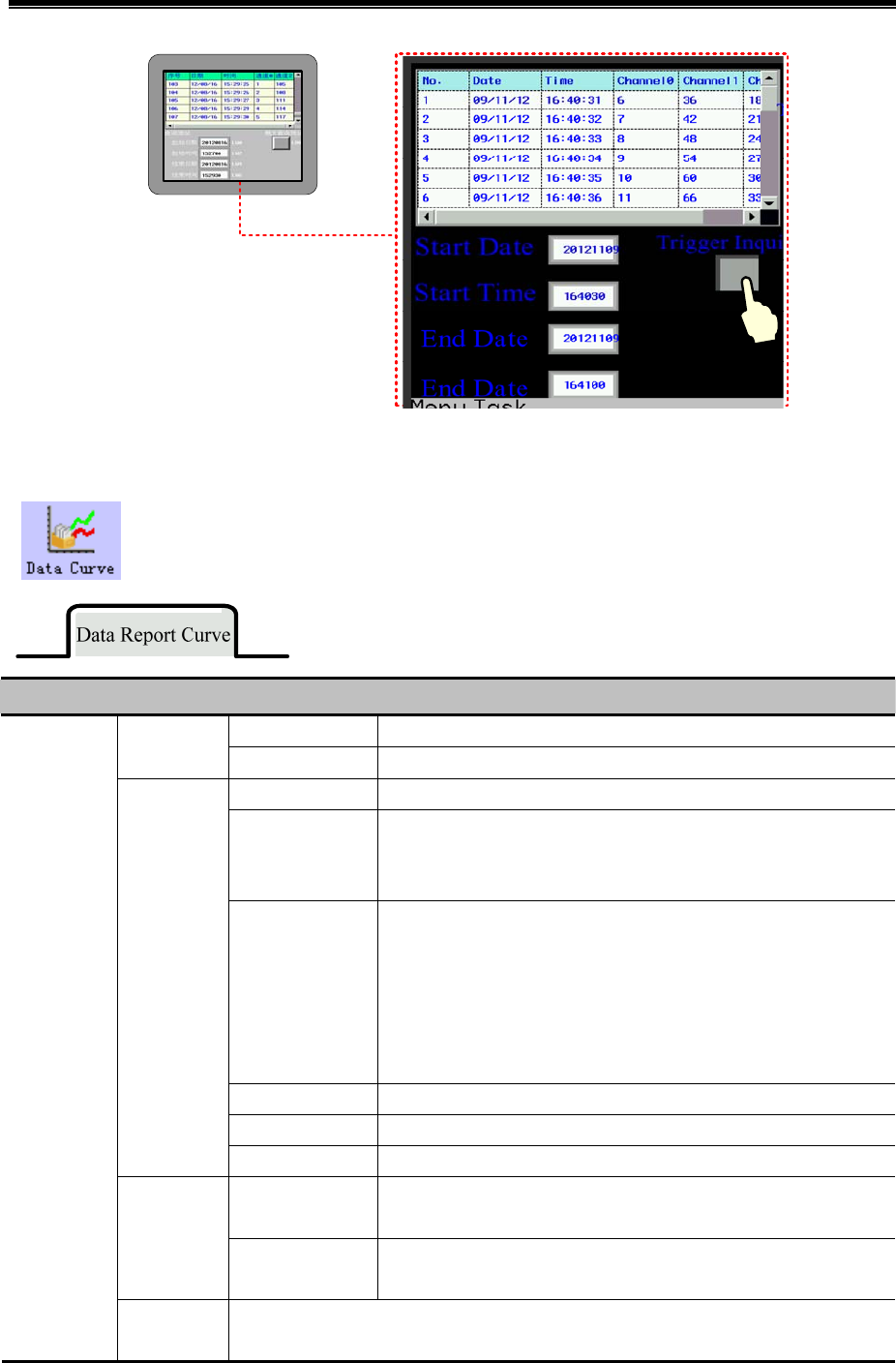
Kinco HMIware Configuration Edit Software
246
事件信
息
4.13.6 Data Curve
Data Report Curve component is used to display data that is logged in the Data Logger and stored in
external memory device on the HMI in curves. The logged registers can be continous or discontinuous
registers. newly added. Via the Data Report Curve component, users could display the sampled data in
trend curves on HMI.
Detail Description of Data Report Curve
Real time Update data report curve timely according to the settings. Report
mode History Query historical data report curve according to input time range.
Trigger Report During defined time interval, trigger sampling to get instant data.
Free Report Display all the sampled data in defined time interval.
Note: In Real Time mode, if Free Report exceeds the defined length,
then the earliest data will be deleted, and the whole report moves up.
Daily Report Display the data of one day.
Note: In real-time Report Mode, the Daily Report is displayed in
circle. The new data is displayed at the bottom of report. If the report
exceeds the length of row number, the newest data displays at the top
of report, and all the data in previous circle will be deleted, only the
newest row data is reserved, and then start a new circle.
Monthly Report Display the data of one month.
Quarterly Report Display the data of three months.
Report type
Annual Report Display the data of one year.
By Order The sampled data is sequenced by time order; the newest data is at the
bottom.
Display
Order
Reverse The sampling data is sequenced by reverse time order, the newest data
is at the top.
Data Report
Curve
Attribute
Total Points Set number of total points of Data Report Curve. It is only valid for Trigger Report and Free
Report in Real Time Report mode.

Advanced Part Component
247
Note: If the number of sampled points exceeds number of total points, the earliest data will
be deleted, and the newest sampled data will be displayed at the end of the curve.
Get Value
Type
There are five options: Instantaneous Value, Min Value, Max Value, Average Value and
Added Value.
When Min Value, Max Value, Average Value or Added Value is set, it will calculate all the
sampled data during set time interval, and output corresponding Min Value, Max Value,
Average Value, Added Value.
Time
Record
There are Begin Time, Mid Time and End Time selectable for time displayed in report.
Specified
Value
When there is no value in sampled register, the report displays specified value,
the default specified valued is 0.
Empty Data
Process
Last Valid
Value
When there is no value in sampled register, the report displays the last valid
value.
Time
Interval
There are two options for report time interval: minute and hour.
Note: This option is only suitable when Free Report and Daily Report. Because time interval
for Monthly Report, Quarterly Report and Annual Report are fixed as month, three month
and year respectively.
History Inquire Address, word length is 8.
Trigger
Report
Start Date: specified address, word length is 2, input year and date in this address;
Start Time: specified address+2, word length is 2, input time (hour, minute and second) in
this address;
End Date: specified address+4, word length is 2, input year and date in this address;
End Time: specified address+6, word length is 2, input time (hour, minute and second) in
this address;
【Example】It is the same with Data Report Display component.
Free Report Start Date: specified address, word length is 2, input year and date in this address;
Start Time: specified address+2, word length is 2, input time (hour, minute and second) in
this address;
End Date: specified address+4, word length is 2, input year and date in this address;
End Time: specified address+6, word length is 2, input time (hour, minute and second) in
this address;【Example】It is the same with Data Report Display component.
Daily
Report
The specified address, word length is 2, input year and date in this address.
【Example】It is the same with Data Report Display component.
Monthly
Report
The specified address, word length is 2, input year and month in this address.
【Example】It is the same with Data Report Display component.
Quarterly
Report
The specified address, word length is 2, input year and quarter number in this address.
【Example】It is the same with Data Report Display component.
History
Inquire
Address
Annual
Report
The specified address, word length is 2, input year in this address.
【Example】It is the same with Data Report Display component.
Output data report curve when the specified register satisfies the set condition.
OFF→ON Only when the specified register changes from OFF to ON, HMI outputs data report curve.
ON→OFF Only when the specified register changes from ON to OFF, HMI outputs data report curve.
OFF←→ON Only when the specified register changes its status, HMI outputs data report curve.
Trig history
inquire
OFF→ON Only when the specified register changes from OFF to ON, HMI outputs data report curve,
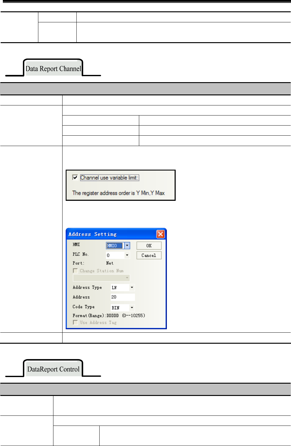
Kinco HMIware Configuration Edit Software
248
(Auto reset) and then reset the specified register automatically.
ON→OFF
(Auto reset)
Only when the specified register changes from ON to OFF, HMI outputs data report curve,
and then reset the specified register automatically.
Detail Description of Data Report Channel
Data Logger Touch this button to pop up Data Logger library.
Touch this button to pop up dialog box to choose channels.
Data Sample List Display all sampling data added in the Data Logger Library.
Data Sample Channel Display all channel information of one sampling data group.
Data Report Channel
List
The data-report channel list Display all the channels added to the current report.
Variable Max/Min
Value Setting
Check this option, the report channel read maximum and minimum value from specified
registers.
For example: The specified address is LW20, then LW20 indicates the minimum value and
LW21 indicates the maximum value.
Data report channel Set the title, integer and decimal of report channel.
Detail Description of DataReport Control
Pause address In real-time report mode, use a bit register to pause data sampling, ON means pause, OFF means
outputting data.
In real-time report mode, use a bit to clear the sampling data in Data Report Curve. Data clear address
OFF→ON Only when the specified register changes from OFF to ON, HMI clears data
report curve.
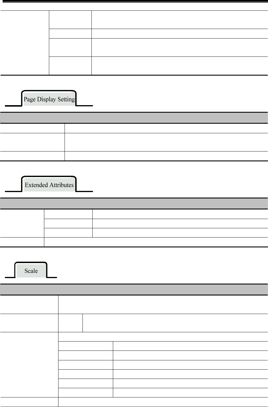
Advanced Part Component
249
ON→OFF Only when the specified register changes from ON to OFF, HMI clears data
report curve.
OFF←→ON Only when the specified register changes its status, HMI clears data report curve.
OFF→ON(Auto
reset)
Only when the specified register changes from OFF to ON, HMI clears data
report curve, and then reset the specified register automatically.
ON→OFF(Auto
reset)
Only when the specified register changes from ON to OFF, HMI clears data
report curve, and then reset the specified register automatically.
Detail Description of Page Display Setting
Number of items per page Maximum items displayed in one page.
TotalPage Addr Total page number is calculated according to inquiry time: total page=number of total
items/Number of items per page.
PageNumber Addr Users could inquiry by page number, Range: 0~(total page-1). 0 indicates the first page.
Detail Description of Extended Attributes
Channel Set line style and width.
Connect Style Dot, LINE, X axis projection, Y axis projection.
Channel
Properties
Node Properties Set node graph, node size, node color.
Use Grid Set line number, column number, background color, grid line width, grid line style and grid line color.
Detail Description of DataReport Control
Horizontal Scroll Bar Check this option to use the system scroll bar. Users can set scroll bar width range 20~120
pixels.
Vertical Axis Scale
Reference Channel
Channel The maximum/minimum value of the vertical axis takes the maximum/minimum
value of the reference channel.
Check this option to display vertical axis scale
Scale color Set vertical axis scale color
Display Scale Frame Display vertical axis scale frame
Major Scale Number Set major scale number
Major Scale Length Set major scale length, unit: pixel.
Minor Scale Number Set minor scale number.
Use Vertical Axis Scale
Minor Scale Length Set minor scale length, unit: pixel.
Use Vertical Axis Scale Check this option to display vertical axis scale label.
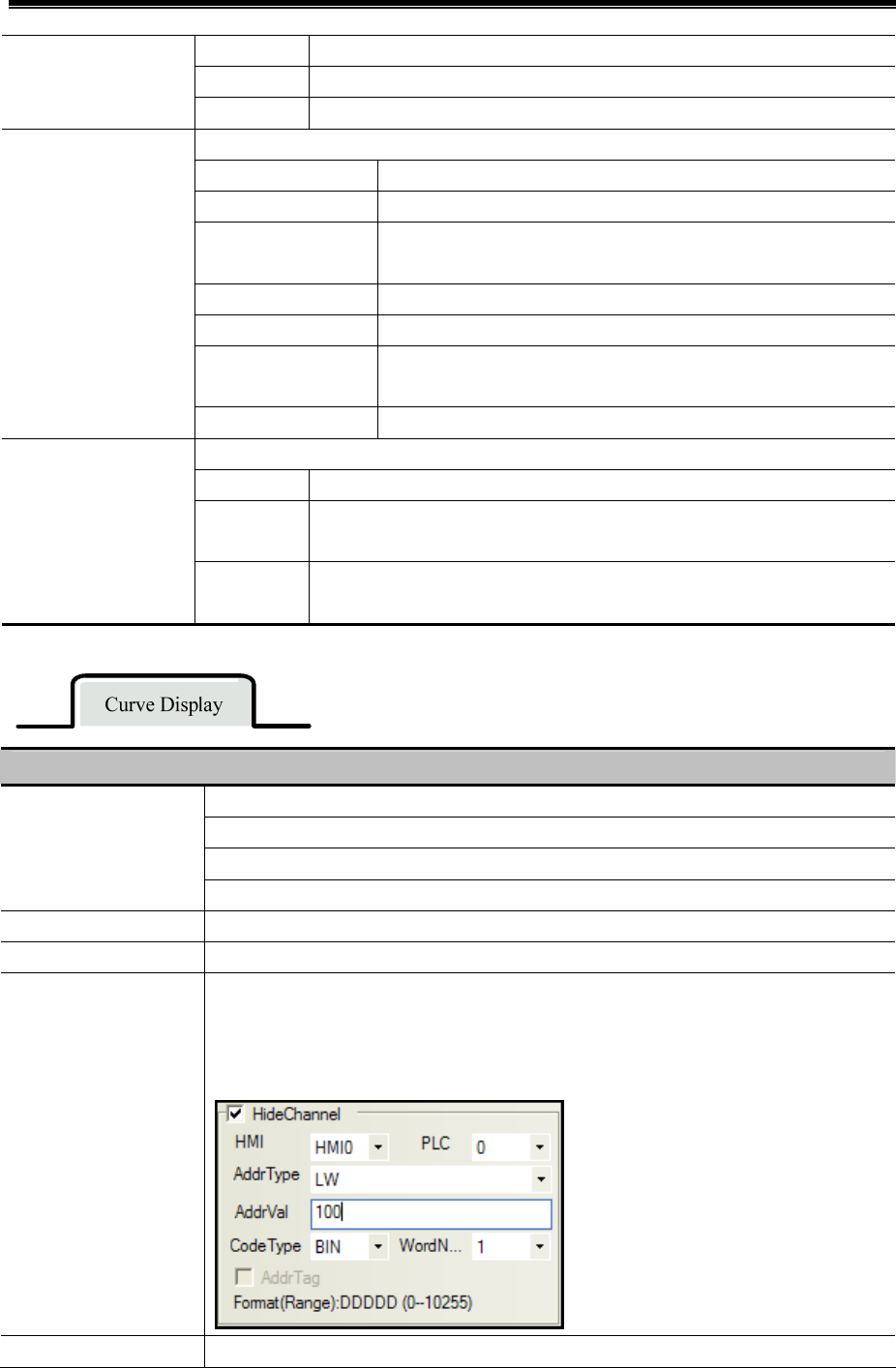
Kinco HMIware Configuration Edit Software
250
Label Font Set the label font
Integer The integer number of scale (Users cannot adjust it).
Label
Decimal The decimal number of scale (Users cannot adjust it).
Check this option to display horizontal axis scale.
Scale Color Set horizontal axis time scale color
Display Scale Frame Display horizontal axis time scale frame
Display Relative Time Horizontal axis starts with the first sampled point, and its displayed
time is 0.
Time scale interval The time interval between two time scales, the unit is sampling circle.
Length Set the length of time scale, the unit is pixel.
Mark each sampling
point scale
Mark a scale on each sampling point.
Use Horizontal Axis
Time Scale
Length Set the length of each sampling points, the unit is pixel.
Check this option to display the horizontal time scale label.
Label Font Set the scale label font.
Integer Display and set time format. There are three formats: HH:MM:SS, HH:MM,
HH:MM:SS:MS.
Use Horizontal Axis
Time Scale Label
Decimal Display and set date format, there are three formats: DD*MM*YY,
MM*DD*YY, YY*MM*DD. Separator: “/”, “—“, “.”.
Detail Description of DataReport Control
Start from left
Start from right
Start from top
Property
Start from bottom
Sampling points Sampling points on each page
Variable sampling points Read number of sampling points on each page form specified address.
Hide Channel Set a specified register for hiding channels. Then set the corresponding bits to ON to hide the
corresponding channels.
Example: Check “Hide Channels” and set address to LW100. Then, when LW.B100.0=1,
Channel 0 will be hidden; when LW.B100.1=1, channel 1 will be hidden; and so on.
Scroll Use scroll to inquire sampled scale and time of the curve.
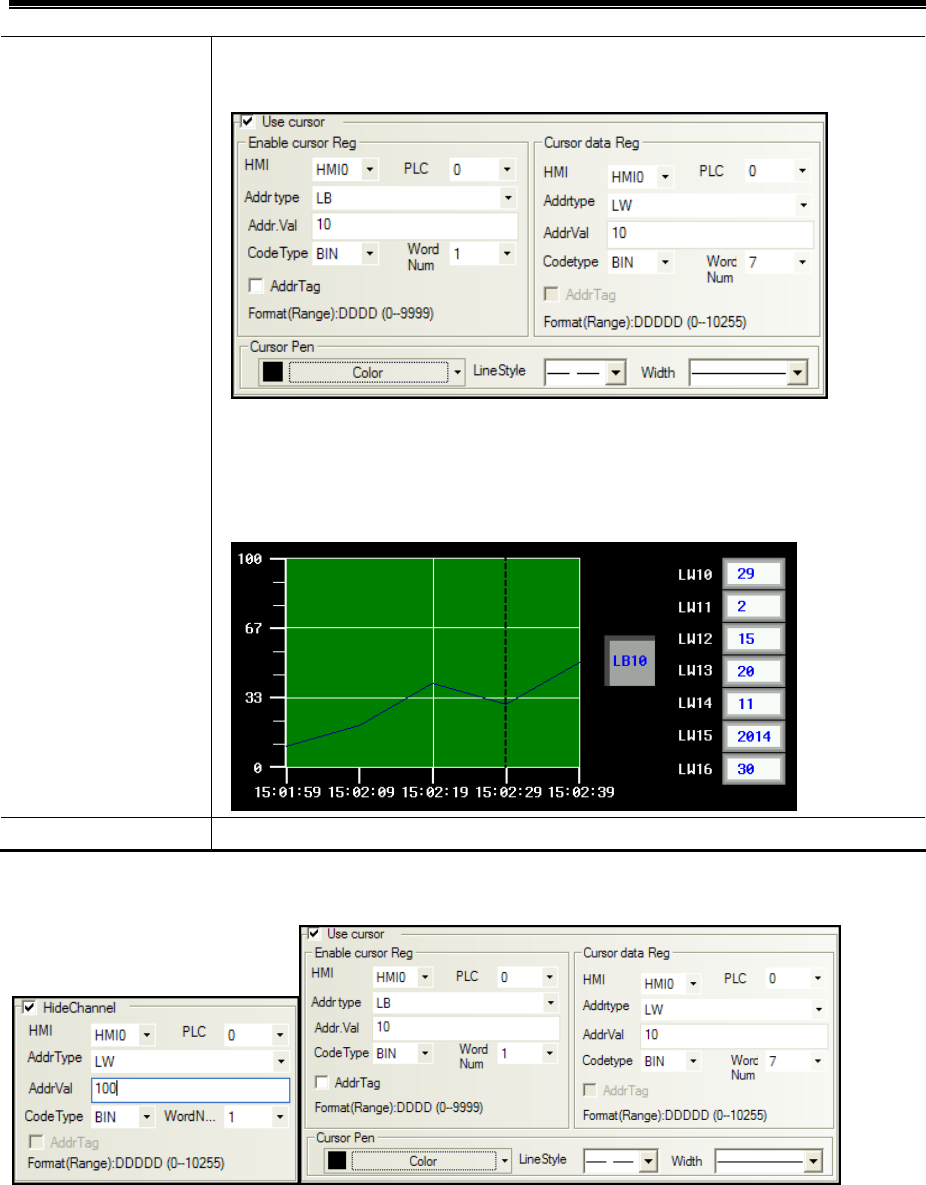
Advanced Part Component
251
Example: Check “Scroll”, set Enable Scroll Address And Scroll Data Address to LB10 and
LW10 respectively.
As following picture: Set Enable Scroll AddressLB0 to ON, then Scroll Data Address LW10,
LW11, LW12, LW13, LW14, LW15 correspond to second, minute, hour, date, month, and year
of the sampled data respectively. LW16 corresponds to data value of channel 0; LW17
corresponds to data value of channel 1, and so on.
Scroll Brush Set color, line style and width of scroll brush.
【Example】 Settings of Hide Channel and Scroll are as follows:
Set LW.B100.0 to ON, Channel 0 will be hidden; Set LW.B100.1 to ON, channel 1 will be hidden and so on.
Set LB10 to ON to enable scroll function. LW10, LW11, LW12, LW13, LW14, LW15 correspond to second, minute,
hour, date, month, and year of the sampled data respectively. LW16 corresponds to sampled value of channel 0; LW17
corresponds to sampled value of channel 1, and so on.
Offline simulation:
Scroll inquiry:

Kinco HMIware Configuration Edit Software
252
Hide Channel:
4.14 Data Transmission Component
Data Transmission component is used to exchange the data between HMI and PLC or controller. In Kinco HMIware, the
following components can be used to exchange data: Recipe Data, Data Transmission, Data Transmission function in Timer
and General PLC control in PLC Control component.
4.14.1 Recipe
Recipe Data component can transmit HMI data that can be stored even powered off to specified
PLC/controller registers, or transmit data in PLC/controller data to HMI registers that can be stored even
powered off.

Advanced Part Component
253
The Write Address of Recipe Data is the start register of transmitting PLC/controller
Detail description of Recipe Data
Upload from PLC to Recipe Transmit data in specified PLC/controller registers to HMI RW registers
Download from Recipe to
PLC
Transmit data in HMI RW registers to specified PLC/controller registers
Upload from PLC ERW0*1
Transmit data in specified PLC/controller registers to external memory
device(the default is SD card)
Download from ERW0 to PLC
Transmit data in external memory device (the default is SD card) to
specified PLC/controller registers.
Upload from PLC to ERW1*1
Transmit data in specified PLC/controller registers to external memory
device(the default is USB DISK1)
Download from ERW1 to PLC
Transmit data in external memory device (the default is USB DISK1) to
specified PLC/controller registers.
Upload from PLC to ERW2*1
Transmit data in specified PLC/controller registers to external memory
device(the default is USB DISK2)
Download from ERW2 to PLC
Transmit data in external memory device (the default is USB DISK2) to
specified PLC/controller registers.
Upload from PLC to FRW*2
Transmit data in specified PLC/controller registers to HMI FLASH
memory FRW.
Function
Download from FRW PLC
Transmit data in HMI FLASH memory FRW to specified PLC/controller
registers.
Data
Length
The length of transmitting data, unit is word.
Key
Map the function to the external keys (F1~F2) or HMI keys (F1~F8). The HMI with USB host slot or keys
supports this function. The HMI with USB host or keys supports this function.
*1.ERW0, ERW1, ERW2 are special registers for the external memory device, users can distribute them to U disk or SD card
in the Extended Memory of the HMI Attributes
2. FRW is a special register type for the HMI flash memory.
☞For details, refer to [Advanced Part 11 Recipe/ Recipe Editor]
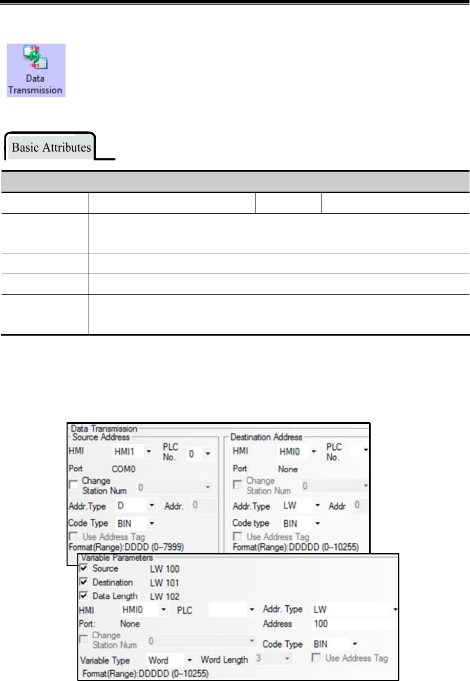
Kinco HMIware Configuration Edit Software
254
4.14.2 Data Transmission
Data Transmission component transmits data in specified HMI or PLC/controller registers to the other
HMI or PLC/controller registers. The transmission can be triggered by touching or change of specified
register.
Basic Attributes of Data Transition
Data Type Set the transmitting data type: bit or word Data Length Set the transmitting data length
Key
Map the function to the external keys (F1~F2) or HMI keys (F1~F8). The HMI with USB host slot
or keys supports this function. The HMI with USB host or keys supports this function
Source Address Set the source address of transmitting data
Destination Address Set the destination address of transmitting data
Variable Parameters
The offset of Source Address, Destination Address and Data Length are read from specified
registers
Take the following picture for example, the Source Address, Destination Address and Data Length use variable parameters,
set the D register (PLC register) for Source Address, and the LW100 (HMI register) controls the offset of Source Register;
Set LW register (HMI register) for Destination Address, and the LW101 (HMI register) controls the offset of Destination
Register; LW103 controls the Data Length.
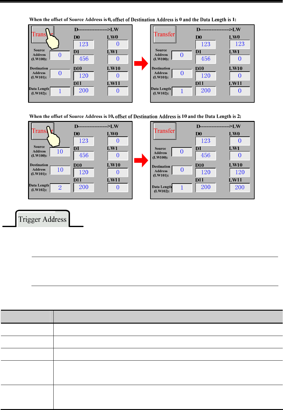
Advanced Part Component
255
Check the “Use Trigger Address” in Trigger Address page to trigger the transmission by status of specified register.
If use the trigger address to trigger the transmission but not by touch, user can set the Always Invalid in the
Control Setting page.
Detail Description of Trigger Address
Trigger Type Description
OFFON When specified register changes from OFF to ON, the transmission is triggered
ONOFF When specified register changes from ON to OFF, the transmission is triggered
OFFON When specified register changes its status, the transmission is triggered
OFFON (Reset)
When specified register changes from OFF to ON, the transmission is triggered, at the same time
reset the trigger address
ONOFF (Reset)
When specified register changes from ON to OFF, the transmission is triggered, at the same time
reset the trigger address
4.15 Project Database
In Kinco Builder, user can put the repeat information or background function in the specified area, in this way, it is easy to
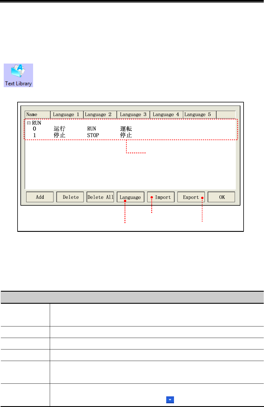
Kinco HMIware Configuration Edit Software
256
control and call this information and function, at the same time it can reduce the data redundancy. The specified area are in
the project Data Base components, they are: Text Library, Address Tag, Alarm Information, Event Information, PLC Control ,
Sound Lib and so on.
4.15.1 Text Library
Text Library component is used to store the text content in the project, so that it can avoid the input the
same text tag many times. Text Library supports multiple language, it makes the HMI can switch the
display languages. Kinco HMIware supports 32 languages switching at most.
- Text Library Interface
Import csv file*1
Export csv file*2
Open【Language Setting】
Display the text content
*1. Import csv file (text library file) to Text Library of current project
2. Export the Text Library to the CSV file, User can use Microsoft EXCEL to open and edit this CSV file.
Language attributes
Click the Language in the Text Library to open the Language Setting dialog box, in this dialog box, user can set the font
attributes of each language, refer to the following table for details:
Description of Language Setting
Max Lang Num
Text Library supports 32 different languages setting at most; the default max language number is 8.
Note: If customer needs to display more than 8 languages, he should set the Max Lang Num.
Current Lang Choose the current language.
Font Type Choose the data type for current language: Vector Font or Dot Matrix Font.
Font Attribute Set the font attributes of current language: Size, Alignment, Color, Italic/Bold and so on.
Copy Font Attribute
to All Language
Copy the current font attributes to the font of all the languages.
Language
It is related to the OS and input method, take Windows XP for example, if user wants to add the
English (America) and Japanese language, click the on the system language bar, then choose

Advanced Part Component
257
the “set” to add English(America) and Japanese as the following picture.
1
2
3
4
After add the English(America) and Japanese languages, user can finde the English(America) and
Japanese in the dropdown menu of Language
5☞For details, refer to [Advanced Part 5.1 Text Library]
4.15.2 Address Tag
Address Tag component can be used to store the address information , and user can add description to
these addresses.
- Tag Address Interface
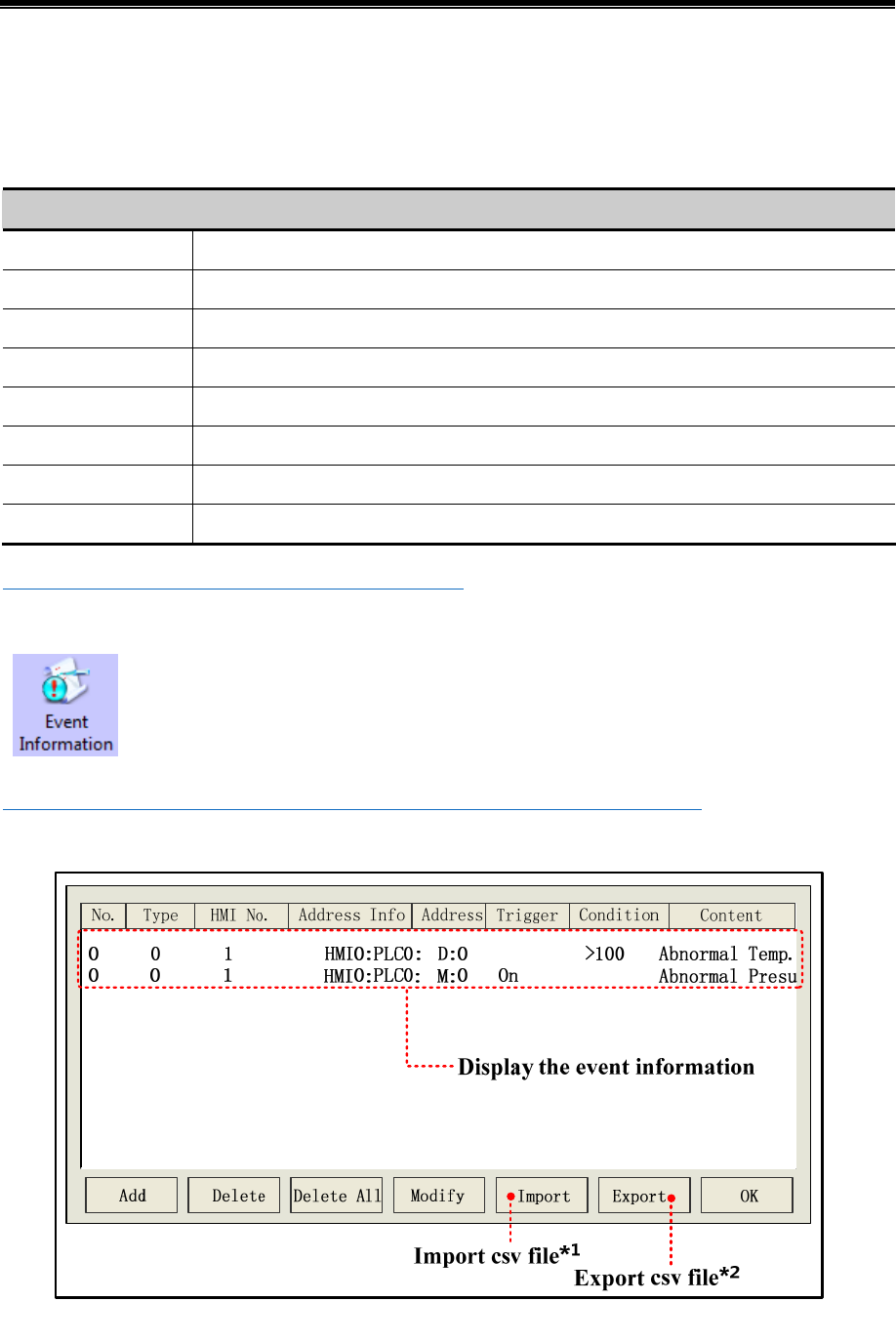
Kinco HMIware Configuration Edit Software
258
*1. Import the address information (CSV file) to the Address Tag.
2. Export the address information of Address Tag to a CSV file, user can use Microsoft EXECEL to pen an edit this CSV file.
Build Address Tag attributes
Click the Add in Address Tag to open the Build Address Tag box, see the following table for details:
Description of Build Address Tag
Tag Name Set the name of this address tag.
HMI Choose the HMI number of this address tag.
PLC NO. Choose PLC/controller number of this address tag.
Data Type Choose the data type: word or bit.
Address Type Choose the address type of address tag, it can be HMI register or PLC/controller register.
Address Set the address of address tag.
Code Type Display the code type of address tag: BIN or BCD
Format(range) Display the address format and address range.
5☞For details, refer to [Advanced Part 5.2 Address Tag Library]
4.15.3 Event Information
Event Information is used to configure the event content and trigger conditions; it is used with the Event
Display and Event Bar together. Event Information supports bit register and word register to trigger
event.
☞For details about Event Display and Event Bar, refer to [Advanced Part 4.7 Alarm Component]
- Event Information Interface
*1. Import the event information (in CSV file) to the Event Information library.
2. Export the event information to a CSV file, user can use Microsoft EXECEL to pen an edit this CSV file.
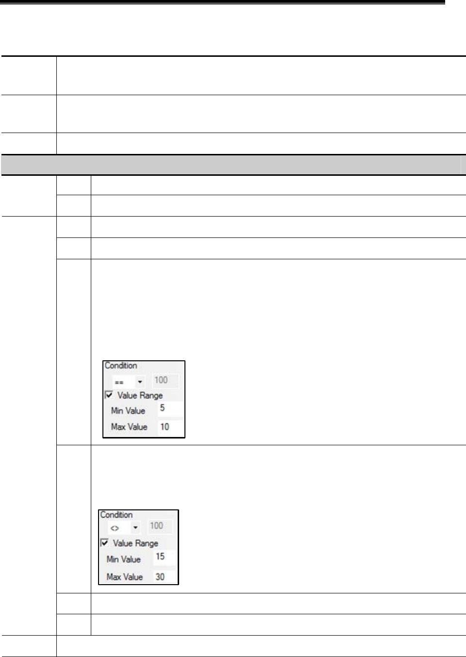
Advanced Part Component
259
Event Attributes
Click the Add in the Event Information to open the Event attributes dialog box, see the following table for details:
Triggered
HMI
In multiple HMI program, set the HMI where the Event Display or Event Bar displays this event information.
Type Set the event type: 0~255 are optional.
Event Display and Event Bar can display the event information conditionally according to the event type.
Address Set the read address of trigger register, choose the bit or word type in Data Type.
Attributes
On When specified bit register’s status changes from OFF to ON, an event log will be generated.
Bit
Off When specified bit register’s status changes from ON to OFF, an event log will be generated.
< When the value in specified register smaller than the specified value, an event log will be generated.
> When the value in specified register larger than a specified value, an event log will be generated.
==
When the value in specified register equals the specified value, an event log will be generated.
Value Range: When the value in specified register equals is in the specified value range, an event log
will be generated.
Take the following picture for example, check the “Value Range”, set 5 to the Min Value and 10 to
Max Value , suppose the data in specified register is N , if 5<=N<=10, an event log will be generated.
< >
When the data in specified register is not equal to the set value, an event log will be generated.
For example, check the “Value Range”, set the Min Value to 15, set the Max Value to 30, suppose the
data in specified register is N , if N<15 or N>30, an event log will be generated.
< = When the data in specified register is less than or equal to the set value, an event log will be generated.
Word
> = When the data in specified register is more than or equal to the set value, an event log will be generated.
Print
Configure the Event Printing in the Printing Setting of HMI Attributes.
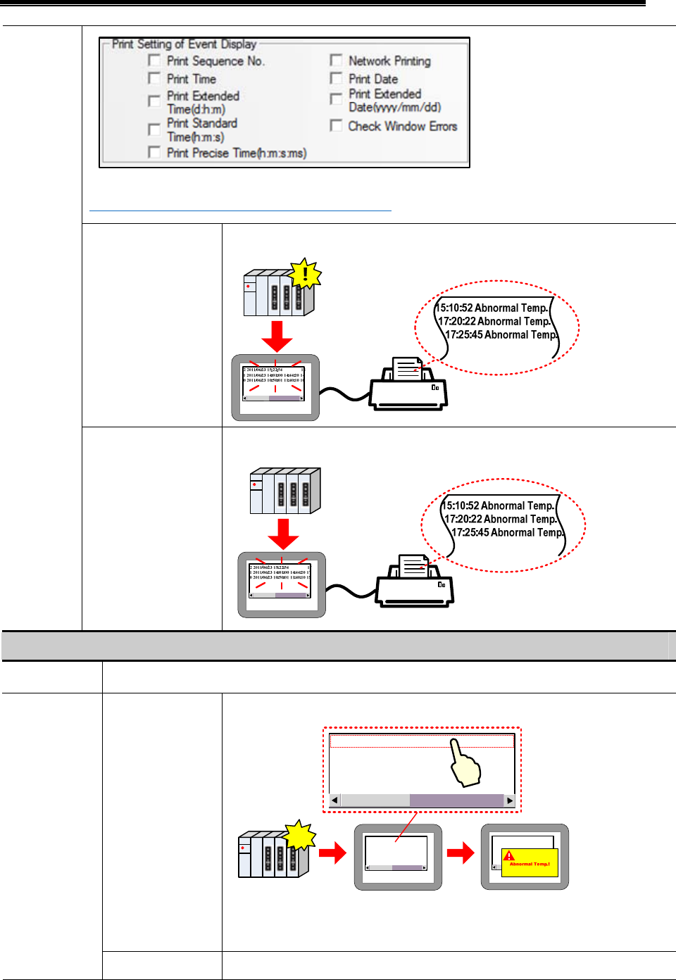
Kinco HMIware Configuration Edit Software
260
☞For details, refer to [Advanced Part 6.1.8 Print Setting]
On Trigger Print the event when event is triggered.
Return to Normal Print the event when the event returns to normal.
Trigger Function
Execute Macro The specified macro is triggered when the event happens.
Confirm Pop When the event is touched in the Event Display component, pop up specified window.
2 2011/06/23 15:22:54 15
1 2011/06/23 14:01:00 14:44:20 14
0 2011/06/23 10:50:01 11:40:10 10
!
2 2011/06/23 15:22:54 15
1 2011/06/23 14:01:00 14:44:20 14
0 2011/06/23 10:50:01 11:40:10 10
2 2011/06/23 15:22:54 15
1 2011/06/23 14:01:00 14:44:20 14
0 2011/06/23 10:50:01 11:40:10 10
Note: please use the “Close window” function in Function Key to close the pop-up
window.
Pop-up Window
Trigger Pop When the event is triggered, pop up specified window.
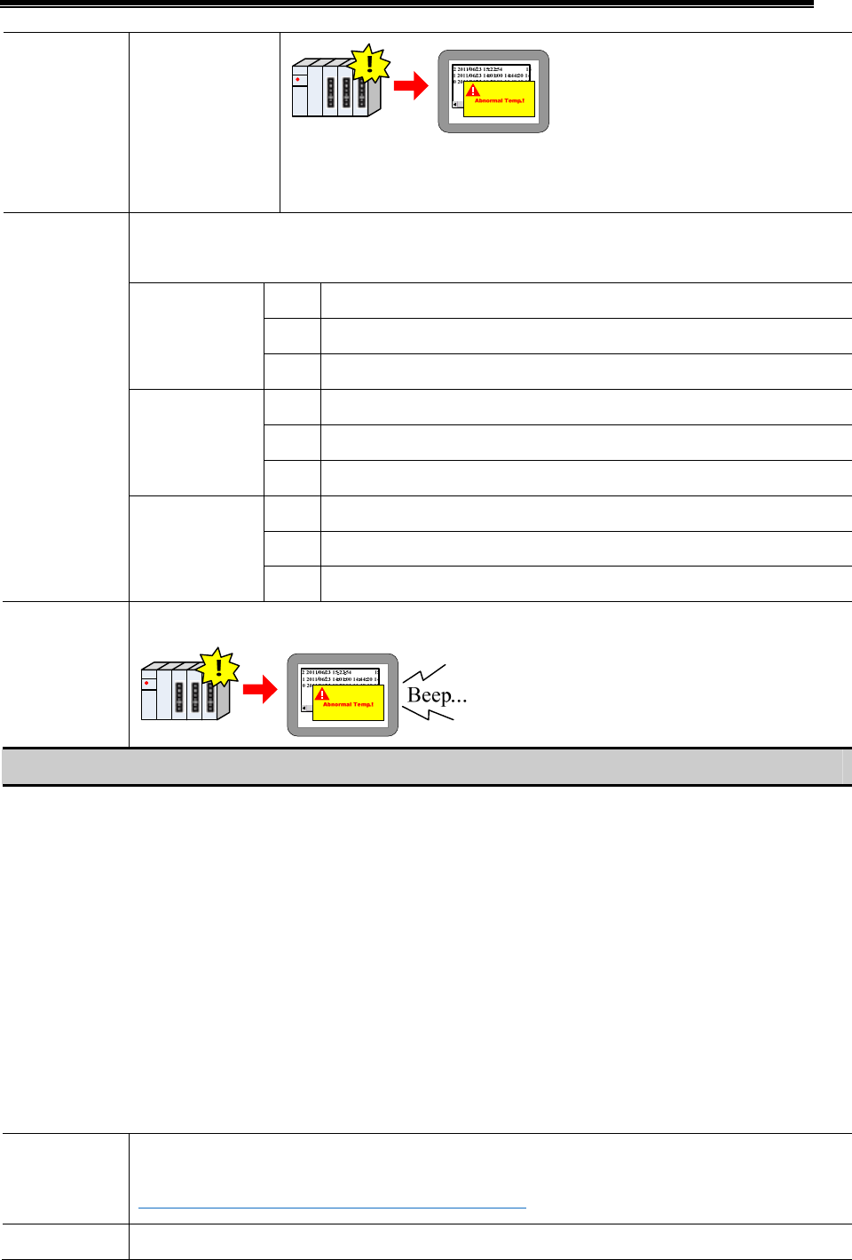
Advanced Part Component
261
Note: please use the “Close window” function in Function Key to close the pop-up
window.
Word length is 3. Write (Trig) address is the specified address; Write (Confirm) address is the specified
address+1; Write (Resume) address is the specified address+2;
0 When the event happens, set OFF to specified register.
1 When the event happens, set ON to specified register.
Write(Trig)
Not When the event happens, reverse specified register status.
0 When the event confirm, set OFF to specified register.
1 When the event confirm, set ON to specified register.
Write(Confirm)
Not When the event confirm, reverse specified register status.
0 When the event resume, set OFF to specified register.
1 When the event resume, set ON to specified register.
Write Data
Write(Resume)
Not When the event resume, reverse specified register status.
User Buzzer
When the event happens, trigger the buzzer. Buzzing Time ranges from 1 to 65535, the units is second.
Text
Input text content that needs to be displayed in Event Display after event happens, click the Font to set the font attributes.
Data in LW register can be displayed in the event information, user can configure it according to the following format:
^xxxx^: Print header, which means print this content when the event is triggered the first time or a different event is triggered.
For example, print “water” as a header, the format is ^water^
%h:mm:s#: Print time;
%y:mm:d#: Print date;
%nnfmd: Print variable, % means the start sign, nn means register number of LW, ranges from 00 to 99, that is to say , it is from
LW0 to LW99, f means there is decimal in the data , d means the end sign. If there is no decimal in the data, the format can be
%nnd. Take printing the data in LW20 for example; there is a decimal in this data, use the %20f1d in the Text of the Event
Information. Note: If customer wants to print data in PLC register, use the Timer to transmit the dat to LW0~LW99.
Use Text
Library
The Text content reads from the text library, but not writes in the text box.
☞For details, refer to [Advanced Part 4.15.1 Text Library]
Use Graph Font Set the graph font for the text content in event display, user can set the font attribute after the “Use Graph
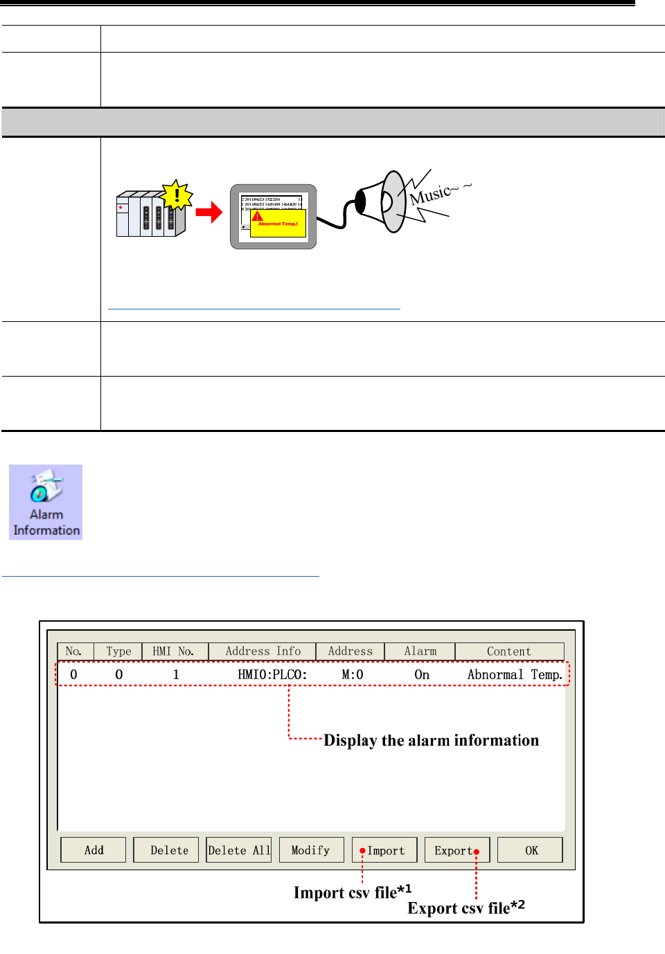
Kinco HMIware Configuration Edit Software
262
Font” is checked.
Language
When multiple languages is used in Text Library, user can choose language then set the font attributes of this
language.
Sound
Select Sound
Play selected audio file when this event is triggered.
Note: Only the HMI with audio output port supports this function.
☞For details, refer to [Advanced Part 4.15.6 Sound Lib]
Open Text
Library
Open the Text Library dialog box.
Open Address
Tag Library
Open the Address Tag dialog box.
4.15.4 Alarm Information
Alarm Information is used to configure the alarm content and trigger conditions; it is used with the Alarm
Display and Alarm Bar together. Alarm Information only supports bit register to trigger alarm.
☞For details, refer to [Advanced Part 4.7 Alarm Component]
Alarm Information
*1. Import the alarm information (in CSV file) to the Alarm Information library.
2. Export the alarm information to a CSV file, user can use Microsoft EXECEL to pen an edit this CSV file.
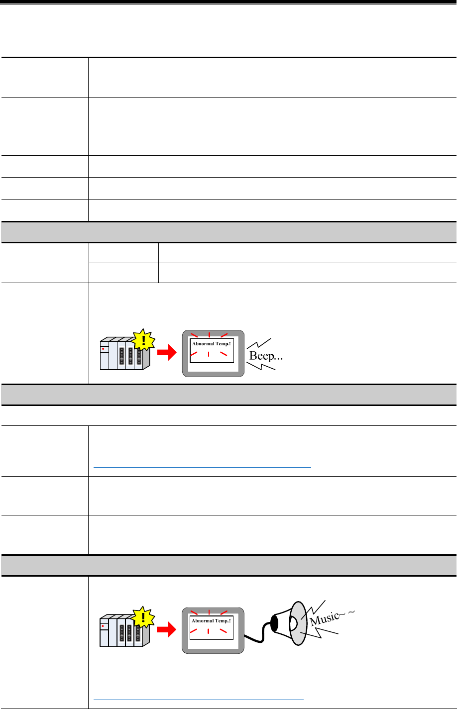
Advanced Part Component
263
Alarm Attributes
Click the Add in the Alarm Information to configure the alarm information, see the following table for details:
Triggered HMI
In multiple HMI program, set the HMI where the Alarm Display or Event Bar displays this alarm
information.
Type
Set the event type: 0~255 are optional.
Alarm Display and Alarm Bar can display the event information conditionally according to the
event type.
PLC Address Set the read address of trigger register, supports bit address only.
Use Address Tag Use the address in the Address Tag library.
Address Tag Library Open the Address Tag library dialog box.
Attributes
On When specified bit register changes from OFF to ON, an alarm log is generated.
Trigger
Off When specified bit register changes from ON to OFF, an alarm log is generated.
User Buzzer
When the alarm is triggered, the buzzer will be buzzing. Buzzing Time: 1~65535 are optional , the
units is second.
Text
Input the displaying constant when the alarm is triggered; click the Font to set the font attributes.
Use Text Library
The Text content reads from the text library, but not writes in the text box.
☞For details, refer to [Advanced Part 4.15.1 Text Library]
Use Graph Font
Set the graph font for the text content in event display, user can set the font attribute after the “Use
Graph Font” is checked.
Language
When multiple languages is used in Text Library, user can choose language then set the font
attributes of this language.
Sound
Select Sound
Play selected audio file when current alarm is triggered.
Note: Only the HMI with audio output port supports this function.
☞For details, refer to [Advanced Part 4.15.6 Sound Lib]
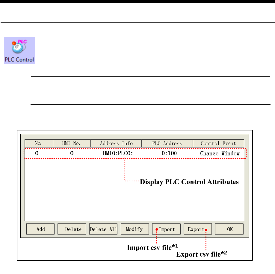
Kinco HMIware Configuration Edit Software
264
Text Library Open the Text Library dialog box.
4.15.5 PLC Control
PLC Control is used to log in the trigger condition of some functions, when specified register satisfies the
setting condition, the corresponding function will be executed.
The function in PLC Control will not be limited by window, the function will execute as soon as the
condition is satisfied.
- PLC Control Interface
*1. Import the control file constant (in CSV file) to the PLC Control library.
2. Export the control file constant to a CSV file, user can use Microsoft EXECEL to pen and edit this CSV file.
Alarm Attributes
- PLC Control Attributes
Click the Add in the PLC Control to open the dialog box, chose the control function in the Control Type and set the control
register and trigger condition.
The control type that PLC Control supports are as followings: Change Window (Ignore the window 0), Write Data to PLC
(Current Base Window number); Report Printout; Screen Hard Copy; General PLC Control; General PLC Control(Extended);
Backlight Close; Backlight Close (Write Back); Execute Macro Program; Backlight Open; Backlight Open(Write Back);
Sound Ctrl; Save Screen Shoot Data to Extended Memory.
See the following for details of the control type.
(1) Change Window
When the value in specified register changes to a valid window number, HMI will switch to the window with this window
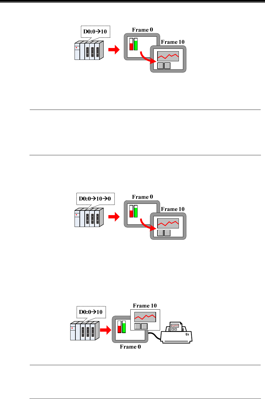
Advanced Part Component
265
number automatically. And write the new window number to the specified register+1 address.
For example, Suppose the current window number is 0, specified register address is D100, when the D100 is 10, the HMI
switches to the window 10, and return the new window number 10 to D101.
If the “Change Window” in PLC Control and “Change Common Window” in Function Key are used
at the same time, user can set an invalid window number to the control register by “Set at Window
Close” of Multiple State Setting component, in this way to avoid inputting the same window number, but
cannot change the window at the next time.
(2)Change Window (Ignore the window 0)
Change common window function, when the value in specified register is 0, HMI will not change to Window 0.
(3)Write Data to PLC (Current Base Window)
When switching common window, write the window number to specified register.
(4) Report Printout
Print the HMI screen according to the value in the specified register. When value in specified register changes and this value
is a valid window number, the constant in this window will be printed out.
1. HMI will not switch to the printed window when printing out this window in Print Out function.
2. The data in specified register will be reset to 0 automatically after printing.
3. Report Printout cannot print the constant in window 0.
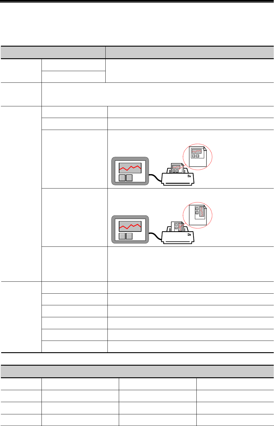
Kinco HMIware Configuration Edit Software
266
User can set the printing constant by the following two methods:
Method 1: Check the Custom Print Options
Attributes of Custom Print Options
Custom Print Attributes Detail Description
Monochrome
Printer Color
Color
Only the color printer supports switching printer color.
Magnification
Ranges from 0.1 to 5.0(Zoom-out printing may causes anamorphous, we do not advice zoom-out
printing.)
Current Page Start the printing at the first paper in printer.
Change page to print Print a blank paper first, and then start the HMI screen printing.
Horizontal print
Print the screen horizontally.
Vertical print
Print the screen vertically.
Print Page
Automatically Take The
Paper
Print a whole paper automatically when finishing the printing. This option
is only suitable for the stylus printer, micro printer does not support, and
laser printer has this setting itself, user needs not to set on HMI.
Print Text Print the static text and tag text of current window.
Print Meter Print meter component in current window.
Print Trend Curve Print trend curve component in current window.
Print Bit Map Print bit map component in current window.
Print All The Vector Graph Print all vector graph component in current window.
Print Text
Print Background Color Print meter component in current window.
Method 2: Do not check the Custom Print Options; use the bits of LW9054 and LW9055 to set the print.
LW9054 Setting
Bit No. Name 0(OFF) 1(ON)
Bit0 Print Text Do not print Print
Bit 1 Print Meter Do not print Print
Bit 2 Print Trend Curve Do not print Print
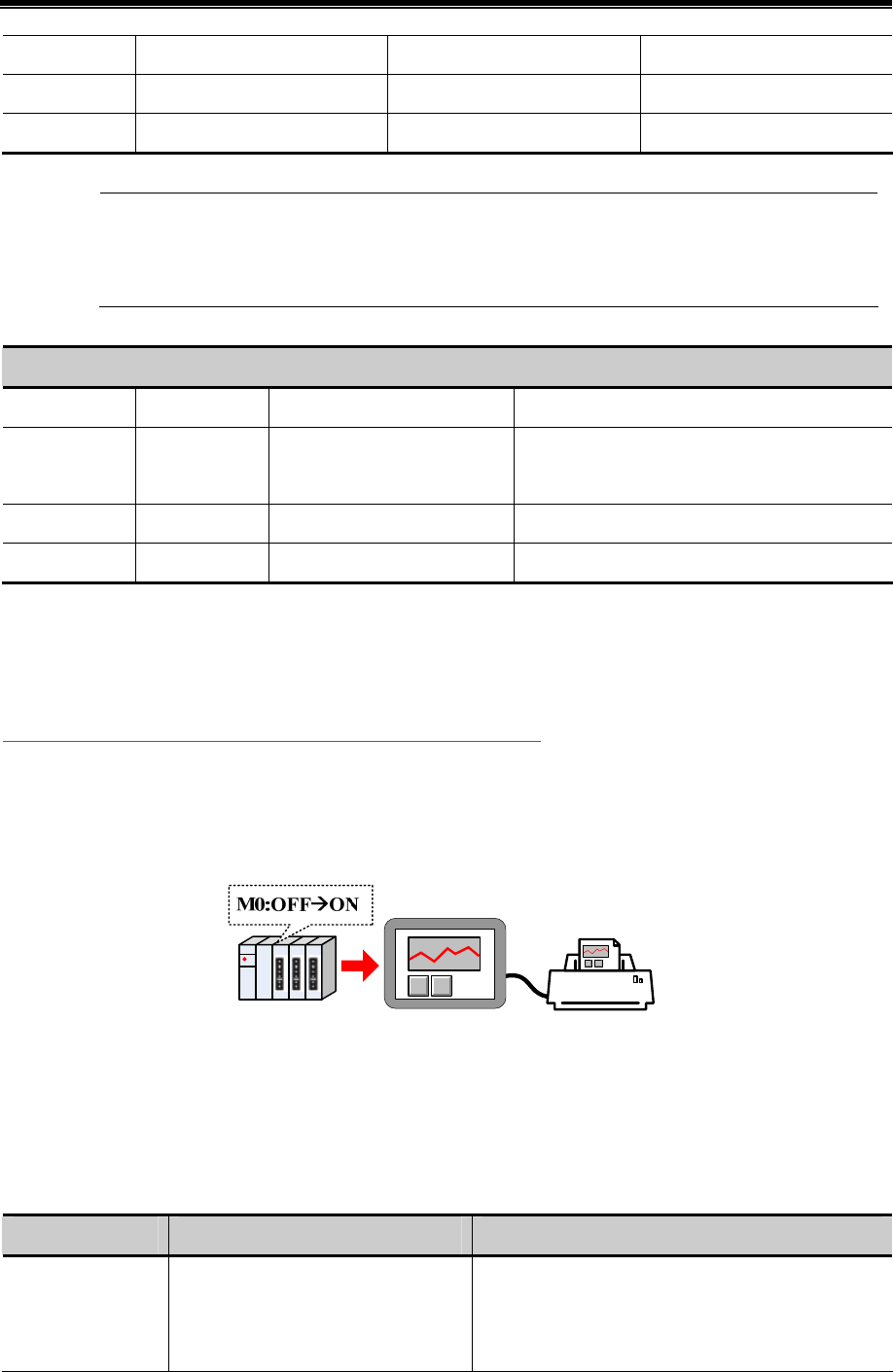
Advanced Part Component
267
Bit 3 Print Bit Map Do not print Print
Bit 4 Print All The Vector Graph Do not print Print
Bit 5 Print Background Color Do not print Print
Use the Multiple States Setting component to set the value of LW9054, if all the constant needs printing,
put the Multiple State Setting component in the common window(frame 1) and the setting mode is Set at
Window Open, set value is 255.
LW9055 Setting
Bit NO. Name 0(OFF) 1(ON)
Bit 0~ Bit 7 Magnification
Each bits means zoom out 0.1
times
Each bits means zoom in 0.1 times (LW9055
ranges from 1 to 50, which means 0. 1 to 5 times.)
Bit 8 Printer Color Color Monochrome
Bit 9 Print page Current page Change page to print
For example, if the Magnification is 0.3, Monochrome printing and print current page, that is to say, set the LW.B9055.0,
LW.B9055.1, LW.B9055.8 and LW.B9055.9 On. User also can set the above configuration by LW9055 directly, set LW9055
to 259(bit 0, 1, 8 and 9 on means 259)
5☞For details, refer to [Advanced Part 13.3 Print Function Setting Method]
(5)Screen Hard Copy
Screen Hard Copy is used to print current screen: when the specified bit register changes from OFF to ON, the current screen
is printed.
The Custom Print Options setting is the same as the Report Printout.
(6)General PLC Control
General PLC Control is used to transmit data between PLC/controller registers and HMI local registers.
When the Control Type is General PLC Control, system will distribute 4 registers to control transmit type, transmit data
length, offset of PLC/controller register address and offset of HMI register address. See the following table for details:
Address Function Description
Specified address
Store the transmit type code, different
codes mean different transmitting
direction.
There are 4 transmit type, see details in table 4.15.5_5,
when the register is write new code, HMI executes
corresponding transmit and the register will be reset to 0
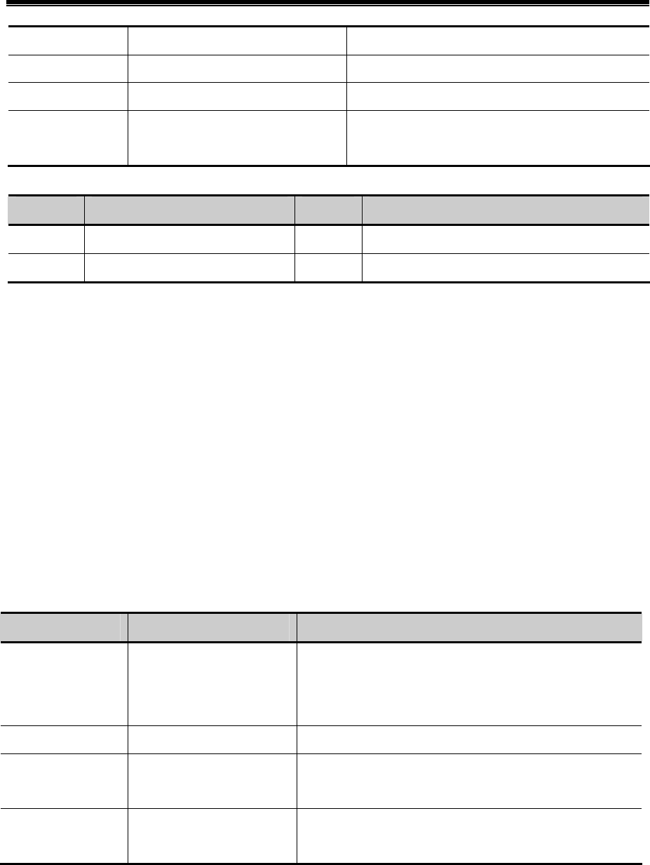
Kinco HMIware Configuration Edit Software
268
after the transmitting finishes.
Specified address+1 Data length The transmitting data length, units is word.
Specified address+2 offset of PLC/controller register address This offset is for the “specified address +4”.
Specified address+3
offset of HMI register address
Set the start address of HMI recipe register(RW) or local
register(LW).
See the following table for details of transmit type.
Code Data transmit type Code Data transmit type
1 PLC RW(HMI Recipe register) 2 PLC LW(HMI local register)
3 RW(HMI Recipe register) PLC 4 LW(HMI local register) PLC
For example: Transmit the data in D100~D104 (PLC register) to the RS100 ~RW104 (HMI recipe register).
Set D0 as the specified address in PLC Control, that is to say, D0 controls the Transmit Type, D1 controls the Transmit Data
Length, D2 controls the offset of data source register (PLC) and D3 controls the offset of destination register (HMI).
According to the example, D0=1 means transmit data from PLC to RW; D1=5 means there are 5 words (D100~D104)
needs transmitting; D2=96 which means PLC source address is D100=(96+0)+4, 0 means the start address in General PLC
Control. As the D0 to D3 are used for control register, so the source address is D4 , and the offset(96) is also for D4 , so the
PLC source register address is D2+ start address in General PLC Control(D0)+4. D3=100 means that the start address of
destination register is RW100.
(7)General PLC Control (Extend)
General PLC Control (Extend) is similar as the General PLC Control, it is also used to transmit data between PLC/controller
register sand HMI registers; the difference is that it distributes 6 registers to transmit type, transmit data length, offset of
PLC/controller register address and offset of HMI register address. See the following table for details
Address Function Description
Specified Address
Store the transmit type code,
different codes mean different
transmitting direction
There are 4 transmit type, see details in table 4.15.5_5, when the
register is write new code, HMI executes corresponding transmit
and the register will be reset to 0 after the transmitting finishes
Specified Address+1 Data length The transmitting data length, units is word
Specified Address+2
Specified Address+3
offset of PLC/controller
register address
This offset is for the “specified address +6”
Specified Address+4
Specified Address+5
offset of HMI register address
Set the start address of HMI recipe register (RW) or local
register(LW)
(8)Backlight Close
When the specified bit register changes from OFF to ON, HMI turns off the backlight, and the backlight will be on again if
the screen is touched.
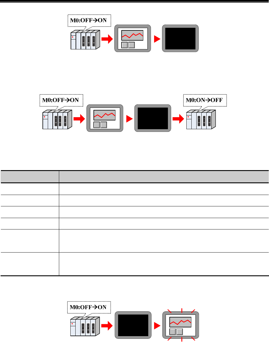
Advanced Part Component
269
(9)Backlight Close(Write Back)
When the specified bit register changes from OFF to ON, HMI turns off the backlight, and reset the specified register to OFF.
The backlight will be on again if the screen is touched.
(10)Execute Macro Program
When the specified register satisfies the execute method, the specified macro will be executed.
The execute methods are as follows:
Execute Method Description
ONOFF When the status of specified register changes, HMI executes specified macro
OFFON When the status of specified register changes from OFF to ON, HMI executes specified macro
ONOFF When the status of specified register changes from ON to OFF, HMI executes specified macro
ON When the status of specified register keeps ON, HMI executes specified macro
OFFON, reset
When the status of specified register changes from OFF to ON, HMI executes specified macro
At the same time reset the specified register to OFF automatically
ONOFF, reset
When the status of specified register changes from ON to OFF, HMI executes specified macro
At the same time reset the specified register to ON automatically
(11)Backlight Open
When the specified register changes from OFF to ON, HMI will turn on the backlight.
(12)Backlight Open (Write Back)
When the specified register changes from OFF to ON, HMI will turn on the backlight. At the same time HMI resets the
register to OFF.
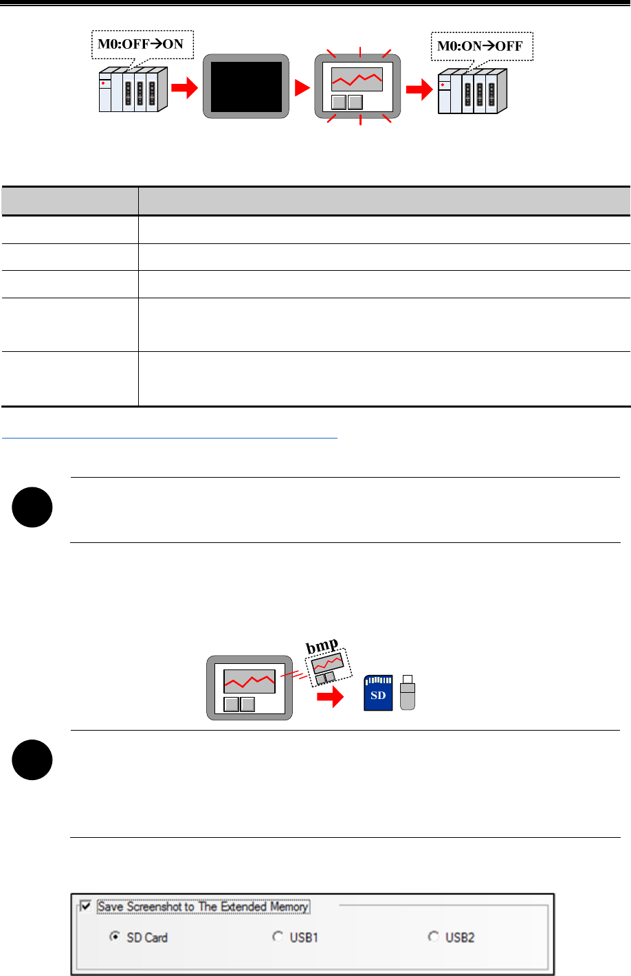
Kinco HMIware Configuration Edit Software
270
(13)Sound Control
When the specified register satisfies the setting condition, HMI plays specified audio file.
Execute Method Description
ONOFF When the status of specified register changes, HMI plays specified audio file
OFFON When the status of specified register changes from OFF to ON, HMI plays specified audio file
ONOFF When the status of specified register changes from ON to OFF, HMI plays specified audio file
OFFON, reset
When the status of specified register changes from OFF to ON, HMI plays specified audio file
At the same time reset the specified register to OFF automatically
ONOFF, reset
When the status of specified register changes from ON to OFF, HMI plays specified audio file
At the same time reset the specified register to ON automatically
☞For details, refer to [Advanced Part 5.4 Sound Lib Application]
!
Only the HMI with audio output port supports this Sound Control function
(14)Save Screenshot Data to Extended Memory.
When specified register changes from OFF to ON, save the current screen constant to the extended memory in picture.
!
1. Only the HMI with USB host and SD card supports this function
2. This function supports offline simulation, indirect online simulation and direct simulation. The
screenshot pictures are saved in the \disk\sd(usb1 or usb2)\scr file folder of Kinco HHMIware installation
route
User needs to set the extended device in the HMI Attributes>> HMI.
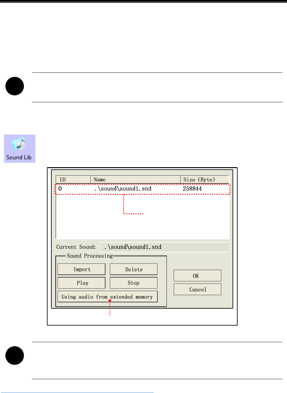
Advanced Part Component
271
The bmp pictures are named as year-month-day, hour: minute: second: millisecond, for example: 2010-09-01,
10:12:50:203.bmp. User also can define the picture name by system special register. The LW9470~LW9485 define the prefix
of file name, for example the constant in LW9470~LW9485 is “Version Num .20100001-”, then the screenshot picture
name is Version Num .20100001-2010-09-01,10:15:28:421.bmp.
!
After the save screenshot is executed, please do not plug out the extended memory device in 1 minute, or
the picture may cannot be saved.
4.15.6 Sound Lib
Sound Lib is used to save the wav or mp3 audio file. The system will transfer the audio file to snd format
file automatically, and user can call this file, the original audio file (WAV or mp3 file) are saved in the
sound file folder of current project.
Import from extended memory
Display the audio file
!
1. One imported audio file must be smaller than 256KB, but the audio file from the Using audio from
extended memory does not limit the file size.
2. Supports WAV, MP3 format audio file.
☞For details, refer to [Advanced Part 5.4 Sound Lib Application]
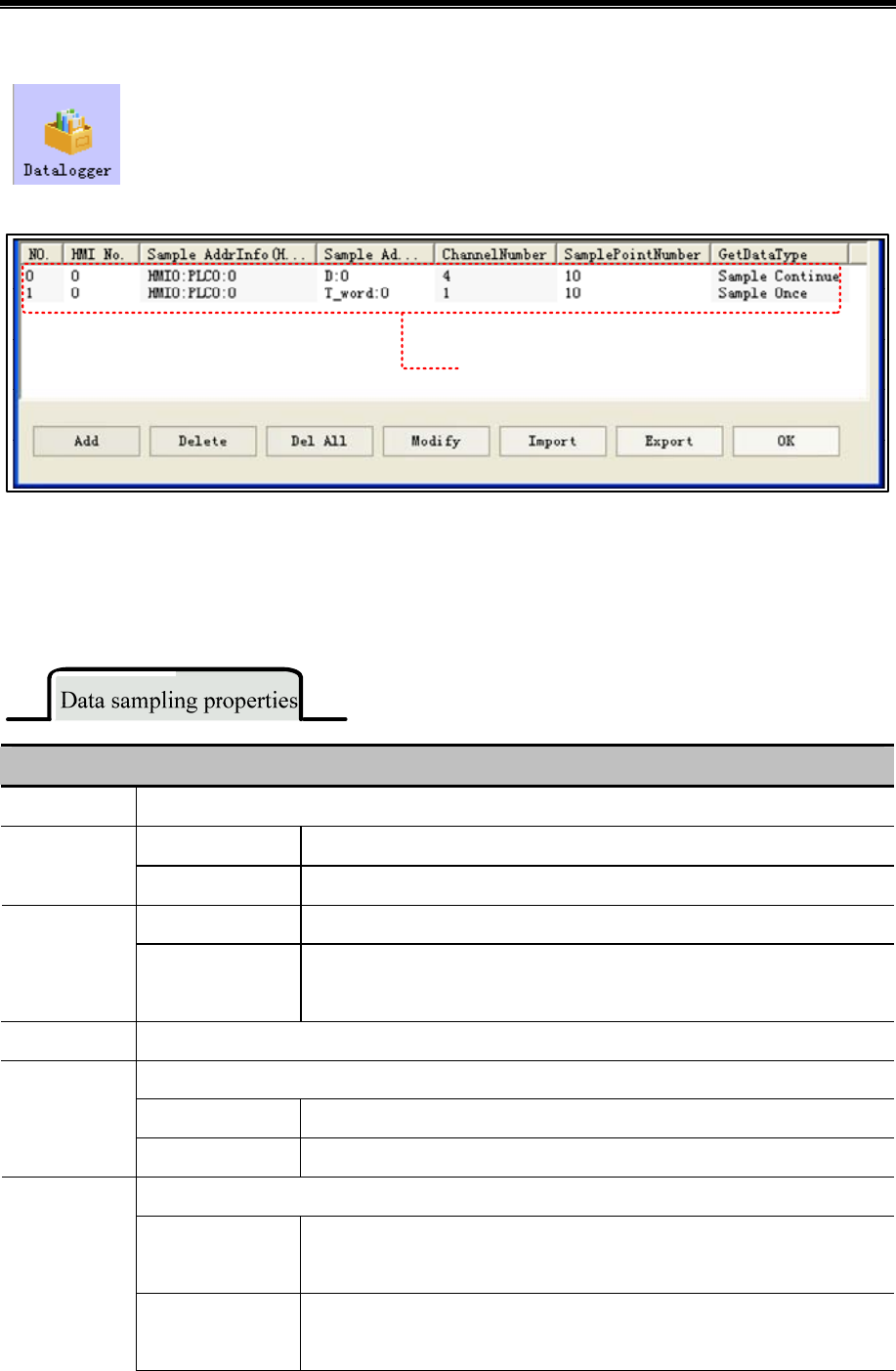
Kinco HMIware Configuration Edit Software
272
4.15.7 Data Logger
Data Logger is used to sample data and set sampling method, these data can be displayed on Data Report
component.
●Interface of Data Logger
Display logged data
1. Import: .Import the data sampling information in CSV file format to the Data Logger
2. Export: Export all logged in sampling data to a CSV file; this file is editable by Microsoft EXCEL.
- Data Logger Attributes
Click the Add to open the Data Logger attributes dialog window, the detail attributes are as follows:
Detail Description of Data sampling properties.
Sample Point The total sample point number, it ranges from 1~999999
Circle Sampling Sample the data periodically.
Sample Type
Trigger Sampling Trigger sampling when the specified register satisfies the condition.
Sample Continue The sampling continues even if all the sampling points are finished.
Get Datatype Sample Once The sampling stops when all the sampling points are finished, that is to say , the
sampling is executed only once.
Channel The continuous sampling registers number, 128 channels at most.
It is invalid if the Sampling Type is Circle Sampling.
Sample Circle The time interval between each two sampling points, the unit is millisecond.
Circle Sample
Param
Viable Circle Read sample circle from specified register in circle sampling.
It is invalid if the Sampling Type is Trigger Sampling.
OFFON
Only when the specified register changes from OFF to ON, HMI triggers the
sampling..
Trigger Type
ONOFF
Only when the specified register changes from ON to OFF, HMI triggers the
sampling..
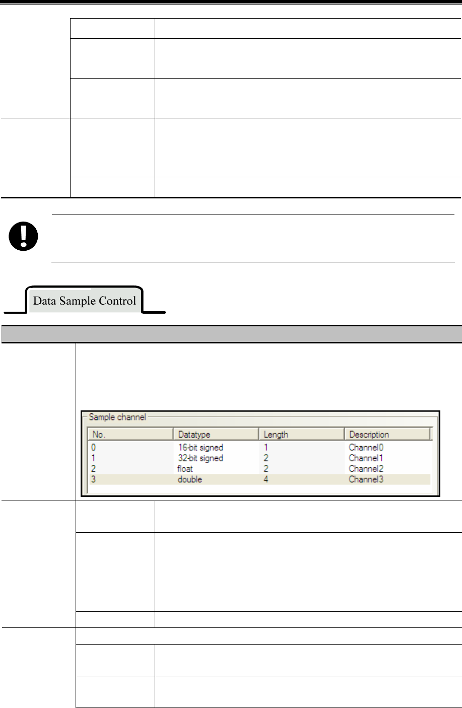
Advanced Part Component
273
OFFON Only when the specified register changes its status, HMI triggers the sampling..
OFFON(reset)
Only when the specified register changes from OFF to ON, HMI triggers the
sampling, and then reset the specified register automatically.
ONOFF(Reset)
Only when the specified register changes from ON to OFF, HMI triggers the
sampling, and then reset the specified register automatically.
Data Type Set the display data format for the sampling data, there are six formats , they are
16-bit signed, 16-bit unsigned, 32-bit signed, 32-bit unsigned, float, double and
string.
Sample
Channel
Description Set the description name for the channel
If the Variable Circle is checked, the variable value is used preferentially, if the variable value cannot be get
because of communication lost , HMI uses the default value(the Sample Circle) .
Detail Description of Data Sample Control
Sample Address
Set the start address of sampling data, the word length depends on the channel and data type. Take the
following picture for example: there are 4 channels, their data types are 16-bit signed, 32-bit signed,
float and double. So the word length is 9, because the 16-bit signed is one word, 32-bit signed is two
words; float is two words and double is 4 words.
Save Disk The external memory device of HMI, the SD Card, USB1 and USB2 are
optional.
Save Dir The subdirectory where sampling data is saved in the external memory device.
The default name is SampleDataStore, customers can change this name
themselves, and the detail route of this file is \external
device\database\subdirectory name\export file name.db.
The file format is .db.
Sample Data
Save
Variable Dir The subdirectory name is read from specified register, the max word length is 16.
Use a bit register to clear the sample data and delete the file in the database.
OFFON Only when the specified register changes from OFF to ON, HMI clears the
sample data.
Sample Data
Clear
ONOFF Only when the specified register changes from ON to OFF, HMI clears the
sample data.
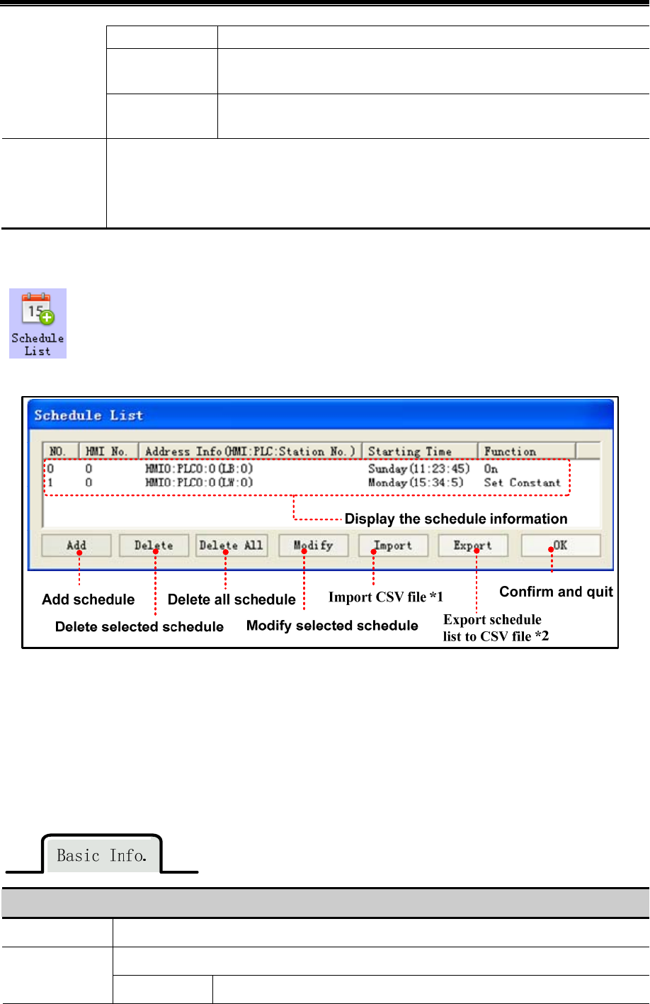
Kinco HMIware Configuration Edit Software
274
OFFON Only when the specified register changes its status, HMI clears the sample data.
OFFON(reset) Only when the specified register changes from OFF to ON, HMI clears the
sample data. and then reset the specified register automatically.
ONOFF(Reset) Only when the specified register changes from ON to OFF, HMI clears the
sample data., and then reset the specified register automatically.
Pause Sample
Use a specified bit register to pause the sampling, ON means HMI stops sampling and OFF means
HMI starts sampling.
Note: In Sample Once mode, this register will be set ON automatically when the sampling is finished,
user can set this register OFF to trigger the sampling again.
4.15.8 Schedule List
Schedule List is used to configure the operation which will be executed in specific time.
- 【Schedule List】Interface
※1.Import the CSV file which include schedule list format into【Schedule List】in the current project.
2.Export all the schedule information in current project to specific directory and saved as CSV file.This file can be open
by Microsoft EXCEL.
- 【Schedule List】Setting
Click 【Add】 in【Schedule List】to open the setting window of【Schedule List】,its attributes are shown as follows.
Descriptions
Execute HMI List Select the HMI which will execute the schedule.
Execute when power on Basic Pro.
Select If HMI power on after the setting time of schedule, then it will execute the “Begin
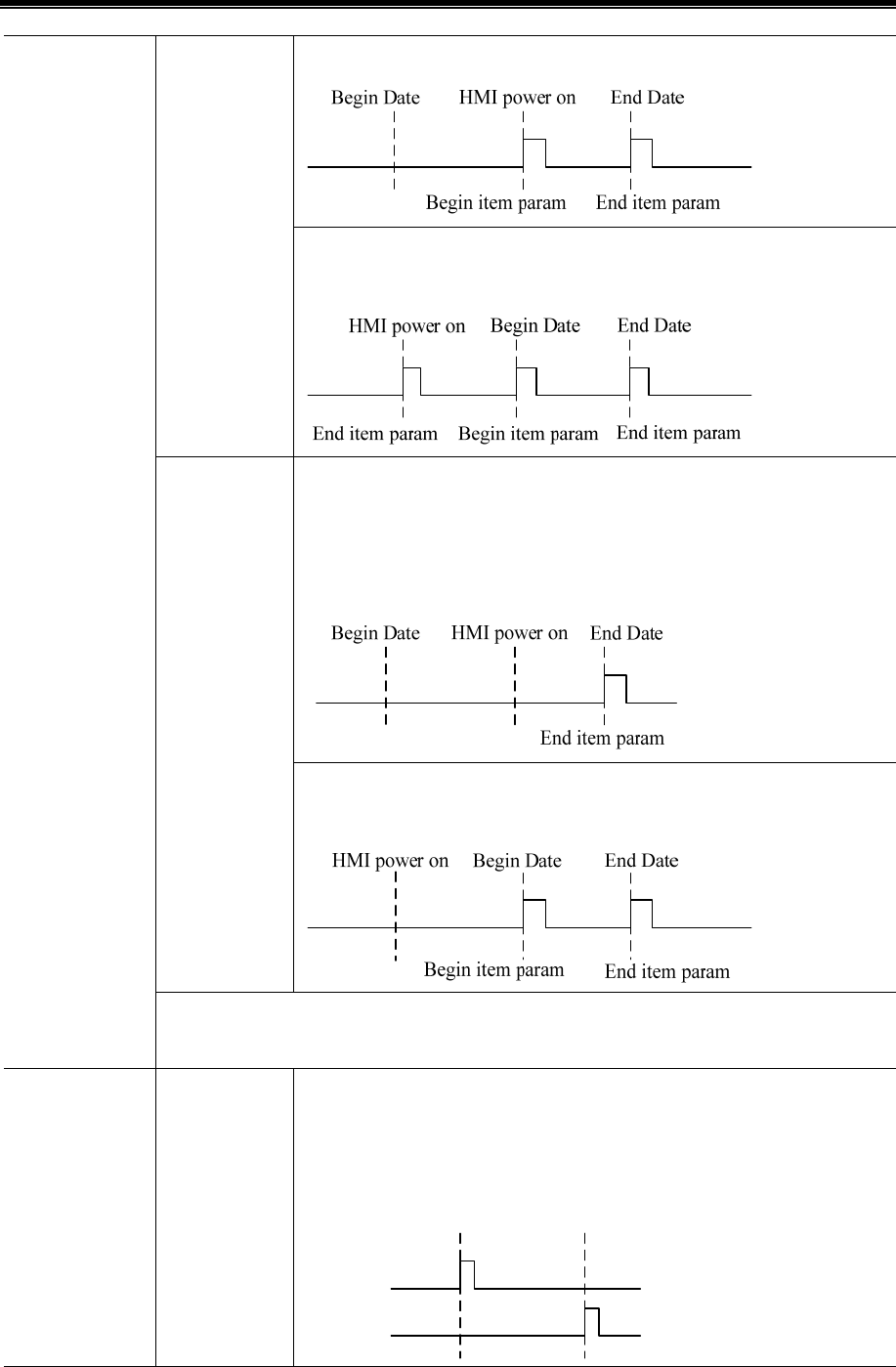
Advanced Part Component
275
item param” automatically.
If HMI power on before setting time of schedule and select “End item
param”,then it will execute the “End item param” automatically.
If HMI power on after setting time of schedule and select “End item param”, then
it won’t execute “Begin item param” automatically,but it will execute the end item
param automatically.If “End item param” is not selected,then no item will be
executed.
Unselect
If HMI power on before setting time of schedule and not select “End item
param”,then it will execute
Trig Beep.It is used to set the buzzer when start executing preset operation.The range of buzzer is
1~65535s.
Date and Time UseSingleDate
When selecting this option,then the begin date and end date can be different,but
there can only select one begin date and one end date.
For example, begin date is 9:00:00 Sunday,end date is 17:30:00 Tuesday.
Sunday
Tuesday
9:00 17:30
Begin item param End item param

Kinco HMIware Configuration Edit Software
276
When unselecting this option, then the schedule is executed within one day(means
from the begin date to end date is within 24 hours) ,but it can set multiple begin
date and end date.
Note:If the time of end date is earlier than the time of begin date,then the end item
param will be executed in next day.
Begin Date
Set time and day for begin item param.Format is HH:MM:SS
(Hour:Minute:Second).Range:hour(0~23),minute(0~59),second(0~59)
End Date When selecting [Use end date],the time of end date can be set.
When selecting[UseSingleDate],the day of end date can be set.
Variable Date
Addr.
It is used to set schedule time and date by local or PLC address.
If unselecting [Use end date],it will occupy 4 words,these addresses are only used
for begin date.
The variable date addr.=Week. Bit0:Sunday(0:Invalid, 1:Valid)……Bit6:Saturday
(0:Invalid, 1:Valid).The format is as following figure.
The variable date addr.+1=Hour
The variable date addr.+2=Minute
The variable date addr.+3=Second
Exammple 1:The variable date addr. is LW0,then Week=LW0,Hour=LW1,
Mintue=LW2,Second=LW3.
If selecting [Use end date],it will occupy 8 words,then these addresses are used
for begin date and end date.
Example 2:if the variable date addr. is LW0,then the begin date is:Week=LW0,
Hour=LW1,Minute=LW2,Second=LW3.End date is:Week=LW4,Hour=LW5,
Minute=LW6,Second=LW7.
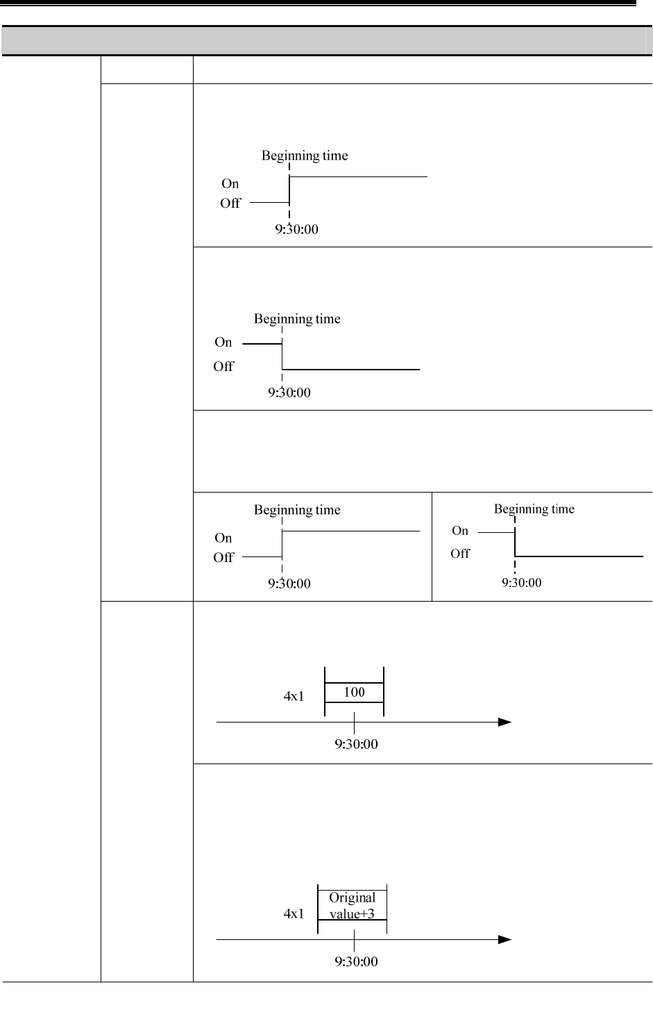
Advanced Part Component
277
Descriptions
Execute Type Descriptions as follows.
On: it will set the specific bit address as on at the beginning time.
For example, beginning time is 9:30:00.
Off:it will set the specific bit address as off at the beginning time.
For example:beginning time is 9:30:00
Toggle:it will switch the status of the specific bit address at beginning time.If the orginal
status of the bit address is off,then it will switch to on.Or it will switch to off.
For example,beginning time is 9:30:00
Bit Set
Set Constant:it will write a constant to specific register at the beginning time.
For example:beginning time is 9:30:00,constant value is 100 and specific register is 4x1.
Control Info.
Word Set
Add Value:it will use the original value of specific register to add an addend at the
beginning time,and its final value will not exceed the upper limit.
For example:beginning time is 9:30:00,addend is 3,upper limit is 80 and specific register
is 4x1.
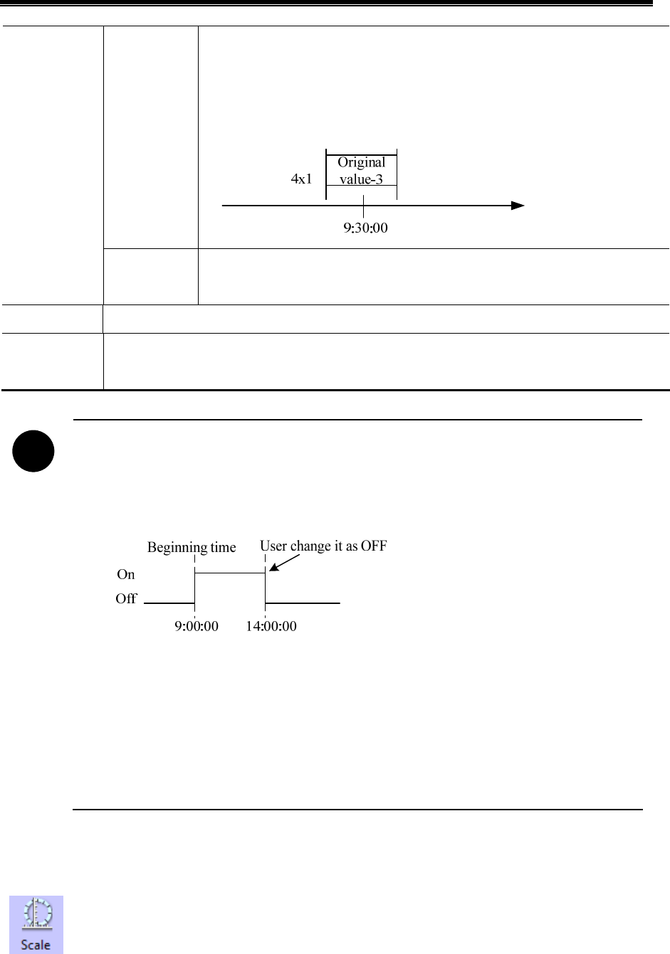
Kinco HMIware Configuration Edit Software
278
Sub Value: it will use the original value of specific register to subtract a subtrahend at
the beginning time,and its final value will not exceed the lower limit.
For example:beginning time is 9:30:00,subtrahend is 3,lower limit is 9 and specific
register is 4x1.
Data type
It is used to select the data type of setting value.It supports 16-bit signed\16-bit
unsigned,32-bit signed\32-bit unsigned,float,double.
Write Address Set the address which is used for execution.
Variable Param
Address
Use variables to change the set value(for set constant),Addend,upper(for add),subtrahend and lower(for
sub)
!
1. If the write addresses are the same in schedule list,it is forbidden to set the same time and date to
them.
2. Every time in schedule list only executes once.When it reaches execution time,the specific address
will be written a value once.
3. Because it needs to read the data of [Word Set] and [Control Setting],the execution maybe delay
according to the data communication.
4. When selecting [Variable Date Address],system will read the address cyclically,the cycle time depends
on the busyness of system.
5. When the value of the variable date address exceeds the range of standard time,then the setting
schedule will be wrong.
4.16 Auxiliary Component
4.16.1 Scale
Scale Component is used to set equal scale label for some components, like Bar Picture, Meter and so on.
So components has scale itself, they also can use the Scale component.
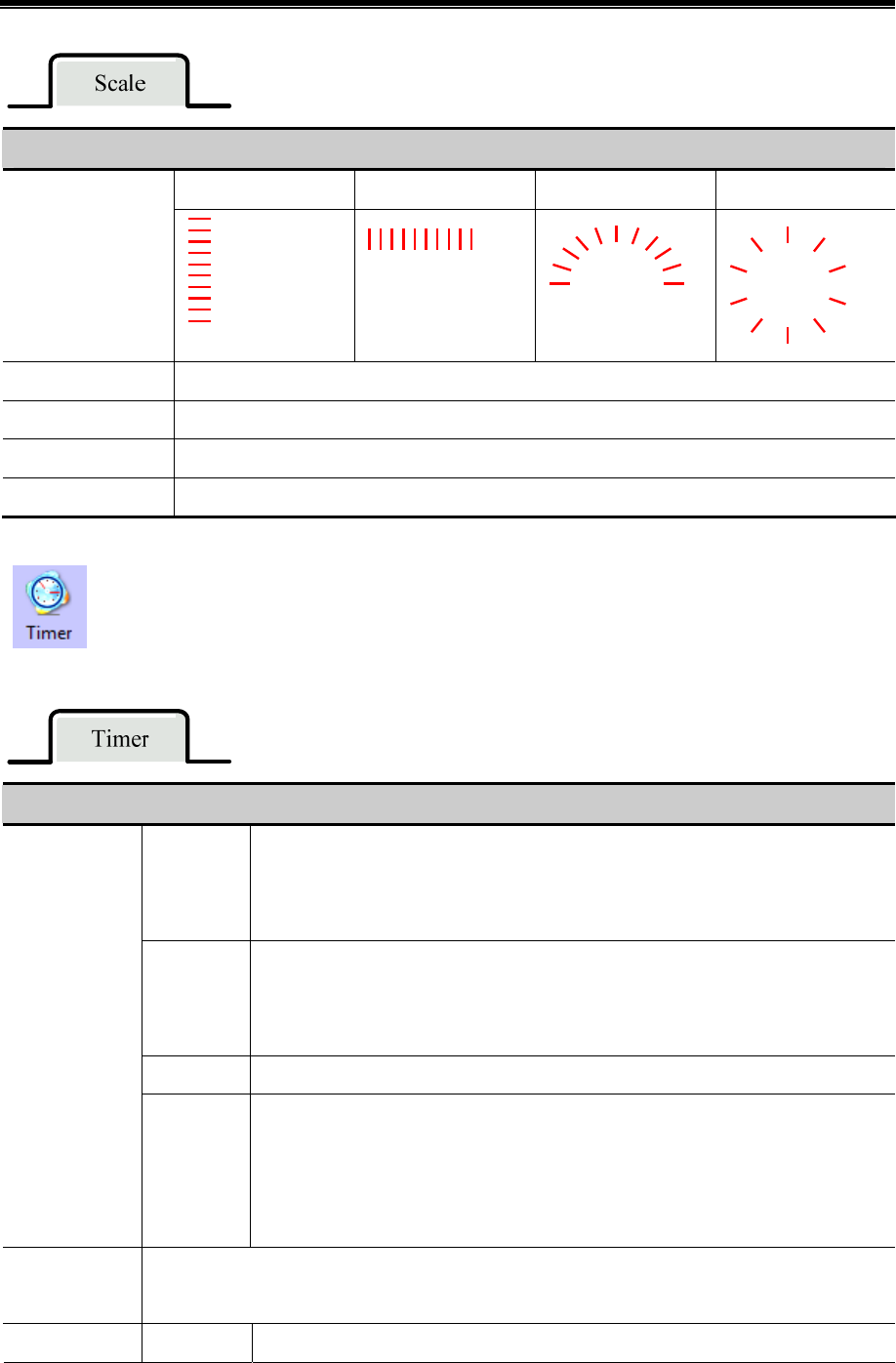
Advanced Part Component
279
Description of Scale component
Horizontal Vertical Arc Circularity
Style
Equal Division Set the equal division number
Line Length Set the scale length of Arc and Circularity style
Start/End Angle Set the start and end angle of Acr style
Line Color Set the line color
4.16.2 Timer
When the setting time is up, Timer will execute corresponding functions, like macro, setting parameters,
data transmission and so on.
Description of Timer Attributes.
All time
Timer function will be executed as soon as the timer is initialized, and stopped
automatically after the Repeat Count. Then the timer will not be triggered till the next
initialization. If the Repeat Count is 0, that means the function is executed all the time.
Initial frame
Timer function will be executed as soon as the frame is initialized, and stopped
automatically after the Repeat Count. Then the timer will not be triggered till the next
initialization. It is the almost the same the “All time” Trigger Mode.
Close frame Timer function will be executed when the frame is close.
Trigger Mode
By
re-address
The function will be triggered according to the Trigger Address. When the Repeat Count
is 0, it means that the function will be executed till the trigger condition is canceled.
When the repeat Count is N, it means that the function will be executed N times if
address is triggered, then it will stop automatically.
Execution Cycle
The execution cycle of timer, the unit is hundred milliseconds. The timer executes the Timer Function
one time in every execution cycle.
Response Mode Immediate Timer executes the function immediately when the condition is triggered.
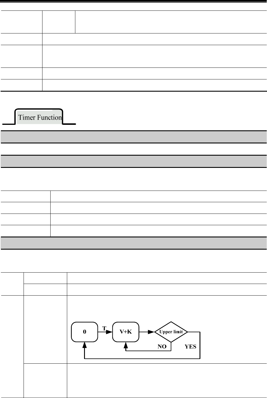
Kinco HMIware Configuration Edit Software
280
Delay
Timer executes the function in the next execution cycle when the condition is triggered.
That is to say, there will be one circle delay.
Trigger State In the By reg-address mode, the Trigger State is On or Off.
Repeat Count
The execution number of timer function. If the Repeat Count is 0, it means the function will be
executed all the time.
Trigger Address In the By reg-address mode, set the register address for trigger register.
Variable Period Once users choose variable period, it is determined by the specific register
Execute Macro
Execute the specified macro program. That is to say, when the timing time is up, the macro will be executed
Data Transmission
Transmit the data in batch. When the timing time is up, timer transmits corresponding length data from Source Address to
Destination Address
Source Address Set the source address of data
Destination Address Set the destination address of transmitting data
Data Type Set the type of transmitting data, bit or word
Data Length Set the number of transmitting data
State Setting
Change the state or value of specified register. When the timing time is up, timer changes the state of corresponding bit
register or write value to the word register.
Set Value When the “Execution Cycle” time is up, set the bit register to 0 or 1.
Bit
Periodical Toggle When the “Execution Cycle” time is up, toggle the bit register between 0 and 1.
Periodical
JOG++(circle)
Add an Asc value (K) to the data (V) of specified register automatically in every execution
circle. When the data reaches to the Upper limit, it will start from 0 again.
Word
Periodical
JOG--(one way)
Subtract a Desc value (K) from the data (V) of specified register automatically in every
execution circle. When the data reaches to the Lower limit, the data will stop at the lower
limit.

Advanced Part Component
281
Periodical
JOG++(one way)
Add an Asc value (K) to the data (V) of specified register automatically in every execution
circle. When the data reaches to the Upper limit, it will stop at the Upper limit.
Periodical
Bounce(turnover
upon limit)
Add a Step value (K) to the data (V) of specified register automatically in every execution
circle. When the data reaches to the Upper limit, subtract a Step value (K) in every
execution circle till 0, then start add Step a value (K) to the data again, repeat the above
process circularly.
V+K
YESNO
T
V-K
NOYES
Lower
limit Upper limit
Lower limit
Step Up(circle)
Add a Step value (K) to the data (V) of specified register automatically in every execution
circle, when the data reaches to the Upper limit, it will be reset to the Lower limit, then start
to add step value again from the Lower limit.
Step
Down(circle)
Subtract a Desc value (K) from the data (V) of specified register automatically in every
execution circle, when the data reaches the Lower limit, it will be reset to the Upper limit,
then start to subtract step value again from the Upper limit.
Set Constant When the timing time is up, the preset constant will be written to the specified register.
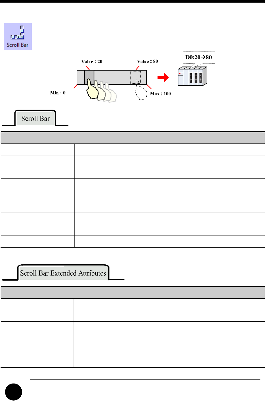
Kinco HMIware Configuration Edit Software
282
4.16.3 Scroll Bar
Scroll Bar is used to change the value of HMI or PLC register by moving the slider, and the scaling
relation between actual value and Min/Max is displayed by the position of slider.
Description of Scroll Bar Attributes
Word Length of Index Number Word and Double Word are optional.
Direction Set the direction of scroll bar, there are four directions; they are From Left To Right,
From Right To Left, From Up to Down and From Down to UP.
Background Image Set the background image of scroll bar, there are three options; they are Not Used,
Vector Graphics and Bitmap.
Import Image Import the background image from the system image library.
Button Image Set the button image of scroll bar, there are three options; they are Not Used, Vector
Graphics and Bitmap.
Import Image Import the button image from the system image library.
Description of Scroll Bar Extended Attributes
Slider Width Set the width of slider, ranges from 1 to 99. Uncheck means that the slider uses the
default width, which is 10 pixels.
Max/Min Value Setting Set the start value and max value of scroll bar.
Variable Max/Min Value
Setting
Set the variable for the Min and Max for the scroll bar, and set the register address, the
specified address is the Min, and the specified address+1 is the Max.
Set Scroll Mode Ranging from 1 to 100, each time user clicks scroll bar , it adds or subs the setting value.
!
The Scroll Bar will not takes 3 words after V1.4.0.0, because the Min and Max can be set as constant, if the
Min and Max use variable, user can set the register separately.

Advanced Part Component
283
4.16.4 Date/Time
Date/Time component is used to display HMI system date and time in specified format.
Description of Time attributes
Set the component to display date or not
Date format Four formats are optional. DD means day, MM means month, YY means year.
Date Separator Three formats are optional, for example, 2011.01.01.
Year 4-digital
Display
Checked means Timer displays year in 4 numbers, for example 2011; unchecked
means Timer displays year in 2 numbers, for example 11.
Display Date
Zero suppress for
Year and Day
Checked means there is not a 0 before year and month take June for example, when
this option is checked, Timer displays 6, if unchecked, and Timer displays 06.
Display Week Set the component to display week or not, the week is displayed in abbr.
Set the component to display the time or not.
Time Two formats are optional: HH means hour, MM means minutes, SS means second.
Display Time
12-hour System
(AM/PM)
Checked means Time is displayed in 12-hour system, take the three o'clock in the
afternoon for example, if this option is checked, it displays 3:00 PM , if
unchecked , it displays 15:00.
The Date/Time component can read the RTC time in the HMI, but cannot change it. If user need to change
the date or time, they can change it in HMI SETUP screen or via system special
registers(LW10000~LW10006)
6☞For details, refer to [Advanced Part 2.7 RTC Set]
4.16.5 Note Pad
Note Pad is the message board function; it is used together with the Message Board function in the
Function Key.

Kinco HMIware Configuration Edit Software
284
4.16.6 File List
File List is used to display the file information in the external memory device. It is divided into three area:
the left part displays the file folder information of current catalog. Upper right part displays the file
information of current catalog; the Lower right part displays the chosen project file (.pkg file) or recipe file
(.rcp file) of current catalog.
..\
event\
exmem\
historystore
\
log\
scr\
trend\
Test.pkg
HMI0:
File folder information
of current catalog
File information
of current catalog
Chosen file HMI
information of current
catalog
File list component is a special component; it is usually used together with the Import/Export function of Function Key.
System also provides [Frame5: File List Window] as file list when user import/export project file or recipe file in the SETUP
screen. And the File Browser Window can be changed in the HMI Attributes.
4.16.7 Trigger Touch
Trigger Touch is used to trigger multiple components without touching them, when the specified address
satisfies the setting Trigger Type condition, all the components in the Trigger Touch area will be
triggered.
Take the following component for example:
The components (1, 3 and 4) are in the Trigger Touch area.
Advanced Part Component
285
The component 2 is not in the Trigger Touch area.
When the specified address satisfies the setting Trigger Type condition, the 1, 3 and 4 will be trigged, but 2 will not be
triggered, because it is out of the Trigger Touch area.
Detail Description of Trigger Touch
Trigger Touch Description
OFFON
When the specified register changes from OFF to ON, the components in the Trigger Touch area will
be triggered.
ONOFF
When the specified register changes from ON to OF, the components in the Trigger Touch area will be
triggered.
OFFON
When the specified register changes its state, the components in the Trigger Touch area will be
triggered.
OFFON (reset)
When the specified register changes from OFF to ON, the components in the Trigger Touch area will
be triggered. At the same time, reset the specified register to OFF.
ONOFF (reset)
When the specified register changes from ON to OFF, the components in the Trigger Touch area will
be triggered. At the same time, reset the specified register to ON.
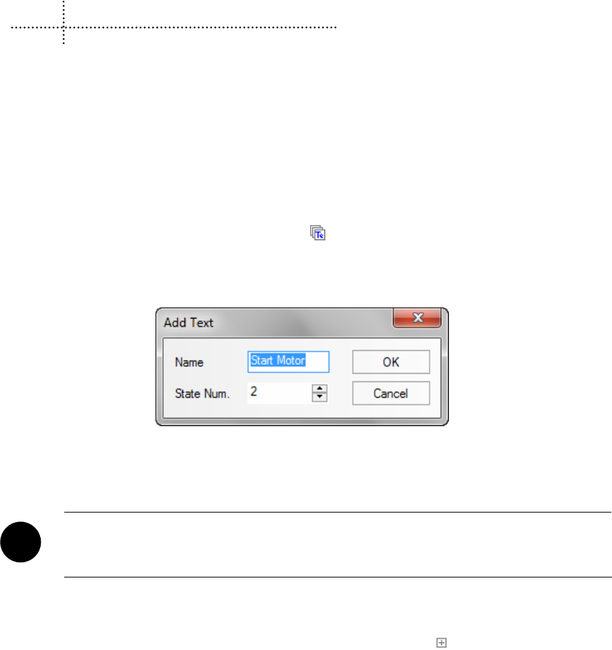
286
5 Better Understanding of Library
In Kinco HMIware, user can load the text, address tag, graphic and sound in the database, when they need to use this
information, they can call it from the database directly, this database is called library in Kinco HMIware. This chapter will
give you a detail description of how to use library.
5.1 Text Library
We will describe how to use Text Library in this section.
5.1.1 Create a Text Library
(1) Click on the Option (O) menu>>Text Library (T) or the icon in the tool bar or the Text Library in the Project
Database of Graph element window to open the Text Library dialog box.
(2) Click on the Add to pop up the Add Text dialog box.
For example, build a text item named “Start Motor”, the State Num is 2, each text supports 256 states at most. Click on
the Ok to finish building the text, and click on the Cancel to give up this text.
!
The Name of text cannot be modified after it is built
After setting the Name and State Num, click on the OK to the next step.
(3) The text named “Start Motor” has been added to the Text Library, click on the icon before “Start Motor” to
view the states of this text, there are two states: 0 and 1. Click on the blank area under the each language to input text content.
In this example , we input “启动” in the language1 of state 0,and “停止”in the language1 of state 1; Input “Start” in
the language2 of state 0,and “Stop” in the language2 of state 1.
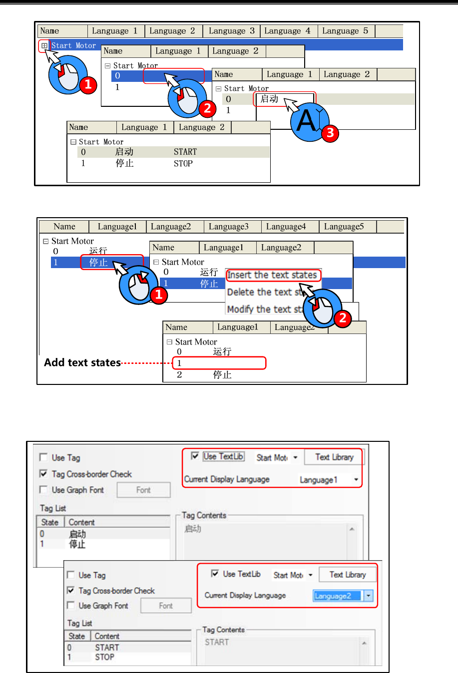
Advanced Part Better Understanding of Library
287
Besides, user can add/delete/modify the text state by right click option, take the following picture for
example:
(4) Click on the OK to close the Text Library dialog box after editing. Check the “Use Textlib” in Tag option of a
component and then select a already built text in list.

Kinco HMIware Configuration Edit Software
288
5.1.2 Export/Import Text Library
The built text library can be exported in a csv file, and the csv file also can be import into the Text Library.
!
Import/export the whole text library, but cannot import/export a single text item
(1) Export text library
The exported csv file can be edit by Microsoft Excel.
(2) Import text library
5.1.3 Set the Language of Text Library
Click on the Language Setting in the HMI Extended Attributes option of HMI Attributes or the Language in the Text Library
dialog box to open the Language Setting dialog box, and then set the global font attributes of each language.
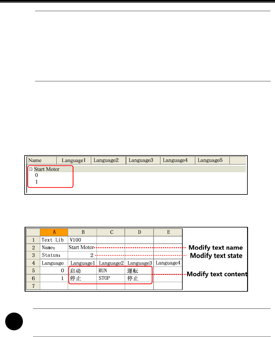
Advanced Part Better Understanding of Library
289
1. The font attributes in Language Setting is global, and the font attributes in the tag option is only for the
tag content of current component.
2. If the font attributes in Language Setting change, it will not affect the font attributes of the tag which
has already used the text in text library, if user want this font attributes to be the same as the Language
Setting, they can cancel the “Use Textlib”in the tag and then recheck it, so the font attributes is
refreshed.
5.1.4 Text Library Application
- Edit the Text Library quickly
When there is a lot of text content in text library, user can export the text library in a csv file , then edit it in the Microsoft
excel, it is very conveniently to edit in this way.
Firstly, build a text library, and then set the state number and text content.
Export the text library to a csv file in your PC, and then open and edit it by Microsoft Excel, you can edit the text name, state
number, text content and add new text item.
!
The Name, Status, Language1~32 are fixed formwork, if they are modified, there will be problem when
the csv file is imported to the Text Library.
Save the csv file before close it:
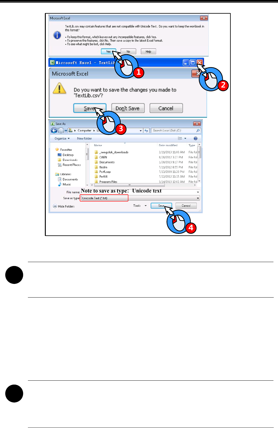
Kinco HMIware Configuration Edit Software
290
At last, import the text library file (textlib.csv) to the project.
!
When importing the text library file, if there is a text in the project text library has the same name as the text
in the file, there will be a tip to warn that whether you want to cover the same name text or not, the covered
text cannot be regained.
- Use Text Library to switch multiple languages
Use the special system register LW9130 to switch the languages in text library
When LW9130=0, HMI displays the text content in Language1; when LW9130=1, HMI displays the text content in
Language2….and so on, When LW9130=31, HMI displays the text content in Language32; if the LW9130>31, HMI
displays the text content in Language1.
!
The Number of Language in the HMI Extended Attributes of HMI Attributes will limit the language number
in Text Library. The default language number is 8 in Text Library, even if the LW9130>8 , HMI only
displays the Language1~Language8. If user wants to use more than 8 languages, he needs to set the Max
Lang Num in Language Setting, and the Number of Language must be smaller than Max Lang Num. The
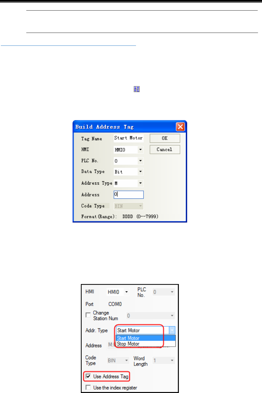
Advanced Part Better Understanding of Library
291
Default Language means the default language that HMI displays, for example, the language2 is English in
Text Library, if the Default Language is 2, HMI will display the text content in English till LW9130 changes.
☞For details, refer to [Advanced Part 2.6 Language Switching]
5.2 Address Tag Library
We will describe how to use Address Tag library in this section
5.2.1 Build a Address tag Library
(1) Click on the Option (O) menu>>Address Tag (A) or the icon in the tool bar or the Address Tag in the Project
Database of Graph element window to open the Text Library dialog box.
(2) Click on the Add to pop Build Address Tag dialog box
For example, build an address tag named “Start Motor”, the address is M0. Click on the OK to finish building this address
tag, and click on Cancel to give up this address tag.
5.2.2 Address Tag Application
After building the address tag in Address Tag Library, check the Use Address Tag, and chose the corresponding address tag
name. Take the following picture for example:
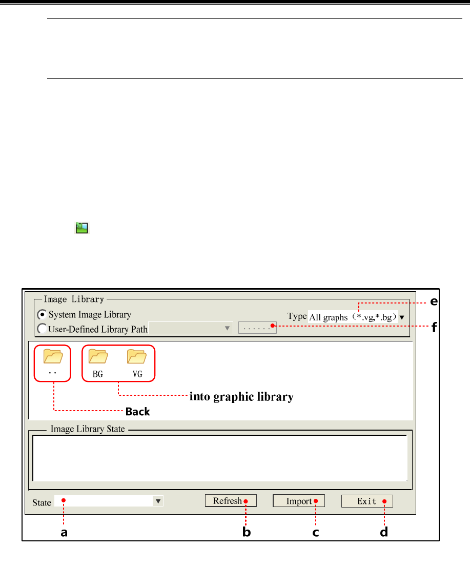
Kinco HMIware Configuration Edit Software
292
Bit component can only use the bit address tag; and the word component can only use the word address tag.
The Address Tag library supports being imported and exported; the import/export operation is the same as
the Text Library.
5.3 Graphic Library
Kinco HMiware provides user rich vector graphic and bit map. User can draw vector graphics, like, switch, lamp and so on.
User also can import external pictures to bit map. We will describe how to use the Graphic Library in this section.
5.3.1 Import Graphics
(1) Import Graphics
There are three methods to open the Import Graphic dialog box
1. Click on the icon
2. Click on the Import Graphics Library in Draw (D) menu.
3. Click on the Import Graphics in the Graphics option of a component attributes.
a. Switch the states of selected graphic.
b. When all graphic are not displayed in above area, click on Refresh to display them all.
c. Choose a wanted graphic in above area, click on the Import to load this graphic (vg or bg) to current project.
d. Close the Import Graphic dialog box
e. Set the graphic type that needs displaying in following area.
f. Open the route selection dialog box.
There are two sources for graphic library
System graphic library: The graphic library in software, it is in the vg_bg_lib file folder of Kinco HMIware installation file
folder.
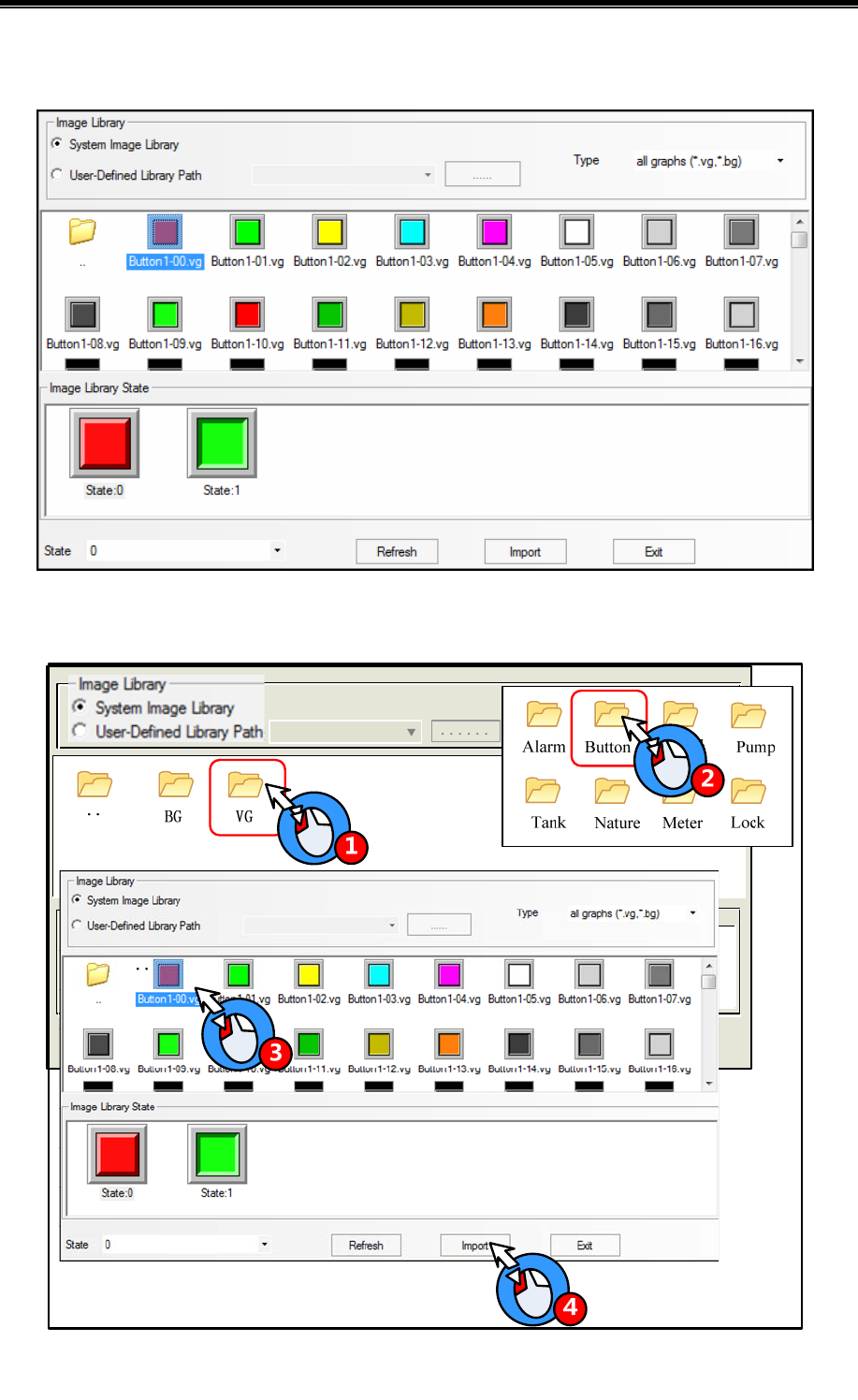
Advanced Part Better Understanding of Library
293
There are two parts for graphic display area, the upper half displays all thumbnail in graphic library, the lower half displays
all states’ preview graphic of selected graphic
Import graphic from system graphic library, for example, import the button named “Button1-00.vg”from the System
Graphic Library>>Vg>> Button, the operation steps are as follows:
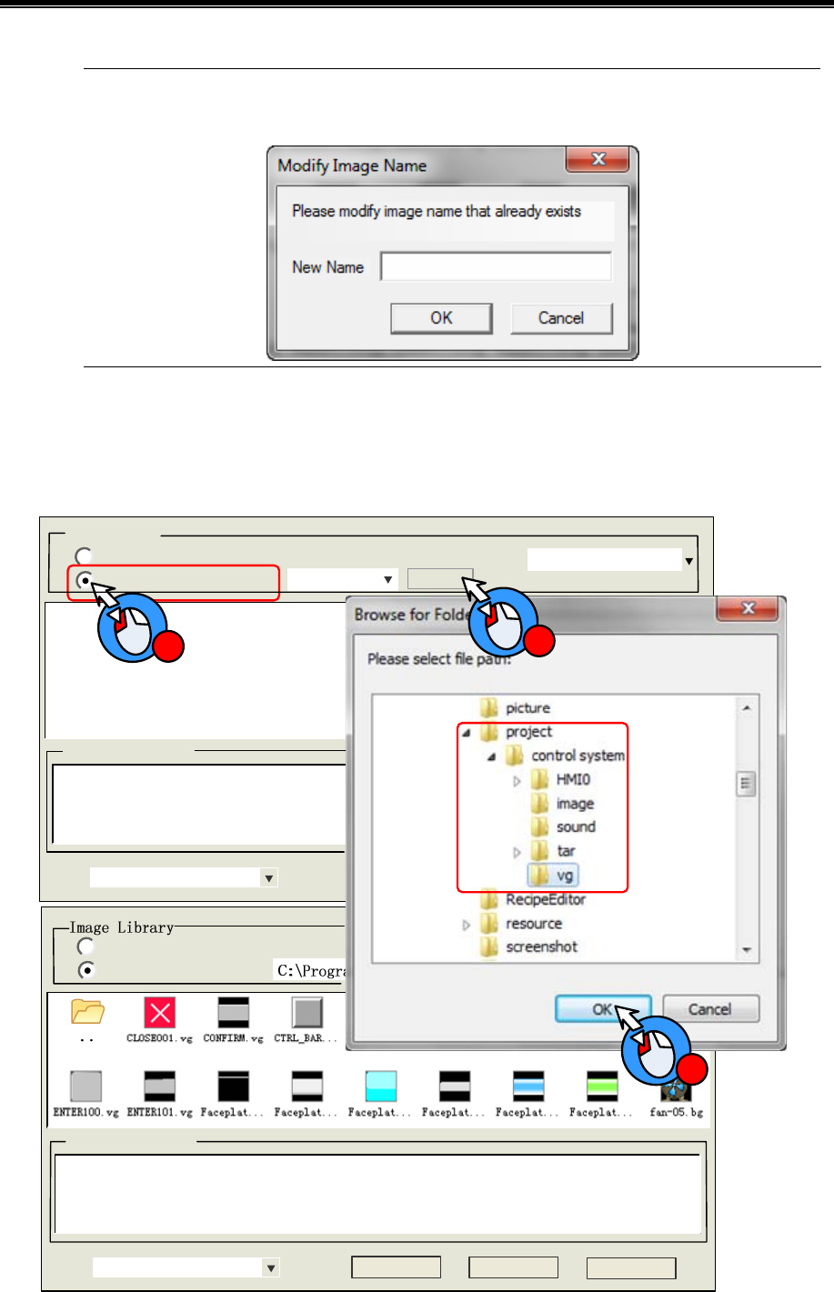
Kinco HMIware Configuration Edit Software
294
If the imported vector graphic (vg) or bit graphic (bg) has the same name as the graphic in current project
graphic library, there will be a Modify Image Name dialog box to input a new name.
- User-defined Library Path: user can import a vg or bg from a specified route, that is , user can import the graphics from
the vg file folder of other project files. For example , import graphic from D:\Program Files\Kinco\Kinco HMIware\
project \control system\ vg, the steps are as follows:
System Image Library
User-Defined Library Path ......
Image Library State
State Refresh Import Exit
Image Liarary
System Image Library
User-Defined Library Path
Type All graphs(.vg,.bg)
......
Image Library State
State
1
3
2

Advanced Part Better Understanding of Library
295
Multiple vg/ bg cannot be imported/exported at the same time
2. Export Graphic
The imported vg/bg from system library or the new build vg/bg graphics are stored in the vg file folder of project file folder.
There are two methods to save the graphic in current project to system graphic; they are stored in vg_bg_lib>>vg /BG
>>UserselPath file folder of Kinco HMIware installation file folder. So user can use these graphics in the other project.
1. Project File Window>> Vector Graph
2. Graphic option of component attributes
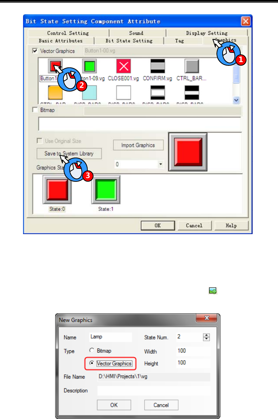
Kinco HMIware Configuration Edit Software
296
5.3.2 Build New Graphics
If the vg/bg in system graph library cannot satisfy user’s application, he can build new vg/bg himself.
(1) Build a new vector graph
The New Graphics button
For example, draw a indicator light name “Lamp” and has two states: Click on the icon or New Graphics (N) of
Draw (D) menu to open the New Graphics dialog box:
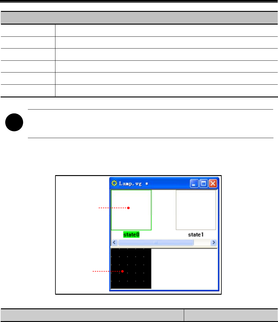
Advanced Part Better Understanding of Library
297
New Graphics dialog box
Name The name of new graph
State Num Set the state number of new graph, it is 256 at most
Type The type of new graphic: vector graph or bit map
Width/Height Set the width and height of new graph, the unit is pixel
File Name The store route of new graph
Description The note information for new graph
!
The width and height cannot be modified after being built.
Choose the Vector Graph type, input “Lamp” as its name and set 3 to State Number, use the default width (100) and height
(100). Click on OK to enter the graphics edit window:
View Area
Edit Area
Draw the graphics for State0 and State1; see the drawing steps as follows:
Example Draw a base for the lamp
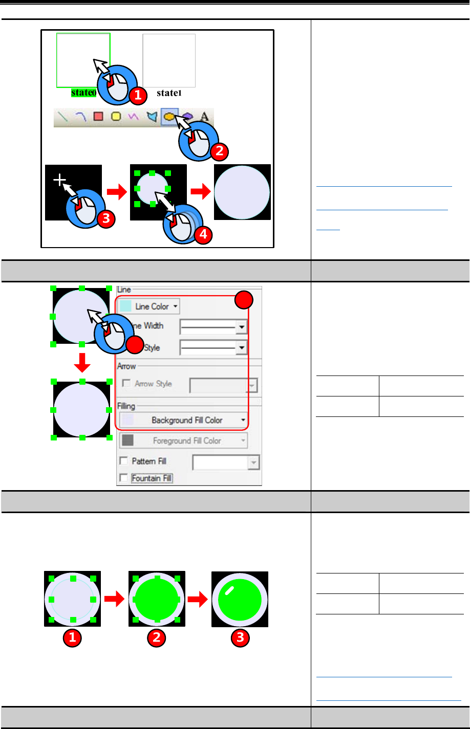
Kinco HMIware Configuration Edit Software
298
1.Choose State0
2. Choose the Ellipse in the draw tool
bar.
3. Move the mouse to edit area, and left
click when the + icon appears.
4. Draw a ellipse
☞For details about how to draw a
ellipse, refer to [Advanced Part 2.2
Draw]
Example Set the graph attributes
2
1
1. Double click the ellipse to open
graphic dialog box.
2. Set the ellipse attributes as follows:
Line Color RGB(230,230,250)
Filling Color RGB(230,230,250)
Example Draw lamp and flashing effect
1. Draw a ellipse which is smaller than
the base.
2. Set the ellipse attributes as follows:
Line Color RGB(0,255,0)
Filling Color RGB(0,255,0)
3. Draw a short line on lamp as the
flashing effect.
☞For details about how to draw a
line, refer to [Advanced Part 2.2 Draw]
Example Draw graph for State1
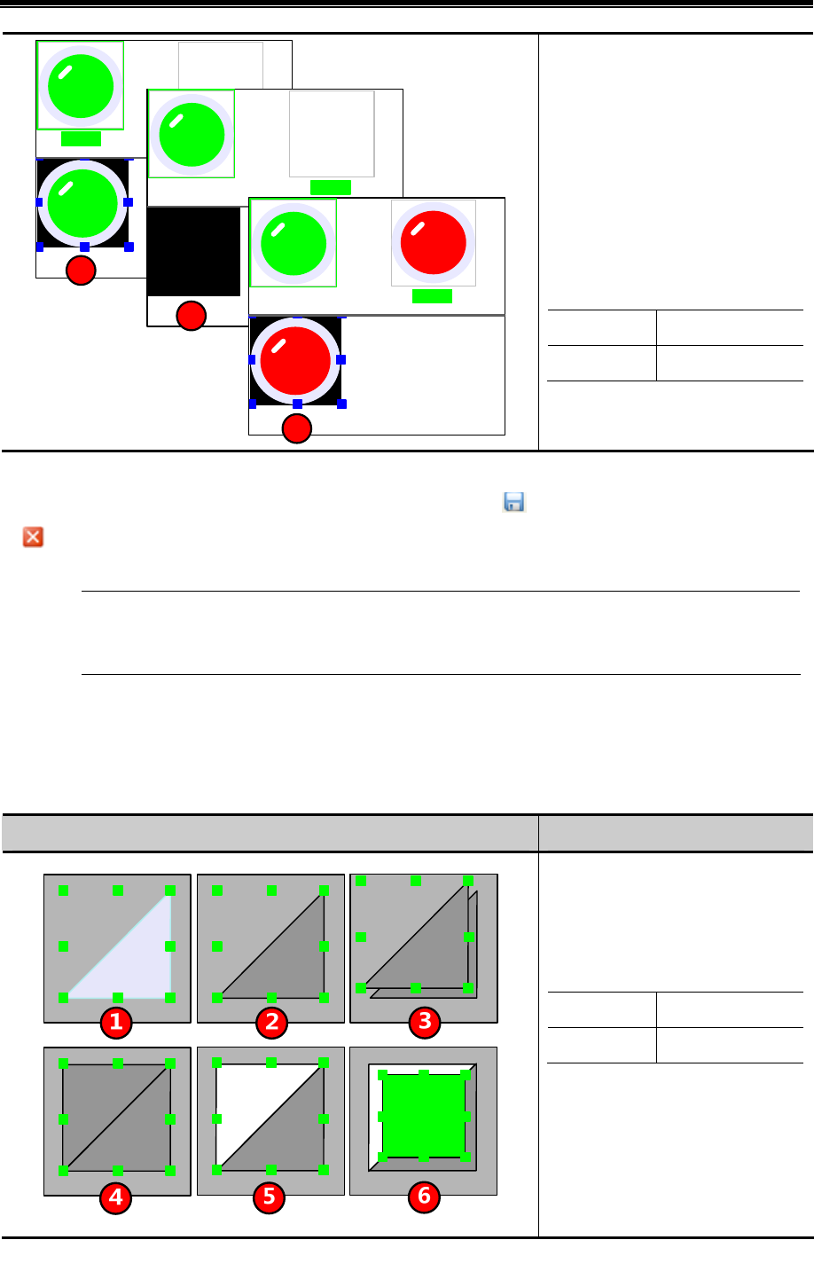
Advanced Part Better Understanding of Library
299
state0state1
state0state1
1
state0state1
2
3
1. Select all the graphics of State0 and
copy(Ctrl+A and Ctrl+C)
2. Select the State1, paste the graphics
to state1(Ctrl+V)
3. Set the lamp attributes of Stae1 as
follows:
Line Color RGB(255,0,0)
Filling Color RGB(255,0,0)
After drawing the lamp graphics, click on the Save in File menu or icon to save the new graphic, at last click on
the icon to close the graph edit window.
The new vector graphics will be saved as vg format file, they are in the vg file folder of current project file folder
User can only use the draw bar to draw pictures on vector, but cannot add some text or external picture to
vector graph.
Save to the VG map
User also can draw vector graphics in project edit window and then save them as VG map.
For example, draw a vector graph named “button”, and has two states. The drawing steps are as follows:
Example Draw graphics for State0
1. Draw a polygon in HMI Edit
Window
2. Double click the polygon, setits
attributes as follows:
Line Color RGB(0,0,0)
Filling Color RGB(165,165,165)
3. Copy (Ctrl +C) and paste (Ctrl +V)
the polygon.
4. Rotate the polygon2 horizontally and
then vertically.
5. Double click the polygon2 to set its
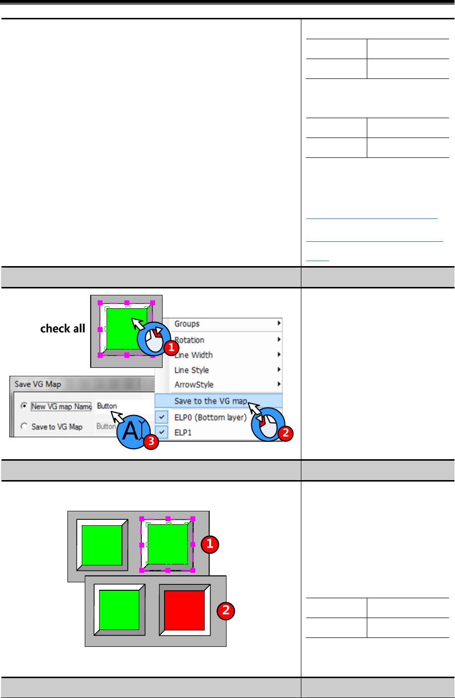
Kinco HMIware Configuration Edit Software
300
attributes as follows:
Line Color RGB(0,0,0)
Filling Color RGB(255,255,255)
6. Draw a rectangle, and double click to
set its attributes as follows:
Line Color RGB(0,0,0)
Filling Color RGB(0,255,0)
Now finish drawing the graphics of
State0.
☞For details about how to draw a
rectangle, refer to [Advanced Part 2.2
Draw]
Example Save the graphics of State0
1. Select all the graphics of State0, then
right click.
2. Choose the Save to the VG map in
the right click option
3. Set a name for this vector graph in
the popped up dialog box, and then
click on OK to save.
Example Draw graphics for State1
1. Select all he graphics of State0, and
then copy (Ctrl +C) and paste (Ctrl
+V)
2. After pasting , exchange the two
polygon, and set the rectangle’s
attributes as follow:
Line Color RGB(0,0,0)
Filing Color RGB(255,0,0)
Now finish drawing the graphics of
State1.
Example Save the graphics of State1
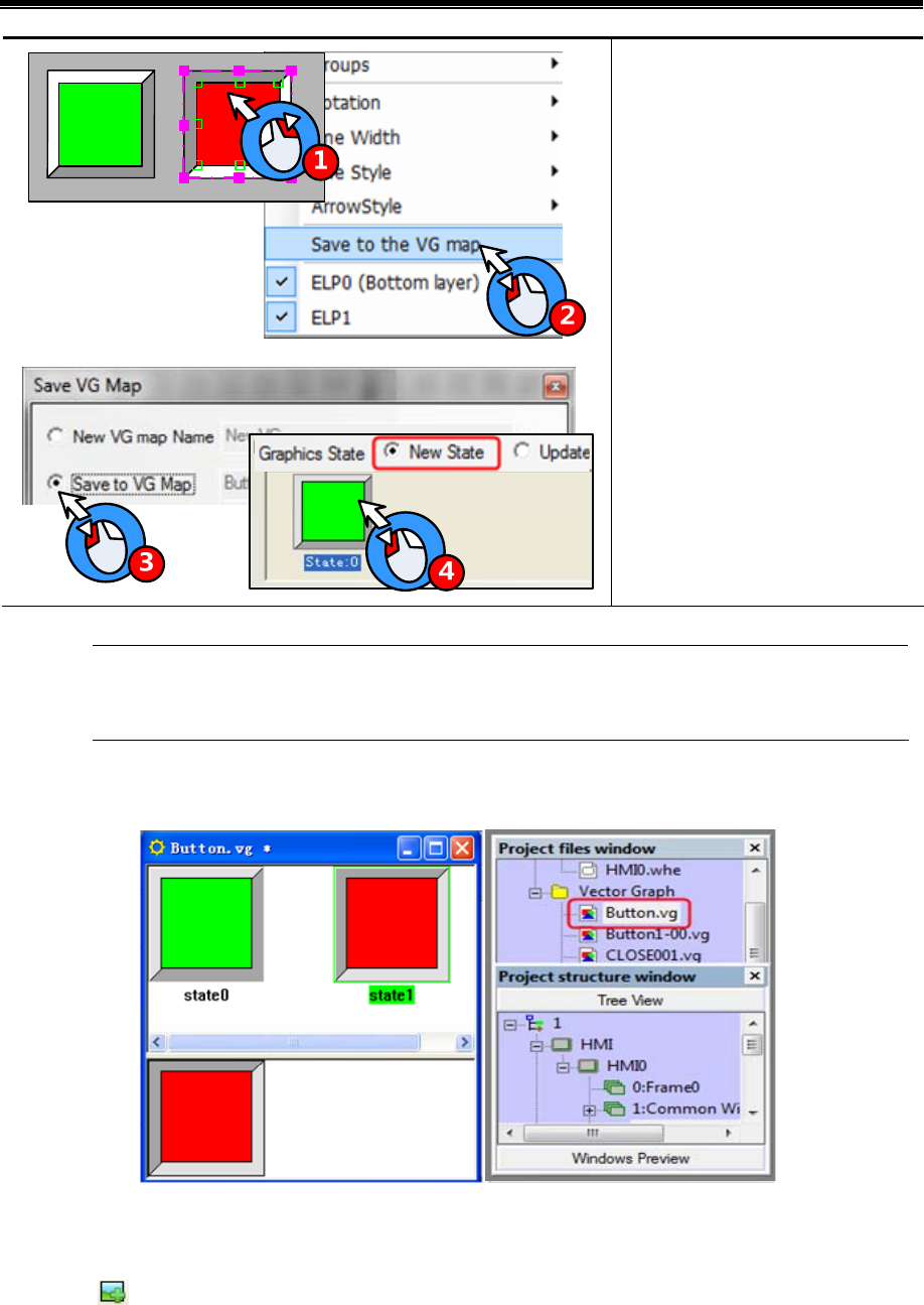
Advanced Part Better Understanding of Library
301
1. Select all the graphics of State1, then
right click.
2. Choose the “Save as VG map” in
right click options.
3. Choose the “Save to VG map” in
the popped up dialog box.
4. Choose the “New State” in the
Graphics States.
The New States in Save VG map dialog box means add a new state to the vg, Update Current State means
replace a specified state.
User can view the saved vg in Vector Graph of Project file window.
(2) Build a new bit map
For example, build a new bit graph named “Button”, and it has two states. Click on the New Graphics (N) of Draw (D)
menu or icon to open the New Graphic dialog box.
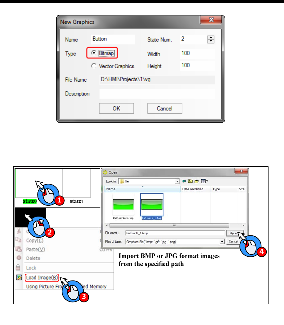
Kinco HMIware Configuration Edit Software
302
Choose the Bit Map type and input “Button” as its name, set the State Num to 2, and then click on the OK to enter the
graph edit window
Import a picture for State0:
Import a picture for State1
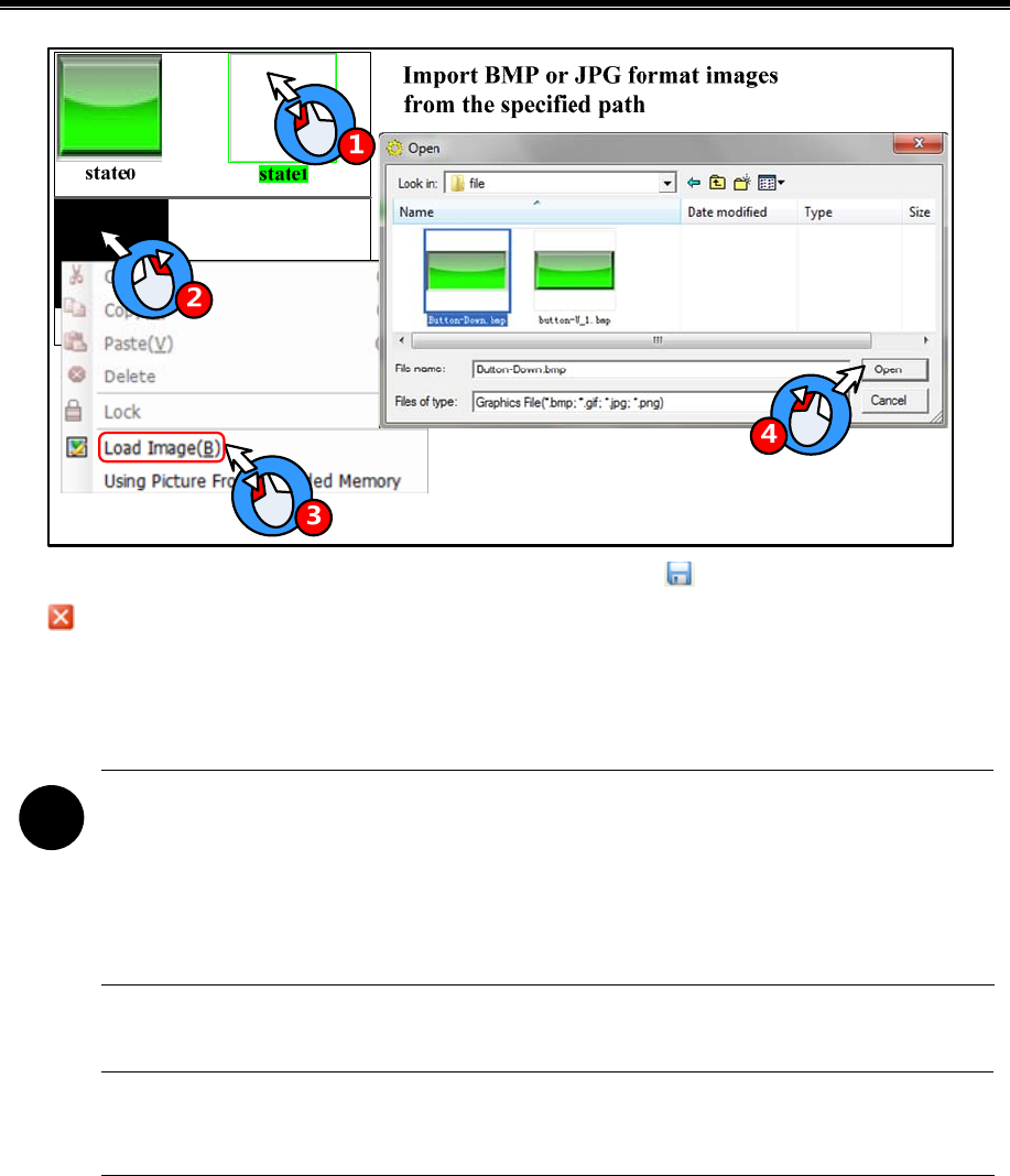
Advanced Part Better Understanding of Library
303
After import pictures to bit map, click on the Save in the File menu or the icon to save bit map, at last click on the
icon to exit the graph edit window.
The new build bit graph will be saved as bg format file, it is saved in the vg file folder of current project file folder. The
imported original bmp, jpg, gif pictures are saved in the image file folder of project file folder.
!
1. Do not delete any file in the vg file folder, or the vg/bg cannot display normally in the project.
2. User can only load external picture to bit graph, but cannot use draw tool to draw pictures or add text on it.
3. If user load gif format picture to bit graph, the gif cannot be controlled by component state, for example, if
the Bit State Switch uses the gif picture, the component displays the gif animation effect, no matter the
component is ON or OFF.
Kinco HMIware supports reading the pictures from extended memory devices to bit map; it can save the HMI memory.
Only the HMI with USB host and SD card port support reading picture from extended memory device.
Example: Put a picture (background.bmp) in the U disk or SD card (It is USB1 in this example), the HMI project read this
picture (background.bmp) in the U disk.
1. Copy the picture (background.bmp) to the U disk.
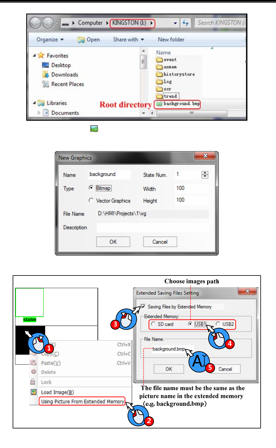
Kinco HMIware Configuration Edit Software
304
2. Build a new bitmap: Click on the icon or the New Graphics(N) in the Draw(D) menu to pop up New Graphics dialog
box: Name: background, State Num: 1, Type: Bitmap.
3. Using picture from extended memory
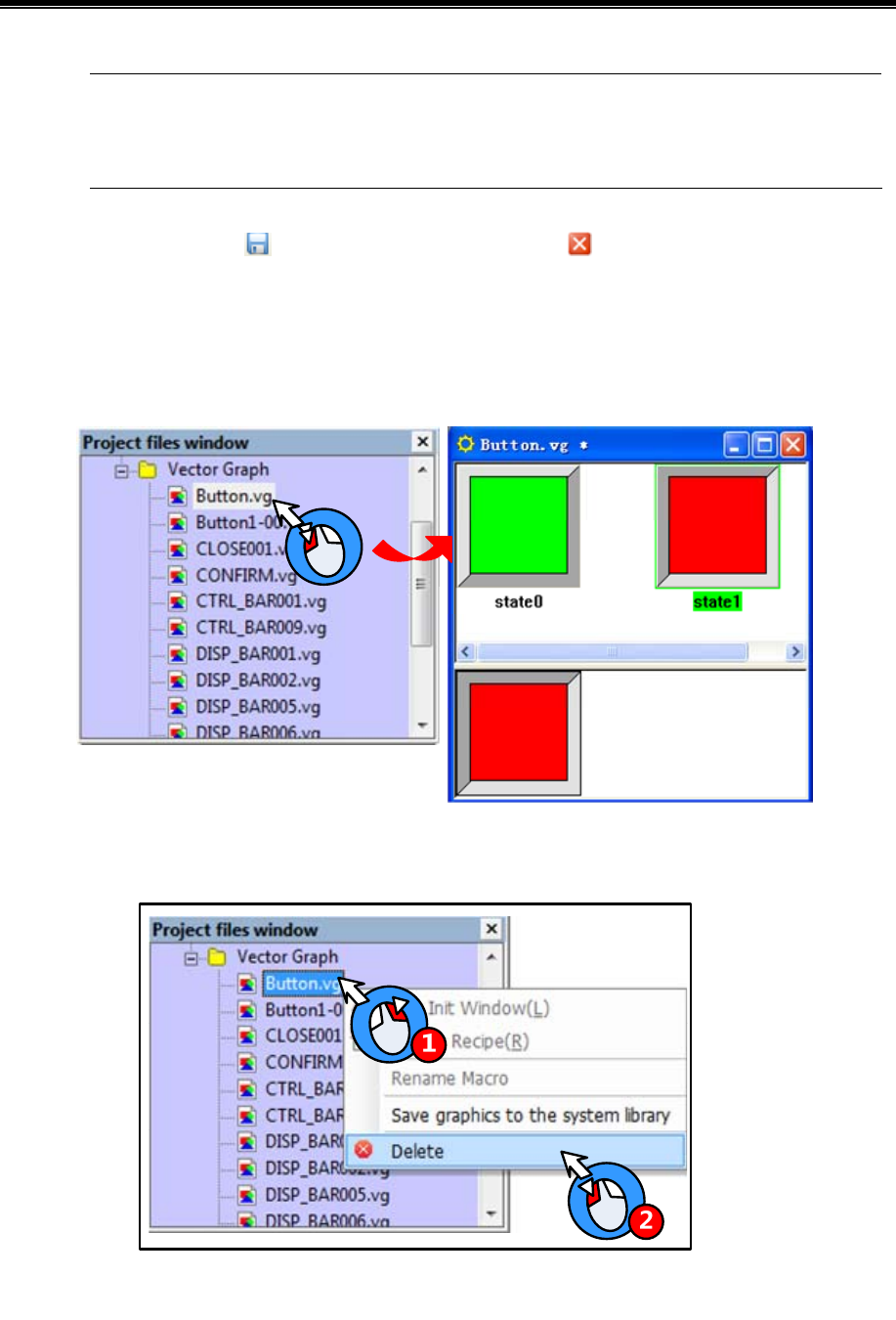
Advanced Part Better Understanding of Library
305
1. The File Name must be the same as the picture name in the extended memory.
2. The picture can be bmp, jpg or gif or png format.
3. The picture must be in the root directory of extended memory.
After above setting, click the icon to save the bitmap, and click on the icon at the upper right to close the graph edit
window.
5.3.3 Edit Graphics
- How to open the Graph Edit Window
Open the Graph Edit Window as shown in following picture:
- Delete the graph
Delete the vg/bg graph in current project as shown in following picture:
Click on the Yes to delete the chosen vg/bg, and click on the No to cancel this operation.
Add/delete states for graphics
User can add/delete graphics states in the Graph Edit Window.
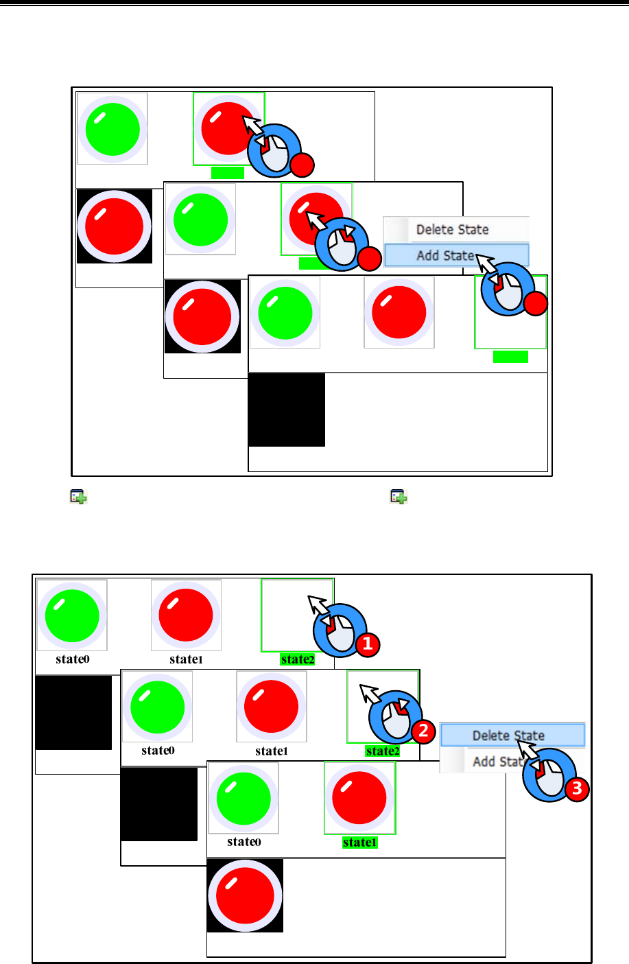
Kinco HMIware Configuration Edit Software
306
Add state
(1) Add States in the right click options
state0state1
state0state1
1
state0state1state2
3
2
(2) The icon in the tool bar: choose one state, and then click on the icon to add state.
Delete States
(1) Delete States in the right click options.
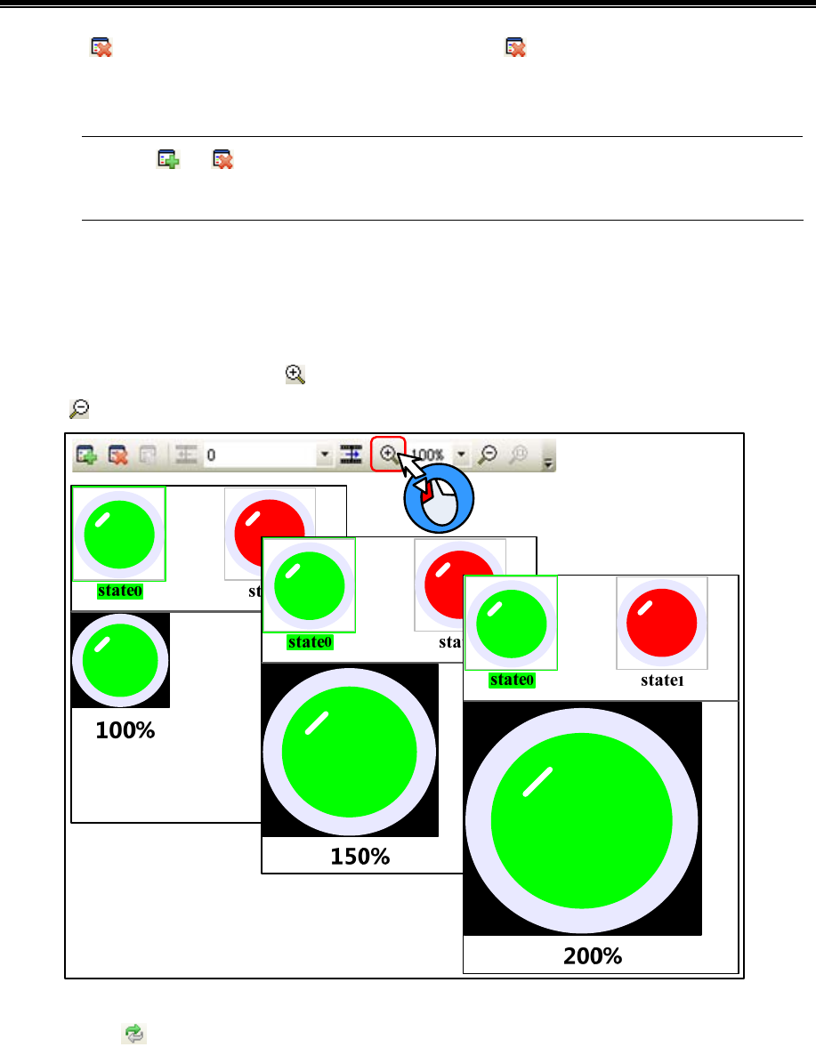
Advanced Part Better Understanding of Library
307
(2) The icon in the tool bar: choose one state, and then click on the icon to delete this sate.
Delete States
The icons and are used to add/delete window in HMI Edit Window, and add/delete graph states in
Graph Edit Window.
Zoom in/Zoom out edit area
In the graph edit window, it is not easy to edit graph if the edit area is too small, user can use the zoom in function to zoom in
the edit area.
In the graph edit window, click on the icon to zoom in the work space, the maximum is 300%; In the same way, click on
the icon to zoom out the work space, the minimum is 25%. See the 200% effect as follows:
Gray level of graph
Click on the icon to switch the gray level of current graph.
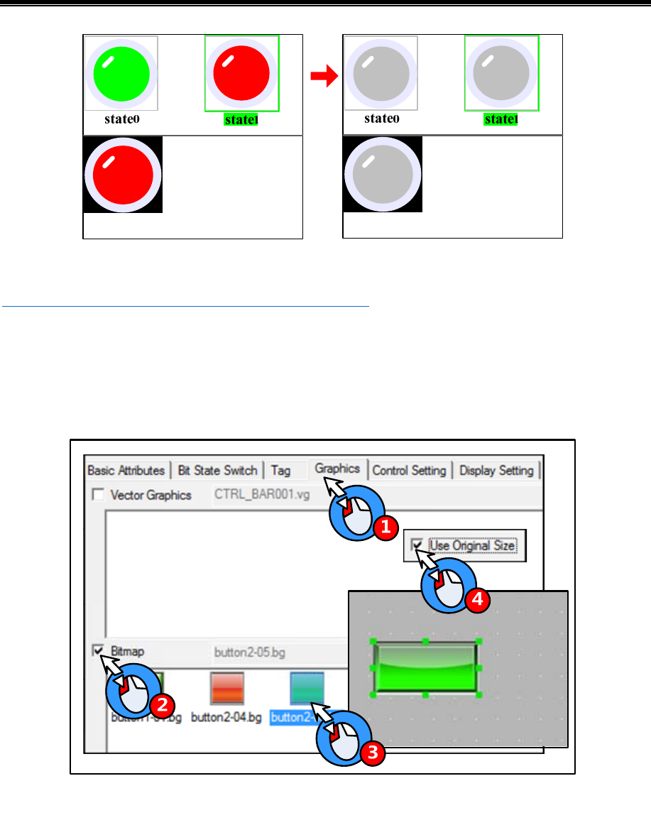
Kinco HMIware Configuration Edit Software
308
The transparent color of bit graph
6☞For details, refer to [Advanced Part 2.2.6 About Transparent Color]
5.3.4 How to Use the Graphics
(1) How to use the vector and bit graphics.
Take the lamp, button and background pictures for example:
Add a Bit State Switch to the edit window, and use the Bitmap in Graphics option.
Add a Bit State Lamp, and use the Vector Graph in Graphics option.
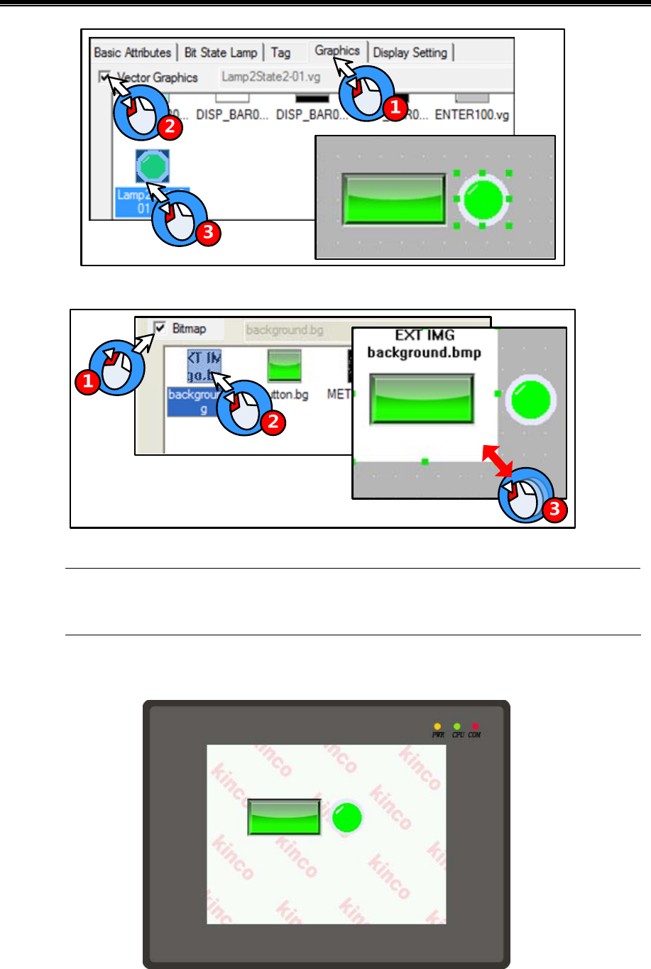
Advanced Part Better Understanding of Library
309
Add a Bitmap component as a background picture.
The bitmap which uses the picture from extended memory device does not support the “Use Original
Size” function; user needs to adjust the size according to the original size himself.
The simulation effect is as follows:
(2)Optimize the bitmap

Kinco HMIware Configuration Edit Software
310
The bitmap supports the multiple formats picture, like BMP, JPG, JPE, JPEG, GIF, and PNG. But the color and size of
imported pictures will affect the HMI project size and execution speed. Please note the following issues when you import a
picture to the bitmap:
- The resolution of imported picture cannot be higher than HMI’s resolution, for example the HMI’s resolution is
640*480, and the imported picture’s resolution should be lower than 640*480. User can edit the picture to the same
size as component by picture edit tool before importing this picture to the project, for example, a bitmap is used in a
component with the width and height 100*100, and user can edit the picture to resolution 100*100 before importing
this picture to bitmap. If you do not need the high resolution display, edit the picture as small as possible before
importing, and then zoom in the program.
- The pictures saved in HMI are lossless compression in BMP format, if the imported pictures are loss compression in
JPG, the pictures will be larger after compiling, and the resolutions will loss. That is, when using bit map. Please
optimize the picture size, and chose compression format according to the actual application.
- Relatively Speaking, the vector graph takes much smaller size than bit map. That is, do not use too many bit maps in
the program, use vector graphics as possible, it also can make HMI execute faster.
5.4 Sound Lib Application
Kinco HMIware supports sound files, like WAV, MP3 formats. They can be used for touch sound or Event/Alarm sound.
1. The audio output port does not support OPAMP function; user needs to connect a loud speaking to this
port.
2. A signal imported sound file must be smaller than 256K, but if the sound file is saved in extended memory,
the size is not limited.
3. Supports WAV and MP3 formats only.
4. Only the HMI with audio output port support Sound Lib function.
5.4.1 Import Audio File
Click on the icon or Graph element window>>Project Database>>Sound Lib to open the Sound Library box.
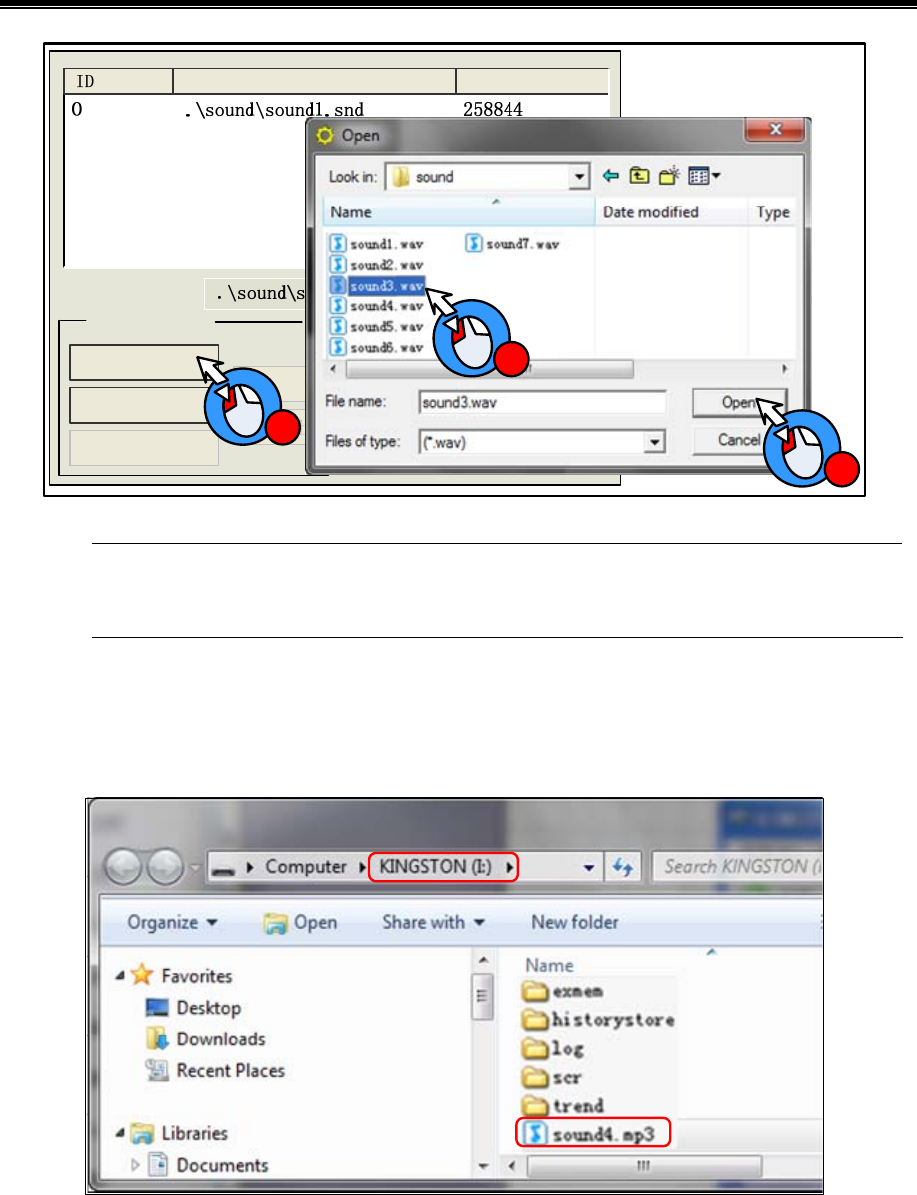
Advanced Part Better Understanding of Library
311
Name Size(Byte)
Import...
Using audio from
Delete
Current Sound:
Sound Processing
play
1
2
3
The system will convert the imported sound file to snd file automatically; the original sound file is saved in
the sound file folder of current project file.
The sound file also can be read from extended memory, which can save HMI’s memory.
[Example]: Read the sound file named “sound4.mp3” from U disk. First, save the sound4.mp3 file to the root catalog of U
disk.
Root directory
Choose the “Using audio from extended memory” in Sound Library.
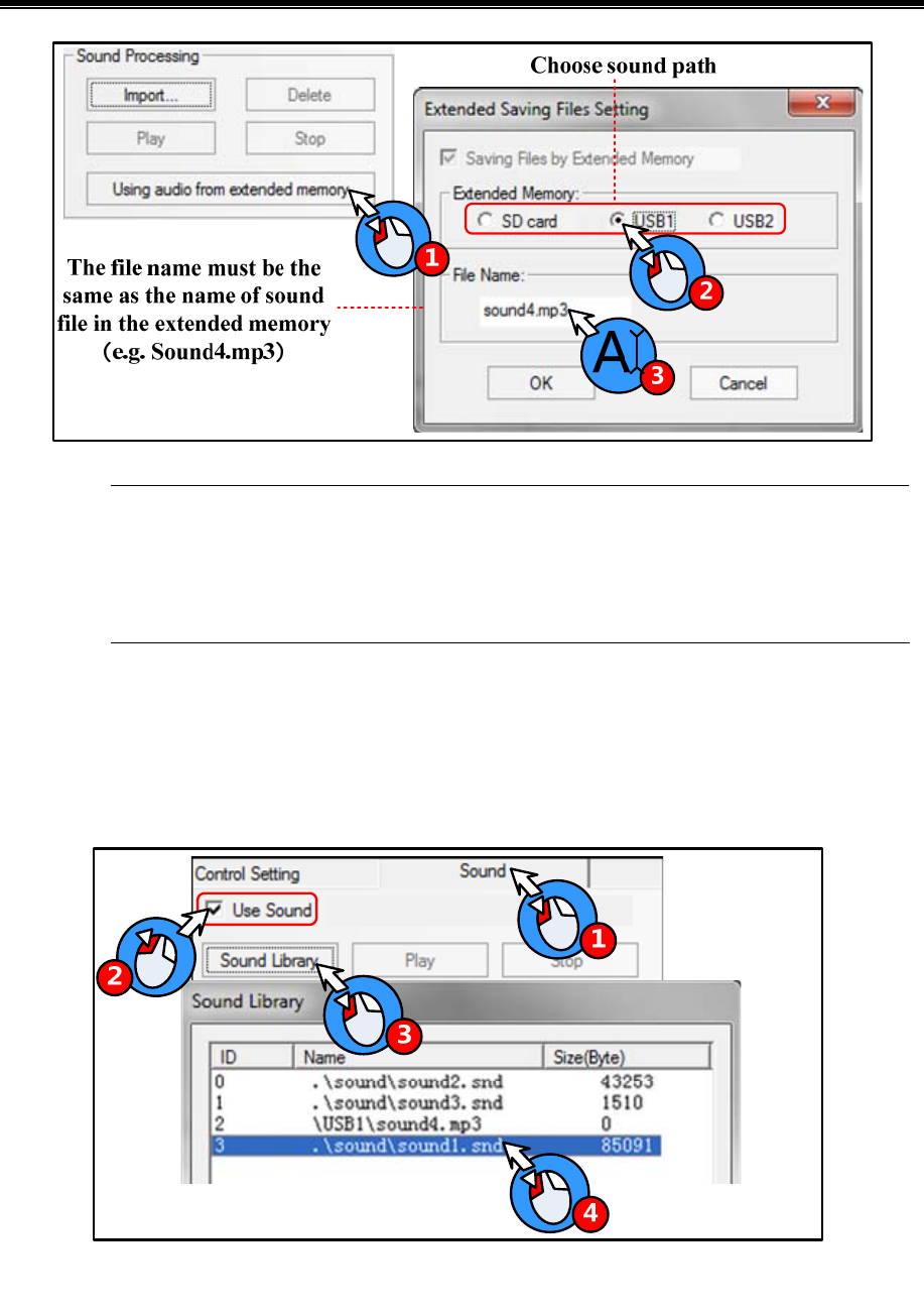
Kinco HMIware Configuration Edit Software
312
1. The File Name must be the same as the name of sound file in the extended memory.
2. The audio file read from extended memory must be mp4 format, the wav is not supported.
3. The audio file must be saved in the root catalog of extended memory.
4. The size of audio file is not limited , it depends on the memory size of extended memory device.
5.4.2 How to Use Audio File
(1)How to use audio file
Only the HMI with audio output port has the Sound option in component attributes. The audio file will be played till the it is
over when the component is touched, and this sound cannot be paused.
The Alarm/Event Information also can use the sound as the alarm sound.
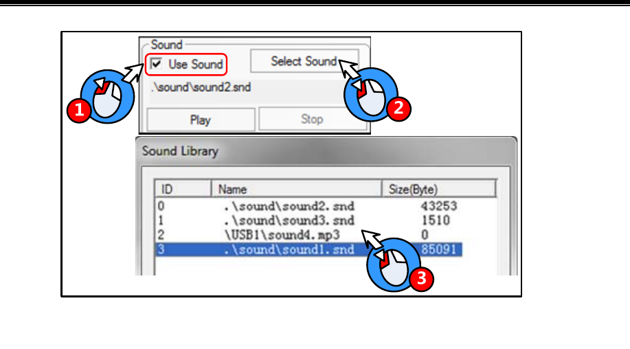
Advanced Part Better Understanding of Library
313
(2)Adjust the audio volume
User can use the system register LW9464 to adjust the volume, if LW9464=0, it means sound off. The value of LW9464 is
from 1 to 100, which means the volume is larger.
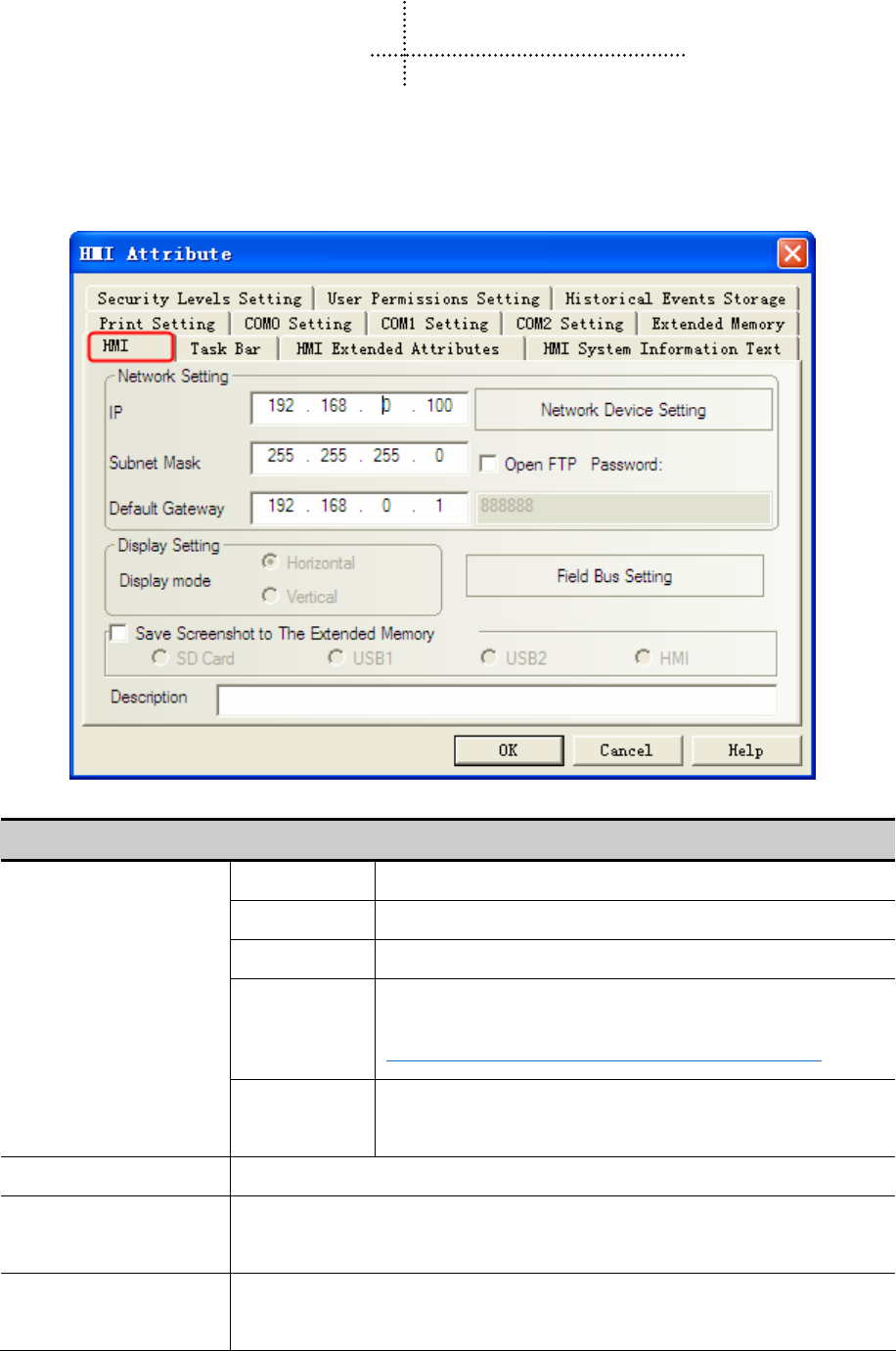
314
6 System Parameters
6.1 HMI Attributes
Double the HMI icon or right click the HMI icon and choose the Attribute to open the HMI Attributes box. User can
configure some HMI system parameters in this box.
6.1.1 HMI
Detail description of HMI Attributes option
IP Set the IP address for the HMI with Ethernet port
Subnet Mask Set the subnet mask for the HMI with Ethernet port
Default Gateway Set the gateway of LAN which HMI is connected to
Open FTP
Enable the FTP function and set a password.
☞For details, refer to [Advanced Part 14.2.4 FTP Function]
Network Setting
Network Device
Setting
Configure the Ethernet protocol when HMI communicates with
PLC/controller via Ethernet
Display Setting Display the HMI display mode
Field Bus Setting Configure the field bus protocol and parameters when HMI communicates with
PLC/controller via field bus
Save Screenshots to The
Extended Memory
Choose the extended memory device where the screenshots are saved. Only the HMI with
extended memory supports this function
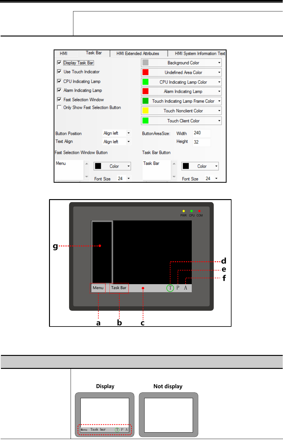
Advanced Part System Parameters
315
Description
Input description for HMI , this description will distinguish different HMI when
downloading and simulating
6.1.2 Task Bar
The display effect on HMI is as follows:
a. Fast Selection Window button b. Task Bar button c. Task Bar d. Touch Indicator e. CPU Indicator f. Alarm
Indicator g. Fast Selection Window
Detail Descriptions of Task Bar
Display Task Bar Display the task bar on HMI or not

Kinco HMIware Configuration Edit Software
316
Display touch indicator on tool bar.
Undefined Area Color Set the indicator color when touching the undefined area.
Touch Nonclient
Color
Set the indicator color when touching the blank area, where there
are no components orders.
Touch Client Color Set the indicator color when touching the workplace area, where
there are components and orders.
Use Touch Indicator
Touch Indicating
Lamp Frame Color
Set the color for indicator frame.
Display CPU indictor on task bar. CPU Indicating Lamp
CPU Indicating Lamp
Color
Set the color for CPU indicating lamp.
Display alarm indictor on task bar. Alarm Indicating Lamp
Alarm Indicating
Lamp
Set the color for alarm indicating lamp.
Fast Selection Window When clicking on the Menu button , pop up the fast selection window or not.
Only Show Fast Selection
Button
Set this option to display fast selection button only.
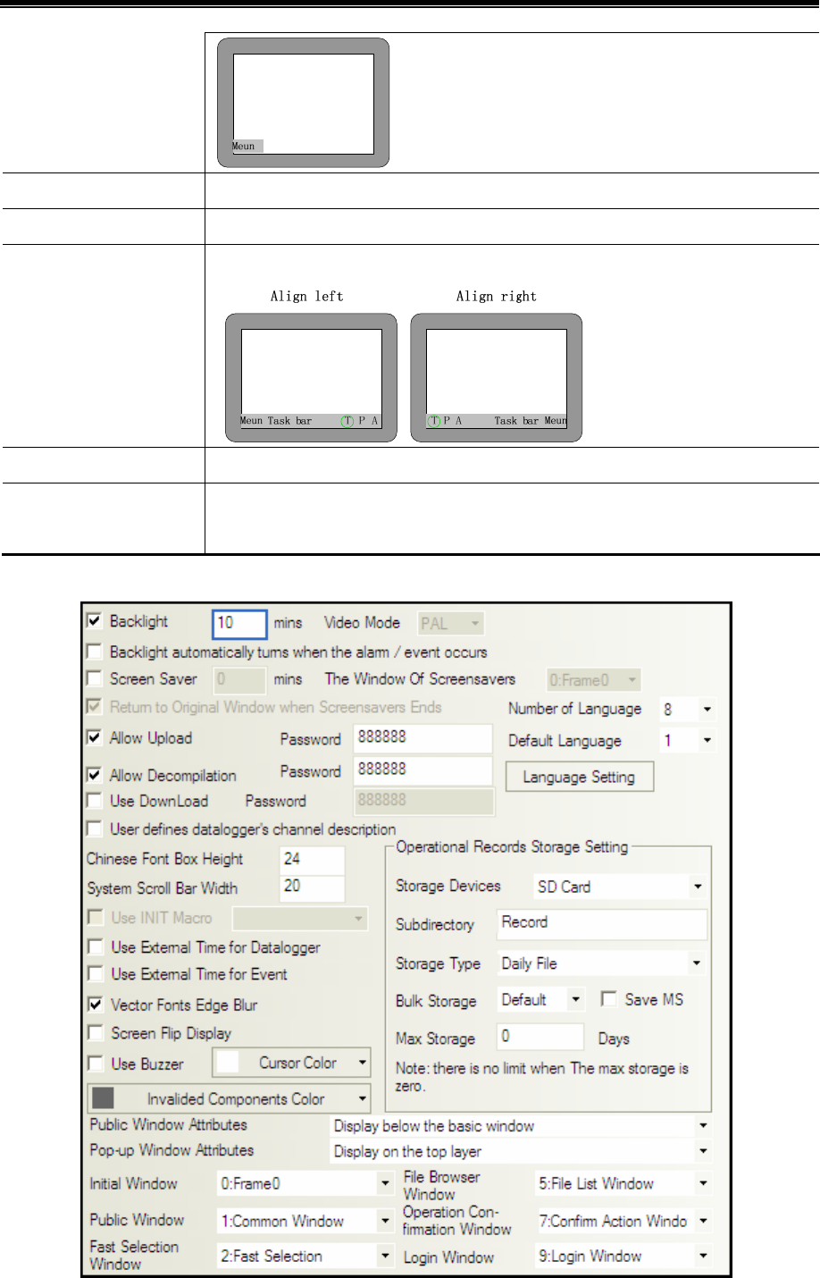
Advanced Part System Parameters
317
Button Area Size Set the size of buttons on fast selection window and task bar, the unit is pixel.
Font Size/Color Set the font size and color of text on fast selection window and task bar, the unit is pixel.
Button Position Set the position of buttons on fast selection window and task bar.
Text Align Set the align method of text on fast selection window and task bar.
Hide the buttons of fast
section window and task bar
Delete the text in the text box to hide the buttons.
6.1.3 HMI Extended Attributes

Kinco HMIware Configuration Edit Software
318
Back Light/Screen Saver Setting
HMI turns off the backlight if there is no touch within set time, and the backlight will turn on when
the HMI screen is touched again. The unit of set time is minute, and the default time is 10 minutes.
Backlight
Backlight automatically turns when
alarm/event occurs.
In the backlight off state, The backlight will turn on
automatically if alarm or event is triggered.
HMI displays the screen saver window if there is no touch within set time, user can set the screen
saver window in the Window of Screensavers. HMI will display the normal screen again if the
screen is touched in screen saver mode. The default screen saver time is 10 minutes.
The Window of Screensavers Select a window as screensaver screen picture.
Screen Saver
Return to Original Window when
Screensaver Ends.
If this option is checked, the HMI returns to original
window when screensaver ends, if it is not checked, HMI
goes to the screensaver window when screensaver ends.
Upload/Decompile function settings
Allow Upload Allow user uploads the project in HMI to PC, the default password is 888888. Note: the Password
can not be empty or 0.
☞For details, refer to [Advanced Part 8.4 Upload]
Allow Decompile Allow user decompile the pkg file to wpj file, which Kinco HMIware can edit, the default password
is 888888. Note: the Password cannot be empty or 0.
☞For details, refer to [Advanced Part 8.7 Decompile Operation]
Use Download Allow user download the pkg file to HMI, the default password is 888888.
☞For details, refer to [Advanced Part 10.1.4 Download Password Protection]
Video function settings
Video Mode Set the signal format of video input, the PAL and NTSC are optional. Only the HMI with BNC port
supports this function, and uses the Video component in the program.
Text library settings
Number of
Language
Set the language number in the Text Library, there are 32 languages at most. This function is used
together with Text Library.
Default Language
The default display language of the texts which use text library. This function is used together with
Text Library.
Language Setting Open the Language Setting dialog box .This function is used together with Text Library.
System function setting

Advanced Part System Parameters
319
Use INIT Macro Trigger the macro when HMI is powered on.
Use Buzzer Enable the buzzer in HMI
Screen Flip Display Display a 180 degrees turn over screen.
Auxiliary parameters setting
System Scroll Bar
Width.
Set the width of system scroll bar, it ranges from 20 to 120, the unit is pixel.
Chinese Font Box
Height
Set the height of Chinese character input box, it ranges from 24 to 99, and the unit is pixel. This
function is used when input Chinese character to Text Input component.
Invalided
Components Color
Set the color of invalid components, this function is used together with component which is set the
Conditional Enabling option.
Cursor Color Set the cursor color in the input status of Number/Text Input component.
Use External Time
for Datalogger
Set the time source of the data sample in Datalogger and Data Report.
☞For details, refer to [Advanced Part 2.7.3 System Time and PLC Time Synchronization]
Use External Time
for Event
Set the time source of Event Trig time and Return to Normal Time in the Event Display and Event
Bar.
☞For details, refer to [Advanced Part 2.7.3 System Time and PLC Time Synchronization]
User defines
datalogger’s
channel description
Set the description in created *.db file same as the sample channel description.
Storage Devices The SD, USB DISK1*, USB DISK2* , HMI are optional.
Save MS Save the millisecond of operation log and save them in the CSV file.
Subdirectory Set the subdirectory where CSV file is storage, user can modify it.
The default subdirectory is Record.
Daily File Save the daily operation log in CSV file, the file name is
named by date,“yyyy mmdd”.
Storage Type
Single
File
Save the every recodes of operation log in CSV file, the
filename is the Subdirectory.
Bulk Storage Select a cache mode, when the data in buffer memory reaches the set
size; write data to SD card or USB drive. The Default means no buffer
memory, data is write to SD card or USB drive directly.
Operational
Records Storage
Settings
Max Storage Set the upper limit of storage.
The unit of Daily File is Day , and the unit of Single File is item
If the Storage Type is Daily File, the CSV file is named as
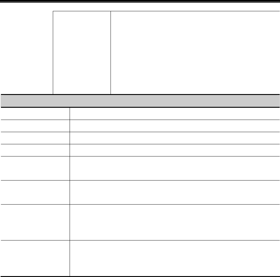
Kinco HMIware Configuration Edit Software
320
“yyyymmdd”and the Max Storage is upper limit of CSV file number in
this route. The early file will be delete if the file number exceeds the
Max Storage; If the Storage Type is Single File, The file is named as
Subdirectory, the Max Storage means the upper limit of the item number
in this file, if item number exceeds the Max Storage , the data will not
be stored any more.(yyyymmdd means the date when the operation log
happens)
Related Settings of Window
Public Window Attributes Display Public Window above the basic window or below the basic window
Pop_up Window Attributes Display pop-up window on the top or not
Initial Window Set the first window when HMI is powered on. The default is [0:Frame0]
Public Window Set a window as Public Window. The default is [1: Common Window]
Fast Selection Window
Set a window as Fast Selection Window, The default is [2:Fast Selection]. The Fast
Selection is used together with the fast selection button in the task bar.
File Brower Window
Set a window as File Brower Window, The default is[5:File List Window]. The File Brower
Window is used together with the Import/Export in Function Key.
Operation Confirmation
Window
Set a window as Operation Confirmation Window, the default is [7: Confirm Action
Window].The Operation Confirmation Window is used together with Operator Confirm of a
component.
Login Window
Set a window as Login Window of User Permission and Security Level, the default is
[9:Login Window]. The Login Window is used together with the User Permission and
Security Level function.
※Some models have two USB Host ports; the number of USB DISK is according to the sequence when the USB drives are
plugged in HMI, but not the position of the USB slot. The USB drive which is plugged in first is the USD DISK1 and
the second one is USB DISK2.
6.1.4 HMI System Information Text
User can define the display content for the system error information in the User-Defined System Information. When the error
happens, if user defines the display content for system error, HMI will display the user-defined content, or HMI displays the
default system error information.
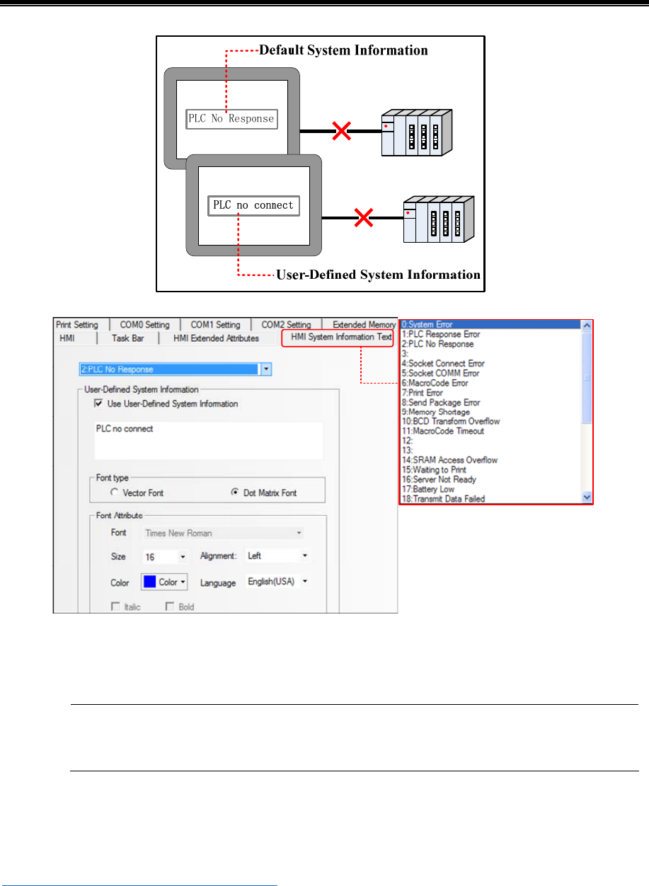
Advanced Part System Parameters
321
Select the default system error information in the red frame, then check the Use User-Defined Information and input
user-defined content in the input box.
User can define multiple system error information
6.1.5 Security Levels Setting
In this option, user can set the security levels and their passwords. There are 16 levels at most
☞For details, refer to [Advanced Part 10 Password]
6.1.6 User Permissions Setting
In this option, user can configure user name, password, logoff time and permission and so on. There are 32 users at most, and
each user has 32 permissions at most.
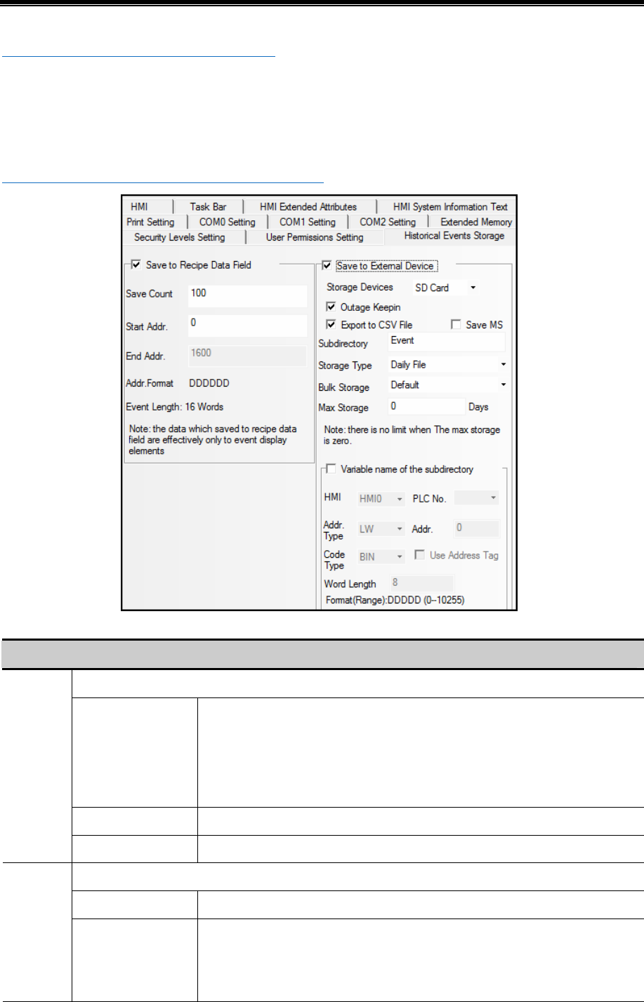
Kinco HMIware Configuration Edit Software
322
☞For details, refer to [Advanced Part 10 Password]
6.1.7 Historical Events Storage
In this option, user can set the route where the historical events are stored; this function is used together with Event
components.
☞For details, refer to [Advanced Part 4.7 Alarm Component]
Descriptions of Historical Events Storage
Save the historical event information in the recipe memory.
Save Count Set the item number of historical events, which are saved in recipe memory. If the
event item is larger than the set Save Count, the early information will be deleted,
and save new information.
Note:If the Save Count is 0, the historical event will not be stored.
Start Addr Set the start address from which the historical events are stored in recipe memory.
Save to
Recipe
Data Field
End Addr Software will calculate the End Address according to the Save Count and Start Addr.
Save the historical event information to external devices.
Storage Devices The SD card, USB DISK1*, and USB DISK2* are optional.
Save to
External
Device Outage Keepin When HMI is restarted by power outage,HMI can recover 1024 items historical
event which are triggered before power outage, and display them in the Event
Display component.
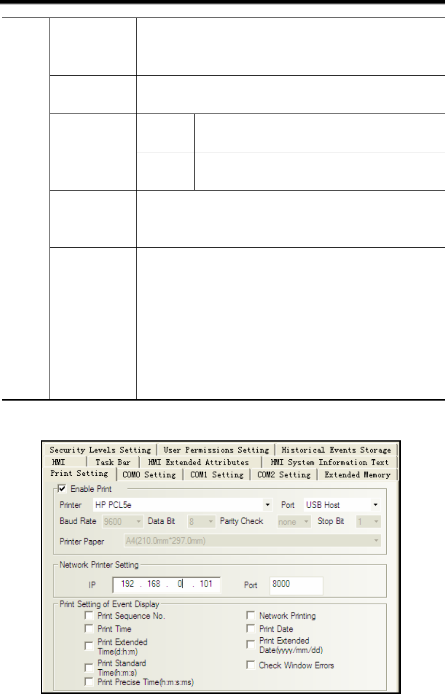
Advanced Part System Parameters
323
Export to CSV file Save the historical event information in CSV file, and save this CSV file to
external memory device, the storage route is :/event/subdirectory name/file name
Save MS Save the millisecond of operation log and save them in the CSV file.
Subdirectory Set the subdirectory where CSV file is storage, user can modify it.
The default subdirectory for historical event is Event.
Daily File Save the daily historical event information in CSV file, the file is
named by date, “yyyy mmdd”.
Storage Type
Single File Save the every recodes of operation log in CSV file, the filename is
the Subdirectory.
Bulk Storage Select a cache mode, when the data in buffer memory reaches the set size; write data
to SD card or USB drive. The Default means no buffer memory, data is write to SD
card or USB drive directly.
Max Storage Set the upper limit of storage.
The unit of Daily File is Day , and the unit of Single File is item
If the Storage Type is Daily File, the CSV file is named as “yyyymmdd”and the Max
Storage is upper limit of CSV file number in this route. The early file will be delete
if the file number exceeds the Max Storage; If the Storage Type is Single File, The
file is named as Subdirectory, the Max Storage means the upper limit of the item
number in this file, if item number exceeds the Max Storage , the data will not be
stored any more.(yyyymmdd means the date when the operation log happens)
6.1.8 Print Setting
In the Print Setting option, user can enable print functions and set its parameters.
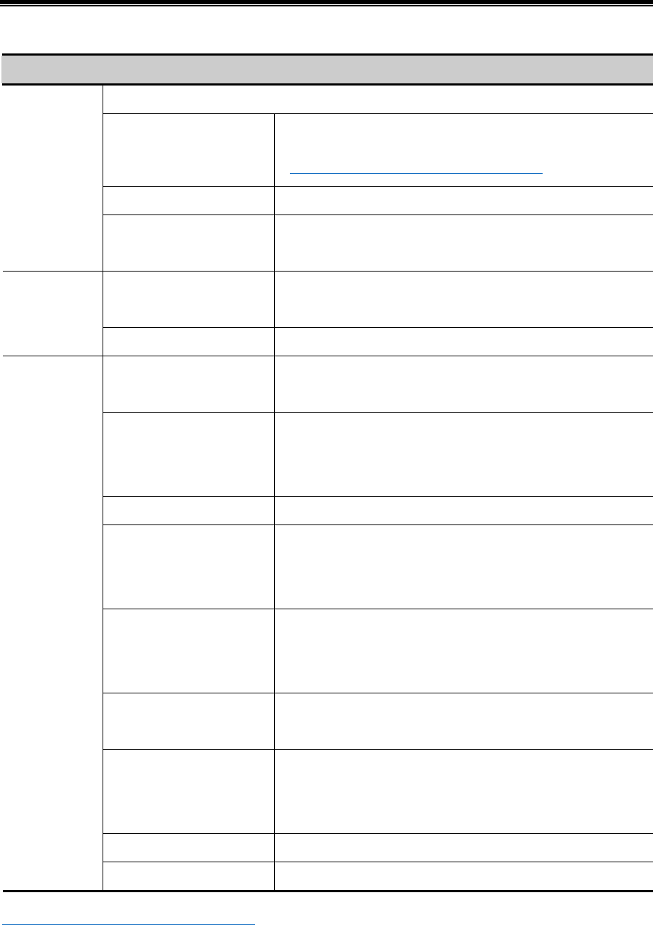
Kinco HMIware Configuration Edit Software
324
Descriptions of Printing Setting
Enable print function of HMI
Printer Select a communication protocol for printer
☞For details, refer to [Advanced Part 13 Print]
port Select a communication port for HMI and printer
Enable Print
Baud Rate/Data Bit/Parity
Check/Stop Bit
If the printing port is serial port, set the corresponding parameters of
serial port
IP The IP address of the PC which connects to the network printer
in the LAN
Net Print
Setting
Port The port of the PC which connects to the network printer in the LAN
Print Date Print the date when the event is triggered and returns to normal.
Format:mm/dd
Print Standard Time(h:m:s) Print the standard time when the event is triggered and returns to
normal, If this option is checked the Print Time will be checked
automatically. Format: h:m:s
Print Sequence NO. Print sequence NO. of event
Print Extended Date(d:h:m) Print the extended date when the event is triggered and returns to
normal, If this option is checked the Print Date will be checked
automatically. Format: yyyyy/mm/dd
Print Precise Time(h:m:s:ms) Print the precise time when the event is triggered and the returns to
normal, If this option is checked the Print Time will be checked
automatically. Format: h:m:s:ms
Print Time Print the time when the event is triggered and the returns to normal.
Format: m:s
Print Extended Time(d:h:m) Print the extended time when the event is triggered and the returns to
normal, If this option is checked the Print Time will be checked
automatically. Format: h:m:s:ms. Format: d:h:m
Check Window Error Check if there is error in this window when printing
Print Setting of
Event Display
Network Printing Enable the Network Printing function
☞For details, refer to [Advanced Part 13 Print]
6.1.9 Serial Port Setting
In the CMO0/1/2 Setting, user can set the HMI communication parameters when HMI communicates with PLC.
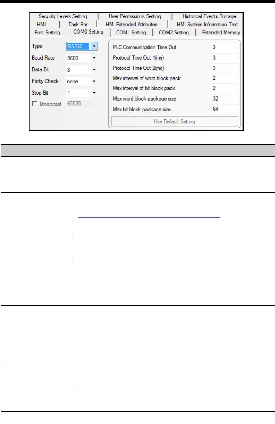
Advanced Part System Parameters
325
Descriptions of COM0/1/2 Setting
Type Select a communication type when HMI communicates with PLC, the RS232 (RS-232C),
RS485-2(RS-485), RS485-4(RS-422A) are optional.
Note: the COM2 only supports the RS232(RS232C)
Baud Rate/Data Bit/Parity
Check/Stop Bit
Set the HMI communication parameters when HMI communicates with PLC
☞For details, refer to [Advanced Part 14 HMI Communication]
Device No. When HMI works as a slave device, set the HMI station number.
Broadcast When HMI works as MODBUS RTU master, HMI only sends command to PLC, but
ignores any response from PLC. The Broadcast can only be 0.
PLC Communication Time
Out
The time HMI waits response from PLC/controller, unit is millisecond or second. If
PLC/controller has no response within this time, it is time out; HMI gives up this request
and try the next request. If there is no response after several requests, HMI display PLC
no response. Do not suggest customers to modify this parameter.
Protocol Time Out1(ms) Time out of character. The protocol takes this time as time interval to cut frame; In other
words, it is the max time interval between each character. If the communication is not
stable, user can increase this value to improve the communication. It ranges from 1to
500. This parameter is set when you connect a PLC to HMI port in the software. Do not
suggest customers to modify this parameter.
Protocol Time Out2(ms) The communication speed will be slow, but the communication error and error package
will also be reduced. Do not suggest customers to modify this parameter.
Max Inter of bit/word block
pack
These parameters decide that how many registers can be read in a package when the
registers are not continual. Do not suggest customers to modify this parameter.
Max word block word/bit These parameters decide the max length of package. That is, how many the registers that
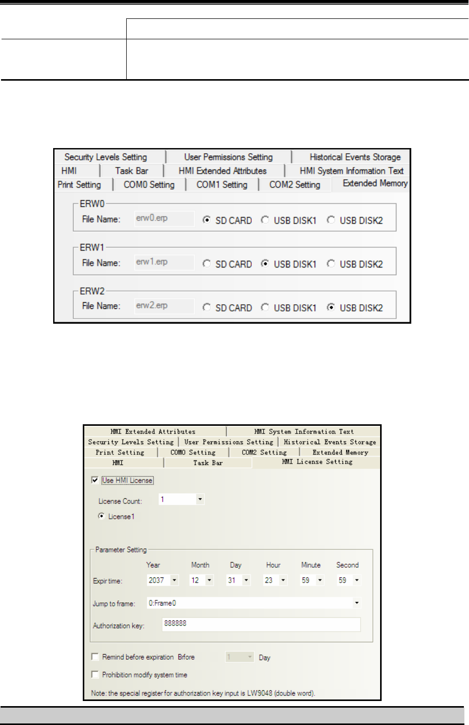
Kinco HMIware Configuration Edit Software
326
package size can be read as one frame at a time. Do not suggest customers to modify this parameter.
Use Default Setting If users modify the default communication parameters, and HMI and PLC does not
communicate successfully, they can use this button to set the parameters to default value.
6.1.10 Extended Memory
In the Extended Memory option, user can define address type ERW0, ERW1, ERW2 in the extended memory devices, USB
drive or SD card.
The ERW data will stored in the extended memory in erp file, its route is /exmem/erw.erp, (x=0, 1, 2)
6.1.11 HMI License Setting
Users can get a HMI rocked at the set time through [HMI ]-[HMI License Setting].HMI will jump to an expected frame
when time is up.Until users enter the right password ,HMI keeps at that frame.
We use HMI system time in this function.And system time reset will not disable the license function.
HMI License Setting Instruction
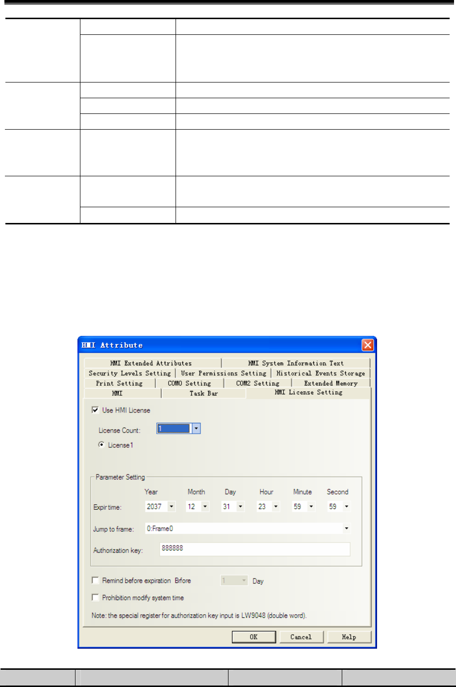
Advanced Part System Parameters
327
License Court 1~10 Use HMI License
License1 ~ 10 Authorization Key is set according to the setting time. Longer the time is,
higher the level will be. With higher level key, users can release the lower
license.
Expir Time The time when HMI is rocked
Jump to Frame The frame HMI jumps to when time is up
Parameter
Settings
Authorization Key Release password. No more limit once this key is entered
Remind before
expiration
1~30 days For example: set 15 days.15 days before the expiration time, HMI will
show a message :[40] HMI will be rocked :015(days).While it keeps
working until the expiration time comes
Not chosen System time can be modified. However, only setting latter time comes
effective after HMI restarted.
Prohibition
modify system
time Chosen System time cannot be modified, invalid set
For example: three times to rock a HMI.
License1: expiration time: 2015.12.13 23:59:59, key:11111111,
License2: expiration time: 2012.12.31 23:59:59,key:22222222,
License3: expiration time:2016.12.31 23:59:59,key:33333333,
After users enter the right password,HMI jumps to the initial frame.
Steps:
1)HMI License Setting, double click to open [HMI Attribute]-[HMI License Setting]
2)choose “use HMI license”,license court:3
License court Expir time Jump to frame Authorization key
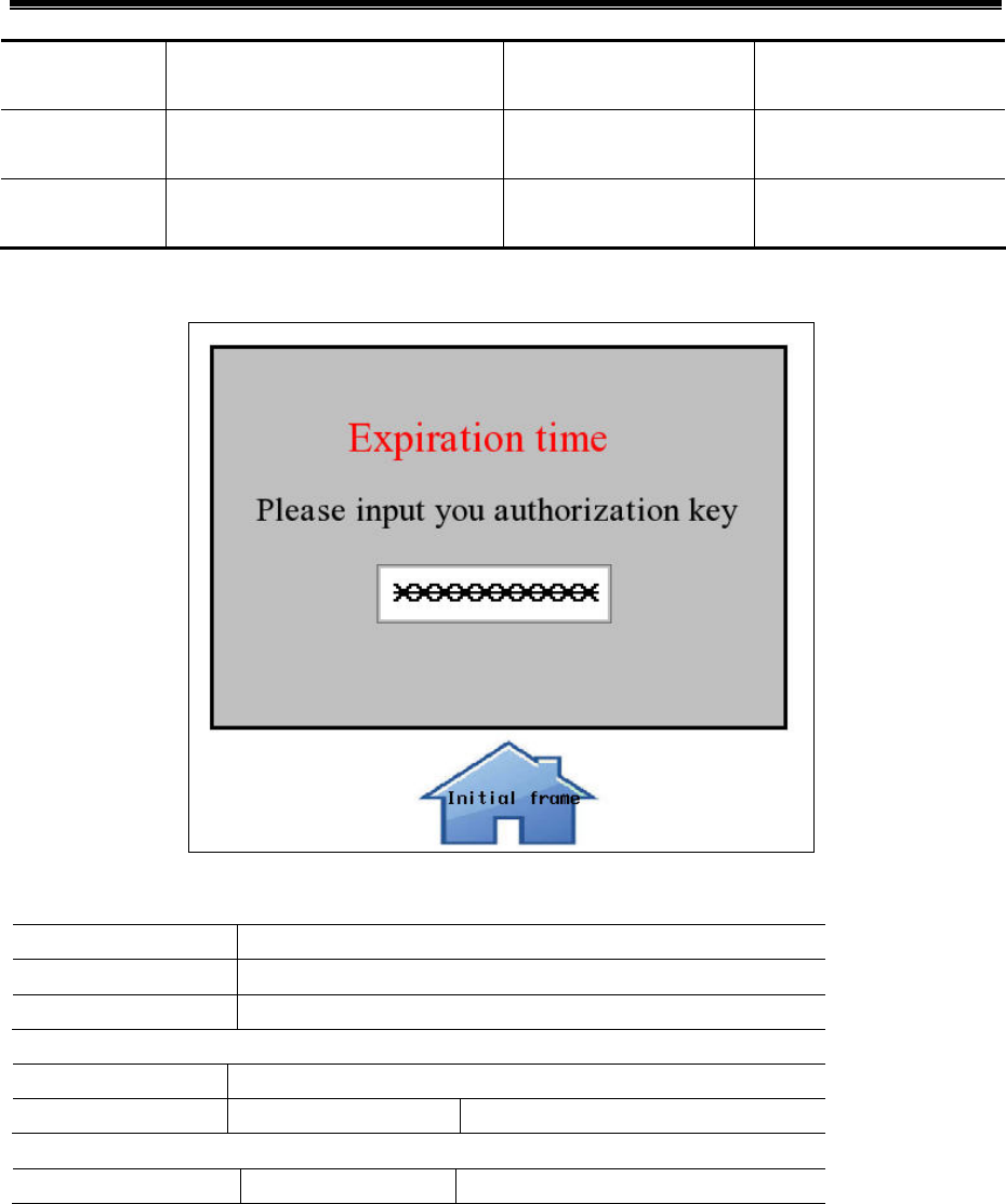
Kinco HMIware Configuration Edit Software
328
License 1 2015.12.31
23:59:59
Frame 11 11111111
License 2 2012.12.31
23:59:59
Frame 11 22222222
License 3 2016.12.31
23:59:59
Frame 11 33333333
3)choose “remind before expiration time”,before 15 days;choose “prohibition modify system time”
4)Edit jump-to frame:frame 11
Number Input
Read/Write Address LW 9048(HMI special system register)
Data type password
Data length DWORD
Text
Font
Text Expiration time Please input you authorization key
Function key
Switch window Change window 0:Frame0
5)Simulation
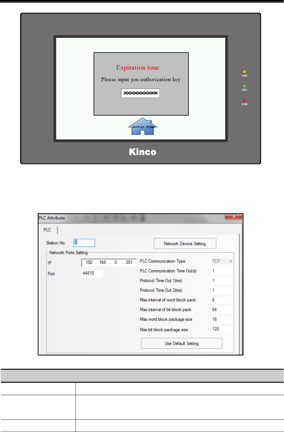
Advanced Part System Parameters
329
Now, users have to enter the right key to unlock the HMI.
6.2 PLC Attribute
In the Construct window, double click PLC icon or right click PLC icon and choose the Attributes to open the PLC Attribute
option. User can configure PLC communication parameters
PLC Attribute Description
Station No. When PLC/controller works as slave device, set the station No. for PLC/controller.
Network Device Setting When HMI communicates with PLC/controller via Ethernet, configure the Ethernet
protocol and communication parameters here.
IP Address Set the IP address for PLC/controller.

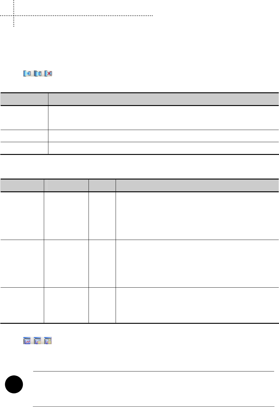
331
7 Compile/Simulate/Download/Upload
7.1 Compilation
Compilation can be divided into:【Compile】,【Compile All】,【Clear Build Result】.
7.1.1 Methods of Compilation
Click the icons in toolbar,or select 【Compile】/【Compile All】/【Clear Build Result】in the【Tools】
menu.
Name Description
Compile When there are Macro files in the project, click【Compile】will do not compile the Macro files that has
been compiled
Compile All Compile all the files
Clear Build Result Clear all the compiled files, including .pkg files, Macro files .so/.dll, .hmi files, .logo files
7.2 Simulation
Kinco HMIware supports 3 modes of simulation: Offline Simulation, Indirect Online Simulation, Direct Online Simulation
Name PLC/Controller HMI Description
Offline
Simulation
— —
Connections with PLC and HMI are not needed, so the time for each
download is shortened significantly. But the program cannot acquire
data from the PLC, only read data from the local address. Therefore
all data displayed on the configuration windows are static data
Indirect Online
Simulation
√ √
Need to connect PLC and HMI. PLC data can be obtained
dynamically. The operating environment of the program is the same as
downloaded into HMI, but does not need to download the project to
HMI repeatedly, which is quickly and convenient
Direct Online
Simulation
√ —
Only PLC needs to be connected, while HMI doesn’t. PLC data can be
obtained dynamically. This mode can be used to check whether
communication is normal without connecting with an HMI
7.2.1 Modes of Simulation
Click the icons in toolbar,or select 【Offline simulation】/【Indirect Online Simulation】/【Direct Online
Simulation】in the【Tools】 menu. Select an HMI to be simulated, and click 【Simulation】to start simulation.
!
1. The maximum test time for the direct online simulation is 15 minutes. After 15 minutes, the system will
prompt “Online Simulation overtime and Program is end, if want, Please Simulate again.”
2. Mostly only the RS232 communication mode can be used for direct online simulation. Some PLCs

Kinco HMIware Configuration Edit Software
332
communicating through Ethernet port can execute direct online simulation through Ethernet port.
3. Connection of direct online simulation for RS232 communication: program cable of PLC connects with
the serial port of PC directly. Connection of direct online simulation for Ethernet port communication
mode: connect directly through cross-over cable or through a Switch.
4. The port used for direct online simulation cannot be used by other programs, otherwise, communication
will fail when simulating.
7.2.2 Exit Simulation
To exit simulation by the space key of the keyboard, or click the right mouse button in the simulation box blank, select
【Close】to exit simulation.
7.3 Download
Kinco HMIware provides 3 ways of download: USB, Serial port, Ethernet port (Download via Ethernet port is only suitable
for HMIs with Ethernet ports).
7.3.1 Download Method Selection
Click the icon in toolbar, or select from【Tools】menu—【Download Method】:
The Properties dialog box of【Project Setting Option】pops up, the default download method is via USB port, single click the
drop-down list of【Download Method】to select download way.
!
1. Download way is saved according to HMI. For example: there are 2 HMIs in a project, HMI0 and HMI1.
The download way of HMI0 is via serial port before closed, and HMI1 is via USB cable before closed.
Then open the project again, download way of HMI0 is still via serial port, and HMI1 is still via USB cable.
2. When USB downloading cable is used for the first time, the USB device driver should be installed
manually.
☞For more details about the installation of USB driver, please refer to【Basic Part 2.8 Install USB Driver】
3. For downloading through serial port, users should weld the cable by themselves.
☞For more details about welding downloading cable for serial port, please refer to the manual of
【Communication Connection Guide】
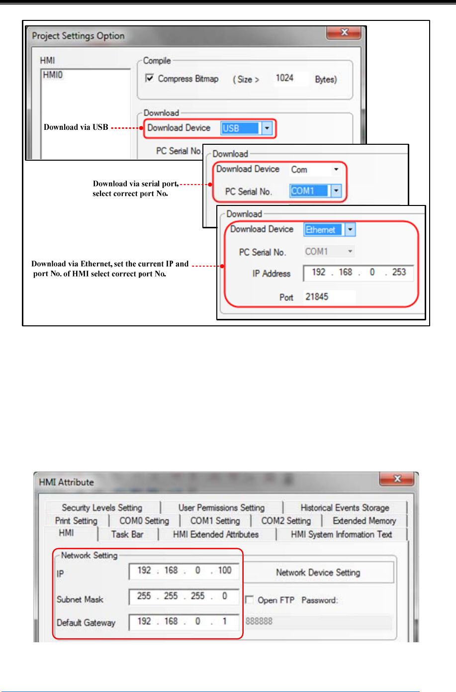
Advanced Part Compile/Simulate/Download/Upload
333
- Notes for downloading through Ethernet and setting of IP:
The IPs of PC and HMI should be in the same section. That means the first three digits should be the same and the last
digit should be different. If the devices are connected in local area network, then the IPs should not conflict with other
device in the local area network.
Modify the current IP and PORT of HMI
Click【HMI Attribute】—【HMI】, set the target IP to HMI, compile and download into HMI, then the IP of HMI is in line
with the set value in project.
- Set IP in SETUP Interface
☞For more details about setting IP in SETUP interface,please refer to【Hardware Part 3 System Setting Mode】
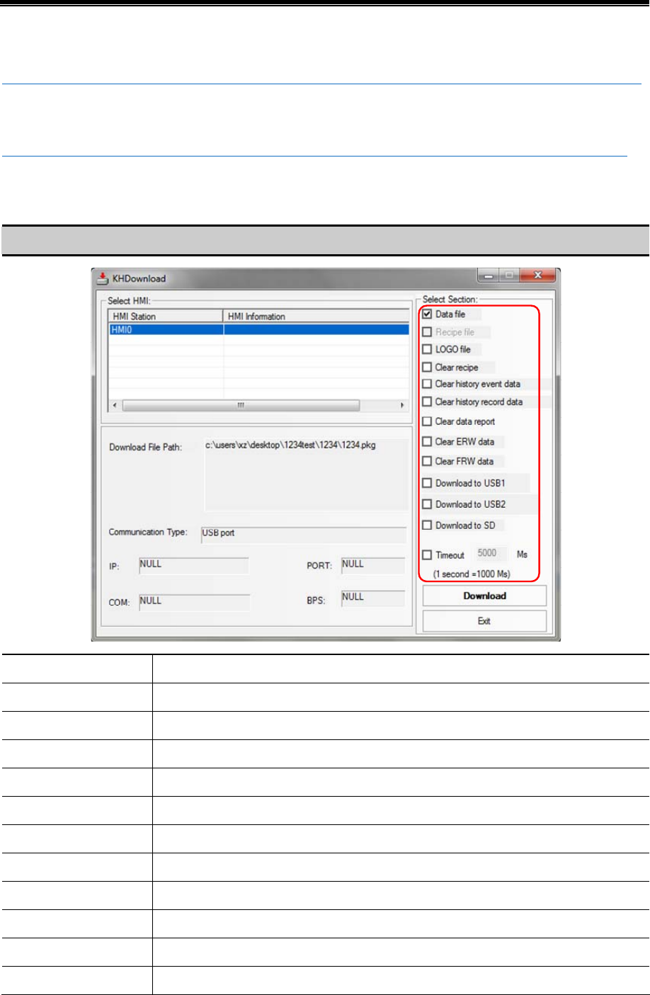
Kinco HMIware Configuration Edit Software
334
- Set IP via【Update IP/PORT】in KHManager
☞For more details about setting IP via【Update IP/PORT】in KHManager,please refer to【Advanced Part 8 KHManager】
7.3.2 Download via U disk or SD card
☞For more details about downloading via U disk or SD card,please refer to【Hardware Part 3 System Setting Mode】
7.3.3 Download Selection
In the property box of 【KHDownload】,select the related options in 【Select Section】 to download the files needed.
Detailed description for【Select Section】
Name Description
Data file Download user project files in .pkg format
Recipe file Download recipe files in .rcp format
LOGO file Download Initial Start Window in .logo format
Clear recipe Clear recipe data saved in RB/RBI/RW/RWI
Clear history event data Clear the record in【Event Display】/【Historical Event Display】parts
Clear history record data Clear the record in【Historical Event Display】/【Trend Curve】/【Trend Curve】parts
Clear data report Clear data saved in【Data Report】parts
Clear ERW data Clear the data saved in external register ERW/ERWI
Clear FRW data Clear the data saved in FLASH register FRB/FRBI/FRW/FRWI
Download to USB1 Download the project files to external register USB1
Download to USB2 Download the project files to external register USB2
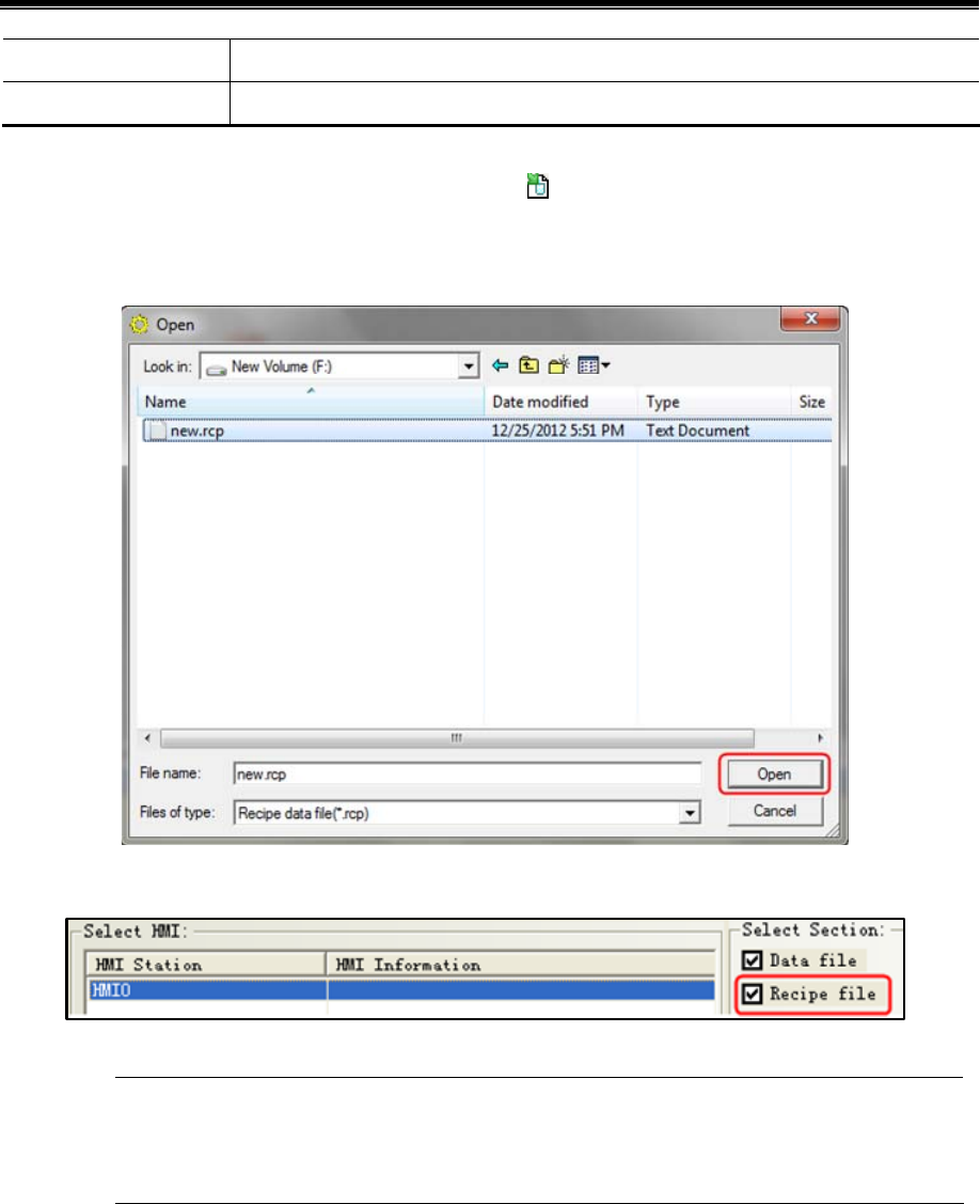
Advanced Part Compile/Simulate/Download/Upload
335
Download to SD Download the project files to external register SD
Timeout Set the timeout time of download, the unit is millisecond, and it ranges from 0 to 65535
- Download recipe files
Recipe files should be imported before downloading. Single click icon in toolbar or single click 【Options】menu —
【Import Recipe】,then dialog box of 【Open】pops up,select the recipe files to be downloaded and single click【Open】
to load the recipe files:
Compile and then download, select 【Recipe File】as shown in the below figure:
Kinco HMIware will record the directories of recipe files, when the selected recipe files is loaded into
HMIKinco HMIware. If the directories of recipe files changed, warning information will appear in the
compilation message window, the recipe files will no longer be selected when download again.
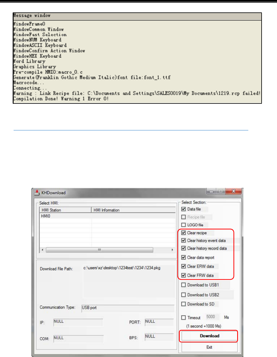
Kinco HMIware Configuration Edit Software
336
- Download LOGO file (Initial Start Window)
☞For more details about【LOGO file】,please refer to【Advanced Part 2.8 LOGO Screen(LOGO)】
- Clear data when download
When download project, user could select【Clear recipe】,【Clear history event】,【Clear history record】,【Clear data report】,
【Clear ERW data】,【Clear FRW data】. Select the data to be deleted, then the related data in HMI will be deleted when
downloading.
- Project runs directly in external storage devices
When there are too many pictures in project, then the project will be too big to download into HMI. Prompt: When compress
bitmap of large size, users could download the project to external devices.
Select【Download to USB1】,【Download to USB2】,【Download to USB3】when download as shown in the below picture:
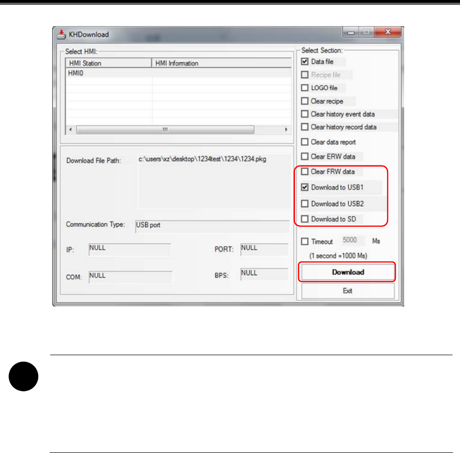
Advanced Part Compile/Simulate/Download/Upload
337
Single click【Download】,the project will be downloaded to external memory device.
!
1. The function that project runs directly in the external storage device is only applicable for HMIs
supporting external storage devices.
2. The projects copied directly into external storage devices cannot run.
3. The external storage devices cannot be removed during running, otherwise, the project stored in external
device will be abnormal.
- The timeout time of KHDownload can be set by user
If the timeout option is checked, user can set the timeout time of download, the unit is millisecond, and it ranges from 0 to
65535.The function can improve download timeout error of serial port, USB and Ethernet port.
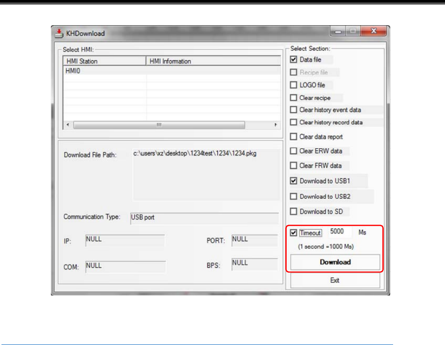
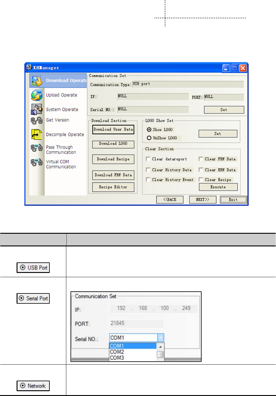
339
8 KHManager
8.1 Introduction to KHManager
KHManager consists of six processing modules: 【Download】, 【Upload】, 【System Operation】, 【Get Version】,
【Decompile Operate】, 【Pass Through Communication】.
【Communication parameter setting】:The current download way selected in KHManager will be displayed. Click 【Set】
to modify the current download way.
Download way Parameter setting
Download via USB port
No need to set communication parameters
Download via serial port
Choose the current used serial port NO.
Download via network
Set the IP address and port number of the current HMI
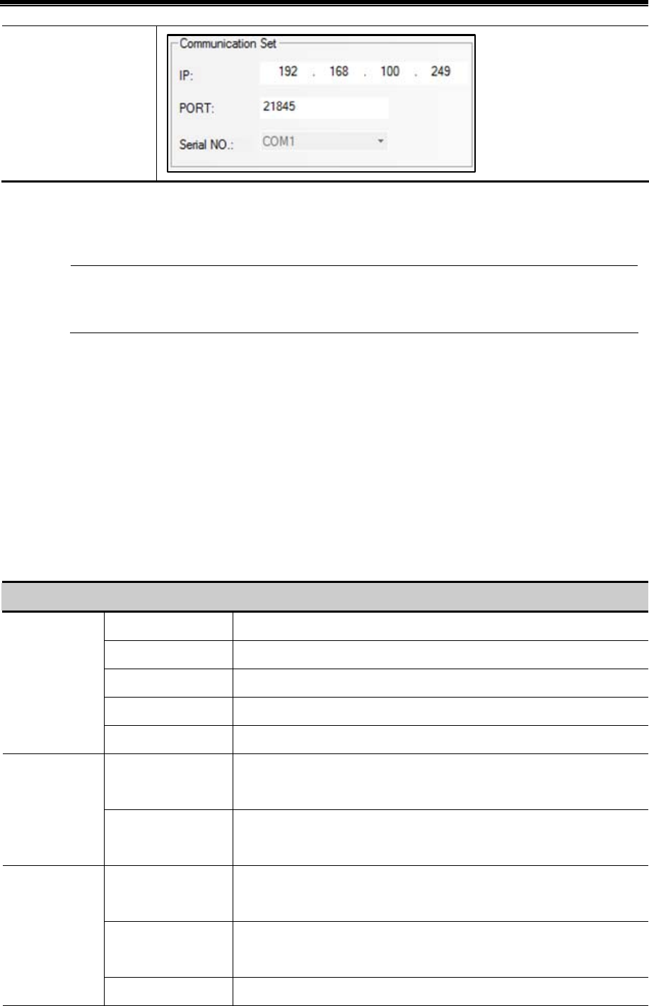
Kinco HMIware Configuration Edit Software
340
【PageUP】/【PageDown】:Click 【PageUP/PageDown】to skip among the 6 processing modules.
【Exit】:Exit KHManager.
【Pass Through Communication】is not supported temporarily
8.2 Methods of Open KHManager
- Open from the【Start】menu of PC.
- Double click the shortcut of KHManager on desktop.
- Open from【Tools】menu of Kinco HMIware software.
Click【Tools】menu—【System Manager】/【HMI Version Manager】/【Upload Manager】/【Upload Init Window】/
【Download Init Window】/【Upload project】/【Decompile Manager】to open【KHManager】
- Double click【KHManager.exe】in the installation directory of Kinco HMIware software.
8.3 Download
Detailed descriptions of【Download】
Download User Data Download .pkg files to HMI
Download LOGO Download Initial Start Window of .logo files to HMI
Download Recipe Download .rcp files to HMI
Recipe Editor Open【Recipe Editor】
Download
Section
Download FRW Data Download .frp files to HMI
Show LOGO
Select【Show LOGO】,click【Set】,HMI will display Initial Start Window
when boots up.
Initial Start
Window
setting Area UnShow LOGO
Select【UnShow LOGO】,and click【Set】,HMI will do not display Initial Start
Window when boots up, but keeps white screen until project window displays.
Clear Recipe
Select【Clear Recipe】,and click【Execute】,to clear the data that is saved in
physical storage area of HMI RB/RBI/RW/RWI.
Clear FRW Data
To clear the data that is saved in physical storage area of FLASH
FRB/FRBI/FRW/FRWI.
Clear Section
Clear ERW Data To clear the data that is saved in physical storage area of external memory
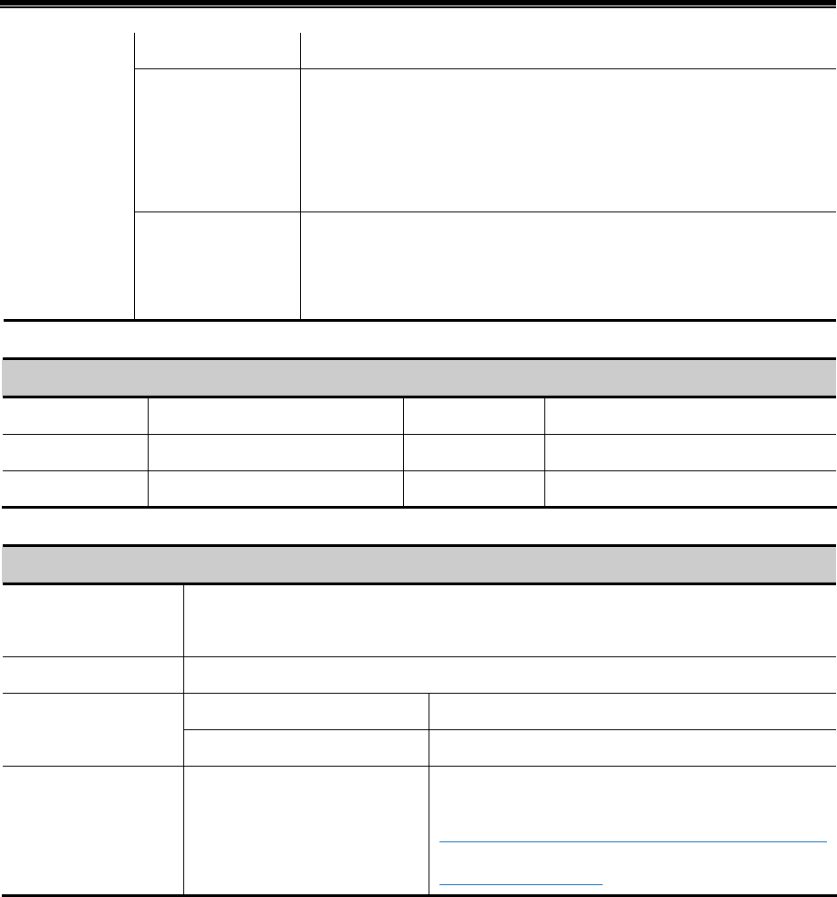
Advanced Part KHManager
341
ERW/ERWI.
Clear History Data
To clear the displayed history data that is recorded in【History Data Display】
/【Trend Curve】/【XY Curve】parts, at the same time the history data and files
that are saved in recipe memories and external memories will also be
cleared.
Clear History Event
To clear the displayed history events that are recorded in【Event Display】/
【Historical Event Display】, at the same time the history data and files that
are saved in recipe memories and external memories will also be cleared.
8.4 Upload
Detailed descriptions of【Upload】
Upload User Data Upload project files of .pkg format Recipe Editor Open【Recipe Editor】
Upload Recipe Upload .rcp files in HMI Upload FRW Upload .frw files in HMI
Upload LOGO Upload .logo files in HMI
8.5 System Operation
Detailed descriptions of【System Operation】
Get HMI IP / PORT
Information Area
Obtain the IP address and port number information of the target HMI
Update IP/PORT Area Update the IP address and port number to the set value
Return to User Application Status HMI jumps to run the configuration program
Jumping Section Area
Return to Set Application Status HMI changes to the embedded SETUP interface
Update Operation Area Update the kernel/ file system
Update firmware of HMI
☞For more details please refer to [Hardware Part 5
Firmware Update Mode]
8.6 Get Version
User could view firmware version information of HMI through 【Get Version】 in KHManager, click 【Version Get】, HMI
firmware version information will be displayed. Otherwise please check whether the current communication
mode is correct or other reasons.
8.7 Decompile Operation
The configuration screen edited by Kinco HMIware is saved as wpj files. Compile to generate pkg files which are required
for running in HMI and download into HMI. So the files uploaded from HMI are in pkg format. Before open the projects
uploaded from HMI, users should decompile the pkg files by KHManager to generate a project file in which wpj file and
other files are included, then users can open wpj file and edit.
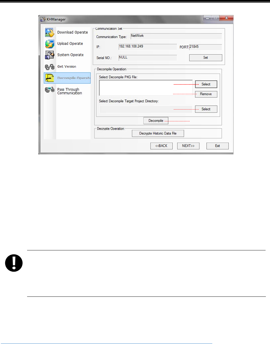
Kinco HMIware Configuration Edit Software
342
a
b
c
d
a. Select the target pkg files to be decompiled
b. Delete the redundant pkg files no need to be compiled.
c. Select a saving path for the decompiling project files.
d. Execute decompilation operation
Regardless of whether the file allow decompiling or not, upload password dialog box will pop up and request for
decompilation password. If decompilation is prohibited, user cannot move to the next step. While if decompilation is allowed
and no password is set, and then enter the default password 888888 to move to the next step.
1. When there are more than one (2 or more) HMIs in a project, users need to add all the pkg files of each
HMI to execute decompilation operation.
2. When there are more than one (2 or more) HMIs in a project, all the pkg files uploaded from the HMIs
must be compiled at the same time, otherwise, the the pkg files cannot be decompiled.
8.8 Data Decryption
To decrypt the encrypted CSV files.
☞For more details about [Data Encryption], please refer to [Advanced Part 2.15 Data Encryption]
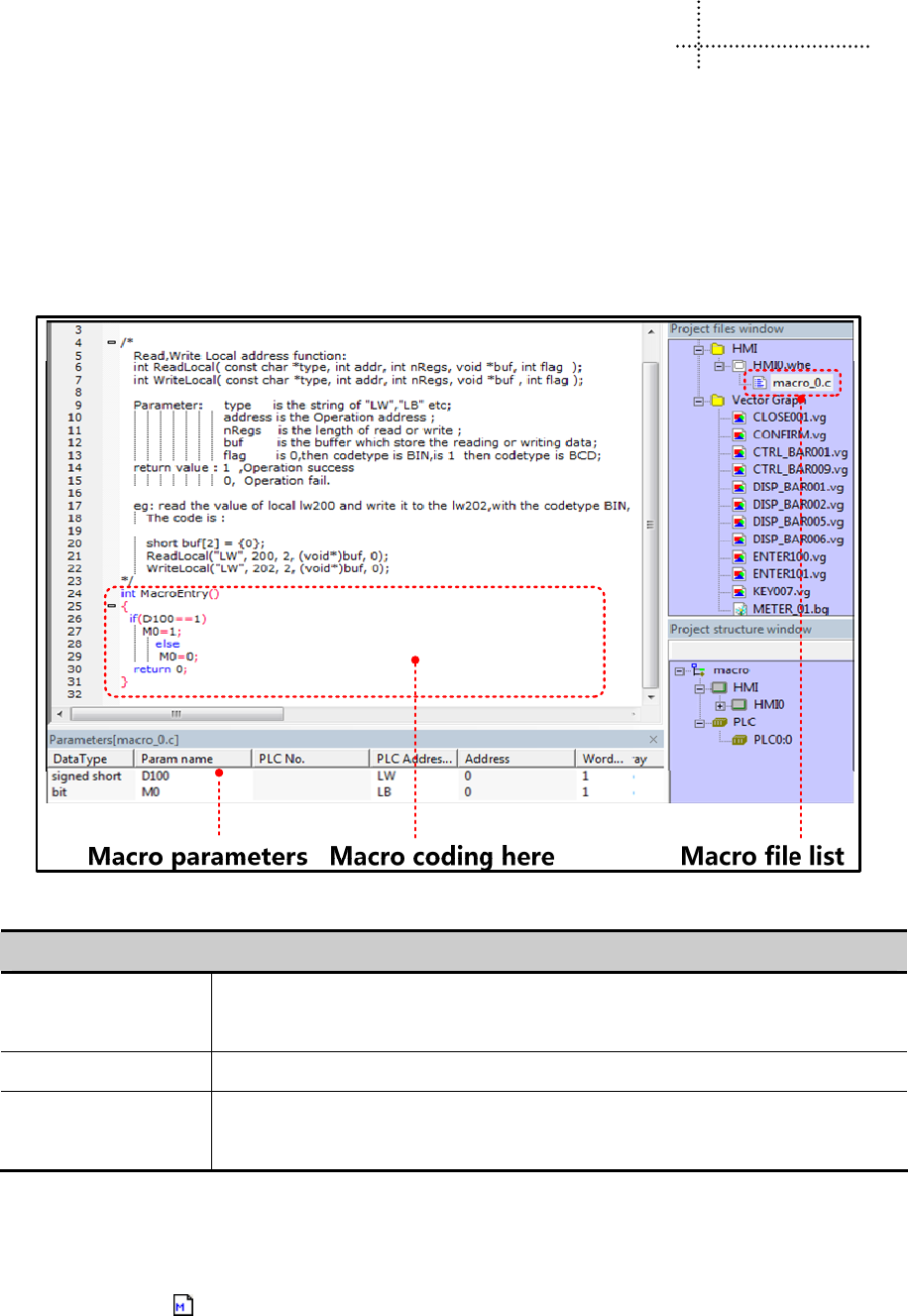
343
9 Macro
Macro uses C language to release logic and arithmetic calculation. User can use macro and other components together to
release some complex calculation and make HMI strong function. The macro instructions in Kinco HMIware are compatible
with standard C language(ANSI C89).
9.1 Macro Editing Environment
There are three parts in this edit environment, they are macro edit window, Macro variables window and macro file list in the
project files window.
The detail description of macro edit environment
detail description of macro edit environment
Macro edit window User writes C language code in this window, the variables are defined in the Parameters list;
you can use them in the C code.
Macro variables window The write and read variables in this macro, which are external variable of this macro.
Macro file list
User can rename and delete macro in this list. If there are multiple macro, user also can switch
macro among different macro.
9.2 Macro Edit
9.2.1 Build Macro
There are two ways to build macro:
- Click on the icon
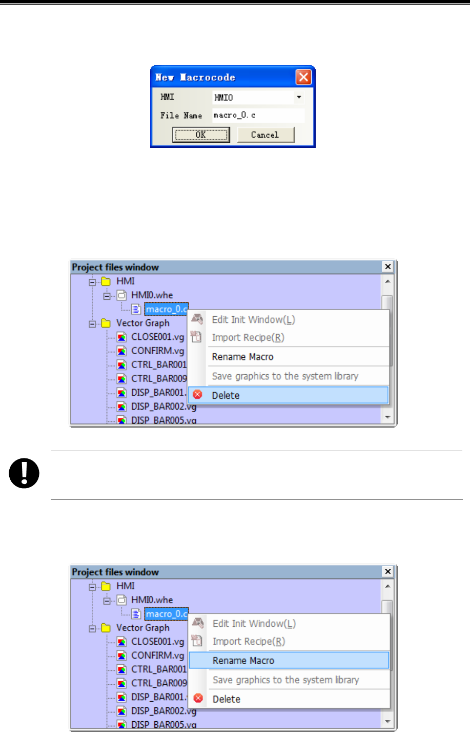
Kinco HMIware Configuration Edit Software
344
- Click on the “Option”>>Macrocode…(M)
There is a New Macrocode dialog window when you build the macro:
1. Choose the HMI where the macro is build, for example HMI0.
2. There is a default macro name(macro_0.C) in the File Name, user can rename it .
2. Click on OK to enter the macro edit window.
9.2.2 Delete Macro
Right click the macro in the Project files window; choose the delete to delet the macro. As shown in the following picture:
Note that the delete operation of macro does not support undo operation,
9.2.3 Rename Macro
Right click the macro in the Project files window; choose the Rename Macro to rename the macro. As shown in the
following picture:
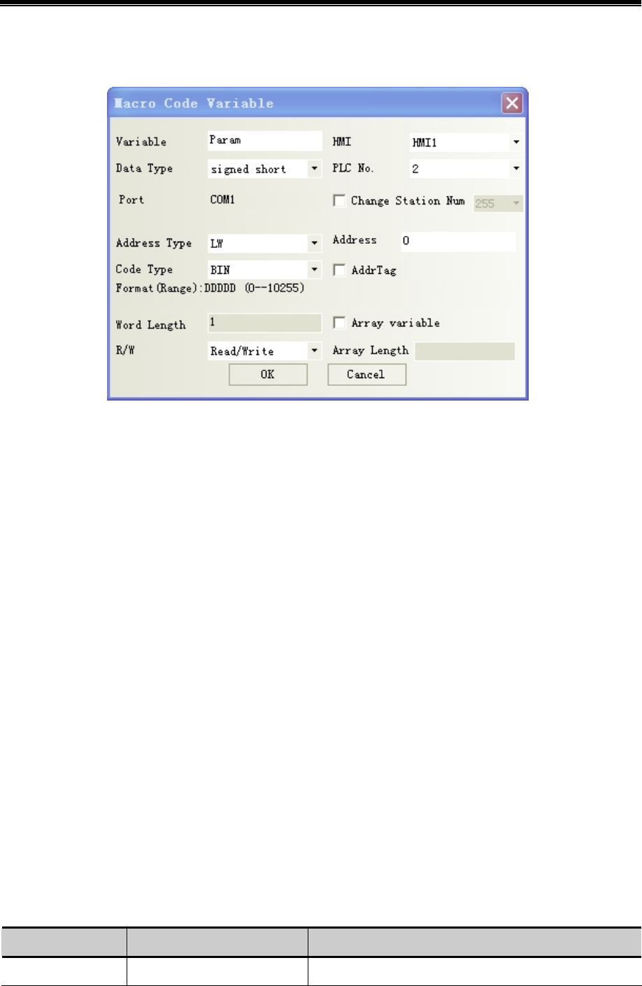
Advanced Part Macro
345
9.2.4 Program Macro
1 Define the macro variables before program the macro.
Macro Variables
In macro, the unit whose value can be changed is called variable, each variable has a name and a initial value, it takes a
memory unit in the memory.
Variable name
When user builds a new variable, the default name is Param and user can modify the name. The definition of macro name
must follow the principle of C language, the following are exceptional case:
1. Cannot use the reserved word of language C code.
2. The variable name is not case sensitive(not C language standard)
3. The variable name must start with 26 English letters
4. The variable name only supports 26 English letters, number and underline.
5. The number of group data must be from 2 to 1024, but the number of (unsigned) shot group data cannot be 4, the
number of int/float group data be 2.( (not C language standard))
The type of macro variable
There are internal variables and external variables in the macro variables
Internal variables: they are the registers in HMI. The internal variables can be defined in the Parameters window; it also can
be defined in the macro edit window directly.
External variables: they are the registers in the PLC/controller which is connected to HMI. The external variables must be
defined in the parameters window, and then they can used in the macro edit window.
The data type which is supported in macro variable
Data Type Data Length Description
Bit 1bit Bit variable, 0 and 1
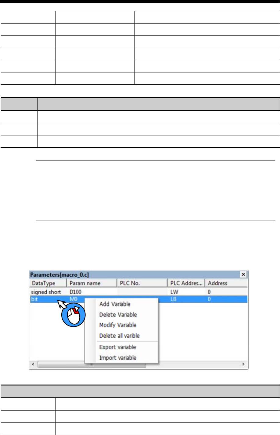
Kinco HMIware Configuration Edit Software
346
Signed short 1word(16bits) Signed short integer variable, -215~(215 -1)
Unsigned short 1word(16bits) Unsigned short integer variable,0~(216-1)
Signed int 2word(32bits) Signed integer variable,-231~(231-1)
Unsigned int 2word(32bits) Unsigned integer variable,0~(232-1)
Float 2word(32bits) Single float variable
Double 4word(64bits) Double float variable
The write & read type of macro variable
write & read Description
Read Read the register before the C code is executed, the register will not be read when the C codede is running.
Write Write the register after the C code is executed, the register will not be write when the C
Read/Write Read the register before the C code is executed and wirte it after the C code is executed.
Usually, we define the registers which only need reading as Read type; the registers which need writing
have read operation too, so we define them as Read/Write. Regarding some special registers, which are
write only, but cannot be read, we can define them as Read. Therefore , in the assignment instruction, the
variables at the left side of“=”icon are usually defined as Read/Write and variables at the right side of
“=”icon are usually defined as Read
Operation of macro variable
Right click variable list in the macro variable window, user can choose the add/delete/modify/export/import macro
operations.
Detail descriptions of variable operations
Detail descriptions of variable operations
Add Variable Add the new variable to the macro
Delete Variable Delete the selected macro
Modify Variable Modify the attributes of selected macro
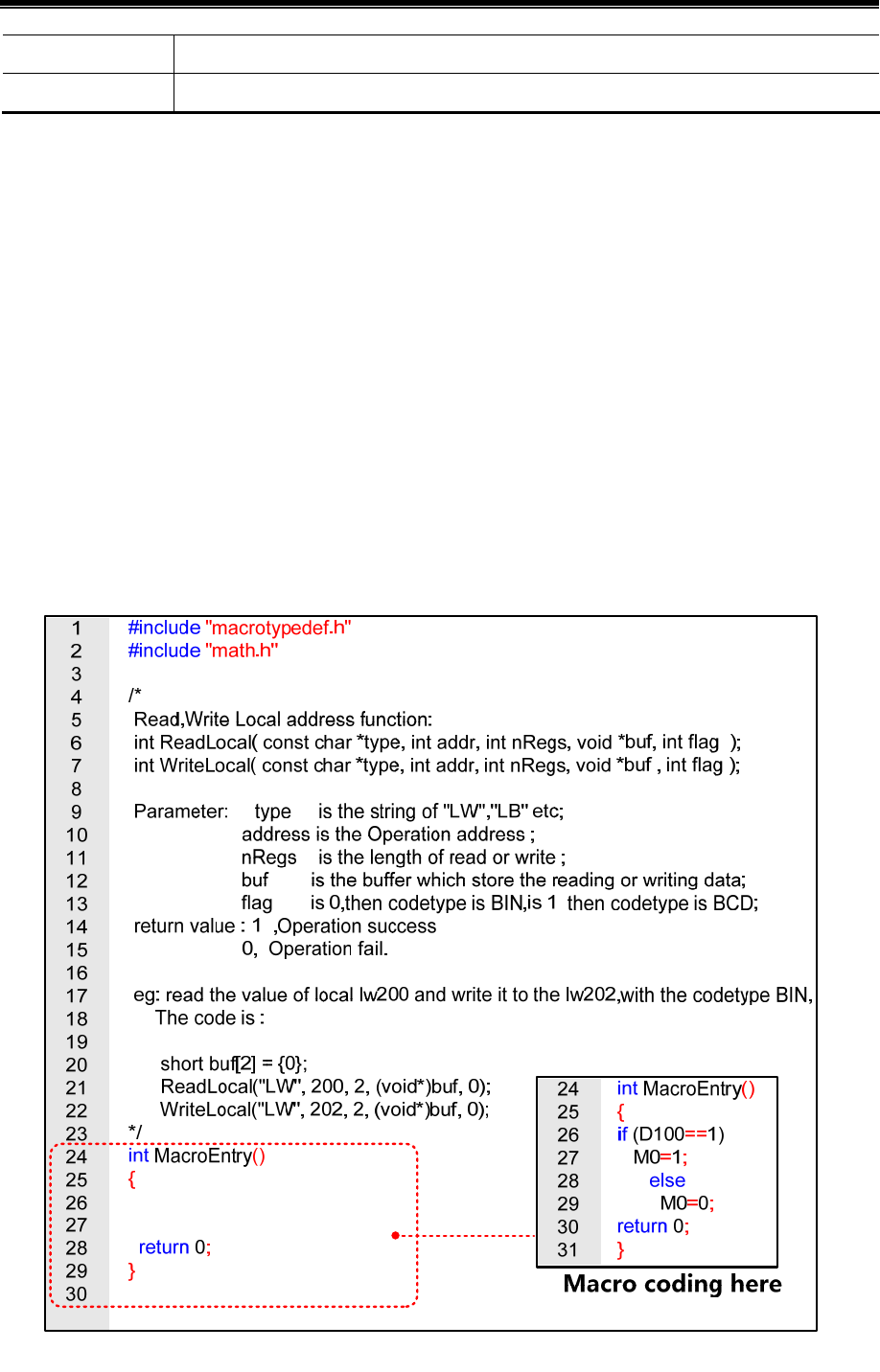
Advanced Part Macro
347
Export Variable Export the defined variables to PC in a CSV file.
Import Variable Import the variable CSV file to the macro variable window.
The notes of macro variable
(1) When defining the variable, make sure that there is no overlap in the address range, for example, the LW1000 is defined
as a float variable A (double words), that is A takes two addresses: LW1000 and LW1001. If user defines another
variable which uses LW1001, there will be error in the macro calculation.
(2) The macro only supports the logic and arithmetic operation, but do not supports char type operation.
(3) When the variable uses variable station number, especially when the special registers are used as index, the value in the
index registers must be modified before macro execution, so the modified station number can be effective in the macro.
If the index value is set in the macro, the modified station number can be effective in the next execution of macro.
(4) The Export/Import operation only supports export/import all the variables, but not supports export/import a single
variable.
(5) When user uses Excel to edit exported variable CSV file, note that the ParamName~StationNumID are default
formwork, do not modify them or there will be error when you import the CSV file to the macro variable window.
Program the C code in the Macro Edit Window
………………
…………
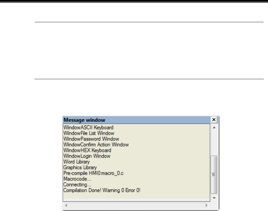
Kinco HMIware Configuration Edit Software
348
1. Add the note information in the macro, so you can check and modify the code conveniently in the
future.
2. Use the tab and line break to make the macro a good structure.
3. Do not delete or modify the default code in the macro edit window, press the Enter before “return” to
add your code.
3. After the macro is build, save and compile the HMI program , then check if there is any error information in the
Message Window
.
9.2.5 Execute Macro
There are 6 methods to execute the macro in Kinco HMIware, user can choose one method according his application.
1. Triggered when the HMI system starts.
Set initialization macro in HMI Attributes>>HMI Extended Attributes, this macro will be trigged when the HMI starts, user
can use this macro to set the initialization value of some parameters and transmit some recipe value.
2. Triggered by Function Key
Use the Execute Macro function in the Function Key, when the function is pressed , the macro will be triggered once
3. Triggered by Timer
There are many trigger method in the Timer, it is very flexible to trigger macro by timer.
4. Triggered by PLC Control
When the certain register satisfies the setting condition, the macro will be triggered.
5. Triggered by Event
The macro is triggered when the event is triggered
6. Triggered by Notification
User can use notification in Control Setting to trigger macro.
9.3 Macro Application
For example, we use the value of D100 (PLC register) to change the state of M0 (PLC register), we make this in a macro as
an example: when the value of D100 is 123, M0 is 1, or the M0 is 0.
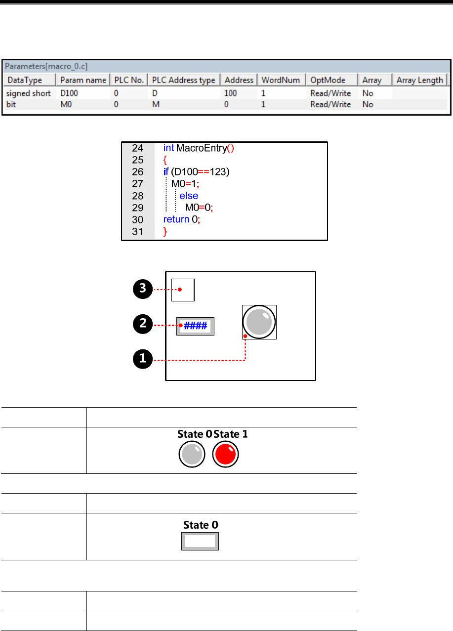
Advanced Part Macro
349
First, build a macro, set the macro name “ouput status.c”
Then define the variable D100 and M0 in the Parameters Window in macro.
Write the following macro code in the macro edit window.
Save the project, close the macro edit window then switch to the HMI program edit screen, make the program as follows:
Bit State Lamp, which is used to display the state of M0. Its attribute are as follows:
Read Address M0(PLC register)
Graphics
Use Vector Graphics,
Number Input Component, which is used to input the value of D100, its attributes are as follows:
Read/Write Address D100(PLC Registers)
Graphics
User Vector Graphics,
Timer Component,which is used to execute the macro, its attributes are as follows:
Exectution Cylcle 1×100ms
Execute Macro Output status
Save, Compile and Execute:
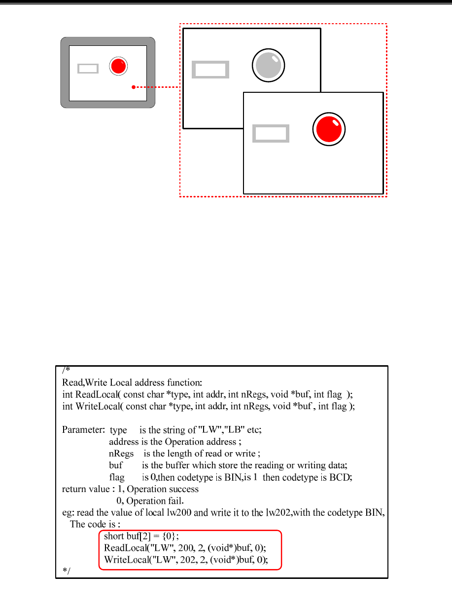
Kinco HMIware Configuration Edit Software
350
0
123
123
9.4 Local Variable Function
When you use the internal (local)l variable, you do not need to define the variable in the macro parameters window, you can
define it macro directly, that is to use the local variable of HMI.
The advantage of using local variable is that the local variable in the macro can be read/write in real time and the execution
speed is faster, performance is better. At the same time, it also saves the time of defining variables in the macro parameters
window.
In the macro edit window ,there is demo code(example) to read/write the local variable, user can write the macro code to
read/write local variable according the demo code, see as follows
In this demo code, we transfer the values in LW200 and LW201 to the LW202 and LW203.
We will explain to you how to use the local variable function in the following example.
For example, use the macro to achieve the addition calculation: LW100(HMI local register) adds LW101(HMI local
register) and transfer this result to LW102(HMI local register), the macro code is as follows:
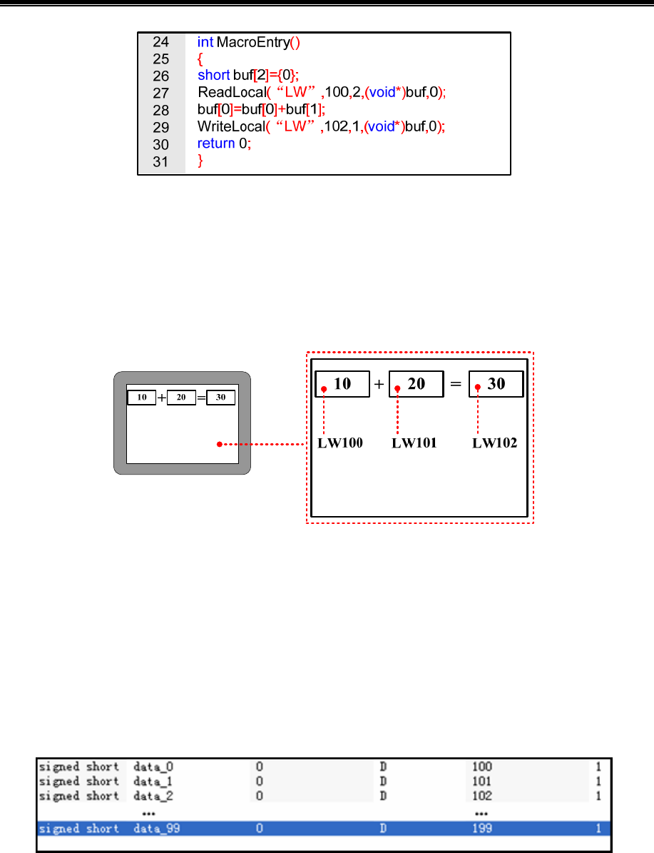
Advanced Part Macro
351
In this example ,
ReadLocal ("LW", 100, 2, (void*)buf, 0) means read the value in LW100 and LW101 and give this value to
buf[0] and buf[1].
buf[0]=buf[0]+buf[1] means addition calculation
WriteLocal ("LW", 102, 1, (void*)buf, 0) means write the calculation result to the LW102.
Save, Compile and Execute:
9.5 Array Application
Array is a group of variables, who has the same data type and name. These variables are called element of array. Each
element has its own serial number in the array, this number is called index. User can distinguish these elements by their
index. The total number of the element of an array is also called the array length.
We explain the array to you in the following example:
For example, use macro to assign values to 100 continuous registers which starts from D100(PLC register), if we do not use
array , we need to define 100 registers in macro parameters window and assign value one by one in the macro code. See as
follows:
Macro code:
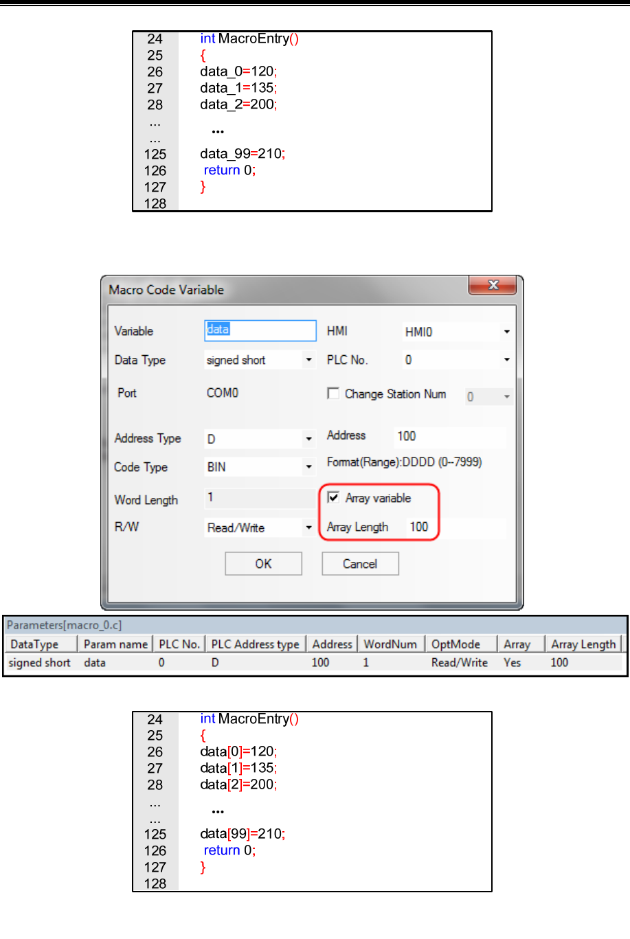
Kinco HMIware Configuration Edit Software
352
In the above macro code, the variable name has no unified rule, at the same time , it also takes too much time on define the
variables. If users use the array, they can define these variables in one array, see as follows:
Macro code:
User can use a name and index to representation a variable in the array. For example, data [0] means the first variable in a
array, data[1] means the second variable in a array. The data is the variable name of this array, the number after data is the
index of this array, we need to put the index to a [].
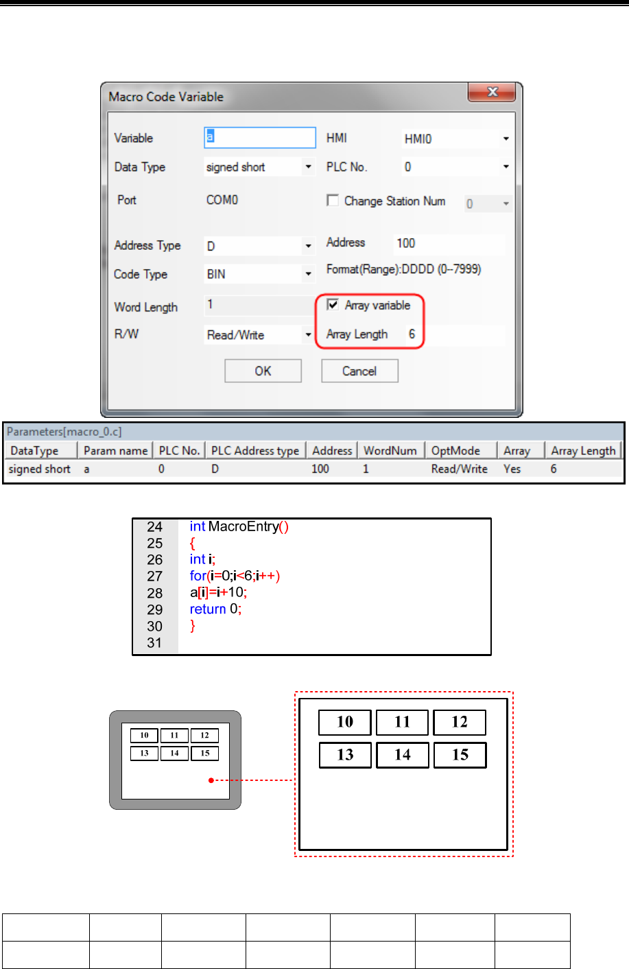
Advanced Part Macro
353
For example, the following example is to define a array variable, then use loop statement to assign 10~15 to the array
elements, these data will be displayed on the Number Display Components. The variable is defined as follows:
Macro code:
Save , compile and execute:
Actually, array is a list of data which has the same data type in the memory. Take the above array for example; a[i] starts
from the number 100 in the memory. The content and value of this array are as follows:
Variable a[0] a[1] a[2] a[3] a[4] a[5]
Value 10 11 12 13 14 15
Kinco HMIware Configuration Edit Software
354
Memory Unit D100 D101 D102 D103 D104 D105
1. When users visits or assign array variable, they need to according to the defined data type.
2. The indexes of array are inter, which starts from 0, not 1. The index n means the (n+1) variable
3. The array a[n] has n elements, but there is no a[n] in these elements. If user uses the nonexistent elements
in macro, there will be a overflow error.
9.6 Some Notes on the Macro
- The values of external variables in the macro are read once when the macro is triggered. The macro will not read it
again or in real time in the macro execution process. So the macro result will not be changed if the registers are changed
from outside during the macro execution process. When we use the macro, we need to make sure that all the input value are
ready before we trigger the macro, or we may cannot get the expect result.
- The macro result is output once when the macro is finished. The external variable value will not be changed during the
macro execution process When we use the macro , we need to make sure that the macro is finished and all the outputs are
updated, then we can get the right result..
- It is meanness to write the Read Only variable and it is meanness to read the Write Only variable. If the variable
needs to be read and write, please define it as R/W. Besides, user must assign value to the variable which has write operation
attributes(Write Only or R/W variable)
- User can define the temporary variable in the macro according to the C language, but can not set the global variable
and static variable. If the global variable is needed, please use the LW, LB register.
- One macro can not call other macros in Kinco HMIware, if user wants to use the Function Call as the C language, they
can use a trigger bit in one macro to trigger other macros.

355
10 Password
Kinco HMIware provides powerful password function for users, to ensure the security of user’s intellectual property.
The passwords are used for project protection, window protection, and important component protection.
- Project protection functions:
Password protection for opening project
Password protection for uploading project from HMI
Prohibit uploading project from HMI
Password protection for decompiling project
Prohibit decompiling project
- Operation window protection: To protect important windows, passwords must be entered when accessing important
windows.
- Component protection: To avoid disoperation, user name and password must be entered to access some important
components.
!
1. When project password, uploading password and decompilation password are used, please keep the
passwords in mind. The manufacture does not provide factory recovery and universal password
service.
2. The system default passwords for decompiling and uploading are 888888.
3. When the password is 0 or Null, system will automatically default to not using password. When
passwords begin with 0, 0 is invalid.
Differences between User level and User permission:
Difference Security Level User Permission
Level Range 16 levels(0~15), level 0 is invalid 32 users, 32 operation permissions, User 0 is valid
User Name None Available
Logout time None Available
Add/Delete levels or
permissions in HMI
Not support Support
Modify password in HMI Support Not support
Access Restriction
Users with low security level password
cannot access high security levels;
high security level is the “authority”.
A user can possess multiple operation permissions,
and different users can possess the same operation
permission. There is no hierarchy of user
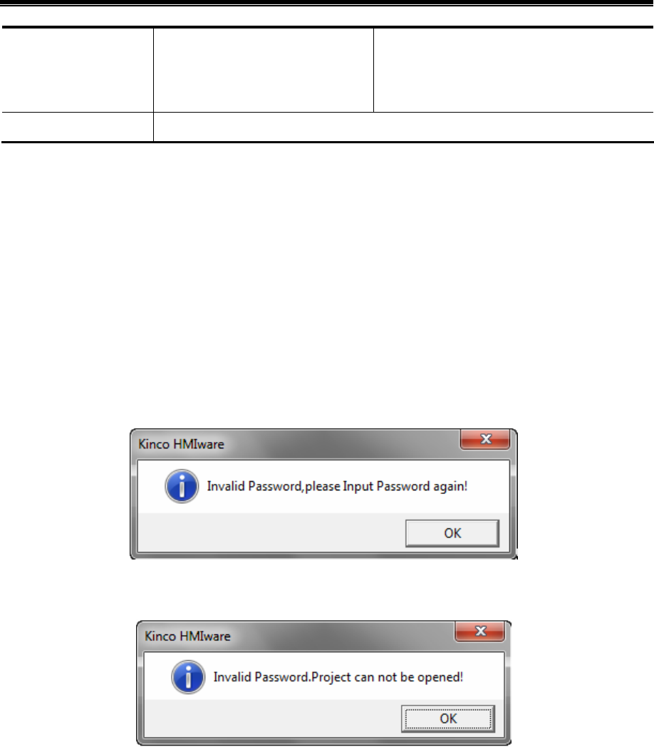
Kinco HMIware Configuration Edit Software
356
Users with high level password can
access low security level windows or
components.
permissions, only user name and correct
password are needed to execute corresponding
operation.
System reserved register The involved system reserved registers are different.
10.1 Project Protection
10.1.1 Project Password Protection
To prevent unauthorized access and protect user’s intellectual property, passwords are required to open project file of .wpj.
- Set project password for first time
Open the software, single click【File】—【 Project Password】, then attribute box of 【Project Password Setting】will pop
up,input the password and confirm it. The project password will take effect when open the project next time.
- Enter password to open project
Once project password is set, password entry box will pop up when opening the project again.
Enter correct password to open the project, otherwise, error prompt box will pop up.
If entering password wrong continuously for 3 times, it would pop up a dialog box showing【Invalid Password. Project
cannot be opened!】,then user needs to single click【File】menu—【Open】.
- Modify or cancel project encryption
Open the encrypted project, single click【File】menu—【Project Password】,the attribute box of 【Setting Project Password】
will pop up. To modify password, users need to enter old password, and at the same time set new password. To cancel the
password, users only need to enter the old password, leave the new password box blank. Single click 【OK】button., then
the modification will take effect when opening the project next time.
10.1.2 Upload Password Protection and Prohibit Uploading
- Upload Password setting
Project allows uploading by default, but upload password is required to prevent unauthorized operation. Default password is
“888888”.
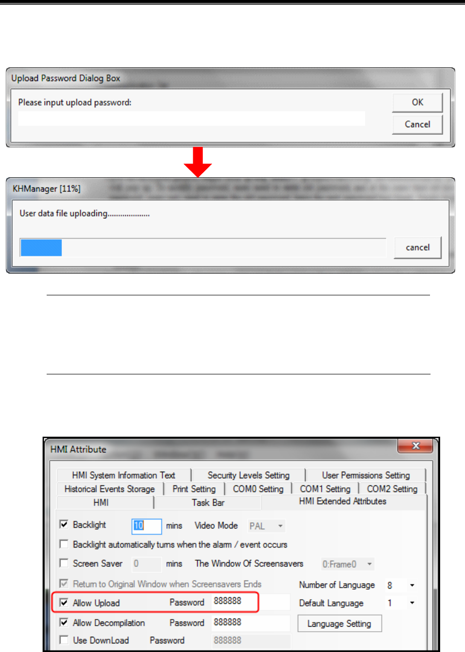
Advanced Part Recipe/RecipeEditor
357
Upload Password setting: Check the option of 【Allow Upload】in 【HMI Attributes】—【 HMI Extended Attributes】page.
After upload password is set, dialog box of 【Password input】will pop up when uploading, as shown in following pictures:
1. Upload password cannot be null.
2. Data package loss may occur during uploading, then restart the HMI and upload again.
3. Project allows uploading by default, but upload password is required to prevent unauthorized
operation. Default password is “888888”.
- Prohibit uploading: prohibit uploading project from HMI. The specific setting is: 【HMI Attribute】—【 HMI Extended
Attributes】,do not select the option of【Allow Upload】.
When prohibit uploading is set, prompt box will pop up if forcibly upload:
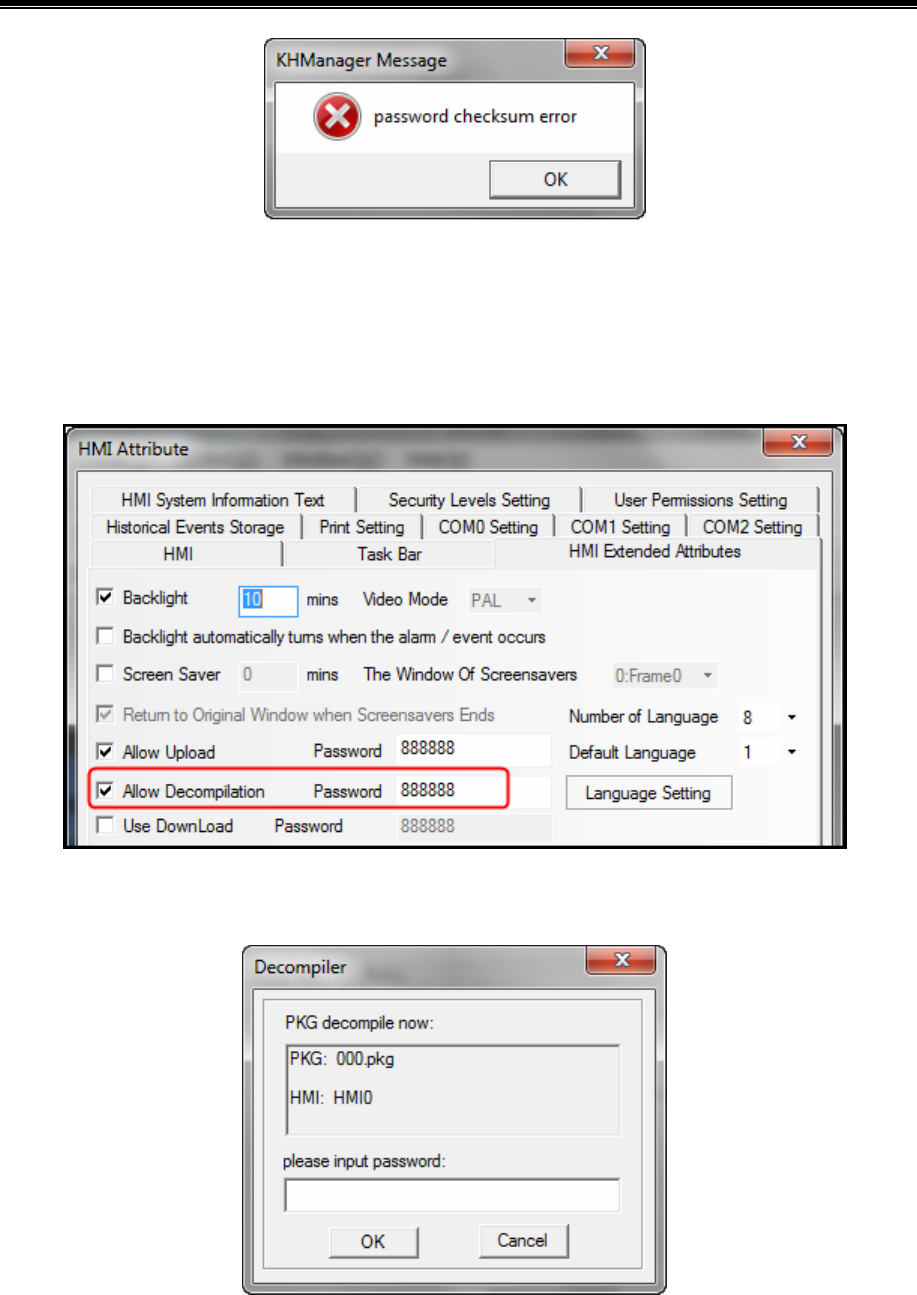
Kinco HMIware Configuration Edit Software
358
10.1.3 Decompilation Password Protection and Prohibit Decompiling
- Decompilation setting
Decompilation is used to convert the pkg files running in HMI to wpj files, which can be opened and edited by Kinco
HMIware. For new project, system allows decompilation by default, and the default password is“888888”.
Setting of decompilation: Select“Allow Decompile”in 【HMI Attribute】—【HMI Extended Attributes】, and set password.
For projects that decompilation passwords have been set, when clicking decompilation, password entry box will pop up as
shown in following picture:
- Prohibit decompilation
Prohibit decompiling: Prohibit decompiling project from HMI. Do not check the option of【Allow Upload】in【HMI
Attribute】—【HMI Extended Attributes】 page, to prohibit user decompiling.pkg file to wpj.
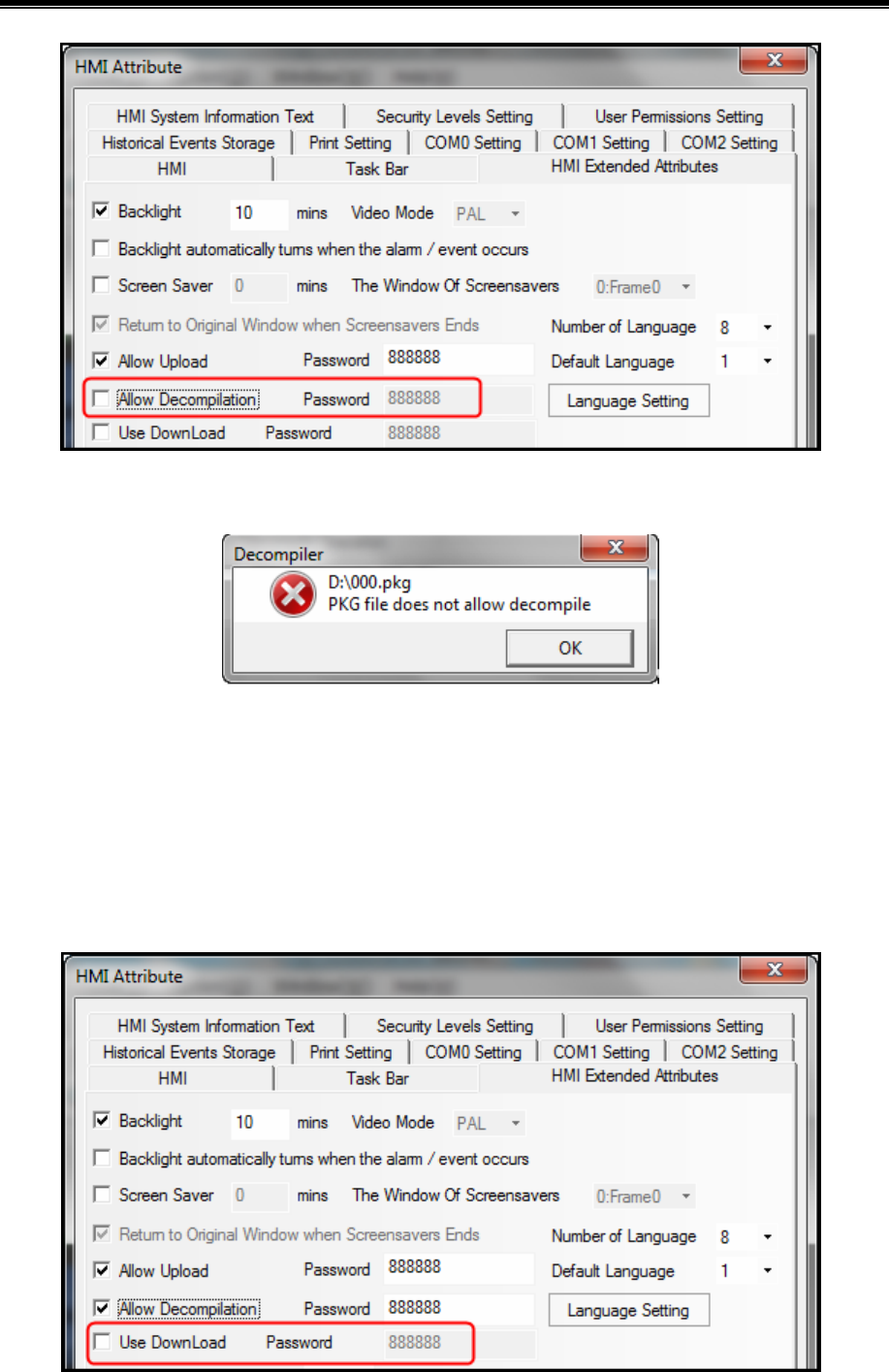
Advanced Part Recipe/RecipeEditor
359
The pkg files that are set to prohibit decompiling can still be downloaded into HMI.
When prohibiting decompilation is set, prompt box will pop up if forcibly decompile:
10.1.4 Download Password Protection
Set download password to HMI, to prevent user project saved in HMI being covered by unauthorized operation.
- Do not use download password
Projects do not use password by default. Settings of no use of password: Do not select the option of【Use Download
Password】in【HMI Attribute】—【HMI Extended Attributes】 page to do not use password. If download password is not set,
the dialog box of download password will not pop up the next time when you download project into HMI. Users can
download project into HMI directly.
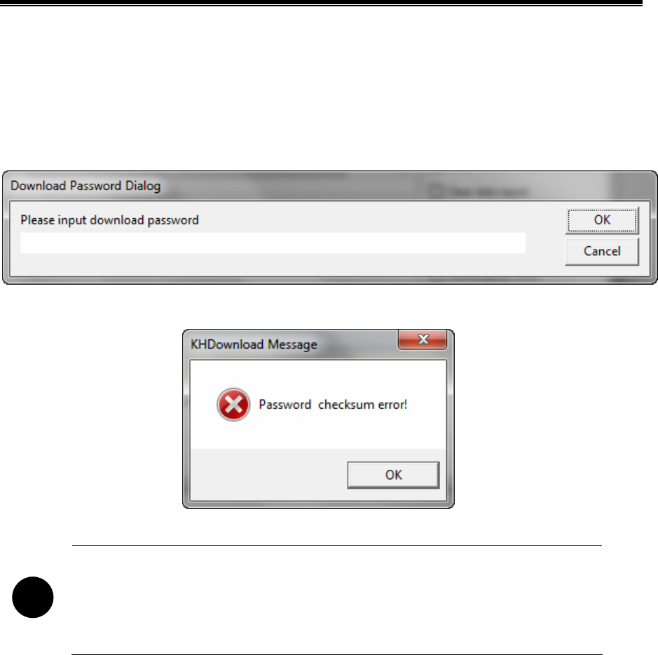
Kinco HMIware Configuration Edit Software
360
- Use password
Use password: Select the option of【Use Download Password】in【HMI Attribute】—【HMI Extended Attributes】 page and
set password. The default password is “888888”.
When project running in HMI is set to use download password, then【Download Password Dialog】box will pop up next time
when user download project into HMI, as follows:
If input password is wrong, password error prompt will pop up.
Only enter password correctly then project can be downloaded into HMI.
!
1. When set or modify download password in HMI attributes, users have to download project into
HMI for the first time and restart HMI, then download password will take effect.
2. After the password is set, please keep it in mind, otherwise, configuration project download will
fail. Manufacture does not provide factory recovery and universal password service.
10.2 Window Protection
For windows with important parameters or components, user could protect these important windows by security level
function.
10.2.1 Window Password Setting
Set the number of security levels and corresponding passwords in【HMI Attribute】—【Security Levels Setting】, and system
default passwords are“888888”.
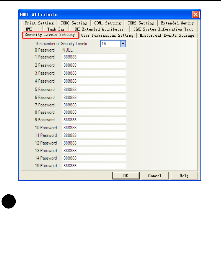
Advanced Part Recipe/RecipeEditor
361
!
1. Support at most 16 security levels from 0 to 15. Level 0 indicates that there is no password;
Level 15 is the highest security level. The bigger the number is the higher the level.
2. The password cannot be zero or empty; when passwords begin with 0, 0 is invalid.
3. The maximum value of password is 99999999.
4. Security level is valid only for base window and not available for other windows.
5. Users with high security level can access low security level windows; While users with low
security level cannot access high security level windows.
10.2.2 Security Level Setting of Window
Access【Window Attribute】page—【Security Level】and choose the corresponding security level.
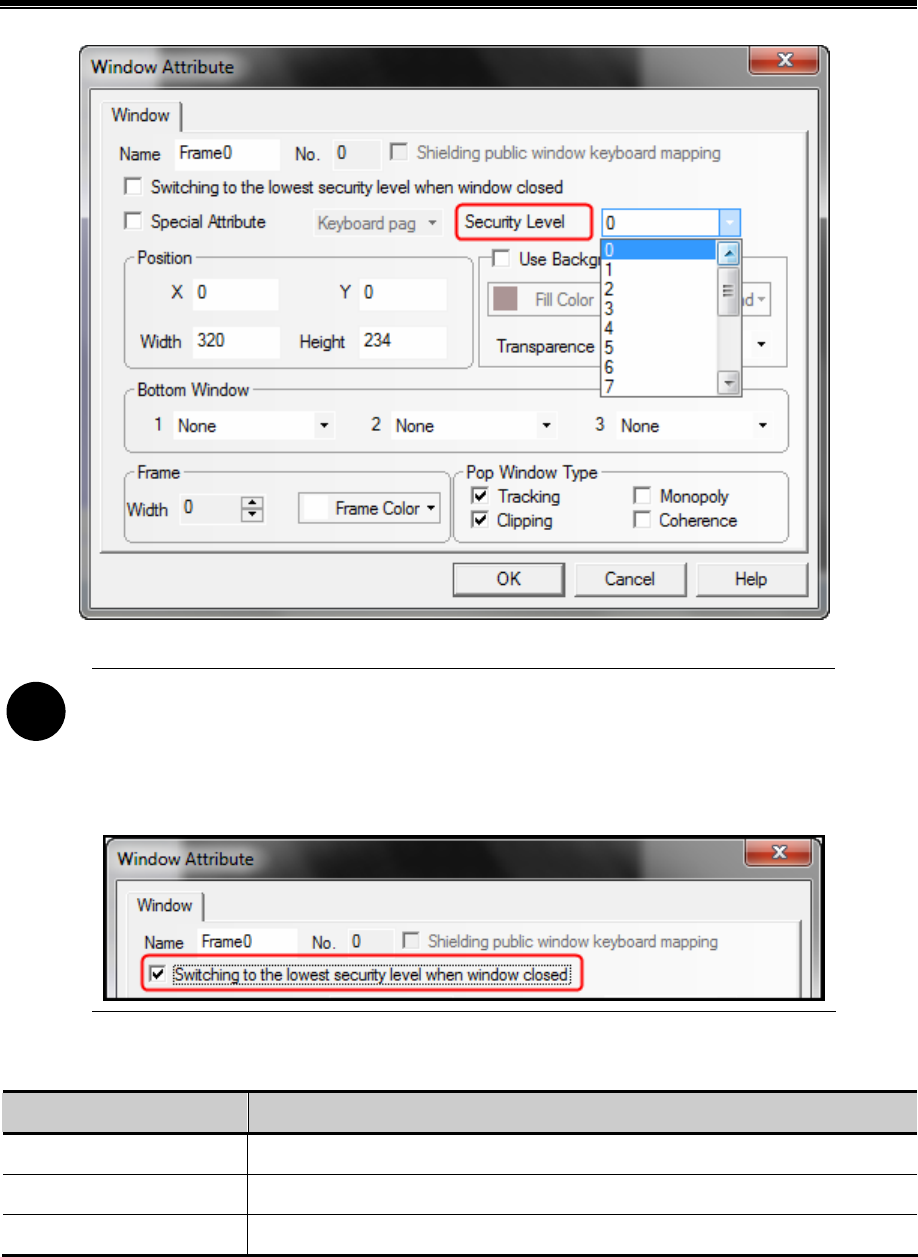
Kinco HMIware Configuration Edit Software
362
!
Software will remember the password input for the first time by default, as long as HMI is powered
continuously, do not need to enter the password again when enter into the window next time.
If the option of 【Switching to the lowest security level when window closed】is checked, then the
password need to be entered again when accessing the window next time.
10.2.3 System reserved registers related to security level
Address Description
LW9040~9041 Double words, is for inputting password of 【Security Level】
LW9042 Display the security level of current base window
LW9043 Force to lower the security level
10.2.4 Security level password input window
【Frame9:Login Window】is provided by the system for security level password input.
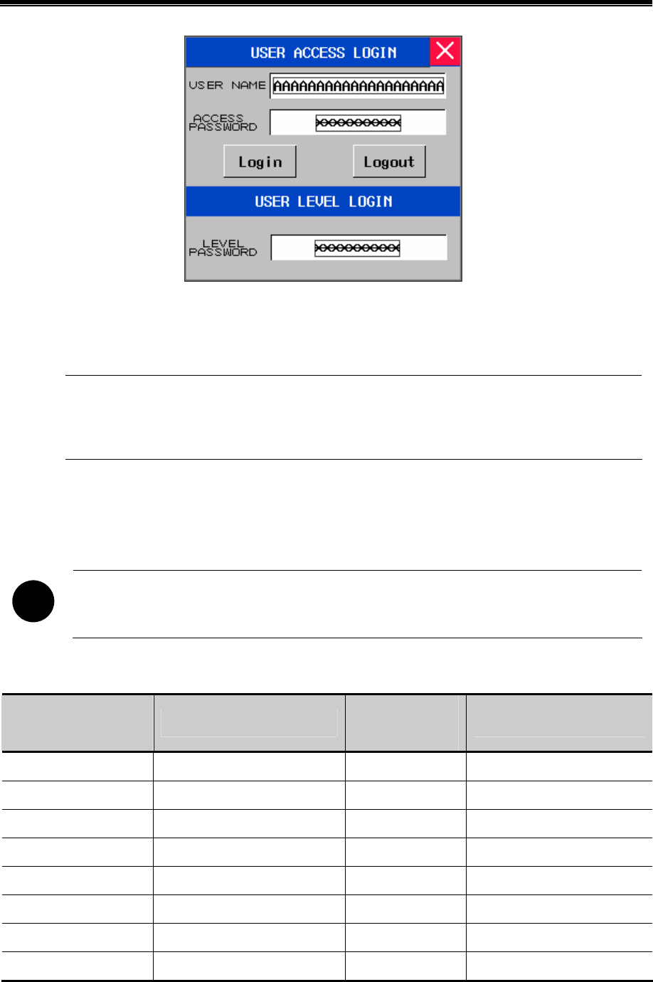
Advanced Part Recipe/RecipeEditor
363
[Frame9:Login Window] is for inputting passwords of security levels and user permissions. User using security level
function only need to input appropriate password of security level.
1. The system reserved registers referred in【Frame9:Login Window】could be found in 【Chapter 14
Registers】of this manual
2. User could move the window by the control bar on the top of 【Frame9:Login Window】
10.2.5 Modifying Password Online
Kinco HMIware supports security level password modifying online.
!
User permission password does not support online modification
System reserved registers for modifying security levels
Addresses of system
reserved registers
Description
Addresses of system
reserved registers
Description
LW10024~10025 Level 1 password. Double word LW10026~10027 Level 2 password. Double word
LW10118~10119 Level 3 password. Double word LW10120~10121 Level 4 password. Double word
LW10122~10123 Level 5 password. Double word LW10124~10125 Level 6 password. Double word
LW10126~10127 Level 7 password. Double word LW10128~10129 Level 8 password. Double word
LW10130~10131 Level 9 password. Double word LW10132~10133 Level 10 password. Double word
LW10134~10135 Level 11 password. Double word LW10136~10137 Level 12 password. Double word
LW10138~10139 Level 13 password. Double word LW10140~10141 Level 14 password. Double word
LW10142~10143 Level 15 password. Double word
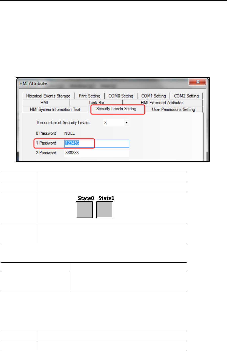
Kinco HMIware Configuration Edit Software
364
10.2.6 Application of Passwords Required for Switching Windows
The following example describes how to protect the window by the security level function.
【Example】Switch the window from window 0 to window 10 by switch window function of “Function Key” component,
the window will switch only when the password is entered correctly.
In this example, set security level of window 0 to 0, set security level of window 10 to 1 and the password is 123456.
Set security level password
In the attribute page of【HMI Attribute】—【Security Level Setting】,set level 1 password to 123456.
Create a Function Key component in window 0, and the attributes setting is as follows:
Function Switch Window: Chang window【10:Frame10】
Tag Use Tag; State 0: Switching window 10; State 1: Switching window 10.
Graphics
Use vector graphics:
Control Setting Select【Conditional Enabling】;Check【Security Level】; Check 【Minimum
level: 1】;Check【Auto show login window】.
Set the attributes of window 10 and create a Function Key component to switch to window 0.
Double click at the blank area of window 10 to open the 【Window Attribute】, and set its attributes as follows:
Security Level 1
Switching to the lowest security
level when window closed*
Check
※ When the option is checked, the current window will be set to the lowest security level when window closed. Password
is required to input again when access high level windows;
When the option is not checked, there is no need to input password when access windows with the same security level.
Set the attributes of Function Key as follows:
Function Switch Window: Chang window【0:Frame0】
Tag Use Tag; State 0: Switching window 0; State 1: Switching window 0.
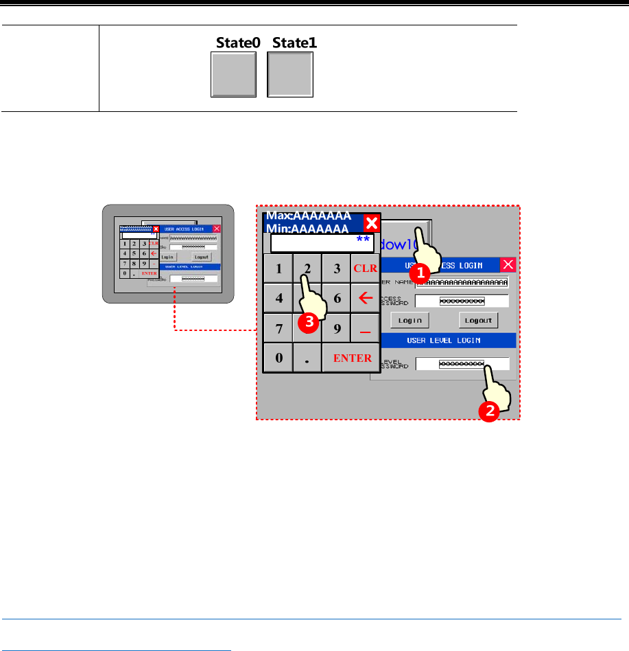
Advanced Part Recipe/RecipeEditor
365
Graphics
Use vector graphics:
Save and compile
During running, touch Function Key component in window 0 to pop up password input window 【Frame9:Login Window】,
and input “123456”to the【LEVEL PASSWORD】box to switch to window 10.
10.3 Component Protection
Some important components are set with permission /security level control. Only users with higher or equal permission/
security level could operate to prevent wrong operation.
There are two ways for component protection: security level protection, user permission protection.
10.3.1 Security Level Protection for Components
Settings of Security level protection for components are similar with window protection.
☞For more details about components using [Security level protection],please refer to [Advanced Part 10.2.6 Application
of passwords required for switching windows]
10.3.2 User Permission Protection for Components
When【Permission control】is set to a component,then only users with corresponding permission can operate this component.
- User name and access password setting
Open【HMI Attribute】—【 User Permissions Setting】,in the box of 【User Permissions Setting】,select 【Enabled】and
input User Name,Password, Logoff Time and Permissions.

Kinco HMIware Configuration Edit Software
366
!
1. Password only supports number, but does not support other characters. The range of password is
0~2147483647. When password is set to 0, indicating no password in use.
2. Range of logout time is 0~2147483647 minutes. 0 indicates that do not log off and permission remains in
effect. The logoff time is timed from the last time operation finished after login.
10.3.3 System Reserved Registers Related to User Permissions
Besides set user permission in【HMI Attributes】—【 User Permissions Setting】,the following system reserved registers can
also be used for user permissions setting:
Address Function Description
LW9486~LW9501 Input user name for login 32 characters at most
LW9502~LW9503 Input user password for login Double word
LW9504~LW9505 Display permission of current user
Double word ,read only, display 32 bits corresponding
permission
LB9165 User login confirmation Set ON to execute login operation, then set OFF automatically
LB9166 User logout confirmation
Set ON to execute logoff operation, then set OFF
automatically
10.3.4 System Reserved Registers Related to Add/Delete Users and User Permissions Online
Besides add/delete users and user permissions in 【HMI Attributes】—【 User Permissions Setting】,user also can add/delete
users and user permissions online. See the table below for system reserved registers related to add/delete users and user
permissions online:
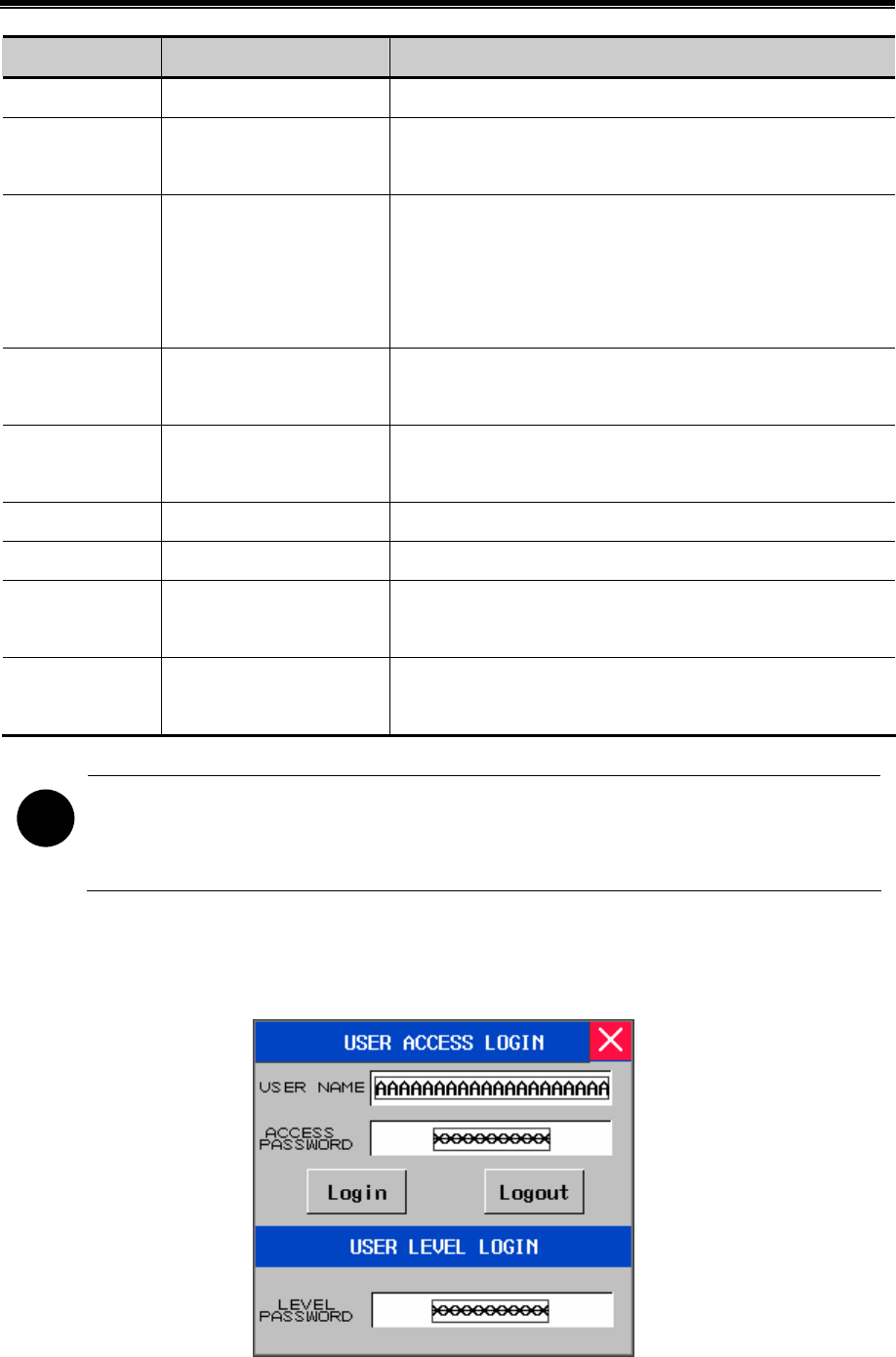
Advanced Part Recipe/RecipeEditor
367
Address Function Description
LW9486~LW9501 Input user name for login 32 characters at most
LW9502~LW9503 Input password
corresponding to user name
Double word
LW9506~LW9507 User permission assignment Double words, readable/writable, 32 permissions assignment, LW
9506~9507 corresponds to permission 0~31 separately. LW.B
corresponds to bits of LW 9506~9507. For example: LW.B 9506.0
indicates permission no. 0. LW.B 9506.A indicates permission no. 10
LW9508~LW9509 Logout time for user
permission
Double words, in minutes
LW9510~LW9511 Confirm password for
adding/deleting user
Double word
LB9167 Confirm to add user Set ON to execute adding user, then set OFF automatically
LB9168 Confirm to delete user Set ON to execute deleting user, then set OFF automatically
LB9190 Executive mark of user
management
The bit will be set to ON when execute operations of Add/Delete
users
LB9191 Operation failure of user
management
The bit will be set to ON when operation of user management fails
!
1. Only users and user permissions added online can be deleted online.
2. User permissions do not support modify passwords online, but user could modify password through
adding/deleting users online.
10.3.5 Window for User Permission Password Input
【Frame9:Login Window】 is provide by the system to input user permission password.
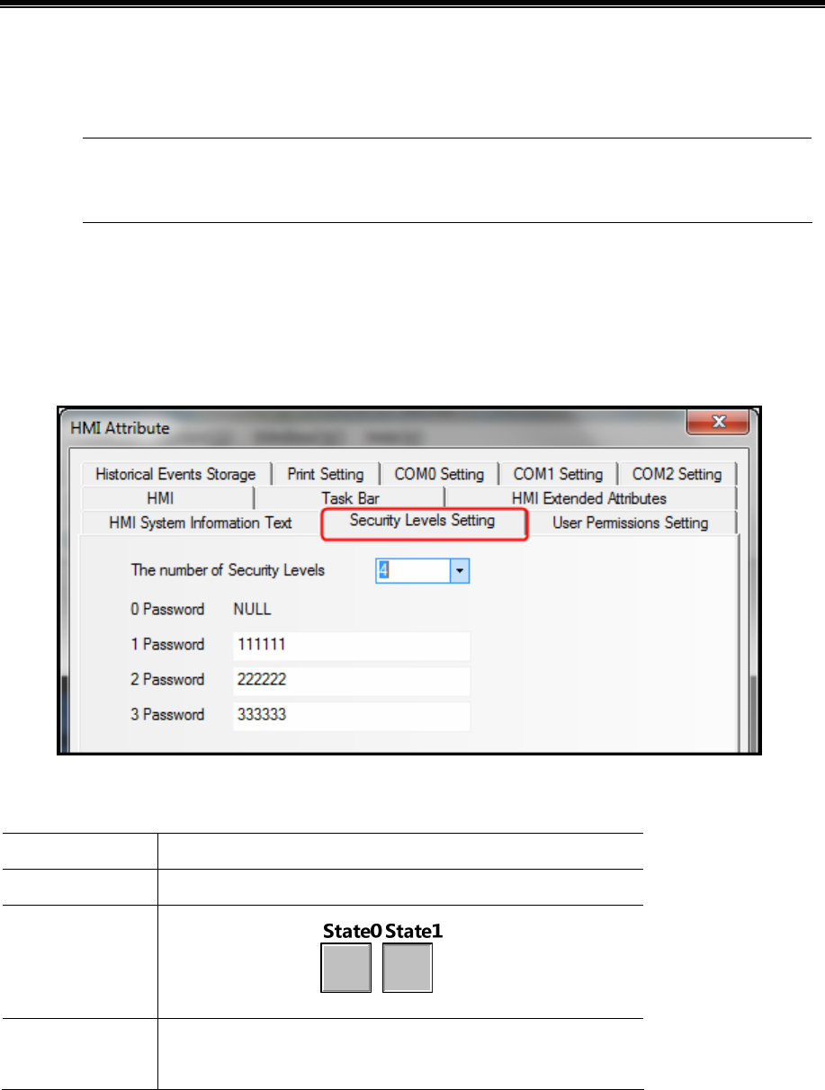
Kinco HMIware Configuration Edit Software
368
If user permission function is use, users only need to input corresponding “USER NAME” and “ACCESS
PASS WOR D” then click “Login”.
1. System reserved registers referred in【Frame9:Login Window】can be found in 【Chapter 14 Registers】.
2. User could move【Frame9:Login Window】by the control bar on the top of the window.
10.3.6 Application of Security Level Protection for Components
【Example】Correct password required before operation of “Bit State Switch” component.
In the example, security level is used to protect component, and set minimum level at least 2 to operate this component.
Open 【HMI Attributes】—【Security Levels Setting】. Detailed settings are as follows:
Create a bit state switch component in window 0, and set its attributes as follows: address LB0. Switch Type: Toggle.
【Control Setting】—【Conditional Enabling】—【Security Level】—【Minimum level: 2】—【Auto show login window】.
Read/Write address LB 0(HMI local register)
Switch Type Toggle
Graphics
Use Vector Graphics:
Control Setting Select【Conditional Enabling】;Check【Permission Control】; Check
【Select Permission:2】;Check【Auto show login window】
Save and compile
During running, when touch the bit state switch component, password input window【Frame9:Login Window]】will pop up,
then input level 2 password“222222” or level 3 password “333333” in the password level box. After confirm, user
could operate the bit state switch component; If input level 1 password or wrong password, then the operation will fail.
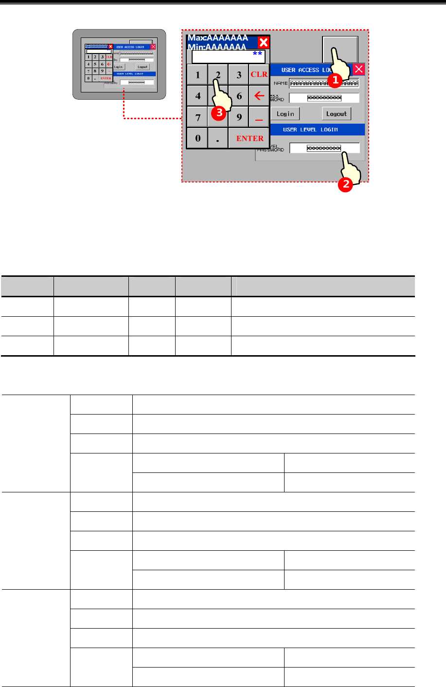
Advanced Part Recipe/RecipeEditor
369
10.3.7 Application of User Permission Protection for Component
【Example】Set 3 users: Administrator,Engineer,Operator. The 3 users have different permissions. Operator can
operate number input component; Engineer can operate bit state switch component; Administrator can operate both the
number Input component and bit state switch component.
User ID User Name Password Logoff Time Permission
User 0 Operator 111111 10 minutes Operator permission
User 1 Engineer 222222 10 minutes Engineer permission
User 2 Administrator 333333 1 minutes Operator permission and engineer permission
Registered user and corresponding permission in【HMI Attribute】—【User Permission Setting】, the settings are as
follows:
User Name Operator
Password 111111
Logoff Time 10
Permission 0:Operator permission Check
User 0: Enable
Permission
Permission 1:Engineer permission Uncheck
User Name Engineer
Password 222222
Logoff Time 10
Permission 0:Operator permission Uncheck
User 1: Enable
Permission
Permission 1:Engineer permission Check
User Name Administrator
Password 333333
Logoff Time 1
Permission 0:Operator permission Check
User 2: Enable
Permission
Permission 1:Engineer permission Check
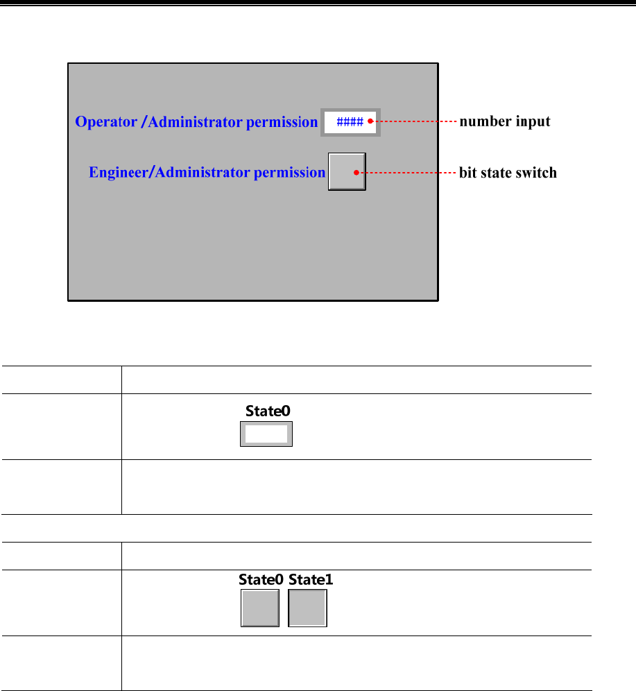
Kinco HMIware Configuration Edit Software
370
Set user permission control for components
Create a number input component and a bit state switch component, and the attribute setting is as follows:
Number input component
Read/Write address LW 0(HMI local register)
Graphics
Use vector graphics:
Control Setting Select【Conditional Enabling】;Check【Permission Control】,Select Permission:0
Operator permission; Check【Auto show login window】
Bit state switch component
Read/Write address LB 0(HMI local register)
Graphics
Use vector graphics:
Control Setting Select【Conditional Enabling】;Check【Permission Control】,Select Permission:1 Engineer
permission; Check【Auto show login window】
Save and compile
During running, touch number input component to pop up password input window 【Frame9:Login Window】, and input
“Operator” to the 【USER NAME】box and“111111”to the【ACCESS PASSWORD】box. Then click 【login 】 to login
Operator permission. Now user can operate the number input component. Operations for other components are similar.
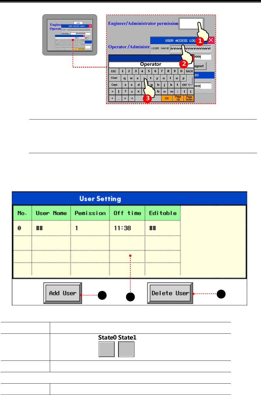
Advanced Part Recipe/RecipeEditor
371
1. Logoff time: it is the valid time after login,user permission will be lapsed automatically after the time
limit.
2. User name is case sensitive.
【Example】Add/Delete user permissions: Take MT5420 for example:
(1)Window 0
12
3
Function key component is used to pop up window 10, and attribute settings are as follows:
Function Switch window: popup window
Graphics
Use vector graphics:
Tag Use Tag: Add user
Function key component is used to pop up window 11, and attribute settings are as follows:
Function Switch window: popup window
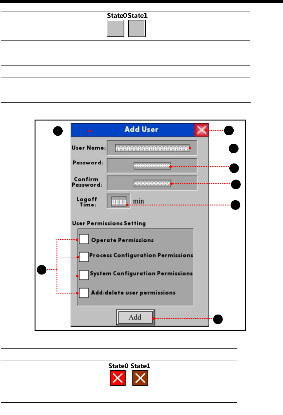
Kinco HMIware Configuration Edit Software
372
Graphics
Use vector graphics:
Tag Use Tag: Add user
User info display component is used to display user’s information, and attribute settings are as follows:
Separator Setting Color: Black; Style: ------
Background Setting Background Color: White; Title Bar Background Color: Green; Border Color: Black
Border Width 2
(2)Window 10
1
2
3
4
5
6
8
7
Function key component is used to close keyboard, and attribute settings are as follows:
Function Keyboard Function: Escape
Graphics
Use vector graphics:
Function key component is used to move keyboard, and attribute settings are as follows:
Function Switch Window: Popup window title bar
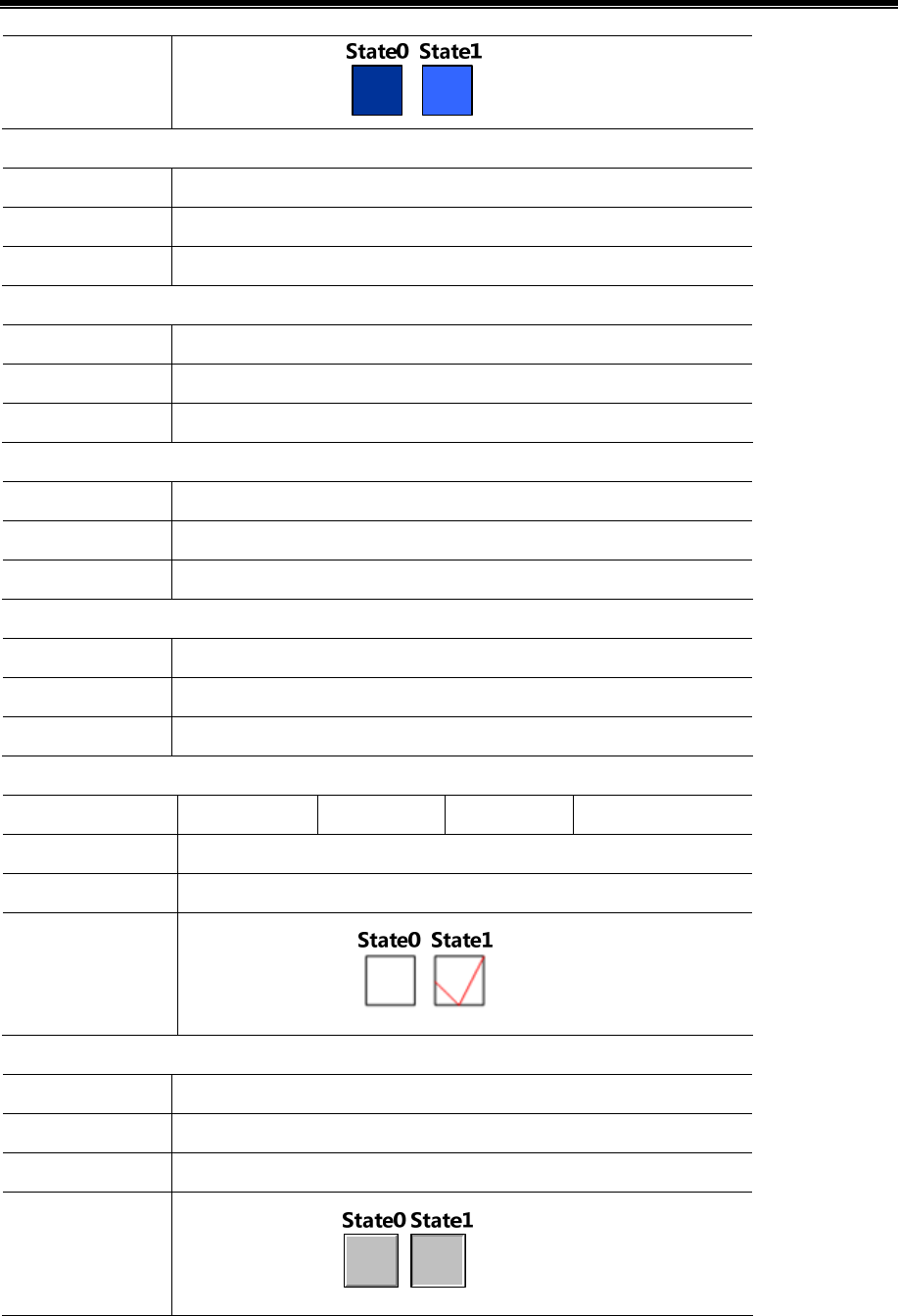
Advanced Part Recipe/RecipeEditor
373
Graphics
Use vector graphics:
Text input component is used to input user name, and attribute settings are as follows:
Read/Write address LW9486
Word Length 10
Graphics None
Number input component is used to input password, and attribute settings are as follows:
Read/Write address LW9502
Numeric Data Word Length:2 words;Data Type: 【password】; Data Width【DWORD】
Graphics None
Number input component is used to confirm password, and attribute settings are as follows:
Read/Write address LW9510
Numeric Data Word Length:2 words;Data Type: 【password】; Data Width【DWORD】
Graphics None
Number input component is used to set logout time, and attribute settings are as follows:
Read/Write address LW9508
Numeric Data Word Length:2 words; Data Type【unsigned int】,Data Width【DWORD】
Graphics None
Bit state switch component is used to select user permissions, and attribute settings are as follows:
Write address LW.B9506.0 LW.B9506.1 LW.B9506.2 LW.B9506.3
Switch Type Toggle
Tag None
Graphics
Use vector graphics:
Bit state setting component is used to confirm to add users, and attribute settings are as follows:
Write address LB9167
Switch Type On
Tag Use Tag, 0: Add
Graphics
Use vector graphics:
(3)Window 11
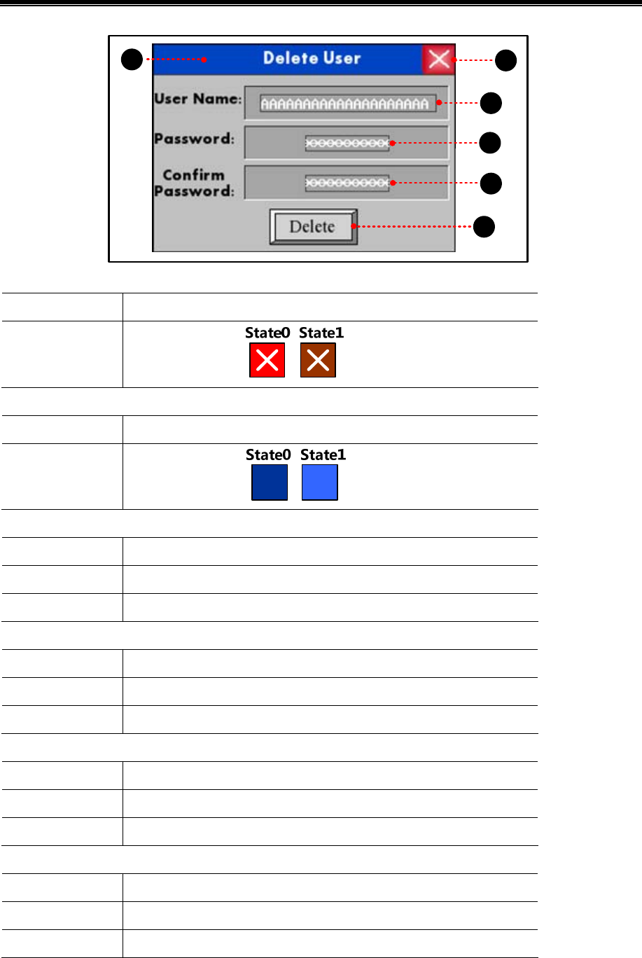
Kinco HMIware Configuration Edit Software
374
21
3
4
5
6
Function key component is used to close keyboard, and attribute settings are as follows:
Function Keyboard Function: Escape
Graphics
Use vector graphics:
Function key component is used to move keyboard, and attribute settings are as follows:
Function Switch Window:Popup window title bar
Graphics
Use vector graphics:
Text input component is used to input user name, and attribute settings are as follows:
Read/Write address LW9486
Numeric Data 10
Graphics None
Number input component is used to input password, and attribute settings are as follows:
Read/Write address LW9502
Numeric Data Word Length:2 words;Data Type: 【password】; Data Width【DWORD】
Graphics None
Number input component is used to confirm password, and attribute settings are as follows:
Read/Write address LW9510
Numeric Data Word Length:2 words;Data Type: 【password】; Data Width【DWORD】
Graphics None
Bit state setting component is used to confirm to delete users, and attribute settings are as follows:
Write address LB9168
Switch Type On
Tag Use Tag; 0: Delete
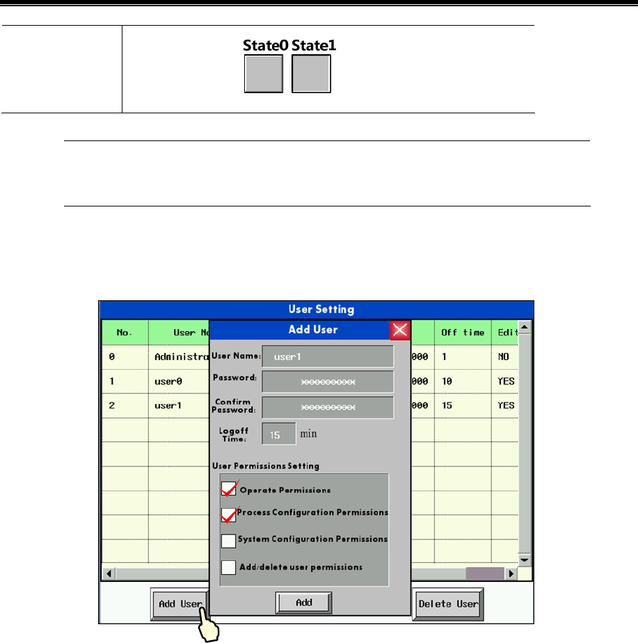
Advanced Part Recipe/RecipeEditor
375
Graphics
Use vector graphics:
Delete user permission is only valid for the users added in HMI. Users set in the configuration project
cannot be deleted
(4)Save, compile and offline simulation
Touch the 【Add User】button, add user dialog box will pop up.
Input the user name to be added and the corresponding password, confirm it, then click “Add” to complete the operation.
Touch the【Delete User】button, delete user dialog box will pop up.
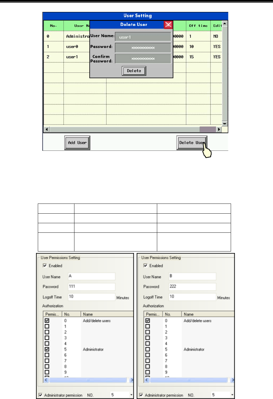
Kinco HMIware Configuration Edit Software
376
Input the user name to be deleted and the corresponding password, confirm it, and then click “Delete” to complete the
operation.
【Example】Delete user by administrator permission. There are two users in the project as follows:
User 1 User 2
User Name A B
Password 111 222
Permission 1.Add/delete permission
2.Administrator permission 1.Add/delete permission
1) Add new user online, User Name: 1, Password: 123.
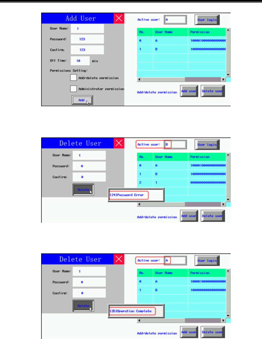
Advanced Part Recipe/RecipeEditor
377
2) User B(No Administrator Permission)execute delete operation without password, it prompts “Password Error”, and
delete operation is fails.
3)When User A(Check Administrator Permission) execute delete operation without password, it prompts “Operation
Complete”, and delete operation is complete.
378
11 Recipe/ RecipeEditor
Recipe data is saved on the HMI and can be stored inside the area power down. Recipe data can be stored in the RW and
FRW register. For with USB HOST interface or SD card slot on the HMI, the recipe data can also be stored in the ERW
register.
RW, FRW and ERW distinction as follows:
Recipe Register Description
RW RW is specially designed for HMI recipe memory physical storage area that is defined by the address
type. When the HMI is powered down, RW in 4000 series remains . RW in 5000 series depends on
backup battery . If it is powerfui,data remains,but back-up battery power is low, or when no electricity,
RW data will be lost.
FRW FRW is dedicated to the physical storage area HMI FLASH address type definition. The data stored in
FLASH FRW, not because of HMI powered off or HMI backup battery power and loss of data. But
there are erasing times limit FLASH
ERW0~2
ERW0 ~ 2 is dedicated to the physical storage area defined in the external memory address type. The
data stored in the ERW, not because of HMI powered off or HMI backup battery is dead and losing data
RW, FRW, ERW using methods similar, the following content mainly RW, for example, no longer on the FRW and ERW
additionally described.
11.1 Register Related to the Recipe
Register/ Component Descriptions
RB The absolute addresses of the recipe bit addresses saved in the HMI.
RBI The index addresses of the recipe bit addresses saved in the HMI.
FRB The absolute addresses of the recipe bit addresses saved in the flash.
FRBI The index addresses of the recipe bit addresses saved in the flash.
RW The absolute addresses of the recipe word addresses saved in the HMI.
RWI The index addresses of the recipe word addresses saved in the HMI.
FRW The absolute addresses of the recipe word addresses saved in the flash.
FRWI The index addresses of the recipe word addresses saved in the flash.
ERW0~2 The absolute addresses of the recipe word addresses saved in the external memory.
ERWI0~2 The index addresses of the recipe word addresses saved in the external memory.
LW9000 The data in LW9000 is the offset of the index address
Data Transmission
Timer
Transfer the data in recipe data to the data in PLC or HMI.
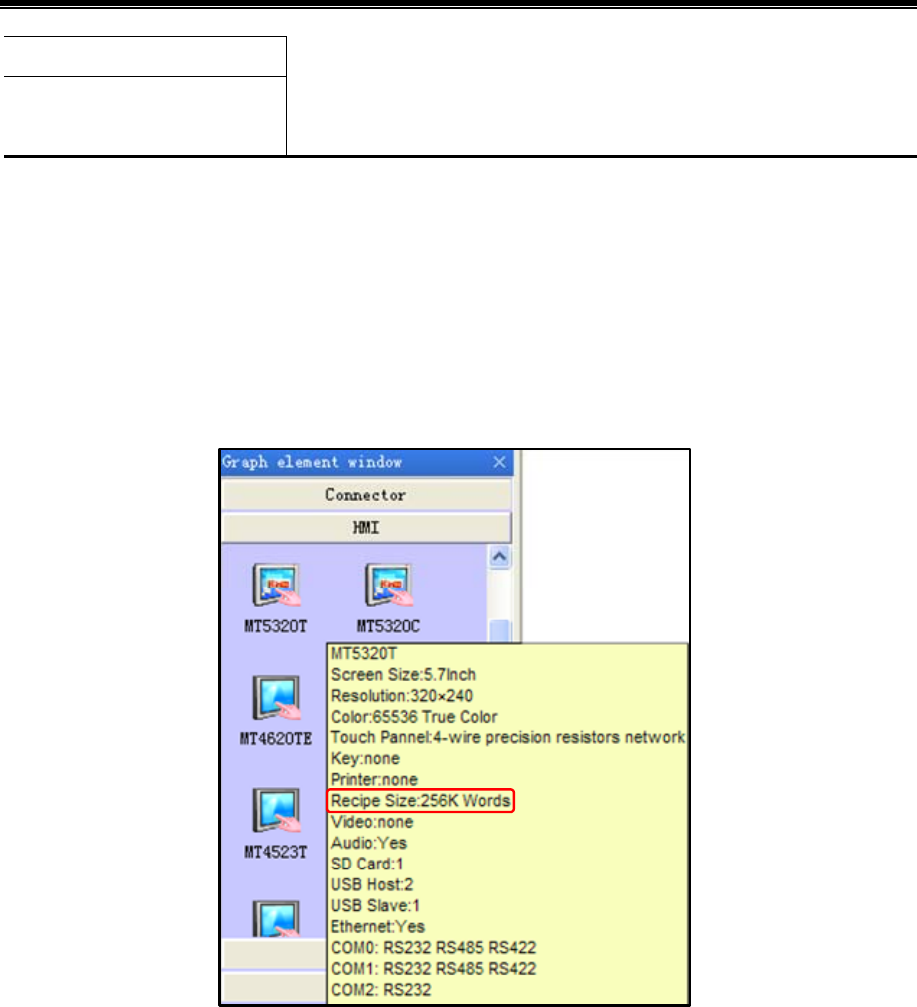
Advanced Part Recipe/RecipeEditor
379
Recipe Data
General PLC Control/ General PLC
Control (Extend)
11.2 Method for Checking the Recipe Size
11.2.1 Method for Checking the RW Size
The capacity (RW size) is different from different types of HMI. Through the following ways user can check the RW size.
For example: Take MT5320T for example:
- Check in Kinco HMIware software
Move the mouse to the MT5320 icon in HMI in Graph element window, the system will automatically display the relevant
information of this HMI. The [Recipe Size] is the RW size. The recipe size of MT5320T is 256k words that are 512 K Bits.
- Check in selection guide
- Check the recipe file attribute after uploading the recipe by KHManager
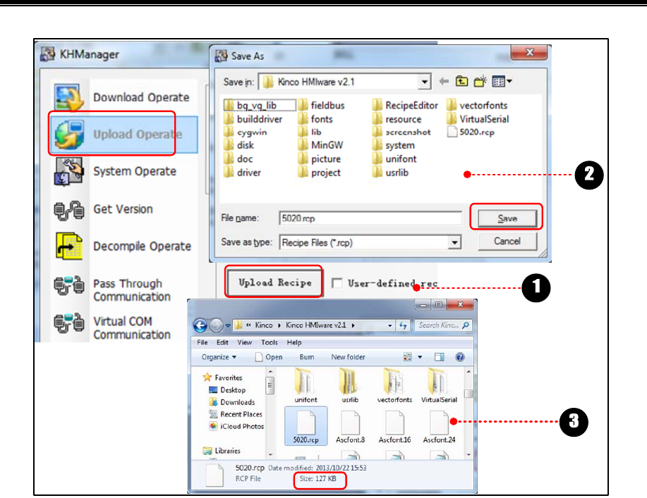
Kinco HMIware Configuration Edit Software
380
Click [Upload Recipe] in [KHManager], and input [File Name], then click [Save].
Recipe is uploading until the “Upload Success” dialog box pop up.
Check the size of recipe file uploaded.
11.2.2 Calculation for Recipe Address Range
There are two following ways for calculating HMI recipe address range.
- Calculation based on recipe size
[Example]: Take MT5320T for example, the recipe size is 256K words, that 256Kword= 512K Byte, and 1k byte is occupied
by the system. The calculation is (512-1)×1024 Byte=523264 Byte. Because Kinco HMIware are addressed in words, so
bytes divided by 2 becomes the word address, and then the last three digits become 0,finally get 261000 words.
- View through the element address range
[Examples] For example create a new model for the MT5320T HMI configuration, in the Configuration Editor to create a
new screen number input component, set the address type is RW, the user can view the MT5320T in the [address range], RW
register address range is: 0 ~ 261000.
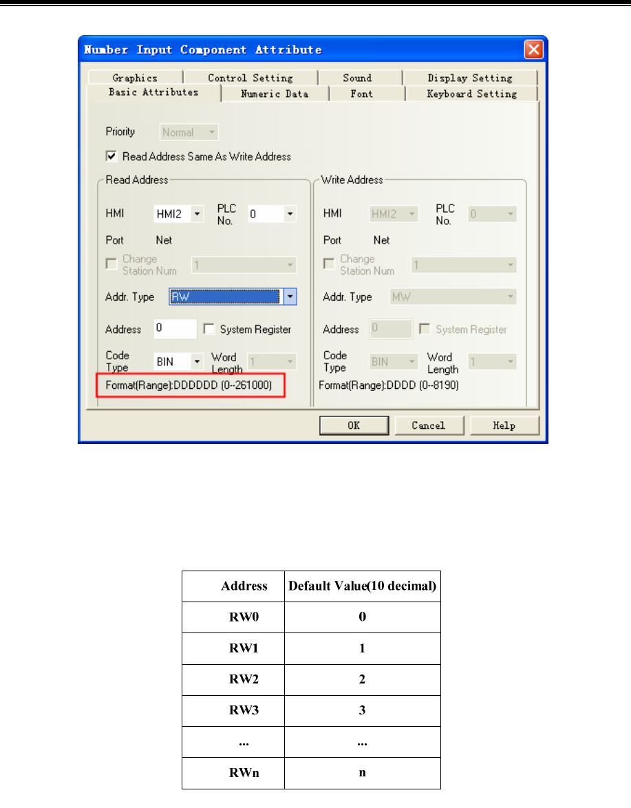
Advanced Part Recipe/RecipeEditor
381
11.3 Usage of Recipe
11.3.1 Absolute Address
The recipe memory has an address corresponding recipe absolute addressing (It is assumed that the initial value of
illustration only, to actually quasi) as shown:
11.3.2 Index Address
Because absolute address too much, find it very difficult, so the index provides a virtual address of a temporary storage area
RWI0, ..., RWIn and an index register LW9000 (occupies 2 words) by changing t LW9000 to find RW.
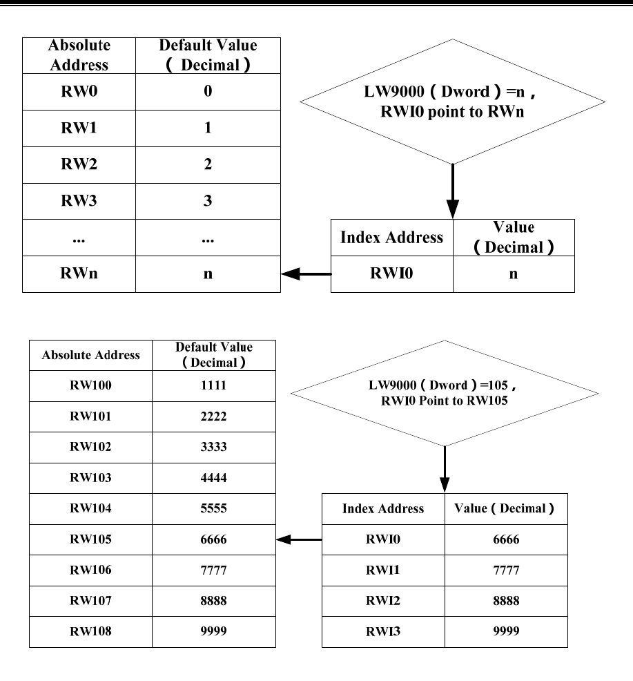
Kinco HMIware Configuration Edit Software
382
[Example] If the value of LW9000 is equal to 105, then the RWI0 will point to the data in address RW105.
11.3.3 Application of Recipe
For example: We take the address 4x of Modbus RTU protocol for example, save the value of 4X1~4X5 to 0 recipe file and 1
recipe file. The address range of 0 recipe file is RW0~RW4, The address range of 1 recipe file is RW5~RW9.

Advanced Part Recipe/RecipeEditor
383
Configuration screen as shown:
Text: PLC address, recipe 0, recipe 1
Multiple State Switch component used to change the value of LW9000, its attribute are:
Read/ Write address LW9000 (HMI system special register)
Function Control Mode: add, State Num.: 2, State No. 0 map value 0, State No. 1
map value 1
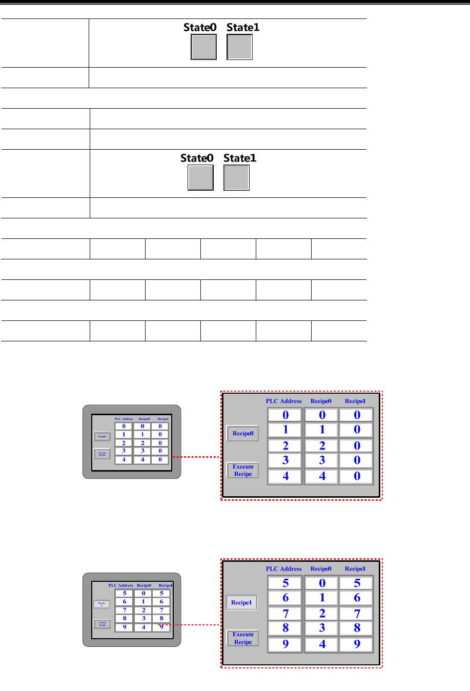
Kinco HMIware Configuration Edit Software
384
Graphics
Use vector graphic:
Tag Use Tag:recipe 0, recipe 1
Recipe Data component transferring the value of PLC to RW, its attribute are:
Write Address 4X 1 (PLC register)
Function Recipe Data: Upload from PLC to Recipe, Data Length: 5 words
Graphics
Use vector graphic:
Tag Use Tag;0:Execute Recipe
Number Input component inputting the value of the PLC register, its attribute are:
Read/ Write address 4X 1 4X 2 4X 3 4X 4 4X 5
Number Display component displaying the value of RW0~4, its attribute are:
Read/ Write address RW0 RW1 RW2 RW3 RW4
Number Display component displaying the value of RW5~9, its attribute are:
Read/ Write address RW5 RW6 RW7 RW8 RW9
Run and input 0~4 in the PLC address 4X1~4X5, then press [Execute Recipe] button, the value of RW0~RW4 will display
0~4.
Press [recipe 0] button and switch to [recipe 1], and modify the value of PLC address 4X1~4X5 to 5~9, then press [Execute
Recipe] button, the value of RW5~RW9 will display 5~9.
11.4 RecipeEditor
RecipeEditor is a tool in Kinco HMIware, and it is mainly used for the user to create, check, or edit the recipe file in *.rcp,
*.csv, *.erp and *.frp format.

Advanced Part Recipe/RecipeEditor
385
The data file in *.rcp, *.erp and *.frp format can save as *.csv file, and can open, check, edit or print by
Excel.
File Format Descriptions
rcp
HMI own the recipe memory corresponding recipe file format, using KHManager tool can upload and
download files to the format of the recipe (which, file size depends on the HMI recipe memory size) It is
the file format which can be identified by HMI
csv
It usually means the file format is based on the configuration settings and automatically saved to an
external storage device or through the recipe editor to save. This particular binary file format, you can
use Microsoft Excel software to open and can be to edit, save and print, and other related operations, but
can not be freely modified template format, otherwise the recipe editor and HMI can not be resolved
erp The file format only supported that the HMI with external memory, can be saved in USB DISK, SD card
frp
The recipe file format corresponding to the FLASH address, HMI will be only generated while used,
supports a maximum address is 2G Bits, 2 × 1024 × 1024 × 1024/16 Words = 134217728 Words,
when configuration, placed a number input element, the address type selection FRW, will see the range is
0-134217727. The number of FLASH recipe address using as the same as the HMI is open, when not in
use will be released. Usually used to save the more important and not always erase the data, because the
HMI powered off or battery power is not lost, but erasing times is limited. using KHManager tool can
upload and download the recipe file format (upload FRW, download FRW)
11.4.1 Recipe Editor Start-up
- Open from the [Start] menu in the PC operation.
- Open from the [Tools] menu in Kinco HMIware.
Click [Recipe Editor] in the [Tools] menu.
- Double-click [RecipeEditor.exe] in the [RecipeEditor] file document in Kinco HMIware installation directory.
The RecipeEditor folder is copied to another location can be used alone.
- Click [Recipe Editor] button in [KHManager]-[Download Operate].
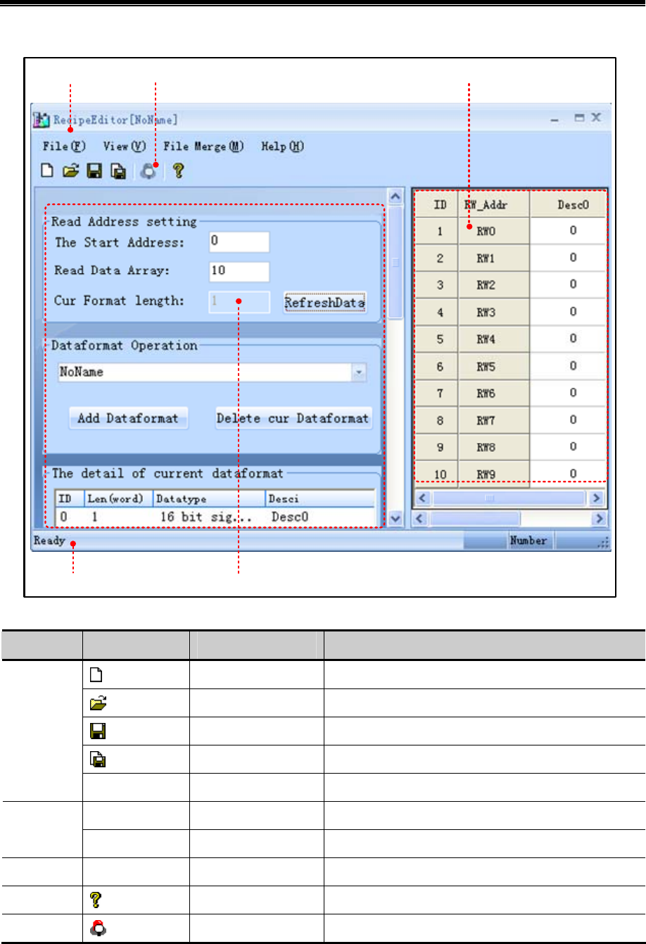
Kinco HMIware Configuration Edit Software
386
11.4.2 Recipe Editor User interface
Data editing area
Status Bar
ToolBarMenu
Data configuration area
- Menu Bar/ Toolbar
Name Icon Toolbar name Descriptions
New File Create a new recipe file
Open File Open a recipe file
Save File Save recipe file
Save As Save as a recipe file
File
Exit Exit recipe editor
ToolBar Start/ Close Toolbar
View
Status Bar Start/ Close Status Bar
File Merge File Merge HMI Merge some recipe files to a recipe file
Help About RecipeEditor The version of RecipeEditor
Bit Browser Bit Browser Display word register in bit format
- Data configuration area
There are [Read Address Setting], [Dataformat Operation], [The detail of current dataformat] and [Dataformat Operation
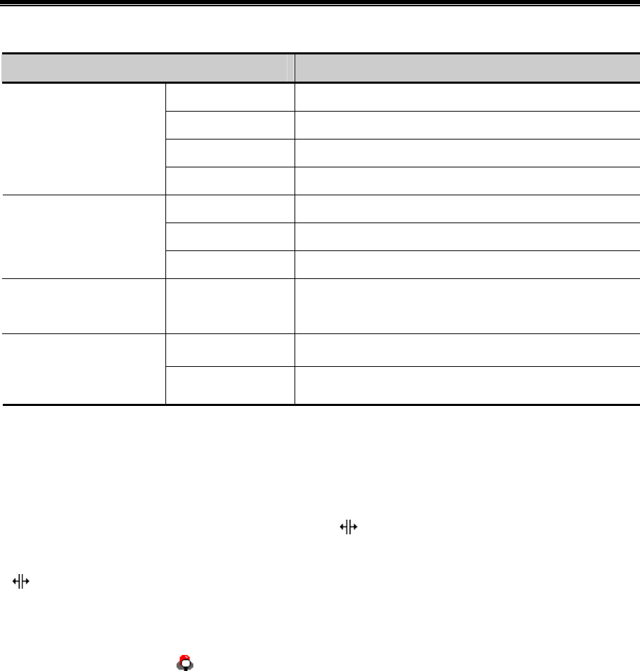
Advanced Part Recipe/RecipeEditor
387
Usage] in data configuration area.
Name Descriptions
The Start Address The start address of the reads data segment
Read Data Array The number of groups to read data
Cur Format length The sum length of each data type× the number of groups
Read Address Setting
RefreshData Click【Refresh Data】,display data as a new setting
Select the current data format
Add Dataformat Click【Add Data format】to add the data format
Dataformat Operation
Delete cur Dataformat Click【Delete cur Data format】to delete the current data format
The detail of current
dataformat
-
Select an entry, double click, pop [Data Type Editor] dialog;
blank right-click menu, you can add, modify, delete data type
Auto use dataformat After modify the data format, automatically read the current file
Dataformat Operation Usage
Use Dataformat With the same effect [Refresh Data]
- Data editing area
Data editing area according to [data configuration area] set the start address, the number of data and data types to display the
corresponding register address, and the user can view and modify data area data corresponding to these addresses.
Hide / Show [Data Configuration area]
Move the mouse to the control bar when the mouse is displayed as , pulling the control bar or click the left mouse button,
you can hid [Data Configuration area]. At this moment move the mouse to place the control bar when the mouse is displayed
as , pulling the control bar or click the left mouse button, you can restore the display [Data Configuration area].
【Data editing area】to view, modify, and bit browser
Directly input data in the data field [Desc1] (eg.RW1-RW9 are input 1-9), select the data bar required to bit browser, the data
bar turns blue, right-click or click on the toolbar, can pop [bit browse] properties box.
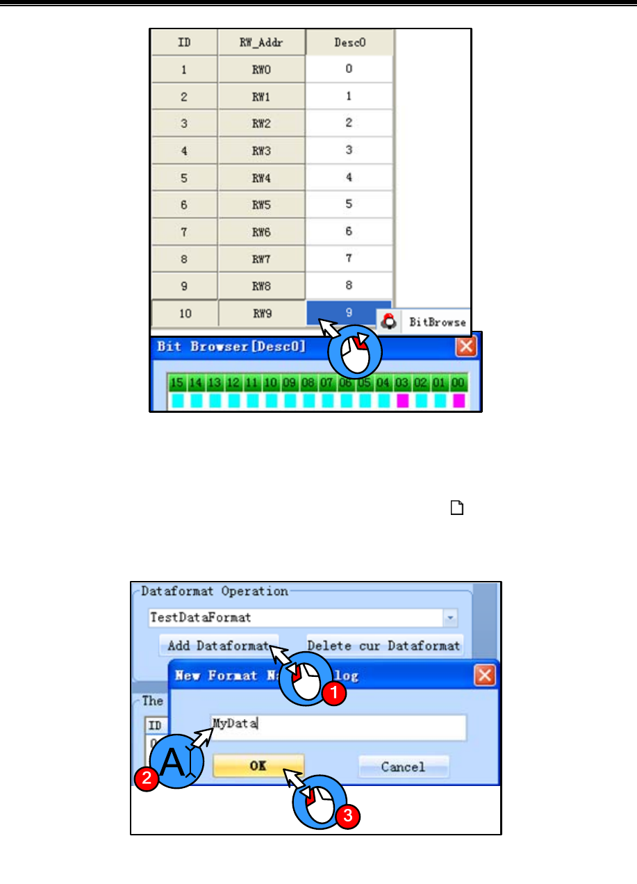
Kinco HMIware Configuration Edit Software
388
[Examples] For example RW9 value is 9, bit browser form RW9: 03,00 bit address can be seen in red: ON, decimal 9 to
binary form as 0000 0000 0000 1001.
11.4.3 Usage of RecipeEditor
(1)Add a new recipe file: If you use the RecipeEditor in the first time, you can click icon in the toolbar and then can
create a new recipe file.
(2)Add Dataformat: Click [Add Dataformat] and input the new format name: e.g. “Mydata”, then click [OK] button.
(3)Add Data Item
- The procedure of adding data type is shown as below:
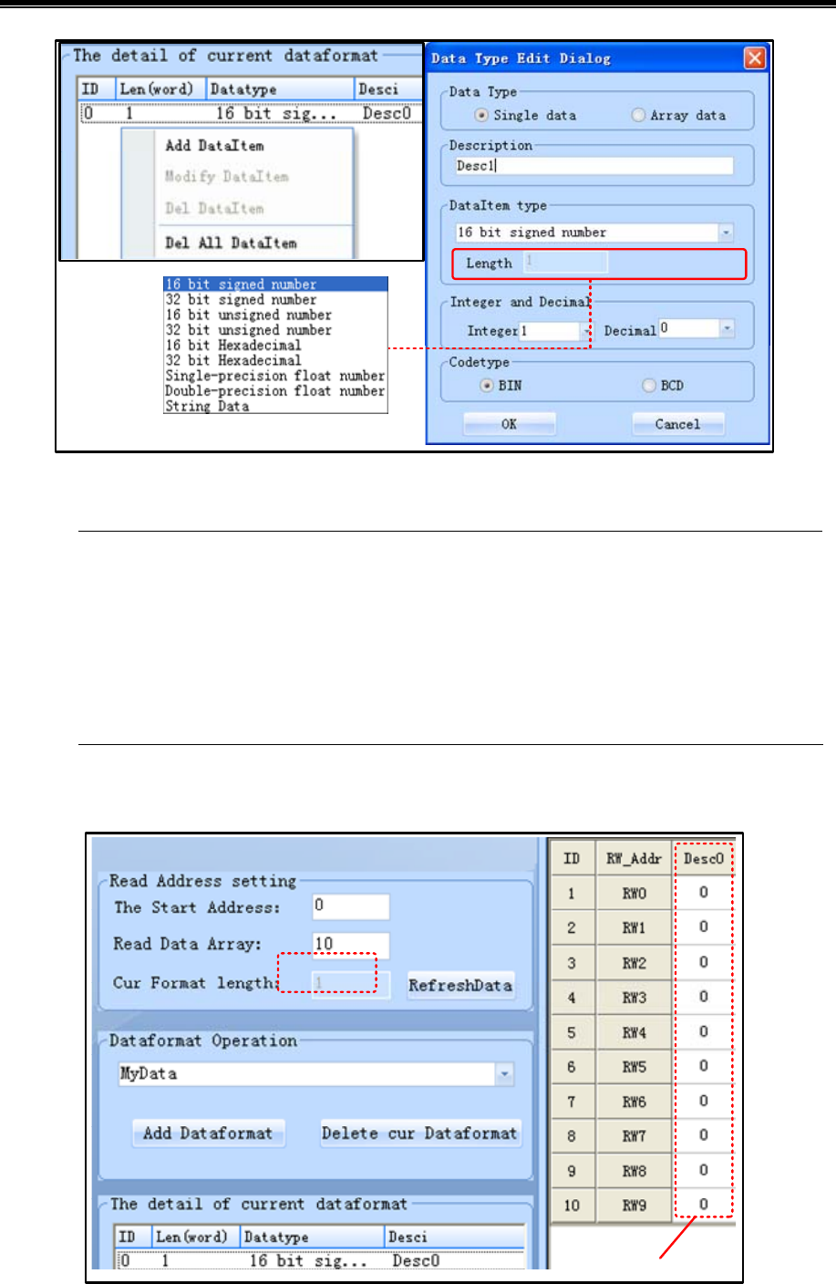
Advanced Part Recipe/RecipeEditor
389
- Data Type can be [Single data] or [Array data].
In 【The detail of current dataformats】, if each ID entry is a single data, data area address only corresponds to
one column, if each ID entry is array data, and the array length is N, then the address of the data area
corresponding N columns. If the [read address set area] is M, then the address of the data area corresponding
to M lines. The entire data area of the format is M rows × (N0 + ... + Nx) columns, where Nx represents the
x-th ID entry length of the array, if a single data, Nx = 1, if the array data, and the length of the array number
N, the Nx = N
Single data
Value of RW0~RW9
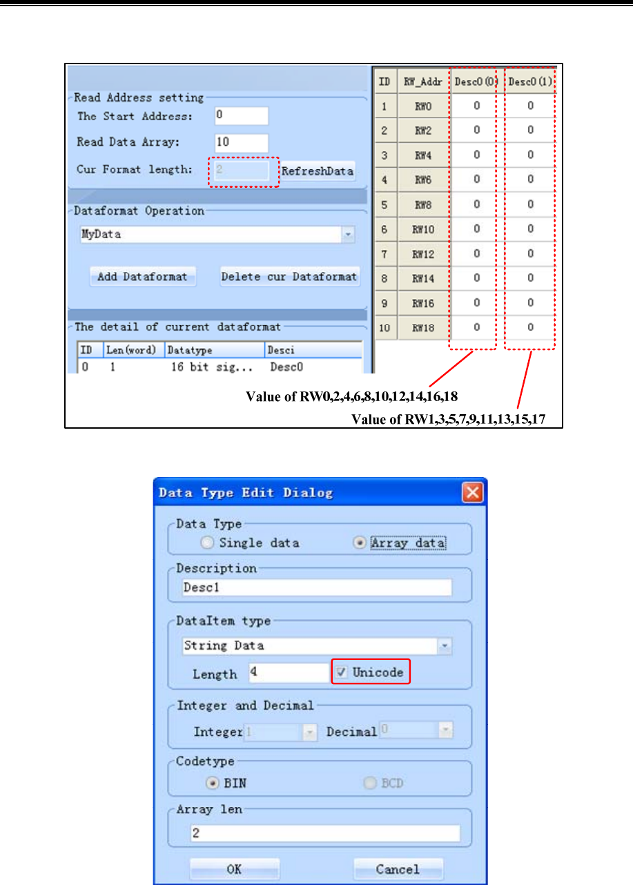
Kinco HMIware Configuration Edit Software
390
Array data
- [String Data] support Unicode code type
(4)Adjustment of Data Start Address and Data Length
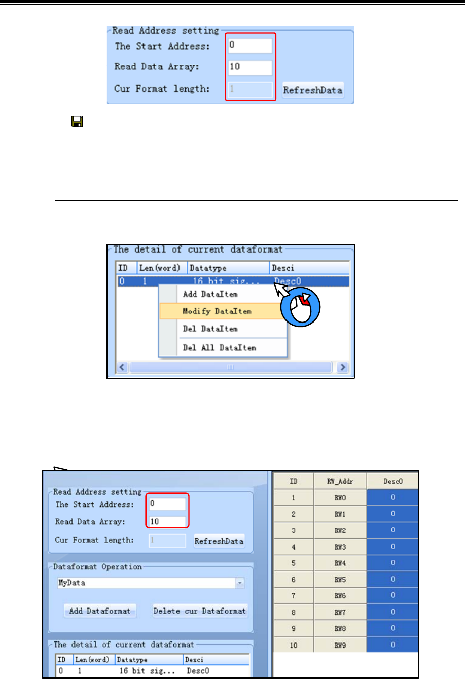
Advanced Part Recipe/RecipeEditor
391
(5)Save: Click icon, and save the current data to recipe file.
After the completion of number modify, it would be click [save], otherwise the previous data will be lost
after RefreshData button is pressed.
(6)Modify data item
(7)File Merge
HMI can only download a recipe file every time. If you download the second recipe file will overwrite the first file. If you
need to use a different recipe file, you can merge all recipe files to one file, then download the file to HMI.
- Create a 1.rcp file, default setting, and input 1~10.
- 20~29 Create a 2.rcp file, the start address: 20, and input 2~29.
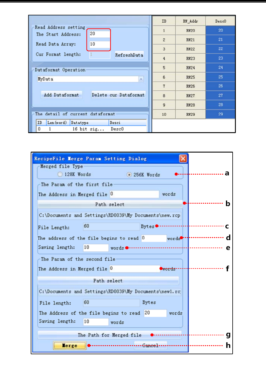
Kinco HMIware Configuration Edit Software
392
- Merge 1.rcp and 2.rcp: Click [File Merge] menu-[File Merge].
a:Select merged file type: The merged file will download to 128k words HMI or 256k words HMI.
The files size of merge depends on the file type after the merger, if it is 4000 series, then the size is 256KB, if it is 5000
series, then the size is 512KB. Note: The recipe size of MT4522T is 512KB, this time the file types after merger to choose
5000 Series.
b:Select the path: Select the file needed to merge.

Advanced Part Recipe/RecipeEditor
393
c:File Length: the size of merged file
[Example]: 1.rcp file is 20 bytes, then the file length is 20 Bytes.
d:The address of the file begins to read: the starting address of recipe file.
[Example]: The starting address of 1.rcp file is 0, so [The Param of the first file] –[The Address in Merged file] is 0 words.
The starting address of 2.rcp file is 20, so [The Param of the second file] –[The Address in Merged file]: 20 words.
e:File length: the length of recipe file.
[Example]: the data type of 1.rcp and 2.rcp are single data, so the [The Param of the first file]/ [The Param of the second
file]-[File length] is 10 words.
f:The Address of the file begins to read: The Address of the file begins to merge.
[Example]: The Starting address of the 1.rcp file is 0, so [The Param of the first file]-[ The Address of the file begins to read]
is 0 words. [File length] is 10 words, that is RW0~RW9.
The Starting address of the 2.rcp file is 20, so [The Param of the second file]-[ The Address of the file begins to read] is 20
words. [File length] is 10 words, that is RW10~RW19.
So [The Param of the first file]-[ The Address in merged file] is 0 words, [The Param of the second file]-[ The Address
merged file] is 10 words.
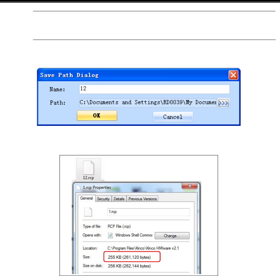
Kinco HMIware Configuration Edit Software
394
The Address merged file in the Param of the second file must be greater than the sum of the Address
merged file and the Address of the file begins to read in the Param of the first file.
g:The path for merged file: Set the name and path for the merged recipe file.
h:Merge file: Execute the [Merge file] operation.
The size of the 12.rcp merged file.
Open the 12.rcp merged file in RecipeEditor, and the data will display in [RecipeEditor] as below:
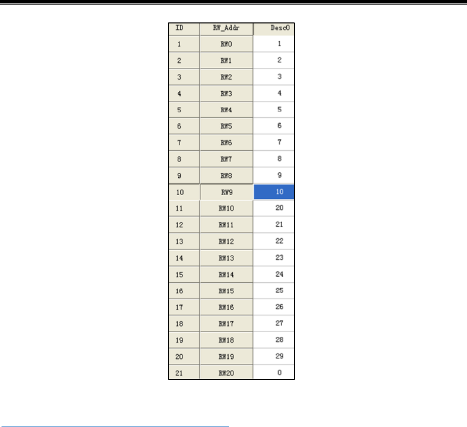
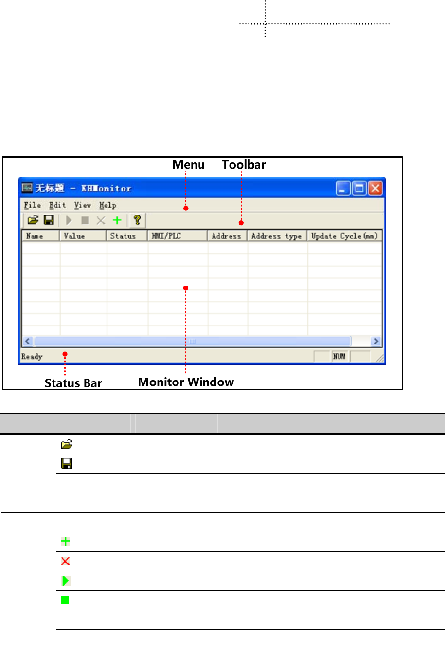
396
12 KHMonitor
12.1 Descriptions of KHMonitor
KHMonitor is used to monitor the data in HMI and PLC registers through HMI.
12.2 Start KHMonitor
-Click【Start】-【All Programs】-【Kinco】-【Kinco HMIware v2.1】-【Tools】-【KHMonitor】
-In the installation directory of Kinco HMIware,double click【KHMonitor.exe】
12.3 KHMonitor Interface
- Menu/Toolbar
Menu Toolbar Icon Toolbar Description
Open Open an exist monitor file
Save Save the monitor configuration file
Save as Save as another configuration file,its format is *.khm
File
Exit Close KHMonitor
Select All Select all the monitor items in monitor window
Add Add a monitor item
Del Delete the selected monitor item
Run Execute selected monitor register
Edit
Stop Stop the status of selected monitor register
Toolbar Open/Close Toolbar
View
Status Bar Open/Close status bar
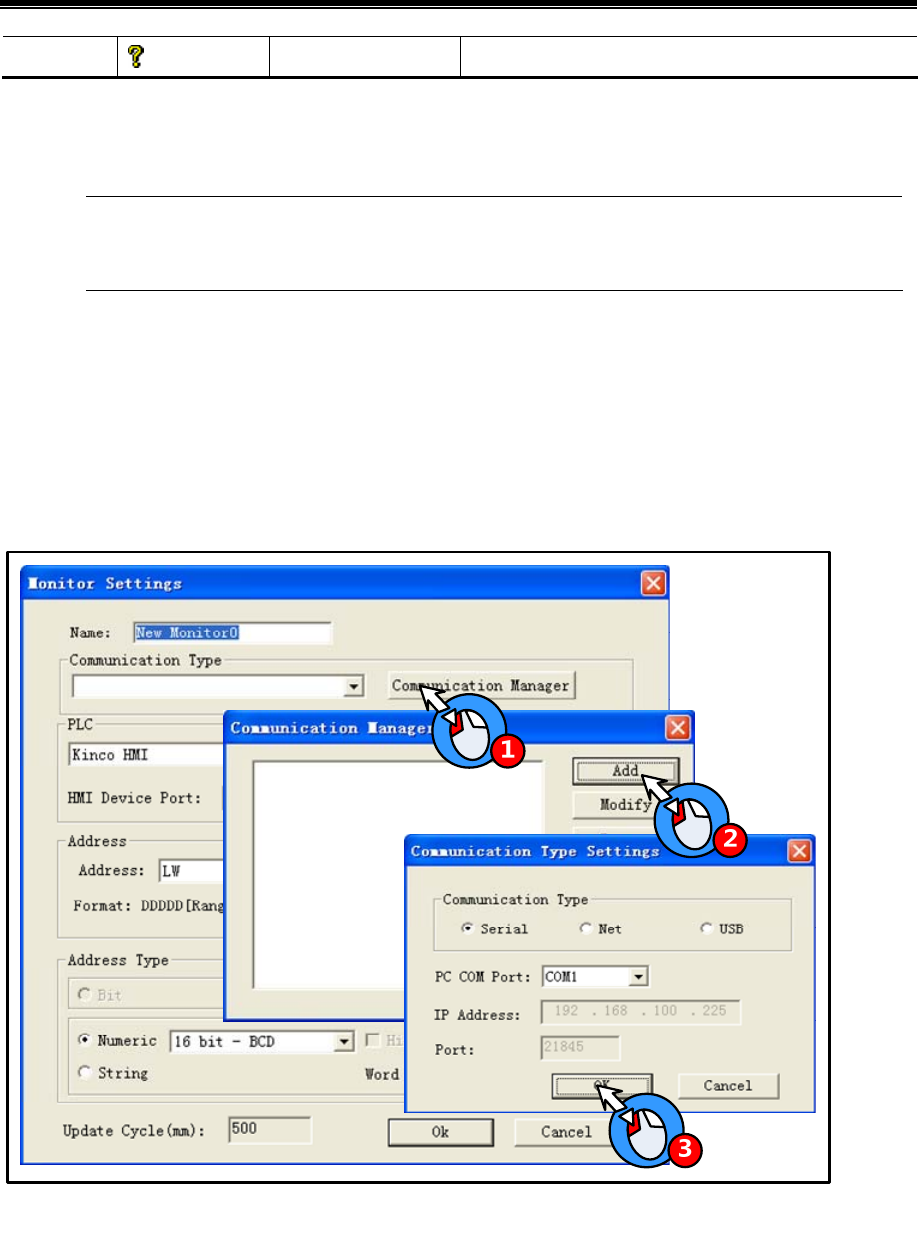
Advanced Part KHManager
397
Help About KHMonitor Version information
- Monitor Window
- Monitor Window is used to display information such as Name, Value, Status, HMI/PLC, Address, Address type,
Update Cycle (ms).
Double click the monitor item in Monitor Window to change its setting.
12.4 How to Use KHMonitor
1) Create new monitor item: When it is first time to use KHMonitor, click in toolbar to create data monitor.
2) Enter monitor name: Enter monitor name in the popup window when creating new monitor.Default name is New
Monitor0, if create another item, the No. will increase automatically.
3) Set Communication Type: Set the current connection type between HMI and PC.
-Set Communication Type as following figure:
-Communication Manager include function such as【Add】,【Modify】,【Remove】,【Remove all】,【OK】
Add: to add a new communication type between HMI and PLC.
Modify: to modify the current communication type.
Remove: to remove the selected communication type.
Remove all: to remove all the communication
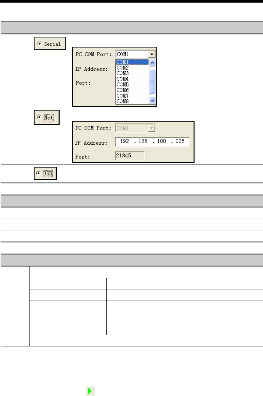
Kinco HMIware Configuration Edit Software
398
- Descriptions of Communication Type Settings.
Communication Type Parameters Setting
Serial Select current PC COM port.
Select current PC COM port.
Ethernet
Set current HMI IP.
USB
No need to set parameters.
4) PLC: to select the communication protocol between HMI and PLC.
Descriptions of【PLC】
Drop down menu for PLC Select the corresponding communication protocol between HMI and PLC.
Station PLC’s station No.
HMI Device Port Select the HMI port which is used to communicate with PLC
5) Address: to set the address which needs to be monitored
Descriptions of【Adderss】
Address Set the address of HMI/PLC which needs to be monitored
Batch Count Set the number of address which will be copied, its range is 1~1000
Address Auto Change Mode Copy by address increment/decrement.
Forward Address Auto Change Increment/decrement for the address of the register
After Address Auto Change Increment/decrement for the address of the register in accordance with
the decimal point
Batch
Note: Batch is only valid in the first time to add monitor items.
6) Address Type: to select the data type of the address, including bit, number and string. It will display the data according
to selected data type when monitoring.
7) Run/Stop monitor
【Run】:Select monitor item and click icon in toolbar to run it. Press ctrl/shift icon to select more items. The data will
display in “Value” after run the item.

Advanced Part KHManager
399
【Stop】:Select monitor item and click icon in toolbar to stop it. Press ctrl/shift to select more items.
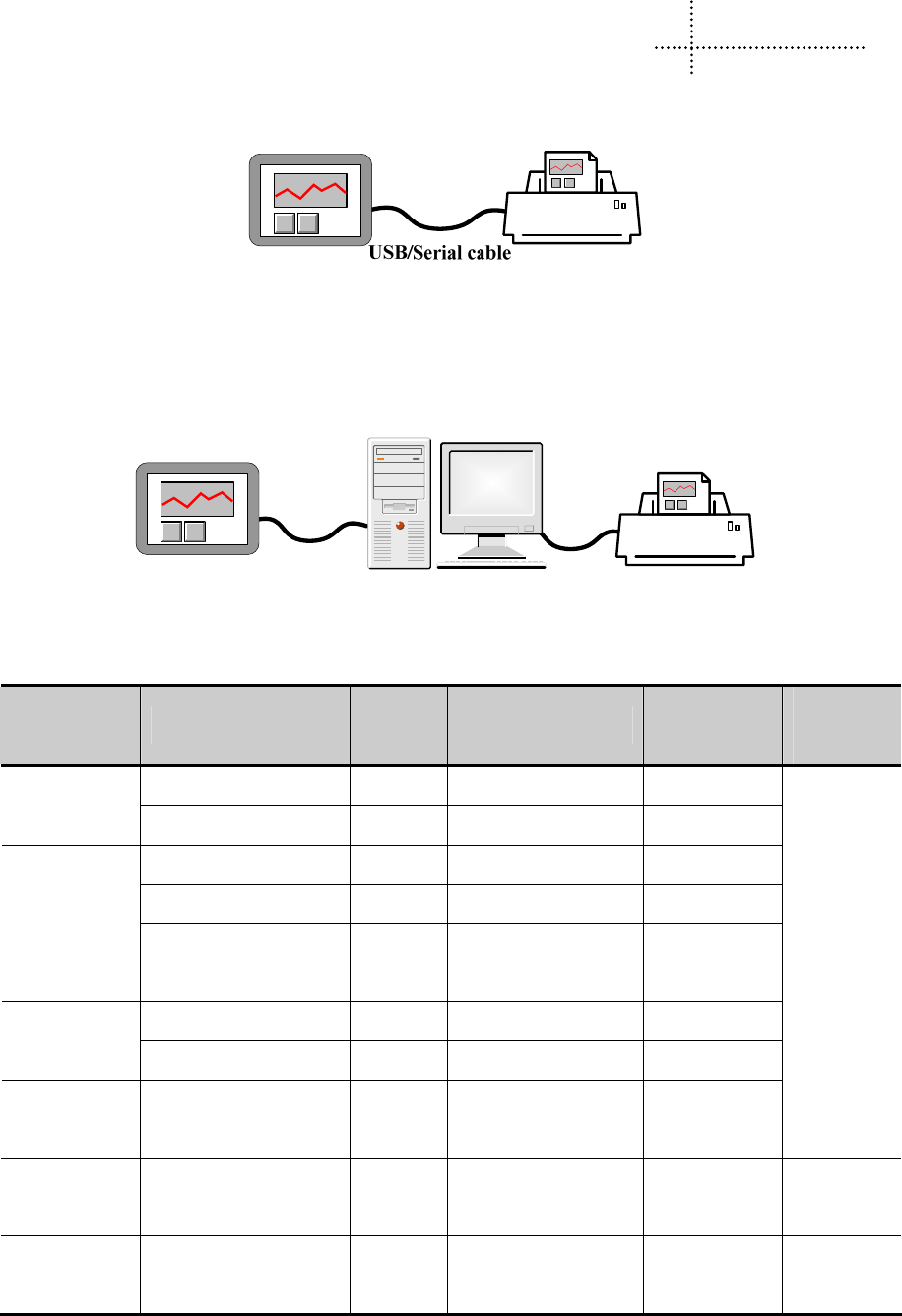
400
13 Print
Kinco HMIware support 2 type of printing method:
- Local print: Printing via serial or USB interface, HMI is connected directly to the printer to print the HMI screen.
- Network print (remote print): Through network printer to print HMI screen.
Network printing needs hardware configuration: HMI with Ethernet port and connect to the LAN, the LAN with a PC,
printer, and the printer is no direct link between the HMI, and HMI does not need any drivers.
Enthernet
Cable
13.1 Type of Printer supports local printing
Kinco HMIware supported printer models as follows:
Kinco HMIware
Printer Driver
Printer Models
Printer
Interface
Printer method Dot Matrix
Manufacturer
information
WH-A52Z20-30E125 Serial Pin micro-printing 240 pixels / line WH4008A31-0
53 WH-A52Z20-40E125 Serial Pin micro-printing 240 pixels / line
WH-A62R10-41E725 Serial Thermal micro-printing 192 pixels / line
WH-A93RG0-00E725 Serial Thermal micro-printing 192 pixels / line
WH-A62R10
WH-E173R90-00E11720
GA
Serial Thermal micro-printing 192 pixels / line
WH-A93RG0-00E825 Serial Thermal micro-printing 384 pixels / line WH-A93RG0-0
0E825 WH-T2AR10-30E82B Serial Thermal POS 384 pixels / line
WH-E191RB0-
00E1182055
WH-E191RB0-00E11820
55
Serial Thermal micro-printing 576 pixels / line
http://www.b
rightek.com.c
n
Siupo SP-M, D,
E, F
SP-E4004SK Serial Impact dot matrix 240 pixels / line
http://www.si
upo.com
MY-POS80K MY-POS80K Serial Thermal POS 240 pixels / line
http://www.
mypos.cn

Advanced Part Printer
401
13.2 Printing-related Components
In Kinco HMIware, you can use the print function of specific components as follows:
Components name
Trigger
Register
Print Content
Support
Local Print
Support Network
Print
Function Key — Print Current Screen
PLC Control(Report Printout) Word Print the specified screen
PLC Control(Screen Hard Copy) Bit Print Current Screen
Event Information Logon Word / Bit Print the contents of trigger event
Trend Curve Word / Bit Print trend curve
☞ For more details about the print-related elements settings, please refer to [Advanced Part 4 Compent]
- Report Printout
You control the specified window screen printout by changing the value of the specified word registers. When the value of
the specified register word changed, and is a valid window number, the window number corresponding window contents will
be printed. Printing is completed; the value of the specified register address automatically changes to 0.
Example:Set as shown below, when the value of LW0 is equal to 10, print the contents of the window 10. Printing is
completed,the value of LW0 automatically change to 0. When the value of LW0 is equal to 11, print the contents of the
window 11. [Report] function using output only execute print function does not perform the function of switching window,
will not switch to the print window. Using the [Report Printout] function performs only print function and will not switch to
the printed window.
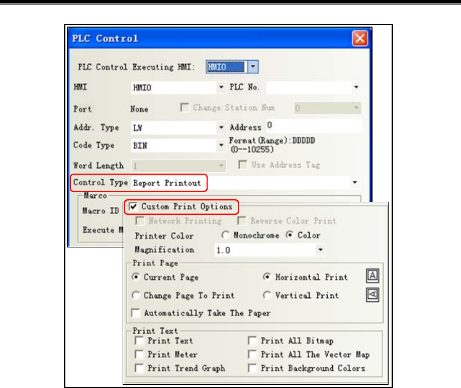
Kinco HMIware Configuration Edit Software
402
- Event Print
In the [Event Information Logon], set the print log events, when the set condition is triggered, it will print out the event
contents.
Example: Set as shown below, selecting [On Trigger] and [Return to Normal]: when LB0 is ON, print "temperature is too
high!” When LB0 returns to OFF, print "Temperature is too high!".
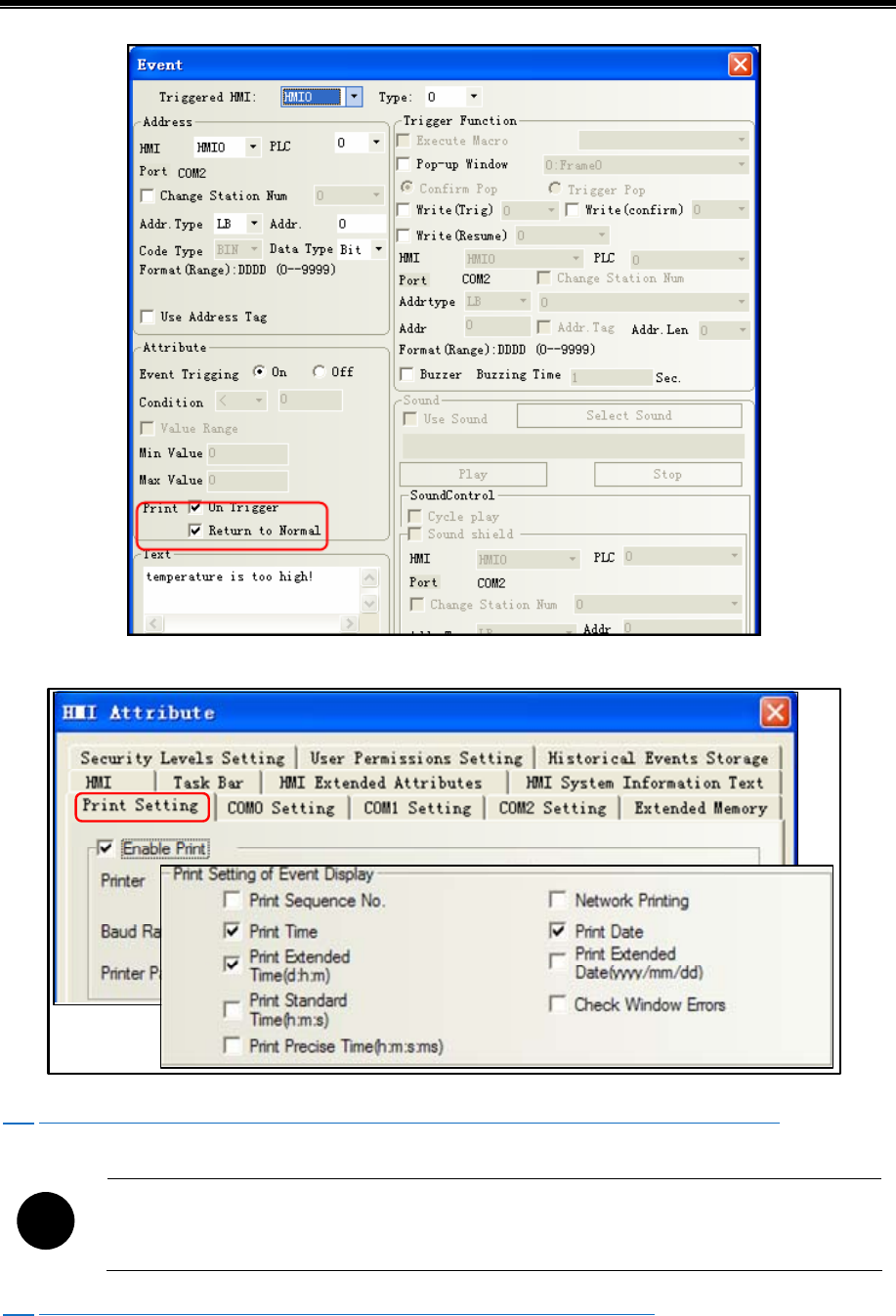
Advanced Part Printer
403
If you need to print the time, check the contents in [HMI Attribute] - [Print Settings] - [Print Settings of Event Display].
☞ For more details about Print Settings of Event Display, please refer to [Advanced part 6.1.8 Print Setting]
!
[Print] - check the [Print Relative Time], if no printer is connected, HMI will be prompted to an error
message "Print Error"
☞ For more details about [Trend Print], please refer to [Advanced Part 4.6.1 Trend Curve]
13.3 Pictbridge Print
Pictbridge is a direct connection and picture printing standard, the devices which support this protocol can be connected
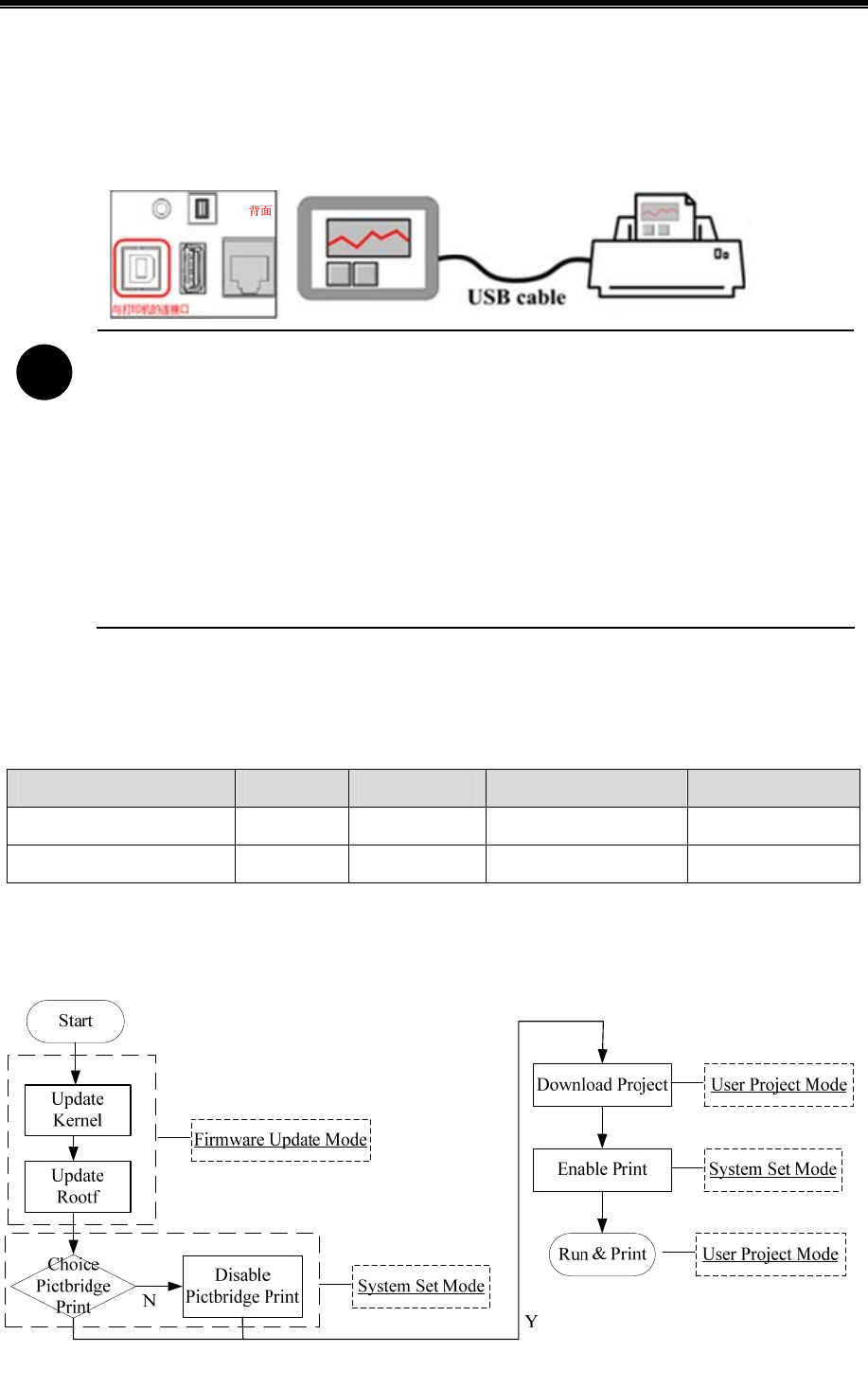
Kinco HMIware Configuration Edit Software
404
together and print pictures directly. In Kinco HMIware V2.2, customer can use Pictbridge to connect HMI directly with
printer and print the screen directly. This standard supports connecting devices to printer directly but do not need to connect
the device to PC to print, it is very convenient for different applications.
MT4000 serial HMI supports all the printers which support PictBridge protocol, user can connect HMI and this printer
with USB cable on HMI USB slave port. Then they can print HMI screen and data on this printer.
HMI
!
1. MT4210T、MT4220TE、MT4310C、MT4300C、MT4300CE、MT4403T\TE、MT4512T\TE、
MT4523T\TE、MT4404T、MT4424TE、MT4522T\TE、MT4620TE,MT4414T\TE,MT4513T\TE.
The HMI which are produced after Dec 2013 support Pictbridge printing.
2. MT4210T、MT4220TE、MT4310C、MT4300C、MT4300CE、MT4403T\TE、MT4512T\TE、
MT4523T\TE, MT4404T, MT4424TE、MT4522T\TE、MT4620TE, MT4414T\TE ,MT4513T\TE.The
HMI which are produced before Dec 2013 will support Pictbridge printing after updated the kernel
and rootfs in Kinco HMIware v2.2(build131108).
3. Kinco HMIware v2.2(build131108)or higher version supports Pictbridge printing
When user downloads program from Kinco HMIware or U disk to HMI, if there is information of “Please update
Kernel and Rootfs”, which means user needs to update the Kernel and Rootfs.
Version Information:
Kinco HMIware Version Kernel Roots Need to update or not Enable PictBridge
V2.1(build130805) 1828 1895 Yes Do not support
V2.2(build131108) 1958 1971 No Support
If customer does not need the print function in Kinco HMIware V2.2, please disable the “Enable Pint” in HMI Print
Setting and then compile the program again before downloading
Flow chart of update printing function
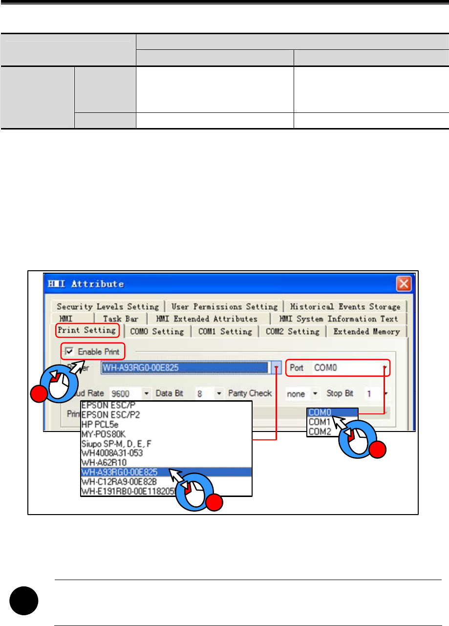
Advanced Part Printer
405
Different modes of HMI USB slave port.
Enable Print in HMI Attribute in Kinco HMIware
Setting Items Checked Unchecked
Checked
Print Mode, can print from USB
slave port, but cannot download
program.
Print Mode, but cannot print from
USB slave port, because there is no
compiled files for printing.
Enable Printer
Function in
HMI Setup
Window Unchecked Download Mode, cannot print Download Mode, cannot print
To sum up,user must check the Enable Printer Function in setup window and Enable Print in Kinco HMIware to enable the
print function in HMI.
13.4 Print Function Setting Method
13.4.1 Local Print: HMI serial is connected directly to the Printer
[Example 1] MT5320T connect to WH-A93RG0-00E825 printer, print the current screen by function key. First create a new
project.
Enable Print and select Printer driver: [HMI Attribute]-[Print Setting]-[Enable Print]
2
3
1
Select the printer driver "WH-A93RG0-00E825" from the [Printer] list.
Select the printer port connected with HMI, in this case choose "COM0".
!
Same port cannot be set to print port and communication port
[Baud rate / data bits / parity / stop bits] recommend using the default settings, and printer parameters must be consistent.
In this case [baud] / [data bits] / [Parity] / [stop bits] are the default.
You place a function key on screen0, and select [Print] - select All [Print Text]. Compile and download to HMI.
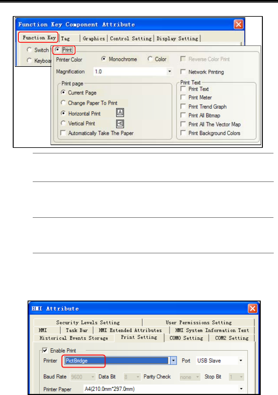
Kinco HMIware Configuration Edit Software
406
The COM0 wiring connection instructions about WH-A93RG0-00E825 printer and MT5320T, please refer
to [Communication Manual]
Through press the function key to print current screen.
Because micro-printer are monochrome printers, when editing HMI configuration project, recommended
window fill color is white, the text color is black, try not to use the color pictures, so as to avoid the
printing effect is not clear
13.4.2 Local Print: HMI USB Slave is connected directly to the Printer
Example of how to use PictBridge function:
1. Enable the “Enable Print” in Print Setting of HMI Attributes. Choose the PictBridge as the Printer.。
2. Set the small dip switches SW1 and SW2 to ON then restart, HMI will display the set up screen, check the “Enable
Printer Function” to enable the printing protocol
Enable Printer Function in set up screen:
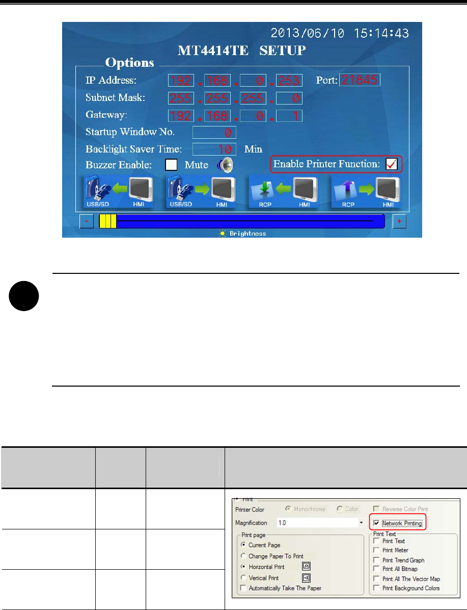
Advanced Part Printer
407
3. Set the DIP switches SW1 and SW2 to OFF then restart, HMI display the normal operation screen.
4. Use USB cable to connect HMI (USB Slave) to printer to print HMI screen and data.
!
a) The USB slave port on HMI is used to download/upload program in default setting, if chick
the “Enable Printer Function” in HMI setup screen, the USB port is configured as printing
port, It does not support program download/upload or other functions in this mode.
b) In rewrite Kernel and Rootfs mode (SW1 ON, SW2 OFF and restart), the USB slave port is
always configured as download mode, the above setting can not affect this function in this mode.
c) The printer may not work normally after HMI is repowered or restarted, please restart the
printer if this problem happens.
13.4.3 Network Print (remote print): Through Network Printer to Print HMI Screen.
Element to enable network printing setup method as follows:
Components name
Trigger
Register
Print Content
Enable Network print
Function Key —
Print Current
Screen
PLC Control(Report
Printout)
Word
Print the specified
screen
PLC Control(Screen
Hard Copy)
Bit
Print Current
Screen
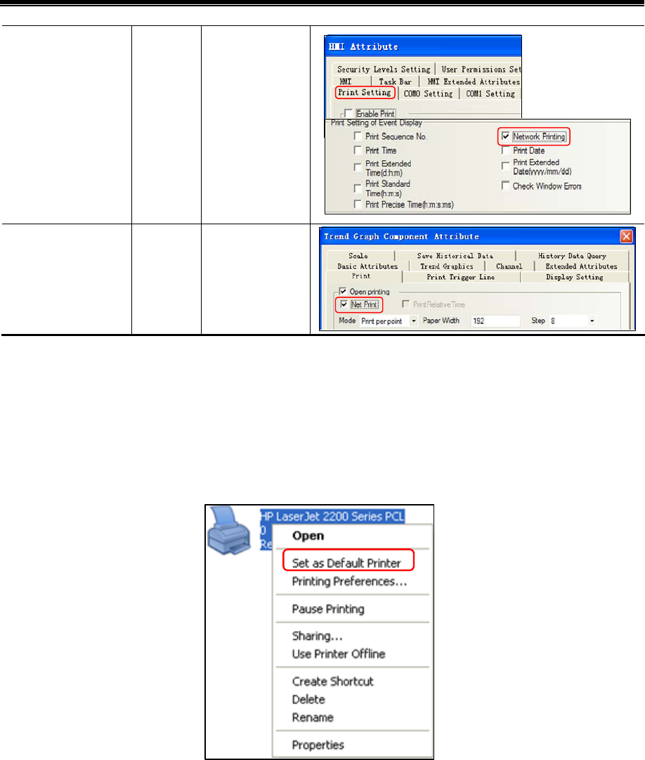
Kinco HMIware Configuration Edit Software
408
Event Information
Logon
Word/ Bit
Print the contents
of trigger event
rend Curve Word Print trend curve
[Example]: requirements through remote printer to print the HMI Screens.
Preparation before printing: a PC, a HMI with network interface, a printer can be directly connected to the PC
This example uses the HP USB printer which model is HP LaserJet P2014, HMI model is MT5320T, and use the [PLC
Control] - [Report Printout] function to print the specified screen.
Installed printer driver on the PC, then in the operating system [Control Panel] - [Printers and Faxes] to find the
appropriate printer, and through the right-click menu to set as the default printer
Run the print program on PC【NetPrint.exe】
[NetPrint.exe] program is stored in Kinco HMIware software installation directory, if the user did not change the
installation directory, the default installation path is【D:\Program Files\Kinco\Kinco HMIware】。
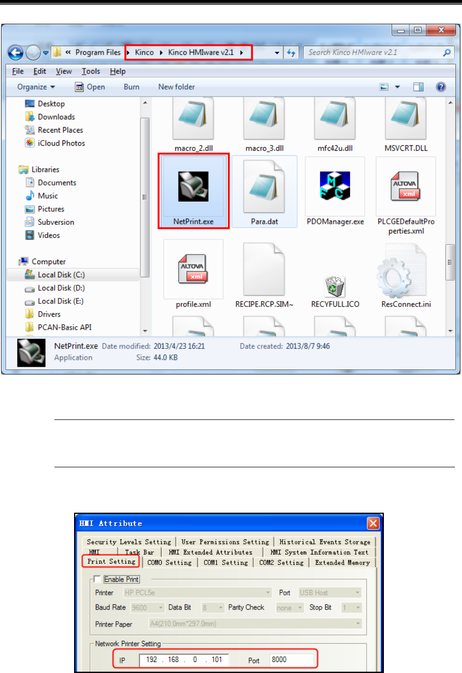
Advanced Part Printer
409
Double click to run [NetPrint.exe], if the firewall prompts [you want to keep this process?], Select [Unblock].
When printing, [NetPrint.exe] need to keep running, [NetPrint.exe] during operation will be minimized to
the tray
In the [HMI Attribute] - [Print Settings], set the PC IP address and port which run [NetPrint.exe]:
In the [HMI Attribute]-[HMI], set the HMI IP address
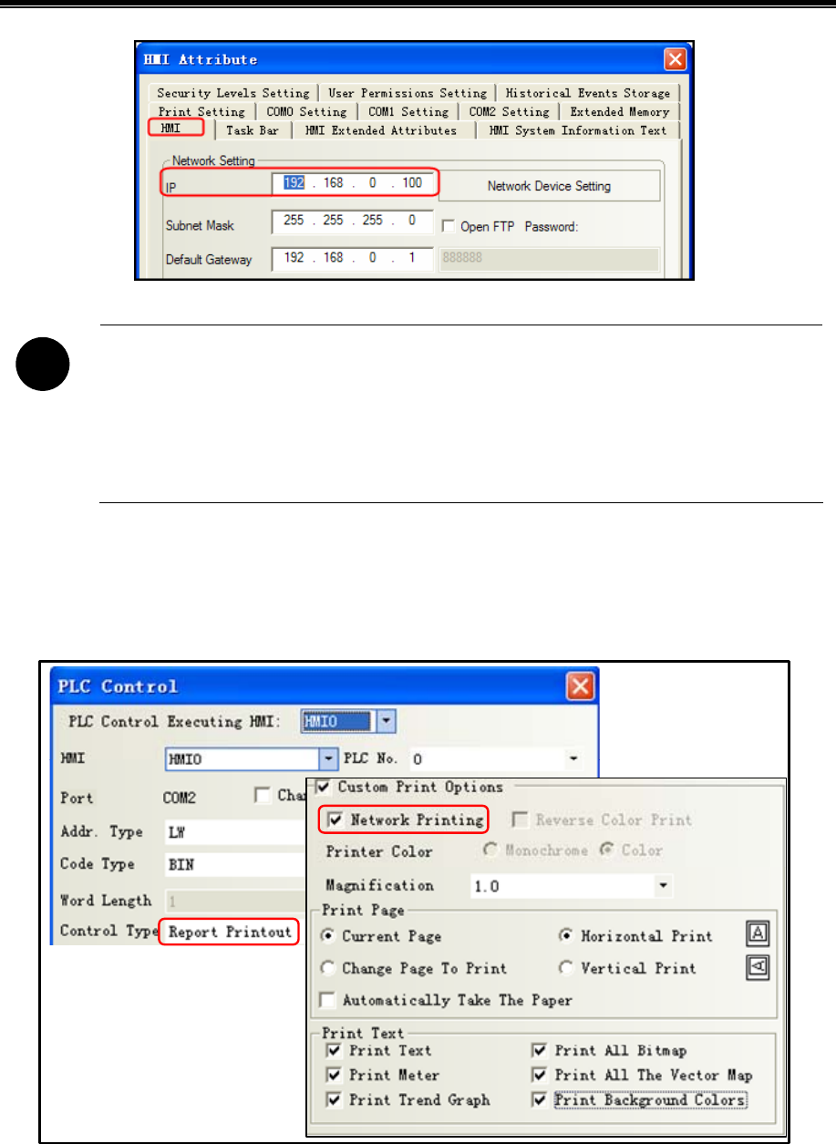
Kinco HMIware Configuration Edit Software
410
!
1. The PC which connect to the printer and the PC which run the [NetPrint.exe] program can be the same,
and it can also be any PC within the LAN
2. The PC which connect the printer, the PC which run the [NetPrint.exe] program and HMI are connected
to the same LAN, IP address must be on the same subnet, IP address must be the same in front of three, the
last one is not the same
Enable network printing
PLC Control] property in the [[control type] is set to "Report Output" to specify the address of the register LW0; then check
[custom printing options]] and [network printing and check all the options] [print content.
And then you place a "Numeric Input" component on screen 0. [Read / Write Address] is set LW0. Save and compiled, then
downloaded to HMI.
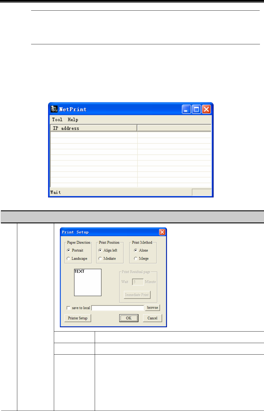
Advanced Part Printer
411
1. Use [network printing] function, you need to enable the print function in related components,while
local print only need to enable print function in [HMI attribute]-[Print setting]
2. Select the [Network Printing], printer color cannot be modified, the default is monochrome
Cable
The HMI through cross or direct network cable access network.
Setting print properties
Click [NetPrint.exe] icon to pop up the properties window. As shown:
Property described as follows:
NetPrint property descriptions
Paper Direction set portrait/landscape
Print Position set align left/mediate
Tool Print Setup
Print Method
[alone]:Printers print in real time, immediately upon receiving the print job
Print
[merge]: After receiving the print job is not printed immediately, but covered
with a total content of paper to print the print job again, this function is mainly
used to save paper
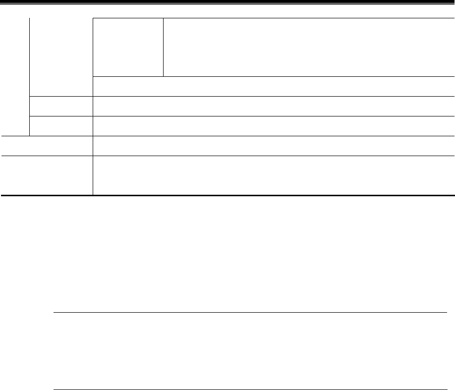
Kinco HMIware Configuration Edit Software
412
Save to local
Checked, and choose the path, upon receiving the print job, you can save the
screen pictures on your PC instead of printing. Picture format. JPG, picture
naming names is the time, yyyymmdd-hhmmss, such as 20120903-110552.jpg
Printer Setup
Print Preview View print effect
Exit Exit [NetPrint.exe]
Help About [NetPrint.exe] version information
IP address
HMI IP address。If the HMI with the PC connected to the same LAN, NetPrint will automatically
detect
Change on the value of LW0, it will print the contents of the corresponding window
13.4 Print Page Application Skills
When the HMI window larger or smaller than the actual width of print paper, you can set the current window to 【Print
Page】, by changing the HMI window width and height to achieve print paper more or less than the actual width of the HMI
window. This feature is only available for [Report printout]
1. Select [Print page], the window maximum width and height can be set to 1024 x 1024 pixels / line.
2. Once the height of the window is set to exceed the actual height of the HMI window, if the HMI runs
the window, over the part will not show up. Recommended to use [Report printout], that only need to print
this window, no view on the HMI. If you want to view, you can do a normal screen identical to the user.
[Example] HMI model: MT5320T, the width of window is 320 pixels / line.
WH-A62R10-41E725 printer support 192 pixels / line.
If MT5320T connect to WH-A62R10-41E725, the HMI is wider than the width of the paper, so the window to the right of
HMI 128 pixels printed out.
Create a new project of MT5320T
[HMI Attribute]—[Print Setting]—select[Enable Print].
[Printer]: WH-A62R10
[Port]:COM0
[Baud Rate]/ [Data Bit]/ [Parity Check]/ [Stop Bit] are default.
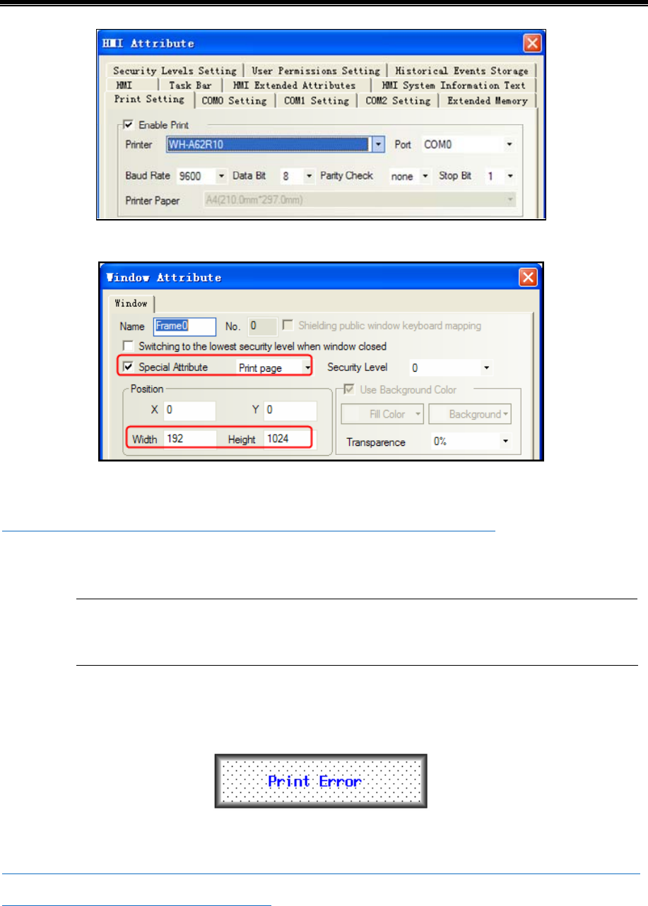
Advanced Part Printer
413
Double-click screen0,[Window Attribute]-choose [special attribute]-[print page], and set the width is 192, height is 1024.
Set control type: [Report printout]
☞ For more detail about [Report printout], please refer to [Advanced part 4.15.5 PLC Control]
Cable
For more details about the printer connection cable, refer to [communication connection Manual]
13.5 Print Error
The following dialog box will be displayed when the printer error:
When this error occurs, please check the printer power, cable, printer port, etc. are normal.
☞ For more details about shielding print error messages and modify the print error information content, please refer to
[Advanced part 6.1.4 HMI System Information Text]
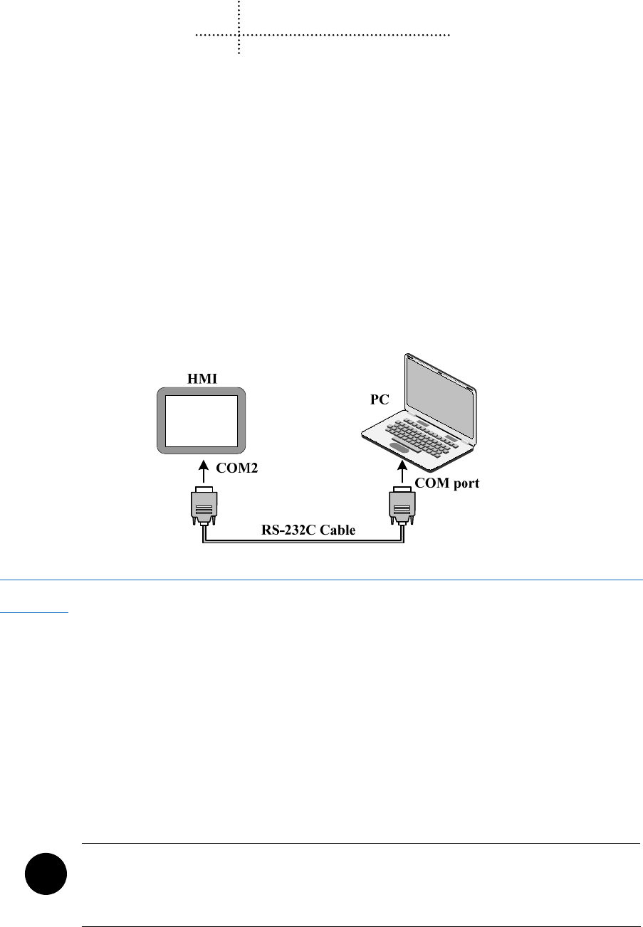
414
14 HMI Communication
This chapter introduces the HMI supports communication and various communication configurations.
14.1 Serial Communication
Serial interface that is referred to is a bit of data sent in the order. Serial communication is common in industrial control
communication, which is characterized by a communication line as simple as a pair of transmission line can be two-way
communication, thereby reducing costs, especially for long-distance communication, the communication distance can be
from a few meters to several thousand m, the transfer speed is slow.
HMI supports RS-232C, RS-485, and RS-422A three kinds of serial communication connection.
14.1.1 HMI and PC Serial Communication
HMI via RS-232C serial cable to connect the PC side serial interface for user projects, recipes and other data upload /
download and HMI firmware update.
☞For more details about uploading and downloading via the serial port on the HMI, please refer to [Advanced Part 8
KHManager]
14.1.2 HMI and PLC /Controller Serial Communication
Single HMI via the serial port with single PLC communication, but also support multiple serial communication protocol to
use the same or a different serial communication protocols PLC / controller communication.
In the same COM port, can connect multiple serial communication protocol and uses the same multi-point communication
PLC / controller can connect up to 255 devices. The serial communication protocols using different PLC / controller needs
were connected to the HMI different COM port, and can simultaneously and use three different serial communication
protocols PLC / controller communications, depending on the hardware configuration of the actual HMI decision.
!
COM0 and COM1 port supports RS485 interface mode, respectively simultaneously with multiple serial
communication protocol to use the same PLC / controller communication; The RS232 interface COM2
port supports only way, it does not support multiple PLC / controller communication
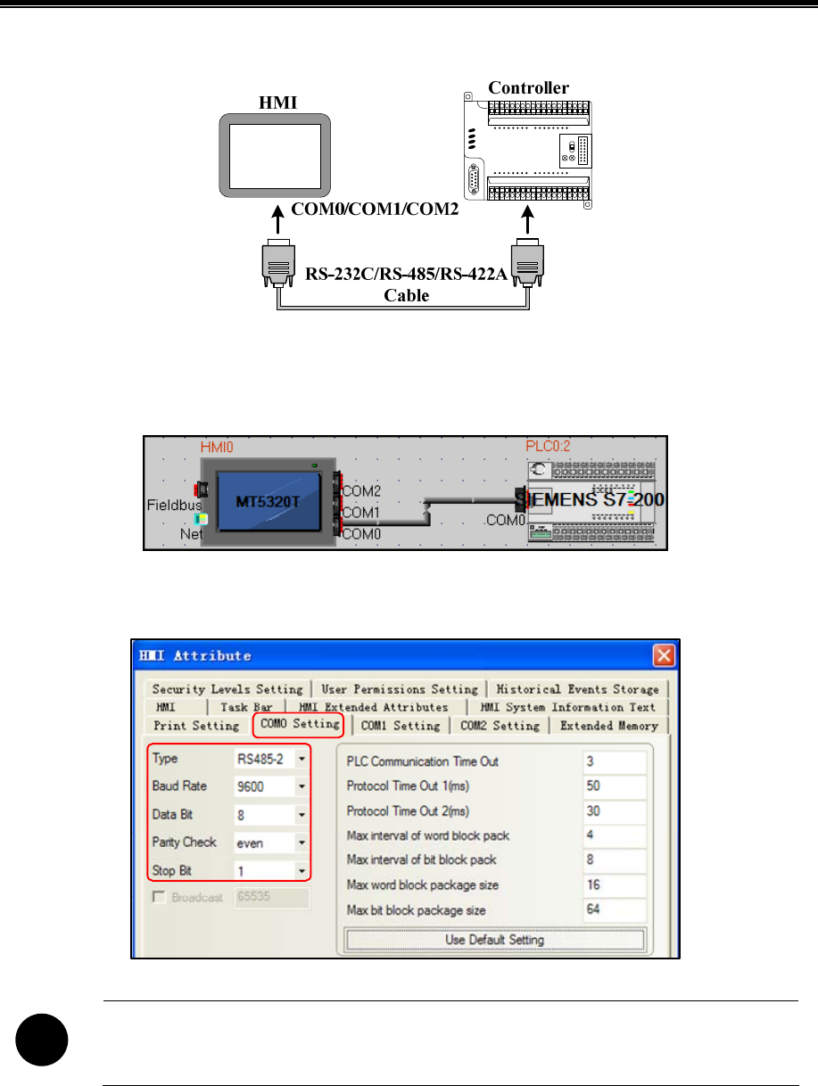
Advanced Part HMI Communication
415
- single HMI with a single PLC / controller communication
[Example] Below a MT5320T with a SIEMENS S7-200 communication, for example, requires the HMI monitor PLC M0.0
output state. (This example uses the HMI COM0 port to connect PLC communication)
Configure the device in the topology window and set the communication parameters
Configuring HMI COM0 client communications parameters: [HMI Attribute]-[COM0 Setting] set the serial communication
parameters
!
HMI serial communication parameters with the actual PLC communication port parameters consistent
Configure the PLC station number: [PLC Attribute] – [station NO.] setting 2
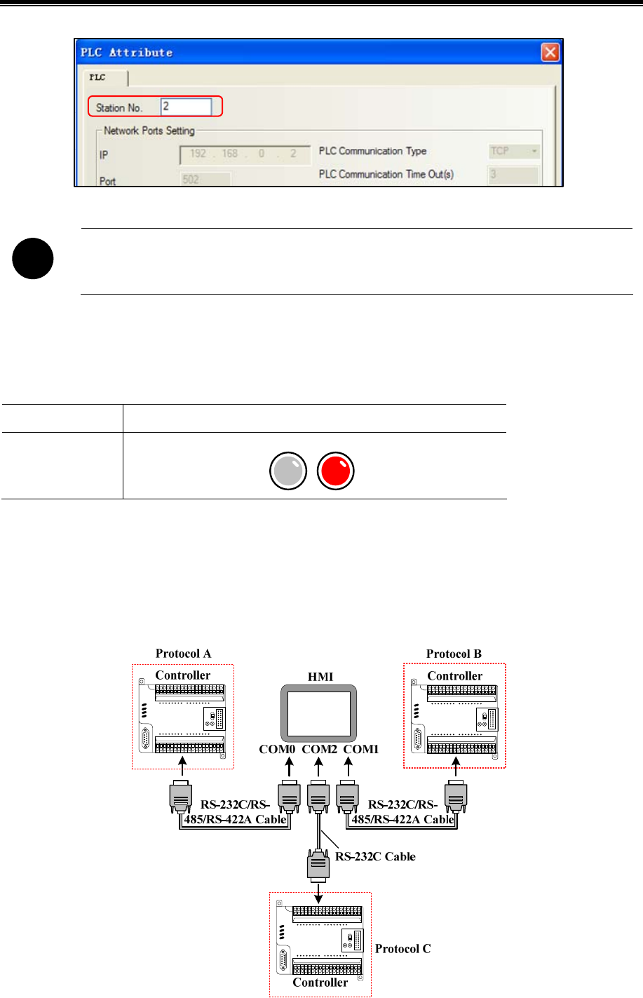
Kinco HMIware Configuration Edit Software
416
!
[PLC Attribute] – [station NO.] consistent with the actual PLC station number
Edit the configuration screen
Double-click the HMI in the topology window icon to open the Configuration Editor window, From the[ Graph Element
window] - [PLC Parts], select "Bit State Lamp" component added to the Configuration Editor window, and set the
component Attribute are:
Read Address M.B 0.0(PLC Register)
Graph
Using vector graphics,
State0 State1
After setting, save the project, compile and download.
Using RS-485 communication cable for connecting the HMI and the PLC,After successful communication can be
established on the HMI monitor the state of M0.0
- single HMI with multiple PLC / controller communication
Single HMI with multiple PLC / controller (different communication protocols) communication
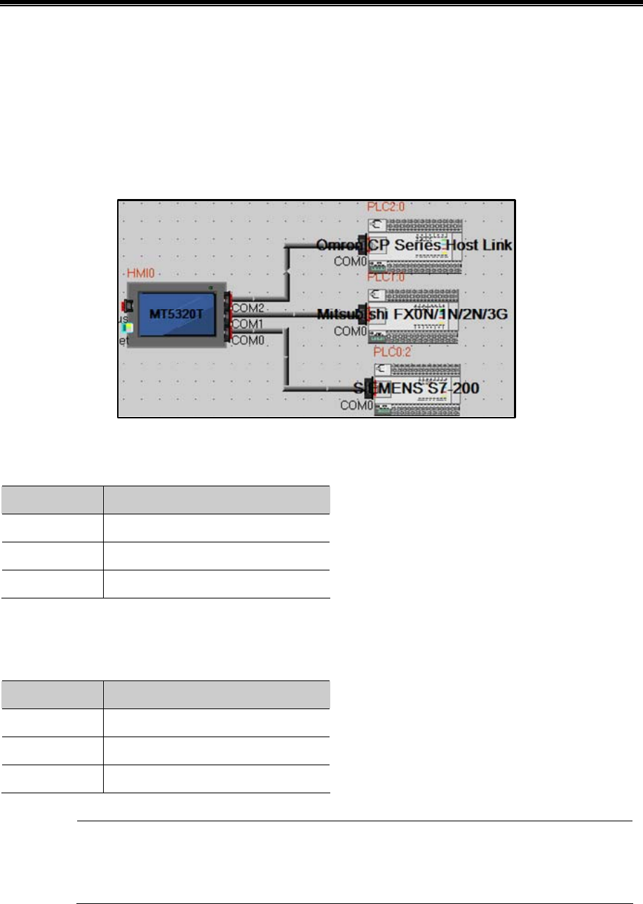
Advanced Part HMI Communication
417
[Example] Below a MT5320T with a SIEMENS S7-200 (hereinafter referred to as PLC 0), a MITSUBISHI FX2N
(hereinafter referred to as PLC 1), a OMRON CP1H (hereinafter referred to as PLC 2) communication, for example,
Requirements were monitored on the HMI PLC 0 of VW 100, PLC 1 of D100 data and PLC 2 in Q 0.0 outputs.
(This example uses the HMI COM0 port to connect PLC 0, COM1 connected PLC 1, COM2 communication connection
PLC 2)
Configure the device in the topology window and set the communication parameters
In the [HMI Attribute] - [COM0/COM1/COM2 Setting] According to the serial communications port of the connected PLC
actual parameters were set to HMI serial communication parameters, Parameters are set as follows:
HMI serial Serial communication parameters
COM0 RS485-2,9600,8,Even parity,1
COM1 RS485-4,9600,7,Even parity,1
COM2 RS232,9600,7,Even parity,2
In the PLC 0, PLC 1, and PLC 2 [PLC Attribute], in accordance with the actual [PLC station number] to each station number
setting:
PLC Number Station number
PLC 0 2
PLC 1 0
PLC 2 0
Connected to the serial port on a different HMI PLC / controller can be set to the same or a different
station number, setting the station number to be connected with the actual PLC / controller station number
the same.
Edit the configuration screen
Double-click the HMI in the topology window icon to open the Configuration Editor window, Respectively, from the [Graph
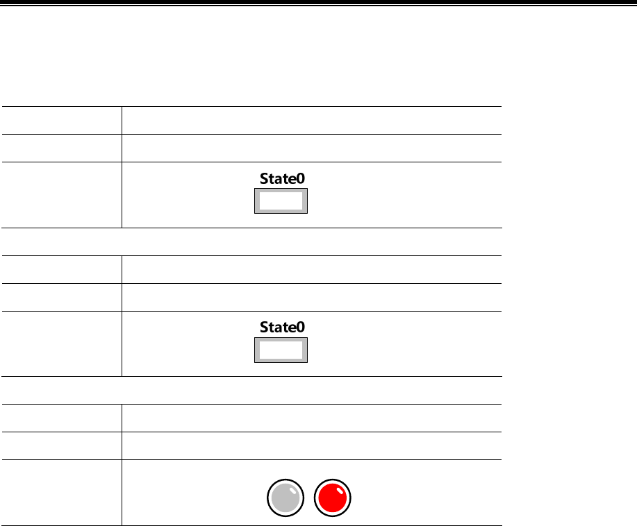
Kinco HMIware Configuration Edit Software
418
Element window] - [PLC Parts] select two "Number Display" and a "Bit State Lamp" component added to the Configuration
Editor window, Component Attribute are set to:
Number display element _1
PLC Number* 0
Read Address VW 100(PLC Register)
Graph
Using vector graphics,
Number display element _2
PLC Number* 1
Read Address D 100(PLC Register)
Graph
Using vector graphics,
Bit State Lamp
PLC Number * 2
Read Address CIO _bit 100.00(PLC Register)
Graph
Using vector graphics,
State0 State1
※A multi-machine HMI by changing the components Attribute required of the [PLC number] to distinguish PLC control
object.
After setting, save the project, compile and download.
Use the appropriate communication cable are connected HMI and PLC 0, PLC 1, PLC 2, after the success of
communication is established on the HMI monitor VW 100, D100 data as well as the state of Q 0.0
Single HMI with multiple PLC / controller (the same communication protocol) communication
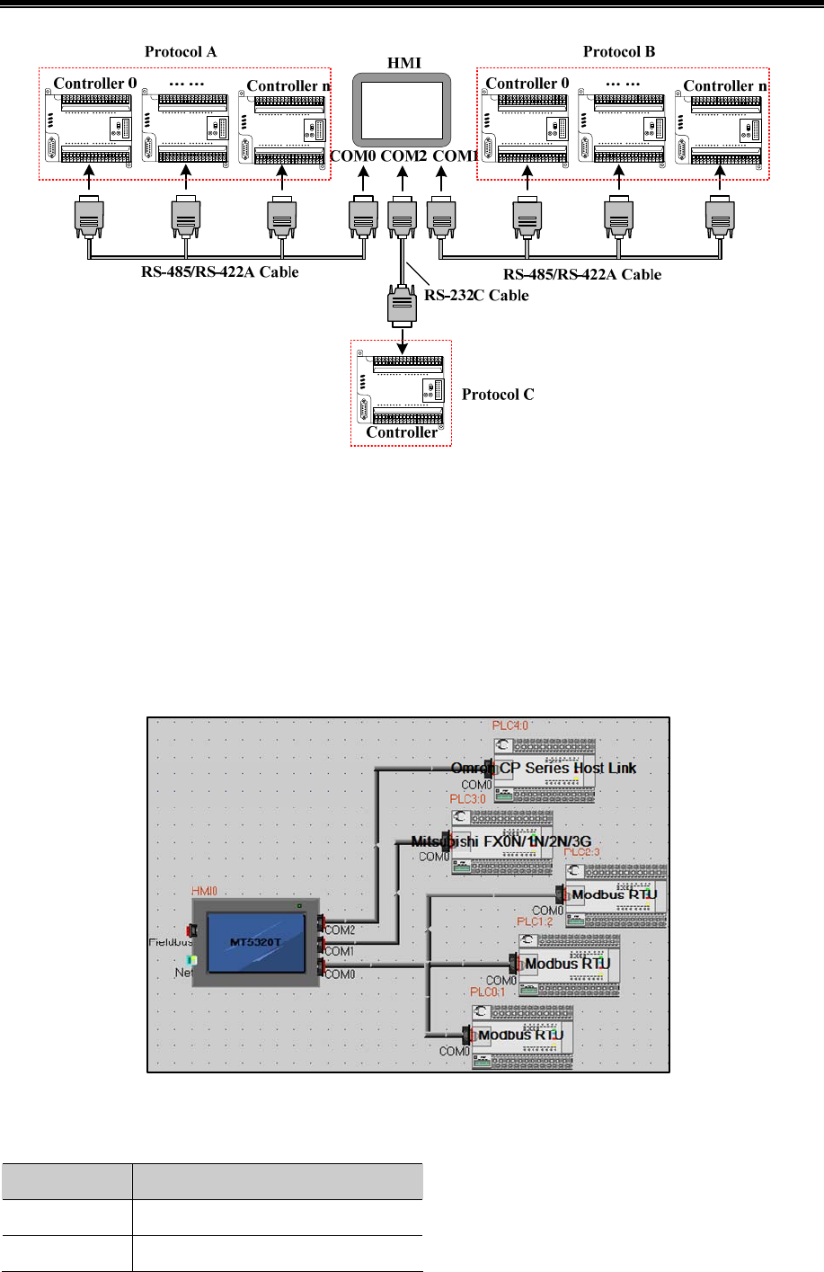
Advanced Part HMI Communication
419
[Example] Below a MT5320T with three MODBUS device (hereinafter referred to as PLC 0, PLC 1, PLC 2), a
MITSUBISHI FX2N (hereinafter referred to as PLC 3), a OMRON CP1H (hereinafter referred to as PLC 4) communication
is cases, Requirements were monitored on the HMI PLC 0, PLC 1, PLC 2 of 4X 100, PLC 3 of D100 data and PLC 4 of Q
0.0 outputs.
(This example uses the HMI COM0 port to connect PLC 0, PLC 1, PLC 2, COM1 connected PLC 3, COM2
communication connection PLC 4)
Configure the device in the topology window and set the communication parameters
In the [HMI Attribute] - [Serial 0/1/2 setup] According to the serial communications port of the connected PLC actual
parameters were set to HMI serial communication parameters, the parameters are set as follows:
HMI Serial ports Serial communication parameters
COM0 RS485-2,9600,8,Even parity,1
COM1 RS485-4,9600,7,Even parity,1
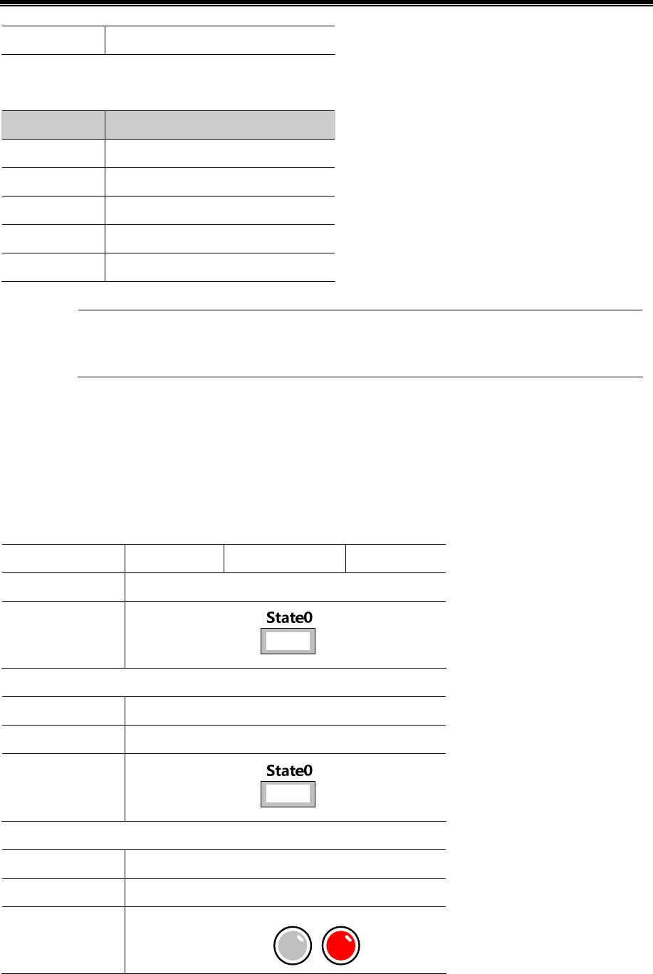
Kinco HMIware Configuration Edit Software
420
COM2 RS232,9600,7,Even parity,2
In the PLC 0, PLC 1, PLC 2 [PLC Attribute] , in accordance with the actual [PLC station number] to each station number
setting :
PLC Number Station number
PLC 0 1
PLC 1 2
PLC 2 3
PLC 3 0
PLC 4 0
Connected to a serial port on the HMI with PLC / controller must be set to a different station number and
station number set to be connected with the actual PLC / controller station number consistent
Edit the configuration screen
Double-click the HMI in the topology window icon to open the Configuration Editor window, respectively, from the [Graph
Element window] - [PLC Parts] selected four "Number Display" and a "bit status indicator" component added to the
Configuration Editor window, element attributes are set as follows:
Number display element _1/2/3
PLC Number* 0 1 2
Read Address 4X 100(PLC Register)
Graph
Using vector graphics,
Number display element _4
PLC Number* 4
Read Address D 100(PLC Register)
Graph
Using vector graphics,
Bit Lamp
PLC Number* 5
Read Address CIO_bit 100.00(PLC Register)
Graph
Using vector graphics,
State0 State1
※A multi-machine screen by changing the components required Attribute of the [number] to distinguish PLC control object.

Advanced Part HMI Communication
421
After setting, save the project, compile and download.
Use the appropriate communication cable are connected HMI and PLC 0, PLC 1, PLC 2, PLC 3, PLC 4, after the
success of communication is established on the HMI monitor VW 100, D100 data and Q 0.0 state.
14.1.3 Serial Communication Related Settings
(1)Kinco HMIware allowed through "Exchange serial 0 and serial 1 " option will COM0 and COM1 serial port
communication parameters and settings in these two serial ports to connect devices on the exchange.
☞ For details about serial to exchange, refer to [Advanced Part 2.9 Exchange Serial]
(2)Users in making redundant communication, it can provide a system through Kinco HMIware special register to mask
the corresponding fault site communications.
☞ For details about the Station No. Shield, refer to [Advanced Part 15 Register]
(3)When the HMI and PLC / controller serial communication failure occurs, the system will automatically prompt the
corresponding fault error message. Fault error message contains information about the PLC station number in hexadecimal
data display.
Meanwhile, the user can customize the system to provide fault error message content or special registers through the system
to mask the corresponding fault error message.
☞ For details about the System Information screen, refer to [Advanced Part 15 Register]
☞ For details about the system customization, refer to [Advanced Part 6.1.4 HMI System Information Text]
14.2 Network Port Communication
Ethernet has a high transmission speed, low power, easy to install and good compatibility and other advantages, it is widely
used in industrial automation control system.
HMI via Ethernet communication mainly in the following two ways:
One is through the ends of the Straight through Cable RJ45 connector or Crossover Cable, via a hub or switch
communications;
Another is through the RJ45 connectors at both ends of the Crossover Cable, not through a hub or switch communications,
this approach only applies to one pair of a communication.
14.2.1 HMI and PC Network Port Communication
HMI via RJ45 connectors at both ends of the Crossover Cable and PC-side network interface connector for user projects,
recipes and other data upload / download and HMI firmware update.
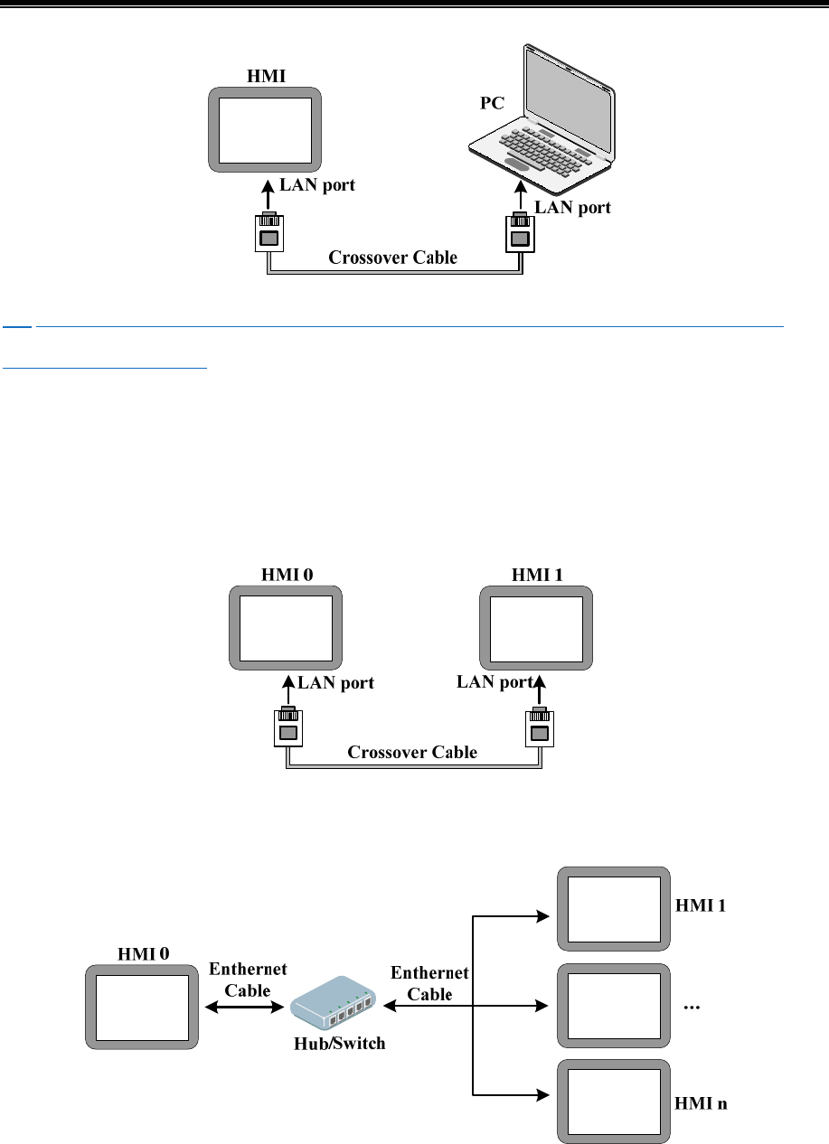
Kinco HMIware Configuration Edit Software
422
☞ For more details about HMI via Ethernet port on uploading and downloading, refer to [Advanced part 7 Compile /
Simulate / Download / Upload]
14.2.2 HMI and HMI Port Communication Network
HMI and HMI port communication network are the following two ways:
- Single HMI and single HMI communication
Single HMI and single HMI via a network port communication, through both ends of the cross UTP RJ45 connector is
connected directly communicate.
- Multiple (two or more) HMI group network communication
Multiple HMI via the network port communication, need to communicate through the Hub or Switch connection.
[Example] Below two MT5320T communication, for example, requires HMI0 screen control HMI1 of LB100 status output
to ON.
Configure the device in the topology window and set the communication parameters
In the [HMI Attribute] - [HMI] - [Network Configuration Settings], click [Add] Configuring the HMI network port
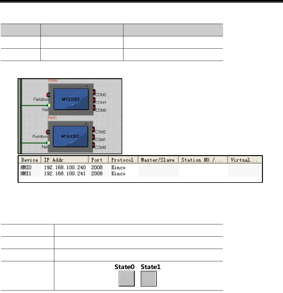
Advanced Part HMI Communication
423
communication parameters:
HMI Number Communication protocol IP Address
HMI0 Kinco 192.168.100.240
HMI1 Kinco 192.168.100.241
Once configured, the topology diagram and bus configurations are listed below:
Edit the configuration screen
In the topology window, double HMI0 icon to open HMI0 Configuration Editor window, from the [Graph Element window]
- [PLC Parts], select “ Bit State Setting” added to the Configuration Editor window, the component property is set to:
HMI* 1
Write Address LB 100(HMI Local register)
Switch Type toggle
Graphics
Using vector graphics,
※In Multi-screen network, elements required by changing the properties of the [number] to distinguish between the touch
screen control object.
After setting, save the project, compile and download
Use a crossover cable to connect HMI0 and HMI1, after the communication is established successfully, you can touch
on the HMI0 Bit State Setting Part, Can be HMI1 LB100 state turns ON.
14.2.3 HMI and PLC/Controller Network Port Communication
HMI and PLC communications network ports are the following ways:
- Single HMI and single PLC communication network port
Single HMI and single PLC communication via Ethernet port,through the ends of the cross UTP RJ45 connector is
connected directly communicate.
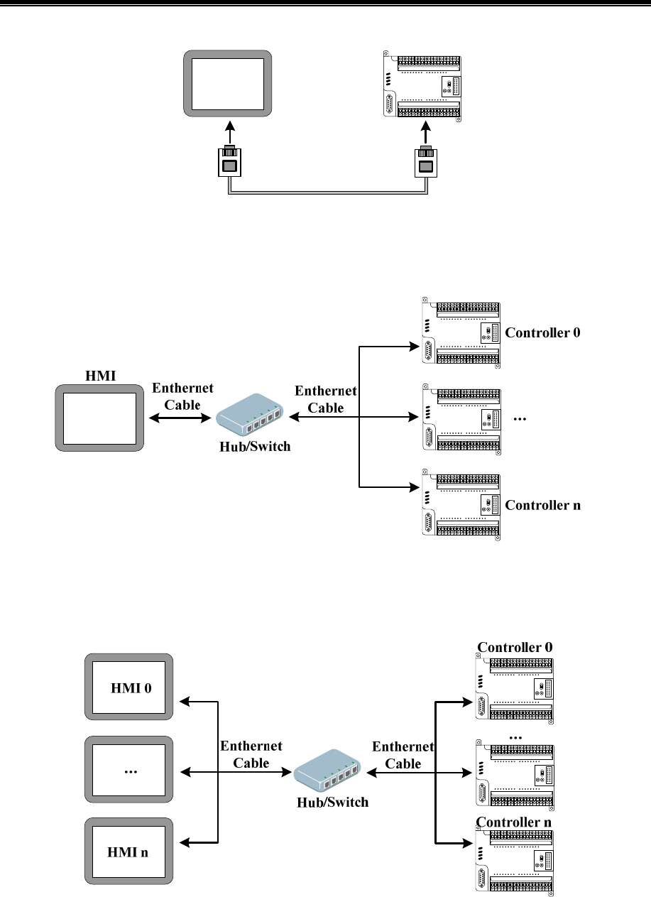
Kinco HMIware Configuration Edit Software
424
LAN port
HMI
LAN port
Controller
Crossover Cable
- Single HMI and multiple PLC network port communication
Single HMI and multiple PLC communication via Ethernet port, need to communicate through the Hub or Switch
connection.
- Multiple HMI and multiple PLC communication network port
- Multiple HMI and multiple PLC communication via Ethernet port need to communicate through the Hub or Switch
connection.
[Examples] Below two MT5320T (hereinafter referred HMI0 and HMI1) and one MODBUS TCP device (hereinafter
referred to PLC0), and one OMRON CJ series PLC (hereinafter referred to PLC1) communications as an example. Require
to monitor the data of PLC0 4x100 in the HMI0, and to monitor the data of PLC1 D100 in HMI1.
Configure the device in the topology window and set the communication parameters
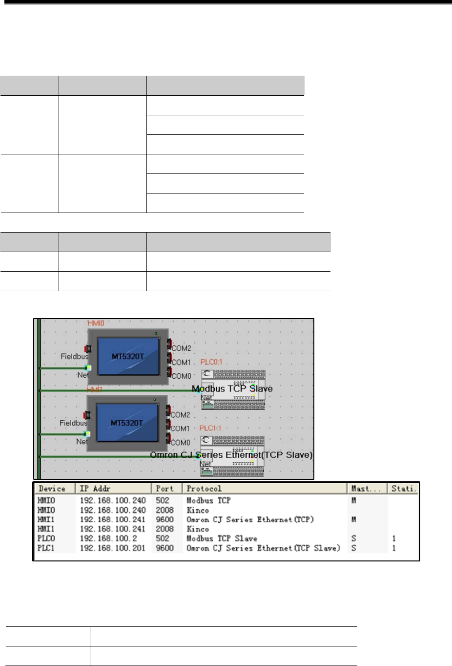
Advanced Part HMI Communication
425
In【HMI Attribute】—【HMI】—【Network Device Settings】,Click【Add】configuring the HMI network port communication
parameters。
Setting HMI:
HMI NO. IP Address Communication protocol
Kinco
Modbus TCP
HMI0 192.168.100.240
Omron CJ Series Ethernet(TCP)
Kinco
Modbus TCP
HMI1 192.168.100.241
Omron CJ Series Ethernet(TCP)
Setting PLC:The IP address set here with the actual IP address of the PLC consistent
PLC NO. IP Address Communication protocol
PLC0 192.168.100.2 Modbus TCP Slave
PLC1 192.168.100.201 Omron CJ Series Ethernet(TCP Slave)
After configuration, the topology diagram and field bus setting are listed below:
Edit the configuration screen
In the topology window, double HMI0 icon,opens HMI0 configuration Editor window,from【Graph element window】—
【PLC Parts】choose “Number Display” element add to Configuration Editor window,Element attribute is set to:
HMI* 1
Read Address 4x 100(PLC Register)
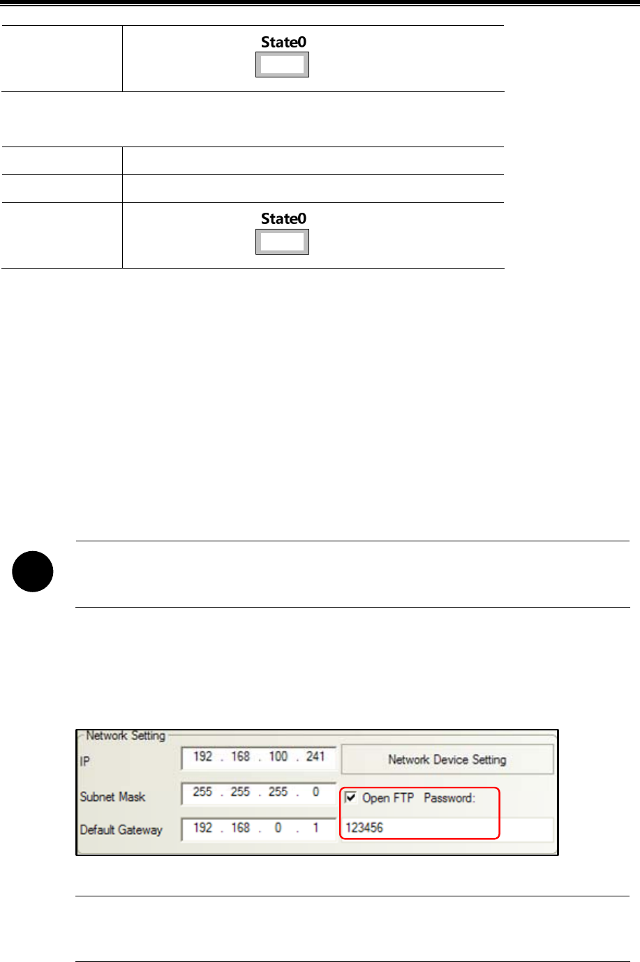
Kinco HMIware Configuration Edit Software
426
Graphics
Using vector graphics,
Then opens the Configuration Editor window of HMI1,from【Graph element window】—【PLC Parts】choose “Number
Display” element add to Configuration Editor window, Element attribute is set to:
HMI* 0
Read Address D 100(PLC Register)
Graphics
Using vector graphics,
※Multi-screen network elements required by changing the properties of the [number] to distinguish between the touch
screen control object.
After setting, save the project, compile and download.
Using crossover or straight-through cable through the Hub or Switch are connected HMI0, HMI1, PLC0, PLC1, after
successful communication can be established to monitor the PLC0's 4x100 data in HMI0 and to monitor the PLC1 D100 data
in HMI1
14.2.4 FTP Function
Kinco HMIware open the FTP functions,can transport files of external storage device to the PC via the LAN, or transport
files of PC to external storage device.
!
FTP function is only available with USB HOST or SD card interface and an HMI with Ethernet port.
【Examples】Through the LAN to access MT5320T U disk file, HMI's IP address is 192.168.100.241.
In【HMI Attributes】—【HMI】open the property page FTP function。
Select【open FTP】,setting password:123456。
1. FTP default password is 888888.
2. FTP password are not supported characters, cannot be empty, only digits.
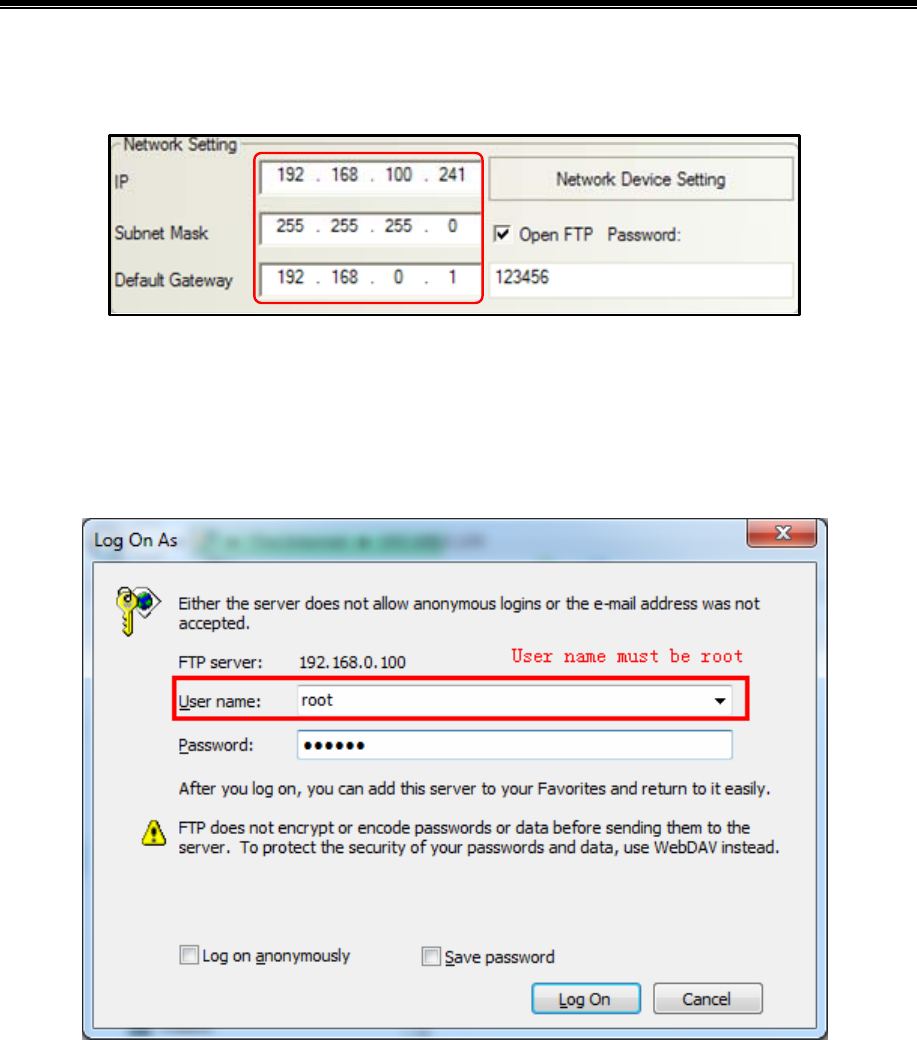
Advanced Part HMI Communication
427
In【HMI Attributes】—【HMI】configure the HMI network parameters. Set the IP address of the current HMI:
192.168.100.241,,Not to modify the subnet mask and default gateway。
Save, compile, then downloading the project.
Use cross or straight-through cable via Hub or Switch to access the HMI LAN. Open the IE browser or Explorer, in the
address bar, enter the IP address of the HMI: ftp://192.168.100.241, Enter the system will automatically pop-up dialog
[Login identity], Enter the user name: root, Password: 123456, you can log into the FTP server.
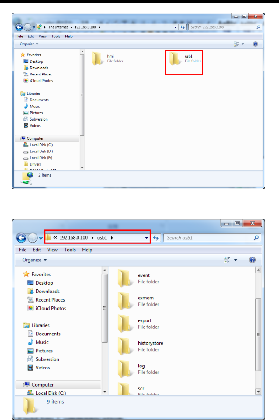
Kinco HMIware Configuration Edit Software
428
Open usb1 folder, internal documents can browse. But also can be copy their files to a PC or copy files from the PC to
the U disk.

Advanced Part HMI Communication
429
14.3 Field Bus Communication
Fieldbus is a kind used in the production site, between devices in the field, between field devices and control devices
implement two-way, string-shaped, multi-node digital communication technology. Kinco HMIware Supports field bus
communication with CAN and Profibus-DP.
14.3.1 CAN Communicate
Kinco HMIware provided CANOpen Node Slave HMI communication protocol can be realized as a slave device with
CANOpen communication between the master devices.
[Examples] Take one MT5320T-CAN screen and one CAN communications equipment for example.
In Kinco HMIware topology window to configure the device and set the communication parameters
Double-click the HMI icon in the topology window,in【HMI Attribute】—【HMI】—【Field bus setting】,Click【Add】
configuring the HMI communication parameters.
Setting【Protocol】for"CANOpen Node Slave";The remaining parameter settings and the connected CAN device
communication parameters are consistent.
After configuration, the topology diagram and bus configurations are listed below:
Edit the configuration screen
Place the “number input/display” in configuration screen, Address Range LW8000~8031. Save and compile and download
the project.
Configuration of the CAN device

Kinco HMIware Configuration Edit Software
430
For more information on the CAN device configuration, see [Communication connection
instructions]CanOpen Node Slave(CANOpenSlave protocol) related content
Communications configuration and communication cables are set up, after successfully established communication, HMI
can read and write operations on the CAN devices.
14.3.2 DP Communicate
The DP of PROFIBUS-DP is Decentralized Periphery,is a field bus. It has the characteristics of high-speed low-cost,Used
for device-level control systems and distributed I / O communications.
In Kinco HMIware ,HMI software provided by the communication protocol Profibus Slave ,HMI as a slave device and
supports Profibus-DP communication protocol PLC / controller communications.
HMI as a slave device,HMI local address LW is mapped to PIW(D)/PQW(D),Written to or read from the PLC.
The correspondence relation table of registers below:
PLC Register Address Local address range corresponding HMI
PIW(D) LW8500~8615
PQW(D) LW8000~8115
!
With PLC / controller communication via Profibus DP HMI must be extended with Fieldbus interfaces and
the DP model
[Examples] Below a MT5320T-DP and a SIEMENS S7-300 communication, for example, requires the HMI monitor PLC
PQW256 data.
Installing the GSD file by STEP7 software
Slave devices need to have a device description file, is used to describe the characteristics of DP the device,This file is
called GSD file,This file usually contains device-specific parameters: Such as baud rate, the input / output data length, IO
data definition. It is an ASCII text file format,Usually provided by the device manufacturer.
Kinco provided "kinco.gsd" File can find In Kinco HMIware installation directory fieldbus folder or
“http://www.kinco.cn/Search.aspx?type=product&par1=1&par2=8&nodeid=45&lang=cn” download
“kinco MT5020 series ProfibusDP GSD file”
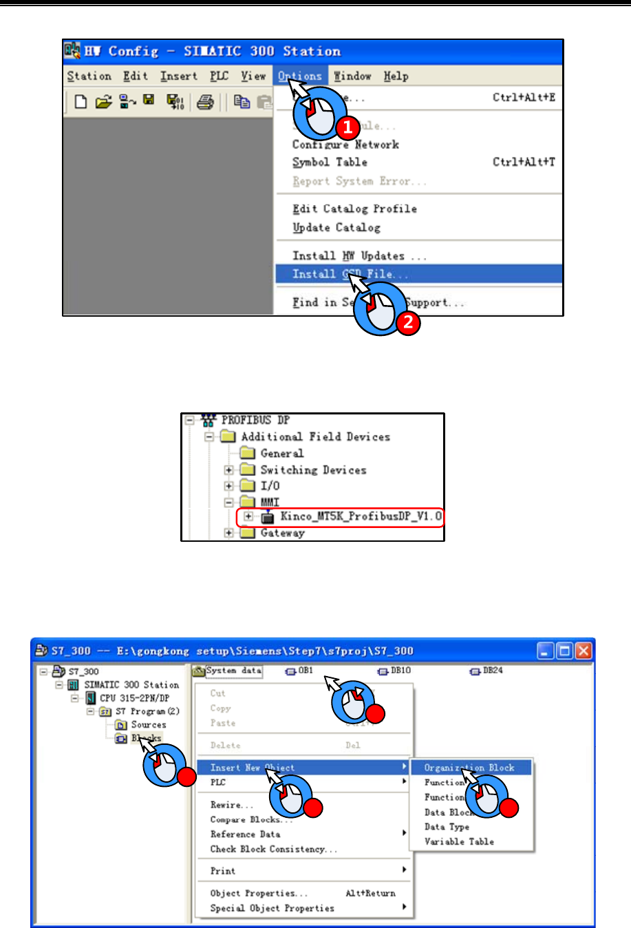
Advanced Part HMI Communication
431
GSD file installed,Right in the HW Config directory PROFIBUS DP / Additional Field Devices / MMI find the appropriate
configuration file:
PLC hardware configuration
Open SIMATIC Manager, in the block configuration Insert included OB1、OB82、OB86、OB100、OB121、OB122 tissue
blocks:
1
2
3 4
Open HW Config,add Master System:
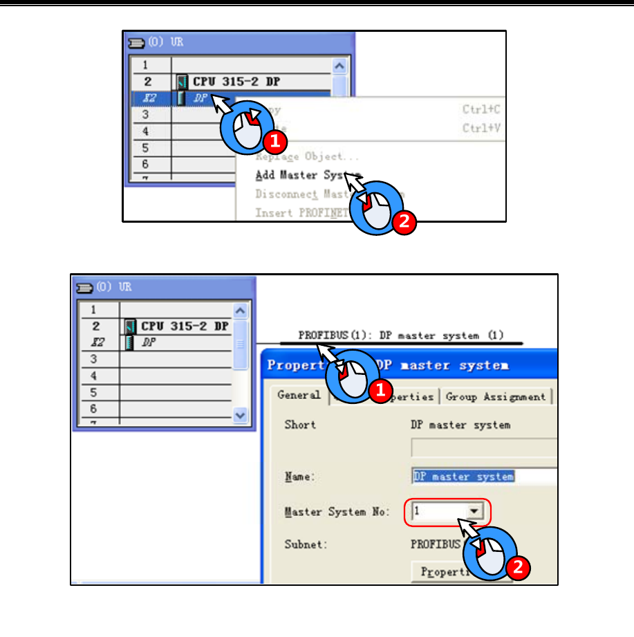
Kinco HMIware Configuration Edit Software
432
After appears the main rail station system, Configure the master system
Add a slave:
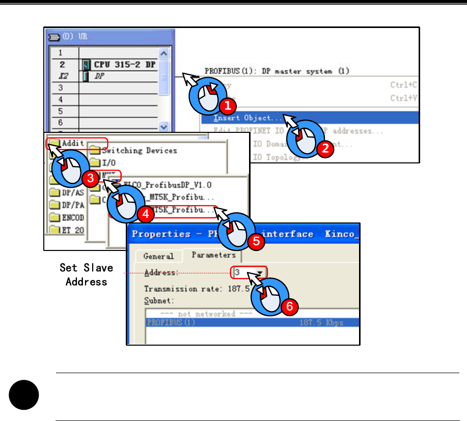
Advanced Part HMI Communication
433
!
DP master system and the slave device address number cannot be the same; In addition slave device
transfer rate adaptation, without setting
Configuring the slave input and output resources:This example configure 16 Words Input,16 Words Output,PIW address
from 256~287,PQW address from 256~287
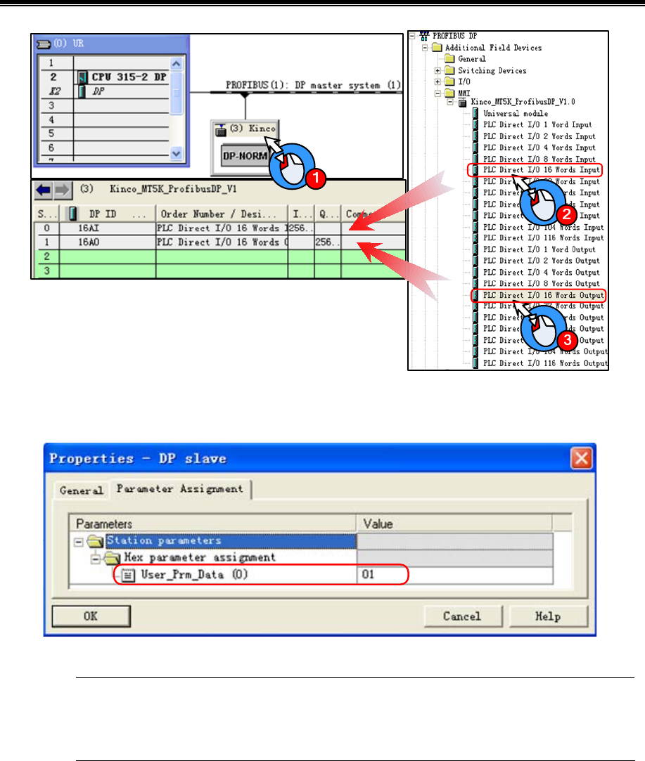
Kinco HMIware Configuration Edit Software
434
Setting User_Prm_Data(0):Double-click the slave station device icon,in【DP slave】—【Parameter assignment】set
User_Prm_Data(0)为1
When LW using double word, only with SIEMENS products through DP communication, only need to
User_Prm_Data (0) is set to 1; If communicate with a master device support other DP protocol,
User_Prm_Data (0) defaults to 0.
In Kinco HMIware topology window to configure the device and set the communication parameters
Double-click the HMI icon in the topology window,in【HMI Attribute】—【HMI】—【Field bus setting】,Click【Add】
configuring the HMI communication parameters.
Setting【Protocol】for “Profibus Slave”;【Input/output Modules】Are set to 16 Words,should match with HW Config Slave
device input and output resources;Slave address should match with HW Config.

Advanced Part HMI Communication
435
Input/ Output Modules should match with Master configuration, The max length are 116 words.
After configuration, the topology diagram and bus configurations are listed below:
Edit the configuration screen
Double-click the HMI icon in the topology window,and open the Configuration Editor window,in【Graph element window】
—【PLC Parts】Select "Number Display" component added to the Configuration Editor window,Element attribute is set to:
Read Address LW 8000(HMI Local address)
Graphics
Using vector graphics,,
After setting, save the project, compile and download.
Using DP communication cables are connected the HMI and PLC,After successful communication established , can monitor
PQW256 data on the HM.
14.4 MPI Communicate
MPI is the multi-point interface (Multi Point Interface) for short,is developed for PLC communication by Siemens. MPI
communication when the communication rate is less demanding, communication data is not used when a cheap and easy
means of communication. The main advantage of MPI communication CPU can establish communications with multiple

Kinco HMIware Configuration Edit Software
436
devices,Such as PG / PC programming, HMI device (PC) and the other PLC can be connected together to run
simultaneously. MPI interface using RS-485 physical interface mode, the transmission rate can be 19.2kbit / s or 187.5kbit /
s.
In Kinco HMI ware in, HMI software provided by SIEMENS S7-300/400 (MPI Direct) communications protocol, as the
master station and HMI MPI communication protocol support PLC / controller communications.
!
With PLC / HMI controller via MPI communication must be extended with Fieldbus Interface and is-MPI
model.
[Examples] Below two MT5320T-MPI (hereinafter referred HMI0 and HMI1) and two SIEMENS S7-300 (hereinafter
referred to PLC0 and PLC1) communications, for example, requires HMI0 monitoring PLC0 data on data block variables
DB10.DBW 10.
In STEP7 Software Configure PLC side communication parameters
Create a New Project ,Under this project insert two PLC stations ,are STATION1(CPU315-2DP) and
STATION2(CPU315-2DP),Respectively, to complete the hardware configuration into the CPU,Establish MPI network and
configure the MPI station address and baud rate,In this example, the MPI station addresses are set to No. 2 and No. 3, and
communication rate 187.5kbit / s.
!
1. Throughout the MPI network communication rate must be consistent and MPI station addresses cannot
conflict.
2. When the PLC with 4 or 4 above HMI communication, Need to set the [attributes] - [Communications]
to change the parameters of PG communication.
For example , CPU 315-2DP,CPU default PG communication number is 1 , OP communication for the 1,
S7 standard communication is 12, while the maximum number of connection resources 16; The number of
the previous three together is always more than the maximum number of connection resources 16 less two,
that means there are two shared an office for the first three, So S7 300 CPU is always maximum and three
HMI communication, cannot be even the first four,If you need to increase the number of connecting HMI,
just to reduce the number of S7 standard communication to further increase the number of PG
communication and keep three of the total does not exceed the maximum number of 16 connection
resources can be. To increase communication between the PLC, will have to increase the number of OP
communication.
Configure DB data block
In the SIMATIC Manager to add the data block DB10, in this case the data required to monitor DB10.DBW 10, the
definition of a variable data block DB10, the need to define DB10.DBW 0 ~ DB10.DBW 14 or more variables.
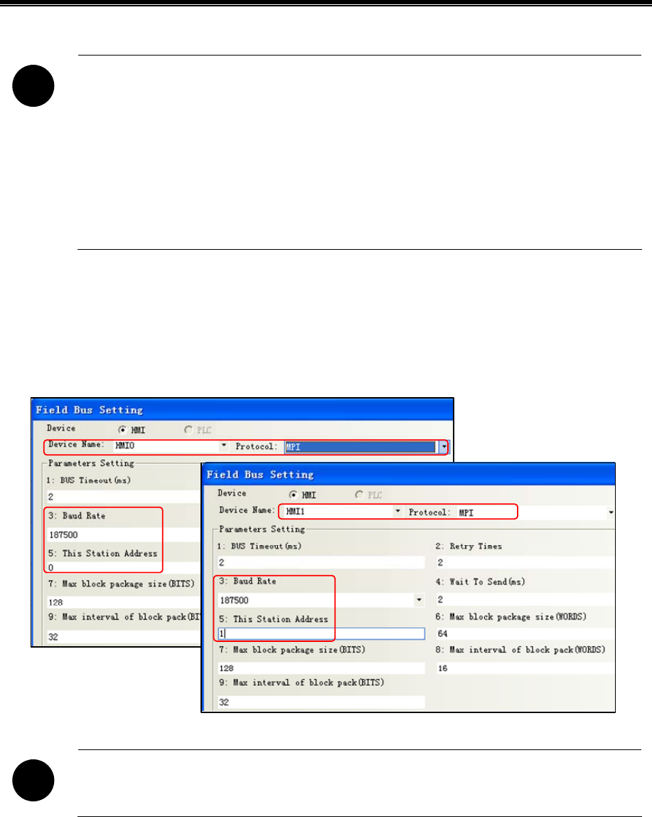
Advanced Part HMI Communication
437
!
1. Define data block variables, note: the variable data type to be set in the HMI data type.
Such as data type REAL, then the values in the HMI device data types required to single-precision
floating-point
2. Ensure that the data defined in the PLC HMI block variable than the actual use of the data block
variables and more.
For example, used in the HMI DB5.DBW32, the PLC cannot be defined only to DB5.DBW32, but defined
to DB5.DBW34 or DB5.DBW36 or more
In Kinco HMIware topology window to configure the device and set the communication parameters
Double-click the HMI icon in the topology window,in【HMI Attribute】—【HMI】—【Field bus setting】,Click【Add】
configuring the HMI communication parameters. Setting HMI:in【Device Name】select the appropriate configuration object,
and set【protocol】 “MPI”,【Baud Rate】should be match with the actual PLC communication port consistent.
!
MPI network connecting multiple master devices, pay attention to the 【master station number】 setting
and cannot be the same.
Setting PLC:in【Device Name】select the appropriate configuration object,【Target Address】should be match with the actual
PLC station number consistent.
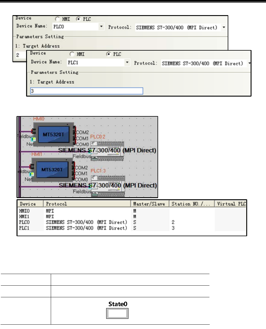
Kinco HMIware Configuration Edit Software
438
After configuration, the topology diagram and bus configurations are listed below:
Edit the configuration screen
Double-click the HMI icon in the topology window,and open the Configuration Editor window,in【Graph element window】
—【PLC Parts】Select "Number Display" component added to the Configuration Editor window,Element attribute is set to:
PLC No.*1 0
Read Address DBn_DBW 1000010(PLC Register)*2
Graphics
Using vector graphics,
※1. A multi-screen or multi-screen multi-machine, Need to change element attributes 【PLC No.】to distinguish control
object.
2. In the HMI, the address type DBn_ DBX, DBn_DBW, DBn_DBD as custom data block address. The first three data
formats for the data block number, later five for the address, address less than five to the previous zero padding.
After setting, save the project, compile and download.
Using MPI communication cables are connected HMI0, HMI1, PLC 0, PLC 1, after the success of communication is
established to monitor DB10.DBW10 in HMI0.
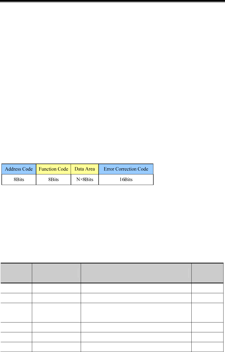
Advanced Part HMI Communication
439
14.5 MODBUS Protocol Applications(Master-slave mode)
MODBUS protocol is a common language applied on the electronic controller. Over this protocol, between the controller,
the controller through the network (such as Ethernet), and other devices can communicate. Today, MODBUS protocol has
become a common industry standard by which different manufacturers of industrial control equipment can be connected into
the network, thereby performing centralized monitoring.
14.5.1 MODBUS Protocol Overview
Modbus is a request / response protocol, and provide services required by the function code.
Modbus protocol including ASCII, RTU, TCP, etc., does not require the physical layer. Protocol defines the controller can
recognize and use the message structure, regardless of what network they are communicating. The Modbus ASCII, RTU
protocol provides news, data structures, commands, and fluent manner , Data communication using Maser / Slave mode ,
Master station data request message, the slave receives the correct data can be sent after a message to the master station in
response to the request ; master can also be directly send message modify the data from a slave, two-way read and write.
MODBUS stipulates that only master station has the initiative, only a passive response from the slave, including answering
error message.
MT Series HMI Modbus protocol communications to achieve, follow the standard Modbus communication process:
Common data frame format is as follows:
- Address code
Address field of a message frame contains two characters (ASCII) or 8Bit (RTU). Possible from the device address is 0 ...
247 (decimal). Single device address range is 1 ... 247. To contact master device through the slave device address into the
address field of the message to select from the device. When a message is sent from the device to respond, he put his address
in response to the address field in order to know which device is the master device to respond. Address 0 is used as the
broadcast address and all slave devices will recognize.
- Function code
In the HMI system, commonly used function codes are as follows:
Modbus
Function code
Name Function
Corresponding
address type
01 Read Coil Status Read bit(Read N Bits) 0x
02 Read input discrete Read bit 1x
03 Read multiple registers
Reading integer, character, status word, float(Read N
Words)
4x
04 Read Input Registers Reading integer, status word, float 3x
05 Write Single Coil Write bit(Write a Bit) 0x
06 Write Single Register Write integer, character, status word, float(Write a Word) 4x

Kinco HMIware Configuration Edit Software
440
15 Write multiple coils Write bit(Write N Bits) 0x
16
Write Multiple
Registers
Write integer, character, status word, float(Write N Words) 4x
- Data Area
Data area contains the specific function of the terminal data needed to respond to queries or the terminal to collect data.
These data may be numeric, reference address or set values. For example:Function code tells terminal reads a register the
data area from which you need to specify the beginning and read the number of register data, the embedded addresses and
data types according to the contents of the slave varies.
- Error correction code
Modbus protocol data needs to checksum, in addition to the serial protocol parity outside, ASCII mode uses the LRC parity,
RTU mode uses a 16-bit CRC checksum, TCP checksum mode without additional requirements.
Parity
Users can configure the controller is an odd or even parity, or no parity. This will determine the character of each parity
bit is how to set up.
If you specify an odd or even parity, "1" digit will count to the number of bits in each character (ASCII Mode 7 data bits,
RTU, 8 data bits). For example RTU character frame contains the following eight data bits:1 1 0 0 0 1 0 1;The whole
"1", the number is four。Such as the use even parity, the parity frame bit will be 0, so that the entire "1" bits remain is
four. If the odd parity, the parity frame bit will be 1, so that the entire "1" bits is 5. If no parity bit, no parity bit is
transmitted, nor checksum testing. Additional padding instead of stop bits to be transmitted character frame.
LRC Detect
Using ASCII mode, messages include methods based LRC error detection domains. LRC field testing except the
beginning of the message field colon and end carriage return line numbers outside content.
LRC field is a binary value that contains an 8-bit byte. LRC value calculated by the transmission device and into the
message frame, the receiving device receiving the message in the process of calculating LRC, and place it in the
message received LRC field value, and if the two values are unequal, there is an error.
LRC is the message of the continuous accumulation of bytes 8Bit, discarding the carry bit.
LRC Simple function as follows:
static unsigned char LRC(auchMsg,usDataLen)
unsigned char *auchMsg ; /* Message to be calculated */
unsigned short usDataLen ; /* LRC number of bytes to be processed */
{
unsigned char uchLRC = 0 ; /* LRC Byte Initialization */
while (usDataLen--) /* Send Message */
uchLRC += *auchMsg++ ; /* Cumulative */
return ((unsigned char)(-((char_uchLRC))) ;
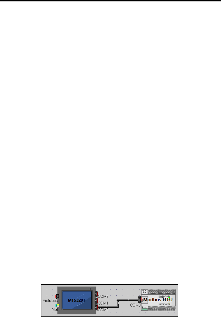
Advanced Part HMI Communication
441
}
CRC Detect
Use RTU mode, the message including the method based on the CRC error detection fields. CRC field test the entire
contents of the message.
The CRC field is two bytes that contains a 16 bit binary value. Calculated by the transmission equipment was added to
the message. Receives the message receiving device recalculates the CRC, and with the received CRC value in the
field, and if the two values are different, then an error.
CRC added to messages, the low byte of the first to join, and then the high byte. CRC simple function as follows:
unsigned short CRC16(puchMsg, usDataLen)
unsigned char *puchMsg ; /* the message to be CRC checksum */
unsigned short usDataLen ; /* The number of bytes in the message */
{
unsigned char uchCRCHi = 0xFF ; /* High CRC byte initialization */
unsigned char uchCRCLo = 0xFF ; /* Low CRC byte initialization */
unsigned uIndex ; /* CRC cycle index */
while (usDataLen--) /* Transmitted message buffer */
{
uIndex = uchCRCHi ^ *puchMsgg++ ; /* Calculate the CRC */
uchCRCHi = uchCRCLo ^ auchCRCHi[uIndex} ;
uchCRCLo = auchCRCLo[uIndex] ;
}
return (uchCRCHi << 8 | uchCRCLo) ;
}
14.5.2 MODBUS Protocol Communication Format
Following through several examples, and use the serial debugging tools to send and receive data frames HMI listen to learn
more about the Modbus protocol communication format.
The following examples are primary device HMI, PLC done from the device, and use the RTU transmission mode is
described:
Topology diagram is shown below:
(1)01 Function Code Application
Function Code 01 reads 0x10, 0x11, 0x12, 0x13, 0x14, 0x15 Bit of these six states.
Placed six "bit state lamp" parts in the HMI configuration, the read address are set to 0x10 ~ 0x15.
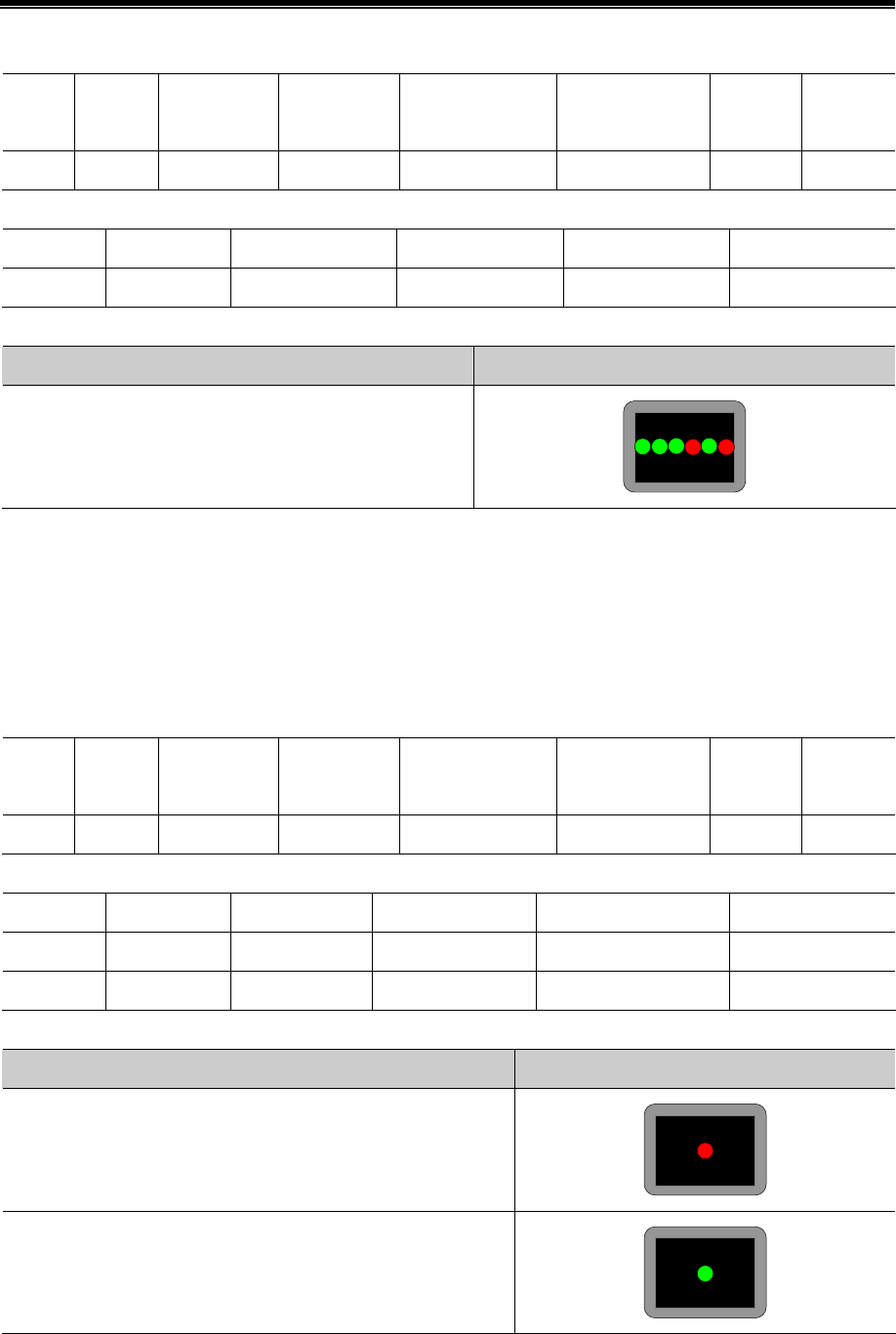
Kinco HMIware Configuration Edit Software
442
Running, the host (HMI) Request
Station
no.
Function
code
First address
(High byte)
First address
(Low byte)
Read Bit Number
(high byte)
Read Bit Number
(low byte)
CRC
High byte
CRC
low byte
01 01 00 09 00 06 6C 0A
Slave (PLC) response
Station no. Function code Byte count Single byte of data CRC High byte CRC low byte
01 01 01 3A D1 9B
HMI debugging tools from the serial port to send data packets HMI display
01H 01H 01H 3AH D1H 9BH
0x15 HMI reads as ON, 0x14 is ON, 0x13 is ON, 0x12 is OFF, 0x11 is ON, 0x10 is OFF. 3A hexadecimal number is covert
into binary to 111,010, corresponding exactly.
(2)02 Function Code Application
Function Code 02 reads 1x999 this Bit state.
In the HMI configuration to place a "bit state lamp" part, the read address is set to 1x999。
Running, the host (HMI) Request
Station
no.
Function
code
First address
(High byte)
First address
(Low byte)
Read Bit Number
(high byte)
Read Bit Number
(low byte)
CRC
high byte
CRC
low byte
01 02 03 E6 00 01 58 79
Slave (PLC) response
Station no. Function code Byte count Data (single-byte) CRC high byte CRC low byte
01 02 01 00 A1 88
01 02 01 01 60 48
HMI debugging tools from the serial port to send data packets HMI display
01H 02H 01H 00H A1H 88H
01H 02H 01H 01H 60H 48H
(3)03 Function Code Application
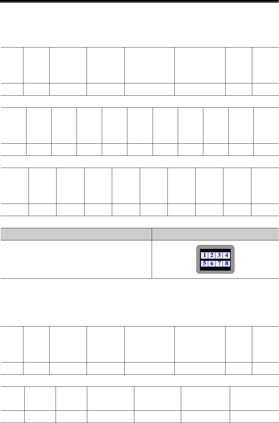
Advanced Part HMI Communication
443
Function Code 03 reads 4x 208 ~ 215 this 8 Words value.
Placed on the HMI configuration 8 "Number Display" component, the read address are set to 4x 208 ~ 215.
Running, the host (HMI) Request
Station
no.
Function
code
First address
(High byte)
First address
(Low byte)
Read Word
Number (high byte)
Read Word Number
(low byte)
CRC
high
byte
CRC
low byte
01 03 00 CF 00 08 74 33
Slave (PLC) response
Station
no.
Functio
n code
Byte
count
Data(1)
High
Byte
Data(1)
low
Byte
Data(2)
High
Byte
Data(2)
low
Byte
Data(3)
High
Byte
Data(3)
low
Byte
Data(4)
High
Byte
Data(4)
low
Byte
01 03 10 00 01 00 02 00 03 00 04
Data(5)
High
Byte
Data(5)
low
Byte
Data(6)
High
Byte
Data(6)
low
Byte
Data(7)
High
Byte
Data(7)
low
Byte
Data(8)
High
Byte
Data(8)
low
Byte
CRC
high byte
CRC
low byte
00 05 00 06 00 07 00 08 72 98
HMI debugging tools from the serial port to send data packets HMI display
01H 03H 10H 00H 01H 00H 02H 00H 03H 00H 04H 00H 05H
00H 06H 00H 07H 00H 08H 72H 98H
(4)04 Function Code Application
Function Code 04 reads 3x 10²³ the value of the Word.
Placed on the HMI configuration 8 "Number Display" component, the read address are set to3x 1023.
Running, the host (HMI) Request
Station
no.
Function
code
First address
(High byte)
First address
(Low byte)
Read Word
Number (high byte)
Read Word Number
(low byte)
CRC
high
byte
CRC
low byte
01 04 03 FE 00 01 50 7E
Slave (PLC) response
Station
no.
Function
code
Byte count Data High Byte Data low Byte
CRC
high byte
CRC
low byte
01 04 02 04 D2 3B AD
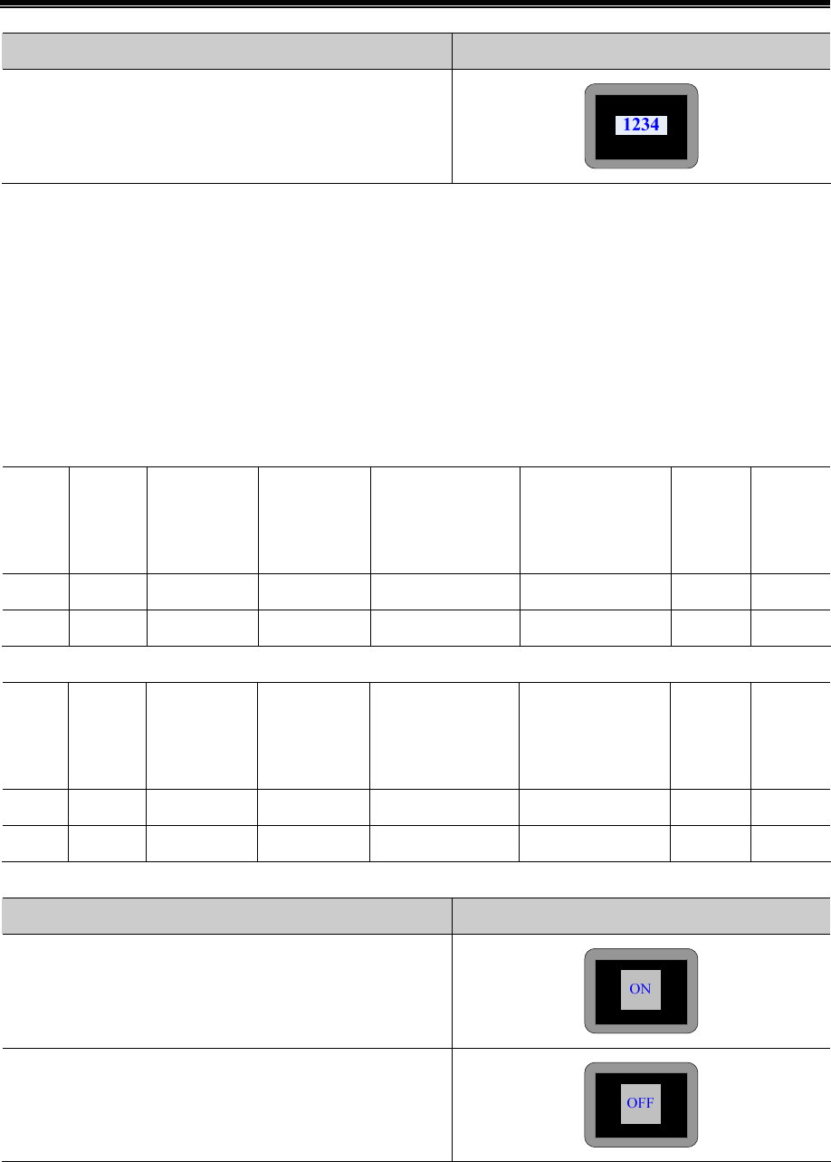
Kinco HMIware Configuration Edit Software
444
HMI debugging tools from the serial port to send data packets HMI display
01H 04H 02H 04H D2H 3BH ADH
(5)05 Function Code Application
Use 05 Function code to modify 0x 1 Bit state.
Place a "Bit State Setting” component in HMI, the write address is set to 0x 1, switch type is set to "Toggle."
Runtime on the HMI click "Bit State Setting" component to switch to the ON state, the serial debugging tools for the data
received 01 05 00 00 FF 00 8C 3A; Be switched to the OFF state, the serial debugging tools for the data received 01 05 00
00 00 00 CD CA;(Among them, the hexadecimal value 0XFF00 requests coil to ON. Hexadecimal value 0X0000 request
coil is OFF)Meanwhile, the serial debugging tools to reply to the same data.
The host (HMI) Request
Station
no.
Function
code
First address
(High byte)
First address
(Low byte)
Write Bit Number
(high byte)
Write Bit Number
(low byte)
CRC
high
byte
CRC
low byte
01 05 00 00 FF 00 8C CA
01 05 00 00 00 00 CD CA
Slave (PLC) response
Station
no.
Function
code
First address
(High byte)
First address
(Low byte)
Write Bit Number
(high byte)
Write Bit Number
(low byte)
CRC
high
byte
CRC
low byte
01 05 00 00 FF 00 8C CA
01 05 00 00 00 00 CD CA
HMI debugging tools from the serial port to send data packets HMI display
01H 05H 00H 00H FFH 00H 8CH 3AH
01H 05H 00H 00H 00H 00H CDH CAH
(6)06 Function Code Application
Use 06 Function code writes 4x 1 this Word value.
In the HMI configuration to place a "multiple state setting" component, the write address is set to 4x 1, set the mode to "set
constant", set the value to 88.
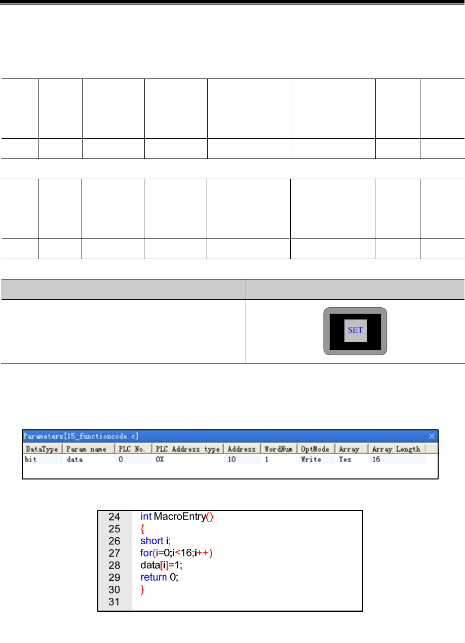
Advanced Part HMI Communication
445
Runtime on the HMI click on the " multiple state setting " component, the serial debugging tools received data to 01 06 00
00 00 58 88 30; while serial debugging tools To reply to the same data.
the host (HMI) Request
Station
no.
Function
code
First address
(High byte)
First address
(Low byte)
Write Word
Number (high byte)
Write Word
Number (low byte)
CRC
high
byte
CRC
low byte
01 06 00 00 00 58 88 30
Slave (PLC) response
Station
no.
Function
code
First address
(High byte)
First address
(Low byte)
Write Word
Number (high byte)
Write Word
Number (low byte)
CRC
high
byte
CRC
low byte
01 06 00 00 00 58 88 30
HMI debugging tools from the serial port to send data packets HMI display
01H 06H 00H 00H 00H 58H 88H 30H
(7)15 Function Code Application
Use 15 Function code modify the 0x 10 ~ 25 this 16 Bit state.
In the HMI configuration to create a macro code: 15 function code. C, variables are defined as follows:
Code is as follows:
And then placed on a configuration screen "function key" component, the function is set to "execute macro code: 15 function
code. C".
Running, click on the function keys on the HMI, the serial data received on debugging tools for the 01H 0FH 00H 09H 00H
10H 02H FFH FFH E3H 09H, while serial debugging tools, the reply data 01H 0FH 00H 09H 00H 10H 84H 05H.
The host (HMI) Request
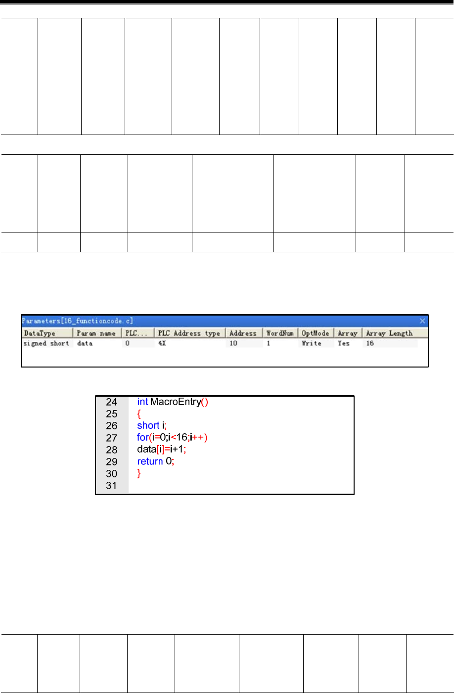
Kinco HMIware Configuration Edit Software
446
Station
no.
Function
code
First
address
(High
byte)
First
address
(Low
byte)
Write Bit
Number
(high
byte)
Write
Bit
Number
(low
byte)
Write
Bit
Byte
count
Bit
Data
High
Byte
Bit
Data
low
Byte
CRC
High
Byte
CRC
low
Byte
01 0F 00 09 00 10 02 FF FF E3 09
Slave (PLC) response
Station
no.
Function
code
First
address
(High
byte)
First address
(Low byte)
Write Bit
Number (high byte)
Write Bit
Number (low byte)
CRC
High Byte
CRC
low
Byte
01 0F 00 09 00 10 84 05
(8)16 Function Code Application
Use 16 Function code writes 4x 10 ~ 25 these 16 Words value.
In the HMI configuration to create a macro code: 16 function code. C, variables are defined as follows:
Code is as follows:
And then placed on a configuration screen "function key" component, the function is set to "execute macro code: 16 function
code. C".
Running, click on the function keys on the HMI, the serial data received on debugging tools for the 01H 10H 00H 09H 00H
10H 20H 00H 01H 00H 02H 00H 03H 00H 04H 00H 05H 00H 06H 00H 07H 00H 08H 00H 09H 00H 0AH 00H 0BH 00H
0CH 00H 0DH 00H 0EH 00H 0FH 00H 10H 88H 37H.while serial debugging tools, the reply data 01H 10H 00H 09H 00H
10H 11H C7H。
The host (HMI) Request
Station
no.
Function
code
First
address
(High
First
address
(Low
Write Word
Number (high
byte)
Write Word
Number (low
byte)
Write Word
Byte count
Data(1)
High
Byte
Data(1)
low
Byte
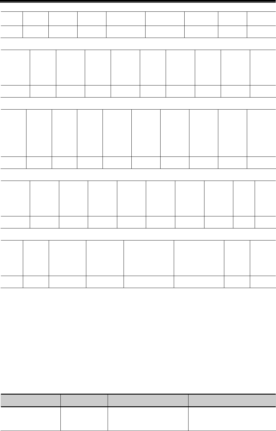
Advanced Part HMI Communication
447
byte) byte)
01 10 00 09 00 10 20 00 01
Data(3)
High
Byte
Data(3)
low
Byte
Data(4)
High
Byte
Data(4)
low
Byte
Data(5)
High
Byte
Data(5)
low
Byte
Data(6)
High
Byte
Data(6)
low
Byte
Data(7)
High
Byte
Data(7)
low
Byte
00 03 00 04 00 05 00 06 00 07
Data(8)
High
Byte
Data(8)
low
Byte
Data(9)
High
Byte
Data(9)
low
Byte
Data(10)
High
Byte
Data(10)
low
Byte
Data(11)
High
Byte
Data(11)
low
Byte
Data(12)
High
Byte
Data(12)
low
Byte
00 08 00 09 00 0A 00 0B 00 0C
Data(13)
High
Byte
Data(13)
low
Byte
Data(14)
High
Byte
Data(14)
low
Byte
Data(15)
High
Byte
Data(15)
low
Byte
Data(16)
High
Byte
Data(16)
low
Byte
CRC
High
Byte
CRC
low
Byte
00 0D 00 0E 00 0F 00 10 88 37
Slave (PLC) response
Station
no.
Function
code
First address
(High byte)
First address
(Low byte)
Write Word
Number (high byte)
Write Word
Number (low byte)
CRC
High
Byte
CRC
low
Byte
01 10 00 09 00 10 11 C7
14.5.3 MODBUS Protocol in the HMI Application
In the HMI interface design applications, often encountered need to design their own microcontroller control board
communication situation. In this application environment, the MCU control system designers want a simple, stable and
reliable means of communication with the HMI to exchange data. The MODBUS protocol is achieved between the HMI and
the equipment master-slave communication mode most commonly used way.
Below microcontroller (hereinafter referred to as MCU) and HMI through MODBUS protocol (RTU transmission mode in
case) communication, for example, explains how to use MODBUS protocol communication between the HMI and the MCU.
Between the HMI and the MCU communication through MODBUS protocol mainly have the following two Master-slave
ways:
Master / Slave Using protocol Advantage Disadvantages
HMI as Master device
MCU as Slave device
Modbus RTU HMI direct access to the MCU
mapped out 0X, 1X, 3X, 4X
MCU as a slave device must constantly
respond to queries the HMI, CPU

Kinco HMIware Configuration Edit Software
448
registers. occupancy rate is high; MCU interrupt
response shall be used, programming is
relatively difficult.
HMI as Master device
MCU as Slave device
Modbus RTU
Slave
MCU as the master device can
initiate communication; do not take
up too much CPU time.
HMI local address LW, LB is
mapped to 4X, 0 X register, write or
read by the MCU.
LW on the HMI configuration data is
modified, you must regularly check the
MCU can be read out to achieve them
inconvenient.
MCU can only access the HMI local
word (LW), the position (LB)
(1)HMI as Master, MCU as Slave (using the Modbus RTU protocol)
MCU and HMI using standard Modbus RTU protocol for communication, HMI as master, MCU for the slave side, the MCU,
you need to write the interrupt service routine to handle communication requests from HMI. MCU must support the standard
Modbus RTU protocol, while MCU must map out 0X, 1X, 3X, 4X registers (where 0X, 1X is bit register; 3X, 4X for the
word register)
The recommended communication parameter is 19200, data bits, 1 stop bit, no parity. In addition to seven data bits protocol
support all settings other than combinations. Baud rate range from 1200-115200, with the flexibility to choose.
- Communication processes
First, HMI sends a request to the MCU, MCU accepts the request, a response back to the HMI. MCU can access the HMI,
4X, 3X, 0X, 1X register; the address range is 1 to 65535.
!
1. MODBUS protocol is relatively complex, demanding overtime
2. In the communication process, HMI continuously sends request packets to MCU; MCU accepts the
request, the need to continue to give a response to the HMI. MCU's response is given using interrupt
mode; therefore, MCU's CPU usage is high. Most of the MCU's CPU resources consumed during the
communication response. Therefore, in practical applications need to be taken into account, if the MCU is
used in addition to doing communication functions, there are other response functions, HMI (Master)
MCU (Slave) using Modbus RTU protocol solution is not recommended, it is recommended to use HMI
(Slave) MCU (Master), using Modbus RTU Slave protocol solutions
- HMI Power communication processes
When the HMI after power
(1)If the configuration page does not place any project component, the HMI will not send any communication packets
External
(2)If the configuration page placed engineering components and these components address types are local types (LW, RW,
RWI, LB, RB, RBI, LW.B), the HMI will not send any communication packets External
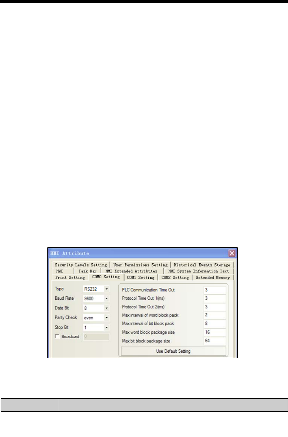
Advanced Part HMI Communication
449
(3)If the configuration page to place the component works, and these elements are not the local address type for 0X, 1X,
3X, 4X, the HMI constantly scanning configuration page of these registers, and constantly sends communication data
packets
(4)When using the timer device batch write bit components (consecutive addresses transmission number greater than one)
when, HMI will be issued by the packet encapsulation function code: 0x0F
(5)When using the timer components word element bulk write (consecutive address transfer number greater than one)
when, HMI will be issued by the packet encapsulation function code: 0x10
(6)Using recipes components download operation (that is, the local word register in HMI RW data downloaded to the
MCU in the appropriate register, such as 4X).
When the download operation data length is greater than 1, HMI will be issued by the packet encapsulation function code:
0x10
- Data communications package
Assuming HMI configuration screen is placed 25 0X register address type, starting address: 20, HMI station number is 1.
HMI send packets: ("H" indicates hexadecimal form)
01H 01H 00H 13H 00H 25H XXH XXH(Wherein: "XX" indicates LRC / CRC)
MCU Return packets:
01H 01H 05H CDH 6BH B2H 0EH 1BH XXH XXH(Wherein: "XX" indicates LRC / CRC)
- HMI Communication parameter configuration
HMI Port parameter settings:
According to the actual physical connection mode selection set [Communication type].
Baud rate, data bits, parity, stop bits setting must be connected to the MCU and the corresponding parameters consistent.
Other parameters are described below:
Parameter Explanation
PLC Communication
timeout
HMI wait MCU response, if the MCU to set the time interval in which the response is not given,
the HMI that communication timeout, and then continue to send request packet, continue to wait

Kinco HMIware Configuration Edit Software
450
Protocol timeout 1 Inter-character timeout. HMI communication with the MCU in the process, if the communication
frame characters and the time interval between characters exceeds the set time interval, the HMI
think this communication process is completed, then, to deal with the communication data frame,
parse packets.
For Modbus protocol, baud rate calculation within the program should be based on an estimate.
As follows:
Protocol timeout 1 = 1.5*1000000*(1 + data bits + parity + stop bits) / baud + set adjust time bps
(baud rate);
Sample code (standard C language):
int speed_arr[] = { B115200, B57600, B38400, B19200, B9600, B4800, B2400, B1200,
B300,B150, B134, B110, B75 };
int name_arr[] = {115200, 57600, 38400, 19200, 9600, 4800, 2400, 1200, 300, 150, 134,
110, 75 };
int adjust_time_bps_arr[]={1000,4000,10000,11000,25000,40000,70000,140000,
600000,0,0,0,0};
Function: Set a baud rate adjustment values check time
Parameter: baud_rate
Returns: the current baud rate of the checksum time adjustment value
int set_adjust_time_bps(int baud_rate)
{
int adjust_time;
int i;
for(i=0;i<sizeof(speed_arr)/sizeof(int);i++)
{
if(baud_rate==name_arr[i])
{
adjust_time=adjust_time_bps_arr[i];
break;
}
}
return adjust_time;
}
Protocol timeout 2 The communication speed will be slow, but the communication error and error package will also
be reduced. Do not suggest customers to modify this parameter.
Max interval of word Occurs mainly in the HMI read data phase, in order to improve communication efficiency,
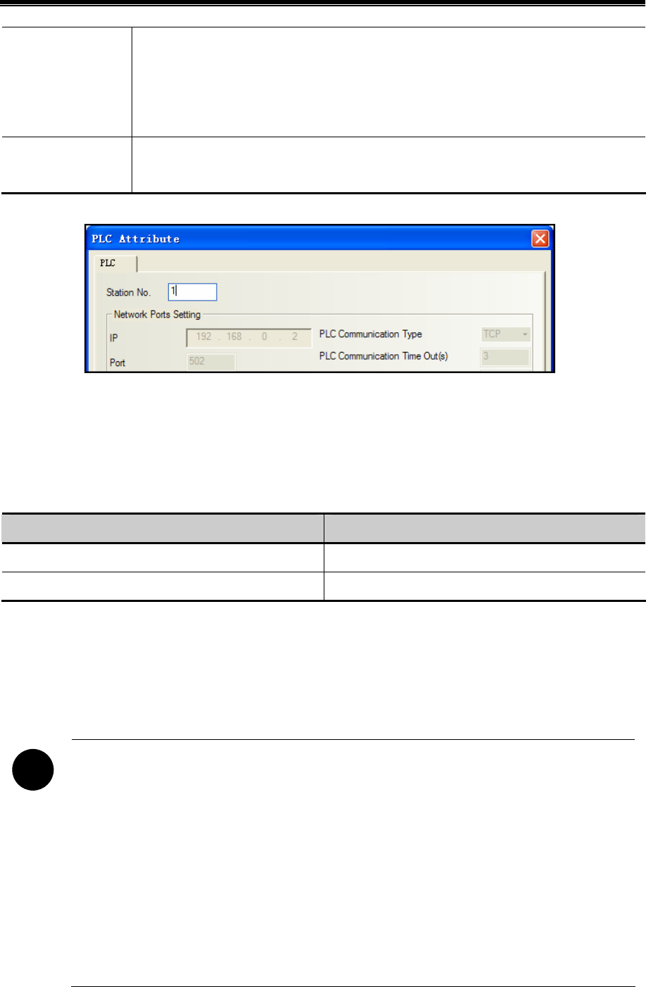
Advanced Part HMI Communication
451
(bit) block pack relatively tight group of registers connected to pack together to form a bulk read, for example, D1,
D2, D4, group packet interval is set to 10, these three registers will be taken a bulk read (read
from D1 from the bulk 4 registers). Note: The group packet interval must be less than the
maximum length of batch read.
Max word (bits) block
package size
Protocol supports the largest number of registers to read and write batch. This function is used to
achieve data transmission components to achieve
PLC Station number setting:
(2)MCU as Master, HMI as Slave (using Modbus RTU Slave protocol)
MCU and HMI using standard Modbus RTU protocol for communication, MCU for remote, HMI for the slave side, the
MCU, just write a simple communication read / write programs without having to write the interrupt service routine. HMI
local address LW, LB is mapped to 4X, 0X register, write or read by the MCU.
Registers the correspondence table is as follows:
Modbus Register address range Local address range corresponding HMI
0X(1---9000) LB(0---8999)
4X(1---9000) LW(0---8999)
The recommended communication parameter is 19200, data bits, 1 stop bit, no parity. In addition to seven data bits protocol
support all settings other than combinations. Baud rate range from 1200-115200, with the flexibility to choose from.
- Communication processes
First, MCU sends a request to the HMI, HMI accepts the request, a response back to the MCU.
!
1. MODBUS protocol is relatively complex, demanding overtime
2. In the communication process, MCU as the initiator of communication, initiate communication. When
the HMI device accepts the request, a response back to the MCU. Therefore, MCU without constantly
interrupt, do not take up too much CPU time
Therefore, in practice, if the MCU is used in addition to doing communication functions, there are other
response functions (recommended to use this solution).
3. HMI configuration on LW, LB data is modified, you must regularly check the MCU can be read out and
realize it is not very convenient. Therefore, the actual application, the MCU written communication read /
write process, you should consider requesting the HMI data interval stated in the program to give much
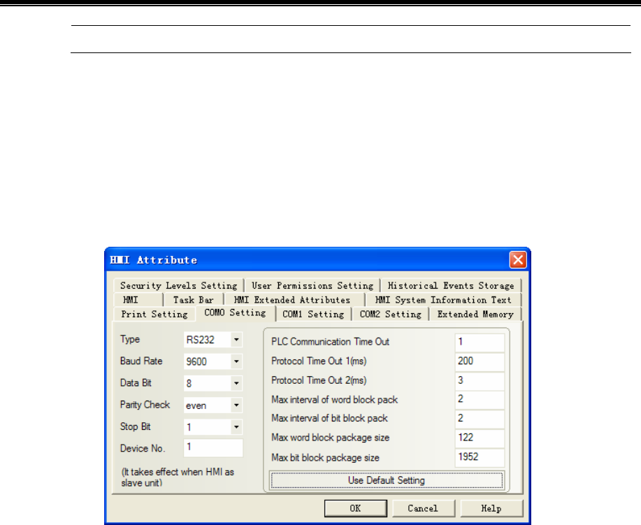
Kinco HMIware Configuration Edit Software
452
time to wait for a communication request
- HMI Power communication processes
In this scheme, the user edit the configuration project, the component type can only select local word address register LW
and the local register LB. When powered on the HMI, HMI does not take the initiative to send out a packet communication,
HMI is waiting to receive state. After the MCU send request, HMI resuming a response.
- HM Communication parameter configuration
HMI Port parameter settings:
Them from the device number for the HMI station number, other communications parameters set according to specific
circumstances.
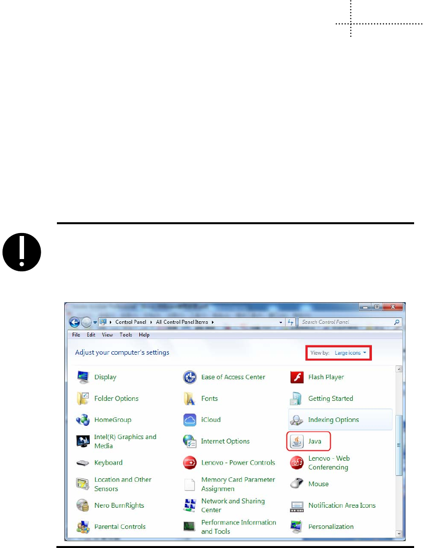
453
15 VNC
VNC (Virtual Network Computing) is a kind of software for screen sharing and remote operation via RFB
protocol. The VNC software could transfer mouse and keyboard operation and real-time screen.
VNC system is composed of client-side, server-side and protocol. The server side shares screen with
client-side, while the client-side interacts with server side by monitoring and controlling server-side.
VNC is OS independent. Users could use the VNC system to remote control HMI via PC, mobile and so
on.
15.1 Various client-sides
Kinco does not provide the VNC software. Users could download from the internet:
- VNC software for PC: VNC Viewer
- Browser: IE, Firefox…
- VNC software for mobile terminal: most mobile system support VNC software, for example:
VNC/RDP.
1. JAVA plugin tool is required by browser access. Generally, PC has the JAVA
plugin. Please refer to Java.com to install if there is no JAVA plugin on PC.
2. IF after install the JAVA plug-in, the brower to monitor HMI, JAVA plug-in
can not run normally, you can change the security level to “Medium” in
[Control Panel]-[All Control Panel Items].
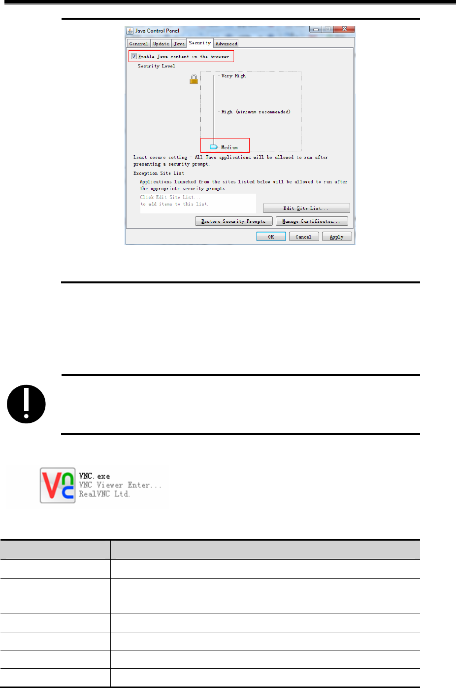
Kinco HMIware Configuration Edit Software
454
3. You can open multiple VNC Viewer clients to access to multiple HMI at the
same time.
15.2 Access via LAN
15.2.1 Remote control HMI by PC via LAN
【Example 1】Remote control MT4414TE by PC. MT4414TE works as server, while PC as client.
1. Only the HMI models with Ethernet port support VNC function for the VNC
function is realized via Ethernet.
1) Tools required for Client-side:
2) The related system registers of HMI are as follows:
Register Function
LB9290 Open VNC function. Set to “1” to open the VNC function.
LB9291 Mask user operation. Set to “1” to mask user operation(check only,
cannot operate)
LB9292 Operation password enabled. Set to “1” to enable operation password.
LB9293 Inquiry password enabled. Set to “1” to enable inquiry password.
LW10146~LW10147 Operation password
LW10148~LW10149 Inquiry password

Advanced Part HMI Communication
455
3) Parameter settings for HMI:
Set IP of HMI as follows:
1. Take the default gateway in LAN.
Set the VNC related registers:
4) Parameter setting on PC
Input IP of the target HMI:
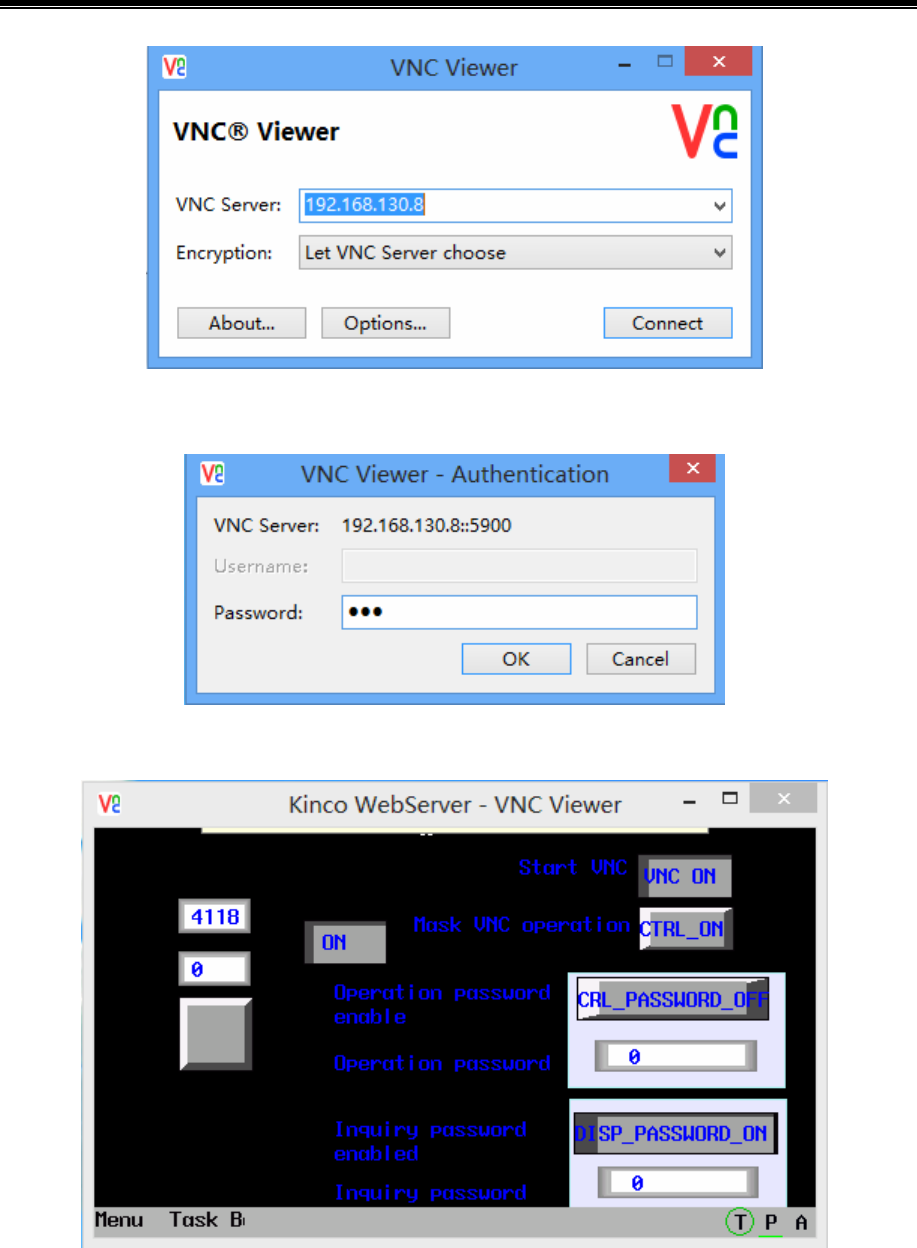
Kinco HMIware Configuration Edit Software
456
Input Password (Operation password or inquiry password)
Monitoring on PC:
Changes on HMI is displayed on PC simultaneously, meanwhile, user could control HMI by operating on
PC.
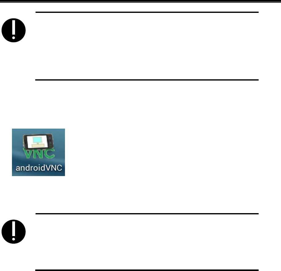
Advanced Part HMI Communication
457
1. If input inquiry password on PC side, then users only could check HMI
information, but cannot operate.
2. If input operation password on PC side, then users could check HMI
information and operate HMI on PC, but cannot operate.
3. If there is no password set on HMI, then no passwords required for monitoring
or operating HMI.
15.2.2 Remote control HMI by mobile via LAN
【Example 2】Remote control MT4414TE by an android mobile. MT4414TE works as server, while the
android mobile as client.
1) Tools required for mobile
2) Parameter setting of HMI is the same with 【Example 1】
3) Parameter setting on mobile
1. Input IP in the Address box.
2. The default port is 5900, please do not change it, otherwise, may not get
connection.
3. Nickname and User name can be omitted.
4. Input operation password or inquiry password.
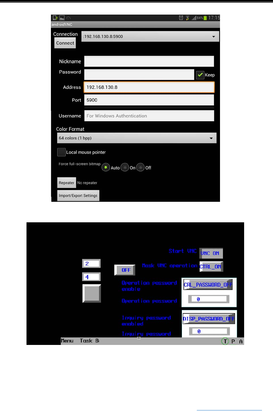
Kinco HMIware Configuration Edit Software
458
Monitoring on mobile:
Changes on HMI is displayed on mobile simultaneously, meanwhile, user could control HMI by operating
on mobile.
15.2.3 Remote control HMI by browser via LAN
【Example 3】Remote control MT4414TE by browser.
1) Parameter setting of HMI is the same with 【Example 1】
2) Open the browser, input IP and port of the target HMI in the website box: http://192.168.130.8:5800
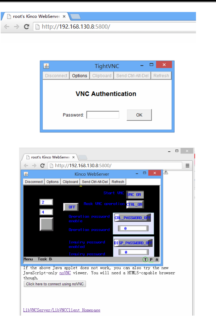
Advanced Part HMI Communication
459
Input password (Operation password or inquiry password)
Monitoring by browser:
Changes on HMI is displayed by browser simultaneously, meanwhile, users could control HMI by
operating on browser.

Kinco HMIware Configuration Edit Software
460
1. The remote control by browser is realized by a JAVA plugin running on the
website. Please make sure that JAVA software has been installed on PC.
2. Default port for browser access is 5800. Please do not change it, otherwise may
not get connection.
3. Only after updated kernel and Rootfs by v2.2 (build140314) software or above,
the HMI can support the remote control by brower.
15.3 Access via WAN
For remote access via WAN, users need to set port mapping of HMI by router.
For remote access by VNC Viewer on PC via WAN, users need to map IP of target HMI to port number
5900.
【Example 4】The IP of the remote HMI is: 192.168.4.39
1) Port mapping:Choose menu“Forwarding->Virtual Servers”,click the Add New…button
2) Parameter setting of HMI:
3) Assumed that the WAN IP of the local network where the HMI located is 192.168.100.14, then, users
need to input IP 192.168.100.14 into VNC Viewer and mobiles of external network to remote control
HMI. Choose menu ”Network->WAN”
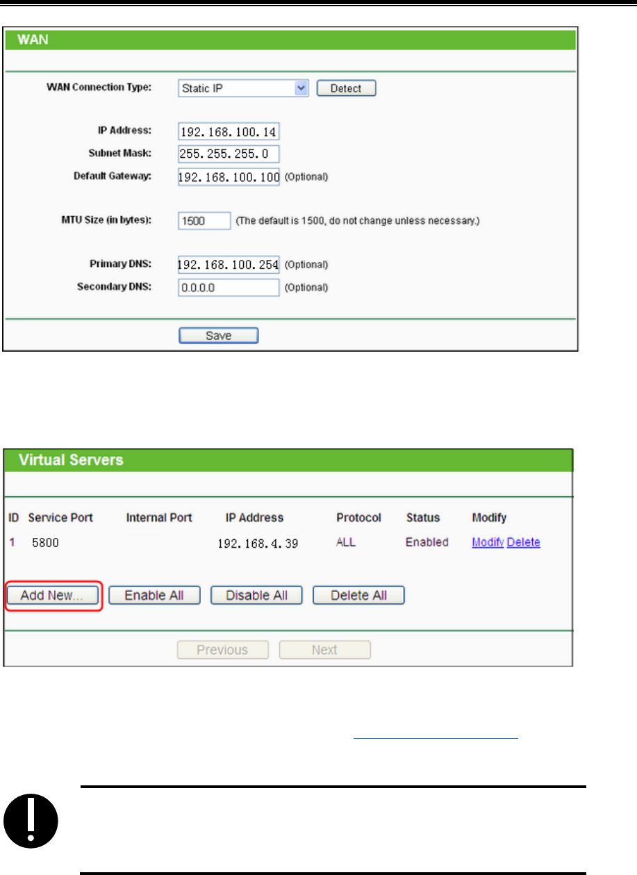
Advanced Part HMI Communication
461
For remote access by browser via WAN, users need to map the HMI IP to port number 5800.
【Example 5】 The IP of the remote HMI is: 192.168.4.39
1) Port mapping: Choose menu“Forwarding->Virtual Servers”,click the Add New…button
2) Parameter setting of HMI is the same with 【Example 4】
3) Assumed that the WAN IP of the local network where the HMI located is 192.168.100.14, then, use
the browser of the external network to visit website: http://192.168.100.14:5800 to remote control
HMI.
1. The Gateway must been set in the same network segment for access via WAN.
2. The firewall and antivirus software are suggested to be closed, for it may affect
the VNC function.
Router mapping method: If the DMZ host is opened on PC, then users could remote control HMI by VNC
without port mapping.
【Example 6】 The IP of the remote HMI is: 192.168.4.39
1) Router mapping:Choose menu ”Forwarding->DMZ”
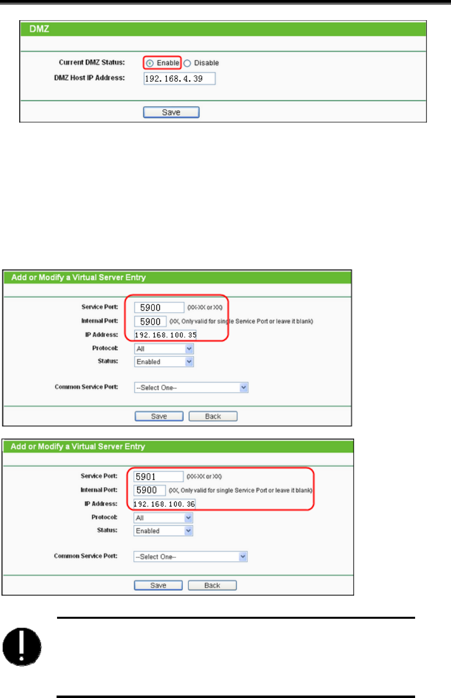
Kinco HMIware Configuration Edit Software
462
2) Parameter setting of HMI is the same with 【Example 4】
3) Assumed that the WAN IP of the local network where the HMI located is 192.168.100.14, then,users
need to input IP 192.168.100.14 into PCs of external network to remote control HMI.
If users need to access multiple HMIs by VNC via WAN, then the router is required for supporting port
self-definition of external network port. The model TL-WR841N (TP-LINK) supports port self-definition
of external network.
【Example 7】IP of remote HMI1 is 192.168.100.35, IP of remote HMI2 is 192.168.100.36.
1) Port setting of router: add two new items in [transfer rule]-[Virtual server]
1. For access by VNC Viewer, the internal port must be set to 5900 by router, and
serve port can be set as casual value. Input IP and internal port for access by
VNC Viewer via WAN.
2. For access by browser, the internal port must be set to 5800 by router, and serve
port can be set as casual value. Input IP and internal port for access by
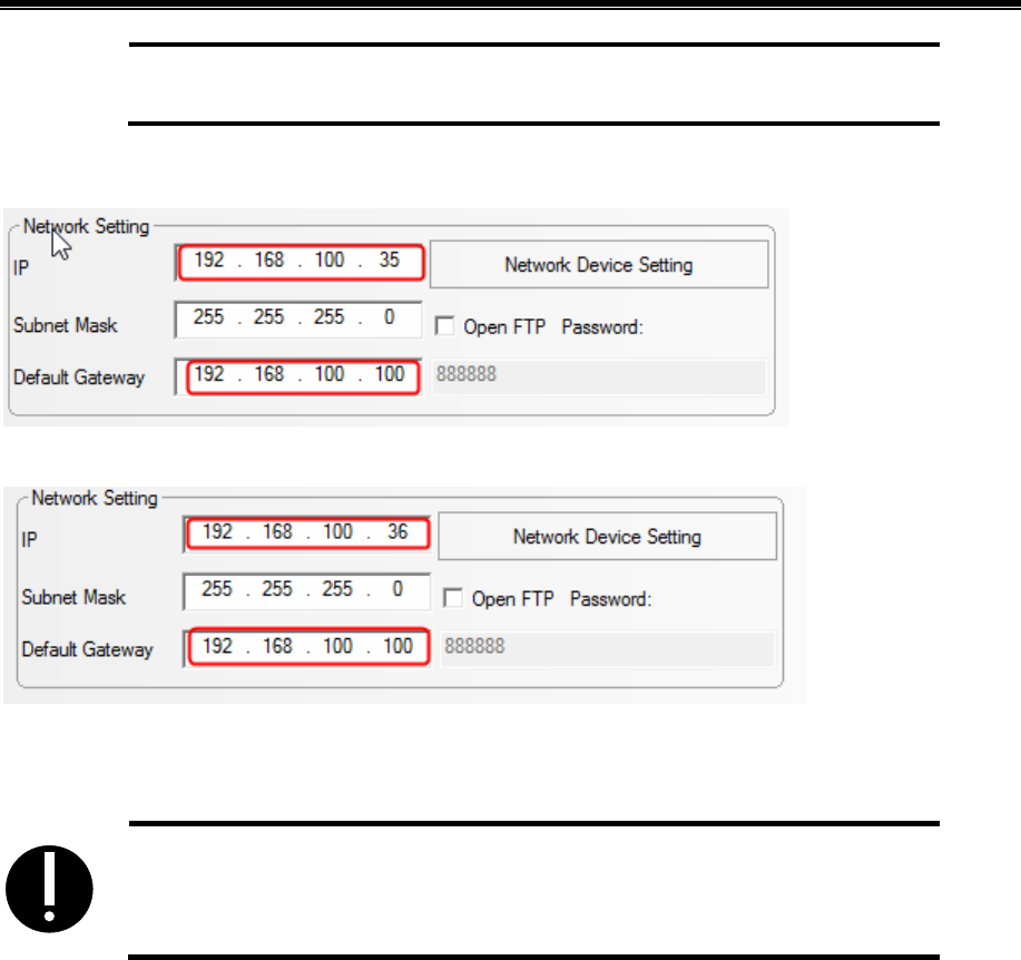
Advanced Part HMI Communication
463
browser via WAN.
2) Parameter setting of HMI:
HMI1:
HMI2:
3) Assumed that the WAN IP of the local network where the HMI located is 203.110.174.214, then,
users need to input 203.110.174.214:5900 and 203.110.174.214:5901 into PCs and mobiles of
external network to remote control HMI.
1. The firewall and antivirus software are suggested to be closed, for it may affect
the VNC function.
464
16 Register
The registers supported by HMI include local registers and external PLC or the registers of control devices. Local registers
include Local Word(LW),Local Bit(LB),Recipe Word(RW) and so on. External registers include M,D,S, etc.
16.1 Local Registers of HMI
16.1.1 Bit Address
Description Address Type Address Range Format
Local bit, Local word address, local registers
of HMI, don’t save data after power off.
LB 0~9999 DDDD:Decimal system
Bit extended from local word,Bit addresses
extended from local words.
LW.B 0~10255.F
DDDDD.H
No. “H” bit of the no. DDDDD
word, range of H:0~f
Recipe bit,Recipe bit address, local registers
of HMI, save data after power off, don’t save
data when run out of batteries.
RB 0~261000.F DDDDDD.H
Recipe bit index,Recipe bit index addresses,
indirect addressing mode is adopted, save data
after power off, don’t save data when run out
of batteries.
RBI 0~261000.F
DDDDDD.H
【Example】RBI50
RB address=50+[LW9000]
Flash recipe bit,Flash recipe bit addresses,
using FLASH to save the data that is Erased
/Written infrequently, save data after power
off even when run out of batteries, but the
“erease/write”times are limited.
FRB 0~134217727.F DDDDDDDDD.H
Flash recipe bit index,Flash recipe bit index
addresses, using FLASH to save the data that
is Erased /Written infrequently, save data
after power off even when run out of
batteries, but the “erease/write”times are
limited.
FRBI 0~134217727.F DDDDDDDDD.H
16.1.2 Word Address
Description Address Type Address Range Format
Local word,Local word addresses. LW 0~10255 DDDDD

HardwarePartNameandSpecification
465
Recipe word ,Local recipe word addresses,
indicating the local register of HMI, save data
after power off, don’t save data when run out of
batteries.
RW 0~261000 DDDDDD
Recipe word index,Recipe word index addresses,
local register of HMI, indirect addressing mode is
adopted, save data after power off, don’t save data
when run out of batteries.
RWI 0~261000
DDDDDD
【Example】RWI50
RW address = 50 +
[LW9000]
Extended Recipe word,Extended recipe word
addresses, usually for HMI external storage
devices access, such as SD card, U disk and so on,
when more than one external storage devices are
used, ERW0/ERW1/ERW2 will be used for
indentifying.
ERW0~ERW2 0~2147483647 DDDDDDDDDD
Extended Recipe word index,Extended recipe
word index addresses, usually for HMI external
storage devices access, such as SD card, U disk
and so on, when more than one external storage
devices are used, ERW0/ERW1/ERW2 will be
used for indentifying.
ERWI0~
ERWI2
0~2147483647 DDDDDDDDDD
Flash recipe word,Flash recipe word addresses,
using FLASH to save the data that is Erased
/Written infrequently, save data after power off
even when run out of batteries, but the
“Erease/Write” times are limited.
FRW 0~134217727 DDDDDDDDD
Flash recipe word ,Flash recipe word index
address, using FLASH to save the data that is
Erased /Written infrequently, save data after power
off even when run out of batteries, but the
“Erease/Write” times are limited.
FRWI 0~134217727 DDDDDDDDD
16.2 System Special Registers of HMI
The system has reserved some Local Word(LW),Local Bit(LB) addresses for special purpose, the users must use the
addresses according to related description.

Kinco HMIware Configuration Edit Software
466
!
When local registers are used, users need to pay special attention to making sure that the local registers
cannot conflict with the special registers, otherwise the registers will not be able to be used normally or
unexpected results will be lead.
16.2.1 Parameter Setting of Hardware
Address Description Read/Write
LB9018
Screen saver indication for entering. When the system enters screen saver/backlight and energy
saving state, the bit is automatically set to ON; when the system exits screen saver state, it is
set to OFF.
R
LB9019
Screen saver indication for exiting. When the system enters screen saver/backlight and energy
saving state, the bit is automatically set to OFF; when the system exits screen saver state, it is
set to ON.
R
LB9045 Restart touch screen. Restart HMI when this bit is set to ON. W
LB9051
Enable/disable touch function when backlight is closed. Set this bit to ON will disable the
touch function when backlight is closed.
R/W
LB9091
Increase LCD contrast. The system will execute the function of increasing LCD contrast by
setting the bit to ON, upon completion, the bit will be cleared automatically.
W
LB9092
Decrease LCD contrast. The system will execute the function of decreasing LCD contrast by
setting the bit to ON, upon completion, the bit will be cleared automatically.
W
LB9093
Increase backlight brightness. The system will execute the function of increasing backlight
brightness by setting the bit to ON, upon completion, the bit will be cleared automatically.
W
LB9094
Decrease backlight brightness. The system will execute the function of decreasing backlight
brightness by setting the bit to ON, upon completion, the bit will be cleared automatically.
W
LB9120
Trigger long sound of buzzer. Set the bit to ON to trigger long sound of buzzer once, upon
completion, the bit will be cleared automatically.
W
LB9121
Trigger short sound of buzzer. Set the bit to ON to trigger short sound of buzzer once, upon
completion, the bit will be cleared automatically.
W
LB9145
Automatically restart after system crash. Set the bit to ON, to make HMI will restart
automatically after it crash for 5 seconds.
R/W
LB9160 Switch bit of CPU light. Set the bit to ON to turn off CPU light, and forbid blinking. R/W
LB9163 Screen flip display. Set the bit to ON to flip vertical display the HMI screen. R/W
LW9140 Display screen brightness level. R
LW9141
Display screen contrast level.
Note:as for KM5303,the value of LW9141 indicates the brightness of the buttons.
R
LW9464 Audio volume register. Range: 0~100, 0 indicates mute, from 1 to 100, the volume increases R/W
HardwarePartNameandSpecification
467
gradually.
LW9532 Number of the screen saver window. Display and set the number of the screen saver window. R/W
16.2.2 System Setting
- System parameter Setting
Address Description Read/Write
LW10010 Initial window number, range: 0~65535. R/W
LW10011
Screen saver/backlight and energy saving time setting. 0: Disable screen saver; 1~65535:
Enable screen saver (take effect without restart). Time unit: minute.
R/W
LW10012
Buzzer sound. 0: Disable; 1: Enable (take effect without restart, non-zero value enables the
function)
Note: LW10012 is only used for closing buzzer, not for closing the buzzer sound triggered by
alarms and events. For the buzzer sound triggered by alarms and events, the function is
prohibited.
R/W
LW10013 Pop-up window attribute. 0: Normal;1: Display above other windows. R/W
LW10014 Common window attribute. 0: Display below base window; 1: Display above base window. R/W
LW10015 Number of stored events. Range: 0~65535 R/W
LW10017 Default language. Range: 0~7. R/W
LW10018 System reserved. For HMI internal use. R/W
LW10019 Exchange communication ports. Set the bit to ON to exchange com0 and com1 of HMI.
LW10028 Screen saver. 0: off,1-65535: on(no restart is need) ,unit: minute R/W
- Taskbar control
Address Description Read/Write
LB9040 Hide/display Fast selection window. Set the bit to ON to hide; Set the bit to OFF to display. R/W
LB9041 Hide/display taskbar. Set the bit to ON to hide; Set the bit to OFF to display. R/W
LB9042 Hide/display task buttons. Set the bit to ON to hide; Set the bit to OFF to display. R/W
LB9043
Hide/display all (Fast selection window, taskbar, task buttons). Set the bit to ON to hide; Set
the bit to OFF to display.
R/W
- Keyboard control
Address Description Read/Write
LB9060
LB9061
Keypad popup indication. Keypad popup is controlled by the component in the left part of the
window. When numeric input or text input function is enabled by users, HMI will set the bit to
ON automatically, and pop up a direct window including a keypad. After successful entry or
pressing [Esc], this bit will be set to OFF, and the keypad window will be closed automatically.
R
LB9062 Keypad popup indication. Keypad popup is controlled by the component in the upper left part R
Kinco HMIware Configuration Edit Software
468
of the window.
LB9063
Keypad popup indication. Keypad popup is controlled by the component in the bottom left part
of the window.
R
LB9064
LB9065
Keypad popup indication. Keypad popup is controlled by the component in the right part of the
window.
R
LB9066
Keypad popup indication. Keypad popup is controlled by the component in the upper right part
of the window.
R
LB9067
Keypad popup indication. Keypad popup is controlled by the component in the bottom right
part of the window.
R
LB9068
LB9069
Keypad popup indication. Keypad popup is controlled by the component in optional position of
the window.
R
LB9080
Keypad popup indication. Keypad popup is controlled by the component in the upper half part
of the window.
R
LB9081
Keypad popup indication. Keypad popup is controlled by the component in the bottom half part
of the window.
R
- Pinyin input method
Address Description Read/Write
LB9100
This bit is used to switch input method of Chinese and English. When the bit is set to
ON, the system switches to Pinyin input method; when it is set to OFF, the system
switched to English input method.
R/W
LW9150
The value is the serial number of the current window in which Chinese characters are
displayed; the value is used for page turning.
R/W
LW9152~9167 Display the currently entered Pinyin characters. R
- Touch
Address Description Read/Write
LB9053 Touch status. The bit will be set to ON when press, OFF when lose. R
LW9030
Touch coordinates. Record the touch coordinate of X position that takes the upper-left corner
of the screen as origin.
R/W
LW9031
Touch coordinates. Record the touch coordinates of Y position that takes the upper-left corner
of the screen as origin.
R/W
LW9540
~9543
Position of the touch component (component position). The values are the coordinates (x, y, w,
h) of the touch component relative to the window coordinates.
R
LW9544
~9547
Position of the window which the touch components are in (window position). The values are
the coordinates (x, y, w, h) of the window which the touch components are in relative to the
R

HardwarePartNameandSpecification
469
screen coordinates.
- Cursor
Address Description Read/Write
LB9135
Cursor lock. When the bit is set to ON, the cursor is locked in the current input component, it
will switch to other input components only after the current input is completed.
R/W
LW9520 Cursor position. X position of the cursor in the input component. R
LW9521 Cursor position. Y position of the cursor in the input component. R
LW9530
Cursor semi-transparent display. When the value are not set to 0,the cursor will display
semi-transparently, the range of the value is 20~100.
R/W
- Transparence
Address Description Read/Write
LW9611 Specifies the pop-up window number to dynamically change the transparency of the window R/W
LW9612 Set the transparency value of the pop-up window . 0~100, 0 full transparent, 100 opaque R/W
LB9210 Set ON to perform the settings of the pop-up window transparency operation W
- Change Base Window
Address Description Read/Write
LB9052
Disable the return value function of 【PLC Control】—【Change Base Window】. ON: Disable;
OFF: Enable.
【Example】: To switch from Base Window 10 to Base Window 12 with the 【PLC Control】
—【Change Base Window】 function,and the reading address is D12, the switchover will be
implemented when the value of D20 is 12. After the system switches to Base Window 12, PLC
will automatically return the number 12 to the address D21. If the return value function is
disabled, the system will not return the number 12 to D21.
R/W
LB9139
The bit will be set when change Base Window. The bit will be set to ON when change Base
Window display.
R
LW9100
LW9101
The value of LW9100 is the window number; the value of LW9101 is the offset address of
PLC. Apply only to controller.
[for example] if you set LW9100 to 11, LW9101 to 20, then all the components of the PLC
address in the window 11 will add offset 20 , that is, D10 into D30, all of the bit address will
add offset 20*16=320, that is, M20 into M340.
R/W
LW9050
Displaying Base Window Number. Slave machine can maintain the same Base Window with
master machine according to the word.
R
- Print control
Address Description Read/Write

Kinco HMIware Configuration Edit Software
470
LB9016
Printer error indication. The bit is set to ON in case of printer error and to OFF if printer is
normal.
R
LB9017
Printer control. Set it to ON to disable print function; set it to OFF to enable print function.
Note: 【HMI Attributes】—【print Setting】—【Enable print】must be selected, otherwise the
function of this bit will be invalid.
R/W
LB9123
Event printing setting. Set the bit to ON to separate event content from other information such
as serial number, time and so on.
R/W
LB9132 Printing indication. The bit will be set to ON when printing, OFF when finished. R
LB9133
Printing preprocessing. Set the bit to ON to execute printing preprocessing operation to
improve the printing results.
R/W
LB9143 USB printer connection status. Set the bit to ON for connection, OFF for disconnection. R
LB9202 Print header of History Data. Set the bit to ON to always print header; OFF to print only once. R/W
LW9800 Error code register, word length:2 R
LW10254
Enable Pictbridge print. Set it to 1 to enable pictbridge print; set it to 0 to disable pictbridge
print.
R/W
- HMI System Version Information
Register Description Read/Write
LW9640 Hardware Version R
LW9641 Kernel Version R
LW9642 Rootfs Version R
LW9643 GUI Version R
LW9644 Comserver Version R
LW9645 Servo Version R
- HMI Time
Address Description Read/Write
LW9034~9035 Stopwatch, double word, display the time in unit of 0.1 second. R
LW10000 BIN code,System time (Second), range:0~59 R/W
LW10001 BIN code,System time (Minute), range:0~59 R/W
LW10002 BIN code,System time (Hour), range:0~23 R/W
LW10003 BIN code,System time (Date), range:0~31 R/W
LW10004 BIN code,System time (Month), range:0~12 R/W
LW10005 BIN code,System time (Year), range:0~9999 R/W
LW10006 BIN code,System time (Week), range:0~6 R/W
HardwarePartNameandSpecification
471
!
The system time should be downloaded into HMI for debugging, it will call the system time of PC when run
in offline simulation mode on PC.
- External time
Address Description Readable/Writable
LW9010 Local time(Second), Range:0~59 R/W
LW9011 Local time(Minute), Range:0~59 R/W
LW9012 Local time(Hour), Range:0~23 R/W
LW9013 Local time(Date), Range:0~31 R/W
LW9014 Local time(Month), Range:0~12 R/W
LW9015 Local time(Year), Range:0~9999 R/W
LW9016 Local time(Week), Range:0~6 R/W
LW9017 Local time(Millisecond), Range:0~999 R/W
!
1.When 【HMI Attributes】—【Use The External Clock for Event】 is selected, the events will read the
values of LW9010~9017 rather than adopt system time of HMI.
2. Before this function is used, the values of PLC time registers must be transmitted to LW9010~9017.
- VNC
Address Description Read/Write
LB9290 VNC enable, set on,start VNC function R/W
LB9291 VNC operation disable, set on,no VNC operation R/W
LB9292 VNC operation password enable,set on, password valid R/W
LB9293 VNC check password enable, set on, password valid R/W
LW10146~10147 VNC operation password R/W
LW10148~10149 VNC check password R/W
- Two-dimensional code function
Address Description Read/Write
LW9680 Set the character input address R/W
LW9681 Set the address of two-dimensional code display R/W
LW9683 Set the imge size of two-dimensional code R/W
LB9421 Produce two-dimensional code R/W
!
1.Must use Freeplotting to show two-dimensional code;
2. The size of freeplotting must be same as the value of LW9683;
3. Here we use indirect addressing because of shortage of LW. We use LW9680 to point to input adderss.
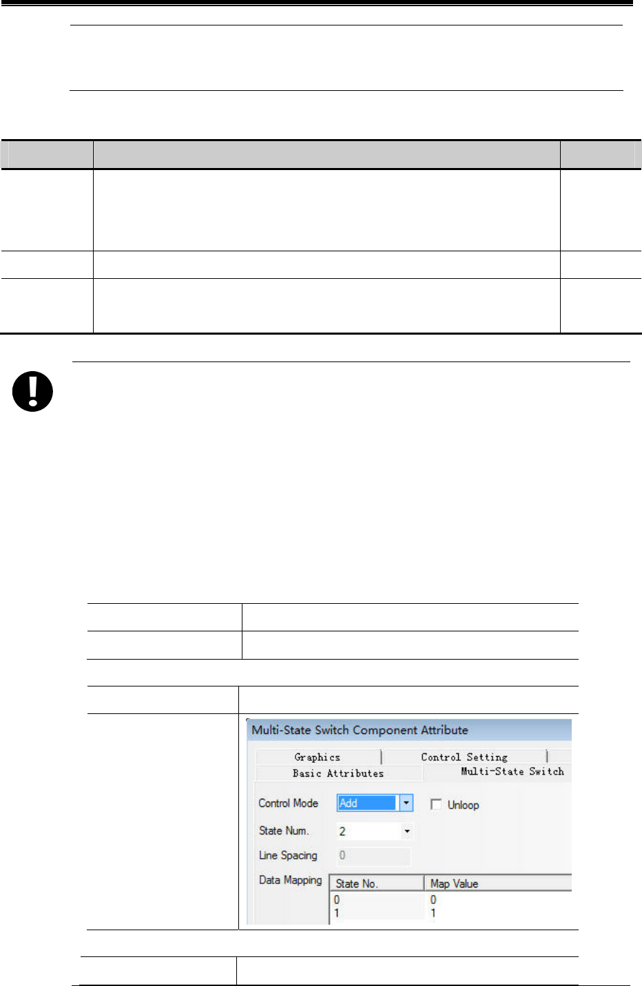
Kinco HMIware Configuration Edit Software
472
For example, LW9680=1000,input adderss LW1000. We use LW9681 to point to output address. For
example,LW9681=2000, Output address LW.B2000.
- USB Camera to scan two-dimension code
Address description Read/write
LB9420 Open USB camera scan.
ON: camera shows a rectangle frame, put the two-dimension code inside. Once
recognized, the buzzer rings out, and LB9420 turns off. OFF: no scan
R/W
LW9819 Number of bytes of the text R
LW9820 Save the address which keeps the text. For example:LW9820=1000, then the text will be
stored in LW1000 until the next scan clears it.
R/W
To scan two-dimension code, users have to open camera. The size of frame is suggest to be 640*480.If it is
too small, the code cannot be included.
Chinese is not supported
Users have to update their kernel and rootfs by software with version higher than V2.3 (build150820) if
MT4000 and F series HMI produced before 2015.8.28 are used. While HMI produced latter can use this
function without extra settings.
For example:Connect MT4414 to Logitech C170 to scan two-dimension code
Steps:
Put camera in frame 0
Read address LW0
Display settings Width:640, height:480
Multiple sate switch
Read/write address LW0
Control mode
Bit state switch
Read/write address LB9420(special system register)
HardwarePartNameandSpecification
473
Switch type Toggle
Multiple sate setting
Write address LW9820 (special system register)
Setting mode Set at window open value 1000
Number display
Read address LW9819 (special system register)
Data type Unsigned int
Text display
Read address LW1000
Word length 16
Result:
Set 1 to multiple state switch and switch LB9420 ON,
Users can scan code and display it on the screen
- Others
Address Description Read/Write
LB9162
TTF font optimization display. Set the bit to ON to optimize the display effect of the edge of
the TTF font.
R/W
LB9164 Video mode selection. ON: NTSC mode; OFF: VPAL mode. R/W
LB9260 Speed selection switch pages. ON: Switch page displays fast. OFF: Switch page displays slow. R/W
LB9261
Switch page data display selection. ON:Keep original data. OFF:Page data first brush cut to
zero, and then display valid data.
R/W
LB9271 CSV of History Data Display and Data Report keeps the same fractional part with the
functioning component. Set on to use it. If the decimal number has fractional part , the CSV file
has it too. Default OFF
R/W
LB9910
Open WebServer. Set the bit to ON to open WebServer function; while OFF to close this
function.
R/W
LB9911
Brower display mode. Set the bit to ON to display HMI image with gray mode in browser;
while OFF to display actual HMI image.
R/W
LW9370 Operation acknowledgement mode. Operator acknowledgement mode: 1: Confirm; 2: Cancel. R
LB9915 Set on,with key, KM5303 switch disable RW
LB9920 Set on, instead invalid float number NAN of former value RW
!
1. The above functions will take effect after restart.
2. The values of the local words above will be saved after power off.

Kinco HMIware Configuration Edit Software
474
16.2.3 Components Setting
- Input Components
Address Description Read/Write
LB9129
Trigger input components in basic window. Set the bit to ON to trigger input components in
basic window.
W
LB9131
Input components trigger automatically. Set the bit to ON to make the input components
triggered automatically after open window.
R/W
LB9140
Caps Lock. Set the bit to ON to make English letters input in capital format; the bit will be set
to OFF automatically after input finished.
R/W
LB9142
Trigger input components in popup window. Set the bit to ON to trigger input components in
the popup window in top layer.
W
LB9161
Components left alignment display. Set the bit to ON to make the display
component(LW9060~9075) on the keyboard displays left alignment when input.
R/W
LB9240
ON: When he number input component which read address same as write address is input ENT,
the new value will display immediately.
R/W
LB9241
The number input element display the blank before password input. Set ON, the number input
element display blank before password input;Set OFF, the number input element display *
number before password input. Default is OFF。
R/W
LW9002 ~
9003
Display the maximum of numeric input. When numeric input component is activated, it will
display the maximum of the numeric component. Otherwise, it will be set to 0.
R
LW9004 ~
9005
Display the minimum of numeric input. When numeric input component is activated, it will
display the minimum of the numeric component. Otherwise, it will be set to 0.
R
LW9060 ~
9075
Number/Text input procedure display. The words will display the input procedure when
Number/Text input components are activated. LW9075 display the latest input data. Usually text
components are used for displaying.
R
LW9180 ~
9187
Display the maximum of number input, usually by text components. R/W
LW9190 ~
9197
Display the minimum of number input, usually by text components. R/W
LW9380 ~
9395
Display the historical data of number input components, usually by text components. R
- Text components
Address Description Read/Write
LB9137 Display the bytes of text display component in inverted order. Set the bit to ON, then the R/W

HardwarePartNameandSpecification
475
high bytes and low bytes of text component will exchange to display, the low bytes will
display on the right side of the text component.
LB9138
Mask text characters. Set the bit to ON to make text component only display characters in
code 33~127. Other characters will be replaced by space character.
R/W
LB9243
Set ON, the text input element is not allowed to enter after the full input;Set OFF, more than
the number of bits, the highest in order to remove. Default is OFF.
R/W
LB9410 Set the bit to ON, the lack bit display 0; otherwise the lack bit display space. Default: Off R/W
LB9411 Set the bit to ON,clear content before input. Otherwise no action. R/W
LW9130 Switch text library contents online. The value indicates the text library index. R/W
LW9170
Display the page number of note book component. The value indicates the initial row of the
input area. It is used for page turning of note book component.
R
- Alarm/Event
Address Description Read/Write
LB9124 Times of alarm setting. Set the bit to ON to display alarm times in the front of the massages. R/W
LB9141
Turn off the current sound of buzzer alarm. Set the bit to On to turn off the current sound of
buzzer alarm, upon completion, the bit will be cleared automatically.
W
LB9270
Open the function of exporting event to csv file including date. ON:Open.After setting ON,the
format of csv file in external device(USB,SD Card)will change,it can’t be used together with
the function “Save to external device” like USB and SD Card. OFF: Close.
R/W
LB9280
Identifier bit of unconfirmed event. ON: there are events which are unconfirmed; OFF: there
is no event which is unconfirmed.
R/W
LB9281 ON: confirm all events. R/W
LB9401
Mask buzzer for event and alarm. Set this bit to ON to close buzzer; Set this bit to OFF to
open buzzer.
R
LB9916
Page registers prohibit cross-border display blank. Set ON, when the page registers
cross-border, the events will automatically change to the maximum value of the normal range.
R/W
LW9533
LW9534
Events exported to save as CSV file by the type. LW9533 control the lower type, LW9534
control the higher type.
R/W
LW9616 Record the current number of events triggered. Word length:1 R/W
- Trend Curve
Address Description Read/Write
LB9110 Active view and zoom function of trend curve. R/W
LB9111 Active cursors function of trend curve. R
LB9203 Set on to print Y-axis each time. Default OFF R/W
Kinco HMIware Configuration Edit Software
476
LW9200 Time value of the browsed points of trend curve, second. BIN code. R
LW9201 Time value of the browsed points of trend curve, minute. BIN code. R
LW9202 Time value of the browsed points of trend curve, hour. BIN code. R
LW9203 Time value of the browsed points of trend curve, date. BIN code. R
LW9204 Time value of the browsed points of trend curve, month. BIN code. R
LW9205 Time value of the browsed points of trend curve, year. BIN code. R
LW9210~
Display the value of every channel of every browsing dot in trend curve. According to the
channels of trend curve, the registers will display the current value of each channel. LW9210
displays the value of channel 0; LW9211 displays the value of channel 1; …
R
- Register decoding in Modbus Slave driver
Address Descriptions R/W
Adjust the decoding sequence of 16bits integer
Value Sequence Descriptions For example:0x0001
0 12 High byte and low byte are normal Means 1 (0x0001)
LW9810
1 21 High byte and low byte swap Means 256 (0x0100)
R/W
Adjust the decoding sequence of 2bits integer
Value Sequence Descriptions For example:0x0000 0001
0 1234 High byte and low byte,high word and low
word are Normal
Means 1 (0x0000 0001)
1 2143 High word and low word are normal,but
high byte and low byte swap.
Means 256(0x0000 0100)
2 3412 High word and low word swap,but
high byte and low byte are normal.
Means 65536
(0x0001 0000)
LW9811
3 4321 High word and low word,high byte
and low byte swap.
Means 16777216
(0x0100 0000)
R/W
Adjust the decoding sequence of 2bits float
Value Sequence Descriptions For example:0x3F80 0000
0 1234 High byte and low byte,high word and
low word are Normal
Means 1.0(0x3F80 0000)
1 2143 High word and low word are normal,but
high byte and low byte swap.
Means -5.78564e-039
(0x803F 0000)
2 3412 High word and low word swap,but
high byte and low byte are normal.
Means 2.27795e-041
(0x3F80 0000)
LW9812
3 4321 High word and low word,high byte
and low byte swap.
Means 4.60060e-041
(0x0000 803F)
R/W
16.2.4 Security Leve l and User Permission
- Security Level
Address Description Read/Write
LB9046 Lower security level. The bit will be set to ON when system switches from a lower R

HardwarePartNameandSpecification
477
security level to a higher level.
LW9040~9041 Password of security level. Double word. W
LW9042 Security level. Display security level of current base window. R
LW9043
Switch security level by force. Force to switch from higher level (for example, level 2)
to lower level (for example, level 0).
W
- Mapping of Security Level
Address Description Read/Write
LW10024~10025 Level 1 password. Double word R/W
LW10026~10027 Level 2 password. Double word R/W
LW10118~10119 Level 3 password. Double word R/W
LW10120~10121 Level 4 password. Double word R/W
LW10122~10123 Level 5 password. Double word R/W
LW10124~10125 Level 6 password. Double word R/W
LW10126~10127 Level 7 password. Double word R/W
LW10128~10129 Level 8 password. Double word R/W
LW10130~10131 Level 9 password. Double word R/W
LW10132~10133 Level 10 password. Double word R/W
LW10134~10135 Level 11 password. Double word R/W
LW10136~10137 Level 12 password. Double word R/W
LW10138~10139 Level 13 password. Double word R/W
LW10140~10141 Level 14 password. Double word R/W
LW10142~10143 Level 15 password. Double word R/W
!
1. The value of the local word above could be saved after power off.
2. Online modification of passwords is supported by the function.
3. Passwords could be modified online, while offline simulation does not support passwords modification.
- User Permission
Address Description ReadWrite
LB9165 User login. Set ON to execute logining operation, then set OFF automatically. W
LB9166 User logoff. Set ON to execute logoff operation, then set OFF automatically. W
LB9167 Add user. Set ON to execute adding user operation, then set OFF automatically. W
LB9168 Delete user. Set ON to execute deleting user operation, then set OFF automatically. W
LB9169 Modify password. Set ON to modify password operation, then set OFF automatically. W
Kinco HMIware Configuration Edit Software
478
LB9190
Executive mark of user management. The bit will set to ON when execute operations of
Add/Delete users.
R
LB9191
Operation failure of user management. The bit will be set to ON when operation of user
management fails.
R
LW9486~9501 User name for login. Input user name for login, 32 characters at most. R/W
LW9502~9503 User password. Input user password for login. R/W
LW9504~9505
Display user permission of the current user. Display the user permission with 32 bits
corresponding to the current user.
R
LW9506~9507 Set user permission. Set user permission with 32 bits when adding user information. W
LW9508~9509 Set automatic logoff time. Set automatic logoff time when adding user information. W
LW9510~9511
Password confirmation. Input password again to confirm the consistency when adding
user information.
W
LW9650~9665 Display login user name R
- Set HMI license online
Address Description Read/Write
LW9821 License count R/W
LW9822 License number(license1-license10) R/W
LW9823 Authorization password login window R/W
LW9824~9829 Expire time,year,month,date,hour,minute,second R/W
LW9830 Authorization password R/W
LW9832 License grade. LW.B9832.0 is first , LW.B9832.1is second …LW.B9832.9is 10th R
LB9425 Set on to save R/W
16.2.5 Data and Project Management
Recipe operation
Address Description Read/Write
LB9010
Recipe downloading indication. The bit will be set to ON in downloading status, and set
to OFF automatically after download is finished (Download from recipe to PLC).
R
LB9011
Recipe uploading indication. The bit will be set to ON in uploading status, and set to
OFF automatically after uploading is finished (Upload from PLC to recipe).
R
LB9012
Recipe Download/Upload indication. Set to ON in downloading/uploading status, and
set to OFF automatically after downloading/uploading is finished.
R
LW9000~9001
Index address for recipe data. RWI and RBI access recipe data by this index address.
LW9000 is low word, LW9001 is high word.
R/W
LB9130 Clear RW register. Set the bit to ON to trigger RW clearance. R/W
LW9260~9261 Initial address for RW clear operation. R/W
LW9262~9263 Word length for RW clear operation. R/W
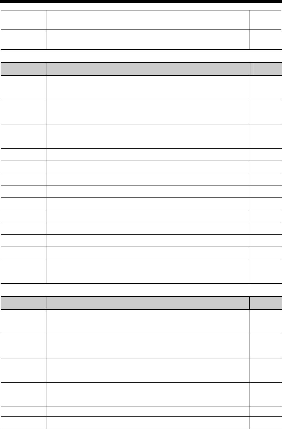
HardwarePartNameandSpecification
479
LW9536~
9537
Set start address when using external device for example U disk to download recipe data R/W
LW9538~
9539
Set length when using external device for example U disk to download recipe data. 0:
download all
R/W
- External memory operation
Address Description Read/Write
LB9153
Safety removing setting of SD card. Set the bit to ON before inserting SD card; Set to
OFF before removing to make sure safety removing.
R/W
LB9154
Safety removing setting of U disk 1. Set the bit to ON before inserting U disk 1; Set to
OFF before removing to make sure safety removing.
R/W
LB9155
Safety removing setting of U disk 2. Set the bit to ON before inserting U disk 2; Set to
OFF before removing to make sure safety removing.
R/W
LB9156 Clear files in SD card. Clear all the files that generated in SD card. W
LB9157 Clear files in U disk 1. Clear all the files that generated in U disk 1. W
LB9158 Clear files in U disk 2. Clear all the files that generated in U disk 2. W
LB9220 HMI is reading SD card indication. ON: reading operation R
LB9221 HMI is reading U disk1 indication. ON: reading operation R
LB9222 HMI is reading U disk2 indication. ON: reading operation R
LB9230 HMI is writing SD card indication. ON: writing operation R
LB9231 HMI is writing U disk1 indication. ON: writing operation R
LB9232 HMI is writing U disk2 indication. ON: writing operation R
LW9470~9485
Prefix title of the copied file. Prefix character strings of the file name which is copied to
SD card or U disk.
R/W
- File list box operation
Address Description Read/Write
LB9150
Execute import/export operation of project or recipe. Set the bit to ON to execute
import/export operation.
W
LB9151
Protection bit of export project. Uploading password is input correctly when export
project, then the bit will be set to OFF, otherwise, it will be set to ON.
R
LB9152
Switch folder type between tree type and list type. Set the bit to ON to display folders in
tree type, while set it to OFF to display folders in list type.
R/W
LB9265
Open import/export logo function.ON: Open import/export logo function. OFF: Open
import/export project function.
R/W
LB9266 Import and export FRW/RW. ON: FRW import/export. OFF: RW import/export. R/W
LW9300~9331 Route name of the browsed file. Display the route name which is browsed currently in R

Kinco HMIware Configuration Edit Software
480
file list component.
LW9332~9363
Current selected file. Display the file name which is browsing currently in file list
component.
R/W
LW9364
Import/ export selection of project or recipe. 1: project import; 2: project export; 3:
recipe import; 4: recipe export. 7: LOGO import; 8: LOGO export. 9: FRW import; 10:
FRW export.
R/W
LW9366
Copy/cut/ paste operation of files. With file browse component to execute: 1: copy; 2:
cut; 3: paste. 4:Delete
W
16.2.6 Communication
- PLC communication information
Address Description Read/Write
LB9136
Filtrate communication of the non-response PLC. Set the bit to on to filtrate
communication of the non-response PLC.
R/W
LB9144
Hide the component which failed in communication. Set the bit to ON to hide the
component which failed in communication.
R/W
LB9180
Notification bit of PLC access error, when PLC communication error occurs, the bit will
be set to ON.
R
LW9264~9279
Mask off code of PLC station NO. (COM port 0). Each bit corresponds to one station no.
of port 0 (9264.0 corresponds to station no. 0, … , 9279.F corresponds to station no.
255), set the corresponding bit to ON to mask the communication of the corresponding
station.
R/W
LW9280~9295
Mask off code of PLC station NO. (COM port 1). Each bit corresponds to one station no.
of port 1 (9280.0 corresponds to station no. 0, … , 9295.F corresponds to station no.
255), set the corresponding bit to ON to mask the communication of the corresponding
station.
R/W
LW9400~9415
Mask off code of HMI no.. Each bit corresponds to one HMI no. in the network (9400.0
corresponds to HMI no. 0, … , 9415.F corresponds to HMI no. 255), set the
corresponding bit to ON to mask the communication of the corresponding HMI.
R/W
LW9432~9447
Register for communication status indication (COM 0). Each bit corresponds to one
station no. (9432.0 corresponds to station no. 0, … , 9447.F corresponds to station no.
255). When PLC communication timeout and no response, the corresponding bit will be
set to ON, otherwise, the bit will be set to OFF.
R/W
LW9448~9463
Register for communication status indication (COM 1). Each bit corresponds to one
station no. (9448.0 corresponds to station no. 0, … , 9463.F corresponds to station no.
255). When there is no response and PLC communication timeout, the corresponding bit
R/W

HardwarePartNameandSpecification
481
will be set to ON, otherwise, the bit will be set to OFF.
LW9296~9299
Mask off code of error message. Each bit corresponds to one error message. Set the bit
to ON to mask the corresponding error message indication.
For example:“PLC No Response” corresponds to 9296.2, “Socket Connect Error”
corresponds to 9296.4
R/W
LW9550~9553
Indication code of error message. Each bit corresponds to one error message, when an
error indication occurred, the corresponding bit will be set to ON automatically.
For example :“PLC No Response” corresponds to 9550.2 ,“Socket Connect
Error”corresponds to 9550.4
R
- Mapping of communication parameters
Address Description Read/Write
LW10030~10033 IP address. Each section occupies one word, range 0~255. R/W
LW10034
Download port number. It is download port number rather than communication port
number.
R/W
LW10035 Reserved. R/W
LW10110 Gateway. Each section occupies one word, range 0~255. R/W
LW10114 Subnet mask. Each section occupies one word, range 0~255. R/W
LW10036 Work mode of COM0. 0:232;1:485-4w;2:485-2w R/W
LW10037~10038 Baud rate of COM0. Double word.. R/W
LW10039 Data bit of COM0. R/W
LW10040 Check bit of COM0. R/W
LW10041 Stop bit of COM0. R/W
LW10042 Slave station no. of COM0 (HMI station no.) R/W
LW10043~10044 PLC time-out constant of COM0. R/W
LW10045~10046 Protocol time-out constant 1of COM0. R/W
LW10047~10048 Protocol time-out constant 2 of COM0. R/W
LW10056 Work mode of COM1. 0:232;1:485-4w;2:485-2w R/W
LW10057~10058 Baud rate of COM1. Double word.. R/W
LW10059 Data bit of COM1. R/W
LW10060 Check bit of COM1. R/W
LW10061 Stop bit of COM1. R/W
LW10062 Slave station no. of COM1 (HMI station no.) R/W
LW10063~10064 PLC time-out constant of COM1. R/W
LW10065~10066 Protocol time-out constant 1of COM1. R/W

Kinco HMIware Configuration Edit Software
482
LW10067~10068 Protocol time-out constant 2 of COM1. R/W
LW10182 Work mode of COM2. 0:232; R/W
LW10183~10184 Baud rate of COM2. Double word.. R/W
LW10185 Data bit of COM2. R/W
LW10186 Check bit of COM2. R/W
LW10187 Stop bit of COM2. R/W
LW10188 Slave station no. of COM2 (HMI station no.) R/W
LW10189~10190 PLC time-out constant of COM2. R/W
LW10191~10192 Protocol time-out constant 1of COM2. R/W
LW10193~10194 Protocol time-out constant 2 of COM2. R/W
!
1. The above functions will take effect after restart.
2. The value of some local words above will be saved after power off.
- Variables of station number
Address Description Read/Write
LW9416 Variable register of station number. It corresponds to index 0 of variable of station number. R/W
LW9417 Variable register of station number. It corresponds to index 1 of variable of station number. R/W
LW9418 Variable register of station number. It corresponds to index 2 of variable of station number. R/W
LW9419 Variable register of station number. It corresponds to index 3 of variable of station number. R/W
LW9420 Variable register of station number. It corresponds to index 4 of variable of station number. R/W
LW9421 Variable register of station number. It corresponds to index 5 of variable of station number. R/W
LW9422 Variable register of station number. It corresponds to index 6 of variable of station number. R/W
LW9423 Variable register of station number. It corresponds to index 7 of variable of station number. R/W
LW9424 Variable register of station number. It corresponds to index 8 of variable of station number. R/W
LW9425 Variable register of station number. It corresponds to index 9 of variable of station number. R/W
LW9426 Variable register of station number. It corresponds to index 10 of variable of station number. R/W
LW9427 Variable register of station number. It corresponds to index 11 of variable of station number. R/W
LW9428 Variable register of station number. It corresponds to index 12 of variable of station number. R/W
LW9429 Variable register of station number. It corresponds to index 13 of variable of station number. R/W
LW9430 Variable register of station number. It corresponds to index 14 of variable of station number. R/W
LW9431 Variable register of station number. It corresponds to index 15 of variable of station number. R/W
- Error code of bus
Address Description Read/Write

HardwarePartNameandSpecification
483
LW9145 Record error codes of Profibus. R
LW9146 Record error codes of Canopen. R
Macro code operation
Address Description Read/Write
LB9116 Macro reading input registers indication. The bit will be set to ON when Macro is reading input
registers, set to OFF automatically after finish reading.
R
LB9117 Macro writing output register indication. The bit will be set to ON when Macro is writing input
registers, set to OFF automatically after finish writing.
R
LB9118 Macro working indication. The bit will be set to ON When Macro is running (read and write
register operation are included), set to OFF after finish.
R
LW9465 Time magnification of Macro time-out. If it is set to N, then the allowable maximum running
time for once of Marco is N times as long as the default value.
LW9466 Macro to read communication time of register
R/W
Data Transmit Operation
Address Description Read/Write
LW9467 Write communication time of Data Transmit R/W
LW9468 Read communication time of Data Transmit R/W

484
Hardware Part

485
1 Name and Specification
This chapter mainly introduces names and specifications of the universal parts of MT series HMI.
Names and specifications of the special parts of MT series HMI, please refer to related selection manual.
1.1 Name of Each Part
Names of the universal parts of MT series:
Front:
PWR
CPU
COM
a
d
c
b
a. Screen display /Touch control area b. PWR indicator c. CPU indicator d. COM indicator
Back:
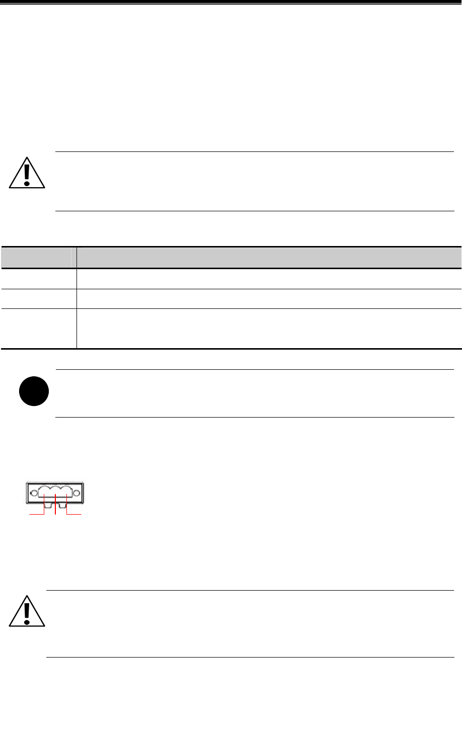
Kinco HMIware Configuration Edit Software
486
a. Input terminal of power supply DC24V b. 1A Fuse c. LAN interface d. USB HOST(USB type A interface) e. USB
SLAVE(USB type B interface) f. COM1(female) g. COM0&COM2(male) h. RESET Button i. DIP Switch j. SD
CARD interface k. One-time button type lithium battery
1.2 Specifications of Each Part
1.2.1 Screen display/Touch control area
The touch panel is for input/output and display.
Caution
In the case of personal safety may be endangered or significant losses may be leaded, please do not use the
input function of HMI touch switch as emergency stop switch.
1.2.2 LED indicator
Indicator Description
PWR When the power supply of HMI is ON/OFF, the yellow indicator is ON/OFF.
CPU When CPU works normally, the green indicator is ON.
COM
When HMI communicates with PLC and such controllers normally, the red indicator will frequently
flick or be normally ON.
!
COM indicator only indicates the communication states of PLCs connected to COM0 and COM1.
1.2.3 Power Supply
Input voltage:DC24V±15%
24V GND FG
24V:Connect to 24V+ terminal of the power supply.
GND:Connect to COM terminal or 0V terminal of the power supply.
FG:Earthing terminal
1.2.4 Fuse
Fast fuse with rated current 1A is used.
Notice
Fast fuse offers protection when the power supply voltage is too high or power polarity is connected
reversely, but it cannot ensure the internal electronic components shall not be damaged.
1.2.5 Serial ports
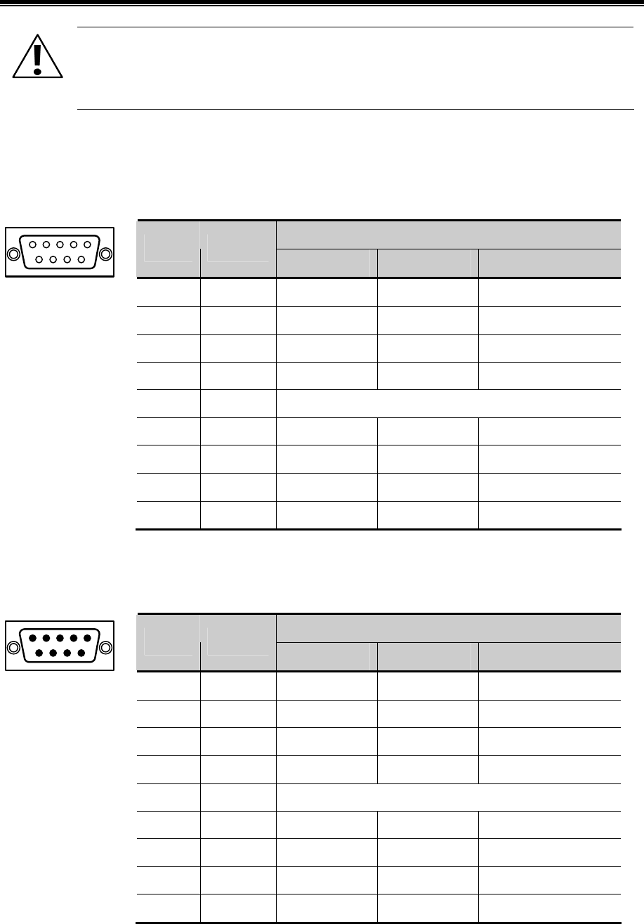
Hardware Part Name and Specification
487
Notice
Please do not hot plug communication cable with charged, to avoid the communication interface being
damaged.
- Serial port COM0
COM0 is a 9-pin D-SUB male connector, it supports communication functions of RS-232C/RS-485/RS-422A, and its pin
assignment is as follows:
Function
Pin# Signal
RS-232C RS-485 RS-422A
1 RX-(B) -- RS485B Receive data
2 RXD Receive data -- --
3 TXD Send data -- --
4 TX- -- -- Send data
5 SG Signal Ground
6 RX+(A) -- RS485A Receive data
7 NC -- -- --
8 NC -- -- --
9 TX+ -- -- Send data
- Serial port COM1
COM1 is a 9-pin D-SUB female connector, it supports communication functions of RS-232C/RS-485/RS-422A, and its pin
assignment is as follows:
Function
Pin# Signal
RS-232C RS-485 RS-422A
1 RX-(B) -- RS485B Receive data
2 RXD Receive data -- --
3 TXD Send data -- --
4 TX- -- -- Send data
5 SG Signal Ground
6 RX+(A) -- RS485A Receive data
7 CTS Clear to send -- --
8 RTS Request to send -- --
9 TX+ -- -- Send data
- Serial port COM2
COM2 shares physical interface with COM0, is 9-pin D-SUB male connector, this port only supports communication
function of RS-232C, and its pin assignment is as follows:

Kinco HMIware Configuration Edit Software
488
Function
Pin# Signal
RS-232C
1 NC --
2 NC --
3 NC --
4 NC --
5 SG Signal Ground
6 NC --
7 RXD Receive data
8 TXD Send data
9 NC --
COM2 can connect with controllers supporting RS-232C, also can be used to upload/download program and debug.
1.2.6 USB interfaces
- USB HOST
USB HOST is a USB A type interface,can connect with peripheral equipments such as USB storage device, keyboard,
mouse and so on. Its pin assignment is as follows:
Pin# Signal Function
1 VCC +5V power supply
2 D- Data-
3 D+ Data+
4 GND -5V Earthing
- USB SLAVE
USB SLAVE is a USB B type interface,can connect with the USB port of PC, and is used to upload/download program and
debug. Its pin assignment is as follows:
Pin# Signal Function
1 VCC +5V power supply
2 D- Data-
3 D+ Data+
4 GND -5V Earthing
1.2.7 LAN interface
LAN port is a 10M/100M transmission speed auto-adapted RJ-45 type interface, can be used to upload/download program
and debug; Multiple HMIs equipped with LAN interfaces can be networked at will via this port and communication with
controllers supporting Ethernet communication is also supported by this port. Its pin assignment is as follows:

Hardware Part Name and Specification
489
Pin# Signal Function
1 TX+ Send data +
2 TX- Send data -
3 RX+ Receive data +
4 NC --
5 NC --
6 RX- Receive data -
7 NC --
8 NC --
1.2.8 SD CARD interface
SD CARD port is suitable for connecting with ordinary plug of which the size is 32mm×24mm×2.1mm. It can be used to
save data and quick upload/download user projects, recipes and such files. Its pin assignment is as follows:
Pin# Signal Function
1 CD/DAT3 Card checkout / Data 3
2 CMD Command
3 VSS1 GND
4 VDD Power supply (+3V)
5 CLK Clock
6 VSS2 GND
7 DAT0 Data 0
8 DAT1 Data 1
9 DAT2 Data 2
1.2.9 DIP switch
DIP Switch is used to set the HMI system in different working modes, the corresponding working modes of the setting are as
follows:
SW1 SW2 Working mode
OFF OFF Normal working mode
ON OFF
☞ More details about Firmware Update Mode, please refer to
【Hardware Part 5 Firmware Update Mode】
OFF ON
☞More details about Touch Screen Calibrate Mode, please
refer to【Hardware Part 4 Touch Screen Calibrate Mode】
ON ON
☞More details about System Setting Mode, please refer to
【Hardware Part 3 System Setting Mode】

Kinco HMIware Configuration Edit Software
490
1.2.10 RESET switch
Press the RESET button,HMI will restart.
1.2.11 Button battery
Non-rechargeable button type LI-Mn battery is used, and the standard voltage is 3V. (CR series)

491
2 Connection with Preiferal Equipments
To meet users’ requirements for multifunction screens of intelligence, information, humanity, MT series HMIs have equipped
with kinds of interfaces. The equipments supported by the interfaces are described in turn as follows.
2.1 Connection via Serial Port
(1) Connect with PLC and other controllers via serial ports to communicate
HMI can connect with the serial ports of PLC and such controllers to communicate via RS-232C/RS-485/RS-422A serial
cable.
- Requirements for connection
The PLC and such controllers communicate with HMI must be of the types supported by Kinco HMIware, or support the
serial communication protocols supported by Kinco HMIware.
- Cable production
Users can make the connection cable by themselves according to the types of controllers and communication modes.
(2) Upload/download data via serial ports
HMI can connect with the serial ports of PC to upload/download user projects, recipes and such data via RS-232C serial
cable.
- Requirements for connection
Install and run the HMIware configuration software of Kinco on PC, select download ways through the 【Tools】menu of the

Kinco HMIware Configuration Edit Software
492
software.
☞More details about download please refer to【Advanced Part 7.3 Download】
- Cable production
Users can make the connection cable by themselves.
(3)Connect with scanner and such equipments via serial ports
HMI can connect with scanner via RS-232Cserial cable to receive banner code and such data.
- Requirements for connection
The scanners communicate with HMI must be of the types supported by Kinco HMIware, or support the serial
communication protocols supported by Kinco HMIware.
- Cable production
Directly use the RS-232C communication cable provided by the scanner manufacturer.
(4)Connect with miniprinter via serial ports
HMI could connect with miniprinters to print screen or data report via RS-232C serial ports.
- Requirements for connection
The miniprinters communicate with HMI must of the types supported by Kinco HMIware, or support the serial
communication protocols supported by Kinco HMIware.
More details please refer to the manual of 【Communication Connection Guide】.
- Cable production
Users can make the connection cable by themselves.
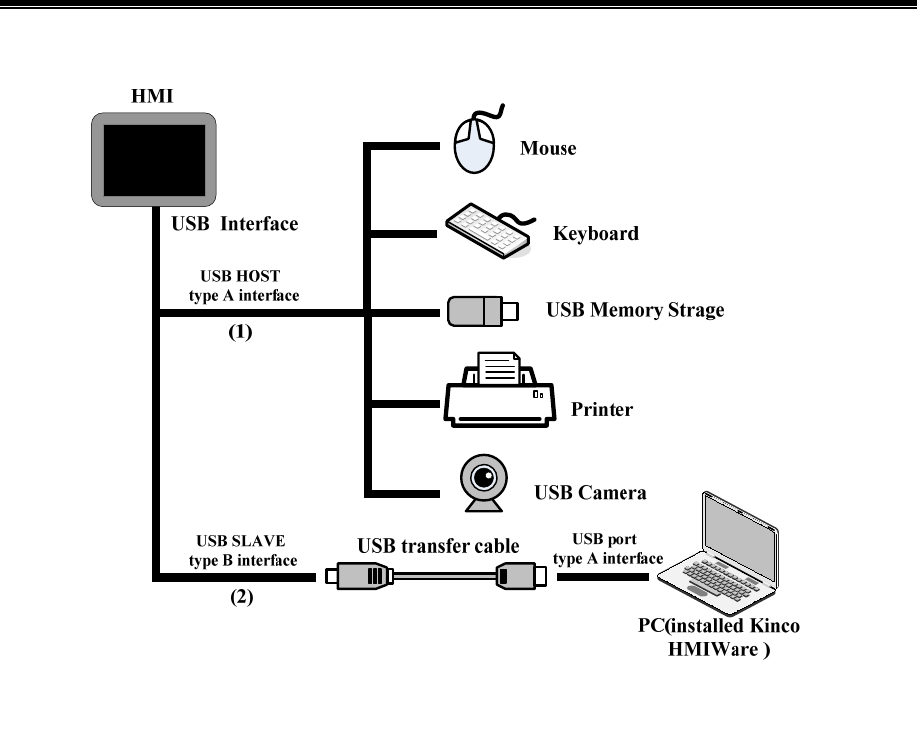
Hardware Part Connection with Preiferal Equipments
493
2.2 Connection via USB Interfaces
(1) Connect with USB mouse, USB keyboard and such equipments via USB HOST
- Connect with USB mouse
HMI connects with USB mouse, then the USB mouse can execute input operation to the HMI screen.
- Connect with USB keyboard
HMI connects with USB keyboard, then the USB keyboard can execute input operation to the HMI screen via the
【Map Key】function of Function Key components.
- Connect with USB mass storage device
Connection between HMI and USB mass storage device can be used for:
Quick upload/download user projects, recipes and such files between HMI and USB mass storage devices via
import/export functions;
A physical storage area (ERW) is divided up from the USB mass storage device, users take access to ERW registers to
read/write data directly on HMI.
Historical data of Trend Curve and XY Curve, historical events, operation log and such data can be saved in USB mass
storage devices.
- Connect with USB printer
HMI can connect with USB printers via USB cable to print screen and data report.
The USB printers communicate with HMI mush be of the types supported by Kinco HMIware, or support the printer
communication protocols supported by Kinco HMIware.
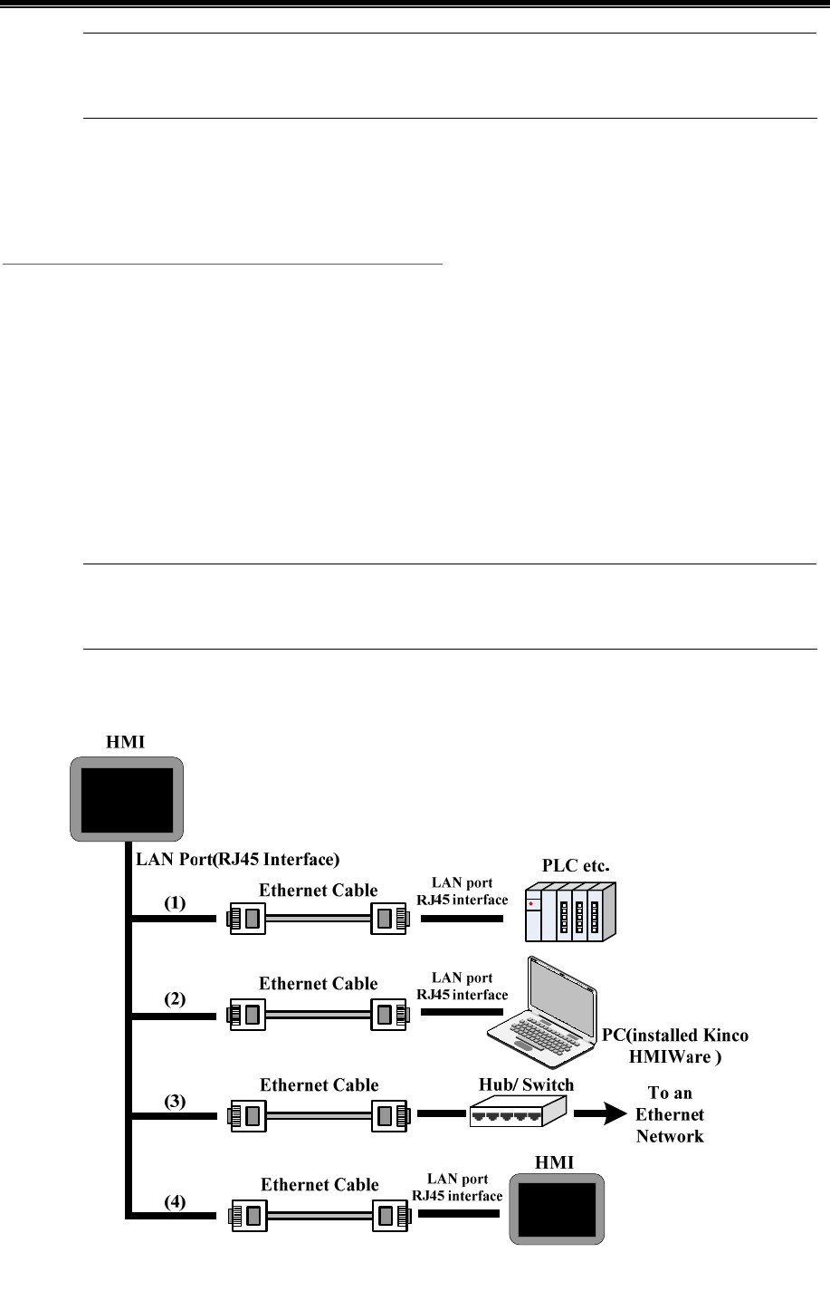
Kinco HMIware Configuration Edit Software
494
Details about the supported printers please refer to the manual of 【Communication Connection Guide】.
- Connect with USB camera
HMI can connect to camera with drive type USB to display the video pictures input by USB camera via camera component.
☞More details please refer to 【Advanced Part 4.10.2 Camera】
(2)Upload/download data via USB SLAVE
HMI can connect with the USB interfaces of PC to upload/download projects, recipes and such data via USB cable.
- Requirements for connection
Install and run the HMIware configuration software of Kinco on PC, select download ways through the 【Tools】menu of the
software.
- Cable production
Users can make the connection cable by themselves.
Details about cable production please refer to the manual of 【Communication Connection Guide】.
2.3 Connection via LAN Interfaces
(1)Connect with PLC and such controllers to communicate

Hardware Part Connection with Preiferal Equipments
495
HMI can connect to PLC and such controllers to communicate via an interconnection cable (RJ45 Crossover Cable).
- Requirements for connection
The PLC and such controllers communicate with HMI mush be of the types supported by Kinco HMIware, or support the
Ethernet communication protocols supported by Kinco HMIware.
- Cable production
Users can make the connection cable by themselves.
(2)Upload/download/monitor data via LAN interface
Via interconnection cable (RJ45 Crossover Cable), HMI can connect with the LAN interface of PC to upload/download user
projects, recipes and such data; meanwhile users can monitor the data of HMI or PLC and such controllers on PC.
- Requirements for connection
Install and run the HMIware configuration software of Kinco on PC, select download ways through the 【Tools】menu of the
software.
- Cable production
Users can make the cable for connection by themselves.
(3)Connect HMI to a Local Area Network via Hub/Switch
HMI can be connected to a HUB or SWITCH to access a Local Area Network via a standard Ethernet cable (RJ45
straight-through cable) or interconnection cable (RJ45 cross-over cable). This is mainly used for multiple HMIs links or
HMI network with multiple PLC and such controllers.
☞ More details please refer to【Adavanced Part 14 HMI Communication】
(4)linking via LAN interface
HMI can link to another HMI via interconnection cable (RJ45 Crossover Cable).
- Requirements for connection
All HMIs online are with LAN interfaces, and set 【HMI Attributes】—【Networking Device Setting】in the software.
- Cable production
Users can make the connection cable by themselves.
More details please refer to the manual of 【Communication Connection Guide】.
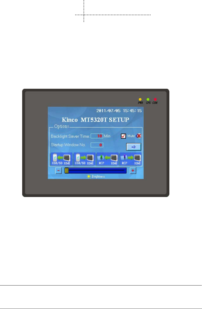
496
3 System Setting Mode
In this mode, users can set such items as system time, Startup Window, IP address.
3.1 Methods to Display System Setting Mode
Enter the System Setting Mode by the following steps:
Set the DIP switch SW1 and SW2 to “ON”;
Press the “RESET button, then HMI restarts and enters the SETUP interface.
3.2 System Setting
Take the SETUP interface of MT5320T for example:
In the SETUP interface of MT5320T,the following items can be set:
- Startup Window No.:Startup window. It is the displayed window when start HMI, the default value is 0.
- Backlight Saver Time:Screen saver time, in minutes. The default value is 10. Screen saver is unavailable when the
value is 0.
- Buzzer Disabled/Enabled:Enable/Disable the buzzer. For MT5000/4000 series HMI, select “Mute” to close the buzzer.
- Network parameter setting: set the network parameters such as IP Address, Port, Subnet Mask, Gateway of a target
screen equipped with Ethernet port.
- Brightness adjustment: Adjust brightness(Brightness Up/Down)to achieve the best visual effect.
Brightness adjustment is not supported by some HMI models.
- Calibrate Time: Check whether the year, month, day, hour, minute and second are the current time, otherwise, calibrate
manually.
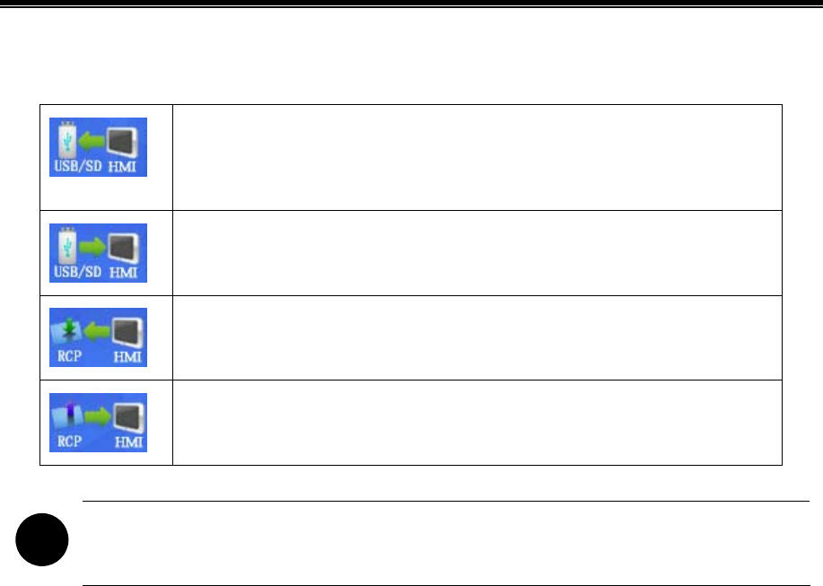
Hardware
497
- Import/Export: Quick upload/download user project files or recipe files. The function is only supported be HMIs
equipped with USB HOST/SD Card ports.
Upload the user project files (.pkg)saved in HMI to USB or SD Card. Upload password is
required when upload, the default password is 888888 if it has not been set in the HMI
attributes dialogue box.
Download the user project files (.pkg)saved in USB or SD Card into HMI.
Upload the recipe files (.rcp)saved in HMI to USB or SD Card.
Download the recipe files (.rcp)saved in USB or SD Card into HMI.
!
The SETUP interface may not be displayed in full size in a single screen, then click “Next” or “” to enter
the next page and click Back” or “” to return the previous page.

498
4 Touch Screen Calibrate Mode
When the screen touch is not accurate after firmware update, users can calibrate HMI screen under this mode.
4.1 Methods to Display Touch Screen Calibrate Mode
There are two methods to enter the Touch Screen Calibrate Mode:
Method 1: Enter Touch Screen Calibrate Mode by set DIP switches.
Set the DIP switch SW1 and SW2 (on the back of the HMI) to “ON”;
Press the “RESET button, then HMI restarts and enters the Touch Screen Calibrate interface.
Method 2:Enter Touch Screen Calibrate Mode by the “Touch Calibration” function of【Function Key】.
Method 2 is directly completed on the HMI screen, users do not need to manipulate the DIP switches and without bothering
to open the control cabinet.
☞More details please refer to【Advanced Part 4.2.6 Function Key】
4.2 Touch Screen Calibrate Setting
Follow the “+”sign to touch the screen until you hear a click sound and the“+”sign disappears, then “TP Adjust Success!”is
showing, which indicates that Touch Screen Calibrate is successed. Then, set DIP switch 1 and 2 to “OFF” and press
【Reset】button, restart HMI to exit Touch Screen Calibrate Mode.

499
5 Firmware Update Mode
In firmware update mode, users can update the version of the Kernel and Root files system (It is strongly recommended that
the users use the function under the guidance of Manufacturer).
5.1 Methods to Display Firmware Update Mode
Enter the Firmware Update Mode by the following steps:
Set the DIP switch (on the back of the HMI) SW1 to “ON” and SW2 to “OFF”;
Press the “RESET button, then HMI restarts and enters the Touch Screen Calibrate interface.
5.2 Firmware Update Setting
Open KHManager, enter【System Operation】to update the Kernel and Root files system.
☞More details please refer to 【Advanced Part 8 KHManager】
!
Please backup the configuration projects, recipe data and so on before update Kernel/Root files system, to
avoid data loss during update.

500
6 Maintenance and Tending
This chapter mainly introduces the maintenance and inspection methods to prevent errors occur, so as to ensure the normal
use of the products.
Caution
Do not disassemble the host or touch any internal component in a powered state, otherwise electric
shock accidents may be leaded.
6.1 Maintenance
To ensure the HMI in an optimal state, please maintain the following items regularly:
- Engineering data backup
Regularly backup engineering data and store it to safe place, to prevent engineering data loss when HMI malfunctions and
in need of repairment and parts replacement.
- Backlight replacement
When the backlight darkens and is difficult to see clearly, then, the backlight should be replaced. The users cannot replace
the backlight privately.
When you need to replace the backlight, please contact your local dealer or representative offices.
- Battery replacement
Some HMI models use button type Li-Mn batteries to save recipe data and system time when HMI powers off, when the
voltage of the battery is lower than 2.5V, then the battery should be replaced. Users could buy and replace the batteries
according to the specified specifications by themselves.
6.2 Tending
- Screen tending
When the screen gathers dust or dirt, please disconnect the power supply for HMI, then, soak a piece of soft cloth in neutral
detergent and wring it to dry, and then wipe the screen gently.
!
Prohibition
1. Do not use paint thinner, organic solvent or strong acid mixture to clean the screen.
2. Do not use hard or sharp objects to operate or wipe the screen, otherwise, screen surface will be
damaged.
- Periodic inspection
To ensure the HM in an optimal state, please inspect the following items regularly:

Appendix 3 List of System Prompt Message
501
Working environment
Whether the temperature or humidity of HMI working environment is in the specified range?
Whether there is corrosive or flammable gas in the working environment of HMI?
Electrical performance
Whether the power supply input voltage is in the specified range?
Others
Has any of the power cable or power cord of the power supply terminals been loosened?
Whether all the installed fasteners are locked tight?

502
Appendix 1 Regular PLC Used for HMI
Brand Connecting device description
ABB AC31/ AC500
MicroLogix PLC
SLC500 PLC
PLC-5 PLC
AB SLC500/PLC5/MicroLogix
Series(DF1)
AB SLC500/PLC5/MicroLogix Series
Ethernet(TCP Slave)
CompactLogix PLC
(Rockwell)Allen-Bradley
ControlLogix PLC
AB CompactLogix/ControlLogix
Series(DF1)
AB CompactLogix/ControlLogix Series
Ethernet(TCP Slave)
(Advantech)ADAM ADAM-4015/ ADAM-4017
Baldor NextMove ES Controller
Baumuller BM4413-ST0-02200-03
KVFC+ Inverter
PPC-R Series Controller
Bosch Rexroth
IndraLogic L Series Controller Bosch Rexroth
Bosch Rexroth Ethernet
Kinco k4
(CAN)CANOpen Node
Slave Other company devices which support
CANOpen
Danfoss FC-300
DVP PLC Delta
DVP
Emerson EC10/ EC20 Series PLC
Facon FBs/ FBe/FBn Facon FB/Modbus RTU
Fuji SPB Series PLC/ NB Series PLC
Fanuc Series 90-30 Series PLC
Fanuc Series 90-70 Series PLC
VersaMax Series PLC
VersaMax Micro&Nano Series PLC
GE
PACSystem RX7i Series PLC
GE Fanuc Series SNP/GE SNP-X
Modbus TCP
Hitachi H Series PLC

Appendix 1 Regular PLC Used for HMI
503
EH-150 Series PLC
MICRO-EH Series PLC
SJ300 Inverter
LM Series PLC Hollysys
LK Series PLC Hollysys LK Modbus RTU
Hollysys LK Modbus TCP Slave
IDEC Micro Smart Series PLC
Inovance H2U Series PLC Inovance H2u
Modbus RTU
Kinco K3 PLC
ED Series Servo
CD Series Servo
EB-MOD2P-01 Modbus RTU
Kinco EB-MOD2P-01
Kinco
EB-MOD2P-11
Keyence KV-16DT/ KV-1000/ KV-3000/ KV-5000
Lenze Lecom A/B Series Inverter
Master-k Series PLC LS K-Master Cnet
LS K-Master CPU Direct
LS K-Master Modbus RTU
XGT Series PLC LS XGT Cnet
LS XGT CPU Direct
LS
GLOFA Series PLC LS GLOFA Cnet
LS GLOFA FEnet
CDE34.008 LUST
ServoOne junior
FX Series PLC
Q Series PLC
FX Series Link Module
Mitsubishi
QJ Series Link Module
Modbus RTU
Modbus RTU Extend
Modbus RTU Slave
Modbus RTU MT500 Compatible
Modbus
Modbus ASCII

Kinco HMIware Configuration Edit Software
504
Modbus TCP
Modbus TCP Slave
Modbus UDP
Modbus UDP Slave
C Series PLC
C Series Link PLC
CJ2 Series PLC
CJ1 Series PLC
CS1 Series PLC
CJ Series Link Module
CS Series Link Module
Omron
E5EZ-R3 Controller
OPTO SNAP
Panasonic FP Series PLC
Compax3 Series
SLVD Series
Parker
6K4 Series
Siemens S7-300/ Siemens S7-400 Profibus DP Slave
Other company devices which support
PROFIBUS DP Master
Micro Series PLC
Premium Series PLC
Nano Series PLC
Modbus RTU
Schneider Modicon Uni-TelWay
Schneider
Twido
S7-200 SIEMENS S7-200
SIEMENS S7-200 Ethernet(TCP Slave)
S7-300 SIEMENS S7-300/400(PC Adapter Direct)
SIEMENS S7-300/400(MPI Direct)
Profibus Slave
SIEMENS S7-300 Ethernet(TCP Slave)
S7-400 SIEMENS S7-300/400(PC Adapter Direct)
SIEMENS S7-300/400(MPI Direct)
Profibus Slave
SIEMENS S7-400 Ethernet(TCP Slave)
Siemens
S7-1200

Appendix 1 Regular PLC Used for HMI
505
Thinget XC3-32R-E Modbus RTU
Thinget Controller
Trio Euro Trio
Modbus RTU Extend
Vigor VH series PLC/ VB0 series PLC
V Inverter
MP Series Yaskawa MP2300
Yaskawa Ethernet(UDP Slave)
Yaskawa
∑Ⅱ/∑Ⅱ Plus Servo
Yokogawa FA-M3 Yokogawa FA-M3
Yokogawa FA-M3 Ethernet(TCP Slave)
YuDian AI Series PLC

506
Appendix 2 List of Error Information
No. Error information Description
1
Compilation failed! No compiled PKG files are
generated!
Macro code or other reasons result in compilation failing,
no compiled PKG files are generated.
2
Warning: Init. Start Window does not exist, the
software will add the default Init. Start Window
automatically!
The initial start picture saved in the original project possibly
has been lost, the system will automatically replace it with
Kinco initial start picture.
3
Logo's size is too big, please adjust it! Logo's
size is out of limit: Width*Height > 2097152
The bitmap imported for Initial Start Window is bigger than
the software restriction.
4 Logo file error! HMI0.lg file went wrong.
5 HMI%s logo compile failed!
HMI0.lg corresponding to Logo does not exist, or the
picture used by logo does not exist.
6 Current HMI can not support this component! The current HMI does not support the component.
7
Export file already exist, do you want to replace
it?
The same file is exported to the same path repeatedly.
8 Unable to write file, export failed! The exported file name is possibly illegal.
9 Unable to parse file, import failed!
The file to import does not exist or the file format is
discrepant.
10
The project is existed in your selected content,
replace the old one?
The new project is of the same name with the already
existing project in the path.
11
Project has been opened, can not open
repeatedly!
Kinco HMIware cannot open one project repeatedly.
12
The new version project can not be opened by
the old version software! Please update your
software!
Software of low version cannot open the project edited by
new version software. The software is upward compatible,
please use the new version software.
13
Can not save project. Please check the following
files permission!
The project is set to read only and cannot be modified and
saved again.
14
Save project error, please resume you project
from \"temp\" directory in your project directory!
The project saved last time will be backupped automatically
in the \"temp\" directory.
15
The project had been modified, please save and
compile first!
After modifying, the project should be saved and compiled
again.
16 Can not find compiled file, please compile first! PKG file is wrong or lost.
17
A same name project already exists in this folder,
please select another folder!
Projects of the same name cannot be saved in the same path.

Appendix 2 List of Error Information
507
18
Software was closed abnormally last time,
whether restore the unsaved project?
Prompt when reopen the project after abnormal close.
19
The project is created by old version
software .Do you want to backup and update the
project now?\n\nWarning:the updated project can
not be opened by old version software!
Prompt for backuping when use high version software to
open the project edited by low version software.
20 System default window, unable to delete!
Frame0~9 are the system default windows, cannot be
deleted.
21 Rename variable error!
The variable names possibly include “?”, “、”, “/” and such
illegal characters.
22 Project incompleted!
There are only serial port cables or PLCs in the Construct
Window.
23
Project error: some HMIs, PLCs or connectors
are not be connected!
HMIs, PLCs and communication cables do not be
connected properly in the Construct Window.
24
After delete, all related pictures will lost and can
not be recovered! Do you want to continue?
When delete the HMIs in the Construct Window, all the
configuration pictures will be deleted and cannot be
recovered, please be cautious with this operation.
25
After delete, all related register address for the
plc items will be set default value and can not be
recovered! Do you want to continue?
When delete PLCs, all the registers related with PLC will be
changed to HMI default registers, and cannot be recovered,
please be cautious with this operation.
26
If remove all, all objects will be deleted and can
not be recovered! Do you want to continue?
Prompts of 【Delete all】in the attribute box of BUS, events,
alarms, text libraries, address labels, PLC control.
27
After replace, some parts of the HMI will change
position, size or colour, and can not be
recovered! Do you want to continue?
When replacing HMI models, the different screen sizes will
lead to some components’ attributes be adjusted
automatically in the configuration project.
28
Element or the special function of the element. It
has been deleted!
When replacing HMI, some components not supported by
the new HMI will be automatically deleted due to different
hardware, for example Video, Historical Event Display and
such components.
29
Project contains some HMIs which are not
supported by current version software. These
HMIs had been auto updated to some available
HMIs:\n\n
The discontinued HMI models have been deleted in the
configuration software of higher version, the discontinued
HMI model will be replaced automatically when open the
project edited by low version software.
30 Error: address cross-border The addresses exceed the allowed range.
31 Error: address format error The address format does not match with the actual format of

Kinco HMIware Configuration Edit Software
508
Error: address input error component, possibly decimal number is written to octonary
system, or entered characters are illegal.
32 Invalid address type!
Address type not supported by the driver protocols is used
in the project.
33 The files are damaged or deleted, can not play! Audio files faulted.
34
Load system word library error!/ Vector font files
used in project does not exist, please close the
project, install the missing font files
If the font library used in the project does not exist in the
computer, then song typeface will be taken as default when
opening the project.
35
Copy error: the destination window ID already
exists!
Source windows cannot be copied to the existing windows.
36 Size too large, can not be pasted!
Copy component across windows or projects, the
component size should be smaller than target window.
37
The size of File %s is larger than 256K, the file
can not be added to sound library!
Audio file imported into audio library should be less than
256k.
38
The fieldbus device is already defined, do you
want to replace it?/ Network device is already
defined,do you want to replace it?
If a fieldbus or network device is already defined in HMI, it
will prompt when you add the same fieldbus or network
device again.
39 Only one protocal can be defined in a device!
Prompt when the same protocol is added repeatedly in the
same fieldbus device.
40 The Invalid Path!/ The Invalid ProjectName!
Prompt when saving project as or opening project but there
is no path or project name checked.
41
Bottom Window Error: the frame can not be used
as both parent window and bottom window!
Two windows cannot be used as mutual bottom window.
42
Window size settings failed, please adjust parts
position first, then reset the windows size!
The width and height values of the modified window should
be bigger than its coordinate values.
43
Image of GIF/PNG format or with alpha channel
do not support the additional transparent color
treatment!
In picture editing window, transparent color treatment is
invalid for image of GIF/PNG format or with alpha channel.
44
Error: Please select at least one display
condition!
【Conditional display】of component is chosen,but no
display condition is checked and click【OK】.
45
Part size error: Width and height of part can not
less than 1!
The width and height values should both be bigger than 1
when modifying component size.
46 Error: The content cannot be empty! When static text is used, it must not be empty.
47 Error: Text size must less than screen size!
The input content of static text is too long and exceeds the
screen size.

Appendix 2 List of Error Information
509
48
Same item exists in the text library, whether or
not to replace?
Prompt when import text library and there is item of the
same name already existed.
49 Error: Text size must less than screen size!
The Fonts are too big that exceed the display area of the
components and windows.
50
The HMI does not support the HistoryDataDisp
components!
KW5300T/KM5303T/KG5509T/KG5300T do not support
historical data display.
51 HMI cannot support USB2!
MT4220TE/4414TE/4424/4522/4523/4620TE are equipped
with only one USB host.
52
IP address is already defined, please check it/ IP
address conflict, please check it!
When there are multiple HMIs in the configuration and
network communication protocol is used to network, the IP
addresses cannot repeat.
53
The station NO. is already defined, please check
it!
When adding new PLC, there is the same station no. already
existing in the same protocol.
54
The window id is incorrect or the window exists,
please input another id!
The number for the new frame is illegal or the number is
already existed.
55
The current screen does not support the property
of sound !
The target HMI does not support audio.
56
The hmi %s dosn't support the property of Save
screen shots to extend memory!
The target HMI does not support external storage devices.
57 Failed to open file File error when uploading.
58 Cannot open Serial Port Serial port may be occupied already.
59 Open usb handel fail
USB cable is not connected or the USB port is broken, or
the USB driver is not installed successfully.
60
Send data error/read data error/Data checkSum
error/file checksum fail
Errors appear during downloading, so data received by HMI
is inconsistent with data sent by upper machine, please
unplug the communication cable between HMI and PLC,
restart HMI and try again.
61 Recipe file size error Recipe size is larger than HMI recipe registers.
62 No download option was be selected
Click the【Download】button when no download option is
chosen in KHDownload dialog box.
63 Unsupport HMI, download failed!
The model of the HMI is not supported by the used
software, high version software should be used.
64
Please use method of big BMP zipped or
simplify configuration project
The project is too large to be downloaded, please check
whether lots of bitmaps or vector fonts are used in the
project and simplify the project and download again.

Kinco HMIware Configuration Edit Software
510
65 create file fail
Cannot download to external storage device, possibly there
are illegal characters included in the file name.
66 Save file fail
Prompt when download to external storage device and the
memory is insufficient.
67
Upload password must contain nonzero
character!
The password cannot be zero when setting upload password
in【HMI Attribute】page.
68 Invalid Password, please Input Password again! Upload password entry failure.
69 password checksum fail Prohibiting upload is set in the target HMI program.
70 Invalid Password. Project cannot be opened!
After the project is encrypted, password input is wrong
when open project.
71 password error, please reset system and try again Password for decompilation is input wrong repeatedly.
72 Failed to upload file
Data package lost when uploading file, please unplug the
communication cable between HMI and PLC, restart HMI
and try again.
73 No select decompile PKG file
Click【Decompile】button when no PKG file or target
project for decomilation is chosen.
74
Number of PKG Files wrong ,can not
decompile!/ PKG file is not generated by the
same project and same build, can not decompile!
When multiple HMIs are networked, decompilation is not
supported.
75 PKG file does not allow decompile! Prohibit decompiling is set in the【HMI Attributes】page.
76
PKG file edited by configuration software
version lower than1.2.3.0 cannot be decompiled!
Only the PKG files edited by software version higher than
version 1.2.3.0 can be decompiled.
77
Another decompile process has not ended, please
closed it first!
Prompt when starting a new decompilation while there is a
decompilation in process.
78 A same directory exists, delete it and continue?
Target project file cannot be saved in the same directory
with the original PKG file.
79
Online Simulation overtime and Program is end,
if want, Please Simulate again
Maximum duration for direct online simulation is 15
minutes, after the time run out users need to simulate again.
80
An instance of software already exists, please
close it first!
Only one simulation process can be executed at one time.

System Parameters
511
Appendix 3 List of System Prompt Message
Edit/Mask Mask address Prompt message Description
LW.B9296.0 [0]System Error System error (Possibly file system fault)
LW.B9296.1 [1]PLC Response Error Communication with PLC error, possibly the
selected driver protocol do not support the current
connected PLC (Read/write error)
LW.B9296.2 [2]PLC No Response :xx-xx-x PLC no response:xx-xx-x(HMI No.-PLC station
No. –Port No.)(Communication with PLC fail,
please check communication cable and whether
the communication parameters of PLC AND HMI
are consistent)
LW.B9296.4 [4]Socket Connect Error Connect to server failed. (Connect to local or
remote server failed. Usually network
communication faulted or PLC driver faulted, very
occasionally may communication cable of PLC
fault)
LW.B9296.5 [5]Socket COMM Error Communication with server error
LW.B9296.6 [6]MacroCode Error:xxxx Macro code xxxx execution error (Check marco
code, possibly there are memory access
cross-border or dividing by zero errors in marco
code)
LW.B9296.7 [7]Print Error Print error (communication with printer error.
Please check printer connection, make sure that
whether the current printer is supported by
selected printer protocol)
LW.B9296.8 [8]Send Package Error Send network massage failed.
LW.B9296.9 [9]Memory Shortage Run out of memory (Possibly open two many
popup windows or components occupying too
much resources, check whether use too many
popup windows, direct windows, indirect
windows, trend curves, oscillograghs, XY plots,
alarms and events in project)
Allow
mask/edit
LW.B9296.A [10]BCD Transform Overflow BCD conversion outflow. Check whether BCD
settings of component are correct.

Kinco HMIware Configuration Edit Software
512
LW.B9296.B [11]MacroCode Timeout:xxxx Marco code xxxx executing timeout (Macro
execution time is too long or there is an endless
loop)
LW.B9296.E [14]RW Access Overflow Recipe memory access cross-border(The accessed
recipe address is beyond current allowable range
of HMI)
LW.B9296.F [15]Waiting to Print Waiting for printing. Printing dada is under
processing (This is a normal prompt during
printing)
LW.B9297.0 [16]Servo Not Ready Server data is not ready (possibly server error), or
possibly firmware error or PLC driver error.
LW.B9297.2 [18]Transmit Data Failed Data transmission failed.
LW.B9297.3 [19]Data Input Failed Number input failed, the input value exceeds the
minimum/maximum values of number input
component.
LW.B9297.4 [20]Device Error Device fault (Access to input/output devices error,
possibly file system or firmware fault)
LW.B9297.5 [21]Copying File ... File is in copy (This is a normal prompt during
project export or screen shoot)
LW.B9297.6 [22]Copy File Failed File copy failed (Project export or screen shoot
fail)
LW.B9297.7 [23]Invalid File Import file is invalid(Filename invalid)
LW.B9297.8 [24]Password Error Input password wrong
LW.B9297.9 [25]SD Card Full SD card is full
LW.B9297.A [26]USB Disk1 Full U disk 1 is full
LW.B9297.B [27]USB Disk2 Full U disk 2 is full
LW.B9298.0 [32]RTC Device Error RTC clock fault (possibly RTC chip fault)
LW.B9298.2 [34]Invalid UserName Invalid user name (The input user name is invalid
when login or add/delete user)
LW.B9298.3 [35]Operation Complete Prompt of operation success (This is normal
prompt during printing when adding/deleting user
or modifying password)
DOWNLOAD/SIM MODE Enter download mode
STRAIGHT MODE Enter straight mode
Do not allow
edit/mask
No
corresponding
mask bits SIMULATION MODE Enter indirect online simulation mode

System Parameters
513
LOAD PKG OK! Project download success.
LOAD PKG ERROR! Project download fail.
TP adjust success! Touch screen calibration success.
TP adjust fail, try again! Touch screen calibration fail, calibrate again.
DOWNLOAD/SIM MODE
User Data invalid, please
redownload!
There is no project in HMI, download project
again.
Kinco HMIware version too low!
Please compile with new version!
The software version is too low, please use the
newest version, compile and download project
again.
System Crash HMI system crash, possibly project is too large or
firmware error.
