Kymco MXER 125 150 Service Manual
User Manual: Kymco MXER 125 - 150 Service Manual
Open the PDF directly: View PDF ![]() .
.
Page Count: 181 [warning: Documents this large are best viewed by clicking the View PDF Link!]
PREFACE
This Service Manual describes the
technical features and servicing
procedures for the KYMCO MX’er
125/150.
Section 1 contains the precautions for
all operations stated in this manual.
Read them carefully before starting any
operation.
Section 2 is the removal/installation
procedures for the frame covers which
are subject to higher removal/installation
frequency during maintenance and
servicing operations.
Section 3 describes the inspection/
adjustment procedures, safety rules and
service information for each part,
starting from periodic maintenance.
Sections 4 through 17 give instructions
for disassembly, assembly and
inspection of engine, chassis frame and
electrical equipment.
Most sections start with an assembly or
system illustration and troubleshooting
for the section. The subsequent pages
give detailed procedures for the section.
KWANG YANG MOTOR CO., LTD.
OVERSEAS SALES DEPARTMENT
OVERSEAS SERVICE SECTION
TABLE OF CONTENTS
GENERAL INFORMATION 1
FRAME COVERS/EXHAUST MUFFLER 2
INSPECTION/ADJUSTMENT 3
LUBRICATION SYSTEM 4
FUEL SYSTEM 5
ENGINE REMOVAL/INSTALLATION 6
CYLINDER HEAD/VALVES 7
CYLINDER/PISTON 8
DRIVE AND DRIVEN PULLEYS 9
FINAL REDUCTION/TRANSMISSION
SYSTEM 10
CRANKCASE/CRANKSHAFT/
BALANCE SHAFT 11
FRONT WHEEL/FRONT BRAKE/
FRONT SUSPENSION/STEERING
SYSTEM 12
REAR WHEEL /SWING
ARM/HYDRAULIC BRAKE 13
BATTERY/CHARGING SYSTEM/A.C.
GENERATOR 14
IGNITION SYSTEM 15
STARTING SYSTEM 16
LIGHTS/SWITCHES 17
ONLY ATV ON ROAD AVAILABLE 18
ENGINE CHASSIS
ELECTRICAL
EQUIPMENT
The information and contents included
in this manual may be different from
the motorcycle in case specifications
are changed.

1. GENERAL INFORMATION
1-0
MX’er SYSTEM
1
__________________________________________________________________________________
1
____________________________________________________________________
____________________________________________________________________
____________________________________________________________________
____________________________________________________________________
GENERAL INFORMATION
____________________________________________________________________
SERIAL NUMBER---------------------------------------------------------- 1- 1
SPECIFICATIONS ---------------------------------------------------------- 1- 2
SERVICE PRECAUTIONS------------------------------------------------ 1- 4
TORQUE VALUES --------------------------------------------------------- 1-12
SPECIAL TOOLS ----------------------------------------------------------- 1-14
LUBRICATION POINTS -------------------------------------------------- 1-15
CABLE & HARNESS ROUTING ---------------------------------------- 1-18
WIRING DIAGRAM-------------------------------------------------------- 1-22
TROUBLESHOOTING----------------------------------------------------- 1-23
1. GENERAL INFORMATION
1-1
MX’er SYSTEM
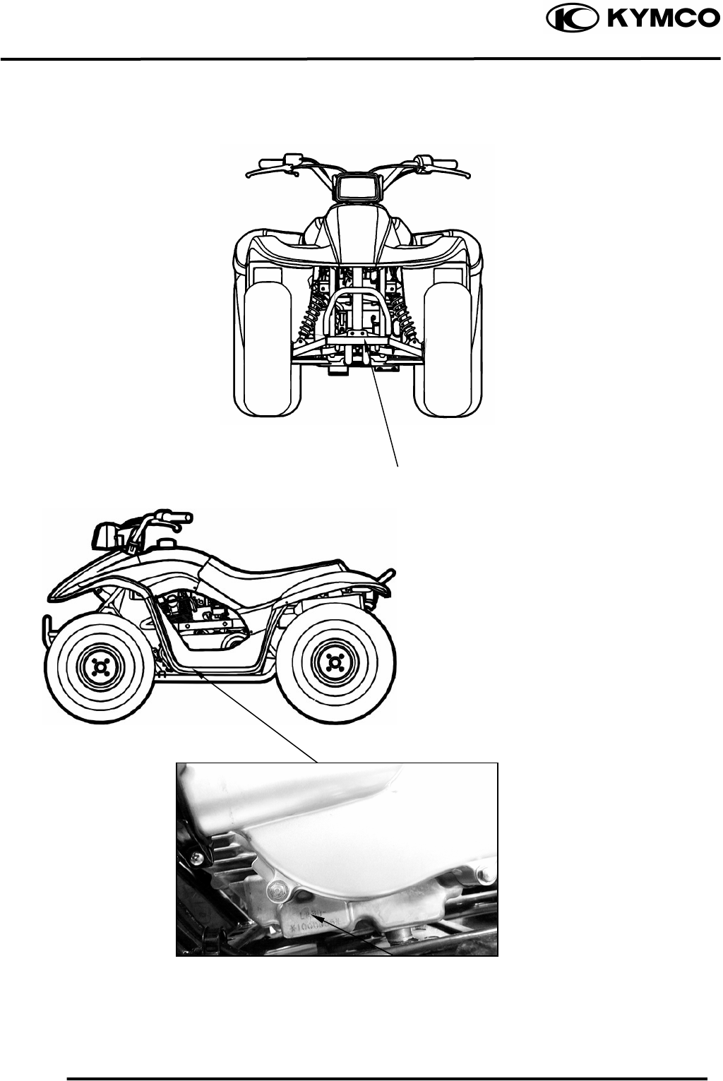
SERIAL NUMBER
Location of Frame Serial Numbe
r
Location of Engine Serial Numbe
r
1. GENERAL INFORMATION
1-2
MX’er SYSTEM
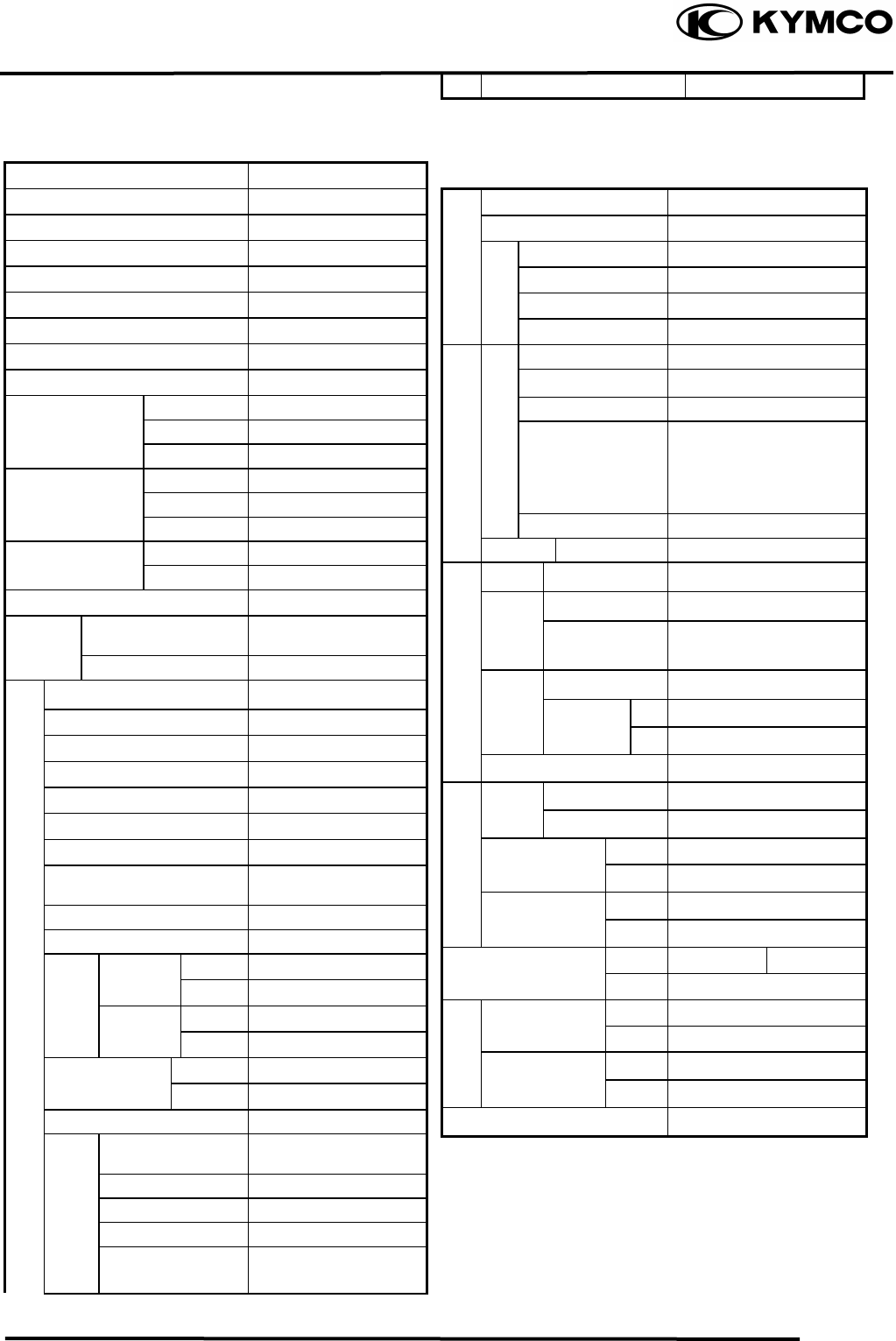
SPECIFICATIONS
Name & Model No. LA30AA, AB
Motorcycle Name & Type MX’er
Overall length (mm) 1600
Overall width (mm) 980
Overall height (mm) 990
Wheel base (mm) 1120
Engine type O.H.C.
Displacement (cc) 149.4
Fuel Used 92# nonleaded gasoline
Front wheel 74
Net weight (kg) Rear wheel 78
Total 152
Front wheel 80
Gross weight(kg) Rear wheel 82
Total 162
Front wheel 20*7-8
Rear wheel 22*10-8
Ground clearance (mm) 130
Perform- Breaking distance
(m)(ANSI) 20.6 below
ance Min. turning radius (m) 3
Starting system Starting motor
Type Gasoline, 4-stroke
Cylinder arrangement Single cylinder
Combustion chamber type Semi-sphere
Valve arrangement O.H.C., chain drive
Bore x stroke (mm) 62 x 49.5
Compression ratio 9.7:1
Compression pressure
(kg/cm²) 16.0
Max. output (ps/rpm) 11/7500
Max. torque (kg m/rpm) 1.1/5500
Intake
Open 5.5° BTDC
Port (1mm) Close 27.5° ABDC
timing Exhaust Open 36° BBDC
(1mm)
Close 4° ATDC
Valve clearance Intake 0.06
(cold) (mm) Exhaust 0.06
Idle speed (rpm) 1700rpm
Lubrication type Forced pressure &
wet sump
Oil pump type Inner/outer rotor type
Oil filter type Full-flow filtration
Oil capacity 1.0 liter
Oil exchanging
capacity 0.9 liter
Cooling Type Forced air cooling
Air cleaner type & No Sponge
Fuel capacity 8.1 liters
Type PD
Float lever 14.8mm
Venturi dia.(mm) φ25
Throttle type PISTON
Type CDI
Ignition timing 15°BTDC/1700rpm
Contact breaker Non-contact point type
Spark plug
NGK
CR8E
Spark plug gap 0.60.7mm
Battery Capacity 12V8AH
Clutch Type CVT
Type Helical gear
Operation Automatic centrifugal
type
Type Chain drive
Reduction 1st 2.8-0.95
ratio 2nd 7.226
Counter gear ratio 26.902
Front Caster angle
Axle Trail length
Tire
p
ressure Fron
t
0.2
(kg/cm²) Rear 0.25
Turning Left 44°
angle Right 44°
Brake s
y
ste
m
Rea
r
Disk brake Drum brake
type Front Drum brake
Sus
p
ension Fron
t
Swin
g
type Rear Swing arm
Shock Front Swing
type Rear Swing arm
Frame type SP pipe
Fuel S
y
stem
Carbureto
r
Electrical Equipment
I
g
nition S
y
stem
Tires
Power Drive System
Transmis-
sion Gear Reduction
Gear
Moving Device
Engine
Damping
Device
Lubrication
S
y
stem
1. GENERAL INFORMATION
1-3
MX’er SYSTEM
SPECIFICATIONS
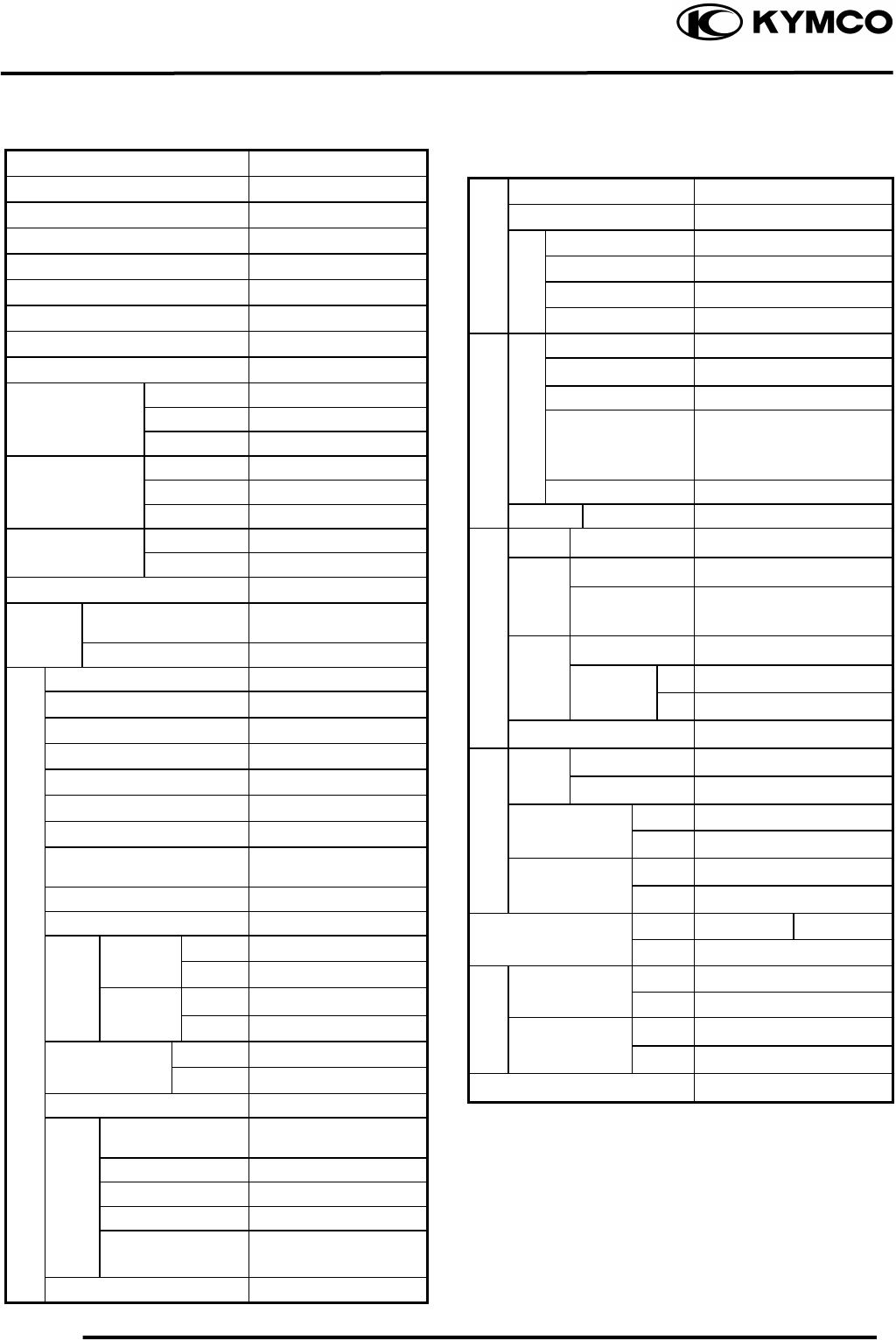
Name & Model No. LA25AB
Motorcycle Name & Type MX’er
Overall length (mm) 1685
Overall width (mm) 980
Overall height (mm) 990
Wheel base (mm) 1120
Engine type OHC
Displacement (cc) 124
Fuel Used 92# nonleaded gasoline
Front wheel 74
Net weight (kg) Rear wheel 78
Total 152
Front wheel 80
Gross weight(kg) Rear wheel 82
Total 162
Front wheel 20*7-8
Rear wheel 22*10-8
Ground clearance (mm) 130
Perform- Breaking distance
(m)(ANSI) 20.6 below
ance Min. turning radius (m) 2.5
Starting system Starting motor
Type Gasoline, 4-stroke
Cylinder arrangement Single cylinder
Combustion chamber type Semi-sphere
Valve arrangement O.H..C., chain drive
Bore x stroke (mm) 56.5 x 49.5
Compression ratio 9.2:1
Compression pressure
(kg/cm²) 14.0
Max. output (ps/rpm) 9.8/7500
Max. torque (kg m/rpm) 0.98/5500
Intake
Open 5.5° BTDC
Port (1mm) Close 27.5° ABDC
Timi
n
g
Exhaust Open 36° BBDC
(1mm)
Close 4° ATDC
Valve clearance Intake 0.06
(cold) (mm) Exhaust 0.06
Idle speed (rpm) 1700rpm
Lubrication type Forced pressure &
wet sump
Oil pump type Inner/outer rotor type
Oil filter type Full-flow filtration
Oil capacity 1.0 liter
Oil exchanging
capacity 0.9 liter
Cooling Type Forced air cooling
Air cleaner type & No Sponge
Fuel capacity 8.1 liters
Type PD
Piston dia. (mm) 14.8mm
Venturi dia.(mm) φ25
Throttle type PISTON
Type CDI
Ignition timing 15°BTDC/1700rpm
Contact breaker Non-contact point type
Spark plug NGK
CR8E
Spark plug gap 0.60.7mm
Battery Capacity 12V8AH
Clutch Type CVT
Type Helical gear
Operation Automatic centrifugal
type
Type Chain drive
Reduction 1st 2.8-0.95
ratio 2nd 7.226
Counter gear ratio 26.902
Front Caster angle
Axle Trail length
Tire
p
ressure Fron
t
0.2
(kg/cm²) Rear 0.25
Turning Left 44°
angle Right 44°
Brake s
y
ste
m
Rea
r
Disk brake Drum brake
type Front Drum brake
Sus
p
ension Fron
t
Swin
g
type Rear Swing arm
Shock Front Swing
type Rear Swing arm
Frame type SP pipe
Fuel S
y
stem
Carbureto
r
I
g
nition S
y
stem
Electrical Equipment
Tires
Power Drive System
Transmis-
sion Gear Reduction
Gear
Moving Device
Engine
Damping
Device
Lubrication
S
y
stem
1. GENERAL INFORMATION
1-4
MX’er SYSTEM
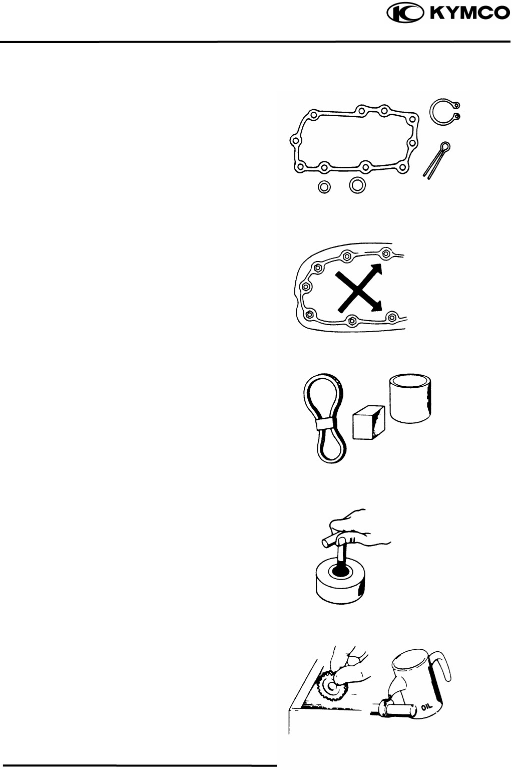
SERVICE PRECAUTIONS
Make sure to install new gaskets, O-rings,
circlips, cotter pins, etc. when
reassembling.
When tightening bolts or nuts, begin with
larger-diameter to smaller ones at several
times, and tighten to the specified torque
diagonally.
Use genuine parts and lubricants.
When servicing the motorcycle, be sure
to use special tools for removal and
installation.
After disassembly, clean removed parts.
Lubricate sliding surfaces with engine oil
before reassembly.
1. GENERAL INFORMATION
1-5
MX’er SYSTEM
Apply or add designated greases and
lubricants to the specified lubrication
points.
After reassembly, check all parts for
proper tightening and operation.
When two persons work together, pay
attention to the mutual working safety.
Disconnect the battery negative (-)
terminal before operation.
When using a spanner or other tools,
make sure not to damage the motorcycle
surface.
After operation, check all connecting
points, fasteners, and lines for proper
connection and installation.
When connecting the battery, the positive
(+) terminal must be connected first.
After connection, apply grease to the
battery terminals.
Terminal caps shall be installed securely.
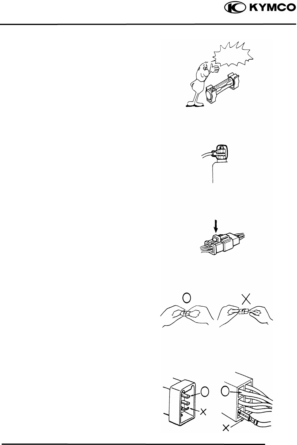
1. GENERAL INFORMATION
1-6
MX’er SYSTEM
If the fuse is burned out, find the cause
and repair it. Replace it with a new one
according to the specified capacity.
After operation, terminal caps shall be
installed securely.
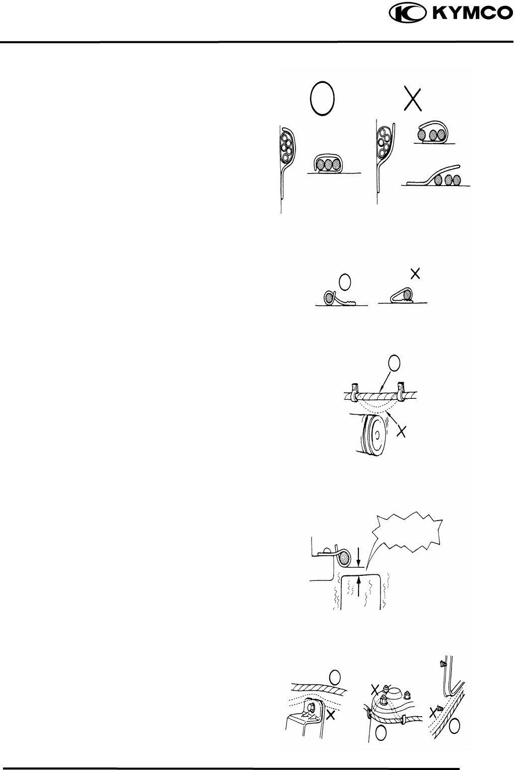
When taking out the connector, the lock
on the connector shall be released before
operation.
Hold the connector body when
connecting or disconnecting it.
Do not pull the connector wire.
Check if any connector terminal is
bending, protruding or loose.
Confirm
Capacity
1. GENERAL INFORMATION
1-7
MX’er SYSTEM
The connector shall be inserted
completely.
If the double connector has a lock,
lock it at the correct position.
Check if there is any loose wire.
Before connecting a terminal, check
for damaged terminal cover or loose
negative terminal.
Check the double connector cover for
proper coverage and installation.
Insert the terminal completely.
Check the terminal cover for proper
coverage.
Do not make the terminal cover opening
face up.
Secure wire harnesses to the frame with
their respective wire bands at the
designated locations.
Tighten the bands so that only the
insulated surfaces contact the wire
harnesses.
Sna
pp
in
g
!
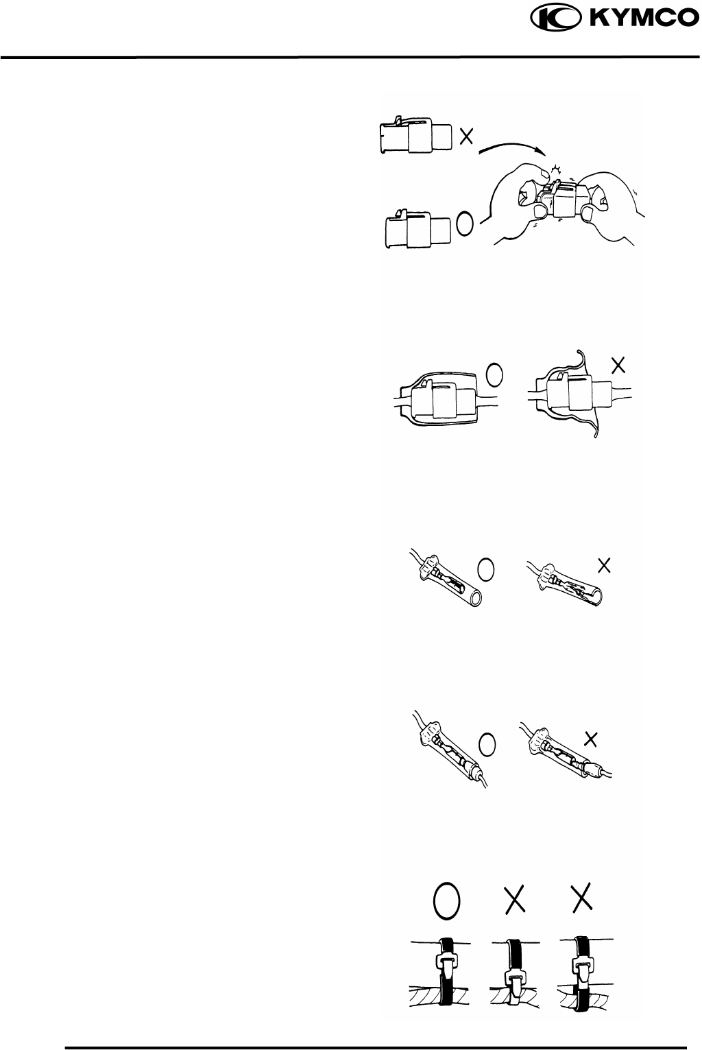
1. GENERAL INFORMATION
1-8
MX’er SYSTEM
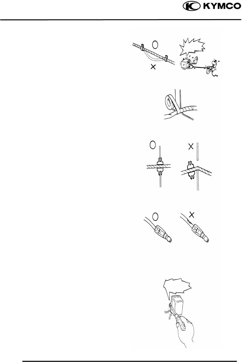
After clamping, check each wire to make
sure it is secure.
Do not squeeze wires against the weld or
its clamp.
After clamping, check each harness to
make sure that it is not interfering with
any moving or sliding parts.
When fixing the wire harnesses, do not
make it contact the parts which will
generate high heat.
Route wire harnesses to avoid sharp
edges or corners. Avoid the projected
ends of bolts and screws.
Route wire harnesses passing through the
side of bolts and screws. Avoid the
projected ends of bolts and screws.
No Contact !
1. GENERAL INFORMATION
1-9
MX’er SYSTEM
Route harnesses so they are neither
pulled tight nor have excessive slack.
Protect wires and harnesses with
electrical tape or tube if they contact a
sharp edge or corner.
When rubber protecting cover is used to
protect the wire harnesses, it shall be
installed securely.
Do not break the sheath of wire.
If a wire or harness is with a broken
sheath, repair by wrapping it with
protective tape or replace it.
When installing other parts, do not press
or squeeze the wires.
Do not pull
too ti
g
ht!
Do not press
or squeeze
the wire.
1. GENERAL INFORMATION
1-10
MX’er SYSTEM
After routing, check that the wire
harnesses are not twisted or kinked.
Wire harnesses routed along with
handlebar should not be pulled tight, have
excessive slack or interfere with adjacent
or surrounding parts in all steering
positions.
When a testing device is used, make sure
to understand the operating methods
thoroughly and operate according to the
operating instructions.
Be careful not to drop any parts.
When rust is found on a terminal, remove
the rust with sand paper or equivalent
before connecting.
Do you understand
the instrument?
Is the instrument set
correctly?
Remove Rust !
1. GENERAL INFORMATION
1-11
MX’er SYSTEM
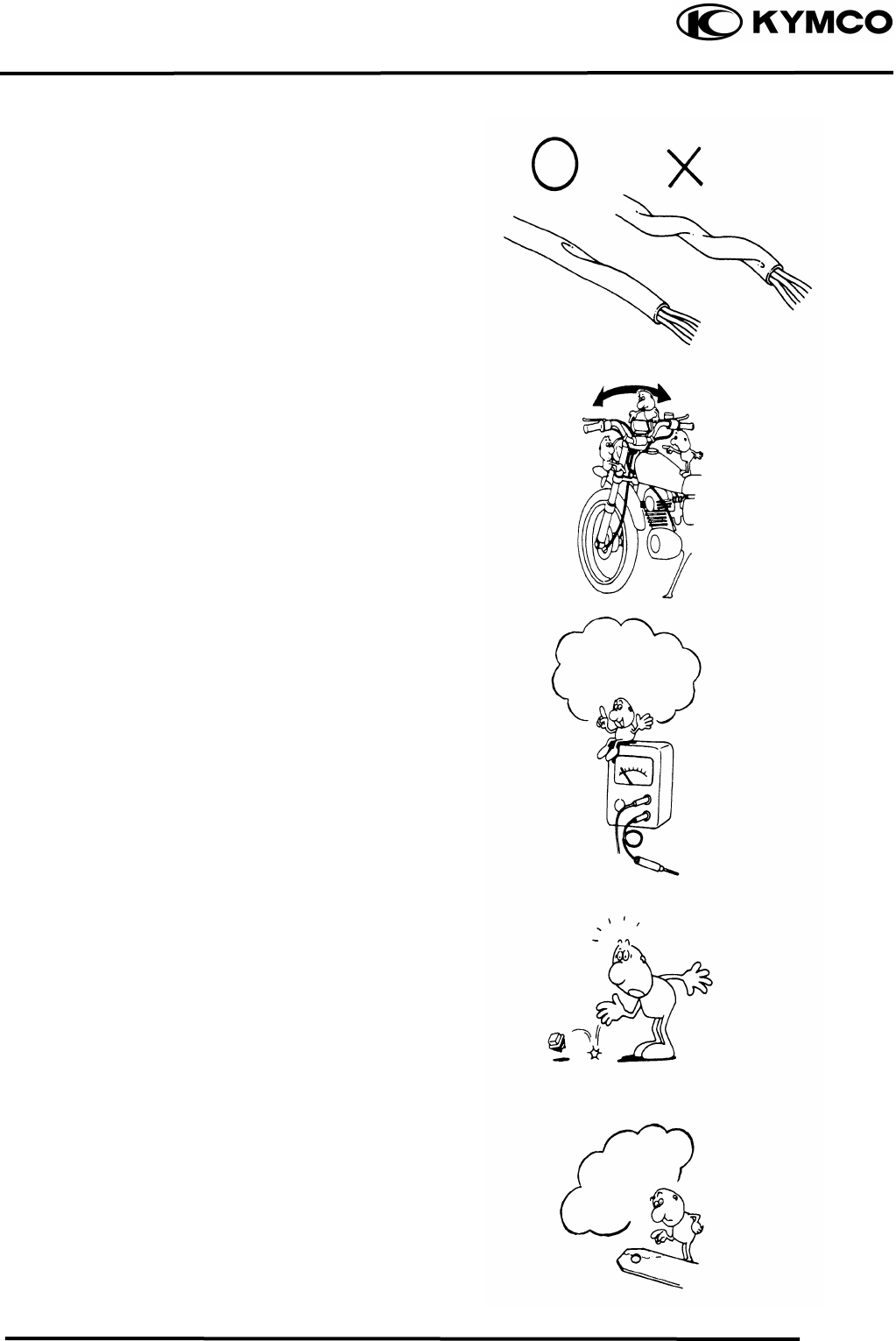
Symbols:
The following symbols represent the
servicing methods and cautions included
in this service manual.
: Apply engine oil to the
specified points. (Use
designated engine oil for
lubrication.)
: Apply grease for
lubrication.
: Transmission Gear Oil
(90#)
: Use special tool.
: Caution
: Warning
En
g
ine Oil
Grease
Gear Oil
Special
1. GENERAL INFORMATION
1-12
MX’er SYSTEM
TORQUE VALUES
STANDARD TORQUE VALUES
Ite
m
Torque (k
g
f-m) Ite
m
Torque (k
g
f-m)
5mm bolt, nut
6mm bolt, nut
8mm bolt, nut
10mm bolt, nut
12mm bolt, nut
14mm bolt, nut
0.450.6
0.81.2
1.82.5
3.04.0
5.06.0
6.08.0
4mm screw
5mm screw
6mm screw, SH bolt
6mm flange bolt and nut
8mm flange bolt and nut
10mm flange bolt and nut
0.150.4
0.30.5
0.71.1
1.01.4
2.43.0
3.54.5
Torque specifications listed below are for important fasteners.
ENGINE
Item Q‘ty Thread dia.(mm) Torque (kgf-m) Remarks
Stud bolt
Oil filter screen cap
Seat ball stopper bolt
Bearing hold
L cover
Stud bolt
Cam holder
Tappet ADJ nut
Pivot tensioner
Lifter tensioner
Lifter tensioner
MISTON oil drive bolt
Driver face
Clutch outer
Oneway clutch
Balancer shaft
ACG flywheel
Spark plug
Drain bolt mission
Drain plug
Clamper wre harness
Motor srart
Oil pump
Oil pump sprocket
Head CYL bolt
Drive plate nut
Startor
4
1
1
1
8
4
4
2
1
2
1
9
1
1
3
1
1
1
1
1
1
2
2
2
2
1
4
8
30
14
6
6
6
8
6
8
6
6
6
12
12
8
16
14
8
8
12
6
6
6
6
6
22
5
0.71.1
1.02.0
4.55.0
1.01.2
1.01.4
0.71.1
1.82.2
1.41.8
0.81.2
1.01.4
0.350.5
0.81.2
5.56.5
5.06.0
2.43.0
4.05.0
5.06.0
1.12.3
0.81.2
2.03.0
0.81.2
0.81.2
0.81.2
0.81.2
0.81.2
5.06.0
0.81.2
1. GENERAL INFORMATION
1-13
MX’er SYSTEM
Item Q‘ty Thread dia.(mm) Torque (kgf-m) Remarks
R cover
Head cover
Cap R cover
Guide star change handle
Sprocket drive plate
Carburetor
Check bolt oil
9
4
1
3
2
2
1
6
6
6
6
6
6
10
0.81.2
0.81.2
0.81.2
0.81.2
1.01.6
0.81.2
1.01.5
FRAME
Item Q‘ty Thread dia.(mm) Torque (kgf-m) Remarks
Steering stem nut
Swing arm nut
Rear wheel nut
Front wheel nut
Rear shock absorber upper mount bolt
Front shock absorber upper mount bolt
Front shock absorber lower mount bolt
Rear fork axle
Rear hub nut
Rear wheel shaft nut
Rear engine bracket up bolt
Rear engine bracket bolt
Engine hanger bracket bolt
Exhaust muffler lock bolt
1
4
2
2
1
2
2
1
4
2
1
1
1
2
14
10
14
14
10
10
10
14
12
32
10
10
10
8
6.08.0
4.05.0
6.08.0
6.08.0
3.54.5
3.54.5
3.54.5
6.08.0
6.08.0
11.013.0
3.54.5
3.54.5
3.54.5
3.23.8
1. GENERAL INFORMATION
1-14
MX’er SYSTEM
SPECIAL TOOLS
Tool Name Tool No. Remarks Ref. Page
Flywheel puller E003
Lock nut wrench E009
Valve adjuster E012
Valve spring compressor E040
Oil seal and bearing install E014
Universal holder E017
Flywheel holder E021
Clutch spring compressor E027
Bearing puller E008
Bearing puller E018
Bearing puller E020
Bearing puller E031
Nut wrench F010
Float level gauge
1. GENERAL INFORMATION
1-15
MX’er SYSTEM
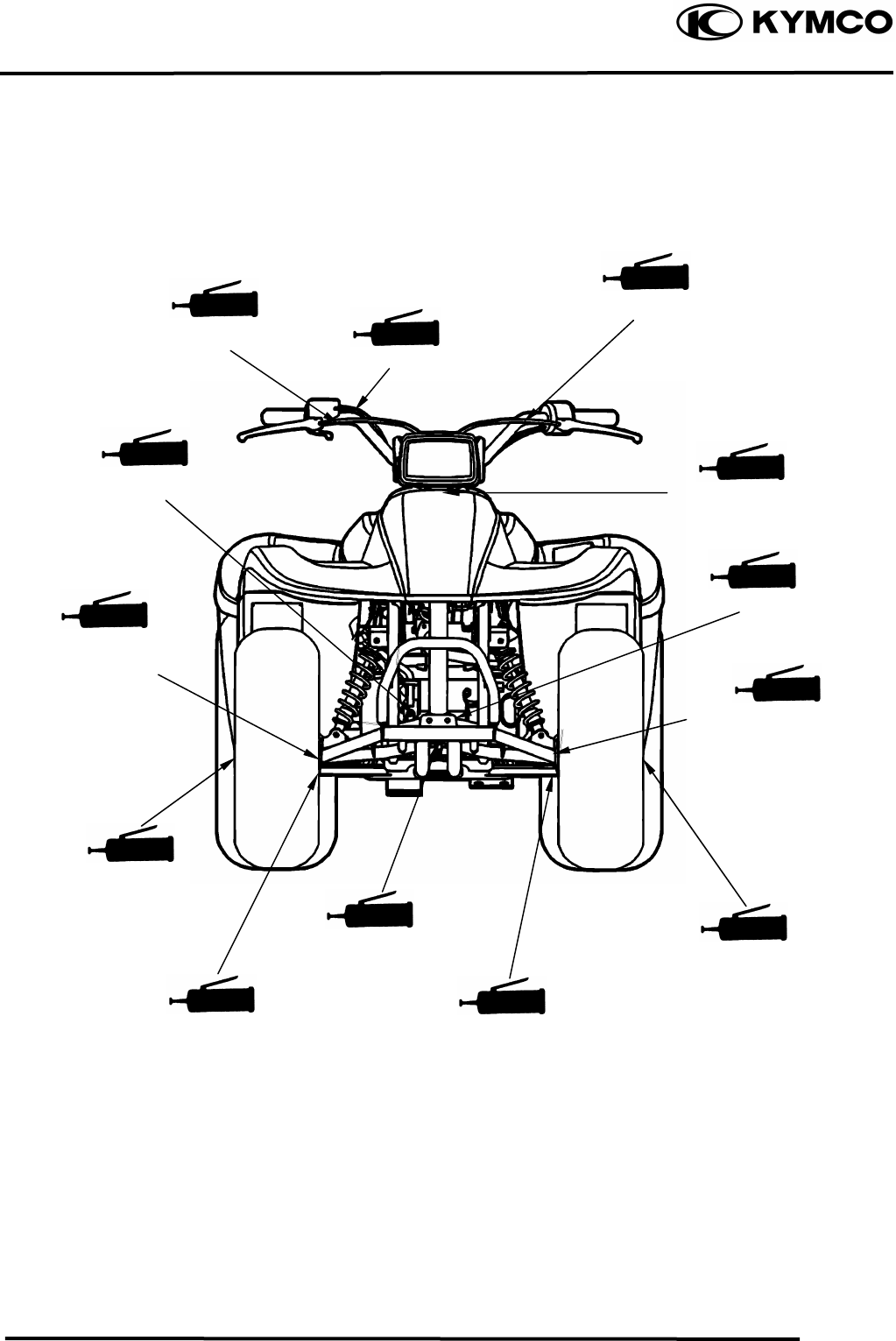
LUBRICATION POINTS
ENGINE
Lubrication Points Lubricant
Valve guide/valve stem movable part
Cam lobes
Valve rocker arm friction surface
Cam chain
Cylinder lock bolt and nut
Piston surroundings and piston ring grooves
Piston pin surroundings
Cylinder inside wall
Connecting rod/piston pin hole
Connecting rod big end
Crankshaft right side oil seal
Crankshaft one-way clutch movable part
Oil pump drive chain
Balance gear
A.C. generator
Starter one-way clutch
Bearing movable part
O-ring face
Oil seal lip
•Genuine KYMCO Engine Oil (SAE15W-40)
•API SG Engine Oil
Transmission gear and movable parts Gear oil: SAE90#
1. GENERAL INFORMATION
1-16
MX’er SYSTEM
FRAME
The following is the lubrication points for the frame.
Use general purpose grease for parts not listed.
Apply clean engine oil or grease to cables and movable parts not specified. This will avoid
abnormal noise and rise the durability of the motorcycle.
Steering knuckle/Thrust
Cover/Bush/Colla
r
Steering Column Uppe
r
Front Brake
camshaft/Oil
Seal/O-ring
Steering knuckle/Thrust
Cover/Bush/Colla
r
Front Arm Bush
Front Brake
camshaft/Oil
Seal/O-ring
Steering Column Lowe
r
Front Wheel
Oil Seal
Front Arm Bush
Rear Brake Cable
Throttle Cable
Front Brake Cable
Front Wheel
Oil Seal
1. GENERAL INFORMATION
1-17
MX’er SYSTEM
Swing arm Thrust
Cove
r
Rear Brake Cam/
Axle Hub Collar/Oil
Seal/Bearing
Sprocket hub/Rear
Axle Hub Collar/Oil
Seal/Bearing
Driven Sprocket
1. GENERAL INFORMATION
1-18
MX’er SYSTEM
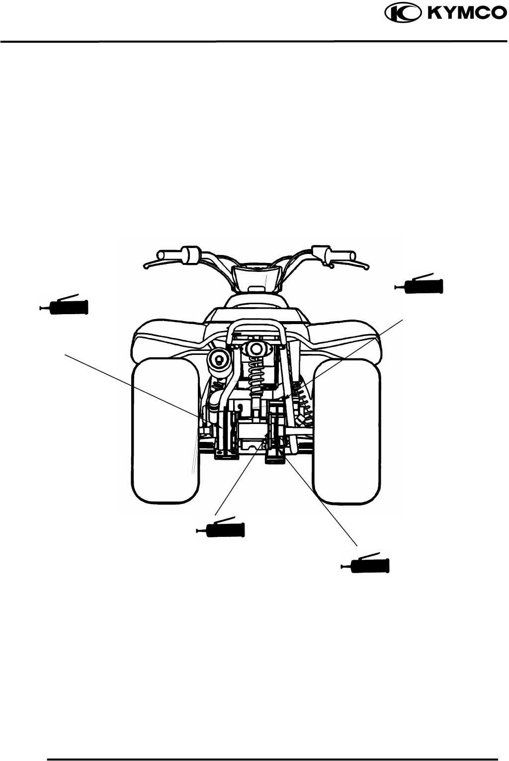
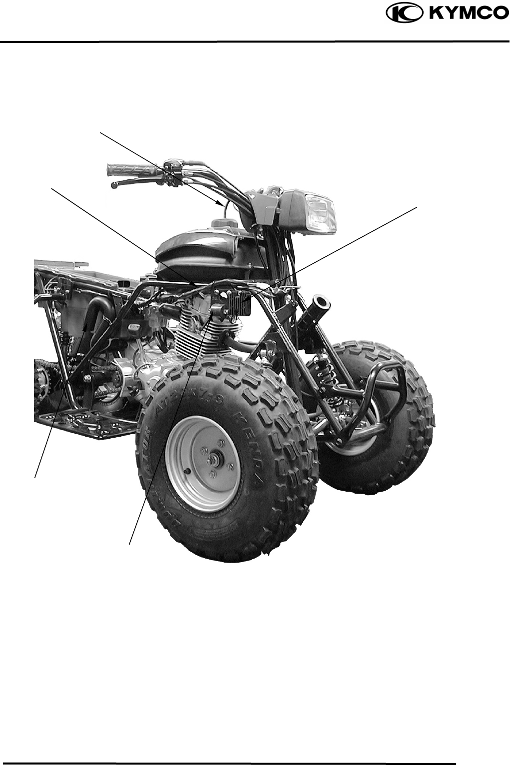
CABLE & HARNESS ROUTING
Rear Brake Cable
Throttle Cable
Front Brake Cable
Handlebar Switch Lea
d
Right Front Brake Cable
Left Front Brake Cable
1. GENERAL INFORMATION
1-19
MX’er SYSTEM
Breather Hose (CYL
Head Cover)
Main Switch
Inlet Hose
Breather
Hose
(C k )
1. GENERAL INFORMATION
1-20
MX’er SYSTEM
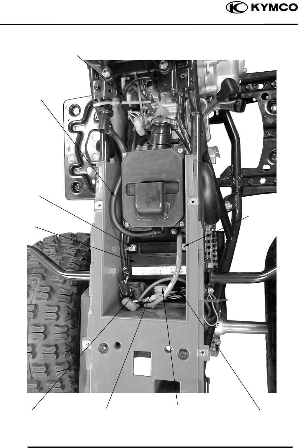
Wire Harness
Breather Hose
Rectifier/Regulato
Ignition Coil
Outlet Hose
Fuse
1. GENERAL INFORMATION
1-21
MX’er SYSTEM
Battery Negative
Cable
Battery
A.C.G Wire
Connector
Breather Hose (CYL
Head Cover)
Positive Cable
CDI Unit
Chan
g
e Gear Control
Starter Relay
Fuse
1. GENERAL INFORMATION
1-22
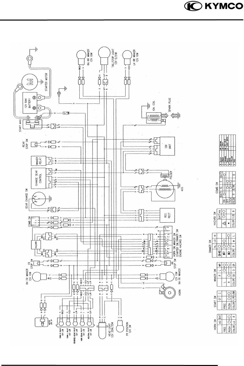
MX’er SYSTEM
WIRING DIAGRAM
1. GENERAL INFORMATION
1-23
MX’er SYSTEM
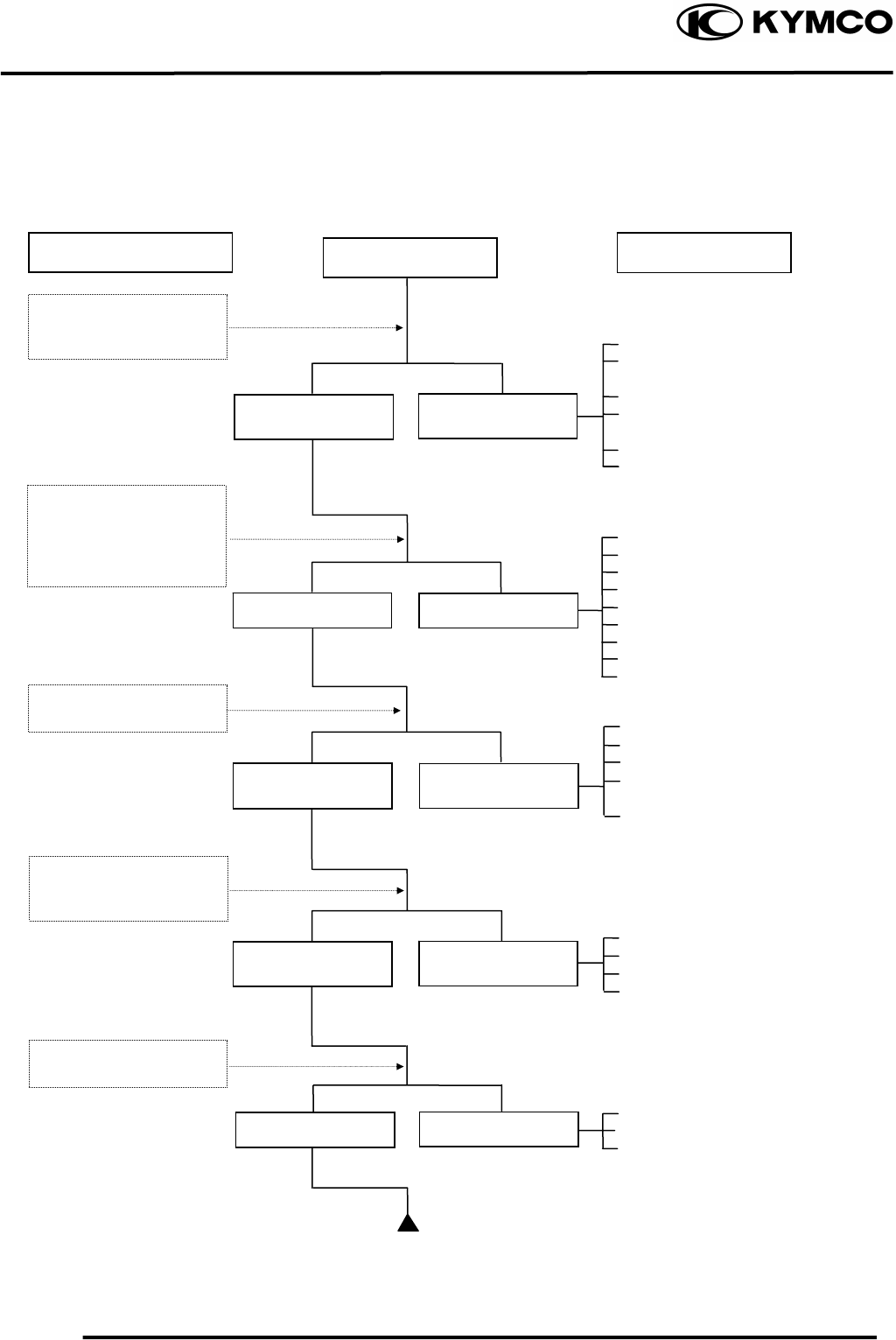
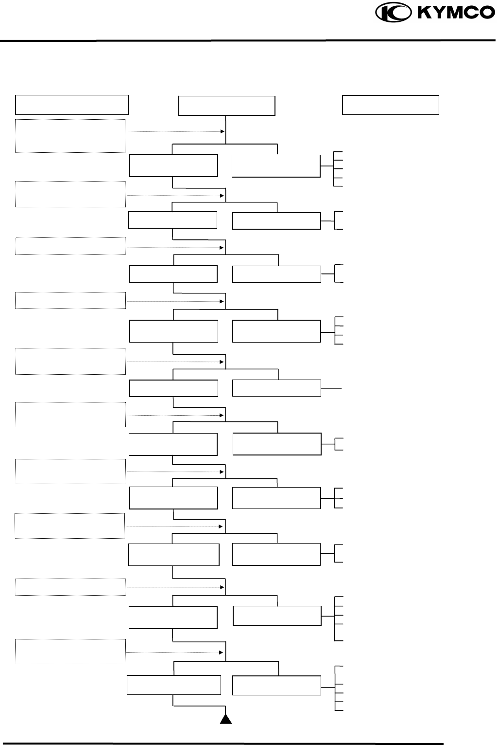
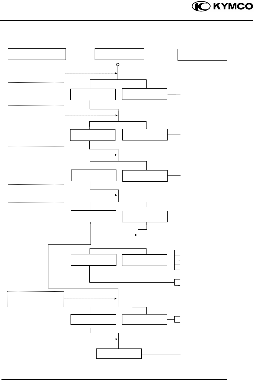
TROUBLESHOOTING
ENGINE WILL NOT START OR IS HARD TO START
Empty fuel tank
Clogged fuel line between fuel
tank and carburetor
Clogged float oil passage
Clogged fuel tank cap breather
hole
Clogged fuel filter
Clogged fuel valve passage
Faulty spark plug
Fouled spark plug
Faulty CDI unit
Faulty change gear control unit
Faulty pulser coil
Broken or shorted ignition coil
Broken or shorted exciter coil
Faulty ignition switch
Weak or dead battery
Faulty starter clutch
Valve clearance too small
Valve stuck open
Worn cylinder, piston and piston
rings
Leaking cylinder head gasket
Air leaking through intake pipe
Leaking intake manifold
Incorrect ignition timing
Incorrectly adjusted air*/ screw
Flooded carburetor
Clogged air cleaner
Throttle valve excessively open
Check if fuel reaches
carburetor by loosening
drain screw
Remove spark plug and
install it into spark plug
cap to test spark by
connecting it to engine
ground
Inspection/Adjustment
Spark jumps
Normal
compression
Engine does not
fire
Weak or no spark
Low or no
compression
Engine fires but
does not start
Test cylinder
compression
Start engine by
follow-ing normal
startin
g
p
rocedure
Fuel reaches
carburetor Fuel does not
reach carburetor
Wet spark plug
Dry spark plug
Symptom
Remove spark plug and
inspect again
Probable Cause
1. GENERAL INFORMATION
1-24
MX’er SYSTEM
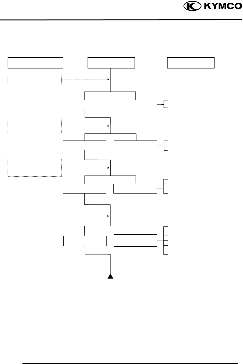
ENGINE LACKS POWER
Clogged air cleaner
Restricted fuel flow
Clogged fuel tank cap breather hole
Clogged exhaust muffler
Carburetor fuel level too low
Faulty CDI unit
Faulty pulser coil
Improper valve clearance
adjustment
Excessively worn valve seat
(protruded valve stem)
Improper valve and seat contact
Worn cylinder and piston rings
Leaking cylinder head gasket
Improper valve timing
Clean and unclog
Fouled spark plug
Incorrect heat range plug
Oil level too high
Oil level too low
Oil not changed
Clogged oil line
Faulty oil pump
Worn cylinder and piston rings
Mixture too lean
Poor quality fuel
Excessive carbon build-up in
combustion chamber
Ignition timing too early
Excessive carbon build-up in
combustion chamber
Poor quality fuel
Clutch slipping
Mixture too lean
Ignition timing too early
Start engine and
accelerate lightly for
observation
Inspection/Adjustment Symptom
Engine speed
increases
Correct timin
g
Engine speed does not
increase sufficientl
y
Incorrect timin
g
Check ignition timing
(using a timing light)
Test cylinder compression
Check carburetor for
clogging
Rapidly accelerate or run
at hi
g
h s
p
eed
Remove spark plug and
ins
p
ec
t
Check if engine overheats
Check valve clearance
Correc
t
Incorrec
t
N
ormal
com
p
ression Abnormal
compression
Remove oil dipstick and
check oil level and condition
Engine overheats
Engine does no
t
overheats
Plug not fouled o
r
discolored Plug fouled or
discolored
Correct and no
t
contaminated Incorrect o
r
contaminated
Valve train lubricated
p
ro
p
erl
y
Valve train not
lubricated
p
ro
p
erl
y
Engine does not knock Engine knocks
Not clo
gg
ed Clo
gg
ed
Remove cylinder head oil
p
i
p
e bolt and ins
p
ec
t
Probable Cause
1. GENERAL INFORMATION
1-25
MX’er SYSTEM
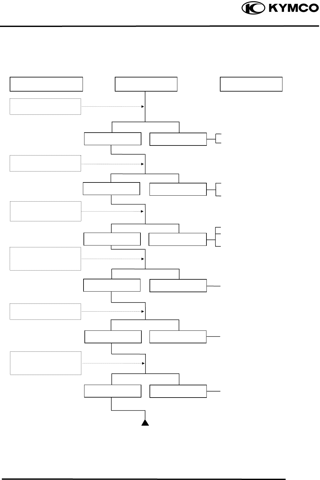
POOR PERFORMANCE (ESPECIALLY AT IDLE AND LOW SPEEDS)
Faulty CDI unit
Faulty pulser coil
Mixture too rich (turn screw
out)
Mixture too lean (turn screw in)
Deteriorated O-ring
Carburetor not securely
tightened
Damaged insulator rubber
Faulty or fouled spark plug
Faulty CDI unit
Faulty A.C. generator
Faulty ignition coil
Broken or shorted spark plug
wire
Faulty ignition switch
Remove spark plug and
install it into spark plug
cap to test spark by
connecting it to engine
g
round
Symptom
Correctly adjusted
No air leak Air leaks
Good spark Weak or inte
r
-
mittent spark
Incorrectly adjusted
Incorrect timing
Correct timing
Probable Cause Inspection/Adjustment
Check ignition timing
Check carburetor ai
r
screw adjustment
Check carburetor gasket
for air leaks
1. GENERAL INFORMATION
1-26
MX’er SYSTEM
POOR PERFORMANCE (AT HIGH SPEED)
Faulty CDI unit
Faulty pulser coil
Improperly adjusted valve
clearance
Worn valve seat
Empty fuel tank
Clogged fuel tube or filter
Clogged Fuel tank cap breather
hole
Clean and unclog
Cam timing gear aligning marks
not aligned
Faulty spring
Inspection/Adjustment Symptom
Check carburetor jets
for clogging
Check fuel pump fo
r
fuel supply
Correct ti
m
ing Incorrect timing
Fuel flows freely Fuel flow restricted
Correc
t
Incorrec
t
Not clogged Clogged
Not weakened Weak spring
Incorrectly adjusted
Correctly adjusted
Check valve clearance
Check valve spring
tension
Probable Cause
Check ignition timing
Check valve timing
1. GENERAL INFORMATION
1-27
MX’er SYSTEM
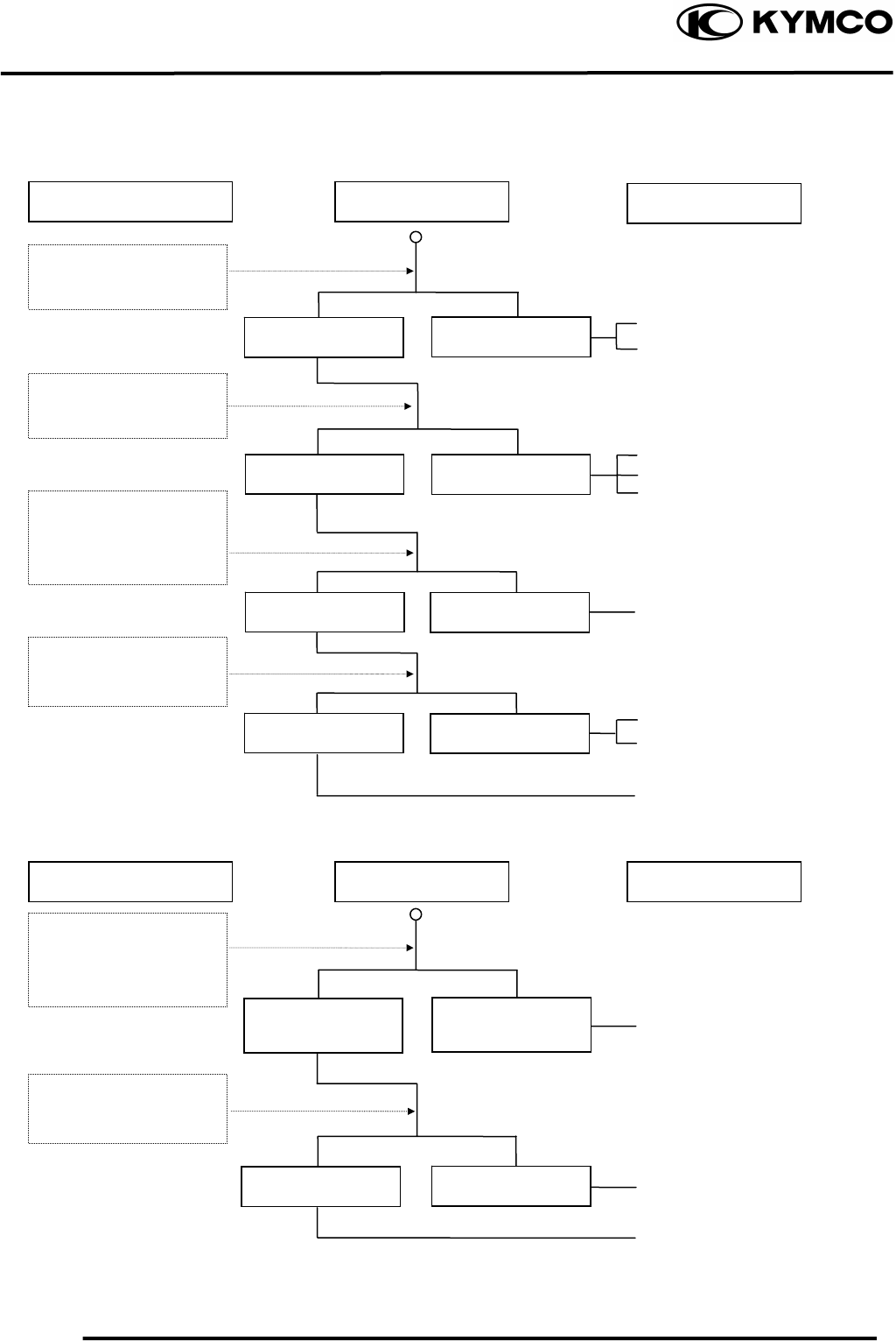
POOR CHARGING (BATTERY OVER DISCHARGING OR OVERCHARGING)
Undercharging
Inspection/Adjustment Symptom Probable Cause
Dead battery
Faulty battery
Faulty A.C. generator coil
Broken yellow wire
Shorted pink and yellow
wires
Broken red wire
Faulty regulator/rectifier
Poorly connected coupler
Faulty A.C. generator
Overcharging
Broken green wire
Poorly connected coupler
Faulty regulator/rectifier
Start engine and test
limit voltage of battery
terminals
Connect battery (+) wire
to regulator/rectifier
coupler red wire and
battery (-) wire to engine
g
round and test volta
g
e
Inspection/Adjustment Symptom
Normal voltage
B
attery
h
as vo
l
tage
with ignition
switch “ON”
Normal
Voltage does no
t
increase
Normal Abnormal
B
attery
h
as no
voltage with ignition
switc
h
“ON”
Resistance too high
Normal voltage No voltage
Normal Abnormal
Measure resistance
between AC generator
coil terminals
Probable Cause
Check regulator/rectifier
coupler for loose
connection
Connect battery (+) wire
to regulator/rectifier
coupler green wire and
battery (-) wire to engine
g
round and test volta
g
e
Check regulator/rectifier
coupler for loose
connection
1. GENERAL INFORMATION
1-28
MX’er SYSTEM
NO SPARK AT SPARK PLUG
Inspection/Adjustment Symptom Probable Cause
Faulty spark plug
Loose spark plug cap
Poorly connected coupler
Faulty ignition switch
Weak battery
Faulty pulser coil
Faulty ignition coil
Faulty charging system
Broken wire harness
Poorly connected coupler
Faulty CDI unit
Faulty change gear control
unit
Faulty ignition coil
Replace with a new
spark plug and inspect
a
g
ain
Check CDI unit coupler
for looseness
Normal
Abnormal
Normal
Abnormal
Normal Abnormal
Abnormal
Measure resistance
between terminals of
CDI unit cou
p
le
r
Check related parts
Check ignition coil with
a CDI unit tester
Weak or no spark
Not loose
Good spark
Good Good
Check CDI unit with a
CDI unit tester
Loose
Check spark plug cap
and high-tension wire
for looseness

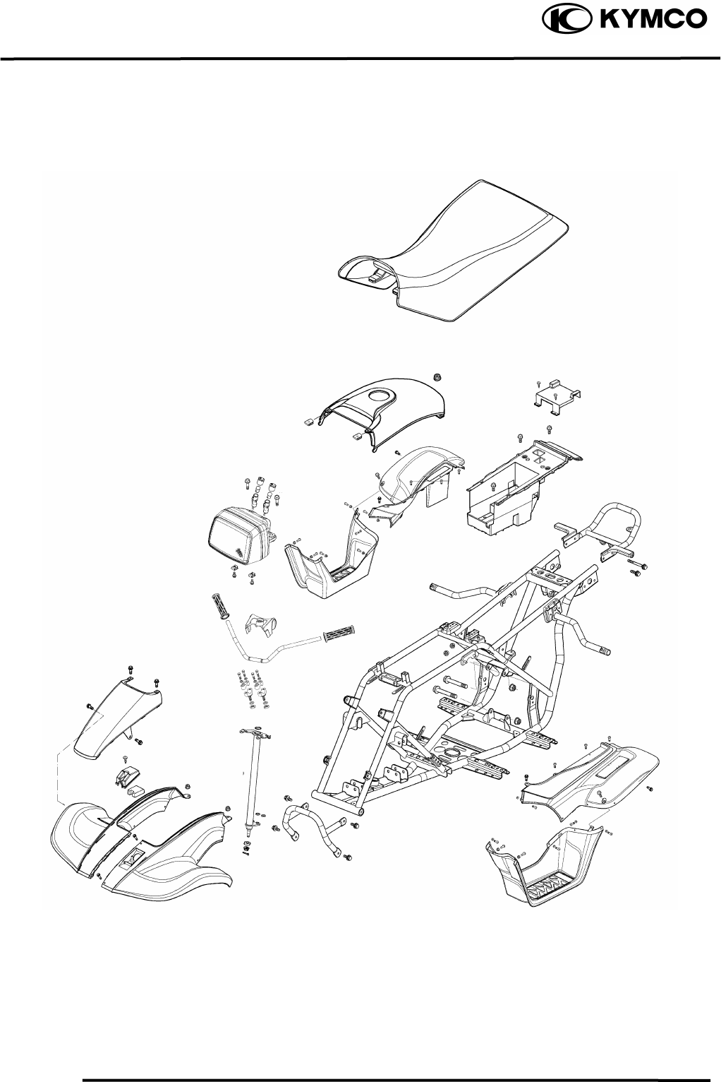
2. FRAME COVERS/EXHAUST MUFFLER
2-0
MX’er SYSTEM
2
__________________________________________________________________________________
____________________________________________________________________
2
____________________________________________________________________
____________________________________________________________________
____________________________________________________________________
FRAME COVERS/EXHAUST MUFFLER
____________________________________________________________________
SERVICE INFORMATION------------------------------------------------ 2- 2
TROUBLESHOOTING----------------------------------------------------- 2- 2
FRAME COVERS----------------------------------------------------------- 2- 3
HEADLIGHT REMOVAL ------------------------------------------------- 2- 5
EXHAUST MUFFLER REMOVAL-------------------------------------- 2- 5
2. FRAME COVERS/EXHAUST MUFFLER
2-1
MX’er SYSTEM

2. FRAME COVERS/EXHAUST MUFFLER
2-2
MX’er SYSTEM
SERVICE INFORMATION
GENERAL INSTRUCTIONS
• When removing frame covers, use special care not to pull them by force because the cover joint
claws may be damaged.
• Make sure to route cables and harnesses according to the Cable & Harness Routing.
TORQUE VALUES
Exhaust muffler lock bolt 3.23.8kgf-m
Exhaust muffler joint lock nut 0.81.2kgf-m
TROUBLESHOOTING
Noisy exhaust muffler
• Damaged exhaust muffler
• Exhaust muffler joint air leaks
Lack of power
• Caved exhaust muffler
• Exhaust muffler air leaks
• Clogged exhaust muffler
2. FRAME COVERS/EXHAUST MUFFLER
2-3
MX’er SYSTEM
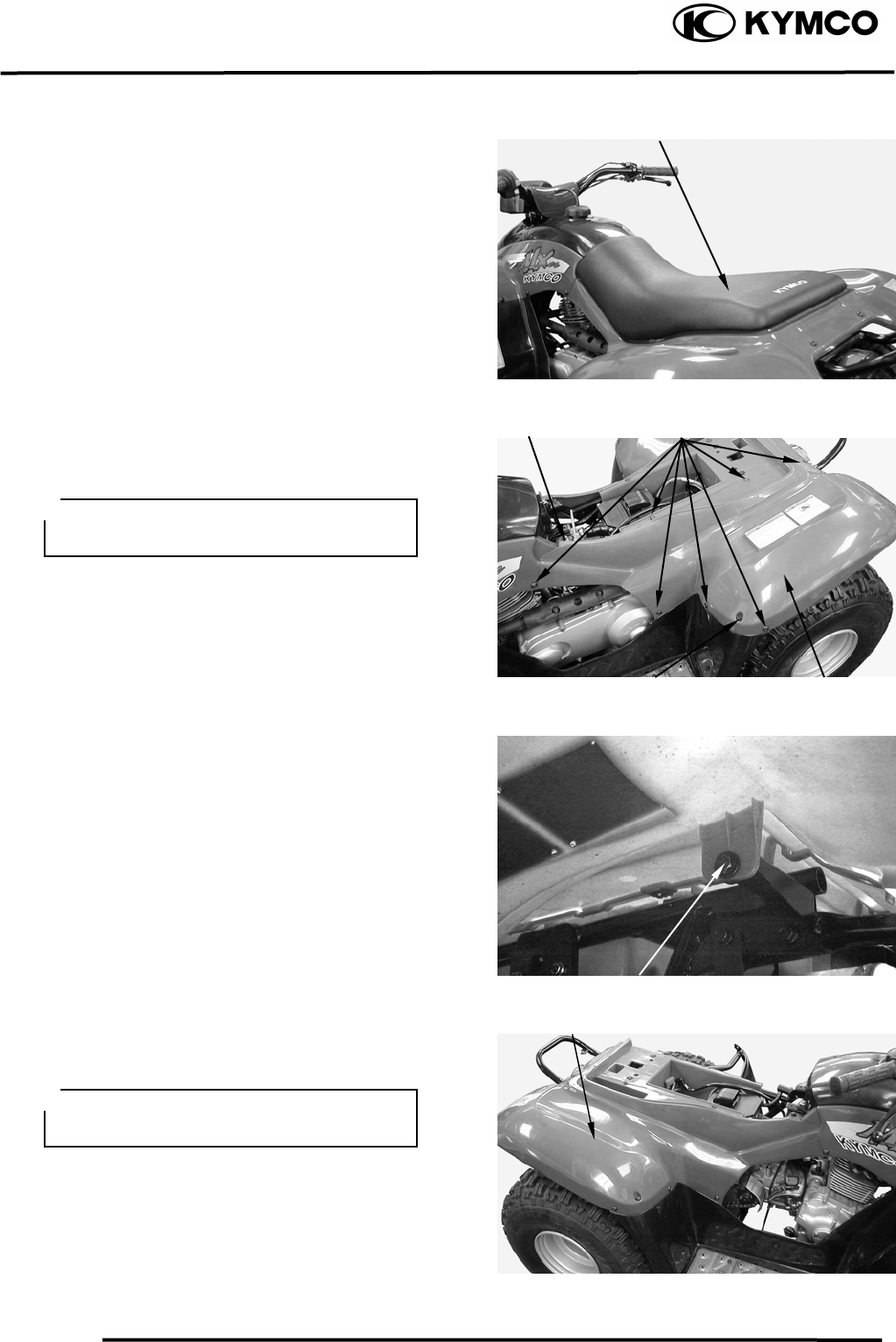
FRAME COVERS
SEAT REMOVAL
Pull the lever backward, then pull up the
seat at the rear.
Remove the seat.
LEFT REAR FENDER REMOVAL
Remove seven screws and two bolts
attaching the left rear fender.
Remove the left rear fender under bolt.
Remove the left rear fender.
RIGHT REAR FENDER REMOVAL
Remove seven screws and two bolts
attaching the right rear fender.
Sea
t
Screws
Frame Lef
t
Cove
r
Bol
t
Bol
t
During rem
Bol
t
Frame Ri
g
h
t
Cove
r
During removal, do not pull the joint
claws forcedly to avoid damage.
oval, do not pull the joint
aclaws forcedly to avoid dam ge.
2. FRAME COVERS/EXHAUST MUFFLER
2-4
MX’er SYSTEM
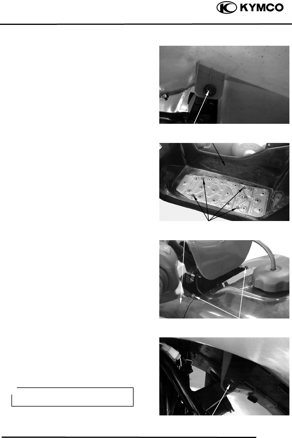
Remove right rear fender under bolt.
Remove the right rear fender.
FLOOR BOARD COVER REMOVAL
Remove the four bolts on the floorboard
cover.
Remove the floorboard cover.
FRONT COVERS REMOVAL
Remove the two screws on the front cover.
Remove the left and right front fender under
bolt.
Remove the front cover.
FRONT FENDER REMOVAL
Remove the left and right front fender under
bolt.
Remove screws attaching the left and right
front fender.
Remove the left and right front fender.
Bol
t
Floor Board Cove
r
Bolts
Bol
t
Screws
Front Cove
r
During removal, be careful not to
damage the joint claws.
2. FRAME COVERS/EXHAUST MUFFLER
2-5
MX’er SYSTEM
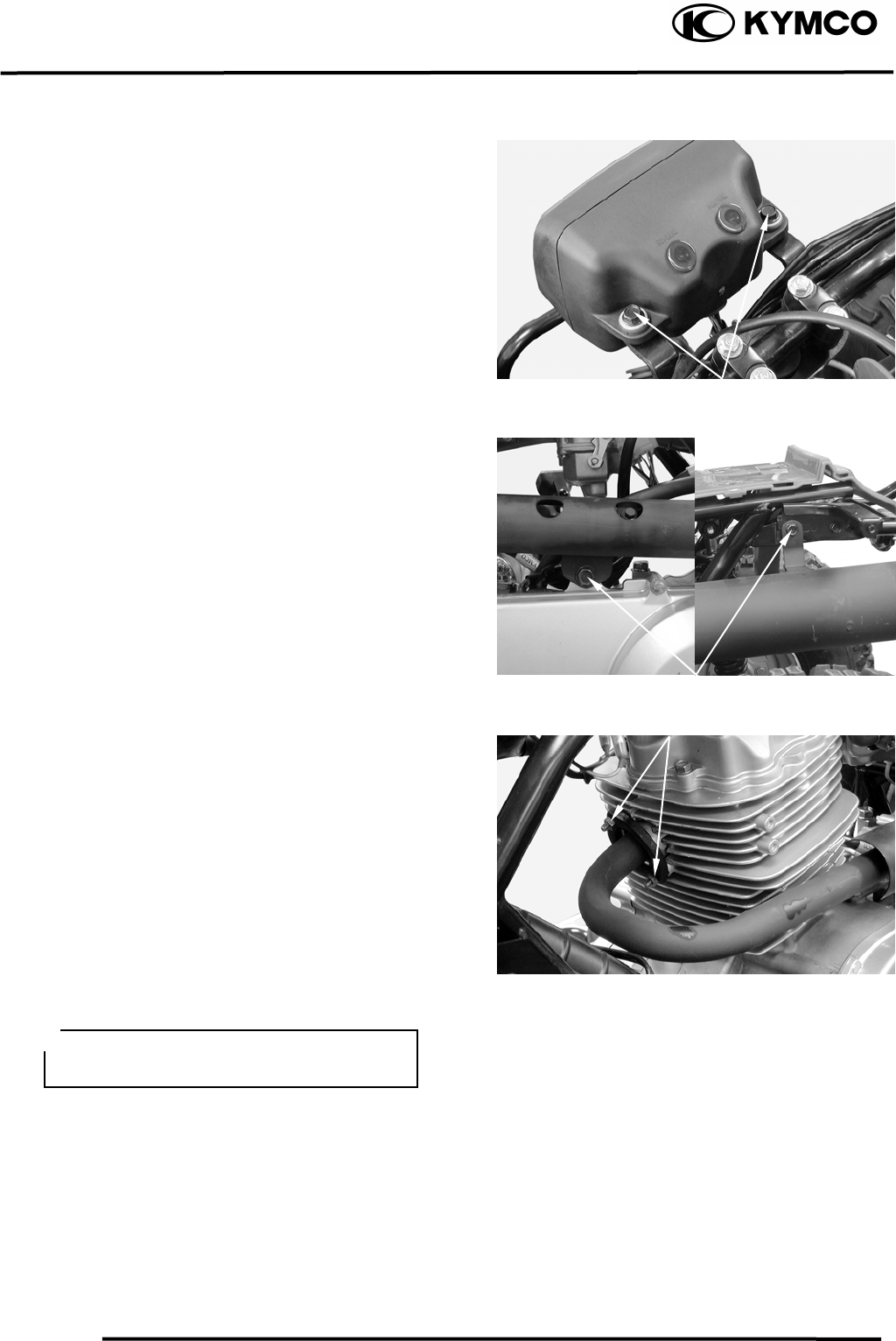
HEADLIGHT REMOVAL
Remove the headlight connector wire.
Remove the two bolts on the headlight.
EXHAUST MUFFLER
REMOVAL
Remove the two bolts attaching the exhaust
muffler.
Remove the two exhaust muffler joint lock
nuts.
Remove the exhaust muffler joint packing
collar.
When installing, first install the exhaust
muffler packing collar onto the engine and
then install the exhaust muffler.
Torque:
Exhaust muffler lock bolt: 3.23.8kgf-m
Exhaust muffler joint lock nut: 0.8
1.2kgf-m
Bol
t
s
Joint Lock Nuts
Bol
t
s
Be sure to install a new exhaust muffler
packing collar.

3. INSPECTION/ADJUSTMENT
3-0
MX’er SYSTEM
3
__________________________________________________________________________________
____________________________________________________________________
____________________________________________________________________
3
____________________________________________________________________
____________________________________________________________________
INSPECTION/ADJUSTMENT
____________________________________________________________________
SERVICE INFORMATION------------------------------------------------ 3- 1
MAINTENANCE SCHEDULE-------------------------------------------- 3- 2
FUEL LINE/THROTTLE OPERATION/AIR CLEANER ------------ 3- 3
AIR FILTER FOR DRIVE BELT ----------------------------------------- 3- 4
SPARK PLUG---------------------------------------------------------------- 3- 5
VALVE CLEARANCE/CARBURETOR IDLE SPEED--------------- 3- 6
IGNITION TIMING/CYLINDER COMPRESSION ------------------- 3- 7
ENGINE OIL/FINAL REDUCTION GEAR OIL----------------------- 3- 8
DRIVE BELT/BRAKE SHOE/BRAKE SYSTEM --------------------- 3- 9
HEADLIGHT AIM---------------------------------------------------------- 3-11
STEERING SYSTEM INSPECTION------------------------------------- 3-11
TOE-IN ADJUSTMENT --------------------------------------------------- 3-12
WHEELS/TIRES ------------------------------------------------------------ 3-13
DRIVE CHAIN SLACK ADJUSTMENT-------------------------------- 3-14
CABLE INSPECTION AND LUBRICATION-------------------------- 3-16
FRONT SUSPENSION LUBRICATION -------------------------------- 3-16
3. INSPECTION/ADJUSTMENT
3-1
MX’er SYSTEM
SERVICE INFORMATION
GENERAL
WARNING
•Before running the engine, make sure that the working area is well-ventilated. Never run the
engine in a closed area. The exhaust contains poisonous carbon monoxide gas which may
cause death to people.
•Gasoline is extremely flammable and is explosive under some conditions. The working area
must be well-ventilated and do not smoke or allow flames or sparks near the working area or
fuel storage area.
SPECIFICATIONS
ENGINE
Throttle grip free play : 14mm
Spark plug gap : 0.60.7mm
Spark plug: Standard : NGK: CR8E
Valve clearance : IN: 0.06mm
EX: 0.06mm
Idle speed : 1700±100rpm
Engine oil capacity:
At disassembly : 1.0 liter
At change : 0.9 liter
Gear oil capacity :
At disassembly : 400cc
At change : 200cc
Cylinder compression : 16kg/cm²
Ignition timing : BTDC 15°/1700rpm
CHASSIS
Front brake free play: 1020mm
Rear brake free play: 1020mm
TIRE PRESSURE
1 Rider
Front 0.20kgf/cm²
Rear 0.25kgf/cm²
TIRE SIZE:
Front : 20*7-8
Rear : 22*10-8
TORQUE VALUES
Front wheel nut 5.06.0kgf-m
Rear wheel nut 5.06.0kgf-m
3. INSPECTION/ADJUSTMENT
3-2
MX’er SYSTEM
MAINTENANCE SCHEDULE
This chapter includes all information necessary to perform recommended inspections and
adjustments. These preventive maintenance procedures, if followed, will ensure more reliable
vehicle operation and a longer service life. The need for costly overhaul work will be greatly
reduced. This information applies to vehicles already in service ad well as new vehicles that are
being prepared for sale. All service technicians should be familiar with this entire chapter.
Initial Every
Item
Remarks 1
month 3
month 6
month 6
month 1
year
Valves Check valve clearance. Adjust if
necessary. ○ ○ ○ ○
Spark plug Check condition. Clean or replace if
necessary. ○ ○ ○ ○ ○
Air clearance Clean. Replace if necessary. ○ ○ ○ ○
Carburetor Check idle speed/starter operation.
Adjust if necessary. ○ ○ ○ ○
Fuel line Check fuel hose for cracks or
damage. Replace if necessary. ○ ○ ○
Engine oil Replace (Warm engine before
draining). ○ ○ ○ ○
Engine oil filter screen Clean. Replace if necessary. ○ ○
Transmission oil Check oil leakage. Replace every
12 months. ○ ○
Brake system Check operation. Adjust if
necessary. ○ ○ ○ ○ ○
Drive belt Check operation/replace if damage
or excessive wear. ○ ○
Wheels Check balance/damage/runout.
Replace if necessary. ○ ○ ○ ○
Wheel bearings Check bearings assembly for
looseness/damage. Replace if
damaged.
○ ○ ○ ○
Steering system Check operation/replace if damage.
Check toe-in/adjust if necessary. ○ ○ ○ ○ ○
Knuckle shafts Lubricate every 6 months. ○ ○ ○
Fitting/Fasteners Check all chassis fittings and
fasteners. Correct if necessary. ○ ○ ○ ○ ○
• In the interest of safety, we recommend these items should be serviced only by an authorized
KYMCO motorcycle dealer.
FUEL LINE
Remove the met-in box.
3. INSPECTION/ADJUSTMENT
3-3
MX’er SYSTEM
Check the fuel tubes and replace any parts,
which show signs of deterioration, damage
or leakage.
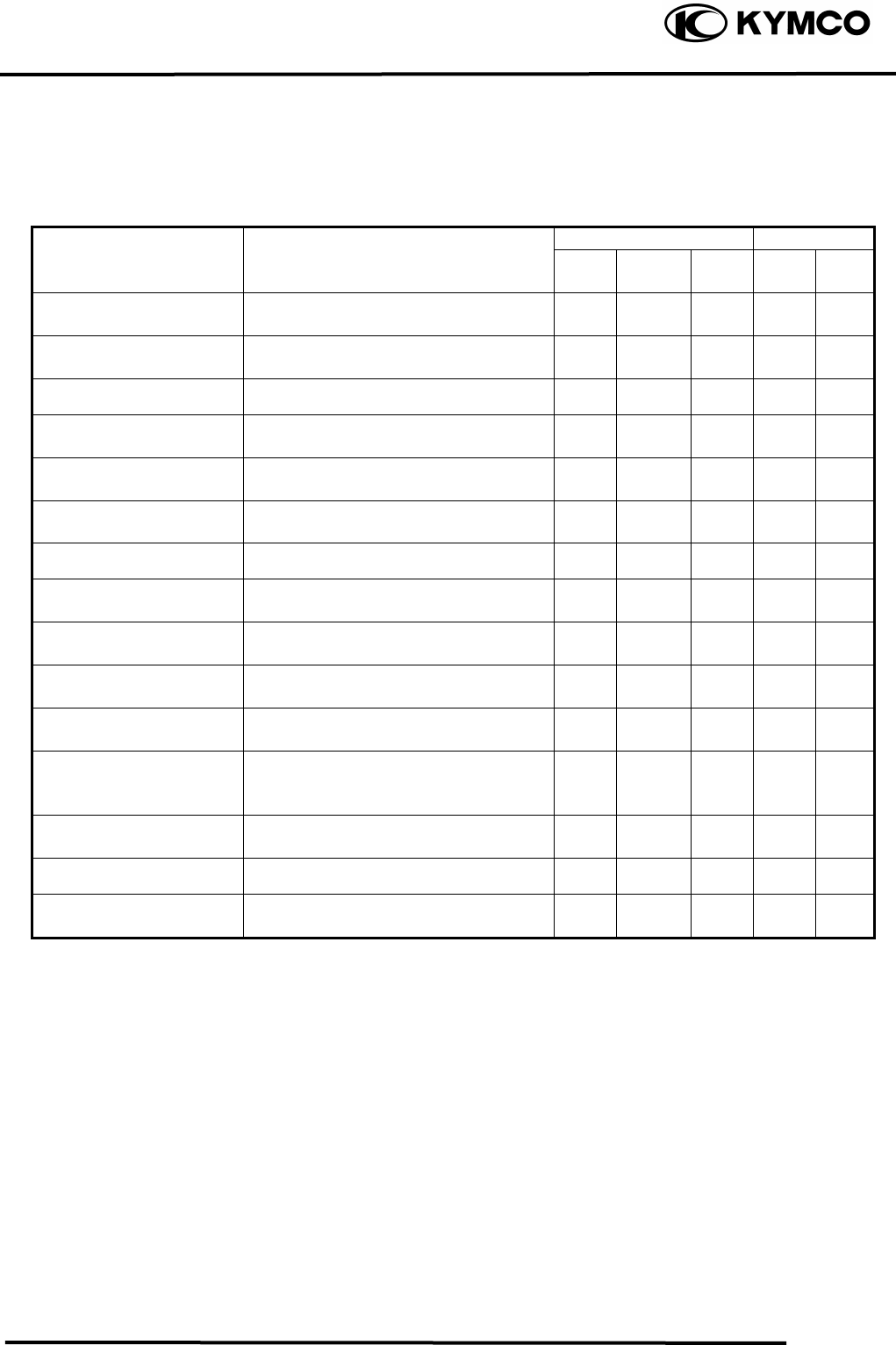
THROTTLE OPERATION
Check the throttle to swing for smooth
movement.
Measure the throttle to swing free play.
Free Play: 14mm
Minor adjustment is made with the
adjusting nut at the throttle to swing above.
Slide the rubber cover out and adjust by
loosening the lock nut and turning the
adjusting nut.
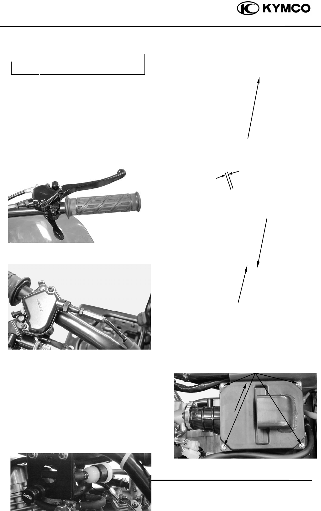
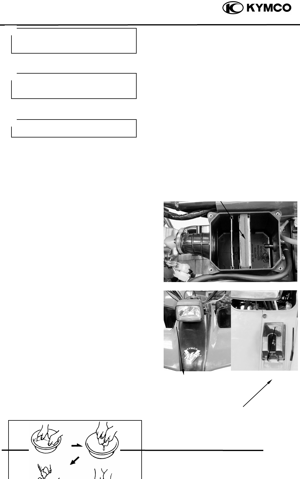
AIR CLEANER
AIR CLEANER REPLACEMENT
Remove the rear side covers.
Remove four screws on the air cleaner case
cover and the cover.
Check the element and replace it if it is
excessively dirty or damaged.
Do not smoke or allow flames or sparks
in your working area.
Fuel Filte
r
Adjusting Nu
t
Lock Nu
t
Screws
CLEAN AIR FILTER ELEMENT
Fuel tube
Air Cleaner Case Cove
r
Wash the element gently, but throughly in
solvent.
3. INSPECTION/ADJUSTMENT
3-4
MX’er SYSTEM
Use parts cleaning solvent only. Never
use gasoline or low flash point solvents
which may lead to a fire or explosion.
Squeeze the excess solvent out of the
element and let dry.
Apply the engine oil.
Squeeze out the excess oil.
CHANGE INTERVAL
More frequent replacement is required when
riding in unusually dusty or rainy areas.
AIR FILTER FOR DRIVE BELT
Remove the front cover.
Remove the screw, air filter case and air
filter element.
Inspect the air filter element.
Replace if damage.
Do not twist or wring out the foam
element. This could damage the foam
material.
The element should be wet but not
dri
pp
in
g
.
Air Cleaner Elemen
t
Front cove
r
Air Filter Case
Clean air filter element steps:
Tap the element lightly to remove most of
Screw
3. INSPECTION/ADJUSTMENT
3-5
MX’er SYSTEM
the dust and dirt.
Blow out the remaining dirt with
compressed air.
Install the air filter element and air filter
case.
Install the front cover.
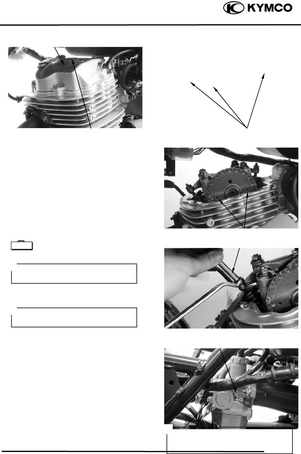
SPARK PLUG
Remove the spark plug.
Check the spark plug for wear and fouling
deposits.
Clean any fouling deposits with a spark
plug cleaner or a wire brush.
Gap, Wear, and Fouling Deposits
Specified Spark Plug: NGK: CR8E
Measure the spark plug gap.
Spark Plug Gap: 0.60.7mm
VALVE CLEARANCE
Inspect and adjust valve clearance while
the engine is cold (below 35).
Cracks, Damage
Washer Deformation
When installing, first screw in the spark
plug by hand and then tighten it with a
spark plug wrench.
3. INSPECTION/ADJUSTMENT
3-6
MX’er SYSTEM
Remove the cylinder head cover.
Turn the flywheel counterclockwise so that
the “T” mark on the flywheel aligns with
the index mark on the crankcase to bring the
round hole on the camshaft gear facing up
to the top dead center on the compression
stroke.
Inspect and adjust the valve clearance.
Valve Clearance: IN: 0.06mm
EX: 0.06mm
Loosen the lock nut and adjust by turning
the adjusting nut
Tappet adjuster E012
CARBURETOR IDLE SPEED
Warm up the engine before this operation.
Start the engine and connect a tachometer.
Turn the throttle stop screw to obtain the
specified idle speed.
Idle Speed: 1700±100rpm
When the engine misses or run erratic,
adjust the air screw.
Bolts
Punch Marks
Valve Wrench
IGNITION TIMING
• Check the valve clearance again after
the lock nut is tightened.
• The engine must be warm for accurate
idle speed inspection and adjustment.
The CDI unit is not adjustable. If the
ignition timing is incorrect, check the
ignition system.
Throttle Stop Screw
Cylinder Head Cove
r
Special
Throttle Stop Screw
3. INSPECTION/ADJUSTMENT
3-7
MX’er SYSTEM
Remove the timing hole cap.
Check the ignition timing with a timing
light.
When the engine is running at idle speed,
the ignition timing is correct if the “F” mark
on the flywheel aligns with the index mark
on the crankcase.
CYLINDER COMPRESSION
Warm up the engine before compression
test.
Remove the spark plug.
Insert a compression gauge.
Open the throttle valve fully and push the
starter button to test the compression.
Compression: 16kg/cm²
If the compression is low, check for the
following:
- Leaky valves
- Valve clearance too small
- Leaking cylinder head gasket
- Worn piston rings
- Worn piston/cylinder
If the compression is high, it indicates that
carbon deposits have accumulated on the
combustion chamber and the piston head.
Compression Gauge
Timing Ligh
t
Timing Hole Cap ENGINE OIL
OIL LEVEL
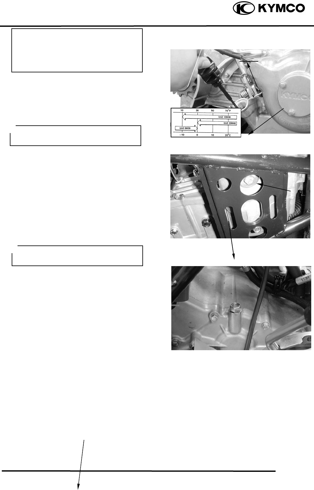
3. INSPECTION/ADJUSTMENT
3-8
MX’er SYSTEM
Remove the oil dipstick and check the oil
level with the oil dipstick.
If the level is near the lower level, fill to the
upper level with the specified engine oil.
OIL CHANGE
Remove the oil drain plug bolt located on
the bottom of the engine to drain the engine
oil thoroughly.
After the oil has been completely drained,
Install the oil drain plug bolt.
Torque: 2..03.0kgf-m
Recommended Oil: SAE30#
FINAL REDUCTION GEAR OIL
Recommended Oil: GEAR OIL SAE90#
GEAR OIL CHANGE
Remove the oil filler bolt.
Removes the oil drains bolt and drain the oil
Oil Fille
r
Bol
t
Place the motorcycle on level g
r
ound for
oil level check.
Oil Dipstick
Oil Filter Screen Cap
Lower Level
Upper Level
• Place the motorcycle upright on level
ground for engine oil level check.
• Run the engine for 23 minutes and
check the oil level after the engine is
stopped for 23 minutes.
The engine oil will drain more easily
while the engine is warm.
oil drain
p
lu
g
bol
t
3. INSPECTION/ADJUSTMENT
3-9
MX’er SYSTEM
thoroughly.
Install the oil drain bolt.
Torque: 0.81.2kgf-m
Fill with the recommended oil.
Oil Capacity: At disassembly : 400cc
At change : 200cc
Reinstall the oil filler bolt and check for oil
leaks.
Torque: 0.81.2kgf-m
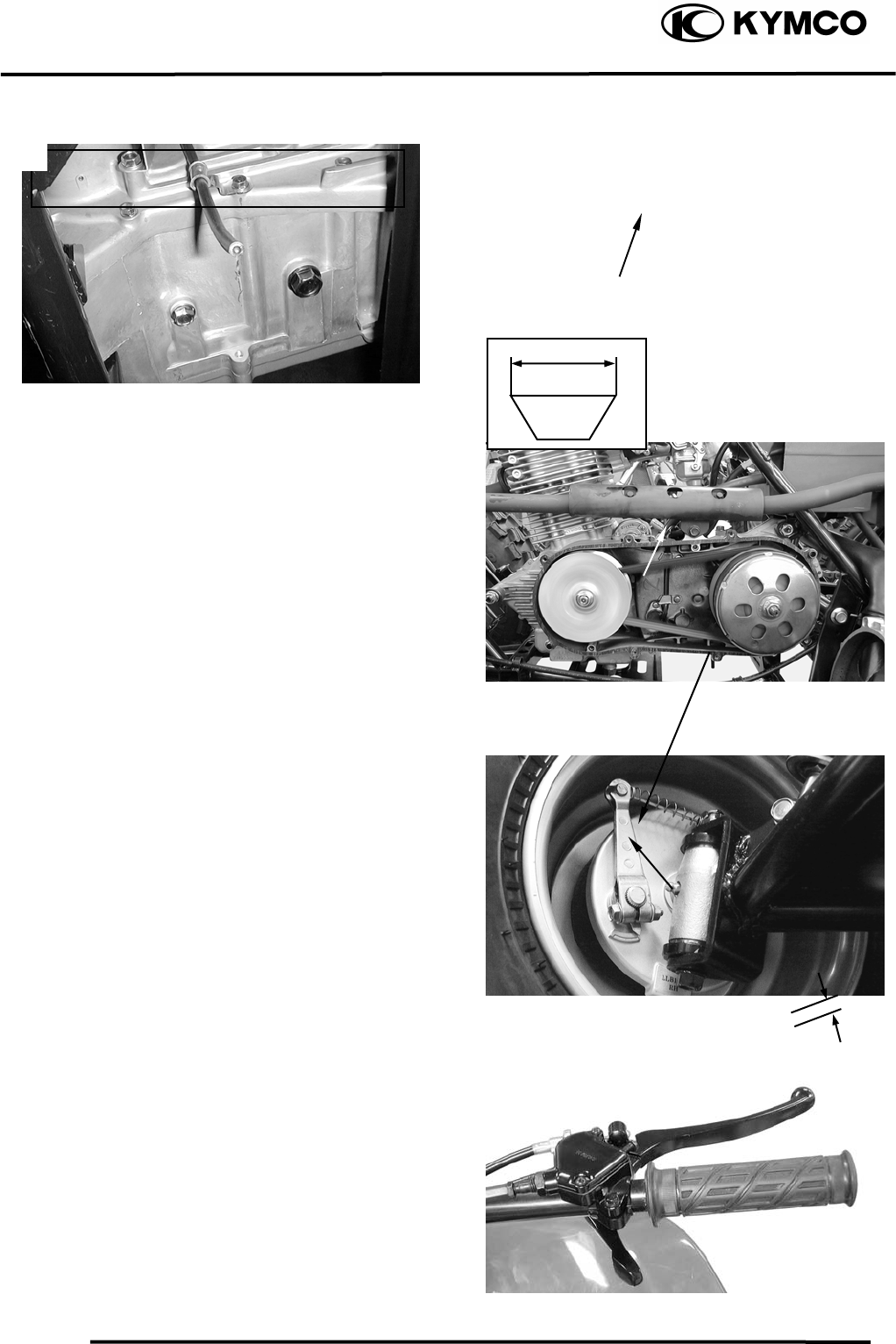
DRIVE BELT
Remove the left crankcase cover.
Inspect the drive belt for cracks, scaling,
chipping or excessive wear.
Measure the V-belt width
Service limit: 17mm
Replace the drive belt if out of specification.
BRAKE SHOE
Replace the brake shoes if the arrow on the
wear indicator plate aligns with the punch
mark on the brake panel when the brake is
fully applied.
BRAKE SYSTEM
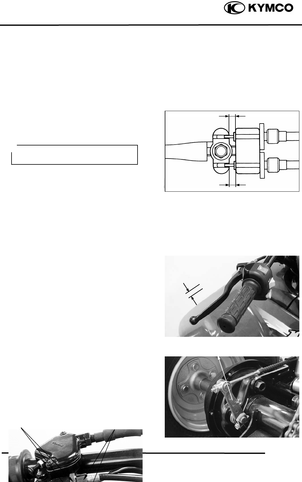
FRONT BRAKE
Measure the front brake lever free play.
Free Play: 1020mm
Adjust if out of specification.
Make sure that the sealing washer is in
good condition.
Oil Drain Bolt/ Sealing Washe
r
Drive Bel
t
Wear Indicato
r
Punch Mark
Adjust brake lever free play:
Loosen the lock nuts.
3. INSPECTION/ADJUSTMENT
3-10
MX’er SYSTEM
Turn the adjusters in or out until the
specified free play is obtained.
Turning adjusters in that the free play is
increased.
Turning adjusters out that the free play is
decreased.
The difference between both clearances
should be 2 mm or less when front brake is
applied.
Tighten the lock nuts.
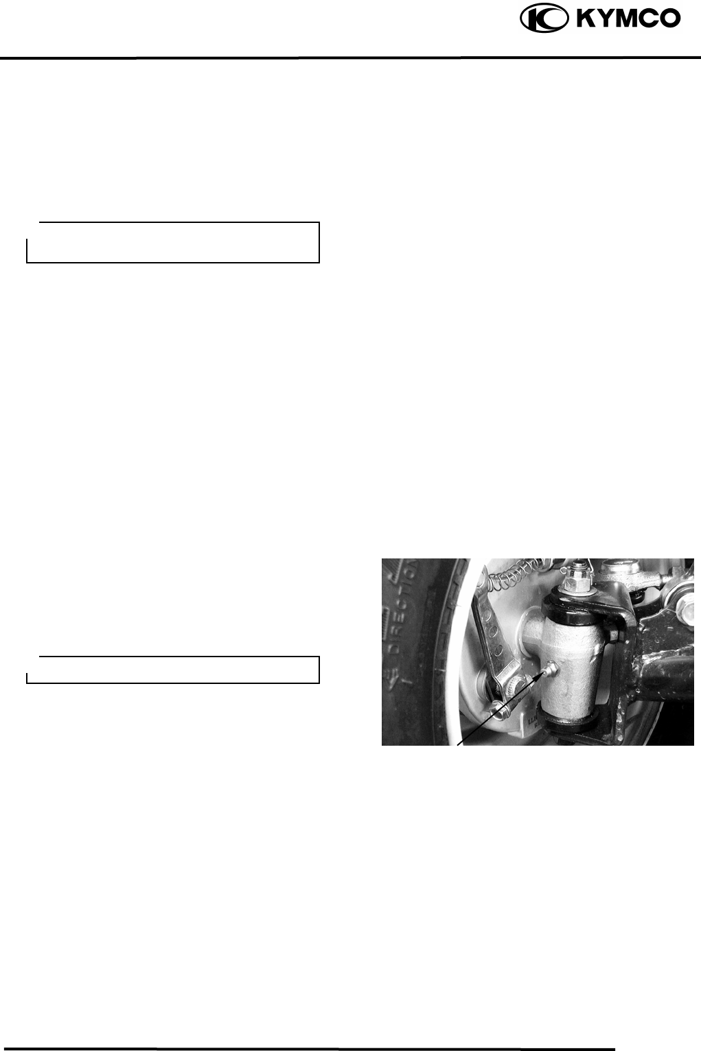
REAR BRAKE
Measure the rear brake lever free play.
Free Play: 1020mm
If the free play do not fall within the limit,
adjust by turning the adjusting nut.
HEADLIGHT AIM
Turn the ignition switch ON and start the
Adjusting Nu
t
Make sure that the
b
rake does not drag
after adjusting.
Lock Nuts Ad
j
usters
3. INSPECTION/ADJUSTMENT
3-11
MX’er SYSTEM
engine.
Turn on the headlight switch.
Adjust the headlight aim by turning the
headlight aim adjusting screw.
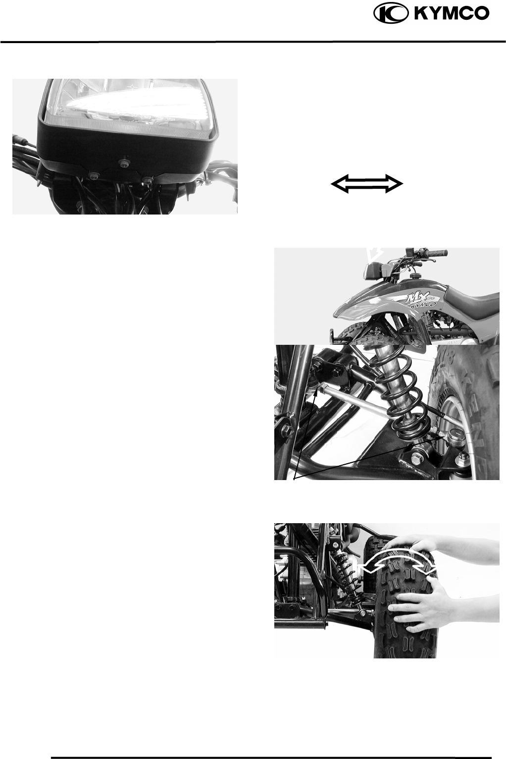
STEERING SYSTEM
INSPECTION
Place the machine on a level place.
Check the steering column bushings and
bearings:
Move the handlebar up and down, and/or
back and forth.
Replace the steering column bushings and
or bearings if excessive play
Check the tie-rod ends
Turn the handlebar to the left and/or right
until it stops completely, then slightly move
the handlebar from left to right.
Replace the tie-rod ends if tie-rod end has
any vertical play.
Raise the front end of the machine so that
there is no weight on the front wheels.
Check ball joints and/or wheel bearings.
Move the wheels lately back and froth.
Replace the front arms and/or wheel
bearings if excessive free play.
Adjusting Screw
Tie-rod Ends
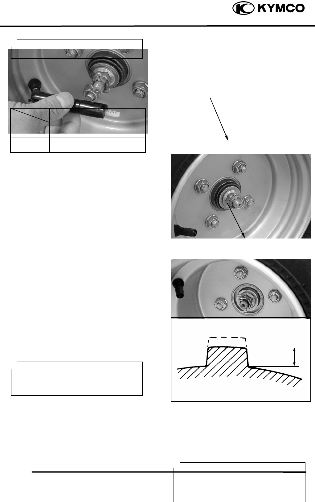
TOE-IN ADJUSTMENT
Place the machine on a level place.
Measure the toe-in
3. INSPECTION/ADJUSTMENT
3-12
MX’er SYSTEM
Adjust if out of specification.
Toe-in measurement steps:
Mark both front tire tread centers.
Raise the front end of the machine so that
there is no weight on the front tires.
Fix the handlebar straight ahead.
Measure the width A between the marks.
Rotate the front tires 180 degrees until the
marks come exactly opposite.
Measure the width B between the marks.
Calculate the toe-in using the formula given
below.
Toe-in = BA
Toe-in: 010mm
If the toe-in is incorrect, adjust the toe-in
Adjust the toe-in step:
Mark both tie-rods ends.
This reference point will be needed during
adjustment.
Loosen the lock nuts (tie-rod end) of both
tie-rods
The same number of turns should be given
to both tie-rods right and left until the
specified toe-in is obtained, so that the
lengths of the rods will be kept the same.
Torque: 2.53.5kgf-m
WHEELS/TIRES
Check the tires for cuts, imbedded nails or
other damages.
Check the tire pressure.
• Be sure that both tie-rod are turned the
same amount. If not, the machine will
drift tight or left even though the
handlebar is positioned straight which
may lead to mishandling and accident.
• After setting the toe-in to specification,
run the machine slowly for some
distance with hands placed lightly on
the handlebar and check that the
handlebar responds correctly. If not,
turn either the right or left tie-rod
within the toe-in specification.
B
Tie-rod
Tie-rod End Nuts
A
3. INSPECTION/ADJUSTMENT
3-13
MX’er SYSTEM
TIRE PRESSURE
1 Rider
Front 0.20kgf/cm²
Rear 0.25kgf/cm²
TIRE SIZE
Front : 20*7-8
Rear : 22*10-8
Check the front axle nut for looseness.
Check the rear axle nut for looseness.
If the axle nuts are loose, tighten them to the
specified torque.
Torque: Front : 6.08.0kgf-m
Rear : 6.08.0kgf-m
WHEEL INSPECTION
Inspect the tire surfaces.
Replace if wear or damage.
Tire wear limit: 3.0mm
Inspect the wheel.
Replace if damage or bends
Always balance the wheel when a tire or
wheel has been changed or replaced.
Front Axle Nu
t
Tire pressure should be checked when
tires are cold.
Rea
r
Axle Nu
t
It is dangerous to ride with a worn out
tire. When a tire wear is out of
specification, replace the tire
immediately.
•
Never attempt even small repairs to the
wheel.
• Ride conservatively after installing a
tire to allow it to seat itself properly on
the rim.
3. INSPECTION/ADJUSTMENT
3-14
MX’er SYSTEM
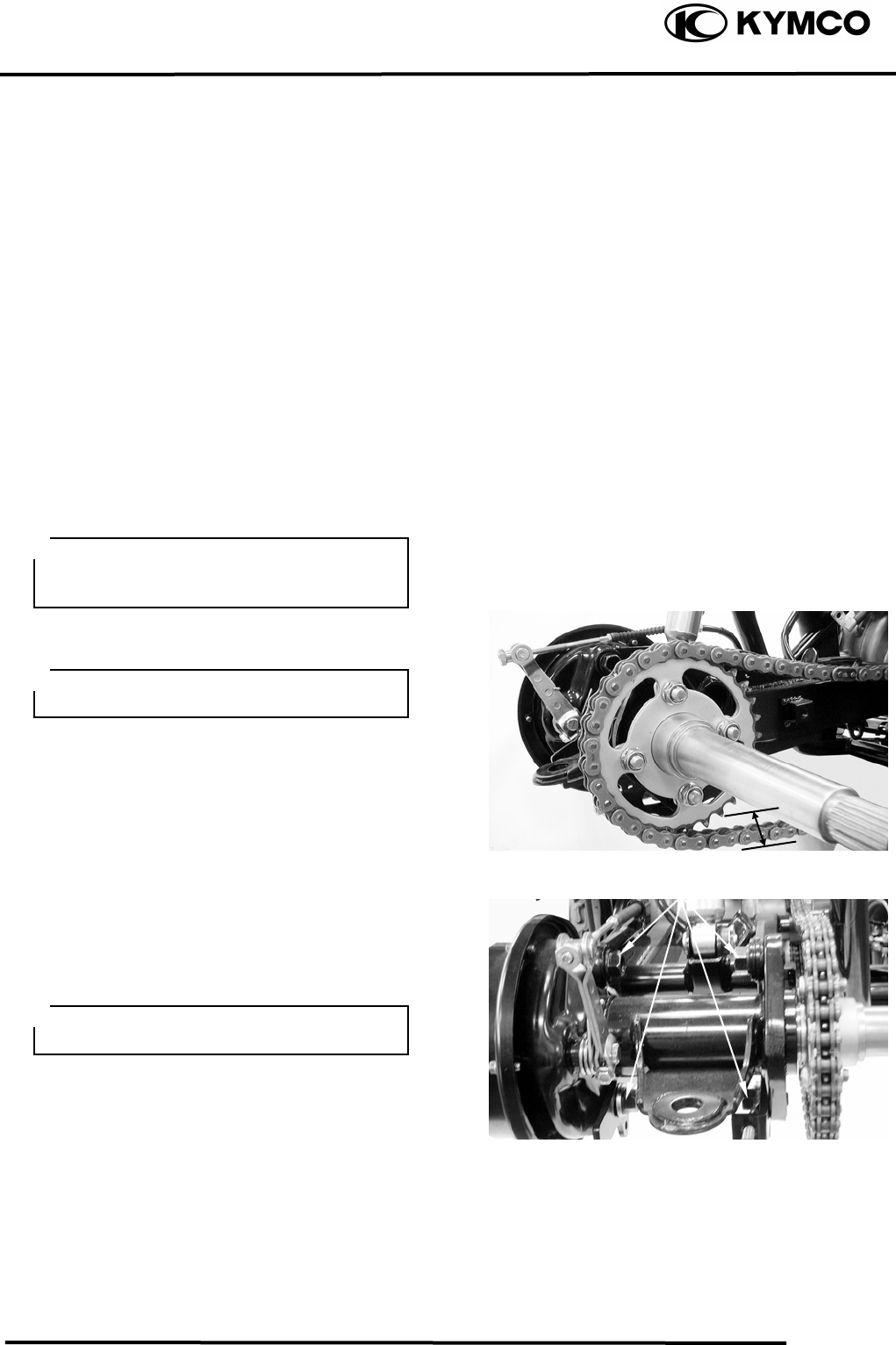
DRIVE CHAIN SLACK
ADJUSTMENT
Before checking and/or adjusting, rotate the
rear wheels several revolutions and check
slack at several points to find the tightest
point. Check and/or adjust the chain slack
with the rear wheels in this “tightest”
position.
Place the machine on a level place.
Check drive chain slack.
Adjust if out of specification.
Drive chain slack: Approximately 30mm
Adjust drive chain slack:
Elevate the rear wheels by placing a suitable
stand under the rear of frame.
Loosen four bolts attaching rear axle hub.
Too little of chain slack will overload the
engine and other vital parts; keep the
slack within the specified limits.
Wheels should be on the ground without
the rider on it.
Bolts
Support the machine securely so there is
no danger of it falling over.
Turn the adjuster in or out until the
specified slack is obtained.
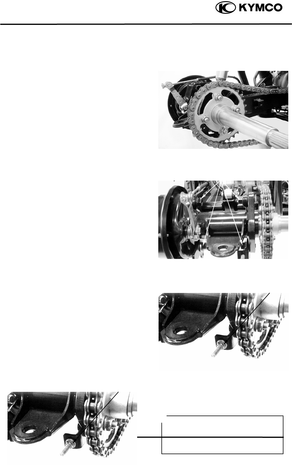
3. INSPECTION/ADJUSTMENT
3-15
MX’er SYSTEM
Turn out: Slack is decreased.
Turn in: Slack is increased.
Tighten four bolts attaching rear axle hub to
the specification. While pushing up or down
on the chain to zero slack.
Torque: 6.08.0kgf-m
Tighten the adjuster.
Torque: 1.82.5kgf-m
Bolts
Adjuste
r
CABLE INSPECTION AND
LUBRICATION
Adjuste
r
Damaged cable sheath may cause
corrosion and interfere with the cable
movement. An unsafe condition may
result so replace such cable as soon as
possible.
3. INSPECTION/ADJUSTMENT
3-16
MX’er SYSTEM
Inspect the cable sheath.
Replace if damage.
Check the cable operation.
Lubricate or replace if unsmooth operation.
LEVER LUBRICATION
Lubricate the pivoting parts of each lever.
FRONT SUSPENSION
LUBRICATION
Inject grease into the nipples using a grease
gun until slight over flow is observed from
the thrust covers.
Hold cable end high and apply several
dro
p
s of lubricant to cable.
Wi
pe off the excess grease.
Nipple

4. LUBRICATION SYSTEM
4-0
MX’er SYSTEM
4
__________________________________________________________________________________
____________________________________________________________________
____________________________________________________________________
____________________________________________________________________
4
____________________________________________________________________
LUBRICATION SYSTEM
____________________________________________________________________
SERVICE INFORMATION------------------------------------------------ 4- 2
TROUBLESHOOTING----------------------------------------------------- 4- 2
ENGINE OIL/OIL FILTER ------------------------------------------------ 4- 3
OIL PUMP-------------------------------------------------------------------- 4- 3
4. LUBRICATION SYSTEM
4-1
MX’er SYSTEM
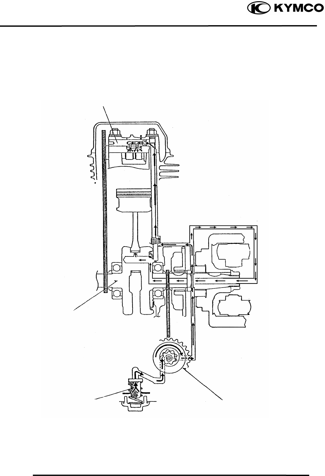
LUBRICATION SYSTEM
Rocker Arm Shaft
Crankshaft
Oil Filter Screen Oil Pump
4. LUBRICATION SYSTEM
4-2
MX’er SYSTEM
SERVICE INFORMATION
GENERAL INSTRUCTIONS
• The maintenance of lubrication system can be performed with the engine installed in the frame.
• Use care when removing and installing the oil pump not to allow dust and foreign matters to
enter the engine and oil line.
• Do not attempt to disassemble the oil pump. The oil pump must be replaced as a set when it
reaches its service limit.
• After the oil pump is installed, check each part for oil leaks.
SPECIFICATIONS
Item Standard (mm) Service Limit (mm)
Inner rotor-to-outer rotor clearance ⎯ 0.12
Oil pump Outer rotor-to-pump body clearance ⎯ 0.12
Rotor end-to-pump body clearance 0.050.10 0.2
TROUBLESHOOTING
Oil level too low Poor lubrication pressure
• Natural oil consumption • Oil level too low
• Oil leaks • Clogged oil filter or oil passages
• Worn or poorly installed piston rings • Not use the specified oil
• Worn valve guide or seal
4. LUBRICATION SYSTEM
4-3
MX’er SYSTEM
Nu
t
Flywheel
ENGINE OIL/OIL FILTER
OIL LEVEL
Remove the oil dipstick and check the oil
level with the oil dipstick.
If the level is near the lower level, fill to the
upper level with the specified engine oil.
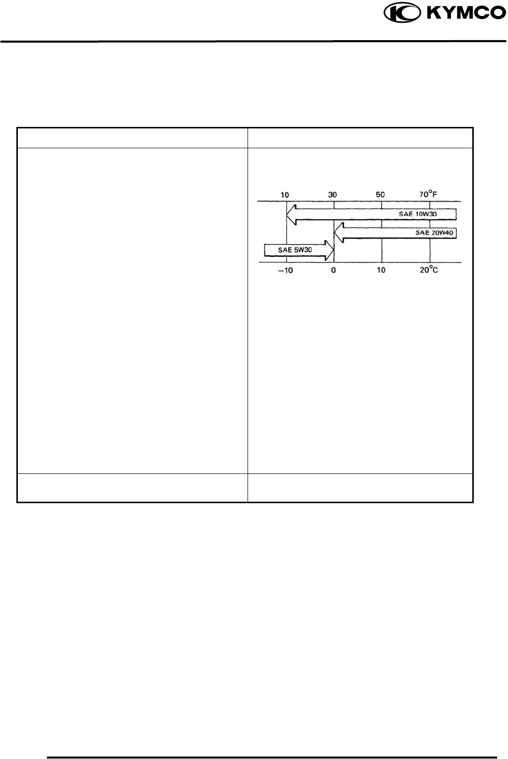
OIL CHANGE
Remove the oil drain plug bolt located on
the bottom of the engine to drain the engine
oil thoroughly.
After the oil has been completely drained,
Install the oil drain plug bolt.
Torque: 2..03.0kgf-m
Refer to page 3-2 to clean the engine oil
filter screen
After the oil has been completely drained,
check the filter screen O-ring for damage
and replace if necessary.
Install the oil filter screen, spring and filter
screen cap.
Torque: 1.02.0kgf-m
Fill with the specified SAE15W40#, API: SG
engine oil to the proper level.
Oil Capacity: At disassembly : 1.0 liter
At change : 0.9 liter
Check for oil leaks and then start the engine
and let it idle for few minutes.
Recheck the oil level.
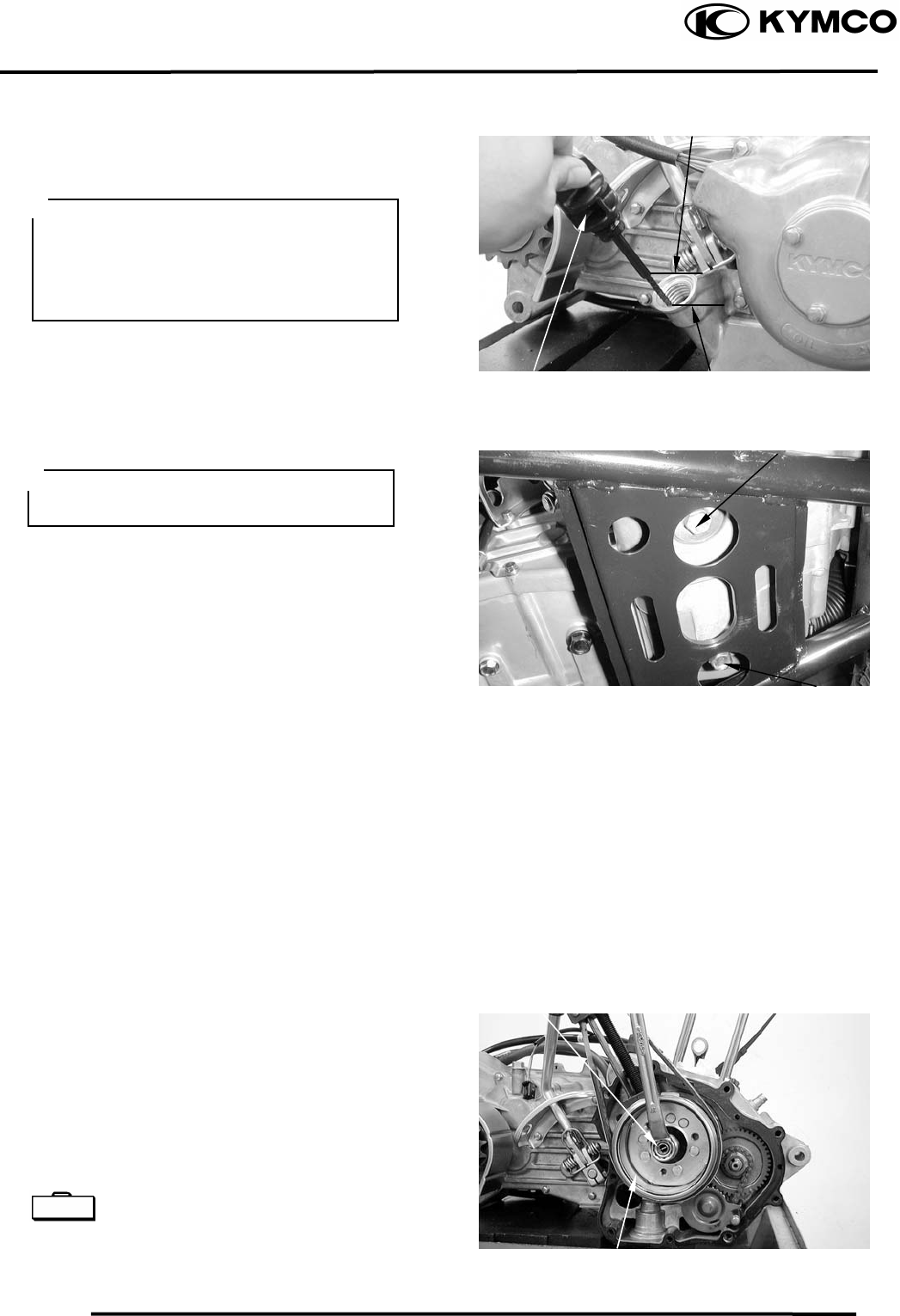
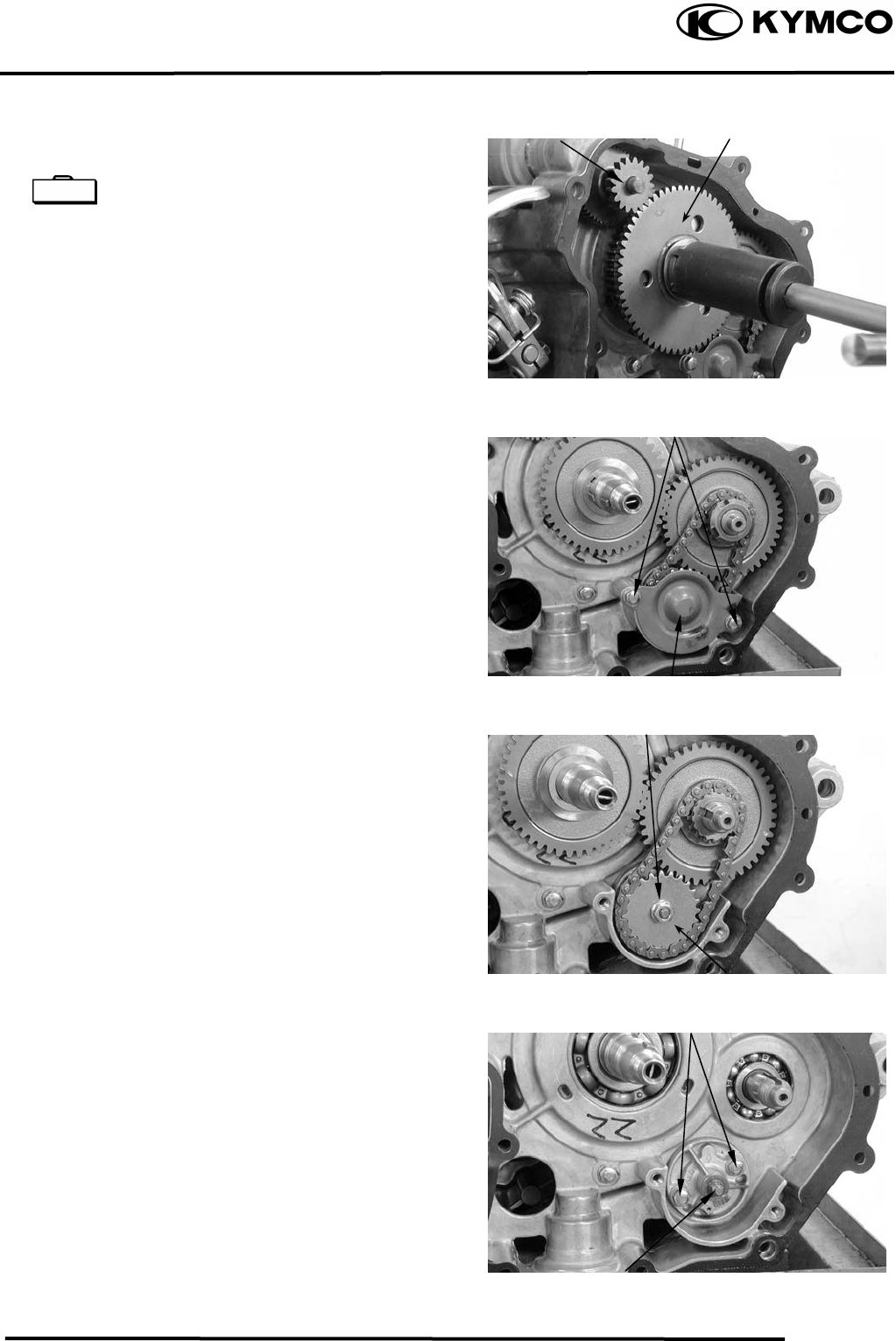
OIL PUMP
REMOVAL
Remove the right crankcase cover.
Remove the A.C. generator flywheel.
Flywheel holder E021
Flywheel puller E003
Lower Level
Oil Dipstick
Oil Filter Screen Cap
•
Place the motorcycle upright on level
ground for engine oil level check.
• Run the engine for 23 minutes and
check the oil level after the engine is
stopped for 23 minutes.
Upper Level
The engine oil will drain more easily
while the engine is warm.
oil drain plug bol
t
pecial S
4. LUBRICATION SYSTEM
4-4
MX’er SYSTEM
Oil Pump Driven Gea
r
Bolts
Bolts
Nu
t
Remove the starter idle gear and starter
clutch.
Lock nut socket wrench E009
Remove the two bolts and oil separator
cover.
Remove the oil pump driven gear nut to
remove the oil pump driven gear and drive
chain.
Remove the oil pump mounting two bolts
and the oil pump.
S
t
arter Clutch
Oil Separator Cove
r
Oil Pump
Starter Idle Gea
r
Special
4. LUBRICATION SYSTEM
4-5
MX’er SYSTEM
Outer Roto
r
Outer Roto
r
Inner Roto
r
Pump Body
Screw
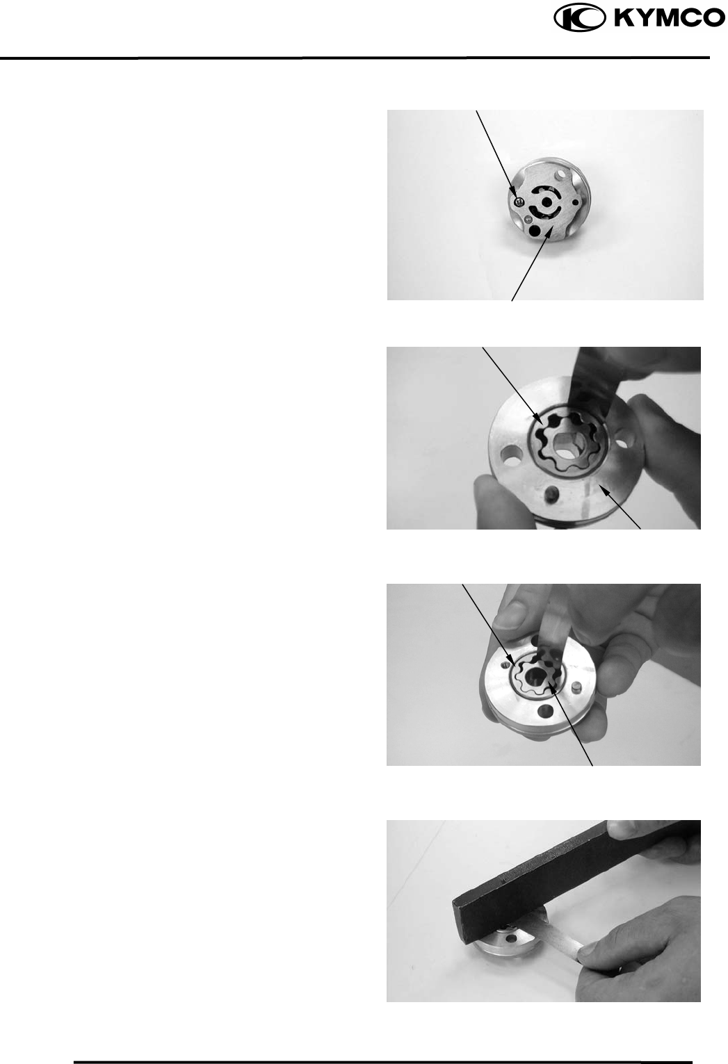
DISASSEMBLY
Remove the screw and disassemble the oil
pump.
INSPECTION
Measure the pump body-to-outer rotor
clearance.
Service Limit: 0.12mm
Measure the inner rotor-to-outer rotor
clearance.
Service Limit: 0.12mm
Measure the rotor end-to-pump body
clearance.
Service Limit: 0.2mm
Pump Body
4. LUBRICATION SYSTEM
4-6
MX’er SYSTEM
Screw
Inner Roto
r
Bolts
Pump Cove
r
Outer Roto
r
ASSEMBLY
Dowel Pin
Oil Pum
p
Arrow
Install the outer rotor, inner rotor and pump
shaft into the pump body.
Install the dowel pin.
Install the pump cover by aligning the hole
in the cover with the dowel pin.
Tighten the screw to secure the pump cover.
Make sure that the pump shaft rotates freely
without binding.
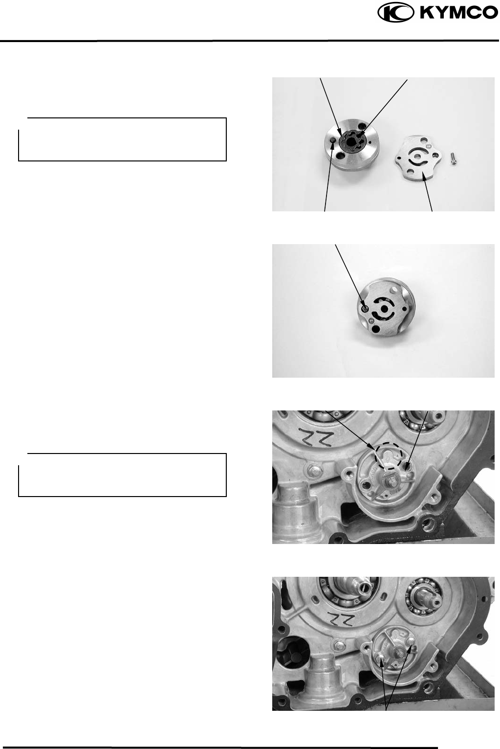
INSTALLATION
Install the oil pump into the crankcase.
After the oil pump is installed, tighten the
two mounting bolts.
Insert the pump shaft by aligning the flat
on the shaf at in the inner
rotor.
t with the fl
Install the oil pum
the pum
pump with engine oil before installation.
p with the arrow on
p body facing up and fill the oil
4. LUBRICATION SYSTEM
4-7
MX’er SYSTEM
Install the pump driven gear and drive chain
by aligning the pump driven gear with the
cutout in the pump shaft.
Flywheel
Starter Idle Gea
r
Bolts
Nu
t
Pump Driven Gea
r
Starter Clutch
Install and tighten the pump driven gear nut.
Torque: 0.81.2kgf-m
Install the oil separator cover and tighten
the bolts.
Install the starter idle gear and starter
clutch.
Install the starter clutch nut and tighten it to
specified torque..
Torque: 9.5 kgf-m
Install the gasket and dowel pins.
Install the A.C. generator flywheel.
Install the right crankcase cover.
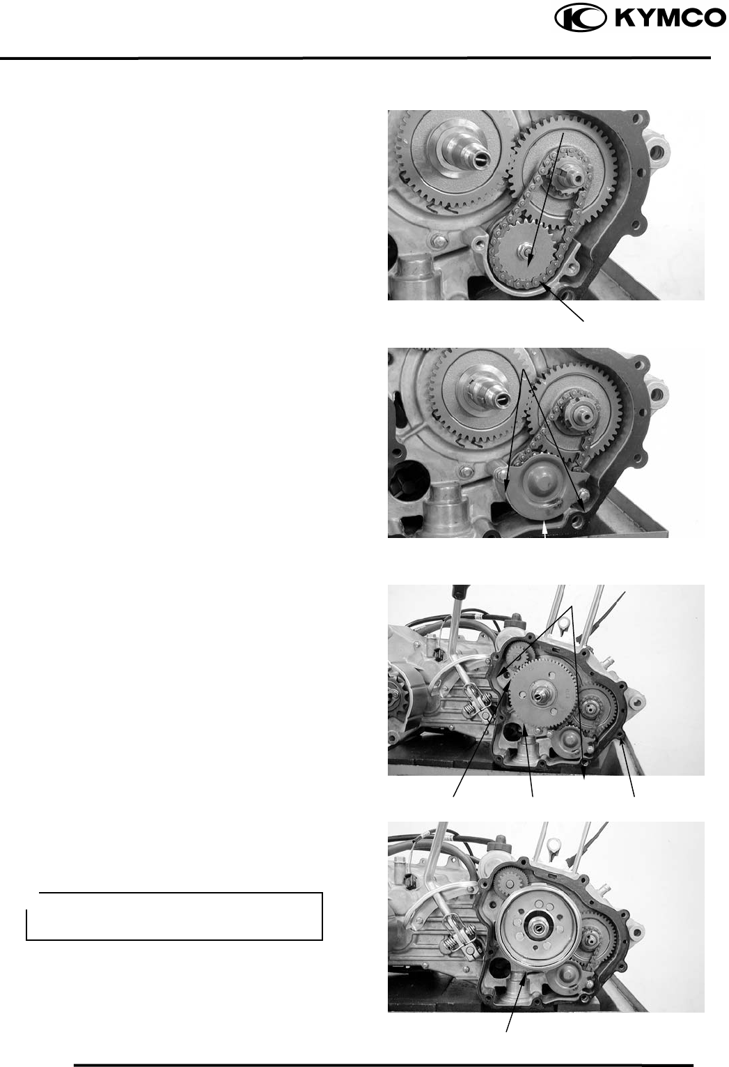
Torque: 0.81.2kgf-m
Oil Separator Cove
r
Dowel Pin
Gaske
t
Diagonally tighten the bolts in 23
times.

5. FUEL SYSTEM
5-0
MX’er SYSTEM
5
__________________________________________________________________________________
____________________________________________________________________
____________________________________________________________________
____________________________________________________________________
5
____________________________________________________________________
FUEL SYSTEM
____________________________________________________________________
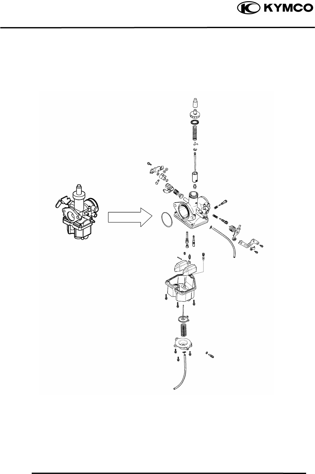
SERVICE INFORMATION------------------------------------------------ 5- 2
TROUBLESHOOTING----------------------------------------------------- 5- 3
THROTTLE VALVE DISASSEMBLY/CARBURETOR REMOVAL-- 5- 4
FLOAT/FLOAT VALVE/JETS-------------------------------------------- 5- 5
CARBURETOR INSTALLATION --------------------------------------- 5- 8
FUEL TANK ----------------------------------------------------------------- 5- 9
FUEL VALVE REMOVAL------------------------------------------------ 5- 9
AIR CLEANER -------------------------------------------------------------- 5-10
5. FUEL SYSTEM
5-1
MX’er SYSTEM
5. FUEL SYSTEM
5-2
MX’er SYSTEM
SERVICE INFORMATION
GENERAL INSTRUCTIONS
Gasoline is very dangerous. When working with gasoline, keep sparks and flames away
from the working area.
Gasoline is extremely flammable and is explosive under certain conditions. Be sure to
work in a well-ventilated area.
• Do not bend or twist control cables. Damaged control cables will not operate smoothly.
• When disassembling fuel system parts, note the locations of O-rings. Replace them with new
ones during reassembly.
• Before float chamber disassembly, loosen the drain screw to drain the residual gasoline into a
clean container.
• After the carburetor is removed, plug the intake manifold side with a clean shop towel to prevent
foreign matters from entering.
• When cleaning the carburetor air and fuel jets, the O-rings and diaphragm must be removed first
to avoid damage. Then, clean with compressed air.
• When the motorcycle is not used for over one month, drain the residual gasoline from the float
chamber to avoid erratic idling and clogged slow jet due to deteriorated fuel.
SPECIFICATIONS MX’er 150 MX’er 125
Item Standard Standard
Type PD PD
Venturi dia. φ25 φ25
Float level 14.8mm 14.8mm
Main jet No. 95 95
Adjust method Piston Piston
Idle speed 1700±100rpm 1700±100rpm
Throttle grip free play 14mm 14mm
Air screw opening 2±1/2 2±1/2

5. FUEL SYSTEM
5-3
MX’er SYSTEM
SPECIAL TOOL
Float level gauge
TROUBLESHOOTING
Engine cranks but won’t start Engine lacks power
• No fuel in tank • Clogged air cleaner
• No fuel to carburetor • Faulty carburetor
• Cylinder flooded with fuel • Faulty ignition system
• No spark at plug
• Clogged air cleaner Lean mixture
• Intake air leak • Clogged carburetor fuel jets
• Improper throttle operation • Float level too low
• Intake air leak
Engine idles roughly, stalls or runs poorly • Clogged fuel tank cap breather hole
• Excessively used choke • Kinked or restricted fuel line
• Ignition malfunction
• Faulty carburetor Rich mixture
• Poor quality fuel • Float level too high
• Lean or rich mixture • Clogged air jets
• Incorrect idle speed • Clogged air cleaner
Misfiring during acceleration
• Faulty ignition system
• Faulty carburetor
Backfiring at deceleration
• Float level too low
• Incorrectly adjusted carburetor
• Faulty exhaust muffler
5. FUEL SYSTEM
5-4
MX’er SYSTEM
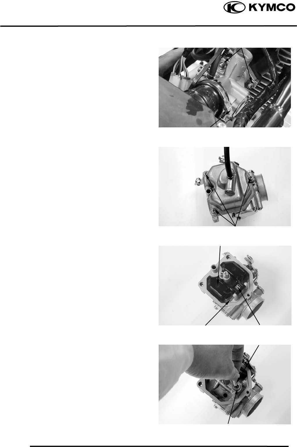
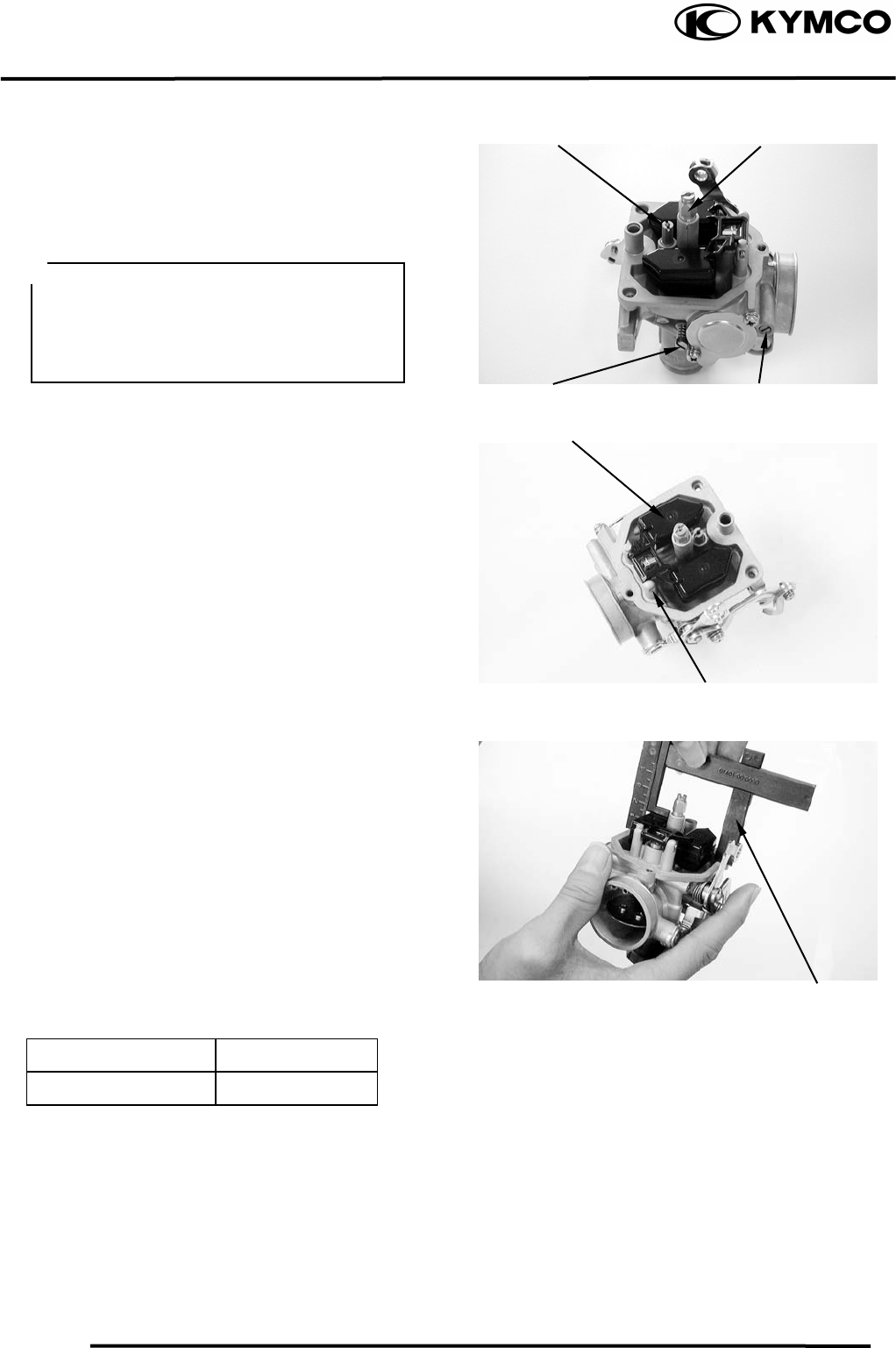
THROTTLE VALVE DISASSEMBLY
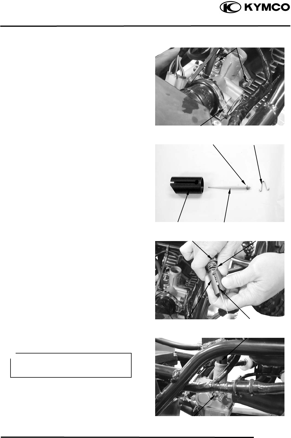
Remove the front cover.
Remove the front fender.
Remove the carburetor cap.
Pull out the throttle valve.
Disconnect the choke knob cable.
Disconnect the throttle cable and remove the
spring from the throttle valve.
Pry off the needle retainer and remove the jet
needle.
Check the throttle valve and jet needle for
wear or damage.
CARBURETOR REMOVAL
Switch the fuel valve OFF.
Loosen the drain screw to drain the gasoline
from the float chamber.
Disconnect the fuel inlet tube and the choke
cable.
Carburetor Cap
Spring
Throttle Cable
Throttle Valve
Clip Needle Retaine
r
Throttle Valve Jet Needle
Choke Cable
• Keep sparks and flames away from the
work area.
• Drain gasoline into a clean container.
5. FUEL SYSTEM
5-5
MX’er SYSTEM
Loosen the air cleaner connecting tube band
screw.
Remove the two carburetor lock nuts.
Remove the carburetor
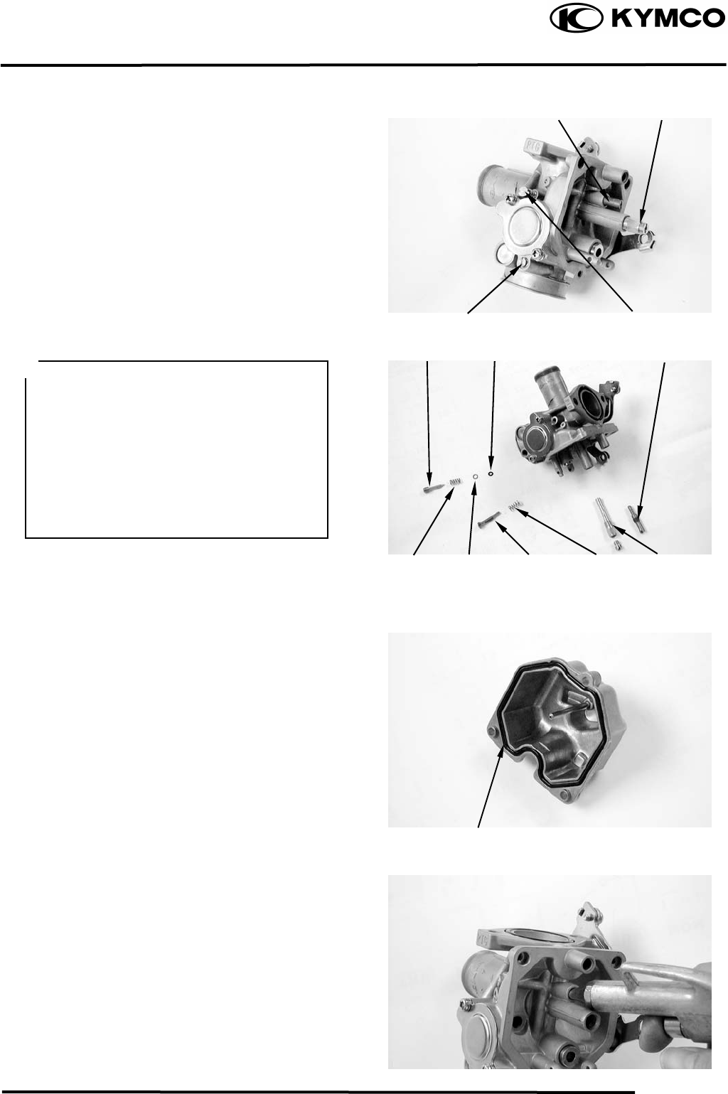
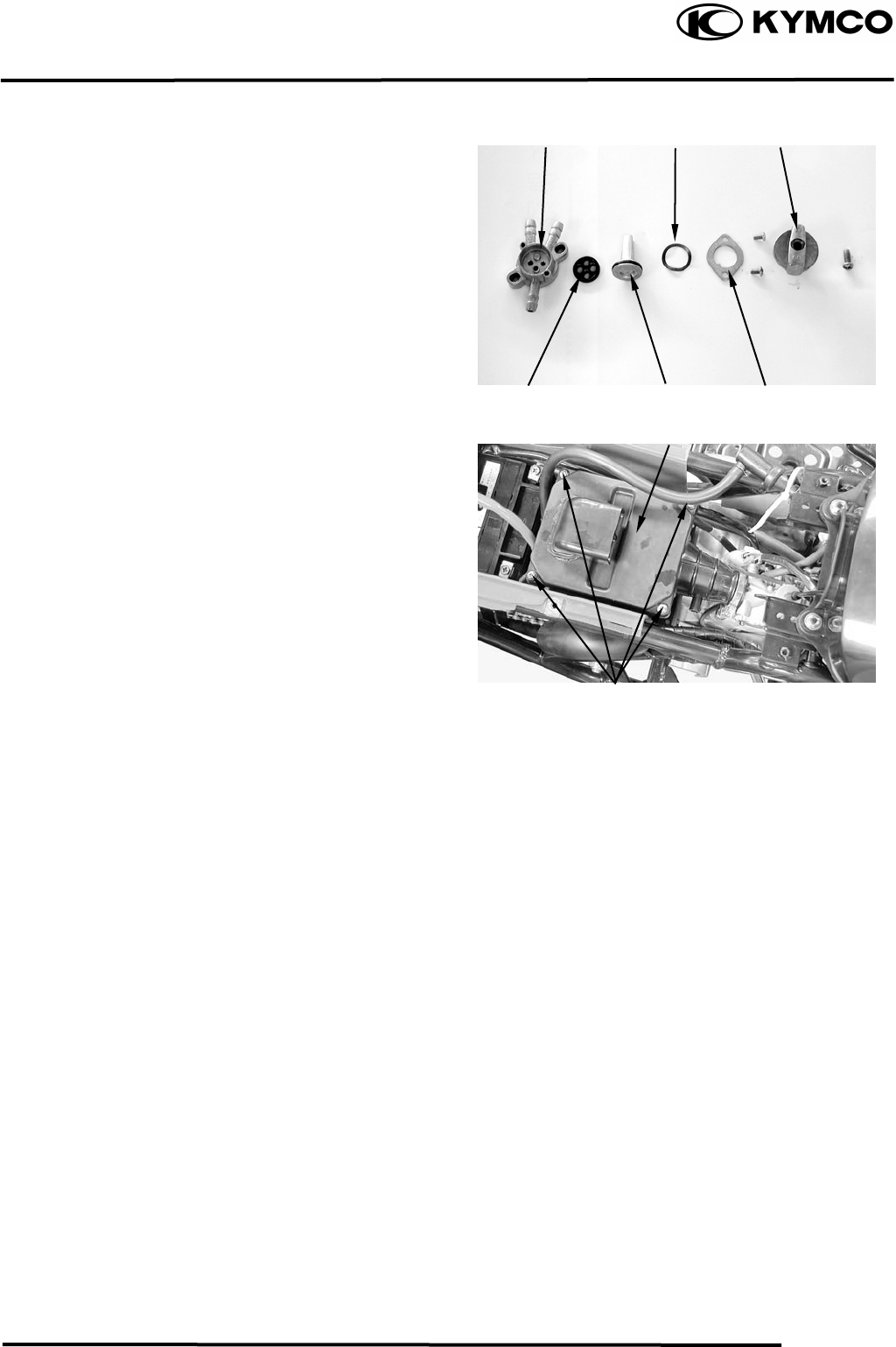
FLOAT/FLOAT VALVE/JETS
FLOAT/FLOAT VALVE DISASSEMBLY
Remove the float chamber attaching three
screws and remove the float chamber.
Remove the float pin, float and float valve.
FLOAT/FLOAT VALVE INSPECTION
Inspect the float valve seat for wear or
damage.
Inspect the float for damage or fuel level
inside the float chamber.
Lock Nuts
Screw
Screws
Floa
t
Float Pin Float Valve
Float Valve
Float Valve Sea
t
5. FUEL SYSTEM
5-6
MX’er SYSTEM
JETS/AIR SCREW/THROTTLE STOP
SCREW REMOVAL
Remove the main jet, needle jet holder, and
needle jet.
Remove the slow jet.
Remove the air screw and throttle stop
screw.
CAUTIONS !
FUEL RESERVOIR O-RING CHECK
Remove the O-ring.
INSPECTION
Inspect the check the O-ring for damage.
Replace with new ones if necessary
CARBURETOR CLEANING
Blow compressed air through all passages of
the carburetor body.
Air Screw
Slow Je
t
Main Je
t
Throttle Sto
p
Screw
O-ring
Slow Je
t
Air Screw
• Be careful not to damage the jets and
jet holder when removing them.
• Before removal, turn the throttle stop
screw and air screw in and count the
number of turns until they seat lightly
and then make a note of this.
• Do not force the screw against its seat
to avoid seat damage.
• Be sure to install the O-ring in the
reverse order of removal.
S
p
rin
g
Main Je
t
Throttle
Stop Screw
Washe
r
O-rin
g
S
p
rin
g
5. FUEL SYSTEM
5-7
MX’er SYSTEM
SLOW/MAIN JET INSTALLATION
Install the slow jet.
Install the needle jet, needle jet holder and
main jet.
Install the throttle stop screw and air screw
Install the float valve, float and float pin.
FLOAT LEVEL INSPECTION
Turn the carburetor upside down so that the
float will go down to make the float valve
contact the float valve seat.
Then slowly tilt the carburetor and measure
the float level with the float level gauge
while the float pin just contacts with float
valve.
Float Level:
MX’er 150 14.8mm
MX’er 125
When adjusting, carefully bend the float pin.
Check the float for proper operation and then
install the float chamber.
Main Je
t
Slow Je
t
Float Level Gauge
• When installing the air screw, return it
to the original position as noted during
removal
• After the carburetor is installed, be
sure to perform the Exhaust Emission
Throttle Sto
p
Screw
Float Pin
Floa
t
Ai
r
Screw
5. FUEL SYSTEM
5-8
MX’er SYSTEM
CARBURETOR INSTALLATION
Install the carburetor onto the intake
manifold and tighten the two lock nuts.
Torque: 0.81.2kgf-m
Install the air cleaner connecting tube and
tighten the band screw.
THROTTLE VALVE ASSEMBLY
Install the jet needle into the throttle valve
and secure with the needle retainer.
Jet Needle Notch: 4th Notch
(Counted from top to bottom)
Assemble the rubber cover, carburetor cap
and throttle valve spring.
Connect the throttle cable to the throttle
valve.
Install the throttle valve into the carburetor
body.
Connect the accelerating pump cable.
Fully open the throttle and adjust the
accelerating pump cable to align the punch
mark on the accelerating pump arm with the
punch mark on the set plate.
Lock Nu
t
Band Screw
Needle Retaine
r
Clip
Je
t
Needle
Throttle Valve
Spring
Carburetor Cap
Notch
Throttle Valve
Groove
Throttle Stop Screw
Align the groove in the throttle valve
with the throttle stop screw on the
carburetor body.
5. FUEL SYSTEM
5-9
MX’er SYSTEM
Tighten the choke cable.
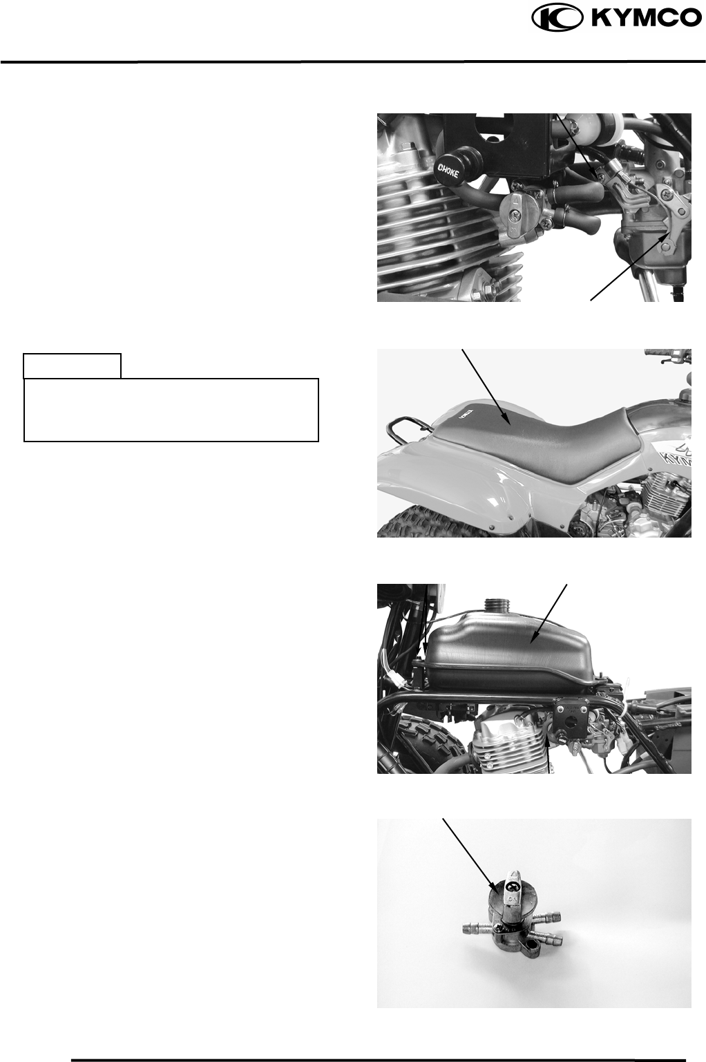
FUEL TANK
FUEL TANK REMOVAL
Remove the seat.
Remove the center cover.
Remove the right and left front fender.
Switch the fuel valve “OFF”.
Disconnect the fuel tube and remove two
bolts on the end of the fuel tank.
Remove the fuel tank.
FUEL VALVE REMOVAL
Remove the fuel valve and fuel cup.
Screw
Choke Cable
Bolts Fuel Tank
Fuel Valve
Tube
Side
• Keep sparks and flames away from the
work area.
• Wipe off any spilled gasoline.
5. FUEL SYSTEM
5-10
MX’er SYSTEM
Remove the screw on the fuel valve control
switch.
Remove the two screws on the fuel valve
body.
INSPECTION
Inspect the fuel valve strainer for dirt and
clog. Clean if necessary.
Replace the O-rings with new ones if they
are damaged or deteriorated.
AIR CLEANER
REMOVAL
Remove the seat.
Remove the four screws on the air cleaner
case cover and the cover.
Remove the air cleaner screen and element.
Fuel Valve Body
Screws
Air Cleaner Case Cove
r
Washe
r
Cont
r
ol Switch
Control Shaf
t
Rubber Gaske
t
Retaining Ring

6. ENGINE REMOVAL/INSTALLATION
6-0
MX’er SYSTEM
6
__________________________________________________________________________________
____________________________________________________________________
____________________________________________________________________
____________________________________________________________________
____________________________________________________________________
ENGINE REMOVAL/INSTALLATION
____________________________________________________________________
6
SERVICE INFORMATION------------------------------------------------ 6- 1
ENGINE REMOVAL ------------------------------------------------------- 6- 2
ENGINE INSTALLATION ------------------------------------------------ 6- 4

6. ENGINE REMOVAL/INSTALLATION
6-1
MX’er SYSTEM
SERVICE INFORMATION
GENERAL INSTRUCTIONS
• A floor jack or other adjustable support is required to support and maneuver the engine. Be
careful not to damage the machine body, cables and wires during engine removal.
• Use shop towels to protect the motorcycle body during engine removal.
• Parts requiring engine removal for servicing:
⎯ Crankcase
⎯ Crankshaft
6. ENGINE REMOVAL/INSTALLATION
6-2
MX’er SYSTEM
ENGINE REMOVAL
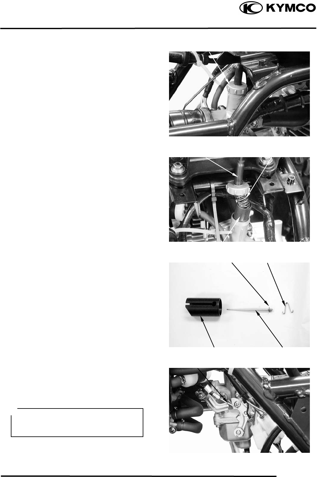
Drain engine oil and transmission oil.
Remove seat, front cover, center cover,
front fender and rear fender.
Remove the carburetor.
Disconnect the battery negative cable.
Remove the frame body cover.
Disconnect the engine negative cable.
Disconnect the A.C.G. wire connector.
Disconnect the starter motor cable from the
starter relay.
Disconnect the oil recycle tube at the engine
body.
Disconnect the oil recycle tube at the
cylinder head cover.
Loosen the drive belt air cleaner connecting
tube band screw and remove the connecting
tube.
Starter Relay Starter Motor Cable
Oil Recycle Tube
Connecting Tube
Screw
Oil Recycle Tube
A.C.G. Wire Connecto
r
6. ENGINE REMOVAL/INSTALLATION
6-3
MX’er SYSTEM
Disconnect the spark plug high-tension
wire.
Remove the spark plug cap and disconnect
the ignition coil wire from the set plate.
Remove the rear drive chain gear on the
bolts.
Remove the drive chain gear.
Remove the two bolts and two joint lock
nuts attaching the exhaust muffler.
Remove the exhaust muffler.
ENGINE REMOVAL
Remove the engine any connector thing.
Remove the engine back bracket tow bolts.
Ignition Coil Wire
Drive Chain Gea
r
Exhaust Muffle
r
Bolts
Bolts
6. ENGINE REMOVAL/INSTALLATION
6-4
MX’er SYSTEM
Remove the engine front bracket bolt.
ENGINE HANGER BRACKET
REMOVE
Remove the two bolts on the left engine
hanger bracket.
Remove the left engine hanger bracket.
Remove the engine.
ENGINE INSTALLATION
Install the engine and tighten the engine
mounting bolts.
Torque: 3.54.5kgf-m
Install the removed parts in the reverse
order of removal.
Bol
t
Engine Hanger Bracke
t
Bolts
Route the wires and cables properly.

7. CYLINDER HEAD/VALVES
7-0
MX’er SYSTEM
7
__________________________________________________________________________________
____________________________________________________________________
____________________________________________________________________
____________________________________________________________________
____________________________________________________________________
CYLINDER HEAD/VALVES
____________________________________________________________________
7
SERVICE INFORMATION------------------------------------------------ 7- 2
TROUBLESHOOTING----------------------------------------------------- 7- 3
CAMSHAFT REMOVAL-------------------------------------------------- 7- 4
CYLINDER HEAD REMOVAL ------------------------------------------ 7- 7
CYLINDER HEAD DISASSEMBLY ------------------------------------ 7- 8
CYLINDER HEAD ASSEMBLY----------------------------------------- 7-10
CYLINDER HEAD INSTALLATION ----------------------------------- 7-10
CAMSHAFT INSTALLATION ------------------------------------------- 7-11
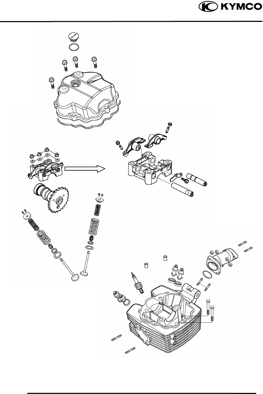
7. CYLINDER HEAD/VALVES
7-1
MX’er SYSTEM
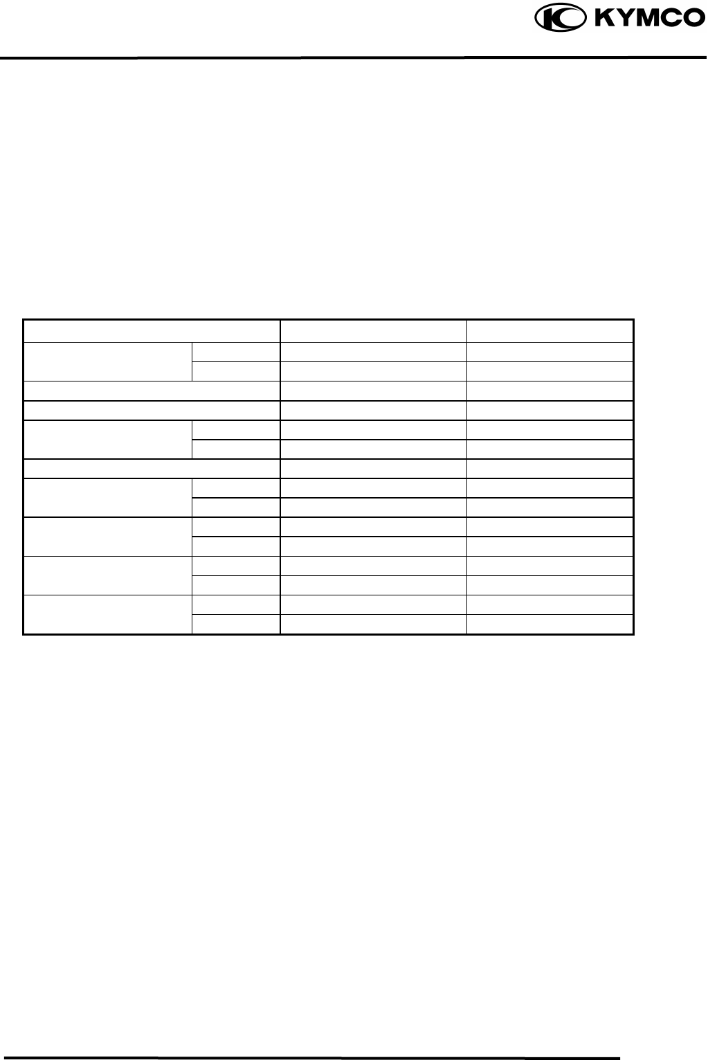
7. CYLINDER HEAD/VALVES
7-2
MX’er SYSTEM
SERVICE INFORMATION
GENERAL INSTRUCTIONS
• The cylinder head can be serviced with the engine installed in the frame.
• When assembling, apply molybdenum disulfide grease or engine oil to the valve guide movable
parts, valve arm and camshaft sliding surfaces for initial lubrication.
• The camshaft is lubricated by engine oil through the cylinder head engine oil passages. Clean and
unclog the oil passages before assembling the cylinder head.
• After disassembly, clean the removed parts and dry them with compressed air before inspection.
• After removal, mark and arrange the removed parts in order. When assembling, install them in
the reverse order of removal.
SPECIFICATIONS
Item Standard (mm) Service Limit (mm)
IN 0.06 ⎯
EX 0.06 ⎯
Cylinder head compression pressure 16kg/cm²
Cylinder head warpage ⎯ 0.05
IN 31.8 31.4
EX 31.53 31.13
Valve rocker arm to shaft clearance 0.090.034 0.1
Valve stem-to-guide IN 0.0100.037 0.06
clearance EX 0.0250.052 0.08
IN 39.4 ⎯
Valve spring free length EX 45.5 ⎯
IN 7.78.9kg(at 33.7mm) ⎯
Valve spring
compressed force EX 19.522.5kg(at 38.4mm) ⎯
IN 1.7 ⎯
Valve spring tilt EX 1.95 ⎯
Valve clearance (cold)
Camshaft cam height

7. CYLINDER HEAD/VALVES
7-3
MX’er SYSTEM
TORQUE VALUES
Cylinder head nut 1.82.2kgf-m Apply engine oil to threads
Valve clearance adjusting nut 1.41.8kgf-m Apply engine oil to threads
Stud bolt 0.71.1kgf-m
SPECIAL TOOLS
Valve spring compressor E040
Tappet adjuster E012
TROUBLESHOOTING
• The poor cylinder head operation can be diagnosed by a compression test or by tracing engine
top-end noises.
Poor performance at idle speed White smoke from exhaust muffler
• Compression too low • Worn valve stem or valve guide
• Damaged valve stem seal
Compression too low
• Incorrect valve clearance adjustment Abnormal noise
• Burned or bend valves • Incorrect valve clearance adjustment
• Incorrect valve timing • Sticking valve or broken valve spring
• Broken valve spring • Damaged or worn camshaft
• Poor valve and seat contact • Worn cam chain guide
• Leaking cylinder head gasket • Worn camshaft and rocker arm
• Warped or cracked cylinder head
• Poorly installed spark plug
Compression too high
• Excessive carbon build-up in combustion
chamber
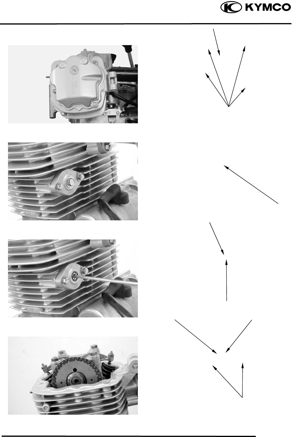
7. CYLINDER HEAD/VALVES
7-4
MX’er SYSTEM
CAMSHAFT REMOVAL
Remove seat, front cover, center cover.
Front fender, fuel tank and exhaust pipe.
Remove the four cylinder head cover bolts
to remove the cylinder head cover.
Remove the cam chain tensioner cap bolt
and the O-ring.
Turn the cam chain tensioner screw
clockwise to tighten it.
Turn the flywheel counterclockwise so that
the “T” mark on the flywheel aligns with
the index mark on the crankcase to bring the
round hole on the camshaft gear facing up
to the top dead center on the compression
stroke.
Cylinder Head Cove
r
O-ring
Tensioner Screw
Round Hole
Camshaft Gea
r
Bol
t
Punch Marks
Bolts
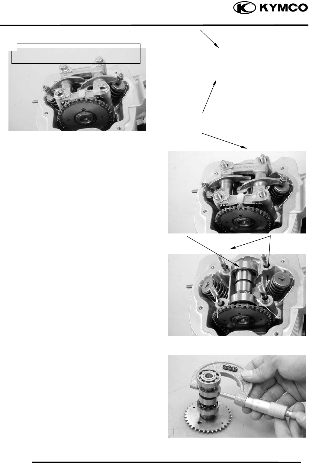
7. CYLINDER HEAD/VALVES
7-5
MX’er SYSTEM
Remove the four cylinder head nuts and
washers.
Remove the camshaft holder and dowel
pins.
Remove the camshaft gear from the cam
chain and remove the camshaft.
CAMSHAFT INSPECTION
Check each cam lobe for wear or damage.
Measure the cam lobe height.
Service Limits:
IN : 31.40mm replace if below
EX: 31.13mm replace if below
Cam Chain Camshaft Gea
r
Camshaft Holde
r
Nu
t
Washe
r
Dowel PinsCamshaf
t
Diagonally loosen the cylinder head nuts
in 2 or 3 times.
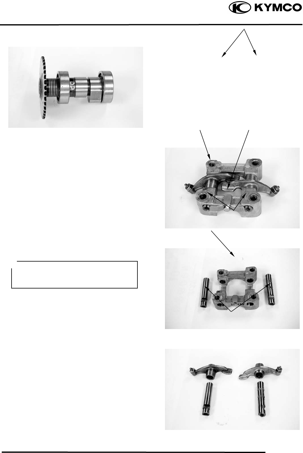
7. CYLINDER HEAD/VALVES
7-6
MX’er SYSTEM
Check each camshaft bearing for play or
damage. Replace the camshaft assembly
with a new one if the bearings are noisy or
have excessive play.
CAMSHAFT HOLDER DISASSEMBLY
Remove the bolt attaching the stop plate.
Take out the valve rocker arm shafts using a
5mm bolt.
Remove the valve rocker arms.
CAMSHAFT HOLDER INSPECTION
Inspect the camshaft holder, valve rocker
arms and rocker arm shafts for wear or
damage.
Measure the I.D. of each valve rocker arm.
Measure each rocker arm shaft O.D.
Measure arm to shaft clearance.
Replace as a set if out of specification.
Service limits: 0.10mm
Rocker Ar
m
Bol
t
Rocker Arm Shaf
t
Camshaft Holde
r
Rocker Arm Shafts
If the valve rocker arm contact surface is
worn, check each cam lobe for wear or
damage.
Camshaft Bearin
g
s
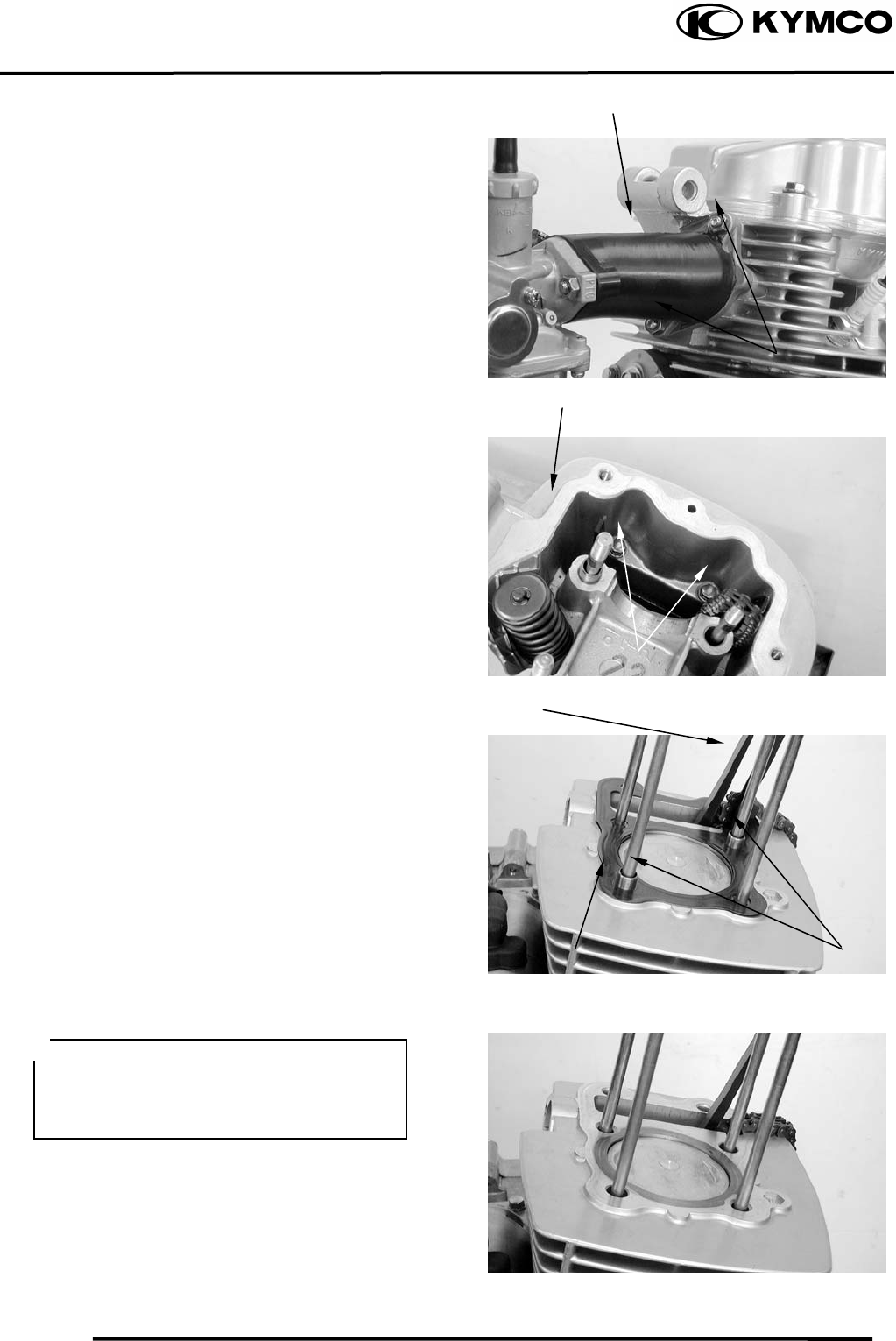
7. CYLINDER HEAD/VALVES
7-7
MX’er SYSTEM
CYLINDER HEAD REMOVE
Remove the camshaft.
Remove the carburetor.
Remove the exhaust muffler.
Remove the carburetor intake manifold.
Remove the two cylinder head bolts.
Remove the cylinder head.
Remove the dowel pins and cylinder head
gasket.
Remove the cam chain guide.
Remove all gasket material from the
cylinder mating surface.
Intake Manifold
Cylinder Head
Dowel Pins
Cam Chain Guide
C
y
linder Head Gaske
t
Bolts
Bolts
• Avoid damaging the cylinder mating
surface.
• Be careful not to drop any gasket
material into the engine.
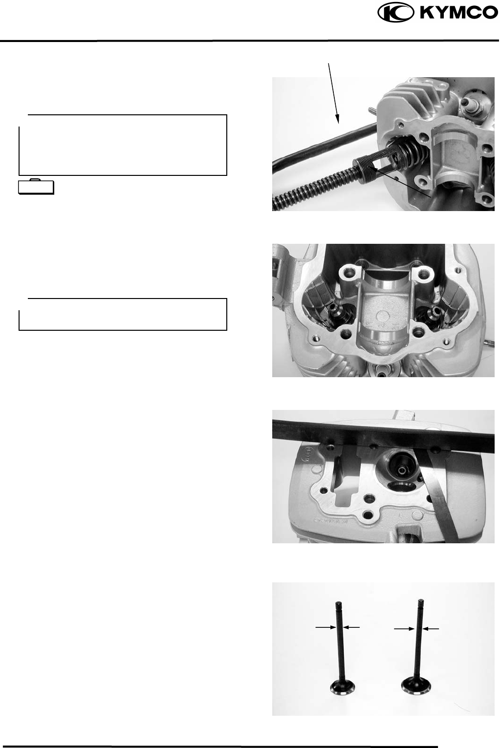
7. CYLINDER HEAD/VALVES
7-8
MX’er SYSTEM
CYLINDER HEAD
DISASSEMBLY
Remove the valve spring cotters, retainers,
springs, spring seats and valve stem seals
using a valve spring compressor.
Valve Spring Compressor E040
Remove carbon deposits from the
combustion chamber.
Clean off any gasket material from the
cylinder head mating surface.
INSPECTION
CYLINDER HEAD
Check the spark plug hole and valve areas
for cracks.
Check the cylinder head for warpage with a
straight edge and feeler gauge.
Service Limit: 0.05mm repair or replace if
over
VALVE /VALVE GUIDE
Inspect each valve for bending, burning,
scratches or abnormal stem wear.
Check valve movement in the guide.
Measure each valve stem O.D.
Valve Spring Compresso
r
• Be sure to compress the valve springs
with a valve spring compressor.
• Mark all disassembled parts to ensure
correct reassembly.
Valve S
p
rin
g
Com
p
ressor
Be careful not to damage the cylinder
head mating surface.
Special
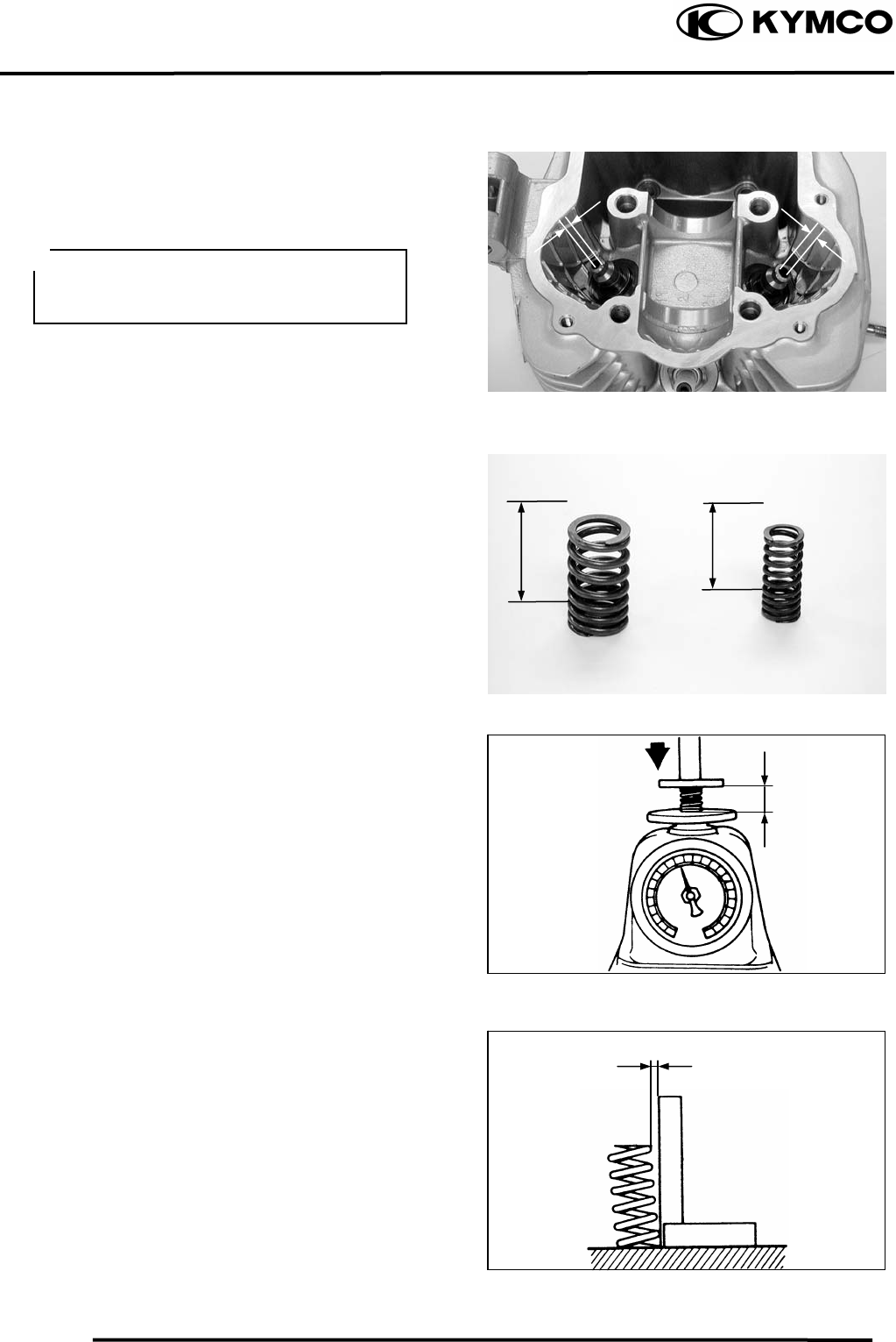
7. CYLINDER HEAD/VALVES
7-9
MX’er SYSTEM
Measure each valve guide I.D.
Subtract each valve stem O.D. from the
corresponding guide I.D. to obtain the
stem-to-guide clearance.
Service limits: IN : 0.06mm replace if over
EX: 0.08mm replace if over
VALVE SPRING FREE LENGTH
Measure the free length of the inner and
outer valve springs.
Inner : 39.4mm replace if below
Outer: 45.5mm replace if below
Measure compressed force (valve spring)
and installed length.
Replace if out of specification.
Service limits:
IN : 7.78.9kg (at 33.7mm)
EX : 19.522.5kg (at 38.4mm)
Measure the spring tilt.
Replace if out of specification.
Service limits: IN : 1.7mm
EX : 1.95mm
If the ste
m
-to-guide clearance exceeds
the service limits, replace the cylinder
head as necessary.
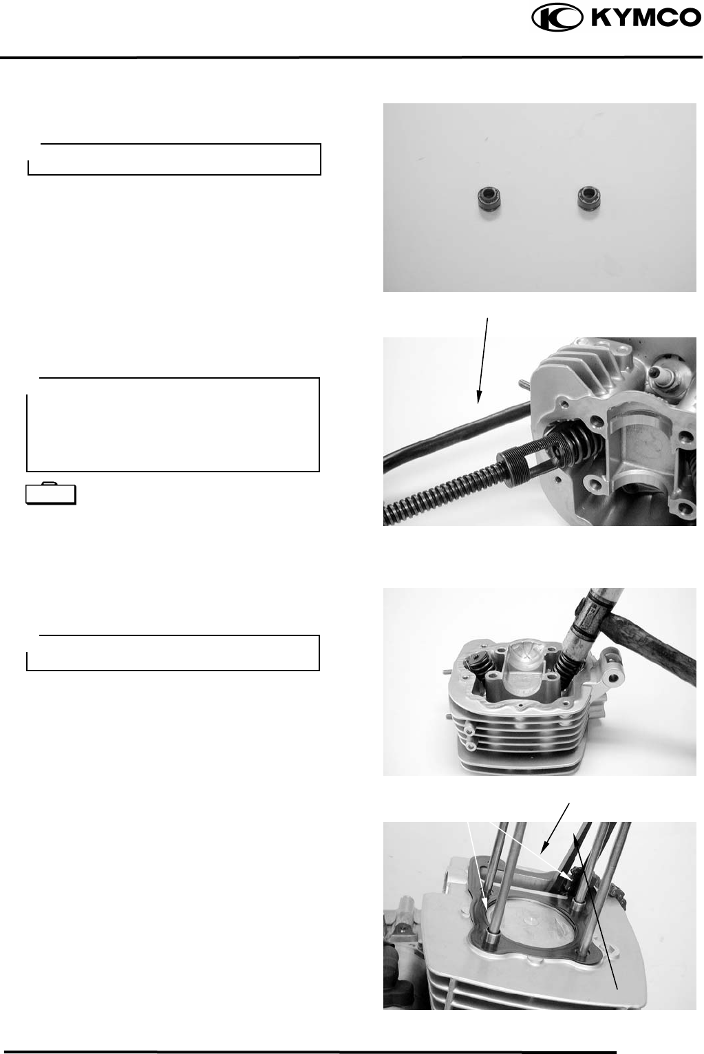
7. CYLINDER HEAD/VALVES
7-10
MX’er SYSTEM
CYLINDER HEAD ASSEMBLY
Install the valve spring seats and valve stem
seals.
Lubricate each valve stem with engine oil
and insert the valves into the valve guides.
Install the valve springs and retainers.
Compress the valve springs using the valve
spring compressor, then install the valve
cotters.
Valve Spring Compressor E040
Tap the valve stems gently with a plastic
hammer for 23 times to firmly seat the
cotters.
CYLINDER HEAD
INSTALLATION
Install the dowel pins and a new cylinder
head gasket.
Install the cam chain guide.
Be sure to install new valve stem seals.
Valve Spring Compresso
r
Gaske
t
Cam Chain Guide
Dowel Pins
• When assembling, a valve spring
comp
ressor must be used.
• Install the cotters with the pointed ends
facing down from the upper side of the
cylinder head.
Special
Be careful not to damage the valves.
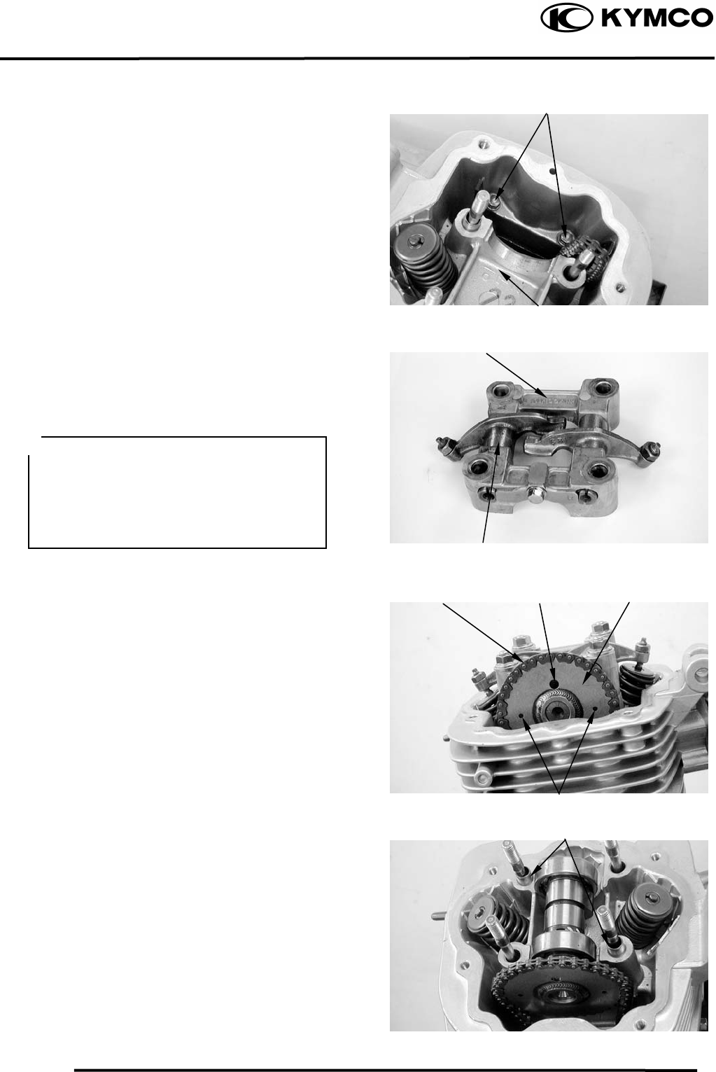
7. CYLINDER HEAD/VALVES
7-11
MX’er SYSTEM
Install two cylinder head bolts do not
tighten completely.
Install the cylinder head.
Torque: Stud Bolts :0.81.2kgf-m
CAMSHAFT HOLDER ASSEMBLY
Install the exhaust valve rocker arm to the
“EX” mark side of the camshaft holder.
Install the intake valve rocker arm and the
rocker arm shafts.
Tighten the bolt attaching stop plate.
CAMSHAFT INSTALLATION
Turn the flywheel so that the “T” mark on
the flywheel aligns with the index mark on
the crankcase.
Keep the round hole on the camshaft gear
facing up and align the punch marks on the
camshaft gear with the cylinder head
surface (Position the intake and exhaust cam
lobes down.) and install the camshaft onto
the cylinder head.
Install the cam chain over the camshaft
gear.
Install the dowel pins.
Dowel Pins
Valve Rocker Ar
m
C
y
linder Head
Punch Marks
Camshaft Holde
r
Cam Chain Round Hole Camshaft Gea
r
Bolts
• Align the cutout on the front end of the
intake valve rocker arm
valve rocker arm
shaft with the
bolt of the camshaft holder.
• Align the cross cutout on the exhaust
shaft with the bolt of
the camshaft holder.
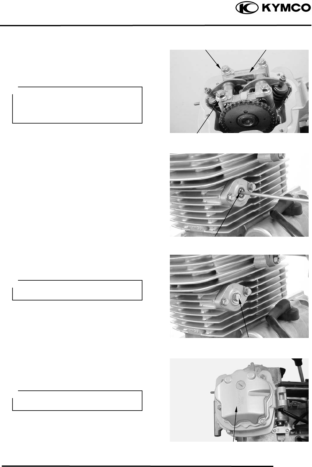
7. CYLINDER HEAD/VALVES
7-12
MX’er SYSTEM
Install the camshaft holder, washers and
nuts on the cylinder head.
Tighten the four cylinder head nuts, then
tighten two cylinder head bolts compeletly.
Torque: Cylinder head nut: 1.82.2kgf-m
Adjust the valve clearance.
Turn the cam chain tensioner screw
counter-clockwise to release it.
Apply engine oil to a new O-ring and install
it.
Tighten the cam chain tensioner cap bolt.
Install a new cylinder head cover O-ring
and install the cylinder head cover.
Install and tighten the cylinder head cover
bolts.
Nu
t
Camshaft Holde
r
Washe
r
Tensioner Screw
Cylinder Head Cove
r
Bol
t
• Apply engine oil to the threads of the
cylinder head nuts.
• Diagonally tighten the cylinder head
nuts in 23 times.
Be sure to install the O-ring into the
groove properly.
Be sure to install the O-ring into the
groove properly.

8. CYLINDER/PISTON
8-0
MX’er SYSTEM
8
__________________________________________________________________________________
____________________________________________________________________
____________________________________________________________________
____________________________________________________________________
____________________________________________________________________
CYLINDER /PISTON
____________________________________________________________________
SERVICE INFORMATION------------------------------------------------ 8- 2
TROUBLESHOOTING----------------------------------------------------- 8- 2 8
CYLINDER REMOVAL --------------------------------------------------- 8- 4
PISTON REMOVAL-------------------------------------------------------- 8- 4
PISTON INSTALLATION------------------------------------------------- 8- 8
CYLINDER INSTALLATION -------------------------------------------- 8- 8
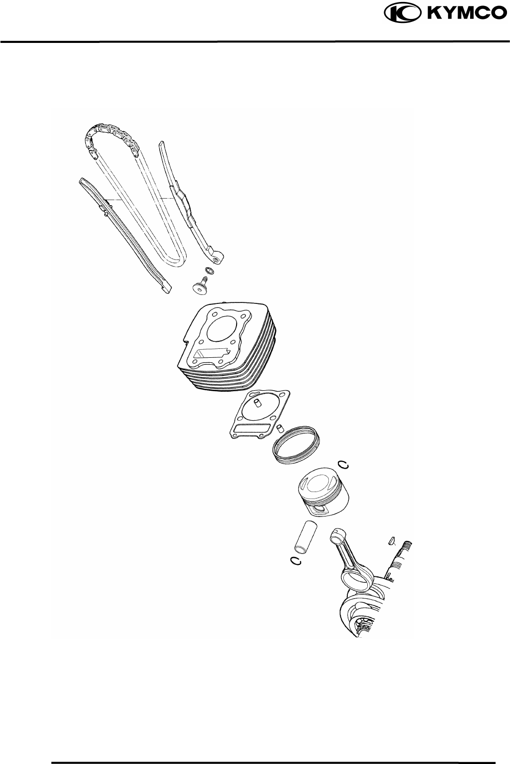
8. CYLINDER/PISTON
8-1
MX’er SYSTEM

8. CYLINDER/PISTON
8-2
MX’er SYSTEM
SERVICE INFORMATION
GENERAL INSTRUCTIONS
• The cylinder and piston can be serviced with the engine installed in the frame.
• After disassembly, clean the removed parts and dry them with compressed air before inspection.
TROUBLESHOOTING
• When hard starting or poor performance at low speed occurs, check the crankcase breather for
white smoke. If white smoke is found, it means that the piston rings are worn, stuck or broken.
Compression too low or uneven
compression Excessive smoke from exhaust muffler
• Worn, stuck or broken piston rings • Worn or damaged piston rings
• Worn or damaged cylinder and piston • Worn or damaged cylinder and piston
Compression too high Abnormal noisy piston
• Excessive carbon build-up in combustion • Worn cylinder, piston and piston rings
chamber or on piston head • Worn piston pin hole and piston pin
8. CYLINDER/PISTON
8-3
MX’er SYSTEM
SPECIFICATIONS
Mx’er 150 Standard (mm) Service Limit (mm)
I.D. 62.0362.045 ⎯
Warpage ⎯ 0.05
Cylindricity ⎯ 0.05
True roundness ⎯ 0.05
Rin
g
-to-
g
roove Top 0.0150.055 0.09
clearance Second 0.0150.055 0.09
Top 0.100.25 0.5
Piston, Ring end gap Second 0.100.25 0.5
piston ring Oil side rail 0.20.7 ⎯
Piston O.D. 61.9662 ⎯
Piston O.D. measuring position 5mm from bottom of skirt ⎯
. Piston-to-cylinder clearance 0.0100.040 0.1
Piston pin hole I.D. 15.00215.008 15.04
Piston pin O.D 14.99415.000 14.96
Piston-to-piston pin clearance 0.0020.014 0.02
Connecting rod small end I.D. bore 15.01615.034 15.06
Cylinde
r
Mx’er 125 Standard (mm) Service Limit (mm)
I.D. 56.5356.545 ⎯
Warpage ⎯ 0.05
Cylindricity ⎯ 0.05
True roundness ⎯ 0.05
Rin
g
-to-
g
roove Top 0.0150.055 0.09
clearance Second 0.0150.055 0.09
Top 0.100.25 0.5
Piston, Ring end gap Second 0.100.25 0.5
piston ring Oil side rail 0.20.7 ⎯
Piston O.D. 56.4656.5 ⎯
Piston O.D. measuring position 5mm from bottom of skirt ⎯
. Piston-to-cylinder clearance 0.0100.040 0.1
Piston pin hole I.D. 15.00215.008 15.04
Piston pin O.D 14.99415.000 14.96
Piston-to-piston pin clearance 0.0020.014 0.02
Connecting rod small end I.D. bore 15.01615.034 15.06
Cylinde
r
8. CYLINDER/PISTON
8-4
MX’er SYSTEM
CYLINDER REMOVAL
Turn the cam chain tension screw clockwise
to tighten it.
Remove the two bolts on the cam chain
tension.
Remove the cylinder head.
Remove the cam chain guide.
Remove the cylinder base bolts.
Remove the cylinder
.
Remove the cylinder gasket and dowel pins.
Clean any gasket material from the cylinder
surface.
PISTON REMOVAL
Remove the piston pin clip.
Press the piston pin out of the piston and
remove the piston.
Bol
t
Cylinde
r
Dowel Pins
Piston
Piston Pin Clip
Place a clean shop towel in the crankcase
to keep the piston pin clip from falling
into the crankcase.
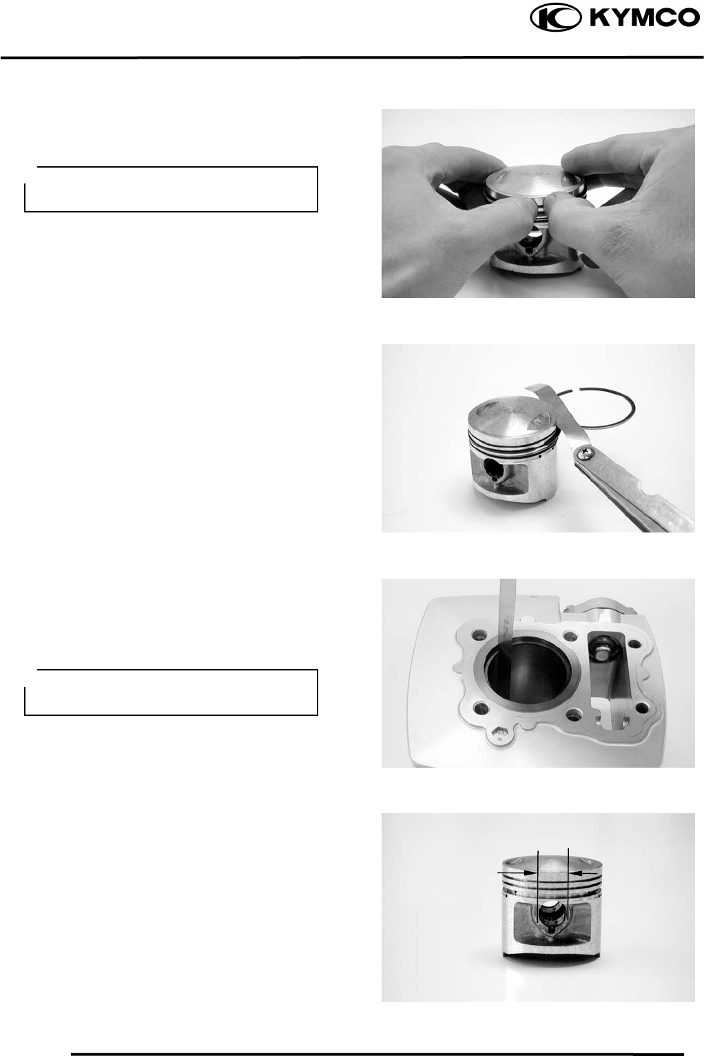
8. CYLINDER/PISTON
8-5
MX’er SYSTEM
Inspect the piston, piston pin and piston
rings.
Remove the piston rings.
Clean carbon deposits from the piston ring
grooves.
Install the piston rings onto the piston and
measure the piston ring-to-groove clearance.
Service Limits: Top: 0.09mm replace if
over
2nd: 0.09mm replace if
over
Remove the piston rings and insert each
piston ring into the cylinder bottom.
Measure the piston ring end gap.
Service Limit: 0.5mm replace if over
Measure the piston pin hole I.D.
Service Limit: 15.04mm replace if over
Take care not to damage or break the
piston rings during removal.
Use the piston head to push each piston
ring into the cylinder.
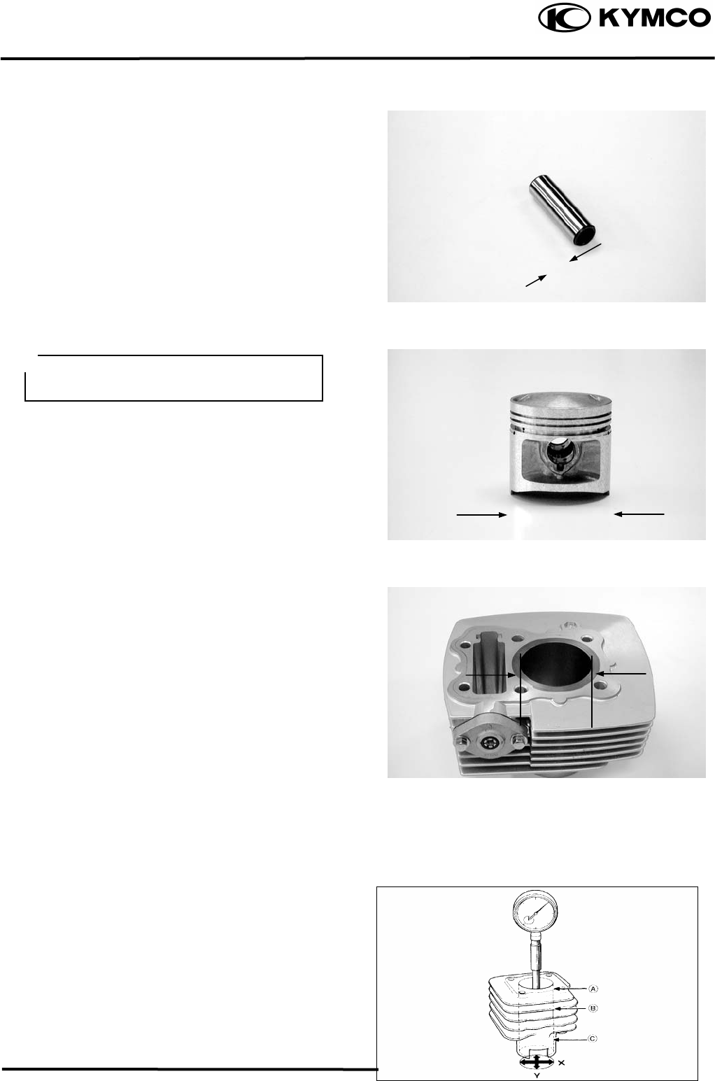
8. CYLINDER/PISTON
8-6
MX’er SYSTEM
Measure the piston pin O.D.
Service Limit: 14.96mm replace if below
Measure the piston O.D.
Piston O.D.: 61.9662mm (MX’er 150)
Piston O.D.: 56.4656.5mm (MX’er 125)
Measure the piston-to-piston pin clearance.
Service Limit: 0.02mm replace if over
CYLINDER INSPECTION
Inspect the cylinder bore for wear or damage.
Measure the cylinder I.D. at three levels of
top, middle and bottom at 90° to the piston
pin (in both X and Y directions).
Cylinder I.D.:
62.0362.045mm (MX’er
150)
56.5356.545mm (MX’er
125)
Measure the cylinder-to-piston clearance.
Service Limit: 0.1mm repair or replace if
over
The true roundness is the difference
between the values measured in X and Y
directions. The cylindricity (difference
between the values measured at the three
levels) is subject to the maximum value
calculated.
Service Limits:
True Roundness: 0.05mm repair or replace
if over
Cylindricity: 0.05mm repair or replace if
over
Take measurement at 5mm from the
bottom and 90° to the piston pin hole.
Top
Middle
Botto
m
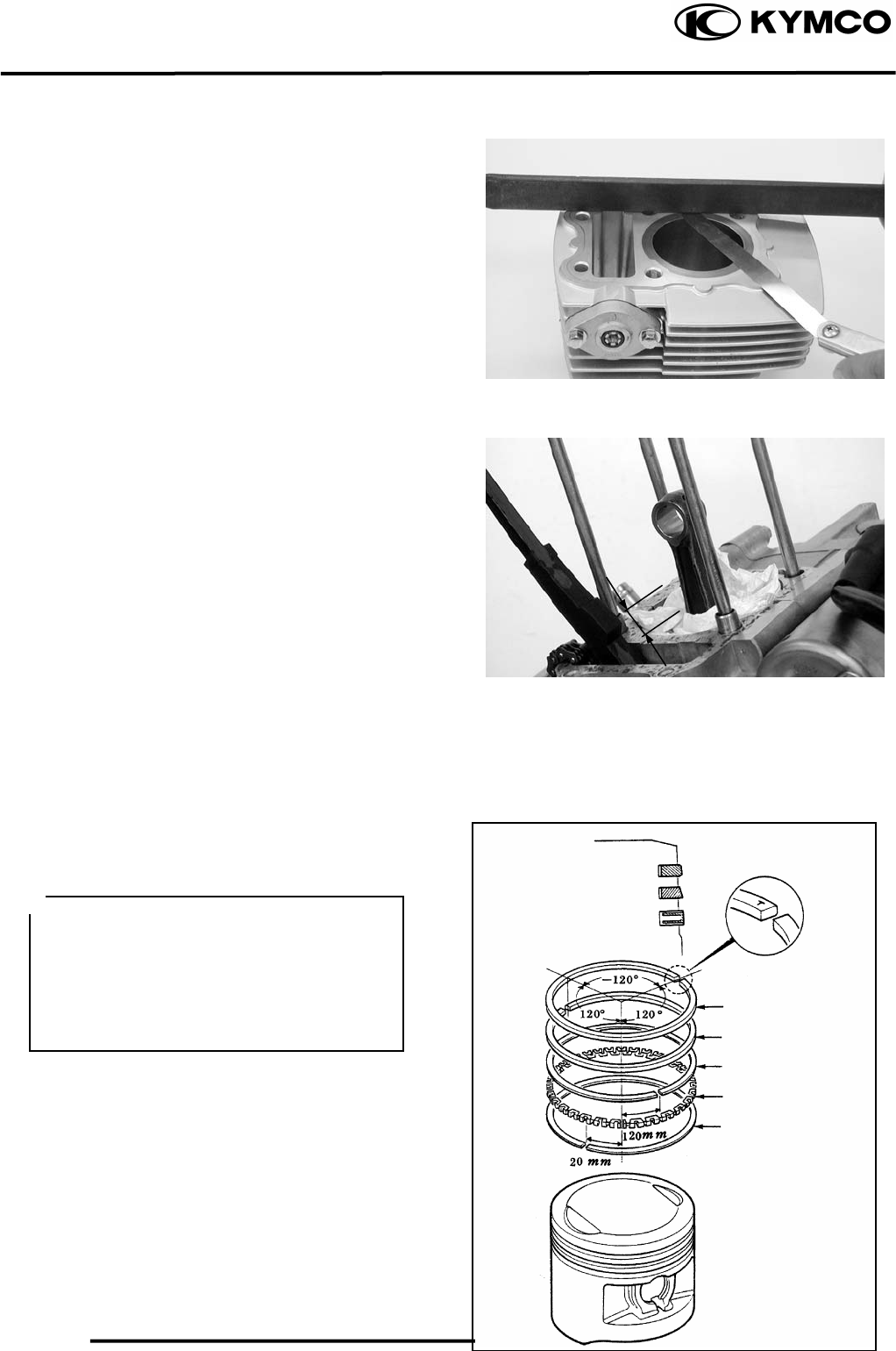
8. CYLINDER/PISTON
8-7
MX’er SYSTEM
Inspect the top of the cylinder for warpage.
Service Limit: 0.05mm repair or replace if
over
Measure the connecting rod small end I.D.
Service Limit: 15.06mm replace if over
PISTON RING INSTALLATION
Install the piston rings onto the piston.
Apply engine oil to each piston ring.
• Be careful not to damage or break the
piston and piston rings.
• All rings should be installed with the
markings facing up.
• After installing the rings, they should
rotate freely without sticking.
Second
Top
Side Rail
Side Rail
Oil Ring
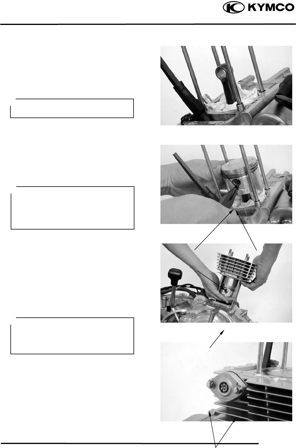
8. CYLINDER/PISTON
8-8
MX’er SYSTEM
PISTON INSTALLATION
Remove any gasket material from the
crankcase surface.
Install the piston, piston pin and a new
piston pin clip.
CYLINDER INSTALLATION
Install the dowel pins and a new cylinder
gasket on the crankcase.
Coat the cylinder bore, piston and piston
rings with clean engine oil.
Carefully lower the cylinder over the piston
by compressing the piston rings.
Install the cam chain tension.
Tighten the cam chain tension bolts.
Be careful not to drop foreign matters
into the crankcase.
Piston
Gaske
t
Cylinde
r
Piston Pin
Piston Pin Clip
• Position the piston “IN” mark on the
intake valve side.
• Place a clean shop towel in the
crankcase to keep the piston pin clip
from falling into the crankcase.
• Be careful not to damage or break the
piston rings.
• Stagger the ring end gaps at 120° to the
piston pin.
Bolts

8. CYLINDER/PISTON
8-9
MX’er SYSTEM

9. DRIVE AND DRIVEN PULLEYS
9-0
MX’er SYSTEM
9
DRIVE AND DRIVEN PULLEYS
SERVICE INFORMATION.................................................................... 9-2
TROUBLESHOOTING........................................................................... 9-2
LEFT CRANKCASE COVER ................................................................ 9-3
DRIVE PULLEY.....................................................................................9-3
CLUTCH/DRIVEN PULLEY.................................................................9-3
9
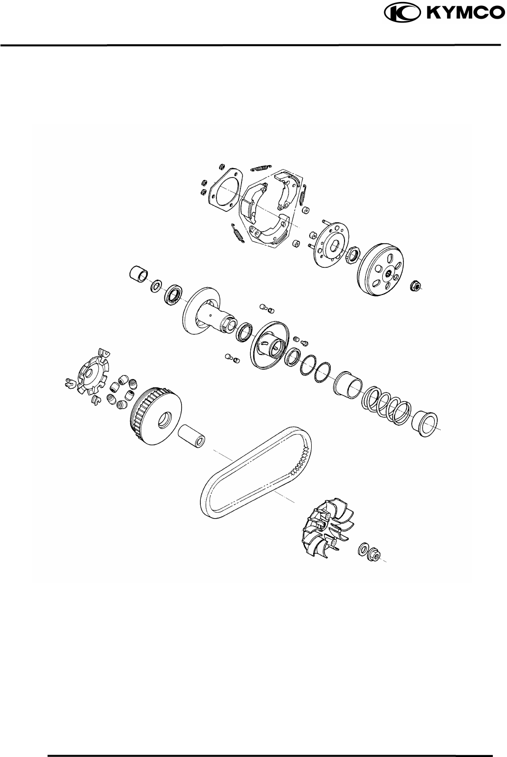
9. DRIVE AND DRIVEN PULLEYS
9-1
MX’er SYSTEM
5.5kg-
m
5.5kg-
m
5.5kg-
m
9. DRIVE AND DRIVEN PULLEYS
9-2
MX’er SYSTEM
SERVICE INFORMATION
GENERAL INSTRUCTIONS
• The drive pulley, clutch and driven pulley can be serviced with the engine installed in the frame.
• Avoid getting grease and oil on the drive belt and pulley faces. Remove any oil or grease from
them to minimize the slipping of drive belt and drive pulley.
SPECIFICATIONS
Ite
m
Standard
(
mm
)
Service Limit
(
mm
)
Movable drive face bushin
g
I.D. 27.0
27.021 27.06
Drive face collar O.D. 26.97
26.99 226.94
Drive belt width 20.0
21.0 19.0
Clutch linin
g
thickness
⎯
2.0
Clutch outer I.D. 130.0
130.2 130.5
Driven face s
p
rin
g
free len
g
th
⎯
83.2
Driven face O.D. 33.965
33.485 33.94
Movable driven face I.D. 34.000
34.025 34.06
Wei
g
ht roller O.D. 20.95
21.1 20.42
TORQUE VALUES
Drive face nut 5.56.5kgf-m
Clutch outer nut 5.06.0kgf-m
SPECIAL TOOLS
Universal holder E017 Clutch spring compressor E027
Bearing puller E008 Oil seal and bearing install E014
TROUBLESHOOTING
Engine starts but motorcycle won’t move Lack of power
• Worn drive belt • Worn drive belt
• Broken ramp plate • Weak driven face spring
• Worn or damaged clutch lining • Worn weight roller
• Broken driven face spring • Fouled drive face
Engine stalls or motorcycle creeps
• Broken clutch weight spring
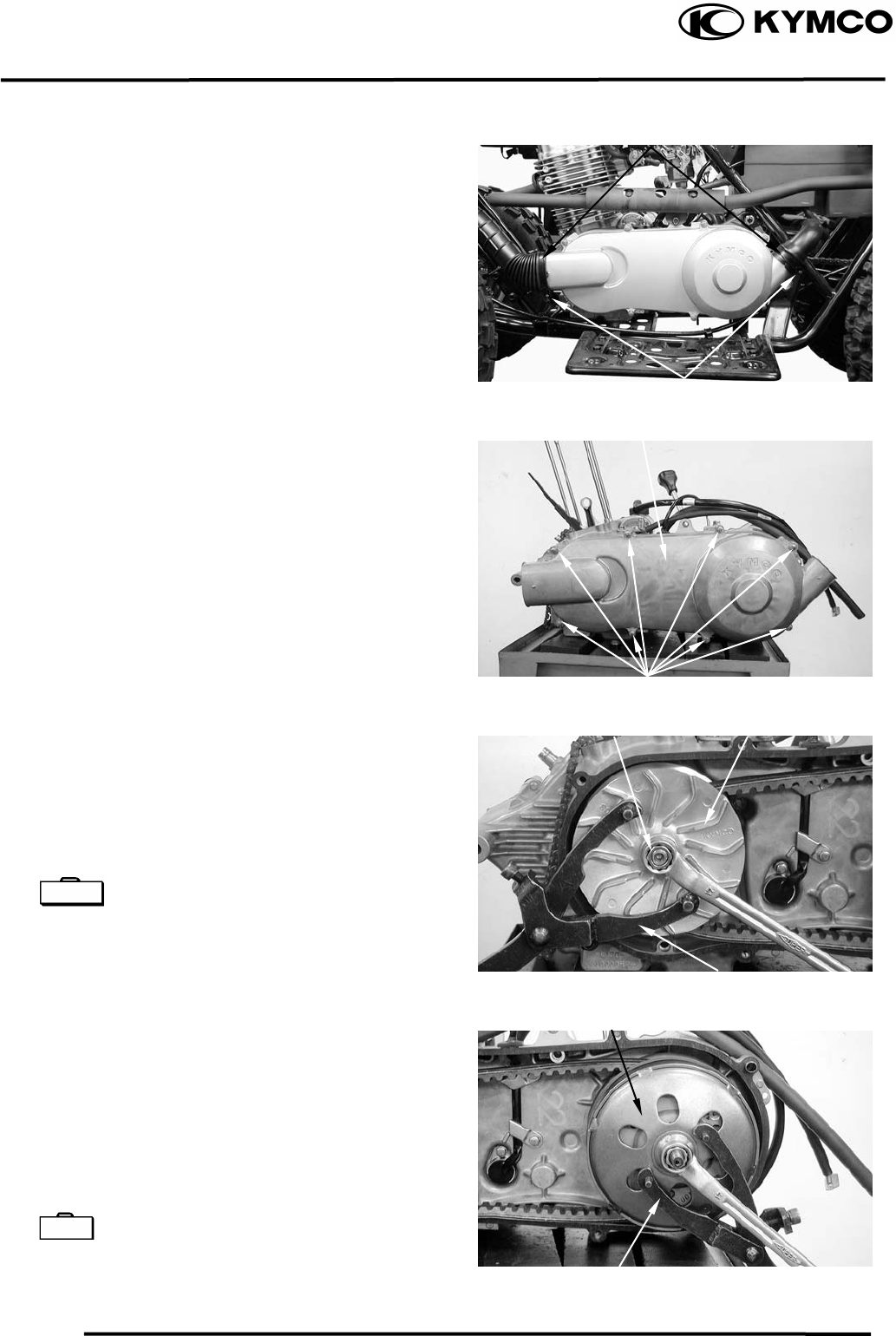
9. DRIVE AND DRIVEN PULLEYS
9-3
MX’er SYSTEM
LEFT CRANKCASE COVER
REMOVAL
Loosen the drive belt air tube band screw.
Remove the left crankcase cover bolts and
left crankcase cover.
Remove the gasket and dowel pins.
DRIVE PULLEY
REMOVAL
Hold the drive pulley using an universal
holder and remove the drive face nut and
starting ratchet.
Remove the drive pulley face.
Universal Holder E017
CLUTCH/DRIVEN PULLEY
Remove the drive pulley and drive belt.
Hold the clutch outer with the flywheel
holder and remove the clutch outer nut.
Remove the clutch outer.
Remove the clutch/driven pulley and drive
belt.
Universal Holder E017
Air Tube Band
Screw
Left Crankcase Cove
r
Bolts
Drive Pulley Face
Nu
t
Universal Holde
r
Clutch Oute
r
Universal Holde
r
Special
Special
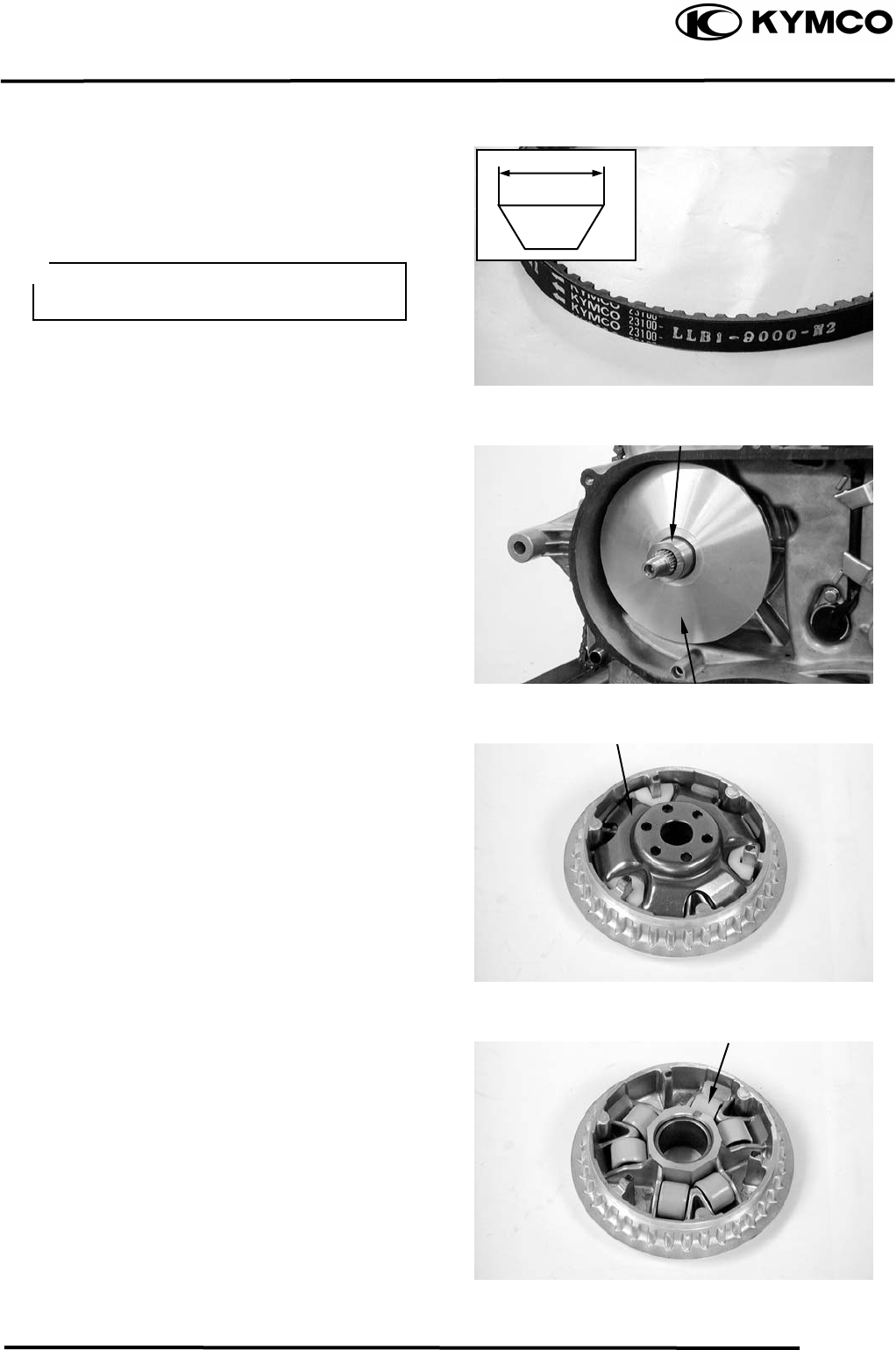
9. DRIVE AND DRIVEN PULLEYS
9-4
MX’er SYSTEM
INSPECTION
Check the drive belt for cracks, separation or
abnormal or excessive wear.
Measure the drive belt width.
Service Limit: 17.0mm replace if below
Remove the movable drive face assembly.
Remove the drive pulley collar.
DISASSEMBLY
Remove the ramp plate.
Remove the weight rollers.
Use specified genuine parts for
replace-ment.
Drive Pulley Colla
r
Movable Drive Face Assembly
Ramp Plate
Weight Rollers
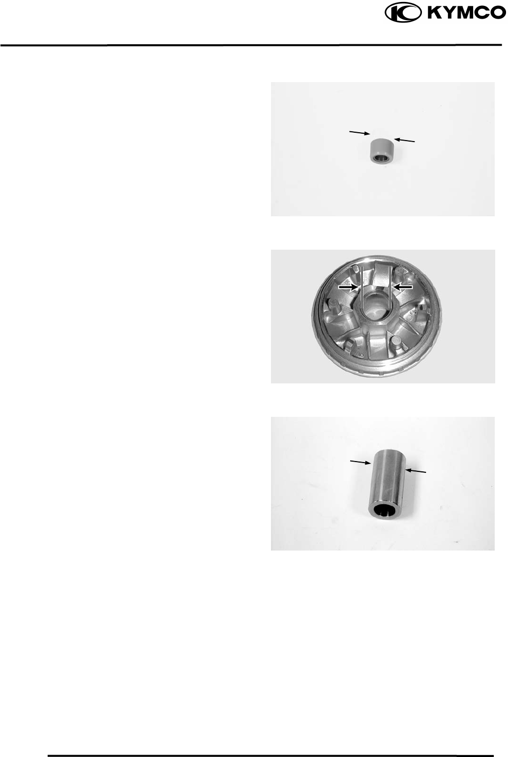
9. DRIVE AND DRIVEN PULLEYS
9-5
MX’er SYSTEM
INSPECTION
Check each weight roller for wear or damage.
Measure each weight roller O.D.
Service Limit: 20.42mm replace if below.
Measure the movable drive face bushing I.D.
Service Limit: 27.06mm replace if over
Check the drive pulley bushing for wear or
damage.
Measure the O.D. of the drive pulley bushing
sliding surface.
Service Limit: 26.94mm replace if below
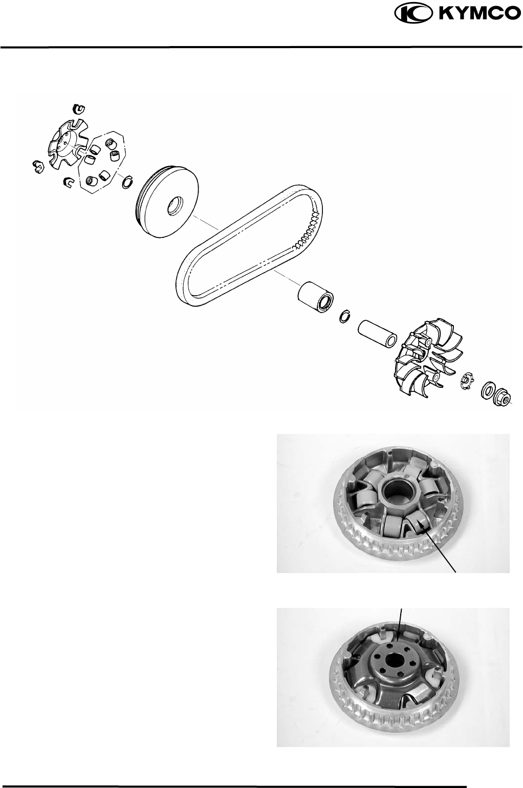
9. DRIVE AND DRIVEN PULLEYS
9-6
MX’er SYSTEM
ASSEMBLY
Install the weight rollers into the movable
drive face.
Install the ramp plate.
Weight Rolle
r
Ramp Plate
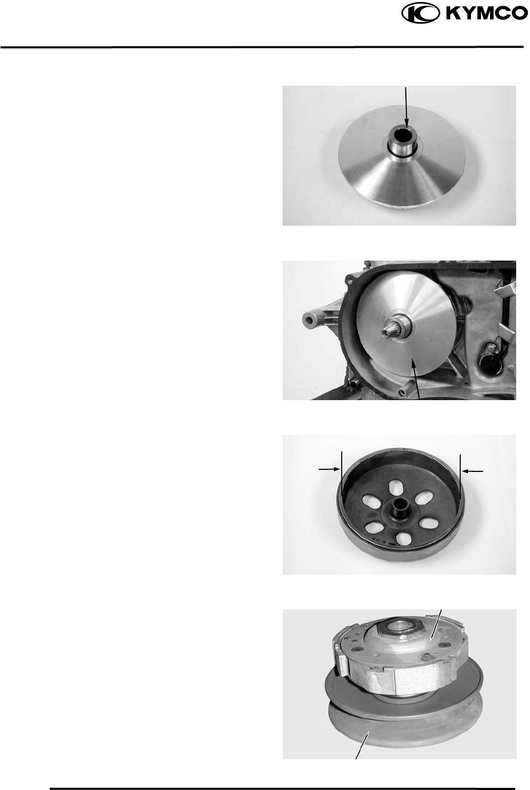
9. DRIVE AND DRIVEN PULLEYS
9-7
MX’er SYSTEM
Insert the drive pulley collar into the movable
drive face.
INSTALLATION
Install the movable drive face onto the
crankshaft.
INSPECTION
Inspect the clutch outer for wear or damage.
Measure the clutch outer I.D.
Service Limit: 130.5mm replace if over
CLUTCH/DRIVEN PULLEY
DISASSEMBLY
Drive Pulley Colla
r
Movable Drive Face Assembly
Clutch
Driven Pulley
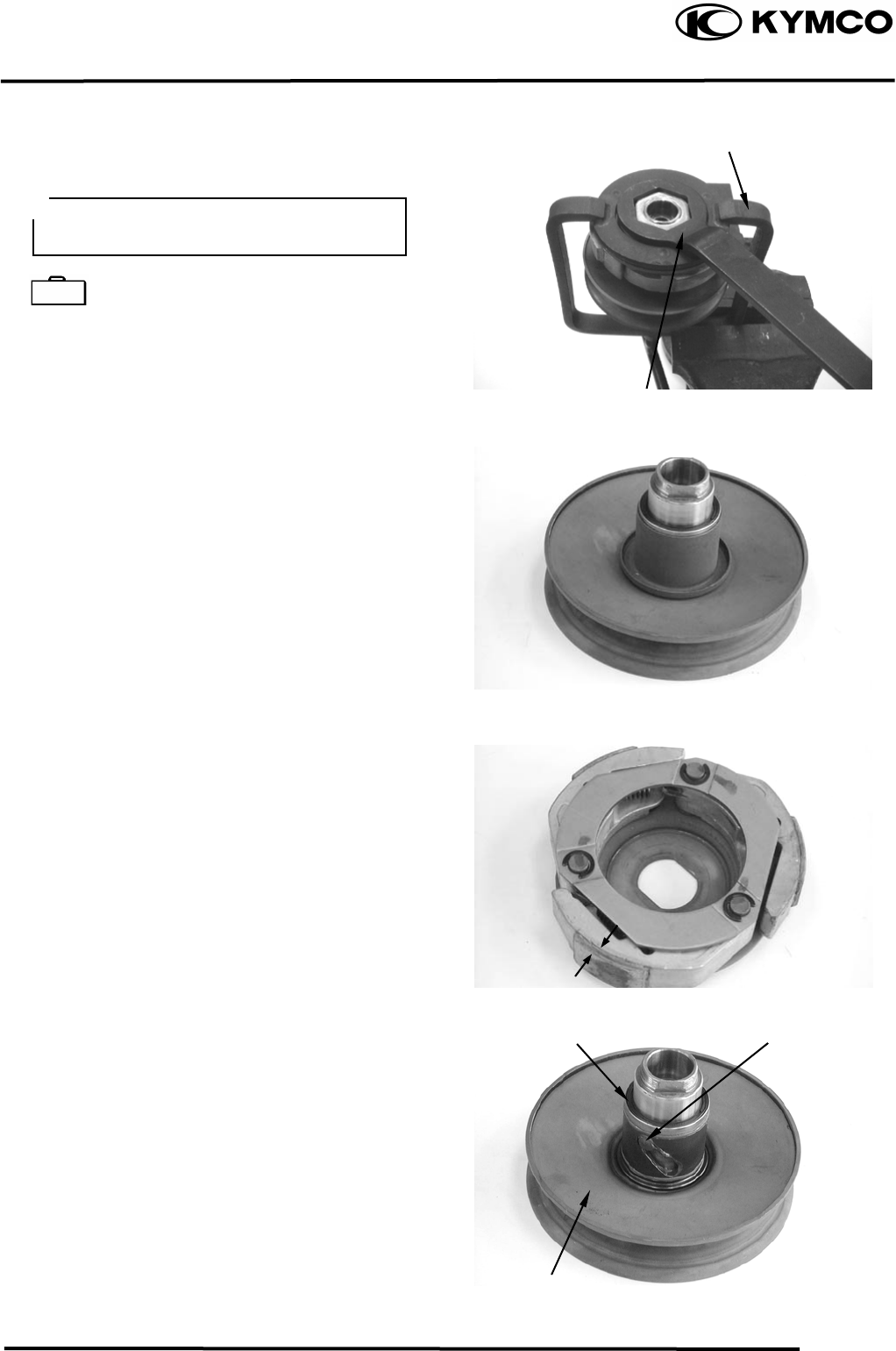
9. DRIVE AND DRIVEN PULLEYS
9-8
MX’er SYSTEM
Hold the clutch/driven pulley assembly with
the clutch spring compressor.
Clutch Spring Compressor E027
Set the clutch spring compressor in a vise and
remove the clutch drive plate nut.
Loosen the clutch spring compressor and
disassemble the clutch/driven pulley assembly.
Remove the seal collar.
Check the driven face for wear or damage.
Measure the clutch lining thickness.
Service Limit: 2.0mm replace if below
Pull out the guide roller pins and guide rollers.
Remove the movable driven face from the
driven face.
Clutch Spring Compresso
r
Be sure to use a clutch spring
comp
ressor to avoid spring damage.
Special
Lock Nut Wrench
Guide Roller Pin
O-ring
Movable Driven Face
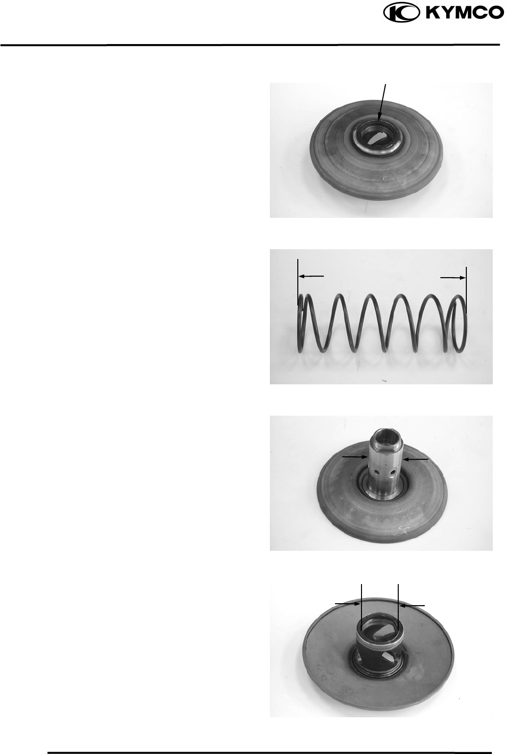
9. DRIVE AND DRIVEN PULLEYS
9-9
MX’er SYSTEM
Remove the oil seal from the movable driven
face.
INSPECTION
Measure the driven face spring free length.
Service Limit: 83.2mm replace if below
Check the driven face for wear or damage.
Measure the driven face O.D.
Service Limit: 33.94mm replace if below
Check the movable driven face for wear or
damage.
Measure the movable driven face I.D.
Service Limit: 34.06mm replace if over
Oil Seal
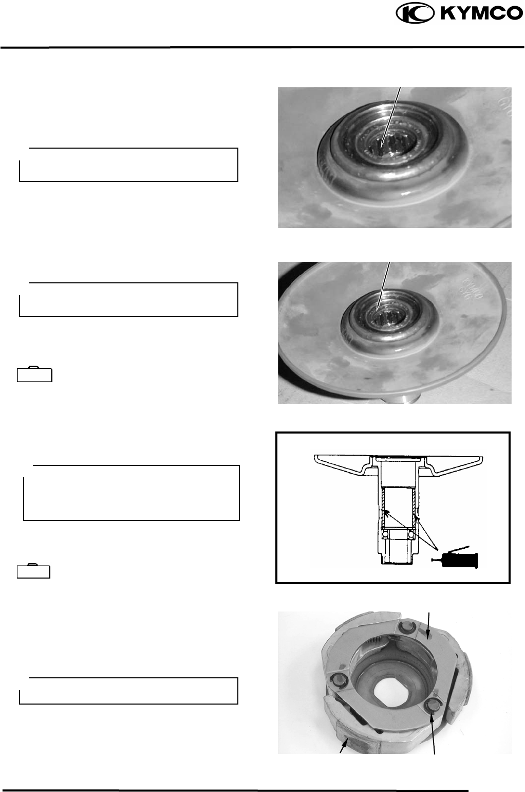
9. DRIVE AND DRIVEN PULLEYS
9-10
MX’er SYSTEM
DRIVEN PULLEY FACE BEARING
REPLACEMENT
Drive the inner needle bearing out of the
driven pulley face.
Remove the snap ring and drive the outer
bearing out of the driven face.
Apply grease to the outer bearing.
Drive a new outer bearing into the driven face
with the sealed end facing up.
Bearing Puller E008
Seat the snap ring in its groove.
Apply grease to the driven face bore areas.
Press a new needle bearing into the driven
face.
Oil Seal And Bearing Install E014
CLUTCH DISASSEMBLY
Remove the circlips and retainer plate to
disassemble the clutch.
Inner Bearing
Discard the removed bearing and replace
with a new one.
Outer Bearing
Discard the removed bearing and replace
with a new one.
Special
Pack all bearing cavities with 99.5g
grease.
Specified grease: Heat resistance 230°C
Special
Retainer Plate
Circlip
Clutch Lining
Keep grease off the clutch linings.
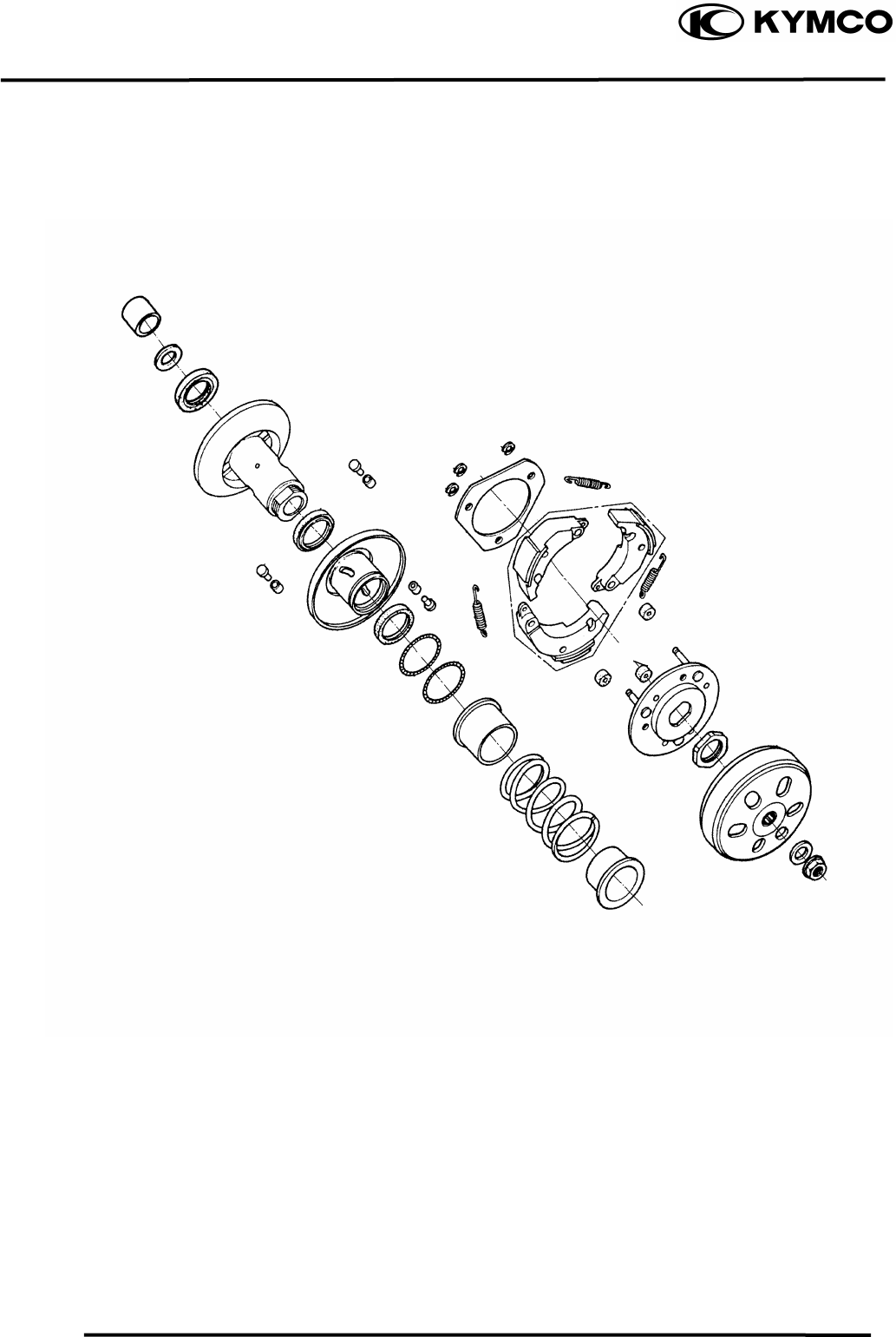
9. DRIVE AND DRIVEN PULLEYS
9-11
MX’er SYSTEM
CLUTCH / DRIVEN PULLEY ASSEMBLY
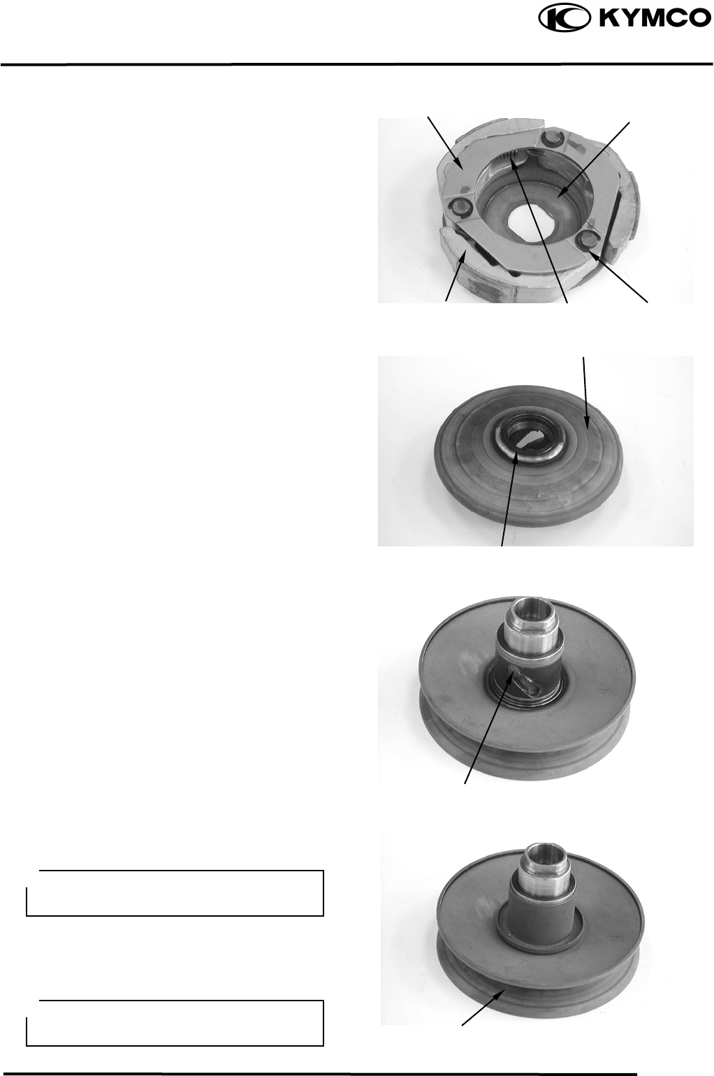
9. DRIVE AND DRIVEN PULLEYS
9-12
MX’er SYSTEM
Install the damper rubbers on the drive plate
pins.
Install the clutch weights/shoes and clutch
springs onto the drive plate.
Install the retainer plate and secure with the
circlips.
CLUTCH/DRIVEN PULLEY ASSEMBLY
Clean the driven pulley faces and remove any
grease from them.
Install the oil seal onto the moveable driven
face.
Apply grease to the Oil seal and install them
onto the moveable driven face.
Install the movable driven face onto the
driven face.
Apply grease to the guide rollers and guide
roller pins and then install them into the holes
of the driven face.
Install the seal collar.
Remove any excessive grease.
Set the driven pulley assembly, driven face
spring and clutch assembly onto the clutch
spring compressor.
Retainer Plate
Drive Plate
Springs
Clutch Wei
g
hts/Shoes Circlip
Movable Driven Face
Oil Seal
Guide Roller Pin
Driven Face
Be sure to clean the driven face off any
grease.
Align the flat surface of the
d
riven face
with the flat on the clutch drive plate.
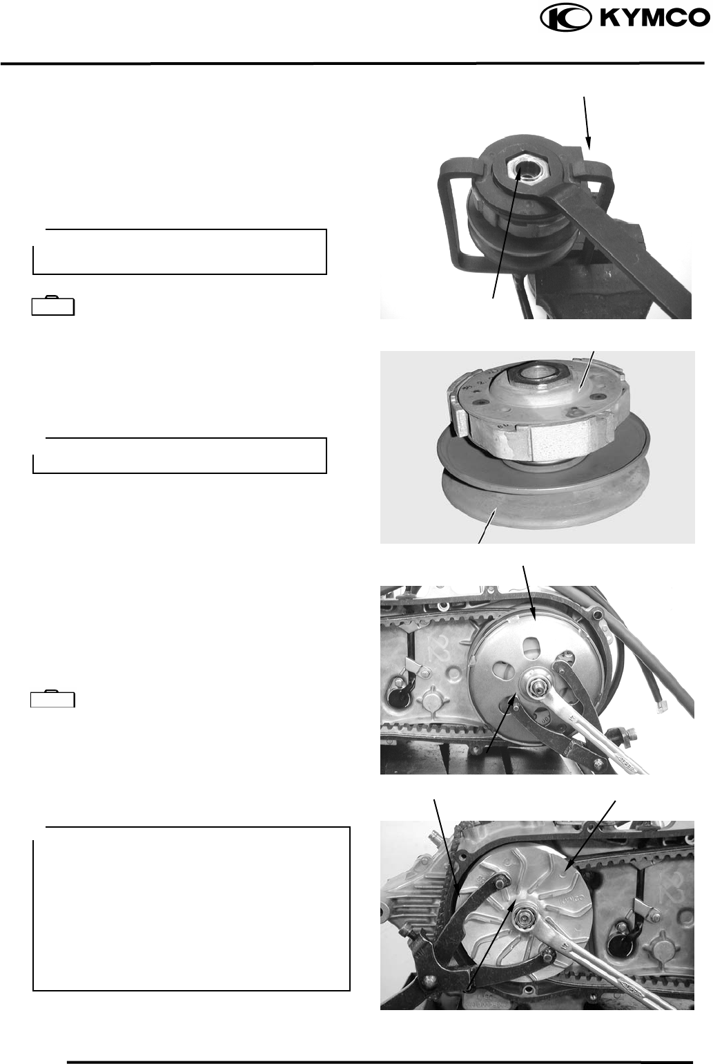
9. DRIVE AND DRIVEN PULLEYS
9-13
MX’er SYSTEM
Compress the clutch spring compressor and
install the drive plate nut.
Set the clutch spring compressor in a vise and
tighten the drive plate nut to the specified
torque.
Torque: 5.06.0kgf-m
Clutch Spring Compressor E027
INSTALLATION
Install the clutch/driven pulley onto the drive
shaft.
Install the clutch outer.
Hold the clutch outer with the flywheel
holder.
Install and tighten the clutch outer nut.
Torque: 5.5kg-m
Universal Holder E017
Install the drive belt.
Install the drive pulley face, starting ratchet
and drive face nut.
T orque: 5.56.5kgf-m
Clutch Spring Compresso
r
Be sure to use a clutch spring compressor to avoid spring damage.
Special Lock Nut Wrench
Clutch
Keep grease off the drive shaft.
Driven Pulley
Clutch Oute
r
Universal Holde
r
Drive Pulley
Special
Universal Holde
r
Nu
t
Wh
en installing the drive pulley face,
com ress it to let the drive belt move
downward to the lowest position so that the
drive pulley can be tightened.
Install the starting ratchet by aligning the
starting ratchet teeth with the crankshaft
teeth.
Do not get oil or grease on the drive belt or
pulley faces.
p
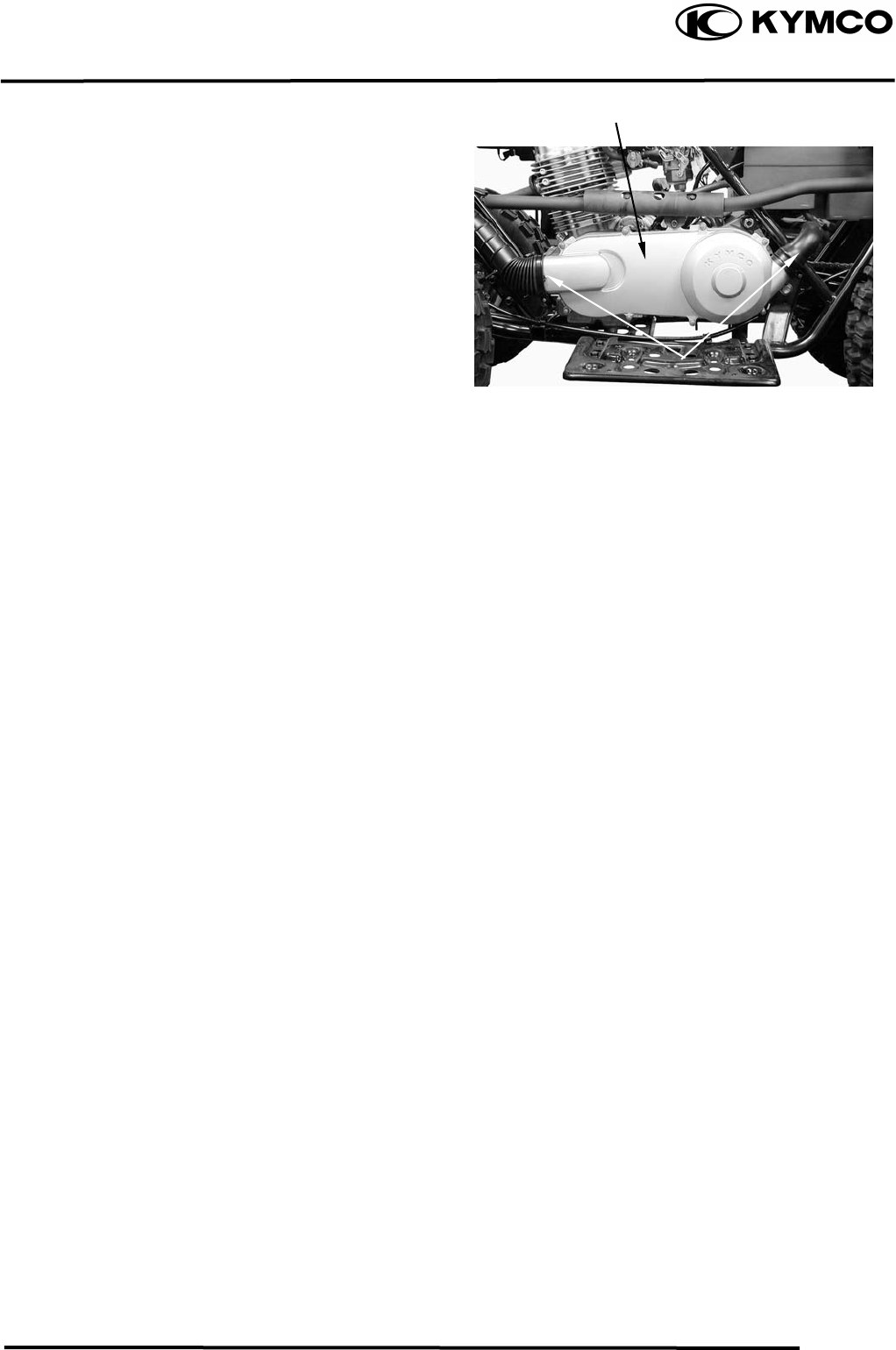
9. DRIVE AND DRIVEN PULLEYS
9-14
MX’er SYSTEM
Install the left crankcase cover and tighten the
cover bolts diagonally.
Connect the drive belt air tube and tighten the
band screw.
Left Crankcase Cove
r
Screw

10. FINAL REDUCTION/
TRANSMISSION SYSTEM
10-0
MX’er SYSTEM
10
__________________________________________________________________________________
____________________________________________________________________
____________________________________________________________________
____________________________________________________________________
____________________________________________________________________
FINAL REDUCTION/TRANSMISSION SYSTEM
____________________________________________________________________
SERVICE INFORMATION------------------------------------------------ 10- 2
TROUBLESHOOTING----------------------------------------------------- 10- 2
FINAL REDUCTION DISASSEMBLY --------------------------------- 10- 3
FINAL REDUCTION INSPECTION------------------------------------- 10- 4
TRANSMISSION GEARS/CRANKSHAFT REMOVAL------------- 10- 6
FINAL REDUCTION INSTALLATION -------------------------------- 10- 7
10
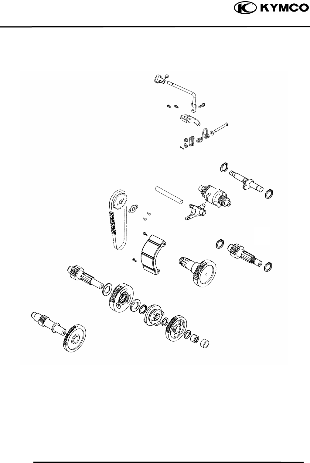
10. FINAL REDUCTION/
TRANSMISSION SYSTEM
10-1
MX’er SYSTEM

10. FINAL REDUCTION/
TRANSMISSION SYSTEM
10-2
MX’er SYSTEM
SERVICE INFORMATION
GENERAL INSTRUCTIONS
• When replacing the drive shaft, use a special tool to hold the bearing inner race for this operation.
SPECIFICATIONS
Specified Oil: GEAR OIL SAE 90#
Oil Capacity: At change : 0.2 liter
At disassembly : 0.4 liter
TORQUE VALUES
Transmission case cover bolt 0.81.2kgf-m
SPECIAL TOOLS
Flywheel holder E021
Flywheel puller E005
Lock nut socket wrench E009
TROUBLESHOOTING
Engine starts but motorcycle won‘t move
• Damaged transmission
• Seized or burnt transmission
Oil leaks
• Oil too rich
• Worn or damaged oil seal
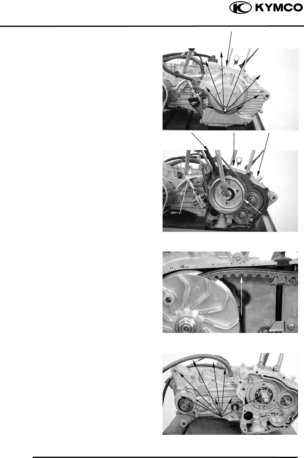
10. FINAL REDUCTION/
TRANSMISSION SYSTEM
10-3
MX’er SYSTEM
FINAL REDUCTION DISASSEMBLY
Drain engine oil and transmission gear oil
into a clean container.
Remove the engine.
Remove the right crankcase cover.
Remove the shift gear spindle.
Remove the flywheel and starter clutch.
Remove the balance gear oil pump and starter
motor.
Remove the left case bolt.
Remove the transmission case cover
attaching bolts.
Fl
y
wheel
Bolts
Starter Moto
r
Shift Gear S
p
indle
Bol
t
Oil Pum
p
Balance Gea
r
Bol
t
Crankcase Cove
r
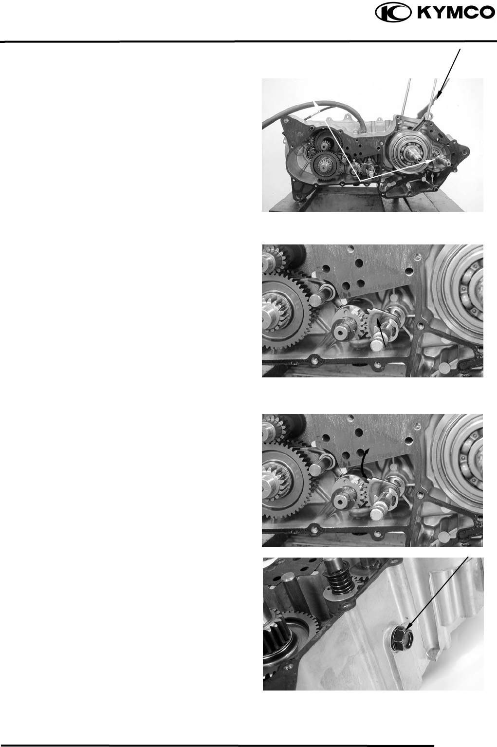
10. FINAL REDUCTION/
TRANSMISSION SYSTEM
10-4
MX’er SYSTEM
Remove gasket and two dowel pins.
FINAL REDUCTION/
TRANSMISSION INSPECTION
Inspect the change gear shaft for wear,
damage or seizure.
Check the transmission operation.
Repair if unsmooth operation.
Remove the plug.
Dowel Pins
Change Gear Shaf
t
Plug
Gaske
t
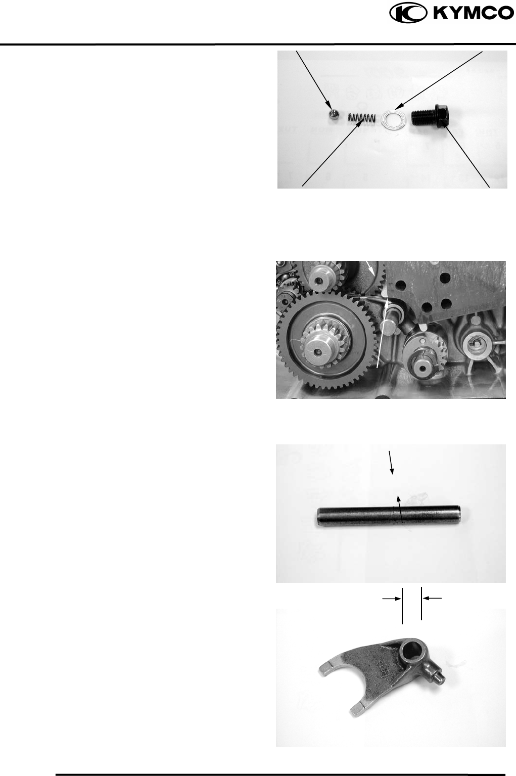
10. FINAL REDUCTION/
TRANSMISSION SYSTEM
10-5
MX’er SYSTEM
Shift Cam Stoppe
r
Remove spring, washer and shift cam
stopper.
Remove the transmission fork shaft and
transmission fork.
Measure the transmission fork shaft O.D.
Service Limit: 11.936
Measure the transmission fork shaft hole I.D.
Service Limit: 12.058
Plug
Transmission fork
Transmission fork shaf
t
Washe
r
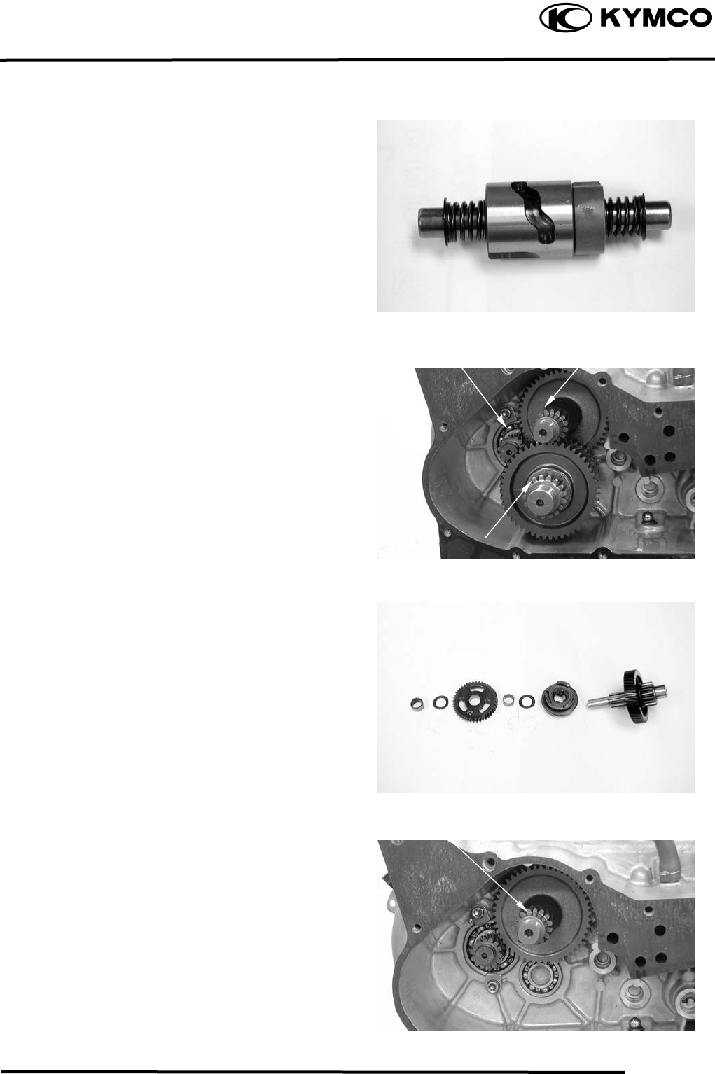
10. FINAL REDUCTION/
TRANSMISSION SYSTEM
10-6
MX’er SYSTEM
Check the shift cam groove and shift cam
gear.
Replace if wear or damage.
TRANSMISSION GEARS/
CRANKSHAFT REMOVAL
Remove the final gear and main shaft.
GEAR/SHAFT COLLAR INSPECTION
Check each gear and gear teeth for wear,
damage, or poor lubrication.
Remove the counter shaft.
Countershaf
t
Driver Shaf
t
Countershaf
t
Main Shaf
t
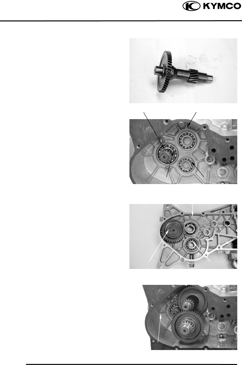
10. FINAL REDUCTION/
TRANSMISSION SYSTEM
10-7
MX’er SYSTEM
FINAL REDUCTION INSPECTION
Inspect the countershaft and gear for wear or
damage.
Inspect the drive shaft and gear for wear or
damage.
Check the left crankcase bearings for
excessive play and inspect the oil seal for
wear or damage.
Inspect the final shaft gear for wear or
damage.
Check the right crankcase bearings for
excessive play and inspect the oil seal for
wear or damage.
FINAL REDUCTION
INSTALLATION
Install the final gear and final shaft into the
left crankcase.
Install the countershaft and gear into the left
crankcase.
Install the main shaft and gear into the left
crankcase.
Countershaf
t
Bearing
Drive Shaf
t
Final Shaft Gea
r
Left Crankcase
Drive Shaf
t
Bearing Main Shaf
t
Bearing
Main Shaf
t
Bearing
Countershaf
t
Bearing
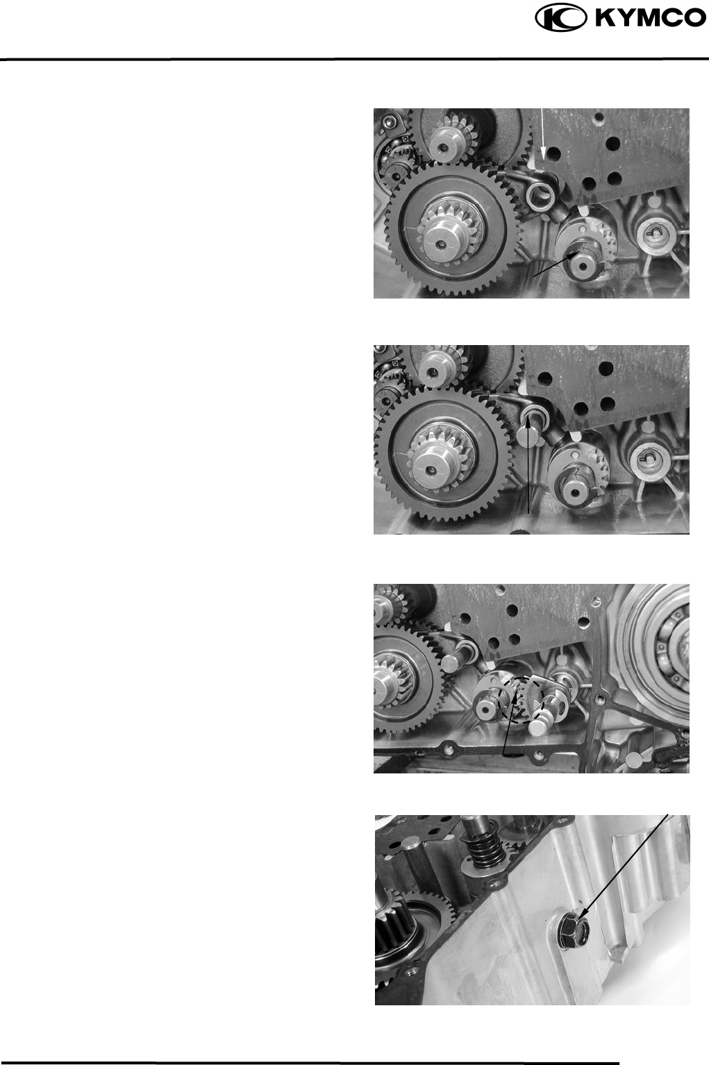
10. FINAL REDUCTION/
TRANSMISSION SYSTEM
10-8
MX’er SYSTEM
Install the shift cam into the left crankcase.
Install the transmission fork to the main shaft
gear and install the transmission fork guide
pin into the shift cam groove.
Install the transmission fork shaft into the left
crankcase.
Install the change gear shaft by aligning the
punch mark between with the punch mark of
the shift cam gear.
Install shift cam stopper, spring, washer and
plug and tighten the plug.
Transmission Fork
Shift ca
m
Transmission Fork Shaf
t
Mark
Plug
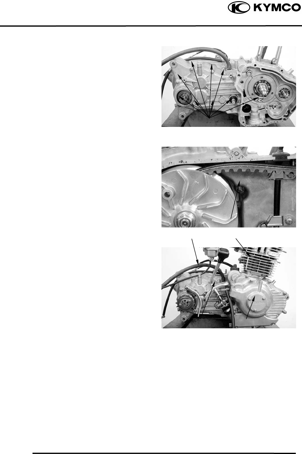
10. FINAL REDUCTION/
TRANSMISSION SYSTEM
10-9
MX’er SYSTEM
Install the dowel pins and a new gasket onto
the right crankcase.
Tighten the crankcase attaching bolts.
Torque: 0.81.2kgf-m
Tighten the left crankcase attaching bolt.
Install the shaft gear, balance gear, oil pump,
starter clutch and flywheel.
Install and tighten the right case cover bolt.
Install the shift gear spindle.
Install the cylinder.
Specified Gear Oil:
KYMCO SIGMA GEAR OIL 90#
Oil Capacity:
At disassembly : 0.4 liter
At change : 0.2 liter
Install and tighten the oil check bolt.
Torque: 0.81.2kgf-m
Bolts
Bolts
Cylinde
r
Oil Filler Bol
t
Shift Gear Spindle Right Case Cove
r

11. CRANKSCASE/CRANKSHAFT/
BALANCE SHAFT
11-0
MX’er SYSTEM
11
__________________________________________________________________________________
____________________________________________________________________
____________________________________________________________________
____________________________________________________________________
____________________________________________________________________
CRANKCASE/CRANKSHAFT/BALANCE SHAFT
____________________________________________________________________
SERVICE INFORMATION------------------------------------------------ 11- 2
TROUBLESHOOTING----------------------------------------------------- 11- 2
CRANKCASE SEPARATION -------------------------------------------- 11- 3
CRANKSHAFT INSPECTION-------------------------------------------- 11- 4
CRANKCASE/BALANCE SHAFT ASSEMBLY---------------------- 11- 5
11
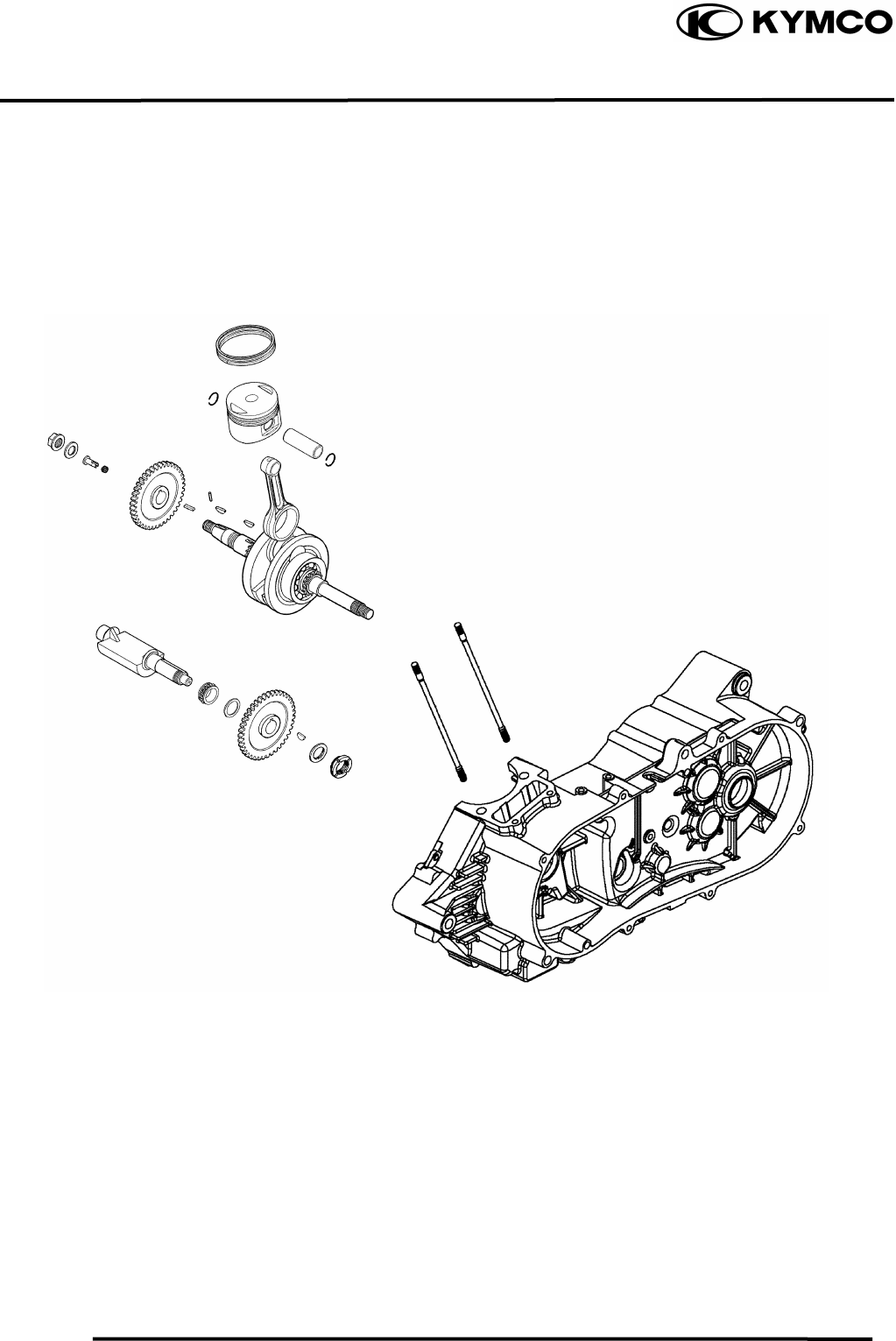
11. CRANKCASE/CRANKSHAFT/
BALANCE SHAFT
11-1
MX’er SYSTEM
11. CRANKSCASE/CRANKSHAFT/
BALANCE SHAFT
11-2
MX’er SYSTEM
SERVICE INFORMATION
GENERAL INSTRUCTIONS
• This section covers crankcase separation to service the crankshaft. The engine must be
removed for this operation.
• The following parts must be removed before separating the crankcase.
−Cylinder head (ÖSection 7)
−Cylinder/piston (ÖSection 8)
−Drive and driven pulleys (ÖSection 9)
−A.C. generator (ÖSection 4)
−Carburetor/air cleaner (ÖSection 5)
−Starter motor (ÖSection 16)
−Oil pump (ÖSection 4)
SPECIFICATIONS
Ite
m
Standard (mm) Service Limit (mm)
Connecting rod big end side clearance 0.100.35 0.55
Crankshaft Connecting rod big end radial clearance 00.008 0.05
Run out ⎯ 0.10
TORQUE VALUES
Crankcase bolt 0.81.2kgf-m
Cam chain tensioner slipper bolt 0.81.2kgf-m
Cam chain cover bolt 0.81.2kgf-m
TROUBLESHOOTING
Excessive engine noise
Excessive bearing play
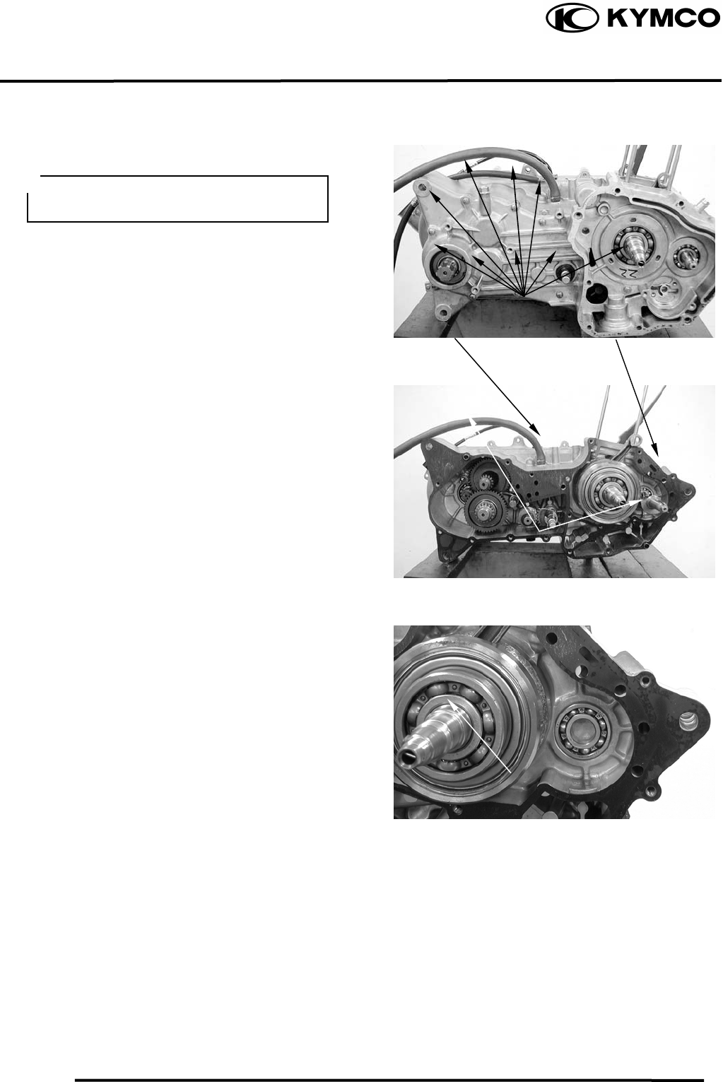
11. CRANKCASE/CRANKSHAFT/
BALANCE SHAFT
11-3
MX’er SYSTEM
CRANKCASE SEPARATION
Remove the left and right crankcase
attaching bolts. (Section 10)
Separate the left and right crankcase halves.
Remove the gasket and dowel pins.
Remover balance shaft from the left
crankcase.
Dowel Pins
Crankcase Bolts
Gaske
t
Do not damage the crankcase gasket
surface.
Balance Shaf
t
Crankshaf
t
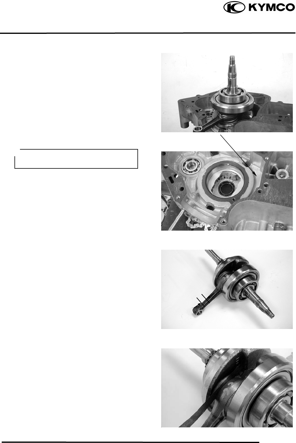
11. CRANKSCASE/CRANKSHAFT/
BALANCE SHAFT
11-4
MX’er SYSTEM
Remove the crankshaft and cam chain from
the left crankcase.
Clean off all gasket material from the
crankcase mating surfaces.
CRANKSHAFT INSPECTION
Measure the connecting rod small end I.D.
Service Limit: 15.06 mm replace if over
Measure the connecting rod big end side
clearance.
Service Limit: 0.55mm replace if over
Gaske
t
Avoid damaging the crankcase mating
surfaces.
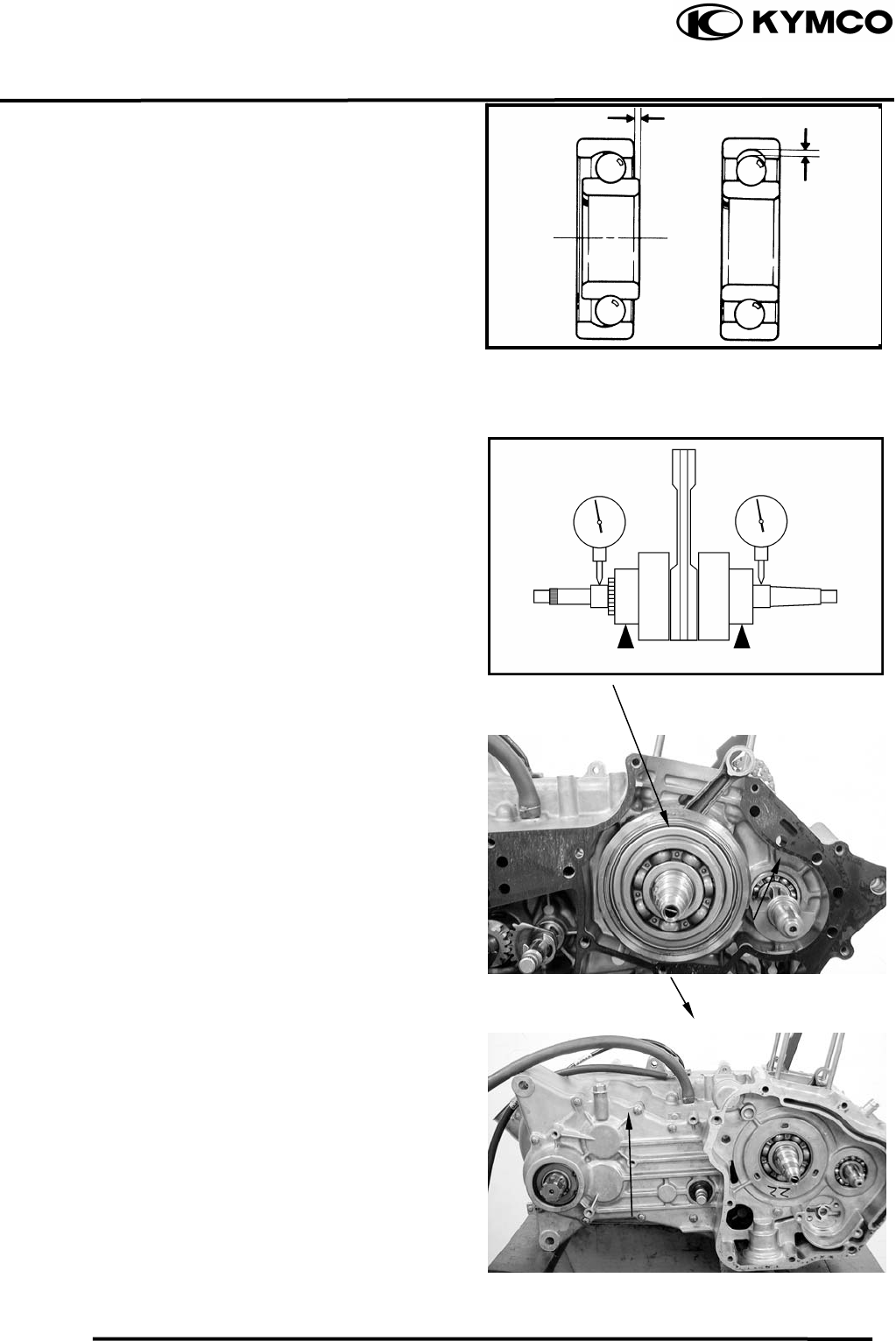
11. CRANKCASE/CRANKSHAFT/
BALANCE SHAFT
11-5
MX’er SYSTEM
Turn the crankshaft bearings and check for
excessive play.
Measure the crankshaft bearing play.
Service Limit:
Axial : 0.20mm replace if over
Radial : 0.05mm replace if over
Measure the crankshaft run out.
Service Limit: 0.10mm replace if over
CRANKCASE/BALANCE SHAFT
ASSEMBLY
Install the cam chain into the left crankcase.
Install the crankshaft and balance shaft into
the left crankcase.
Install the right and left crankcase.(10-8)
Tighten crankcase attach bolts.
Play
Play
Radial
Axial
Crankshaf
t
Balance Shaf
t
Ri
g
ht Crankcase
Left Crankcase
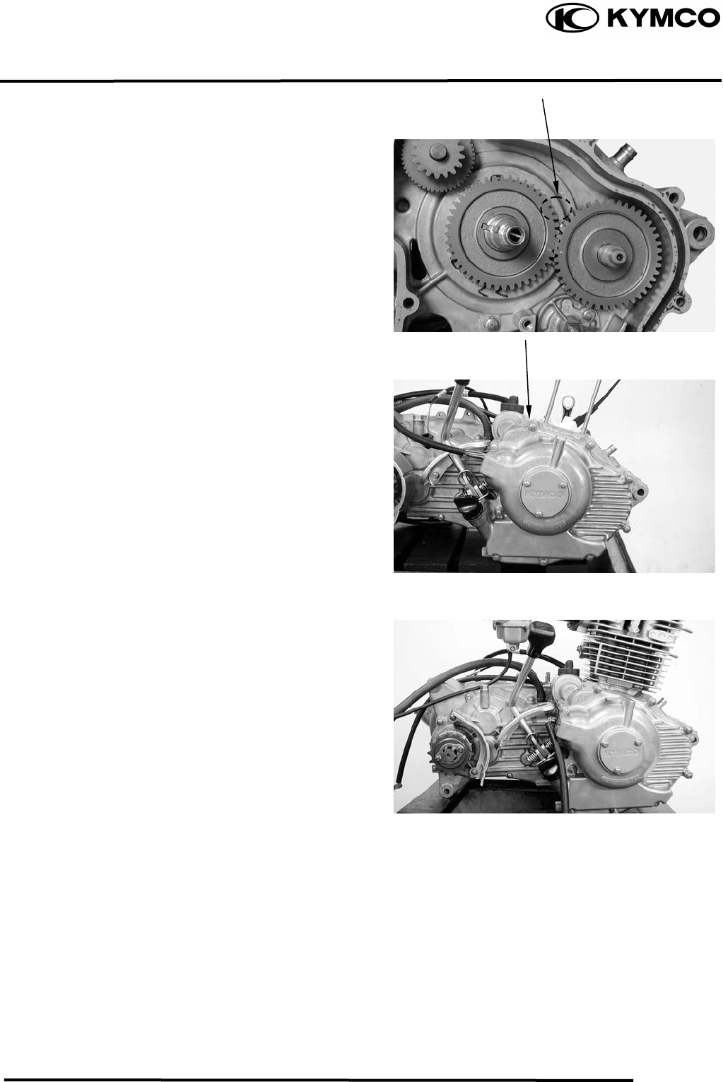
11. CRANKSCASE/CRANKSHAFT/
BALANCE SHAFT
11-6
MX’er SYSTEM
Align the mark on the balance gear with the
mark on the crankshaft gear.
Install the right and left case cover.
.
Install the cylinder.
Ri
g
ht Case Cove
r
Mark

12. FRONT WHEEL/FRONT BRAKE/FRONT
SUSPENSION/STEERING SYSTEM
12-0
MX’er SYSTEM
12
__________________________________________________________________________________
____________________________________________________________________
____________________________________________________________________
____________________________________________________________________
____________________________________________________________________
FRONT WHEEL/FRONT BRAKE/
FRONT SUSPENSION\STEERING SYSTEM
____________________________________________________________________
SERVICE INFORMATION------------------------------------------------ 12- 2
TROUBLESHOOTING----------------------------------------------------- 12- 3
FRONT WHEEL------------------------------------------------------------- 12- 4
FRONT BRAKE ------------------------------------------------------------- 12- 7
FRONT SUSPENSION ----------------------------------------------------- 12- 9
STEERING SYSTEM------------------------------------------------------- 12-13
12
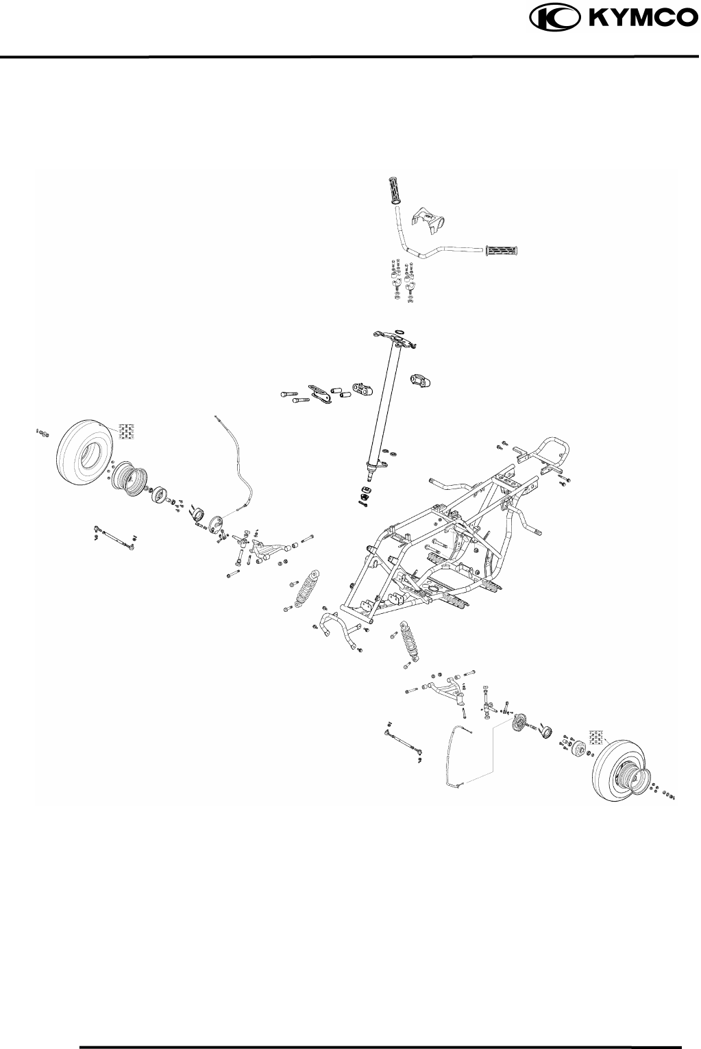
12. FRONT WHEEL/FRONT BRAKE/FRONT
SUSPENSION/STEERING SYSTEM
12-1
MX’er SYSTEM
12. FRONT WHEEL/FRONT BRAKE/FRONT
SUSPENSION/STEERING SYSTEM
12-2
MX’er SYSTEM
SERVICE INFORMATION
GENERAL INSTRUCTIONS
• Remove the machine frame covers before removing the front wheel. Jack the machine front
wheel off the ground and be careful to prevent the machine from falling down.
• During servicing, keep oil or grease off the brake drum and brake linings.
• Inspect the brake system before riding.
SPECIFICATIONS
Ite
m
Standard
(
mm
)
Service Limit
(
mm
)
Radial
⎯
2.0
Axial
⎯
2.0
Front brake drum I.D 110 111
Front brake linin
g
thickness 4 1.5
Tie rod len
g
th 266.5
⎯
Ro
d
-end
(
tie rod
)
an
g
le 180º
⎯
Front wheel rim run out
TORQUE VALUES
Steering stem nut 6.08.0kgf-m
Swing arm nut 4.05.0kgf-m
Front wheel nut 6.08.0kgf-m
Front wheel hub nut 6.08.0kgf-m
Front shock absorber upper
mount bolt 3.54.5kgf-m
Front shock absorber lower
mount bolt 3.54.5kgf-m

12. FRONT WHEEL/FRONT BRAKE/FRONT
SUSPENSION/STEERING SYSTEM
12-3
MX’er SYSTEM
SPECIAL TOOLS
Oil seal and bearing install E014
TROUBLESHOOTING
Hard steering (heavy) Front wheel wobbling
•Insufficient tire pressure • Bent rim
• Excessive wheel bearing play
• Bent spoke plate
• Faulty tire
Steers to one side or does not track straight • Improperly tightened axle nut
• Uneven front shock absorbers Soft front shock absorber
• Bent front arm • Weak shock springs
• Bent steering knuckle • Insufficient damper oil
Poor brake performance Front shock absorber noise
• Incorrectly adjusted brake • Slider bending
• Worn brake linings • Loose arm fasteners
• Contaminated brake lining surface • Lack of lubrication
• Worn brake shoes at cam contacting area
• Worn brake drum
• Poorly connected brake arm
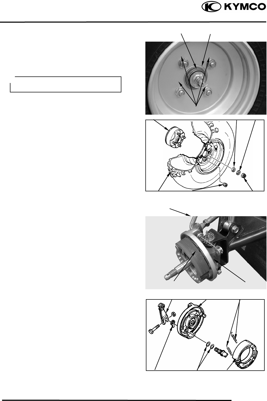
12. FRONT WHEEL/FRONT BRAKE/FRONT
SUSPENSION/STEERING SYSTEM
12-4
MX’er SYSTEM
FRONT WHEEL
REMOVAL
Place the machine on a level place.
Remove four nuts attaching the wheel panel
and front wheel.
Elevate the front wheels by placing a
suitable stand under the frame.
Remove the cotter pin.
Remove nut attaching the wheel hub and
washer.
Remove the collar and wheel hub.
FRONT BRAKE DISASSEMBLY
Loosen the lock nut and tighten the adjuster
nut at brake lever. (Refer to the “FRONT
BRAKE ADJUSTMENT” section in the
CHAPTER 3.).
Disconnect the front brake cable from brake
cam lever and remove the brake panel.
Remove the brake shoes.
REMOVE
Remove brake shoes and springs.
Remove the bolt attaching camshaft lever
and remove camshaft lever.
Remove the wear indicator, camshaft and
O-
rings
Nu
t
Pin
Camshaft leve
r
Brake Cable
Support the machine securely so there is
no dan
g
er of it fallin
g
over.
Wheel Hub
Front Wheel
Colla
r
Wheel Panel Nuts Hub Nu
t
Brake Panel
Nuts
Washe
r
Wear Indicato
r
Brake Panel
Brake Shoes
S
p
rin
g
s
Brake Shoes
O-rin
g
s
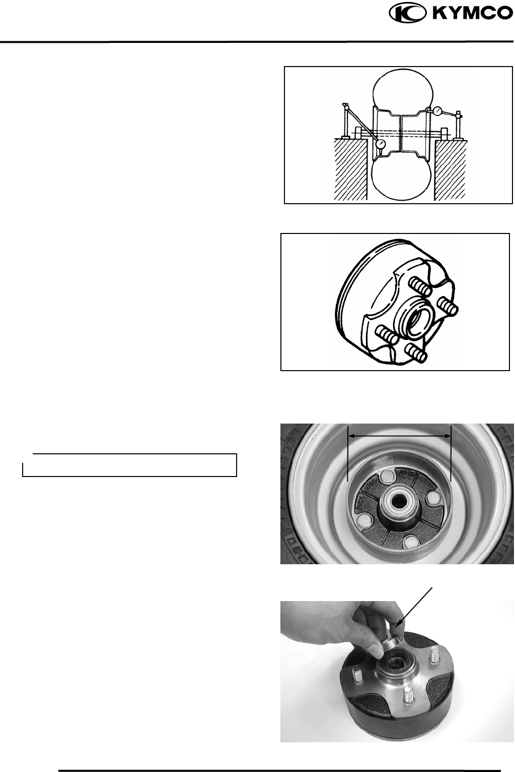
12. FRONT WHEEL/FRONT BRAKE/FRONT
SUSPENSION/STEERING SYSTEM
12-5
MX’er SYSTEM
Measure the wheel run out.
Replace wheel or check bearing play if out
of specification
Rim run out limits:
Vertical: 2.0mm
Lateral: 2.0mm
Inspect the front wheel hub.
Replace if cracks or damage.
Inspect the front brake drum.
Measure the front brake drum I.D.
Service limits: 111mm
FRONT WHEEL BEARING
Remove the side collar.
Side Colla
r
Keep oil or grease off the
b
rake dru
m
.
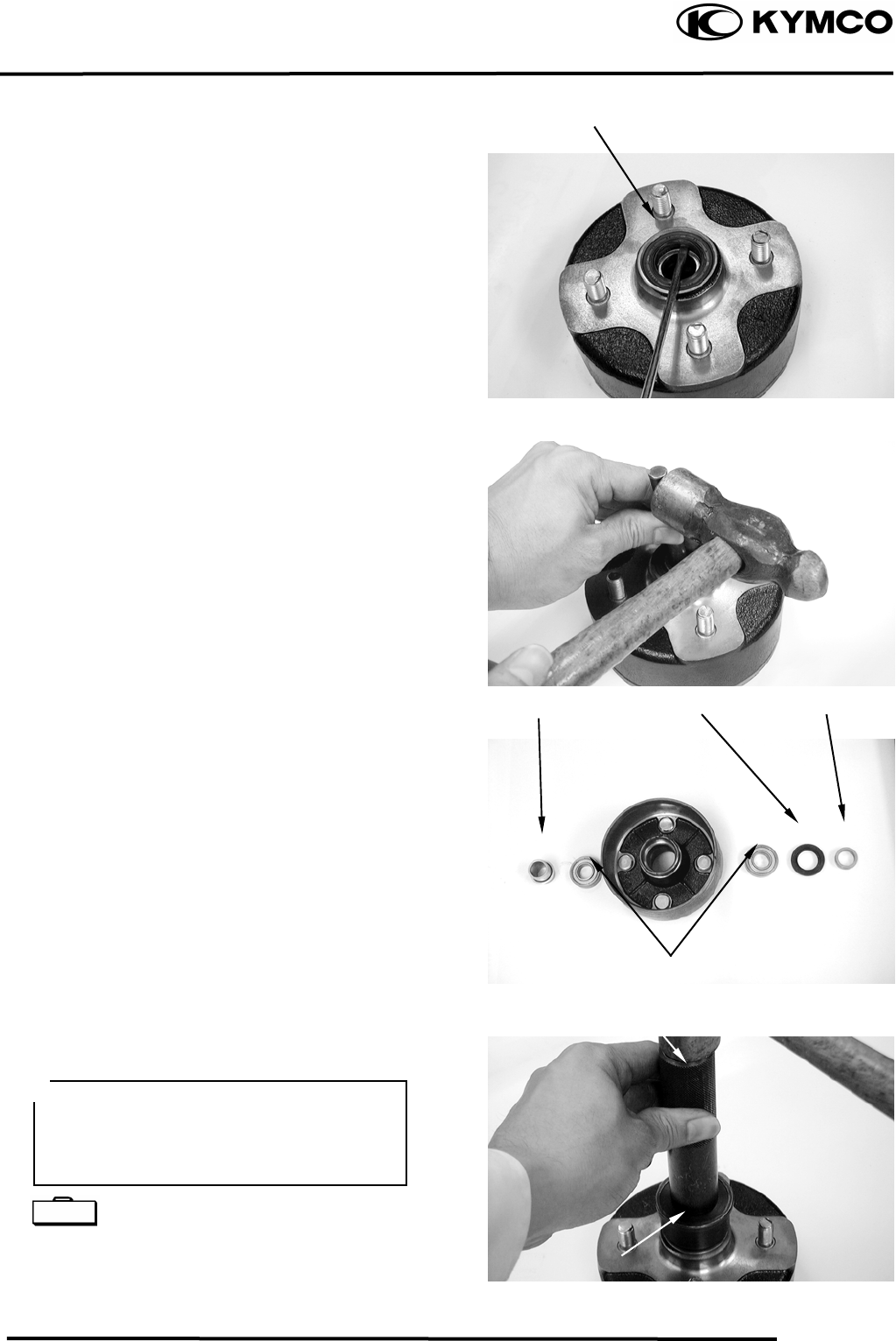
12. FRONT WHEEL/FRONT BRAKE/FRONT
SUSPENSION/STEERING SYSTEM
12-6
MX’er SYSTEM
Remove the dust seal.
Turn the inner race of each bearing with
your finger to see if they turn smoothly and
quietly. Also check if the outer race fits
tightly in the hub.
BEARING REPLACEMENT
Remove the front wheel bearings and
distance collar.
Replace the bearings if the races do not turn
smoothly, quietly, or if they fit loosely in
the hub.
Apply grease to a new dust seal lip and
install the dust seal.
Pack all bearing cavities with grease.
Drive in the left bearing.
Install the distance collar.
Drive in the right bearing.
Oil seal and bearing install E014
Dust Seal
Wheel Bearin
g
Dust Seal Side Colla
r
Colla
r
Driver Handle
Outer Driver
• Do not allow the bearings to tilt while
driving them in.
• Drive in the bearing squarely with the
sealed end facing out.
Special
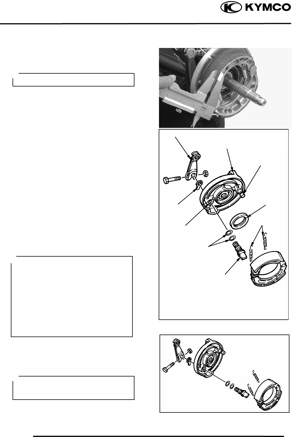
12. FRONT WHEEL/FRONT BRAKE/FRONT
SUSPENSION/STEERING SYSTEM
12-7
MX’er SYSTEM
FRONT BRAKE
FRONT BRAKE LINING INSPECTION
Measure the front brake lining thickness.
Service limit: 2.0mm replace if below
REMOVAL
Inspect the shoe springs, O-rings, camshaft
lever and wear indicator.
Replace if damage.
Inspect the brake shoe plate.
Replace if cracks or damage.
Inspect the brake shoe pivot pin.
Replace if wear or damage.
Inspect the camshaft hole and camshaft.
Replace if scratches or excessive wear.
INSTALLATION
Reverse the “REMOVAL” procedures.
Tighten the bolt for camshaft lever.
Torque: 1.82.5kgf-m
Brake Linin
g
Keep oil or grease off the brake linings.
Camshaft leve
r
Wear Indicato
r
Brake Plate
Apply the grease onto the o-ring, oil seal
lips, pivot pin of brake shoe and
camshaft.
• Install the camshaft to the brake shoe
plate with the slot of the camshaft
placing at bass line of the wear
indicator scale.
• Align the projection with the slot of the
camshaft when installing the wear
indicator to the camshaft.
• Align the cut-out of the camshaft lever
with the slot of the camshaft when
installing the camshaft lever to the
camshaft.
O-rin
g
s
S
p
rin
g
s
Oil Seal
Brake shoe
p
ivot
p
in
Camshaf
t
Camshaft Hole
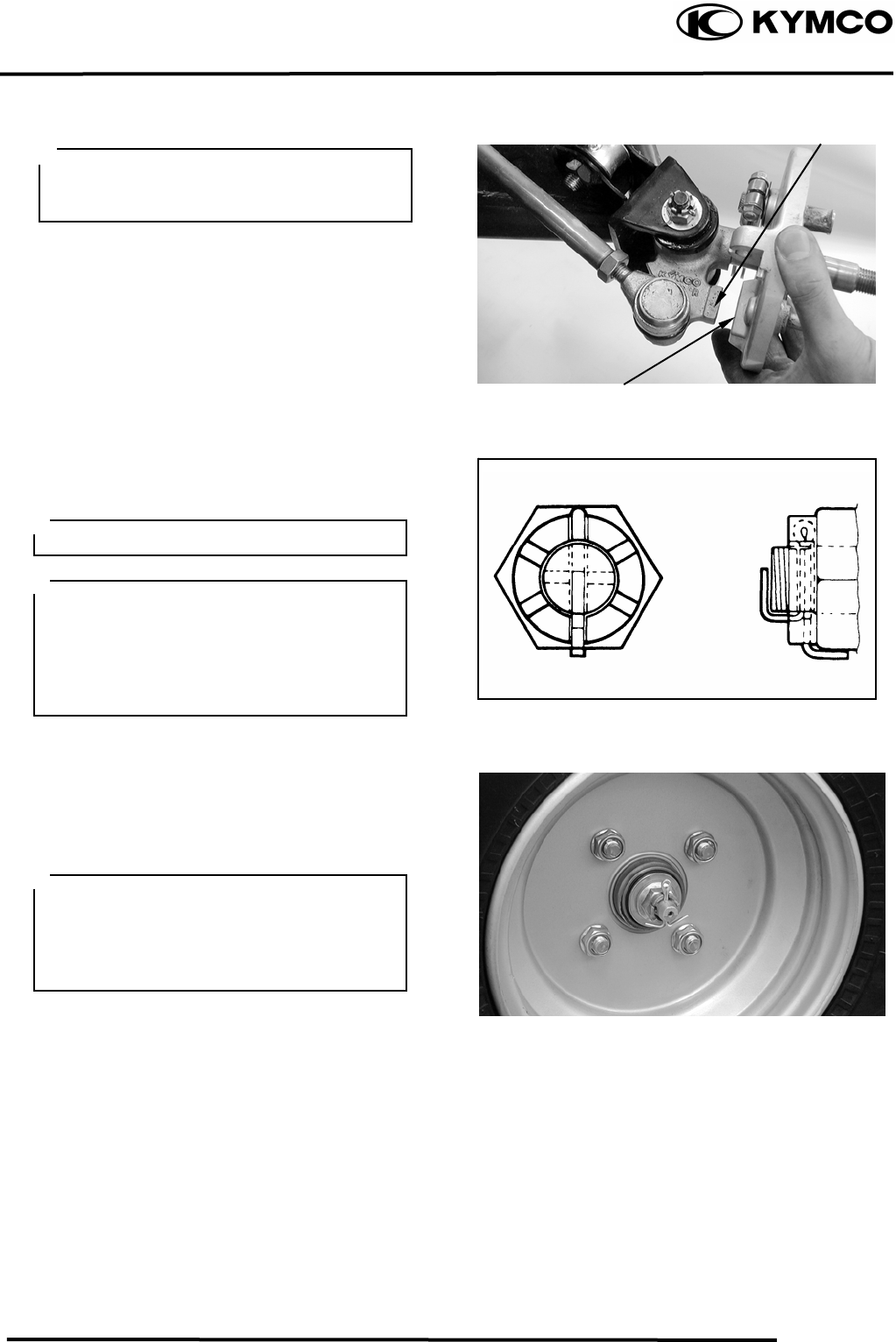
12. FRONT WHEEL/FRONT BRAKE/FRONT
SUSPENSION/STEERING SYSTEM
12-8
MX’er SYSTEM
Install the brake shoe plate.
Apply the grease onto the bearings and oil
seal lips of the wheel hub.
Install wheel hub, plate washer and tight the
nut (wheel hub).
Torque: 6.08.0kgf-m
Install cotter pins.
Install the front wheel and tighten the nuts
(wheel).
Torque: 6.08.0kgf-m
Adjust the front brake cable free play.
Refer to the “FRONT BRAKE
ADJUSTMENT” section in the
CHAPTER 3.
Brake cable free play: 1020mm at lever
pivot.
Make sure that the boss on the knuckle
correctly engages with the locating slot
on the brake shoe plate.
Boss
Locatin
g
Slo
t
Do not loosen the axle nut after torque
tightening. If the axle nut groove id not
aligned with the cotter pin hole, align
groove with the hole by tightening ut on
the axle nut.
Always use a new cotter pin.
Tapered wheel nuts are used for front
wheels.
Install the nuts with its tapered side
towards the wheel.
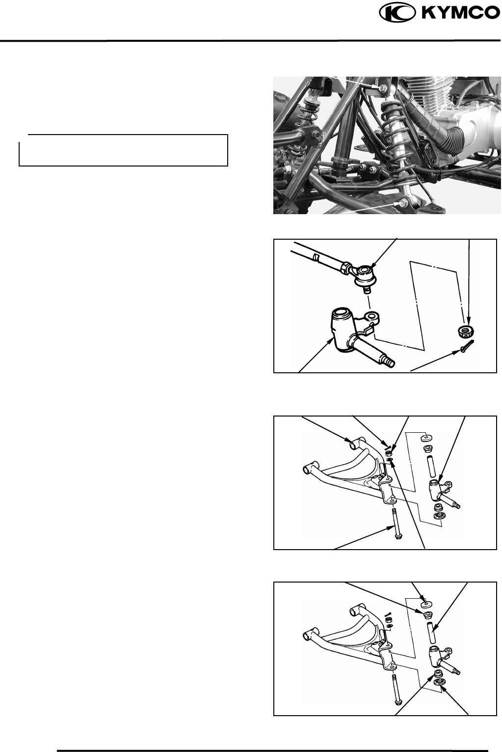
12. FRONT WHEEL/FRONT BRAKE/FRONT
SUSPENSION/STEERING SYSTEM
12-9
MX’er SYSTEM
FRONT SUSPENSION
REMOVAL
Elevate the front wheels by placing a
suitable stand under the frame.
Remove the front wheel, wheel hub, brake
shoe plate.
Remove the upper and lower bolt, then
remove the shock absorber.
Remove the cotter pin and nut, then remove
tie-rod from steering knuckle.
Remove cotter pin, nut, washer and bolt,
then remove the steering knuckle, covers,
collar and bush from the front arm.
Upper Bol
t
Lower Bol
t
Support the machine securely so there is
no dan
g
er of it fallin
g
over.
Tie-rod Nu
t
Cotter pinSteering Knuckle
Front ar
m
Cotter pin Nu
t
Steering Knuckle
Bol
t
Washe
r
Cove
r
Bush Colla
r
Bush Cove
r
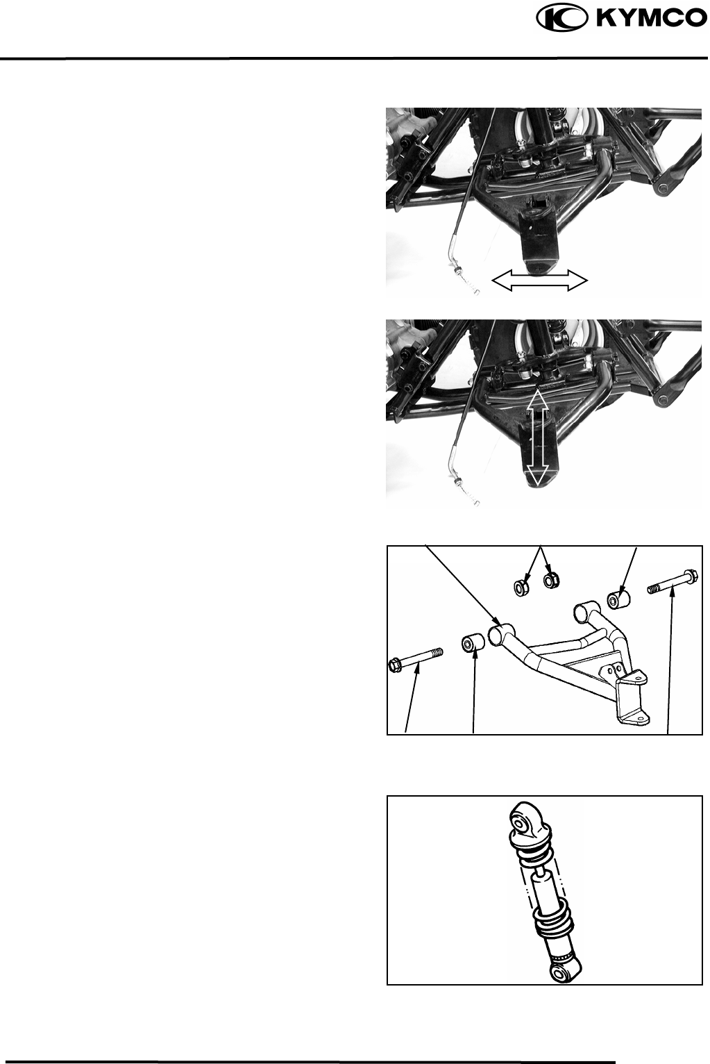
12. FRONT WHEEL/FRONT BRAKE/FRONT
SUSPENSION/STEERING SYSTEM
12-10
MX’er SYSTEM
INSPECTION
Check the front arm brackets of the frame.
If bent, cracked or damaged, repair or
replace the frame.
Check the tightening torque of the front
arms securing nuts.
Torque: 4.05.0kgf-m
Check the front arm side play by moving it
from side to side.
If side play noticeable, replace the inner
collar, bushings and thrust covers as a set.
Check the front arm vertical movement by
moving it up and down.
If vertical movement is tight, binding or
rough, replace the inner collar, bushings and
thrust covers as a set.
Remove the two nut and two bolt attaching
the front arm, then remove the front arm.
INSPECTION
Inspect the shock absorber rod.
Replace the shock absorber assembly if
bends or damage.
Inspect the shock absorber.
Replace the shock absorber assembly if oil
leakes.
Inspect the spring of the shock absorber by
move the spring up and down.
Replace the shock absorber assembly if
fatigue.
Nuts
Bush
Front Ar
m
Bol
t
Bush
Bush
Bol
t
12. FRONT WHEEL/FRONT BRAKE/FRONT
SUSPENSION/STEERING SYSTEM
12-11
MX’er SYSTEM
Inspect the steering knuckle.
Replace if cracks, pitting or damage.
.
Inspect the front arm.
Replace if cracks, bends or damage.
Inspect bushes.
Replace if wear or damage.
INSTALLATION
Reverse the “REMOVAL” procedures.
Install the front arm nut onto the frame and
tighten the nuts.
Torque: 4.05.0kgf-m
Do not attempt to straighten a bent arm,
this ma
y
dan
g
erousl
y
weaken the arm.
Bushes
Apply the grease onto the bushes, collars
and covers.
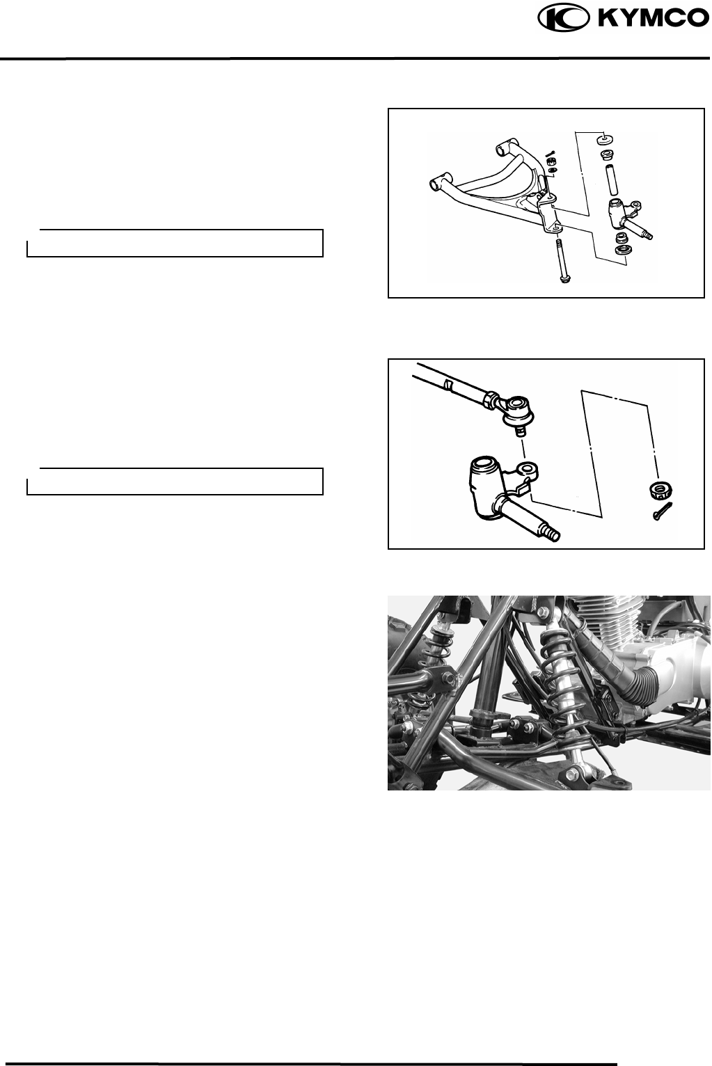
12. FRONT WHEEL/FRONT BRAKE/FRONT
SUSPENSION/STEERING SYSTEM
12-12
MX’er SYSTEM
Apply the grease onto the bush, collars and
covers, then install the steering knuckle
onto the front arm and tighten the nut.
Torque: 4.05.0kgf-m
Install the cotter pin and band ends of cotter
pin.
Install the tie-rod onto the steering knuckle
and tighten the nut.
Torque: 4.05.0kgf-m
Install the cotter pin and band ends of cotter
pin.
Install the shock absorber and tighten the
upper and lower bolts.
Torque: 3.54.5kgf-m
Install the brake shoe plate, wheel hub and
front wheel.
Refer to the “FRONT WHEEL
INSTALLATION” section.
Bleed Valve
Always use a new cotter pin.
Always use a new cotter pin.
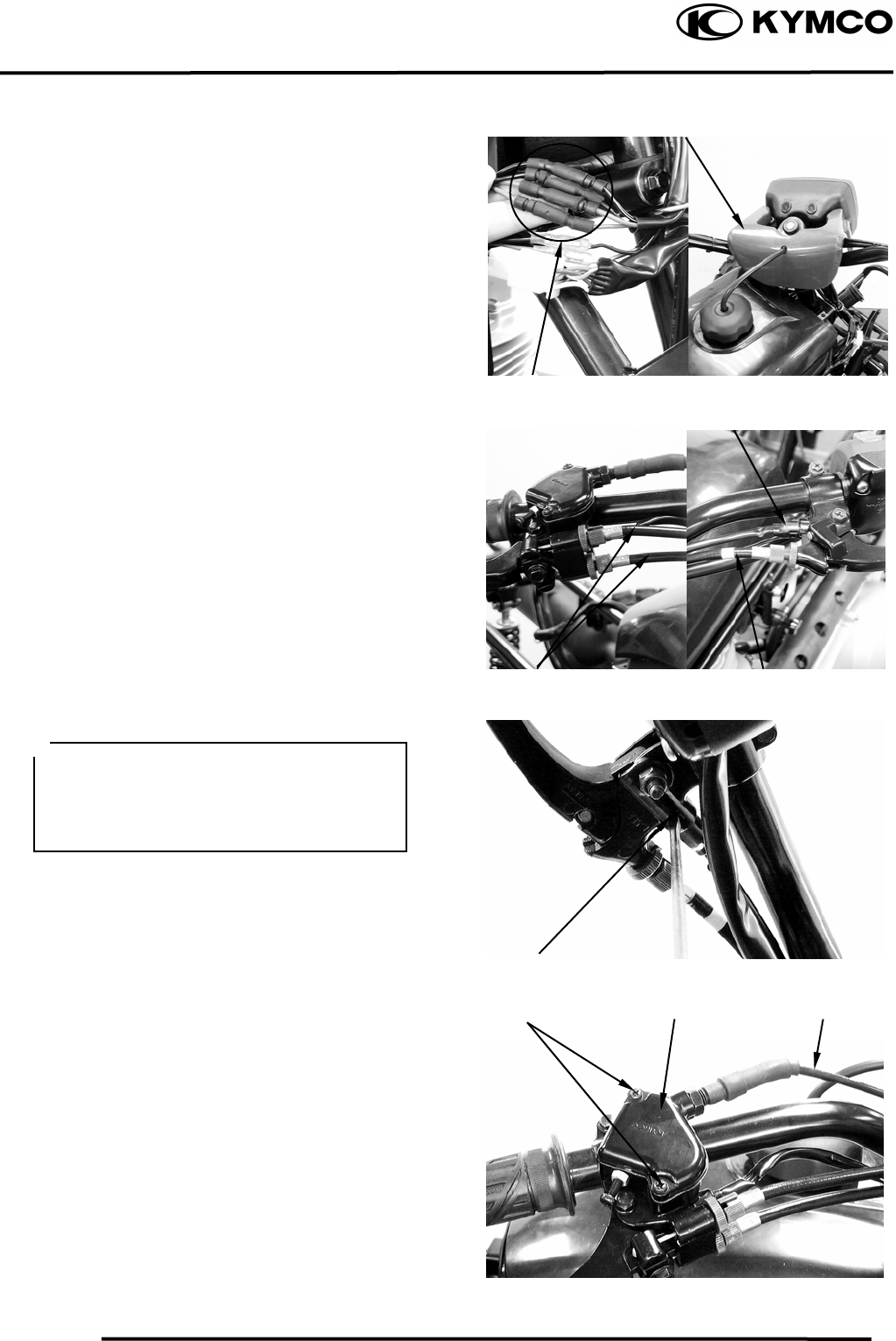
12. FRONT WHEEL/FRONT BRAKE/FRONT
SUSPENSION/STEERING SYSTEM
12-13
MX’er SYSTEM
STEERING SYSTEM
REMOVAL
Remove the following parts:
Seat, Front cover, Center cover and Front
fender
Refer to the “FENDERS” section in the
CHAPTER 2
Disconnect the main switch lead.
Remove the handlebar cover with main
switch.
Disconnect the front brake cables from the
brake lever, rear brake cable from the brake
lever and brake switch from the bracket of the
brake lever.
Remove the two screws to remove the cover
of the throttle housing.
Disconnect the throttle cable from the lever.
Handlebar Cove
r
Main Switch Lead
Brake Switch
Hook
Front Brake Cables Rear Brake Cable
Disconnect the brake switch from the
bracket of the brake lever while pushing
the hook of the brake switch with a
driver.
Cove
r
Screws Throttle Housing
12. FRONT WHEEL/FRONT BRAKE/FRONT
SUSPENSION/STEERING SYSTEM
12-14
MX’er SYSTEM
Remove the two screws and remove the
handlebar switch.
Remove the two bolts and remove headlight
unit.
Remove the four handlebar holder bolts and
remove the handlebar.
Remove the cotter pins and nuts attaching
the tie-rods, then remove tie-rods.
Remove the cotter pin and nut attaching the
steering column, then remove steering
column and collar.
Screws Handlebar Switch
Headlight Uni
t
Bolts
Bolts Handleba
r
Cotter Pin
Cotter Pin
Nu
t
Nu
t
Tie-rod
Cotter Pin Nu
t
12. FRONT WHEEL/FRONT BRAKE/FRONT
SUSPENSION/STEERING SYSTEM
12-15
MX’er SYSTEM
Remove the two bolts to remove the cable
holder, steering bracket, collars and steering
column.
INSPECTION
Inspect the handlebar.
Replace if cracks, bends or damage.
Inspect the steering column.
Replace if bends or damage.
Inspect the steering brackets and oil seal.
Replace if wear or damage.
Bolts
Colla
r
Steering Column
Cable Holde
r
Do not attempt to straighten a bent shaft,
this may dangerously weaken the shaft.
Steering Bracke
t
Steering Brackets
Oil Seal
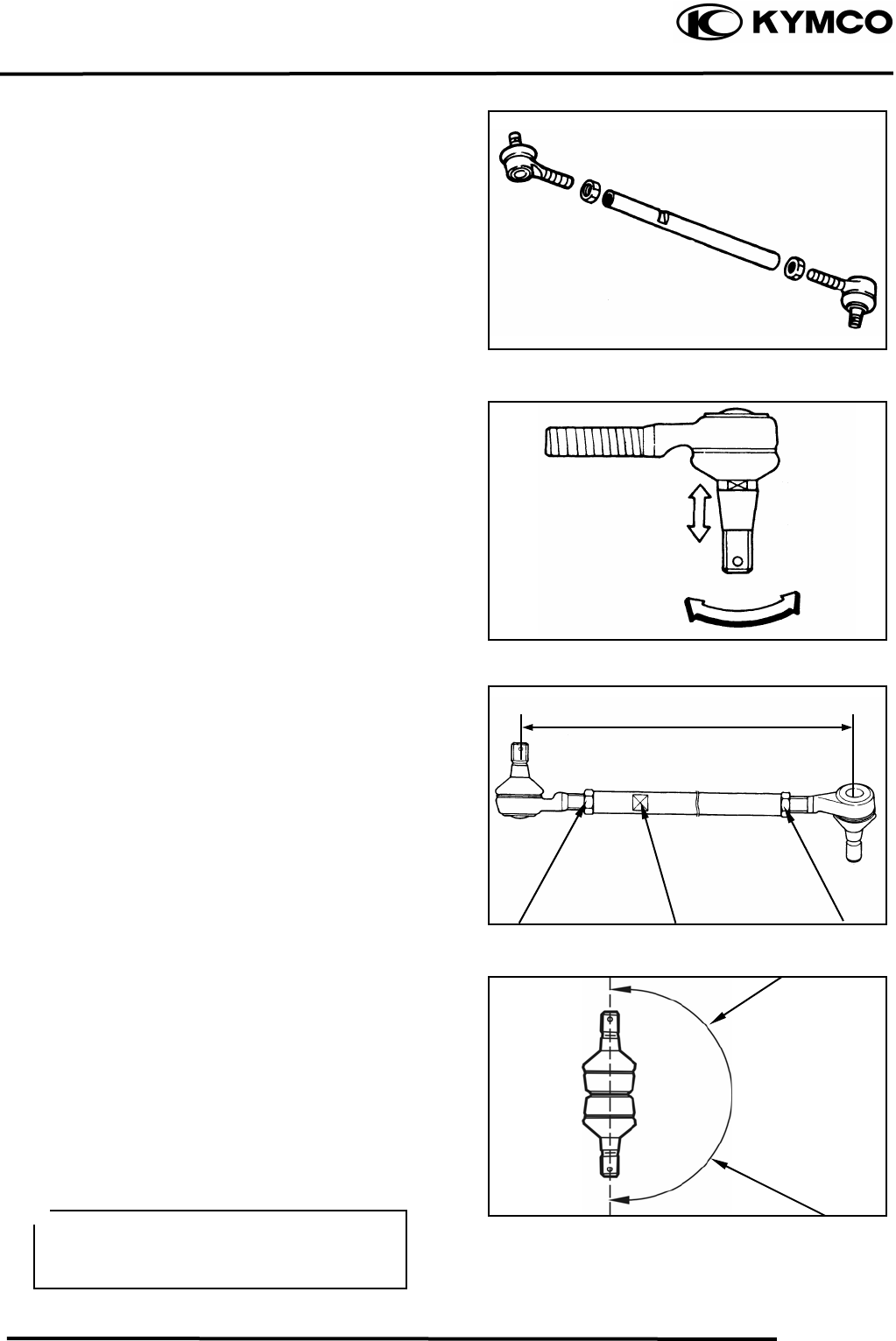
12. FRONT WHEEL/FRONT BRAKE/FRONT
SUSPENSION/STEERING SYSTEM
12-16
MX’er SYSTEM
Inspect the tie-rod.
Replace if bend or damage.
Check the tie-rod end movement.
Replace if the tie-rod end exists free play or
turns roughly.
Check the tapered surface of the tie-rod end.
Replace if pitting, wear or damage.
Adjust the tie-rod length.
Adjustment steps:
(The following procedures are done on both
tie-rods, right and left.)
Loosen the lock nuts.
Adjust the tie-rod length by tuning both
tie-rod ends.
Tie rod length: 266.5mm
Set the rod-end (steering column side) in an
angle where the indentation surface of the
tie-rod is parallel to the rod-end shaft, and
then tighten the lock nut.
Torque: 2.53.5kgf-m
Set the other rod-end (knuckle arm side) in
an angle as shown (right-hand tie-rod and
left-had tie-rod), and then tighten the lock
nut.
Rod-end (tie rod) angle: 180º
Torque: 2.53.5kgf-m
Lock Nu
t
Indentation Surface Lock Nu
t
To Steering Column
After making adjustment on both tie rods
be sure to mark them R and L for
identification.
To Knuckle Ar
m
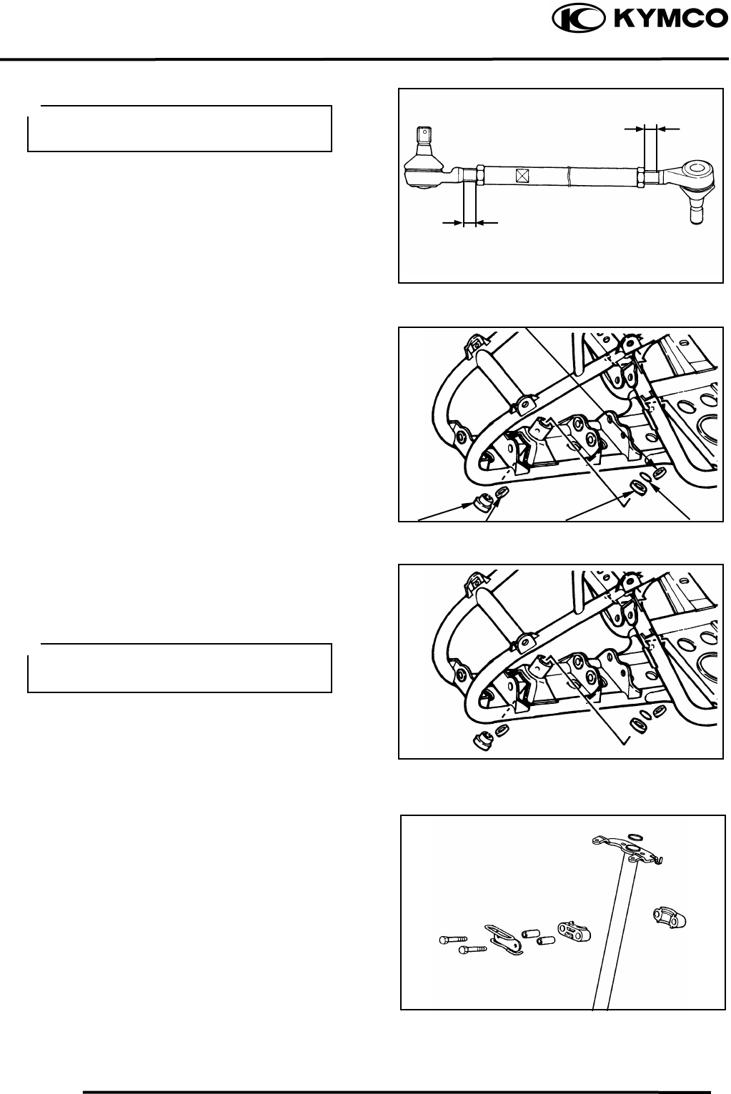
12. FRONT WHEEL/FRONT BRAKE/FRONT
SUSPENSION/STEERING SYSTEM
12-17
MX’er SYSTEM
Inspect the collar, duty seal, snap ring and
bearing.
Replace if wear or damage.
INSTALLATION
Reverse the “REMOVAL” procedures.
Assembly the steering column and tighten
the two bolts.
Torque: 1.82.5kgf-m
Band the lock washer tabs.
The threads on both rod-end must be of
the same len
g
th.
Apply the grease onto the collar, duty
seal, and bearing.
Colla
r
Snap Ring
Bearing
Dust Seal
Dust Seal
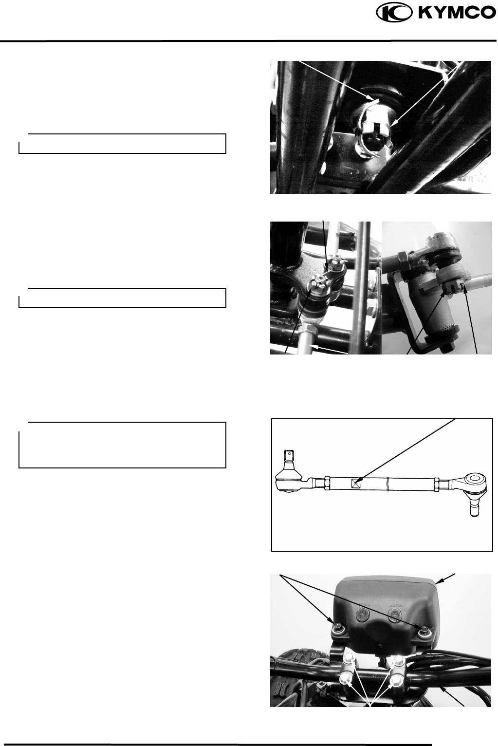
12. FRONT WHEEL/FRONT BRAKE/FRONT
SUSPENSION/STEERING SYSTEM
12-18
MX’er SYSTEM
Install the steering column and collar, then
tighten the nut.
Torque: 6.08.0kgf-m
Install the cotter pin and band ends of cotter
pin.
Install the tie rods and tighten the nut.
Torque: 4.05.0kgf-m
Install the cotter pin and band ends of cotter
pin.
Install handlebar and handlebar holder, then
tighten the four bolts.
Torque: 1.82.5kgf-m
Be sure that the ro
d
-end on the
indentation surface side is connected to
the steering column.
Always use a new cotter pin.
Always use a new cotter pin.
Indentation Surface
Bolts Headlight Uni
t
Bolts Handleba
r
Cotter Pin
Cotter Pin
Nu
t
Nu
t
Tie-rod
Cotter Pin Nu
t
12. FRONT WHEEL/FRONT BRAKE/FRONT
SUSPENSION/STEERING SYSTEM
12-19
MX’er SYSTEM
Apply the grease onto the end of the throttle
cable and end of the brake cable.
Refer to the “TOE-IN ADJUSTMENT”
section in the CHAPTER 3 to adjust toe-in.
Refer to the “FRONT BRAKE
ADJUSTMENT” section in the CHAPTER
3 to adjust front brake.
Refer to the “REAR BRAKE
ADJUSTMENT” section in the CHAPTER
3 to adjust rear brake.
• Be sure the upper handlebar holder
mark face to front.
• Fist tighten the bolts on the front side
of the handlebar holder, and then
tighten the bolts on the rear side.

15. IGNITION SYSTEM
15-0
MX’er SYSTEM
15
__________________________________________________________________________________
____________________________________________________________________
____________________________________________________________________
15
____________________________________________________________________
____________________________________________________________________
IGNITION SYSTEM
____________________________________________________________________
SERVICE INFORMATION------------------------------------------------ 15- 2
TROUBLESHOOTING----------------------------------------------------- 15- 3
CDI UNIT INSPECTION--------------------------------------------------- 15- 4
IGNITION COIL------------------------------------------------------------- 15- 6
PULSER COIL--------------------------------------------------------------- 15- 7
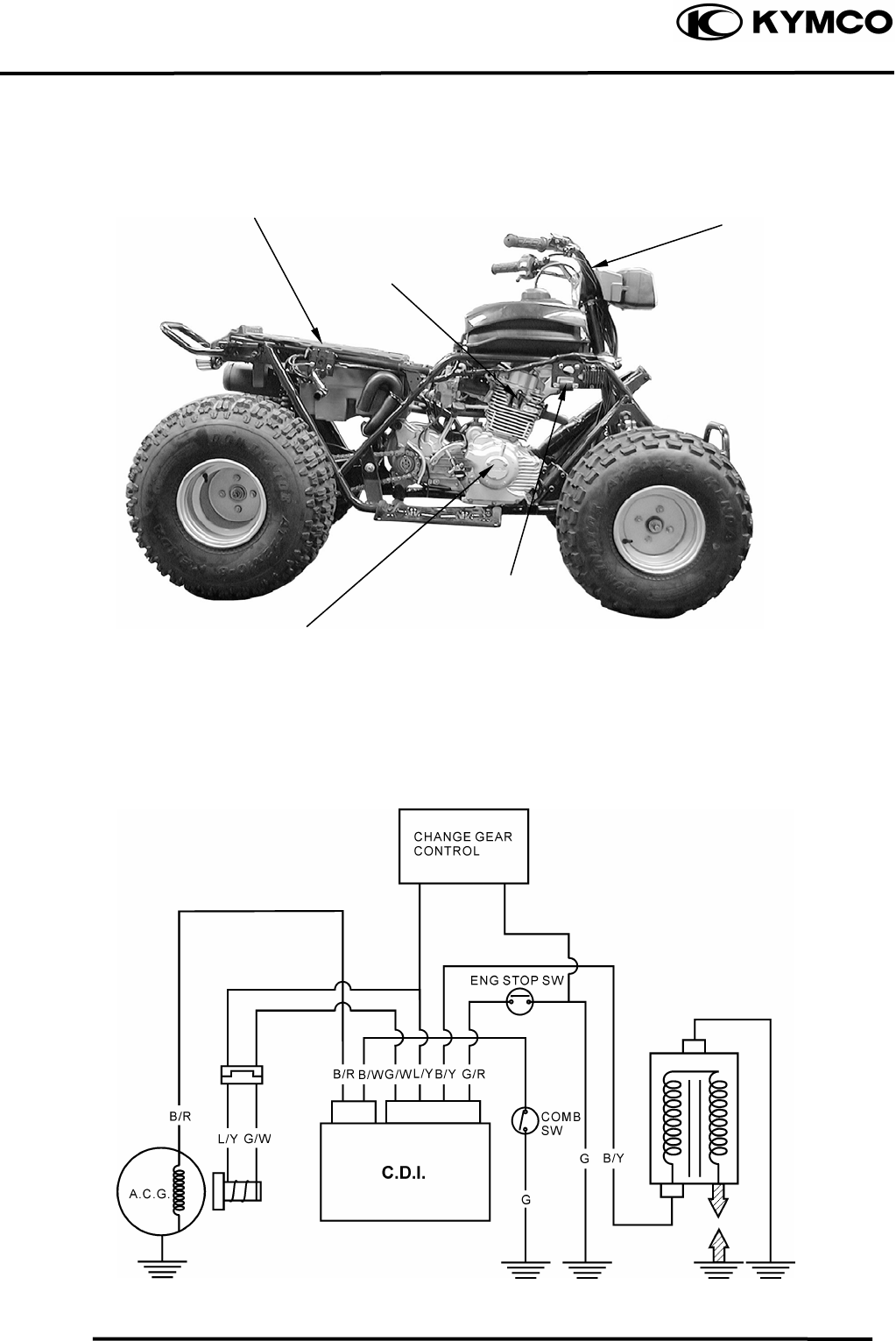
15. IGNITION SYSTEM
15-1
MX’er SYSTEM
Ignition Switch
CDI Uni
t
/Change Gear Control.
l
A.C. Generato
r
/
Pulser Coil
Spark Plug
Ignition Coil
IGNITION CIRCUIT
PULSER COIL
15. IGNITION SYSTEM
15-2
MX’er SYSTEM
SERVICE INFORMATION
GENERAL INSTRUCTIONS
• Check the ignition system according to the sequence specified in the Troubleshooting.
• The ignition system adopts CDI unit , change gear control and the ignition timing cannot be
adjusted.
• If the timing is incorrect, inspect the CDI unit, A.C. generator, change gear control and replace
any faulty parts. Inspect the CDI unit with a CDI tester
• Loose connector and poor wire connection are the main causes of faulty ignition system.
Check each connector before operation.
• Use of spark plug with improper heat range is the main cause of poor engine performance.
• The inspections in this section are focused on maximum voltage. The inspection of ignition coil
resistance is also described in this section.
• Inspect the ignition switch according to the continuity table specified in page 17-5.
• Inspect the spark plug referring to Section 3.
SPECIFICATIONS
Item Standard
Standard type CR8E
Spark plug Hot type
Cold type
Spark plug gap 0.60.7mm
Ignition timing “F” mark
Full advance 15ºBTDC/1,700±100rpm
Primary coil 0.20.3Ω
Ignition coil resistance (20) Secondary with plug cap 3.24.8KΩ
coil plug cap 4.25.2KΩ
Pulser coil resistance (20) 5060Ω
Exciter coil resistance (20) 100120Ω
Ignition coil primary side max. voltage 12V min.
Pulser coil max. voltage 2.1V min.
TESTING INSTRUMENT
Kowa Electric Tester
or commercially available electric tester with resistance over 10MΩ/CDV

15. IGNITION SYSTEM
15-3
MX’er SYSTEM
TROUBLESHOOTING
High voltage too low No high voltage
• Weak battery or low engine speed • Faulty ignition switch
• Loose ignition system connection • Faulty CDI unit
• Faulty CDI unit • Poorly connected or broken CDI ground wire
• Faulty ignition coil •Dead battery or faulty regulator/rectifier
• Faulty pulser coil • Faulty ignition coil connector
Normal high voltage but no spark at plug • Faulty pulser coil
• Faulty spark plug
• Electric leakage in ignition secondary circuit
• Faulty ignition coil
Good spark at plug but engine won‘t start
• Faulty CDI or incorrect ignition timing
• Faulty change gear control unit
• Improperly tightened A.C. generator flywheel
CDI UNIT INSPECTION
Remove the seat.
Disconnect the CDI coupler and remove the
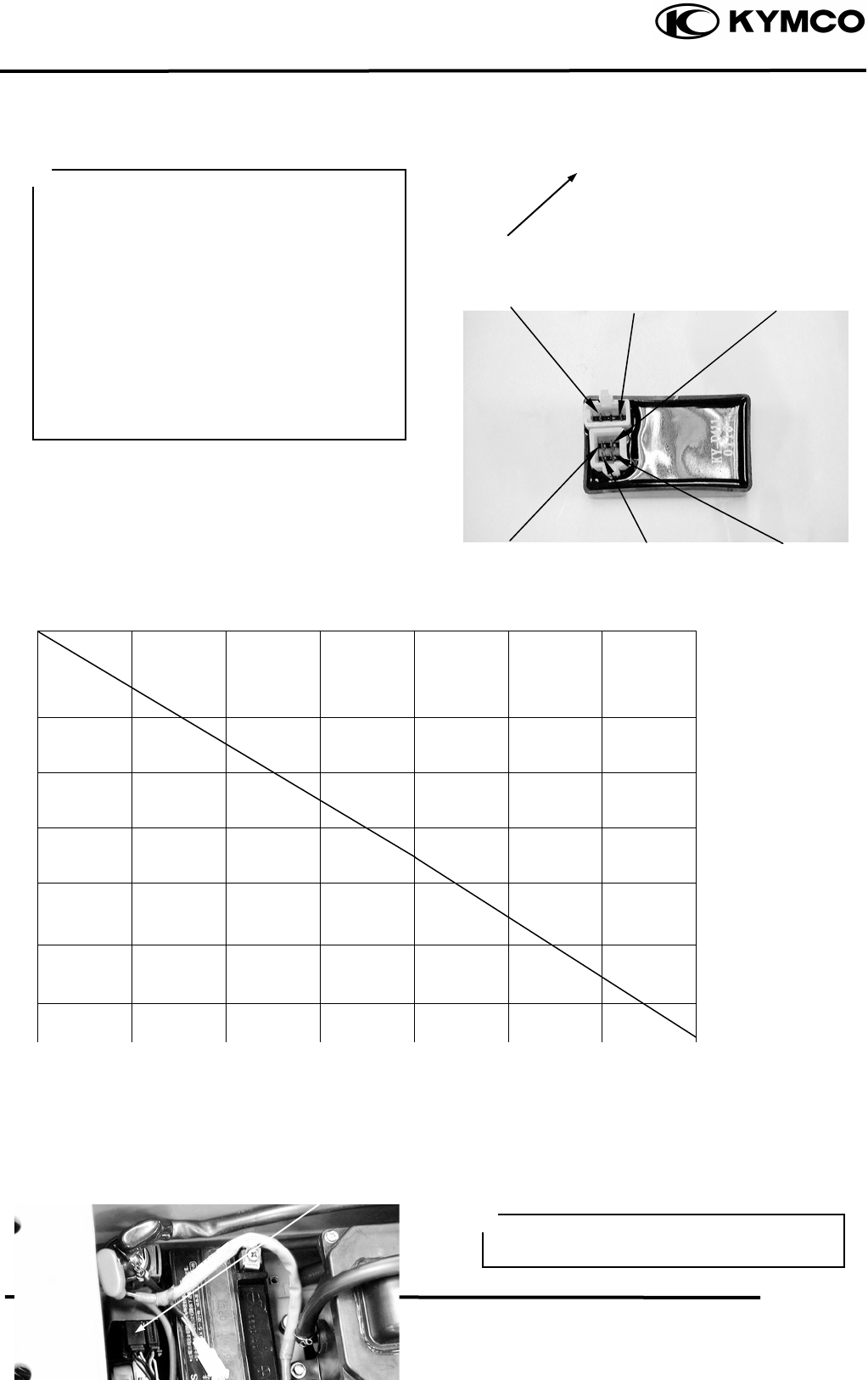
15. IGNITION SYSTEM
15-4
MX’er SYSTEM
CDI unit.
Measure the resistance between the
terminals using the electric tester.
.
Testing Range
Use the xKΩ range for the Sanwa Tester.
Use the xKΩ range for the Kowa Tester.
Note: The readings in this table are taken
with a Sanwa Tester.
• Due to the semiconductor in circuit, it is
necessary to use a specified tester for
accurate testing. Use of an improper
tester in an improper range may give
false readings.
• Use a Sanwa Electric Tester or Kowa
Electric Tester.
• In this table, “Needle swings then
returns” indicates that there is a charging
current applied to a condenser. The needle
will then remain at “∞” unless the
condenser is discharged.
Unit: KΩ
Test the CDI unit using the CDI tester.
Black
/
White
Blue/Yellow
CDI Uni
t
Black/Red
Black/Yellow
Green/Red
Green/White
Probe⊕
(-)Probe
Black/
White Black/
Red Blue/
White Green Green/
White Black/
Yellow
Black/
White ∞ ∞ ∞ ∞ ∞
Black/
Red 3-6K ∞ ∞ ∞ ∞
Blue/
White 35-42K 18-22K 8-10K 8-10K ∞
Green 15-18K 4.5-5.5K 7-9K There is
continuity ∞
Green/
White 15-18K 4.5-5.5K 8-9K There is
continuity ∞
Black/ ∞ ∞
∞
∞
∞
Needle
Swings then Needle
Swings then
Change Gear Control
Operate the CDI tester by following the
manufacturer‘s instructions.
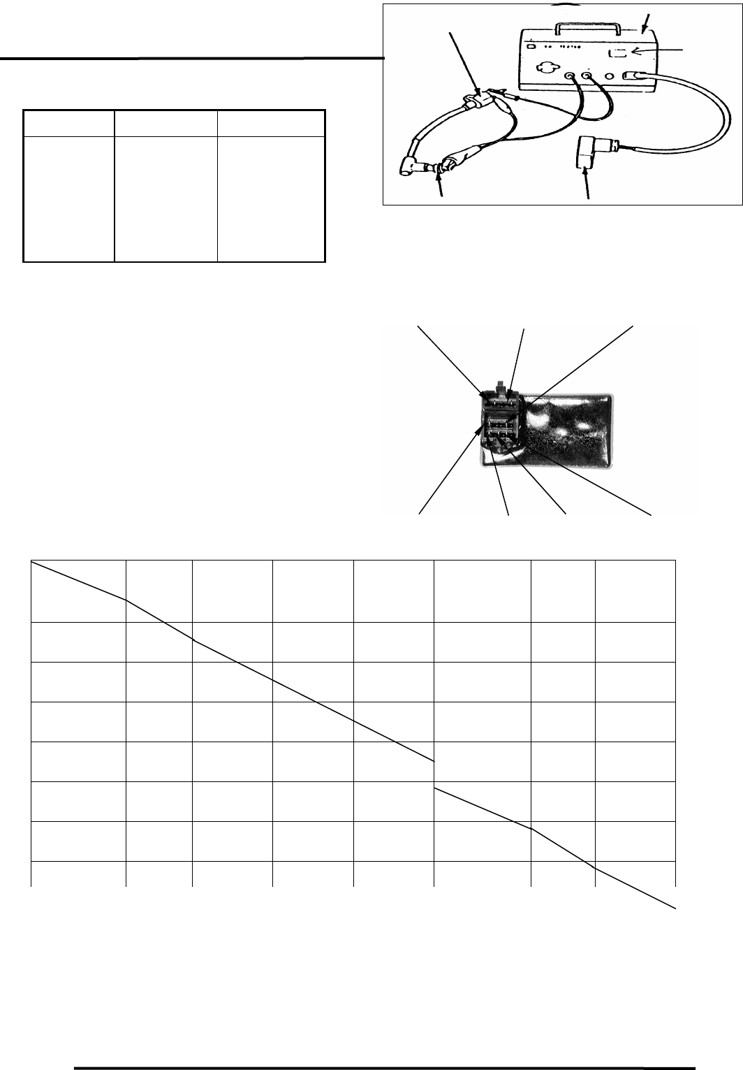
15. IGNITION SYSTEM
15-5
MX’er SYSTEM
Connect the special connector to the CDI
coupler and CDI tester.
Switch Range Good CDI Faulty CDI
1. OFF
2. P
3. EXT
4. ON1
5. ON2
No spark
No spark
No spark
Good spark
Good spark
⎯⎯
⎯⎯
Good spark
No spark
No spark
If the CDI unit is faulty, replace it with a
new one.
Remove the seat.
Disconnect the change gear control coupler
and remove the change gear control unit.
Measure the resistance between the
terminals using the electric tester.
Testing Range
Use the xKΩ range for the Sanwa Tester.
Use the xKΩ range for the Kowa Tester.
Note: The readings in this table are taken
with a Sanwa Tester.
CDI Teste
r
Ignition Coil
Spark
Window
CDI Uni
t
Spark Plug
Unit:
KΩ
IGNITION COIL INSPECTION
CONTINUITY TEST
Probe⊕
(-)Probe
Black Green Green/
Yellow Green/
Pink Light Green/
Red Blue/
Yellow Yellow/
Brown
Black
5-50K 5-50K 5-50K 5-50K 5-50K 5-50K
Green ∞
5-50K 5-50K 5-50K 5-50K 0
Green/
Yellow ∞ 5-50K 10-50K 10-50K 10-50K 5-50K
Green/
Pink ∞ ∞ ∞ 0 ∞ ∞
Light Green/
Red ∞ ∞ ∞ 0 ∞ ∞
Blue/
Yellow ∞ 50-200K 50-200K 50-200K 50-200K
Yellow/
B
∞ 0 5-50
K
5-50
K
5-50
K
5-50
K
Blue/Yellow Yellow/Brown Light Green/Red
Black Green /YellowGreen
Green
/
Pink
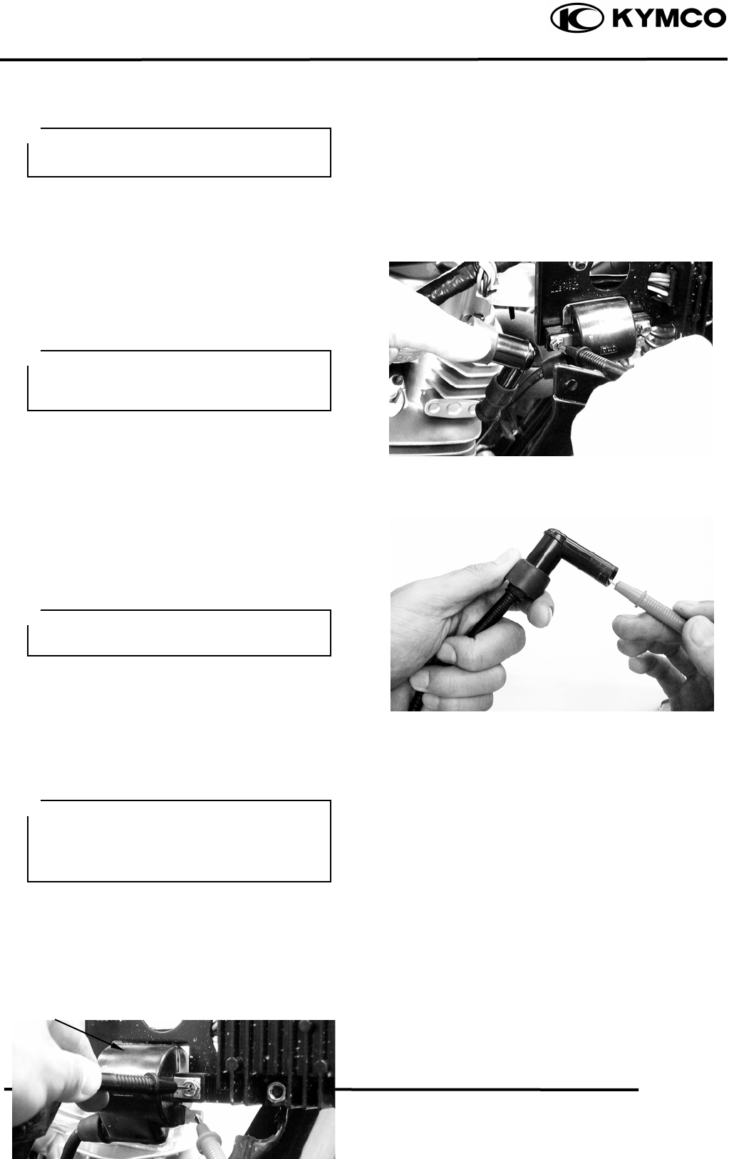
15. IGNITION SYSTEM
15-6
MX’er SYSTEM
Remove the front cover.
Remove the spark plug cap.
Disconnect the ignition coil wires.
Measure the resistance between the ignition
coil primary coil terminals.
Resistance: 0.20.3Ω/20
Remove the spark plug cap and measure the
secondary coil resistance between the spark
plug wire and the primary coil terminal.
Resistance: 3.24.8KΩ/20
Measure the spark plug cap resistance.
Remove the spark plug cap and measure the
spark plug resistance.
Resistance: 4.25.2KΩ/20
PERFORMANCE TEST
Test the performance with a CDI tester.
If the spark is weak, inspect the spark plug
and CDI unit. If both of them are normal,
replace the ignition coil with a new one.
This test is to inspect the continuity of
ignition coil.
This test is for reference only. Accurate
test should be performed with a CDI
tester.
Measure the resistance in the XKΩrange
of the electric tester.
• Operate the CDI tester by following
the manufacturer‘s instructions.
• Use the special connector to connect
the CDI unit.
PULSER COIL
I
g
nition Coil
INSPECTION
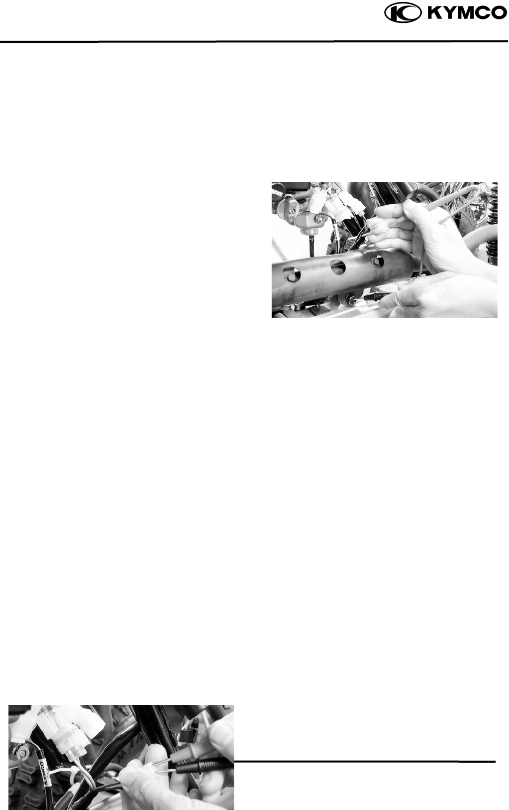
15. IGNITION SYSTEM
15-7
MX’er SYSTEM
Remove the front cover.
Disconnect the pulser coil wire coupler and
measure the resistance between the blue/
yellow and green/white wire terminals.
Resistance: 5060Ω
EXCITER COIL
INSPECTION
Disconnect the exciter coil wire coupler and
measure the resistance between the
black/red wire terminal and ground.
Resistance: 100120Ω

16. STARTING SYSTEM
16-0
MX’er SYSTEM
16
__________________________________________________________________________________
____________________________________________________________________
____________________________________________________________________
____________________________________________________________________
16
____________________________________________________________________
STARTING SYSTEM
____________________________________________________________________
SERVICE INFORMATION------------------------------------------------ 16- 2
TROUBLESHOOTING----------------------------------------------------- 16- 2
STARTER MOTOR--------------------------------------------------------- 16- 3
STARTER RELAY---------------------------------------------------------- 16- 5
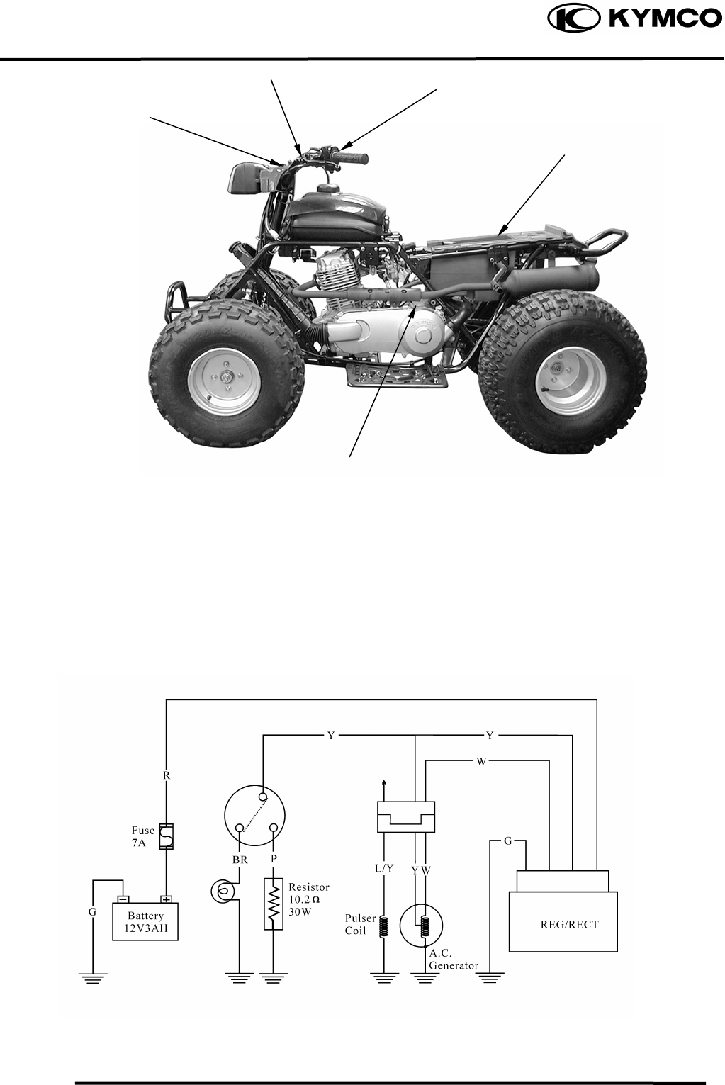
16. STARTING SYSTEM
16-1
MX’er SYSTEM
Ignition
Sith
Starter Moto
r
Starter Button
Fuse/Battery
/
Starter Relay
Stop Switches
STARTING CIRCUIT
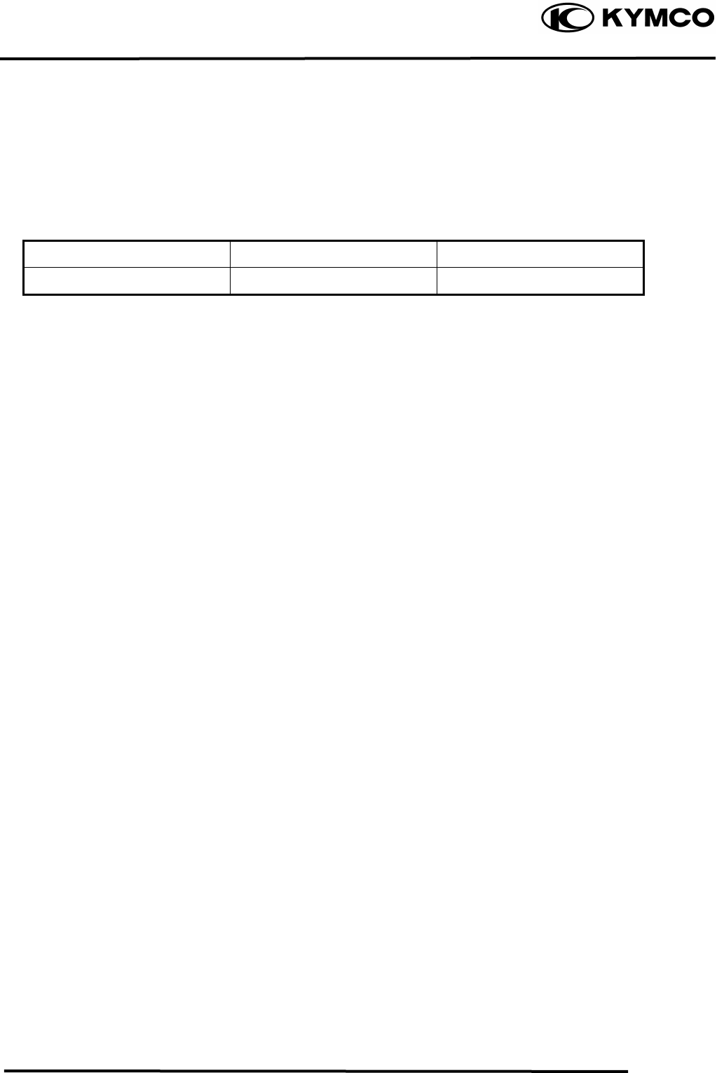
16. STARTING SYSTEM
16-2
MX’er SYSTEM
SERVICE INFORMATION
GENERAL INSTRUCTIONS
• The removal of starter motor can be accomplished with the engine installed.
• For the starter clutch removal, refer to Section 4.
SPECIFICATIONS
Item Standard (mm) Service Limit (mm)
Starter motor brush length 12.5 8.5
TROUBLESHOOTING
Starter motor won‘t turn Lack of power
• Fuse burned out • Weak battery
• Weak battery • Loose wire or connection
• Faulty ignition switch • Foreign matter stuck in starter motor
• Faulty starter clutch or gear
• Faulty front or rear stop switch
• Faulty starter relay Starter motor rotates but engine does
• Poorly connected, broken or shorted wire not start
• Faulty starter motor • Faulty starter clutch
• Starter motor rotates reversely
• Weak battery
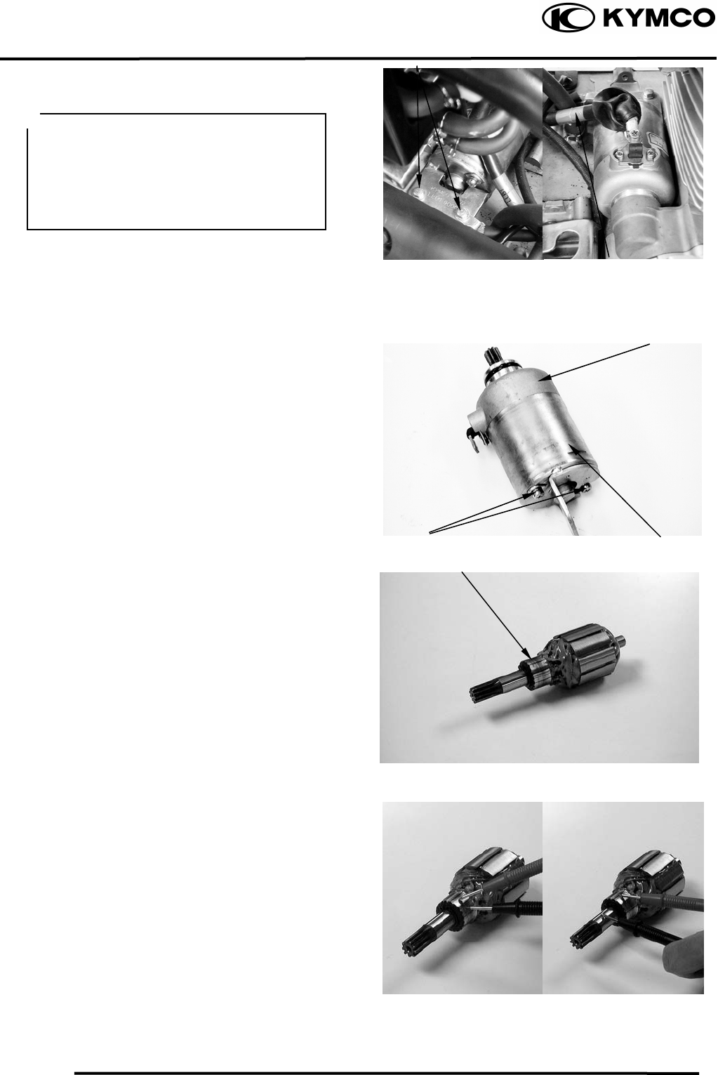
16. STARTING SYSTEM
16-3
MX’er SYSTEM
STARTER MOTOR
REMOVAL
Remove the two starter motor mounting
bolts and the motor.
Remove the waterproof rubber jacket and
disconnect the starter motor cable
connector.
DISASSEMBLY
Remove the two starter motor case screws,
front cover, motor case and other parts.
INSPECTION
Inspect the removed parts for wear, damage
or discoloration and replace if necessary.
Clean the commutator if there is metal
powder between the segments.
Check for continuity between pairs of the
commutator segments and there should be
continuity.
Also, make a continuity check between
individual commutator segments and the
armature shaft. There should be no
continuity.
Front Cove
r
Starter Motor Cable
Bolts
Commutato
r
Before removing the starter motor, turn
the ignition switch OFF and remove the
battery ground. Then, turn on the
ignition switch and push the starter
button to see if the starter motor operates
properly.
Case Screws Motor Case
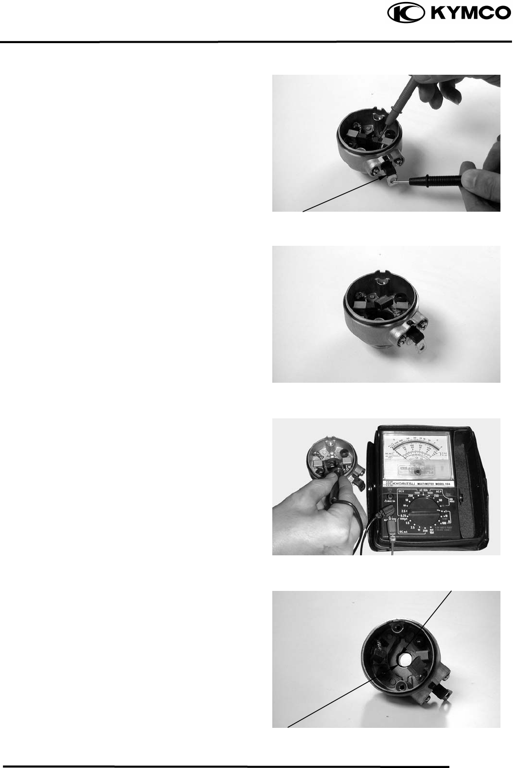
16. STARTING SYSTEM
16-4
MX’er SYSTEM
STARTER MOTOR CASE
CONTINUITY CHECK
Check to confirm that there is no continuity
between the starter motor wire terminal and
the motor front cover.
Also check for the continuity between the
wire terminal and each brush.
Replace if necessary.
Measure the length of the brushes.
Service Limit: 8.5mm replace if below
Check for continuity between the brushes. If
there is continuity, replace with new ones.
Check if the needle bearing in the front
cover turns freely and has no excessive
play.
Replace if necessary.
Check the dust seal for wear or damage.
Wire Terminal
Bearin
g
Dust Seal
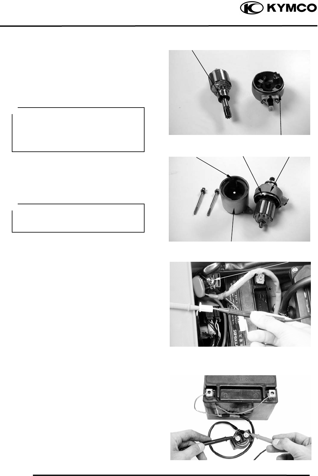
16. STARTING SYSTEM
16-5
MX’er SYSTEM
ASSEMBLY
Apply grease to the dust seal in the front
cover.
Install the brushes onto the brush holders.
Apply a thin coat of grease to the two ends
of the armature shaft.
Insert the commutator into the front cover.
Install a new O-ring to the front cover.
Install the starter motor case, aligning the
tab on the motor case with the groove on the
front cover.
Tighten the starter motor case screws.
STARTER RELAY
INSPECTION
Remove the seat.
Turn the ignition switch ON and the starter
relay is normal if you hear a click when the
starter button is depressed.
If there is no click sound:
• Inspect the starter relay voltage
• Inspect the starter relay ground circuit
• Check for continuity between the starter
relay yellow/red and green/red wire
terminals
STARTER RELAY VOLTAGE
INSPECTION
Connect a 12V battery across the starter
relay yellow/red and green/red wire
terminals.
Connect an electric tester between the
starter relay large terminals and check for
continuity between the two terminals.
The relay is normal if there is continuity.
Replace the starter relay with a new one if
there is no continuity.
Commutato
r
Front Cove
r
Groove
Motor Case
O-rin
g
Tab
Starter Rela
y
• Be careful not to damage the brush and
armature shaft mating surfaces.
• When installing the commutator, the
armature shaft should not damage the
dust seal lip.
When assembling the front cover and
motor case, slightly press down the
armature shaft to assemble them.
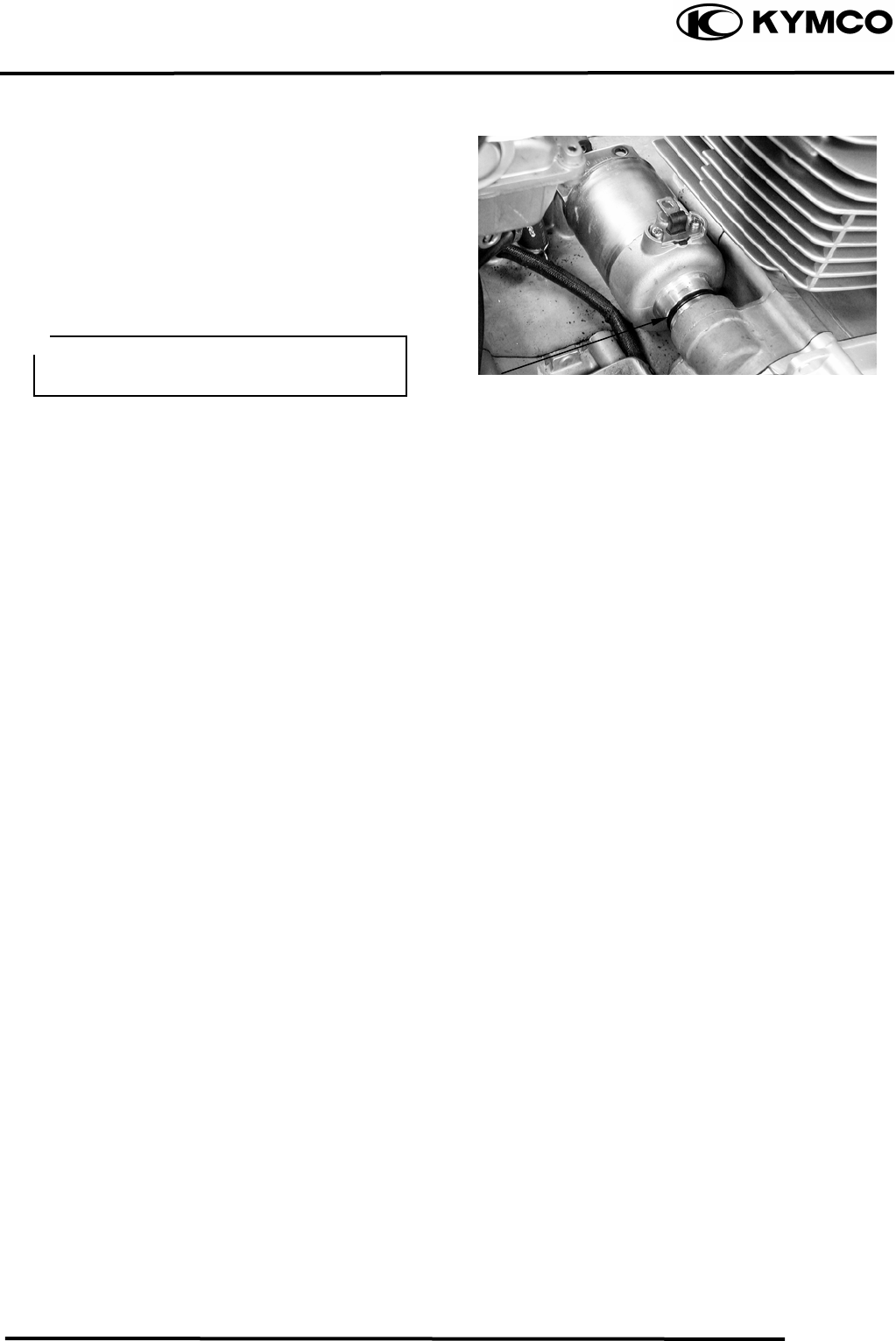
16. STARTING SYSTEM
16-6
MX’er SYSTEM
STARTER MOTOR INSTALLATION
Connect the starter motor cable connector
and properly install the waterproof rubber
jacket.
Check the O-ring for wear or damage and
replace if necessary.
Apply grease to the O-ring and install the
starter motor.
Tighten the two mounting bolts.
O-rin
g
The starter mo
be installed properly.
tor cable connector must

17. LIGHTS/ SWITCHES
17-0
MX’er SYSTEM
17
__________________________________________________________________________________
____________________________________________________________________
____________________________________________________________________
____________________________________________________________________
____________________________________________________________________
17
LIGHTS/SWITCHES
____________________________________________________________________
SERVICE INFORMATION------------------------------------------------ 17- 2
TROUBLESHOOTING----------------------------------------------------- 17- 2
HEADLIGHT ---------------------------------------------------------------- 17- 3
INSTRUMENTS/STOP LIGHT/TAILLIGHT -------------------------- 17- 4
IGNITION SWITCH -------------------------------------------------------- 17- 5
STOP SWITCH -------------------------------------------------------------- 17- 5
STARTER BUTTON-------------------------------------------------------- 17- 6
HEADLIGHT SWITCH ---------------------------------------------------- 17- 6
ENGINE STOP SWITCH -------------------------------------------------- 17- 6
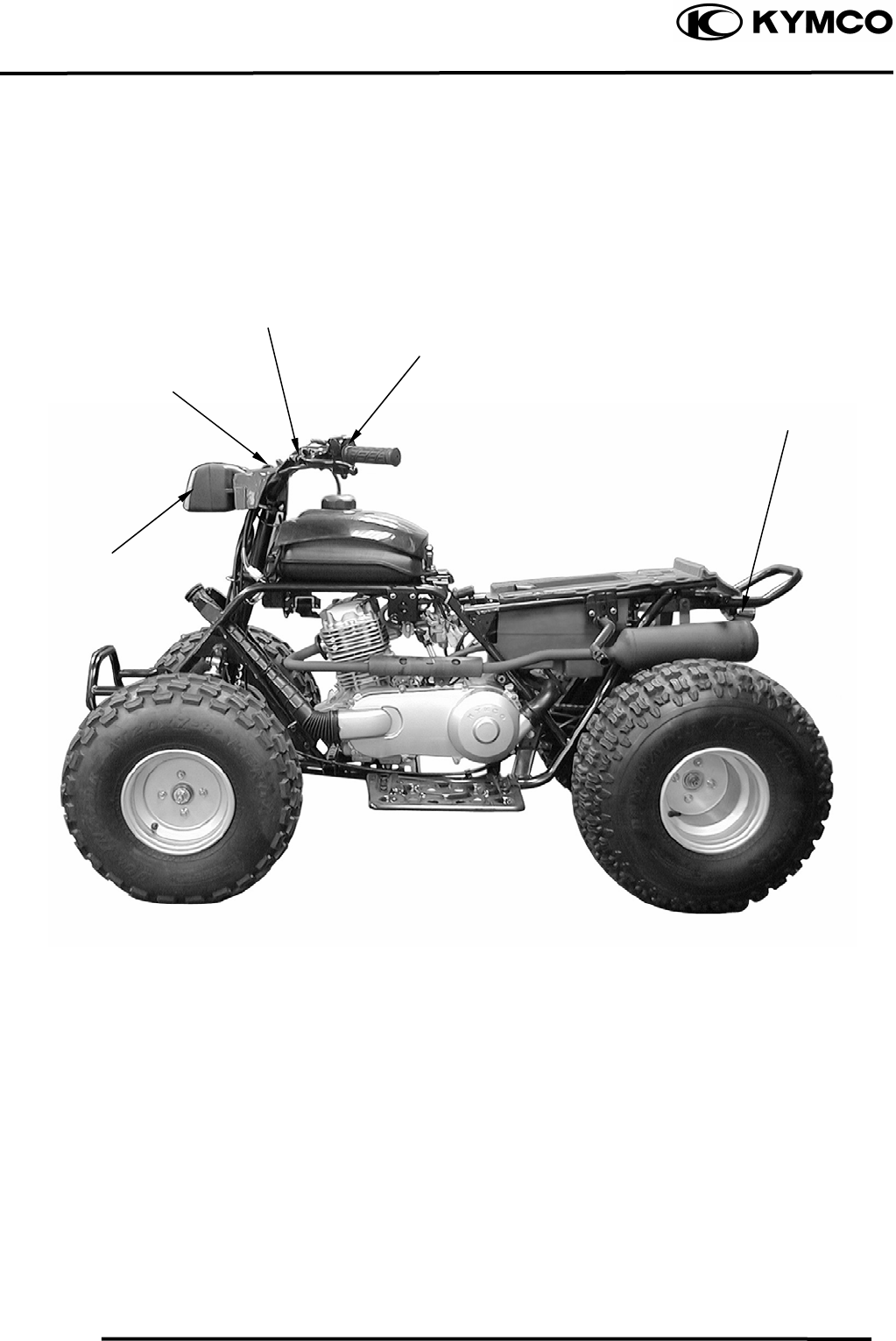
17. LIGHTS/ SWITCHES
17-1
MX’er SYSTEM
ELECTRICAL EQUIPMENT LAYOUT
Stop Switches
Ignition Switch
Headlight Switch
/
Starter Button
Headlight
Taillight/Stop Light

17. LIGHTS/ SWITCHES
17-2
MX’er SYSTEM
SERVICE INFORMATION
GENERAL INSTRUCTIONS
• An electric tester is needed to measure or test the electric equipment.
• Be sure to use fuses and bulbs of the same specifications to avoid damage of electrical
equipment.
• After installation of each switch, a continuity check must be performed. A continuity check can
usually be made without removing the part from the motorcycle.
TROUBLESHOOTING
Lights do not come on Engine starts but stalls during idling
when ignition switch is “ON” • Clogged carburetor
• Faulty ignition switch
• Fuse burned out
• Weak battery
• Burned bulb
• Faulty switch
• Poorly connected, broken or shorted wire
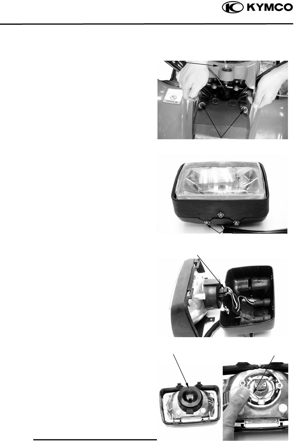
17. LIGHTS/ SWITCHES
17-3
MX’er SYSTEM
HEADLIGHT
BULB REPLACEMENT
Disconnect the cover of the ignition switch
and remove the two headlight attaching
bolts.
Remove the headlight and disconnect the
headlight wire coupler.
Remove the two headlight case attaching
screws and disconnect the headlight.
Check the bulb for damage and replace with
a new one if necessary.
Disconnect the headlight wire coupler.
Remove the rubber boot.
Push and disconnect the spring from the
headlight cover.
Screws
Bolts
Cove
r
Screws
Headli
g
ht Wire Cou
p
le
r
Rubber Boo
t
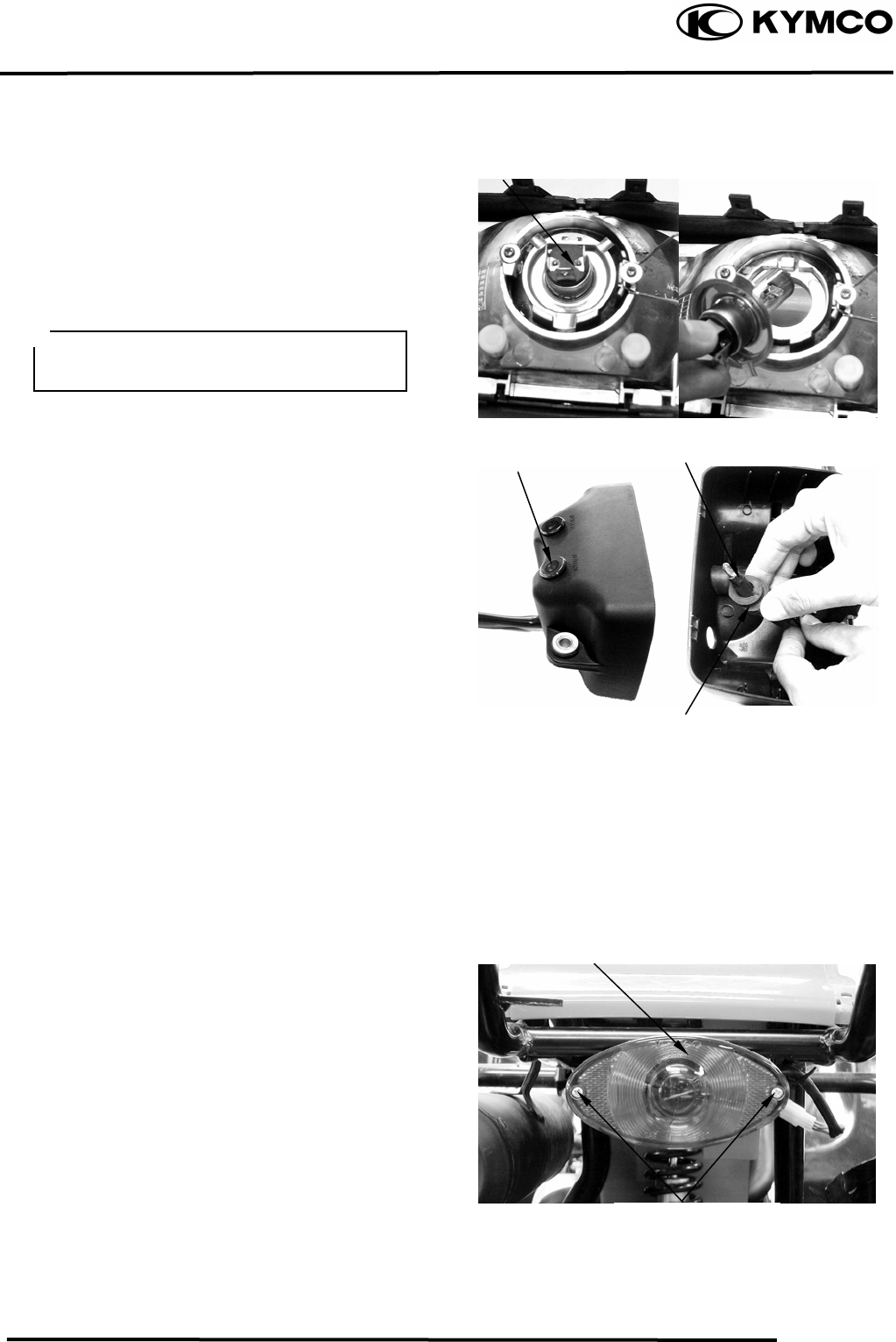
17. LIGHTS/ SWITCHES
17-4
MX’er SYSTEM
Remove the headlight bulb
INSTALLATION
Install the headlight in the reverse order of
removal.
INSTRUMENTS
REMOVAL
Remove the two headlight attaching bolts.
Remove the headlight and disconnect the
headlight wire coupler.
Remove the two headlight case attaching
screws and disconnect the headlight.
Remove the light shell, rubber boot and
bulb socket.
Check the bulb for damage and replace with
a new one if necessary.
INSTALLATION
The installation sequence is the reverse of
removal.
STOP LIGHT/TAILLIGHT
Remove the two taillight shell screws and
the shell.
Headli
g
ht Bulb
Li
g
ht Shell
Taillight Shell Screws
After installation, adjust the headlight
beam.
Bulb Socke
t
Rubber Boo
t
Taillight Shell
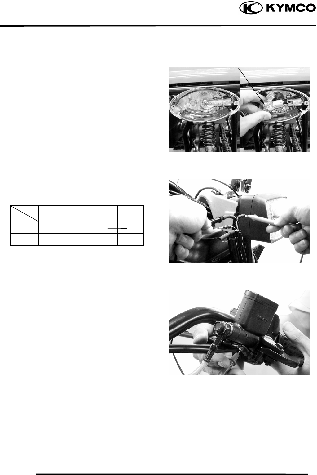
17. LIGHTS/ SWITCHES
17-5
MX’er SYSTEM
Remove the bulb and check the bulb for
damage. Replace with a new one if
necessary.
IGNITION SWITCH
Check for continuity between the wires
indicated below.
Color
Position Black Red
Black/
White Green
OFF ○ ○
ON ○ ○
STOP SWITCH
Disconnect the front stop switch wire
coupler.
Check for continuity between the front stop
switch wires.
Brake lever applied: There is continuity.
Brake lever released: There is no continuity.
Bul
b
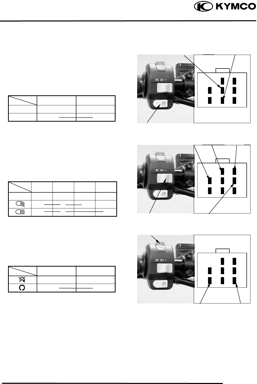
17. LIGHTS/ SWITCHES
17-6
MX’er SYSTEM
STARTER BUTTON
Remove the center cover.
Disconnect the starter button yellow/brown
and yellow/red wires.
Check for continuity between the black and
yellow/red wires.
Color
Position Yellow/Brown Yellow/Red
FREE
PUSH ○ ○
HEADLIGHT SWITCH
Remove the center cover.
Disconnect the headlight switch wire
coupler. Check for continuity between the
headlight switch wires.
Color
Position Black Brown White Blue
○ ○ ○
○ ○ ○
ENGINE STOP SWITCH
Remove the center cover.
Disconnect the headlight switch wire
coupler. Check for continuity between the
headlight switch wires.
Color
Position Green/Red Green
○ ○
Yellow
/
Brown Yellow
/
Red
Starter Button
Black BrownWhite
Blue
Headlight Switch
Green/Red
Green
Engine Stop Switch

17. LIGHTS/ SWITCHES
17-7
MX’er SYSTEM

18. ONLY ATV ON ROAD AVAILABLE
18-0
MX’er SYSTEM
18
__________________________________________________________________________________
____________________________________________________________________
____________________________________________________________________
____________________________________________________________________
____________________________________________________________________
ONLY ATV ON ROAD AVAILABLE
____________________________________________________________________
18
WARING DIAGRAM ------------------------------------------------------ 18- 1
BRAKE PEDAL ADJUSTMENT----------------------------------------- 18- 2
INSTRUMENT -------------------------------------------------------------- 18- 3
INDICATOR LIGHT-------------------------------------------------------- 18- 3
HAZARD SWITCH --------------------------------------------------------- 18- 4
HORN ------------------------------------------------------------------------- 18- 4
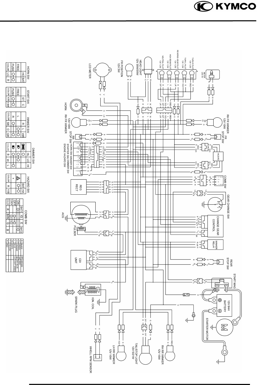
18. ONLY ATV ON ROAD AVAILABLE
18-1
MX’er SYSTEM
WIRING DIAGRAM
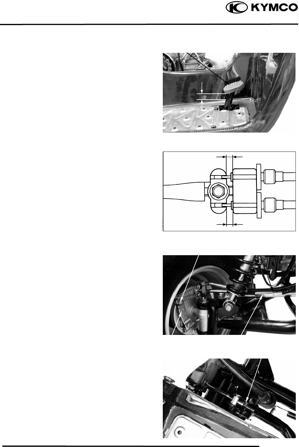
18. ONLY ATV ON ROAD AVAILABLE
18-2
MX’er SYSTEM
BRAKE PEDAL ADJUSTMENT
The brake pedal free play should be
adjusted
to 10~20 mm (0.4~0.8 in) at the brake pedal
pivot. If the free play is incorrect, adjust as
Follows:
Keep front brake lever free play at 10~20
mm (0.4~0.8 in). (Refer to page 3-9)
Loosen the lock nut.
Turn the adjusting bolt until the front
lower brake cable is tensed.
Apply the front brake lever and check front
bake cam lever to make sure that the brake
does not drag after adjusting.
Tighten the lock nut.
Turn the adjusting nut on the brake cam
lever to decrease play or increase play.
Turn the adjusting nut until specified free
Play is obtained.
Brake Pedal
10~20mm
Front lower brake cable Lock Nut
Brake Cam Lever Adjusting Bolt
Adjusting Nut
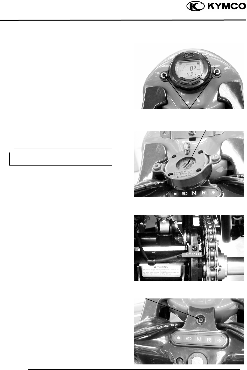
18. ONLY ATV ON ROAD AVAILABLE
18-3
MX’er SYSTEM
INSTRUMENT
REMOVAL
Remove the two instrument attaching
screws.
Disconnect the instrument.
Remove battery cover on instrument back to
replace battery.
SENSOR WHEEL
If the sensor is lost or wore, the speed will
be not calculated on the instrument.
INDICATOR LIGHT
REMOVAL
Remove the screw and disconnect the cover
of the ignition switch.
Screws
Battery Cover
After replace battery, the instrument will
be reset. (Refer to owner’s manual)
Speed Wheel
Screw
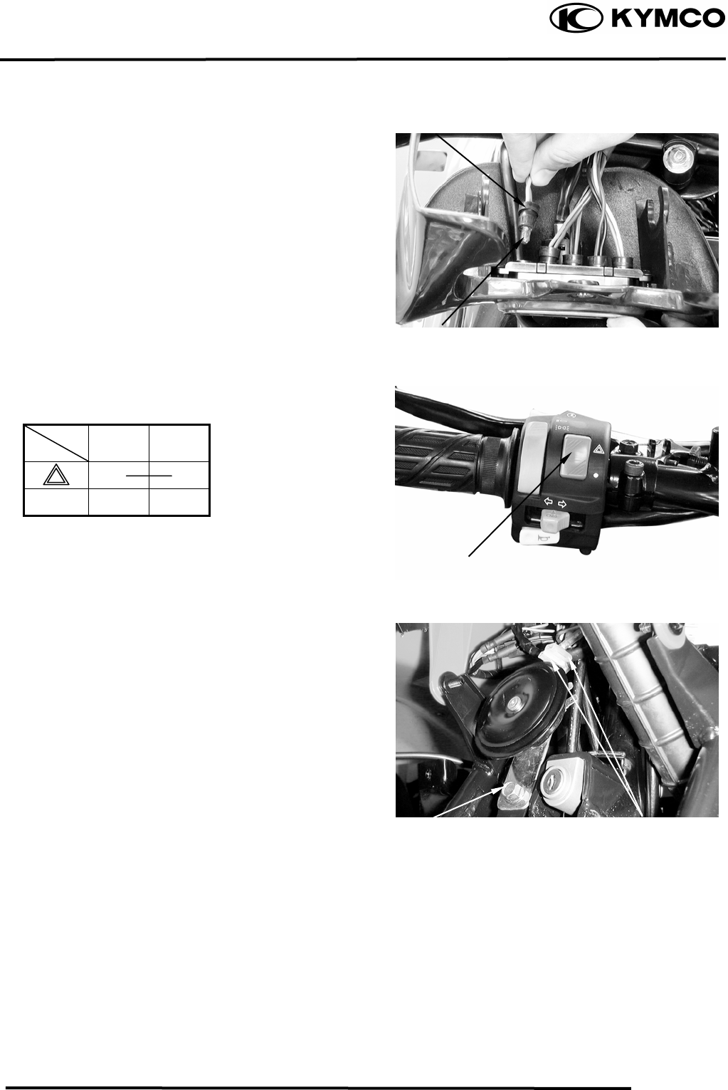
18. ONLY ATV ON ROAD AVAILABLE
18-4
MX’er SYSTEM
Remove the bulb socket and bulb.
Check the bulb for damage and replace with
a new one if necessary.
INSTALLATION
The installation sequence is the reverse of
removal.
HAZARD SWITCH
Check for continuity between the wires
indicated below.
Color
Position Yellow
/Black Black
○ ○
●
HORN
REMOVAL
Disconnect the horn switch wire.
Remove the bolt and remove horn.
INSTALLATION
The installation sequence is the reverse of
removal.
Bulb Socket
Bulb
Hazard Switch
Bolt Horn Switch wire

18. ONLY ATV ON ROAD AVAILABLE
18-5
MX’er SYSTEM
