DPblhv001man L010022 DPBHV001, DPZHV002 Users Guide
User Manual: L010022 - DPBHV001, DPZHV002 Users Guide
Open the PDF directly: View PDF ![]() .
.
Page Count: 12
February 2001
DPBHV001, DPZHV002
High Voltage Step Motor Driver
User’s Guide
#L010022
910 East Orangefair Lane, Anaheim, CA 92801
e-mail: info@anaheimautomation.com
(714) 992-6990 fax: (714) 992-0471
website: www.anaheimautomation.com
ANAHEIM AUTOMATION
User’s Guide # DPBHV001, DPZHV002
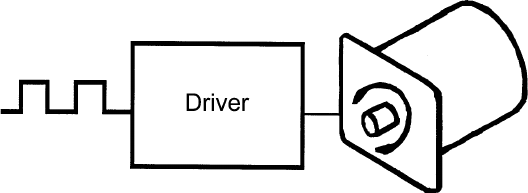
What Is a Step Motor Driver?
A step motor driver is a device that takes input signals (usually Clock and Direction) and translates this
information into phase currents in the motor. Each time the step motor driver receives a pulse, the step
motor moves one step. If the driver receives 200 pulses, the motor moves 200 steps. The motor steps at
the same frequency as the clock pulses.
•Integrated BLHV, 440W Power Supply, and Cooling Fan
•Bilevel Driver Operation
•90-265 VAC Input
•10 Amps per Phase Operating Current (Kick Current)
•7 Amps per Phase Standstill Current
•95 Volt Operation
•Short Circuit Protection
•Open Circuit Protection
•Unipolar Operation
•Motor ON/OFF Input
•Half-Step and Full-Step Operations
•Fault LED and Fault Output
•Detachable Terminal Block
•Compact and Rugged
Features
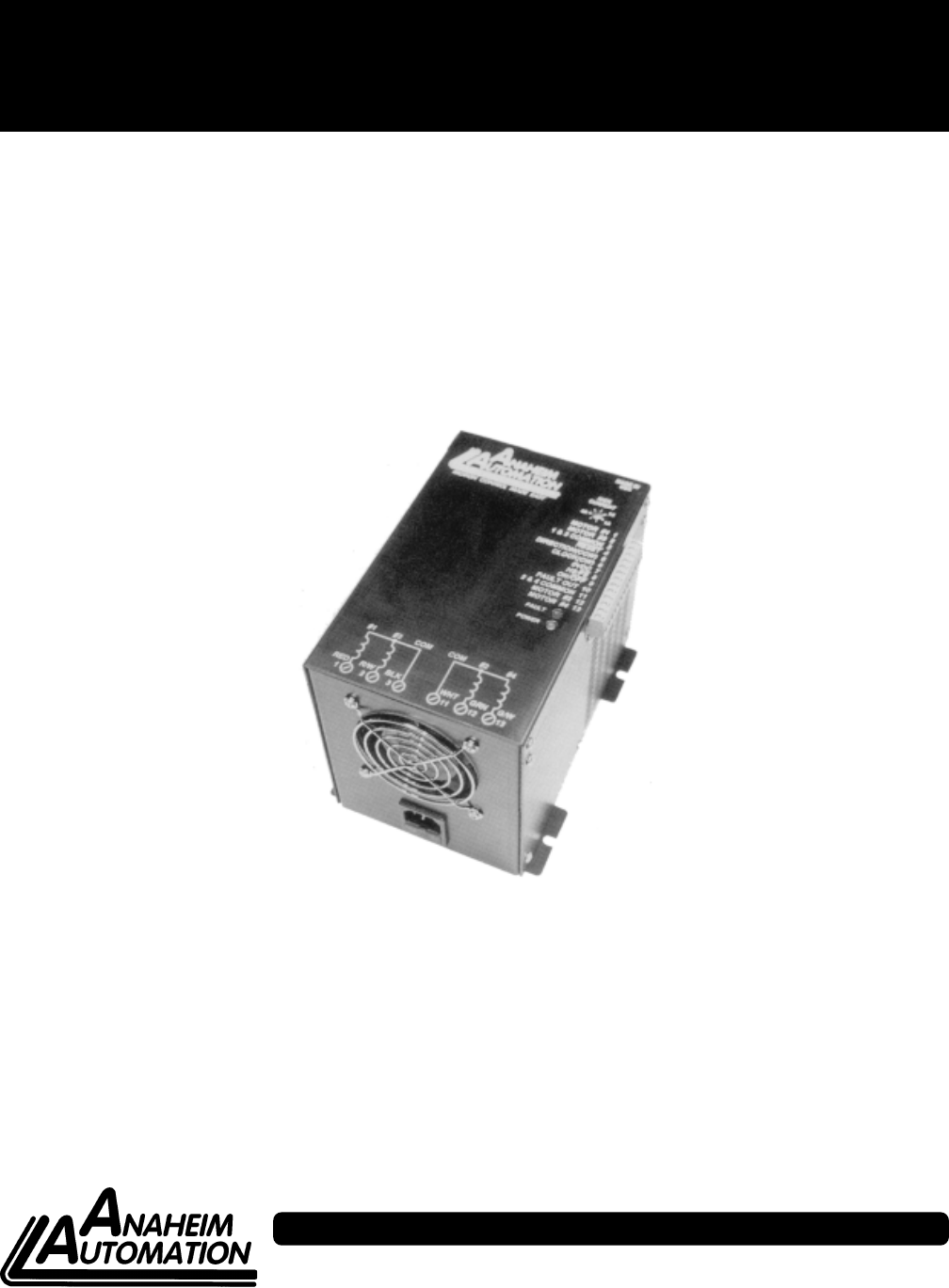
FIGURE 1: Step Motor Driver
General Description
The BLHV is a step motor driver that can drive motors rated from 1 to 7 amps/phase (unipolar rating). It
can handle 6-lead and 8-lead motors. This driver features a unipolar bilevel (or dual voltage) drive tech-
nique with short and open circuit protection (with a Fault LED and Fault Output).
Bilevel Drive
The basic function of a motor driver is to provide the rated motor phase current to the motor windings in
the shortest possible time. The bilevel driver uses a high voltage to get a rapid rate of current rise in the
motor windings in the least amount of time. When reaching the preset trip current, the driver turns off the
high voltage and sustains the current from the low voltage supply.
Half-Step/Full-Step
Users have a choice of full-step operation or half-step operation. Full-step operation occurs by energizing
two phases at a time, rotating a typical motor 1.8 degrees per step. Half-step operation occurs by alter-
nately energizing one, and then two, phases at a time, rotating the motor 0.9 degrees per step. Full-step
operation is suggested for applications that specifically require that mode, such as when retrofitting exist-
ing full-step systems.
February 2001
Clock Modes
The BLHV has two clock options: Clock and Direction, or Dual Clock operation. Jumper JP2 is used to
select the clock option. Basically JP2 selects Terminal 5 as either the Direction input or the CCW input.
With the Clock and Direction option (most common option), clock pulses applied to the Clock input (Ter-
minal 6) cause the motor to step. The direction of the motor is determined by the logic level of the Direction
input (Terminal 5). Jumper JP2 must be in the “2-3” position for this mode (see Figure 4 and Table 1).
With the Dual Clock option, clock pulses applied to the Clock input (Terminal 6) cause the motor to step in
the clockwise direction. Clock pulses applied to the CCW input (Terminal 5) cause the motor to step in the
counterclockwise direction. Jumper JP2 must be in the “1-2” position for this mode.
Either positive or negative going pulses may be used by setting jumper JP1 in the appropriate position
(see Table 1). To determine which setting to use, first consider the type of clock pulse output on the pulse
generator or indexer (controller). If the clock output on the controller is open-collector type (sinking), then
use the negative going jumper setting (JP2 must be in the “1-2” position). If the clock output on the
controller is a pnp or p-channel (sourcing) type, then use the positive going jumper setting (JP2 must be
in the “2-3” position). If the clock output on the controller is a TTL/CMOS type (totem pole), then either
setting will work; but the jumper setting should be chosen based on the level of the clock output when the
controller is not pulsing. If the clock is low when not pulsing then use positive going jumper settings. If the
clock is high when not pulsing then use negative going jumper setting.
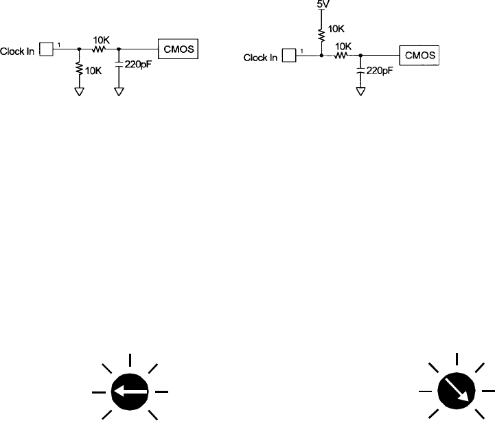
The clock inputs (Clock and CCW) are pulled up to +5VDC through a 10K ohm resistor for negative going
clock inputs; they are pulled down to 0VDC through a 10K ohm resistor for positive going clock inputs. The
pullups/pulldowns are followed by an RC filter. See Figure 2 and Figure 3.
Adjusting Kick Current
By following the silkscreen instructions on the cover, use a small screwdriver to adjust the potentiometer.
Line up the potentiometer’s arrow to the number corresponding to the motors rated current (amps/phase).
4
3
2
5
6
7
1
4
3
2
5
6
7
1
Example 1: 23D104 Motor, Set to 2.0A. Example 2: 34D314 Motor, Set to 7.0A.
Figure 3: Negative
Going Clock Input
Figure 2: Positive
Going Clock Input
User’s Guide # DPBHV001, DPZHV002
Motor Connections
Figure 5 is a hookup diagram for typical BLHV driver applications.
Input connections must be separated
from motor connections and all other possible sources of interference.
IMPORTANT NOTE: If the motor cable between the driver and the step motor extends beyond 25 feet,
consult the factory.
Fault Protection
There are 2 types of fault detection. When a fault is detected, the driver turns off the motor current, pulls
the Fault Out output low (0V), and the red Fault LED indicates which type of fault occurred. See the
Troubleshooting section for more information.
snoitacidnItluaF
1knilBwolS-DEL.elbacrorotomehtnieriwdetrohS
2knilBtsaF-DEL.elbacrorotomehtnieriwnepO
If the driver goes into a fault condition, the fault may be reset by turning the power OFF for at least 15
seconds or by pulling the RESET FAULT input (terminal 4) to a logic “0” for at least 100ms.
Table 2: Fault LED
Motor ON/OFF Input
The motor on/off input allows de-energizing a motor without disturbing the positioning logic. After re-
energizing the motor, a routine can continue. This reduces motor heating and conserves power, espe-
cially in applications where motors are stopped for long periods and no holding torque is required. If
holding torque is required (such as when lifting a load vertically), then the motor must stay energized.
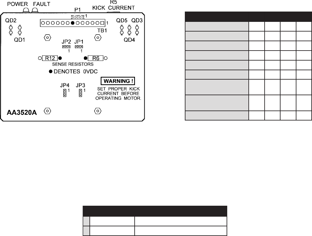
Jumper Functions/Locations
noitcnuF 1PJ 2PJ 3PJ 4PJ
skcolCgnioGevitageN2-1 xxx
skcolCgnioGevitisoP3-2 xxx
WCC=5lanimreTx2-1xx
noitceriD=5lanimreTx3-2xx
rotoMllamSxx2-1x
rotoMegraLxx3-2x
tiucriCtrohSdradnatS noitcetorP xxx 2-1
trohSdezitisneseD noitcetorPtiucriC xxx 3-2
tcudorPdradnatS2-13-22-12-1
Table 1: Jumper Settings
Figure 4: Jumper Loactions

February 2001
Hook-Up Drawing
Figure 5: Typical Hook-Up for Clockwise and Direction Option and Motor Wiring.
Power Supply Requirements
The DPBHV001 and DPZHV002 are both powered by the AC line voltage ranging from 90-265VAC. The
following figure shows the various line voltages.
User’s Guide # DPBHV001, DPZHV002
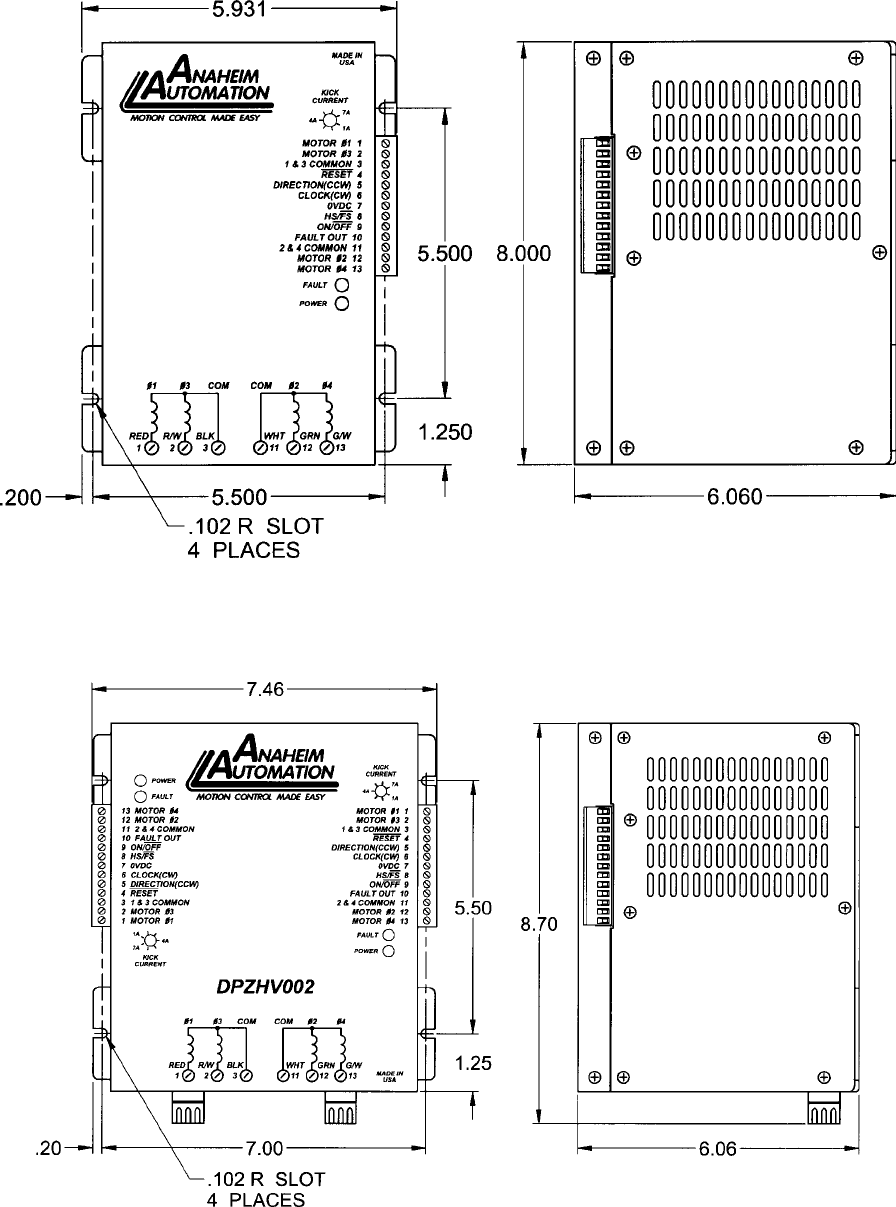
Dimensions Drawings
DPBHV001- Single Axis Driver Pack
DPZHV002- Dual Axis Driver Pack
February 2001
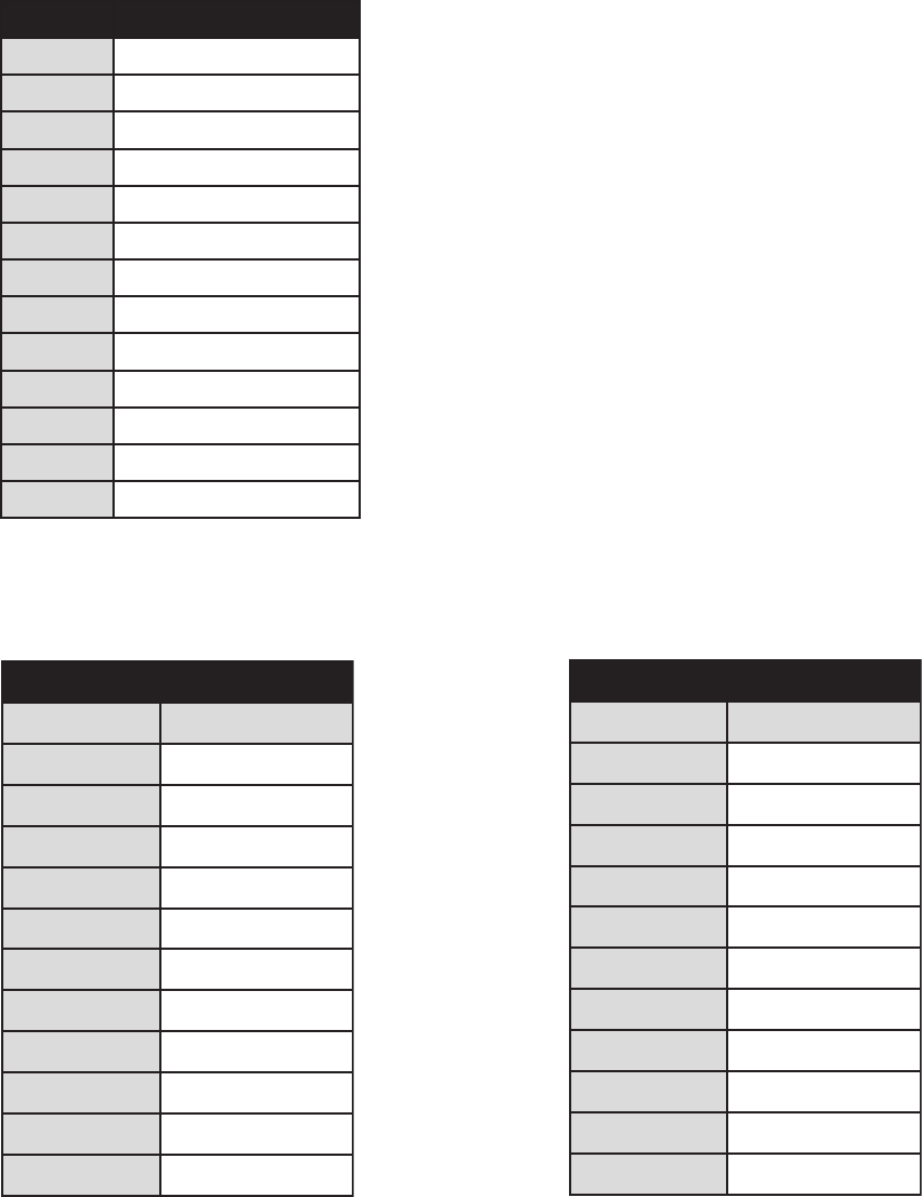
Motor Compatibility
Add suffix “S” for single-ended shaft, or suffix “D” for double-ended shaft.
Notes: Other motors not listed above may be compatible with this driver.
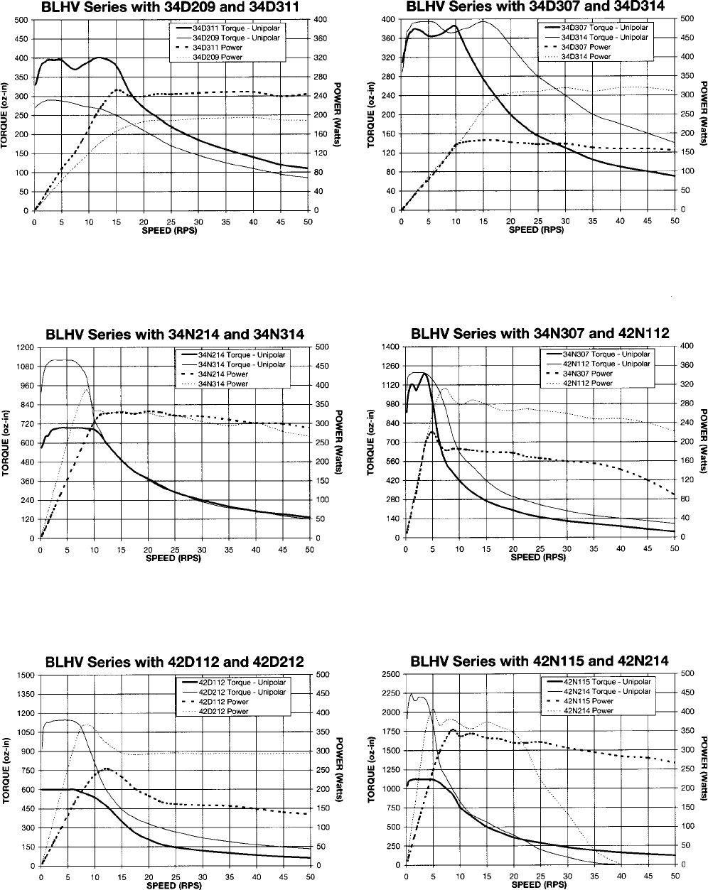
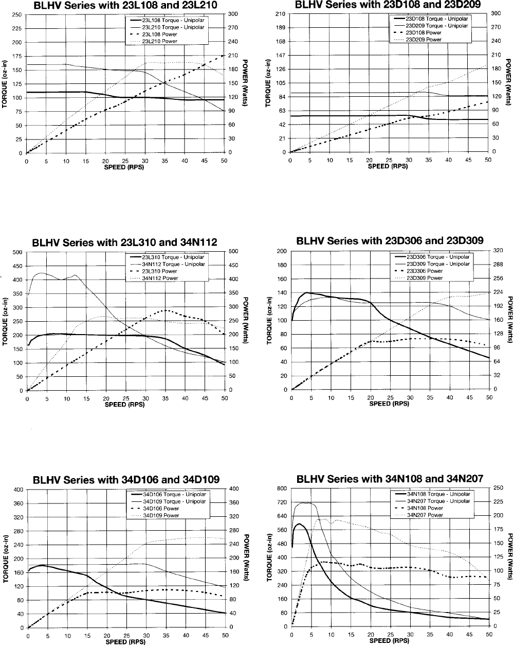
Anaheim Automation carries a full-line of standard and high torque step motors. Contact the factory
regarding compatibility. See last two pages for speed/toque curves.
srotoMeuqroThgiH
rebmuNtraP gnitaRralopinU
_602L32A0.3
_012L32A0.5
_603L32A0.3
_013L32A0.5
_801N43A0.4
_211N43A0.6
_702N43A5.3
_412N43A0.7
_703N43A5.3
_413N43A0.7
_511N24A5.7
srotoMdradnatS
rebmuNtraP gnitaRralopinU
_401D32A0.2
_801D32A0.4
_902D32A5.4
_903D32A5.4
_601D43A0.3
_901D43A5.4
_702D43A5.3
_312D43A5.6
_413D43A0.7
_211D24A0.6
_212D24A0.6
Table 4 Table 5
13 Pin Terminal Description
lanimreT noitpircseD
11esahP,rotoM
23esahP,rotoM
33,1nommoC,rotoM
4teseRtluaF
5)WCC(noitceriD
6)WC(kcolC
7CDV0
8petSlluF/petS-flaH
9ffO/nO
01tuOtluaF
114,2nommoC,rotoM
212esahP,rotoM
314esahP,rotoM
Table 3
User’s Guide # DPBHV001, DPZHV002
Specifications
Control Inputs (All): (Terminals 5, 6, 8, 9)
TTL-compatible
Logic “0” - 0 to 0.8 V
Logic “1” - 3.5 to 5.0 V
Fault Reset: (Terminal 4)
Pulled up to +5VDC through a 10k Ohm
Logic “1” (open) - Driver enabled and Fault detection enabled
Logic “0” - Resets a Fault condition (driver is disabled when this input is low). This input must be held low for at least
100ms.
Clock Inputs: (Terminals 5 and 6)
Pulse required; 15 microseconds minimum. The clock input is pulled up/down internally to +5VDC/ 0VDC through a
10k Ohm resistor, based upon JP2 selection.
Direction Control: (Terminal 5)
Pulled up to +5VDC through a 10k Ohm
Logic “1” (open) - CW
Logic “0” - CCW
Excitation Mode Select: (Terminal 8)
Pulled up to +5VDC through a 10k Ohm
Logic “1” (open) - Half-step
Logic “0” - 2 Phase Full-step
Power ON/OFF: (Terminal 9)
Logic “1” (open) - motor current on
Logic “0” - motor current off
Fault Output: (Terminal 10)
This output is an open drain output, capable of standing off 50 volts and sinking 150mA. This output is pulled to
ground when a fault occurs.
Output Current Rating:
(Terminals 1, 2, 3, 11, 12, and 13)
10 Amps/phase maximum operating current, 7.0 Amps/phase maximum standstill current, over the operating voltage
and temperature range. Motor phase ratings of 1.0 Amp minimum are required to meet the minimum kick level.

February 2001
Troubleshooting
If a Fault occurs, reset the Fault by applying a logic “0” to the Reset Fault Input (terminal 4) for at least
100ms (or by cycling power OFF for at least 15 seconds). After resetting, try to run the motor again. If the
driver faults again then check the conditions listed below.
Is the LED blinking slowly? (once a second)
This indicates that the motor has a phase shorted or there is a short in the motor cable or wiring. Check
the motor and the wiring for shorts. If the driver continues to sense “shorts” after the motor and wiring are
determined to be accurate, then the output transistors should be checked (see below).
Is the LED blinking quickly? (three times a second)
This indicates that there is an open or intermittant connection in one of the motor wires. Check the motor
and the wiring for opens. Another condition that may cause this type of fault, is when a large motor is
ramped down too quickly so that it loses it’s positioning.
Checking Output Transistors
1. Set the multimeter to Diode Test
2. Place the RED meter lead on 0VDC (Terminal 7)
3. Touch the black meter lead to each phase (terminals 1, 2, 12, and 13)
4. Reading should be between 0.450V and 0.550V
5. If any readings are signifigantly less than 0.450V, then the unit has been damaged.
If a factory repair is required, contact Anaheim Automations for an RMA#.
(800) 345-9401 or (714) 992-6990
COPYRIGHT
Copyright 2001 by Anaheim Automation. All rights reserved. No part of this publication may be reproduced, transmitted, transcribed, stored in
a retrieval system, or translated into any language, in any form or by any means, electronic, mechanical, magnetic, optical, chemical, manual,
or otherwise, without the prior written permission of Anaheim Automation, 910 E. Orangefair Lane, Anaheim, CA 92801.
DISCLAIMER
Though every effort has been made to supply complete and accurate information in this manual, the contents are subject to change without
notice or obligation to inform the buyer. In no event will Anaheim Automation be liable for direct, indirect, special, incidental, or conse-
quential damages arising out of the use or inability to use the product or documentation.
Anaheim Automation’s general policy does not recommend the use of its’ products in life support applications wherein a failure or malfunction of
the product may directly threaten life or injury. Per Anaheim Automation’s Terms and Conditions, the user of Anaheim Automation products in
life support applications assumes all risks of such use and indemnifies Anaheim Automation against all damages.
LIMITED WARRANTY
All Anaheim Automation products are warranted against defects in workmanship, materials and construction, when used under Normal Operat-
ing Conditions and when used in accordance with specifications. This warranty shall be in effect for a period of twelve months from the date of
purchase or eighteen months from the date of manufacture, whichever comes first. Warranty provisions may be voided if products are
subjected to physical modifications, damage, abuse, or misuse.
Anaheim Automation will repair or replace at its’ option, any product which has been found to be defective and is within the warranty period,
provided that the item is shipped freight prepaid, with previous authorization (RMA#) to Anaheim Automation’s plant in Anaheim, California.
TECHNICAL SUPPORT
If you should require technical support or if you have problems using any of the equipment covered by this manual, please read the manual
completely to see if it will answer the questions you have. Be sure to refer to the TROUBLESHOOTING section of this manual. If you need
assistance beyond what this manual can provide, contact your Local Distributor where you purchased the unit, or contact the factory direct.
User’s Guide # DPBHV001, DPZHV002
Torque Speed Curves
February 2001
Torque Speed Curves

User’s Guide # DPBHV001, DPZHV002
ANAHEIM AUTOMATION
