TM3000 User's Guide L010108 Users
User Manual: L010108 - TM3000 Users Guide
Open the PDF directly: View PDF ![]() .
.
Page Count: 4
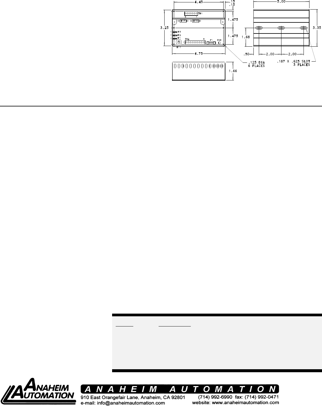
FIGURE 1: DIMENSIONS 0F TM3000
MODEL DESCRIPTION
TM3000HV HIGH VOLTAGE DRIVER (60 VDC)
TM3000 DRIVER w/ TRACK
TM3000-T1 DRIVER w/ TRACK and 100VA TRANSFORMER
TM3000-T2 DRIVER w/ TRACK and 200VA TRANSFORMER
TM3000-1 DRIVER w/ MOUNTING PLATE
TM3000-1-T1 DRIVER w/ MOUNTING PLATE and 100VA TRANSFORMER
TABLE 1: ORDERING INFORMATION
TM3000 STEP MOTOR DRIVER
! Requires 12-28VAC or 10-40VDC
! 0.3 - 5.0 Amperes/phase Operating Current
! 0.15 - 2.5 Amperes/phase Standstill Motor Current
! Open Frame Circuit Board Mounts on Snaptrack
! Higher Torque/Speed Output
! Improved Start-Stop Speeds
! Reduced Power Requirements
! Positive or Negative Going Clock Input
! Full and Half-Step Operation
! Motor Turn-Off Provisions
! TTL-CMOS Compatible Inputs
! No RFI or EMI Problems
GENERAL DESCRIPTION Bilevel drivers do not use high frequencypower, especially in applications where
The ANAHEIM AUTOMATION TM3000 switching techniques as chopper driversmotors are stopped for long periods.
is a low cost, bilevel step motor driver to be do. Consequently, they do not create the
used with 4-phase step motors. TheEMI, RFI, and motor heating problems that CLOCK, CCW AND DIRECTION
TM3000 comes mounted on easy to useare associated with chopper drivers. Pulses applied to the CLOCK input cause
snaptrack, available in lengths up to 6 feet. the motor to step in the clockwise direction
BILEVEL DRIVE Users have a choice of dual-phase, Full-"1" (or No connection), and in the
The basic function of a step motor driver is step operation or Half-step operation.counterclockwise direction if the
to control the motor winding currents.Dual-phase, Full-step operation occurs byDIRECTION Control input is a logic "0".
Motor performance is determined by howenergizing two phases at a time, rotating aPulses applied to the CCW input cause the
fast the driver can increase and decreasetypical motor 1.8 degrees per step. Half-motor to step in the counterclockwise
the winding currents. A rapid rise instep operation occurs by alternatelydirection. Positive or negative going
winding current is achieved by applying aenergizing one, and then two, phases at apulses may be used (see Table 2).
high voltage directly to a motor winding.time, rotating the motor 0.9 degrees per
This rapid rise of current is also referred to step. Full-step operation is only forPHASE INPUTS
as the "kick" or operating current. When a applications that specifically require thatThe TM3000 has the ability to accept
desired current level is reached, the highmode, such as when retrofitting existingphase inputs to control each of the 4 motor
voltage is turned off and a low voltage isfull-step systems. phases. For example, a microcontroller can
applied to maintain a suitable holdingbe used to control the motor phases.
current level. When a motor winding isMOTOR ON/OFF Terminals 1,2, 3, and 4 of TB2 are used as
turned off, a rapid decrease in windingThe Motor On/Off feature allows de-the inputs for Phase 1, Phase 2, Phase 3,
current is achieved by routing the energyenergizing a motor without disturbing theand Phase 4 respectively. Either Positive
in the collapsing field back to the powerpositioning logic. After re-energizing theTrue Phase Inputs or Negative True Phase
supply through a high voltage path. Themotor, a routine can continue. ThisInputs may be used (see Table 2 and
high voltage supply furnishes the energyreduces motor heating and conservesFigure 1).
necessary to maintain motor output torque
at high step rates thus providing high
mechanical power output. The low voltage
supply provides much of the current
needed at low step rates and all of the
holding current.
EXCITATION MODE SELECTION if the DIRECTION Control input is a logic
#L010108
OPERATING MODE JUMPER
SELECTION
JP1 JP2 JP3
POSITIVE GOING CLOCK INPUT 1 TO
2
2 TO
3
1 TO
2
NEGATIVE GOING CLOCK INPUT 1 TO
2
1 TO
2
1 TO
2
POSITIVE TRUE PHASE INPUTS 2 TO
3
2 TO
3
2 TO
3
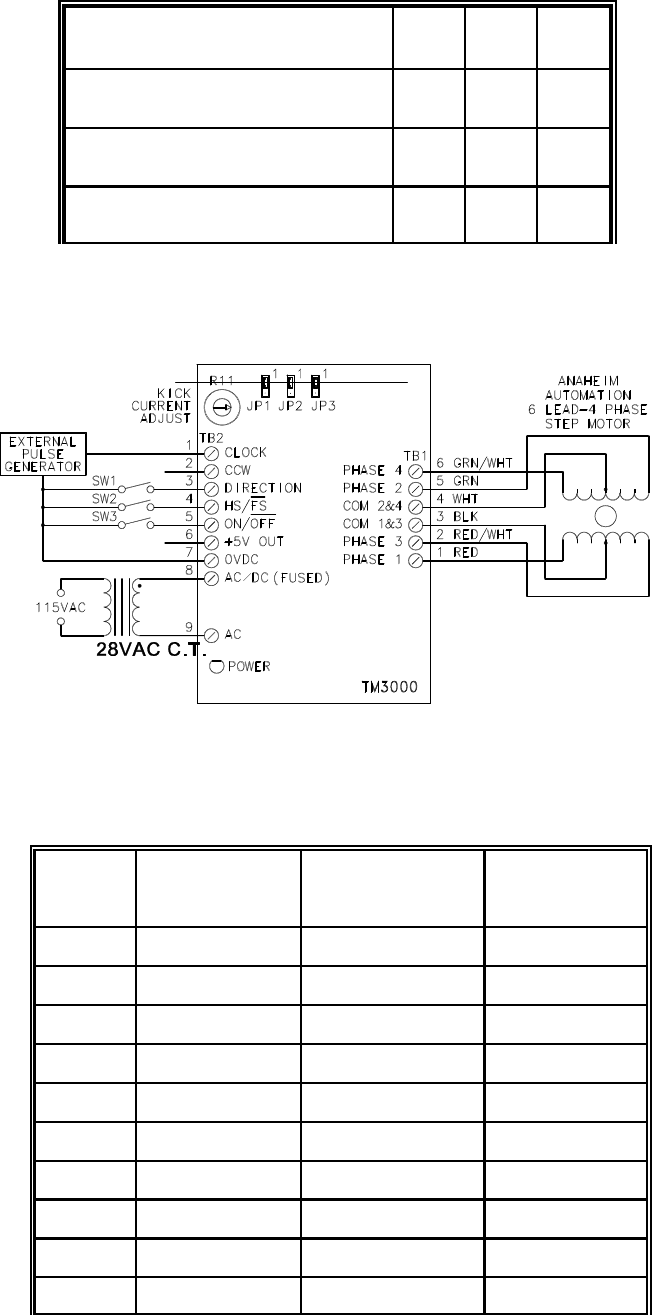
FIGURE 2: HOOKUP DIAGRAM.
POT RATED MOTOR
CURRENT
ACTUAL
STANDSTILL
CURRENT
KICK CURRENT
00.21 0.15 0.3
10 0.55 0.385 0.77
20 0.89 0.62 1.24
30 1.22 0.855 1.71
40 1.56 1.09 2.18
50 1.89 1.33 2.66
60 2.23 1.56 3.12
70 2.56 1.8 3.6
80 2.9 2.03 4.06
90 3.24 2.27 4.54
MOTOR CONNECTIONS
Figure 2 is a hookup diagram for typical
driver applications. Wiring connected to
inputs must be separated from motor
connections and all other possible sources
of interference.
IMPORTANT NOTE: When the wiring
from the driver to the step motor extends
beyond 25 feet, consult the factory.
CURRENT SETTING
The potentiometer on the driver is used to
set the motor current. See Table 3. The
pot should be set according to the motor's
rated current. This will produce a standstill
current of 70% of the rated current and a
kick current of 1.4x the rated motor current.
Example: For a motor rated at 2.0 amps per
phase, the POT should be set between 50
and 60.
POWER REQUIREMENTS
The TM3000 can be powered up by an AC
or DC voltage (see specifications). For AC
operation, the driver may be purchased
with a transformer (see Table 1). A single
transformer may be used to power up
several drivers.
HEATING CONSIDERATIONS
The temperature of the heatsink should
never be allowed to rise above 60 degrees
Celsius. If necessary, air should be blown
across the heatsink to maintain suitable
temperatures.
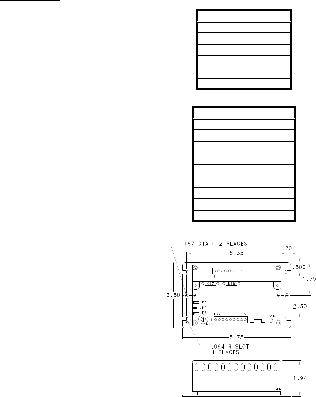
TM3000-1
The TM3000 is available with a mounting
plate for those who do not use "track"
systems. The model number for this driver
with the mounting plate is the TM3000-1.
Dimensions are shown in figure 3.
PIN DESCRIPTION
1PHASE 1 (RED)
2PHASE 3 (RED/WHT)
3COM PHASE 1 & 3 (BLK)
4COM PHASE 2 & 4 (WHT)
5PHASE 2 (GRN)
6PHASE 4 (GRN/WHT)
PIN DESCRIPTION
1CLOCK INPUT (PHASE 1)
2CCW INPUT (PHASE 2)
3DIRECTION CONTROL (PHASE 3)
4HALFSTEP/FULLSTEP (PHASE 4)
5MOTOR ON/OFF
6+5VDC OUTPUT
70VDC
8AC/DC POWER INPUT (FUSED)
9AC POWER INPUT
FIGURE 3: DIMENSIONS OF TM3000-1.
SPECIFICATIONS
CONTROL INPUTS: (Terminals 1-5, TB2)
TTL-CMOS Compatible
Logic "0"=0 to 0.8 Vdc
Logic "1"=3.5 to 5.0 Vdc
Terminals 1-4 are pulled up or down (depending on Jumpers)
through 10k ohm resistors. Terminal 5 is pulled up through a 10k
ohm resistor.
CLOCK, CCW:
(Terminals 1 and 2 of TB2)
15 microseconds minimum pulse width, positive or negative going
(see Table 2).
DIRECTION CONTROL:
(Terminal 3 of TB2)
Logic "1"(open)-clockwise
Logic "0"-counterclockwise
MODE SELECT:
(Terminal 4 of TB2)
Logic "1"(open)-half-step
Logic "0"-dual full-step
MOTOR ON/OFF:
(Terminal 5 of TB2)
Logic "1"(open)-motor energized
Logic "0"-motor de-energized
OUTPUT CURRENT RATING: (TB1)
5.0 Amperes per phase maximum operating current; 2.5 Amperes per
phase maximum standstill current, over the operating voltage and
temperature range. Motor phase ratings of 0.5 Amperes minimum
are required to meet the minimum kick level.
+5VDC OUTPUT: (Terminal 6, TB2)
100mA maximum
POWER REQUIREMENTS: (Terminals 8 & 9, TB2)
12 Vac(min)-28 Vac(max)
12 Vac(min) -42.5 Vac(max) {60 Vdc Version}
10 Vdc(min)-40 Vdc(max)
Use Terminal 8 for DC input with Terminal 7 as the 0Vdc reference.
OPERATING TEMPERATURE:
Heatsink - 0E to 60EC
FUSE: 5 Amp Fast Blow, 5mm
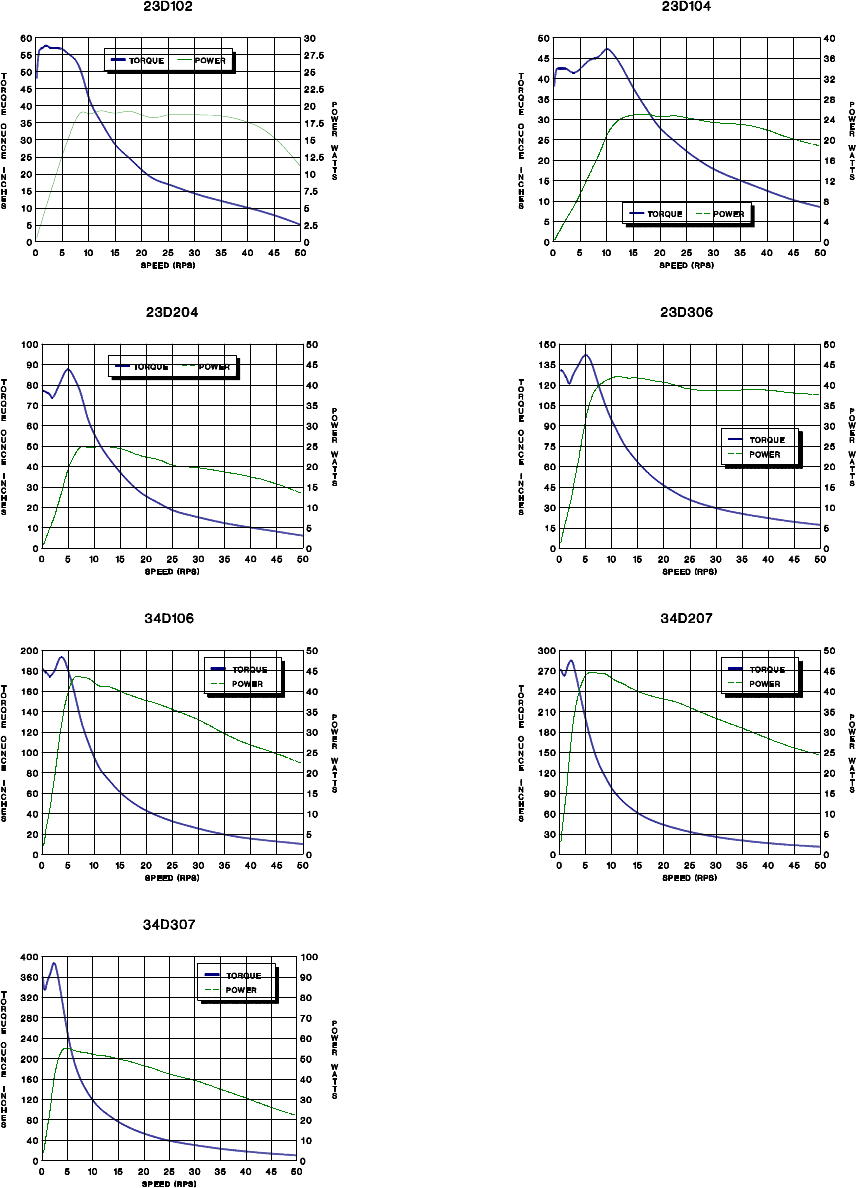
TORQUE CURVES
Note: All Torque Curves were taken with an AA2295 (28Vac) Transformer.
Standstill Current = 0.7 x Rated Motor Current
Kick Current = 1.4 x Rated Motor Current.
