L010442 MDC050 050051 Series Users Guide Guide(org)
User Manual: L010442 - MDC050-050051 Users Guide(org)
Open the PDF directly: View PDF ![]() .
.
Page Count: 6
February 2012L010442
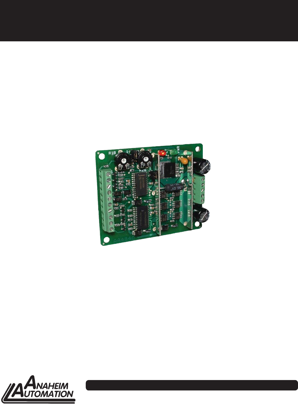
MDC050-050051 Series
50V, 5A Brushless Controller
User’s Guide
910 East Orangefair Lane, Anaheim, CA 92801
e-mail: info@anaheimautomation.com (714) 992-6990 fax: (714) 992-0471
website: www.anaheimautomation.com
ANAHEIM AUTOMATION

February 2012L010442
General Description
The MDC050-050051 driver is designed to drive DC brushless motors at currents of up to 5A (peak) and
50V. The driver operates in the basic open loop confi guration with either 60° or 120° DC brushless mo-
tors. The driver is protected against over current (cycle-by-cycle), hall sensor error and under voltage.
When an error occurs, a fault light is turned on to notify the user. Included on the driver is an internal
potentiometer to control the maximum phase current allowed into the motor and an internal potentiometer
to control the speed of the motor. An optional external voltage (1.5-4VDC) or external 5V/10Khz PWM
signal can be used to control the speed as well. The direction of the motor can be preset by the direction
control input. Other inputs to the drive include a run/stop and a motor freewheel input. The freewheel
input overrides all other inputs into the driver.
Fault Protection
A cycle-by-cycle over current protection is provided when the motor current level exceeding the cur-
rent limit set by adjusting R28 is produced. When the over current protection is activated, the controller
shuts off the outputs to the motor. The maximum current set by R28 is 5A per phase.
MDC050-05001 Driver Features
• Open Loop Operation
• 1.5V to 4V External Voltage Speed Control
• 5V/10Khz External PWM Speed Control
• 2-Quadrant Operation
• Hall Sensor Feedback
• Short Circuit Protection
• Maximum Current Limit at 5.0 Amps (peak)
• Run/Stop, Freewheel and Direction Inputs
• TTL-CMOS Compatible Inputs
• Compact Size
• Screw type Terminal Block
Suggested Power Supplies
Part # Description
PSAM24V2.7A DC Power Supply 24VDC at 2.7 Amps
PSAM48V1.3A DC Power Supply 48VDC at 1.3 Amps
February 2012L010442
Specifi cations
Control Inputs: (TB1, Pins 1-3)
TTL-CMOS Compatible
Logic “0” = 0-0.8VDC
Logic “1” = OPEN
All three inputs (run/stop, freewheel, and direction) are pulled up through 10k Ohm resistors.
Direction Control: (TB1, Pin 1)
Logic “1” (open) - Clockwise
Logic “0” - Counterclockwise
Freewheel: (TB1, Pin 2)
Logic “1” (open) - Motor is Enabled
Logic “0” - Motor is de-energized and will coast to a stop
Run/Stop: (TB1, Pin 3)
Logic “1” (open) - Motor will not run
Logic “0” - Motor will run and will accelerate according to speed setting
Vcontrol: (TB1, Pin 4)
To control the speed of the motor with an external DC voltage, a voltage from 1.5VDC-4VDC, must be ap-
plied with reference to AGND (TB1, Pin 5). Or, to control the speed of the motor with an external 5V/10Khz
PWM signal, a duty cycle from 30% - 90%, must be applied with reference to AGND (TB1, Pin 5).
Care must be taken not to exceed 6V on this pin.
Output Current Rating:
5.0 amperes per phase maximum operating peak current, set by R28
2.5 amperes per phase maximum operating continuous current
Power Requirements: (TB2, Pins 4 and 5)
20VDC (min) - 50VDC (max)
Operating Temperature:
0°-70° C
Heating Considerations
The temperature of the driver transistors should never be allowed to rise above 70° Celsius. If necessary,
air should be blown across the driver to maintain suitable temperatures.
February 2012L010442
Freewheel
The motor freewheel feature allows the de-energized of the motor phases. A high (open) input at this input
causes the motor to run at the given speed, while a low at this input causes the motor to coast to a stop.
Motor Run/Stop
The motor run/stop feature allows the stopping of a motor by shorting out the bottom drives of the three
phases. A low at this input allows the motor to run, while a high (open) input does not allow motor opera-
tion and if operating causes rapid deceleration.
Speed Adjust Setting
There are three ways to set the speed on this DC Brushless Motor Driver
1. One is to use an external voltage by setting JP2 to position 2-3. If a voltage is used to control the speed
of the motor, the 1.5V to 4V voltage can be tied on Vcontrol (TB1 - pin 4) with respect to AGND (TB1- pin 5).
2. Another is to use external 5V/10Khz signal by setting JP2 to position 2-3. If a voltage is used to control
the speed of the motor, the 30% to 90% duty cycle can be tied on Vcontrol (TB1 - pin 4) with respect to
AGND (TB1 - pin 5).
3. Another is to use the internal potentiometer, R18, by setting JP2 to position 1-2.
The maximum voltage amplitude that can be placed on Vcontrol (TB1-Pin 4) 6V. A voltage exceeding 6V
will cause damage to the driver.
February 2012L010442
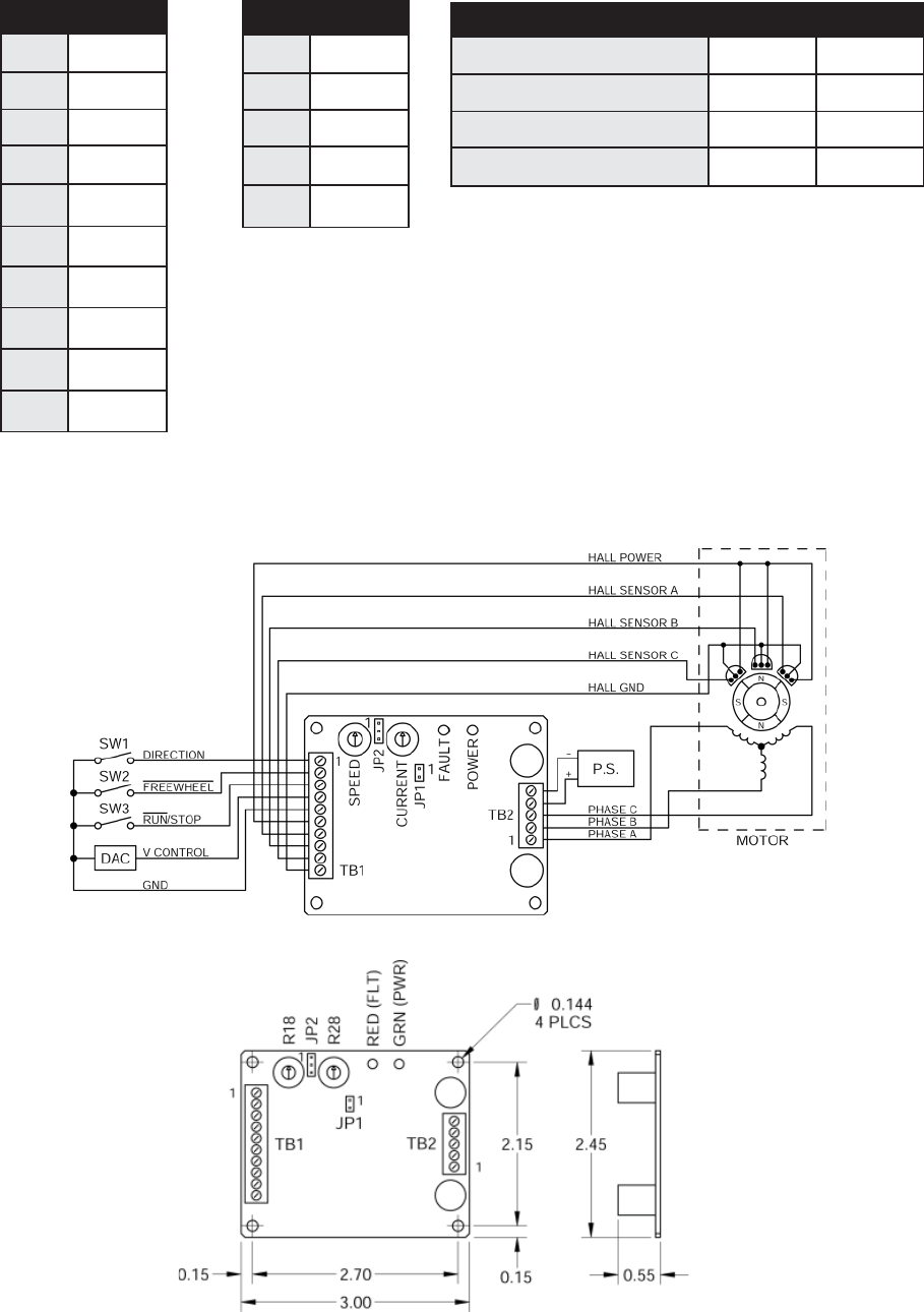
Typical Hookup Drawing
Dimensions
Terminal Block and Jumper Descriptions
TB1: Control Inputs and
Motor Halls
Pin # Description
1 Direction
2 Freewheel
3 Run/Stop
4 Vcontrol
5 GND
6 Hall Power
7 Hall A
8 Hall B
9 Hall C
10 Hall GND
Pin # Description
1 Phase A
2 Phase B
3 Phase C
4 VIN
5 GND
Function JP1 JP2
60° Hall Sensor Spacing Open ---
120° Hall Sensor Spacing 1-2 ---
Internal Speed Control (R13) --- 1-2
External Speed Control (Vcontrol) --- 2-3
TB2: Power In and
Motor Phases
JP1 and JP2: Functions and Settings

February 2012L010442
ANAHEIM AUTOMATION
COPYRIGHT
Copyright 2007 by Anaheim Automation. All rights reserved. No part of this publication may be reproduced,
transmitted, transcribed, stored in a retrieval system, or translated into any language, in any form or by
any means, electronic, mechanical, magnetic, optical, chemical, manual, or otherwise, without the prior
written permission of Anaheim Automation, 910 E. Orangefair Lane, Anaheim, CA 92801.
DISCLAIMER
Though every effort has been made to supply complete and accurate information in this manual, the
contents are subject to change without notice or obligation to inform the buyer. In no event will Anaheim
Automation be liable for direct, indirect, special, incidental, or consequential damages arising out
of the use or inability to use the product or documentation.
Anaheim Automation’s general policy does not recommend the use of its’ products in life support applications
wherein a failure or malfunction of the product may directly threaten life or injury. Per Anaheim Automation’s
Terms and Conditions, the user of Anaheim Automation products in life support applications assumes all
risks of such use and indemnifi es Anaheim Automation against all damages.
LIMITED WARRANTY
All Anaheim Automation products are warranted against defects in workmanship, materials and construction,
when used under Normal Operating Conditions and when used in accordance with specifi cations. This
warranty shall be in effect for a period of twelve months from the date of purchase or eighteen months
from the date of manufacture, whichever comes fi rst. Warranty provisions may be voided if products
are subjected to physical modifi cations, damage, abuse, or misuse.
Anaheim Automation will repair or replace at its’ option, any product which has been found to be defective
and is within the warranty period, provided that the item is shipped freight prepaid, with previous authorization
(RMA#) to Anaheim Automation’s plant in Anaheim, California.
TECHNICAL SUPPORT
If you should require technical support or if you have problems using any of the equipment covered by this
manual, please read the manual completely to see if it will answer the questions you have. If you need
assistance beyond what this manual can provide, contact your Local Distributor where you purchased the
unit, or contact the factory direct.
Torque Speed Curves
