L011069 ENC A4TD Series Assembly Instructions
User Manual: L011069 - ENC-A4TD Series Assembly Instructions
Open the PDF directly: View PDF ![]() .
.
Page Count: 2
910 East Orangefair Ln. Anaheim, CA 92801 Tel. (714) 992-6990 Fax. (714) 992-0471 www.anaheimautomation.com
L011069
ENC-A4TD Series Assembly
Instructions Guide
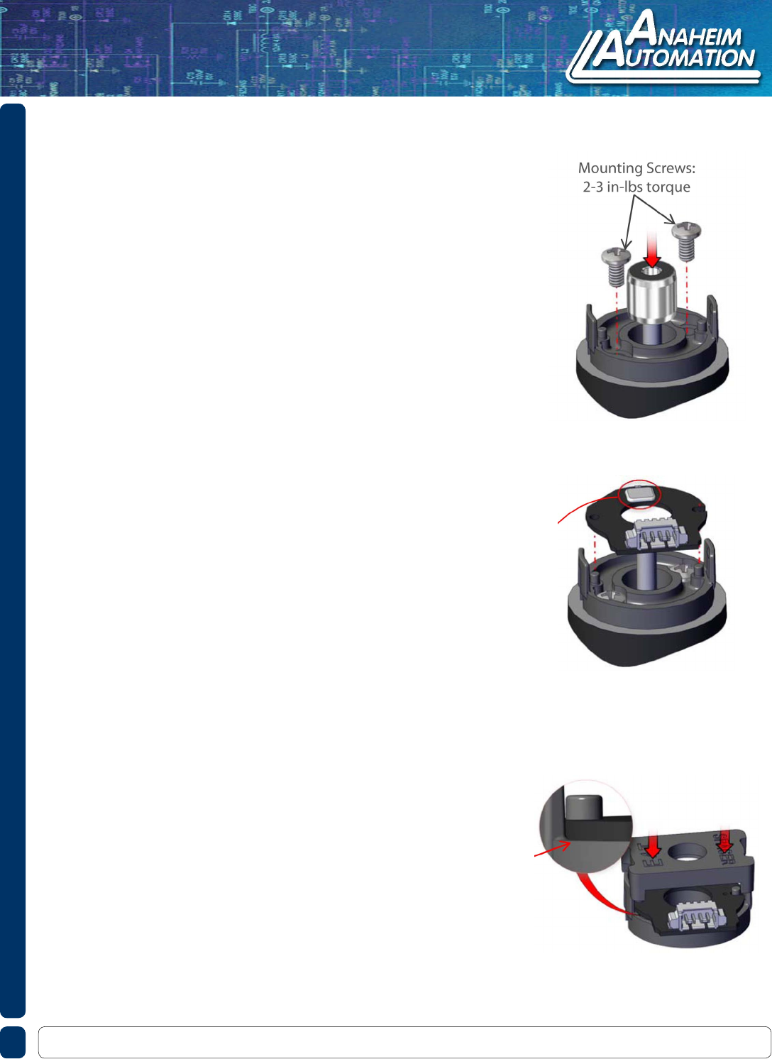
Step 1
Place the base over the shaft and onto the mounting surface.
Slide the centering tool onto the shaft so that it contacts and
aligns the base. While applying light pressure to the center-
ing tool, secure the base to the mounting surface using two
screws.
Step 2
Remove the centering tool and place the PCB onto the base,
aligning the hole and slot to the two pins on the base. Note
that the base is symmetrical allowing the connector to exit
out either side.
Caution: When handling the PCB it is best to avoid directly
touching the optical sensor.
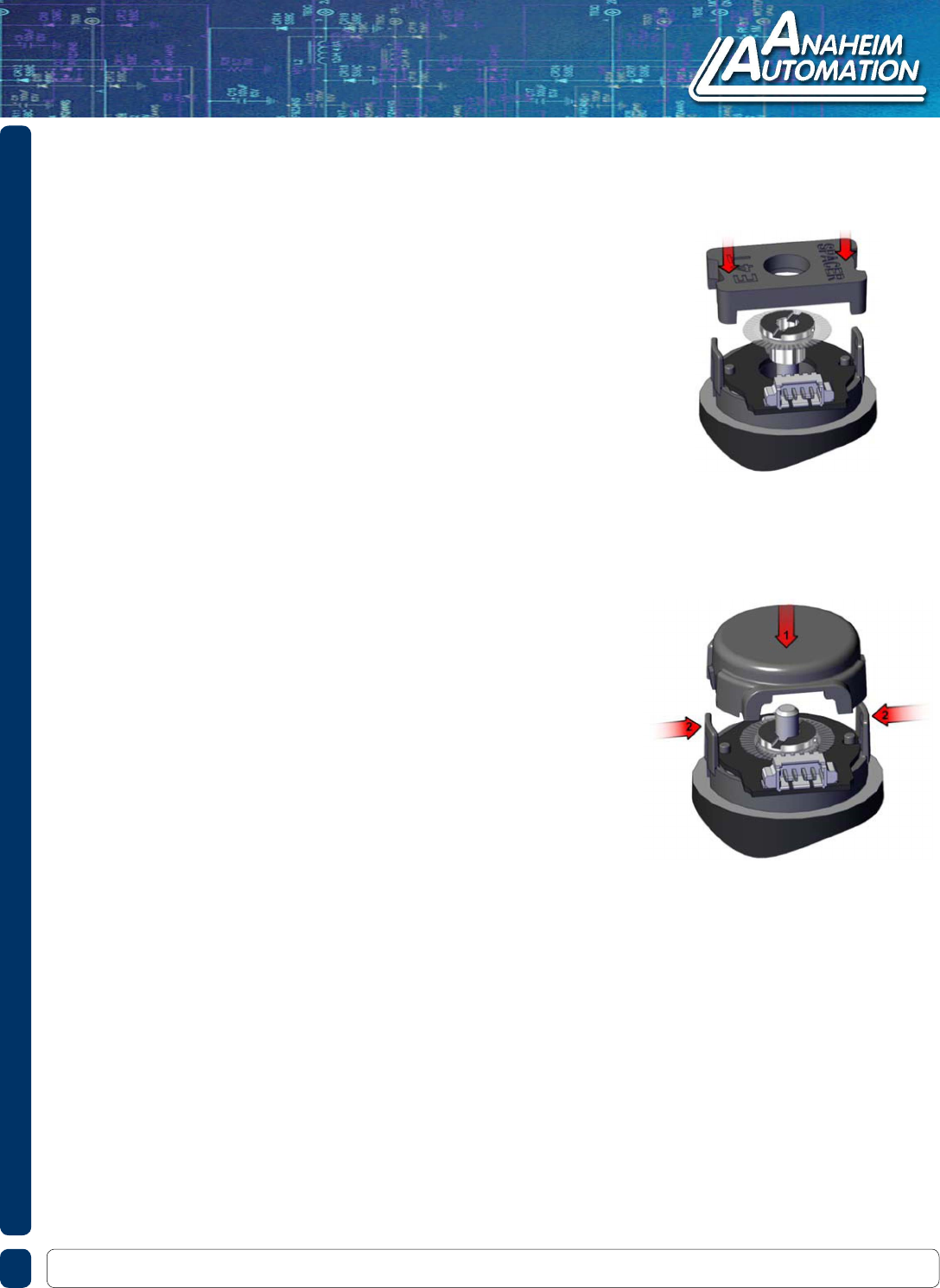
Step 3
Using the spacer tool, very rmly press down on the PCB in
order to push it over the alignment pins and completely onto
the base surface. Check to make sure that the PCB is fully
seated against the base. If it is not, use the spacer tool to
press it again, recheck that it is fully seated.
Note: A4TS images are shown. The same assembly instructions apply for the A4TD.
910 East Orangefair Ln. Anaheim, CA 92801 Tel. (714) 992-6990 Fax. (714) 992-0471 www.anaheimautomation.com
Step 4
Place the hubdisk onto the shaft with the longer end of hub
toward the base. Position the spacer tool onto the hub such
that the notches are aligned with the latches of the base.
Press down rmly until the tool bottoms out on the PCB.
Verify that this action has pressed the PCB ush against the
base.
Caution: While installing the hubdisk ensure that the hub
bore is parallel to the shaft. Forcing the hub onto the shaft at
an angle may cause permanent damage to the hub.
Step 5
Remove the spacer tool and snap the cover down
onto the base, (1). With your thumb and nger,
squeeze the base latches together to ensure they
are fully engaged with the cover, (2).
