CM1 SC P1 L011146 Users Manual
User Manual: L011146 - SC Users Manual
Open the PDF directly: View PDF ![]() .
.
Page Count: 123 [warning: Documents this large are best viewed by clicking the View PDF Link!]
- CM1-SC p1.pdf
- L010988 - CICON Users Manual_Ver4.03
- XP / CP Series(CM1)
- Serial Communication Module
- Specifications
- Operation Setup
- Internal I/O
- Shared Memory
- Network Example
- 1:1 Communication between CIMON PLC and PC
- 1:1 Communication between CIMON PLC and 3rd vendor device
- 1:2 Communication with 3rd vendor device via modem
- 1:2 Communication with 3rd vendor device
- 1:N long distance communication via modem
- 1:N Multi-drop communication
- 1:N Multi-drop communication between various devices via modem
- 1:N Multi-drop communication between various devices
- An example of CIMON PLC network
- An example of CIMON PLC network including 3rd vendor devices
- Communication Services
- User Communication (SND, RCV)
- User Communication (SEND, RECV)
- Operation Procedure of User Communications
- Registering and Editing a Special Program
- Instructions for User Program
- Error Codes for User Communications
- Example of Programming for User Communications
- Example of Application of MODICON (MODBUS) protocol
- Sending/Receiving communication frames at communication intervals
- CIMON PLC - HMI Protocol
- Dial-Up Modem Communication
- Leased Line Modem Communication
- RS485 PLC Link Service
- MODBUS Protocol Service
- MODBUS Master Special module program Service
- Installing and Testing
- Trouble Shooting
- Appendix
- Serial Communication Module
- XP / CP Series(CM1)
- CM1-SC pn

XP / CP Series(CM1) 1077
Copyright 2012 BY KDT SYSTEMS, All rights reserved.
·As modem communication function is built in, a PLC at a long distance can be controlled through
exclusive communication.
·Baud rate can be set up in the range from 300bps to 38400bps variously.
·It is available to set up RS232C / RS422(RS485) communication port as independent channel or linked
channel.
·1:1 / 1:N / N:M communication (In case RS422 channel is used) are supported.
·Full – Duplex(RS422) and Half-Duplex(RS485) communication method are supported.
·RS485 multi-drop communication system can be configured, using RS485 channel.
See :
·Specifications
·Operation Setup
·Internal I/O
·Shared Memory
·Network Example
·Communication Services
·Installing and Testing
·Trouble Shooting
·Appendix
6.2.1 Specifications
RS 232C/422/485 Specifications :
·SC02A Dimensions
·SC01A Dimensions
·SC01B Dimensions
·General Specifications
·Module Specifications
·Cable Specifications
·Termination Register
CIMON-PLC1078
Copyright 2012 BY KDT SYSTEMS, All rights reserved.
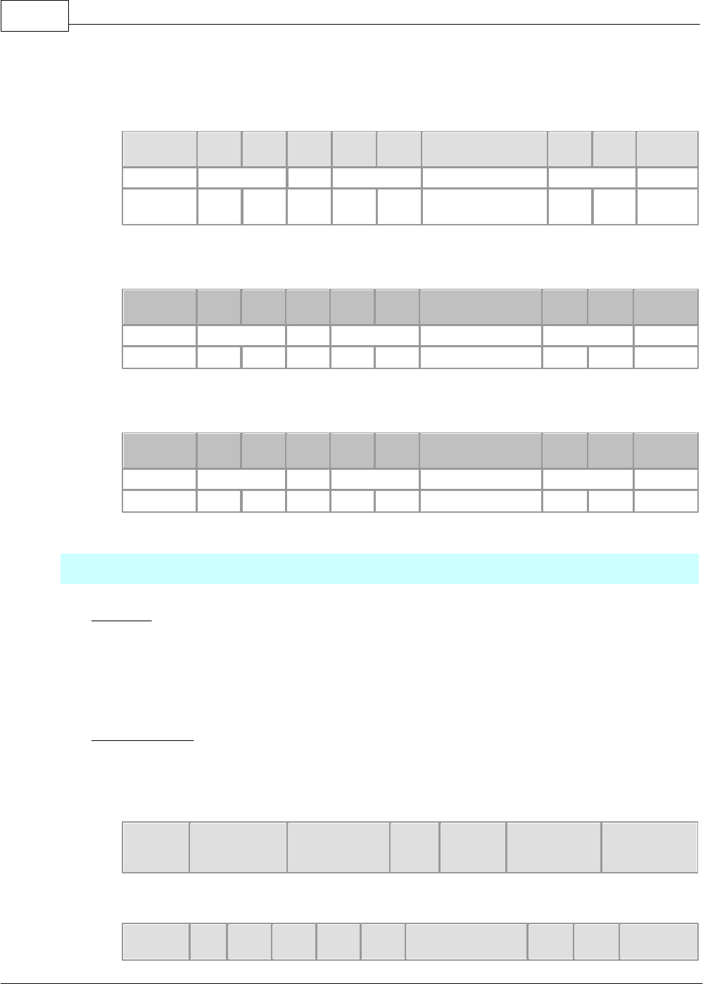
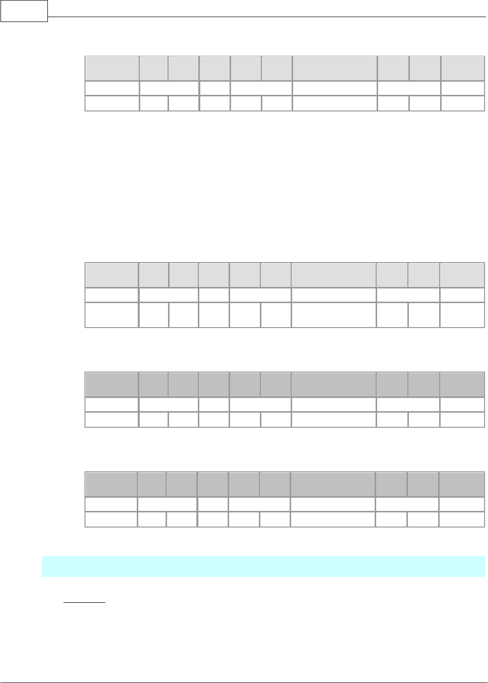
6.2.1.1 General Specifications
The general specifications for CIMON PLC communication modules are as follows.
Item
Specification
Operating
Temperature
-10 ~ 65oC
Storage Temperature
-25 ~ 80oC
Operating Humidity
5 ~ 95%RH, Not condensed.
Storage Humidity
5 ~ 95%RH, Not condensed.
Vibration
In case of intermittent vibration
Frequency
Acceleration
Amplitude
Sweep
10 f< 57Hz
-
0.075mm
10 times in each
direction (X,Y,Z)
57 f < 150 Hz
9.8m/s2 {1G}
-
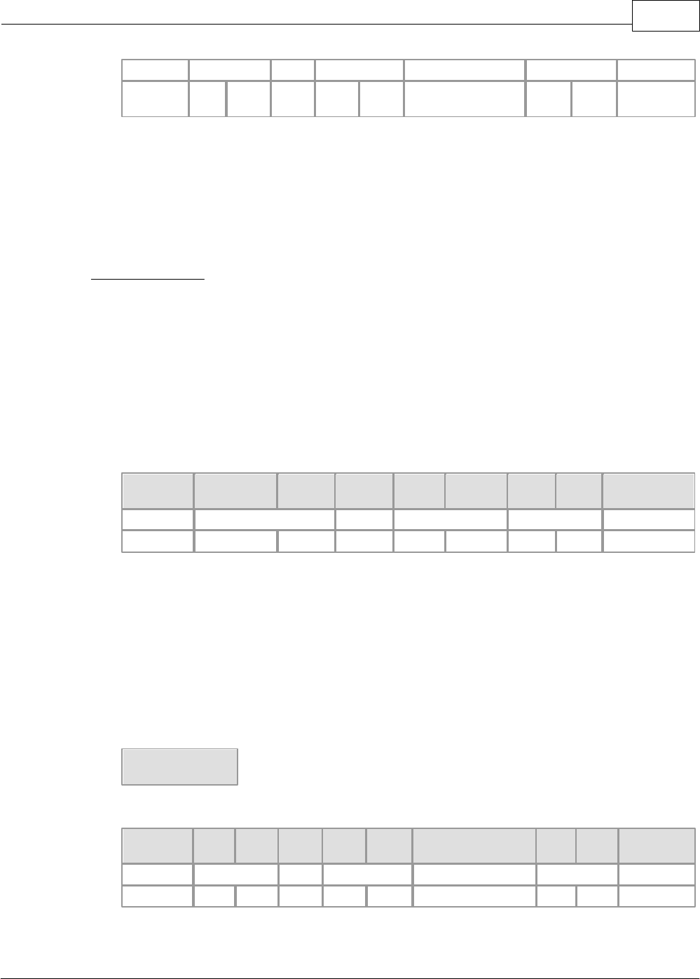
In case of continuous vibration
Frequency
Acceleration
Amplitude
Sweep
10 f < 57Hz
-
0.035mm
10 times in each
direction (X,Y,Z)
57 f < 150 Hz
4.9m/s2 {1G}
-
Shock
- Max. Shock Acc.: 147 m/s2 {15G}
- Time : 11 (3 times in X, Y, Z)
- Pulse Wave : Half sine wave pulse
Noise
Square wave impulse
noise
±1500V
Electrostatic
discharge
Voltage: 4 kV(Contact discharge)
Radiated
electro-magnetic field
27 ~ 500 MHz. 10 V/m
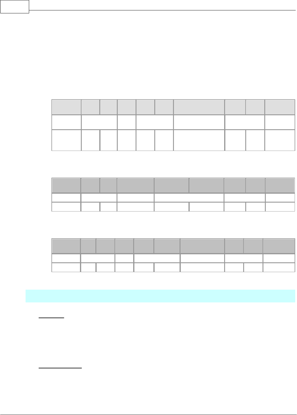
Fast Transient Bust
Noise
Item
Power
Modul
e
Digital I/O
(24V or more)
Digital I/O(Less than 24V)
Analog I/O Comm.
interface
Voltage
2KV
1KV
0.25KV
Environment
No corrosive gas and no dust.
Altitude
2,000m or less
Pollution
Less than 2
Cooling
Natural Air cooling
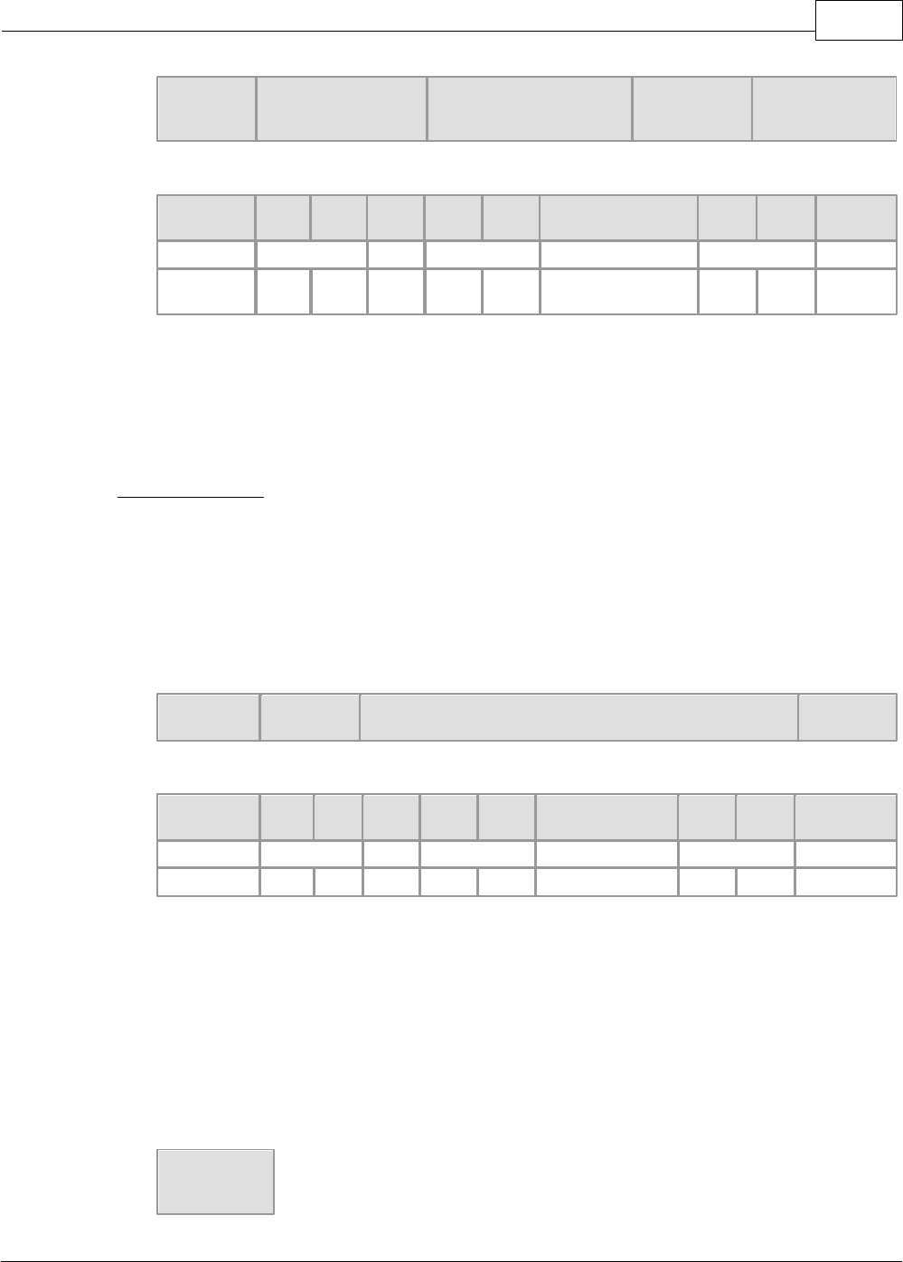
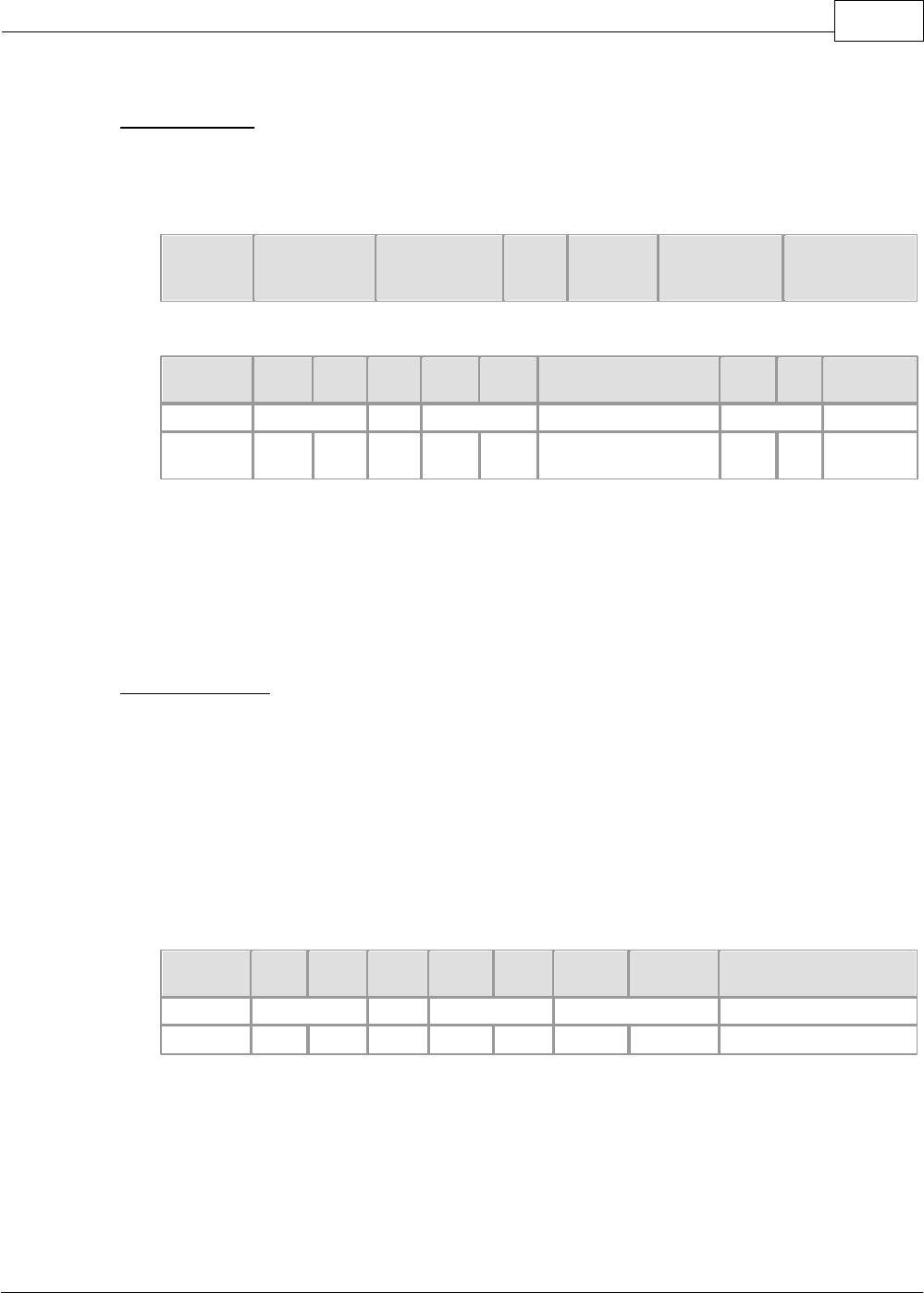
6.2.1.2 Module Specifications
Model
CM-SC02A
CM1-SC01A
CM1-SC01B
Interface
RS232C / 422 / 485
RS232C
RS422 / 485
Null Modem
Direct communication between a PC and RS232C/RS422 port

XP / CP Series(CM1) 1079
Copyright 2012 BY KDT SYSTEMS, All rights reserved.
Communication
Method
Leased-Line Modem
Communication using a leased-line modem
Dial-up Modem
Remote communication using a dial-up modem
Operation Mode
User Protocol
Communication using user protocol
HMI Protocol
Communication using exclusive protocol
MODBUS Protocol
Communication using Modicon protocol
Graphic Loader Mode
Controls a PLC, using link function in the CICON
Data Type
Data Bit
7 or 8 bits
Stop Bit
1 or 2 bits
Parity
Even / Odd / None
Synchronous Type
Asynchronous
Baud Rate
300bps / 600 / 1200 / 2400 / 4800 / 9600 / 19200 / 38400bps
Modem Link Function
Long-distance communication linking modem
6.2.1.3 Cable Specifications
In case of communication, especially, communication distance and baud rate is to be considered among items.
In case of the communication using RS-232C port and RS-422/RS-485 port provided from a PLC, to minimize
the noise received from outside, a twisted-fair cable for RS-232 is to be used.
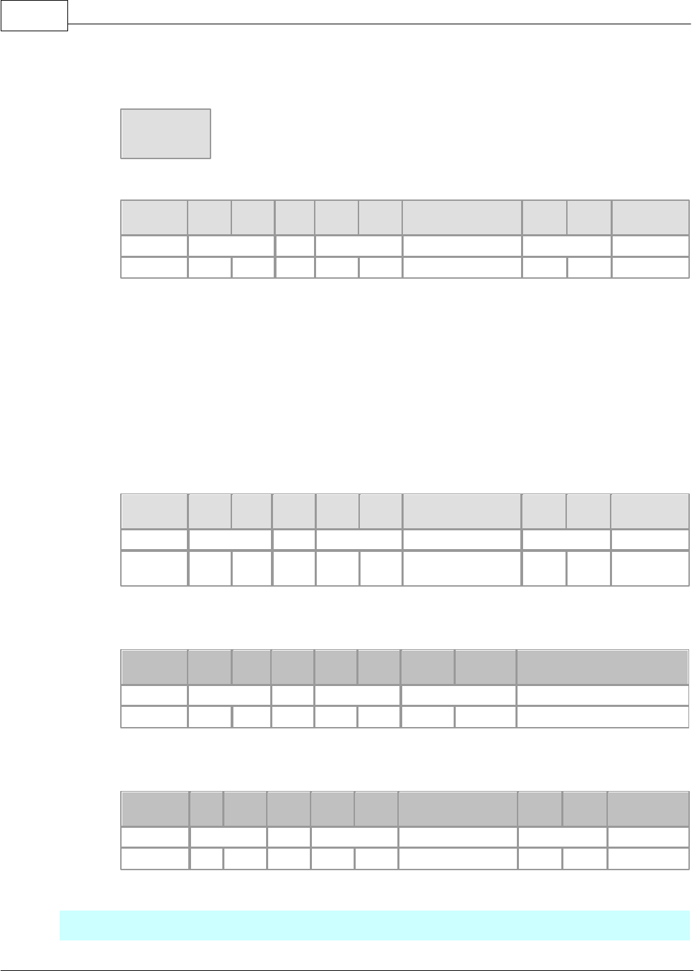
6.2.1.4 Termination Register
In case of communication through RS-422 channel, a termination register is to be connected to outside. As
termination register protects the signal from the distortion by reflected wave in case of a long-distance
communication, the register (1/2W) with the same value as the feature impedance of a cable is to be connected
to the termination of a network. In case of recommended cable, connect the termination register of 120? to both
ends of the line.
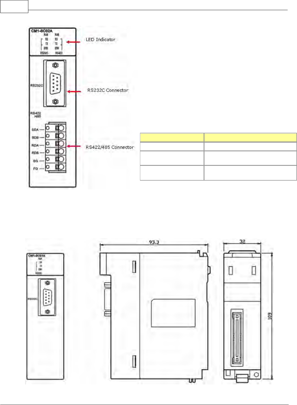
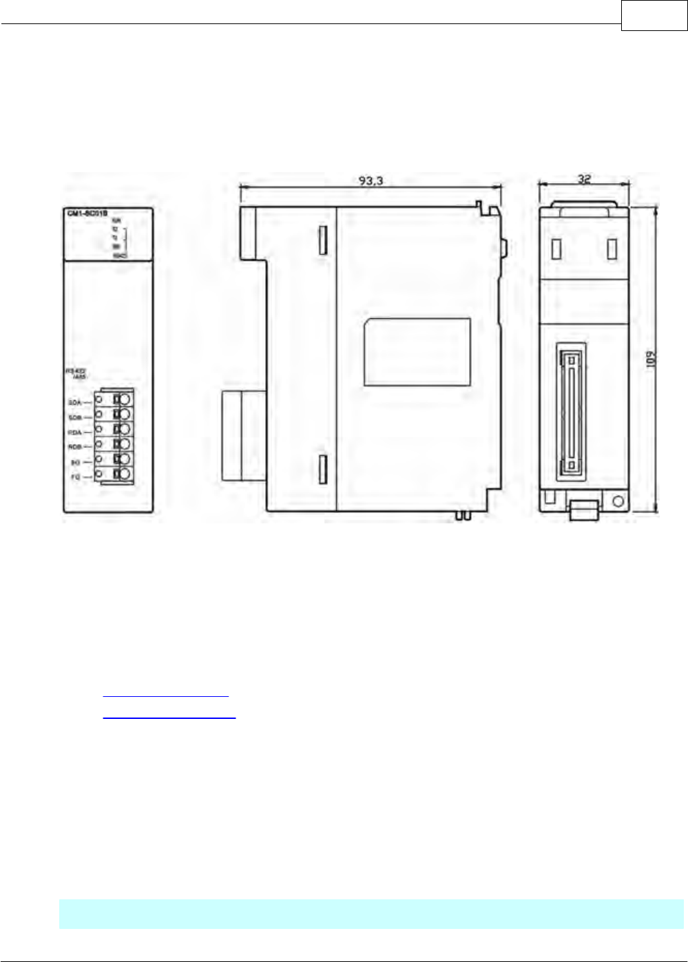
6.2.1.5 SC02A Dimensions
Unit : mm
CIMON-PLC1080
Copyright 2012 BY KDT SYSTEMS, All rights reserved.
Name
Description
LED Indicator
Indicates operation status.
RS232C Connector
RS232C connector to connect with an
outer device
RS422/485 Connector
RS422/485 connector to connect with
an outer device
6.2.1.6 SC01A Dimensions
Unit : mm
XP / CP Series(CM1) 1081
Copyright 2012 BY KDT SYSTEMS, All rights reserved.
6.2.1.7 SC01B Dimensions
Unit : mm
6.2.2 Operation Setup
Operation Setup :
·Operation Mode Setup
·Series Interface Method
6.2.2.1 Operation Mode Setup
Independent mode and linked mode are used as communication operation mode.
Default is independent mode.
Independent Mode of Channel Operation
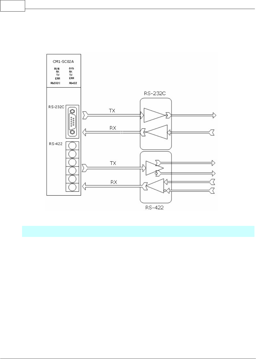
CIMON-PLC1082
Copyright 2012 BY KDT SYSTEMS, All rights reserved.
As RS-232C channel and RS-422 channel are operated independently each other, sending and receiving
are available as individual sending standard at one time. By channels, the sending standard can be set up,
and the operation can be started and stopped.
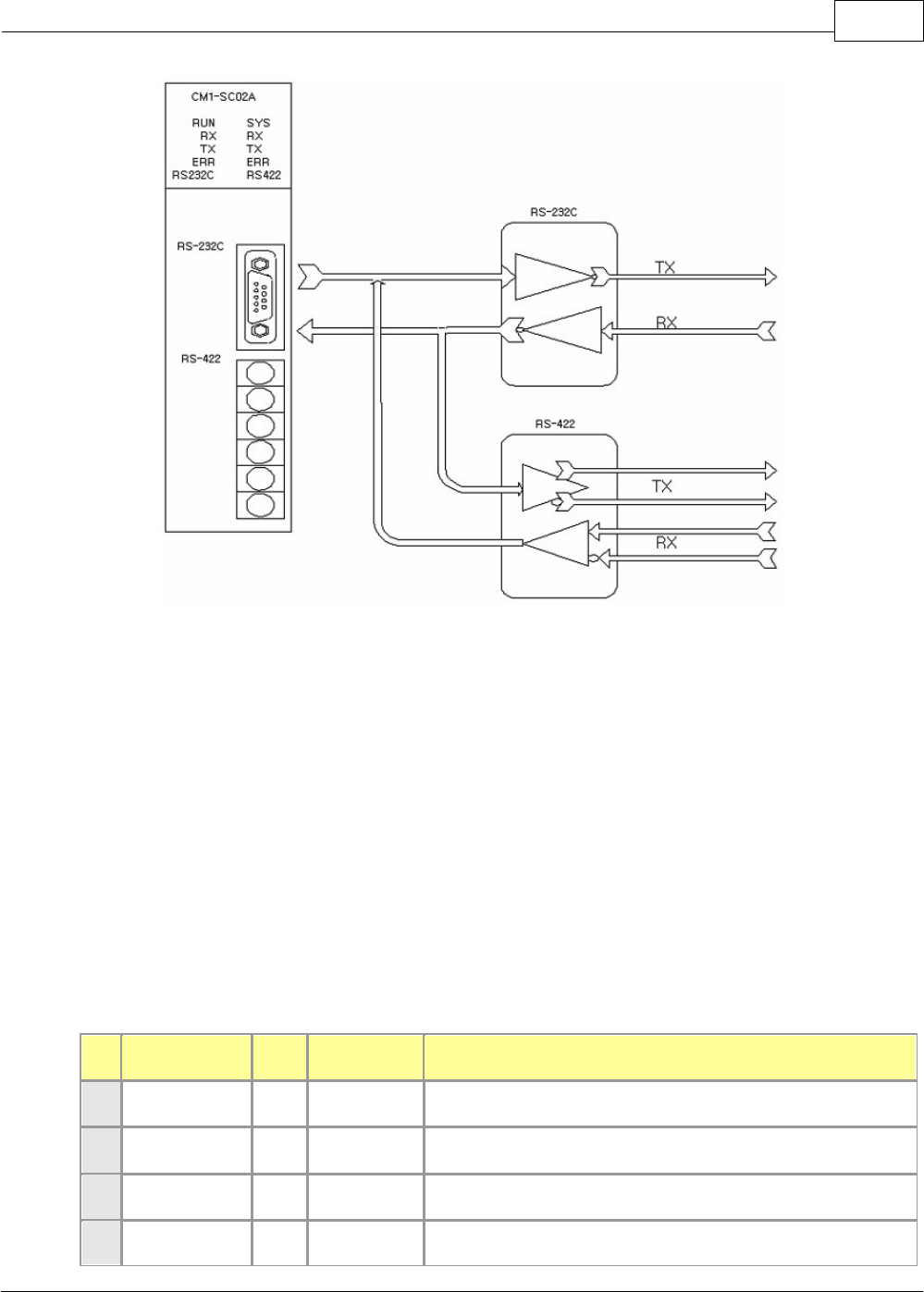
Linked Mode of Channel Operation
The data received through RS-232C channel and RS-422 channel are sent through RS-232C channel.
In the linked mode, RS-232C channel is automatically set up as main channel and the station number is the
same as the main channel. The data received through RS-232C channel is both received in RS232C/422
module and sent through RS-422 channel. The data received through RS-422 channel is not received in
RS232C/422 module but is automatically sent through RS-232C channel.
XP / CP Series(CM1) 1083
Copyright 2012 BY KDT SYSTEMS, All rights reserved.
6.2.2.2 Series Interface Method
RS-232C channel is communicated with other device with a 9-pin connector.
It is directly communicated with a long-distance device, using a modem, as well as with other device.
Pin
Function
Nam
e
Direction of
Signal
Description
1
Carrier Detect
CD
Inside to
outside
Signal wire that DCE informs DTE about the detection of carrier
2
Received Data
RXD
Outside to
inside
Signal wire receiving data
3
Transmitted
Data
TXD
Inside to
outside
Signal wire sending data
4
Data Terminal
DTR
Inside to
Signal wire that DTE informs DCE about the state that DTE is
CIMON-PLC1084
Copyright 2012 BY KDT SYSTEMS, All rights reserved.
Ready
outside
able to send and receive
5
Signal Ground
SG
Both
directions
Ground wire for signal
6
Data Set Ready
DSR
Outside to
inside
Signal wire that DCE informs DTE about the state that DCE is
able to send and to receive
7
Request To
Send
RTS
Inside to
outside
DTE is ready and requests DCE to send data.
8
Clear To Send
CTS
Outside to
inside
Signal wire that DCE inform DTE about the state that DCE is
able to send
9
Ring
RI
Outside to
inside
Signal wire that DCE inform DTE of receiving RING
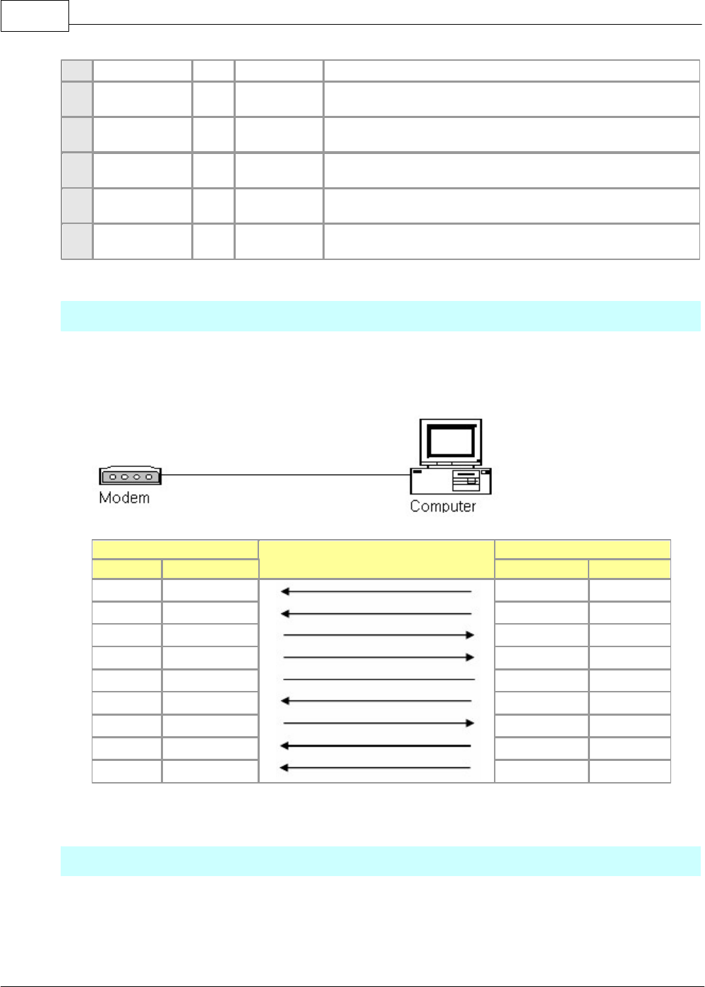
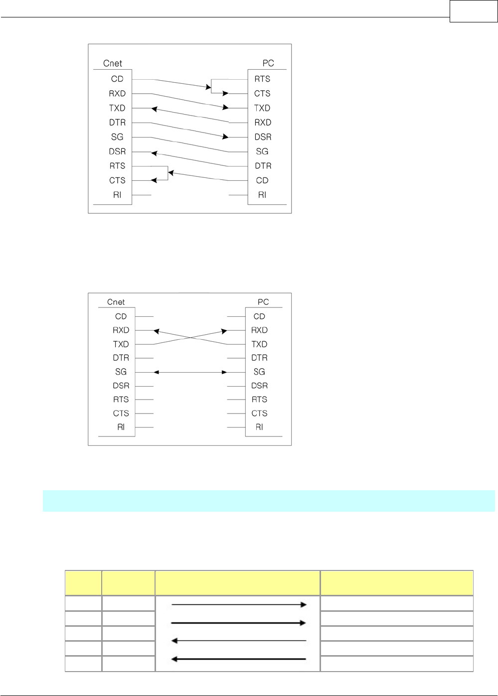
Connection with a modem
A long-distance communication is available.
modem interface is described.
PLC(RS-232C)
Signal Direction
Modem
Pin
Name
Name
Pin
1
CD
CD
8
2
RXD
RXD
3
3
TXD
TXD
2
4
DTR
DTR
20
5
SG
SG
7
6
DSR
DSR
6
7
RTS
RTS
4
8
CTS
CTS
5
9
RI
RI
22
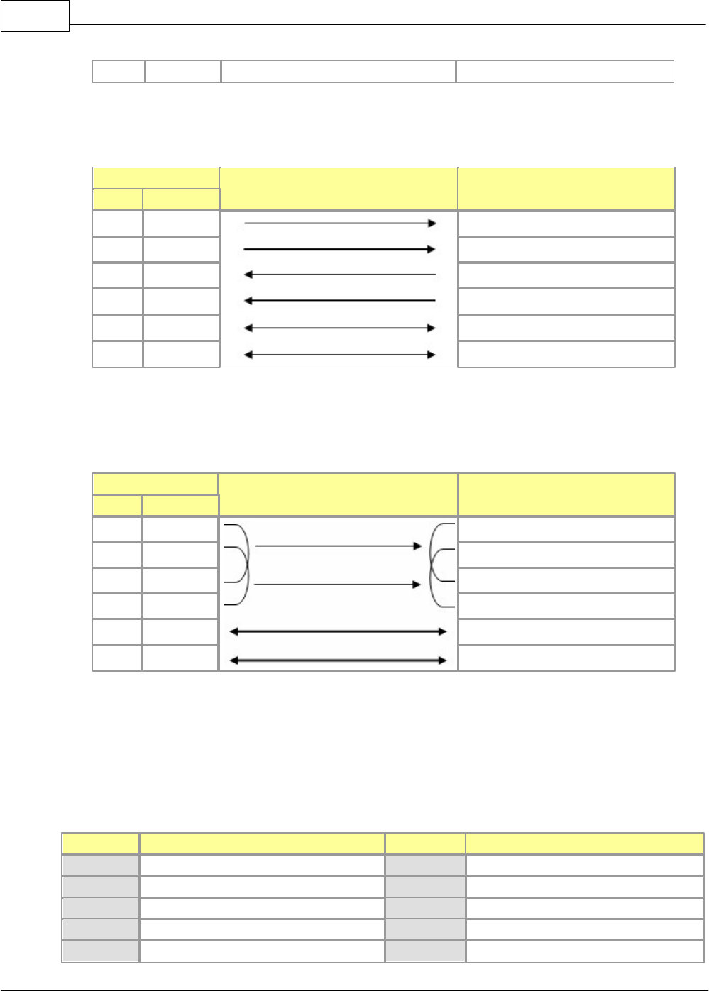
Connection with a null modem
·PLC and Computer/Communication device: There are 3-wire type and 7-wire type.
XP / CP Series(CM1) 1085
Copyright 2012 BY KDT SYSTEMS, All rights reserved.
·In case that a PC is connected with a RS-232C connector, RXD, TXD and SG is to be connected in
3-wire type.
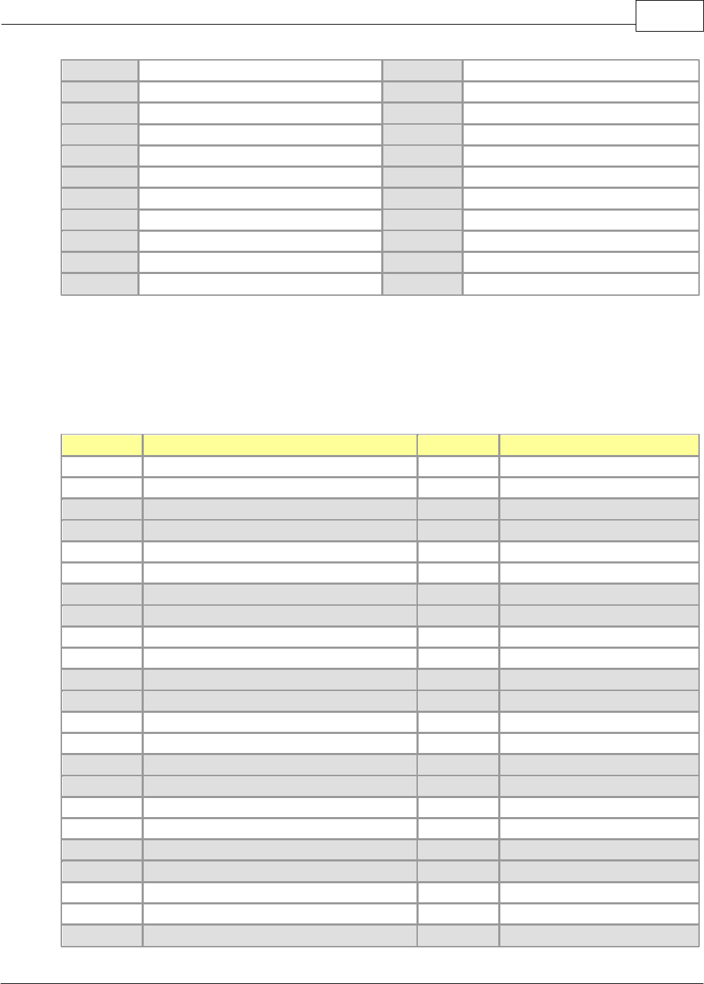
RS-422 Interface
A 6-pin connector is used for RS-422 interface. The functions and names of the pin and the flow of data are
described as follows.
Pin
Name
Direction of Signal
PLC Device
Function
1
SDA
Sends data. (+)
2
SDB
Sends data. (-)
3
RDA
Receives data. (+)
4
RDB
Receives data. (-)
5
S.G
Ground wire of signal
CIMON-PLC1086
Copyright 2012 BY KDT SYSTEMS, All rights reserved.
6
F.G
Ground wire of frame
RS-422 channel can be connected with other device for RS-422 and RS-485 (Multi-drop).
Computer Link
Direction of Signal
PLC Device
Outside Communication Device
Pin
Name
1
SDA
RDA
2
SDB
RDB
3
RDA
SDA
4
RDB
SDB
5
S.G
S.G
6
F.G
F.G
The following is an example to connect RS-485 channel with an outside device. At this time, as a sending
wire shares with a receiving one (Half Duplex), the channel mode is to be set up as RS-485.
Computer Link
Direction of Signal
PLC Device
Outside Device
Pin
Name
1
SDA
SDA
2
SDB
SDB
3
RDA
RDA
4
RDB
RDB
5
S.G
S.G
6
F.G
F.G
6.2.3 Internal I/O
Device
Description For Signal
Device
Description For Signal
X0000
Error in module
Y0000
Clear error
X0001
Initialized (Card Ready)
Y0001
X0002
Y0002
X0003
Y0003
X0004
Rx Data Existing(Ch1)
Y0004
Clear Rx Buffer (Ch1)
XP / CP Series(CM1) 1087
Copyright 2012 BY KDT SYSTEMS, All rights reserved.
X0005
Tx Buffer Empty(Ch1)
Y0005
Clear Tx Buffer (Ch1)
X0006
Rx Data Existing(Ch2)
Y0006
Clear Rx Buffer (Ch2)
X0007
Tx Buffer Empty(Ch2)
Y0007
Clear Tx Buffer (Ch2)
X0008
Y0008
X0009
Y0009
X000A
Modem Initialized
Y000A
Modem Initialization Request
X000B
Dialing
Y000B
Dialing Request(Line Connection)
X000C
Detect DCD Signal
Y000C
Connection Release Request
X000D
Detect DSR Signal
Y000D
X000E
Y000E
X000F
Parameter Applied
Y000F
Parameter Setup Request
6.2.4 Shared Memory
Offset
Description
R/W
Remarks
0
Status Code (0=Normal, Others=Error)
1
Mode
2
CH1 Port Parameter
3
CH2 Port Parameter
4
Number of Retrying Dialing
1 – 5
5
Interval of Retrying Dialing
20 – 300 secs
6
Modem Initialization/Dialing Timeout
1 – 60 secs
7
Number of Retrying Modem Initialization
1 – 5 times
8
Station Number
0 – 31(Ch1=High,Ch2=Low)
9
SND Command Timeout
0 – 3000 sec
10
RCV Command Timeout
0 – 3000 sec
11 ~31
Modem Initialization Command
…
37
PLC Link Station Number
R
Not Link Join(0xFF)
38
PLC Link Connection
R
Stn0 ~ Stn15
39
PLC Link Connection
R
Stn16 ~ Stn31
40
Dial Number (H)
R/W
…
49
Dial Number (L)
50
Response Delay Time(CH1)
R/W
Delay Time(0~200ms)
51
Response Delay Time(CH2)
R/W
Delay Time(0~200ms)
…
62
CIMON-PLC1088
Copyright 2012 BY KDT SYSTEMS, All rights reserved.
63
OS Version
R
64 - 255
User Message
R/W
216 Word (432 Bytes)
The user data memory device is divided into the contents set up to an optional card and the memory indicating
error code. And set contents are stored in buffer memory and finally are stored in Eprom by I/O Point Map.
See :
·Mode
·Parameter
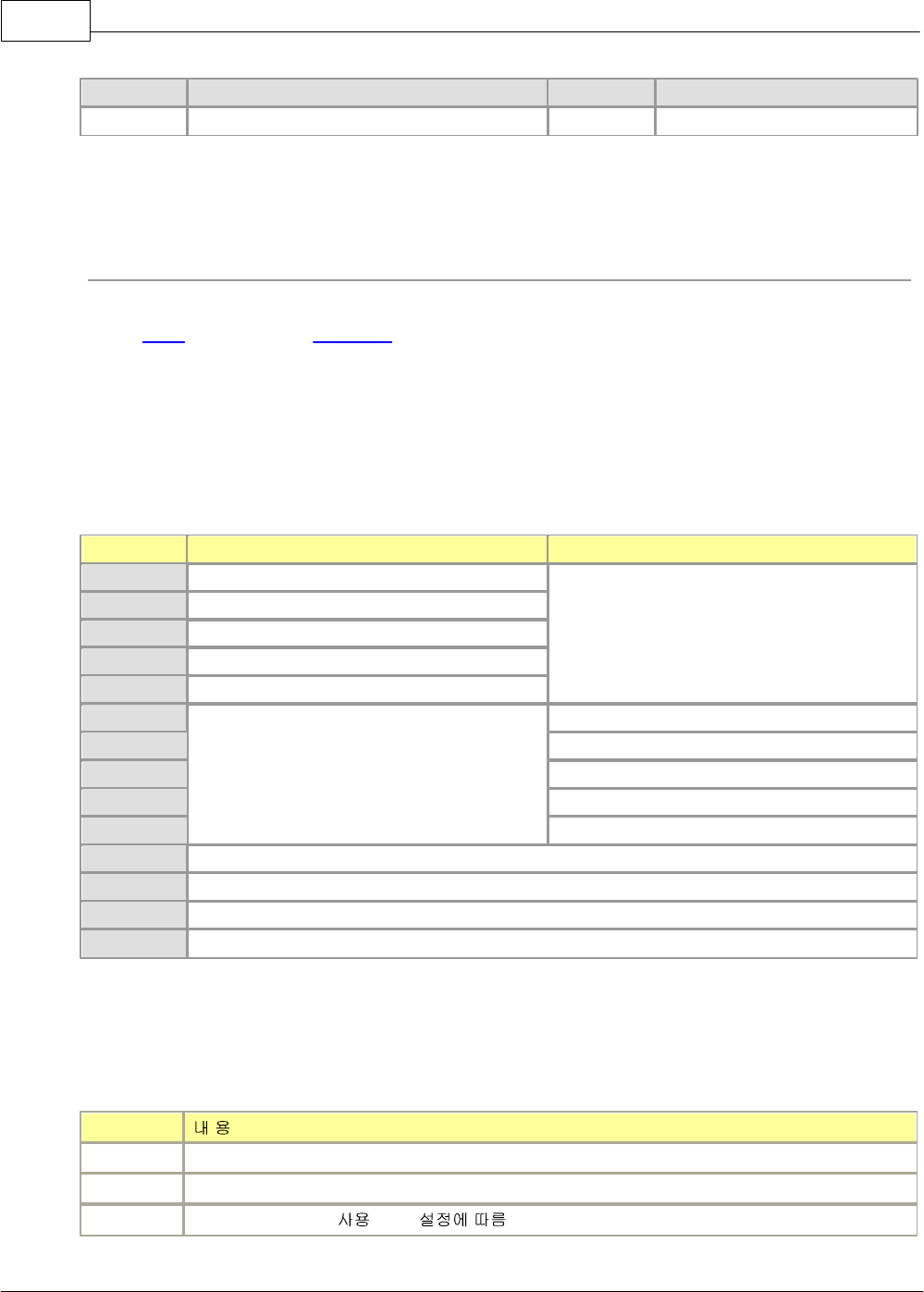
6.2.4.1 Mode
Code
RS232C
RS422/485
0x00--
Independent (User)
-
0x01--
Independent (HMI Protocol)
0x02--
Independent (MODBUS Protocol)
0x03--
Independent (PLC LINK Protocol)
0x04--
Independent (Graphic Loader I/F)
0x--00
-
Independent (User)
0x--01
Independent (HMI Protocol)
0x--02
Independent (MODBUS Protocol)
0x--03
Independent (PLC LINK Protocol)
0x--04
Independent (Graphic Loader I/F)
0x80FF
Linked (User)
0x81FF
Linked (HMI Protocol)
0x82FF
Linked (MODBUS Protocol)
0x84FF
Linked (Graphic Loader I/F)
6.2.4.2 Parameter
Bit
0
Data Bit : 0=7, 1=8
1
Parity : 0=Even, 1=Odd
2
Parity : 0=None, 1= (Bit 1 )
XP / CP Series(CM1) 1089
Copyright 2012 BY KDT SYSTEMS, All rights reserved.
3
Stop Bit : 0=1 Bit, 1=2
4
(0=300, 1=600, 2=1200, 3=2400, 4=4800, 5=9600, 6=19200, 7=38400, 8=76800)
5
6
7
8
Network Type
Code
Channel 1
Channel 2
0
NULL Modem
RS422
1
RS485
2
Dial-Up Modem
N/A
3-7
N/A
N/A
9
10
11~15
System (Reserved)
6.2.5 Network Example
System Configuration :
·1:1 Communication between CIMON PLC and PC
·1:1 Communication between CIMON PLC and 3rd vendor device
·1:2 Communication with 3rd vendor device via modem
·1:2 Communication with 3rd vendor device
·1:N long distance communication via modem
·1:N Multi-drop communication
·1:N Multi-drop communication between various devices via modem
·1:N Multi-drop communication between various devices
·An example of CIMON PLC network
·An example of CIMON PLC network including 3rd vendor devices
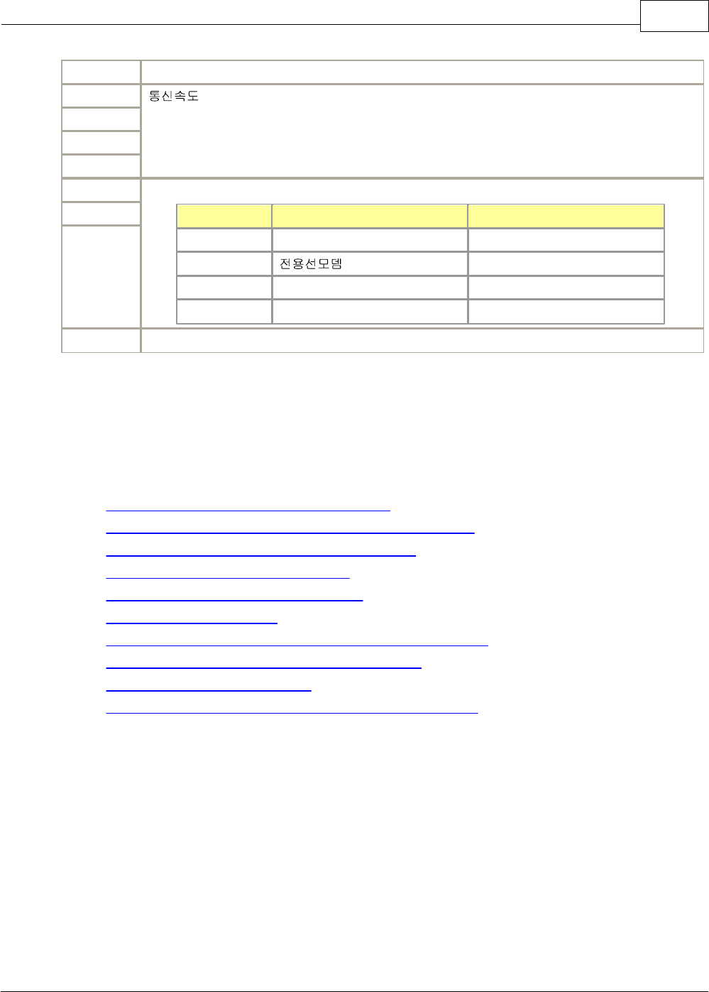
6.2.5.1 1:1 Communication between CIMON PLC and PC
The following is to use RS-232C channel or RS-422 channel, and the exclusive protocol of the CIMON PLC to
configure a network.
CIMON-PLC1090
Copyright 2012 BY KDT SYSTEMS, All rights reserved.
Components and parameters of computer link module,
Component
Name of Module
Parameter
Ex. of Station No.
PC
Built-in RS-232C
-
-
PLC
CM1-SC02A
Exclusive Comm., Independent Mode
0
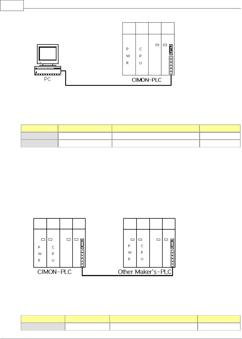
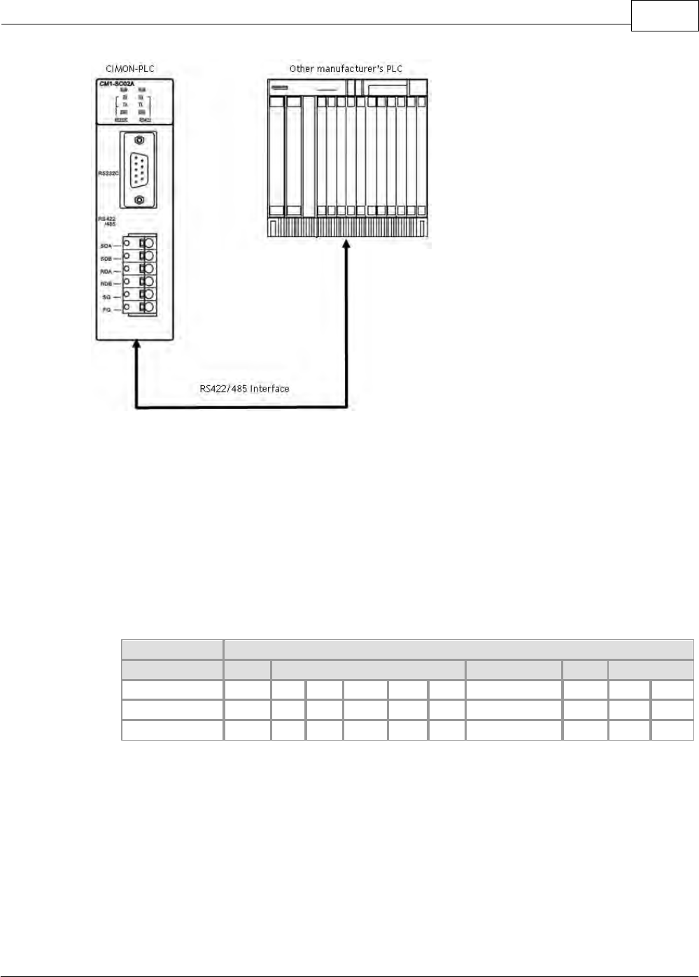
6.2.5.2 1:1 Communication between CIMON PLC and 3rd vendor device
The following is the network configuration when linking other maker’s PLC with a computer module.
Components and parameters of computer link module,
Component
Name of Module
Parameter
Ex. of Station No.
PLC
CM1-SC02A
User Communication, Independent Mode
1
XP / CP Series(CM1) 1091
Copyright 2012 BY KDT SYSTEMS, All rights reserved.
Other maker’s PLC
CM1-SC02A
-
-
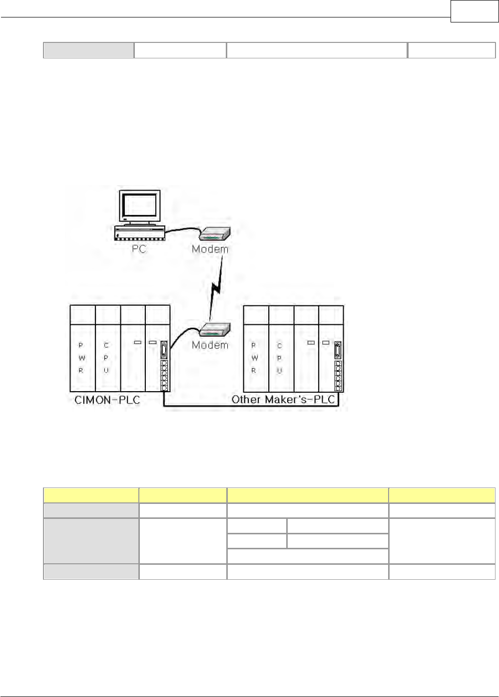
6.2.5.3 1:2 Communication with 3rd vendor device via modem
RS-232C and a modem are used for a long-distance communication.
Components and parameters of computer link module,
Component
Name of Module
Parameter
Ex. of Station No.
PC
Built-in RS-232C
-
-
PLC
CM1-SC02A
RS-232C
Exclusive Comm.
0
RS-485
User Comm.
Independent Mode
Other maker’s PLC
-
-
-
CIMON-PLC1092
Copyright 2012 BY KDT SYSTEMS, All rights reserved.
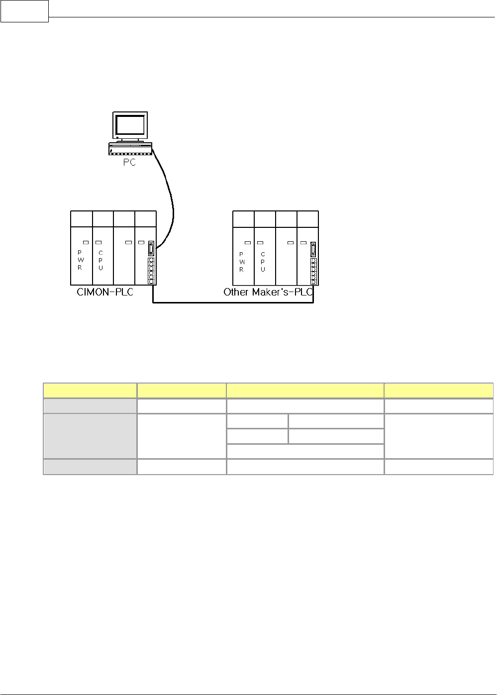
6.2.5.4 1:2 Communication with 3rd vendor device
A RS-232C cable is used for interface.
Components and parameters of computer link module,
Component
Name of Module
Parameter
Ex. of Station No.
PC
Built-in RS-232C
-
-
PLC
CM1-SC02A
RS-232C
Exclusive Comm.
0
RS-422
User Comm.
Independent Mode
Other maker’s PLC
-
-
-
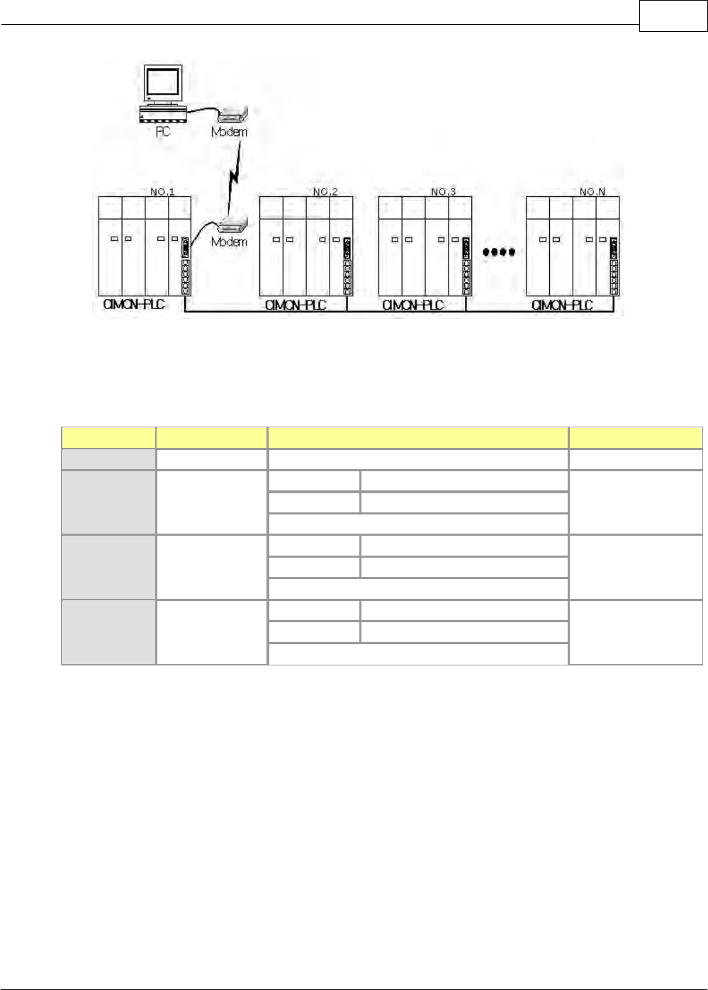
6.2.5.5 1:N long distance communication via modem
A modem and RS-232C are used for a long-distance communication.
XP / CP Series(CM1) 1093
Copyright 2012 BY KDT SYSTEMS, All rights reserved.
Components and parameters of computer link module,
Component
Name of Module
Parameter
Ex. of Station No.
PC
Built-in RS-232C
-
-
PLC NO.1
CM1-SC02A
RS-232C
Exclusive Comm. (RS-232C Mode)
0
RS-422
Exclusive Comm.
Linked Mode
PLC NO.2
CM1-SC02A
RS-232C
Exclusive Comm.
1
RS-422
Exclusive Comm.
Independent Mode
PLC NO.N
CM1-SC02A
RS-232C
Exclusive Comm.
31
RS-422
Exclusive Comm.
Independent Mode
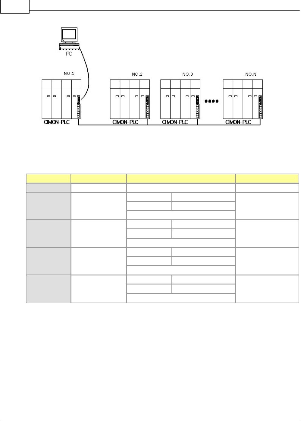
6.2.5.6 1:N Multi-drop communication
A RS-232C cable is used to connect a PC with a PLC. RS-422 cables are used to connect between PLCs.
CIMON-PLC1094
Copyright 2012 BY KDT SYSTEMS, All rights reserved.
Components and parameters of computer link module,
Component
Name of Module
Parameter
Ex. of Station No.
PC
Built-in RS-232C
-
-
PLC NO.1
CM1-SC02A
RS-232C
Exclusive Comm.
0
RS-422
Exclusive Comm.
Linked Mode
PLC NO.2
CM1-SC02A
RS-232C
Exclusive Comm.
1
RS-422
Exclusive Comm.
Independent Mode
PLC NO.3
CM1-SC02A
RS-232C
Exclusive Comm.
2
RS-422
Exclusive Comm.
Independent Mode
PLC NO.N
CM1-SC02A
RS-232C
Exclusive Comm.
31
RS-422
Exclusive Comm.
Independent Mode
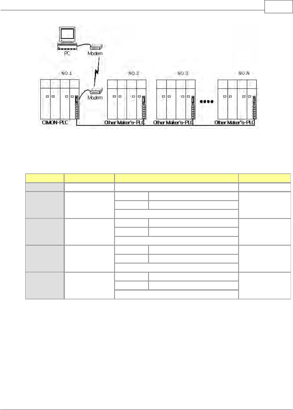
6.2.5.7 1:N Multi-drop communication between various devices via modem
A RS-232C cable is used to connect a PC with a PLC. RS-422 cables are used to connect between PLCs.
XP / CP Series(CM1) 1095
Copyright 2012 BY KDT SYSTEMS, All rights reserved.
Components and parameters of computer link module,
Component
Name of Module
Parameter
Ex. of Station No.
PC
Built-in RS-232C
-
-
PLC NO.1
CM1-SC02A
RS-232C
Exclusive Comm. (RS-232C Mode)
0
RS-422
User Comm.
Independent Mode
PLC NO.2
CM1-SC02A
RS-232C
-
-
RS-422
-
-
PLC NO.3
CM1-SC02A
RS-232C
-
-
RS-422
-
-
PLC NO.N
CM1-SC02A
RS-232C
-
-
RS-422
-
-
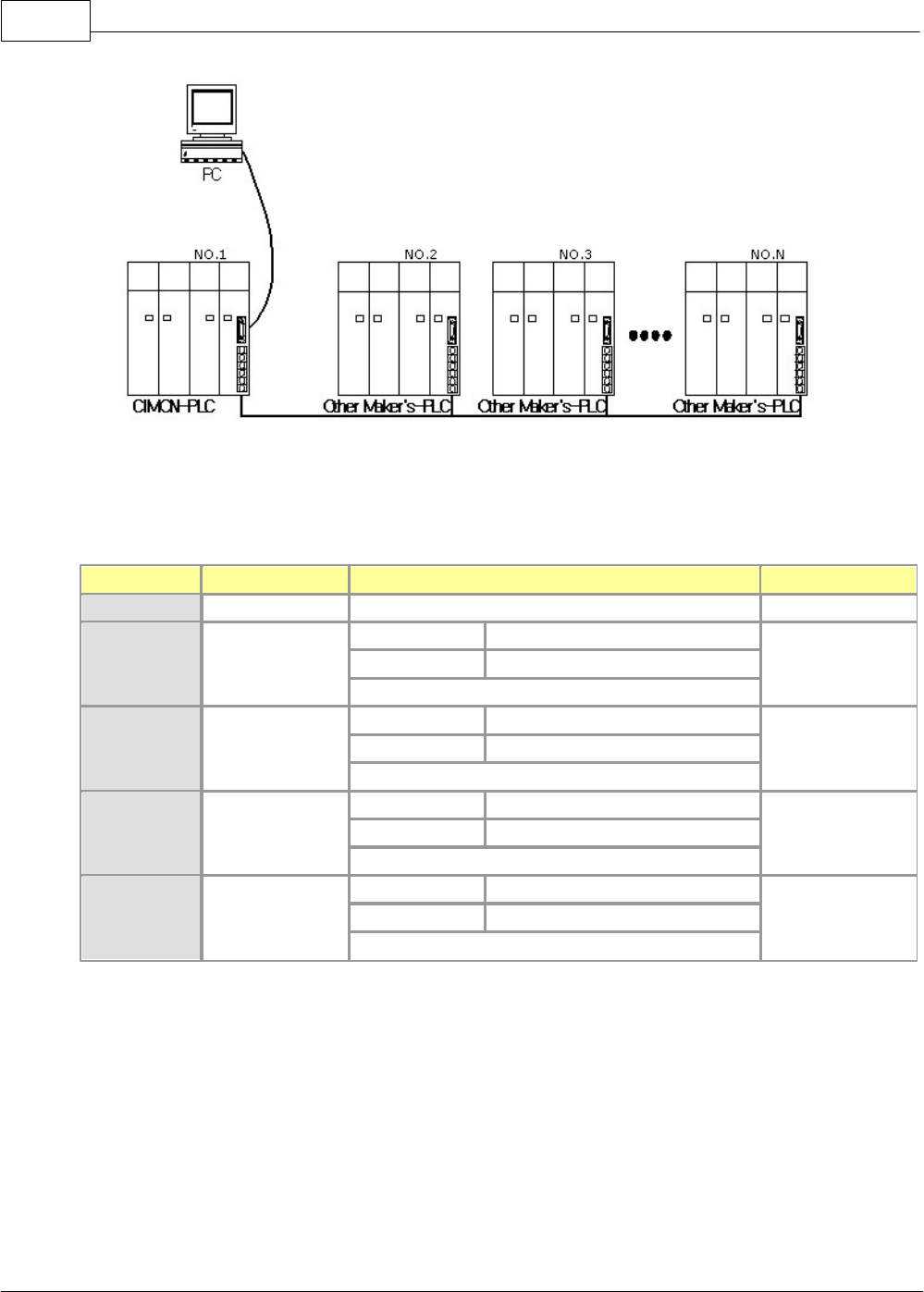
6.2.5.8 1:N Multi-drop communication between various devices
A RS-232C cable is used to connect a PC with a PLC. RS-422 cables are used to connect between PLCs.
CIMON-PLC1096
Copyright 2012 BY KDT SYSTEMS, All rights reserved.
Components and parameters of computer link module,
Component
Name of Module
Parameter
Ex. of Station No.
PC
Built-in RS-232C
-
-
PLC NO.1
CM1-SC02A
RS-232C
HMI Comm. (RS-232C Mode)
0
RS-422
User Comm.
Independent Mode
PLC NO.2
CM1-SC02A
RS-232C
-
-
RS-422
-
-
PLC NO.3
CM1-SC02A
RS-232C
-
-
RS-422
-
-
PLC NO.N
CM1-SC02A
RS-232C
-
-
RS-422
-
-
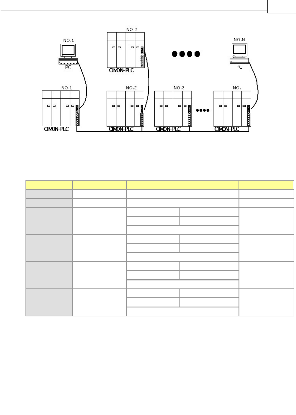
6.2.5.9 An example of CIMON PLC network
A RS-232C cable is used to connect a PC with a PLC. A modem can be used in case of long-distance
communication. RS-422 cables are used to connect between PLCs.
XP / CP Series(CM1) 1097
Copyright 2012 BY KDT SYSTEMS, All rights reserved.
Components and parameters of computer link module,
Component
Name of Module
Parameter
Ex. of Station No.
PC NO.1
Built-in RS-232C
-
-
PC NO.N
Built-in RS-232C
-
-
PLC NO.1
CM1-SC02A
RS-232C
Exclusive Comm.
0
RS-422
Exclusive Comm.
Linked Mode
PLC NO.2
CM1-SC02A
RS-232C
User Comm.
1
RS-422
Exclusive Comm.
Independent Mode
PLC NO.2
CM1-SC02A
RS-232C
Exclusive Comm.
2
RS-422
Exclusive Comm.
Independent Mode
PLC NO.M
CM1-SC02A
RS-232C
Exclusive Comm.
31
RS-422
Exclusive Comm.
Independent Mode
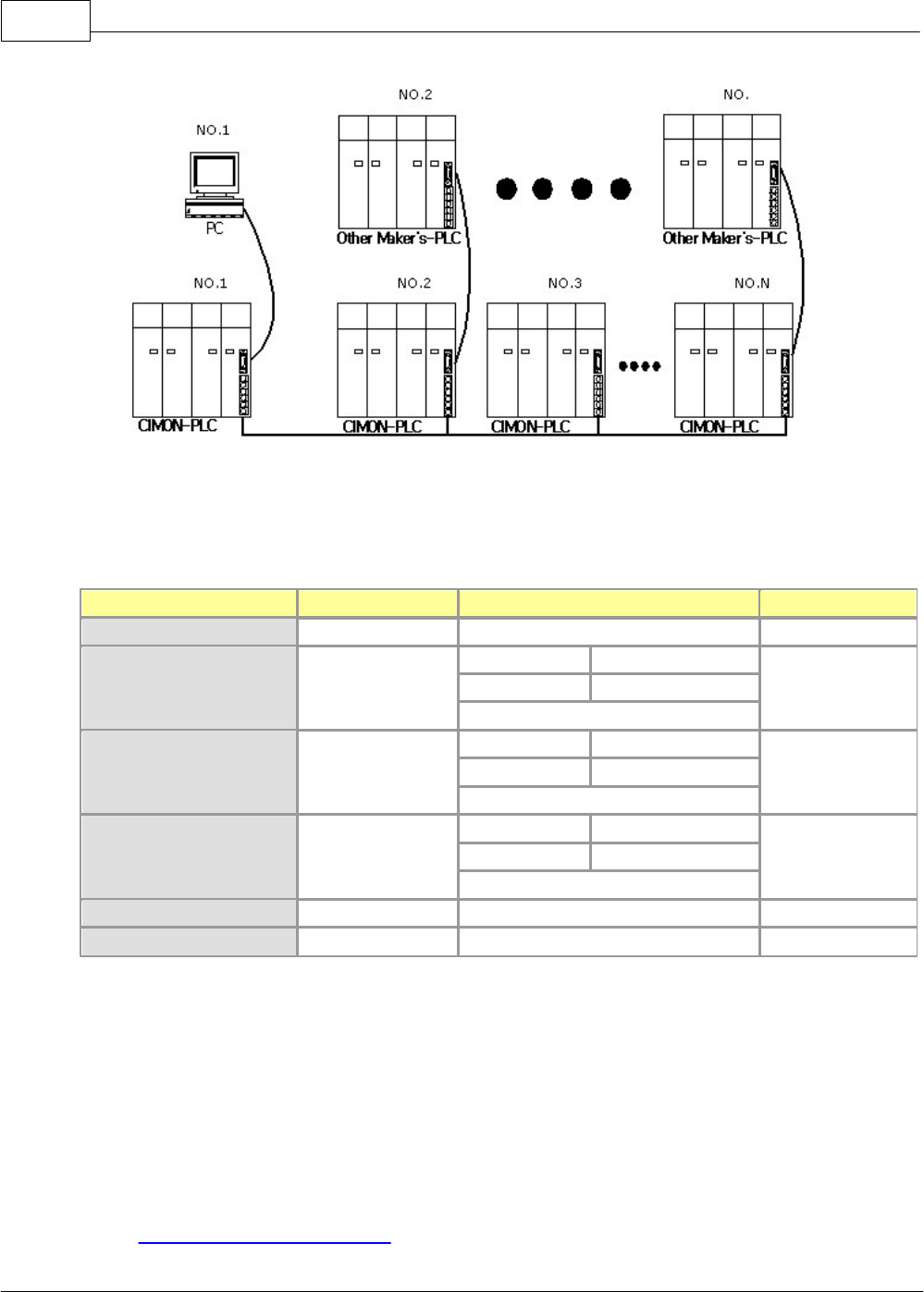
6.2.5.10 An example of CIMON PLC network including 3rd vendor devices
A RS-232C cable is used to connect a PC with a PLC. A modem can be used in case of long-distance
communication. RS-422 cables are used to connect between PLCs
CIMON-PLC1098
Copyright 2012 BY KDT SYSTEMS, All rights reserved.
Components and parameters of computer link module,
Component
Name of Module
Parameter
Ex. of Station No.
PC NO.1
Built-in RS-232C
-
-
PLC NO.1
CM1-SC02A
RS-232C
Exclusive Comm.
0
RS-422
Exclusive Comm.
Linked Mode
PLC NO.2
CM1-SC02A
RS-232C
User Comm.
1
RS-422
Exclusive Comm.
Independent Mode
PLC NO.N
CM1-SC02A
RS-232C
User Comm.
2
RS-422
Exclusive Comm.
Independent Mode
Other maker’s PLC NO.2
-
-
-
Other maker’s PLC NO.M
-
-
-
6.2.6 Communication Services
Communication Services :
1. User Communication (SND, RCV)

XP / CP Series(CM1) 1099
Copyright 2012 BY KDT SYSTEMS, All rights reserved.
2. User Communication (SEND, RECV)
·Operation Procedure of User Communications
·Registering and Editing a Special Program
·Instructions for User Program
·Error Codes for User Communications
·Example of Programming for User Communications
·Example of Application of MODICON (MODBUS) protocol
·Sending/Receiving communication frames at communication intervals
3. CIMON PLC - HMI Protocol
·Structure of Frame
·Details of Command
4. Dial-Up Modem Communication
5. Leased Line Modem Communication
6. MODBUS Protocol Service
7. RS485 PLC Link Service
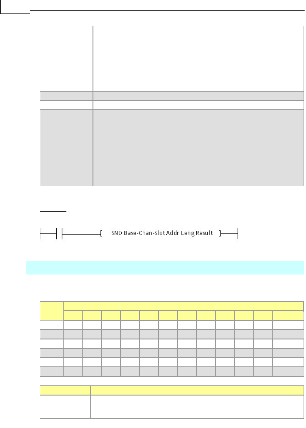
6.2.6.1 User Communication (SND, RCV)
Exclusive Commands for Computer Communication,
This is used when the communication frame defined in a user program is used to send and receive data in
a program.
SND
This is used to send data as much as the length of the data requested from a computer link module.
CMD
Usable Device
M
X
Y
K
L
F
T
C
S
D
@D
Integer
Base
O
Chan
O
Slot
O
Addr
O
O
O
O
O
O
O
O
O
O
O
Leng
O
Result
O
O
O
O
O
O
O
O
O
O
COMMAND
Description
Base-Chan-Slot
Base: The number of the base where a computer link module is mounted is
indicated. In case of expansion base, the number (1~16) of a corresponding base is
CIMON-PLC1100
Copyright 2012 BY KDT SYSTEMS, All rights reserved.
indicated. In case of local one, the number is ‘0’.
Channel Mode: Ch 1(RS232:0) and Ch 2(RS422:1).
Slot No.: The number of the slot where a computer link module is mounted
[Ex.] In case of local base, Slot 2, Channel 1(RS232) -> h0002 : RS-232C
[Ex.] In case of expansion base (1), Slot 1, Channel 2(RS422) -> h0111 : RS-422
Addr
Address of the data sent
Leng
Length of the data sent (BYTE), Decimal figure, Max. 500BYTE
Result
The address where the result of sending is noticed is assigned.
(X,Y,M,L,K,T,C,D,@D,Z)
Result Format :
·Bit 0 : When sending completed, 1Scan ON. When failed, always ON.
·Bit 1 : When sending failed, always ON.
·Bit 2-7 : OFF
·Bit 8-F : Error Code (0=No Error)
FORMAT
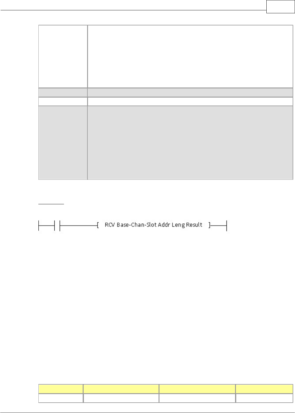
RCV
This is used to store data as much as the length of the data requested from a computer link module.
CMD
Usable Device
M
X
Y
K
L
F
T
C
S
D
@D
Integer
Base
O
ChNo
O
Slot
O
Addr
O
O
O
O
O
O
O
O
O
O
O
Leng
O
Result
O
O
O
O
O
O
O
O
O
O
COMMAND
Description
Base-Chan-Slot
Base: The number of the base where a computer link module is mounted is
indicated. In case of expansion base, the number (1~16) of a corresponding base is
XP / CP Series(CM1) 1101
Copyright 2012 BY KDT SYSTEMS, All rights reserved.
indicated. In case of local one, the number is ‘0’.
Channel Mode: Ch 1(RS232:0) and Ch 2(RS422:1).
Slot No.: The number of the slot where a computer link module is mounted
[Ex.] In case of local base, Slot 0, Channel 1(RS232)-> h0000 : RS-232C
[Ex.] In case of expansion base (1), Slot 4, Channel 2(RS422)-> h0114 : RS-422
Addr
Address where data are received and stored
Leng
Length of the data received (BYTE), Decimal figure, Max. 500BYTE
Result
The address where the result of receiving is noticed is assigned.
(X,Y,M,L,K,T,C,D,@D,Z)
Result Format :
·Bit 0 : When receiving completed, 1Scan ON. When failed, always ON
·Bit 1 : When receiving failed, always ON
·Bit 2-7 : OFF
·Bit 8-F : Error Code (0=No Error)
FORMAT
6.2.6.2 User Communication (SEND, RECV)
This is used to define communication frames in the protocol editor, sending or receiving the frames in a program.
User communications is the mode that other companies’ protocols can be defined in the CIMON PLC to
communicate communications modules with other devices. Diverse communications protocols are used
according to manufacturers and all the protocols cannot be built in. And if a protocol is defined properly to an
application field and a program is written, communications with other devices is available according to a defined
protocol. If a protocol editor is used to define protocol frames (In the CICON), it is available to write and edit
other manufacturers’ protocols. To use as user communication mode for correct data communication, the
information about the contents of the protocol used is to be correct and a program using the instructions to
control sending/receiving in a PLC as well as editing frames be written. This chapter explains the communication
specifications and the directions for use of user protocols.
The modes of communications modules operated as a user protocol are as follows.
Module Name
RS232C
RS422/485
Remarks
CM1-SC01A
User Protocol
X
X
CIMON-PLC1102
Copyright 2012 BY KDT SYSTEMS, All rights reserved.
CM1-SC01B
X
User Protocol
X
CM1-SC02A
User Protocol
User Protocol
Linked
User Protocol
User Protocol
Independent
User Protocol
HMI User Protocol
Independent
User Protocol
Modbus RTU User Protocol
Independent
User Protocol
PLC Link User Protocol
Independent
User Protocol
CICON User Protocol
Independent
HMI User Protocol
User Protocol
Independent
Modbus RTU User Protocol
User Protocol
Independent
PLC Link User Protocol
User Protocol
Independent
CICON User Protocol
User Protocol
Independent
But, Make sure the version before using user protocol (SEND, RECV) function.
CICON
CM1-CPXXX(CPU)
CM1-SCXXX (RS232C/422/485)
Version
1.83.0043
V 1.56
V 1.20
To use user protocols, a version should be higher than the versions described above.
Otherwise, consult with the head office to upgrade.
See :
·Operation Procedure of User Communications
·Registering and Editing a Special Program
·Instructions for User Program
·Error Codes for User Communications
·Example of Programming for User Communications
·Example of Application of MODICON (MODBUS) protocol
·Sending/Receiving communication frames at communication intervals
6.2.6.2.1 Operation Procedure of User Communications
As user communications require to use a frame editor and write a CICON program, it is set up as the following
order.
Programming Order for User Communications ,
XP / CP Series(CM1) 1103
Copyright 2012 BY KDT SYSTEMS, All rights reserved.
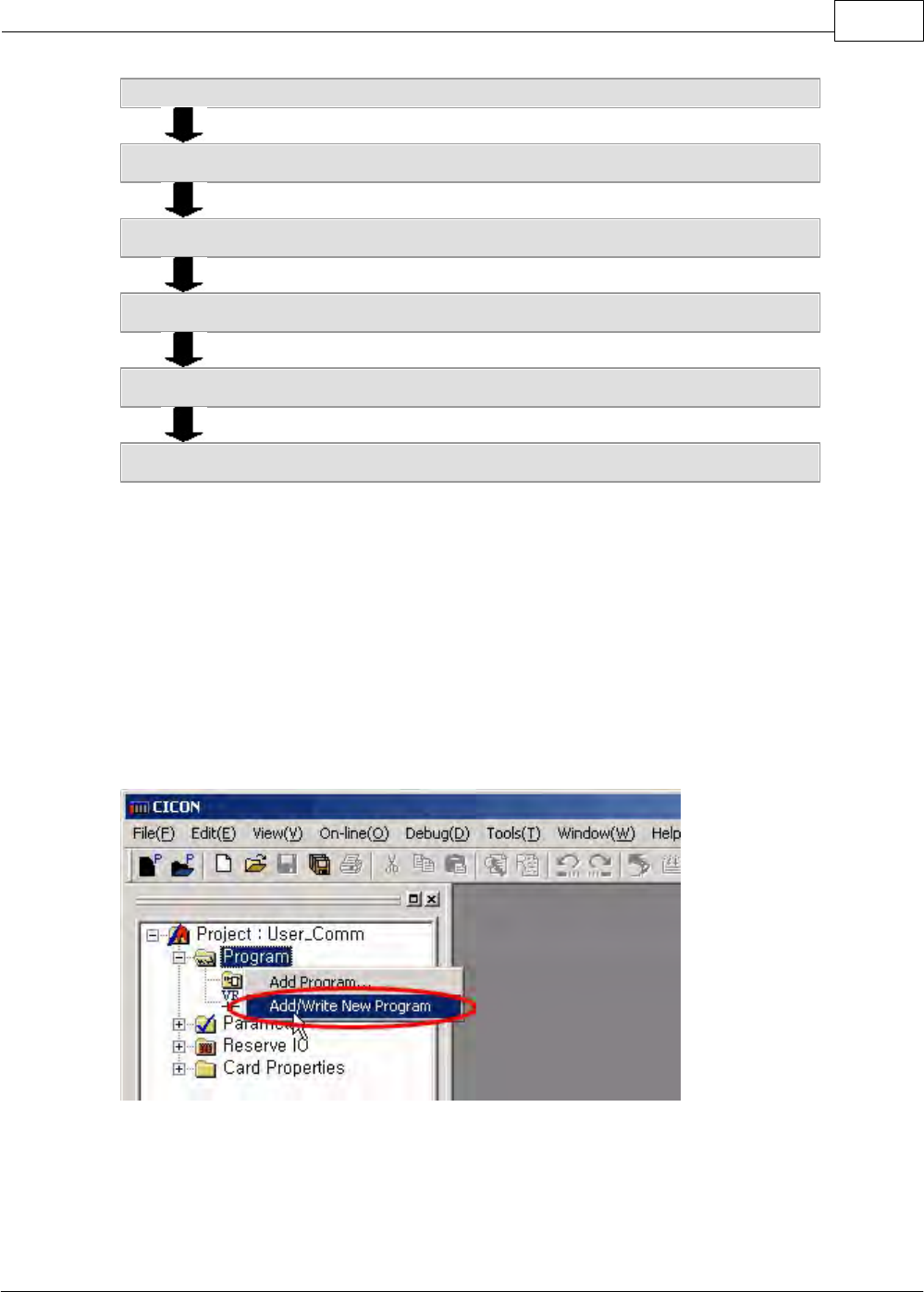
1. Register a special program to define frames.
2. Edit the protocol in the special program.
3. Write a PLC program for sending/receiving in the CICON.
4. Download the PLC program and the special program.
5. Convert CPU status to RUN mode.
6. Normal communication starts.
6.2.6.2.2 Registering and Editing a Special Program
1. Select the add/write new program in the CICON.
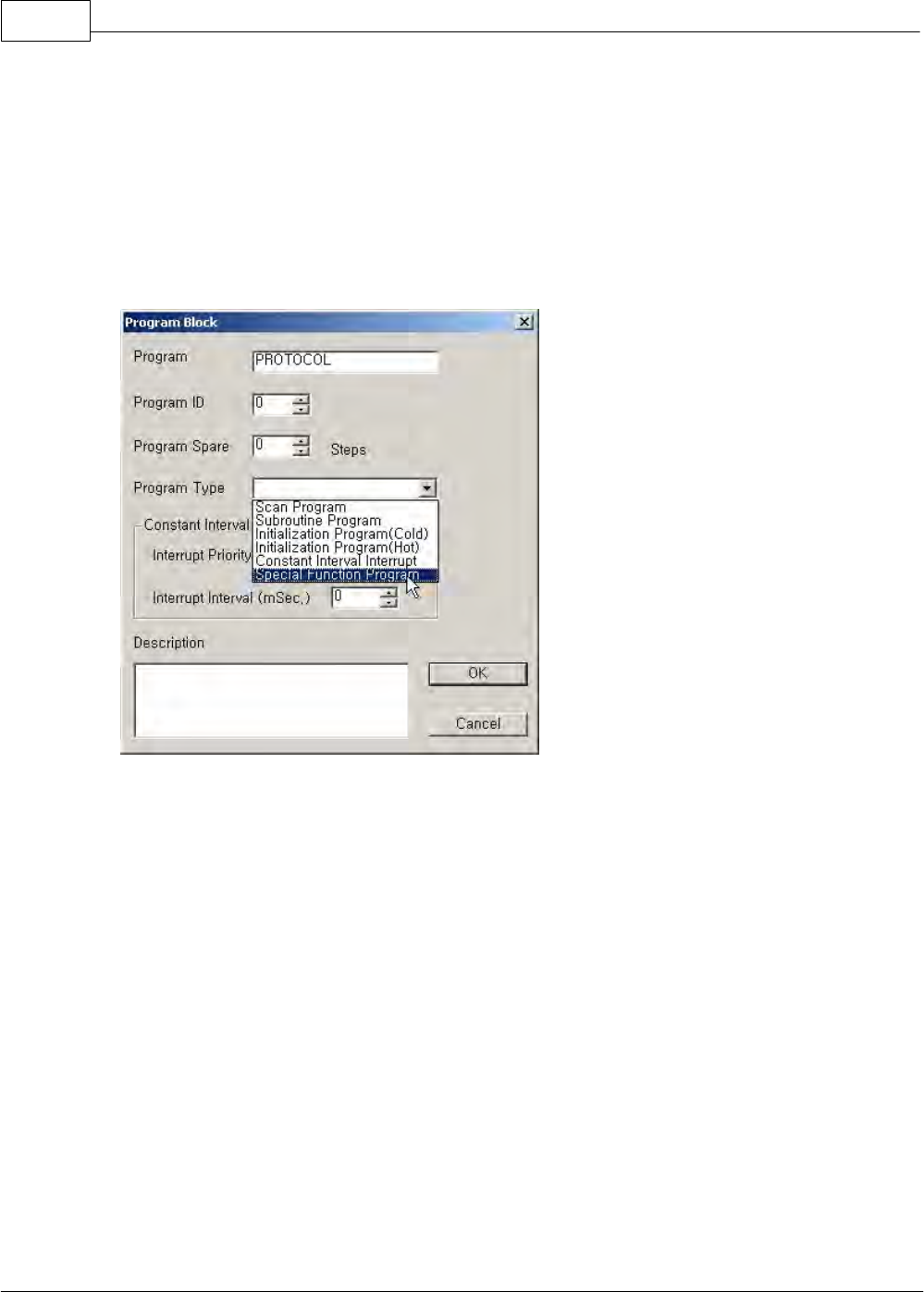
2. If you select the add/write new program, the program block
dialog box will appear as follows.
·Program: This is used to define the name of special program. Up to 12 letters can be entered.
CIMON-PLC1104
Copyright 2012 BY KDT SYSTEMS, All rights reserved.
·Program ID: This is used to define ID for each program.
·Program Spare: This is to indicate the max. size for editing the protocols in a special program while
CPU status is run.
·Program Type: This is used to select the type of the program registered at this time. Here, select the
special program.
If you finish registering the parameters, press the [OK] button.
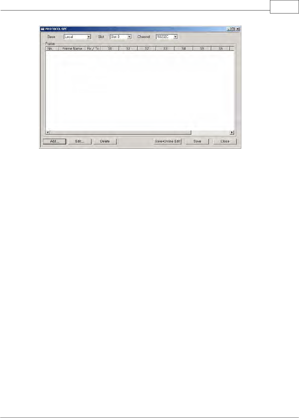
3. If you press the [OK] button, the dialog box for registering
protocols will appear.
XP / CP Series(CM1) 1105
Copyright 2012 BY KDT SYSTEMS, All rights reserved.
In a created PROTOCOL.SPC file, protocols can be registered.
·Base: This is used to select the base where a communication card (CM1- SCXXX) is mounted.
·Slot: This is used to select the slot where a communication card (CM1-SCXXX) is mounted. Slot number
is counted from the slot next to a CPU module.
·Channel: This is used to select the communication port between a master and a slave.
·Result: This is used to send data without SEND command as sending interval is set up and, if a
receiving frame is defined, to indicate whether a defined receiving frame is normally received. (Memory
device: M0000)
a. Received: The bit corresponding to the frame number in M0000 is on for 1 scan.
b. Not Received: The bit corresponding to the frame number in M0020 is on for 1 scan.
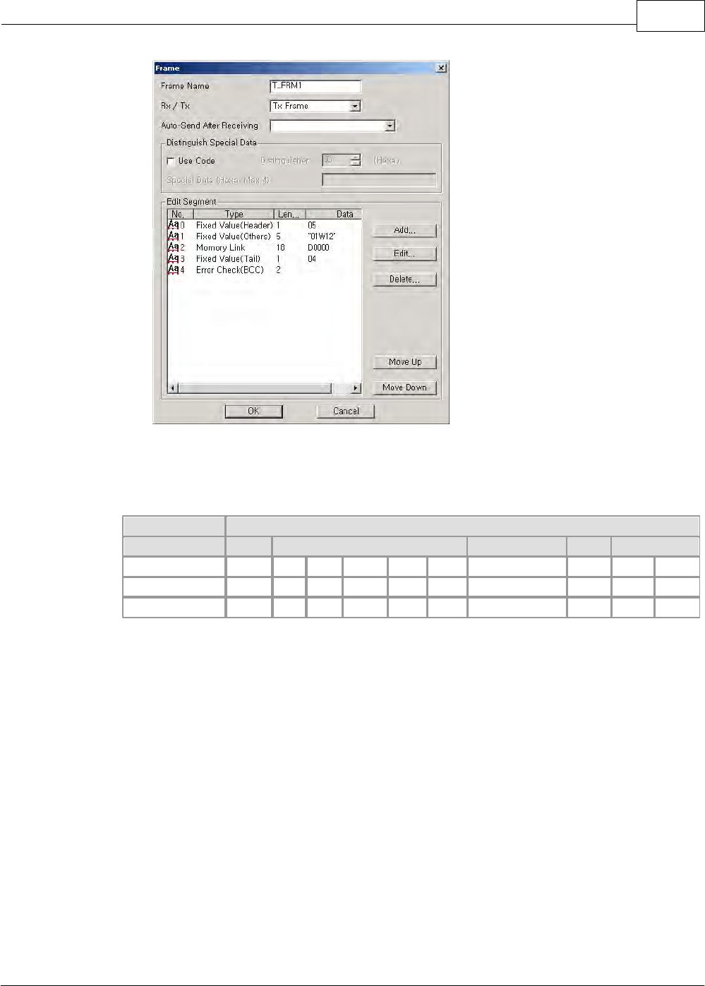
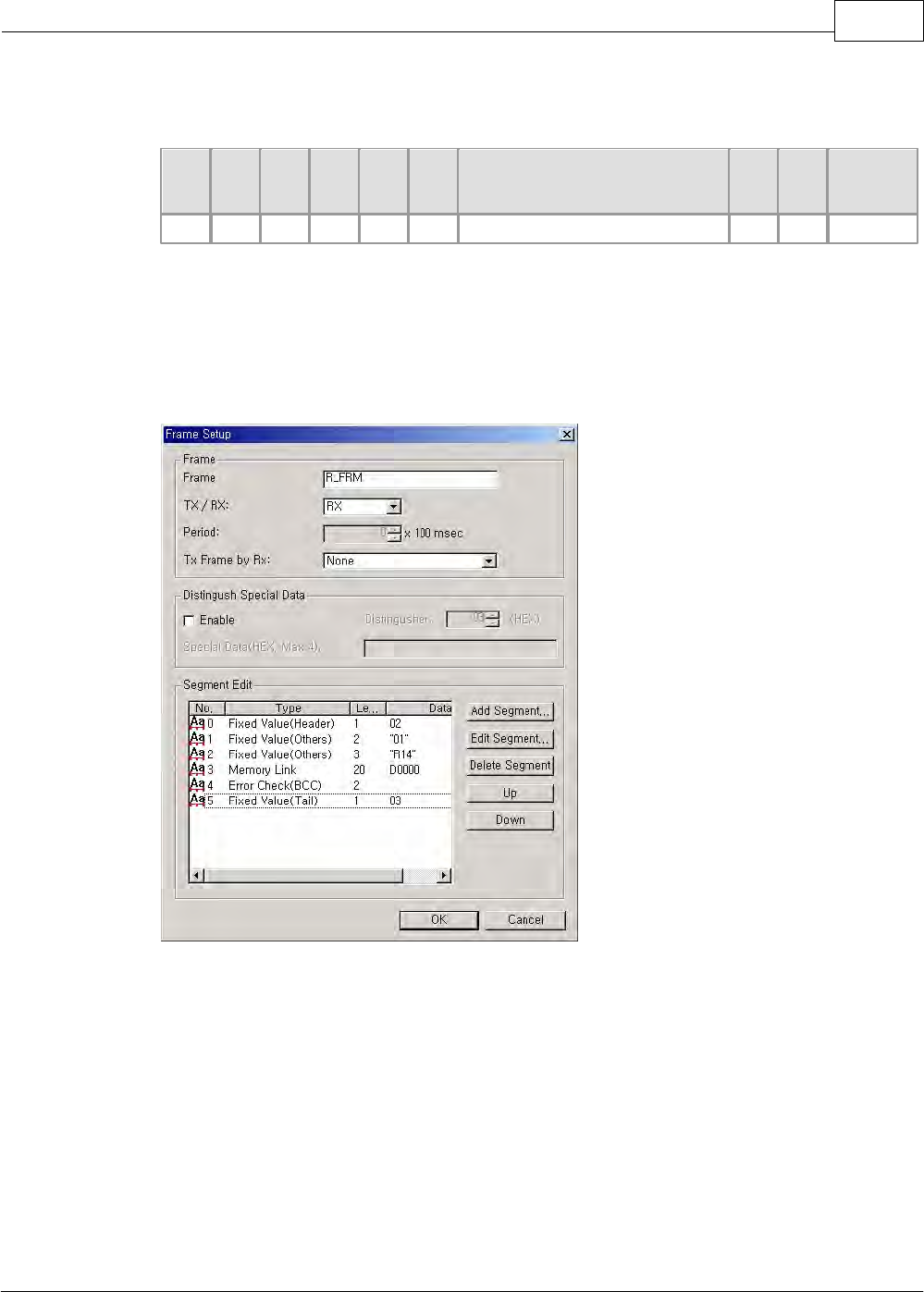
4. If you select the add button, the dialog box for adding a frame
will appear.
·Frame Name: This is used to register a frame name. (Max. 20 letters)
·Comm. Direction: This is used to select whether the frame registered is the one sent or the one
received.
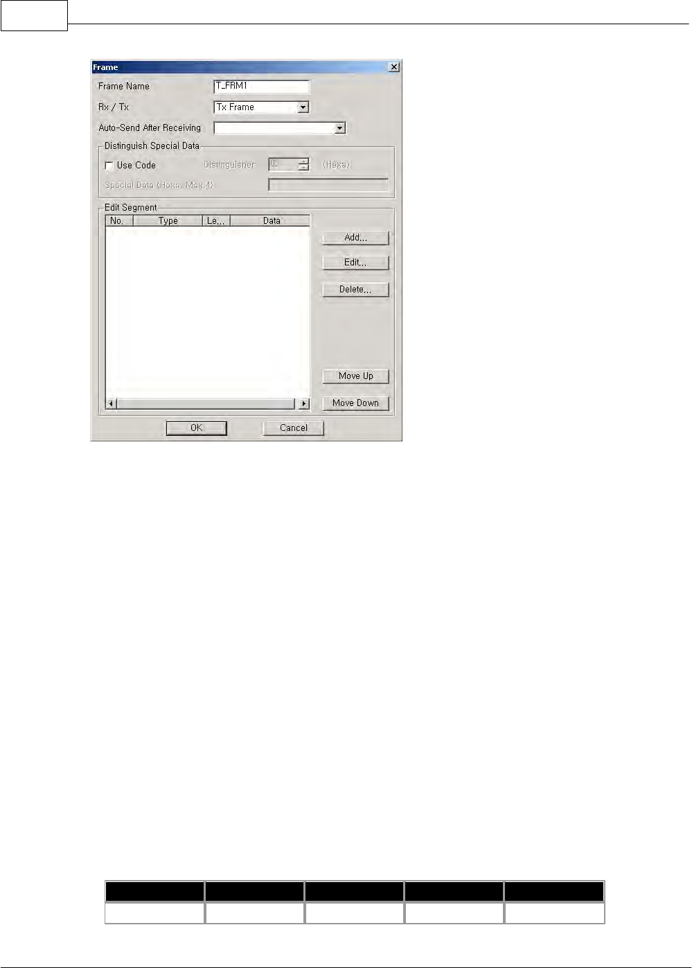
CIMON-PLC1106
Copyright 2012 BY KDT SYSTEMS, All rights reserved.
·Comm. Interval: Frames are automatically sent at intervals without SEND command in a PLC program.
If Comm. interval is ‘0’, frames will be sent only by SEND command. A PLC program is not needed in
case of sending/receiving frames by using comm. interval.
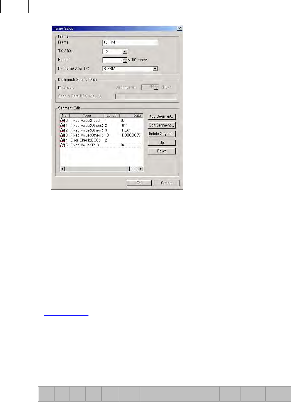
[Receiving frame for sending] This corresponds to the case comm. frames are sending ones.
If a corresponding frame is sent and the receiving frame for the sending frame is registered, the
registered frame will be received without RECV command in the PLC program.
·Auto-send after Receiving: This is operated in case that comm. direction is the frame received. If a
corresponding frame is received, the frame registered for sending will be automatically sent without the
command to send in a PLC program.
·Use Code: This is used to distinguish a special data from the data in the frames sent/received. In case
that there is the same letter as the corresponding distinguishes among the data in the frames
sent/received, registered data are attached next to the distinguishes to be sent or received.
For example, the case hexadecimal FEh is registered to a distinguishes and FFh to special data.
Header
Length
Cmd
MSG
Checksum
FEh
03h
3Ch
3Fh
FEh

XP / CP Series(CM1) 1107
Copyright 2012 BY KDT SYSTEMS, All rights reserved.
Header
Length
Cmd
MSG
Checksum
Special Data
FEh
03h
3Ch
3Fh
FEh
FFh
Up to 4 special data can be registered. If 4 special data are registered, they will be sent/received
continuously next to a distinguisher.
·Add: This is used to add segments to write a frame. Up to 10 segments can be registered.
·Edit: This is used to edit the segments in a made frame.
·Delete: This is used to delete the segments in a made frame.
·Move Up: This is used to switch the location of the segments in a made frame. A selected one is
moved up one step by one step.
·Move Down: This is used to switch the location of the segments in a made frame. A selected one is
moved down one step by one step.
5. To make a frame, segments should be added.
SEGMENT0
SEGMENT1
........
SEGMENT8
SEGMENT9
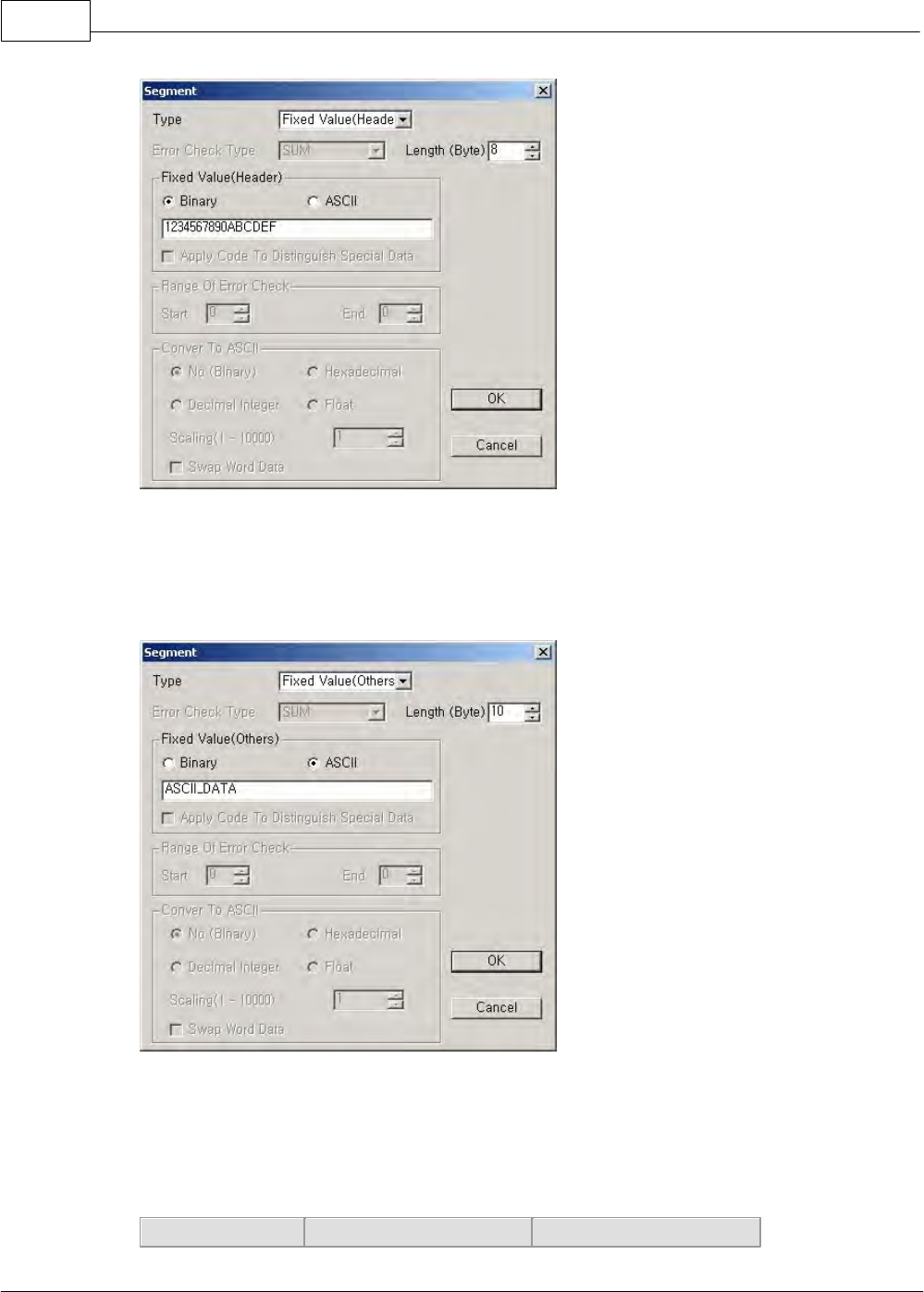
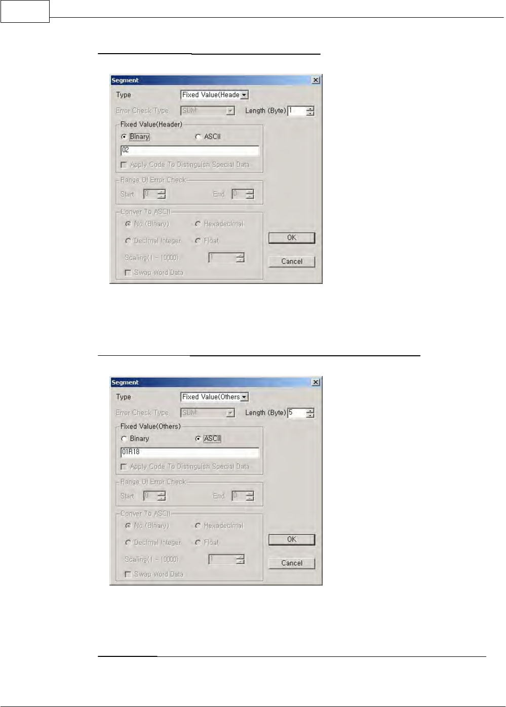
1. Type
[Fixed Value (Header)]
This means the first data in the frame made. The value is to be assigned in the type of ASCII or Binary.
In case that data is in Binary type, assign in hexadecimal number and a byte data in 2-place
hexadecimal number. In case of ASCII type, a letter is processed as byte data.
CIMON-PLC1108
Copyright 2012 BY KDT SYSTEMS, All rights reserved.
[Fixed Value (Others)]
This is the segment assigning general data in the frame made.
Assign constant value in the type of ASCII or Binary.
In case that data is in Binary type, assign in hexadecimal number and a byte data in 2-place
hexadecimal number. In case of ASCII type, a letter is processed as byte data.
·Fixed Value (Header, Tail, Others) Data Sent
PLC
12345678
12345678
XP / CP Series(CM1) 1109
Copyright 2012 BY KDT SYSTEMS, All rights reserved.
Data Conversion
Binary
ASCII
Other Device
12345678
3132333435363738
·Fixed Value (Header, Tail, Others) Data Received
Other Device
12345678
3132333435363738
Data Conversion
Binary
ASCII
PLC
12345678
3132333435363738
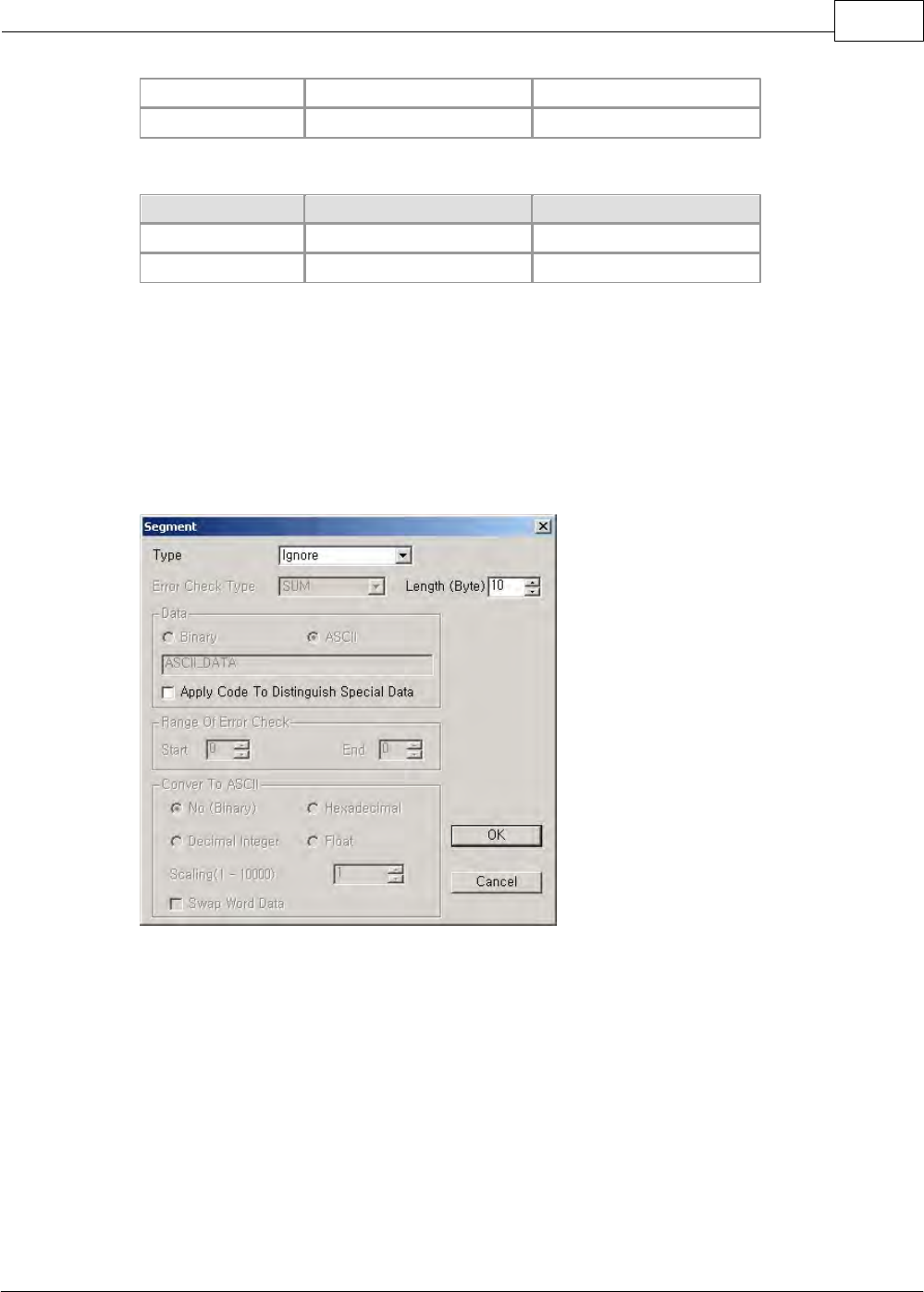
[Ignore]
This segment is used to ignore assigned-length data after receiving, irrelevantly to the value of received
data. This can be set up in case of only the frame received. If the use code is applied, it is distinguished
that the letters like the distinguisher of special data are continuously received and the data next to the
distinguisher are disregarded. It is available to apply the use code.
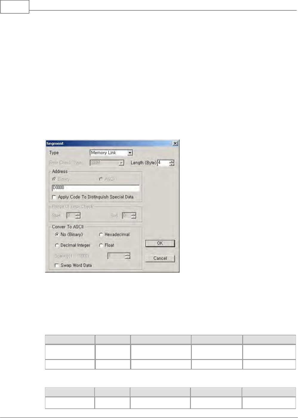
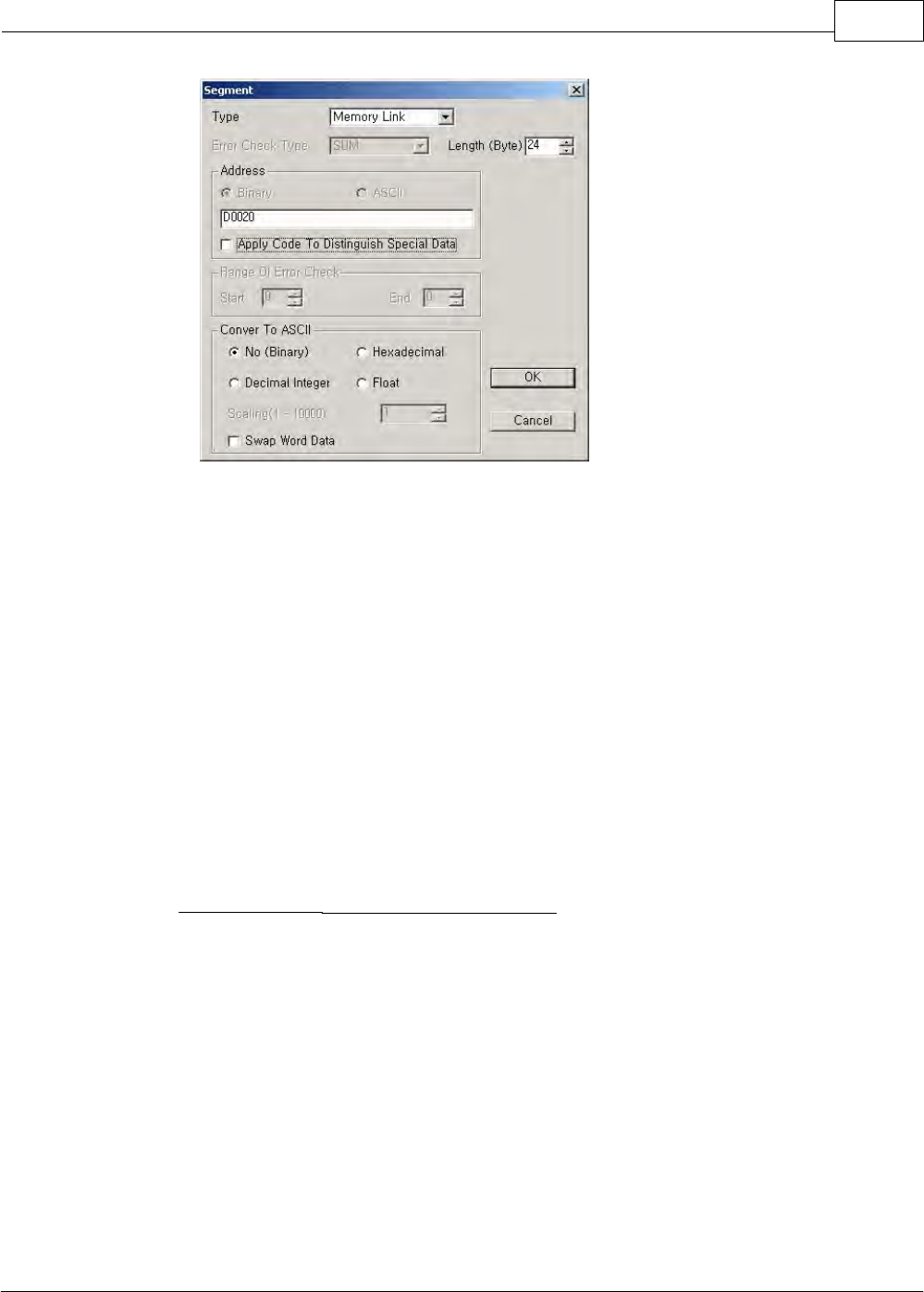
[Memory Link]
This segment is used to send the data stored in the memory of CPU as much as an assigned length or
store received data in the memory device of CPU as much as assigned length. The maximum data size
is 250Byte. If the use code is applied, it is distinguished that the letters like the distinguisher of the
special data are continuously received and the data next to the distinguisher are disregarded. It is
available to apply the use code.
·Convert to ASCII
No(Binary)
This is used to send/receive the data in the memory device of CPU as they are.
CIMON-PLC1110
Copyright 2012 BY KDT SYSTEMS, All rights reserved.
Hexadecimal
Integer
This is used to convert the data in the memory device of CPU to hexadecimal
ASCII data, sending the result. And to convert received hexadecimal ASCII data to
binary data, storing the result in the memory of CPU.
Decimal Interger
This is used to convert the data in the memory device of CPU to decimal ASCII
data, sending the result. And to convert the received decimal ASCII data to binary
data, storing the result in the memory of CPU.
Real
Number(Float)
This is used to scale the data in the memory of CPU(Ratio.1-10000), sending the
result. And to scale the received data(Ratio.1-10000), storing the result in the
memory of CPU.
If you select the swap word data, upper 1 byte data and lower 1 byte data of the data sent/received are
swapped. For example, if the data stored in the memory of CPU is h1234(ASC:1234), the actual data
sent will be h3412(ASC:3421). If a received data is h1234(ASC:1234), the actually received data
h3412(ASC:3412) will be stored in the memory of CPU.
·Memory Link Data Sent
PLC
1234h
1234h
1234h
1234h
Data Conversion
No(Binary)
Hexadecimal Integer
Decimal Integer
Real Number
(Scaling:10)
Other Device
1234h
31323334
34363630
01D2h
·Memory Link Data Received
Other Device
1234h
31323334
34363630
1234h
Data Conversion
No(Binary)
Hexadecimal Integer
Decimal Integer
Real Number
XP / CP Series(CM1) 1111
Copyright 2012 BY KDT SYSTEMS, All rights reserved.
(Scaling:10)
PLC
1234h
1234h
1234h
B608h
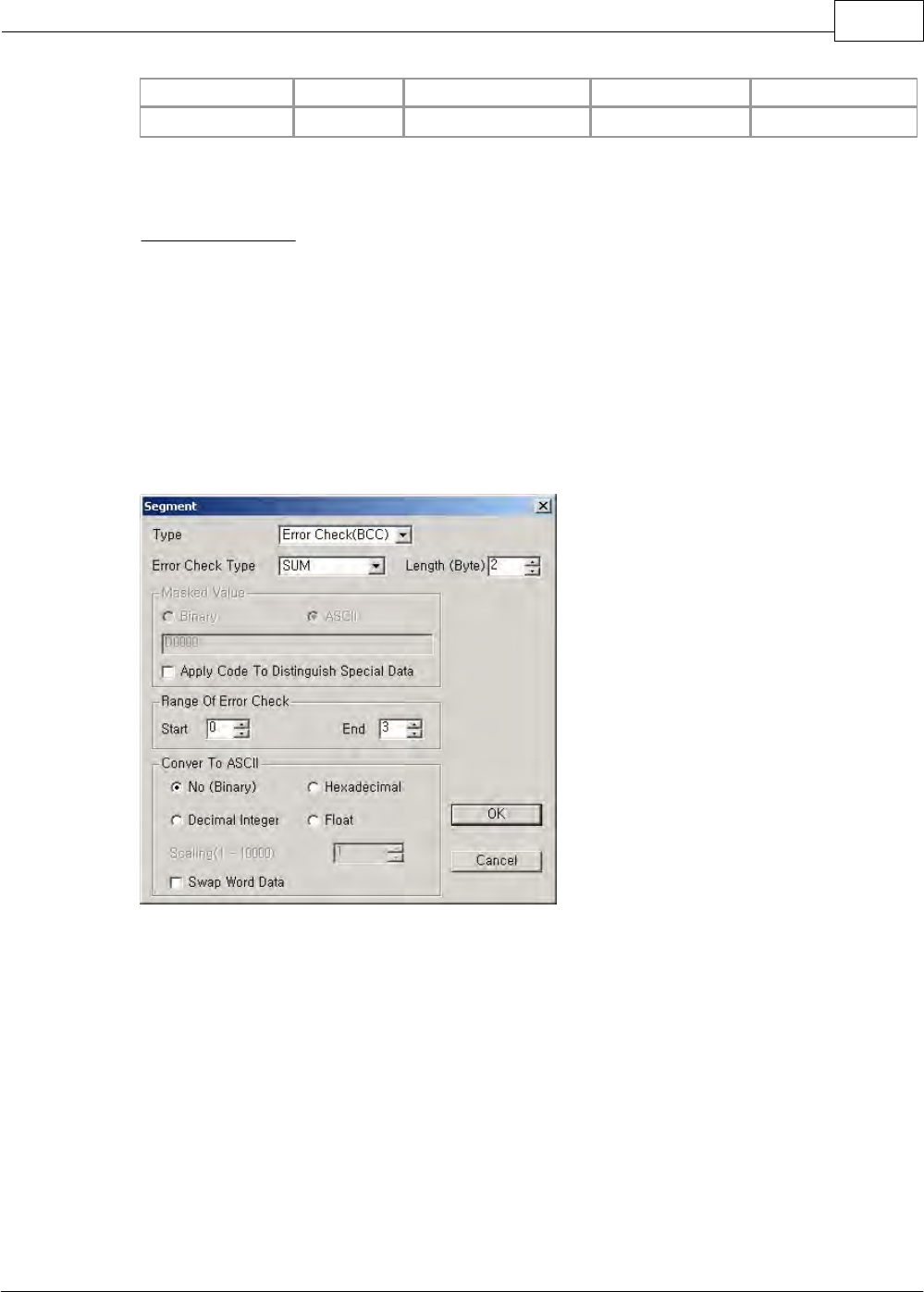
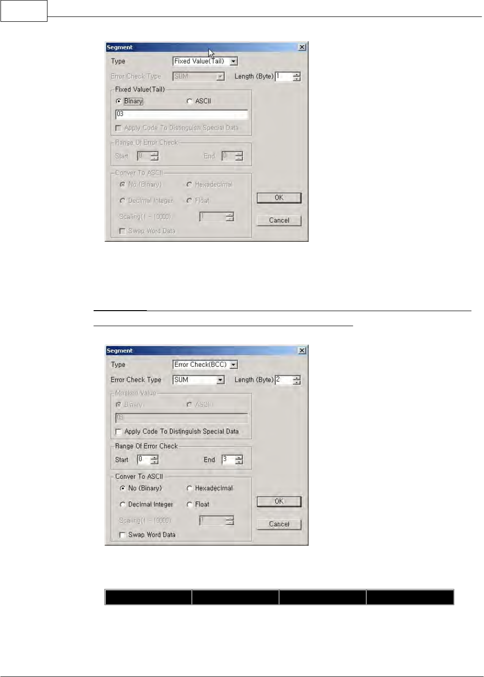
2. Error Check Type
This is used to check whether the data of a frame are correctly sent/received. It is available to distinguish
special data.
[SUM]
This is used to binary-sum an edited frame from the first of a selected range to the last of it and to
send/receive data as much as a set length (Byte). Enter a range in the error check range (Range of
segments). Refer to the memory link for ASCII data conversion.
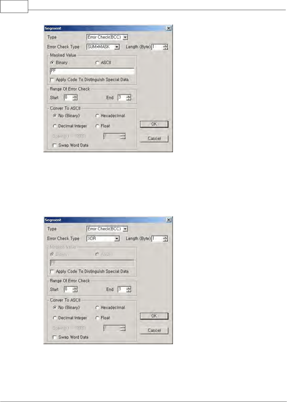
[SUM+MASK]
This is used to binary-sum an edited frame from the first of a selected range to the last of it, masking the
binary-summed data with masking value (FFh) and to send/receive data as much as a set length (Byte).
Refer to the memory link for ASCII data conversion.
CIMON-PLC1112
Copyright 2012 BY KDT SYSTEMS, All rights reserved.
[XOR]
This is used to binary-or an edited frame from the first of a selected range to the last of it and to
send/receive the data as much as a set length (Byte). Refer to the memory link for ASCII data
conversion.
[XOR+MASK]
This is used to binary-or an edited frame from the first of a selected range to the last of it, masking the
binary-summed data with masking value (FFh) and to send/receive the data as much as a set length
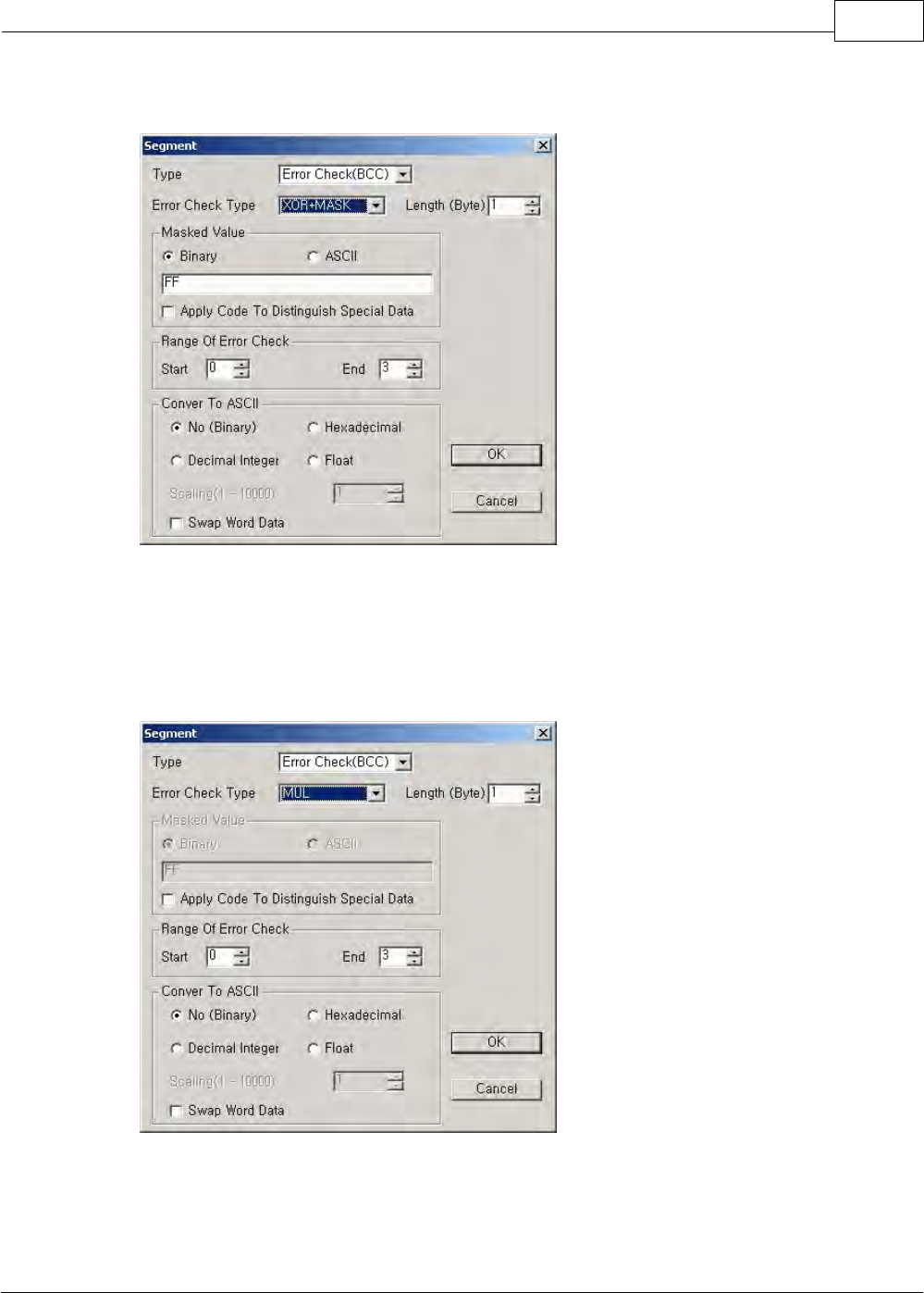
XP / CP Series(CM1) 1113
Copyright 2012 BY KDT SYSTEMS, All rights reserved.
(Byte). Refer to the memory link for ASCII data conversion.
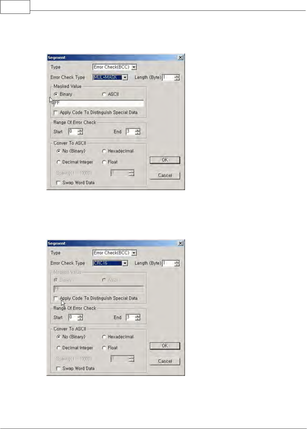
[MUL]
This is used to binary-mul an edited frame from the first of a selected range to the last of it and to
send/receive the data as much as a set length (Byte).
[MUL+MASK]
This is used to binary-mul an edited frame from the first of a selected range to the last of it, masking the
CIMON-PLC1114
Copyright 2012 BY KDT SYSTEMS, All rights reserved.
binary-summed data with masking value (FFh) and to send/receive the data as much as a set length
(Byte).
[CRC16]
This is used to CRC16 an edited frame from the first of a selected range to the last of it.
XP / CP Series(CM1) 1115
Copyright 2012 BY KDT SYSTEMS, All rights reserved.
6.2.6.2.3 Instructions for User Program
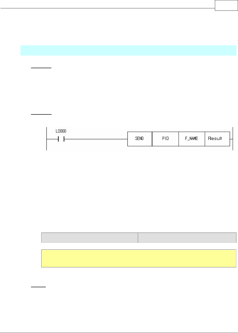
SEND(P)
Function
This is the instruction used to send frame data of user type from a master station to slave stations. To use
this instruction, a user protocol is to be selected as action mode protocol and to be downloaded in the
RS232C/422/485 card setup. SEND instruction is to be executed by pulse.
FORAMT
·PID: This is used to assign the name or the ID of special program.
·F_NAME
1. This is used to enter a frame name or to assign a frame number. The number is to be assigned
according to the following form.
2. Format in case of assigning a frame number
a. Upper byte(Bit 8-F): Assigning communication form(0: RS232C, 1: RS422/485)
b. Lower byte(Bit 0-7): Frame number in special program
Assigning communication form (Upper byte)
Frame number (Lower byte)
[Ex.] In case communication form is RS232C and the frame of which number is 3 is sent,
SEND (PID) h0003 (Result)
Result
·The word device informed of the result of sending is assigned.
·Result Format
a. First Bit(Bit 0): In case of having been sent, 1 Scan On.
CIMON-PLC1116
Copyright 2012 BY KDT SYSTEMS, All rights reserved.
b. Second Bit(Bit 1): In case of having not been sent, always On.
c. Third Bit – Eighth Bit(Bit 2-7): Always Off.
d. Ninth Bit – Sixteenth Bit(Bit 8-F): Error Code.(0=No Error)
Error Code
Not Use
In case of an error in sending,
On
In case of having been sent,
1Scan On
Bit 8 ~ F
Bit 2 ~ 7
Bit 1
Bit 0
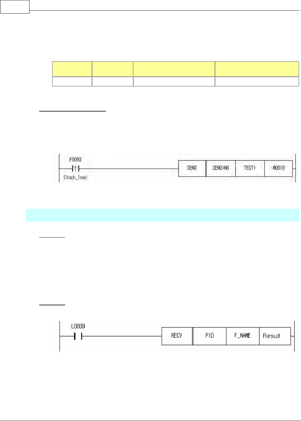
Example of Application
The following is an example of PLC program that a frame is sent to a slave station, in case that the special
program file name of a master station is SENDING and the frame name registered to a protocol editor is
TEST1.
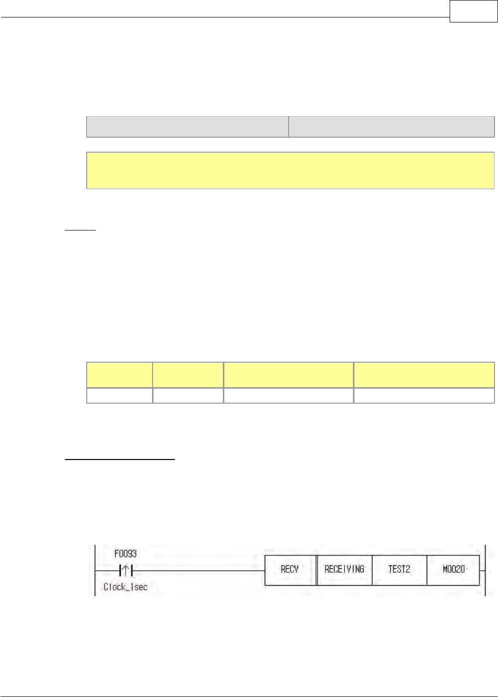
RECV(P)
Function
This is the instruction used in slave stations to receive frame data from a master station. In case that a data
accords with the frame of user form and is normal frame, the flag indicating received(Bit 0) is turned on. To
use this instruction, a user protocol is to be selected as action mode protocol and to be downloaded in the
RS232C/422/485 card setup. RECV instruction is to be executed by pulse.
FORAMT
·PID: This is used to assign the name or the ID of special program.
·F_NAME
1. This is used to enter a frame name or to assign a frame number. The number is to be assigned
according to the following form.
XP / CP Series(CM1) 1117
Copyright 2012 BY KDT SYSTEMS, All rights reserved.
2. Format in case of assigning a frame number
a. Upper byte(Bit 8-F): Assigning communication form(0: RS232C, 1: RS422/485)
b. Lower byte(Bit 0-7): Frame number in special program
Assigning communication form (Upper byte)
Frame number (Lower byte)
[Ex.] In case communication form is RS422/485 and the frame of which number is 5 is sent,
RECV (PID) h0105 (Result)
Result
·The word device informed of the result of sending is assigned.
·Result Format
e. First Bit(Bit 0): In case of having been sent, 1 Scan On.
f. Second Bit(Bit 1): In case of having not been sent, always On.
g. Third Bit – Eighth Bit(Bit 2-7): Always Off.
h. Ninth Bit – Sixteenth Bit(Bit 8-F): Error Code.(0=No Error)
Error Code
Not Use
In case of an error in
receiving, On
In case of having been received,
1Scan On
Bit 8 ~ F
Bit 2 ~ 7
Bit 1
Bit 0
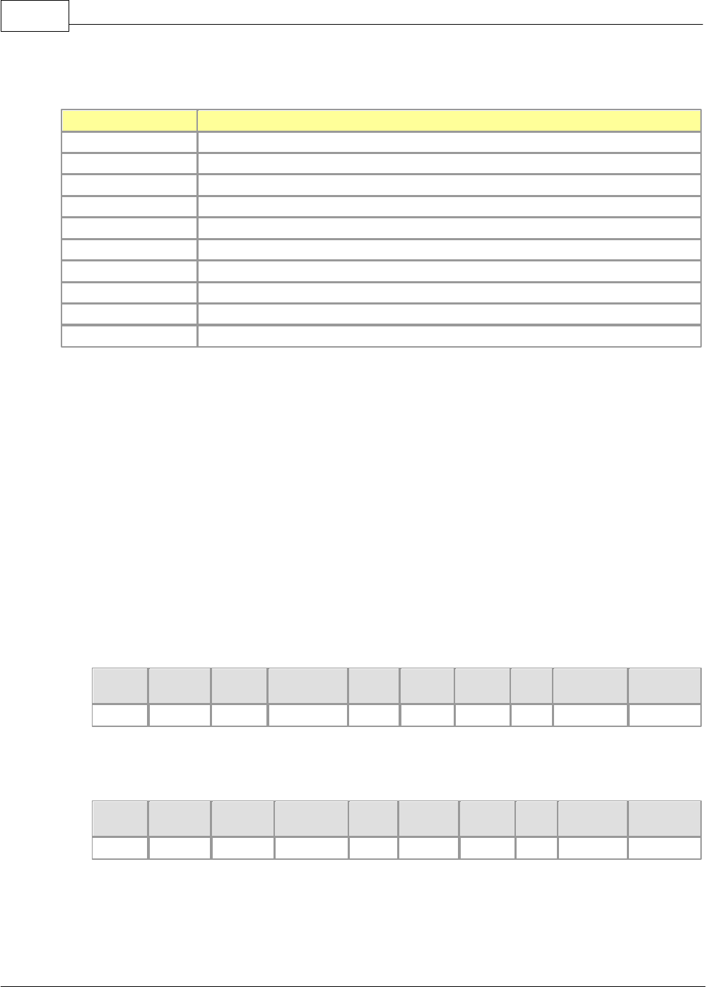
Example of Application
Using RS232C/422/485 card, slave stations receive data from a master station. After receiving the data, the
slave stations compare them with assigned frame data. The following is an example of PLC program that
the frame is sent to a slave station, in case that a special program file name is RECEVING and the frame
name registered in a protocol editor is TEST2.
CIMON-PLC1118
Copyright 2012 BY KDT SYSTEMS, All rights reserved.
6.2.6.2.4 Error Codes for User Communications
Error Code
Description
18 (12h)
The range to check errors is wrongly set up.
19 (13h)
There is no registered frame.
20 (14h)
Segments are not registered to the frame.
21 (15h)
The communication direction of the frame is wrongly set up.
22 (16h)
Sending/receiving frames are disabled.
23 (17h)
Access to buffer memory is failed.
24 (18h)
The size of each segment data is over.
25 (19h)
When swapping word data, the size of the data is wrong.
26 (20h)
The entire length of sending/receiving frame is over 600Byte.
27 (21h)
The size of data is wrongly assigned.
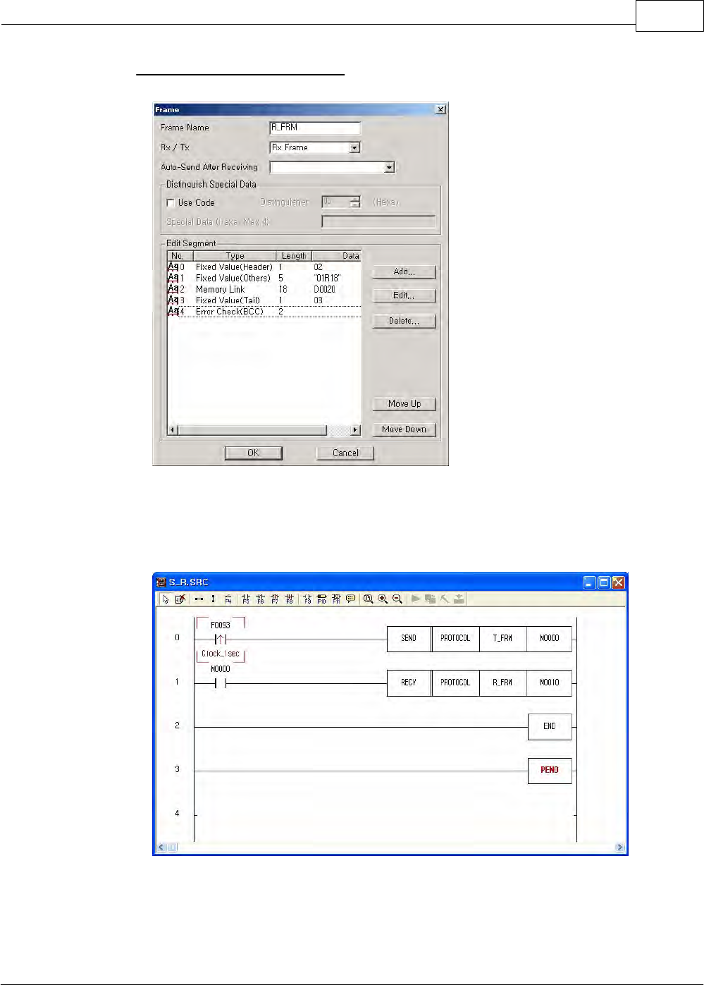
6.2.6.2.5 Example of Programming for User Communications
The following shows an example of configuration of communication system and frame between a CIMON-PLC
and other manufacturer’s PLC to explain the programming method for user communication. It is the case that the
18-byte data in Memory D0000 of the CIMON-PLC are written to other manufacturer’s PLC and the 24-byte data
of other manufacturer’s PLC are read and stored in Memory D0020 of the CIMON-PLC.
PLC protocol of other manufacturer,
Frame requesting to write (CIMON-PLC -> Other manufacturer’s PLC)
Header
Station
(H)
Station
(L)
Command
Size
(H)
Size
(L)
Data
Tail
Error
Check(H)
Error
Check(L)
ENQ
0
1
W
1
2
18Byte
EOT
?
?
Frame responding to request to read (Other manufacturer’s PLC -> CIMON-PLC)
Header
Station
(H)
Station
(L)
Command
Size
(H)
Size
(L)
Data
Tail
Error
Check (H)
Error
Check (L)
STX
0
1
R
1
8
24Byte
ETX
?
?
XP / CP Series(CM1) 1119
Copyright 2012 BY KDT SYSTEMS, All rights reserved.
Description for Protocols,
1) Frame Requesting to Write
ENQ and EOT, which are the control letters of ASCII code, are used at the header and the tail.
Command ‘W’ is used.
The length of data indicates 18 bytes(12h).
Order of Sending
Start -------------------------------------------------------> End
Type of Frame
Header
Fixed Value (Others)
Data
Tail
Error Check
Frame sent
ENQ
0
1
W
1
2
Variable Data
EOT
H
L
Binary
05h
30h
31h
57h
31h
32h
D0000
04h
ASCII
‘0’
‘1’
‘W’
‘1’
‘2’
D0000
12-byte data in the memory for sending data of CPU (CIMON-PLC D0000) are sent.
The error check is to binary-sum ASCII code values from the header to the tail. Calculated data is
varied according to frame.
To make the above frame sent in a protocol editor, binary or ASCII can be selected as fixed value. In
case of binary like the above table, enter a hexadecimal value. In case of ASCII, enter letters. But,
hexadecimal 2-digit number occupies 1 byte and a letter occupies 1 byte.
CIMON-PLC1120
Copyright 2012 BY KDT SYSTEMS, All rights reserved.
Using the protocol editor, make the frame sent of other manufacturer’s protocol as the
following procedure.
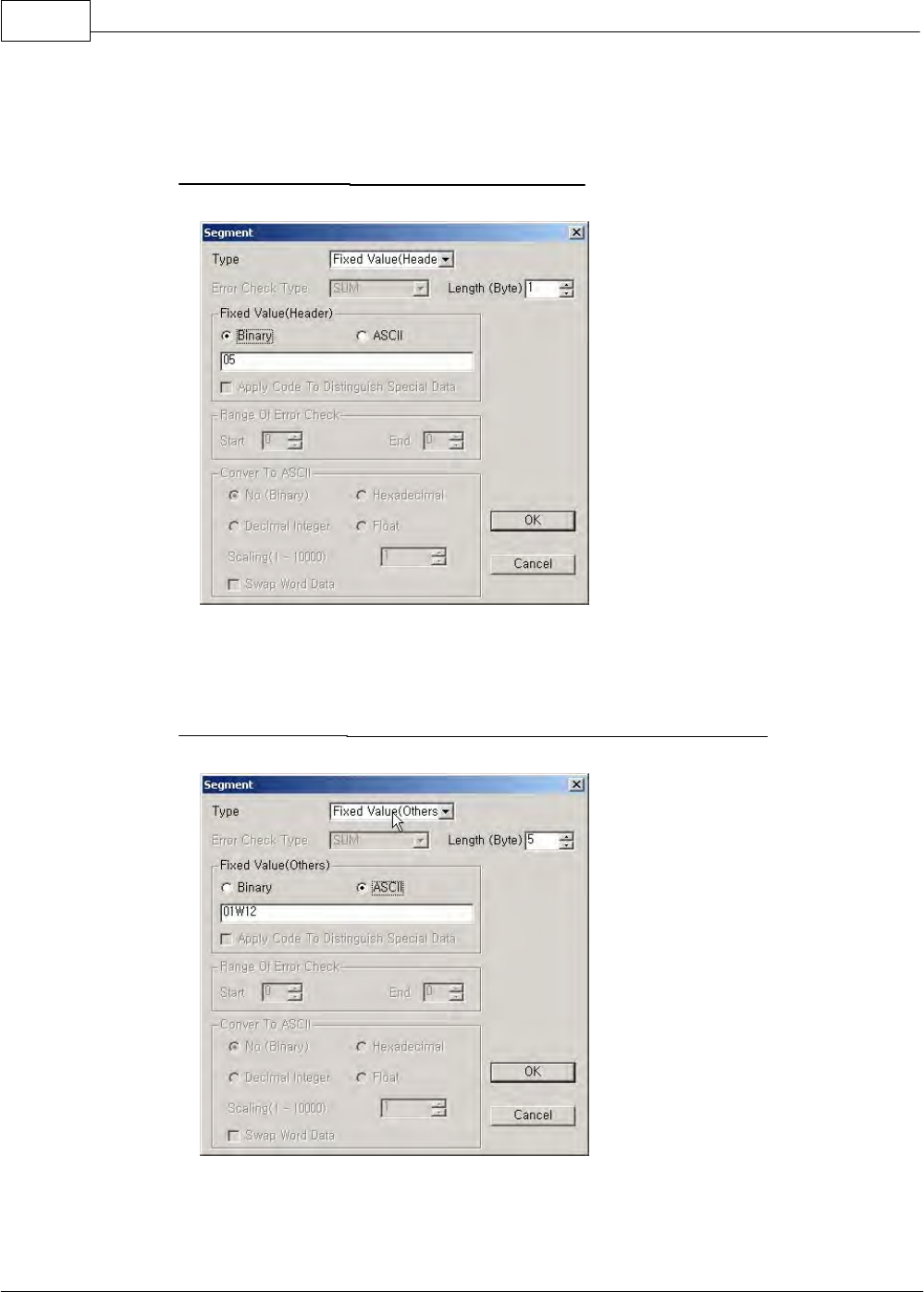
1. Fixed Value (Header): This is the first data of a frame.
Binary 05h is ENQ. Hexadecimal 2-digit number occupies 1 byte.
2. Fixed Value (Others): As a data is displayed in ASCII, a letter occupies 1 byte.
Binary data (30 31 57 31 32) can be displayed.
XP / CP Series(CM1) 1121
Copyright 2012 BY KDT SYSTEMS, All rights reserved.
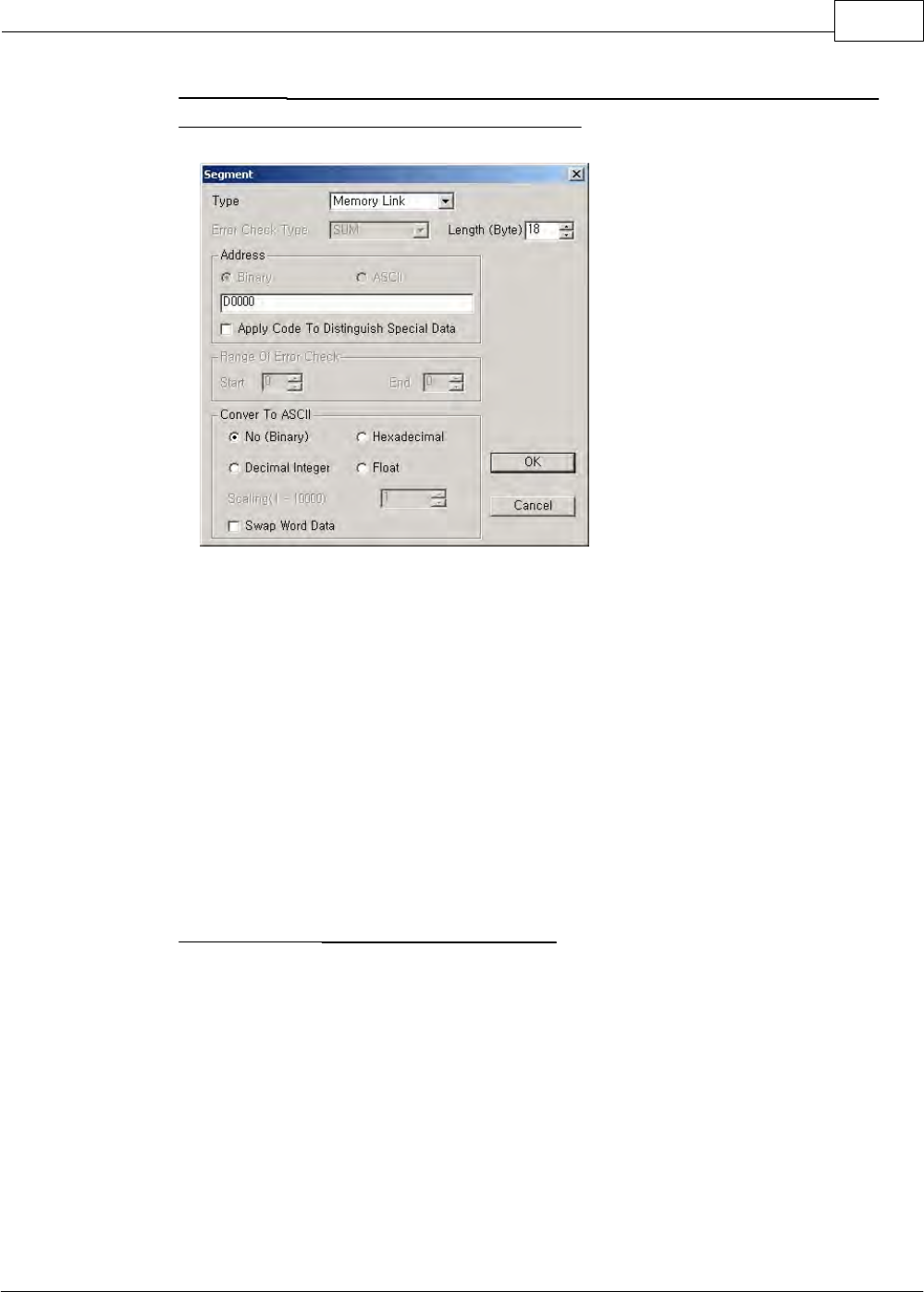
3. Memory Link: If an address is selected as D0000 with the length of 18 bytes, the 18-byte data
stored in D0000 will be sent without ASCII conversion.
Convert to ASCII Data :
·No(Binary): The data stored in the memory of CPU is sent without conversion. For example, if
the length of a data is 2 bytes and the value is 0x1234(2Byte), Data 1234 will be sent.
·Hexadecimal Integer: A data is converted to ASCII data and the result is sent. As actually sent
data are ‘1’,’2’,’3’,’4’, in case that a data value is 0x1234, 4 bytes is to be set up as the length
of the data.
·Decimal Integer: 0x1234 is equivalent to decimal 4660. As actually sent data are ‘4’,’6’,‘6’,’0’,
4 bytes is to be set up as the length of the data.
·Real Number: In case that scaling is 10, Data Value 0x1234 is divided by 10 and the result is
sent in binary data. The actual sent data is 0x01D2.
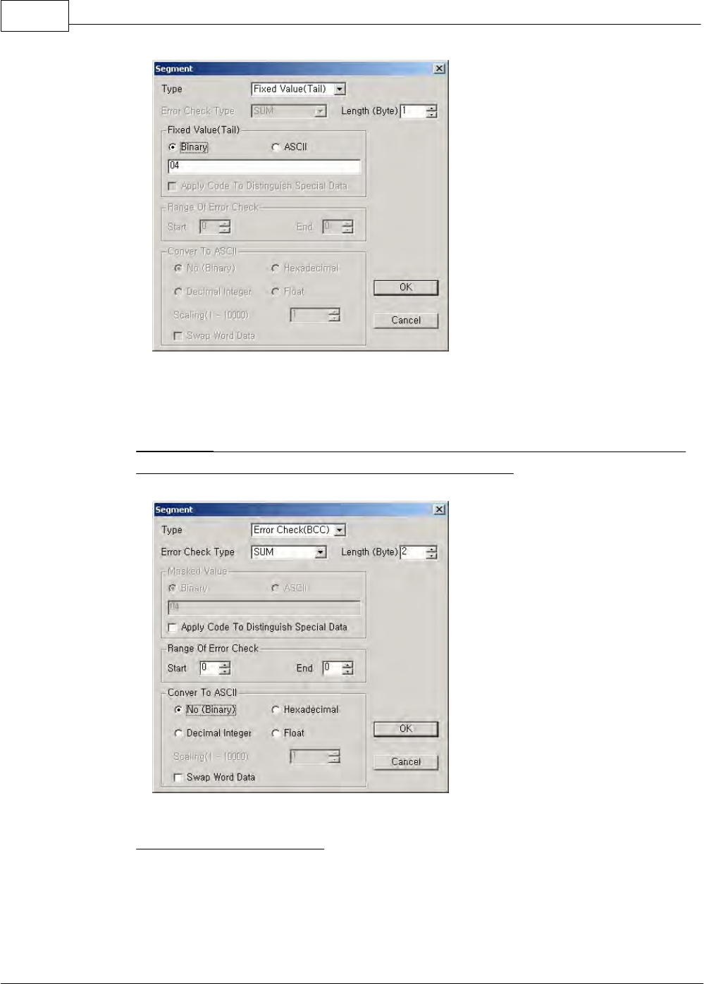
4. Fixed Value (Tail): This is the last data of a frame.
CIMON-PLC1122
Copyright 2012 BY KDT SYSTEMS, All rights reserved.
Binary 04h is EOT. Hexadecimal 2-digit number occupies 1 byte.
5. Error Check: The data of the frame sent are binary-summed as much as a set value in the range
of error check. Refer to the memory link for ASCII data conversion.
6. The frame sent has been edited.
XP / CP Series(CM1) 1123
Copyright 2012 BY KDT SYSTEMS, All rights reserved.
2) Frame Responding to Request to Read
Order of Sending
Start ----------------------------------------------------------------------------> End
Type of Frame
Header
Fixed Value (Others)
Data
Tail
BCC
Frame sent
STX
0
1
R
1
8
Variable Data
ETX
H
L
Binary
02h
30h
31h
57h
31h
38h
D0000
03h
ASCII
‘0’
‘1’
‘R’
‘1’
‘8’
D0000
STX and ETX, which are the control letters of ASCII code, are used at the header and the tail.
Command ‘R’ is used.
The length of a data displays 24 bytes(18).
24-byte data in the memory for sending data of CPU are sent.
Error check is to binary-sum ASCII code values from the header to the tail. A calculated data is varied
according to frame.
To make the above frame received in a protocol editor, binary or ASCII can be selected as fixed
value. In case of binary like the above table, enter a hexadecimal value. In case of ASCII, enter
letters. But, hexadecimal 2-digit number occupies 1 byte and a letter occupies 1 byte.
Using a protocol editor, make the frame sent of other manufacturer’s protocol as the following
procedure.
CIMON-PLC1124
Copyright 2012 BY KDT SYSTEMS, All rights reserved.
1. Fixed Value (Header): This is the first data of a frame.
Binary 02h is STX. Hexadecimal 2-digit number occupies 1 byte.
2. Fixed Value (Others): As a data is displayed in ASCII, a letter occupies 1 byte.
Binary data (30 31 52 31 38) can be displayed.
3. Memory Link: As D0020 is selected as address, 24-byte data is sent without ASCII conversion.
XP / CP Series(CM1) 1125
Copyright 2012 BY KDT SYSTEMS, All rights reserved.
Convert to ASCII Data
·No(Binary): A received data is stored in the memory of CPU without conversion. For example,
if the length of a data is 2 bytes and the value is 0x1234(2Byte), Data h1234 will be stored in
the memory of CPU.
·Hexadecimal Integer: A received data is converted to hexadecimal integer and the result is
stored. And Data ‘1’,’2’,’3’,’4’ are received. In this case, the actually stored data is 0x1234.
But, 4 bytes are set up as the length of the data.
·Decimal Integer: A received data is converted to decimal integer and the result is stored. And
Data ‘4’,’6’,‘6’,’0’ are received. In this case, the actually stored data is 0x1234. But, 4 bytes are
set up as the length of the data.
·Real Number: In case that scaling is 10, Data Value 0x1234 is multiplied by 10 and the result
is received in binary data. The actual sent data is 0xB608.
4. Fixed Value (Tail): This is the last data of a frame.
CIMON-PLC1126
Copyright 2012 BY KDT SYSTEMS, All rights reserved.
Binary 04h is ETX. Hexadecimal 2-digit number occupies 1 byte.
5. Error Check: The data of the frame sent are binary-summed as much as a set value in the range
of error check. Refer to the memory link for ASCII data conversion.
Range of Error Check (Segment) : Start: 0 / End: 3
Segment 0
Segment 1
Segment 2
Segment 3
Error Check = Segment 0 + Segment 1 + Segment 2 + Segment 3
XP / CP Series(CM1) 1127
Copyright 2012 BY KDT SYSTEMS, All rights reserved.
6. The frame received has been edited.
PLC Program: Use a protocol editor to send a registered frame every second. If the frame is
sent, M0000 is turned on for one scan to execute Receive command. Send/Receive command is
to be turned on for one scan.
CIMON-PLC1128
Copyright 2012 BY KDT SYSTEMS, All rights reserved.
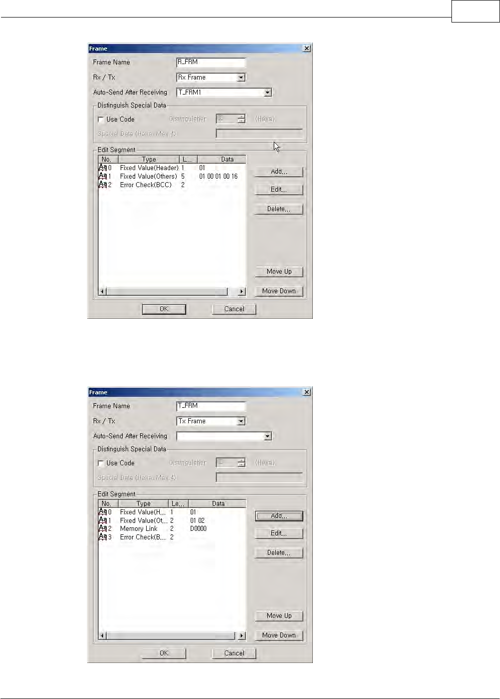
6.2.6.2.6 Example of Application of MODICON (MODBUS) protocol
It is available to configure a communication system and frames between a CIMON-PLC and other manufacturer’
s PLC using Modbus Protocol.
The following is an example for request to read 16-bit data from other manufacturer’s PLC using Modbus
Protocol to a CIMON-PLC. If a requesting frame is received from other manufacturer’s PLC, the received frame
will be evaluated. If correct, it will be sent automatically.
Structure of Modbus Protocol Request (Other manufacturer’s PLC)
Slave
Address
Function
Starting
Address(H)
Start
Address(L)
No.
Point(H)
No.
Point(H)
BCC(H)
BCC(L)
01
01
00
01
0
16
?
?
Structure of Modbus Protocol Response (CIMON-PLC)
Slave
Address
Function
Byte Count
Data
Data
BCC(H)
BCC(L)
01
01
02
CD
6B
?
?
Setting up the requesting frame received from other manufacturer’s PLC
Select the auto-send after receiving. But, the frame sent automatically is to be registered.
XP / CP Series(CM1) 1129
Copyright 2012 BY KDT SYSTEMS, All rights reserved.
Setting up a responding frame
CIMON-PLC1130
Copyright 2012 BY KDT SYSTEMS, All rights reserved.
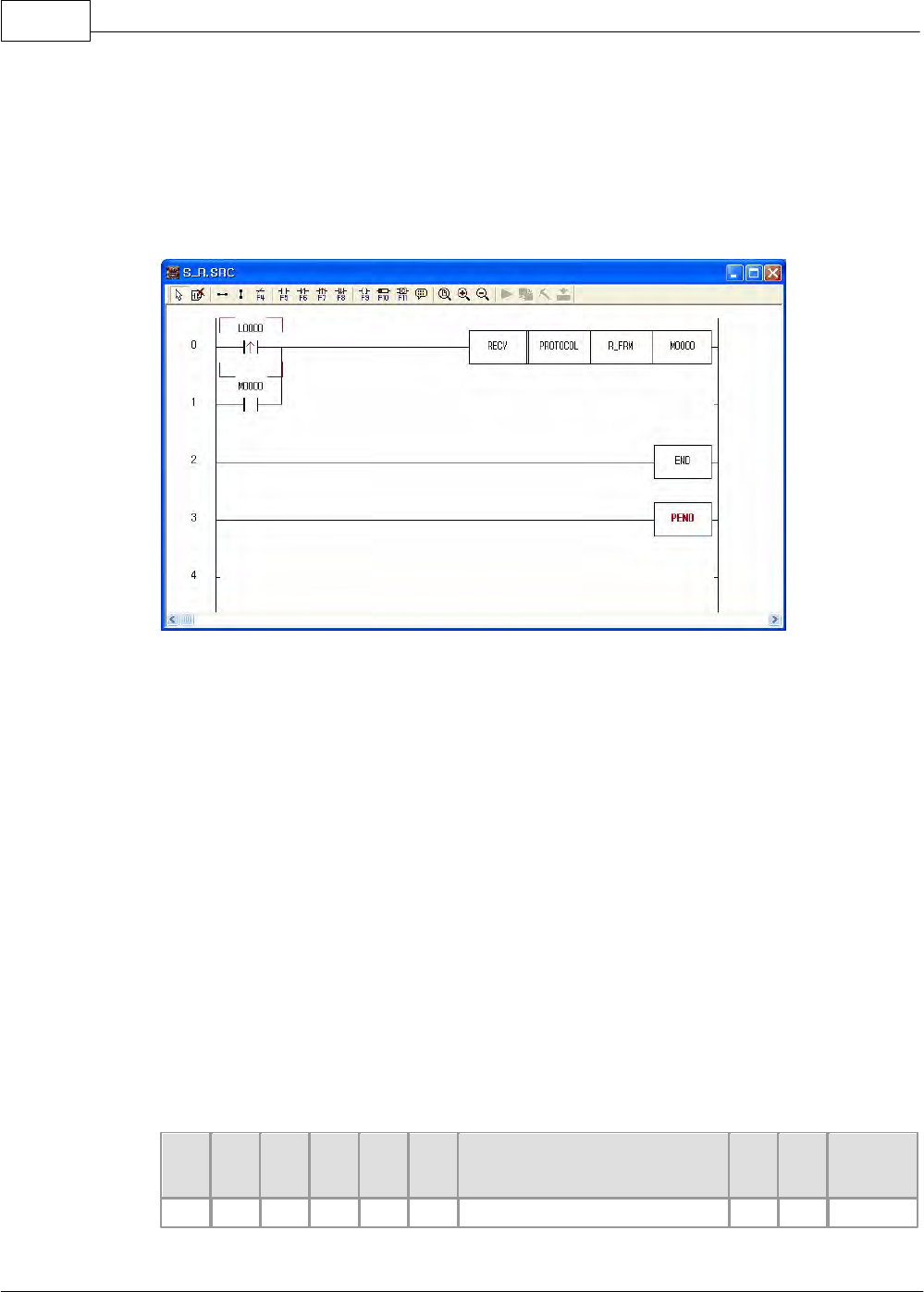
PLC Program:
If Data Value L0000 is ‘1’, the received data is evaluated. The frame registered to the auto-send after
receiving is sent without SEND command. Also, M0000 is or-operated and the above will be
continuously processed if a frame is received.
6.2.6.2.7 Sending/Receiving communication frames at communication intervals
The following is the example of a communication system and frame composition between a master CIMON-PLC
and a slave CIMON-PLC by using CIMON-PLC exclusive protocol.
A master PLC requests 5-word data of Memory Device ‘D0000’ at every 100ms.
Enter parameters as follows.
·Master PLC : User Protocol
·Slave PLC : HMI Protocol
Request Frame Format of CIMON-PLC Exclusive Protocol
ENQ
Stn
H
Stn
L
Cmd
Len
g
H
Len
g
L
Data
BCC
H
BCC
L
EOT
ENQ
0
1
R
0
A
D0000000 05
?
?
EOT
XP / CP Series(CM1) 1131
Copyright 2012 BY KDT SYSTEMS, All rights reserved.
Response Frame Format of CIMON-PLC Exclusive Protocol
STX
Stn
H
Stn
L
Cmd
Len
g
H
Len
g
L
Data
BCC
H
BCC
L
ETX
STX
0
1
R
1
4
0000 0000 0000 0000 0000
?
?
ETX
Response frame of master side
This is used to define the response frame received from a slave CIMON-PLC.
Sending frames are sent from a master PLC and expected receiving frames are registered.
Request frame of master side
This is used to define the request frames sent to a slave CIMON-PLC.
Sending frame is sent from a master PLC at every 100ms and the above-defined receiving frame is
registered to the receiving frame for sending.
If a sending frame is sent and a registered frame is received, the bit corresponding to the frame
number of communication result memory device(If frame number is 1, communication result bit is
M0001) will be on for one scan.
CIMON-PLC1132
Copyright 2012 BY KDT SYSTEMS, All rights reserved.
6.2.6.3 CIMON PLC - HMI Protocol
This service is used to have a PC and other devices read and write the information and data in a PLC, and to
have them control a PLC (RUN, STOP, PAUSE). In the system composing of a Master and a Slave, if station
numbers are assigned, multi-drop communication is available.
See :
·Structure of Frame
·Details of Command
6.2.6.3.1 Structure of Frame
Request Frame (Master) :
The frame that an outside communication device requests to a computer link module
ENQ
Stn
H
Stn
L
Cmd
Leng
H
Leng
L
Data
BCC
H
BCC
L
EOT
XP / CP Series(CM1) 1133
Copyright 2012 BY KDT SYSTEMS, All rights reserved.
Response Frame (Slave) :
The frame that a computer link module responds to an outside communication device
STX
Stn
H
Stn
L
Cmd
Leng
H
Leng
L
Data
BCC
H
BCC
L
ETX
1) The structure of a sending frame and the one of a receiving frame are same.
2) The same as the command codes received from a request frame (Master) are used for response frame.
But, if there is an error in communication or process, Code E is responded.
3) Description for Codes
Code
Hex Value
Description
ENQ
05H
Master Frame Header
EOT
04H
Master Frame Tail
STX
02H
Slave Header
ETX
03H
Slave Tail
Stn
00H~1FH, FFH
PLC Station Number
Cmd
Command
Leng
Length of Data Device (Length Bytes), Hexadecimal
Data
Data Device according to Command (Length Bytes)
BCC
Remainder value when dividing the binary-sum from Cmd to the end of
data by 256
4) Commands
The commands used for exclusive communication service are as follows.
Command
Code
ASCII
Function
Read Word Data
52H
R
Reads Word Memory Device.
Write Word Data
57H
W
Writes to Word Memory Device.
Read Bit Data
72H
r
Reads Bit Memory Device.
Write Bit Data
77H
w
Writes to Bit Memory Device.
Change PLC Mode
4DH
M
Changes PLC Mode.
Register Monitoring Device
58H
X
Registers Monitoring Device.
Read Monitoring Device
59H
Y
Reads Registered Monitoring Device
Respond Error
45H
E
Responds Error in PLC.

CIMON-PLC1134
Copyright 2012 BY KDT SYSTEMS, All rights reserved.
6.2.6.3.2 Details of Command
List :
·Read Word Data
·Write Word Data
·Read Bit Data
·Write Bit Data
·Change PLC Mode
·Register Monitoring Device
·Read Monitoring Device
·Error Response
Read Word Data
Function
·This is used to read the data in the word device of a PLC. (Max. 63 words)
·Device Symbol: X, Y, M, L, K, F, Z, TC, TS, CC, CS, D, S
Request Frame (Master)
·COMMAND: ‘R’
·Data Device Format
Address
8 Char
Size (Word)
Hexadecimal, 2 Char
......
Address
8 Char
Size (Word)
Hexadecimal, 2 Char
[Master(Request Format)]
HEADER
Stn
H
Stn
L
Cmd
Leng
H
Leng
L
Data
BCC
H
BCC
L
EOT
ENQ
02
R
0A
D0000001 01
B9
EOT
05H
30H
32H
52H
30H
41H
4430303030303031
3031H
42H
39H
04H
Leng is the length of a data and its value means the length of a data (D0000001 01).
XP / CP Series(CM1) 1135
Copyright 2012 BY KDT SYSTEMS, All rights reserved.
Data means the address really read (D0000001) and the length of the word data read (01).
BCC is the remainder value when dividing the binary-sum from Cmd to the end of data by 256.
Response Frame (Slave)
·COMMAND (In completed case: ‘R’ / In failed case: ‘E’)
·Format of Data Device
[Completed Case]
PLC Data
Word Data
4 Char
Word Data
4 Char
......
Word Data
4 Char
Slave(Response Format)
HEADER
Stn
H
Stn
L
Cmd
Leng
H
Leng
L
Data
BCC
H
BCC
L
ETX
STX
02
R
04
F4AC
B4
ETX
02H
30H
32H
52H
30H
34H
46344143H
42H
34H
03H
The request frame received from a master is used as the response frame of a PLC.
BCC is the remainder value when dividing binary-sum from Cmd to the end of data by 256.
As the response frame is processed, Cmd is ‘R’. (* Leng means the length of a data (F4AC).
[Failed Case]
Error Code
Error Code
2 Char
Slave(Response Format)
HEADER
Stn
H
Stn
L
Cmd
Leng
H
Leng
L
Error Code
BCC
H
BCC
L
ETX
STX
02
E
02
02
09
ETX
02H
30H
32H
45H
30H
32H
3032H
30H
39H
03H
The request frame received from a master is used as the response frame of a PLC.
BCC is the remainder value when dividing the binary-sum from Cmd to the end of data by 256.
As the response frame is not processed, Cmd is ‘E’. (*Leng means the length of error code(02).)
* Error code displays the type of an error. Please refer to the ‘ERROR RESPONSE’.
CIMON-PLC1136
Copyright 2012 BY KDT SYSTEMS, All rights reserved.
[Ex.] Read data from Address D00040 of Station 02H.
Master (Request Format)
HEADER
Stn
H
Stn
L
Cmd
Leng
H
Leng
L
Data
BCC
H
BCC
L
EOT
ENQ
02
R
0A
D0000040 01
BC
EOT
05H
30H
32H
52H
30H
41H
4430303030303430
3031H
42H
43H
04H
Completed Case> reads 1-word data ‘F4AC’
Slave(Response Format)
HEADER
Stn
H
Stn
L
Cmd
Leng
H
Leng
L
Data
BCC
H
BCC
L
ETX
STX
02
R
04
F4AC
B4
ETX
02H
30H
32H
52H
30H
34H
46344143H
42H
34H
03H
Failed Case> Error in BCC
Slave(Response Format)
HEADER
Stn
H
Stn
L
Cmd
Leng
H
Leng
L
Error Code
BCC
H
BCC
L
ETX
STX
02
E
02
02
09
ETX
02H
30H
32H
45H
30H
32H
3032H
30H
39H
03H
Write Word Data
Function
·This is used to write a data to the word device of a PLC.
·Device Symbol: X, Y, M, L, K, F, Z, TC, TS, CC, CS, D, S
Request Frame
·COMMAND: ‘W’
·Format of Data Device
Address
8 Char
Size (Word)
Hexadecimal,
2 Char
Word Data
Hexadecimal,
Size*4 Char
.......
Address
8 Char
Size (Word)
Hexadecimal,
2 Char
Word Data
Hexadecimal,
Size*4 Char
[Master (Request Format)]
HEADER
Stn
H
Stn
L
Cmd
Leng
H
Leng
L
Data
BCC
H
BCC
L
EOT
XP / CP Series(CM1) 1137
Copyright 2012 BY KDT SYSTEMS, All rights reserved.
ENQ
02
W
0E
D0000010 01 FA34
B0
EOT
05H
30H
32H
57H
30H
45H
4430303030303130
3031 46413334H
42H
30H
04H
Leng is the length of a data and its value means the length of the Data (D0000010 01 FA34).
The address really written (D0000010), the length of the data (01) and the data written (FA34) are
input in the Data (D1000 02 FA34).
BCC is the remainder value (F3) when dividing the binary-sum from Cmd to the end of data by 256.
Response Frame
·COMMAND ( In completed case: ‘W’ / In failed case: ‘E’ )
·Format of Data Device
[Completed Case]
No Data
Slave (Response Format)
HEADER
Stn
H
Stn
L
Cmd
Leng
H
Leng
L
BCC
H
BCC
L
ETX
STX
02
W
00
B7
ETX
02H
30H
32H
57H
30H
30H
42H
37H
03H
The request frame received from a master is used as the response frame of a PLC.
BCC is the remainder value when dividing the binary-sum from Cmd to the end of data by 256.
As the response frame is processed, Cmd is ‘W’.
Leng means the length of a data.
[Failed Case]
Error Code
Error Code
2 Char
Slave (Response Format)
HEADER
Stn
H
Stn
L
Cmd
Leng
H
Leng
L
Error Code
BCC
H
BCC
L
ETX
STX
02
E
02
01
08
ETX
02H
30H
32H
45H
30H
32H
3031H
30H
38H
03H
The request frame received from a master is used as the response frame of a PLC.
CIMON-PLC1138
Copyright 2012 BY KDT SYSTEMS, All rights reserved.
BCC is the remainder value when dividing the binary-sum from Cmd to the end of data by 256.
As the response frame is not processed, Cmd is ‘E’.
Leng(02) means the length of Error Code(01).
Error code displays the type of an error. Please refer to the ‘ERROR RESPONSE’.
[ [Ex.] Write FA34H to Address D0010 and 8D41H to Address D0020. ]
Master (Request Format)
HEADER
Stn
H
Stn
L
Cmd
Leng
H
Leng
L
Data
BCC
H
BCC
L
EOT
ENQ
02
W
12
D0000010 02 FA34
8D41
AF
EOT
05H
30H
32H
57H
31H
32H
4430303030303130
3032 46413334
38443431H
41H
46H
04H
Completed Case>
Slave (Response Format)
HEADER
Stn
H
Stn
L
Cmd
Leng
H
Leng
L
BCC
H
BCC
L
ETX
STX
02
W
0
B7
ETX
02H
30H
32H
57H
30H
30H
42H
37H
03H
Failed Case>Receiving unknown command code (01H).
Slave (Response Format)
HEADER
Stn
H
Stn
L
Cmd
Leng
H
Leng
L
Error Code
BCC
H
BCC
L
ETX
STX
02
E
02
01
08
ETX
02H
30H
32H
45H
30H
32H
3031H
30H
38H
03H
Read Bit Data
Function
·This is used to read the data in the bit device of a PLC.
·Device Symbol: X, Y, M, L, K, F, Z, T, C
Request Frame
·COMMAND: ‘r’
·Format of Data Device
XP / CP Series(CM1) 1139
Copyright 2012 BY KDT SYSTEMS, All rights reserved.
Address
8 Char
Size (Bit)
Hexadecimal,
2 Char
.......
Address
8 Char
Size (Bit)
Hexadecimal,
2 Char
Master(Request Format)
HEADER
Stn
H
Stn
L
Cmd
Leng
H
Leng
L
Data
BCC
H
BCC
L
EOT
ENQ
03
r
0A
M000010F 02
F9
EOT
05H
30H
33H
72H
30H
41H
4D303030313030
46 3032H
46H
39H
04H
Leng is the length of a data and its value means the length of Data (M000010F 02H).
The address really read(M000010F) and the length of the data(02) are input in the Data.
BCC is the remainder value when dividing the binary-sum from Cmd to the end of data by 256.
Response Frame
·COMMAND ( In completed case: ‘r’ / In failed case: ‘E’ )
·Format of Data Device
[Completed Case]
PLC Data
Bit Data
1 Char
Bit Data
1 Char
......
Bit Data
1 Char
Slave (Response Format)
HEADER
Stn
H
Stn
L
Cmd
Leng
H
Leng
L
Data
BCC
H
BCC
L
ETX
STX
01
r
02
0 1
35
ETX
02H
30H
31H
72H
30H
32H
30 31H
33H
35H
03H
The request frame received from a master is used as the response frame of a PLC.
BCC is the remainder value when dividing the binary-sum from Cmd to the end of data by 256.
As the response frame is processed, Cmd is ‘r’.
Leng(02) means the length of the Data(0 1).
[Failed Case]
Error Code
Error Code
2 Char
CIMON-PLC1140
Copyright 2012 BY KDT SYSTEMS, All rights reserved.
Slave(Response Format)
HEADER
Stn
H
Stn
L
Cmd
Leng
H
Leng
L
Error Code
BCC
H
BCC
L
ETX
STX
03
E
02
01
08
ETX
02H
30H
33H
45H
30H
32H
3031H
30H
38H
03H
The request frame received from a master is used as the response frame of a PLC.
BCC is the remainder value when dividing the binary-sum from Cmd to the end of data by 256.
As the response frame is not processed, Cmd is ‘E’.
Leng(02) means the length of Error Code(01).
Error code indicates the type of an error. Please refer to the ‘ERROR RESPONSE’.
[Ex.] Read the bit data in Address M0104 and Address M0105 of Station 03 PLC.
Master (Request Format)
HEADER
Stn
H
Stn
L
Cmd
Leng
H
Leng
L
Data
BCC
H
BCC
L
EOT
ENQ
03
r
0A
M0000104 02
E7
EOT
05H
30H
33H
72H
30H
41H
4D3030303031
3034 3032H
45H
37H
04H
Completed Case > Reads Data ‘0 1’.
Slave (Response Format)
HEADER
Stn
H
Stn
L
Cmd
Leng
H
Leng
L
Data
BCC
H
BCC
L
ETX
STX
03
r
02
0 1
35
ETX
02H
30H
33H
72H
30H
32H
30 31H
33H
35H
03H
Failed Case > Error in BCC
Slave (Response Format)
HEADER
Stn
H
Stn
L
Cmd
Leng
H
Leng
L
Error Code
BCC
H
BCC
L
ETX
STX
03
E
02
02
09
ETX
02H
30H
33H
45H
30H
32H
3032H
30H
39H
03H
Write Bit Data
Function
·This is used to write data to the bit device of a PLC.
·Device Symbol : X, Y, M, L, K, F, Z, T, C
XP / CP Series(CM1) 1141
Copyright 2012 BY KDT SYSTEMS, All rights reserved.
Request Frame
·COMMAND : ‘w’
·Format of Data Device
Address
8 Char
Size (Bit)
Hexadecimal,
2 Char
Bit Data
Size*1 Char
.......
Address
8 Char
Size (Bit)
Hexadecimal,
2 Char
Bit Data
Size*1 Char
Master(Request Format)
HEADER
Stn
H
Stn
L
Cmd
Leng
H
Leng
L
Data
BCC
H
BCC
L
EOT
ENQ
03
w
0D
M0000101 03 110
82
EOT
05H
30H
33H
77H
30H
42H
4D303030303130 31
3033 313130H
38H
32H
04H
Leng(0B) is the length of data and its value means the length of Data (M0000101 03 110).
The address really written(M0000101), the length of the data(03) and the data written(110) are input in
the Data.
BCC is the remainder value when dividing the binary-sum from Cmd to the end of data by 256.
Response Frame
·COMMAND ( In completed case: ‘w’ / In failed case: ‘E’)
·Format of Data Device
[Completed Case]
No Data
Slave(Response Format)
HEADER
Stn
H
Stn
L
Cmd
Leng
H
Leng
L
BCC
H
BCC
L
ETX
STX
03
w
00
D7
ETX
02H
30H
33H
77H
30H
30H
44H
37H
03H
The request frame received from a master is used as the response frame of a PLC.
BCC is the remainder value when dividing the binary-sum from Cmd to the end of data by 256.
As the response frame is processed, Cmd is ‘w’.
Leng(00) means the length of the data.
CIMON-PLC1142
Copyright 2012 BY KDT SYSTEMS, All rights reserved.
[Failed Case]
Error Code
Error Code
2 Char
Slave(Response Format)
HEADER
Stn
H
Stn
L
Cmd
Leng
H
Leng
L
Error Code
BCC
H
BCC
L
ETX
STX
02
E
02
04
0B
ETX
02H
30H
32H
45H
30H
32H
3034H
30H
42H
03H
The request frame received from a master is used as the response frame of a PLC.
BCC is the remainder value when dividing the binary-sum from Cmd to the end of data by 256.
As the response frame is not processed, Cmd is ‘E’.
Leng(02) means the length of Error Code (04).
Error code indicates the type of an error. Please refer to the ‘ERROR RESPONSE’.
[Ex.] Write bit data to Bit Address M0104.
Master(Request Format)
HEADER
Stn
H
Stn
L
Cmd
Leng
H
Leng
L
Data
BCC
H
BCC
L
EOT
ENQ
01
w
0D
M0000104 03 110
82
EOT
05H
30H
31H
77H
30H
44H
4D303030303130
34 3033 313130H
38H
32H
04H
Completed Case
Slave(Response Format)
HEADER
Stn
H
Stn
L
Cmd
Leng
H
Leng
L
BCC
H
BCC
L
ETX
STX
01
w
00
D7
ETX
02H
30H
31H
77H
30H
30H
44H
37H
03H
Failed Case> Data Size Overflow
Slave (Response Format)
HEADER
Stn
H
Stn
L
Cmd
Leng
H
Leng
L
Error Code
BCC
H
BCC
L
ETX
STX
01
E
02
04
0B
ETX
02H
30H
31H
45H
30H
32H
3034H
30H
42H
03H
Change PLC Mode
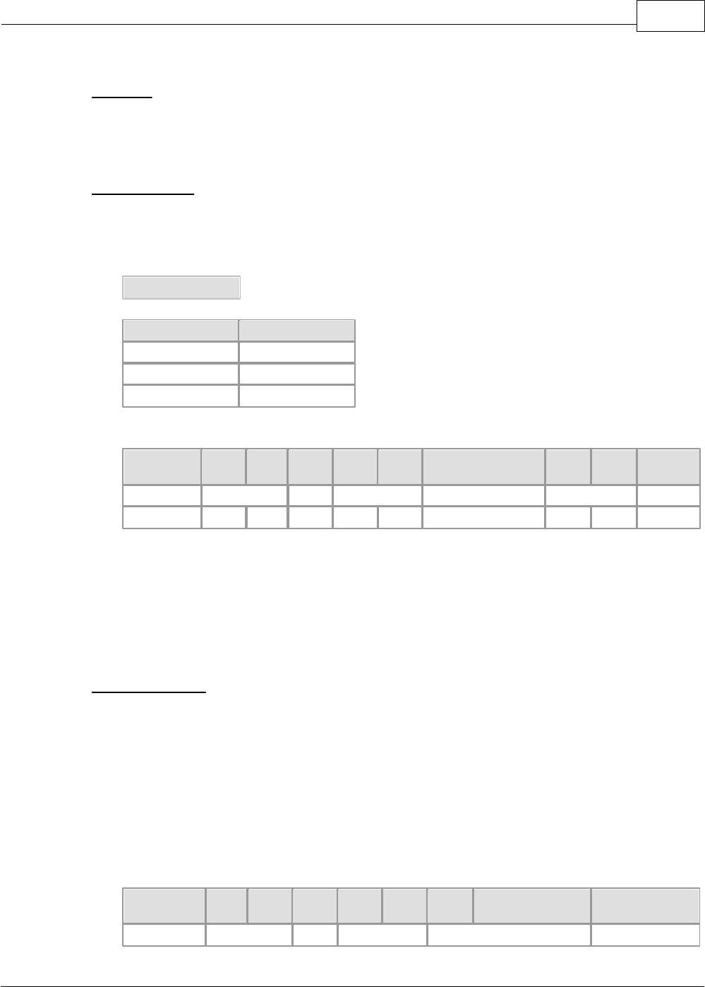
XP / CP Series(CM1) 1143
Copyright 2012 BY KDT SYSTEMS, All rights reserved.
Function
·This is used to change the operation mode of a PLC.
Request Frame
·COMMAND : ‘M’
·Format of Data Device
Mode Code
Mode
Code
Run
0
Program
1
Pause/Remote
2
Master(Request Format)
HEADER
Stn
H
Stn
L
Cmd
Leng
H
Leng
L
Data
BCC
H
BCC
L
EOT
ENQ
01
M
01
0
DE
EOT
05H
30H
31H
4DH
30H
31H
30H
44H
45H
04H
Leng(01) is the length of data.
Mode code value(0) is input in the Data(0).
BCC is the remainder value when dividing the binary-sum from Cmd to the end of data by 256.
Only the case CPU is under REMOTE status is available.
Response Frame
·COMMAND ( In completed case: ‘M’ / In failed case: ‘E’ )
·Format of Data Device
[Completed Case]
No Data
Slave(Response Format)
HEADER
Stn
H
Stn
L
Cmd
Leng
H
Leng
L
BCC
H
BCC
L
ETX
STX
01
M
00
AD
ETX
CIMON-PLC1144
Copyright 2012 BY KDT SYSTEMS, All rights reserved.
02H
30H
31H
4DH
30H
30H
41H
44H
03H
The request frame received from a master is used as the response frame of a PLC.
BCC is the remainder value when dividing the binary-sum from Cmd to the end of data by 256.
As the response frame is processed, Cmd is ‘M’.
Leng(00) means the length of the data.
[Failed Case]
Error Code
Error Code
2 Char
Slave(Response Format)
HEADER
Stn
H
Stn
L
Cmd
Leng
H
Leng
L
Error Code
BCC
H
BCC
L
ETX
STX
02
E
02
03
0A
ETX
02H
30H
32H
45H
30H
32H
3033H
30H
41H
03H
The request frame received from a master is used as the response frame of a PLC.
BCC is the remainder value when dividing the binary-sum from Cmd to the end of data by 256.
As the response frame is not processed, Cmd is ‘E’.
Leng(02) means the length of Error Code (03).
Error code indicates the type of an error. Please refer to the ‘ERROR RESPONSE’.
[Ex.] Change the operation mode of a PLC to PAUSE/REMOTE mode.
Master(Request Format)
HEADER
Stn
H
Stn
L
Cmd
Leng
H
Leng
L
Data
BCC
H
BCC
L
EOT
ENQ
01
M
01
2
E0
EOT
05H
30H
31H
4DH
30H
31H
32H
45H
30H
04H
Completed Case
Slave(Response Format)
HEADER
Stn
H
Stn
L
Cmd
Leng
H
Leng
L
BCC
H
BCC
L
ETX
STX
01
M
00
AD
ETX
02H
30H
31H
4DH
30H
30H
41H
44H
03H
Failed Case > Invalid mode
Slave(Response Format)
XP / CP Series(CM1) 1145
Copyright 2012 BY KDT SYSTEMS, All rights reserved.
HEADER
Stn
H
Stn
L
Cmd
Leng
H
Leng
L
Error Code
BCC
H
BCC
L
ETX
STX
01
E
02
03
0A
ETX
02H
30H
31H
45H
30H
32H
3033H
30H
41H
03H
Register Monitoring Device
Function
·This is used to register a monitoring device.
·16 devices can be registered as maximum. (Distinguishing by Frame No., 0h – Fh)
·Individual device should be continuous and is limited to 63 words as maximum.
Request Frame
·COMMAND : ‘X’
·Format of Data Device
Frame No.
1 Char
Word Address
8 Char
Word Size
Hexadecimal,
2 Char
Master(Request Format)
HEADER
Stn
H
Stn
L
Cmd
Leng
H
Leng
L
Data
BCC
H
BCC
L
EOT
ENQ
01
X
0B
0
D0000001
02
C0
EOT
05H
30H
31H
58H
30H
42H
30H
4430303030
303031H
3032H
43H
30H
04H
Leng(0B) is the length of a data.
The Mode code(0), the Address(D0000001) and the Size(02) are input in the Data (0 D00001 02).
BCC is the remainder value when dividing the binary-sum from Cmd to the end of data by 256.
Response Frame
·COMMAND ( In completed case: ‘X’ / In failed case: ‘E’)
·Format of Data Device
[Completed Case]
No Data
CIMON-PLC1146
Copyright 2012 BY KDT SYSTEMS, All rights reserved.
Slave(Response Format)
HEADER
Stn
H
Stn
L
Cmd
Leng
H
Leng
L
BCC
H
BCC
L
ETX
STX
01
X
00
B8
ETX
02H
30H
31H
58H
30H
30H
42H
38H
03H
The request frame received from a master is used as the response frame of a PLC.
BCC is the remainder value when dividing the binary-sum from Cmd to the end of data by 256.
As the response frame is processed, Cmd is ‘X’.
Leng(00) means the length of the data.
[Failed Case]
Error Code
Error Code
2 Char
Slave(Response Format)
HEADER
Stn
H
Stn
L
Cmd
Leng
H
Leng
L
Error Code
BCC
H
BCC
L
ETX
STX
01
E
02
07
0E
ETX
02H
30H
31H
45H
30H
32H
3037H
30H
45H
03H
The request frame received from a master is used as the response frame of a PLC.
BCC is the remainder value when dividing the binary-sum from Cmd to the end of data by 256.
As the response frame is not processed, Cmd is ‘E’.
Leng(02) means the number of Error Codes (07).
Error code indicates the type of an error. Please refer to the ‘ERROR RESPONSE’.
[Ex.] Register Frame 1 and Addresses from D0011 to D0014 to Station 1.
Master(Request Format)
HEADER
Stn
H
Stn
L
Cmd
Leng
H
Leng
L
Data
BCC
H
BCC
L
EOT
ENQ
01
X
0B
1 D0000011 04
C5
EOT
05H
30H
31H
58H
30H
42H
31 443030303030
3131 3034H
43H
35H
04H
Completed Case
Slave(Response Format)

XP / CP Series(CM1) 1147
Copyright 2012 BY KDT SYSTEMS, All rights reserved.
HEADER
Stn
H
Stn
L
Cmd
Leng
H
Leng
L
BCC
H
BCC
L
ETX
STX
01
X
00
B8
ETX
02H
30H
31H
58H
30H
30H
42H
38H
03H
Failed Case > Invalid Monitor Frame No.(0h~Fh)
Slave(Response Format)
HEADER
Stn
H
Stn
L
Cmd
Leng
H
Leng
L
Error Code
BCC
H
BCC
L
ETX
STX
01
E
02
07
0E
ETX
02H
30H
31H
45H
30H
32H
3037H
30H
45H
03H
Read Monitoring Device
Function
·This is used to read the registered monitoring device.
Request Frame
·COMMAND : ‘Y’
·Format of Data Device
Frame No.
1 Char
Master(Request Format)
HEADER
Stn
H
Stn
L
Cmd
Leng
H
Leng
L
Data
BCC
H
BCC
L
EOT
ENQ
01
Y
01
0
EA
EOT
05H
30H
31H
59H
30H
31H
30H
45H
41H
04H
Leng(01) is the length of a data.
Frame No. is input in the Data(0).
BCC is the remainder value when dividing the binary-sum from Cmd to the end of data by 256.
Response Frame
·COMMAND ( In completed case: ‘Y’ / In failed case: ‘E’ )
·Format of Data Device
CIMON-PLC1148
Copyright 2012 BY KDT SYSTEMS, All rights reserved.
[Completed Case]
Frame No.
Word Data
4 Char
......
Word Data
4 Char
Slave(Response Format)
HEADER
Stn
H
Stn
L
Cmd
Leng
H
Leng
L
Data
BCC
H
BCC
L
EOT
ENQ
01
Y
05
0 87F3
D6
EOT
05H
30H
31H
59H
30H
35H
30 38374633H
44H
36H
04H
The request frame received from a master is used as the response frame of a PLC.
BCC is the remainder value when dividing the binary-sum from Cmd to the end of data by 256.
As the response frame is processed, Cmd is ‘Y’.
Leng(05) means the length of the Data(0 87F3).
[Failed Case]
Error Code
Error Code
2 Char
Slave(Response Format)
HEADER
Stn
H
Stn
L
Cmd
Leng
H
Leng
L
Error Code
BCC
H
BCC
L
ETX
STX
01
E
02
08
0F
ETX
02H
30H
31H
45H
30H
32H
3038H
30H
46H
03H
The request frame received from a master is used as the response frame of a PLC.
BCC is the remainder value when dividing the binary-sum from Cmd to the end of data by 256.
As the response frame is not processed, Cmd is ‘E’.
Leng(02) means the length of Error Code(08H).
Error code indicates the type of an error. Please refer to the ‘ERROR RESPONSE’.
[Ex.] If Frame 2h, Address D1005 and Address D1006 are registered as a monitoring device,
read the registered device.
Master(Request Format)
HEADER
Stn
H
Stn
L
Cmd
Leng
H
Leng
L
Data
BCC
H
BCC
L
EOT
XP / CP Series(CM1) 1149
Copyright 2012 BY KDT SYSTEMS, All rights reserved.
ENQ
01
Y
01
2
EC
EOT
05H
30H
31H
59H
30H
31H
32H
45H
43H
04H
Completed Case
Slave(Response Format)
HEADER
Stn
H
Stn
L
Cmd
Leng
H
Leng
L
Data
BCC
H
BCC
L
EOT
ENQ
01
Y
09
2 87F3 32E7
BD
EOT
05H
30H
31H
59H
30H
39H
32 38374633
33324537H
42H
44H
04H
Failed Case > Number of the unregistered(Not initialized) frame
Slave(Response Format)
HEADER
Stn
H
Stn
L
Cmd
Leng
H
Leng
L
Error Code
BCC
H
BCC
L
ETX
STX
01
E
02
08
0F
ETX
02H
30H
32H
45H
30H
32H
3038H
30H
46H
03H
Error Response
Function
·This is the function to inform a master of error occurring in the process of a communication frame or a
request frame and is used in a response frame only.
Request Frame
·All request frames
Response Frame
·COMMAND : ‘E’
·Format of Data Device
Error Code
Error Code
2 Char
CIMON-PLC1150
Copyright 2012 BY KDT SYSTEMS, All rights reserved.
Error Code
Description
01
Receives unknown command code.
02
An error occurs in BCC.
03
CPU does not respond.
04
Receives unknown device code.
05
Exceeds the device read.
06
Invalid address.
07
Internal error
08
Receives the number of invalid data
09
Invalid data
10
Unregistered (Not initialized) frame number
11
Invalid Monitor Frame No. (0h – Fh) Invalid frame number
12
CPU is not in REMOTE status.
13
Invalid CPU status is assigned.
14
An error occurs in the size of the data written.
15
It is disabled to write.
16
It is disabled to change mode.
6.2.6.4 Dial-Up Modem Communication
Outline
This function is to use the public network for a long-distance network.
Modem Specifications
In case of modem communications, it is required to use the modem complying with the recommendable
specifications for reliability.
According to the performance of a modem and the state of a public network, the case that a line is not
linked or the case that a link is cut off while exchanging data may occur.
·Baud Rate
Over 14400 bps
·DTE Interface
CTS / RTS Flow Control
·Command
Hayes Exchange AT Command
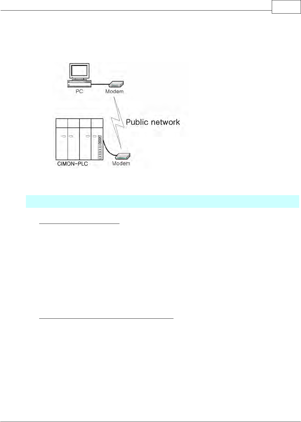
XP / CP Series(CM1) 1151
Copyright 2012 BY KDT SYSTEMS, All rights reserved.
·Error Correction
Error Correction Function while Sending data
·Controlling carrier
Controls to send carrier
Modem Link
Order of Modem Installation
1. Use RS-232C interface cable to connect a computer link module and an external type RS-232C
modem.
2. Connect a RS-232C interface cable to the RS-232C port of the computer link module and DTE link
terminal.
3. Connect the telephone line of a public network to the line terminal of the modem.
4. If there is a telephone set, connect the phone terminal of the modem with the telephone set.
5. Turning on the power for the PLC and the modem, make sure the modem is initialized.
Parameters Setup for Modem Communications
As all modems provide the functions discriminated by manufacturers, the parameters for modems are
to be set up.
The modem operation mode is set up with the initialization command of a modem. The same
operation mode is to be set up for the two modems used.
1. Select the menu to run the graphic loader(CICON).
2. Select menu to set up communication parameters such as communication channel, modem, baud
rate, parity bit, stop bit, station number and communication type.
3. If a modem is set up, it will be available to set up the initialization command. Enter the modem
initialization command set up.
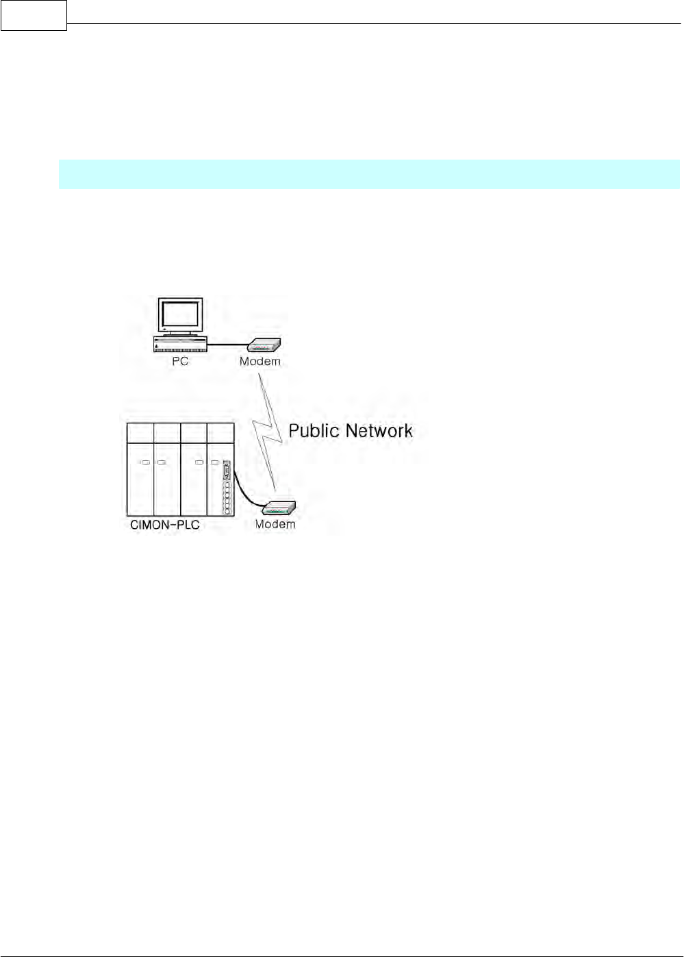
CIMON-PLC1152
Copyright 2012 BY KDT SYSTEMS, All rights reserved.
4. Enter the default value for basic parameters such as station number, communication method, parity
bit, stop bit and initialization command. Baud rate is to be set up according to the maximum rate of
a modem.
CICON Link Service through Modem
·This function is used to write programs, to download user programs, to debug programs and to
monitor in the network system that a PLC is linked through a computer link module by remote
control without moving the physical link of the CICON.
When a master(CICON) is far away from a slave(PLC), using the function of the modem link, a PLC
can be linked with the CICON.
As it is available to link with the PLC located at the place difficult to access as well as to link with a
PLC at a long distance without moving the contents of the PLC, using the communication service of
the CICON, programming is easy after installation. This function reduces the time and efforts taken
when installing and modifying.
·CICON-Modem Link Method
This service is to link a computer link module with the CICON through a modem. After the CICON is
connected with a telephone, the order of remote link is as follows.
1. Select the menu to set up a dial-up modem and the CICON protocol as the parameters of a
computer link module. And select the menu to set up baud rate.
2. After connecting a modem with a computer link module and a telephone wire to the modem, turn
the power on.
3. Select the menu to initialize the modem.

XP / CP Series(CM1) 1153
Copyright 2012 BY KDT SYSTEMS, All rights reserved.
4. After the CICON is run, select the environment setup in the tools.
5. Select the dial-up and set the values for other parameters.
6. If the CICON dials, the message that the dial-up link is completed will appear.
7. It is available to control the PLC at a remote place.
6.2.6.5 Leased Line Modem Communication
Outline
A computer link module is used for the long-distance communication using a leased line through a leased
line modem of external type and the control of the modem for communication.
Leased Line Modem Specifications
The performance of the leased line modem communication using a computer link module is decided
according to the state of a leased line. For reliable communication, the modem complying with a
recommended standard is to be used.
·Baud Rate
Over 1200 bps
·DTE Interface
CTS / RTS Flow Control
·Error Correction
Corrects error when sending data
·Carrier Control
Controls to send carrier
·Line Control
Full duplex/Half duplex(2-wire, 4-wire)
·RTS/CTS Delay Time
Within 500ms
Modem Link Method
Order to Link a Computer Link Module with a Modem
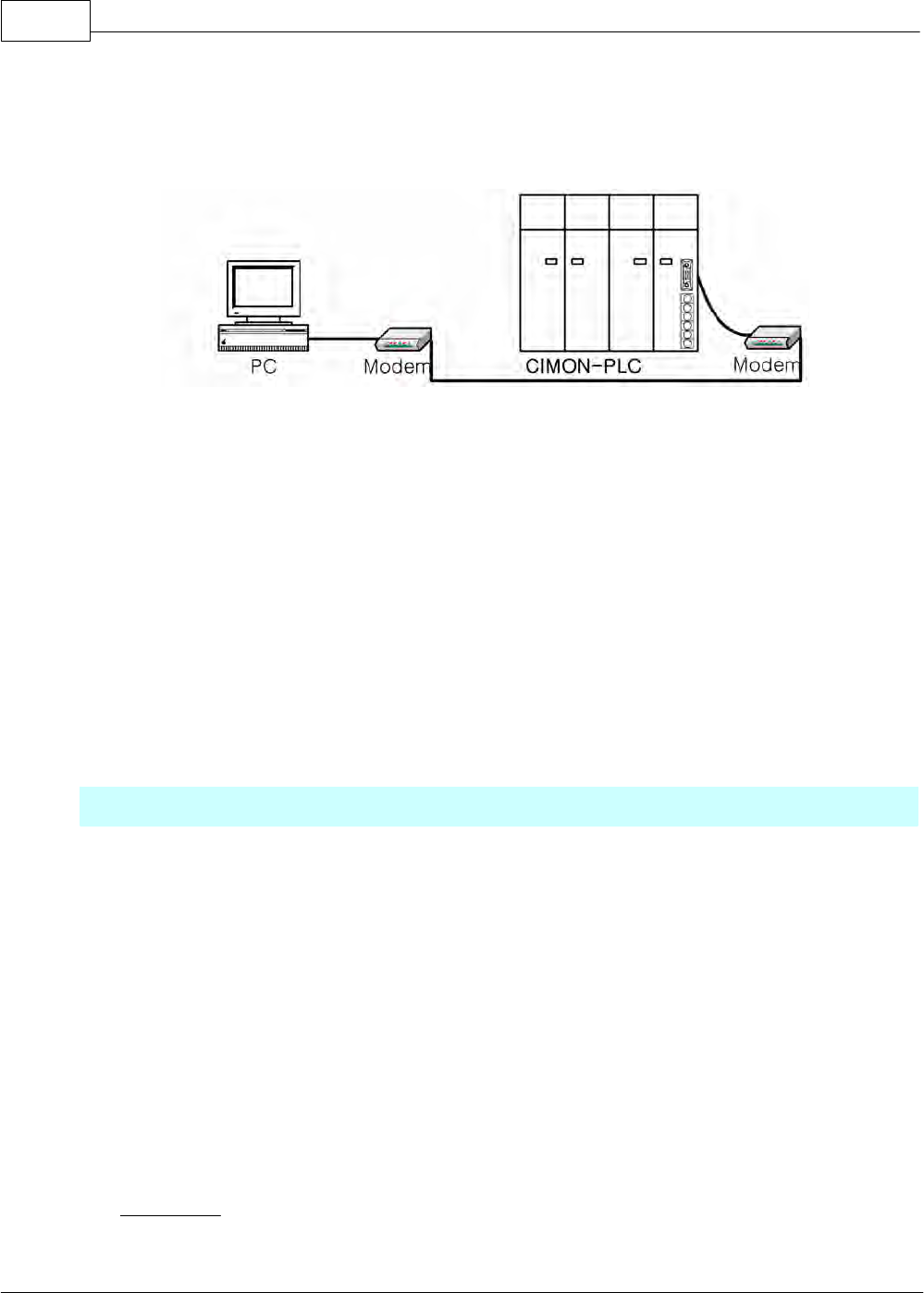
CIMON-PLC1154
Copyright 2012 BY KDT SYSTEMS, All rights reserved.
1) Connect a RS-232C cable to an external type modem and a computer link module.
2) Select the menu to set up the leased modem method as the communication method in the CICON.
3) Make sure the modem is initialized after inputting the power to it.
4) If the modem is not initialized normally, make sure the communication method is set up as the leased
line modem communication and the wiring of the RS-232C cable.
5) The wiring of the RS232C cable is 1:1 connection.
6.2.6.6 RS485 PLC Link Service
Outline
CM1-SC01A/SC01B/SC02A card are used for this service, which is the protocol using a RS485 Network to
exchange data between the CIMON PLCs. The specifications are as follows.
·Maximum connected PLCs : 32 units
·Up to 32 sending blocks per PLC can be assigned.
·The interval of communication for each sending block can be set up in the range from 50ms to 3s.
·The data of up to 64 words per one sending block can be sent.
·The number of the communication blocks assigned to each PLC, summing receiving blocks and sending
blocks, is up to 64.
·The necessary blocks selected among the sending blocks of other PLCs in a network are assigned to
receiving blocks.
Link Points
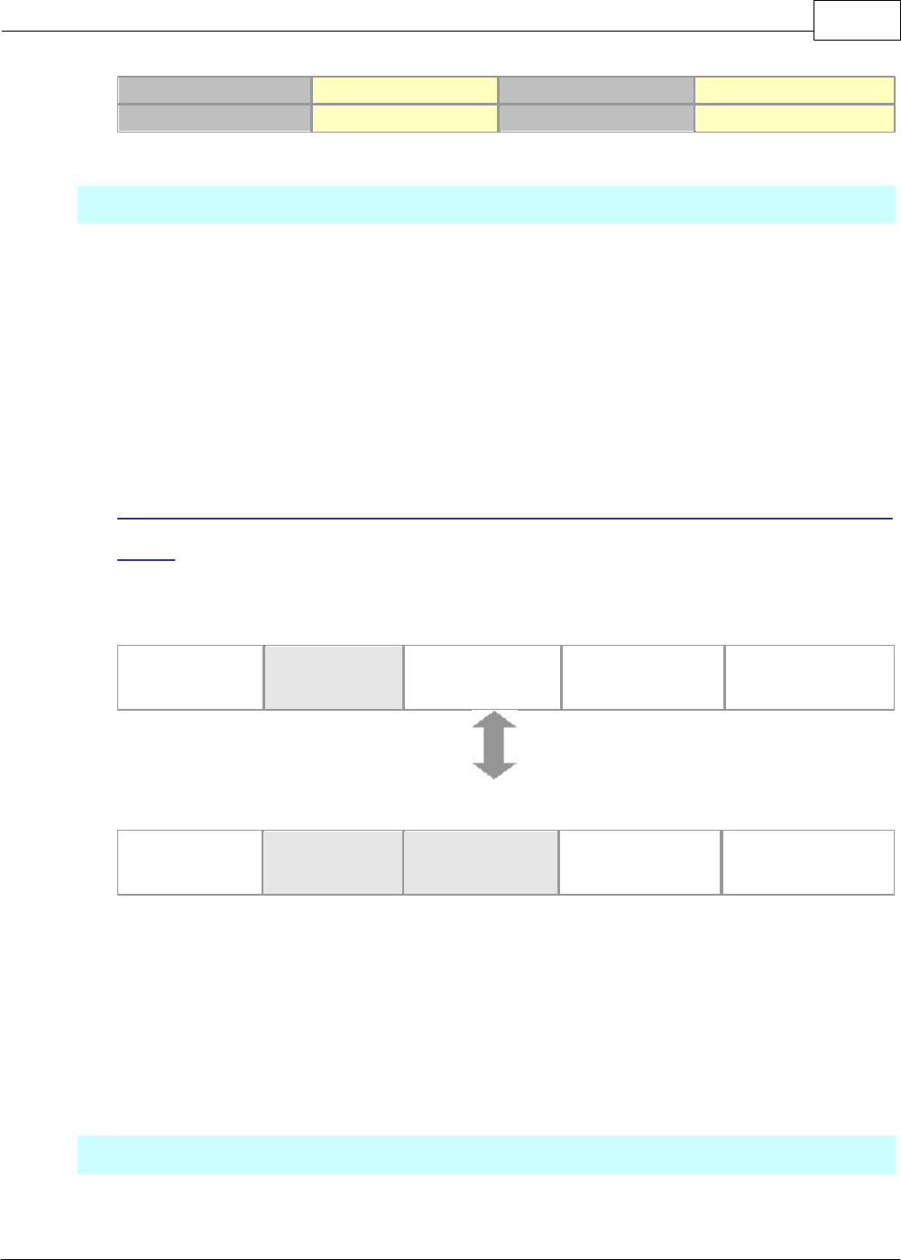
XP / CP Series(CM1) 1155
Copyright 2012 BY KDT SYSTEMS, All rights reserved.
Max. Comm. Points
Max. Sending Points
Max. Block No.
Max. Points per Block
4,096
2,048
64Points (0~63)
64
Processing the Sent Data and the Received Data under PLC Link
An Example is taken to explain how data are processed when they are sent or received under PLC Link.
·Sending Party : This is used to set up the data read, the number of the block where data is sent, data
size and sending interval to a sending party in broadcasting method.
·Receiving Party : This is used to set up the station number and block number for the sent data to a
receiving party in broadcasting method to receive a desired data.
[Ex.] Station 0 sends the data of Device D0000 and Station 1 stores received data in Device
Y0000.
Sending Party (Station: 0)
Type
Sending Block
Block Number
0
Sending Interval
100ms
Address
D0000
Size
10 Words
Receiving Party (Station: 1)
Type
Receiving Block
Station Number
0
Block Number
0
Address
Y0000
Size
4 Words
The block number of a sending party and the one of a receiving party are the same as 0, and the station
number of the sending party is set up as 0 like the one of the receiving party. In this condition, the receiving
party can receive every 100ms and the data sent from the sending party every 100ms. Though the sending
party sends the data of 10-word size, the receiving party selects and receives the necessary data of 4-word
size. But, if the size of received data is greater than the size of sent data, the PLC will receive the data as
much as the size of the sent data.
Setting up PLC Link Parameter
To run PLC Link and to exchange data between communication modules, the parameter is to be set up in
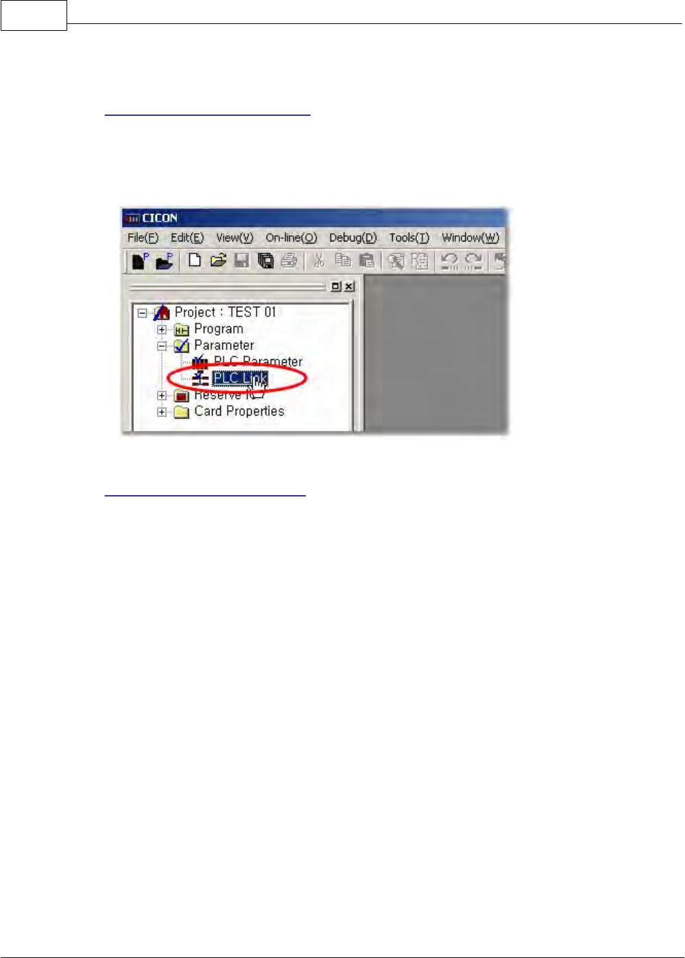
CIMON-PLC1156
Copyright 2012 BY KDT SYSTEMS, All rights reserved.
the CICON.
1) Creating a Project in the CICON
Select the menu to run the CICON and to open a corresponding project.
[Picture 6-1]
2) Setting up PLC Link Parameter
1. Selecting PLC Link Parameter:
If you select the PLC Link on the window like [Picture 6-1], a PLC link dialog box
will appear. In the dialog box, up to 4 communication modules can be set up for
one CPU. To set up the PLC Link to a mounted communication module, select Link(0), Link(1),
Link(2) and Link(3) on the top of the dialog box and enter the values for each communication module
a. Setting up PLC Link Type:
PLC Link Type is used to set up basic items such as network type, base, slot number, station number
and so on.
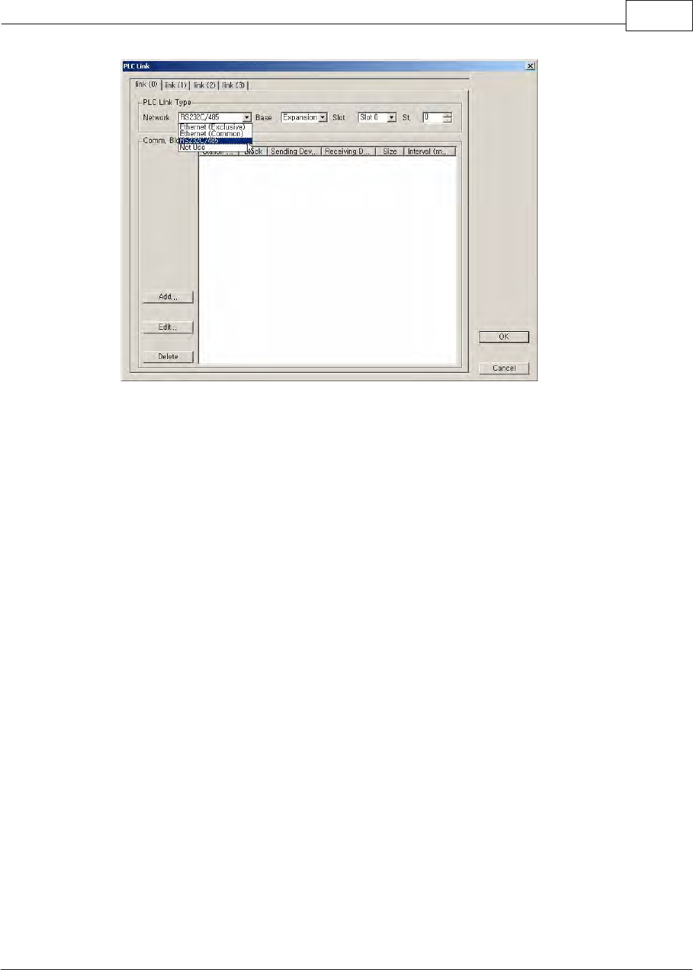
XP / CP Series(CM1) 1157
Copyright 2012 BY KDT SYSTEMS, All rights reserved.
[Picture 6-2. PLC Link Setup]
Network
This is used to set up the type of the communication module for PLC Link. If you do
not use PLC Link, select the Not Use.
Here, select the RS232C/485.
Base
This is used to select the base where the communication module for PLC Link is
mounted. For example, if there is no expansion base (The base where a expansion
card is mounted), select the Local. If there is expansion base (The base where a
expansion card is mounted), select the Expansion Base where the communication
module is mounted.
Slot
This is used to select the slot number of the base where a communication module is
mounted.
b. Setting up the communication block for PLC Link:
Communication Block is used to register the information about sending/receiving real data. If you
select RS232C/422 as Network and the Add button in [Picure 6-2. PLC Link Setup], a Communication
Block dialog box will appear like [Picture 6-3. Communication Block Setup].
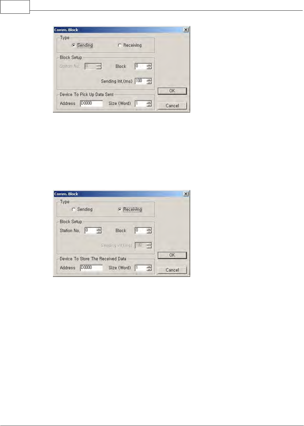
CIMON-PLC1158
Copyright 2012 BY KDT SYSTEMS, All rights reserved.
[Picture 6-3. Communication Block Setup]
Sending
When communication modules communicate each other, this is used to send a
selected block.
Receiving
When communication modules communicate each other, this is used to receive a
selected block.
Station No.
When communication modules communicate each other, in case of sending data, it
is not necessary to set up station number. But, in case of receiving data, the station
number of a receiving communication module is to be selected. The station number
can be set up in the range from 0 to 63.
Block No.
The communication modules for a sending party communicate with each peculiar
block number. In the same way, the communication modules for a receiving party
have each peculiar block number to receive data. The receiving block number is
used to detect the data that a receiving party wants together with the station number
when the party communicates with a sending party. But, the block number can be set
up in the range from 0 to 31. To receive the data of a sending party, the same
number is to be set up as the block number for the sending party and the block
number for a receiving party.
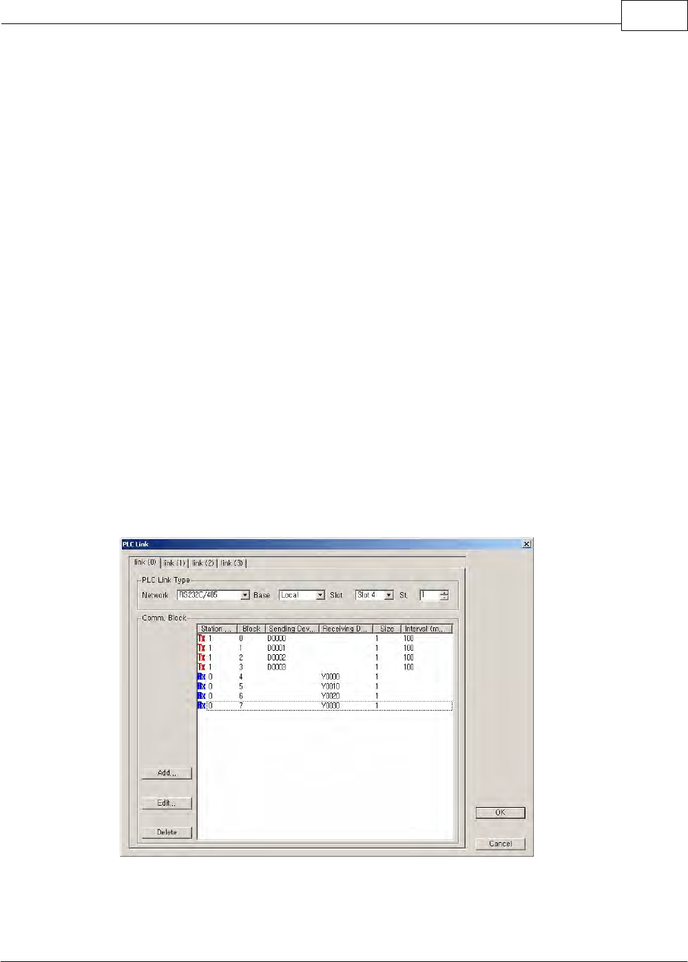
XP / CP Series(CM1) 1159
Copyright 2012 BY KDT SYSTEMS, All rights reserved.
Sending
Interval
The sending interval, the parameter for deciding the interval at which data are sent,
can be set up in the range from 50ms to 3sec according to users’ need. For example,
if 50 ms is set up as sending interval, the data will be sent every 50ms.
Device to Pick up Data Sent & Device to Store The Received Data (Address):
·When sending: This is used to set up the device where the data sent are read.
·When receiving: This is used to set up the device where received data are stored.
Device to Pick up Data Sent & Device to Store The Received Data (Size):
This, the size of the data sent or received, can be set up by the word. But, the size is
from one word to 64 words. If the data size of a sending device is greater than the
size of the data set up to a receiving device, the necessary data as much as the size
of the one set up to the receiving device can be received selectively and used.
[Ex.] The communication module of Station 1 sends Block 0, 1, 2 and 3, and receives Block 4,
5, 6 and 7. And the communication module of Station 2 sends Block 4, 5, 6, and 7, receives 0,
1, 2 and 3. An RS232C/422 card is mounted on Slot 4. Each data size is one word and the
interval is 50 ms each.
Such case is taken as an example and the PLC link parameter for it is configured as follows.
[Station 1]
Station 1 sends the data of the sending devices from D0000 to D0003 by the word at each interval.
The received data will be written to the corresponding addresses in the receiving devices from Y0000
to Y0030, if the corresponding station and blocks are in accord.
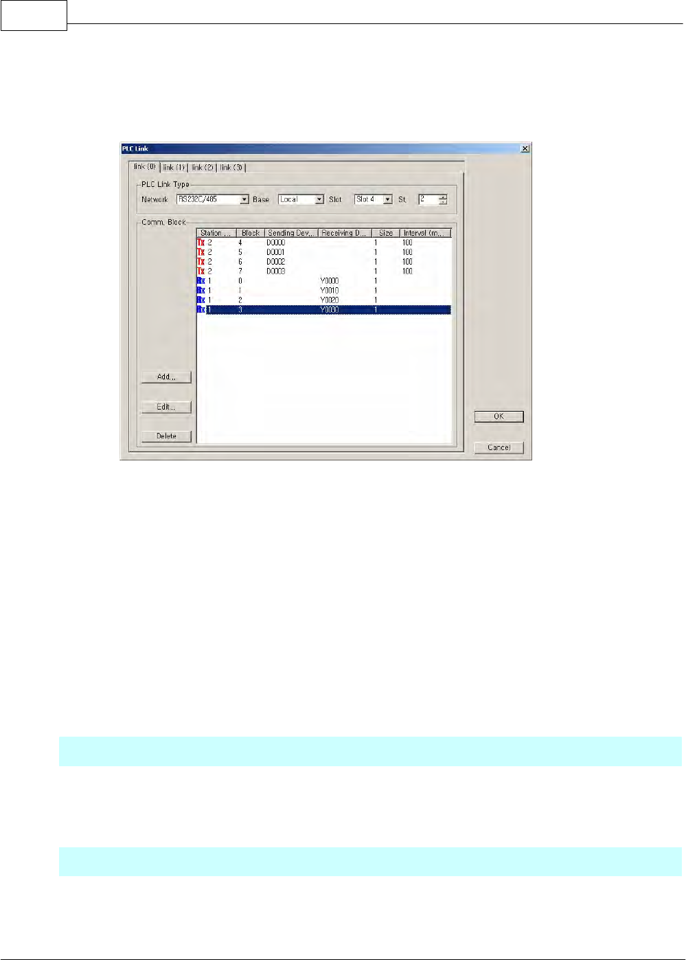
CIMON-PLC1160
Copyright 2012 BY KDT SYSTEMS, All rights reserved.
[Station 2]
Enter 2 as the sending station number and 4, 5, 6, 7 as the block number to send at each interval. If
so, the RS232C/422 module of Station 1 receives, comparing the receiving station and the blocks.
In the same way, Station 2 compares the numbers of the blocks in the received frames with Block 0,
1, 2, and 3 of Station 1. And if they are the same, Station 2 receives them and writes the data to the
devices from Y0000 to Y0030.
6.2.6.7 MODBUS Protocol Service
Outline
This is to access CPU data, using MODBUS protocol in a PC.
Parameter Setup
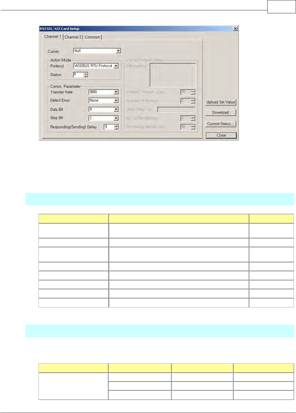
XP / CP Series(CM1) 1161
Copyright 2012 BY KDT SYSTEMS, All rights reserved.
Select the MODBUS RTU Protocol as the protocol in the Action Mode and enter the station number of the
communication card as the station number. If the parameters are set up, press the download button. If they
are downloaded and you press the upload button, the downloaded value will be uploaded.
Modbus Command
Command
Description
Remarks
1 (Read Coil)
Accesses the bit device where data can be read
and written.
Read Bit
2 (Read Input)
Accesses the bit device where data can be read.
Read Bit
3 (Read Holding)
Accesses the word device where data can be
read and written.
Read Word
4 (Read Input)
Accesses the word device where data can be read.
Read Word
5 (Force Single Coil)
Accesses the bit device where data can be written.
Write Bit
6 (Preset Single Register)
Accesses the word device where data can be written.
Write Word
15 (Force Multiple Coils)
Accesses the bit device where data can be written.
Write Bit
16 (Preset Multiple Regs)
Accesses the word device where data can be written.
Write Word
Address Map
Device Memories of all kinds can be corresponded.
Bit / Word
Modicon Address
CIMON-PLC Address
Size CIMON-PLC
Bit Read Input
100001 ~ 104096
X 0000 ~
4096 Bits
104097 ~ 106144
F 0000 ~
2048 Bits
106145 ~ 107168
T 0000 ~
1024 Bits
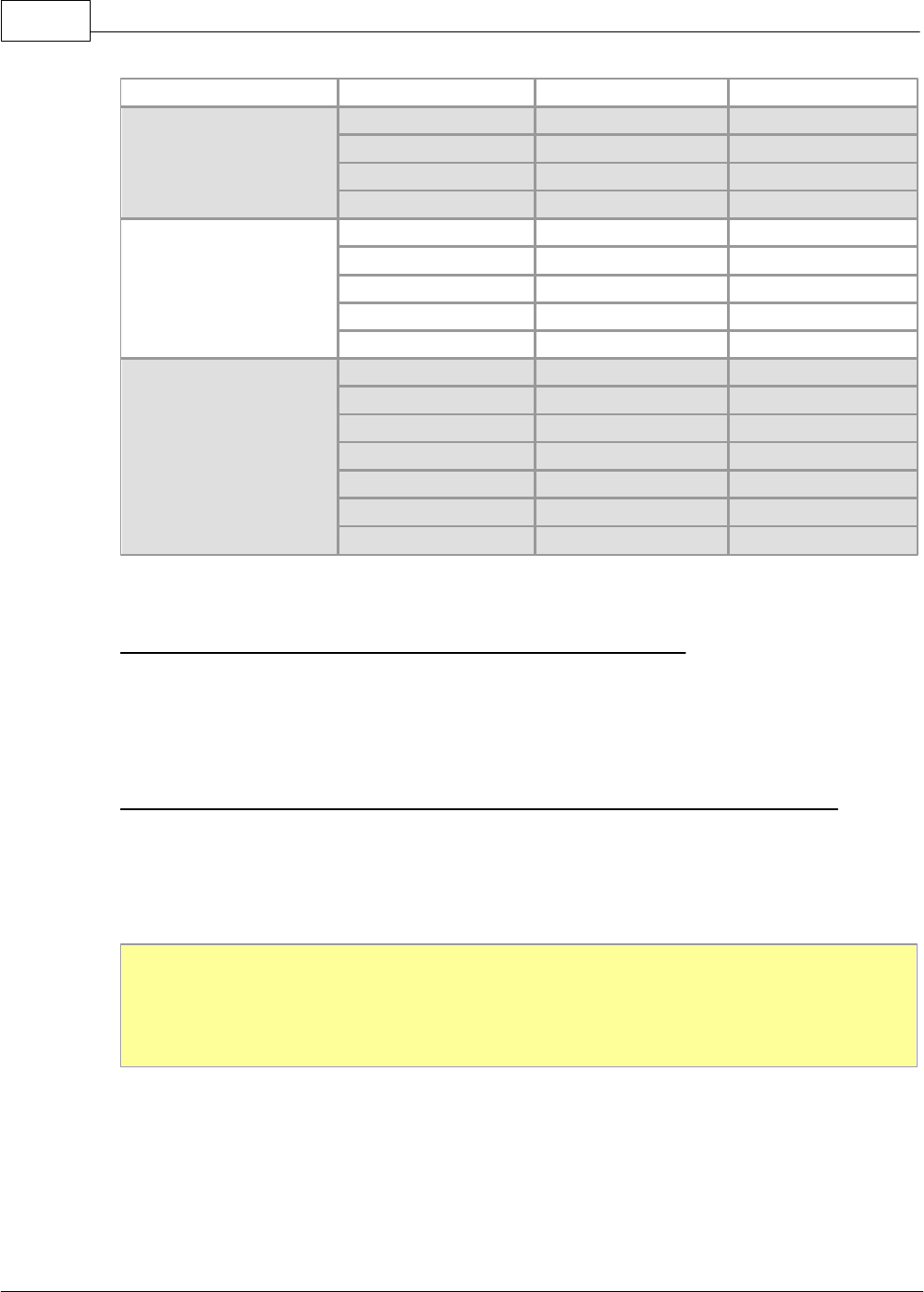
CIMON-PLC1162
Copyright 2012 BY KDT SYSTEMS, All rights reserved.
107169 ~ 108192
C 0000 ~
1024 Bits
Bit Read Coil
000001 ~ 004096
Y 0000 ~
4096 Bits
004097 ~ 012288
M 0000 ~
8192 Bits
012289 ~ 014336
K 0000 ~
2048 Bits
014337 ~ 016384
L 0000 ~
2048 Bits
Word Input Register
400001 ~ 400256
X 0000 ~
256 Words
400257 ~ 400384
F 0000 ~
128 Words
400385 ~ 401408
TC 0000 ~
1024 Words
401409 ~ 402432
CC 0000 ~
1024 Words
402433 ~ 402482
S 0000 ~
50 Words
Word Holding Register
300001 ~ 300256
Y 0000 ~
256 Words
300257 ~ 300384
K 0000 ~
128 Words
300385 ~ 301408
TS 0000 ~
1024 Words
301409 ~ 302432
CS 0000 ~
1024 Words
302433 ~ 302560
L 0000 ~
128 Words
302561 ~ 303072
M 0000 ~
512 Words
303073 ~ 313072
D 0000 ~
10000 Words
Bit(Read Inputl, Read Coil) occupies Modicon Address bit by bit.
[Ex.] Read Input -> 100001: X0000, 100002: X0001,....., 100017: X0010,.....
[Ex.] Read Coil -> 000001: Y0000, 000002: Y0001,..... , 000017: Y0010,.....
Word(Input Register, Holding Register) occupies Modicon Address word by word.
[Ex.] Input Register -> 400001: X0000, 400002->X0010, 400003->X0020,.....
[Ex.] Holding Register -> 302561: M0000, 302562: M0010, 302563: M0020,......
[Note] Some MODBUS Master devices can read and write the devices from 1 to 9999 in the range of the
address of each data type. In this case, as the part corresponding to the device greater than Modicon
Address 9999 in the data of a PLC cannot be accessed, the access memory of the user program may be
controlled.
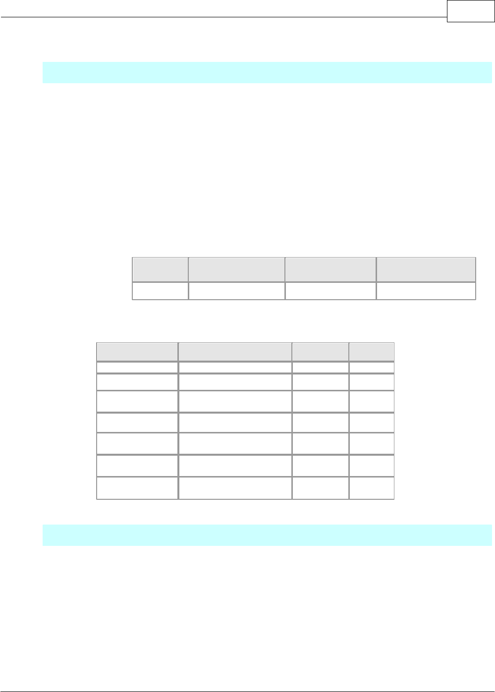
XP / CP Series(CM1) 1163
Copyright 2012 BY KDT SYSTEMS, All rights reserved.
6.2.6.8 MODBUS Master Special module program Service
Outline
1.1 General information
CM1-SC01A/SC01B/SC02A cards are used for this service, which is the protocol using
RS232/485 MODBUS Master to
exchange data between the Slaves. The specifications are as follows.
•Maximum connectable Slaves: 128 units.
•Easy to recognize to communicate successful or not with result bits of communication.
•Sequnce program is not necessary when periodic communication.
•It is Flexible for Slaves supported variable commands
•To communication in special events is possible with command, "SEND"?
CAUTION, identify a version of program for MODBUS Master special program. If it cannot
support program as lower version,
please make sure whether it is the recommend version
CICON
CM1-CPxx(CPU)
CM1-SC0xx
Version
V1.89
V1.56
V1.40
1.2 Supported MODBUS RTU commands
Command
Substance
Remark
Domain
1 (Read Coil)
Read the bit device coil
Read Bit
0X
2 (Read Input)
Read the bit device input
Read Bit
1X
3 (Read Holding)
Read the word device
holding register
Read Word
4X
4 (Read Input)
Read the word device input
Read Word
3X
5 (Force Single
Coil)
Write the bit device coil
Write Bit
0X
6 (Preset Single
Register)
Write Accesses the word
device register
Write Word
4X
16 (Preset Multiple
Regs.)
Write the word device
register
Write Word
4X
SETTING UP COMMUNICATION CARD
To run MODBUS Master function, the parameter have to be set up in the special module setup. After
running the CICON, select the
menu [ tool - Special Module Setup – RS232C/422 module...]
Please select "MODBUS Master Program".
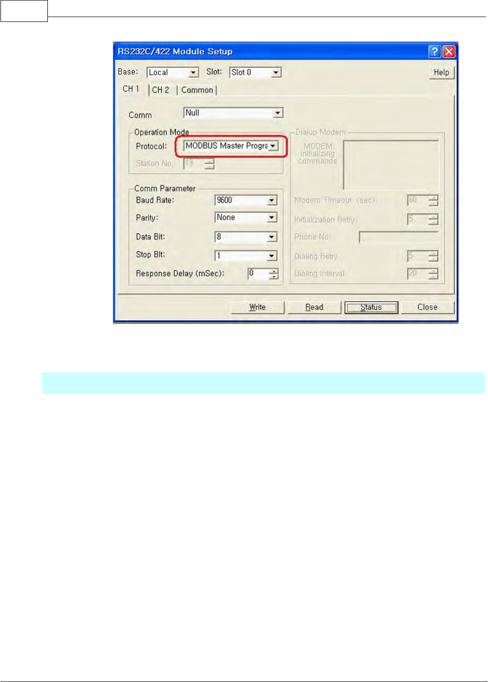
CIMON-PLC1164
Copyright 2012 BY KDT SYSTEMS, All rights reserved.
REGISTER SPECIAL PROGRAM
3.1 Start scan program
- Select [NEW program – MODBUS/RTU Master Program], and register program name.
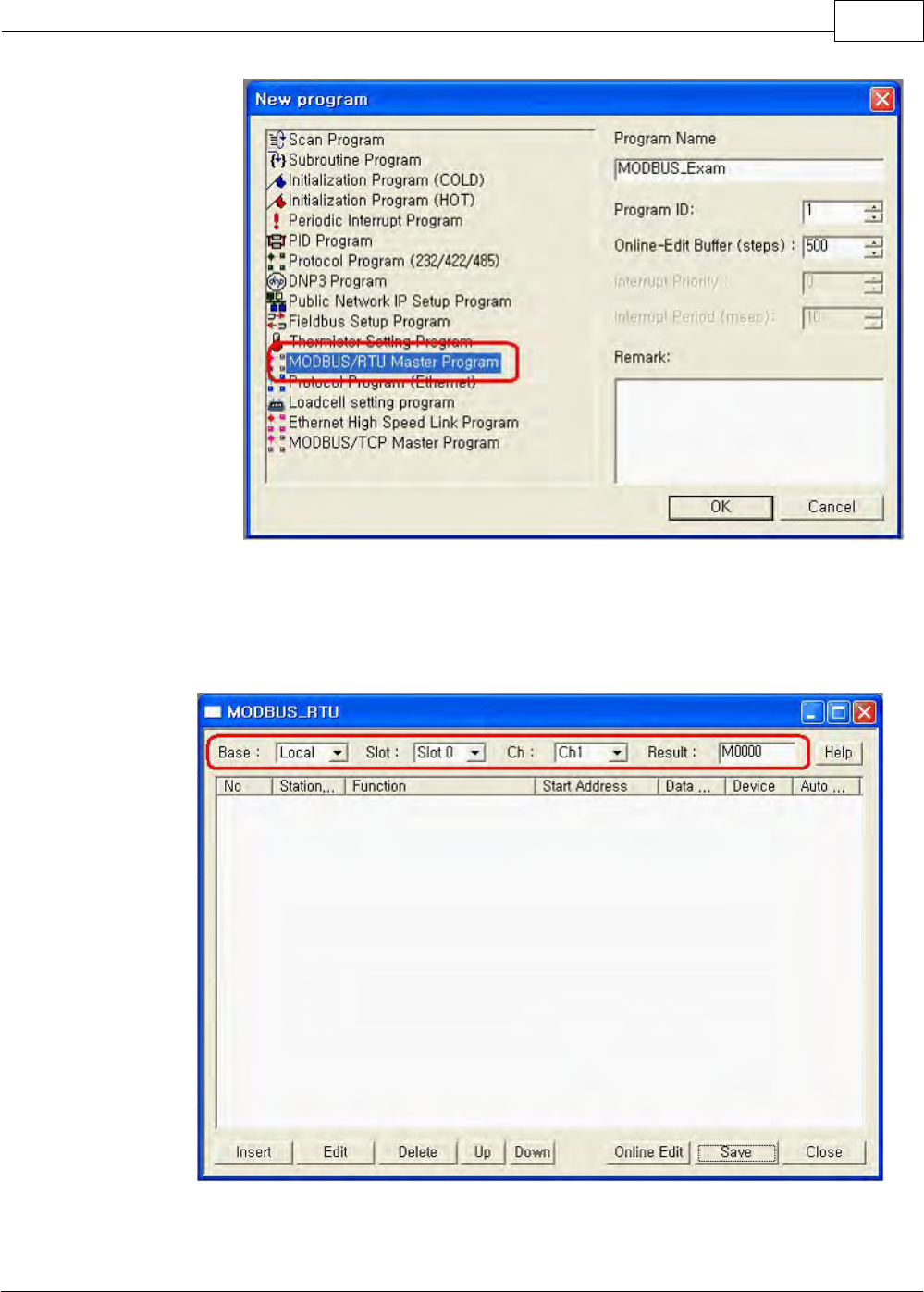
XP / CP Series(CM1) 1165
Copyright 2012 BY KDT SYSTEMS, All rights reserved.
Select the [OK] button.
3.2 MODBUS_RTU dialog box will appear, set up a device.
•Base: This is used select the base of MODBUS/RTU Master module configured.
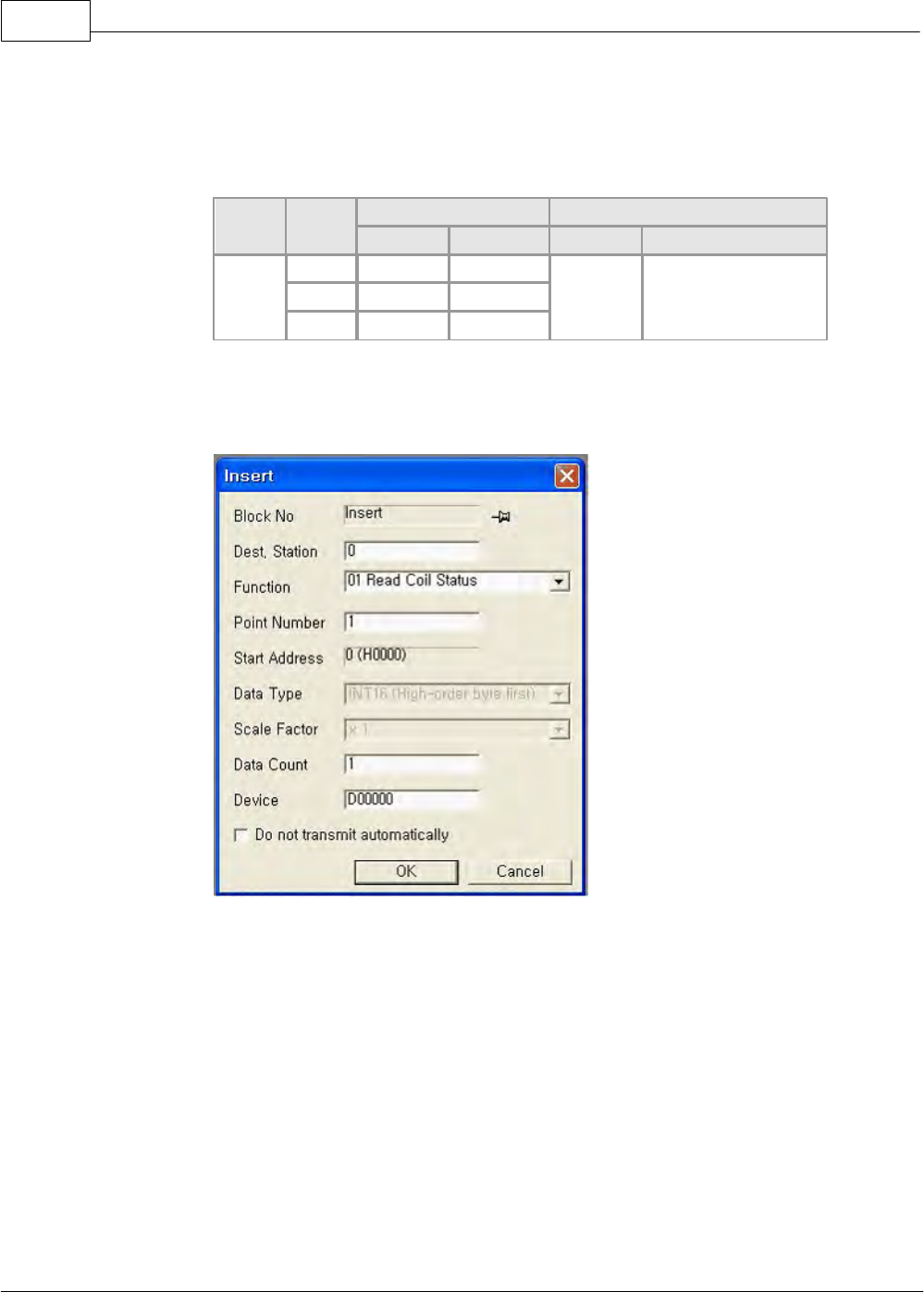
CIMON-PLC1166
Copyright 2012 BY KDT SYSTEMS, All rights reserved.
•Slot: This is used select the slot of MODBUS/RTU Master module configured.
•Ch : This is used select the channel of MODBUS/RTU Master module configured.
•Result: This is used to appear the send/receive data’s result of communication frame.
result
Frame
No.
The comm. Result Flag
The comm. Result Flag Running
Succeed
Fail
Succeed
Fail
M0000
0
M0000
M0080
1 Scan On
On at all times
Off at communication
flag success
11
M000B
M000B
127
M007F
M007F
Example of configuration " result " M0000
3.4 REGISTER COMM. BLOCK
•Dest. Station. : This is used to select a station number of RTU MODBUS Slave configured,
In case of connecting between several slaves used through RS422/485
communication, the station number
have to be different between slaves each other.
•Function : This is used to select a suitable function when a data read/write between slaves.
Please refer to the manual
of "Command"
•Point Number : Resister read/write domains referred to a address table of slaves. Please refer
to
" Address table in SLAVE "
•Start Address: It is used to register the address of a read/write domain which is referred to
address tables of slave.
Please refer to the manual of " Address table of slave "
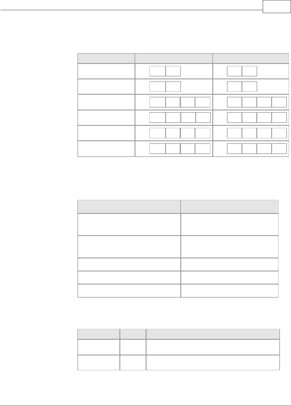
XP / CP Series(CM1) 1167
Copyright 2012 BY KDT SYSTEMS, All rights reserved.
•Data Type : This is used to select a type of send/receive data between slaves. Only selected
analog data (Function 3, 4, 6, 16),
they are valid
Data Type
Valid Data(Byte)
Result Data(Byte)
INT16(High-Order
byte first)
12
34
12
34
INT16(Low-Order byte
first)
12
34
34
12
INT32(High-Order
byte first)
12
34
56
78
56
78
12
34
INT32(Low-Order byte
first)
12
34
56
78
34
12
78
56
Float(High-Order byte
first)
12
34
56
78
56
78
12
34
Float(Low-Order byte
first)
12
34
56
78
34
12
78
56
•Scale Vector: Not Necessary
•Data Count: This is used to set up a count of read/write slaves data.
•
Command(Function)
Data Size
1 - Read Coil Status
2 - Read Input Status
Bit Size
3 – Read Holding Registers
4 – Read Input Registers
Word Size
5 – Force Single Coil
Not Necessary.(1Bit Write)
6 – Preset Single Registers
Not Necessary.(2Byte Write)
16 - Preset Multiple Registers
Word Size
•device: This is used to select a device address of send/receive data stored.
Function
device
Substance
Read Function
D0000
Address stored receive data between slaves
Write Function
D0010
Address stored send data between slaves
•Do not transmit Automatically : This is used to communicate the block configured MODBUS
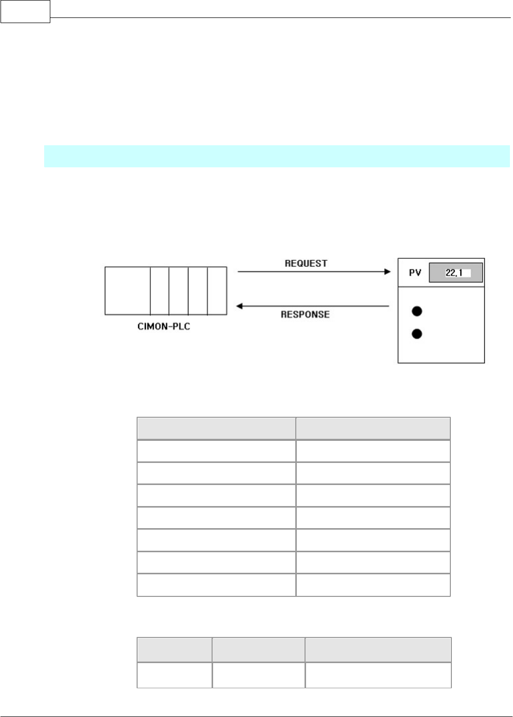
CIMON-PLC1168
Copyright 2012 BY KDT SYSTEMS, All rights reserved.
RTU Master
program sequencely(0~15). When you don’t use this function, check the blank. It is possible
to receive data if only
SEND command when check the blank,
Example of MODBUS RTU Master Special Programming Communication
Following picture shows slaves, communication system and frame structure which supported
CIMON-PLC and MODBUS RTU Protocol.
[Information of slave ]
Parameter of slave
Substance
Comm. Protocol
MODBUS RTU protocol(Slave)
Comm. Type
RS232C
Station
1
Baud Rate
9600bps
Parity
None
Data bit
8
Stop bit
1
[ Address table of slave ]
Address
Substance
PLC device address
00001
PV(present)
D00000
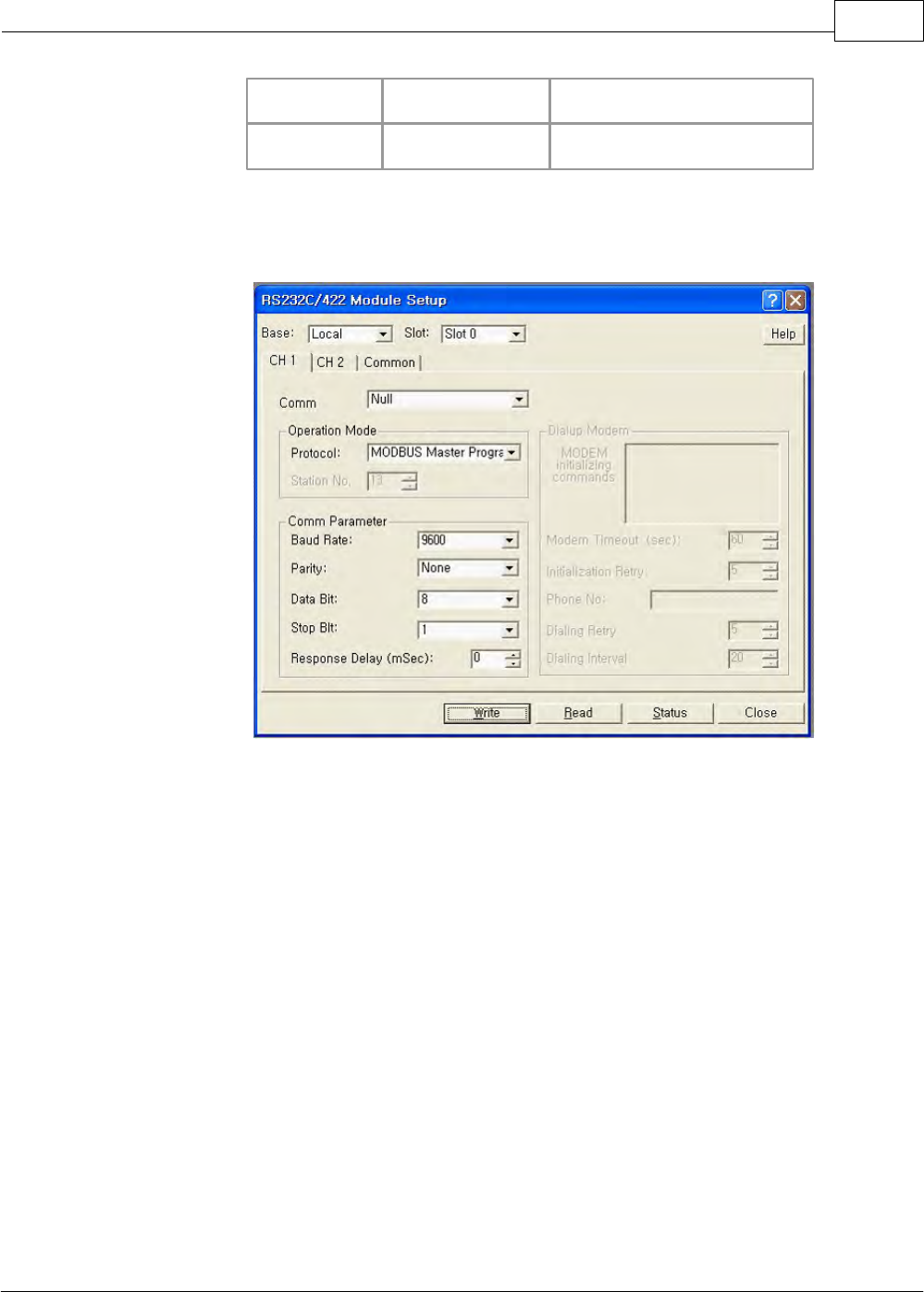
XP / CP Series(CM1) 1169
Copyright 2012 BY KDT SYSTEMS, All rights reserved.
00002
SV(set value)
D00010
…
…
…
4-1. EXAMPLE OF REGISTE
1. Register " special module setup ". Please refer to " Communication Setup "
2. Register " a communication parameter of slave" . Please compare to " special module setup "
whether it’s the same or not.
3. Register " MODBUS RTU MASTER special program "
a. Register a communication block for receiving PV value
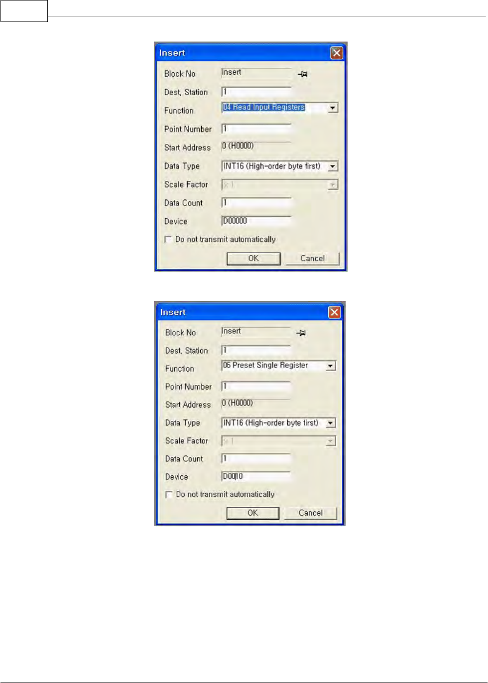
CIMON-PLC1170
Copyright 2012 BY KDT SYSTEMS, All rights reserved.
b. Register a communication block for sending SV value
c. Complete to register two communication blocks ,‘a’ and ‘b’
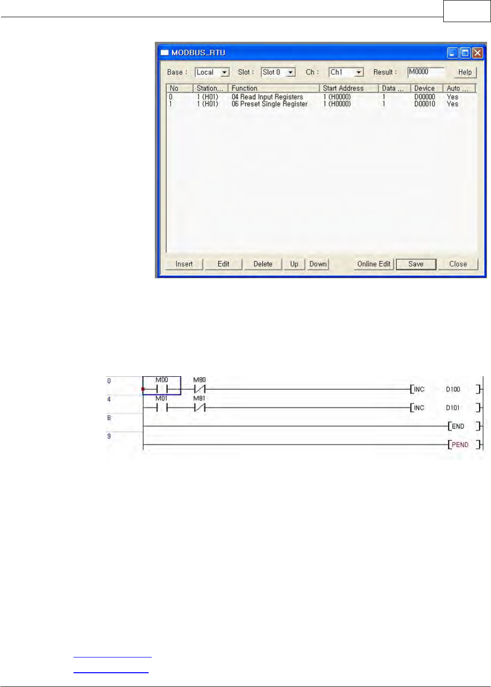
XP / CP Series(CM1) 1171
Copyright 2012 BY KDT SYSTEMS, All rights reserved.
4. Download PLC program. After downloading, please change the mode to " RUN "
5. Program PLC scan program for debugging.
a. In case of succeed in receiving PV value, Increase a data in D00100..
b. In case of succeed in sending SV value, Increase a data in D00101.
6.2.7 Installing and Testing
Installing and Testing :
·Order of Installation
·Safety Precautions

CIMON-PLC1172
Copyright 2012 BY KDT SYSTEMS, All rights reserved.
·Testing
6.2.7.1 Order of Installation
1. Prepare the components for system configuration.
2. Mount a communication module in the state that the power for a PLC is not supplied.
3. Make sure there are dust and remains in the connecter of the base where the communication module will be
mounted and whether the connecter pins of the communication module are broken.
4. The maximum number of modules mounted on one base is 8.
When you mount this module, insert the connecting part on the bottom of the module to the slot of a base
exactly in the state that the communication cable is not connected and press the power sufficient to lock the
module to the base completely. Otherwise, an error in the interface with CPU may occur.
5. Tighten the screws at both ends of the RS232C cable to secure connection.
6. Input the power after connecting the communication cable. Make sure whether the module is operated
normally, observing the operation of the LED. In case of normal operation, select the menu to set up various
parameters for the communication module and to download the program to run.
6.2.7.2 Safety Precautions
1. Select communication method correctly.
2. Select the action mode of a computer link module correctly and click it to set up. If the action mode is set up
wrongly, the communication may be disabled.
3. If the station number is duplicated in the state that the action mode is set up as the exclusive communication
mode, there will be an error in communication.
4. Use the cable of the assigned standard as the communication cable.
5. Check where the communication cable is broken.
6. Tighten the screws to fix the communication cable connecter.
7. Connect the cable of Channel 2(RS422/RS485) correctly.
·Installation of RS422 Cable :
Connect TX with RX between the first two stations. Connect TX with TX and RX with RX, between other
stations.
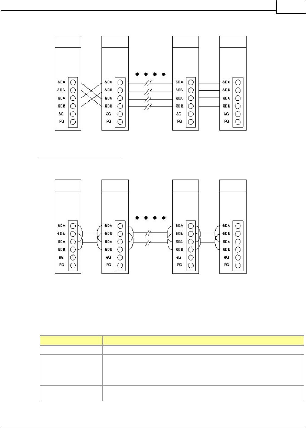
XP / CP Series(CM1) 1173
Copyright 2012 BY KDT SYSTEMS, All rights reserved.
·Installation of RS485 Cable :
Connect SDA with SDB and RDA with RDB each other in 2-wire type connection.
6.2.7.3 Testing
Check Points before Testing ,
Check Point
Description
Mount of This Module
Is it all right the mounted state of this communication module on the base?
Mount of Standard
Modules
Does the power used for the power module comply with its specifications?
Is it all right the mounted state of the standard modules?
Does a battery connect with the CPU module?
Connection of Comm.
Cable
Is it all right the connected state of the communication cable?
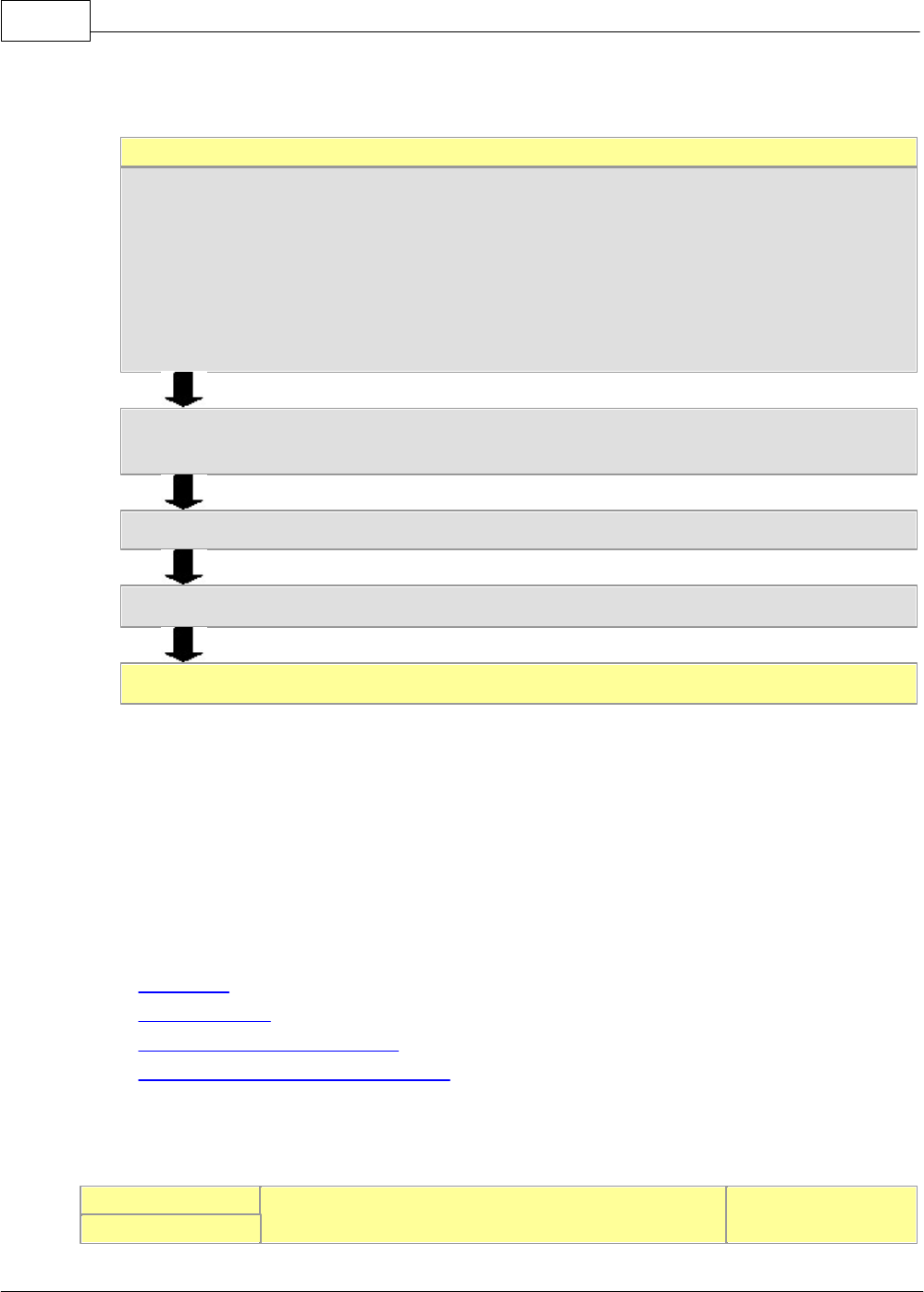
CIMON-PLC1174
Copyright 2012 BY KDT SYSTEMS, All rights reserved.
Testing ,
Start
Supplying the Power :
1) Make sure the input power.
2) Make sure the connection of the communication cable.
3) Supply the power.
4) Make sure whether the power LED lamp of the power module is on.
5) Make sure the state of the LED in the CPU module
6) Make sure whether the state of the LED is operated normally.
Select the menu in the CICON to set up the communication parameters of RS232/422 and to download
them to the communication module.
Write user program in the CICON and select the menu to download it to the CPU.
Make sure whether the communication module is operated according to the program.
Finish
6.2.8 Trouble Shooting
Trouble Shooting :
·Error Codes
·Error in Hardware
·Error in Exclusive Communications
·Error in Modem Link when Linking CICON
6.2.8.1 Error Codes
Error Code
Description
Remarks
Hexa(Deci)
XP / CP Series(CM1) 1175
Copyright 2012 BY KDT SYSTEMS, All rights reserved.
0x0000 (0)
No error
0x0001 (1)
A module is not initialized.
0x0005 (5)
A CPU module does not respond.
0x0006 (6)
Not able to access buffer memory.
0x0007 (7)
A CPU module is dismounted from a base plate.
0x0009 (9)
CTS signal does not come from modem.
0x000A (10)
A modem is not initialized.
0x000D (13)
Station number for PLC Link is duplicated.
0x0010 (16)
Link between modems is failed.
0x0012 (18)
SND command is duplicated.
0x0013 (19)
RCV command is duplicated.
0x0014 (20)
Invalid serial port is used.
0x0016 (22)
Unregistered frame for sending/receiving
0x0017
A segment is not registered to a frame.
0x0018
The registration of Sending/receiving frame is wrong.
0x001D
Sending/receiving size is over the maximum.
6.2.8.2 Error in Hardware
This corresponds to Error Code 1, 2, 3, 6 and 7.
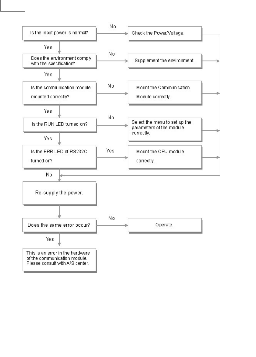
CIMON-PLC1176
Copyright 2012 BY KDT SYSTEMS, All rights reserved.
6.2.8.3 Error in Exclusive Communications
This corresponds Error Code 5.
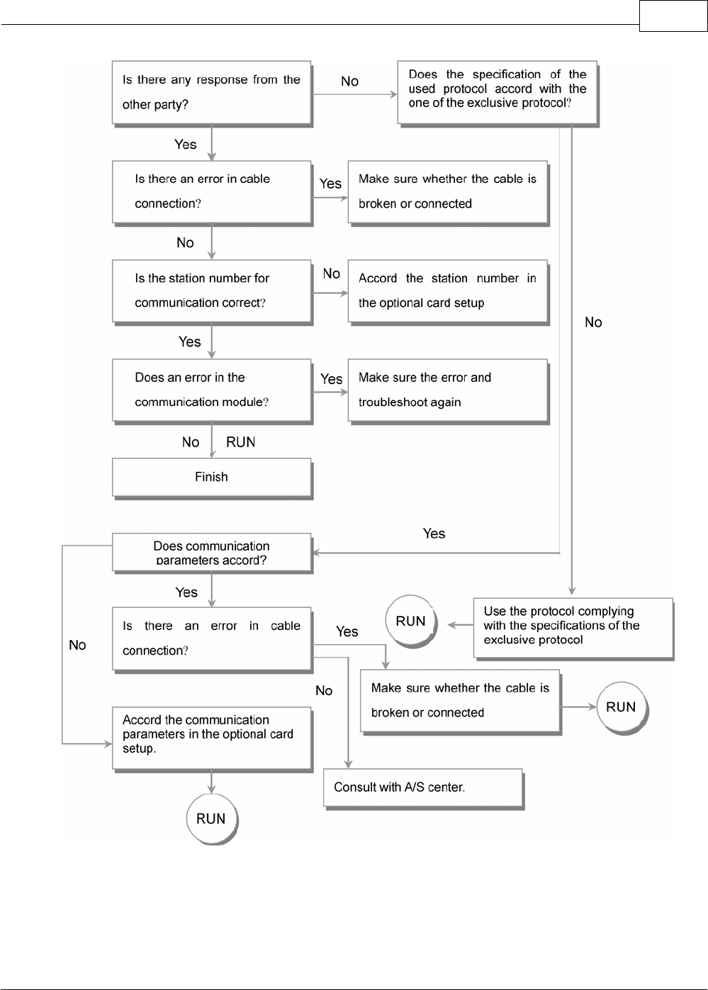
XP / CP Series(CM1) 1177
Copyright 2012 BY KDT SYSTEMS, All rights reserved.
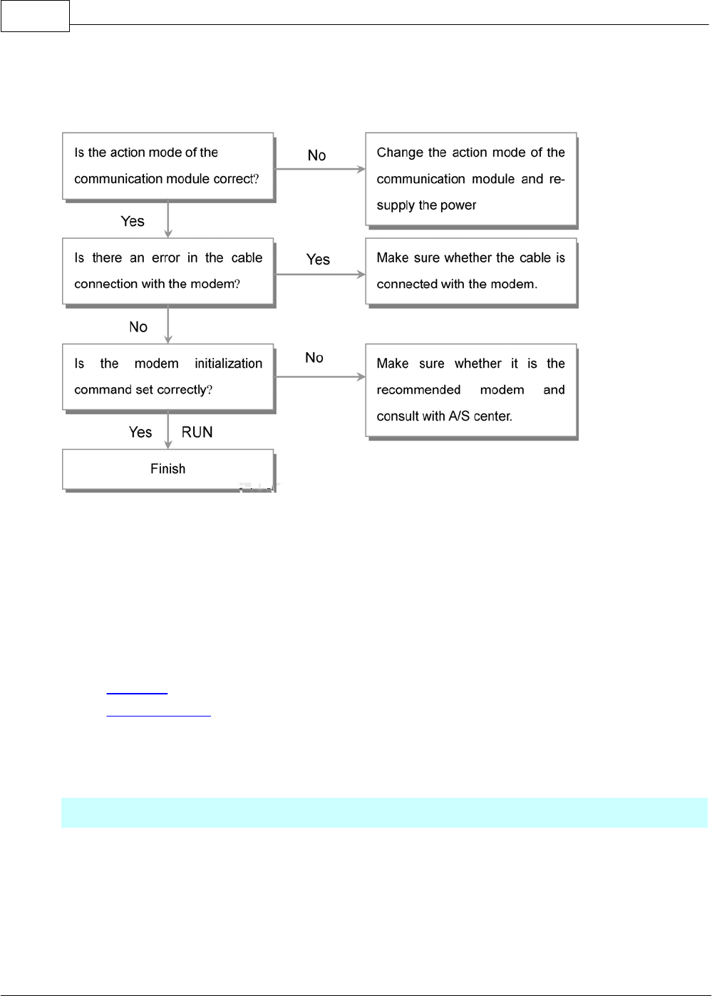
CIMON-PLC1178
Copyright 2012 BY KDT SYSTEMS, All rights reserved.
6.2.8.4 Error in Modem Link when Linking CICON
This corresponds Error Code 4, 9 and10.
6.2.9 Appendix
Appendix :
·Definitions
·ASCII Code Table
6.2.9.1 Definitions
Communication Method
Simplex
This communication method is that the flow of information is always constant in one
direction. Information cannot be transferred in reverse direction.
Half Duplex
As one-wire cable is used, this communication method is that information can be
transferred in both directions not at the same time, but at regular intervals.

XP / CP Series(CM1) 1179
Copyright 2012 BY KDT SYSTEMS, All rights reserved.
Full Duplex
As two-wire cable is used, this communication method is that data can be sent and
received at the same time.
Sending Method
According to rate, safety and economical efficiency when data are sent, sending method is classified into
series sending and parallel sending. Advantage, disadvantage and features for each method are described
as follows.
Series sending
This method is to send data bit by bit through one cable. Though baud rate is slow,
installation cost is cheap and software is simple.
Parallel sending
This method is used for a video card or a hard disc in a computer and is to transfer
data by one byte (8 bits). Though baud rate is fast and data is transferred exactly,
there is disadvantage that the longer sending distance is, the higher installation cost
is.
Protocol
This is the communication rule prescribed in advance between a sending party and a
receiving party to send and receive efficient and confident information without error
among more than two (2) computers and terminal units.
Asynchronous
method
This method is to send word by word in synchronism in case of series sending. Start
bit is sent in front of one character and the character code is sent. Finally, Stop bit is
sent.
Node
This is the location where the data in the tree structure of a network is. Each node is
composed of the device storing data and the pointer device for sub-node.
BPS and CPS
·BPS : Bits Per Second
·CPS : Characters Per Second
BPS means the number of sending bits in a second. CPS, the abbreviation for
characters per second, is the unit of printer speed and means the number of the
characters printed by a printer in a second.
Packet
This is a bundle of the data used when sending data. The data communicated
between two stations is divided into suitable-size Packets and the packets are sent
one by one. Packet includes the information about control such as receiving party,
address or control code as well as a certain-size data.
Port
This is the part of the computer used to communicate with other devices. In case of
computer link communication, this means RS-232C port or RS-422(485) port.

CIMON-PLC1180
Copyright 2012 BY KDT SYSTEMS, All rights reserved.
RS232C
This, one of the communication interface codes established by Electronics Industry
Association (EIA), is mainly used to link with diverse devices such as computer,
terminal unit, printer, floater and modem. And this is a synchronous series
communication interface or an asynchronous series communication interface. There
is the disadvantage that sending distance is short and only one to one communication
is available, but cost is cheap.
RS422 / RS485
This, one of series communication interfaces such as RS-232C, is used in longer
sending distance than the one of RS-232C and one to N access is available.
RS-422(1:N) is used for Full Duplex communication with 4 signal lines and
RS-485(N:M) is used for Half Duplex communication with 2 signal lines.
BCC
Block Check Character
As series sending may send distorted signal due to the influence of noise to sending
line, this is the data that is for a receiving party to decide whether signal is normal or
distorted. A receiving party calculates the data received up to the front of BCC and
compares the result with received BCC to decide whether signal is normal or not.
FRAME
This, the constant-size data sent in data communication, includes additional
information such as destination code, control character for synchronism, parity or
CRC to detect an error as well as data.
6.2.9.2 CIMON-PLC/HMI Protocal
CIMON-PLC / HMI Protocal Manual.
See :
Structure of Frame / Exclusive Communication / Error Response
6.2.9.2.1 Structure of Frame
Request Frame (Master) : The frame that an outside communication device requests to a computer
link module
ENQ
Stn
H
Stn
L
Cmd
Leng
H
Leng
L
Data
BCC
H
BCC
L
EOT
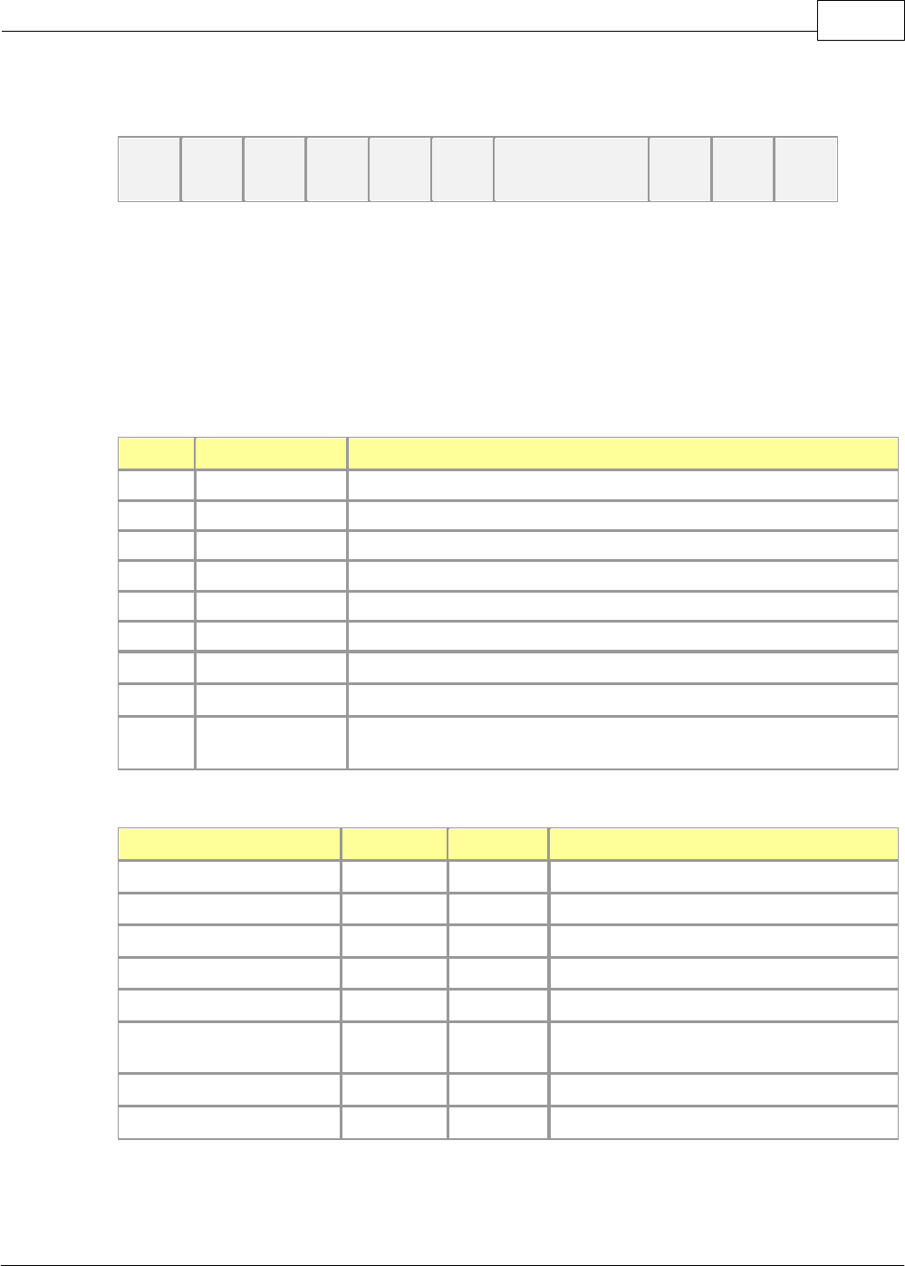
XP / CP Series(CM1) 1181
Copyright 2012 BY KDT SYSTEMS, All rights reserved.
Response Frame (Slave) : The frame that a computer link module responds to an outside
communication device
STX
Stn
H
Stn
L
Cmd
Leng
H
Leng
L
Data
BCC
H
BCC
L
ETX
1) The structure of a sending frame and the one of a receiving frame are same.
2) The same as the command codes received from a request frame (Master) are used for
response frame.
But, if there is an error in communication or process, Code E is responded.
Description for Codes
Code
Hex Value
Description
ENQ
05H
Master Frame Header
EOT
04H
Master Frame Tail
STX
02H
Slave Header
ETX
03H
Slave Tail
Stn
00H~1FH, FFH
PLC Station Number
Cmd
Command
Leng
Length of Data Device (Length Bytes), Hexadecimal
Data
Data Device according to Command (Length Bytes)
BCC
Remainder value when dividing the binary-sum from Cmd to the
end of data by 256
Commands : The commands used for exclusive communication service are as follows
Command
Code
ASCII
Function
Read Word Data
52H
R
Reads Word Memory Device.
Write Word Data
57H
W
Writes to Word Memory Device.
Read Bit Data
72H
r
Reads Bit Memory Device.
Write Bit Data
77H
w
Writes to Bit Memory Device.
Mode Change
4DH
M
Changes PLC Mode.
Register Monitoring
Device
58H
X
Registers Monitoring Device.
Monitor Read
59H
Y
Reads Registered Monitoring Device
Error Response
45H
E
Responds Error in PLC.
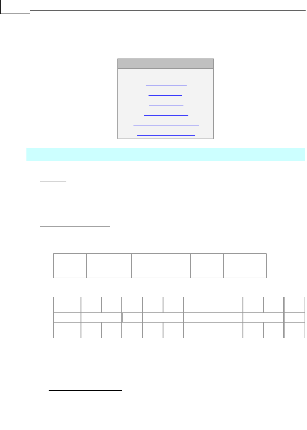
CIMON-PLC1182
Copyright 2012 BY KDT SYSTEMS, All rights reserved.
6.2.9.2.2 Exclusive Communications
IN THIS TOPIC :
READ Word Data
Write Word Data
Read Bit Data
Write Bit Data
Change PLC Mode
Register Monitoring Device
Read Monitoring Device
READ WORD DATA
Function
·This is used to read the data in the word device of a PLC. (Max. 63 words)
·Device Symbol : X, Y, M, L, K, F, Z, TC, TS, CC, CS, D, S
Request Frame (Master)
·COMMAND : ‘R’
·Data Device Format
Address
8 Char
Size (Word)
Hexadecimal,
2 Char
......
Address
8 Char
Size (Word)
Hexadecimal,
2 Char
Master(Request Format)
HEADER
Stn
H
Stn
L
Cmd
Leng
H
Leng
L
Data
BCC
H
BCC
L
EOT
ENQ
02
R
0A
D0000001 01
B9
EOT
05H
30H
32H
52H
30H
41H
4430303030303031
3031H
42H
39H
04H
Leng is the length of a data and its value means the length of a data (D0000001 01).
Data means the address really read (D0000001) and the length of the word data read (01).
BCC is the remainder value when dividing the binary-sum from Cmd to the end of data by
256
Response Frame (Slave)
·COMMAND ( In completed case: ‘R’ / In failed case: ‘E’ )
·Format of Data Device
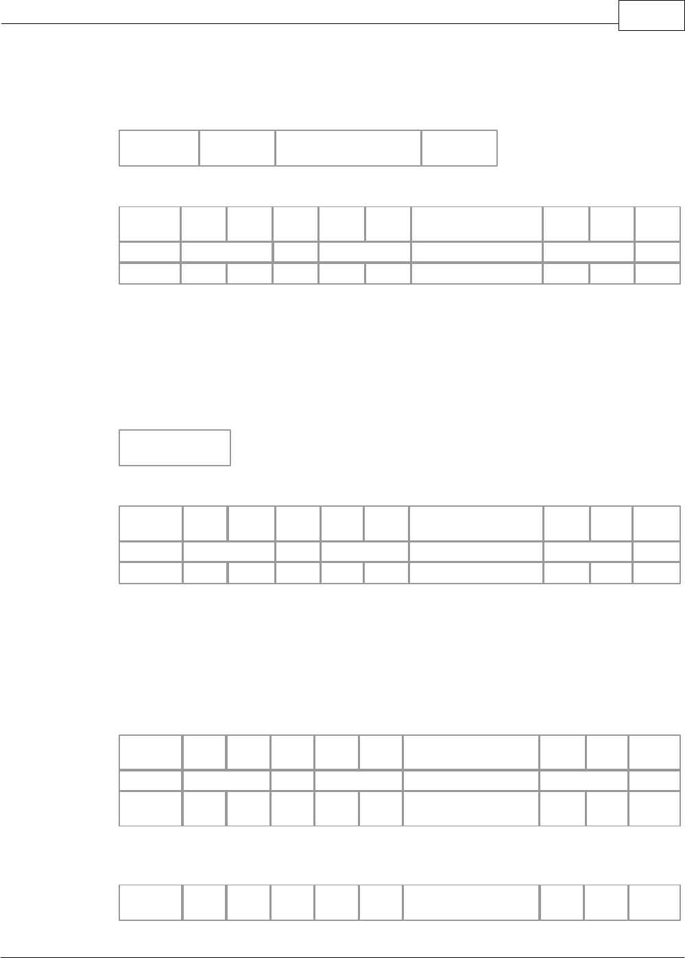
XP / CP Series(CM1) 1183
Copyright 2012 BY KDT SYSTEMS, All rights reserved.
[Completed Case]
PLC DATA
Word Data
4 Char
Word Data
4 Char
......
Word Data
4 Char
Slave(Response Format)
HEADER
Stn
H
Stn
L
Cmd
Leng
H
Leng
L
Data
BCC
H
BCC
L
ETX
STX
02
R
04
F4AC
B4
ETX
02H
30H
32H
52H
30H
34H
46344143H
42H
34H
03H
The request frame received from a master is used as the response frame of a PLC.
BCC is the remainder value when dividing binary-sum from Cmd to the end of data by 256.
As the response frame is processed, Cmd is ‘R’
..
Leng means the length of a data (F4AC).
[Failed Case]
Error Code
Error Code
2 Char
Slave(Response Format)
HEADER
Stn
H
Stn
L
Cmd
Leng
H
Leng
L
Error Code
BCC
H
BCC
L
ETX
STX
02
E
02
02
09
ETX
02H
30H
32H
45H
30H
32H
3032H
30H
39H
03H
The request frame received from a master is used as the response frame of a PLC.
BCC is the remainder value when dividing the binary-sum from Cmd to the end of data by 256.
As the response frame is not processed, Cmd is ‘
E’.
Leng means the length of error code(02).
Error code displays the type of an error. Please refer to the ‘
ERROR RESPONSE’.
Ex.) Read data from Address D00040 of Station 02H.
Master(Request Format)
HEADER
Stn
H
Stn
L
Cmd
Leng
H
Leng
L
Data
BCC
H
BCC
L
EOT
ENQ
02
R
0A
D0000040 01
BC
EOT
05H
30H
32H
52H
30H
41H
4430303030303430
3031H
42H
43H
04H
Completed Case> reads 1-word data ‘
F4AC’
Slave(Response Format)
HEADER
Stn
H
Stn
L
Cmd
Leng
H
Leng
L
Data
BCC
H
BCC
L
ETX
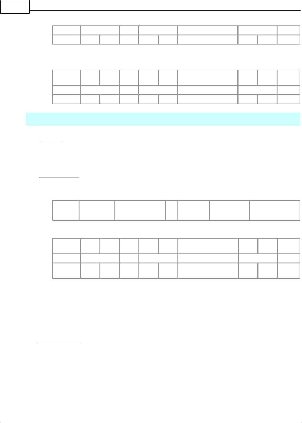
CIMON-PLC1184
Copyright 2012 BY KDT SYSTEMS, All rights reserved.
STX
02
R
04
F4AC
B4
ETX
02H
30H
32H
52H
30H
34H
46344143H
42H
34H
03H
Failed Case> Error in BCC
Slave(Response Format)
HEADER
Stn
H
Stn
L
Cmd
Leng
H
Leng
L
Error Code
BCC
H
BCC
L
ETX
STX
02
E
02
02
09
ETX
02H
30H
32H
45H
30H
32H
3032H
30H
39H
03H
Write WORD DATA ?
Function
·This is used to write a data to the word device of a PLC.
·Device Symbol : X, Y, M, L, K, F, Z, TC, TS, CC, CS, D, S
Request Frame
·COMMAND : ‘W’
·Format of Data Device
Address
8 Char
Size (Word)
Hexadecima
l, 2 Char
Word Data
Hexadecimal,
Size*4 Char
.....
Address
8 Char
Size (Word)
Hexadecimal,
2 Char
Word Data
Hexadecimal,
Size*4 Char
Master(Request Format)
HEADER
Stn
H
Stn
L
Cmd
Leng
H
Leng
L
Data
BCC
H
BCC
L
EOT
ENQ
02
W
0E
D0000010 01 FA34
B0
EOT
05H
30H
32H
57H
30H
45H
4430303030303130
3031 46413334H
42H
30H
04H
Leng is the length of a data and its value means the length of the Data (D0000010 01 FA34).
The address really written (D0000010), the length of the data (01) and the data written (FA34)
are input in the Data (D1000 02 FA34).
BCC is the remainder value (F3) when dividing the binary-sum from Cmd to the end of data by
256.
Response Frame
·COMMAND (In completed case:
‘W’ / In failed case : ‘E’ )
·Format of Data Device
[Completed Case]
No Data?
Slave(Response Format)
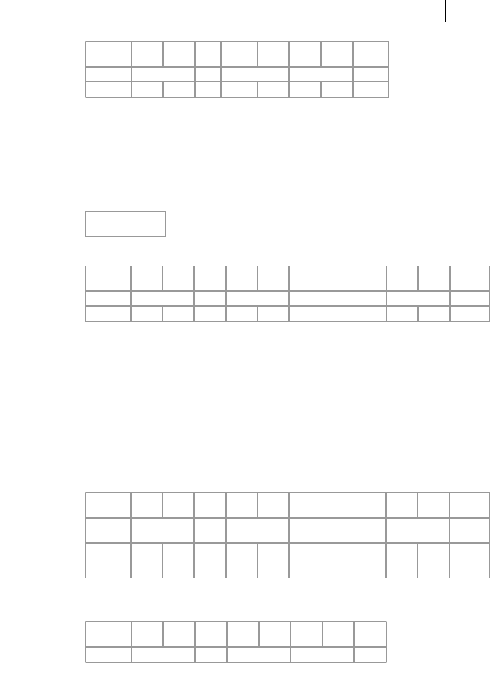
XP / CP Series(CM1) 1185
Copyright 2012 BY KDT SYSTEMS, All rights reserved.
HEADER
Stn
H
Stn
L
Cmd
Leng
H
Leng
L
BCC
H
BCC
L
ETX
STX
02
W
00
B7
ETX
02H
30H
32H
57H
30H
30H
42H
37H
03H
The request frame received from a master is used as the response frame of a PLC.
BCC is the remainder value when dividing the binary-sum from Cmd to the end of data by 256.
As the response frame is processed, Cmd is ‘
W’.
Leng means the length of a data.
[Failed Case]
ERROR CODE
Error Code
2 Char
Slave(Response Format)
HEADER
Stn
H
Stn
L
Cmd
Leng
H
Leng
L
Error Code
BCC
H
BCC
L
ETX
STX
02
E
02
01
08
ETX
02H
30H
32H
45H
30H
32H
3031H
30H
38H
03H
The request frame received from a master is used as the response frame of a PLC.
BCC is the remainder value when dividing the binary-sum from Cmd to the end of data by 256.
As the response frame is not processed, Cmd is ‘
E’.
Leng(02) means the length of Error Code(01).
Error code displays the type of an error. Please refer to the ‘
ERROR RESPONSE’.
Ex.) Write FA34H to Address D0010 and 8D41H to Address D0020.
Master(Request Format)
HEADER
Stn
H
Stn
L
Cmd
Leng
H
Leng
L
Data
BCC
H
BCC
L
EOT
ENQ
02
W
12
D0000010 02 FA34
8D41
80
EOT
05H
30H
32H
57H
31H
32H
4430303030303130
3032 46413334
38443431H
38H
30H
04H
Completed Case > No Data?
Slave(Response Format)
HEADER
Stn
H
Stn
L
Cmd
Leng
H
Leng
L
BCC
H
BCC
L
ETX
STX
02
W
0
B7
ETX
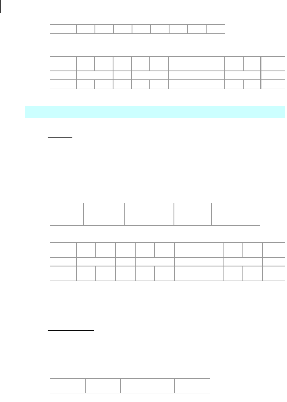
CIMON-PLC1186
Copyright 2012 BY KDT SYSTEMS, All rights reserved.
02H
30H
32H
57H
30H
30H
42H
37H
03H
Failed Case>Receiving unknown command code (01H).
Slave(Response Format)
HEADER
Stn
H
Stn
L
Cmd
Leng
H
Leng
L
Error Code
BCC
H
BCC
L
ETX
STX
02
E
02
01
08
ETX
02H
30H
32H
45H
30H
32H
3031H
30H
38H
03H
Read BIT DATA
Function
·This is used to read the data in the bit device of a PLC.
·Device Symbol : X, Y, M, L, K, F, Z, T, C
Request Frame
·COMMAND : ‘r’
·Format of Data Device
Address
8 Char
Size (Bit)
Hexadecimal,
2 Char
.......
Address
8 Char
Size (Bit)
Hexadecimal, 2
Char
Master(Requset Format)
HEADER
Stn
H
Stn
L
Cmd
Leng
H
Leng
L
Data
BCC
H
BCC
L
EOT
ENQ
03
r
0A
M000010F 02
F9
EOT
05H
30H
33H
72H
30H
41H
4D303030313030
46 3032H
46H
39H
04H
• Leng is the length of a data and its value means the length of Data (M000010F 02H).
• The address really read(M000010F) and the length of the data(02) are input in the Data.
• BCC is the remainder value when dividing the binary-sum from Cmd to the end of data by
256.
Response Frame
·COMMAND (In completed case: ‘r’ / In failed case: ‘E’ )
·Format of Data Device
[Completed Case]
PLC Data
Bit Data
Bit Data
......
Bit Data

XP / CP Series(CM1) 1187
Copyright 2012 BY KDT SYSTEMS, All rights reserved.
1 Char
1 Char
1 Char
Slave(Response Format)
HEADER
Stn
H
Stn
L
Cmd
Leng
H
Leng
L
Data
BCC
H
BCC
L
ETX
STX
01
r
02
0 1
35
ETX
02H
30H
31H
72H
30H
32H
30 31H
33H
35H
03H
Ÿ The request frame received from a master is used as the response frame of a PLC.
Ÿ BCC is the remainder value when dividing the binary-sum from Cmd to the end of data by 256.
Ÿ As the response frame is processed, Cmd is ‘r’.
Ÿ Leng(02) means the length of the Data(0 1).
[ Failed Case ]
Error Code
Error Code
2 Char
Slave(Response Format)
HEADER
Stn
H
Stn
L
Cmd
Leng
H
Leng
L
Error Code
BCC
H
BCC
L
ETX
STX
03
E
02
01
08
ETX
02H
30H
33H
45H
30H
32H
3031H
30H
38H
03H
Ÿ The request frame received from a master is used as the response frame of a PLC.
Ÿ BCC is the remainder value when dividing the binary-sum from Cmd to the end of data by 256.
Ÿ As the response frame is not processed, Cmd is ‘E’.
Ÿ Leng(02) means the length of Error Code(01).
ŸError code indicates the type of an error. Please refer to the ‘ERROR RESPONSE’.
Ex.) Read the bit data in Address M0104 and Address M0105 of Station 03 PLC.
Master(Request Format)
HEADER
Stn
H
Stn
L
Cmd
Leng
H
Leng
L
Data
BCC
H
BCC
L
EOT
ENQ
03
r
0A
M0000104 02
E7
EOT
05H
30H
33H
72H
30H
41H
4D3030303031 3034
3032H
45H
37H
04H
Completed Case > Reads Data ‘0 1’.
Slave(Response Format)
HEADER
Stn
H
Stn
L
Cmd
Leng
H
Leng
L
Data
BCC
H
BCC
L
ETX
STX
03
r
02
0 1
35
ETX
02H
30H
33H
72H
30H
32H
30 31H
33H
35H
03H
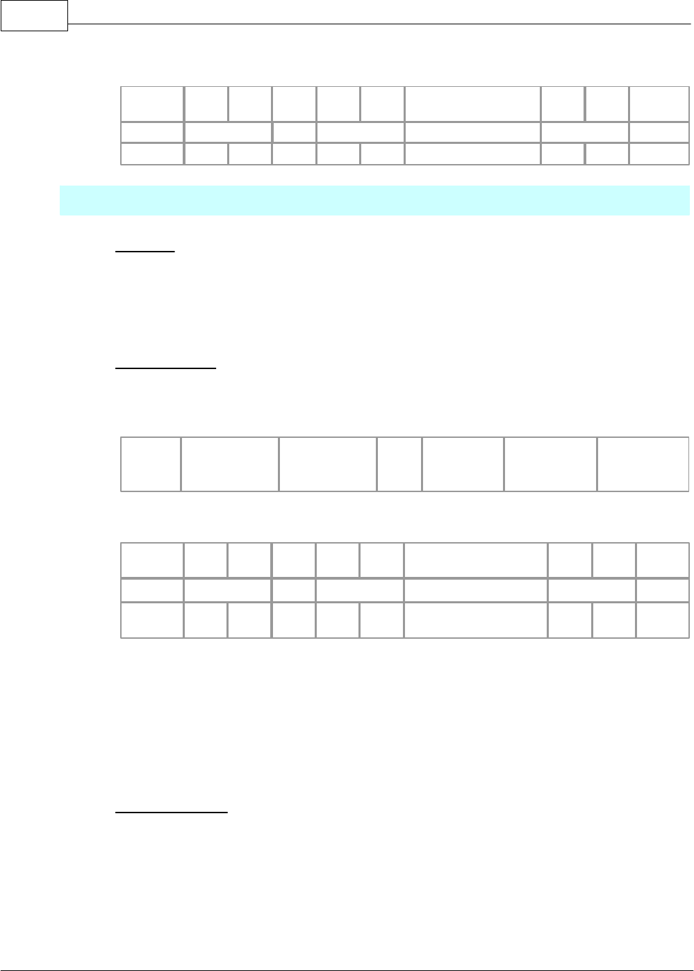
CIMON-PLC1188
Copyright 2012 BY KDT SYSTEMS, All rights reserved.
Failed Case > Error in BCC
Slave (Response Format)
HEADER
Stn
H
Stn
L
Cmd
Leng
H
Leng
L
Error Code
BCC
H
BCC
L
ETX
STX
03
E
02
02
09
ETX
02H
30H
33H
45H
30H
32H
3032H
30H
39H
03H
Write BIT DATA
Function
·This is used to write data to the bit device of a PLC
·Device Symbol : X, Y, M, L, K, F, Z, T, C
Request Frame
·COMMAND : ‘w’
·Format of Data Device
·
Address
8 Char
Size (Bit)
Hexadecimal,
2 Char
Bit Data
Size*1 Char
…
Address
8 Char
Size (Bit)
Hexadecimal,
2 Char
Bit Data
Size*1 Char
Master(Request Format)
HEADER
Stn
H
Stn
L
Cmd
Leng
H
Leng
L
Data
BCC
H
BCC
L
EOT
ENQ
03
w
0D
M0000101 03 110
7F
EOT
05H
30H
33H
77H
30H
44H
4D303030303130 31
3033 313130H
37H
46H
04H
• Leng(0B) is the length of data and its value means the length of Data (M0000101 03 110).
•
The address really written(M0000101), the length of the data(03) and the data written(110)
are input in the Data.
•
BCC is the remainder value when dividing the binary-sum from Cmd to the end of data by
256.
Response Frame
·COMMAND ( In completed case: ‘w’ / In failed case: ‘E’ )
·Format of Data Device
[Completed Case]
No Data
Slave(Response Format)
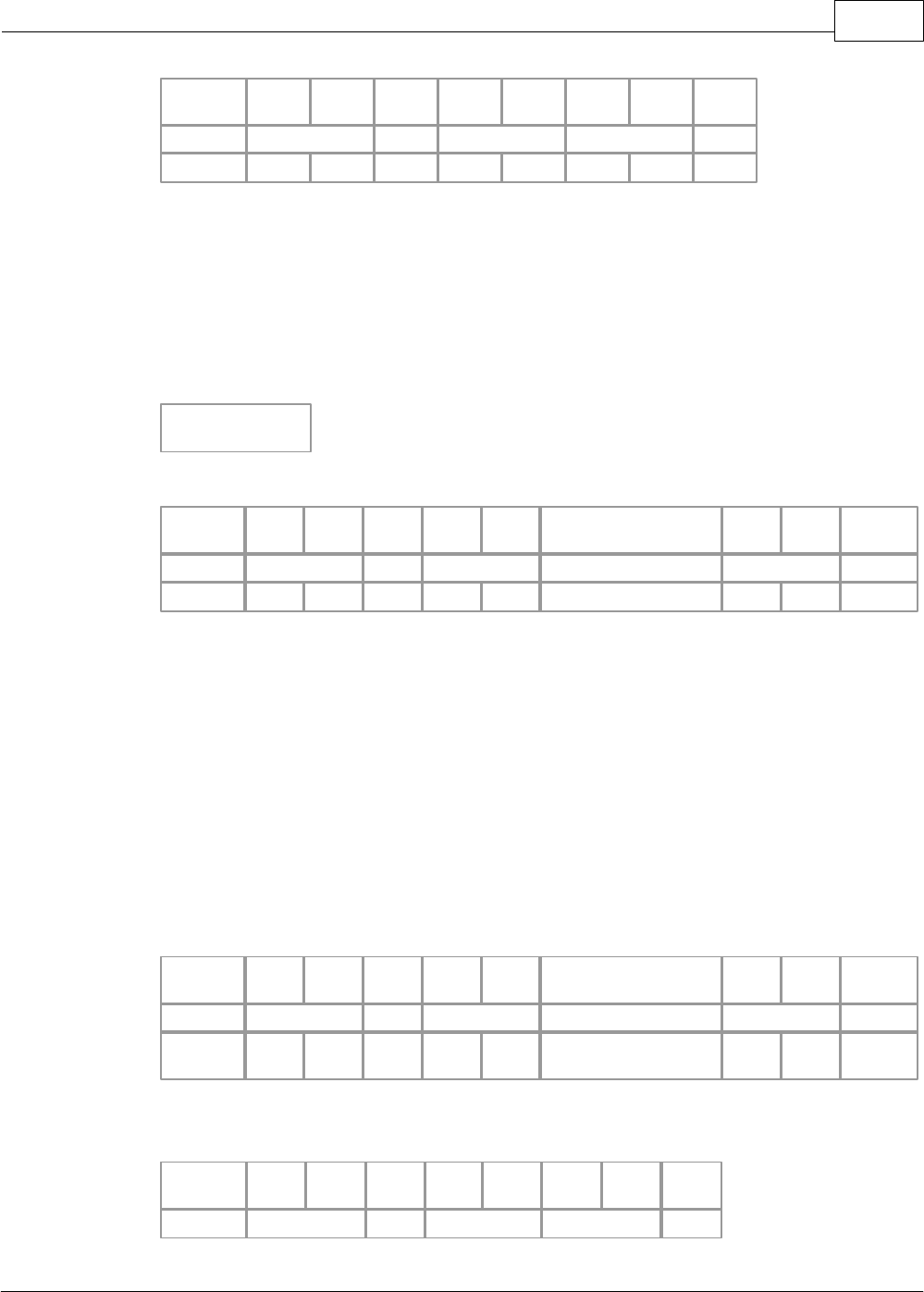
XP / CP Series(CM1) 1189
Copyright 2012 BY KDT SYSTEMS, All rights reserved.
HEADER
Stn
H
Stn
L
Cmd
Leng
H
Leng
L
BCC
H
BCC
L
ETX
STX
03
w
00
D7
ETX
02H
30H
33H
77H
30H
30H
44H
37H
03H
Ÿ The request frame received from a master is used as the response frame of a PLC.
Ÿ BCC is the remainder value when dividing the binary-sum from Cmd to the end of data by 256.
Ÿ As the response frame is processed, Cmd is ‘w’.
Ÿ Leng(00) means the length of the data.
[Failed Case]
Error Code
Error Code
2 Char
Slave(Response Format)
HEADER
Stn
H
Stn
L
Cmd
Leng
H
Leng
L
Error Code
BCC
H
BCC
L
ETX
STX
02
E
02
04
0B
ETX
02H
30H
32H
45H
30H
32H
3034H
30H
42H
03H
• The request frame received from a master is used as the response frame of a PLC.
• BCC is the remainder value when dividing the binary-sum from Cmd to the end of data by
256.
• As the response frame is not processed, Cmd is ‘E’
.
• Leng(02) means the length of Error Code (04).
•
Error code indicates the type of an error. Please refer to the ‘ERROR RESPONSE’
.
Ex.) Write bit data to Bit Address M0104.
Master(Request Format)
HEADER
Stn
H
Stn
L
Cmd
Leng
H
Leng
L
Data
BCC
H
BCC
L
EOT
ENQ
01
w
0D
M0000104 03 110
82
EOT
05H
30H
31H
77H
30H
44H
4D303030303130 34
3033 313130H
38H
32H
04H
< Completed Case >
Slave(Response Format)
HEADER
Stn
H
Stn
L
Cmd
Leng
H
Leng
L
BCC
H
BCC
L
ETX
STX
01
w
00
D7
ETX
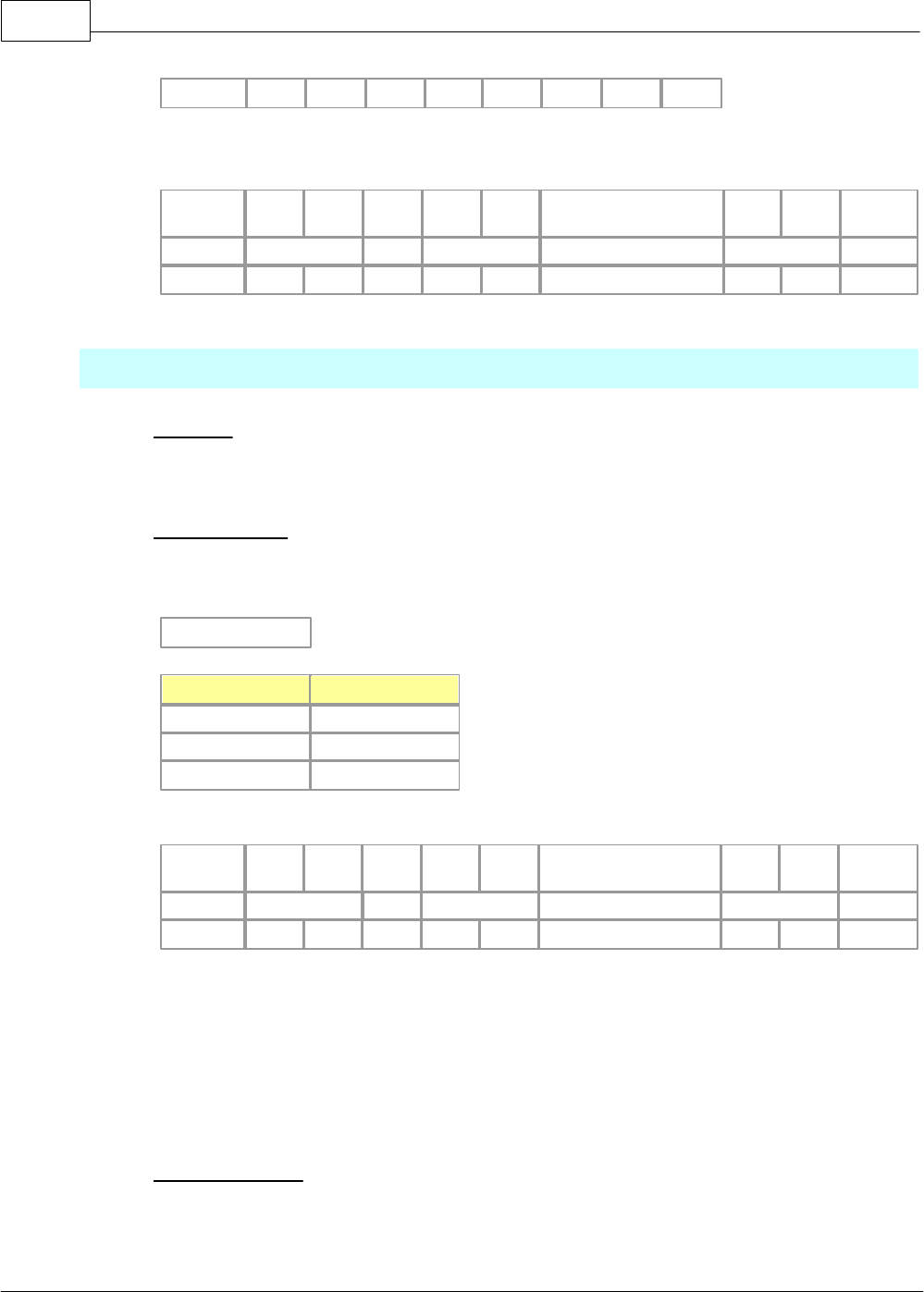
CIMON-PLC1190
Copyright 2012 BY KDT SYSTEMS, All rights reserved.
02H
30H
31H
77H
30H
30H
44H
37H
03H
Failed Case > Data Size Overflow
Slave(Response Format)
HEADER
Stn
H
Stn
L
Cmd
Leng
H
Leng
L
Error Code
BCC
H
BCC
L
ETX
STX
01
E
02
04
0B
ETX
02H
30H
31H
45H
30H
32H
3034H
30H
42H
03H
Change PLC Mode
Function
·This is used to change the operation mode of a PLC. .
Request Frame
·COMMAND : ‘M’
·Format of Data Device
Mode Code
Mode
Code
Run
0
Program
1
Pause / Remote
2
Master(Request Format)
HEADER
Stn
H
Stn
L
Cmd
Leng
H
Leng
L
Data
BCC
H
BCC
L
EOT
ENQ
01
M
01
0
DE
EOT
05H
30H
31H
4DH
30H
31H
30H
44H
45H
04H
• Leng(01) is the length of data.
• Mode code value(0) is input in the Data(0).
? •
BCC is the remainder value when dividing the binary-sum from Cmd to the end of data by
256.
• Only the case CPU is under REMOTE status is available.
Response Frame
·COMMAND ( In completed case: ‘M’ / In failed case: ‘E’ )
·Format of Data DEvice
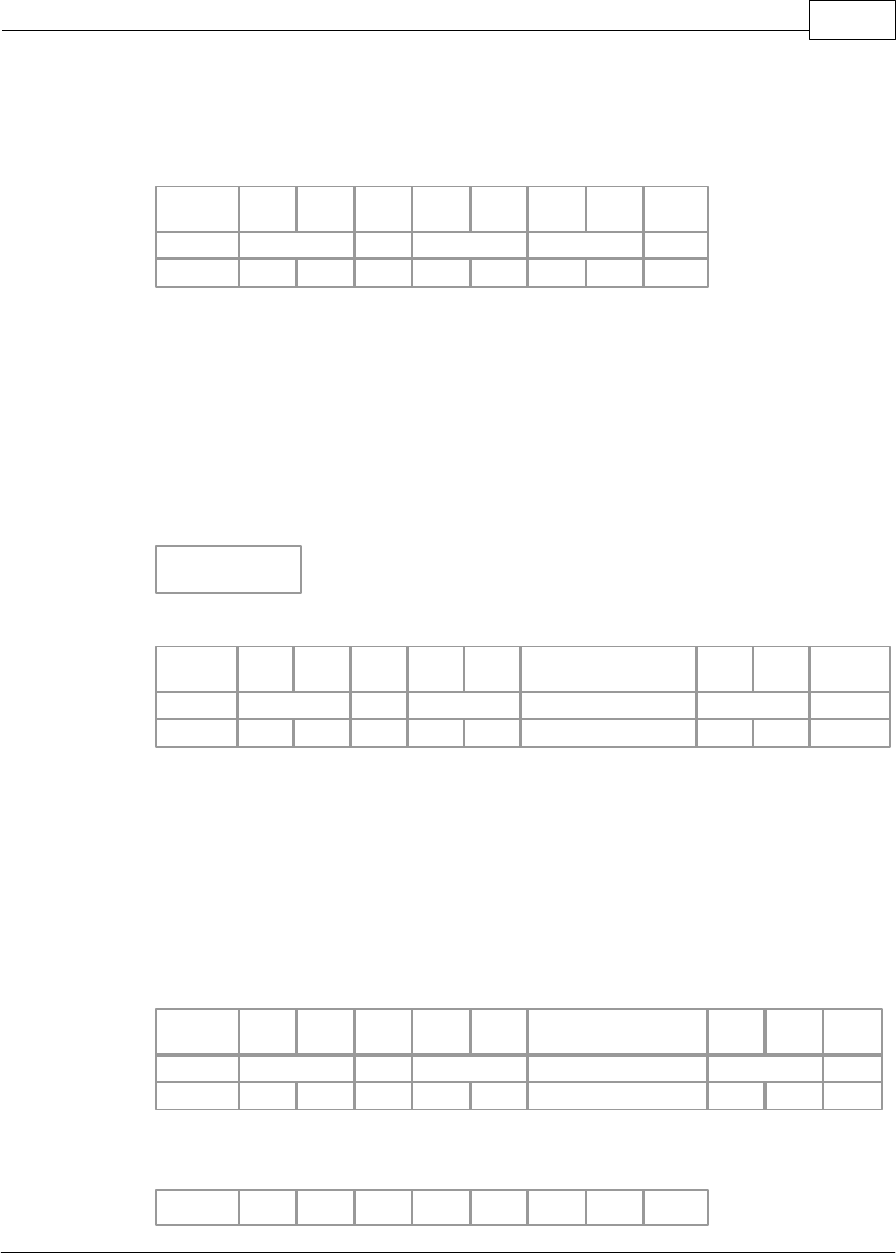
XP / CP Series(CM1) 1191
Copyright 2012 BY KDT SYSTEMS, All rights reserved.
[Completed Case] No Date?
Slave(Response Format)
HEADER
Stn
H
Stn
L
Cmd
Leng
H
Leng
L
BCC
H
BCC
L
ETX
STX
01
M
00
AD
ETX
02H
30H
31H
4DH
30H
30H
41H
44H
03H
• The request frame received from a master is used as the response frame of a PLC.
• BCC is the remainder value when dividing the binary-sum from Cmd to the end of data by
256.
• As the response frame is processed, Cmd is ‘M’
.
• Leng(00) means the length of the data.
[Failed Case]
Error Code
Error Code
2 Char
Slave(Response Format)
HEADER
Stn
H
Stn
L
Cmd
Leng
H
Leng
L
Error Code
BCC
H
BCC
L
ETX
STX
02
E
02
03
0A
ETX
02H
30H
32H
45H
30H
32H
3033H
30H
41H
03H
Ÿ The request frame received from a master is used as the response frame of a PLC.
Ÿ BCC is the remainder value when dividing the binary-sum from Cmd to the end of data by 256.
Ÿ As the response frame is not processed, Cmd is ‘E’.
Ÿ Leng(02) means the length of Error Code (03).
Ÿ Error code indicates the type of an error. Please refer to the ‘ERROR RESPONSE’.
Ex.) Change the operation mode of a PLC to PAUSE/REMOTE mode.
Master(Requset Format)
HEADER
Stn
H
Stn
L
Cmd
Leng
H
Leng
L
Data
BCC
H
BCC
L
EOT
ENQ
01
M
01
2
E0
EOT
05H
30H
31H
4DH
30H
31H
32H
45H
30H
04H
Completed Case
Slave(Response Format)
HEADER
Stn
Stn
Cmd
Leng
Leng
BCC
BCC
ETX
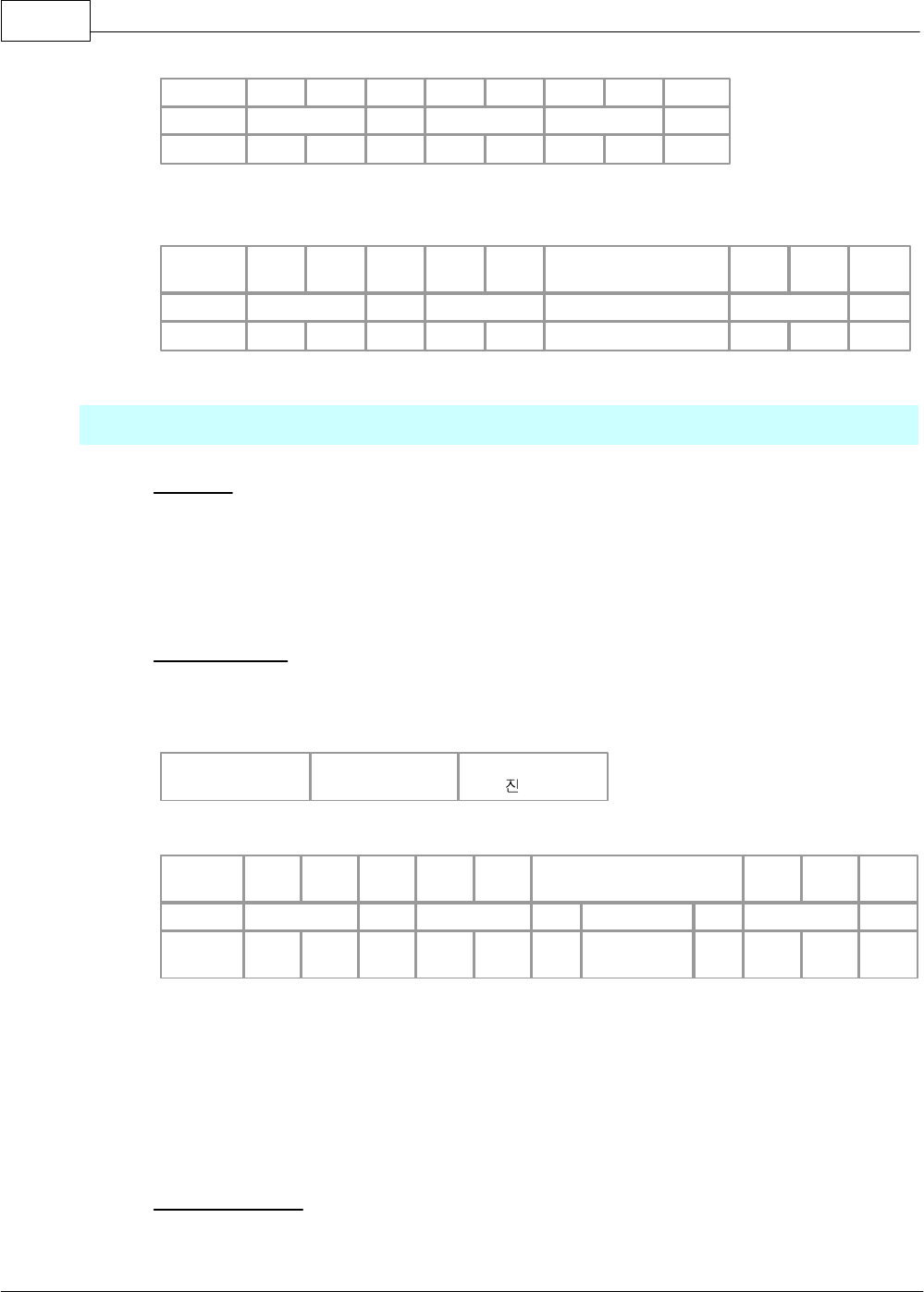
CIMON-PLC1192
Copyright 2012 BY KDT SYSTEMS, All rights reserved.
H
L
H
L
H
L
STX
01
M
00
AD
ETX
02H
30H
31H
4DH
30H
30H
41H
44H
03H
< Failed CAse > Invalid mode
Slave(Response Format)
HEADER
Stn
H
Stn
L
Cmd
Leng
H
Leng
L
Error Code
BCC
H
BCC
L
ETX
STX
01
E
02
03
0A
ETX
02H
30H
31H
45H
30H
32H
3033H
30H
41H
03H
Register Monitoring Device
Function
·This is used to register a monitoring device.
·16 devices can be registered as maximum. (Distinguishing by Frame No., 0h – Fh)
·Individual device should be continuous and is limited to 63 words as maximum.
Request Frame
·COMMAND : ‘X’
·Format of Data Device
·
Frame No.
1 Char
Word Address
8 Char
Word Size
16 , 2 Char
Master(Request Format)
HEADER
Stn
H
Stn
L
Cmd
Leng
H
Leng
L
Data
BCC
H
BCC
L
EOT
ENQ
01
X
0B
0
D0000001
02
C0
EOT
05H
30H
31H
58H
30H
42H
30H
44303030303
03031H
3032
H
43H
30H
04H
• Leng(0B) is the length of a data.
• The Mode code(0), the Address(D0000001) and the Size(02) are input in the Data (0
D00001 02).
•
BCC is the remainder value when dividing the binary-sum from Cmd to the end of data by
256.
Response Frame
·COMMAND ( In completed case: ‘X’ / In failed case: ‘E’ )
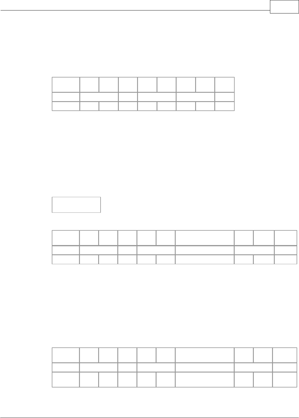
XP / CP Series(CM1) 1193
Copyright 2012 BY KDT SYSTEMS, All rights reserved.
·Format of Data Device
[Completed Case]
No Data
Slave(Response Format)
HEADER
Stn
H
Stn
L
Cmd
Leng
H
Leng
L
BCC
H
BCC
L
ETX
STX
01
X
00
B8
ETX
02H
30H
31H
58H
30H
30H
42H
38H
03H
• The request frame received from a master is used as the response frame of a PLC.
• BCC is the remainder value when dividing the binary-sum from Cmd to the end of data by
256.
• As the response frame is processed, Cmd is ‘X’
.
• Leng(00) means the length of the data.
[Failed Case]
Error Code
Error Code
2 Char
Slave(Response Format)
HEADER
Stn
H
Stn
L
Cmd
Leng
H
Leng
L
Error Code
BCC
H
BCC
L
ETX
STX
01
E
02
07
0E
ETX
02H
30H
31H
45H
30H
32H
3037H
30H
45H
03H
The request frame received from a master is used as the response frame of a PLC.
BCC is the remainder value when dividing the binary-sum from Cmd to the end of data by 256.
As the response frame is not processed, Cmd is ‘
E’.
Leng(02) means the number of Error Codes (07).
Error code indicates the type of an error. Please refer to the ‘
ERROR RESPONSE’.
Ex.) Register Frame 1 and Addresses from D0011 to D0014 to Station 1.
Master(Response Format)
HEADER
Stn
H
Stn
L
Cmd
Leng
H
Leng
L
Data
BCC
H
BCC
L
EOT
ENQ
01
X
0B
1 D0000011 04
C5
EOT
05H
30H
31H
58H
30H
42H
31 443030303030
3131 3034H
43H
35H
04H
< Completed Case >
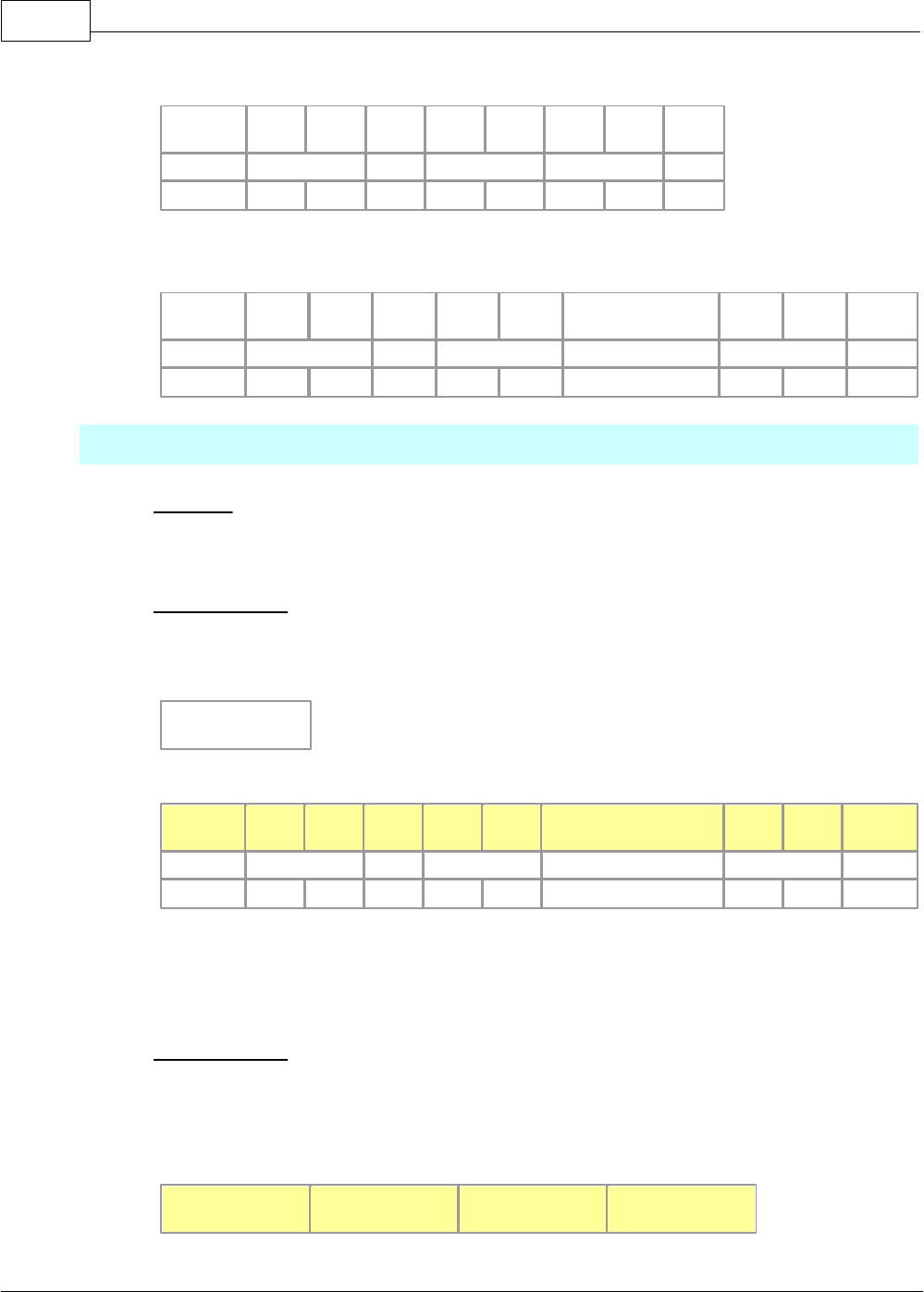
CIMON-PLC1194
Copyright 2012 BY KDT SYSTEMS, All rights reserved.
Slave(Response Format)
HEADER
Stn
H
Stn
L
Cmd
Leng
H
Leng
L
BCC
H
BCC
L
ETX
STX
01
X
00
B8
ETX
02H
30H
31H
58H
30H
30H
42H
38H
03H
Failed CAse > Invalid Monitor Frame No.(0h~Fh)
Slave(Response Format)
HEADER
Stn
H
Stn
L
Cmd
Leng
H
Leng
L
Error Code
BCC
H
BCC
L
ETX
STX
01
E
02
07
0E
ETX
02H
30H
31H
45H
30H
32H
3037H
30H
45H
03H
Read Monitoring Device
Function
·This is used to read the registered monitoring device..
Request Frame
·COMMAND : ‘Y’
·Format of Data Device
Frame No.
1 Char
Master(Request Format)
HEADER
Stn
H
Stn
L
Cmd
Leng
H
Leng
L
Data
BCC
H
BCC
L
EOT
ENQ
01
Y
01
0
EA
EOT
05H
30H
31H
59H
30H
31H
30H
45H
41H
04H
Leng(01) is the length of a data.
Frame No. is input in the Data(0).
BCC is the remainder value when dividing the binary-sum from Cmd to the end of data by 256.
Request Frame
·COMMAND ( In completed case: ‘Y’ / In failed case: ‘E’ )
·Format of Data Device
[Completed Case]
Frame No.
Word Data
4 Char
.....
Word Data
4 Char
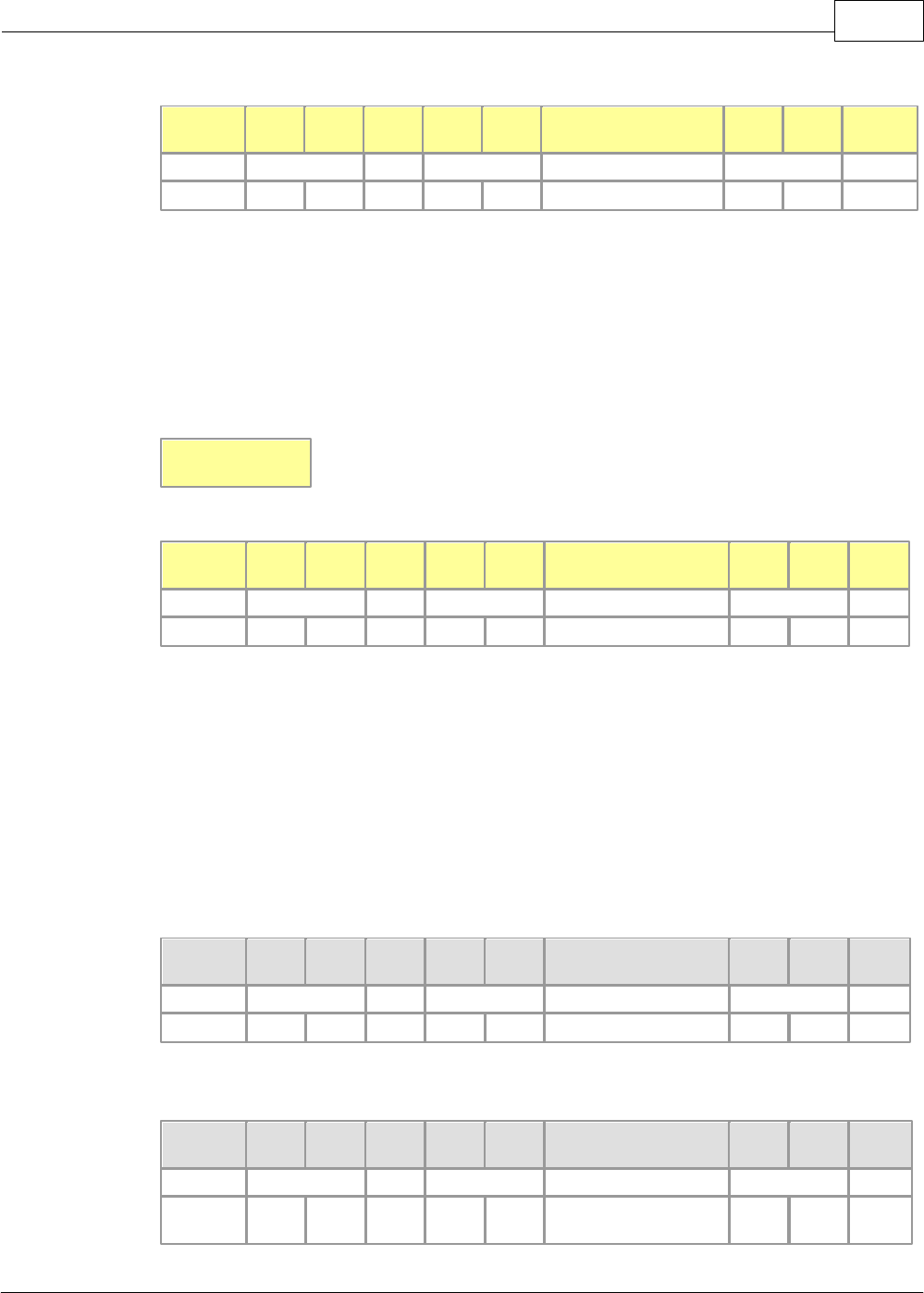
XP / CP Series(CM1) 1195
Copyright 2012 BY KDT SYSTEMS, All rights reserved.
Slave(Response Format)
HEADER
Stn
H
Stn
L
Cmd
Leng
H
Leng
L
Data
BCC
H
BCC
L
EOT
ENQ
01
Y
05
0 87F3
D6
EOT
05H
30H
31H
59H
30H
35H
30 38374633H
44H
36H
04H
·The request frame received from a master is used as the response frame of a PLC.
·BCC is the remainder value when dividing the binary-sum from Cmd to the end of data by 256.
·As the response frame is processed, Cmd is ‘Y’.
·Leng(05) means the length of the Data(0 87F3).
[Failed Case]
Error Code
Error Code
2 Char
Slave(Response Format)
HEADER
Stn
H
Stn
L
Cmd
Leng
H
Leng
L
Error Code
BCC
H
BCC
L
ETX
STX
01
E
02
08
0F
ETX
02H
30H
31H
45H
30H
32H
3038H
30H
46H
03H
Ÿ The request frame received from a master is used as the response frame of a PLC.
Ÿ BCC is the remainder value when dividing the binary-sum from Cmd to the end of data by 256.
Ÿ As the response frame is not processed, Cmd is ‘E’.
Ÿ Leng(02) means the length of Error Code(08H).
ŸError code indicates the type of an error. Please refer to the ‘ERROR RESPONSE’.
Ex.) If Frame 2h, Address D1005 and Address D1006 are registered as a monitoring device,
read the registered device.
Master(Request Format)
HEADER
Stn
H
Stn
L
Cmd
Leng
H
Leng
L
Data
BCC
H
BCC
L
EOT
ENQ
01
Y
01
2
EC
EOT
05H
30H
31H
59H
30H
31H
32H
45H
43H
04H
< Completed Case >
Slave(Response Format)
HEADER
Stn
H
Stn
L
Cmd
Leng
H
Leng
L
Data
BCC
H
BCC
L
ETX
STX
01
Y
09
2 87F3 32E7
BD
ETX
02H
30H
31H
59H
30H
39H
32 38374633
33324537H
42H
44H
03H
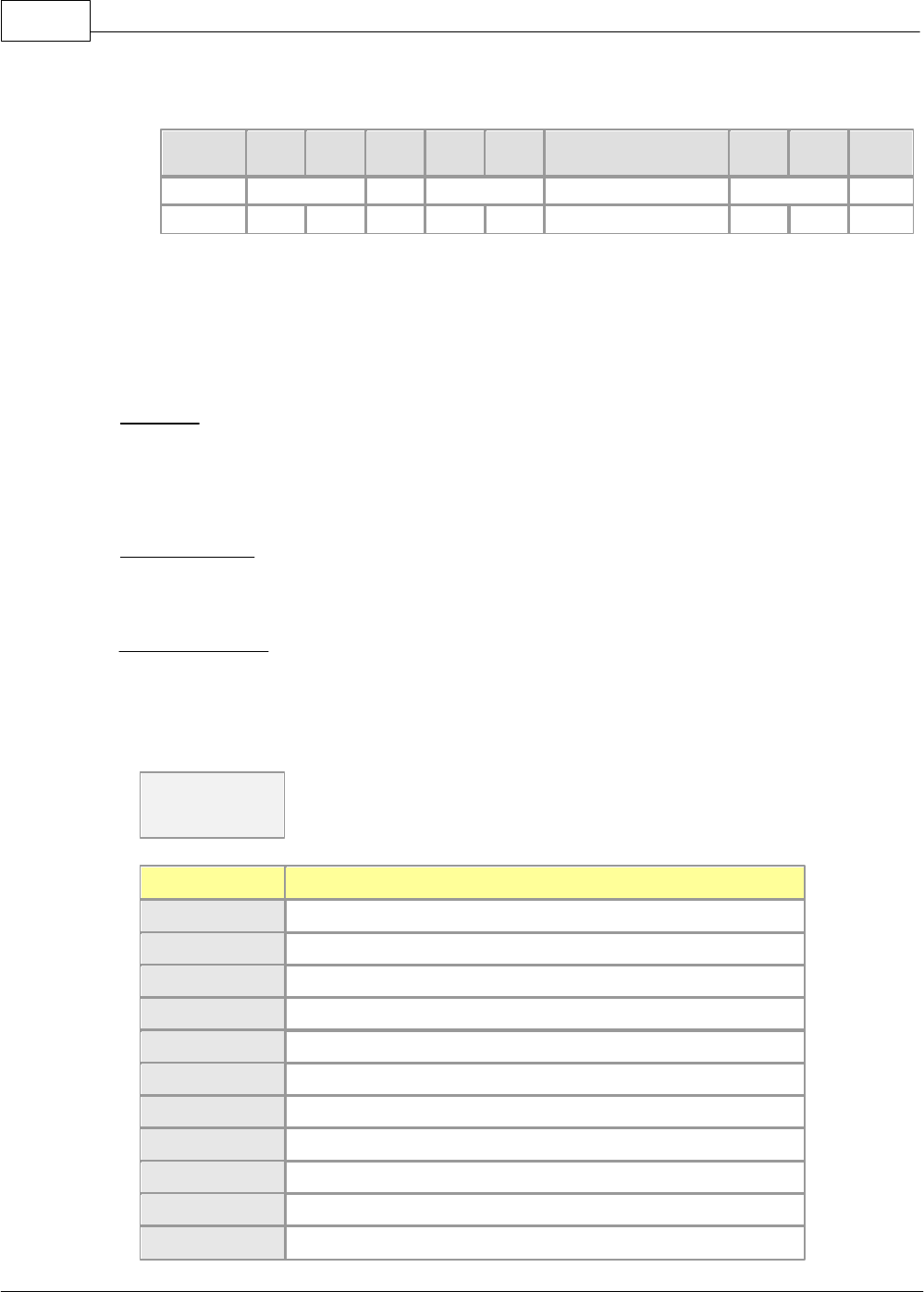
CIMON-PLC1196
Copyright 2012 BY KDT SYSTEMS, All rights reserved.
< Failed Case > Number of the unregistered(Not initialized) frame
Slave(Response Format)
HEADER
Stn
H
Stn
L
Cmd
Leng
H
Leng
L
Error Code
BCC
H
BCC
L
ETX
STX
01
E
02
08
0F
ETX
02H
30H
32H
45H
30H
32H
3038H
30H
46H
03H
6.2.9.2.3 Error Response
Function
·This is the function to inform a master of error occurring in the process of a communication
frame or a request frame and is
used in a response frame only.
Request Frame
·All request frames
Response Frame
·COMMAND : ‘E’
·Format of Data Device
·Error Code
Error Code
2 Char
Error Code
Description
00
No error.
01
Receives unknown command code.
02
An error occurs in BCC.
03
CPU does not respond.
04
Receives unknown device code.
05
Exceeds the device read.
06
Invalid address.
07
Internal error
08
Receives the number of invalid data
09
Invalid data
10
Unregistered (Not initialized) frame number
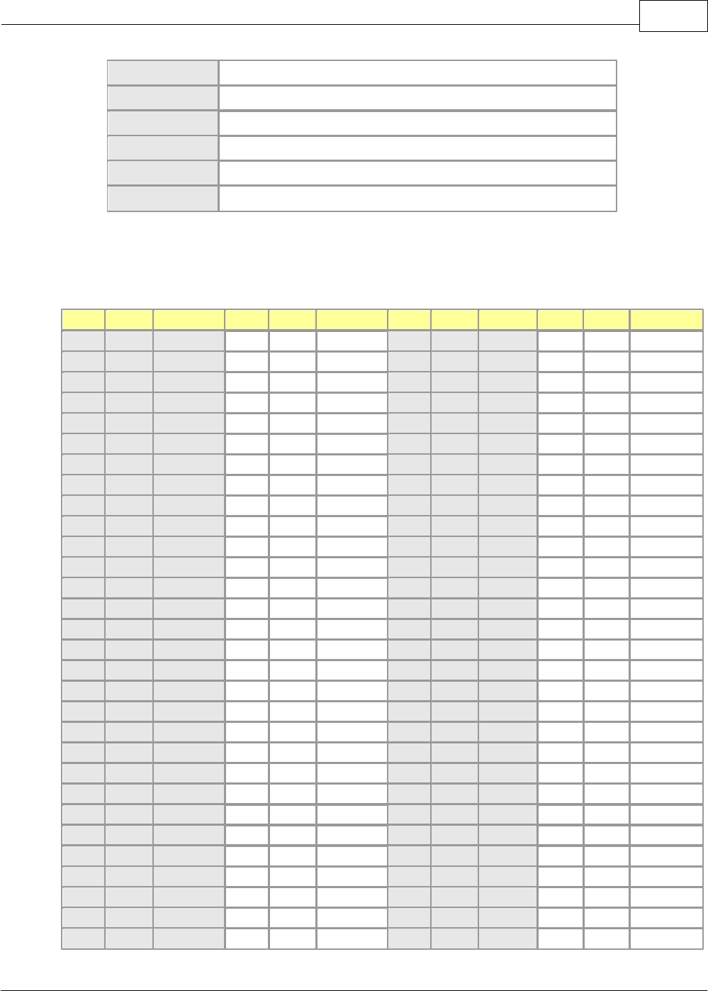
XP / CP Series(CM1) 1197
Copyright 2012 BY KDT SYSTEMS, All rights reserved.
11
Invalid Monitor Frame No. (0h – Fh) Invalid frame number
12
CPU is not in REMOTE status.
13
Invalid CPU status is assigned.
14
An error occurs in the size of the data written.
15
It is disabled to write.
16
It is disabled to change mode.
6.2.9.3 ASCII Code Table
BIN
Hex
Symbol
BIN
Hex
Symbol
BIN
Hex
Symbol
BIN
Hex
Symbol
0
0
NUL
32
20
(space)
64
40
@
96
60
`
1
1
SOH
33
21
!
65
41
A
97
61
a
2
2
STX
34
22
"
66
42
B
98
62
b
3
3
ETX
35
23
#
67
43
C
99
63
c
4
4
EOT
36
24
$
68
44
D
100
64
d
5
5
ENQ
37
25
%
69
45
E
101
65
e
6
6
ACK
38
26
&
70
46
F
102
66
f
7
7
BEL
39
27
'
71
47
G
103
67
g
8
8
BS
40
28
(
72
48
H
104
68
h
9
9
TAB
41
29
)
73
49
I
105
69
i
10
A
LF
42
2A
*
74
4A
J
106
6A
j
11
B
VT
43
2B
+
75
4B
K
107
6B
k
12
C
FF
44
2C
,
76
4C
L
108
6C
l
13
D
CR
45
2D
-
77
4D
M
109
6D
m
14
E
SO
46
2E
.
78
4E
N
110
6E
n
15
F
SI
47
2F
/
79
4F
O
111
6F
o
16
10
DLE
48
30
0
80
50
P
112
70
p
17
11
DC1
49
31
1
81
51
Q
113
71
q
18
12
DC2
50
32
2
82
52
R
114
72
r
19
13
DC3
51
33
3
83
53
S
115
73
s
20
14
DC4
52
34
4
84
54
T
116
74
t
21
15
NAK
53
35
5
85
55
U
117
75
u
22
16
SYN
54
36
6
86
56
V
118
76
v
23
17
ETB
55
37
7
87
57
W
119
77
w
24
18
CAN
56
38
8
88
58
X
120
78
x
25
19
EM
57
39
9
89
59
Y
121
79
y
26
1A
SUB
58
3A
:
90
5A
Z
122
7A
z
27
1B
ESC
59
3B
;
91
5B
[
123
7B
{
28
1C
FS
60
3C
<
92
5C
\
124
7C
|
29
1D
GS
61
3D
=
93
5D
]
125
7D
}