L011618 KNC VFD FV100 5T Series Kinco Spec Sheet
User Manual: L011618 - KNC-VFD-FV100-5T- Series Kinco Spec Sheet
Open the PDF directly: View PDF ![]() .
.
Page Count: 4
DESCRIPTION
910 East Orangefair Ln. Anaheim, CA 92801 Tel. (714) 992-6990 Fax. (714) 992-0471 www.anaheimautomation.com
SPECIFICATIONS
• Input Voltage Range of 480-540VAC
• Power Rating 7.5kW - 90kW Watts
• Methods of Control: V/F Control, Closed-
Loop Vector, Open Loop Vector
• Open Phase (optional), Overcurrent,
Overvoltage, Undervoltage, Overheat,
and Overload Protection
• Sleep/Wake Up Function
L011618
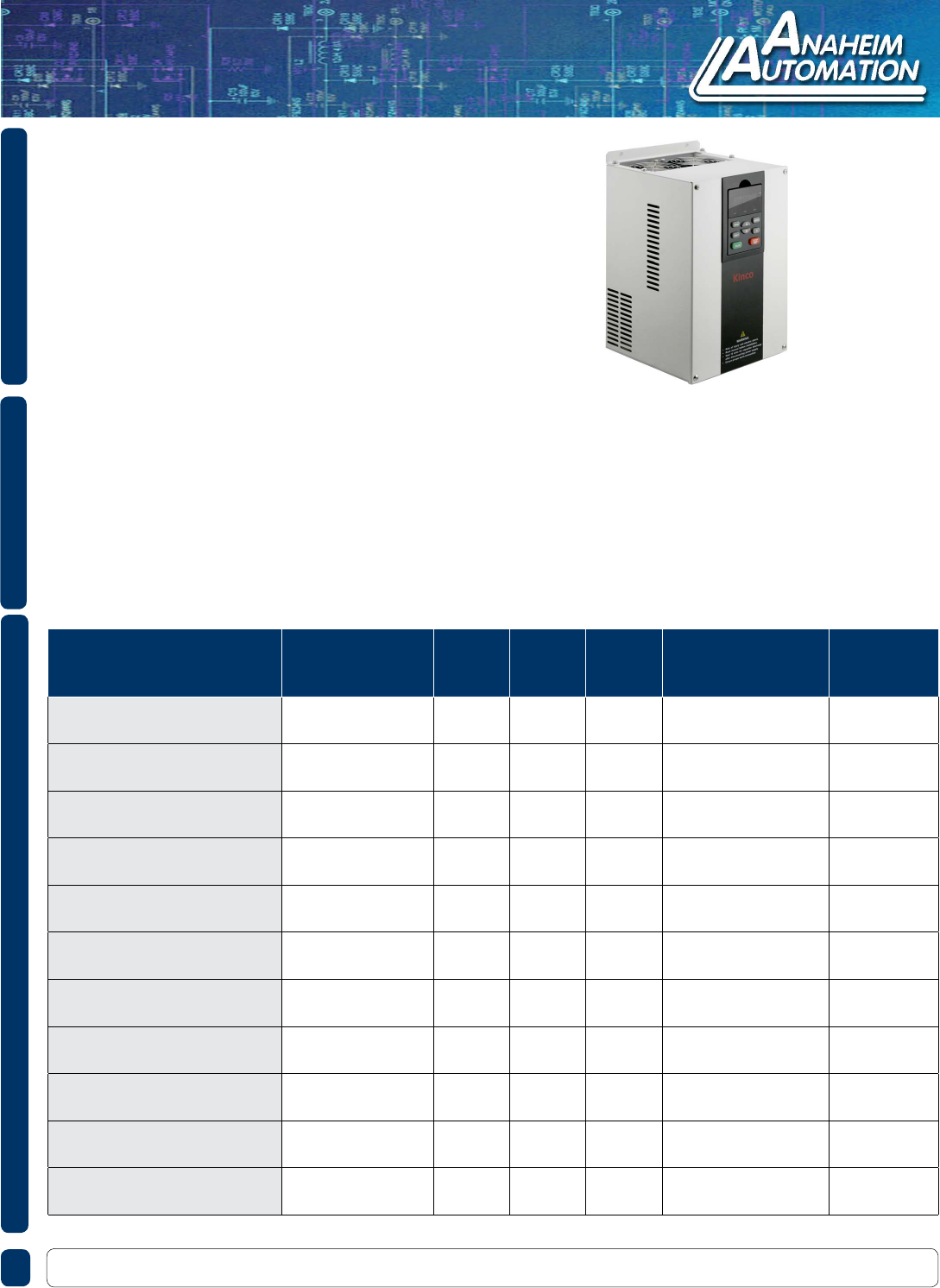
The Kinco KNC-VFD-FV100-5T Series combines power and performance into one compact
package. With 480 VAC Three-Phase input, this drive offers from 7.5kW - 90kW (10 - 120
HP) of power to drive your Three-Phase AC motor. This series offers unique control methods
to achieve high torque and accuracy, and variable speed range. Other features for this drive
include exible I/O terminals, overcurrent, overvoltage, undervoltage, and overheat protection,
acceleration and deceleration times, and vector control.
FEATURES
KNC-VFD-FV100-5T Series
SERIES # Input Voltage
Range
Max
Power
(KW)
Max
Power
(HP)
Rated
Current
(A)
Overload Tolerance
for One Minute
(A)
Installation
Type
KNC-VFD-FV100-5T-0075G 3-Phase,
480V
7.5 10 17 25 Wall Mount
KNC-VFD-FV100-5T-0110G 3-Phase,
480V
11 15 25 37 Wall Mount
KNC-VFD-FV100-5T-0150G 3-Phase,
480V
15 20 32 48 Wall Mount
KNC-VFD-FV100-5T-0185G 3-Phase,
480V
18.5 25 37 55 Wall Mount
KNC-VFD-FV100-5T-0220G 3-Phase,
480V
22 30 45 67 Wall Mount
KNC-VFD-FV100-5T-0300G 3-Phase,
480V
30 40 60 90 Wall Mount
KNC-VFD-FV100-5T-0370G 3-Phase,
480V
37 50 75 112 Wall Mount
KNC-VFD-FV100-5T-0450G 3-Phase,
480V
45 60 90 135 Wall Mount
KNC-VFD-FV100-5T-0550G 3-Phase,
480V
55 74 110 165 Wall Mount
KNC-VFD-FV100-5T-0750G 3-Phase,
480V
75 100 152 228 Wall Mount
KNC-VFD-FV100-5T-0900G 3-Phase,
480V
90 120 176 264 Wall Mount

910 East Orangefair Ln. Anaheim, CA 92801 Tel. (714) 992-6990 Fax. (714) 992-0471 www.anaheimautomation.com
DIMENSIONS
KNC-VFD-FV100-5T Series
L011618
Item W W1 H H1 D D1 T1
KNC-VFD-FV100-5T-0075G 165 110 274 264 193 - 2
KNC-VFD-FV100-5T-0110G 194 120 324 312 197 - 2
KNC-VFD-FV100-5T-0150G 194 120 324 312 197 - 2
KNC-VFD-FV100-5T-0185G 194 120 324 312 197 - 2
KNC-VFD-FV100-5T-0220G 297 200 451 433 224 - 3
KNC-VFD-FV100-5T-0300G 297 200 451 433 224 - 3
KNC-VFD-FV100-5T-0370G 320 220 535 512 224 88.5 3
KNC-VFD-FV100-5T-0450G 320 220 535 512 224 88.5 3
KNC-VFD-FV100-5T-0550G 373 240 649 628 262 102.5 3
KNC-VFD-FV100-5T-0750G 373 240 649 628 262 102.5 3
KNC-VFD-FV100-5T-0900G 440 340 758 737 285 102 2.5
KNC-VFD-FV100-5T-0075G ~ KNC-VFD-FV100-5T-0450G
KNC-VFD-FV100-5T-0550G ~ KNC-VFD-FV100-5T-0900G
INPUT
Rated Voltage/Frequency 3-phase, 480-540V AC; 50Hz/60Hz
Allowable Voltage Range 420-560V AC; Voltage Tolerance:<3%; Frequency: ±5%
OUTPUT
Rated Voltage 0~Rated Input Voltage
Frequency 0Hz-300Hz (0Hz-3000Hz Custom)
Overload Capacity 150% Rated Current for 1 Minute, 180% Rated Current for 10 Seconds
MAIN CONTROL CHARACTERISTICS
Control Method Vector Control Without PG, V/F Control
Modulation Mode Space Vector PWM Modulation
Starting Torque 0.5Hz: 150% Rated Torque (Vector Control Without PG)
Frequency Accuracy Digital Setting: Max. Frequency x ±0.01%; Analog Setting: Max. Frequency x ±0.2%
Frequency Resolution Digital Setting: 0.01Hz; Analog Setting: Max. Frequency x 0.05%
Torque Boost Manual Torque Boost: 0%-30.0%
V/F Pattern 4 Patterns: 1 V/F Curve Mode Set by User and 3 Kinds of Torque-Derating Modes
(2.0 Power, 1.7 Power, 1.2 Power)
Acceleration/Deceleration
Curve
Linear Acceleration/Deceleration. Four Kinds of Acceleration/Deceleration Time
Auto Current Limit Limit Current During Operation Automatically to Prevent Frequent Overcurrent Trip
Jog Range of Jog Frequency: 0.20Hz-50.00Hz; Acc/Dec Time of Jog Operation: 0.1-
60.0s, Interval of Jog Operation is also settable.
Multiple Speed Operation Implement Multiple Speed Operation by Digital Inputs
FUNCTIONS
Operation Command Keypad Setting, Terminal Setting, Communication Setting
Frequency Command Setting Digital Setting, Analog Voltage Setting, Analog Current Setting
Auxiliary Frequency Setting Implement Flexible Auxiliary Frequency Trim and Frequency Synthesis
Pulse Output Terminal 0.1-100kHz Pulse Output. For example setting frequency, output frequency
Analog Output Terminal 1 Channel Analog Output (0/4~20mA or 0/2~10V)
LED Display Display frequency setting, frequency output, voltage output, current output and so on,
about 20 parameters
Parameters Copy Copy parameters by operation panel
Keys Lock and Function
Selection
Lock part of keys or all the keys. Dene the function of part of keys, in case of
misoperation
Protection Function Open Phase Protection (optional), Overcurrent Protection, Overvoltage Protection,
Undervoltage Protection, Overheat Protection, and Overload Protection
ENVIRONMENT
Altitude Derated Above 1000m, The Rated Output Current Shall be Decreased by 10% for
Every Rise of 1000m
Ambient Temperature -10°C~ + 40°C (Derated at 40°C~50°C)
Humidity 5%~95%RH, Non-Condensing
Vibration Less Than 5.9m/s2 (0.6g)
Storage Temperature -40°C~ + 70°C
TECHNICAL SPECIFICATIONS
910 East Orangefair Ln. Anaheim, CA 92801 Tel. (714) 992-6990 Fax. (714) 992-0471 www.anaheimautomation.com
KNC-VFD-FV100-5T Series
L011618
KNC-VFD-FV100-5T Series
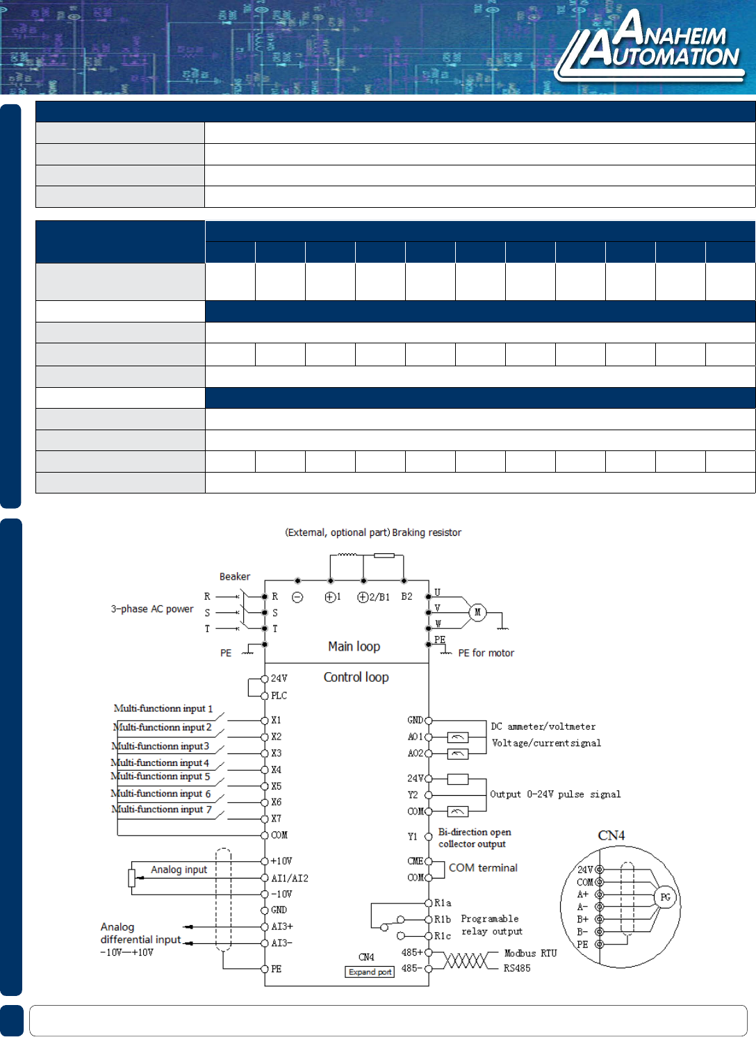
WIRING DIAGRAM
910 East Orangefair Ln. Anaheim, CA 92801 Tel. (714) 992-6990 Fax. (714) 992-0471 www.anaheimautomation.com
MODEL KNC-VFD-FV100-5T
0075 0110 0150 0185 0220 0300 0370 0450 0550 0750 0900
The Power of Suitable
Motor (KW)
7.5 11 15 18.5 22 30 37 45 55 75 90
OUTPUT
Voltage (V) 3-Phase, 0~ Rated Input Voltage
Rate Output Current (A) 17 25 32 37 45 60 75 90 110 152 176
Overload Capacity 150% Rated Current for 1 Minute; 180% Rated Current for 10 Seconds;
INPUT
Rated Voltage/Frequency 3 Phase, 480V~540V AC; 50Hz/60Hz
Allowable Voltage Range 420V~560VAC; Voltage Tolerance:<3%; Frequency: ± 5%
Rated Input Current (A) 20.5 26 35 38.5 46.5 62 76 92 113 157 180
Brake Unit Built-In (optional)
SPECIFICATIONS
L011618
SPECIFICATIONS
Protection Class IP20
Cooling Method Air Cooling, with Fan Control
Installation Method Wall-Mounted
Efciency Power Under 45kW ≥ 93%; Power Above 55kW ≥ 95%
