L 33 Solo Flight Review Dick Johnson
User Manual: L-33 Solo Flight Review Dick Johnson
Open the PDF directly: View PDF ![]() .
.
Page Count: 1
A FLIGHT TEST EVALUATION OF THE LET L-33 SOLO SAILPLANE
By Richard H. Johnson, Published in
Soaring
Magazine, July 1995
The L-33 Solo is an excellent 14-meter, single-seated metal sailplane, designed principally by Marian
Meciar and manufactured in what is now the Czech Republic by the LET factory. They have long produced
quality metal aircraft, including 2-seated aluminum sailplane trainers such as the Blanik L-13, and more
recently the newer Super Blanik L-23. An L-33 prototype was delivered to Oerlinghausen, Germany for the
FAI-International Gliding Commission’s flight trials and
evaluation for the Olympic World Class Sailplane De-
sign Competition during September of 1992.
There it was judged to be an excellent sailplane, but it
did not win the design competition, principally for the
following three reasons:
1. Manufacturing cost. It was a beautiful example of
metal craftmanship, with all flush rivets and some ad-
hesive bonding to insure a smooth finish. It used proven
construction techniques that appeared to require a fac-
tory with large machine tools, presses and special fix-
tures. It had many beautifully made small parts that were
judged to be too labor intensive for successful kit or
home building.
2. Stall speed. At full 750 lb gross weight it measured about 35 kts calibrated airspeed (CAS) with airbrakes
retracted, and about 37.8 kts with its powerful airbrakes extended. With airbrakes extended the stalling
speed exceeded the World Class Sailplane specified design goal of 35.1 kts by 2.7 kts.
3. Stall characteristics. Only about 1.5 kts of stall warning buffet was observed with the prototype, and the
stall was accompanied by a sudden roll into a spin entry. The World Class judges considered those charac-
teristics to be unsatisfactory for low time pilots.
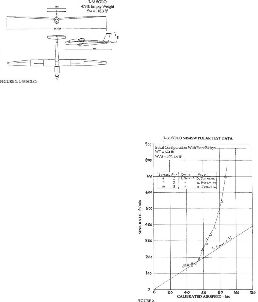
Figure 1 is a 3-view of the prototype L-33, and it appears to closely match the current production models.
Because of the favorable present currency exchange
rate with the Czech Republic, the L-33 is currently be-
ing offered in the U.S. for about $24,000 to $26,000 (de-
pending on options) complete with basic instruments,
U.S. Standard Type Certificate, licensing, and a very
well prepared Flight Manual. An excellent Slovakian
made enclosed fiberglass trailer is also available. The
glider’s construction is almost entirely of aluminum al-
loy, and only the rudder is covered with fabric.
The prototype brought to Germany in 1992 for evalu-
ation had just completed extensive certification flight
testing in the Czech Republic, and it was somewhat
degraded by that unusually harsh activity. Each wing
panel had 4 large wrinkles in its upper surface wing skins,
two on each side of each airbrake. That damage oc-
curred, I was told, during beyond-redline 143 kt flutter
testing, when the airbrakes accidently deployed. Even
with the damaged upper wing skins, we measured its
maximum glide ratio at about 31.1:1 at 45 kts.
The aluminum wing skins were relatively thick and well
supported such that they were quiet and did not nor-
mally “oil can” or wrinkle in flight. Wave gage chordwise
measurements showed about .006 inches (.15 mm)
maximum waviness, except in the above discussed dam-
aged areas at each end of the airbrake upper surface
skins, and that was excellent for a bare aluminum wing
skins. In the damaged airbrake areas, .025 to .035 inches (.63 to .90 mm) of
chordwise waviness was measured with a 2 inch long gage. The wing air-
foils were reported to be modern Wortmann designs, with thickness-to-chord
ratios of .180 at the root tapering to .126 at the tips.
Steve Waymire of Stillwater, Oklahoma received his new L-33, SN 940214
during May of 1994, and he kindly offered to bring it to Caddo Mills, Texas,
late that year for flight testing. SN 214 came complete with a beautiful white
enamel paint on all its exterior surfaces, and an optional red starburst trim
on both the wing and horizontal tail outboard portions to enhance its visibil-
ity (better red than dead, as the all white sailplane anti-collision phrase goes).
No doubt, the red trim enamel was too fresh and soft to sand at the factory,
therefore SN 214 came with a total of 32 sharp edged diagonal paint ridges,
measuring about .004 inches (.10 mm) high across a large portion of its
wing and tail surfaces.
The initial 3 sink rate measurement flights were made with the as deliv-
ered paint ridges somewhat spoiling the airflows, and those polar data are
presented in Figure 2. There a maximum glide ratio of about 31:1 is shown
at 50 kts CAS, a minimum sink rate of about 150 ft/min at 42 kts, and a high
speed sink rate of about 500 ft/min at 80 kts. That is fairly good perfor-
mance, considering the paint ridges. There did appear to be a high drag
knee in the polar at 59 kts, possibly due to the paint ridges discussed above.
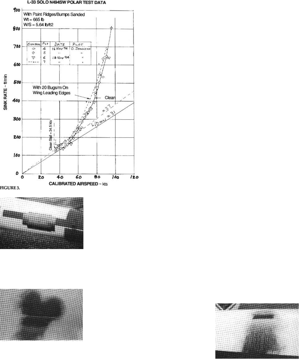
Since it was obvious that the paint ridges were detrimental to the L-33’s
performance, they were carefully sanded down to about .001 to.002 inches
(.025 to .05 mm) before 3 additional high tow sink rate measurement flights
were performed. Those data are shown versus calibrated airspeed in Figure
3. The maximum glide ratio appeared to be unchanged and still at about 31,
but the minimum sink rate appeared to be reduced to about 135 ft/min at 38
kts. The high speed sink rate was significantly improved, with the 80 kt point
decreasing about 50 ft/min, to 450 ft/min.
After that, oil flow studies were performed on the wing. Dirty 10W-40 mo-
tor oil was sprayed on the left wing upper and lower wing surfaces at 4
spanwise stations, starting near its root and ending near the tip. The L-33
was then flown by Steve for about 24 minutes at airspeeds between 50 to 60
kts. The oil flow patterns formed well during that flight, and they indicated
that low drag laminar flow was being achieved on both the top and bottom
surfaces, from the leading edge aft to about half of the wing chord. Laminar
flow was also indicated in the sanded down paint ridge areas. Normal lami-
nar-to-turbulent airflow transitions were shown near the 50% chord loca-
tions, and no significant separation bubbles were indicated, except on the
bottom surfaces ahead of the ailerons. If turbulator strips were installed
slightly ahead of the bubble leading edge, a further improvement of the L-
33’s performance is possible. Unsuitable weather prevented that testing for
the present time.
Chordwise wing surface waviness mea-
surements showed SN 214’s surfaces to
be relatively smooth, for metal construc-
tion, with about .010 inch maximum waves
shown. Its wing thickness-to-chord mea-
surements showed .185 from its root out
to the inboard end of the ailerons, then
tapering to about .118 at the aileron tips.
Excellent top and bottom surface mylar
seals had been installed by the factory over
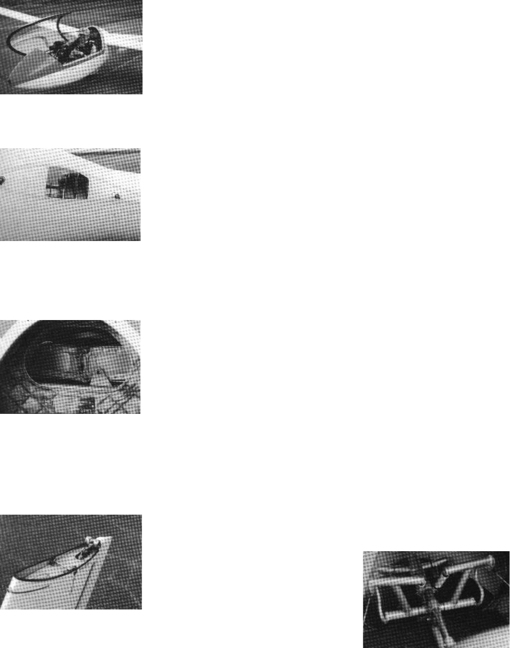
Photo 1: Author in L-33 cockpit,
with airspeed calibration Kiel tube
pitot mounted on canopy left side
window.
Photo 2: Fuselage wing attach-
ment area, showing wing spar
opening, forward and aft shear
pins, and aileron and airbrake au-
tomatic control connection sock-
ets.
Photo 3: Aluminum wing spars
joined at the fuselage centerline
behind pilot by 2 longitudinal
steel shear pins. Bracket forward
of left wing spar retains that wing
during assembly/disassembly
operations.
Photo 4: Horizontal tail interface
at top of vertical fin. Automatic
elevator control connection pin at
aft, and lateral steel shear pin
near mid-chord to support hori-
zontal stabilizer.
Photo 5: Inflight adjustable rudder
pedals, ahead of instrument ped-
estal.
the aileron, elevator and rudder gaps. The .010 inch
(.25 mm) high blunt leading edges on all the mylar seals
were beveled somewhat before Flights 6 and 7.
The effect of roughness on the L-33’s wing leading
edges was evaluated during one final sink rate mea-
surement flight, with 20 small duct tape “bugs” per meter
of span attached to the wing leading edges. Those test
data are included in Figure 3, and they indicate that the
sailplane’s minimum sink rate increased to about 155
ft/min at 38 kts, and that its maximum glide ratio de-
creased to about 27 at 45 kts. That is not a very serious
degradation considering the degree of roughening used
during that test. Later oil flow testing showed that sig-
nificant laminar flow on the wing leading edges contin-
ued to exist between the tape bugs.
The L-33’s cockpit is adequately large and is quite
comfortable for most pilots. The canopy is an excellent
side hinged design that provides the pilot with excep-
tionally good visibility. All the control handles are easy
to reach, and their operating forces are adequately low.
The controls all connect automatically on assembly, as
they should. The wings weigh about 115 lbs each, thus
allowing fairly easy assembly with two persons.
The main landing wheel mounts a generously sized
13.8 inch diameter by 5.3 inch wide (350 by 135 mm)
tire. The wheel is equipped with an internal drum brake
that functions well, and commendably, the wheel is mounted to an oleo-
hydraulic shock absorber. Much of the L-33’s main gear system uses hard-
ware that is common to the L-23. A nicely sized 7.9 by 2 inch (200 by 50
mm) pneumatic tail wheel helps keep the takeoff and landing rolls straight.
Our test sailplane was equipped with optional 1.7 inch diameter by .55 inch
wide wingtip wheels, instead of .60 inch wide steel skids. Their drag penalty
was estimated to be very small.
Our test sailplane’s assembled empty weight was 486 lbs. That included
basic instruments, optional cockpit upholstery, two tow hooks, and external
paint. The L-33 comes with a C.G. hook mounted just forward of the main
landing wheel, for either ground or aero towing. An optional nose tow hook
for aero towing only can be included, and both tow hooks were installed on
our test sailplane. We did not perform any ground tows, but that was well
tested at Oerlinghausen during the 1992
prototype evaluations.
All the internal aluminum parts of the sail-
plane are anodized by the factory before
assembly, for corrosion protection. The ba-
sic sailplane comes with a white enamel
exterior finish, but a lighter weight gold or
silver anodized exterior finish is offered for
those who desire that option. Our test sail-
plane included the standard external
enamel paint plus the bright red sunburst
trim, adding about 14 pounds to the
sailplane’s weight.
The final test flights made with SN 214
Photo 6: Cardboard taped around
aft fuselage side airspeed system
static port, for flush static port
configuration testing.
Photo 7: Oil flow on bottom sur-
face of right wing near fuselage.
Laminar flow is indicated to
about 4 inches aft of white wing
skin butt joint line at main spar,
where thinning of oil indicates
higher shear turbulent flow is ini-
tiated.
Photo 8: Oil flow on top surface
of right wing near fuselage. Dark
oil band behind main wing spar
indicates a separation bubble, fol-
lowed by high shear turbulent flow
to trailing edge.
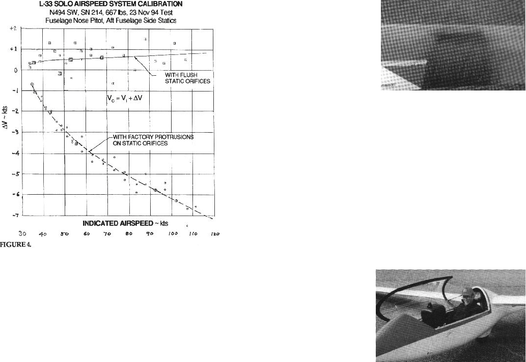
were for its airspeed calibra-
tions. The ASI pitot is at the
fuselage nose, and it ap-
pears to function well there.
The ASI static ports are lo-
cated on the aft fuselage
sides, and unlike the proto-
type L-33 tested in Germany,
SN 214’s static ports were
not flush with the fuselage
surface, but protruded about
.06 inches (1.5 mm) into the
airstream. The extended
static ports caused the air-
flow to be faster than it
should be at the static orifices. That in turn caused the air-
speed system to indicate higher airspeeds than it should, as
indicated in the lower curve in Figure 4.
It had been noted that the discrepancy between the
towplane’s indicated air-
speed and SN 214’s was greater than usual. In general, it is basically a
good airspeed system, but biased to indicate about 6% higher airspeeds
than it should. The ASI system showed fairly good performance during side-
slip approaches, where the indicated airspeed dropped only about 5 kts or
so. Crossflow at the flush nose pitot is the likely cause when indicated
airspeed drops during constant true airspeed sideslips.
To confirm that the protruding static ports were the cause for the rela-
tively high airspeed system errors discussed earlier, an additional airspeed
system calibration flight was performed with SN 214’s static ports flush with
the fuselage sides. Instead of actually cutting off the static port protrusions,
they were made aerodynamically flush by taping a 10 inch long cardboard sheet around the static port, equal
in thickness to the .06 inch static port protrusion. That appeared to fix the airspeed system error problem, as
indicated by the test data shown in the upper portion of Figure 4. With that modification the airspeed system
showed less than 1 kt of error over the entire airspeed test range. In order to not violate L-33’s Certificate of
Airworthiness, the static port protrusions should not be cut off or aerodynamically flushed without factory
approval.
Level flight stall testing of the new L-33 showed the control stick to be well aft as stall was approached, with
mushy control responses and a nose high attitude, but little to no pre-stall warning buffet was observed. In
smooth air, I was able to maintain steady flight down to about 34.5 kts CAS (35.5 kts indicated) without any
significant buffeting being felt. At stall, a wing drops rather suddenly, and unless corrective action is taken
promptly, a spin will start, just as with most high performance sailplanes. Recovery from the incipient spin
stage is positive, and quickly achieved thru application of forward stick to reduce the sailplane’s angle of
attack and unstall the wing. At my 664 lb test gross weight, the level flight stalling speeds varied from about
34 kts calibrated when the wings were clean, to 35.5 kts with the 20 bugs/meter on the wing leading edges,
to about 37 kts with the airbrakes fully open. In my opinion the excellent glide path control offered by the
strong airbrakes more than offset their 3 kt increase in stalling airspeed.
Overall the L-33 is an outstandingly well-constructed sailplane with good performance, and well worth its
present attractive low price. However, in my opinion, its stall characteristics make it questionable for low-
time pilots, unless they have been carefully checked out in a suitable trainer with similar stalling characteris-
tics. In any case, recent low-speed handling and full spin training is highly recommended.
Thanks go to Stephen Waymire for kindly bringing his fine new sailplane to Caddo Mills for testing, the
Dallas Gliding Association for providing the hangarage and high test tow funding, and especially to Carol
Walker who did almost all of the towing.
Author ready to takeoff on a sink
rate measurement flight.
Photo 9: Oil flow on top surface
of right wing near aileron tip. Low
shear laminar flow is indicated by
thickening oil to about 2 inches
aft of main wing spar, followed by
normal higher shear turbulent
flow to trailing edge.
