Repair 6632L 0470A And 0471A For Panel LC420WU5 Q205 Inverter
User Manual: Q205
Open the PDF directly: View PDF ![]() .
.
Page Count: 4
OHMWORK 2. LCD INVERTER REPAIR
The following information is on the repair several types of inverters, you will find:
•The inverter types used and the listing of the repair kits along with panel and an
example of some of the models used.
•The list of fault symptoms
•The listings of the repair kits with cct refs.
•Helpful fitting directions
Also covered is a method of s.m. Ic removal
INVERTER BOARD NUMBERS REPAIR KIT NUMBER
Master - 6632L-0470A PNEL-T707A KIT63
Slave - 6632L-0471A PNEL-T708A KIT63
As used on the LG / PHILIPS LCD PANEL TYPE: LC420WU5
Examples of models that use this panel:
•PHILIPS 42PFL7662
•PHILIPS 42PFL9900D10
•PHILIPS 42PFL5332D
•PHILIPS 42PFL7332D37
•PHILIPS42MF337B/37
-------------------------------------------------------------------------------------------------------
INVERTER BOARD NUMBERS REPAIR KIT NUMBER
Master - 6632L-0448C PNEL-T702C KIT61
Slave - 6632L-0449C PNEL-T703C KIT61
As used on the LG / PHILIPS LCD PANEL TYPE: LC420WX7
Examples of models that use this panel:
•PHILIPS 42PFL5533D
•PHILIPS 42PFL5332/45
•PHILIPS 42PFL5332D/37
-------------------------------------------------------------------------------------------------------
INVERTER BOARD NUMBERS REPAIR KIT NUMBER
Master - HIU-813M KIT62
Slave – HIU-813S KIT62
IPS ALPHA TECHNOLOGY LCD PANEL TYPE: AX080E002B
Examples of models that use this panel:
•BEKO 32WLU530HID
•HITACHI 32LD8D20U
•TOSHIBA 32C3035D
•TOSHIBA 32AV500U

Fault Symptom:
•No picture
•No audio (backlight does not function).
•Slight fizzing noise then trips off
•Burn up of one or all of the components listed
CURE:
KIT63
For boards that use KIT63, check the following components:
MASTER SLAVE
MU1 SU1
MQ1 SQ8
MQ2 SQ9
MQ4 SQ10
MQ5 SQ11
MZD3 * SZD3*
*for the protection of the driver-IC, 2 zener diodes must be added to both Master and Slave
inverter (if not already present). These diodes are included in KIT63
KIT61
Check the following components on the boards that use KIT61:
MASTER SLAVE
MU1 SU1
MQ1 SQ8
MQ2 SQ9
MQ4 SQ10
MQ5 SQ11
Protection diodes MZD3 and SZD3 should be fitted to these boards
KIT62
Check the following components on the boards that use KIT62:
MASTER SLAVE
IC2 IC202
Q3 Q203
Q4 Q204
Q5 Q205
Q6 Q206
This repair kit can also be used on the similar inverters:
Master - HIU-812M Slave – HIU-812S
Example of models that use these are:
•DIGITAL LIFESTYLES WT323
•DIGIMATE LTV-3203HT
Please note. All the models listed are examples only, it is not a definitive list.
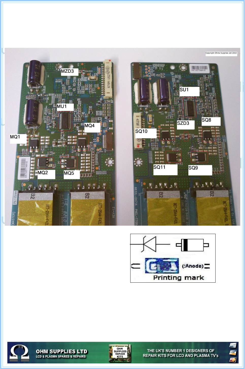
Diagram showing the location of the parts IN KIT63 but pay special attention to MZD3 &
SZD3 which can be difficult to locate if not shown
Diagram showing the orientation of MZD3 &
SZD3 to be fitted if missing from the board.
This diagram is included on the backer of
KIT63
TIP
We have had reports on the 470uf/35V giving
problems, it might be wise to check them as a
matter of course
Remember, as with all inverter repair faults, if Audio is still present but you have no picture,
its always wise to look through the vents to see if you can see the backlight is working, if
not, shine a torch into the front of the screen and look at a slight angle into the screen.
Quite often the picture is present, just not illuminated.
If the lamps are lit then you must have another fault.
It is important that all parts are fitted by suitably qualified engineers. We cannot be held
responsible for any loss or damage made by incorrectly fitted parts.
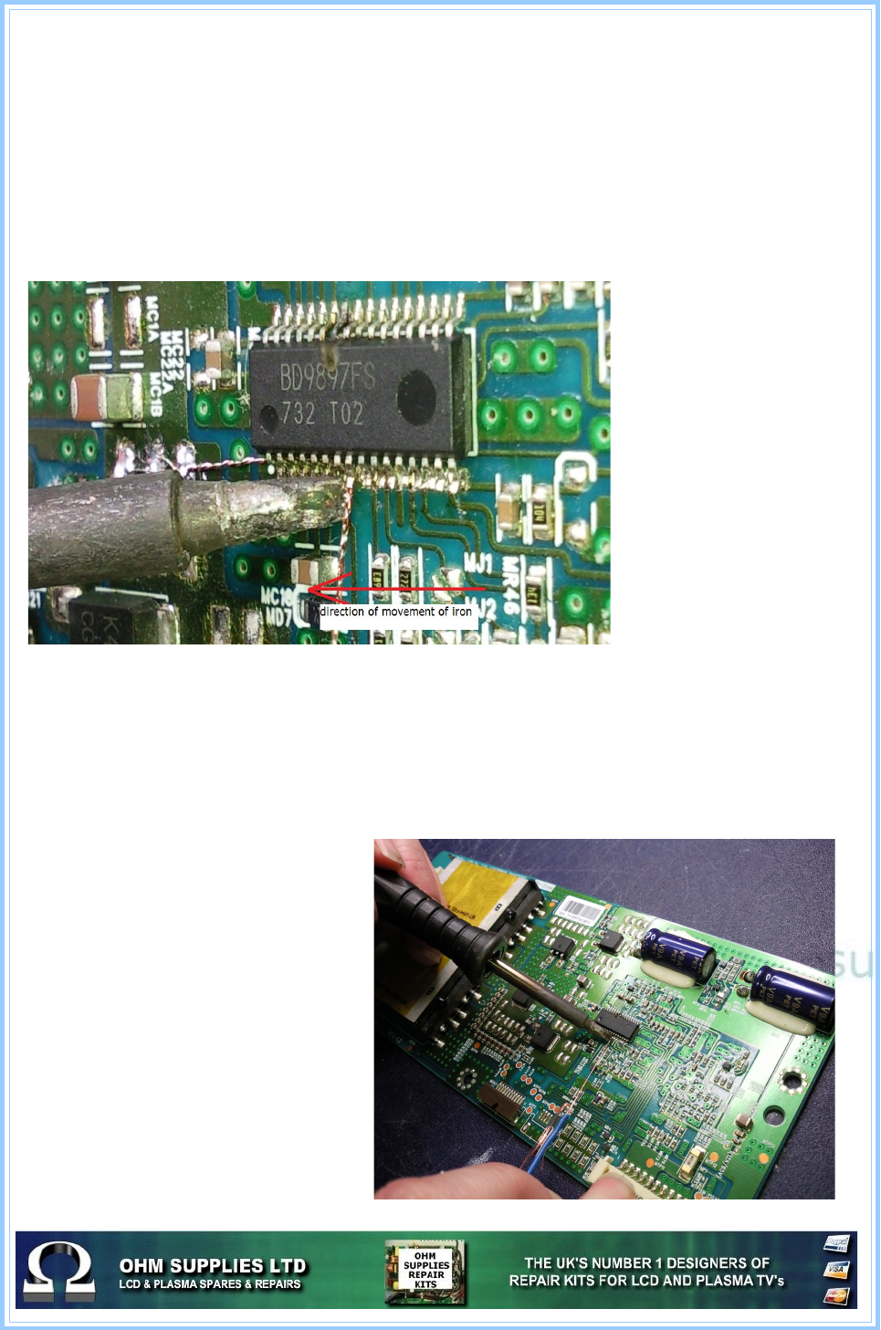
Removal of surface mounted ic's
Although there are several methods of removing surface mount components, from lifting
each leg to reflowing the ic and lifting off with a vacuum, here's a simple method that is
favoured by many engineers.
You'll need solder braid, your iron and some thin wire.
•First, remove the excess solder on the legs of the ic as normal.
•Slide your wire under each leg then “anchor” it by soldering it to a suitable position
on the board
•Place your iron tip on the first leg of the ic you want to remove then pull the wire.
Here you can see the the
direction of the iron and
how close the wire is
behind it not allowing the
legs and solder to cool.
The trick is to get the
correct angle and speed
of the iron and wire
You can also see the
typical damage when the
ic fails.
As you move your iron
along the ic pull the wire
CAREFULLY just behind
it, the legs should then
lift easily off the board.
Once all the legs have been lifted, repeat on the other side of the ic. If the ic does not lift,
check all the legs have been removed from the track. If they have it could be the ic has a
small amount of glue used to keep it in place when originally soldered.
If this is the case, place the iron tip on the top of the ic then, again CARFULLY lift the edge
of the ic to remove it to the board. Then remove any excess glue from the board.
You can also see where the wire has
been soldered to the board to anchor
it.
If the wire snaps then it's probably to
thin. Either try slightly thicker wire or
twist 2 lengths together.
This method is not only quick and
inexpensive but also has the
advantage of not heating up other
components and surrounding print.
Obviously, its best to practise any
new technique on an old scrap board
until you're comfortable with it.
